Self Configuring Binary Multipliers for LUT addressable FPGAs
Application-Level Multicast using Content-AddressableNetworks
Sylvia Ratnasamy��� �
, Mark Handley�, Richard Karp
��� �, and Scott Shenker
�
�University of California, Berkeley, CA, USA�AT&T Center for Internet Research at ICSI
Abstract. Most currently proposed solutions to application-level multicast orga-nize the group members into an application-level mesh over which a Distance-Vector routing protocol, or a similar algorithm, is used to construct source-rooteddistribution trees. The use of a global routing protocol limits the scalability ofthese systems. Other proposed solutions that scale to larger numbers of receiversdo so by restricting the multicast service model to be single-sourced. In this pa-per, we propose an application-level multicast scheme capable of scaling to largegroup sizes without restricting the service model to a single source. Our schemebuilds on recent work on Content-Addressable Networks (CANs). Extending theCAN framework to support multicast comes at trivial additional cost and, becauseof the structured nature of CAN topologies, obviates the need for a multicastrouting algorithm. Given the deployment of a distributed infrastructure such as aCAN, we believe our CAN-based multicast scheme offers the dual advantages ofsimplicity and scalability.
1 Introduction
Several recent research projects[8, 10, 7] propose designs for application-level networkswherein nodes are structured in some well-defined manner. A Content-Addressable Net-works (CANs)[6] is one such system. Briefly,1 a Content-Addressable Network is anapplication-level network whose constituent nodes can be thought of as forming a vir-tual
�-dimensional Cartesian coordinate space. Every node in a CAN “owns” a portion
of the total space. For example, Figure 1 shows a 2-dimensional CAN occupied by5 nodes. A CAN, as described in [6], is scalable, fault-tolerant and completely dis-tributed. Such CANs are useful for a range of distributed applications and services. Forexample, in [6] we focus on the use of a CAN to provide hash table-like functional-ity on Internet-like scales – a function useful for indexing in peer-to-peer applications,large-scale storage management systems, the construction of wide-area name resolutionservices and so forth.
This paper looks into the question of how the deployment of such CAN-like dis-tributed infrastructures might be utilized to support multicast services and applications.We outline the design of an application-level multicast scheme built using a CAN. Ourdesign shows that extending the CAN framework to support multicast comes at trivialadditional cost in terms of complexity and added protocol mechanism. A key feature
1 Section 2 describes the CAN design in some detail

of our scheme is that because we exploit the well-defined structured nature of CANtopologies (i.e. the virtual coordinate space) we can eliminate the need for a multicastrouting algorithm to construct distribution trees. This allows our CAN-based multicastscheme to scale to large group sizes. While our design is in the context of CANs inparticular, we believe our technique of exploiting the structure of these systems shouldbe applicable to the Chord [8], Pastry [7] and Tapestry [10] designs.
In previous work, several research proposals have argued for application-level mul-ticast[1, 3, 4] as a more tractable alternative to a network-level multicast service andhave described designs for such a service and its applications. The majority of theseproposed solutions (for example [1, 4]) typically involve having the members of a mul-ticast group self-organize into an essentially random application-level mesh topologyover which a traditional multicast routing algorithm such as DVMRP [2] is used to con-struct distribution trees rooted at each possible traffic source. Such routing algorithmsrequire every node to maintain state for every other node in the topology. Hence, al-though these proposed solutions are well suited to their targeted applications,2 their useof a global routing algorithm limits their ability to scale to large (many thousands ofnodes) group sizes and to operate under conditions of dynamic group membership.
Bayeux[11] is an application-level multicast scheme that scales to large group sizesbut restricts the service model to a single source. In contrast to the above schemes,CAN-based multicast can scale to large group sizes without restricting the servicemodel to a single source.
In summary, we believe our CAN-based multicast scheme offers two key advan-tages:
– CAN-based multicast can scale to very large (i.e. many thousands of nodes andhigher) group sizes without restricting the service model to a single-source. To thebest of our knowledge, no currently proposed application-level multicast schemecan operate in this regime.
– Assuming the deployment of a CAN-like infrastructure, CAN-based multicast istrivially simple to achieve. This is not to suggest that CAN-based multicast by itselfis either simpler or more complex than other proposed solutions to application-levelmulticast. Rather, our point is that CANs can serve as a building block in a rangeof Internet applications and services and that one such, easily achievable, service isapplication-level multicast.
The remainder of this paper is organized as follows: Section 2 reviews the design andoperation of a CAN. We describe the design of a CAN-based multicast service in Sec-tion 3 and evaluate this design through simulation in Section 4. Finally, we discussrelated work in Section 5 and conclude.
2 Content-Addressable Networks
In this Section, we present our design of a Content-Addressable Network. This papergives only a brief overview of our CAN design; [6] presents the details and evaluation.
2 The authors in [4], state that End System Multicast is more appropriate for small, sparse groupsas in audio-video conferencing and virtual classrooms, while the authors in [1] apply theiralgorithm, Gossamer, to the self-organization of infrastructure proxies

node B’s virtual coordinate zone
(0.5-1.0,0.0-0.5)0-0.5,0-0.5)(
(0.0-0.5,0.5,1.0)(0.75-1.0,0.5-1.0)
1.0
0.0 1.00.0
A B
D EC
(0.5-0.75,0.5-1.0)
Fig. 1. Example 2-d coordinateoverlay with 5 nodes
7’s coordinate neighbor set = { }
1 5
2
3
6
4
(x,y)
sample routing path from node 1 to point (x,y)
1’s coordinate neighbor set = {2,3,4,5}
Fig. 2. Example 2-d spacebefore node 7 joins
7 5
2
3
4
6
1’s coordinate neighbor set = {2,3,4,7} 7’s coordinate neighbor set = {1,2,4,5}
1
Fig. 3. Example 2-d space af-ter node 7 joins
2.1 Design Overview
Our design centers around a virtual�-dimensional Cartesian coordinate space on a
�-
torus. 3 This coordinate space is completely logical and bears no relation to any physicalcoordinate system. At any point in time, the entire coordinate space is dynamicallypartitioned among all the nodes in the system such that every node “owns” its individual,distinct zone within the overall space. For example, Figure 1 shows a 2-dimensional� ��������� �������
coordinate space partitioned between 5 CAN nodes. This coordinate spaceprovides us with a level of indirection, since one can now talk about storing content ata “point” in the space or routing between “points” in the space where a “point” refersto the node in the CAN that owns the zone enclosing that point.
For example, this virtual coordinate space is used to store (key,value) pairs as fol-lows: to store a pair ( � � , � � ), key � � is deterministically mapped onto a point, say ��������
in the coordinate space using a uniform hash function. The corresponding key-value pair is then stored at the node that owns the zone within which the point
��������lies. To retrieve an entry corresponding to key � � , any node can apply the same deter-ministic hash function to map � � onto point
��������and then retrieve the corresponding
value from the point ��������
. If the point ��������
is not owned by the requesting node or itsimmediate neighbors, the request must be routed through the CAN infrastructure until itreaches the node in whose zone
��������lies. Efficient routing is therefore a critical aspect
of our CAN.Nodes in the CAN self-organize into an overlay network that represents this virtual
coordinate space. A node learns and maintains as its set of neighbors the IP addressesof those nodes that hold coordinate zones adjoining its own zone. This set of immediateneighbors serves as a coordinate routing table that enables routing between arbitrarypoints in the coordinate space.
We first describe the three most basic pieces of our design: CAN routing, construc-tion of the CAN coordinate overlay, and maintenance of the CAN overlay and thenbriefly discuss the simulated performance of our design.
3 For simplicity, the illustrations in this paper do not show a torus.

2.2 Routing in a CAN
Intuitively, routing in a Content Addressable Network works by following the straightline path through the Cartesian space from source to destination coordinates.
A CAN node maintains a coordinate routing table that holds the IP address and vir-tual coordinate zone of each of its neighbors in the coordinate space. In a
�-dimensional
coordinate space, two nodes are neighbors if their coordinate spans overlap along��� �
dimensions and abut along one dimension. For example, in Figure 2, node 5 is a neigh-bor of node 1 because its coordinate zone overlaps with 1’s along the Y axis and abutsalong the X-axis. On the other hand, node 6 is not a neighbor of 1 because their co-ordinate zones abut along both the X and Y axes. This purely local neighbor state issufficient to route between two arbitrary points in the space: A CAN message includesthe destination coordinates. Using its neighbor coordinate set, a node routes a messagetowards its destination by simple greedy forwarding to the neighbor with coordinatesclosest to the destination coordinates. Figure 2 shows a sample routing path.
For a�
dimensional space partitioned into � equal zones, the average routing pathlength is thus
����� �� � ��� � and individual nodes maintain � � neighbors. These scalingresults mean that for a
�dimensional space, we can grow the number of nodes (and
hence zones) without increasing per node state while the path length grows as � � � � �.
Note that many different paths exist between two points in the space and so, evenif one or more of a node’s neighbors were to crash, a node would automatically routealong the next best available path. If however, a node loses all its neighbors in a certaindirection, and the repair mechanisms described in Section 2.4 have not yet rebuilt thevoid in the coordinate space, then greedy forwarding may temporarily fail. In this case,a node may use an expanding ring search to locate a node that is closer to the destina-tion than itself. The message is then forwarded to this closer node, from which greedyforwarding is resumed.
2.3 CAN construction
As described above, the entire CAN space is divided amongst the nodes currently inthe system. To allow the CAN to grow incrementally, a new node that joins the systemmust be allocated its own portion of the coordinate space. This is done by an existingnode splitting its allocated zone in half, retaining half and handing the other half to thenew node.
The process takes three steps:
1. First the new node must find a node already in the CAN.2. Next, using the CAN routing mechanisms, it must find a node whose zone will be
split.3. Finally, the neighbors of the split zone must be notified so that routing can include
the new node.
Bootstrap A new CAN node first discovers the IP address of any node currently inthe system. The functioning of a CAN does not depend on the details of how this isdone, but we use the same bootstrap mechanism as Yallcast and YOID [3]. As in [3] we
assume that a CAN has an associated DNS domain name, and that this resolves to theIP address of one or more CAN bootstrap nodes. A bootstrap node maintains a partiallist of CAN nodes it believes are currently in the system. Simple techniques to keepthis list reasonably current are described in [3]. To join a CAN, a new node looks upthe CAN domain name in DNS to retrieve a bootstrap node’s IP address. The bootstrapnode then supplies the IP addresses of several randomly chosen nodes currently in thesystem.
Finding a Zone The new node then randomly chooses a point ������ �
in the space andsends a JOIN request destined for point
������ �. This message is sent into the CAN via
any existing CAN node. Each CAN node then uses the CAN routing mechanism toforward the message, until it reaches the node in whose zone
��������lies.
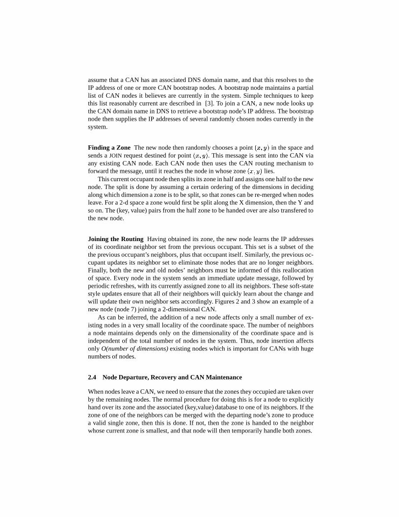
This current occupant node then splits its zone in half and assigns one half to the newnode. The split is done by assuming a certain ordering of the dimensions in decidingalong which dimension a zone is to be split, so that zones can be re-merged when nodesleave. For a 2-d space a zone would first be split along the X dimension, then the Y andso on. The (key, value) pairs from the half zone to be handed over are also transfered tothe new node.
Joining the Routing Having obtained its zone, the new node learns the IP addressesof its coordinate neighbor set from the previous occupant. This set is a subset of thethe previous occupant’s neighbors, plus that occupant itself. Similarly, the previous oc-cupant updates its neighbor set to eliminate those nodes that are no longer neighbors.Finally, both the new and old nodes’ neighbors must be informed of this reallocationof space. Every node in the system sends an immediate update message, followed byperiodic refreshes, with its currently assigned zone to all its neighbors. These soft-statestyle updates ensure that all of their neighbors will quickly learn about the change andwill update their own neighbor sets accordingly. Figures 2 and 3 show an example of anew node (node 7) joining a 2-dimensional CAN.
As can be inferred, the addition of a new node affects only a small number of ex-isting nodes in a very small locality of the coordinate space. The number of neighborsa node maintains depends only on the dimensionality of the coordinate space and isindependent of the total number of nodes in the system. Thus, node insertion affectsonly O(number of dimensions) existing nodes which is important for CANs with hugenumbers of nodes.
2.4 Node Departure, Recovery and CAN Maintenance
When nodes leave a CAN, we need to ensure that the zones they occupied are taken overby the remaining nodes. The normal procedure for doing this is for a node to explicitlyhand over its zone and the associated (key,value) database to one of its neighbors. If thezone of one of the neighbors can be merged with the departing node’s zone to producea valid single zone, then this is done. If not, then the zone is handed to the neighborwhose current zone is smallest, and that node will then temporarily handle both zones.

The CAN also needs to be robust to node or network failures, where one or morenodes simply become unreachable. This is handled through a recovery algorithm, de-scribed in [6], that ensures one of the failed node’s neighbors takes over the zone.
2.5 Design Improvements and Performance
Our basic CAN algorithm as described in the previous section provides a balance be-tween low per-node state ( � � �
for a�
dimensional space) and short path lengths with� � � ��� � hops for
�dimensions and � nodes. This bound applies to the number of hops
in the CAN path. These are application level hops, not IP-level hops, and the latency ofeach hop might be substantial; recall that nodes that are adjacent in the CAN might bemany miles (and many IP hops) away from each other. In [6], we describe a number ofdesign techniques whose primary goal is to reduce the latency of CAN routing. Of par-ticular relevance to the work in this paper, is a distributed “binning” scheme wherebyco-located nodes on the Internet can be placed close by in the CAN coordinate space.In this scheme, every node independently measures its distance (i.e. latency) from aset of well known landmark machines and joins a particular portion of the coordinatespace based on these measurements. Our simulation results in [6] indicate that theseadded mechanisms are very effective in reducing overall path latency. For example, weshow that for a system with over 130,000 nodes, for a range of link delay distributions,we can route with a latency that is well within a factor of three of the underlying IPnetwork latency. The number of neighbors that a node must maintain to achieve this isapproximately 28 (details of this test are in Section 4 in [6]).
3 CAN-based Multicast
In this section, we describe a solution whereby CANs can be used to offer an application-level multicast service.
If all the nodes in a CAN are members of a given multicast group, then multicastinga message only requires flooding the message over the entire CAN. As we shall describein Section 3.2, we can exploit the existence of a well defined coordinate space to providesimple, efficient flooding algorithms from arbitrary sources without having to computedistribution trees for every potential source.
If only a subset of the CAN nodes are members of a particular group, then multi-casting involves two pieces:
– the members of the group first form a group-specific ”mini” CAN and then,– multicasting is achieved by flooding over this mini CAN
In what follows, we describe the two key components of our scheme: group forma-tion and multicast by flooding over the CAN.
3.1 Multicast Group Formation
To assist in our explanation, we assume the existence of a CAN � within which asubset of the nodes wish to form a multicast group � . We achieve this by forming an
F
B A ED
C
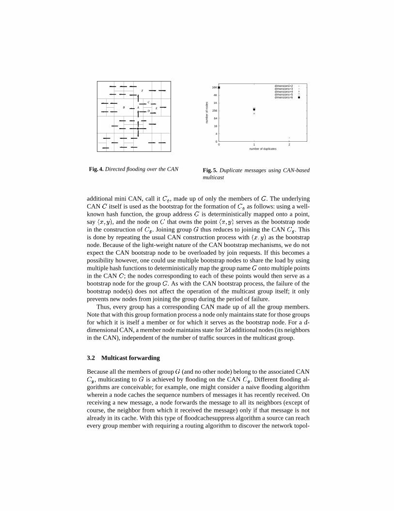
Fig. 4. Directed flooding over the CAN
0
4
16
64
256
1K
4K
16K
0 1 2
num
ber
of n
odes
number of duplicates
dimensions=2dimensions=3dimensions=4dimensions=5dimensions=6
Fig. 5. Duplicate messages using CAN-basedmulticast
additional mini CAN, call it ��� , made up of only the members of � . The underlyingCAN � itself is used as the bootstrap for the formation of ��� as follows: using a well-known hash function, the group address � is deterministically mapped onto a point,say
��������, and the node on � that owns the point
��������serves as the bootstrap node
in the construction of � � . Joining group � thus reduces to joining the CAN � � . Thisis done by repeating the usual CAN construction process with
��������as the bootstrap
node. Because of the light-weight nature of the CAN bootstrap mechanisms, we do notexpect the CAN bootstrap node to be overloaded by join requests. If this becomes apossibility however, one could use multiple bootstrap nodes to share the load by usingmultiple hash functions to deterministically map the group name � onto multiple pointsin the CAN � ; the nodes corresponding to each of these points would then serve as abootstrap node for the group � . As with the CAN bootstrap process, the failure of thebootstrap node(s) does not affect the operation of the multicast group itself; it onlyprevents new nodes from joining the group during the period of failure.
Thus, every group has a corresponding CAN made up of all the group members.Note that with this group formation process a node only maintains state for those groupsfor which it is itself a member or for which it serves as the bootstrap node. For a
�-
dimensional CAN, a member node maintains state for � � additional nodes (its neighborsin the CAN), independent of the number of traffic sources in the multicast group.
3.2 Multicast forwarding
Because all the members of group � (and no other node) belong to the associated CAN� � , multicasting to � is achieved by flooding on the CAN � � . Different flooding al-gorithms are conceivable; for example, one might consider a naive flooding algorithmwherein a node caches the sequence numbers of messages it has recently received. Onreceiving a new message, a node forwards the message to all its neighbors (except ofcourse, the neighbor from which it received the message) only if that message is notalready in its cache. With this type of floodcachesuppress algorithm a source can reachevery group member with requiring a routing algorithm to discover the network topol-

ogy. Such an algorithm does not make any special use of the CAN structure and couldin fact be run over any application-level topology including a random mesh topologyas generated in [4, 1]. The problem with this type of naive flooding algorithm is that itcan result in a large amount of duplication of messages; in the worst case, a node couldreceive a single message from each of its neighbors.
A more efficient flooding solution would be to exploit the coordinate space structureof the CAN as follows:
Assume that our CAN is a�-dimensional CAN with dimensions
� ����� � . Individualnodes thus have at least � � neighbors; 2 per dimension with one to move forward andanother to move in reverse along each dimension. i.e. for every dimension
�a node has
at least one neighbor whose zone abuts its own own in the forward direction along�
and another neighbor whose zone abuts its own in the reverse direction along�. For
example, consider node � in Figure 4: node � abuts � in the reverse direction alongdimension 1 while nodes � and � abut � in the forward direction along dimension 1.
Messages are then forwarded as follows:
1. The source node (i.e. node that generates a new message) forwards a message to allits neighbors
2. A node that receives a message from a neighbor with which it abuts along dimen-sion
�forwards the message to those neighbors with which it abuts along dimension� ����� � � � �
and the neighbors with which it abuts along dimension�
on the oppo-site side to that from which it received the message. Figure 4 depicts this directedflooding algorithm for a 2-dimensional CAN.
3. a node does not forward a message along a particular dimension if that messagehas already traversed at least half-way across the space from the source coordinatesalong that dimension. This rule prevents the flooding from looping round the backof the space.
4. a node caches the sequence numbers of messages it has received and does not for-ward a message that it has already previously received
For a perfectly partitioned (i.e. where nodes have equal sized zones) coordinatespace, the above algorithm ensures that every node receives a message exactly once. Forimperfectly partitioned spaces however, a node might receive the same message frommore than one neighbor. For example, in Figure 4, node � would receive a messagefrom both neighbors � and � .
Certain duplicates can be easily avoided because, under normal CAN operation, ev-ery node knows the zone coordinates for each of its neighbors. For example, consideronce more Figure 4; nodes � and � both know each others’ and node � ’s zone coor-dinates and could hence use a deterministic rule such that only one of them forwardsmessages to � . Such a rule, however, only eliminates duplicates that arise by floodingalong the first dimension. The rule works along the first dimension because, all nodesforward along the first dimension. Hence even if a node, by applying some deterministicrule, does not forward a message to its neighbor along the first dimension, we know thatsome other node that does satisfy the deterministic rule will do so. But this need not bethe case when forwarding along higher dimensions. Consider a 3-dimensional CAN; ifa node by the application of a deterministic rule decides not to forward to a neighboralong the second dimension, there is no guarantee that any node will eventually forward

it up along the second dimension because the node that does satisfy the deterministicrule might receive the packet along the first dimension and hence will not forward themessage along the second dimension. 4 For example, in Figure 4 let us assume that node� decides (by the use of some deterministic rule) not to forward to node � . Becausenode � receives the message (from � ) along the first dimension, it will not forwardthe message along the second dimension either and hence node � and the other nodeswith � -axis coordinates in the same range as � , will never receive the message. Whilethe above strategy does not eliminate all duplicates, it does eliminate a large fractionof it because most of the flooding occurs along the first dimension. Hence, we augmentthe above flooding algorithm with the following deterministic rule used to eliminateduplicates that arise from forwarding along the first dimension:
– let us assume that a node, � , received a message along dimension�
and that node�abuts � along dimension 1 in the opposite direction from which � received the
message. Consider the corner ��� of�
’s zone that abuts � along dimension 1 andhas the lowest coordinates along dimensions � ����� � . Then, � only forwards themessage on to
�, if � is in contact with the corner ��� .
So, for example, in Figure 4, with respect to nodes � and � , the corner under consider-ation for node � would be the lower, leftmost corner of � ’s zone. Hence only � (andnot � ) would forward messages � in the forward direction along the first dimension.
For the above flooding algorithm, we measured through simulation the percentageof nodes that experienced different degrees of message duplication caused by imper-fectly partitioned spaces. Figure 5 plots the number of nodes that received a particularnumber of duplicate messages for a system with 16,384 nodes using CANs with di-mensions ranging from 2 to 6. In all cases, over 97% of the nodes receive no duplicatemessages and amongst those nodes that do, virtually all of them receive only a single du-plicate message. This is a considerable improvement over the naive flooding algorithmwherein every node might receive a number of duplicates up to the degree (number ofneighbors) of the node.
It is worth noting that the naive flooding algorithm is very robust to message lossbecause a node can receive a message via any of its neighbors. However, the efficientflooding algorithm is less robust because the loss of a single message results in thebreakdown of message delivery to several subsequent nodes thus requiring additionalloss recovery techniques. This problem is however, no different than in the case of tra-ditional IP multicast or other application-level schemes where the loss of a packet alonga single link results in the packet being lost by all downstream nodes in the distributiontree. With both flooding algorithms, the duplication of messages arises because we donot (unlike most other solutions to multicast delivery) construct a single spanning treerooted at the source of traffic. However, we believe that the simplicity and scalabilitygained by not having to run routing algorithms to construct and maintain such deliv-ery trees is well worth the slight inefficiencies that may arise from the duplication ofmessages.
Using the above flooding algorithm, any group member can multicast a messageto the entire group. Nodes that are not group members can also multicast to the en-
4 By the second rule in the flooding algorithm.
tire group by first discovering a random group member and relaying the transmissionthrough this random group member. 5 This random member node can be discovered bycontacting the bootstrap node associated with the group name.
4 Performance Evaluation
0
0.1
0.2
0.3
0.4
0.5
0.6
0.7
0.8
0.9
1
0 10 20 30 40 50 60 70 80
Cum
ulat
ive
perc
enta
ge o
f nod
es
RDP
dimensions=6
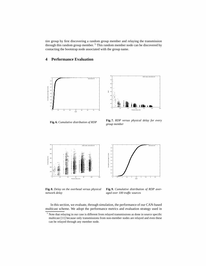
Fig. 6. Cumulative distribution of RDP
0
10
20
30
40
50
60
70
80
0 20 40 60 80 100 120R
DP
Physical delay (ms)
8192 nodes, dimensions=6
Fig. 7. RDP versus physical delay for everygroup member
0
100
200
300
400
500
600
700
0 20 40 60 80 100 120
Ove
rlay
dela
y (m
s)
Physical delay (ms)
8192 nodes, dimensions=6
Fig. 8. Delay on the overhead versus physicalnetwork delay
0
0.1
0.2
0.3
0.4
0.5
0.6
0.7
0.8
0.9
1
2 2.5 3 3.5 4 4.5 5 5.5 6 6.5 7
Cum
ulat
ive
perc
enta
ge o
f nod
es
RDP
dimensions=6
Fig. 9. Cumulative distribution of RDP aver-aged over 100 traffic sources
In this section, we evaluate, through simulation, the performance of our CAN-basedmulticast scheme. We adopt the performance metrics and evaluation strategy used in
5 Note that relaying in our case is different from relayed transmissions as done in source specificmulticast [11] because only transmissions from non-member nodes are relayed and even thesecan be relayed through any member node.

[4]. As with previous evalution studies of application-level multicasti schemes[4, 1, 11]we compare the performance of CAN-based multicast to native IP multicast and naiveunicast-based multicast where the source simply unicasts a message to every receiverin succession. Our evaluation metrics are:
– Relative Delay Penalty (RDP): the ratio of the delay between two nodes (in thiscase, the source node and a receiver) using CAN-based multicast to the unicastdelay between them on the underlying physical network
– Link Stress: the number of identical copies of a packet carried by a physical link
Our simulations were performed on Transit-Stub (TS) topologies using the GT-ITMtopology generator [9]. TS topologies model networks using a 2-level hierarchy of rout-ing domains with transit domains that interconnect lower level stub domains.
4.1 Relative Delay Penalty
We first present results from a multicast transmission using a single source as this rep-resents the performance typically seen across the different receiver nodes for a trans-mission from a single source. These simulations were performed using a CAN with 6dimensions and a group size of 8192 nodes. The source node was selected at random.We used Transit-Stub topologies with link latencies of 20ms for intra-transit domainlinks, 5ms for stub-transit links and 2ms for intra-stub domain links.
Both IP multicast and Unicast-based multicast achieve an RDP value of one for allgroup members because messages are transmitted along the direct physical (IP-level)path between the source and receivers. Routing on an overlay network however, funda-mentally results in higher delays. Figure 6 plots the cumulative distribution of RDP overthe group members. While the majority of receivers see an RDP of less than about 5 or6, a few group members have a high RDP. This can be explained 6 from the scatter-plotin Figure 7. The figure plots the relation between the RDP observed by a receiver andits distance from the source on the underlying IP-level, physical network. Each point inFigure 7 indicates the existence of a receiver with the corresponding RDP and IP-leveldelay. As can be seen, all the nodes with high values of RDP have a low physical delayto the source, i.e. the very low delay from these receivers to the source inflates theirRDP. However, the absolute value of their delay from the source on the CAN overlayis not really very high. This can be seen from Figure 8, which plots, for every receiver,its delay from the source using CAN multicast versus its physical network delay. Theplot shows that while the maximum physical delay can be about 100ms, the maximumdelay using CAN-multicast is about 600ms and the receivers on the left hand side of thegraph, which had the high RDP, experience delays of not more than 300ms.
The above results were all for a single multicast transmission using a single source;Figure 9 plots the cumulative distribution of the RDP with the delays averaged overmulticast transmissions from a 100 sources selected at random. Because a node is un-likely to be very close (in terms of physical delay) to all 100 sources, averaging theresults over transmissions from many sources helps to reduce the appearance of inflated
6 The authors in [4] make the same observation and explanation

1
2
3
4
5
6
7
8
9
10
128 256 512 1K 2K 4K 8K 16K 32K 64K
RD
P
Group Size
50th percentile90th percentile
Fig. 10. RDP versus increasing group size
1
2
4
8
16
32
64
128
256
512
1 2 4 8 16 32 64 128 256 512 1K 2K
num
ber
of n
odes
Stress
CAN-based multicastUnicast
Fig. 11. Number of physical links with a givenstress
RDPs that occurs when a receiver is very close to the source. From Figure 9 we see that,on an average, no node sees an RDP of more than about 6.0.
Finally, Figure 10 plots the 50 and 90 percentile RDP values for group sizes rang-ing from 128 to 65,000 for a single source. We scale the group size as follows: we takea 1,000 node Transit-Stub topology as before and to this topology, we add end-host(source and receiver) nodes to the stub (leaf) nodes in the topology. The delay of thelink from the end-host node to the stub node is set to 1ms. Thus in scaling the groupsize from a 128 to 65K nodes, we’re scaling the density of the graph without scalingthe backbone (transit) domain. So, for example, a group size of 128 nodes implies thatapproximately one in ten stub nodes has an associated group member while a groupsize of 65K implies that every stub node has approximately 65 attached end-host nodes.This method of scaling the graph causes the flat trend in the growth of RDP with groupsize because for a given source the relative number of close-by and distant nodes stayspretty much constant. Further, at high density, every CAN node has increasingly manyclose-by nodes and hence the CAN binning technique used to cluster co-located nodesyields higher gains. Different methods for scaling topologies could yield different scal-ing trends.
While the significant differences between End-System Multicast and CAN-basedmulticast makes it hard to draw any direct comparison between the two systems; Fig-ure 10 indicates that the performance of CAN-based multicast even for small groupsizes is competitive with End-System multicast.
4.2 Link Stress
Ideally, one would like the stress on the different physical links to be somewhat evenlydistributed. Using native IP multicast, every link in the network has a stress of exactlyone. In the case of unicasting from the source directly to all the receivers, links close tothe source node have very high stress (equal to the group size at the first hop link fromthe source). Figure 11 plots the number of nodes that experienced a particular stressvalue for a group size of 1024 for a 6-dimensional CAN. Unlike naive unicast where a

small number of links see extremely high stress, CAN-based multicast distributes thestress much more evenly over all the links.
Figure 12 plots the worst-case stress for group sizes ranging from 128 to 65,000nodes. The high stress in the case of large group sizes is because, as described earlier,we scale the group size without scaling the size of the backbone topology. For the abovesimulation, we used a transit-stub topology with a 1,000 nodes. Hence for a group sizeof 65,000 nodes, all 65,000 nodes are interconnected by a backbone topology of lessthan 1,000 nodes thus putting high stress on some backbone links. We repeated theabove simulation for a transit-stub topology with 10,000 nodes, thus decreasing thedensity of the graph by a factor of 10. Figure 13 plots the worst-case stress for groupsizes up to 2,048 nodes for all three cases (i.e. CAN-based multicast using Transit-Stubtopologies with 1,000 and 10,000 nodes and naive unicast-based multicast). As can beseen, at lower density the worst-case stress drops sharply. For example, at 2,048 nodesthe worst case stress drops from 169 (for TS1000) to 37 (for TS10000). Because, inpractice, we do not expect very high densities of group member nodes relative to theInternet topology itself, worst-case stress using CAN-based multicast should be at areasonable level. In future work, we intend looking into techniques that might furtherlower this stress value.
1
4
16
64
256
1K
4K
16K
64K
128 256 512 1K 2K 4K 8K 16K 32K 64K
Str
ess
Group size
CAN-based multicastUnicast
Fig. 12. Stress versus increasing group size
1
4
16
64
256
1K
4K
16K
64K
128 256 512 1K 2K 4K
Str
ess
Group size
CAN-based multicast using TS1,000Unicast
CAN-based multicast using TS10,000
Fig. 13. Effect of topology density on stress
5 Related Work
The case for application-level multicast as a more tractable alternative to a network-level multicast service was first put forth in [4, 3, 1].
The End-system multicast [4] work proposes an architecture for multicast over smalland sparse groups. End-system multicast builds a mesh structure across participatingend-hosts and then constructs source-rooted trees by running a routing protocol over thismesh. The authors also study the fundamental performance penalty associated with suchan application-level model. The authors in [1] argue for infrastructure support to tacklethe problem of content distribution over the Internet. The Scattercast architecture relies

on proxies deployed within the network infrastructure. These proxies self-organize intoan application-level mesh over which a global routing algorithm is used to constructdistribution trees. In terms of being a solution to application-level multicast, the keydifference between our work and the End-System multicast and Scattercast work is thepotential for CAN-based multicast to scale to large group sizes.
Yoid [3] proposes a solution to application-level multicast wherein a spanning treeis directly constructed across the participating nodes without first constructing a meshstructure. The resultant protocols are more complex because the tree-first approach re-sults in expensive loop detection and avoidance techniques and must be made resilientto partitions.
Tapestry [10] is a wide-area overlay routing and location infrastructure that, likeCANs, embeds nodes in a well-defined virtual address space. Bayeux [11] is a source-specific, application-level multicast scheme that leverages the Tapestry routing infras-tructure. To join a multicast session, Bayeux nodes send JOIN messages to the sourcenode. The source replies to a JOIN request by routing a TREE message, on the Tapestryoverlay, to the requesting node. This TREE message is used to set up state at inter-mediate nodes along the path from the source node to the new member. Similarly, aLEAVE message from an existing member triggers a PRUNE message from the root,which removes the appropriate forwarding state along the distribution tree. Bayeuxand CAN-based multicast are similar in that they achieve scalability by leveraging thescalable routing infrastructure provided by systems like CAN and Tapestry. In termsof service model, Bayeux fundamentally supports only source-specific multicast whileCAN-based multicast allows any group member to act as a traffic source. In terms ofdesign, Bayeux uses an explicit protocol to set-up and tear down a distribution tree fromthe source node to the current set of receiver nodes. CAN-based multicast by contrast,fully exploits the CAN structure because of which messages can be forwarded withoutrequiring a routing protocol to explicitly construct distribution trees.
Overcast[5] is a scheme for source-specific, reliable multicast using an overlay net-work. Overcast constructs efficient dissemination trees rooted at the single source oftraffic. The overlay network in Overcast is composed of nodes that reside within thenetwork infrastructure. This assumption of the existence of permanent storage withinthe network distinguishes Overcast from CANs and indeed, from most of the other sys-tems described above. Unlike Overcast, CANs can be composed entirely from end-usermachines with no form of central authority.
6 Conclusion
Content-Addressable Networks have the potential to serve as an infrastructure that isuseful across a range of applications. In this paper, we present and evaluate a schemethat extends the basic CAN framework to support application-level multicast deliv-ery. There are, we believe, two key benefits to CAN-based multicast: the potential toscale to large groups without restricting the service model and the simplicity of thescheme under the assumption of the deployment of a distributed infrastructure such asa Content-Addressable Network.

Our CAN-based multicast scheme is optimal in terms of the distance (in terms ofpath length) in flooding messages over the CAN overlay structure itself. In future work,we intend looking into simple clustering techniques to further reduce the link stresscaused by our flooding algorithm and understanding what the fundamental limitationsthere are. A number of important questions such as security, loss recovery, and conges-tion control remain to be addressed in the context of CAN-based multicast.
7 Acknowledgments
We thank Ion Stoica for his valuable input and Yan Chen and Morley Mao for sharing their data.
References
1. CHAWATHE, Y., MCCANNE, S., AND BREWER, E. An architecture for internet content dis-tribution as an infrastructure service. available at http://www.cs.berkeley.edu/ yatin/papers,2000.
2. DEERING, S. E. Multicast Routing in a Datagram Internetwork. PhD thesis, StanfordUniversity, Dec. 1991.
3. FRANCIS, P. Yoid: Extending the internet multicast architecture. Unpublished paper, avail-able at http://www.aciri.org/yoid/docs/index.html, Apr. 2000.
4. HUA CHU, Y., RAO, S., AND ZHANG, H. A case for end system multicast. In Proceedingsof SIGMETRICS 2000 (Santa Clara, CA, June 2000).
5. JANNOTTI, J., GIFFORD, D., JOHNSON, K., KAASHOEK, F., AND O’TOOLE, J. Overcast:Reliable multicasting with an overlay network. In Proceedings of the Fourth Symposium onOperating Systems Design and Implementation (San Diego, CA, Oct. 2000).
6. RATNASAMY, S., FRANCIS, P., HANDLEY, M., KARP, R., AND SHENKER, S. A ScalableContent-Addressable Network. In Proceedings of SIGCOMM 2001 (Aug. 2001).
7. ROWSTRON, A., AND DRUSCHEL, P. Pastry: Scalable, distributed ob-ject location and routing for large-scale peer-to-peer systems. available athttp://research.microsoft.com/ antr/PAST/, 2001.
8. STOICA, I., MORRIS, R., KARGER, D., KAASHOEK, M. F., AND BALAKRISHNAN, H.Chord: A scalable peer-to-peer lookup service for internet applications. In Proceedings ofSIGCOMM 2001 (Aug. 2001).
9. ZEGURA, E., CALVERT, K., AND BHATTACHARJEE, S. How to Model an Internetwork. InProceedings IEEE Infocom ’96 (San Francisco, CA, May 1996).
10. ZHAO, B. Y., KUBIATOWICZ, J., AND JOSEPH, A. Tapestry: An infrastructure for fault-tolerant wide-area location and routing. available at http://www.cs.berkeley.edu/ raven-ben/tapestry/, 2001.
11. ZHUANG, S. Q., ZHAO, B., JOSEPH, A., KATZ, R., AND KUBIATOWICZ, J. Bayeux: Anarchitecture for scalable and fault-tolerant wide-area data dissemination. In Proceedingsof the Eleventh International Workshop on Network and OS Support for Digital Audio andVideo (New York, July 2001), ACM.
Copyright © 2022 FDOKUMEN