An hybrid explicit multicast/recursive unicast approach for multicast routing
21
An hybrid explicit multicast/recursive unicast approach for multicast routing Ali Boudani * , Bernard Cousin IRISA/INRIA, Campus de Beaulieu, 35 042 Rennes Cedex, France Received 2 July 2003; revised 22 February 2005; accepted 22 February 2005 Available online 23 March 2005 Abstract In this paper, we propose a new approach, Simple Explicit Multicast (SEM), which uses an efficient method to construct multicast trees and to deliver multicast packets to all destinations. In order to construct a multicast tree, the source encodes the list of destination addresses in a branch message. This message discovers the tree branching routers and creates a multicast routing state in each of these routers. For multicast packets delivery, it uses recursive unicast trees where packets travel from a branching router to another following the tree constructed by the branch message. q 2005 Elsevier B.V. All rights reserved. Keywords: Multicast; IP; Routing protocol; Explicit multicast 1. Introduction Multicast has become increasingly important with the emergence of network-based applications that consume a large amount of network bandwidth such as video conferencing, distributed interactive simulation (DIS) and software upgrading. Using multicast services, a single transmission is needed for sending a packet to n destinations by sharing the link bandwidth, while n independent transmissions would be required using unicast services. But, multicast suffers from a scalability problem. Indeed, a multicast router should keep a routing state for every multicast tree passing through it and the number of routing states grows with the number of groups. Recently, significant research effort has focused on the multicast scalability problem. Some schemes attempt to reduce the number of routing states by tunneling [1] or by routing states aggregation [2]. Both these works attempt to aggregate routing states after these have been allocated to groups. It is assumed that underlying multicast protocols such as PIM-SM [3] or CBT [4] already exists in all routers in the network. Other architectures aim to eliminate routing states at routers either completely by explicitly encoding the list of destinations in packets, instead of using a multicast address (Xcast [5], GXcast [6]) or partially by using branching routers in the multicast tree (REUNITE [7], SEM, HBH [8]). It should be noted that the HBH protocol tried to eliminate routing states (called multicast forwarding tables MFT) from nonbranching routers while conserving control states (called multicast control tables MCT) in these routers. But as we will see later in this paper, nonbranching routers in HBH may still have multicast routing state. This document describes a new approach, Simple Explicit Multicast (SEM), which uses an efficient method to construct multicast trees and deliver multicast packets. In order to construct the multicast tree, the source encodes the list of destination addresses in a branch message which has a role to discover routers acting as branching nodes in the multicast tree. We mean by branching router, a router where packets arrive in an interface and should be forwarded to multiple interfaces (according to the next hop toward the destination routers). A special control plane is introduced to inform each branching router about its next and previous hop branching routers for a group. Instead, for multicast packets delivery, packets will travel from a branching router to another following the tree constructed by the branch message. We propose that the source uses unicast encoding for multicast packets and sends them to its next hop Computer Communications 28 (2005) 1814–1834 www.elsevier.com/locate/comcom 0140-3664/$ - see front matter q 2005 Elsevier B.V. All rights reserved. doi:10.1016/j.comcom.2005.02.013 * Corresponding author. Tel.: C33 2 9984 2537; fax: C33 2 9984 2529. E-mail addresses: [email protected] (A. Boudani), [email protected] (B. Cousin).
-
Upload
univ-rennes1 -
Category
Documents
-
view
0 -
download
0
Transcript of An hybrid explicit multicast/recursive unicast approach for multicast routing

An hybrid explicit multicast/recursive unicast approach
for multicast routing
Ali Boudani*, Bernard Cousin
IRISA/INRIA, Campus de Beaulieu, 35 042 Rennes Cedex, France
Received 2 July 2003; revised 22 February 2005; accepted 22 February 2005
Available online 23 March 2005
Abstract
In this paper, we propose a new approach, Simple Explicit Multicast (SEM), which uses an efficient method to construct multicast trees and
to deliver multicast packets to all destinations. In order to construct a multicast tree, the source encodes the list of destination addresses in a
branch message. This message discovers the tree branching routers and creates a multicast routing state in each of these routers. For multicast
packets delivery, it uses recursive unicast trees where packets travel from a branching router to another following the tree constructed by the
branch message.
q 2005 Elsevier B.V. All rights reserved.
Keywords: Multicast; IP; Routing protocol; Explicit multicast
1. Introduction
Multicast has become increasingly important with the
emergence of network-based applications that consume a
large amount of network bandwidth such as video
conferencing, distributed interactive simulation (DIS) and
software upgrading. Using multicast services, a single
transmission is needed for sending a packet to n destinations
by sharing the link bandwidth, while n independent
transmissions would be required using unicast services.
But, multicast suffers from a scalability problem. Indeed, a
multicast router should keep a routing state for every
multicast tree passing through it and the number of routing
states grows with the number of groups.
Recently, significant research effort has focused on the
multicast scalability problem. Some schemes attempt to
reduce the number of routing states by tunneling [1] or by
routing states aggregation [2]. Both these works attempt to
aggregate routing states after these have been allocated to
groups. It is assumed that underlying multicast protocols
such as PIM-SM [3] or CBT [4] already exists in all routers
0140-3664/$ - see front matter q 2005 Elsevier B.V. All rights reserved.
doi:10.1016/j.comcom.2005.02.013
* Corresponding author. Tel.: C33 2 9984 2537; fax: C33 2 9984 2529.
E-mail addresses: [email protected] (A. Boudani), [email protected]
(B. Cousin).
in the network. Other architectures aim to eliminate routing
states at routers either completely by explicitly encoding the
list of destinations in packets, instead of using a multicast
address (Xcast [5], GXcast [6]) or partially by using
branching routers in the multicast tree (REUNITE [7],
SEM, HBH [8]). It should be noted that the HBH protocol
tried to eliminate routing states (called multicast forwarding
tables MFT) from nonbranching routers while conserving
control states (called multicast control tables MCT) in these
routers. But as we will see later in this paper, nonbranching
routers in HBH may still have multicast routing state.
This document describes a new approach, Simple
Explicit Multicast (SEM), which uses an efficient method
to construct multicast trees and deliver multicast packets. In
order to construct the multicast tree, the source encodes the
list of destination addresses in a branch message which has
a role to discover routers acting as branching nodes in the
multicast tree. We mean by branching router, a router where
packets arrive in an interface and should be forwarded to
multiple interfaces (according to the next hop toward the
destination routers). A special control plane is introduced to
inform each branching router about its next and previous
hop branching routers for a group. Instead, for multicast
packets delivery, packets will travel from a branching router
to another following the tree constructed by the branch
message. We propose that the source uses unicast encoding
for multicast packets and sends them to its next hop
Computer Communications 28 (2005) 1814–1834
www.elsevier.com/locate/comcom

A. Boudani, B. Cousin / Computer Communications 28 (2005) 1814–1834 1815
branching routers. Each branching router acts as a source
and packets travel from a branching router to another.
The remainder of this paper is organized as follows. In
Section 2, we present some related works. In Section 3, we
describe SEM and we discuss some related issues. In
Section 4, we present the tree management mechanisms for
the three protocols REUNITE, HBH and SEM. We also
compare SEM to HBH and we discuss the type of a branch
message in both protocols. Sections 5 and 6 contain SEM
analysis, evaluation and simulation. Section 7 is a summary
followed by a list of references.
2. Related work
In this section, we present some of our proposal related
works: Tunneling [1], State aggregation [2], Explicit
Multicast [5], REUNITE [7] and HBH [8].
2.1. Tunneling and state aggregation
In [1], the underlying multicast protocol is used to
construct dynamic tunnels. Besides, a router interface can
operate in dual mode where two copies of the same packet
will be sent at the same time in native and tunnel mode. In
[2], leaky multicast addresses aggregation was studied. A
packet that matches the resulting forwarding entry will be
forwarded on all interfaces on which join messages have
been received, but it may be forwarded on some other
interfaces as well (those for which no join message was
received). In SEM, there is no need for underlying multicast
routing protocols (that use generally the reverse path
forwarding) to construct multicast trees. branch message
constructs the shortest path tree from the source to all
destinations and thus only one copy of packet is sent through
this shortest path from a branching router to another.
2.2. Explicit multicast
Explicit Multicast (Xcast) [5] is a newly proposed
multicast scheme to support a very large number of small
multicast groups. It explicitly encodes the list of desti-
nations in packets, instead of using a multicast address.
Thus, the source encodes the list of destinations in the Xcast
header, and then sends the packet to a router. Each router
along the way parses the header, partitions the destinations
based on each destination’s next hop, and forwards a packet
with an appropriate Xcast header to each of the next hops.
An increased header processing per packet is cumbersome
for high link speeds.
XcastC [9] is an extension of Xcast for a more efficient
delivery of multicast packets. Every source or destination is
associated to a Designated Router (DR). Instead of encoding
in the Xcast packet header the set of group members,
XcastC encodes the set of their DR. When a new member
wants to join the group G of source S, it sends an IGMP [10]
join message to its DR. The DR will send a join-request
message to the source S. The DR of the source intercepts this
message and analyzes it in order to keep track of all
concerned DR addresses. When the source S wants to send a
message to the group G, it sends a multicast packet.
This packet is received by its DR and converted to an Xcast
packet using the Multicast-to-Xcast algorithm (M2X). The
packet is then forwarded as in Xcast to all DR destinations,
since the destination list in the Xcast header contains the DR
addresses instead of the member addresses. Then, each DR
converts the Xcast packet to a multicast packet using the
Xcast-to-Multicast protocol (X2M) and sends it in its
subnetworks. Whereas Xcast can support a very large
number of small multicast groups, XcastC can support a
very large number of medium size multicast groups.
In [6] we proposed GXcast: a simple generalized version
of the Xcast and the XcastC protocols. Indeed, instead of
sending a message to n destinations, the source limits the
number of destinations in a packet to nM. Thus, the list of n
destinations is cutted into sub-lists of at most nM
destinations. Each sub-list corresponds to a destination list
for an Xcast packet. Several packets may have to be sent in
order to deliver data to all the n destinations. GXcast packets
are similar to Xcast packets: they have the same header and
are treated the same way by intermediate routers, by DR
destinations and by receivers destinations. The only
difference between the Xcast protocol and the GXcast
protocol is done in the DR of the source. The Xcast protocol
and the GXcast protocol can therefore inter-operate easily.
In all these newly proposed protocols the source (the
terms source and DR of the source are used undistinctly)
knows the addresses of all the destinations before sending
packets. The header processing time in every router grows
with the number of the DR. The major difference between
GXcast for example and SEM is that XcastC encodes the
list of destinations in each packet while SEM uses this
mechanism only with the branch message. In both protocols
the packet follows the unicast path between the source and
all destinations. In SEM the packet will travel from a
branching router to another following the same unicast path.
This seems a good solution in order to optimize the packet
header processing time in every router.
2.3. REUNITE and HBH
REUNITE [7] and HBH [8], use recursive unicast trees to
implement multicast service. REUNITE does not use class D
IP addresses. Instead, both group identification and data
forwarding are based on unicast IP addresses. Only branching
routers for a group need to keep multicast routing state. All
other nonbranching routers keep only multicast control state
and simply forward data packets by unicast routing.
The HBH multicast routing protocol attempted to solve
some problems in REUNITE. First, HBH uses class D IP
addresses for multicast channels and not a unicast addresses
as in REUNITE. Second, in REUNITE, when the first router

S, G - B1
TCM
S, G L S
B1
R1B2
R2 R3
S, G S R1,B2
S,G B1 R2, R3
TRM
TRM
TRM
TRM
TRM TRM
S, G B1
S, G B2 S, G B2
Router
Branching Routeror destination
Fig. 1. Multicast routing tables (TRM).
A. Boudani, B. Cousin / Computer Communications 28 (2005) 1814–18341816
that has previously joined a group leaves the group, the tree
maintenance becomes very complicated. Third, HBH
attempted to resolve the asymmetric routing problem
present in REUNITE. Finally, an HBH router keeps only
the next hop router addresses and not the first router that join
the channel (multicast control table (MCT) and multicast
forwarding table (MFT) have been modified).
SEM (same as HBH) uses the unicast infrastructure to
forward packets as REUNITE does but uses (S, G) channels
with class-D IP addresses to identify multicast channels.
Using the IP multicast addressing model preserves compat-
ibility with conventional multicast protocols. Since SEM
uses the multicast addresses, The SEM control plane is
compatible with the existing multicast protocols. SEM
solves also the asymmetric routing problem present in
REUNITE since it uses the shortest path tree from the
source to destinations. Besides, SEM eliminate all MCT and
MFT entries in nonbranching routers. In Section 3, we
describe SEM and we compare it to HBH in Section 4.
3. Simple explicit multicast protocol
In order to simplify address allocation in SEM, a source
creates and advertises a multicast channel (S, G) where S is
the source unicast address and G is a standard group
multicast address. Special multicast address range can be
used to identify and differentiate easily SEM channels from
conventional multicast channels. To build a multicast tree,1
SEM uses two messages: branch and previous_branch.
Moreover, SEM uses an alive message to maintain the
multicast tree. A destination joins the tree and leaves it with
source specific join and leave messages which always reach
the source. These two messages are identical to those used
for the SSM protocol [11,12]. Only the tree branching
routers keep a routing state for the multicast channel (S, G)
in their multicast routing table (called hereafter TRM).
TRM(S, G) (cf. Fig. 1) represents the entry associated with
the channel (S, G) in TRM. Entries in each TRM(S, G) are S,
the source address, G, the group address, pB, the previous
branching router address on the tree, and the addresses of
the next branching routers on the tree.
2
3.1. Receiver and router considerations
A receiver whishing to subscribe to an (S, G) channel
sends IGMP join message destinated to this channel. When
receiving this message, the designated router (called
hereafter DR) associated to the receiver subnet sends source
specific join(S, G) message directly to the source S. When
the source receives this message, it maintains in a multicast
control table (TCM) the list of addresses (L) of all DR
routers having receivers belonging to the (S, G) channel.
1 A multicast tree is formed from branching routers only.
TCM(S, G) (cf. Fig. 1) represents the entry associated with
the channel (S, G) in TCM. Entries in each (S, G) are S, the
source address, G, the group address, and the list L.
Intermediate routers do not need to keep a routing state or
a control state for the channel (S, G). Thus, it is necessary
that the DR routers associated with receivers know the
source address and the previous branching router address for
that channel. Current version of IGMP, IGMPv3 [10]
supports source discovery and source specific host member-
ship report. That is, SEM receivers do not use additional
control to join SEM channels: they use IGMP.
For gradual implementation in networks, SEM can use
for its branch message the IPv6 Hop-by-Hop option as
described in the basic specification of Xcast [5]. One
domain can then implement SEM while other domains may
implement conventional multicast routing protocols.
Fig. 2 describes the join process of a receiver to a channel
(S, G). The receiver subscribes to the channel (S, G) by
sending an IGMP join message to the DR of its local area
network (1 and 2 in Fig. 2). The DR receives this IGMP join
message and sends to the source a source specific join(S, G)
message (3 and 4 in Fig. 2). When receiving this message,
the source adds the address of the DR to the list L for the
channel (S, G)2 (5 and 6 in Fig. 2).
The SEM protocol uses alive messages between branch-
ing routers to maintain the tree. The alive messages are
periodically sent in unicast by the receivers (the DR of the
local area network of the receivers) towards the previous
branching router on the tree. This message is used to refresh
the routing state in this router. A router B which receives
from the router R an alive(S,G,R)3 destinated to it refreshes
the entry which corresponds to R in its mutlicast routing
table TRM(S, G) (this entry is called hereafter TRM(S,
G).R). The alive(S,G,R) message is discarded and a new
alive(S,G,B) message is sent to the previous branching
router. The periodic alive(S,G,B) message, is used for
If no list exists for the channel (S, G), a new list is created.3 alive(S, G, R) indicates the alive message sent in unicast by the router R
towards the previous branching router for the channel (S, G).

*
TRM(S,G)exists?
The router B receives from router pB the messagebranch(S,G,pB,L) with L ={R1,..., Rn}
NOYESB is
a branching router for
(S,G)
NOYES
TRM(S,G) is initialized (S,G):pB,{}
The entry (S,G):pB,{}is created in table TRM
* Classification of destinationsin sub-lists Li according to the next hop routers.
5. Receiving a join(S,G)source specific message
3. Receiving an IGMPjoin message
2. IGMP joinmessage
Receiver
4. Join (S,G) sourcespecific messagesent towards the source
Designated router (DR)
6. The source adds the DRaddress to the list L corresponding to channel (S,G)
Source
1. Joining the channel (S,G)
Fig. 2. Joining the channel (S, G) in SEM.
A. Boudani, B. Cousin / Computer Communications 28 (2005) 1814–1834 1817
the maintenance of the tree and does not occur directly after
the discard of the alive(S,G,R) message.
Send towards pB the messageprevious_branch(B,pB, S,G)
Resend messages branch(S,G,B,Li) towards the next routers for each
list Li
Resend the messagebranch(S,G,B,L) towards the
unique next router for all destinataions in the list
Fig. 3. branch message processing in a SEM router.
B' = pB
The router B' receives a message previous_branch(B,pB,S,G) sent from the router B
NOYES
3.2. SEM tree construction and packet delivery
In SEM, the source keeps track of the DR routers
addresses that have sent source specific join messages for a
multicast channel (S, G). The source encodes the list L of
these DR addresses in a SEM header of a branch message.
The source parses the header, partitions the destinations into
sublists (Li) according to their next unicast hop router, and
forwards a branch message with an appropriate SEM header
to each of the next hop routers. Each router along the path to
DR destinations repeats the same processing on receiving a
branch message. The role of the branch message is to
discover the multicast tree branching routers. Fig. 3
describes the branch4 message processing in a SEM router.
When this branch message reaches a nonbranching router
for a channel (S, G), it is forwarded unchanged to the unique
next hop router for all destinations. Otherwise, it checks the
presence of an entry in the routing table corresponding to the
channel (S, G). If TRM(S, G) exists, this entry is updated.5 If
no entry exists, a new entry is created at this branching router.
The entry contains the source address, the multicast address
for the group, the previous branching router address and the
list of addresses of the next hop branching routers (the list is
initially empty). The branching router replaces the value of
the previous branching router of the new branch message
header with its own address. In both cases, the router sends
branch messages for all the lists Li.
The branching router sends also a previous_branch
message towards the previous branching router (the address
is deduced from the branch message). Fig. 4 describes the
processing of a previous_branch6 message in a SEM router.
The previous_branch message received by the previous
branching router updates the state corresponding to
4 branch(S, G,pB, L) indicates the branch message for the list L
corresponding to the channel (S, G) sent by the router pB.5 TRM (S, G) is initialized as empty.6 previous_branch(B,pB,S,G) indicates the previous_branch message for
the channel (S, G) sent by the router B to the router pB.
the channel (S, G). Thus, this message informs the previous
branching router about its next branching routers. At the end
of this operation, we obtain a path from the source towards
each DR by using the addresses of the next branching
routers. Thus, the source can send data packets to the
various receivers of the channel (S, G).
Example. Consider the network represented in Fig. 1 and the
group G formed from the source S and the six destinations A,
B, C, D, E and F. A, B, C, D, E and F generate IGMP join
messages to the DR associated to their sub-networks. When
receiving the IGMP messages, R4, R8 and R9 each sends a
source specific join message to the source S. Then, S sends a
branch message to R1 with the list of multicast routers (R4,
R8 and R9) in its SEM header. The IP header of the branch
message sent by S to R1 contains: the source address S and the
group address G. The SEM header of the branch message
Add B to the entry TRM(S,G)
Resend towards pB the messageprevious_branch(B,pB,S,G)
Fig. 4. previous_branch message processing in a SEM router.
S D
E
F
C
B
R1 R2
R4
R5 R6 R7
R3
R8
R9A
[src=S|adresse groupe=G|previous_branching_router = S|dest=R4,R8,R9]
join message
branch message
previous_branch message
alive message
branch message:
IP header SEM header
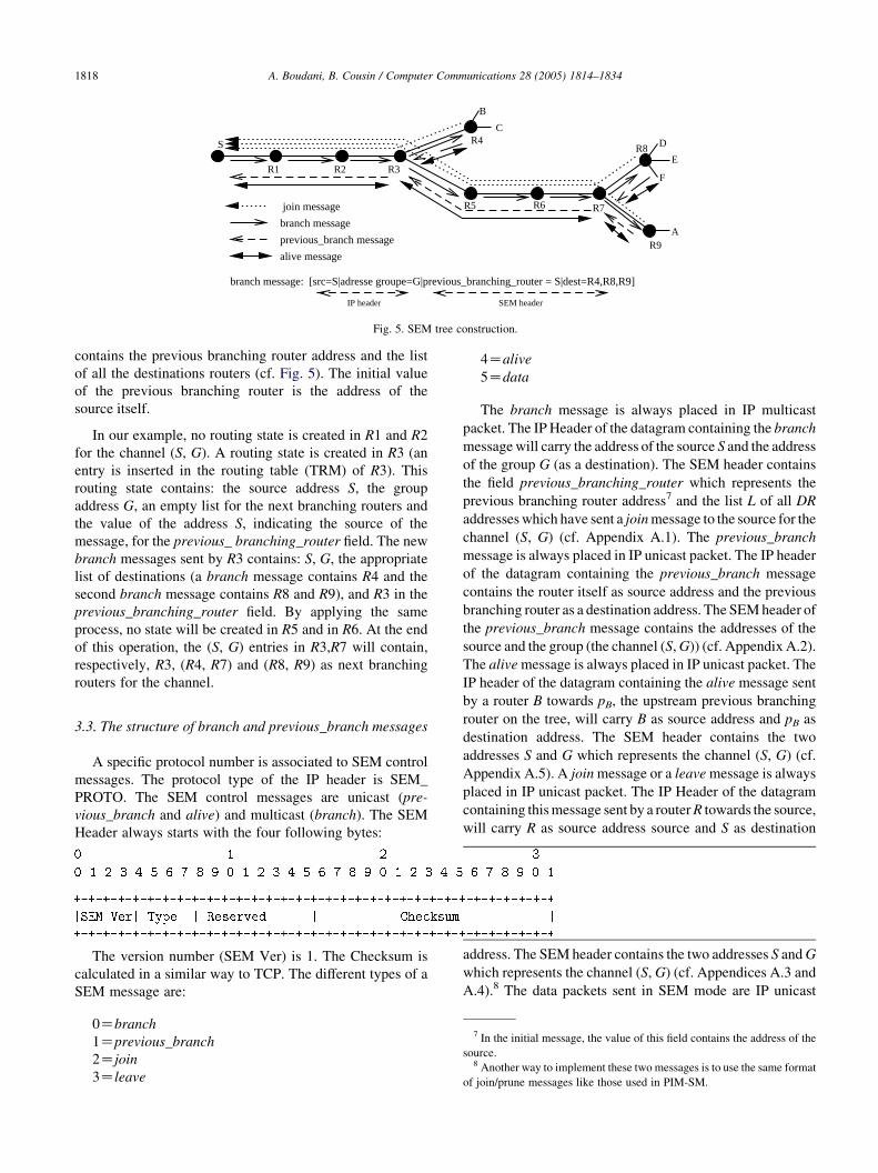
Fig. 5. SEM tree construction.
A. Boudani, B. Cousin / Computer Communications 28 (2005) 1814–18341818
contains the previous branching router address and the list
of all the destinations routers (cf. Fig. 5). The initial value
of the previous branching router is the address of the
source itself.
In our example, no routing state is created in R1 and R2
for the channel (S, G). A routing state is created in R3 (an
entry is inserted in the routing table (TRM) of R3). This
routing state contains: the source address S, the group
address G, an empty list for the next branching routers and
the value of the address S, indicating the source of the
message, for the previous_ branching_router field. The new
branch messages sent by R3 contains: S, G, the appropriate
list of destinations (a branch message contains R4 and the
second branch message contains R8 and R9), and R3 in the
previous_branching_router field. By applying the same
process, no state will be created in R5 and in R6. At the end
of this operation, the (S, G) entries in R3,R7 will contain,
respectively, R3, (R4, R7) and (R8, R9) as next branching
routers for the channel.
3.3. The structure of branch and previous_branch messages
A specific protocol number is associated to SEM control
messages. The protocol type of the IP header is SEM_
PROTO. The SEM control messages are unicast (pre-
vious_branch and alive) and multicast (branch). The SEM
Header always starts with the four following bytes:
The version number (SEM Ver) is 1. The Checksum is
calculated in a similar way to TCP. The different types of a
SEM message are:
7
0ZbranchIn the initial message, the value of this field contains the address of the
1Zprevious_branch source.8 Another way to implement these two messages is to use the same format
2Zjoinof join/prune messages like those used in PIM-SM.
3Zleave4Zalive
5Zdata
The branch message is always placed in IP multicast
packet. The IP Header of the datagram containing the branch
message will carry the address of the source S and the address
of the group G (as a destination). The SEM header contains
the field previous_branching_router which represents the
previous branching router address7 and the list L of all DR
addresses which have sent a join message to the source for the
channel (S, G) (cf. Appendix A.1). The previous_branch
message is always placed in IP unicast packet. The IP header
of the datagram containing the previous_branch message
contains the router itself as source address and the previous
branching router as a destination address. The SEM header of
the previous_branch message contains the addresses of the
source and the group (the channel (S, G)) (cf. Appendix A.2).
The alive message is always placed in IP unicast packet. The
IP header of the datagram containing the alive message sent
by a router B towards pB, the upstream previous branching
router on the tree, will carry B as source address and pB as
destination address. The SEM header contains the two
addresses S and G which represents the channel (S, G) (cf.
Appendix A.5). A join message or a leave message is always
placed in IP unicast packet. The IP Header of the datagram
containing this message sent by a router R towards the source,
will carry R as source address source and S as destination
address. The SEM header contains the two addresses S and G
which represents the channel (S, G) (cf. Appendices A.3 and
A.4).8 The data packets sent in SEM mode are IP unicast

BR
DR
Alive messageSource specific leave message
3. BR, the previous branchingrouter does not receivealive(S,G,DR)messages anymore
5. The BR sendsleave(S,G,DR) to the source
2. The DR stops sendingalive(S,G,DR)messagesto the BR
4. The BR eliminates the DRcorresponding entry in (S,G) stateof the multicast routing table
1. The DR with no more members
Fig. 6. The case when DR does not have members anymore.
10
A. Boudani, B. Cousin / Computer Communications 28 (2005) 1814–1834 1819
packets. The IP header of the datagram containing the data in
SEM mode contains the address of the source and the address
of the next branching router. The SEM header contains only
G, the group address (cf. Appendix A.6).
3.4. Data packet processing in SEM mode
When the source starts sending packets to a group, the
state of the corresponding channel is examined.9 A packet is
forwarded directly in mode SEM (unicast) to the next
branching routers. When the subsequent branching routers
receive the packet, the same operation is repeated. Thus, if
the router receiving the packet is not the next branching
router for that packet, it forwards the packet in unicast to the
specific next branching router. When the packet arrives at
the router in the destination field, it is replicated and sent to
each next branching router. When the packet arrives to one
DR, the packet destination field should be replaced with the
G address to ensure that it will be delivered through
multicast to all receivers in the subnet of that DR.
3.5. Maintenance of SEM tree
Alive messages are used between branching routers to
maintain the SEM tree. When a DR discovers that there are
no more receivers in its directly connected subnet for a
particular channel (S, G), the DR ceases sending alive(S, G)
messages towards the previous branching router. The
previous branching router eliminates the corresponding
state (it stops forwarding packets to the leaf router) and
generates a source specific leave message (sent directly to
the source). When receiving the leave message, the source
eliminates the corresponding state and sends a new branch
message to rebuild the tree (cf. Fig. 6).
Moreover, when one DR or a branching router breaks
down, the previous router will not receive any more alive
messages and thus eliminates the routing state. It sends also
a leave message to the source which sends a new branch
message to rebuild the tree.
9 Data packet processing in GXcast mode will be studied in Section 4.5.
A timer at the source is associated with the control state
for each channel (S, G). A branch message is not sent
directly after receiving a join message or a leave message.
The arrival of a join or a leave arms the timer associated
with the channel (S, G). The source waits until this timer
expires to send a new branch message. During all this phase
of tree construction, packets will be sent in GXcast mode.
Fig. 7 describes the behavior of the source when it
receives a join(S,G) message or a leave(S,G) message
according to the expiration of the timer associated with the
channel (S, G).
4. Comparison between SEM and HBH
There are many similarities between SEM and HBH but
also many differences in the forwarding scheme and the
control plane. We briefly describe the tree management
mechanisms for REUNITE and HBH and we compare them
then to SEM.
4.1. REUNITE tree management mechanism
In REUNITE, join messages are generated periodically
by each receiver and are sent in unicast towards the source
of the group. tree messages are generated periodically by the
source of the group and are sent10 towards all receivers
present in the MFT table at the source. When a new receiver
subscribes with the group, it sends a join message towards
the source. If the join message is intercepted by a router
having a non-empty MCT, this router becomes a branching
router. The router eliminates then the control table MCT and
creates a routing table MFT.
For better understanding the tree management mechan-
ism of REUNITE, let us take the example of Fig. 8. Let us
suppose the following unicast paths: R1/H2/H1/S;
S/H1/H3/R1; R2/H3/H1/S; S/H4/R2;
S/H1/H3/R3 et R3/H3/H1/S.
tree messages are unicast messages but we consider them as multicast
messages since they generate other tree messages which will reach all the
group receivers.

1. The source receives join(S,G) or leave(S,G)message
The source
Timer
2. The timer associated to (S,G) is started
3. The source sends a branch message after the timer expires
Fig. 7. The timer associated to a channel and the messagesjoin and leave.
H2
R1 R3
R2
S
H1
H4
H3
R1
MCT
MFT
MFT
R1
MCT
MCT
MFTR1
MCT
MFT
(a)
H2
R1 R3
R2
S
H1
H4
H3
R1
MCT
MFT
MFT
R1
MCT
MCT
MFT
MFT
MCTR1 R2 R3
(b)
H2
R1 R3
R2
S
H1
H4
H3
R1
MCT
MFT
MFT
R1
MCT
MCT
MFT
MFT
MCTR1 R2 R3
(c)
join message
First destinationthat joined the group
tree message
Fig. 8. REUNITE tree management mechanism.
A. Boudani, B. Cousin / Computer Communications 28 (2005) 1814–18341820
Suppose that R1 subscribes first to the group, then R2 and
finally R3. R1 subscribes to the group by sending a join(S, G,
R1) towards S. This message arrives at S which adds R1 to
its MFT. S starts sending tree(S, G, R1) on the tree. These
messages create entries (S, G, R1) in the MCT of H1 and H3.
Data follows the same path towards R1. Then, when R2
subscribes by sending a join(S, G, R2) towards S, this
message is intercepted by H3 since this router already
installed the state for this channel. H3 creates a MFT with
R1 as a next routeur11 to follow by the packets and adds R2
as a receiver. Also, R3 is added to the MFT as a receiver.
When packets are received from S towards R1, two copies
are created and sent to R2 and R3. Note that R1 and R3
receive the packets sent by S through the shortest path. It is
not however the case for R2. When a REUNITE router
11 This is Called dst in [7].
receives a packet, it extracts from this packet the source and
destination addresses and the source port number and
consults the table MFT. If the entry is not found, then a
second consultation is done in the unicast routing table.
Thus, when a unicast packet is received, two lookups are
required. REUNITE does not propose any solution to this
significant problem but it supposes that since the lookup of
the MFT table is based on an exact correspondence of the
address and not on a correspondence of the longest prefix,
this double lookup is fast.
4.2. HBH tree management mechanism
HBH uses three types of messages to construct the
multicast tree: join, tree and fusion. The join messages are
periodically sent in unicast by the receivers towards the
source, and are used to refresh the routing state (the entry in
the MFT) in the router to which the receiver is connected.

Join(S,G,R)The router B receives
(S,G) exists in
MFT of routerB?
NOYES
R exists
MFT(S,G)?in
Refresh MFT(S,G).R
sendjoin(S,G,R)
send join(S,G,B)
YES NO
(a)
B = Bp?
MFT(S,G).Bnexists?
The router B receives fusion(S,G,R,[Rn])addressed to Bp sent by Bn
NO
YES
Mark R,[R'] Send fusion(S,G,R,[Rn])
NO YES
Insert Bn inMFT(S,G)Bn.T01 expires
Refresh MFT(S,G).BnBn.T01 expires(=refresh Bn.T02)
(c)
MCT(S,G)=R?
R=B?
Send tree(S,G,R)
Sendfusion(S,G,R,[Rn]) à Bp
The router B receives tree(S,G,R) from Bp
YES
NO
MFT(S,G)exists?
R exists in
MFT(S,G)?NO
YESNO MCT(S,G) exists?
YES
Refresh MFT(S,G).R
RefreshMCT(S,G).R
Eliminate R' from MCT(S,G)Insert R inMCT(S,G)
YES NO
Create MCT(S,G)Insert R inMCT(S,G) YES
Insert R inMFT(S,G)
Send fusion(S,G,R,[Rn]) to Bp
NO
MCT(S,G)
stale?exists and NO
YES
Eliminate R' from MCT(S,G)Insert R, R'in MFT(S,G)
Send fusion(S,G,R,R')to Bp
Send tree(S,G,[Rn])
(b)
R′ is the router address in MCT(S,G)[Rn] is the list of routers addresses in MFT(S,G)
Fig. 9. The processing of the different messages in HBH. (a) join message; (b) tree message; (c) fusion message.
A. Boudani, B. Cousin / Computer Communications 28 (2005) 1814–1834 1821
The source sends periodically in multicast a tree message12
for each channel (S, G) which is used to refresh the structure
of the tree. fusion messages are sent in unicast by potential
branching routers in order to construct the tree, using the tree
messages received from the source. Fig. 9 shows the
processing algorithms for the three type of messages used
in HBH.
Each HBH router on the (S, G) tree has either an MCT if
it is not a branching router or an MFT for (S, G) if it is. The
MCT for a channel (S, G) can have only one entry, which are
12 We study the transmission mode of this tree message later on.
associated two timers, t1 and t2. When t1 expires, the entry
becomes stale.13 When t2 expires, the entry (the MCT
consequently) is destroyed. A node on the tree for a channel
(S, G) but which is not a branching node will have an MCT
for (S, G). The entry in the MFT can also be marked.14
Let us take the same example of the preceding paragraph.
R1 subscribes to the channel (S, G) and S starts sending
tree(S, G, R1) messages. These messages create an MCT for
13 stale entry is used for the routing of multicast packets on the tree, but
does not generate any tree message downstream.14 Marked entry will generate a tree message but not data packets.

A. Boudani, B. Cousin / Computer Communications 28 (2005) 1814–18341822
(S, G) (that contains R1) in H1 and H3. When R2 starts
sending join(S, G, R2) while subscribing with the group, this
message is not intercepted and reaches the source which
starts sending tree(S,G,R2) (the first join sent by the receiver
is never intercepted and always arrives at the source). The
tree(S,G,R2) messages sent by the source create a state for
the channel (S, G) in the MCT of H4 (cf. Fig. 10b).
R3 sends a join(S, G, R3) towards S which starts sending
tree(S, G, R3). As soon as H1 starts receiving two different
tree messages, it sends a fusion(S, G, R1, R3) message
towards the source. When receiving this fusion message by
S, it causes the addition of H1 in the table MFT of S, and the
marking of R1 and R3. In the same way that H1, H3 receives
tree(S, G, R1) and tree(S, G, R3) message R3 sends a join(S,
G, R3) towards S which starts sending tree(S, G, R3). As
soon as H1 starts receiving two different tree messages, it
sends a fusion(S, G, R1, R3) message towards the source.
When receiving this fusion message by S, it causes the
addition of H1 in the table MFT of S, and the marking of R1
and R3. In the same way that H1, H3 receives tree(S, G, R1)
and tree(S, G, R3) messages and sends consequently a
fusion(S, G, R1, R3) message towards H1. When receiving
the message fusion(S, G, R1, R3), H1 adds H3 in its table
MFT and mark the two entries R1 and R3. The MFT of H3
join message
tree message
fusion messag
(
M
(a)
H2
R1 R3
R2
S
H1
H4
H3
R1
MCT
MFT
MFT
MCT
MCT
MFTR1
MCT
MFT
R1 R2
MFT
(
M
(c)
R1 R3
H2
R1 R3
R2
S
H1
H4
H3
R1
MCT
MFT
MFT
MCT
MCT
MFTR1
MCTMCT
MFTR2
MFT
R1 R2 R3
R1 R3
MCT
Fig. 10. HBH tree manag
contains now R1 and R3. The subsequent join(S, G, R1) will
be intercepted by H1 (and will refresh the entry marked for
R1 in the MFT of H1). The join(S, G, R3) will refresh the
entry R3 in the MFT of H3. The packets are addressed by S
to H1 then to H3, which sends them to R1 and sends a copy
to R3. As S will not receive anymore a join resulting from
R1 and R3, the marked entries of R1, R3 disappear at the
expiration of the corresponding timers. The final structure is
that of Fig. 10d.
4.3. SEM tree management mechanism
SEM uses three messages to construct the multicast tree:
join, branch and previous_branch. Moreover, alive mess-
ages replace join messages after sending of the first join
towards the source and they are periodically sent in unicast
by the receivers towards the previous branching router on
the tree. Thus, these alive messages are used to refresh the
routing state in the router to which the receiver is connected.
The source sends a branch message of type GXcast
(cf. Section 4.4) to discover the branching routers on the
tree. previous_branch messages are sent in unicast by
potential branching routers in order to build the structure of
e
Marked entry
b)
H2
R1 R3
R2
S
H1
H4
H3
R1
CT
MFT
MFT
MCT
MCT
MFTR1
MCT
MFT
R1 R2
R2
MFT
d)
R1 R3
H2
R1 R3
R2
S
H1
H4
H3
CT
MFT
MFT
MCT
MCT
MFT
MFTR2
MFT
H1 R2
H3 R1
MCT
ement mechanism.

TRM
S,G - R1 R2
H2
R1 R3
R2
S
H1
H4
H3
(b)TRM
S,G - R1 R2
H2
R1 R3
R2
S
H1
H4
H3
(a)
(c)
H2
R1 R3
R2
S
H1
H4
H3
S,G - R1 R2 R3
TRM (d) TRM
H2
R1 R3
R2
S
H1
H4
H3
S,G - H3 R2
TRM
S,G S R1 R3
join message
branch message
previous_branch message
alive message
Fig. 11. SEM tree management mechanism.
15 The first join is not never intercepted and always arrives at the source.
A. Boudani, B. Cousin / Computer Communications 28 (2005) 1814–1834 1823
distribution of the tree, using the messages branch received
from the source.
A receiver sends the first join message in unicast towards
the source. The source sends a message branch of GXcast
type on each channel (S, G). Contrary to REUNITE and
HBH, SEM eliminates any presence of a routing state
(equivalent to MFT) orof a control state (equivalent to
MCT) in the intermediate routers on the multicast tree who
are not branching routers. A SEM branching router in the
distribution tree of (S, G) has only one routing state for each
channel (S, G) (TRM(S, G)). SEM simplifies the routing
algorithm by also eliminating the presence of marked
entries or stale entries. To each entry in the routing state is
associated a timer, t1. When t1 expires, the entry is
destroyed.
Let us consider the example of Fig. 11. R1 subscribes to
the channel (S, G) and S starts sending branch(S,G,pBZS,R1) messages. R1 sends then a previous_branch(R1,pBZS,S,G) message. These messages create a routing state for
(S, G) (contains R1) in S. When R2 sends a join(S,G,R2)
message to subscribe the group, this message is not
intercepted and reach the source15 who starts sending a
branch(S,G,pBZS,R1,R2) message. Thereafter, alive mess-
ages replace join messages to maintain the tree.
The branch(S,G,pBZS,R1,R2) message sent by the
source generates previous_branch(R2,pBZS,S,G) message
sent by R2 towards S and thus creating the state for the
channel (S, G) in S. This state contains R1, R2 (since the two
paths from S to these receivers are different) (cf. Fig. 11b).
When R3 sends a join(S,G,R3) message towards S, S starts
sending branch(S,G,pBZS,R1,R2,R3) messages. The
GXcast mechanism of the branch message discovers the
branching routers for the channel (S, G) (S and H3 are two
branching routers on the tree). S intercepts the
branch(S,G,pBZS,R1,R2,R3) message and generates two
messages: branch(S,G,pBZS,R1,R3) and branch(S,G,pBZS,R2), the first on the interface connecting S to H1 and the
second on the interface connecting S to H4. In the same way,
H3 generates also two branch messages: branch(S,G,pBZH3,R1) and branch(S,G,pBZH3,R3). The previous_branch

The router receives a messagebranch(S,G,pB,Li) of type GXcast for a channel (S,G)
Ifthe control
state for the channel (S,G)
exists ?
YES NO
Update the temporary control state TCM(S,G) : L =L + Li
Create a temporary control state TCM(S,G) : L = Li
Start the timer t2 for this state
The timer t2 expires
Processing according to the algorithm of figure 3
Destroy the temporarycontrol state TCM(S,G)
Fig. 12. The processing of a branch message of type GXcast in a SEM router.
A. Boudani, B. Cousin / Computer Communications 28 (2005) 1814–18341824
messages generated by R1, R2 and R3 as response to the
branch messages create finally routing states in S (It
contains H316 and R2 as entries) and in H3 (It contains
R1 and R3 as entries). The data sent by S to H3 are sent to R1
and R3. Moreover, the receivers periodically send alive
messages towards the previous branching routers to
maintain the tree. The alive(S,G,R1) and alive(S,G,R3)
messages sent by R1 and R3 are intercepted by H3 which
sends an alive(S,G,H3) message towards the source S. The
final structure is that of Fig. 11d.
4.4. The branch message of type GXcast
At most 135 IP addresses can be encoded in an Xcast
packet, and it is the same for a branch message17 [6]. A
branch message for a group having more than 135 DR can
be divided into several branch messages of type GXcast. At
the arrival of a branch message at a router, a temporary
control state TCM(S,G) is created in the router containing
the list (Li) of addresses of the DR in the SEM header of the
branch message (TCM(S,G):LZLi) and a timer t2 is
associated to this state. At the arrival of the next branch
for the same channel (S,G) and if the timer did not expired,
the new list of DR addresses in the SEM header of the
branch message is added to the state corresponding to the
channel (S,G) (TCMðS;GÞ : LZLCLi) and the timer is
started again. This operation is repeated for each branch
message for all the sublists Li for the main list L. If the timer
t2 expires, the router process the list L in the control state,
classifies the destinations in sublists Lj according to their
next router, generates a branch message with the appro-
priate SEM header and sends it towards each next router.
Fig. 12 shows the processing of a branch message of type
16 As a next branching router.17 MTUZ576 bytes, 12 bytes for SEM header (cf. Appendix A.1).
GXcast in a SEM router. When t2 expires, the temporary
control state is destroyed.18
4.5. The transmission of branch messages of type GXcast
and the rapidity of tree construction
It is clear that the construction time of the tree by the
three protocols REUNITE, HBH and SEM is higher than the
construction time of the tree by a conventional multicast
routing protocol (for example, PIM-SM). This is due to the
fact that the construction of the tree does not depend with
these three protocols only of the conventional join messages
which build the tree in an effective and fast way. Indeed, the
first join messages of HBH and SEM must always reach the
source. The construction of the tree in REUNITE is carried
out by using join messages and tree messages together.
Moreover, to these messages, fusion messages are added in
the case of HBH. These messages are identical to the
messages used in SEM.
SEM eliminates any presence of routing states or control
states in the intermediate routers who are not branching
routers for the tree. This brings that the tree maintenance at
the departure of a member is easier in HBH.
SEM uses a very effective mechanism to avoid this
disadvantage. Indeed, during the tree construction, the SEM
protocol uses the transmission in GXcast mode to deliver
the data packets. Once the tree is built, the transmission in
SEM mode is again used. If the groups are very dynamic,
one falls into the case of pure GXcast protocol. If the groups
are fairly dynamic or quasi-stable, the tree built by SEM is
quasi-stable too. At the source of a SEM tree, the algorithm
of Fig. 13 is used.
18 Note that the control state TMC(S,G) for a channel (S,G) at the source is
never destroyed. The source will always need the list of the receivers.

Launching a branch message tothe SEM tree
Transmission in SEM mode Transmission in GXcast mode
YES NOThe
SEMtree is constructed ?
Fig. 13. The packet forwarding algorithm in GXcast mode during the SEM
tree construction.
(a)
R1 R3
H2
R1 R3
R2
H1
H4
H3MCT
MFT
MCT
MFT
MFT
MFTH3 R1
MCT
S
MCT
MFT
H1
H0H1
MCT
M
(
(c)
H2
R1 R3
R2
H1
H4
H3
MCT
MFT
MCT
MFT
MFT
MCT
S
MCT
MFT
H0
H1 R2 H0
MCT
H1 H1 R2MFT
R1 R3 R2
MFTH3 R1 R2
(
M
join message
tree message
fusion message
Fig. 14. Comparaison of tree states red
A. Boudani, B. Cousin / Computer Communications 28 (2005) 1814–1834 1825
4.6. Comparison between SEM and HBH
4.6.1. Table size reduction
According to HBH specifications, MFT entries exist in
branching routers and MCT entries exist in all other
intermediate routers on the tree. HBH protocol tried to
eliminate routing states from nonbranching routers while
conserving control states in these routers. But as we already
saw in Fig. 10d with the HBH’s tree construction
mechanism (see also Fig. 5 in [8]), nonbranching routers
may still have multicast routing state. Unlike HBH, there is
no need for MFT neither for MCT tables in nonbranching
routers.
Let us take the example of Fig. 14. Let us suppose
the following unicast routes: R1/H2/H1/H0/S;
R1 R3
H2
R1 R3
R2
H1
H4
H3
CT
MFT
MCT
MFT
MFT
MFTH3 R1
MCT
S
MCT
MFT
H0H1
MCT
H1 R2b)
d)
H2
R1 R3
R2
H1
H4
H3CT
MFT
MCT
MFT
MFT
MCT
S
MCT
MFT
H0MCT
H1 H1 R2MFT
R1 R3 R2
MFT
H0
H3 R1
Marked entry
uction between SEM and HBH.

MFT
R1 R2
H2
R1 R3
R2
S
H1
H4
H3
R1
MCT
MCT
MFTR1
MCT
MFT
MFT
join message
tree message
Fig. 15. The tree message in recursive unicast mode.
19 In fact, there is no big difference between a recursive unicast message
and unicast when the tree is stable, since the destination of the tree message
is the next branching router on the multicast tree already built.
A. Boudani, B. Cousin / Computer Communications 28 (2005) 1814–18341826
S/H0/H1/H3/R1; R2/H4/H0/S; S/H0/H1/H3/R2; R3/H3/H1/H0/S; S/H0/H1/H3/R3;. This network is asymmetrical since some routes
are asymmetric.
Let us apply the HBH protocol mechanism. R1
subscribes with the channel (S,G) and S starts sending
tree(S,G,R1) messages. These messages create a MCT for
(S,G) (it contains R1) in H0, H1 and H3. R3 sends a
join(S,G,R3) towards S which starts sending tree(S,G,R3).
Following the same reasoning as that of Section 4.2, the
structure of the tree at the end of this phase is that of
Fig. 14a.
Let us suppose now that R2 starts to send join(S, G, R2)
in order to subscribe to the group, these messages are not
intercepted and reach the source which starts to send tree(S,
G, R2) (cf. Fig. 14b). As soon as H0 starts to receive two
different tree messages (tree(S, G, H1) and tree(S, G, R2)), it
destroys the MCT and creates an entry for (S, G) in its MFT,
that contain H1 and R2, and it sends a fusion(S, G, H1, R2)
message towards the source. The reception of the fusion by
S involves the addition of H0 in table MFT of S, and the
marking of H1 and R2. As same as in H0, H1 receives the
message tree(S, G, R2) and sends consequently a fusion(S,
G, H3, R1, R2) towards H0. The reception of the fusion by
H0 involves the addition of H1 in its table MFT, and the
marking of R2. H3 receives tree(S, G, R2) messages and
sends consequently a fusion(S, G, R1, R3, R2) towards H1.
The reception of the fusion by H1 involves the refreshing of
H3 in table MFT, and the marking of R2 (cf. Fig. 14c). The
final structure of the tree is that of Fig. 14d.
We deduce that if the network is asymmetrical (which is
the case in Internet), the reduction of routing states with
HBH is not sufficient. Note that when the number of groups
increases in the network, the number of routing states grows
too. In our example, if R1, R2 and R3 belong to n different
multicast groups, we will have n routing states in each router
on the multicast tree.
4.6.2. Control messages overhead
In order to build and maintain the HBH multicast tree, a
tree message is sent. The mode of diffusion of the message
is not detailed in HBH proposal. We consider three modes
of diffusion: multicast, unicast and recursive unicast.
HBH does not use the conventional multicast routing. No
conventional multicast routing state exists in the intermedi-
ate routers and thus a tree message cannot be sent in multicast
mode. Moreover, one tree message must follows the shortest
path unicast between the source and the receiver and not a
RPF (Reverse Path Forwarding) path between the source and
the receiver like that borrowed by the join message.
A tree message can be sent in recursive unicast mode if
the tree is already built. Thus, the message reaches all the
receivers, but its IP destination address is modified
according to recursive unicast when progressing on the
tree. The problem arises during the tree construction.
Indeed, the first join message is sent directly to the source
and does not keep any information in the intermediate
routers concerning the receiver who sent the join message.
Thus there is no information concerning the receivers in the
intermediate routers that can be used by the tree message for
the routing in recursive unicast mode.
Let us take the example of Fig. 15. R1 subscribes to the
channel (S, G) and S starts sending tree(S, G, R1) messages.
These messages create a MCT for (S, G) (it contains R1) in
H1 and H3. R3 sends a join(S, G, R3) towards S which starts
to send tree(S, G, R3). There is no means for S to send tree
messages in recursive unicast. Indeed, in the case of the
recursive unicast, S will send a tree message to R1 and then
in H3 there will be a duplication of the tree message: the
initial message for R1 and a copy for R3. But since there is
no state in H3 during the construction of the tree, the
recursive unicast cannot be used in this case.
Thus it seems to us that the tree message described in
HBH cannot be else than unicast and a tree message is sent
for each receiver. Once the tree is stable, a tree message in
recursive unicast mode can be sent.19
It remains only the unicast mode: for each receiver who
subscribes with the channel (S, G), a tree message is sent
from the source towards this receiver. This seems to us the
best adapted with the description made in [8] (cf. Fig. 9).
The number of tree messages sent periodically in HBH is
thus proportional to the number of receivers.
Consequently, by sending the tree message in order to
build the HBH tree, this tree message passing through a
router always generates new tree messages for all the entries
of the table MFT. Fig. 16 shows a tree HBH in the phase of
construction. The two routers R1, R2 send their join messages
to the source. In response to the join message of R1, the
source sends a tree message towards R1 which creates a
table MCT in each router between S and R1. Following

R1
R1
R1
R1
R1
S
1tree(R1)
MFT
MCT
MCT
MCT
MCT
H1
H2
H3
H4
1tree(R1)
1tree(R1)
1tree(R1)
1tree(R2)
1tree(R2)
1tree(R2)
1tree(R2)
1tree(R1)
3tree(R1)
5tree(R1)
2tree(R1)
1tree(R2)
MFT
R2R1
MFT
R2R1
MFT
R2R1
MFT
H2
H3
H4
R1
(a)
R2
R1 R2
H1R2R1
MFT
During the tree construction
(b) S
H1
H2
H3
H4
MFT
R1 R2
R1 R2
tree(R1) tree(R2)
MFT
H4
1tree(H4)
1tree(H4)
1tree(H4)
1tree(H4)
The table is stable after construction
Fig. 16. The tree message in unicast mode.
A. Boudani, B. Cousin / Computer Communications 28 (2005) 1814–1834 1827
the message join of R2, the source sends a tree message
towards R2. This tree message destroys the table MCT in the
next router (H1) and creates a table MFT in its place with R1
and R2 as entries in this table. A tree message is generated
then for each entry in the new table MFT (R1 and R2). This
operation is repeated for each router between the source and
the destinations. We deduce that during the phase of
construction of the tree and before the marked entries
expired, 5 tree messages are generated for the router R1 and
only one message tree is generated for the router R2. Each
new join message for a new destination has the same effect on
the tree until all the marked entries expire. Once the tree is
built, the marked entries will expire and HBH solves the
problem automatically since the entries of next branching
routers are always stale (entries that allow the data packets
routing but do not generate any tree message). This is only
true if the tree messages are not sent immediately after the
periodic join messages which refresh the stale entries. If not,
this problem of flooding persist. HBH can limit the effect of
this problem by using a timer like that used in Section 4.4 for
the branch messages of type GXcast.
To build the multicast tree, we consider in SEM that the
use of a branch message of type GXcast (which has a
similar role of HBH tree messages) is the best adapted for
the multicast tree construction.
We conclude that the tree construction is simpler in SEM
than in HBH. The presence of MCT and MFT in the routers,
the processing of messages tree and fusion and the large
number of these messages during the tree construction phase
add some complexity to the protocol HBH compared to SEM.
5. Analytical evaluation
We have evaluated our approach in terms of scalability
(forwarding table size and control messages overhead) and
efficiency (tree cost, delay and data processing).
5.1. Forwarding table size
We consider the parameter a of a distribution tree T to be
the average number of multicast forwarding table entries per
router for a tree:
aðTÞ ZNe
NT(1)
where Ne is the sum of the total number of multicast
forwarding table entries, i.e., the total number of (S,G)
entries, on all the routers for distribution tree T, and NT is
the number of routers on the tree. In a source specific
distribution tree, every router contains one (S, G) forward-
ing table entry for the distribution tree, in which case NeZNT and the value of the a parameter reaches its maximum
1.0 for source specific trees. The minimum a value for any
particular tree is defined by the following equation:
aminðTÞ ZNb CNl CNs
NT(2)
where Nb is the number of branching routers on tree T, Nl is
the number of leaf node routers on the tree, Ns is the number
of sources of the tree which always 1, and NT is the total
number of routers on tree T. The a parameter of a tree
reaches its minimum when all uni-multicast routers on the
tree are bypassed by dynamic tunnels.
We observed that in a multicast topology (constructed
tree) resulting from a traceroute experiments from the
IRISA (university of Rennes 1) to 5 sites in France, there are
only 4 branching routers out of 30 routers. We deduced that
the a parameter value is smaller than 34% when using
tunnels between branching routers which implies that we
can achieve over 66% reductions in multicast forwarding
table size using our approach.

Table 1
The simulation parameters for the SEM protocol
N 100 Number of nodes in the network
P 10, 20, 30, 40, 50, 60 Percentage of sources among
network nodes (number of trees)
NDR 3, 6, 9, 12, 15, 18 Number of DR destinations for
every source
A. Boudani, B. Cousin / Computer Communications 28 (2005) 1814–18341828
5.2. Data processing and delay
The source in Xcast encodes the list of destinations in the
Xcast header, and then sends the packet to a router. Each
router along the path parses the header, partitions the
destinations based on each destination’s next hop, and
forwards a packet with an appropriate Xcast header to each
of the next hops.
The Xcast packet header processing time in a router
(Xhdrt) is approximately proportional to the number of
entries in the list of destinations present in the Xcast packet.
It could be defined by the following equation:
Xhdrt Z Nl!Uhdrt (3)
where Nl is the number of leaf node routers on the tree
(number of entries in the list of destinations) and Uhdrt is
the header processing time needed for a unicast packet.
Using the SEM protocol, only branch messages need
extra header processing time. Comparing to Xcast, the packet
header processing (and thus delay) in SEM is minimized.
5.3. Tree cost and control overhead analysis
Our approach has an advantage over conventional multi-
cast protocols like PIM-SM and CBT since we do not force
multicast packets to be sent all the way to the Rendez–Vous
point and next to receivers. Packets follow only shortest paths
between source and receivers. Thus, SEM presents better
support for networks with asymmetric routes. Besides there
is no switching between shared tree and source specific tree.
During the tree construction in HBH, as explained in [8],
there are a huge number of periodic join messages, tree
messages and fusion messages especially when considering
networks with asymmetric routes.
Otherwise, the control overhead of SEM can be
measured using the total number of control packets sent
per link or the total percentage of bandwidth spent on
control traffic. In both PIM-SM and SEM, each distribution
tree needs to be refreshed periodically. SEM uses branch
messages, previous_branch messages and alive messages to
ensure the tree maintenance. The first join message reaches
always the source, while in PIM-SM it is intercepted by the
nearest router that already joined the channel. The number
of control packets needed to refresh the states in PIM-SM
and SEM would have been roughly the same, if there are no
dynamic join and leave, since alive messages between two
branching routers have the same impact as periodic join
messages between routers in PIM-SM.
20 The number of receivers in the DR sub-networks can be much higher.21 Our goal is to obtain a maximum number of routing states in routers to
show the reduction obtained with SEM in comparison with PIM.
6. Simulation analysis
We simulate SEM in NS (Network Simulator) [13] to
validate the basic protocol behavior and its efficiency,
especially its effectiveness in table size reduction in routers
and in tree construction. The performance of SEM is
compared to PIM, Xcast and HBH. PIM in our simulations
refers to the simulation with NS of PIM-SM that constructs
only source specific trees. In addition to SEM, we have
simulated Xcast according to [5] and some of HBH
mechanisms according to [8].
We present two simulation models generated using the
GT-ITM scenario generator [14]: both models with flat
graph of 100 nodes and bidirectional 20 Mbps bandwidth
links. The topology of the first model (used as a dense mode
network) is based on the first algorithm of Waxman [15]
with 0.3 as the node degree distribution. The topology of the
second model (used as a sparse mode network) is based on
the pure random algorithm [15] and is divided into five
domains. Four domains contain destinations and sources
only, while the fifth domain is considered as the core
domain. P (percentage of sources among the network nodes)
and NDR (the number of DR destinations for each source) are
randomly deployed in the network.20 The destinations join
randomly the tree and there is no leave messages 21. Table 1
summarizes the parameters used in the simulation.
6.1. Multicast routing tables size reduction
The routing tables size in all routes of the network for the
first model of topology (dense mode and Waxman algorithm)
is shown in Fig. 17 and that of the second model of topology
(sparse mode and pure random algorithm) in Fig. 18. The
horizontal axis is the percentage of active sources (among
nodes) in the network, and the vertical axis is the total axis is
the size of the multicast routing tables in the network. The
polylines labeled PIM-x and SEM-x show the total size of
routing tables PIM and Sem, respectively when the number
of destinations by groups is x.
The multicast routing table size increases with the
number of active groups and the number destinations, as
discussed in Section 5.1. We deduce from Figs. 17 and 18
that the reduction of the number of routing states in SEM is
roughly 40% for the dense mode and 80% for the sparse
mode, respectively, in comparison with PIM. This is an
expected result since in a dense network the number of
branching routers is higher than that in a sparse network.
We conclude that our protocol is more suitable for sparse
mode networks.

16
34
15
33
14
32
13
31
12
29
30
11
28
10
9
27
8
26
725
6
24
5
23
4
22
3
21
2
19
20
1
18
0
17
35
Fig. 19. The MCI topology.
0
200
400
600
800
1000
1200
0 10 20 30 40 50 60 70
Rou
ting
tabl
e si
ze
Percentage of sources in the network
PIM-3SEM-3PIM-6
SEM-6PIM-9
SEM-9PIM-12
SEM-12PIM-15
SEM-15PIM-18
SEM-18
Fig. 17. Global routing tables size per group number in the network—dense
mode and Waxman algorithm.
A. Boudani, B. Cousin / Computer Communications 28 (2005) 1814–1834 1829
6.2. Table size reduction compared to HBH
We presented in Section 4.6 that SEM reduces better than
HBH the number of routing states in an asymmetrical
network. For simulations we used the topology suggested
for HBH in [8]. This topology (cf. Fig. 19) is a typical ISP
wide-area network (MCI) [16].
0
500
1000
1500
2000
2500
3000
0 10 20 30 40 50 60 70
Rou
ting
tabl
e si
ze
Percentage of sources in the network
PIM-3SEM-3PIM-6
SEM-6PIM-9
SEM-9PIM-12
SEM-12PIM-15
SEM-15PIM-18
SEM-18
Fig. 18. Global routing tables size per group number in the network—sparse
mode and pure random algorithm.
Only one receiver is connected to each topology node.
The presence of one or more receivers attached to the same
node does not change the multicast tree cost. Nodes from
0 to 17 are routers (core network) while nodes from 18 to 35
are potential members of the multicast channel. We
associate to the link hn1; n2i which connects the nodes n1
and n2 two costs, n1–n2 and n2–n1 randomly choosen in the
interval [1,10]. We consider multicast channels of 1 to N
receivers. The node 18 is fixed as the source. A variable
number of receivers is randomly selected among the nodes
19–35. For each number of receivers, we realized, as in
HBH, 500 simulations by algorithm.
Fig. 20 presents the average number of routing states for
a channel in the network for SEM and HBH while Fig. 21
presents the cost overhead of the protocol HBH compared to
the protocol SEM in term of this average number of routing
states22. We notice (HBH % SEM) that SEM reduces at least
34% the average number of routing states. This reduction
varies according to the number of receivers and can reach
approximate ly100%23 for the channels having 2 receivers.
Table 2 shows the total number of entries in the routing
tables for all the intermediate routers between the source
and the receivers in the network. We consider 4000 channels
in the network and we compare SEM to HBH. We notice
that SEM has smaller number of entries in routing tables
compared to HBH. This reduction in the total number of
22 We considered only the routing states present in the intermediate nodes
of the trees (essentially core nodes: neither source, nor destination).23 We already saw that there is 0 reduction of routing states in HBH
compared to a multicast routing protocol for a channel like the one of the
network presented in Fig. 14.

0
20
40
60
80
100 HBH % SEM
Ove
rcos
t of H
BH
com
pare
d to
SE
M
0 2
Number of destinations
4 6 8 10 12 14 16
Fig. 21. HBH overhead compared SEM in term of average number of
routing states fo ra channel.
Table 3
Control messages sent by the three protocols PIM, SEM and HBH
Protocol Similar messages Additional messages compared
PIM
PIM 1 join multicast message
1 periodic join message
SEM 1 previous_branch
message
1 join message towards the
source
1 periodic alive message 1 branch message
HBH 1 periodic join message 1 join message towards the
source
1 fusion message 1 tree message towards all desti-
nations
1 periodic tree message0
2
4
6
8
10
12
0 2
Number of destinations
Ave
rage
num
ber
of r
outin
g st
ates
4 6 8 10 12 14 16
SEM
HBH
Fig. 20. The average number of routing states for SEM and HBH.
A. Boudani, B. Cousin / Computer Communications 28 (2005) 1814–18341830
entries in the routing tables becomes increasingly significant
if the number of active groups in the network increases.
6.3. The tree cost and control messages overhead
SEM packets follow the shortest paths tree between the
source and the destinations. This represents an advantage to
SEM over conventional multicast routing protocols as PIM-
SM (with a shared tree and a rendez-vous point) and CBT
which send the multicast packets towards a rendez-vous
point which in its turn return them to the destinations. This
represents also an advantage to SEM over protocols like
Table 2
The global entry reduction in SEM routing tables compared to HBH in the
network
Protocol The total number of entries in the routing tables for all
branching routers in the network for 4000 channels
SEM 20,054
HBH 28,529
Cost overhead 8475
PIM-SSM (With a source based tree) which use the reverse
shortest path tree from receivers to the source. Thus the cost
of the data transmission through the multicast tree build by
SEM is lower than through that build by a conventional
multicast routing protocol.
In HBH, the periodic join messages, the tree messages
and the fusion messages generated during the tree
construction phase cause a significant cost overhead. The
cost overhead for protocol SEM can be measured by using
the total number of control packets sent over links or the
percentage of the band-width used by these control
messages. Let us note that SEM uses branch messages,
previous_branch messages to build the tree and periodic
alive messages to ensure the tree maintenance.
In SEM, the first join message reaches the source. Between
two branching routers there are periodic alive messages. In
PIM, there are also periodic join messages between two
routers on the multicast tree. If the same refreshing timer is
chosen, the number of control packets is almost the same in
PIM and SEM, if there are no changes in members of the
multicast group (no new join or leave message)
Table 3 recapitulates the control messages sent by the
three protocols: PIM, HBH and SEM.24 The cost overhead
in SEM compared to PIM results from the join messages
sent directly to the source when a new receiver join the
channel and from branch messages sent to build the tree. In
the case of the fairly static groups the cost overhead due to
these messages is not significant. On the other hand, with
protocol HBH the number of control packets grows with
time since the tree messages of HBH are sent periodically
towards all the receivers of the group.
Fig. 22 presents the total number of control packets
branch and tree for SEM and HBH25 for the MCI topology
represented in Fig. 3. The marked polylines tree-src,
branch-src show the number of tree and branch messages
generated by the source while the marked polylines
24 To simply, we suppose that in this topology the network links are
symmetrical.25 We consider that the trees are stable and we do not take account of the
duplication of the tree messages presented in Section 4.6. Moreover, we do
not consider the periodic tree messages of HBH.

0
500
1000
1500
2000
2500
3000
3500
4000
4500
0 2 4 6 8 10 12 14 16
branch-src
branch-core
tree-src
tree-core
Number of destinations
Num
ber
of p
acke
ts o
n lin
ks
Fig. 22. Control packets overhead in HBH compared to SEM.
A. Boudani, B. Cousin / Computer Communications 28 (2005) 1814–1834 1831
tree-core, branch-core show the number of tree and branch
messages which crosses the core network of this topology.
We deduce from Fig. 22 that the number of control
messages for the tree maintenance in HBH is much higher
than the number in SEM, which represents an advantage for
SEM compared to HBH.
6.4. The comparison between the protocol SEM
and the protocol GXcast
During the SEM tree construction, SEM transmit packets
in GXcast mode. Once the tree is built, the mechanisms of
protocol SEM are again used. If the groups are very
dynamic, we fall in the case of the GXcast protocol. If the
groups are fairly dynamic the tree built by SEM is quasi-
stable too.
We made a comparison between several alternatives of
SEM and the GXcast protocol. Indeed, we varied the
utilization ratio of the GXcast protocol within protocol
SEM. If the tree is not stable (very dynamic groups) the
volume transmitted in the network approaches the volume
transmitted by the GXcast protocol. If the tree is stable (static
groups) the volume of data approaches a conventional
multicast routing protocol. It should be note that the cost
overhead of the GXcast protocol comes from the packets size.
We take the Internet2 topology of the Abilene network26
and we choose the following values for our parameters: 90,
140 and 190 receivers in a group.27 Thus, graphs in Fig. 23
shows the quantity of transmitted data on all the links of the
core network. The horizontal axis shows the quantity of
transmitted data and the vertical axis shows the number of
receivers (n takes the three following values: 90, 140 and
190) for a group. Polylines marked PKx show the values
obtained by transmitting x% of the traffic in SEM mode
26 abilene.internet2.edu27 All the values of the simulation scenario parameters have been choosed
from a real network game packet distribution [17,18].
and (100Kx)% of the traffic in GXcast mode. According to
the figures, we deduce that using GXcast during the phase of
tree construction does not introduce a significant cost
overhead compared to SEM if the percentage of using the
GXcast mode is weak (PK100 and PK95, for example).
This cost overhead becomes significant if the percentage of
using the GXcast mode is high (PK40 and PK0). This is a
normal and expected result due to the nature of the GXcast
protocol. On the other hand, the use of the GXcast mode is
an advantage for protocol SEM enabling him to reduce the
latency problem (the non-reception of data packets by
receivers during the phase of tree construction). This
problem is crucial in the case of the dynamic groups.
6.5. Processing time and delay
The processing time of the GXcast header in each router
grows with the size of the multicast group. In SEM, only the
branch messages needs an additional processing which
depends on the size of the multicast group. In comparison
with GXcast, the total processing time of the packets and
thereafter the delay are reduced at least in SEM. SEM
allows a greater number of members and consume less
resources than GXcast.
7. Conclusion and future works
In this paper, we proposed a new approach, Simple
Explicit Multicast (SEM), which uses an efficient method to
construct multicast trees and deliver multicast packets. In
order to construct a multicast tree, the source encodes the list
of destination addresses in a branch message. This message
discovers branching routers in the multicast tree and creates
entries (multicast routing states) in these routers for the
multicast channel. For multicast packets delivery, it uses
recursive unicast trees where packets travel from a branching
router to another following the tree constructed by the branch
message. SEM uses the source specific channel address
allocation and implements data distribution using unicast
trees. The application areas for SEM includes conferencing,
multi-player games and collaborative working.
SEM, compared to Xcast, has control overheads, but the
cost of packet header processing time is minimized. SEM
presents some advantages over HBH protocol especially
during the tree construction and in terms of multicast table
size reduction in nonbranching routers. We confirmed
through simulations that SEM can significantly reduce the
number of multicast routing states and presents many
advantages over other multicast protocols.
Our future work will focus on studying the latency
problem in the case of very dynamic groups. We will study
also extending our technique for many-to-many multicast,
the possibility of including QoS parameters inside SEM tree
construction and using SEM to construct trees with multi-
cast mobile nodes.

0
1000
2000
3000
4000
5000
6000
7000
8000
80 100 120 140 160 180 200
Nombre de membres dans un groupe, d=80 octets
P-0P-20P-50P-85P-95
P-100
Tra
nsm
itted
dat
a qu
antit
y
0
2000
4000
6000
8000
10000
80 100 120 140 160 180 200
Number of members in a group, d = 130 bytes
P-0P-20P-50P-85P-95
P-100
Tra
nsm
itted
dat
a qu
antit
y
0
2000
4000
6000
8000
10000
12000
14000
80 100 120 140 160 180 200
Number of members in a group, d = 250 bytes
P-0P-20P-50P-85P-95
P-100
Tra
nsm
itted
dat
a qu
antit
y
5000
50000
45000
40000
35000
30000
25000
20000
15000
10000
80 100 120 140 160 180 200
Number of members in a group, d = 1000 bytes
P-0P-20P-50P-85P-95
P-100
Tra
nsm
itted
dat
a qu
antit
y
Fig. 23. The transmitted volume in the core network with protocols GXcast and SEM.
A. Boudani, B. Cousin / Computer Communications 28 (2005) 1814–18341832
Appendix A. SEM packets headers
A.1. branch message
The SEM header of a branch message is described as follows:
L represents the list of destinations (field with a variable length) and is described as follows:

A. Boudani, B. Cousin / Computer Communications 28 (2005) 1814–1834 1833
A.2. previous_branch message
The SEM header of a previous_branch is described as follows:
A.3. join message
The SEM header of a join is described as follows:
A.4. leave message
The SEM header of a leave is described as follows:
A.5. alive message
The SEM header of a alive is described as follows:

A. Boudani, B. Cousin / Computer Communications 28 (2005) 1814–18341834
A.6. Data packet in SEM mode
The SEM header of a data packet in SEM mode is described as follows:
[9] S. MyungKI, K. YongJin, P. KiShik, K. SangHa, Explicit multicast
References[1] J. Tian, G. Neufeld, Forwarding state reduction for sparse mode
multicast communication, in: INFOCOM (2) (1998) 711–719
[2] P. Radoslavov, D. Estrin, R. Govindan, Exploiting the bandwidth-
memory tradeoff in multicast state aggregation, Technical report 99-697,
University of Southern California, Department of CS (July 1999).
[3] D. Estrin, D. Farinacci, A. Helmy, D. Thaler, S. Deering, M. Handley,
V. Jacobson, C. Liu, P. Sharma, L. Wei, Protocol independent
multicast-sparse mode (PIM-SM): protocol specification, IETF RFC
1998; 2362.
[4] A. Ballardie, Core based trees (CBT) multicast routing architecture,
IETF RFC 1997; 2201.
[5] R. Boivie, N. Feldman, Y. Imai, W. Livens, D. Ooms, O. Paridaens,
Explicit multicast (Xcast) basic specification, IETF Internet draft
(January 2003).
[6] A. Boudani, A. Guitton, B. Cousin, GXcast: generalized explicit
multicast routing protocol, in: The Ninth IEEE Symposium on
Computers and Communications (ISCC 2004) (2004) 1000–1005.
[7] I. Stoica, T. Eugene, H. Zhang, REUNITE: a recursive unicast
approach to multicast, in: INFOCOM (3) (2000) 1644–1653.
[8] L. HMK Costa, S. Fdida, O. CMB Duarte, Hop-by-hop multicast
routing protocol, in: ACM SIGCOMM (2001) 249–259.
extension (XcastC) for efficient multicast packet delivery, ETRI
Journal 23 (4) (2001).
[10] B. Cain, S. Deering, A. Thyagarajan, Internet Group Management
Protocol, version 3 IETF RFC 3376 (2002).
[11] S. Bhattacharyya, An overview of source-specific multicast (SSM),
IETF RFC 2003; 3569.
[12] H. Holbrook, B. Cain, Source-specific multicast for IP, IETF Internet
draft (2003).
[13] K. Fall, K. Varadhan, The NS Manual, UC Berkeley, LBL, USC/ISI,
and Xerox PARC (January 2001).
[14] E. Zegura, K. Calvert, S. Bhattacharjee, How to model an internet-
work, IN: INFOCOM (1996) 594–602
[15] B. Waxman, Routing of multipoint connections, IEEE Journal on
Selected Areas in Communications 6 (9) (1988) 1617–1622.
[16] G. Apostolopoulos, R. Guerin, S. Kamat, S. Tripathi, Quality
of service based routing: a performance perspective, in: ACM
SIGCOMM (1998) 913–919.
[17] J. Farber, Network game traffic modelling, in: The First Workshop on
Network and System Support for Games (Netgames), 2002.
[18] W. Feng, F. Chang, W. Feng, J. Walpole, Provisioning online games:
a traffic analysis of a busy counter-strike server, in: The Second
ACM SIGCOMM Workshop on Internet Measurement, 2002.