
AMRoute: Ad Hoc Multicast Routing Protocol
16
The Center for Satellite and Hybrid Communication Networks is a NASA-sponsored Commercial Space Center also supported by the Department of Defense (DOD), industry, the State of Maryland, the University of Maryland and the Institute for Systems Research. This document is a technical report in the CSHCN series originating at the University of Maryland. Web site http://www.isr.umd.edu/CSHCN/ TECHNICAL RESEARCH REPORT AMRoute: Adhoc Multicast Routing Protocol by Mingyan Liu, Rajesh R. Talpade, Anthony McAuley, Ethendranath Bommaiah CSHCN T.R. 99-1 (ISR T.R. 99-8)
-
Upload
independent -
Category
Documents
-
view
1 -
download
0
Transcript of AMRoute: Ad Hoc Multicast Routing Protocol

The Center for Satellite and Hybrid Communication Networks is a NASA-sponsored Commercial SpaceCenter also supported by the Department of Defense (DOD), industry, the State of Maryland, the
University of Maryland and the Institute for Systems Research. This document is a technical report inthe CSHCN series originating at the University of Maryland.
Web site http://www.isr.umd.edu/CSHCN/
TECHNICAL RESEARCH REPORT
AMRoute: Adhoc Multicast Routing Protocol
by Mingyan Liu, Rajesh R. Talpade, Anthony McAuley,Ethendranath Bommaiah
CSHCN T.R. 99-1(ISR T.R. 99-8)

AMRoute: Adhoc Multicast Routing Protocol
Abstract
The Adhoc Multicast Routing Protocol (AMRoute) presents a novel approach for robust IP Multicastin mobile adhoc networks by exploiting user-multicast trees and dynamic logical cores. It creates a bi-directional, shared tree for data distribution using only group senders and receivers as tree nodes. Unicasttunnels are used as tree links to connect neighbors on the user-multicast tree. Thus, AMRoute does notneed to be supported by network nodes that are not interested/capable of multicast, and group state costis incurred only by group senders and receivers. Also, the use of tunnels as tree links implies that treestructure does not need to change even in case of a dynamic network topology, which reduces the signalingtra�c and packet loss. Thus AMRoute does not need to track network dynamics; the underlying unicastprotocol is solely responsible for this function. AMRoute does not require a speci�c unicast routingprotocol; therefore, it can operate seamlessly over separate domains with di�erent unicast protocols.Certain tree nodes are designated by AMRoute as logical cores, and are responsible for initiating andmanaging the signaling component of AMRoute, such as detection of group members and tree setup.Logical cores di�er signi�cantly from those in CBT and PIM-SM, since they are not a central point fordata distribution and can migrate dynamically among member nodes. Simulation results demonstratethat AMRoute signaling tra�c and join latency remain at relatively low levels for typical group sizes.The results also indicate that group members receive a high proportion of data multicast by a sender,even in the case of a dynamic network.
Keywords: IP Multicast, Mobile Adhoc Networks, Network Protocols, Routing.
0
1 Introduction
Mobile Adhoc Networks (MANETs, [4], [5]) are envisioned to have dynamic, sometimes rapidly-changing,
random, multihop topologies that are likely composed of relatively bandwidth-constrained wireless links.
Individual nodes and even whole networks of nodes may continuously move, or disappear, leading to
highly dynamic topologies. The TCP/IP protocol suite is expected to be used for robust communication
over heterogeneous network technologies in MANETs. E�cient IP Multicast is needed for dessiminating
information to large numbers of nodes.
This document describes the Adhoc Multicast Routing Protocol (AMRoute), which enables the use of
IP Multicast in MANETs. Existing multicast protocols ([1], [2], [3]) do not work well in MANETs as the
frequent tree reorganization can cause excessive signaling overhead and frequent loss of datagrams. The
tree reorganization in MANETs is more frequent as compared to conventional static networks, since the
multicast protocols have to respond to network dynamics in addition to group dynamics. AMRoute solves
this problem by tracking group dynamics only; the underlying unicast routing protocol is relied upon for
tracking network dynamics, which it is required to do anyway. AMRoute emphasizes robustness even with
rapidly changing membership or highly dynamic networks; it does not attempt to provide the absolute
minimum bandwidth or latency guarantees in a given topology. The two key features of AMRoute that
make it robust and e�cient in MANETs are:
� User-multicast trees, where replication and forwarding is only performed by group members overunicast tunnels.
� Dynamic migration of core node according to group membership and network connectivity.
The user-multicast tree includes only the group senders and receivers as its nodes. Each node is aware
of its tree neighbors only, and forwards data on the tree links to its neighbors. Multicast state is maintained
by the group nodes only, and is not required by other network nodes. In fact, AMRoute does not even
require non-member nodes to support any IP multicast protocol. The elimination of state in other network
nodes clearly saves node resources, especially when compared with broadcast-and-prune native multicast
protocols that require per source and per group state at all network nodes. More importantly, especially
in highly dynamic adhoc networks, user-multicast trees also eliminate the need to change the tree as the
network changes. Neighboring tree nodes are inter-connected by IP-in-IP tunnels, similar to the approach
adopted for connecting multicast routers on the MBONE. Consequently, assuming unicast connectivity is
maintained among member nodes, the AMRoute distribution tree will continue to function despite network
changes. Each group in the network has at least one logical core that is responsible for discovering new
group members and creating/maintaining the multicast tree for data distribution. This logical core is
signi�cantly di�erent from the core in CBT and the RP in PIM-SM as it is not the central point on the
data path (only for signaling), it is not a preset node (chosen from among currently known members)
and it can change dynamically. The absence of a single point of failure is an important requirement for
MANETs.
1

AMRoute includes some of the best features of other multicast protocols. Like CBT [1] and PIM-SM
[2] it uses shared trees, so only one tree is required per group, thus improving its scalability. Like DVMRP
[3], CBT and PIM the protocol is independent from speci�c semantics of the underlying unicast routing
protocol. Although some e�ciency gains are possible by tying the protocol closely with a unicast protocol,
we see the independence as more important. Its independence allows use of the optimal adhoc unicast
protocol for the network and can work transparently across domains supporting di�erent unicast protocols.
Like DVMRP and PIM-DM, it does not rely on core nodes in the data path. Like DVMRP and PIM-DM,
it provides robustness by periodic ooding for tree construction. However, AMRoute periodically oods a
small signaling message instead of data.
AMRoute simulation results indicate that broadcast signaling tra�c generated by AMRoute is inde-
pendent of group size, and is inversely proportional to network dynamicity. Unicast signaling tra�c is
proportional to group size, and is inversely proportional to network dynamicity. Moreover, the total sig-
naling tra�c remains independent of rate of data being multicast by senders to the group. Both signaling
tra�c and join latency remain at relatively low levels for typical group sizes. The results also indicate that
group members receive a high proportion of data multicast by a sender, even in the case of a dynamic
network.
This paper is organized as follows. Section 2 explicitly states the assumptions made during AMRoute
design. A conceptual explanation of the AMRoute design is presented in Section 3, followed by a description
of the operation in Section 4. Experimental results using an OPNET-based simulation are presented in
Section 5. Other approaches for multicast routing in MANETs are discussed in Section 6. A discussion
and plans for further work are presented in Section 7.
2 Assumptions (or lack thereof)
AMRoute assumes the existence of an underlying unicast routing protocol that can be utilized for unicast
IP communication between neighboring tree nodes. However, no assumptions are made about the syntax or
semantics of the unicast protocol, and the same unicast protocol is not required to be used in all domains.
The actual paths followed by the two directions of a unicast tunnel connecting neighboring group members
may be di�erent. It is not required that all network nodes support AMRoute or any other IP Multicast
protocol. Non-multicast routers only need to support unicast, and forward the control packets (without
any AMRoute protocol processing) if the IP-level TTL is non-zero (and decrement the TTL �eld before
forwarding).
Both multicast receivers and senders are required to explicitly join the multicast tree and perform data
forwarding, which is a slight departure from the classical IP Multicast model. All group members1 must
be capable of processing IP-in-IP encapsulation. No group members need have more than one interface or
1Group members can imply receivers and senders.
2

or AMRoute-capable)
G Group Member Router
X Non-member Router (need not be multicast
(AMRoute capable)
Physical Link
Virtual Multicast Tree Link (Tunnel)
GG
G
G
G
XX
X
X
X
X
LC
Mesh Link (Tunnel)
LC Logical Core
Figure 1: A Virtual User-Multicast tree
act as unicast routers (we can build a tree entirely from host computers). However, at least one member
(ideally all) must be capable of being AMRouters: forwarding and replicating datagrams to other members.
AMRoute routers must be able to set the TTL �eld in the IP headers (decrementing the inner IP TTL
�eld before a datagram is repackaged and forwarded).
3 Concepts
AMRoute creates a per group multicast distribution tree using unicast tunnels connecting group members.
The protocol has two main components: mesh creation and tree creation. Only logical core nodes initiate
mesh and tree creation; however, the core can migrate dynamically according to group membership and
network connectivity. Bi-directional tunnels are created between pairs of group members that are close
together, thus forming a mesh. Using a subset of the available mesh links, the protocol periodically creates
a multicast distribution tree.
3.1 User-Multicast Distribution Trees
Figure 1 shows a user-multicast tree connecting six members. The group members forward and replicate
multicast tra�c along the branches of the virtual tree. The datagram that is sent between logically
neighboring nodes is physically sent on a unicast tunnel through potentially many intermediate routers.
The path taken by the unicast tunnel can change without a�ecting the user-multicast tree.
There are two key advantages to implementing our multicast protocol using only members:
� Provided there remains a path among all nodes connected by mesh branches, the user-multicast treeneed not change because of network changes (e.g., because of node movement). This independenceimproves robustness and reduces signaling overhead.
� Non-members are not required to perform packet replication or even support any IP multicast protocol.This places the processing and storage overhead needed to support the multicast tree only on members.
The penalty paid for using a user-multicast tree is reduced e�ciency. Clearly, bandwidth e�ciency is
reduced, as non-member routers are not allowed to perform packet replication. Furthermore, the delay is
often increased. However, the di�erence between an optimal tree using all network nodes and an optimal
tree using only member nodes is theoretically bounded.
3

In a stable network, the worst case bandwidth overhead for forwarding on a user multicast tree is less
than twice as that for an optimal tree using all network nodes. This worst case overhead occurs in case of
a simple star network with a non-member central node directly connecting n member nodes: a tree using
the central node will take n-hops, while a user multicast tree will take 2 � (n � 1) hops. The worst case
delay overhead depends on the time it takes to do packet replication. Assuming all nodes can only send one
packet at a time, then the worst case delay overhead is again twice as much as the other case. (However, if
a router can send on multiple interfaces simultaneouly, then the worst case delay overhead will be higher).
In a dynamic network, the overhead becomes more complex to calculate. The bandwidth overhead for
using an optimal tree must include the signaling overhead of maintaining the tree. On the other hand, a
user multicast tree has the overhead of the tree becoming less optimal as nodes move. The balance between
these overheads depends on the mobility pattern.
Just as there are many ways to create native multicast trees, there are many ways to create user-
multicast trees. We now describe a way that is well suited to adhoc networks.
3.2 Logical core and non-core members
In the AMRoute protocol each group has at least one logical core2 that is responsible for initiating signaling
actions, speci�cally: a) mesh joins (discovering new group members and disjoint mesh segments and b)
multicast tree creation. A non-core node cannot initiate these two operations, and can act only as a passive
responding agent. Limiting the number of nodes that perform these two functions (ultimately to a single
logical core) ensures that AMRoute can scale, without causing excessive signaling or processing overhead.
The AMRoute logical core node is di�erent from a CBT core and a PIM-SM rendezvous point in several
fundamental aspects. In particular, it avoids robustness problems while permitting scalability since it:
� is not a central point for all data. Forwarding can continue on working branches of the tree irrespectiveof the status of the logical core and links to the logical core.
� is not a preset node. Each multicast tree segment designates one of its nodes to be the core based onthe core resolution algorithm.
� changes dynamically. The core node migrates according to group membership and network connec-tivity.
An AMRoute segment can temporarily have more than one core node for a group after new nodes
join or disjoint segments merge together. A network node designates itself as a core when �rst joining a
group. As a logical core a node can quickly discover new group members and join the mesh and tree with
its closest neighbors (not just to the existing core. When multiple core nodes exist in a segment, they
will advertise their presence by sending out tree creation messages. Core nodes use the reception of tree
creation messages from other cores to decide whether to remain as a core. The core resolution algorithm
is run in a distributed fashion by all nodes. The goal of the algorithm is to ensure that any group segment
2The term logical core and core are used interchangeably for AMRoute, and imply the same entity.
4

has exactly one core node and that the core node migrates to maintain a robust and e�cient multicast
tree.
An AMRoute segment can also have no core nodes because the core node disappears (e.g., leaves the
group) or an existing segment is split into multiple disjoint segments (e.g., because of link or node failure).
If a segment does not have a core node, one of the nodes will designate itself as the core node at some
random time, on not receiving any tree creation messages.
A key issue with any algorithm that assigns a single core node is that it can centralize the multicast
tree and indeed the mesh links on itself. AMRoute prevents centralization in the following ways:
� A non-core node is not allowed to graft to its own logical core. Without this limitation, all groupmembers would ultimately be connected to the core.
� All nodes, including the core, are only allowed to have a limited number of tree links. If the limit isreached the node must drop the link furthest (at highest cost) from its current location.
� A logical core will take responsibility as core for a limited time or until some event makes changingthe core desirable. A new logical core can be picked; for example when the core's mesh connectivitylimit is reached.
Clearly the core resolution and change algorithms are key to the robustness and performance of the
AMRoute protocol. However, it is also desirable to contain the complexity of the algorithms. Simulations
are hence being undertaken to determine the tradeo�s between simplicity, robustness and e�ciency.
4 Operation
We now discuss the operation of AMRoute, with an emphasis on explaining the design choices. The detailed
design is available in the AMRoute speci�cation.
4.1 Control Messages
AMRoute uses �ve control messages for signaling purposes. These are sent directly over IP. JOIN REQ is
the only message broadcast using an expanding ring search, while the other control messages are unicast
between group members. The data packets are sent over UDP/IP, with no separate encapsulation for
AMRoute. The message formats can be found in the AMRoute design speci�cation. Their purpose can be
summarized as follows:
� JOIN REQ: This is broadcast periodically by a logical core for detecting other group segments.
� JOIN ACK: This is generated by a tree node in response to receiving a JOIN REQ from a di�erentlogical core.
� JOIN NAK: This is generated by a tree node if its application leaves the group.
� TREE CREATE: This is generated periodically by a logical core to refresh the group spanning tree.
� TREE CREATE NAK: This is generated by a tree node to convert a tree link into a mesh link.
A group member uses a monotonically increasing sequence number for unicast control messages gen-
erated for each group. These are used by its tree neighbors for ordering of received control messages, so
that older messages are not processed after newer ones have been received.
5
4.2 Mesh Creation
An AMRoute mesh is a graph where each node is a member (sender or receiver) of the group and every
link is a bi-directional unicast tunnel (Figure 1). While the mesh establishes connectivity across all the
members of a group, a tree is needed for forwarding the data. We use a two step process of creating a
mesh before the tree because the mesh is simpler and more robust.
It is much simpler to maintain a mesh (that could potentially have loops) than a tree (with no loops) at
every stage of member mutual discovery phase. For example, a very naive merging algorithm could result
in a loop when three disjoint trees discover each other. In addition, the redundant mesh links contribute
towards increased robustness in the case of node/link failures. (Note that the use of unicast tunnels between
neighboring nodes of the mesh itself contributes towards robustness in the face of intermediate node/link
failures along routes between them as the unicast protocol is expected to establish a separate route around
the failed network node/link).
4.3 Joining and Leaving a Group
To create a mesh encompassing all the members (senders and receivers) of a speci�c group, mechanisms
are needed to allow members to discover each other. The expanding ring search mechanism based on
TTL-limited broadcasts is adopted. All core nodes periodically broadcast JOIN REQ messages.
Each member begins by identifying itself as the core of a 1-node mesh consisting of only itself. The
core node sends JOIN REQ packets with increasing TTL to discover other members of the group. When a
member (core or non-core) node receives a JOIN REQ from a core for a di�erent mesh for the same group,
the node responds back with a JOIN ACK. A new bi-directional tunnel is established between the core
and the responding node of the other mesh. Due to mesh mergers, a mesh will have multiple cores. One
of the cores will emerge as the \winning" core of the uni�ed mesh due to the core resolution algorithm.
If a node leaves a group, it sends out a single JOIN NAK message to its neighboring nodes. If it
subsequently receives any data or signaling message for that group, it can send out further JOIN NAK
messages.
4.4 Becoming a Passive Non-Core Node
Only logical core nodes initiate the discovery of other disjoint meshes, while both core and non-core nodes
respond to the discovery messages. It is simpler and more scalable (in bandwidth usage) to have only the
core node initiate discovery as against every node of the mesh. However, to avoid the situation where every
merger adds a link to a core (which might result in too many links from the core), non-core nodes can
participate in the mergers by responding to discovery messages received from other cores.
4.5 Tree Creation
This section discusses the creation of a tree for data forwarding purposes once a mesh has been established.
The core is responsible for initiating the tree creation process. From the point of view of individual nodes
6

of the mesh, this phase involves identifying the subset of links incident on it that belong to the tree.
The core sends out periodic TREE CREATE messages along all the links incident on it in the mesh.
(Note that TREE CREATE messages are sent along the unicast tunnels in the mesh and are processed by
group members only, while JOIN REQ messages are broadcast messages that are processed by all network
nodes). The periodicity of the TREE CREATE messages depends on the size of the mesh and on the
mobility of the nodes of the mesh. As the mesh nodes are mobile, the number of hops between neighbors
keeps changing dynamically. So newer and more optimal trees might be created when TREE CREATE
messages are sent out. Group members receiving non-duplicate TREE CREATEs forward it on all mesh
links except the incoming, and mark the incoming and outgoing links as tree links. If a node has a collection
of neighbors all 1-hop away on the same broadcast capable interface, then a possible optimization would
be for the node to send a single broadcast message to all 1-hop neighbors simultaneously.
4.6 Purging of Tree Links
If a link is not going to be used as part of the tree, the TREE CREATE message is discarded and a
TREE CREATE NAK is sent back along the incoming links. On receiving a TREE CREATE NAK, a
group member marks the incoming link as a mesh link and not a tree link. Thus, each non-core node
considers the link along which a non-duplicate TREE CREATE message was received and every other
link along which no TREE CREATE NAK message was received to be part of the tree for a speci�c
group. (Core considers every link incident on it to be part of the tree). Note that all these tree links are
bi-directional tunnels.
The choice of using ACK or NAK in response to the TREE CREATE messages is dictated by whether
robustness or saving bandwidth is more important. If an ACK-based (positive acknowledgment) scheme is
used, then data may not be delivered along links where ACKs were lost. This results in loss of data, but no
waste of bandwidth. However, if a NAK (negative acknowledgment) based scheme is used, loss of NAKs
can only result in same data being forwarded more than once (which is discarded by the downstream node
on reception).
When data arrives at a group member along one of the tree links, it is forwarded along all other tree
links. However, if it arrives along a non-tree link, a TREE CREATE NAK message is sent back along that
link and the data is discarded.
4.7 Transient Loops
The tree created by the nth TREE CREATE message might not be the same as the one created by (n�1)th
message. A situation may exist where some nodes are forwarding data according to the older tree and some
according to the newer tree, which may result in loops or data loss. Such a phase is to be expected due
to the dynamic nature of adhoc networks. However it is considered to be transient and AMRoute recovers
from it as soon as the network reduces its dynamicity.
7

4.8 E�ect of Node Failures and Group Leaves
Nodes leaving a group or node failures are only partially handled by the redundant links in the mesh. In
some situation, node failures might result in splitting the mesh into multiple disjoint meshes, where only
one of these meshes has the core. Each node in the mesh expects to periodically receive TREE CREATE
messages. In case this message is not received within a speci�c period, the node designates itself to be the
core after a random time. The node whose timer expires the earliest succeeds in becoming the core and
initiates the processes of discovering other disjoint meshes as well as tree creation. Multiple cores that may
arise in this case are resolved by the core resolution procedure
4.9 Core Resolution
In case of mesh mergers, there may be multiple active cores in the new mesh. Nodes in the mesh become
aware of this situation when they receive TREE CREATE messages from multiple cores. The nodes
execute a deterministic core resolution algorithm to decide on a unique core for the mesh. They forward
TREE CREATE messages arriving from the unique core and discard TREE CREATE messages from other
cores. As the multiple cores in the mesh will also become aware of the existence of other cores, they will
also execute the same core resolution algorithm. All the cores except the \winning" core will demote
themselves to non-core state. One simple core resolution algorithm could pick the winning core to be the
one with the highest IP address.
4.10 Picking which branch to use for the Tree
We adopt the simplest approach for picking a mesh-branch as a tree-link by simply accepting the �rst
TREE CREATE message that is received, and discarding any duplicate TREE CREATE messages using
the sequence number included in each TREE CREATE message. This results is a reasonable tree, but it is
not necessarily the most bandwidth e�cient (e.g., using minimum number of total hops) or lowest latency.
We are therefore investigating the tradeo� of increasing the complexity of branch selection in order to
improve bandwidth e�ciency or reduce latency.
4.11 State Diagram
AMRoute's simplicity is illustrated by the state diagram in Figure 2, which shows the three main AMRoute
states and state transitions (with causing events and resulting actions). The states can be interpreted as
follows :
� NON-MEMBER - a node does not belong to the multicast group.
� CORE - a node currently recognizes itself to be a logical core.
� NON-CORE - a node is currently a non-core member in the multicast group.
A node transitions from the NON MEMBER state when an application on the node joins a group and
transitions to it from all other states when the application leaves the group. A node transitions to the
CORE state when an application joins a group, and by default sets itself to be a logical core. A logical
8

JOIN
& TREE_CREATEsnd JOIN_REQ
recv TREE_CREATE & lose
TREE_CREATE timeout
snd JOIN_REQ and TREE_CREATE
X
snd JOIN_NAK
LEAVE
NON_MEMBER
CORE NON_CORE
snd JOIN_NAK
LEAVE
Figure 2: AMRoute State Diagram
core sends out periodic JOIN REQ messages and TREE CREATE messages. A logical core becomes a
non-core node if it loses in the core resolution procedure that ensues when it receives a TREE CREATE
message from another core belonging to the same multicast group, which means the other core becomes
the new core. A non-core member expects periodic TREE CREATE messages from a logical core. If it
does not receive one within the speci�ed period, the associated timer expires and the node resets itself to
be a core.
4.12 Timers
A logical core keeps two timers, namely the JOIN REQ SEND timer and the TREE CREATE SEND
timer. The expiry of JOIN REQ SEND causes the node to compute the new TTL value to use for the
expanding ring search, broadcast a new JOIN REQ with this TTL value and restart the timer. To facilitate
fast discovery of the group when a group member is not connected to any other group member, the
JOIN REQ SEND timer has a signi�cantly smaller value as compared to that when the core is connected
to other group members. The TREE CREATE SEND timer is used to send out periodic TREE CREATE
messages.
A non-core member uses a TREE CREATE RECV timer. When it expires, the node waits for a random
amount of time before it sets itself to be a core, and starts sending out JOIN REQs and TREE CREATEs.
This period is set to be random to reduce the possibility of multiple non-core nodes becoming cores
simultaneously.
5 Experimental Results
The detailed AMRoute operation can be found in the design speci�cation. It was simulated using OPNET
4.0 to determine some of the design trade-o� and the performance. The AMRoute simulation runs on top
of the TORA reference model, i.e. TORA is used as the underlying unicast protocol. Our preliminary
experiments simulated a 43 node network with one multicast group and one data sender. The network
dynamicity was emulated by keeping the node location �xed and breaking/connecting links between neigh-
boring nodes. This mechanism emulated a MANET wherein the node positions remain �xed relative to
each other, and occasionally get disconnected from their neighbors, as would be the case in an army in-
fantry unit that is traversing a battle�eld. The network dynamicity was controlled using the Op Factor,
9

0
12
34
56
7
0.3 0.5 0.7 0.9
Bca
st P
acke
t Rat
e
Op_Factor
Broadcast Packet Overhead
Grp-sz = 5Grp-sz = 10Grp-sz = 20Grp-sz = 40
0
10
20
30
40
0.3 0.5 0.7 0.9
Uni
cast
Pac
ket R
ate
Op_Factor
Unicast Packet Overhead
Grp-sz = 5Grp-sz = 10Grp-sz = 20Grp-sz = 40
01020304050607080
0.3 0.5 0.7 0.9
Join
Lat
ency
Op_Factor
Join Latency
Grp-sz = 5Grp-sz = 10Grp-sz = 20Grp-sz = 40
13
1415
1617
1819
20
0.3 0.5 0.7 0.9
Dat
a D
eliv
ery
Op_Factor
Data Delivery
Grp-sz = 5Grp-sz = 10Grp-sz = 20Grp-sz = 40
Figure 3: E�ect of Network Dynamics on Signaling Tra�c, Join Latency and Data Delivery
which is represented by the expression
mttr = mttf � (1�Op Factor)=Op Factor (1)
where mttr is mean time to recovery and mttf is mean time to failure of links.
The simulation setup is as follows: mttr was kept constant at 100 time units and Op Factor3 was
varied (0:3, 0:5, 0:7, 0:9 and 0:99), with mttf varying accordingly. Thus we have di�erent levels of network
dynamicity. The link bandwidth was �xed at 8192 bps. Control variables include group size, initial and
maximum value of TTL for transmitting JOIN REQs (4 and 6 respectively), and the periods in time-units
for JOIN REQ SEND, TREE CREATE RECV and TREE CREATE SEND. Their values were varied in
di�erent sets of simulations to study design trade-o�s.
The parameters of interest were the signaling overhead, join latency and the proportion of data packets
that are delivered from the sender to the group members. The signaling overhead imposed by AMRoute
in terms of broadcast and unicast packet generation rate was measured. This re ected the total number
of unique AMRoute control packets generated in the network per unit time. In case of broadcast packets
(JOIN REQ), a single JOIN REQ from the logical core may be re-broadcast by intermediate nodes. Each
copy of the same JOIN REQ is accounted for in the signaling rate measurement. A similar approach is taken
for counting TREE CREATEs, which are multicast over the mesh by the logical core. Since AMRoute is
not dependent on a speci�c unicast protocol, the signaling generated by TORA is not considered in the
measurements. The join latency was de�ned as the time between the sending of a JOIN REQ by a node
until that node receives a JOIN ACK from another group member. The data delivery ratio was measured
as a function of the average number of data packets received by each group member.
5.1 E�ect of Network Dynamics
The �rst set of experiments focussed on understanding the e�ect of network dynamics only on AMRoute
performance. Towards this end, the group size was kept �xed for each run at 5, 10, 20 and 40 nodes. A
node joined the group at the beginning of the simulation, and remained a member until the end. The
sender did not initiate data transmission until all group members were present, and then transmitted a
�xed number (20) of data packets. Each simulation run lasted for 2000 time-units.
Figure 3 shows the signaling tra�c using timer values of 20/40/60f5g (20 seconds for TREE CREATE SEND,
3It is inversely proportional to network dynamicity.
10

2
34
56
78
9
0.3 0.5 0.7 0.9
Bca
st P
acke
t Rat
e
Op_Factor
Broadcast Packet Overhead
20/40/60(5)10/20/40/(5)
0
10
20
30
40
0.3 0.5 0.7 0.9
Uni
cast
Pac
ket R
ate
Op_Factor
Unicast Packet Overhead
20/40/60(5)10/20/40/(5)
5
6
7
8
9
10
0.3 0.5 0.7 0.9
Join
Lat
ency
Op_Factor
Join Latency
20/40/60(5)10/20/40/(5)
1011121314151617181920
0.3 0.5 0.7 0.9
Dat
a D
eliv
ery
Op_Factor
Data Delivery
20/40/60(5)10/20/40/(5)
Figure 4: E�ect of Timer Values on Signaling Tra�c, Join Latency and Data Delivery
40 seconds for TREE CREATE RECV and 60 seconds for JOIN REQ SEND, with 5 seconds as value of
JOIN REQ SEND timer whenever the member has no other members connected to it). The unicast
signaling tra�c seems to be proportional to the group size. This is because each group member gen-
erates TREE CREATE NAKs, and the number of TREE CREATE NAKs generated in the network in-
creases with the group size. Considering this result, tt may seem desirable to dynamically change the
TREE CREATE SEND and TREE CREATE RECV timer values according to the group size. However,
since no group members are aware of the complete group membership or the group size, it is not feasible to
incorporate this feature in AMRoute. The broadcast tra�c remains relatively independent of group size,
since it re ects JOIN REQs that are generated at a �xed rate by the core. This is a desirable characteristic
since the group size will not in uence the amount of broadcast tra�c being generated. Similar results are
obtained when using timer values of 10/20/40f5g.
The decrease in network dynamicity (increasing Op Factor) results in an increase in broadcast and
unicast signaling tra�c in general. A less dynamic network has more physical links than a more dynamic
network. This results in an increase in the number of mesh links, which leads to an increase in the average
degree (number of other group members that a member has a mesh link to) of group members in the mesh.
This translates to an increase in signaling tra�c. Using the second set of timer values (10/20/40f5g) also
produces similar results. Also, a comparison of results (Figure 4) from the two timer value sets reveals that
unicast signaling tra�c is inversely proportional to the timer values used. Hence it may be desirable to set
the timer values according to the expected network dynamicity. Further research is required to quantify
network dynamicity and establish a relation between dynamicity and AMRoute timer values.
Join latency decreases with increase in group size, as is indicated in Figure 3. As the group size
increases and the network size is constant, new group members can locate existing group members with
lower delay. There seems to be no distinct e�ect of network dynamicity on join latency, which is a desirable
characteristic. Data delivery signi�cantly improves with decrease in network dynamicity, which is to be
expected. All packets multicast by the sender are received by the group members for the static network
case (Op Factor = 0:99).
Figure 4 compares the results from the two timer value sets for a group size of 20. As was pointed
out earlier, unicast signaling tra�c is lower for the larger timer values. However the broadcast tra�c, join
latency and data delivered remain relative unchanged in both the cases. Similar results were obtained for
11
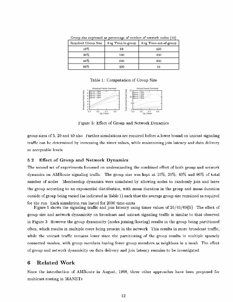
Group size expressed as percentage of number of network nodes (43)
Required Group Size Avg Time-in-group Avg Time-out-of-group
10% 50 450
20% 100 400
40% 200 300
90% 400 44
Table 1: Computation of Group Size
0
12
34
56
7
0.3 0.5 0.7 0.9
Bro
adca
st P
acke
t Rat
e
Op_Factor
Broadcast Packet Overhead
Grp-sz = 10%Grp-sz = 20%Grp-sz = 40%Grp-sz = 90%
0
5
10
15
0.3 0.5 0.7 0.9
Tot
al U
nica
st P
acke
t Rat
e
Op_Factor
Unicast Packet Overhead
Grp-sz = 10%Grp-sz = 20%Grp-sz = 40%Grp-sz = 90%
Figure 5: E�ect of Group and Network Dynamics
group sizes of 5, 20 and 40 also. Further simulations are required before a lower bound on unicast signaling
tra�c can be determined by increasing the timer values, while maintaining join latency and data delivery
at acceptable levels.
5.2 E�ect of Group and Network Dynamics
The second set of experiments focussed on understanding the combined e�ect of both group and network
dynamics on AMRoute signaling tra�c. The group size was kept at 10%, 20%, 40% and 90% of total
number of nodes. Membership dynamics were simulated by allowing nodes to randomly join and leave
the group according to an exponential distribution, with mean duration in the group and mean duration
outside of group being varied (as indicated in Table 1) such that the average group size remained as required
for the run. Each simulation run lasted for 2000 time-units.Figure 5 shows the signaling tra�c and join latency using timer values of 20/40/60f5g. The e�ect of
group size and network dynamicity on broadcast and unicast signaling tra�c is similar to that observed
in Figure 3. However the group dynamicity (nodes joining/leaving) results in the group being partitioned
often, which results in multiple cores being present in the network. This results in more broadcast tra�c,
while the unicast tra�c remains lower since the partitioning of the group results in multiple sparsely
connected meshes, with group members having fewer group members as neighbors in a mesh. The e�ect
of group and network dynamicity on data delivery and join latency remains to be investigated.
6 Related Work
Since the introduction of AMRoute in August, 1998, three other approaches have been proposed for
multicast routing in MANETs.
12

The Adhoc Multicast Routing Protocol utilizing Increasing ID-numbers (AMRIS, [6]) assigns an iden-
ti�er to each node in a multicast session. A per-multicast session delivery tree rooted at a special node
(by necessity a sender) in the session joins all the group members. The tree structure is maintained by
assigning identi�ers in increasing order from the tree root outward to the other group members. Election
algorithms (not yet speci�ed) may be required to choose one special node if multiple senders are present
in a multicast session. All nodes in the network are required to support AMRIS and any node can be on
a tree. All nodes are required to process the tree setup and maintainance messages that are transmitted
by the root periodically. No global state is required to be maintained by nodes on the tree, and repairs
to damaged links are performed locally. AMRIS currently assumes the existence of bi-directional links
between network nodes. It also assumes that applications (multicast sessions) are long-lived, and hence
sacri�ces route discovery latency to route recovery latency.
The On-Demand Multicast Routing Protocol (ODMRP, [7]) uses a mesh-based approach for data
delivery, rather than the traditional tree-based approaches. It requires sources rather than receivers to
initiate the mesh building by periodic ooding of control packets. Receivers are required to periodically
exchange information with their neighbors locally. All nodes in the network are required to be involved
in the protocol, with per group and per source state being maintained at intermediate nodes and group
members. Additionally, nodes on the mesh seem to require maintenance of a cache to detect duplicate
data and control messages that may arise due to the use of a mesh. The use of soft state implies that
receivers/sources do not need to generate an explicit control message to leave the mesh.
The Adhoc On Demand Distance Vector (AODV, [8]) protocol was primarily designed for unicast, but
has since been extended to support multicast. It uses the concept of a group leader, which is similar to a
logical core, for managing the per-group, shared, bi-directional tree. Non-member nodes and non-senders
can also be part of the multicast tree, and hence need to support AODV.
The Dynamic Source Routing (DSR, [9]) protocol emulates multicast by controlled ooding of data
packets, using the TTL �eld to limit the scope of the ooding. Individual nodes within the scope of the
TTL value used are required to �lter based on the multicast address speci�ed in the destination �eld of
the data packet. While this approach ensures that the multicast data reaches all nodes within the speci�ed
scope, both node and network resources are ine�ciently utilized.
7 Discussion
The Adhoc Multicast Routing Protocol (AMRoute) presents a novel approach for robust IP Multicast
in mobile adhoc networks by exploiting user-multicast trees and dynamic logical cores. It creates a bi-
directional, shared tree for data distribution using only the group senders and receivers as tree nodes.
Unicast tunnels are used as tree links to connect neighbors on the user-multicast tree. Thus, AMRoute
does not need to be supported by network nodes that are not interested/capable of multicast, and group
state cost is incurred only by group senders and receivers. Also, the use of tunnels as tree links implies
13

that tree structure does not need to change even in case of a dynamic network topology, which reduces
the signaling tra�c and packet loss. Thus AMRoute does not need to track network dynamics; the
underlying unicast protocol is solely responsible for this function. AMRoute does not require a speci�c
unicast routing protocol; therefore, it can operate seamlessly over separate domains with di�erent unicast
protocols. Certain tree nodes are designated by AMRoute as logical cores, and are responsible for initiating
and managing the signaling component of AMRoute, such as detection of group members and tree setup.
Logical cores di�er signi�cantly from those in CBT and PIM-SM, since they are not a central point for
data distribution and can migrate dynamically among member nodes.
AMRoute simulation results indicate that broadcast signaling tra�c generated by AMRoute is inde-
pendent of group size, and is inversely proportional to network dynamicity. Unicast signaling tra�c is
proportional to group size, and inversely proportional to network dynamicity. Moreover, the total signal-
ing tra�c remains independent of rate of data being multicast by senders to the group. Both signaling
tra�c and join latency remain at relatively low levels for typical group sizes. The results also indicate that
group members receive a high proportion of data multicast by a sender, even in the case of a dynamic
network.
AMRoute performance is in uenced by the characteristics of unicast routing protocol being used,
which was TORA in this case. Further simulations are needed to explore the e�ects of using other unicast
protocols (DSR, AODV). Also, the simulations need to incorporate node mobility patterns, and physical
and data link layer models. A performance comparison of AMRoute with PIM, DVMRP and the other
adhoc multicast routing approaches is also needed.
8 References1. Ballardie, T., \Core based Trees (CBT) Multicast Routing Architecture," RFC 2201, Sept. 1997.
2. Deering, S., et al, \Protocol Independent Multicast-Sparse Mode (PIM-SM): Motivation and Architecture," Internet
Draft, draft-ietf-idmr-pim-arch-04, Oct. 1996.
3. Pusateri, T., \Distance Vector Multicast Routing Protocol," Internet Draft, draft-ietf-idmr-dvmrp-v3-06, Mar. 1998.
4. Corson, S., and J. Macker, \Mobile Ad hoc Networking: Routing Protocol Performance Issues and Evaluation Consid-
erations," Internet Draft, draft-ietf-manet-issues-00, Sept. 1997.
5. Perkins, C., \Mobile Ad hoc Networking Terminology," Internet Draft, draft-ietf-manet-term-00, Oct. 1997.
6. Wu, C.W., Tay, Y. C., and Toh, C-K., \Adhoc Multicast Routing Protocol utilizing Increasing ID-numbers (AMRIS)
Functional Speci�cation," Internet Draft, draft-ietf-manet-amris-spec-00.txt, Nov. 1998.
7. Gerla, M., Pei, G., Lee, S-J, and Chiang, C-C, \On-Demand Multicast Routing Protocol for Ad-Hoc Networks," Internet
Draft, draft-ietf-manet-odmrp-00-txt, Nov. 1998.
8. Perkins, C.E., and Royer, E.M., \Adhoc On Demand Distance Vector (AODV) Routing," Internet Draft, draft-ietf-
manet-aodv-02.txt, Nov. 1998.
9. Broch, J., Johnson, D.B., and Maltz, D.A., \Dynamic Source Routing Protocol for Mobile Adhoc Networks," Internet
Draft, draft-ietf-manet-dsr-01.txt, Dec. 1998.
14