Outdoor experimental comparison of four ad hoc routing algorithms
21
Outdoor Experimental Comparison of Four Ad Hoc Routing Algorithms * Robert S. Gray, David Kotz, Calvin Newport, Nikita Dubrovsky, Aaron Fiske, Jason Liu, Christopher Masone, Susan McGrath, and Yougu Yuan Dartmouth College, Hanover, NH 03755 Dartmouth College Computer Science Technical Report TR2004-511 June 18, 2004 Abstract Most comparisons of wireless ad hoc routing algorithms involve simulated or indoor trial runs, or outdoor runs with only a small number of nodes, potentially leading to an incorrect picture of algorithm performance. In this paper, we report on the results of an outdoor trial run of four different routing algorithms, APRL, AODV, GPSR, and STARA, running on top of thirty-three 802.11-enabled laptops moving randomly through an athletic field. The laptops generated random traffic according to the traffic patterns observed in a prototype application, and ran each routing algorithm for a fifteen-minute period over the course of the hour-long trial run. The 33-laptop experiment represents one of the largest outdoor tests of wireless routing algorithms, and three of the algorithms each come from a different algorithmic class, providing insight into the behavior of ad hoc routing algorithms at larger real-world scales than have been considered so far. In addition, we compare the outdoor results with both indoor (“tabletop”) and simulation results for the same algorithms, examining the differences between the indoor results and the outdoor reality. The paper also describes the software infrastructure that allowed us to implement the ad hoc routing algorithms in a comparable way, and use the same codebase for indoor, outdoor, and simulated trial runs. 1 Introduction Ad hoc wireless networks can provide connectivity in a variety of environments in which tradi- tional communication infrastructures are absent. One notable environment is the modern bat- tlefield [Gra00]. Although some urban locations may have cell phone or other communication networks, these systems may be destroyed, non-operational or inaccessible under battle conditions. Therefore, warfighters must rely on communication mechanisms that they can carry with them, and the military is actively pursuing soldier-mounted ad hoc networks for data communications. In the US Army’s vision of the Future Force Warrior, 1 for example, soldiers will have transmission equipment that will make each person a node in an ad hoc network. 2 The application of ad hoc * Supported under Contract Number F49620-93-10266 from the Department of Defense (DoD) and Air Force Office of Scientific Research (AFOSR), with additional support from Dartmouth College, DARPA under Contract Number F30602-98-2-0107, and the Department of Homeland Security (DHS) under Contract Number Number 2000- DT-CX-K001 (S-2). Points of view in this document are those of the authors and do not necessarily represent the official position of the DoD, AFOSR, DARPA, DHS or Dartmouth College. 1 http://www.natick.army.mil/soldier/WSIT/ 2 http://www.mit-kmi.com/archive article.cfm?DocID=14 1
-
Upload
independent -
Category
Documents
-
view
1 -
download
0
Transcript of Outdoor experimental comparison of four ad hoc routing algorithms

Outdoor Experimental Comparison of Four Ad Hoc Routing
Algorithms∗
Robert S. Gray, David Kotz, Calvin Newport, Nikita Dubrovsky,Aaron Fiske, Jason Liu, Christopher Masone, Susan McGrath, and Yougu Yuan
Dartmouth College, Hanover, NH 03755Dartmouth College Computer Science Technical Report TR2004-511
June 18, 2004
Abstract
Most comparisons of wireless ad hoc routing algorithms involve simulated or indoor trialruns, or outdoor runs with only a small number of nodes, potentially leading to an incorrectpicture of algorithm performance. In this paper, we report on the results of an outdoor trialrun of four different routing algorithms, APRL, AODV, GPSR, and STARA, running on topof thirty-three 802.11-enabled laptops moving randomly through an athletic field. The laptopsgenerated random traffic according to the traffic patterns observed in a prototype application,and ran each routing algorithm for a fifteen-minute period over the course of the hour-long trialrun. The 33-laptop experiment represents one of the largest outdoor tests of wireless routingalgorithms, and three of the algorithms each come from a different algorithmic class, providinginsight into the behavior of ad hoc routing algorithms at larger real-world scales than have beenconsidered so far. In addition, we compare the outdoor results with both indoor (“tabletop”)and simulation results for the same algorithms, examining the differences between the indoorresults and the outdoor reality. The paper also describes the software infrastructure that allowedus to implement the ad hoc routing algorithms in a comparable way, and use the same codebasefor indoor, outdoor, and simulated trial runs.
1 Introduction
Ad hoc wireless networks can provide connectivity in a variety of environments in which tradi-tional communication infrastructures are absent. One notable environment is the modern bat-tlefield [Gra00]. Although some urban locations may have cell phone or other communicationnetworks, these systems may be destroyed, non-operational or inaccessible under battle conditions.Therefore, warfighters must rely on communication mechanisms that they can carry with them,and the military is actively pursuing soldier-mounted ad hoc networks for data communications.In the US Army’s vision of the Future Force Warrior, 1 for example, soldiers will have transmissionequipment that will make each person a node in an ad hoc network. 2 The application of ad hoc
∗ Supported under Contract Number F49620-93-10266 from the Department of Defense (DoD) and Air ForceOffice of Scientific Research (AFOSR), with additional support from Dartmouth College, DARPA under ContractNumber F30602-98-2-0107, and the Department of Homeland Security (DHS) under Contract Number Number 2000-DT-CX-K001 (S-2). Points of view in this document are those of the authors and do not necessarily represent theofficial position of the DoD, AFOSR, DARPA, DHS or Dartmouth College.
1http://www.natick.army.mil/soldier/WSIT/2http://www.mit-kmi.com/archive article.cfm?DocID=14
1
networks between vehicles is also possible, and, in fact, the United States military currently isusing this technology in Iraq. 3 Similarly, ad hoc networks can be used to expedite response in civilemergencies, as in our own work on remote triage for casualties [WMB03].
Many other applications of ad hoc networks exist, such as urban rooftop networks or land- orocean-based sensor networks, but we focus on the battlefield and emergency-response scenarios inour research work. More specifically, in this paper, we focus on routing algorithms for outdoor,mobile ad hoc networks. Unfortunately, although there have been a few outdoor tests with a largenumber of stationary sensors, there have been few, if any, outdoor tests with a large number ofmobile laptops or other personal computing devices. Most outdoor tests have involved only afew nodes. Moreover, results obtained from a small number of real nodes or a large number ofsimulated nodes do not necessarily generalize to a large number of real nodes, potentially leadingto an incorrect view of routing-algorithm performance.
This paper partially addresses this gap by analyzing the results of an outdoor trial run of fourdifferent routing algorithms, APRL, AODV, GPSR, and STARA, running on top of thirty-three802.11-enabled laptops moving randomly through an athletic field. The laptops generated randomtraffic according to the traffic patterns observed in a prototype battlefield application, and raneach routing algorithm for a fifteen-minute period over the course of the one-hour trial run. This33-laptop experiment represents one of the largest outdoor tests of ad hoc routing algorithms, andpossibly represents the largest outdoor test for which results are publicly available. In addition,we compare these outdoor results with both indoor (“single shelf”) and simulation results for thesame algorithms. Finally, the paper also describes the software infrastructure that allowed us toimplement the ad hoc routing algorithms in a comparable way, and use the same codebase forindoor, outdoor, and simulation trial runs.
With this analysis, the paper accomplishes three goals. First, three of the routing algorithmseach come from a different algorithmic class, and the outdoor experiment therefore provides insightinto how these classes of algorithms behave at larger real-world scales than have been consideredso far. Second, the comparison with indoor and simulated results confirms again that real-worldperformance is difficult to predict without real-world experiments, but also confirms that it is pos-sible to model radio and other behaviors accurately enough for simulated results to be meaningful.Finally, the implemented software infrastructure provides an effective starting point for furtherlarge-scale, outdoor routing experiments, either with one of our four implemented algorithms orwith another algorithm.
Section 2 describes the four routing algorithms that we considered, and Section 3 presents ourexperimental infrastructure. Section 4 analyzes the results of the outdoor, indoor and simulationexperiments, considering the suitability of specific algorithms for the outdoor environment, andexamining whether indoor experiments or simulation can predict the outdoor results. Finally,Section 5 summarizes related work, and Section 6 concludes with the major lessons learned andimportant areas of future work.
2 Routing Algorithms
The experiments involved four routing algorithms, Any Path Routing without Loops (APRL) [KK98],Ad hoc On-demand Distance Vector (AODV) [PR99], On-Demand Multicast Routing Protocol(ODMRP) [LSG02], and System- and Traffic-dependent Adaptive Routing Algorithm (STARA) [GK97,Gup00]. APRL and STARA were developed at Harvard and the University of Illinois as part of
3http://lists.personaltelco.net/pipermail/general/2003q2/012362.html
2
a Dartmouth-led Multi-disciplinary University Research Initiative (MURI) on field communica-tions for military personnel, while AODV and ODMRP are algorithms that are extensively usedas comparison baselines for other routing algorithms (and that have seen some use in militaryapplications). Although APRL and STARA are not standard choices, we feel that our selection isrepresentative of an important subsection of the ad hoc routing space, simple (APRL) and complex(STARA) pro-active routing protocols, and two related reactive protocols (AODV and ODMRP).In this section, we provide a general overview of how the four algorithms work. We save a discussionof specific parameters, such as time out values, for the experiment section.
2.1 APRL and STARA
APRL and STARA are both pro-active routing algorithms. APRL is quite simple in that it onlytries to discover a fixed number of routes, not necessarily shortest, from one node to another, whileSTARA is quite complex in that it uses dynamic latency measurements to select from multipleavailable routes.
With APRL [KK98], each node broadcasts routing beacons at a fixed frequency, and eachsuch beacon contains a complete copy of the node’s current routing table. Neighboring nodesuse the embedded routing information to update their own routing table, and then propagate theupdated information further as part of their own beacons. Initially, the routing tables are empty,and a beacon serves only to tell one node that it has another node as a neighbor. The receivingnode, however, then will be able to include the existence of the sending node in its own beacons.Eventually every node in the network will learn about a route to every other node, the exact amountof time depending on the diameter of the network and the beaconing interval. Nodes use whateverroute they learn about first, without regard to the route’s length or quality, but routes will time outif they are not refreshed by a beacon within a specific time interval. In addition, APRL will recorda configurable number of alternate routes to each destination, and will switch to an alternate routeas soon as a primary route times out.
The beaconing approach described so far can lead to loops in the routing topology since routeson different nodes will not time out at the same time. Suppose, for example, that the current routesto A are linear and go from node D to node C to node B to node A. In the worst case, node Amoves out of range of the other nodes, node B’s route to A times out, and node B immediatelyhears a beacon from D containing D’s route to node A. Node B now will believe that it can sendits node-A traffic through node D, resulting in a three-node loop for all traffic destined for node A.To address this problem, APRL does not use a route as soon as it learns about it from a beacon,but instead sends a probe packet along the route. The destination node, if the packet makes itthat far, sends the probe packet back to the sender along the reverse route. The sender will startusing the route only if the probe packet successfully reaches the destination and returns. If a nodehas an alternate route, the node will switch to the alternate route when the primary fails, but willsend out a probe packet to confirm that the alternate route still is valid.
STARA takes a different approach than APRL, and tries to accurately estimate each route’slatency so that it can choose the best route among many [GK97, Gup00]. STARA uses latency,rather than hop count, as a metric, since interference from traffic or environmental features cancause a short-hop route to have a significantly longer end-to-end delay than a long-hop route.
STARA maintains a list of neighbors that are in immediate transmission range of a particularnode, and updates that list through the periodic broadcast of Neighborhood Probe (NP) packetsand Neighborhood Probe Acknowledgment Packets (NP ACK). When sending a packet to a non-neighbor, STARA probabilistically chooses a neighbor through which to route the packet. Initially,the probability distribution is uniform, but STARA will adjust the probabilities according to its
3
latency observations. Specifically, just before STARA sends a Data Packet (DP), it attaches acurrent timestamp to the packet. When the data packet reaches its destination, the destinationnode sends a DP ACK back to the original machine; this DP ACK contains the original timestampalong with a new timestamp indicating the time that the packet was received. Once the DP ACKhas returned to the original node, the route delay is calculated simply as the difference between thetwo timestamps. STARA does not require the clocks on the nodes to be synchronized, since thedifference between delays to the same destination is independent of clock skew. As STARA receivesdelay information, it adjusts the probability distribution to be proportional to the observed delays,and distributes traffic along available routes that have approximately the same minimal delay (toreduce packet re-sequencing requirements).
One problem with STARA is that routes with large delays are seldom (if ever) used, which meansthat their delay estimates are updated infrequently or not at all. Thus, an improvement in the delayof a formerly slow path may go unnoticed. To avoid this, STARA periodically sends a DummyData Packet (DDP) along those routes for which a large time has elapsed since the last updateof their delay estimates. The developer of STARA presents a simple version of DDPs in [GK97],which sends every DDP as a separate network packet, and a more complex version in [Gup00],which condenses multiple dummy data packets into a single network packet. We implemented thesimpler version, and as we will see, the simpler version overloads our real network. The morecomplex version could be expected to have significantly better performance since it reduces controltraffic by an order of magnitude or more. Thus, our STARA results should not be taken as anoverall view of STARA’s performance, but instead should serve as another demonstration of howa single detail in control-packet handling can undo the performance gains expected from a morecomplex algorithm. To emphasize this point, we will refer to our STARA implementation asSTARA-SIMPLE or STARA-S in the rest of this paper.
2.2 AODV and ODMRP
AODV and ODMRP are closely related re-active routing algorithms, differing mainly in ODMRP’ssupport for multicast traffic and its inclusion of data packets inside route-discovery packets.
Like any reactive protocol, AODV searches for a route only when a node has data traffic thatit needs to send [PR99]. Specifically, when a node needs a route to a destination for which it doesnot have a route (or for which the route has expired), AODV broadcasts a Route Request (RREQ)message. 4 All nodes that receive the RREQ message, but do not have a route to the requesteddestination, rebroadcast the RREQ, while at the same time establishing a reverse route to thesource node. When the RREQ reaches an intermediate node that has a sufficiently recent routeto the destination (as determined by sequence numbers associated with routing entries) or reachesthe destination node itself, the intermediate or destination node sends a Route Response (RREP)message back to the source node along the reverse route. 5 Once the original host receives theRREP message, it records and begins using the new route.
All nodes keep track of their neighbors through regularly broadcast HELLO messages. When ahost detects a missing neighbor through a lack of HELLO messages, it invalidates the routes thatused that neighbor as the gateway and broadcasts a Route Error (RERR) message that includes alist of all destinations that are now unreachable due to the failed link. Nodes that receive an RERRmessage will invalidate their own routes, and broadcast their own RERR messages. Any node that
4As an optimization, AODV can use an expanding ring search method for broadcasting RREQs, but we do notimplement this capability in our version.
5An intermediate host also will send an RREP packet to the destination of the RREQ to make sure that thedestination still has a route to the source.
4

still needs to communicate with one of the unreachable destinations will search for an alternativeroute through the RREQ/RREP process.
ODMRP is a multicast ad hoc routing protocol that, unlike many other multicast protocols,does not require a separate underlying unicast protocol. ODMRP establishes and maintains routesin much the same manner as AODV. When a node has a data packet that it needs to send, buthas no route to the destination, ODMRP broadcasts a JoinQuery packet. In contrast to AODV,however, ODMRP embeds the data packet inside the JoinQuery, so that the data packet reachesthe destination as soon as the JoinQuery does. A node that receives a new JoinQuery rebroadcastsit, and if the node wants to receive packets on the multicast IP address of the JoinQuery, it sendsa JoinReply packet back to the source using the reverse route. Intermediate hosts receiving theJoinReply set a forwarding flag for the corresponding multicast group in a “forwarding group”table, indicating that they are on the path between the source and one or more of the destinationsand thus should rebroadcast any future incoming data packets. A forwarding group has a presetexpiration timeout, and ODMRP refreshes the group at regular intervals by resending JoinQuerypackets. ODMRP only resends JoinQuerys so long as there still are data packets that need to besent, however.
In our experiments, all data traffic is sent to only a single destination, reducing ODMRP to theunicast case and leaving the inclusion of the data packet in the JoinQuery as the primary differencebetween ODMRP and AODV.
3 Experimental Setup
We conducted outdoor, indoor, and simulation experiments for the four routing algorithms de-scribed above. All three experiments used the same hardware and software infrastructure, andthe indoor and simulation experiments used the position traces from the outdoor experiment toduplicate the outdoor movement patterns. For the indoor experiment, the movement patterns wereduplicated by having a laptop ignore any traffic from a laptop that was too far away at the corre-sponding time in the outdoor experiment. This approach to simulating movement does not addressthe fact that the wireless channel behaves differently when all the laptops are on the same tabletop,and we will see below that there are significant performance differences when the four algorithmsare run indoors rather than outdoors (and in simulation rather than with real hardware).
3.1 Hardware Platform
The routing experiments ran on top of a set of 41 Gateway Solo 9300 laptops, each with a 10GBdisk, 128MB of main memory, and a 500MHz Intel Pentium III CPU with 256KB of cache. Weused one laptop to control each experiment, leaving 40 laptops to actually run the ad hoc routingalgorithms. Each laptop ran Linux kernel version 2.2.19 with PCMCIA card manager version 3.2.4,and had a Lucent (Orinoco) Wavelan Turbo Gold 802.11b wireless card. Although these cardscan transmit at different bit rates and can auto-adjust this bit rate depending on the observedsignal-to-noise ratio, we used an ad hoc mode in which the transmission rate was fixed at 2 Mb/s.Specifically, we used Lucent (Orinoco) firmware version 4.32 and the proprietary ad hoc “demo”mode originally developed by Lucent. Although the demo mode has been deprecated in favorof the IEEE-defined IBSS, we used the demo mode to ensure consistency with a series of ad hocrouting experiments of which this outdoor experiment was a culminating event. 6 The fixed rate did
6Our series of experiments began before IBSS was available in standard 802.11b wireless cards, and time andpersonnel constraints prevented both demo-mode and IBSS-mode experiments.
5

Tun
nel D
rive
r
WirelessDriver
Application
RoutingAlgorithm
1
2
3
PhysicalNetwork
/deventry
VirtualNetworkInterface
Interface
Linux Kernel
Lin
ux n
etw
ork
stac
k
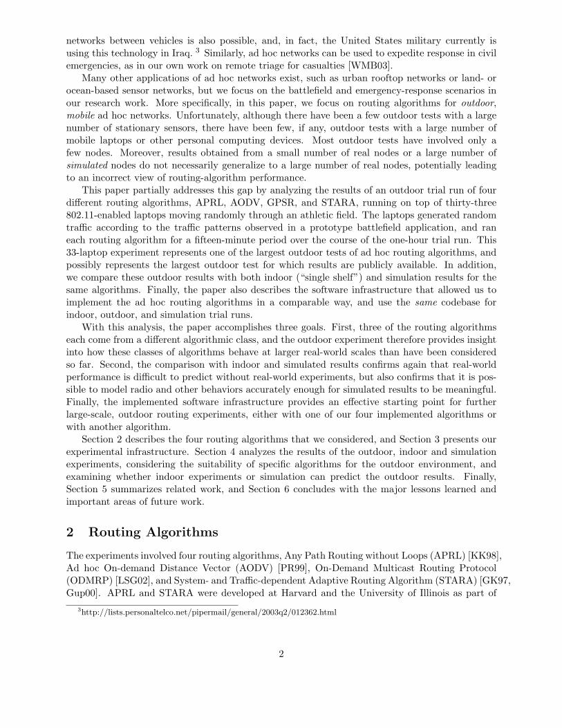
Figure 1: A schematic of the tunnel device and the path of an outgoing data packet.
make it much easier to analyze the routing results, since we did not need to account for automaticchanges in each card’s transmission rate. On the other hand, we would expect to see variationin the routing results if we had used IBSS instead, both due to its multi-rate capabilities and itsgeneral improvements over the demo mode. The routing results remain representative, however,since demo mode provides sufficient functionality to serve as a reasonable data-link layer. Finally,each laptop had a Garmin eTrex GPS unit attached via the serial port. These GPS units did nothave differential GPS capabilities, but were accurate to within thirty feet during the experiment.
3.2 Software Infrastructure
To allow as accurate a comparison as possible between the four routing algorithms, we needed theimplementations of those algorithms to be as similar as possible. If one algorithm operated inkernel space and another operated in user space, for example, it would not be possible to attributeany difference in packet latencies solely to the way in which an algorithm finds and uses its routes.For this reason, although we used existing source code as a guide in all four cases, we implementedeach algorithm from scratch so that we could minimize any implementation differences. There arefour key features that the implementations have in common:
• All four algorithms are implemented as user-level applications through the use of a tunneldevice. The tunnel device, which we ported from FreeBSD, provides a network interface onone end and a file interface, specifically a /dev entry, on the other end. All packets sent tothe network interface can be read from the file, and all packets written to the file will besent up Linux’s network stack. Each node is assigned two IP addresses, one associated withthe physical network device, and one associated with the tunnel or virtual network device.Applications use the virtual IP address, while the routing algorithms use the physical IPaddress. We configure the standard Linux routing tables so that all virtual IP addressesare directed to the virtual network interface. Any application-level packets, therefore, aredirected through the tunnel, and the routing algorithms can read those packets from the fileend. Figure 1 shows the tunnel device and the path of an outgoing data packet.
The tunnel allowed us to avoid any implementation work at the kernel or driver level, and alsoto switch from one routing algorithm to another (during experiments) simply by stopping one
6

user-level process and starting another. The drawback of our approach is the additional over-head associated with moving packets between kernel and user space. Our laptops, however,had more than enough capacity for the modest amount of network traffic that we generatedin most of our experiments,7 and thus we chose implementation simplicity over maximumperformance.
• All four algorithms use UDP for traffic destined for a specific neighbor and multicast IP fortraffic that should reach every neighbor. Multicast IP, as opposed to broadcast IP, allowsus to run multiple routing algorithms at the same time without adding filtering code toevery algorithm, a useful feature in some of our earlier experiments. Each algorithm simplysubscribes to its own multicast address.
• All four algorithms use an event loop that invokes algorithm-specific handlers in responseto (1) incoming UDP or multicast IP network traffic or (2) the expiration of route or othertimeouts. As with user-level routing, the event-loop approach leads to additional overhead,but allows more straightforward implementation.
• All four algorithms are implemented in C++ and share a core set of classes. These classesinclude the event loop, as well as unicast and multicast, routing, and logging support.
With these design choices and shared classes, algorithm-specific code is confined to the packethandler classes that process incoming control and data packets, the timer handler classes thatprocess timed actions (such as route expiration), a logging class that logs algorithm events, andutility classes that serialize and unserialize control packets. Minimizing the algorithm-specific codesimplified implementation and debugging, and should make the routing results as independent ofa particular implementation choice as possible.
The routing algorithms themselves are not enough, of course, since we also need to generateapplication-level traffic, record a position trace for each laptop, and manage the end-to-end experi-ment. A traffic generator runs on each laptop, and sends a sequence of packet streams to randomlyselected laptops. Each stream contains a random number of packets of a random size. Two Gaus-sian distributions determine the packet numbers and sizes, two exponential distributions determinethe delay between streams and packets, and a uniform distribution determines the destination lap-tops. A GPS service also runs on each laptop, reading and recording the current laptop positionfrom the attached GPS unit, and broadcasting beacons that contain the laptop’s position (as wellas sequence-numbered positions that it has received from other laptops). We thus are floodingthe GPS beacons through the network, an appropriate choice in our application domain wheresoldiers and first responders need to see a continuous view of each other’s positions. In addition,broadcasting the beacons allows us to build a connectivity graph, independent of any particularrouting algorithm, as to which laptops actually can hear which other laptops. Such a connectivitygraph serves as input to the indoor experiments, and also will allow future examination of caseswhere the routing algorithms did not discover a route even though there was at least some minimalconnectivity that could have made the route possible. Finally, we use a set of Tcl scripts to setupand run the experiments.
3.3 Outdoor Experiment
The same software infrastructure is used for the outdoor, indoor and simulation experiments, butwe will describe most of the specific parameters (timeout values, beacon intervals, etc.) in this
7We will see that the STARA routing algorithm overloaded our network and laptops.
7
section. We use the same parameter values for the indoor and simulation experiments, since weseek to compare all three sets of results.
The outdoor routing experiment took place on a rectangular athletic field measuring approx-imately 225 (north-south) by 365 (east-west) meters. This field can be roughly divided into fourflat, equal-sized sections, three of which are at the same altitude, and one of which (at the south-east corner) is approximately four to six meters lower. There was a short, steep slope between theupper and lower sections. We chose this particular athletic field because it was physically distantfrom campus and the campus’ wireless network, reducing potential interference. In addition, weconfigured the 802.11 cards to use wireless channel 9 for maximum separation from the standardchannels of 1, 6 and 11, further reducing potential interference. We used all 41 laptops, one as thecontrol laptop, and 40 as application laptops.
The GPS service on each laptop recorded the current position (latitude, longitude and altitude)once per second, and synchronized the laptop clock with the GPS clock to provide sub-second,albeit not millisecond, time synchronization. Every three seconds, the GPS service broadcast abeacon containing its own position and any other positions about which it knew. Three seconds islonger than strictly necessary for displaying accurate positions to soldiers or first responders, butwas necessary to build a reasonably accurate connectivity trace. Each beacon contains at most 41position records of 21 bytes each, and has a maximum data payload of 861 bytes.
The traffic generator on each laptop generated packet streams with a mean packet size of 1200bytes (including UDP, IP and Ethernet headers), a mean of approximately 5.5 packets per stream,a mean delay between streams of 15 seconds, and a mean delay between packets of approximately3 seconds. These parameters produced approximately 423 bytes of data traffic (including UDP, IPand Ethernet headers) per laptop per second, a relatively modest traffic volume, but correspondingto the traffic volume observed during trial runs of one of our prototype military applications [Gra00].
Each of the routing algorithms, APRL, AODV, ODMRP and STARA, ran for fifteen minuteswith a two-minute period between successive routing algorithms to handle setup and cleanup chores.Fifteen minutes per algorithm leads to an overall experiment time of approximately an hour and ahalf (given the time needed for initial boot and experiment startup), corresponding to the maximumreliable lifetime of our laptop batteries. The traffic generator ran for thirteen minutes of each fifteen-minute period, starting one minute after the routing algorithm to allow the pro-active routingalgorithms to reach a stable state.
The best parameters for the four routing algorithms could not be determined precisely before-hand, since there are no experiments of this size for which data is available. Instead, we usedvalues that gave effective results in published simulation studies or that were set as default valuesin the sample source code obtained from the developers. We did adjust some values to achievesome degree of consistency between the algorithms, however.
Summarizing the major parameters, APRL recorded up to seven routes per destination, oneprimary and six alternates, broadcast its beacons every 6 seconds, and expired any route that hadnot been refreshed by a beacon within the last 12 seconds. STARA broadcast a neighborhoodprobe every 2 seconds, sent a dummy data packet if a path had gone unexplored for 6 seconds,removed a neighbor from a node’s neighborhood set if two successive neighborhood probes passedwithout an acknowledgment, and weighed delay estimates by 0.9 on each update to exponentiallyforget old delay information as new information became available. AODV broadcast each RREQtwice, expired a route if it had not been used in 12 seconds, sent a HELLO every 6 seconds, andremoved a neighbor from a node’s neighborhood set if it did not receive two successive HELLOs.ODMRP refreshed an in-use route every 6 seconds, and expired a route (i.e., a forwarding group) ifit had not been used for 12 seconds. As can be seen, these parameters reduce to 6 seconds betweenbeacons, HELLO messages or route refreshes for APRL, AODV and ODMRP, and 12 seconds for a
8

route to time out for APRL, AODV and ODMRP, either by direct timeout or by failure to receivetwo successive HELLOs. Using equivalent values for STARA, however, led to unacceptably slowconvergence of the delay estimates, particularly given the fifteen-minute window available to us foreach algorithm. Reducing the parameters improved convergence, but at the expense of even morecontrol overhead, an effect that we will consider below.
The laptops moved continuously during the experiment. At the start of the experiment, theparticipants were divided into equal-sized groups of ten, each participant given a laptop, and eachgroup instructed to randomly disburse in one of the four sections of the field (three upper and onelower). The participants then walked continuously, always picking a section different than the onein which they were currently located, picking a random position within that section, walking tothat position in a straight line, and then repeating. This approach was chosen since it was simple,but still provided continuous movement to which the routing algorithms could react, as well assimilar spatial distributions across each algorithm.
Finally, during the experiment, seven laptops generated no network traffic due to hardware andconfiguration issues, and an eighth laptop generated the position beacons only for the first half ofthe experiment. The seven complete failures left thirty-three laptops actually participating in thead hoc routing.
3.4 Indoor and Simulation Experiments
The indoor and simulation experiments used the recorded GPS information from the outdoorexperiment to simulate the outdoor network connectivity. Specifically, if a node did not receivetwo successive GPS beacons from another node, the two nodes were assumed to be out of rangeof each other (disconnected). Otherwise the two nodes were assumed to be in range of eachother (connected). In addition, we used the same routing-algorithm parameters as in the outdoorexperiment and the same codebase (through the use of a direct-execution technique [LYN+04] inthe simulation case), and were careful to take into account the seven failed laptops. For example,the seven failed laptops were left in or configured to the same failed state that had occurredoutdoors, and the traffic generators were allowed to generate traffic destined for one of those failedlaptops. Finally, we averaged the results from multiple runs, each with a different traffic generationpattern to get the final indoor and simulation results. The overall goal of this approach is to leavethe behavior of the wireless channel as the primary difference between the outdoor, indoor, andsimulation experiments.
4 Analysis
We evaluate the relative performance of the four algorithms with four metrics: message deliveryratio, communication efficiency, hop count, and end-to-end latency. Before examining these met-rics, we define three important terms. First, a message is a group of dummy bytes produced by anode’s traffic generator for intended transportation to a randomly-selected destination. All of ourgenerated messages are small enough to fit into a single data packet. 8 Second, a data packet is anytransmitted packet containing message data. Therefore, every message requires the transmissionof at least one data packet to reach its destination. A message also can generate more than onedata packet, depending on the length of the route or the delivery strategy of the algorithm. It alsois possible for a message to generate no data packets, since the sending node may fail to identifyany active route toward the message’s destination. Finally, a control packet is any transmitted
8The mean message size was 1200 bytes, including all relevant headers.
9

AverageMessage Hop Count MessageDelivery Data Packets Control Packets Total Packets (successful Latency
Ratio Per Message Per Message Per Message messages) (seconds)AODV 0.50 1.32 6.18 7.50 1.61 0.37APRL 0.20 0.90 32.40 33.30 2.11 0.49
ODMRP 0.77 22.79 22.80 45.59 2.47 1.62STARA-S 0.08 0.20 150.47 150.67 1.18 2.98
Table 1: The key outdoor statistics for each algorithm
packet that does not contain message data. Control packets are the means by which our routingalgorithms communicate status information with nearby nodes.
4.1 Outdoor Results
Message Delivery Ratio. The message delivery ratio is the total number of messages received attheir intended destination divided by the total number of generated messages (over the lifetime ofthe algorithm’s run), and measures each algorithm’s overall success in providing end-to-end messagedelivery. This metric could be referred to as the packet delivery ratio, but we substitute the termmessage for packet to emphasize that a single application-level message can turn into many networkpackets.
The first column of Table 1 shows the message delivery ratio for each algorithm. A strikingresult is the dominance of ODMRP, best explained by ODMRP’s aggressive approach to routediscovery. Instead of discovering a route and then sending the desired message, ODMRP embedsthe message inside the route-discovery control packets. This greatly increases the chance that amessage will reach its intended destination, since we need only to get one message from sourceto destination. If route discovery is a separate process, we must get three messages from sourceto destination (or back), the route-discovery control message, the route-response control message,and the application-level data message. AODV performs better than APRL for a similar reason.APRL pro-actively finds routes before they are needed, but the timeout values allow a relativelylarge time window during which a route physically might no longer be viable but still appearsin most of the routing tables. Messages generated during this time will be lost, and will countagainst the message delivery ratio. If the nodes in our experiment had been more static, or ifthe physical environment had otherwise provided less opportunity for route breakage, we wouldsee much less of a gap between the AODV and APRL delivery ratios. Different timeout values orminimal message-buffering capabilities also might help APRL.
STARA-S’ message delivery ratio is the worst of the four algorithms, simply because STARA-S overwhelms the wireless network and the individual nodes with the dummy data packets usedto re-explore previously high-latency routes. Gupta proposes condensing multiple control packetsarriving at a node into a single control packet before rebroadcast [Gup00], but neither he nor weimplemented this solution. As is, STARA-S confirms again that inefficient handling of a singlecontrol-packet type can undo any potential benefits of a more complex algorithm.
Communication Efficiency. The second through fourth columns of Table 1 show the averagenumber of data packets, control packets, and total packets transmitted for each generated message.The first two are calculated by dividing the total number of data or control packets by the totalnumber of generated messages (over the traffic-generation lifetime of each algorithm), and the
10
third is simply the sum of the other two. These metrics provide insight into each algorithm’s datatransportation efficiency.
ODMRP dominates on data-packet overhead since it embeds many data packets inside floodedcontrol packets. If the size of the transmitted messages were large, the effect of this data packetload on available bandwidth would be dramatic. In our experiment, however, the generated trafficwas relatively modest, and ODMRP did not create excessive congestion. In addition, if the trafficwere concentrated on fewer destinations, or if the network were more static, we would observe fewerdata packets since ODMRP would not need to flood the network as often. AODV transmitted 1.32data packets per message while APRL transmitted only 0.90. This difference, although small inmagnitude, is quite significant since APRL used longer routes on average than AODV, suggestingthat the data-packet count should be higher. APRL often had no route at all from a sourceto a destination, however, leading to many messages that produced no data packets. Instead,the messages were dropped on the source node. Finally, STARA-S transmitted the fewest datapackets, simply because the overload conditions prevented most data packets from making it ontothe network (and prevented STARA-S from accurately discovering routes). Note that we countdummy data packets as control packets, rather than data packets.
On the other hand, STARA-S produces the most control traffic, generating, on average, 150control packets for each message due to its excessive transmission of dummy data packets. APRLgenerated 32 control packets for each message, while AODV, the best for this metric, generatedonly 6 control packets for each message. In our scenario of modest traffic and dynamic connectivity,AODV’s reactive discovery clearly required less control overhead than APRL’s pro-active discovery.
Finally, if we consider the total number of data and control packets versus the total number ofmessages, we see that AODV generates an average of 7.50 packets per message, APRL generates33.30, ODMRP generates 49.59, and STARA-S generates 150.67. Surprisingly, ODMRP doesnot fare much worse than APRL. One might assume that ODMRP’s aggressive network floodingwould lead to a more significant increase in traffic costs as compared to APRL’s periodic routeadvertisements, but ODMRP’s 45.59 packets transmitted for each message is not overwhelminglylarger than APRL’s 33.30. It should, however, be noted that if the traffic volume increased, APRLcould gain a noticeable lead over ODMRP, particularly in terms of transmitted bytes. The majorityof APRL’s traffic is in the form of streamlined control packets 9 sent at fixed intervals, whereasODMRP includes copies of its data packets with much of its route-discovery traffic. Consideringthat AODV and ODMRP are both reactive algorithms that flood the network to discover routes,it also was surprising at first glance to note how many fewer packets per message are required byAODV. AODV, however, is a unicast protocol, and can halt the route-discovery process at anyintermediate node that contains a valid route to the destination. ODMRP must always fully floodthe route-discovery packets so that new nodes have the opportunity to join the multicast group.
Generally, APRL’s volume of control traffic depends on its beaconing interval (time-based),AODV’s volume depends on the rate at which sources send data traffic to new destinations (datatraffic-based), and STARA-S’ volume depends on the rate at which it re-explores unused routes(time-based). The relative control overhead of the algorithms can change significantly dependingon the traffic pattern and timeout values, therefore, and APRL may gain a significant advantageover reactive algorithms such as AODV if the amount of data traffic increases significantly.
Hop Count. The next column of Table 1 shows the average number of hops that successfullyreceived messages traveled to reach their destination. For ODMRP, we use the hop count for thefirst copy of each message to reach the intended destination.
STARA-S has the lowest average hop count for successfully received packets, but this result is9APRL includes only a simple binary indication of whether a route exists in its routing beacons.
11

due to the excessive control traffic that made successful packet transmission difficult. Only datapackets whose final destination was an immediate neighbor of the original sender had a good chanceof successful receipt. AODV required the next fewest hops for successful packets, since AODV triesto select for the shortest path, whereas APRL and ODMRP do not consider path length. Infact, ODMRP has the largest average hop-count value, since many of its messages follow a semi-random path to the destination during undirected route discovery phase, On the other hand, iftraffic was concentrated on a few destinations, ODMRP’s hop count would drop significantly, sincemost data traffic could be sent over an already discovered route (rather than included in a floodedroute-discovery packet).
One interesting result, not shown in the table, is that STARA-S dropped or lost nearly 88% ofthe generated messages before those messages left the source node (zero-hop), and APRL droppedor lost nearly 63%. For STARA-S, which averaged nearly 150 packets per message, interferencecaused the large number of zero-hop failures, with most such failures involving the transmission of apacket that was never received. For APRL, most zero-hop failures occurred when APRL explicitlydropped the packet due to a lack of a valid route to the destination node, indicating that APRL’speriodic route advertising scheme was unable to consistently maintain adequate routing informationin our experiment. While there were many cases in our experiment where a route physically didnot exist between two nodes, AODV had a zero-hop failure rate of only 25%, indicating a moreserious problem with APRL’s performance.
End-to-End Latency. The main obstacle to calculating end-to-end message latencies is a lackof synchronization between the individual node clocks, creating a situation in which a comparisonof receiver and sender timestamps is not sufficient for generating accurate latency values. AlthoughNTP was a possibility, we made the decision to avoid the extra bandwidth usage during the exper-iments. Instead, we relied on the GPS units to provide accurate timestamps through our periodicsynchronization of the node clock with the GPS clock. Since we required regular GPS queries forother purposes (such as tracking node mobility), this approach did not introduce significant extraoverhead, and required no bandwidth usage. We found, however, that our node clocks still driftedfrom each other on the order of tens to a few hundreds of milliseconds, partially due to delays inreading the time from the GPS unit and invoking the kernel system-time calls.
Though relatively small, this clock drift is still significant, since many of our calculated end-to-end latency values are within the same order of magnitude. To overcome this, we paired thelog entries corresponding to transmission and reception of the same beacons, and then used thepaired timestamps to calculate the average clock skew between laptop pairs over non-overlappingtime windows. The skew value for the appropriate window then was used to “correct” the apparentlatency of a transmitted data packet. We recognize that this approach is only approximate forseveral reasons: (1) it is unrealistic to assume that two nodes A and B will receive and timestampa broadcast beacon at the same instant, due to physical transmission time and computationaloverhead that may delay the actual log entry; (2) in a multi-hop routing environment, it is possiblethat the sender and the receiver of a given packet are too distant to have recently received the samebeacon, producing a time window during which the sender and receiver have no available clock-skew value; and (3) using the average observed time skew calculated over a given bucket durationis not necessarily as accurate as always searching out the closest single time synchronization event.Accordingly, we do not present our end-to-end latency values as precise measurements. We do,however, maintain that our corrected values are more accurate indications of transit time thanrelying on uncorrected timestamps.
The last column of Table 1 shows the average corrected end-to-end latency value value forsuccessful messages. We find the expected relationship between end-to-end latency and hop count.For AODV, APRL, and ODMRP, the average end-to-end latency value increases as the hop count
12

increases (although not strictly proportionally). For STARA-S, the hop count is low, but the end-to-end latency is high. This abnormality arises due to the large volume of control traffic, whichsignificantly increases the time needed to receive and forward any data packet.
Conclusions. Any conclusions that we draw from this outdoor experiment must be qualified bythe conditions of our particular testing environment. A markedly different scenario would producemarkedly different results. For example, our nodes were mobile, our terrain was obstruction-free but non-uniform, and our participants carried the laptops tucked under their arms (thuspotentially placing their bodies between the 802.11 card and the intended destination laptop).The dynamic environment penalizes an algorithm like APRL that does not seek routes on demand,while the modest traffic load helps an aggressive flooding algorithm like ODMRP. The way in whichthe laptops were carried changes the connectivity characteristics, and, in particular, may preventsuccessful transmission along routes that would have been fine with head-mounted antennas. Otherimportant factors include the random pair-wise communication between nodes and the humanapproximation of the random-waypoint mobility model that we used. With such qualifications inmind, we can present the following conclusions, which track with other results in the literature:
• AODV is efficient, but far from effective in all scenarios. Though its message deliveryratio was not as high as ODMRP, it delivered messages significantly better than APRL andSTARA-S. More importantly, on all measures of communication efficiency, AODV generatedby far the least amount of traffic for each message. In addition, AODV was successful in con-sistently finding short paths, giving it the additional advantage of having the lowest averageend-to-end latency. In an environment with limited bandwidth or energy resources, AODVis a good choice. In an environment with extremely high mobility, however, AODV may notbe able to keep up with topology changes.
• ODMRP is highly effective for some scenarios, but very bad for others. ODMRPgenerates significant network overhead. Its flooding is bandwidth-intensive, and if data pack-ets are large, ODMRP could suffer significant performance penalties. At the same time,however, it had the highest message delivery ratio of all four algorithms, and will handle highmobility better than AODV through its packet flooding. If bandwidth and energy resourcesare plentiful, data packets are small, and communication reliability is crucial, ODMRP is agood choice.
• Reactive is better than proactive in dynamic environments. APRL’s and STARA-S’spoor performance, as compared to AODV and ODMRP’s relative success, highlights the gen-eral advantage of a reactive routing approach. Our analysis of APRL shows an unnecessarilylarge number of messages dropped before leaving their source node, and STARA-S crippleditself with excessive proactive discovery. Although STARA-S likely can be fixed throughadditional engineering, if we had restrained the existing STARA-S to produce a reasonablevolume of control traffic, it would have faced the same lack of quality routing information asAPRL. Similarly, if we had increased APRL’s beaconing interval to increase the timeliness ofits routing information, it would have suffered from an excess amount of control traffic likeSTARA-S. This observation underscores the perhaps unresolvable tension between controltraffic and message delivery success for proactive algorithms operating in dynamic environ-ments: if you make your algorithm efficient, its reliability drops; if you make your algorithmreliable, its efficiency drops. Reactive approaches clearly are preferable for many dynamicscenarios.
Overall, this outdoor experiment should serve as a useful data point for future work, demon-strating the relative performance of four common (types of) routing algorithms in a (relatively)
13

(A) 0
0.5
1
1.5
2
2.5
AODVAPRL ODMRP
Mea
n H
op C
ount
Outdoor ResultsIndoor Results
(B) 0
0.1
0.2
0.3
0.4
0.5
0.6
0.7
AODVAPRL ODMRP
Mes
sage
Del
iver
y R
atio
Outdoor ResultsIndoor Results
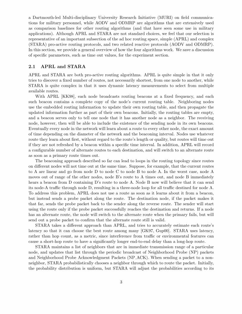
Figure 2: The hop counts (A) and message delivery ratios (B) for the indoor and indoor exper-iments. ODMRP delivers far more message outdoors, while AODV delivers far more messagesindoors.
large-scale, real-world experiment.
4.2 Comparison with Indoor Results
During the indoor experiment, we placed the laptops on two shelving units, ten feet apart fromeach other with twenty and twenty-one laptops per shelf respectively. We used the same hardwareand codebase except that (1) we configured the GPS service to read the position information fromthe outdoor mobility trace, rather than from the GPS unit; and (2) we derived a connectivity tracefrom the outdoor beacon logs, and configured each routing algorithm to ignore traffic from laptopsthat were actually unreachable during the outdoor experiment. We used three different (randomlygenerated) traffic patterns, and averaged the indoor routing results for three separate runs toensure that we were comparing the outdoor results with a meaningful view of indoor results. 10
The primary difference between the outdoor and indoor experiment then is that every indoor laptopcan hear every packet due to the physical proximity of the nodes, a situation in which the 802.11bprotocol theoretically can significantly reduce collisions through its standard CSMA/CA11 protocol.We would expect, therefore, that the routing algorithms will behave differently indoors even thoughwe use the outdoor connectivity information.
What was surprising in our case, however, was the magnitude of the change in the messagedelivery ratios when we moved indoors. Figure 2 shows the message delivery ratio and meanhop count for APRL, AODV and ODMRP; we omit STARA-S since the control-packet overloadled to the same minimal performance as in the outdoor experiment (and the outdoor overloadmade the derived connectivity trace suspect anyway). Although the hop counts are roughly thesame in the outdoor and indoor experiments, the message delivery ratios for AODV and ODMRPchange dramatically, with AODV suddenly doing much better than ODMRP. Even if the outdoortraffic pattern somehow represents an outlier in the traffic space, the switch in relative performanceremains significant. The largest standard deviation for any indoor message-delivery value was7.732% for ODMRP, and the outdoor results are more than three standard deviations away fromthe indoor average for all three algorithms.
The reason for this performance switch is clear in hindsight. ODMRP includes the data packetin the flooded route-discovery packets, leading to route discovery packets an order of magnitude
10Future software enhancements will allow us to replay the outdoor traffic pattern exactly.11Carrier Sense Multiple Access with Collision Avoidance
14

larger than those of AODV (for our payload sizes). In addition, every node must rebroadcast theroute-discovery packet, since ODMRP is a multicast protocol that allows nodes to dynamicallyjoin multicast groups. During the indoor test, every laptop is in range of every other laptop, andthe CSMA/CA protocol cannot overcome the higher collision rate caused by ODMRP’s flood oflarge route discovery packets. Outdoors, each packet in the flood can be heard by only a fractionof the laptops, significantly reducing the collision potential. At the same time, AODV generatesa much smaller number of much smaller packets, leading to relatively few collisions even indoors.Moreover, these packets will not suffer the environmental effects that can occur outdoors. In otherwords, in the absence of collisions, each packet has a much greater chance of successful receptionindoors than outdoors. These two factors, increased collisions for ODMRP and greater chance ofsuccessful reception for AODV, lead to the performance switch.
These indoor results are important for two reasons. First, they confirm again that indoorexperiments with real hardware will not necessarily lead to a correct view of algorithm performance,no matter the scale of the ad hoc network. In this case, indoor experiments would have led us toselect the wrong algorithm for outdoor use, leading to a 33% drop in outdoor performance. Second,the results also suggest that the benefits of embedding a data packet inside a flooded route-discoverypacket depend heavily on the number of nodes that can hear each packet within the flood. Evenwhen used entirely outdoors, it is worth considering routing algorithms that turn on or off embeddeddata packets depending on the “clustering” of the nodes.
4.3 Comparison with Simulation Results
Given the failure of indoor experiments to accurately represent outdoor results, we need to considersimulation. As described in an earlier paper [LYN+04], we configured a wireless network simulatorto mimic our outdoor experimental conditions. We then conducted a simulation experiment withthree different commonly used physical-layer models under a variety of traffic loads, considering ineach case whether the simulation provided results comparable to those observed outdoors.
Simulator. SWAN is a simulator for wireless ad hoc networks that provides an integrated, con-figurable, and flexible environment for evaluating ad hoc routing protocols, especially for large-scalenetwork scenarios. SWAN contains a detailed model of the IEEE 802.11 wireless LAN protocoland a stochastic radio channel model, both of which we used in this study. In addition, we usedSWAN’s direct-execution simulation techniques to execute the same routing code that was usedin the indoor and outdoor experiments. We modified the real routing code only slightly to allowmultiple instances of a routing protocol, the traffic generator, and the GPS service to run simulta-neously in the SWAN’s single address space. We also extended the simulator to read the positiontraces generated by the outdoor experiment. We included the seven failed nodes, and ran the GPSservice program so that we would generate just as much network traffic as in the outdoor andindoor experiments.
Experiments. We examined three radio propagation models: a free-space model, a two-rayground reflection model, and a generic propagation model. The simulator delivered each trans-mitted packet to all neighbor stations that could receive the packet with an average signal powerbeyond a minimum threshold, and we used the propagation models to calculate the signal powerand signal-to-noise ratio at the receiver. We combined the three models with the connectivity tracederived from the beacon logs, leading to six different radio propagation models in simulation: threethat used the connectivity traces and three that did not. In the first three cases, the model usedthe connectivity trace to determine whether a packet from one node could reach another node,and then used the radio propagation models to determine the receiving power for the interferencecalculation. Using a connectivity trace is not ideal, since we would instead prefer a model that
15
(A) 0%
10%
20%
30%
40%
50%
60%
70%
80%
90%
AODV APRL ODMRP STARA
Pac
ket D
eliv
ery
Rat
io
real experimentgeneric model with connectivity
free-space with connectivitytwo-ray with connectivity
generic model no connectivityfree-space no connectivity
two-ray no connectivity
(B) 0%
10%
20%
30%
40%
50%
60%
70%
80%
90%
0 1 2 3 4 5
Frac
tion
of T
otal
Dat
a P
acke
ts in
Tra
nsit
Hop Count
real experimentgeneric model with connectivity
free-space with connectivitytwo-ray with connectivity
generic model no connectivityfree-space no connectivity
two-ray no connectivity
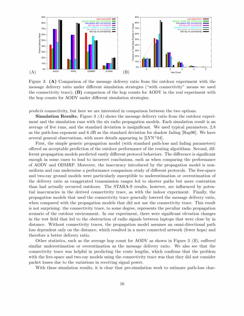
Figure 3: (A) Comparison of the message delivery ratio from the outdoor experiment with themessage delivery ratio under different simulation strategies (“with connectivity” means we usedthe connectivity trace); (B) comparison of the hop counts for AODV in the real experiment withthe hop counts for AODV under different simulation strategies.
predicts connectivity, but here we are interested in comparison between the two options.Simulation Results. Figure 3 (A) shows the message delivery ratio from the outdoor experi-
ment and the simulation runs with the six radio propagation models. Each simulation result is anaverage of five runs, and the standard deviation is insignificant. We used typical parameters, 2.8as the path-loss exponent and 6 dB as the standard deviation for shadow fading [Rap96]. We haveseveral general observations, with more details appearing in [LYN+04].
First, the simple generic propagation model (with standard path-loss and fading parameters)offered an acceptable prediction of the outdoor performance of the routing algorithms. Second, dif-ferent propagation models predicted vastly different protocol behaviors. The difference is significantenough in some cases to lead to incorrect conclusions, such as when comparing the performanceof AODV and ODMRP. Moreover, the inaccuracy introduced by the propagation model is non-uniform and can undermine a performance comparison study of different protocols. The free-spaceand two-ray ground models were particularly susceptible to underestimation or overestimation ofthe delivery ratio as exaggerated transmission ranges led to shorter paths but more contentionthan had actually occurred outdoors. The STARA-S results, however, are influenced by poten-tial inaccuracies in the derived connectivity trace, as with the indoor experiment. Finally, thepropagation models that used the connectivity trace generally lowered the message delivery ratio,when compared with the propagation models that did not use the connectivity trace. This resultis not surprising: the connectivity trace, to some degree, represents the peculiar radio propagationscenario of the outdoor environment. In our experiment, there were significant elevation changesin the test field that led to the obstruction of radio signals between laptops that were close by indistance. Without connectivity traces, the propagation model assumes an omni-directional pathloss dependent only on the distance, which resulted in a more connected network (fewer hops) andtherefore a better delivery ratio.
Other statistics, such as the average hop count for AODV as shown in Figure 3 (B), sufferedsimilar underestimation or overestimation as the message delivery ratio. We also see that theconnectivity trace was helpful in predicting the route lengths, which confirms that the problemwith the free-space and two-ray models using the connectivity trace was that they did not considerpacket losses due to the variations in receiving signal power.
With these simulation results, it is clear that pre-simulation work to estimate path-loss char-
16

acteristics or more complex channel models might be needed. On the other hand, if the objectiveis to compare protocols, knowledge that the generic propagation model is good lets us compareprotocols using a range of path-loss values. While this does not quantify behavior, it may allow usto make qualitative conclusions about the protocols over a range of environments.
5 Related Work
There have been a limited number of evaluations of ad hoc routing algorithms on top of realhardware. For example, De Couto et al evaluate the performance of a modified version of DSDVin a static, 29-node indoor testbed, discovering that a path-throughput metric for route selec-tion can improve total network throughput for many traffic scenarios [CABM03]; He et al use astatic, 70-node indoor sensor network to evaluate a distributed spanning-tree approach to routeformation [HKK+04]; and Fang et al do a preliminary evaluation of their DAM data-routing andaggregation protocol on top of a static, 25-node indoor testbed [FZG03]. Most relevantly, Lundgrenet al used their Ad Hoc Protocol Evaluation testbed (APE) to evaluate the performance of AODVand OLSR with up to 37 nodes moving along indoor hallways [LLN+02]. Other researchers havedone real-world tests of other services in ad hoc networks, including navigation, localization andtracking services [LRR03, SHS01, WSBC04]; lightweight security mechanisms [PSW+01], MACprotocols [WC01], Our work complements these and similar efforts in that we compare four ad hocrouting algorithms under outdoor conditions with a significant number of moving nodes. To ourknowledge, our work represents the largest outdoor and mobile routing experiment for which resultsare publicly available.
Several researchers have developed general software infrastructures that can be used to im-plement (and evaluate) ad hoc routing or other protocols. For example, DIRAC provides a sup-port framework for services, such as link-layer assisted fast handover, channel-adaptive scheduling,and link-layer enforced policing, in base-station networks, and may be extensible to ad hoc net-works [ZZC+03]; the SPINS framework can be used to construct security-aware routing and otherprotocols in resource-constrained ad hoc networks [PSW+01]; Kawadia et al have developed anAd hoc Support Library (ASL) that provides the low-level routing services needed in many ad-hocrouting protocols [KZG03]; Zhang and Li have developed an emulation-based testbed for evaluatingad-hoc routing implementations indoors [ZL02]; Lundgren et al have developed the APE testbedmentioned above [LLN+02, TLN03]; Kohler et al have developed the Click modular router forrapidly composing elements to create arbitrary routing functionality [KMC+00]; and Neufeld et alhave developed the nsclick extension that allows the direct execution of Click modules inside nssimulations [NJG02]. DIRAC and SPINS have a different focus than ad hoc routing, but sharedrouting infrastructure that we used for our experiments can be viewed as a user-space version ofthe ASL, and has similar goals as the Click modular router and the nsclick extension (although ismore specific to ad hoc routing). In addition, our experimental infrastructure operates in much thesame way as the Zhang and Li testbed and the APE testbed, including the use of a tunnel deviceor modified driver to allow user-level routing.
Many researchers are working on improved simulation techniques that have the potential toprovide a closer (or simpler) match between outdoor, indoor and simulated performance. Forexample, there has been work on interference modeling [JPPQ03], mobility modeling [HGPC99,SK99], and channel modeling [ZHKS04, KR03, KZJL01]. In addition, Takai et al explored the effectsof different physical-channel models on simulation results, observing similar changes in relativealgorithm ranking as when we re-ran our experiment indoors [TMB01]. All of this work will helpto make future simulations accurate enough to predict outdoor behavior under much wider ranges
17

of conditions.Finally, most researchers use simulation to evaluate new ad hoc routing algorithms or other
protocols. We hope that our work can help to provide guidance on whether these simulation resultsaccurately predict outdoor performance, and that our data corpus can be used to fine-tune thesimulations for further evaluation. One simulation study of note is Broch’s comparison of DSDV,TORA, DSR and AODV [BMJ+98]. Our own study parallels this study in many ways.
6 Conclusion
Generally, reactive algorithms were preferred for our (relatively) large number of nodes and ourmodest traffic load, with ODMRP outperforming AODV due its inclusion of the original messagein the flooded route-discovery packets. Interestingly, however, ODMRP’s performance droppedprecipitously (and AODV’s improved by a similar amount) when the nodes were indoors and couldall hear each other, in both cases due to the different levels of contention and packet loss. Indoorexperiments on real hardware clearly cannot predict the outdoor performance of common routingalgorithms. On the other hand, the indoor performance does suggest that contention may playa larger role outdoors than might be expected, with results changing dramatically depending onthe “clustering” of the network. Finally, the simulation results indicate that simulation, with anappropriate choice of models, can accurately predict outdoor performance. A non-experimentalmethodology for selecting the simulation parameters, however, remains unclear.
The most immediate area of future work must be the development of a community-wide corpusof outdoor ad hoc routing results, conducted under some standardized set of conditions to allowmeaningful comparison of results taken at different times and by different organizations. Unfor-tunately, such an effort is beyond the capabilities of any single organization (with the possibleexception of the government). Whether the corpus is small or big, another critical area of futurework is to improve and develop procedures by which a simulation can be calibrated to match ob-served outdoor behavior. A large part of any such effort must be to reach a point where we canargue model completeness, so that we assure ourselves of simulation accuracy without running evenmore outdoor experiments as confirmation. Finally, and somewhat tangentially, some of the re-sults in our outdoor experiment confirm that hybrid routing algorithms or routing algorithms thatdynamically adjust their routing strategy according to the current network environment remain avery promising area of work.
Acknowledgments
Many thanks to Lisa Shay and Eileen Entin for assistance with the military scenarios that ledto our routing experiments; to Brad Karp and Piyush Gupta for developing APRL and STARArespectively and generously making their code available to us; to Michael DeRosa for softwaredevelopment; and to the army of Dartmouth faculty, staff members, and students who gave up anafternoon to carry laptops around an athletic field.
References
[BMJ+98] J. Broch, D. A. Maltz, D. B. Johnson, Y.-C. Hu, and J. Jetcheva. A performancecomparison of multi-hop wireless ad hoc network routing protocols. In Proc. of the 4thAnnual Conference on Mobile Computing and Networking (MOBICOM 1998), pages85–97, Dallas, Texas, October 1998.
18

[CABM03] D. S. J. De Couto, D. Aguayo, J. Bicket, and R. Morris. A high-throughput pathmetric for multi-hop wireless routing. In Proc. of the 9th Annual Conference on MobileComputing and Networking (MOBICOM 2003), pages 134–146, San Diego, California,September 2003.
[FZG03] Q. Fang, F. Zhao, and L. Guibas. Lightweight sensing and communication protocolsfor target enumeration and aggregation. In Proc. of the 4th Int’l Symposium on Ad HocNetworking and Computing (MOBIHOC 2003), pages 165–176, Annapolis, Maryland,June 2003.
[GK97] P. Gupta and P. R. Kumar. A system and traffic dependent adaptive routing algorithmfor ad hoc networks. In Proc. of the 36th IEEE Conference on Decision and Control,pages 2375–2380, December 1997.
[Gra00] R. S. Gray. Soldiers, agents and wireless networks: a report on a military application.In Proc. of the 5th Int’l Conference and Exhibition on the Practical Application ofIntelligent Agents and Multi-Agents, April 2000.
[Gup00] P. Gupta. Design and Performance Analysis of Wireless Networks. PhD thesis, Uni-versity of Illinois at Urbana-Champaign, August 2000.
[HGPC99] X. Hong, M. Gerla, G. Pei, and C.-C. Chiang. A group mobility model for ad hoc wire-less networks. In Proc. of the 2nd Int’l Workshop on Modeling Analysis and Simulationof Wireless and Mobile Systems (MSWIM 1999), pages 53–60, Seattle, Washington,August 1999.
[HKK+04] T. He, B. Krogh, S. Krishnamurthy, J. A. Stankovic, T. Abdelzaher, L. Luo, R. Stoleru,T. Yan, L. Gu, and J. Hui. Energy-efficient surveillance system using wireless sensornetworks. In Proc. of the 2nd Int’l Conference on Mobile Systems, Applications, andServices (MOBISYS 2004), pages 270–283, Boston, Massachusetts, June 2004.
[JPPQ03] K. Jain, J. Padhye, V. N. Padmanabhan, and L. Qiu. Impact of interference on multi-hop wireless network performance. In Proc. of the 9th Annual Conference on MobileComputing and Networking (MOBICOM 2003), pages 66–80, San Diego, California,September 2003.
[KK98] B. Karp and H. T. Kung. Dynamic neighbor discovery and loopfree, multi-hop routingfor wireless, mobile networks. Harvard University, May 1998.
[KMC+00] E. Kohler, R. Morris, B. Chen, J. Jannotti, and M. F. Kaashoek. The Click modularrouter. ACM Transactions on Computer Systems, 18(3):263–297, August 2000.
[KR03] S. A. Khayam and H. Radha. Markov-based modeling of wireless local area networks.In Proc. of the 6th Int’l Workshop on Modeling Analysis and Simulation of Wirelessand Mobile Systems (MSWIM 2003), pages 100–107, San Diego, California, September2003.
[KZG03] V. Kawadia, Y. Zhang, and B. Gupta. System services for ad-hoc routing: Architec-ture, implementation and experiences. In Proc. of the First Int’l Conference on MobileSystems, Applications, and Services (MOBISYS 2003), San Francisco, California, May2003.
19
[KZJL01] A. Konrad, B. Y. Zhao, A. D. Joseph, and R. Ludwig. A Markov-based channel modelalgorithm for wireless networks. In Proc. of the 4th Int’l Workshop on Modeling Analysisand Simulation of Wireless and Mobile Systems (MSWIM 2001), pages 28–36, Rome,Italy, July 2001.
[LLN+02] H. Lundgren, D. Lundberg, J. Nielsen, E. Nordstrom, and C. Tschudin. A large-scaletestbed for reproducible ad hoc protocol evaluations, March 2002.
[LRR03] Q. Li, M. De Rosa, and D. Rus. Distributed algorithms for guiding navigation acrossa sensor network. In Proc. of the 9th Annual Conference on Mobile Computing andNetworking (MOBICOM 2003), pages 313–325, San Diego, California, September 2003.
[LSG02] S.-J. Lee, W. Su, and M. Gerla. On-demand multicast routing protocol in multihopwireless mobile networks. ACM/Kluwer MONET, 7(6):441–453, December 2002.
[LYN+04] J. Liu, Y. Yuan, D. M. Nicol, R. S. Gray, C. C. Newport, D. Kotz, and L. F. Per-rone. Simulation validation using direct execution of wireless ad-hoc routing protocols.In Proc. of the 18th Workshop on Parallel and Distributed Simulation (PADS 2004),Kufstein, Austria, May 2004.
[NJG02] M. Neufeld, A. Jain, and D. Grunwald. Nsclick: Bridging network simulation anddeployment. In Proc. of the 5th Int’l Workshop on Modeling Analysis and Simula-tion of Wireless and Mobile Systems (MSWIM 2002), pages 74–81, Atlanta, Georgia,September 2002.
[PR99] C. E. Perkins and E. M. Royer. Ad hoc on-demand distance vector routing. In WMCSA,pages 90–100, February 1999.
[PSW+01] A. Perrig, R. Szewczyk, V. Wen, D. Culler, and J. D. Tygar. SPINS: Security suitefor sensor networks. In Proc. of the 7th Annual Conference on Mobile Computing andNetworking (MOBICOM 2001), pages 189–199, Rome, Italy, July 2001.
[Rap96] T. S. Rappaport. Wireless Communications, Principles and Practice. Prentice Hall,1996.
[SHS01] A. Savvides, C.-C. Han, and M. Srivastava. Dynamic fine-grained localization in ad-hocnetworks of sensors. In Proc. of the 7th Annual Conference on Mobile Computing andNetworking (MOBICOM 2001), pages 166–179, Rome, Italy, July 2001.
[SK99] J. Scourias and T. Kunz. An activity-based mobility model and location manage-ment simulation framework. In Proc. of the 2nd Int’l Workshop on Modeling Analysisand Simulation of Wireless and Mobile Systems (MSWIM 1999), pages 61–68, Seattle,Washington, August 1999.
[TLN03] C. Tschudin, H. Lundgren, and E. Nordstrom. Embedding MANETs in the real world.In Proc. of the 8th Int’l Conference on Personal Wireless Communications (PWC 2003),Venice, Italy, September 2003.
[TMB01] M. Takai, J. Martin, and R. Bagrodia. Effects of wireless physical layer modelingin mobile ad hoc networks. In Proc. of the 2nd Int’l Symposium on Mobile Ad HocNetworking and Computing, pages 87–94, Long Beach, California, October 2001.
20

[WC01] A. Woo and D. Culler. A rate-adaptive MAC protocol for multi-hop wireless. In Proc. ofthe 7th Annual Conference on Mobile Computing and Networking (MOBICOM 2001),pages 221–235, Rome, Italy, July 2001.
[WMB03] S. Wendelken, S. McGrath, and G. Blike. A medical assessment algorithm for auto-mated remote triage. In Proc. of the 25th Annual Engineering in Medicine and BiologyConference, Cancun, Mexico, September 2003.
[WSBC04] K. Whitehouse, C. Sharp, E. Brewer, and D. Culler. HOOD: A neighborhood ab-straction for sensor networks. In Proc. of the 2nd Int’l Conference on Mobile Systems,Applications, and Services, pages 99–110, Boston, Massachusetts, June 2004.
[ZHKS04] G. Zhou, T. He, S. Krishnamurthy, and J. A. Stankovic. Impact of radio irregularityon wireless sensor networks. In Proc. of the 2nd Int’l Conference on Mobile Systems,Applications, and Services (MOBISYS 2004), pages 125–138, Boston, Massachusetts,June 2004.
[ZL02] Y. Zhang and W. Li. An integrated environment for testing mobile ad-hoc networks.In Proc. of the Third Int’l Symposium on Mobile Ad Hoc Networking and Computing(MOBIHOC 2002), pages 104–111, Lausanne, Switzerland, June 2002.
[ZZC+03] P. Zerfos, G. Zhong, J. Cheng, H. Luo, S. Lu, and J. J.-R. Li. DIRAC: A software-basedwireless router system. In Proc. of the 9th Annual Conference on Mobile Computingand Networking (MOBICOM 2003), pages 230–244, San Diego, California, September2003.
21