Virtual Backbone Based Content Routing in Wireless Ad-Hoc Network
18
International Journal of Wireless & Mobile Networks (IJWMN), Vol 1, No 2, November 2009 30 VIRTUAL BACKBONE CONTENT ROUTING IN WIRELESS AD-HOC NETWORK Longxiang Gao and Ming Li School of Information Technology Deakin University, Australia {longxiang.gao, ming.li}@deakin.edu.au ABSTRACT We developed a new content routing based on the virtual backbone structure, which groups wireless nodes and contents into a virtual architecture. Our approach is scalable, works with local information, and does not rely on address information. The naming system uses flat naming to identify nodes and contents, and organizes these identifiers together. Backbone nodes can be selected automatically or pre- defined to direct their associated normal nodes in a local area. The normal nodes are guided by the backbone nodes to full fill the searching and routing processes. With a virtual structure, the searching performance can be improved by using the DHT technique. Experiments using ns2 simulator demonstrate that this virtual backbone routing architecture has the following significances: workable without being aware address in a mobile situation; scalable with the size of network; efficient in terms of the reduced hop counts and short end-to-end delay, and also resistant to the dead-end problem. Keywords Virtual backbone structure, wireless networks, distributed hash table, routing, flat naming 1. INTRODUCTION The wireless network is promising because it is easy to deploy without requiring centralized management. The content delivery in wireless networks is attractive because the wireless and sensor networks are being integrated into the Internet [1]. More and more traffic today in Internet is the peer-to-peer applications [2] which are content based. It is expected to have a high demand for content delivery in wireless network in near future. To meet this growing trend, the content routing solution has been proposed by using the name-based routing [3]. The proposed network consists of Content Routers (CR) to provide support in the Internet to distribute, maintain and make use of the content delivery; the Name-Based Routing Protocol (NBRP) to distribute the names and set the routing tables to provide routing in a structure similar to BGP; and the Internet Resolution Protocol (INRP) to perform efficient lookup on the distributed integrated name-based routing system. This approach The naming system is designed to identify a node or content into certain sized digital value. We use the mathematics module to shrink those binary values with different size into certain size unique values, name identifiers, which are used for the searching and routing. The searching system is designed to find the corresponding destination node or content correctly and quickly. This function is especially important for peer-to-peer application, where most of traffics are content based and distributed among different nodes. The primary routing schemes currently used in wireless networks are the address routing [4]. These schemes use the geographic address to identify and locate mobile nodes. To support
-
Upload
independent -
Category
Documents
-
view
1 -
download
0
Transcript of Virtual Backbone Based Content Routing in Wireless Ad-Hoc Network
International Journal of Wireless & Mobile Networks (IJWMN), Vol 1, No 2, November 2009
30
VIRTUAL BACKBONE CONTENT ROUTING IN
WIRELESS AD-HOC NETWORK
Longxiang Gao and Ming Li
School of Information Technology Deakin University, Australia
{longxiang.gao, ming.li}@deakin.edu.au
ABSTRACT
We developed a new content routing based on the virtual backbone structure, which groups wireless
nodes and contents into a virtual architecture. Our approach is scalable, works with local information,
and does not rely on address information. The naming system uses flat naming to identify nodes and
contents, and organizes these identifiers together. Backbone nodes can be selected automatically or pre-
defined to direct their associated normal nodes in a local area. The normal nodes are guided by the
backbone nodes to full fill the searching and routing processes. With a virtual structure, the searching
performance can be improved by using the DHT technique.
Experiments using ns2 simulator demonstrate that this virtual backbone routing architecture has the
following significances: workable without being aware address in a mobile situation; scalable with the
size of network; efficient in terms of the reduced hop counts and short end-to-end delay, and also
resistant to the dead-end problem.
Keywords
Virtual backbone structure, wireless networks, distributed hash table, routing, flat naming
1. INTRODUCTION
The wireless network is promising because it is easy to deploy without requiring centralized
management. The content delivery in wireless networks is attractive because the wireless and
sensor networks are being integrated into the Internet [1]. More and more traffic today in
Internet is the peer-to-peer applications [2] which are content based. It is expected to have a
high demand for content delivery in wireless network in near future. To meet this growing
trend, the content routing solution has been proposed by using the name-based routing [3]. The
proposed network consists of Content Routers (CR) to provide support in the Internet to
distribute, maintain and make use of the content delivery; the Name-Based Routing Protocol
(NBRP) to distribute the names and set the routing tables to provide routing in a structure
similar to BGP; and the Internet Resolution Protocol (INRP) to perform efficient lookup on the
distributed integrated name-based routing system. This approach
The naming system is designed to identify a node or content into certain sized digital value. We
use the mathematics module to shrink those binary values with different size into certain size
unique values, name identifiers, which are used for the searching and routing.
The searching system is designed to find the corresponding destination node or content correctly
and quickly. This function is especially important for peer-to-peer application, where most of
traffics are content based and distributed among different nodes.
The primary routing schemes currently used in wireless networks are the address routing [4].
These schemes use the geographic address to identify and locate mobile nodes. To support
International Journal of Wireless & Mobile Networks (IJWMN), Vol 1, No 2, November 2009
31
searching and routing packets, the address routing schemes in wireless network need to deploy
servers or beacons [5][6] to allocate addresses. But, when we consider the mobility character of
wireless network, the address cannot be treated as a unique identification for mobile nodes. And
also, the address routing needs a certain identifier to route the packet, such as URL. Thus, the
address routing is not suitable for the next generation wireless network. Although, it is possible
to build a large address network [7] today, such as Internet with Domain Name Service (DNS)
[8] server. It is difficult to implement an address wireless network with mobility, energy-
awareness, and self-learning. In order to overcome these drawbacks, we propose a novel name
identifier and content routing structure, virtual backbone routing. This routing scheme uses
embedded [9] name identifier to route packets without being aware addresses.
In wireless networks, nodes may be mobile and organize themselves into arbitrary
configurations. Due to their dynamic nature and resource limitation, routing in wireless
networks should be scalable, distributed, localized, and would be ideal if no global servers
involved. The tree-based routing structures [11] require re-structuring the global tree structure
when a node join or leave the network which happens very often in wireless networks. The
address-based routing [5] requires every node knows its own position for making forwarding
decision which is not suitable for the content routing because it requires significant overhead to
maintain the mapping between the content and its address, especially becomes hard when the
node moves around frequently. To improve the routing efficiency, we propose a virtual
backbone routing scheme to route packets. The structure can be used to easily manage the
network topology when a node joins in or leaves the network. The routing can also takes the
advantages of the virtual structure built based on these backbones.
We analyze the virtual backbone content routing scheme, show that it is correct and efficient,
and present simulation results to support our analysis by using ns2 [12] simulator.
By analyzing these characters, we believe the content routing should be based on name
identifiers rather than addresses. Also using the virtual structure to organize those backbones
together can improve the routing efficiently. It should also be scalable in the following senses:
1) The global routing information should be avoided or restricted due to the limited
memory of wireless nodes.
2) The flooding or broadcast messages should be avoided or limited in the searching
process.
3) The routing process should be smart to take shorter path without going through every
node along the route.
4) The dead-end problem should be mitigated to a certain extent.
The rest of the paper describes the design and simulated performance of this virtual backbone
routing scheme. Section 2 reviews existing routing schemes in wireless network. Section 3
describes the structure and algorithms of virtual routing scheme in details. Section 4 studies the
simulation results. Section 5 suggests areas for future research. Section 6 summarizes the
paper's contributions
2. RELATED WORK
There has been a large amount of work on routing protocols for wireless network. Based on
their principles and performances, we can classify them into three generations. Each generation
has its own characters and contributions.
International Journal of Wireless & Mobile Networks (IJWMN), Vol 1, No 2, November 2009
32
The first generation of routing schemes for wireless network primarily focuses on data
collection. It mainly includes reactive and proactive protocols [13][14]. The proactive protocols,
such as Destination Sequenced Distance Vector (DSDV) [14][15] and Optimized Link State
Routing protocol (OLSR) [16], need to maintain consistent up-to-date routing information from
each node to every other nodes. Reactive protocols, such as Dynamic Source Routing (DSR)
[17][18] and Ad-hoc On-demand Distance Vector Routing (AODV) [19][20], construct routes
to destinations only when they need. The need is initiated by the source, as the name suggests.
When a node requires a route to a destination, it floods a route request message within the
network. If a node receives a route request, it responds with a route reply. Unfortunately, this
process may lead to significant flooding the network in order to discover the desired route. The
first generation wireless network engrosses vast of bandwidth and energy due to the flooding
traffic involved. Also it is difficult to be implemented in a large scale network.
The second generation of routing protocol for wireless network is the coordinator-based routing
protocol which uses coordinator-based identifier [11][6][5] to locate nodes and perform the
searching and routing process. Beacon Vector Routing protocol (BVR) [6] and Greedy
Perimeter Stateless Routing (GPSR) [5] belong to this category. These schemes need the global
or local coordinators to direct the routing process. The coordinator-based routing protocols are
efficient and smart, since they utilize the geographic information to get the accurate address of
the destination and use this information to forward packets. However, in order to implement the
coordinator-based searching and routing functions, we need to set up the fixed infrastructures
for the servers [5] or beacons [6] and maintain them as well. That could be very expensive or
impossible in some cases to equip every node with the global server (e.g., Global Positioning
System) [5]. Further, these local or global infrastructures need to be updated regularly.
During this time, a new peer-to-peer mapping and searching protocol, Distributed Hash Table
(DHT) [21][22][23][24], has been developed. DHT is a building block for peer-to-peer
applications. At the basic level, it allows a group of distributed hosts to collectively manage a
mapping from keys to data values, without and fixed hierarchy, and with very little human
assistance. This building block can then be used to ease the implementation of a diverse variety
of peer-to-peer [25][26] applications such as file sharing services [27][28], DNS replacements
[29][30] and web caches [31][32]. Although, DHT originally was created and used in wired
network, ideas and mechanisms can be applied and implemented in a wireless network.
With the DHT, the third generation of wireless network with name routing becomes true. Each
node can use a name as a unique identifier (i.e., MAC address) and distribute it among in a
wireless network without pre-defined address information. By using this way, name routing
avoids drawbacks of address routing and can be deployed in a large network where each node
can identify its name by through self-learning process. Virtual Ring Routing (VRR) [33] is an
originator for the name routing. The VRR uses the node's natural identifier and DHT to map
nodes into a ring. Based on this ring, VRR performs continuous hash searching and single route
routing. This routing protocol can achieve name routing and avoid drawbacks in the address
routing. However, the routing performance of VRR is in doubt. It uses clockwise or anti-
clockwise to forward Node Hashed Identifier packets, sometimes this single route may be the
worst route. And also, the VRR has a high risk to encounter the dead-end problem [34], since
the DHT ring is created by continuous hash function and with the order of nodes' hash value.
Recently, we developed the virtual backbone routing scheme which belongs to the name routing
category, but it improves the routing performance which VRR has suffered from the single level
routing. With the associated backbone nodes, normal nodes in this structure can maintain their
natural connection relationship and find other nodes' relationships, which can efficiently
mitigate the dead-end problem. With the virtual backbone structure, packets do not need to go
International Journal of Wireless & Mobile Networks (IJWMN), Vol 1, No 2, November 2009
33
through every node along the route to the destination. Instead, lots of packets can be forward
direct to their destination with the backbone node's director.
The content routing is a natural extension from the name routing. By our knowledge, there is no
other work that integrates the name routing and the content delivery in wireless networks so far.
However, a name-based content routing protocol in the Internet was outlined by Gritter and
Cheriton [3]. They propose a new type of routing Content Routing (CR) that aims to reduce the
time needed to access content in the Internet. The main idea is to have a network based scheme
for content discovery through content routers. Our work shares a similar spirit with it but differ
in how to construct the naming data structure and how to route messages due to the unique
characters of wireless networks. Our work, virtual backbone content routing, organize all of
backbone nodes into a virtual structure and perform the content searching and routing.
3. BACKBONE SELECTION
There are some challenges to implement the content routing in wireless networks: addresses
cannot be used to identify mobile nodes because network topologies are not static; some
wireless node has limited resources in terms of memory and power which are sensitive to the
size of the routing table; and the routing should be efficient in terms of hops and power.
The virtual backbone routing scheme aims at fixing these problems. First, it gets rid of address
altogether. That is, we propose to route directly on the name identifiers of the wireless node.
Secondly, with backbone nodes, rest of normal nodes can be associated. Thirdly, normal nodes
can use the backup route provided by their associated backbone node to route packets and avoid
the dead-end problem in some certain extent. Finally, we can organize those backbone nodes
into a virtual structure, such as Cord [35] and Ring [33], and use the Distributed Hash Table
(DHT) [21][23] techniques, to perform the exponential searching process.
In order to implement and take advantages of the virtual backbone routing scheme, we
developed the following components:
• Backbone Selection
• Naming
• Routing
We explain each component in the following four sub-sections.
3.1. Backbone Selection
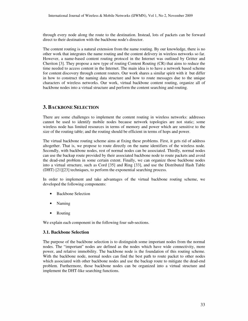
The purpose of the backbone selection is to distinguish some important nodes from the normal
nodes. The “important'' nodes are defined as the nodes which have wide connectivity, more
power, and relative immobility. The backbone node is the foundation of this routing scheme.
With the backbone node, normal nodes can find the best path to route packet to other nodes
which associated with other backbone nodes and use the backup route to mitigate the dead-end
problem. Furthermore, those backbone nodes can be organized into a virtual structure and
implement the DHT-like searching functions.
International Journal of Wireless & Mobile Networks (IJWMN), Vol 1, No 2, November 2009
34
In order to select backbone nodes, we mainly have two different ways. One is manual pre-define
the backbone node, the other one is use the backbone selection algorithm. In some topology, the
network administer can pre-define which node should be treated as the backbone node
according different scenarios. For example, in a business organization, they can choose and
deploy wireless nodes into different location to cover all signal range and as backbone nodes,
which similar to the router.
The backbone selection algorithm is a self-running algorithm, which does not need to set up any
infrastructure. Instead, each node runs this algorithm and gets its backbone selection metric
value by itself. Only those nodes whose backbone selection metric values are bigger than the
threshold can be selected as the backbone node. The backbone selection metric should include
the following items:
• Connectivity
• Power
• Immobility
The connectivity metric is a measure of the relationship among neighbours. Let Na denote the
neighbours of node a, including the node itself. Depend on different requirements, we can set up
different base B. If Na is bigger than the B, then the connectivity metric is set up as 1.
Otherwise, the connectivity metric is set up as the value of Na/B, which should be bigger than 0
and smaller than 1.
The power status is a measure of power capability that can support a node to function properly.
It is measured dynamically with a value between 0 and 1, with 0.1 being a minimally
maintained power threshold and 1 being 100 percent power capability. The power is expressed
as a fraction of 1; the higher the value, the more powerful the node has.
The immobility metric reflects the moving speed of a node and is expressed as a fraction of 100.
In this case, a lower immobility value is more desirable because it indicates more stable of the
node. So, 1/100 would be a minimally immobile measure, and 100/100 is a node that is 100
percent unstable.
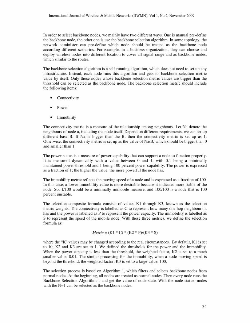
The selection composite formula consists of values K1 through K3, known as the selection
metric weights. The connectivity is labelled as C to represent how many one hop neighbours it
has and the power is labelled as P to represent the power capacity. The immobility is labelled as
S to represent the speed of the mobile node. With these three metrics, we define the selection
formula as:
Metric = (K1 * C) * (K2 * P)/(K3 * S)
where the “K'' values may be changed according to the real circumstances. By default, K1 is set
to 10, K2 and K3 are set to 1. We defined the thresholds for the power and the immobility.
When the power capacity is less than the threshold, the weighted factor, K2 is set to a much
smaller value, 0.01. The similar processing for the immobility, when a node moving speed is
beyond the threshold, the weighted factor, K3 is set to a large value, 100.
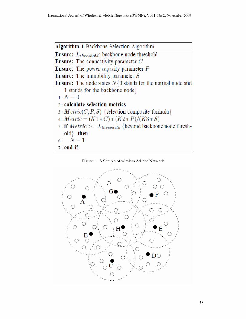
The selection process is based on Algorithm 1, which filters and selects backbone nodes from
normal nodes. At the beginning, all nodes are treated as normal nodes. Then every node runs the
Backbone Selection Algorithm 1 and get the value of node state. With the node statue, nodes
with the N=1 can be selected as the backbone nodes.
International Journal of Wireless & Mobile Networks (IJWMN), Vol 1, No 2, November 2009
35
Figure 1. A Sample of wireless Ad-hoc Network
International Journal of Wireless & Mobile Networks (IJWMN), Vol 1, No 2, November 2009
36
After the backbone selection process, backbone nodes send a 1 hop broadcast messages to
inform those normal nodes who received this message that they can send an associate message
to this backbone node. Normal nodes send the Associate Message to the first Hello Message
received backbone node and ignore other Associate Messages. Backbone nodes have a set to
store those associated normal nodes who reply the Associate Message to the backbone node.
As shown in Figure 1, after the automatic backbone selection process, node A, B, C, D, E, F, G
and H are selected as backbone nodes. The signal range of these backbone nodes covers all of
nodes in this wireless topology.
3.2. Naming
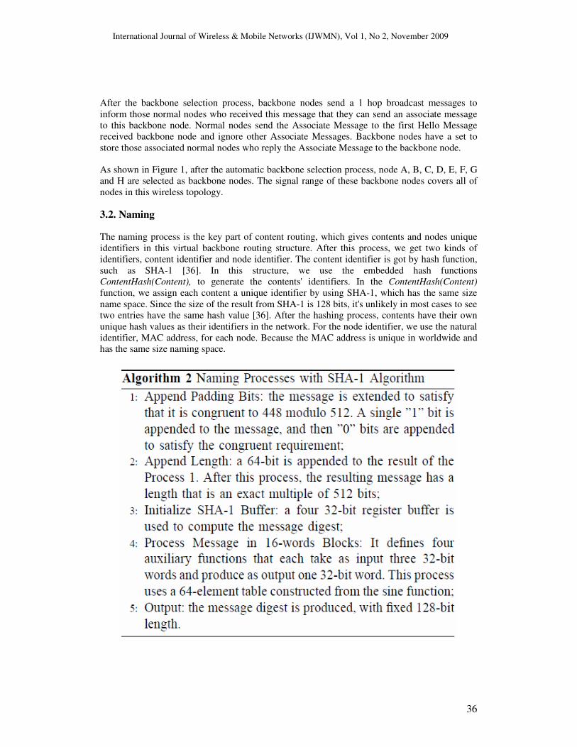
The naming process is the key part of content routing, which gives contents and nodes unique
identifiers in this virtual backbone routing structure. After this process, we get two kinds of
identifiers, content identifier and node identifier. The content identifier is got by hash function,
such as SHA-1 [36]. In this structure, we use the embedded hash functions
ContentHash(Content), to generate the contents' identifiers. In the ContentHash(Content)
function, we assign each content a unique identifier by using SHA-1, which has the same size
name space. Since the size of the result from SHA-1 is 128 bits, it's unlikely in most cases to see
two entries have the same hash value [36]. After the hashing process, contents have their own
unique hash values as their identifiers in the network. For the node identifier, we use the natural
identifier, MAC address, for each node. Because the MAC address is unique in worldwide and
has the same size naming space.
International Journal of Wireless & Mobile Networks (IJWMN), Vol 1, No 2, November 2009
37
For example, assume there are three pictures, Pa, Pb and Pc, are stored at node A. Each picture
has different size and the Pa, Pb and Pc are stored as the digital binary format. During the
naming process, node A uses ContentHash() function to hash these pictures and gets three 128
bit different hash values, ContentHash(Pa), ContentHash(Pb), and ContentHash(Pc).
3.3. Routing
The routing process takes the advantage of virtual backbone structure. The virtual backbone
structure maps all backbone nodes into a virtual structure. One classical architecture is the
virtual ring routing [33]. Our structure borrows some technique methods from VRR and extend
with our own idea. In our routing scheme, we only put backbone nodes into the virtual structure
instead of put all of nodes into it, which is different from the virtual ring routing and the virtual
cord protocol. One advantage of this routing scheme is that normal nodes can directly route
packets to those nodes that have the same associated backbone node with at most two hops.
Another advantage is that it can mitigate the dead-end problem. When the normal node route
packets, the associated backbone can choose the best path and keep other paths as the backup. If
the backbone node is moved, a new backbone node is selected to take its responsibility. In most
of cases, using those back up paths can improve the reliability of the network structure.
In order to set up a routing table, normal nodes send their name identifier and content identifiers
to their associated backbone node and are stored in the Content Identifier Storage Table. During
this process another two tables are built up for each backbone node, the DHT look-up table and
the local index table. The DHT look-up table is used to find the location of target content's
visual associated backbone node. The local index table is created to map the certain number of
contents to their real backbone nodes. We use the following example to explain our basic ideas.
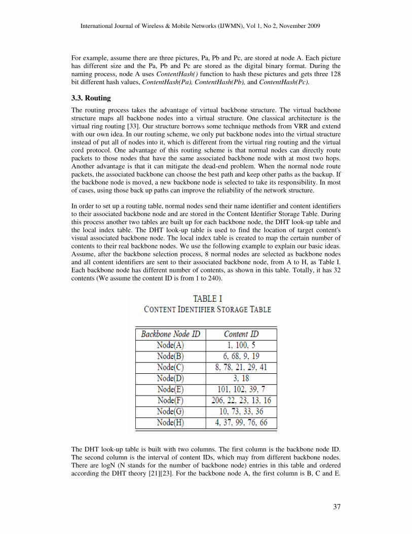
Assume, after the backbone selection process, 8 normal nodes are selected as backbone nodes
and all content identifiers are sent to their associated backbone node, from A to H, as Table I.
Each backbone node has different number of contents, as shown in this table. Totally, it has 32
contents (We assume the content ID is from 1 to 240).
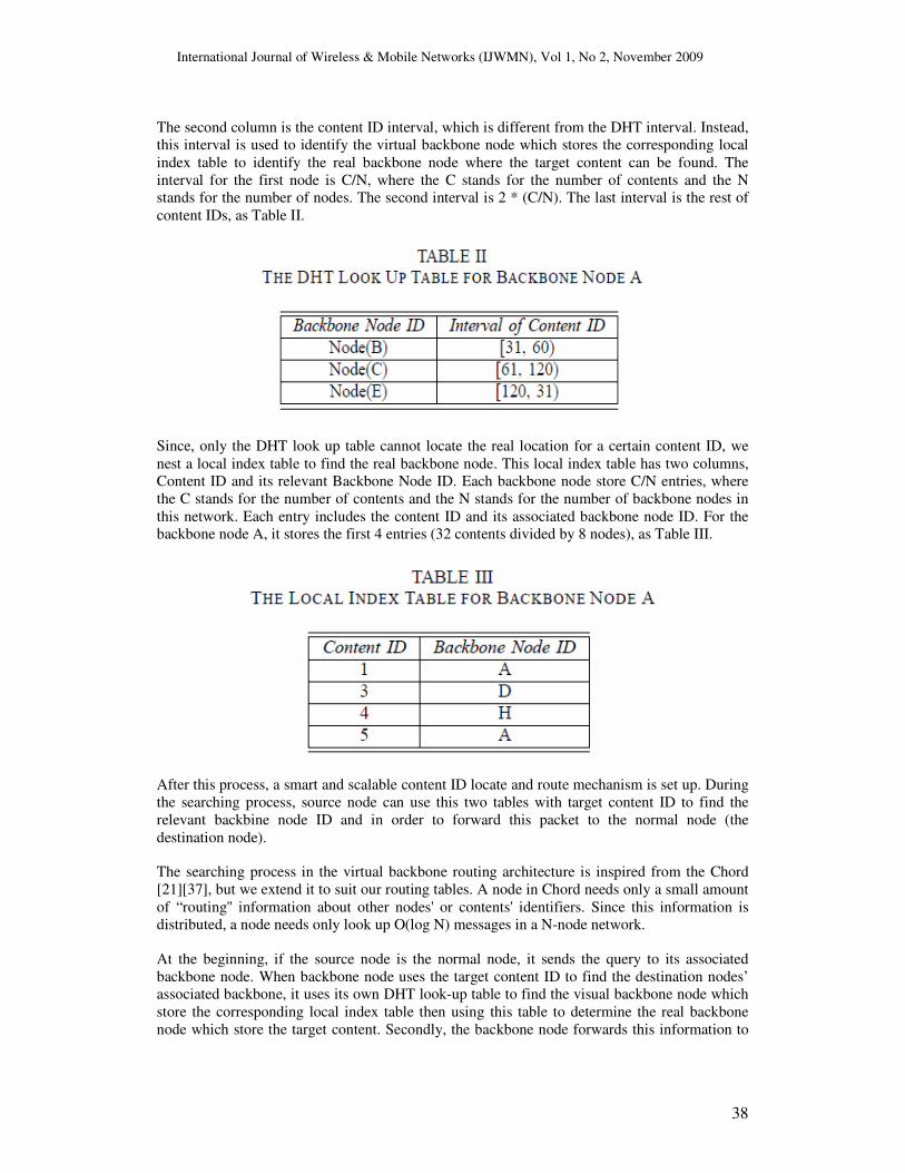
The DHT look-up table is built with two columns. The first column is the backbone node ID.
The second column is the interval of content IDs, which may from different backbone nodes.
There are logN (N stands for the number of backbone node) entries in this table and ordered
according the DHT theory [21][23]. For the backbone node A, the first column is B, C and E.
International Journal of Wireless & Mobile Networks (IJWMN), Vol 1, No 2, November 2009
38
The second column is the content ID interval, which is different from the DHT interval. Instead,
this interval is used to identify the virtual backbone node which stores the corresponding local
index table to identify the real backbone node where the target content can be found. The
interval for the first node is C/N, where the C stands for the number of contents and the N
stands for the number of nodes. The second interval is 2 * (C/N). The last interval is the rest of
content IDs, as Table II.
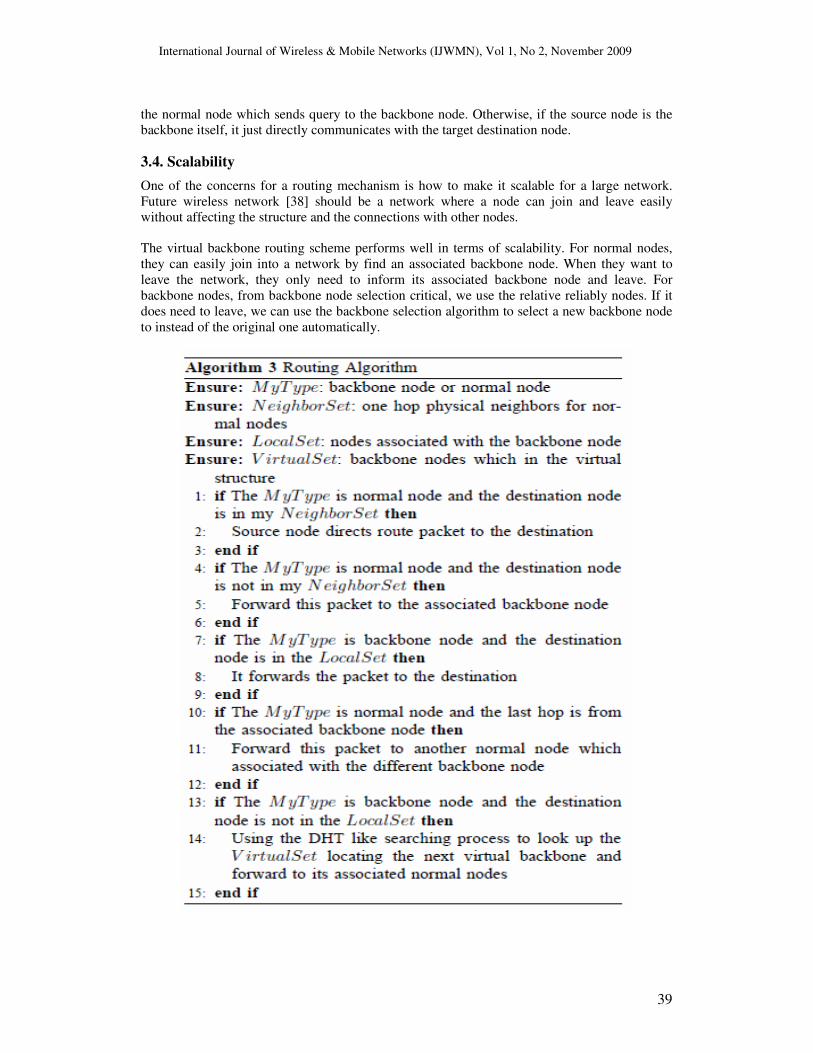
Since, only the DHT look up table cannot locate the real location for a certain content ID, we
nest a local index table to find the real backbone node. This local index table has two columns,
Content ID and its relevant Backbone Node ID. Each backbone node store C/N entries, where
the C stands for the number of contents and the N stands for the number of backbone nodes in
this network. Each entry includes the content ID and its associated backbone node ID. For the
backbone node A, it stores the first 4 entries (32 contents divided by 8 nodes), as Table III.
After this process, a smart and scalable content ID locate and route mechanism is set up. During
the searching process, source node can use this two tables with target content ID to find the
relevant backbine node ID and in order to forward this packet to the normal node (the
destination node).
The searching process in the virtual backbone routing architecture is inspired from the Chord
[21][37], but we extend it to suit our routing tables. A node in Chord needs only a small amount
of “routing'' information about other nodes' or contents' identifiers. Since this information is
distributed, a node needs only look up O(log N) messages in a N-node network.
At the beginning, if the source node is the normal node, it sends the query to its associated
backbone node. When backbone node uses the target content ID to find the destination nodes’
associated backbone, it uses its own DHT look-up table to find the visual backbone node which
store the corresponding local index table then using this table to determine the real backbone
node which store the target content. Secondly, the backbone node forwards this information to
International Journal of Wireless & Mobile Networks (IJWMN), Vol 1, No 2, November 2009
39
the normal node which sends query to the backbone node. Otherwise, if the source node is the
backbone itself, it just directly communicates with the target destination node.
3.4. Scalability
One of the concerns for a routing mechanism is how to make it scalable for a large network.
Future wireless network [38] should be a network where a node can join and leave easily
without affecting the structure and the connections with other nodes.
The virtual backbone routing scheme performs well in terms of scalability. For normal nodes,
they can easily join into a network by find an associated backbone node. When they want to
leave the network, they only need to inform its associated backbone node and leave. For
backbone nodes, from backbone node selection critical, we use the relative reliably nodes. If it
does need to leave, we can use the backbone selection algorithm to select a new backbone node
to instead of the original one automatically.
International Journal of Wireless & Mobile Networks (IJWMN), Vol 1, No 2, November 2009
40
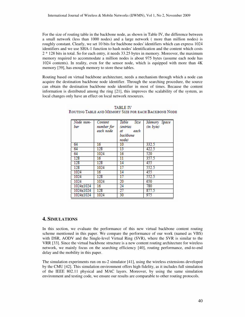
For the size of routing table in the backbone node, as shown in Table IV, the difference between
a small network (less than 1000 nodes) and a large network ( more than million nodes) is
roughly constant. Clearly, we set 10 bits for backbone nodes' identifiers which can express 1024
identifiers and we use SHA-1 function to hash nodes' identification and the content which costs
2 * 128 bits in total. So for each entry, it needs 33.25 bytes in memory. Moreover, the maximum
memory required to accommodate a million nodes is about 975 bytes (assume each node has
1024 contents). In reality, even for the sensor node, which is equipped with more than 4K
memory [39], has enough memory to store these tables.
Routing based on virtual backbone architecture, needs a mechanism through which a node can
acquire the destination backbone node identifier. Through the searching procedure, the source
can obtain the destination backbone node identifier in most of times. Because the content
information is distributed among the ring [21], this improves the scalability of the system, as
local changes only have an effect on local network resources.
4. SIMULATIONS
In this section, we evaluate the performance of this new virtual backbone content routing
scheme mentioned in this paper. We compare the performance of our work (named as VBS)
with DSR, AODV and the Single-level Virtual Ring (SVR), where the SVR is similar to the
VRR [33]. Since the virtual backbone structure is a new content routing architecture for wireless
network, we mainly focus on the searching efficiency [40], routing performance, end-to-end
delay and the mobility in this paper.
The simulation experiments run on ns-2 simulator [41], using the wireless extensions developed
by the CMU [42]. This simulation environment offers high fidelity, as it includes full simulation
of the IEEE 802.11 physical and MAC layers. Moreover, by using the same simulation
environment and testing code, we ensure our results are comparable to other routing protocols.
International Journal of Wireless & Mobile Networks (IJWMN), Vol 1, No 2, November 2009
41
4.1. Evaluation Metrics
In order to evaluate its performance, the following aspects have been studied:
1) Searching performance: the number of hops it takes to find the required content.
2) End-to-end delay: the total time it takes from a source node to the destination node.
3) Routing efficiency: in this experiment, we measure the number of hops it in different
routing schemes.
4) Message overhead: this is the total number of control messages generated to exchange
and maintain routing schemes.
For each metric, we set up the mobile function, where each node get to a random destination
with a random speed. And also, it uses the same traffic and topology patterns for all protocols.
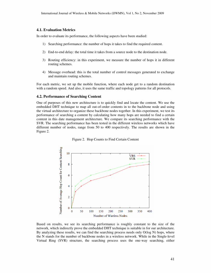
4.2. Performance of Searching Content
One of purposes of this new architecture is to quickly find and locate the content. We use the
embedded DHT technique to map all out-of-order contents in to the backbone node and using
the virtual architecture to organize these backbone nodes together. In this experiment, we test its
performance of searching a content by calculating how many hops are needed to find a certain
content in this date management architecture. We compare its searching performance with the
SVR. The searching performance has been tested in the different wireless networks which have
different number of nodes, range from 50 to 400 respectively. The results are shown in the
Figure 2.
Figure 2. Hop Counts to Find Certain Content
Based on results, we see its searching performance is roughly constant to the size of the
network, which indirectly prove the embedded DHT technique is suitable in for our architecture.
By analyzing these results, we can find the searching process needs only O(log N) hops, where
the N stands for the number of backbone nodes in a wireless network. While in the Single-level
Virtual Ring (SVR) structure, the searching process uses the one-way searching, either
International Journal of Wireless & Mobile Networks (IJWMN), Vol 1, No 2, November 2009
42
clockwise or anti-clockwise, thus the performance of SVR is sensitive to the size of the network
in which the number of hops required for searching is proportional to the size of the network.
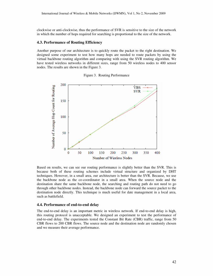
4.3. Performance of Routing Efficiency
Another purpose of our architecture is to quickly route the packet to the right destination. We
designed some experiment to test how many hops are needed to route packets by using the
virtual backbone routing algorithm and comparing with using the SVR routing algorithm. We
have tested wireless networks in different sizes, range from 50 wireless nodes to 400 sensor
nodes. The results are shown in the Figure 3.
Figure 3. Routing Performance
Based on results, we can see our routing performance is slightly better than the SVR. This is
because both of these routing schemes include virtual structure and organized by DHT
techniques. However, in a small area, our architecture is better than the SVR. Because, we use
the backbone node as the co-coordinator in a small area. When the source node and the
destination share the same backbone node, the searching and routing path do not need to go
through other backbone nodes. Instead, the backbone node can forward the source packet to the
destination node directly. This technique is much useful for date management in a local area,
such as battlefield.
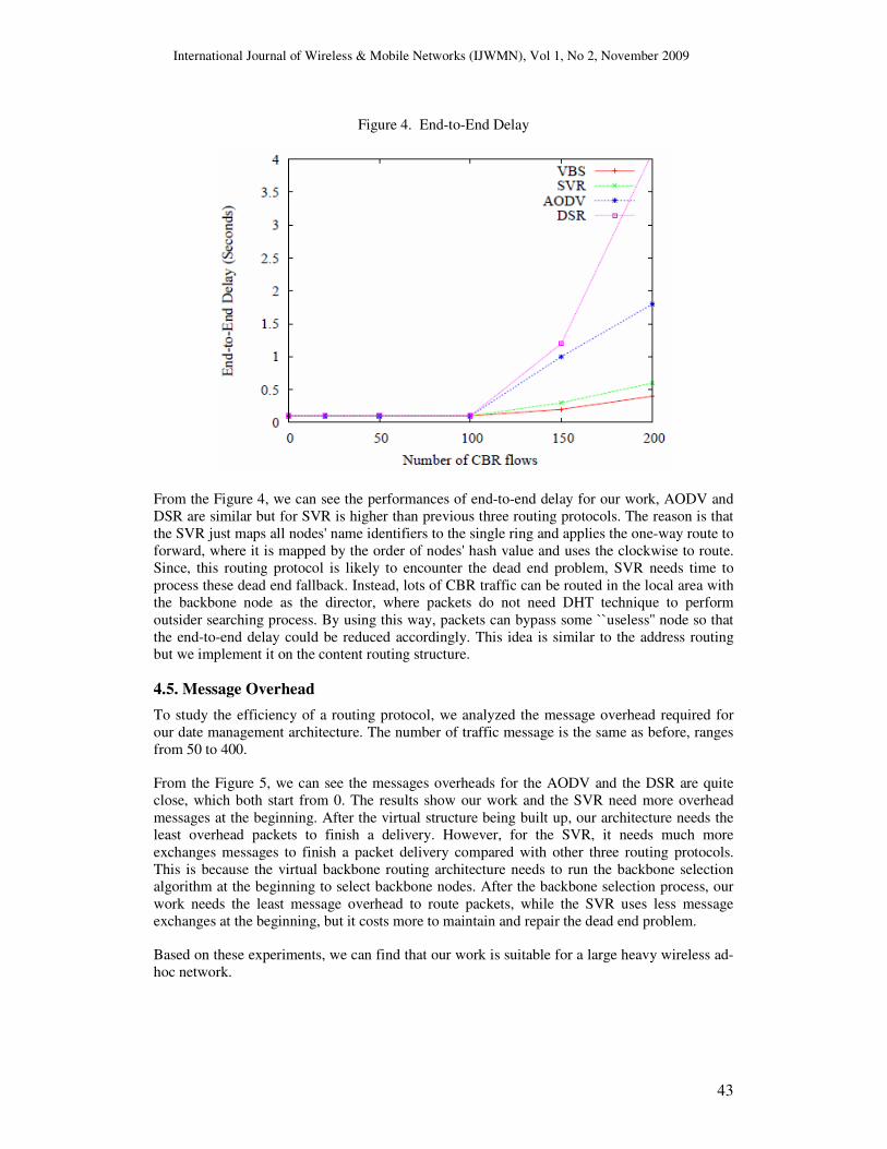
4.4. Performance of end-to-end delay
The end-to-end delay is an important metric in wireless network. If end-to-end delay is high,
this routing protocol is unacceptable. We designed an experiment to test the performance of
end-to-end delay. The experiments tested the Constant Bit Rate (CBR) traffic, range from 50
CBR flows to 200 CBR flows. The source node and the destination node are randomly chosen
and we measure their average performance.
International Journal of Wireless & Mobile Networks (IJWMN), Vol 1, No 2, November 2009
43
Figure 4. End-to-End Delay
From the Figure 4, we can see the performances of end-to-end delay for our work, AODV and
DSR are similar but for SVR is higher than previous three routing protocols. The reason is that
the SVR just maps all nodes' name identifiers to the single ring and applies the one-way route to
forward, where it is mapped by the order of nodes' hash value and uses the clockwise to route.
Since, this routing protocol is likely to encounter the dead end problem, SVR needs time to
process these dead end fallback. Instead, lots of CBR traffic can be routed in the local area with
the backbone node as the director, where packets do not need DHT technique to perform
outsider searching process. By using this way, packets can bypass some ``useless'' node so that
the end-to-end delay could be reduced accordingly. This idea is similar to the address routing
but we implement it on the content routing structure.
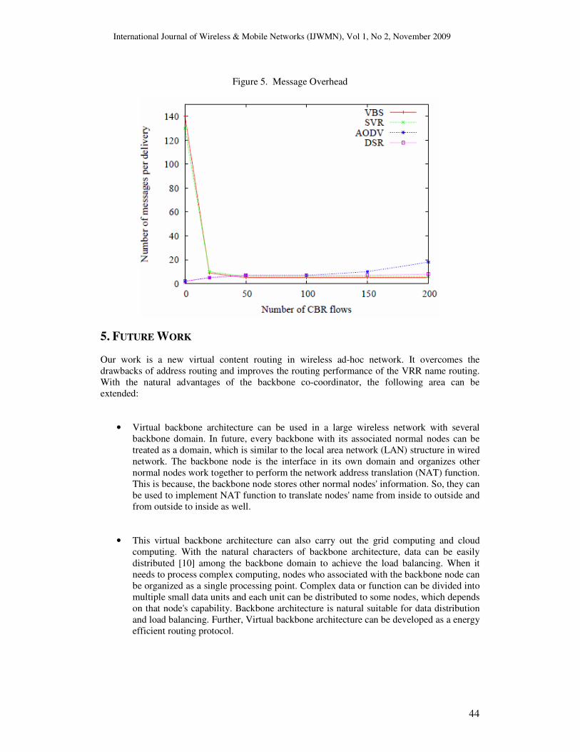
4.5. Message Overhead
To study the efficiency of a routing protocol, we analyzed the message overhead required for
our date management architecture. The number of traffic message is the same as before, ranges
from 50 to 400.
From the Figure 5, we can see the messages overheads for the AODV and the DSR are quite
close, which both start from 0. The results show our work and the SVR need more overhead
messages at the beginning. After the virtual structure being built up, our architecture needs the
least overhead packets to finish a delivery. However, for the SVR, it needs much more
exchanges messages to finish a packet delivery compared with other three routing protocols.
This is because the virtual backbone routing architecture needs to run the backbone selection
algorithm at the beginning to select backbone nodes. After the backbone selection process, our
work needs the least message overhead to route packets, while the SVR uses less message
exchanges at the beginning, but it costs more to maintain and repair the dead end problem.
Based on these experiments, we can find that our work is suitable for a large heavy wireless ad-
hoc network.
International Journal of Wireless & Mobile Networks (IJWMN), Vol 1, No 2, November 2009
44
Figure 5. Message Overhead
5. FUTURE WORK
Our work is a new virtual content routing in wireless ad-hoc network. It overcomes the
drawbacks of address routing and improves the routing performance of the VRR name routing.
With the natural advantages of the backbone co-coordinator, the following area can be
extended:
• Virtual backbone architecture can be used in a large wireless network with several
backbone domain. In future, every backbone with its associated normal nodes can be
treated as a domain, which is similar to the local area network (LAN) structure in wired
network. The backbone node is the interface in its own domain and organizes other
normal nodes work together to perform the network address translation (NAT) function.
This is because, the backbone node stores other normal nodes' information. So, they can
be used to implement NAT function to translate nodes' name from inside to outside and
from outside to inside as well.
• This virtual backbone architecture can also carry out the grid computing and cloud
computing. With the natural characters of backbone architecture, data can be easily
distributed [10] among the backbone domain to achieve the load balancing. When it
needs to process complex computing, nodes who associated with the backbone node can
be organized as a single processing point. Complex data or function can be divided into
multiple small data units and each unit can be distributed to some nodes, which depends
on that node's capability. Backbone architecture is natural suitable for data distribution
and load balancing. Further, Virtual backbone architecture can be developed as a energy
efficient routing protocol.
International Journal of Wireless & Mobile Networks (IJWMN), Vol 1, No 2, November 2009
45
6. CONCLUSION
We present a new content routing scheme based on the virtual backbone in wireless ad-hoc
network. The virtual backbone routing architecture gets rid of addresses in routing, instead it
achieves not only the name routing but also the content routing. With the backbone selection
and naming, the virtual backbone routing architecture can be built up. With exponential
searching algorithm and efficient routing forward, our architecture achieves a good routing
performance. The backbone selection algorithm was designed to abstract the physical
connections among nodes in which some “important'' nodes are selected as the backbone nodes.
The embedded DHT techniques are used to distribute the content and node information among
backbone nodes to improve the searching performance.
With the simulation results, we prove this new architecture can be implemented by deployed
and it is suitable for the next generation wireless network compared with other address routing
protocols. However, it still cannot root up the dead end problem and has some concerns (i.e.,
high overhead at the beginning) worth further investigation in the future research work.
REFERENCES
[1] I. F. Akyildiz, W. Su, Y. Sankarasubramaniam, and E. Cayirci, “Wireless sensor networks: a
survey,” Computer Networks, vol. 38, pp. 393–422, 2002.
[2] A. Harwood and E. Tanin, “Hashing spatial content over peer-topeer networks,” in In Australian
Telecommunications, Networks, and Applications Conference-ATNAC, 2003, pp. 1–5.
[3] M. Gritter and D. Cheriton, “An architecture for content routing support in the internet,” in
Proceedings of the USENIX Symposium on Internet Technologies and Systems, San Francisco,
California, USA:USENIX, March 2001.
[4] J. Eriksson, M. Faloutsos, and S. V. Krishnamurthy, “Dart: dynamic address routing for scalable
ad hoc and mesh networks,” IEEE/ACM Trans. Netw., vol. 15, no. 1, pp. 119–132, 2007.
[5] B. Karp and H. T. Kung, “Gpsr: greedy perimeter stateless routing for wireless networks,” in
MobiCom ’00: Proceedings of the 6th annual international conference on Mobile computing and
networking. New York, NY, USA: ACM Press, 2000, pp. 243–254. [Online]. Available:
http://dx.doi.org/10.1145/345910.345953
[6] R. Fonseca, S. Ratnasamy, J. Zhao, C. Ee, D. Culler, S. Shenker, and I. Stoica, “Beacon vector
routing: Scalable point-to-point routing in wireless sensornets,” in In NSDI, 2005.
[7] I. D. Scherson, D. S. Valencia, and E. Cauich, “Service address routing: a network-embedded
resource management layer for cluster computing,” Parallel Computing, vol. 33, no. 7-8, pp.
561–571, 2007.
[8] P. Mockapetris, “Domain names: concepts and facilities,” Published Online, Internet
Engineering Task Force, RFC 1034, November 1987. [Online]. Available:
http://rfc.net/rfc1034.txt
[9] Hill, “Mica: a wireless platform for deeply embedded networks,” Micro, IEEE, vol. 22, no. 6,
pp. 12–24, Nov/Dec 2002.
[10] V. D. Park and S. M. Corson, “A highly adaptive distributed routing algorithm for mobile
wireless networks,” in INFOCOM (3), 1997, pp. 1405–1413. [Online].
Available:http://citeseer.ist.psu.edu/park97highly.html
International Journal of Wireless & Mobile Networks (IJWMN), Vol 1, No 2, November 2009
46
[11] A. Ward, A. Jones, and A. Hopper, “A new location technique for the active office,” Personal
Communications, IEEE [see also IEEE Wireless Communications], vol. 4, no. 5, pp. 42–47,
1997. [Online]. Available: http://ieeexplore.ieee.org/xpls/abs all.jsp?arnumber=626982
[12] S. Mccanne, S. Floyd, and K. Fall, “ns2 (network simulator 2),” http://www-nrg.ee.lbl.gov/ns/.
[Online]. Available: http://wwwnrg.ee.lbl.gov/ns
[13] R. Bhaskar, J. Herranz, and F. Laguillaumie, “Efficient authentication for reactive routing
protocols,” in AINA ’06: Proceedings of the 20th International Conference on Advanced
Information Networking and Applications - Volume 2 (AINA’06). Washington, DC, USA: IEEE
Computer Society, 2006, pp. 57–61.
[14] C.Perkins and P.Bhagwat, “Highly dynamic destination-sequenced distance-vector routing
(dsdv) for mobile computer,” ACM Sigcomm’94, August 1994.
[15] K. U. R. Khan, R. U. Zaman, A. V. Reddy, K. A. Reddy, and T. S. Harsha, “An efficient dsdv
routing protocol for wireless mobile ad hoc networks and its performance comparison,” in EMS
’08: Proceedings of the 2008 Second UKSIM European Symposium on Computer Modeling and
Simulation. Washington, DC, USA: IEEE Computer Society, 2008, pp. 506–511.
[16] A. Baayer, N. Enneya, and M. E. Koutbi, “A new criterion for mpr selection in olsr,” in EATIS
’07: Proceedings of the 2007 Euro American conference on Telematics and information systems.
New York, NY, USA: ACM, 2007, pp. 1–6.
[17] D. B. Johnson, D. A. Maltz, and J. Broch, “Dsr: the dynamic source routing protocol for
multihop wireless ad hoc networks,” Ad hoc networking, pp. 139–172, 2001.
[18] M. Alilou and M. Dehghan, “Upgrading performance of dsr routing protocol in mobile ad hoc
networks,” in WEC (5), 2005, pp. 38–40.
[19] C.Perkins and E.Royer, “Ad hoc on-demand distance vector routing,” Mobile Computing
System and Applications, February 1999.
[20] S. Xu, Y. Mu, and W. Susilo, “Authenticated aodv routing protocol using one-time signature and
transitive signature schemes,” JNW, vol. 1, no. 1, pp. 47–53, 2006.
[21] I. Stoica, R. Morris, D. Karger, F. F. Kaashoek, and H. Balakrishnan, “Chord: A scalable peer-
to-peer lookup service for internet applications,” SIGCOMM Comput. Commun. Rev., vol. 31,
no. 4, pp. 149–160, October 2001. [Online]. Available: http://dx.doi.org/10.1145/964723.383071
[22] A. Haeberlen, J. Hoye, A. Mislove, and P. Druschel, “Consistent key mapping in structured
overlays,” in In Technical Report TR05-456, Rice CS Department, 2005.
[23] A. Rowstron and P. Druschel, “Pastry: Scalable, distributed object location and routing for large-
scale peer-to-peer systems,” in IFIP/ACM International Conference on Distributed Systems
Platforms (Middleware), November 2001, pp. 329–350.
[24] H. Balakrishnan, M. F. Kaashoek, D. Karger, R. Morris, and I. Stoica, “Looking up data in p2p
systems,” Commun. ACM, vol. 46, no. 2, pp. 43–48, 2003.
[25] J. Eriksson, M. Faloutsos, and S. Krishnamurthy, “Peernet: Pushing peerto- peer down the
stack,” in In 2nd International Workshop on Peer-to-Peer Systems, 2003.
[26] P. Maymounkov and D. Mazi`eres, “Kademlia: A peer-to-peer information system based on the
xor metric,” in Lecture Notes in Computer Science : Peer-to-Peer Systems: First International
International Journal of Wireless & Mobile Networks (IJWMN), Vol 1, No 2, November 2009
47
Workshop, IPTPS 2002 Cambridge, MA, USA, March 7-8, 2002. Revised Papers, 2002, pp. 53–
65.
[27] A.-T. Gai, F. Mathieu, J. Reynier, and F. de Montgolfier, “Stratification in p2p networks -
application to bittorrent,” CoRR, vol. abs/cs/0612130, 2006.
[28] D. Qiu and R. Srikant, “Modeling and performance analysis of bittorrent-like peer-to-peer
networks,” SIGCOMM Comput. Commun. Rev., vol. 34, no. 4, pp. 367–378, October 2004.
[Online]. Available: http://dx.doi.org/10.1145/1030194.1015508
[29] R. Cox, A. Muthitacharoen, and R. T. Morris, “Serving dns using a peer-to-peer lookup service,”
in IPTPS, 2002, pp. 155–165.
[30] R. Cox, A. Muthitacharoen, and R. Morris, “Serving dns using chord,” in Proceedings of the 1st
International Workshop on Peer-to-Peer Systems (IPTPS), Cambridge, MA, March 2002.
[31] P. Linga, I. Gupta, and K. Birman, “A churn-resistant peer-to-peer web caching system,” in
SSRS ’03: Proceedings of the 2003 ACM workshop on Survivable and self-regenerative
systems. New York, NY, USA: ACM, 2003, pp. 1–10.
[32] S. Iyer, A. Rowstron, and P. Druschel, “Squirrel: A decentralized peer-to-peer web cache,” 2002.
[Online]. Available: http://citeseer.ist.psu.edu/541645.html
[33] M. C. Miguel, “Virtual ring routing: Network routing inspired by dhts.” [Online]. Available:
http://citeseer.ist.psu.edu/caesar06virtual.html
[34] Y.-J. Kim, R. Govindan, B. Karp, and S. Shenker, “Geographic routing made practical,” in
Proceedings of the USENIX Symposium on Networked Systems Design and Implementation,
Boston, Massachusetts, USA:USENIX, May 2005.
[35] A. Awad, R. German, and F. Dressler, “P2P-based Routing and Data Management using the
Virtual Cord Protocol (VCP),” in 9th ACM International Symposium on Mobile Ad Hoc
Networking and Computing (ACM Mobihoc 2008), Poster Session. Hong Kong, China: ACM,
May 2008, pp. 443–444.
[36] D. Eastlake and P. Jones, “Us secure hash algorithm 1 (sha1),” Published Online, Internet
Engineering Task Force, RFC 3174, September 2001. [Online]. Available:
http://www.faqs.org/rfcs/rfc3174.html
[37] P. A.Gupta, M.Sanghi and F.Bustamante, “Magnolia: A novel dht architecture for keyword-
based searching,” in Proc. of the Second Symposium on Networked Systems Design &
Implementation (NSDI), 2005.
[38] A. Woo, T. Tong, and D. Culler, “Taming the underlying challenges of reliable multihop routing
in sensor networks,” in SenSys ’03: Proceedings of the 1st international conference on
Embedded networked sensor systems. New York, NY, USA: ACM Press, 2003, pp. 14–27.
[Online]. Available: http://dx.doi.org/http://doi.acm.org/10.1145/958491.958494
[39] “Sensor node,” http://en.wikipedia.org/wiki/Sensor node.
[40] I. Stojmenovi and J. Urrutia, “Routing with guaranteed delivery in ad hoc wireless networks,” in
Wireless Networks, 1999, pp. 48–55.
[41] VINT, The Network Simulator -ns -2, ISI, 2000.
[42] J. Broch, D. A. Maltz, D. B. Johnson, Y. C. Hu, and J. Jetcheva, “A performance comparison of
multi-hop wireless ad hoc network routing protocols,” in Proceedings of the 4th annual
ACM/IEEE international conference on Mobile computing and networking. ACM Press, 1998,
pp. 85–97. [Online]. Available: http://dx.doi.org/10.1145/288235.288256