Cisco Nexus 7000 Series NX-OS Unicast Routing ...
564
Cisco Nexus 7000 Series NX-OS Unicast Routing Configuration Guide, Release 6.x Last Modified: 2014-10-17 Americas Headquarters Cisco Systems, Inc. 170 West Tasman Drive San Jose, CA 95134-1706 USA http://www.cisco.com Tel: 408 526-4000 800 553-NETS (6387) Fax: 408 527-0883 Text Part Number: OL-25777-03
-
Upload
khangminh22 -
Category
Documents
-
view
0 -
download
0
Transcript of Cisco Nexus 7000 Series NX-OS Unicast Routing ...
Cisco Nexus 7000 Series NX-OS Unicast Routing Configuration Guide,Release 6.xLast Modified: 2014-10-17
Americas HeadquartersCisco Systems, Inc.170 West Tasman DriveSan Jose, CA 95134-1706USAhttp://www.cisco.comTel: 408 526-4000
800 553-NETS (6387)Fax: 408 527-0883
Text Part Number: OL-25777-03

THE SPECIFICATIONS AND INFORMATION REGARDING THE PRODUCTS IN THIS MANUAL ARE SUBJECT TO CHANGE WITHOUT NOTICE. ALL STATEMENTS, INFORMATION, ANDRECOMMENDATIONS IN THIS MANUAL ARE BELIEVED TO BE ACCURATE BUT ARE PRESENTED WITHOUT WARRANTY OF ANY KIND, EXPRESS OR IMPLIED. USERS MUST TAKE FULLRESPONSIBILITY FOR THEIR APPLICATION OF ANY PRODUCTS.
THE SOFTWARE LICENSE AND LIMITED WARRANTY FOR THE ACCOMPANYING PRODUCT ARE SET FORTH IN THE INFORMATION PACKET THAT SHIPPED WITH THE PRODUCT AND AREINCORPORATED HEREIN BY THIS REFERENCE. IF YOU ARE UNABLE TO LOCATE THE SOFTWARE LICENSE OR LIMITED WARRANTY, CONTACT YOUR CISCO REPRESENTATIVE FOR A COPY.
The Cisco implementation of TCP header compression is an adaptation of a program developed by the University of California, Berkeley (UCB) as part of UCB's public domain version of theUNIX operating system. All rights reserved. Copyright © 1981, Regents of the University of California.
NOTWITHSTANDING ANY OTHER WARRANTY HEREIN, ALL DOCUMENT FILES AND SOFTWARE OF THESE SUPPLIERS ARE PROVIDED “AS IS" WITH ALL FAULTS. CISCO AND THE ABOVE-NAMEDSUPPLIERS DISCLAIM ALL WARRANTIES, EXPRESSED OR IMPLIED, INCLUDING, WITHOUT LIMITATION, THOSE OF MERCHANTABILITY, FITNESS FOR A PARTICULAR PURPOSE ANDNONINFRINGEMENT OR ARISING FROM A COURSE OF DEALING, USAGE, OR TRADE PRACTICE.
IN NO EVENT SHALL CISCO OR ITS SUPPLIERS BE LIABLE FOR ANY INDIRECT, SPECIAL, CONSEQUENTIAL, OR INCIDENTAL DAMAGES, INCLUDING, WITHOUT LIMITATION, LOST PROFITSOR LOSS OR DAMAGE TO DATA ARISING OUT OF THE USE OR INABILITY TO USE THIS MANUAL, EVEN IF CISCO OR ITS SUPPLIERS HAVE BEEN ADVISED OF THE POSSIBILITY OF SUCHDAMAGES.
Any Internet Protocol (IP) addresses and phone numbers used in this document are not intended to be actual addresses and phone numbers. Any examples, command display output, networktopology diagrams, and other figures included in the document are shown for illustrative purposes only. Any use of actual IP addresses or phone numbers in illustrative content is unintentionaland coincidental.
All printed copies and duplicate soft copies of this document are considered uncontrolled. See the current online version for the latest version.
Cisco has more than 200 offices worldwide. Addresses and phone numbers are listed on the Cisco website at www.cisco.com/go/offices.
Cisco and the Cisco logo are trademarks or registered trademarks of Cisco and/or its affiliates in the U.S. and other countries. To view a list of Cisco trademarks, go to this URL:https://www.cisco.com/c/en/us/about/legal/trademarks.html. Third-party trademarks mentioned are the property of their respective owners. The use of the word partner does not imply apartnership relationship between Cisco and any other company. (1721R)
© 2009-2014 Cisco Systems, Inc. All rights reserved.

C O N T E N T S
Preface xxxiP R E F A C E
Audience xxxi
Document Conventions xxxi
Related Documentation for Cisco Nexus 7000 Series NX-OS Software xxxii
Documentation Feedback xxxiv
Communications, Services, and Additional Information xxxv
New and Changed Information 1C H A P T E R 1
New and Changed Information 1
Overview 7C H A P T E R 2
Overview 7
Licensing Requirements 7
Information About Layer 3 Unicast Routing 7
Routing Fundamentals 7
Packet Switching 8
Routing Metrics 9
Router IDs 10
Autonomous Systems 11
Convergence 12
Load Balancing and Equal Cost Multipath 12
Route Redistribution 12
Administrative Distance 13
Stub Routing 13
Routing Algorithms 14
Static Routes and Dynamic Routing Protocols 14
Cisco Nexus 7000 Series NX-OS Unicast Routing Configuration Guide, Release 6.xiiiOL-25777-03

Interior and Exterior Gateway Protocols 14
Distance Vector Protocols 14
Link-State Protocols 15
Layer 3 Virtualization 15
Cisco NX-OS Forwarding Architecture 16
Unicast RIB 16
Adjacency Manager 17
Unicast Forwarding Distribution Module 17
FIB 17
Hardware Forwarding 17
Software Forwarding 18
Layer 3 Interoperation with the N7K-F132-15 Module 18
Summary of Layer 3 Routing Features 19
IPv4 and IPv6 19
IP Services 19
OSPF 19
EIGRP 19
IS-IS 19
BGP 19
RIP 20
Static Routing 20
Layer 3 Virtualization 20
Route Policy Manager 20
Policy-Based Routing 20
First Hop Redundancy Protocols 20
Object Tracking 20
Related Documents for Layer 3 Unicast Routing 21
IP 23P A R T I
Configuring IPv4 25C H A P T E R 3
Finding Feature Information 25
Information About IPv4 25
Multiple IPv4 Addresses 26
Cisco Nexus 7000 Series NX-OS Unicast Routing Configuration Guide, Release 6.xOL-25777-03iv
Contents

Address Resolution Protocol 26
ARP Caching 27
Static and Dynamic Entries in the ARP Cache 27
Devices That Do Not Use ARP 27
Reverse ARP 28
Proxy ARP 28
Local Proxy ARP 29
Gratuitous ARP 29
Glean Throttling 29
Path MTU Discovery 29
ICMP 30
Virtualization Support for IPv4 30
Prerequisites for IPv4 30
Guidelines and Limitations for IPv4 30
Default Settings for IPv4 Parameters 31
Configuring IPv4 31
Configuring IPv4 Addressing 31
Configuring Multiple IPv4 Addresses 32
Configuring a Static ARP Entry 33
Configuring Proxy ARP 33
Configuring Local Proxy ARP 34
Configuring Gratuitous ARP 35
Configuring the IP ARP Cache Limit 35
Configuring Glean Optimization 36
Configuring Bloom Filter Support for Glean Adjacencies 37
Configuring Path MTU Discovery 37
Configuring IP Packet Verification 38
Configuring IP Glean Throttling 39
Configuring the Hardware IP Glean Throttle Maximum 40
Configuring the Hardware IP Glean Throttle Timeout 41
Configuring the Hardware IP Glean Throttle Syslog 41
Verifying the IPv4 Configuration 42
Configuration Examples for IPv4 43
Cisco Nexus 7000 Series NX-OS Unicast Routing Configuration Guide, Release 6.xvOL-25777-03
Contents
Example: Reserving All Ports on a Module for Proxy Routing 43
Example: Reserving Ports for Proxy Routing 45
Example: Excluding Ports From Proxy Routing 45
Related Documents for IPv4 46
Standards for IPv4 46
Feature History for IPv4 46
Configuring IPv6 49C H A P T E R 4
Finding Feature Information 49
Information About IPv6 49
IPv6 Address Formats 50
IPv6 Unicast Addresses 51
Aggregatable Global Addresses 51
Link-Local Addresses 52
IPv4-Compatible IPv6 Addresses 53
Unique Local Addresses 53
Site Local Addresses 54
IPv6 Anycast Addresses 54
IPv6 Multicast Addresses 54
IPv4 Packet Header 56
Simplified IPv6 Packet Header 56
DNS for IPv6 59
Path MTU Discovery for IPv6 59
CDP IPv6 Address Support 60
ICMP for IPv6 60
IPv6 Neighbor Discovery 61
IPv6 Neighbor Solicitation Message 61
IPv6 Router Advertisement Message 63
IPv6 Router Advertisement Options for DNS Configuration 64
IPv6 Neighbor Redirect Message 64
Virtualization Support for IPv6 66
Prerequisites for IPv6 66
Guidelines and Limitations for Configuring IPv6 66
Cisco Nexus 7000 Series NX-OS Unicast Routing Configuration Guide, Release 6.xOL-25777-03vi
Contents

Default Settings for IPv6 67
Configuring IPv6 67
Configuring IPv6 Addressing 67
Configuring IPv6 Neighbor Discovery 68
Configuring Optional IPv6 Neighbor Discovery 71
Configuring Recursive DNS Server (RDNSS) 73
Configuring DNS Search List (DNSSL) 74
Configuring IPv6 Packet Verification 75
Verifying the IPv6 Configuration 76
Configuration Example for IPv6 76
Related Documents for IPv6 76
Standards for IPv6 76
Feature History for IPv6 77
Configuring DNS 79C H A P T E R 5
Finding Feature Information 79
Information About DNS Clients 79
DNS Client Overview 79
DNS Name Servers 80
DNS Operation 80
High Availability for DNS Clients 80
Virtualization Support for DNS Clients 80
Prerequisites for DNS Clients 80
Guidelines and Limitations for DNS Clients 81
Default Settings for DNS Client Parameters 81
Configuring DNS Clients 81
Configuring the DNS Client 81
Verifying the DNS Client Configuration 83
Configuration Examples for DNS Clients 83
Related Documents for DNS Clients 83
Standards for DNS Clients 83
Feature History for DNS 83
Cisco Nexus 7000 Series NX-OS Unicast Routing Configuration Guide, Release 6.xviiOL-25777-03
Contents

Configuring WCCPv2 85C H A P T E R 6
Finding Feature Information 85
Information About WCCPv2 85
WCCPv2 Overview 85
WCCPv2 Service Types 86
WCCPv2 Service Groups 86
WCCPv2 Service Group Lists 87
WCCPv2 Designated Cache Engine 88
WCCPv2 Redirection 88
WCCPv2 Authentication 90
WCCPv2 Redirection Method 91
WCCPv2 Packet Return Method 91
High Availability for WCCPv2 91
Virtualization Support for WCCPv2 91
WCCPv2 Error Handling for SPM Operations 92
Prerequisites for WCCPv2 92
Guidelines and Limitations for WCCPv2 92
WCCPv2 Default Settings 94
Configuring WCCPv2 94
Enabling and Disabling WCCPv2 94
Configuring a WCCPv2 Service Group 95
Applying WCCPv2 Redirection to an Interface 96
Configuring WCCPv2 in a VRF 98
Verifying the WCCPv2 Configuration 100
Configuration Examples for WCCPv2 100
Related Documents for WCCPv2 101
Standards for the WCCPv2 101
Feature History for WCCPv2 101
Routing 103P A R T I I
Configuring OSPFv2 105C H A P T E R 7
Cisco Nexus 7000 Series NX-OS Unicast Routing Configuration Guide, Release 6.xOL-25777-03viii
Contents

Finding Feature Information 105
Information About OSPFv2 105
Hello Packet 106
Neighbors 106
Adjacency 107
Designated Routers 107
Areas 108
Link-State Advertisements 109
Link-State Advertisements Types 109
OSPFv2 and the Unicast RIB 111
Authentication 111
Simple Password Authentication 111
MD5 Authentication 111
Advanced Features for OSPFv2 111
Stub Area 112
Not-So-Stubby Area 112
Virtual Links 112
Route Redistribution 113
Route Summarization 113
High Availability and Graceful Restart 114
OSPFv2 Stub Router Advertisements 115
Multiple OSPFv2 Instances 115
SPF Optimization 115
BFD 115
Virtualization Support for OSPFv2 116
Prerequisites for OSPFv2 116
Guidelines and Limitations for OSPFv2 116
Default Settings for OSPFv2 118
Configuring Basic OSPFv2 118
Enabling OSPFv2 118
Creating an OSPFv2 Instance 119
Configuring OSPF Packet Size 120
Configuring Optional Parameters on an OSPFv2 Instance 122
Cisco Nexus 7000 Series NX-OS Unicast Routing Configuration Guide, Release 6.xixOL-25777-03
Contents

Configuring Networks in OSPFv2 123
Configuring Authentication for an Area 124
Configuring Authentication for an Interface 126
Configuring Advanced OSPFv2 127
Configuring Filter Lists for Border Routers 127
Configuring Stub Areas 128
Configuring a Totally Stubby Area 129
Configuring NSSA 129
Configuring Virtual Links 131
Configuring Redistribution 133
Limiting the Number of Redistributed Routes 134
Configuring Route Summarization 136
Configuring Stub Route Advertisements 137
Configuring the Administrative Distance of Routes 138
Modifying the Default Timers 140
Configuring Graceful Restart 142
Restarting an OSPFv2 Instance 143
Configuring OSPFv2 with Virtualization 143
Verifying the OSPFv2 Configuration 144
Monitoring OSPFv2 146
Configuration Examples for OSPFv2 146
Related Documents for OSPFv2 146
Feature History for OSPFv2 146
Configuring OSPFv3 149C H A P T E R 8
Finding Feature Information 149
Information About OSPFv3 149
Comparison of OSPFv3 and OSPFv2 150
Hello Packet 150
Neighbors 151
Adjacency 151
Designated Routers 151
Areas 152
Cisco Nexus 7000 Series NX-OS Unicast Routing Configuration Guide, Release 6.xOL-25777-03x
Contents

Link-State Advertisement Types 153
Link Cost 155
Flooding and LSA Group Pacing 155
Link-State Database 155
Multi-Area Adjacency 155
OSPFv3 and the IPv6 Unicast RIB 156
Address Family Support 156
Authentication 156
Encryption 157
Guidelines and Limitations for configuring ESP on OSPFv3 157
Advanced Features 158
Stub Area 158
Not-So-Stubby Area 158
Virtual Links 159
Route Redistribution 159
Route Summarization 160
High Availability and Graceful Restart 160
Multiple OSPFv3 Instances 161
SPF Optimization 161
Virtualization Support 161
Prerequisites for OSPFv3 161
Guidelines and Limitations for OSPFv3 162
Default Settings for OSPFv3 164
Configuring Basic OSPFv3 164
Enabling OSPFv3 164
Creating an OSPFv3 Instance 165
Configuring OSPFv3 Packet Size 167
Configuring Networks in OSPFv3 168
Configuring Advanced OSPFv3 170
Configuring Filter Lists for Border Routers 170
Configuring Stub Areas 171
Configuring a Totally Stubby Area 172
Configuring NSSA 172
Cisco Nexus 7000 Series NX-OS Unicast Routing Configuration Guide, Release 6.xxiOL-25777-03
Contents

Configuring Multi-Area Adjacency 174
Configuring Virtual Links 175
Configuring Redistribution 176
Limiting the Number of Redistributed Routes 178
Configuring Route Summarization 179
Configuring the Administrative Distance of Routes 180
Modifying the Default Timers 183
Configuring the OSPFv3 Max-Metric Router LSA 184
Configuring Graceful Restart 185
Restarting an OSPFv3 Instance 186
Configuring OSPFv3 with Virtualization 187
Configuring OSPFv3 Authentication at Router Level 188
Configuring OSPFv3 Authentication at Area Level 189
Configuring OSPFv3 Authentication at Interface Level 189
Configuring OSPFv3 Encryption at Router Level 191
Configuring OSPFv3 Encryption at Area Level 191
Configuring OSPFv3 Encryption at Interface Level 192
Configuring OSPFv3 Encryption for Virtual Links 194
Configuration Examples for OSPFv3 195
Related Documents for OSPFv3 195
Feature History for OSPFv3 195
Configuring EIGRP 197C H A P T E R 9
Finding Feature Information 197
Information About EIGRP 197
EIGRP Components 198
Reliable Transport Protocol 198
Neighbor Discovery and Recovery 198
Diffusing Update Algorithm 198
EIGRP Route Updates 199
Internal Route Metrics 199
Wide Metrics 200
External Route Metrics 200
Cisco Nexus 7000 Series NX-OS Unicast Routing Configuration Guide, Release 6.xOL-25777-03xii
Contents

EIGRP and the Unicast RIB 201
Advanced EIGRP 201
Address Families 201
Authentication 201
Stub Routers 202
Route Summarization 202
Route Redistribution 202
Load Balancing 203
Split Horizon 203
BFD 203
Virtualization Support for EIGRP 203
Graceful Restart and High Availability 203
Multiple EIGRP Instances 204
Prerequisites for EIGRP 204
Guidelines and Limitations for EIGRP 205
Default Settings for EIGRP Parameters 206
Configuring Basic EIGRP 207
Enabling or Disabling the EIGRP Feature 207
Creating an EIGRP Instance 207
Restarting an EIGRP Instance 209
Shutting Down an EIGRP Instance 209
Configuring a Passive Interface for EIGRP 210
Shutting Down EIGRP on an Interface 211
Configuring Advanced EIGRP 211
Configuring Authentication in EIGRP 211
Configuring EIGRP Stub Routing 213
Configuring a Summary Address for EIGRP 214
Redistributing Routes into EIGRP 214
Limiting the Number of Redistributed Routes 216
Configuring the Administrative Distance of Routes 217
Configuring Route-Map Filtering 218
Configuring Load Balancing in EIGRP 219
Configuring Graceful Restart for EIGRP 220
Cisco Nexus 7000 Series NX-OS Unicast Routing Configuration Guide, Release 6.xxiiiOL-25777-03
Contents
Adjusting the Interval Between Hello Packets and the Hold Time 221
Disabling Split Horizon 222
Enabling Wide Metrics 223
Tuning EIGRP 223
Configuring Virtualization for EIGRP 226
Verifying the EIGRP Configuration 227
Displaying EIGRP Statistics 228
Configuration Example for EIGRP 228
Related Documents for EIGRP 229
MIBs 229
Feature History for EIGRP 230
Configuring IS-IS 231C H A P T E R 1 0
Finding Feature Information 231
Information About IS-IS 231
IS-IS Overview 232
IS-IS Areas 232
NET and System ID 233
Designated Intermediate System 233
IS-IS Authentication 233
Mesh Groups 233
Overload Bit 234
Route Summarization 234
Route Redistribution 234
Administrative Distance 234
Load Balancing 235
BFD 235
Virtualization Support 235
High Availability and Graceful Restart 235
Multiple IS-IS Instances 236
Prerequisites for IS-IS 236
Guidelines and Limitations for IS-IS 236
Default Settings for IS-IS 236
Cisco Nexus 7000 Series NX-OS Unicast Routing Configuration Guide, Release 6.xOL-25777-03xiv
Contents

Configuring IS-IS 237
IS-IS Configuration Modes 237
Router Configuration Mode Example 237
Router Address Family Configuration Mode Example 237
Enabling the IS-IS Feature 238
Creating an IS-IS Instance 238
Restarting an IS-IS Instance 239
Shutting Down IS-IS 239
Configuring IS-IS on an Interface 240
Configuring IS-IS Authentication in an Area 241
Configuring IS-IS Authentication on an Interface 242
Configuring a Mesh Group 242
Configuring a Designated Intermediate System 243
Configuring Dynamic Host Exchange 243
Setting the Overload Bit 243
Configuring the Attached Bit 244
Configuring the Transient Mode for Hello Padding 244
Configuring a Summary Address 244
Configuring Redistribution 245
Limiting the Number of Redistributed Routes 246
Configuring the Administrative Distance of Routes 247
Disabling Strict Adjacency Mode 248
Configuring a Graceful Restart 249
Configuring Virtualization 250
Tuning IS-IS 251
Monitoring IS-IS 253
Configuration Examples for IS-IS 254
Related Documents for IS-IS 254
Standards for IS-IS 254
Feature History for IS-IS 254
Configuring Basic BGP 257C H A P T E R 1 1
Finding Feature Information 257
Cisco Nexus 7000 Series NX-OS Unicast Routing Configuration Guide, Release 6.xxvOL-25777-03
Contents
Information About Basic BGP 257
BGP Autonomous Systems 258
4-Byte AS Number Support 258
Administrative Distance 258
BGP Peers 259
BGP Sessions 259
Dynamic AS Numbers for Prefix Peers 259
BGP Router Identifier 259
BGP Path Selection 260
BGP Path Selection - Comparing Pairs of Paths 260
BGP Path Selection - Determining the Order of Comparisons 262
BGP Path Selection - Determining the Best-Path Change Suppression 262
BGP and the Unicast RIB 263
BGP Prefix Independent Convergence 263
BGP PIC Feature Support Matrix 263
BGP PIC Core 264
BGP PIC Edge 264
BGP PIC Edge Unipath 265
BGP PIC Edge with Multipaths 266
BGP Virtualization 267
Prerequisites for BGP 267
Guidelines and Limitations for BGP 267
Default Settings 268
CLI Configuration Modes 268
Global Configuration Mode 269
Address Family Configuration Mode 269
Neighbor Configuration Mode 269
Neighbor Address Family Configuration Mode 270
Configuring Basic BGP 270
Enabling BGP 270
Creating a BGP Instance 271
Restarting a BGP Instance 272
Shutting Down BGP 272
Cisco Nexus 7000 Series NX-OS Unicast Routing Configuration Guide, Release 6.xOL-25777-03xvi
Contents
Configuring BGP Peers 272
Configuring AS-4 Dot Notation 274
Configuring Dynamic AS Numbers for Prefix Peers 275
Configuring BGP PIC Edge 276
Clearing BGP Information 278
Verifying the Basic BGP Configuration 281
Monitoring BGP Statistics 283
Configuration Examples for Basic BGP 283
Related Documents for Basic BGP 283
MIBs 284
Feature History for BGP 284
Configuring Advanced BGP 287C H A P T E R 1 2
Finding Feature Information 287
Information About Advanced BGP 287
Peer Templates 288
Authentication 288
Route Policies and Resetting BGP Sessions 288
eBGP 289
BGP Next Hop Unchanged 289
iBGP 289
AS Confederations 290
Route Reflector 290
Capabilities Negotiation 291
Route Dampening 291
Load Sharing and Multipath 292
BGP Additional Paths 292
Route Aggregation 293
BGP Conditional Advertisement 293
BGP Next-Hop Address Tracking 294
Route Redistribution 295
BGP Support for Importing Routes from Default VRF 295
BGP Support for Exporting Routes to Default VRF 296
Cisco Nexus 7000 Series NX-OS Unicast Routing Configuration Guide, Release 6.xxviiOL-25777-03
Contents
BFD 296
Tuning BGP 296
BGP Timers 296
Tuning the Best-Path Algorithm 296
Multiprotocol BGP 296
Graceful Restart and High Availability 297
Low Memory Handling 298
ISSU 298
Virtualization Support 298
Prerequisites for Advanced BGP 299
Guidelines and Limitations for Advanced BGP 299
Default Settings 300
Configuring Advanced BGP 301
Configuring BGP Session Templates 301
Configuring BGP Peer-Policy Templates 302
Configuring BGP Peer Templates 304
Configuring Prefix Peering 306
Configuring BGP Authentication 307
Resetting a BGP Session 307
Modifying the Next-Hop Address 308
Configuring BGP Next-Hop Address Tracking 308
Configuring Next-Hop Filtering 309
Disabling Capabilities Negotiation 309
Configuring BGP Additional Paths 309
Advertising the Capability of Sending and Receiving Additional Paths 309
Configuring the Sending and Receiving of Additional Paths 310
Configuring Advertised Paths 311
Configuring Additional Path Selection 312
Configuring eBGP 312
Disabling eBGP Single-Hop Checking 312
Configuring eBGP Multihop 313
Disabling a Fast External Fallover 313
Limiting the AS-path Attribute 313
Cisco Nexus 7000 Series NX-OS Unicast Routing Configuration Guide, Release 6.xOL-25777-03xviii
Contents

Configuring Local AS Support 314
Configuring AS Confederations 315
Configuring Route Reflector 315
Configuring Next-Hops on Reflected Routes Using an Outbound Route-Map 316
Configuring Route Dampening 318
Configuring Load Sharing and ECMP 319
Configuring Maximum Prefixes 319
Configuring Dynamic Capability 320
Configuring Aggregate Addresses 320
Unsuppressing the Advertisement of Aggregated Routes 320
Configuring BGP Conditional Route Injection 321
Configuring BGP Conditional Advertisement 322
Configuring Route Redistribution 324
Advertising the Default Route 325
Configuring Route Import from Default VRF to any other VRF 325
Configuring Route Export from BGP VRF to Default VRF 326
Configuring Multiprotocol BGP 328
Configuring Policy-Based Administrative Distance 328
Tuning BGP 330
Configuring a Graceful Restart 333
Configuring Virtualization 334
Verifying the Advanced BGP Configuration 335
Displaying Advanced BGP Statistics 337
Related Documents 337
RFCs 337
MIBs 337
Feature History for Advanced BGP 338
Configuring RIP 341C H A P T E R 1 3
Finding Feature Information 341
Information About RIP 341
RIPv2 Authentication 342
Split Horizon 342
Cisco Nexus 7000 Series NX-OS Unicast Routing Configuration Guide, Release 6.xxixOL-25777-03
Contents

Route Filtering 343
Route Summarization 343
Route Redistribution 343
Load Balancing 343
High Availability for RIP 343
Virtualization Support 343
Prerequisites for RIP 344
Guidelines and Limitations for RIP 344
Default Settings for RIP Parameters 344
Configuring RIP 344
Enabling RIP 344
Creating a RIP Instance 345
Restarting a RIP Instance 346
Configuring RIP on an Interface 347
Configuring RIP Authentication 347
Configuring a Passive Interface 348
Configuring Split Horizon with Poison Reverse 349
Configuring Route Summarization 349
Configuring Route Redistribution 350
Configuring Cisco NX-OS RIP for Compatibility with Cisco IOS RIP 351
Configuring Virtualization 352
Tuning RIP 354
Verifying the RIP Configuration 355
Displaying RIP Statistics 356
Configuration Examples for RIP 356
Related Documents for RIP 356
Standards for RIP 357
Feature History for RIP 357
Configuring Static Routing 359C H A P T E R 1 4
Finding Feature Information 359
Information About Static Routing 359
Administrative Distance 360
Cisco Nexus 7000 Series NX-OS Unicast Routing Configuration Guide, Release 6.xOL-25777-03xx
Contents

Directly Connected Static Routes 360
Fully Specified Static Routes 360
Floating Static Routes 360
Remote Next-Hops for Static Routes 360
Reliable Static Routing Backup Using Object Tracking Deployment 361
IP Service Level Agreements 361
BFD 361
Virtualization Support 361
Prerequisites for Static Routing 362
Guidelines and Limitations for Static Routing 362
Default Settings for Static Routing Parameters 362
Configuring Static Routing 362
Configuring a Static Route for IPv4 362
Configuring a Static Route for IPv6 363
Configuring a Static Route over a VLAN 364
Configuring Reliable Static Routing Backup Using Object Tracking 365
Configuring Virtualization for IPv4 366
Configuring Virtualization for IPv6 367
Verifying the Static Routing Configuration 368
Related Documents for Static Routing 368
Feature History for Static Routing 368
Configuring the Interoperability of Modules for Unicast Routing 371C H A P T E R 1 5
Finding Feature Information 371
Configuring the Interoperability of Modules for Unicast Routing 371
Information About the Interoperability of Modules for Unicast Routing 372
Guidelines and Limitations for the Interoperability of Modules for Unicast Routing 372
Configuring the Interoperability of Modules for Unicast Routing 372
Verifying the Configuration for the Interoperability of Modules for Unicast Routing 373
Configuration Examples for the Interoperability of Modules for Unicast Routing 373
Related Documents for the Interoperability of Modules for Unicast Routing 374
Feature History for the Interoperability of Modules for Unicast Routing 374
Cisco Nexus 7000 Series NX-OS Unicast Routing Configuration Guide, Release 6.xxxiOL-25777-03
Contents
Configuring Layer 3 Virtualization 375C H A P T E R 1 6
Finding Feature Information 375
Information About Layer 3 Virtualization 375
VRF and Routing 377
VRF-Aware Services 377
Reachability 378
Filtering 378
Combining Reachability and Filtering 379
Guidelines and Limitations for VRF 379
Default Settings for VRF 380
Configuring VRFs 380
Creating a VRF 380
Assigning VRF Membership to an Interface 381
Configuring VRF Parameters for a Routing Protocol 381
Configuring VRF Aware Service 382
Setting the VRF Scope 383
Verifying the VRF Configuration 384
Configuration Examples for VRF 384
Related Documents for VRF 385
Standards for VRF 386
Feature History for VRF 386
Managing the Unicast RIB and FIB 387C H A P T E R 1 7
Finding Feature Information 387
Information About the Unicast RIB and FIB 387
Layer 3 Consistency Checker 388
Dynamic TCAM Allocation 388
Maximum TCAM Entries and FIB Scale Limits 389
Default Settings for the Unicast RIB and FIB 390
Managing the Unicast RIB and FIB 390
Displaying Module FIB Information 390
Configuring Load Sharing in the Unicast FIB 391
Cisco Nexus 7000 Series NX-OS Unicast Routing Configuration Guide, Release 6.xOL-25777-03xxii
Contents
Configuring Per-Packet Load Sharing 393
Displaying Routing and Adjacency Information 394
Triggering the Layer 3 Consistency Checker 395
Clearing Forwarding Information in the FIB 396
Configuring Maximum Routes for the Unicast RIB 396
Estimating Memory Requirements for Routes 397
Clearing Routes in the Unicast RIB 398
Verifying the Unicast RIB and FIB 399
Related Documents for the Unicast RIB and FIB 399
Feature History for the Unicast RIB and FIB 399
Configuring Route Policy Manager 401C H A P T E R 1 8
Finding Feature Information 401
Information About Route Policy Manager 401
Prefix Lists 402
MAC Lists 402
Route Maps 402
Match Criteria 403
Set Changes 403
Access Lists 403
AS Numbers for BGP 404
AS-path Lists for BGP 404
Community Lists for BGP 404
Extended Community Lists for BGP 404
Route Redistribution and Route Maps 405
Route Map Support Matrix for Routing Protocols 405
Policy-Based Routing 408
Prerequisites for Route Policy Manager 409
Guidelines and Limitations 409
Default Settings for Route Policy Manager Parameters 409
Configuring Route Policy Manager 410
Configuring IP Prefix Lists 410
Configuring MAC Lists 411
Cisco Nexus 7000 Series NX-OS Unicast Routing Configuration Guide, Release 6.xxxiiiOL-25777-03
Contents

Configuring AS-path Lists 412
Configuring Community Lists 412
Configuring Extended Community Lists 413
Optional Match Parameters for Route Maps 414
Optional Set Parameters for Route Maps 416
Verifying the Route Policy Manager Configuration 419
Configuration Examples for Route Policy Manager 419
Related Documents for Route Policy Manager 420
Standards for Route Policy Manager 420
Feature History for Route Policy Manager 420
Configuring Policy-Based Routing 423C H A P T E R 1 9
Finding Feature Information 423
Information About Policy Based Routing 423
Policy Route Maps 424
Set Criteria for Policy-Based Routing 424
Local Policy Routing 425
Route Map Support Matrix for Policy-Based Routing 425
Prerequisites for Policy-Based Routing 426
Guidelines and Limitations for Policy-Based Routing 426
Default Settings for Policy-Based Routing 427
Configuring Policy-Based Routing 428
Enabling the Policy-Based Routing 428
Configuring a Route Policy 428
Configuring Local Policy Routing 432
Configuring a Deny ACE 432
Verifying the Policy-Based Routing Configuration 433
Configuration Examples for Policy Based-Routing 433
Configuration Example for Local Policy Routing 434
Related Documents for Policy-Based Routing 434
Standards for Policy-Based Routing 434
Feature History for Policy-Based Routing 434
Cisco Nexus 7000 Series NX-OS Unicast Routing Configuration Guide, Release 6.xOL-25777-03xxiv
Contents

First-Hop Redundancy Protocols 437P A R T I I I
Configuring GLBP 439C H A P T E R 2 0
Finding Feature Information 439
Information About GLBP 439
GLBP Active Virtual Gateway 440
GLBP Virtual MAC Address Assignment 440
GLBP Virtual Gateway Redundancy 440
GLBP Virtual Forwarder Redundancy 441
GLBP Authentication 442
GLBP Load Balancing and Tracking 442
High Availability and Extended Nonstop Forwarding 443
Virtualization Support 443
Prerequisites for GLBP 444
Guidelines and Limitations for GLBP 444
Default Settings for GLBP 444
Configuring GLBP 445
Enabling GLBP 445
Configuring GLBP Authentication 446
Configuring GLBP Load Balancing 447
Configuring GLBP Weighting and Tracking 447
Customizing GLBP 449
Configuring Extended Hold Timers for GLBP 451
Enabling a GLBP Group 451
Verifying the GLBP Configuration 452
Configuration Examples for GLBP 453
Related Documents for GLBP 453
Standards for GLBP 453
Feature History for GLBP 453
Configuring HSRP 455C H A P T E R 2 1
Finding Feature Information 455
Cisco Nexus 7000 Series NX-OS Unicast Routing Configuration Guide, Release 6.xxxvOL-25777-03
Contents

Information About HSRP 455
HSRP for IPv4 457
HSRP for IPv6 457
HSRP for IPv6 Addresses 458
Multiple Group Optimization for HSRP 458
HSRP Versions 459
HSRP Authentication 459
HSRP Messages 459
HSRP Load Sharing 459
Object Tracking and HSRP 460
vPC and HSRP 460
vPC Peer Gateway and HSRP 461
FabricPath Anycast HSRP 461
BFD 461
High Availability and Extended Nonstop Forwarding 461
Virtualization Support 462
HSRP VIP 462
Prerequisites for HSRP 463
Guidelines and Limitations for HSRP 463
Default Settings for HSRP Parameters 464
Configuring HSRP 465
Enabling HSRP 465
Configuring the HSRP Version 466
Configuring an HSRP Group for IPv4 466
Configuring an HSRP Group for IPv6 467
Configuring an HSRP Master Group Task 469
Configuring an HSRP Slave Group 470
Configuring the HSRP Virtual MAC Address Manually 472
Configuring the HSRP Virtual MAC Address Using Burned-in MAC Address 473
Authenticating HSRP 474
Configuring HSRP Object Tracking 475
Configuring the HSRP Priority 477
Customizing HSRP in HSRP Configuration Mode 478
Cisco Nexus 7000 Series NX-OS Unicast Routing Configuration Guide, Release 6.xOL-25777-03xxvi
Contents

Customizing HSRP in Interface Configuration Mode 479
Configuring Extended Hold Timers for HSRP 480
Verifying the HSRP Configuration 480
Configuration Examples for HSRP 481
Related Documents for HSRP 482
MIBs 482
Feature History for HSRP 482
Configuring VRRP 485C H A P T E R 2 2
Finding Feature Information 485
Information About VRRP 485
VRRP Operation 485
VRRP Benefits 487
Multiple VRRP Groups 487
VRRP Router Priority and Preemption 488
vPC and VRRP 489
VRRP Advertisements 489
VRRP Authentication 489
VRRP Tracking 489
VRRPv3 and VRRS 490
BFD for VRRP 490
High Availability 490
Virtualization Support 491
Guidelines and Limitations for VRRP 491
Default Settings for VRRP Parameters 492
Configuring VRRP 492
Enabling VRRP 492
Configuring VRRP Groups 493
Configuring VRRP Priority 494
Configuring VRRP Authentication 495
Configuring Time Intervals for Advertisement Packets 496
Disabling Preemption 497
Configuring VRRP Interface State Tracking 498
Cisco Nexus 7000 Series NX-OS Unicast Routing Configuration Guide, Release 6.xxxviiOL-25777-03
Contents

Enabling the VRRPv3 Feature 500
Creating VRRPv3 Groups 500
Configuring the Delay Period for FHRP Client Initialization 502
Configuring VRRPv3 Control Groups 503
Configuring VRRS Pathways 504
Verifying the VRRP Configuration 505
Monitoring VRRP Statistics 506
Configuration Example for VRRP 506
Related Documents for VRRP 508
Feature History for VRRP 508
Configuring Object Tracking 509C H A P T E R 2 3
Finding Feature Information 509
Information About Object Tracking 509
Object Track List 510
High Availability 511
Virtualization Support 511
Prerequisites for Object Tracking 511
Guidelines and Limitations for Object Tracking 511
Default Settings for Object Tracking Parameters 511
Configuring Object Tracking 512
Configuring Object Tracking for an Interface 512
Deleting a Tracking Object 513
Configuring Object Tracking for Route Reachability 513
Configuring an Object Track List with a Boolean Expression 514
Configuring an Object Track List with a Percentage Threshold 515
Configuring an Object Track List with a Weight Threshold 516
Configuring an Object Tracking Delay 517
Configuring Object Tracking for a Nondefault VRF 519
Verifying the Object Tracking Configuration 520
Configuration Example for Object Tracking 521
Related Documents for Object Tracking 521
Standards for Object Tracking 521
Cisco Nexus 7000 Series NX-OS Unicast Routing Configuration Guide, Release 6.xOL-25777-03xxviii
Contents

Feature History for Object Tracking 521
IETF RFCs Supported by Cisco NX-OS Unicast Features Release 6.x 523A P P E N D I X A
BGP RFCs 523
First-Hop Redundancy Protocols RFCs 524
IP Services RFCs 524
IPv6 RFCs 525
IS-IS RFCs 525
OSPF RFCs 526
RIP RFCs 526
Configuration Limits for Cisco NX-OS Layer 3 Unicast Features 527A P P E N D I X B
Cisco Nexus 7000 Series NX-OS Unicast Routing Configuration Guide, Release 6.xxxixOL-25777-03
Contents

Cisco Nexus 7000 Series NX-OS Unicast Routing Configuration Guide, Release 6.xOL-25777-03xxx
Contents
Preface
This preface describes the audience, organization and conventions of the Cisco Nexus 7000 Series NX-OSUnicast Routing Configuration Guide. It also provides information on how to obtain related documentation.
•
• Audience, on page xxxi• Document Conventions, on page xxxi• Related Documentation for Cisco Nexus 7000 Series NX-OS Software, on page xxxii• Documentation Feedback, on page xxxiv• Communications, Services, and Additional Information, on page xxxv
AudienceThis publication is for network administrators who configure and maintain Cisco Nexus devices.
Document Conventions
As part of our constant endeavor to remodel our documents to meet our customers' requirements, we havemodified the manner in which we document configuration tasks. As a result of this, you may find a deviationin the style used to describe these tasks, with the newly included sections of the document following the newformat.
Note
Command descriptions use the following conventions:
DescriptionConvention
Bold text indicates the commands and keywords that you enter literallyas shown.
bold
Italic text indicates arguments for which the user supplies the values.Italic
Square brackets enclose an optional element (keyword or argument).[x]
Square brackets enclosing keywords or arguments separated by a verticalbar indicate an optional choice.
[x | y]
Cisco Nexus 7000 Series NX-OS Unicast Routing Configuration Guide, Release 6.xxxxiOL-25777-03

DescriptionConvention
Braces enclosing keywords or arguments separated by a vertical barindicate a required choice.
{x | y}
Nested set of square brackets or braces indicate optional or requiredchoices within optional or required elements. Braces and a vertical barwithin square brackets indicate a required choice within an optionalelement.
[x {y | z}]
Indicates a variable for which you supply values, in context where italicscannot be used.
variable
A nonquoted set of characters. Do not use quotation marks around thestring or the string will include the quotation marks.
string
Examples use the following conventions:
DescriptionConvention
Terminal sessions and information the switch displays are in screen font.screen font
Information you must enter is in boldface screen font.boldface screen font
Arguments for which you supply values are in italic screen font.italic screen font
Nonprinting characters, such as passwords, are in angle brackets.< >
Default responses to system prompts are in square brackets.[ ]
An exclamation point (!) or a pound sign (#) at the beginning of a line ofcode indicates a comment line.
!, #
This document uses the following conventions:
Means reader take note. Notes contain helpful suggestions or references to material not covered in the manual.Note
Means reader be careful. In this situation, you might do something that could result in equipment damage orloss of data.
Caution
Related Documentation for Cisco Nexus 7000 Series NX-OSSoftware
The entire Cisco Nexus 7000 Series NX-OS documentation set is available at the following URL:
https://www.cisco.com/c/en/us/support/switches/nexus-7000-series-switches/series.html#~tab-documents
Cisco Nexus 7000 Series NX-OS Unicast Routing Configuration Guide, Release 6.xOL-25777-03xxxii
PrefaceRelated Documentation for Cisco Nexus 7000 Series NX-OS Software

Release Notes
The release notes are available at the following URL:
http://www.cisco.com/en/US/products/ps9402/prod_release_notes_list.html
Configuration Guides
These guides are available at the following URL:
http://www.cisco.com/en/US/products/ps9402/products_installation_and_configuration_guides_list.html
The documents in this category include:
• Cisco Nexus 7000 Series NX-OS Configuration Examples
• Cisco Nexus 7000 Series NX-OS FabricPath Configuration Guide
• Cisco Nexus 7000 Series NX-OS Fundamentals Configuration Guide
• Cisco Nexus 7000 Series NX-OS Interfaces Configuration Guide
• Cisco Nexus 7000 Series NX-OS IP SLAs Configuration Guide
• Cisco Nexus 7000 Series NX-OS Layer 2 Switching Configuration Guide
• Cisco Nexus 7000 Series NX-OS LISP Configuration Guide
• Cisco Nexus 7000 Series NX-OS MPLS Configuration Guide
• Cisco Nexus 7000 Series NX-OS Multicast Routing Configuration Guide
• Cisco Nexus 7000 Series NX-OS OTV Configuration Guide
• Cisco Nexus 7000 Series NX-OS Quality of Service Configuration Guide
• Cisco Nexus 7000 Series NX-OS SAN Switching Guide
• Cisco Nexus 7000 Series NX-OS Security Configuration Guide
• Cisco Nexus 7000 Series NX-OS System Management Configuration Guide
• Cisco Nexus 7000 Series NX-OS Unicast Routing Configuration Guide
• Cisco Nexus 7000 Series NX-OS Verified Scalability Guide
• Cisco Nexus 7000 Series NX-OS Virtual Device Context Configuration Guide
• Cisco Nexus 7000 Series NX-OS Virtual Device Context Quick Start
• Cisco Nexus 7000 Series NX-OS OTV Quick Start Guide
• Cisco NX-OS FCoE Configuration Guide for Cisco Nexus 7000 and Cisco MDS 9500
• Cisco Nexus 2000 Series Fabric Extender Software Configuration Guide
Command References
These guides are available at the following URL:
http://www.cisco.com/en/US/products/ps9402/prod_command_reference_list.html
Cisco Nexus 7000 Series NX-OS Unicast Routing Configuration Guide, Release 6.xxxxiiiOL-25777-03
PrefacePreface

The documents in this category include:
• Cisco Nexus 7000 Series NX-OS Command Reference Master Index
• Cisco Nexus 7000 Series NX-OS FabricPath Command Reference
• Cisco Nexus 7000 Series NX-OS Fundamentals Command Reference
• Cisco Nexus 7000 Series NX-OS High Availability Command Reference
• Cisco Nexus 7000 Series NX-OS Interfaces Command Reference
• Cisco Nexus 7000 Series NX-OS Layer 2 Switching Command Reference
• Cisco Nexus 7000 Series NX-OS LISP Command Reference
• Cisco Nexus 7000 Series NX-OS MPLS Configuration Guide
• Cisco Nexus 7000 Series NX-OS Multicast Routing Command Reference
• Cisco Nexus 7000 Series NX-OS OTV Command Reference
• Cisco Nexus 7000 Series NX-OS Quality of Service Command Reference
• Cisco Nexus 7000 Series NX-OS SAN Switching Command Reference
• Cisco Nexus 7000 Series NX-OS Security Command Reference
• Cisco Nexus 7000 Series NX-OS System Management Command Reference
• Cisco Nexus 7000 Series NX-OS Unicast Routing Command Reference
• Cisco Nexus 7000 Series NX-OS Virtual Device Context Command Reference
• Cisco NX-OS FCoE Command Reference for Cisco Nexus 7000 and Cisco MDS 9500
Other Software Documents
You can locate these documents starting at the following landing page:
https://www.cisco.com/c/en/us/support/switches/nexus-7000-series-switches/series.html#~tab-documents
• Cisco Nexus 7000 Series NX-OS MIB Quick Reference
• Cisco Nexus 7000 Series NX-OS Software Upgrade and Downgrade Guide
• Cisco Nexus 7000 Series NX-OS Troubleshooting Guide
• Cisco NX-OS Licensing Guide
• Cisco NX-OS System Messages Reference
• Cisco NX-OS Interface User Guide
Documentation FeedbackTo provide technical feedback on this document, or to report an error or omission, please send your commentsto: .
Cisco Nexus 7000 Series NX-OS Unicast Routing Configuration Guide, Release 6.xOL-25777-03xxxiv
PrefaceDocumentation Feedback

We appreciate your feedback.
Communications, Services, and Additional Information• To receive timely, relevant information from Cisco, sign up at Cisco Profile Manager.
• To get the business impact you’re looking for with the technologies that matter, visit Cisco Services.
• To submit a service request, visit Cisco Support.
• To discover and browse secure, validated enterprise-class apps, products, solutions and services, visitCisco Marketplace.
• To obtain general networking, training, and certification titles, visit Cisco Press.
• To find warranty information for a specific product or product family, access Cisco Warranty Finder.
Cisco Bug Search Tool
Cisco Bug Search Tool (BST) is a web-based tool that acts as a gateway to the Cisco bug tracking system thatmaintains a comprehensive list of defects and vulnerabilities in Cisco products and software. BST providesyou with detailed defect information about your products and software.
Cisco Nexus 7000 Series NX-OS Unicast Routing Configuration Guide, Release 6.xxxxvOL-25777-03
PrefaceCommunications, Services, and Additional Information

Cisco Nexus 7000 Series NX-OS Unicast Routing Configuration Guide, Release 6.xOL-25777-03xxxvi
PrefaceCommunications, Services, and Additional Information
C H A P T E R 1New and Changed Information
• New and Changed Information, on page 1
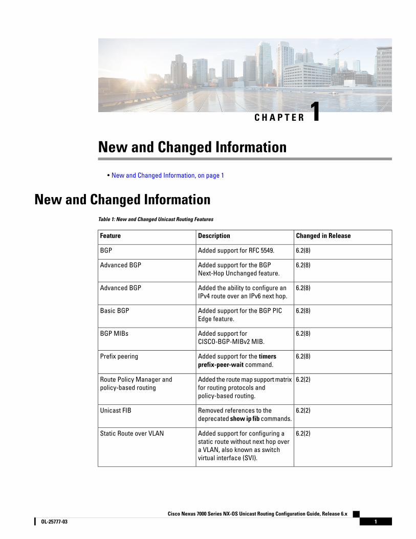
New and Changed InformationTable 1: New and Changed Unicast Routing Features
Changed in ReleaseDescriptionFeature
6.2(8)Added support for RFC 5549.BGP
6.2(8)Added support for the BGPNext-Hop Unchanged feature.
Advanced BGP
6.2(8)Added the ability to configure anIPv4 route over an IPv6 next hop.
Advanced BGP
6.2(8)Added support for the BGP PICEdge feature.
Basic BGP
6.2(8)Added support forCISCO-BGP-MIBv2 MIB.
BGP MIBs
6.2(8)Added support for the timersprefix-peer-wait command.
Prefix peering
6.2(2)Added the route map support matrixfor routing protocols andpolicy-based routing.
Route Policy Manager andpolicy-based routing
6.2(2)Removed references to thedeprecated show ip fib commands.
Unicast FIB
6.2(2)Added support for configuring astatic route without next hop overa VLAN, also known as switchvirtual interface (SVI).
Static Route over VLAN
Cisco Nexus 7000 Series NX-OS Unicast Routing Configuration Guide, Release 6.x1OL-25777-03
Changed in ReleaseDescriptionFeature
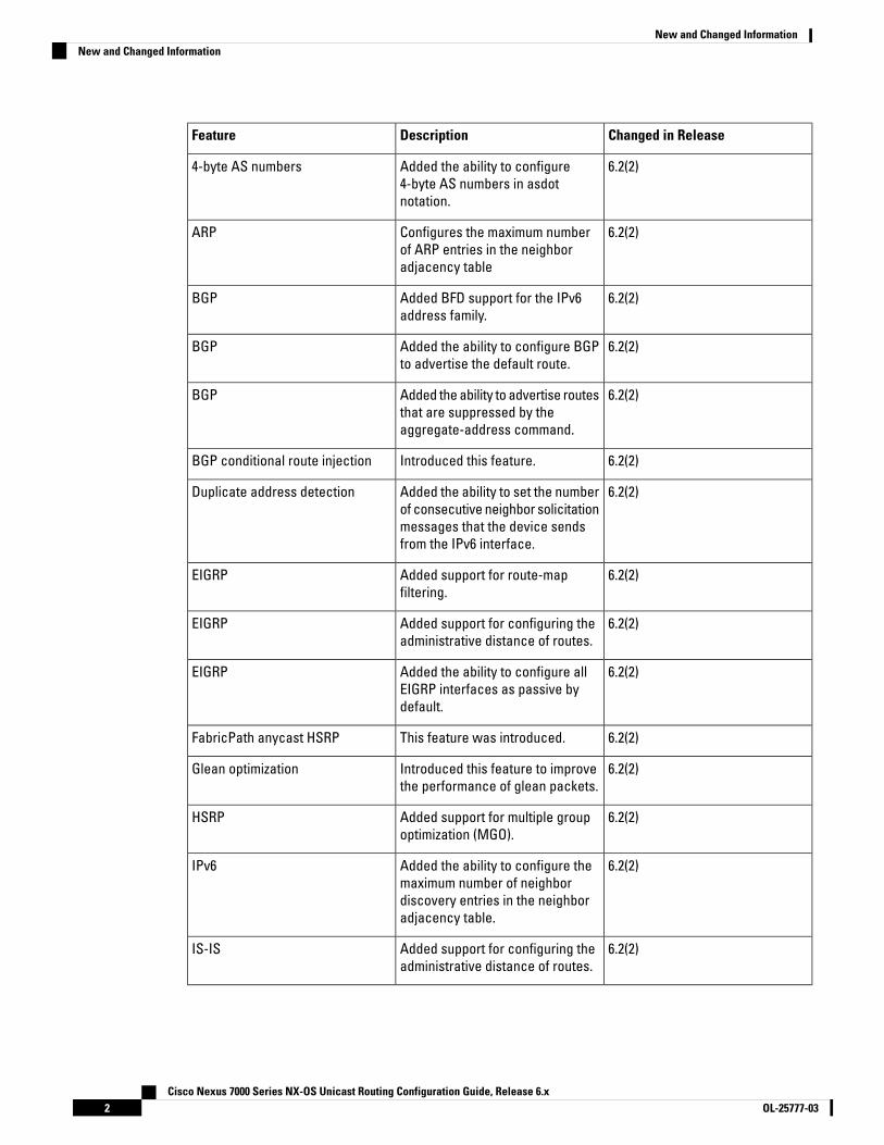
6.2(2)Added the ability to configure4-byte AS numbers in asdotnotation.
4-byte AS numbers
6.2(2)Configures the maximum numberof ARP entries in the neighboradjacency table
ARP
6.2(2)Added BFD support for the IPv6address family.
BGP
6.2(2)Added the ability to configure BGPto advertise the default route.
BGP
6.2(2)Added the ability to advertise routesthat are suppressed by theaggregate-address command.
BGP
6.2(2)Introduced this feature.BGP conditional route injection
6.2(2)Added the ability to set the numberof consecutive neighbor solicitationmessages that the device sendsfrom the IPv6 interface.
Duplicate address detection
6.2(2)Added support for route-mapfiltering.
EIGRP
6.2(2)Added support for configuring theadministrative distance of routes.
EIGRP
6.2(2)Added the ability to configure allEIGRP interfaces as passive bydefault.
EIGRP
6.2(2)This feature was introduced.FabricPath anycast HSRP
6.2(2)Introduced this feature to improvethe performance of glean packets.
Glean optimization
6.2(2)Added support for multiple groupoptimization (MGO).
HSRP
6.2(2)Added the ability to configure themaximum number of neighbordiscovery entries in the neighboradjacency table.
IPv6
6.2(2)Added support for configuring theadministrative distance of routes.
IS-IS
Cisco Nexus 7000 Series NX-OS Unicast Routing Configuration Guide, Release 6.xOL-25777-032
New and Changed InformationNew and Changed Information

Changed in ReleaseDescriptionFeature
6.2(2)Added the ability to configure allIS-IS interfaces as passive bydefault and then activate only thoseinterfaces where adjacencies aredesired.
IS-IS
6.2(2)Introduced this feature.Local policy routing
6.2(2)Added the filter keyword to thetable-map command to specify thatonly routes permitted by the routemap are downloaded to the RIB.
OSPFv2 and OSPFv3
6.2(2)Added the optional name-lookupparameter for OSPFv2 and OSPFv3instances.
OSPFv2 and OSPFv3
6.2(2)Added the ability to advertiselocally generated router LSAs withthe maximum metric value possible.
OSPFv3
6.2(2)Added OSPFv3 SNMP/trap support.OSPFv3 MIBs
6.2(2)Introduced this feature.Policy-based administrativedistance
6.2(2)Introduced this feature.Reliable static routing backup usingobject tracking
6.2(2)Added support for null interfacesto the match interface command.
Route policy manager
6.2(2)Added the ability to prevent discardroutes from being created.
Route summarization
6.2(2)Added the ability to monitor TCAMutilization on M1 Series modules.
TCAM utilization
6.2(2)Added the ability to check forinconsistent, missing, or failedroutes in the unicast FIB.
Unicast FIB
6.2(2)Added the optional keywordlonger-prefixes [detail] to the showrouting command to display specificroutes for a particular prefix.
Unicast RIB
6.2(2)Introduced these features.VRRPv3 and VRRS
Cisco Nexus 7000 Series NX-OS Unicast Routing Configuration Guide, Release 6.x3OL-25777-03
New and Changed InformationNew and Changed Information

Changed in ReleaseDescriptionFeature
6.1(3)Added support for deny accesscontrol entries (ACEs) in asequence for the followingsequence-based features: VACLs,policy-based routing, and QoS.
Policy-based routing
6.1(1)Added support for additional BGPpaths.
BGP
6.1(1)Added the ability to set the defaultweight for routes from a neighborusing the weight command in theneighbor address familyconfiguration mode.
BGP
6.1(1)Added support for IPv6.IS-IS
6.1(1)Added the no adjacency-checkcommand to disable strictadjacency mode.
IS-IS
6.1(1)Added support for M2 Seriesmodules.
Layer 3 routing using a mixedchassis
6.1(1)Added support for more than fourprocess instances for OSPFv2 perVDC.
OSPFv2
6.1(1)Added support for configuring theadministrative distance of routesfor OSPFv2 or OSPFv3.
OSPFv2 and OSPFv3
6.1(1)Added support for policy-basedrouting and WCCPv2 on the sameinterface if bank chaining isdisabled.
Policy-based routing and WCCPv2
6.1(1)Added the ability to configure CiscoNX-OS RIP to be behaviorallycompatible with Cisco IOS RIP inthe way that routes are advertisedand processed.
RIP
6.1(1)Added support for the set distancecommand and for the inter-areaand intra-area options in the matchroute-type command.
Route policy manager
6.0(1)Added the as-path multipath-relaxoption to the bestpath command.
BGP
Cisco Nexus 7000 Series NX-OS Unicast Routing Configuration Guide, Release 6.xOL-25777-034
New and Changed InformationNew and Changed Information

Changed in ReleaseDescriptionFeature
6.0(1)Added support for setting next-hopson reflected routes using anoutbound route-map.
BGP
6.0(1)Added the med confed option to thebestpath command to forcebestpath to do a MED comparisononly between paths originatedwithin a confederation.
BGP bestpath
6.0(1)Updated for F2 Series modules.IPv4 and IPv6
6.0(1)Updated for F2 Series modules.Static routing
5.2(1)Added BFD support to VRRP.BFD on VRRP
5.2(1)Added support for the BGP PIC corefeature.
BGP
5.2(1)Added the cost-community ignoreoption to the bestpath command.
BGP
5.2(1)Added support for EIGRP widemetrics.
EIGRP
5.2(1)Added support to configure themaximum number of routes allowedin the routing table.
Maximum routes
5.2(1)Added support for setextcommunity cost and setextcommunity rt commands.
Route-map enhancements
5.2(1)Added support for set interfacecommands.
Route-policy enhancements
5.2(1)Added support for VPNv4 andVPNv6 address modes.
VPN address mode
5.1(2)Added options for the max-metricrouter-lsa command.
OSPFv2
5.1(1)Added support for glean throttlingrate limiters to protect thesupervisor from the glean traffic.
IP Glean Throttling
5.1(1)Added support for WCCPv2 ErrorHandling for SPM Operations.
WCCP
5.1(1)Added the name option to the iproute command.
Static routing
Cisco Nexus 7000 Series NX-OS Unicast Routing Configuration Guide, Release 6.x5OL-25777-03
New and Changed InformationNew and Changed Information

Changed in ReleaseDescriptionFeature
5.1(1)Added support for the Layer 3Interoperation with the N7K-F132-15Module.
Layer 3 Interoperation with theN7K-F132-15 Module
5.0(2)Added support for BFD.BFD
5.0(2)Enabled by default and cannot bedisabled.
Dynamic TCAM allocation
5.0(2)Added support for IPv6 Path MTUdiscovery.
IPv6
5.0(2)Added support for IPv6.HSRP
5.0(2)Added support for IPv6.Object Tracking
5.0(2)Added support for BFD and statefulrestart.
IS-IS
5.0(2)Added support for larger TCAM andFIB sizes with XL modules.
TCAM and FIB Size
5.0(2)Added support for match mac-list, match metric, and match vlancommands.
Route Maps
Cisco Nexus 7000 Series NX-OS Unicast Routing Configuration Guide, Release 6.xOL-25777-036
New and Changed InformationNew and Changed Information
C H A P T E R 2Overview
This chapter contains the following sections:
• Overview, on page 7
OverviewThis chapter introduces the underlying concepts for the Layer 3 unicast routing protocols in Cisco NX-OS.
Licensing RequirementsFor a complete explanation of Cisco NX-OS licensing recommendations and how to obtain and apply licenses,see the Cisco NX-OS Licensing Guide.
Information About Layer 3 Unicast RoutingLayer 3 unicast routing involves two basic activities: determining optimal routing paths and packet switching.You can use routing algorithms to calculate the optimal path from the router to a destination. This calculationdepends on the algorithm selected, route metrics, and other considerations such as load balancing andalternate path discovery.
Routing FundamentalsRouting protocols use a metric to evaluate the best path to the destination. A metric is a standard ofmeasurement, such as a path bandwidth, that routing algorithms use to determine the optimal path to adestination. To aid path determination, routing algorithms initialize and maintain routing tables that containroute information such as the IP destination address, the address of the next router, or the next hop. Destinationand next-hop associations tell a router that an IP destination can be reached optimally by sending the packetto a particular router that represents the next hop on the way to the final destination. When a router receivesan incoming packet, it checks the destination address and attempts to associate this address with the nexthop.
Routing tables can contain other information, such as the data about the desirability of a path. Routers comparemetrics to determine optimal routes, and these metrics differ depending on the design of the routing algorithmused.
Routers communicate with one another and maintain their routing tables by transmitting a variety of messages.The routing update message is one such message that consists of all or a portion of a routing table. By analyzing
Cisco Nexus 7000 Series NX-OS Unicast Routing Configuration Guide, Release 6.x7OL-25777-03

routing updates from all other routers, a router can build a detailed picture of the network topology. A link-stateadvertisement, which is another example of a message sent between routers, informs other routers of the linkstate of the sending router. You can also use link information to enable routers to determine optimal routes tonetwork destinations.
Packet SwitchingIn packet switching, a host determines that it must send a packet to another host. Having acquired a routeraddress by some means, the source host sends a packet that is addressed specifically to the router physical(Media Access Control [MAC]-layer) address but with the IP (network layer) address of the destination host.
The router examines the destination IP address and tries to find the IP address in the routing table. If the routerdoes not know how to forward the packet, it typically drops the packet. If the router knows how to forwardthe packet, it changes the destination MAC address to the MAC address of the next-hop router and transmitsthe packet.
The next hop might be the ultimate destination host or another router that executes the same switching decisionprocess. As the packet moves through the internetwork, its physical address changes, but its protocol addressremains constant (see the following figure).
Cisco Nexus 7000 Series NX-OS Unicast Routing Configuration Guide, Release 6.xOL-25777-038
OverviewPacket Switching
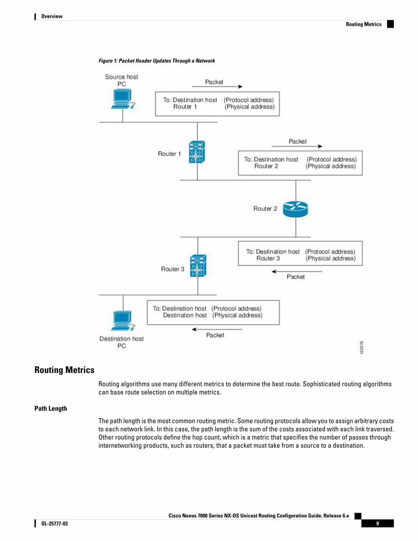
Figure 1: Packet Header Updates Through a Network
Routing MetricsRouting algorithms use many different metrics to determine the best route. Sophisticated routing algorithmscan base route selection on multiple metrics.
Path Length
The path length is the most common routing metric. Some routing protocols allow you to assign arbitrary coststo each network link. In this case, the path length is the sum of the costs associated with each link traversed.Other routing protocols define the hop count, which is a metric that specifies the number of passes throughinternetworking products, such as routers, that a packet must take from a source to a destination.
Cisco Nexus 7000 Series NX-OS Unicast Routing Configuration Guide, Release 6.x9OL-25777-03
OverviewRouting Metrics

Reliability
The reliability, in the context of routing algorithms, is the dependability (in terms of the bit-error rate) of eachnetwork link. Some network links might go down more often than others. After a network fails, certain networklinks might be repaired more easily or more quickly than other links. The reliability factors that you can takeinto account when assigning the reliability rating are arbitrary numeric values that you usually assign to networklinks.
Routing Delay
The routing delay is the length of time required to move a packet from a source to a destination through theinternetwork. The delay depends on many factors, including the bandwidth of intermediate network links, theport queues at each router along the way, the network congestion on all intermediate network links, and thephysical distance that the packet must travel. Because the routing delay is a combination of several importantvariables, it is a common and useful metric.
Bandwidth
The bandwidth is the available traffic capacity of a link. For example, a 10-Gigabit Ethernet link is preferableto a 1-Gigabit Ethernet link. Although the bandwidth is the maximum attainable throughput on a link, routesthrough links with greater bandwidth do not necessarily provide better routes than routes through slower links.For example, if a faster link is busier, the actual time required to send apacket to the destination could begreater.
Load
The load is the degree to which a network resource, such as a router, is busy. You can calculate the load ina variety of ways, including CPU usage and packets processed per second. Monitoring these parameters ona continual basis can be resource intensive.
Communication Cost
The communication cost is a measure of the operating cost to route over a link. The communication cost isanother important metric, especially if you do not care about performance as much as operating expenditures.For example, the line delay for a private line might be longer than a public line, but you can send packets overyour private line rather than through the public lines that cost money for usage time.
Router IDsEach routing process has an associated router ID. You can configure the router ID to any interface in thesystem. If you do not configure the router ID, Cisco NX-OS selects the router ID based on the following criteria:
• Cisco NX-OS prefers loopback0 over any other interface. If loopback0 does not exist, then Cisco NX-OSprefers the first loopback interface over any other interface type.
• If you have not configured a loopback interface, Cisco NX-OS uses the first interface in the configurationfile as the router ID. If you configure any loopback interface after Cisco NX-OS selects the router ID, theloopback interface becomes the router ID. If the loopback interface is not loopback0 and you configureloopback0 with an IP address, the router ID changes to the IP address of loopback0.
• If the interface that the router ID is based on changes, that new IP address becomes the router ID. If anyother interface changes its IP address, there is no router ID change.
Cisco Nexus 7000 Series NX-OS Unicast Routing Configuration Guide, Release 6.xOL-25777-0310
OverviewReliability

Autonomous SystemsAn autonomous system (AS) is a network controlled by a single technical administration entity. Autonomoussystems divide global external networks into individual routing domains, where local routing policies areapplied. This organization simplifies routing domain administration and simplifies consistent policy configuration.
Each autonomous system can support multiple interior routing protocols that dynamically exchange routinginformation through route redistribution. The Regional Internet Registries assign a unique number to eachpublic autonomous system that directly connects to the Internet. This autonomous system number (AS number)identifies both the routing process and the autonomous system.
The Border Gateway Protocol (BGP) supports 4-byte AS numbers that can be represented in asplain and asdotnotations:
• asplain—A decimal value notation where both 2-byte and 4-byte AS numbers are represented by
their decimal value. For example, 65526 is a 2-byte AS number, and 234567 is a 4-byte AS number.
• asdot—An AS dot notation where 2-byte AS numbers are represented by their decimal value and 4-byteAS numbers are represented by a dot notation. For example, 2-byte AS number 65526 is represented as65526, and 4-byte AS number 65546 is represented as 1.10.
The BGP 4-byte AS number capability is used to propagate 4-byte-based AS path information across BGPspeakers that do not support 4-byte AS numbers. Beginning with Cisco NX-OS Release 6.2(2), you can configure4-byte AS numbers in asdot notation. The default value is asplain.
The following table lists the AS number ranges.
Table 2: AS Numbers
Purpose4-Byte Numbers inplaintext Notation
4-Byte Numbers in AS.dotNotation
2-Byte Numbers
Public AS (assigned byRIR)1
1 to 64511N/A1 to 64511
Private AS (assigned bylocal administrator)
64512 to 65534N/A64512 to 65534
Reserved65535N/A65535
Public AS (assigned byRIR)
65536 to 42949672951.0 to 65535.65535N/A
1 RIR=Regional Internet Registries
RFC 5396 is partially supported. The asplain and asdot notations are supported, but the asdot+ notation is not.Note
Private autonomous system numbers are used for internal routing domains but must be translated by the routerfor traffic that is routed out to the Internet. You should not configure routing protocols to advertise privateautonomous system numbers to external networks. By default, Cisco NX-OS does not remove private autonomoussystem numbers from routing updates.
Cisco Nexus 7000 Series NX-OS Unicast Routing Configuration Guide, Release 6.x11OL-25777-03
OverviewAutonomous Systems

The autonomous system number assignment for public and private networks is governed by the InternetAssigned Number Authority (IANA). For information about autonomous system numbers, including the reservednumber assignment, or to apply to register an autonomous system number, refer to the following URL:http://www.iana.org/
Note
ConvergenceA key aspect to measure for any routing algorithm is how much time a router takes to react to network topologychanges. When a part of the network changes for any reason, such as a link failure, the routing informationin different routers might not match. Some routers will have updated information about the changed topology,while other routers will still have the old information. The convergence is the amount of time before all routersin the network have updated, matching routing information. The convergence time varies depending on therouting algorithm. Fast convergence minimizes the chance of lost packets caused by inaccurate routinginformation.
Load Balancing and Equal Cost MultipathRouting protocols can use load balancing or equal cost multipath (ECMP) to share traffic across multiplepaths.When a router learns multiple routes to a specific network, it installs the route with the lowestadministrative distance in the routing table. If the router receives and installs multiple paths with the sameadministrative distance and cost to a destination, load balancing can occur. Load balancing distributes thetraffic across all the paths, sharing the load. The number of paths used is limited by the number of entries thatthe routing protocol puts in the routing table. Cisco NX-OS supports up to 16 paths to a destination. Startingfrom Cisco NX-OS Release 8.4(1), the BGP feature supports up to 64 paths to a destination on M3- and F3-SeriesI/O modules. Starting from Cisco NX-OS Release 8.4(2), the BGP feature supports up to 64 paths to a destinationon F4-Series I/O modules.
The Enhanced Interior Gateway Routing Protocol (EIGRP) also supports unequal cost load balancing.
Route RedistributionIf you have multiple routing protocols configured in your network, you can configure these protocols to sharerouting information by configuring route redistribution in each protocol. For example, you can configure theOpen Shortest Path First (OSPF) protocol to advertise routes learned from the Border Gateway Protocol (BGP).You can also redistribute static routes into any dynamic routing protocol. The router that is redistributing routesfrom another protocol sets a fixed route metric for those redistributed routes, which prevents incompatibleroute metrics between the different routing protocols. For example, routes redistributed from EIGRP into OSPFare assigned a fixed link cost metric that OSPF understands.
You are required to use route maps when you configure redistribution of routing information.Note
Route redistribution also uses an administrative distance to distinguish between routes learned from twodifferent routing protocols. The preferred routing protocol is given a lower administrative distance so that itsroutes are picked over routes from another protocol with a higher administrative distance assigned.
Cisco Nexus 7000 Series NX-OS Unicast Routing Configuration Guide, Release 6.xOL-25777-0312
OverviewConvergence

Administrative DistanceAn administrative distance is a rating of the trustworthiness of a routing information source. A higher valueindicates a lower trust rating. Typically, a route can be learned through more than one protocol. Administrativedistance is used to discriminate between routes learned from more than one protocol. The route with thelowest administrative distance is installed in the IP routing table.
Stub RoutingYou can use stub routing in a hub-and-spoke network topology, where one or more end (stub) networks areconnected to a remote router (the spoke) that is connected to one or more distribution routers (the hub). Theremote router is adjacent only to one or more distribution routers. The only route for IP traffic to follow intothe remote router is through a distribution router. This type of configuration is commonly used in WAN topologiesin which the distribution router is directly connected to a WAN. The distribution router can be connected tomany more remote routers. Often, the distribution router is connected to 100 or more remote routers. In ahub-and-spoke topology, the remote router must forward all nonlocal traffic to a distribution router, so itbecomes unnecessary for the remote router to hold a complete routing table. Generally, the distribution routersends only a default route to the remote router.
Only specified routes are propagated from the remote (stub) router. The stub router responds to all queriesfor summaries, connected routes, redistributed static routes, external routes, and internal routes with themessage "inaccessible." A router that is configured as a stub sends a special peer information packet to allneighboring routers to report its status as a stub router.
Any neighbor that receives a packet that informs it of the stub status does not query the stub router for anyroutes, and a router that has a stub peer does not query that peer. The stub router depends on the distributionrouter to send the proper updates to all peers. The following figure shows a simple hub-and-spoke network.
Figure 2: Simple Hub-and-Spoke Network
Stub routing does not prevent routes from being advertised to the remote router. This figure shows that theremote router can access the corporate network and the Internet through the distribution router only. A fullroute table on the remote router, in this example, serves no functional purpose because the path to the corporatenetwork and the Internet is always through the distribution router. A larger route table only increases theamount of memory consumed by the remote router. The bandwidth and memory used can be lessened bysummarizing and filtering routes in the distribution router. In this network topology, the remote router does notneed to receive routes that have been learned from other networks because the remote router must send allnon-local traffic, regardless of its destination, to the distribution router. To configure a true stub network, youshould configure the distribution router to send only a default route to the remote router.
OSPF supports stub areas and EIGRP supports stub routers.
Cisco Nexus 7000 Series NX-OS Unicast Routing Configuration Guide, Release 6.x13OL-25777-03
OverviewAdministrative Distance

Routing AlgorithmsRouting algorithms determine how a router gathers and reports reachability information, how it deals withtopology changes, and how it determines the optimal route to a destination. Various types of routing algorithmsexist, and each algorithm has a different impact on network and router resources. Routing algorithms use avariety of metrics that affect calculation of optimal routes. You can classify routing algorithms by type, suchas static or dynamic, and interior or exterior.
Static Routes and Dynamic Routing ProtocolsStatic routes are route table entries that you manually configure. These static routes do not change unlessyou reconfigure them. Static routes are simple to design and work well in environments where network trafficis relatively predictable and where network design is relatively simple.
Because static routing systems cannot react to network changes, you should not use them for large, constantlychanging networks. Most routing protocols today use dynamic routing algorithms that adjust to changingnetwork circumstances by analyzing incoming routing update messages. If the message indicates that anetwork change has occurred, the routing software recalculates routes and sends out new routing updatemessages. These messages permeate the network, triggering routers to rerun their algorithms and changetheir routing tables accordingly.
You can supplement dynamic routing algorithms with static routes where appropriate. For example, you shouldconfigure each subnetwork with a static route to the IP default gateway or router of last resort (a router towhich all unrouteable packets are sent).
Interior and Exterior Gateway ProtocolsYou can separate networks into unique routing domains or autonomous systems. An autonomous system is aportion of an internetwork under common administrative authority that is regulated by a particular set ofadministrative guidelines. Routing protocols that route between autonomous systems are called exteriorgateway protocols or interdomain protocols. The Border Gateway Protocol (BGP) is an example of an exteriorgateway protocol. Routing protocols used within an autonomous system are called interior gateway protocolsor intradomain protocols. EIGRP and OSPF are examples of interior gateway protocols.
Distance Vector ProtocolsDistance vector protocols use distance vector algorithms (also known as Bellman-Ford algorithms) that callfor each router to send all or some portion of its routing table to its neighbors. Distance vector algorithmsdefine routes by distance (for example, the number of hops to the destination) and direction (for example, thenext-hop router). These routes are then broadcast to the directly connected neighbor routers. Each routeruses these updates to verify and update the routing tables.
To prevent routing loops, most distance vector algorithms use split horizon with poison reverse which meansthat the routes learned from an interface are set as unreachable and advertised back along the interface thatthey were learned on during the next periodic update. This process prevents the router from seeing its ownroute updates coming back.
Distance vector algorithms send updates at fixed intervals but can also send updates in response to changesin route metric values. These triggered updates can speed up the route convergence time. The RoutingInformation Protocol (RIP) is a distance vector protocol.
Cisco Nexus 7000 Series NX-OS Unicast Routing Configuration Guide, Release 6.xOL-25777-0314
OverviewRouting Algorithms
Link-State ProtocolsThe link-state protocols, also known as shortest path first (SPF), share information with neighboring routers.Each router builds a link-state advertisement (LSA) that contains information about each link and directlyconnected neighbor router.
Each LSA has a sequence number. When a router receives an LSA and updates its link-state database, theLSA is flooded to all adjacent neighbors. If a router receives two LSAs with the same sequence number (fromthe same router), the router does not flood the last LSA that it received to its neighbors because it wants toprevent an LSA update loop. Because the router floods the LSAs immediately after it receives them, theconvergence time for link-state protocols is minimized.
Discovering neighbors and establishing adjacency is an important part of a link state protocol. Neighbors arediscovered using special Hello packets that also serve as keepalive notifications to each neighbor router.Adjacency is the establishment of a common set of operating parameters for the link-state protocol betweenneighbor routers.
The LSAs received by a router are added to the router's link-state database. Each entry consists of the followingparameters:
• Router ID (for the router that originated the LSA)
• Neighbor ID
• Link cost
• Sequence number of the LSA
• Age of the LSA entry
The router runs the SPF algorithm on the link-state database, building the shortest path tree for that router.This SPF tree is used to populate the routing table.
In link-state algorithms, each router builds a picture of the entire network in its routing tables. The link-statealgorithms send small updates everywhere, while distance vector algorithms send larger updates only toneighboring routers.
Because they converge more quickly, link-state algorithms are less likely to cause routing loops than distancevector algorithms. However, link-state algorithms require more CPU power and memory than distance vectoralgorithms and they can be more expensive to implement and support. Link-state protocols are generally morescalable than distance vector protocols.
OSPF is an example of a link-state protocol.
Layer 3 VirtualizationCisco NX-OS uses a virtual device context (VDC) to provide separate management domains per VDC andsoftware fault isolation. Each VDC supports multiple virtual routing and forwarding instances and multiplerouting information bases (RIBs) to support multiple address domains. Each VRF is associated with a RIB andthis information is collected by the Forwarding Information Base (FIB). The following figure shows therelationship between a VDC, a VRF, and a Cisco NX-OS device.
Cisco Nexus 7000 Series NX-OS Unicast Routing Configuration Guide, Release 6.x15OL-25777-03
OverviewLink-State Protocols
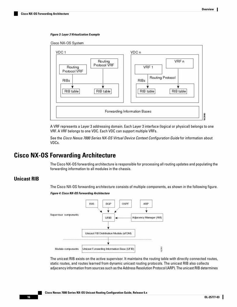
Figure 3: Layer 3 Virtualization Example
A VRF represents a Layer 3 addressing domain. Each Layer 3 interface (logical or physical) belongs to oneVRF. A VRF belongs to one VDC. Each VDC can support multiple VRFs.
See the Cisco Nexus 7000 Series NX-OS Virtual Device Context Configuration Guide for information aboutVDCs.
Cisco NX-OS Forwarding ArchitectureThe Cisco NX-OS forwarding architecture is responsible for processing all routing updates and populating theforwarding information to all modules in the chassis.
Unicast RIBThe Cisco NX-OS forwarding architecture consists of multiple components, as shown in the following figure.
Figure 4: Cisco NX-OS Forwarding Architecture
The unicast RIB exists on the active supervisor. It maintains the routing table with directly connected routes,static routes, and routes learned from dynamic unicast routing protocols. The unicast RIB also collectsadjacency information from sources such as the Address Resolution Protocol (ARP). The unicast RIB determines
Cisco Nexus 7000 Series NX-OS Unicast Routing Configuration Guide, Release 6.xOL-25777-0316
OverviewCisco NX-OS Forwarding Architecture
the best next hop for a given route and populates the unicast forwarding information base (FIB) by using theservices of the unicast FIB distribution module (FDM).
Each dynamic routing protocol must update the unicast RIB for any route that has timed out. The unicast RIBthen deletes that route and recalculates the best next hop for that route (if an alternate path is available).
Adjacency ManagerThe adjacency manager exists on the active supervisor and maintains adjacency information for differentprotocols including ARP, Neighbor Discovery Protocol (NDP), and static configuration. The most basic adjacencyinformation is the Layer 3 to Layer 2 address mapping discovered by these protocols. Outgoing Layer 2 packetsuse the adjacency information to complete the Layer 2 header.
The adjacency manager can trigger ARP requests to find a particular Layer 3 to Layer 2 mapping. The newmapping becomes available when the corresponding ARP reply is received and processed. For IPv6, theadjacency manager finds the Layer 3 to Layer 2 mapping information from NDP.
Unicast Forwarding Distribution ModuleThe unicast Forwarding Distribution Module (FDM) exists on the active supervisor and distributes the forwardingpath information from the unicast RIB and other sources. The unicast RIB generates forwarding informationthat the unicast FIB programs into the hardware forwarding tables on the standby supervisor and the modules.The unicast FDM also downloads the FIB information to newly inserted modules.
The unicast FDM gathers adjacency information, rewrite information, and other platform-dependent informationwhen updating routes in the unicast FIB. The adjacency and rewrite information consists of interface, nexthop, and Layer 3 to Layer 2 mapping information. The interface and next-hop information is received in routeupdates from the unicast RIB. The Layer 3 to Layer 2 mapping is received from the adjacency manager.
FIBThe unicast FIB exists on supervisors and switching modules and builds the information used for the hardwareforwarding engine. The unicast FIB receives route updates from the unicast FDM and sends the informationto be programmed in the hardware forwarding engine. The unicast FIB controls the addition, deletion, andmodification of routes, paths, and adjacencies.
The unicast FIBs are maintained on a per-VRF and per-address-family basis, that is, one for IPv4 and one forIPv6 for each configured VRF. Based on route update messages, the unicast FIB maintains a per-VRF prefixand next-hop adjacency information database. The next-hop adjacency data structure contains the next-hopIP address and the Layer 2 rewrite information. Multiple prefixes could share a next-hop adjacency informationstructure.
Hardware ForwardingCisco NX-OS supports distributed packet forwarding. The ingress port takes relevant information from thepacket header and passes the information to the local switching engine. The local switching engine does theLayer 3 lookup and uses this information to rewrite the packet header. The ingress module forwards the packetto the egress port. If the egress port is on a different module, the packet is forwarded using the switch fabricto the egress module. The egress module does not participate in the Layer 3 forwarding decision.
The forwarding tables are identical on the supervisor and all the modules.
You also use the show platform fib or show platform forwarding commands to display details on hardwareforwarding.
Cisco Nexus 7000 Series NX-OS Unicast Routing Configuration Guide, Release 6.x17OL-25777-03
OverviewAdjacency Manager

Software ForwardingThe software forwarding path in Cisco NX-OS is used mainly to handle features that are not supported in thehardware or to handle errors encountered during the hardware processing. Typically, packets with IP optionsor packets that need fragmentation are passed to the CPU on the active supervisor. All packets that shouldbe switched in the software or terminated go to the supervisor. The supervisor uses the information providedby the unicast RIB and the adjacency manager to make the forwarding decisions. The module is not involvedin the software forwarding path.
Software forwarding is controlled by control plane policies and rate limiters. For more information, see theCisco Nexus 7000 Series NX-OS Security Configuration Guide.
Layer 3 Interoperation with the N7K-F132-15 Module
You must install one of the N7K-M Series modules in the Cisco Nexus 7000 Series chassis to run Layer 3 routingwith the N7K-F132-15 module. You must have interfaces from both the M Series and the N7K-F132-15 modulesin the same VDC. (See the Cisco Nexus 7000 Series NX-OS Virtual Device Context Configuration Guide formore information about VDCs.
Note
You cannot use F2 Series modules in the Cisco Nexus 7000 Series chassis to run Layer 3 routing with theN7K-F132-15 module
Note
Layer 3 routing functionality comes up automatically when you have one of the N7K-M Series modules installedin the chassis with the N7K-F132-15 module. You would usually position a chassis with both the N7K-F132-15and M Series modules, or a mixed chassis, at the boundary between the Layer 2 and Layer 3 networks.
You must configure a VLAN interface for each VLAN on the N7K-F132-15 module that you want to use theproxy-routing functionality in a mixed chassis. (See the Cisco Nexus 7000 Series NX-OS Interfaces ConfigurationGuide for information about configuring VLAN interfaces.)
By default, all of the physical interfaces on the N7K-M series modules in the VDC become proxy routing portsfor the VLANs that are configured with VLAN interfaces on the Layer 2-only N7K-F132-15 module in the sameVDC. The physical interfaces on the M Series module can be administratively down and still pass traffic asproxy forwarding.
Packets that enter an interface on the N7K-F132-15 module are automatically forwarded to one of the interfaceson the M Series modules in the same VDC to be routed. The interface on the M Series module also performsegress replication for Layer 3 multicast packets that enter an interface on the N7K-F132-15 module in the sameVDC.
Because the Layer 3 (proxy routing) traffic from the N7K-F132-15 modules adds to the traffic that the M Seriesmodules are already processing, the device automatically provides load balancing for the total traffic loadamong the front panel ports of the available M Series modules in the VDC. If you add or remove interfaces tothe M Series modules in the VDC, the device automatically rebalances the traffic. Note that proxy routing issharing the forwarding capacity of the M Series modules. Removing interfaces reduces the amount of capacityavailable.
Instead of using the automatically configured proxy-routing interfaces on the M Series modules, you canoptionally configure which interfaces on the M Series modules in the VDC performs proxy routing.
Cisco Nexus 7000 Series NX-OS Unicast Routing Configuration Guide, Release 6.xOL-25777-0318
OverviewSoftware Forwarding

Summary of Layer 3 Routing FeaturesThis section provides a brief introduction to the Layer 3 unicast features and protocols supported in CiscoNX-OS.
IPv4 and IPv6Layer 3 uses either the IPv4 or IPv6 protocol. IPv6 is a new IP protocol designed to replace IPv4, the Internetprotocol that is predominantly deployed and used throughout the world. IPv6 increases the number of networkaddress bits from 32 bits (in IPv4) to 128 bits.
IP ServicesIP Services includes Dynamic Host Configuration Protocol (DHCP) and Domain Name System (DNS Client)clients.
OSPFThe Open Shortest Path First (OSPF) protocol is a link-state routing protocol used to exchange networkreachability information within an autonomous system. Each OSPF router advertises information about itsactive links to its neighbor routers. Link information consists of the link type, the link metric, and the neighborrouter that is connected to the link. The advertisements that contain this link information are called link-stateadvertisements.
EIGRPThe Enhanced Interior Gateway Routing Protocol (EIGRP) is a unicast routing protocol that has thecharacteristics of both distance vector and link-state routing protocols. It is an improved version of IGRP,which is a Cisco proprietary routing protocol. EIGRP relies on its neighbors to provide the routes. It constructsthe network topology from the routes advertised by its neighbors, similar to a lin-state protocol, and uses thisinformation to select loop-free paths to destinations.
IS-ISThe Intermediate System-to-Intermediate System (IS-IS) protocol is an intradomain Open System Interconnection(OSI) dynamic routing protocol specified in the International Organization for Standardization (ISO) 10589. TheIS-IS routing protocol is a link-state protocol. IS-IS features are as follows:
• Hierarchical routing• Classless behavior• Rapid flooding of new information• Fast Convergence• Very scalable
BGPThe Border Gateway Protocol (BGP) is an inter-autonomous system routing protocol. A BGP router advertisesnetwork reachability information to other BGP routers using Transmission Control Protocol (TCP) as its reliabletransport mechanism. The network reachability information includes the destination network prefix, a list ofautonomous systems that needs to be traversed to reach the destination, and the next-hop router. Reachabilityinformation contains additional path attributes such as preference to a route, origin of the route, communityand others..
Cisco Nexus 7000 Series NX-OS Unicast Routing Configuration Guide, Release 6.x19OL-25777-03
OverviewSummary of Layer 3 Routing Features

RIPThe Routing Information Protocol (RIP) is a distance-vector protocol that uses a hop count as its metric. RIPis widely used for routing traffic in the global Internet and is an Interior Gateway Protocol (IGP), which meansthat it performs routing within a single autonomous system.
Static RoutingStatic routing allows you to enter a fixed route to a destination. This feature is useful for small networks wherethe topology is simple. Static routing is also used with other routing protocols to control default routes androute distribution.
Layer 3 VirtualizationVirtualization allows you to share physical resources across separate management domains. Cisco NX-OSsupports Virtual Device Contexts (VDCs) that allow you to create separate virtual systems within a Cisco NX-OSsystem. Each VDC is isolated from the others, which means that a problem in one VDC does not affect anyother VDCs. VDCs are also secure from each other. You can assign separate network operators to each VDCand these network operators cannot control or view the configuration of a different VDC.
Cisco NX-OS also supports Layer 3 virtualization with virtual routing and forwarding (VRF). VRF provides aseparate address domain for configuring Layer 3 routing protocols.
Route Policy ManagerThe Route Policy Manager provides a route filtering capability in Cisco NX-OS. It uses route maps to filterroutes distributed across various routing protocols and between different entities within a given routingprotocol. Filtering is based on specific match criteria, which is similar to packet filtering by access controllists.
Policy-Based RoutingPolicy-based routing uses the Route Policy Manager to create policy route filters. These policy route filterscan forward a packet to a specified next hop based on the source of the packet or other fields in the packetheader. Policy routes can be linked to extended IP access lists so that routing might be based on protocoltypes and port numbers.
First Hop Redundancy ProtocolsFirst hop redundancy protocols (FHRP), such as Gateway Load Balancing Protocol (GLBP), Hot Standby RouterProtocol (HSRP), and Virtual Router Redundancy Protocol (VRRP), allow you to provide redundant connectionsto your hosts. If an active first-hop router fails, the FHRP automatically selects a standby router to take over.You do not need to update the hosts with new IP addresses since the address is virtual and shared betweeneach router in the FHRP group.
Object TrackingObject tracking allows you to track specific objects on the network, such as the interface line protocol state,IP routing, and route reachability, and take action when the tracked object's state changes. This feature allowsyou to increase the availability of the network and shorten the recovery time if an object state goes down.
Cisco Nexus 7000 Series NX-OS Unicast Routing Configuration Guide, Release 6.xOL-25777-0320
OverviewRIP

Related Documents for Layer 3 Unicast RoutingFeature InformationFeature Name
Cisco NEXUS 7000 Series NX-OS Multicast Routing ConfigurationGuide
Cisco NEXUS 7000 Series NX-OS High Availability and RedundancyGuide
Cisco NEXUS 7000 Series NX-OS Virtual Device Context
Exploring Autonomous System Numbers: http://www.cisco.com/web/about/ac123/ac147/archived_issues/ipj_9-1/autonomous_system_numbers.html
Layer 3 features
Cisco Nexus 7000 Series NX-OS Unicast Routing Configuration Guide, Release 6.x21OL-25777-03
OverviewRelated Documents for Layer 3 Unicast Routing

Cisco Nexus 7000 Series NX-OS Unicast Routing Configuration Guide, Release 6.xOL-25777-0322
OverviewRelated Documents for Layer 3 Unicast Routing

P A R T IIP
• Configuring IPv4, on page 25• Configuring IPv6, on page 49• Configuring DNS, on page 79• Configuring WCCPv2, on page 85

C H A P T E R 3Configuring IPv4
This chapter contains the following sections:
• Finding Feature Information, on page 25• Information About IPv4, on page 25• Virtualization Support for IPv4, on page 30• Prerequisites for IPv4, on page 30• Guidelines and Limitations for IPv4, on page 30• Default Settings for IPv4 Parameters, on page 31• Configuring IPv4, on page 31• Verifying the IPv4 Configuration, on page 42• Configuration Examples for IPv4, on page 43• Related Documents for IPv4, on page 46• Standards for IPv4, on page 46• Feature History for IPv4, on page 46
Finding Feature InformationYour software release might not support all the features documented in this module. For the latest caveatsand feature information, see the Bug Search Tool at https://tools.cisco.com/bugsearch/ and the release notesfor your software release. To find information about the features documented in this module, and to see a listof the releases in which each feature is supported, see the "New and Changed Information"chapter or theFeature History table in this chapter.
Information About IPv4You can configure IP on the device to assign IP addresses to network interfaces. When you assign IP addresses,you enable the interfaces and allow communication with the hosts on those interfaces.
You can configure an IP address as primary or secondary on a device. An interface can have one primary IPaddress and multiple secondary addresses. All networking device on an interface should share the sameprimary IP address because the packets that are generated by the device always use the primary IPv4 address.Each IPv4 packet is based on the information from a source or destination IP address.
You can use a subnet to mask the IP addresses. A mask is used to determine what subnet an IP addressbelongs to. An IP address contains the network address and the host address. A mask identifies the bits that
Cisco Nexus 7000 Series NX-OS Unicast Routing Configuration Guide, Release 6.x25OL-25777-03

denote the network number in an IP address. When you use the mask to subnet a network, the mask is thenreferred to as a subnet mask. Subnet masks are 32-bit values that allow the recipient of IP packets to distinguishthe network ID portion of the IP address from the host ID portion of the IP address.
The IP feature is responsible for handling IPv4 packets that terminate in the supervisor module, as well asforwarding of IPv4 packets, which includes IPv4 unicast/multicast route lookup, reverse path forwarding (RPF)checks, and software access control list/policy-based routing (ACL/PBR) forwarding. The IP feature alsomanages the network interface IP address configuration, duplicate address checks, static routes, and packetsend/receive interface for IP clients.
Multiple IPv4 AddressesCisco NX-OS supports multiple IP addresses per interface. You can specify an unlimited number of secondaryaddresses for a variety of situations.
The most common situations are as follows:
• When there are not enough host IP addresses for a particular network interface. For example, if yoursubnetting allows up to 254 hosts per logical subnet, but on one physical subnet you must have 300 hostaddresses, then you can use secondary IP addresses on the routers or access servers to allow you tohave two logical subnets that use one physical subnet.
• Two subnets of a single network might otherwise be separated by another network. You can create asingle network from subnets that are physically separated by another network by using a secondaryaddress. In these instances, the first network is extended, or layered on top of the second network. Asubnet cannot appear on more than one active interface of the router at a time.
If any device on a network segment uses a secondary IPv4 address, other devices on that same networksegment that require a secondary address must use a secondary address from the same network or subnet.The inconsistent use of secondary addresses on a network segment can quickly cause routing loops.
Note
Address Resolution ProtocolNetworking devices and Layer 3 switches use Address Resolution Protocol (ARP) to map IP (network layer)addresses to (Media Access Control [MAC]-layer) addresses to enable IP packets to be sent across networks.Before a device sends a packet to another device, it looks in its own ARP cache to see if there is a MACaddress and corresponding IP address for the destination device. If there is no entry, the source device sendsa broadcast message to every device on the network.
Each device compares the IP address to its own. Only the device with the matching IP address replies to thedevice that sends the data with a packet that contains the MAC address for the device. The source deviceadds the destination device MAC address to its ARP table for future reference, creates a data-link header andtrailer that encapsulates the packet, and proceeds to transfer the data.
Cisco Nexus 7000 Series NX-OS Unicast Routing Configuration Guide, Release 6.xOL-25777-0326
IPMultiple IPv4 Addresses

Figure 5: ARP Process
When the destination device lies on a remote network that is beyond another device, the process is the sameexcept that the device that sends the data sends an ARP request for the MAC address of the default gateway.After the address is resolved and the default gateway receives the packet, the default gateway broadcaststhe destination IP address over the networks connected to it. The device on the destination device networkuses ARP to obtain the MAC address of the destination device and delivers the packet. ARP is enabled bydefault.
The default system-defined CoPP policy rate limits ARP broadcast packets bound for the supervisor module.The default system-defined CoPP policy prevents an ARP broadcast storm from affecting the control planetraffic but does not affect bridged packets.
ARP CachingARP caching minimizes broadcasts and limits wasteful use of network resources. The mapping of IP addressesto MAC addresses occurs at each hop (device) on the network for every packet sent over an internetwork,which may affect network performance.
ARP caching stores network addresses and the associated data-link addresses in the memory for a period oftime, which minimizes the use of valuable network resources to broadcast for the same address each timethat a packet is sent. You must maintain the cache entries that are set to expire periodically because theinformation might become outdated. Every device on a network updates its tables as addresses are broadcast.
To maintain the ARP entry, active MAC address-table entries and host routing adjacencies, Cisco NX-OS sendsup to 3 unicast ARP request messages to devices that are present in the ARP cache. The first message is sentat 75% of the configured ARP timeout value, followed by two retries 30 and 60 seconds later if the cached entryhas not already been refreshed.
Static and Dynamic Entries in the ARP CacheStatic routing requires that you manually configure the IP addresses, subnet masks, gateways, andcorresponding MAC addresses for each interface of each device. Static routing requires more work to maintainthe route table. You must update the table each time you add or change routes.
Dynamic routing uses protocols that enable the devices in a network to exchange routing table informationwith each other. Dynamic routing is more efficient than static routing because the route table is automaticallyupdated unless you add a time limit to the cache. The default time limit is 25 minutes but you can modify thetime limit if the network has many routes that are added and deleted from the cache.
Devices That Do Not Use ARPWhen a network is divided into two segments, a bridge joins the segments and filters traffic to each segmentbased on MAC addresses. The bridge builds its own address table, which uses MAC addresses only. A devicehas an ARP cache that contains both IP addresses and the corresponding MAC addresses.
Cisco Nexus 7000 Series NX-OS Unicast Routing Configuration Guide, Release 6.x27OL-25777-03
IPARP Caching
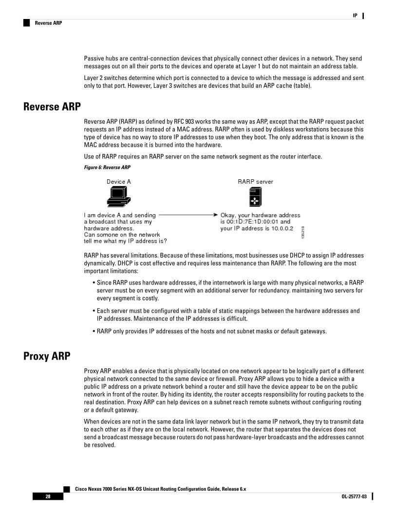
Passive hubs are central-connection devices that physically connect other devices in a network. They sendmessages out on all their ports to the devices and operate at Layer 1 but do not maintain an address table.
Layer 2 switches determine which port is connected to a device to which the message is addressed and sentonly to that port. However, Layer 3 switches are devices that build an ARP cache (table).
Reverse ARPReverse ARP (RARP) as defined by RFC 903 works the same way as ARP, except that the RARP request packetrequests an IP address instead of a MAC address. RARP often is used by diskless workstations because thistype of device has no way to store IP addresses to use when they boot. The only address that is known is theMAC address because it is burned into the hardware.
Use of RARP requires an RARP server on the same network segment as the router interface.
Figure 6: Reverse ARP
RARP has several limitations. Because of these limitations, most businesses use DHCP to assign IP addressesdynamically. DHCP is cost effective and requires less maintenance than RARP. The following are the mostimportant limitations:
• Since RARP uses hardware addresses, if the internetwork is large with many physical networks, a RARPserver must be on every segment with an additional server for redundancy. maintaining two servers forevery segment is costly.
• Each server must be configured with a table of static mappings between the hardware addresses andIP addresses. Maintenance of the IP addresses is difficult.
• RARP only provides IP addresses of the hosts and not subnet masks or default gateways.
Proxy ARPProxy ARP enables a device that is physically located on one network appear to be logically part of a differentphysical network connected to the same device or firewall. Proxy ARP allows you to hide a device with apublic IP address on a private network behind a router and still have the device appear to be on the publicnetwork in front of the router. By hiding its identity, the router accepts responsibility for routing packets to thereal destination. Proxy ARP can help devices on a subnet reach remote subnets without configuring routingor a default gateway.
When devices are not in the same data link layer network but in the same IP network, they try to transmit datato each other as if they are on the local network. However, the router that separates the devices does notsend a broadcast message because routers do not pass hardware-layer broadcasts and the addresses cannotbe resolved.
Cisco Nexus 7000 Series NX-OS Unicast Routing Configuration Guide, Release 6.xOL-25777-0328
IPReverse ARP

When you enable Proxy ARP on the device and it receives an ARP request, it identifies the request as a requestfor a system that is not on the local LAN. The device responds as if it is the remote destination for which thebroadcast is addressed, with an ARP response that associates the device’s MAC address with the remotedestination's IP address. The local device believes that it is directly connected to the destination, while inreality its packets are being forwarded from the local subnetwork toward the destination subnetwork by theirlocal device. By default, Proxy ARP is disabled.
Local Proxy ARPYou can use local Proxy ARP to enable a device to respond to ARP requests for IP addresses within a subnetwhere normally no routing is required. When you enable local Proxy ARP, ARP responds to all ARP requestsfor IP addresses within the subnet and forwards all traffic between hosts in the subnet. Use this feature onlyon subnets where hosts are intentionally prevented from communicating directly by the configuration on thedevice to which they are connected.
Gratuitous ARPGratuitous ARP sends a request with an identical source IP address and a destination IP address to detectduplicate IP addresses. Cisco NX-OS supports enabling or disabling gratuitous ARP requests or ARP cacheupdates.
Glean ThrottlingWhen forwarding an incoming IP packet in a line card, if the Address Resolution Protocol (ARP) request forthe next hop is not resolved, the line card forwards the packets to the supervisor (glean throttling). Thesupervisor resolves the MAC address for the next hop and programs the hardware.
The Cisco Nexus 7000 Series device hardware has glean rate limiters to protect the supervisor from the gleantraffic. If the maximum number of entries is exceeded, the packets for which the ARP request is not resolvedcontinues to be processed in the software instead of getting dropped in the hardware.
When an ARP request is sent, the software adds a /32 drop adjacency in the hardware to prevent the packetsto the same next-hop IP address to be forwarded to the supervisor. When the ARP is resolved, the hardwareentry is updated with the correct MAC address. If the ARP entry is not resolved before a timeout period, theentry is removed from the hardware.
Path MTU DiscoveryPath maximum transmission unit (MTU) discovery is a method for maximizing the use of available bandwidthin the network between the endpoints of a TCP connection. It is described in RFC 1191. Existing connectionsare not affected when this feature is turned on or off.
Please ensure you enable ip unreachables command between TCP endpoints for the Path MTU discoveryfeature to work correctly.
Note
Cisco Nexus 7000 Series NX-OS Unicast Routing Configuration Guide, Release 6.x29OL-25777-03
IPLocal Proxy ARP

ICMPYou can use the Internet Control Message Protocol (ICMP) to provide message packets that report errors andother information that is relevant to IP processing. ICMP generates error messages, such as ICMP destinationunreachable messages, ICMP Echo Requests (which send a packet on a round trip between two hosts) andEcho Reply messages. ICMP also provides many diagnostic functions and can send and redirect error packetsto the host. By default, ICMP is enabled.
Some of the ICMP message types are as follows:
• Network error messages
• Network congestion messages
• Troubleshooting information
• Timeout announcements
ICMP redirects are disabled on interfaces where the local proxy ARP feature is enabled.Note
Virtualization Support for IPv4IPv4 supports virtual routing and forwarding (VRF) instances. VRFs exist within virtual device contexts (VDCs).By default, Cisco NX-OS places you in the default VDC and default VRF unless you specifically configureanother VDC and VRF. For more information, see the Cisco NX-OS Virtual Device Context Configuration Guide.
Prerequisites for IPv4IPv4 has the following prerequisites:
• IPv4 can only be configured on Layer 3 interfaces.
Guidelines and Limitations for IPv4IPv4 has the following configuration guidelines and limitations:
• You can configure a secondary IP address only after you configure the primary IP address.
• F2 Series modules do not support IPv4 tunnels.
• If any device on a network segment uses a secondary IPv4 address, other devices on that same networksegment that require a secondary address must use a secondary address from the same network orsubnet. The inconsistent use of secondary addresses on a network segment can quickly cause routingloops.
• If you are familiar with the Cisco IOS CLI, be aware that the Cisco NX-OS commands for this feature mightdiffer from the Cisco IOS commands that you would use.
Cisco Nexus 7000 Series NX-OS Unicast Routing Configuration Guide, Release 6.xOL-25777-0330
IPICMP

Default Settings for IPv4 ParametersTable 3: Default IPv4 Parameters
DefaultParameters
1500 secondsARP timeout
Disabledproxy ARP
131,072Maximum number of IPv4 ARP entries in the neighboradjacency table
Configuring IPv4
Configuring IPv4 AddressingYou can assign a primary IP address for a network interface.
Before you begin
Ensure that you are in the correct VDC (or use the switchto vdc command).
Procedure
PurposeCommand or Action
Enters global configuration mode.switch# configure terminalStep 1
Enters interface configuration mode.switch(config)# interface ethernet numberStep 2
Configures the interface as a Layer 3 routedinterface.
switch(config-if)# no switchportStep 3
Specifies a primary or secondary IPv4 addressfor an interface.
switch(config-if)# ip address ip-address/length[secondary]
Step 4
• The network mask can be a four-partdotted decimal address. For example,255.0.0.0 indicates that each bit equal to 1means the corresponding address bitbelongs to the network address.
• The network mask can be indicated as aslash (/) and a number—a prefix length.The prefix length is a decimal value thatindicates how many of the high-ordercontiguous bits of the address comprisethe prefix (the network portion of the
Cisco Nexus 7000 Series NX-OS Unicast Routing Configuration Guide, Release 6.x31OL-25777-03
IPDefault Settings for IPv4 Parameters
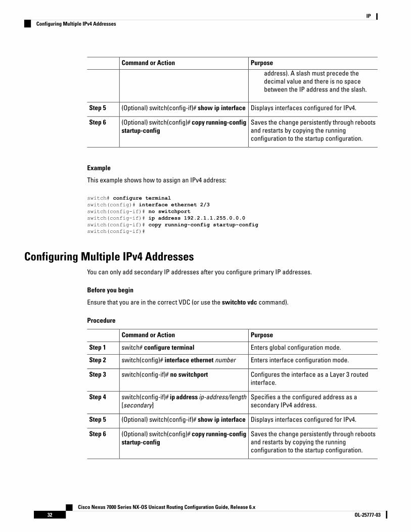
PurposeCommand or Action
address). A slash must precede thedecimal value and there is no spacebetween the IP address and the slash.
Displays interfaces configured for IPv4.(Optional) switch(config-if)# show ip interfaceStep 5
Saves the change persistently through rebootsand restarts by copying the runningconfiguration to the startup configuration.
(Optional) switch(config)# copy running-configstartup-config
Step 6
Example
This example shows how to assign an IPv4 address:
switch# configure terminalswitch(config)# interface ethernet 2/3switch(config-if)# no switchportswitch(config-if)# ip address 192.2.1.1.255.0.0.0switch(config-if)# copy running-config startup-configswitch(config-if)#
Configuring Multiple IPv4 AddressesYou can only add secondary IP addresses after you configure primary IP addresses.
Before you begin
Ensure that you are in the correct VDC (or use the switchto vdc command).
Procedure
PurposeCommand or Action
Enters global configuration mode.switch# configure terminalStep 1
Enters interface configuration mode.switch(config)# interface ethernet numberStep 2
Configures the interface as a Layer 3 routedinterface.
switch(config-if)# no switchportStep 3
Specifies a the configured address as asecondary IPv4 address.
switch(config-if)# ip address ip-address/length[secondary]
Step 4
Displays interfaces configured for IPv4.(Optional) switch(config-if)# show ip interfaceStep 5
Saves the change persistently through rebootsand restarts by copying the runningconfiguration to the startup configuration.
(Optional) switch(config)# copy running-configstartup-config
Step 6
Cisco Nexus 7000 Series NX-OS Unicast Routing Configuration Guide, Release 6.xOL-25777-0332
IPConfiguring Multiple IPv4 Addresses

Configuring a Static ARP EntryConfigure a static ARP entry on the device to map IP addresses to MAC hardware addresses, including staticmulticast MAC addresses.
Before you begin
Ensure that you are in the correct VDC (or use the switchto vdc command).
Procedure
PurposeCommand or Action
Enters global configuration mode.switch# configure terminalStep 1
Enters interface configuration mode.switch(config)# interface ethernet numberStep 2
Configures the interface as a Layer 3 routedinterface.
switch(config)# no switchportStep 3
Associates an IP address with a MAC addressas a static entry.
switch(config-if)# ip arp address ip-addressmac-address
Step 4
Saves the change persistently through rebootsand restarts by copying the runningconfiguration to the startup configuration.
(Optional) switch(config)# copy running-configstartup-config
Step 5
Example
This example shows how to assign a static ARP entry:
switch# configure terminalswitch(config)# interface ethernet 2/3switch(config-if)# no switchportswitch(config-if)# ip arp 192.2.1.1.0019.076c.1a78switch(config-if)# copy running-config startup-configswitch(config-if)#
Configuring Proxy ARPConfigure proxy ARP on the device to determine the media addresses of hosts on other networks or subnets.
Before you begin
Ensure that you are in the correct VDC (or use the switchto vdc command).
Procedure
PurposeCommand or Action
Enters global configuration mode.switch# configure terminalStep 1
Cisco Nexus 7000 Series NX-OS Unicast Routing Configuration Guide, Release 6.x33OL-25777-03
IPConfiguring a Static ARP Entry

PurposeCommand or Action
Enters interface configuration mode.switch(config-if)# interface ethernet numberStep 2
Configures the interface as a Layer 3 routedinterface.
switch(config-if)# no switchportStep 3
Enables proxy ARP on the interface.switch(config-if)# ip proxy arpStep 4
(Optional) Saves the change persistently throughreboots and restarts by copying the runningconfiguration to the startup configuration.
switch(config)# copy running-configstartup-config
Step 5
Example
This example shows how to configure proxy ARP:
switch# configure terminalswitch(config)# interface ethernet 2/3switch(config-if)# no switchportswitch(config-if)# ip proxy-arpswitch(config-if)# copy running-config startup-configswitch(config-if)#
Configuring Local Proxy ARP
Before you begin
Ensure that you are in the correct VDC (or use the switchto vdc command).
Procedure
PurposeCommand or Action
Enters global configuration mode.switch# configure terminalStep 1
Enters interface configuration mode.switch(config)# interface ethernet numberStep 2
Configures the interface as a Layer 3 routedinterface.
switch(config)# no switchportStep 3
Enables local proxy ARP on the interface.switch(config-if)# ip local-proxy-arpStep 4
Saves the change persistently through rebootsand restarts by copying the runningconfiguration to the startup configuration.
(Optional) switch(config)# copy running-configstartup-config
Step 5
Example
This example shows how to configure local proxy ARP:
Cisco Nexus 7000 Series NX-OS Unicast Routing Configuration Guide, Release 6.xOL-25777-0334
IPConfiguring Local Proxy ARP

switch# configure terminalswitch(config)# interface ethernet 2/3switch(config-if)# no switchportswitch(config-if)# ip local-proxy-arpswitch(config-if)# copy running-config startup-configswitch(config-if)#
Configuring Gratuitous ARP
Before you begin
Ensure that you are in the correct VDC (or use the switchto vdc command).
Procedure
PurposeCommand or Action
Enters global configuration mode.switch# configure terminalStep 1
Enters interface configuration mode.switch(config)# interface ethernet numberStep 2
Configures the interface as a Layer 3 routedinterface.
switch(config-if)# no switchportStep 3
Enables gratuitous ARP on the interface.switch(config-if)# ip arp gratuitous {request |update]
Step 4
Gratuitous ARP is enabled by default.
Saves the change persistently through rebootsand restarts by copying the runningconfiguration to the startup configuration.
(Optional) switch(config)# copy running-configstartup-config
Step 5
Example
This example shows how to configure gratuitous ARP:
switch# configure terminalswitch(config)# interface ethernet 2/3switch(config-if)# no switchportswitch(config-if)# ip arp gratuitous requestswitch(config-if)# copy running-config startup-configswitch(config-if)#
Configuring the IP ARP Cache Limit
Before you begin
Ensure that you are in the correct VDC (or use the switchto vdc command).
Cisco Nexus 7000 Series NX-OS Unicast Routing Configuration Guide, Release 6.x35OL-25777-03
IPConfiguring Gratuitous ARP
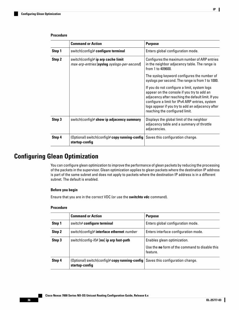
Procedure
PurposeCommand or Action
Enters global configuration mode.switch(config)# configure terminalStep 1
Configures the maximum number of ARP entriesin the neighbor adjacency table. The range isfrom 1 to 409600.
switch(config)# ip arp cache limitmax-arp-entries [syslog syslogs-per-second]
Step 2
The syslog keyword configures the number ofsyslogs per second. The range is from 1 to 1000.
If you do not configure a limit, system logsappear on the console if you try to add anadjacency after reaching the default limit. If youconfigure a limit for IPv4 ARP entries, systemlogs appear if you try to add an adjacency afterreaching the configured limit.
Displays the global limit of the neighboradjacency table and a summary of throttleadjacencies.
switch(config)# show ip adjacency summaryStep 3
Saves this configuration change.(Optional) switch(config)# copy running-configstartup-config
Step 4
Configuring Glean OptimizationYou can configure glean optimization to improve the performance of glean packets by reducing the processingof the packets in the supervisor. Glean optimization applies to glean packets where the destination IP addressis part of the same subnet and does not apply to packets where the destination IP address is in a differentsubnet. The default is enabled.
Before you begin
Ensure that you are in the correct VDC (or use the switchto vdc command).
Procedure
PurposeCommand or Action
Enters global configuration mode.switch# configure terminalStep 1
Enters interface configuration mode.switch(config)# interface ethernet numberStep 2
Enables glean optimization.switch(config-if)# [no] ip arp fast-pathStep 3
Use the no form of the command to disable thisfeature.
Saves this configuration change.(Optional) switch(config)# copy running-configstartup-config
Step 4
Cisco Nexus 7000 Series NX-OS Unicast Routing Configuration Guide, Release 6.xOL-25777-0336
IPConfiguring Glean Optimization

Configuring Bloom Filter Support for Glean AdjacenciesBloom Filter Support for Glean Adjacencies is introduced in Cisco NX-OS Release 8.4(2).
When a routed frame has an ARP cache miss, the packet hits a glean adjacency (which means the IP DA hitson the FIB table but cannot resolve MAC DA for the routed frame), and it is punted to the supervisor module.Until the ARP cache is updated, all packets belonging to this flow will hit the glean adjacency and are puntedto the supervisor module. To avoid this punting of the supervisor module, the L3 engine hashes a flow to set abit in a leak table to indicate that the packet has been punted to the supervisor module. Subsequent framesare dropped until the software clears the leak table bit. This helps to forward the packets without any furtherdelay.
The Bloom Filter Support for Glean Adjacencies feature is supported on M3 and F4 modules.
Before you perform the configuration, ensure that you are in the correct VDC or use the switchto vdc command.This command is a global, system CLI on the default vdc and it is not configurable on a non-default vdc.
Procedure
PurposeCommand or Action
Enters global configuration mode.switch# configure terminalStep 1
Enables the bloom filter forwarding. Thiscommand is disabled by default.
switch(config)# hardware forwardingglean-bloom-filter
Step 2
Disables the bloom filter forwarding.switch(config)# no hardware forwardingglean-bloom-filter
Step 3
Saves the change persistently through rebootsand restarts by copying the runningconfiguration to the startup configuration.
(Optional) switch(config)# copy running-configstartup-config
Step 4
Exits the global configuration mode.switch(config)# exitStep 5
Displays the glean routes from all supportedmodules.
(Optional) switch# show system internalforwarding route summary
Step 6
Example
This example shows how to enable IP glean throttling:
switch# configure terminalswitch(config)# hardware forwarding glean-bloom-filterswitch(config)# copy running-config startup-configswitch(config)# exitswitch# show system internal forwarding route summary
Configuring Path MTU Discovery
Before you begin
Ensure that you are in the correct VDC (or use the switchto vdc command).
Cisco Nexus 7000 Series NX-OS Unicast Routing Configuration Guide, Release 6.x37OL-25777-03
IPConfiguring Bloom Filter Support for Glean Adjacencies

Procedure
PurposeCommand or Action
Enters global configuration mode.switch# configure terminalStep 1
Enables path MTU discovery.switch(config)# ip tcp path-mtu-discoveryStep 2
Saves the change persistently through rebootsand restarts by copying the runningconfiguration to the startup configuration.
(Optional) switch(config)# copy running-configstartup-config
Step 3
Configuring IP Packet VerificationCisco NX-OS supports an Intrusion Detection System (IDS) that checks for IP packet verification. You canenable or disable these IDS checks.
Procedure
PurposeCommand or Action
Enters global configuration mode.switch# configure terminalStep 1
Performs the following IDS checks on the IPaddress:
switch(config)# hardware ip verify address{destination zero | identical | reserved | source{broadcast | multicast}}
Step 2
• destination zero—Drops IP packets if thedestination IP address is 0.0.0.0.
• identical—Drops IP packets if the sourceIP address is identical to the destinationIP address.
• reserved—Drops IP packets if the IPaddress is in the 127.x.x.x range.
• source—Drops IP packets if the IP sourceaddress is either 255.255.255.255(broadcast) or in the 224.x.x.x range(multicast).
Drops IP packets if the packet checksum isinvalid.
switch(config)# hardware ip verify checksumStep 3
Drops IP packets if the packet fragment has anonzero offset and the DF bit is active.
switch(config)# hardware ip verify fragmentStep 4
Performs the following IDS checks on the IPaddress:
switch(config)# hardware ip verify length{consistent | maximum {max-frag | max-tcp |udp} | minimum}
Step 5
• consistent— Drops IP packets where theEthernet frame size is greater than or equalto the IP packet length plus the Ethernetheader.
Cisco Nexus 7000 Series NX-OS Unicast Routing Configuration Guide, Release 6.xOL-25777-0338
IPConfiguring IP Packet Verification

PurposeCommand or Action
• maximum max-frag—Drops IP packets ifthe maximum fragment offset is greaterthan 65536.
• maximum max-tcp—Drops IP packets ifthe TCP length is greater than the IPpayload length.
• maximum udp—Drops IP packets if the IPpayload length is less than the UDP packetlength.
• minimum—Drops IP packets if the Ethernetframe length is less than the IP packetlength plus four octets (the CRC length).
Drops TCP packets if the IP fragment offset is1, or if the IP fragment offset is 0 and the IPpayload length is less than 16.
switch(config)# hardware ip verify tcp tiny-fragStep 6
Drops IP packets if the ethertype is not set to 4(IPv4).
switch(config)# hardware ip verify versionStep 7
What to do next
Use the show hardware forwarding ip verify command to display the IP packet verification configuration.
Configuring IP Glean ThrottlingCisco NX-OS software supports glean throttling rate limiters to protect the supervisor from the glean traffic.
We recommend that you configure the IP glean throttle feature by using the hardware ip glean throttle commandto filter the unnecessary glean packets that are sent to the supervisor for ARP resolution for the next hopsthat are not reachable or do not exist. IP glean throttling boosts software performance and helps to managetraffic more efficiently.
Note
Before you begin
Ensure that you are in the correct VDC (or use the switchto vdc command).
Procedure
PurposeCommand or Action
Enters global configuration mode.switch# configure terminalStep 1
Enables ARP throttling.switch(config)# hardware ip glean throttleStep 2
Disables ARP throttling.switch(config)# no hardware ip glean throttleStep 3
Cisco Nexus 7000 Series NX-OS Unicast Routing Configuration Guide, Release 6.x39OL-25777-03
IPConfiguring IP Glean Throttling
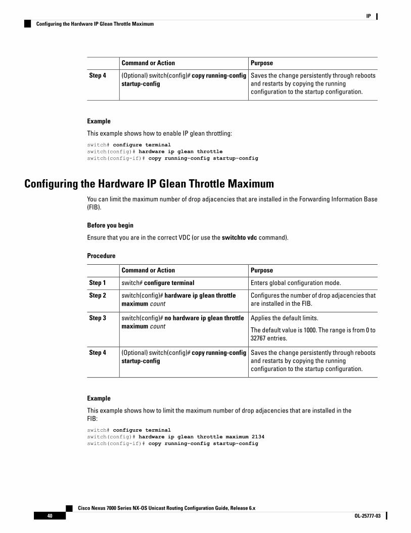
PurposeCommand or Action
Saves the change persistently through rebootsand restarts by copying the runningconfiguration to the startup configuration.
(Optional) switch(config)# copy running-configstartup-config
Step 4
Example
This example shows how to enable IP glean throttling:
switch# configure terminalswitch(config)# hardware ip glean throttleswitch(config-if)# copy running-config startup-config
Configuring the Hardware IP Glean Throttle MaximumYou can limit the maximum number of drop adjacencies that are installed in the Forwarding Information Base(FIB).
Before you begin
Ensure that you are in the correct VDC (or use the switchto vdc command).
Procedure
PurposeCommand or Action
Enters global configuration mode.switch# configure terminalStep 1
Configures the number of drop adjacencies thatare installed in the FIB.
switch(config)# hardware ip glean throttlemaximum count
Step 2
Applies the default limits.switch(config)# no hardware ip glean throttlemaximum count
Step 3
The default value is 1000. The range is from 0 to32767 entries.
Saves the change persistently through rebootsand restarts by copying the runningconfiguration to the startup configuration.
(Optional) switch(config)# copy running-configstartup-config
Step 4
Example
This example shows how to limit the maximum number of drop adjacencies that are installed in theFIB:
switch# configure terminalswitch(config)# hardware ip glean throttle maximum 2134switch(config-if)# copy running-config startup-config
Cisco Nexus 7000 Series NX-OS Unicast Routing Configuration Guide, Release 6.xOL-25777-0340
IPConfiguring the Hardware IP Glean Throttle Maximum

Configuring the Hardware IP Glean Throttle TimeoutYou can configure a timeout for the installed drop adjacencies to remain in the Forwarding Information Base(FIB).
Before you begin
Ensure that you are in the correct VDC (or use the switchto vdc command).
Procedure
PurposeCommand or Action
Enters global configuration mode.switch# configure terminalStep 1
Configures the timeout for the installed dropadjacencies to remain in the FIB.
switch(config)# hardware ip glean throttlemaximum timeout timeout-in-seconds
Step 2
Applies the default limits.switch(config)# no hardware ip glean throttlemaximum timeout timeout-in-seconds
Step 3
The timeout value is in seconds. The range isfrom 300 seconds (5 minutes) to 1800 seconds(30 minutes).
After the timeout period is exceeded,the drop adjacencies are removedfrom the FIB.
Note
Saves the change persistently through rebootsand restarts by copying the runningconfiguration to the startup configuration.
(Optional) switch(config)# copy running-configstartup-config
Step 4
Configuring the Hardware IP Glean Throttle SyslogYou can a syslog if the number of packets that get dropped for a specific flow exceeds the configured packetcount.
Before you begin
Ensure that you are in the correct VDC (or use the switchto vdc command).
Procedure
PurposeCommand or Action
Enters global configuration mode.switch# configure terminalStep 1
Generates a syslog if the number of packets thatget dropped for a specific flow exceed theconfigured packet count.
switch(config)# hardware ip glean throttlesyslog packet-count
Step 2
Applies the default limits.switch(config)# no hardware ip glean throttlesyslog packet-count
Step 3
Cisco Nexus 7000 Series NX-OS Unicast Routing Configuration Guide, Release 6.x41OL-25777-03
IPConfiguring the Hardware IP Glean Throttle Timeout

PurposeCommand or Action
The default is 10000 packets. The range is from0 to 65535 packets.
After the timeout period is exceeded,the drop adjacencies are removedfrom the FIB.
Note
Saves the change persistently through rebootsand restarts by copying the runningconfiguration to the startup configuration.
(Optional) switch(config)# copy running-configstartup-config
Step 4
Example
This example shows how to generate a syslog if the number of packets that get dropped for a specificflow exceeds the configured packet count:
switch# configure terminalswitch(config)# hardware ip glean throttle maximum timeout 300switch(config-if)# copy running-config startup-config
Verifying the IPv4 ConfigurationUse one of the following commands to verify the configuration:
PurposeCommand
Shows the IP packet verification configuration.show hardware forwarding ip verify
Displays the adjacency table.show ip adjacency
Displays the summary of number of throttleadjacencies.
show ip adjacency summary
Displays the ARP table.show ip arp
Displays the summary of the number of throttleadjacencies.
show ip arp summary
Displays only the throttle adjacencies.show ip adjacency throttle statistics
Displays IP-related interface information.show ip interface
Displays the ARP statistics.show ip arp statistics [vrf vrf-name]
Cisco Nexus 7000 Series NX-OS Unicast Routing Configuration Guide, Release 6.xOL-25777-0342
IPVerifying the IPv4 Configuration
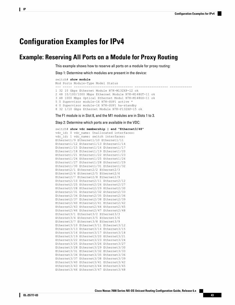
Configuration Examples for IPv4
Example: Reserving All Ports on a Module for Proxy RoutingThis example shows how to reserve all ports on a module for proxy routing:
Step 1: Determine which modules are present in the device:
switch# show moduleMod Ports Module-Type Model Status--- ----- -------------------------------- ------------------ ------------1 32 10 Gbps Ethernet Module N7K-M132XP-12 ok2 48 10/100/1000 Mbps Ethernet Module N7K-M148GT-11 ok3 48 1000 Mbps Optical Ethernet Modul N7K-M148GS-11 ok5 0 Supervisor module-1X N7K-SUP1 active *6 0 Supervisor module-1X N7K-SUP1 ha-standby8 32 1/10 Gbps Ethernet Module N7K-F132XP-15 ok
The F1 module is in Slot 8, and the M1 modules are in Slots 1 to 3.
Step 2: Determine which ports are available in the VDC:
switch# show vdc membership | end "Ethernet3/48"vdc_id: 0 vdc_name: Unallocated interfaces:vdc_id: 1 vdc_name: switch interfaces:Ethernet1/9 Ethernet1/10 Ethernet1/11Ethernet1/12 Ethernet1/13 Ethernet1/14Ethernet1/15 Ethernet1/16 Ethernet1/17Ethernet1/18 Ethernet1/19 Ethernet1/20Ethernet1/21 Ethernet1/22 Ethernet1/23Ethernet1/24 Ethernet1/25 Ethernet1/26Ethernet1/27 Ethernet1/28 Ethernet1/29Ethernet1/30 Ethernet1/31 Ethernet1/32Ethernet2/1 Ethernet2/2 Ethernet2/3Ethernet2/4 Ethernet2/5 Ethernet2/6Ethernet2/7 Ethernet2/8 Ethernet2/9Ethernet2/10 Ethernet2/11 Ethernet2/12Ethernet2/25 Ethernet2/26 Ethernet2/27Ethernet2/28 Ethernet2/29 Ethernet2/30Ethernet2/31 Ethernet2/32 Ethernet2/33Ethernet2/34 Ethernet2/35 Ethernet2/36Ethernet2/37 Ethernet2/38 Ethernet2/39Ethernet2/40 Ethernet2/41 Ethernet2/42Ethernet2/43 Ethernet2/44 Ethernet2/45Ethernet2/46 Ethernet2/47 Ethernet2/48Ethernet3/1 Ethernet3/2 Ethernet3/3Ethernet3/4 Ethernet3/5 Ethernet3/6Ethernet3/7 Ethernet3/8 Ethernet3/9Ethernet3/10 Ethernet3/11 Ethernet3/12Ethernet3/13 Ethernet3/14 Ethernet3/15Ethernet3/16 Ethernet3/17 Ethernet3/18Ethernet3/19 Ethernet3/20 Ethernet3/21Ethernet3/22 Ethernet3/23 Ethernet3/24Ethernet3/25 Ethernet3/26 Ethernet3/27Ethernet3/28 Ethernet3/29 Ethernet3/30Ethernet3/31 Ethernet3/32 Ethernet3/33Ethernet3/34 Ethernet3/35 Ethernet3/36Ethernet3/37 Ethernet3/38 Ethernet3/39Ethernet3/40 Ethernet3/41 Ethernet3/42Ethernet3/43 Ethernet3/44 Ethernet3/45Ethernet3/46 Ethernet3/47 Ethernet3/48
Cisco Nexus 7000 Series NX-OS Unicast Routing Configuration Guide, Release 6.x43OL-25777-03
IPConfiguration Examples for IPv4

Step 3: Determine which ports are available for proxy routing:
switch# show hardware proxy layer-3 detailGlobal Information:F1 Modules: Count: 1 Slot: 8M1 Modules: Count: 3 Slot: 1-3Replication Rebalance Mode: ManualNumber of proxy layer-3 forwarders: 13Number of proxy layer-3 replicators: 8Forwarder Interfaces Status Reason------------------------------------------------------------------------------Eth1/9, Eth1/11, Eth1/13, Eth1/15 up SUCCESSEth1/10, Eth1/12, Eth1/14, Eth1/16 up SUCCESSEth1/17, Eth1/19, Eth1/21, Eth1/23 up SUCCESSEth1/18, Eth1/20, Eth1/22, Eth1/24 up SUCCESSEth1/25, Eth1/27, Eth1/29, Eth1/31 up SUCCESSEth1/26, Eth1/28, Eth1/30, Eth1/32 up SUCCESSEth2/1-12 up SUCCESSEth2/25-36 up SUCCESSEth2/37-48 up SUCCESSEth3/1-12 up SUCCESSEth3/13-24 up SUCCESSEth3/25-36 up SUCCESSEth3/37-48 up SUCCESSReplicator Interfaces #Interface-Vlan Interface-Vlan------------------------------------------------------------------------------Eth1/1, Eth1/3, Eth1/5, Eth1/7, Eth1/9, 0Eth1/11, Eth1/13, Eth1/15Eth1/2, Eth1/4, Eth1/6, Eth1/8, Eth1/10, 0Eth1/12, Eth1/14, Eth1/16Eth1/17, Eth1/19, Eth1/21, Eth1/23, 0Eth1/25, Eth1/27, Eth1/29, Eth1/31Eth1/18, Eth1/20, Eth1/22, Eth1/24, 0Eth1/26, Eth1/28, Eth1/30, Eth1/32Eth2/1-24 0Eth2/25-48 0Eth3/1-24 0Eth3/25-48 0switch#
Ports are listed in their respective port groups.Note
Step 4: Reserve a module for unicast and multicast proxy routing:
switch# configure terminalswitch(config)# hardware proxy layer-3 forwarding use module 2switch(config)# hardware proxy layer-3 replication use module 2
Step 5: Verify this configuration:
switch(config)# show hardware proxy layer-3 detailGlobal Information:F1 Modules: Count: 1 Slot: 8M1 Modules: Count: 3 Slot: 1-3Replication Rebalance Mode: ManualNumber of proxy layer-3 forwarders: 3Number of proxy layer-3 replicators: 2Forwarder Interfaces Status Reason------------------------------------------------------------------------------Eth2/1-12 up SUCCESSEth2/25-36 up SUCCESSEth2/37-48 up SUCCESS
Cisco Nexus 7000 Series NX-OS Unicast Routing Configuration Guide, Release 6.xOL-25777-0344
IPExample: Reserving All Ports on a Module for Proxy Routing

Replicator Interfaces #Interface-Vlan Interface-Vlan------------------------------------------------------------------------------Eth2/1-24 0Eth2/25-48 0switch(config)#
Example: Reserving Ports for Proxy RoutingThis example shows how to reserve some ports on a module for proxy routing:
Step 1: Reserve a subset of ports on a module:
switch(config)# hardware proxy layer-3 forwarding use interface ethernet 2/1-6switch(config)# hardware proxy layer-3 replication use interface ethernet 2/1-6 <----subsetof port group
This example reserves a subset of ports from a port group.
Step 2: Verify this configuration:
switch(config)# show hardware proxy layer-3 detailGlobal Information:F1 Modules: Count: 1 Slot: 8M1 Modules: Count: 3 Slot: 1-3Replication Rebalance Mode: ManualNumber of proxy layer-3 forwarders: 1Number of proxy layer-3 replicators: 1Forwarder Interfaces Status Reason------------------------------------------------------------------------------Eth2/1-12 up SUCCESSReplicator Interfaces #Interface-Vlan Interface-Vlan------------------------------------------------------------------------------Eth2/1-24 0switch(config)#
All ports in a port group are reserved for proxy routing.Note
Example: Excluding Ports From Proxy RoutingThe following example excludes some ports on a module for proxy routing:
switch(config)# hardware proxy layer-3 forwarding exclude interface ethernet 2/1-12switch(config)# hardware proxy layer-3 replication exclude interface ethernet 2/1-12switch(config)# show hardware proxy layer-3 detailGlobal Information:F1 Modules: Count: 1 Slot: 8M1 Modules: Count: 3 Slot: 1-3Replication Rebalance Mode: ManualNumber of proxy layer-3 forwarders: 12Number of proxy layer-3 replicators: 7Forwarder Interfaces Status Reason------------------------------------------------------------------------------Eth1/9, Eth1/11, Eth1/13, Eth1/15 up SUCCESSEth1/10, Eth1/12, Eth1/14, Eth1/16 up SUCCESSEth1/17, Eth1/19, Eth1/21, Eth1/23 up SUCCESSEth1/18, Eth1/20, Eth1/22, Eth1/24 up SUCCESSEth1/25, Eth1/27, Eth1/29, Eth1/31 up SUCCESSEth1/26, Eth1/28, Eth1/30, Eth1/32 up SUCCESS
Cisco Nexus 7000 Series NX-OS Unicast Routing Configuration Guide, Release 6.x45OL-25777-03
IPExample: Reserving Ports for Proxy Routing

Eth2/25-36 up SUCCESSEth2/37-48 up SUCCESSEth3/1-12 up SUCCESSEth3/13-24 up SUCCESSEth3/25-36 up SUCCESSEth3/37-48 up SUCCESS
Replicator Interfaces #Interface-Vlan Interface-Vlan------------------------------------------------------------------------------Eth1/1, Eth1/3, Eth1/5, Eth1/7, Eth1/9, 0Eth1/11, Eth1/13, Eth1/15Eth1/2, Eth1/4, Eth1/6, Eth1/8, Eth1/10, 0Eth1/12, Eth1/14, Eth1/16Eth1/17, Eth1/19, Eth1/21, Eth1/23, 0Eth1/25, Eth1/27, Eth1/29, Eth1/31Eth1/18, Eth1/20, Eth1/22, Eth1/24, 0Eth1/26, Eth1/28, Eth1/30, Eth1/32Eth2/25-48 0Eth3/1-24 0Eth3/25-48 0switch(config)#
Related Documents for IPv4Document TitleRelated Topic
https://www.cisco.com/c/en/us/td/docs/switches/datacenter/nexus7000/sw/unicast/command/cisco_nexus7000_unicast_routing_command_ref.html
IP CLI commands
Standards for IPv4TitleStandards
—No new or modified standards are supported by thisfeature, and support for existing standards has notbeen modified by this feature.
Feature History for IPv4This table includes only the updates for those releases that have resulted in additions or changes to the feature.
Table 4: Feature History for IPv4
Feature InformationReleaseFeature Name
This feature was introduced.6.2(2)Glean optimization
Added the ability to configure the maximumnumber of ARP entries in the neighboradjacency table.
6.2(2)ARP
Cisco Nexus 7000 Series NX-OS Unicast Routing Configuration Guide, Release 6.xOL-25777-0346
IPRelated Documents for IPv4

Feature InformationReleaseFeature Name
Updated for F2 Series modules.6.0(1)IP
Added support to filter IP directed broadcaststhrough an IP access list.
5.2(1)ACL filter for IP directedbroadcasts
Added support for IPv4 glean throttling.5.1(1)Glean throttling
Added support to protect against an ARPbroadcast storm.
4.1(4)ARP
Changed the platform ip verify command tothe hardware ip verify command.
4.1(3)IP
Added support for gratuitous ARP. The ip arpgratuitous {request | update} command wasadded.
4.0(3)ARP
This feature was introduced.4.0(1)IP
Cisco Nexus 7000 Series NX-OS Unicast Routing Configuration Guide, Release 6.x47OL-25777-03
IPFeature History for IPv4

Cisco Nexus 7000 Series NX-OS Unicast Routing Configuration Guide, Release 6.xOL-25777-0348
IPFeature History for IPv4

C H A P T E R 4Configuring IPv6
This chapter contains the following sections:
• Finding Feature Information, on page 49• Information About IPv6, on page 49• Virtualization Support for IPv6, on page 66• Prerequisites for IPv6, on page 66• Guidelines and Limitations for Configuring IPv6, on page 66• Default Settings for IPv6, on page 67• Configuring IPv6, on page 67• Verifying the IPv6 Configuration, on page 76• Configuration Example for IPv6, on page 76• Related Documents for IPv6, on page 76• Standards for IPv6, on page 76• Feature History for IPv6, on page 77
Finding Feature InformationYour software release might not support all the features documented in this module. For the latest caveatsand feature information, see the Bug Search Tool at https://tools.cisco.com/bugsearch/ and the release notesfor your software release. To find information about the features documented in this module, and to see a listof the releases in which each feature is supported, see the "New and Changed Information"chapter or theFeature History table in this chapter.
Information About IPv6IPv6, which is designed to replace IPv4, increases the number of network address bits from 32 bits (in IPv4)to 128 bits. IPv6 is based on IPv4 but it includes a much larger address space and other improvements suchas a simplified main header and extension headers.
The larger IPv6 address space allows networks to scale and provide global reachability. The simplified IPv6packet header format handles packets more efficiently. The flexibility of the IPv6 address space reduces theneed for private addresses and the use of Network Address Translation (NAT), which translates private (notglobally unique) addresses into a limited number of public addresses. IPv6 enables new application protocolsthat do not require special processing by border routers at the edge of networks.
Cisco Nexus 7000 Series NX-OS Unicast Routing Configuration Guide, Release 6.x49OL-25777-03

IPv6 functionality, such as prefix aggregation, simplified network renumbering, and IPv6 site multihomingcapabilities, enable more efficient routing. IPv6 supports Routing Information Protocol (RIP), IntegratedIntermediate System-to-Intermediate System (IS-IS), Open Shortest Path First (OSPF) for IPv6, and multiprotocolBorder Gateway Protocol (BGP).
IPv6 Address FormatsAn IPv6 address has 128 bits or 16 bytes. The address is divided into eight, 16-bit hexadecimal blocks separatedby colons (:) in the format x:x:x:x:x:x:x:x.
Two examples of IPv6 addresses are as follows:
2001:0DB8:7654:3210:FEDC:BA98:7654:3210
2001:0DB8:0:0:8:800:200C:417A
IPv6 addresses contain consecutive zeros within the address. You can use two colons (::) at the beginning,middle, or end of an IPv6 address to replace the consecutive zeros.
You can use two colons (::) only once in an IPv6 address to replace the longest string of consecutive zeroswithin the address.
Note
You can use a double colon as part of the IPv6 address when consecutive 16-bit values are denoted as zero.You can configure multiple IPv6 addresses per interface but only one link-local address.
The hexadecimal letters in IPv6 addresses are not case sensitive.
Table 5: Compressed IPv6 Address Formats
Compressed FormatPreferred FormatIPv6 Address Type
2001::0DB8:800:200C:417A2001:0:0:0:0:DB8:800:200C:417AUnicast
FF01::101FF01:0:0:0:0:0:0:101Multicast
::10:0:0:0:0:0:0:0:1Loopback
::0:0:0:0:0:0:0:0:0Unspecified
A node may use the loopback address listed in the table to send an IPv6 packet to itself. The loopback addressin IPv6 is the same as the loopback address in IPv4.
You cannot assign the IPv6 loopback address to a physical interface. A packet that contains the IPv6 loopbackaddress as its source or destination address must remain within the node that created the packet. IPv6 routersdo not forward packets that have the IPv6 loopback address as their source or destination address.
You cannot assign an IPv6 unspecified address to an interface. You should not use the unspecified IPv6addresses as destination addresses in IPv6 packets or the IPv6 routing header.
Note
The IPv6-prefix is in the form documented in RFC 2373 where the IPv6 address is specified in hexadecimalusing 16-bit values between colons. The prefix length is a decimal value that indicates how many of the
Cisco Nexus 7000 Series NX-OS Unicast Routing Configuration Guide, Release 6.xOL-25777-0350
IPIPv6 Address Formats

high-order contiguous bits of the address comprise the prefix (the network portion of the address). For example,2001:0DB8:8086:6502::/32 is a valid IPv6 prefix.
IPv6 Unicast AddressesAn IPv6 unicast address is an identifier for a single interface on a single node. A packet that is sent to a unicastaddress is delivered to the interface identified by that address.
Aggregatable Global AddressesAn aggregatable global address is an IPv6 address from the aggregatable global unicast prefix. The structureof aggregatable global unicast addresses enables strict aggregation of routing prefixes that limits the numberof routing table entries in the global routing table. Aggregatable global addresses are used on links that areaggregated upward through organizations and eventually to the Internet service providers (ISPs).
Aggregatable global IPv6 addresses are defined by a global routing prefix, a subnet ID, and an interface ID.Except for addresses that start with binary 000, all global unicast addresses have a 64-bit interface ID. TheIPv6 global unicast address allocation uses the range of addresses that start with binary value 001 (2000::/3).The figure shows the structure of an aggregatable global address.
Figure 7: Aggregatable Global Addresses
Addresses with a prefix of 2000::/3 (001) through E000::/3 (111) are required to have 64-bit interface identifiersin the extended universal identifier (EUI)-64 format. The Internet Assigned Numbers Authority (IANA) allocatesthe IPv6 address space in the range of 2000::/16 to regional registries.
The aggregatable global address consists of a 48-bit global routing prefix and a 16-bit subnet ID or Site-LevelAggregator (SLA). In the IPv6 aggregatable global unicast address format document (RFC 2374), the globalrouting prefix included two other hierarchically structured fields called Top-Level Aggregator (TLA) andNext-Level Aggregator (NLA). The IETF decided to remove the TLS and NLA fields from the RFCs becausethese fields are policy based. Some existing IPv6 networks deployed before the change might still use networksthat are on the older architecture.
A subnet ID, which is a 16-bit subnet field, can be used by individual organizations to create a local addressinghierarchy and to identify subnets. A subnet ID is similar to a subnet in IPv4, except that an organization withan IPv6 subnet ID can support up to 65,535 individual subnets.
An interface ID identifies interfaces on a link. The interface ID is unique to the link. In many cases, an interfaceID is the same as or based on the link-layer address of an interface. Interface IDs used in aggregatable globalunicast and other IPv6 address types have 64 bits and are in the modified EUI-64 format.
Interface IDs are in the modified EUI-64 format in one of the following ways:
• For all IEEE 802 interface types (for example, Ethernet, and Fiber Distributed Data interfaces), the firstthree octets (24 bits) are the Organizationally Unique Identifier (OUI) of the 48-bit link-layer address (MACaddress) of the interface, the fourth and fifth octets (16 bits) are a fixed hexadecimal value of FFFE, andthe last three octets (24 bits) are the last three octets of the MAC address. The Universal/Local (U/L) bit,
Cisco Nexus 7000 Series NX-OS Unicast Routing Configuration Guide, Release 6.x51OL-25777-03
IPIPv6 Unicast Addresses

which is the seventh bit of the first octet, has a value of 0 or 1. Zero indicates a locally administeredidentifier; 1 indicates a globally unique IPv6 interface identifier.
• For all other interface types (for example, serial, loopback, ATM, Frame Relay, and tunnel interfacetypes-except tunnel interfaces used with IPv6 overlay tunnels), the interface ID is similar to the interfaceID for IEEE 802 interface types; however, the first MAC address from the pool of MAC addresses in therouter is used as the identifier (because the interface does not have a MAC address).
• For tunnel interface types that are used with IPv6 overlay tunnels, the interface ID is the IPv4 addressassigned to the tunnel interface with all zeros in the high-order 32 bits of the identifier
For interfaces that use the Point-to-Point Protocol (PPP), where the interfaces atboth ends of the connection might have the same MAC address, the interfaceidentifiers at both ends of the connection are negotiated (picked randomly and,if necessary, reconstructed) until both identifiers are unique. The first MAC addressin the router is used as the identifier for interfaces using PPP.
Note
If no IEEE 802 interface types are in the router, link-local IPv6 addresses are generated on the interfaces inthe router in the following sequence:
1. The router is queried for MAC addresses (from the pool of MAC addresses in the router).
2. If no MAC addresses are available in the router, the serial number of the router is used to form the link-localaddresses.
3. If the serial number of the router cannot be used to form the link-local addresses, the router uses a MessageDigest 5 (MD5) hash to determine the MAC address of the router from the hostname of the router.
Link-Local AddressesA link-local address is an IPv6 unicast address that can be automatically configured on any interface usingthe link-local prefix FE80::/10 (1111 1110 10) and the interface identifier in the modified EUI-64 format. Link-localaddresses are used in the Neighbor Discovery Protocol (NDP) and the stateless autoconfiguration process.Nodes on a local link can use link-local addresses to communicate; the nodes do not need globally uniqueaddresses to communicate.
IPv6 routers cannot forward packets that have link-local source or destination addresses to other links.
Figure 8: Link-Local Address Format
Cisco Nexus 7000 Series NX-OS Unicast Routing Configuration Guide, Release 6.xOL-25777-0352
IPLink-Local Addresses
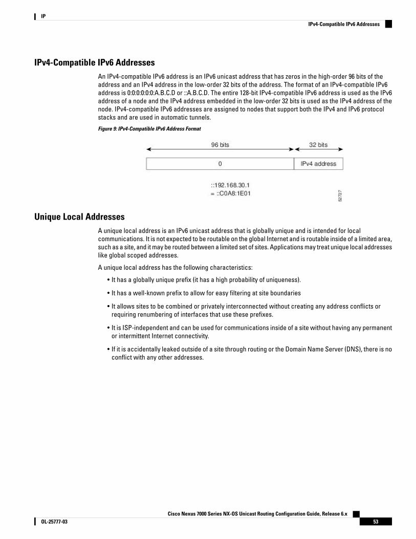
IPv4-Compatible IPv6 AddressesAn IPv4-compatible IPv6 address is an IPv6 unicast address that has zeros in the high-order 96 bits of theaddress and an IPv4 address in the low-order 32 bits of the address. The format of an IPv4-compatible IPv6address is 0:0:0:0:0:0:A.B.C.D or ::A.B.C.D. The entire 128-bit IPv4-compatible IPv6 address is used as the IPv6address of a node and the IPv4 address embedded in the low-order 32 bits is used as the IPv4 address of thenode. IPv4-compatible IPv6 addresses are assigned to nodes that support both the IPv4 and IPv6 protocolstacks and are used in automatic tunnels.
Figure 9: IPv4-Compatible IPv6 Address Format
Unique Local AddressesA unique local address is an IPv6 unicast address that is globally unique and is intended for localcommunications. It is not expected to be routable on the global Internet and is routable inside of a limited area,such as a site, and it may be routed between a limited set of sites. Applications may treat unique local addresseslike global scoped addresses.
A unique local address has the following characteristics:
• It has a globally unique prefix (it has a high probability of uniqueness).
• It has a well-known prefix to allow for easy filtering at site boundaries
• It allows sites to be combined or privately interconnected without creating any address conflicts orrequiring renumbering of interfaces that use these prefixes.
• It is ISP-independent and can be used for communications inside of a site without having any permanentor intermittent Internet connectivity.
• If it is accidentally leaked outside of a site through routing or the Domain Name Server (DNS), there is noconflict with any other addresses.
Cisco Nexus 7000 Series NX-OS Unicast Routing Configuration Guide, Release 6.x53OL-25777-03
IPIPv4-Compatible IPv6 Addresses
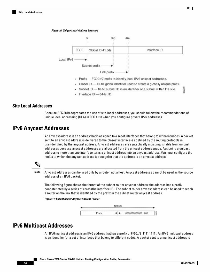
Figure 10: Unique Local Address Structure
Site Local AddressesBecause RFC 3879 deprecates the use of site-local addresses, you should follow the recommendations ofunique local addressing (ULA) in RFC 4193 when you configure private IPv6 addresses.
IPv6 Anycast AddressesAn anycast address is an address that is assigned to a set of interfaces that belong to different nodes. A packetsent to an anycast address is delivered to the closest interface-as defined by the routing protocols inuse-identified by the anycast address. Anycast addresses are syntactically indistinguishable from unicastaddresses because anycast addresses are allocated from the unicast address space. Assigning a unicastaddress to more than one interface turns a unicast address into an anycast address. You must configure thenodes to which the anycast address to recognize that the address is an anycast address.
Anycast addresses can be used only by a router, not a host. Anycast addresses cannot be used as the sourceaddress of an IPv6 packet.
Note
The following figure shows the format of the subnet router anycast address; the address has a prefixconcatenated by a series of zeros (the interface ID). The subnet router anycast address can be used to reacha router on the link that is identified by the prefix in the subnet router anycast address.
Figure 11: Subnet Router Anycast Address Format
IPv6 Multicast AddressesAn IPv6 multicast address is an IPv6 address that has a prefix of FF00::/8 (1111 1111). An IPv6 multicast addressis an identifier for a set of interfaces that belong to different nodes. A packet sent to a multicast address is
Cisco Nexus 7000 Series NX-OS Unicast Routing Configuration Guide, Release 6.xOL-25777-0354
IPSite Local Addresses

delivered to all interfaces identified by the multicast address. The second octet following the prefix definesthe lifetime and scope of the multicast address. A permanent multicast address has a lifetime parameter equalto 0; a temporary multicast address has a lifetime parameter equal to 1. A multicast address that has the scopeof a node, link, site, or organization, or a global scope, has a scope parameter of 1, 2, 5, 8, or E, respectively.For example, a multicast address with the prefix FF02::/16 is a permanent multicast address with a link scope.
Figure 12: IPv6 Multicast Address Format
IPv6 nodes (hosts and routers) are required to join (where received packets are destined for) the followingmulticast groups:
• All-nodes multicast group FF02:0:0:0:0:0:0:1 (the scope is link-local)
• Solicited-node multicast group FF02:0:0:0:0:1:FF00:0000/104 for each of its assigned unicast and anycastaddresses
IPv6 routers must also join the all-routers multicast group FF02:0:0:0:0:0:0:2 (the scope is link-local).
The solicited-node multicast address is a multicast group that corresponds to an IPv6 unicast or anycastaddress. IPv6 nodes must join the associated solicited-node multicast group for every unicast and anycastaddress to which it is assigned. The IPv6 solicited-node multicast address has the prefixFF02:0:0:0:0:1:FF00:0000/104 concatenated with the 24 low-order bits of a corresponding IPv6 unicast or anycastaddress. For example, the solicited-node multicast address that corresponds to the IPv6 address2037::01:800:200E:8C6C is FF02::1:FF0E:8C6C. Solicited-node addresses are used in neighbor solicitation messages.
Figure 13: Pv6 Solicited-Node Multicast Address Format
Cisco Nexus 7000 Series NX-OS Unicast Routing Configuration Guide, Release 6.x55OL-25777-03
IPIPv6 Multicast Addresses
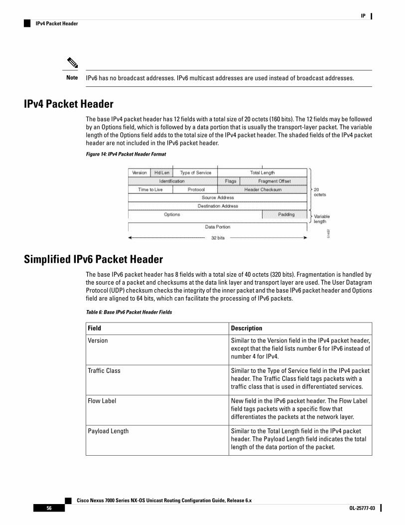
IPv6 has no broadcast addresses. IPv6 multicast addresses are used instead of broadcast addresses.Note
IPv4 Packet HeaderThe base IPv4 packet header has 12 fields with a total size of 20 octets (160 bits). The 12 fields may be followedby an Options field, which is followed by a data portion that is usually the transport-layer packet. The variablelength of the Options field adds to the total size of the IPv4 packet header. The shaded fields of the IPv4 packetheader are not included in the IPv6 packet header.
Figure 14: IPv4 Packet Header Format
Simplified IPv6 Packet HeaderThe base IPv6 packet header has 8 fields with a total size of 40 octets (320 bits). Fragmentation is handled bythe source of a packet and checksums at the data link layer and transport layer are used. The User DatagramProtocol (UDP) checksum checks the integrity of the inner packet and the base IPv6 packet header and Optionsfield are aligned to 64 bits, which can facilitate the processing of IPv6 packets.
Table 6: Base IPv6 Packet Header Fields
DescriptionField
Similar to the Version field in the IPv4 packet header,except that the field lists number 6 for IPv6 instead ofnumber 4 for IPv4.
Version
Similar to the Type of Service field in the IPv4 packetheader. The Traffic Class field tags packets with atraffic class that is used in differentiated services.
Traffic Class
New field in the IPv6 packet header. The Flow Labelfield tags packets with a specific flow thatdifferentiates the packets at the network layer.
Flow Label
Similar to the Total Length field in the IPv4 packetheader. The Payload Length field indicates the totallength of the data portion of the packet.
Payload Length
Cisco Nexus 7000 Series NX-OS Unicast Routing Configuration Guide, Release 6.xOL-25777-0356
IPIPv4 Packet Header
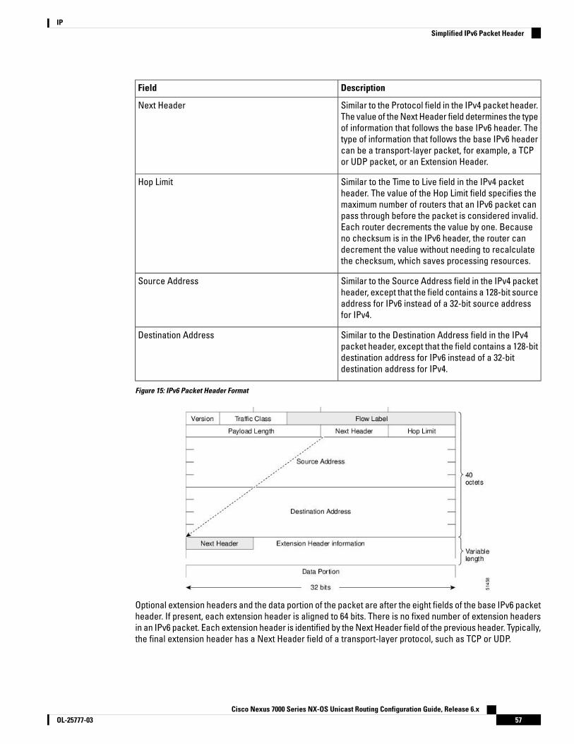
DescriptionField
Similar to the Protocol field in the IPv4 packet header.The value of the Next Header field determines the typeof information that follows the base IPv6 header. Thetype of information that follows the base IPv6 headercan be a transport-layer packet, for example, a TCPor UDP packet, or an Extension Header.
Next Header
Similar to the Time to Live field in the IPv4 packetheader. The value of the Hop Limit field specifies themaximum number of routers that an IPv6 packet canpass through before the packet is considered invalid.Each router decrements the value by one. Becauseno checksum is in the IPv6 header, the router candecrement the value without needing to recalculatethe checksum, which saves processing resources.
Hop Limit
Similar to the Source Address field in the IPv4 packetheader, except that the field contains a 128-bit sourceaddress for IPv6 instead of a 32-bit source addressfor IPv4.
Source Address
Similar to the Destination Address field in the IPv4packet header, except that the field contains a 128-bitdestination address for IPv6 instead of a 32-bitdestination address for IPv4.
Destination Address
Figure 15: IPv6 Packet Header Format
Optional extension headers and the data portion of the packet are after the eight fields of the base IPv6 packetheader. If present, each extension header is aligned to 64 bits. There is no fixed number of extension headersin an IPv6 packet. Each extension header is identified by the Next Header field of the previous header. Typically,the final extension header has a Next Header field of a transport-layer protocol, such as TCP or UDP.
Cisco Nexus 7000 Series NX-OS Unicast Routing Configuration Guide, Release 6.x57OL-25777-03
IPSimplified IPv6 Packet Header

Figure 16: IPv6 Extension Header Format
Table 7: IPv6 Extension Header Types
DescriptionNext Header ValueHeader Type
Header that is processed byall hops in the path of apacket. When present, thehop-by-hop options headeralways follows immediatelyafter the base IPv6 packetheader.
0Hop-by-Hop options header
Header that can follow anyhop-by-hop options header.The header is processed atthe final destination and ateach visited address specifiedby a routing header.Alternatively, the destinationoptions header can follow anyEncapsulating SecurityPayload (ESP) header. Thedestination options header isprocessed only at the finaldestination.
60Destination Header Options
Header that is used for sourcerouting.
43Routing Header
Cisco Nexus 7000 Series NX-OS Unicast Routing Configuration Guide, Release 6.xOL-25777-0358
IPSimplified IPv6 Packet Header
DescriptionNext Header ValueHeader Type
Header that is used when asource fragments a packetthat is larger than themaximum transmission unit(MTU) for the path betweenitself and a destination. TheFragment header is used ineach fragmented packet.
44Fragment Header
Headers that are used insidea packet to transport the data.The two main transportprotocols are TCP and UDP.
6 (TCP)
17 (UDP)
Upper-Layer Headers
DNS for IPv6IPv6 supports DNS record types that are supported in the DNS name-to-address and address-to-name lookupprocesses. The DNS record types support IPv6 addresses.
IPv6 also supports the reverse mapping of IPv6 addresses to DNS names.Note
Table 8: IPv6 DNS Record Types
FormatDescriptionRecord Type
www.abc.test AAAA3FFE:YYYY:C18:1::2
Maps a hostname to an IPv6address. (Equivalent to an A recordin IPv4.)
AAAA
2.0.0.0.0.0.0.0.0.0.0.0.0.0.0.0.1.0.0.0.8.1.c.0.y.y.y.y.e.f.f.3.ip6.intPTR www.abc.test
Maps an IPv6 address to ahostname. (Equivalent to a PTRrecord in IPv4.)
PTR
Path MTU Discovery for IPv6As in IPv4, you can use path MTU discovery in IPv6 to allow a host to dynamically discover and adjust todifferences in the MTU size of every link along a data path. In IPv6, however, fragmentation is handled by thesource of a packet when the path MTU of one link along a given data path is not large enough to accommodatethe size of the packets. Having IPv6 hosts handle packet fragmentation saves IPv6 router processing resourcesand helps IPv6 networks run more efficiently. Once the path MTU is reduced by the arrival of an ICMP Too Bigmessage, Cisco NX-OS retains the lower value. The connection does not increase the segment size to gaugethe throughput.
Cisco Nexus 7000 Series NX-OS Unicast Routing Configuration Guide, Release 6.x59OL-25777-03
IPDNS for IPv6

In IPv6, the minimum link MTU is 1280 octets. We recommend that you use an MTU value of 1500 octets forIPv6 links.
Note
CDP IPv6 Address SupportYou can use the Cisco Discovery Protocol (CDP) IPv6 address support for the neighbor information feature totransfer IPv6 addressing information between two Cisco devices. Cisco Discovery Protocol support for IPv6addresses provides IPv6 information to network management products and troubleshooting tools.
ICMP for IPv6You can use ICMP in IPv6 to provide information about the health of the network. ICMPv6, the version thatworks with IPv6, reports errors if packets cannot be processed correctly and sends informational messagesabout the status of the network. For example, if a router cannot forward a packet because it is too large to besent out on another network, the router sends out an ICMPv6 message to the originating host. Additionally,ICMP packets in IPv6 are used in IPv6 neighbor discovery and path MTU discovery. The path MTU discoveryprocess ensures that a packet is sent using the largest possible size that is supported on a specific route.
A value of 58 in the Next Header field of the base IPv6 packet header identifies an IPv6 ICMP packet. The ICMPpacket follows all the extension headers and is the last piece of information in the IPv6 packet.Within the IPv6ICMP packets, the ICMPv6 Type and ICMPv6 Code fields identify IPv6 ICMP packet specifics, such as theICMP message type. The value in the Checksum field is computed by the sender and checked by the receiverfrom the fields in the IPv6 ICMP packet and the IPv6 pseudo header.
The IPv6 header does not have a checksum. But a checksum on the transport layer can determine if packetshave not been delivered correctly. All checksum calculations that include the IP address in the calculationmust be modified for IPv6 to accommodate the new 128-bit address. A checksum is generated using a pseudoheader.
Note
The ICMPv6 Payload field contains error or diagnostic information that relates to IP packet processing.
Cisco Nexus 7000 Series NX-OS Unicast Routing Configuration Guide, Release 6.xOL-25777-0360
IPCDP IPv6 Address Support
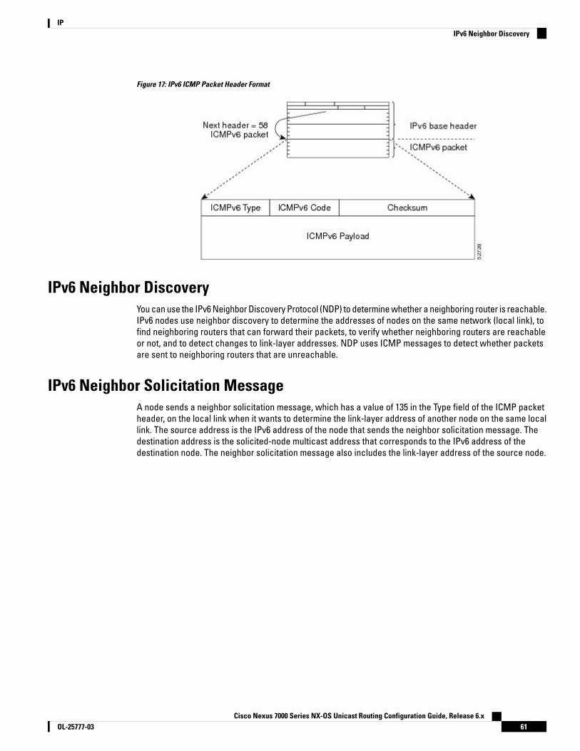
Figure 17: IPv6 ICMP Packet Header Format
IPv6 Neighbor DiscoveryYou can use the IPv6 Neighbor Discovery Protocol (NDP) to determine whether a neighboring router is reachable.IPv6 nodes use neighbor discovery to determine the addresses of nodes on the same network (local link), tofind neighboring routers that can forward their packets, to verify whether neighboring routers are reachableor not, and to detect changes to link-layer addresses. NDP uses ICMP messages to detect whether packetsare sent to neighboring routers that are unreachable.
IPv6 Neighbor Solicitation MessageA node sends a neighbor solicitation message, which has a value of 135 in the Type field of the ICMP packetheader, on the local link when it wants to determine the link-layer address of another node on the same locallink. The source address is the IPv6 address of the node that sends the neighbor solicitation message. Thedestination address is the solicited-node multicast address that corresponds to the IPv6 address of thedestination node. The neighbor solicitation message also includes the link-layer address of the source node.
Cisco Nexus 7000 Series NX-OS Unicast Routing Configuration Guide, Release 6.x61OL-25777-03
IPIPv6 Neighbor Discovery
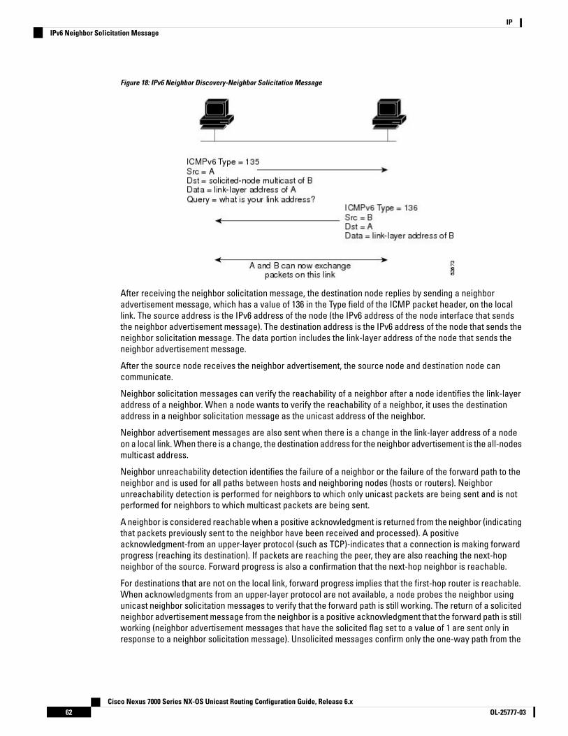
Figure 18: IPv6 Neighbor Discovery-Neighbor Solicitation Message
After receiving the neighbor solicitation message, the destination node replies by sending a neighboradvertisement message, which has a value of 136 in the Type field of the ICMP packet header, on the locallink. The source address is the IPv6 address of the node (the IPv6 address of the node interface that sendsthe neighbor advertisement message). The destination address is the IPv6 address of the node that sends theneighbor solicitation message. The data portion includes the link-layer address of the node that sends theneighbor advertisement message.
After the source node receives the neighbor advertisement, the source node and destination node cancommunicate.
Neighbor solicitation messages can verify the reachability of a neighbor after a node identifies the link-layeraddress of a neighbor. When a node wants to verify the reachability of a neighbor, it uses the destinationaddress in a neighbor solicitation message as the unicast address of the neighbor.
Neighbor advertisement messages are also sent when there is a change in the link-layer address of a nodeon a local link. When there is a change, the destination address for the neighbor advertisement is the all-nodesmulticast address.
Neighbor unreachability detection identifies the failure of a neighbor or the failure of the forward path to theneighbor and is used for all paths between hosts and neighboring nodes (hosts or routers). Neighborunreachability detection is performed for neighbors to which only unicast packets are being sent and is notperformed for neighbors to which multicast packets are being sent.
A neighbor is considered reachable when a positive acknowledgment is returned from the neighbor (indicatingthat packets previously sent to the neighbor have been received and processed). A positiveacknowledgment-from an upper-layer protocol (such as TCP)-indicates that a connection is making forwardprogress (reaching its destination). If packets are reaching the peer, they are also reaching the next-hopneighbor of the source. Forward progress is also a confirmation that the next-hop neighbor is reachable.
For destinations that are not on the local link, forward progress implies that the first-hop router is reachable.When acknowledgments from an upper-layer protocol are not available, a node probes the neighbor usingunicast neighbor solicitation messages to verify that the forward path is still working. The return of a solicitedneighbor advertisement message from the neighbor is a positive acknowledgment that the forward path is stillworking (neighbor advertisement messages that have the solicited flag set to a value of 1 are sent only inresponse to a neighbor solicitation message). Unsolicited messages confirm only the one-way path from the
Cisco Nexus 7000 Series NX-OS Unicast Routing Configuration Guide, Release 6.xOL-25777-0362
IPIPv6 Neighbor Solicitation Message

source to the destination node; solicited neighbor advertisement messages indicate that a path is working inboth directions.
A neighbor advertisement message that has the solicited flag set to a value of 0 is not considered as a positiveacknowledgment that the forward path is still working.
Note
Neighbor solicitation messages are also used in the stateless autoconfiguration process to verify the uniquenessof unicast IPv6 addresses before the addresses are assigned to an interface. Duplicate address detection isperformed first on a new, link-local IPv6 address before the address is assigned to an interface (the newaddress remains in a tentative state while duplicate address detection is performed). A node sends a neighborsolicitation message with an unspecified source address and a tentative link-local address in the body of themessage. If another node is already using that address, the node returns a neighbor advertisement messagethat contains the tentative link-local address. If another node is simultaneously verifying the uniqueness ofthe same address, that node also returns a neighbor solicitation message. If no neighbor advertisementmessages are received in response to the neighbor solicitation message and no neighbor solicitation messagesare received from other nodes that are attempting to verify the same tentative address, the node that sent theoriginal neighbor solicitation message considers the tentative link-local address to be unique and assigns theaddress to the interface.
IPv6 Router Advertisement MessageRouter advertisement (RA) messages, which have a value of 134 in the Type field of the ICMP packet header,are periodically sent out to each configured interface of an IPv6 router. For stateless autoconfiguration towork properly, the advertised prefix length in RA messages must always be 64 bits.
The RA messages are sent to the all-nodes multicast address.
Figure 19: Neighbor Discovery—RA Message
RA messages typically include the following information:
• One or more onlink IPv6 prefixes that nodes on the local link can use to automatically configure their IPv6addresses
• Life-time information for each prefix included in the advertisement
• Sets of flags that indicate the type of autoconfiguration (stateless or stateful) that can be completed
• Default router information (whether the router sending the advertisement should be used as a defaultrouter and, if so, the amount of time in seconds that the router should be used as a default router)
Cisco Nexus 7000 Series NX-OS Unicast Routing Configuration Guide, Release 6.x63OL-25777-03
IPIPv6 Router Advertisement Message
• Additional information for hosts, such as the hop limit and MTU that a host should use in packets that itoriginates
RAs are also sent in response to router solicitation messages. Router solicitation messages, which have avalue of 133 in the Type field of the ICMP packet header, are sent by hosts at system startup so that the hostcan immediately autoconfigure without needing to wait for the next scheduled RA message. The source addressis usually the unspecified IPv6 address (0:0:0:0:0:0:0:0). If the host has a configured unicast address, the unicastaddress of the interface that sends the router solicitation message is used as the source address in themessage. The destination address is the all-routers multicast address with a scope of the link. When an RAis sent in response to a router solicitation, the destination address in the RA message is the unicast addressof the source of the router solicitation message.
You can configure the following RA message parameters:
• The time interval between periodic RA messages
• The router life-time value, which indicates the usefulness of a router as the default router (for use by allnodes on a given link)
• The network prefixes in use on a given link
• The time interval between neighbor solicitation message retransmissions (on a given link)
• The amount of time that a node considers a neighbor reachable (for use by all nodes on a given link)
The configured parameters are specific to an interface. The sending of RA messages (with default values) isautomatically enabled on Ethernet interfaces. For other interface types, you must enter the no ipv6 ndsuppress-ra command to send RA messages. You can disable the RA message feature on individual interfacesby entering the ipv6 nd suppress-ra command.
IPv6 Router Advertisement Options for DNS ConfigurationMost of the internet services are identified by a Domain Name Server (DNS) name. Cisco NX-OS IPv6 RouterAdvertisement (RA) provides the following two options to allow IPv6 hosts to perform automatic DNSconfiguration:
• Recursive DNS Server (RDNSS)
• DNS Search List (DNSSL)
RDNSS contains the address of recursive DNS servers that help in DNS name resolution in IPv6 hosts. DNSSearch List is a list of DNS suffix domain names used by IPv6 hosts when they perform DNS query searches.
For more information on RA options for DNS configuration, refer IETF RFC 6106.
IPv6 Neighbor Redirect MessageRouters send neighbor redirect messages to inform hosts of better first-hop nodes on the path to a destination.A value of 137 in the Type field of the ICMP packet header identifies an IPv6 neighbor redirect message.
Cisco Nexus 7000 Series NX-OS Unicast Routing Configuration Guide, Release 6.xOL-25777-0364
IPIPv6 Router Advertisement Options for DNS Configuration

Figure 20: IPv6 Neighbor Discovery—Neighbor Redirect Message
A router must be able to determine the link-local address for each of its neighboring routers in order to ensurethat the target address (the final destination) in a redirect message identifies the neighbor router by its link-localaddress. For static routing, you should specify the address of the next-hop router using the link-local addressof the router. For dynamic routing, you must configure all IPv6 routing protocols to exchange the link-localaddresses of neighboring routers.
Note
After forwarding a packet, a router sends a redirect message to the source of the packet under the followingcircumstances:
• The destination address of the packet is not a multicast address.
• The packet was not addressed to the router.
• The packet is about to be sent out the interface on which it was received.
• The router determines that a better first-hop node for the packet resides on the same link as the sourceof the packet.
• The source address of the packet is a global IPv6 address of a neighbor on the same link or a link-localaddress.
Cisco Nexus 7000 Series NX-OS Unicast Routing Configuration Guide, Release 6.x65OL-25777-03
IPIPv6 Neighbor Redirect Message
Virtualization Support for IPv6IPv6 supports virtual routing and forwarding (VRF) instances. VRFs exist within virtual device contexts (VDCs).By default, Cisco NX-OS places you in the default VDC and default VRF unless you specifically configureanother VDC and VRF. For more information, see the Cisco Nexus 7000 Series NX-OS Virtual Device ContextConfiguration Guide.
Prerequisites for IPv6IPv6 has the following prerequisites:
• You must be familiar with IPv6 basics such as IPv6 addressing, IPv6 header information, ICMPv6, and theIPv6 Neighbor Discovery (ND) Protocol.
• Ensure that you follow the memory/processing guidelines when you make a device a dual-stack device(IPv4/IPv6).
Guidelines and Limitations for Configuring IPv6IPv6 has the following configuration guidelines and limitations:
• IPv6 packets are transparent to Layer 2 LAN switches because the switches do not examine Layer 3packet information before forwarding IPv6 frames. IPv6 hosts can be directly attached to Layer 2 LANswitches.
• You can configure multiple IPv6 global addresses within the same prefix on an interface. However, multipleIPv6 link-local addresses on an interface are not supported.
• It supports contiguous masks only for both IPv4 and IPv6 addresses and does not support discontiguousmasks IPv6 and IPv4 filters.
• Each interface can be configured with a maximum of 255 global IPv6 addresses and a maximum of 255anycast IPv6 addresses.
• Because RFC 3879 deprecates the use of site-local addresses, you should configure private IPv6 addressesaccording to the recommendations of unique local addressing (ULA) in RFC 4193.
• F2 Series modules do not support IPv6 tunnels.
• On F2 Series modules, you must disable IGMP optimized multicast flooding (OMF) on any VLANs thatrequire any IPv6 packet forwarding (unicast or multicast). IPv6 neighbor discovery functions correctlyonly in a VLAN with the OMF feature disabled. To disable OMF, use the no ip igmp snoopingoptimised-multicast-flood command in VLAN configuration mode. With OMF disabled, unknown IPv4multicast traffic (as well as all IPv6 multicast traffic) is flooded to all ports in the VLAN. Note that unknownmulticast traffic refers to multicast packets with an active source but no receivers (and therefore nogroup forwarding entry in the hardware) in the ingress VLAN.
• IPv6 static route next hop link-local address cannot be configured at any local interface.
Cisco Nexus 7000 Series NX-OS Unicast Routing Configuration Guide, Release 6.xOL-25777-0366
IPVirtualization Support for IPv6

Default Settings for IPv6DefaultParameters
0 millisecondsND reachable time
1000 millisecondsneighbor solicitation retransmit interval
By default, IPv6 source routing is enabled on the switch. To disable IPv6 source routing configure no ipv6source-route command on the switch.
Configuring IPv6
Configuring IPv6 AddressingYou must configure an IPv6 address on an interface so that the interface can forward IPv6 traffic. When youconfigure a global IPv6 address on an interface, it automatically configures a link-local address and activatesIPv6 for that interface.
Each interface can be configured with a maximum of 255 global IPv6 addresses and a maximum of 255 anycastIPv6 addresses.
Note
Before you begin
Ensure that you are in the correct VDC (or use the switchto vdc command).
Procedure
PurposeCommand or Action
Enters global configuration mode.switch# configure terminalStep 1
Enters interface configuration mode.switch(config)# interface ethernet numberStep 2
Specifies an IPv6 address assigned to theinterface and enables IPv6 processing on theinterface.
switch(config-if)# ipv6 address {address [eui64][route-preference preference] [secondary] tagtag-id] or switch(config-if)# ipv6 addressipv6-address use-link-local-only
Step 3
Entering the ipv6 address command configuresglobal IPv6 addresses with an interfaceidentifier (ID) in the low-order 64 bits of the IPv6address. Only the 64-bit network prefix for theaddress needs to be specified; the last 64 bitsare automatically computed from the interfaceID.
Cisco Nexus 7000 Series NX-OS Unicast Routing Configuration Guide, Release 6.x67OL-25777-03
IPDefault Settings for IPv6

PurposeCommand or Action
Entering the ipv6 addressuse-link-local-onlycommand configures alink-local address on the interface that is usedinstead of the link-local address that isautomatically configured when IPv6 is enabledon the interface.
This command enables IPv6 processing on aninterface without configuring an IPv6 address.
Displays interfaces configured for IPv4.(Optional) switch(config-if)# show ip interfaceStep 4
Saves the change persistently through rebootsand restarts by copying the runningconfiguration to the startup configuration.
(Optional) switch(config)# copy running-configstartup-config
Step 5
Example
This example shows how to assign an IPv6 address:
switch# configure terminalswitch(config)# interface ethernet 2/3switch(config-if)# ipv6 address 2001:db8::/64 eui64switch(config-if)# copy running-config startup-configswitch(config-if)#
This example shows how to display an IPv6 interface:
switch# configure terminalswitch(config)# show ipv6 interface ethernet 3/1Ethernet3/1, Interface status: protocol-down/link-down/admin-down, iod: 36IPv6 address: 0dc3:0dc3:0000:0000:0218:baff:fed8:239dIPv6 subnet: 0dc3:0dc3:0000:0000:0000:0000:0000:0000/64IPv6 link-local address: fe80::0218:baff:fed8:239d (default)IPv6 multicast routing: disabledIPv6 multicast groups locally joined:ff02::0001:ffd8:239d ff02::0002 ff02::0001 ff02::0001:ffd8:239dIPv6 multicast (S,G) entries joined: noneIPv6 MTU: 1500 (using link MTU)IPv6 RP inbound packet-filtering policy: noneIPv6 RP outbound packet-filtering policy: noneIPv6 inbound packet-filtering policy: noneIPv6 outbound packet-filtering policy: noneIPv6 interface statistics last reset: neverIPv6 interface RP-traffic statistics: (forwarded/originated/consumed)Unicast packets: 0/0/0Unicast bytes: 0/0/0Multicast packets: 0/0/0Multicast bytes: 0/0/0
Configuring IPv6 Neighbor DiscoveryYou can configure IPv6 neighbor discovery on the router. Neighbor Discovery (ND) enables IPv6 nodes androuters to determine the link-layer address of a neighbor on the same link, find neighboring routers, and keeptrack of neighbors.
Cisco Nexus 7000 Series NX-OS Unicast Routing Configuration Guide, Release 6.xOL-25777-0368
IPConfiguring IPv6 Neighbor Discovery

Before you begin
Ensure that you are in the correct VDC (or use the switchto vdc command).
Procedure
PurposeCommand or Action
Enters global configuration mode.switch# configure terminalStep 1
Enters interface configuration mode.switch(config)# interface ethernet numberStep 2
Specifies an IPv6 address assigned to theinterface and enables IPv6 processing on theinterface.
switch(config-if)# ipv6 nd [hop-limit hop-limit |managed-config-flag | mtu mtu | ns-intervalinterval | other-config-flag | prefix | ra-interval
Step 3
interval | ra-lifetime lifetime | reachable-time • hop-limit hop-limit— Advertises the hoplimit in IPv6 neighbor discovery packets.The range is from 0 to 255.
time | redirects | retrans-timer time |suppress-ra]
• managed-config-flag— Advertises inICMPv6 router-advertisement messagesto use stateful address auto-configurationto obtain address information.
• mtu mtu—Advertises the maximumtransmission unit (MTU) in ICMPv6router-advertisement messages on thislink. The range is from 1280 to 65535 bytes.
• ns-interval interval—Configures theretransmission interval between IPv6neighbor solicitation messages. The rangeis from 1000 to 3600000 milliseconds.
• other-config-flag—Indicates in ICMPv6router-advertisement messages that hostsuse stateful auto-configuration to obtainnonaddress related information.
• prefix—Advertises the IPv6 prefix in therouter-advertisement messages.
• ra-interval interval—Configures theinterval between sending ICMPv6router-advertisement messages. The rangeis from 4 to 1800 seconds.
• ra-lifetime lifetime—Advertises the lifetimeof a default router in ICMPv6router-advertisement messages. The rangeis from 0 to 9000 seconds.
• reachable-time time—Advertises the timewhen a node considers a neighbor up afterreceiving a reachability confirmation in
Cisco Nexus 7000 Series NX-OS Unicast Routing Configuration Guide, Release 6.x69OL-25777-03
IPConfiguring IPv6 Neighbor Discovery

PurposeCommand or Action
ICMPv6 router-advertisement messages.The range is from 0 to 9000 seconds.
• redirects—Enables sending ICMPv6redirect messages.
• retrans-timer time—Advertises the timebetween neighbor-solicitation messagesin ICMPv6 router-advertisement messages.The range is from 0 to 9000 seconds.
• suppress-ra— Disables sending ICMPv6router-advertisement messages.
Advertises the IPv6 prefix in the routeradvertisement messages.
Required: switch(config-if)# ipv6 nd prefix{ipv6-address/prefix-length | default}
Step 4
{valid-lifetime | infinite | no-advertise} • valid-lifetime—The amount of time (inseconds) that the specified IPv6 prefix isadvertised as being valid.
{preferred-lifetime | infinite} [no-autoconfig][no-onlink] [off-link]
• infinite—Specifies that the valid lifetimeis infinite.
• no-advertise—Specifies that the prefix isnot advertised.
• preferred-lifetime—The amount of time (inseconds) that the specified IPv6 prefix isadvertised as being preferred.
• no-autoconfig—Indicates to hosts on thelocal link that the specified prefix cannotbe used for IPv6 autoconfiguration. Theprefix will be advertised with the A-bitclear.
• no-onlink—Configures the specified prefixas not on-link. The prefix will be advertisedwith the L-bit clear.
• off-link—Configures the specified prefixas off-link. The prefix will be advertisedwith the L-bit clear. The prefix will not beinserted into the routing table as aconnected prefix. If the prefix is alreadypresent in the routing table as a connectedprefix (for example, because the prefix wasalso configured using the ipv6 addresscommand), it will be removed.
Displays interfaces configured for IPv6 neighbordiscovery.
(Optional) switch(config-if)# show ip ndinterface
Step 5
Cisco Nexus 7000 Series NX-OS Unicast Routing Configuration Guide, Release 6.xOL-25777-0370
IPConfiguring IPv6 Neighbor Discovery
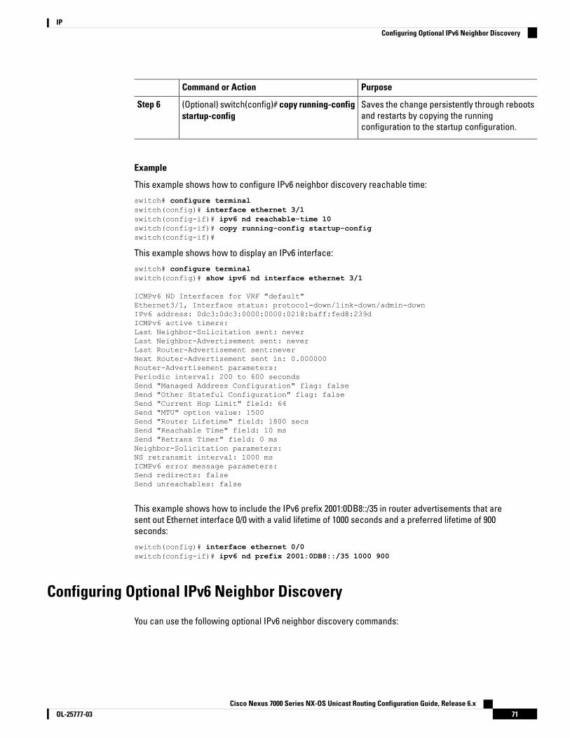
PurposeCommand or Action
Saves the change persistently through rebootsand restarts by copying the runningconfiguration to the startup configuration.
(Optional) switch(config)# copy running-configstartup-config
Step 6
Example
This example shows how to configure IPv6 neighbor discovery reachable time:
switch# configure terminalswitch(config)# interface ethernet 3/1switch(config-if)# ipv6 nd reachable-time 10switch(config-if)# copy running-config startup-configswitch(config-if)#
This example shows how to display an IPv6 interface:
switch# configure terminalswitch(config)# show ipv6 nd interface ethernet 3/1
ICMPv6 ND Interfaces for VRF "default"Ethernet3/1, Interface status: protocol-down/link-down/admin-downIPv6 address: 0dc3:0dc3:0000:0000:0218:baff:fed8:239dICMPv6 active timers:Last Neighbor-Solicitation sent: neverLast Neighbor-Advertisement sent: neverLast Router-Advertisement sent:neverNext Router-Advertisement sent in: 0.000000Router-Advertisement parameters:Periodic interval: 200 to 600 secondsSend "Managed Address Configuration" flag: falseSend "Other Stateful Configuration" flag: falseSend "Current Hop Limit" field: 64Send "MTU" option value: 1500Send "Router Lifetime" field: 1800 secsSend "Reachable Time" field: 10 msSend "Retrans Timer" field: 0 msNeighbor-Solicitation parameters:NS retransmit interval: 1000 msICMPv6 error message parameters:Send redirects: falseSend unreachables: false
This example shows how to include the IPv6 prefix 2001:0DB8::/35 in router advertisements that aresent out Ethernet interface 0/0 with a valid lifetime of 1000 seconds and a preferred lifetime of 900seconds:
switch(config)# interface ethernet 0/0switch(config-if)# ipv6 nd prefix 2001:0DB8::/35 1000 900
Configuring Optional IPv6 Neighbor Discovery
You can use the following optional IPv6 neighbor discovery commands:
Cisco Nexus 7000 Series NX-OS Unicast Routing Configuration Guide, Release 6.x71OL-25777-03
IPConfiguring Optional IPv6 Neighbor Discovery
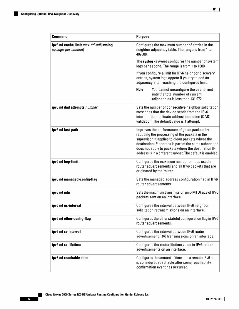
PurposeCommand
Configures the maximum number of entries in theneighbor adjacency table. The range is from 1 to409600.
The syslog keyword configures the number of systemlogs per second. The range is from 1 to 1000.
If you configure a limit for IPv6 neighbor discoveryentries, system logs appear if you try to add anadjacency after reaching the configured limit.
You cannot unconfigure the cache limituntil the total number of currentadjacencies is less than 131,072.
Note
ipv6 nd cache limit max-nd-adj [syslogsyslogs-per-second]
Sets the number of consecutive neighbor solicitationmessages that the device sends from the IPv6interface for duplicate address detection (DAD)validation. The default value is 1 attempt.
ipv6 nd dad attempts number
Improves the performance of glean packets byreducing the processing of the packets in thesupervisor. It applies to glean packets where thedestination IP address is part of the same subnet anddoes not apply to packets where the destination IPaddress is in a different subnet. The default is enabled.
ipv6 nd fast-path
Configures the maximum number of hops used inrouter advertisements and all IPv6 packets that areoriginated by the router.
ipv6 nd hop-limit
Sets the managed address configuration flag in IPv6router advertisements.
ipv6 nd managed-config-flag
Sets the maximum transmission unit (MTU) size of IPv6packets sent on an interface.
ipv6 nd mtu
Configures the interval between IPv6 neighborsolicitation retransmissions on an interface.
ipv6 nd ns-interval
Configures the other stateful configuration flag in IPv6router advertisements.
ipv6 nd other-config-flag
Configures the interval between IPv6 routeradvertisement (RA) transmissions on an interface.
ipv6 nd ra-interval
Configures the router lifetime value in IPv6 routeradvertisements on an interface.
ipv6 nd ra-lifetime
Configures the amount of time that a remote IPv6 nodeis considered reachable after some reachabilityconfirmation event has occurred.
ipv6 nd reachable-time
Cisco Nexus 7000 Series NX-OS Unicast Routing Configuration Guide, Release 6.xOL-25777-0372
IPConfiguring Optional IPv6 Neighbor Discovery
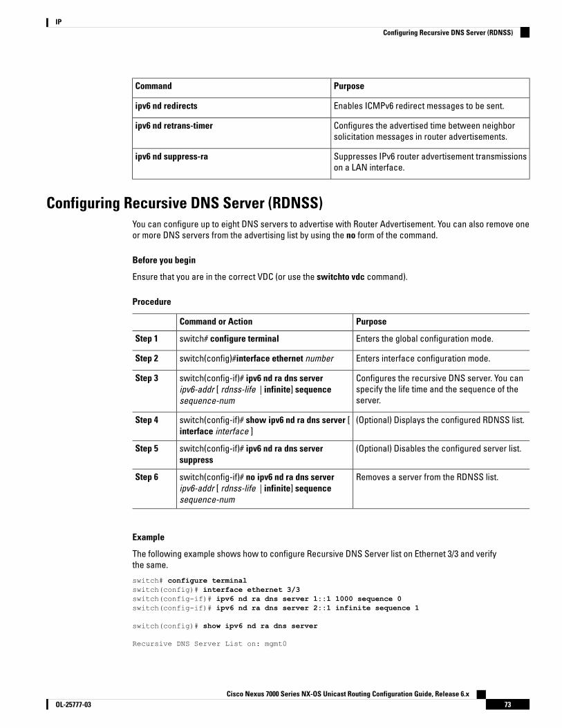
PurposeCommand
Enables ICMPv6 redirect messages to be sent.ipv6 nd redirects
Configures the advertised time between neighborsolicitation messages in router advertisements.
ipv6 nd retrans-timer
Suppresses IPv6 router advertisement transmissionson a LAN interface.
ipv6 nd suppress-ra
Configuring Recursive DNS Server (RDNSS)You can configure up to eight DNS servers to advertise with Router Advertisement. You can also remove oneor more DNS servers from the advertising list by using the no form of the command.
Before you begin
Ensure that you are in the correct VDC (or use the switchto vdc command).
Procedure
PurposeCommand or Action
Enters the global configuration mode.switch# configure terminalStep 1
Enters interface configuration mode.switch(config)#interface ethernet numberStep 2
Configures the recursive DNS server. You canspecify the life time and the sequence of theserver.
switch(config-if)# ipv6 nd ra dns serveripv6-addr [ rdnss-life | infinite] sequencesequence-num
Step 3
(Optional) Displays the configured RDNSS list.switch(config-if)# show ipv6 nd ra dns server [interface interface ]
Step 4
(Optional) Disables the configured server list.switch(config-if)# ipv6 nd ra dns serversuppress
Step 5
Removes a server from the RDNSS list.switch(config-if)# no ipv6 nd ra dns serveripv6-addr [ rdnss-life | infinite] sequencesequence-num
Step 6
Example
The following example shows how to configure Recursive DNS Server list on Ethernet 3/3 and verifythe same.
switch# configure terminalswitch(config)# interface ethernet 3/3switch(config-if)# ipv6 nd ra dns server 1::1 1000 sequence 0switch(config-if)# ipv6 nd ra dns server 2::1 infinite sequence 1
switch(config)# show ipv6 nd ra dns server
Recursive DNS Server List on: mgmt0
Cisco Nexus 7000 Series NX-OS Unicast Routing Configuration Guide, Release 6.x73OL-25777-03
IPConfiguring Recursive DNS Server (RDNSS)

Suppress DNS Server List: NoRecursive DNS Server List on: Ethernet3/3Suppress DNS Server List: NoDNS Server 1: 1::1 Lifetime:1000 seconds Sequence:0DNS Server 2: 2::1 Infinite Sequence:1
Configuring DNS Search List (DNSSL)You can configure up to eight DNS search lists to advertise with Router Advertisement. You can also removeone or more DNS search lists from the advertising list by using the no form of the command.
Before you begin
Ensure that you are in the correct VDC (or use the switchto vdc command).
Procedure
PurposeCommand or Action
Enters the global configuration mode.switch# configure terminalStep 1
Enters interface configuration mode.switch(config)#interface ethernet numberStep 2
Configures the DNS search list. You can specifythe life time and the sequence of the search list.
switch(config-if)# ipv6 nd ra dns search-list list[ dnssl-life | infinite] sequence sequence-num
Step 3
(Optional) Displays the configured DNS searchlist.
switch(config-if)# show ipv6 nd ra dnssearch-list [ interface interface ]
Step 4
(Optional) Disables the configured search list.switch(config-if)# ipv6 nd ra dns search-listsuppress
Step 5
(Optional) Removes a search list from the RA.switch(config-if)# no ipv6 nd ra dns search-listlist [ dnssl-life | infinite] sequencesequence-num
Step 6
Example
The following example shows how to configure DNS Search list on Ethernet 3/3 and verify the same.
switch# configure terminalswitch(config)# interface ethernet 3/3switch(config-if)# ipv6 nd ra dns search-list cisco.com 100 sequence 1switch(config-if)# ipv6 nd ra dns search-list ind.cisco.com 100 sequence 2
switch(config)# show ipv6 nd ra dns search-list
DNS Search List on: mgmt0Suppress DNS Search List: NoDNS Search List on: Ethernet3/3Suppress DNS Search List: NoDNS Server 1:cisco.com 100 Sequence:1DNS Server 2:ind.cisco.com 100 Sequence:2
Cisco Nexus 7000 Series NX-OS Unicast Routing Configuration Guide, Release 6.xOL-25777-0374
IPConfiguring DNS Search List (DNSSL)
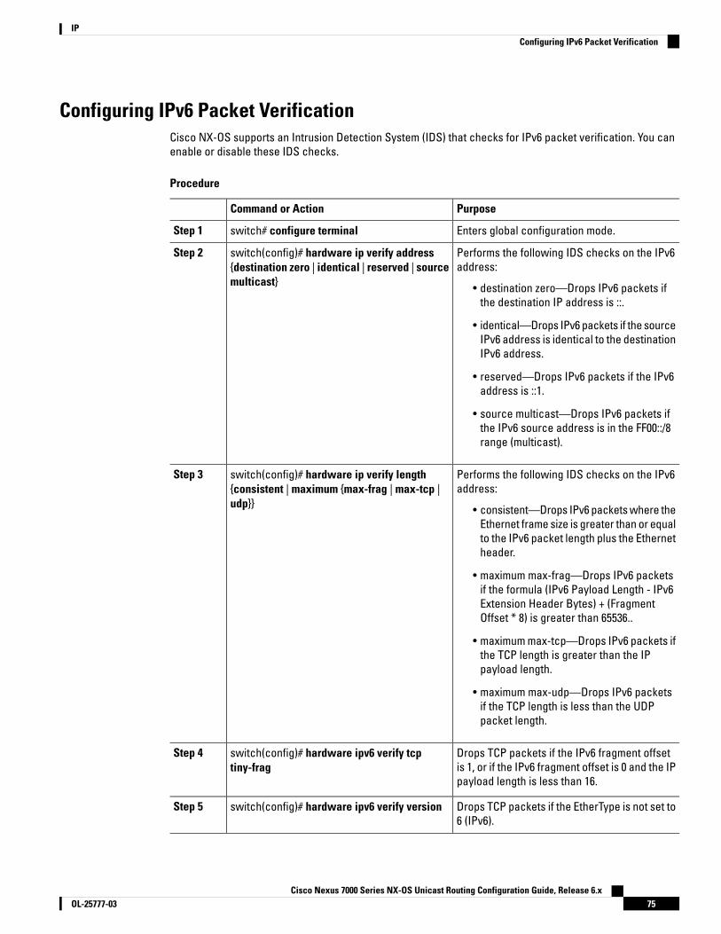
Configuring IPv6 Packet VerificationCisco NX-OS supports an Intrusion Detection System (IDS) that checks for IPv6 packet verification. You canenable or disable these IDS checks.
Procedure
PurposeCommand or Action
Enters global configuration mode.switch# configure terminalStep 1
Performs the following IDS checks on the IPv6address:
switch(config)# hardware ip verify address{destination zero | identical | reserved | sourcemulticast}
Step 2
• destination zero—Drops IPv6 packets ifthe destination IP address is ::.
• identical—Drops IPv6 packets if the sourceIPv6 address is identical to the destinationIPv6 address.
• reserved—Drops IPv6 packets if the IPv6address is ::1.
• source multicast—Drops IPv6 packets ifthe IPv6 source address is in the FF00::/8range (multicast).
Performs the following IDS checks on the IPv6address:
switch(config)# hardware ip verify length{consistent | maximum {max-frag | max-tcp |udp}}
Step 3
• consistent—Drops IPv6 packets where theEthernet frame size is greater than or equalto the IPv6 packet length plus the Ethernetheader.
• maximum max-frag—Drops IPv6 packetsif the formula (IPv6 Payload Length - IPv6Extension Header Bytes) + (FragmentOffset * 8) is greater than 65536..
• maximum max-tcp—Drops IPv6 packets ifthe TCP length is greater than the IPpayload length.
• maximum max-udp—Drops IPv6 packetsif the TCP length is less than the UDPpacket length.
Drops TCP packets if the IPv6 fragment offsetis 1, or if the IPv6 fragment offset is 0 and the IPpayload length is less than 16.
switch(config)# hardware ipv6 verify tcptiny-frag
Step 4
Drops TCP packets if the EtherType is not set to6 (IPv6).
switch(config)# hardware ipv6 verify versionStep 5
Cisco Nexus 7000 Series NX-OS Unicast Routing Configuration Guide, Release 6.x75OL-25777-03
IPConfiguring IPv6 Packet Verification
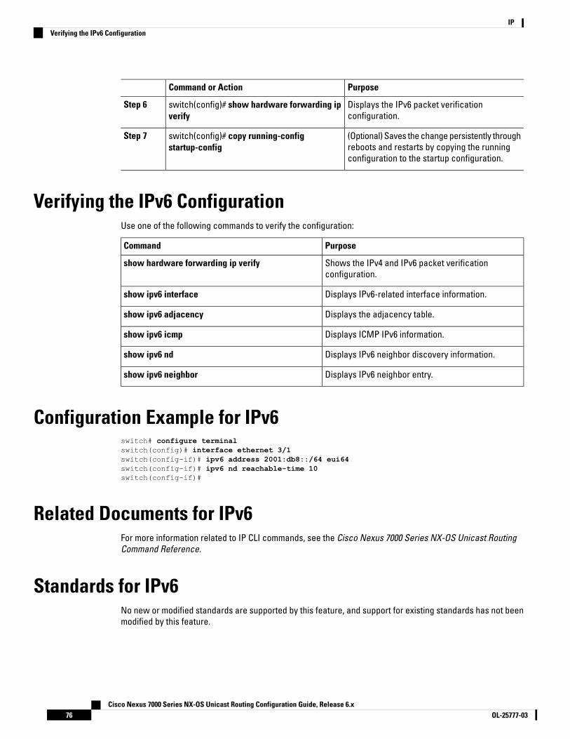
PurposeCommand or Action
Displays the IPv6 packet verificationconfiguration.
switch(config)# show hardware forwarding ipverify
Step 6
(Optional) Saves the change persistently throughreboots and restarts by copying the runningconfiguration to the startup configuration.
switch(config)# copy running-configstartup-config
Step 7
Verifying the IPv6 ConfigurationUse one of the following commands to verify the configuration:
PurposeCommand
Shows the IPv4 and IPv6 packet verificationconfiguration.
show hardware forwarding ip verify
Displays IPv6-related interface information.show ipv6 interface
Displays the adjacency table.show ipv6 adjacency
Displays ICMP IPv6 information.show ipv6 icmp
Displays IPv6 neighbor discovery information.show ipv6 nd
Displays IPv6 neighbor entry.show ipv6 neighbor
Configuration Example for IPv6switch# configure terminalswitch(config)# interface ethernet 3/1switch(config-if)# ipv6 address 2001:db8::/64 eui64switch(config-if)# ipv6 nd reachable-time 10switch(config-if)#
Related Documents for IPv6For more information related to IP CLI commands, see the Cisco Nexus 7000 Series NX-OS Unicast RoutingCommand Reference.
Standards for IPv6No new or modified standards are supported by this feature, and support for existing standards has not beenmodified by this feature.
Cisco Nexus 7000 Series NX-OS Unicast Routing Configuration Guide, Release 6.xOL-25777-0376
IPVerifying the IPv6 Configuration

Feature History for IPv6This table includes only the updates for those releases that have resulted in additions or changes to the feature.
Table 9: Feature History for IPv6
Feature InformationReleaseFeature Name
Added the ability to set the number ofconsecutive neighbor solicitation messagesthat the device sends from the IPv6 interface.
6.2(2)Duplicate address detection
Added the fast-path keyword to the ipv6 ndcommand to improve the performance of gleanpackets by reducing the processing of thepackets in the supervisor.
6.2(2)Glean optimization
Added the ability to configure the maximumnumber of neighbor discovery entries in theneighbor adjacency table.
6.2(2)IPv6
Updated for F2 Series modules.6.0(1)IPv6
Added support for IPv6 path MTU discovery.5.0(2)IPv6
Changed platform {ip | ipv6} verify commandto the hardware {ip | ipv6} verify command.
4.1(3)IPv6
Added the tag keyword to theipv6 addresscommand.
4.0(3)IPv6
This feature was introduced.4.0(1)IPv6
Cisco Nexus 7000 Series NX-OS Unicast Routing Configuration Guide, Release 6.x77OL-25777-03
IPFeature History for IPv6

Cisco Nexus 7000 Series NX-OS Unicast Routing Configuration Guide, Release 6.xOL-25777-0378
IPFeature History for IPv6

C H A P T E R 5Configuring DNS
This chapter contains the following sections:
• Finding Feature Information, on page 79• Information About DNS Clients, on page 79• Prerequisites for DNS Clients, on page 80• Guidelines and Limitations for DNS Clients, on page 81• Default Settings for DNS Client Parameters, on page 81• Configuring DNS Clients, on page 81• Verifying the DNS Client Configuration, on page 83• Configuration Examples for DNS Clients, on page 83• Related Documents for DNS Clients, on page 83• Standards for DNS Clients, on page 83• Feature History for DNS, on page 83
Finding Feature InformationYour software release might not support all the features documented in this module. For the latest caveatsand feature information, see the Bug Search Tool at https://tools.cisco.com/bugsearch/ and the release notesfor your software release. To find information about the features documented in this module, and to see a listof the releases in which each feature is supported, see the "New and Changed Information"chapter or theFeature History table in this chapter.
Information About DNS Clients
DNS Client OverviewIf your network devices require connectivity with devices in networks for which you do not control the nameassignment, you can assign device names that uniquely identify your devices within the entire internetworkusing the domain name server (DNS). DNS uses a hierarchical scheme for establishing host names for networknodes, which allows local control of the segments of the network through a client-server scheme. The DNSsystem can locate a network device by translating the hostname of the device into its associated IP address.
Cisco Nexus 7000 Series NX-OS Unicast Routing Configuration Guide, Release 6.x79OL-25777-03
On the Internet, a domain is a portion of the naming hierarchy tree that refers to general groupings of networksbased on the organization type or geography. Domain names are pieced together with periods (.) as thedelimiting characters. For example, Cisco is a commercial organization that the Internet identifies by a comdomain, so its domain name is cisco.com. A specific hostname in this domain, the File Transfer Protocol (FTP)system, for example, is identified as ftp.cisco.com.
DNS Name ServersName servers keep track of domain names and know the parts of the domain tree for which they have completeinformation. A name server may also store information about other parts of the domain tree. To map domainnames to IP addresses in Cisco NX-OS, you must identify the hostnames, specify a name server, and enablethe DNS service.
Cisco NX-OS allows you to statically map IP addresses to domain names. You can also configure Cisco NX-OSto use one or more domain name servers to find an IP address for a host name.
DNS OperationA name server handles client-issued queries to the DNS server for locally defined hosts within a particularzone as follows:
• An authoritative name server responds to DNS user queries for a domain name that is under its zone ofauthority by using the permanent and cached entries in its own host table. If the query is for a domainname that is under its zone of authority but for which it does not have any configuration information, theauthoritative name server replies that no such information exists.
• A name server that is not configured as the authoritative name server responds to DNS user queries byusing information that it has cached from previously received query responses. If no router is configuredas the authoritative name server for a zone, queries to the DNS server for locally defined hosts receivenonauthoritative responses.
Name servers answer DNS queries (forward incoming DNS queries or resolve internally generated DNSqueries) according to the forwarding and lookup parameters configured for the specific domain.
High Availability for DNS ClientsCisco NX-OS supports stateless restarts for the DNS client. After a reboot or supervisor switchover, CiscoNX-OS applies the running configuration.
Virtualization Support for DNS ClientsCisco NX-OS supports multiple instances of the DNS clients that run on the same system. You can configurea DNS client in each virtual device connect (VDC).You can optionally have a different DNS client configurationin each virtual routing and forwarding (VRF) instance within a VDC. By default, Cisco NX-OS places you in thedefault VDC and default VRF unless you specifically configure another VDC and VRF. See the Cisco NX-OSVirtual Device Context Configuration Guide .
Prerequisites for DNS Clients• You must have a DNS name server on your network.
Cisco Nexus 7000 Series NX-OS Unicast Routing Configuration Guide, Release 6.xOL-25777-0380
IPDNS Name Servers

Guidelines and Limitations for DNS Clients• You configure the DNS client in a specific VRF. If you do not specify a VRF, Cisco NX-OS uses the default
VRF.
• Cisco NX-OS does not support underscore in a DNS name. Hence do not use underscore in a DNS name.
• If you are familiar with the Cisco IOS CLI, be aware that the Cisco NX-OS commands for this feature mightdiffer from the Cisco IOS commands that you would use.
Default Settings for DNS Client ParametersThe table below lists the default settings for DNS client parameters.
Table 10: Default DNS Client Parameters
DefaultParameters
EnabledDNS client
Configuring DNS Clients
Configuring the DNS Client
Before you begin
• Ensure that you have a domain name server on your network.
• Ensure that you are in the correct VDC (or use the switchto vdc command).
Procedure
PurposeCommand or Action
Enters global configuration mode.switch# configure terminalStep 1
Defines up to six static hostname-to-addressmappings in the hostname cache. The address
switch(config)# ip host name address1[address2... address6]
Step 2
can be either an IPv4 address or an IPv6address.
Defines the default domain name that CiscoNX-OS uses to complete unqualified host names.
(Optional) switch(config)# ip domain-namename [use-vrf vrf-name]
Step 3
You can optionally define a VRF that CiscoNX-OS uses to resolve this domain name if itcannot be resolved in the VRF that youconfigured this domain name under.
Cisco Nexus 7000 Series NX-OS Unicast Routing Configuration Guide, Release 6.x81OL-25777-03
IPGuidelines and Limitations for DNS Clients

PurposeCommand or Action
Cisco NX-OS appends the default domain nameto any hostname that does not contain acomplete domain name before starting adomain-name lookup.
use-vrf is used as a DNS query supposed to besending on a different VRF and listening for thereply on a different VRF. Example: DNS query issent over VRF RED while the response shouldcome on VRF Default.
Defines what will be the source IP for the DNSQuery which will be sent out. When DNS server
switch(config)# ip dns source-interface[loopback X different interface]
Step 4
tries to answer back, it will use the Loopback0as the destination and there should be a validreturn route.
Defines additional domain names that CiscoNX-OS can use to complete unqualified
(Optional) switch(config)# ip domain-list name[use-vrf vrf-name]
Step 5
hostnames. You can optionally define a VRF thatCisco NX-OS uses to resolve these domainnames if they cannot be resolved in the VRF thatyou configured this domain name under.
Cisco NX-OS uses each entry in the domain listto append that domain name to any hostnamethat does not contain a complete domain namebefore starting a domain-name lookup. CiscoNX-OS continues this process for each entry inthe domain list until it finds a match.
Defines up to six name servers. The addresscan be either an IPv4 address or an IPv6address.
(Optional) switch(config)# ip name-serveraddress1 [address2... address6] [ use-vrfvrf-name]
Step 6
You can optionally define a VRF that CiscoNX-OS uses to reach this name server if itcannot be reached in the VRF that youconfigured this name server under.
Enables DNS-based address translation. Thisfeature is enabled by default.
(Optional) switch(config)# ip domain-lookupStep 7
Displays information about DNS.(Optional) switch(config)# show hostsStep 8
Saves the change persistently through rebootsand restarts by copying the runningconfiguration to the startup configuration.
(Optional) switch(config)# copy running-configstartup-config
Step 9
Cisco Nexus 7000 Series NX-OS Unicast Routing Configuration Guide, Release 6.xOL-25777-0382
IPConfiguring the DNS Client

Verifying the DNS Client ConfigurationTo display the DNS client configuration, perform the following task:
PurposeCommand
Displays information about DNS.show hosts
Configuration Examples for DNS ClientsThis example shows how to establish a domain list with several alternate domain names:
ip domain list csi.comip domain list telecomprog.eduip domain list merit.edu
This example shows how to configure the hostname-to-address mapping process and specify IP DNS-basedtranslation. The example also configures the addresses of the name servers and the default domain name.
ip domain lookupip name-server 192.168.1.111 192.168.1.2ip domain name cisco.com
Related Documents for DNS ClientsRelated Topic
Cisco Nexus 7000 Series NX-OS Unicast RoutingCommand Reference
DNS Client CLI commands
Cisco Nexus 7000 Series NX-OS Virtual Device ContextConfiguration Guide, Release 5.x
VDCs and VRFs
Standards for DNS ClientsNo new or modified standards are supported by this feature, and support for existing standards has not beenmodified by this feature.
Feature History for DNSThis table includes only the updates for those releases that have resulted in additions or changes to the feature.
Feature InformationReleaseFeature Name
This feature was introduced.4.0(1)DNS
Cisco Nexus 7000 Series NX-OS Unicast Routing Configuration Guide, Release 6.x83OL-25777-03
IPVerifying the DNS Client Configuration

Cisco Nexus 7000 Series NX-OS Unicast Routing Configuration Guide, Release 6.xOL-25777-0384
IPFeature History for DNS
C H A P T E R 6Configuring WCCPv2
This chapter contains the following sections:
• Finding Feature Information, on page 85• Information About WCCPv2, on page 85• Prerequisites for WCCPv2, on page 92• Guidelines and Limitations for WCCPv2, on page 92• WCCPv2 Default Settings, on page 94• Configuring WCCPv2, on page 94• Verifying the WCCPv2 Configuration, on page 100• Configuration Examples for WCCPv2, on page 100• Related Documents for WCCPv2, on page 101• Standards for the WCCPv2, on page 101• Feature History for WCCPv2, on page 101
Finding Feature InformationYour software release might not support all the features documented in this module. For the latest caveatsand feature information, see the Bug Search Tool at https://tools.cisco.com/bugsearch/ and the release notesfor your software release. To find information about the features documented in this module, and to see a listof the releases in which each feature is supported, see the "New and Changed Information"chapter or theFeature History table in this chapter.
Information About WCCPv2
WCCPv2 OverviewWCCPv2 enables the Cisco NX-OS router to transparently redirect packets to cache engines. WCCPv2 doesnot interfere with normal router operations. Using WCCPv2, the router can redirect requests on configuredinterfaces to cache engines rather than to intended host sites. With WCCPv2, the router can balance trafficloads across a cluster of cache engines (cache cluster) and ensure fault-tolerant and fail-safe operation inthe cluster. As you add or delete cache engines from a cache cluster, WCCPv2 dynamically redirects thepackets to the currently available cache engines.
Cisco Nexus 7000 Series NX-OS Unicast Routing Configuration Guide, Release 6.x85OL-25777-03

WCCPv2 accepts the traffic at the cache engine and establishes the connection with the traffic originator (theclient). The cache engine acts as if it were the original destination server. If the requested object is not availableon the cache engine, the cache engine establishes its own connection out to the original destination serverto retrieve the object.
Until Release 8.1(2), WCCPv2 is supported only on the Layer3 or SVI interfaces, for Cisco Nexus 7000 SeriesSwitches.
WCCPv2 communicates between routers and cache engines on UDP port 2048.
By allowing a cache cluster to connect to multiple routers, WCCPv2 provides redundancy and a distributedarchitecture for instances when a cache engine must connect to many interfaces. In addition, WCCPv2 allowsyou to keep all the cache engines in a single cluster, which avoids the unnecessary duplication of web pagesacross several clusters.
WCCPv2 Service TypesA service is a defined traffic type that the router redirects to a cache engine with the WCCPv2 protocol.
You can configure the router to run one of the following cache-related services:
• Well-known —The router and the cache engine know the traffic type, for example the web cache serviceon TCP port 80 for HTTP.
• Dynamic service—A service in which the cache engine describes the type of redirected traffic to therouter.
WCCPv2 Service GroupsA service group is a subset of cache engines within a cluster and the routers connected to the cluster thatare running the same service. The figure shows a service group within a cache cluster. The cache enginesand the routers can be a part of multiple service groups.
Cisco Nexus 7000 Series NX-OS Unicast Routing Configuration Guide, Release 6.xOL-25777-0386
IPWCCPv2 Service Types

Figure 21: WCCPv2 Cache Cluster and Service Group
You can configure a service group as open or closed. An open service group forwards traffic without redirectionif there is no cache engine to redirect the traffic to. A closed service group drops traffic if there is no cacheengine to redirect the traffic to.
The service group defines the traffic that is redirected to individual cache engines in that service group. Theservice group definition consists of the following:
• Service ID (0–255)
• Service Type
• Priority of the service group
• Protocol (TCP or UDP) of redirected traffic
• Service flags
• Up to eight TCP or UDP port numbers (either all source or all destination port numbers)
WCCPv2 Service Group ListsWCCPv2 requires that each cache engine be aware of all the routers in the service group. You can configurea list of router addresses for each of the routers in the group on each cache engine.
The following sequence of events details how WCCPv2 configuration works:
1. You configure each cache engine with a list of routers.
2. Each cache engine announces its presence and generates a list of all routers with which it has establishedcommunications.
Cisco Nexus 7000 Series NX-OS Unicast Routing Configuration Guide, Release 6.x87OL-25777-03
IPWCCPv2 Service Group Lists
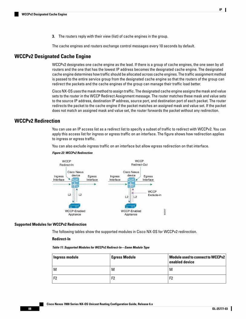
3. The routers reply with their view (list) of cache engines in the group.
The cache engines and routers exchange control messages every 10 seconds by default.
WCCPv2 Designated Cache EngineWCCPv2 designates one cache engine as the lead. If there is a group of cache engines, the one seen by allrouters and the one that has the lowest IP address becomes the designated cache engine. The designatedcache engine determines how traffic should be allocated across cache engines. The traffic assignment methodis passed to the entire service group from the designated cache engine so that the routers of the group canredirect the packets and the cache engines of the group can manage their traffic load better.
Cisco NX-OS uses the mask method to assign traffic. The designated cache engine assigns the mask and valuesets to the router in the WCCP Redirect Assignment message. The router matches these mask and value setsto the source IP address, destination IP address, source port, and destination port of each packet. The routerredirects the packet to the cache engine if the packet matches an assigned mask and value set. If the packetdoes not match an assigned mask and value set, the router forwards the packet without any redirection.
WCCPv2 RedirectionYou can use an IP access list as a redirect list to specify a subset of traffic to redirect with WCCPv2. You canapply this access list for ingress or egress traffic on an interface. The figure shows how redirection appliesto ingress or egress traffic.
You can also exclude ingress traffic on an interface but allow egress redirection on that interface.
Figure 22: WCCPv2 Redirection
Supported Modules for WCCPv2 Redirection
The following tables show the supported modules in Cisco NX-OS for WCCPv2 redirection.
Redirect-In
Table 11: Supported Modules for WCCPv2 Redirect-In—Same Module Type
Module used to connect to WCCPv2enabled device
Egress ModuleIngress module
MMM
F2F2F2
Cisco Nexus 7000 Series NX-OS Unicast Routing Configuration Guide, Release 6.xOL-25777-0388
IPWCCPv2 Designated Cache Engine

Module used to connect to WCCPv2enabled device
Egress ModuleIngress module
F2eF2eF2e
F3F3F3
Table 12: Supported Modules for WCCPv2 Redirect-In—Mixed Module Type
Module used to connect to WCCPv2enabled device
Egress ModuleIngress module
F2eF2eM
F3M2/M3M2/M3
M2/M3F3M2/M3
M2/M3M2/M3F3
F3F3M2/M3
F3M2/M3F3
M2/M3F3F3
F3F2eF2e
F2eF3F2e
F2eF2eF3
F2eF3F3
F3F2eF3
F3F3F2e
Redirect-Out
Table 13: Supported Modules for WCCPv2 Redirect-Out—Same Module Type
Module used to connect to WCCPv2enabled device
Egress ModuleIngress module
MMM
F2 1F2 1F2
F2e 1F2e 1F2e
F3F3F3
Cisco Nexus 7000 Series NX-OS Unicast Routing Configuration Guide, Release 6.x89OL-25777-03
IPSupported Modules for WCCPv2 Redirection

1 Redirect-out and exclude-in are not supported on interface VLANs (SVIs).Note
Table 14: Supported Modules for WCCPv2 Redirect-Out—Mixed Module Type
Module used to connect to WCCPv2enabled device
Egress ModuleIngress module
MMF2e
MF2eF2e
MF2eM
F3M2/M3M2/M3
M2/M3M2/M3F3 2
F3M2/M3F3
F3F2e 4F2e 3
F2e 5F3F2e 3
F2e 5F2e 4F3 3
F2e 5F3F3 3
F3F2e 4F3 3
F3F3F2e 3
2 Will not work if the F3 port is a FabricPath core port.3 WCCP redirect-out will not work if the ingress traffic is on a FabricPath VLAN.4 WCCP redirect-out is not supported on an F2e SVI.5 WCCP exclude-in is not supported on an F2e SVI.
Note
WCCPv2 AuthenticationWCCPv2 can authenticate a device before it adds that device to the service group. Message Digest (MD5)authentication allows each WCCPv2 service group member to use a secret key to generate a keyed MD5digest string that is part of the outgoing packet. At the receiving end, a keyed digest of an incoming packet isgenerated. If the MD5 digest within the incoming packet does not match the generated digest, WCCP ignoresthe packet.
WCCPv2 rejects packets in any of the following cases:
• The authentication schemes differ on the router and in the incoming packet.
Cisco Nexus 7000 Series NX-OS Unicast Routing Configuration Guide, Release 6.xOL-25777-0390
IPWCCPv2 Authentication

• The MD5 digests differ on the router and in the incoming packet.
You must configure the same authentication on all members of a WCCPv2 service group.
WCCPv2 Redirection MethodWCCPv2 negotiates the packet redirection method between the router and the cache engine. Cisco NX-OSuses this traffic redirection method for all cache engines in a service group.
WCCPv2 redirects packets using Layer 2 Destination MAC rewrite method, where WCCPv2 replaces thedestination MAC address of the packet with the MAC address of the cache engine that needs to handle thepacket. The cache engine and the router must be adjacent to Layer 2.
You can also configure an access control list (ACL), called a redirect list, for a WCCPv2 service group. ThisACL can either permit a packet to go through the WCCPv2 redirection process or deny the WCCP redirectionand send the packet through the normal packet forwarding procedure.
WCCPv2 Packet Return MethodWCCPv2 filters packets to determine which redirected packets have been returned from the cache engineand which packets have not. WCCPv2 does not redirect the returned packets, because the cache engine hasdetermined that these packets should not be cached. WCCPv2 returns packets that the cache engine doesnot service to the router that transmitted them.
A cache engine may return a packet for one of the following reasons:
• The cache engine is overloaded and cannot service the packets.
• The cache engine is filtering certain conditions that make caching packets counterproductive, for example,when IP authentication has been turned on.
WCCPv2 negotiates the packet return method between the router and the cache engine. Cisco NX-OS usesthis traffic return method for all cache engines in a service group.
WCCPv2 returns packets using the Destination MAC rewrite method, where WCCPv2 replaces the destinationMAC address of the packet with the MAC address of the router that originally redirected the packet. The cacheengine and the router must be adjacent to Layer 2.
High Availability for WCCPv2WCCPv2 supports stateful restarts and stateful switchovers. A stateful restart occurs when the WCCPv2process fails and is restarted. A stateful switchover occurs when the active supervisor switches to the standbysupervisor. Cisco NX-OS applies the running configuration after a switchover.
Virtualization Support for WCCPv2WCCPv2 supports virtual routing and forwarding (VRF) instances. VRFs exist within virtual device contexts(VDCs). By default, Cisco NX-OS places you in the default VDC and default VRF unless you specifically configureanother VDC and VRF.
WCCP redirection occurs within a VRF. You must configure the WCCP cache engine so that the forward andreturn traffic to and from the cache engine occurs from interfaces that are a part of the same VRF.
Cisco Nexus 7000 Series NX-OS Unicast Routing Configuration Guide, Release 6.x91OL-25777-03
IPWCCPv2 Redirection Method

The VRF used for the WCCP on an interface should match the VRF configured on that interface.
If you change the VRF membership of an interface, Cisco NX-OS removes all layer 3 configuration, includingWCCPv2.
For more information, see the Cisco Nexus 7000 Series NX-OS Virtual Device Context Configuration Guide.
WCCPv2 Error Handling for SPM OperationsThe Service Policy Manager (SPM) supervisor component acts as a data path manager for the WCCP Manager.The WCCP manager is shielded from the underlying platform specifics by the SPM and is portable to platformvariations. The WCCP manager has a set of SPM APIs to pass the configurations that are mapped andprogrammed in the hardware. These APIs can process and parse the application data that is implementedand maintained in one single handler.
The interface redirects that failed to be programmed by the SPM are stored until there is a service groupconfiguration change through the CLI or an RA message. The WCCP manager retries programming policiesthat failed previously.
The WCCP manager sends policy updates to the SPM in intervals to program TCAM entries in the hardware.These policy updates can be triggered by the CLI or through RA (Redirect-Assign) messages. When the WCCPis notified of an SPM error, a syslog message appears.
Prerequisites for WCCPv2WCCPv2 has the following prerequisites:
• You must globally enable the WCCPv2 feature.
• You can only configure WCCPv2 on Layer 3 or VLAN interfaces (see the Cisco Nexus 7000 Series NX-OSInterfaces Configuration Guide).
Guidelines and Limitations for WCCPv2WCCPv2 has the following configuration guidelines and limitations:
• A WCCPv2 service group supports up to 32 routers and 32 cache engines.
• All cache engines in a cluster must include all routers that service the cluster in its configuration. If acache engine within a cluster does not include one or more of the routers in its configuration, the servicegroup detects the inconsistency and the cache engine is not allowed to operate within the service group.
• The cache engine cannot be on the same SVI with a redirect out statement.
• WCCPv2 works with IPv4 networks only.
• Any traffic that is coming from an M1-Series or M2-Series I/O module interface and going towards aTraffic Engineering (TE) Class-based Tunnel Selection (CBTS) tunnel will be dropped if you have configuredthe ip wccp redirect exclude in command on the inbound M1-Series or M2-Series I/O module interfaceor Switch Virtual Interface (SVI).
Cisco Nexus 7000 Series NX-OS Unicast Routing Configuration Guide, Release 6.xOL-25777-0392
IPWCCPv2 Error Handling for SPM Operations
• WCCPv2 supports multiple service groups in the same direction (either inbound or outbound) on any Layer3 interface, under the following conditions:
• The access-list used must not have deny ip any any entry.
• The access-list used for multiple service groups must not contain overlapping entries.
The following is an example of an overlapping entry:
ip access-list wccp_acl1permit tcp 10.0.0.0/8 10.0.0.0/8ip access-list wccp_acl2permit tcp 10.10.10.1/32 10.10.10.10/32
• Cisco NX-OS removes all Layer 3 configuration on an interface when you change the VDC, interface VRFmembership, port-channel membership, or the port mode to Layer 2.
• Cisco NX-OS does not support WCCPv2 on tunnel interfaces.
• WCCPv2 is supported on all types of FEX devices.
• WCCP requires the client, server, and WCCP client to be on separate interfaces. If you migrate a topologyfrom a Cisco Catalyst 6500 Series switch deployment, it might not be supported.
• F2 Series, F2e Series, M1 Series, and M2 Series modules support WCCPv2. However, F2 and F2e Seriesmodules do not support egress WCCPv2 on an SVI including “exclude in” on SVI. F1 Series modules donot support WCCPv2.
• WCCPv2 redirect-in and redirect-out is fully supported in Cisco NX-OS Release 6.2 in non-mixed moduleVDCs. WCCPv2 is also support in mixed module VDC scenarios for most module combinations.
• For egress WCCPv2, traffic is not redirected when the ingress includes F2 series modules, and the next-hopis pointing to an SVI interface or subinterface of any module. If the egress WCCP policy is applied on aSVI or subinterface and if the packet ingresses on a F2 module, the same limitation applies.
• Beginning with Cisco NX-OS Release 5.2(4), policy-based routing and WCCPv2 are supported on the sameinterface. However, policy-based routing with statistics and WCCPv2 is supported on the same interfaceonly if bank chaining is disabled.
• GRE redirection/return and hash assignment are not supported on a Cisco Nexus 7000 Series switch.
• Traffic might encounter a vPC loop and drop if you have Web Cache Control Protocol (WCCP) and vPCon your Cisco Nexus 7000 Series switch and the traffic migrates from a Cisco Nexus 65xx switch to yourswitch. Traffic that comes from a vPC member port and crosses a vPC peer-link is not permitted to egressany vPC member port. However, it can egress any other type of port, such a Layer 3 port or an orphanport. This behavior is expected.
If traffic drops after you configure WCCP and vPC on your Nexus 7000 Series switch and based on yourdesign, you can perform one of the following tasks to avoid the vPC loop:
• Configure a Layer 2 trunk to carry the traffic in question.
• Enable a peer gateway.
• Shut down one of the member ports in the vPC.
• If you are familiar with the Cisco IOS CLI, be aware that the Cisco NX-OS commands for this feature mightdiffer from the Cisco IOS commands that you would use.
Cisco Nexus 7000 Series NX-OS Unicast Routing Configuration Guide, Release 6.x93OL-25777-03
IPGuidelines and Limitations for WCCPv2

• The following restrictions apply to the redirect-list, ACL:
• Permit statements in the redirect ACL will consume more security TCAM entries compared to denystatements. Ensure the TCAM does not become oversubscribed.
• The ACL must be an IPV4 simple ACL.
• The protocol must be IP or TCP.
• Only individual source or destination port numbers may be specified; port ranges cannot be specified.
• The use of fragments or options is not permitted.
WCCPv2 Default SettingsDefaultParameters
No authenticationAuthentication
DisableWCCPv2
Configuring WCCPv2To configure WCCPv2, perform these tasks in this chapter:
Procedure
Step 1 Enable the WCCPv2 feature.Step 2 Configure a WCCPv2 service group.Step 3 Apply WCCPv2 redirection to an interface.
Enabling and Disabling WCCPv2
Before you begin
• Enable the WCCPv2 feature.
• Ensure you are in the correct VDC (or use the switchto vdc command
Procedure
PurposeCommand or Action
Enters global configuration mode.switch# configure terminalStep 1
Cisco Nexus 7000 Series NX-OS Unicast Routing Configuration Guide, Release 6.xOL-25777-0394
IPWCCPv2 Default Settings
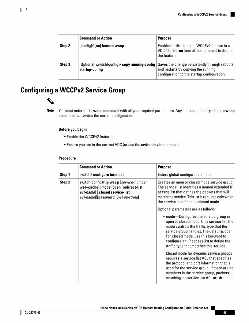
PurposeCommand or Action
Enables or disables the WCCPv2 feature in aVDC. Use the no form of the command to disablethe feature.
(config)# [no] feature wccpStep 2
Saves the change persistently through rebootsand restarts by copying the runningconfiguration to the startup configuration.
(Optional) switch(config)# copy running-configstartup-config
Step 3
Configuring a WCCPv2 Service Group
You must enter the ip wccp command with all your required parameters. Any subsequent entry of the ip wccpcommand overwrites the earlier configuration.
Note
Before you begin
• Enable the WCCPv2 feature.
• Ensure you are in the correct VDC (or use the switchto vdc command
Procedure
PurposeCommand or Action
Enters global configuration mode.switch# configure terminalStep 1
Creates an open or closed mode service group.The service list identifies a named extended IP
switch(config)# ip wccp {service-number |web-cache} [mode {open [redirect-list
Step 2
access list that defines the packets that willacl-name] | closed service-listacl-name}][password [0-7] pwstring] match the service. This list is required only when
the service is defined as closed mode
Optional parameters are as follows:
• mode—Configures the service group inopen or closed mode. On a service list, themode controls the traffic type that theservice group handles. The default is open.For closed mode, use this keyword toconfigure an IP access list to define thetraffic type that matches this service.
Closed mode for dynamic service groupsrequires a service list ACL that specifiesthe protocol and port information that isused for the service group. If there are nomembers in the service group, packetsmatching the service-list ACL are dropped.
Cisco Nexus 7000 Series NX-OS Unicast Routing Configuration Guide, Release 6.x95OL-25777-03
IPConfiguring a WCCPv2 Service Group

PurposeCommand or Action
• password—Configures MD5authentication for a service group. Usepassword 0 pwstring to store the passwordin clear text. Use password 7 pwstring tostore the password in encrypted form. Youcan use the password 7 keywords for analready encrypted password.
• redirect-list—Configures a global WCCPv2redirection list for the service group tocontrol the traffic that is redirected to thecache engine.
• service-list—Configures an IP access listthat defines the traffic type redirected bythe service group.
• The service-number range is from 1 to 255.The acl-name can be any case-sensitive,alphanumeric string up to 64 characters.The pwstring can be any case-sensitive,alphanumeric string up to eight characters.
Saves the change persistently through rebootsand restarts by copying the runningconfiguration to the startup configuration.
(Optional) switch(config)# copy running-configstartup-config
Step 3
Applying WCCPv2 Redirection to an Interface
Procedure
PurposeCommand or Action
Enters global configuration mode.switch# configure terminalStep 1
Enters interface configuration mode.switch(config)# interface ethernet numberStep 2
Applies the specified type of WCCPv2redirection to the interface. The commandexamples show the following:
switch(config-if)# ip wccp {service-numberredirect{in | out} | web-cache | redirect {in |out}}
Step 3
• WCCPv2 redirection applied on the ingressor egress traffic for this interface.
• WCCPv2 redirection applied on the ingressor egress web cache traffic for thisinterface.
• Ingress traffic excluded from WCCPredirection on this interface.
Cisco Nexus 7000 Series NX-OS Unicast Routing Configuration Guide, Release 6.xOL-25777-0396
IPApplying WCCPv2 Redirection to an Interface
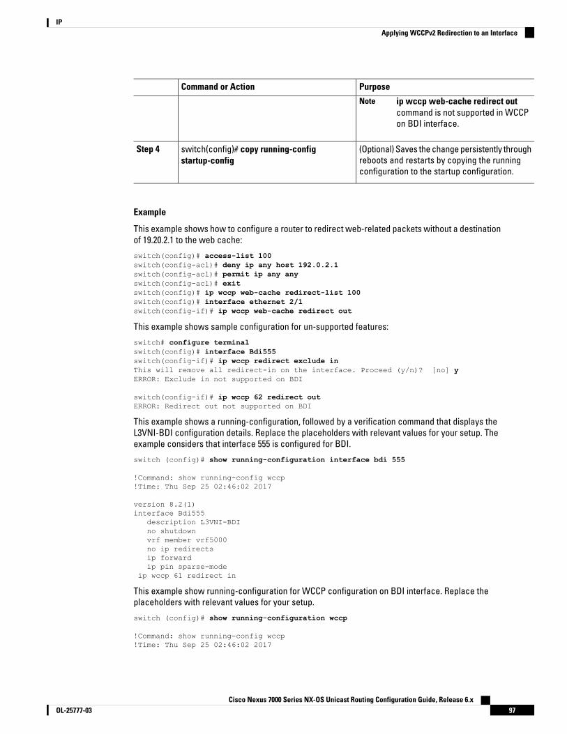
PurposeCommand or Action
ip wccp web-cache redirect outcommand is not supported in WCCPon BDI interface.
Note
(Optional) Saves the change persistently throughreboots and restarts by copying the runningconfiguration to the startup configuration.
switch(config)# copy running-configstartup-config
Step 4
Example
This example shows how to configure a router to redirect web-related packets without a destinationof 19.20.2.1 to the web cache:
switch(config)# access-list 100switch(config-acl)# deny ip any host 192.0.2.1switch(config-acl)# permit ip any anyswitch(config-acl)# exitswitch(config)# ip wccp web-cache redirect-list 100switch(config)# interface ethernet 2/1switch(config-if)# ip wccp web-cache redirect out
This example shows sample configuration for un-supported features:
switch# configure terminalswitch(config)# interface Bdi555switch(config-if)# ip wccp redirect exclude inThis will remove all redirect-in on the interface. Proceed (y/n)? [no] yERROR: Exclude in not supported on BDI
switch(config-if)# ip wccp 62 redirect outERROR: Redirect out not supported on BDI
This example shows a running-configuration, followed by a verification command that displays theL3VNI-BDI configuration details. Replace the placeholders with relevant values for your setup. Theexample considers that interface 555 is configured for BDI.
switch (config)# show running-configuration interface bdi 555
!Command: show running-config wccp!Time: Thu Sep 25 02:46:02 2017
version 8.2(1)interface Bdi555
description L3VNI-BDIno shutdownvrf member vrf5000no ip redirectsip forwardip pin sparse-mode
ip wccp 61 redirect in
This example show running-configuration for WCCP configuration on BDI interface. Replace theplaceholders with relevant values for your setup.
switch (config)# show running-configuration wccp
!Command: show running-config wccp!Time: Thu Sep 25 02:46:02 2017
Cisco Nexus 7000 Series NX-OS Unicast Routing Configuration Guide, Release 6.x97OL-25777-03
IPApplying WCCPv2 Redirection to an Interface

version 8.2(1)feature wccp
vrf context vrf5000ip wccp web-cacheip wccp 61ip wccp 62
interface Bdi555vrf member vrf5000ip wccp 61 redirect in
Configuring WCCPv2 in a VRF
You must enter the ip wccp command with all your required parameters. Any subsequent entry of the ip wccpcommand overwrites the earlier configuration.
Note
Before you begin
• Enable the WCCPv2 feature.
• Ensure you are in the correct VDC (or use the switchto vdc command
Procedure
PurposeCommand or Action
Enters global configuration mode.switch# configure terminalStep 1
Enters VRF configuration mode. The vrf-namecan be any case-sensitive, alphanumeric stringup to 63 characters.
switch(config)# vrf context vrf-nameStep 2
Creates an open or closed mode service group.The service list identifies a named extended IP
switch(config)# ip wccp {service-number |web-cache} [mode {open [redirect-list
Step 3
access list that defines the packets that willacl-name] | closed service-listacl-name}][password [0-7] pwstring] match the service. This list is required only when
the service is defined as closed mode
Optional parameters are as follows:
• mode—Configures the service group inopen or closed mode. On a service list, themode controls the traffic type that theservice group handles. The default is open.For closed mode, use this keyword toconfigure an IP access list to define thetraffic type that matches this service.
Closed mode for dynamic service groupsrequires a service list ACL that specifies
Cisco Nexus 7000 Series NX-OS Unicast Routing Configuration Guide, Release 6.xOL-25777-0398
IPConfiguring WCCPv2 in a VRF
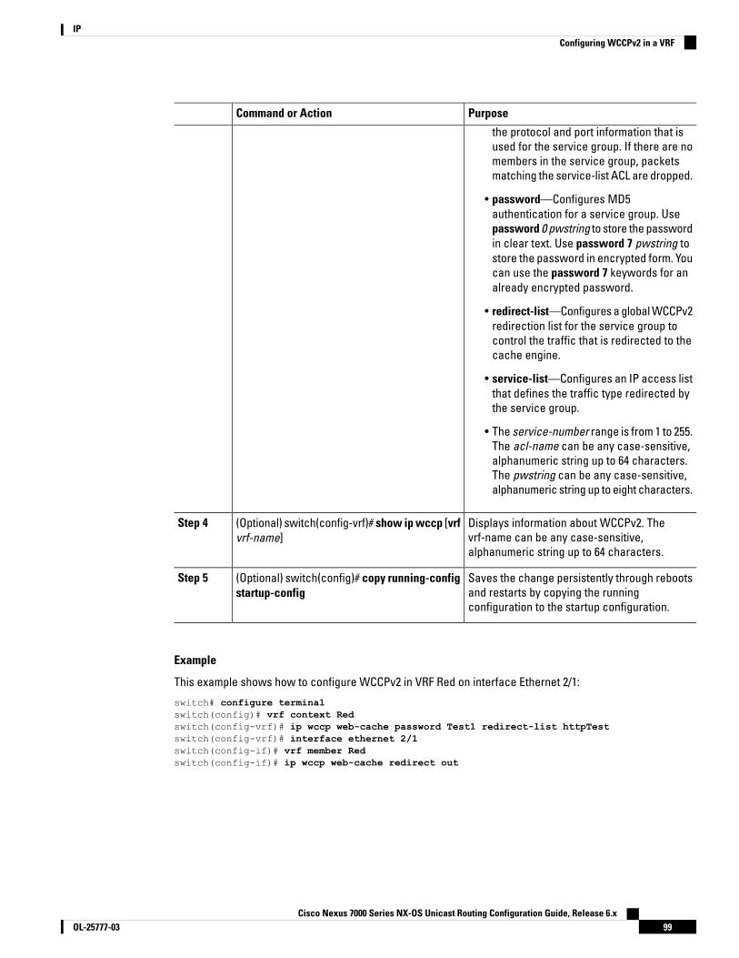
PurposeCommand or Action
the protocol and port information that isused for the service group. If there are nomembers in the service group, packetsmatching the service-list ACL are dropped.
• password—Configures MD5authentication for a service group. Usepassword 0 pwstring to store the passwordin clear text. Use password 7 pwstring tostore the password in encrypted form. Youcan use the password 7 keywords for analready encrypted password.
• redirect-list—Configures a global WCCPv2redirection list for the service group tocontrol the traffic that is redirected to thecache engine.
• service-list—Configures an IP access listthat defines the traffic type redirected bythe service group.
• The service-number range is from 1 to 255.The acl-name can be any case-sensitive,alphanumeric string up to 64 characters.The pwstring can be any case-sensitive,alphanumeric string up to eight characters.
Displays information about WCCPv2. Thevrf-name can be any case-sensitive,alphanumeric string up to 64 characters.
(Optional) switch(config-vrf)# show ip wccp [vrfvrf-name]
Step 4
Saves the change persistently through rebootsand restarts by copying the runningconfiguration to the startup configuration.
(Optional) switch(config)# copy running-configstartup-config
Step 5
Example
This example shows how to configure WCCPv2 in VRF Red on interface Ethernet 2/1:
switch# configure terminalswitch(config)# vrf context Redswitch(config-vrf)# ip wccp web-cache password Test1 redirect-list httpTestswitch(config-vrf)# interface ethernet 2/1switch(config-if)# vrf member Redswitch(config-if)# ip wccp web-cache redirect out
Cisco Nexus 7000 Series NX-OS Unicast Routing Configuration Guide, Release 6.x99OL-25777-03
IPConfiguring WCCPv2 in a VRF

Verifying the WCCPv2 ConfigurationUse one of the following commands to verify the configuration:
PurposeCommand
Displays the WCCPv2 status for all groups or onegroup in a VRF.
show ip wccp [vrf vrf-name] [service-number |web-cache]
Displays the WCCPv2 interface information.show ip interface [ethernet-number]
Displays the WCCPv2 service group status.show ip wccp [service-number | web-cache]
Displays the clients in a WCCPv2 service group.show ip wccp [service-number | web-cache] detail
Displays the WCCPv2 mask assignment.show ip wccp [service-number | web-cache] mask
Displays the WCCPv2 service group definition.show ip wccp [service-number | web-cache] service
Displays the WCCPv2 group membership.show ip wccp [service-number | web-cache] view
Configuration Examples for WCCPv2This example shows how to configure WCCPv2 authentication on router redirect web-related packets withouta destination of 192.0.2.1 to the web cache:
access-list 100deny ip any host 192.0.2.1permit ip any anyfeature wccpip wccp web-cache password 0 Test1 redirect-list 100interface ethernet 1/2ip wccp web-cache redirect outno shutdown
This example shows the sample output when WCCP is configuration in a VRF.
switch(config)# show ip wccp vrf vrf5000
VRF vrf5000 WCCP information:Router information:
Router Identifier: 50.50.50.1Protocol Version: 2.0
Service Identifier: web-cacheNumber of Service Group Clients: 1Number of Service Group Routers: 1Service mode: OpenService Access-list: -none-Redirect Access-list: -none-
Service Identifier: 61Number of Service Group Clients: 1Number of Service Group Routers: 1Service mode: OpenService Access-list: -none-Redirect Access-list: -none-
Service Identifier: 62
Cisco Nexus 7000 Series NX-OS Unicast Routing Configuration Guide, Release 6.xOL-25777-03100
IPVerifying the WCCPv2 Configuration

Number of Service Group Clients: 1Number of Service Group Routers: 1Service mode: OpenService Access-list: -none-Redirect Access-list: -none-
The following example shows a verification command to display the kind of service for WCCP.
switch(config)# show ip wccp vrf vrf5000 61 serviceWCCP service information definition:
Type: DynamicId: 61Priority: 34Protocol: 6Options: 0x00000501--------
Mask/Value sets: 1Value elements : 16Ports: -none-
The following example shows a verification command to display cache engine information, after the connectionwith the cache engine is established
switch(config)# show ip wccp vrf vrf5000 61 view
WCCP Router Informed of:50.50.50.1
WCCP Cache Engines Visible:10.10.10.3
WCCP Cache Engines Not Visible:-none-
Related Documents for WCCPv2Document TitleRelated Topic
Cisco Nexus 7000 Series NX-OS Unicast RoutingCommand Reference
WCCPv2 CLI commands
Cisco Nexus 7000 Series NX-OS Security ConfigurationGuide, Release 6.x
IP ACLs
Standards for the WCCPv2No new or modified standards are supported by this feature, and support for existing standards has not beenmodified by this feature.
Feature History for WCCPv2This table includes only the updates for those releases that have resulted in additions or changes to the feature.
Cisco Nexus 7000 Series NX-OS Unicast Routing Configuration Guide, Release 6.x101OL-25777-03
IPRelated Documents for WCCPv2

Feature InformationReleaseFeature Name
Added support on BDIinterface.
8.2(1)WCCPv2 on BDI
Added support for M3 module.7.3(0)DX(1)WCCPv2 Redirection
Added support forpolicy-based routing andWCCPv2 on the sameinterface if bank chaining isdisabled.
5.2(4)WCCPv2
This feature was added.5.1(1)WCCPv2 Error Handling forSPM Operations
This feature was introduced.4.2(1)WCCPv2
Cisco Nexus 7000 Series NX-OS Unicast Routing Configuration Guide, Release 6.xOL-25777-03102
IPFeature History for WCCPv2

P A R T IIRouting
• Configuring OSPFv2, on page 105• Configuring OSPFv3, on page 149• Configuring EIGRP, on page 197• Configuring IS-IS, on page 231• Configuring Basic BGP, on page 257• Configuring Advanced BGP, on page 287• Configuring RIP, on page 341• Configuring Static Routing, on page 359• Configuring the Interoperability of Modules for Unicast Routing, on page 371• Configuring Layer 3 Virtualization, on page 375• Managing the Unicast RIB and FIB, on page 387• Configuring Route Policy Manager, on page 401• Configuring Policy-Based Routing, on page 423


C H A P T E R 7Configuring OSPFv2
This chapter contains the following sections:
• Finding Feature Information, on page 105• Information About OSPFv2, on page 105• Prerequisites for OSPFv2, on page 116• Guidelines and Limitations for OSPFv2, on page 116• Default Settings for OSPFv2, on page 118• Configuring Basic OSPFv2, on page 118• Configuring Advanced OSPFv2, on page 127• Verifying the OSPFv2 Configuration, on page 144• Monitoring OSPFv2 , on page 146• Configuration Examples for OSPFv2, on page 146• Related Documents for OSPFv2, on page 146• Feature History for OSPFv2, on page 146
Finding Feature InformationYour software release might not support all the features documented in this module. For the latest caveatsand feature information, see the Bug Search Tool at https://tools.cisco.com/bugsearch/ and the release notesfor your software release. To find information about the features documented in this module, and to see a listof the releases in which each feature is supported, see the "New and Changed Information"chapter or theFeature History table in this chapter.
Information About OSPFv2OSPFv2 is an IETF link-state protocol for IPv4 networks. An OSPFv2 router sends a special message, called ahello packet, out each OSPF-enabled interface to discover other OSPFv2 neighbor routers. Once a neighboris discovered, the two routers compare information in the to determine if the routers have compatibleconfigurations. The neighbor routers try to establish , which means that the routers synchronize their link-statedatabases to ensure that they have identical OSPFv2 routing information. Adjacent routers share (LSAs) thatinclude information about the operational state of each link, the cost of the link, and any other neighborinformation. The routers then flood these received LSAs out every OSPF-enabled interface so that all OSPFv2routers eventually have identical link-state databases. When all OSPFv2 routers have identical link-state
Cisco Nexus 7000 Series NX-OS Unicast Routing Configuration Guide, Release 6.x105OL-25777-03
databases, the network is converged. Each router then uses Dijkstra’s Shortest Path First (SPF) algorithm tobuild its route table.
You can divide OSPFv2 networks into areas. Routers send most LSAs only within one area, which reduces theCPU and memory requirements for an OSPF-enabled router.
OSPFv2 supports IPv4, while OSPFv3 supports IPv6. For more information, see the "Configuring OSPFv3" chapter.
OSPFv2 on Cisco NX-OS supports RFC 2328. This RFC introduced a different method to calculate route summarycosts which is not compatible with the calculation used by RFC1583. RFC 2328 also introduced different selectioncriteria for AS-external paths. It is important to ensure that all routers support the same RFC. Use therfc1583compatibility command if your network includes routers that are only compliant with RFC1583. Thedefault supported RFC standard for OSPFv2 may be different for Cisco NX-OS and Cisco IOS. You must makeadjustments to set the values identically. For more information, see the “OSPF RFC Compatibility Mode Example”section.
Note
Hello PacketOSPFv2 routers periodically send Hello packets on every OSPF-enabled interface. The hello interval determineshow frequently the router sends these Hello packets and is configured per interface. OSPFv2 uses Hello packetsfor the following tasks:
• Neighbor discovery
• Keepalives
• Bidirectional communications
• Designated router election
The Hello packet contains information about the originating OSPFv2 interface and router, including the assignedOSPFv2 cost of the link, the , and optional capabilities of the originating router. An OSPFv2 interface thatreceives these Hello packets determines if the settings are compatible with the receiving interface settings.Compatible interfaces are considered neighbors and are added to the neighbor table.
Hello packets also include a list of router IDs for the routers that the originating interface has communicatedwith. If the receiving interface sees its own router ID in this list, then bidirectional communication has beenestablished between the two interfaces.
OSPFv2 uses Hello packets as a keepalive message to determine if a neighbor is still communicating. If a routerdoes not receive a Hello packet by the configured (usually a multiple of the hello interval), then the neighboris removed from the local neighbor table.
NeighborsAn OSPFv2 interface must have a compatible configuration with a remote interface before the two can beconsidered neighbors. The two OSPFv2 interfaces must match the following criteria:
• Hello interval
• Dead interval
• Area ID
Cisco Nexus 7000 Series NX-OS Unicast Routing Configuration Guide, Release 6.xOL-25777-03106
RoutingHello Packet

• Authentication
• Optional capabilities
If there is a match, the following information is entered into the neighbor table:
• Neighbor ID—The router ID of the neighbor.
• Priority—Priority of the neighbor. The priority is used for designated router election.
• State—Indication of whether the neighbor has just been heard from, is in the process of setting upbidirectional communications, is sharing the link-state information, or has achieved full adjacency.
• Dead time—Indication of the time since the last Hello packet was received from this neighbor.
• IP Address—The IP address of the neighbor.
• Designated Router—Indication of whether the neighbor has been declared as the designated router oras the backup designated router.
• Local interface—The local interface that received the Hello packet for this neighbor.
AdjacencyNot all neighbors establish adjacency. Depending on the network type and designated router establishment,some neighbors become fully adjacent and share LSAs with all their neighbors, while other neighbors do not.
Adjacency is established using Database Description packets, Link State Request packets, and Link StateUpdate packets in OSPF. The Database Description packet includes just the LSA headers from the link-statedatabase of the neighbor. The local router compares these headers with its own link-state database anddetermines which LSAs are new or updated. The local router sends a Link State Request packet for each LSAthat it needs new or updated information on. The neighbor responds with a Link State Update packet. Thisexchange continues until both routers have the same link-state information.
Designated RoutersNetworks with multiple routers present a unique situation for OSPF. If every router floods the network withLSAs, the same link-state information is sent from multiple sources. Depending on the type of network, OSPFv2might use a single router, the (DR), to control the LSA floods and represent the network to the rest of theOSPFv2 area. If the DR fails, OSPFv2 selects a (BDR). If the DR fails, OSPFv2 uses the BDR.
Network types are as follows:
• Point-to-point—A network that exists only between two routers. All neighbors on a point-to-point networkestablish adjacency and there is no DR.
• Broadcast—A network with multiple routers that can communicate over a shared medium that allowsbroadcast traffic, such as Ethernet. OSPFv2 routers establish a DR and BDR that controls LSA floodingon the network. OSPFv2 uses the well-known IPv4 multicast addresses 224.0.0.5 and a MAC address of0100.5300.0005 to communicate with neighbors.
The DR and BDR are selected based on the information in the Hello packet. When an interface sends a Hellopacket, it sets the priority field and the DR and BDR field if it knows who the DR and BDR are. The routersfollow an election procedure based on which routers declare themselves in the DR and BDR fields and the
Cisco Nexus 7000 Series NX-OS Unicast Routing Configuration Guide, Release 6.x107OL-25777-03
RoutingAdjacency
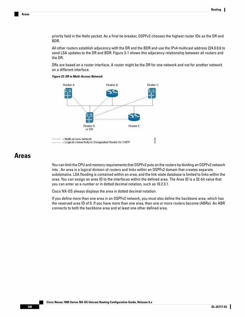
priority field in the Hello packet. As a final tie breaker, OSPFv2 chooses the highest router IDs as the DR andBDR.
All other routers establish adjacency with the DR and the BDR and use the IPv4 multicast address 224.0.0.6 tosend LSA updates to the DR and BDR. Figure 3-1 shows this adjacency relationship between all routers andthe DR.
DRs are based on a router interface. A router might be the DR for one network and not for another networkon a different interface.
Figure 23: DR in Multi-Access Network
AreasYou can limit the CPU and memory requirements that OSPFv2 puts on the routers by dividing an OSPFv2 networkinto . An area is a logical division of routers and links within an OSPFv2 domain that creates separatesubdomains. LSA flooding is contained within an area, and the link-state database is limited to links within thearea. You can assign an area ID to the interfaces within the defined area. The Area ID is a 32-bit value thatyou can enter as a number or in dotted decimal notation, such as 10.2.3.1.
Cisco NX-OS always displays the area in dotted decimal notation.
If you define more than one area in an OSPFv2 network, you must also define the backbone area, which hasthe reserved area ID of 0. If you have more than one area, then one or more routers become (ABRs). An ABRconnects to both the backbone area and at least one other defined area.
Cisco Nexus 7000 Series NX-OS Unicast Routing Configuration Guide, Release 6.xOL-25777-03108
RoutingAreas
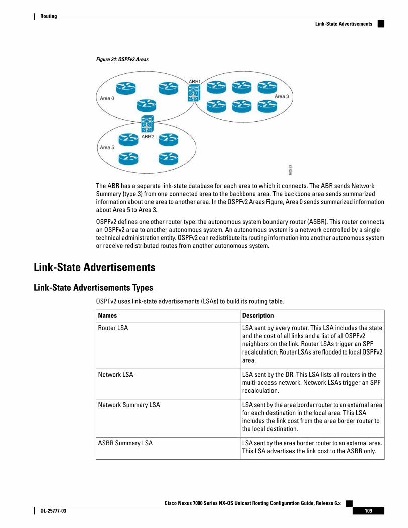
Figure 24: OSPFv2 Areas
The ABR has a separate link-state database for each area to which it connects. The ABR sends NetworkSummary (type 3) from one connected area to the backbone area. The backbone area sends summarizedinformation about one area to another area. In the OSPFv2 Areas Figure, Area 0 sends summarized informationabout Area 5 to Area 3.
OSPFv2 defines one other router type: the autonomous system boundary router (ASBR). This router connectsan OSPFv2 area to another autonomous system. An autonomous system is a network controlled by a singletechnical administration entity. OSPFv2 can redistribute its routing information into another autonomous systemor receive redistributed routes from another autonomous system.
Link-State Advertisements
Link-State Advertisements TypesOSPFv2 uses link-state advertisements (LSAs) to build its routing table.
DescriptionNames
LSA sent by every router. This LSA includes the stateand the cost of all links and a list of all OSPFv2neighbors on the link. Router LSAs trigger an SPFrecalculation. Router LSAs are flooded to local OSPFv2area.
Router LSA
LSA sent by the DR. This LSA lists all routers in themulti-access network. Network LSAs trigger an SPFrecalculation.
Network LSA
LSA sent by the area border router to an external areafor each destination in the local area. This LSAincludes the link cost from the area border router tothe local destination.
Network Summary LSA
LSA sent by the area border router to an external area.This LSA advertises the link cost to the ASBR only.
ASBR Summary LSA
Cisco Nexus 7000 Series NX-OS Unicast Routing Configuration Guide, Release 6.x109OL-25777-03
RoutingLink-State Advertisements

DescriptionNames
LSA generated by the ASBR. This LSA includes thelink cost to an external autonomous systemdestination. AS External LSAs are flooded throughoutthe autonomous system.
AS External LSA
LSA generated by the ASBR within a not-so-stubbyarea (NSSA). This LSA includes the link cost to anexternal autonomous system destination. NSSAExternal LSAs are flooded only within the local NSSA.
NSSA External LSA
LSA used to extend OSPF.Opaque LSAs
Link Cost
Each OSPFv2 interface is assigned a . The cost is an arbitrary number. By default, Cisco NX-OS assigns a costthat is the configured reference bandwidth divided by the interface bandwidth. By default, the referencebandwidth is 40 Gb/s. The link cost is carried in the LSA updates for each link.
Flooding and LSA Group Pacing
When an OSPFv2 router receives an LSA, it forwards that LSA out every OSPF-enabled interface, flooding theOSPFv2 area with this information. This LSA flooding guarantees that all routers in the network have identicalrouting information. LSA flooding depends on the OSPFv2 area configuration. The LSAs are flooded based onthe (every 30 minutes by default). Each LSA has its own link-state refresh time.
You can control the flooding rate of LSA updates in your network by using the LSA group pacing feature. LSAgroup pacing can reduce high CPU or buffer utilization. This feature groups LSAs with similar link-state refreshtimes to allow OSPFv2 to pack multiple LSAs into an OSPFv2 Update message.
By default, LSAs with link-state refresh times within 10 seconds of each other are grouped together. You shouldlower this value for large link-state databases or raise it for smaller databases to optimize the OSPFv2 load onyour network.
Link-State Database
Each router maintains a link-state database for the OSPFv2 network. This database contains all the collectedLSAs, and includes information on all the routes through the network. OSPFv2 uses this information to calculatethe best path to each destination and populates the routing table with these best paths.
LSAs are removed from the link-state database if no LSA update has been received within a set interval, calledthe MaxAge. Routers flood a repeat of the LSA every 30 minutes to prevent accurate link-state informationfrom being aged out. Cisco NX-OS supports the LSA grouping feature to prevent all LSAs from refreshing atthe same time.
Opaque LSAs
Opaque LSAs allow you to extend OSPF functionality. Opaque LSAs consist of a standard LSA header followedby application-specific information. This information might be used by OSPFv2 or by other applications. OSPFv2uses Opaque LSAs to support OSPFv2 Graceful Restart capability. Three Opaque LSA types are defined asfollows:
• LSA type 9—Flooded to the local network.
• LSA type 10—Flooded to the local area.
Cisco Nexus 7000 Series NX-OS Unicast Routing Configuration Guide, Release 6.xOL-25777-03110
RoutingLink Cost
• LSA type 11—Flooded to the local autonomous system.
OSPFv2 and the Unicast RIBOSPFv2 runs the Dijkstra shortest path first algorithm on the link-state database. This algorithm selects thebest path to each destination based on the sum of all the link costs for each link in the path. The resultantshortest path for each destination is then put in the OSPFv2 route table. When the OSPFv2 network is converged,this route table feeds into the unicast RIB. OSPFv2 communicates with the unicast RIB to do the following:
• Add or remove routes
• Handle route redistribution from other protocols
• Provide convergence updates to remove stale OSPFv2 routes and for stub router advertisements
OSPFv2 also runs a modified Dijkstra algorithm for fast recalculation for summary and external (type 3, 4, 5,and 7) LSA changes.
AuthenticationYou can configure authentication on OSPFv2 messages to prevent unauthorized or invalid routing updates inyour network. Cisco NX-OS supports two authentication methods:
• Simple password authentication
• MD5 authentication digest
You can configure the OSPFv2 authentication for an OSPFv2 area or per interface.
Simple Password AuthenticationSimple password authentication uses a simple clear-text password that is sent as part of the OSPFv2 message.The receiving OSPFv2 router must be configured with the same clear-text password to accept the OSPFv2message as a valid route update. Because the password is in clear text, anyone who can watch traffic on thenetwork can learn the password.
MD5 AuthenticationYou should use MD5 authentication to authenticate OSPFv2 messages. You configure a password that is sharedat the local router and all remote OSPFv2 neighbors. For each OSPFv2 message, Cisco NX-OS creates an MD5one-way message digest based on the message itself and the encrypted password. The interface sends thisdigest with the OSPFv2 message. The receiving OSPFv2 neighbor validates the digest using the same encryptedpassword. If the message has not changed, the digest calculation is identical and the OSPFv2 message isconsidered valid.
MD5 authentication includes a sequence number with each OSPFv2 message to ensure that no message isreplayed in the network.
Advanced Features for OSPFv2Cisco NX-OS supports advanced OSPFv2 features that enhance the usability and scalability of OSPFv2 in thenetwork.
Cisco Nexus 7000 Series NX-OS Unicast Routing Configuration Guide, Release 6.x111OL-25777-03
RoutingOSPFv2 and the Unicast RIB

Stub AreaYou can limit the amount of external routing information that floods an area by making it a stub area. A stubarea is an area that does not allow AS External (type 5) LSAs. These LSAs are usually flooded throughout thelocal autonomous system to propagate external route information. Stub areas have the following requirements:
• All routers in the stub area are stub routers.
• No ASBR routers exist in the stub area.
• You cannot configure virtual links in the stub area.
The following figure shows an example of an OSPFv2 autonomous system where all routers in area 0.0.0.10have to go through the ABR to reach external autonomous systems. Area 0.0.0.10 can be configured as a stubarea.
Figure 25: Stub Area
Stub areas use a default route for all traffic that needs to go through the backbone area to the externalautonomous system. The default route is 0.0.0.0 for IPv4.
Not-So-Stubby AreaA Not-so-Stubby Area (NSSA) is similar to a stub area, except that an NSSA allows you to import autonomoussystem external routes within an NSSA using redistribution. The NSSA ASBR redistributes these routes andgenerates NSSA External (type 7) LSAs that it floods throughout the NSSA. You can optionally configure theABR that connects the NSSA to other areas to translate this NSSA External LSA to AS External (type 5) LSAs.The ABR then floods these AS External LSAs throughout the OSPFv2 autonomous system. Summarization andfiltering are supported during the translation.
You can, for example, use NSSA to simplify administration if you are connecting a central site using OSPFv2to a remote site that is using a different routing protocol. Before NSSA, the connection between the corporatesite border router and a remote router could not be run as an OSPFv2 stub area because routes for the remotesite could not be redistributed into a stub area. With NSSA, you can extend OSPFv2 to cover the remoteconnection by defining the area between the corporate router and remote router as an NSSA.
The backbone Area 0 cannot be an NSSA.
Virtual LinksVirtual links allow you to connect an OSPFv2 area ABR to a backbone area ABR when a direct physicalconnection is not available. The figure shows a virtual link that connects Area 3 to the backbone area throughArea 5.
Cisco Nexus 7000 Series NX-OS Unicast Routing Configuration Guide, Release 6.xOL-25777-03112
RoutingStub Area

Figure 26: Virtual Links
You can also use virtual links to temporarily recover from a partitioned area, which occurs when a link withinthe area fails, isolating part of the area from reaching the designated ABR to the backbone area.
Route RedistributionOSPFv2 can learn routes from other routing protocols by using route redistribution. You configure OSPFv2 toassign a link cost for these redistributed routes or a default link cost for all redistributed routes.
Route redistribution uses route maps to control which external routes are redistributed. You must configurea route map with the redistribution to control which routes are passed into OSPFv2. A route map allows youto filter routes based on attributes such as the destination, origination protocol, route type, route tag, and soon. You can use route maps to modify parameters in the AS External (type 5) and NSSA External (type 7) LSAsbefore these external routes are advertised in the local OSPFv2 autonomous system.
OSPFv2 sets the type-5 LSA's forwarding address as described below:
• If the next-hop for the route is an attached-route then the forwarding address is the next-hop addressfor that route.
• If the next-hop for the route is a recursive route and next-hop's next-hop is an attached route then theforwarding address is the next-hop's next-hop address.
Route SummarizationBecause OSPFv2 shares all learned routes with every OSPF-enabled router, you might want to use routesummarization to reduce the number of unique routes that are flooded to every OSPF-enabled router. Routesummarization simplifies route tables by replacing more-specific addresses with an address that representsall the specific addresses. For example, you can replace 10.1.1.0/24, 10.1.2.0/24, and 10.1.3.0/24 with one summaryaddress, 10.1.0.0/16.
Typically, you would summarize at the boundaries of area border routers (ABRs). Although you could configuresummarization between any two areas, it is better to summarize in the direction of the backbone so that thebackbone receives all the aggregate addresses and injects them, already summarized, into other areas. Thetwo types of summarization are as follows
Cisco Nexus 7000 Series NX-OS Unicast Routing Configuration Guide, Release 6.x113OL-25777-03
RoutingRoute Redistribution

• Inter-area route summarization
• External route summarization
You configure inter-area route summarization on ABRs, summarizing routes between areas in the autonomoussystem. To take advantage of summarization, you should assign network numbers in areas in a contiguousway to be able to lump these addresses into one range.
External route summarization is specific to external routes that are injected into OSPFv2 using routeredistribution. You should make sure that external ranges that are being summarized are contiguous.Summarizing overlapping ranges from two different routers could cause packets to be sent to the wrongdestination. Configure external route summarization on ASBRs that are redistributing routes into OSPF.
When you configure a summary address, Cisco NX-OS automatically configures a discard route for the summaryaddress to prevent routing black holes and route loops.
High Availability and Graceful RestartCisco NX-OS provides a multilevel high-availability architecture. OSPFv2 supports stateful restart, which isalso referred to as non-stop routing (NSR). If OSPFv2 experiences problems, it attempts to restart from itsprevious run-time state. The neighbors do not register any neighbor event in this case. If the first restart is notsuccessful and another problem occurs, OSPFv2 attempts a graceful restart.
A graceful restart, or nonstop forwarding (NSF), allows OSPFv2 to remain in the data forwarding path througha process restart. When OSPFv2 needs to perform a graceful restart, it sends a link-local opaque (type 9) LSA,called a grace LSA. This restarting OSPFv2 platform is called NSF capable.
The grace LSA includes a grace period, which is a specified time that the neighbor OSPFv2 interfaces holdonto the LSAs from the restarting OSPFv2 interface. (Typically, OSPFv2 tears down the adjacency and discardsall LSAs from a down or restarting OSPFv2 interface.) The participating neighbors, which are called NSFhelpers, keep all LSAs that originate from the restarting OSPFv2 interface as if the interface was still adjacent.
When the restarting OSPFv2 interface is operational again, it rediscovers its neighbors, establishes adjacency,and starts sending its LSA updates again. At this point, the NSF helpers recognize that the graceful restart hasfinished.
Stateful restart is used in the following scenarios:
• First recovery attempt after the process experiences problems
• ISSU
• User-initiated switchover using the system switchover command
• Active supervisor reload using the reload module active-sup command
Graceful restart is used in the following scenarios:
• Second recovery attempt after the process experiences problems within a 4-minute interval
• Manual restart of the process using the restart ospf command
• Active supervisor removal
Cisco Nexus 7000 Series NX-OS Unicast Routing Configuration Guide, Release 6.xOL-25777-03114
RoutingHigh Availability and Graceful Restart
The Cisco Nexus 7000 series devices support the Internet Engineering Task Force (IETF) version only. As aresult, NSF IETF must be explicitly configured under the routing protocols in the Virtual Switching System(VSS). Use the nsf ietf command in router configuration mode for NSF IETF configuration. No additionalconfiguration is required on the Cisco Nexus 7000 pairs because they run NSF IETF graceful-restart by default.However, each neighbor device that will become Layer 3 adjacent must have NSF configured and the samemode of NSF must be enabled to successfully operate a graceful failover.
Note
OSPFv2 Stub Router AdvertisementsYou can configure an OSPFv2 interface to act as a stub router using the OSPFv2 Stub Router Advertisementsfeature. Use this feature when you want to limit the OSPFv2 traffic through this router, such as when you wantto introduce a new router to the network in a controlled manner or limit the load on a router that is alreadyoverloaded. You might also want to use this feature for various administrative or traffic engineering reasons.
OSPFv2 stub router advertisements do not remove the OSPFv2 router from the network topology, but they doprevent other OSPFv2 routers from using this router to route traffic to other parts of the network. Only thetraffic that is destined for this router or directly connected to this router is sent.
OSPFv2 stub router advertisements mark all stub links (directly connected to the local router) to the cost ofthe local OSPFv2 interface. All remote links are marked with the maximum cost (0xFFFF).
Multiple OSPFv2 InstancesCisco NX-OS supports multiple instances of the OSPFv2 protocol that run on the same node. You cannotconfigure multiple instances over the same interface. By default, every instance uses the same system routerID. You must manually configure the router ID for each instance if the instances are in the same OSPFv2autonomous system.
SPF OptimizationCisco NX-OS optimizes the SPF algorithm in the following ways:
• Partial SPF for Network (type 2) LSAs, Network Summary (type 3) LSAs, and AS External (type 5)LSAs—When there is a change on any of these LSAs, Cisco NX-OS performs a faster partial calculationrather than running the whole SPF calculation.
• SPF timers—You can configure different timers for controlling SPF calculations. These timers includeexponential backoff for subsequent SPF calculations. The exponential backoff limits the CPU load ofmultiple SPF calculations.
BFDThis feature supports bidirectional forwarding detection (BFD). BFD is a detection protocol that provides fastforwarding-path failure detection times. BFD provides subsecond failure detection between two adjacentdevices and can be less CPU-intensive than protocol hello messages because some of the BFD load can bedistributed onto the data plane on supported modules. See the Cisco Nexus 7000 Series NX-OS InterfacesConfiguration Guide for more information.
Cisco Nexus 7000 Series NX-OS Unicast Routing Configuration Guide, Release 6.x115OL-25777-03
RoutingOSPFv2 Stub Router Advertisements
Virtualization Support for OSPFv2OSPFv2 supports virtual routing and forwarding (VRF) instances. VRFs exist within virtual device contexts(VDCs). By default, Cisco NX-OS places you in the default VDC and default VRF unless you specifically configureanother VDC and VRF.
Cisco NX-OS Release 6.1 or later supports more than four process instances for OSPFv2 per VDC. However,only the first four configured OSPFv2 instances are supported with MPLS LDP and MPLS TE. Each OSPFv2instance can support multiple VRFs, up to the system limit. For more information, see the Cisco Nexus 7000Series NX-OS Virtual Device Context Configuration Guide and the Cisco Nexus 7000 Series NX-OS VerifiedScalability Guide.
Prerequisites for OSPFv2OSPFv2 has the following prerequisites:
• You must be familiar with routing fundamentals to configure OSPF.
• You are logged on to the switch.
• You have configured at least one interface for IPv4 that can communicate with a remote OSPFv2 neighbor.
• You have completed the OSPFv2 network strategy and planning for your network. For example, you mustdecide whether multiple areas are required.
• You have enabled the OSPF feature.
• You have installed the appropriate license and entered the desired VDC (see the Cisco Nexus 7000 SeriesNX-OS Virtual Device Context Configuration Guide for configuration information and the Cisco NX-OSLicensing Guide for licensing information) if you are configuring VDCs.
Guidelines and Limitations for OSPFv2OSPFv2 has the following configuration guidelines and limitations:
• CE devices installs type 3 LSAs with DN-bit or Type 5 LSAs with DN-bit and VPN Route TAG in the RIB(non-default VRF). This behaviour is applicable prior to Cisco NX-OS Release 8.3(2).
• The default-information originate command must be configured so that the MPLS default route is advertisedto the CE-VRF. When using default-information originate command, the DN-bit in type 3 5 LSAs optionsand Route TAGs in Type 5 LSAs are not set for the default route only.
• The Cisco Nexus 7000 supports the Internet Engineering Task Force (IETF) version only. As a result, NSFIETF must be explicitly configured under the routing protocols in the Virtual Switching System (VSS). Noadditional configuration is required on the Cisco Nexus 7000 pairs because they run NSF IETFgraceful-restart by default. However, each neighbor device that will become Layer 3 adjacent must haveNSF configured and the same mode of NSF must be enabled to successfully operate a graceful failover.
• Cisco NX-OS displays areas in dotted decimal notation regardless of whether you enter the area in decimalor dotted decimal notation.
Cisco Nexus 7000 Series NX-OS Unicast Routing Configuration Guide, Release 6.xOL-25777-03116
RoutingVirtualization Support for OSPFv2

• All OSPFv2 routers must operate in the same RFC compatibility mode. OSPFv2 for Cisco NX-OS complieswith RFC 2328. Use the rfc1583compatibility command in router configuration mode if your networkincludes routers that support only RFC 1583.
• In scaled scenarios, when the number of interfaces and link-state advertisements in an OSPF process islarge, the snmp-walk on OSPF MIB objects is expected to time out with a small-values timeout at theSNMP agent. If your observe a timeout on the querying SNMP agent while polling OSPF MIB objects,increase the timeout value on the polling SNMP agent.
• MTU configured at interface level works in either the data plane or in the control plane but not at bothplanes at the same time.
When you configure MTU with a size lower than the supported size in data and control planes a fewfeatures that have minimum MTU requirements may not work in both the planes.
For example, MPLS VPN is supported in the data plane since this plane supports the MTU of 1500 bytesthat the MPLS VPN requires. But control plane does not support MPLS VPN because this plane cannothandle the 1500-byte packets.
To make the configured MTU work in control plane for MPLS VPN, you need to manually configure theOSPF packet size (by using the packet-sizesize command) so that OSPF works on the control plane. Thisis applicable from Cisco NX-OS Release 8.3(2) onwards.
The packet-sizesize command is supported on the Ethernet, SVI, and GRE tunnel interfaces.
• Cisco NX-OS Release 6.1 or later supports more than four process instances for OSPFv2 per VDC. However,only the first four configured OSPFv2 instances are supported with MPLS LDP and MPLS TE.
• The default-information-originate always command advertises the OSPF defaut route from Cisco NX-OSRelease 7.3(5)D1(1) and later releases and from Cisco NX-OS Release 8.0(1) and later releases in 8.xrelease train.
• The following guidelines and limitations apply to the administrative distance feature, which is supportedbeginning with Cisco NX-OS Release 6.1:
• When an OSPF route has two or more equal cost paths, configuring the administrative distance isnon-deterministic for the match ip route-source command.
• Configuring the administrative distance is supported only for the match route-type, match ip addressprefix-list, and match ip route-source prefix-list commands. The other match statements are ignored.
• There is no preference among the match route-type, match ip address, and match ip route-sourcecommands for setting the administrative distance of OSPF routes. In this way, the behavior of thetable map for setting the administrative distance in Cisco NX-OS OSPF is different from that in CiscoIOS OSPF.
• The discard route is always assigned an administrative distance of 220. No configuration in the tablemap applies to OSPF discard routes.
• In Cisco NX-OS Release 6.2(6a) and later releases, you can filter next-hop paths for an OSPF routeto prevent the path from being added to the RIB. Before Cisco NX-OS Release 6.2(6a), filtering on aspecific path was ignored and the entire route was not added to the RIB.
Cisco Nexus 7000 Series NX-OS Unicast Routing Configuration Guide, Release 6.x117OL-25777-03
RoutingGuidelines and Limitations for OSPFv2
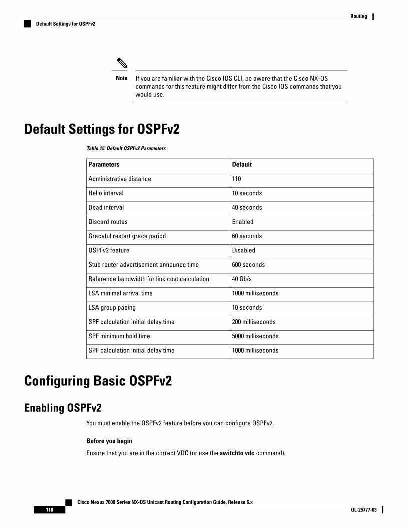
If you are familiar with the Cisco IOS CLI, be aware that the Cisco NX-OScommands for this feature might differ from the Cisco IOS commands that youwould use.
Note
Default Settings for OSPFv2Table 15: Default OSPFv2 Parameters
DefaultParameters
110Administrative distance
10 secondsHello interval
40 secondsDead interval
EnabledDiscard routes
60 secondsGraceful restart grace period
DisabledOSPFv2 feature
600 secondsStub router advertisement announce time
40 Gb/sReference bandwidth for link cost calculation
1000 millisecondsLSA minimal arrival time
10 secondsLSA group pacing
200 millisecondsSPF calculation initial delay time
5000 millisecondsSPF minimum hold time
1000 millisecondsSPF calculation initial delay time
Configuring Basic OSPFv2
Enabling OSPFv2You must enable the OSPFv2 feature before you can configure OSPFv2.
Before you begin
Ensure that you are in the correct VDC (or use the switchto vdc command).
Cisco Nexus 7000 Series NX-OS Unicast Routing Configuration Guide, Release 6.xOL-25777-03118
RoutingDefault Settings for OSPFv2
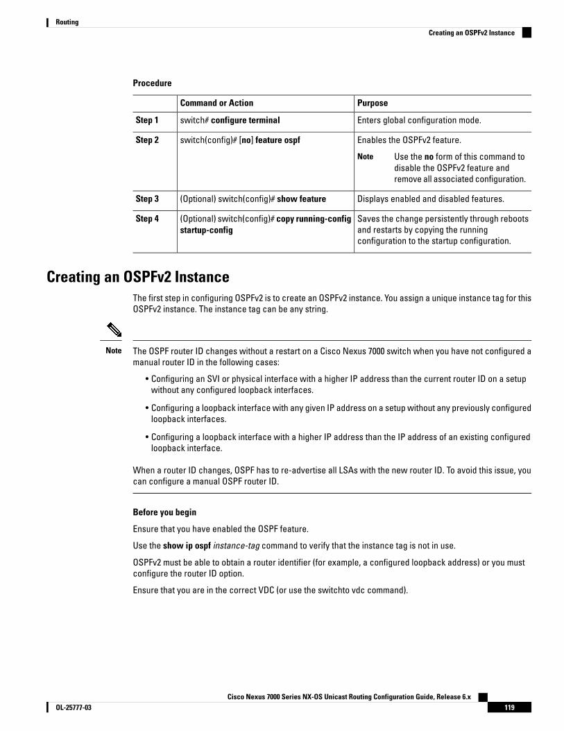
Procedure
PurposeCommand or Action
Enters global configuration mode.switch# configure terminalStep 1
Enables the OSPFv2 feature.switch(config)# [no] feature ospfStep 2
Use the no form of this command todisable the OSPFv2 feature andremove all associated configuration.
Note
Displays enabled and disabled features.(Optional) switch(config)# show featureStep 3
Saves the change persistently through rebootsand restarts by copying the runningconfiguration to the startup configuration.
(Optional) switch(config)# copy running-configstartup-config
Step 4
Creating an OSPFv2 InstanceThe first step in configuring OSPFv2 is to create an OSPFv2 instance. You assign a unique instance tag for thisOSPFv2 instance. The instance tag can be any string.
The OSPF router ID changes without a restart on a Cisco Nexus 7000 switch when you have not configured amanual router ID in the following cases:
• Configuring an SVI or physical interface with a higher IP address than the current router ID on a setupwithout any configured loopback interfaces.
• Configuring a loopback interface with any given IP address on a setup without any previously configuredloopback interfaces.
• Configuring a loopback interface with a higher IP address than the IP address of an existing configuredloopback interface.
When a router ID changes, OSPF has to re-advertise all LSAs with the new router ID. To avoid this issue, youcan configure a manual OSPF router ID.
Note
Before you begin
Ensure that you have enabled the OSPF feature.
Use the show ip ospf instance-tag command to verify that the instance tag is not in use.
OSPFv2 must be able to obtain a router identifier (for example, a configured loopback address) or you mustconfigure the router ID option.
Ensure that you are in the correct VDC (or use the switchto vdc command).
Cisco Nexus 7000 Series NX-OS Unicast Routing Configuration Guide, Release 6.x119OL-25777-03
RoutingCreating an OSPFv2 Instance
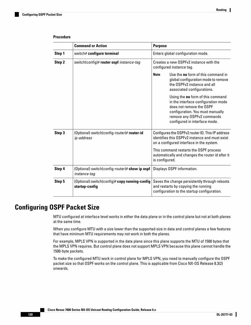
Procedure
PurposeCommand or Action
Enters global configuration mode.switch# configure terminalStep 1
Creates a new OSPFv2 instance with theconfigured instance tag.
switch(config)# router ospf instance-tagStep 2
Use the no form of this command inglobal configuration mode to removethe OSPFv2 instance and allassociated configurations.
Using the no form of this commandin the interface configuration modedoes not remove the OSPFconfiguration. You must manuallyremove any OSPFv2 commandsconfigured in interface mode.
Note
Configures the OSPFv2 router ID. This IP addressidentifies this OSPFv2 instance and must existon a configured interface in the system.
(Optional) switch(config-router)# router-idip-address
Step 3
This command restarts the OSPF processautomatically and changes the router id after itis configured.
Displays OSPF information.(Optional) switch(config-router)# show ip ospfinstance-tag
Step 4
Saves the change persistently through rebootsand restarts by copying the runningconfiguration to the startup configuration.
(Optional) switch(config)# copy running-configstartup-config
Step 5
Configuring OSPF Packet SizeMTU configured at interface level works in either the data plane or in the control plane but not at both planesat the same time.
When you configure MTU with a size lower than the supported size in data and control planes a few featuresthat have minimum MTU requirements may not work in both the planes.
For example, MPLS VPN is supported in the data plane since this plane supports the MTU of 1500 bytes thatthe MPLS VPN requires. But control plane does not support MPLS VPN because this plane cannot handle the1500-byte packets.
To make the configured MTU work in control plane for MPLS VPN, you need to manually configure the OSPFpacket size so that OSPF works on the control plane. This is applicable from Cisco NX-OS Release 8.3(2)onwards.
Cisco Nexus 7000 Series NX-OS Unicast Routing Configuration Guide, Release 6.xOL-25777-03120
RoutingConfiguring OSPF Packet Size

Procedure
PurposeCommand or Action
Enters global configuration mode.switch# configure terminalStep 1
Creates a new OSPF instance with theconfigured instance tag.
switch(config)# [no] router ospf instance-tagStep 2
Use the no form of this command inglobal configuration mode to removethe OSPFv2 instance and allassociated configurations.
Using the no form of this commandin the interface configuration modedoes not remove the OSPFconfiguration. You must manuallyremove any OSPFv2 commandsconfigured in interface mode.
Note
Configures the OSPFv2 router ID. This IP addressidentifies this OSPFv2 instance and must existon a configured interface in the system.
switch(config-router)# router-id ip-addressStep 3
This command restarts the OSPF processautomatically and changes the router id after itis configured.
switch(config-router)# packet-size sizeStep 4 • Configures the OSPFv2 packet size. Thesize range is from 572 to 9212 bytes.
• You can configure the packet-size in theinterface configuration mode also.
• You can configure the packet-size sizecommand even if theip ospf mtu-ignorecommand is already configured in thenetwork.
Displays OSPF information.(Optional) switch(config-router)# show ip ospfinterface interface-number
Step 5
Example
This example shows how to configure the OSPF packet-size:
router ospf 1router-id 3.3.3.3[no] packet-size 2000
This example shows the display of the OSPF packet-size:
Switch (config-router)# show ip ospf interface ethernet 1/25Ethernet1/25 is up, line protocol is up
IP address 1.0.0.1/24
Cisco Nexus 7000 Series NX-OS Unicast Routing Configuration Guide, Release 6.x121OL-25777-03
RoutingConfiguring OSPF Packet Size

--------- snip ---------------Number of opaque link LSAs: 0, checksum sum 0Max Packet Size: 2000
Configuring Optional Parameters on an OSPFv2 InstanceYou can configure optional parameters for OSPF. The following commands are available in the routerconfiguration mode.
For more information about OSPFv2 instance parameters, see the “Configuring Advanced OSPFv2” section
Before you begin
Ensure that you have enabled the OSPF feature.
OSPFv2 must be able to obtain a router identifier (for example, a configured loopback address) or you mustconfigure the router ID option.
Ensure that you are in the correct VDC (or use the switchto vdc command).
Procedure
PurposeCommand or Action
Configures the administrative distance for thisOSPFv2 instance. The range is from 1 to 255.The default is 110.
switch(config-router)# distance numberStep 1
Generates a system message whenever aneighbor changes state.
switch(config-router)# log-adjacency-changes[detail]
Step 2
Configures the maximum number of equalOSPFv2 paths to a destination in the route table.
switch(config-router)# maximum-pathspath-number
Step 3
This command is used for load balancing. Therange is from 1 to 16. The default is 8.
Enables the translation of OSPF router IDs tohost names, either by looking up the local hosts
switch(config-router)# [no]name-lookuppath-number
Step 4
database or querying DNS names in IPv6. Thiscommand makes it easier to identify a devicebecause it displays the device by name ratherthan by its router ID or neighbor ID.
To stop displaying OSPF router IDsas DNS names, use the no form ofthis command.
Note
Suppresses routing updates on all interfaces.This command is overridden by the VRF orinterface command mode configuration.
switch(config-router)# passive-interface defaultStep 5
Cisco Nexus 7000 Series NX-OS Unicast Routing Configuration Guide, Release 6.xOL-25777-03122
RoutingConfiguring Optional Parameters on an OSPFv2 Instance

Example
This example shows how to create an OSPFv2 instance:
switch# configure terminalswitch(config)# router ospf 201switch(config-router)# copy running-config startup-config
Configuring Networks in OSPFv2You can configure a network to OSPFv2 by associating it through the interface that the router uses to connectto that network. You can add all networks to the default backbone area (Area 0), or you can create new areasusing any decimal number or an IP address.
All areas must connect to the backbone area either directly or through a virtual link.Note
OSPF is not enabled on an interface until you configure a valid IP address for that interface.Note
Before you begin
Ensure that you have enabled the OSPF feature
Ensure that you are in the correct VDC (or use the switchto vdc command).
Procedure
PurposeCommand or Action
Enters global configuration mode.switch# configure terminalStep 1
Enters interface configuration mode.switch(config)# interface interface-typeslot/port
Step 2
Assigns an IP address and subnet mask to thisinterface.
switch(config-if)# ip address ip-prefix/lengthStep 3
Adds the interface to the OSPFv2 instance andarea.
switch(config-if)# ip router ospf instance-tagarea area-id [secondaries none]
Step 4
Displays OSPF information.(Optional) switch(config-if)# show ip ospfinstance-tag interface interface-type slot/port
Step 5
Saves the change persistently through rebootsand restarts by copying the runningconfiguration to the startup configuration.
(Optional) switch(config)# copy running-configstartup-config
Step 6
Configures the OSPFv2 cost metric for thisinterface. The default is to calculate cost
(Optional) switch(config)# ip ospf cost numberStep 7
metric, based on reference bandwidth and
Cisco Nexus 7000 Series NX-OS Unicast Routing Configuration Guide, Release 6.x123OL-25777-03
RoutingConfiguring Networks in OSPFv2

PurposeCommand or Action
interface bandwidth. The range is from 1 to65535.
Configures the OSPFv2 dead interval, inseconds. The range is from 1 to 65535. The
(Optional) switch(config)# ip ospf dead-intervalseconds
Step 8
default is four times the hello interval, inseconds.
Configures the OSPFv2 hello interval, inseconds. The range is from 1 to 65535. Thedefault is 10 seconds.
(Optional) switch(config)# ip ospf hello-intervalseconds
Step 9
Configures OSPFv2 to ignore any IP MTUmismatch with a neighbor. The default is to not
(Optional) switch(config)# ip ospf mtu-ignoreStep 10
establish adjacency if the neighbor MTU doesnot match the local interface MTU.
Suppresses routing updates on the interface.This command overrides the router or VRF
(Optional) switch(config)# [default | no] ip ospfpassive-interface
Step 11
command mode configuration. The defaultoption removes this interface mode commandand reverts to the router or VRF configuration,if present.
Configures the OSPFv2 priority, used todetermine the DR for an area. The range is from0 to 255. The default is 1.
(Optional) switch(config)# ip ospf prioritynumber
Step 12
Shuts down the OSPFv2 instance on thisinterface.
(Optional) switch(config)# ip ospf shutdownStep 13
Example
This example shows how to add a network area 0.0.0.10 in OSPFv2 instance 201:
switch# configure terminalswitch(config)# interface ethernet 1/2
switch(config-if)# ip address 192.0.2.1/16switch(config-if)# ip router ospf 201 area 0.0.0.10switch(config-if)# copy running-config startup-config
Use the show ip ospf interface command to verify the interface configuration. Use the show ip ospfneighbor command to see the neighbors for this interface.
Configuring Authentication for an AreaYou can configure authentication for all networks in an area or for individual interfaces in the area. Interfaceauthentication configuration overrides area authentication.
Cisco Nexus 7000 Series NX-OS Unicast Routing Configuration Guide, Release 6.xOL-25777-03124
RoutingConfiguring Authentication for an Area

Before you begin
Ensure that you have enabled the OSPF feature.
Ensure that all neighbors on an interface share the same authentication configuration, including the sharedauthentication key.
Create the key chain for this authentication configuration. See the Cisco Nexus 7000 Series NX-OS SecurityConfiguration Guide
Ensure that you are in the correct VDC (or use the switchto vdc command).
For OSPFv2, the key identifier in the key key-id command supports values from 0 to 255 only.Note
Procedure
PurposeCommand or Action
Enters global configuration mode.switch# configure terminalStep 1
Creates a new OSPFv2 instance with theconfigured instance tag.
switch(config)# router ospf instance-tagStep 2
Configures the authentication mode for an area.switch(config-router)# area area-idauthentication [message-digest]
Step 3
Enters interface configuration mode.switch(config-router)# interface interface-typeslot/port
Step 4
The first command configures simple passwordauthentication for this interface. Use this
(Optional) Configure one of the followingcommands:
Step 5
command if the authentication is not set to• ip ospf authentication-key [0 | 3] key key-chain or message-digest. The 0 keyword• ip ospf message-digest-key key-id md5 [0
| 3] keyconfigures the password in clear text. The 3keyword configures the password as 3DESencrypted.
The second command configures messagedigest authentication for this interface. Use thiscommand if the authentication is set tomessage-digest. The key-id range is from 1 to255. The MD5 option 0 configures the passwordin clear text and 3 configures the pass key as3DES encrypted.
Displays OSPF information.(Optional) switch(config)# show ip ospfinstance-tag interface interface-type slot/port
Step 6
Saves the change persistently through rebootsand restarts by copying the runningconfiguration to the startup configuration.
(Optional) switch(config)# copy running-configstartup-config
Step 7
Cisco Nexus 7000 Series NX-OS Unicast Routing Configuration Guide, Release 6.x125OL-25777-03
RoutingConfiguring Authentication for an Area
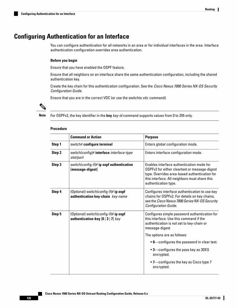
Configuring Authentication for an InterfaceYou can configure authentication for all networks in an area or for individual interfaces in the area. Interfaceauthentication configuration overrides area authentication.
Before you begin
Ensure that you have enabled the OSPF feature.
Ensure that all neighbors on an interface share the same authentication configuration, including the sharedauthentication key.
Create the key chain for this authentication configuration. See the Cisco Nexus 7000 Series NX-OS SecurityConfiguration Guide.
Ensure that you are in the correct VDC (or use the switchto vdc command).
For OSPFv2, the key identifier in the key key-id command supports values from 0 to 255 only.Note
Procedure
PurposeCommand or Action
Enters global configuration mode.switch# configure terminalStep 1
Enters interface configuration mode.switch(config)# interface interface-typeslot/port
Step 2
Enables interface authentication mode forOSPFv2 for either cleartext or message-digest
switch(config-if)# ip ospf authentication[message-digest]
Step 3
type. Overrides area-based authentication forthis interface. All neighbors must share thisauthentication type.
Configures interface authentication to use keychains for OSPFv2. For details on key chains,
(Optional) switch(config-if)# ip ospfauthentication key-chain key-name
Step 4
see the Cisco Nexus 7000 Series NX-OS SecurityConfiguration Guide.
Configures simple password authentication forthis interface. Use this command if the
(Optional) switch(config-if)# ip ospfauthentication-key [0 | 3 | 7] key
Step 5
authentication is not set to key-chain ormessage-digest.
The options are as follows:
• 0—configures the password in clear text.
• 3—configures the pass key as 3DESencrypted.
• 7—configures the key as Cisco type 7encrypted.
Cisco Nexus 7000 Series NX-OS Unicast Routing Configuration Guide, Release 6.xOL-25777-03126
RoutingConfiguring Authentication for an Interface

PurposeCommand or Action
Configures message digest authentication forthis interface. Use this command if the
(Optional) switch(config-if)# ip ospfmessage-digest-key key-id md5 [0 | 3 | 7] key
Step 6
authentication is set to message-digest. Thekey-id range is from 1 to 255. The MD5 optionsare as follows:
• 0—configures the password in clear text.
• 3—configures the pass key as 3DESencrypted.
• 7—configures the key as Cisco type 7encrypted.
Displays OSPF information.(Optional) switch(config-if)# show ip ospfinstance-tag interface interface-type slot/port
Step 7
Saves the change persistently through rebootsand restarts by copying the runningconfiguration to the startup configuration.
(Optional) switch(config)# copy running-configstartup-config
Step 8
Example
This example shows how to set an interface for simple, unencrypted passwords and set the passwordfor Ethernet interface 1/2:
switch# configure terminalswitch(config)# router ospf 201switch(config-router)# exitswitch(config)# interface ethernet 1/2
switch(config-if)# ip router ospf 201 area 0.0.0.10switch(config-if)# ip ospf authenticationswitch(config-if)# ip ospf authentication-key 0 mypassswitch(config-if)# copy running-config startup-config
Configuring Advanced OSPFv2
Configuring Filter Lists for Border RoutersYou can separate your OSPFv2 domain into a series of areas that contain related networks. All areas mustconnect to the backbone area through an area border router (ABR). OSPFv2 domains can connect to externaldomains as well, through an autonomous system border router (ASBR).
ABRs have the following optional configuration parameters:
• Area range—Configures route summarization between areas.
• Filter list—Filters the Network Summary (type 3) LSAs that are allowed in from an external area.
Cisco Nexus 7000 Series NX-OS Unicast Routing Configuration Guide, Release 6.x127OL-25777-03
RoutingConfiguring Advanced OSPFv2

ASBRs also support filter lists.
Before you begin
Ensure that you have enabled the OSPF feature.
Create the route map that the filter list uses to filter IP prefixes in incoming or outgoing Network Summary(type 3) LSAs.
Ensure that you are in the correct VDC (or use the switchto vdc command).
Procedure
PurposeCommand or Action
Enters global configuration mode.switch# configure terminalStep 1
Creates a new OSPFv2 instance with theconfigured instance tag.
switch(config)# router ospf instance-tagStep 2
Filters incoming or outgoing Network Summary(type 3) LSAs on an ABR.
switch(config-router)# area area-id filter-listroute-map map-name {in | out}
Step 3
Displays OSPF policy information.(Optional) switch(config-if)# show ip ospf policystatistics area id filter-list {in | out}
Step 4
Saves the change persistently through rebootsand restarts by copying the runningconfiguration to the startup configuration.
(Optional) switch(config)# copy running-configstartup-config
Step 5
Example
This example shows how to configure a filter list in area 0.0.0.10:
switch# configure terminalswitch(config)# router ospf 201switch(config-router)# area 0.0.0.10 filter-list route-map FilterLSAs inswitch(config-router)# copy running-config startup-config
Configuring Stub AreasYou can configure a stub area for part of an OSPFv2 domain where external traffic is not necessary. Stub areasblock AS External (type 5) LSAs and limit unnecessary routing to and from selected networks. You can optionallyblock all summary routes from going into the stub area.
Before you begin
Ensure that you have enabled the OSPF feature.
Ensure that there are no virtual links or ASBRs in the proposed stub area.
Ensure that you are in the correct VDC (or use the switchto vdc command).
Cisco Nexus 7000 Series NX-OS Unicast Routing Configuration Guide, Release 6.xOL-25777-03128
RoutingConfiguring Stub Areas
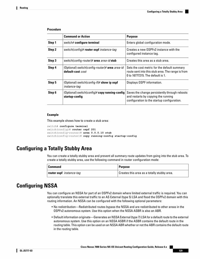
Procedure
PurposeCommand or Action
Enters global configuration mode.switch# configure terminalStep 1
Creates a new OSPFv2 instance with theconfigured instance tag.
switch(config)# router ospf instance-tagStep 2
Creates this area as a stub area.switch(config-router)# area area-id stubStep 3
Sets the cost metric for the default summaryroute sent into this stub area. The range is from0 to 16777215. The default is 1.
(Optional) switch(config-router)# area area-iddefault-cost cost
Step 4
Displays OSPF information.(Optional) switch(config-if)# show ip ospfinstance-tag
Step 5
Saves the change persistently through rebootsand restarts by copying the runningconfiguration to the startup configuration.
(Optional) switch(config)# copy running-configstartup-config
Step 6
Example
This example shows how to create a stub area:
switch# configure terminalswitch(config)# router ospf 201switch(config-router)# area 0.0.0.10 stubswitch(config-router)# copy running-config startup-config
Configuring a Totally Stubby AreaYou can create a totally stubby area and prevent all summary route updates from going into the stub area. Tocreate a totally stubby area, use the following command in router configuration mode:
PurposeCommand
Creates this area as a totally stubby area.router ospf instance-tag
Configuring NSSAYou can configure an NSSA for part of an OSPFv2 domain where limited external traffic is required. You canoptionally translate this external traffic to an AS External (type 5) LSA and flood the OSPFv2 domain with thisrouting information. An NSSA can be configured with the following optional parameters:
• No redistribution—Redistributed routes bypass the NSSA and are redistributed to other areas in theOSPFv2 autonomous system. Use this option when the NSSA ASBR is also an ABR.
• Default information originate—Generates an NSSA External (type 7) LSA for a default route to the externalautonomous system. Use this option on an NSSA ASBR if the ASBR contains the default route in therouting table. This option can be used on an NSSA ABR whether or not the ABR contains the default routein the routing table.
Cisco Nexus 7000 Series NX-OS Unicast Routing Configuration Guide, Release 6.x129OL-25777-03
RoutingConfiguring a Totally Stubby Area

• Route map—Filters the external routes so that only those routes that you want are flooded throughoutthe NSSA and other areas.
• Translate—Translates NSSA External LSAs to AS External LSAs for areas outside the NSSA. Use thiscommand on an NSSA ABR to flood the redistributed routes throughout the OSPFv2 autonomous system.You can optionally suppress the forwarding address in these AS External LSAs. If you choose this option,the forwarding address is set to 0.0.0.0.
• No summary—Blocks all summary routes from flooding the NSSA. Use this option on the NSSA ABR.
Before you begin
Ensure that you have enabled the OSPF feature.
Ensure that there are no virtual links in the proposed NSSA and that it is not the backbone area.
Ensure that you are in the correct VDC (or use the switchto vdc command).
Procedure
PurposeCommand or Action
Enters global configuration mode.switch# configure terminalStep 1
Creates a new OSPFv2 instance with theconfigured instance tag.
switch(config)# router ospf instance-tagStep 2
Creates this area as an NSSA.switch(config-router)# area area-id nssa[no-redistribution]
Step 3
[default-information-originate]originate[route-map map-name]] [no-summary] [translatetype7 {always | never} [suppress-fa]]
Sets the cost metric for the default summaryroute sent into this NSSA.
(Optional) switch(config-router)# area area-iddefault-cost cost
Step 4
Displays OSPF information.(Optional) switch(config-if)# show ip ospfinstance-tag
Step 5
Saves the change persistently through rebootsand restarts by copying the runningconfiguration to the startup configuration.
(Optional) switch(config)# copy running-configstartup-config
Step 6
Example
This example shows how to create an NSSA that blocks all summary route updates:
switch# configure terminalswitch(config)# router ospf 201switch(config-router)# area 0.0.0.10 nssa no-summaryswitch(config-router)# copy running-config startup-config
This example shows how to create an NSSA that generates a default route:
switch# configure terminalswitch(config)# router ospf 201
Cisco Nexus 7000 Series NX-OS Unicast Routing Configuration Guide, Release 6.xOL-25777-03130
RoutingConfiguring NSSA

switch(config-router)# area 0.0.0.10 nssa default-info-originateswitch(config-router)# copy running-config startup-config
This example shows how to create an NSSA that filters external routes and blocks all summary routeupdates:
switch# configure terminalswitch(config)# router ospf 201switch(config-router)# area 0.0.0.10 nssa route-map ExternalFilter no-summaryswitch(config-router)# copy running-config startup-config
This example shows how to create an NSSA that always translates NSSA External (type 5) LSAs toAS External (type 7) LSAs:
switch# configure terminalswitch(config)# router ospf 201switch(config-router)# area 0.0.0.10 nssa translate type 7 alwaysswitch(config-router)# copy running-config startup-config
Configuring Virtual LinksA virtual link connects an isolated area to the backbone area through an intermediate area. You can configurethe following optional parameters for a virtual link:
• Authentication—Sets a simple password or MD5 message digest authentication and associated keys.
• Dead interval—Sets the time that a neighbor waits for a Hello packet before declaring the local routeras dead and tearing down adjacencies.
• Hello interval—Sets the time between successive Hello packets.
• Retransmit interval—Sets the estimated time between successive LSAs.
• Transmit delay—Sets the estimated time to transmit an LSA to a neighbor.
You must configure the virtual link on both routers involved before the link becomes active.Note
You cannot add a virtual link to a stub area.
Before you begin
Ensure that you have enabled the OSPF feature.
Ensure that you are in the correct VDC (or use the switchto vdc command).
Procedure
PurposeCommand or Action
Enters global configuration mode.switch# configure terminalStep 1
Creates a new OSPFv2 instance with theconfigured instance tag.
switch(config)# router ospf instance-tagStep 2
Cisco Nexus 7000 Series NX-OS Unicast Routing Configuration Guide, Release 6.x131OL-25777-03
RoutingConfiguring Virtual Links

PurposeCommand or Action
Creates one end of a virtual link to a remoterouter. You must create the virtual link on thatremote router to complete the link.
switch(config-router)# area area-id virtual linkrouter-id
Step 3
Displays OSPF virtual link information.(Optional) switch(config-router-vlink)# showip ospf virtual-link [brief]
Step 4
Overrides area-based authentication for thisvirtual link.
(Optional) switch(config-router-vlink)#authentication [key-chain key-idmessage-digest | null]
Step 5
Configures a simple password for this virtuallink. Use this command if the authentication is
(Optional) switch(config-router-vlink)#authentication-key [0 | 3] key
Step 6
not set to key-chain or message-digest. 0configures the password in clear text. 3configures the password as 3DES encrypted.
Configures the OSPFv2 dead interval, inseconds. The range is from 1 to 65535. The
(Optional) switch(config-router-vlink)#dead-interval seconds
Step 7
default is four times the hello interval, inseconds.
Configures the OSPFv2 hello interval, inseconds. The range is from 1 to 65535. Thedefault is 10 seconds.
(Optional) switch(config-router-vlink)#hello-interval seconds
Step 8
Configures message digest authentication forthis virtual link. Use this command if the
(Optional) switch(config-router-vlink)#message-digest-key key-id md5 [0 | 3] key
Step 9
authentication is set to message-digest. 0configures the password in cleartext. 3configures the pass key as 3DES encrypted.
Configures the OSPFv2 retransmit interval, inseconds. The range is from 1 to 65535. Thedefault is 5.
(Optional) switch(config-router-vlink)#retransmit-interval seconds
Step 10
Configures the OSPFv2 transmit-delay, inseconds. The range is from 1 to 450. The defaultis 1.
(Optional) switch(config-router-vlink)#transmit-delay seconds
Step 11
Saves the change persistently through rebootsand restarts by copying the runningconfiguration to the startup configuration.
(Optional) switch(config)# copy running-configstartup-config
Step 12
Example
This example shows how to create a simple virtual link between two ABRs.
The configuration for ABR 1 (router ID 27.0.0.55) is as follows:
switch# configure terminalswitch(config)# router ospf 201
Cisco Nexus 7000 Series NX-OS Unicast Routing Configuration Guide, Release 6.xOL-25777-03132
RoutingConfiguring Virtual Links

switch(config-router)# area 0.0.0.10 virtual-link 10.1.2.3switch(config-router)# copy running-config startup-config
The configuration for ABR 2 (Router ID 10.1.2.3) is as follows:
switch# configure terminalswitch(config)# router ospf 101switch(config-router)# area 0.0.0.10 virtual-link 27.0.0.55switch(config-router)# copy running-config startup-config
Configuring RedistributionYou can redistribute routes learned from other routing protocols into an OSPFv2 autonomous system throughthe ASBR.
You can configure the following optional parameters for route redistribution in OSPF:
• Default information originate—Generates an AS External (type 5) LSA for a default route to the externalautonomous system.
Default information originate ignores match statements in the optional route map.Note
• Default metric—Sets all redistributed routes to the same cost metric.
If you redistribute static routes, Cisco NX-OS requires the configuration ofdefault-information originate command under the router OSPF process tosuccessfully redistribute or generate the default static route.
Note
Before you begin
Ensure that you have enabled the OSPF feature.
Create the necessary route maps used for redistribution.
Ensure that you are in the correct VDC (or use the switchto vdc command).
Procedure
PurposeCommand or Action
Enters global configuration mode.switch# configure terminalStep 1
Creates a new OSPFv2 instance with theconfigured instance tag.
switch(config)# router ospf instance-tagStep 2
Redistributes the selected protocol into OSPFthrough the configured route map.
switch(config-router)# redistribute {bgp id |direct | eigrp id | isis id ospf id rip id | static}route-map map-name
Step 3
If you redistribute static routes, CiscoNX-OS also redistributes the defaultstatic route.
Note
Cisco Nexus 7000 Series NX-OS Unicast Routing Configuration Guide, Release 6.x133OL-25777-03
RoutingConfiguring Redistribution

PurposeCommand or Action
Creates a default route into this OSPF domainif the default route exists in the RIB. Use thefollowing optional keywords:
switch(config-router)# default-informationoriginate [always] [route-map map-name]
Step 4
• always —Always generate the defaultroute of 0.0.0. even if the route does notexist in the RIB
• route-map—Generate the default route ifthe route map returns true.
This command ignores matchstatements in the route map.
Note
Sets the cost metric for the redistributed routes.This command does not apply to directly
switch(config-router)# default-metric [cost]Step 5
connected routes. Use a route map to set thedefault metric for directly connected routes.
Saves the change persistently through rebootsand restarts by copying the runningconfiguration to the startup configuration.
(Optional) switch(config)# copy running-configstartup-config
Step 6
Example
This example shows how to create an NSSA that blocks all summary route updates:
switch# configure terminalswitch(config)# router ospf 201switch(config-router)# redistribute bgp route-map FilterExternalBGPswitch(config-router)# copy running-config startup-config
Limiting the Number of Redistributed RoutesRoute redistribution can add many routes to the OSPFv2 route table. You can configure a maximum limit to thenumber of routes accepted from external protocols. OSPFv2 provides the following options to configureredistributed route limits:
• Fixed limit—Logs a message when OSPFv2 reaches the configured maximum. OSPFv2 does not acceptany more redistributed routes. You can optionally configure a threshold percentage of the maximumwhere OSPFv2 logs a warning when that threshold is passed.
• Warning only—Logs a warning only when OSPFv2 reaches the maximum. OSPFv2 continues to acceptredistributed routes.
• Withdraw—Starts the timeout period when OSPFv2 reaches the maximum. After the timeout period,OSPFv2 requests all redistributed routes if the current number of redistributed routes is less than themaximum limit. If the current number of redistributed routes is at the maximum limit, OSPFv2 withdrawsall redistributed routes. You must clear this condition before OSPFv2 accepts more redistributed routes.
• You can optionally configure the timeout period.
Cisco Nexus 7000 Series NX-OS Unicast Routing Configuration Guide, Release 6.xOL-25777-03134
RoutingLimiting the Number of Redistributed Routes

Before you begin
Ensure that you have enabled the OSPF feature.
Ensure that you are in the correct VDC (or use the switchto vdc command).
Procedure
PurposeCommand or Action
Enters global configuration mode.switch# configure terminalStep 1
Creates a new OSPFv2 instance with theconfigured instance tag.
switch(config)# router ospf instance-tagStep 2
Redistributes the selected protocol into OSPFthrough the configured route map.
switch(config-router)# redistribute {bgp id direct| eigrp id | isis id | ospf id | rip id | static}route-map map-name
Step 3
Specifies a maximum number of prefixes thatOSPFv2 distributes. The range is from 0 to 65536.Optionally specifies the following:
switch(config-router)# redistributemaximum-prefix max [threshold] [warning-only| withdraw [num-retries timeout]]
Step 4
• threshold—Percent of maximum prefixesthat trigger a warning message.
• warning-only—Logs an warning messagewhen the maximum number of prefixes isexceeded.
• withdraw—Withdraws all redistributedroutes. Optionally tries to retrieve theredistributed routes. The num-retries rangeis from 1 to 12. The timeout is 60 to 600seconds. The default is 300 seconds. Usethe clear ip ospf redistribution commandif all routes are withdrawn.
Displays the OSPFv2 configuration.(Optional) switch(config-router)# showrunning-config ospf
Step 5
Saves the change persistently through rebootsand restarts by copying the runningconfiguration to the startup configuration.
(Optional) switch(config)# copy running-configstartup-config
Step 6
Example
This example shows how to limit the number of redistributed routes into OSPF:
switch# configure terminalswitch(config)# router ospf 201switch(config-router)# redistribute bgp route-map FilterExternalBGPswitch(config-router)# redistribute maximum-prefix 1000 75
Cisco Nexus 7000 Series NX-OS Unicast Routing Configuration Guide, Release 6.x135OL-25777-03
RoutingLimiting the Number of Redistributed Routes

Configuring Route SummarizationYou can configure route summarization for inter-area routes by configuring an address range that is summarized.You can also configure route summarization for external, redistributed routes by configuring a summary addressfor those routes on an ASBR.
Before you begin
Ensure that you have enabled the OSPF feature.
Ensure that you are in the correct VDC (or use the switchto vdc command).
Procedure
PurposeCommand or Action
Enters global configuration mode.switch# configure terminalStep 1
Creates a new OSPFv2 instance with theconfigured instance tag.
switch(config)# router ospf instance-tagStep 2
The first command creates a summary addresson an ABR for a range of addresses and
Configure one of the following commands:Step 3
• area area-id range ip-prefix/length[no-advertise] [cost cost] optionally does not advertise this summary
address in a Network Summary (type 3) LSA.The cost range is from 0 to 16777215.• summary-address ip-prefix/length
[no-advertise | tag tag]The second command creates a summaryaddress on an ASBR for a range of addressesand optionally assigns a tag for this summaryaddress that can be used for redistribution withroute maps.
When you configure a summary address, CiscoNX-OS software automatically configures a
(Optional) switch(config-router)# [no] discardroute {internal | external}
Step 4
discard route for the summary address toprevent routing black holes and route loops. Youcan use the no form of this command to preventthe discard routes from being created.
Displays information about OSPF summaryaddresses.
(Optional) switch(config-router)# show ip ospfsummary-address
Step 5
Saves the change persistently through rebootsand restarts by copying the runningconfiguration to the startup configuration.
(Optional) switch(config)# copy running-configstartup-config
Step 6
Example
This example shows how to create summary addresses between areas on an ABR:
switch# configure terminalswitch(config)# router ospf 201
Cisco Nexus 7000 Series NX-OS Unicast Routing Configuration Guide, Release 6.xOL-25777-03136
RoutingConfiguring Route Summarization

switch(config-router)# area 0.0.0.10 range 10.3.0.0/16switch(config-router)# copy running-config startup-config
This example shows how to create summary addresses on an ASBR:
switch# configure terminalswitch(config)# router ospf 201switch(config-router)# summary-address 10.5.0.0/16switch(config-router)# copy running-config startup-config
Configuring Stub Route AdvertisementsUse stub route advertisements when you want to limit the OSPFv2 traffic through this router for a short time.
Stub route advertisements can be configured with the following optional parameters:
• on startup—Sends stub route advertisements for the specified announce time.
• wait-for bgp—Sends stub router advertisements until BGP converges.
You should not save the running configuration of a router when it is configured for a graceful shutdown becausethe router continues to advertise a maximum metric after it is reloaded.
Note
Before you begin
Ensure that you have enabled the OSPF feature.
Ensure that you are in the correct VDC (or use the switchto vdc command).
Procedure
PurposeCommand or Action
Enters global configuration mode.switch# configure terminalStep 1
Creates a new OSPFv2 instance with theconfigured instance tag.
switch(config)# router ospf instance-tagStep 2
Configures OSPFv2 stub route advertisements.switch(config-router)# max-metric router-lsa[external-lsa [max-metric-value]] [include-stub]
Step 3
[on-startup [seconds]] [wait-for bgp tag][summary-lsa [max-metric-value]]
Saves the change persistently through rebootsand restarts by copying the runningconfiguration to the startup configuration.
(Optional) switch(config)# copy running-configstartup-config
Step 4
Example
This example shows how to enable the stub router advertisements on startup for the default 600seconds:
Cisco Nexus 7000 Series NX-OS Unicast Routing Configuration Guide, Release 6.x137OL-25777-03
RoutingConfiguring Stub Route Advertisements

switch# configure terminalswitch(config)# router ospf 201switch(config-router)# max-metric router-lsa on-startupswitch(config-router)# copy running-config startup-config
Configuring the Administrative Distance of RoutesBeginning with Cisco NX-OS Release 6.1, you can set the administrative distance of routes added by OSPFv2into the RIB.
The administrative distance is a rating of the trustworthiness of a routing information source. A higher valueindicates a lower trust rating. Typically, a route can be learned through more than one routing protocol. Theadministrative distance is used to discriminate between routes learned from more than one routing protocol.The route with the lowest administrative distance is installed in the IP routing table.
Before you begin
Ensure that you have enabled OSPF.
Ensure that you are in the correct VDC (or use the switchto vdc command).
See the guidelines and limitations for this feature.
Procedure
PurposeCommand or Action
Enters global configuration mode.switch# configure terminalStep 1
Creates a new OSPFv2 instance with theconfigured instance tag.
switch(config)# router ospf instance-tagStep 2
Configures the policy for filtering or modifyingOSPFv2 routes before sending them to the RIB.
switch(config-router)# [no] table-mapmap-name [filter]
Step 3
You can enter up to 63 alphanumericcharacters for the map name.
The filter keyword specifies that only routesthat are permitted by the route map(map-name)configuration are downloaded to the routinginformation base (RIB).
Exits router configuration mode.switch(config-router)# exitStep 4
Creates a route map or enters route-mapconfiguration mode for an existing route map.Use seq to order the entries in a route map.
switch(config)# route-map map-name [permit| deny] [seq]
Step 5
The permit option enables you toset the distance. If you use the denyoption, the default distance isapplied.
Note
Cisco Nexus 7000 Series NX-OS Unicast Routing Configuration Guide, Release 6.xOL-25777-03138
RoutingConfiguring the Administrative Distance of Routes

PurposeCommand or Action
Matches against one of the following routetypes:
switch(config-route-map)# match route-typeroute-type
Step 6
• external: The external route (BGP, EIGRP,and OSPF type 1 or 2)
• inter-area: OSPF inter-area route
• internal: The internal route (including theOSPF intra- or inter-area)
• intra-area: OSPF intra-area route
• nssa-external: The NSSA external route(OSPF type 1 or 2)
• type-1: The OSPF external type 1 route
• type-2: The OSPF external type 2 route
Matches the IPv4 route source address orrouter ID of a route to one or more IP prefix
switch(config-route-map)# match iproute-source prefix-list name
Step 7
lists. Use the ip prefix-list command to createthe prefix list.
Matches against one or more IPv4 prefix lists.Use the ip prefix-list command to create theprefix list.
switch(config-route-map)# match ip addressprefix-list name
Step 8
Sets the administrative distance of routes forOSPFv2. The range is from 1 to 255.
switch(config-route-map)# set distance valueStep 9
Saves the change persistently through rebootsand restarts by copying the runningconfiguration to the startup configuration.
(Optional) switch(config)# copy running-configstartup-config
Step 10
Example
This example shows how to configure the OSPFv2 administrative distance for inter-area routes to150, for external routes to 200, and for all prefixes in prefix list p1 to 190:
switch# configure terminalswitch(config)# router ospf 201switch(config-router)# table-map fooswitch(config-router)# exitswitch(config)# route-map foo permit 10switch(config-route-map)# match route-type inter-areaswitch(config-route-map)# set distance 150switch(config)# route-map foo permit 20switch(config-route-map)# match route-type externalswitch(config-route-map)# set distance 200switch(config)# route-map foo permit 30switch(config-route-map)# match ip route-source prefix-list p1
Cisco Nexus 7000 Series NX-OS Unicast Routing Configuration Guide, Release 6.x139OL-25777-03
RoutingConfiguring the Administrative Distance of Routes

switch(config-route-map)# match ip address prefix-list p1switch(config-route-map)# set distance 190
The following example shows how to configure a route map for blocking the next hops that are learnedthrough VLAN 10:
switch(config)# route-map Filter-OSPF 10 denyswitch(config-route-map)# match interface VLAN 10switch(config-route-map)# exitswitch(config)# route-map Filter-OSPF 20 permit
The following example shows how to configure the table-map command with the filter keyword touse a route map (Filter-OSPF) to remove the next-hop path that is learned through VLAN 10 but notthe next-hop path that is learned through VLAN 20:
switch(config)# route ospf p1switch(config-router)# table-map Filter-OSPF filter
Modifying the Default TimersOSPFv2 includes a number of timers that control the behavior of protocol messages and shortest path first(SPF) calculations. OSPFv2 includes the following optional timer parameters:
• LSA arrival time—Sets the minimum interval allowed between LSAs that arrive from a neighbor. LSAsthat arrive faster than this time are dropped.
• Pacing LSAs—Sets the interval at which LSAs are collected into a group and refreshed, checksummed,or aged. This timer controls how frequently LSA updates occur and optimizes how many are sent in anLSA update message.
• Throttle LSAs—Sets the rate limits for generating LSAs. This timer controls how frequently LSAs aregenerated after a topology change occurs.
• Throttle SPF calculation—Controls how frequently the SPF calculation is run.
At the interface level, you can also control the following timers:
• Retransmit interval—Sets the estimated time between successive LSAs
• Transmit delay—Sets the estimated time to transmit an LSA to a neighbor.
Before you begin
Ensure that you have enabled the OSPF feature.
Ensure that you are in the correct VDC (or use the switchto vdc command).
Procedure
PurposeCommand or Action
Enters global configuration mode.switch# configure terminalStep 1
Creates a new OSPFv2 instance with theconfigured instance tag.
switch(config)# router ospf instance-tagStep 2
Cisco Nexus 7000 Series NX-OS Unicast Routing Configuration Guide, Release 6.xOL-25777-03140
RoutingModifying the Default Timers
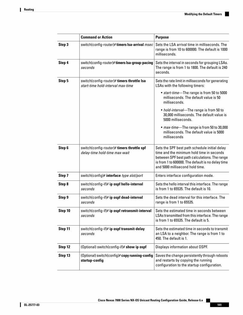
PurposeCommand or Action
Sets the LSA arrival time in milliseconds. Therange is from 10 to 600000. The default is 1000milliseconds.
switch(config-router)# timers lsa-arrival msecStep 3
Sets the interval in seconds for grouping LSAs.The range is from 1 to 1800. The default is 240seconds.
switch(config-router)# timers lsa-group-pacingseconds
Step 4
Sets the rate limit in milliseconds for generatingLSAs with the following timers:
switch(config-router)# timers throttle lsastart-time hold-interval max-time
Step 5
• start-time—The range is from 50 to 5000milliseconds. The default value is 50milliseconds.
• hold-interval—The range is from 50 to30,000 milliseconds. The default value is5000 milliseconds.
• max-time—The range is from 50 to 30,000milliseconds. The default value is 5000milliseconds
Sets the SPF best path schedule initial delaytime and the minimum hold time in seconds
switch(config-router)# timers throttle spfdelay-time hold-time max-wait
Step 6
between SPF best path calculations. The rangeis from 1 to 600000. The default is no delay timeand 5000 millisecond hold time.
Enters interface configuration mode.switch(config)# interface type slot/portStep 7
Sets the hello interval this interface. The rangeis from 1 to 65535. The default is 10.
switch(config-if)# ip ospf hello-intervalseconds
Step 8
Sets the dead interval for this interface. Therange is from 1 to 65535.
switch(config-if)# ip ospf dead-intervalseconds
Step 9
Sets the estimated time in seconds betweenLSAs transmitted from this interface. The rangeis from 1 to 65535. The default is 5.
switch(config-if)# ip ospf retransmit-intervalseconds
Step 10
Sets the estimated time in seconds to transmitan LSA to a neighbor. The range is from 1 to450. The default is 1.
switch(config-if)# ip ospf transmit-delayseconds
Step 11
Displays information about OSPF.(Optional) switch(config-if)# show ip ospfStep 12
Saves the change persistently through rebootsand restarts by copying the runningconfiguration to the startup configuration.
(Optional) switch(config)# copy running-configstartup-config
Step 13
Cisco Nexus 7000 Series NX-OS Unicast Routing Configuration Guide, Release 6.x141OL-25777-03
RoutingModifying the Default Timers

Example
This example shows how to control LSA flooding with the lsa-group-pacing option:
switch# configure terminalswitch(config)# router ospf 201switch(config-router)# timers lsa-group-pacing 300switch(config-router)# copy running-config startup-config
Configuring Graceful RestartGraceful restart is enabled by default. You can configure the following optional parameters for graceful restartin an OSPFv2 instance:
• Grace period—Configures how long neighbors should wait after a graceful restart has started beforetearing down adjacencies.
• Helper mode disabled—Disables helper mode on the local OSPFv2 instance. OSPFv2 does not participatein the graceful restart of a neighbor.
• Planned graceful restart only—Configures OSPFv2 to support graceful restart only in the event of aplanned restart.
Before you begin
Ensure that you have enabled OSPF.
Ensure that all neighbors are configured for graceful restart with matching optional parameters set.
Ensure that you are in the correct VDC (or use the switchto vdc command).
Procedure
PurposeCommand or Action
Enters global configuration mode.switch# configure terminalStep 1
Creates a new OSPFv2 instance with theconfigured instance tag.
switch(config)# router ospf instance-tagStep 2
Enables a graceful restart. A graceful restart isenabled by default.
switch(config-router)# graceful-restartStep 3
Sets the grace period, in seconds. The range isfrom 5 to 1800. The default is 60 seconds.
(Optional) switch(config-router)#graceful-restart grace-period seconds
Step 4
Disables helper mode. This feature is enabledby default.
(Optional) switch(config-router)#graceful-restart helper-disable
Step 5
Configures a graceful restart for plannedrestarts only.
(Optional) switch(config-router)#graceful-restart planned-only
Step 6
Displays OSPF information.(Optional) switch(config-if)# show ip ospfinstance-tag
Step 7
Cisco Nexus 7000 Series NX-OS Unicast Routing Configuration Guide, Release 6.xOL-25777-03142
RoutingConfiguring Graceful Restart
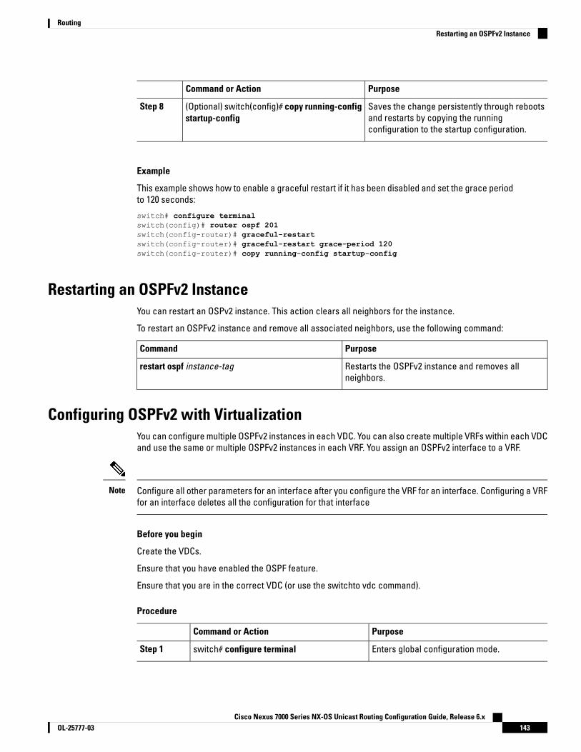
PurposeCommand or Action
Saves the change persistently through rebootsand restarts by copying the runningconfiguration to the startup configuration.
(Optional) switch(config)# copy running-configstartup-config
Step 8
Example
This example shows how to enable a graceful restart if it has been disabled and set the grace periodto 120 seconds:
switch# configure terminalswitch(config)# router ospf 201switch(config-router)# graceful-restartswitch(config-router)# graceful-restart grace-period 120switch(config-router)# copy running-config startup-config
Restarting an OSPFv2 InstanceYou can restart an OSPv2 instance. This action clears all neighbors for the instance.
To restart an OSPFv2 instance and remove all associated neighbors, use the following command:
PurposeCommand
Restarts the OSPFv2 instance and removes allneighbors.
restart ospf instance-tag
Configuring OSPFv2 with VirtualizationYou can configure multiple OSPFv2 instances in each VDC. You can also create multiple VRFs within each VDCand use the same or multiple OSPFv2 instances in each VRF. You assign an OSPFv2 interface to a VRF.
Configure all other parameters for an interface after you configure the VRF for an interface. Configuring a VRFfor an interface deletes all the configuration for that interface
Note
Before you begin
Create the VDCs.
Ensure that you have enabled the OSPF feature.
Ensure that you are in the correct VDC (or use the switchto vdc command).
Procedure
PurposeCommand or Action
Enters global configuration mode.switch# configure terminalStep 1
Cisco Nexus 7000 Series NX-OS Unicast Routing Configuration Guide, Release 6.x143OL-25777-03
RoutingRestarting an OSPFv2 Instance
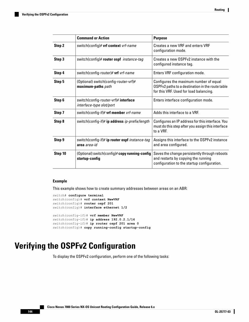
PurposeCommand or Action
Creates a new VRF and enters VRFconfiguration mode.
switch(config)# vrf context vrf-nameStep 2
Creates a new OSPFv2 instance with theconfigured instance tag.
switch(config)# router ospf instance-tagStep 3
Enters VRF configuration mode.switch(config-router)# vrf vrf-nameStep 4
Configures the maximum number of equalOSPFv2 paths to a destination in the route tablefor this VRF. Used for load balancing.
(Optional) switch(config-router-vrf)#maximum-paths path
Step 5
Enters interface configuration mode.switch(config-router-vrf)# interfaceinterface-type slot/port
Step 6
Adds this interface to a VRF.switch(config-if)# vrf member vrf-nameStep 7
Configures an IP address for this interface. Youmust do this step after you assign this interfaceto a VRF.
switch(config-if)# ip address ip-prefix/lengthStep 8
Assigns this interface to the OSPFv2 instanceand area configured.
switch(config-if)# ip router ospf instance-tagarea area-id
Step 9
Saves the change persistently through rebootsand restarts by copying the runningconfiguration to the startup configuration.
(Optional) switch(config)# copy running-configstartup-config
Step 10
Example
This example shows how to create summary addresses between areas on an ABR:
switch# configure terminalswitch(config)# vrf context NewVRFswitch(config)# router ospf 201switch(config)# interface ethernet 1/2
switch(config-if)# vrf member NewVRFswitch(config-if)# ip address 192.0.2.1/16switch(config-if)# ip router ospf 201 area 0switch(config)# copy running-config startup-config
Verifying the OSPFv2 ConfigurationTo display the OSPFv2 configuration, perform one of the following tasks:
Cisco Nexus 7000 Series NX-OS Unicast Routing Configuration Guide, Release 6.xOL-25777-03144
RoutingVerifying the OSPFv2 Configuration

PurposeCommand
Displays the information about one or more OSPFv2routing instances. The output includes the followingarea-level counts:
• Interfaces in this area—A count of all interfacesadded to this area (configured interfaces).
• Active interfaces—A count of all interfacesconsidered to be in router link states and SPF(UP interfaces).
• Passive interfaces—A count of all interfacesconsidered to be OSPF passive ( no adjacencieswill be formed).
• Loopback interfaces—A count of all localloopback interfaces.
show ip ospf [instance-tag] [vrf vrf-name]
Displays the OSPFv2 link-state database summary.show ip ospf border-routers [vrf {vrf-name | all |default | management}]
Displays the OSPFv2 interface configuration.show ip ospf interface number [vrf {vrf-name | all |default | management}]
Displays the OSPFv2 LSAs that have changed.show ip ospf lsa-content-changed-list neighbor-idinterface-type number [vrf {vrf-name | all | default |management}]
Displays the list of OSPFv2 neighbors.show ip ospf neighbors [neighbor-id] [detail][interface-type number] [vrf {vrf-name | all | default |management}] [summary]
Displays the list of OSPFv2 link-state requests.show ip ospf request-list neighbor-id interface-typenumber [vrf {vrf-name | all | default | management}]
Displays the list of OSPFv2 link-state retransmissions.show ip ospf retransmission-list neighbor-idinterface-type number [vrf {vrf-name | all | default |management}]
Displays the internal OSPFv2 routes.show ip ospf route [ospf-route] [summary] [vrf{vrf-name | all | default | management}]
Displays information about the OSPFv2 summaryaddresses.
show ip ospf summary-address [vrf {vrf-name | all |default | management}]
Displays information about OSPFv2 virtual links.show ip ospf virtual-links [brief] [vrf {vrf-name | all| default | management}]
Displays information about VRF-based OSPFv2configuration.
show ip ospf vrf {vrf-name | all | default | management}
Displays the current running OSPFv2 configuration.show running-configuration ospf
Cisco Nexus 7000 Series NX-OS Unicast Routing Configuration Guide, Release 6.x145OL-25777-03
RoutingVerifying the OSPFv2 Configuration

Monitoring OSPFv2To display OSPFv2 statistics, use the following commands:
PurposeCommand
Displays the OSPFv2 route policy statistics for an area.show ip ospf policy statistics area area-id filter-list{in | out} [vrf vrf-name | all | default | management}]
Displays the OSPFv2 route policy statistics.show ip ospf policy statistics redistribute {bgp id |direct | eigrp id | isis id | ospf id | rip id | static} [vrf{vrf-name | all | default | management}]
Displays the OSPFv2 event counters.show ip ospf statistics [vrfnumber [vrf {vrf-name | all| default | management}]
Displays the OSPFv2 packet counters.show ip ospf traffic interface-type number [vrf{vrf-name | all | default | management}]
Configuration Examples for OSPFv2feature ospfrouter ospf 201router-id 290.0.2.1interface ethernet 1/2
ip router ospf 201 area 0.0.0.10ip ospf authenticationip ospf authentication-key 0 mypass
Related Documents for OSPFv2For more information related to OSPFv2 CLI commands, see the Cisco Nexus 5000 Series Command Reference
.
Feature History for OSPFv2This table includes only the updates for those releases that have resulted in additions or changes to the feature.
Table 16: Feature History for OSPFv2
Feature InformationReleaseFeature Name
Added support for configuring OSPFpacket-size.
8.3(2)OSPF Packet-size
Added support for filtering next-hop paths foran OSPF route to prevent the path from beingadded to the RIB.
6.2(6a)OSPF—Distribute List to FilterPaths
Cisco Nexus 7000 Series NX-OS Unicast Routing Configuration Guide, Release 6.xOL-25777-03146
RoutingMonitoring OSPFv2
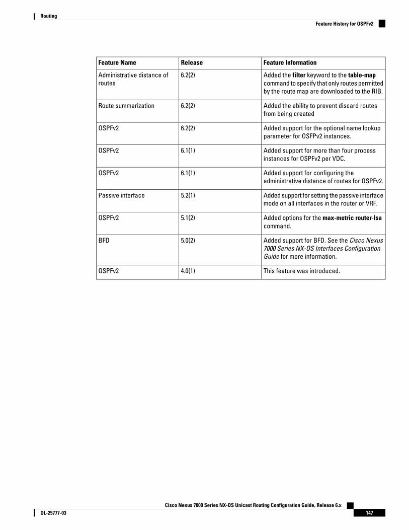
Feature InformationReleaseFeature Name
Added the filter keyword to the table-mapcommand to specify that only routes permittedby the route map are downloaded to the RIB.
6.2(2)Administrative distance ofroutes
Added the ability to prevent discard routesfrom being created
6.2(2)Route summarization
Added support for the optional name lookupparameter for OSFPv2 instances.
6.2(2)OSPFv2
Added support for more than four processinstances for OSPFv2 per VDC.
6.1(1)OSPFv2
Added support for configuring theadministrative distance of routes for OSPFv2.
6.1(1)OSPFv2
Added support for setting the passive interfacemode on all interfaces in the router or VRF.
5.2(1)Passive interface
Added options for the max-metric router-lsacommand.
5.1(2)OSPFv2
Added support for BFD. See the Cisco Nexus7000 Series NX-OS Interfaces ConfigurationGuide for more information.
5.0(2)BFD
This feature was introduced.4.0(1)OSPFv2
Cisco Nexus 7000 Series NX-OS Unicast Routing Configuration Guide, Release 6.x147OL-25777-03
RoutingFeature History for OSPFv2

Cisco Nexus 7000 Series NX-OS Unicast Routing Configuration Guide, Release 6.xOL-25777-03148
RoutingFeature History for OSPFv2
C H A P T E R 8Configuring OSPFv3
This chapter contains the following sections:
• Finding Feature Information, on page 149• Information About OSPFv3, on page 149• Advanced Features, on page 158• Prerequisites for OSPFv3, on page 161• Guidelines and Limitations for OSPFv3, on page 162• Default Settings for OSPFv3, on page 164• Configuring Basic OSPFv3, on page 164• Configuring Advanced OSPFv3, on page 170• Configuring OSPFv3 Encryption at Router Level, on page 191• Configuring OSPFv3 Encryption at Area Level, on page 191• Configuring OSPFv3 Encryption at Interface Level, on page 192• Configuring OSPFv3 Encryption for Virtual Links, on page 194• Configuration Examples for OSPFv3, on page 195• Related Documents for OSPFv3, on page 195• Feature History for OSPFv3, on page 195
Finding Feature InformationYour software release might not support all the features documented in this module. For the latest caveatsand feature information, see the Bug Search Tool at https://tools.cisco.com/bugsearch/ and the release notesfor your software release. To find information about the features documented in this module, and to see a listof the releases in which each feature is supported, see the "New and Changed Information"chapter or theFeature History table in this chapter.
Information About OSPFv3OSPFv3 is an IETF link-state protocol. An OSPFv3 router sends a special message, called a hello packet, outeach OSPF-enabled interface to discover other OSPFv3 neighbor routers. Once a neighbor is discovered, thetwo routers compare information in the Hello packet to determine if the routers have compatible configurations.The neighbor routers attempt to establish adjacency, which means that the routers synchronize their link-statedatabases to ensure that they have identical OSPFv3 routing information. Adjacent routers share link-stateadvertisements (LSAs) that include information about the operational state of each link, the cost of the link,
Cisco Nexus 7000 Series NX-OS Unicast Routing Configuration Guide, Release 6.x149OL-25777-03

and any other neighbor information. The routers then flood these received LSAs out every OSPF-enabledinterface so that all OSPFv3 routers eventually have identical link-state databases. When all OSPFv3 routershave identical link-state databases, the network is converged. Each router then uses Dijkstra’s Shortest PathFirst (SPF) algorithm to build its route table.
You can divide OSPFv3 networks into areas. Routers send most LSAs only within one area, which reduces theCPU and memory requirements for an OSPF-enabled router.
OSPFv3 supports IPv6.
Comparison of OSPFv3 and OSPFv2Much of the OSPFv3 protocol is the same as in OSPFv2. OSPFv3 is described in RFC 2740.
The key differences between the OSPFv3 and OSPFv2 protocols are as follows:
• OSPFv3 expands on OSPFv2 to provide support for IPv6 routing prefixes and the larger size of IPv6addresses.
• LSAs in OSPFv3 are expressed as prefix and prefix length instead of address and mask.
• The router ID and area ID are 32-bit numbers with no relationship to IPv6 addresses.
• OSPFv3 uses link-local IPv6 addresses for neighbor discovery and other features.
• OSPFv3 can use the IPv6 authentication trailer (RFC 6506) or IPSec (RFC 4552) for authentication. However,neither of these options is supported on Cisco NX-OS.
• OSPFv3 redefines LSA types.
Hello PacketOSPFv3 routers periodically send Hello packets on every OSPF-enabled interface. The hello interval determineshow frequently the router sends these Hello packets and is configured per interface. OSPFv3 uses Hello packetsfor the following tasks:
• Neighbor discovery
• Keepalives
• Bidirectional communications
• Designated router election
The Hello packet contains information about the originating OSPFv3 interface and router, including the assignedOSPFv3 cost of the link, the hello interval, and optional capabilities of the originating router. An OSPFv3 interfacethat receives these Hello packets determines if the settings are compatible with the receiving interface settings.Compatible interfaces are considered neighbors and are added to the neighbor table.
Hello packets also include a list of router IDs for the routers that the originating interface has communicatedwith. If the receiving interface sees its own router ID in this list, then bidirectional communication has beenestablished between the two interfaces.
OSPFv3 uses Hello packets as a keepalive message to determine if a neighbor is still communicating. If a routerdoes not receive a Hello packet by the configured dead interval (usually a multiple of the hello interval), thenthe neighbor is removed from the local neighbor table.
Cisco Nexus 7000 Series NX-OS Unicast Routing Configuration Guide, Release 6.xOL-25777-03150
RoutingComparison of OSPFv3 and OSPFv2

NeighborsAn OSPFv3 interface must have a compatible configuration with a remote interface before the two can beconsidered neighbors. The two OSPFv3 interfaces must match the following criteria:
• Hello interval
• Dead interval
• Area ID
• Optional capabilities
If there is a match, the information is entered into the neighbor table:
• If there is a match, the information is entered into the neighbor table:
• Priority—Priority of the neighbor router. The priority is used for designated router election.
• State—Indication of whether the neighbor has just been heard from, is in the process of setting upbidirectional communications, is sharing the link-state information, or has achieved full adjacency.
• Dead time—Indication of how long since the last Hello packet was received from this neighbor.
• Link-local IPv6 Address—The link-local IPv6 address of the neighbor.
• Designated Router—Indication of whether the neighbor has been declared the designated router orbackup designated router.
• Local interface—The local interface that received the Hello packet for this neighbor.
When the first Hello packet is received from a new neighbor, the neighbor is entered into the neighbor tablein the initialization state. Once bidirectional communication is established, the neighbor state becomes two-way.ExStart and exchange states come next, as the two interfaces exchange their link-state database. Once thisis all complete, the neighbor moves into the full state, which signifies full adjacency. If the neighbor fails tosend any Hello packets in the dead interval, then the neighbor is moved to the down state and is no longerconsidered adjacent.
AdjacencyNot all neighbors establish adjacency. Depending on the network type and designated router establishment,some neighbors become fully adjacent and share LSAs with all their neighbors, while other neighbors do not.
Adjacency is established using Database Description packets, Link State Request packets, and Link StateUpdate packets in OSPFv3. The Database Description packet includes the LSA headers from the link-statedatabase of the neighbor. The local router compares these headers with its own link-state database anddetermines which LSAs are new or updated. The local router sends a Link State Request packet for each LSAthat it needs new or updated information on. The neighbor responds with a Link State Update packet. Thisexchange continues until both routers have the same link-state information.
Designated RoutersNetworks with multiple routers present a unique situation for OSPFv3. If every router floods the network withLSAs, the same link-state information is sent from multiple sources. Depending on the type of network, OSPFv3
Cisco Nexus 7000 Series NX-OS Unicast Routing Configuration Guide, Release 6.x151OL-25777-03
RoutingNeighbors

might use a single router, the designated router (DR), to control the LSA floods and represent the network tothe rest of the OSPFv3 area. If the DR fails, OSPFv3 uses the BDR.
Network types are as follows:
• Point-to-point—A network that exists only between two routers. All neighbors on a point-to-point networkestablish adjacency and there is no DR.
• Broadcast—A network with multiple routers that can communicate over a shared medium that allowsbroadcast traffic, such as Ethernet. OSPFv3 routers establish a DR and BDR that controls LSA floodingon the network. OSPFv3 uses the well-known IPv6 multicast addresses, FF02::5, and a MAC address of0100.5300.0005 to communicate with neighbors.
The DR and BDR are selected based on the information in the Hello packet. When an interface sends a Hellopacket, it sets the priority field and the DR and BDR field if it knows who the DR and BDR are. The routersfollow an election procedure based on which routers declare themselves in the DR and BDR fields and thepriority field in the Hello packet. As a final determinant, OSPFv3 chooses the highest router IDs as the DR andBDR.
All other routers establish adjacency with the DR and the BDR and use the IPv6 multicast address FF02::6 tosend LSA updates to the DR and BDR. The Figure shows this adjacency relationship between all routers andthe DR.
DRs are based on a router interface. A router might be the DR for one network and not for another networkon a different interface.
Figure 27: DR in Multi-Access Network
AreasYou can limit the CPU and memory requirements that OSPFv3 puts on the routers by dividing an OSPFv3 networkinto areas. An area is a logical division of routers and links within an OSPFv3 domain that creates separatesubdomains. LSA flooding is contained within an area, and the link-state database is limited to links within thearea. You can assign an area ID to the interfaces within the defined area. The Area ID is a 32-bit value thatcan be expressed as a number or in dotted decimal notation, such as 10.2.3.1.
Cisco NX-OS always displays the area in dotted decimal notation.
If you define more than one area in an OSPFv3 network, you must also define the backbone area, which hasthe reserved area ID of 0. If you have more than one area, then one or more routers become area borderrouters (ABRs). An ABR connects to both the backbone area and at least one other defined area.
Cisco Nexus 7000 Series NX-OS Unicast Routing Configuration Guide, Release 6.xOL-25777-03152
RoutingAreas

Figure 28: OSPFv3 Areas
The ABR has a separate link-state database for each area which it connects to. The ABR sends Inter-AreaPrefix (type 3) LSAs from one connected area to the backbone area. The backbone area sends summarizedinformation about one area to another area. In the figure, Area 0 sends summarized information about Area 5to Area 3.
OSPFv3 defines one other router type: the autonomous system boundary router (ASBR). This router connectsan OSPFv3 area to another autonomous system. An autonomous system is a network controlled by a singletechnical administration entity. OSPFv3 can redistribute its routing information into another autonomous systemor receive redistributed routes from another autonomous system.
Link-State Advertisement TypesOSPFv3 uses link-state advertisements (LSAs) to build its routing table.
DescriptionNames
LSA sent by every router.This LSA includes thestate and cost of all linksbut does not include prefixinformation. Router LSAstrigger an SPFrecalculation. Router LSAsare flooded to the localOSPFv3 area.
Router LSA1
LSA sent by the DR. ThisLSA lists all routers in themulti-access network butdoes not include prefixinformation. NetworkLSAs trigger an SPFrecalculation.
Network LSA2
Cisco Nexus 7000 Series NX-OS Unicast Routing Configuration Guide, Release 6.x153OL-25777-03
RoutingLink-State Advertisement Types

DescriptionNames
LSA sent by the areaborder router to anexternal area for eachdestination in local area.This LSA includes the linkcost from the borderrouter to the localdestination.
Inter-Area Prefix LSA3
LSA sent by the areaborder router to anexternal area. This LSAadvertises the link cost tothe ASBR only.
Inter-Area Router LSA4
LSA generated by theASBR. This LSA includesthe link cost to an externalautonomous systemdestination. AS ExternalLSAs are floodedthroughout theautonomous system.
AS External LSA5
LSA generated by theASBR within an NSSA.This LSA includes the linkcost to an externalautonomous systemdestination. Type-7 LSAsare flooded only within thelocal NSSA.
Type-7 LSA7
LSA sent by every router,using a link-local floodingscope. This LSA includesthe link-local address andIPv6 prefixes for this link.
Link LSA8
LSA sent by every router.This LSA includes anyprefix or link statechanges. Intra-Area PrefixLSAs are flooded to thelocal OSPFv3 area. ThisLSA does not trigger anSPF recalculation.
Intra-Area Prefix LSA9
Cisco Nexus 7000 Series NX-OS Unicast Routing Configuration Guide, Release 6.xOL-25777-03154
RoutingLink-State Advertisement Types

DescriptionNames
LSA sent by a restartingrouter, using a link-localflooding scope. This LSAis used for a gracefulrestart of OSPFv3.
Grace LSAs11
Link CostEach OSPFv3 interface is assigned a link cost. The cost is an arbitrary number. By default, Cisco NX-OS assignsa cost that is the configured reference bandwidth divided by the interface bandwidth. By default, the referencebandwidth is 40 Gb/s. The link cost is carried in the LSA updates for each link.
Flooding and LSA Group PacingOSPFv3 floods LSA updates to different sections of the network, depending on the LSA type. OSPFv3 uses thefollowing flooding scopes:
• Link-local—LSA is flooded only on the local link. Used for Link LSAs and Grace LSAs.
• Area-local—LSA is flooded throughout a single OSPF area only. Used for Router LSAs, Network LSAs,Inter-Area-Prefix LSAs, Inter-Area-Router LSAs, and Intra-Area-Prefix LSAs.
• AS scope—LSA is flooded throughout the routing domain. An AS scope is used for AS External LSAs.
LSA flooding guarantees that all routers in the network have identical routing information. LSA flooding dependson the OSPFv3 area configuration. The LSAs are flooded based on the link-state refresh time (every 30 minutesby default). Each LSA has its own link-state refresh time.
You can control the flooding rate of LSA updates in your network by using the LSA group pacing feature. LSAgroup pacing can reduce high CPU or buffer utilization. This feature groups LSAs with similar link-state refreshtimes to allow OSPFv3 to pack multiple LSAs into an OSPFv3 Update message.
By default, LSAs with link-state refresh times within 10 seconds of each other are grouped together. You shouldlower this value for large link-state databases or raise it for smaller databases to optimize the OSPFv3 load onyour network.
Link-State DatabaseEach router maintains a link-state database for the OSPFv3 network. This database contains all the collectedLSAs and includes information on all the routes through the network. OSPFv3 uses this information to calculatethe bast path to each destination and populates the routing table with these best paths.
LSAs are removed from the link-state database if no LSA update has been received within a set interval, calledthe MaxAge. Routers flood a repeat of the LSA every 30 minutes to prevent accurate link-state informationfrom being aged out. Cisco NX-OS supports the LSA grouping feature to prevent all LSAs from refreshing atthe same time.
Multi-Area AdjacencyOSPFv3 multi-area adjacency allows you to configure a link on the primary interface that is in more than onearea. This link becomes the preferred intra-area link in those areas. Multi-area adjacency establishes apoint-to-point unnumbered link in an OSPFv3 area that provides a topological path for that area. The primary
Cisco Nexus 7000 Series NX-OS Unicast Routing Configuration Guide, Release 6.x155OL-25777-03
RoutingLink Cost
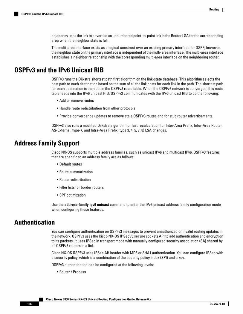
adjacency uses the link to advertise an unnumbered point-to-point link in the Router LSA for the correspondingarea when the neighbor state is full.
The multi-area interface exists as a logical construct over an existing primary interface for OSPF; however,the neighbor state on the primary interface is independent of the multi-area interface. The multi-area interfaceestablishes a neighbor relationship with the corresponding multi-area interface on the neighboring router.
OSPFv3 and the IPv6 Unicast RIBOSPFv3 runs the Dijkstra shortest path first algorithm on the link-state database. This algorithm selects thebest path to each destination based on the sum of all the link costs for each link in the path. The shortest pathfor each destination is then put in the OSPFv3 route table. When the OSPFv3 network is converged, this routetable feeds into the IPv6 unicast RIB. OSPFv3 communicates with the IPv6 unicast RIB to do the following:
• Add or remove routes
• Handle route redistribution from other protocols
• Provide convergence updates to remove stale OSPFv3 routes and for stub router advertisements.
OSPFv3 also runs a modified Dijkstra algorithm for fast recalculation for Inter-Area Prefix, Inter-Area Router,AS-External, type-7, and Intra-Area Prefix (type 3, 4, 5, 7, 8) LSA changes.
Address Family SupportCisco NX-OS supports multiple address families, such as unicast IPv6 and multicast IPv6. OSPFv3 featuresthat are specific to an address family are as follows:
• Default routes
• Route summarization
• Route redistribution
• Filter lists for border routers
• SPF optimization
Use the address-family ipv6 unicast command to enter the IPv6 unicast address family configuration modewhen configuring these features.
AuthenticationYou can configure authentication on OSPFv3 messages to prevent unauthorized or invalid routing updates inthe network. OSPFv3 uses the Cisco NX-OS IPSecV6 secure sockets API to add authentication and encryptionto its packets. It uses IPSec in transport mode with manually configured security association (SA) shared byall OSPFv3 routers in a link.
Cisco NX-OS OSPFv3 uses IPSec AH header with MD5 or SHA1 authentication. You can configure IPSec witha security policy, which is a combination of the security policy index (SPI) and a key.
OSPFv3 authentication can be configured at the following levels:
• Router / Process
Cisco Nexus 7000 Series NX-OS Unicast Routing Configuration Guide, Release 6.xOL-25777-03156
RoutingOSPFv3 and the IPv6 Unicast RIB

• Area
• Interface
If you configure IPSec for an OSPFv3 area, the authentication is applied to all the interfaces in that area, exceptfor the interfaces that have IPSec configured directly. If you configure IPSec for an OSPFv3 process, theauthentication is applied on each interface in every area of that process. A security policy applied on aninterface overrides the policy applied at the process or the area level.
EncryptionBeginning from Cisco Nexus Release 8.4.4, you can encrypt and authenticate OSPFv3 messages. OSPFv3depends on IPSec for secure connection. IPSec supports two encapsulation types:
• Authentication Header (AH)
• Encapsulating Security Payload (ESP)
ESP configuration provides both encryption and authentication for OSPFv3 messages.
You can configure ESP at the following levels:
• Router
• Area
• Interface
• Virtual Links
Guidelines and Limitations for configuring ESP on OSPFv3ESP configuration has the following guidelines and limitations:
• ESP configuration supports IPsec Transport Mode only.
• You can configure ESP on OSPFv3 for one SPI at one level, cannot configure two SPIs in one level.
• You cannot configure both encryption and authentication configurations for a same level.
• Supported encryption algorithms in ESP:
• AES-CBC (128-bit)
• 3DES-CBC
• NULL
• Supported authentication algorithms in ESP:
• SHA-1
• NULL
• You cannot configure both ESP and AUTH algorithm as null in one ESP CLI.
• If ESP is not configured at local level, it inherits configuration from higher level, if configured:
Cisco Nexus 7000 Series NX-OS Unicast Routing Configuration Guide, Release 6.x157OL-25777-03
RoutingEncryption
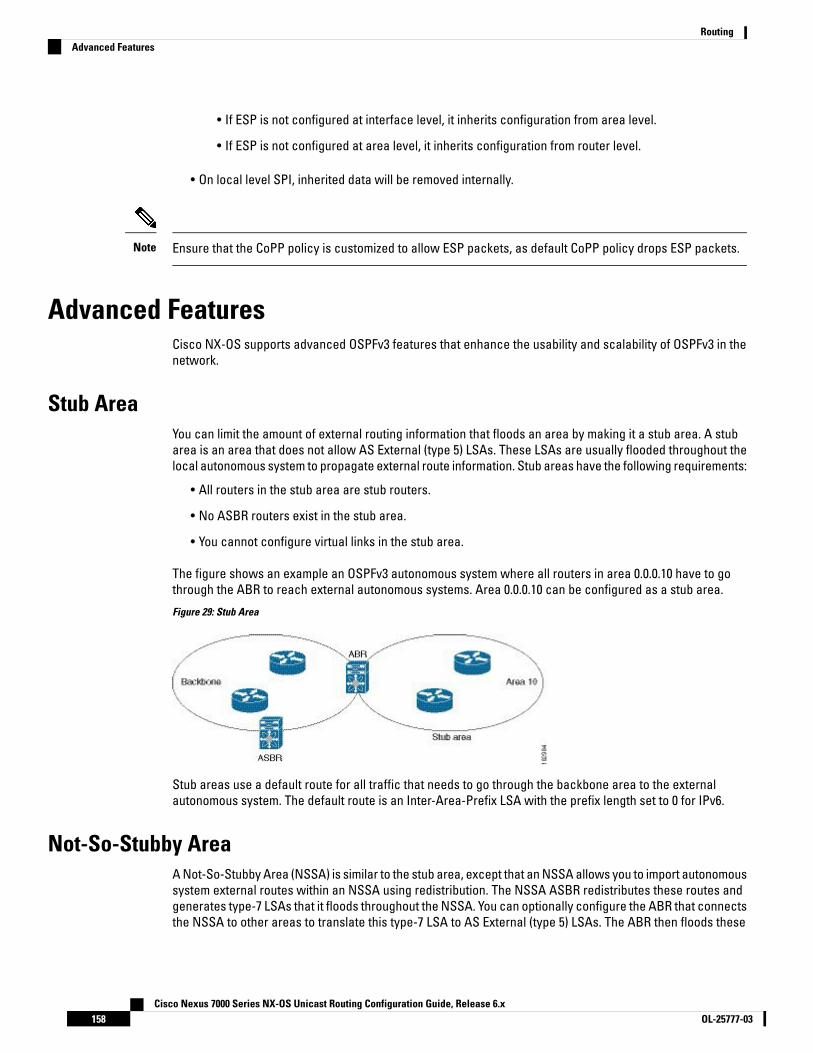
• If ESP is not configured at interface level, it inherits configuration from area level.
• If ESP is not configured at area level, it inherits configuration from router level.
• On local level SPI, inherited data will be removed internally.
Ensure that the CoPP policy is customized to allow ESP packets, as default CoPP policy drops ESP packets.Note
Advanced FeaturesCisco NX-OS supports advanced OSPFv3 features that enhance the usability and scalability of OSPFv3 in thenetwork.
Stub AreaYou can limit the amount of external routing information that floods an area by making it a stub area. A stubarea is an area that does not allow AS External (type 5) LSAs. These LSAs are usually flooded throughout thelocal autonomous system to propagate external route information. Stub areas have the following requirements:
• All routers in the stub area are stub routers.
• No ASBR routers exist in the stub area.
• You cannot configure virtual links in the stub area.
The figure shows an example an OSPFv3 autonomous system where all routers in area 0.0.0.10 have to gothrough the ABR to reach external autonomous systems. Area 0.0.0.10 can be configured as a stub area.
Figure 29: Stub Area
Stub areas use a default route for all traffic that needs to go through the backbone area to the externalautonomous system. The default route is an Inter-Area-Prefix LSA with the prefix length set to 0 for IPv6.
Not-So-Stubby AreaA Not-So-Stubby Area (NSSA) is similar to the stub area, except that an NSSA allows you to import autonomoussystem external routes within an NSSA using redistribution. The NSSA ASBR redistributes these routes andgenerates type-7 LSAs that it floods throughout the NSSA. You can optionally configure the ABR that connectsthe NSSA to other areas to translate this type-7 LSA to AS External (type 5) LSAs. The ABR then floods these
Cisco Nexus 7000 Series NX-OS Unicast Routing Configuration Guide, Release 6.xOL-25777-03158
RoutingAdvanced Features
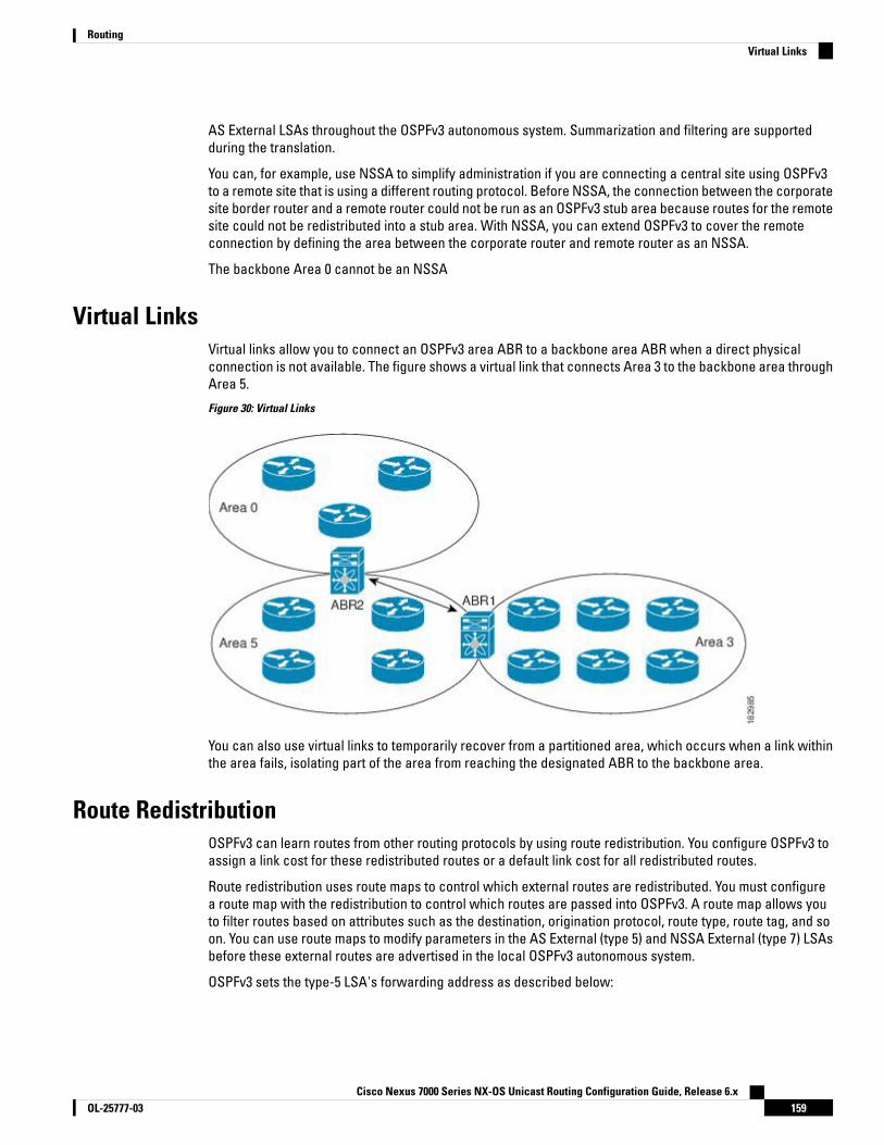
AS External LSAs throughout the OSPFv3 autonomous system. Summarization and filtering are supportedduring the translation.
You can, for example, use NSSA to simplify administration if you are connecting a central site using OSPFv3to a remote site that is using a different routing protocol. Before NSSA, the connection between the corporatesite border router and a remote router could not be run as an OSPFv3 stub area because routes for the remotesite could not be redistributed into a stub area. With NSSA, you can extend OSPFv3 to cover the remoteconnection by defining the area between the corporate router and remote router as an NSSA.
The backbone Area 0 cannot be an NSSA
Virtual LinksVirtual links allow you to connect an OSPFv3 area ABR to a backbone area ABR when a direct physicalconnection is not available. The figure shows a virtual link that connects Area 3 to the backbone area throughArea 5.
Figure 30: Virtual Links
You can also use virtual links to temporarily recover from a partitioned area, which occurs when a link withinthe area fails, isolating part of the area from reaching the designated ABR to the backbone area.
Route RedistributionOSPFv3 can learn routes from other routing protocols by using route redistribution. You configure OSPFv3 toassign a link cost for these redistributed routes or a default link cost for all redistributed routes.
Route redistribution uses route maps to control which external routes are redistributed. You must configurea route map with the redistribution to control which routes are passed into OSPFv3. A route map allows youto filter routes based on attributes such as the destination, origination protocol, route type, route tag, and soon. You can use route maps to modify parameters in the AS External (type 5) and NSSA External (type 7) LSAsbefore these external routes are advertised in the local OSPFv3 autonomous system.
OSPFv3 sets the type-5 LSA's forwarding address as described below:
Cisco Nexus 7000 Series NX-OS Unicast Routing Configuration Guide, Release 6.x159OL-25777-03
RoutingVirtual Links

• If the next-hop for the route is an attached-route then the forwarding address is the next-hop addressfor that route.
• If the next-hop for the route is a recursive route and next-hop's next-hop is an attached route then theforwarding address is the next-hop's next-hop address.
Route SummarizationBecause OSPFv3 shares all learned routes with every OSPF-enabled router, you might want to use routesummarization to reduce the number of unique routes that are flooded to every OSPF-enabled router. Routesummarization simplifies route tables by replacing more-specific addresses with an address that representsall the specific addresses. For example, you can replace 2010:11:22:0:1000::1 and 2010:11:22:0:2000:679:1 withone summary address, 2010:11:22::/32.
Typically, you would summarize at the boundaries of area border routers (ABRs). Although you could configuresummarization between any two areas, it is better to summarize in the direction of the backbone so that thebackbone receives all the aggregate addresses and injects them, already summarized, into other areas. Thetwo types of summarization are as follows:
• Inter-area route summarization
• External route summarization
You configure inter-area route summarization on ABRs, summarizing routes between areas in the autonomoussystem. To take advantage of summarization, assign network numbers in areas in a contiguous way to be ableto lump these addresses into one range.
External route summarization is specific to external routes that are injected into OSPFv3 using routeredistribution. You should make sure that external ranges that are being summarized are contiguous.Summarizing overlapping ranges from two different routers could cause packets to be sent to the wrongdestination. Configure external route summarization on ASBRs that are redistributing routes into OSPF.
When you configure a summary address, Cisco NX-OS automatically configures a discard route for the summaryaddress to prevent routing black holes and route loops.
High Availability and Graceful RestartCisco NX-OS provides a multilevel high-availability architecture. OSPFv3 supports stateful restart, which isalso referred to as non-stop routing (NSR). If OSPFv3 experiences problems, it attempts to restart from itsprevious run-time state. The neighbors do not register any neighbor event in this case. If the first restart is notsuccessful and another problem occurs, OSPFv3 attempts a graceful restart.
A graceful restart, or non-stop forwarding (NSF), allows OSPFv3 to remain in the data forwarding path througha process restart. When OSPFv3 needs to perform a graceful restart, it sends a link-local Grace (type 11) LSA.This restarting OSPFv3 platform is called NSF capable.
The Grace LSA includes a grace period, which is a specified time that the neighbor OSPFv3 interfaces holdonto the LSAs from the restarting OSPFv3 interface. (Typically, OSPFv3 tears down the adjacency and discardsall LSAs from a down or restarting OSPFv3 interface.) The participating neighbors, which are called NSFhelpers, keep all LSAs that originate from the restarting OSPFv3 interface as if the interface was still adjacent.
When the restarting OSPFv3 interface is operational again, it rediscovers its neighbors, establishes adjacency,and starts sending its LSA updates again. At this point, the NSF helpers recognize that the graceful restart hasfinished.
Cisco Nexus 7000 Series NX-OS Unicast Routing Configuration Guide, Release 6.xOL-25777-03160
RoutingRoute Summarization

Stateful restart is used in the following scenarios:
• First recovery attempt after the process experiences problems
• ISSU
• User-initiated switchover using the system switchover command
Graceful restart is used in the following scenarios:
• Second recovery attempt after the process experiences problems within a 4-minute interval
• Manual restart of the process using the restart ospfv3 command
• Active supervisor removal
• Active supervisor reload using the reload module active-supcommand
Multiple OSPFv3 InstancesCisco NX-OS supports multiple instances of the OSPFv3 protocol. By default, every instance uses the samesystem router ID. You must manually configure the router ID for each instance if the instances are in the sameOSPFv3 autonomous system.
The OSPFv3 header includes an instance ID field to identify that OSPFv3 packet for a particular OSPFv3 instance.You can assign the OSPFv3 instance. The interface drops all OSPFv3 packets that do not have a matchingOSPFv3 instance ID in the packet header.
Cisco NX-OS allows only one OSPFv3 instance on an interface.
SPF OptimizationCisco NX-OS optimizes the SPF algorithm in the following ways:
• Partial SPF for Network (type 2) LSAs, Inter-Area Prefix (type 3) LSAs, and AS External (type 5) LSAs—Whenthere is a change on any of these LSAs, Cisco NX-OS performs a faster partial calculation rather thanrunning the whole SPF calculation.
• SPF timers—You can configure different timers for controlling SPF calculations. These timers includeexponential backoff for subsequent SPF calculations. The exponential backoff limits the CPU load ofmultiple SPF calculations.
Virtualization SupportOSPFv3 supports virtual routing and forwarding (VRF) instances. VRFs exist within virtual device contexts(VDCs). By default, Cisco NX-OS places you in the default VDC and default VRF unless you specifically configureanother VDC and VRF. Each OSPFv3 instance can support multiple VRFs, up to the system limit. For moreinformation, see the Cisco Nexus 7000 Series NX-OS Virtual Device Context Configuration Guide.
Prerequisites for OSPFv3OSPFv3 has the following prerequisites:
Cisco Nexus 7000 Series NX-OS Unicast Routing Configuration Guide, Release 6.x161OL-25777-03
RoutingMultiple OSPFv3 Instances

• You must be familiar with routing fundamentals to configure OSPFv3.
• You must be logged on to the switch.
• You have configured at least one interface for IPv6 that is capable of communicating with a remote OSPFv3neighbor.
• You have completed the OSPFv3 network strategy and planning for your network. For example, you mustdecide whether multiple areas are required.
• You have enabled OSPF.
• You are familiar with IPv6 addressing and basic configuration.
Guidelines and Limitations for OSPFv3OSPFv3 has the following configuration guidelines and limitations:
• You can have up to four instances of OSPFv3 in a VDC.
• Before Cisco NX-OS Release 6.2(2), Bidirectional Forwarding Detection (BFD) was not supported forOSPFv3. In Cisco NX-OS Release 6.2(2) and later releases, BFD includes a client for OSPFv3.
• Cisco NX-OS displays areas in dotted decimal notation regardless of whether you enter the area in decimalor dotted decimal notation.
• MTU configured at interface level works in either the data plane or in the control plane but not at bothplanes at the same time.
When you configure MTU with a size lower than the supported size in data and control planes a fewfeatures that have minimum MTU requirements may not work in both the planes.
For example, MPLS VPN is supported in the data plane since this plane supports the MTU of 1500 bytesthat the MPLS VPN requires. But control plane does not support MPLS VPN because this plane cannothandle the 1500-byte packets.
To make the configured MTU work in control plane for MPLS VPN, you need to manually configure theOSPF packet size (by using the packet-sizesize command) so that OSPF works on the control plane. Thisis applicable from Cisco NX-OS Release 8.3(2) onwards.
The packet-sizesize command is supported on the Ethernet, SVI, and GRE tunnel interfaces.
• If you configure OSPFv3 in a virtual port channel (vPC) environment, use the following timer commandsin router configuration mode on the core switch to ensure fast OSPF convergence when a vPC peer linkis shut down:
switch (config-router)# timers throttle spf 1 50 50switch (config-router)# timers lsa-arrival 10
• The value of object OSPFv3 router ID differs from RFC 5643 for traps ospfv3NbrRestartHelperStatusChangeand ospfv3VirtNbrRestartHelperStatusChange. As per the RFC 5643, the value of object OSPFv3 router IDshould be the router ID of the originator of the trap. But the current implementation will provide the routerID of the neighbor for both ospfv3NbrRestartHelperStatusChange andospfv3VirtNbrRestartHelperStatusChange.
• Only the first four OSPFv3 instances are supported with MPLS LDP and MPLS TE.
Cisco Nexus 7000 Series NX-OS Unicast Routing Configuration Guide, Release 6.xOL-25777-03162
RoutingGuidelines and Limitations for OSPFv3

• In scaled scenarios, when the number of interfaces and link-state advertisements in an OSPFv3 processis large, the snmp-walk on OSPF MIB objects is expected to time out with a small-value timeout at theSNMP agent. If you observe a timeout on the querying SNMP agent while polling OSPF MIB objects,increase the timeout value on the polling SNMP agent.
• If there is a particular OSPFv3 prefix that is learnt through type-5 as well as type-7, and both have differentforwarding addresses, then these two route types are not comparable as per RFC3101, Section 2.5, step6(e). (This applies only if the same destination/cost/non-zero forwarding addresses are there). OSPF willtherefore do ECMP with all available next-hops.
• NXOS OSPF and U6RIB store only one route-type per route. If there is a mix of route-type across next-hops,only one of them, (the new path type) will be shown for all next hops.
Currently, route-type is a route property, and not a next-hop property.
• The default-information-originate always command advertises the OSPF defaut route from Cisco NX-OSRelease 7.3(5)D1(1) and later releases and from Cisco NX-OS Release 8.0(1) and later releases in 8.xrelease train.
• The following guidelines and limitations apply to the administrative distance feature, which is supportedbeginning with Cisco NX-OS Release 6.1:
• When an OSPF route has two or more equal cost paths, configuring the administrative distance isnon-deterministic for the match ip route-source command.
• For matching route sources in OSPFv3 routes, you must configure match ip route-source instead ofmatch ipv6 route-source because the route sources and router IDs for OSPFv3 are IPv4 addresses.
• Configuring the administrative distance is supported only for the match route-type, match ipv6address prefix-list, and match ip route-source prefix-list commands. The other match statementsare ignored.
• The discard route is always assigned an administrative distance of 220. No configuration in the tablemap applies to OSPF discard routes.
• There is no preference among the match route-type, match ipv6 address, and match ip route-sourcecommands for setting the administrative distance of OSPF routes. In this way, the behavior of thetable map for setting the administrative distance in Cisco NX-OS OSPF is different from that in CiscoIOS OSPF.
• In Cisco NX-OS Release 6.2(6a) and later releases, you can filter next-hop paths for an OSPF routeto prevent the path from being added to the RIB. Before Cisco NX-OS Release 6.2(6a), filtering on aspecific path was ignored and the entire route was not added to the RIB.
• If you are familiar with the Cisco IOS CLI, be aware that the Cisco NX-OS commands for this feature mightdiffer from the Cisco IOS commands that you would use.
Cisco Nexus 7000 Series NX-OS Unicast Routing Configuration Guide, Release 6.x163OL-25777-03
RoutingGuidelines and Limitations for OSPFv3
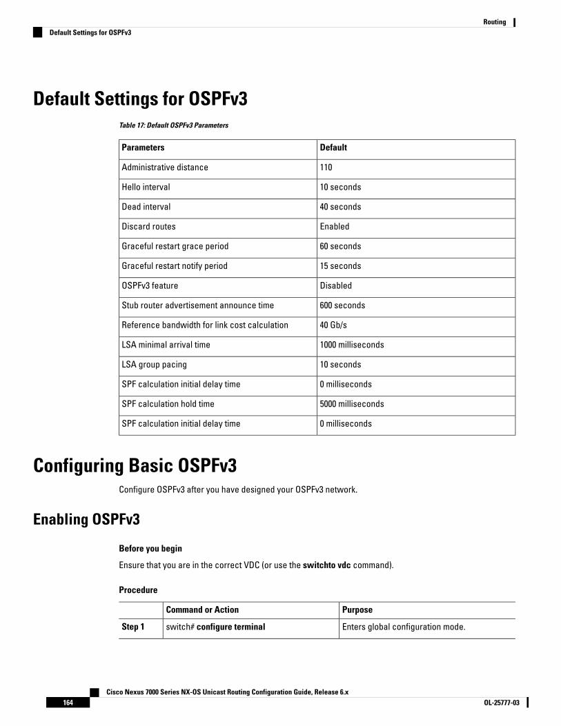
Default Settings for OSPFv3Table 17: Default OSPFv3 Parameters
DefaultParameters
110Administrative distance
10 secondsHello interval
40 secondsDead interval
EnabledDiscard routes
60 secondsGraceful restart grace period
15 secondsGraceful restart notify period
DisabledOSPFv3 feature
600 secondsStub router advertisement announce time
40 Gb/sReference bandwidth for link cost calculation
1000 millisecondsLSA minimal arrival time
10 secondsLSA group pacing
0 millisecondsSPF calculation initial delay time
5000 millisecondsSPF calculation hold time
0 millisecondsSPF calculation initial delay time
Configuring Basic OSPFv3Configure OSPFv3 after you have designed your OSPFv3 network.
Enabling OSPFv3
Before you begin
Ensure that you are in the correct VDC (or use the switchto vdc command).
Procedure
PurposeCommand or Action
Enters global configuration mode.switch# configure terminalStep 1
Cisco Nexus 7000 Series NX-OS Unicast Routing Configuration Guide, Release 6.xOL-25777-03164
RoutingDefault Settings for OSPFv3

PurposeCommand or Action
Enables OSPFv3. To disable the OSPFv3 featureand remove all associated configurations, usethe no form of the command.
switch(config)# [no] feature ospfv3Step 2
Displays enabled and disabled features.(Optional) switch(config)# show featureStep 3
Saves the change persistently through rebootsand restarts by copying the runningconfiguration to the startup configuration.
(Optional) switch(config)# copy running-configstartup-config
Step 4
Creating an OSPFv3 InstanceThe first step in configuring OSPFv3 is to create an instance or OSPFv3 instance. You assign a unique instancetag for this OSPFv3 instance. The instance tag can be any string. For each OSPFv3 instance, you can alsoconfigure the following optional parameters:
• Router ID—Configures the router ID for this OSPFv3 instance. If you do not use this parameter, the routerID selection algorithm is used.
• Administrative distance—Rates the trustworthiness of a routing information source.
• Log adjacency changes—Creates a system message whenever an OSPFv3 neighbor changes its state.
• Name lookup—Translates OSPF router IDs to host names, either by looking up the local hosts
database or querying DNS names in IPv6.
• Maximum paths—Sets the maximum number of equal paths that OSPFv3 installs in the route table for aparticular destination. Use this parameter for load balancing between multiple paths.
• Reference bandwidth—Controls the calculated OSPFv3 cost metric for a network. The calculated costis the reference bandwidth divided by the interface bandwidth. You can override the calculated cost byassigning a link cost when a network is added to the OSPFv3 instance.
The OSPF router ID changes without a restart on a Cisco Nexus 7000 series switch when you have not configureda manual router ID in the following cases:
• Configuring an SVI or physical interface with a higher IP address than the current router ID on a setupwithout any configured loopback interfaces.
• Configuring a loopback interface with any given IP address on a setup without any previously configuredloopback interfaces.
• Configuring a loopback interface with a higher IP address than the IP address of an existing configuredloopback interface.
When a router ID changes, OSPF has to re-advertise all LSAs with the new router ID. To avoid this issue, youneed to configure a manual OSPF router ID.
Note
Cisco Nexus 7000 Series NX-OS Unicast Routing Configuration Guide, Release 6.x165OL-25777-03
RoutingCreating an OSPFv3 Instance
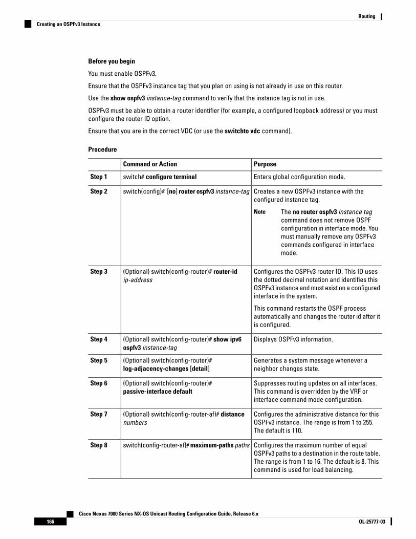
Before you begin
You must enable OSPFv3.
Ensure that the OSPFv3 instance tag that you plan on using is not already in use on this router.
Use the show ospfv3 instance-tag command to verify that the instance tag is not in use.
OSPFv3 must be able to obtain a router identifier (for example, a configured loopback address) or you mustconfigure the router ID option.
Ensure that you are in the correct VDC (or use the switchto vdc command).
Procedure
PurposeCommand or Action
Enters global configuration mode.switch# configure terminalStep 1
Creates a new OSPFv3 instance with theconfigured instance tag.
switch(config)# [no] router ospfv3 instance-tagStep 2
The no router ospfv3 instance tagcommand does not remove OSPFconfiguration in interface mode. Youmust manually remove any OSPFv3commands configured in interfacemode.
Note
Configures the OSPFv3 router ID. This ID usesthe dotted decimal notation and identifies this
(Optional) switch(config-router)# router-idip-address
Step 3
OSPFv3 instance and must exist on a configuredinterface in the system.
This command restarts the OSPF processautomatically and changes the router id after itis configured.
Displays OSPFv3 information.(Optional) switch(config-router)# show ipv6ospfv3 instance-tag
Step 4
Generates a system message whenever aneighbor changes state.
(Optional) switch(config-router)#log-adjacency-changes [detail]
Step 5
Suppresses routing updates on all interfaces.This command is overridden by the VRF orinterface command mode configuration.
(Optional) switch(config-router)#passive-interface default
Step 6
Configures the administrative distance for thisOSPFv3 instance. The range is from 1 to 255.The default is 110.
(Optional) switch(config-router-af)# distancenumbers
Step 7
Configures the maximum number of equalOSPFv3 paths to a destination in the route table.
switch(config-router-af)# maximum-paths pathsStep 8
The range is from 1 to 16. The default is 8. Thiscommand is used for load balancing.
Cisco Nexus 7000 Series NX-OS Unicast Routing Configuration Guide, Release 6.xOL-25777-03166
RoutingCreating an OSPFv3 Instance

PurposeCommand or Action
Saves the change persistently through rebootsand restarts by copying the runningconfiguration to the startup configuration.
(Optional) switch(config)# copy running-configstartup-config
Step 9
Example
This example shows how to create an OSPFv3 instance:
switch# configure terminalswitch(config)# router ospfv3 201switch(config-router)# copy running-config startup-config
Configuring OSPFv3 Packet SizeMTU configured at interface level works in either the data plane or in the control plane but not at both planesat the same time.
When you configure MTU with a size lower than the supported size in data and control planes a few featuresthat have minimum MTU requirements may not work in both the planes.
For example, MPLS VPN is supported in the data plane since this plane supports the MTU of 1500 bytes thatthe MPLS VPN requires. But control plane does not support MPLS VPN because this plane cannot handle the1500-byte packets.
To make the configured MTU work in control plane for MPLS VPN, you need to manually configure the OSPFpacket size so that OSPF works on the control plane. This is applicable from Cisco NX-OS Release 8.3(2)onwards.
Procedure
PurposeCommand or Action
Enters global configuration mode.switch# configure terminalStep 1
Creates a new OSPFv3 instance with theconfigured instance tag.
switch(config)# [no] router ospfv3 instance-tagStep 2
The no router ospfv3 instance-tagcommand does not remove OSPFconfiguration in interface mode. Youmust manually remove any OSPFv3commands configured in interfacemode.
Note
Configures the OSPFv3 router ID. This ID usesthe dotted decimal notation and identifies this
switch(config-router)# router-id ip-addressStep 3
OSPFv3 instance and must exist on a configuredinterface in the system.
Cisco Nexus 7000 Series NX-OS Unicast Routing Configuration Guide, Release 6.x167OL-25777-03
RoutingConfiguring OSPFv3 Packet Size

PurposeCommand or Action
This command restarts the OSPF processautomatically and changes the router id after itis configured.
switch(config-router)# ospfv3 packet-size sizeStep 4 • Configures the OSPFv3 packet size. Thesize range is from 1280 to 9212 bytes.
• You can configure the packet-size in theinterface configuration mode also.
• You can configure the packet-size sizecommand even if theip ospf mtu-ignorecommand is already configured in thenetwork.
Displays OSPF information.(Optional) switch(config-router)# show ospfv3interface
Step 5
Example
This example shows how to configure the OSPFv3 packet-size:
router ospf 1router-id 3.3.3.3[no] packet-size 2000
This example shows the display of the configured OSPFv3 packet-size:
Switch (config-router)# show ospfv3 interface ethernet 1/25Ethernet1/25 is up, line protocol is up
IP address 1.0.0.1/24--------- snip ---------------Number of opaque link LSAs: 0, checksum sum 0Max Packet Size: 2000
Configuring Networks in OSPFv3You can configure a network to OSPFv3 by associating it through the interface that the router uses to connectto that network. You can add all networks to the default backbone area (Area 0), or you can create new areasusing any decimal number or an IP address.
All areas must connect to the backbone area either directly or through a virtual link.Note
OSPFv3 is not enabled on an interface until you configure a valid IPv6 address for that interface.Note
Cisco Nexus 7000 Series NX-OS Unicast Routing Configuration Guide, Release 6.xOL-25777-03168
RoutingConfiguring Networks in OSPFv3

Before you begin
You must enable OSPFv3.
Ensure that you are in the correct VDC (or use the switchto vdc command).
Procedure
PurposeCommand or Action
Enters global configuration mode.switch# configure terminalStep 1
Enters interface configuration mode.switch(config)# interface interface-typeslot/port
Step 2
Assigns an IPv6 address to this interface.switch(config-if)# ipv6 addressipv6-prefix/length
Step 3
Adds the interface to the OSPFv3 instance andarea.
switch(config-if)# ipv6 router ospfv3instance-tag area area-id [secondaries none]
Step 4
Displays OSPFv3 information.(Optional) switch(config-if)# show ipv6 ospfv3instance-tag interface interface-type slot/port
Step 5
Configures the OSPFv3 cost metric for thisinterface. The default is to calculate a cost
(Optional) switch(config-if)# ospfv3 costnumber
Step 6
metric, based on the reference bandwidth andinterface bandwidth. The range is from 1 to65535.
Configures the OSPFv3 dead interval, inseconds. The range is from 1 to 65535. The
(Optional) switch(config-if)# ospfv3dead-interval seconds
Step 7
default is four times the hello interval, inseconds.
Configures the OSPFv3 hello interval, inseconds. The range is from 1 to 65535. Thedefault is 10 seconds.
(Optional) switch(config-if)# ospfv3hello-interval seconds
Step 8
Configures the OSPFv3 instance ID. The rangeis from 0 to 255. The default is 0. The instanceID is link-local in scope.
(Optional) switch(config-if)# ospfv3 instanceinstance
Step 9
Configures OSPFv3 to ignore any IP maximumtransmission unit (MTU) mismatch with a
(Optional) switch(config-if)# ospfv3 mtu-ignoreStep 10
neighbor. The default is to not establishadjacency if the neighbor MTU does not matchthe local interface MTU.
Sets the OSPFv3 network type.(Optional) switch(config-if)# ospfv3 network{broadcast | point-point}
Step 11
Configures the OSPFv3 priority, used todetermine the DR for an area. The range is from0 to 255. The default is 1.
(Optional) switch(config-if)# ospfv3 prioritynumber
Step 12
Cisco Nexus 7000 Series NX-OS Unicast Routing Configuration Guide, Release 6.x169OL-25777-03
RoutingConfiguring Networks in OSPFv3
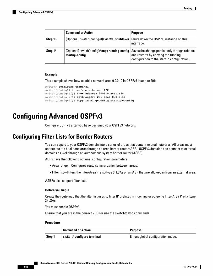
PurposeCommand or Action
Shuts down the OSPFv3 instance on thisinterface.
(Optional) switch(config-if)# ospfv3 shutdownStep 13
Saves the change persistently through rebootsand restarts by copying the runningconfiguration to the startup configuration.
(Optional) switch(config)# copy running-configstartup-config
Step 14
Example
This example shows how to add a network area 0.0.0.10 in OSPFv3 instance 201:
switch# configure terminalswitch(config)# interface ethernet 1/2switch(config-if)# ipv6 address 2001:0DB8::1/48switch(config-if)# ipv6 ospfv3 201 area 0.0.0.10switch(config-if)# copy running-config startup-config
Configuring Advanced OSPFv3Configure OSPFv3 after you have designed your OSPFv3 network.
Configuring Filter Lists for Border RoutersYou can separate your OSPFv3 domain into a series of areas that contain related networks. All areas mustconnect to the backbone area through an area border router (ABR). OSPFv3 domains can connect to externaldomains as well through an autonomous system border router (ASBR).
ABRs have the following optional configuration parameters:
• Area range—Configures route summarization between areas.
• Filter list—Filters the Inter-Area Prefix (type 3) LSAs on an ABR that are allowed in from an external area.
ASBRs also support filter lists.
Before you begin
Create the route map that the filter list uses to filter IP prefixes in incoming or outgoing Inter-Area Prefix (type3) LSAs.
You must enable OSPFv3.
Ensure that you are in the correct VDC (or use the switchto vdc command).
Procedure
PurposeCommand or Action
Enters global configuration mode.switch# configure terminalStep 1
Cisco Nexus 7000 Series NX-OS Unicast Routing Configuration Guide, Release 6.xOL-25777-03170
RoutingConfiguring Advanced OSPFv3

PurposeCommand or Action
Creates a new OSPFv3 instance with theconfigured instance tag
switch(config)# router ospfv3 instance-tagStep 2
Enters IPv6 unicast address family mode.switch(config-router)# address-family ipv6unicast
Step 3
Filters incoming or outgoing Inter-Area Prefix(type 3) LSAs on an ABR.
switch(config-router-af)# area area-id filter-listroute-map map-name {in | out}
Step 4
Displays OSPFv3 policy information.(Optional) switch(config-if)# show ipv6 ospfv3policy statistics area id filter-list {in | out}
Step 5
Saves the change persistently through rebootsand restarts by copying the runningconfiguration to the startup configuration.
(Optional) switch(config)# copy running-configstartup-config
Step 6
Example
This example shows how to enable graceful restart if it has been disabled:
switch# configure terminalswitch(config)# router ospfv3 201switch(config-router)# address-family ipv6 unicastswitch(config-router-af)# area 0.0.0.10 filter-list route-map FilterLSAs inswitch(config-router-af)# copy running-config startup-config
Configuring Stub AreasYou can configure a stub area for part of an OSPFv3 domain where external traffic is not necessary. Stub areasblock AS External (type 5) LSAs, limiting unnecessary routing to and from selected networks. You can optionallyblock all summary routes from going into the stub area.
Before you begin
You must enable OSPF.
Ensure that there are no virtual links or ASBRs in the proposed stub area.
Ensure that you are in the correct VDC (or use the switchto vdc command).
Procedure
PurposeCommand or Action
Enters global configuration mode.switch# configure terminalStep 1
Creates a new OSPFv3 instance with theconfigured instance tag.
switch(config)# router ospfv3 instance-tagStep 2
Creates this area as a stub area.switch(config-router)# area area-id stubStep 3
Cisco Nexus 7000 Series NX-OS Unicast Routing Configuration Guide, Release 6.x171OL-25777-03
RoutingConfiguring Stub Areas
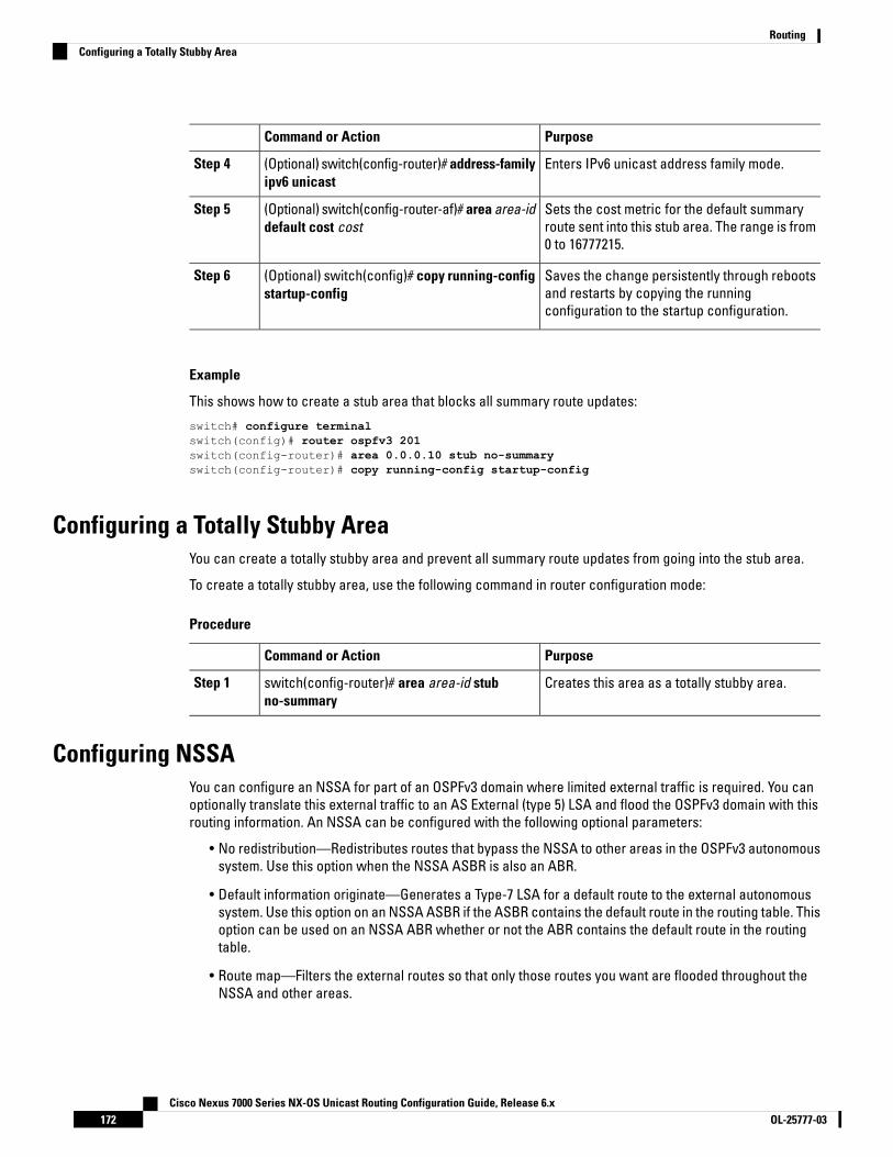
PurposeCommand or Action
Enters IPv6 unicast address family mode.(Optional) switch(config-router)# address-familyipv6 unicast
Step 4
Sets the cost metric for the default summaryroute sent into this stub area. The range is from0 to 16777215.
(Optional) switch(config-router-af)# area area-iddefault cost cost
Step 5
Saves the change persistently through rebootsand restarts by copying the runningconfiguration to the startup configuration.
(Optional) switch(config)# copy running-configstartup-config
Step 6
Example
This shows how to create a stub area that blocks all summary route updates:
switch# configure terminalswitch(config)# router ospfv3 201switch(config-router)# area 0.0.0.10 stub no-summaryswitch(config-router)# copy running-config startup-config
Configuring a Totally Stubby AreaYou can create a totally stubby area and prevent all summary route updates from going into the stub area.
To create a totally stubby area, use the following command in router configuration mode:
Procedure
PurposeCommand or Action
Creates this area as a totally stubby area.switch(config-router)# area area-id stubno-summary
Step 1
Configuring NSSAYou can configure an NSSA for part of an OSPFv3 domain where limited external traffic is required. You canoptionally translate this external traffic to an AS External (type 5) LSA and flood the OSPFv3 domain with thisrouting information. An NSSA can be configured with the following optional parameters:
• No redistribution—Redistributes routes that bypass the NSSA to other areas in the OSPFv3 autonomoussystem. Use this option when the NSSA ASBR is also an ABR.
• Default information originate—Generates a Type-7 LSA for a default route to the external autonomoussystem. Use this option on an NSSA ASBR if the ASBR contains the default route in the routing table. Thisoption can be used on an NSSA ABR whether or not the ABR contains the default route in the routingtable.
• Route map—Filters the external routes so that only those routes you want are flooded throughout theNSSA and other areas.
Cisco Nexus 7000 Series NX-OS Unicast Routing Configuration Guide, Release 6.xOL-25777-03172
RoutingConfiguring a Totally Stubby Area
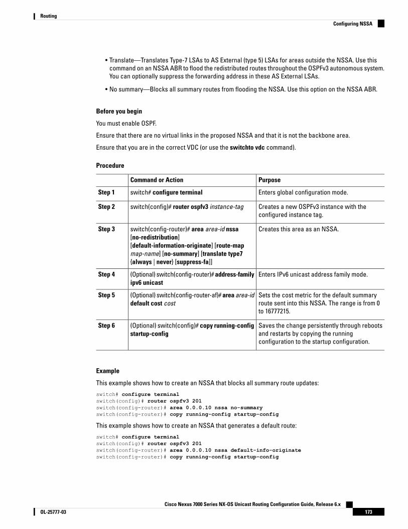
• Translate—Translates Type-7 LSAs to AS External (type 5) LSAs for areas outside the NSSA. Use thiscommand on an NSSA ABR to flood the redistributed routes throughout the OSPFv3 autonomous system.You can optionally suppress the forwarding address in these AS External LSAs.
• No summary—Blocks all summary routes from flooding the NSSA. Use this option on the NSSA ABR.
Before you begin
You must enable OSPF.
Ensure that there are no virtual links in the proposed NSSA and that it is not the backbone area.
Ensure that you are in the correct VDC (or use the switchto vdc command).
Procedure
PurposeCommand or Action
Enters global configuration mode.switch# configure terminalStep 1
Creates a new OSPFv3 instance with theconfigured instance tag.
switch(config)# router ospfv3 instance-tagStep 2
Creates this area as an NSSA.switch(config-router)# area area-id nssa[no-redistribution]
Step 3
[default-information-originate] [route-mapmap-name] [no-summary] [translate type7{always | never} [suppress-fa]]
Enters IPv6 unicast address family mode.(Optional) switch(config-router)# address-familyipv6 unicast
Step 4
Sets the cost metric for the default summaryroute sent into this NSSA. The range is from 0to 16777215.
(Optional) switch(config-router-af)# area area-iddefault cost cost
Step 5
Saves the change persistently through rebootsand restarts by copying the runningconfiguration to the startup configuration.
(Optional) switch(config)# copy running-configstartup-config
Step 6
Example
This example shows how to create an NSSA that blocks all summary route updates:
switch# configure terminalswitch(config)# router ospfv3 201switch(config-router)# area 0.0.0.10 nssa no-summaryswitch(config-router)# copy running-config startup-config
This example shows how to create an NSSA that generates a default route:
switch# configure terminalswitch(config)# router ospfv3 201switch(config-router)# area 0.0.0.10 nssa default-info-originateswitch(config-router)# copy running-config startup-config
Cisco Nexus 7000 Series NX-OS Unicast Routing Configuration Guide, Release 6.x173OL-25777-03
RoutingConfiguring NSSA

This example shows how to create an NSSA that filters external routes and blocks all summary routeupdates:
switch# configure terminalswitch(config)# router ospfv3 201switch(config-router)# area 0.0.0.10 nssa route-map ExternalFilter no-summaryswitch(config-router)# copy running-config startup-config
This example shows how to create an NSSA that always translates Type-7 LSAs to AS External (type5) LSAs:
switch# configure terminalswitch(config)# router ospfv3 201switch(config-router)# area 0.0.0.10 nssa translate type 7 alwaysswitch(config-router)# copy running-config startup-config
This example shows how to create an NSSA that blocks all summary route updates:
switch# configure terminalswitch(config)# router ospfv3 201switch(config-router)# area 0.0.0.10 nssa no-summaryswitch(config-router)# copy running-config startup-config
Configuring Multi-Area AdjacencyYou can add more than one area to an existing OSPFv3 interface. The additional logical interfaces supportmulti-area adjacency.
Before you begin
You must enable OSPF.
Ensure that you are in the correct VDC (or use the switchto vdc command).
Ensure that you have configured a primary area for the interface.
Procedure
PurposeCommand or Action
Enters global configuration mode.switch# configure terminalStep 1
Enters interface configuration mode.switch(config)# interface interface-typeslot/port
Step 2
Adds the interface to another area.switch(config-if)# ipv6 router ospfv3instance-tag multi-area area-id
Step 3
Displays OSPFv3 information.(Optional) switch(config-if)# show ipv6 ospfv3instance-tag interface interface-type slot/port
Step 4
Saves the change persistently through rebootsand restarts by copying the runningconfiguration to the startup configuration.
(Optional) switch(config)# copy running-configstartup-config
Step 5
Cisco Nexus 7000 Series NX-OS Unicast Routing Configuration Guide, Release 6.xOL-25777-03174
RoutingConfiguring Multi-Area Adjacency
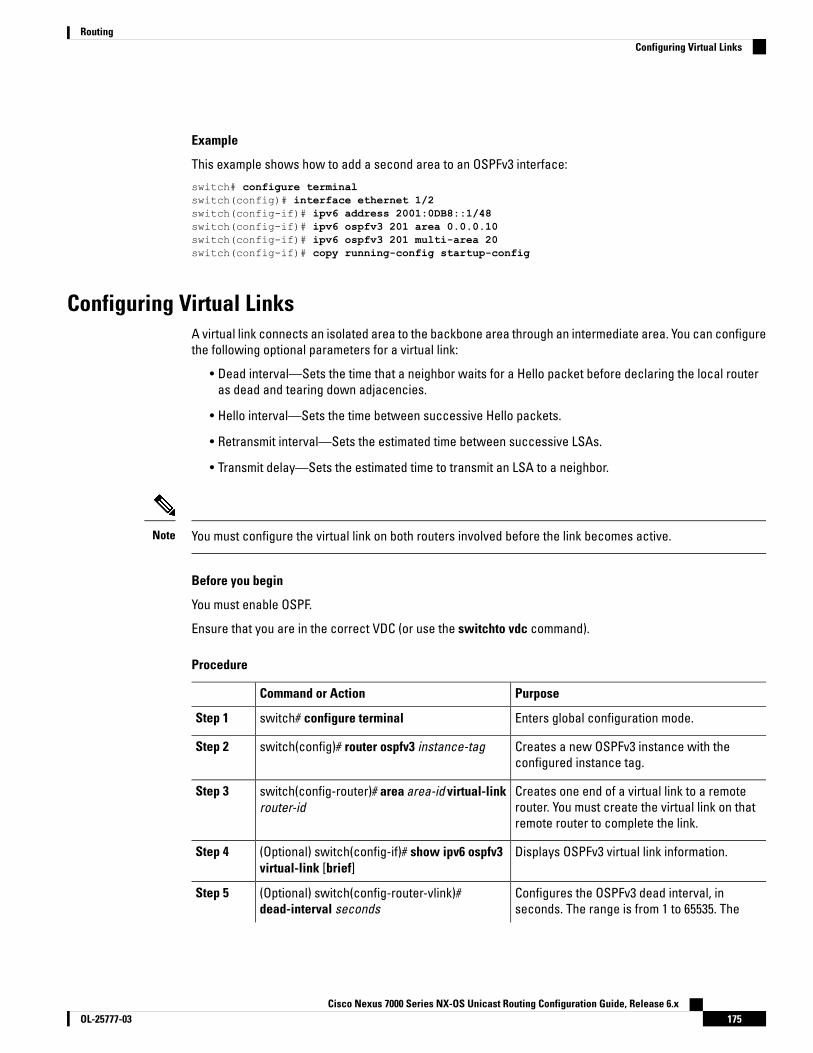
Example
This example shows how to add a second area to an OSPFv3 interface:
switch# configure terminalswitch(config)# interface ethernet 1/2switch(config-if)# ipv6 address 2001:0DB8::1/48switch(config-if)# ipv6 ospfv3 201 area 0.0.0.10switch(config-if)# ipv6 ospfv3 201 multi-area 20switch(config-if)# copy running-config startup-config
Configuring Virtual LinksA virtual link connects an isolated area to the backbone area through an intermediate area. You can configurethe following optional parameters for a virtual link:
• Dead interval—Sets the time that a neighbor waits for a Hello packet before declaring the local routeras dead and tearing down adjacencies.
• Hello interval—Sets the time between successive Hello packets.
• Retransmit interval—Sets the estimated time between successive LSAs.
• Transmit delay—Sets the estimated time to transmit an LSA to a neighbor.
You must configure the virtual link on both routers involved before the link becomes active.Note
Before you begin
You must enable OSPF.
Ensure that you are in the correct VDC (or use the switchto vdc command).
Procedure
PurposeCommand or Action
Enters global configuration mode.switch# configure terminalStep 1
Creates a new OSPFv3 instance with theconfigured instance tag.
switch(config)# router ospfv3 instance-tagStep 2
Creates one end of a virtual link to a remoterouter. You must create the virtual link on thatremote router to complete the link.
switch(config-router)# area area-id virtual-linkrouter-id
Step 3
Displays OSPFv3 virtual link information.(Optional) switch(config-if)# show ipv6 ospfv3virtual-link [brief]
Step 4
Configures the OSPFv3 dead interval, inseconds. The range is from 1 to 65535. The
(Optional) switch(config-router-vlink)#dead-interval seconds
Step 5
Cisco Nexus 7000 Series NX-OS Unicast Routing Configuration Guide, Release 6.x175OL-25777-03
RoutingConfiguring Virtual Links

PurposeCommand or Action
default is four times the hello interval, inseconds.
Configures the OSPFv3 hello interval, in seconds.The range is from 1 to 65535. The default is 10seconds.
(Optional) switch(config-router-vlink)#hello-interval seconds
Step 6
Configures the OSPFv3 retransmit interval, inseconds. The range is from 1 to 65535. Thedefault is 5.
(Optional) switch(config-router-vlink)#retransmit-interval seconds
Step 7
Configures the OSPFv3 transmit-delay, inseconds. The range is from 1 to 450. The defaultis 1.
(Optional) switch(config-router-vlink)#transmit-delay seconds
Step 8
Saves the change persistently through rebootsand restarts by copying the runningconfiguration to the startup configuration.
(Optional) switch(config)# copy running-configstartup-config
Step 9
Example
These examples show how to create a simple virtual link between two ABRs:
Configuration for ABR 1 (router ID 2001:0DB8::1) is as follows:
switch# configure terminalswitch(config)# router ospfv3 201switch(config-router)# area 0.0.0.10 virtual-link 2001:0DB8::10switch(config-router)# copy running-config startup-config
Configuration for ABR 2 (router ID 2001:0DB8::10) is as follows:
switch# configure terminalswitch(config)# router ospfv3 201switch(config-router)# area 0.0.0.10 virtual-link 2001:0DB8::1switch(config-router)# copy running-config startup-config
Configuring RedistributionYou can redistribute routes learned from other routing protocols into an OSPFv3 autonomous system throughthe ASBR.
You can configure the following optional parameters for route redistribution in OSPF:
• Default information originate—Generates an AS External (type 5) LSA for a default route to the externalautonomous system.
Default information originate ignores match statements in the optional route map.Note
• Default metric—Sets all redistributed routes to the same cost metric.
Cisco Nexus 7000 Series NX-OS Unicast Routing Configuration Guide, Release 6.xOL-25777-03176
RoutingConfiguring Redistribution
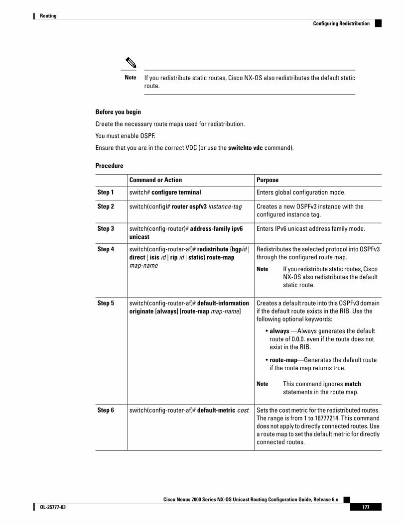
If you redistribute static routes, Cisco NX-OS also redistributes the default staticroute.
Note
Before you begin
Create the necessary route maps used for redistribution.
You must enable OSPF.
Ensure that you are in the correct VDC (or use the switchto vdc command).
Procedure
PurposeCommand or Action
Enters global configuration mode.switch# configure terminalStep 1
Creates a new OSPFv3 instance with theconfigured instance tag.
switch(config)# router ospfv3 instance-tagStep 2
Enters IPv6 unicast address family mode.switch(config-router)# address-family ipv6unicast
Step 3
Redistributes the selected protocol into OSPFv3through the configured route map.
switch(config-router-af)# redistribute {bgpid |direct | isis id | rip id | static} route-mapmap-name
Step 4
If you redistribute static routes, CiscoNX-OS also redistributes the defaultstatic route.
Note
Creates a default route into this OSPFv3 domainif the default route exists in the RIB. Use thefollowing optional keywords:
switch(config-router-af)# default-informationoriginate [always] [route-map map-name]
Step 5
• always —Always generates the defaultroute of 0.0.0. even if the route does notexist in the RIB.
• route-map—Generates the default routeif the route map returns true.
This command ignores matchstatements in the route map.
Note
Sets the cost metric for the redistributed routes.The range is from 1 to 16777214. This command
switch(config-router-af)# default-metric costStep 6
does not apply to directly connected routes. Usea route map to set the default metric for directlyconnected routes.
Cisco Nexus 7000 Series NX-OS Unicast Routing Configuration Guide, Release 6.x177OL-25777-03
RoutingConfiguring Redistribution
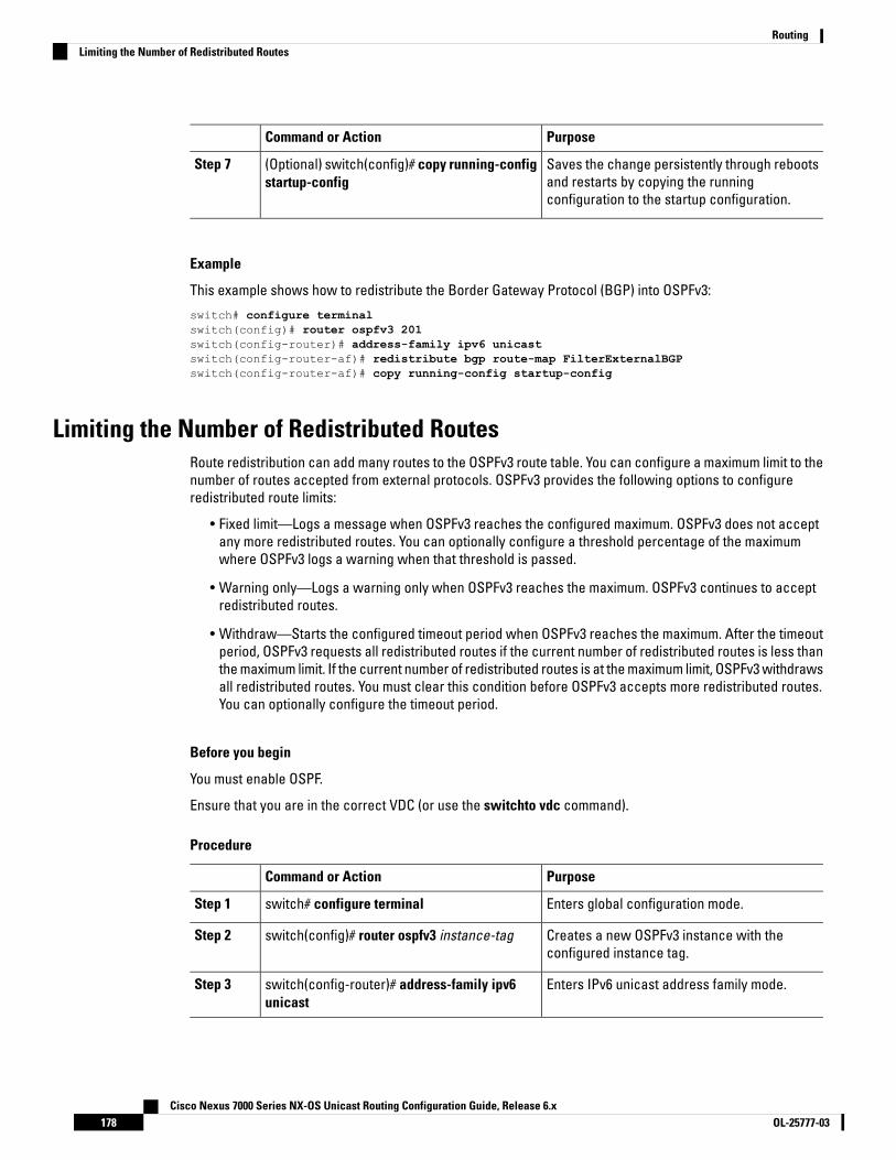
PurposeCommand or Action
Saves the change persistently through rebootsand restarts by copying the runningconfiguration to the startup configuration.
(Optional) switch(config)# copy running-configstartup-config
Step 7
Example
This example shows how to redistribute the Border Gateway Protocol (BGP) into OSPFv3:
switch# configure terminalswitch(config)# router ospfv3 201switch(config-router)# address-family ipv6 unicastswitch(config-router-af)# redistribute bgp route-map FilterExternalBGPswitch(config-router-af)# copy running-config startup-config
Limiting the Number of Redistributed RoutesRoute redistribution can add many routes to the OSPFv3 route table. You can configure a maximum limit to thenumber of routes accepted from external protocols. OSPFv3 provides the following options to configureredistributed route limits:
• Fixed limit—Logs a message when OSPFv3 reaches the configured maximum. OSPFv3 does not acceptany more redistributed routes. You can optionally configure a threshold percentage of the maximumwhere OSPFv3 logs a warning when that threshold is passed.
• Warning only—Logs a warning only when OSPFv3 reaches the maximum. OSPFv3 continues to acceptredistributed routes.
• Withdraw—Starts the configured timeout period when OSPFv3 reaches the maximum. After the timeoutperiod, OSPFv3 requests all redistributed routes if the current number of redistributed routes is less thanthe maximum limit. If the current number of redistributed routes is at the maximum limit, OSPFv3 withdrawsall redistributed routes. You must clear this condition before OSPFv3 accepts more redistributed routes.You can optionally configure the timeout period.
Before you begin
You must enable OSPF.
Ensure that you are in the correct VDC (or use the switchto vdc command).
Procedure
PurposeCommand or Action
Enters global configuration mode.switch# configure terminalStep 1
Creates a new OSPFv3 instance with theconfigured instance tag.
switch(config)# router ospfv3 instance-tagStep 2
Enters IPv6 unicast address family mode.switch(config-router)# address-family ipv6unicast
Step 3
Cisco Nexus 7000 Series NX-OS Unicast Routing Configuration Guide, Release 6.xOL-25777-03178
RoutingLimiting the Number of Redistributed Routes
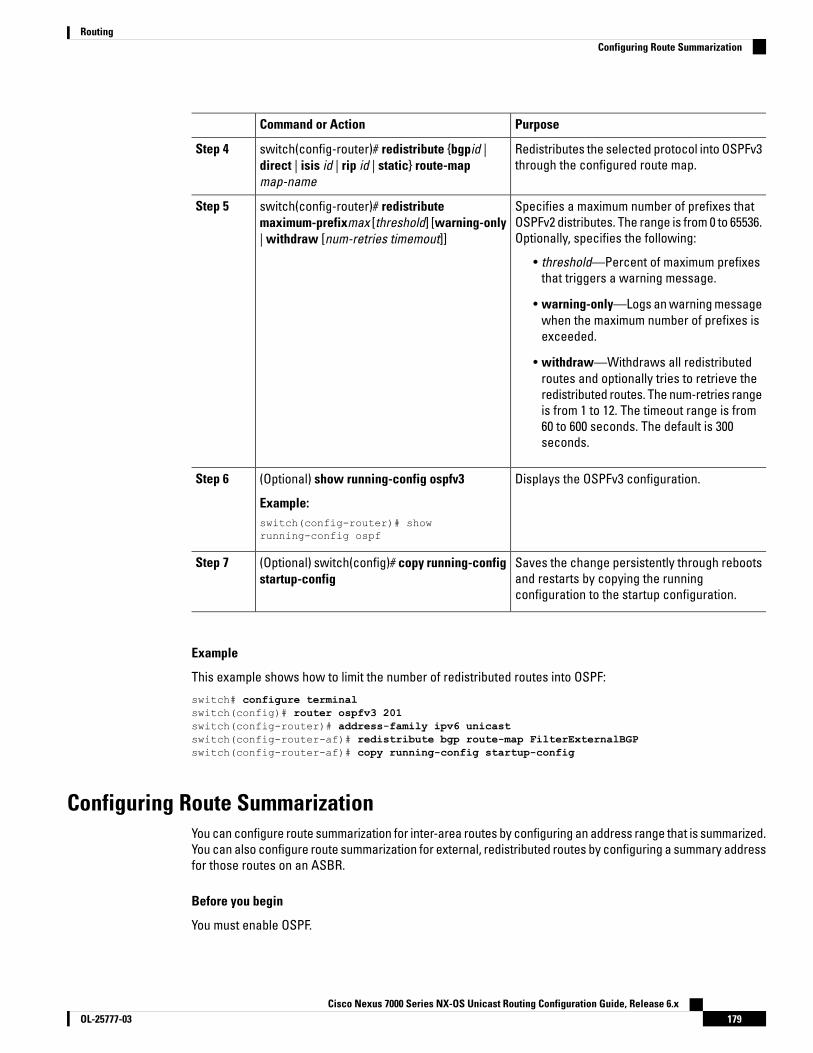
PurposeCommand or Action
Redistributes the selected protocol into OSPFv3through the configured route map.
switch(config-router)# redistribute {bgpid |direct | isis id | rip id | static} route-mapmap-name
Step 4
Specifies a maximum number of prefixes thatOSPFv2 distributes. The range is from 0 to 65536.Optionally, specifies the following:
switch(config-router)# redistributemaximum-prefixmax [threshold] [warning-only| withdraw [num-retries timemout]]
Step 5
• threshold—Percent of maximum prefixesthat triggers a warning message.
• warning-only—Logs an warning messagewhen the maximum number of prefixes isexceeded.
• withdraw—Withdraws all redistributedroutes and optionally tries to retrieve theredistributed routes. The num-retries rangeis from 1 to 12. The timeout range is from60 to 600 seconds. The default is 300seconds.
Displays the OSPFv3 configuration.(Optional) show running-config ospfv3
Example:
Step 6
switch(config-router)# showrunning-config ospf
Saves the change persistently through rebootsand restarts by copying the runningconfiguration to the startup configuration.
(Optional) switch(config)# copy running-configstartup-config
Step 7
Example
This example shows how to limit the number of redistributed routes into OSPF:
switch# configure terminalswitch(config)# router ospfv3 201switch(config-router)# address-family ipv6 unicastswitch(config-router-af)# redistribute bgp route-map FilterExternalBGPswitch(config-router-af)# copy running-config startup-config
Configuring Route SummarizationYou can configure route summarization for inter-area routes by configuring an address range that is summarized.You can also configure route summarization for external, redistributed routes by configuring a summary addressfor those routes on an ASBR.
Before you begin
You must enable OSPF.
Cisco Nexus 7000 Series NX-OS Unicast Routing Configuration Guide, Release 6.x179OL-25777-03
RoutingConfiguring Route Summarization
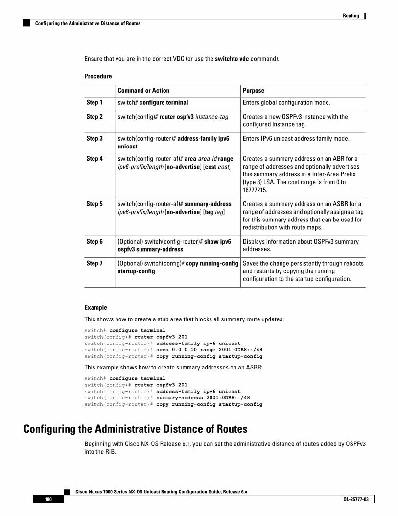
Ensure that you are in the correct VDC (or use the switchto vdc command).
Procedure
PurposeCommand or Action
Enters global configuration mode.switch# configure terminalStep 1
Creates a new OSPFv3 instance with theconfigured instance tag.
switch(config)# router ospfv3 instance-tagStep 2
Enters IPv6 unicast address family mode.switch(config-router)# address-family ipv6unicast
Step 3
Creates a summary address on an ABR for arange of addresses and optionally advertises
switch(config-router-af)# area area-id rangeipv6-prefix/length [no-advertise] [cost cost]
Step 4
this summary address in a Inter-Area Prefix(type 3) LSA. The cost range is from 0 to16777215.
Creates a summary address on an ASBR for arange of addresses and optionally assigns a tag
switch(config-router-af)# summary-addressipv6-prefix/length [no-advertise] [tag tag]
Step 5
for this summary address that can be used forredistribution with route maps.
Displays information about OSPFv3 summaryaddresses.
(Optional) switch(config-router)# show ipv6ospfv3 summary-address
Step 6
Saves the change persistently through rebootsand restarts by copying the runningconfiguration to the startup configuration.
(Optional) switch(config)# copy running-configstartup-config
Step 7
Example
This shows how to create a stub area that blocks all summary route updates:
switch# configure terminalswitch(config)# router ospfv3 201switch(config-router)# address-family ipv6 unicastswitch(config-router)# area 0.0.0.10 range 2001:0DB8::/48switch(config-router)# copy running-config startup-config
This example shows how to create summary addresses on an ASBR:
switch# configure terminalswitch(config)# router ospfv3 201switch(config-router)# address-family ipv6 unicastswitch(config-router)# summary-address 2001:0DB8::/48switch(config-router)# copy running-config startup-config
Configuring the Administrative Distance of RoutesBeginning with Cisco NX-OS Release 6.1, you can set the administrative distance of routes added by OSPFv3into the RIB.
Cisco Nexus 7000 Series NX-OS Unicast Routing Configuration Guide, Release 6.xOL-25777-03180
RoutingConfiguring the Administrative Distance of Routes

The administrative distance is a rating of the trustworthiness of a routing information source. A higher valueindicates a lower trust rating. Typically, a route can be learned through more than one routing protocol. Theadministrative distance is used to discriminate between routes learned from more than one routing protocol.The route with the lowest administrative distance is installed in the IP routing table.
Before you begin
Ensure that you have enabled OSPFv3.
Ensure that you are in the correct VDC (or use the switchto vdc command).
See the guidelines and limitations for this feature.
Procedure
PurposeCommand or Action
Enters global configuration mode.switch# configure terminalStep 1
Creates a new OSPFv3 instance with theconfigured instance tag.
switch(config)# router ospf instance-tagStep 2
Enters IPv6 unicast address family mode.switch(config-router)# address-family ipv6unicast
Step 3
Configures the policy for filtering or modifyingOSPFv2 routes before sending them to the RIB.
switch(config-router-af)# [no] table-mapmap-name [filter]
Step 4
You can enter up to 63 alphanumericcharacters for the map name.
The filter keyword specifies that only routesthat are permitted by the route map(map-name)configuration are downloaded to the routinginformation base (RIB).
Exits router address-family configuration mode.switch(config-router-af)# exitStep 5
Exits router configuration mode.switch(config-router)# exitStep 6
Creates a route map or enters route-mapconfiguration mode for an existing route map.Use seq to order the entries in a route map.
switch(config)# route-map map-name [permit| deny] [seq]
Step 7
The permit option enables you toset the distance. If you use the denyoption, the default distance isapplied.
Note
Matches against one of the following routetypes:
switch(config-route-map)# match route-typeroute-type
Step 8
• external—The external route (BGP,EIGRP, and OSPF type 1 or 2)
• inter-area—OSPF inter-area route
Cisco Nexus 7000 Series NX-OS Unicast Routing Configuration Guide, Release 6.x181OL-25777-03
RoutingConfiguring the Administrative Distance of Routes
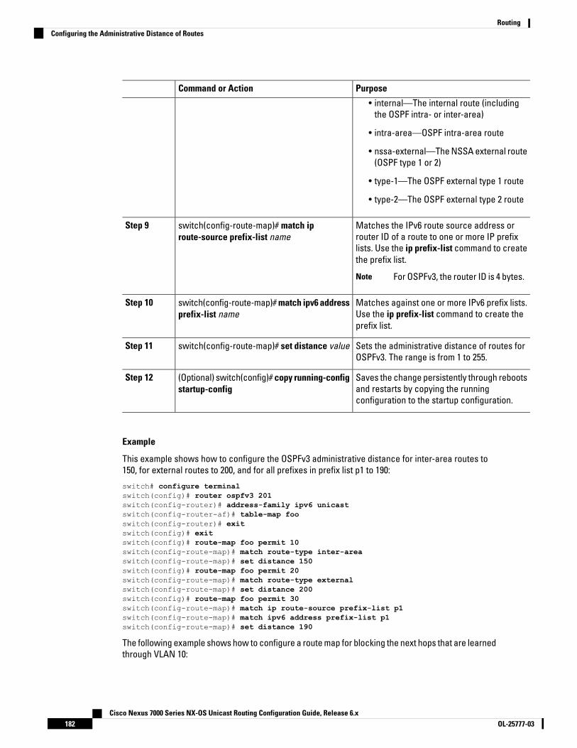
PurposeCommand or Action
• internal—The internal route (includingthe OSPF intra- or inter-area)
• intra-area—OSPF intra-area route
• nssa-external—The NSSA external route(OSPF type 1 or 2)
• type-1—The OSPF external type 1 route
• type-2—The OSPF external type 2 route
Matches the IPv6 route source address orrouter ID of a route to one or more IP prefix
switch(config-route-map)# match iproute-source prefix-list name
Step 9
lists. Use the ip prefix-list command to createthe prefix list.
For OSPFv3, the router ID is 4 bytes.Note
Matches against one or more IPv6 prefix lists.Use the ip prefix-list command to create theprefix list.
switch(config-route-map)# match ipv6 addressprefix-list name
Step 10
Sets the administrative distance of routes forOSPFv3. The range is from 1 to 255.
switch(config-route-map)# set distance valueStep 11
Saves the change persistently through rebootsand restarts by copying the runningconfiguration to the startup configuration.
(Optional) switch(config)# copy running-configstartup-config
Step 12
Example
This example shows how to configure the OSPFv3 administrative distance for inter-area routes to150, for external routes to 200, and for all prefixes in prefix list p1 to 190:
switch# configure terminalswitch(config)# router ospfv3 201switch(config-router)# address-family ipv6 unicastswitch(config-router-af)# table-map fooswitch(config-router)# exitswitch(config)# exitswitch(config)# route-map foo permit 10switch(config-route-map)# match route-type inter-areaswitch(config-route-map)# set distance 150switch(config)# route-map foo permit 20switch(config-route-map)# match route-type externalswitch(config-route-map)# set distance 200switch(config)# route-map foo permit 30switch(config-route-map)# match ip route-source prefix-list p1switch(config-route-map)# match ipv6 address prefix-list p1switch(config-route-map)# set distance 190
The following example shows how to configure a route map for blocking the next hops that are learnedthrough VLAN 10:
Cisco Nexus 7000 Series NX-OS Unicast Routing Configuration Guide, Release 6.xOL-25777-03182
RoutingConfiguring the Administrative Distance of Routes

switch(config)# route-map Filter-OSPF 10 denyswitch(config-route-map)# match interface VLAN 10switch(config-route-map)# exitswitch(config)# route-map Filter-OSPF 20 permit
The following example shows how to configure the table-map command with the filter keyword touse a route map (Filter-OSPF) to remove the next-hop path that is learned through VLAN 10 but notthe next-hop path that is learned through VLAN 20:
switch(config)# route ospfv3 p1switch(config-router)# table-map Filter-OSPF filter
Modifying the Default TimersOSPFv3 includes a number of timers that control the behavior of protocol messages and shortest path first(SPF) calculations. OSPFv3 includes the following optional timer parameters:
• LSA arrival time—Sets the minimum interval allowed between LSAs arriving from a neighbor. LSAs thatarrive faster than this time are dropped.
• Pacing LSAs—Sets the interval at which LSAs are collected into a group and refreshed, checksummed,or aged. This timer controls how frequently LSA updates occur and optimizes how many are sent in anLSA update message.
• Throttle LSAs—Sets rate limits for generating LSAs. This timer controls how frequently LSAs are generatedafter a topology change occurs.
• Throttle SPF calculation—Controls how frequently the SPF calculation is run.
At the interface level, you can also control the following timers:
• Retransmit interval—Sets the estimated time between successive LSAs
• Transmit delay—Sets the estimated time to transmit an LSA to a neighbor.
Before you begin
Ensure that you are in the correct VDC (or use the switchto vdc command).
Procedure
PurposeCommand or Action
Enters global configuration mode.switch# configure terminalStep 1
Creates a new OSPFv3 instance with theconfigured instance tag.
switch(config)# router ospfv3 instance-tagStep 2
Sets the LSA arrival time in milliseconds. Therange is from 10 to 600000. The default is 1000milliseconds.
switch(config-router)# timers lsa-arrival msecStep 3
Sets the interval in seconds for grouping LSAs.The range is from 1 to 1800. The default is 10seconds.
switch(config-router)# timers lsa-group-pacingseconds
Step 4
Cisco Nexus 7000 Series NX-OS Unicast Routing Configuration Guide, Release 6.x183OL-25777-03
RoutingModifying the Default Timers
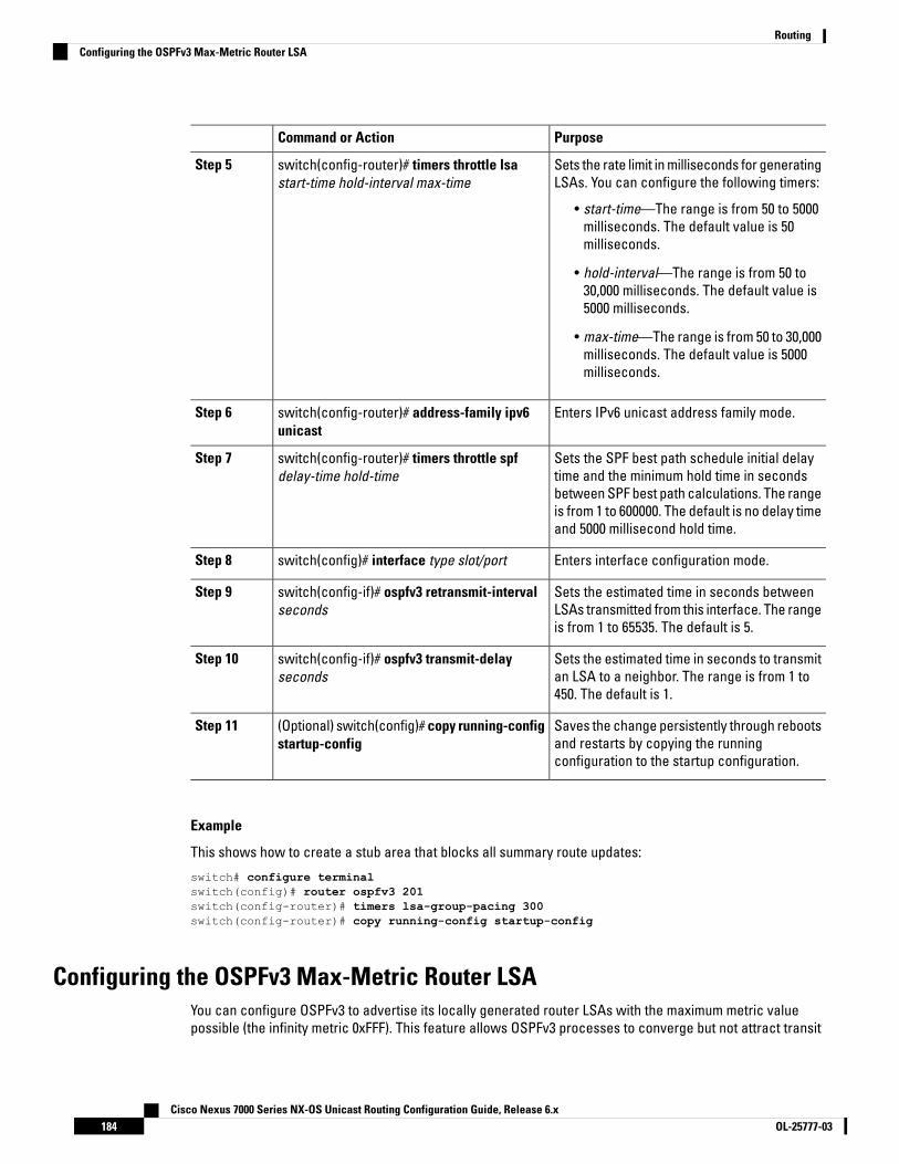
PurposeCommand or Action
Sets the rate limit in milliseconds for generatingLSAs. You can configure the following timers:
switch(config-router)# timers throttle lsastart-time hold-interval max-time
Step 5
• start-time—The range is from 50 to 5000milliseconds. The default value is 50milliseconds.
• hold-interval—The range is from 50 to30,000 milliseconds. The default value is5000 milliseconds.
• max-time—The range is from 50 to 30,000milliseconds. The default value is 5000milliseconds.
Enters IPv6 unicast address family mode.switch(config-router)# address-family ipv6unicast
Step 6
Sets the SPF best path schedule initial delaytime and the minimum hold time in seconds
switch(config-router)# timers throttle spfdelay-time hold-time
Step 7
between SPF best path calculations. The rangeis from 1 to 600000. The default is no delay timeand 5000 millisecond hold time.
Enters interface configuration mode.switch(config)# interface type slot/portStep 8
Sets the estimated time in seconds betweenLSAs transmitted from this interface. The rangeis from 1 to 65535. The default is 5.
switch(config-if)# ospfv3 retransmit-intervalseconds
Step 9
Sets the estimated time in seconds to transmitan LSA to a neighbor. The range is from 1 to450. The default is 1.
switch(config-if)# ospfv3 transmit-delayseconds
Step 10
Saves the change persistently through rebootsand restarts by copying the runningconfiguration to the startup configuration.
(Optional) switch(config)# copy running-configstartup-config
Step 11
Example
This shows how to create a stub area that blocks all summary route updates:
switch# configure terminalswitch(config)# router ospfv3 201switch(config-router)# timers lsa-group-pacing 300switch(config-router)# copy running-config startup-config
Configuring the OSPFv3 Max-Metric Router LSAYou can configure OSPFv3 to advertise its locally generated router LSAs with the maximum metric valuepossible (the infinity metric 0xFFF). This feature allows OSPFv3 processes to converge but not attract transit
Cisco Nexus 7000 Series NX-OS Unicast Routing Configuration Guide, Release 6.xOL-25777-03184
RoutingConfiguring the OSPFv3 Max-Metric Router LSA

traffic through the device if there are better alternate paths. After a specified timeout or a notification fromBGP, OSPFv3 advertises the LSAs with normal metrics.
Before you begin
Ensure that you are in the correct VDC (or use the switchto vdc command).
Procedure
PurposeCommand or Action
Enters global configuration mode.switch# configure terminalStep 1
Creates a new OSPFv3 instance with theconfigured instance tag.
switch(config)# router ospfv3 instance-tagStep 2
Configures a device that is running the OSPFv3protocol to advertise a maximum metric so that
switch(config-router)# max-metric router-lsa[external-lsa [max-metric-value]]
Step 3
other devices do not prefer the device as anintermediate hop in their SPF calculations.
[stub-prefix-lsa] [on-startup [seconds]] [wait-forbgp tag] [inter-area-prefix-lsa[max-metric-value]]
Saves the change persistently through rebootsand restarts by copying the runningconfiguration to the startup configuration.
(Optional) switch(config)# copy running-configstartup-config
Step 4
Example
This example shows how to configure a router to advertise a maximum metric for the stub links:
switch(config)# router ospfv3 200switch(config-router)# max-metric router-lsa stub-prefix-lsa
Configuring Graceful RestartGraceful restart is enabled by default. You can configure the following optional parameters for graceful restartin an OSPFv3 instance:
• Grace period—Configures how long neighbors should wait after a graceful restart has started beforetearing down adjacencies.
• Helper mode disabled—Disables helper mode on the local OSPFv3 instance. OSPFv3 does not participatein the graceful restart of a neighbor.
• Planned graceful restart only—Configures OSPFv3 to support graceful restart only in the event of aplanned restart.
Before you begin
You must enable OSPF.
Ensure that all neighbors are configured for graceful restart with matching optional parameters set.
Cisco Nexus 7000 Series NX-OS Unicast Routing Configuration Guide, Release 6.x185OL-25777-03
RoutingConfiguring Graceful Restart
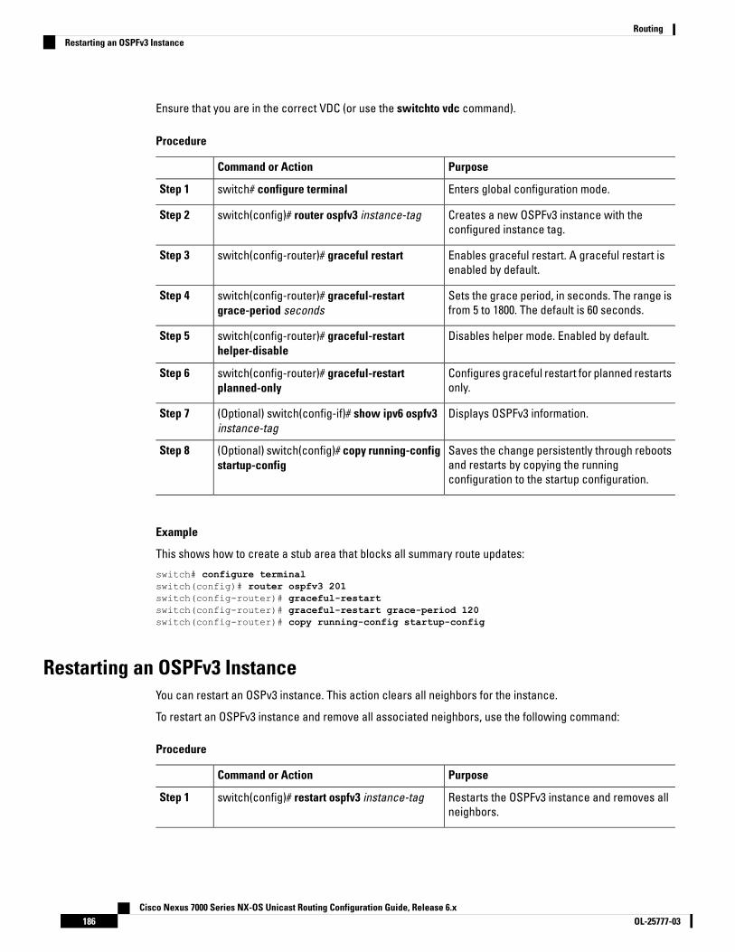
Ensure that you are in the correct VDC (or use the switchto vdc command).
Procedure
PurposeCommand or Action
Enters global configuration mode.switch# configure terminalStep 1
Creates a new OSPFv3 instance with theconfigured instance tag.
switch(config)# router ospfv3 instance-tagStep 2
Enables graceful restart. A graceful restart isenabled by default.
switch(config-router)# graceful restartStep 3
Sets the grace period, in seconds. The range isfrom 5 to 1800. The default is 60 seconds.
switch(config-router)# graceful-restartgrace-period seconds
Step 4
Disables helper mode. Enabled by default.switch(config-router)# graceful-restarthelper-disable
Step 5
Configures graceful restart for planned restartsonly.
switch(config-router)# graceful-restartplanned-only
Step 6
Displays OSPFv3 information.(Optional) switch(config-if)# show ipv6 ospfv3instance-tag
Step 7
Saves the change persistently through rebootsand restarts by copying the runningconfiguration to the startup configuration.
(Optional) switch(config)# copy running-configstartup-config
Step 8
Example
This shows how to create a stub area that blocks all summary route updates:
switch# configure terminalswitch(config)# router ospfv3 201switch(config-router)# graceful-restartswitch(config-router)# graceful-restart grace-period 120switch(config-router)# copy running-config startup-config
Restarting an OSPFv3 InstanceYou can restart an OSPv3 instance. This action clears all neighbors for the instance.
To restart an OSPFv3 instance and remove all associated neighbors, use the following command:
Procedure
PurposeCommand or Action
Restarts the OSPFv3 instance and removes allneighbors.
switch(config)# restart ospfv3 instance-tagStep 1
Cisco Nexus 7000 Series NX-OS Unicast Routing Configuration Guide, Release 6.xOL-25777-03186
RoutingRestarting an OSPFv3 Instance
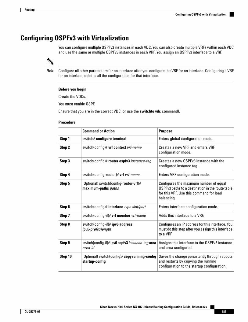
Configuring OSPFv3 with VirtualizationYou can configure multiple OSPFv3 instances in each VDC. You can also create multiple VRFs within each VDCand use the same or multiple OSPFv3 instances in each VRF. You assign an OSPFv3 interface to a VRF.
Configure all other parameters for an interface after you configure the VRF for an interface. Configuring a VRFfor an interface deletes all the configuration for that interface.
Note
Before you begin
Create the VDCs.
You must enable OSPF.
Ensure that you are in the correct VDC (or use the switchto vdc command).
Procedure
PurposeCommand or Action
Enters global configuration mode.switch# configure terminalStep 1
Creates a new VRF and enters VRFconfiguration mode.
switch(config)# vrf context vrf-nameStep 2
Creates a new OSPFv3 instance with theconfigured instance tag.
switch(config)# router ospfv3 instance-tagStep 3
Enters VRF configuration mode.switch(config-router)# vrf vrf-nameStep 4
Configures the maximum number of equalOSPFv3 paths to a destination in the route table
(Optional) switch(config-router-vrf)#maximum-paths paths
Step 5
for this VRF. Use this command for loadbalancing.
Enters interface configuration mode.switch(config)# interface type slot/portStep 6
Adds this interface to a VRF.switch(config-if)# vrf member vrf-nameStep 7
Configures an IP address for this interface. Youmust do this step after you assign this interfaceto a VRF.
switch(config-if)# ipv6 addressipv6-prefix/length
Step 8
Assigns this interface to the OSPFv3 instanceand area configured.
switch(config-if)# ipv6 ospfv3 instance-tag areaarea-id
Step 9
Saves the change persistently through rebootsand restarts by copying the runningconfiguration to the startup configuration.
(Optional) switch(config)# copy running-configstartup-config
Step 10
Cisco Nexus 7000 Series NX-OS Unicast Routing Configuration Guide, Release 6.x187OL-25777-03
RoutingConfiguring OSPFv3 with Virtualization

Example
This example shows how to create a VRF and add an interface to the VRF:
switch# configure terminalswitch(config)# vrf context NewVRFswitch(config-vrf)# exitswitch(config)# router ospfv3 201switch(config-router)# exitswitch(config)# interface ethernet 1/2switch(config-if)# vrf member NewVRFswitch(config-if)# ipv6 address 2001:0DB8::1/48switch(config-if)# ipv6 ospfv3 201 area 0switch(config-if)# copy running-config startup-config
Configuring OSPFv3 Authentication at Router LevelYou can enable authentication of OSPFv3 packets on a per-interface basis at the Router level using the followingcommands.
Before you begin
Ensure you have enabled OSPF.
Ensure that you are in the correct VDC(or use the switchto vdc command)
Enable the authentication package.
Procedure
Step 1 Enter the global configuration mode:
switch# configure terminal
Step 2 Enable the authentication package:
switch(config)# feature imp
Step 3 Create a new OSPFv3 instance with the configured instance tag:
switch(config)# router ospfv3 instance-tag
Step 4 Enable IPSec AH Authentication:
switch(config-router)# authentication ipsec spi spi auth [ 0 | 3 | 7] key
You can specify the security policy index through spi and define the authentication algorithm through authwhich can be md5 or sha1. Numbers 0, 3 and 7 specify the format of key.
Step 5 (Optional) Display OSPFv3 information:
switch(config)# show running-config ospfv3
Cisco Nexus 7000 Series NX-OS Unicast Routing Configuration Guide, Release 6.xOL-25777-03188
RoutingConfiguring OSPFv3 Authentication at Router Level

Configuring OSPFv3 Authentication at Area LevelAuthentication of OSPFv3 packets is enabled on a per-interface basis at the Area level using the followingcommands.
Before you begin
Ensure you have enabled OSPF.
Ensure that you are in the correct VDC(or use the switchto vdc command)
Enable the authentication package.
Procedure
Step 1 Enter the global configuration mode:
switch# configure terminal
Step 2 Enable the authentication package:
switch(config)# feature imp
Step 3 Create a new OSPFv3 instance with the configured instance tag:
switch(config)#router ospfv3 instance-tag
Step 4 Enable IPSec AH Authentication:
switch(config-router)#area area-num authentication ipsec spi spi auth [ 0 | 3 | 7] key
You can specify the security policy index through spi and define the authentication algorithm through authwhich can be md5 or sha1. Numbers 0, 3 and 7 specify the format of key.
Step 5 (Optional) Display OSPFv3 information:
switch(config)# show running-config ospfv3
Configuring OSPFv3 Authentication at Interface LevelYou can configure the authentication of OSPFv3 packets per interface using the following commands.
Before you begin
Ensure you have enabled OSPF.
Ensure that you are in the correct VDC(or use the switchto vdc command)
Enable the authentication package.
Cisco Nexus 7000 Series NX-OS Unicast Routing Configuration Guide, Release 6.x189OL-25777-03
RoutingConfiguring OSPFv3 Authentication at Area Level
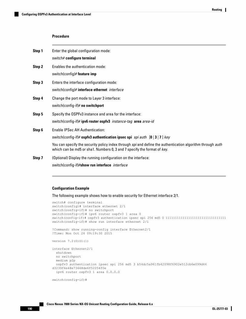
Procedure
Step 1 Enter the global configuration mode:
switch# configure terminal
Step 2 Enables the authentication mode:
switch(config)# feature imp
Step 3 Enters the interface configuration mode:
switch(config)# interface ethernet interface
Step 4 Change the port mode to Layer 3 interface:
switch(config-if)# no switchport
Step 5 Specify the OSPFv3 instance and area for the interface:
switch(config-if)# ipv6 router ospfv3 instance-tag area area-id
Step 6 Enable IPSec AH Authentication:
switch(config-if)# ospfv3 authentication ipsec spi spi auth [0 | 3 | 7 ] key
You can specify the security policy index through spi and define the authentication algorithm through authwhich can be md5 or sha1. Numbers 0, 3 and 7 specify the format of key.
Step 7 (Optional) Display the running configuration on the interface:
switch(config-if)#show run interface interface
Configuration Example
The following example shows how to enable security for Ethernet interface 2/1.
switch# configure terminalswitch(config)# interface ethernet 2/1switch(config-if)# no switchportswitch(config-if)# ipv6 router ospfv3 1 area 0switch(config-if)# ospfv3 authentication ipsec spi 256 md5 0 11111111111111111111111111111111switch(config-if)# show run interface ethernet 2/1
!Command: show running-config interface Ethernet2/1!Time: Mon Oct 26 09:19:30 2015
version 7.2(0)D1(1)
interface Ethernet2/1shutdownno switchportmedium p2pospfv3 authentication ipsec spi 256 md5 3 b54dc5a961fb42098f6902e512cb6e099d44
d3239f4e48e73668de6f52254f0eipv6 router ospfv3 1 area 0.0.0.0
switch(config-if)#
Cisco Nexus 7000 Series NX-OS Unicast Routing Configuration Guide, Release 6.xOL-25777-03190
RoutingConfiguring OSPFv3 Authentication at Interface Level
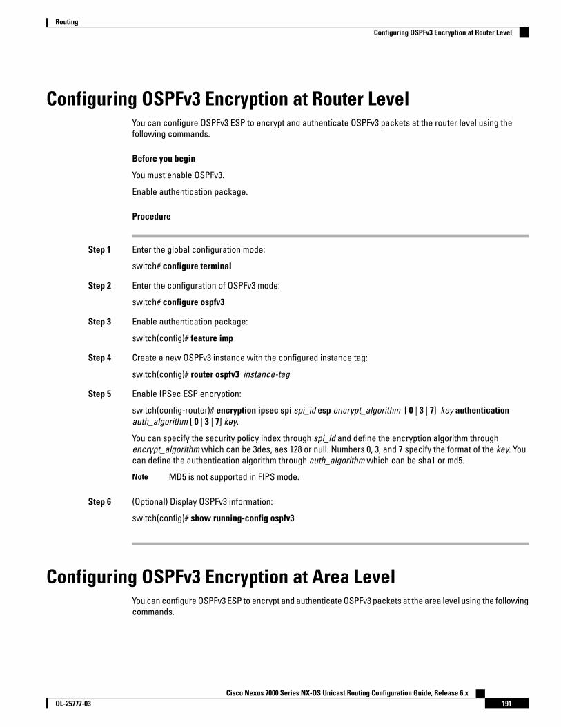
Configuring OSPFv3 Encryption at Router LevelYou can configure OSPFv3 ESP to encrypt and authenticate OSPFv3 packets at the router level using thefollowing commands.
Before you begin
You must enable OSPFv3.
Enable authentication package.
Procedure
Step 1 Enter the global configuration mode:
switch# configure terminal
Step 2 Enter the configuration of OSPFv3 mode:
switch# configure ospfv3
Step 3 Enable authentication package:
switch(config)# feature imp
Step 4 Create a new OSPFv3 instance with the configured instance tag:
switch(config)# router ospfv3 instance-tag
Step 5 Enable IPSec ESP encryption:
switch(config-router)# encryption ipsec spi spi_id esp encrypt_algorithm [ 0 | 3 | 7] key authenticationauth_algorithm [ 0 | 3 | 7] key.
You can specify the security policy index through spi_id and define the encryption algorithm throughencrypt_algorithm which can be 3des, aes 128 or null. Numbers 0, 3, and 7 specify the format of the key. Youcan define the authentication algorithm through auth_algorithm which can be sha1 or md5.
MD5 is not supported in FIPS mode.Note
Step 6 (Optional) Display OSPFv3 information:
switch(config)# show running-config ospfv3
Configuring OSPFv3 Encryption at Area LevelYou can configure OSPFv3 ESP to encrypt and authenticate OSPFv3 packets at the area level using the followingcommands.
Cisco Nexus 7000 Series NX-OS Unicast Routing Configuration Guide, Release 6.x191OL-25777-03
RoutingConfiguring OSPFv3 Encryption at Router Level

Before you begin
You must enable OSPFv3.
Enable authentication package.
Procedure
Step 1 Enter the global configuration mode:
switch# configure terminal
Step 2 Enter the configuration of OSPFv3 mode:
switch# configure ospfv3
Step 3 Enable the authentication package:
switch(config)# feature imp
Step 4 Create a new OSPFv3 instance with the configured instance tag:
switch(config)# router ospfv3 instance-tag
Step 5 Enable IPSec ESP Encryption:
switch(config-router)#area area-num encryption ipsec spi spi_val esp encrypt_algorithm [ 0 | 3 | 7] keyauthentication auth_algorithm [ 0 | 3 | 7] key
You can specify the security policy index through spi_id and define the encryption algorithm throughencrypt_algorithm which can be 3des, aes 128 or null. Numbers 0, 3, and 7 specify the format of the key. Youcan define the authentication algorithm through auth_algorithm which can be sha1 or md5.
MD5 is not supported in FIPS mode.Note
Step 6 (Optional) Display OSPFv3 information:
switch(config)# show running-config ospfv3
Configuring OSPFv3 Encryption at Interface LevelYou can configure OSPFv3 ESP to encrypt and authenticate OSPFv3 packets at the interface level using thefollowing commands.
Before you begin
You must enable OSPFv3.
Enable authentication package.
Cisco Nexus 7000 Series NX-OS Unicast Routing Configuration Guide, Release 6.xOL-25777-03192
RoutingConfiguring OSPFv3 Encryption at Interface Level
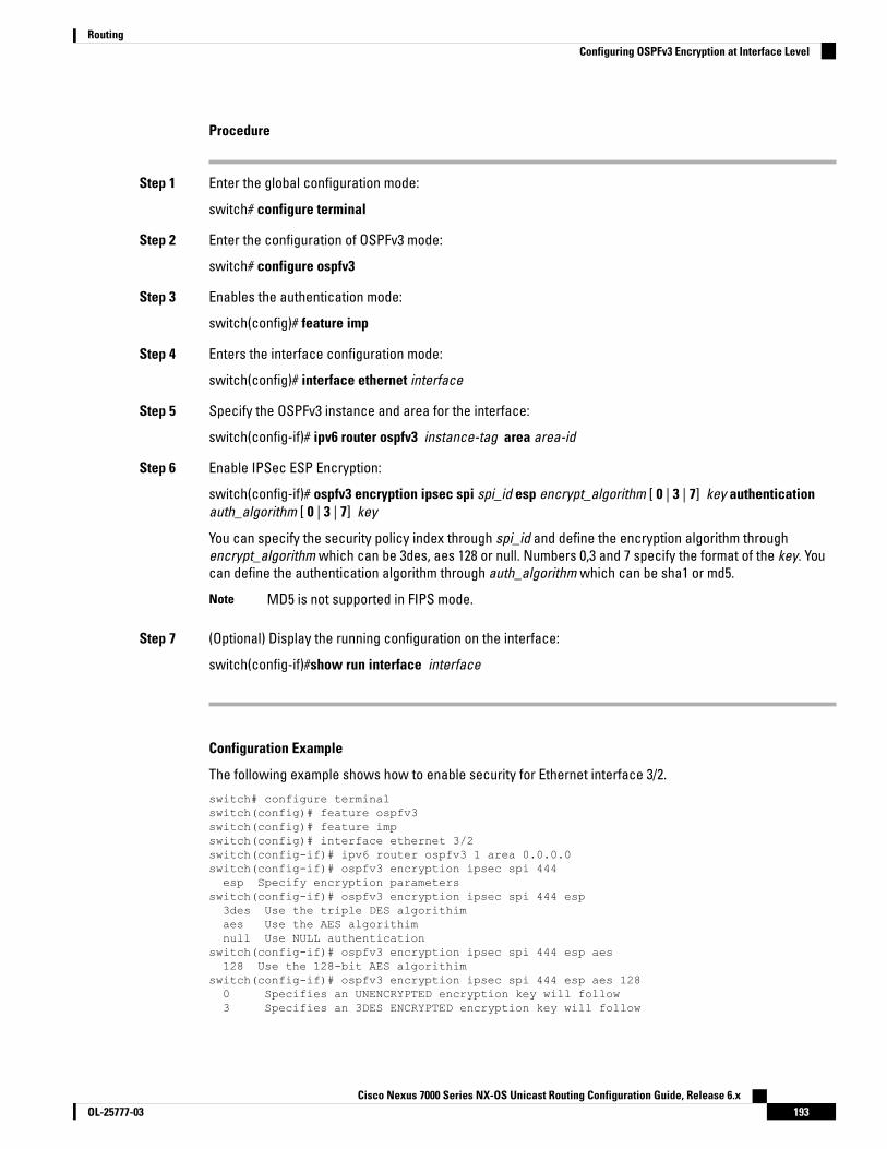
Procedure
Step 1 Enter the global configuration mode:
switch# configure terminal
Step 2 Enter the configuration of OSPFv3 mode:
switch# configure ospfv3
Step 3 Enables the authentication mode:
switch(config)# feature imp
Step 4 Enters the interface configuration mode:
switch(config)# interface ethernet interface
Step 5 Specify the OSPFv3 instance and area for the interface:
switch(config-if)# ipv6 router ospfv3 instance-tag area area-id
Step 6 Enable IPSec ESP Encryption:
switch(config-if)# ospfv3 encryption ipsec spi spi_id esp encrypt_algorithm [ 0 | 3 | 7] key authenticationauth_algorithm [ 0 | 3 | 7] key
You can specify the security policy index through spi_id and define the encryption algorithm throughencrypt_algorithm which can be 3des, aes 128 or null. Numbers 0,3 and 7 specify the format of the key. Youcan define the authentication algorithm through auth_algorithm which can be sha1 or md5.
MD5 is not supported in FIPS mode.Note
Step 7 (Optional) Display the running configuration on the interface:
switch(config-if)#show run interface interface
Configuration Example
The following example shows how to enable security for Ethernet interface 3/2.
switch# configure terminalswitch(config)# feature ospfv3switch(config)# feature impswitch(config)# interface ethernet 3/2switch(config-if)# ipv6 router ospfv3 1 area 0.0.0.0switch(config-if)# ospfv3 encryption ipsec spi 444esp Specify encryption parameters
switch(config-if)# ospfv3 encryption ipsec spi 444 esp3des Use the triple DES algorithimaes Use the AES algorithimnull Use NULL authentication
switch(config-if)# ospfv3 encryption ipsec spi 444 esp aes128 Use the 128-bit AES algorithim
switch(config-if)# ospfv3 encryption ipsec spi 444 esp aes 1280 Specifies an UNENCRYPTED encryption key will follow3 Specifies an 3DES ENCRYPTED encryption key will follow
Cisco Nexus 7000 Series NX-OS Unicast Routing Configuration Guide, Release 6.x193OL-25777-03
RoutingConfiguring OSPFv3 Encryption at Interface Level

7 Specifies a Cisco type 7 ENCRYPTED encryption key will followWORD The UNENCRYPTED (cleartext) encryption key
switch(config-if)# ospfv3 encryption ipsec spi 444 esp aes 12812345678123456781234567812345678 authentication nullswitch(config-if)# sh ospfv3 interfaceEthernet3/2 is up, line protocol is up
IPv6 address 1:1:1:1::2/64Process ID 1 VRF default, Instance ID 0, area 0.0.0.0Enabled by interface configurationState DOWN, Network type BROADCAST, cost 40ESP Encryption AES, Authentication NULL, SPI 444, ConnId 444
switch(config-if)#
Configuring OSPFv3 Encryption for Virtual LinksYou can configure OSPFv3 ESP to encrypt and authenticate OSPFv3 packets for virtual links using the followingcommands.
Before you begin
You must enable OSPFv3.
Enable authentication package.
Procedure
Step 1 Enter the global configuration mode:
switch# configure terminal
Step 2 Enter the configuration of OSPFv3 mode:
switch# configure ospfv3
Step 3 Enable the authentication package:
switch(config)# feature imp
Step 4 Create a new OSPFv3 instance with the configured instance tag:
switch(config)#router ospfv3 instance-tag
Step 5 Enable IPSec ESP Encryption:
switch(config-router)# encryption ipsec spi spi_id esp encrypt_algorithm [ 0 | 3 | 7] key authenticationauth_algorithm [ 0 | 3 | 7] key
You can specify the security policy index through spi_id and define the encryption algorithm throughencrypt_algorithm which can be 3des, aes 128 or null. Numbers 0,3 and 7 specify the format of the key. Youcan define the authentication algorithm through auth_algorithm which can be sha1 or md5.
MD5 is not supported in FIPS mode.Note
Step 6 (Optional) Display OSPFv3 information:
Cisco Nexus 7000 Series NX-OS Unicast Routing Configuration Guide, Release 6.xOL-25777-03194
RoutingConfiguring OSPFv3 Encryption for Virtual Links
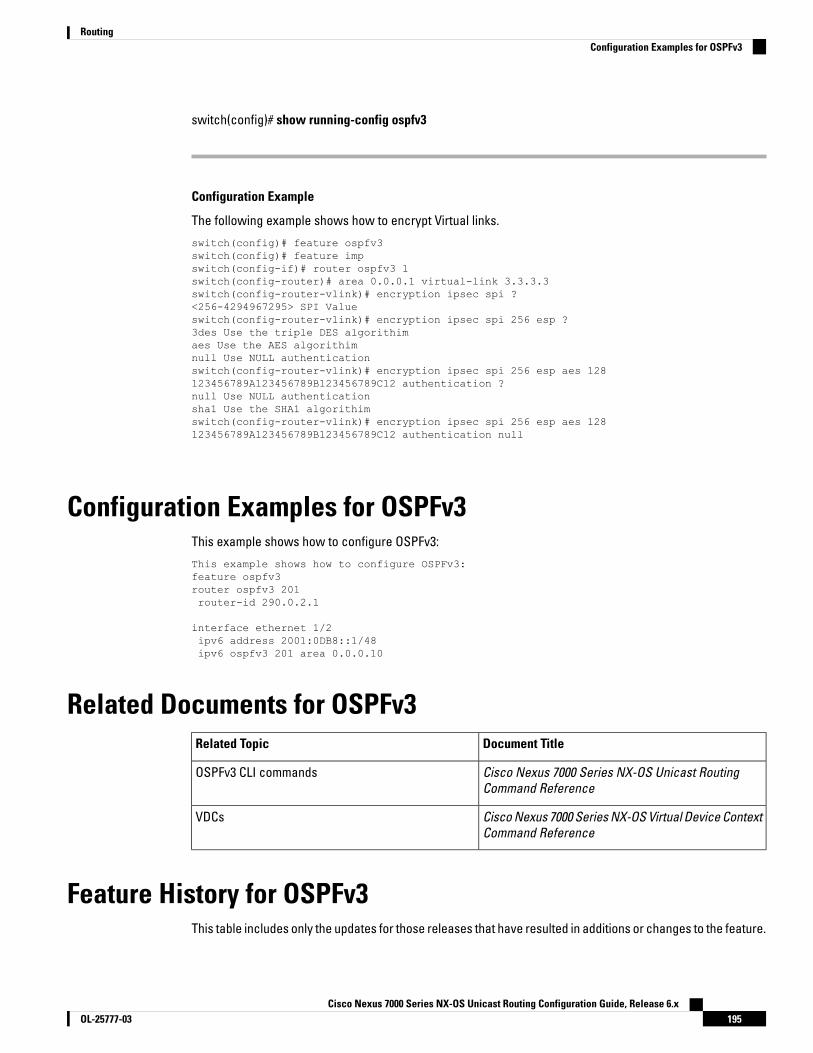
switch(config)# show running-config ospfv3
Configuration Example
The following example shows how to encrypt Virtual links.
switch(config)# feature ospfv3switch(config)# feature impswitch(config-if)# router ospfv3 1switch(config-router)# area 0.0.0.1 virtual-link 3.3.3.3switch(config-router-vlink)# encryption ipsec spi ?<256-4294967295> SPI Valueswitch(config-router-vlink)# encryption ipsec spi 256 esp ?3des Use the triple DES algorithimaes Use the AES algorithimnull Use NULL authenticationswitch(config-router-vlink)# encryption ipsec spi 256 esp aes 128123456789A123456789B123456789C12 authentication ?null Use NULL authenticationsha1 Use the SHA1 algorithimswitch(config-router-vlink)# encryption ipsec spi 256 esp aes 128123456789A123456789B123456789C12 authentication null
Configuration Examples for OSPFv3This example shows how to configure OSPFv3:
This example shows how to configure OSPFv3:feature ospfv3router ospfv3 201router-id 290.0.2.1
interface ethernet 1/2ipv6 address 2001:0DB8::1/48ipv6 ospfv3 201 area 0.0.0.10
Related Documents for OSPFv3Document TitleRelated Topic
Cisco Nexus 7000 Series NX-OS Unicast RoutingCommand Reference
OSPFv3 CLI commands
Cisco Nexus 7000 Series NX-OS Virtual Device ContextCommand Reference
VDCs
Feature History for OSPFv3This table includes only the updates for those releases that have resulted in additions or changes to the feature.
Cisco Nexus 7000 Series NX-OS Unicast Routing Configuration Guide, Release 6.x195OL-25777-03
RoutingConfiguration Examples for OSPFv3

Table 18: Feature History for OSPFv3
Feature InformationReleaseFeature Name
Added ESP encryption for OSPFv3 packets.8.4(4)OSPFv3 ESP Encryption
Added support for filtering next-hop paths foran OSPF route to prevent the path from beingadded to the RIB.
6.2(6a)OSPF—Distribute List to FilterPaths
Added the filter keyword to the table-mapcommand to specify that only routes permittedby the route map are downloaded to the RIB.
6.2(2)Administrative distance ofroutes
Added the ability to prevent discard routesfrom being created.
6.2(2)Route summarization
• Bidirectional Forwarding Detection (BFD)was enhanced to add a client for OSPFv3
• Added the ability to advertise locallygenerated router LSAs with the maximummetric value possible.
• Added the optional name-lookupparameter for
OSPFv3 instances.
6.2(2)OSPFv3
Added OSPFv3 SNMP/trap support.6.2(2)MIBs
Added support for configuring theadministrative distance of routes for OSPFv3.
6.1(1)OSPFv3
Added support for setting the passive interfacemode on all interfaces in the router or VRF.
5.2(1)Passive interface
This feature was introduced.4.0(1)OSPFv3
Cisco Nexus 7000 Series NX-OS Unicast Routing Configuration Guide, Release 6.xOL-25777-03196
RoutingFeature History for OSPFv3
C H A P T E R 9Configuring EIGRP
This chapter contains the following sections:
• Finding Feature Information, on page 197• Information About EIGRP, on page 197• Prerequisites for EIGRP, on page 204• Guidelines and Limitations for EIGRP, on page 205• Default Settings for EIGRP Parameters, on page 206• Configuring Basic EIGRP, on page 207• Configuring Advanced EIGRP, on page 211• Configuring Virtualization for EIGRP, on page 226• Verifying the EIGRP Configuration, on page 227• Displaying EIGRP Statistics, on page 228• Configuration Example for EIGRP, on page 228• Related Documents for EIGRP, on page 229• MIBs, on page 229• Feature History for EIGRP, on page 230
Finding Feature InformationYour software release might not support all the features documented in this module. For the latest caveatsand feature information, see the Bug Search Tool at https://tools.cisco.com/bugsearch/ and the release notesfor your software release. To find information about the features documented in this module, and to see a listof the releases in which each feature is supported, see the "New and Changed Information"chapter or theFeature History table in this chapter.
Information About EIGRPEIGRP combines the benefits of distance vector protocols with the features of link-state protocols. EIGRPsends out periodic Hello messages for neighbor discovery. Once EIGRP learns a new neighbor, it sends aone-time update of all the local EIGRP routes and route metrics. The receiving EIGRP router calculates theroute distance based on the received metrics and the locally assigned cost of the link to that neighbor. Afterthis initial full route table update, EIGRP sends incremental updates to only those neighbors affected by theroute change. This process speeds convergence and minimizes the bandwidth used by EIGRP.
Cisco Nexus 7000 Series NX-OS Unicast Routing Configuration Guide, Release 6.x197OL-25777-03

EIGRP ComponentsEIGRP has the following basic components:
• Reliable Transport Protocol
• Neighbor Discovery and Recovery
• Diffusing Update Algorithm
Reliable Transport ProtocolThe Reliable Transport Protocol guarantees ordered delivery of EIGRP packets to all neighbors. The ReliableTransport Protocol supports an intermixed transmission of multicast and unicast packets. The reliable transportcan send multicast packets quickly when unacknowledged packets are pending. This provision helps to ensurethat the convergence time remains low for various speed links.
The Reliable Transport Protocol includes the following message types:
• Hello—Used for neighbor discovery and recovery. By default, EIGRP sends a periodic multicast Hellomessage on the local network at the configured hello interval. By default, the hello interval is 5 seconds.
• Acknowledgement—Verify reliable reception of Updates, Queries, and Replies.
• Updates—Send to affected neighbors when routing information changes. Updates include the routedestination, address mask, and route metrics such as delay and bandwidth. The update information isstored in the EIGRP topology table.
• Queries and Replies—Sent as part of the Diffusing Update Algorithm used by EIGRP.
Neighbor Discovery and RecoveryEIGRP uses the Hello messages from the Reliable Transport Protocol to discover neighboring EIGRP routerson directly attached networks. EIGRP adds neighbors to the neighbor table. The information in the neighbortable includes the neighbor address, the interface it was learned on, and the hold time, which indicates howlong EIGRP should wait before declaring a neighbor unreachable. By default, the hold time is three times thehello interval or 15 seconds.
EIGRP sends a series of Update messages to new neighbors to share the local EIGRP routing information. Thisroute information is stored in the EIGRP topology table. After this initial transmission of the full EIGRP routeinformation, EIGRP sends Update messages only when a routing change occurs. These Update messagescontain only the new or changed information and are sent only to the neighbors affected by the change.
EIGRP also uses the Hello messages as a keepalive to its neighbors. As long as Hello messages are received,Cisco NX-OS can determine that a neighbor is alive and functioning.
Diffusing Update AlgorithmThe Diffusing Update Algorithm (DUAL) calculates the routing information based on the destination networksin the topology table. The topology table includes the following information:
• IPv4 or IPv6 address/mask—The network address and network mask for this destination.
• Successors—The IP address and local interface connection for all feasible successors or neighbors thatadvertise a shorter distance to the destination than the current feasible distance.
Cisco Nexus 7000 Series NX-OS Unicast Routing Configuration Guide, Release 6.xOL-25777-03198
RoutingEIGRP Components

• Feasibility distance (FD)—The lowest calculated distance to the destination. The feasibility distance isthe sum of the advertised distance from a neighbor plus the cost of the link to that neighbor.
DUAL uses the distance metric to select efficient, loop-free paths. DUAL selects routes to insert into the unicastRouting Information Base (RIB) based on feasible successors. When a topology change occurs, DUAL looksfor feasible successors in the topology table. If there are feasible successors, DUAL selects the feasiblesuccessor with the lowest feasible distance and inserts that into the unicast RIB, avoiding unnecessaryrecomputation.
When there are no feasible successors but there are neighbors advertising the destination, DUAL transitionsfrom the passive state to the active state and triggers a recomputation to determine a new successor ornext-hop router to the destination. The amount of time required to recompute the route affects the convergencetime. EIGRP sends Query messages to all neighbors, searching for feasible successors. Neighbors that havea feasible successor send a Reply message with that information. Neighbors that do not have feasiblesuccessors trigger a DUAL recomputation.
EIGRP Route UpdatesWhen a topology change occurs, EIGRP sends an Update message with only the changed routing informationto affected neighbors. This Update message includes the distance information to the new or updated networkdestination.
The distance information in EIGRP is represented as a composite of available route metrics, including bandwidth,delay, load utilization, and link reliability. Each metric has an associated weight that determines if the metricis included in the distance calculation. You can configure these metric weights. You can fine-tune linkcharacteristics to achieve optimal paths, but we recommend that you use the default settings for mostconfigurable metrics.
Internal Route MetricsInternal routes are routes that occur between neighbors within the same EIGRP autonomous system. Theseroutes have the following metrics:
• Next hop—The IP address of the next-hop router.
• Delay—The sum of the delays configured on the interfaces that make up the route to the destinationnetwork. The delay is configured in tens of microseconds.
• Bandwidth—The calculation from the lowest configured bandwidth on an interface that is part of theroute to the destination.
We recommend that you use the default bandwidth value. This bandwidthparameter is also used by EIGRP.
Note
• MTU—The smallest maximum transmission unit value along the route to the destination.
• Hop count—The number of hops or routers that the route passes through to the destination. This metricis not directly used in the DUAL computation.
• Reliability—An indication of the reliability of the links to the destination.
• Load—An indication of how much traffic is on the links to the destination.
Cisco Nexus 7000 Series NX-OS Unicast Routing Configuration Guide, Release 6.x199OL-25777-03
RoutingEIGRP Route Updates

By default, EIGRP uses the bandwidth and delay metrics to calculate the distance to the destination. You canmodify the metric weights to include the other metrics in the calculation.
Wide MetricsEIGRP supports wide (64-bit) metrics to improve route selection on higher-speed interfaces or bundled interfaces.Routers supporting wide metrics can interoperate with routers that do not support wide metrics as follows:
• A router that supports wide metrics—Adds local wide metrics values to the received values and sendsthe information on.
• A router that does not support wide metrics— Sends any received metrics on without changing thevalues.
EIGRP uses the following equation to calculate path cost with wide metrics:
metric = [k1 x bandwidth + (k2 x bandwidth)/(256 – load) + k3 x delay + k6 xextended attributes] x [k5/(reliability+ k4)]
Because the unicast RIB cannot support 64-bit metric values, EIGRP wide metrics use the following equationwith a RIB scaling factor to convert the 64-bit metric value to a 32-bit value:
RIB Metric = (Wide Metric / RIB scale value)
where the RIB scale value is a configurable parameter.
EIGRP wide metrics introduce the following two new metric values represented as k6 in the EIGRP metricsconfiguration:
• Jitter—(Measured in microseconds) accumulated across all links in the route path. Routes lower jittervalues are preferred for EIGRP path selection.
• Energy—(Measured in watts per kilobit) accumulated across all links in the route path. Routes lowerenergy values are preferred for EIGRP path selection.
EIGRP prefers a path with no jitter or energy metric values or lower jitter or metric values over a path withhigher values.
EIGRP wide metrics are sent with a TLV version of 2.Note
External Route MetricsExternal routes are routes that occur between neighbors in different EIGRP autonomous systems. These routeshave the following metrics:
• Next hop—The IP address of the next-hop router.
• Router ID—The router ID of the router that redistributed this route into EIGRP.
• AS number—The autonomous system number of the destination.
• Protocol ID—A code that represents the routing protocol that learned the destination route.
• Tag—An arbitrary tag that can be used for route maps.
• Metric—The route metric for this route from the external routing protocol.
Cisco Nexus 7000 Series NX-OS Unicast Routing Configuration Guide, Release 6.xOL-25777-03200
RoutingWide Metrics
EIGRP and the Unicast RIBEIGRP adds all learned routes to the EIGRP topology table and the unicast RIB. When a topology changeoccurs, EIGRP uses these routes to search for a feasible successor. EIGRP also listens for notifications fromthe unicast RIB for changes in any routes redistributed to EIGRP from another routing protocol.
Advanced EIGRPYou can use the advanced features of EIGRP to optimize your EIGRP configuration.
Address FamiliesEIGRP supports both IPv4 and IPv6 address families. For backward compatibility, you can configure EIGRPv4in route configuration mode or in IPv4 address family mode. You must configure EIGRP for IPv6 in addressfamily mode.
Address family configuration mode includes the following EIGRP features:
• Authentication
• AS number
• Default route
• Metrics
• Distance
• Graceful restart
• Logging
• Load balancing
• Redistribution
• Router ID
• Stub router
• Timers
You cannot configure the same feature in more than one configuration mode. For example, if you configurethe default metric in router configuration mode, you cannot configure the default metric in address familymode.
AuthenticationYou can configure authentication on EIGRP messages to prevent unauthorized or invalid routing updates inyour network. EIGRP authentication supports MD5 authentication digest.
You can configure the EIGRP authentication per virtual routing and forwarding (VRF) instance or interfaceusing key-chain management for the authentication keys. Key-chain management allows you to control changesto the authentication keys used by MD5 authentication digest. See the Cisco Nexus 7000 Series NX-OS SecurityConfiguration Guide, for more details about creating key chains.
Cisco Nexus 7000 Series NX-OS Unicast Routing Configuration Guide, Release 6.x201OL-25777-03
RoutingEIGRP and the Unicast RIB

For MD5 authentication, you configure a password that is shared at the local router and all remote EIGRPneighbors. When an EIGRP message is created, Cisco NX-OS creates an MD5 one-way message digest basedon the message itself and the encrypted password and sends this digest along with the EIGRP message. Thereceiving EIGRP neighbor validates the digest using the same encrypted password. If the message has notchanged, the calculation is identical and the EIGRP message is considered valid.
MD5 authentication also includes a sequence number with each EIGRP message that is used to ensure thatno message is replayed in the network.
Stub RoutersYou can use the EIGRP stub routing feature to improve network stability, reduce resource usage, and simplifystub router configuration. Stub routers connect to the EIGRP network through a remote router.
When using EIGRP stub routing, you need to configure the distribution and remote routers to use EIGRP andconfigure only the remote router as a stub. EIGRP stub routing does not automatically enable summarizationon the distribution router. In most cases, you need to configure summarization on the distribution routers.
Without EIGRP stub routing, even after the routes that are sent from the distribution router to the remote routerhave been filtered or summarized, a problem might occur. For example, if a route is lost somewhere in thecorporate network, EIGRP could send a query to the distribution router. The distribution router could then senda query to the remote router even if routes are summarized. If a problem communicating over the WAN linkbetween the distribution router and the remote router occurs, EIGRP could get stuck in an active conditionand cause instability elsewhere in the network. EIGRP stub routing allows you to prevent queries to the remoterouter.
Route SummarizationYou can configure a summary aggregate address for a specified interface. Route summarization simplifiesroute tables by replacing a number of more-specific addresses with an address that represents all the specificaddresses. For example, you can replace 10.1.1.0/24, 10.1.2.0/24, and 10.1.3.0/24 with one summary address,10.1.0.0/16.
If more specific routes are in the routing table, EIGRP advertises the summary address from the interface witha metric equal to the minimum metric of the more specific routes.
EIGRP does not support automatic route summarization.Note
Route RedistributionYou can use EIGRP to redistribute static routes, routes learned by other EIGRP autonomous systems, or routesfrom other protocols. You must configure a route map with the redistribution to control which routes are passedinto EIGRP. A route map allows you to filter routes based on attributes such as the destination, originationprotocol, route type, route tag, and so on.
You also configure the default metric that is used for all imported routes into EIGRP.
You use distribute lists to filter routes from routing updates. These filtered routes are applied to each interfacewith the ip distribute-list eigrp command.
Cisco Nexus 7000 Series NX-OS Unicast Routing Configuration Guide, Release 6.xOL-25777-03202
RoutingStub Routers

Load BalancingYou can use load balancing to allow a router to distribute traffic over all the router network ports that are thesame distance from the destination address. Load balancing increases the usage of network segments, whichincreases effective network bandwidth.
Cisco NX-OS supports the Equal Cost Multiple Paths (ECMP) feature with up to 16 equal-cost paths in theEIGRP route table and the unicast RIB. You can configure EIGRP to load balance traffic across some or all ofthose paths.
EIGRP in Cisco NX-OS does not support unequal cost load balancing.Note
Split HorizonYou can use split horizon to ensure that EIGRP never advertises a route out of the interface where it waslearned.
Split horizon is a method that controls the sending of EIGRP update and query packets. When you enable splithorizon on an interface, Cisco NX-OS does not send update and query packets for destinations that werelearned from this interface. Controlling update and query packets in this manner reduces the possibility ofrouting loops.
Split horizon with poison reverse configures EIGRP to advertise a learned route as unreachable back throughthat the interface that EIGRP learned the route from.
EIGRP uses split horizon or split horizon with poison reverse in the following scenarios:
• Exchanging topology tables for the first time between two routers in startup mode.
• Advertising a topology table change.
• Sending a Query message.
By default, the split horizon feature is enabled on all interfaces.
BFDThis feature supports bidirectional forwarding detection (BFD). BFD is a detection protocol designed to providefast forwarding-path failure detection times. BFD provides subsecond failure detection between two adjacentdevices and can be less CPU-intensive than protocol hello messages because some of the BFD load can bedistributed onto the data plane on supported modules. See the Cisco Nexus 7000 Series NX-OS InterfacesConfiguration Guide, for more information.
Virtualization Support for EIGRPCisco NX-OS supports multiple instances of EIGRP that runs on the same system. EIGRP supports VirtualRouting and Forwarding instances (VRFs). VRFs exist within virtual device contexts (VDCs). By default, CiscoNX-OS places you in the default VDC and default VRF unless you specifically configure another VDC and VRF.See the Cisco Nexus 7000 Series NX-OS Virtual Device Context Configuration Guide, for more information.
Graceful Restart and High AvailabilityCisco NX-OS supports nonstop forwarding and graceful restart for EIGRP.
Cisco Nexus 7000 Series NX-OS Unicast Routing Configuration Guide, Release 6.x203OL-25777-03
RoutingLoad Balancing
You can use nonstop forwarding for EIGRP to forward data packets along known routes in the FIB while theEIGRP routing protocol information is being restored following a failover. With nonstop forwarding (NSF), peernetworking devices do not experience routing flaps. During failover, data traffic is forwarded through intelligentmodules while the standby supervisor becomes active.
If a Cisco NX-OS system experiences a cold reboot, the device does not forward traffic to the system andremoves the system from the network topology. In this scenario, EIGRP experiences a stateless restart, andall neighbors are removed. Cisco NX-OS applies the startup configuration, and EIGRP rediscovers the neighborsand shares the full EIGRP routing information again.
A dual supervisor platform that runs Cisco NX-OS can experience a stateful supervisor switchover. Beforethe switchover occurs, EIGRP uses a graceful restart to announce that EIGRP will be unavailable for sometime. During a switchover, EIGRP uses nonstop forwarding to continue forwarding traffic based on theinformation in the FIB, and the system is not taken out of the network topology.
The graceful restart-capable router uses Hello messages to notify its neighbors that a graceful restart operationhas started. When a graceful restart-aware router receives a notification from a graceful restart-capableneighbor that a graceful restart operation is in progress, both routers immediately exchange their topologytables. The graceful restart-aware router performs the following actions to assist the restarting router asfollows:
• The router expires the EIGRP Hello hold timer to reduce the time interval set for Hello messages. Thisprocess allows the graceful restart-aware router to reply to the restarting router more quickly and reducesthe amount of time required for the restarting router to rediscover neighbors and rebuild the topologytable.
• The router starts the route-hold timer. This timer sets the period of time that the graceful restart-awarerouter will hold known routes for the restarting neighbor. The default time period is 240 seconds.
• The router notes in the peer list that the neighbor is restarting, maintains adjacency, and holds knownroutes for the restarting neighbor until the neighbor signals that it is ready for the graceful restart-awarerouter to send its topology table or the route-hold timer expires. If the route-hold timer expires on thegraceful restart-aware router, the graceful restart-aware router discards held routes and treats therestarting router as a new router that joins the network and reestablishes adjacency.
After the switchover, Cisco NX-OS applies the running configuration, and EIGRP informs the neighbors that itis operational again.
You must enable graceful restart to support in-service software upgrades (ISSU) for EIGRP. If you disablegraceful restart, Cisco NX-OS issues a warning that an ISSU cannot be supported with this configuration.
Note
Multiple EIGRP InstancesCisco NX-OS supports multiple instances of the EIGRP protocol that run on the same system. Every instanceuses the same system router ID. You can optionally configure a unique router ID for each instance. For thenumber of supported EIGRP instances, see the Cisco Nexus 7000 Series NX-OS Verified Scalabilty Guide.
Prerequisites for EIGRPYou must enable EIGRP.
Cisco Nexus 7000 Series NX-OS Unicast Routing Configuration Guide, Release 6.xOL-25777-03204
RoutingMultiple EIGRP Instances

If you configure VDCs, you must install the Advanced Services license and enter the desired VDC (see theCisco Nexus 7000 Series NX-OS Virtual Device Context Configuration Guide).
Guidelines and Limitations for EIGRP• A system configured with EIGRP 64bit metric version and having 32bit metric version neighbors precision
in delay conversion from 64bit metric to 32bit metric and from 32bit metric to 64bit metric is improved. Itimplies that the 32bit metric of prefixes in the 64bit EIGRP system and 64bit metric of prefixed in 32bitEIGRP system changes from previous releases. This is not applicable for the 32bit metric EIGRP systemor if all neighbors are the 64bit metric version.
• When you configure a table map, administrative distance of the routes and the metric, the configurationcommands make the EIGRP neighbours to flap. This is an expected behavior.
• If the filtered list is modified when redistributing routes into EIGRP and filtering prefixes with a route mapor prefix list, all prefixes permitted by the filter, even those not touched, are refreshed in the EIGRP topologytable. This refresh is signaled to all EIGRP routers in the query domain for this set of prefixes.
• A metric configuration (either through the default-metric configuration option or through a route map) isrequired for redistribution from any other protocol, connected routes, or static routes.
• For graceful restart, an NSF-aware router must be up and completely converged with the network beforeit can assist an NSF-capable router in a graceful restart operation.
• For graceful restart, neighboring devices participating in the graceful restart must be NSF-aware orNSF-capable.
• Cisco NX-OS EIGRP is compatible with EIGRP in the Cisco IOS software.
• Do not change the metric weights without a good reason. If you change the metric weights, you mustapply the change to all EIGRP routers in the same autonomous system.
• A mix of standard metrics and wide metrics in an EIGRP network with interface speeds of 1 Gigabit orgreater may result in suboptimal routing.
• Consider using stubs for larger networks.
• Avoid redistribution between different EIGRP autonomous systems because the EIGRP vector metric willnot be preserved.
• The no {ip | ipv6} next-hop-self command does not guarantee reachability of the next hop.
• The {ip | ipv6} passive-interface eigrp command suppresses neighbors from forming.
• Cisco NX-OS does not support IGRP or connecting IGRP and EIGRP clouds.
• Autosummarization is disabled by default and cannot be enabled.
• Cisco NX-OS supports only IP.
• EIGRPv6 adjacency cannot be formed over an interface that only has IPv6 link local address.
Global IPv6 address is required on the interface for EIGRPv6 neighbour adjacency to be formed over suchinterface.
• High availability is not supported with EIGRP aggressive timers.
Cisco Nexus 7000 Series NX-OS Unicast Routing Configuration Guide, Release 6.x205OL-25777-03
RoutingGuidelines and Limitations for EIGRP
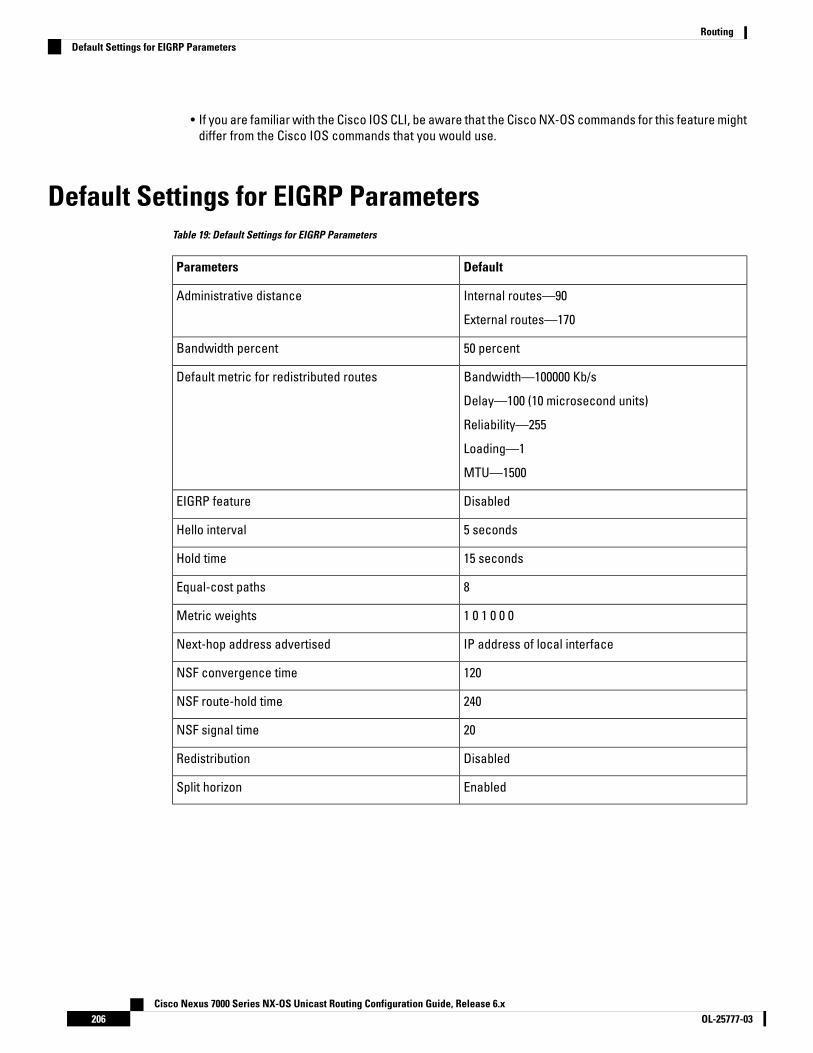
• If you are familiar with the Cisco IOS CLI, be aware that the Cisco NX-OS commands for this feature mightdiffer from the Cisco IOS commands that you would use.
Default Settings for EIGRP ParametersTable 19: Default Settings for EIGRP Parameters
DefaultParameters
Internal routes—90
External routes—170
Administrative distance
50 percentBandwidth percent
Bandwidth—100000 Kb/s
Delay—100 (10 microsecond units)
Reliability—255
Loading—1
MTU—1500
Default metric for redistributed routes
DisabledEIGRP feature
5 secondsHello interval
15 secondsHold time
8Equal-cost paths
1 0 1 0 0 0Metric weights
IP address of local interfaceNext-hop address advertised
120NSF convergence time
240NSF route-hold time
20NSF signal time
DisabledRedistribution
EnabledSplit horizon
Cisco Nexus 7000 Series NX-OS Unicast Routing Configuration Guide, Release 6.xOL-25777-03206
RoutingDefault Settings for EIGRP Parameters

Configuring Basic EIGRP
Enabling or Disabling the EIGRP FeatureYou must enable the EIGRP feature before you can configure EIGRP.
Before you begin
Ensure that you are in the correct VDC (or use the switchto vdc command).
Procedure
PurposeCommand or Action
Enters global configuration mode.switch# configure terminalStep 1
Enables the EIGRP feature. The no optiondisables the EIGRP feature and removes allassociated configuration.
switch(config)# [no] feature eigrpStep 2
Displays information about enabled features.(Optional) switch(config)# show featureStep 3
Saves the change persistently through rebootsand restarts by copying the runningconfiguration to the startup configuration.
(Optional) switch(config)# copy running-configstartup-config
Step 4
Example
The following example enables EIGRP:
switch# configure terminalswitch(config)# feature eigrpswitch(config)# copy running-config startup-config
Creating an EIGRP InstanceYou can create an EIGRP instance and associate an interface with that instance. You assign a uniqueautonomous system number for this EIGRP process. Routes are not advertised or accepted from otherautonomous systems unless you enable route redistribution.
Before you begin
• Ensure that you have enabled the EIGRP feature.
• EIGRP must be able to obtain a router ID (for example, a configured loopback address) or you mustconfigure the router ID option.
• If you configure an instance tag that does not qualify as an AS number, you must configure the AS numberexplicitly or this EIGRP instance remains in the shutdown state. For IPv6, this number must be configuredunder address family.
Cisco Nexus 7000 Series NX-OS Unicast Routing Configuration Guide, Release 6.x207OL-25777-03
RoutingConfiguring Basic EIGRP

• Confirm that you are in the correct VDC. To change the VDC, use the switchto vdc command.
Procedure
PurposeCommand or Action
Enters global configuration mode.switch# configure terminalStep 1
Creates a new EIGRP process with theconfigured instance tag. The instance tag can
switch(config)# [no] router eigrp instance-tagStep 2
be any case-sensitive, alphanumeric string upto 20 characters.
If you configure an instance tag that does notqualify as an AS number, you must use theautonomous-system command to configure theAS number explicitly or this EIGRP instance willremain in the shutdown state.
The no option deletes the EIGRP process andall associated configuration. You should alsoremove any EIGRP commands configured ininterface mode if you remove the EIGRPprocess.
Configures a unique AS number for this EIGRPinstance.
(Optional) switch(config-router)#autonomous-system as-number
Step 3
The range is from 1 to 65535.
Generates a system message whenever anadjacency changes state. This command isenabled by default.
(Optional) switch(config-router)#log-adjacency-changes
Step 4
Generates a system message whenever aneighbor warning occurs.
(Optional) switch(config-router)#log-neighbor-warnings [seconds]
Step 5
You can configure the time between warningmessages, from 1 to 65535, in seconds. Thedefault is 10 seconds. This command is enabledby default.
Enters interface configuration mode. Use ? todetermine the slot and port ranges.
switch(config-router)# interface interface-typeslot/port
Step 6
Associates this interface with the configuredEIGRP process. The instance tag can be any
switch(config-if)# {ip | ipv6} router eigrpinstance-tag
Step 7
case-sensitive, alphanumeric string up to 20characters.
Displays information about EIGRP interfaces.(Optional) switch(config-if)# show {ip | ipv6}eigrp interfaces
Step 8
Cisco Nexus 7000 Series NX-OS Unicast Routing Configuration Guide, Release 6.xOL-25777-03208
RoutingCreating an EIGRP Instance

PurposeCommand or Action
Saves the change persistently through rebootsand restarts by copying the runningconfiguration to the startup configuration.
(Optional) switch(config-if)# copyrunning-config startup-config
Step 9
Example
This example shows how to create an EIGRP process and configure an interface for EIGRP:
switch# configure terminalswitch(config)# router eigrp Test1switch(config)# interface ethernet 1/2
switch(config-if)# ip router eigrp Test1switch(config-if)# no shutdownswitch(config-if)# copy running-config startup-config
Restarting an EIGRP InstanceYou can restart an EIGRP instance. This action clears all neighbors for the instance.
Procedure
PurposeCommand or Action
Flushes all EIGRP routes in the unicast RIB whenthis EIGRP instance restarts.
(Optional) switch(config)# flush-routesStep 1
Restarts the EIGRP instance and removes allneighbors. The instance tag can be any
Required: switch(config)# restart eigrpinstance-tag
Step 2
case-sensitive, alphanumeric string up to 20characters.
Saves the change persistently through rebootsand restarts by copying the runningconfiguration to the startup configuration.
(Optional) switch(config)# copy running-configstartup-config
Step 3
Example
The following example shows how to restart an EIGRP instance:
switch(config)# flush-routesswitch(config)# restart eigrp Test1switch(config)# copy running-config startup-config
Shutting Down an EIGRP InstanceYou can gracefully shut down an EIGRP instance. This action removes all routes and adjacencies but preservesthe EIGRP configuration.
Cisco Nexus 7000 Series NX-OS Unicast Routing Configuration Guide, Release 6.x209OL-25777-03
RoutingRestarting an EIGRP Instance
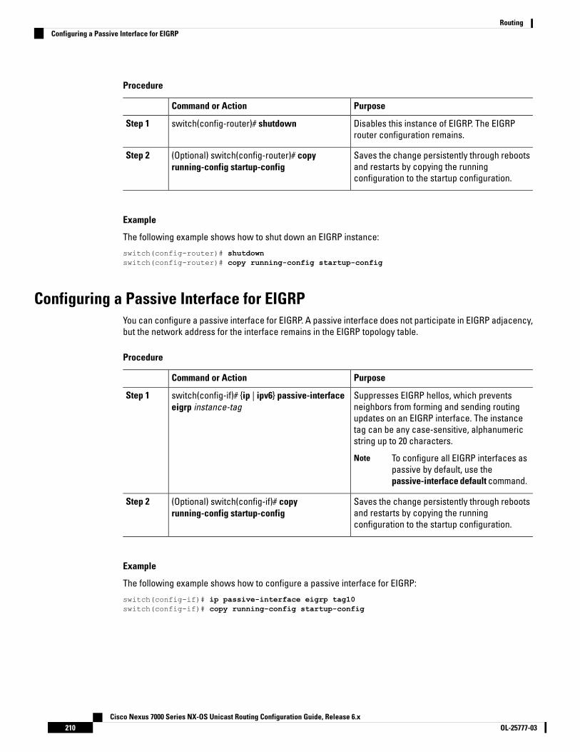
Procedure
PurposeCommand or Action
Disables this instance of EIGRP. The EIGRProuter configuration remains.
switch(config-router)# shutdownStep 1
Saves the change persistently through rebootsand restarts by copying the runningconfiguration to the startup configuration.
(Optional) switch(config-router)# copyrunning-config startup-config
Step 2
Example
The following example shows how to shut down an EIGRP instance:
switch(config-router)# shutdownswitch(config-router)# copy running-config startup-config
Configuring a Passive Interface for EIGRPYou can configure a passive interface for EIGRP. A passive interface does not participate in EIGRP adjacency,but the network address for the interface remains in the EIGRP topology table.
Procedure
PurposeCommand or Action
Suppresses EIGRP hellos, which preventsneighbors from forming and sending routing
switch(config-if)# {ip | ipv6} passive-interfaceeigrp instance-tag
Step 1
updates on an EIGRP interface. The instancetag can be any case-sensitive, alphanumericstring up to 20 characters.
To configure all EIGRP interfaces aspassive by default, use thepassive-interface default command.
Note
Saves the change persistently through rebootsand restarts by copying the runningconfiguration to the startup configuration.
(Optional) switch(config-if)# copyrunning-config startup-config
Step 2
Example
The following example shows how to configure a passive interface for EIGRP:
switch(config-if)# ip passive-interface eigrp tag10switch(config-if)# copy running-config startup-config
Cisco Nexus 7000 Series NX-OS Unicast Routing Configuration Guide, Release 6.xOL-25777-03210
RoutingConfiguring a Passive Interface for EIGRP

Shutting Down EIGRP on an InterfaceYou can gracefully shut down EIGRP on an interface. This action removes all adjacencies and stops EIGRPtraffic on this interface but preserves the EIGRP configuration.
Procedure
PurposeCommand or Action
Disables EIGRP on this interface. The EIGRPinterface configuration remains. The instance
switch(config-if)# {ip | ipv6} eigrp instance-tagshutdown
Step 1
tag can be any case-sensitive, alphanumericstring up to 20 characters.
Saves the change persistently through rebootsand restarts by copying the runningconfiguration to the startup configuration.
(Optional) switch(config-if)# copyrunning-config startup-config
Step 2
Example
The following example shows how to shut down EIGRP on an interface:
switch(config-if)# ip eigrp Test1 shutdownswitch(config-if)# copy running-config startup-config
Configuring Advanced EIGRP
Configuring Authentication in EIGRPYou can configure authentication between neighbors for EIGRP. You can configure EIGRP authentication forthe EIGRP process or for individual interfaces. The interface EIGRP authentication configuration overrides theEIGRP process-level authentication configuration.
Before you begin
• Ensure that you have enabled the EIGRP feature.
• Ensure that all neighbors for an EIGRP process share the same authentication configuration, includingthe shared authentication key.
• Create the key chain for this authentication configuration. For more information, see the Cisco Nexus7000 Series NX-OS Security Configuration Guide.
• Confirm that you are in the correct VDC. To change the VDC, use the switchto vdc command.
Procedure
PurposeCommand or Action
Enters global configuration mode.switch# configure terminalStep 1
Cisco Nexus 7000 Series NX-OS Unicast Routing Configuration Guide, Release 6.x211OL-25777-03
RoutingShutting Down EIGRP on an Interface
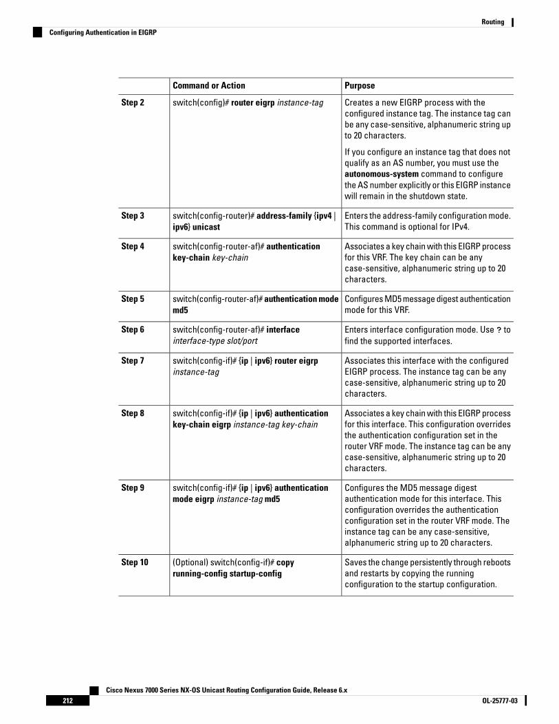
PurposeCommand or Action
Creates a new EIGRP process with theconfigured instance tag. The instance tag can
switch(config)# router eigrp instance-tagStep 2
be any case-sensitive, alphanumeric string upto 20 characters.
If you configure an instance tag that does notqualify as an AS number, you must use theautonomous-system command to configurethe AS number explicitly or this EIGRP instancewill remain in the shutdown state.
Enters the address-family configuration mode.This command is optional for IPv4.
switch(config-router)# address-family {ipv4 |ipv6} unicast
Step 3
Associates a key chain with this EIGRP processfor this VRF. The key chain can be any
switch(config-router-af)# authenticationkey-chain key-chain
Step 4
case-sensitive, alphanumeric string up to 20characters.
Configures MD5 message digest authenticationmode for this VRF.
switch(config-router-af)# authentication modemd5
Step 5
Enters interface configuration mode. Use ? tofind the supported interfaces.
switch(config-router-af)# interfaceinterface-type slot/port
Step 6
Associates this interface with the configuredEIGRP process. The instance tag can be any
switch(config-if)# {ip | ipv6} router eigrpinstance-tag
Step 7
case-sensitive, alphanumeric string up to 20characters.
Associates a key chain with this EIGRP processfor this interface. This configuration overrides
switch(config-if)# {ip | ipv6} authenticationkey-chain eigrp instance-tag key-chain
Step 8
the authentication configuration set in therouter VRF mode. The instance tag can be anycase-sensitive, alphanumeric string up to 20characters.
Configures the MD5 message digestauthentication mode for this interface. This
switch(config-if)# {ip | ipv6} authenticationmode eigrp instance-tag md5
Step 9
configuration overrides the authenticationconfiguration set in the router VRF mode. Theinstance tag can be any case-sensitive,alphanumeric string up to 20 characters.
Saves the change persistently through rebootsand restarts by copying the runningconfiguration to the startup configuration.
(Optional) switch(config-if)# copyrunning-config startup-config
Step 10
Cisco Nexus 7000 Series NX-OS Unicast Routing Configuration Guide, Release 6.xOL-25777-03212
RoutingConfiguring Authentication in EIGRP

Example
The following example shows how to configure MD5 message digest authentication for EIGRP overEthernet interface 1/2:
switch# configure terminalswitch(config)# router eigrp Test1switch(config-router)# exitswitch(config)# interface ethernet 1/2
switch(config-if)# ip router eigrp Test1switch(config-if)# ip authentication key-chain eigrp Test1 routeKeysswitch(config-if)# ip authentication mode eigrp Test1 md5switch(config-if)# copy running-config startup-config
Configuring EIGRP Stub RoutingTo configure a router for EIGRP stub routing, use these commands in address-family configuration mode:
Procedure
PurposeCommand or Action
Configures a remote router as an EIGRP stubrouter. The map name can be any
switch(config-router-af)# stub [direct |receive-only | redistributed [direct] leak-mapmap-name]
Step 1
case-sensitive, alphanumeric string up to 20characters.
Verifies that the router has been configured asa stub router.
(Optional) switch(config-router-af)# show ipeigrp neighbor detail
Step 2
Saves the change persistently through rebootsand restarts by copying the runningconfiguration to the startup configuration.
(Optional) switch(config-router-af)# copyrunning-config startup-config
Step 3
Example
The following example shows how to configure a stub router to advertise directly connected andredistributed routes. The last line of the output for the show ip eigrp neighbor detail command showsthe stub status of the remote or spoke router.
switch# configure terminalswitch(config)# router eigrp Test1switch(config-router)# address-family ipv4 unicastswitch(config-router-af)# stub direct redistributedswitch(config-router-af)# show ip eigrp neighbor detail
IP-EIGRP neighbors for process 201H Address Interface Hold Uptime SRTT RTO Q Seq Type
(sec) (ms) Cnt Num0 10.1.1.2 Se3/1 11 00:00:59 1 4500 0 7
Version 12.1/1.2, Retrans: 2, Retries: 0Stub Peer Advertising ( CONNECTED SUMMARY ) Routes
Cisco Nexus 7000 Series NX-OS Unicast Routing Configuration Guide, Release 6.x213OL-25777-03
RoutingConfiguring EIGRP Stub Routing
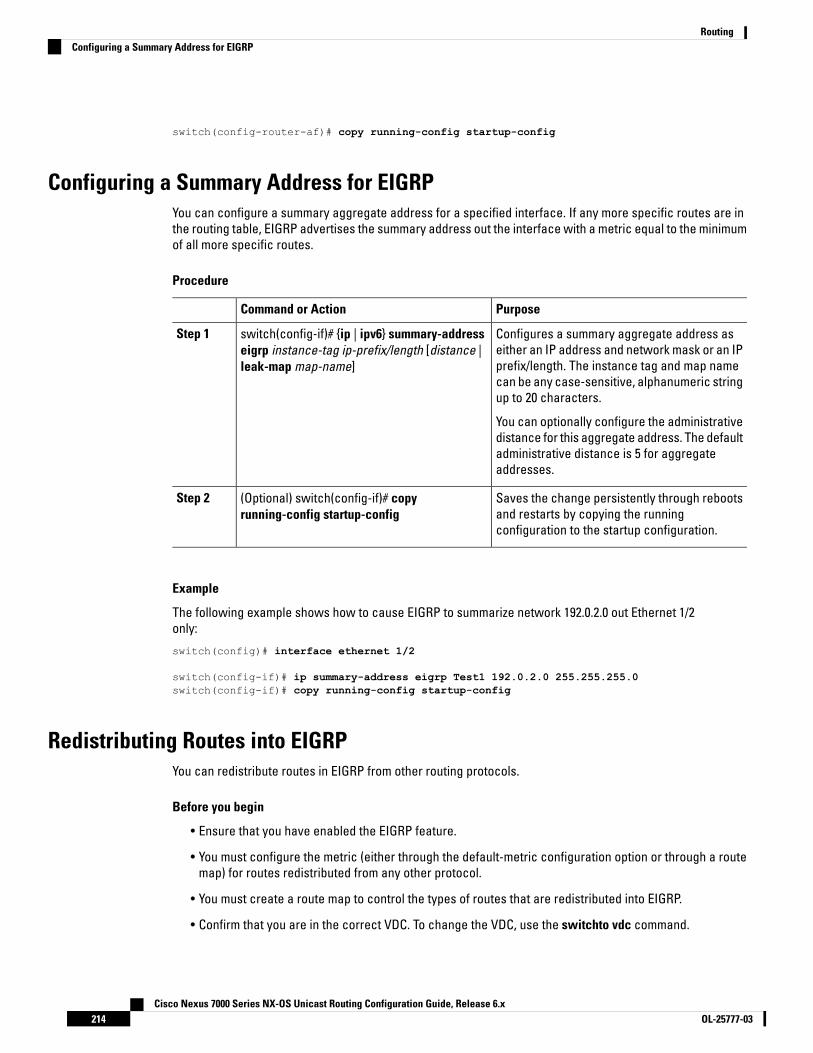
switch(config-router-af)# copy running-config startup-config
Configuring a Summary Address for EIGRPYou can configure a summary aggregate address for a specified interface. If any more specific routes are inthe routing table, EIGRP advertises the summary address out the interface with a metric equal to the minimumof all more specific routes.
Procedure
PurposeCommand or Action
Configures a summary aggregate address aseither an IP address and network mask or an IP
switch(config-if)# {ip | ipv6} summary-addresseigrp instance-tag ip-prefix/length [distance |leak-map map-name]
Step 1
prefix/length. The instance tag and map namecan be any case-sensitive, alphanumeric stringup to 20 characters.
You can optionally configure the administrativedistance for this aggregate address. The defaultadministrative distance is 5 for aggregateaddresses.
Saves the change persistently through rebootsand restarts by copying the runningconfiguration to the startup configuration.
(Optional) switch(config-if)# copyrunning-config startup-config
Step 2
Example
The following example shows how to cause EIGRP to summarize network 192.0.2.0 out Ethernet 1/2only:
switch(config)# interface ethernet 1/2
switch(config-if)# ip summary-address eigrp Test1 192.0.2.0 255.255.255.0switch(config-if)# copy running-config startup-config
Redistributing Routes into EIGRPYou can redistribute routes in EIGRP from other routing protocols.
Before you begin
• Ensure that you have enabled the EIGRP feature.
• You must configure the metric (either through the default-metric configuration option or through a routemap) for routes redistributed from any other protocol.
• You must create a route map to control the types of routes that are redistributed into EIGRP.
• Confirm that you are in the correct VDC. To change the VDC, use the switchto vdc command.
Cisco Nexus 7000 Series NX-OS Unicast Routing Configuration Guide, Release 6.xOL-25777-03214
RoutingConfiguring a Summary Address for EIGRP

Procedure
PurposeCommand or Action
Enters global configuration mode.switch# configure terminalStep 1
Creates a new EIGRP process with theconfigured instance tag. The instance tag can
switch(config)# router eigrp instance-tagStep 2
be any case-sensitive, alphanumeric string upto 20 characters.
If you configure an instance tag that does notqualify as an AS number, you must use theautonomous-system command to configure theAS number explicitly or this EIGRP instance willremain in the shutdown state.
Enters the address-family configuration mode.This command is optional for IPv4.
switch(config-router)# address-family {ipv4 |ipv6} unicast
Step 3
Injects routes from one routing domain intoEIGRP. The instance tag and map name can be
switch(config-router-af)# redistribute {bgp as |{eigrp | isis | ospf | ospfv3 | rip} instance-tag |direct | static} route-map map-name
Step 4
any case-sensitive, alphanumeric string up to20 characters.
Sets the metrics assigned to routes learnedthrough route redistribution. The default valuesare as follows:
switch(config-router-af)# default-metricbandwidth delay reliability loading mtu
Step 5
• bandwidth—100000 Kb/s
• delay—100 (10 microsecond units)
• reliability—255
• loading—1
• MTU—1492
Displays information about EIGRP route mapstatistics.
(Optional) switch(config-router-af)# show {ip |ipv6} eigrp route-map statistics redistribute
Step 6
Saves the change persistently through rebootsand restarts by copying the runningconfiguration to the startup configuration.
(Optional) switch(config-router-af)# copyrunning-config startup-config
Step 7
Example
The following example shows how to redistribute BGP into EIGRP for IPv4:
switch# configure terminalswitch(config)# router eigrp Test1switch(config-router)# redistribute bgp 100 route-map BGPFilterswitch(config-router)# default-metric 500000 30 200 1 1500switch(config-router)# copy running-config startup-config
Cisco Nexus 7000 Series NX-OS Unicast Routing Configuration Guide, Release 6.x215OL-25777-03
RoutingRedistributing Routes into EIGRP

Limiting the Number of Redistributed RoutesRoute redistribution can add many routes to the EIGRP route table. You can configure a maximum limit to thenumber of routes accepted from external protocols. EIGRP provides the following options to configureredistributed route limits:
• Fixed limit—Logs a message when EIGRP reaches the configured maximum. EIGRP does not accept anymore redistributed routes. You can optionally configure a threshold percentage of the maximum whereEIGRP logs a warning when that threshold is passed.
• Warning only—Logs a warning only when EIGRP reaches the maximum. EIGRP continues to acceptredistributed routes.
• Withdraw—Starts the timeout period when EIGRP reaches the maximum. After the timeout period, EIGRPrequests all redistributed routes if the current number of redistributed routes is less than the maximumlimit. If the current number of redistributed routes is at the maximum limit, EIGRP withdraws all redistributedroutes. You must clear this condition before EIGRP accepts more redistributed routes. You can optionallyconfigure the timeout period.
Before you begin
• Ensure that you have enabled the EIGRP feature.
• Confirm that you are in the correct VDC. To change the VDC, use the switchto vdc command.
Procedure
PurposeCommand or Action
Enters global configuration mode.switch# configure terminalStep 1
Creates a new EIGRP process with theconfigured instance tag.
switch(config)# router eigrp instance-tagStep 2
Redistributes the selected protocol into EIGRPthrough the configured route map.
switch(config-router)# redistribute {bgp id |direct | eigrp id | isis id | ospf id | rip id | static}route-map map-name
Step 3
Specifies a maximum number of prefixes thatEIGRP distributes. The range is from 0 to 65536.Optionally specifies the following:
switch(config-router)# redistributemaximum-prefix max [threshold] [warning-only| withdraw [num-retries timeout]]
Step 4
• threshold—Percent of maximum prefixesthat triggers a warning message.
• warning-only—Logs a warning messagewhen the maximum number of prefixes isexceeded.
• withdraw—Withdraws all redistributedroutes. Optionally tries to retrieve theredistributed routes. The num-retries rangeis from 1 to 12. The timeout is from 60 to600 seconds. The default is 300 seconds.
Cisco Nexus 7000 Series NX-OS Unicast Routing Configuration Guide, Release 6.xOL-25777-03216
RoutingLimiting the Number of Redistributed Routes
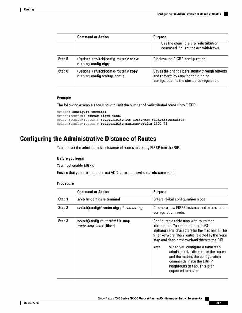
PurposeCommand or Action
Use the clear ip eigrp redistributioncommand if all routes are withdrawn.
Displays the EIGRP configuration.(Optional) switch(config-router)# showrunning-config eigrp
Step 5
Saves the change persistently through rebootsand restarts by copying the runningconfiguration to the startup configuration.
(Optional) switch(config-router)# copyrunning-config startup-config
Step 6
Example
The following example shows how to limit the number of redistributed routes into EIGRP:
switch# configure terminalswitch(config)# router eigrp Test1switch(config-router)# redistribute bgp route-map FilterExternalBGPswitch(config-router)# redistribute maximum-prefix 1000 75
Configuring the Administrative Distance of RoutesYou can set the administrative distance of routes added by EIGRP into the RIB.
Before you begin
You must enable EIGRP.
Ensure that you are in the correct VDC (or use the switchto vdc command).
Procedure
PurposeCommand or Action
Enters global configuration mode.switch# configure terminalStep 1
Creates a new EIGRP instance and enters routerconfiguration mode.
switch(config)# router eigrp instance-tagStep 2
Configures a table map with route mapinformation. You can enter up to 63
switch(config-router)# table-maproute-map-name [filter]
Step 3
alphanumeric characters for the map name. Thefilter keyword filters routes rejected by the routemap and does not download them to the RIB.
When you configure a table map,administrative distance of the routesand the metric, the configurationcommands make the EIGRPneighbours to flap. This is anexpected behavior.
Note
Cisco Nexus 7000 Series NX-OS Unicast Routing Configuration Guide, Release 6.x217OL-25777-03
RoutingConfiguring the Administrative Distance of Routes

PurposeCommand or Action
Saves the change persistently through rebootsand restarts by copying the runningconfiguration to the startup configuration.
(Optional) switch(config)# copy running-configstartup-config
Step 4
Configuring Route-Map FilteringYou can enable EIGRP to interoperate with other protocols to leverage additional routing functionality byfiltering inbound and outbound traffic based on route-map options.
Before you begin
You must enable EIGRP.
Ensure that you are in the correct VDC (or use the switchto vdc command).
Procedure
PurposeCommand or Action
Enters global configuration mode.switch# configure terminalStep 1
Enters route-map configuration mode.switch(config)# route-map map-tag [permit |deny] [sequence-number]
Step 2
Specifies a match clause that filters inboundupdates that match an internal or externalprotocol metric.
The metric-value argument is an internalprotocol metric that can be an EIGRP five-partmetric. The range is from 1 to 4294967295.
switch(config-route-map)# match metricmetric-value [+- deviation-number] [...metric-value [ +- deviation-number ]]
Step 3
The +- deviation-number argument representsa standard deviation, which can be anynumber. When you specify a metric deviationwith the + and - keywords, the router matchesany metric that falls inclusively in that range.
Specifies a match clause that matches externalroutes from sources that match the sourceprotocol.
switch(config-route-map)# matchsource-protocol source-protocol [as-number]
Step 4
The source-protocol argument is the protocolto match. The valid options are bgp, connected,eigrp, isis, ospf, rip, and static.
The as-number argument does not apply to theconnected, rip, and static options. The rangeis from 1 to 65535.
Cisco Nexus 7000 Series NX-OS Unicast Routing Configuration Guide, Release 6.xOL-25777-03218
RoutingConfiguring Route-Map Filtering

PurposeCommand or Action
Sets a tag value on the route in the destinationrouting protocol when all the match criteria ofa route map are met.
switch(config-route-map)# set tag tag-valueStep 5
Exits route-map configuration mode.switch(config-route-map)# exitStep 6
Creates a new EIGRP instance and entersrouter configuration mode.
switch(config)# router eigrp instance-tagStep 7
Exits router configuration mode.switch(config-router)# exitStep 8
Enters interface configuration mode. Use ? todetermine the slot and port ranges.
switch(config)# interface interface-typeslot/port
Step 9
Specifies an IP address for the EIGRP routingprocess.
switch(config-if)# ip address ip-addressStep 10
Configures the EIGRP routing process andenters the router configuration mode.
switch(config-if)# ip router eigrp as-numberStep 11
Filters networks received in updates.switch(config-if)# ip distribute-list eigrpas-number route-map map-tag in
Step 12
Saves the change persistently through rebootsand restarts by copying the runningconfiguration to the startup configuration.
(Optional) switch(config)# copy running-configstartup-config
Step 13
Configuring Load Balancing in EIGRPYou can configure the number of Equal Cost Multiple Path (ECMP) routes using the maximum-paths option.
Before you begin
• Ensure that you have enabled the EIGRP feature.
• Confirm that you are in the correct VDC. To change the VDC, use the switchto vdc command.
Procedure
PurposeCommand or Action
Enters global configuration mode.switch# configure terminalStep 1
Creates a new EIGRP process with theconfigured instance tag. The instance tag can
switch(config)# router eigrp instance-tagStep 2
be any case-sensitive, alphanumeric string upto 20 characters.
If you configure an instance tag that does notqualify as an AS number, you must use theautonomous-system command to configure the
Cisco Nexus 7000 Series NX-OS Unicast Routing Configuration Guide, Release 6.x219OL-25777-03
RoutingConfiguring Load Balancing in EIGRP

PurposeCommand or Action
AS number explicitly or this EIGRP instanceremains in the shutdown state.
Enters the address-family configuration mode.This command is optional for IPv4.
switch(config-router)# address-family {ipv4 |ipv6} unicast
Step 3
Sets the number of equal cost paths that EIGRPaccepts in the route table. The range is from 1to 16. The default is 8.
switch(config-router-af)# maximum-pathsnum-paths
Step 4
Saves the change persistently through rebootsand restarts by copying the runningconfiguration to the startup configuration.
(Optional) switch(config-router-af)# copyrunning-config startup-config
Step 5
Example
The following example shows how to configure equal cost load balancing for EIGRP over IPv4 witha maximum of six equal cost paths:
switch# configure terminalswitch(config)# router eigrp Test1switch(config-router)# address-family ipv4 unicastswitch(config-router-af)# maximum-paths 6switch(config-router-af)# copy running-config startup-config
Configuring Graceful Restart for EIGRPYou can configure graceful restart or nonstop forwarding for EIGRP.
Graceful restart is enabled by default.Note
Before you begin
• Ensure that you have enabled the EIGRP feature.
• An NSF-aware router must be up and completely converged with the network before it can assist anNSF-capable router in a graceful restart operation.
• Neighboring devices participating in the graceful restart must be NSF aware or NSF capable.
• Confirm that you are in the correct VDC. To change the VDC, use the switchto vdc command.
Procedure
PurposeCommand or Action
Enters global configuration mode.switch# configure terminalStep 1
Cisco Nexus 7000 Series NX-OS Unicast Routing Configuration Guide, Release 6.xOL-25777-03220
RoutingConfiguring Graceful Restart for EIGRP

PurposeCommand or Action
Creates a new EIGRP process with theconfigured instance tag. The instance tag can
switch(config)# router eigrp instance-tagStep 2
be any case-sensitive, alphanumeric string upto 20 characters.
If you configure an instance tag that does notqualify as an AS number, you must use theautonomous-system command to configure theAS number explicitly or this EIGRP instanceremains in the shutdown state.
Enters the address-family configuration mode.This command is optional for IPv4.
switch(config-router)# address-family {ipv4 |ipv6} unicast
Step 3
Enables graceful restart. This feature is enabledby default.
switch(config-router-af)# graceful-restartStep 4
Sets the time limit for the convergence after aswitchover. The range is from 60 to 180 seconds.The default is 120.
switch(config-router-af)# timers nsf convergeseconds
Step 5
Sets the hold time for routes learned from thegraceful restart-aware peer. The range is from20 to 300 seconds. The default is 240.
switch(config-router-af)# timers nsf route-holdseconds
Step 6
Sets the time limit for signaling a gracefulrestart. The range is from 10 to 30 seconds. Thedefault is 20.
switch(config-router-af)# timers nsf signalseconds
Step 7
Saves the change persistently through rebootsand restarts by copying the runningconfiguration to the startup configuration.
(Optional) switch(config-router-af)# copyrunning-config startup-config
Step 8
Example
This example shows how to configure graceful restart for EIGRP over IPv6 using the default timervalues:
switch# configure terminalswitch(config)# router eigrp Test1switch(config-router)# address-family ipv6 unicastswitch(config-router-af)# graceful-restartswitch(config-router-af)# copy running-config startup-config
Adjusting the Interval Between Hello Packets and the Hold TimeYou can adjust the interval between Hello messages and the hold time.
By default, Hello messages are sent every 5 seconds. The hold time is advertised in Hello messages andindicates to neighbors the length of time that they should consider the sender valid. The default hold time isthree times the hello interval, or 15 seconds.
Cisco Nexus 7000 Series NX-OS Unicast Routing Configuration Guide, Release 6.x221OL-25777-03
RoutingAdjusting the Interval Between Hello Packets and the Hold Time

On very congested and large networks, the default hold time might not be sufficient time for all routers toreceive hello packets from their neighbors. In this case, you might want to increase the hold time.
Procedure
PurposeCommand or Action
Configures the hello interval for an EIGRProuting process. The instance tag can be any
switch(config-if)# {ip | ipv6} hello-interval eigrpinstance-tag seconds
Step 1
case-sensitive, alphanumeric string up to 20characters. The range is from 1 to 65535seconds. The default is 5.
Configures the hold time for an EIGRP routingprocess. The instance tag can be any
switch(config-if)# {ip | ipv6} hold-time eigrpinstance-tag seconds
Step 2
case-sensitive, alphanumeric string up to 20characters. The range is from 1 to 65535seconds.
Verifies the timer configuration.(Optional) switch(config-if)# show ip eigrpinterface detail
Step 3
Saves the change persistently through rebootsand restarts by copying the runningconfiguration to the startup configuration.
(Optional) switch(config-if)# copyrunning-config startup-config
Step 4
Example
The following example shows how to change the interval between Hello packets and the hold time:
switch(config)# interface ethernet 1/2switch(config-if)# ip hello-interval eigrp Test1 30switch(config-if)# ip hold-time eigrp Test1 30switch(config-if)# show ip eigrp interface detailswitch(config-if)# copy running-config startup-config
Disabling Split HorizonYou can use split horizon to block route information from being advertised by a router out of any interface fromwhich that information originated. Split horizon usually optimizes communications among multiple routingdevices, particularly when links are broken.
By default, split horizon is enabled on all interfaces.
Procedure
PurposeCommand or Action
Disables split horizon.switch(config-if)# no {ip | ipv6} split-horizoneigrp instance-tag
Step 1
Cisco Nexus 7000 Series NX-OS Unicast Routing Configuration Guide, Release 6.xOL-25777-03222
RoutingDisabling Split Horizon
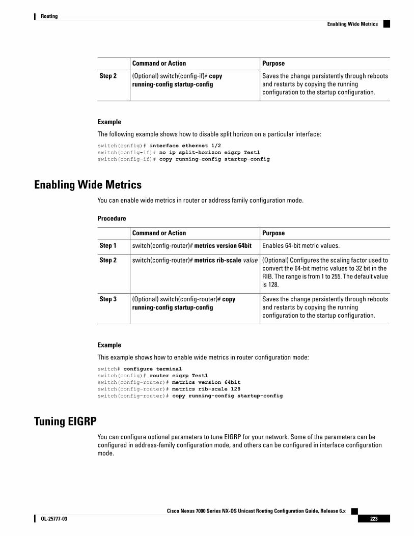
PurposeCommand or Action
Saves the change persistently through rebootsand restarts by copying the runningconfiguration to the startup configuration.
(Optional) switch(config-if)# copyrunning-config startup-config
Step 2
Example
The following example shows how to disable split horizon on a particular interface:
switch(config)# interface ethernet 1/2switch(config-if)# no ip split-horizon eigrp Test1switch(config-if)# copy running-config startup-config
Enabling Wide MetricsYou can enable wide metrics in router or address family configuration mode.
Procedure
PurposeCommand or Action
Enables 64-bit metric values.switch(config-router)# metrics version 64bitStep 1
(Optional) Configures the scaling factor used toconvert the 64-bit metric values to 32 bit in the
switch(config-router)# metrics rib-scale valueStep 2
RIB. The range is from 1 to 255. The default valueis 128.
Saves the change persistently through rebootsand restarts by copying the runningconfiguration to the startup configuration.
(Optional) switch(config-router)# copyrunning-config startup-config
Step 3
Example
This example shows how to enable wide metrics in router configuration mode:
switch# configure terminalswitch(config)# router eigrp Test1switch(config-router)# metrics version 64bitswitch(config-router)# metrics rib-scale 128switch(config-router)# copy running-config startup-config
Tuning EIGRPYou can configure optional parameters to tune EIGRP for your network. Some of the parameters can beconfigured in address-family configuration mode, and others can be configured in interface configurationmode.
Cisco Nexus 7000 Series NX-OS Unicast Routing Configuration Guide, Release 6.x223OL-25777-03
RoutingEnabling Wide Metrics

Procedure
PurposeCommand or Action
Originates or accepts the default route withprefix 0.0.0.0/0. When a route-map is supplied,
(Optional) switch(config-router-af)#default-information originate [always |route-map map-name]
Step 1
the default route is originated only when theroute map yields a true condition. Theroute-map name can be any case-sensitive,alphanumeric string up to 20 characters.
Configures the administrative distance for thisEIGRP process. The range is from 1 to 255. The
(Optional) switch(config-router-af)# distanceinternal external
Step 2
internal value sets the distance for routeslearned from within the same autonomoussystem (the default value is 90). The externalvalue sets the distance for routes learned froman external autonomous system (the defaultvalue is 170).
Sets the maximum allowed hops for anadvertised route. Routes over this maximum
(Optional) switch(config-router-af)# metricmax-hops hop-count
Step 3
are advertised as unreachable. The range isfrom 1 to 255. The default is 100.
Adjusts the EIGRP metric or K value. EIGRPuses the following formula to determine thetotal metric to the network:
(Optional) switch(config-router-af)# metricweights tos k1 k2 k3 k4 k5 k6
Step 4
metric = [k1 x bandwidth + (k2 xbandwidth)/(256 – load) + k3 x delay + k6 xextended attributes] x [k5/(reliability + k4)]
Default values and ranges are as follows:
• TOS—0. The range is from 0 to 8.
• k1—1. The range is from 0 to 255.
• k2—0. The range is from 0 to 255.
• k3—1. The range is from 0 to 255.
• k4—0. The range is from 0 to 255.
• k5—0. The range is from 0 to 255.
• k6—0. The range is from 0 to 255.
Sets the time the router waits in minutes (aftersending a query) before declaring the route to
(Optional) switch(config-router-af)# timersactive-time {time-limit | disabled}
Step 5
be stuck in the active (SIA) state. The range isfrom 1 to 65535. The default is 3.
Exits address-family configuration mode.switch(config-router-af)# exitStep 6
Cisco Nexus 7000 Series NX-OS Unicast Routing Configuration Guide, Release 6.xOL-25777-03224
RoutingTuning EIGRP
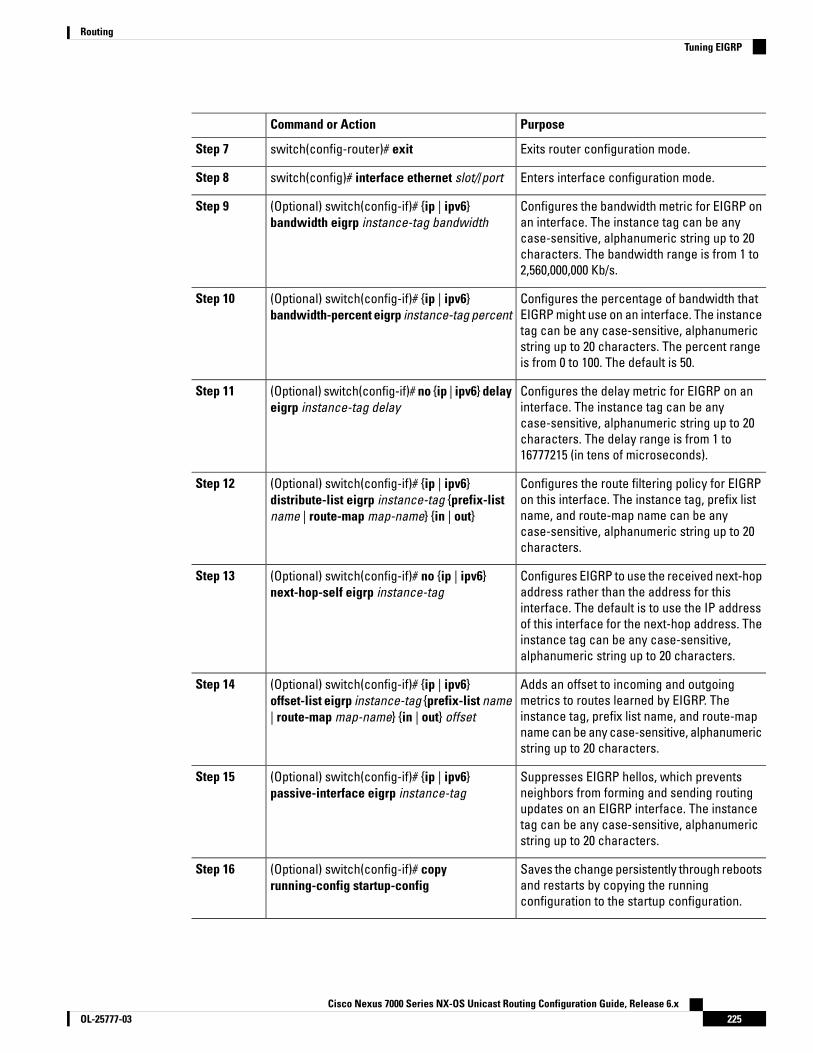
PurposeCommand or Action
Exits router configuration mode.switch(config-router)# exitStep 7
Enters interface configuration mode.switch(config)# interface ethernet slot//portStep 8
Configures the bandwidth metric for EIGRP onan interface. The instance tag can be any
(Optional) switch(config-if)# {ip | ipv6}bandwidth eigrp instance-tag bandwidth
Step 9
case-sensitive, alphanumeric string up to 20characters. The bandwidth range is from 1 to2,560,000,000 Kb/s.
Configures the percentage of bandwidth thatEIGRP might use on an interface. The instance
(Optional) switch(config-if)# {ip | ipv6}bandwidth-percent eigrp instance-tag percent
Step 10
tag can be any case-sensitive, alphanumericstring up to 20 characters. The percent rangeis from 0 to 100. The default is 50.
Configures the delay metric for EIGRP on aninterface. The instance tag can be any
(Optional) switch(config-if)# no {ip | ipv6} delayeigrp instance-tag delay
Step 11
case-sensitive, alphanumeric string up to 20characters. The delay range is from 1 to16777215 (in tens of microseconds).
Configures the route filtering policy for EIGRPon this interface. The instance tag, prefix list
(Optional) switch(config-if)# {ip | ipv6}distribute-list eigrp instance-tag {prefix-listname | route-map map-name} {in | out}
Step 12
name, and route-map name can be anycase-sensitive, alphanumeric string up to 20characters.
Configures EIGRP to use the received next-hopaddress rather than the address for this
(Optional) switch(config-if)# no {ip | ipv6}next-hop-self eigrp instance-tag
Step 13
interface. The default is to use the IP addressof this interface for the next-hop address. Theinstance tag can be any case-sensitive,alphanumeric string up to 20 characters.
Adds an offset to incoming and outgoingmetrics to routes learned by EIGRP. The
(Optional) switch(config-if)# {ip | ipv6}offset-list eigrp instance-tag {prefix-list name| route-map map-name} {in | out} offset
Step 14
instance tag, prefix list name, and route-mapname can be any case-sensitive, alphanumericstring up to 20 characters.
Suppresses EIGRP hellos, which preventsneighbors from forming and sending routing
(Optional) switch(config-if)# {ip | ipv6}passive-interface eigrp instance-tag
Step 15
updates on an EIGRP interface. The instancetag can be any case-sensitive, alphanumericstring up to 20 characters.
Saves the change persistently through rebootsand restarts by copying the runningconfiguration to the startup configuration.
(Optional) switch(config-if)# copyrunning-config startup-config
Step 16
Cisco Nexus 7000 Series NX-OS Unicast Routing Configuration Guide, Release 6.x225OL-25777-03
RoutingTuning EIGRP

Example
The following example shows how to configure optional parameters in address-family configurationmode to tune EIGRP for your network:
switch# configure terminalswitch(config)# router eigrp Test1switch(config-router)# address-family ipv4 unicastswitch(config-router-af)# default-information originate alwaysswitch(config-router-af)# distance 25 100switch(config-router-af)# metric max-hops 70switch(config-router-af)# metric weights 0 1 3 2 1 0switch(config-router-af)# timers active-time 200switch(config-router-af)# copy running-config startup-config
The following example shows how to configure optional parameters in interface configuration modeto tune EIGRP for your network:
switch# configure terminalswitch(config)# interface ethernet 1/2switch(config-if)# ip bandwidth eigrp Test1 30000switch(config-if)# ip bandwidth-percent eigrp Test1 30switch(config-if)# ip delay eigrp Test1 100switch(config-if)# ip distribute-list eigrp Test1 route-map EigrpTest inswitch(config-if)# ip next-hop-self eigrp Test1switch(config-if)# ip offset-list eigrp Test1 prefix-list EigrpList inswitch(config-if)# ip passive-interface eigrp Test1switch(config-if)# copy running-config startup-config
Configuring Virtualization for EIGRPYou can configure multiple EIGRP processes in each VDC. You can also create multiple VRFs within each VDCand use the same or multiple EIGRP processes in each VRF. You assign an interface to a VRF.
Configure all other parameters for an interface after you configure the VRF for an interface. Configuring a VRFfor an interface deletes all other configuration for that interface.
Note
Before you begin
• Ensure that you have enabled the EIGRP feature.
• Create the VDCs and VRFs.
• Confirm that you are in the correct VDC. To change the VDC, use the switchto vdc command.
Procedure
PurposeCommand or Action
Enters global configuration mode.switch# configure terminalStep 1
Cisco Nexus 7000 Series NX-OS Unicast Routing Configuration Guide, Release 6.xOL-25777-03226
RoutingConfiguring Virtualization for EIGRP

PurposeCommand or Action
Creates a new VRF and enters VRF configurationmode. The VRF name can be any case-sensitive,alphanumeric string up to 20 characters.
switch(config)# vrf context vrf-nameStep 2
Creates a new EIGRP process with theconfigured instance tag. The instance tag can
switch(config-vrf)# router eigrp instance-tagStep 3
be any case-sensitive, alphanumeric string upto 20 characters.
If you configure an instance tag that does notqualify as an AS number, you must use theautonomous-system command to configure theAS number explicitly or this EIGRP instanceremains in the shutdown state.
Enters interface configuration mode. Use ? tofind the slot and port ranges.
switch(config-router)# interface ethernetslot//port
Step 4
Adds this interface to a VRF. The VRF name canbe any case-sensitive, alphanumeric string upto 20 characters.
switch(config-if)# vrf member vrf-nameStep 5
Adds this interface to the EIGRP process. Theinstance tag can be any case-sensitive,alphanumeric string up to 20 characters.
switch(config-if)# {ip | ipv6} router eigrpinstance-tag
Step 6
Saves the change persistently through rebootsand restarts by copying the runningconfiguration to the startup configuration.
(Optional) switch(config-if)# copyrunning-config startup-config
Step 7
Example
This example shows how to create a VRF and add an interface to the VRF:
switch# configure terminalswitch(config)# vrf context NewVRFswitch(config-vrf)# router eigrp Test1switch(config-router)# interface ethernet 1/2
switch(config-if)# ip router eigrp Test1switch(config-if)# vrf member NewVRFswitch(config-if)# copy running-config startup-config
Verifying the EIGRP ConfigurationUse one of the following commands to verify the configuration:
Cisco Nexus 7000 Series NX-OS Unicast Routing Configuration Guide, Release 6.x227OL-25777-03
RoutingVerifying the EIGRP Configuration
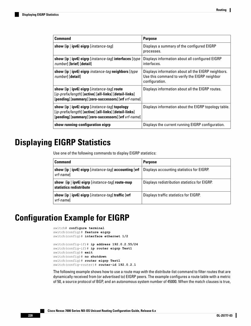
PurposeCommand
Displays a summary of the configured EIGRPprocesses.
show {ip | ipv6} eigrp [instance-tag]
Displays information about all configured EIGRPinterfaces.
show {ip | ipv6} eigrp [instance-tag] interfaces [typenumber] [brief] [detail]
Displays information about all the EIGRP neighbors.Use this command to verify the EIGRP neighborconfiguration.
show {ip | ipv6} eigrp instance-tag neighbors [typenumber] [detail]
Displays information about all the EIGRP routes.show {ip | ipv6} eigrp [instance-tag] route[ip-prefix/length] [active] [all-links] [detail-links][pending] [summary] [zero-successors] [vrf vrf-name]
Displays information about the EIGRP topology table.show {ip | ipv6} eigrp [instance-tag] topology[ip-prefix/length] [active] [all-links] [detail-links][pending] [summary] [zero-successors] [vrf vrf-name]
Displays the current running EIGRP configuration.show running-configuration eigrp
Displaying EIGRP StatisticsUse one of the following commands to display EIGRP statistics:
PurposeCommand
Displays accounting statistics for EIGRP.show {ip | ipv6} eigrp [instance-tag] accounting [vrfvrf-name]
Displays redistribution statistics for EIGRP.show {ip | ipv6} eigrp [instance-tag] route-mapstatistics redistribute
Displays traffic statistics for EIGRP.show {ip | ipv6} eigrp [instance-tag] traffic [vrfvrf-name]
Configuration Example for EIGRPswitch# configure terminalswitch(config)# feature eigrpswitch(config)# interface ethernet 1/2
switch(config-if)# ip address 192.0.2.55/24switch(config-if)# ip router eigrp Test1switch(config)# exitswitch(config)# no shutdownswitch(config)# router eigrp Test1switch(config-router)# router-id 192.0.2.1
The following example shows how to use a route map with the distribute-list command to filter routes that aredynamically received from (or advertised to) EIGRP peers. The example configures a route table with a metricof 50, a source protocol of BGP, and an autonomous system number of 45000. When the match clauses is true,
Cisco Nexus 7000 Series NX-OS Unicast Routing Configuration Guide, Release 6.xOL-25777-03228
RoutingDisplaying EIGRP Statistics

the tag value of the destination routing protocol is set to 5. The route map is used to distribute incoming packetsfor an EIGRP process
switch(config)# route-map metric-rangeswitch(config-route-map)# match metric 50switch(config-route-map)# match source-protocol bgp 45000switch(config-route-map)# set tag 5switch(config-route-map)# exitswitch(config)# router eigrp 1switch(config-router)# exitswitch(config)# interface ethernet 1/2switch(config-if)# ip address 172.16.0.0switch(config-if)# ip router eigrp 1switch(config-if)# ip distribute-list eigrp 1 route-map metric-range in
The following example shows how to use a route map with the redistribute command to allow routes that areredistributed from the routing table to be filtered with a route map before being admitted into an EIGRP topologytable. The example shows how to configure a route map to match EIGRP routes with a metric of 110, 200, oran inclusive range of 700 to 800. When the match clause is true, the tag value of the destination routing protocolis set to 10. The route map is used to redistribute EIGRP packets.
switch(config)# route-map metric-eigrpswitch(config-route-map)# match metric 110 200 750 +- 50switch(config-route-map)# set tag 10switch(config-route-map)# exitswitch(config)# router eigrp 1switch(config-router)# redistribute eigrp route-map metric-eigrpswitch(config-router)# exitswitch(config)# interface ethernet 1/2switch(config-if)# ip address 172.16.0.0switch(config-if)# ip router eigrp 1
Related Documents for EIGRPDocument TitleRelated Topic
Cisco Nexus 7000 Series NX-OS Unicast RoutingCommand Reference
EIGRP CLI commands
Cisco Nexus 7000 Series NX-OS Virtual Device ContextConfiguration Guide
VDCs and VRFs
Introduction to EIGRP Tech NoteEIGRP overview
EIGRP Frequently Asked QuestionsEIGRP FAQs
MIBsMIBs LinkMIBs
To locate and download MIBs, go to the following URL:https://cfnng.cisco.com/mibs.
CISCO-EIGRP-MIB
Cisco Nexus 7000 Series NX-OS Unicast Routing Configuration Guide, Release 6.x229OL-25777-03
RoutingRelated Documents for EIGRP
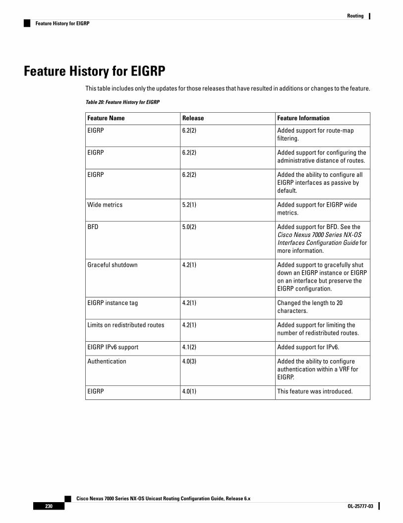
Feature History for EIGRPThis table includes only the updates for those releases that have resulted in additions or changes to the feature.
Table 20: Feature History for EIGRP
Feature InformationReleaseFeature Name
Added support for route-mapfiltering.
6.2(2)EIGRP
Added support for configuring theadministrative distance of routes.
6.2(2)EIGRP
Added the ability to configure allEIGRP interfaces as passive bydefault.
6.2(2)EIGRP
Added support for EIGRP widemetrics.
5.2(1)Wide metrics
Added support for BFD. See theCisco Nexus 7000 Series NX-OSInterfaces Configuration Guide formore information.
5.0(2)BFD
Added support to gracefully shutdown an EIGRP instance or EIGRPon an interface but preserve theEIGRP configuration.
4.2(1)Graceful shutdown
Changed the length to 20characters.
4.2(1)EIGRP instance tag
Added support for limiting thenumber of redistributed routes.
4.2(1)Limits on redistributed routes
Added support for IPv6.4.1(2)EIGRP IPv6 support
Added the ability to configureauthentication within a VRF forEIGRP.
4.0(3)Authentication
This feature was introduced.4.0(1)EIGRP
Cisco Nexus 7000 Series NX-OS Unicast Routing Configuration Guide, Release 6.xOL-25777-03230
RoutingFeature History for EIGRP

C H A P T E R 10Configuring IS-IS
This chapter contains the following sections:
• Finding Feature Information, on page 231• Information About IS-IS, on page 231• Prerequisites for IS-IS, on page 236• Guidelines and Limitations for IS-IS, on page 236• Default Settings for IS-IS, on page 236• Configuring IS-IS, on page 237• Monitoring IS-IS, on page 253• Configuration Examples for IS-IS, on page 254• Related Documents for IS-IS, on page 254• Standards for IS-IS, on page 254• Feature History for IS-IS, on page 254
Finding Feature InformationYour software release might not support all the features documented in this module. For the latest caveatsand feature information, see the Bug Search Tool at https://tools.cisco.com/bugsearch/ and the release notesfor your software release. To find information about the features documented in this module, and to see a listof the releases in which each feature is supported, see the "New and Changed Information"chapter or theFeature History table in this chapter.
Information About IS-ISIS-IS is an Interior Gateway Protocol (IGP) based on Standardization (ISO)/International Engineering Consortium(IEC) 10589. Cisco NX-OS supports Internet Protocol version 4 (IPv4), and beginning with Cisco NX-OS Release6.1, Cisco NX-OS supports IPv6. IS-IS is a dynamic link-state routing protocol that can detect changes in thenetwork topology and calculate loop-free routes to other nodes in the network. Each router maintains alink-state database that describes the state of the network and sends packets on every configured link todiscover neighbors. IS-IS floods the link-state information across the network to each neighbor. The routeralso sends advertisements and updates on the link-state database through all the existing neighbors.
Cisco Nexus 7000 Series NX-OS Unicast Routing Configuration Guide, Release 6.x231OL-25777-03

IS-IS OverviewIS-IS sends a hello packet out every configured interface to discover IS-IS neighbor routers. The hello packetcontains information, such as the authentication, area, and supported protocols, which the receiving interfaceuses to determine compatibility with the originating interface. The hello packets are also padded to ensurethat IS-IS establishes adjacencies only with interfaces that have matching maximum transmission unit (MTU)settings. Compatible interfaces form adjacencies, which update routing information in the link-state databasethrough link-state update messages (LSPs). By default, the router sends a periodic LSP refresh every 10 minutesand the LSPs remain in the link-state database for 20 minutes (the LSP lifetime). If the router does not receivean LSP refresh before the end of the LSP lifetime, the router deletes the LSP from the database.
The LSP interval must be less than the LSP lifetime or the LSPs time out before they are refreshed.
IS-IS sends periodic hello packets to adjacent routers. If you configure transient mode for hello packets, thesehello packets do not include the excess padding used before IS-IS establishes adjacencies. If the MTU valueon adjacent routers changes, IS-IS can detect this change and send padded hello packets for a period of time.IS-IS uses this feature to detect mismatched MTU values on adjacent routers.
IS-IS AreasYou can design IS-IS networks as a single area that includes all routers in the network or as multiple areasthat connect into a backbone or Level 2 area. Routers in a nonbackbone area are Level 1 routers that establishadjacencies within a local area (intra-area routing). Level 2 area routers establish adjacencies to other Level2 routers and perform routing between Level 1 areas (inter-area routing). A router can have both Level 1 andLevel 2 areas configured. These Level 1/Level 2 routers act as area border routers that route information fromthe local area to the Level 2 backbone area
Within a Level 1 area, routers know how to reach all other routers in that area. The Level 2 routers know howto reach other area border routers and other Level 2 routers. Level 1/Level 2 routers straddle the boundarybetween two areas, routing traffic to and from the Level 2 backbone area. Level1/Level2 routers use theattached (ATT) bit signal Level 1 routers to set a default route to this Level1/Level2 router to connect to theLevel 2 area.
In some instances, such as when you have two or more Level1/Level 2 routers in an area, you may want tocontrol which Level1/Level2 router that the Level 1 routers use as the default route to the Level 2 area. Youcan configure which Level1/Level2 router sets the attached bit.
Each IS-IS instance in Cisco NX-OS supports either a single Level 1 or Level 2 area, or one of each. By default,all IS-IS instances automatically support Level 1 and Level 2 routing.
Figure 31: IS-IS Network Divided into Areas
An autonomous system boundary router (ASBR) advertises external destinations throughout the IS-ISautonomous system. External routes are the routes redistributed into IS-IS from any other protocol.
Cisco Nexus 7000 Series NX-OS Unicast Routing Configuration Guide, Release 6.xOL-25777-03232
RoutingIS-IS Overview

NET and System IDEach IS-IS instance has an associated network entity title (NET). The NET is comprised of the IS-IS systemID, which uniquely identifies this IS-IS instance in the area and the area ID. For example, if the NET is47.0004.004d.0001.0001.0c11.1111.00, the system ID is 0000.0c11.1111.00 and the area is ID 47.0004.004d.0001.
Designated Intermediate SystemIS-IS uses a designated intermediate system (DIS) in broadcast networks to prevent each router from formingunnecessary links with every other router on the broadcast network. IS-IS routers send LSPs to the DIS, whichmanages all the link-state information for the broadcast network. You can configure the IS-IS priority that IS-ISuses to select the DIS in an area.
No DIS is required on a point-to-point network.Note
IS-IS AuthenticationYou can configure authentication to control adjacencies and the exchange of LSPs. Routers that want tobecome neighbors must exchange the same password for their configured level of authentication. IS-IS blocksa router that does not have the correct password. You can configure IS-IS authentication globally or for anindividual interface for Level 1, Level 2, or both Level 1/Level 2 routing.
IS-IS supports the following authentication methods:
• Clear text—All packets exchanged carry a cleartext 128-bit password.
• MD5 digest—All packets exchanged carry a message digest that is based on a 128-bit key.
To provide protection against passive attacks, IS-IS never sends the MD5 secret key as cleartext through thenetwork. In addition, IS-IS includes a sequence number in each packet to protect against replay attacks.
You can use also keychains for hello and LSP authentication. See the Cisco Nexus 7000 Series NX-OS SecurityConfiguration Guide, for information on keychain management.
Mesh GroupsA mesh group is a set of interfaces in which all routers reachable over the interfaces have at least one link toevery other router. Many links can fail without isolating one or more routers from the network.
In normal flooding, an interface receives a new LSP and floods the LSP out over all other interfaces on therouter. With mesh groups, when an interface that is part of a mesh group receives a new LSP, the interfacedoes not flood the new LSP over the other interfaces that are part of that mesh group.
You may want to limit LSPs in certain mesh network topologies to improve network scalability. Limiting LSPfloods might also reduce the reliability of the network (in case of failures). For this reason, we recommend thatyou use mesh groups only if specifically required, and then only after you make a careful network design.
Note
You can also configure mesh groups in block mode for parallel links between routers. In this mode, all LSPsare blocked on that interface in a mesh group after the routers initially exchange their link-state information.
Cisco Nexus 7000 Series NX-OS Unicast Routing Configuration Guide, Release 6.x233OL-25777-03
RoutingNET and System ID
Overload BitIS-IS uses the overload bit to tell other routers not to use the local router to forward traffic but to continuerouting traffic destined for that local router.
You may want to use the overload bit in these situations:
• The router is in a critical condition.
• Graceful introduction and removal of the router to/from the network.
• Other (administrative or traffic engineering) reasons such as waiting for BGP convergence.
Route SummarizationYou can configure a summary aggregate address. Route summarization simplifies route tables by replacing anumber of more-specific addresses with an address that represents all the specific addresses. For example,you can replace 10.1.1.0/24, 10.1.2.0/24, and 10.1.3.0/24 with one summary address, 10.1.0.0/16.
If more specific routes are in the routing table, IS-IS advertises the summary address with a metric equal tothe minimum metric of the more specific routes.
Cisco NX-OS does not support automatic route summarization.Note
Route RedistributionYou can use IS-IS to redistribute static routes, routes learned by other IS-IS autonomous systems, or routesfrom other protocols. You must configure a route map with the redistribution to control which routes are passedinto IS-IS. A route map allows you to filter routes based on attributes such as the destination, originationprotocol, route type, route tag, and so on.
Whenever you redistribute routes into an IS-IS routing domain, Cisco NX-OS does not, by default, redistributethe default route into the IS-IS routing domain. You can generate a default route into IS-IS, which can becontrolled by a route policy.
You also configure the default metric that is used for all imported routes into IS-IS.
Administrative DistanceThe administrative distance is a rating of the trustworthiness of a routing information source. A higher valueindicates a lower trust rating. The administrative distance is used to discriminate between routes learned frommore than one routing protocol. The route with the lowest administrative distance is installed in the IP routingtable.
You can configure the administrative distance for internal and external routes based on various match criteriafor a given prefix. Routing protocols such as IS-IS configure the prefix into the Routing Information Base (RIB),along with the next hops based on these metrics. If multiple paths are available for a prefix, the routing protocolchooses the best path based on the cost to reach the next hop and the administrative distance. Beginningwith Cisco NX-OS Release 6.2(2), you can specify that prefixes be considered based on specific routes. Inprior releases, one administrative distance was sufficient for all internal routes.
Cisco Nexus 7000 Series NX-OS Unicast Routing Configuration Guide, Release 6.xOL-25777-03234
RoutingOverload Bit
Load BalancingYou can use load balancing to allow a router to distribute traffic over all the router network ports that are thesame distance from the destination address. Load balancing increases the utilization of network segmentsand increases the effective network bandwidth.
Cisco NX-OS supports the Equal Cost Multiple Paths (ECMP) feature with up to 16 equal-cost paths in the IS-ISroute table and the unicast RIB. You can configure IS-IS to load balance traffic across some or all of thosepaths.
BFDThis feature supports bidirectional forwarding detection (BFD). BFD is a detection protocol designed to providefast forwarding-path failure detection times. BFD provides subsecond failure detection between two adjacentdevices and can be less CPU-intensive than protocol hello messages because some of the BFD load can bedistributed onto the data plane on supported modules. See the Cisco Nexus 7000 Series NX-OS InterfacesConfiguration Guide, for more information.
Virtualization SupportCisco NX-OS supports multiple instances of the IS-IS protocol that runs on the same system. IS-IS supportsvirtual routing and forwarding (VRF) instances. VRFs exist within virtual device contexts (VDCs). You canconfigure up to four IS-IS instances in a VDC.
By default, Cisco NX-OS places you in the default VDC and default VRF unless you specifically configureanother VDC and VRF. See the Cisco Nexus 7000 Series NX-OS Virtual Device Context Configuration Guide.
High Availability and Graceful RestartCisco NX-OS provides a multilevel high-availability architecture. IS-IS supports stateful restart, which is alsoreferred to as non-stop routing (NSR). If IS-IS experiences problems, it attempts to restart from its previousrun-time state. The neighbors would not register any neighbor event in this case. If the first restart is notsuccessful and another problem occurs, IS-IS attempts a graceful restart as per RFC 3847. A graceful restart,or non-stop forwarding (NSF), allows IS-IS to remain in the data forwarding path through a process restart.When the restarting IS-IS interface is operational again, it rediscovers its neighbors, establishes adjacency,and starts sending its updates again. At this point, the NSF helpers recognize that the graceful restart hasfinished.
A stateful restart is used in the following scenarios:
• First recovery attempt after process experiences problems
• ISSU
• User-initiated switchover using the system switchover command
A graceful restart is used in the following scenarios:
• Second recovery attempt after the process experiences problems within a 4-minute interval
• Manual restart of the process using the restart isis command
• Active supervisor removal
Cisco Nexus 7000 Series NX-OS Unicast Routing Configuration Guide, Release 6.x235OL-25777-03
RoutingLoad Balancing
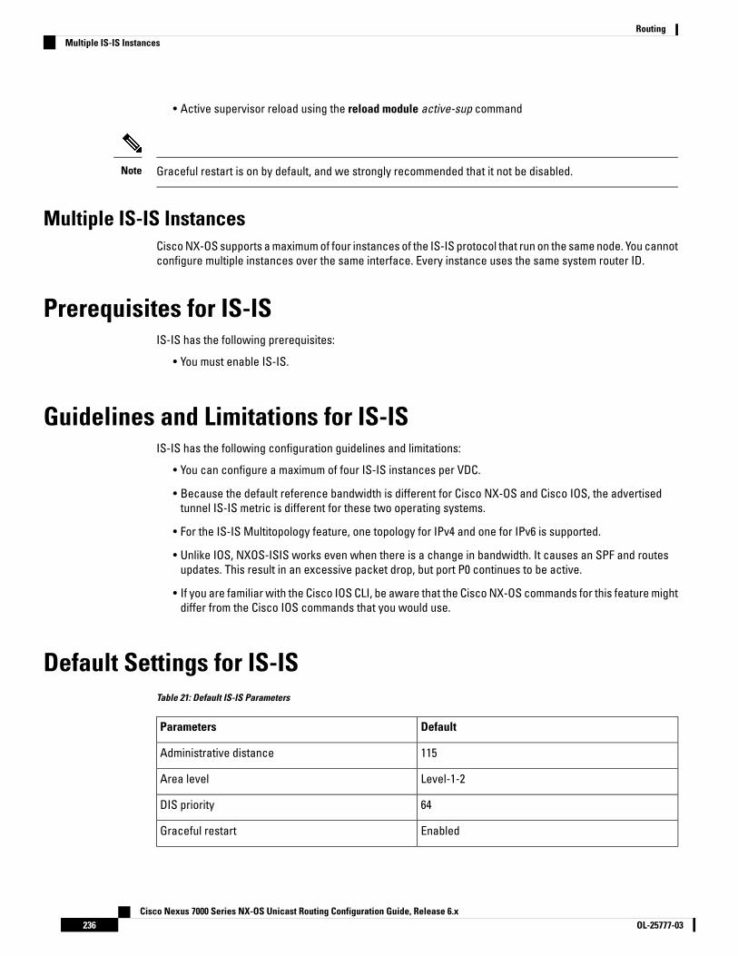
• Active supervisor reload using the reload module active-sup command
Graceful restart is on by default, and we strongly recommended that it not be disabled.Note
Multiple IS-IS InstancesCisco NX-OS supports a maximum of four instances of the IS-IS protocol that run on the same node. You cannotconfigure multiple instances over the same interface. Every instance uses the same system router ID.
Prerequisites for IS-ISIS-IS has the following prerequisites:
• You must enable IS-IS.
Guidelines and Limitations for IS-ISIS-IS has the following configuration guidelines and limitations:
• You can configure a maximum of four IS-IS instances per VDC.
• Because the default reference bandwidth is different for Cisco NX-OS and Cisco IOS, the advertisedtunnel IS-IS metric is different for these two operating systems.
• For the IS-IS Multitopology feature, one topology for IPv4 and one for IPv6 is supported.
• Unlike IOS, NXOS-ISIS works even when there is a change in bandwidth. It causes an SPF and routesupdates. This result in an excessive packet drop, but port P0 continues to be active.
• If you are familiar with the Cisco IOS CLI, be aware that the Cisco NX-OS commands for this feature mightdiffer from the Cisco IOS commands that you would use.
Default Settings for IS-ISTable 21: Default IS-IS Parameters
DefaultParameters
115Administrative distance
Level-1-2Area level
64DIS priority
EnabledGraceful restart
Cisco Nexus 7000 Series NX-OS Unicast Routing Configuration Guide, Release 6.xOL-25777-03236
RoutingMultiple IS-IS Instances

DefaultParameters
3Hello multiplier
EnabledHello padding
10 secondsHello time
DisabledIS-IS feature
33LSP interval
1492LSP MTU
1200 secondsMaximum LSP lifetime
4Maximum paths
40Metric
40 GbpsReference bandwidth
Configuring IS-IS
IS-IS Configuration Modes
Router Configuration Mode ExampleThis example shows how to enter router configuration mode:
switch#: configure terminalswitch(config)# router isis ispswitch(config-router)#
From a mode, you can enter the ? command to display the commands available in that mode.Note
Router Address Family Configuration Mode ExampleThis example shows how to enter router address family configuration mode:
switch(config)# router isis ispswitch(config-router)# address-family ipv4 unicastswitch(config-router-af)#
From a mode, you can enter the ? command to display the commands available in that mode.Note
Cisco Nexus 7000 Series NX-OS Unicast Routing Configuration Guide, Release 6.x237OL-25777-03
RoutingConfiguring IS-IS

Enabling the IS-IS FeatureYou must enable the IS-IS feature before you can configure IS-IS.
Before you begin
Ensure that you are in the correct VDC (or use the switchto vdc command).
Procedure
PurposeCommand or Action
Enters global configuration mode.switch# configure terminalStep 1
Enables the IS-IS feature.switch(config)# [no] feature isisStep 2
Displays enabled and disabled features.(Optional) switch(config)# show featureStep 3
Saves the change persistently through rebootsand restarts by copying the runningconfiguration to the startup configuration.
(Optional) switch(config)# copy running-configstartup-config
Step 4
Creating an IS-IS InstanceYou can create an IS-IS instance and configure the area level for that instance.
You must remove any IS-IS commands that are configured in interface mode to completely remove allconfiguration for the IS-IS instance
Before you begin
You must enable IS-IS.
Ensure that you are in the correct VDC (or use the switchto vdc command).
Procedure
PurposeCommand or Action
Enters global configuration mode.switch# configure terminalStep 1
Creates a new IS-IS instance with theconfigured instance tag.
switch(config)# router isis instance-tagStep 2
Configures the NET for this IS-IS instance.switch(config-router)# net network-entity-titleStep 3
Configures the area level for this IS-ISinstance. The default is level-1-2.
(Optional) switch(config-router)# is-type{level-1 | level-2 | level-1-2}
Step 4
Displays a summary of IS-IS information for allIS-IS instances.
(Optional) switch(config)# show isis {vrfvrf-name} process
Step 5
Sets the administrative distance for IS-IS. Therange is from 1 to 255. The default is 115.
(Optional) switch(config-router)# distancevalue
Step 6
Cisco Nexus 7000 Series NX-OS Unicast Routing Configuration Guide, Release 6.xOL-25777-03238
RoutingEnabling the IS-IS Feature

PurposeCommand or Action
Sends a system message whenever an IS-ISneighbor changes the state.
(Optional) switch(config-router)#log-adjacency-changes
Step 7
Sets the MTU for LSPs in this IS-IS instance.The range is from 128 to 4352 bytes. The defaultis 1492.
(Optional) switch(config-router)# lsp-mtu sizeStep 8
Configures the maximum number of equal-costpaths that IS-IS maintains in the route table.The range is from 1 to 16. The default is 4.
(Optional) switch(config-router)#maximum-paths number
Step 9
Sets the default reference bandwidth used forcalculating the IS-IS cost metric. The range isfrom 1 to 4000 Gbps. The default is 40 Gbps.
(Optional) switch(config-router)#reference-bandwidth bandwidth value {Mbps| Gbps}
Step 10
Clears neighbor statistics and removedadjacencies for this IS-IS instance.
(Optional) switch(config-if)# clear isis[instance-tag] adjacency [* | system-id |interface]
Step 11
Saves the change persistently through rebootsand restarts by copying the runningconfiguration to the startup configuration.
(Optional) switch(config)# copy running-configstartup-config
Step 12
Example
The following example shows how to create an IS-IS instance in a level 2 area:
switch# configure terminalswitch(config)# router isis Enterpriseswitch(config-router)# net 47.0004.004d.0001.0001.0c11.1111.00switch(config-router)# is-type level 2switch(config-router)# copy running-config startup-config
Restarting an IS-IS InstanceYou can restart an IS-IS instance. This action clears all neighbors for the instance.
To restart an IS-IS instance and remove all associated neighbors, use the following command:
Procedure
PurposeCommand or Action
Restarts the IS-IS instance and removes allneighbors.
switch(config)# restart isis instance-tagStep 1
Shutting Down IS-ISYou can shut down the IS-IS instance. This action disables this IS-IS instance and retains the configuration.
Cisco Nexus 7000 Series NX-OS Unicast Routing Configuration Guide, Release 6.x239OL-25777-03
RoutingRestarting an IS-IS Instance
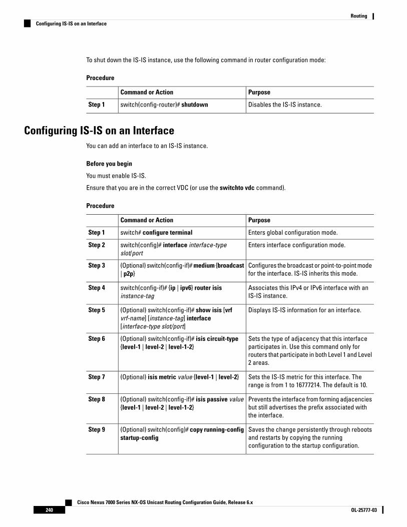
To shut down the IS-IS instance, use the following command in router configuration mode:
Procedure
PurposeCommand or Action
Disables the IS-IS instance.switch(config-router)# shutdownStep 1
Configuring IS-IS on an InterfaceYou can add an interface to an IS-IS instance.
Before you begin
You must enable IS-IS.
Ensure that you are in the correct VDC (or use the switchto vdc command).
Procedure
PurposeCommand or Action
Enters global configuration mode.switch# configure terminalStep 1
Enters interface configuration mode.switch(config)# interface interface-typeslot/port
Step 2
Configures the broadcast or point-to-point modefor the interface. IS-IS inherits this mode.
(Optional) switch(config-if)# medium {broadcast| p2p}
Step 3
Associates this IPv4 or IPv6 interface with anIS-IS instance.
switch(config-if)# {ip | ipv6} router isisinstance-tag
Step 4
Displays IS-IS information for an interface.(Optional) switch(config-if)# show isis [vrfvrf-name] [instance-tag] interface[interface-type slot/port]
Step 5
Sets the type of adjacency that this interfaceparticipates in. Use this command only for
(Optional) switch(config-if)# isis circuit-type{level-1 | level-2 | level-1-2}
Step 6
routers that participate in both Level 1 and Level2 areas.
Sets the IS-IS metric for this interface. Therange is from 1 to 16777214. The default is 10.
(Optional) isis metric value {level-1 | level-2}Step 7
Prevents the interface from forming adjacenciesbut still advertises the prefix associated withthe interface.
(Optional) switch(config-if)# isis passive value{level-1 | level-2 | level-1-2}
Step 8
Saves the change persistently through rebootsand restarts by copying the runningconfiguration to the startup configuration.
(Optional) switch(config)# copy running-configstartup-config
Step 9
Cisco Nexus 7000 Series NX-OS Unicast Routing Configuration Guide, Release 6.xOL-25777-03240
RoutingConfiguring IS-IS on an Interface
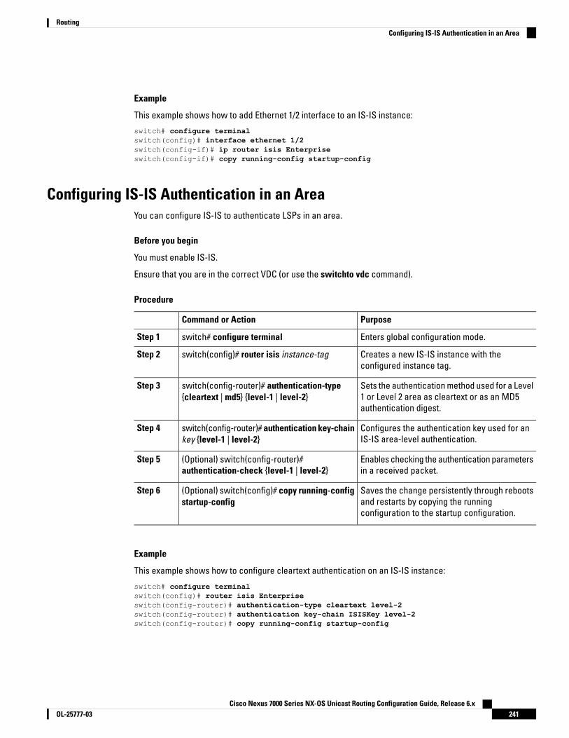
Example
This example shows how to add Ethernet 1/2 interface to an IS-IS instance:
switch# configure terminalswitch(config)# interface ethernet 1/2switch(config-if)# ip router isis Enterpriseswitch(config-if)# copy running-config startup-config
Configuring IS-IS Authentication in an AreaYou can configure IS-IS to authenticate LSPs in an area.
Before you begin
You must enable IS-IS.
Ensure that you are in the correct VDC (or use the switchto vdc command).
Procedure
PurposeCommand or Action
Enters global configuration mode.switch# configure terminalStep 1
Creates a new IS-IS instance with theconfigured instance tag.
switch(config)# router isis instance-tagStep 2
Sets the authentication method used for a Level1 or Level 2 area as cleartext or as an MD5authentication digest.
switch(config-router)# authentication-type{cleartext | md5} {level-1 | level-2}
Step 3
Configures the authentication key used for anIS-IS area-level authentication.
switch(config-router)# authentication key-chainkey {level-1 | level-2}
Step 4
Enables checking the authentication parametersin a received packet.
(Optional) switch(config-router)#authentication-check {level-1 | level-2}
Step 5
Saves the change persistently through rebootsand restarts by copying the runningconfiguration to the startup configuration.
(Optional) switch(config)# copy running-configstartup-config
Step 6
Example
This example shows how to configure cleartext authentication on an IS-IS instance:
switch# configure terminalswitch(config)# router isis Enterpriseswitch(config-router)# authentication-type cleartext level-2switch(config-router)# authentication key-chain ISISKey level-2switch(config-router)# copy running-config startup-config
Cisco Nexus 7000 Series NX-OS Unicast Routing Configuration Guide, Release 6.x241OL-25777-03
RoutingConfiguring IS-IS Authentication in an Area
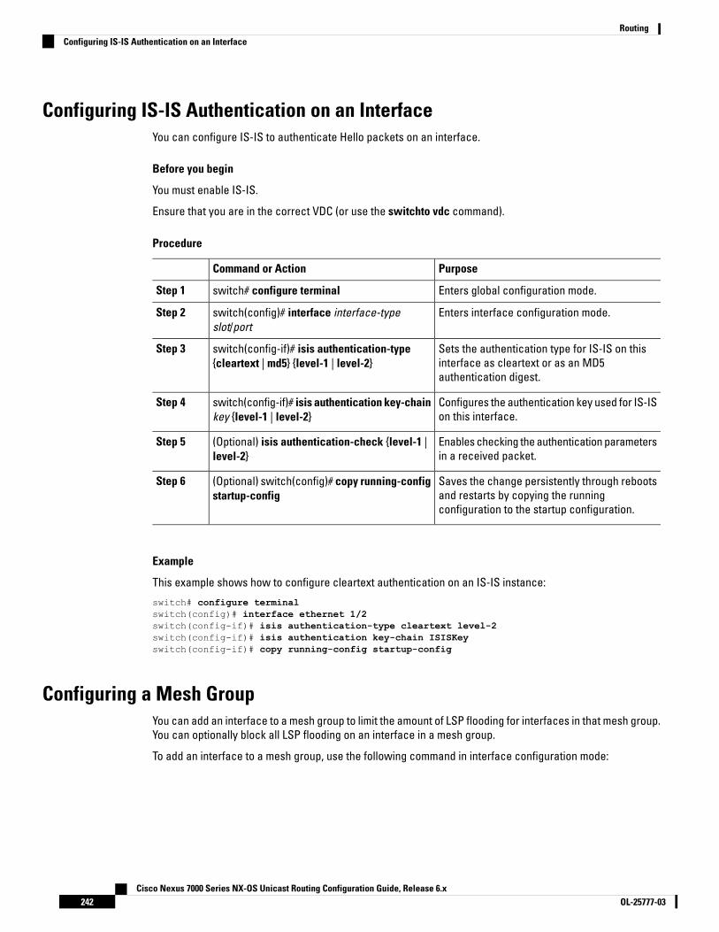
Configuring IS-IS Authentication on an InterfaceYou can configure IS-IS to authenticate Hello packets on an interface.
Before you begin
You must enable IS-IS.
Ensure that you are in the correct VDC (or use the switchto vdc command).
Procedure
PurposeCommand or Action
Enters global configuration mode.switch# configure terminalStep 1
Enters interface configuration mode.switch(config)# interface interface-typeslot/port
Step 2
Sets the authentication type for IS-IS on thisinterface as cleartext or as an MD5authentication digest.
switch(config-if)# isis authentication-type{cleartext | md5} {level-1 | level-2}
Step 3
Configures the authentication key used for IS-ISon this interface.
switch(config-if)# isis authentication key-chainkey {level-1 | level-2}
Step 4
Enables checking the authentication parametersin a received packet.
(Optional) isis authentication-check {level-1 |level-2}
Step 5
Saves the change persistently through rebootsand restarts by copying the runningconfiguration to the startup configuration.
(Optional) switch(config)# copy running-configstartup-config
Step 6
Example
This example shows how to configure cleartext authentication on an IS-IS instance:
switch# configure terminalswitch(config)# interface ethernet 1/2switch(config-if)# isis authentication-type cleartext level-2switch(config-if)# isis authentication key-chain ISISKeyswitch(config-if)# copy running-config startup-config
Configuring a Mesh GroupYou can add an interface to a mesh group to limit the amount of LSP flooding for interfaces in that mesh group.You can optionally block all LSP flooding on an interface in a mesh group.
To add an interface to a mesh group, use the following command in interface configuration mode:
Cisco Nexus 7000 Series NX-OS Unicast Routing Configuration Guide, Release 6.xOL-25777-03242
RoutingConfiguring IS-IS Authentication on an Interface

Procedure
PurposeCommand or Action
Adds this interface to a mesh group. The rangeis from 1 to 4294967295.
switch(config-if)# isis mesh-group {blocked |mesh-id}
Step 1
Configuring a Designated Intermediate SystemYou can configure a router to become the designated intermediate system (DIS) for a multiaccess network bysetting the interface priority.
To configure the DIS, use the following command in interface configuration mode:
Procedure
PurposeCommand or Action
Sets the priority for DIS selection. The range isfrom 0 to 127. The default is 64.
switch(config-if)# isis priority number {level-1| level-2}
Step 1
Configuring Dynamic Host ExchangeYou can configure IS-IS to map between the system ID and the hostname for a router using dynamic hostexchange.
To configure dynamic host exchange, use the following command in router configuration mode:
Procedure
PurposeCommand or Action
Enables dynamic host exchange.switch(config-router)# hostname dynamicStep 1
Setting the Overload BitYou can configure the router to signal other routers not to use this router as an intermediate hop in theirshortest path first (SPF) calculations. You can optionally configure the overload bit temporarily on startup, untilBGP converges.
In addition to setting the overload bit, you might also want to suppress certain types of IP prefix advertisementsfrom LSPs for Level 1 or Level 2 traffic.
To set the overload bit, use the following command in router configuration mode:
Procedure
PurposeCommand or Action
Sets the overload bit for IS-IS. The secondsrange is from 5 to 86400.
switch(config-router)# set-overload-bit {always| on-startup {seconds | wait-for bgp as-number}}[suppress [interlevel | external]]
Step 1
Cisco Nexus 7000 Series NX-OS Unicast Routing Configuration Guide, Release 6.x243OL-25777-03
RoutingConfiguring a Designated Intermediate System

Configuring the Attached BitYou can configure the attached bit to control which Level 1/Level 2 router that the Level 1 routers use as thedefault route to the Level 2 area. If you disable setting the attached bit, the Level 1 routers do not use this Level1/Level 2 router to reach the Level 2 area.
To configure the attached bit for a Level 1/Level 2 router, use the following command in router configurationmode:
Procedure
PurposeCommand or Action
Configures the Level 1/Level 2 router to set theattached bit. This feature is enabled by default.
switch(config-router)# [no] attached-bitStep 1
Configuring the Transient Mode for Hello PaddingYou can configure the transient mode for hello padding to pad hello packets when IS-IS establishes adjacencyand remove that padding after IS-IS establishes adjacency.
To configure the mode for hello padding, use the following command in router configuration mode:
Procedure
PurposeCommand or Action
Pads the hello packet to the full MTU. Thedefault is enabled. Use the no form of this
switch(config-if)# [no] isis hello-paddingStep 1
command to configure the transient mode ofhello padding.
Configuring a Summary AddressYou can create aggregate addresses that are represented in the routing table by a summary address. Onesummary address can include multiple groups of addresses for a given level. Cisco NX-OS advertises thesmallest metric of all the more-specific routes.
Before you begin
You must enable IS-IS.
Ensure that you are in the correct VDC (or use the switchto vdc command).
Procedure
PurposeCommand or Action
Enters global configuration mode.switch# configure terminalStep 1
Creates a new IS-IS instance with theconfigured instance tag.
switch(config)# router isis instance-tagStep 2
Cisco Nexus 7000 Series NX-OS Unicast Routing Configuration Guide, Release 6.xOL-25777-03244
RoutingConfiguring the Attached Bit
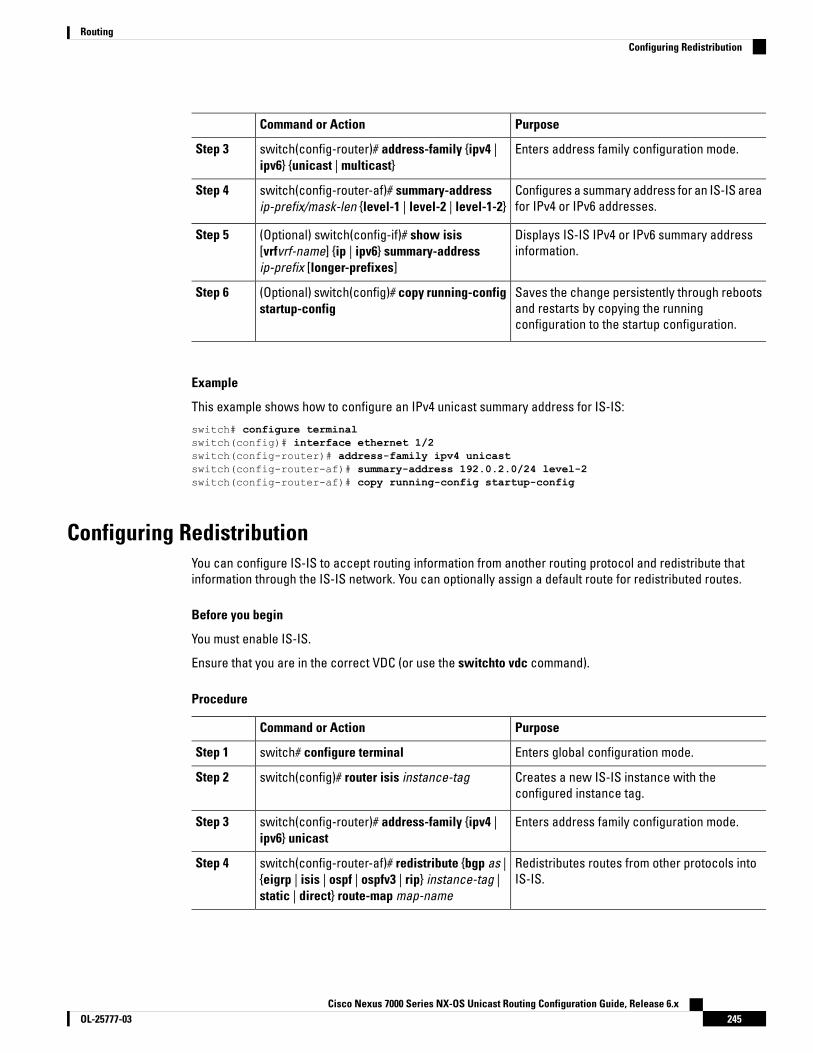
PurposeCommand or Action
Enters address family configuration mode.switch(config-router)# address-family {ipv4 |ipv6} {unicast | multicast}
Step 3
Configures a summary address for an IS-IS areafor IPv4 or IPv6 addresses.
switch(config-router-af)# summary-addressip-prefix/mask-len {level-1 | level-2 | level-1-2}
Step 4
Displays IS-IS IPv4 or IPv6 summary addressinformation.
(Optional) switch(config-if)# show isis[vrfvrf-name] {ip | ipv6} summary-addressip-prefix [longer-prefixes]
Step 5
Saves the change persistently through rebootsand restarts by copying the runningconfiguration to the startup configuration.
(Optional) switch(config)# copy running-configstartup-config
Step 6
Example
This example shows how to configure an IPv4 unicast summary address for IS-IS:
switch# configure terminalswitch(config)# interface ethernet 1/2switch(config-router)# address-family ipv4 unicastswitch(config-router-af)# summary-address 192.0.2.0/24 level-2switch(config-router-af)# copy running-config startup-config
Configuring RedistributionYou can configure IS-IS to accept routing information from another routing protocol and redistribute thatinformation through the IS-IS network. You can optionally assign a default route for redistributed routes.
Before you begin
You must enable IS-IS.
Ensure that you are in the correct VDC (or use the switchto vdc command).
Procedure
PurposeCommand or Action
Enters global configuration mode.switch# configure terminalStep 1
Creates a new IS-IS instance with theconfigured instance tag.
switch(config)# router isis instance-tagStep 2
Enters address family configuration mode.switch(config-router)# address-family {ipv4 |ipv6} unicast
Step 3
Redistributes routes from other protocols intoIS-IS.
switch(config-router-af)# redistribute {bgp as |{eigrp | isis | ospf | ospfv3 | rip} instance-tag |static | direct} route-map map-name
Step 4
Cisco Nexus 7000 Series NX-OS Unicast Routing Configuration Guide, Release 6.x245OL-25777-03
RoutingConfiguring Redistribution

PurposeCommand or Action
Generates a default route into IS-IS.(Optional) switch(config-router-af)#default-information originate [always][route-map map-name]
Step 5
Redistributes routes from one IS-IS level to theother IS-IS level.
(Optional) switch(config-router-af)# distribute{level-1 | level-2} into {level-1 | level-2}{route-map route-map | all}
Step 6
Shows the IS-IS routes.(Optional) switch(config-router-af)# show isis[vrf vrf-name] {ip | ipv6} route ip-prefix [detail |longer-prefixes [summary | detail]]
Step 7
Saves the change persistently through rebootsand restarts by copying the runningconfiguration to the startup configuration.
(Optional) switch(config)# copy running-configstartup-config
Step 8
Example
This example shows how to redistribute EIGRP into IS-IS:
switch# configure terminalswitch(config)# interface ethernet 1/2switch(config-router)# address-family ipv4 unicastswitch(config-router-af)# redistribute eigrp 201 route-map ISISmapswitch(config-router-af)# copy running-config startup-config
Limiting the Number of Redistributed RoutesRoute redistribution can add many routes to the IS-IS route table. You can configure a maximum limit to thenumber of routes accepted from external protocols. IS-IS provides the following options to configureredistributed route limits:
• Fixed limit—Logs a message when IS-IS reaches the configured maximum. IS-IS does not accept anymore redistributed routes. You can optionally configure a threshold percentage of the maximum whereIS-IS logs a warning when that threshold is passed.
• Warning only—Logs a warning only when IS-IS reaches the maximum. IS-IS continues to acceptredistributed routes.
• Withdraw—Starts the timeout period when IS-IS reaches the maximum. After the timeout period, IS-ISrequests all redistributed routes if the current number of redistributed routes is less than the maximumlimit. If the current number of redistributed routes is at the maximum limit, IS-IS withdraws all redistributedroutes. You must clear this condition before IS-IS accepts more redistributed routes. You can optionallyconfigure the timeout period.
Before you begin
You must enable IS-IS.
Ensure that you are in the correct VDC (or use the switchto vdc command).
Cisco Nexus 7000 Series NX-OS Unicast Routing Configuration Guide, Release 6.xOL-25777-03246
RoutingLimiting the Number of Redistributed Routes
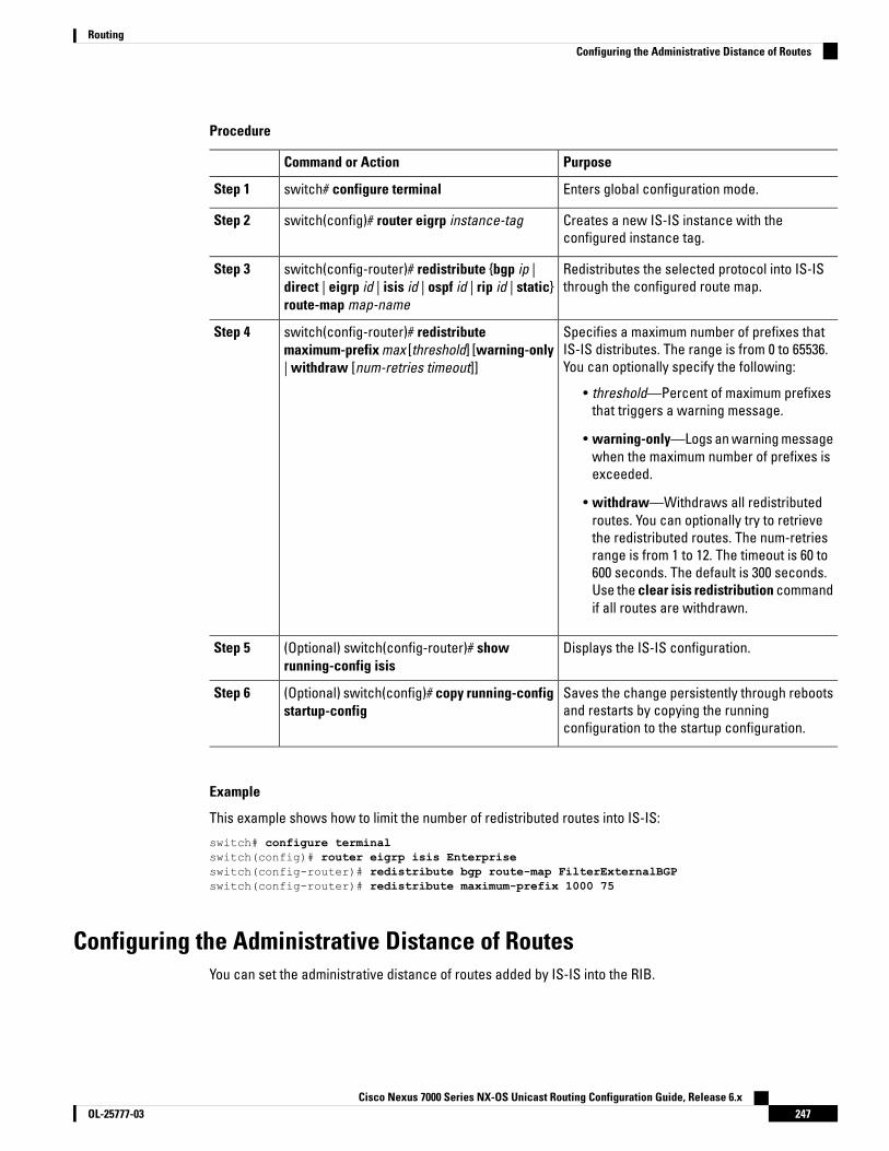
Procedure
PurposeCommand or Action
Enters global configuration mode.switch# configure terminalStep 1
Creates a new IS-IS instance with theconfigured instance tag.
switch(config)# router eigrp instance-tagStep 2
Redistributes the selected protocol into IS-ISthrough the configured route map.
switch(config-router)# redistribute {bgp ip |direct | eigrp id | isis id | ospf id | rip id | static}route-map map-name
Step 3
Specifies a maximum number of prefixes thatIS-IS distributes. The range is from 0 to 65536.You can optionally specify the following:
switch(config-router)# redistributemaximum-prefix max [threshold] [warning-only| withdraw [num-retries timeout]]
Step 4
• threshold—Percent of maximum prefixesthat triggers a warning message.
• warning-only—Logs an warning messagewhen the maximum number of prefixes isexceeded.
• withdraw—Withdraws all redistributedroutes. You can optionally try to retrievethe redistributed routes. The num-retriesrange is from 1 to 12. The timeout is 60 to600 seconds. The default is 300 seconds.Use the clear isis redistribution commandif all routes are withdrawn.
Displays the IS-IS configuration.(Optional) switch(config-router)# showrunning-config isis
Step 5
Saves the change persistently through rebootsand restarts by copying the runningconfiguration to the startup configuration.
(Optional) switch(config)# copy running-configstartup-config
Step 6
Example
This example shows how to limit the number of redistributed routes into IS-IS:
switch# configure terminalswitch(config)# router eigrp isis Enterpriseswitch(config-router)# redistribute bgp route-map FilterExternalBGPswitch(config-router)# redistribute maximum-prefix 1000 75
Configuring the Administrative Distance of RoutesYou can set the administrative distance of routes added by IS-IS into the RIB.
Cisco Nexus 7000 Series NX-OS Unicast Routing Configuration Guide, Release 6.x247OL-25777-03
RoutingConfiguring the Administrative Distance of Routes
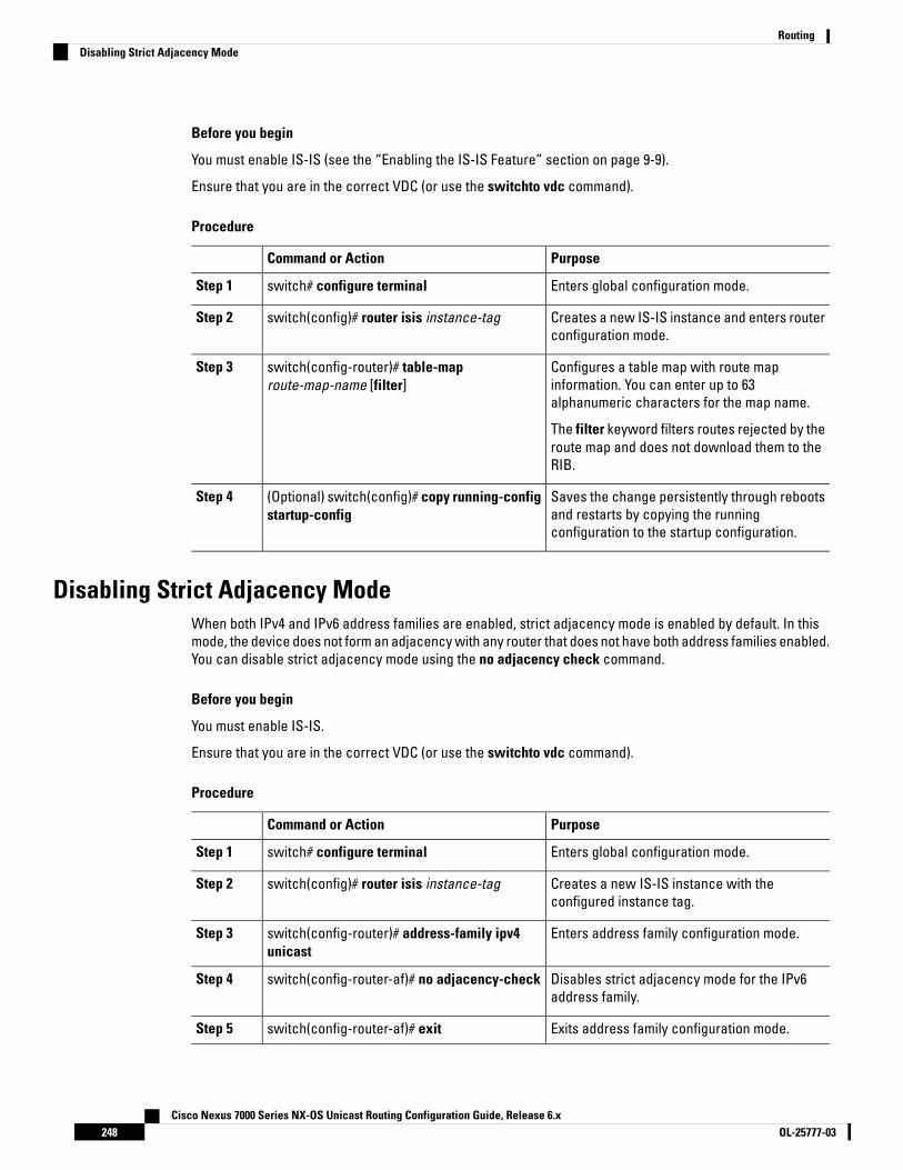
Before you begin
You must enable IS-IS (see the “Enabling the IS-IS Feature” section on page 9-9).
Ensure that you are in the correct VDC (or use the switchto vdc command).
Procedure
PurposeCommand or Action
Enters global configuration mode.switch# configure terminalStep 1
Creates a new IS-IS instance and enters routerconfiguration mode.
switch(config)# router isis instance-tagStep 2
Configures a table map with route mapinformation. You can enter up to 63alphanumeric characters for the map name.
switch(config-router)# table-maproute-map-name [filter]
Step 3
The filter keyword filters routes rejected by theroute map and does not download them to theRIB.
Saves the change persistently through rebootsand restarts by copying the runningconfiguration to the startup configuration.
(Optional) switch(config)# copy running-configstartup-config
Step 4
Disabling Strict Adjacency ModeWhen both IPv4 and IPv6 address families are enabled, strict adjacency mode is enabled by default. In thismode, the device does not form an adjacency with any router that does not have both address families enabled.You can disable strict adjacency mode using the no adjacency check command.
Before you begin
You must enable IS-IS.
Ensure that you are in the correct VDC (or use the switchto vdc command).
Procedure
PurposeCommand or Action
Enters global configuration mode.switch# configure terminalStep 1
Creates a new IS-IS instance with theconfigured instance tag.
switch(config)# router isis instance-tagStep 2
Enters address family configuration mode.switch(config-router)# address-family ipv4unicast
Step 3
Disables strict adjacency mode for the IPv6address family.
switch(config-router-af)# no adjacency-checkStep 4
Exits address family configuration mode.switch(config-router-af)# exitStep 5
Cisco Nexus 7000 Series NX-OS Unicast Routing Configuration Guide, Release 6.xOL-25777-03248
RoutingDisabling Strict Adjacency Mode
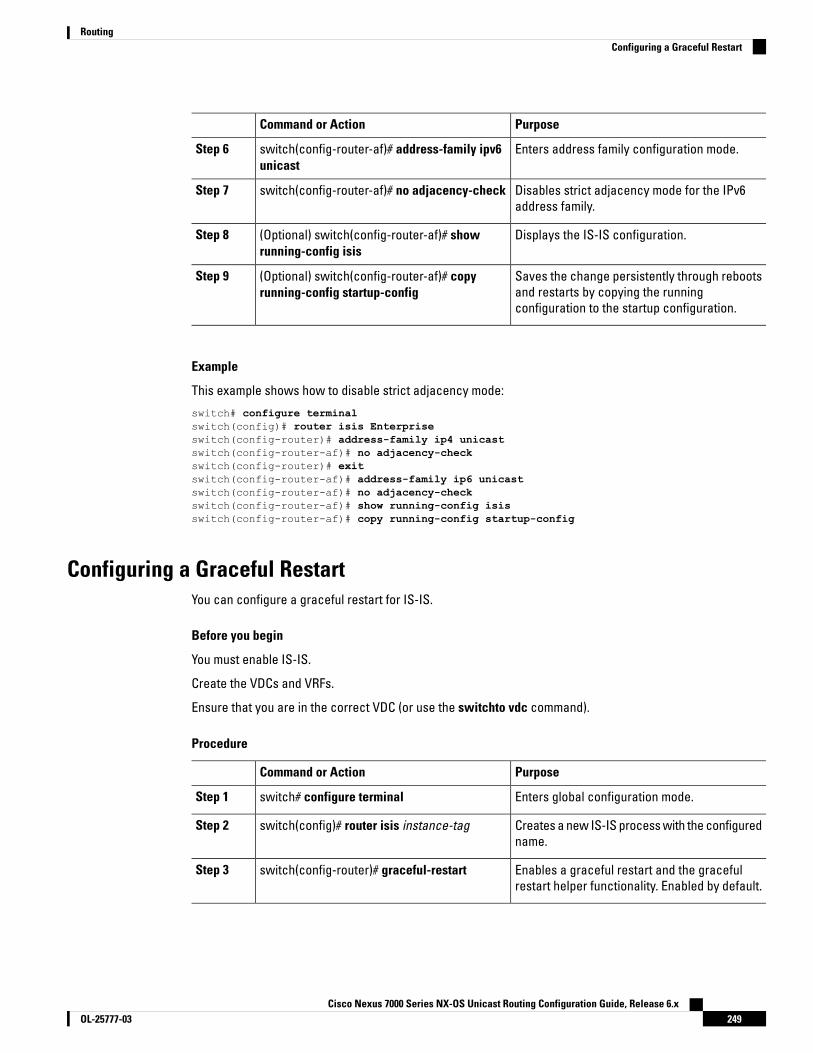
PurposeCommand or Action
Enters address family configuration mode.switch(config-router-af)# address-family ipv6unicast
Step 6
Disables strict adjacency mode for the IPv6address family.
switch(config-router-af)# no adjacency-checkStep 7
Displays the IS-IS configuration.(Optional) switch(config-router-af)# showrunning-config isis
Step 8
Saves the change persistently through rebootsand restarts by copying the runningconfiguration to the startup configuration.
(Optional) switch(config-router-af)# copyrunning-config startup-config
Step 9
Example
This example shows how to disable strict adjacency mode:
switch# configure terminalswitch(config)# router isis Enterpriseswitch(config-router)# address-family ip4 unicastswitch(config-router-af)# no adjacency-checkswitch(config-router)# exitswitch(config-router-af)# address-family ip6 unicastswitch(config-router-af)# no adjacency-checkswitch(config-router-af)# show running-config isisswitch(config-router-af)# copy running-config startup-config
Configuring a Graceful RestartYou can configure a graceful restart for IS-IS.
Before you begin
You must enable IS-IS.
Create the VDCs and VRFs.
Ensure that you are in the correct VDC (or use the switchto vdc command).
Procedure
PurposeCommand or Action
Enters global configuration mode.switch# configure terminalStep 1
Creates a new IS-IS process with the configuredname.
switch(config)# router isis instance-tagStep 2
Enables a graceful restart and the gracefulrestart helper functionality. Enabled by default.
switch(config-router)# graceful-restartStep 3
Cisco Nexus 7000 Series NX-OS Unicast Routing Configuration Guide, Release 6.x249OL-25777-03
RoutingConfiguring a Graceful Restart

PurposeCommand or Action
Configures the graceful restart T3 timer. Therange is from 30 to 65535 seconds. The defaultis 60.
switch(config-router)# graceful-restart t3manual time
Step 4
Displays the IS-IS configuration.(Optional) switch(config-router)# showrunning-config isis
Step 5
Saves the change persistently through rebootsand restarts by copying the runningconfiguration to the startup configuration.
(Optional) switch(config)# copy running-configstartup-config
Step 6
Example
This example shows how to enable a graceful restart:
switch# configure terminalswitch(config)# router isis Enterpriseswitch(config-router)# graceful restartswitch(config-router)# copy running-config startup-config
Configuring VirtualizationYou can configure multiple IS-IS instances in each VDC. You can also create multiple VRFs within each VDCand use the same or multiple IS-IS instances in each VRF. You assign an IS-IS interface to a VRF.
You must configure a NET for the configured VRF.
Configure all other parameters for an interface after you configure the VRF for an interface. Configuring a VRFfor an interface deletes all the configuration for that interface.
Note
Before you begin
You must enable IS-IS.
Create the VDCs and VRFs.
Ensure that you are in the correct VDC (or use the switchto vdc command).
Procedure
PurposeCommand or Action
Enters global configuration mode.switch# configure terminalStep 1
Creates a new VRF and enters VRFconfiguration mode.
switch(config)# vrf context vrf-nameStep 2
Exits VRF configuration mode.switch(config)# exitStep 3
Cisco Nexus 7000 Series NX-OS Unicast Routing Configuration Guide, Release 6.xOL-25777-03250
RoutingConfiguring Virtualization

PurposeCommand or Action
Creates a new IS-IS instance with theconfigured instance tag.
switch(config)# router isis instance-tagStep 4
Enters VRF configuration mode.(Optional) switch(config-router)# vrf vrf-nameStep 5
Configures the NET for this IS-IS instance.switch(config-router-vrf)# netnetwork-entity-title
Step 6
Exits router VRF configuration mode.switch(config-router-vrf)# exitStep 7
Enters interface configuration mode.switch(config)# interface ethernet slot/portStep 8
Adds this interface to a VRF.switch(config-if)# vrf member vrf-nameStep 9
Configures an IP address for this interface. Youmust do this step after you assign this interfaceto a VRF.
switch(config-if)# ip address ip-prefix/lengthStep 10
Associates this IPv4 interface with an IS-ISinstance.
switch(config-if)# ip router isis instance-tagStep 11
Displays IS-IS information for an interface. ina VRF.
(Optional) switch(config-if)# show isis [vrfvrf-name] [instance-tag] interface[interface-type slot/port]
Step 12
Saves the change persistently through rebootsand restarts by copying the runningconfiguration to the startup configuration.
(Optional) switch(config)# copy running-configstartup-config
Step 13
Example
The following example shows how to create a VRF and add an interface to the VRF:
switch# configure terminalswitch(config)# vrf context NewVRFswitch(config-vrf)# exitswitch(config)# router isis Enterpriseswitch(config-router)# vrf NewVRFswitch(config-router-vrf)# net 47.0004.004d.0001.0001.0c11.1111.00switch(config-router-vrf)# interface ethernet 1/2switch(config-if)# vrf member NewVRFswitch(config-if)# ip address 192.0.2.1/16switch(config-if)# ip router isis Enterpriseswitch(config-if)# copy running-config startup-config
Tuning IS-ISYou can tune IS-IS to match your network requirements.
You can use the following optional commands in router configuration mode to tune IS-IS:
Cisco Nexus 7000 Series NX-OS Unicast Routing Configuration Guide, Release 6.x251OL-25777-03
RoutingTuning IS-IS
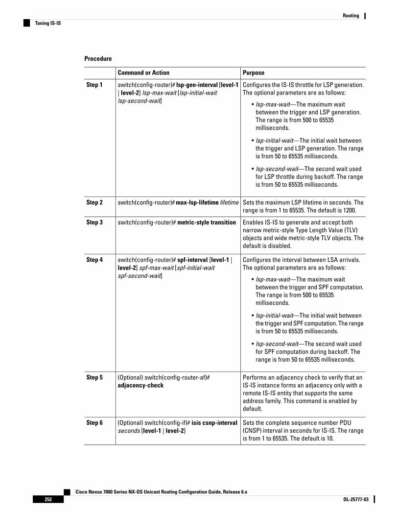
Procedure
PurposeCommand or Action
Configures the IS-IS throttle for LSP generation.The optional parameters are as follows:
switch(config-router)# lsp-gen-interval [level-1| level-2] lsp-max-wait [lsp-initial-waitlsp-second-wait]
Step 1
• lsp-max-wait—The maximum waitbetween the trigger and LSP generation.The range is from 500 to 65535milliseconds.
• lsp-initial-wait—The initial wait betweenthe trigger and LSP generation. The rangeis from 50 to 65535 milliseconds.
• lsp-second-wait—The second wait usedfor LSP throttle during backoff. The rangeis from 50 to 65535 milliseconds.
Sets the maximum LSP lifetime in seconds. Therange is from 1 to 65535. The default is 1200.
switch(config-router)# max-lsp-lifetime lifetimeStep 2
Enables IS-IS to generate and accept bothnarrow metric-style Type Length Value (TLV)
switch(config-router)# metric-style transitionStep 3
objects and wide metric-style TLV objects. Thedefault is disabled.
Configures the interval between LSA arrivals.The optional parameters are as follows:
switch(config-router)# spf-interval [level-1 |level-2] spf-max-wait [spf-initial-waitspf-second-wait]
Step 4
• lsp-max-wait—The maximum waitbetween the trigger and SPF computation.The range is from 500 to 65535milliseconds.
• lsp-initial-wait—The initial wait betweenthe trigger and SPF computation. The rangeis from 50 to 65535 milliseconds.
• lsp-second-wait—The second wait usedfor SPF computation during backoff. Therange is from 50 to 65535 milliseconds.
Performs an adjacency check to verify that anIS-IS instance forms an adjacency only with a
(Optional) switch(config-router-af)#adjacency-check
Step 5
remote IS-IS entity that supports the sameaddress family. This command is enabled bydefault.
Sets the complete sequence number PDU(CNSP) interval in seconds for IS-IS. The rangeis from 1 to 65535. The default is 10.
(Optional) switch(config-if)# isis csnp-intervalseconds [level-1 | level-2]
Step 6
Cisco Nexus 7000 Series NX-OS Unicast Routing Configuration Guide, Release 6.xOL-25777-03252
RoutingTuning IS-IS

PurposeCommand or Action
Sets the hello interval in seconds for IS-IS. Therange is from 1 to 65535. The default is 10.
(Optional) switch(config-if)# isis hello-intervalseconds [level-1 | level-2]
Step 7
Specifies the number of IS-IS hello packets thata neighbor must miss before the router tears
(Optional) switch(config-if)# isis hello-multipliernum [level-1 | level-2]
Step 8
down an adjacency. The range is from 3 to 1000.The default is 3.
Sets the interval in milliseconds between LSPssent on this interface during flooding. The rangeis from 10 to 65535. The default is 33.
(Optional) switch(config-if)# isis lsp-intervalmilliseconds
Step 9
Monitoring IS-ISTo display IS-IS statistics, use the following commands:
PurposeCommand
Displays the IS-IS adjacency statistics.show isis [instance-tag] adjacency [interface][system-ID] [detail] [summary] [vrf vrf-name]
Displays the IS-IS database statistics.show isis [instance-tag] database [level-1 | level-2][detail] [summary] [lsip] {[adjacency id {ip | ipv6}prefix prefix] [router-id id] [zero-sequence]} [vrfvrf-name]
Displays the IS-IS interface statistics.show isis [instance-tag] statistics [interface] [vrfvrf-name]
Displays the IS-IS redistribution statistics.show isis ip route-map statistics redistribute {bgp id| eigrp id | isis id | ospf id | rip id | static} [vrf vrf-name]
Displays IS-IS distribution statistics for routesdistributed between levels.
show isis ip route-map statistics distribute {level-1 |level-2} into {level-1 | level-2} [vrf vrf-name]
Displays the IS-IS SPF calculation statistics.show isis [instance-tag] spf-log [detail] [vrf vrf-name]
Displays the IS-IS traffic statistics.show isis [instance-tag] traffic [interface] [vrfvrf-name]
To clear IS-IS configuration statistics, perform one of the following tasks:
PurposeCommand
Clears the IS-IS adjacency statistics.clear isis [instance-tag] adjacency [* | [interface][system-id id]] [vrf vrf-name]
Clears the IS-IS redistribution statisticsclear {ip | ipv6} route map statistics {bgp id | eigrpid | isis id | ospf id | rip id | static} [vrf vrf-name]
Clears IS-IS distribution statistics for routes distributedbetween levels.
clear isis route-map statistics distribute {level-1 |level-2} into {level-1 | level-2} [vrf vrf-name]
Cisco Nexus 7000 Series NX-OS Unicast Routing Configuration Guide, Release 6.x253OL-25777-03
RoutingMonitoring IS-IS

PurposeCommand
Clears the IS-IS interface statistics.clear isis [instance-tag] statistics [* | interface] [vrfvrf-name]
Clears the IS-IS traffic statistics.clear isis [instance-tag] traffic [* | interface] [vrfvrf-name]
Configuration Examples for IS-ISThe following example shows how to configure IS-IS:
router isis Enterpriseis-type level-1net 49.0001.0000.0000.0003.00graceful-restartaddress-family ipv4 unicastdefault-information originate
interface ethernet 2/1ip address 192.0.2.1/24isis circuit-type level-1ip router isis Enterprise
Related Documents for IS-ISDocument TitleRelated Topic
Cisco Nexus 7000 Series NX-OS Unicast RoutingCommand Reference
IS-IS CLI commands
Cisco Nexus 7000 Series NX-OS Virtual Device ContextCommand Reference
VDCs and VRFs
Standards for IS-ISNo new or modified standards are supported by this feature, and support for existing standards has not beenmodified by this feature.
Feature History for IS-ISThis table includes only the updates for those releases that have resulted in additions or changes to the feature.
Table 22: Feature History for IS-IS
Feature InformationReleaseFeature Name
Added support for configuring theadministrative distance of routes.
6.2(2)IS-IS
Cisco Nexus 7000 Series NX-OS Unicast Routing Configuration Guide, Release 6.xOL-25777-03254
RoutingConfiguration Examples for IS-IS
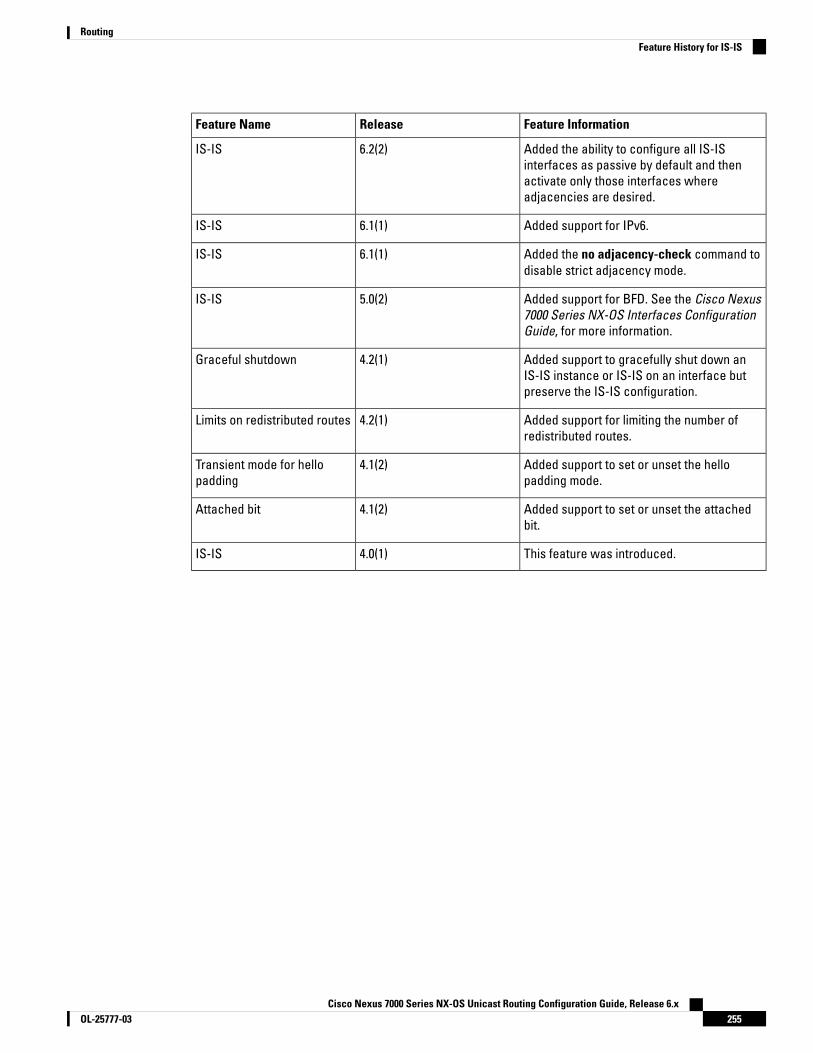
Feature InformationReleaseFeature Name
Added the ability to configure all IS-ISinterfaces as passive by default and thenactivate only those interfaces whereadjacencies are desired.
6.2(2)IS-IS
Added support for IPv6.6.1(1)IS-IS
Added the no adjacency-check command todisable strict adjacency mode.
6.1(1)IS-IS
Added support for BFD. See the Cisco Nexus7000 Series NX-OS Interfaces ConfigurationGuide, for more information.
5.0(2)IS-IS
Added support to gracefully shut down anIS-IS instance or IS-IS on an interface butpreserve the IS-IS configuration.
4.2(1)Graceful shutdown
Added support for limiting the number ofredistributed routes.
4.2(1)Limits on redistributed routes
Added support to set or unset the hellopadding mode.
4.1(2)Transient mode for hellopadding
Added support to set or unset the attachedbit.
4.1(2)Attached bit
This feature was introduced.4.0(1)IS-IS
Cisco Nexus 7000 Series NX-OS Unicast Routing Configuration Guide, Release 6.x255OL-25777-03
RoutingFeature History for IS-IS

Cisco Nexus 7000 Series NX-OS Unicast Routing Configuration Guide, Release 6.xOL-25777-03256
RoutingFeature History for IS-IS

C H A P T E R 11Configuring Basic BGP
This chapter contains the following sections:
• Finding Feature Information, on page 257• Information About Basic BGP, on page 257• Prerequisites for BGP, on page 267• Guidelines and Limitations for BGP, on page 267• Default Settings, on page 268• CLI Configuration Modes, on page 268• Configuring Basic BGP, on page 270• Verifying the Basic BGP Configuration, on page 281• Monitoring BGP Statistics, on page 283• Configuration Examples for Basic BGP, on page 283• Related Documents for Basic BGP, on page 283• MIBs, on page 284• Feature History for BGP , on page 284
Finding Feature InformationYour software release might not support all the features documented in this module. For the latest caveatsand feature information, see the Bug Search Tool at https://tools.cisco.com/bugsearch/ and the release notesfor your software release. To find information about the features documented in this module, and to see a listof the releases in which each feature is supported, see the "New and Changed Information"chapter or theFeature History table in this chapter.
Information About Basic BGPCisco NX-OS supports BGP version 4, which includes multiprotocol extensions that allow BGP to carry routinginformation for IP multicast routes and multiple Layer 3 protocol address families. BGP uses TCP as a reliabletransport protocol to create TCP sessions with other BGP-enabled devices.
BGP uses a path-vector routing algorithm to exchange routing information between BGP-enabled networkingdevices or BGP speakers. Based on this information, each BGP speaker determines a path to reach a particulardestination while detecting and avoiding paths with routing loops. The routing information includes the actualroute prefix for a destination, the path of autonomous systems to the destination, and additional path attributes.
Cisco Nexus 7000 Series NX-OS Unicast Routing Configuration Guide, Release 6.x257OL-25777-03

BGP selects a single path, by default, as the best path to a destination host or network. Each path carrieswell-known mandatory, well-known discretionary, and optional transitive attributes that are used in BGPbest-path analysis. You can influence BGP path selection by altering some of these attributes by configuringBGP policies.
BGP also supports load balancing or equal-cost multipath (ECMP).
For information on configuring BGP in an MPLS network, see the Cisco Nexus 7000 Series NX-OS MPLSConfiguration Guide.
BGP Autonomous SystemsAn autonomous system (AS) is a network controlled by a single administration entity. An autonomous systemforms a routing domain with one or more interior gateway protocols (IGPs) and a consistent set of routingpolicies. BGP supports 16-bit and 32-bit autonomous system numbers.
Separate BGP autonomous systems dynamically exchange routing information through external BGP (eBGP)peering sessions. BGP speakers within the same autonomous system can exchange routing information throughinternal BGP (iBGP) peering sessions.
4-Byte AS Number SupportBGP supports 2-byte or 4-byte AS numbers. Cisco NX-OS displays 4-byte AS numbers in plain-text notation(that is, as 32-bit integers). You can configure 4-byte AS numbers as either plain-text notation (for example, 1to 4294967295) or AS.dot notation (for example, 1.0).
Administrative DistanceAn administrative distance is a rating of the trustworthiness of a routing information source. By default, BGPuses the administrative distances shown in the table.
Table 23: BGP Default Administrative Distances
FunctionDefault ValueDistance
Applied to routes learned fromeBGP.
20External
Applied to routes learned fromiBGP.
200Internal
Applied to routes originated by therouter.
200Local
The administrative distance does not influence the BGP path selection algorithm, but it does influence whetherBGP-learned routes are installed in the IP routing table.
Note
Cisco Nexus 7000 Series NX-OS Unicast Routing Configuration Guide, Release 6.xOL-25777-03258
RoutingBGP Autonomous Systems

BGP PeersA BGP speaker does not discover another BGP speaker automatically. You must configure the relationshipsbetween BGP speakers. A BGP peer is a BGP speaker that has an active TCP connection to another BGPspeaker.
BGP SessionsBGP uses TCP port 179 to create a TCP session with a peer. When a TCP connection is established betweenpeers, each BGP peer initially exchanges all of its routes—the complete BGP routing table—with the otherpeer. After this initial exchange, the BGP peers send only incremental updates when a topology change occursin the network or when a routing policy change occurs. In the periods of inactivity between these updates,peers exchange special messages called keepalives. The hold time is the maximum time limit that can elapsebetween receiving consecutive BGP update or keepalive messages.
Cisco NX-OS supports the following peer configuration options:
• Individual IPv4 or IPv4 address—BGP establishes a session with the BGP speaker that matches theremote address and AS number.
• IPv4 or IPv6 prefix peers for a single AS number—BGP establishes sessions with BGP speakers thatmatch the prefix and the AS number.
• Dynamic AS number prefix peers—BGP establishes sessions with BGP speakers that match the prefixand an AS number from a list of configured AS numbers.
Dynamic AS Numbers for Prefix PeersCisco NX-OS accepts a range or list of AS numbers to establish BGP sessions. For example, if you configureBGP to use IPv4 prefix 192.0.2.0/8 and AS numbers 33, 66, and 99, BGP establishes a session with 192.0.2.1 withAS number 66 but rejects a session from 192.0.2.2 with AS number 50.
Cisco NX-OS does not associate prefix peers with dynamic AS numbers as either interior BGP (iBGP) or externalBGP (eBGP) sessions until after the session is established.
The dynamic AS number prefix peer configuration overrides the individual AS number configuration that isinherited from a BGP template.
Note
BGP Router IdentifierTo establish BGP sessions between peers, BGP must have a router ID, which is sent to BGP peers in the OPENmessage when a BGP session is established. The BGP router ID is a 32-bit value that is often represented byan IPv4 address. You can configure the router ID. By default, Cisco NX-OS sets the router ID to the IPv4 addressof a loopback interface on the router. If no loopback interface is configured on the router, the software choosesthe highest IPv4 address configured to a physical interface on the router to represent the BGP router ID. TheBGP router ID must be unique to the BGP peers in a network.
If BGP does not have a router ID, it cannot establish any peering sessions with BGP peers.
Cisco Nexus 7000 Series NX-OS Unicast Routing Configuration Guide, Release 6.x259OL-25777-03
RoutingBGP Peers

BGP Path SelectionAlthough BGP might receive advertisements for the same route from multiple sources, BGP selects only onepath as the best path. BGP puts the selected path in the IP routing table and propagates the path to its peers.
Beginning with Cisco NX-OS Release 6.1, BGP supports sending and receiving multiple paths per prefix andadvertising such paths.
Note
The best-path algorithm runs each time that a path is added or withdrawn for a given network. The best-pathalgorithm also runs if you change the BGP configuration. BGP selects the best path from the set of valid pathsavailable for a given network.
Beginning with Cisco NX-OS Release 8.4(1), the behavior of the BGP pre-best path point of insertion (POI) ischanged. In this release, the NX-OS RPM, BGP, and HMM software uses a single cost community ID (either128 for internal routes or 129 for external routes) to identify a BGP VPNv4 route as an EIGRP originated route.
Only the routes that have the pre-best path value set to cost community ID 128 or 129 are installed in the URIBalong with the cost extcommunity. Any non-eigrp originated route carrying the above described cost communityID would be installed in URIB along with pre-best path cost community. As a result, URIB would use this costto identify the better route between the route learnt through the iBGP and backdoor-EIGRP instead of theadministrative distance.
Cisco NX-OS implements the BGP best-path algorithm in the following steps:
1. Compares two paths to determine which is better.
2. Explores all paths and determines in which order to compare the paths to select the overall best path.
3. Determines whether the old and new best paths differ enough so that the new best path should be used.
The order of comparison determined in Part 2 is important. Consider the case where you have three paths, A,B, and C. When Cisco NX-OS compares A and B, it chooses A. When Cisco NX-OS compares B and C, it choosesB. But when Cisco NX-OS compares A and C, it might not choose A because some BGP metrics apply onlyamong paths from the same neighboring autonomous system and not among all paths.
Note
The path selection uses the BGP AS-path attribute. The AS-path attribute includes the list of autonomoussystem numbers (AS numbers) traversed in the advertised path. If you subdivide your BGP autonomous systeminto a collection or confederation of autonomous systems, the AS-path contains confederation segments thatlist these locally defined autonomous systems.
BGP Path Selection - Comparing Pairs of PathsThis first step in the BGP best-path algorithm compares two paths to determine which path is better. Thefollowing sequence describes the basic steps that Cisco NX-OS uses to compare two paths to determine thebetter path:
1. Cisco NX-OS chooses a valid path for comparison. (For example, a path that has an unreachable nexthop is not valid.)
2. Cisco NX-OS chooses the path with the highest weight.
Cisco Nexus 7000 Series NX-OS Unicast Routing Configuration Guide, Release 6.xOL-25777-03260
RoutingBGP Path Selection
3. Cisco NX-OS chooses the path with the highest local preference.
4. If one of the paths is locally originated, Cisco NX-OS chooses that path.
5. Cisco NX-OS chooses the path with the shorter AS path.
When calculating the length of the AS-path, Cisco NX-OS ignores confederation segments and counts AS setsas 1.
Note
6. Cisco NX-OS chooses the path with the lower origin. Interior Gateway Protocol (IGP) is considered lowerthan EGP.
7. Cisco NX-OS chooses the path with the lower multiexit discriminator (MED).
You can configure a number of options that affect whether or not this step is performed. In general,Cisco NX-OS compares the MED of both paths if the paths were received from peers in the sameautonomous system; otherwise, Cisco NX-OS skips the MED comparison.
You can configure Cisco NX-OS to always perform the best-path algorithm MED comparison, regardlessof the peer autonomous system in the paths. Otherwise, Cisco NX-OS performs a MED comparison thatdepends on the AS-path attributes of the two paths being compared:
a. If a path has no AS-path or the AS-path starts with an AS_SET, the path is internal and Cisco NX-OScompares the MED to other internal paths.
b. If the AS-path starts with an AS_SEQUENCE, the peer autonomous system is the first AS number inthe sequence and Cisco NX-OS compares the MED to other paths that have the same peerautonomous system.
c. If the AS-path contains only confederation segments or starts with confederation segments followedby an AS_SET, the path is internal and Cisco NX-OS compares the MED to other internal paths.
d. If the AS-path starts with confederation segments that are followed by an AS_SEQUENCE, the peerautonomous system is the first AS number in the AS_SEQUENCE and Cisco NX-OS compares theMED to other paths that have the same peer autonomous system.
If Cisco NX-OS receives no MED attribute with the path, Cisco NX-OS considers the MED to be 0 unless youconfigure the best-path algorithm to set a missing MED to the highest possible value.
Note
e. If the non-deterministic MED comparison feature is enabled, the best-path algorithm uses the CiscoIOS style of MED comparison.
8. If one path is from an internal peer and the other path is from an external peer, Cisco NX-OS choosesthe path from the external peer.
9. If the paths have different IGP metrics to their next-hop addresses, Cisco NX-OS chooses the path withthe lower IGP metric.
10. Cisco NX-OS uses the path that was selected by the best-path algorithm the last time it was run.
11. If all path parameters in Step 1 through Step 9 are the same, and there is no current best path (forexample, the current best path can be lost when the neighbor that offers the current best path goes
Cisco Nexus 7000 Series NX-OS Unicast Routing Configuration Guide, Release 6.x261OL-25777-03
RoutingBGP Path Selection - Comparing Pairs of Paths
down), then the route from the BGP router with the lowest router ID is chosen. If the path includes anoriginator attribute, Cisco NX-OS uses that attribute as the router ID to compare to; otherwise, CiscoNX-OS uses the router ID of the peer that sent the path. If the paths have different router IDs, CiscoNX-OS chooses the path with the lower router ID.
When using the attribute originator as the router ID, it is possible that two paths have the same router ID. It isalso possible to have two BGP sessions with the same peer router, so you could receive two paths with thesame router ID.
Note
12. Cisco NX-OS selects the path with the shorter cluster length. If a path was not received with a clusterlist attribute, the cluster length is 0.
13. Cisco NX-OS chooses the path received from the peer with the lower IP address. Locally generatedpaths (for example, redistributed paths) have a peer IP address of 0.
Paths that are equal after Step 9 can be used for multipath if you configure multipath.Note
BGP Path Selection - Determining the Order of ComparisonsThe second step of the BGP best-path algorithm implementation is to determine the order in which CiscoNX-OS compares the paths:
1. Cisco NX-OS partitions the paths into groups. Within each group, Cisco NX-OS compares the MED amongall paths. Cisco NX-OS uses the same rule as in the section Step 1—Comparing Pairs of Paths to determinewhether MED can be compared between any two paths. Typically, this comparison results in one groupbeing chosen for each neighbor autonomous system. If you configure the bgp bestpath med alwayscommand, Cisco NX-OS chooses just one group that contains all the paths.
2. Cisco NX-OS determines the best path in each group by iterating through all paths in the group and keepingtrack of the best one so far. Cisco NX-OS compares each path with the temporary best path found so farand if the new path is better, it becomes the new temporary best path and Cisco NX-OS compares it withthe next path in the group.
3. Cisco NX-OS forms a set of paths that contain the best path selected from each group in Step 2. CiscoNX-OS selects the overall best path from this set of paths by going through them as in Step 2.
BGP Path Selection - Determining the Best-Path Change SuppressionThe next part of the implementation is to determine whether Cisco NX-OS uses the new best path or suppressesthe new best path. The router can continue to use the existing best path if the new one is identical to the oldpath (if the router ID is the same). Cisco NX-OS continues to use the existing best path to avoid route changesin the network.
You can turn off the suppression feature by configuring the best-path algorithm to compare the router IDs.See the “Tuning the Best-Path Algorithm” section on page 11-10 for more information. If you configure thisfeature, the new best path is always preferred to the existing one.
You cannot suppress the best-path change if any of the following conditions occur:
Cisco Nexus 7000 Series NX-OS Unicast Routing Configuration Guide, Release 6.xOL-25777-03262
RoutingBGP Path Selection - Determining the Order of Comparisons

• The existing best path is no longer valid.
• Either the existing or new best paths were received from internal (or confederation) peers or were locallygenerated (for example, by redistribution).
• The paths were received from the same peer (the paths have the same router ID).
• The paths have different weights, local preferences, origins, or IGP metrics to their next-hop addresses.
• The paths have different MEDs.
BGP and the Unicast RIBBGP communicates with the unicast routing information base (unicast RIB) to store IPv4 routes in the unicastrouting table. After selecting the best path, if BGP determines that the best path change needs to be reflectedin the routing table, it sends a route update to the unicast RIB.
BGP receives route notifications regarding changes to its routes in the unicast RIB. It also receives routenotifications about other protocol routes to support redistribution.
BGP also receives notifications from the unicast RIB regarding next-hop changes. BGP uses these notificationsto keep track of the reachability and IGP metric to the next-hop addresses.
Whenever the next-hop reachability or IGP metrics in the unicast RIB change, BGP triggers a best-pathrecalculation for affected routes.
BGP communicates with the IPv6 unicast RIB to perform these operations for IPv6 routes.
BGP Prefix Independent ConvergenceThe BGP Prefix Independent Convergence (PIC) feature achieves subsecond convergence in the forwardingplane for BGP IP and Layer 3 VPN routes, when there are BGP next-hop network reachability failures.
BGP PIC has two categories:
• PIC core
• PIC edge
PIC core ensures fast convergence for BGP routes when there is a link or node failure in the core that causesa change in the IGP reachability to a remote BGP next-hop address.
PIC edge ensures fast convergence to a BGP backup path when an external (eBGP) edge link or an externalneighbor node fails.
BGP PIC Feature Support MatrixBGP PIC feature support matrix is shown in the table below:
VPNv6 (perVRF)
VPNv4 (perVRF)
VPNv6 (perprefix)
VPNv4 (perprefix)
IPv6 UnicastIPv4 UnicastBGP PIC
NoYesNoNoYesYesCore Unipath
NoNoNoNoYesYesEdge Unipath
Cisco Nexus 7000 Series NX-OS Unicast Routing Configuration Guide, Release 6.x263OL-25777-03
RoutingBGP and the Unicast RIB

VPNv6 (perVRF)
VPNv4 (perVRF)
VPNv6 (perprefix)
VPNv4 (perprefix)
IPv6 UnicastIPv4 UnicastBGP PIC
NoYesNoNoYesYesCore with Multipathequal
NoNoNoNoYesYesEdge Multipathequal (multipleactive ECMP, onlyone backup)
BGP PIC CoreThe BGP PIC core feature is supported by Cisco NX-OS Release 5.2 and later. The feature allows for fasterconvergence for traffic destined to BGP prefixes that share the same remote next hop in case of a failure inthe core of the network. Both MPLS and pure IP traffic can benefit from this feature. It is enabled by defaultand cannot be disabled.
IPv4, VPNv4, 6PE, and VPNv6 (6VPE) support PIC core with the following constraints:
• For both IP and MPLS core, convergence for internet routes is prefix-independent on the order of BGPnext hops.
• With per-VRF label allocation, VPN route convergence is also prefix-independent on the order of BGPnext hops. That is, when a path to a remote PE changes, the number of VRFs on that PE determinesconvergence.
• With per-prefix label allocation, route convergence is not prefix-independent. Convergence moves to theorder of VPN routes that are advertised by a remote PE if a failure or change occurs in the reachabilityto that PE.
For additional considerations when using BGP PIC core in MPLS networks, see the Cisco Nexus 7000 SeriesNX-OS MPLS Configuration Guide.
BGP PIC EdgeThe BGP PIC for Edge feature improves BGP convergence after a network failure. This convergence is applicableto edge failures in an IP network. The BGP PIC Edge feature creates and stores a backup path in the routinginformation base (RIB) and forwarding information base (FIB) so that when a failure on an eBGP link to SP isdetected (the primary path fails), the backup path can immediately take over, enabling fast fail over in theforwarding plane.
From Cisco NX-OS Release 7.3(0)D1(1) onwards BGP PIC Edge feature supports both IPv4 and IPv6 addressfamilies.
Note
If BGP PIC edge is configured, BGP calculates an additional second best-path (the backup path) along withthe primary best-path. BGP installs both best and backup paths for the prefixes with PIC support into the BGPRIB. BGP also downloads the backup path along with the RNH via APIs to the URIB, which then updates theFIB with the next hop marked as a backup. The backup path provides a fast reroute mechanism to counter asingular network failure.
Cisco Nexus 7000 Series NX-OS Unicast Routing Configuration Guide, Release 6.xOL-25777-03264
RoutingBGP PIC Core

This feature detects both the local interface failure and remote interface/link failure and triggers the use ofthe backup path.
BGP PIC Edge UnipathA BGP PIC edge unipath topology is shown in the figure below:
Figure 32: BGP PIC Edge Unipath
In the above figure:
• eBGP sessions are between S2-S4 and S3-S5
• iBGP session is between S2-S3
• Traffic from S1 uses S2 and uses the e1 interface to reach prefixes Z1..Zn.
• S2 has two paths to reach Z1…Zn
• Primary path via S4
• Backup/alternate via S5
In this example, S3 advertises to S2 the prefixes Z1…Zn to reach with itself as the next hop. BGP on S2, withBGP PIC feature enabled, installs both bestpath (via S4) and backup path (via S3/S5) towards the AS6500 intothe RIB and then the RIB downloads both routes to the FIB.
When the S2-S4 link goes down, the FIB on S2 detects the link failure. It automatically switches from theprimary path to the backup/alternate and points to the new next hop S3. Traffic is quickly rerouted due to thelocal fast re-convergence in FIB. After learning the link failure event, BGP on S2 recomputes the bestpath(which is the previous backup path), removing the next hop S4 from RIB and reinstalling S3 as the primary nexthop into RIB. It also computes a new backup/alternate path, if any, and notifies RIB. With the support of theBGP PIC feature, the FIB can switch to the available backup route instantly upon detection of link failure onthe primary route without waiting for BGP to select new bestpath and converge, and achieve a fast reroute.
Cisco Nexus 7000 Series NX-OS Unicast Routing Configuration Guide, Release 6.x265OL-25777-03
RoutingBGP PIC Edge Unipath
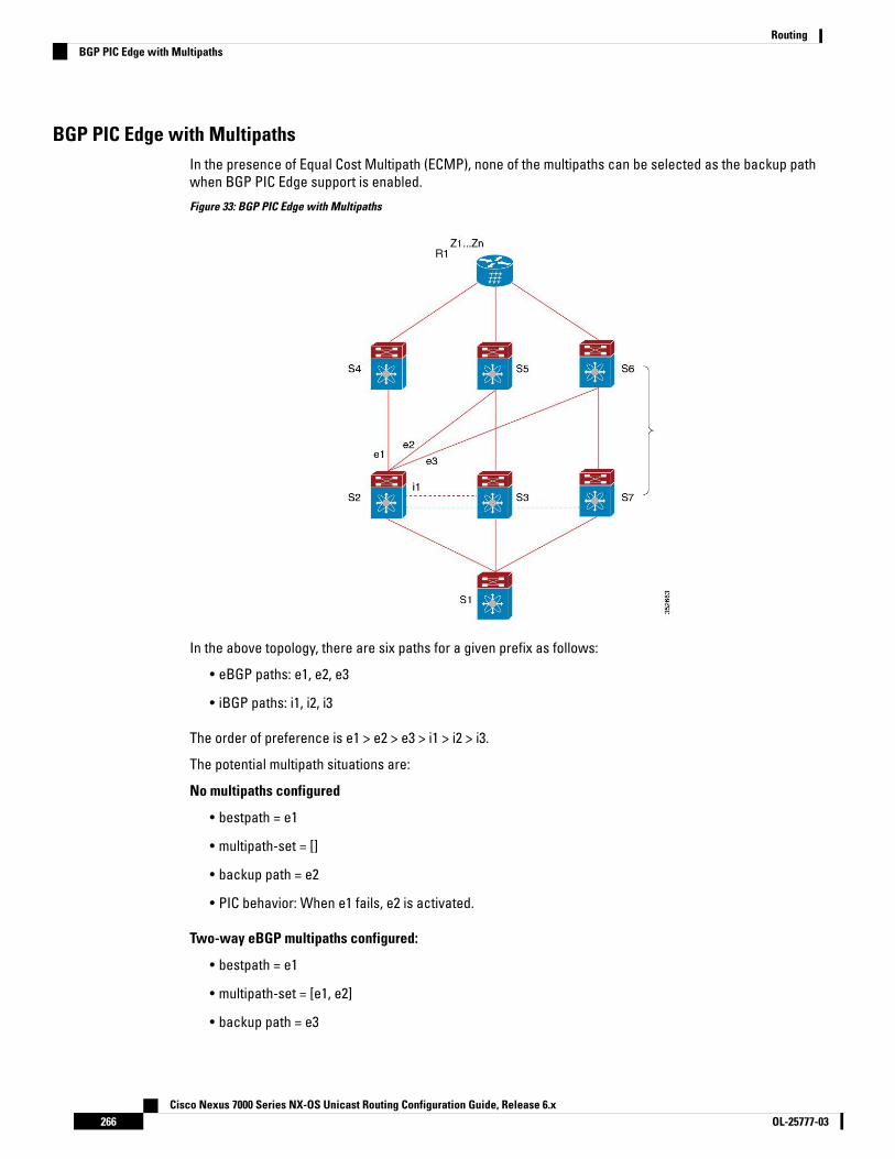
BGP PIC Edge with MultipathsIn the presence of Equal Cost Multipath (ECMP), none of the multipaths can be selected as the backup pathwhen BGP PIC Edge support is enabled.
Figure 33: BGP PIC Edge with Multipaths
In the above topology, there are six paths for a given prefix as follows:
• eBGP paths: e1, e2, e3
• iBGP paths: i1, i2, i3
The order of preference is e1 > e2 > e3 > i1 > i2 > i3.
The potential multipath situations are:
No multipaths configured
• bestpath = e1
• multipath-set = []
• backup path = e2
• PIC behavior: When e1 fails, e2 is activated.
Two-way eBGP multipaths configured:
• bestpath = e1
• multipath-set = [e1, e2]
• backup path = e3
Cisco Nexus 7000 Series NX-OS Unicast Routing Configuration Guide, Release 6.xOL-25777-03266
RoutingBGP PIC Edge with Multipaths
• PIC behavior: Active multipaths are mutually backed up. When all multipaths fail, e3 is activated.
Three-way eBGP multipaths configured:
• bestpath = e1
• multipath-set = [e1, e2, e3]
• backup path = i1
• PIC behavior: Active multipaths are mutually backed up. When all multipaths fail, i1 is activated.
Four-way eiBGP multipaths configured:
• bestpath = e1
• multipath-set = [e1, e2, e3, i1]
• backup path = i2
• PIC behavior: Active multipaths are mutually backed up. When all multipaths fail, i2 is activated.
BGP VirtualizationBGP supports virtual routing and forwarding (VRF) instances. VRFs exist within virtual device contexts (VDCs).By default, Cisco NX-OS places you in the default VDC and default VRF unless you specifically configureanother VDC and VRF. For more information, see the Cisco Nexus 7000 Series NX-OS Virtual Device ContextConfiguration Guide.
Prerequisites for BGPBGP has the following prerequisites:
• You must enable BGP.
• You should have a valid router ID configured on the system.
• You must have an AS number, either assigned by a Regional Internet Registry (RIR) or locally administered.
• You must configure at least one IGP that is capable of recursive next-hop resolution.
• You must configure an address family under a neighbor for the BGP session establishment.
Guidelines and Limitations for BGPBGP has the following configuration guidelines and limitations:
• Cisco NX-OS does not support "fast-external-fallover" for the multi-hop eBGP peering. The BGPdifferentiates the single-hop (directly connected) and the multi-hop eBGP neighbors using theebgp-multihop command. When you use the ebgp-multihop 2 command for an eBGP peer, the BGP treatsit as multi-hop session and does not trigger the "fast-external-fallover". This is a known behaviour.
Cisco Nexus 7000 Series NX-OS Unicast Routing Configuration Guide, Release 6.x267OL-25777-03
RoutingBGP Virtualization
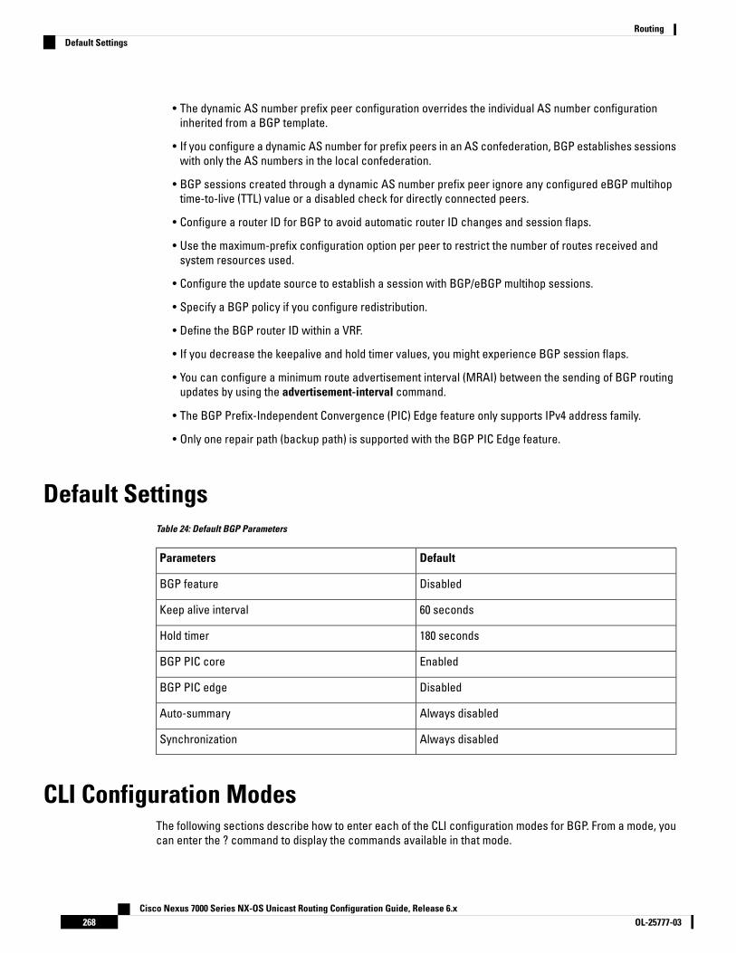
• The dynamic AS number prefix peer configuration overrides the individual AS number configurationinherited from a BGP template.
• If you configure a dynamic AS number for prefix peers in an AS confederation, BGP establishes sessionswith only the AS numbers in the local confederation.
• BGP sessions created through a dynamic AS number prefix peer ignore any configured eBGP multihoptime-to-live (TTL) value or a disabled check for directly connected peers.
• Configure a router ID for BGP to avoid automatic router ID changes and session flaps.
• Use the maximum-prefix configuration option per peer to restrict the number of routes received andsystem resources used.
• Configure the update source to establish a session with BGP/eBGP multihop sessions.
• Specify a BGP policy if you configure redistribution.
• Define the BGP router ID within a VRF.
• If you decrease the keepalive and hold timer values, you might experience BGP session flaps.
• You can configure a minimum route advertisement interval (MRAI) between the sending of BGP routingupdates by using the advertisement-interval command.
• The BGP Prefix-Independent Convergence (PIC) Edge feature only supports IPv4 address family.
• Only one repair path (backup path) is supported with the BGP PIC Edge feature.
Default SettingsTable 24: Default BGP Parameters
DefaultParameters
DisabledBGP feature
60 secondsKeep alive interval
180 secondsHold timer
EnabledBGP PIC core
DisabledBGP PIC edge
Always disabledAuto-summary
Always disabledSynchronization
CLI Configuration ModesThe following sections describe how to enter each of the CLI configuration modes for BGP. From a mode, youcan enter the ? command to display the commands available in that mode.
Cisco Nexus 7000 Series NX-OS Unicast Routing Configuration Guide, Release 6.xOL-25777-03268
RoutingDefault Settings
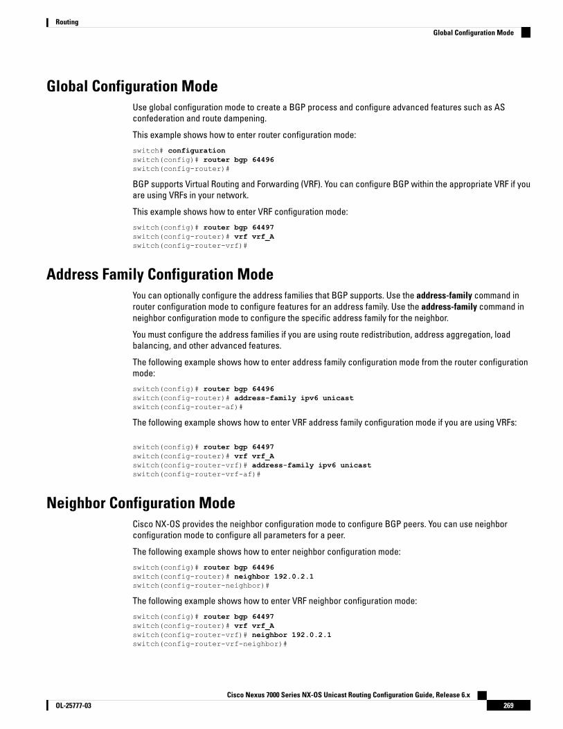
Global Configuration ModeUse global configuration mode to create a BGP process and configure advanced features such as ASconfederation and route dampening.
This example shows how to enter router configuration mode:
switch# configurationswitch(config)# router bgp 64496switch(config-router)#
BGP supports Virtual Routing and Forwarding (VRF). You can configure BGP within the appropriate VRF if youare using VRFs in your network.
This example shows how to enter VRF configuration mode:
switch(config)# router bgp 64497switch(config-router)# vrf vrf_Aswitch(config-router-vrf)#
Address Family Configuration ModeYou can optionally configure the address families that BGP supports. Use the address-family command inrouter configuration mode to configure features for an address family. Use the address-family command inneighbor configuration mode to configure the specific address family for the neighbor.
You must configure the address families if you are using route redistribution, address aggregation, loadbalancing, and other advanced features.
The following example shows how to enter address family configuration mode from the router configurationmode:
switch(config)# router bgp 64496switch(config-router)# address-family ipv6 unicastswitch(config-router-af)#
The following example shows how to enter VRF address family configuration mode if you are using VRFs:
switch(config)# router bgp 64497switch(config-router)# vrf vrf_Aswitch(config-router-vrf)# address-family ipv6 unicastswitch(config-router-vrf-af)#
Neighbor Configuration ModeCisco NX-OS provides the neighbor configuration mode to configure BGP peers. You can use neighborconfiguration mode to configure all parameters for a peer.
The following example shows how to enter neighbor configuration mode:
switch(config)# router bgp 64496switch(config-router)# neighbor 192.0.2.1switch(config-router-neighbor)#
The following example shows how to enter VRF neighbor configuration mode:
switch(config)# router bgp 64497switch(config-router)# vrf vrf_Aswitch(config-router-vrf)# neighbor 192.0.2.1switch(config-router-vrf-neighbor)#
Cisco Nexus 7000 Series NX-OS Unicast Routing Configuration Guide, Release 6.x269OL-25777-03
RoutingGlobal Configuration Mode

Neighbor Address Family Configuration ModeAn address family configuration submode inside the neighbor configuration submode is available for enteringaddress family-specific neighbor configuration and enabling the address family for the neighbor. Use thismode for advanced features such as limiting the number of prefixes allowed for this neighbor and removingprivate AS numbers for eBGP.
The following example shows how to enter neighbor address family configuration mode:
switch(config)# router bgp 64496switch(config-router # neighbor 192.0.2.1switch(config-router-neighbor)# address-family ipv4 unicastswitch(config-router-neighbor-af)#
This example shows how to enter VRF neighbor address family configuration mode:
switch(config)# router bgp 64497switch(config-router)# vrf vrf_Aswitch(config-router-vrf)# neighbor 209.165.201.1switch(config-router-vrf-neighbor)# address-family ipv4 unicastswitch(config-router-vrf-neighbor-af)#
Configuring Basic BGPTo configure a basic BGP, you must enable BGP and configure a BGP peer. Configuring a basic BGP networkconsists of a few required tasks and many optional tasks. You must configure a BGP routing process and BGPpeers.
If you are familiar with the Cisco IOS CLI, be aware that the Cisco NX-OS commands for this feature mightdiffer from the Cisco IOS commands that you would use.
Note
Enabling BGPYou must enable BGP before you can configure BGP.
Before you begin
Ensure that you are in the correct VDC (or use the switchto vdc command).
Procedure
PurposeCommand or Action
Enters global configuration mode.switch# configure terminalStep 1
Enables BGP.switch(config)# feature bgpStep 2
Use the no feature bgp command to disable BGPand remove all associated configuration.
(Optional) Displays enabled and disabledfeatures.
(Optional) switch(config)# show featureStep 3
Cisco Nexus 7000 Series NX-OS Unicast Routing Configuration Guide, Release 6.xOL-25777-03270
RoutingNeighbor Address Family Configuration Mode
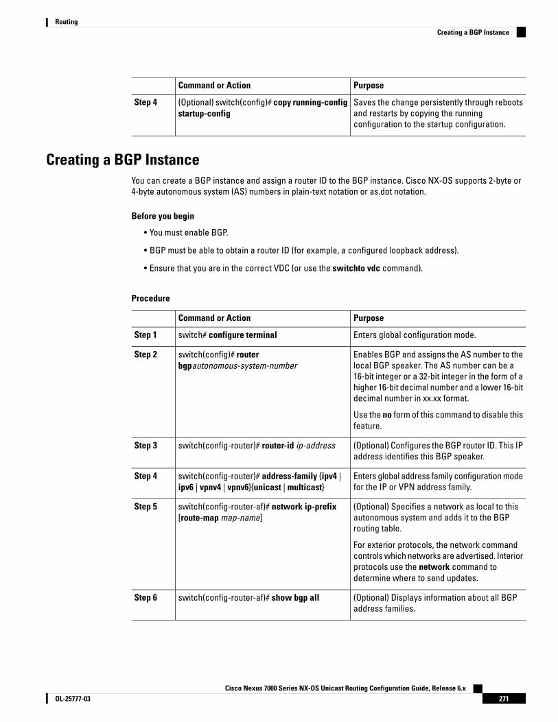
PurposeCommand or Action
Saves the change persistently through rebootsand restarts by copying the runningconfiguration to the startup configuration.
(Optional) switch(config)# copy running-configstartup-config
Step 4
Creating a BGP InstanceYou can create a BGP instance and assign a router ID to the BGP instance. Cisco NX-OS supports 2-byte or4-byte autonomous system (AS) numbers in plain-text notation or as.dot notation.
Before you begin
• You must enable BGP.
• BGP must be able to obtain a router ID (for example, a configured loopback address).
• Ensure that you are in the correct VDC (or use the switchto vdc command).
Procedure
PurposeCommand or Action
Enters global configuration mode.switch# configure terminalStep 1
Enables BGP and assigns the AS number to thelocal BGP speaker. The AS number can be a
switch(config)# routerbgpautonomous-system-number
Step 2
16-bit integer or a 32-bit integer in the form of ahigher 16-bit decimal number and a lower 16-bitdecimal number in xx.xx format.
Use the no form of this command to disable thisfeature.
(Optional) Configures the BGP router ID. This IPaddress identifies this BGP speaker.
switch(config-router)# router-id ip-addressStep 3
Enters global address family configuration modefor the IP or VPN address family.
switch(config-router)# address-family {ipv4 |ipv6 | vpnv4 | vpnv6}{unicast | multicast}
Step 4
(Optional) Specifies a network as local to thisautonomous system and adds it to the BGProuting table.
switch(config-router-af)# network ip-prefix[route-map map-name]
Step 5
For exterior protocols, the network commandcontrols which networks are advertised. Interiorprotocols use the network command todetermine where to send updates.
(Optional) Displays information about all BGPaddress families.
switch(config-router-af)# show bgp allStep 6
Cisco Nexus 7000 Series NX-OS Unicast Routing Configuration Guide, Release 6.x271OL-25777-03
RoutingCreating a BGP Instance
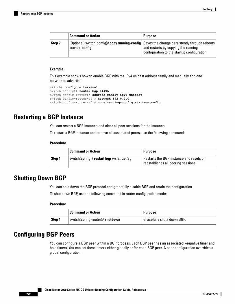
PurposeCommand or Action
Saves the change persistently through rebootsand restarts by copying the runningconfiguration to the startup configuration.
(Optional) switch(config)# copy running-configstartup-config
Step 7
Example
This example shows how to enable BGP with the IPv4 unicast address family and manually add onenetwork to advertise:
switch# configure terminalswitch(config)# router bgp 64496switch(config-router)# address-family ipv4 unicastswitch(config-router-af)# network 192.0.2.0switch(config-router-af)# copy running-config startup-config
Restarting a BGP InstanceYou can restart a BGP instance and clear all peer sessions for the instance.
To restart a BGP instance and remove all associated peers, use the following command:
Procedure
PurposeCommand or Action
Restarts the BGP instance and resets orreestablishes all peering sessions.
switch(config)# restart bgp instance-tagStep 1
Shutting Down BGPYou can shut down the BGP protocol and gracefully disable BGP and retain the configuration.
To shut down BGP, use the following command in router configuration mode:
Procedure
PurposeCommand or Action
Gracefully shuts down BGP.switch(config-router)# shutdownStep 1
Configuring BGP PeersYou can configure a BGP peer within a BGP process. Each BGP peer has an associated keepalive timer andhold timers. You can set these timers either globally or for each BGP peer. A peer configuration overrides aglobal configuration.
Cisco Nexus 7000 Series NX-OS Unicast Routing Configuration Guide, Release 6.xOL-25777-03272
RoutingRestarting a BGP Instance

You must configure the address family under neighbor configuration mode for each peer.Note
Before you begin
• You must enable BGP.
• Ensure that you are in the correct VDC (or use the switchto vdccommand).
Procedure
PurposeCommand or Action
Enters global configuration mode.switch# configure terminalStep 1
Enables BGP and assigns the AS number tothe local BGP speaker. The AS number can be
switch(config)# router bgpautonomous-system-number
Step 2
a 16-bit integer or a 32-bit integer in the formof a higher 16-bit decimal number and a lower16-bit decimal number in xx.xx format.
Configures the IPv4 or IPv6 address and ASnumber for a remote BGP peer. The ip-address
switch(config-router)# neighbor {ip-address |ipv6-address} remote-as as-number
Step 3
format is x.x.x.x. The ipv6-address format isA:B::C:D.
(Optional) Adds a description for the neighbor.The description is an alphanumeric string upto 80 characters.
switch(config-router-neighbor)# descriptiontext
Step 4
(Optional) Adds the keepalive and hold timeBGP timer values for the neighbor. The range
switch(config-router-neighbor)# timerskeepalive-time hold-time
Step 5
is from 0 to 3600 seconds. The default is 60seconds for the keepalive time and 180seconds for the hold time.
(Optional). Administratively shuts down thisBGP neighbor. This command triggers an
switch(config-router-neighbor)# shutdownStep 6
automatic notification and session reset forthe BGP neighbor sessions.
Enters neighbor address family configurationmode for the unicast IPv4 address family.
switch(config-router-neighbor)#address-family {ipv4 | ipv6 | vpnv4 | vpnv6}{unicast | multicast}
Step 7
(Optional) Sets the default weight for routesfrom this neighbor. The range is from 0 to 65535.
switch(config-router-neighbor)# weight valueStep 8
All routes learned from this neighbor have theassigned weight initially. The route with thehighest weight is chosen as the preferred routewhen multiple routes are available to a
Cisco Nexus 7000 Series NX-OS Unicast Routing Configuration Guide, Release 6.x273OL-25777-03
RoutingConfiguring BGP Peers

PurposeCommand or Action
particular network. The weights assigned withthe set weight route-map command overridethe weights assigned with this command.
If you specify a BGP peer policy template, allthe members of the template inherit thecharacteristics configured with this command.
(Optional) Displays information about BGPpeers.
(Optional) switch(config-router-neighbor)#show bgp {ipv4|ipv6|vpnv4|vpnv6}{unicast|multicast} neighbors
Step 9
Saves the change persistently through rebootsand restarts by copying the runningconfiguration to the startup configuration.
(Optional) switch(config)# copy running-configstartup-config
Step 10
Example
The following example shows how to configure a BGP peer:
switch# configure terminalswitch(config)# router bgp 64496switch(config-router)# neighbor 192.0.2.1 remote-as 64497switch(config-router-neighbor)# description Peer Router Bswitch(config-router-neighbor)# address-family ipv4 unicastswitch(config-router-neighbor)# weight 100switch(config-router-neighbor-af)# copy running-config startup-config
Configuring AS-4 Dot NotationYou can configure 4-byte autonomous system (AS) numbers in asdot notation. The default value is asplain.
Before you begin
Ensure that you are in the correct VDC (or use the switchto vdc command).
Procedure
PurposeCommand or Action
Enters global configuration mode.switch# configure terminalStep 1
Configures the ASN notation to asdot.switch(config)# as-format asdotStep 2
Saves the change persistently through rebootsand restarts by copying the runningconfiguration to the startup configuration.
(Optional) switch(config)# copy running-configstartup-config
Step 3
Cisco Nexus 7000 Series NX-OS Unicast Routing Configuration Guide, Release 6.xOL-25777-03274
RoutingConfiguring AS-4 Dot Notation
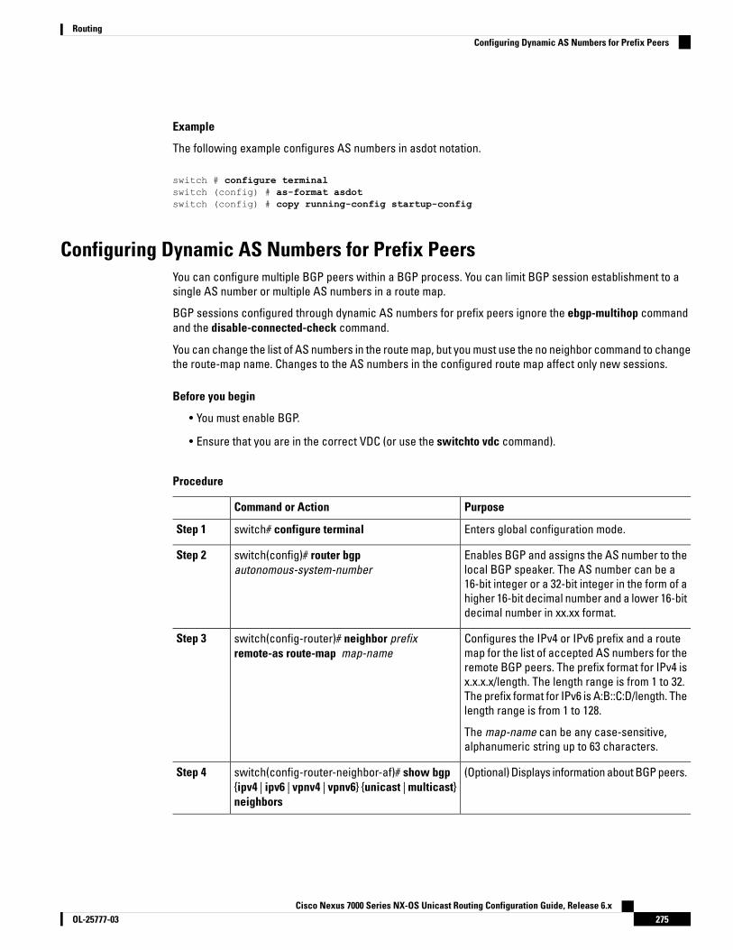
Example
The following example configures AS numbers in asdot notation.
switch # configure terminalswitch (config) # as-format asdotswitch (config) # copy running-config startup-config
Configuring Dynamic AS Numbers for Prefix PeersYou can configure multiple BGP peers within a BGP process. You can limit BGP session establishment to asingle AS number or multiple AS numbers in a route map.
BGP sessions configured through dynamic AS numbers for prefix peers ignore the ebgp-multihop commandand the disable-connected-check command.
You can change the list of AS numbers in the route map, but you must use the no neighbor command to changethe route-map name. Changes to the AS numbers in the configured route map affect only new sessions.
Before you begin
• You must enable BGP.
• Ensure that you are in the correct VDC (or use the switchto vdc command).
Procedure
PurposeCommand or Action
Enters global configuration mode.switch# configure terminalStep 1
Enables BGP and assigns the AS number to thelocal BGP speaker. The AS number can be a
switch(config)# router bgpautonomous-system-number
Step 2
16-bit integer or a 32-bit integer in the form of ahigher 16-bit decimal number and a lower 16-bitdecimal number in xx.xx format.
Configures the IPv4 or IPv6 prefix and a routemap for the list of accepted AS numbers for the
switch(config-router)# neighbor prefixremote-as route-map map-name
Step 3
remote BGP peers. The prefix format for IPv4 isx.x.x.x/length. The length range is from 1 to 32.The prefix format for IPv6 is A:B::C:D/length. Thelength range is from 1 to 128.
The map-name can be any case-sensitive,alphanumeric string up to 63 characters.
(Optional) Displays information about BGP peers.switch(config-router-neighbor-af)# show bgp{ipv4 | ipv6 | vpnv4 | vpnv6} {unicast | multicast}neighbors
Step 4
Cisco Nexus 7000 Series NX-OS Unicast Routing Configuration Guide, Release 6.x275OL-25777-03
RoutingConfiguring Dynamic AS Numbers for Prefix Peers
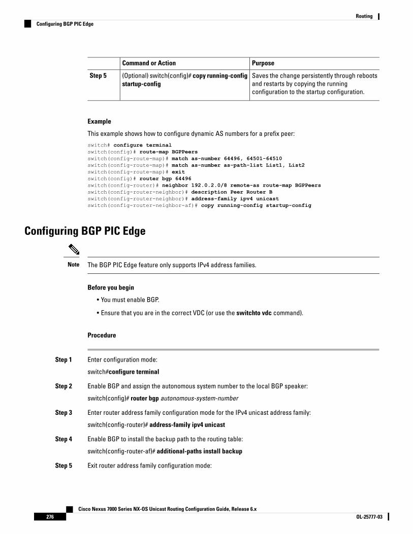
PurposeCommand or Action
Saves the change persistently through rebootsand restarts by copying the runningconfiguration to the startup configuration.
(Optional) switch(config)# copy running-configstartup-config
Step 5
Example
This example shows how to configure dynamic AS numbers for a prefix peer:
switch# configure terminalswitch(config)# route-map BGPPeersswitch(config-route-map)# match as-number 64496, 64501-64510switch(config-route-map)# match as-number as-path-list List1, List2switch(config-route-map)# exitswitch(config)# router bgp 64496switch(config-router)# neighbor 192.0.2.0/8 remote-as route-map BGPPeersswitch(config-router-neighbor)# description Peer Router Bswitch(config-router-neighbor)# address-family ipv4 unicastswitch(config-router-neighbor-af)# copy running-config startup-config
Configuring BGP PIC Edge
The BGP PIC Edge feature only supports IPv4 address families.Note
Before you begin
• You must enable BGP.
• Ensure that you are in the correct VDC (or use the switchto vdc command).
Procedure
Step 1 Enter configuration mode:
switch#configure terminal
Step 2 Enable BGP and assign the autonomous system number to the local BGP speaker:
switch(config)# router bgp autonomous-system-number
Step 3 Enter router address family configuration mode for the IPv4 unicast address family:
switch(config-router)# address-family ipv4 unicast
Step 4 Enable BGP to install the backup path to the routing table:
switch(config-router-af)# additional-paths install backup
Step 5 Exit router address family configuration mode:
Cisco Nexus 7000 Series NX-OS Unicast Routing Configuration Guide, Release 6.xOL-25777-03276
RoutingConfiguring BGP PIC Edge

switch(config-router-af)# exit
Example
This example shows how to configure the device to support BGP PIC Edge in IPv4 network:
interface Ethernet2/2ip address 1.1.1.5/24no shutdown
interface Ethernet2/3ip address 2.2.2.5/24no shutdown
router bgp 100address-family ipv4 unicast
additional-paths install backupneighbor 1.1.1.6 remote-as 200address-family ipv4 unicast
neighbor 2.2.2.6 remote-as 100address-family ipv4 unicast
If BGP receives the same prefix (for example, 99.0.0.0/24) from the two neighbors 1.1.1.6 and 2.2.2.6,both paths will be installed in the URIB—one as the primary path and the other as the backup path.
BGP output:
switch(config)# show ip bgp 99.0.0.0/24BGP routing table information for VRF default, address family IPv4 UnicastBGP routing table entry for 99.0.0.0/24, version 4Paths: (2 available, best #2)Flags: (0x00001a) on xmit-list, is in urib, is best urib route
Path type: internal, path is valid, not best reason: Internal path, backup pathAS-Path: 200 , path sourced external to AS2.2.2.6 (metric 0) from 2.2.2.6 (2.2.2.6)Origin IGP, MED not set, localpref 100, weight 0
Advertised path-id 1Path type: external, path is valid, is best pathAS-Path: 200 , path sourced external to AS1.1.1.6 (metric 0) from 1.1.1.6 (99.0.0.1)Origin IGP, MED not set, localpref 100, weight 0
Path-id 1 advertised to peers:2.2.2.6
URIB output:
URIB output:switch(config)# show ip route 99.0.0.0/24IP Route Table for VRF "default"'*' denotes best ucast next-hop'**' denotes best mcast next-hop'[x/y]' denotes [preference/metric]'%<string>' in via output denotes VRF <string>
99.0.0.0/24, ubest/mbest: 1/0*via 1.1.1.6, [20/0], 14:34:51, bgp-100, external, tag 200
Cisco Nexus 7000 Series NX-OS Unicast Routing Configuration Guide, Release 6.x277OL-25777-03
RoutingConfiguring BGP PIC Edge
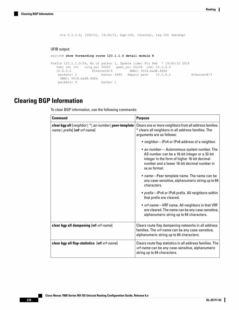
via 2.2.2.6, [200/0], 14:34:51, bgp-100, internal, tag 200 (backup)
UFIB output:
switch# show forwarding route 123.1.1.0 detail module 8
Prefix 123.1.1.0/24, No of paths: 1, Update time: Fri Feb 7 19:00:12 2014Vobj id: 141 orig_as: 65002 peer_as: 65100 rnh: 10.3.0.210.4.0.2 Ethernet8/4 DMAC: 0018.bad8.4dfdpackets: 2 bytes: 3484 Repair path 10.3.0.2 Ethernet8/3DMAC: 0018.bad8.4dfdpackets: 0 bytes: 1
Clearing BGP InformationTo clear BGP information, use the following commands:
PurposeCommand
Clears one or more neighbors from all address families.* clears all neighbors in all address families. Thearguments are as follows:
• neighbor—IPv4 or IPv6 address of a neighbor.
• as-number— Autonomous system number. TheAS number can be a 16-bit integer or a 32-bitinteger in the form of higher 16-bit decimalnumber and a lower 16-bit decimal number inxx.xx format.
• name—Peer template name. The name can beany case-sensitive, alphanumeric string up to 64characters.
• prefix—IPv4 or IPv6 prefix. All neighbors withinthat prefix are cleared.
• vrf-name—VRF name. All neighbors in that VRFare cleared. The name can be any case-sensitive,alphanumeric string up to 64 characters.
clear bgp all {neighbor | * | as-number | peer-templatename | prefix} [vrf vrf-name]
Clears route flap dampening networks in all addressfamilies. The vrf-name can be any case-sensitive,alphanumeric string up to 64 characters.
clear bgp all dampening [vrf vrf-name]
Clears route flap statistics in all address families. Thevrf-name can be any case-sensitive, alphanumericstring up to 64 characters.
clear bgp all flap-statistics [vrf vrf-name]
Cisco Nexus 7000 Series NX-OS Unicast Routing Configuration Guide, Release 6.xOL-25777-03278
RoutingClearing BGP Information
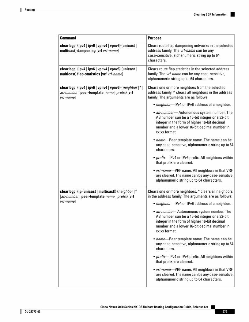
PurposeCommand
Clears route flap dampening networks in the selectedaddress family. The vrf-name can be anycase-sensitive, alphanumeric string up to 64characters.
clear bgp {ipv4 | ipv6 | vpnv4 | vpnv6} {unicast |multicast} dampening [vrf vrf-name]
Clears route flap statistics in the selected addressfamily. The vrf-name can be any case-sensitive,alphanumeric string up to 64 characters.
clear bgp {ipv4 | ipv6 | vpnv4 | vpnv6} {unicast |multicast} flap-statistics [vrf vrf-name]
Clears one or more neighbors from the selectedaddress family. * clears all neighbors in the addressfamily. The arguments are as follows:
• neighbor—IPv4 or IPv6 address of a neighbor.
• as-number— Autonomous system number. TheAS number can be a 16-bit integer or a 32-bitinteger in the form of higher 16-bit decimalnumber and a lower 16-bit decimal number inxx.xx format.
• name—Peer template name. The name can beany case-sensitive, alphanumeric string up to 64characters.
• prefix—IPv4 or IPv6 prefix. All neighbors withinthat prefix are cleared.
• vrf-name—VRF name. All neighbors in that VRFare cleared. The name can be any case-sensitive,alphanumeric string up to 64 characters.
clear bgp {ipv4 | ipv6 | vpnv4 | vpnv6} {neighbor |* |as-number | peer-template name | prefix} [vrfvrf-name]
Clears one or more neighbors. * clears all neighborsin the address family. The arguments are as follows:
• neighbor—IPv4 or IPv6 address of a neighbor.
• as-numbe— Autonomous system number. TheAS number can be a 16-bit integer or a 32-bitinteger in the form of higher 16-bit decimalnumber and a lower 16-bit decimal number inxx.xx format.
• name—Peer template name. The name can beany case-sensitive, alphanumeric string up to 64characters.
• prefix—IPv4 or IPv6 prefix. All neighbors withinthat prefix are cleared.
• vrf-name—VRF name. All neighbors in that VRFare cleared. The name can be any case-sensitive,alphanumeric string up to 64 characters.
clear bgp {ip {unicast | multicast}} {neighbor |*|as-number | peer-template name | prefix} [vrfvrf-name]
Cisco Nexus 7000 Series NX-OS Unicast Routing Configuration Guide, Release 6.x279OL-25777-03
RoutingClearing BGP Information

PurposeCommand
Clears route flap dampening in one or more networks.The arguments are as follows:
• ip-neighbor—IPv4 address of a neighbor.
• ip-prefix—IPv4. All neighbors within that prefixare cleared.
• vrf-name—VRF name. All neighbors in that VRFare cleared. The name can be any case-sensitive,alphanumeric string up to 64 characters.
clear bgp dampening [ip-neighbor |ip-prefix] [vrfvrf-name]
Clears route flap statistics in one or more networks.The arguments are as follows:
• ip-neighbor—IPv4 address of a neighbor.
• ip-prefix—IPv4. All neighbors within that prefixare cleared.
• vrf-name—VRF name. All neighbors in that VRFare cleared. The name can be any case-sensitive,alphanumeric string up to 64 characters.
clear bgp flap-statistics [ip-neighbor |ip-prefix] [vrfvrf-name]
• neighbor—IPv4 or IPv6 address of a neighbor.
• as-number— Autonomous system number. TheAS number can be a 16-bit integer or a 32-bitinteger in the form of higher 16-bit decimalnumber and a lower 16-bit decimal number inxx.xx format.
• name—Peer template name. The name can beany case-sensitive, alphanumeric string up to 64characters.
• prefix—IPv4 or IPv6 prefix. All neighbors withinthat prefix are cleared.
• vrf-name—VRF name. All neighbors in that VRFare cleared. The name can be any case-sensitive,alphanumeric string up to 64 characters.
clear ip mbgp {ip {unicast | multicast}} {neighbor |*|as-number | peer-template name | prefix} [vrfvrf-name]
Clears route flap dampening in one or more networks.The arguments are as follows:
• ip-neighbor—IPv4 address of a neighbor.
• ip-prefix—IPv4. All neighbors within that prefixare cleared.
• vrf-name—VRF name. All neighbors in that VRFare cleared. The name can be any case-sensitive,alphanumeric string up to 64 characters.
clear ip mbgp dampening [ip-neighbor |ip-prefix] [vrfvrf-name]
Cisco Nexus 7000 Series NX-OS Unicast Routing Configuration Guide, Release 6.xOL-25777-03280
RoutingClearing BGP Information
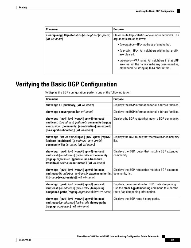
PurposeCommand
Clears route flap statistics one or more networks. Thearguments are as follows:
• ip-neighbor—IPv4 address of a neighbor.
• ip-prefix—IPv4. All neighbors within that prefixare cleared.
• vrf-name—VRF name. All neighbors in that VRFare cleared. The name can be any case-sensitive,alphanumeric string up to 64 characters.
clear ip mbgp flap-statistics [ip-neighbor |ip-prefix][vrf vrf-name]
Verifying the Basic BGP ConfigurationTo display the BGP configuration, perform one of the following tasks:
PurposeCommand
Displays the BGP information for all address families.show bgp all [summary] [vrf vrf-name]
Displays the BGP information for all address families.show bgp convergence [vrf vrf-name]
Displays the BGP routes that match a BGP community.show bgp {ipv4 | ipv6 | vpnv4 | vpnv6} {unicast |multicast} [ip-address | ipv6-prefix community [regexpexpression | [community] [no-advertise] [no-export][no-export-subconfed]} [vrf vrf-name]
Displays the BGP routes that match a BGP communitylist.
show bgp [vrf vrf-name] {ipv4 | ipv6 | vpnv4 | vpnv6}{unicast | multicast} [ip-address | ipv6-prefix]community-list list-name [vrf vrf-name]
Displays the BGP routes that match a BGP extendedcommunity.
show bgp {ipv4 | ipv6 | vpnv4 | vpnv6} {unicast |multicast} [ip-address | ipv6-prefix extcommunity[regexp expression | [generic [non-transitive |transitive] aa4:nn [exact-match]} [vrf vrf-name]
Displays the BGP routes that match a BGP extendedcommunity list.
show bgp {ipv4 | ipv6 | vpnv4 | vpnv6} {unicast |multicast} [ip-address | ipv6-prefix extcommunity-listlist-name [exact-match]} [vrf vrf-name]
Displays the information for BGP route dampening.Use the clear bgp dampening command to clear theroute flap dampening information.
show bgp {ipv4 | ipv6 | vpnv4 | vpnv6} {unicast |multicast} [ip-address | ipv6-prefix {dampeningdampened-paths [regexp expression]} [vrf vrf-name]
Displays the BGP route history paths.show bgp {ipv4 | ipv6 | vpnv4 | vpnv6} {unicast |multicast} [ip-address | ipv6-prefix history-paths[regexp expression] [vrf vrf-name]
Cisco Nexus 7000 Series NX-OS Unicast Routing Configuration Guide, Release 6.x281OL-25777-03
RoutingVerifying the Basic BGP Configuration

PurposeCommand
Displays the information for the BGP filter list.show bgp {ipv4 | ipv6 | vpnv4 | vpnv6} {unicast |multicast} [ip-address | ipv6-prefix filter-list list-name[vrf vrf-name]
Displays the information for BGP peers. Use the clearbgp neighbors command to clear these neighbors.
show bgp {ipv4 | ipv6 | vpnv4 | vpnv6} {unicast |multicast} [ip-address | ipv6-prefix] neighbors[ip-address | ipv6-prefix] [vrf vrf-name]
Displays the information for the BGP route next hop.show bgp {ipv4 | ipv6 | vpnv4 | vpnv6} {unicast |multicast} [ip-address | ipv6-prefix] neighbors[ip-address | ipv6-prefix] {nexthop | nexthop-database}[vrf vrf-name]
Displays the BGP path information.show bgp paths
Displays the BGP policy information. Use the clearbgp policy command to clear the policy information.
show bgp {ipv4 | ipv6 | vpnv4 | vpnv6} {unicast |multicast} [ip-address | ipv6-prefix] policy name [vrfvrf-name]
Displays the BGP routes that match the prefix list.show bgp {ipv4 | ipv6 | vpnv4 | vpnv6} {unicast |multicast} [ip-address | ipv6-prefix] prefix-listlist-name [vrf vrf-name]
Displays the BGP paths stored for soft reconfiguration.show bgp {ipv4 | ipv6 | vpnv4 | vpnv6} {unicast |multicast} [ip-address | ipv6-prefix] received-paths[vrf vrf-name]
Displays the BGP routes that match the AS_pathregular expression.
show bgp {ipv4 | ipv6 | vpnv4 | vpnv6} {unicast |multicast} [ip-address | ipv6-prefix] regexp expression[vrf vrf-name]
Displays the BGP routes that match the route map.show bgp {ipv4 | ipv6 | vpnv4 | vpnv6} {unicast |multicast} [ip-address | ipv6-prefix] route-mapmap-name [vrf vrf-name]
Displays the information about BGP peer policies.show bgp peer-policy name [vrf vrf-name]
Displays the information about BGP peer sessions.show bgp peer-session name [vrf vrf-name]
Displays the information about BGP peer templates.Use the clear bgp peer-template command to clearall neighbors in a peer template.
show bgp peer-template name [vrf vrf-name]
Displays the BGP process information.show bgp process
Displays the BGP status and configuration information.This command has multiple options. See the CiscoNexus 7000 Series NX-OS Unicast Routing CommandReference, for more information.
show {ipv | ipv6} bgp options
Cisco Nexus 7000 Series NX-OS Unicast Routing Configuration Guide, Release 6.xOL-25777-03282
RoutingVerifying the Basic BGP Configuration

PurposeCommand
Displays the BGP status and configuration information.This command has multiple options. See the CiscoNexus 7000 Series NX-OS Unicast Routing CommandReference, for more information.
show {ipv | ipv6} mbgp options
Displays the current running BGP configuration.show running-configuration bgp
Monitoring BGP StatisticsTo display BGP statistics, use the following commands:
PurposeCommand
Displays the BGP route flap statistics. Use the clearbgp flap-statistics command to clear these statistics.
show bgp {ipv4 | ipv6 | vpnv4 | vpnv6} {unicast |multicast} [ip-address | ipv6-prefix] flap-statistics [vrfvrf-name]
Displays the BGP sessions for all peers. Use the clearbgp sessions command to clear these statistics.
show bgp sessions [vrf vrf-name]
Displays the BGP statistics.show bgp statistics
Configuration Examples for Basic BGPThis example shows a basic BGP configuration:
switch (config) # feature bgpswitch (config) # router bgp 64496switch (config-router) # neighbor 2001:ODB8:0:1::55 remote-as 64496switch (config-router) # address-family ipv6 unicastswitch (config-router-af) # next-hop-self
This example shows a basic BGP configuration:
switch (config) # address-familyswitch (config) # router bgp 64496switch (config-router) # address-family ipv4 unicastswitch (config-router) # network 1.1.10 mask 255.255.255.0switch (config-router) # neighbor 10.1.1.1 remote-as 64496switch (config-router) # address-family ipv4 unicast
Related Documents for Basic BGPDocument TitleRelated Topics
Cisco Nexus 7000 Series NX-OS Unicast RoutingCommand Reference
BGP CLI commands
Cisco Nexus 7000 Series NX-OS Unicast Routing Configuration Guide, Release 6.x283OL-25777-03
RoutingMonitoring BGP Statistics

Document TitleRelated Topics
Cisco Nexus 7000 Series NX-OS MPLS ConfigurationGuide
MPLS configuration
Cisco Nexus 7000 Series NX-OS Virtual Device ContextConfiguration Guide, Release 5.x
VDCs and VRFs
MIBsMIBs LinkMIBs
To locate and download MIBs, go to the followingURL:https://cfnng.cisco.com/mibs.
BGP4-MIB
CISCO-BGP4-MIB
CISCO-BGP-MIBv2
Feature History for BGPThis table includes only the updates for those releases that have resulted in additions or changes to the feature.
Table 25: Feature History for BGP
Feature InformationReleasesFeature Name
Introduced this feature.6.2(8)BGP PIC Edge
Added support forCISCO-BGP-MIBv2
6.2(8)BGP
Added the ability to configure4-byte AS numbers in asdotnotation.
6.2(2)4-byte AS number
Added support for additional BGPpaths.
6.1(1)BGP
Added the ability to set the defaultweigh for routes from a neighborusing the weight command in theneighbor address familyconfiguration mode.
6.1(1)BGP
Added support for the BGP PIC corefeature.
5.2(1)BGP
Added support for VPN addressfamilies.
5.2(1)VPN address families
Cisco Nexus 7000 Series NX-OS Unicast Routing Configuration Guide, Release 6.xOL-25777-03284
RoutingMIBs

Feature InformationReleasesFeature Name
Added support for BFD. See theCisco Nexus 7000 Series NX-OSInterfaces Configuration Guide,Release 6.x for more information.
5.0(2)BFD
Lowered BGP minimum hold-timecheck to eight seconds.
4.2(3)ISSU
Added support for IPv6.4.2(1)IPv6
Added support for 4-byte ASnumbers in plaintext notation.
4.2(1)4-Byte AS numbers
Added support for conditionallyadvertising BGP routes based onthe existence of other routes in theBGP table.
4.2(1)Conditional advertisement
Added support for a range of ASnumbers for BGP prefix peerconfiguration.
4.1(2)Dynamic AS number for prefixpeers
This feature was introduced.4.0(1)BGP
Cisco Nexus 7000 Series NX-OS Unicast Routing Configuration Guide, Release 6.x285OL-25777-03
RoutingFeature History for BGP

Cisco Nexus 7000 Series NX-OS Unicast Routing Configuration Guide, Release 6.xOL-25777-03286
RoutingFeature History for BGP

C H A P T E R 12Configuring Advanced BGP
This chapter contains the following sections:
• Finding Feature Information, on page 287• Information About Advanced BGP, on page 287• Prerequisites for Advanced BGP, on page 299• Guidelines and Limitations for Advanced BGP, on page 299• Default Settings, on page 300• Configuring Advanced BGP, on page 301• Verifying the Advanced BGP Configuration, on page 335• Displaying Advanced BGP Statistics, on page 337• Related Documents, on page 337• RFCs, on page 337• MIBs, on page 337• Feature History for Advanced BGP , on page 338
Finding Feature InformationYour software release might not support all the features documented in this module. For the latest caveatsand feature information, see the Bug Search Tool at https://tools.cisco.com/bugsearch/ and the release notesfor your software release. To find information about the features documented in this module, and to see a listof the releases in which each feature is supported, see the "New and Changed Information"chapter or theFeature History table in this chapter.
Information About Advanced BGPBGP is an interdomain routing protocol that provides loop-free routing between organizations or autonomoussystems. Cisco NX-OS supports BGP version 4. BGP version 4 includes multiprotocol extensions that allowBGP to carry routing information for IP multicast routes and multiple Layer 3 protocol address families. BGPuses TCP as a reliable transport protocol to create TCP sessions with other BGP-enabled devices called BGPpeers. When connecting to an external organization, the router creates external BGP (eBGP) peering sessions.BGP peers within the same organization exchange routing information through internal BGP (iBGP) peeringsessions.
Cisco Nexus 7000 Series NX-OS Unicast Routing Configuration Guide, Release 6.x287OL-25777-03

Peer TemplatesBGP peer templates allow you to create blocks of common configuration that you can reuse across similarBGP peers. Each block allows you to define a set of attributes that a peer then inherits. You can choose tooverride some of the inherited attributes as well, making it a very flexible scheme for simplifying the repetitivenature of BGP configurations.
Cisco NX-OS implements three types of peer templates:
• The peer-session template defines BGP peer session attributes, such as the transport details, remoteautonomous system number of the peer, and session timers. A peer-session template can also inheritattributes from another peer-session template (with locally defined attributes that override the attributesfrom an inherited peer-session).
• A peer-policy template defines the address-family dependent policy aspects for a peer including theinbound and outbound policy, filter-lists, and prefix-lists. A peer-policy template can inherit from a set ofpeer-policy templates. Cisco NX-OS evaluates these peer-policy templates in the order specified by thepreference value in the inherit configuration. The lowest number is preferred over higher numbers.
• The peer template can inherit the peer-session and peer-policy templates to allow for simplified peerdefinitions. It is not mandatory to use a peer template but it can simplify the BGP configuration by providingreusable blocks of configuration.
AuthenticationYou can configure authentication for a BGP neighbor session. This authentication method adds an MD5authentication digest to each TCP segment sent to the neighbor to protect BGP against unauthorized messagesand TCP security attacks.
The MD5 password must be identical between BGP peers.Note
Route Policies and Resetting BGP SessionsYou can associate a route policy to a BGP peer. Route policies use route maps to control or modify the routesthat BGP recognizes. You can configure a route policy for inbound or outbound route updates. The routepolicies can match on different criteria, such as a prefix or AS_path attribute, and selectively accept or denythe routes. Route policies can also modify the path attributes.
When you change a route policy applied to a BGP peer, you must reset the BGP sessions for that peer. CiscoNX-OS supports the following three mechanisms to reset BGP peering sessions:
• Hard reset—A hard reset tears down the specified peering sessions, including the TCP connection, anddeletes routes coming from the specified peer. This option interrupts packet flow through the BGP network.Hard reset is disabled by default.
• Soft reconfiguration inbound—A soft reconfiguration inbound triggers routing updates for the specifiedpeer without resetting the session. You can use this option if you change an inbound route policy. Softreconfiguration inbound saves a copy of all routes received from the peer before processing the routesthrough the inbound route policy. If you change the inbound route policy, Cisco NX-OS passes thesestored routes through the modified inbound route policy to update the route table without tearing down
Cisco Nexus 7000 Series NX-OS Unicast Routing Configuration Guide, Release 6.xOL-25777-03288
RoutingPeer Templates

existing peering sessions. Soft reconfiguration inbound can use significant memory resources to storethe unfiltered BGP routes. Soft reconfiguration inbound is disabled by default.
• Route Refresh—A route refresh updates the inbound routing tables dynamically by sending route refreshrequests to supporting peers when you change an inbound route policy. The remote BGP peer respondswith a new copy of its routes that the local BGP speaker processes with the modified route policy. CiscoNX-OS automatically sends an outbound route refresh of prefixes to the peer.
• BGP peers advertise the route refresh capability as part of the BGP capability negotiation when establishingthe BGP peer session. Route refresh is the preferred option and enabled by default.
BGP also uses route maps for route redistribution, route aggregation, route dampening, and other features.
eBGPExternal BGP (eBGP) allows you to connect BGP peers from different autonomous systems to exchange routingupdates. Connecting to external networks enables traffic from your network to be forwarded to other networksand across the Internet.
You should use loopback interfaces for establishing eBGP peering sessions because loopback interfaces areless susceptible to interface flapping. An interface flap occurs when the interface is administratively broughtup or down because of a failure or maintenance issue.
BGP Next Hop UnchangedIn an eBGP session, by default, the router changes the next-hop attribute of a BGP route to its own addresswhen the router sends out a route. The BGP next-hop unchanged feature allows BGP to send an update to aneBGP multihop peer with the next-hop attribute unchanged.
By default, BGP puts itself as the next hop when announcing to an eBGP peer. When you enter the set ipnext-hop unchanged command for an outbound route map that is configured for an eBGP peer, it propagatesthe received next hop to the eBGP peer.
iBGPInternal BGP (iBGP) allows you to connect BGP peers within the same autonomous system. You can use iBGPfor multihomed BGP networks (networks that have more than one connection to the same external autonomoussystem).
The figure shows an iBGP network within a larger BGP network.
Figure 34: iBGP Network
Cisco Nexus 7000 Series NX-OS Unicast Routing Configuration Guide, Release 6.x289OL-25777-03
RoutingeBGP

iBGP networks are fully meshed. Each iBGP peer has a direct connection to all other iBGP peers to preventnetwork loops.
For single-hop iBGP peers with update-source configured under neighbor configuration mode, the peer supportsfast external fall-over.
You should configure a separate interior gateway protocol in the iBGP network.Note
AS ConfederationsA fully meshed iBGP network becomes complex as the number of iBGP peers grows. You can reduce the iBGPmesh by dividing the autonomous system into multiple subautonomous systems and grouping them into a singleconfederation. A confederation is a group of iBGP peers that use the same autonomous system number tocommunicate to external networks. Each subautonomous system is fully meshed within itself and has a fewconnections to other subautonomous systems in the same confederation.
The figure shows the BGP network, split into two subautonomous systems and one confederation.
Figure 35: AS Confederation
In this example, AS10 is split into two subautonomous systems, AS1 and AS2. Each subautonomous system isfully meshed, but there is only one link between the subautonomous systems. By using AS confederations,you can reduce the number of links compared to the fully meshed autonomous system.
Route ReflectorYou can alternately reduce the iBGP mesh by using a route reflector configuration where route reflectors passlearned routes to neighbors so that all iBGP peers do not need to be fully meshed.
The figure below shows a simple iBGP configuration with four meshed iBGP speakers (routers A,B,C, and D.)Without these route reflectors, when router A receives a route from an external neighbor, it advertise the routeto all three iBGP neighbors.
When you configure an iBGP peer to be a route reflector, it becomes responsible for passing iBGP learnedroutes to a set of iBGP neighbors.
In the figure, router B is the route reflector. When the route reflector receives routes advertised from routerA, it advertises (reflects) the routes to routers C and D. Router A no longer has to advertise to both routers Cand D.
Cisco Nexus 7000 Series NX-OS Unicast Routing Configuration Guide, Release 6.xOL-25777-03290
RoutingAS Confederations
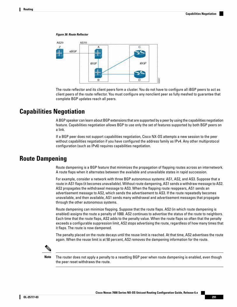
Figure 36: Route Reflector
The route reflector and its client peers form a cluster. You do not have to configure all iBGP peers to act asclient peers of the route reflector. You must configure any nonclient peer as fully meshed to guarantee thatcomplete BGP updates reach all peers.
Capabilities NegotiationA BGP speaker can learn about BGP extensions that are supported by a peer by using the capabilities negotiationfeature. Capabilities negotiation allows BGP to use only the set of features supported by both BGP peers ona link.
If a BGP peer does not support capabilities negotiation, Cisco NX-OS attempts a new session to the peerwithout capabilities negotiation if you have configured the address family as IPv4. Any other multiprotocolconfiguration (such as IPv6) requires capabilities negotiation.
Route DampeningRoute dampening is a BGP feature that minimizes the propagation of flapping routes across an internetwork.A route flaps when it alternates between the available and unavailable states in rapid succession.
For example, consider a network with three BGP autonomous systems: AS1, AS2, and AS3. Suppose that aroute in AS1 flaps (it becomes unavailable). Without route dampening, AS1 sends a withdraw message to AS2.AS2 propagates the withdrawal message to AS3. When the flapping route reappears, AS1 sends anadvertisement message to AS2, which sends the advertisement to AS3. If the route repeatedly becomesunavailable, and then available, AS1 sends many withdrawal and advertisement messages that propagatethrough the other autonomous systems.
Route dampening can minimize flapping. Suppose that the route flaps. AS2 (in which route dampening isenabled) assigns the route a penalty of 1000. AS2 continues to advertise the status of the route to neighbors.Each time that the route flaps, AS2 adds to the penalty value. When the route flaps so often that the penaltyexceeds a configurable suppression limit, AS2 stops advertising the route, regardless of how many times thatit flaps. The route is now dampened.
The penalty placed on the route decays until the reuse limit is reached. At that time, AS2 advertises the routeagain. When the reuse limit is at 50 percent, AS2 removes the dampening information for the route.
The router does not apply a penalty to a resetting BGP peer when route dampening is enabled, even thoughthe peer reset withdraws the route.
Note
Cisco Nexus 7000 Series NX-OS Unicast Routing Configuration Guide, Release 6.x291OL-25777-03
RoutingCapabilities Negotiation
Load Sharing and MultipathBGP can install multiple equal-cost eBGP or iBGP paths into the routing table to reach the same destinationprefix. Traffic to the destination prefix is then shared across all the installed paths.
The BGP best-path algorithm considers the paths as equal-cost paths if the following attributes are identical:
• Weight
• Local preference
• AS_path
• Origin code
• Multi-exit discriminator (MED)
• IGP cost to the BGP next hop
In Cisco NX-OS releases prior to 6.1, BGP selects only one of these multiple paths as the best path and advertisesthe path to the BGP peers. Beginning with Cisco NX-OS Release 6.1, BGP supports sending and receivingmultiple paths per prefix and advertising such paths.
Paths that are received from different AS confederations are considered as equal-cost paths if the externalAS_path values and the other attributes are identical.
Note
When you configure a route reflector for iBGP multipath, and the route reflector advertises the selected bestpath to its peers, the next hop for the path is not modified.
Note
BGP Additional PathsIn Cisco NX-OS releases prior to 6.1, only one BGP best path is advertised, and the BGP speaker accepts onlyone path for a given prefix from a given peer. If a BGP speaker receives multiple paths for the same prefixwithin the same session, it uses the most recent advertisement.
Beginning with Cisco NX-OS Release 6.1, BGP supports the additional paths feature, which allows the BGPspeaker to propagate and accept multiple paths for the same prefix without the new paths replacing anyprevious ones. This feature allows BGP speaker peers to negotiate whether they support advertising andreceiving multiple paths per prefix and advertising such paths. A special 4-byte path ID is added to the networklayer reachability information (NLRI) to differentiate multiple paths for the same prefix sent across a peersession. The following figure illustrates the BGP additional paths capability.
Cisco Nexus 7000 Series NX-OS Unicast Routing Configuration Guide, Release 6.xOL-25777-03292
RoutingLoad Sharing and Multipath
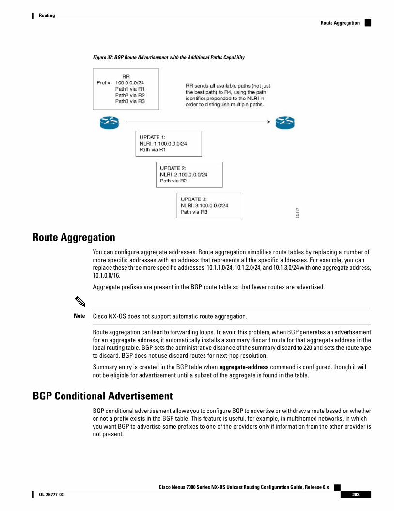
Figure 37: BGP Route Advertisement with the Additional Paths Capability
Route AggregationYou can configure aggregate addresses. Route aggregation simplifies route tables by replacing a number ofmore specific addresses with an address that represents all the specific addresses. For example, you canreplace these three more specific addresses, 10.1.1.0/24, 10.1.2.0/24, and 10.1.3.0/24 with one aggregate address,10.1.0.0/16.
Aggregate prefixes are present in the BGP route table so that fewer routes are advertised.
Cisco NX-OS does not support automatic route aggregation.Note
Route aggregation can lead to forwarding loops. To avoid this problem, when BGP generates an advertisementfor an aggregate address, it automatically installs a summary discard route for that aggregate address in thelocal routing table. BGP sets the administrative distance of the summary discard to 220 and sets the route typeto discard. BGP does not use discard routes for next-hop resolution.
Summary entry is created in the BGP table when aggregate-address command is configured, though it willnot be eligible for advertisement until a subset of the aggregate is found in the table.
BGP Conditional AdvertisementBGP conditional advertisement allows you to configure BGP to advertise or withdraw a route based on whetheror not a prefix exists in the BGP table. This feature is useful, for example, in multihomed networks, in whichyou want BGP to advertise some prefixes to one of the providers only if information from the other provider isnot present.
Cisco Nexus 7000 Series NX-OS Unicast Routing Configuration Guide, Release 6.x293OL-25777-03
RoutingRoute Aggregation

Consider an example network with three BGP autonomous systems: AS1, AS2, and AS3, where AS1 and AS3connect to the Internet and to AS2. Without conditional advertisement, AS2 propagates all routes to both AS1and AS3. With conditional advertisement, you can configure AS2 to advertise certain routes to AS3 only ifroutes from AS1 do not exist (if for example, the link to AS1 fails).
BGP conditional advertisement adds an exist or not-exist test to each route that matches the configured routemap.
BGP Next-Hop Address TrackingBGP monitors the next-hop address of installed routes to verify next-hop reachability and to select, install, andvalidate the BGP best path. BGP next-hop address tracking speeds up this next-hop reachability test bytriggering the verification process when routes change in the Routing Information Base (RIB) that may affectBGP next-hop reachability.
BGP receives notifications from the RIB when the next-hop information changes (event-driven notifications).BGP is notified when any of the following events occurs:
• Next hop becomes unreachable.
• Next hop becomes reachable.
• Fully recursed Interior Gateway Protocol (IGP) metric to the next hop changes.
• First hop IP address or first hop interface changes.
• Next hop becomes connected.
• Next hop becomes unconnected.
• Next hop becomes a local address.
• Next hop becomes a nonlocal address.
Reachability and recursed metric events trigger a best-path recalculation.Note
Event notifications from the RIB are classified as critical and noncritical. Notifications for critical and noncriticalevents are sent in separate batches. However, a noncritical event is sent with the critical events if the noncriticalevent is pending and there is a request to read the critical events.
• Critical events are related to next-hop reachability, such as the loss of next hops resulting in a switchoverto a different path. A change in the IGP metric for a next hop resulting in a switchover to a different pathcan also be considered a critical event.
• Non-critical events are related to next hops being added without affecting the best path or changing theIGP metric to a single next hop.
Critical and non-critical events can be configured individually on a per address family basis. For more informationon address families, see the "Configuring MPLS Layer 3 VPNs" chapter in the Cisco Nexus 7000 Series NX-OSMPLS Configuration Guide.
Note
Cisco Nexus 7000 Series NX-OS Unicast Routing Configuration Guide, Release 6.xOL-25777-03294
RoutingBGP Next-Hop Address Tracking

Route RedistributionYou can configure BGP to redistribute static routes or routes from other protocols. You must configure a routemap with the redistribution to control which routes are passed into BGP. A route map allows you to filter routesbased on attributes such as the destination, origination protocol, route type, route tag, and so on.
Prior to Cisco NX-OS Release 5.2(1), when you redistribute BGP to IGP, iBGP is redistributed as well. To overridethis behavior, you must insert an additional deny statement into the route map. Beginning with Cisco NX-OSRelease 5.2(1), redistribution varies as follows:
• In a non-MPLS VPN scenario, iBGP is not redistributed to IGP by default.
• In an MPLS VPN scenario (route distinguisher configured under a VRF), iBGP is redistributed to IGP bydefault.
You can use route maps to override the default behavior in both scenarios, but be careful when doing so asincorrect use of route maps can result in network loops. The following examples show how to use route mapsto change the default behavior.
You can change the default behavior for scenario 1 by modifying the route map as follows:
route-map foo permit 10match route-type internal
router ospf 1redistribute bgp 100 route-map foo
Similarly, you can change the default behavior for scenario 2 by modifying the route map as follows:
route-map foo deny 10match route-type internal
router ospf 1vrf barredistribute bgp 100 route-map foo
The default route should be redistributed into BGP or advertised to peers only when default-informationoriginate is configured for an Address Family where the command is supported.
BGP should withdraw the default route on removal of default-information originate if it was already advertised.Also, the redistributed path should be removed for the default route.
You can delete the redistributed path for default route using the following command:
no default-information originate
BGP Support for Importing Routes from Default VRFYou can import IP prefixes from the global routing table (the default VRF) into any other VRF by using an importpolicy. The VRF import policy uses a route map to specify the prefixes to be imported into a VRF. The policycan import IPv4 and IPv6 unicast prefixes.
You can configure the maximum number of prefixes that can be imported from the default VRF.
Routes in the BGP default VRF can be imported directly. Any other routes in the global routing table should beredistributed into BGP first.
Note
Cisco Nexus 7000 Series NX-OS Unicast Routing Configuration Guide, Release 6.x295OL-25777-03
RoutingRoute Redistribution

BGP Support for Exporting Routes to Default VRFYou can export IP prefixes to the default VRF (global routing table) from any other VRF using an export policy.The VRF export policy leaks a VRF route into default VRF BGP table, which will then be installed in the IPv4/IPv6routing table. The VRF export policy uses a route map to specify the prefixes to be exported to the default VRF.The policy can export IPv4 and IPv6 unicast prefixes.
You can configure the maximum number of prefixes that can be exported to the default VRF to prevent therouting table from being overloaded.
BFDThis feature supports bidirectional forwarding detection (BFD) for IPv4 only. BFD is a detection protocoldesigned to provide fast forwarding-path failure detection times. BFD provides subsecond failure detectionbetween two adjacent devices and can be less CPU-intensive than protocol hello messages because someof the BFD load can be distributed onto the data plane on supported modules.
BFD for BGP is supported on eBGP peers and iBGP single-hop peers. Configure the update-source option inneighbor configuration mode for iBGP single-hop peers using BFD.
BFD is not supported on other iBGP peers or for multihop eBGP peers.Note
See the Cisco Nexus 7000 Series NX-OS Interfaces Configuration Guide for more information.
Tuning BGPYou can modify the default behavior of BGP through BGP timers and by adjusting the best-path algorithm.
BGP TimersBGP uses different types of timers for neighbor session and global protocol events. Each established sessionhas a minimum of two timers for sending periodic keepalive messages and for timing out sessions when peerkeepalives do not arrive within the expected time. In addition, there are other timers for handling specificfeatures. Typically, you configure these timers in seconds. The timers include a random adjustment so thatthe same timers on different BGP peers trigger at different times.
Tuning the Best-Path AlgorithmYou can modify the default behavior of the best-path algorithm through optional configuration parameters,including changing how the algorithm handles the multi-exit discriminator (MED) attribute and the router ID.
Multiprotocol BGPBGP on Cisco NX-OS supports multiple address families. Multiprotocol BGP (MP-BGP) carries different setsof routes depending on the address family. For example, BGP can carry one set of routes for IPv4 unicastrouting, one set of routes for IPv4 multicast routing, and one set of routes for IPv6 multicast routing. You canuse MP-BGP for reverse-path forwarding (RPF) checks in IP multicast networks.
Cisco Nexus 7000 Series NX-OS Unicast Routing Configuration Guide, Release 6.xOL-25777-03296
RoutingBGP Support for Exporting Routes to Default VRF
Because Multicast BGP does not propagate multicast state information, you need a multicast protocol, suchas Protocol Independent Multicast (PIM).
Note
Use the router address-family and neighbor address-family configuration modes to support multiprotocol BGPconfigurations. MP-BGP maintains separate RIBs for each configured address family, such as a unicast RIBand a multicast RIB for BGP.
A multiprotocol BGP network is backward compatible but BGP peers that do not support multiprotocol extensionscannot forward routing information, such as address family identifier information, that the multiprotocolextensions carry.
Beginning with Cisco NX-OS Release 6.2(8), BGP supports RFC 5549 which allows an IPv4 prefix to be carriedover an IPv6 next hop. Because BGP is running on every hop and all routers are capable of forwarding IPv4and IPv6 traffic, there is no need to support IPv6 tunnels between any routers. BGP installs IPv4 over an IPv6route to the Unicast Route Information Base (URIB).
Note
Graceful Restart and High AvailabilityCisco NX-OS supports nonstop forwarding and graceful restart for BGP.
You can use nonstop forwarding (NSF) for BGP to forward data packets along known routes in the ForwardInformation Base (FIB) while the BGP routing protocol information is being restored following a failover. WithNSF, BGP peers do not experience routing flaps. During a failover, the data traffic is forwarded throughintelligent modules while the standby supervisor becomes active.
If a Cisco NX-OS router experiences a cold reboot, the network does not forward traffic to the router andremoves the router from the network topology. In this scenario, BGP experiences a nongraceful restart andremoves all routes. When Cisco NX-OS applies the startup configuration, BGP reestablishes peering sessionsand relearns the routes.
A Cisco NX-OS router that has dual supervisors can experience a stateful supervisor switchover. During theswitchover, BGP uses nonstop forwarding to forward traffic based on the information in the FIB, and the systemis not removed from the network topology. A router whose neighbor is restarting is referred to as a "helper."After the switchover, a graceful restart operation begins. When it is in progress, both routers reestablish theirneighbor relationship and exchange their BGP routes. The helper continues to forward prefixes pointing tothe restarting peer, and the restarting router continues to forward traffic to peers even though those neighborrelationships are restarting. When the restarting router has all route updates from all BGP peers that aregraceful restart capable, the graceful restart is complete, and BGP informs the neighbors that it is operationalagain.
When a router detects that a graceful restart operation is in progress, both routers exchange their topologytables. When the router has route updates from all BGP peers, it removes all the stale routes and runs thebest-path algorithm on the updated routes.
After the switchover, Cisco NX-OS applies the running configuration, and BGP informs the neighbors that it isoperational again.
For single-hop iBGP peers with update-source configured under neighbor configuration mode, the peer supportsfast external fall-over.
Cisco Nexus 7000 Series NX-OS Unicast Routing Configuration Guide, Release 6.x297OL-25777-03
RoutingGraceful Restart and High Availability

With the additional BGP paths feature, if the number of paths advertised for a given prefix is the same beforeand after restart, the choice of path ID guarantees the final state and removal of stale paths. If fewer pathsare advertised for a given prefix after a restart, stale paths can occur on the graceful restart helper peer.
Low Memory HandlingBGP reacts to low memory for the following conditions:
• Minor alert—BGP does not establish any new eBGP peers. BGP continues to establish new iBGP peersand confederate peers. Established peers remain, but reset peers are not re-established.
• Severe alert—BGP shuts down select established eBGP peers every two minutes until the memory alertbecomes minor. For each eBGP peer, BGP calculates the ratio of total number of paths received to thenumber of paths selected as best paths. The peers with the highest ratio are selected to be shut downto reduce memory usage. You must clear a shutdown eBGP peer before you can bring the eBGP peerback up to avoid oscillation.
You can exempt important eBGP peers from this selection process.Note
• Critical alert—BGP gracefully shuts down all the established peers. You must clear a shutdown BGP peerbefore you can bring the BGP peer back up.
ISSUCisco NX-OS supports in-service software upgrades (ISSU). ISSU allows you to upgrade software withoutimpacting forwarding.
The following conditions are required to support ISSU:
• Graceful restart must be enabled (default)
• Keepalive and hold timers must not be smaller than their default values
If either of these requirements is not met, Cisco NX-OS issues a warning. You can proceed with the upgradeor downgrade, but service might be disrupted.
Cisco NX-OS cannot guarantee ISSU for non-default timer values if the negotiated hold time between BGPpeers is less than the system switchover time.
Note
Virtualization SupportCisco NX-OS supports multiple instances of BGP that run on the same system. BGP supports virtual routingand forwarding (VRF) instances that exist within virtual device contexts (VDCs). You can configure one BGPinstance in a VDC, but you can have multiple VDCs on the system.
By default, Cisco NX-OS places you in the default VDC and default VRF unless you specifically configureanother VDC and VRF.
Cisco Nexus 7000 Series NX-OS Unicast Routing Configuration Guide, Release 6.xOL-25777-03298
RoutingLow Memory Handling
Prerequisites for Advanced BGPAdvanced BGP has the following prerequisites:
• You must enable BGP.
• You should have a valid router ID configured on the system.
• You must have an AS number, either assigned by a Regional Internet Registry (RIR) or locally administered.
• You must have reachability (such as an interior gateway protocol [IGP], a static route, or a directconnection) to the peer that you are trying to make a neighbor relationship with.
• You must explicitly configure an address family under a neighbor for the BGP session establishment.
Guidelines and Limitations for Advanced BGPAdvanced BGP has the following configuration guidelines and limitations:
• The dynamic AS number prefix peer configuration overrides the individual AS number configurationinherited from a BGP template.
• If you configure a dynamic AS number for prefix peers in an AS confederation, BGP establishes sessionswith only the AS numbers in the local confederation.
• Command ttl-security hops is visible but not supported for Nexus 7K platform, it is supported only forNexus 9K platform.
• BGP sessions created through a dynamic AS number prefix peer ignore any configured eBGP multihoptime-to-live (TTL) value or a disabled check for directly connected peers.
• Configure a router ID for BGP to avoid automatic router ID changes and session flaps.
• Use the maximum-prefix configuration option per peer to restrict the number of routes received andsystem resources used.
• Configure the update source to establish a session with eBGP multihop sessions.
• Specify a BGP route map if you configure a redistribution.
• Configure the BGP router ID within a VRF.
• If you decrease the keepalive and hold timer values, the network might experience session flaps.
• When you redistribute BGP to IGP, iBGP is redistributed as well. To override this behavior, you must insertan additional deny statement into the route map.
• Cisco NX-OS does not support multi-hop BFD. BFD for BGP has the following limitations:
• BFD is supported only for BGP IPv4.
• BFD is supported only for eBGP peers and iBGP single-hop peers.
• To enable BFD for iBGP single-hop peers, you must configure the update-source option on thephysical interface.
Cisco Nexus 7000 Series NX-OS Unicast Routing Configuration Guide, Release 6.x299OL-25777-03
RoutingPrerequisites for Advanced BGP

• BFD is not supported for multi-hop iBGP peers and multi-hop eBGP peers.
• For single-hop iBGP peers with update-source configured under neighbor configuration mode, the peersupports fast external fall-over.
• The following guidelines and limitations apply to the remove-private-as command:
• It applies only to eBGP peers.
• It can be configured only in neighbor configuration mode and not in neighbor-address-family mode.
• If the AS-path includes both private and public AS numbers, the private AS numbers are not removed.
• If the AS-path contains the AS number of the eBGP neighbor, the private AS numbers are not removed.
• Private AS numbers are removed only if all AS numbers in that AS-path belong to a private AS numberrange. Private AS numbers are not removed if a peer's AS number or a non-private AS number isfound in the AS-path segment.
• BGP conditional route injection is available only for IPv4 and IPv6 unicast address families in all VRFinstances.
• The match interface command is only supported for redistribute command route-maps.
• When sending a route advertisement to an iBGP peer, NXOS sets the interface IP address through whichthe announced network is reachable for the peer as the next hop instead of preserving the original nexthop of the non locally originated route.
This occurs with the 'network' statement and route 'redistribution' configurations in BGP.
The knobs 'set ip next-hop redist-unchanged' or 'set ipv6 next-hop redist-unchanged' available underroute-map configuration mode helps to resolve this issue. These knobs are available from Cisco NX-OSRelease 6.2(12) onwards.
Default SettingsDefaultParameters
DisabledBGP feature
DisabledBGP additional paths
180 secondsHold timer
60 secondsKeep alive interval
EnabledDynamic capability
Cisco Nexus 7000 Series NX-OS Unicast Routing Configuration Guide, Release 6.xOL-25777-03300
RoutingDefault Settings

Configuring Advanced BGP
Configuring BGP Session TemplatesYou can use BGP session templates to simplify the BGP configuration for multiple BGP peers with similarconfiguration needs. BGP templates allow you to reuse common configuration blocks. You configure BGPtemplates first and then apply these templates to BGP peers.
With BGP session templates, you can configure session attributes such as inheritance, passwords, timers,and security.
A peer-session template can inherit from one other peer-session template. You can configure the secondtemplate to inherit from a third template. The first template also inherits this third template. This indirectinheritance can continue for up to seven peer-session templates.
Any attributes configured for the neighbor take priority over any attributes inherited by that neighbor from aBGP template.
Use the show bgp neighbor command to see the template applied. See the Cisco Nexus 7000 Series NX-OSUnicast Routing Command Reference, for details on all commands available in the template.
Note
Before you begin
• You must enable BGP.
• Ensure that you are in the correct VDC (or use the switchto vdc command).
When editing a template, you can use the no form of a command at either the peer or template level to explicitlyoverride a setting in a template. You must use the default form of the command to reset that attribute to thedefault state.
Note
Procedure
PurposeCommand or Action
Enters configuration mode.switch# configure terminalStep 1
Enables BGP and assigns the autonomoussystem number to the local BGP speaker.
switch(config)# router bgpautonomous-system-number
Step 2
Enters peer-session template configurationmode.
switch(config-router)# template peer-sessiontemplate-name
Step 3
(Optional) Adds the clear text password test tothe neighbor. The password is stored anddisplayed in type 3 encrypted form (3DES).
switch(config-router-stmp)# password numberpassword
Step 4
Cisco Nexus 7000 Series NX-OS Unicast Routing Configuration Guide, Release 6.x301OL-25777-03
RoutingConfiguring Advanced BGP

PurposeCommand or Action
(Optional) Adds the BGP keepalive andholdtimer values to the peer-session template.
switch(config-router-stmp)# timers keepalivehold
Step 5
The default keepalive interval is 60. The defaulthold time is 180.
Exits peer-session template configurationmode.
switch(config-router-stmp)# exitStep 6
Places the router in the neighbor configurationmode for BGP routing and configures theneighbor IP address.
switch(config-router)# neighbor ip-addressremote-as as-number
Step 7
Applies a peer-session template to the peer.switch(config-router-neighbor)# inheritpeer-session template-name
Step 8
(Optional) Adds a description for the neighbor.switch(config-router-neighbor)# descriptiontext
Step 9
(Optional) Displays the peer-policy template.switch(config-router-neighbor)# show bgppeer-session template-name
Step 10
(Optional) Saves this configuration change.switch(config-router-neighbor)# copyrunning-config startup-config
Step 11
Example
This example shows how to configure a BGP peer-session template and apply it to a BGP peer:
switch# configure terminalswitch(config)# router bgp 65535switch(config-router)# template peer-session BaseSessionswitch(config-router-stmp)# timers 30 90switch(config-router-stmp)# exitswitch(config-router)# neighbor 192.168.1.2 remote-as 65535switch(config-router-neighbor)# inherit peer-session BaseSessionswitch(config-router-neighbor)# description Peer Router Aswitch(config-router-neighbor)# address-family ipv4 unicastswitch(config-router-neighbor)# copy running-config startup-config
Configuring BGP Peer-Policy TemplatesYou can configure a peer-policy template to define attributes for a particular address family. You assign apreference to each peer-policy template and these templates are inherited in the order specified, for up tofive peer-policy templates in a neighbor address family.
Cisco NX-OS evaluates multiple peer policies for an address family using the preference value. The lowestpreference value is evaluated first. Any attributes configured for the neighbor take priority over any attributesinherited by that neighbor from a BGP template.
Peer-policy templates can configure address family-specific attributes such as AS-path filter lists, prefix lists,route reflection, and soft reconfiguration.
Cisco Nexus 7000 Series NX-OS Unicast Routing Configuration Guide, Release 6.xOL-25777-03302
RoutingConfiguring BGP Peer-Policy Templates
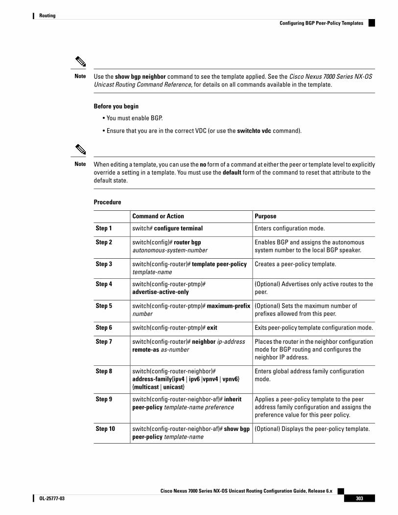
Use the show bgp neighbor command to see the template applied. See the Cisco Nexus 7000 Series NX-OSUnicast Routing Command Reference, for details on all commands available in the template.
Note
Before you begin
• You must enable BGP.
• Ensure that you are in the correct VDC (or use the switchto vdc command).
When editing a template, you can use the no form of a command at either the peer or template level to explicitlyoverride a setting in a template. You must use the default form of the command to reset that attribute to thedefault state.
Note
Procedure
PurposeCommand or Action
Enters configuration mode.switch# configure terminalStep 1
Enables BGP and assigns the autonomoussystem number to the local BGP speaker.
switch(config)# router bgpautonomous-system-number
Step 2
Creates a peer-policy template.switch(config-router)# template peer-policytemplate-name
Step 3
(Optional) Advertises only active routes to thepeer.
switch(config-router-ptmp)#advertise-active-only
Step 4
(Optional) Sets the maximum number ofprefixes allowed from this peer.
switch(config-router-ptmp)# maximum-prefixnumber
Step 5
Exits peer-policy template configuration mode.switch(config-router-ptmp)# exitStep 6
Places the router in the neighbor configurationmode for BGP routing and configures theneighbor IP address.
switch(config-router)# neighbor ip-addressremote-as as-number
Step 7
Enters global address family configurationmode.
switch(config-router-neighbor)#address-family{ipv4 | ipv6 |vpnv4 | vpnv6}{multicast | unicast}
Step 8
Applies a peer-policy template to the peeraddress family configuration and assigns thepreference value for this peer policy.
switch(config-router-neighbor-af)# inheritpeer-policy template-name preference
Step 9
(Optional) Displays the peer-policy template.switch(config-router-neighbor-af)# show bgppeer-policy template-name
Step 10
Cisco Nexus 7000 Series NX-OS Unicast Routing Configuration Guide, Release 6.x303OL-25777-03
RoutingConfiguring BGP Peer-Policy Templates

PurposeCommand or Action
(Optional) Saves this configuration change.switch(config-router-neighbor-af)# copyrunning-config startup-config
Step 11
Example
This example shows how to configure a BGP peer-policy template and apply it to a BGP peer:
switch# configure terminalswitch(config)# router bgp 65535switch(config-router)# template peer-session BasePolicyswitch(config-router-ptmp)# maximum-prefix 20switch(config-router-ptmp)# exitswitch(config-router)# neighbor 192.168.1.1 remote-as 65535switch(config-router-neighbor)# address-family ipv4 unicastswitch(config-router-neighbor-af)# inherit peer-policy BasePolicyswitch(config-router-neighbor-af)# copy running-config startup-config
Configuring BGP Peer TemplatesYou can configure BGP peer templates to combine session and policy attributes in one reusable configurationblock. Peer templates can also inherit peer-session or peer-policy templates. Any attributes configured forthe neighbor take priority over any attributes inherited by that neighbor from a BGP template. You configureonly one peer template for a neighbor, but that peer template can inherit peer-session and peer-policy templates.
Peer templates support session and address family attributes, such as eBGP multihop time-to-live, maximumprefix, next-hop self, and timers.
Use the show bgp neighbor command to see the template applied. See the Cisco Nexus 7000 Series NX-OSUnicast Routing Command Reference, for details on all commands available in the template.
Note
Before you begin
• You must enable BGP.
• Ensure that you are in the correct VDC (or use the switchto vdc command).
When editing a template, you can use the no form of a command at either the peer or template level to explicitlyoverride a setting in a template. You must use the default form of the command to reset that attribute to thedefault state.
Note
Procedure
PurposeCommand or Action
Enters global configuration mode.switch# configure terminalStep 1
Cisco Nexus 7000 Series NX-OS Unicast Routing Configuration Guide, Release 6.xOL-25777-03304
RoutingConfiguring BGP Peer Templates
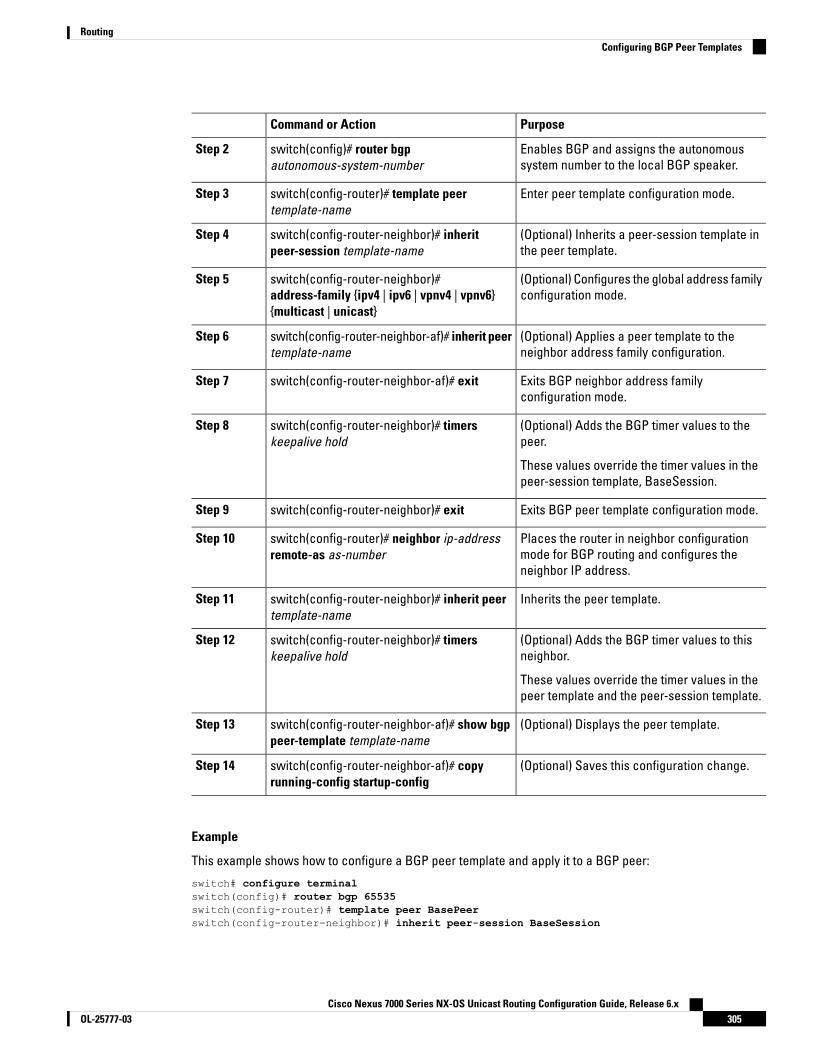
PurposeCommand or Action
Enables BGP and assigns the autonomoussystem number to the local BGP speaker.
switch(config)# router bgpautonomous-system-number
Step 2
Enter peer template configuration mode.switch(config-router)# template peertemplate-name
Step 3
(Optional) Inherits a peer-session template inthe peer template.
switch(config-router-neighbor)# inheritpeer-session template-name
Step 4
(Optional) Configures the global address familyconfiguration mode.
switch(config-router-neighbor)#address-family {ipv4 | ipv6 | vpnv4 | vpnv6}{multicast | unicast}
Step 5
(Optional) Applies a peer template to theneighbor address family configuration.
switch(config-router-neighbor-af)# inherit peertemplate-name
Step 6
Exits BGP neighbor address familyconfiguration mode.
switch(config-router-neighbor-af)# exitStep 7
(Optional) Adds the BGP timer values to thepeer.
switch(config-router-neighbor)# timerskeepalive hold
Step 8
These values override the timer values in thepeer-session template, BaseSession.
Exits BGP peer template configuration mode.switch(config-router-neighbor)# exitStep 9
Places the router in neighbor configurationmode for BGP routing and configures theneighbor IP address.
switch(config-router)# neighbor ip-addressremote-as as-number
Step 10
Inherits the peer template.switch(config-router-neighbor)# inherit peertemplate-name
Step 11
(Optional) Adds the BGP timer values to thisneighbor.
switch(config-router-neighbor)# timerskeepalive hold
Step 12
These values override the timer values in thepeer template and the peer-session template.
(Optional) Displays the peer template.switch(config-router-neighbor-af)# show bgppeer-template template-name
Step 13
(Optional) Saves this configuration change.switch(config-router-neighbor-af)# copyrunning-config startup-config
Step 14
Example
This example shows how to configure a BGP peer template and apply it to a BGP peer:
switch# configure terminalswitch(config)# router bgp 65535switch(config-router)# template peer BasePeerswitch(config-router-neighbor)# inherit peer-session BaseSession
Cisco Nexus 7000 Series NX-OS Unicast Routing Configuration Guide, Release 6.x305OL-25777-03
RoutingConfiguring BGP Peer Templates
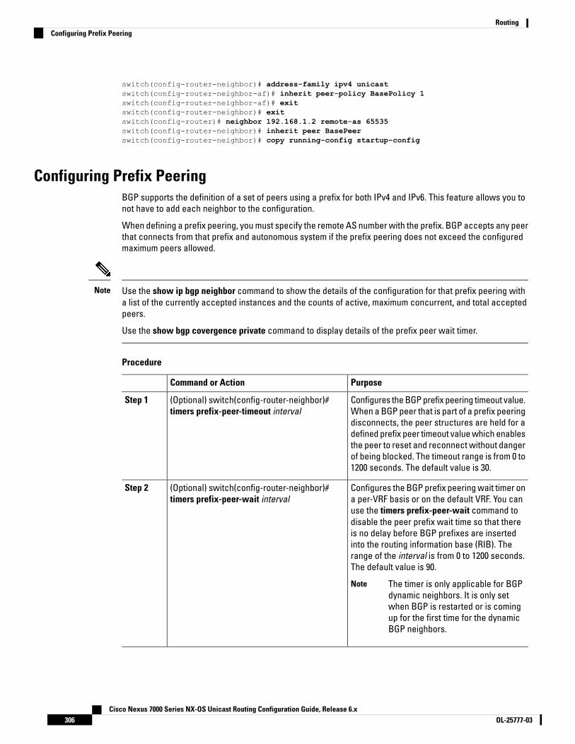
switch(config-router-neighbor)# address-family ipv4 unicastswitch(config-router-neighbor-af)# inherit peer-policy BasePolicy 1switch(config-router-neighbor-af)# exitswitch(config-router-neighbor)# exitswitch(config-router)# neighbor 192.168.1.2 remote-as 65535switch(config-router-neighbor)# inherit peer BasePeerswitch(config-router-neighbor)# copy running-config startup-config
Configuring Prefix PeeringBGP supports the definition of a set of peers using a prefix for both IPv4 and IPv6. This feature allows you tonot have to add each neighbor to the configuration.
When defining a prefix peering, you must specify the remote AS number with the prefix. BGP accepts any peerthat connects from that prefix and autonomous system if the prefix peering does not exceed the configuredmaximum peers allowed.
Use the show ip bgp neighbor command to show the details of the configuration for that prefix peering witha list of the currently accepted instances and the counts of active, maximum concurrent, and total acceptedpeers.
Use the show bgp covergence private command to display details of the prefix peer wait timer.
Note
Procedure
PurposeCommand or Action
Configures the BGP prefix peering timeout value.When a BGP peer that is part of a prefix peering
(Optional) switch(config-router-neighbor)#timers prefix-peer-timeout interval
Step 1
disconnects, the peer structures are held for adefined prefix peer timeout value which enablesthe peer to reset and reconnect without dangerof being blocked. The timeout range is from 0 to1200 seconds. The default value is 30.
Configures the BGP prefix peering wait timer ona per-VRF basis or on the default VRF. You can
(Optional) switch(config-router-neighbor)#timers prefix-peer-wait interval
Step 2
use the timers prefix-peer-wait command todisable the peer prefix wait time so that thereis no delay before BGP prefixes are insertedinto the routing information base (RIB). Therange of the interval is from 0 to 1200 seconds.The default value is 90.
The timer is only applicable for BGPdynamic neighbors. It is only setwhen BGP is restarted or is comingup for the first time for the dynamicBGP neighbors.
Note
Cisco Nexus 7000 Series NX-OS Unicast Routing Configuration Guide, Release 6.xOL-25777-03306
RoutingConfiguring Prefix Peering

PurposeCommand or Action
Configures the maximum number of peers forthis prefix peering in neighbor configurationmode. The range is from 1 to 1000.
(Optional) switch(config-router-neighbor)#maximum-peers value
Step 3
Example
This example shows how to configure a prefix peering that accepts up to 10 peers:
switch(config)# router bgp 65535switch(config-router)# timers prefix-peer-timeout 120switch(config-router)# neighbor 10.100.200.0/24 remote-as 65535switch(config-router-neighbor)# maximum-peers 10switch(config-router-neighbor)# address-family ipv4 unicastswitch(config-router-neighbor-af)#
Configuring BGP AuthenticationYou can configure BGP to authenticate route updates from peers using MD5 digests.
To configure BGP to use MD5 authentication, use the following command in neighbor configuration mode:
Procedure
PurposeCommand or Action
Configures an MD5 password (forauthentication) for BGP neighbor sessions inneighbor configuration mode.
switch(config-router-neighbor)# password {0 |3 | 7} string
Step 1
Resetting a BGP SessionIf you modify a route policy for BGP, you must reset the associated BGP peer sessions. If the BGP peers donot support route refresh, you can configure a soft reconfiguration for inbound policy changes. Cisco NX-OSautomatically attempts a soft reset for the session.
To configure soft reconfiguration inbound, use the following command in neighbor address-family configurationmode.
Procedure
PurposeCommand or Action
This command in neighbor address-familyconfiguration mode, enables soft reconfiguration
switch(config-router-neighbor-af)#soft-reconfiguration inbound
Step 1
to store the inbound BGP route updates. Thiscommand triggers an automatic soft clear orrefresh of BGP neighbor sessions.
This command in any mode resets the BGPsession without tearing down the TCP session.
switch# clear bgp {ipv4 | ipv6 | vpnv4 | vpnv6}{unicast | multicast ip-address soft {in | out}
Step 2
Cisco Nexus 7000 Series NX-OS Unicast Routing Configuration Guide, Release 6.x307OL-25777-03
RoutingConfiguring BGP Authentication

Modifying the Next-Hop AddressYou can modify the next-hop address used in a route advertisement in the following ways:
• Disable next-hop calculation and use the local BGP speaker address as the next-hop address.
• Set the next-hop address as a third-party address. Use this feature in situations where the original next-hopaddress is on the same subnet as the peer that the route is being sent to. Using this feature saves anextra hop during forwarding.
To modify the next-hop address, use the following commands in address-family configuration mode:
Procedure
PurposeCommand or Action
Uses the local BGP speaker address as thenext-hop address in route updates. This
switch(config-router-neighbor-af)#next-hop-self
Step 1
command triggers an automatic soft clear orrefresh of BGP neighbor sessions.
Sets the next-hop address as a third-partyaddress. Use this command for single-hop EBGPpeers that do not have next-hop-self configured.
switch(config-router-neighbor-af)#next-hop-third-party
Step 2
Configuring BGP Next-Hop Address TrackingBGP next-hop address tracking is enabled by default and cannot be disabled.
You can modify the delay interval between RIB checks to increase the performance of BGP next-hop tracking.
To modify the BGP next-hop address tracking, use the following commands in address-family configurationmode:
Procedure
PurposeCommand or Action
Specifies the next-hop address tracking delaytimer for critical next-hop reachability routes
switch(config-router-af)# nexthop trigger-delay{critical | non-critical} milliseconds
Step 1
and for noncritical routes. The range is from 1to 4294967295 milliseconds. The critical timerdefault is 3000. The noncritical timer default is10000.
Specifies a route map to match the BGPnext-hop addresses to. The name can be any
switch(config-router-af)# nexthop route-mapname
Step 2
case-sensitive, alphanumeric string up to 63characters.
Cisco Nexus 7000 Series NX-OS Unicast Routing Configuration Guide, Release 6.xOL-25777-03308
RoutingModifying the Next-Hop Address
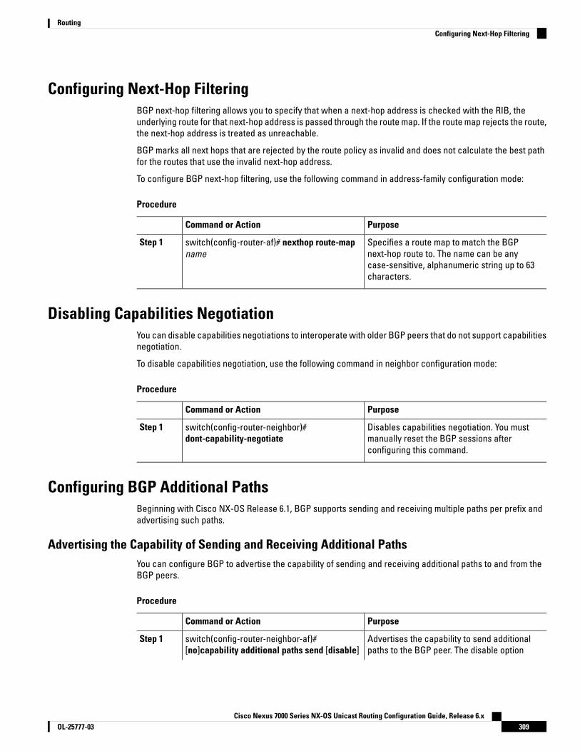
Configuring Next-Hop FilteringBGP next-hop filtering allows you to specify that when a next-hop address is checked with the RIB, theunderlying route for that next-hop address is passed through the route map. If the route map rejects the route,the next-hop address is treated as unreachable.
BGP marks all next hops that are rejected by the route policy as invalid and does not calculate the best pathfor the routes that use the invalid next-hop address.
To configure BGP next-hop filtering, use the following command in address-family configuration mode:
Procedure
PurposeCommand or Action
Specifies a route map to match the BGPnext-hop route to. The name can be any
switch(config-router-af)# nexthop route-mapname
Step 1
case-sensitive, alphanumeric string up to 63characters.
Disabling Capabilities NegotiationYou can disable capabilities negotiations to interoperate with older BGP peers that do not support capabilitiesnegotiation.
To disable capabilities negotiation, use the following command in neighbor configuration mode:
Procedure
PurposeCommand or Action
Disables capabilities negotiation. You mustmanually reset the BGP sessions afterconfiguring this command.
switch(config-router-neighbor)#dont-capability-negotiate
Step 1
Configuring BGP Additional PathsBeginning with Cisco NX-OS Release 6.1, BGP supports sending and receiving multiple paths per prefix andadvertising such paths.
Advertising the Capability of Sending and Receiving Additional PathsYou can configure BGP to advertise the capability of sending and receiving additional paths to and from theBGP peers.
Procedure
PurposeCommand or Action
Advertises the capability to send additionalpaths to the BGP peer. The disable option
switch(config-router-neighbor-af)#[no]capability additional paths send [disable]
Step 1
Cisco Nexus 7000 Series NX-OS Unicast Routing Configuration Guide, Release 6.x309OL-25777-03
RoutingConfiguring Next-Hop Filtering
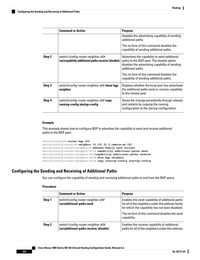
PurposeCommand or Action
disables the advertising capability of sendingadditional paths.
The no form of this command disables thecapability of sending additional paths.
Advertises the capability to send additionalpaths to the BGP peer. The disable option
switch (config-router-neighbor-af)#[no]capability additional paths receive [disable]
Step 2
disables the advertising capability of sendingadditional paths.
The no form of this command disables thecapability of sending additional paths.
Displays whether the local peer has advertisedthe additional paths send or receive capabilityto the remote peer.
switch(config-router-neighbor-af)# show bgpneighbor
Step 3
Saves the change persistently through rebootsand restarts by copying the runningconfiguration to the startup configuration.
switch(config-router-neighbor-af)# copyrunning-config startup-config
Step 4
Example
This example shows how to configure BGP to advertise the capability to send and receive additionalpaths to the BGP peer:
switch(config)# router bgp 100switch(config-router)# neighbor 10.131.31.2 remote-as 100switch(config-router-neighbor)# address-family ipv4 unicastswitch(config-router-neighbor-af)# capability additional-paths sendswitch(config-router-neighbor-af)#capability additional-paths receiveswitch(config-router-neighbor-af)# show bgp neighborswitch(config-router-neighbor-af)# copy running-config startup-config
Configuring the Sending and Receiving of Additional PathsYou can configure the capability of sending and receiving additional paths to and from the BGP peers.
Procedure
PurposeCommand or Action
Enables the send capability of additional pathsfor all of the neighbors under this address familyfor which the capability has not been disabled.
switch(config-router-neighbor-af)#[no]additional-paths send
Step 1
The no form of this command disables the sendcapability.
Enables the receive capability of additionalpaths for all of the neighbors under this address
switch (config-router-neighbor-af)#[no]additional-paths receive [disable]
Step 2
Cisco Nexus 7000 Series NX-OS Unicast Routing Configuration Guide, Release 6.xOL-25777-03310
RoutingConfiguring the Sending and Receiving of Additional Paths
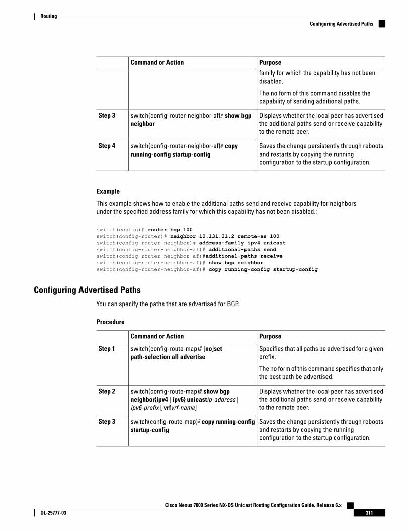
PurposeCommand or Action
family for which the capability has not beendisabled.
The no form of this command disables thecapability of sending additional paths.
Displays whether the local peer has advertisedthe additional paths send or receive capabilityto the remote peer.
switch(config-router-neighbor-af)# show bgpneighbor
Step 3
Saves the change persistently through rebootsand restarts by copying the runningconfiguration to the startup configuration.
switch(config-router-neighbor-af)# copyrunning-config startup-config
Step 4
Example
This example shows how to enable the additional paths send and receive capability for neighborsunder the specified address family for which this capability has not been disabled.:
switch(config)# router bgp 100switch(config-router)# neighbor 10.131.31.2 remote-as 100switch(config-router-neighbor)# address-family ipv4 unicastswitch(config-router-neighbor-af)# additional-paths sendswitch(config-router-neighbor-af)#additional-paths receiveswitch(config-router-neighbor-af)# show bgp neighborswitch(config-router-neighbor-af)# copy running-config startup-config
Configuring Advertised PathsYou can specify the paths that are advertised for BGP.
Procedure
PurposeCommand or Action
Specifies that all paths be advertised for a givenprefix.
switch(config-route-map)# [no]setpath-selection all advertise
Step 1
The no form of this command specifies that onlythe best path be advertised.
Displays whether the local peer has advertisedthe additional paths send or receive capabilityto the remote peer.
switch(config-route-map)# show bgpneighbor{ipv4 | ipv6} unicastip-address |ipv6-prefix [ vrfvrf-name]
Step 2
Saves the change persistently through rebootsand restarts by copying the runningconfiguration to the startup configuration.
switch(config-route-map)# copy running-configstartup-config
Step 3
Cisco Nexus 7000 Series NX-OS Unicast Routing Configuration Guide, Release 6.x311OL-25777-03
RoutingConfiguring Advertised Paths
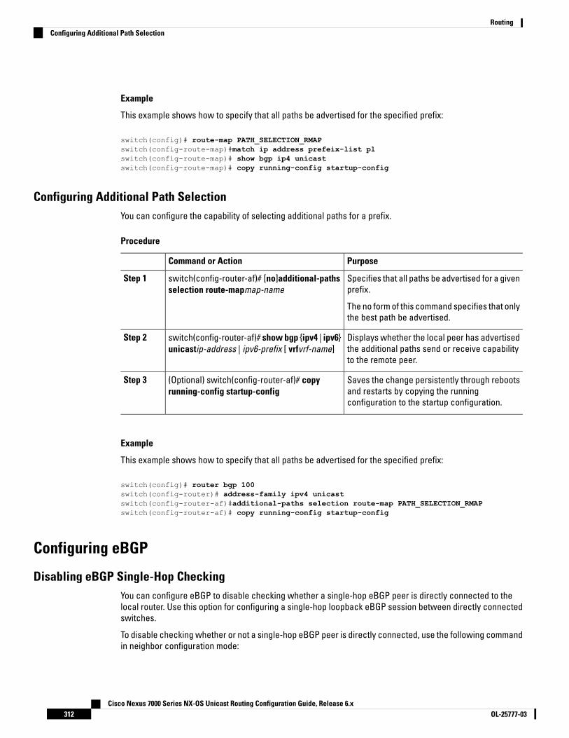
Example
This example shows how to specify that all paths be advertised for the specified prefix:
switch(config)# route-map PATH_SELECTION_RMAPswitch(config-route-map)#match ip address prefeix-list plswitch(config-route-map)# show bgp ip4 unicastswitch(config-route-map)# copy running-config startup-config
Configuring Additional Path SelectionYou can configure the capability of selecting additional paths for a prefix.
Procedure
PurposeCommand or Action
Specifies that all paths be advertised for a givenprefix.
switch(config-router-af)# [no]additional-pathsselection route-mapmap-name
Step 1
The no form of this command specifies that onlythe best path be advertised.
Displays whether the local peer has advertisedthe additional paths send or receive capabilityto the remote peer.
switch(config-router-af)# show bgp {ipv4 | ipv6}unicastip-address | ipv6-prefix [ vrfvrf-name]
Step 2
Saves the change persistently through rebootsand restarts by copying the runningconfiguration to the startup configuration.
(Optional) switch(config-router-af)# copyrunning-config startup-config
Step 3
Example
This example shows how to specify that all paths be advertised for the specified prefix:
switch(config)# router bgp 100switch(config-router)# address-family ipv4 unicastswitch(config-router-af)#additional-paths selection route-map PATH_SELECTION_RMAPswitch(config-router-af)# copy running-config startup-config
Configuring eBGP
Disabling eBGP Single-Hop CheckingYou can configure eBGP to disable checking whether a single-hop eBGP peer is directly connected to thelocal router. Use this option for configuring a single-hop loopback eBGP session between directly connectedswitches.
To disable checking whether or not a single-hop eBGP peer is directly connected, use the following commandin neighbor configuration mode:
Cisco Nexus 7000 Series NX-OS Unicast Routing Configuration Guide, Release 6.xOL-25777-03312
RoutingConfiguring Additional Path Selection

Procedure
PurposeCommand or Action
Disables checking whether or not a single-hopeBGP peer is directly connected. You must
switch(config-router-neighbor)#disable-connected-check
Step 1
manually reset the BGP sessions after using thiscommand.
Configuring eBGP MultihopYou can configure the eBGP time-to-live (TTL) value to support eBGP multihop. In some situations, an eBGPpeer is not directly connected to another eBGP peer and requires multiple hops to reach the remote eBGPpeer. You can configure the eBGP TTL value for a neighbor session to allow these multihop sessions.
To configure eBGP multihop, use the following command in neighbor configuration mode:
Procedure
PurposeCommand or Action
Configures the eBGP TTL value for eBGPmultihop. The range is from 2 to 255. You must
switch(config-router-neighbor)# ebgp-multihopttl-value
Step 1
manually reset the BGP sessions after using thiscommand.
Disabling a Fast External FalloverBy default, the Cisco Nexus 7000 Series device supports fast external fallover for neighbors in all VRFs andaddress-families (IPv4 or IPv6).
Typically, when a BGP router loses connectivity to a directly connected eBGP peer, BGP triggers a fast externalfallover by resetting the eBGP session to the peer. You can disable this fast external fallover to limit the instabilitycaused by link flaps.
To disable fast external fallover, use the following command in router configuration mode:
Procedure
PurposeCommand or Action
Disables a fast external fallover for eBGP peers.This command is enabled by default.
switch(config-router)# no fast-external-falloverStep 1
Limiting the AS-path AttributeYou can configure eBGP to discard routes that have a high number of AS numbers in the AS-path attribute.
To discard routes that have a high number of AS numbers in the AS-path attribute, use the following commandin router configuration mode:
Cisco Nexus 7000 Series NX-OS Unicast Routing Configuration Guide, Release 6.x313OL-25777-03
RoutingConfiguring eBGP Multihop
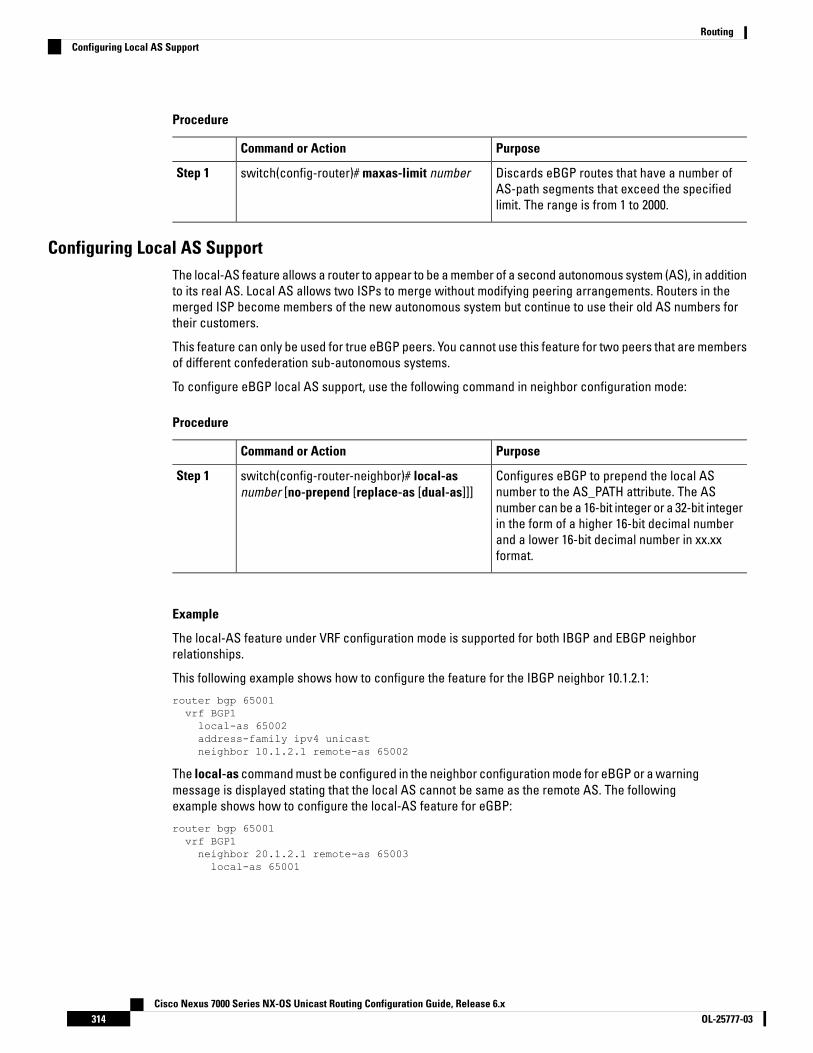
Procedure
PurposeCommand or Action
Discards eBGP routes that have a number ofAS-path segments that exceed the specifiedlimit. The range is from 1 to 2000.
switch(config-router)# maxas-limit numberStep 1
Configuring Local AS SupportThe local-AS feature allows a router to appear to be a member of a second autonomous system (AS), in additionto its real AS. Local AS allows two ISPs to merge without modifying peering arrangements. Routers in themerged ISP become members of the new autonomous system but continue to use their old AS numbers fortheir customers.
This feature can only be used for true eBGP peers. You cannot use this feature for two peers that are membersof different confederation sub-autonomous systems.
To configure eBGP local AS support, use the following command in neighbor configuration mode:
Procedure
PurposeCommand or Action
Configures eBGP to prepend the local ASnumber to the AS_PATH attribute. The AS
switch(config-router-neighbor)# local-asnumber [no-prepend [replace-as [dual-as]]]
Step 1
number can be a 16-bit integer or a 32-bit integerin the form of a higher 16-bit decimal numberand a lower 16-bit decimal number in xx.xxformat.
Example
The local-AS feature under VRF configuration mode is supported for both IBGP and EBGP neighborrelationships.
This following example shows how to configure the feature for the IBGP neighbor 10.1.2.1:
router bgp 65001vrf BGP1local-as 65002address-family ipv4 unicastneighbor 10.1.2.1 remote-as 65002
The local-as command must be configured in the neighbor configuration mode for eBGP or a warningmessage is displayed stating that the local AS cannot be same as the remote AS. The followingexample shows how to configure the local-AS feature for eGBP:
router bgp 65001vrf BGP1neighbor 20.1.2.1 remote-as 65003local-as 65001
Cisco Nexus 7000 Series NX-OS Unicast Routing Configuration Guide, Release 6.xOL-25777-03314
RoutingConfiguring Local AS Support

Configuring AS ConfederationsTo configure an AS confederation, you must specify a confederation identifier. To the outside world, the groupof autonomous systems within the AS confederation look like a single autonomous system with the confederationidentifier as the autonomous system number.
Procedure
PurposeCommand or Action
In router configuration mode, this commandconfigures a BGP confederation identifier.
switch(config-router)# confederation identifieras-number
Step 1
The command triggers an automatic notificationand session reset for the BGP neighborsessions.
In router configuration mode, this commandconfigures the autonomous systems that belongto the AS confederation.
switch(config-router)# bgp confederation peersas-number [as-number2...]
Step 2
The command specifies a list of autonomoussystems that belong to the confederation and ittriggers an automatic notification and sessionreset for the BGP neighbor sessions.
Configuring Route ReflectorYou can configure iBGP peers as route reflector clients to the local BGP speaker, which acts as the routereflector. Together, a route reflector and its clients form a cluster. A cluster of clients usually has a singleroute reflector. In such instances, the cluster is identified by the router ID of the route reflector. To increaseredundancy and avoid a single point of failure in the network, you can configure a cluster with more than oneroute reflector. You must configure all route reflectors in the cluster with the same 4-byte cluster ID so that aroute reflector can recognize updates from route reflectors in the same cluster.
Before you begin
• You must enable BGP.
• Ensure that you are in the correct VDC (or use the switchto vdc command).
Procedure
PurposeCommand or Action
Enters global configuration mode.switch# configure terminalStep 1
Enters BGP mode and assigns the autonomoussystem number to the local BGP speaker.
switch(config)# router bgp as-numberStep 2
Configures the local router as one of the routereflectors that serve the cluster. You specify a
switch(config-router)# cluster-id cluster-idStep 3
Cisco Nexus 7000 Series NX-OS Unicast Routing Configuration Guide, Release 6.x315OL-25777-03
RoutingConfiguring AS Confederations

PurposeCommand or Action
cluster ID to identify the cluster. This commandtriggers an automatic soft clear or refresh ofBGP neighbor sessions.
Enters router address family configurationmode for the specified address family.
switch(config-router)# address-family {ipv4 |ipv6 | vpnv4 | vpnv6} {unicast | multicast}
Step 4
(Optional) Configures client-to-client routereflection. This feature is enabled by default.
switch(config-router-af)# client-to-clientreflection
Step 5
This command triggers an automatic soft clearor refresh of BGP neighbor sessions.
Exits router address configuration mode.switch(config-router-neighbor)# exitStep 6
Configures the IP address and AS number fora remote BGP peer.
switch(config-router)# neighbor ip-addressremote-as as-number
Step 7
Enters neighbor address family configurationmode for the unicast IPv4 address family.
switch(config-router-neighbor)#address-family {ipv4 | ipv6 | vpnv4 | vpnv6}{unicast | multicast}
Step 8
Configures the device as a BGP route reflectorand configures the neighbor as its client. This
switch(config-router-neighbor-af)#route-reflector-client
Step 9
command triggers an automatic notificationand session reset for the BGP neighborsessions.
Displays the BGP peers.(Optional) switch(config-router-neighbor-af)#show bgp {ipv4 | ipv6 | vpnv4 | vpnv6} {unicast| multicast} neighbors
Step 10
Saves this configuration change.(Optional) switch(config-router-neighbor-af)#copy running-config startup-config
Step 11
Example
This example shows how to configure the router as a route reflector and add one neighbor as a client:
switch(config)# router bgp 65535switch(config-router)# neighbor 192.0.2.10 remote-as 65535switch(config-router-neighbor)# address-family ip unicastswitch(config-router-neighbor-af)# route-reflector-clientswitch(config-router-neighbor-af)# copy running-config startup-config
Configuring Next-Hops on Reflected Routes Using an Outbound Route-MapYou can change the next-hop on reflected routes on a BGP route reflector using an outbound route-map. Youcan configure the outbound route-map to specify the peer’s local address as the next-hop address.
Cisco Nexus 7000 Series NX-OS Unicast Routing Configuration Guide, Release 6.xOL-25777-03316
RoutingConfiguring Next-Hops on Reflected Routes Using an Outbound Route-Map

The next-hop-self command does not enable this functionality for routes being reflected to clients by a routereflector. This functionality can only be enabled using an outbound route-map.
Note
Before you begin
You must enable BGP.
Ensure that you are in the correct VDC (or use the switchto vdc command).
You must enter the set next-hop command to configure an address family specific next-hop address. Forexample, for the IPv6 address family, you must enter the set ipv6 next-hop peer-address command.
• When setting IPv4 next-hops using route-maps—If set ip next-hop peer-address matches the route-map,the next-hop is set to the peer’s local address. If no next-hop is set in the route-map, the next-hop is setto the one stored in the path.
• When setting IPv6 next-hops using route-maps—If set ipv6 next-hop peer-address matches the route-map,the next-hop is set as follows:
• For IPv6 peers, the next-hop is set to the peer’s local IPv6 address.
• For IPv4 peers, if update-source is configured, the next-hop is set to the source interface’s IPv6address, if any. If no IPv6 address is configured, no next-hop is set
• For IPv4 peers, if update-source is not configured, the next-hop is set to the outgoing interface’sIPv6 address, if any. If no IPv6 address is configured, no next-hop is set.
Procedure
PurposeCommand or Action
Enters global configuration mode.switch# configure terminalStep 1
Enters BGP mode and assigns the autonomoussystem number to the local BGP speaker.
switch(config)# router bgp as-numberStep 2
Configures the IP address and AS number for aremote BGP peer.
switch(config-router)# neighbor ip-addressremote-as as-number
Step 3
(Optional) Specifies and updates the source ofthe BGP session.
switch(config-router-neighbor)# update-sourceinterface number
Step 4
Enters router address family configuration modefor the specified address family.
switch(config-router-neighbor)# address-family{ipv4 | ipv6 | vpnv4 | vpnv6} {unicast | multicast}
Step 5
Configures the device as a BGP route reflectorand configures the neighbor as its client. This
switch(config-router-neighbor-af)#route-reflector-client
Step 6
command triggers an automatic notification andsession reset for the BGP neighbor sessions.
Applies the configured BGP policy to outgoingroutes.
switch(config-router-neighbor-af)# route-mapmap-name out
Step 7
Cisco Nexus 7000 Series NX-OS Unicast Routing Configuration Guide, Release 6.x317OL-25777-03
RoutingConfiguring Next-Hops on Reflected Routes Using an Outbound Route-Map

PurposeCommand or Action
Displays the BGP routes that match the routemap.
(Optional) switch(config-router-neighbor-af)#show bgp {ipv4 | ipv6 | vpnv4 | vpnv6} {unicast| multicast} [ip-address | ipv6-prefix] route-mapmap-name [vrf vrf-name]
Step 8
Saves this configuration change.(Optional) switch(config-router-neighbor-af)#copy running-config startup-config
Step 9
Example
This example shows how to configure the next-hop on reflected routes on a BGP route reflector usingan outbound route-map:
switch(config)# interface loopback 300switch(config-if)# ip address 192.0.2.11/32switch(config-if)# ipv6 address 2001::a0c:1a65/64switch(config-if)# ip router ospf 1 area 0.0.0.0switch(config-if)# exitswitch(config)# route-map setrrnh permit 10switch(config-route-map)# set ip next-hop peer-addressswitch(config-route-map)# exitswitch(config)# route-map setrrnhv6 permit 10switch(config-route-map)# set ipv6 next-hop peer-addressswitch(config-route-map)# exitswitch(config)# router bgp 200switch(config-router)# neighbor 192.0.2.12 remote-as 200switch(config-router-neighbor)# update-source loopback 300switch(config-router-neighbor)# address-family ipv4 unicastswitch(config-router-neighbor-af)# route-reflector-clientswitch(config-router-neighbor-af)# route-map setrrnh outswitch(config-router-neighbor-af)# exitswitch(config-router-neighbor)# address-family ipv6 unicastswitch(config-router-neighbor-af)# route-reflector-clientswitch(config-router-neighbor-af)# route-map setrrnhv6 out
Configuring Route DampeningYou can configure route dampening to minimize route flaps propagating through your iBGP network.
To configure route dampening, use the following command in address-family or VRF address family configurationmode.
Procedure
PurposeCommand or Action
Disables capabilities negotiation. The parametervalues are as follows:
switch (config-router-af)# dampening [half-lifereuse-limit suppress-limit max-suppress-time |route-map map-name}]
Step 1
• half-life—The range is from 1 to 45
• reuse-limit—The range is from 1 to 20000.
Cisco Nexus 7000 Series NX-OS Unicast Routing Configuration Guide, Release 6.xOL-25777-03318
RoutingConfiguring Route Dampening

PurposeCommand or Action
• suppress-limit—The range is from 1 to20000.
• max-suppress-time—The range is from 1to 255
Configuring Load Sharing and ECMPYou can configure the maximum number of paths that BGP adds to the route table for equal-cost multipathload balancing.
To configure the maximum number of paths, use the following command in router address-family configurationmode:
PurposeCommand
Configures the maximum number of equal-cost paths for load sharing.The range is from 1 to 16. The default is 1. Starting from Cisco NX-OSRelease 8.4(1), the range is from 1 to 64 on M3- and F3-Series I/O modules.Starting from Cisco NX-OS Release 8.4(2), the range is from 1 to 64 onF4-Series I/O modules.
switch(config-router-af)#maximum-paths [ibgp] maxpaths
Configuring Maximum PrefixesYou can configure the maximum number of prefixes that BGP can receive from a BGP peer. If the number ofprefixes exceeds this value, you can optionally configure BGP to generate a warning message or tear downthe BGP session to the peer.
To configure the maximum allowed prefixes for a BGP peer, use the following command in neighboraddress-family configuration mode:
Procedure
PurposeCommand or Action
Configure the maximum number of prefixes froma peer. The parameter ranges are as follows:
switch(config-router-neighbor-af)#maximum-prefix maximum [threshold][restarttime | warning-only]
Step 1
• maximum—The range is from 1 to 300000.
• threshold—The range is from 1 to 100percent. The default is 75 percent.
• time—The range is from 1 to 65535minutes.
This command triggers an automatic notificationand session reset for the BGP neighbor sessionsif the prefix limit is exceeded.
Cisco Nexus 7000 Series NX-OS Unicast Routing Configuration Guide, Release 6.x319OL-25777-03
RoutingConfiguring Load Sharing and ECMP
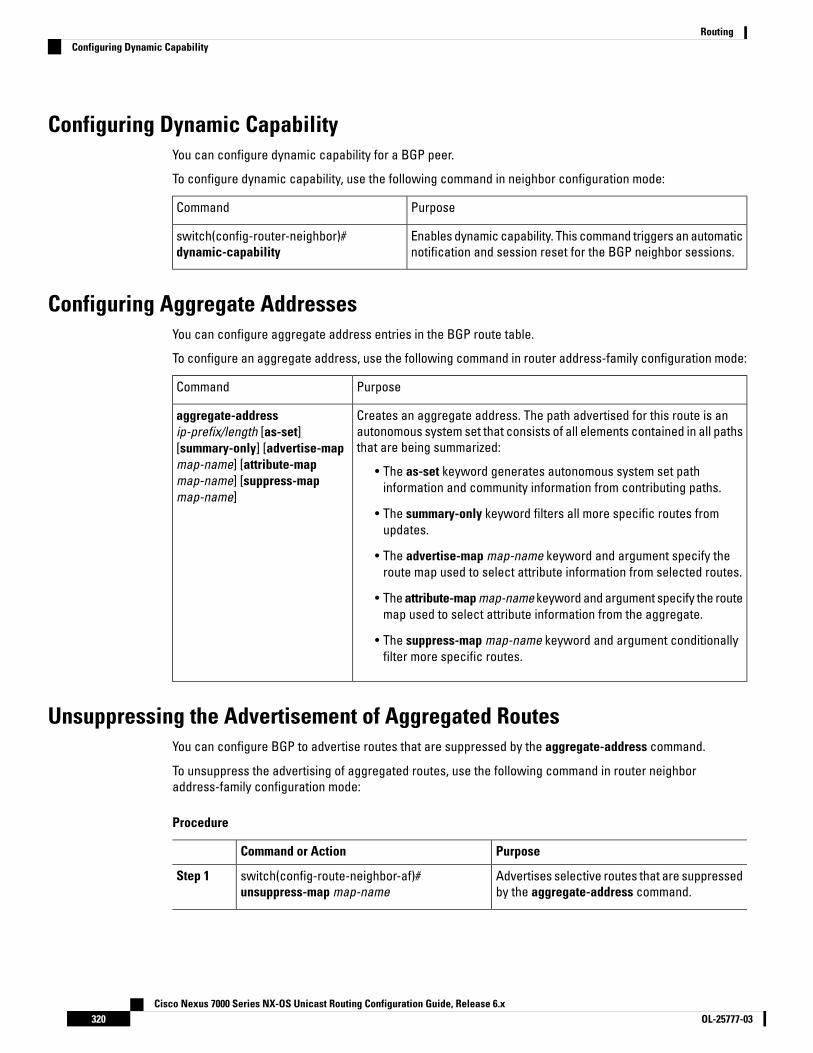
Configuring Dynamic CapabilityYou can configure dynamic capability for a BGP peer.
To configure dynamic capability, use the following command in neighbor configuration mode:
PurposeCommand
Enables dynamic capability. This command triggers an automaticnotification and session reset for the BGP neighbor sessions.
switch(config-router-neighbor)#dynamic-capability
Configuring Aggregate AddressesYou can configure aggregate address entries in the BGP route table.
To configure an aggregate address, use the following command in router address-family configuration mode:
PurposeCommand
Creates an aggregate address. The path advertised for this route is anautonomous system set that consists of all elements contained in all pathsthat are being summarized:
• The as-set keyword generates autonomous system set pathinformation and community information from contributing paths.
• The summary-only keyword filters all more specific routes fromupdates.
• The advertise-map map-name keyword and argument specify theroute map used to select attribute information from selected routes.
• The attribute-map map-name keyword and argument specify the routemap used to select attribute information from the aggregate.
• The suppress-map map-name keyword and argument conditionallyfilter more specific routes.
aggregate-addressip-prefix/length [as-set][summary-only] [advertise-mapmap-name] [attribute-mapmap-name] [suppress-mapmap-name]
Unsuppressing the Advertisement of Aggregated RoutesYou can configure BGP to advertise routes that are suppressed by the aggregate-address command.
To unsuppress the advertising of aggregated routes, use the following command in router neighboraddress-family configuration mode:
Procedure
PurposeCommand or Action
Advertises selective routes that are suppressedby the aggregate-address command.
switch(config-route-neighbor-af)#unsuppress-map map-name
Step 1
Cisco Nexus 7000 Series NX-OS Unicast Routing Configuration Guide, Release 6.xOL-25777-03320
RoutingConfiguring Dynamic Capability
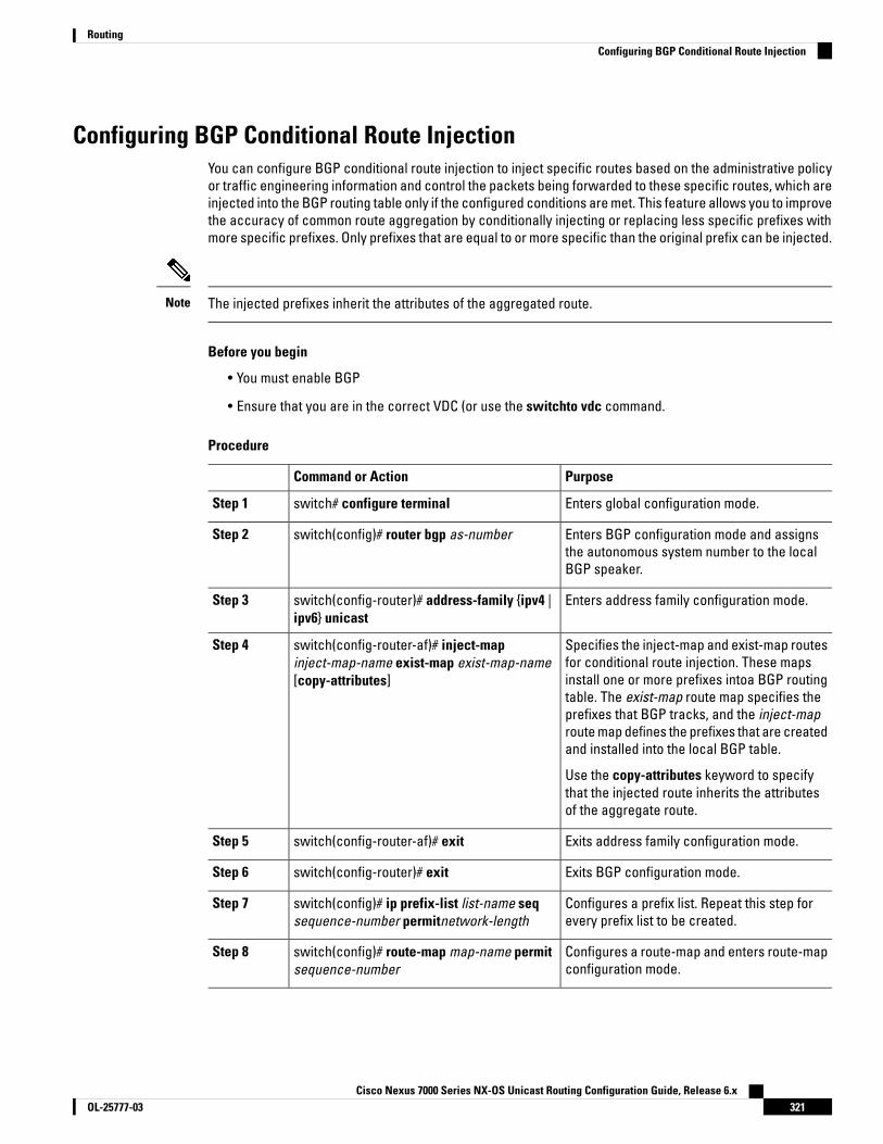
Configuring BGP Conditional Route InjectionYou can configure BGP conditional route injection to inject specific routes based on the administrative policyor traffic engineering information and control the packets being forwarded to these specific routes, which areinjected into the BGP routing table only if the configured conditions are met. This feature allows you to improvethe accuracy of common route aggregation by conditionally injecting or replacing less specific prefixes withmore specific prefixes. Only prefixes that are equal to or more specific than the original prefix can be injected.
The injected prefixes inherit the attributes of the aggregated route.Note
Before you begin
• You must enable BGP
• Ensure that you are in the correct VDC (or use the switchto vdc command.
Procedure
PurposeCommand or Action
Enters global configuration mode.switch# configure terminalStep 1
Enters BGP configuration mode and assignsthe autonomous system number to the localBGP speaker.
switch(config)# router bgp as-numberStep 2
Enters address family configuration mode.switch(config-router)# address-family {ipv4 |ipv6} unicast
Step 3
Specifies the inject-map and exist-map routesfor conditional route injection. These maps
switch(config-router-af)# inject-mapinject-map-name exist-map exist-map-name[copy-attributes]
Step 4
install one or more prefixes intoa BGP routingtable. The exist-map route map specifies theprefixes that BGP tracks, and the inject-maproute map defines the prefixes that are createdand installed into the local BGP table.
Use the copy-attributes keyword to specifythat the injected route inherits the attributesof the aggregate route.
Exits address family configuration mode.switch(config-router-af)# exitStep 5
Exits BGP configuration mode.switch(config-router)# exitStep 6
Configures a prefix list. Repeat this step forevery prefix list to be created.
switch(config)# ip prefix-list list-name seqsequence-number permitnetwork-length
Step 7
Configures a route-map and enters route-mapconfiguration mode.
switch(config)# route-map map-name permitsequence-number
Step 8
Cisco Nexus 7000 Series NX-OS Unicast Routing Configuration Guide, Release 6.x321OL-25777-03
RoutingConfiguring BGP Conditional Route Injection
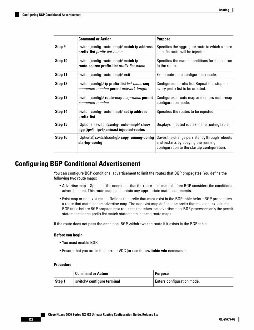
PurposeCommand or Action
Specifies the aggregate route to which a morespecific route will be injected.
switch(config-route-map)# match ip addressprefix-list prefix-list-name
Step 9
Specifies the match conditions for the sourcefo the route.
switch(config-route-map)# match iproute-source prefix-list prefix-list-name
Step 10
Exits route-map configuration mode.switch(config-route-map)# exitStep 11
Configures a prefix list. Repeat this step forevery prefix list to be created.
switch(config)# ip prefix-list list-name seqsequence-number permit network-length
Step 12
Configures a route map and enters route-mapconfiguration mode.
switch(config)# route-map map-name permitsequence-number
Step 13
Specifies the routes to be injected.switch(config-route-map)# set ip addressprefix-list
Step 14
Displays injected routes in the routing table.(Optional) switch(config-route-map)# showbgp {ipv4 | ipv6} unicast injected-routes
Step 15
Saves the change persistently through rebootsand restarts by copying the runningconfiguration to the startup configuration.
(Optional) switch(config)# copy running-configstartup-config
Step 16
Configuring BGP Conditional AdvertisementYou can configure BGP conditional advertisement to limit the routes that BGP propagates. You define thefollowing two route maps:
• Advertise map—Specifies the conditions that the route must match before BGP considers the conditionaladvertisement. This route map can contain any appropriate match statements.
• Exist map or nonexist map—Defines the prefix that must exist in the BGP table before BGP propagatesa route that matches the advertise map. The nonexist map defines the prefix that must not exist in theBGP table before BGP propagates a route that matches the advertise map. BGP processes only the permitstatements in the prefix list match statements in these route maps.
If the route does not pass the condition, BGP withdraws the route if it exists in the BGP table.
Before you begin
• You must enable BGP.
• Ensure that you are in the correct VDC (or use the switchto vdc command).
Procedure
PurposeCommand or Action
Enters configuration mode.switch# configure terminalStep 1
Cisco Nexus 7000 Series NX-OS Unicast Routing Configuration Guide, Release 6.xOL-25777-03322
RoutingConfiguring BGP Conditional Advertisement

PurposeCommand or Action
Enters BGP mode and assigns the autonomoussystem number to the local BGP speaker.
switch(config)# router bgp as-numberStep 2
Places the router in neighbor configurationmode for BGP routing and configures theneighbor IP address.
switch(config-router)#neighbor ip-addressremote-as as-number
Step 3
Enters address family configuration mode.switch(config-router-neighbor)# address-family{ipv4|ipv6|vpnv4|vpnv6} {unicast|multicast}
Step 4
Configures BGP to conditionally advertise routesbased on the two configured route maps:
switch(config-router-neighbor-af)#advertise-map adv-map {exist-mapexist-rmap|non-exist-map nonexist-rmap}
Step 5
• adv-map—Specifies a route map withmatch statements that the route must passbefore BGP passes the route to the nextroute map. The adv-map is acase-sensitive, alphanumeric string up to63 characters.
• exist-rmap—Specifies a route map withmatch statements for a prefix list. A prefixin the BGP table must match a prefix in theprefix list before BGP advertises the route.The exist-rmap is a case-sensitive,alphanumeric string up to 63 characters.
• nonexist-rmap—Specifies a route mapwith match statements for a prefix list. Aprefix in the BGP table must not match aprefix in the prefix list before BGPadvertises the route. The nonexist-rmap isa case-sensitive, alphanumeric string upto 63 characters.
Displays information about BGP and theconfigured conditional advertisement routemaps.
(Optional) switch(config-router-neighbor-af)#show ip bgp neighbor
Step 6
Saves this configuration change.(Optional) switch(config-router-neighbor-af)#copy running-config startup-config
Step 7
Example
This example shows how to configure BGP conditional advertisement:
switch# configure terminalswitch(config)# router bgp 65535switch(config-router)# neighbor 192.0.2.2 remote-as 65537switch(config-router-neighbor)# address-family ipv4 unicastswitch(config-router-neighbor-af)# advertise-map advertise exist-map existswitch(config-router-neighbor-af)# exit
Cisco Nexus 7000 Series NX-OS Unicast Routing Configuration Guide, Release 6.x323OL-25777-03
RoutingConfiguring BGP Conditional Advertisement

switch(config-router-neighbor)# exitswitch(config-router)# exitswitch(config)# route-map advertiseswitch(config-route-map)# match as-path pathListswitch(config-route-map)# exitswitch(config)# route-map exitswitch(config-route-map)# match ip address prefix-list plistswitch(config-route-map)# exitswitch(config)# ip prefix-list plist permit 209.165.201.0/27
Configuring Route RedistributionYou can configure BGP to accept routing information from another routing protocol and redistribute thatinformation through the BGP network. Optionally, you can assign a default metric for redistributed routes.
Before you begin
• You must enable BGP.
• Ensure that you are in the correct VDC (or use the switchto vdc command).
Procedure
PurposeCommand or Action
Enters global configuration mode.switch# configure terminalStep 1
Enters BGP mode and assigns the autonomoussystem number to the local BGP speaker.
switch(config)# router bgp as-numberStep 2
Enters address family configuration mode.switch(config-router)# address-family {ipv4 |ipv6 | vpnv4 | vpnv6} {unicast | multicast}
Step 3
Redistributes routes from other protocols intoBGP.
switch(config-router-af)# redistribute {direct |{eigrp | isis | ospf | ospfv3 | rip} instance-tag |static} route-map map-name
Step 4
Generates a default metric into BGP.(Optional) switch(config-router-af)#default-metric value
Step 5
Saves this configuration change.(Optional) switch(config-router-neighbor-af)#copy running-config startup-config
Step 6
Example
This example shows how to redistribute EIGRP into BGP:
switch# configure terminalswitch(config)# router bgp 65535switch(config-router)# address-family ipv4 unicastswitch(config-router-af)# redistribute eigrp 201 route-map Eigrpmapswitch(config-router-af)# copy running-config startup-config
Cisco Nexus 7000 Series NX-OS Unicast Routing Configuration Guide, Release 6.xOL-25777-03324
RoutingConfiguring Route Redistribution

Advertising the Default RouteYou can configure BGP to advertise the default route (network 0.0.0.0).
Before you begin
You must enable BGP.
Ensure that you are in the correct VDC (or use the switchto vdc command).
Procedure
PurposeCommand or Action
Enters global configuration mode.switch# configure terminalStep 1
Enters router map configuration mode anddefines the conditions for redistributing routes
switch(config)# route-map allow permitStep 2
Exits router map configuration mode.switch(config-route-map)# exitStep 3
Configures the IP address.switch(config)# ip route ip-addressnetwork-mask null null-interface-number
Step 4
Enters BGP mode and assigns the AS numberto the local BGP speaker.
switch(config)# router bgp as-numberStep 5
Enters address family configuration mode.switch(config-router)# address-family {ipv4 |ipv6 | vpnv4 | vpnv6} unicast
Step 6
Advertises the default route.switch(config-router-af)# default-informationoriginate
Step 7
Redistributes the default route.switch(config-router-af)# redistribute staticroute-map allow
Step 8
Saves the change persistently through rebootsand restarts by copying the runningconfiguration to the startup configuration.
(Optional) switch(config)# copy running-configstartup-config
Step 9
Configuring Route Import from Default VRF to any other VRFPerform the following steps to import routes from default VRF to any other non-default VRF.
Before you begin
• Enable BGP.
• Ensure that you are in the correct VDC.
Cisco Nexus 7000 Series NX-OS Unicast Routing Configuration Guide, Release 6.x325OL-25777-03
RoutingAdvertising the Default Route
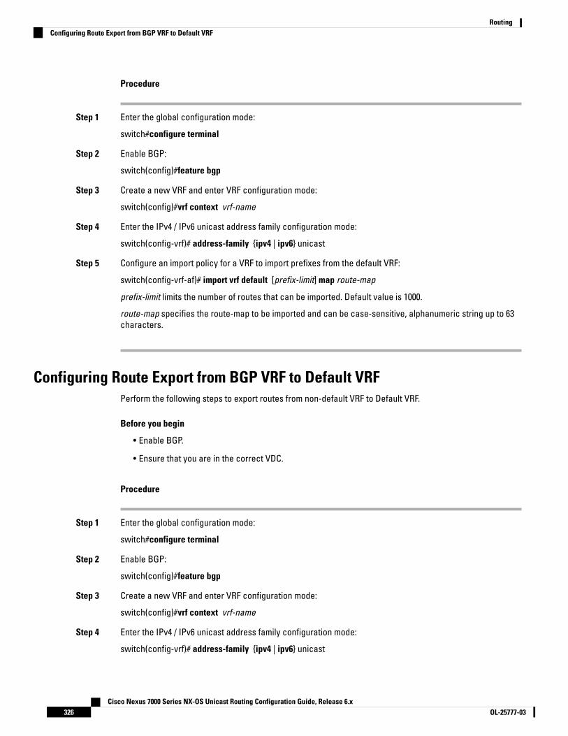
Procedure
Step 1 Enter the global configuration mode:
switch#configure terminal
Step 2 Enable BGP:
switch(config)#feature bgp
Step 3 Create a new VRF and enter VRF configuration mode:
switch(config)#vrf context vrf-name
Step 4 Enter the IPv4 / IPv6 unicast address family configuration mode:
switch(config-vrf)# address-family {ipv4 | ipv6} unicast
Step 5 Configure an import policy for a VRF to import prefixes from the default VRF:
switch(config-vrf-af)# import vrf default [prefix-limit] map route-map
prefix-limit limits the number of routes that can be imported. Default value is 1000.
route-map specifies the route-map to be imported and can be case-sensitive, alphanumeric string up to 63characters.
Configuring Route Export from BGP VRF to Default VRFPerform the following steps to export routes from non-default VRF to Default VRF.
Before you begin
• Enable BGP.
• Ensure that you are in the correct VDC.
Procedure
Step 1 Enter the global configuration mode:
switch#configure terminal
Step 2 Enable BGP:
switch(config)#feature bgp
Step 3 Create a new VRF and enter VRF configuration mode:
switch(config)#vrf context vrf-name
Step 4 Enter the IPv4 / IPv6 unicast address family configuration mode:
switch(config-vrf)# address-family {ipv4 | ipv6} unicast
Cisco Nexus 7000 Series NX-OS Unicast Routing Configuration Guide, Release 6.xOL-25777-03326
RoutingConfiguring Route Export from BGP VRF to Default VRF

Step 5 Export IPv4 or IPv6 prefixes from non-default VRF to default VRF, filtered by route-map.:
switch(config-vrf-af)# export vrf default [prefix-limit] map route-map
prefix-limit limits the number of routes that can be exported, in order to avoid the global table being overloaded.Default value is 1000.
route-map can be case-sensitive, alphanumeric string up to 63 characters. It specifies the route-map.
If the route map does not exist, the command will be accepted but processed at a later time when the routemap is created.
Example
The following example shows how to export the route map, BgpMap, to default VRF, and verify theconfiguration.
switch# configure terminalswitch(config)# feature bgpswitch(config)#vrf context vpn1switch(config-vrf)# address-family ipv4 unicastswitch(config-vrf-af)# export vrf default 3 map BgpMapswitch(config-vrf-af)# exitswitch(config)#show bgp process vrf vpn1
Information regarding configured VRFs:
BGP Information for VRF vpn1VRF Id : 3VRF state : UPRouter-ID : 20.0.0.1Configured Router-ID : 0.0.0.0Confed-ID : 0Cluster-ID : 0.0.0.0No. of configured peers : 2No. of pending config peers : 0No. of established peers : 2VRF RD : 100:1
Information for address family IPv4 Unicast in VRF vpn1Table Id : 3Table state : UPPeers Active-peers Routes Paths Networks Aggregates1 1 6 6 0 0
Redistributionstatic, route-map allow
Export RT list:100:11000:1
Import RT list:100:1
Label mode: per-prefixAggregate label: 492287Import default limit : 1000Import default prefix count : 2Import default map : allowExport default limit : 1000
Cisco Nexus 7000 Series NX-OS Unicast Routing Configuration Guide, Release 6.x327OL-25777-03
RoutingConfiguring Route Export from BGP VRF to Default VRF

Export default prefix count : 3Export default map : allow
Configuring Multiprotocol BGPYou can configure MP-BGP to support multiple address families, including IPv4 and IPv6 unicast and multicastroutes.
Before you begin
• You must enable BGP.
• Ensure that you are in the correct VDC (or use the switchto vdc command).
Procedure
PurposeCommand or Action
Enters configuration mode.switch# configure terminalStep 1
Enters BGP mode and assigns the autonomoussystem number to the local BGP speaker.
switch(config)# router bgp as-numberStep 2
Places the router in neighbor configurationmode for BGP routing and configures theneighbor IP address.
switch(config-router)#neighbor ip-addressremote-as as-number
Step 3
Enters address family configuration mode.switch(config-router-neighbor)# address-family{ipv4|ipv6|vpnv4|vpnv6} {unicast|multicast}
Step 4
Saves this configuration change.(Optional) switch(config-router-neighbor-af)#copy running-config startup-config
Step 5
Example
This example shows how to enable advertising and receiving IPv4 and IPv6 routes for multicast RPFfor a neighbor:
switch# configure terminalswitch(config)# interface ethernet 2/1switch(config-if)# ipv6 address 2001:0DB8::1switch(config-if)# router bgp 65535switch(config-router)# neighbor 192.168.1.2 remote-as 35537switch(config-router-neighbor)# address-family ipv4 multicastswitch(config-router-neighbor-af)# exitswitch(config-router-neighbor)# address-family ipv6 multicastswitch(config-router-neighbor-af)# copy running-config startup-config
Configuring Policy-Based Administrative DistanceYou can configure a distance for external BGP (eBGP) and internal BGP (iBGP) routes that match a policydescribed in the configured route map. The distance configured in the route map is downloaded to the unicast
Cisco Nexus 7000 Series NX-OS Unicast Routing Configuration Guide, Release 6.xOL-25777-03328
RoutingConfiguring Multiprotocol BGP

RIB along with the matching routes. BGP uses the best path to determine the administrative distance whendownloading next hops in the unicast RIB table. If there is no match or a deny clause in the policy, BGP usesthe distance configured in the distance command or the default distance for routes.
The policy-based administrative distance feature is useful when there are two or more different routes to thesame destination from two different routing protocols.
Before you begin
You must enable BGP.
Ensure that you are in the correct VDC (or use the switchto vdc command).
Procedure
PurposeCommand or Action
Enters global configuration mode.switch# configure terminalStep 1
Creates a prefix list to match IP packets orroutes with the permit keyword.
switch(config)# ip prefix-list name seq numberpermit prefix-length
Step 2
Creates a route map and enters route-mapconfiguration mode with the permit keyword.
switch(config)# route-map map-tag permitsequence-number
Step 3
If the match criteria for the route is met in thepolicy, the packet is policy routed.
Matches IPv4 network routes based on a prefixlist. The prefix-list name can be anyalphanumeric string up to 63 characters.
switch(config-route-map)# match ip addressprefix-list prefix-list-name
Step 4
Specifies the administrative distance forinterior BGP (iBGP) or exterior BGP (eBGP)
switch(config-route-map)# set distance<value1> <value2> <value3>
Step 5
routes and BGP routes originated in the localautonomous system. The range is from 1 to 255.
After you enter the value for the externaladministrative distance, you must enter thevalue for the administrative distance for theinternal routes or/and the value for theadministrative distance for the local routesdepending on your requirement; so that theinternal/local routes are also considered in theroute administration.
Exits route-map configuration mode.switch(config-route-map)# exitStep 6
Enters BGP mode and assigns the AS numberto the local BGP speaker.
switch(config)# router bgp as-numberStep 7
Enters address family configuration mode.switch(config-router)# address-family {ipv4 |ipv6 | vpnv4 | vpnv6} unicast
Step 8
Configures the selective administrativedistance for a route map for BGP routes before
switch(config-router-af)# table-map map-nameStep 9
Cisco Nexus 7000 Series NX-OS Unicast Routing Configuration Guide, Release 6.x329OL-25777-03
RoutingConfiguring Policy-Based Administrative Distance
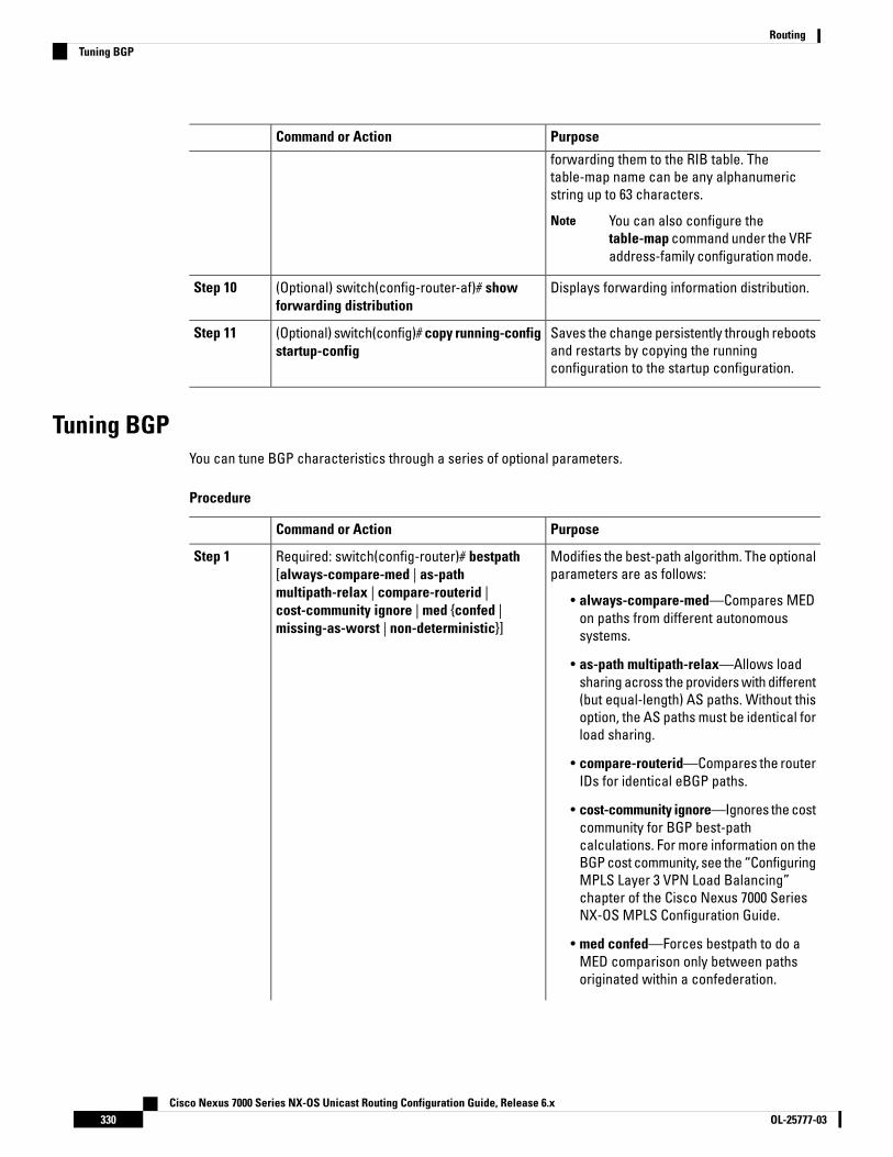
PurposeCommand or Action
forwarding them to the RIB table. Thetable-map name can be any alphanumericstring up to 63 characters.
You can also configure thetable-map command under the VRFaddress-family configuration mode.
Note
Displays forwarding information distribution.(Optional) switch(config-router-af)# showforwarding distribution
Step 10
Saves the change persistently through rebootsand restarts by copying the runningconfiguration to the startup configuration.
(Optional) switch(config)# copy running-configstartup-config
Step 11
Tuning BGPYou can tune BGP characteristics through a series of optional parameters.
Procedure
PurposeCommand or Action
Modifies the best-path algorithm. The optionalparameters are as follows:
Required: switch(config-router)# bestpath[always-compare-med | as-pathmultipath-relax | compare-routerid |
Step 1
• always-compare-med—Compares MEDon paths from different autonomoussystems.
cost-community ignore | med {confed |missing-as-worst | non-deterministic}]
• as-path multipath-relax—Allows loadsharing across the providers with different(but equal-length) AS paths. Without thisoption, the AS paths must be identical forload sharing.
• compare-routerid—Compares the routerIDs for identical eBGP paths.
• cost-community ignore—Ignores the costcommunity for BGP best-pathcalculations. For more information on theBGP cost community, see the “ConfiguringMPLS Layer 3 VPN Load Balancing”chapter of the Cisco Nexus 7000 SeriesNX-OS MPLS Configuration Guide.
• med confed—Forces bestpath to do aMED comparison only between pathsoriginated within a confederation.
Cisco Nexus 7000 Series NX-OS Unicast Routing Configuration Guide, Release 6.xOL-25777-03330
RoutingTuning BGP
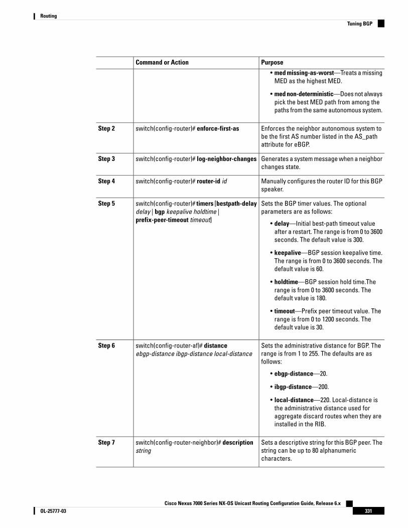
PurposeCommand or Action
• med missing-as-worst—Treats a missingMED as the highest MED.
• med non-deterministic—Does not alwayspick the best MED path from among thepaths from the same autonomous system.
Enforces the neighbor autonomous system tobe the first AS number listed in the AS_pathattribute for eBGP.
switch(config-router)# enforce-first-asStep 2
Generates a system message when a neighborchanges state.
switch(config-router)# log-neighbor-changesStep 3
Manually configures the router ID for this BGPspeaker.
switch(config-router)# router-id idStep 4
Sets the BGP timer values. The optionalparameters are as follows:
switch(config-router)# timers [bestpath-delaydelay | bgp keepalive holdtime |prefix-peer-timeout timeout]
Step 5
• delay—Initial best-path timeout valueafter a restart. The range is from 0 to 3600seconds. The default value is 300.
• keepalive—BGP session keepalive time.The range is from 0 to 3600 seconds. Thedefault value is 60.
• holdtime—BGP session hold time.Therange is from 0 to 3600 seconds. Thedefault value is 180.
• timeout—Prefix peer timeout value. Therange is from 0 to 1200 seconds. Thedefault value is 30.
Sets the administrative distance for BGP. Therange is from 1 to 255. The defaults are asfollows:
switch(config-router-af)# distanceebgp-distance ibgp-distance local-distance
Step 6
• ebgp-distance—20.
• ibgp-distance—200.
• local-distance—220. Local-distance isthe administrative distance used foraggregate discard routes when they areinstalled in the RIB.
Sets a descriptive string for this BGP peer. Thestring can be up to 80 alphanumericcharacters.
switch(config-router-neighbor)# descriptionstring
Step 7
Cisco Nexus 7000 Series NX-OS Unicast Routing Configuration Guide, Release 6.x331OL-25777-03
RoutingTuning BGP

PurposeCommand or Action
Exempts this BGP neighbor from a possibleshutdown due to a low memory condition.
switch(config-router-neighbor)# low-memoryexempt
Step 8
Allows a passive connection setup only. ThisBGP speaker does not initiate a TCP
switch(config-router-neighbor)# transportconnection-mode passive
Step 9
connection to a BGP peer. You must manuallyreset the BGP sessions after configuring thiscommand.
Removes private AS numbers from outboundroute updates to an eBGP peer. This command
remove-private-asStep 10
triggers an automatic soft clear or refresh ofBGP neighbor sessions.
See the “Guidelines and Limitationsfor Advanced BGP” section formore information on this command.
Note
Configures the BGP speaker to use the sourceIP address of the configured interface for BGP
switch(config-router-neighbor)# update-sourceinterface-type number
Step 11
sessions to the peer. This command triggersan automatic notification and session reset forthe BGP neighbor sessions. Single-hop iBGPpeers support fast external failover whenupdate-source is configured.
Advertises the best (active) routes only to theBGP peer. This command triggers an automaticsoft clear or refresh of BGP neighbor sessions.
switch(config-router-neighbor)#suppress-inactive
Step 12
Generates a default route to the BGP peer.switch(config-router-neighbor)#default-originate [route-map map-name]
Step 13
Applies an AS path filter list to this BGP peerfor inbound or outbound route updates. This
switch(config-router-neighbor)# filter-listlist-name {in|out}
Step 14
command triggers an automatic soft clear orrefresh of BGP neighbor sessions.
Applies a prefix list to this BGP peer forinbound or outbound route updates. This
switch(config-router-neighbor)# prefix-listlist-name {in|out}
Step 15
command triggers an automatic soft clear orrefresh of BGP neighbor sessions.
Sends the community attribute to this BGPpeer. This command triggers an automatic softclear or refresh of BGP neighbor sessions.
switch(config-router-neighbor)#send-community
Step 16
Sends the extended community attribute to thisBGP peer. This command triggers an automaticsoft clear or refresh of BGP neighbor sessions.
switch(config-router-neighbor)#send-community extended
Step 17
Cisco Nexus 7000 Series NX-OS Unicast Routing Configuration Guide, Release 6.xOL-25777-03332
RoutingTuning BGP

Configuring a Graceful RestartYou can configure a graceful restart and enable the graceful restart helper feature for BGP.
Before you begin
You must enable BGP.
Create the VDCs and VRFs.
Ensure that you are in the correct VDC (or use the switchto vdc command).
Procedure
PurposeCommand or Action
Enters configuration mode.switch# configure terminalStep 1
Creates a new BGP process with the configuredautonomous system number.
switch(config)# router bgp as-numberStep 2
Enables a graceful restart and the gracefulrestart helper functionality. This command isenabled by default.
switch(config-router)# graceful-restartStep 3
This command triggers an automatic notificationand session reset for the BGP neighborsessions.
Configures the graceful restart timers.switch(config-router)# graceful-restart{restart-time time|stalepath-time time}
Step 4
The optional parameters are as follows:
• restart-time—Maximum time for a restartsent to the BGP peer. The range is from 1to 3600 seconds. The default is 120.
• stalepath-time—Maximum time that BGPkeeps the stale routes from the restartingBGP peer. The range is from 1 to 3600seconds. The default is 300.
This command triggers an automatic notificationand session reset for the BGP neighborsessions.
Enables the graceful restart helper functionality.Use this command if you have disabled graceful
switch(config-router)# graceful-restart-helperStep 5
restart but you still want to enable gracefulrestart helper functionality. This commandtriggers an automatic notification and sessionreset for the BGP neighbor sessions.
Displays the BGP configuration.(Optional) switch(config-router)# showrunning-config bgp
Step 6
Cisco Nexus 7000 Series NX-OS Unicast Routing Configuration Guide, Release 6.x333OL-25777-03
RoutingConfiguring a Graceful Restart
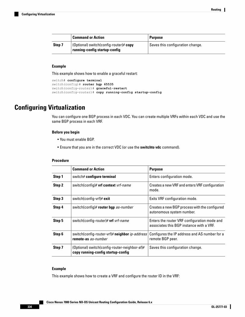
PurposeCommand or Action
Saves this configuration change.(Optional) switch(config-router)# copyrunning-config startup-config
Step 7
Example
This example shows how to enable a graceful restart:
switch# configure terminalswitch(config)# router bgp 65535switch(config-router)# graceful-restartswitch(config-router)# copy running-config startup-config
Configuring VirtualizationYou can configure one BGP process in each VDC. You can create multiple VRFs within each VDC and use thesame BGP process in each VRF.
Before you begin
• You must enable BGP.
• Ensure that you are in the correct VDC (or use the switchto vdc command).
Procedure
PurposeCommand or Action
Enters configuration mode.switch# configure terminalStep 1
Creates a new VRF and enters VRF configurationmode.
switch(config)# vrf context vrf-nameStep 2
Exits VRF configuration mode.switch(config-vrf)# exitStep 3
Creates a new BGP process with the configuredautonomous system number.
switch(config)# router bgp as-numberStep 4
Enters the router VRF configuration mode andassociates this BGP instance with a VRF.
switch(config-router)# vrf vrf-nameStep 5
Configures the IP address and AS number for aremote BGP peer.
switch(config-router-vrf)# neighbor ip-addressremote-as as-number
Step 6
Saves this configuration change.(Optional) switch(config-router-neighbor-af)#copy running-config startup-config
Step 7
Example
This example shows how to create a VRF and configure the router ID in the VRF:
Cisco Nexus 7000 Series NX-OS Unicast Routing Configuration Guide, Release 6.xOL-25777-03334
RoutingConfiguring Virtualization

switch# configure terminalswitch(config)# vrf context NewVRFswitch(config-vrf)# exitswitch(config)# router bgp 65535switch(config-router)# vrf NewVRFswitch(config-router-vrf)# neighbor 209.165.201.1 remote-as 65535switch(config-router-vrf-neighbor)# copy running-config startup-config
Verifying the Advanced BGP ConfigurationTo display the BGP configuration, perform one of the following tasks:
PurposeCommand
Displays the BGP information for alladdress families.
show bgp all [summary] [vrf vrf-name]
Displays the BGP information for alladdress families.
show bgp convergence vrf vrf-name
Displays the BGP routes that matcha BGP community.
show bgp {ipv4 | ipv6 | vpnv4 | vpnv6} {unicast | multicast} [ip-address |ipv6-prefix] community {regexp expression | [community] [no-advertise][no-export] [no-export-subconfed]} [vrf vrf-name]
Displays the BGP routes that matcha BGP community list.
show bgp [vrf vrf-name] {ipv4 | ipv6 | vpnv4 | vpnv6} {unicast | multicast}[ip-address | ipv6-prefix] community-list list-name [vrf vrf-name]
Displays the BGP routes that matcha BGP extended community.
show bgp {ipv4 | ipv6 | vpnv4 | vpnv6} {unicast | multicast} [ip-address |ipv6-prefix] extcommunity {regexp expression | generic [non-transitive| transitive] aa4:nn [exact-match]} [vrf vrf-name]
Displays the BGP routes that matcha BGP extended community list.
show bgp {ipv4 | ipv6 | vpnv4 | vpnv6} {unicast | multicast} [ip-address |ipv6-prefix] extcommunity-list list-name [exact-match]} [vrf vrf-name]
Displays the information for BGProute dampening. Use the clear bgpdampening command to clear theroute flap dampening information.
show bgp {ipv4 | ipv6 | vpnv4 | vpnv6} {unicast | multicast} [ip-address |ipv6-prefix] {dampening dampened-paths [regexp expression]} [vrfvrf-name]
Displays the BGP route historypaths.
show bgp {ipv4 | ipv6 | vpnv4 | vpnv6} {unicast | multicast} [ip-address |ipv6-prefix] history-paths [regexp expression] [vrf vrf-name]
Displays the information for theBGP filter list.
show bgp {ipv4 | ipv6 | vpnv4 | vpnv6} {unicast | multicast} [ip-address |ipv6-prefix] filter-list list-name [vrf vrf-name]
Displays the information for BGPpeers. Use the clear bgp neighborscommand to clear these neighbors.
show bgp {ipv4 | ipv6 | vpnv4 | vpnv6} {unicast | multicast} [ip-address |ipv6-prefix] neighbors [ip-address | ipv6-prefix] [vrf vrf-name]
show bgp {ipv4 | ipv6 | vpnv4 |vpnv6} {unicast | multicast}[ip-address | ipv6-prefix] {nexthop| nexthop-database} [vrf vrf-name]
show bgp {ipv4 | ipv6 | vpnv4 | vpnv6} {unicast | multicast} [ip-address |ipv6-prefix] {nexthop | nexthop-database} [vrf vrf-name]
Cisco Nexus 7000 Series NX-OS Unicast Routing Configuration Guide, Release 6.x335OL-25777-03
RoutingVerifying the Advanced BGP Configuration

Displays the BGP path information.show bgp paths
Displays the BGP policyinformation. Use the clear bgppolicy command to clear the policyinformation.
show bgp {ipv4 | ipv6 | vpnv4 | vpnv6} {unicast | multicast} [ip-address |ipv6-prefix] policy name [vrf vrf-name]
Displays the BGP routes that matchthe prefix list.
show bgp {ipv4 | ipv6 | vpnv4 | vpnv6} {unicast | multicast} [ip-address |ipv6-prefix] prefix-list list-name [vrf vrf-name]
Displays the BGP paths stored forsoft reconfiguration.
show bgp {ipv4 | ipv6 | vpnv4 | vpnv6} {unicast | multicast} [ip-address |ipv6-prefix] received-paths [vrf vrf-name]
Displays the BGP routes that matchthe AS_path regular expression.
show bgp {ipv4 | ipv6 | vpnv4 | vpnv6} {unicast | multicast} [ip-address |ipv6-prefix] regexp expression [vrf vrf-name]
Displays the BGP routes that matchthe route map.
show bgp {ipv4 | ipv6 | vpnv4 | vpnv6} {unicast | multicast} [ip-address |ipv6-prefix] route-map map-name [vrf vrf-name]
Displays the information about BGPpeer policies.
show bgp peer-policy name [vrf vrf-name]
Displays the information about BGPpeer sessions.
show bgp peer-session name [vrf vrf-name]
Displays the information about BGPpeer templates. Use the clear bgppeer-template command to clearall neighbors in a peer template.
show bgp peer-template name [vrf vrf-name]
Displays the BGP processinformation.
show bgp process
Displays the BGP status andconfiguration information. Thiscommand has multiple options. Seethe Cisco Nexus 7000 Series NX-OSUnicast Routing CommandReference, for more information.
show {ipv4 | ipv6 | vpnv4 | vpnv6} bgp options
Displays the BGP status andconfiguration information. Thiscommand has multiple options. Seethe Cisco Nexus 7000 Series NX-OSUnicast Routing CommandReference, for more information.
show {ipv4 | ipv6 | vpnv4 | vpnv6} mbgp options
Displays the current running BGPconfiguration.
show running-configuration bgp
Cisco Nexus 7000 Series NX-OS Unicast Routing Configuration Guide, Release 6.xOL-25777-03336
RoutingVerifying the Advanced BGP Configuration

Displaying Advanced BGP StatisticsTo display advanced BGP statistics, use the following commands:
PurposeCommand
Displays the BGP route flap statistics. Use the clear bgpflap-statistics command to clear these statistics.
show bgp {ipv4 | ipv6 | vpnv4 | vpnv6} {unicast |multicast} [ip-address | ipv6-prefix] flap-statistics[vrf vrf-name]
Displays the BGP sessions for all peers. Use the clear bgpsessions command to clear these statistics.
show bgp sessions [vrf vrf-name]
Displays the BGP statistics.show bgp statistics
Related DocumentsDocument TitleRelated Topic
Cisco Nexus 7000 Series NX-OS Unicast Routing Command ReferenceBGP CLIcommands
Cisco Nexus 7000 Series NX-OS Virtual Device Context Configuration GuideVDCs and VRFs
RFCsTitleRFC
Route Refresh Capability for BGP-4 http://www.faqs.org/rfcs/rfc2918.htmlRFC2918
MIBsMIBs LinkMIBs
To locate and download MIBs, go to the following URL: https://cfnng.cisco.com/mibs.BGP4-MIB
CISCO-BGP4-MIB
CISCO-BGP-MIBv2
Cisco Nexus 7000 Series NX-OS Unicast Routing Configuration Guide, Release 6.x337OL-25777-03
RoutingDisplaying Advanced BGP Statistics
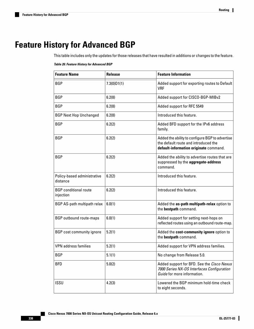
Feature History for Advanced BGPThis table includes only the updates for those releases that have resulted in additions or changes to the feature.
Table 26: Feature History for Advanced BGP
Feature InformationReleaseFeature Name
Added support for exporting routes to DefaultVRF
7.3(0)D1(1)BGP
Added support for CISCO-BGP-MIBv26.2(8)BGP
Added support for RFC 55496.2(8)BGP
Introduced this feature.6.2(8)BGP Next Hop Unchanged
Added BFD support for the IPv6 addressfamily.
6.2(2)BGP
Added the ability to configure BGP to advertisethe default route and introduced thedefault-information originate command.
6.2(2)BGP
Added the ability to advertise routes that aresuppressed by the aggregate-addresscommand.
6.2(2)BGP
Introduced this feature.6.2(2)Policy-based administrativedistance
Introduced this feature.6.2(2)BGP conditional routeinjection
Added the as-path multipath-relax option tothe bestpath command.
6.0(1)BGP AS-path multipath relax
Added support for setting next-hops onreflected routes using an outbound route-map.
6.0(1)BGP outbound route-maps
Added the cost-community ignore option tothe bestpath command.
5.2(1)BGP cost community ignore
Added support for VPN address families.5.2(1)VPN address families
No change from Release 5.0.5.1(1)BGP
Added support for BFD. See the Cisco Nexus7000 Series NX-OS Interfaces ConfigurationGuide for more information.
5.0(2)BFD
Lowered the BGP minimum hold-time checkto eight seconds.
4.2(3)ISSU
Cisco Nexus 7000 Series NX-OS Unicast Routing Configuration Guide, Release 6.xOL-25777-03338
RoutingFeature History for Advanced BGP

Feature InformationReleaseFeature Name
Added support for the BGP next-hop addresstracking and filtering.
4.2(1)Next-hop addressing
Added support for 4-byte AS numbers inplaintext notation.
4.2(1)4-Byte AS numbers
Added support for conditionally advertisingBGP routes based on the existence of otherroutes in the BGP table.
4.2(1)Conditional advertisement
Added support for a range of AS numbers forthe BGP prefix peer configuration.
4.1(2)Dynamic AS number for prefixpeers
This feature was introduced.4.0(1)BGP
Cisco Nexus 7000 Series NX-OS Unicast Routing Configuration Guide, Release 6.x339OL-25777-03
RoutingFeature History for Advanced BGP

Cisco Nexus 7000 Series NX-OS Unicast Routing Configuration Guide, Release 6.xOL-25777-03340
RoutingFeature History for Advanced BGP
C H A P T E R 13Configuring RIP
This chapter contains the following sections:
• Finding Feature Information, on page 341• Information About RIP, on page 341• Prerequisites for RIP, on page 344• Guidelines and Limitations for RIP, on page 344• Default Settings for RIP Parameters, on page 344• Configuring RIP, on page 344• Verifying the RIP Configuration, on page 355• Displaying RIP Statistics, on page 356• Configuration Examples for RIP, on page 356• Related Documents for RIP, on page 356• Standards for RIP, on page 357• Feature History for RIP, on page 357
Finding Feature InformationYour software release might not support all the features documented in this module. For the latest caveatsand feature information, see the Bug Search Tool at https://tools.cisco.com/bugsearch/ and the release notesfor your software release. To find information about the features documented in this module, and to see a listof the releases in which each feature is supported, see the "New and Changed Information"chapter or theFeature History table in this chapter.
Information About RIPRIP uses User Datagram Protocol (UDP) data packets to exchange routing information in small internetworks.RIPv2 supports IPv4. RIPv2 uses an optional authentication feature supported by the RIPv2 protocol.
Cisco NX-OS does not support IPv6 for RIP.Note
RIP uses the following two message types:
• Request—Sent to the multicast address 224.0.0.9 to request route updates from other RIP-enabled routers.
Cisco Nexus 7000 Series NX-OS Unicast Routing Configuration Guide, Release 6.x341OL-25777-03
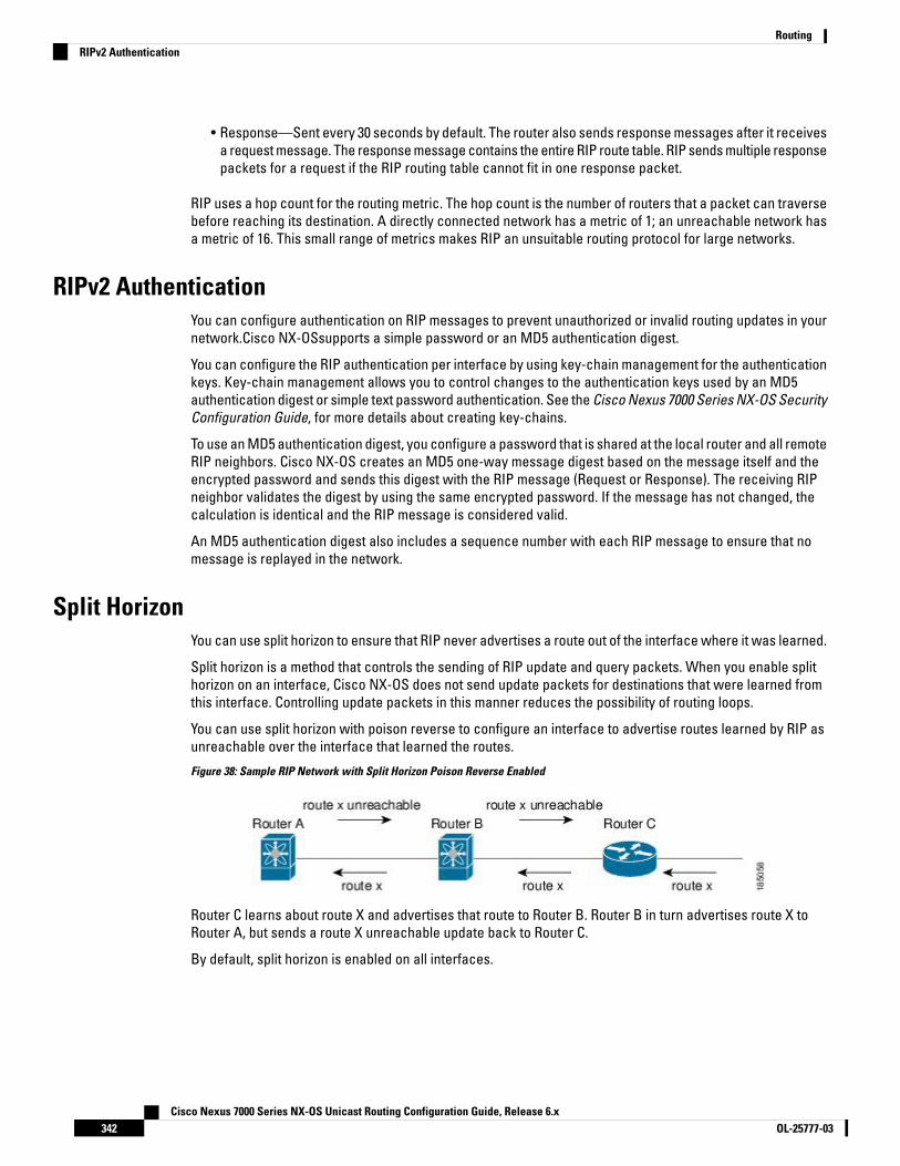
• Response—Sent every 30 seconds by default. The router also sends response messages after it receivesa request message. The response message contains the entire RIP route table. RIP sends multiple responsepackets for a request if the RIP routing table cannot fit in one response packet.
RIP uses a hop count for the routing metric. The hop count is the number of routers that a packet can traversebefore reaching its destination. A directly connected network has a metric of 1; an unreachable network hasa metric of 16. This small range of metrics makes RIP an unsuitable routing protocol for large networks.
RIPv2 AuthenticationYou can configure authentication on RIP messages to prevent unauthorized or invalid routing updates in yournetwork.Cisco NX-OSsupports a simple password or an MD5 authentication digest.
You can configure the RIP authentication per interface by using key-chain management for the authenticationkeys. Key-chain management allows you to control changes to the authentication keys used by an MD5authentication digest or simple text password authentication. See the Cisco Nexus 7000 Series NX-OS SecurityConfiguration Guide, for more details about creating key-chains.
To use an MD5 authentication digest, you configure a password that is shared at the local router and all remoteRIP neighbors. Cisco NX-OS creates an MD5 one-way message digest based on the message itself and theencrypted password and sends this digest with the RIP message (Request or Response). The receiving RIPneighbor validates the digest by using the same encrypted password. If the message has not changed, thecalculation is identical and the RIP message is considered valid.
An MD5 authentication digest also includes a sequence number with each RIP message to ensure that nomessage is replayed in the network.
Split HorizonYou can use split horizon to ensure that RIP never advertises a route out of the interface where it was learned.
Split horizon is a method that controls the sending of RIP update and query packets. When you enable splithorizon on an interface, Cisco NX-OS does not send update packets for destinations that were learned fromthis interface. Controlling update packets in this manner reduces the possibility of routing loops.
You can use split horizon with poison reverse to configure an interface to advertise routes learned by RIP asunreachable over the interface that learned the routes.
Figure 38: Sample RIP Network with Split Horizon Poison Reverse Enabled
Router C learns about route X and advertises that route to Router B. Router B in turn advertises route X toRouter A, but sends a route X unreachable update back to Router C.
By default, split horizon is enabled on all interfaces.
Cisco Nexus 7000 Series NX-OS Unicast Routing Configuration Guide, Release 6.xOL-25777-03342
RoutingRIPv2 Authentication

Route FilteringYou can configure a route policy on a RIP-enabled interface to filter the RIP updates. Cisco NX-OS updatesthe route table with only those routes that the route policy allows.
Route SummarizationYou can configure multiple summary aggregate addresses for a specified interface. Route summarizationsimplifies route tables by replacing a number of more-specific addresses with an address that represents allthe specific addresses. For example, you can replace 10.1.1.0/24, 10.1.2.0/24, and 10.1.3.0/24 with one summaryaddress, 10.1.0.0/16.
If more specific routes are in the routing table, RIP advertises the summary address from the interface with ametric equal to the maximum metric of the more specific routes.
Cisco NX-OS does not support automatic route summarization.Note
Route RedistributionYou can use RIP to redistribute static routes or routes from other protocols. You must configure a route mapwith the redistribution to control which routes are passed into RIP. A route policy allows you to filter routesbased on attributes such as the destination, origination protocol, route type, route tag, and so on. For moreinformation, see Configuring Route Policy Manager, on page 401.
Whenever you redistribute routes into a RIP routing domain, Cisco NX-OS does not, by default, redistributethe default route into the RIP routing domain. You can generate a default route into RIP, which can be controlledby a route policy.
You also configure the default metric that is used for all imported routes into RIP.
Load BalancingYou can use load balancing to allow a router to distribute traffic over all the router network ports that are thesame distance from the destination address. Load balancing increases the usage of network segments andincreases effective network bandwidth.
Cisco NX-OS supports the Equal Cost Multiple Paths (ECMP) feature with up to 16 equal-cost paths in the RIProute table and the unicast RIB. You can configure RIP to load balance traffic across some or all of those paths.
High Availability for RIPCisco NX-OS supports stateless restarts for RIP. After a reboot or supervisor switchover, Cisco NX-OS appliesthe running configuration and RIP immediately sends request packets to repopulate its routing table.
Virtualization SupportCisco NX-OS supports multiple instances of the RIP protocol that run on the same system. RIP supports virtualrouting and forwarding (VRF) instances. VRFs exist within virtual device contexts (VDCs).
Cisco Nexus 7000 Series NX-OS Unicast Routing Configuration Guide, Release 6.x343OL-25777-03
RoutingRoute Filtering

You can configure up to four RIP instances on a VDC. By default, Cisco NX-OS places you in the default VDCand default VRF unless you specifically configure another VDC and VRF.
See the Cisco Nexus 7000 Series NX-OS Virtual Device Context Configuration Guide.
Prerequisites for RIP• You must enable RIP.
Guidelines and Limitations for RIP• Cisco NX-OS does not support RIPv1. if Cisco NX-OS receives a RIPv1 packet, it logs a message and
drops the packet.
• Cisco NX-OS does not establish adjacencies with RIPv1 routers.
• If you are familiar with the Cisco IOS CLI, be aware that the Cisco NX-OS commands for this feature mightdiffer from the Cisco IOS commands that you would use.
Default Settings for RIP ParametersDefault RIP Parameters
DefaultParameters
8Maximum paths for load balancing
DisabledRIP feature
EnabledSplit horizon
Configuring RIP
Enabling RIP
Before you begin
Confirm that you are in the correct VDC. To change the VDC, use the switchto vdc command.
Procedure
PurposeCommand or Action
Enters global configuration mode.switch# configure terminalStep 1
Cisco Nexus 7000 Series NX-OS Unicast Routing Configuration Guide, Release 6.xOL-25777-03344
RoutingPrerequisites for RIP

PurposeCommand or Action
Enables the RIP feature.switch(config)# [no] feature ripStep 2
Use the no form of this command to disable thisfeature.
Saves the change persistently through rebootsand restarts by copying the runningconfiguration to the startup configuration.
(Optional) switch(config)# copy running-configstartup-config
Step 3
Displays enables and disabled features.(Optional) switch(config)# show featureStep 4
Example
The following example enables RIP:
switch # configure terminalswitch(config)# feature ripswitch(config)# copy running-config startup-config
Creating a RIP InstanceYou can create a RIP instance and configure the address family for that instance.
Before you begin
You must enable RIP.
Ensure that you are in the correct VDC (or use the switchto vdc command).
Procedure
PurposeCommand or Action
Enters global configuration mode.switch# configure terminalStep 1
Creates a new RIP instance with the configuredinstance-tag.
switch(config)# [no] router rip instance-tagStep 2
Use the no form of this command to disable thisfeature.
You must also remove any RIPcommands configured in interfacemode.
Note
Configures the address family for this RIPinstance and enters address-familyconfiguration mode.
switch(config-router)# address-family ipv4unicast
Step 3
Displays a summary of RIP information for allRIP instances.
(Optional) switch(config-router-af)# show ip rip[instance instance-tag] [vrf vrf-name]
Step 4
Cisco Nexus 7000 Series NX-OS Unicast Routing Configuration Guide, Release 6.x345OL-25777-03
RoutingCreating a RIP Instance

PurposeCommand or Action
Sets the administrative distance for RIP, inaddress-family configuration mode. The rangeis from 1 to 255.
(Optional) switch(config-router-af)# distancevalue
Step 5
Configures the maximum number of equal-costpaths that RIP maintains in the route table, in
(Optional) switch(config-router-af)#maximum-paths number
Step 6
address-family configuration mode. The rangeis from 1 to 16.
Saves the change persistently through rebootsand restarts by copying the runningconfiguration to the startup configuration.
(Optional) switch(config-router-af)# copyrunning-config startup-config
Step 7
Example
The following example creates a RIP instance for IPv4 and sets the number of equal-cost paths forload balancing:
switch# configure terminalswitch(config)# router rip Enterpriseswitch(config-router)# address-family ipv4 unicastswitch(config-router-af)# max-paths 10switch(config-router-af)# copy running-config startup-config
Restarting a RIP InstanceYou can restart a RIP instance and remove all associated neighbors for the instance.
Procedure
PurposeCommand or Action
Enters global configuration mode.switch# configure terminalStep 1
Restarts the RIP instance and removes allneighbors.
switch(config)# restart rip instance-tagStep 2
Saves the change persistently through rebootsand restarts by copying the runningconfiguration to the startup configuration.
(Optional) switch(config)# copy running-configstartup-config
Step 3
Example
The following example restarts a RIP instance:
switch # configure terminalswitch(config)# restart rip Enterpriseswitch(config)# copy running-config startup-config
Cisco Nexus 7000 Series NX-OS Unicast Routing Configuration Guide, Release 6.xOL-25777-03346
RoutingRestarting a RIP Instance

Configuring RIP on an Interface
Before you begin
• You must enable RIP.
• Confirm that you are in the correct VDC. To change the VDC, use the switchto vdc command.
Procedure
PurposeCommand or Action
Enters global configuration mode.switch# configure terminalStep 1
Enters interface configuration mode.switch(config)# interface interface-typeslot/port
Step 2
Associates this interface with a RIP instance.switch(config-if)# ip router rip instance-tagStep 3
Saves the change persistently through rebootsand restarts by copying the runningconfiguration to the startup configuration.
(Optional) switch(config-if)# copyrunning-config startup-config
Step 4
Displays RIP information for an interface.(Optional) switch(config-if)# show ip rip[instance instance-tag] interface [interface-typeslot/port] [vrf vrf-name] [detail]
Step 5
Example
The following example configures RIP on an Ethernet interface:
switch # configure terminalswitch(config)# interface ethernet 1/2switch(config-if)# no switchportswitch(config-if)# ip router rip Enterpriseswitch(config-if)# show ip rip Enterprise ethernet 1/2switch(config-if)# copy running-config startup-config
Configuring RIP AuthenticationYou can configure authentication for RIP packets on an interface.
Before you begin
• You must enable RIP.
• Ensure that you are in the correct VDC (or use the switchto vdc command).
• Configure a keychain if necessary before enabling authentication. For details about implementing keychains, see the Cisco Nexus 7000 Series NX-OS Security Configuration Guide.
Cisco Nexus 7000 Series NX-OS Unicast Routing Configuration Guide, Release 6.x347OL-25777-03
RoutingConfiguring RIP on an Interface

Procedure
PurposeCommand or Action
Enters global configuration mode.switch# configure terminalStep 1
Enters interface configuration mode.switch(config)# interface interface-typeslot/port
Step 2
Sets the authentication type for RIP on thisinterface as cleartext or MD5 authenticationdigest.
switch(config-if)# ip rip authentication mode{text | md5}
Step 3
Configures the authentication key used for RIPon this interface.
switch(config-if)# ip rip authentication keychainkey
Step 4
Saves the change persistently through rebootsand restarts by copying the runningconfiguration to the startup configuration.
(Optional) switch(config-if)# copyrunning-config startup-config
Step 5
Example
The following example creates a key chain and configures MD5 authentication on a RIP interface:
switch# configure terminalswitch(config)# key chain RIPKeyswitch(config)# key-string myripswitch(config)# accept-lifetime 00:00:00 Jan 01 2000 infiniteswitch(config)# send-lifetime 00:00:00 Jan 01 2000 infiniteswitch(config)# interface ethernet 1/2switch(config-if)# ip rip authentication mode md5switch(config-if)# ip rip authentication keychain RIPKeyswitch(config-if)# copy running-config startup-config
Configuring a Passive InterfaceYou can configure a RIP interface to receive routes but not send route updates by setting the interfaces topassive mode. You can configure a RIP interface in passive mode in the interface configuration mode.
Procedure
PurposeCommand or Action
Enters global configuration mode.switch# configure terminalStep 1
Enters interface configuration mode.switch(config)# interface interface-typeslot/port
Step 2
Sets the interface into passive mode.switch(config-if)# ip rip passive-interfaceStep 3
Saves the change persistently through rebootsand restarts by copying the runningconfiguration to the startup configuration.
(Optional) switch(config-if)# copyrunning-config startup-config
Step 4
Cisco Nexus 7000 Series NX-OS Unicast Routing Configuration Guide, Release 6.xOL-25777-03348
RoutingConfiguring a Passive Interface

Example
The following example configures a RIP interface in passive mode:
switch # configure terminalswitch(config)# interface ethernet 1/2switch(config-if)# ip rip passive-interfaceswitch(config-if)# copy running-config startup-config
Configuring Split Horizon with Poison ReverseYou can configure an interface to advertise routes learned by RIP as unreachable over the interface thatlearned the routes by enabling poison reverse. You can configure split horizon with poison reverse on aninterface using the interface configuration mode.
Procedure
PurposeCommand or Action
Enters global configuration mode.switch# configure terminalStep 1
Enters interface configuration mode.switch(config)# interface interface-typeslot/port
Step 2
Enables split horizon with poison reverse. Splithorizon with poison reverse is disabled bydefault.
switch(config-if)# ip rip poison-reverseStep 3
Saves the change persistently through rebootsand restarts by copying the runningconfiguration to the startup configuration.
(Optional) switch(config-if)# copyrunning-config startup-config
Step 4
Example
The following example restarts a RIP instance:
switch # configure terminalswitch(config)# interface ethernet 1/2switch(config-if)# ip rip poison-reverseswitch(config-if)# copy running-config startup-config
Configuring Route SummarizationYou can create aggregate addresses that are represented in the routing table by a summary address. CiscoNX-OS advertises the summary address metric that is the smallest metric of all the more-specific routes. Toconfigure a summary address on an interface, use the interface configuration mode.
Cisco Nexus 7000 Series NX-OS Unicast Routing Configuration Guide, Release 6.x349OL-25777-03
RoutingConfiguring Split Horizon with Poison Reverse

Procedure
PurposeCommand or Action
Enters global configuration mode.switch# configure terminalStep 1
Enters interface configuration mode.switch(config)# interface interface-typeslot/port
Step 2
Configured a summary address for RIP for IPv4addresses.
switch(config-if)# ip rip summary-addressip-prefix/mask-len
Step 3
Saves the change persistently through rebootsand restarts by copying the runningconfiguration to the startup configuration.
(Optional) switch(config-if)# copyrunning-config startup-config
Step 4
Example
The following example restarts a RIP instance:
switch# configure terminalswitch(config)# interface ethernet 1/2switch(config-if)# ip router rip summary-address 192.0.2.0/24switch(config-if)# copy running-config startup-config
Configuring Route RedistributionYou can configure RIP to accept routing information from another routing protocol and redistribute thatinformation through the RIP network. Redistributed routes can optionally be assigned a default route.
Before you begin
• You must enable RIP.
• Ensure that you are in the correct VDC (or use the switchto vdc command).
• Configure a route map before configuring redistribution.
Procedure
PurposeCommand or Action
Enters global configuration mode.switch# configure terminalStep 1
Creates a new RIP instance with the configuredinstance-tag.
switch(config)# router rip instance-tagStep 2
Enters address family configuration mode.switch(config-router)# address-family ipv4unicast
Step 3
Redistributes routes from other protocols intoRIP.
switch(config-router-af)# redistribute {bgp as |direct | eigrp | isis | ospf | ospfv3 | rip}instance-tag | static} route-map map-name
Step 4
Cisco Nexus 7000 Series NX-OS Unicast Routing Configuration Guide, Release 6.xOL-25777-03350
RoutingConfiguring Route Redistribution

PurposeCommand or Action
Generates a default route into RIP, optionallycontrolled by a route map.
(Optional) switch(config-router-af)#default-information originate [always][route-map map-name]
Step 5
Sets the default metric for all redistributedroutes. The range is from 1 to 15. The default is1.
(Optional) switch(config-router-af)#default-metric value
Step 6
Saves the change persistently through rebootsand restarts by copying the runningconfiguration to the startup configuration.
(Optional) switch(config-router-af)# copyrunning-config startup-config
Step 7
Shows the routes in RIP.(Optional) switch(config-router-af)# show ip riproute [ip-prefix [longer-prefixes |shorter-prefixes]] [vrf vrf-name] [summary]
Step 8
Example
The following example shows how to redistribute EIGRP into RIP:
switch# configure terminalswitch(config)# router rip Enterpriseswitch(config-router)# address-family ipv4 unicastswitch(config-router-af)# redistribute eigrp 201 route-map RIPmapswitch(config-router-af)# copy running-config startup-config
Configuring Cisco NX-OS RIP for Compatibility with Cisco IOS RIPBeginning with Cisco NX-OS Release 6.1, you can configure Cisco NX-OS RIP to behave like Cisco IOS RIP inthe way that routes are advertised and processed.
Directly connected routes are treated with cost 1 in Cisco NX-OS RIP and with cost 0 in Cisco IOS RIP. Whenroutes are advertised in Cisco NX-OS RIP, the receiving device adds a minimum cost of +1 to all receivedroutes and installs the routes in its routing table. In Cisco IOS RIP, this cost increment is done on the sendingrouter, and the receiving router installs the routes without any modification. This difference in behavior cancause issues when both Cisco NX-OS and Cisco IOS devices are working together. You can prevent thesecompatibility issues by configuring Cisco NX-OS RIP to advertise and process routes like Cisco IOS RIP
Before you begin
• You must enable RIP.
• Ensure that you are in the correct VDC (or use the switchto vdc command).
Procedure
PurposeCommand or Action
Enters global configuration mode.switch# configure terminalStep 1
Cisco Nexus 7000 Series NX-OS Unicast Routing Configuration Guide, Release 6.x351OL-25777-03
RoutingConfiguring Cisco NX-OS RIP for Compatibility with Cisco IOS RIP
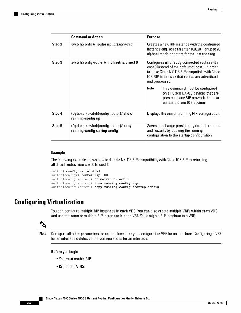
PurposeCommand or Action
Creates a new RIP instance with the configuredinstance-tag. You can enter 100, 201, or up to 20alphanumeric chapters for the instance tag.
switch(config)# router rip instance-tagStep 2
Configures all directly connected routes withcost 0 instead of the default of cost 1 in order
switch(config-router)# [no] metric direct 0Step 3
to make Cisco NX-OS RIP compatible with CiscoIOS RIP in the way that routes are advertisedand processed.
This command must be configuredon all Cisco NX-OS devices that arepresent in any RIP network that alsocontains Cisco IOS devices.
Note
Displays the current running RIP configuration.(Optional) switch(config-router)# showrunning-config rip
Step 4
Saves the change persistently through rebootsand restarts by copying the runningconfiguration to the startup configuration
(Optional) switch(config-router)# copyrunning-config startup config
Step 5
Example
The following example shows how to disable NX-OS RIP compatibility with Cisco IOS RIP by returningall direct routes from cost 0 to cost 1:
switch# configure terminalswitch(config)# router rip 100switch(config-router)# no metric direct 0switch(config-router)# show running-config ripswitch(config-router)# copy running-config startup-config
Configuring VirtualizationYou can configure multiple RIP instances in each VDC. You can also create multiple VRFs within each VDCand use the same or multiple RIP instances in each VRF. You assign a RIP interface to a VRF.
Configure all other parameters for an interface after you configure the VRF for an interface. Configuring a VRFfor an interface deletes all the configurations for an interface.
Note
Before you begin
• You must enable RIP.
• Create the VDCs.
Cisco Nexus 7000 Series NX-OS Unicast Routing Configuration Guide, Release 6.xOL-25777-03352
RoutingConfiguring Virtualization

Procedure
PurposeCommand or Action
Enters global configuration mode.switch# configure terminalStep 1
Creates a new VRF.switch(config)# vrf vrf-nameStep 2
Exits VRF configuration mode.switch(config-vrf)# exitStep 3
Creates a new RIP instance with the configuredinstance tag.
switch(config)# router rip instance-tagStep 4
Creates a new VRF and enters VRFconfiguration mode.
switch(config-router)# vrf vrf-nameStep 5
(Optional) Configures the VRF address familyfor this RIP instance.
(Optional) switch(config-router-vrf)#address-family ipv4 unicast
Step 6
Redistributes routes from other protocols intoRIP.
(Optional) switch(-router-vrf-af)# redistribute{bgp as | direct | {eigrp | isis | ospf | ospfv3 |rip} instance-tag | static} route-map map-name
Step 7
See Configuring Route Policy Manager, onpage 401.
Enters interface configuration mode.switch(config-router-vrf-af)# interface ethernetslot/port
Step 8
Configures the interface as a Layer 3 routedinterface.
switch(config-if)# no switchportStep 9
Adds this interface to a VRF.switch(config-if)# vrf member vrf-nameStep 10
Configures an IP address for this interface. Youmust perform this step after you assign thisinterface to a VRF.
switch(config-if)# ip-address ip-prefix/lengthStep 11
Associates this interface with a RIP instance.switch(config-if)# ip router rip instance-tagStep 12
Saves the change persistently through rebootsand restarts by copying the runningconfiguration to the startup configuration.
(Optional) switch(config-if)# copyrunning-config startup-config
Step 13
Displays RIP information for an interface in aVRF.
(Optional) switch(config-if)# show ip rip[instance instance-tag] interface[interface-type slot/port] [vrf vrf-name]
Step 14
Example
The following example shows how to create a VRF and add an interface to the VRF:
switch# configure terminalswitch(config)# vrf context RemoteOfficeVRFswitch(config-vrf)# exitswitch(config)# router rip Enterpriseswitch(config-router)# vrf RemoteOfficeVRF
Cisco Nexus 7000 Series NX-OS Unicast Routing Configuration Guide, Release 6.x353OL-25777-03
RoutingConfiguring Virtualization
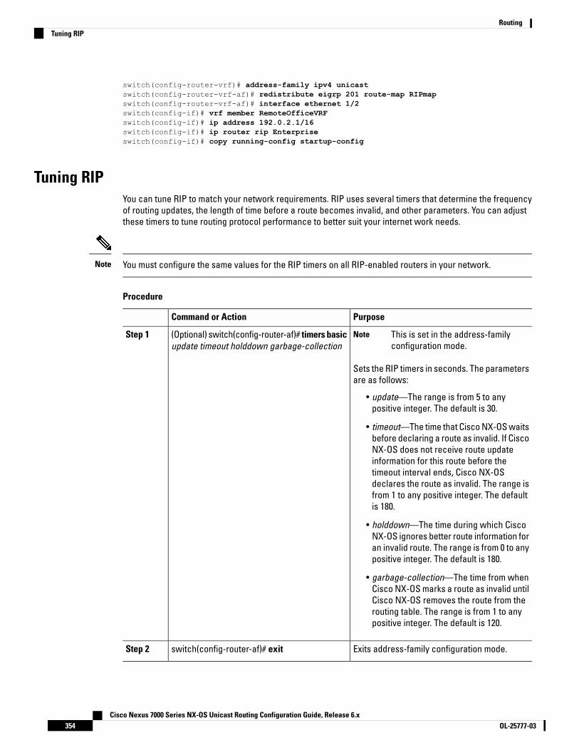
switch(config-router-vrf)# address-family ipv4 unicastswitch(config-router-vrf-af)# redistribute eigrp 201 route-map RIPmapswitch(config-router-vrf-af)# interface ethernet 1/2switch(config-if)# vrf member RemoteOfficeVRFswitch(config-if)# ip address 192.0.2.1/16switch(config-if)# ip router rip Enterpriseswitch(config-if)# copy running-config startup-config
Tuning RIPYou can tune RIP to match your network requirements. RIP uses several timers that determine the frequencyof routing updates, the length of time before a route becomes invalid, and other parameters. You can adjustthese timers to tune routing protocol performance to better suit your internet work needs.
You must configure the same values for the RIP timers on all RIP-enabled routers in your network.Note
Procedure
PurposeCommand or Action
(Optional) switch(config-router-af)# timers basicupdate timeout holddown garbage-collection
Step 1 This is set in the address-familyconfiguration mode.
Note
Sets the RIP timers in seconds. The parametersare as follows:
• update—The range is from 5 to anypositive integer. The default is 30.
• timeout—The time that Cisco NX-OS waitsbefore declaring a route as invalid. If CiscoNX-OS does not receive route updateinformation for this route before thetimeout interval ends, Cisco NX-OSdeclares the route as invalid. The range isfrom 1 to any positive integer. The defaultis 180.
• holddown—The time during which CiscoNX-OS ignores better route information foran invalid route. The range is from 0 to anypositive integer. The default is 180.
• garbage-collection—The time from whenCisco NX-OS marks a route as invalid untilCisco NX-OS removes the route from therouting table. The range is from 1 to anypositive integer. The default is 120.
Exits address-family configuration mode.switch(config-router-af)# exitStep 2
Cisco Nexus 7000 Series NX-OS Unicast Routing Configuration Guide, Release 6.xOL-25777-03354
RoutingTuning RIP

PurposeCommand or Action
Exits router configuration mode.switch(config-router)# exitStep 3
Enters interface configuration mode.switch(config)# interface type numberStep 4
(Optional) switch(config-if)# ip rip metric-offsetvalue
Step 5 This is set in the interfaceconfiguration mode.
Note
Adds a value to the metric for every routerreceived on this interface. The range is from 1to 15. The default is 1.
(Optional) switch(config-if)# ip rip route-filter{prefix-list list-name | route-map map-name |[in | out]
Step 6 This is set in the interfaceconfiguration mode.
Note
Specifies a route map to filter incoming oroutgoing RIP updates.
Example
The following optional examples show how to tune RIP:
switch(config-router-af)# timers basic 40 120 120 100switch(config-router-af)# exitswitch(config-router)# exitswitch(config)# exitswitch(config)# interface ethernet 1/2switch(config-if)# ip rip metric-offset 10switch(config-if)# ip rip route-filter route-map InputMap in
Verifying the RIP ConfigurationUse one of the following commands to verify the configuration:
PurposeCommand
Displays the status for an instance of RIP.show ip rip instance [instance-tag] [vrf vrf-name]
Displays the RIP status for an interfaceshow ip rip [instance instance-tag] interface slot/portdetail [vrf vrf-name]
Displays the RIP neighbor tableshow ip rip [instance instance-tag] neighbor[interface-type number] [vrf vrf-name]
Displays the RIP route tableshow ip rip [instance instance-tag] route[ip-prefix/length [longer-prefixes | shorter-prefixes]][summary] [vrf vrf-name]
Displays the current running RIP configuration.show running-configuration rip
Cisco Nexus 7000 Series NX-OS Unicast Routing Configuration Guide, Release 6.x355OL-25777-03
RoutingVerifying the RIP Configuration

Displaying RIP StatisticsUse one of the following commands to display RIP statistics:
PurposeCommand
Displays the RIP policy status.
Use the clear ip rip policy command to clear policystatistics.
show ip rip [instance instance-tag] policy statisticsredistribute {bgp as | direct | {eigrp | isis | ospf | ospfv3| rip} instance-tag | static} [vrf vrf-name]
Displays the RIP statistics.
Use the clear ip rip statistics command to clear RIPstatistics.
show ip rip [instance instance-tag] statisticsinterface-type number] [vrf vrf-name]
Use the clear ip rip policy command to clear policy statistics.
Use the clear ip rip statistics command to clear RIP statistics.
Configuration Examples for RIPThis example creates the Enterprise RIP instance in a VRF and adds Ethernet interface 1/2 to this RIP instance.The example also configures authentication for Ethernet interface 1/2 and redistributes EIGRP into this RIPdomain.
vrf context NewVRF!feature riprouter rip Enterprisevrf NewVRFaddress-family ip unicastredistribute eigrp 201 route-map RIPmapmax-paths 10
!interface ethernet 1/2vrf NewVRFip address 192.0.2.1/16ip router rip Enterpriseip rip authentication mode md5ip rip authentication keychain RIPKey
•
Related Documents for RIPDocument TitleRelated Topic
Cisco Nexus 7000 Series NX-OS Unicast RoutingCommand Reference
RIP CLI
Cisco Nexus 7000 Series NX-OS Virtual Device ContextConfiguration Guide
VDCs and VRFs
Cisco Nexus 7000 Series NX-OS Unicast Routing Configuration Guide, Release 6.xOL-25777-03356
RoutingDisplaying RIP Statistics
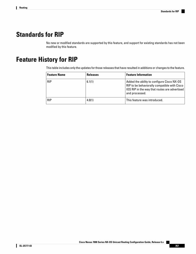
Standards for RIPNo new or modified standards are supported by this feature, and support for existing standards has not beenmodified by this feature.
Feature History for RIPThis table includes only the updates for those releases that have resulted in additions or changes to the feature.
Feature InformationReleasesFeature Name
Added the ability to configure Cisco NX-OSRIP to be behaviorally compatible with CiscoIOS RIP in the way that routes are advertisedand processed.
6.1(1)RIP
This feature was introduced.4.0(1)RIP
Cisco Nexus 7000 Series NX-OS Unicast Routing Configuration Guide, Release 6.x357OL-25777-03
RoutingStandards for RIP

Cisco Nexus 7000 Series NX-OS Unicast Routing Configuration Guide, Release 6.xOL-25777-03358
RoutingFeature History for RIP

C H A P T E R 14Configuring Static Routing
This chapter contains the following sections:
• Finding Feature Information, on page 359• Information About Static Routing, on page 359• Prerequisites for Static Routing, on page 362• Guidelines and Limitations for Static Routing, on page 362• Default Settings for Static Routing Parameters, on page 362• Configuring Static Routing, on page 362• Verifying the Static Routing Configuration, on page 368• Related Documents for Static Routing, on page 368• Feature History for Static Routing, on page 368
Finding Feature InformationYour software release might not support all the features documented in this module. For the latest caveatsand feature information, see the Bug Search Tool at https://tools.cisco.com/bugsearch/ and the release notesfor your software release. To find information about the features documented in this module, and to see a listof the releases in which each feature is supported, see the "New and Changed Information"chapter or theFeature History table in this chapter.
Information About Static RoutingRouters forward packets using either route information from route table entries that you manually configureor the route information that is calculated using dynamic routing algorithms.
Static routes, which define explicit paths between two routers, cannot be automatically updated; you mustmanually reconfigure static routes when network changes occur. Static routes use less bandwidth thandynamic routes. No CPU cycles are used to calculate and analyze routing updates.
You can supplement dynamic routes with static routes where appropriate. You can redistribute static routesinto dynamic routing algorithms but you cannot redistribute routing information calculated by dynamic routingalgorithms into the static routing table.
You should use static routes in environments where network traffic is predictable and where the networkdesign is simple. You should not use static routes in large, constantly changing networks because static routescannot react to network changes. Most networks use dynamic routes to communicate between routers but
Cisco Nexus 7000 Series NX-OS Unicast Routing Configuration Guide, Release 6.x359OL-25777-03

might have one or two static routes configured for special cases. Static routes are also useful for specifyinga gateway of last resort (a default router to which all unroutable packets are sent).
Administrative DistanceAn administrative distance is the metric used by routers to choose the best path when there are two or moreroutes to the same destination from two different routing protocols. An administrative distance guides theselection of one routing protocol (or static route) over another, when more than one protocol adds the sameroute to the unicast routing table. Each routing protocol is prioritized in order of most to least reliable usingan administrative distance value.
Static routes have a default administrative distance of 1. A router prefers a static route to a dynamic routebecause the router considers a route with a low number to be the shortest. If you want a dynamic route tooverride a static route, you can specify an administrative distance for the static route. For example, if you havetwo dynamic routes with an administrative distance of 120, you would specify an administrative distance thatis greater than 120 for the static route if you want the dynamic route to override the static route.
Directly Connected Static RoutesYou must specify only the output interface (the interface on which all packets are sent to the destinationnetwork) in a directly connected static route. The router assumes the destination is directly attached to theoutput interface and the packet destination is used as the next-hop address. The next hop can be an interface,only for point-to-point interfaces. For broadcast interfaces, the next hop must be an IPv4or IPv6 address.
Fully Specified Static RoutesYou must specify either the output interface (the interface on which all packets are sent to the destinationnetwork) or the next-hop address in a fully specified static route. You can use a fully specified static routewhen the output interface is a multi-access interface and you need to identify the next-hop address. Thenext-hop address must be directly attached to the specified output interface.
Floating Static RoutesA floating static route is a static route that the router uses to back up a dynamic route. You must configure afloating static route with a higher administrative distance than the dynamic route that it backs up. In thisinstance, the router prefers a dynamic route to a floating static route. You can use a floating static route as areplacement if the dynamic route is lost.
By default, a router prefers a static route to a dynamic route because a static route has a smaller administrativedistance than a dynamic route.
Note
Remote Next-Hops for Static RoutesYou can specify the next-hop address of a neighboring router which is not directly connected to the router forstatic routes with remote (non-directly attached) next-hops. If a static route has remote next-hops during
Cisco Nexus 7000 Series NX-OS Unicast Routing Configuration Guide, Release 6.xOL-25777-03360
RoutingAdministrative Distance
data-forwarding, the next-hops are recursively used in the unicast routing table to identify the correspondingdirectly attached next-hop(s) that have reachability to the remote next-hops.
Reliable Static Routing Backup Using Object Tracking DeploymentYou can configure Cisco NX-OS to initiate a backup connection from an alternative port if the circuit to theprimary gateway is interrupted. You can ensure reliable deployment backups in the case of certain catastrophicevents, such as an Internet circuit failure or peer device failure.
Reliable static routing backup using object tracking can determine the state of the primary connection withouthaving to enable a dynamic routing protocol. It also provides a reliable backup solution that can be used forcritical circuits that must not go down without automatically engaging a backup circuit.
In a typical scenario, the primary interface of the remote router forwards traffic from the remote LAN to themain office. If the router loses the connection to the main office, the status of the tracked object changes fromup to down. When this change occurs, the router removes the routing table entry for the primary interface andinstalls the preconfigured floating static route on the secondary interface. The router’s secondary interfacethen forwards traffic to the preconfigured destination. The backup circuit can be configured to use the Internet.When the state of the tracked object changes from down to up, the router reinstalls the routing table entry forthe primary interface and removes the floating static route for the secondary interface.
IP Service Level AgreementsThis feature uses IP service level agreements (IP SLAs), a network monitoring feature set, to generate ICMPpings to monitor the state of the connection to the primary gateway. An IP SLA is configured to ping a target,such as a publicly routable IP address or a target inside the corporate network. The pings are routed from theprimary interface only. A track object is created to monitor the status of the IP SLA configuration. The trackobject informs the client, the static route, if a state change occurs. The preconfigured floating static route onthe secondary interface is installed when the state changes from up to down.
User Datagram Protocol (UDP) echo, or any other protocol supported by IP SLAs, can be used instead of ICMPpings.
Note
For more information on IP SLAs, see the Cisco Nexus 7000 Series NX-OS IP SLAs Configuration Guide.
BFDThis feature supports bidirectional forwarding detection (BFD). BFD is a detection protocol designed to providefast forwarding-path failure detection times. BFD provides subsecond failure detection between two adjacentdevices and can be less CPU-intensive than protocol hello messages because some of the BFD load can bedistributed onto the data plane on supported modules. See the Cisco Nexus 7000 Series NX-OS InterfacesConfiguration Guide, Release 6.x, for more information.
Virtualization SupportStatic routes support virtual routing and forwarding (VRF) instances. VRFs exist within virtual device contexts(VDCs). By default, Cisco NX-OS places you in the default VDC and default VRF unless you specifically configureanother VDC and VRF. For more information, see the Cisco Nexus 7000 Series NX-OS Virtual Device ContextConfiguration Guide.
Cisco Nexus 7000 Series NX-OS Unicast Routing Configuration Guide, Release 6.x361OL-25777-03
RoutingReliable Static Routing Backup Using Object Tracking Deployment
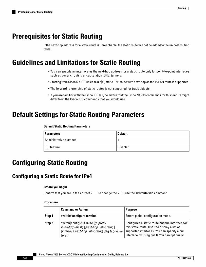
Prerequisites for Static RoutingIf the next-hop address for a static route is unreachable, the static route will not be added to the unicast routingtable.
Guidelines and Limitations for Static Routing• You can specify an interface as the next-hop address for a static route only for point-to-point interfaces
such as generic routing encapsulation (GRE) tunnels.
• Starting from Cisco NX-OS Release 8.2(4), static IPv6 route with next-hop as the VxLAN route is supported.
• The forward referencing of static routes is not supported for track objects.
• If you are familiar with the Cisco IOS CLI, be aware that the Cisco NX-OS commands for this feature mightdiffer from the Cisco IOS commands that you would use.
Default Settings for Static Routing ParametersDefault Static Routing Parameters
DefaultParameters
1Administrative distance
DisabledRIP feature
Configuring Static Routing
Configuring a Static Route for IPv4
Before you begin
Confirm that you are in the correct VDC. To change the VDC, use the switchto vdc command.
Procedure
PurposeCommand or Action
Enters global configuration mode.switch# configure terminalStep 1
Configures a static route and the interface forthis static route. Use ? to display a list of
switch(config)# ip route {ip-prefix |ip-addr/ip-mask} {[next-hop | nh-prefix] |
Step 2
supported interfaces. You can specify a null[interface next-hop | nh-prefix]} [tag tag-value][pref] interface by using null 0. You can optionally
Cisco Nexus 7000 Series NX-OS Unicast Routing Configuration Guide, Release 6.xOL-25777-03362
RoutingPrerequisites for Static Routing
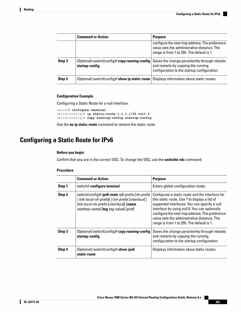
PurposeCommand or Action
configure the next-hop address. The preferencevalue sets the administrative distance. Therange is from 1 to 255. The default is 1.
Saves the change persistently through rebootsand restarts by copying the runningconfiguration to the startup configuration.
(Optional) switch(config)# copy running-configstartup-config
Step 3
Displays information about static routes.(Optional) switch(config)# show ip static-routeStep 4
Configuration Example
Configuring a Static Route for a null interface.
switch# configure terminalswitch(config)# ip static-route 1.1.1.1/32 null 0switch(config)# copy running-config startup-config
Use the no ip static-route command to remove the static route.
Configuring a Static Route for IPv6
Before you begin
Confirm that you are in the correct VDC. To change the VDC, use the switchto vdc command.
Procedure
PurposeCommand or Action
Enters global configuration mode.switch# configure terminalStep 1
Configures a static route and the interface forthis static route. Use ? to display a list of
switch(config)# ipv6 route ip6-prefix {nh-prefix| link-local-nh-prefix} | {nh-prefix [interface] |
Step 2
supported interfaces. You can specify a nulllink-local-nh-prefix [interface]} [namenexthop-name] [tag tag-value] [pref] interface by using null 0. You can optionally
configure the next-hop address. The preferencevalue sets the administrative distance. Therange is from 1 to 255. The default is 1.
Saves the change persistently through rebootsand restarts by copying the runningconfiguration to the startup configuration.
(Optional) switch(config)# copy running-configstartup-config
Step 3
Displays information about static routes.(Optional) switch(config)# show ipv6static-route
Step 4
Cisco Nexus 7000 Series NX-OS Unicast Routing Configuration Guide, Release 6.x363OL-25777-03
RoutingConfiguring a Static Route for IPv6
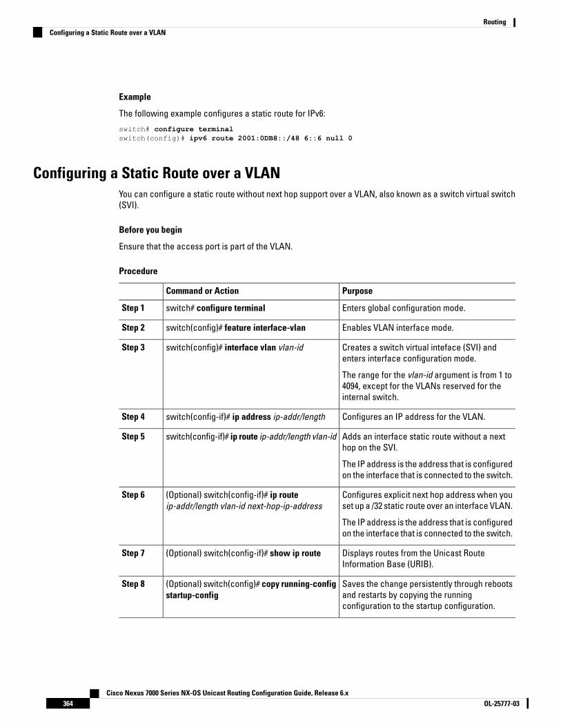
Example
The following example configures a static route for IPv6:
switch# configure terminalswitch(config)# ipv6 route 2001:0DB8::/48 6::6 null 0
Configuring a Static Route over a VLANYou can configure a static route without next hop support over a VLAN, also known as a switch virtual switch(SVI).
Before you begin
Ensure that the access port is part of the VLAN.
Procedure
PurposeCommand or Action
Enters global configuration mode.switch# configure terminalStep 1
Enables VLAN interface mode.switch(config)# feature interface-vlanStep 2
Creates a switch virtual inteface (SVI) andenters interface configuration mode.
switch(config)# interface vlan vlan-idStep 3
The range for the vlan-id argument is from 1 to4094, except for the VLANs reserved for theinternal switch.
Configures an IP address for the VLAN.switch(config-if)# ip address ip-addr/lengthStep 4
Adds an interface static route without a nexthop on the SVI.
switch(config-if)# ip route ip-addr/length vlan-idStep 5
The IP address is the address that is configuredon the interface that is connected to the switch.
Configures explicit next hop address when youset up a /32 static route over an interface VLAN.
(Optional) switch(config-if)# ip routeip-addr/length vlan-id next-hop-ip-address
Step 6
The IP address is the address that is configuredon the interface that is connected to the switch.
Displays routes from the Unicast RouteInformation Base (URIB).
(Optional) switch(config-if)# show ip routeStep 7
Saves the change persistently through rebootsand restarts by copying the runningconfiguration to the startup configuration.
(Optional) switch(config)# copy running-configstartup-config
Step 8
Cisco Nexus 7000 Series NX-OS Unicast Routing Configuration Guide, Release 6.xOL-25777-03364
RoutingConfiguring a Static Route over a VLAN
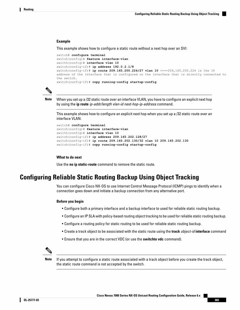
Example
This example shows how to configure a static route without a next hop over an SVI:
switch# configure terminalswitch(config)# feature interface-vlanswicth(config)# interface vlan 10switch(config-if)# ip address 192.0.2.1/8switch(config-if)# ip route 209.165.200.224/27 vlan 10 <===209,165.200.224 is the IPaddress of the interface that is configured on the interface that is directly connected tothe switch.switch(config-if)# copy running-config startup-config
When you set up a /32 static route over an interface VLAN, you have to configure an explicit next hopby using the ip route ip-addr/length vlan-id next-hop-ip-address command.
Note
This example shows how to configure an explicit next hop when you set up a /32 static route over aninterface VLAN:
switch# configure terminalswitch(config)# feature interface-vlanswicth(config)# interface vlan 10switch(config-if)# ip address 209.165.202.128/27switch(config-if)# ip route 209.165.202.130/32 vlan 10 209.165.202.130switch(config-if)# copy running-config startup-config
What to do next
Use the no ip static-route command to remove the static route.
Configuring Reliable Static Routing Backup Using Object TrackingYou can configure Cisco NX-OS to use Internet Control Message Protocol (ICMP) pings to identify when aconnection goes down and initiate a backup connection from any alternative port.
Before you begin
• Configure both a primary interface and a backup interface to used for reliable static routing backup.
• Configure an IP SLA with policy-based routing object tracking to be used for reliable static routing backup.
• Configure a routing policy for static routing to be used for reliable static routing backup.
• Create a track object to be associated with the static route using the track object-id interface command
• Ensure that you are in the correct VDC (or use the switchto vdc command).
If you attempt to configure a static route associated with a track object before you create the track object,the static route command is not accepted by the switch.
Note
Cisco Nexus 7000 Series NX-OS Unicast Routing Configuration Guide, Release 6.x365OL-25777-03
RoutingConfiguring Reliable Static Routing Backup Using Object Tracking

Procedure
PurposeCommand or Action
Enters global configuration mode.switch# configure terminalStep 1
Configures a static route associated with thetrack object. The object-number argument
switch(config)# {ip | ipv6} route ip-prefix ip-maskip-addr track object-number
Step 2
specifies that the static route is installed only ifthe configured track object is up.
Displays information about the IPv4 or IPv6static-route track table.
switch(config)# show {ip | ipv6} static-routetrack-table
Step 3
Displays information about a specific trackedobject.
switch(config)# show track track-numberStep 4
Configures a floating IPv4 or IPv6 static routeon the secondary interface.
switch(config)# {ip | ipv6} route network-numbernetwork-mask {ip-address | interface} [distance][name name]
Step 5
The network prefix and mask length must be thesame as the static route previously configuredfor the primary interface associated with a trackobject. The floating static route should have ahigher value of preference than the routeassociated with the track object.
Configuring Virtualization for IPv4
Before you begin
Confirm that you are in the correct VDC. To change the VDC, use the switchto vdc command.
Procedure
PurposeCommand or Action
Enters global configuration mode.switch# configure terminalStep 1
Creates a VRF and enters VRF configurationmode.
switch(config)# vrf context vrf-nameStep 2
Configures a static route and the interface forthis static route. Use ? to display a list of
switch(config-vrf)# ip route {ip-prefix | ip-addrip-mask} {next-hop | nh-prefix | interface
Step 3
supported interfaces. You can specify a null[sub-intf-separtor sub-intf-num ] next-hop } [tagtag-value] [pref] interface by using null 0. You can optionally
configure the next-hop address. The preferencevalue sets the administrative distance. Therange is from 1 to 255. The default is 1.
Saves the change persistently through rebootsand restarts by copying the runningconfiguration to the startup configuration.
(Optional) switch(config-vrf)# copyrunning-config startup-config
Step 4
Cisco Nexus 7000 Series NX-OS Unicast Routing Configuration Guide, Release 6.xOL-25777-03366
RoutingConfiguring Virtualization for IPv4

PurposeCommand or Action
Displays information on static routes.(Optional) switch(config-vrf)# show ipstatic-route vrf vrf-name
Step 5
Example
The following example configures VRF for IPv4.
switch # configure terminalswitch(config)# vrf context StaticVrfswitch(config-vrf)# ip route 192.0.2.0/8 ethernet 1/2 10.0.0.2switch(config-vrf)# show running-config startup-config
Configuring Virtualization for IPv6
Before you begin
Confirm that you are in the correct VDC. To change the VDC, use the switchto vdc command.
Procedure
PurposeCommand or Action
Enters global configuration mode.switch# configure terminalStep 1
Creates a VRF and enters VRF configurationmode.
switch(config)# vrf context vrf-nameStep 2
Configures a static route and the interface forthis static route. Use ? to display a list of
switch(config-vrf)# ipv6 route ip6-prefix{nh-prefix | link-local-nh-prefix } | {next-hop |
Step 3
supported interfaces. You can specify a nulllink-local-net-hop | interface [sub-intf-separtorinterface by using null 0. You can optionallysub-intf-num] next-hop } [name nexthop-name]
[tag tag-value] [pref] configure the next-hop address. The preferencevalue sets the administrative distance. Therange is from 1 to 255. The default is 1.
Saves the change persistently through rebootsand restarts by copying the runningconfiguration to the startup configuration.
(Optional) switch(config-vrf)# copyrunning-config startup-config
Step 4
Displays information on static routes.(Optional) switch(config-vrf)# show ipv6static-route vrf vrf-name
Step 5
Example
The following example configures virtualization for IPv6:
switch # configure terminalswitch(config)# vrf context StaticVrfswitch(config-vrf)# ipv6 route 2001:0DB8::/48 6::6 ethernet 2/1 2b11::2f01:4cswitch(config-vrf)# copy running-config startup-config
Cisco Nexus 7000 Series NX-OS Unicast Routing Configuration Guide, Release 6.x367OL-25777-03
RoutingConfiguring Virtualization for IPv6
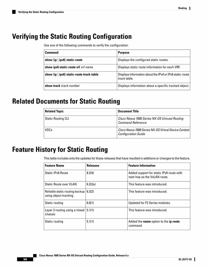
Verifying the Static Routing ConfigurationUse one of the following commands to verify the configuration:
PurposeCommand
Displays the configured static routes.show {ip | ipv6} static-route
Displays static route information for each VRF.show ipv6 static-route vrf vrf-name
Displays information about the IPv4 or IPv6 static-routetrack table.
show {ip | ipv6} static-route track-table
Displays information about a specific tracked object.show track track-number
Related Documents for Static RoutingDocument TitleRelated Topic
Cisco Nexus 7000 Series NX-OS Unicast RoutingCommand Reference
Static Routing CLI
Cisco Nexus 7000 Series NX-OS Virtual Device ContextConfiguration Guide
VDCs
Feature History for Static RoutingThis table includes only the updates for those releases that have resulted in additions or changes to the feature.
Feature InformationReleasesFeature Name
Added support for static IPv6 route withnext-hop as the VxLAN route.
8.2(4)Static IPv6 Route
This feature was introduced.6.2(2a)Static Route over VLAN
This feature was introduced.6.2(2)Reliable static routing backupusing object tracking
Updated for F2 Series modules.6.0(1)Static routing
This feature was introduced.5.1(1)Layer 3 routing using a mixedchassis
Added the name option to the ip routecommand.
5.1(1)Static routing
Cisco Nexus 7000 Series NX-OS Unicast Routing Configuration Guide, Release 6.xOL-25777-03368
RoutingVerifying the Static Routing Configuration

Feature InformationReleasesFeature Name
Added support for BFD. See the Cisco Nexus7000 Series NX-OS Interfaces ConfigurationGuide, for more information.
5.0(2)BFD
This feature was introduced.4.0(1)Static routing
Cisco Nexus 7000 Series NX-OS Unicast Routing Configuration Guide, Release 6.x369OL-25777-03
RoutingFeature History for Static Routing

Cisco Nexus 7000 Series NX-OS Unicast Routing Configuration Guide, Release 6.xOL-25777-03370
RoutingFeature History for Static Routing

C H A P T E R 15Configuring the Interoperability of Modules forUnicast Routing
This chapter contains the following sections:
• Finding Feature Information, on page 371• Configuring the Interoperability of Modules for Unicast Routing, on page 371• Information About the Interoperability of Modules for Unicast Routing, on page 372• Guidelines and Limitations for the Interoperability of Modules for Unicast Routing, on page 372• Configuring the Interoperability of Modules for Unicast Routing, on page 372• Verifying the Configuration for the Interoperability of Modules for Unicast Routing, on page 373• Configuration Examples for the Interoperability of Modules for Unicast Routing, on page 373• Related Documents for the Interoperability of Modules for Unicast Routing , on page 374• Feature History for the Interoperability of Modules for Unicast Routing, on page 374
Finding Feature InformationYour software release might not support all the features documented in this module. For the latest caveatsand feature information, see the Bug Search Tool at https://tools.cisco.com/bugsearch/ and the release notesfor your software release. To find information about the features documented in this module, and to see a listof the releases in which each feature is supported, see the "New and Changed Information"chapter or theFeature History table in this chapter.
Configuring the Interoperability of Modules for Unicast RoutingThis chapter describes how to configure the interoperability of F1 Series modules with M Series modules forunicast routing on the Cisco NX-OS device.
Cisco Nexus 7000 Series NX-OS Unicast Routing Configuration Guide, Release 6.x371OL-25777-03

Information About the Interoperability of Modules for UnicastRouting
A mixed chassis is a Cisco Nexus 7000 Series chassis that contains at least one F1 Series module and at leastone M Series module. Because the F1 Series module processes only Layer 2 traffic, you must configure it topass Layer 3 traffic through the chassis.
Guidelines and Limitations for the Interoperability of Modulesfor Unicast Routing
The interoperability of modules for unicast routing has the following configuration guidelines and limitations:
• You cannot use F2, F2e, or F3 Series modules in the Cisco Nexus 7000 Series chassis to perform proxyLayer 3 routing for F1 series modules.
• To support the coexistence of an F2e Series module with an M Series module in the same VDC, the F2eSeries module operates in a proxy mode so that all Layer 3 traffic is sent to an M Series module in thesame VDC. For F2e proxy mode, having routing adjacencies connected through F2e interfaces with anM1 Series module is not supported. However, routing adjacencies connected through F2e interfaces withan M2 Series module is supported.
Configuring the Interoperability of Modules for Unicast RoutingTo configure a Layer 3 gateway in a mixed chassis, you use the proxy routing functionality. You enable routingon a specific VLAN by configuring a VLAN interface, and the system automatically provides load-balancedrouting functionality. See the Cisco Nexus 7000 Series NX-OS Interfaces Configuration Guide for more informationabout Layer 3 routing and VLAN interfaces.
For interoperability between F1 Series and M Series modules, use the following procedure to specify whichphysical interfaces on the M Series modules you want to use for Layer 3 routing.
Before you begin
You must configure a VLAN interface for each VLAN on the F1 Series module that you want to use with theproxy-routing functionality in a mixed chassis.
You must have interfaces from both the M Series modules and the F1 Series modules in the same VDC.
Procedure
PurposeCommand or Action
Enters global configuration mode.switch# configure terminalStep 1
Configures specific modules and physicalinterfaces on the M Series module to providethe proxy routing on the F1 Series module.
switch(config)# hardware proxy layer-3 routing{use | exclude} {module mod-number | interfaceslot/port} [module-type f1]
Step 2
Cisco Nexus 7000 Series NX-OS Unicast Routing Configuration Guide, Release 6.xOL-25777-03372
RoutingInformation About the Interoperability of Modules for Unicast Routing

PurposeCommand or Action
Displays information about the proxy Layer 3functionality.
(Optional) switch(config)# show hardware proxylayer-3 detail
Step 3
Saves the change persistently through rebootsand restarts by copying the runningconfiguration to the startup configuration.
(Optional) switch(config)# copy running-configstartup-config
Step 4
Verifying the Configuration for the Interoperability of Modulesfor Unicast Routing
To display the interoperability of modules for unicast routing configuration, perform one of the following tasks:
PurposeCommand
Displays the number of packets sent by F1 Seriesmodules to each M Series module for proxyforwarding.
Enter the clear hardware proxy layer-3counters command to clear the counters.
Note
show hardware proxy layer-3 counters {brief | detail}
Displays information about proxy routing from an F1Series module to an M Series module in a chassis thatcontains both types of modules.
show hardware proxy layer-3 detail
Configuration Examples for the Interoperability of Modules forUnicast Routing
This example shows how to specify physical interfaces on M Series modules to perform proxy routing on F1Series modules in a mixed chassis:
switch# configure terminalswitch(config)# hardware proxy layer-3 routing use module 1, 7switch(config)# show hardware proxy layer-3 detail
Cisco Nexus 7000 Series NX-OS Unicast Routing Configuration Guide, Release 6.x373OL-25777-03
RoutingVerifying the Configuration for the Interoperability of Modules for Unicast Routing
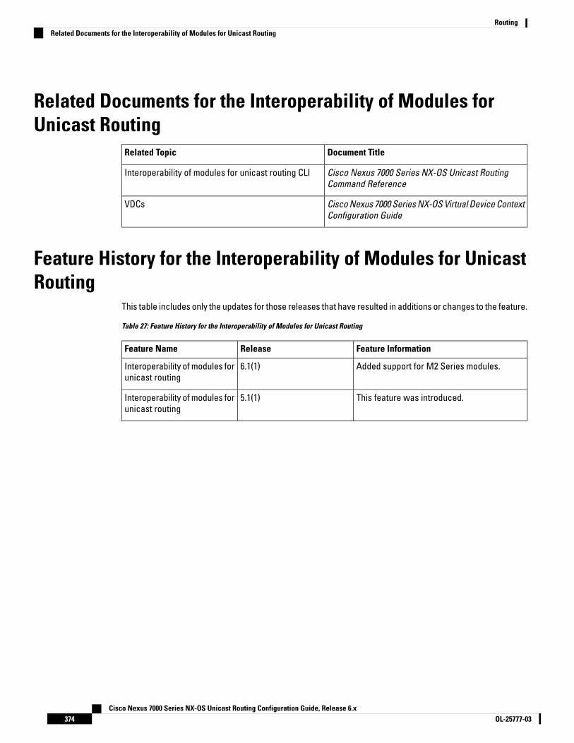
Related Documents for the Interoperability of Modules forUnicast Routing
Document TitleRelated Topic
Cisco Nexus 7000 Series NX-OS Unicast RoutingCommand Reference
Interoperability of modules for unicast routing CLI
Cisco Nexus 7000 Series NX-OS Virtual Device ContextConfiguration Guide
VDCs
Feature History for the Interoperability of Modules for UnicastRouting
This table includes only the updates for those releases that have resulted in additions or changes to the feature.
Table 27: Feature History for the Interoperability of Modules for Unicast Routing
Feature InformationReleaseFeature Name
Added support for M2 Series modules.6.1(1)Interoperability of modules forunicast routing
This feature was introduced.5.1(1)Interoperability of modules forunicast routing
Cisco Nexus 7000 Series NX-OS Unicast Routing Configuration Guide, Release 6.xOL-25777-03374
RoutingRelated Documents for the Interoperability of Modules for Unicast Routing

C H A P T E R 16Configuring Layer 3 Virtualization
This chapter contains the following sections:
• Finding Feature Information, on page 375• Information About Layer 3 Virtualization, on page 375• Guidelines and Limitations for VRF, on page 379• Default Settings for VRF, on page 380• Configuring VRFs, on page 380• Verifying the VRF Configuration, on page 384• Configuration Examples for VRF, on page 384• Related Documents for VRF, on page 385• Standards for VRF, on page 386• Feature History for VRF, on page 386
Finding Feature InformationYour software release might not support all the features documented in this module. For the latest caveatsand feature information, see the Bug Search Tool at https://tools.cisco.com/bugsearch/ and the release notesfor your software release. To find information about the features documented in this module, and to see a listof the releases in which each feature is supported, see the "New and Changed Information"chapter or theFeature History table in this chapter.
Information About Layer 3 VirtualizationCisco NX-OS supports a hierarchy of virtualization that can divide the physical system resources into multiplevirtual device contexts (VDCs). Each VDC acts as a standalone device with both Layer 2 and Layer 3 servicesavailable. You can configure up to 4 VDCs, including the default VDC. See the Cisco Nexus 7000 Series NX-OSVirtual Device Context Configuration Guide, Release 5.x, for more information on VDCs.
Cisco NX-OS further virtualizes each VDC to support virtual routing and forwarding instances (VRFs). You canconfigure multiple VRFs in a VDC. Each VRF contains a separate address space with unicast and multicastroute tables for IPv4 and IPv6 and makes routing decisions independent of any other VRF.
The figure shows multiple independent VRFs in two different VDCs.
Cisco Nexus 7000 Series NX-OS Unicast Routing Configuration Guide, Release 6.x375OL-25777-03

Figure 39: Multiple VRFs in VDCs
A VRF name is local to a VDC, so you can configure two VRFs with the same name if the VRFs exist in differentVDCs. In Figure 14-1, VRF A in VDC 2 is independent of VRF B and VRF A in VDC n.
Each router has a default VRF and a management VRF. All Layer 3 interfaces and routing protocols exist in thedefault VRF until you assign them to another VRF. The mgmt0 interface exists in the management VRF and isshared among multiple VDCs. Each VDC has a unique IP address for the mgmt0 interface (see the Cisco Nexus7000 Series NX-OS Fundamentals Configuration Guide, Release 6.x).
Management VRF
• The management VRF is for management purposes only.
• Only the mgmt 0 interface can be in the management VRF.
• The mgmt 0 interface cannot be assigned to another VRF.
• The mgmt 0 interface is shared among multiple VDCs.
• No routing protocols can run in the management VRF (static only).
Default VRF
• All Layer 3 interfaces exist in the default VRF until they are assigned to another VRF.
• Routing protocols run in the default VRF context unless another VRF context is specified.
• The default VRF uses the default routing context for all show commands.
• The default VRF is similar to the global routing table concept in Cisco IOS.
Cisco Nexus 7000 Series NX-OS Unicast Routing Configuration Guide, Release 6.xOL-25777-03376
RoutingInformation About Layer 3 Virtualization
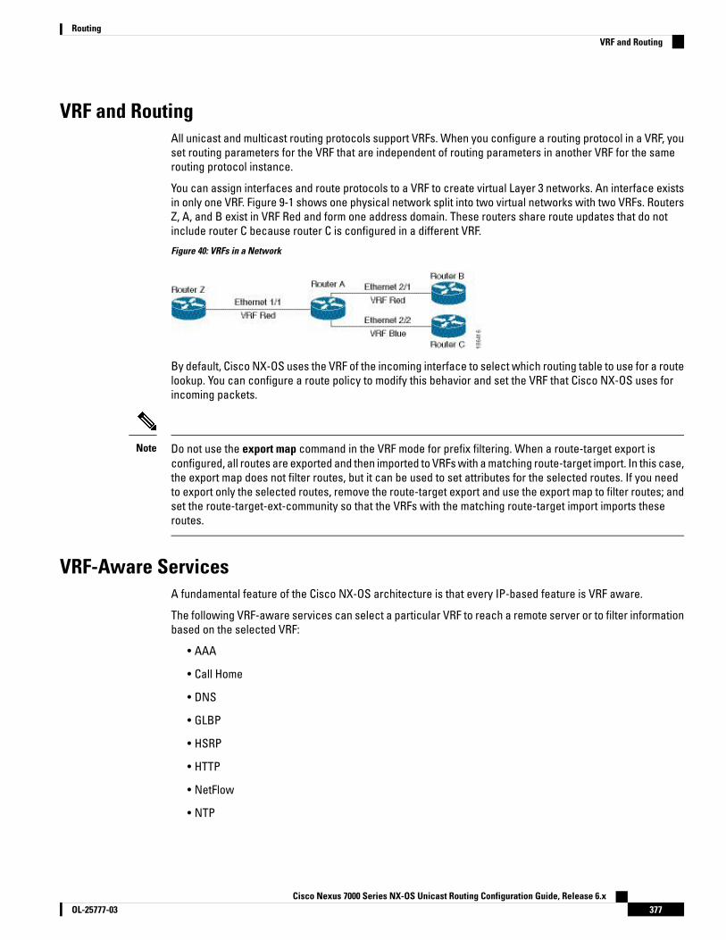
VRF and RoutingAll unicast and multicast routing protocols support VRFs. When you configure a routing protocol in a VRF, youset routing parameters for the VRF that are independent of routing parameters in another VRF for the samerouting protocol instance.
You can assign interfaces and route protocols to a VRF to create virtual Layer 3 networks. An interface existsin only one VRF. Figure 9-1 shows one physical network split into two virtual networks with two VRFs. RoutersZ, A, and B exist in VRF Red and form one address domain. These routers share route updates that do notinclude router C because router C is configured in a different VRF.
Figure 40: VRFs in a Network
By default, Cisco NX-OS uses the VRF of the incoming interface to select which routing table to use for a routelookup. You can configure a route policy to modify this behavior and set the VRF that Cisco NX-OS uses forincoming packets.
Do not use the export map command in the VRF mode for prefix filtering. When a route-target export isconfigured, all routes are exported and then imported to VRFs with a matching route-target import. In this case,the export map does not filter routes, but it can be used to set attributes for the selected routes. If you needto export only the selected routes, remove the route-target export and use the export map to filter routes; andset the route-target-ext-community so that the VRFs with the matching route-target import imports theseroutes.
Note
VRF-Aware ServicesA fundamental feature of the Cisco NX-OS architecture is that every IP-based feature is VRF aware.
The following VRF-aware services can select a particular VRF to reach a remote server or to filter informationbased on the selected VRF:
• AAA
• Call Home
• DNS
• GLBP
• HSRP
• HTTP
• NetFlow
• NTP
Cisco Nexus 7000 Series NX-OS Unicast Routing Configuration Guide, Release 6.x377OL-25777-03
RoutingVRF and Routing

• RADIUS
• Ping and Traceroute
• SSH
• SNMP
• Syslog
• TACACS+
• TFTP
• VRRP
• XML
See the appropriate configuration guide for each service for more information on configuring VRF support inthat service.
ReachabilityReachability indicates which VRF contains the routing information necessary to get to the server providingthe service. For example, you can configure an SNMP server that is reachable on the management VRF. Whenyou configure that server address on the router, you also configure which VRF that Cisco NX-OS must use toreach the server.
Th figure shows an SNMP server that is reachable over the management VRF. You configure router A to usethe management VRF for SNMP server host 192.0.2.1.
Figure 41: Service VRF Reachability
FilteringFiltering allows you to limit the type of information that goes to a VRF-aware service based on the VRF. Forexample, you can configure a syslog server to support a particular VRF. The figure shows two syslog serverswith each server supporting one VRF. syslog server A is configured in VRF Red, so Cisco NX-OS sends onlysystem messages generated in VRF Red to syslog server A.
Cisco Nexus 7000 Series NX-OS Unicast Routing Configuration Guide, Release 6.xOL-25777-03378
RoutingReachability
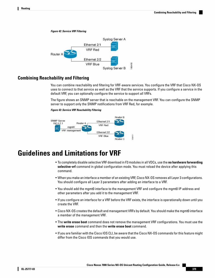
Figure 42: Service VRF Filtering
Combining Reachability and FilteringYou can combine reachability and filtering for VRF-aware services. You configure the VRF that Cisco NX-OSuses to connect to that service as well as the VRF that the service supports. If you configure a service in thedefault VRF, you can optionally configure the service to support all VRFs.
The figure shows an SNMP server that is reachable on the management VRF. You can configure the SNMPserver to support only the SNMP notifications from VRF Red, for example.
Figure 43: Service VRF Reachability Filtering
Guidelines and Limitations for VRF• To completely disable selective VRF download in F3 modules in all VDCs, use the no hardware forwarding
selective-vrf command in global configuration mode. You must reload the device after applying thiscommand.
• When you make an interface a member of an existing VRF, Cisco NX-OS removes all Layer 3 configurations.You should configure all Layer 3 parameters after adding an interface to a VRF.
• You should add the mgmt0 interface to the management VRF and configure the mgmt0 IP address andother parameters after you add it to the management VRF.
• If you configure an interface for a VRF before the VRF exists, the interface is operationally down until youcreate the VRF.
• Cisco NX-OS creates the default and management VRFs by default. You should make the mgmt0 interfacea member of the management VRF.
• The write erase boot command does not remove the management VRF configurations. You must use thewrite erase command and then the write erase boot command.
• If you are familiar with the Cisco IOS CLI, be aware that the Cisco NX-OS commands for this feature mightdiffer from the Cisco IOS commands that you would use.
Cisco Nexus 7000 Series NX-OS Unicast Routing Configuration Guide, Release 6.x379OL-25777-03
RoutingCombining Reachability and Filtering

Default Settings for VRFDefaultParameters
Default, managementConfigured VRFs
Default VRFrouting context
Configuring VRFs
Creating a VRFCommands available in global configuration mode are also available in VRF configuration mode.
Before you begin
Ensure that you are in the correct VDC (or use the switchto vdc command).
Procedure
PurposeCommand or Action
Enters global configuration mode.switch# configure terminalStep 1
Creates a new VRF and enters VRF configurationmode. The name can be any case-sensitive,alphanumeric string up to 32 characters.
switch(config)# vrf context nameStep 2
Configures a static route and the interface forthis static route. You can optionally configure
(Optional) switch(config-vrf)# ip route {ip-prefix| ip-addr ip-mask} {[next-hop | nh-prefix] |
Step 3
the next-hop address. The preference value sets[interface next-hop | nh-prefix]} [tag tag-value[pref] the administrative distance. The range is from
1 to 255. The default is 1.
Displays VRF information.(Optional) switch(config-vrf)# show vrf[vrf-name]
Step 4
Exists the current configuration mode.switch(config-vrf)# exitStep 5
Saves the change persistently through rebootsand restarts by copying the runningconfiguration to the startup configuration.
(Optional) switch(config)# copy running-configstartup-config
Step 6
Example
This example shows how to create a VRF and add a static route to the VRF:
switch# configure terminalswitch(config)# vrf context Enterprise
Cisco Nexus 7000 Series NX-OS Unicast Routing Configuration Guide, Release 6.xOL-25777-03380
RoutingDefault Settings for VRF

switch(config-vrf)# ip route 192.0.2.0/8 ethernet 1/2switch(config-vrf)# exitswitch(config)# copy running-config startup-config
Assigning VRF Membership to an Interface
Before you begin
• Ensure that you are in the correct VDC or use switchto vdc command).
• Assign the IP address for an interface after you have configured the interface for a VRF
Procedure
PurposeCommand or Action
Enters global configuration mode.switch# configure terminalStep 1
Enters interface configuration mode.switch(config)# interface interface-typeslot/port
Step 2
Adds this interface to a VRF.switch(config-if)# vrf member vrf-nameStep 3
Configures an IP address for this interface. Youmust do this step after you assign this interfaceto a VRF.
switch(config-if)# ip address ip-prefix/lengthStep 4
Displays VRF information.(Optional) switch(config-vrf)# show vrf vrf-nameinterface interface-type number
Step 5
Exits the current configuration mode.switch(config-vrf)# exitStep 6
Saves the change persistently through rebootsand restarts by copying the runningconfiguration to the startup configuration.
(Optional) switch(config)# copy running-configstartup-config
Step 7
Example
This example shows how to add an interface to the VRF:
switch# configure terminalswitch(config)# interface ethernet 1/2switch(config-if)# vrf member RemoteOfficeVRFswitch(config-if)# ip address 192.0.2.1/16switch(config-if)# copy running-config startup-config
Configuring VRF Parameters for a Routing ProtocolYou can associate a routing protocol with one or more VRFs. See the appropriate chapter for information onhow to configure VRFs for routing protocol. This section uses OSPFv2 as an example protocol for the detailedconfiguration steps.
Cisco Nexus 7000 Series NX-OS Unicast Routing Configuration Guide, Release 6.x381OL-25777-03
RoutingAssigning VRF Membership to an Interface

Procedure
PurposeCommand or Action
Enters global configuration mode.switch# configure terminalStep 1
Creates a new OSFPv2 instance with theconfigured instance tag.
switch(config)# router osfp instance tagStep 2
Enters VRF configuration mode.switch(config-router)# vrf vrf-nameStep 3
(Optional) Configures the maximum number ofequal OSPFv2 paths to a destination in the routetable for this VRF. Used for load balancing.
switch(config-router-vrf)# maximum-pathspaths
Step 4
Enters interface configuration mode.switch(config)# interface interface-typeslot/port
Step 5
Assigns this interface to the OSPFv2 instanceand area configured.
switch(config-if)# ip address ip-prefix/lengthStep 6
Configures an IP address for this interface. Youmust do this step after you assign this interfaceto a VRF.
switch(config-if)# ip address ip-prefix/lengthStep 7
Assigns this interface to the OSPFv2 instanceand area configured.
switch(config-if)# ip router ospf area area-idinstance-tag area area-id
Step 8
Saves the change persistently through rebootsand restarts by copying the runningconfiguration to the startup configuration.
(Optional) switch(config)# copy running-configstartup-config
Step 9
Example
This example shows how to add an interface to the VRF:
switch# configure terminalswitch(config)# vrf context RemoteOfficeVRFswitch(config-vrf)# exitswitch(config)# router ospf 201switch(config-router)# vrf RemoteOfficeVRFswitch(config-router-vrf)# maximum-paths 4switch(config-router-vrf)# interface ethernet 1/2switch(config-if)# vrf member RemoteOfficeVRFswitch(config-if)# ip address 192.0.2.1/16switch(config-if)# ip router ospf 201 area 0switch(config-if)# exitswitch(config)# copy running-config startup-config
Configuring VRF Aware ServiceYou can configure a VRF-aware service for reachability and filtering. See the “VRF-Aware Services” sectionfor links to the appropriate chapter or configuration guide for information on how to configure the service forVRFs. This section uses SNMP and IP domain lists as example services for the detailed configuration steps.
Cisco Nexus 7000 Series NX-OS Unicast Routing Configuration Guide, Release 6.xOL-25777-03382
RoutingConfiguring VRF Aware Service

Procedure
PurposeCommand or Action
Enters global configuration mode.switch# configure terminalStep 1
Configures a global SNMP server andconfigures the VRF that Cisco NX-OS uses to
switch(config)# snmp-server hostip-address[filter-vrf vrf-name] [use-vrf vrf-name]
Step 2
reach the service. Use the filter-vrf keyword tofilter information from the selected VRF to thisserver.
Creates a new VRF.switch(config)# vrf context vrf-nameStep 3
Configures the domain list in the VRF andoptionally configures the VRF that Cisco NX-OSuses to reach the domain name listed.
switch(config-vrf)# ip domain-list domain-name[all-vrfs] [use-vrf vrf-name]]
Step 4
Saves the change persistently through rebootsand restarts by copying the runningconfiguration to the startup configuration.
(Optional) switch(config)# copy running-configstartup-config
Step 5
Example
This example shows how to send SNMP information for all VRFs to SNMP host 192.0.2.1, reachableon VRF Red:
switch# configure terminalswitch(config)# snmp-server host 192.0.2.1 for-all-vrfs use-vrf Redswitch(config)# copy running-config startup-config
This example shows how to filter SNMP information for VRF Blue to SNMP host 192.0.2.12, reachableon VRF Red:
switch# configure terminalswitch(config)# vrf context Blueswitch(config-vrf)# snmp-server host 192.0.2.12 use-vrf Redswitch(config)# copy running-config startup-config
Setting the VRF ScopeYou can set the VRF scope for all EXEC commands (for example, show commands). This automatically restrictsthe scope of the output of EXEC commands to the configured VRF. You can override this scope by using theVRF keywords available for some EXEC commands.
To set the VRF scope, use the following command in EXEC mode:
Procedure
PurposeCommand or Action
Sets the routing context for all EXEC commands.Default routing context is the default VRF.
switch# routing-context vrf vrf-nameStep 1
Cisco Nexus 7000 Series NX-OS Unicast Routing Configuration Guide, Release 6.x383OL-25777-03
RoutingSetting the VRF Scope

PurposeCommand or Action
To return to the default VRF scope,use the following command in EXECmode:
routing-context vrf default
Sets the default routing context.
Note
Verifying the VRF ConfigurationTo display VRF configuration information, perform one of the following tasks:
Procedure
PurposeCommand or Action
Displays the information for all or one VRF.show vrf [vrf-name]Step 1
Displays detailed information for all or one VRF.show vrf [vrf-name] detailStep 2
Displays the VRF status for an interface.show vrf [vrf-name] [interfaceinterface-typeslot/port]
Step 3
Configuration Examples for VRFThis example shows how to configure VRF Red, add an SNMP server to that VRF, and add an instance of OSPFto VRF Red:
configure terminalvrf context Redsnmp-server host 192.0.2.12 use-vrf Redrouter ospf 201vrf Redinterface ethernet 1/2vrf member Redip address 192.0.2.1/16ip router ospf 201 area 0
This example shows how to configure VRF Red and Blue, add an instance of OSPF to each VRF, and create anSNMP context for each OSPF instance in each VRF:
configure terminal!Create the VRFsvrf context Redvrf context Bluevrf context Green!Create the OSPF instances and associate them with a single VRF or multiple VRFs(recommended)feature ospfrouter ospf Labvrf Red!router ospf Production
Cisco Nexus 7000 Series NX-OS Unicast Routing Configuration Guide, Release 6.xOL-25777-03384
RoutingVerifying the VRF Configuration
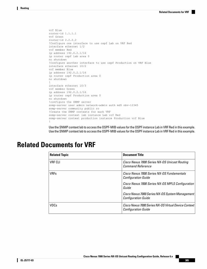
vrf Bluerouter-id 1.1.1.1vrf Greenrouter-id 2.2.2.2!Configure one interface to use ospf Lab on VRF Redinterface ethernet 1/2vrf member Redip address 192.0.2.1/16ip router ospf Lab area 0no shutdown!Configure another interface to use ospf Production on VRF Blueinterface ethernet 10/2vrf member Blueip address 192.0.2.1/16ip router ospf Production area 0no shutdown!interface ethernet 10/3vrf member Greenip address 192.0.2.1/16ip router ospf Production area 0no shutdown!configure the SNMP serversnmp-server user admin network-admin auth md5 nbv-12345snmp-server community public ro!Create the SNMP contexts for each VRFsnmp-server context lab instance Lab vrf Redsnmp-server context production instance Production vrf Blue!
Use the SNMP context lab to access the OSPF-MIB values for the OSPF instance Lab in VRF Red in this example.Use the SNMP context lab to access the OSPF-MIB values for the OSPF instance Lab in VRF Red in this example.
Related Documents for VRFDocument TitleRelated Topic
Cisco Nexus 7000 Series NX-OS Unicast RoutingCommand Reference
VRF CLI
Cisco Nexus 7000 Series NX-OS FundamentalsConfiguration Guide
Cisco Nexus 7000 Series NX-OS MPLS ConfigurationGuide
Cisco Nexus 7000 Series NX-OS System ManagementConfiguration Guide
VRFs
Cisco Nexus 7000 Series NX-OS Virtual Device ContextConfiguration Guide
VDCs
Cisco Nexus 7000 Series NX-OS Unicast Routing Configuration Guide, Release 6.x385OL-25777-03
RoutingRelated Documents for VRF

Standards for VRFNo new or modified standards are supported by this feature, and support for existing standards has not beenmodified by this feature.
Feature History for VRFThis table includes only the updates for those releases that have resulted in additions or changes to the feature.
Table 28: Feature History for VRF
Feature InformationReleaseFeature Name
This feature was introduced.4.0(1)VRF
Cisco Nexus 7000 Series NX-OS Unicast Routing Configuration Guide, Release 6.xOL-25777-03386
RoutingStandards for VRF
C H A P T E R 17Managing the Unicast RIB and FIB
This chapter describes how to manage routes in the unicast Routing Information Base (RIB) and the ForwardingInformation Base (FIB) on the Cisco NX-OS device.
• Finding Feature Information, on page 387• Information About the Unicast RIB and FIB, on page 387• Default Settings for the Unicast RIB and FIB, on page 390• Managing the Unicast RIB and FIB, on page 390• Verifying the Unicast RIB and FIB, on page 399• Related Documents for the Unicast RIB and FIB, on page 399• Feature History for the Unicast RIB and FIB, on page 399
Finding Feature InformationYour software release might not support all the features documented in this module. For the latest caveatsand feature information, see the Bug Search Tool at https://tools.cisco.com/bugsearch/ and the release notesfor your software release. To find information about the features documented in this module, and to see a listof the releases in which each feature is supported, see the "New and Changed Information"chapter or theFeature History table in this chapter.
Information About the Unicast RIB and FIBThe unicast RIB (IPv4 RIB and IPv6 RIB) and FIB are part of the Cisco NX-OS forwarding architecture,
Cisco Nexus 7000 Series NX-OS Unicast Routing Configuration Guide, Release 6.x387OL-25777-03

Figure 44: Cisco NX-OS Forwarding Architecture
The unicast RIB exists on the active supervisor. It maintains the routing table with directly connected routes,static routes, and routes learned from dynamic unicast routing protocols. The unicast RIB also collectsadjacency information from sources such as the Address Resolution Protocol (ARP). The unicast RIB determinesthe best next hop for a given route and populates the unicast forwarding information bases (FIBs) on themodules by using the services of the unicast FIB distribution module (FDM).
Each dynamic routing protocol must update the unicast RIB for any route that has timed out. The unicast RIBthen deletes that route and recalculates the best next hop for that route (if an alternate path is available).
Layer 3 Consistency CheckerIn rare instances, an inconsistency can occur between the unicast RIB and the FIB on each module. CiscoNX-OS supports the Layer 3 consistency checker. This feature detects inconsistencies between the unicastIPv4 RIB on the supervisor module and the FIB on each interface module. Inconsistencies include the following:
• Missing prefix• Extra prefix• Wrong next-hop address• Incorrect Layer 2 rewrite string in the ARP or neighbor discovery (ND) cache
The Layer 3 consistency checker compares the FIB entries to the latest adjacency information from theAdjacency Manager (AM) and logs any inconsistencies. The consistency checker then compares the unicastRIB prefixes to the module FIB and logs any inconsistencies.
Dynamic TCAM AllocationDynamic TCAM allocation reallocates unused TCAM blocks on M1 Series non-XL modules to an adjacentregion when all existing blocks in that region are full. Dynamic TCAM allocation allows more flexibility in thenumber of routes that the FIB can allocate for a route type.
Cisco NX-OS divides the FIB to support multiple address families. The FIB TCAM for M1 Series non-XL moduleshas 128K physical entries.
Table 29: Default FIB TCAM Allocation
Entry SizeNumber of TCAM BlocksDefault Number of RoutesRegion
72 bits756,000IPv4 Unicast Routes
Cisco Nexus 7000 Series NX-OS Unicast Routing Configuration Guide, Release 6.xOL-25777-03388
RoutingLayer 3 Consistency Checker

Entry SizeNumber of TCAM BlocksDefault Number of RoutesRegion
144 bits832,000IPv4 Multicast Routes or IPv6Unicast Routes
288 bits12,000IPv6 Multicast Routes
Maximum TCAM Entries and FIB Scale LimitsThe FIB TCAM entries are system wide resources that are shared across virtual device contexts (VDC)configured on the module. Table 16-2 describes the supported maximum FIB scale entries on the Nexus 7000system configuration per route-type.
Table 30: Maximum Supported TCAM Entries and FIB Scale Limits
MaximumSupportedIPv6MulticastRoutes
MaximumSupportedIPv6 UnicastRoutes
MaximumSupported IPv4MulticastRoutes
MaximumSupportedIPv4 UnicastRoutes
MaximumTCAMPhysicalEntries in aVDC
Module Type in a VDC
2,000 routes56,000 routes32,000 mroutes112,000128,000Only non-XL modules in aVDC
2,000 routes350,000 routes32,000 mroutes900,000900,000Only XL modules in a VDC
2,000 routes56,000 routes32,000 mroutes112,000128,000Mix of XL/non-XL modules inthe same VDC
8,192 routes16,384 routes16,384 mroutes32,76832,000Only F2 Series modules in aVDC2
2 Utilization may vary based on the sequence of routes being added and on the mix of unicast and multicastroutes.
The table above captures the scale limits in a VDC. In a Cisco Nexus 7000 system, the total memory on thesupervisor module restricts the actual route scale limits across all VDCs in the system.
Note
Do not exceed the maximum route limits for non-XL modules in a VDC that contains both XL modules andnon-XL modules.
Note
The actual FIB TCAM can scale to a higher scale number from a hardware perspective. The table abovecaptures the currently supported FIB sizes.
Note
Cisco Nexus 7000 Series NX-OS Unicast Routing Configuration Guide, Release 6.x389OL-25777-03
RoutingMaximum TCAM Entries and FIB Scale Limits

The maximum routes are individual route-type maximum values and these values are not cumulative acrosseach route-type.
Note
Configure the higher shared memory sizes (see the Cisco Nexus 7000 Series NX-OS Virtual Device ContextConfiguration Guide, Release 5.x) for the routing table to enable the higher FIB scale on the XL modules. Seethe Cisco Nexus 7000 Series Hardware Installation and Reference Guide for more information on the XL modules.
The full IPv4 Internet route tables currently have more than 500,000 routes and require the XL modules.Note
The unicast RIB and FIB support virtual routing and forwarding (VRF) instances. VRF exists within VDCs. Bydefault, Cisco NX-OS places you in the default VDC and default VRF unless you specifically configure anotherVDC and VRF. For more information, see the Cisco Nexus 7000 Series NX-OS Virtual Device Context ConfigurationGuide.
Default Settings for the Unicast RIB and FIBTable 31: Default Unicast RIB and FIB Parameters
DefaultParameters
Enabled by default and cannot be disabled.Dynamic TCAM allocation
Managing the Unicast RIB and FIB
If you are unfamiliar with the Cisco IOS CLI, be aware that the Cisco NX-OS commands for this feature mightdiffer from the Cisco IOS commands that you would use.
Note
Displaying Module FIB InformationThe following show commands can be entered in any mode.
Procedure
PurposeCommand or Action
Displays the adjacency information for IPv4 orIPv6.
switch# show forwarding {ipv4 | ipv6}adjacency module slot
Step 1
Displays the route table for IPv4 or IPv6.switch# show forwarding {ipv4 | ipv6} routemoduleslot
Step 2
Cisco Nexus 7000 Series NX-OS Unicast Routing Configuration Guide, Release 6.xOL-25777-03390
RoutingDefault Settings for the Unicast RIB and FIB

Configuring Load Sharing in the Unicast FIBDynamic routing protocols such as Open Shortest Path First (OSPF) support load balancing with equal-costmultipath (ECMP). The routing protocol determines its best routes based on the metrics configured for theprotocol and installs up to the protocol-configured maximum paths in the unicast RIB. The unicast RIB comparesthe administrative distances of all routing protocol paths in the RIB and selects a best path set from all of thepath sets installed by the routing protocols. The unicast RIB installs this best path set into the FIB for use bythe forwarding plane.
The forwarding plane uses a load-sharing algorithm to select one of the installed paths in the FIB to use for agiven data packet.
You can globally configure the following load-sharing settings:
• Load-share mode—Selects the best path based on the destination address and port or the source andthe destination address and port.
• Universal ID—Sets the random seed for the hash algorithm. You do not need to configure the UniversalID. Cisco NX-OS chooses the Universal ID if you do not configure it.
Load sharing uses the same path for all packets in a given flow. A flow is defined by the load-sharing methodthat you configure. For example, if you configure source-destination load sharing, then all packets with thesame source IP address and destination IP address pair follow the same path.
Note
To configure the unicast FIB load-sharing algorithm, use the following command in global configuration mode:
Cisco Nexus 7000 Series NX-OS Unicast Routing Configuration Guide, Release 6.x391OL-25777-03
RoutingConfiguring Load Sharing in the Unicast FIB

PurposeCommand
Configures the unicast FIB load-sharing algorithm fordata traffic.
• The universal-id option sets the random seed forthe hash algorithm and shifts the flow from onelink to another.
You do not need to configure the universal ID.Cisco NX-OS chooses the Universal ID if you donot configure it. The universal-id range is from 1to 4294967295.
• The rotate option causes the hash algorithm torotate the link picking selection so that it doesnot continually choose the same link across allnodes in the network. It does so by influencingthe bit pattern for the hash algorithm. This optionshifts the flow from one link to another and loadbalances the already load-balanced (polarized)traffic from the first ECMP level across multiplelinks.
If you specify a rotate value, the 64-bit stream isinterpreted starting from that bit position in acyclic rotation. The rotate range is from 1 to 63,and the default is 32.
With multi-tier Layer 3 topology,polarization is possible. To avoidpolarization, use a different rotate bitat each tier of the topology.
Note
To configure a rotation value for portchannels, use the port-channelload-balance src-dst ip-l4port rotaterotate command. For more informationon this command, see the Cisco Nexus7000 Series NX-OS InterfacesConfiguration Guide.
Note
• For packets with GTP header, gtp-teid specifiesthat 32-bit TEID value has to be considered forthe path calculation.
• The concatenation option ties together the hashtag values for ECMP and the hash tag values forport channels in order to use a stronger 64-bithash. If you do not use this option, you cancontrol ECMP load-balancing and port-channelload-balancing independently. The default isdisabled.
switch(config)# ip load-sharing address {destinationport destination | source-destination [portsource-destination]} [universal-id seed] [gtp-teid][rotate rotate] [concatenation]
Cisco Nexus 7000 Series NX-OS Unicast Routing Configuration Guide, Release 6.xOL-25777-03392
RoutingConfiguring Load Sharing in the Unicast FIB

To display the unicast FIB load-sharing algorithm, use the following command in any mode:
PurposeCommand
Displays the unicast FIB load-sharing algorithm fordata traffic.
switch(config)# show ip load-sharing
To display the route that the unicast RIB and FIB use for a particular source address and destination address,use the following command in any mode:
PurposeCommand
Displays the route that the unicast RIB FIB use for asource and destination address pair. The sourceaddress and destination address format is x.x.x.x. Thesource port and destination port range is from 1 to65535. The VRF name can be any case-sensitive,alphanumeric string up to 64 characters.
switch# show routing hash source-addr dest-addr[source-port dest-port] [vrf vrf-name]
This example shows the route selected for a source/destination pair:
switch# show routing hash 10.0.0.5 30.0.0.2Load-share parameters used for software forwarding:load-share mode: address source-destination port source-destinationUniversal-id seed: 0xe05e2e85Hash for VRF "default"Hashing to path *20.0.0.2 (hash: 0x0e), for route:
Configuring Per-Packet Load SharingYou can use per-packet load sharing to evenly distribute data traffic in an IP network over multiple equal-costconnections. Per-packet load sharing allows the router to send successive data packets over paths on apacket-by-packet basis rather than on a per-flow basis.
Using per-packet load sharing can result in out-of-order packets. Packets for a given pair of source-destinationhosts might take different paths and arrive at the destination out of order. Make sure you understand theimplications of out-of-order packets to your network and applications. Per-packet load sharing is not appropriatefor all networks. Per-flow load sharing ensures packets always arrive in the order that they were sent.
Note
Per-packet load sharing uses the round-robin method to determine which path each packet takes to thedestination. With per-packet load sharing enabled on interfaces, the router sends one packet for destination1over the first path, the second packet for (the same) destination1 over the second path, and so on. Per-packetload sharing ensures balancing over multiple links.
Use per-packet load sharing to ensure that a path for a single source-destination pair does not get overloaded.If most of the traffic passing through parallel links is for a single pair, per-destination load sharing will overloada single link while other links will have very little traffic. Enabling per-packet load sharing allows you to usealternate paths to the same busy destination.
Per-packet load sharing on an interface overrides the global load-sharing configuration.Note
Cisco Nexus 7000 Series NX-OS Unicast Routing Configuration Guide, Release 6.x393OL-25777-03
RoutingConfiguring Per-Packet Load Sharing

You configure per-packet load sharing on the input interface. This configuration determines the output interfacethat Cisco NX-OS chooses for the packet.
For example, if you have ECMP paths on two output interfaces, Cisco NX-OS uses the following load-sharingmethods for input packets on Ethernet 1/1:
• Per-packet load sharing if you configure per-packet load sharing on Ethernet 1/1.
• Per-flow load sharing.
The configurations for the other interfaces have no effect on the load-sharing method used for Ethernet 1/1 inthis example.
Procedure
PurposeCommand or Action
Configures per-packet load sharing on aninterface.
switch(config-if)# ip load-sharing per-packetStep 1
Displaying Routing and Adjacency Information
Procedure
PurposeCommand or Action
Displays the unicast route table. The route-typeargument can be a single route prefix, direct,
switch# show {ip | ipv6} route [route-type |interface int-type number | next-hop]
Step 1
static, or a dynamic route protocol. Use the ?command to see the supported interfaces.
Displays the adjacency table.switch# show {ip | ipv6} adjacency [prefix |interface-type number [summary] | non-best][detail] [vrf vrf-id]
Step 2
The argument ranges are as follows:
• prefix—Any IPv4 or IPv6 prefix address.
• interface-type number—Use the ?command to see the supported interfaces.
• vrf-id—Any case-sensitive, alphanumericstring up to 64 characters.
Displays the unicast route table. The route-typeargument can be a single route prefix, direct,
switch# show {ip | ipv6} routing [route-type |interface int-type number | next-hop |
Step 3
static, or a dynamic route protocol. Use the ?command to see the supported interfaces.
recursive-next-hop | summary | updated {since| until} time]
Example
The following example displays the unicast route table:
Cisco Nexus 7000 Series NX-OS Unicast Routing Configuration Guide, Release 6.xOL-25777-03394
RoutingDisplaying Routing and Adjacency Information

switch# show ip route
IP Route Table for Context "default"'*' denotes best ucast next-hop '**' denotes best mcast next-hop'[x/y]' denotes [preference/metric]
0.0.0.0/0, 1 ucast next-hops, 0 mcast next-hops*via 10.1.1.1, mgmt0, [1/0], 5d21h, static
0.0.0.0/32, 1 ucast next-hops, 0 mcast next-hops*via Null0, [220/0], 1w6d, local, discard
10.1.0.0/22, 1 ucast next-hops, 0 mcast next-hops, attached*via 10.1.1.55, mgmt0, [0/0], 5d21h, direct
10.1.0.0/32, 1 ucast next-hops, 0 mcast next-hops, attached*via 10.1.0.0, Null0, [0/0], 5d21h, local
10.1.1.1/32, 1 ucast next-hops, 0 mcast next-hops, attached*via 10.1.1.1, mgmt0, [2/0], 5d16h, am
10.1.1.55/32, 1 ucast next-hops, 0 mcast next-hops, attached*via 10.1.1.55, mgmt0, [0/0], 5d21h, local
10.1.1.253/32, 1 ucast next-hops, 0 mcast next-hops, attached*via 10.1.1.253, mgmt0, [2/0], 5d20h, am
10.1.3.255/32, 1 ucast next-hops, 0 mcast next-hops, attached*via 10.1.3.255, mgmt0, [0/0], 5d21h, local
255.255.255.255/32, 1 ucast next-hops, 0 mcast next-hops*via Eth Inband Port, [0/0], 1w6d, local
The following example shows the adjacency information:
switch# show ip adjacency
IP Adjacency Table for context defaultTotal number of entries: 2Address Age MAC Address Pref Source Interface Best10.1.1.1 02:20:54 00e0.b06a.71eb 50 arp mgmt0 Yes10.1.1.253 00:06:27 0014.5e0b.81d1 50 arp mgmt0 Yes
Triggering the Layer 3 Consistency CheckerYou can manually trigger the Layer 3 consistency checker.
To manually trigger the Layer 3 consistency checker, use the following commands in global configurationmode:
PurposeCommand
Starts a Layer 3 consistency check. The vrf-name canbe any case-sensitive, alphanumeric string up to 64characters. The slot range is from 1 to 10.
test forwarding [ipv4 | ipv6] [unicast] inconsistency[vrf vrf-name] [module {slot| all}]
To stop the Layer 3 consistency checker, use the following commands in global configuration mode:
PurposeCommand
Stops a Layer 3 consistency check. The vrf-name canbe any case-sensitive, alphanumeric string up to 64characters. The slot range is from 1 to 10.
test forwarding [ipv4 | ipv6] [unicast] inconsistency[vrf vrf-name] [module {slot| all}] stop
To display the Layer 3 inconsistencies, use the following commands in any mode:
Cisco Nexus 7000 Series NX-OS Unicast Routing Configuration Guide, Release 6.x395OL-25777-03
RoutingTriggering the Layer 3 Consistency Checker
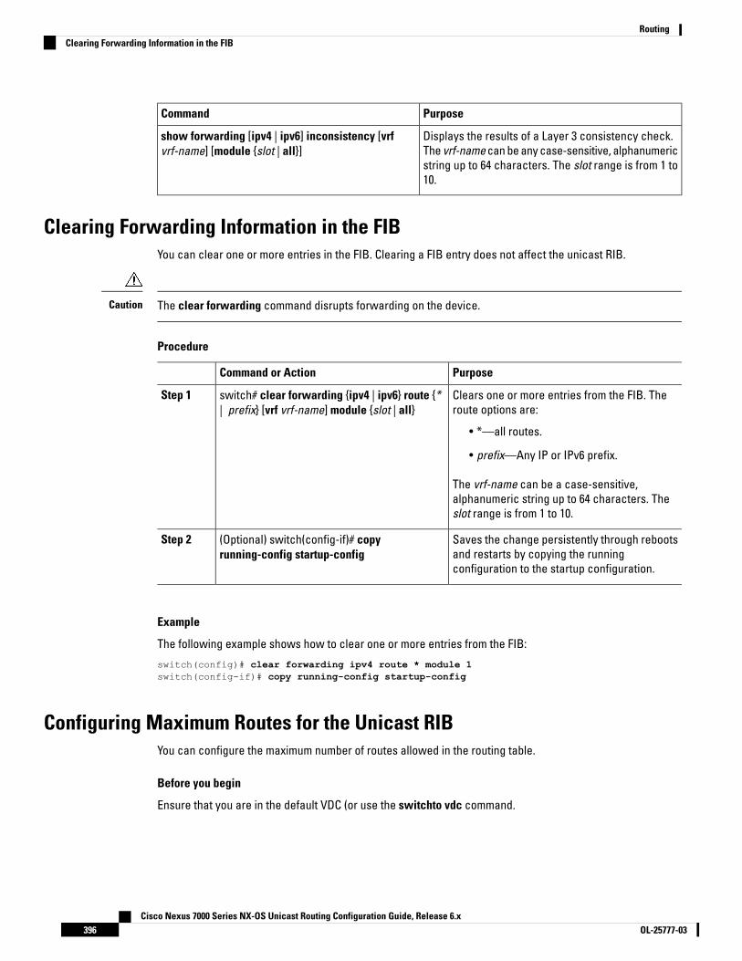
PurposeCommand
Displays the results of a Layer 3 consistency check.The vrf-name can be any case-sensitive, alphanumericstring up to 64 characters. The slot range is from 1 to10.
show forwarding [ipv4 | ipv6] inconsistency [vrfvrf-name] [module {slot | all}]
Clearing Forwarding Information in the FIBYou can clear one or more entries in the FIB. Clearing a FIB entry does not affect the unicast RIB.
The clear forwarding command disrupts forwarding on the device.Caution
Procedure
PurposeCommand or Action
Clears one or more entries from the FIB. Theroute options are:
switch# clear forwarding {ipv4 | ipv6} route {*| prefix} [vrf vrf-name] module {slot | all}
Step 1
• *—all routes.
• prefix—Any IP or IPv6 prefix.
The vrf-name can be a case-sensitive,alphanumeric string up to 64 characters. Theslot range is from 1 to 10.
Saves the change persistently through rebootsand restarts by copying the runningconfiguration to the startup configuration.
(Optional) switch(config-if)# copyrunning-config startup-config
Step 2
Example
The following example shows how to clear one or more entries from the FIB:
switch(config)# clear forwarding ipv4 route * module 1switch(config-if)# copy running-config startup-config
Configuring Maximum Routes for the Unicast RIBYou can configure the maximum number of routes allowed in the routing table.
Before you begin
Ensure that you are in the default VDC (or use the switchto vdc command.
Cisco Nexus 7000 Series NX-OS Unicast Routing Configuration Guide, Release 6.xOL-25777-03396
RoutingClearing Forwarding Information in the FIB
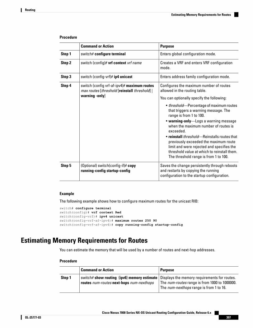
Procedure
PurposeCommand or Action
Enters global configuration mode.switch# configure terminalStep 1
Creates a VRF and enters VRF configurationmode.
switch (config)# vrf context vrf nameStep 2
Enters address family configuration mode.switch (config-vrf)# ip4 unicastStep 3
Configures the maximum number of routesallowed in the routing table.
switch (config vrf-af-ipv4)# maximum routesmax routes [threshold [reinstall threshold] |warning -only]
Step 4
You can optionally specify the following:
• threshold—Percentage of maximum routesthat triggers a warning message. Therange is from 1 to 100.
• warning-only—Logs a warning messagewhen the maximum number of routes isexceeded.
• reinstall threshold—Reinstalls routes thatpreviously exceeded the maximum routelimit and were rejected and specifies thethreshold value at which to reinstall them.The threshold range is from 1 to 100.
Saves the change persistently through rebootsand restarts by copying the runningconfiguration to the startup configuration.
(Optional) switch(config-if)# copyrunning-config startup-config
Step 5
Example
The following example shows how to configure maximum routes for the unicast RIB:
switch# configure terminalswitch(config)# vrf context Redswitch(config-vrf)# ipv4 unicastswitch(config-vrf-af-ipv4)# maximum routes 250 90switch(config-vrf-af-ipv4)# copy running-config startup-config
Estimating Memory Requirements for RoutesYou can estimate the memory that will be used by a number of routes and next-hop addresses.
Procedure
PurposeCommand or Action
Displays the memory requirements for routes.The num-routes range is from 1000 to 1000000.The num-nexthops range is from 1 to 16.
switch# show routing {ipv6} memory estimateroutes num-routes next-hops num-nexthops
Step 1
Cisco Nexus 7000 Series NX-OS Unicast Routing Configuration Guide, Release 6.x397OL-25777-03
RoutingEstimating Memory Requirements for Routes

PurposeCommand or Action
Saves the change persistently through rebootsand restarts by copying the runningconfiguration to the startup configuration.
(Optional) switch(config-if)# copyrunning-config startup-config
Step 2
Example
The following example shows how to estimate the memory requirements for routes:
switch# show routing memory estimate routes 5000 next-hopsswitch(config-if)# copy running-config startup-config
Clearing Routes in the Unicast RIBYou can estimate the memory to be used by a number of routes and next-hop addresses.
The * keyword is severely disruptive to routing.Caution
Procedure
PurposeCommand or Action
Clears one or more routes from both the unicastRIB and all the module FIBs. The route optionsare:
clear {ip | ip4 | ipv6} route {* | prefix/length}[next hop interface] [vrf vrf-name] module {slot| all}
Step 1
• *—All routes.• route— An individual IP or IPv6 route.• prefix/length— Any IP or IPv6 prefix.• next-hop—The next-hop address.• interface—The interface to reach the
next-hop address.
The vrf-name can be an case-sensitive,alphanumeric string up to 32 64characters.
Clears one or more routes from both the unicastRIB and all the module FIBs. The route optionsare:
clear routing [multicast | unicast]{ip |ip4 | ipv6}{* | {route | prefix/length} [next-hop interface]}[vrf vrf-name]
Step 2
• *—All routes.• route— An individual IP or IPv6 route.• prefix/length— Any IP or IPv6 prefix.• next-hop—The next-hop address.• interface—The interface to reach the
next-hop address.
Cisco Nexus 7000 Series NX-OS Unicast Routing Configuration Guide, Release 6.xOL-25777-03398
RoutingClearing Routes in the Unicast RIB

PurposeCommand or Action
The vrf-name can be any case-sensitive,alphanumeric string up to 64 characters.
Saves the change persistently through rebootsand restarts by copying the runningconfiguration to the startup configuration.
(Optional) switch(config-if)# copyrunning-config startup-config
Step 3
Verifying the Unicast RIB and FIBTo display advanced BGP statistics, use the following commands:
PurposeCommand
Displays the adjacency table on amodule.
show forwarding adjacency
Displays the FIB distributioninformation.
show forwarding distribution {clients | fib-state}
Displays the FIB information for amodule.
show forwarding interfaces module slot
Displays routes in the FIB.show forwarding {ip | ipv4 | ipv6} route
Displays the adjacency table.show {ip |ipv4 | ipv6} adjacency}
Displays the IPv4 or IPv6 routesfrom the unicast RIB.
show {ip | ipv6} route}
Displays routes from the unicastRIB.
show routing
Related Documents for the Unicast RIB and FIBFeature InformationFeature Name
Cisco Nexus 7000 Series NX-OS Unicast Routing CommandReference
Unicast RIB and FIB CLI commands
Feature History for the Unicast RIB and FIBThis table includes only the updates for those releases that have resulted in additions or changes to the feature.
Cisco Nexus 7000 Series NX-OS Unicast Routing Configuration Guide, Release 6.x399OL-25777-03
RoutingVerifying the Unicast RIB and FIB

Table 32: Feature History for the Unicast RIB and FIB
Feature InformationReleaseFeature Name
Added support for GTP headers.7.3(0)DX(1)Load Sharing in Unicast FIB
Added the ability to check forinconsistent, missing, or failedroutes in the unicast FIB.
6.2(2)Unicast FIB
Added the ability to monitor TCAMutilization on M1 Series modules.
6.2(2)TCAM utilization
Added the optional keywordlonger-prefixes [detail] to the showrouting command to displayspecific routes for a particularprefix.
6.2(2)Unicast RIB
Added support to configure themaximum number of routes allowedin the routing table.
5.2(1)Maximum routes
Added support for larger TCAM andFIB sizes with XL modules.
5.0(2)TCAM Size for XL Modules
Enabled by default and cannot bedisabled.
5.0(2)Dynamic TCAM allocation
Added support to check forinconsistencies in the IPv6forwarding table.
4.2(1)IPv6 forwarding inconsistencychecker
Added support for dynamicallyallocating TCAM blocks in the FIB.
4.2(1)Dynamic TCAM allocation
Added support to load balance perpacket on an interface.
4.1(2)Per-packet load sharing
Added support to clear individualroutes in unicast RIB and FIB.
4.0(3)Unicast RIB and FIB
This feature was introduced.4.0(1)Unicast RIB and FIB
Cisco Nexus 7000 Series NX-OS Unicast Routing Configuration Guide, Release 6.xOL-25777-03400
RoutingFeature History for the Unicast RIB and FIB

C H A P T E R 18Configuring Route Policy Manager
This chapter contains the following sections:
• Finding Feature Information, on page 401• Information About Route Policy Manager, on page 401• Prerequisites for Route Policy Manager , on page 409• Guidelines and Limitations, on page 409• Default Settings for Route Policy Manager Parameters, on page 409• Configuring Route Policy Manager, on page 410• Configuration Examples for Route Policy Manager, on page 419• Related Documents for Route Policy Manager, on page 420• Standards for Route Policy Manager, on page 420• Feature History for Route Policy Manager, on page 420
Finding Feature InformationYour software release might not support all the features documented in this module. For the latest caveatsand feature information, see the Bug Search Tool at https://tools.cisco.com/bugsearch/ and the release notesfor your software release. To find information about the features documented in this module, and to see a listof the releases in which each feature is supported, see the "New and Changed Information"chapter or theFeature History table in this chapter.
Information About Route Policy ManagerRoute Policy Manager supports route maps and IP prefix lists. These features are used for route redistribution.A prefix list contains one or more IPv4 network prefixes and the associated prefix length values. You can usea prefix list by itself in features such as Border Gateway Protocol (BGP) templates, route filtering, or redistributionof routes that are exchanged between routing domains.
Route maps can apply to both routes and IP packets. Route filtering and redistribution pass a route through aroute map.
Cisco Nexus 7000 Series NX-OS Unicast Routing Configuration Guide, Release 6.x401OL-25777-03

Prefix ListsYou can use prefix lists to permit or deny an address or range of addresses. Filtering by a prefix list involvesmatching the prefixes of routes or packets with the prefixes listed in the prefix list. An implicit deny is assumedif a given prefix does not match any entries in a prefix list.
You can configure multiple entries in a prefix list and permit or deny the prefixes that match the entry. Eachentry has an associated sequence number that you can configure. If you do not configure a sequence number,Cisco NX-OS assigns a sequence number automatically. Cisco NX-OS evaluates prefix lists starting with thelowest sequence number. Cisco NX-OS processes the first successful match for a given prefix. Once a matchoccurs, Cisco NX-OS processes the permit or deny statement and does not evaluate the rest of the prefix list.
Prefix Lists in Cisco NX-OS support only one of the following addresses at a time:
• source
• destination
• group address
An empty prefix list permits all routes.Note
MAC ListsYou can use MAC lists to permit or deny a MAC address or range of addresses. A MAC list consists of a listof MAC addresses and optional MAC masks. A MAC mask is a wild-card mask that is logically AND-ed withthe MAC address when the route map matches on the MAC list entry. Filtering by a MAC list involves matchingthe MAC address of packets with the MAC addresses listed in the MAC list. An implicit deny is assumed if agiven MAC address does not match any entries in a MAC list.
You can configure multiple entries in a MAC list and permit or deny the MAC addresses that match the entry.Each entry has an associated sequence number that you can configure. If you do not configure a sequencenumber, Cisco NX-OS assigns a sequence number automatically. Cisco NX-OS evaluates MAC lists startingwith the lowest sequence number. Cisco NX-OS processes the first successful match for a given MAC address.Once a match occurs, Cisco NX-OS processes the permit or deny statement and does not evaluate the restof the MAC list.
Route MapsYou can use route maps for route redistribution or policy-based routing. Route map entries consist of a list ofmatch and set criteria. The match criteria specify match conditions for incoming routes or packets, and theset criteria specify the action taken if the match criteria are met.
You can configure multiple entries in the same route map. These entries contain the same route map nameand are differentiated by a sequence number.
You create a route map with one or more route map entries arranged by the sequence number under a uniqueroute map name. The route map entry has the following parameters:
• Sequence number
• Permission—permit or deny
Cisco Nexus 7000 Series NX-OS Unicast Routing Configuration Guide, Release 6.xOL-25777-03402
RoutingPrefix Lists

• Match criteria
• Set changes
The IPv4 and the IPv6-based matches on the same route map sequence number is not supported in CiscoNexus 7000 Series.
By default, a route map processes routes or IP packets in a linear fashion, that is, starting from the lowestsequence number. You can configure the route map to process in a different order using the continue statement,which allows you to determine which route map entry to process next.
Match CriteriaYou can use a variety of criteria to match a route or IP packet in a route map. Some criteria, such as BGPcommunity lists, are applicable only to a specific routing protocol, while other criteria, such as the IP sourceor the destination address, can be used for any route or IP packet.
When Cisco NX-OS processes a route or packet through a route map, it compares the route or packet to eachof the match statements configured. If the route or packet matches the configured criteria, Cisco NX-OSprocesses it based on the permit or deny configuration for that match entry in the route map and any set criteriaconfigured.
The match categories and parameters are as follows:
• IP access lists—(For policy-based routing only). Match based on source or destination IP address,protocol, or QoS parameters.
• BGP parameters—Match based on AS numbers, AS-path, community attributes, or extended communityattributes.
• Prefix lists—Match based on an address or range of addresses.
• Multicast parameters—Match based on rendezvous point, groups, or sources.
• Other parameters—Match based on IP next-hop address or packet length.
Set ChangesOnce a route or packet matches an entry in a route map, the route or packet can be changed based on oneor more configured set statements.
The set changes are as follows:
• BGP parameters—Change the AS-path, tag, community, extended community, dampening, local preference,origin, or weight attributes.
• Metrics—Change the route-metric, the route-tag, or the route-type.
• Policy-based routing only—Change the interface or the default next-hop address.
• Other parameters—Change the forwarding address or the IP next-hop address.
Access ListsIP access lists can match the packet to a number of IP packet fields such as the following:
• Source or destination IPv4 or IPv6 address
Cisco Nexus 7000 Series NX-OS Unicast Routing Configuration Guide, Release 6.x403OL-25777-03
RoutingMatch Criteria

• Protocol
• Precedence
• ToS
You can use ACLs in a route map for policy-based routing only. See the Cisco Nexus 7000 Series NX-OS SecurityConfiguration Guide for more information on ACLs.
AS Numbers for BGPYou can configure a list of AS numbers to match against BGP peers. If a BGP peer matches an AS number inthe list and matches the other BGP peer configuration, BGP creates a session. If the BGP peer does not matchan AS number in the list, BGP ignores the peer. You can configure the AS numbers as a list, a range of ASnumbers, or you can use an AS-path list to compare the AS numbers against a regular expression.
AS-path Lists for BGPYou can configure an AS-path list to filter inbound or outbound BGP route updates. If the route update containsan AS-path attribute that matches an entry in the AS-path list, the router processes the route based on thepermit or deny condition configured. You can configure AS-path lists within a route map.
You can configure multiple AS-path entries in an AS-path list by using the same AS-path list name. The routerprocesses the first entry that matches.
Community Lists for BGPYou can filter BGP route updates based on the BGP community attribute by using community lists in a routemap. You can match the community attribute based on a community list, and you can set the communityattribute using a route map.
A community list contains one or more community attributes. If you configure more than one communityattribute in the same community list entry, the BGP route must match all community attributes listed to beconsidered a match.
You can also configure multiple community attributes as individual entries in the community list by using thesame community list name. In this case, the router processes the first community attribute that matches theBGP route, using the permit or deny configuration for that entry.
You can configure community attributes in the community list in one of the following formats:
• A named community attribute, such as internet or no-export.
• In aa:nn format, where the first two bytes represent the two-byte AS number and the last two bytesrepresent a user-defined network number.
• A regular expression.
See the Cisco Nexus 7000 Series NX-OS Unicast Routing Command Reference for more information on regularexpressions.
Extended Community Lists for BGPExtended community lists support 4-byte AS numbers. You can configure community attributes in the extendedcommunity list in one of the following formats:
Cisco Nexus 7000 Series NX-OS Unicast Routing Configuration Guide, Release 6.xOL-25777-03404
RoutingAS Numbers for BGP
• In aa4:nn format, where the first four bytes represent the four-byte AS number and the last two bytesrepresent a a user-defined network number.
• A regular expression.
See the Cisco Nexus 7000 Series NX-OS Unicast Routing Command Reference for more information on regularexpressions.
Cisco NX-OS supports generic specific extended community lists, which provide similar functionality to regularcommunity lists for four-byte AS numbers. You can configure generic specific extended community lists withthe following properties:
• Transitive—BGP propagates the community attributes across autonomous systems.
• Nontransitive—BGP removes community attributes before propagating the route to another autonomoussystem.
Route Redistribution and Route MapsYou can use route maps to control the redistribution of routes between routing domains. Route maps matchon the attributes of the routes to redistribute only those routes that pass the match criteria. The route map canalso modify the route attributes during this redistribution using the set changes.
The router matches redistributed routes against each route map entry. If there are multiple match statements,the route must pass all of the match criteria. If a route passes the match criteria defined in a route map entry,the actions defined in the entry are executed. If the route does not match the criteria, the router compares theroute against subsequent route map entries. Route processing continues until a match is made or the routeis processed by all entries in the route map with no match.
Each ACL ends with an implicit deny statement, by design convention; there is no similar convention forroute-maps. If the end of a route-map is reached during matching attempts, the result depends on the specificapplication of the route-map. Fortunately, route-maps that are applied to redistribution behave the same wayas ACLs: if the route does not match any clause in a route-map, then the route redistribution is denied, as ifthe route-map contained a deny statement at the end.
When you redistribute BGP to IGP, iBGP is redistributed as well. To override this behavior, you must insert anadditional deny statement into the route map.
Note
Route Map Support Matrix for Routing ProtocolsThe following tables include the configurable match and set statements for routing protocols on Cisco Nexus70xx and 77xx Series switches running the latest shipping release. For specific release information, see theFeature History for Route Policy Manager, on page 420.
The following legend applies to the tables:
• Yes—The statement is supported for the protocol.
• No—The statement is not supported for the protocol.
• If a statement does not apply for the protocol, there is an em dash (—) in the column next to the statement.
Cisco Nexus 7000 Series NX-OS Unicast Routing Configuration Guide, Release 6.x405OL-25777-03
RoutingRoute Redistribution and Route Maps
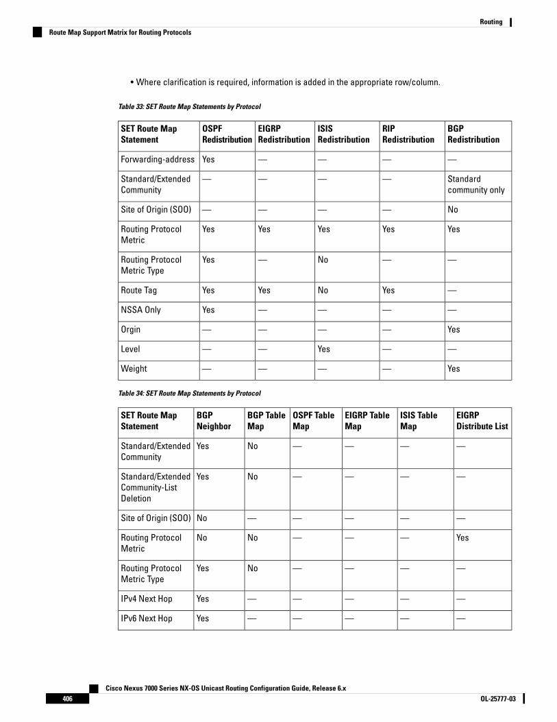
• Where clarification is required, information is added in the appropriate row/column.
Table 33: SET Route Map Statements by Protocol
BGPRedistribution
RIPRedistribution
ISISRedistribution
EIGRPRedistribution
OSPFRedistribution
SET Route MapStatement
————YesForwarding-address
Standardcommunity only
————Standard/ExtendedCommunity
No————Site of Origin (SOO)
YesYesYesYesYesRouting ProtocolMetric
——No—YesRouting ProtocolMetric Type
—YesNoYesYesRoute Tag
————YesNSSA Only
Yes————Orgin
——Yes——Level
Yes————Weight
Table 34: SET Route Map Statements by Protocol
EIGRPDistribute List
ISIS TableMap
EIGRP TableMap
OSPF TableMap
BGP TableMap
BGPNeighbor
SET Route MapStatement
————NoYesStandard/ExtendedCommunity
————NoYesStandard/ExtendedCommunity-ListDeletion
—————NoSite of Origin (SOO)
Yes———NoNoRouting ProtocolMetric
————NoYesRouting ProtocolMetric Type
—————YesIPv4 Next Hop
—————YesIPv6 Next Hop
Cisco Nexus 7000 Series NX-OS Unicast Routing Configuration Guide, Release 6.xOL-25777-03406
RoutingRoute Map Support Matrix for Routing Protocols

EIGRPDistribute List
ISIS TableMap
EIGRP TableMap
OSPF TableMap
BGP TableMap
BGPNeighbor
SET Route MapStatement
—————YesIPv4 Prefix list
—————YesIPv6 Prefix list
—————NoInterface
Yes—————Route Tag
————NoYesAS PATH
————NoYesOrgin
————NoYesAll PathAdvertisement
—YesYesYesYes—Distance
————NoNoDampening
————NoNoLevel
———NoYesYesWeight
Table 35: MATCH Route Map Statements by Protocol
BGPRedistribution
RIPRedistribution
ISISRedistribution
EIGRPRedistribution
OSPFRedistribution
MATCH RouteMap Statement
—YesyesYesOSPFv2 onlyCommunity List
—Yes—YesOSPFv2 onlyExt CommunityList
YesYesYesYesYesInterface
YesYesYesYesYesIPv4 Next Hop
YesNoYesYesYesIPv6 Next Hop
YesYesYesYesYesMetric
YesYesYesYesYesRoute Type
YesYesYesYesYesTag
YesNoYesYesYesIPv6 Prefix List
YesYesYesYesYesIPv4 Prefix list
NoNoNoNoNoIP ACL
—YesYesYesYesSource Protocol
Cisco Nexus 7000 Series NX-OS Unicast Routing Configuration Guide, Release 6.x407OL-25777-03
RoutingRoute Map Support Matrix for Routing Protocols

BGPRedistribution
RIPRedistribution
ISISRedistribution
EIGRPRedistribution
OSPFRedistribution
MATCH RouteMap Statement
—NoNoNoNoAS Path
—NoNoNoNoAS Number
Table 36: MATCH Route Map Statements by Protocol
EIGRPDistribute List
ISIS TableMap
EIGRP TableMap
OSPF TableMap
BGP TableMap
BGP NeighborMATCH RouteMapStatement
————YesYesCommunityList
————YesYesExtCommunityList
—YesYesYesNo—Interface
YesYesYesYesYesYesIPv4 Next Hop
YesYesYesYesYesYesIPv6 Next Hop
NoNoNoYesYesYesMetric
NoYesYesYesYesYesRoute Type
YesNoYesYesYes—Tag
YesYesYesYesYesYesIPv6 PrefixList
YesYesYesYesYesYesIPv4 Prefix list
NoNoNoNoNoNoIP ACL
————YesYesAS Path
————NoYesAS Number
———Yes——IPv4 RouteSource
Policy-Based RoutingYou can use policy-based routing to forward a packet to a specified next-hop address based on the sourceof the packet or other fields in the packet header.
Cisco Nexus 7000 Series NX-OS Unicast Routing Configuration Guide, Release 6.xOL-25777-03408
RoutingPolicy-Based Routing
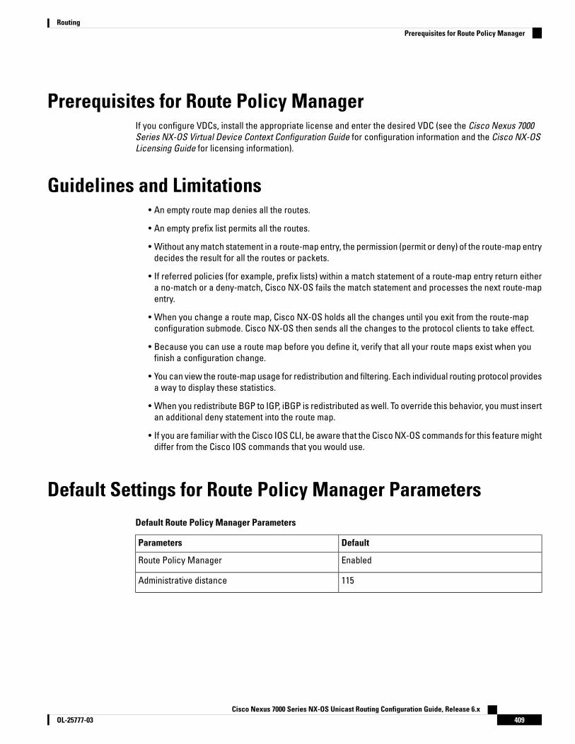
Prerequisites for Route Policy ManagerIf you configure VDCs, install the appropriate license and enter the desired VDC (see the Cisco Nexus 7000Series NX-OS Virtual Device Context Configuration Guide for configuration information and the Cisco NX-OSLicensing Guide for licensing information).
Guidelines and Limitations• An empty route map denies all the routes.
• An empty prefix list permits all the routes.
• Without any match statement in a route-map entry, the permission (permit or deny) of the route-map entrydecides the result for all the routes or packets.
• If referred policies (for example, prefix lists) within a match statement of a route-map entry return eithera no-match or a deny-match, Cisco NX-OS fails the match statement and processes the next route-mapentry.
• When you change a route map, Cisco NX-OS holds all the changes until you exit from the route-mapconfiguration submode. Cisco NX-OS then sends all the changes to the protocol clients to take effect.
• Because you can use a route map before you define it, verify that all your route maps exist when youfinish a configuration change.
• You can view the route-map usage for redistribution and filtering. Each individual routing protocol providesa way to display these statistics.
• When you redistribute BGP to IGP, iBGP is redistributed as well. To override this behavior, you must insertan additional deny statement into the route map.
• If you are familiar with the Cisco IOS CLI, be aware that the Cisco NX-OS commands for this feature mightdiffer from the Cisco IOS commands that you would use.
Default Settings for Route Policy Manager ParametersDefault Route Policy Manager Parameters
DefaultParameters
EnabledRoute Policy Manager
115Administrative distance
Cisco Nexus 7000 Series NX-OS Unicast Routing Configuration Guide, Release 6.x409OL-25777-03
RoutingPrerequisites for Route Policy Manager
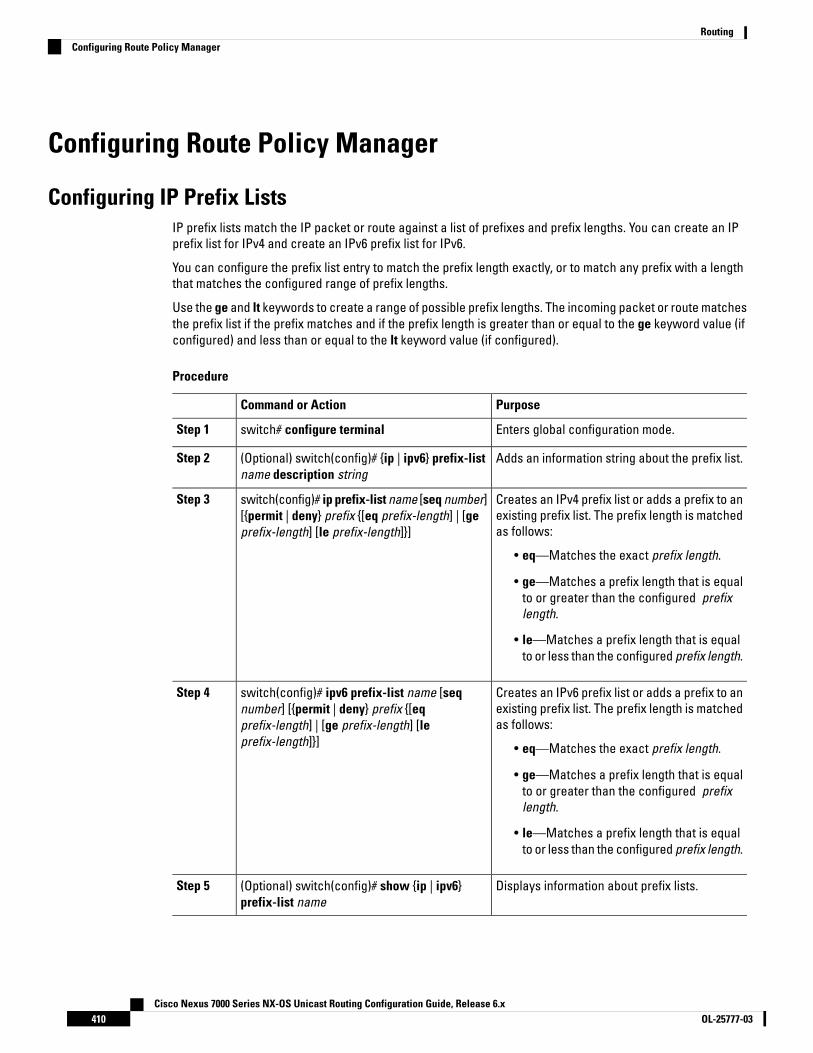
Configuring Route Policy Manager
Configuring IP Prefix ListsIP prefix lists match the IP packet or route against a list of prefixes and prefix lengths. You can create an IPprefix list for IPv4 and create an IPv6 prefix list for IPv6.
You can configure the prefix list entry to match the prefix length exactly, or to match any prefix with a lengththat matches the configured range of prefix lengths.
Use the ge and lt keywords to create a range of possible prefix lengths. The incoming packet or route matchesthe prefix list if the prefix matches and if the prefix length is greater than or equal to the ge keyword value (ifconfigured) and less than or equal to the lt keyword value (if configured).
Procedure
PurposeCommand or Action
Enters global configuration mode.switch# configure terminalStep 1
Adds an information string about the prefix list.(Optional) switch(config)# {ip | ipv6} prefix-listname description string
Step 2
Creates an IPv4 prefix list or adds a prefix to anexisting prefix list. The prefix length is matchedas follows:
switch(config)# ip prefix-list name [seq number][{permit | deny} prefix {[eq prefix-length] | [geprefix-length] [le prefix-length]}]
Step 3
• eq—Matches the exact prefix length.
• ge—Matches a prefix length that is equalto or greater than the configured prefixlength.
• le—Matches a prefix length that is equalto or less than the configured prefix length.
Creates an IPv6 prefix list or adds a prefix to anexisting prefix list. The prefix length is matchedas follows:
switch(config)# ipv6 prefix-list name [seqnumber] [{permit | deny} prefix {[eqprefix-length] | [ge prefix-length] [leprefix-length]}]
Step 4
• eq—Matches the exact prefix length.
• ge—Matches a prefix length that is equalto or greater than the configured prefixlength.
• le—Matches a prefix length that is equalto or less than the configured prefix length.
Displays information about prefix lists.(Optional) switch(config)# show {ip | ipv6}prefix-list name
Step 5
Cisco Nexus 7000 Series NX-OS Unicast Routing Configuration Guide, Release 6.xOL-25777-03410
RoutingConfiguring Route Policy Manager

PurposeCommand or Action
Saves the change persistently through rebootsand restarts by copying the runningconfiguration to the startup configuration.
(Optional) switch# copy running-configstartup-config
Step 6
Example
This example shows how to create an IPv4 prefix list with two entries and apply the prefix list to aBGP neighbor:
switch# configure terminalswitch(config)# ip prefix-list allowprefix seq 10 permit 192.0.2.0/24 eq 24switch(config)# ip prefix-list allowprefix seq 20 permit 209.165.201.0/27 eq 27switch(config)# router bgp 65536:20switch(config-router)# neighbor 192.0.2.1/16 remote-as 65535:20switch(config-router-neighbor)# address-family ipv4 unicastswitch(config-router-neighbor-af)# prefix-list allowprefix in
Configuring MAC ListsYou can configure a MAC list to permit or deny a range of MAC addresses.
Procedure
PurposeCommand or Action
Enters global configuration mode.switch# configure terminalStep 1
Creates a MAC list or adds a MAC address toan existing MAC list. The seq range is from 1 to
switch(config)# mac-list name [seq number]{permit | deny} mac-address [mac-mask]
Step 2
4294967294. The mac-mask specifies the portionof the MAC address to match against and is inMAC address format.
Displays information about MAC lists.(Optional) switch(config)# show mac-list nameStep 3
Saves the change persistently through rebootsand restarts by copying the runningconfiguration to the startup configuration.
(Optional) switch# copy running-configstartup-config
Step 4
Example
This example shows how to create a MAC list and copy the running configuration to the startupconfiguration:
switch# configure terminalswitch(config)# mac-list AllowMac seq 1 permit 0022.5579.a4c1 ffff.ffff.0000switch# copy running-config startup-config
Cisco Nexus 7000 Series NX-OS Unicast Routing Configuration Guide, Release 6.x411OL-25777-03
RoutingConfiguring MAC Lists
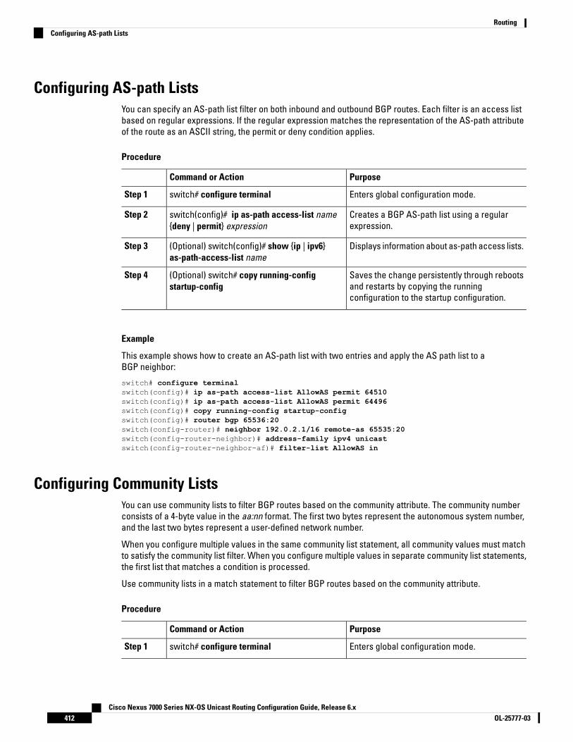
Configuring AS-path ListsYou can specify an AS-path list filter on both inbound and outbound BGP routes. Each filter is an access listbased on regular expressions. If the regular expression matches the representation of the AS-path attributeof the route as an ASCII string, the permit or deny condition applies.
Procedure
PurposeCommand or Action
Enters global configuration mode.switch# configure terminalStep 1
Creates a BGP AS-path list using a regularexpression.
switch(config)# ip as-path access-list name{deny | permit} expression
Step 2
Displays information about as-path access lists.(Optional) switch(config)# show {ip | ipv6}as-path-access-list name
Step 3
Saves the change persistently through rebootsand restarts by copying the runningconfiguration to the startup configuration.
(Optional) switch# copy running-configstartup-config
Step 4
Example
This example shows how to create an AS-path list with two entries and apply the AS path list to aBGP neighbor:
switch# configure terminalswitch(config)# ip as-path access-list AllowAS permit 64510switch(config)# ip as-path access-list AllowAS permit 64496switch(config)# copy running-config startup-configswitch(config)# router bgp 65536:20switch(config-router)# neighbor 192.0.2.1/16 remote-as 65535:20switch(config-router-neighbor)# address-family ipv4 unicastswitch(config-router-neighbor-af)# filter-list AllowAS in
Configuring Community ListsYou can use community lists to filter BGP routes based on the community attribute. The community numberconsists of a 4-byte value in the aa:nn format. The first two bytes represent the autonomous system number,and the last two bytes represent a user-defined network number.
When you configure multiple values in the same community list statement, all community values must matchto satisfy the community list filter. When you configure multiple values in separate community list statements,the first list that matches a condition is processed.
Use community lists in a match statement to filter BGP routes based on the community attribute.
Procedure
PurposeCommand or Action
Enters global configuration mode.switch# configure terminalStep 1
Cisco Nexus 7000 Series NX-OS Unicast Routing Configuration Guide, Release 6.xOL-25777-03412
RoutingConfiguring AS-path Lists
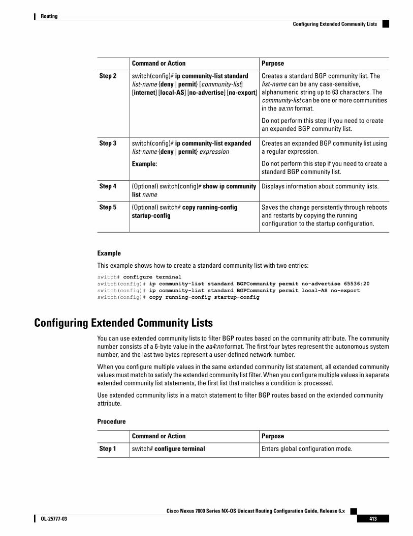
PurposeCommand or Action
Creates a standard BGP community list. Thelist-name can be any case-sensitive,
switch(config)# ip community-list standardlist-name {deny | permit} [community-list][internet] [local-AS] [no-advertise] [no-export]
Step 2
alphanumeric string up to 63 characters. Thecommunity-list can be one or more communitiesin the aa:nn format.
Do not perform this step if you need to createan expanded BGP community list.
Creates an expanded BGP community list usinga regular expression.
switch(config)# ip community-list expandedlist-name {deny | permit} expression
Step 3
Example: Do not perform this step if you need to create astandard BGP community list.
Displays information about community lists.(Optional) switch(config)# show ip communitylist name
Step 4
Saves the change persistently through rebootsand restarts by copying the runningconfiguration to the startup configuration.
(Optional) switch# copy running-configstartup-config
Step 5
Example
This example shows how to create a standard community list with two entries:
switch# configure terminalswitch(config)# ip community-list standard BGPCommunity permit no-advertise 65536:20switch(config)# ip community-list standard BGPCommunity permit local-AS no-exportswitch(config)# copy running-config startup-config
Configuring Extended Community ListsYou can use extended community lists to filter BGP routes based on the community attribute. The communitynumber consists of a 6-byte value in the aa4:nn format. The first four bytes represent the autonomous systemnumber, and the last two bytes represent a user-defined network number.
When you configure multiple values in the same extended community list statement, all extended communityvalues must match to satisfy the extended community list filter. When you configure multiple values in separateextended community list statements, the first list that matches a condition is processed.
Use extended community lists in a match statement to filter BGP routes based on the extended communityattribute.
Procedure
PurposeCommand or Action
Enters global configuration mode.switch# configure terminalStep 1
Cisco Nexus 7000 Series NX-OS Unicast Routing Configuration Guide, Release 6.x413OL-25777-03
RoutingConfiguring Extended Community Lists

PurposeCommand or Action
Creates a standard BGP extended communitylist. The community can be one or moreextended communities in the aa4:nn format.
switch(config)# ip extcommunity-list standardlist-name {deny | permit} 4bytegeneric{transitive | nontransitive} community1[community2...]
Step 2
Do not perform this step if you need to createan expanded BGP extended community list.
Creates an expanded BGP extended communitylist using a regular expression.
switch(config)# ip extcommunity-list expandedlist-name {deny | permit} expression
Step 3
Do not perform this step if you need to create astandard BGP extended community list.
Displays information about community lists.(Optional) switch(config)# show ipextcommunity list name
Step 4
Saves the change persistently through rebootsand restarts by copying the runningconfiguration to the startup configuration.
(Optional) switch(config)# copy running-configstartup-config
Step 5
Example
This example shows how to create a generic specific extended community list:
switch# configure terminalswitch(config)# ip extcommunity-list standard test1 permit 4bytegeneric transitive 65536:4065536:60switch(config)# copy running-config startup-config
Optional Match Parameters for Route MapsYou can configure the following optional match parameters for route maps in route-map configuration mode:
The default-information originate command ignores match statements in the optional route map.Note
PurposeCommand
Matches against one or more AS-path lists. Createthe AS-path list with the ip as-path access-listcommand.
switch(config-route-map)# match as-path name[name...]
Matches against one or more AS numbers or AS-pathlists. Create the AS-path list with the ip as-pathaccess-list command. The number range is from 1 to65535. The AS-path list name can be anycase-sensitive, alphanumeric string up to 63characters.
switch(config-route-map)# match as-number {number[,number...] | as-path-list name [name...]}
Cisco Nexus 7000 Series NX-OS Unicast Routing Configuration Guide, Release 6.xOL-25777-03414
RoutingOptional Match Parameters for Route Maps

PurposeCommand
Matches against one or more community lists. Createthe community list with the ip community-listcommand.
switch(config-route-map)# match community name[name...][exact-match]
Matches against one or more extended communitylists. Create the community list with the ipextcommunity-list command.
switch(config-route-map)# match extcommunity name[name...][exact-match]
Matches any routes that have their next hop out oneof the configured interfaces. Use ? to find a list ofsupported interface types.
switch(config-route-map)# match interfaceinterface-type number [interface-type number...]
Matches against one or more IPv4 prefix lists. Use theip prefix-list command to create the prefix list.
switch(config-route-map)# match ip addressprefix-list name [name...]
Matches against one or more IPv6 prefix lists. Use theipv6 prefix-list command to create the prefix list.
switch(config-route-map)# match ipv6 addressprefix-list name [name...]
Matches an IPv4 multicast packet based on themulticast source, group, or rendezvous point.
switch(config-route-map)# match ip multicast [sourceipsource] [[group ipgroup] [rp iprp]]
Matches an IPv6 multicast packet based on themulticast source, group, or rendezvous point.
switch(config-route-map)# match ipv6 multicast[source ipsource] [[group ipgroup] [rp iprp]]
Matches the IPv4 next-hop address of a route to oneor more IP prefix lists. Use the ip prefix-list commandto create the prefix list.
switch(config-route-map)# match ip next-hopprefix-list name [name...]
Matches the IPv6 next-hop address of a route to oneor more IP prefix lists. Use the ipv6 prefix-listcommand to create the prefix list.
switch(config-route-map)# match ipv6 next-hopprefix-list name [name...]
Matches the IPv4 route source address of a route toone or more IP prefix lists. Use the ip prefix-listcommand to create the prefix list.
switch(config-route-map)# match ip route-sourceprefix-list name [name...]
Matches the IPv6 route-source address of a route toone or more IP prefix lists. Use the ipv6 prefix-listcommand to create the prefix list.
switch(config-route-map)# match ipv6 route-sourceprefix-list name [name...]
Matches against one or more MAC lists. Use themac-list command to create the MAC list.
switch(config-route-map)# match mac-list name[name...]
Matches the route metric against one or more metricvalues or value ranges. Use +- deviation argument toset a metric range. The route map matches any routemetric that falls the range:
value - deviation to value + deviation.
switch(config-route-map)# match metric value [+-deviation.] [value..]
Cisco Nexus 7000 Series NX-OS Unicast Routing Configuration Guide, Release 6.x415OL-25777-03
RoutingOptional Match Parameters for Route Maps

PurposeCommand
Matches against a type of route. The route-type canbe one or more of the following:
• external
• inter-area
• internal
• intra-area
• level-1
• level-2
• local
• nssa-external
• type-1
• type-2
switch(config-route-map)# match route-typeroute-type
Matches a route against one or more tags for filteringor redistribution.
switch(config-route-map)# match tag tagid [tagid...]
Matches against a VLAN.switch(config-route-map)# match vlan vlan-id[vlan-range]
Optional Set Parameters for Route MapsYou can configure the following optional set parameters for route maps in route-map configuration mode:
PurposeCommand
Modifies an AS-path attribute for a BGP route. Youcan prepend the configured number of last ASnumbers or a string of particular AS-path values (as-1as-2...as-n).
switch(config-route-map)# set as-path {tag | prepend{last-as number | as-1 [as-2...]}}
Removes communities from the community attributeof an inbound or outbound BGP route update. Use theip community-list command to create the communitylist.
switch(config-route-map)# set comm-list name delete
Cisco Nexus 7000 Series NX-OS Unicast Routing Configuration Guide, Release 6.xOL-25777-03416
RoutingOptional Set Parameters for Route Maps

PurposeCommand
Sets the community attribute for a BGP route update.
When you use both the set community andset comm-list delete commands in thesame sequence of a route map attribute,the deletion operation is performed beforethe set operation.
Note
Use the send-community command in BGPneighbor address family configurationmode to propagate BGP communityattributes to BGP peers.
Note
switch(config-route-map)# set community {none |additive | local-AS | no-advertise | no-export |community-1 [community-2...]}
Sets the following BGP route dampening parameters:
• halflife—The range is from 1 to 45 minutes. Thedefault is 15.
• reuse—The range is from is 1 to 20000 seconds.The default is 750.
• suppress—The range is from is 1 to 20000. Thedefault is 2000.
• duration—The range is from is 1 to 255 minutes.The default is 60.
switch(config-route-map)# set dampening halflifereuse suppress duration
Sets the administrative distance of routes for OSPFv2or OSPFv3. The range is from 1 to 255.
switch(config-route-map)# set distance value
Removes communities from the extended communityattribute of an inbound or outbound BGP route update.Use the ip extcommunity-list command to create theextended community list.
switch(config-route-map)# set extcomm-list namedelete
Sets the extended community attribute for a BGP routeupdate.
When you use both the set extcommunityand set extcomm-list delete commands inthe same sequence of a route mapattribute, the deletion operation isperformed before the set operation.
Note
Use the send-community command in BGPneighbor address family configurationmode to propagate BGP extendedcommunity attributes to BGP peers.
Note
switch(config-route-map)# set extcommunity4byteas-generic {transitive | nontransitive} {none |additive] community-1 [community-2...]}
Cisco Nexus 7000 Series NX-OS Unicast Routing Configuration Guide, Release 6.x417OL-25777-03
RoutingOptional Set Parameters for Route Maps
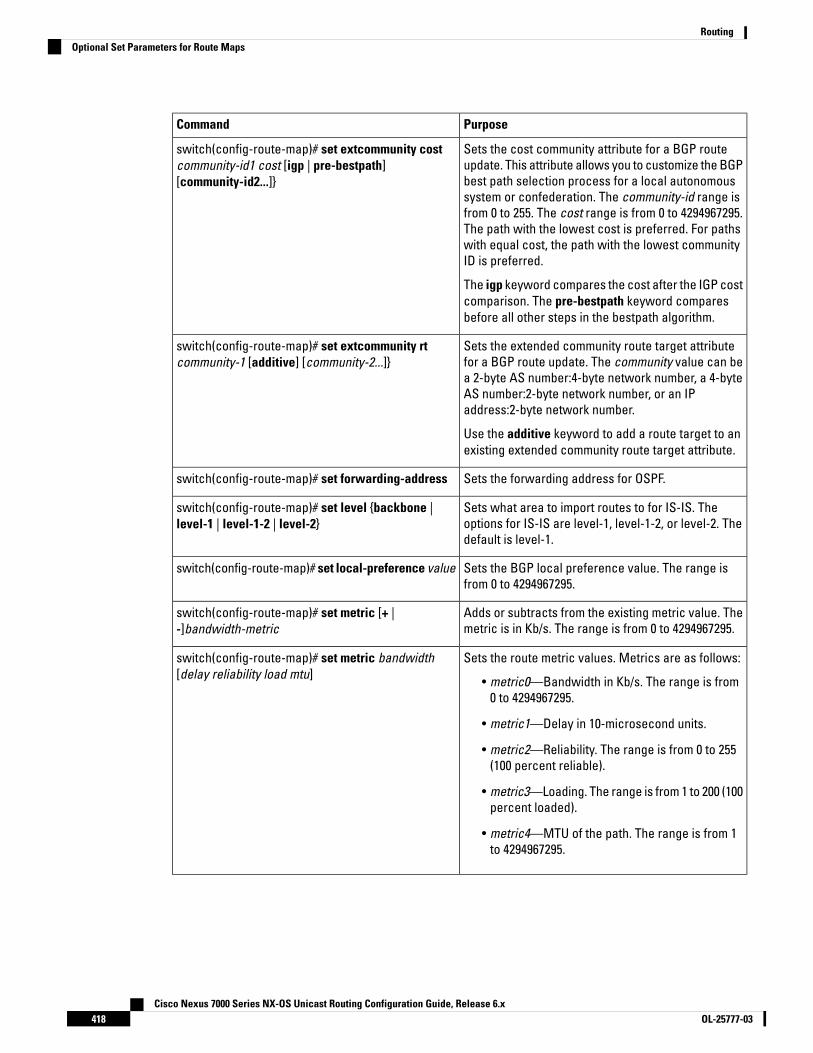
PurposeCommand
Sets the cost community attribute for a BGP routeupdate. This attribute allows you to customize the BGPbest path selection process for a local autonomoussystem or confederation. The community-id range isfrom 0 to 255. The cost range is from 0 to 4294967295.The path with the lowest cost is preferred. For pathswith equal cost, the path with the lowest communityID is preferred.
The igp keyword compares the cost after the IGP costcomparison. The pre-bestpath keyword comparesbefore all other steps in the bestpath algorithm.
switch(config-route-map)# set extcommunity costcommunity-id1 cost [igp | pre-bestpath][community-id2...]}
Sets the extended community route target attributefor a BGP route update. The community value can bea 2-byte AS number:4-byte network number, a 4-byteAS number:2-byte network number, or an IPaddress:2-byte network number.
Use the additive keyword to add a route target to anexisting extended community route target attribute.
switch(config-route-map)# set extcommunity rtcommunity-1 [additive] [community-2...]}
Sets the forwarding address for OSPF.switch(config-route-map)# set forwarding-address
Sets what area to import routes to for IS-IS. Theoptions for IS-IS are level-1, level-1-2, or level-2. Thedefault is level-1.
switch(config-route-map)# set level {backbone |level-1 | level-1-2 | level-2}
Sets the BGP local preference value. The range isfrom 0 to 4294967295.
switch(config-route-map)# set local-preference value
Adds or subtracts from the existing metric value. Themetric is in Kb/s. The range is from 0 to 4294967295.
switch(config-route-map)# set metric [+ |-]bandwidth-metric
Sets the route metric values. Metrics are as follows:
• metric0—Bandwidth in Kb/s. The range is from0 to 4294967295.
• metric1—Delay in 10-microsecond units.
• metric2—Reliability. The range is from 0 to 255(100 percent reliable).
• metric3—Loading. The range is from 1 to 200 (100percent loaded).
• metric4—MTU of the path. The range is from 1to 4294967295.
switch(config-route-map)# set metric bandwidth[delay reliability load mtu]
Cisco Nexus 7000 Series NX-OS Unicast Routing Configuration Guide, Release 6.xOL-25777-03418
RoutingOptional Set Parameters for Route Maps

PurposeCommand
Sets the metric type for the destination routingprotocol. The options are as follows:
• external—IS-IS external metric
• internal— IGP metric as the MED for BGP
• type-1—OSPF external type 1 metric
• type-2—OSPF external type 2 metric
The set metric-type internal command affects anoutgoing policy and an eBGP neighbor only. If youconfigure both the metric and metric-type internalcommands in the same BGP peer outgoing policy, thenCisco NX-OS ignores the metric-type internalcommand.
switch(config-route-map)# set metric-type {external| internal | type-1 | type-2}
Sets Type-7 LSA generated on ASBR with no P bit set.This prevents Type-7 to Type-5 LSA translation inOSPF.
switch(config-route-map)# set nssa-only
Sets the BGP origin attribute. The EGP as-numberrange is from 0 to 65535.
switch(config-route-map)# set origin {egp as-number| igp | incomplete}
Sets the tag value for the destination routing protocol.The name parameter is an unsigned integer.
switch(config-route-map)# set tag name
Sets the weight for the BGP route. The range is from0 to 65535.
switch(config-route-map)# set weight count
Verifying the Route Policy Manager ConfigurationUse one of the following commands to verify the configuration:
PurposeCommand
Displays information about a community list.show ip community-list [name]
Displays information about an extended communitylist.
show ip extcommunity-list [name]
Displays information about an IPv4 or IPv6 prefix list.show [ip | ipv6] prefix-list [name]
Displays information about a route map.show route-map [name]
Configuration Examples for Route Policy ManagerThis example shows how to use an address family to configure Route Policy Manager so that any unicast andmulticast routes from neighbor 209.0.2.1 are accepted if they match prefix-list AllowPrefix:
Cisco Nexus 7000 Series NX-OS Unicast Routing Configuration Guide, Release 6.x419OL-25777-03
RoutingVerifying the Route Policy Manager Configuration
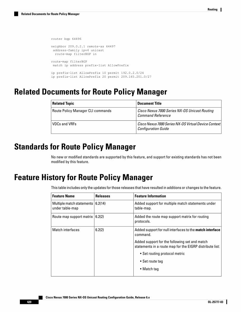
router bgp 64496
neighbor 209.0.2.1 remote-as 64497address-family ipv4 unicastroute-map filterBGP in
route-map filterBGPmatch ip address prefix-list AllowPrefix
ip prefix-list AllowPrefix 10 permit 192.0.2.0/24ip prefix-list AllowPrefix 20 permit 209.165.201.0/27
Related Documents for Route Policy ManagerDocument TitleRelated Topic
Cisco Nexus 7000 Series NX-OS Unicast RoutingCommand Reference
Route Policy Manager CLI commands
Cisco Nexus 7000 Series NX-OS Virtual Device ContextConfiguration Guide
VDCs and VRFs
Standards for Route Policy ManagerNo new or modified standards are supported by this feature, and support for existing standards has not beenmodified by this feature.
Feature History for Route Policy ManagerThis table includes only the updates for those releases that have resulted in additions or changes to the feature.
Feature InformationReleasesFeature Name
Added support for multiple match statements undertable-map.
6.2(14)Multiple match statementsunder table-map
Added the route map support matrix for routingprotocols.
6.2(2)Route map support matrix
Added support for null interfaces to the match interfacecommand.
Added support for the following set and matchstatements in a route map for the EIGRP distribute list:
• Set routing protocol metric
• Set route tag
• Match tag
6.2(2)Match interfaces
Cisco Nexus 7000 Series NX-OS Unicast Routing Configuration Guide, Release 6.xOL-25777-03420
RoutingRelated Documents for Route Policy Manager
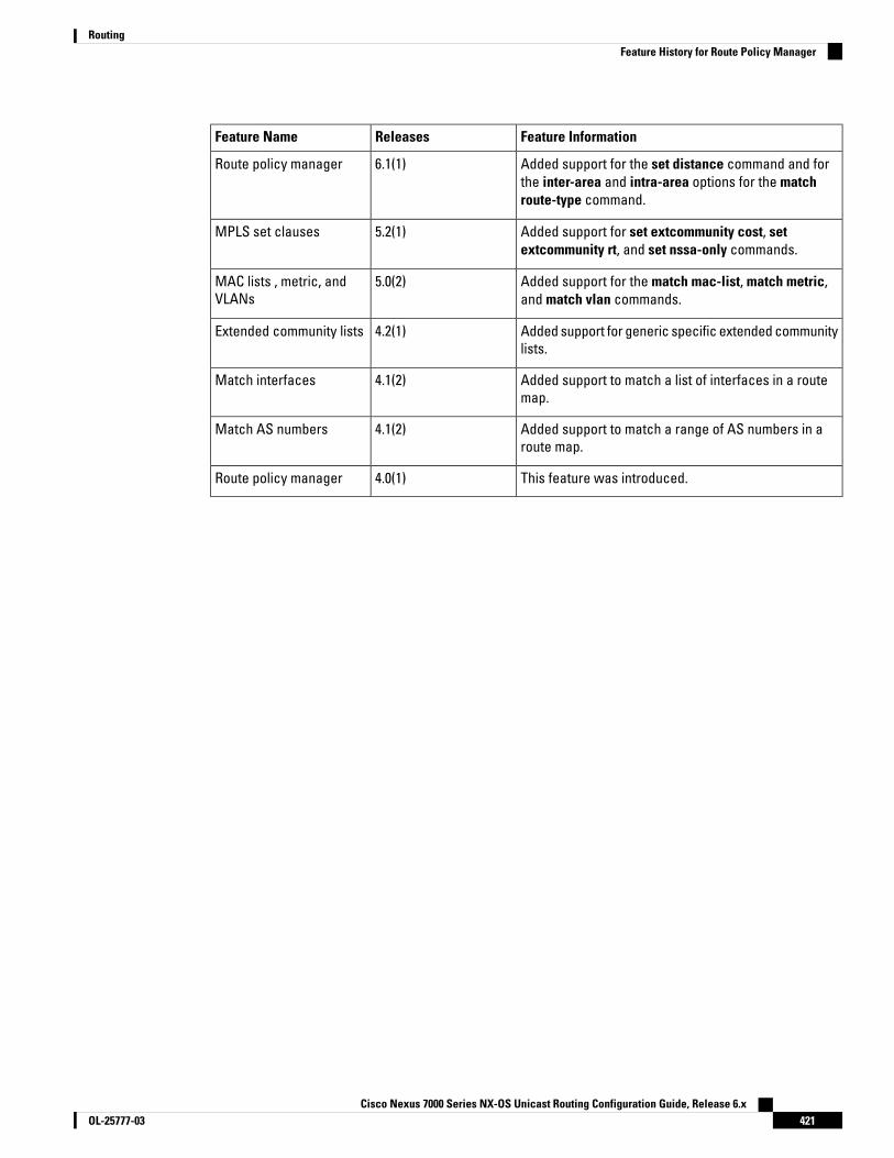
Feature InformationReleasesFeature Name
Added support for the set distance command and forthe inter-area and intra-area options for the matchroute-type command.
6.1(1)Route policy manager
Added support for set extcommunity cost, setextcommunity rt, and set nssa-only commands.
5.2(1)MPLS set clauses
Added support for the match mac-list, match metric,and match vlan commands.
5.0(2)MAC lists , metric, andVLANs
Added support for generic specific extended communitylists.
4.2(1)Extended community lists
Added support to match a list of interfaces in a routemap.
4.1(2)Match interfaces
Added support to match a range of AS numbers in aroute map.
4.1(2)Match AS numbers
This feature was introduced.4.0(1)Route policy manager
Cisco Nexus 7000 Series NX-OS Unicast Routing Configuration Guide, Release 6.x421OL-25777-03
RoutingFeature History for Route Policy Manager

Cisco Nexus 7000 Series NX-OS Unicast Routing Configuration Guide, Release 6.xOL-25777-03422
RoutingFeature History for Route Policy Manager

C H A P T E R 19Configuring Policy-Based Routing
This chapter contains the following sections:
• Finding Feature Information, on page 423• Information About Policy Based Routing, on page 423• Prerequisites for Policy-Based Routing, on page 426• Guidelines and Limitations for Policy-Based Routing, on page 426• Default Settings for Policy-Based Routing, on page 427• Configuring Policy-Based Routing, on page 428• Verifying the Policy-Based Routing Configuration, on page 433• Configuration Examples for Policy Based-Routing, on page 433• Related Documents for Policy-Based Routing, on page 434• Standards for Policy-Based Routing, on page 434• Feature History for Policy-Based Routing, on page 434
Finding Feature InformationYour software release might not support all the features documented in this module. For the latest caveatsand feature information, see the Bug Search Tool at https://tools.cisco.com/bugsearch/ and the release notesfor your software release. To find information about the features documented in this module, and to see a listof the releases in which each feature is supported, see the "New and Changed Information"chapter or theFeature History table in this chapter.
Information About Policy Based RoutingPolicy-based routing allows you to configure a defined policy for IPv4 and IPv6 traffic flows, lessening relianceon routes derived from routing protocols. All packets received on an interface with policy-based routingenabled are passed through enhanced packet filters or route maps. The route maps dictate the policy,determining where to forward packets.
Route maps are composed of match and set statements that you can mark as permit or deny. You can interpretthe statements as follows:
• If the packets match any route map statements, all the set statements are applied. One of these actionsinvolves choosing the next hop.
Cisco Nexus 7000 Series NX-OS Unicast Routing Configuration Guide, Release 6.x423OL-25777-03

• If a statement is marked as deny, the packets that meet the match criteria are sent back through thenormal forwarding channels and destination-based routing is performed.
• If the statement is marked as permit and the packets do not match any route-map statements, the packetsare sent back through the normal forwarding channels and destination-based routing is performed.
Policy-based routing includes the following features:
• Source-based routing—Routes traffic that originates from different sets of users through differentconnections across the policy routers.
• Quality of Service (QoS)—Differentiates traffic by setting the precedence or type of service (ToS) valuesin the IP packet headers at the periphery of the network and leveraging queuing mechanisms to prioritizetraffic in the core or backbone of the network (see the Cisco Nexus 7000 Series NX-OS Quality of ServiceConfiguration Guide).
• Load sharing—Distributes traffic among multiple paths based on the traffic characteristics.
Policy Route MapsEach entry in a route map contains a combination of match and set statements. The match statements definethe criteria for whether appropriate packets meet the particular policy (that is, the conditions to be met). Theset clauses explain how the packets should be routed once they have met the match criteria.
You can mark the route-map statements as permit or deny. If the statement is marked as a deny, the packetsthat meet the match criteria are sent back through the normal forwarding channels (destination-based routingis performed). If the statement is marked as permit and the packets meet the match criteria, all the set clausesare applied. If the statement is marked as permit and the packets do not meet the match criteria, those packetsare also forwarded through the normal routing channel.
Policy routing is specified on the interface that receives the packets, not on the interface from which thepackets are sent.
Note
Set Criteria for Policy-Based RoutingThe set criteria in a route map is evaluated in the order listed in the route map. Set criteria specific to routemaps used for policy-based routing are as follows:
1. List of interfaces through which the packets can be routed—If more than one interface is specified, thefirst interface that is found to be up is used for forwarding the packets.
2. List of specified IP addresses—The IP address can specify the adjacent next-hop router in the path towardthe destination to which the packets should be forwarded. The first IP address associated with a currentlyup connected interface is used to route the packets.
You can optionally configure the set criteria for next-hop addresses to load balance traffic across up to 16 IPaddresses. In this case, Cisco NX-OS sends all traffic for each IP flow to a particular IP next-hop address.
Note
Cisco Nexus 7000 Series NX-OS Unicast Routing Configuration Guide, Release 6.xOL-25777-03424
RoutingPolicy Route Maps

3. List of default interfaces—If there is no explicit route available to the destination address of the packetbeing considered for policy routing, the route map routes it to the first up interface in the list of specifieddefault interfaces.
4. List of default next-hop IP addresses—Route to the interface or the next-hop address specified by thisset statement only if there is no explicit route for the destination address of the packet in the routing table.
You can optionally configure the set criteria for the default next-hop addresses to load balance traffic acrossa maximum of 16 IP addresses. In this case, Cisco NX-OS sends all traffic for each IP flow to a particular IPnext-hop address.
Note
If the packets do not meet any of the defined match criteria, those packets are routed through the normaldestination-based routing process.
Local Policy RoutingLocal policy routing allows you to apply a route map to local (device-generated) traffic. All packets originatingon the device that are not normally policy routed are subject to local policy routing.
Route Map Support Matrix for Policy-Based RoutingThe following tables include the configurable match and set statements for policy-based routing on CiscoNexus 70xx and 77xx Series switches running the latest shipping release. For specific release information,see the Feature History for Policy-Based Routing, on page 434.
The following legend applies to the tables:
• Yes—The statement is supported for policy-based routing.
• No—The statement is not supported for policy-based routing.
• If a statement does not apply for policy-based routing, there is an em dash (—) in the column next to thestatement.
• Where clarification is required, information is added in the appropriate row/column.
Table 37: SET Route Map Statements for Policy-Based Routing
Policy-Based Routing (PBR)SET Route Map Statement
YesIPv4 Next Hop
YesIPv6 Next Hop
YesDefault IPv4 Next Hop
YesDefault IPv6 Next Hop
YesIPv4 Next Hop Verify Availability
YesIPv6 Next Hop Verify Availability
Cisco Nexus 7000 Series NX-OS Unicast Routing Configuration Guide, Release 6.x425OL-25777-03
RoutingLocal Policy Routing

Policy-Based Routing (PBR)SET Route Map Statement
YesDefault IPv4 Next Hop Verify Availability
YesDefault IPv6 Next Hop Verify Availability
YesInterface null0
YesVRF
YesIPv4 Precedence
YesIPv6 Precedence
NoInterface, GRE Ethernet
Table 38: MATCH Route Map Statements for Policy-Based Routing
Policy-Based Routing (PBR)MATCH Route Map Statement
YesTag
YesPacket Length
YesVLAN ID
YesMAC ACL
NoIPv4 Prefix List
NoIPv6 Prefix List
YesIP ACL
Prerequisites for Policy-Based RoutingPolicy-based routing has the following prerequisites:
• Install the correct license.
• You must enable policy-based routing.
• Assign an IP address on the interface and bring the interface up before you apply a route map on theinterface for policy-based routing.
• If you configure VDCs, install the Advanced Services license and enter the desired VDC (see the CiscoNexus 7000 Series NX-OS Virtual Device Context Configuration Guide).
Guidelines and Limitations for Policy-Based RoutingPolicy-based routing has the following configuration guidelines and limitations:
Cisco Nexus 7000 Series NX-OS Unicast Routing Configuration Guide, Release 6.xOL-25777-03426
RoutingPrerequisites for Policy-Based Routing
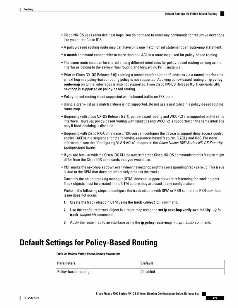
• Cisco NX-OS uses recursive next hops. You do not need to enter any commands for recursive next hopslike you do for Cisco IOS.
• A policy-based routing route map can have only one match or set statement per route-map statement.
• A match command cannot refer to more than one ACL in a route map used for policy-based routing.
• The same route map can be shared among different interfaces for policy-based routing as long as theinterfaces belong to the same virtual routing and forwarding (VRF) instance.
• Prior to Cisco NX-OS Release 8.0(1) setting a tunnel interface or an IP address via a tunnel interface asa next hop in a policy-based routing policy is not supported. Applying policy-based routing or ip policyroute-map on tunnel interfaces is also not supported. From Cisco NX-OS Release 8.0(1) onwards GREnext hop is supported on policy-based routing.
• Policy-based routing is not supported with inbound traffic on FEX ports.
• Using a prefix-list as a match criteria is not supported. Do not use a prefix-list in a policy-based routingroute-map.
• Beginning with Cisco NX-OS Release 5.2(4), policy-based routing and WCCPv2 are supported on the sameinterface. However, policy-based routing with statistics and WCCPv2 is supported on the same interfaceonly if bank chaining is disabled.
• Beginning with Cisco NX-OS Release 6.1(3), you can configure the device to support deny access controlentries (ACEs) in a sequence for the following sequence-based features: VACLs and QoS. For moreinformation, see the “Configuring VLAN ACLs” chapter in the Cisco Nexus 7000 Series NX-OS SecurityConfiguration Guide.
• If you are familiar with the Cisco IOS CLI, be aware that the Cisco NX-OS commands for this feature mightdiffer from the Cisco IOS commands that you would use.
• PBR marks the next-hop as down even when the next hop and the corresponding tracks are up. This issueis due to the RPM that does not effectively process the tracks.
Currently the object tracking manager (OTM) does not support forward referencing for track objects.Track objects must be created in the OTM before they are used in any configuration.
Perform the following steps to configure the track objects with RPM or PBR so that the PBR next-hopissue does not occur:
1. Create the track object in OTM using the track <object id> command.
2. Use the configured track object in a route map using the set ip next-hop verify-availability <ip1>track <object id> command.
3. Apply the route map to an interface using the ip policy route-map <map-name> command.
Default Settings for Policy-Based RoutingTable 39: Default Policy-Based Routing Parameters
DefaultParameters
DisabledPolicy-based routing
Cisco Nexus 7000 Series NX-OS Unicast Routing Configuration Guide, Release 6.x427OL-25777-03
RoutingDefault Settings for Policy-Based Routing
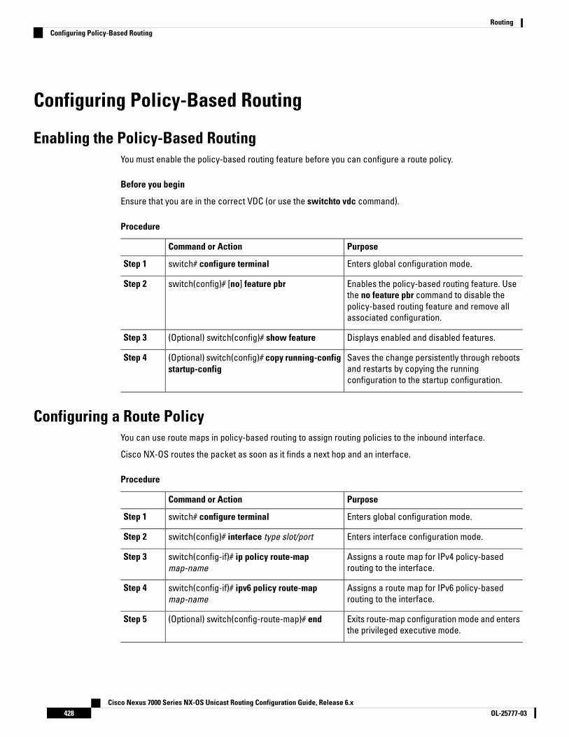
Configuring Policy-Based Routing
Enabling the Policy-Based RoutingYou must enable the policy-based routing feature before you can configure a route policy.
Before you begin
Ensure that you are in the correct VDC (or use the switchto vdc command).
Procedure
PurposeCommand or Action
Enters global configuration mode.switch# configure terminalStep 1
Enables the policy-based routing feature. Usethe no feature pbr command to disable the
switch(config)# [no] feature pbrStep 2
policy-based routing feature and remove allassociated configuration.
Displays enabled and disabled features.(Optional) switch(config)# show featureStep 3
Saves the change persistently through rebootsand restarts by copying the runningconfiguration to the startup configuration.
(Optional) switch(config)# copy running-configstartup-config
Step 4
Configuring a Route PolicyYou can use route maps in policy-based routing to assign routing policies to the inbound interface.
Cisco NX-OS routes the packet as soon as it finds a next hop and an interface.
Procedure
PurposeCommand or Action
Enters global configuration mode.switch# configure terminalStep 1
Enters interface configuration mode.switch(config)# interface type slot/portStep 2
Assigns a route map for IPv4 policy-basedrouting to the interface.
switch(config-if)# ip policy route-mapmap-name
Step 3
Assigns a route map for IPv6 policy-basedrouting to the interface.
switch(config-if)# ipv6 policy route-mapmap-name
Step 4
Exits route-map configuration mode and entersthe privileged executive mode.
(Optional) switch(config-route-map)# endStep 5
Cisco Nexus 7000 Series NX-OS Unicast Routing Configuration Guide, Release 6.xOL-25777-03428
RoutingConfiguring Policy-Based Routing
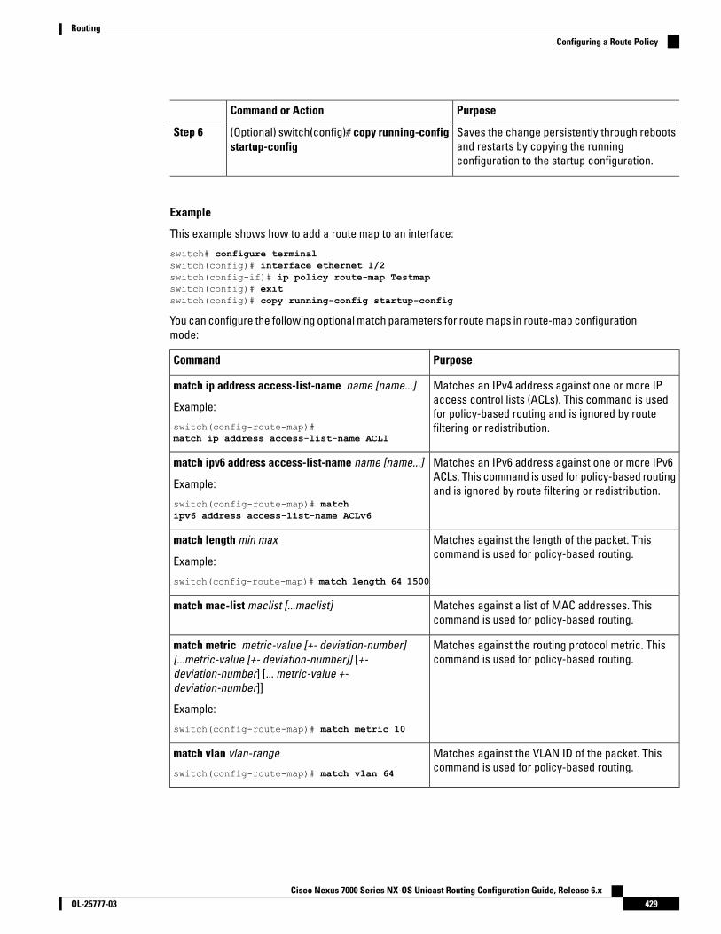
PurposeCommand or Action
Saves the change persistently through rebootsand restarts by copying the runningconfiguration to the startup configuration.
(Optional) switch(config)# copy running-configstartup-config
Step 6
Example
This example shows how to add a route map to an interface:
switch# configure terminalswitch(config)# interface ethernet 1/2switch(config-if)# ip policy route-map Testmapswitch(config)# exitswitch(config)# copy running-config startup-config
You can configure the following optional match parameters for route maps in route-map configurationmode:
PurposeCommand
Matches an IPv4 address against one or more IPaccess control lists (ACLs). This command is usedfor policy-based routing and is ignored by routefiltering or redistribution.
match ip address access-list-name name [name...]
Example:
switch(config-route-map)#match ip address access-list-name ACL1
Matches an IPv6 address against one or more IPv6ACLs. This command is used for policy-based routingand is ignored by route filtering or redistribution.
match ipv6 address access-list-name name [name...]
Example:
switch(config-route-map)# matchipv6 address access-list-name ACLv6
Matches against the length of the packet. Thiscommand is used for policy-based routing.
match length min max
Example:
switch(config-route-map)# match length 64 1500
Matches against a list of MAC addresses. Thiscommand is used for policy-based routing.
match mac-list maclist [...maclist]
Matches against the routing protocol metric. Thiscommand is used for policy-based routing.
match metric metric-value [+- deviation-number][...metric-value [+- deviation-number]] [+-deviation-number] [... metric-value +-deviation-number]]
Example:
switch(config-route-map)# match metric 10
Matches against the VLAN ID of the packet. Thiscommand is used for policy-based routing.
match vlan vlan-range
switch(config-route-map)# match vlan 64
Cisco Nexus 7000 Series NX-OS Unicast Routing Configuration Guide, Release 6.x429OL-25777-03
RoutingConfiguring a Route Policy
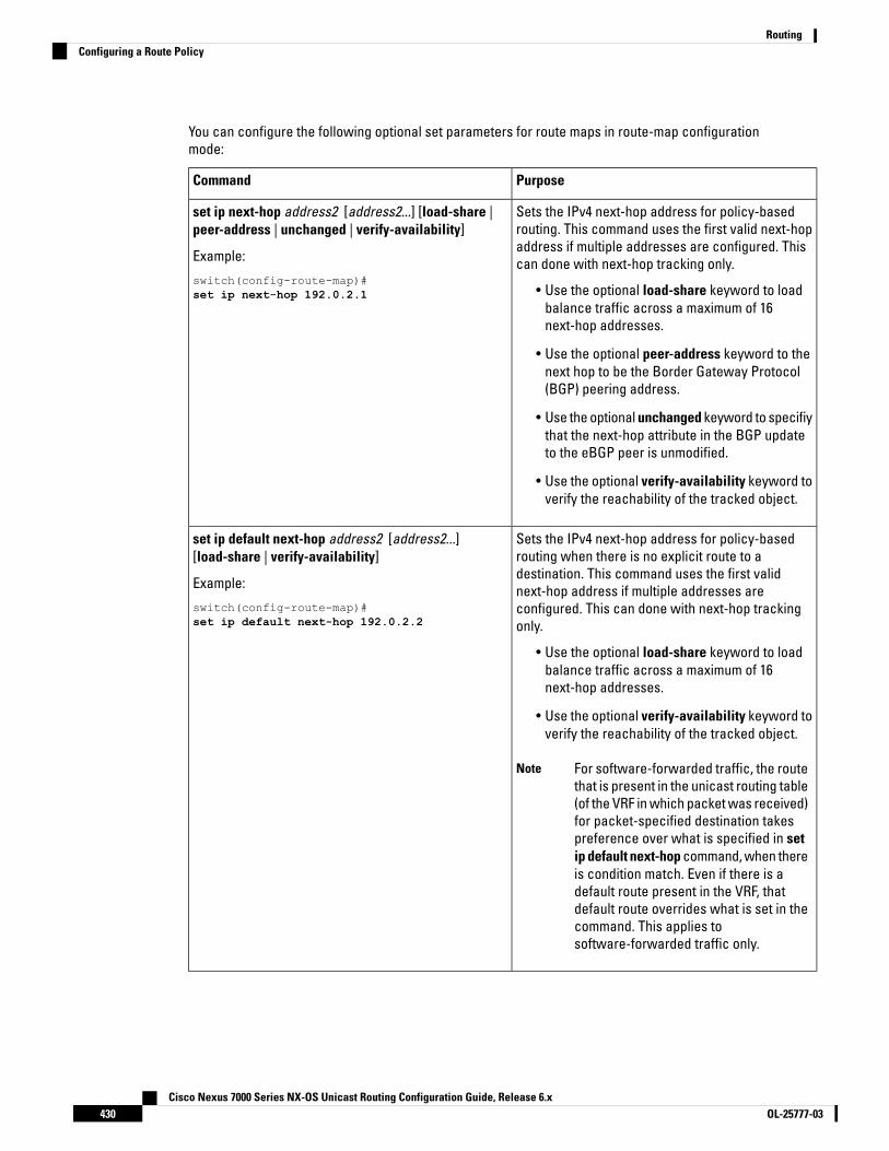
You can configure the following optional set parameters for route maps in route-map configurationmode:
PurposeCommand
Sets the IPv4 next-hop address for policy-basedrouting. This command uses the first valid next-hopaddress if multiple addresses are configured. Thiscan done with next-hop tracking only.
• Use the optional load-share keyword to loadbalance traffic across a maximum of 16next-hop addresses.
• Use the optional peer-address keyword to thenext hop to be the Border Gateway Protocol(BGP) peering address.
• Use the optional unchanged keyword to specifiythat the next-hop attribute in the BGP updateto the eBGP peer is unmodified.
• Use the optional verify-availability keyword toverify the reachability of the tracked object.
set ip next-hop address2 [address2...] [load-share |peer-address | unchanged | verify-availability]
Example:
switch(config-route-map)#set ip next-hop 192.0.2.1
Sets the IPv4 next-hop address for policy-basedrouting when there is no explicit route to adestination. This command uses the first validnext-hop address if multiple addresses areconfigured. This can done with next-hop trackingonly.
• Use the optional load-share keyword to loadbalance traffic across a maximum of 16next-hop addresses.
• Use the optional verify-availability keyword toverify the reachability of the tracked object.
For software-forwarded traffic, the routethat is present in the unicast routing table(of the VRF in which packet was received)for packet-specified destination takespreference over what is specified in setip default next-hop command, when thereis condition match. Even if there is adefault route present in the VRF, thatdefault route overrides what is set in thecommand. This applies tosoftware-forwarded traffic only.
Note
set ip default next-hop address2 [address2...][load-share | verify-availability]
Example:
switch(config-route-map)#set ip default next-hop 192.0.2.2
Cisco Nexus 7000 Series NX-OS Unicast Routing Configuration Guide, Release 6.xOL-25777-03430
RoutingConfiguring a Route Policy
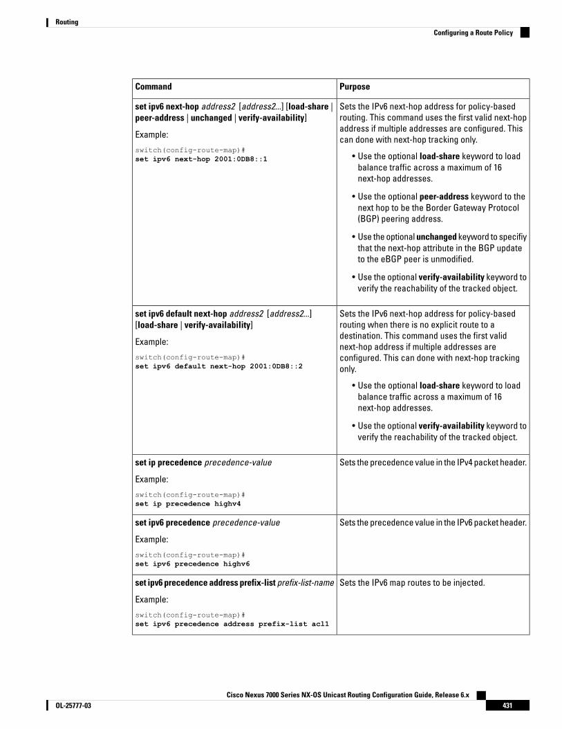
PurposeCommand
Sets the IPv6 next-hop address for policy-basedrouting. This command uses the first valid next-hopaddress if multiple addresses are configured. Thiscan done with next-hop tracking only.
• Use the optional load-share keyword to loadbalance traffic across a maximum of 16next-hop addresses.
• Use the optional peer-address keyword to thenext hop to be the Border Gateway Protocol(BGP) peering address.
• Use the optional unchanged keyword to specifiythat the next-hop attribute in the BGP updateto the eBGP peer is unmodified.
• Use the optional verify-availability keyword toverify the reachability of the tracked object.
set ipv6 next-hop address2 [address2...] [load-share |peer-address | unchanged | verify-availability]
Example:
switch(config-route-map)#set ipv6 next-hop 2001:0DB8::1
Sets the IPv6 next-hop address for policy-basedrouting when there is no explicit route to adestination. This command uses the first validnext-hop address if multiple addresses areconfigured. This can done with next-hop trackingonly.
• Use the optional load-share keyword to loadbalance traffic across a maximum of 16next-hop addresses.
• Use the optional verify-availability keyword toverify the reachability of the tracked object.
set ipv6 default next-hop address2 [address2...][load-share | verify-availability]
Example:
switch(config-route-map)#set ipv6 default next-hop 2001:0DB8::2
Sets the precedence value in the IPv4 packet header.set ip precedence precedence-value
Example:
switch(config-route-map)#set ip precedence highv4
Sets the precedence value in the IPv6 packet header.set ipv6 precedence precedence-value
Example:
switch(config-route-map)#set ipv6 precedence highv6
Sets the IPv6 map routes to be injected.set ipv6 precedence address prefix-list prefix-list-name
Example:
switch(config-route-map)#set ipv6 precedence address prefix-list acl1
Cisco Nexus 7000 Series NX-OS Unicast Routing Configuration Guide, Release 6.x431OL-25777-03
RoutingConfiguring a Route Policy

PurposeCommand
Sets the interface used for routing. Use the null0interface to drop packets. Use the tunnel-te interfaceto forward packets on the MPLS TE tunnel.
set interface {null10 | tunnel-te}
Example:
switch(config-route-map)#set interface null0
Sets the VRF for next-hop resolution.set vrf vrf-name
Example:
switch(config-route-map)#set vrf MainVRF
Configuring Local Policy RoutingYou can enable local policy routing for packets generated by the device and specify which route map thedevice should use.
Procedure
PurposeCommand or Action
Enters global configuration mode.switch# configure terminalStep 1
Configures IPv4 or IPv6 local policy route mapsfor packets generated by the device.
switch(config)# {ip | ipv6} local policy route-mapmap-name
Step 2
Displays the route map used for IPv4 or IPv6local policy routing.
(Optional) show {ip | ipv6} local policyStep 3
Saves the change persistently through rebootsand restarts by copying the runningconfiguration to the startup configuration.
(Optional) switch(config)# copy running-configstartup-config
Step 4
Configuring a Deny ACEBeginning with Cisco NX-OS Release 6.1(3), you can configure the device to support deny access controlentries (ACEs) in a sequence for the following sequence-based features: VACL and Quality of service (QoS).
When deny ACEs are enabled, the traffic that matches a deny ACE (an ACL rule with the deny keyword) in aclass-map-acl is recursively matched against subsequent class-map-acls until it hits a permit ACE.
In earlier releases, an ACL used in a policy-based routing route map cannot include a deny statement.Note
Before you begin
Ensure that you are in the default or admin VDC.
Cisco Nexus 7000 Series NX-OS Unicast Routing Configuration Guide, Release 6.xOL-25777-03432
RoutingConfiguring Local Policy Routing

Procedure
PurposeCommand or Action
Enters global configuration mode.switch# configure terminalStep 1
Enables deny ACEs in a sequence.switch(config)# [no] hardware access-list allowdeny ace
Step 2
The no form of the command disables denyACEs.
Displays the ACL configuration.(Optional) show running-config aclmgrStep 3
Saves the change persistently through rebootsand restarts by copying the runningconfiguration to the startup configuration.
(Optional) switch(config)# copy running-configstartup-config
Step 4
Verifying the Policy-Based Routing ConfigurationTo display policy-based routing configuration information, perform one of the following tasks:
PurposeCommand
Displays information about an IPv4 or IPv6 policy.show [ip | ipv6] policy [name]
Displays the route map used for IPv4 or IPv6 localpolicy routing.
show {ip | ipv6} local policy [vrf name]
Displays policy statistics.show route-map [name] pbr-statistics
Use the route-map map-name pbr-statistics to enable policy statistics. Use the clear route-map map-namepbr-statistics to clear these policy statistics.
Configuration Examples for Policy Based-RoutingThis example shows how to configure a simple route policy on an interface:
feature pbrip access-list pbr-samplepermit tcp host 10.1.1.1 host 192.168.2.1 eq 80
!route-map pbr-samplematch ip address pbr-sampleset ip next-hop 192.168.1.1!route-map pbr-sample pbr-statistics
interface ethernet 1/2ip policy route-map pbr-sample
The following output verifies this configuration:
n7000# show route-map pbr-sample
route-map pbr-sample, permit, sequence 10
Cisco Nexus 7000 Series NX-OS Unicast Routing Configuration Guide, Release 6.x433OL-25777-03
RoutingVerifying the Policy-Based Routing Configuration
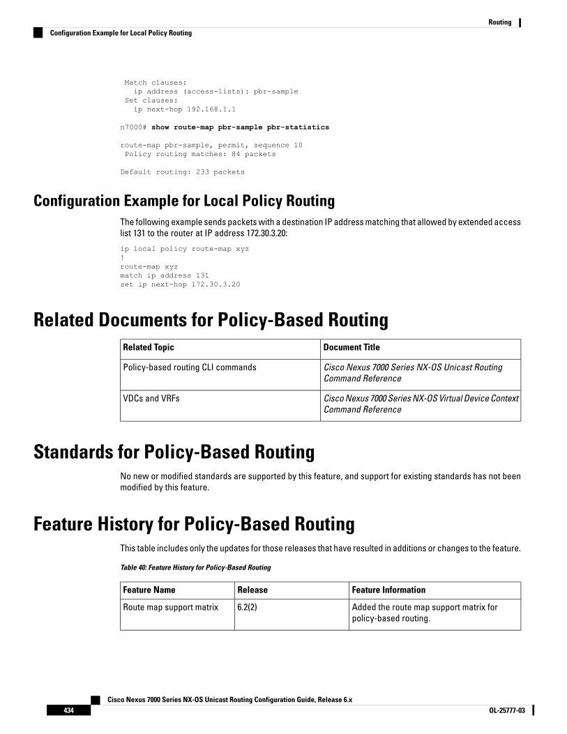
Match clauses:ip address (access-lists): pbr-sample
Set clauses:ip next-hop 192.168.1.1
n7000# show route-map pbr-sample pbr-statistics
route-map pbr-sample, permit, sequence 10Policy routing matches: 84 packets
Default routing: 233 packets
Configuration Example for Local Policy RoutingThe following example sends packets with a destination IP address matching that allowed by extended accesslist 131 to the router at IP address 172.30.3.20:
ip local policy route-map xyz!route-map xyzmatch ip address 131set ip next-hop 172.30.3.20
Related Documents for Policy-Based RoutingDocument TitleRelated Topic
Cisco Nexus 7000 Series NX-OS Unicast RoutingCommand Reference
Policy-based routing CLI commands
Cisco Nexus 7000 Series NX-OS Virtual Device ContextCommand Reference
VDCs and VRFs
Standards for Policy-Based RoutingNo new or modified standards are supported by this feature, and support for existing standards has not beenmodified by this feature.
Feature History for Policy-Based RoutingThis table includes only the updates for those releases that have resulted in additions or changes to the feature.
Table 40: Feature History for Policy-Based Routing
Feature InformationReleaseFeature Name
Added the route map support matrix forpolicy-based routing.
6.2(2)Route map support matrix
Cisco Nexus 7000 Series NX-OS Unicast Routing Configuration Guide, Release 6.xOL-25777-03434
RoutingConfiguration Example for Local Policy Routing
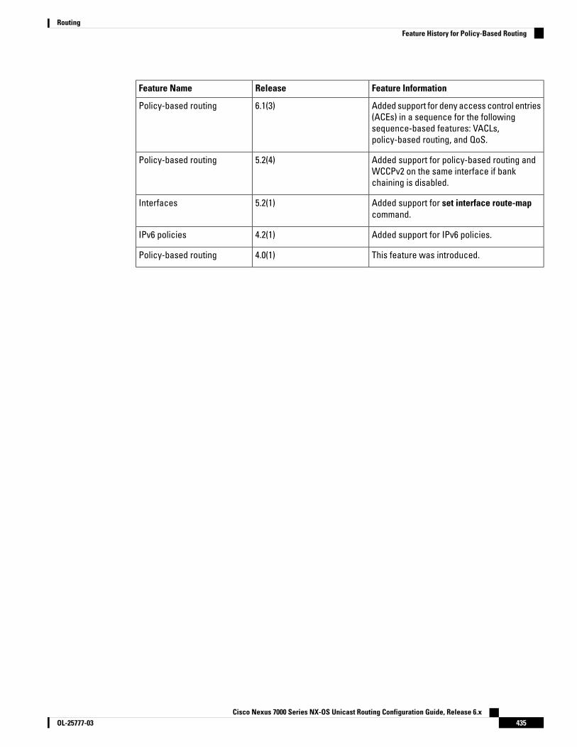
Feature InformationReleaseFeature Name
Added support for deny access control entries(ACEs) in a sequence for the followingsequence-based features: VACLs,policy-based routing, and QoS.
6.1(3)Policy-based routing
Added support for policy-based routing andWCCPv2 on the same interface if bankchaining is disabled.
5.2(4)Policy-based routing
Added support for set interface route-mapcommand.
5.2(1)Interfaces
Added support for IPv6 policies.4.2(1)IPv6 policies
This feature was introduced.4.0(1)Policy-based routing
Cisco Nexus 7000 Series NX-OS Unicast Routing Configuration Guide, Release 6.x435OL-25777-03
RoutingFeature History for Policy-Based Routing

Cisco Nexus 7000 Series NX-OS Unicast Routing Configuration Guide, Release 6.xOL-25777-03436
RoutingFeature History for Policy-Based Routing

P A R T IIIFirst-Hop Redundancy Protocols
• Configuring GLBP, on page 439• Configuring HSRP, on page 455• Configuring VRRP, on page 485• Configuring Object Tracking, on page 509

C H A P T E R 20Configuring GLBP
This chapter contains the following sections:
• Finding Feature Information, on page 439• Information About GLBP, on page 439• Prerequisites for GLBP, on page 444• Guidelines and Limitations for GLBP, on page 444• Default Settings for GLBP, on page 444• Configuring GLBP, on page 445• Verifying the GLBP Configuration, on page 452• Configuration Examples for GLBP, on page 453• Related Documents for GLBP, on page 453• Standards for GLBP, on page 453• Feature History for GLBP, on page 453
Finding Feature InformationYour software release might not support all the features documented in this module. For the latest caveatsand feature information, see the Bug Search Tool at https://tools.cisco.com/bugsearch/ and the release notesfor your software release. To find information about the features documented in this module, and to see a listof the releases in which each feature is supported, see the "New and Changed Information"chapter or theFeature History table in this chapter.
Information About GLBPGateway Load Balancing Protocol (GLBP) provides path redundancy for IP by sharing protocol and MediaAccess Control (MAC) addresses between redundant gateways. Additionally, GLBP allows a group of Layer3 routers to share the load of the default gateway on a LAN. A GLBP router can automatically assume theforwarding function of another router in the group if the other router fails.
GLBP provides automatic gateway backup for IP hosts configured with a single default gateway on an IEEE802.3 LAN. Multiple routers on the LAN combine to offer a single virtual first-hop IP gateway while sharing theIP packet forwarding load. Other routers on the LAN might act as redundant GLBP gateways that becomeactive if any of the existing forwarding gateways fail.
Cisco Nexus 7000 Series NX-OS Unicast Routing Configuration Guide, Release 6.x439OL-25777-03
GLBP performs a similar function to the Hot Standby Redundancy Protocol (HSRP) and the Virtual RouterRedundancy Protocol (VRRP). HSRP and VRRP allow multiple routers to participate in a virtual group configuredwith a virtual IP address. These protocols elect one member as the active router to forward packets to thevirtual IP address for the group. The other routers in the group are redundant until the active router fails.
GLBP performs an additional load balancing function that the other protocols do not provide. GLBP loadbalances over multiple routers (gateways) using a single virtual IP address and multiple virtual MAC addresses.GLBP shares the forwarding load among all routers in a GLBP group instead of allowing a single router tohandle the whole load while the other routers remain idle. You configure each host with the same virtual IPaddress, and all routers in the virtual group participate in forwarding packets. GLBP members communicatebetween each other using periodic hello messages.
GLBP Active Virtual GatewayGLBP prioritizes gateways to elect an active virtual gateway (AVG). If multiple gateways have the same priority,the gateway with the highest real IP address becomes the AVG. The AVG assigns a virtual MAC address toeach member of the GLBP group. Each member is the active virtual forwarder (AVF) for its assigned virtualMAC address, forwarding packets sent to its assigned virtual MAC address.
The AVG also answers Address Resolution Protocol (ARP) requests for the virtual IP address. Load sharing isachieved when the AVG replies to the ARP requests with different virtual MAC addresses.
Packets received on a routed port destined for the GLBP virtual IP address terminate on the local router,regardless of whether that router is the active GLBP router or a redundant GLBP router. This terminationincludes ping and Telnet traffic. Packets received on a Layer 2 (VLAN) interface destined for the GLBP virtualIP address terminate on the active router.
Note
GLBP Virtual MAC Address AssignmentThe AVG assigns the virtual MAC addresses to each member of the group. The group members request avirtual MAC address after they discover the AVG through hello messages. The AVG assigns the next MACaddress based on the load-balancing algorithm selected. A gateway that is assigned with a virtual MAC addressby the AVG is the primary virtual forwarder. The other members of the GLBP group that learn the virtual MACaddresses from hello messages are secondary virtual forwarders.
GLBP Virtual Gateway RedundancyGLBP provides virtual gateway redundancy. A member in a group can be in the active, standby, or listen state.GLBP uses a priority algorithm to elect one gateway as the AVG and elect another gateway as the standbyvirtual gateway. The remaining gateways go into the listen state. You can configure the GLBP priority on eachgateway. If the GLBP priority is identical on multiple gateways, GLBP uses the gateway with the highest IPaddress as the AVG.
If an AVG fails, the standby virtual gateway assumes responsibility for the virtual IP address. GLBP elects anew standby virtual gateway from the gateways in the listen state.
Cisco Nexus 7000 Series NX-OS Unicast Routing Configuration Guide, Release 6.xOL-25777-03440
First-Hop Redundancy ProtocolsGLBP Active Virtual Gateway
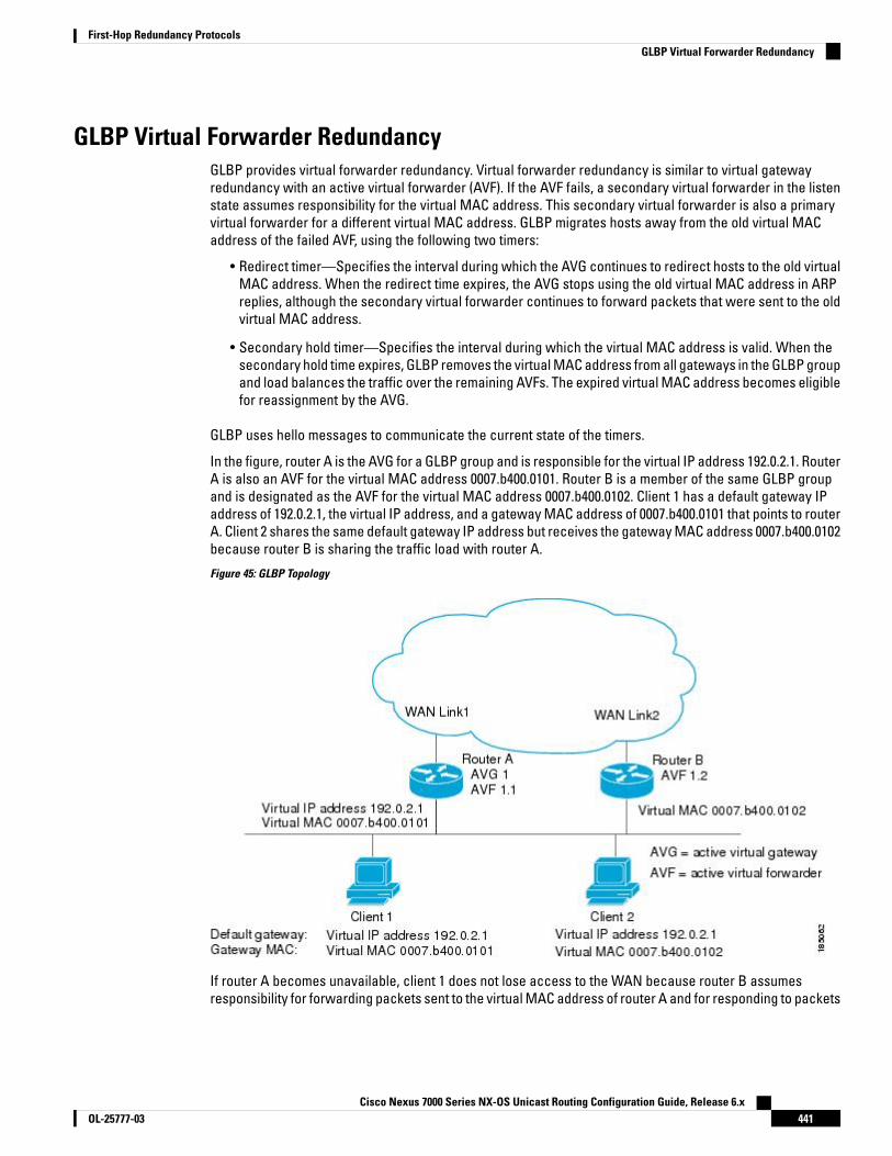
GLBP Virtual Forwarder RedundancyGLBP provides virtual forwarder redundancy. Virtual forwarder redundancy is similar to virtual gatewayredundancy with an active virtual forwarder (AVF). If the AVF fails, a secondary virtual forwarder in the listenstate assumes responsibility for the virtual MAC address. This secondary virtual forwarder is also a primaryvirtual forwarder for a different virtual MAC address. GLBP migrates hosts away from the old virtual MACaddress of the failed AVF, using the following two timers:
• Redirect timer—Specifies the interval during which the AVG continues to redirect hosts to the old virtualMAC address. When the redirect time expires, the AVG stops using the old virtual MAC address in ARPreplies, although the secondary virtual forwarder continues to forward packets that were sent to the oldvirtual MAC address.
• Secondary hold timer—Specifies the interval during which the virtual MAC address is valid. When thesecondary hold time expires, GLBP removes the virtual MAC address from all gateways in the GLBP groupand load balances the traffic over the remaining AVFs. The expired virtual MAC address becomes eligiblefor reassignment by the AVG.
GLBP uses hello messages to communicate the current state of the timers.
In the figure, router A is the AVG for a GLBP group and is responsible for the virtual IP address 192.0.2.1. RouterA is also an AVF for the virtual MAC address 0007.b400.0101. Router B is a member of the same GLBP groupand is designated as the AVF for the virtual MAC address 0007.b400.0102. Client 1 has a default gateway IPaddress of 192.0.2.1, the virtual IP address, and a gateway MAC address of 0007.b400.0101 that points to routerA. Client 2 shares the same default gateway IP address but receives the gateway MAC address 0007.b400.0102because router B is sharing the traffic load with router A.
Figure 45: GLBP Topology
If router A becomes unavailable, client 1 does not lose access to the WAN because router B assumesresponsibility for forwarding packets sent to the virtual MAC address of router A and for responding to packets
Cisco Nexus 7000 Series NX-OS Unicast Routing Configuration Guide, Release 6.x441OL-25777-03
First-Hop Redundancy ProtocolsGLBP Virtual Forwarder Redundancy

sent to its own virtual MAC address. Router B also assumes the role of the AVG for the entire GLBP group.Communication for the GLBP members continues despite the failure of a router in the GLBP group.
GLBP AuthenticationGLBP has three authentication types:
• MD5 authentication
• Plain text authentication
• No authentication
MD5 authentication provides greater security than plain text authentication. MD5 authentication allows eachGLBP group member to use a secret key to generate a keyed MD5 hash that is part of the outgoing packet. Atthe receiving end, a keyed hash of an incoming packet is generated. If the hash within the incoming packetdoes not match the generated hash, the packet is ignored. The key for the MD5 hash can either be givendirectly in the configuration using a key string or supplied indirectly through a key chain.
You can also choose to use a simple password in plain text to authenticate GLBP packets, or choose noauthentication for GLBP.
GLBP rejects packets in any of the following cases:
• The authentication schemes differ on the router and in the incoming packet.
• MD5 digests differ on the router and in the incoming packet.
• Text authentication strings differ on the router and in the incoming packet.
GLBP Load Balancing and TrackingYou can configure the following load-balancing methods for GLBP:
• Round-robin—GLBP cycles through the virtual MAC addresses sent in ARP replies, load balancing thetraffic across all the AVFs.
• Weighted—AVG uses the advertised weight for an AVF to decide the load directed to the AVF. A higherweight means that the AVG directs more traffic to the AVF.
• Host dependent—GLBP uses the MAC address of the host to determine which virtual MAC address todirect the host to use. This algorithm guarantees that a host gets the same virtual MAC address if thenumber of virtual forwarders does not change.
The default for IPv4 networks is round-robin. You can disable all load balancing for GLBP on an interface. Ifyou do not configure load balancing, the AVG handles all traffic for the hosts while the other GLBP groupmembers are in standby or listen mode.
You can configure GLBP to track an interface or routes and enable the secondary virtual forwarder to takeover if a tracked link goes down. GLBP tracking uses weighted load-balancing to determine whether a GLBPgroup member acts as an AVF. You must configure the initial weighting values and optional thresholds toenable or disable this group member as an AVF. You can also configure the interface to track and the valuethat reduces the interface’s weighting if the interface goes down. When the GLBP group weighting dropsbelow the lower threshold, the member is no longer an AVF and a secondary virtual forwarder takes over.When the weighting rises above the upper threshold, the member can resume its role as an AVF.
Cisco Nexus 7000 Series NX-OS Unicast Routing Configuration Guide, Release 6.xOL-25777-03442
First-Hop Redundancy ProtocolsGLBP Authentication

Figure 46: GLBP Object Tracking and Weighting
In the figure, the Ethernet 1/2 interface on router 1 is the gateway for host 1 (the AVF for virtual MAC address,vMAC1), while Ethernet 2/2 on router 2 acts as a secondary virtual forwarder for Host 1. Ethernet 1/2 tracksEthernet 3/1, which is the network connection for router 1. If Ethernet 3/1 goes down, the weighting for Ethernet1/2 drops to 90. Ethernet 2/2 on router 2 preempts Ethernet 1/2 and takes over as AVF because it has the defaultweighting of 100 and is configured to preempt the AVF.
High Availability and Extended Nonstop ForwardingGLBP supports high availability through stateful restarts and stateful switchovers. A stateful restart occurswhen the GLBP process fails and is restarted. A stateful switchover occurs when the active supervisor switchesto the standby supervisor. Cisco NX-OS applies the run-time configuration after the switchover.
If GLBP hold timers are configured for short time periods, these timers might expire during a controlledswitchover or in-service software upgrade (ISSU). GLBP supports extended non-stop forwarding (NSF) totemporarily extend these GLBP hold timers during a controlled switchover or ISSU.
With extended NSF configured, GLBP sends hello messages with the extended timers. GLBP peers updatetheir hold timers with these new values. The extended timers prevent unnecessary GLBP state changes duringthe switchover or ISSU. After the switchover or ISSU event, GLBP restores the hold timers to their originalconfigured values. If the switchover fails, GLBP restores the hold timers after the extended hold timer valuesexpire.
Virtualization SupportGLBP supports virtual routing and forwarding (VRF) instances. VRFs exist within virtual device contexts (VDCs).By default, Cisco NX-OS places you in the default VDC and default VRF unless you specifically configureanother VDC and VRF.
Cisco Nexus 7000 Series NX-OS Unicast Routing Configuration Guide, Release 6.x443OL-25777-03
First-Hop Redundancy ProtocolsHigh Availability and Extended Nonstop Forwarding
If you change the VRF membership of an interface, Cisco NX-OS removes all Layer 3 configuration, includingGLBP.
For more information, see the Cisco Nexus 7000 Series NX-OS Virtual Device Context Configuration Guide.
Prerequisites for GLBPGLBP has the following prerequisites:
• Globally enable the GLBP feature.
• You can only configure GLBP on Layer 3 interfaces (see the Cisco Nexus 7000 Series NX-OS InterfacesConfiguration Guide, and the Interfaces Configuration Guide, Cisco DCNM for LAN).
• If you configure VDCs, install the Advanced Services license and enter the desired VDC (see the CiscoNexus 7000 Series NX-OS Virtual Device Context Configuration Guide.
Guidelines and Limitations for GLBPGLBP has the following configuration guidelines and limitations:
• You should configure all customization options for GLBP on all GLBP member gateways before enablinga GLBP group by configuring a virtual IP address.
• You must configure an IP address for the interface that you configure GLBP on and enable that interfacebefore GLBP becomes active.
• The GLBP virtual IP address must be in the same subnet as the interface IP address.
• We recommend that you do not configure more than one first-hop redundancy protocol on the sameinterface.
• Cisco NX-OS removes all Layer 3 configuration on an interface when you change the VDC, interface VRFmembership, port channel membership, or when you change the port mode to Layer 2.
• Cisco NX-OS does not support GLBP group configuration on interface secondary subnets.
• Cisco NX-OS does not support GLBP for IPv6.
• The GLBP does not support gratuitous ARP by design.
• If you are familiar with the Cisco IOS CLI, be aware that the Cisco NX-OS commands for this feature mightdiffer from the Cisco IOS commands that you would use.
Default Settings for GLBPTable 41: Default GLBP Parameters
DefaultParameters
No authenticationAuthentication
Cisco Nexus 7000 Series NX-OS Unicast Routing Configuration Guide, Release 6.xOL-25777-03444
First-Hop Redundancy ProtocolsPrerequisites for GLBP

DefaultParameters
10 secondsExtended hold timer
30 secondsForwarder preemption delay
14400 secondsForwarder timeout
3 secondsHello timer
10 secondsHold timer
DisabledGLBP feature
Round robinLoad balancing
DisabledPreemption
100Priority
600 secondsRedirect timer
100Weighting
Configuring GLBP
Enabling GLBPYou must enable GLBP before you can configure and enable any GLBP groups.
Before you begin
Ensure that you are in the correct VDC (or use the switchto vdc command).
Procedure
PurposeCommand or Action
Enters global configuration mode.switch# configure terminalStep 1
Enables GLBP.switch(config)# [no] feature glbpStep 2
Example
switch# configure terminalswitch(config)# feature glbpswitch(config)# copy running-config startup-config
Cisco Nexus 7000 Series NX-OS Unicast Routing Configuration Guide, Release 6.x445OL-25777-03
First-Hop Redundancy ProtocolsConfiguring GLBP
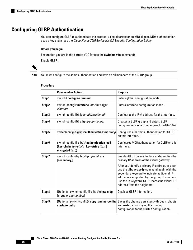
Configuring GLBP AuthenticationYou can configure GLBP to authenticate the protocol using cleartext or an MD5 digest. MD5 authenticationuses a key chain (see the Cisco Nexus 7000 Series NX-OS Security Configuration Guide).
Before you begin
Ensure that you are in the correct VDC (or use the switchto vdc command).
Enable GLBP.
You must configure the same authentication and keys on all members of the GLBP group.Note
Procedure
PurposeCommand or Action
Enters global configuration mode.switch# configure terminalStep 1
Enters interface configuration mode.switch(config)# interface interface-typeslot/port
Step 2
Configures the IPv4 address for the interface.switch(config-if)# ip ip-address/lengthStep 3
Creates a GLBP group and enters GLBPconfiguration mode. The range is from 0 to 1024.
switch(config-if)# glbp group-numberStep 4
Configures cleartext authentication for GLBPon this interface.
switch(config-if-glbp)# authentication text stringStep 5
Configures MD5 authentication for GLBP on thisinterface.
switch(config-if-glbp)# authentication md5{key-chain key-chain | key-string {text |encrypted text}}
Step 6
Enables GLBP on an interface and identifies theprimary IP address of the virtual gateway.
switch(config-if-glbp)# ip [ip-address[secondary]]
Step 7
After you identify a primary IP address, you canuse the glbp group ip command again with thesecondary keyword to indicate additional IPaddresses supported by this group. If you onlyuse the ip keyword, GLBP learns the virtual IPaddress from the neighbors.
Displays GLBP information.(Optional) switch(config-if-glbp)# show glbp[group group-number]
Step 8
Saves the change persistently through rebootsand restarts by copying the runningconfiguration to the startup configuration.
(Optional) switch(config)# copy running-configstartup-config
Step 9
Cisco Nexus 7000 Series NX-OS Unicast Routing Configuration Guide, Release 6.xOL-25777-03446
First-Hop Redundancy ProtocolsConfiguring GLBP Authentication

Example
This example shows how to configure MD5 authentication for GLBP on Ethernet 1/2 after creatingthe key chain:
switch# configure terminalswitch(config)# key chain glbp-keysswitch(config-keychain)# key 0switch(config-keychain-key)# key-string 7 zqdestswitch(config-keychain-key) accept-lifetime 00:00:00 Jun 01 2008 23:59:59 Sep 12 2008switch(config-keychain-key) send-lifetime 00:00:00 Jun 01 2008 23:59:59 Aug 12 2008switch(config-keychain-key) key 1switch(config-keychain-key) key-string 7 uaeqdyitoswitch(config-keychain-key) accept-lifetime 00:00:00 Aug 12 2008 23:59:59 Dec 12 2008switch(config-keychain-key) send-lifetime 00:00:00 Sep 12 2008 23:59:59 Nov 12 2008switch(config)# interface ethernet 1/2switch(config-if)# glbp 1switch(config-if-glbp)# authenticate md5 key-chain glbp-keysswitch(config-if-glbp)# copy running-config startup-config
Configuring GLBP Load BalancingYou can configure GLBP to use load balancing based on round-robin, weighted, or host-dependent methods.
Procedure
PurposeCommand or Action
Creates a GLBP group and enters GLBPconfiguration mode. The range is from 0 to 1024.
switch(config-if)# glbp group-numberStep 1
Sets the GLBP load-balancing method. Thedefault is round-robin.
switch(config-if-glbp)# load-balancing[host-dependent | round-robin | weighted]
Step 2
Example
This example shows how to configure load balancing for GLBP:
switch(config-if)# glbp 1switch(config-if-glbp)# load-balancing weighted
Configuring GLBP Weighting and TrackingYou can configure GLBP weighting values and object tracking to work with the GLBP weighted load-balancingmethod.
You can optionally configure the interface to preempt an AVF if the interface was originally assigned with thevirtual MAC address or if this interface has a higher weight than the AVF.
Before you begin
Ensure that you are in the correct VDC (or use the switchto vdc command).
Cisco Nexus 7000 Series NX-OS Unicast Routing Configuration Guide, Release 6.x447OL-25777-03
First-Hop Redundancy ProtocolsConfiguring GLBP Load Balancing
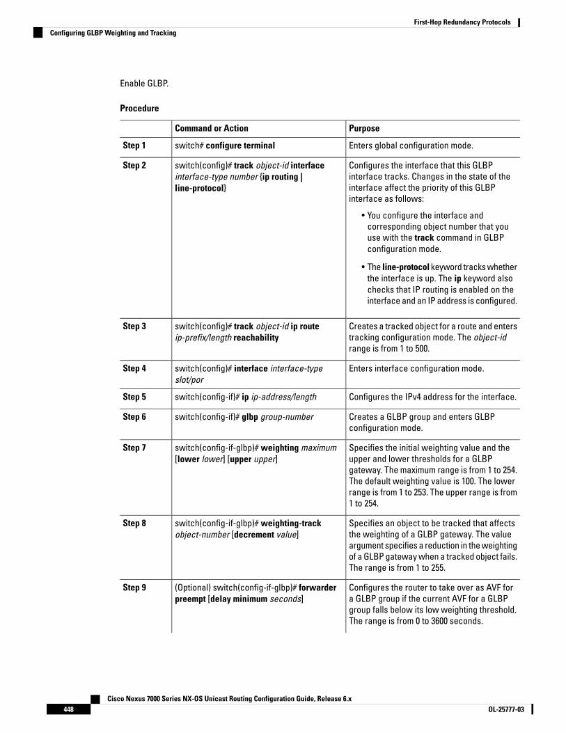
Enable GLBP.
Procedure
PurposeCommand or Action
Enters global configuration mode.switch# configure terminalStep 1
Configures the interface that this GLBPinterface tracks. Changes in the state of the
switch(config)# track object-id interfaceinterface-type number {ip routing |line-protocol}
Step 2
interface affect the priority of this GLBPinterface as follows:
• You configure the interface andcorresponding object number that youuse with the track command in GLBPconfiguration mode.
• The line-protocol keyword tracks whetherthe interface is up. The ip keyword alsochecks that IP routing is enabled on theinterface and an IP address is configured.
Creates a tracked object for a route and enterstracking configuration mode. The object-idrange is from 1 to 500.
switch(config)# track object-id ip routeip-prefix/length reachability
Step 3
Enters interface configuration mode.switch(config)# interface interface-typeslot/por
Step 4
Configures the IPv4 address for the interface.switch(config-if)# ip ip-address/lengthStep 5
Creates a GLBP group and enters GLBPconfiguration mode.
switch(config-if)# glbp group-numberStep 6
Specifies the initial weighting value and theupper and lower thresholds for a GLBP
switch(config-if-glbp)# weighting maximum[lower lower] [upper upper]
Step 7
gateway. The maximum range is from 1 to 254.The default weighting value is 100. The lowerrange is from 1 to 253. The upper range is from1 to 254.
Specifies an object to be tracked that affectsthe weighting of a GLBP gateway. The value
switch(config-if-glbp)# weighting-trackobject-number [decrement value]
Step 8
argument specifies a reduction in the weightingof a GLBP gateway when a tracked object fails.The range is from 1 to 255.
Configures the router to take over as AVF fora GLBP group if the current AVF for a GLBP
(Optional) switch(config-if-glbp)# forwarderpreempt [delay minimum seconds]
Step 9
group falls below its low weighting threshold.The range is from 0 to 3600 seconds.
Cisco Nexus 7000 Series NX-OS Unicast Routing Configuration Guide, Release 6.xOL-25777-03448
First-Hop Redundancy ProtocolsConfiguring GLBP Weighting and Tracking
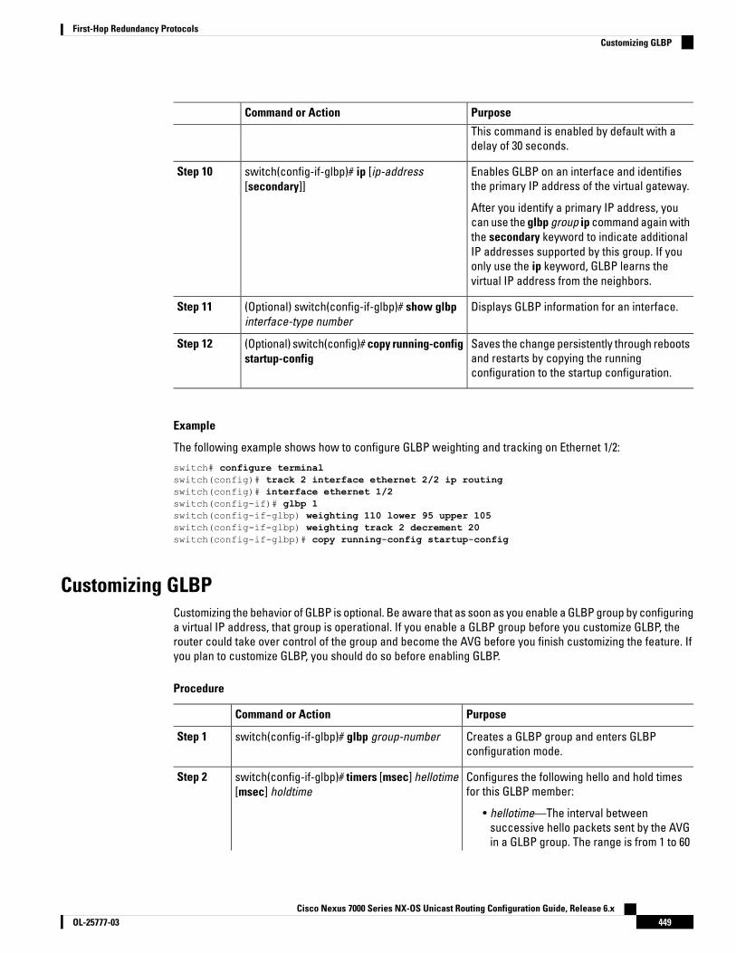
PurposeCommand or Action
This command is enabled by default with adelay of 30 seconds.
Enables GLBP on an interface and identifiesthe primary IP address of the virtual gateway.
switch(config-if-glbp)# ip [ip-address[secondary]]
Step 10
After you identify a primary IP address, youcan use the glbp group ip command again withthe secondary keyword to indicate additionalIP addresses supported by this group. If youonly use the ip keyword, GLBP learns thevirtual IP address from the neighbors.
Displays GLBP information for an interface.(Optional) switch(config-if-glbp)# show glbpinterface-type number
Step 11
Saves the change persistently through rebootsand restarts by copying the runningconfiguration to the startup configuration.
(Optional) switch(config)# copy running-configstartup-config
Step 12
Example
The following example shows how to configure GLBP weighting and tracking on Ethernet 1/2:
switch# configure terminalswitch(config)# track 2 interface ethernet 2/2 ip routingswitch(config)# interface ethernet 1/2switch(config-if)# glbp 1switch(config-if-glbp) weighting 110 lower 95 upper 105switch(config-if-glbp) weighting track 2 decrement 20switch(config-if-glbp)# copy running-config startup-config
Customizing GLBPCustomizing the behavior of GLBP is optional. Be aware that as soon as you enable a GLBP group by configuringa virtual IP address, that group is operational. If you enable a GLBP group before you customize GLBP, therouter could take over control of the group and become the AVG before you finish customizing the feature. Ifyou plan to customize GLBP, you should do so before enabling GLBP.
Procedure
PurposeCommand or Action
Creates a GLBP group and enters GLBPconfiguration mode.
switch(config-if-glbp)# glbp group-numberStep 1
Configures the following hello and hold timesfor this GLBP member:
switch(config-if-glbp)# timers [msec] hellotime[msec] holdtime
Step 2
• hellotime—The interval betweensuccessive hello packets sent by the AVGin a GLBP group. The range is from 1 to 60
Cisco Nexus 7000 Series NX-OS Unicast Routing Configuration Guide, Release 6.x449OL-25777-03
First-Hop Redundancy ProtocolsCustomizing GLBP
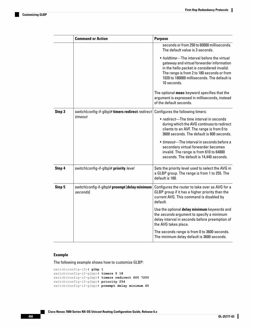
PurposeCommand or Action
seconds or from 250 to 60000 milliseconds.The default value is 3 seconds.
• holdtime—The interval before the virtualgateway and virtual forwarder informationin the hello packet is considered invalid.The range is from 2 to 180 seconds or from1020 to 180000 milliseconds. The default is10 seconds.
The optional msec keyword specifies that theargument is expressed in milliseconds, insteadof the default seconds.
Configures the following timers:switch(config-if-glbp)# timers redirect redirecttimeout
Step 3
• redirect—The time interval in secondsduring which the AVG continues to redirectclients to an AVF. The range is from 0 to3600 seconds. The default is 600 seconds.
• timeout—The interval in seconds before asecondary virtual forwarder becomesinvalid. The range is from 610 to 64800seconds. The default is 14,440 seconds.
Sets the priority level used to select the AVG ina GLBP group. The range is from 1 to 255. Thedefault is 100.
switch(config-if-glbp)# priority levelStep 4
Configures the router to take over as AVG for aGLBP group if it has a higher priority than the
switch(config-if-glbp)# preempt [delay minimumseconds]
Step 5
current AVG. This command is disabled bydefault.
Use the optional delay minimum keywords andthe seconds argument to specify a minimumdelay interval in seconds before preemption ofthe AVG takes place.
The seconds range is from 0 to 3600 seconds.The minimum delay default is 3600 seconds.
Example
The following example shows how to customize GLBP:
switch(config-if)# glbp 1switch(config-if-glbp)# timers 5 18switch(config-if-glbp)# timers redirect 600 7200switch(config-if-glbp)# priority 254switch(config-if-glbp)# preempt delay minimum 60
Cisco Nexus 7000 Series NX-OS Unicast Routing Configuration Guide, Release 6.xOL-25777-03450
First-Hop Redundancy ProtocolsCustomizing GLBP

Configuring Extended Hold Timers for GLBPYou can configure GLBP to use extended hold timers to support extended NSF during a controlled (graceful)switchover or ISSU, including software upgrades and supervisor switchovers. You should configure extendedhold timers on all GLBP gateways.
You must configure extended hold timers on all GLBP gateways if you configure non-default extended holdtimers. You can configure different extended hold timer values on each GLBP gateway, based on the expectedsystem switchover delays.
Note
Use the show glbp command to display the extended hold time.
Procedure
PurposeCommand or Action
Creates a GLBP group and enters GLBPconfiguration mode.
switch(config-if)# glbp group-number
Example:
Step 1
Sets the GLBP extended hold timer, in seconds.The timer range is from 10 to 255. The default is10.
switch(config)# glbp timers extended-hold[timer]
Step 2
Example
The following example shows how to configure extended hold timers for GLBP:
switch(config-if)# glbp 1switch(config)# glbp timers extended-hold 30
Enabling a GLBP GroupYou can configure the virtual IP address on an interface to enable the GLBP group. You must configure eachgateway in the GLBP group with the same group number. The GLBP member can learn all other requiredparameters from another GLBP member.
Before you begin
Ensure that you are in the correct VDC (or use the switchto vdc command).
Enable GLBP.
Procedure
PurposeCommand or Action
Enters global configuration mode.switch# configure terminalStep 1
Enters interface configuration mode.switch(config)# interface interface-type slot/porStep 2
Cisco Nexus 7000 Series NX-OS Unicast Routing Configuration Guide, Release 6.x451OL-25777-03
First-Hop Redundancy ProtocolsConfiguring Extended Hold Timers for GLBP
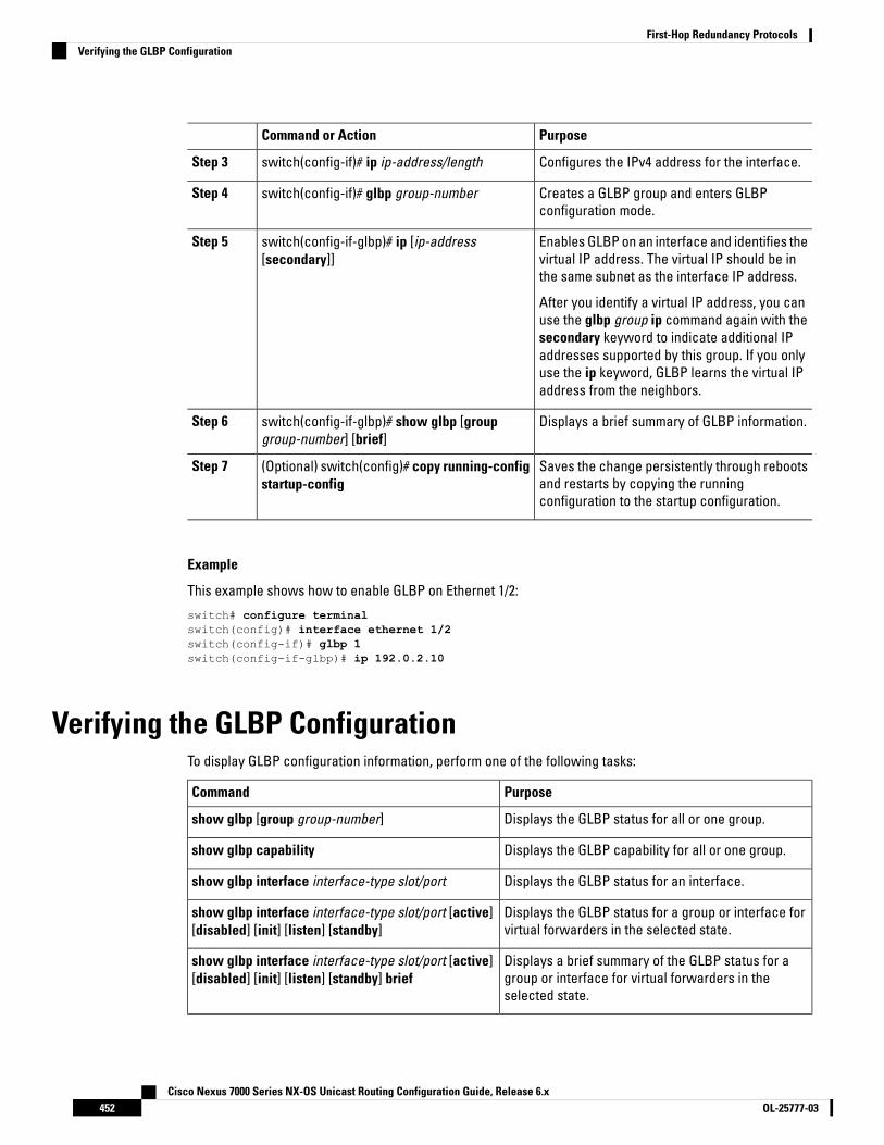
PurposeCommand or Action
Configures the IPv4 address for the interface.switch(config-if)# ip ip-address/lengthStep 3
Creates a GLBP group and enters GLBPconfiguration mode.
switch(config-if)# glbp group-numberStep 4
Enables GLBP on an interface and identifies thevirtual IP address. The virtual IP should be inthe same subnet as the interface IP address.
switch(config-if-glbp)# ip [ip-address[secondary]]
Step 5
After you identify a virtual IP address, you canuse the glbp group ip command again with thesecondary keyword to indicate additional IPaddresses supported by this group. If you onlyuse the ip keyword, GLBP learns the virtual IPaddress from the neighbors.
Displays a brief summary of GLBP information.switch(config-if-glbp)# show glbp [groupgroup-number] [brief]
Step 6
Saves the change persistently through rebootsand restarts by copying the runningconfiguration to the startup configuration.
(Optional) switch(config)# copy running-configstartup-config
Step 7
Example
This example shows how to enable GLBP on Ethernet 1/2:
switch# configure terminalswitch(config)# interface ethernet 1/2switch(config-if)# glbp 1switch(config-if-glbp)# ip 192.0.2.10
Verifying the GLBP ConfigurationTo display GLBP configuration information, perform one of the following tasks:
PurposeCommand
Displays the GLBP status for all or one group.show glbp [group group-number]
Displays the GLBP capability for all or one group.show glbp capability
Displays the GLBP status for an interface.show glbp interface interface-type slot/port
Displays the GLBP status for a group or interface forvirtual forwarders in the selected state.
show glbp interface interface-type slot/port [active][disabled] [init] [listen] [standby]
Displays a brief summary of the GLBP status for agroup or interface for virtual forwarders in theselected state.
show glbp interface interface-type slot/port [active][disabled] [init] [listen] [standby] brief
Cisco Nexus 7000 Series NX-OS Unicast Routing Configuration Guide, Release 6.xOL-25777-03452
First-Hop Redundancy ProtocolsVerifying the GLBP Configuration

Configuration Examples for GLBPThe following example shows how to enable GLBP on an interface, with MD5 authentication, interface tracking,and weighted load balancing:
key chain glbp-keyskey 0key-string 7 zqdestaccept-lifetime 00:00:00 Jun 01 2008 23:59:59 Sep 12 2008send-lifetime 00:00:00 Jun 01 2008 23:59:59 Aug 12 2008key 1key-string 7 uaeqdyitoaccept-lifetime 00:00:00 Aug 12 2008 23:59:59 Dec 12 2008send-lifetime 00:00:00 Sep 12 2008 23:59:59 Nov 12 2008
feature glbptrack 2 interface ethernet 2/2 ipinterface ethernet 1/2ip address 192.0.2.2/8glbp 1authentication md5 key-chain glbp-keysweighting 110 lower 95 upper 105weighting track 2 decrement 20ip 192.0.2.10no shutdown
Related Documents for GLBPDocument TitleRelated Topic
Cisco Nexus 7000 Series NX-OS Unicast RoutingCommand Reference
IS-IS CLI commands
Cisco Nexus 7000 Series NX-OS High Availability andRedundancy Guide
VDCs and VRFs
Standards for GLBPNo new or modified standards are supported by this feature, and support for existing standards has not beenmodified by this feature.
Feature History for GLBPThis table includes only the updates for those releases that have resulted in additions or changes to the feature.
Table 42: Feature History for GLBP
Feature InformationReleaseFeature Name
This feature was introduced.4.0(1)GLBP
Cisco Nexus 7000 Series NX-OS Unicast Routing Configuration Guide, Release 6.x453OL-25777-03
First-Hop Redundancy ProtocolsConfiguration Examples for GLBP

Cisco Nexus 7000 Series NX-OS Unicast Routing Configuration Guide, Release 6.xOL-25777-03454
First-Hop Redundancy ProtocolsFeature History for GLBP

C H A P T E R 21Configuring HSRP
This chapter contains the following sections:
• Finding Feature Information, on page 455• Information About HSRP, on page 455• Prerequisites for HSRP, on page 463• Guidelines and Limitations for HSRP, on page 463• Default Settings for HSRP Parameters, on page 464• Configuring HSRP, on page 465• Verifying the HSRP Configuration, on page 480• Configuration Examples for HSRP, on page 481• Related Documents for HSRP, on page 482• MIBs, on page 482• Feature History for HSRP, on page 482
Finding Feature InformationYour software release might not support all the features documented in this module. For the latest caveatsand feature information, see the Bug Search Tool at https://tools.cisco.com/bugsearch/ and the release notesfor your software release. To find information about the features documented in this module, and to see a listof the releases in which each feature is supported, see the "New and Changed Information"chapter or theFeature History table in this chapter.
Information About HSRPHSRP is a first-hop redundancy protocol (FHRP) that allows a transparent failover of the first-hop IP router.HSRP provides first-hop routing redundancy for IP hosts on Ethernet networks configured with a default routerIP address. You use HSRP in a group of routers for selecting an active router and a standby router. In a groupof routers, the active router is the router that routes packets; the standby router is the router that takes overwhen the active router fails or when preset conditions are met.
Many host implementations do not support any dynamic router discovery mechanisms but can be configuredwith a default router. Running a dynamic router discovery mechanism on every host is not practical for manyreasons, including administrative overhead, processing overhead, and security issues. HSRP provides failoverservices to these hosts.
Cisco Nexus 7000 Series NX-OS Unicast Routing Configuration Guide, Release 6.x455OL-25777-03
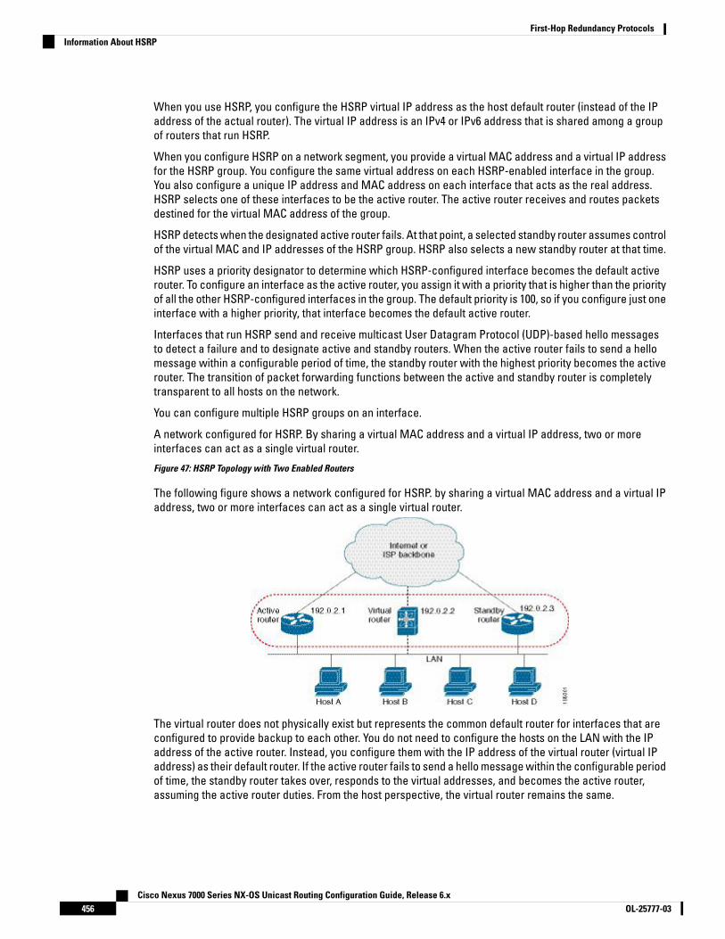
When you use HSRP, you configure the HSRP virtual IP address as the host default router (instead of the IPaddress of the actual router). The virtual IP address is an IPv4 or IPv6 address that is shared among a groupof routers that run HSRP.
When you configure HSRP on a network segment, you provide a virtual MAC address and a virtual IP addressfor the HSRP group. You configure the same virtual address on each HSRP-enabled interface in the group.You also configure a unique IP address and MAC address on each interface that acts as the real address.HSRP selects one of these interfaces to be the active router. The active router receives and routes packetsdestined for the virtual MAC address of the group.
HSRP detects when the designated active router fails. At that point, a selected standby router assumes controlof the virtual MAC and IP addresses of the HSRP group. HSRP also selects a new standby router at that time.
HSRP uses a priority designator to determine which HSRP-configured interface becomes the default activerouter. To configure an interface as the active router, you assign it with a priority that is higher than the priorityof all the other HSRP-configured interfaces in the group. The default priority is 100, so if you configure just oneinterface with a higher priority, that interface becomes the default active router.
Interfaces that run HSRP send and receive multicast User Datagram Protocol (UDP)-based hello messagesto detect a failure and to designate active and standby routers. When the active router fails to send a hellomessage within a configurable period of time, the standby router with the highest priority becomes the activerouter. The transition of packet forwarding functions between the active and standby router is completelytransparent to all hosts on the network.
You can configure multiple HSRP groups on an interface.
A network configured for HSRP. By sharing a virtual MAC address and a virtual IP address, two or moreinterfaces can act as a single virtual router.
Figure 47: HSRP Topology with Two Enabled Routers
The following figure shows a network configured for HSRP. by sharing a virtual MAC address and a virtual IPaddress, two or more interfaces can act as a single virtual router.
The virtual router does not physically exist but represents the common default router for interfaces that areconfigured to provide backup to each other. You do not need to configure the hosts on the LAN with the IPaddress of the active router. Instead, you configure them with the IP address of the virtual router (virtual IPaddress) as their default router. If the active router fails to send a hello message within the configurable periodof time, the standby router takes over, responds to the virtual addresses, and becomes the active router,assuming the active router duties. From the host perspective, the virtual router remains the same.
Cisco Nexus 7000 Series NX-OS Unicast Routing Configuration Guide, Release 6.xOL-25777-03456
First-Hop Redundancy ProtocolsInformation About HSRP

Packets received on a routed port destined for the HSRP virtual IP address terminate on the local router,regardless of whether that router is the active HSRP router or the standby HSRP router. This includes pingand Telnet traffic. Packets received on a Layer 2 (VLAN) interface destined for the HSRP virtual IP addressterminate on the active router.
HSRP for IPv4HSRP routers communicate with each other by exchanging HSRP hello packets. These packets are sent tothe destination IP multicast address 224.0.0.2 (reserved multicast address used to communicate to all routers)on UDP port 1985. The active router sources hello packets from its configured IP address and the HSRP virtualMAC address while the standby router sources hellos from its configured IP address and the interface MACaddress, which might be the burned-in address (BIA). The BIA is the last six bytes of the MAC address that isassigned by the manufacturer of the network interface card (NIC).
Because hosts are configured with their default router as the HSRP virtual IP address, hosts must communicatewith the MAC address associated with the HSRP virtual IP address. This MAC address is a virtual MAC address,0000.0C07.ACxy, where xy is the HSRP group number in hexadecimal based on the respective interface. Forexample, HSRP group 1 uses the HSRP virtual MAC address of 0000.0C07.AC01. Hosts on the adjoining LANsegment use the normal Address Resolution Protocol (ARP) process to resolve the associated MAC addresses.
HSRP version 2 uses the new IP multicast address 224.0.0.102 to send hello packets instead of the multicastaddress of 224.0.0.2, which is used by version 1. HSRP version 2 permits an expanded group number range of0 to 4095 and uses a new MAC address range of 0000.0C9F.F000 to 0000.0C9F.FFFF.
On the HSRP Standby, HSRP adds the HSRP virtual IP address with a cookie "deadbeef".Note
HSRP for IPv6IPv6 hosts learn of available IPv6 routers through IPv6 neighbor discovery (ND) router advertisement (RA)messages. These messages are multicast periodically, or might be solicited by hosts, but the time delay fordetecting when a default route is down might be 30 seconds or more. HSRP for IPv6 provides a much fasterswitchover to an alternate default router than the IPv6 ND protocol provides, less than a second if themilliseconds timers are used. HSRP for IPv6 provides a virtual first hop for IPv6 hosts.
When you configure an IPv6 interface for HSRP, the periodic RAs for the interface link-local address stop afterIPv6 ND sends a final RA with a router lifetime of zero. No restrictions occur for the interface IPv6 link-localaddress. Other protocols continue to receive and send packets to this address.
IPv6 ND sends periodic RAs for the HSRP virtual IPv6 link-local address when the HSRP group is active. TheseRAs stop after a final RA is sent with a router lifetime of 0 when the HSRP group leaves the active state. HSRPuses the virtual MAC address for active HSRP group messages only (hello, coup, and redesign).
HSRP for IPv6 uses the following parameters:
• HSRP version 2
• UDP port 2029
• Virtual MAC address range from 0005.73A0.0000 through 0005.73A0.0FFF
• Multicast link-local IP destination address of FF02::66
Cisco Nexus 7000 Series NX-OS Unicast Routing Configuration Guide, Release 6.x457OL-25777-03
First-Hop Redundancy ProtocolsHSRP for IPv4

• Hop limit set to 255
HSRP for IPv6 AddressesAn HSRP IPv6 group has a virtual MAC address that is derived from the HSRP group number and a virtual IPv6link-local address that is derived, by default, from the HSRP virtual MAC address. The default virtual MACaddress for an HSRP IPv6 group is always used to form the virtual IPv6 link-local address, regardless of theactual virtual MAC address used by the group.
The following table shows the MAC and IP addresses used for IPv6 neighbor discovery packets and HSRPpackets.
Table 43: HSRP and IPv6 ND Addresses
Link-layer AddressOption
IPv6 DestinationAddress
IPv6 source AddressMAC SourceAddress
Packet
Interface MACaddress
—Interface IPv6address
Interface MACaddress
Neighbor solicitation(NS)
Interface MACaddress
—Interface IPv6address
Interface MACaddress
Router solicitation(RS)
HSRP virtual MACaddress
Virtual IPv6 addressInterface IPv6address
Interface MACaddress
Neighboradvertisement (NA)
HSRP virtual MACaddress
—Interface IPv6address
Interface MACaddress
Route advertisement(RA)
——Interface IPv6address
Interface MACaddress
HSRP (inactive)
——Interface IPv6address
Virtual MAC addressHSRP (active)
HSRP does not add IPv6 link-local addresses to the Unicast Routing Information Base (URIB). There are alsono secondary virtual IP addresses for link-local addresses.
For global unicast addresses, HSRP adds the virtual IPv6 address to the URIB and IPv6, but does not registerthe virtual IPv6 addresses to ICMPv6. ICMPv6 redirects are not supported for HSRP IPv6 groups.
Multiple Group Optimization for HSRPBeginning with Cisco NX-OS Release 6.2(2), HSRP supports multiple group optimization (MGO). MGO optimizesperformance and bandwidth when multiple HSRP groups are configured on many subinterfaces. MGO requiresonly one HSRP group, known as the master group, on the physical interface for the purpose of electing activeand standby routers.
You can create other HSRP groups on subinterfaces of the physical interface or a different interface, such asan SVI interface, and link these to the master HSRP group. These groups are known as slave groups. Slavegroups follow their master group state so that they do not participate in any HSRP election mechanisms. Mastergroups send hello messages at their configured rates. Slave groups send hello messages at a reduced rate,which is called the mac-refresh interval rate. This process is required so that the slave groups can send outperiodic messages in order to refresh MAC addresses in switches and learning bridges.
Cisco Nexus 7000 Series NX-OS Unicast Routing Configuration Guide, Release 6.xOL-25777-03458
First-Hop Redundancy ProtocolsHSRP for IPv6 Addresses

HSRP VersionsCisco NX-OS supports HSRP version 1 by default. You can configure an interface to use HSRP version 2.
HSRP version 2 has the following enhancements to HSRP version 1:
Expands the group number range. HSRP version 1 supports group numbers from 0 to 255. HSRP version 2supports group numbers from 0 to 4095.
For IPv4, uses the IPv4 multicast address 224.0.0.102 or the IPv6 multicast address FF02::66 to send hello packetsinstead of the multicast address of 224.0.0.2, which is used by HSRP version 1.
Uses the MAC address range from 0000.0C9F.F000 to 0000.0C9F.FFFF for IPv4 and 0005.73A0.0000 through0005.73A0.0FFF for IPv6 addresses. HSRP version 1 uses the MAC address range 0000.0C07.AC00 to0000.0C07.ACFF.
Adds support for MD5 authentication.
When you change the HSRP version, Cisco NX-OS reinitializes the group because it now has a new virtualMAC address.
HSRP version 2 has a different packet format than HSRP version 1. The packet format uses a type-length-value(TLV) format. HSRP version 2 packets received by an HSRP version 1 router are ignored.
HSRP AuthenticationHSRP message digest 5 (MD5) algorithm authentication protects against HSRP-spoofing software and usesthe industry-standard MD5 algorithm for improved reliability and security. HSRP includes the IPv4 or IPv6address in the authentication TLVs.
HSRP MessagesRouters that are configured with HSRP exchange the following three types of multicast messages:
• Hello—The hello message conveys the HSRP priority and state information of the router to other HSRProuters.
• Coup—When a standby router wants to assume the function of the active router, it sends a coup message.
• Resign—A router that is the active router sends this message when it is about to shut down or when arouter that has a higher priority sends a hello or coup message.
HSRP Load SharingHSRP allows you to configure multiple groups on an interface. You can configure two overlapping IPv4 HSRPgroups to load share traffic from the connected hosts while providing the default router redundancy expectedfrom HSRP. The following figure shows an example of a load-sharing HSRP IPv4 configuration.
Figure 48: HSRP Load Sharing
The figure shows two routers A and B and two HSRP groups. Router A is the active router for group A but isthe standby router for group B. Similarly, router B is the active router for group B and the standby router forgroup A. If both routers remain active, HSRP load balances the traffic from the hosts across both routers. Ifeither router fails, the remaining router continues to process traffic for both hosts.
Cisco Nexus 7000 Series NX-OS Unicast Routing Configuration Guide, Release 6.x459OL-25777-03
First-Hop Redundancy ProtocolsHSRP Versions
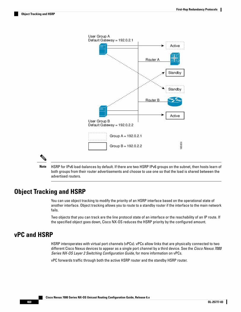
HSRP for IPv6 load-balances by default. If there are two HSRP IPv6 groups on the subnet, then hosts learn ofboth groups from their router advertisements and choose to use one so that the load is shared between theadvertised routers.
Note
Object Tracking and HSRPYou can use object tracking to modify the priority of an HSRP interface based on the operational state ofanother interface. Object tracking allows you to route to a standby router if the interface to the main networkfails.
Two objects that you can track are the line protocol state of an interface or the reachability of an IP route. Ifthe specified object goes down, Cisco NX-OS reduces the HSRP priority by the configured amount.
vPC and HSRPHSRP interoperates with virtual port channels (vPCs). vPCs allow links that are physically connected to twodifferent Cisco Nexus devices to appear as a single port channel by a third device. See the Cisco Nexus 7000Series NX-OS Layer 2 Switching Configuration Guide, for more information on vPCs.
vPC forwards traffic through both the active HSRP router and the standby HSRP router.
Cisco Nexus 7000 Series NX-OS Unicast Routing Configuration Guide, Release 6.xOL-25777-03460
First-Hop Redundancy ProtocolsObject Tracking and HSRP

You should configure HSRP on the primary vPC peer device as active and HSRP on the vPC secondary deviceas standby.
Note
vPC Peer Gateway and HSRPSome third-party devices can ignore the HSRP virtual MAC address and instead use the source MAC addressof an HSRP router. in a vPC environment, the packets using this source MAC address may be sent across thevPC peer link, causing a potential dropped packet. Configure the vPC peer gateway to enable the HSRP routersto directly handle packets sent to the local vPC peer MAC address and the remote vPC peer MAC address, aswell as the HSRP virtual MAC address. See the Cisco Nexus 7000 Series NX-OS Layer 2 Switching ConfigurationGuide, for more information on the vPC peer gateway.
For mixed-chassis configurations where the vPC peer link is configured on an F-series module, configure thevPC peer gateway exclude option to exclude the Layer 3 backup route that traverses the vPC peer link. Seethe Cisco Nexus 7000 Series NX-OS Layer 2 Switching Configuration Guide, for more information on the vPCpeer gateway exclude option.
FabricPath Anycast HSRPCisco NX-OS Release 6.2(2) and later releases facilitate further scalability at the spine layer by providingsupport for more than two nodes. You can create an anycast bundle, which is an association between a setof VLANs and an anycast switch ID. The set of VLANs or the HSRP group elects an active router and a standbyrouter. The remaining routers in the group are in listen state.
All of the HSRP routers that have a configured anycast switch ID advertise the ID through FabricPath IS-IS.The active HSRP router is the only router that uses the anycast switch ID in its hello packets. The leaf switcheslearn that the anycast switch ID is reachable by all of the routers in the group.
All of the first hop gateways at the spine layer need to function in active-active forwarding mode. IP packetsare received by any of the spine switches with the destination set as the gateway MAC address, and thesepackets are terminated and locally forwarded.
BFDThis feature supports bidirectional forwarding detection (BFD). BFD is a detection protocol that providesfast-forwarding and path-failure detection times. BFD provides subsecond failure detection between twoadjacent devices and can be less CPU-intensive than protocol hello messages because some of the BFD loadcan be distributed onto the data plane on supported modules. See the Cisco Nexus 7000 Series NX-OS InterfacesConfiguration Guide, for more information.
High Availability and Extended Nonstop ForwardingHSRP supports stateful restarts and stateful switchovers. A stateful restart occurs when the HSRP processfails and is restarted. A stateful switchover occurs when the active supervisor switches to the standbysupervisor. Cisco NX-OS applies the run-time configuration after the switchover.
If HSRP hold timers are configured for short time periods, these timers might expire during a controlledswitchover or in-service software upgrade (ISSU). Ping to a virtual IP is also unreachable during this timer
Cisco Nexus 7000 Series NX-OS Unicast Routing Configuration Guide, Release 6.x461OL-25777-03
First-Hop Redundancy ProtocolsvPC Peer Gateway and HSRP

expiry period. HSRP supports extended non-stop forwarding (NSF) to temporarily extend these HSRP holdtimers during a controlled switchover or ISSU.
With extended NSF configured, HSRP sends hello messages with the extended timers. HSRP peers updatetheir hold timers with these new values. The extended timers prevent unnecessary HSRP state changes duringthe switchover or ISSU. After the switchover or ISSU event, HSRP restores the hold timers to their originalconfigured values. If the switchover fails, HSRP restores the hold timers after the extended hold timer valuesexpire.
Virtualization SupportHSRP supports virtual routing and forwarding (VRF) instances. VRFs exist within virtual device contexts (VDCs).By default, Cisco NX-OS places you in the default VDC and default VRF unless you specifically configureanother VDC and VRF.
If you change the VRF membership of an interface, Cisco NX-OS removes all Layer 3 configuration, includingHSRP.
HSRP VIPStarting with Cisco NX-OS Release 7.2(0)D1(1), the Hot Standby Router Protocol (HSRP) Virtual IP (VIP) featureprovides support for an HSRP Virtual IP configuration to be in a different subnet than that of the interfacesubnet. This feature is supported only for IPv4 address and not for IPv6. The following are the enhancements:
• Enhance ARP to source with VIP from Supervisor Engine (SUP) for hosts, when the hosts in VIP subnetare referenced by static route to VLAN configuration.
• Support periodic ARP synchronization to vPC peer if the HSRP VIP feature is enabled.
• Allow VIP address as the Layer 3 source address and gateway address for all communications with aDynamic Host Configuration Protocol (DHCP) server.
• Enhance DHCP relay agent to relay DHCP packets with VIP address as source address instead of SVI IPaddress.
HSRP subnet VIP should be configured in the virtual port channel (vPC) topology. The HSRP VIP feature worksonly on HSRP with vPC topologies.
Note
In a subnet VIP configuration, the VIP address must be in a different subnet than the interface IP subnet.Without the subnet VIP configuration, the VIP address must be in the same subnet of the interface IP subnet.
Note
The following is an example for VIP subnet address configuration wherein the VIP address is not configuredin the same subnet of the interface IP subnet.
switch# configure terminalswitch(config)# feature hsrpswitch(config)# feature interface-vlanswitch(config)# interface vlan 2switch(config-if)# ip address 192.0.2.1/24
Cisco Nexus 7000 Series NX-OS Unicast Routing Configuration Guide, Release 6.xOL-25777-03462
First-Hop Redundancy ProtocolsVirtualization Support
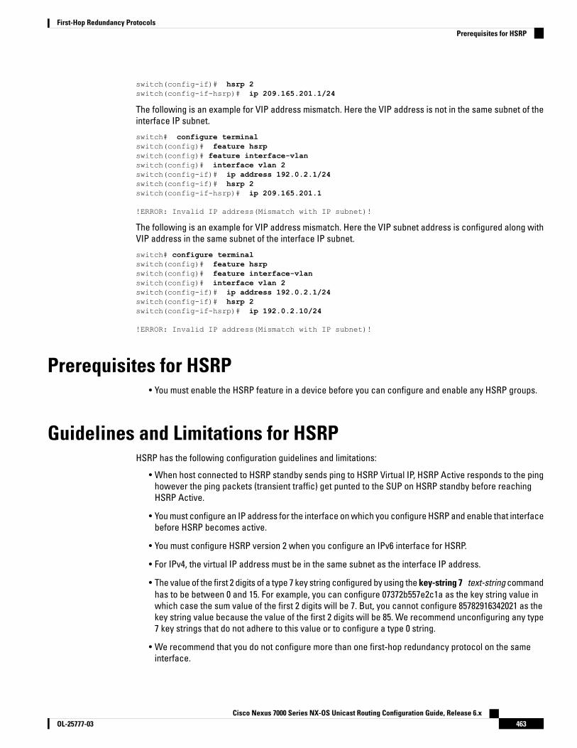
switch(config-if)# hsrp 2switch(config-if-hsrp)# ip 209.165.201.1/24
The following is an example for VIP address mismatch. Here the VIP address is not in the same subnet of theinterface IP subnet.
switch# configure terminalswitch(config)# feature hsrpswitch(config)# feature interface-vlanswitch(config)# interface vlan 2switch(config-if)# ip address 192.0.2.1/24switch(config-if)# hsrp 2switch(config-if-hsrp)# ip 209.165.201.1
!ERROR: Invalid IP address(Mismatch with IP subnet)!
The following is an example for VIP address mismatch. Here the VIP subnet address is configured along withVIP address in the same subnet of the interface IP subnet.
switch# configure terminalswitch(config)# feature hsrpswitch(config)# feature interface-vlanswitch(config)# interface vlan 2switch(config-if)# ip address 192.0.2.1/24switch(config-if)# hsrp 2switch(config-if-hsrp)# ip 192.0.2.10/24
!ERROR: Invalid IP address(Mismatch with IP subnet)!
Prerequisites for HSRP• You must enable the HSRP feature in a device before you can configure and enable any HSRP groups.
Guidelines and Limitations for HSRPHSRP has the following configuration guidelines and limitations:
• When host connected to HSRP standby sends ping to HSRP Virtual IP, HSRP Active responds to the pinghowever the ping packets (transient traffic) get punted to the SUP on HSRP standby before reachingHSRP Active.
• You must configure an IP address for the interface on which you configure HSRP and enable that interfacebefore HSRP becomes active.
• You must configure HSRP version 2 when you configure an IPv6 interface for HSRP.
• For IPv4, the virtual IP address must be in the same subnet as the interface IP address.
• The value of the first 2 digits of a type 7 key string configured by using the key-string 7 text-string commandhas to be between 0 and 15. For example, you can configure 07372b557e2c1a as the key string value inwhich case the sum value of the first 2 digits will be 7. But, you cannot configure 85782916342021 as thekey string value because the value of the first 2 digits will be 85. We recommend unconfiguring any type7 key strings that do not adhere to this value or to configure a type 0 string.
• We recommend that you do not configure more than one first-hop redundancy protocol on the sameinterface.
Cisco Nexus 7000 Series NX-OS Unicast Routing Configuration Guide, Release 6.x463OL-25777-03
First-Hop Redundancy ProtocolsPrerequisites for HSRP
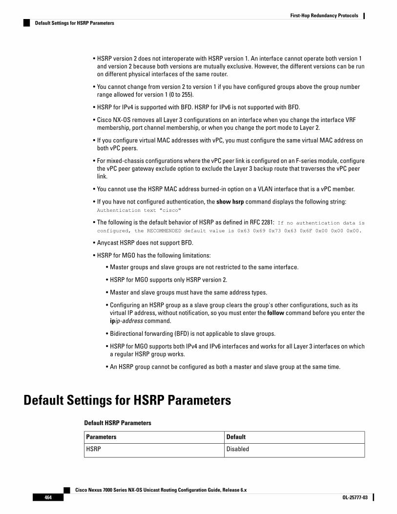
• HSRP version 2 does not interoperate with HSRP version 1. An interface cannot operate both version 1and version 2 because both versions are mutually exclusive. However, the different versions can be runon different physical interfaces of the same router.
• You cannot change from version 2 to version 1 if you have configured groups above the group numberrange allowed for version 1 (0 to 255).
• HSRP for IPv4 is supported with BFD. HSRP for IPv6 is not supported with BFD.
• Cisco NX-OS removes all Layer 3 configurations on an interface when you change the interface VRFmembership, port channel membership, or when you change the port mode to Layer 2.
• If you configure virtual MAC addresses with vPC, you must configure the same virtual MAC address onboth vPC peers.
• For mixed-chassis configurations where the vPC peer link is configured on an F-series module, configurethe vPC peer gateway exclude option to exclude the Layer 3 backup route that traverses the vPC peerlink.
• You cannot use the HSRP MAC address burned-in option on a VLAN interface that is a vPC member.
• If you have not configured authentication, the show hsrp command displays the following string:Authentication text "cisco"
• The following is the default behavior of HSRP as defined in RFC 2281: If no authentication data is
configured, the RECOMMENDED default value is 0x63 0x69 0x73 0x63 0x6F 0x00 0x00 0x00.
• Anycast HSRP does not support BFD.
• HSRP for MGO has the following limitations:
• Master groups and slave groups are not restricted to the same interface.
• HSRP for MGO supports only HSRP version 2.
• Master and slave groups must have the same address types.
• Configuring an HSRP group as a slave group clears the group's other configurations, such as itsvirtual IP address, without notification, so you must enter the follow command before you enter theipip-address command.
• Bidirectional forwarding (BFD) is not applicable to slave groups.
• HSRP for MGO supports both IPv4 and IPv6 interfaces and works for all Layer 3 interfaces on whicha regular HSRP group works.
• An HSRP group cannot be configured as both a master and slave group at the same time.
Default Settings for HSRP ParametersDefault HSRP Parameters
DefaultParameters
DisabledHSRP
Cisco Nexus 7000 Series NX-OS Unicast Routing Configuration Guide, Release 6.xOL-25777-03464
First-Hop Redundancy ProtocolsDefault Settings for HSRP Parameters
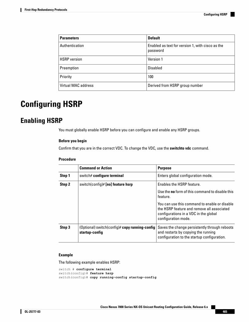
DefaultParameters
Enabled as text for version 1, with cisco as thepassword
Authentication
Version 1HSRP version
DisabledPreemption
100Priority
Derived from HSRP group numberVirtual MAC address
Configuring HSRP
Enabling HSRPYou must globally enable HSRP before you can configure and enable any HSRP groups.
Before you begin
Confirm that you are in the correct VDC. To change the VDC, use the switchto vdc command.
Procedure
PurposeCommand or Action
Enters global configuration mode.switch# configure terminalStep 1
Enables the HSRP feature.switch(config)# [no] feature hsrpStep 2
Use the no form of this command to disable thisfeature.
You can use this command to enable or disablethe HSRP feature and remove all associatedconfigurations in a VDC in the globalconfiguration mode.
Saves the change persistently through rebootsand restarts by copying the runningconfiguration to the startup configuration.
(Optional) switch(config)# copy running-configstartup-config
Step 3
Example
The following example enables HSRP:
switch # configure terminalswitch(config)# feature hsrpswitch(config)# copy running-config startup-config
Cisco Nexus 7000 Series NX-OS Unicast Routing Configuration Guide, Release 6.x465OL-25777-03
First-Hop Redundancy ProtocolsConfiguring HSRP

Configuring the HSRP VersionYou can configure the HSRP version. If you change the version for existing groups, Cisco NX-OS reinitializesHSRP for those groups because the virtual MAC address changes. The HSRP version applies to all groups onthe interface
IPv6 HSRP groups must be configured as HSRP version 2.Note
Procedure
PurposeCommand or Action
Enters global configuration mode.switch# configure terminalStep 1
Enters interface configuration mode.switch(config)# interface type numberStep 2
Confirms the HSRP version. Version 1 is thedefault.
switch(config-if)# hsrp version {1 | 2}Step 3
Saves the change persistently through rebootsand restarts by copying the runningconfiguration to the startup configuration.
(Optional) switch(config-if)# copyrunning-config startup-config
Step 4
Example
The following example shows how to configure an HSRP version:
switch# configure terminalswitch(config)# interface ethernet 1/2switch(config-if)# hsrp version 2switch(config-if)# copy running-config startup-config
Configuring an HSRP Group for IPv4You can configure an HSRP group on an IPv4 interface and configure the virtual IP address and virtual MACaddress for the HSRP group.
Before you begin
• You must enable HSRP.
• Cisco NX-OS enables an HSRP group once you configure the virtual IP address on any member interfacein the group. You must configure HSRP attributes such as authentication, timers, and priority before youenable the HSRP group.
• Confirm that you are in the correct VDC. To change the VDC, use the switchto vdc command.
Cisco Nexus 7000 Series NX-OS Unicast Routing Configuration Guide, Release 6.xOL-25777-03466
First-Hop Redundancy ProtocolsConfiguring the HSRP Version

Procedure
PurposeCommand or Action
Enters global configuration mode.switch# configure terminalStep 1
Enters interface configuration mode.switch(config)# interface type numberStep 2
Configures the IPv4 address of the interface.switch(config-if)# ip ip-address/lengthStep 3
Creates an HSRP group and enters hsrpconfiguration mode. The range for HSRP version
switch(config-if)# hsrp group-number [ipv4]Step 4
1 is from 0 to 255. The range is for HSRP version2 is from 0 to 4095. The default value is 0.
Configures the virtual IP address for the HSRPgroup and enables the group. This address
switch(config-if-hsrp)# ip [ip-address[secondary]]
Step 5
should be in the same subnet as the IPv4address of the interface.
Exits HSRP configuration mode.switch(config-if-hsrp)# exitStep 6
Enables the interface.switch(config-if)# no shutdownStep 7
Saves the change persistently through rebootsand restarts by copying the runningconfiguration to the startup configuration.
(Optional) switch(config-if)# copyrunning-config startup-config
Step 8
Displays HSRP information.(Optional) switch(config-if)# show hsrp [groupgroup-number] [ipv4]
Step 9
Example
The following example shows how to configure an HSRP group on Ethernet 1/2:
switch# configure terminalswitch(config)# interface ethernet 1/2
switch(config-if)# ip 192.0.2.2/8switch(config-if)# hsrp 2switch(config-if-hsrp)# ip 192.0.2.1switch(config-if-hsrp)# exitswitch(config-if)# no shutdownswitch(config-if)# copy running-config startup-config
Configuring an HSRP Group for IPv6You can configure an HSRP group on an IPv6 interface and configure the virtual IP address and virtual MACaddress for the HSRP group. When you configure an HSRP group for IPv6, HSRP generates a link-local addressfrom the link-local prefix. HSRP also generates a modified EUI-64 format interface identifier in which the EUI-64interface identifier is created from the relevant HSRP virtual MAC address. There are no HSRP IPv6 secondaryaddresses.
Cisco Nexus 7000 Series NX-OS Unicast Routing Configuration Guide, Release 6.x467OL-25777-03
First-Hop Redundancy ProtocolsConfiguring an HSRP Group for IPv6

Before you begin
• You must enable HSRP.
• Ensure that you have enabled HSRP version 2 on the interface where you want to configure an IPv6 HSRPgroup.
• Ensure that you have configured HSRP attributes such as authentication, timers, and priority before youenable the HSRP group.
• Confirm that you are in the correct VDC. To change the VDC, use the switchto vdc command.
Procedure
PurposeCommand or Action
Step 1
Enters global configuration mode.switch# configure terminalStep 2
Enters interface configuration mode.switch(config)# interface type numberStep 3
Configures the IPv6 address of the interface.switch(config-if)# ipv6 addressipv6-address/length
Step 4
Configures the group for HSRP version 2.switch(config-if)# hsrp version 2Step 5
Creates an IPv6 HSRP group and enters hsrpconfiguration mode. The range for HSRP
switch(config-if)# hsrp group-number [ipv6]Step 6
version 2 is from 0 to 4095. The range is forHSRP version 2 is from 0 to 4095. The defaultvalue is 0.
Configures the virtual IPv6 address for theHSRP group and enables the group.
switch(config-if-hsrp)# ip [ipv6-address[secondary]]
Step 7
Autoconfigures the virtual IPv6 address for theHSRP group from the calculated link-localvirtual IPv6 address and enables the group.
switch(config-if-hsrp)# ip autoconfigStep 8
Enables the interface.switch(config-if-hsrp)# no shutdownStep 9
Saves the change persistently through rebootsand restarts by copying the runningconfiguration to the startup configuration.
switch(config-if-hsrp)# copy running-configstartup-config
Step 10
Displays HSRP information.(Optional) switch(config-if-hsrp)# show hsrp[group group-number] [ipv6]
Step 11
Example
The following example shows how to configure an HSRP group on Ethernet 1/2:
switch# configure terminalswitch(config)# interface ethernet 3/2
Cisco Nexus 7000 Series NX-OS Unicast Routing Configuration Guide, Release 6.xOL-25777-03468
First-Hop Redundancy ProtocolsConfiguring an HSRP Group for IPv6

switch(config-if)# ipv6 address 2001:0DB8:0001:0001:/64switch(config-if)# hsrp version 2switch(config-if)# hsrp 2 ipv6switch(config)# ip 2001:DB8::1switch(config-if-hsrp)# exitswitch(config-if-hsrp)# no shutdownswitch(config-if-hsrp)# copy running-config startup-config
Configuring an HSRP Master Group TaskYou can configure HSRP for MGO to optimize performance when scaling by configuring master and slavegroups. Slave groups follow the master group state, which minimizes the number of hello messages that aresent. Cisco NX-OS enables an HSRP group once you configure its virtual IP address.
We recommend that you configure master groups on the same parent interface as their slave groups to allowthe slave groups to have the same redundancy requirements as the master group. If a failure occurs on themaster link, all the slave groups are brought down as well, even if the links on which they are configuredremain up.
Before you begin
• Ensure that you have enabled the HSRP feature.
• Configure HSRP attributes such as authentication, timers, and priority before you enable an HSRP groupas a master group.
• Ensure that you are in the correct VDC (or use the switchto vdc command).
Procedure
PurposeCommand or Action
Enters global configuration mode.switch# configure terminalStep 1
Enters interface configuration mode andconfigures an interface type.
switch(config)# interface type/numberStep 2
Configures the IP address of the interface.switch(config-if)# ip addressip-address/lengthStep 3
Configures the HSRP version. Because MGOsupports only HSRP version 2, you must set the
switch(config-if)# hsrp version 2Step 4
HSRP version to version 2. Version 1 is thedefault.
Creates an HSRP group and enters HSRPconfiguration mode. The range for the HSRP
switch(config-if)# hsrp group-number [ipv6]Step 5
group number is from 0 to 4095. The no form ofthis command removes the group.
Specifies a master group name. The namecommand changes a regular HSRP group into
switch(config-if-hsrp)# name[master-group-name]
Step 6
a master group. If you do not specify a name,a unique name is automatically generated. Theno form of this command returns the mastergroup to a regular HSRP group.
Cisco Nexus 7000 Series NX-OS Unicast Routing Configuration Guide, Release 6.x469OL-25777-03
First-Hop Redundancy ProtocolsConfiguring an HSRP Master Group Task

PurposeCommand or Action
Configures the virtual IP address for the HSRPgroup and enables the master group.
switch(config-if-hsrp)# ip [ip-address[secondary]]
Step 7
Exits the HSRP configuration mode.switch(config-if-hsrp)# exitStep 8
Enables the interface.switch(config-if)# no shutdownStep 9
(Optional)switch(config-if)# show hsrp [brief] [groupgroup-number] [ipv4] [ipv6]
Step 10
Displays HSRP information.
(Optional)switch(config-if)# show hsrp mgo [name name][brief]
Step 11
Displays the relationships between HSRPgroups that are in use for MGO and their slavesessions. The name keyword restricts theoutput to the session with a matchingconfigured name. The brief keyword providesa summary of each MGO session with theassociated slave sessions.
Example
The following example shows how to configure an HSRP master group on Ethernet interface 1/1:
switch# configure terminalswitch(config)# interface ethernet 1/1switch(config-if)# ip address 11.0.0.1/24switch(config-if)# hsrp version 2switch(cofig-if)# hsrp 11switch(config-if-hsrp)# name master1switch(config-if-hsrp)# ip 11.0.0.100switch(config-if-hsrp)# exitswitch(config-if)# no shutdownswitch(config-if)# show hsrp group 11switch(config-if)# show hsrp mgo name master1
Configuring an HSRP Slave GroupIf a failure occurs in a slave link that belongs to a different interface than the master group, the slave groupis brought down, regardless of the state of the group it is following.
You can configure HSRP for MGO to optimize performance when scaling by configuring master and slavegroups. Slave groups follow the master group state, which minimizes the number of hello messages that aresent. Cisco NX-OS enables an HSRP group once you configure its virtual IP address.
We recommend that you configure master groups on the same parent interface as their slave groups to allowthe slave groups to have the same redundancy requirements as the master group. If a failure occurs on themaster link, all the slave groups are brought down as well, even if the links on which they are configuredremain up.
Cisco Nexus 7000 Series NX-OS Unicast Routing Configuration Guide, Release 6.xOL-25777-03470
First-Hop Redundancy ProtocolsConfiguring an HSRP Slave Group

Before you begin
• Ensure that you have enabled the HSRP feature.
• Configure HSRP attributes such as authentication, timers, and priority before you enable an HSRP groupas a master group.
• Ensure that you are in the correct VDC (or use the switchto vdc command).
Procedure
PurposeCommand or Action
Enters global configuration mode.switch# configure terminalStep 1
Enters interface configuration mode andconfigures an interface type.
switch(config)# interface type/numberStep 2
Configures the IP address of the interface.switch(config-if)# ip addressip-address/lengthStep 3
Configures the HSRP version. Because MGOsupports only HSRP version 2, you must set the
switch(config-if)# hsrp version 2Step 4
HSRP version to version 2. Version 1 is thedefault.
(Optional)switch(config-if)# hsrp mac refresh secondsStep 5
Configures the MAC refresh interval for theHSRP slave group. You can use this commandto minimize the number of hello messages thatare sent out and reduce HSRP protocoloverheads and CPU utilization when multiplesubinterfaces are configured.
This command is not available for individualsubinterfaces. It applies to all groups on allsubinterfaces. The default is 60 seconds. Therange is from 0 to 10000.
Creates an HSRP group and enters HSRPconfiguration mode. The range for the HSRP
switch(config-if)# hsrp group-number [ipv6]Step 6
group number is from 0 to 4095. The no form ofthis command removes the group.
Configures a regular HSRP group as a slavegroup.
switch(config-if-hsrp)# follow[master-group-name]
Step 7
Configuring an HSRP group as a slave groupclears the group’s other configurations, suchas its virtual IP address without notification,so you must enter the follow command beforeyou enter the ip ip-address command.
Slave groups may forward reference mastergroup names that are undefined.
Cisco Nexus 7000 Series NX-OS Unicast Routing Configuration Guide, Release 6.x471OL-25777-03
First-Hop Redundancy ProtocolsConfiguring an HSRP Slave Group

PurposeCommand or Action
The no form of this command returns the slavegroup to a regular HSRP group.
Configures the virtual IP address for the HSRPgroup and enables the slave group.
switch(config-if-hsrp)# ip [ip-address]Step 8
Exits the HSRP configuration mode.switch(config-if-hsrp)# exitStep 9
Enables the interface.switch(config-if)# no shutdownStep 10
(Optional)switch(config-if)# show hsrp [brief] [groupgroup-number] [ipv4] [ipv6]
Step 11
Displays HSRP information.
(Optional)switch(config-if)# show hsrp mgo [name name][brief]
Step 12
Displays the relationships between HSRPgroups that are in use for MGO and their slavesessions. The name keyword restricts theoutput to the session with a matchingconfigured name. The brief keyword providesa summary of each MGO session with theassociated slave sessions.
Example
The following example shows how to configure an HSRP slave group on Ethernet interface 1/2:
switch# configure terminalswitch(config)# interface ethernet 1/2switch(config-if)# ip address 12.0.0.1/24switch(config-if)# hsrp version 2switch(cofig-if)# hsrp 12switch(config-if-hsrp)# follow master1switch(config-if-hsrp)# ip 12.0.0.100switch(config-if-hsrp)# exitswitch(config-if)# no shutdownswitch(config-if)# show hsrp group 11switch(config-if)# show hsrp mgo name master1
Configuring the HSRP Virtual MAC Address ManuallyYou can override the default virtual MAC address that HSRP derives from the configured group number. Youmust configure the same virtual MAC address on both vPC peers of a vPC link.
Procedure
PurposeCommand or Action
Enters global configuration mode.switch# configure terminalStep 1
Enters interface configuration mode.switch(config)# interface type numberStep 2
Cisco Nexus 7000 Series NX-OS Unicast Routing Configuration Guide, Release 6.xOL-25777-03472
First-Hop Redundancy ProtocolsConfiguring the HSRP Virtual MAC Address Manually

PurposeCommand or Action
Creates an HSRP group and enters hsrpconfiguration mode. The range for HSRP version
switch(config-if)# hsrp group-number [ipv4]Step 3
1 is from 0 to 255. The range is for HSRP version2 is from 0 to 4095. The default value is 0.
Configures the virtual MAC address for an HSRPgroup. The string uses the standard MACaddress format (xxxx.xxxx.xxxx).
switch(config-if-hsrp)# mac-address stringStep 4
Saves the change persistently through rebootsand restarts by copying the runningconfiguration to the startup configuration.
switch(config-if-hsrp)# copy running-configstartup-config
Step 5
Example
The following example configures the HSRP virtual MAC address manually:
switch # configure terminalswitch(config)# interface ethernet 1/2switch(config-if)# hsrp 2switch(config-if-hsrp)# mac-address 5000.1000.1060switch(config-if-hsrp)# copy running-config startup-config
Configuring the HSRP Virtual MAC Address Using Burned-in MAC AddressYou can override the default virtual MAC address that HSRP derives from the configured group number. Youmust configure the same virtual MAC address on both vPC peers of a vPC link.
Procedure
PurposeCommand or Action
Enters global configuration mode.switch# configure terminalStep 1
Enters interface configuration mode.switch(config)# interface type numberStep 2
Configures HSRP to use the burned-in MACaddress of the interface for the HSRP virtual
switch(config-if)# hsrp use-bia [scope interface]Step 3
MAC address. Optionally, you can configureHSRP to use the burned-in MAC address for allgroups on this interface by using the scopeinterface keyword.
Cisco Nexus 7000 Series NX-OS Unicast Routing Configuration Guide, Release 6.x473OL-25777-03
First-Hop Redundancy ProtocolsConfiguring the HSRP Virtual MAC Address Using Burned-in MAC Address

PurposeCommand or Action
Proxy ARP breaks when HSRP isconfigured with use-bia command.A standby router cannot cover forthe lost proxy ARP database of thefailed router.
When the use-bia option isconfigured, the ARP process on theHSRP active device mistakenly seesthe HSRP group as the standbydevice because of the lack of virtualaddress that it looks for. As a result,both the HSRP active and thestandby devices suppress ARPreplies to proxy ARP requests.
Note
(Optional) Saves the change persistently throughreboots and restarts by copying the runningconfiguration to the startup configuration
switch(config-if)# copy running-configstartup-config
Step 4
Example
The following example configures the HSRP virtual MAC address manually:
switch # configure terminalswitch(config)# interface ethernet 1/2switch(config-if)# hsrp use-biaswitch(config-if)# copy running-config startup-config
Authenticating HSRPYou can configure HSRP to authenticate the protocol using cleartext or MD5 digest authentication. MD5authentication uses a key chain. For more details, see the Cisco Nexus 7000 Series NX-OS Security ConfigurationGuide.
Before you begin
• You must enable HSRP.
• You must configure the same authentication and keys on all members of the HSRP group.
• Ensure that you have created the key chain if you are using MD5 authentication.
• Confirm that you are in the correct VDC. To change the VDC, use the switchto vdc command.
Procedure
PurposeCommand or Action
Enters global configuration mode.switch# configure terminalStep 1
Cisco Nexus 7000 Series NX-OS Unicast Routing Configuration Guide, Release 6.xOL-25777-03474
First-Hop Redundancy ProtocolsAuthenticating HSRP

PurposeCommand or Action
Enters interface configuration mode.switch(config)# interface interface-typeslot/port
Step 2
Creates an HSRP group and enters HSRPconfiguration mode.
switch(config-if)# hsrp group-number [ipv4 |ipv6]
Step 3
Configures cleartext authentication for HSRPon this interface by using the authentication
switch(config-if-hsrp)# authentication {textstring | md5 {key-chain key-chain | key-string{0 | 7} text [timeout seconds]}}
Step 4
text command, or you can configure MD5authentication for HSRP on this interface usingthe authentication md5 command. If youconfigure MD5 authentication, you can use akey chain or key string. If you use a key string,you can optionally set the timeout for whenHSRP only accepts a new key. The range is from0 to 32767 seconds.
Saves the change persistently through rebootsand restarts by copying the runningconfiguration to the startup configuration.
switch(config-if-hsrp)# copy running-configstartup-config
Step 5
Displays HSRP information.(Optional) switch(config-if-hsrp)# show hsrp[group group-number]
Step 6
Example
The following example shows how to configure MD5 authentication for HSRP on Ethernet 1/2 aftercreating the key chain:
switch# configure terminalswitch (config)# interface ethernet 1/2switch(config)# key chain hsrp-keysswitch(config-keychain)# key 0switch(config-keychain-key)# key-string 7 zqdestswitch(config-keychain-key) accept-lifetime 00:00:00 Jun 01 2010 23:59:59 Sep 12 2010switch(config-keychain-key) send-lifetime 00:00:00 Jun 01 2010 23:59:59 Aug 12 2010switch(config-keychain-key) key 1switch(config-keychain-key) key-string 7 uaeqdyitoswitch(config-keychain-key) accept-lifetime 00:00:00 Aug 12 2010 23:59:59 Dec 12 2010switch(config-keychain-key) send-lifetime 00:00:00 Sep 12 2010 23:59:59 Nov 12 2010switch(config-keychain-key)# interface ethernet 1/2
switch(config-if)# hsrp 2switch(config-if-hsrp)# authenticate md5 key-chain hsrp-keysswitch(config-if-hsrp)# copy running-config startup-config
Configuring HSRP Object TrackingYou can configure an HSRP group to adjust its priority based on the availability of other interfaces or routes.The priority of a device can change dynamically if it has been configured for object tracking and the objectthat is being tracked goes down.
Cisco Nexus 7000 Series NX-OS Unicast Routing Configuration Guide, Release 6.x475OL-25777-03
First-Hop Redundancy ProtocolsConfiguring HSRP Object Tracking

The tracking process periodically polls the tracked objects and notes any value change. The value changetriggers HSRP to recalculate the priority. The HSRP interface with the higher priority becomes the active routerif you configure the HSRP interface for preemption.
Procedure
PurposeCommand or Action
Enters global configuration mode.switch# configure terminalStep 1
Perform one of the following tasks:Step 2
Enters interface configuration mode.switch(config)# interface interface-typeslot/port
Step 3
Creates an HSRP group and enters hsrpconfiguration mode.
switch(config-if)# hsrp group-number [ipv4 |ipv6]
Step 4
Sets the priority level used to select the activerouter in an HSRP group. The range is from 0 to255. The default is 100.
switch(config-if-hsrp)# priority [value]Step 5
Specifies an object to be tracked that affectsthe weighting of an HSRP interface.
switch(config-if-hsrp)# track object-number[decrement value]
Step 6
The value argument specifies a reduction in thepriority of an HSRP interface when a trackedobject fails. The range is from 1 to 255. Thedefault is 10.
Configures the router to take over as the activerouter for an HSRP group if it has a higher
switch(config-if-hsrp)# preempt [delay[minimum seconds] [reload seconds] [syncseconds]]
Step 7
priority than the current active router. Thiscommand is disabled by default. The range isfrom 0 to 3600 seconds.
Saves the change persistently through rebootsand restarts by copying the runningconfiguration to the startup configuration.
switch(config-if-hsrp)# copy running-configstartup-config
Step 8
Displays HSRP information for an interface.(Optional) switch(config-if-hsrp)# show hsrpinterface interface-type number
Step 9
Example
The following example shows how to configure HSRP object tracking on Ethernet 1/2:
switch# configure terminalswitch(config)# track 1 interface ethernet 2/2 line-protocolswitch(config)# interface ethernet 1/2
switch(config-if)# hsrp 2switch(config-if-hsrp)# track 1 decrement 20switch(config-if-hsrp)# copy running-config startup-config
Cisco Nexus 7000 Series NX-OS Unicast Routing Configuration Guide, Release 6.xOL-25777-03476
First-Hop Redundancy ProtocolsConfiguring HSRP Object Tracking

Configuring the HSRP PriorityYou can configure the HSRP priority on an interface. HSRP uses the priority to determine which HSRP groupmember acts as the active router. If you configure HSRP on a vPC-enabled interface, you can optionallyconfigure the upper and lower threshold values to control when to fail over to the vPC trunk. If the standbyrouter priority falls below the lower threshold, HSRP sends all standby router traffic across the vPC trunk toforward through the active HSRP router. HSRP maintains this scenario until the standby HSRP router priorityincreases above the upper threshold.
For IPv6 HSRP groups, if all group members have the same priority, HSRP selects the active router based onthe IPv6 link-local address.
For IPv4 HSRP groups, HSRP selects the active router based on the interface IP address when the priority issame.
Prior to Cisco NX-OS Release 7.2(0)D1(1), if the HSRP peer has a higher source interface IP address than theexisting HSRP active peer and if preemption is enabled, the HSRP peer that has the same priority as the existingHSRP active peer preempts the existing HSRP active peer in the network.
Note
After Cisco NX-OS Release 7.2(0)D1(1), even if the HSRP peer has a higher source interface IP address thanthe existing HSRP active peer and if preemption is enabled, the HSRP peer that has the same priority as theexisting HSRP active peer does not preempt the existing HSRP active peer in the network.
Procedure
PurposeCommand or Action
Enters global configuration mode.switch# configure terminalStep 1
Enters interface configuration mode.switch(config)# interface type numberStep 2
Creates an HSRP group and enters hsrpconfiguration mode. The range for HSRP version
switch(config-if)# hsrp group-number [ipv4]Step 3
1 is from 0 to 255. The range is for HSRP version2 is from 0 to 4095. The default value is 0.
Sets the priority level used to select the activerouter in an HSRP group in interface
switch(config-if-hsrp)# priority level[forwarding-threshold lower lower-value upperupper-value]
Step 4
configuration mode. The level range is from 0to 255. The default is 100. Optionally, sets theupper and lower threshold values used by vPCto determine when to fail over to the vPC trunk.The lower-value range is from 1 to 255. Thedefault is 1. The upper-value range is from 1 to255. The default is 255.
Saves the change persistently through rebootsand restarts by copying the runningconfiguration to the startup configuration.
switch(config-if-hsrp)# copy running-configstartup-config
Step 5
Cisco Nexus 7000 Series NX-OS Unicast Routing Configuration Guide, Release 6.x477OL-25777-03
First-Hop Redundancy ProtocolsConfiguring the HSRP Priority

Example
The following example configures the HSRP prioritylevel to 60 and the upper and lower thresholdvalues used by vPC:
switch# configure terminalswitch(config)# interface ethernet 1/2switch(config-if)# hsrp 2switch(config-if-hsrp)# priority 60 forwarding-threshold lower 40 upper 50switch(config-if-hsrp)# copy running-config startup-config
Customizing HSRP in HSRP Configuration ModeYou can optionally customize the behavior of HSRP. Be aware that as soon as you enable an HSRP group byconfiguring a virtual IP address, that group is now operational. If you first enable an HSRP group beforecustomizing HSRP, the router could take control over the group and become the active router before you finishcustomizing the feature. If you plan to customize HSRP, you should do so before you enable the HSRP group.To customize HSRP, use the following commands in HSRP configuration mode.
Procedure
PurposeCommand or Action
Specifies the IP redundancy name for an HSRPgroup. The string is from 1 to 255 characters.The default string has the following format:
switch(config-if-hsrp)# name stringStep 1
hsrp-interface short-name group-id. Forexample, hsrp-Eth2/1-1.
Configures the router to take over as an activerouter for an HSRP group if it has a higher
switch(config-if-hsrp)# preempt [delay[minimum seconds] [reload seconds] [syncseconds]]
Step 2
priority than the current active router. Thiscommand is disabled by default. The range isfrom 0 to 3600 seconds.
Configures the hello and hold time for this HSRPmember as follows:
switch(config-if-hsrp)# timers [msec] hellotime[msec] holdtime
Step 3
• hellotime—The interval betweensuccessive hello packets sent. The rangeis from 1 to 254 seconds.
• holdtime—The interval before theinformation in the hello packet isconsidered invalid. The range is from 3 to255.
The optional msec keyword specifies that theargument is expressed in milliseconds insteadof the default seconds. The timer ranges formilliseconds are as follows:
Cisco Nexus 7000 Series NX-OS Unicast Routing Configuration Guide, Release 6.xOL-25777-03478
First-Hop Redundancy ProtocolsCustomizing HSRP in HSRP Configuration Mode
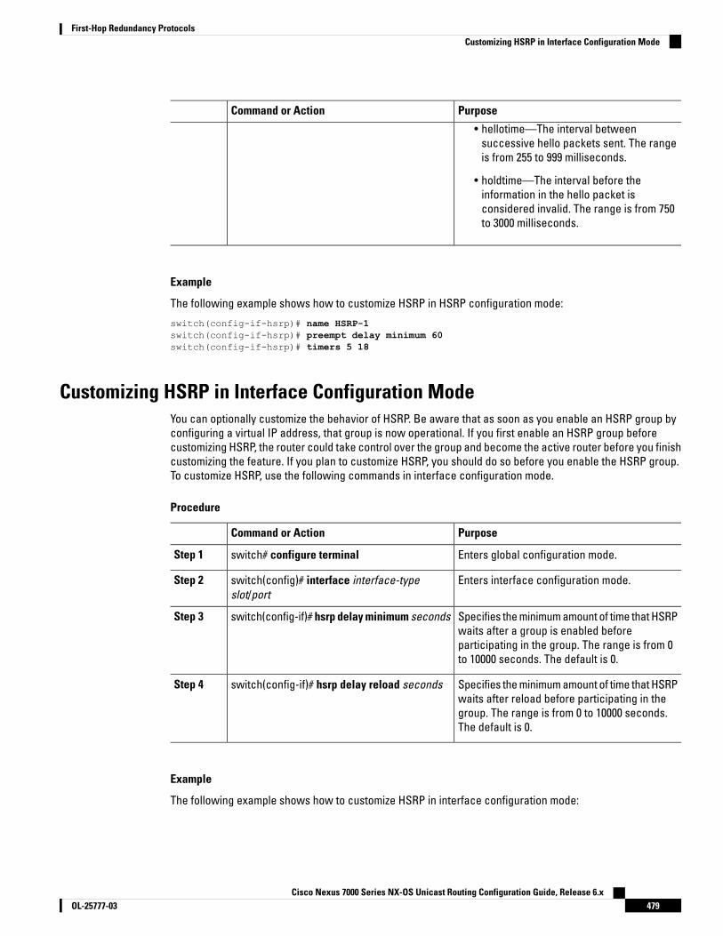
PurposeCommand or Action
• hellotime—The interval betweensuccessive hello packets sent. The rangeis from 255 to 999 milliseconds.
• holdtime—The interval before theinformation in the hello packet isconsidered invalid. The range is from 750to 3000 milliseconds.
Example
The following example shows how to customize HSRP in HSRP configuration mode:
switch(config-if-hsrp)# name HSRP-1switch(config-if-hsrp)# preempt delay minimum 60switch(config-if-hsrp)# timers 5 18
Customizing HSRP in Interface Configuration ModeYou can optionally customize the behavior of HSRP. Be aware that as soon as you enable an HSRP group byconfiguring a virtual IP address, that group is now operational. If you first enable an HSRP group beforecustomizing HSRP, the router could take control over the group and become the active router before you finishcustomizing the feature. If you plan to customize HSRP, you should do so before you enable the HSRP group.To customize HSRP, use the following commands in interface configuration mode.
Procedure
PurposeCommand or Action
Enters global configuration mode.switch# configure terminalStep 1
Enters interface configuration mode.switch(config)# interface interface-typeslot/port
Step 2
Specifies the minimum amount of time that HSRPwaits after a group is enabled before
switch(config-if)# hsrp delay minimum secondsStep 3
participating in the group. The range is from 0to 10000 seconds. The default is 0.
Specifies the minimum amount of time that HSRPwaits after reload before participating in the
switch(config-if)# hsrp delay reload secondsStep 4
group. The range is from 0 to 10000 seconds.The default is 0.
Example
The following example shows how to customize HSRP in interface configuration mode:
Cisco Nexus 7000 Series NX-OS Unicast Routing Configuration Guide, Release 6.x479OL-25777-03
First-Hop Redundancy ProtocolsCustomizing HSRP in Interface Configuration Mode

switch # configure terminalswitch(config)# interface ethernet 1/2switch(config-if)# hsrp delay minimum 30switch(config-if)# hsrp delay reload 30
Configuring Extended Hold Timers for HSRPYou can configure HSRP to use extended hold timers to support extended NSF during a controlled (graceful)switchover or ISSU, including software upgrades and supervisor switchovers. You should configure extendedhold timers on all HSRP routers.
You must configure extended hold timers on all HSRP routers if you configure extended hold timers. If youconfigure a nondefault hold timer, you should configure the same value on all HSRP routers when you configureHSRP extended hold timers.
HSRP extended hold timers are not applied if you configure millisecond hello and hold timers for HSRPv1. Thisstatement does not apply to HSRPv2.
Procedure
PurposeCommand or Action
Enters global configuration mode.switch# configure terminalStep 1
Sets the HSRP extended hold timer, in seconds,for both IPv4 and IPv6 groups. The timer rangeis from 10 to 255. The default is 10.
switch(config)# hsrp timers extended-hold[timer]
Step 2
Use the show hsrp command or theshow running-config hsrp commandto display the extended hold time.
Note
Saves the change persistently through rebootsand restarts by copying the runningconfiguration to the startup configuration.
(Optional) switch(config)# copy running-configstartup-config
Step 3
Example
The following example shows how to configure extended hold timers for HSRP:
switch # configure terminalswitch(config)# hsrp timers extended-holdswitch(config)# copy running-config startup-config
Verifying the HSRP ConfigurationUse one of the following commands to verify the configuration:
PurposeCommand
Displays the HSRP status for all groups or one group.show hsrp [group group-number]
Cisco Nexus 7000 Series NX-OS Unicast Routing Configuration Guide, Release 6.xOL-25777-03480
First-Hop Redundancy ProtocolsConfiguring Extended Hold Timers for HSRP

PurposeCommand
Displays the HSRP delay value for all interfaces or oneinterface.
show hsrp delay [interface interface-type slot/port]
Displays the HSRP status for an interface.show hsrp [interface interface-type slot/port]
Displays the HSRP status for a group or interface forvirtual forwarders in the active, init, learn, listen, orstandby state. Use the all keyword to see all states,including disabled.
show hsrp [group group-number] [interfaceinterface-type slot/port] [active] [all] [init] [learn][listen] [speak] [standby]
Displays a brief summary of the HSRP status for agroup or interface for virtual forwarders in the active,init, learn, listen, or standby state. Use the all keywordto see all states, including disabled.
show hsrp [group group-number] [interfaceinterface-type slot/port] active] [all] [init] [learn][listen] [speak] [standby] brief
Displays the relationships between HSRP groups thatare in use for MGO and their slave sessions.
show hsrp mgo [namename] [brief]
Configuration Examples for HSRPThis example shows how to enable HSRP on an interface with MD5 authentication and interface tracking:
key chain hsrp-keyskey 0key-string 7 zqdestaccept-lifetime 00:00:00 Jun 01 2008 23:59:59 Sep 12 2008send-lifetime 00:00:00 Jun 01 2008 23:59:59 Aug 12 2008key 1key-string 7 uaeqdyitoaccept-lifetime 00:00:00 Aug 12 2008 23:59:59 Dec 12 2008send-lifetime 00:00:00 Sep 12 2008 23:59:59 Nov 12 2008feature hsrptrack 2 interface ethernet 2/2 ipinterface ethernet 1/2ip address 192.0.2.2/8hsrp 1authenticate md5 key-chain hsrp-keyspriority 90track 2 decrement 20ip 192.0.2.10
no shutdown
This example shows how to configure the HSRP priority on an interface:
interface vlan 1hsrp 0
preemptpriority 100 forwarding-threshold lower 80 upper 90ip 192.0.2.2track 1 decrement 30
Cisco Nexus 7000 Series NX-OS Unicast Routing Configuration Guide, Release 6.x481OL-25777-03
First-Hop Redundancy ProtocolsConfiguration Examples for HSRP
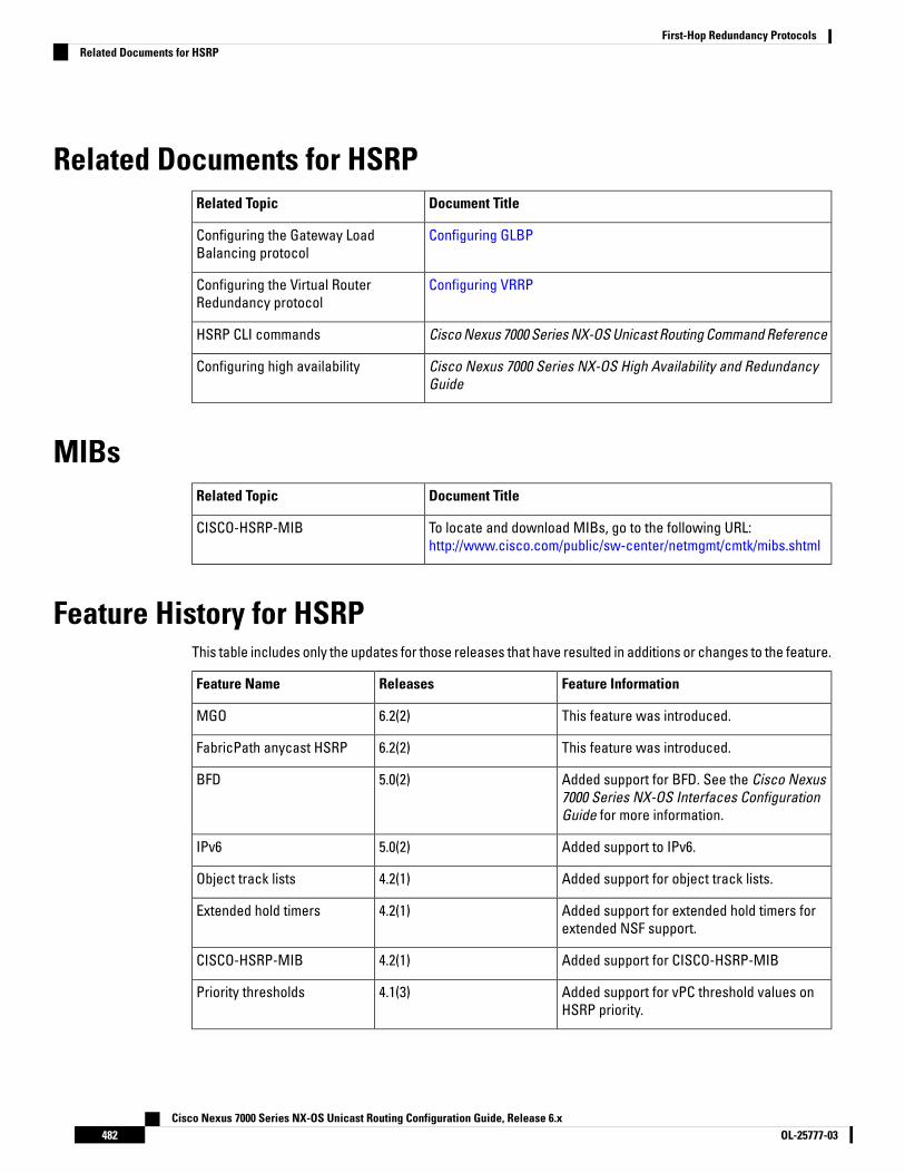
Related Documents for HSRPDocument TitleRelated Topic
Configuring GLBPConfiguring the Gateway LoadBalancing protocol
Configuring VRRPConfiguring the Virtual RouterRedundancy protocol
Cisco Nexus 7000 Series NX-OS Unicast Routing Command ReferenceHSRP CLI commands
Cisco Nexus 7000 Series NX-OS High Availability and RedundancyGuide
Configuring high availability
MIBsDocument TitleRelated Topic
To locate and download MIBs, go to the following URL:http://www.cisco.com/public/sw-center/netmgmt/cmtk/mibs.shtml
CISCO-HSRP-MIB
Feature History for HSRPThis table includes only the updates for those releases that have resulted in additions or changes to the feature.
Feature InformationReleasesFeature Name
This feature was introduced.6.2(2)MGO
This feature was introduced.6.2(2)FabricPath anycast HSRP
Added support for BFD. See the Cisco Nexus7000 Series NX-OS Interfaces ConfigurationGuide for more information.
5.0(2)BFD
Added support to IPv6.5.0(2)IPv6
Added support for object track lists.4.2(1)Object track lists
Added support for extended hold timers forextended NSF support.
4.2(1)Extended hold timers
Added support for CISCO-HSRP-MIB4.2(1)CISCO-HSRP-MIB
Added support for vPC threshold values onHSRP priority.
4.1(3)Priority thresholds
Cisco Nexus 7000 Series NX-OS Unicast Routing Configuration Guide, Release 6.xOL-25777-03482
First-Hop Redundancy ProtocolsRelated Documents for HSRP

Feature InformationReleasesFeature Name
This feature was introduced.4.0(1)HSRP
Cisco Nexus 7000 Series NX-OS Unicast Routing Configuration Guide, Release 6.x483OL-25777-03
First-Hop Redundancy ProtocolsFeature History for HSRP

Cisco Nexus 7000 Series NX-OS Unicast Routing Configuration Guide, Release 6.xOL-25777-03484
First-Hop Redundancy ProtocolsFeature History for HSRP

C H A P T E R 22Configuring VRRP
This chapter contains the following sections:
• Finding Feature Information, on page 485• Information About VRRP, on page 485• Guidelines and Limitations for VRRP, on page 491• Default Settings for VRRP Parameters, on page 492• Configuring VRRP, on page 492• Verifying the VRRP Configuration, on page 505• Monitoring VRRP Statistics, on page 506• Configuration Example for VRRP, on page 506• Related Documents for VRRP, on page 508• Feature History for VRRP, on page 508
Finding Feature InformationYour software release might not support all the features documented in this module. For the latest caveatsand feature information, see the Bug Search Tool at https://tools.cisco.com/bugsearch/ and the release notesfor your software release. To find information about the features documented in this module, and to see a listof the releases in which each feature is supported, see the "New and Changed Information"chapter or theFeature History table in this chapter.
Information About VRRPVRRP allows for transparent failover at the first-hop IP router by configuring a group of routers to share avirtual IP address. VRRP selects a master router in that group to handle all packets for the virtual IP address.The remaining routers are in standby and take over if the master router fails.
VRRP OperationA LAN client can determine which router should be the first hop to a particular remote destination by using adynamic process or static configuration. Examples of dynamic router discovery are as follows:
Proxy ARP—The client uses Address Resolution Protocol (ARP) to get the destination it wants to reach, anda router responds to the ARP request with its own MAC address.
Cisco Nexus 7000 Series NX-OS Unicast Routing Configuration Guide, Release 6.x485OL-25777-03

Routing protocol—The client listens to dynamic routing protocol updates (for example, from Routing InformationProtocol [RIP]) and forms its own routing table.
ICMP Router Discovery Protocol (IRDP) client—The client runs an Internet Control Message Protocol (ICMP)router discovery client.
The disadvantage to dynamic discovery protocols is that they incur some configuration and processing overheadon the LAN client. Also, if a router fails, the process of switching to another router can be slow.
An alternative to dynamic discovery protocols is to statically configure a default router on the client. Although,this approach simplifies client configuration and processing, it creates a single point of failure. If the defaultgateway fails, the LAN client is limited to communicating only on the local IP network segment and is cut offfrom the rest of the network.
VRRP can solve the static configuration problem by enabling a group of routers (a VRRP group) to share asingle virtual IP address.
The VRRP IP address must be different to any physical IP address of the devices participating in the VRRP,otherwise the ARP or MAC entries will be corrupted and may cause forwarding problems.
Note
You can then configure the LAN clients with the virtual IP address as their default gateway.
Figure 49: Basic VRRP Topology
This image shows a basic VLAN topology where routers A, B, and C form a VRRP group. The IP address of theVRRP group must be different to the address that was configured for the Ethernet interface of Router A (10.0.0.1).
Because the virtual IP address uses the IP address of the physical Ethernet interface of Router A, Router A isthe master (also known as the IP address owner). As the master, Router A owns the virtual IP address of theVRRP group and forwards packets sent to this IP address. Clients 1 through 3 are configured with the defaultgateway IP address of 10.0.0.1.
Routers B and C function as backups. If the master fails, the backup router with the highest priority becomesthe master and takes over the virtual IP address to provide uninterrupted service for the LAN hosts. Whenrouter A recovers, it becomes the master again.
Cisco Nexus 7000 Series NX-OS Unicast Routing Configuration Guide, Release 6.xOL-25777-03486
First-Hop Redundancy ProtocolsVRRP Operation
In Cisco NX-OS Release 4.1(2) and later, packets received on a routed port destined for the VRRP virtual IPaddress terminates on the local router, regardless of whether that router is the master VRRP router or a backupVRRP router. This includes ping and Telnet traffic. Packets received on a Layer 2 (VLAN) interface destinedfor the VRRP virtual IP address terminates on the master router.
Note
VRRP BenefitsThe benefits of VRRP are as follows:
• Redundancy—Enables you to configure multiple routers as the default gateway router, which reducesthe possibility of a single point of failure in a network.
• Load sharing—Allows traffic to and from LAN clients to be shared by multiple routers. The traffic load isshared more equitably among available routers.
• Multiple VRRP groups—Supports up to 255 VRRP groups on a router physical interface if the platformsupports multiple MAC addresses. Multiple VRRP groups enable you to implement redundancy and loadsharing in your LAN topology.
• Multiple IP addresses—Allows you to manage multiple IP addresses, including secondary IP addresses.If you have multiple subnets configured on an Ethernet interface, you can configure VRRP on each subnet.
• Preemption—Enables you to preempt a backup router that has taken over for a failing master with ahigher priority backup router that has become available.
• Advertisement protocol—Uses a dedicated Internet Assigned Numbers Authority (IANA) standard multicastaddress (224.0.0.18) for VRRP advertisements. This addressing scheme minimizes the number of routersthat must service the multicasts and allows test equipment to accurately identify VRRP packets on asegment. IANA has assigned the IP protocol number 112 to VRRP.
• VRRP tracking—Ensures that the best VRRP router is the master for the group by altering VRRP prioritiesbased on interface states.
• The benefits of VRRPv3 are as follows:
• Interoperability in multi-vendor environments.• Support for the IPv4 and IPv6 address families.• Improved scalability through the use of VRRS pathways.
Multiple VRRP GroupsYou can configure up to 255 VRRP groups on a physical interface. The number of VRRP groups that a routerinterface can support depends on the following factors:
• Router processing capability
• Router memory capability
In a topology where multiple VRRP groups are configured on a router interface, the interface can act as amaster for one VRRP group and as a backup for one or more other VRRP groups.
Cisco Nexus 7000 Series NX-OS Unicast Routing Configuration Guide, Release 6.x487OL-25777-03
First-Hop Redundancy ProtocolsVRRP Benefits
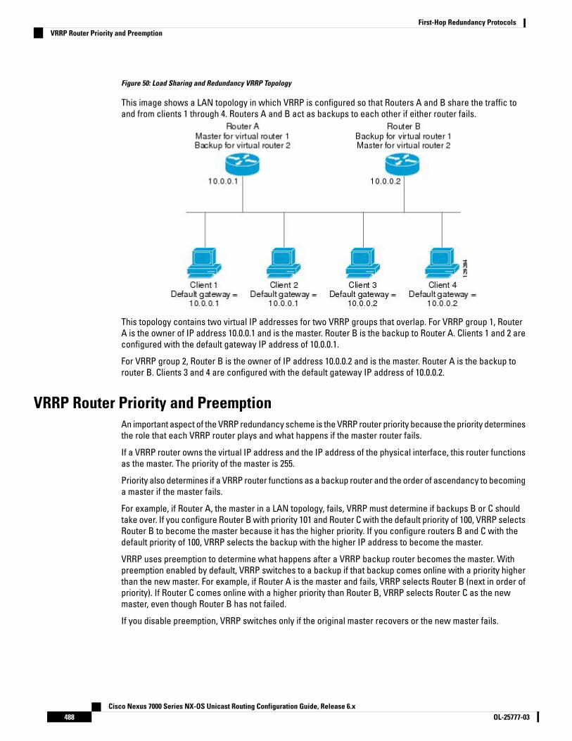
Figure 50: Load Sharing and Redundancy VRRP Topology
This image shows a LAN topology in which VRRP is configured so that Routers A and B share the traffic toand from clients 1 through 4. Routers A and B act as backups to each other if either router fails.
This topology contains two virtual IP addresses for two VRRP groups that overlap. For VRRP group 1, RouterA is the owner of IP address 10.0.0.1 and is the master. Router B is the backup to Router A. Clients 1 and 2 areconfigured with the default gateway IP address of 10.0.0.1.
For VRRP group 2, Router B is the owner of IP address 10.0.0.2 and is the master. Router A is the backup torouter B. Clients 3 and 4 are configured with the default gateway IP address of 10.0.0.2.
VRRP Router Priority and PreemptionAn important aspect of the VRRP redundancy scheme is the VRRP router priority because the priority determinesthe role that each VRRP router plays and what happens if the master router fails.
If a VRRP router owns the virtual IP address and the IP address of the physical interface, this router functionsas the master. The priority of the master is 255.
Priority also determines if a VRRP router functions as a backup router and the order of ascendancy to becominga master if the master fails.
For example, if Router A, the master in a LAN topology, fails, VRRP must determine if backups B or C shouldtake over. If you configure Router B with priority 101 and Router C with the default priority of 100, VRRP selectsRouter B to become the master because it has the higher priority. If you configure routers B and C with thedefault priority of 100, VRRP selects the backup with the higher IP address to become the master.
VRRP uses preemption to determine what happens after a VRRP backup router becomes the master. Withpreemption enabled by default, VRRP switches to a backup if that backup comes online with a priority higherthan the new master. For example, if Router A is the master and fails, VRRP selects Router B (next in order ofpriority). If Router C comes online with a higher priority than Router B, VRRP selects Router C as the newmaster, even though Router B has not failed.
If you disable preemption, VRRP switches only if the original master recovers or the new master fails.
Cisco Nexus 7000 Series NX-OS Unicast Routing Configuration Guide, Release 6.xOL-25777-03488
First-Hop Redundancy ProtocolsVRRP Router Priority and Preemption

vPC and VRRPVRRP interoperates with virtual port channels (vPCs). vPCs allow links that are physically connected to twodifferent Cisco Nexus 7000 series devices to appear as a single port channel by a third device. See the CiscoNexus 7000 Series NX-OS Layer 2 Switching Configuration Guide, for more information on vPCs.
vPC forwards traffic through both the master VRRP router as well as the backup VRRP router.
You should configure VRRP on the primary vPC peer device as active and VRRP on the vPC secondary deviceas standby.
Note
VRRP AdvertisementsThe VRRP master sends VRRP advertisements to other VRRP routers in the same group. The advertisementscommunicate the priority and state of the master. Cisco NX-OS encapsulates the VRRP advertisements in IPpackets and sends them to the IP multicast address assigned to the VRRP group. Cisco NX-OS sends theadvertisements once every second by default, but you can configure a different advertisement interval.
VRRP AuthenticationVRRP supports the following authentication functions:
• No authentication
• Plain text authentication
VRRP rejects packets in any of the following cases:
• The authentication schemes differ on the router and in the incoming packet.
• Text authentication strings differ on the router and in the incoming packet.
VRRP TrackingVRRP supports the following two options for tracking:
• Native interface tracking—Tracks the state of an interface and uses that state to determine the priorityof the VRRP router in a VRRP group. The tracked state is down if the interface is down or if the interfacedoes not have a primary IP address.
• Object tracking—Tracks the state of a configured object and uses that state to determine the priority ofthe VRRP router in a VRRP group.
If the tracked state (interface or object) goes down, VRRP updates the priority based on what you configurethe new priority to be for the tracked state. When the tracked state comes up, VRRP restores the originalpriority for the virtual router group.
For example, you may want to lower the priority of a VRRP group member if its uplink to the network goes downso another group member can take over as master for the VRRP group.
Cisco Nexus 7000 Series NX-OS Unicast Routing Configuration Guide, Release 6.x489OL-25777-03
First-Hop Redundancy ProtocolsvPC and VRRP
VRRP does not support Layer 2 interface tracking.Note
VRRPv3 and VRRSVRRP version 3 (VRRPv3) enables a group of switches to form a single virtual switch in order to provideredundancy and reduce the possibility of a single point of failure in a network. The LAN clients can then beconfigured with the virtual switch as their default gateway. The virtual switch, representing a group of switches,is also known as a VRRPv3 group.
Virtual router redundancy service (VRRS) improves the scalability of VRRPv3 by providing a stateless redundancyservice to VRRS pathways and VRRS clients by monitoring VRRPv3. VRRPv3 acts as a VRRS server that pushesVRRPv3 status information (such as current and previous redundancy states, active and inactive Layer 2 andLayer 3 addresses, and so on) to VRRS pathways and all registered VRRS clients.
VRRS clients are other Cisco processes or applications that use VRRPv3 to provide or withhold a service orresource dependent upon the state of the group. VRRS pathways are special VRRS clients that use the VRRSdatabase information to provide scaled first-hop gateway redundancy across scaled interface environments.
VRRS by itself is limited to maintaining its own state. Linking a VRRS client to a VRRPv3 group provides amechanism that allows VRRS to provide a service to client applications so that they can implement statelessor stateful failovers. A stateful failover requires communication with a nominated backup before the failureso that operational data is not lost when the failover occurs.
VRRS pathways operate in a similar way to clients but are integrated with the VRRS architecture. They providea means to scale first-hop gateway redundancy by allowing you to configure a virtual address across hundredsof interfaces. The virtual gateway state of a VRRS pathway follows the state of a First-Hop Redundancy Protocol(FHRP) VRRS server.
VRRPv3 notifies VRRS of its current state (master, backup, or nonoperational initial state [INIT]) and passesthat infromation to pathways or clients. The VRRPv3 group name activates VRRS and associates the VRRPv3group with any clients or pathways that are configured as part of VRRS with the same name.
Pathways and clients act on the VRRPv3 server state. When a VRRPv3 group changes states, VRRS pathwaysand clients alter their behavior (performing tasks such as shutting down interfaces or appending accountinglogs) depending on the state received from VRRS.
BFD for VRRPThis feature supports bidirectional forwarding detection (BFD). BFD is a detection protocol that providesfast-forwarding and path-failure detection times. BFD provides subsecond failure detection between twoadjacent devices and can be less CPU-intensive than protocol hello messages because some of the BFD loadcan be distributed onto the data plane on supported modules. See the Cisco Nexus 7000 Series NX-OS InterfacesConfiguration Guide, for more information.
High AvailabilityVRRP supports high availability through stateful restarts and stateful switchovers. A stateful restart occurswhen the VRRP process fails and is restarted. Stateful switchover occurs when the active supervisor switchesto the standby supervisor. Cisco NX-OS applies the run-time configuration after the switchover.
Cisco Nexus 7000 Series NX-OS Unicast Routing Configuration Guide, Release 6.xOL-25777-03490
First-Hop Redundancy ProtocolsVRRPv3 and VRRS

VRRPv3 does not support stateful switchovers.
Virtualization SupportVRRP supports virtual routing and forwarding (VRF) instances. VRF exists within virtual device contexts (VDCs).By default, Cisco NX-OS places you in the default VDC and default VRF unless you specifically configureanother VDC and VRF. If you change the VRF membership of an interface, Cisco NX-OS removes all Layer 3configurations, including VRRP.
For more information, see the Cisco Nexus 7000 Series NX-OS Virtual Device Context Configuration Guide andConfiguring Layer 3 Virtualization, on page 375.
Guidelines and Limitations for VRRP• You cannot configure VRRP on the management interface.
• When VRRP is enabled, you should replicate the VRRP configuration across devices in your network.
• We recommend that you do not configure more than one first-hop redundancy protocol on the sameinterface.
• You must configure an IP address for the interface where you configure VRRP and enable that interfacebefore VRRP becomes active.
• Cisco NX-OS removes all Layer 3 configurations on an interface when you change the interface VRFmembership, port channel membership, or when you change the port mode to Layer 2.
• When you configure VRRP to track a Layer 2 interface, you must shut down the Layer 2 interface andreenable the interface to update the VRRP priority to reflect the state of the Layer 2 interface
• BFD for VRRP can only be configured between two routers.
• The VRRP IP address must be different than any physical IP address of the devices participating in theVRRP, otherwise the ARP or MAC entries will be corrupted and may cause forwarding problems.
• VRRPv3 has the following configuration guidelines and limitations:
• VRRPv3 is not intended as a replacement for existing dynamic protocols. VRRPv3 is designed foruse over multi-access, multicast, or broadcast-capable Ethernet LANs.
• VRRPv3 is supported only on Ethernet and Fast Ethernet interfaces, bridge group virtual interfaces(BVIs), and Gigabit Ethernet interfaces as well as on Multiprotocol Label Switching (MPLS) virtualprivate networks (VPNs), VRF-aware MPLS VPNs, and VLANs.
• When VRRPv3 is in use, VRRPv2 is unavailable. To configure VRRPv3, you must disable any VRRPv2configuration.
• VRRS is currently available only for use with VRRPv3.
• Use VRRPv3 millisecond timers only where absolutely necessary and with careful consideration andtesting. Millisecond values work only under favorable circumstances. The millisecond timer valuesare compatible with third-party vendors, as long as they also support VRRPv3.
• Full network redundancy can be achieved only if VRRPv3 operates over the same network path asthe VRRS pathway redundant interfaces. For full redundancy, the following restrictions apply:
Cisco Nexus 7000 Series NX-OS Unicast Routing Configuration Guide, Release 6.x491OL-25777-03
First-Hop Redundancy ProtocolsVirtualization Support

• VRRS pathways should use the same physical interface as the parent VRRPv3 group or beconfigured on a subinterface with the same physical interface as the parent VRRPv3 group.
• VRRS pathways can be configured on switch virtual interfaces (SVIs) only if the associatedVLAN shares the same trunk as the VLAN on which the parent VRRPv3 group is configured.
Default Settings for VRRP ParametersDefault RIP Parameters
DefaultParameters
1 secondAdvertisement interval
No authenticationAuthentication
EnabledPreemption
100Priority
DisabledVRRP feature
DisabledVRRPv3
DisabledVRRS
EnablesVRRPv3 secondary address matching
100Priority of a VRRPv3 group
1000 millisecondsVRRPv3 advertisement timer
Configuring VRRP
Enabling VRRPYou must globally enable the VRRP feature before you configure and enable any VRRP groups.
Procedure
PurposeCommand or Action
Enters global configuration mode.switch# configure terminalStep 1
Enables the VRRP feature.switch(config)# [no] feature vrrpStep 2
Use the no form of this command to disable thisfeature.
Cisco Nexus 7000 Series NX-OS Unicast Routing Configuration Guide, Release 6.xOL-25777-03492
First-Hop Redundancy ProtocolsDefault Settings for VRRP Parameters

PurposeCommand or Action
Using the no form of this command will disablethe feature in a VDC and remove all associatedconfigurations.
Saves the change persistently through rebootsand restarts by copying the runningconfiguration to the startup configuration.
(Optional) switch(config)# copy running-configstartup-config
Step 3
Example
The following example enables VRRP:
switch # configure terminalswitch(config)# feature vrrpswitch(config)# copy running-config startup-config
Configuring VRRP GroupsYou can create a VRRP group, assign the virtual IP address, and enable the group.
You can configure one virtual IPv4 address for a VRRP group. By default, the master VRRP router drops thepackets addressed directly to the virtual IP address because the VRRP master is only intended as a next-hoprouter to forward packets. Some applications require that Cisco NX-OS accept packets addressed to the virtualrouter IP. Use the secondary option to the virtual IP address to accept these packets when the local router isthe VRRP master.
Once you have configured the VRRP group, you must explicitly enable the group before it becomes active.
Before you begin
Confirm that you are in the correct VDC. To change the VDC, use the switchto vdc command.
Ensure that you have configured an IP address on the interface.
Procedure
PurposeCommand or Action
Enters global configuration mode.switch# configure terminalStep 1
Enters interface configuration mode.switch(config)# interface interface-typeslot/port
Step 2
Creates a virtual router group. the range is from1 to 255.
switch(config-if)# vrrp numberStep 3
Configures the virtual IPv4 address for thespecified VRRP group. This address should be
switch(config-if-vrrp)# address ip-address[secondary]
Step 4
in the same subnet as the IPv4 address of theinterface.
Cisco Nexus 7000 Series NX-OS Unicast Routing Configuration Guide, Release 6.x493OL-25777-03
First-Hop Redundancy ProtocolsConfiguring VRRP Groups

PurposeCommand or Action
Use the secondary option only if applicationsrequire that VRRP routers accept the packetssent to the virtual router's IP address and deliverto applications.
Enables the VRRP group. Disabled by default.switch(config-if-vrrp)# no shutdownStep 5
Saves the change persistently through rebootsand restarts by copying the runningconfiguration to the startup configuration.
switch(config-if-vrrp)# copy running-configstartup-config
Step 6
(Optional) Displays VRRP information.(Optional) switch(config-if-vrrp)# show vrrpStep 7
Example
The following example enables VRRP:
switch # configure terminalswitch(config)# interface ethernet 2/1
switch(config-if)# vrrp 250switch(config-if-vrrp)# address 192.0.2.8switch(config-if-vrrp)# no shutdownswitch(config-if-vrrp)# copy running-config startup-configswitch(config-if-vrrp)# show vrrp
Configuring VRRP PriorityThe valid priority range for a virtual router is from 1 to 254 (1 is the lowest priority and 254 is the highest). Thedefault priority value for backups is 100. For devices whose interface IP address is the same as the primaryvirtual IP address (the master), the default value is 255.
If you configure VRRP on a vPC-enabled interface, you can optionally configure the upper and lower thresholdvalues to control when to fail over to the vPC trunk. If the backup router priority falls below the lower threshold,VRRP sends all backup router traffic across the vPC trunk to forward through the master VRRP router. VRRPmaintains this scenario until the backup VRRP router priority increases above the upper threshold.
Before you begin
• Confirm that you are in the correct VDC. To change the VDC, use the switchto vdc command.
• Ensure that you have configured an IP address on the interface.
• You must enable VRRP.
Procedure
PurposeCommand or Action
Enters global configuration mode.switch# configure terminalStep 1
Cisco Nexus 7000 Series NX-OS Unicast Routing Configuration Guide, Release 6.xOL-25777-03494
First-Hop Redundancy ProtocolsConfiguring VRRP Priority

PurposeCommand or Action
Enters interface configuration mode.switch(config)# interface interface-typeslot/port
Step 2
Creates a virtual router group. the range is from1 to 255.
switch(config-if)# vrrp numberStep 3
Disables the VRRP group. Disabled by default.switch(config-if-vrrp)# shutdownStep 4
Sets the priority level used to select the activerouter in a VRRP group. The level range is from
switch(config-if-vrrp)# priority level[forwarding-threshold lower lower-value upperupper-value]
Step 5
1 to 254. The default is 100 for backups and 255for a master that has an interface IP addressequal to the virtual IP address.
Optionally, sets the upper and lower thresholdvalues used by vPC to determine when to failover to the vPC trunk. The lower-value range isfrom 1 to 255. The default is 1. The upper-valuerange is from 1 to 255. The default is 255.
Enables the VRRP group. Disabled by default.switch(config-if-vrrp)# no shutdownStep 6
Saves the change persistently through rebootsand restarts by copying the runningconfiguration to the startup configuration.
switch(config-if-vrrp)# copy running-configstartup-config
Step 7
Displays VRRP information.(Optional) switch(config-if-vrrp)# show vrrpStep 8
Example
The following example enables VRRP:
switch # configure terminalswitch(config)# interface ethernet 2/1
switch(config-if)# vrrp 250switch(config-if)# shutdownswitch(config-if-vrrp)# priority 60 forwarding-threshold lower 40 upper 50switch(config-if-vrrp)# no shutdownswitch(config)# copy running-config startup-configswitch(config-if-vrrp)# show vrrp
Configuring VRRP AuthenticationYou can configure simple text authentication for a VRRP group.
Before you begin
• Ensure that the authentication configuration is identical for all VRRP devices in the network.
• Confirm that you are in the correct VDC. To change the VDC, use the switchto vdc command.
Cisco Nexus 7000 Series NX-OS Unicast Routing Configuration Guide, Release 6.x495OL-25777-03
First-Hop Redundancy ProtocolsConfiguring VRRP Authentication

• Ensure that you have configured an IP address on the interface. See #unique_770.
• You must enable VRRP.
Procedure
PurposeCommand or Action
Enters global configuration mode.switch# configure terminalStep 1
Enters interface configuration mode.switch(config)# interface interface-typeslot/port
Step 2
Creates a virtual router group. The range is from1 to 255.
switch(config-if)# vrrp numberStep 3
Disables the VRRP group. Disabled by default.switch(config-if-vrrp)# shutdownStep 4
Assigns the simple text authentication optionand specifies the keyname password. The
switch(config-if-vrrp)# authentication textpassword
Step 5
keyname range is from 1 to 255 characters. Werecommend that you use at least 16 characters.The text password is up to eight alphanumericcharacters.
Enables the VRRP group. Disabled by default.switch(config-if-vrrp)# no shutdownStep 6
Saves the change persistently through rebootsand restarts by copying the runningconfiguration to the startup configuration.
switch(config-if-vrrp)# copy running-configstartup-config
Step 7
Displays VRRP information.(Optional) switch(config-if-vrrp)# show vrrpStep 8
Example
The following example enables VRRP:
switch # configure terminalswitch(config)# interface ethernet 2/1
switch(config-if)# vrrp 250switch(config-if)# shutdownswitch(config-if-vrrp)# authentication text aPasswordswitch(config-if-vrrp)# no shutdownswitch(config)# copy running-config startup-configswitch(config-if-vrrp)# show vrrp
Configuring Time Intervals for Advertisement PacketsYou can configure the time intervals for advertisement packets.
Before you begin
• Confirm that you are in the correct VDC. To change the VDC, use the switchto vdc command.
Cisco Nexus 7000 Series NX-OS Unicast Routing Configuration Guide, Release 6.xOL-25777-03496
First-Hop Redundancy ProtocolsConfiguring Time Intervals for Advertisement Packets

• Ensure that you have configured an IP address on the interface.
• You must enable VRRP.
Procedure
PurposeCommand or Action
Enters global configuration mode.switch# configure terminalStep 1
Enters interface configuration mode.switch(config)# interface interface-typeslot/port
Step 2
Creates a virtual router group. The range is from1 to 255.
switch(config-if)# vrrp numberStep 3
Disables the VRRP group. Disabled by default.switch(config-if-vrrp)# shutdownStep 4
Sets the interval time in seconds betweensending advertisement frames. The range isfrom 1 to 255. The default is 1 second.
switch(config-if-vrrp)# advertisement intervalseconds
Step 5
Enables the VRRP group. Disabled by default.switch(config-if-vrrp)# no shutdownStep 6
Saves the change persistently through rebootsand restarts by copying the runningconfiguration to the startup configuration.
switch(config-if-vrrp)# copy running-configstartup-config
Step 7
Displays VRRP information.(Optional) switch(config-if-vrrp)# show vrrpStep 8
Example
The following example enables VRRP:
switch # configure terminalswitch(config)# interface ethernet 2/1
switch(config-if)# vrrp 250switch(config-if)# shutdownswitch(config-if-vrrp)# advertisement-interval 15switch(config-if-vrrp)# no shutdownswitch(config)# copy running-config startup-configswitch(config-if-vrrp)# show vrrp
Disabling PreemptionYou can disable preemption for a VRRP group member. If you disable preemption, a higher-priority backuprouter does not take over for a lower-priority master router. Preemption is enabled by default.
Before you begin
• You must enable VRRP.
• Ensure that you have configured an IP address on the interface.
Cisco Nexus 7000 Series NX-OS Unicast Routing Configuration Guide, Release 6.x497OL-25777-03
First-Hop Redundancy ProtocolsDisabling Preemption
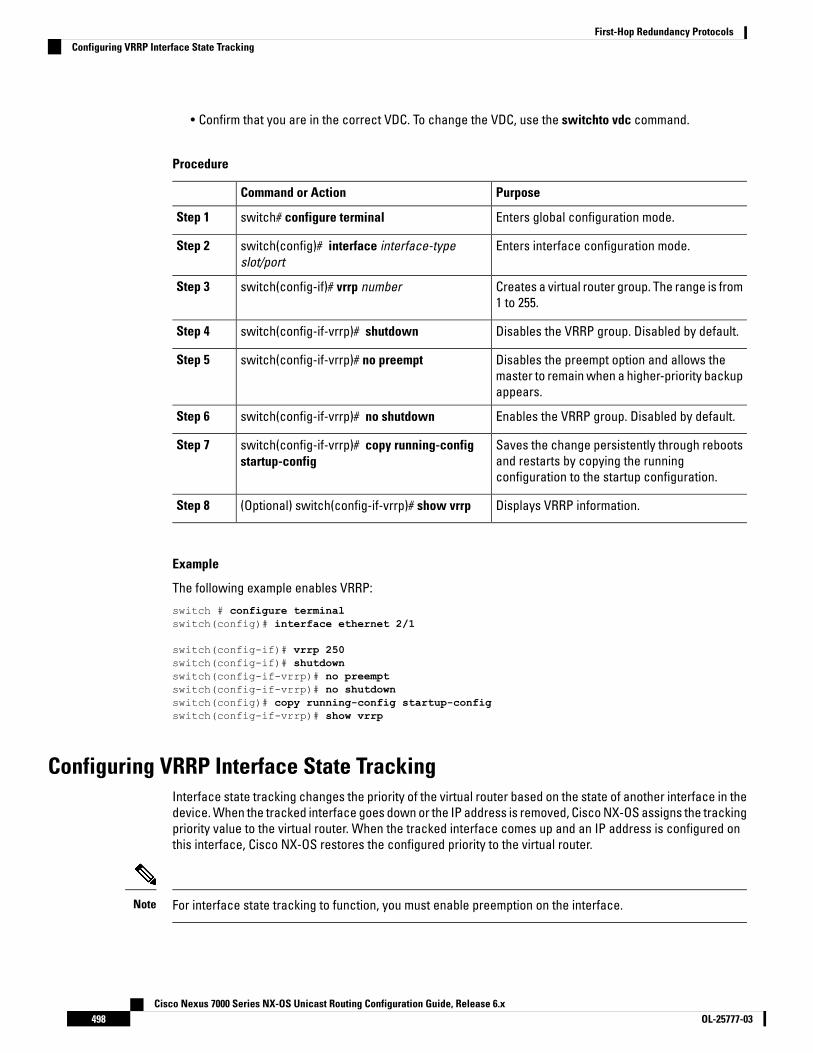
• Confirm that you are in the correct VDC. To change the VDC, use the switchto vdc command.
Procedure
PurposeCommand or Action
Enters global configuration mode.switch# configure terminalStep 1
Enters interface configuration mode.switch(config)# interface interface-typeslot/port
Step 2
Creates a virtual router group. The range is from1 to 255.
switch(config-if)# vrrp numberStep 3
Disables the VRRP group. Disabled by default.switch(config-if-vrrp)# shutdownStep 4
Disables the preempt option and allows themaster to remain when a higher-priority backupappears.
switch(config-if-vrrp)# no preemptStep 5
Enables the VRRP group. Disabled by default.switch(config-if-vrrp)# no shutdownStep 6
Saves the change persistently through rebootsand restarts by copying the runningconfiguration to the startup configuration.
switch(config-if-vrrp)# copy running-configstartup-config
Step 7
Displays VRRP information.(Optional) switch(config-if-vrrp)# show vrrpStep 8
Example
The following example enables VRRP:
switch # configure terminalswitch(config)# interface ethernet 2/1
switch(config-if)# vrrp 250switch(config-if)# shutdownswitch(config-if-vrrp)# no preemptswitch(config-if-vrrp)# no shutdownswitch(config)# copy running-config startup-configswitch(config-if-vrrp)# show vrrp
Configuring VRRP Interface State TrackingInterface state tracking changes the priority of the virtual router based on the state of another interface in thedevice. When the tracked interface goes down or the IP address is removed, Cisco NX-OS assigns the trackingpriority value to the virtual router. When the tracked interface comes up and an IP address is configured onthis interface, Cisco NX-OS restores the configured priority to the virtual router.
For interface state tracking to function, you must enable preemption on the interface.Note
Cisco Nexus 7000 Series NX-OS Unicast Routing Configuration Guide, Release 6.xOL-25777-03498
First-Hop Redundancy ProtocolsConfiguring VRRP Interface State Tracking
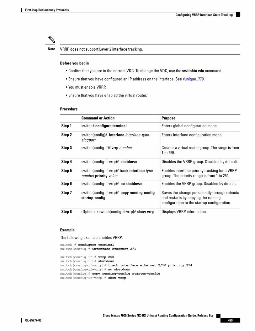
VRRP does not support Layer 2 interface tracking.Note
Before you begin
• Confirm that you are in the correct VDC. To change the VDC, use the switchto vdc command.
• Ensure that you have configured an IP address on the interface. See #unique_770.
• You must enable VRRP.
• Ensure that you have enabled the virtual router.
Procedure
PurposeCommand or Action
Enters global configuration mode.switch# configure terminalStep 1
Enters interface configuration mode.switch(config)# interface interface-typeslot/port
Step 2
Creates a virtual router group. The range is from1 to 255.
switch(config-if)# vrrp numberStep 3
Disables the VRRP group. Disabled by default.switch(config-if-vrrp)# shutdownStep 4
Enables interface priority tracking for a VRRPgroup. The priority range is from 1 to 254.
switch(config-if-vrrp)# track interface typenumber priority value
Step 5
Enables the VRRP group. Disabled by default.switch(config-if-vrrp)# no shutdownStep 6
Saves the change persistently through rebootsand restarts by copying the runningconfiguration to the startup configuration.
switch(config-if-vrrp)# copy running-configstartup-config
Step 7
Displays VRRP information.(Optional) switch(config-if-vrrp)# show vrrpStep 8
Example
The following example enables VRRP:
switch # configure terminalswitch(config)# interface ethernet 2/1
switch(config-if)# vrrp 250switch(config-if)# shutdownswitch(config-if-vrrp)# track interface ethernet 2/10 priority 254switch(config-if-vrrp)# no shutdownswitch(config)# copy running-config startup-configswitch(config-if-vrrp)# show vrrp
Cisco Nexus 7000 Series NX-OS Unicast Routing Configuration Guide, Release 6.x499OL-25777-03
First-Hop Redundancy ProtocolsConfiguring VRRP Interface State Tracking
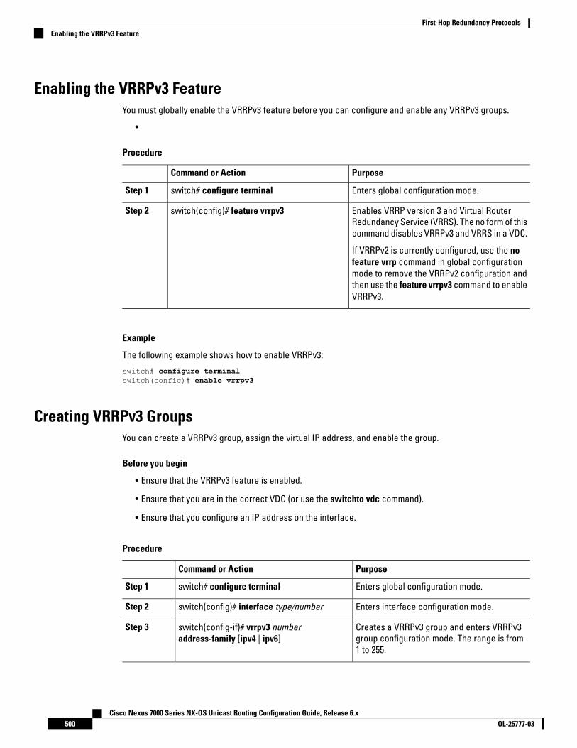
Enabling the VRRPv3 FeatureYou must globally enable the VRRPv3 feature before you can configure and enable any VRRPv3 groups.
•
Procedure
PurposeCommand or Action
Enters global configuration mode.switch# configure terminalStep 1
Enables VRRP version 3 and Virtual RouterRedundancy Service (VRRS). The no form of thiscommand disables VRRPv3 and VRRS in a VDC.
switch(config)# feature vrrpv3Step 2
If VRRPv2 is currently configured, use the nofeature vrrp command in global configurationmode to remove the VRRPv2 configuration andthen use the feature vrrpv3 command to enableVRRPv3.
Example
The following example shows how to enable VRRPv3:
switch# configure terminalswitch(config)# enable vrrpv3
Creating VRRPv3 GroupsYou can create a VRRPv3 group, assign the virtual IP address, and enable the group.
Before you begin
• Ensure that the VRRPv3 feature is enabled.
• Ensure that you are in the correct VDC (or use the switchto vdc command).
• Ensure that you configure an IP address on the interface.
Procedure
PurposeCommand or Action
Enters global configuration mode.switch# configure terminalStep 1
Enters interface configuration mode.switch(config)# interface type/numberStep 2
Creates a VRRPv3 group and enters VRRPv3group configuration mode. The range is from1 to 255.
switch(config-if)# vrrpv3 numberaddress-family [ipv4 | ipv6]
Step 3
Cisco Nexus 7000 Series NX-OS Unicast Routing Configuration Guide, Release 6.xOL-25777-03500
First-Hop Redundancy ProtocolsEnabling the VRRPv3 Feature

PurposeCommand or Action
(Optional)switch(config-if-vrrpv3-group)# addressip-address [primary | secondary]
Step 4
Specifies a primary or secondary IPv4 or IPv6address for the VRRPv3 group.
To utilize secondary IP addresses in a VRRPv3group, you must first configure a primary IPaddress on the same group.
(Optional)switch(config-if-vrrpv3-group)# descriptiondescription
Step 5
Specifies a description for the VRRPv3 group.You can enter up to 80 alphanumericcharacters.
(Optional)switch(config-if-vrrpv3-group)# match-addressStep 6
Matches the secondary address in theadvertisement packet against the configuredaddress.
(Optional)switch(config-if-vrrpv3-group)# preempt [delayminimum seconds]
Step 7
Enables preemption of a lower priority masterswitch with an optional delay. The range isfrom 0 to 3600.
(Optional)switch(config-if-vrrpv3-group)# priority levelStep 8
Specifies the priority of the VRRPv3 group. Therange is from 1 to 254.
(Optional)switch(config-if-vrrpv3-group)# timersadvertise interval
Step 9
Sets the advertisement timer in milliseconds.The range is from 100 to 40950.
Cisco recommends that you set this timer to avalue greater than or equal to 1 second.
(Optional)switch(config-if-vrrpv3-group)# vrrp2Step 10
Enables support for VRRPv2 simultaneously, toensure interoperability with devices thatsupport only VRRPv2.
VRRPv2 compatibility mode is provided to allowan upgrade from VRRPv2 to VRRPv3. This is nota full VRRPv2 implementation and should beused only to perform an upgrade.
(Optional)switch(config-if-vrrpv3-group)# vrrs leadervrrs-leader-name
Step 11
Specifies a leader’s name to be registered withVRRS.
(Optional)switch(config-if-vrrpv3-group)# shutdownStep 12
Cisco Nexus 7000 Series NX-OS Unicast Routing Configuration Guide, Release 6.x501OL-25777-03
First-Hop Redundancy ProtocolsCreating VRRPv3 Groups
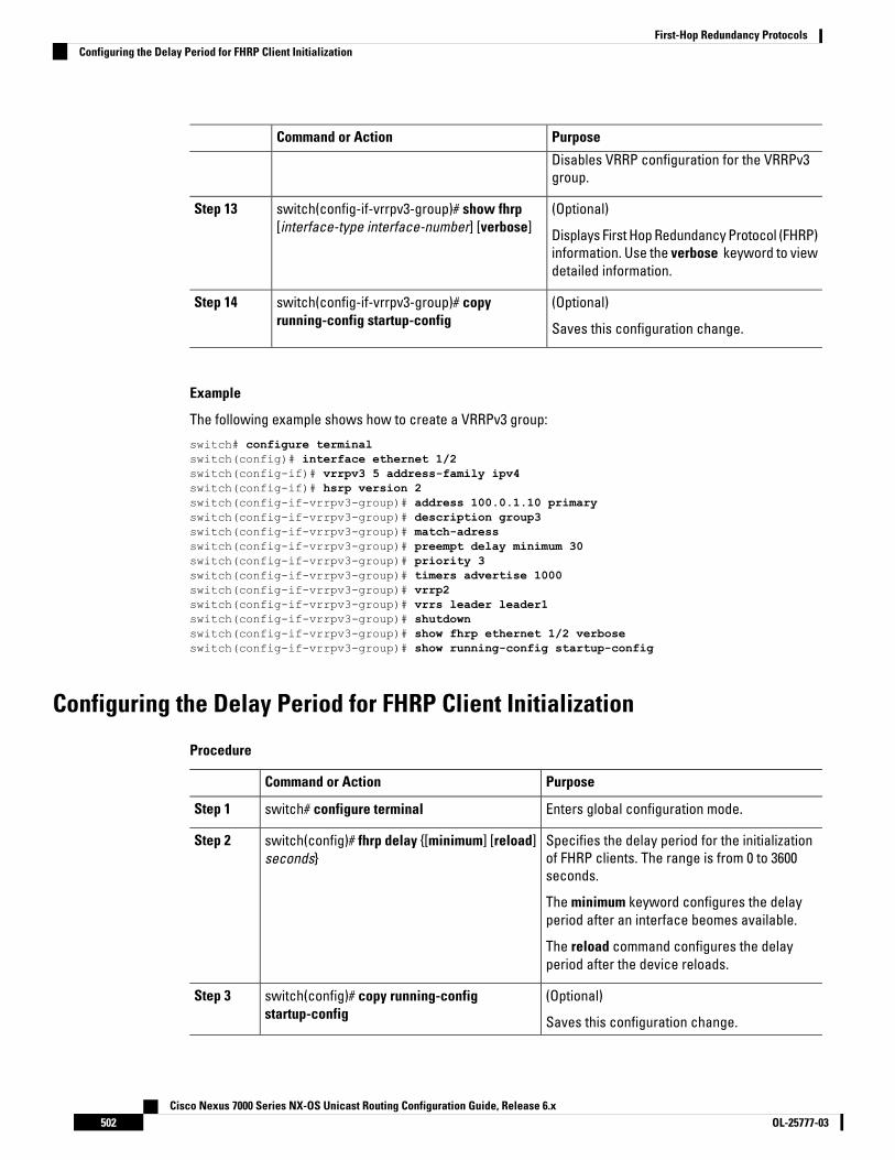
PurposeCommand or Action
Disables VRRP configuration for the VRRPv3group.
(Optional)switch(config-if-vrrpv3-group)# show fhrp[interface-type interface-number] [verbose]
Step 13
Displays First Hop Redundancy Protocol (FHRP)information. Use the verbose keyword to viewdetailed information.
(Optional)switch(config-if-vrrpv3-group)# copyrunning-config startup-config
Step 14
Saves this configuration change.
Example
The following example shows how to create a VRRPv3 group:
switch# configure terminalswitch(config)# interface ethernet 1/2switch(config-if)# vrrpv3 5 address-family ipv4switch(config-if)# hsrp version 2switch(config-if-vrrpv3-group)# address 100.0.1.10 primaryswitch(config-if-vrrpv3-group)# description group3switch(config-if-vrrpv3-group)# match-adressswitch(config-if-vrrpv3-group)# preempt delay minimum 30switch(config-if-vrrpv3-group)# priority 3switch(config-if-vrrpv3-group)# timers advertise 1000switch(config-if-vrrpv3-group)# vrrp2switch(config-if-vrrpv3-group)# vrrs leader leader1switch(config-if-vrrpv3-group)# shutdownswitch(config-if-vrrpv3-group)# show fhrp ethernet 1/2 verboseswitch(config-if-vrrpv3-group)# show running-config startup-config
Configuring the Delay Period for FHRP Client Initialization
Procedure
PurposeCommand or Action
Enters global configuration mode.switch# configure terminalStep 1
Specifies the delay period for the initializationof FHRP clients. The range is from 0 to 3600seconds.
switch(config)# fhrp delay {[minimum] [reload]seconds}
Step 2
The minimum keyword configures the delayperiod after an interface beomes available.
The reload command configures the delayperiod after the device reloads.
(Optional)switch(config)# copy running-configstartup-config
Step 3
Saves this configuration change.
Cisco Nexus 7000 Series NX-OS Unicast Routing Configuration Guide, Release 6.xOL-25777-03502
First-Hop Redundancy ProtocolsConfiguring the Delay Period for FHRP Client Initialization

Example
The following example shows how to configure the delay period for initializing FHRP clients:
switch# configure terminalswitch(config)# fhrp delay minimum 14
Configuring VRRPv3 Control Groups
Before you begin
• Ensure that the VRRPv3 feature is enabled.
Ensure that you are in the correct VDC (or use the switchto vdc command).
Ensure that you configure an IP address on the interface.
Procedure
PurposeCommand or Action
Enters global configuration mode.switch# configure terminalStep 1
Enters interface configuration mode.switch(config)# interface type/numberStep 2
Configures the IP address on the interface.switch(config-if)# ip address ip address mask[secondary]
Step 3
You can use the secondary keyword toconfigure additional IP addresses on theinterface.
Creates a VRRPv3 group and enters VRRPv3group configuration mode. The range is from 1to 255.
switch(config-if)# vrrpv3 number address-family[ipv4 | ipv6]
Step 4
(Optional)switch(config-if-vrrpv3-group)# addressip-address [primary | secondary]
Step 5
Specifies a primary or secondary IPv4 or IPv6address for the VRRPv3 group.
(Optional)switch(config-if-vrrpv3-group)# vrrs leadervrrs-leader-name
Step 6
Specifies a leader’s name to be registered withVRRS.
(Optional)switch(config-if-vrrpv3-group)# shutdownStep 7
Disables VRRP configuration for the VRRPv3group.
(Optional)switch(config-if-vrrpv3-group)# show fhrp[interfice-type interface-number] [verbose]
Step 8
Displays First Hop Redundancy Protocol (FHRP)information.
Cisco Nexus 7000 Series NX-OS Unicast Routing Configuration Guide, Release 6.x503OL-25777-03
First-Hop Redundancy ProtocolsConfiguring VRRPv3 Control Groups

PurposeCommand or Action
Use the verbosekeyword to view detailedinformation
(Optional)switch(config-if-vrrpv3-group)# copyrunning-config startup-config
Step 9
Saves this configuration change.
Example
The following example shows how to configure a VRRPv3 control group:
switch# configure terminalswitch(config)# interface ethernet 1/2switch(config-if)# ip address 209.165.200.230 255.255.255.224switch(config-if)# vrrpv3 5 address-family ipv4switch(cofig-if-vrrpv3-group)# address 209.165.200.227 primaryswitch(cofig-if-vrrpv3-group)# vrrs leader leader1witch(cofig-if-vrrpv3-group)# shutdownswitch(cofig-if-vrrpv3-group)# show fhrp ethernet 1/2 verboseswitch(cofig-if-vrrpv3-group)# show running-config startup-config
Configuring VRRS PathwaysYou can configure a Virtual Router Redundancy Service (VRRS) pathway. In scaled environments, VRRSpathways should be used in combination with VRRPv3 control groups.
Before you begin
• Ensure that the VRRPv3 feature is enabled.
• Ensure that you are in the correct VDC (or use the switchto vdc command).
• Ensure that you configure an IP address on the interface.
Procedure
PurposeCommand or Action
Enters global configuration mode.switch# configure terminalStep 1
Enters interface configuration mode.switch(config)# interface type/numberStep 2
Configures the IP address on the interface.switch(config-if)# ip address ip-address mask[secondary]
Step 3
You can use the secondary keyword toconfigure additional IP addresses on theinterface.
Defines the VRRS pathway for a VRRS groupand enters VRRS pathway configuration mode.
switch(config-if)# vrrs pathway vrrs-tagStep 4
Cisco Nexus 7000 Series NX-OS Unicast Routing Configuration Guide, Release 6.xOL-25777-03504
First-Hop Redundancy ProtocolsConfiguring VRRS Pathways

PurposeCommand or Action
The vrrs-tag argument specifies the name ofthe VRRS tag that is being associated with thepathway.
Specifies a MAC address for the pathway.switch(configif-vrrs-pw)# mac address{mac-address | inherit}
Step 5
The inherit keyword causes the pathway toinherit the virtual MAC address of the VRRPv3group with which the pathway is associated.
Defines the virtual IPv4 or IPv6 address for apathway.
switch(configif-vrrs-pw)# address ip-addressStep 6
A VRRPv3 group is capable of controlling morethan one pathway.
(Optional)switch(configif-vrrs-pw)# show vrrs pathwayinterface-type interface-number
Step 7
Displays the VRRS pathway information fordifferent pathway states, such as active,inactive, and not ready.
(Optional)switch(config-if-vrrs-pw)# copy running-configstartup-config
Step 8
Saves this configuration change.
Example
The following example shows how to configure VRRS pathways:
switch# configure terminalswitch(config)# interface ethernet 1/2switch(config-if)# ip address 209.165.200.230 255.255.255.224switch(config-if)# vrrs pathway path1switch(config-if-vrrs-pw)# mac address fe24.fe24.fe24switch(config-if-vrrs-pw)# address 209.165.201.10switch(config-if-vrrs-pw)# show vrrs pathway ethernet 1/2switch(config-if-vrrs-pw)# show running-config startup-config
Verifying the VRRP ConfigurationUse one of the following commands to verify the configuration:
PurposeCommand
Displays the VRRP status for all groups.show vrrp
Displays the VRRP status for a VRRP group.show vrrp vr group-number
Displays the VRRS client information.show vrrs client [client-name]
Cisco Nexus 7000 Series NX-OS Unicast Routing Configuration Guide, Release 6.x505OL-25777-03
First-Hop Redundancy ProtocolsVerifying the VRRP Configuration

PurposeCommand
Displays the VRRS pathway information for differentpathway states, such as active, inactive, and notready.
show vrrs pathway [interface type/number]
Displays the VRRS server information.show vrrs server
Displays the VRRS tag information.show vrrs tag [tag-name]
Displays First Hop Redundancy Protocol (FHRP)information.
show fhrp [interface-type interface-name] [verbose]
Displays the virtual router configuration for aninterface.
show interface interface-type
Monitoring VRRP StatisticsUse one of the following commands to display statistics about the feature:
PurposeCommand
Displays the VRRP statistics.show vrrp statistics
• Use the clear vrrp vr command to clear the IPv4 VRRP statistics for the specified interface.
• Use the clear vrrp statistics command to clear all the VRRP statistics for all interfaces in the device.
• Use the clear vrrp ipv4 command to clear all the statistics for the specified IPv4 virtual router.
Configuration Example for VRRPIn this example, Router A and Router B each belong to three VRRP groups. In the configuration, each grouphas the following properties:
• Group 1:
• Virtual IP address is 10.1.0.10.
• Router A will become the master for this group with priority 120.
• Advertising interval is 3 seconds.
• Preemption is enabled.
• Group 5:
• Router B will become the master for this group with priority 200.
• Advertising interval is 30 seconds.
• Preemption is enabled.
Cisco Nexus 7000 Series NX-OS Unicast Routing Configuration Guide, Release 6.xOL-25777-03506
First-Hop Redundancy ProtocolsMonitoring VRRP Statistics

• Group 100:
• Router A will become the master for this group first because it has a higher IP address (10.1.0.2).
• Advertising interval is the default 1 second.
• Preemption is disabled.
Router A
switch (config)# interface ethernet 1/0
switch (config-if)# ip address 10.1.0.2/16switch (config-if)# no shutdownswitch (config-if)# vrrp 1switch (config-if-vrrp)# priority 120switch (config-if-vrrp)# authentication text ciscoswitch (config-if-vrrp)# advertisement-interval 3switch (config-if-vrrp)# address 10.1.0.10switch (config-if-vrrp)# no shutdownswitch (config-if-vrrp)# exitswitch (config-if)# vrrp 5switch (config-if-vrrp)# priority 100switch (config-if-vrrp)# advertisement-interval 30switch (config-if-vrrp)# address 10.1.0.50switch (config-if-vrrp)# no shutdownswitch (config-if-vrrp)# exitswitch (config-if)# vrrp 100switch (config-if-vrrp)# no preemptswitch (config-if-vrrp)# address 10.1.0.100switch (config-if-vrrp)# no shutdown
Router B
switch (config)# interface ethernet 1/0
switch (config-if)# ip address 10.2.0.1/2witch (config-if)# no shutdownswitch (config-if)# vrrp 1switch (config-if-vrrp)# priority 100switch (config-if-vrrp)# authentication text ciscoswitch (config-if-vrrp)# advertisement-interval 3switch (config-if-vrrp)# address 10.2.0.10switch (config-if-vrrp)# no shutdownswitch (config-if-vrrp)# exitswitch (config-if)# vrrp 5switch (config-if-vrrp)# priority 200switch (config-if-vrrp)# advertisement-interval 30switch (config-if-vrrp)# address 10.2.0.50switch (config-if-vrrp)# no shutdownswitch (config-if-vrrp)# exitswitch (config-if)# vrrp 100switch (config-if-vrrp)# no preemptswitch (config-if-vrrp)# address 10.2.0.100switch (config-if-vrrp)# no shutdown
This example shows how to enable VRRPv3 and create and customize a VRRPv3 group:
switch# configure terminalswitch(config)# feature vrrpswitch(config)# interface ethernet 4/6switch (config-if)# vrrpv3 5 address-family ipv4switch (config-if-vrrp3-group)# address 209.165.200.225 primary
Cisco Nexus 7000 Series NX-OS Unicast Routing Configuration Guide, Release 6.x507OL-25777-03
First-Hop Redundancy ProtocolsConfiguration Example for VRRP

switch (config-if-vrrp3-group)# description group3switch (config-if-vrrp3-group)# match-addressswitch (config-if-vrrp3-group)# preempt delay minimum 30
Related Documents for VRRPDocument TitleRelated Topic
#unique_775Configuring the gateway loadbalancing protocol
#unique_776Configuring the hot standby routingprotocol
Cisco Nexus 7000 Series Unicast Routing Command ReferenceVRRP CLI commands
Cisco Nexus 7000 Series NX-OS High Availability and RedundancyGuide
Configuring high availability
Feature History for VRRPThis table includes only the updates for those releases that have resulted in additions or changes to the feature.
Feature InformationReleasesFeature Name
These features were introduced.6.2(2)VRRPv3 and VRRS
Added support for BFD.5.2(1)BFD for VRRP
Added support for priority thresholds and vPC.4.2(1)VRRP priority thresholds
Added support for tracking multiple objecttypes in VRRP.
4.2(1)VRRP object tracking
This feature was introduced.4.0(1)VRRP
Cisco Nexus 7000 Series NX-OS Unicast Routing Configuration Guide, Release 6.xOL-25777-03508
First-Hop Redundancy ProtocolsRelated Documents for VRRP

C H A P T E R 23Configuring Object Tracking
This chapter contains the following sections:
• Finding Feature Information, on page 509• Information About Object Tracking, on page 509• Prerequisites for Object Tracking, on page 511• Guidelines and Limitations for Object Tracking, on page 511• Default Settings for Object Tracking Parameters, on page 511• Configuring Object Tracking, on page 512• Verifying the Object Tracking Configuration, on page 520• Configuration Example for Object Tracking, on page 521• Related Documents for Object Tracking, on page 521• Standards for Object Tracking, on page 521• Feature History for Object Tracking, on page 521
Finding Feature InformationYour software release might not support all the features documented in this module. For the latest caveatsand feature information, see the Bug Search Tool at https://tools.cisco.com/bugsearch/ and the release notesfor your software release. To find information about the features documented in this module, and to see a listof the releases in which each feature is supported, see the "New and Changed Information"chapter or theFeature History table in this chapter.
Information About Object TrackingObject tracking allows you to track specific objects on the device, such as the interface line protocol state,IP routing, and route reachability, and to take action when the state of the tracked object changes. This featureallows you to increase the availability of the network and shorten recovery time if an object state goes down.
The object tracking feature allows you to create a tracked object that multiple clients can use to modify theclient behavior when a tracked object changes. Several clients register their interest with the tracking process,track the same object, and take different actions when the object state changes.
Clients include the following features:
• Embedded Event Manager (EEM)
Cisco Nexus 7000 Series NX-OS Unicast Routing Configuration Guide, Release 6.x509OL-25777-03

• Gateway Load Balancing Protocol (GLBP)
• Hot Standby Redundancy Protocol (HSRP)
• Virtual port channel (vPC)
• Virtual Router Redundancy Protocol (VRRP)
The object tracking monitors the status of the tracked objects and communicates any changes made tointerested clients. Each tracked object is identified by a unique number that clients can use to configure theaction to take when a tracked object changes state.
Cisco NX-OS tracks the following object types:
• Interface line protocol state—Tracks whether the line protocol state is up or down.
• Interface IP routing state—Tracks whether the interface has an IPv4 or IPv6 address and if IPv4 or IPv6routing is enabled and active.
• IP route reachability—Tracks whether an IPv4 or IPv6 route exists and is reachable from the local device.
For example, you can configure HSRP to track the line protocol of the interface that connects one of theredundant routers to the rest of the network. If that link protocol goes down, you can modify the priority of theaffected HSRP router and cause a switchover to a backup router that has better network connectivity.
For more information related to object tracking, see the following chapters:
• #unique_775
• #unique_776
• Configuring Layer 3 Virtualization, on page 375
Object Track ListAn object track list allows you to track the combined states of multiple objects. Object track lists support thefollowing capabilities:
• Boolean "and" function—Each object defined within the track list must be in an up state so that the tracklist object can become up.
• Boolean "or" function—At least one object defined within the track list must be in an up state so that thetracked object can become up.
• Threshold percentage—The percentage of up objects in the tracked list must be greater than the configuredup threshold for the tracked list to be in the up state. If the percentage of down objects in the tracked listis above the configured track list down threshold, the tracked list is marked as down.
• Threshold weight—Assign a weight value to each object in the tracked list, and a weight threshold forthe track list. If the combined weights of all up objects exceeds the track list weight up threshold, thetrack list is in an up state. If the combined weights of all the down objects exceeds the track list weightdown threshold, the track list is in the down state.
Other entities, such as virtual Port Channels (vPCs) can use an object track list to modify the state of a vPCbased on the state of the multiple peer links that create the vPC.
See the Cisco Nexus 7000 Series NX-OS Interfaces Configuration Guide, for more information on vPCs.
Cisco Nexus 7000 Series NX-OS Unicast Routing Configuration Guide, Release 6.xOL-25777-03510
First-Hop Redundancy ProtocolsObject Track List
High AvailabilityObject tracking supports high availability through stateful restarts. A stateful restart occurs when the objecttracking process crashes. Object tracking also supports a stateful switchover on a dual supervisor system.Cisco NX-OS applies the runtime configuration after the switchover.
You can also use object tracking to modify the behavior of a client to improve overall network availability.
Virtualization SupportObject tracking supports Virtual Routing and Forwarding (VRF) instances. VRFs exist within virtual devicecontexts (VDCs). By default, Cisco NX-OS places you in the default VDC and default VRF unless you specificallyconfigure another VDC and VRF. By default, Cisco NX-OS tracks the route reachability state of objects in thedefault VRF. If you want to track objects in another VRF, you must configure the object to be a member of thatVRF.
For more information, see the Cisco Nexus 7000 Series NX-OS Virtual Device Context Configuration Guide, andConfiguring Layer 3 Virtualization, on page 375.
Prerequisites for Object Tracking
For a full list of feature-specific prerequisites, see the platform-specific documentation.Note
Guidelines and Limitations for Object TrackingObject Tracking has the following configuration guidelines and limitations:
• Supports up to 500 tracked objects per VDC.
• Supports Ethernet, subinterfaces, tunnels, port channels, loopback interfaces, and VLAN interfaces.
• Supports one tracked object per HSRP group or GLBP group.
• If you are familiar with the Cisco IOS CLI, be aware that the Cisco NX-OS commands for this feature mightdiffer from the Cisco IOS commands that you would use.
Default Settings for Object Tracking ParametersDefault Object Tracking Parameters
DefaultParameters
Member of default VRFTracked Object VRF
Cisco Nexus 7000 Series NX-OS Unicast Routing Configuration Guide, Release 6.x511OL-25777-03
First-Hop Redundancy ProtocolsHigh Availability
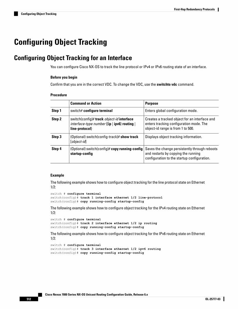
Configuring Object Tracking
Configuring Object Tracking for an InterfaceYou can configure Cisco NX-OS to track the line protocol or IPv4 or IPv6 routing state of an interface.
Before you begin
Confirm that you are in the correct VDC. To change the VDC, use the switchto vdc command.
Procedure
PurposeCommand or Action
Enters global configuration mode.switch# configure terminalStep 1
Creates a tracked object for an interface andenters tracking configuration mode. Theobject-id range is from 1 to 500.
switch(config)# track object-id interfaceinterface-type number {{ip | ipv6} routing |line-protocol}
Step 2
Displays object tracking information.(Optional) switch(config-track)# show track[object-id]
Step 3
Saves the change persistently through rebootsand restarts by copying the runningconfiguration to the startup configuration.
(Optional) switch(config)# copy running-configstartup-config
Step 4
Example
The following example shows how to configure object tracking for the line protocol state on Ethernet1/2:
switch # configure terminalswitch(config)# track 1 interface ethernet 1/2 line-protocolswitch(config)# copy running-config startup-config
The following example shows how to configure object tracking for the IPv4 routing state on Ethernet1/2:
switch # configure terminalswitch(config)# track 2 interface ethernet 1/2 ip routingswitch(config)# copy running-config startup-config
The following example shows how to configure object tracking for the IPv6 routing state on Ethernet1/2:
switch # configure terminalswitch(config)# track 3 interface ethernet 1/2 ipv6 routingswitch(config)# copy running-config startup-config
Cisco Nexus 7000 Series NX-OS Unicast Routing Configuration Guide, Release 6.xOL-25777-03512
First-Hop Redundancy ProtocolsConfiguring Object Tracking
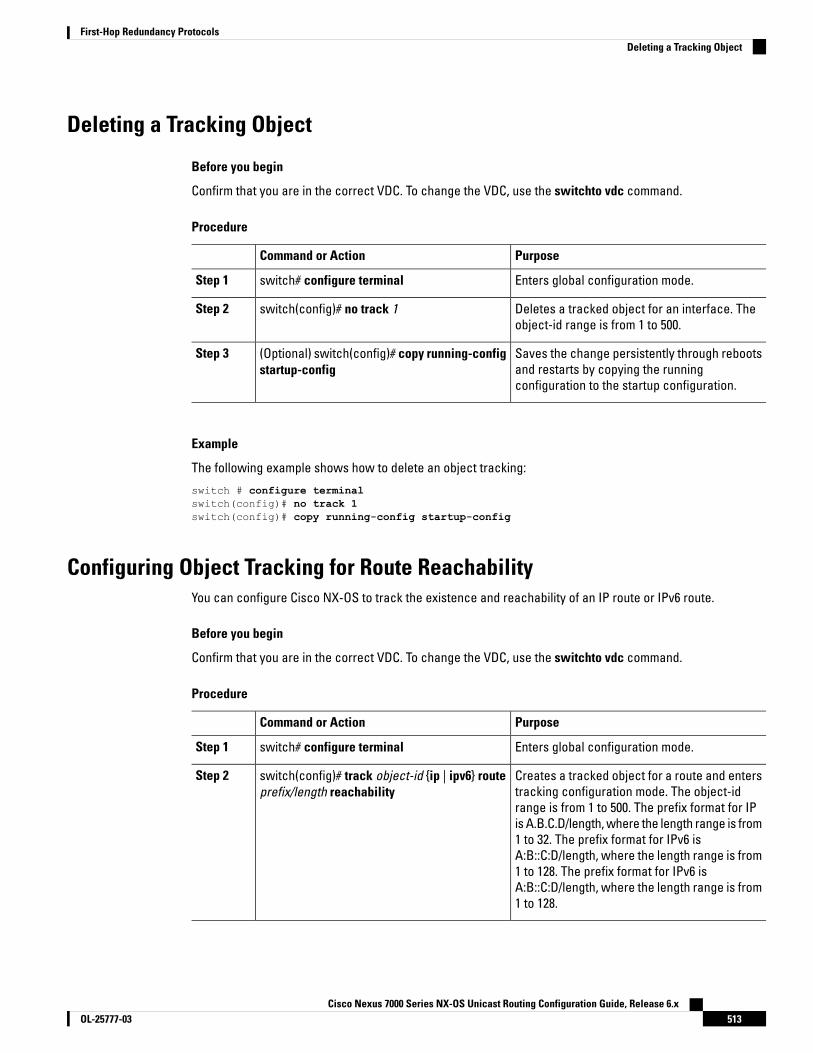
Deleting a Tracking Object
Before you begin
Confirm that you are in the correct VDC. To change the VDC, use the switchto vdc command.
Procedure
PurposeCommand or Action
Enters global configuration mode.switch# configure terminalStep 1
Deletes a tracked object for an interface. Theobject-id range is from 1 to 500.
switch(config)# no track 1Step 2
Saves the change persistently through rebootsand restarts by copying the runningconfiguration to the startup configuration.
(Optional) switch(config)# copy running-configstartup-config
Step 3
Example
The following example shows how to delete an object tracking:
switch # configure terminalswitch(config)# no track 1switch(config)# copy running-config startup-config
Configuring Object Tracking for Route ReachabilityYou can configure Cisco NX-OS to track the existence and reachability of an IP route or IPv6 route.
Before you begin
Confirm that you are in the correct VDC. To change the VDC, use the switchto vdc command.
Procedure
PurposeCommand or Action
Enters global configuration mode.switch# configure terminalStep 1
Creates a tracked object for a route and enterstracking configuration mode. The object-id
switch(config)# track object-id {ip | ipv6} routeprefix/length reachability
Step 2
range is from 1 to 500. The prefix format for IPis A.B.C.D/length, where the length range is from1 to 32. The prefix format for IPv6 isA:B::C:D/length, where the length range is from1 to 128. The prefix format for IPv6 isA:B::C:D/length, where the length range is from1 to 128.
Cisco Nexus 7000 Series NX-OS Unicast Routing Configuration Guide, Release 6.x513OL-25777-03
First-Hop Redundancy ProtocolsDeleting a Tracking Object

PurposeCommand or Action
Displays object tracking information.(Optional) switch(config-track)# show track[object-id]
Step 3
Saves the change persistently through rebootsand restarts by copying and runningconfiguration to the startup configuration.
switch(config-track)# copy running-configstartup-config
Step 4
Example
The following example shows how to configure object tracking for an IPv4 route in the default VRF:
switch # configure terminalswitch(config)# track 4 ip route 192.0.2.0/8 reachabilityswitch(config-track)# copy running-config startup-config
The following example shows how to configure object tracking for an IPv6 route in the default VRF:
switch # configure terminalswitch(config)# track 5 ipv6 route 10::10/128 reachabilityswitch(config-track)# copy running-config startup-config
Configuring an Object Track List with a Boolean ExpressionYou can configure an object track list that contains multiple tracked objects. A tracked list contains one ormore objects. The Boolean expression enables two types of calculation by using either "and" or "or" operators.For example, when tracking two interfaces using the "and" operator, up means that both interfaces are up, anddown means that either interface is down.
Before you begin
Confirm that you are in the correct VDC. To change the VDC, use the switchto vdc command.
Procedure
PurposeCommand or Action
Enters global configuration mode.switch# configure terminalStep 1
Configures a tracked list object and enterstracking configuration mode. Specifies that the
switch(config)# track track-number list boolean{and | or}
Step 2
state of the tracked list is based on a Booleancalculation. The keywords are as follows:
• and—Specifies that the list is up if allobjects are up or down if one or moreobjects are down. For example, whentracking two interfaces, up means that bothinterfaces are up, and down means thateither interface is down.
• or—Specifies that the list is up if at leastone object is up. For example, when
Cisco Nexus 7000 Series NX-OS Unicast Routing Configuration Guide, Release 6.xOL-25777-03514
First-Hop Redundancy ProtocolsConfiguring an Object Track List with a Boolean Expression

PurposeCommand or Action
tracking two interfaces, up means thateither interface is up, and down means thatboth interfaces are down.
The track-number range is from 1 to 500.
Adds a tracked object to the track list. Theobject-id range is from 1 to 500. The not keywordoptionally negates the tracked object state.
switch(config-track)# object object-number[not]
Step 3
The example means that when object10 is up, the tracked list detectsobject 10 as down.
Note
Saves the change persistently through rebootsand restarts by copying the runningconfiguration to the startup configuration.
(Optional) switch(config-track)# copyrunning-config startup-config
Step 4
Displays object tracking information.(Optional) switch(config-track)# show trackStep 5
Example
The following example shows how to configure a track list with multiple objects as a Boolean “and”:
switch # configure terminalswitch(config)# track 1 list boolean andswitch(config-track)# object 10switch(config-track)# object 20 notswitch(config)# copy running-config startup-config
Configuring an Object Track List with a Percentage ThresholdYou can configure an object track list that contains a percentage threshold. A tracked list contains one ormore objects. The percentage of up objects must exceed the configured track list up percent threshold beforethe track list is in an up state. For example, if the tracked list has three objects, and you configure an upthreshold of 60 percent, two of the objects must be in the up state (66 percent of all objects) for the track listto be in the up state.
Before you begin
Confirm that you are in the correct VDC. To change the VDC, use the switchto vdc command.
Procedure
PurposeCommand or Action
Enters global configuration mode.switch# configure terminalStep 1
Configures a tracked list object and enterstracking configuration mode. Specifies that the
switch(config)# track track-number listthreshold percentage
Step 2
Cisco Nexus 7000 Series NX-OS Unicast Routing Configuration Guide, Release 6.x515OL-25777-03
First-Hop Redundancy ProtocolsConfiguring an Object Track List with a Percentage Threshold
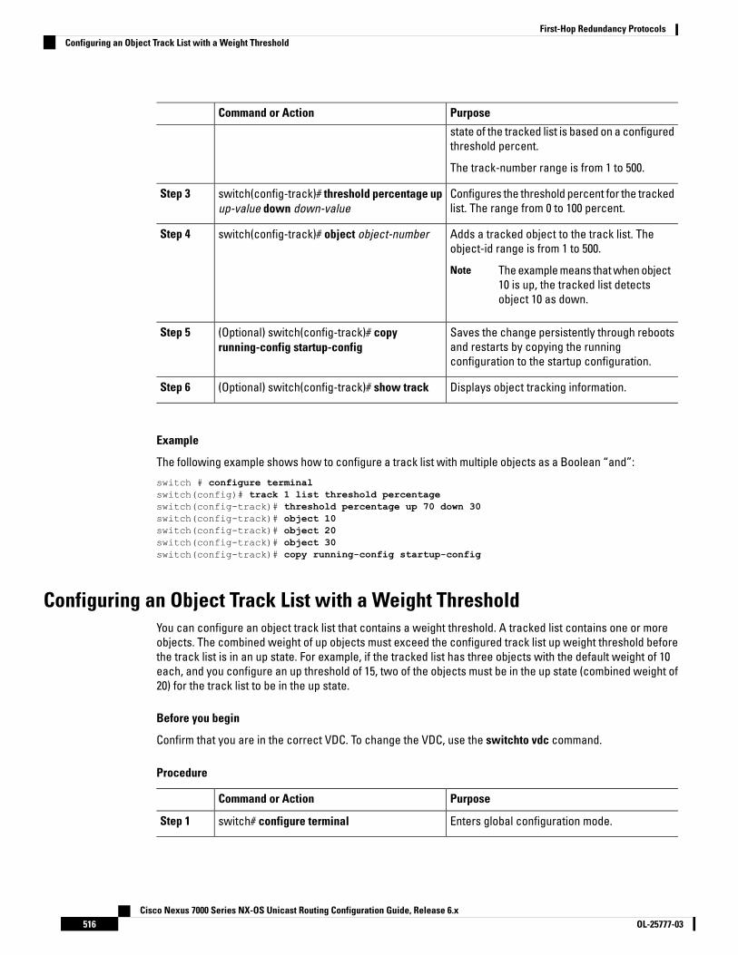
PurposeCommand or Action
state of the tracked list is based on a configuredthreshold percent.
The track-number range is from 1 to 500.
Configures the threshold percent for the trackedlist. The range from 0 to 100 percent.
switch(config-track)# threshold percentage upup-value down down-value
Step 3
Adds a tracked object to the track list. Theobject-id range is from 1 to 500.
switch(config-track)# object object-numberStep 4
The example means that when object10 is up, the tracked list detectsobject 10 as down.
Note
Saves the change persistently through rebootsand restarts by copying the runningconfiguration to the startup configuration.
(Optional) switch(config-track)# copyrunning-config startup-config
Step 5
Displays object tracking information.(Optional) switch(config-track)# show trackStep 6
Example
The following example shows how to configure a track list with multiple objects as a Boolean “and”:
switch # configure terminalswitch(config)# track 1 list threshold percentageswitch(config-track)# threshold percentage up 70 down 30switch(config-track)# object 10switch(config-track)# object 20switch(config-track)# object 30switch(config-track)# copy running-config startup-config
Configuring an Object Track List with a Weight ThresholdYou can configure an object track list that contains a weight threshold. A tracked list contains one or moreobjects. The combined weight of up objects must exceed the configured track list up weight threshold beforethe track list is in an up state. For example, if the tracked list has three objects with the default weight of 10each, and you configure an up threshold of 15, two of the objects must be in the up state (combined weight of20) for the track list to be in the up state.
Before you begin
Confirm that you are in the correct VDC. To change the VDC, use the switchto vdc command.
Procedure
PurposeCommand or Action
Enters global configuration mode.switch# configure terminalStep 1
Cisco Nexus 7000 Series NX-OS Unicast Routing Configuration Guide, Release 6.xOL-25777-03516
First-Hop Redundancy ProtocolsConfiguring an Object Track List with a Weight Threshold

PurposeCommand or Action
Configures a tracked list object and enterstracking configuration mode. Specifies that the
switch(config)# track track-number listthreshold weight
Step 2
state of the tracked list is based on a configuredthreshold weight.
The track-number range is from 1 to 500.
Configures the threshold weight for the trackedlist. The range is from 1 to 255.
switch(config-track)# threshold weight upup-value down down-value
Step 3
Adds a tracked object to the track list. Theobject-id range is from 1 to 500. The value rangeis from 1 to 255. The default weight value is 10
switch(config-track)# object object-id weightvalue
Step 4
Saves the change persistently through rebootsand restarts by copying the runningconfiguration to the startup configuration.
switch(config-track)# copy running-configstartup-config
Step 5
Displays object tracking information.(Optional) switch(config-track)# show trackStep 6
Example
The following example shows how to configure a track list with a up weight threshold of 30 and adown threshold of 10:
In this example, the track list is up if object 10 and object 20 are up, and the track list goes to the downstate if all three objects are down.
Note
switch # configure terminalswitch(config)# track 1 list threshold weightswitch(config-track)# threshold weight up 30 down 10switch(config-track)# object 10 weight 15switch(config-track)# object 20 weight 15switch(config-track)# object 30switch(config-track)# copy running-config startup-config
Configuring an Object Tracking DelayYou can configure a delay for a tracked object or an object track list that delays when the object or list triggersa stage change. The tracked object or track list starts the delay timer when a state change occurs but doesnot recognize a state change until the delay timer expires. At that point, Cisco NX-OS checks the object stateagain and records a state change only if the object or list currently has a changed state. Object tracking ignoresany intermediate state changes before the delay timer expires.
For example, for an interface line-protocol tracked object that is in the up state with a 20 second down delay,the delay timer starts when the line protocol goes down. The object is not in the down state unless the lineprotocol is down 20 seconds later.
Cisco Nexus 7000 Series NX-OS Unicast Routing Configuration Guide, Release 6.x517OL-25777-03
First-Hop Redundancy ProtocolsConfiguring an Object Tracking Delay

You can configure independent up delay and down delay for a tracked object or track list. When you deletethe delay, object tracking deletes both the up and down delay.
You can change the delay at any point. If the object or list is already counting down the delay timer from atriggered event, the new delay is computed as the following:
• If the new configuration value is less than the old configuration value, the timer starts with the new value.
• If the new configuration value is more than the old configuration value, the timer is calculated as the newconfiguration value minus the current timer countdown minus the old configuration value.
Before you begin
Confirm that you are in the correct VDC. To change the VDC, use the switchto vdc command.
Procedure
PurposeCommand or Action
Enters global configuration mode.switch# configure terminalStep 1
Creates a tracked object for a route and enterstracking configuration mode. The object-id
switch(config)# track object-id {parameters}Step 2
range is from 1 to 500. The prefix format for IPis A.B.C.D/length, where the length range is from1 to 32. The prefix format for IPv6 isA:B::C:D/length, where the length range is from1 to 128.
Configures a tracked list object and enterstracking configuration mode. Specifies that the
switch(config-track)# track track-number list{parameters}
Step 3
state of the tracked list is based on a configuredthreshold weight.
The track-number range is from 1 to 500.
Configures the object delay timers. The rangeis from 0 to 180 seconds.
switch(config-track)# delay {up up-time [downdown-time] | down down-time [up up-time]}
Step 4
The track-number range is from 1 to 500.
Saves the change persistently through rebootsand restarts by copying the runningconfiguration to the startup configuration.
(Optional) switch(config-track)# copyrunning-config startup-config
Step 5
Displays object tracking information.(Optional) switch(config-track)# show trackStep 6
Example
The following example shows how to configure object tracking for a route and use delay timers:
switch # configure terminalswitch(config)# track 2 ip route 209.165.201.0/8 reachabilityswitch(config-track)# delay up 20 down 30switch(config-track)# copy running-config startup-config
Cisco Nexus 7000 Series NX-OS Unicast Routing Configuration Guide, Release 6.xOL-25777-03518
First-Hop Redundancy ProtocolsConfiguring an Object Tracking Delay

The following example shows how to configure a track list with an up weight threshold of 30 and adown threshold of 10 with delay timers:
switch# configure terminalswitch(config)# track 1 list threshold weightswitch(config-track)# threshold weight up 30 down 10switch(config-track)# object 10 weight 15switch(config-track)# object 20 weight 15switch(config-track)# object 30switch(config-track)# delay up 20 down 30switch(config-track)# copy running-config startup-config
The following example shows the delay timer in the show track command output before and after aninterface is shut down:
switch(config-track)# show trackTrack 1Interface loopback1 Line ProtocolLine Protocol is UP1 changes, last change 00:00:13Delay down 10 secs
switch(config-track)# interface loopback 1switch(config-if)# shutdownswitch(config-if)# show trackTrack 1Interface loopback1 Line ProtocolLine Protocol is delayed DOWN (8 secs remaining)<------- delay timer counting down1 changes, last change 00:00:22Delay down 10 secs
Configuring Object Tracking for a Nondefault VRFYou can configure Cisco NX-OS to track an object in a specific VRF.
Before you begin
• Confirm that you are in the correct VDC. To change the VDC, use the switchto vdc command.
• Ensure that nondefault VRFs are created first.
Procedure
PurposeCommand or Action
Enters global configuration mode.switch# configure terminalStep 1
Creates a tracked object for a route and enterstracking configuration mode. The object-id
switch(config)# track object-id {ip | ipv6} routeprefix/length reachability
Step 2
range is from 1 to 500. The prefix format for IPis A.B.C.D/length, where the length range is from1 to 32. The prefix format for IPv6 isA:B::C:D/length, where the length range is from1 to 128.
Configures the VRF to use for tracking theconfigured object.
switch(config-track)# vrf member vrf-nameStep 3
Cisco Nexus 7000 Series NX-OS Unicast Routing Configuration Guide, Release 6.x519OL-25777-03
First-Hop Redundancy ProtocolsConfiguring Object Tracking for a Nondefault VRF
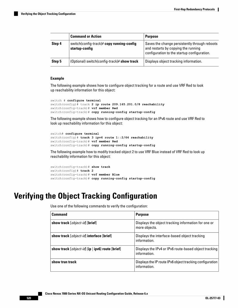
PurposeCommand or Action
Saves the change persistently through rebootsand restarts by copying the runningconfiguration to the startup configuration.
switch(config-track)# copy running-configstartup-config
Step 4
Displays object tracking information.(Optional) switch(config-track)# show trackStep 5
Example
The following example shows how to configure object tracking for a route and use VRF Red to lookup reachability information for this object:
switch # configure terminalswitch(config)# track 2 ip route 209.165.201.0/8 reachabilityswitch(config-track)# vrf member Redswitch(config-track)# copy running-config startup-config
The following example shows how to configure object tracking for an IPv6 route and use VRF Red tolook up reachability information for this object:
switch# configure terminalswitch(config)# track 3 ipv6 route 1::2/64 reachabilityswitch(config-track)# vrf member Redswitch(config-track)# copy running-config startup-config
The following example how to modify tracked object 2 to use VRF Blue instead of VRF Red to look upreachability information for this object:
switch(config-track)# show trackswitch(config)# track 2switch(config-track)# vrf member Blueswitch(config-track)# copy running-config startup-config
Verifying the Object Tracking ConfigurationUse one of the following commands to verify the configuration:
PurposeCommand
Displays the object tracking information for one ormore objects.
show track [object-id] [brief]
Displays the interface-based object trackinginformation.
show track [object-id] interface [brief]
Displays the IPv4 or IPv6 route-based object trackinginformation.
show track [object-id] {ip | ipv6} route [brief]
Displays the IP route IPv6 object tracking configurationinformation.
show trun track
Cisco Nexus 7000 Series NX-OS Unicast Routing Configuration Guide, Release 6.xOL-25777-03520
First-Hop Redundancy ProtocolsVerifying the Object Tracking Configuration
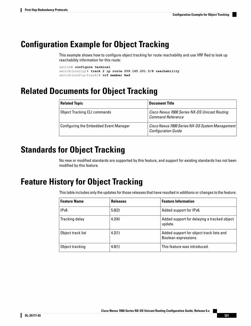
Configuration Example for Object TrackingThis example shows how to configure object tracking for route reachability and use VRF Red to look upreachability information for this route:
switch# configure terminalswitch(config)# track 2 ip route 209.165.201.0/8 reachabilityswitch(config-track)# vrf member Red
Related Documents for Object TrackingDocument TitleRelated Topic
Cisco Nexus 7000 Series NX-OS Unicast RoutingCommand Reference
Object Tracking CLI commands
Cisco Nexus 7000 Series NX-OS System ManagementConfiguration Guide
Configuring the Embedded Event Manager
Standards for Object TrackingNo new or modified standards are supported by this feature, and support for existing standards has not beenmodified by this feature.
Feature History for Object TrackingThis table includes only the updates for those releases that have resulted in additions or changes to the feature.
Feature InformationReleasesFeature Name
Added support for IPv6.5.0(2)IPv6
Added support for delaying a tracked objectupdate.
4.2(4)Tracking delay
Added support for object track lists andBoolean expressions.
4.2(1)Object track list
This feature was introduced.4.0(1)Object tracking
Cisco Nexus 7000 Series NX-OS Unicast Routing Configuration Guide, Release 6.x521OL-25777-03
First-Hop Redundancy ProtocolsConfiguration Example for Object Tracking

Cisco Nexus 7000 Series NX-OS Unicast Routing Configuration Guide, Release 6.xOL-25777-03522
First-Hop Redundancy ProtocolsFeature History for Object Tracking

A P P E N D I X AIETF RFCs Supported by Cisco NX-OS UnicastFeatures Release 6.x
• BGP RFCs, on page 523• First-Hop Redundancy Protocols RFCs, on page 524• IP Services RFCs, on page 524• IPv6 RFCs, on page 525• IS-IS RFCs, on page 525• OSPF RFCs, on page 526• RIP RFCs, on page 526
BGP RFCsTitleRFCs
BGP Communities AttributeRFC 1997
An Application of the BGP Community Attribute in Multi-home RoutingRFC 1998
Protection of BGP Sessions via the TCP MD5 Signature OptionRFC 2385
BGP Route Flap DampingRFC 2439
A Framework for Inter-Domain Route AggregationRFC 2519
Use of BGP-4 Multiprotocol Extensions for iPv6 Inter-Domain RoutingRFC 2545
Multiprotocol Extensions for BGP-4RFC 2858
Autonomous System Confederations for BGPRFC 3065
Carrying Label Information in BGP-4RFC 3107
Capabilities Advertisement with BGP-4RFC 3392
A Border Gateway Protocol 4 (BGP-4)RFC 4271
Definitions of Managed Objects for BGP-4RFC 4273
Cisco Nexus 7000 Series NX-OS Unicast Routing Configuration Guide, Release 6.x523OL-25777-03

TitleRFCs
BGP Route Reflection: An Alternative to Full Mesh Internal BGP (IBGP)RFC 4456
Subcodes for BGP Cease Notification MessageRFC 4486
Graceful Restart Mechanism for BGPRFC 4724
BGP Support for Four-octet AS Number SpaceRFC 4893
Avoid BGP Best Path Transitions from One External to AnotherRFC 5004
Textual Representation of Autonomous System (AS) NumbersRFC 53963
Advertising IPv4 Network Layer Reachability Information with an IPv6Next Hop
RFC 5549
4-Octet AS Specific BGP Extended CommunityRFC 5668
Advertisement of Multiple Paths in BGPdraft-ietf-idr-add-paths-08.txt
BGP4-MIBdraft-ietf-idr-bgp4-mib-15.txt
BGP4+ Peering Using IPv6 Link-local Addressdraft-kato-bgp-ipv6-link-local-00.txt
3 RFC 5396 is partially supported. The asplain and asdot notations are supported, but the asdot+ notationis not.
First-Hop Redundancy Protocols RFCsTitleRFCs
Hot Standby Redundancy ProtocolRFC 2281
Virtual Router Redundancy ProtocolRFC 3768
IP Services RFCsTitleRFCs
UDPRFC 768
IPRFC 791
ICMPRFC 792
TCPRFC 793
ARPRFC 826
Proxy ARPRFC 1027
Cisco Nexus 7000 Series NX-OS Unicast Routing Configuration Guide, Release 6.xOL-25777-03524
IETF RFCs Supported by Cisco NX-OS Unicast Features Release 6.xFirst-Hop Redundancy Protocols RFCs

TitleRFCs
DNS ClientRFC 1591
IPv4 routersRFC 1812
TCP-MIBRFC 4022
IP-FORWARDING-TABLE-MIBRFC 4292
IP-MIBRFC 4293
IPv6 RFCsTitleRFCs
Path MTU Discovery for IP version 6RFC 1981
IP Version 6 Addressing ArchitectureRFC 2373
An Aggregatable Global Unicast Address FormatRFC 2374
Internet Protocol, Version 6 (IPv6) SpecificationRFC 2460
Neighbor Discovery for IP Version 6 (IPv6)RFC 2461
IPv6 Stateless Address AutoconfigurationRFC 2462
Internet Control Message Protocol (ICMPv6) for the Internet ProtocolVersion 6 (IPv6) Specification
RFC 2463
Transmission of IPv6 Packets over Ethernet NetworksRFC 2464
Delegation of IP6.ARPARFC 3152
RADIUS and IPv6RFC 3162
Internet Protocol Version 6 (IPv6) Addressing ArchitectureRFC 3513
DNS Extensions to Support IP version 6RFC 3596
Unique Local IPv6 Unicast AddressesRFC 4193
IS-IS RFCsTitleRFCs
OSI 10589 intermediate system to intermediate system intro-domainrouting exchange protocol
RFC 1142
Use of OSI IS-IS for routing in TCP/IP and dual environmentRFC 1195
Cisco Nexus 7000 Series NX-OS Unicast Routing Configuration Guide, Release 6.x525OL-25777-03
IETF RFCs Supported by Cisco NX-OS Unicast Features Release 6.xIPv6 RFCs
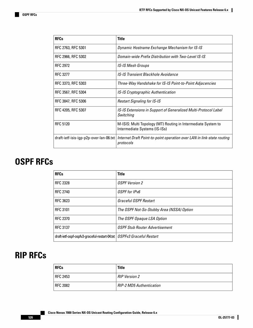
TitleRFCs
Dynamic Hostname Exchange Mechanism for IS-ISRFC 2763, RFC 5301
Domain-wide Prefix Distribution with Two-Level IS-ISRFC 2966, RFC 5302
IS-IS Mesh GroupsRFC 2972
IS-IS Transient Blackhole AvoidanceRFC 3277
Three-Way Handshake for IS-IS Point-to-Point AdjacenciesRFC 3373, RFC 5303
IS-IS Cryptographic AuthenticationRFC 3567, RFC 5304
Restart Signaling for IS-ISRFC 3847, RFC 5306
IS-IS Extensions in Support of Generalized Multi-Protocol LabelSwitching
RFC 4205, RFC 5307
M-ISIS: Multi Topology (MT) Routing in Intermediate System toIntermediate Systems (IS-ISs)
RFC 5120
Internet Draft Point-to-point operation over LAN in link-state routingprotocols
draft-ietf-isis-igp-p2p-over-lan-06.txt
OSPF RFCsTitleRFCs
OSPF Version 2RFC 2328
OSPF for IPv6RFC 2740
Graceful OSPF RestartRFC 3623
The OSPF Not-So-Stubby Area (NSSA) OptionRFC 3101
The OSPF Opaque LSA OptionRFC 2370
OSPF Stub Router AdvertisementRFC 3137
OSPFv3 Graceful Restartdraft-ietf-ospf-ospfv3-graceful-restart-04.txt
RIP RFCsTitleRFCs
RIP Version 2RFC 2453
RIP-2 MD5 AuthenticationRFC 2082
Cisco Nexus 7000 Series NX-OS Unicast Routing Configuration Guide, Release 6.xOL-25777-03526
IETF RFCs Supported by Cisco NX-OS Unicast Features Release 6.xOSPF RFCs

A P P E N D I X BConfiguration Limits for Cisco NX-OS Layer 3Unicast Features
The configuration limits are documented in the Cisco Nexus 7000 Series NX-OS Verified Scalability Guide.
Cisco Nexus 7000 Series NX-OS Unicast Routing Configuration Guide, Release 6.x527OL-25777-03

Cisco Nexus 7000 Series NX-OS Unicast Routing Configuration Guide, Release 6.xOL-25777-03528
Configuration Limits for Cisco NX-OS Layer 3 Unicast FeaturesConfiguration Limits for Cisco NX-OS Layer 3 Unicast Features