6000 and 7000 Appliances Getting Started Guide
50
[Classification: Protected] 23 February 2022 6000 AND 7000 APPLIANCES QS-15, QM-30, QS-2, QM-1, QM-2, QM-35 Getting Started Guide
-
Upload
khangminh22 -
Category
Documents
-
view
2 -
download
0
Transcript of 6000 and 7000 Appliances Getting Started Guide
[Classification:Protected]
23 February 2022
6000 AND 7000APPLIANCES
QS-15, QM-30, QS-2, QM-1, QM-2, QM-35
Getting Started Guide
Check Point Copyright Notice© 2020-2022 Check Point Software Technologies Ltd.
All rights reserved. This product and related documentation are protected by copyright and distributed underlicensing restricting their use, copying, distribution, and decompilation. No part of this product or relateddocumentation may be reproduced in any form or by any means without prior written authorization of CheckPoint. While every precaution has been taken in the preparation of this book, Check Point assumes noresponsibility for errors or omissions. This publication and features described herein are subject to changewithout notice.
RESTRICTED RIGHTS LEGEND:
Use, duplication, or disclosure by the government is subject to restrictions as set forth in subparagraph (c)(1)(ii) of the Rights in Technical Data and Computer Software clause at DFARS 252.227-7013 and FAR52.227-19.
TRADEMARKS:
Refer to the Copyright page for a list of our trademarks.
Refer to the Third Party copyright notices for a list of relevant copyrights and third-party licenses.
6000 and 7000 Appliances Getting Started Guide
6000 and 7000 Appliances Getting Started Guide | 3
Important Information
Latest SoftwareWe recommend that you install the most recent software release to stay up-to-date with thelatest functional improvements, stability fixes, security enhancements and protection againstnew and evolving attacks.
CertificationsFor third party independent certification of Check Point products, see the Check PointCertifications page.
Check Point 6000 and 7000 AppliancesFor more about this release, see the home page.
Latest Version of this Document in EnglishOpen the latest version of this document in a Web browser.Download the latest version of this document in PDF format.
FeedbackCheck Point is engaged in a continuous effort to improve its documentation.Please help us by sending your comments.
6000 and 7000 Appliances Getting Started Guide
6000 and 7000 Appliances Getting Started Guide | 4
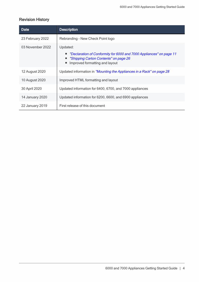
Revision History
Date Description
23 February 2022 Rebranding - New Check Point logo
03 November 2022 Updated:
n "Declaration of Conformity for 6000 and 7000 Appliances" on page 11n "Shipping Carton Contents" on page 26n Improved formatting and layout
12 August 2020 Updated information in "Mounting the Appliances in a Rack" on page 28
10 August 2020 Improved HTML formatting and layout
30 April 2020 Updated information for 6400, 6700, and 7000 appliances
14 January 2020 Updated information for 6200, 6600, and 6900 appliances
22 January 2019 First release of this document
Table of Contents
6000 and 7000 Appliances Getting Started Guide | 5
Table of ContentsSafety, Environmental, and Electronic Emissions Notices 7
Compliance Information 11
Declaration of Conformity for 6000 and 7000 Appliances 11
Remarques relatives à la sécurité, l'environnement et les émissions électroniques 17
Hinweise zu Sicherheit, Umwelt und elektronischen Emissione 21
Introduction 25
Welcome 25
6000 and 7000 Series Appliance Overview 25
Shipping Carton Contents 26
Terminology 26
Mounting the Appliances in a Rack 28
Appliance Physical Specifications 28
Appliance Air Vents 28
Configuring the Appliances 30
Starting the Appliance 30
Available Software Images 30
Synchronizing RAID on 6800, 6900, and 7000 Appliances 30
Initial Configuration 33
Creating the Network Object 33
Advanced Configuration 34
Connecting to the 6000/7000 Appliances CLI 34
6000/7000 Appliances Hardware 35
Front Panel 35
Front Panel Ports 37
Front Panel System LEDs 38
Rear Panel 39
Using the Power Cable Restraint Strip on 6200 and 6400 Appliances 43
Using the Restraint Clip on 6500, 6600, 6700, 6800, 6900, and 7000 Appliances 44
Lights Out Management 46
Dual Redundant BIOS 46
Replacing and Upgrading Components 47
Restoring Factory Defaults 48
Restoring from the Gaia Portal 48
Table of Contents
6000 and 7000 Appliances Getting Started Guide | 6
Restoring from the Boot Menu 48
Restoring from Gaia Clish 49
Registration and Support 50
Registration 50
Support 50
Where To From Here? 50
Safety, Environmental, and Electronic Emissions Notices
6000 and 7000 Appliances Getting Started Guide | 7
Safety, Environmental, andElectronic Emissions NoticesRead the following warnings before setting up or using the appliance.
Warning - Do not block air vents. A minimum 1/2-inch clearance is required.
Before you install or remove a chassis, or work near power supplies, turn off the power and unplug thepower cord.
To prevent damage to any system board, it is important to handle it with care. The following measures aregenerally sufficient to protect your equipment from static electricity discharge:
n When handling the board, to use a grounded wrist strap designed for static discharge elimination.
n Touch a grounded metal object before removing the board from the antistatic bag.
n Handle the board by its edges only. Do not touch its components, peripheral chips, memory modulesor gold contacts.
n When handling processor chips or memory modules, avoid touching their pins or gold edge fingers.
n Restore the communications appliance system board and peripherals back into the antistatic bagwhen they are not in use or not installed in the chassis. Some circuitry on the system board cancontinue operating even though the power is switched off.
n Under no circumstances should the lithium battery cell used to power the real-time clock be allowedto short. The battery cell may heat up under these conditions and present a burn hazard.
Warning - DANGER OF EXPLOSION IF BATTERY IS INCORRECTLY REPLACED. REPLACE ONLYWITH SAME OR EQUIVALENT TYPE RECOMMENDED BY THE MANUFACTURER. DISCARD USEDBATTERIES ACCORDING TO THE MANUFACTURER'S INSTRUCTIONS.
n Disconnect the system board power supply from its power source before you connect or disconnectcables or install or remove any system board components. Failure to do this can result in personnelinjury or equipment damage.
n Avoid short-circuiting the lithium battery; this can cause it to superheat and cause burns if touched.
n Do not operate the processor without a thermal solution. Damage to the processor can occur inseconds.
n Class 1 laser product warning - A totally enclosed laser system containing a class 1 laser.
This device is not intended for use in the direct field of view at visual display workplaces. To avoidincommoding reflexions at visual display workplaces this device must not be placed in the direct field ofview.
Rack Mount Instructions
The following or similar rack-mount instructions are included with the installation instructions:
Safety, Environmental, and Electronic Emissions Notices
6000 and 7000 Appliances Getting Started Guide | 8
1. Elevated Operating Ambient - If installed in a closed or multi-unit rack assembly, the operatingambient temperature of the rack environment may be greater than room ambient. Therefore,consideration should be given to installing the equipment in an environment compatible with themaximum ambient temperature specified by the manufacturer.
2. Reduced Air Flow - Installation of the equipment in a rack should be such that the amount of air flowrequired for safe operation of the equipment is not compromised.
3. Mechanical Loading - Mounting of the equipment in the rack should be such that a hazardouscondition is not achieved due to uneven mechanical loading.
4. Circuit Overloading - Consideration should be given to the connection of the equipment to the supplycircuit and the effect that overloading of the circuits might have on over current protection and supplywiring. Appropriate consideration of equipment nameplate ratings should be used when addressingthis concern.
5. Reliable Earthing - Reliable earthing of rack-mounted equipment should be maintained. Particularattention should be given to supply connections other than direct connections to the branch circuit(e.g. use of power strips).
For California:
Perchlorate Material - special handling may apply. Seehttp://www.dtsc.ca.gov/hazardouswaste/perchlorate
The foregoing notice is provided in accordance with California Code of Regulations Title 22, Division 4.5,Chapter 33. Best Management Practices for Perchlorate Materials. This product, part, or both may include alithium manganese dioxide battery which contains a perchlorate substance.
Proposition 65 Chemical
Chemicals identified by the State of California, pursuant to the requirements of the California Safe DrinkingWater and Toxic Enforcement Act of 1986, California Health & Safety Code s. 25249.5, et seq. ("Proposition65"), that is "known to the State to cause cancer or reproductive toxicity" (see http://www.calepa.ca.gov)
Safety, Environmental, and Electronic Emissions Notices
6000 and 7000 Appliances Getting Started Guide | 9
WARNING:
Handling the cord on this product will expose you to lead, a chemical known to the State of California tocause cancer, and birth defects or other reproductive harm. Wash hands after handling.
Caution
Any changes or modifications not expressly approved by the grantee of this device could void the user'sauthority to operate the equipment.
This equipment complies with Part 15 of the FCC Rules. Operation is subject to the following two conditions:(1) This device may not cause harmful interference, and (2) This device must accept any interferencereceived, including interference that may cause undesired operation.
Caution!
The manufacturer is not responsible for any radio or TV interference caused by unauthorized modificationsto this equipment. Such modifications could void the user authority to operate the equipment.
Information to user:
The user's manual or instruction manual for an intentional or unintentional radiator shall caution the user thatchanges or modifications not expressly approved by the party responsible for compliance could void theuser's authority to operate the equipment. In cases where the manual is provided only in a form other thanpaper, such as on a computer disk or over the Internet, the information required by this section may beincluded in the manual in that alternative form, provided the user can reasonably be expected to have thecapability to access information in that form.
Canadian Department Compliance Statement:
This Class A digital apparatus complies with Canadian ICES-003. Cet appareil numérique de la classe A estconforme à la norme NMB-003 du Canada.
Japan Compliance Statement:
Class A
European Union (EU) Electromagnetic and Safety Compatibility Directives - 6200, 6400, 6500, 6600,6700, 6800, 6900, and 7000 Appliances
This product is herewith confirmed to comply with the requirements set out in the Council Directive on theApproximation of the Laws of the Member States relating to Electromagnetic Compatibility Directives2004/108/EC and 2014/30/EU.
This product is in conformity with Low Voltage Directives 2006/95/EC and 2014/35/EU.
This product complies with the requirements in the Council Directives 2006/95/EC and 2014/35/EU relatingto electrical equipment designed for use within certain voltage limits and the Amendment Directive93/68/EEC.
Safety, Environmental, and Electronic Emissions Notices
6000 and 7000 Appliances Getting Started Guide | 10
Product Disposal
This symbol on the product or on its packaging indicates that this product must not be disposed of with yourother household waste. Instead, it is your responsibility to dispose of your waste equipment by handing itover to a designated collection point for the recycling of waste electrical and electronic equipment. Theseparate collection and recycling of your waste equipment at the time of disposal will help to conservenatural resources and ensure that it is recycled in a manner that protects human health and theenvironment. For more information about where you can drop off your waste equipment for recycling, pleasecontact your local city office or your household waste disposal service.
Compliance Information
6000 and 7000 Appliances Getting Started Guide | 11
Compliance InformationThis appendix contains declaration of conformity, compliance, and related regulatory information.
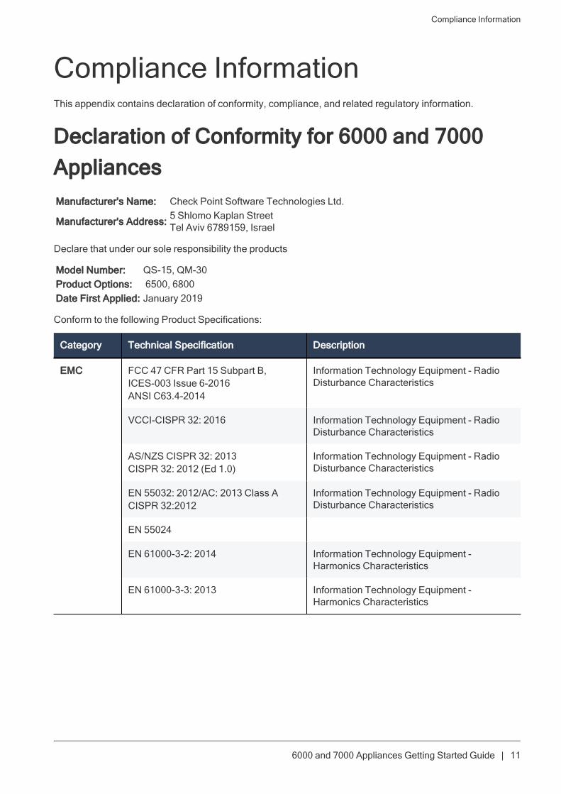
Declaration of Conformity for 6000 and 7000AppliancesManufacturer's Name: Check Point Software Technologies Ltd.
Manufacturer's Address: 5 Shlomo Kaplan StreetTel Aviv 6789159, Israel
Declare that under our sole responsibility the products
Model Number: QS-15, QM-30Product Options: 6500, 6800Date First Applied: January 2019
Conform to the following Product Specifications:
Category Technical Specification Description
EMC FCC 47 CFR Part 15 Subpart B,ICES-003 Issue 6-2016ANSI C63.4-2014
Information Technology Equipment - RadioDisturbance Characteristics
VCCI-CISPR 32: 2016 Information Technology Equipment - RadioDisturbance Characteristics
AS/NZS CISPR 32: 2013CISPR 32: 2012 (Ed 1.0)
Information Technology Equipment - RadioDisturbance Characteristics
EN 55032: 2012/AC: 2013 Class ACISPR 32:2012
Information Technology Equipment - RadioDisturbance Characteristics
EN 55024
EN 61000-3-2: 2014 Information Technology Equipment -Harmonics Characteristics
EN 61000-3-3: 2013 Information Technology Equipment -Harmonics Characteristics
Compliance Information
6000 and 7000 Appliances Getting Started Guide | 12
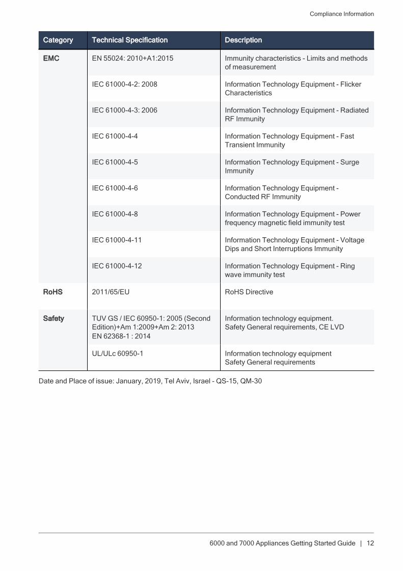
Category Technical Specification Description
EMC EN 55024: 2010+A1:2015 Immunity characteristics - Limits and methodsof measurement
IEC 61000-4-2: 2008 Information Technology Equipment - FlickerCharacteristics
IEC 61000-4-3: 2006 Information Technology Equipment - RadiatedRF Immunity
IEC 61000-4-4 Information Technology Equipment - FastTransient Immunity
IEC 61000-4-5 Information Technology Equipment - SurgeImmunity
IEC 61000-4-6 Information Technology Equipment -Conducted RF Immunity
IEC 61000-4-8 Information Technology Equipment - Powerfrequency magnetic field immunity test
IEC 61000-4-11 Information Technology Equipment - VoltageDips and Short Interruptions Immunity
IEC 61000-4-12 Information Technology Equipment - Ringwave immunity test
RoHS 2011/65/EU RoHS Directive
Safety TUV GS / IEC 60950-1: 2005 (SecondEdition)+Am 1:2009+Am 2: 2013EN 62368-1 : 2014
Information technology equipment. Safety General requirements, CE LVD
UL/ULc 60950-1 Information technology equipmentSafety General requirements
Date and Place of issue: January, 2019, Tel Aviv, Israel - QS-15, QM-30
Compliance Information
6000 and 7000 Appliances Getting Started Guide | 13
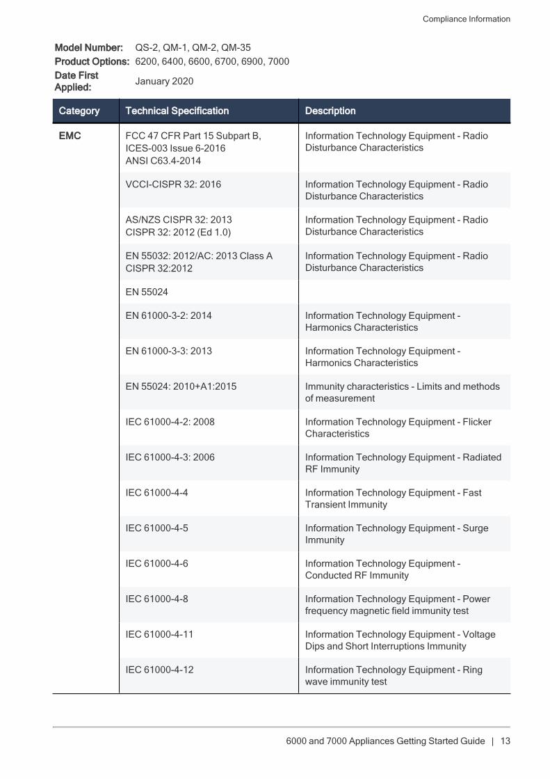
Model Number: QS-2, QM-1, QM-2, QM-35Product Options: 6200, 6400, 6600, 6700, 6900, 7000Date FirstApplied: January 2020
Category Technical Specification Description
EMC FCC 47 CFR Part 15 Subpart B,ICES-003 Issue 6-2016ANSI C63.4-2014
Information Technology Equipment - RadioDisturbance Characteristics
VCCI-CISPR 32: 2016 Information Technology Equipment - RadioDisturbance Characteristics
AS/NZS CISPR 32: 2013CISPR 32: 2012 (Ed 1.0)
Information Technology Equipment - RadioDisturbance Characteristics
EN 55032: 2012/AC: 2013 Class ACISPR 32:2012
Information Technology Equipment - RadioDisturbance Characteristics
EN 55024
EN 61000-3-2: 2014 Information Technology Equipment -Harmonics Characteristics
EN 61000-3-3: 2013 Information Technology Equipment -Harmonics Characteristics
EN 55024: 2010+A1:2015 Immunity characteristics - Limits and methodsof measurement
IEC 61000-4-2: 2008 Information Technology Equipment - FlickerCharacteristics
IEC 61000-4-3: 2006 Information Technology Equipment - RadiatedRF Immunity
IEC 61000-4-4 Information Technology Equipment - FastTransient Immunity
IEC 61000-4-5 Information Technology Equipment - SurgeImmunity
IEC 61000-4-6 Information Technology Equipment -Conducted RF Immunity
IEC 61000-4-8 Information Technology Equipment - Powerfrequency magnetic field immunity test
IEC 61000-4-11 Information Technology Equipment - VoltageDips and Short Interruptions Immunity
IEC 61000-4-12 Information Technology Equipment - Ringwave immunity test
Compliance Information
6000 and 7000 Appliances Getting Started Guide | 14
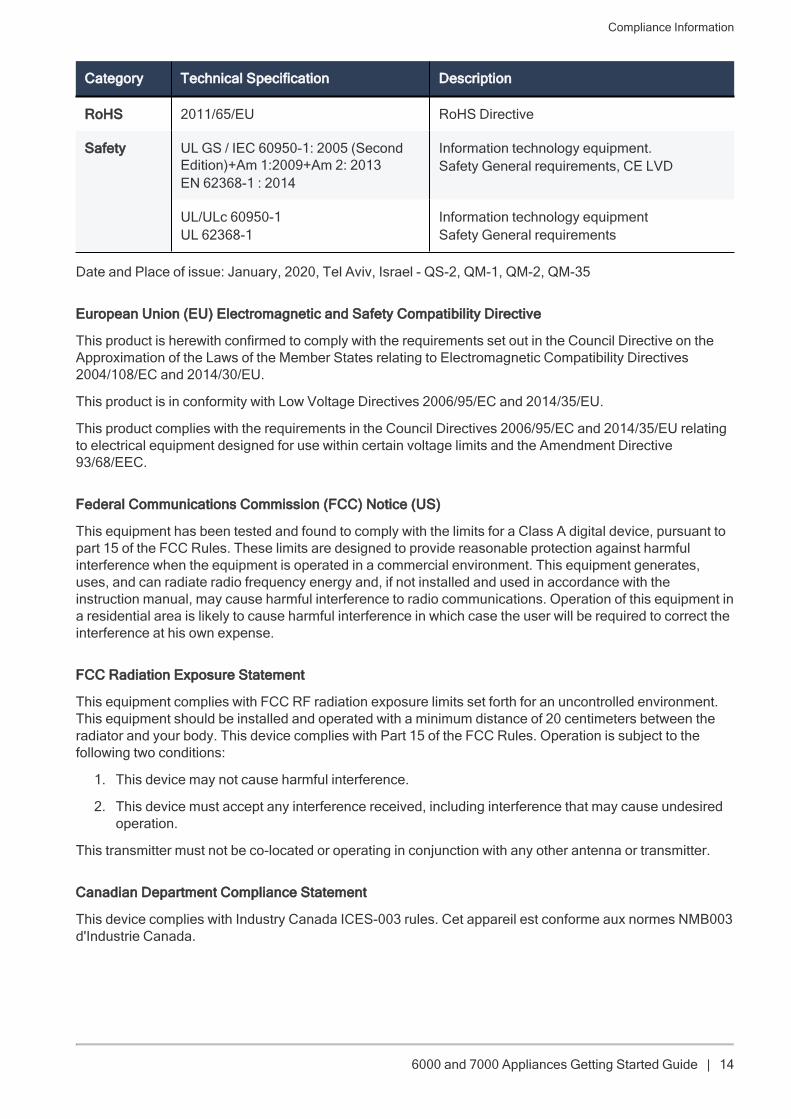
Category Technical Specification Description
RoHS 2011/65/EU RoHS Directive
Safety UL GS / IEC 60950-1: 2005 (SecondEdition)+Am 1:2009+Am 2: 2013EN 62368-1 : 2014
Information technology equipment.Safety General requirements, CE LVD
UL/ULc 60950-1UL 62368-1
Information technology equipmentSafety General requirements
Date and Place of issue: January, 2020, Tel Aviv, Israel - QS-2, QM-1, QM-2, QM-35
European Union (EU) Electromagnetic and Safety Compatibility Directive
This product is herewith confirmed to comply with the requirements set out in the Council Directive on theApproximation of the Laws of the Member States relating to Electromagnetic Compatibility Directives2004/108/EC and 2014/30/EU.
This product is in conformity with Low Voltage Directives 2006/95/EC and 2014/35/EU.
This product complies with the requirements in the Council Directives 2006/95/EC and 2014/35/EU relatingto electrical equipment designed for use within certain voltage limits and the Amendment Directive93/68/EEC.
Federal Communications Commission (FCC) Notice (US)
This equipment has been tested and found to comply with the limits for a Class A digital device, pursuant topart 15 of the FCC Rules. These limits are designed to provide reasonable protection against harmfulinterference when the equipment is operated in a commercial environment. This equipment generates,uses, and can radiate radio frequency energy and, if not installed and used in accordance with theinstruction manual, may cause harmful interference to radio communications. Operation of this equipment ina residential area is likely to cause harmful interference in which case the user will be required to correct theinterference at his own expense.
FCC Radiation Exposure Statement
This equipment complies with FCC RF radiation exposure limits set forth for an uncontrolled environment.This equipment should be installed and operated with a minimum distance of 20 centimeters between theradiator and your body. This device complies with Part 15 of the FCC Rules. Operation is subject to thefollowing two conditions:
1. This device may not cause harmful interference.
2. This device must accept any interference received, including interference that may cause undesiredoperation.
This transmitter must not be co-located or operating in conjunction with any other antenna or transmitter.
Canadian Department Compliance Statement
This device complies with Industry Canada ICES-003 rules. Cet appareil est conforme aux normes NMB003d'Industrie Canada.
Compliance Information
6000 and 7000 Appliances Getting Started Guide | 15
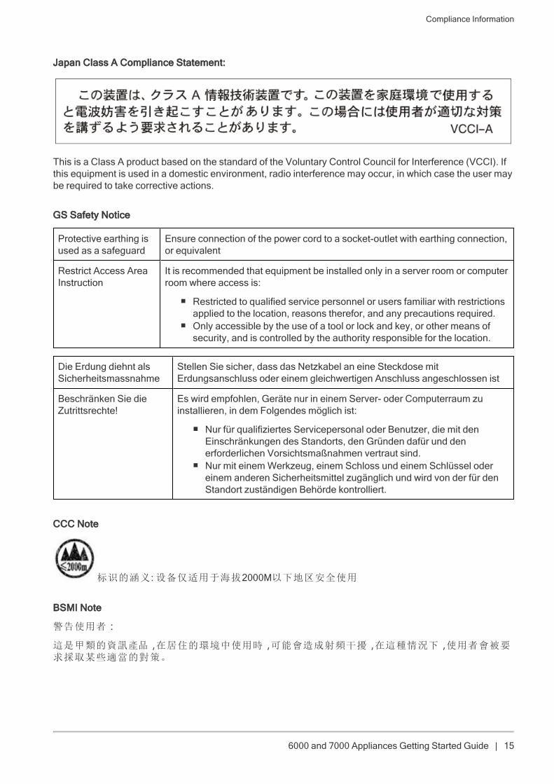
Japan Class A Compliance Statement:
This is a Class A product based on the standard of the Voluntary Control Council for Interference (VCCI). Ifthis equipment is used in a domestic environment, radio interference may occur, in which case the user maybe required to take corrective actions.
GS Safety Notice
Protective earthing isused as a safeguard
Ensure connection of the power cord to a socket-outlet with earthing connection,or equivalent
Restrict Access AreaInstruction
It is recommended that equipment be installed only in a server room or computerroom where access is:
n Restricted to qualified service personnel or users familiar with restrictionsapplied to the location, reasons therefor, and any precautions required.
n Only accessible by the use of a tool or lock and key, or other means ofsecurity, and is controlled by the authority responsible for the location.
Die Erdung diehnt alsSicherheitsmassnahme
Stellen Sie sicher, dass das Netzkabel an eine Steckdose mitErdungsanschluss oder einem gleichwertigen Anschluss angeschlossen ist
Beschränken Sie dieZutrittsrechte!
Es wird empfohlen, Geräte nur in einem Server- oder Computerraum zuinstallieren, in dem Folgendes möglich ist:
n Nur für qualifiziertes Servicepersonal oder Benutzer, die mit denEinschränkungen des Standorts, den Gründen dafür und denerforderlichen Vorsichtsmaßnahmen vertraut sind.
n Nur mit einemWerkzeug, einem Schloss und einem Schlüssel odereinem anderen Sicherheitsmittel zugänglich und wird von der für denStandort zuständigen Behörde kontrolliert.
CCC Note
标识的涵义 :设备仅适用于海拔2000M以下地区安全使用
BSMI Note
警告使用者:
這是甲類的資訊產品,在居住的環境中使用時,可能會造成射頻干擾,在這種情況下,使用者會被要求採取某些適當的對策。
Compliance Information
6000 and 7000 Appliances Getting Started Guide | 16
Remarques relatives à la sécurité, l'environnement et les émissions électroniques
6000 and 7000 Appliances Getting Started Guide | 17
Remarques relatives à la sécurité,l'environnement et les émissionsélectroniquesAvant de mettre en place ou d'utiliser l'appareil, veuillez lire les avertissements suivants.
Avertissement: ne pas obturer les aérations. Il faut laisser au moins 1,27 cm d'espace libre.
Avant d'installer ou retirer un châssis ou de travailler à proximité d'alimentations, mettez-le hors tension etdébranchez le cordon d'alimentation.
Pour éviter d'endommager les cartes système, il est important de les manipuler avec soin. Les mesuressuivantes sont généralement suffisantes pour protéger votre équipement contre les décharges d'électricitéstatique :
n Avant de manipuler la carte, portez aux poignet un bracelet antistatique relié à la terre.
n Touchez un objet métallique relié à la terre avant d'extraire la carte de son sachet antistatique.
n Ne tenez la carte que par ses bords. Ne touchez aucun composant, puce périphérique, modulemémoire ou contact plaqué or.
n Lorsque vous manipulez des processeurs ou des modules mémoire, évitez de toucher leurs brochesou les pistes de contact dorées.
n Remettez dans leur sachet antistatique la carte système et les périphériques de l'appareil decommunications lorsqu'ils ne sont pas utilisés ou installés dans le châssis. Certains circuits sur lacarte système peuvent rester fonctionnels même si l'appareil est éteint.
n Il ne faut jamais court-circuiter la pile au lithium qui alimente l'horloge temps-réel. Elle risque des'échauffer et de causer des brûlures.
Avertissement:DANGER D'EXPLOSION SI LA PILE EST MAL REMPLACÉE. NE REMPLACERQU'AVEC UN TYPE IDENTIQUE OU ÉQUIVALENT, RECOMMANDÉ PAR LE CONSTRUCTEUR. LESPILES DOIVENT ÊTRE MISES AU REBUT CONFORMÉMENT AUX INSTRUCTIONS DE LEURFABRICANT.
n Débrancher l'alimentation de la carte système de sa source électrique avant de connecter oudéconnecter des câbles ou d'installer ou retirer des composants. À défaut, les risques sontd'endommager l'équipement et de causer des blessures corporelles.
n Ne pas court-circuiter la pile au lithium : elle risque de surchauffer et de causer des brûlures en cas decontact.
n Ne pas faire fonctionner le processeur sans refroidissement. Le processeur peut être endommagé enquelques secondes.
n Produit laser de classe 1 : un système laser totalement clos et contenant un laser de classe 1.
Cet appareil n'est pas prévu pour être utilisé dans le champ de vision direct des personnes occupant unbureau. Pour éviter toute gêne occasionnée par un éventuel reflet, cet appareil ne doit pas être placé dansle champ de vision direct des personnes occupant un bureau.
Remarques relatives à la sécurité, l'environnement et les émissions électroniques
6000 and 7000 Appliances Getting Started Guide | 18
Instructions de montage en rack
Les instructions d'installation sont livrées avec les instructions de montage en rack ci-après (ou similaires) :
1. Fonctionnement à température plus élevée : si l'appareil est installé dans une armoire fermée ou unrack à plusieurs unités, la température du rack en fonctionnement peut être supérieure à latempérature ambiante de la pièce. Avant d'installer l'équipement, il faut donc s'assurer qu'il sera dansun environnement compatible avec la température ambiante maximale indiquée par le constructeur.
2. Circulation d'air réduite : l'installation dans un rack doit s'assurer de ne pas limiter la circulation de l'ainécessaire au bon fonctionnement de l'équipement.
3. Charge mécanique : lors du montage de l'équipement dans le rack, il faut faire attention à ne pasdéséquilibrer l'ensemble. Un rack se remplit en commençant par le bas.
4. Surcharge : pour la connexion de l'équipement au circuit électrique, il faut vérifier les risques desurcharge et les éventuelles conséquences sur la protection contre les surcourants et sur le câblageélectrique. Dans ce contexte, il faut tenir compte des informations mentionnées par la plaquetechnique de l'instrument.
5. Mise à la terre : les équipements montés en rack doivent être en permanence reliés à un terre fiable.Il faut faire particulièrement attention aux branchements qui ne vont pas directement à la sourceélectrique (par exemple des multiprises).
Pour la Californie :
Matériau perchloraté : manipulation spéciale potentiellement requise. Voirhttp://www.dtsc.ca.gov/hazardouswaste/perchlorate
L'avis suivant est fourni conformément au California Code of Regulations, titre 22, division 4.5, chapitre 33.Meilleures pratiques de manipulation des matériaux perchloratés. Ce produit, cette pièce ou les deuxpeuvent contenir une pile au dioxyde de lithium manganèse, qui contient une substance perchloratée.
Produits chimiques « Proposition 65 »
Les produits chimiques identifiés par l'état de Californie, conformément aux exigences du California SafeDrinking Water and Toxic Enforcement Act of 1986 du California Health & Safety Code s. 25249.5, et seq. (« Proposition 65 »), qui sont « connus par l'état pour être cancérigène ou être toxiques pour la reproduction »(voir http://www.calepa.ca.gov)
Remarques relatives à la sécurité, l'environnement et les émissions électroniques
6000 and 7000 Appliances Getting Started Guide | 19
AVERTISSEMENT :
La manipulation de ce cordon vous expose au contact du plomb, un élément reconnue par l'état deCalifornie pour être cancérigène, provoquer des malformations à la naissance et autres dommages relatifsà la reproduction. Se laver les mains après toute manipulation.
Attention
Toute modification non approuvée expressément par la garantie du présent appareil pourrait annuler le droitde l'utilisateur à faire fonctionner l'équipement.
Ce dispositif est conforme à la section 15 des réglementations de la FCC. Son fonctionnement est soumisaux deux conditions suivantes: (1) Cet appareil ne doit pas causer d'interférence préjudiciable et (2) Cetappareil doit tolérer toute interférence reçue, y compris celles qui pourraient causer un fonctionnementindésirable.
Attention !
Le fabricant n'est pas responsable des éventuelles interférences radio ou TV dues à des modifications nonautorisées du présent équipement. Ces modifications pourraient annuler le droit de l'utilisateur à fairefonctionner l'équipement.
Ce dispositif est conforme à la section 15 des réglementations de la FCC. Son fonctionnement est soumisaux deux conditions suivantes: (1) Cet appareil ne doit pas causer d'interférence préjudiciable et (2) Cetappareil doit tolérer toute interférence reçue, y compris celles qui pourraient causer un fonctionnementindésirable.
Attention?!
Le fabricant n'est pas responsable des éventuelles interférences radio ou TV dues à des modifications nonautorisées du présent équipement. Ces modifications pourraient annuler le droit de l'utilisateur é fairefonctionner l'équipement.
Information à l'intention de l'utilisateur :
Le manuel utilisateur ou le manuel d'instruction d'un dispositif rayonnant (intentionnel ou non) doit avertirque toute modification non approuvée expressément par la partie responsable de la conformité peut annulerle droit de faire fonctionner l'équipement. Si le manuel n'est pas fourni sous forme imprimée (par exemplesur le disque d'un ordinateur ou via Internet), les informations requises par cette section doivent êtreincluses dans ces versions du manuel, sous réserve que l'utilisateur soit raisonnablement capable d'yaccéder.
Déclaration de conformité du département canadien :
This Class A digital apparatus complies with Canadian ICES-003. Cet appareil numérique de la classe A estconforme à la norme NMB-003 du Canada.
Déclaration de conformité pour le Japon :
Classe A
Remarques relatives à la sécurité, l'environnement et les émissions électroniques
6000 and 7000 Appliances Getting Started Guide | 20
Directives de l'Union européenne (UE) relatives à la compatibilité électromagnétique et à la sécurité -Appareils 6200, 6400, 6500, 6600, 6700, 6800 6900 et 7000
Ce produit est certifié conforme aux exigences de la directive du Conseil concernant le rapprochement deslégislations des États membres relatives aux directives sur la compatibilité électromagnétique(2004/108/CE et 2014/30/UE).
Ce produit est conforme aux directives basse tension 2006/95/CE et 2014/35/UE.
Ce produit satisfait aux exigences des directives 2006/95/CE et 2014/35/UE du Conseil relatives auxéquipements électriques conçus pour être utilisés dans une certaine plage de tensions, selon lesmodifications de la directive 93/68/CEE.
Mise au rebut du produit
Ce symbole apposé sur le produit ou son emballage signifie que le produit ne doit pas être mis au rebutavec les autres déchets ménagers. Il est de votre responsabilité de le porter à un centre de collecte désignépour le recyclage des équipements électriques et électroniques. Le fait de séparer vos équipements lors dela mise au rebut, et de les recycler, contribue à préserver les ressources naturelles et s'assure qu'ils sontrecyclés d'une façon qui protège la santé de l'homme et l'environnement. Pour obtenir plus d'informationssur les lieux où déposer vos équipements mis au rebut, veuillez contacter votre municipalité ou le service degestion des déchets.
Hinweise zu Sicherheit, Umwelt und elektronischen Emissione
6000 and 7000 Appliances Getting Started Guide | 21
Hinweise zu Sicherheit, Umwelt undelektronischen EmissioneLesen Sie die folgenden Warnhinweise durch, bevor Sie das Gerät einrichten oder verwenden.
Warnhinweis - Die Lüftungsschlitze müssen frei gehalten werden. Der Mindestabstand beträgt 0,5 Zoll(1,27 cm).
Schalten Sie das Gerät ab und ziehen Sie den Stecker, bevor Sie ein Gestell anbringen oder entfernen oderwenn Sie in der Nähe der Stromzufuhr arbeiten.
Es ist wichtig, dabei sorgfältig vorzugehen, um Schäden an den Systemplatinen zu vermeiden. Diefolgenden Maßnahmen reichen in der Regel aus, um Ihre Anlage vor elektrostatischer Entladung zuschützen:
n Tragen Sie eine geeignete Erdungsmanschette gegen die statische Entladung, wenn Sie die Platineberühren.
n Berühren Sie einen geerdeten metallischen Gegenstand, bevor Sie die Platine aus der antistatischenSchutzhülle nehmen.
n Berühren Sie die Platine nur an den Rändern. Berühren Sie nicht die Komponenten, zugehörigenChips, Speichermodule oder goldenen Kontakte.
n Wenn Sie mit Prozessor-Chips oder Speichermodulen arbeiten, berühren Sie nicht die Pins oder diegoldenen Einsteckstellen am Rand der Platine.
n Wenn die Systemplatine des Kommunikationsgerätes nicht verwendet oder angebracht wird,verstauen Sie sie wieder in der antistatischen Schutzhülle. Einige der Schaltkreise auf derSystemplatine werden unter Umständen auch dann betrieben, wenn die Stromzufuhr unterbrochenwurde.
n An der Lithiumbatteriezelle, die den Absolutzeitgeber betreibt, sollte unter keinen Umständen einKurzschluss möglich sein. In diesem Fall könnte sich die Batteriezelle erhitzen und eineVerbrennungsgefahr darstellen.
Warnhinweis - EXPLOSIONSGEFAHR BEI NICHT ORDNUNGSGEMÄSS EINGESETZTER BATTERIE.NUR GEMÄSS HERSTELLEREMPFEHLUNGEN DURCH GLEICHEN ODER ÄQUIVALENTEN TYPERSETZEN. GEBRAUCHTE BATTERIEN GEMÄSS HERSTELLERANWEISUNGEN ENTSORGEN.
n Trennen Sie die Stromversorgung der Systemplatine von der entsprechenden Stromquelle, bevor SieKabel ein- bzw. ausstecken oder Komponenten der Systemplatine entfernen. Wenn Sie dies nichtbefolgen, können Personen verletzt und die Anlage beschädigt werden.
n Schließen Sie die Lithiumbatterie nicht kurz; dies kann zur Überhitzung der Batterie und bei Berührenzu Verbrennungen führen.
n Betreiben Sie den Prozessor nur mit einer geeigneten Lösung für die Wärmekontrolle. Der Prozessorkann innerhalb von wenigen Sekunden beschädigt werden.
n Produktwarnung Laserklasse 1 – ein vollständig geschlossenes Lasersystem mit einem Laser derKlasse 1.
Das Gerät ist nicht für den Einsatz im direkten Blickfeld von Bildschirmarbeitsplätzen geeignet. Das Gerätdarf nicht im direkten Blickfeld von Bildschirmarbeitsplätzen angebracht werden, um ein unangenehmesReflektieren zu vermeiden.
Hinweise zu Sicherheit, Umwelt und elektronischen Emissione
6000 and 7000 Appliances Getting Started Guide | 22
Anleitung zur Rackmontage
Die nachfolgende Anleitung zur Rackmontage ist Teil der Installationsanleitung:
1. Erhöhte Betriebsumgebung – Wenn das Gerät in einer geschlossenen Rackbaugruppe oder in einerRackbaugruppe mit mehreren Einheiten installiert wird, ist die Umgebungsbetriebstemperatur desRacks unter Umständen höher als die Raumtemperatur. Deshalb sollte darauf geachtet werden, dieAnlage in einer Umgebung zu installieren, die mit der vom Hersteller angegebenenMaximaltemperatur kompatibel ist.
2. Verringerter Luftstrom – Die Anlage sollte so in das Rack installiert werden, dass der für einensicheren Betrieb der Anlage benötigte Luftstrom nicht beeinträchtigt wird.
3. Mechanische Ladung – Die Anlage sollte so im Rack installiert werden, dass keine Gefahr durchungleichmäßig verteilte mechanische Ladung besteht.
4. Systemüberlastung – Es muss darauf geachtet werden, wie die Anlage an den Versorgungskreisangeschlossen ist, und wie sich eine Überlastung des Systems auf den Überstromschutz und dieVersorgungskabel auswirken könnte. Bei diesem Thema sollte auf ein angemessenes Typenschildder Anlage geachtet werden.
5. Zuverlässige Erdung – Die rackmontierte Anlage muss sicher geerdet werden. Besondere Vorsicht istbei Versorgungsanschlüssen geboten, die nicht direkt mit dem Netzstromkreis verbunden sind (z. B.beim Verwenden von Mehrfachsteckdosen).
Für Kalifornien:
Perchloratmaterial – Evtl. spezielle Handhabung erforderlich. Siehehttp://www.dtsc.ca.gov/hazardouswaste/perchlorate
Der vorhergehende Hinweis gilt in Übereinstimmung mit dem „California Code of Regulations“ Titel 22,Abschnitt 4.5, Kapitel 33. Best Management Practices für Perchloratmaterialien. Dieses Produkt und/oderTeile davon umfassen eine Lithium-Mangandioxid-Batterie, die eine perchlorate Substanz enthält.
Proposition 65, Chemikalien
Chemikalien, die vom US-Bundesstaat Kalifornien gemäß den Anforderungen des „California Safe DrinkingWater and Toxic Enforcement Act“ von 1986 (California Health & Safety Code s. 25249.5 ff., „Proposition65“) als mögliche Ursache für Krebs oder eine fortpflanzungsgefährdende Toxizität eingestuft werden(siehe http://www.calepa.ca.gov)
WARNUNG:
Im Kabel dieses Produktes befindet sich Blei; diese Chemikalie wird vom US-Bundesstaat Kalifornien alsmögliche Ursache für Krebs, Geburtsfehler oder Einschränkungen der Fortpflanzungsfähigkeit eingestuft.Waschen Sie sich anschließend die Hände.
Vorsicht
Sämtliche Änderungen oder Modifikationen, die nicht ausdrücklich in der Garantieerklärung dieses Gerätsgestattet werden, führen möglicherweise zum Erlöschen der Betriebserlaubnis des Benutzers.
Diese Anlage erfüllt Teil 15 der FCC-Regeln. Der Betrieb unterliegt den folgenden zwei Beschränkungen:(1) Das Gerät verursacht keine schädlichen Interferenzen und (2) Dieses Gerät toleriert alle empfangenenStörungen, einschließlich der Störungen, die einen unerwünschten Betrieb zur Folge haben.
Vorsicht!
Der Hersteller ist für keinerlei Störungen des Radio- oder Fernsehempfangs verantwortlich, die durch nichtgenehmigte Änderungen dieser Anlage hervorgerufen werden. Derartige Änderungen können zu einemEntzug der Betriebserlaubnis für diese Anlage führen.
Hinweise zu Sicherheit, Umwelt und elektronischen Emissione
6000 and 7000 Appliances Getting Started Guide | 23
Benutzerinformationen:
Die Betriebs- oder Gebrauchsanleitung eines beabsichtigten oder unbeabsichtigten Radiators dienen dazu,den Benutzer vor Änderungen oder Umrüstungen zu warnen, die nicht ausdrücklich von der zuständigenStelle für Konformität genehmigt wurden, da diese zu einem Entzug der Betriebserlaubnis für diese Anlageführen können. Wenn das Handbuch nur in anderer als gedruckter Form zur Verfügung steht, zum Beispielauf einer Computerfestplatte oder über das Internet, ist die gemäß diesem Abschnitt erforderlicheInformation im Handbuch möglicherweise in dieser alternativen Form enthalten, sofern vom Benutzererwartet werden kann, dass er auf Informationen dieser Form Zugriff hat.
Konformitätserklärung des Kanadischen Ministeriums:
Dieses digitale Gerät der Klasse A erfüllt die kanadische Norm ICES-003. Dieses digitale Gerät der KlasseA erfüllt die kanadische Norm NMB-003.
Konformitätserklärung Japan:
Klasse A
Richtlinien der Europäischen Union (EU) bezüglich elektromagnetischer Verträglichkeit und Sicherheit- Geräte 6200, 6400, 6500, 6600, 6700, 6800, 6900 und 7000
Hiermit wird erklärt, dass dieses Produkt mit den Auflagen der Richtlinie des Europäischen Rates bezüglichzur der Angleichung der Rechtsvorschriften der Mitgliedstaaten im Hinblick auf die Richtlinien überelektromagnetische Verträglichkeit (2004/108/EG) und 2014/30/EU konform ist.
Dieses Produkt ist mit den Niederspannungsrichtlinien 2006/95/EG 2014/35/EU konform.
Dieses Produkt ist mit den Richtlinien des Rates 2006/95/EG und 2014/35/EU konform betreffendelektrischer Betriebsmittel zur Verwendung innerhalb bestimmter Spannungsgrenzen und derÄnderungsrichtlinie 93/68/EWG.
Hinweise zu Sicherheit, Umwelt und elektronischen Emissione
6000 and 7000 Appliances Getting Started Guide | 24
Produktentsorgung
Dieses Symbol auf dem Produkt oder dessen Verpackung gibt an, dass das Produkt nicht zusammen mitRestmüll entsorgt werden darf. Es obliegt daher Ihrer Verantwortung, das Gerät an einer entsprechendenStelle für die Entsorgung oder Wiederverwertung von Elektrogeräten aller Art abzugeben. Die separateSammlung und das Recyceln Ihrer alten Elektrogeräte zum Zeitpunkt ihrer Entsorgung trägt zum Schutz derUmwelt bei und gewährleistet, dass die Geräte auf eine Art und Weise recycelt werden, die keineGefährdung für die Gesundheit des Menschen und der Umwelt darstellt. Weitere Informationen darüber, woSie alte Elektrogeräte zum Recyceln abgeben können, erhalten Sie bei den örtlichen Behörden, denWertstoffhöfen oder dort, wo Sie das Gerät erworben haben
Introduction
6000 and 7000 Appliances Getting Started Guide | 25
IntroductionWelcomeCongratulations on your new 6000/7000 appliance. We hope that you will be satisfied with this SecurityGateway and our support services. Check Point products provide your business with the most up to dateand secure solutions available today.
Check Point also delivers worldwide technical services including educational, professional and supportservices through a network of Authorized Training Centers, Certified Support Partners and Check Pointtechnical support personnel to ensure that you get the most out of your security investment.
For additional information on the Internet Security Product Suite and other security solutions, refer to theCheck Point web site, or call Check Point at 1(800) 429-4391. For additional technical information aboutCheck Point products, consult the Check Point Support Center.
Welcome to the Check Point family. We look forward to meeting all of your current and future network,application and management security needs.
6000 and 7000 Series Appliance OverviewCheck Point Appliances pioneer Gen V Cyber Security equipped with Intel's latest multi-core technologies,increased encrypted traffic inspection performance, and lightning fast networking technologies - alloptimized to provide the highest security effectiveness and performance for mid to large size enterprisesecurity networks.
Strengthening Check Point Infinity Architecture, the new 6000/7000 series appliances deliver consolidationand security across any network, cloud, and mobile environment with full threat visibility and control.
The new 6000/7000 series appliances are optimized for fifth generation cyber threats and the increasedportion of HTTPS (SSL) encrypted traffic. By consolidating multiple security technologies into a singleSecurity Gateway, these appliances are engineered to deliver the most advanced and integrated cybersecurity to meet all of your business needs today and in the future.
The Check Point 6000/7000 series comes with a first year subscription to the full SandBlast Preventionsuite.
Introduction
6000 and 7000 Appliances Getting Started Guide | 26
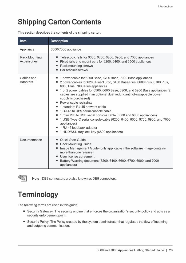
Shipping Carton ContentsThis section describes the contents of the shipping carton.
Item Description
Appliance 6000/7000 appliance
Rack MountingAccessories
n Telescopic rails for 6600, 6700, 6800, 6900, and 7000 appliancesn Fixed rails and mount ears for 6200, 6400, and 6500 appliancesn Rack mounting screwsn Ear bracket screws
Cables andAdapters
n 1 power cable for 6200 Base, 6700 Base, 7000 Base appliancesn 2 power cables for 6200 Plus/Turbo, 6400 Base/Plus, 6600 Plus, 6700 Plus,
6900 Plus, 7000 Plus appliancesn 1 or 2 power cables for 6500, 6600 Base, 6800, and 6900 Base appliances (2
cables are supplied if an optional dual redundant hot-swappable powersupply is purchased)
n Power cable restraintsn 1 standard RJ-45 network cablen 1 RJ-45 to DB9 serial console cablen 1 miniUSB to USB serial console cable (6500 and 6800 appliances)n 1 USB Type-C serial console cable (6200, 6400, 6600, 6700, 6900, and 7000
appliances)n 1 RJ-45 loopback adaptern 1 HDD/SSD tray lock key (6800 appliances)
Documentation n Quick Start Guiden Rack Mounting Guiden Image Management Guide (only applicable if the software image contains
more than one release)n User license agreementn Battery Warning document (6200, 6400, 6600, 6700, 6900, and 7000
appliances)
Note - DB9 connectors are also known as DE9 connectors.
TerminologyThe following terms are used in this guide:
n Security Gateway: The security engine that enforces the organization's security policy and acts as asecurity enforcement point.
n Security Policy: The Policy created by the system administrator that regulates the flow of incomingand outgoing communication.
Introduction
6000 and 7000 Appliances Getting Started Guide | 27
n Security Management Server: The server used by the system administrator to manage the SecurityPolicy. The organization's databases and Security Policies are stored on the Security ManagementServer and downloaded to the Security Gateway.
n SmartConsole: GUI applications that are used to manage various aspects of Security Policyenforcement.
n Locally Managed Deployment: When all Check Point components responsible for both themanagement and enforcement of the Security Policy (the Security Management Server and theSecurity Gateway) are installed on the same machine.
n Centrally Managed Deployment: When the Security Gateway and the Security Management Serverare installed on separate machines.
Mounting the Appliances in a Rack
6000 and 7000 Appliances Getting Started Guide | 28
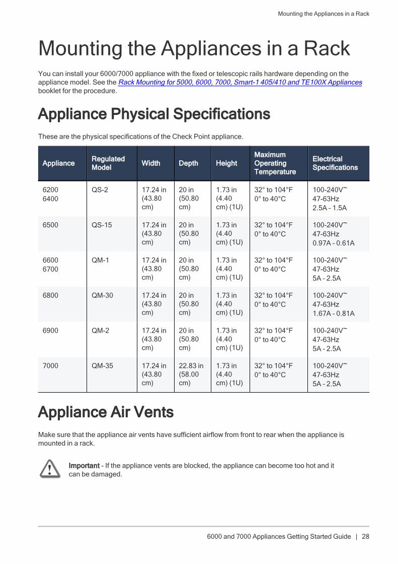
Mounting the Appliances in a RackYou can install your 6000/7000 appliance with the fixed or telescopic rails hardware depending on theappliance model. See the Rack Mounting for 5000, 6000, 7000, Smart-1 405/410 and TE100X Appliancesbooklet for the procedure.
Appliance Physical SpecificationsThese are the physical specifications of the Check Point appliance.
Appliance RegulatedModel Width Depth Height
MaximumOperatingTemperature
ElectricalSpecifications
62006400
QS-2 17.24 in(43.80cm)
20 in(50.80cm)
1.73 in(4.40cm) (1U)
32° to 104°F0° to 40°C
100-240V~47-63Hz2.5A – 1.5A
6500 QS-15 17.24 in(43.80cm)
20 in(50.80cm)
1.73 in(4.40cm) (1U)
32° to 104°F0° to 40°C
100-240V~47-63Hz0.97A – 0.61A
66006700
QM-1 17.24 in(43.80cm)
20 in(50.80cm)
1.73 in(4.40cm) (1U)
32° to 104°F0° to 40°C
100-240V~47-63Hz5A – 2.5A
6800 QM-30 17.24 in(43.80cm)
20 in(50.80cm)
1.73 in(4.40cm) (1U)
32° to 104°F0° to 40°C
100-240V~47-63Hz1.67A – 0.81A
6900 QM-2 17.24 in(43.80cm)
20 in(50.80cm)
1.73 in(4.40cm) (1U)
32° to 104°F0° to 40°C
100-240V~47-63Hz5A – 2.5A
7000 QM-35 17.24 in(43.80cm)
22.83 in(58.00cm)
1.73 in(4.40cm) (1U)
32° to 104°F0° to 40°C
100-240V~47-63Hz5A – 2.5A
Appliance Air VentsMake sure that the appliance air vents have sufficient airflow from front to rear when the appliance ismounted in a rack.
Important - If the appliance vents are blocked, the appliance can become too hot and itcan be damaged.
Mounting the Appliances in a Rack
6000 and 7000 Appliances Getting Started Guide | 29
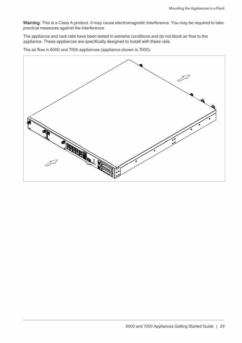
Warning: This is a Class A product. It may cause electromagnetic interference. You may be required to takepractical measures against the interference.
The appliance and rack rails have been tested in extreme conditions and do not block air flow to theappliance. These appliances are specifically designed to install with these rails.
The air flow in 6000 and 7000 appliances (appliance shown is 7000):
Configuring the Appliances
6000 and 7000 Appliances Getting Started Guide | 30
Configuring the AppliancesStarting the ApplianceConnect the appliance to a power source and turn on the appliance. When the appliance is ready, you cando the First Time Configuration Wizard to configure it.
To start the appliance:
Connect the power cable(s) to the power supply unit(s) in the rear panel.
The appliance turns on.
In appliances with two power supply units installed:
Note - When a power supply unit is not connected to the outlet or is taken out of the appliance, an alarmsounds continuously. It will continue to beep until power is restored (cord or power supply unit is replaced)or the alarm is turned off.To turn off the alarm, press the red Alarm off button on the rear panel of the appliance. In 6200 and 6400appliances, press the Locator/Alarm off button on the front panel.
Available Software ImagesThe 6000 and 7000 appliances come with different software images. See the 6000 and 7000 Applianceshome page.
Reverting to a software image takes a few minutes. To follow progress and see when the appliance is ready,connect to the appliance using a serial console.
Synchronizing RAID on 6800, 6900, and 7000 Appliances6800, 6900, and 7000 appliances support two storage devices.
For appliances with two storage devices, the appliance uses RAID1 mirroring across both storage devices.This lets the appliance continue to work if there is a storage device failure.
The mirror rebuild is automatic. Both storage devices must be the same type.
First Boot Up on a 6800, 6900, or 7000 Appliance with Two Storage Devices
At first boot up, wait a few hours to let the storage devices fully synchronize. If you reboot the appliancebefore the storage devices are synchronized, the synchronization starts again from scratch at the next boot.
To monitor the RAID status of the storage devices from the CLI:
1. Log in to the appliance.
2. Run:raid_diagnostic
The output shows data about the RAID and storage devices, with the percent of synchronization

Configuring the Appliances
6000 and 7000 Appliances Getting Started Guide | 31
completed.
DiskID 0 is the top storage device. DiskID 1 is the bottom storage device.
After first boot and replacing a second storage device, the RAID State (in the VolumeID line) showsDEGRADED (this indicates that the drives are not synchronized). The DiskID:0 state shows ONLINE and theDiskID:1 state shows INITIALIZING.
After the RAID is synchronized, the RAID state (in the VolumeID line) shows OPTIMAL (this indicates thatthe drives are synchronized). The DiskID:0 and DiskID:1 state show ONLINE.
Example 1: RAID status for fully synchronized storage devices (disk size and vendor may vary):
Server123> raid_diagnosticRaid status:VolumeID:0 RaidLevel: RAID-1 NumberOfDisks:2 RaidSize:465GB State:OPTIMALFlags:ENABLEDDiskID:0 DiskNumber:0 Vendor:ATA ProductID:HGST HTE25050A7 Revision:GS2OSize:465GB State:ONLINE Flags:NONEDiskID:1 DiskNumber:1 Vendor:ATA ProductID:HGST HTE25050A7 Revision:GS2OSize:465GB State:ONLINE Flags:NONE
Example 2: RAID status for one fully synchronized storage device and another device that was removed(disk size may vary):
Server123> raid_diagnosticRaid status:VolumeID:0 RaidLevel: RAID-1 NumberOfDisks:2 RaidSize:465GB State:DEGRADEDFlags:VOLUME_INACTIVEDiskID:0 DiskNumber:0 Vendor:NONE ProductID:NONE Revision:NONE Size:0GBState:MISSING Flags:NONEDiskID:1 DiskNumber:1 Vendor:ATA ProductID:HGST HTE25050A7 Revision:GS2OSize:465GB State:ONLINE Flags:NONE
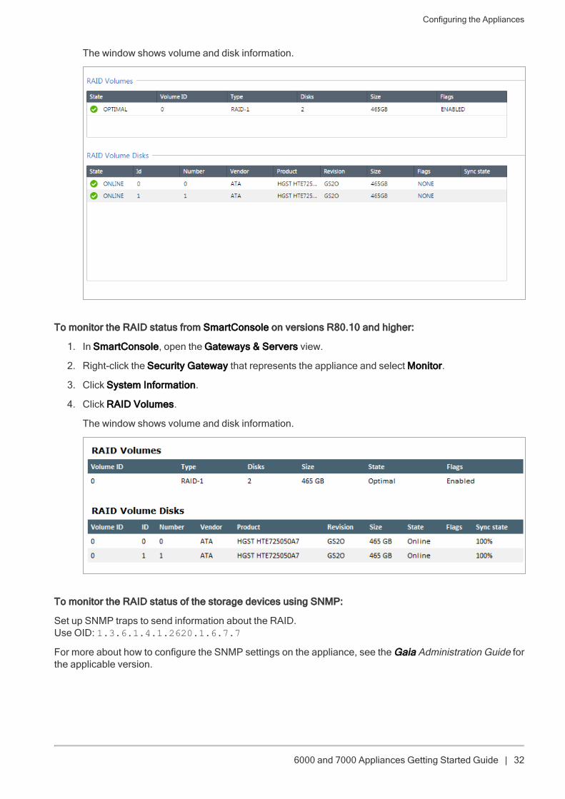
To monitor the RAID status from the WebUI:
1. Log in to the Gaia Portal.
2. From the left navigation tree, click Maintenance> RAID Monitoring.
Configuring the Appliances
6000 and 7000 Appliances Getting Started Guide | 32
The window shows volume and disk information.
To monitor the RAID status from SmartConsole on versions R80.10 and higher:
1. In SmartConsole, open the Gateways & Servers view.
2. Right-click the Security Gateway that represents the appliance and select Monitor.
3. Click System Information.
4. Click RAID Volumes.
The window shows volume and disk information.
To monitor the RAID status of the storage devices using SNMP:
Set up SNMP traps to send information about the RAID.Use OID: 1.3.6.1.4.1.2620.1.6.7.7
For more about how to configure the SNMP settings on the appliance, see the Gaia Administration Guide forthe applicable version.
Configuring the Appliances
6000 and 7000 Appliances Getting Started Guide | 33
To hot swap a storage device:
1. Make sure that there is at least one fully synchronized storage device in the system (state=ONLINE).
2. When the system is up, remove the failed storage device.
a. If necessary, use the key in the accessories bag to unlock the storage device.
b. Move the release latch to the left.
The extraction handle pops out.
c. Hold the extraction handle and carefully pull the storage device casing to remove the storagedevice from the appliance.
Important- Be careful when you pull the ejector handle to remove the storage device from theappliance. If you pull too hard on the ejector handle, it can break off from the storage devicecasing.
3. Wait 15 seconds.
The appliance recognizes that you removed a storage device. See example 2 above.
4. Install a new storage device.
a. Insert the replacement storage device into the slot.
b. Push the extraction handle until it closes and the device clicks into position.
Software RAID is activated and the appliance synchronizes the storage devices. The firstsynchronization can continue for over an hour. If you reboot or turn off the appliance before thestorage devices are synchronized, the synchronization starts again from scratch at the next boot.
5. Monitor the RAID status.
Initial ConfigurationConfigure the appliance with the First Time Configuration Wizard. See the Installation and Upgrade Guiderelated to the software version.
Go to the Installing Security Gateways on Appliances section, and see the instructions to use the First TimeConfiguration Wizard.
Creating the Network ObjectConfigure the 6000/7000 Appliance object as a Security Gateway object in the Security Management Serverdatabase.
1. Connect with SmartConsole (R80.10 or higher) to the Management Server.
2. Configure a new Security Gateway object for the appliance.
3. Enter the IP address for the appliance.
4. For a centrally managed deployment, establish Secure Internal Communication (SIC) between theSecurity Gateway and the Security Management Server. Enter the activation key you used in the FirstTime Configuration Wizard.
Configuring the Appliances
6000 and 7000 Appliances Getting Started Guide | 34
5. Configure the topology.
6. Configure and install the Security Policy.
Advanced ConfigurationYou can configure advanced options on Gaia from the Portal or the CLI.
Connecting to the 6000/7000 Appliances CLITo connect to the command line interface of a 6000/7000 appliance, use one of these:
n An SSH connection to the management interface (if SSHD is configured).
n A serial console cable and terminal emulation software, such as PuTTY (fromWindows) or Minicom(from Unix/Linux).
6000/7000 Appliances support these serial console connectivity options:
l Mini USB - Using the included mini USB to USB console cable in 6500/6800 appliances.
l USB Type-C - Using the included USB Type-C console cable in 6200, 6400, 6600, 6700, 6900,and 7000 appliances.
l RJ45 - Using the included RJ-45 to DB9 serial console cable.
Connection parameters are: 9600bps, 8 bits, no parity, 1 stop bit (8N1), Flow Control - None.
If you use both the mini USB/USB Type-C (depending on the appliance) and RJ45 console ports, themini USB port/USB Type-C has priority. To use the RJ45 port, disconnect the mini USB/USB Type-Cconsole cable.
When you have completed using the RJ45 port, reconnect the miniUSB/USB Type-C console cable.
Note - To use the miniUSB/USB Type-C console port, a driver must be installed on theconsole client machine (desktop/laptop). For installation instructions and download link,see the appliance home page.
6000/7000 Appliances Hardware
6000 and 7000 Appliances Getting Started Guide | 35
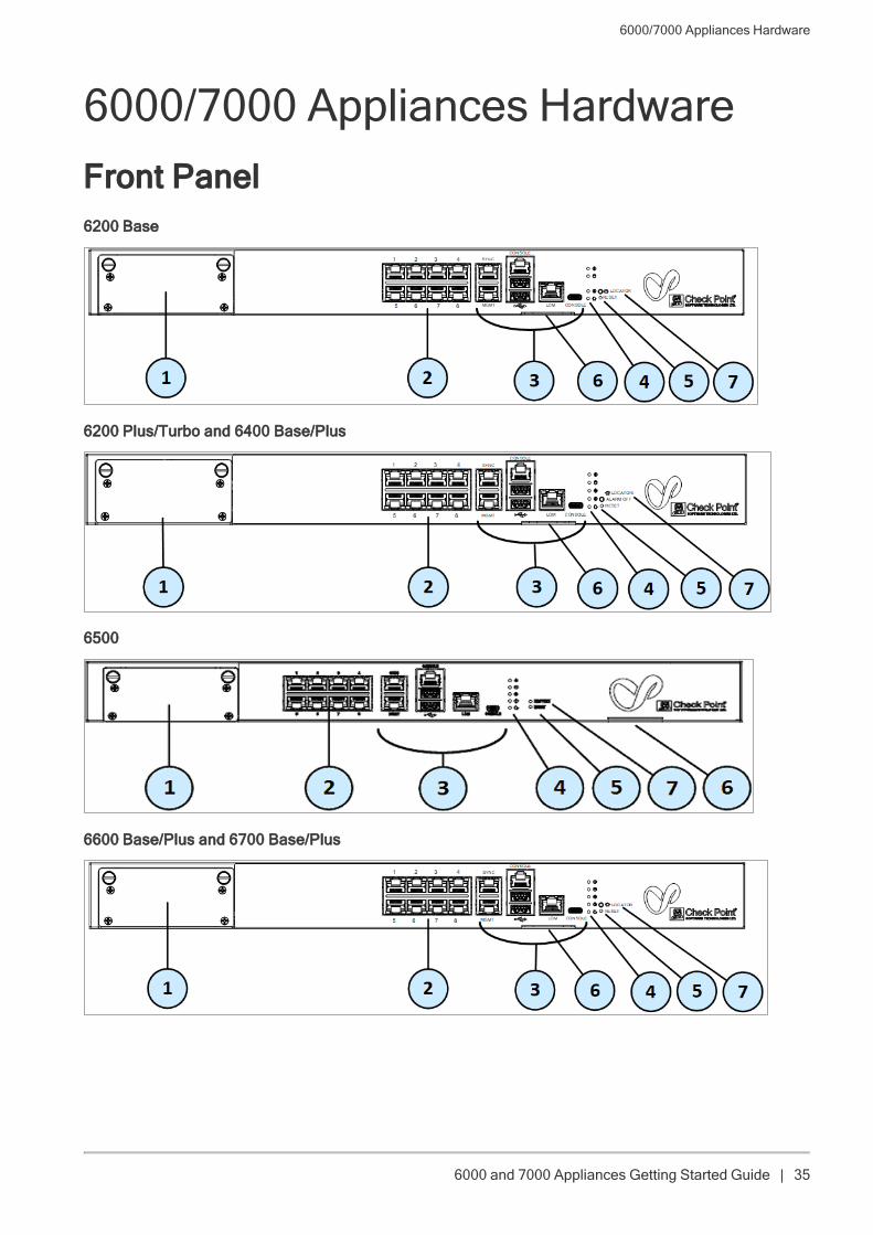
6000/7000 Appliances HardwareFront Panel6200 Base
6200 Plus/Turbo and 6400 Base/Plus
6500
6600 Base/Plus and 6700 Base/Plus
6000/7000 Appliances Hardware
6000 and 7000 Appliances Getting Started Guide | 36
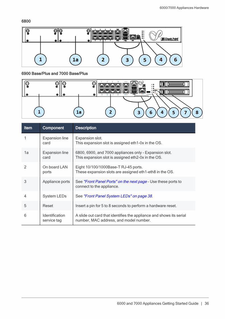
6800
6900 Base/Plus and 7000 Base/Plus
Item Component Description
1 Expansion linecard
Expansion slot.This expansion slot is assigned eth1-0x in the OS.
1a Expansion linecard
6800, 6900, and 7000 appliances only - Expansion slot.This expansion slot is assigned eth2-0x in the OS.
2 On board LANports
Eight 10/100/1000Base-T RJ-45 ports.These expansion slots are assigned eth1-eth8 in the OS.
3 Appliance ports See "Front Panel Ports" on the next page - Use these ports toconnect to the appliance.
4 System LEDs See "Front Panel System LEDs" on page 38.
5 Reset Insert a pin for 5 to 8 seconds to perform a hardware reset.
6 Identificationservice tag
A slide out card that identifies the appliance and shows its serialnumber, MAC address, and model number.
6000/7000 Appliances Hardware
6000 and 7000 Appliances Getting Started Guide | 37
Item Component Description
7 Factory reset /Locator / AlarmOff
n 6200 Base, 6600, 6700, 6900, and 7000 appliances -Locator - Press the button to turn the Location beacon LEDon and off in the appliance.
n 6200 Plus/Turbo and 6400 appliances - Provides Locatorand Alarm Off functionalities.
l Locator - Press the button to turn the Location beaconLED on and off in the appliance.
l Alarm Off - Press and hold it to turn off the soundingalarm when there is a PSU failure.
n 6500 appliances - Factory reset - Press and hold to restorethe appliance to its factory defaults.
n 6800 appliances - See "Restoring Factory Defaults" onpage 48.
8 Storagedevices
6900 and 7000 appliances only - When monitoring the storagedevices with the raid_diagnostic command, DiskID 0 is thetop storage device, and DiskID 1 is the bottom (numbered 1 and2 on the appliance's chassis).
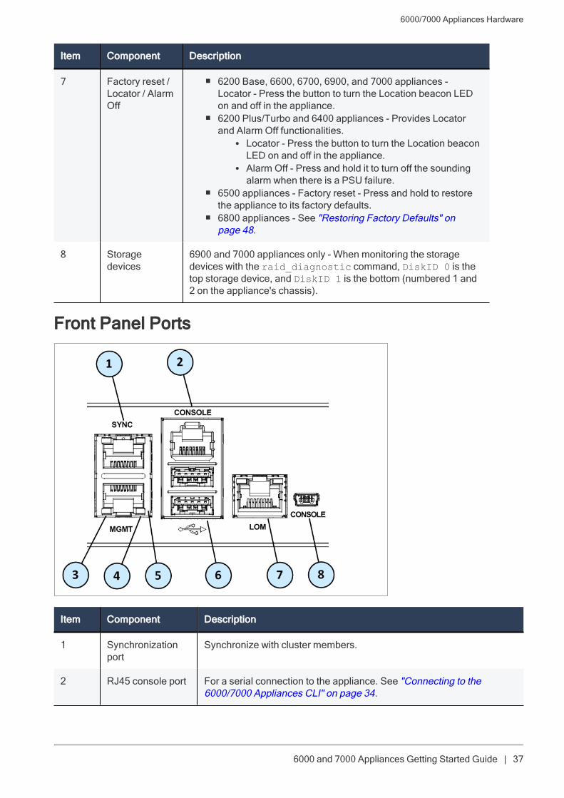
Front Panel Ports
Item Component Description
1 Synchronizationport
Synchronize with cluster members.
2 RJ45 console port For a serial connection to the appliance. See "Connecting to the6000/7000 Appliances CLI" on page 34.
6000/7000 Appliances Hardware
6000 and 7000 Appliances Getting Started Guide | 38
Item Component Description
3 Port activity LED n Off - No activityn Slow Blink (Green) - Activity
4 Link speed LED n Off - No Link or 10M linkn On (Green) - 100M linkn On (Amber) - 1000M link
5 Management port For an Ethernet connection to a remote management computer.
6 USB ports 2 USB 3.0 ports.
7 LOM port LOM (Lights Out Management) port to connect to the LOM card.
8 Console port 6500 and 6800 appliances - a MiniUSB port for a serial connection tothe appliance (shown in image).6200, 6400, 6600, 6700, 6900, and 7000 appliances - a USB Type-Cport for a serial connection to the appliance.See "Connecting to the 6000/7000 Appliances CLI" on page 34.
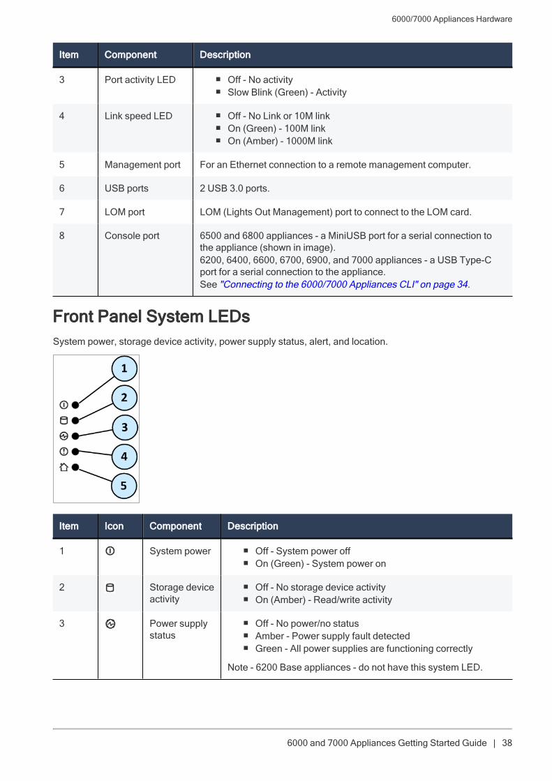
Front Panel System LEDsSystem power, storage device activity, power supply status, alert, and location.
Item Icon Component Description
1 System power n Off - System power offn On (Green) - System power on
2 Storage deviceactivity
n Off - No storage device activityn On (Amber) - Read/write activity
3 Power supplystatus
n Off - No power/no statusn Amber - Power supply fault detectedn Green - All power supplies are functioning correctly
Note - 6200 Base appliances - do not have this system LED.

6000/7000 Appliances Hardware
6000 and 7000 Appliances Getting Started Guide | 39
Item Icon Component Description
4 Alert n Off - No faults detectedn Blinking red - System fault detected
5 Locationbeacon
n Off - Location beacon is turned offn Solid blue - Location beacon is turned on through the Gaia
Portal or Gaia Clish or through the Locator button on thefront panel
Note - You can turn off the Location beacon LED from theLocator button, Gaia Portal, or Gaia Clish.
Rear Panel6200 Base
6200 Plus/Turbo and 6400 Base/Plus
6500
6600 Base/Plus, 6700 Base/Plus, and 6900 Base/Plus
6000/7000 Appliances Hardware
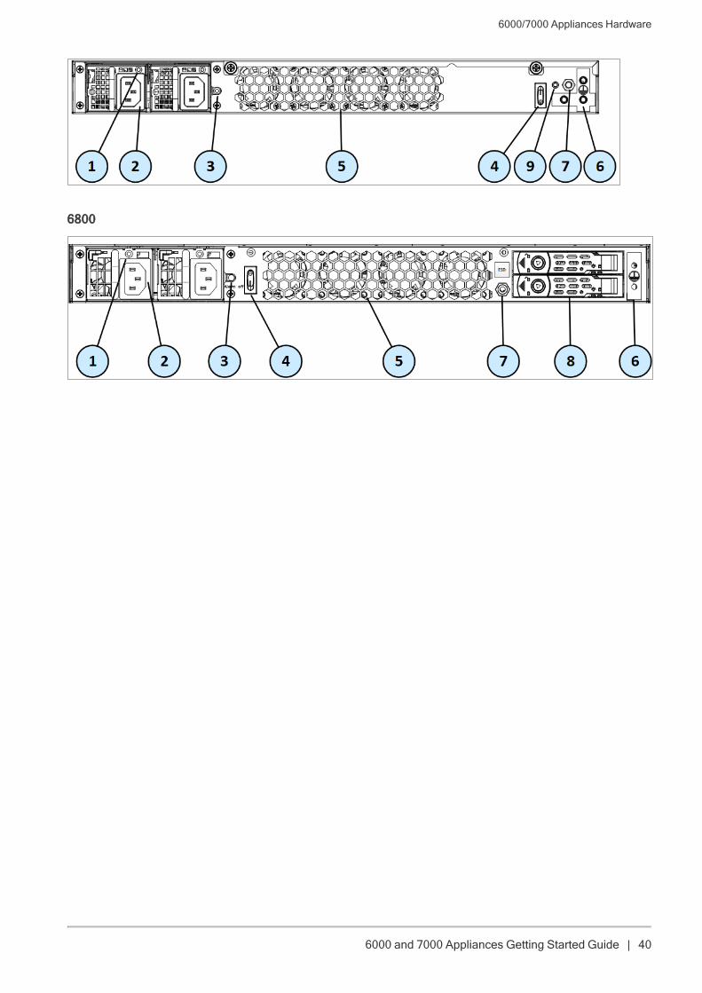
6000 and 7000 Appliances Getting Started Guide | 40
6800
6000/7000 Appliances Hardware
6000 and 7000 Appliances Getting Started Guide | 41
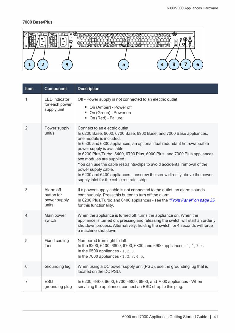
7000 Base/Plus
Item Component Description
1 LED indicatorfor each powersupply unit
Off - Power supply is not connected to an electric outlet
n On (Amber) - Power offn On (Green) - Power onn On (Red) - Failure
2 Power supplyunit/s
Connect to an electric outlet.In 6200 Base, 6600, 6700 Base, 6900 Base, and 7000 Base appliances,one module is included.In 6500 and 6800 appliances, an optional dual redundant hot-swappablepower supply is available.In 6200 Plus/Turbo, 6400, 6700 Plus, 6900 Plus, and 7000 Plus appliancestwo modules are supplied.You can use the cable restraints/clips to avoid accidental removal of thepower supply cable.In 6200 and 6400 appliances - unscrew the screw directly above the powersupply inlet for the cable restraint strip.
3 Alarm offbutton forpower supplyunits
If a power supply cable is not connected to the outlet, an alarm soundscontinuously. Press this button to turn off the alarm.In 6200 Plus/Turbo and 6400 appliances - see the "Front Panel" on page 35for this functionality.
4 Main powerswitch
When the appliance is turned off, turns the appliance on. When theappliance is turned on, pressing and releasing the switch will start an orderlyshutdown process. Alternatively, holding the switch for 4 seconds will forcea machine shut down.
5 Fixed coolingfans
Numbered from right to left.In the 6200, 6400, 6600, 6700, 6800, and 6900 appliances - 1, 2, 3, 4.In the 6500 appliances - 1, 2, 3.In the 7000 appliances - 1, 2, 3, 4, 5.
6 Grounding lug When using a DC power supply unit (PSU), use the grounding lug that islocated on the DC PSU.
7 ESDgrounding plug
In 6200, 6400, 6600, 6700, 6800, 6900, and 7000 appliances - Whenservicing the appliance, connect an ESD strap to this plug.
6000/7000 Appliances Hardware
6000 and 7000 Appliances Getting Started Guide | 42
Item Component Description
8 Storagedevices
In 6800 appliances - When monitoring the storage devices with the raid_diagnostic command, DiskID 0 is the top storage device, and DiskID1 is the bottom storage device (in 6800 appliances only). By default, 6800 isshipped with only one storage device.
9 Location LED In 6200, 6400, 6600, 6700, 6900, and 7000 appliances only
n Off - Location beacon is turned offn Solid blue - Location beacon is turned on through the Gaia Portal or
Gaia Clish or through the Locator button on the front panel
Note - You can turn off the Location beacon LED from the Locator button,Gaia Portal, or Gaia Clish.
6000/7000 Appliances Hardware
6000 and 7000 Appliances Getting Started Guide | 43
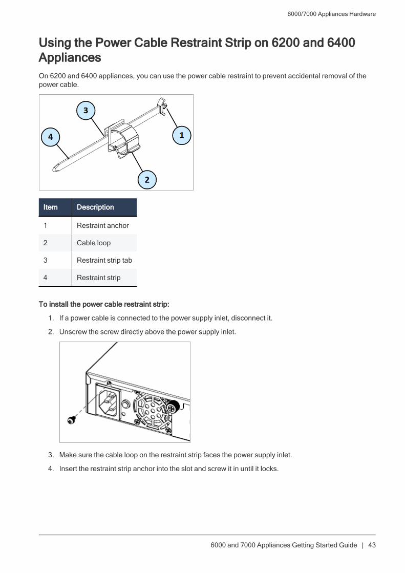
Using the Power Cable Restraint Strip on 6200 and 6400AppliancesOn 6200 and 6400 appliances, you can use the power cable restraint to prevent accidental removal of thepower cable.
Item Description
1 Restraint anchor
2 Cable loop
3 Restraint strip tab
4 Restraint strip
To install the power cable restraint strip:
1. If a power cable is connected to the power supply inlet, disconnect it.
2. Unscrew the screw directly above the power supply inlet.
3. Make sure the cable loop on the restraint strip faces the power supply inlet.
4. Insert the restraint strip anchor into the slot and screw it in until it locks.
6000/7000 Appliances Hardware
6000 and 7000 Appliances Getting Started Guide | 44
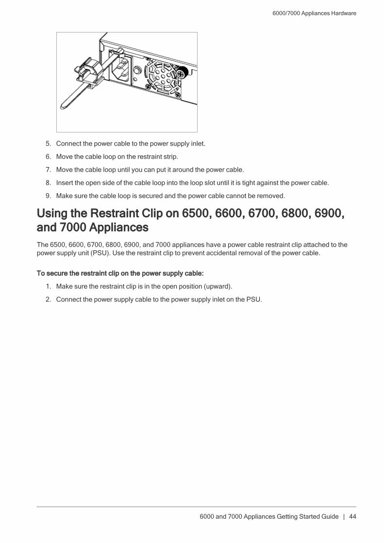
5. Connect the power cable to the power supply inlet.
6. Move the cable loop on the restraint strip.
7. Move the cable loop until you can put it around the power cable.
8. Insert the open side of the cable loop into the loop slot until it is tight against the power cable.
9. Make sure the cable loop is secured and the power cable cannot be removed.
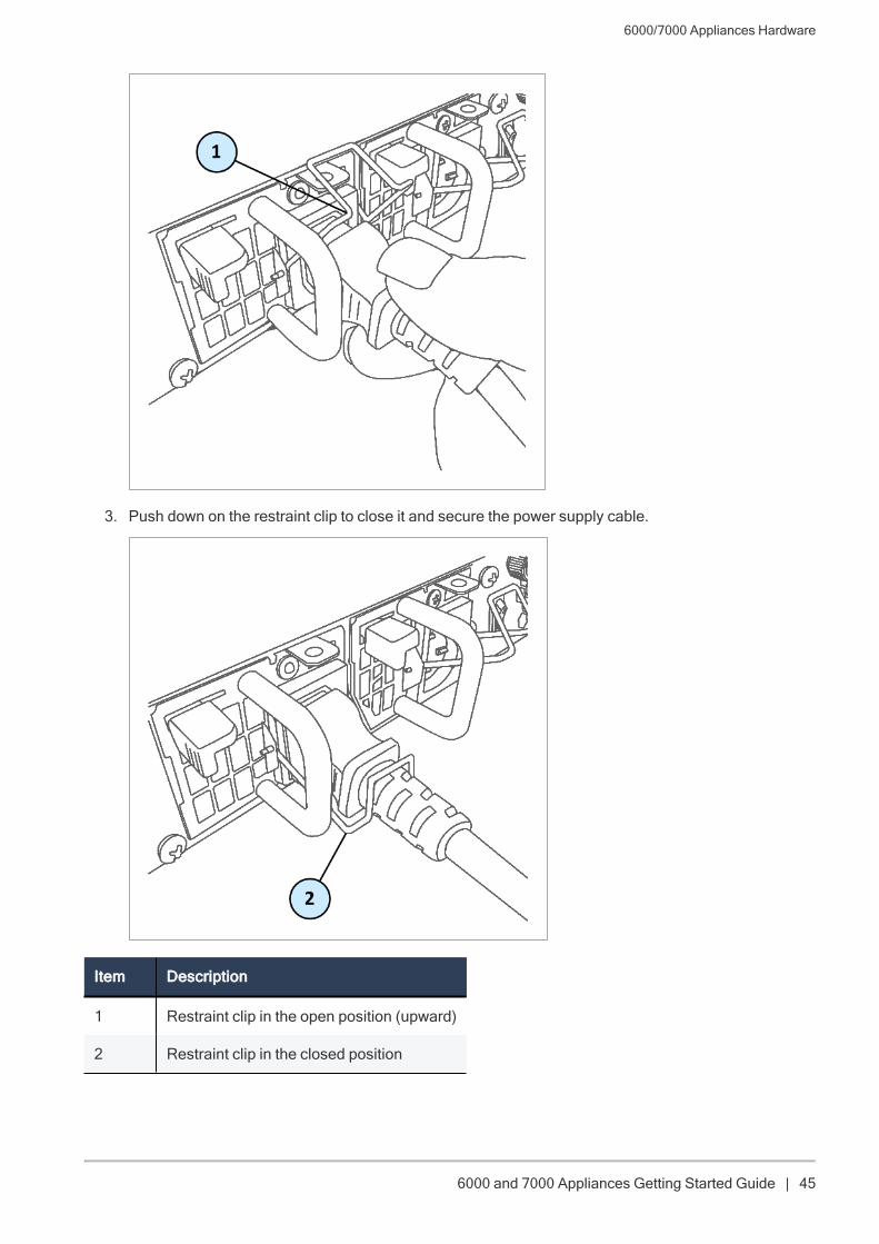
Using the Restraint Clip on 6500, 6600, 6700, 6800, 6900,and 7000 AppliancesThe 6500, 6600, 6700, 6800, 6900, and 7000 appliances have a power cable restraint clip attached to thepower supply unit (PSU). Use the restraint clip to prevent accidental removal of the power cable.
To secure the restraint clip on the power supply cable:
1. Make sure the restraint clip is in the open position (upward).
2. Connect the power supply cable to the power supply inlet on the PSU.
6000/7000 Appliances Hardware
6000 and 7000 Appliances Getting Started Guide | 45
3. Push down on the restraint clip to close it and secure the power supply cable.
Item Description
1 Restraint clip in the open position (upward)
2 Restraint clip in the closed position
6000/7000 Appliances Hardware
6000 and 7000 Appliances Getting Started Guide | 46
Lights Out ManagementThe Check Point Lights Out Management (LOM) card lets you use a dedicated management channel toremotely control Check Point appliances. Lights Out Management can also work when the appliance isturned off or not responding.
Lights Out Management is an optional feature on the 6200 Base, 6400 Base, 6500, 6600 Base, 6700 Base,6900 Base, and 7000 Base appliances.
It is included by default with the 6200 Plus/Turbo, 6400 Plus, 6600 Plus, 6700 Plus, 6800, 6900 Plus, and7000 Plus appliances.
For more about using Lights Out Management, see the Lights Out Management Administration Guide.
Dual Redundant BIOSTo ensure resilience in the event of a BIOS failure, 6000 and 7000 Appliances are equipped with dualredundant BIOS images.
If an appliance encounters a BIOS failure, it will boot up from a recovery, read-only BIOS image that enablesfull functionality of the appliance.
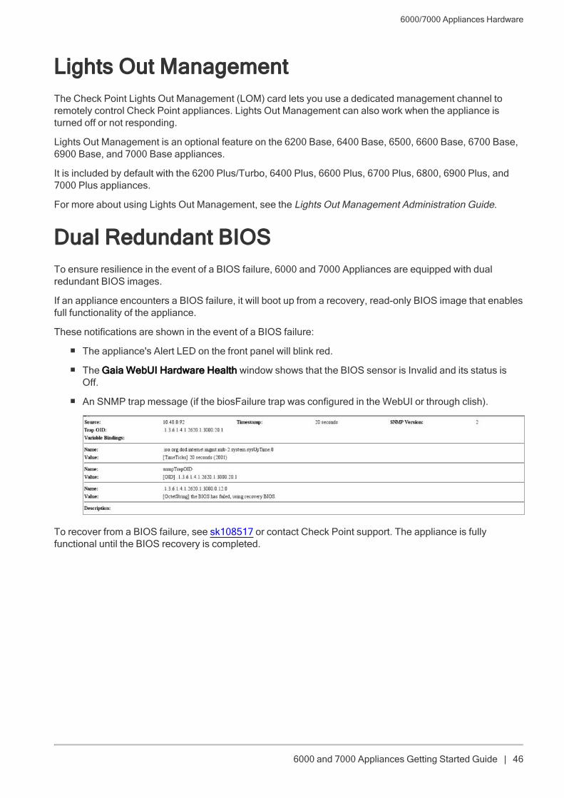
These notifications are shown in the event of a BIOS failure:
n The appliance's Alert LED on the front panel will blink red.
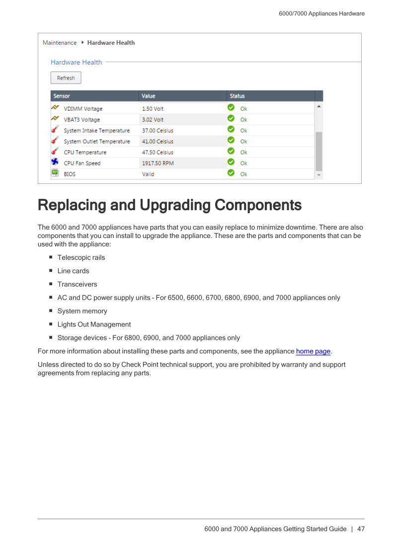
n The Gaia WebUI Hardware Health window shows that the BIOS sensor is Invalid and its status isOff.
n An SNMP trap message (if the biosFailure trap was configured in the WebUI or through clish).
To recover from a BIOS failure, see sk108517 or contact Check Point support. The appliance is fullyfunctional until the BIOS recovery is completed.
6000/7000 Appliances Hardware
6000 and 7000 Appliances Getting Started Guide | 47
Replacing and Upgrading ComponentsThe 6000 and 7000 appliances have parts that you can easily replace to minimize downtime. There are alsocomponents that you can install to upgrade the appliance. These are the parts and components that can beused with the appliance:
n Telescopic rails
n Line cards
n Transceivers
n AC and DC power supply units - For 6500, 6600, 6700, 6800, 6900, and 7000 appliances only
n System memory
n Lights Out Management
n Storage devices - For 6800, 6900, and 7000 appliances only
For more information about installing these parts and components, see the appliance home page.
Unless directed to do so by Check Point technical support, you are prohibited by warranty and supportagreements from replacing any parts.
Restoring Factory Defaults
6000 and 7000 Appliances Getting Started Guide | 48
Restoring Factory DefaultsIf necessary, restore the appliance to its factory default settings.
Important - If you restore factory defaults, note that all information on the appliance is deleted.
Restoring from the Gaia PortalUse the Gaia Portal to restore the appliance to the factory default settings.
To restore a Gaia appliance from the Gaia Portal:
1. In your web browser, connect to the management IP address:
https://<appliance_ip_address>
2. Log in to the Gaia Portal of the appliance with the administrator username and password.
3. In the left navigation tree, click Maintenance > Factory Defaults.
The Factory Defaults window opens. The image installed on the appliance is shown.
4. Click Apply.
The appliance reboots and installs the selected version from scratch.
Restoring from the Boot Menu
To restore the appliance from the Boot Menu:
1. Connect the supplied serial cable's RJ45 or USB type-C connector to the console port on the front ofthe appliance.
2. From the computer, open a terminal emulation program such as PuTTY or Microsoft HyperTerminal.
3. Configure the terminal emulation program:
n In PuTTY select the Serial connection type.
n In the HyperTerminal Connect To window, select a port from the Connect using list.
4. Define the serial port settings:
9600 BPS, 8 bits, no parity, 1 stop bit
5. From the Flow control list, select None.
6. Connect to the appliance.
7. Reboot or turn on the appliance.
The appliance initializes and status messages are shown in the terminal emulation program.
8. When the message "Press any key to see the boot menu" is shown, you have approximately fourseconds to hit any key to activate the Boot menu.
Restoring Factory Defaults
6000 and 7000 Appliances Getting Started Guide | 49
9. From the Boot menu, select the relevant Reset to factory defaults image.
10. Press Enter.
The appliance initializes and status messages are shown in the terminal emulation program.
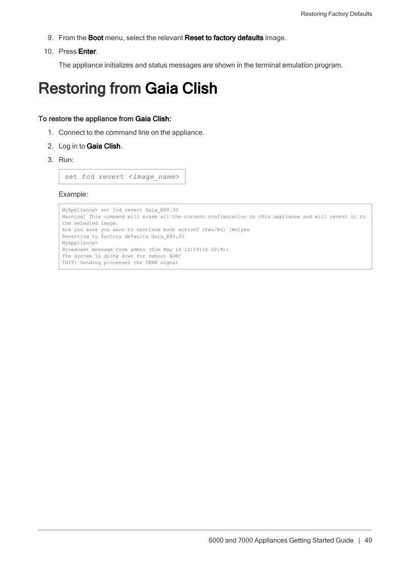
Restoring from Gaia Clish
To restore the appliance from Gaia Clish:
1. Connect to the command line on the appliance.
2. Log in to Gaia Clish.
3. Run:
set fcd revert <image_name>
Example:
MyAppliance> set fcd revert Gaia_R80.30Warning! This command will erase all the current configuration on this appliance and will revert it tothe selected image.Are you sure you want to continue such action? (Yes/No) [No]yesReverting to factory defaults Gaia_R80.30MyAppliance>Broadcast message from admin (Tue May 14 12:19:16 2019):The system is going down for reboot NOW!INIT: Sending processes the TERM signal
Registration and Support
6000 and 7000 Appliances Getting Started Guide | 50
Registration and SupportRegistrationThe appliance requires a product-specific Check Point license.
Connect to the Portal of the appliance (from Advanced mode, select Maintenance > Licenses) to find theMAC address that is required to obtain a license.
Alternatively, you can read the MAC address off the service tag on the appliance. Refer to "Front Panel" onpage 35.
SupportFor additional technical information about Check Point products, consult the Check Point Support Center.
Where To From Here?You have the basics to get started. The next step is to get more advanced knowledge of your Check Pointsoftware.