
TIC-S 6000 - TEKADOOR Luftschleier
24
INDIVIDUAL INNOVATIVE ENERGY-SAVING INDUSTRIAL DOOR AIR CURTAIN TIC 7000 TIC/TIC-S 6000 TIC 3000 TIC TIC 6000 TIC 3000 TIC-S 6000 TIC 7000 TIC 7000 TIC 3000 TIC 3000
-
Upload
khangminh22 -
Category
Documents
-
view
9 -
download
0
Transcript of TIC-S 6000 - TEKADOOR Luftschleier

TIC 3000
INDIVIDUALINNOVATIVEENERGY-SAVING
INDUSTRIAL DOOR AIR CURTAIN
TIC 7000 TIC/TIC-S 6000TIC 3000
TIC
TIC 6000
TIC 3000TIC-S 6000
TIC 7000
TIC 7000
TIC 3000
TIC 3000

ApplicationsThe TIC series TEKADOOR door air curtain is suitable for shielding larger doors in the industrial, warehousing and logistics sectors. This not only ensures draught-free transport of goods through entry and exit doors for the people working there, but also ideally utilises the area around the door.
Special designInstallation-ready industrial door air curtains either as heated or recirculated air curtains (without heat exchanger), in suspended or floor mounted versions. Both variants can be installed in series. Depending on the door width, the floor mounted vertical unit can be installed next to the door, either on one side or both sides. The appropriate TIC modules can be installed on top of each other, depending on the door height.For the suspended variant, multiple modules can be installed next to each other, depending on the door width. In the higher specification variant, the air exitsTIC 6000 & TIC 7000 via the Coanvara discharge nozzle – a multi-nozzle system with opti-mised, drop-shaped profiles. Using the Coanda effect to bring the individual streams together results in a very broad, homog-enous airstream. The purposely long profiles, which are parallel and steplessly adjustable in both directions (up to 40°), act as a
flow straightener. This ensures the stream mixing factor remains low, as desired. The selected discharge temperature is carried far down to the floor, effectively preventing the room from cooling down. This means the discharged air is heated less than with air curtains using a conventional discharge system. For the basic TIC-S design, the air is discharged via a conical discharge box – located centrally – without a discharge grill. For the TIC 3000, the air is discharged through a fully adjustable system of fins.
The housingIndustrial air curtain unit manufactured with a robust, self- supporting, powder coated sheet steel housing. Available in the colour RAL 7032 (pebble grey) as standard, or powder coated in standard RAL tones depending on the wishes of the client. In contrast, the housings of the TIC 3000, TIC-S 6000 und TIC 7000 are manufactured from galvanised sheet steel. For the floor mounted vertical unit, the floor console and connecting pieces for series installation are included as standard. For the suspended version, fixation/suspension is performed using M10 rivet nuts.
+ Self-supporting sheet steel housing
+ Coanvara – discharge systemTIC 6000
INDUSTRIAL DOOR AIR CURTAINTIC
+ Multi-fin discharge systemTIC 3000
2

Advantages at a glanceTIC
Made in Germany
ErP conform
Robust, self-supporting sheet steel housing
Large throw distance, optimum shielding
Simple to install
Optional available with EC fans
Optional available with electrical heat exchanger (230V fans)
+
+++
++
+
Heating mediaHeat exchangers for different heating mediaLPHW: For normal temperature LPHW 70/50 °C or low-temper-ature LPHW 60/40 °C, other temperatures available on request.Recirculating air operation without heating is possible (without heating media). TIC 3000 E: 3-stage heat exchanger, spiral-form, corrosion resistant, with thermal overheating protection.
The fansAxial fans with three-phase motor, IP 54 degree of protection, motor protection via thermal contacts, including protection guard. These fans comply with the EU Directive ErP regarding minimum efficiency requirements for fans within the EU.
MountingEasy installation thanks rivet buts (M10) on top of the unit.
Maintenance In the TIC series, a filter is not necessary thanks to the purposefully large distance between the fins on the electric heater. This enables easy cleaning of the units.
Control unitTIC 7000 / TIC 6000 / TIC-S 6000 / TIC 3000 5 stage HATI speed controller. 400 V / 50 Hz according to VDE 0550 in the housing, with step switch, fault and operation lights, restart interlock for full motor protection, manual to automatic switching and contactor for external signal encoder (e.g. door contact).
Control unitTIC 3000 EC Electronic TEKADOOR GTC EC control unit, multifunctional with touch display, including an optional ModBus interface A GTC 1 EC control unit is used as standard for models with LPHW heating. A GTC E EC control unit is used for models with electrical heating. The control board is preassembled in the air curtain and 20m of preassembled data cable (connection between the door air curtain and control unit) are included.
3

DETAILS
TIC7000 / TIC-S 6000 / TIC 3000
ConnectionsTIC
Heating connections – flow and return (dimensions depend on the model) – at the front side of the unit as standard for easy connection to the on-site heating system. Optionally, the connections can also be located at the side.
Connection box TIC
Connection box (400 V – IP 54 according to VDE 0550) in the unit, easy to open from the outside.
EMPTYING
FORWARD FLOW
Data cable connection/inter-face
Simple, standard plug and play connection of the data cable and an optional magnetic valve on top side of the unit. The connection can be offset on request.
Control:Input for the data cable to the control unit.
Auxiliary:Output for parallel operation with other units.
4

Coanvara discharge nozzleTIC 7000 / TIC 6000 (TIC-S 6000 optional)
Multi-nozzle system with optimised, drop-shaped profiles, steplessly adjustable in both directions (parallel), up to 40°.
Alu-Discharge-fin-system TIC 3000
Completely infinitely adjustable in both directions.For a linear, smoothly directed airflow.
5

Side section
Air curtain mixing temperature in the entry area of a suspended industrial air curtain, using a TIC 6001.8 at rated operation as an example. Temperature: + 5 °C outside temperature and + 30 °C discharge temperature.
Vertical section
Air curtain mixing temperature in the entry area of a floor mounted industrial air curtain, using a TIC 6001.8 at rated operation as an example. Temperature: + 5 °C outside temperature and + 30 °C discharge temperature. The output parameters of our door air curtain units are calculated so that there is still a residual speed of approximately 1.5 m/s - 2 m/s or more after the desired stream length, as well as a room temperature of about 18°C. This is the only way to ensure sufficient function.
ZULUFTAUSTRITT
AUSSENLUFT
RAUMLUFT
LUFTSCHLEIER
INDUKTION RAUMLUFT
INDUKTION AUSSENLUFT
335 mm
TEMPERATUR
WURFWEITE 5 m 4 m 3 m 2 m 1 m 0 m
+ 30 °C+ 27 °C+ 23 °C+ 21 °C+ 19 °C+ 18 °C
AUSTRITTSBREITE
ZULUFTAUSTRITT
AUSSENLUFTRAUMLUFT
LU
FTS
CH
LEIE
R
IND
UK
TIO
N R
AU
MLU
FT
IND
UK
TIO
N A
US
SEN
LU
FT
335 mm AUSTRITTSBREITE
WURFWEITE TEMPERATUR
5 m
4 m
3 m
2 m
1 m
0 m
+ 30 °C
+ 27 °C
+ 23 °C
+ 21 °C
+ 19 °C
+ 18 °C
Basic illustration of the air curtain on the stream axis:
AN INVESTMENT WHICH PAYS OFF!
THE INDUSTRIAL AIR CURTAIN
TIC 6000 / TIC-S 60006

Installation options:
TIC 6000 / TIC-S 60007

Suspended
Connection-ready free-hanging door air curtain unit for visible installation directly above the door.Ambient air intake is from above, from the ceiling area.
INSTALLATION VARIANTSTIC 7000
FRONT VIEW
PLAN VIEW
SIDE VIEW
* WE RESERVE THE RIGHT TO MAKE TECHNICAL CHANGESA = UNIT LENGTH (1440 mm, 2160 mm, 2880 mm)
geändert22.08.2017lagezeichnet
TeileGruppevonPos.
Werkstoff Maßstab
Blatt
Erstelldatum
TIC 7000 W 180822Kunde
Benennung
Kundenzeichnung Nr.:
DatumName
1 von 1
430
730 655
Anschlußbox
1:20
335
CoanvaraAusblassystem
Kabelverschraubung
50
A
300
25
M10 Einnietmuttern75
235
10
OUT
195255
80IN
245
80
A = Längenmaß
TIC 7001,44 TIC 7002,16TIC 7002,88
Technische Änderungen vorbehalten
465Entleerung
connection box
camble entries
Coanvara discharge systen
M10rivet nut
8

Floor mounted
Connection-ready floor mounted door air curtain unit for visible installation directly next to the door.Ambient air intake is from the side, on the room side.
DISCHARGE SIDE SIDE VIEW INTAKE SIDE PLAN VIEW (FROM RIGHT)
* WE RESERVE THE RIGHT TO MAKE TECHNICAL CHANGESA = UNIT LENGTH (1440 mm, 2160 mm, 2880 mm)
geändert26.06.2017lagezeichnet
TeileGruppevonPos.
Werkstoff Maßstab
Blatt
Erstelldatum
TIC 7000 W stehend 180626Kunde
Benennung
Kundenzeichnung Nr.:
DatumName
1 von 1
430730
Ansc
hluß
box
1:20
335
CoanvaraAusblassystem
Kabel-verschraubung
50
A
30025 M10 Einnietmuttern
75
23510
OUT
195255
80
IN
245
185
80
A = Längenmaß
TIC 7001,44 TIC 7002,16TIC 7002,88
Technische Änderungen vorbehalten
45105105
78
595 1756,565
6540
265
685
22,5
45
ø 10
Entle
erun
g
Entlü
ftung
465
M10 rivet nut
Coanvara discharge systen
camble entries
TIC Standfuß 080916
geändert16.09.2008magezeichnet
TeileGruppevonPos.
Werkstoff Maßstab
Blatt
Erstelldatum
Kunde
Benennung
Kundenzeichnung Nr.:
DatumName
1
1:5
Technische Änderungen vorbehalten
Siemensstr. 6, D-40764 LangenfeldTel.: 049 (0)2173 20766-0Fax: 049 (0)2173 20766-111
45105105
78
595 175
6,5
65
65 40
265
685
22,5
45
ø 10
FRONT VIEW TOP VIEW
Floor consoleSIDE VIEW
cam
ble
entr
ies
9

Suspended
Connection-ready free-hanging door air curtain unit for visible installation directly above the door.Ambient air intake is from above, from the ceiling area.
INSTALLATION VARIANTSTIC & TIC-S 6000
FRONT VIEW
PLAN VIEW
SIDE VIEW
* WE RESERVE THE RIGHT TO MAKE TECHNICAL CHANGES
430
80
OUT
A195255
Entleerung
80IN
Anschlußbox
245
A = UNIT LENGTH (1200 mm, 1800 mm, 2400 mm, 3000 mm)
730 575
25
756 St. M10 Einnietmutter
235
10
300135
335360
465
50
Coanvara Düse
Kabeleinführungen
PLAN VIEW TIC-S 6000
300135
465
215240
NOTE: TIC-S 6000 DOESN’T INCLUDE COANVARA-DIS-CHARGE-NOZZLE IN STANDARD
camble entries
connection box
Coanvara discharge systen
M10rivet nut
10

Floor mounted
Connection-ready floor mounted door air curtain unit for visible installation directly next to the door.Ambient air intake is from the side, on the room side.
DISCHARGE SIDE SIDE VIEW INTAKE SIDE PLAN VIEW (FROM LEFT)TIC 6000
* WE RESERVE THE RIGHT TO MAKE TECHNICAL CHANGES
Kabel-einführungen
43080730
575
OU
T
A
195255
Entlüftung
300
135
335 360
465
50
Coanvara-Düse
25
75235
10
80IN
Anschlußbox
185
245
Entleerung
730360335
AusblasseiteVorderansichtAnsaugseiteDraufsichtstehend RECHTS
685
265
78Bodenkonsoleoptional
Kabel-einführungen
43080730
575
OU
T
A
195255
Entlüftung
300
135
335 360
465
50
Coanvara-Düse
25
75235
10
80IN
Anschlußbox
185
245
Entleerung
730360335
AusblasseiteVorderansichtAnsaugseiteDraufsichtstehend RECHTS
685
265
78Bodenkonsoleoptional
Kabel-einführungen
43080730
575
OU
T
A
195255
Entlüftung300
135
335 360
465
50
Coanvara-Düse
25
75235
10
80IN
Anschlußbox
185
245
Entleerung
730360335
AusblasseiteVorderansichtAnsaugseiteDraufsichtstehend RECHTS
685
265
78Bodenkonsoleoptional
Kabel-einführungen
43080730
575
OU
T
A
195255
Entlüftung
300
135
335 360
465
50
Coanvara-Düse
25
75235
10
80IN
Anschlußbox
185
245
Entleerung
730360335
AusblasseiteVorderansichtAnsaugseiteDraufsichtstehend RECHTS
685
265
78Bodenkonsoleoptional
TIC Standfuß 080916
geändert16.09.2008magezeichnet
TeileGruppevonPos.
Werkstoff Maßstab
Blatt
Erstelldatum
Kunde
Benennung
Kundenzeichnung Nr.:
DatumName
1
1:5
Technische Änderungen vorbehalten
Siemensstr. 6, D-40764 LangenfeldTel.: 049 (0)2173 20766-0Fax: 049 (0)2173 20766-111
45105105
78
595 175
6,5
65
65 40
265
685
22,5
45
ø 10
FRONT VIEW TOP VIEW
Floor consoleSIDE VIEW
A = UNIT LENGTH (1200 mm, 1800 mm, 2400 mm, 3000 mm
300
135
465
215240
PLAN VIEW (FROM LEFT)TIC-S 6000
connection box
camble entries
Coanvara discharge systen
connection box
11

TIC 3000 EC
Suspended
Connection-ready free-hanging door air curtain unit for visible installation directly above the door.Ambient air intake is from above, from the ceiling area.
* WE RESERVE THE RIGHT TO MAKE TECHNICAL CHANGES
INSTALLATION VARIANTS
BOTTOM VIEW SIDE VIEW
INTAKE SIDE
A = UNIT LENGTH (1500 MM, 2000 MM) A = UNIT HEIGHT (1500 MM, 2000 MM)
640 486
300135
465
Alu-Discharge-fin-system
25
6 x M10 rivet nuts
10
640
135
430
80
OUT
A195255
80IN
185 245
ventingemptying connection box Platin
TECHNICAL DRAWING TIC 3000 W/E EC/AC, 230V, 400V
SCAN AND DOWNLOAD THETECHNICAL DRAWING
12
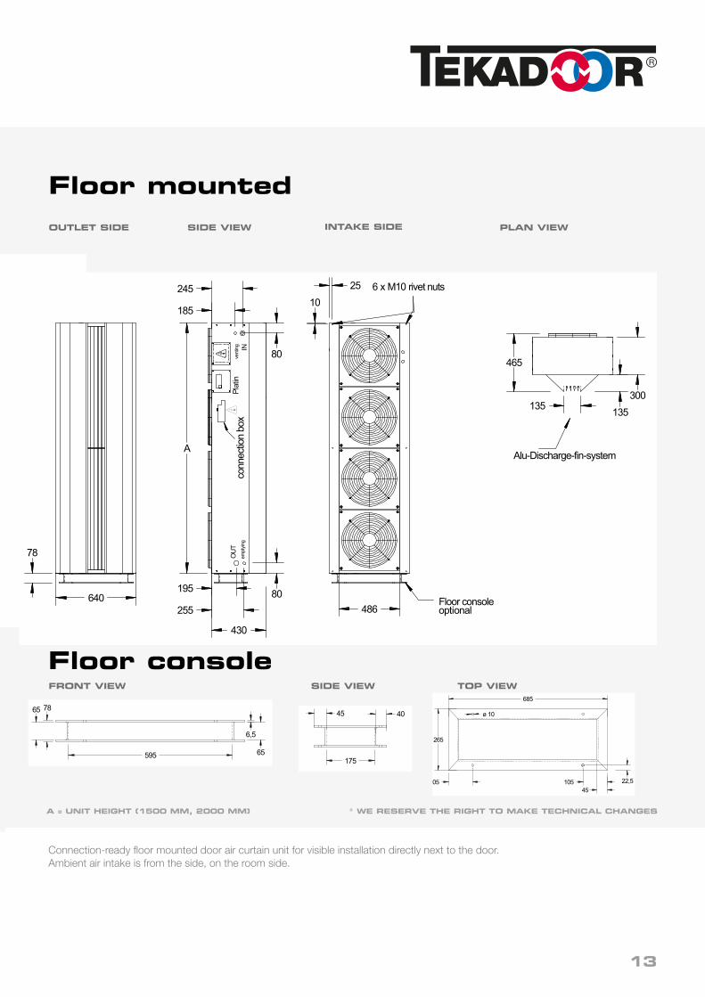
Floor mountedOUTLET SIDE SIDE VIEW PLAN VIEW
A = UNIT HEIGHT (1500 MM, 2000 MM) * WE RESERVE THE RIGHT TO MAKE TECHNICAL CHANGES
TIC Standfuß 080916
geändert16.09.2008magezeichnet
TeileGruppevonPos.
Werkstoff Maßstab
Blatt
Erstelldatum
Kunde
Benennung
Kundenzeichnung Nr.:
DatumName
1
1:5
Technische Änderungen vorbehalten
Siemensstr. 6, D-40764 LangenfeldTel.: 049 (0)2173 20766-0Fax: 049 (0)2173 20766-111
45105105
78
595 175
6,5
65
65 40
265
685
22,5
45
ø 10
FRONT VIEW TOP VIEW
Floor consoleSIDE VIEW
Connection-ready floor mounted door air curtain unit for visible installation directly next to the door.Ambient air intake is from the side, on the room side.
INTAKE SIDE
640 486
300135
465
Alu-Discharge-fin-system
25
6 x M10 rivet nuts
10
640
135
430
80
OUT
A195255
80IN
185 245
ventingemptying connection box Platin
430
80486
A
195
255
300135
465
Alu-Discharge-fin-system
25 6 x M10 rivet nuts10
80
185
245
640
135
78
Floor consoleoptional
OUT
INve
nting
empt
ying
conn
ectio
n bo
xPl
atin
13

STANDARD CIRCUIT DIAGRAM FOR LPHW (PUMPED WARM WATER)
TIC 3000 EC
230V/ 50Hz
3
CONTROL
F 16 AT
L N PE
Platine EC
Anschlußbox
bauseitig
Erdung, Nullung oderSchutzschaltung nachden Vorschriften desVDE und des zuständ.EVU ausführen.
Technische Änderungen vorbehalten
Störun
g pot.
-frei
Betrie
b pot.
-frei
1 211 12 133 4 514 15
0
zum Steuerteil (CONTROL)Adresse 1-9
8
AUXILIARNL2 PE
230V / 50Hz
Magnetventil(OPTIONAL)
L PEN
8
PENL2
internAUX MON
07.03.2017lagezeichnet/signet
TeileGruppevonPos.
Werkstoff Maßstab
Blatt
Erstelldatum
GTM EC MOD Bus 170307Kunde
BenennungName
Kundenzeichnung Nr.:
DatumName
1 von 1
6 716 17 8 9 10 1918 20
CPU
AdressSchalter0 = MASTER1 - 9 = SLAVE
5
1 23
4
9
87 6
nicht
beleg
t
nicht
beleg
t
nicht
beleg
t
nicht
beleg
t
Fros
tschu
tzthe
rmos
tatop
tiona
l
Standard Anschlusskabel(20 m) mitRJ-45 Stecker
1M
PENL1
zu weiterenVentilatoren
blau/blue
gelb/yellow
weiss/white
rot/red
4
321
RJ 45
MOD Bus 1 2 3 4
ON
optio
nal
ext. S
ignalg
eber
DDC-
Fre
igab
e op
tiona
l
Y PWM
0 V
+10 V
imp.
ModBusinterface(optional)
230V/ 50Hz
3
CONTROL
F 16 AT
L N PE
PCB EC
Connecting box
Main switch and fusesto be installed by thirdparties must complyto all applicable rules andrequirements!
Technical changes reserved
1 211 12 133 4 514 15
0
to input (CONTROL) next PCBAddress 1-9
8
AUXILIARNL2 PE
230V / 50Hz
Magnetic valve(OPTIONAL)
L PEN
8
PENL2
internAUX MON
02.01.2019lagezeichnet/signet
TeileGruppevonPos.
Werkstoff Maßstab
Blatt
Erstelldatum
GTC I EC 190102Kunde
BenennungName
Kundenzeichnung Nr.:
DatumName
1 von 1
6 716 17 8 9 10 1918 20
CPU
Addressswitch0 = MASTER1 - 9 = SLAVE
5
1 23
4
9
87 6
ext. C
ontac
t
fault
Opera
tion
Fros
t prot
ectio
n the
rmos
tat
not u
sed
not u
sed
nicht
beleg
t
optio
nal
optio
nal
Standard suppledshielded datacable(20 m) withRJ-45 connectors
1M
PENL1
next Fan
blau/blue
gelb/yellow
weiss/white
rot/red
4
Room
temp.
sens
orop
tiona
l
Room temperature. Sensor installed
q
BMS
On/O
ff
Y 0-10 V
0 V
+10 V
imp.
Timeroff
Fr 21.09.201807:52
Heat level0 / 0
AutomaticHand
Room Temp10°C
Fan level0 / 0
CONTROL UNIT GTC 1 ECMultilingual, menu-driven electronic control unit for TEKADOOR air curtains with LPHW heating and energy-saving EC fans. A standard feature of the control unit with touch display is a choice between 5-stage or stageless fan control, which can be selected individually by the operator. The relevant operating modes and symbols are arranged clearly on the colour display. The date, time and room temperature are shown as standard. The room temperature is monitored via an internal temperature sensor in the control unit as standard.
An easy-to-navigate menu offers a selection of different operating modes:Hand – manual operationAuto AS – automatic operation via cool down protectionAuto RT – automatic operation via room temperatureAuto TK – automatic operation via door contactAuto Kombi – option to combine all individual automatic modes
An enabling contact and potential-free operation and malfunction signals are provided for control via an on-site BMS or BEMS. Errors and faults are displayed with a red „warning“ sign. By coding the control boards differently, up to 10 door air curtains can also be operated in parallel with 1 control unit, using the Master/Slave principle. The control board is preinstalled in the door air curtain unit and 20 m of preassembled data cable (connection between the door air curtain and control unit) are included as standard.
* WE RESERVE THE RIGHT TO MAKE TECHNICAL CHANGES
14

CIRCUIT DIAGRAM FOR ELECTRICAL HEAT EXCHANGER
TIC 3000 EC
* WE RESERVE THE RIGHT TO MAKE TECHNICAL CHANGES
230V/ 50Hz
3
CONTROL
F 16 AT
L N PE
Platine EC
Anschlußbox
bauseitig
Erdung, Nullung oderSchutzschaltung nachden Vorschriften desVDE und des zuständ.EVU ausführen.
Technische Änderungen vorbehalten
Störun
g pot.
-frei
Betrie
b pot.
-frei
1 211 12 133 4 514 15
0
zum Steuerteil (CONTROL)Adresse 1-9
8
AUXILIARNL2 PE
230V / 50Hz
Magnetventil(OPTIONAL)
L PEN
8
PENL2
internAUX MON
07.03.2017lagezeichnet/signet
TeileGruppevonPos.
Werkstoff Maßstab
Blatt
Erstelldatum
GTM EC MOD Bus 170307Kunde
BenennungName
Kundenzeichnung Nr.:
DatumName
1 von 1
6 716 17 8 9 10 1918 20
CPU
AdressSchalter0 = MASTER1 - 9 = SLAVE
5
1 23
4
9
87 6
nicht
beleg
t
nicht
beleg
t
nicht
beleg
t
nicht
beleg
t
Fros
tschu
tzthe
rmos
tatop
tiona
l
Standard Anschlusskabel(20 m) mitRJ-45 Stecker
1M
PENL1
zu weiterenVentilatoren
blau/blue
gelb/yellow
weiss/white
rot/red
4
321
RJ 45
MOD Bus 1 2 3 4
ON
optio
nal
ext. S
ignalg
eber
DDC-
Fre
igab
e op
tiona
l
Y PWM
0 V
+10 V
imp.
ModBusinterface(optional)
Blow
out T
emp s
enso
r
CONTROL
PCB EC
Technical changes reserved
1 211 12 133 4 514 15
0
to inputCONTROLnext PCB
8
AUXILIAR
8
AUX MON
02.01.2019Sagezeichnet/signet
TeileGruppevonPos.
Werkstoff Maßstab
Blatt
Erstelldatum
GTC E EC UK 190201Kunde
BenennungName
Kundenzeichnung Nr.:
DatumName
1 von 1
6 716 17 8 9 10 1918 20
CPU
Adressswitch0 = MASTER1 - 9 = SLAVE
5
1 23
4
9
87 6
Failu
re
Oper
ation
free
Standard supplied shielded datacable (20 m)1:1 straight wired RJ-45 Stecker
S 50°K1
K1 K2 K3
S 80°
S 60°
q q
q
q
K1
Connecting box
Mains switch and fusesto be installed by thirdparties must complyto all applicable rules andrequirements!
BMS
On/O
ff
1M
PENL1
nextFan
blau/blue
gelb/yellow
weiss/white
rot/red
optio
nal
4
free
step 2step 3 = step 1 + step 2
step 1
NL2 PE
PENL2intern
230V / 50Hz
K3 K2
230V/ 50Hz
3
3~400V/ 50Hz4
K0
q
ext.
Sign
alop
tiona
l
Fros
t the
rmos
tat
optio
nal
Room
Tem
p se
nsor
q q
Room temperature. Sensor installed
S 45°
YPWM
0 V
+10 V
imp.
L N PE31 2
S 100°
F 16 AT
Timeroff
Fr 21.09.201807:52
Heat level0 / 0
AutomaticHand
Room Temp10°C
Fan level0 / 0
CONTROL UNIT GTC E EC Multilingual, menu-driven electronic control unit for TEKADOOR air curtains with LPHW heating and energy-saving EC fans. 5-stage fan operation or stageless fan control – easy to adjust on the control unit using the touch display. The electric heater can be activated in 3 stages.The relevant operating modes and symbols are arranged clearly on the colour display. The date, time and room temperature are shown as standard. The room temperature is monitored via an internal temperature sensor in the control unit as standard. An easy-to-navigate menu offers a selection of different operating modes: Hand – manual operation Auto AS – automatic operation via cool down protection Auto RT – automatic operation via room temperature Auto TK – automatic operation via door contact Auto AT – automatic operation via constant discharge temperature Auto Kombi – option to combine all individual automatic modes An enabling contact and potential-free operation and malfunction signals are provided for control via an on-site BMS or BEMS. A constant discharge temperature can be set via an optional temperaturesensor. This enables optimisation of the shielding performance. A week timer is incorporated as standard, enabling up to 12 different switching times to be programmed per week. Errors and faults are displayed with a red „warning“ sign. By coding the control boards differently, up to 10 door air curtains can also be operated in parallel with 1 control unit, using the Master/Slave principle.The control board is preinstalled in the door air curtain unit and 20 m of preassembled data cable (connection between the door air curtain and control unit) are included as standard. 15

CIRCUIT DIAGRAM FOR LPHW (COMFORT)TIC 3000 EC
* WE RESERVE THE RIGHT TO MAKE TECHNICAL CHANGES
PE
2-Wege Regelventil optional
optional
optio
nal
G
YGO N
L
177
24VM
Analo
g Aus
gang
0-10
V
230V
q
Ausb
lastem
p. Se
nsor
DDC-
Freig
abe
4
rot/red
weiss/white
gelb/yellow
blau/blue
zu weiterenVentilatoren
L1NPE
M1
Standard Anschlusskabel(20 m) mitRJ-45 Stecker
optio
nal
optio
nal
nicht
beleg
t
Fros
tschu
tzthe
rmos
tat
Betrie
b pot.
-frei
Störun
g pot.
-frei
q
Raum
temp.
Sens
or
ext. S
ignalg
eber
678
9
4
321
5
AdressSchalter0 = MASTER1 - 9 = SLAVE
CPU
2018 1910981716 76
MONAUX intern
L2 N PE
8N PEL
Magnetventil(OPTIONAL)
230V / 50HzPEL2 N
AUXILIAR
8
zum Steuerteil (CONTROL)Adresse 1-9
0
1514 543 131211 21
bauseitig
Erdung, Nullung oderSchutzschaltung nachden Vorschriften desVDE und des zuständ.EVU ausführen.
Anschlußbox
Platine EC
PENL
F 16 AT
CONTROL
3
230V/ 50Hz
Raumtemp. Sensor eingebaut op
tiona
l
imp.
+10 V
0 V
Y PWM
Fr 21.09.201807:52
Heizstufe0 / 0
AutomatikHand
Raum Temp10°C
Lüfter Stufe0 / 0
Schaltuhraus
���
230V/ 50Hz
3
CONTROL
F 16 AT
L N PE
Platine EC
Anschlußbox
bauseitig
Erdung, Nullung oderSchutzschaltung nachden Vorschriften desVDE und des zuständ.EVU ausführen.
Technische Änderungen vorbehalten
Störun
g pot.
-frei
Betrie
b pot.
-frei
1 211 12 133 4 514 15
0
zum Steuerteil (CONTROL)Adresse 1-9
8
AUXILIARNL2 PE
230V / 50Hz
Magnetventil(OPTIONAL)
L PEN
8
PENL2
internAUX MON
14.06.2017lagezeichnet/signet
TeileGruppevonPos.
Werkstoff Maßstab
Blatt
Erstelldatum
GTM EC MOD Bus 170614Kunde
BenennungName
Kundenzeichnung Nr.:
DatumName
1 von 1
6 716 17 8 9 10 1918 20
CPU
AdressSchalter0 = MASTER1 - 9 = SLAVE
5
1 23
4
9
87 6
nicht
beleg
t
nicht
beleg
t
nicht
beleg
t
nicht
beleg
t
Fros
tschu
tzthe
rmos
tatop
tiona
l
Standard Anschlusskabel(20 m) mitRJ-45 Stecker
1M
PENL1
zu weiterenVentilatoren
blau/blue
gelb/yellow
weiss/white
rot/red
4
321
RJ 45
MOD Bus 1 2
ON
optio
nal
ext. S
ignalg
eber
DDC-
Fre
igab
e op
tiona
l
MOD Bus Adresse
Y PWM
0 V
+10 V
imp.
ModBusSchnittstelle(optional)
EASY-TO-USE CONTROL UNIT GTC 2 EC Multilingual, menu-driven electronic control unit for TEKADOOR air curtains with LPHW heating and ener-
gy-saving EC fans. A standard feature of the control unit with touch display is a choice between 5-stage or stageless fan control, which can be selected individually by the operator. The relevant operating modes and symbols are arranged clearly on the colour display. The date, time and room temperature are shown as standard. The room temperature is monitored via an internal tempera-ture sensor in the control unit as standard. An easy-to-navigate menu offers a selection of different operating modes:Hand – manual operationAuto AS – automatic operation via cool down protectionAuto RT – automatic operation via room temperatureAuto TK – automatic operation via door contactAuto AT – automatic operation via constant discharge temperature (opt. electronic control valve required)
Auto Kombi – option to combine all individual automatic modesAn enabling contact and potential-free operation and malfunction signals are provided for control via an on-site BMS or BEMS. A constant discharge temperature can be set via an optional electronic control valve. This enables optimisation of the shielding performance. A week timer is incorporated as standard, enabling up to 12 different switching times to be programmed per week. Errors and faults are displayed with a red „warning“ sign. By coding the control boards differently, up to 10 door air curtains can also be operated in parallel with 1 control unit, using the Master/Slave principle.The control board is preinstalled in the door air curtain unit and 20 m of preassembled data cable (connection between the door air curtain and control unit) are included as standard.16

HATI5 stage HATI speed controller. 400 V / 50 Hz according to VDE 0550 in the housing, with step switch, fault and operation lights, restart interlock for full motor protection, manual to automatic switching and contactor for external signal encoder (e.g. door contact).Enable contact for on-site BMS, potential-free operation and malfunction signal.
TK1 TK2 PE U1 V1 W1N L1 L2 L3PE A1 A2 27 28 29 30
27 28 29 30
M3~
M
K1
PE
L1
F1T2,0A
S1N
N
L2L3
N
U V W
1 2 AUTO
A1
A2Türk.
K1 H1A1
A2
A1
A2
TK1
TK2
41
42
31
34
21
22
K2
K2 K2 K2
K3K3A2
A1
16
15
41
44
X1
X2
X1
X2
red malfuctiongreen operation
H2
HANDS2
U
8
7
4
3
6
5
K1- B7-40-00K2- 55.34.8.230.0040K3- 80.11.0.240.0000F1 - FuseS1- E12-736-2Na(E16-736-2Na) S2- E12-11-2H1- indicating light green H2- indicating light red
191511734-20
15913172-18
S1
K2
Circuit diagram E5W HATI FT BR 160112
J
PE,N,L1,L2+L3 = 400V voltage supply A1+A2 27 +28 29 +30 TK1 +TK2
= Door contact / DDC-release (230V50Hz) = pot.-free operation signal
= pot.-free malfuction signal = thermal contact + frost protection
PE,U1,V1+W1 = ventilator
T FT
TICSTANDARD CIRCUIT DIAGRAM (NOT FOR PARALLEL CONNECTION TIC / TIC-S / TIC 3000)
* WE RESERVE THE RIGHT TO MAKE TECHNICAL CHANGES
17

18
ACCESSORIES OPTIONAL
TIC 7000 / TIC-S 6000 / TIC 3000
Thermostatic straight-way valve
(Setting range + 20 °C to + 35 °C) limits the discharge temperature (constant supply air temperature limitation). Also available as a 3-way valve.
Door contact solenoid switch
Scolded the air curtain in the automatic modus in the prese-lected step.
Thermo-electric shut-off valve
230 V / 50 Hz, normally closed.On-site installation in theheating flow. Actuated bythe summer/ winter circuit. Summer function – closed. Winter function – opened.
Ceiling attachment set
For problem-free, vibration free ceiling attachment, consisting of M8 or M10 threaded rods, up to 1000 mm length, vibration dampers, turnbuckles and coun-ter nuts.
18

Frost protectionthermostat
For monitoring LPHW heat exchangers exposed to the risk of frost. As soon as the temper-ature falls below +7 °C, the fans are switched off and an optional solenoid valve is opened.
Control unitGTC 2 EC
Possibility of combination of various automatic operations. A constant discharge temperature can be set via an optional elec-tronic control valve, and a week timer is incorporated as stan-dard, enabling up to 12 different switching times to be program-med per week.
Electronic control valve
Electronic valve with 0-10V impulse and blow-out tempera-ture sensor completely installed and wired. In combination with the GTC 2 control, a preselected blow-out temperature is kept constant.
Room temperature sensor
Room temperature sensor - RT-FD (only in combination with GTC and GTC E)
* only for devices with 230V motors
19
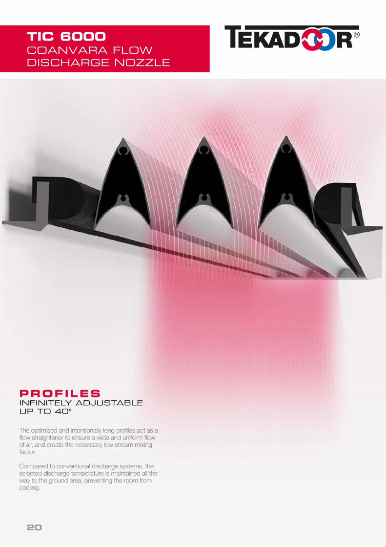
TIC 6000COANVARA FLOW DISCHARGE NOZZLE
PROFILFLANKENSTUFENLOS VERSTELLBAR BIS ZU 40°
Die optimierten und bewusst lang gestalteten Pro-filflanken wirken als Gleichrichter für einen breiten homogenen Luftstrahl und bewirken einen ge-wünscht niedrigen Strahlaufladungsfaktor.
Gegenüber herkömmlichen Ausblassystemen wird die gewählte Ausblastemperatur bis weit zum Bo-denbereich getragen, so dass ein Auskühlen derRäumlichkeiten verhindert wird.
PROFILES INFINITELY ADJUSTABLEUP TO 40°
The optimised and intentionally long profiles act as a flow straightener to ensure a wide and uniform flow of air, and create the necessary low stream mixing factor.
Compared to conventional discharge systems, the selected discharge temperature is maintained all the way to the ground area, preventing the room from cooling.
20

TECHNICAL DATA
TIC 7000
Design based on: recommended operating pointintake temperature tLE = +18 °C
discharge temperature tLA = +30 °Cdischarge height = up to 6.00 m
1. Rated operation based on operating point (see above) 2. Measured at a lateral distance of 3 m. Sound pressure level may very depending on surrounding conditions. 3. W - Normal temperature LPHW 70/50 °C 4. NTR - Low temperature LPHW 60/40 °C5. K - Recirculating air operation without heat exchanger A well-balanced pressure ratio is one of the prerequisites for perfect function.
* WE RESERVE THE RIGHT TO MAKE TECHNICAL CHANGES
TIC 7000 7001,44 7002,16 7002,88
Total air quantity m3/h 10000 15000 20000
Heating capacity rated1
LPHW 70 / 50 °C kW 40,39 60,59 80,78
LPHW 60 / 40 °C kW 40,39 60,59 80,78
Flow rate LPHW 70 / 50 °C m3/h 1,77 2,65 3,54
LPHW 60 / 40 °C m3/h 1,76 2,64 3,52
Water resistance LPHW 70 / 50 °C kPa 8,25 8,58 4,70
LPHW 60 / 40 °C kPa 8,43 8,71 6,16
Nominal connection sizes
Internal thread Zoll 2 x 1 2 x 1 2 x 1 1/4"
Flow/return DN 25 25 32
Fans Voltage V 400 / 3 / N / PE
Frequency Hz 50
Current consumption A 2,8 4,2 5,6
Motor power kW 1,42 2,13 2,84
Sound pressure level 2 Highest setting dB (A) 71 73 75
Drawing dimension Unit length / height (A) mm 1440 2160 2880
Unit length / width mm 530 530 530
Depth mm 730 730 730
Weight TIC 7000 W 3 kg 118 163 207
TIC 7000 NTR 4 kg 132 184 236
TIC 7000 K 5 kg 87 116 142
21

TECHNICAL DATA
TIC 6000 / TIC-S 6000
Design based on: recommended operating pointintake temperature tLE = +18 °C
discharge temperature tLA = +30 °Cdischarge height = up to 5.00 m
1. Rated operation based on operating point (see above) 2. Measured at a lateral distance of 3 m. Sound pressure level may very depending on surrounding conditions. 3. W - Normal temperature LPHW 70/50 °C 4. NTR - Low temperature LPHW 60/40 °C5. K - Recirculating air operation without heat exchanger A well-balanced pressure ratio is one of the prerequisites for perfect function.
* WE RESERVE THE RIGHT TO MAKE TECHNICAL CHANGES
TIC 6000 / TIC-S 6000 6001.2 6001.8 6002.4 6003
Total air quantity m3/h 7000 10500 14000 17500
Heating capacity rated1
LPHW 70 / 50 °C kW 28.27 42.41 56.55 70.68
LPHW 60 / 40 °C kW 28.27 42.41 56.55 70.68
Flow rate LPHW 70 / 50 °C m3/h 1.23 1.85 2.47 3.08
LPHW 60 / 40 °C m3/h 1.24 1.86 2.48 3.10
Water resistance LPHW 70 / 50 °C kPa 6.03 5.41 2.96 4.89
LPHW 60 / 40 °C kPa 5.1 4.45 2.64 4.30
Nominal connection sizes
Internal thread Inches 2 x 1" 2 x 1" 2 x 11/4 " 2 x 11/4 Flow/return DN 25 25 32 32
Fans Voltage V 400 / 3 / N / PE
Frequency Hz 50
Current consumption A 1.4 2.1 2.8 3.5
Motor power kW 0.68 1.02 1.36 1.70
Sound pressure level 2 Highest setting dB (A) 67 69 71 72
Drawing dimension Unit length / height (A) mm 1200 1800 2400 3000
Unit length / width mm 730 730 730 760
Depth mm 465 465 465 465
Weight TIC 6000 W 3 kg 76 112 148 180
TIC 6000 NTR 4 kg 82 125 165 205
TIC 6000 K 5 kg 72 106 140 170
22

TIC 3000 3001,5 3002 3002,5 3003
Total air quantity m3/h 4600 6150 7650 9200
Heating capacity rated 1
LPHW 70 / 50 °C kW 18,6 24,8 30,9 37,2
LPHW 60 / 40 °C kW 18,6 24,8 30,9 37,2
Flow rate LPHW 70 / 50 °C m3/h 0,81 1,09 1,36 1,63
LPHW 60 / 40 °C m3/h 0,81 1,08 1,35 1,62
Water resistance LPHW 70 / 50 °C kPa 1,00 2,01 5,11 4,05
LPHW 60 / 40 °C kPa 0,97 1,96 2,25 5,14
Nominal connection sizes
Internal thread Zoll 2 x 1" 2 x 1" 2 x 1" 2 x 1"
Flow/return DN 25 25 25 25
AC-Ventilatoren* 5-stage
Voltage V 400 / 3 / N / PE
Frequency Hz 50
Current consumption A 1,2 1,5 2 2,4
Motor power kW 0,48 0,53 0,8 0,96
AC-fans5-stage
Voltage V 230 / 1 / N / PE
Frequency Hz 50
Current consumption A 2,2 2,9 3,6 4,4
Motor power kW 0,5 0,7 0,85 1,00
EC-fans5-stage and stepless
Voltage V 230 / 1 / N / PE
Frequency Hz 50
Current consumption A 4,05 5,4 6,75 8,1
Motor power kW 0,49 0,66 0,83 0,99
Sound pressure level 2 Highest setting dB (A) 58 60 62 63
Drawing dimension Unit length ( A ) mm 1500 2000 2500 3000
Unit height mm 640 640 640 640
Unit depth mm 430 430 430 430
Weight TIC 3000 W 3 kg 90 110 140 170
TIC 3000 NTR 4 kg 100 125 160 190
TIC 3000 K 5 kg 80 95 120 155
1. Rated operation based on operating point (see above) 2. Measured at a lateral distance of 3 m. Sound pressure level may very depending on surrounding conditions. 3. W - Normal temperature LPHW 70/50 °C 4. NTR - Low temperature LPHW 60/40 °C5. K - Recirculating air operation without heat exchanger A well-balanced pressure ratio is one of the prerequisites for perfect function.
TECHNICAL DATA
TIC 3000
Electric heater3-stage
Voltage V 400 / 3 / N / PE
Frequency Hz 50
Heating capacity kW 7,5/15/22,5 10/20/30 10,7/21,4/32 10,7/21,4/32
Design based on: recommended operating pointintake temperature tLE = +18 °C
discharge temperature tLA = +30 °Cdischarge height = up to 4.00 m
* WE RESERVE THE RIGHT TO MAKE TECHNICAL CHANGES
23
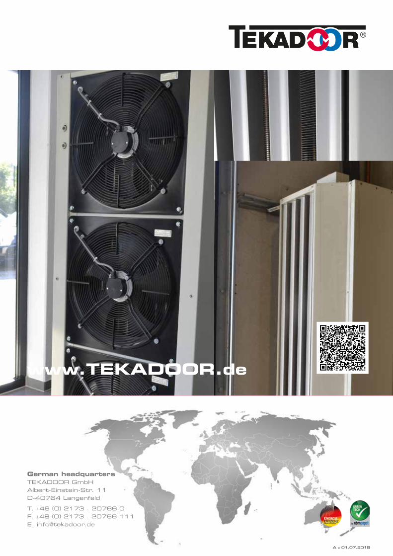
German headquartersTEKADOOR GmbH Albert-Einstein-Str. 11 D-40764 Langenfeld
T. +49 (0) 2173 - 20766-0F. +49 (0) 2173 - 20766-111E. [email protected]
www.TEKADOOR.de
A = 01.07.2019