TIC TAC TOE
100
THE BEST MODERN ELECTRONICS PROJECTS GET STREAMING WITH YOUR OWN KODI-POWERED MEDIA CENTRE A great Raspberry Pi system for streaming and home movies. BUILD A HANDY CUSTOMISABLE BATTERY VOLTAGE CHECKER A simple programmable battery condition checker! HACKING FOR THE HOMELESS This great new startup is driving social change. BUILD YOUR OWN: TIC TAC TOE GAME MACHINE MACHINE LEARNING GET STARTED WITH ARTIFICIAL INTELLIGENCE ON A RASPBERRY PI! Issue 029 Dec 2019 AUS: $9.95 inc. GST ISSN: 2207-8045
-
Upload
khangminh22 -
Category
Documents
-
view
1 -
download
0
Transcript of TIC TAC TOE

THE BEST MODERN ELECTRONICS PROJECTS
GET STREAMING WITH YOUR OWN KODI-POWERED MEDIA CENTRE A great Raspberry Pi system for streaming and home movies.
BUILD A HANDY CUSTOMISABLE BATTERY VOLTAGE CHECKER A simple programmable battery condition checker!
HACKING FOR THE HOMELESSThis great new startup is driving social change.
BUILD YOUR OWN:
TIC TAC TOEGAME MACHINE
MACHINE LEARNING
GET STARTED WITH ARTIFICIAL INTELLIGENCE
ON A RASPBERRY PI!Issue 029 Dec 2019 AUS: $9.95 inc. GST
ISSN: 2207-8045

Gamer to the core.

Okay okay, so it's not truly AI... but Artificial Intelligence seems to gain more attention than "Machine Learning", so we had to run with Artificial Intelligence to sell a few mags. I'm sure you understand!
However what we're doing is bringing Machine Learning concepts to makers, using Raspberry Pi and Python.
There are loads of resources for Machine Learning out there, but we often hear the learning curve is still too steep to grasp it. This is really just a product of Machine Learning being more than just a new language.
Machine Learning requires programmers to temporarily change their role and instead look at the problem and the solution, leaving some of the algorithmic side of the system to the Machine Learning engine itself.
This can be a challenging concept to get around initially, but it truly opens our minds to a world of powerful computing implementations which would have previously required cumbersome and bloated code to perform. Even if we were to somehow manage to obtain similar results, it becomes difficult to improve the accuracy.
The biggest benefits of Machine Learning algorithms come not with simple comparisons. We, as humans, analyse data with one, two, perhaps a handful of data points. We can visualise importance of data on one or two axis, even three. However Machine Learning can take this visualisation and relationship mapping to 4th, 5th, and 1,000th dimensions of complexity.
This is where our human brains really fail to truly make sense of things, and Machine Learning can yield a far superior result. It can do all this with minimal computing power, and lightning speed.
I am truly thrilled to bring this series to our readers personally. Machine Learning and AI has fascinated me for many years, and my hope is that with this series we will inspire others to pick up Machine Learning and implement it in projects.
While it's tempting to grab some tools and start tinkering, we'll take it slow to build comprehension along the way. While there's nothing wrong with using Machine Learning without really understanding it, to truly maximise its power, fundamental comprehension is absolutely important.
Ultimately, I hope that this series will soon become a handful of data-driven projects with Machine Learning. Imagine a photo-based resistor value identifier, or a value-driven component identifier. Amazing!
Rob Bell
Bringing Artificial Intelligence to Makers
EDITOR-IN-CHIEFRob Bell
EDITORMurray Roberts
TECHNICAL EDITORBob Harper
STAFF WRITERSOliver HigginsDaniel KochMike LewisSophie ParkerJohann WyssAndy ClarkLiam Davies
CREATIVE & DIGITAL TEAMLuke ParsonageKayla GourlayMelanie HeardDanielle BellJacqui Creasy
SOCIAL CURATORAnalee Gale
CONTRIBUTORSGeoff CohenSimon LudborzsSteph Piper
AN INDEPENDENT PUBLICATION.
Published by B.E. DIYODE Pty Ltd
ACN 616 556 622 ABN 50 616 556 622
Level 1-2, 156 Mann St, Gosford NSW 2250 Australia
© 2019 No part of this publication may be reproduced without written authorisation. All contributed content is owned by the authors and reproduced with permission. All product names, logos, and brands are property of their respective owners. Printed by Ovato.
Newsagent distribution within Australia managed exclusively by Gordon & Gotch.
ISSN: 2207-8045
Print subscriptions are available to Australian and NZ residents from AU$8.75 per issue including GST. See diyodemag.com for more international subscription pricing.
All prices quoted in AUD including GST unless noted otherwise. All prices are correct at time of printing and subject to change without notice.
ADVERTISE WITH [email protected]
CONTACT [email protected]+61 2 4326 0160
FOLLOW US @diyodemag
Issue 029 December 2019 diyodemag.com4
LOVE YOUR PRINT MAGAZINES? Premium Digital Membership is included with every print subscription and single-issue purchase. To access 30 days of free membership and the PDF magazine download for this issue, enter the code from your print edition into your online account.
64
90
18
14
58
■ ARTIFICIAL INTELLIGENCE Machine Learning for Makers
■ THE CLASSROOM The LM386 IC Amplifier
■ EXPLORING 3D Masked Stereolithography 3D Printing
■ TURN UP THE HEAT Arduino-based Soldering Station
■ OPEN SESAME IoT Garage Door Opener
■ WARNING! LOW BATTERY Battery Voltage Indicator
■ KIDS BASICS Sound Drawing
■ RASPBERRY PI MEDIA CENTRE with KODI
■ TIC TAC TOE Portable Electronic Game Machine
■ EDITOR'S LETTER Bringing AI to Makers
■ NEW AND REVIEWED Snapmaker 3-in-1
■ NEW AND REVIEWED Airwood 4-in-1 Drone Kit
■ MOONSHOTS The Green Tech Solution
■ GOING PRO Hacking for the Homeless
EDUCATION:
FEATURES:
PROJECTS:
1851
58
0406143088
36908464
3280
80
WIN PAGE 13!
5Issue 029 December 2019diyodemag.com

NEW & REVIEWED
We assemble and test the Snapmaker’s 3D printing, LASER etching and CNC carving abilities. - by Johann Wyss
First Impressions:
SNAPMAKER 3-IN-1
Issue 029 December 2019 diyodemag.com6

NEW & REVIEWED
SCREEN:3.5” Colour Touchscreen
3D PRINTING:125 x 125 x 125 build areaHeated build plate up to 80°CSupports 1.75mm PLA & ABS50 to 300-micron height
LASER ENGRAVING:125 x 125mm work area200mW 405nm Class 3B LASER
CNC CARVING:90 x 90 x 50mm work area3.175mm shank dia. Up to 19,000RPM
Features:
key screwdriver. The kit also comes with CNC carving and engraving tools, and surprisingly, a spare extruder nozzle and heat block.
This kit comes with most of the necessary gear to get you started, with the only exception being some test material to use with the CNC engraver. Lucky this isn’t too difficult to find. We went to our local Bunnings hardware store and grabbed some sample coloured vinyl swatches for kitchen thermoformed doors and splashbacks. These are inexpensive and a great size for testing the machine.
ASSEMBLY
Building the kit was remarkably simple, taking no more than 20 minutes from first opening the box to having the machine working on its first task. The instructions are very concise and comprehensive with step-by-step images showing exactly how to assemble the machine. They even have a scale image of the screws and bolts so you can compare each against the image and be 100% sure you’re using the correct fastener.
The main structure of the machine is made from three linear modules containing a stepper motor and a carriage on linear rails. Essentially, the three linear modules are bolted together and secured to an aluminium baseplate. This construction makes the unit extremely rigid but also incredibly simple to assemble.
Once the main structure is assembled, you simply screw on the tool head you wish to use, connect the appropriate cable to it and you’re ready to go. ››
On a recent visit to the Ipswich Jaycar store, we encountered this three-in-one 3D printer, LASER engraver and CNC mill, which was proudly on display at the front counter. We just had to get one and put it through its paces.
Having one tool on your bench that can do three different CNC tasks is a pretty awesome idea, as it opens your rapid prototyping workflow up to quite a few unique possibilities.
UNBOXING
The Snapmaker comes flat packed in a sturdy cardboard and foam filled box. The linear modules, tool heads, control board, and mounting hardware come on one foam packed layer, with the safety glasses, power adaptor, tools and remaining hardware in a second foam tray underneath. This made the entire package well secured and protects it quite well from any shipping damage.
In the package, you get a set of safety glasses, presumably for use with the CNC module, but you also get a set of LASER safety glasses. The standard for class IIIb LASERs does not specifically mandate the necessity for LASER protective eyewear in diffused exposure situations such as this, so it’s pleasing to see that Snapmaker has included them. Eye safety is something we should all take very seriously, even when permanent damage is unlikely.
The kit also comes with a selection of tools such as a scraper, tweezers, hex keys and even a pretty nifty reversible Philips / hex
7Issue 029 December 2019diyodemag.com

›› 3D PRINTING
We first set up the Snapmaker with its 3D printing module. We went to our goto benchmark print file, the Cali Cat calibration print from Dezign, which you can download from Thingiverse here: http://www.thingiverse.com/thing:1545913
This design is simple and is quick and easy to print, however, it allows you to check that the printer is printing dimensions correctly while simultaneously doubling as a print quality test. It has a few 45° overhangs that can show any cooling/temperature issues, and the flat surfaces show ringing artifacts quite nicely.
We were impressed with the surface quality of the print and the total absence of ringing on the face of the cat print. This absence of ringing stems from the incredible rigidity of the linear module construction combined with the small build area and lack of bedsprings, etc. This means all 3 axis are rock solid and thus backlash and slop are at the absolute minimum.
White cat (left) made using Snapmaker.
The white print is the first print using the Snapmaker, alongside a grey print that was printed on a different 3D printer we had in the workshop. Note the ghosting and ringing on the left side of the print and the right ear on the grey print. This ringing is caused by backlash and slop when the machine changes directions sharply. Due to the Snapmaker’s rigidity and smaller printing area, this phenomenon has all but been removed.
The overhangs on the tail were good, however, curling on the edges can be seen. This indicates that the temperature of the default settings may have been a little high in this case. Reducing the temperature would likely help to sharpen these edges. We really are nitpicking here to look for flaws. For the most part, this slight curling is perfectly acceptable for most prints.
The next print we made with the Snapmaker was the popular #3DBenchy from Creative Tools, also available from Thingiverse: http://www.thingiverse.com/thing:763622
This print has long been considered the 3D printing benchmark test due to its difficulty to print well. Whilst its certainly no torture test, it does tend to make printing quality issues stand out. Therefore, it’s a perfect test to show off how the Snapmaker prints out of the box.
The #3DBenchy came out fantastic for stock settings and a second print. We did notice the same overhang issues that we saw with Cali Cat, This confirms that either dropping the temperature slightly or increasing cooling should improve the print quality.
In summary, the first two 3D prints from this printer were very encouraging. The solid construction and smaller build size means the prints have the lowest possible printing artifacts. We are confident that a little tweaking of the stock settings, you should have the printer printing high quality prints.
The build area of 125mm x 125mm x 125mm is on the smaller side but its large enough for the vast majority of designs. With that said, this printer is aimed toward those who are designing and developing projects and thus have the ability to design around the build volume.
NEW & REVIEWED
Issue 029 December 2019 diyodemag.com8
The packaged slicing software is fully featured, offering plenty of customising options, but is also fully equipped with basic express presets for those who don’t want to mess around with settings.
If you like to keep it simple, you can pretty much just select what material you’re using (eg. ABS or PLA), what quality setting you want, generate the G-code and save it to a USB. Alternatively. if you like to have full control over the printing process, you can create your own preset and fully customise everything for speeds and temperatures to retraction and layer density. However, if you’re happier with simplify3D or Cura, Snapmaker provides the setting files to use those slicers if you so wish.
Note: We only used non-tethered printing where the G-code was saved to a USB dongle and then printed directly off the USB. This is our preferred method, as printing issues are not introduced via the PC/printer communication link, and the PC is free for other tasks. However, if you prefer, the software also has direct tethered control of all functions.
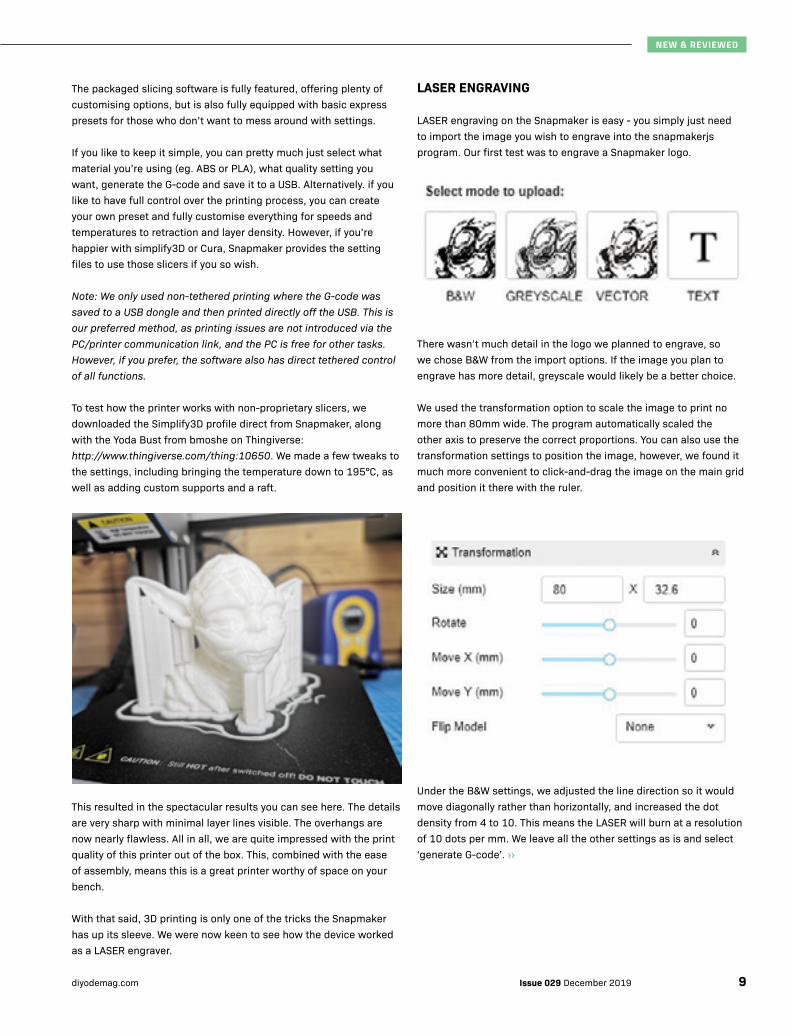
To test how the printer works with non-proprietary slicers, we downloaded the Simplify3D profile direct from Snapmaker, along with the Yoda Bust from bmoshe on Thingiverse: http://www.thingiverse.com/thing:10650. We made a few tweaks to the settings, including bringing the temperature down to 195°C, as well as adding custom supports and a raft.
This resulted in the spectacular results you can see here. The details are very sharp with minimal layer lines visible. The overhangs are now nearly flawless. All in all, we are quite impressed with the print quality of this printer out of the box. This, combined with the ease of assembly, means this is a great printer worthy of space on your bench.
With that said, 3D printing is only one of the tricks the Snapmaker has up its sleeve. We were now keen to see how the device worked as a LASER engraver.
LASER ENGRAVING
LASER engraving on the Snapmaker is easy - you simply just need to import the image you wish to engrave into the snapmakerjs program. Our first test was to engrave a Snapmaker logo.
There wasn’t much detail in the logo we planned to engrave, so we chose B&W from the import options. If the image you plan to engrave has more detail, greyscale would likely be a better choice.
We used the transformation option to scale the image to print no more than 80mm wide. The program automatically scaled the other axis to preserve the correct proportions. You can also use the transformation settings to position the image, however, we found it much more convenient to click-and-drag the image on the main grid and position it there with the ruler.
Under the B&W settings, we adjusted the line direction so it would move diagonally rather than horizontally, and increased the dot density from 4 to 10. This means the LASER will burn at a resolution of 10 dots per mm. We leave all the other settings as is and select ‘generate G-code’. ››
NEW & REVIEWED
9Issue 029 December 2019diyodemag.com

›› Main work area of the Snapmakerjs program showing how the image is
placed with respect to the origin point.
It’s then just a matter of copying that G-code to a USB drive and putting it into the Snapmaker.
You then place and secure the workpiece to the work area. We used a ruler to set the printer’s origin point to match the image origin point (centre of the image). That is to say, we measured 20mm horizontally either side of the LASER identifier and 5mm either side vertically. This is done to make sure the image is placed where we wanted. If you’re using the Snapmaker tethered to a PC, there is a preview function that allows the bed to move around the outline of the image where you intend it to be. You won’t need to do this step if you’re using the machine tethered.
Use the Jog mode to adjust the Z height to raise or lower the LASER until the low powered witness LASER pointer has the smallest practical pinpoint. This will focus the LASER to provide the sharpest possible results. Once the LASER is correctly positioned at the desired origin point, you select the set origin point button on the touchscreen and then run the file.
Make sure you’re wearing the supplied safety glasses here. Whilst the chances a reflection will damage your eyesight are low, the consequences can be severe, so it’s best to err on the side of caution anytime you are using any directed and focused beam technology. (Consider it good practice when you get the bug for bigger LASERs!)
Note: Due to the open design of the LASER engraver, there is no way to extract the smoke and fumes directly. We used our Hakko FA 400 solder fume extractors with carbon filters to cut down on the burning smell. If you’re intending on engraving plastics regularly, we would suggest you create a more permeant extraction setup that exhausts the fumes and smoke outside to ensure you’re not exposing yourself to harmful substances.
We tested the machine with various settings on a few different surfaces, from paper and cardboard to the splashback material and even a leather wallet was tested.
The verdict is, this LASER engraver with its modest 200mW 405nM LASER is very capable of engraving many common maker materials with just a few limitations. Unsurprisingly, it can’t engrave onto metallic materials. We tried a Copper clad board and thin aluminium, and neither were marked in a meaningful way by the near UV LASER.
It is also incapable of marking transparent materials such as acrylic, glass, and plastic as the UV wave can travel through them without transferring much, if any energy, into the material.
Leather wallet.
Wood / vinyl thermoformed panel.
NEW & REVIEWED
Issue 029 December 2019 diyodemag.com10

Wood / vinyl thermoformed panel.
Wood / vinyl thermoformed panel.
We were surprised to see that the LASER was capable of engraving into glossy surfaces such as this grey splashback sample. We were expecting the high gloss surface to cause the UV wave to scatter and reflect off the surface. However, the engraver had little issue marking the surface, which is hard to get on camera but is quite visible in person.
Vinyl thermoformed panel with gloss finish.
FIRST CNC ENGRAVING
Upon entering the CNC carving section of the software, we are greeted with a message stating that the CNC carving features of the software are still in an Alpha phase. Whilst the software is fully capable of carving out of the box, Snapmaker is still in the process of fleshing out the carving software. As such, the feature is currently a little clumsy and difficult to navigate at the time of the review.
With that said, however, with a little practice and experimenting with the software, it is very possible to get some good results.
The main thing we wanted to test with the CNC was if it were possible to carve out single-sided PCBs. Unfortunately, the EagleCAD PCB program we use here can’t easily export a PCB design as a scaled image to perform a full test. If you use KiCAD PCB design software, or similar, that can export directly to a scaled vector format you could try for yourself.
As a proof of concept, we used the Snapmaker to carve out the DIYODE logo onto a 1oz copper clad board, which the machine handled perfectly fine, proving that it was capable of milling a PCB. We did notice during this test, however, that the PCB and spoil board was not perfectly flat. This meant we needed to set the plunge depth quite deep, and the jog height quite high to account for this deviation in level. This isn’t so much an issue, but it does mean that the clearance between traces needs to be quite high with the bits provided by Snapmaker. None the less, the results are encouraging and seem to indicate that the machine should have little issue creating single sided PCB designs, provided sufficient clearance is designed into the board. ››
NEW & REVIEWED
11Issue 029 December 2019diyodemag.com

›› We do have to mention that there is no enclosure with the Snapmaker. This means, not only does the mill function make quite a bit of mess as it cuts through the material, but it is also extremely loud. This is certainly not a tool that you will want on your workbench while milling. When cutting an FR4 PCB, the dust and chips coming from the machine can be a mixture of fibreglass and copper. Neither of these are things you want to be breathing into your lungs. The copper particles can also play havoc in an electronics lab environment. For these reasons we only used the mill functions in an open garage environment.
We moved on from the PCB possibilities and tested the machine with the splashback samples with similar results. The difference in the height between the part and the workpiece is inconsistent. This means, whilst the tool bit may be deep enough in one section to cut completely through the top laminate layer of the material, in one section it is unable to make it through the same layer in another section, as shown here.
This can be a result of an inconsistent surface of the material we are trying to mill. An inconsistency in the spoil board surface or even a mixture of both. As with the copper clad board, our solution was to set the plunge depth deeper and have the tool raise higher before jogging. However, this creates rough edges along the cut when using the provided engraving bit.
We switched to a 30° V-shaped bit that we had available and gave it another try with some more promising results. The cuts along the edges were significantly sharper, however, the same issue with inconsistent cutting depth presented itself in the exact same areas, when cutting from right to left. This seems to suggest that the variation is caused by the machine itself and not the material we are using.
With that said, for cutting logos, text and other lower detail designs, the machine is more than capable. It has fantastic X and Y accuracy and is only let down by the Z height variation, which can be adjusted in software. The current Alpha state of the software makes the process a bit of a challenge, but with that said, the device is still very capable and should have little problem engraving and milling common maker materials such as plastic, wood, acrylic, etc. We wouldn’t recommend attempting to mill metals with this mill due to the lack of an enclosure, and we expect the low power and low RPM motor isn’t really up to the task.
OUR FINAL THOUGHTS
If you’re in the market for either a LASER engraver or a small 3D printer, you can’t go wrong with this device. It is a very capable machine providing exceptional quality results and a simple user experience. With a little tinkering and patience, the CNC milling results will likely be equally as good.
Of course, the three in one design also enables you to keep your workbench free for other equipment. ■
GOT SOMETHING TO SAY?To discuss this review visit:https://diyode.io/029nwnx
NEW & REVIEWED
Snapmaker available from Jaycar: www.jaycar.com.au
► Snapmaker 3-in-1 TL4400 $1349
Shopping List:
Issue 029 December 2019 diyodemag.com12

WIN 1 OF 2
Proudly provided by our friends at Jaycar
jaycar.com.auEntries must be received before Wednesday 1 January 2020. Terms & Conditions apply. See website for details.
To enter, simply head to diyode.io/029comp & tell us what you'll make with it!
DUINOTECH MICRO:BIT STARTER KITS
VALUED AT $99 95CAT NO. XC4322

NEW & REVIEWED
Built & Flown:
Airwood 4-in-1 Drone Kit
We were so excited by the DIY Airwood drone kit that we bought one before we even thought of reviewing it.
Here is what we think. - by Daniel Koch
Issue 029 December 2019 diyodemag.com14

The word drone is somewhat generic, and really just means unmanned aircraft. It was originally applied to flying machines to describe the earlier generations of pilotless aerial vehicles, the sort used for missile testing following World War II. The word came to be associated with unmanned aerial vehicles thanks to the United States of America’s combat unmanned aerial vehicle programs, and their use from the early 2000s in the Middle Eastern Area of Operations.
Thankfully, the word no longer carries these connotations for many of us. With the concept of any remote controlled aerial vehicle being called a drone, that was the word that stuck when what are accurately termed ‘quadcopters’ became popular as a radio controlled hobby. They are unmanned, are controlled from the ground, some can be operated beyond sight range, and often performs tasks for us, such as aerial photography. Little wonder the ‘drone’ name stuck. While unmanned, remote controlled rotary wing aircraft in the consumer category come with up to ten rotors, the Airwood DIY Drone kit is most definitely in the ‘quad’ category.
The kit consists of four different quadcopter models, plus a controller housing. All are laser-cut from sheets of thin, lightweight plywood.
The controller houses a clean, well-constructed circuit board with two joysticks for in-flight control, plus some slide and DIP switches for preflight settings.
The controller also mounts a phone holder, which is adjustable and made entirely of plywood. For some reason, parts are included to turn the phone holder into an ornamental robot if you are not using it to hold a phone.
The four drone frames that can be made all have their own independent wooden parts, so each of the different configurations can stay assembled. Into any one of these mounts the same core set of electronic parts. The central controller connects to all four motors, the battery, and a small, downward-looking camera. This camera is not for the pilot’s view, but for feedback to the drone’s control unit. Visual information is used to determine horizontal level, and maintain the drone in that position.
There are three drone batteries and one controller battery included, along with a USB charger.
The drone batteries are 3.7V 850mAh, while the controller battery is 3.7V 250mAh. In addition to the batteries, there are two other electronic items in the box. One is a camera, which mounts to the top of the drone’s control unit and is used as an FPV camera. This is where the phone holder on the controller comes into play. The second electronic mdule has no documentation or labels, nor does it have a dedicated place in the plastic parts tray like the control unit and camera do. It does have the same mounting header pins as the camera, and has a USB Mini B port in one side. It has a grille ››
NEW & REVIEWED
15Issue 029 December 2019diyodemag.com

›› that covers one surface, and when plugged in, turned out to be an LED display. The USB port is assumed to be for programming, but responsiveness was minimal when plugged into a PC, and the Airwood website was no help for apps or the like.
Electronically, the drone control unit utilises adaptive Artificial Intelligence to track the flight of the unit and change characteristics and responses. In this way, flying the same electronics in any of the four supplied frames is supposed to be easy. In addition, the manufacturers suggest that, in fact, users can make their own frames as well. The system also adapts to environmental factors such as air density, which affect flying characteristics.
Assembling the drone airframes and controller frame all take some care and attention to detail. Some parts are directional, and can easily be installed upside down, for example.
This may not become apparent until later in the build when other parts suddenly do not fit where they should. The phone holder was particularly problematic, but as assembled with only one retracing of steps.
It should be noted that the numbering of the steps repeats, with the sequence appearing as 5, 6, 7, 6, 7, 8, and on.
Assembly was successful, however. Glue should not be needed as all parts fit tightly. Glue would make repair or adjustment difficult.
After all the batteries were charged, we set about getting the flight started. This involves the initial pairing of the controller and control unit. What should be straightforward is complicated by the fact that the pairing button on the controller is not easily accessible inside the frame (while it would be easy to reach if pairing was completed before assembly). The pairing button on the control unit requires a paper clip to reach it.
The operating system requires that the controller be unlocked before use. This is done by pushing the left joystick up, holding for one second, then pulling down all the way. After this, the joystick is released to centre, and the motor should start. However, if no control is input after three seconds, the controller automatically locks again. So, begin flying as soon as you have unlocked the controller.
The drone itself has a beginner mode, set by the DIP switches. For a non-flier, this was most helpful. Beginner mode limits the speed, throttle, and sensitivity of the controls. This done, it was time to attach the camera. Before doing so, you need to scan the QR code in the camera’s manual to download the app. No other download information or app name is provided. At first glance, it could mount either forwards or backwards. While it is unlikely that you would want a backwards-facing camera in the air, close inspection of the base of the camera reveals two small notches, which fit over the triangular direction indicator on the control unit. So far so good.
However, installation of the camera took place while the app was downloading. We then discovered that the app is entirely in an Asian language which we could not determine. While there may be an option to change language in the app, we couldn’t find one. Instead, we contacted the manufacturer, who advised that the QR code was linked to an old app. They suggested we look through the app store for two specific apps, being unable to determine exactly which drone kit we had. As things turned out, XDJ UFO was the name of the app that worked. It connected to the camera and also allows some control of the drone. Control response was delayed, however, and the hand controller was the preferred means of piloting. Of course, this won’t be a challenge because the controller has a phone holder built in anyway.
The only issue we had with the camera was that it is a bit inconsistent. Sometimes the feed is smooth and continuous, while at other times it drops to an apparent frame rate of one per second for short periods. The manufacturer is clearly developing and updating the product, so hopefully the app improves too.
Even without the camera, however, the Airwood drone is intuitive, easy to fly, and seems to adapt well to different environments. Battery life was adequate and within the usual expectations of this type of device, however, three batteries are supplied. Being a USB charger, you could easily have one charging on a battery bank while you’re flying. The batteries as they are last around seven minutes on average.
The manual states that it is best to learn to use the drone in beginner mode indoors, and implies that the drone can be used outdoors. It does not state so explicitly, and we didn’t try it outside. However, it did negotiate a three-story stairwell quite happily, and flew in the door at the top. The camera would have been useful here (the manufacturer had likely not even received our email yet at this early point), but the whole flying experience is still up to standard without the camera. Some quirks were also noted when
NEW & REVIEWED
Issue 029 December 2019 diyodemag.com16

NEW & REVIEWED
the controller seemed to stop communicating with the drone momentarily, but this is hard to determine in the swamp of radio and EMI signals present in the office. We had also played with it so much we may have run down the controller battery.
One thing that is certain, is that the AI can sometimes lose its mind. Occasionally, usually after connecting a new battery, the drone seems to think ‘horizontal’ is actually a few degrees away from level. When it does so, the drone wants to move quite fast in a given direction, which varies depending on the incident, even when idling. Thankfully, there is a procedure in the manual for recalibrating flight trim, and it works quite well. It is also a very fast procedure, and performing it every time you connect a different battery would not be an inconvenience.
All in all, we were very happy with the Airwood 4-in-1 drone kit, and we’re keen to continue putting it through its paces when we should be working instead! ■
GOT SOMETHING TO SAY?To discuss this review, visit:https://diyode.io/029zkbx
Airwood drone kits available from Core Electronics: www.core-electronics.com.au
► AIRWOOD CUBEE DRONE KIT CE06614 $129.95
► AIRWOOD 4 IN 1 DRONE KIT CE06615 $169.95
► AIRWOOD CUBEE DRONE CAMERA KIT CE06616 $169.95
► AIRWOOD CUBEE DRONE PROGRAM KIT CE06617 $169.95
► AIRWOOD 4 IN 1 DRONE KIT WITH CAMERA AND PROGRAM (REVIEWED) CE06618 $229.95
Accessories also available.
Shopping List:
720P High Definition Camera for first person
view (FPV)Program drone using graphical programming
Made from high precision LASER cut eucalyptus laminate
Features hoverlock, one-key return and headless modes.
Issue 029 December 2019diyodemag.com 17

ARTIFICIAL INTELLIGENCE
MACHINE LEARNING for MAKERSPart Zero
WHY PART ZERO?
OK, so at the last minute, I decided to call this part zero instead of part one. Mainly because it’s a precursor to getting our hands dirty and doing the fun stuff with Machine Learning!
It doesn’t really matter, ultimately, but there’s a little coding humour in there since we start at zero. It also made sense, since it feels like this is precursor knowledge before we commence experimenting and coding with Machine Learning.
PROBLEM SOLVING WITH MACHINE LEARNING
Welcome to our brand new series, aimed at getting you started with Artificial Intelligence, and how it can be applied to your next project.
OK, that is the one and only time I’ll refer to this series as being on Artificial Intelligence. While Machine learning (ML) and artificial intelligence (AI) are commonly interchanged, they are not the same thing. Machine Learning is really a subset of Artificial Intelligence. When promoting these concepts to those who are unfamiliar, Artificial Intelligence is usually the phrase being used. Probably because it sounds fancier, can command a higher price tag, and is likely because general public understands it more readily.
Think about this with the following scenario. Someone asks you how a project you’ve developed works and you reply “Machine Learning Algorithms”, you might get a few blank stares. If you replied with “Artificial Intelligence”, virtually anyone will understand what you mean, even if they don’t TRULY understand it. Using AI when you mean ML is a misnomer, however, they’re related to a degree. Just as “the cloud” is the phrase used to cover just about anything which involves data centres, software as a service, and much more.
Our great new series on Machine Learning is here! But before we dive in and swim around in some code, let's make sure we get the fundamentals. - by Rob Bell
ROB BELLEditor in Chief, Maker and Programmer
I have a thorough understanding with Machine Learning and experience using it to solve problems. This is designed as a practical, easy to follow series, particularly aimed at the maker community, with relevant and practical outcomes. There are many people out there with far greater knowledge on this topic than I have. For anyone who feels I have misrepresented a concept here, I welcome discussion - feel free to reach out. It will only serve to provide a greater resource long term and allow more makers to tackle ML.
WAIT A MINUTE!
Issue 029 December 2019 diyodemag.com18

ARTIFICIAL INTELLIGENCE
WHAT IS ARTIFICIAL INTELLIGENCE?
The aim of artificial intelligence is to make decisions based on available data. However, what Artificial Intelligence truly means is something of a debate. This is largely because we can’t easily define “what is intelligence”.
However, the most agreed metric of whether something is truly Artificial Intelligence or not, is whether or not it can think like a human, and indeed learn like a human.
You might think this is fairly easy, but while a computer might have access to the entire internet, humans have a unique way of shaping our view of the world and information. Just because a computer has access to billions of pieces of data in a fraction of a second, a traditional programme doesn’t know how to truly make sense it.
Indeed, two different humans will make sense of data differently too. There are thousands of factors that influence essentially every decision we make. Some environmental, some personal, it’s a complex thing to comprehend.
Ever wondered why Aussies often like vegemite, but Americans usually think it’s strange? Or why a person might stop to lend assistance to a stranger even while putting themselves at risk? Or why some people will cross the road when they see a large dog approach, while others will want to pat it?
Human decisions are made using data, but not data alone. Every decision we make is filtered and influenced by knowledge, experience, skills, and less measurable factors such as “gut instinct” (though even this is arguably driven by data).
This is where an Artificial Intelligence attempts to cross the bridge between computers and humans. Rather than specifically coded algorithms to filter data through a series of predetermined criteria, the objectives are defined, and the AI creates the algorithms.
Just like a baby learning to walk isn’t given step by step instructions, AI is given an environment and a goal, and through testing and measuring outcomes, it finds the path to a solution. More than that, it can find multiple paths, then select the most optimal one. ››
Everybody is a genius. But if you judge a fish by its ability to climb
a tree, it will live its whole life believing that it is stupid.
ALBERT EINSTEIN
Note: there's actually some debate about whether or not this quote is from Einstein. But until we figure out otherwise, he can have the credit.
19Issue 029 December 2019diyodemag.com

›› If you have ever watched a baby learn to stand or walk, you will recognise this pattern of test and analyse. They’ll try and fail many times, gradually improving over time. This constant test and improve iteration is also how AI systems develop too. However, while it might take a child months to learn to walk, Artificial Intelligence can learn solutions by simulating and testing different methods millions of times in no time at all.
While it is debatable whether or not it’s true AI, this deep learning has been used to create design iterations, optimise code, and so much more. It can simulate the efficiency of a million different production line layouts, or test the code runtime of a trillion different tweaks. These are all things which would take lifetimes to do as humans.
This sector of AI is less about behaving like a human, and more geared towards optimisation and solving problems we don’t even know are problems yet. In this instance, the rapid test/revision process can do what a human can do in a tiny fraction of the time.
NEED A NON-TECHNICAL EXAMPLE?
There’s a lot of concepts here. While I don’t really like to include a TV-series reference in an article like this, there is a powerful representation of this in a Netflix series called Black Mirror. In particular, there’s an episode named “Hang the DJ”, part of the fourth season of this anthology. Without giving too much away, this episode essentially represents how Artificial Intelligence creates these iterative examples. It also highlights how “failed” tests are still valuable data.
While I doubt the writers of this episode had education in mind when they created it, this episode, in particular, has a special knack for doing so. I recommend you watch the episode, all the way to the end, and I’m certain you’ll experience a solid “ah ha!” moment right at the end. Indeed, if you enjoy this creative twist on real world technology, you’ll likely enjoy more in the series. While there are subtle links and ties throughout some episodes, you don’t have to start at the beginning and won’t be disadvantaged for watching “Hang the DJ” first.
WHAT IS MACHINE LEARNING?
Machine Learning (ML) uses data to analyse data. The more data you have, the more precise the results will become (as long as you’re asking the right questions).
What’s different about developing with Machine Learning compared to regular code is that you identify the source data, and the outcomes you want, and let Machine Learning figure out how to do so.
We use what’s called supervised learning. This means that your data set is like a traditional textbook. You have lots of questions, but you also have the answers.
WHAT IS DEEP LEARNING
Deep Learning is a subset of Machine Learning. The main difference is that it uses unstructured data, and unsupervised learning.
While Machine Learning (and most of what we’re going to do) relies on good data structure and testing, Deep Learning takes things one step further, allowing the machine to find relevance in the data itself.
With Deep Learning, the system doesn’t rely on the programmer to provide feature extraction and classification. Instead, it will look for correlations and relationships in the data itself, in order to drive the desired classifications and outcomes.
We will move on to Deep Learning later in this series, once we’ve established the fundamentals of Machine Learning and built a few working models.
CONCEPTS IN MACHINE LEARNING
Machine Learning still relies heavily on good program design. You can have all the data in the world, but unless you know how to use it, it’s relatively pointless.
It’s important to realise that there’s no “magic” in machine learning. While this first installment is something of a primer, I didn’t want to leave you without something to think about. We’re going to start using these concepts in practice in the next installment, so let’s go over them with a few examples to ensure they can be understood.
While how you use the data is up to you, the process of Machine Learning is fairly consistent. It requires us to decide what aspects of our data are important, and build a model for using them.
In order to prime you for the coding coming next issue, we’ll go over some of the primary aspects and give a few examples to try and get those concepts well understood.
MACHINE LEARNING ALGORITHMS (CLASSIFIERS)
Machine Learning isn’t “magic” in its own right. There are still algorithms and code behind the outputs, but they can be infinitely more complex (often using deep mathematical processing).
In order to demonstrate one of the most common Machine Learning algorithms, we’re going to use a dummy set of data for classifying fruit. This is just to get us used to thinking the right way about Machine Learning and the way we need to approach it.
A simple yet powerful algorithm used in Machine Learning is k-nearest neighbors (k-NN). And yes, that’s American English spelling of neighbour as are most coding terms. k-NN is not new to machine learning, but has been used for statistical estimation and pattern recognition technologies since the 1970s.
ARTIFICIAL INTELLIGENCE
Issue 029 December 2019 diyodemag.com20
k-NN essentially assumes that similar things are found in similar areas. After all, fish swim in the sea, and humans tend to live on land, as a basic example.
Using very simple data, k-NN is fairly easy to grasp, because it uses distance between plotted objects, and our minds are quite good at spacial awareness. So this is a great way to look at how the algorithm can do its thing.
To explore this we’ll use our tiny dataset with three items of fruit in it. You'll notice that the last has no classifier. That is, we don't know what it is.
Now this is rather important. Based on this data alone, the system will classify the last fruit as either an Orange, or a Watermelon. There is no "magic". Even if it's an apple, the system doesn't know what an apple is yet, nor how to classify one. This is a key point of Machine Learning. Data drives outcomes. Without the data, there is nothing.
You’ll notice our third fruit has no classification. This is essentially our objective. What is the type of fruit for the last item?
WEIGHT RIPENESS SCORE COLOUR CLASSIFICATION
100 8 2 Orange
2000 2 1 Watermelon
100 5 3 ??
Note: we’re using only three items here. Realistically for Machine Learning, this is not enough data to train a model on, but we’re balancing simplicity and practicality for comprehension purposes. The data sets will be much larger for actual Machine Learning work. For this example to work properly, the data would need to contain completed examples of fruit in order to increase accuracy. ››
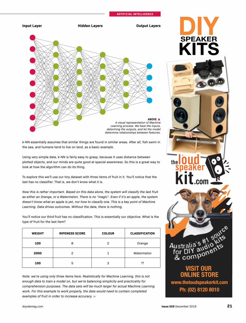
Input Layer Hidden Layers Output Layers
ARTIFICIAL INTELLIGENCE
ABOVE ▲A visual representation of Machine
Learning process. We have the inputs, determing the outputs, and let the model
determine relationships between features.
21Issue 029 December 2019diyodemag.com

›› Using a basic algorithm for trying to resolve this could prove quite difficult. If you started looking at weight, you might find yourself in trouble quickly. Take a look at our diagram for a 2D plot of the attributes weight and ripeness.
From this two-attribute example, it would be reasonable to draw a conclusion that our mystery fruit is closer to an Orange than it is a Watermelon, since it’s light but moderately ripe (since all fruits start out with no weight, this is a factor).
However, can we really draw this conclusion yet?
Here, we’ve visualised our two attributes, ripeness and weight. Our orange is ripe yet doesn’t weigh much. Our watermelon is heavy yet not very ripe, and our mystery item is somewhat ripe yet still lightweight. So how to we classify it? From the graph shown here, it fairly clearly appears to be closer to an Orange than a Watermelon.
What if we change how we actually view the graph by rotating it... now it appears our mystery object is closer. It is, quite literally, a matter of perspective.
So how do we deal with this? The answer is, we need more data. And this is what Machine Learning needs. The more data, the better.
The next graph shows just how important data volume can be for demonstrating proximity, and what makes algorithms such as k-NN so useful.
ARTIFICIAL INTELLIGENCE
BELOW ▼Even the most fundamental Machine Learning
can quickly out-perform human analysis.
Issue 029 December 2019 diyodemag.com22

You can see from this image how three different objects seem to scatter in patterns even though we've plotted three different data points. This is a very simple dataset using three types of fruit with weights and scores for ripeness and colour. You can visually see, how easy it would be to classify a new fruit with those data points based on proximity to others.
You might think “but I can classify a fruit just by looking at it”. Sure, that’s probably correct. But what about a fruit you’ve never seen before? After all, you’ve seen thousands of apples, bananas, oranges, and other types of food in your life. You draw on that experience. If you don’t know what a food tastes like, it probably “tastes like chicken”. This is because you’re unable to classify it. The same outcome would happen with Machine Learning for data it’s not trained with.
We can visualise the basic operation of k-NN in one, two, or three dimensions, but once we add a fourth, or fifth, or thousandth dimension, it becomes far too complex for us to visualise. This is a natural outcome of our own human brain development which is more about making sure we don’t fall off a cliff, can tell how far away the lion is that’s trying to eat us, and other such natural encounters which our brains developed for. Machine Learning also solves issues like “what do we do if it’s equally between two
points”. It also adds another layer of complexity by analysing the interplay between all other nodes too. This is beyond the limit of what our brains can do without methodically working through things.
We can also write our own algorithms to improve accuracy with more complex datasets also. We’ll tackle this at a point in the near future too.
FEATURE SELECTION
Machine Learning relies on us, the programmer, to determine which features of your data are actually important. Sure, the model will “join the dots” for you, but this is about selecting which dots to join.
If you’re trying to determine someone’s hair colour, drawing correlations to the length of their feet or their favourite drink may not be useful. It’s still valid data because if you’re selling shoes, it would be important. This is why not all data will help a Machine Learning model delivery outcomes for you.
Indeed, if you include this data which, while accurate, may not support the desired outcome, you can actually reduce the performance of your Machine Learning Model. ››
ARTIFICIAL INTELLIGENCE
23Issue 029 December 2019diyodemag.com

›› As programmers, we may have already experienced this as a logical fallacy. What’s a logical fallacy? It’s a series of facts which are true and verifiable, yet draw an incorrect conclusion. For example:
> A Raspberry Pi 3 has WiFi.
> A Raspberry Pi 4 has WiFi.
> Therefore a Raspberry Pi 3 is a Raspberry Pi 4.
Usually, this example compares a dog to a table because both have four legs. But you get the idea.
Adding more data doesn’t always resolve the issue either.
> A Raspberry Pi 3 has WiFi and a microprocessor.
> A Raspberry Pi 4 has WiFi and a microprocessor.
> Therefore a Raspberry Pi 3 is a Raspberry Pi 4.
See how important selecting the right data features can be?
Represented as a JSON array, to put it into pseudocode for even better clarity, let’s do this:
var board1 = array(cpu = true, hdmi = true,
clockspeed = 1.4GHz)
var board2 = array(cpu = true, hdmi = true,
clockspeed = 1.5GHz)
if (board1[‘cpu’] == board2[‘cpu’])
print “Same!”
else
print “Not Same!”
endif;
// prints Not Same!
We can still find ourselves in trouble. Yet if we ask the right questions, we can get better answers.
if (board1[‘clockspeed’] == board2[‘clockspeed’])
print “Same!”;
else
print “Not Same!”
endif;
// prints Not Same!
This is a very simple example, using general logic, of how data selection directly influences outcomes, without changing the
algorithm. While we’re using exceptionally simple algorithms here, the same theory applies to anything. Poor attribute selection can lead to poor conclusions.
In the real world, if our example was comparing prices between Raspberry Pi boards, and only looked at whether or not it had HDMI outputs, it may draw the incorrect conclusion that they’re the same, when in fact they’re very different.
When it comes to machine learning, the data you EXCLUDE is just as important as the data you include. Like background noise on a poorly recorded audio track, it takes away from the important information, making it more difficult to get accurate results.
The very same method that draws correlations between data, could in fact, draw incorrect conclusions based on the noise. Purely by necessity, all Raspberry Pi boards contain a USB interface, a processor, copper tracks, GPIO pins... the list goes on. All of these pieces information are accurate data, however, depending on your question, they may assist a Machine Learning algorithm to actually deliver you the WRONG answer.
MODEL TRAINING
Training is the process of providing data to your Machine Learning Algorithm (Classifier). This is somewhat like the classroom education methods used to teach kids how to do something. We give them the questions, as well as the answers.
The classifier (algorithm) is the route to finding the answer. Like the “working out” portion of a maths problem. This is a key point here.
However, this process is still called Model Training, because it is the computer’s version of learning like kids in a classroom. It’s just the method that’s a little different.
As developers, we can tune and train the Model infinite times, to increase the accuracy of the outputs. How do we do that? Model Testing.
We’ll perform some Model Training in next month’s installment.
ARTIFICIAL INTELLIGENCE
Issue 029 December 2019 diyodemag.com24

MODEL TESTING
Naturally, before we deploy our amazing models to production, we need to see how accurate they are with data that doesn’t yet have an answer.
There are several ways to do this. The simplest way, and perhaps the most common for a maker with a limited dataset, is to split the data into train and test groups. Even though you have the answers for all of your training data, testing ignores the answers.
The model will then predict the answers on the test set, and then check how accurate it was. This is like taking an exam, and then marking the answers.
While ideally, you would test with data the model has never seen before, this isn’t always possible either. This is why the volume of good data will influence the accuracy of outcomes.
You can iteratively tune the model itself to drive up accuracy. Your application will determine how accurate you need to be, while your data will determine how accurate you can be.
HIGH EXPECTATIONS
We have oddly high expectations for Machine Learning outputs. Perhaps because early computers were binary and things were simple. While that’s still true for most computing, the questions we’re asking our computers these days require far more comparative thinking than simple binary allows.
For whatever reason, we expect 100% perfection from them (maybe with a Windows Reboot thrown in there every other week). In certain scenarios that’s fair. You won’t even expect an incorrect answer from your calculator, and you don’t want your phone to dial the wrong number despite you selecting the correct contact. However, those are drastically simpler tasks and require no interpretation.
Machine Learning accuracy is really driven by good data, but also good tuning and testing. That part is on us. There are machines out there doing this iterative process autonomously too, but that’s beyond the scope of Machine Learning for Makers.
WHERE TO FROM HERE?
Next month, we’ll set up our Machine Learning development environment on a Raspberry Pi, and start applying these principles with some sample data sets to get some OUTPUT! ■
NEXT MONTH: MACHINE LEARNING FOR MAKERS - PART 1
GOT SOMETHING TO SAY?To discuss this edition of Artificial Intelligence, visit:https://diyode.io/029mkpj
ARTIFICIAL INTELLIGENCE
MODEL TESTING
DATA
ACCURACY
TRAIN TEST
25Issue 029 December 2019diyodemag.com

Sale pricing ends December 31st 2019.See last page for store locations or visit altronics.com.au
Tech for Xmas
Build It Yourself Electronics Centres®
Gift a gadget this festive season!Sale ends December 31st
Core I3 Desktop 3D Printer DIY KitAdd 3D printing to your workbench to produce working prototypes, ‘one-offs’ & finished designs downloadable from the internet. From printing your own gaming pieces to cosplay parts & fixes for broken parts, this printer adds versatility to any workbench. Filament roll holder to suit K 8403 $17.95.
Features: • 200x200x200 build volume• PLA filament • Pre-terminated cables for easy construction • Heated print bed • Assembly time ≈3 hours. • Includes power supply
SAVE $100 K 8400
$499
PLA colour filament 1kg roll: $39.95
New PLA Filament ColoursPrint the rainbow with 1kg reels of orange, green, yellow and purple now available.
$39.95
K 8391 OrangeK 8392 Green
K 8393 YellowK 8394 Purple
C 9021A
Super Quiet Noise Cancelling Bluetooth® Headphones
No outside interference with world class noise reduction technology. Designed & engineered in Silicon Valley USA.
• A must have for any regular traveller! • Superb active noise cancelling • Bluetooth wireless • 12hrs of listening time. • USB rechargeable (includes cable) • Carry pouch.
Why pay $300 or more?
Excellent quality sound reproduction & noise cancelling.
Amazing sound. You be the judge - demo a pair in store!
$139
Cut, Polish, Grind, Sand & Carve.This workbench essential is just the shot for electronics projects, crafts, hobbies and odd jobs around the house! Powerful 130W motor with variable speed between 8000 and 33000 RPM. Included is a 172pc accessory kit of grinding wheels, drills, cutters, sanding discs, polishing pads and more! Stows away in a hard plastic carry case.
T 2120
$60SAVE $14
Carry 240V Power Anywhere! This portable solar generator is fitted with 42,000mAh battery bank & 240V mains inverter. Allowing you cable free power for both AC and DC appliances anywhere! Plus 2.1mm DC power & USB charging. N 0040E 40W solar panel to suit $85.
M 8199A
240V power from
a lithium battery!
$225SAVE $54
Keep vehicle batteries in top conditionThese compact monocrystalline solar panels are designed for keeping your vehicle batteries topped up when parked. Easy croc clip or car accessory plug connection. Can even be permanently installed outdoors. 10W: 377L x 212W x 17D mm. 15W: 40L x 343W x 17Dmm.
$59.95 N 0704A 10W
GREAT FOR: • Motorbikes • Caravans • Boats • Vintage cars • Jet Skis • Mowers & more!
N 0706A 15W $79.95
Get a crisp close up view5x magnifier with LED backlight. Great for reading fine print, sewing etc. USB rechargeable. Includes carry case.
X 0432
No more eye strain!
SAVE $9.95
$30
D 2203
Mini Car Phone Holder• Suits phones up to 85mm wide• Grips securely to your air vent
SAVE 15%
$10

650VA Backup UPS & Power ProtectorProvides power backup when mains fails, plus added protection for surges and spikes on power, phone & data lines. Backup time up of 40 mins depending on load. Includes monitoring software. 2 year warranty.
Protect your work bench appliances!
$135SAVE $14
Save on summer storm protection!UPS Backup for 12V DC AppliancesA compact 12V DC 18W UPS unit for providing backup power to all kinds of DC powered equipment. Great for routers, NAS, telephone & comms systems. D 0875
Backup power for
NBN routers!
$80SAVE $12
750VA UPS Power ProtectionBoardThis quality UPS unit will prevent appliance damage caused by power fluctuations, PLUS keep power on during a blackout! Also protects phone lines. 2 year warranty.
D 0873
$159SAVE $16
Top level power
protection
D 0881
Power Up Your Holidays!
altronics.com.au » 24/7 ordering » In-store order pick up. » Fast delivery.
Inflate a tyre. Start a flat battery.Great for the 4WD/car enthusiast. Features a 16800mAh battery bank plus emergency compressor to top up tyres (max 8 mins run time). Provides 600A peak battery cranking output. 12/16/19V & USB output for powering devices.
M 8198
Includes jump starter
& air com-pressor $129
SAVE $40
M 8010A 150VA
Power mains appliances on the road!• Delivers pure AC power from your car battery • Ideal for tricky loads, such as laptops, & game consoles • USB charging output • 12V input • M 8010A 300W surge rated, 170x108x60mm • M 8012A 800W surge rated, 200Lx108Wx-60Hmm
$135M 8012A 400VA
$199
130W Folding Solar Panel For Remote Power Going bush? Have power wherever you go on your next 4WD/camping adventure. Includes 130W panel, solar regulator, battery connection cables and canvas carry case. 3 stage solar charger. Adjustable stand for best sun placement. 664x631x75mm (folded).
Includes regulator, 5m
battery cable & carry bag.
SAVE $50
M 8990A
Multi-Voltage Replacement Laptop Supply Lost your laptop power supply? Or need an extra one for the office? This unit includes mains lead and 10 tips to suit popular models of laptop. Voltage output is set automatically. 5-24V @ 90W max.
$70SAVE $19
$239SAVE $60
N 1130F
Suits hundreds of laptop models!
Charge EIGHT USB devices at once!Got a family full of devices? This handy charger outputs up to 12A or charging current to keep all your tablets and phones juiced up! Includes power cord.
M 8881
SAVE 32%
$44
Trav
el P
ower
Super Slim Battery BanksEmergency pocket power supply for your phone, tablet or drone. Slimline aluminium design with carry pouch. Micro USB recharge (cable included).
D 0507A 2A 8Ah
D 0505A 1A 4Ah
SAVE 25%
$25
SAVE 22%
$19
Stay powered up on your travels! • Charges 4 devices at once • Australian, US, UK and European outlets • 5V 4.1A output • 100-240V AC • Travel case.
SAVE 25%
$30
A 0309B
Stay charged up on the go - no cables required.• Slim 10,000mAH design • QI wireless charging pad • Works with iPhone and Android • Includes USB cable.
D 0515
SAVE 16%
$50
Charge up to 3 devices
at once!
Automate your Christmas tree lights!Switch any connected appliance on or off remotely from anywhere in the world. Set schedules, monitor and control via your phone.
$39.95
P 8148
Works with Google
Home & Echo
Home QC3.0 Wall ChargerCharge QC 3.0 devices up to 4x faster than conventional USB chargers. 3A output. Compact case doesn’t block outlets on your powerboard.
M 8863
SAVE 26%
$22

See last page for store locations or visit altronics.com.au Sale pricing ends December 31st 2019.
S 9900H 4 Domes
Affordable 4 Megapixel CCTV Surveillance System. Simple to install with instructions supplied. Cameras can be remote viewed on iOS/Android. Each pack includes: • HD digital video recorder • Pro grade 4MP resolution weatherproof cameras • 20m connection leads • Power supply • HARD DRIVES TO SUIT: 1TB $110 (D 5514), 2TB $155 (D 5516).
Why settle for just HD? This
system features 2K detail and
clarity.
REDUCED FROM $899
20 SYSTEMS ONLY AT THIS PRICE!
$499SAVE $400
2 in 1 Battery Bank CompactThe perfect every day accessory for the handbag. • Dual mirror (with magnified view) • LED ring light for a clear view • 3000mAH battery bank for recharging • Includes carry case and charging cable. SAVE
35%D 0504A
$25
TP-Link® Wi-Fi Indoor Camera Crystal clear wide angle 1080p vision with instant alerts of movement, plus two way audio. Excellent night vision performance and easy viewing via the Kasa home app.
S 9018
NEW!
$89.95
TP-Link® Wi-Fi Pan/Tilt Indoor Camera Get the full picture with 360° horizontal and 118° vertical motorised viewing. Kasa app allows easy swipe pan/tilt movements. Provides 1080p full HD video with object tracking mode and night vision.
S 9017
NEW!
$119
Festive gifts & handy gadgets for all!
No more eye strain!Why spend $300 on a Maggy-Lamp®? Ultra-bright long life LED for fantastic clarity (plus no need to change a globe - EVER!). Let “gadget” be your eyes. Identify those impossible to read miniature parts without straining your eyes. Great for collectors, model makers, jewellers etc.130mm lens. Suits desks up to 60mm thickness.
X 4201 5 Dioptre
X 4200 3 Dioptre
SAVE $20
$95
Wireless Weather Station• Indoor/outdoor temperature • Humidity & air pressure • Weather forecast, moon phase, time & date. • Requires 2xAA (S4955B) & 2xAAA (S4949B) batteries.
X 7026
SAVE 22%
$39
Love your slow cooked meats? Cook to perfection with the EasyBBQ dual probe monitor. All while you kick back and enjoy a coldie! Android or iOS compatible. 0-300°C range. Requires 2xAAA batteries (S4904).
Bluetooth® BBQ Temperature Monitor
NEW!
*Phone for illustration purposes.
SAVE 15%
$59X 7015
Home Blood Pressure MonitorA must have for anyone over 50 years old! Save on doc-tors visits. This handy meter records your measurements so you can monitor changes over time. Also includes an irregular heartbeat monitor. Stores readings for 2 people. Requires 4xAA batteries (S 4955B $3.95).
X 4003A
SAVE $15
$59
Secure your place for less these holidays.
30W Lithium ‘Go Anywhere’ Soldering Iron45 minute run time. 600°C max. Ideal for occasional soldering jobs or light duty repairs and field servicing. Recharge by USB power adaptor in your car or at home - or USB battery bank. Includes replaceable 18650 battery.
T 2694A
SAVE $34
$145
INCLUDES ACCESSORY PACK: • 3 tips: conical, hot knife/3D print finishing tool, hot air • Micro USB cable • Solder container & 1m of solder • Tip sponge.
Top gift idea for makers!
Phone Holder with Wireless Charging Simply place your phone in the holder to keep it topped up whilst you’re driving! Convenient windscreen or air vent mounting. Great for Uber drivers or road reps. Includes USB A-C cable.
D 2207
SAVE 10%
$40
Easy Camp Site LED Lighting StripGreat for setting up temporary lighting at campsites. • Yellow light reduces insects. • Secures to tent poles with reusable ties • 12V powered (car adaptor included). • Great work light or dim it down for reading. 5m roll.
X 3260
SAVE $14
$55
X 0225
The ultimate camping, fishing, anything light!Provides 5 hours use from a high performance lithium battery. Folds flat for easy storage and recharges from any USB mains (M 8861) or car charger (M 8628). 10W, 1000 lumens.
SAVE $10
$39

12 In 1 Solar & Hydraulic KitA huge parts kit which can be built and rebuilt into 12 different solar powered designs. Hours of fun for kids aged 8 or over (or younger with adult help). 8+
K 1149
$39.95
© Altronics 2019. E&OE. Prices stated herein are only valid until date shown or until stocks run out. Prices include GST and exclude freight and insurance. See latest catalogue for freight rates.
Sale Ends December 31st 2019Phone: 1300 797 007 Fax: 1300 789 777Mail Orders: [email protected]
Build It Yourself Electronics Centres
Western Australia» Perth: 174 Roe St 08 9428 2188
» Balcatta: 7/58 Erindale Rd 08 9428 2167
» Cannington: 5/1326 Albany Hwy 08 9428 2168
» Midland: 1/212 Gt Eastern Hwy 08 9428 2169
» Myaree: 5A/116 N Lake Rd 08 9428 2170
Victoria» Springvale: 891 Princes Hwy 03 9549 2188
» Airport West: 5 Dromana Ave 03 9549 2121
New South Wales» Auburn: 15 Short St 02 8748 5388
Queensland» Virginia: 1870 Sandgate Rd 07 3441 2810
South Australia» Prospect: 316 Main Nth Rd 08 8164 3466
Please Note: Resellers have to pay the cost of freight & insurance. Therefore the range of stocked products & prices charged by individ-ual resellers may vary from our catalogue.
Find a local reseller at: altronics.com.au/resellers
1. Learn electronics. 2. Have fun!
K 1150
Tobbie II Robot Kit
or $89.95 with BBC micro:bit starter pack (Z 6440). SAVE $5.50
Scurrying Hedgehog KitThis cute hedgehog toy kit bristles his spines when he hears a loud noise (such as a hand clap). He will even curl up and roll away if you scare him! Features light up eyes and motorised feet. Assembles in <2 hours with no special tools required. Requires 4 x AAA batteries (S 4949B $9.95).
K 1152
$49.95
Ages 8+ Tobbie is back and he’s had an
upgrade! Now powered by the popular BBC micro:bit board, this new version has unlimited scope for self programming. Front screen displays text & symbols. Great for teaching kids coding. Requires 4xAAA batteries (S 4949B $9.95) and BBC micro:bit board.
$59.95
Ages 8+
A great STEM robot for the classroom!
Learn coding!
Have fun!
Solar Powered Rover KitBuild this fun 6 wheel all terrain vehicle modelled on famous NASA designs. No soldering or batteries required! Ages 8+
K 1139
SAVE 22%
$19 3 In 1 All-Terrain Robot KitGreat fun for the kids to build and play with! This single kit can be built (and re-built) three ways! Lifting capacity ≈100g. Wired remote control. Requires 4 x AA batteries (S 9455B 4pk $3.95).
K 1095
SAVE 25%
$45
Build it 3 ways!
Air Powered Buggy KitRequires no batteries, electric motor or any conventional fuel to make it drive. Use the air pump to fill the bottle - let it go & watch it fly! Travels up to 50m. Ages 8+
K 1135 SAVE 23%
$25
Build it 12 ways!
4 in 1 Robotics KitAssemble 4 robot designs which teach kids about geared movement in a fun way! Requires 1xAA battery. No soldering required. Ages 7+
K 1126SAVE 22%
$20
Build it 4 ways!
130 in 1 Electronics Learning LabA comprehensive learning lab with many hours of building. Build a radio, broadcast station, organ, kitchen timer, logic circuits & more. Requires 6xAA batteries (S 4906 lithium 2pk $4.95ea). Ages 10+
K 2208 $99SAVE $40
Lab kits to suit any budget in
store!
14 Solar Kits In One!A fun and educational kit designed to assemble 14 different ways to inspire your kids to learn about solar power. No soldering required. Requires no batteries. Ages 8+
K 1113
SAVE 13%
$30Build it
14 ways!
K 1144
$19.95
Solar Recycler KitUses soft drink cans & old CDs to create 6 fun solar powered designs. No soldering or batteries. Ages 8+
K 1132
SAVE 23%
$20
Build it 6 ways!
Mini Solar Bug KitFeatures 51 parts to build up into a solar powered bug which struts about when you place it in the sun. Ages 8+
B 00
91
Tobbie The Smart Robot KitA six legged robot kit designed to avoid objects or follow you around the room. Easy to build. Interactive AI develops its own emotions and gestures. Requires 4 x AAA batteries (S 4949B $9.95).
K 1148
$48.95
Ages 8+

MOONSHOTS
THE GREEN TECH SOLUTION
New technologies and industries should help clean up our land and oceans instead of polluting them. - by Rob Bell
We read so much about how new technology plays a role in harming the environment, from power usage to e-waste, and other impacts that are immeasurable.
However, there’s a growing collection of initiatives and startups that will change the role technology and industry plays, ultimately forming part of the solution.
Issue 029 December 2019 diyodemag.com30

MOONSHOTS
THE GREEN TECH SOLUTION
GROWING LIKE WEEDS
Let’s take agriculture for example. As demand for clean growing methods without the use of pesticides continues to grow, it’s a catalyst driving innovation.
Naturally, pesticides and herbicides have long been deemed a necessary part of agriculture. While organic farming has grown substantially, and most supermarkets now carry a range of organic produce, it’s still not the normal approach. Organic farming can be more difficult to manage, and while a portion of people will happily pay the premium, it’s simply not feasible for everyone to do so.
There’s also a growing issue of weeds’ increasing resistance to herbicides, which is a natural evolution against their use, and will continue to happen. Pesticides and herbicides also end up in our waterways and are easily blown across areas that aren’t being targeted.
So what if we can remove the pesticides and herbicides from regular agriculture, while still tackling the issue of weeds, which fight for nutrients against the crops?
That’s what Aussie startup Growave is doing. Headed up by Graham Brodie, their system targets weeds using microwaves. Just like making popcorn in a microwave, their technology causes cell destruction in the weeds. The major benefit here is that it can be applied and localised to very specific areas, isn’t weather dependent, and of course, won’t release chemicals into the environment, because none are used.
CLEANING UP THE OCEANS
While we’ve seen some amazing new startups creating smart packaging solutions to reduce waste, the industry as a whole will take time to evolve and change. Additionally, there’s already millions of tonnes of waste entering oceans every year (with the current estimation in the trillions of pieces of rubbish). While we need to curb this, as a matter of importance, we also need to figure out how to remove what’s already there.
Sure, technology is partly what created the rubbish, but it can certainly be used to solve the problem too.
There are several startups and initiatives tackling this issue of rubbish and debris. While some initiatives undertake fairly regular approaches using ships and floating booms to circle and gather floating rubbish, other startups are taking a more autonomous approach. There are examples popping up in cities all over the country. There’s a growing trend for solar and tidal powered collection systems, which are periodically emptied,
which are showing huge signs of promise. Most are in early pilot phases, however, they’re starting to yield real results and will no doubt play an important role in the future cleanup solutions.
One interesting initiative in Australia is the Australian Marine Debris Database, run by Tangaroa Blue. This initiative focuses not directly on the solution, but helping database and track the many different initiatives being undertaken across the country. This database can guide funding and attention to areas where it’s needed most, so that any solutions deployed can be done in a most effective way.
SMARTER MONITORING
For large pastoral enterprises raising thousands of cattle, keeping track of cattle and land conditions was a huge ongoing challenge.
As smart drones and connected technology increases in its ability to undertake complex tasks, we’re seeing increasing use of these technologies to cover thousands of kilometers of ground using far less energy and resources than previously required. Drones are now being deployed to run autonomous missions to record data, take headcounts on cattle, and so much more.
The integrated technologies assist farmers to perform exhaustive tasks with ease. Not only can they save time and energy, but they can make better decisions with the abundant data. Finding the most mature paddocks to move the cattle to, checking on water troughs for damage or equipment failure, checking for damaged fences, and so much more.
We have already written about the team at Smart Paddock, who are working to enable healthier farms with smart tags, which monitor cattle movements and health. This is better for the farmer, and better for the cattle, helping address problems at the earliest possible moments.
Especially here in Australia, where farms can span such a large area, these technologies allow far better management. Healthy farms mean healthy food, after all.
THERE’S SO MUCH MORE
We have only scratched the surface. Are you working on, or do you know about a great startup involved in green tech? Tell us about it! ■
GOT SOMETHING TO SAY?To discuss this edition of Moonshots, visit:https://diyode.io/029ftxw
Issue 029 December 2019diyodemag.com 31

FEATURE
TURN UP THE HEAT Arduino-based Soldering Station
When Geoff shared his homemade, state-of-the-art soldering station project with us recently, we just had to get in touch with him to find out more.
Geoff’s amazing project is Arduino controlled, features an OLED display, auto-off functionality, and is housed in a custom 3D printed case. It even has his name on it!
As you will learn, Geoff’s build has some great features, and he has even supplied the files so you can build your own.
With a little ingenuity, Geoff retired his old underperforming soldering station and built his own, with Arduino smarts and digital display.
GEOFF COHENWriter, programmer, and maker.
thingiverse.com/geoff_cohen/designs
Issue 029 December 2019 diyodemag.com32

FEATURE
Thank you for taking the time to chat with DIYODE, Geoff. This is a great project. How long have you been involved in electronics?
I have been in the IT business for over 20 years, ran an Electronics Dept at the Australian National University, designed Computers (Osborne 1) in Silicon Valley, and currently design custom 3D printed things (See Thingiverse). I also write Utility and IOS apps, plus occasional magazine articles.
Gee, where do you find the time to do all that?! You are obviously a keen electronics enthusiast as well. What motivated you to design and build your soldering station?
I was annoyed that my (very) old Duratech Iron was not keeping a constant temp very well, plus it didn’t have enough power when soldering bigger stuff (i.e. very wide PCB tracks/groundplanes) and programming Arduino’s is fun.
It can be time-consuming to wait for some soldering stations to get to temp. What station have you repurposed in your build?
I looked at many Hakko Clones, and settled on a FX-8801 as it has slightly more power than the 900 series (26V/65W vs 24V/50W) – also . some 900 series clones use a platinum resistor and others use a thermocouple (which really needs an instrumentation Op Amp) – but all the 8801’s I tried used a platinum resistor.
Considering you wanted more grunt, we understand why you chose the one with the extra wattage. How did you go about starting the design and workout out what components to use?
I had 2 old laptop 16V power packs – these power the 26V 8801 iron at 32V – boy does it heat up quickly - 25 seconds from room temp to 350°C.
What a great idea to repurpose old laptop power supplies. What temperature are you able to achieve?
Red Hot. I found this out due to a software bug in early testing, just before the element disintegrated – luckily replacement elements are only a few bucks.
Recommended for normal use are temperatures of 180°C to 480°C.
Luckily you didn’t overheat the iron into a melted mess. What Arduino board did you use, and have you performed any tests and made measurements/graphs of how the iron performs soldering different components?
WARNING: Geoff’s project involved working with 240V mains power so the two power supplies could share one power input lead. In Australia, a person cannot legally work on voltages above 50Vac without a licence. Any mains wiring is very dangerous for those not qualified and experienced with it. We recommend that you use the approved power lead for each of the power supplies instead. DIYODE cannot take any responsibility for harm caused by anyone dealing with mains power.
My build uses an Arduino Uno but it will work with most other Arduinos too. It is powered from +12 to +15V, and the Arduino's output powers other parts of the circuit.
I used the Arduino graphing function to check the heating. I settled on a slight overshoot initially – BUT – much faster heating (it’s only 5-20 deg, depending on the initial temperature difference).
Not all stations have a display. Why was it important for you to add a digital display?
I wanted a digital display, as it’s easy to read the temperature accurately, plus it’s simple to add extra stuff – like how long to switch to SLEEP/OFF modes. I also added a power used indicator (similar to a WiFi signal strength S-meter), a mode indicator PWR/SLEEP/OFF/, and Set temperature.
As you can see in the photos, the display indicates Power %, Time to Sleep/Off, Set Temp, actual Temp, current mode (PWR-SLEEP-OFF).
Great to see you fit a lot of content onto such a small display area. We notice you chose to use analogue controls instead of digital. What was your reason for this?
While I like Digital Displays, I’m not so big a fan of Digital Setting – so I used an analog pot to set the temperature. About 1000% quicker to use. Not really critical here, but some cars are very annoying, as well as distracting and dangerous to use.
Agreed. Sometimes analogue is best to make things user-friendly. Please tell us about the code. Did you design the code from scratch or repurpose someone else’s code?
Coded from scratch – used some code from my Touch-Screen Garden Timer.
Interesting! We’ll have to find out more about your garden timer project sometime. Does the code have any intelligent PID control?
It uses the standard Arduino PID library. ››
33Issue 029 December 2019diyodemag.com

FEATURE
100Ω
Black (To MOSFET)
Red (+32V)
Blue
White
CHASSIS SOCKET
ElementSensor
Iron Centre
+32V +IN
-IN
+OUT
-OUT
To BreadboardVin (+9 to +12V)
RegModule
Adjustable Buck
Arduino 5V
390K
100KSet Temp Pot
ArduinoA0
~1V
Set TemperatureSET TEMPERATURE
BUK9511
47Ω
+20-32V
Arduino D6(PWM)
HakkoElement
+
PWM CONTROL
470µF50V
PWM CONTROL
CHASSIS SOCKET
Arduino 5V
1K5Ω
ArduinoA1 Hakko
ResistiveSensor
Read TemperatureREAD TEMPERATURE
+32V
GND*
240VAC 16VDCSupply 1
16VDC
+
+
-
-
Supply 2240VAC
Power Supply
*Next to BUK55 to avoid GND loops
POWER SUPPLY
Arduino 5V
10K
IRON DETECTION
Arduino A2 (Digital IN)Grounded when iron in holder
Washer
IRON DETECTION
Arduino 5V
VCC GND SCL SDA
Arduino A5
Arduino A4
OLED DISPLAYOLED DISPLAY
ADJUSTABLE BUCK
Geoff's prototype.
››
Issue 029 December 2019 diyodemag.com34

FEATURE
That makes it easy. Have you incorporated any safety features?
I have made it turn off if the temperature gets too high.
Great! We notice your schematic has a circuit to detect when the iron is placed back into the holder. Can you explain this, please?
This is used to detect when the iron is IN it’s STAND, and thus start the countdown timers to SLEEP/OFF. I thought of several sneaky and complicated ways to detect IN-STAND, but settled on a KISS method - a 30mm steel washer glued onto the stand, with a wire from it plugged into the electronics.
A very clever solution. We like that you’ve designed and printed your own 3D printed case as well. You are quite resourceful. What’s your goto CAD software?
I nearly always use openScad, as I’ve been a programmer for many years, mostly in C or C-like languages.
Programming experience does come in handy. What advice would you give our readers who want to build their own soldering station like yours?
A few things. I used a BUK9511 MOSFET but an IRF3205 (or similar) will work. Basically any N channel MOSFET with Rds (on) of 5-15 milliohms will do – the low on-resistance means no heatsink is needed. You could even use a HY3403 MOSFET with its super low RDS(ON) of 2.4mΩ, but that’s total overkill here.
My circuit uses a 470µF 50V electrolytic. Users can substitute for a similar value if they don’t have a 470µF available. I’ve added a 100Ω resistor to Ground, not direct as I’ve seen on some Hakko schematics – the reason is because I have occasionally soldered stuff that has voltage (5V-12V usually), and have let the smoke out of a few components – LED’s can get REALLY bright, for a millisecond or two. I’ve provided the code, schematics and 3D print files if any of your readers want to make their own.
Thank you so much. If you were to start over again, what would you change?
If I made another iron, I’d make a PCB - I normally use EasyEDA, which I find easy to use, and quite cheap to get PCB’s made. Sometimes I just use the schematic drawing module.
An online PCB design tool?! We hope our readers check that out. Are you working on any other projects at the moment?
Yes, a 12V DC UPS, 4th 3D printer, and a high capacity 5V USB powerpack using up to 8x18650’s.
We’ll have to keep in touch to see how these projects turn out. Thank you for your time Geoff and for sharing your project with us. ■
WANT MORE?For Geoff's code and 3D print files, or to discuss this feature, visit:https://diyode.io/029ckgk
35Issue 029 December 2019diyodemag.com

PROJECT
WARNING! LOW BATTERYCustomisable Battery Voltage Display
BUILD TIME: 1.5 HOURS + 3D PRINTING TIME DIFFICULTY RATING: INTERMEDIATE
High capacity and deep-cycle rechargeable batteries are all around us. We use them to power our projects that don’t have access to mains power, in back-up systems for UPS, NBN and alarm systems, and in the cars we drive.
If your rechargeable battery is not directly connected to a charger, you need to ensure it doesn’t self-discharge to a level where it can become damaged and never fully recover.
Build this simple ATtiny-based battery voltage indicator to help avoid your high power batteries from becoming flat or damaged. - by Johann Wyss
Perhaps you have a weather station project remotely powered by a 12V SLA battery, or you have a camper trailer, boat, ride-on mower or similar vehicle sitting idle in your backyard or shed with its battery slowly discharging. If you don’t regularly check the battery voltage, you’ll be left without power when you need it, or you could be up for a battery replacement if it goes too flat.
Checking the voltage on the battery usually means the inconvenience of getting the multimeter out each time you want to measure the battery voltage. That is where this project can come in handy.
JOHANN WYSSStaff technical writer
Issue 029 December 2019 diyodemag.com36

PROJECT
HOW IT WORKS
Naturally, this need for an adjustable circuit led us to a programmable solution. Effectively, we can use a microcontroller to read the voltage of the battery and then compare that voltage against a user defined variable. We then simply have the microcontroller activate an LED accordingly. Not only does this make it very simple for the user to customise the threshold of the indicator, it also enables us to program different ways to display the results.
We have opted to use a single RGB LED to indicate the voltage using colours. This configuration allows the user to set multiple thresholds and the colour depending on the measured voltage.
For simplicity, we will set three voltage thresholds, specifically designed for use with a 12V lead acid battery. This project, however, can be programmed to work with many different battery voltages and chemistries, as long as the voltages fall within the design limitations.
This circuit has a minimum input voltage of 6V and a maximum of 15V, so it’s ideal for deep-cycle batteries. If your project uses a voltage that is lower or higher than this, we will explain the circuit and give you ideas on how you can easily adapt the hardware to suit your application.
THE VOLTAGE DIVIDER
We require a voltage divider circuit to convert the battery voltage being measured down to a safe voltage for the microcontroller analog pin to read, i.e. 5V.
This circuit allows us to put a higher voltage on the VCC side and step it down to a lower voltage, which is proportional to the ratio of resistors R1 and R2. This is calculated using the following formula:
Vout = Vin x (R2 / (R1 + R2))
Since we know that our 12V lead acid battery has a maximum charging voltage of around 14V, our Vin needs to be around 14V. Since our Vout can’t exceed 5V, we know that figure. To make the math simple, we can make Vin 15V as it’s a multiple of our output. ››
GND
6-15V
R1
R2
To Micro
THE BROAD OVERVIEW
This compact battery voltage indicator can be connected permanently to your battery, and at the touch of a button, you get to see the battery status on an RGB LED. Red for very low, blue for low and green for ok.
Usually, when requiring a battery level indicator, the circuit that comes to mind is an Op-amp working as a comparator with the inverting input. This would be set to the desired reference state using a Zener diode and the non-inverting input connected to the battery. If the voltage of the battery drops to the reference voltage, the Op-amp pulls its output high to trigger an LED.
This method would be a simple way to get a low voltage indicator on your project but it can only provide feedback if the battery level is lower than the reference voltage. This value is also set with hardware. If say, you wanted it to trigger at a different voltage level, you would need to modify the circuit so the reference voltage would be at that new level.
As makers and hobbyists, our projects often use a wide range of input voltages dependent on what battery technology we have available and what voltages we require for the project. As such, there is no ‘cookie-cutter’ way to approach this task. This means that our battery level indicator would need to be adjustable to work with a whole range of applications.
37Issue 029 December 2019diyodemag.com

PROJECT
›› We can arbitrarily pick a value for R2, keeping in mind that we don’t want to create a significant load on the battery. As such, we picked a 100kΩ resistor for R2.
Therefore, to calculate R1, the formula is:
R1 = R2/Vout x Vin - R2 R1 = 100000/5 x 15 - 100000 R1 = 200KΩ
This combination of resistors will ensure that the input voltage does not exceed the 5V maximum for the microcontroller general purpose input and output (GPIO) pins. To keep the math nice and simple, we now simply multiply the voltage that we read on the GPIO by 3 to get the actual voltage.
If you, for example, want to read up to 20V. You can use the same formula and replace Vin with 20V, which will mean R1 needs to be 300KΩ. You would need to multiply the voltage read by the microcontroller by four to convert it back into the actual voltage.
Note: In our prototype, we used three 100KΩ resistors for our device as we didn’t have a 200kΩ.
For our final build, we also add a 100nF capacitor in parallel with R2. This capacitor, combined with R1, will produce a low pass filter. This will mean that any voltage present across R2 is the DC voltage we want to read and not any coupled noise or transients from the electrical system we are testing. If you’re using this device in a purely DC situation this capacitor can be considered optional.
We can calculate the roll-off frequency of this filter using the formula:
Fc = 1 / (2 x π x RC)
Where:Fc is the roll-off frequency in Hertz R is the value of R1. i.e. 200000Ω C is the value of the bypass capacitor. i.e. 100nF or 100 x 10−9F Fc = 1 / (2 x π x 200000 x (100 x 10−9)) = 8Hz (approx.)
TRANSIENT PROTECTION
GND
D115V
C10.1µF
1
2
3
DTS-6S1
X1-1X1-2
4
We have configured our project to work with a 12V system, which is a common voltage for many hobbyist projects and other applications around the home or workshop, including 12V electrical systems in a car, motorbike, caravan, boat, etc.
These automotive-type electrical systems, however, tend to be very noisy and often produce very large transient voltage spikes. These transients can exceed the 15V maximum input by a considerable amount. Albeit the transient itself tends to be very short-lived, in the area of a few hundred nanoseconds.
As such, we have included a 15V Zener diode and 100nF ceramic capacitor in parallel with the input to the project. The 100nF capacitor will give any short pulse transients a path to ground, while the 15V Zener will help to clip the longer duration pulses.
Note that this is just a very crude and inexpensive way to help protect your electrical circuits from common automotive transients. If you’re intending to use this device in a less hostile environment, the Zener diode is indeed optional but still recommended as it will protect the microcontroller GPIO from overvoltage.
VOLTAGE REGULATION
We have opted to use the 78L05 5V low drop out “LDO” linear voltage regulator. This regulator will provide the 5V regulated DC voltage for the microcontroller. This device in the small TO-92 package has a maximum current delivering capacity of 100mA. This means, at maximum capacity with the maximum input voltage of 15V, the device will need to dissipate 1.5W. i.e. P = V x I = 15 x 0.1 = 1.5W.
This 1.5W is quite significant for such a small package. As such, we need to make sure that we are drawing as minimal current as possible. The prototype circuit was built using an Arduino Nano with the 5V from the LDO connected directly to the Arduino Nano’s 5V pin. Note this is not advised by Arduino, as it bypasses the input protection and could hypothetically damage the 5V regulator, as the output would be at a higher potential than the input.
However, in this configuration we have a total current draw of around 50mA with two LEDs illuminated and up to 80mA with all three colours lit up.
Nano = 20mA LED = 20mA (each) Voltage divider = 50μA
In this configuration, the 78L05 did get warm to touch but was still operating inside of the specifications. However, if you’re intending to run the device using the Nano, we highly recommend you use the LM7805 in the TO-220 package as it is much better suited for the higher power dissipation (i.e. 1A vs. 100mA).
Issue 029 December 2019 diyodemag.com38

PROJECT
GND
GND
IC1
IN OUT
C2
0.1µF 100µF
C4+
The circuit is the usual linear regulator configuration with a 100nF bypass capacitor in parallel with the regulator’s output for noise reduction, and a larger 100uF electrolytic for ripple smoothing. Together, these capacitors provide a smooth regulated voltage for the microcontroller.
LED DISPLAY
The final part of the circuit is the LED display. For our project, we used a single common cathode RGB LED. This one component can create different colours to signify various voltage levels.
R6 120Ω
160Ω
110Ω
GND
Red
D2
RGB
Blue K
Green
R4
R5
We calculated the required resistors by first measuring the forward voltage of each of the LEDs and using the following formula:
R = (Vcc - Vf)/If = (5 - Vf)/0.02
Where: Vf = forward voltage If = forward current Vcc = 5V
COLOURFORWARD VOLTAGE
RESISTORNEAREST E24
VALUE
RED 1.85V 157.5Ω 160Ω
GREEN 2.79V 110.5Ω 110Ω
BLUE 2.61V 119.5Ω 120Ω
We wanted to get these resistor values as close as possible to ensure an even level of illumination/brightness for each colour, and will, therefore, allow the user to program very specific colours.
Note that the forward voltage for your LED may differ from the one we used, so we recommend you use a multimeter so you can calculate the ideal resistor for your LED. ››
BELOW ▼Prototype Fritzing Diagram.
39Issue 029 December 2019diyodemag.com

GND
D115V
C1.1uF
1
2
3
DTS-6S1
X1-1X1-2
4
C3.1uF
GND
R1
R2
R6 120R
160R
110RGND
Red
D2
RGB
Blue KGreen
R4
R5
GND
GND
IC1
IN OUTC2
.1uF 100uF
C45V
GND 2
A0D6
D3D5
M1 Arduino-Nano-3.0
+
PROJECT
PARTS REQUIRED: JAYCAR ALTRONICS CORE ELECTRONICS1 x Arduino Compatible Nano XC4414 Z6372 A000005
1 x 78L05 Low Dropout Voltage Regulator ZV1539 Z0466 -
1 x 5mm Common Cathode RGB LED ZD0270 - COM-00105
1 x 100µF Electrolytic Capacitor RE6310 R4825 CE05258
2 x 100nF Capacitors RC5360 R2865 CE05188
1 x 15V 1W Zener Diode* ZR1415 Z0636 CE05126
1 x 2-way Screw Terminal Block HM3130 P2034A POLOLU-2440
1 x 110Ω Resistor* RR0549 R7535 -
1 x 120Ω Resistor* RR0550 R7035 -
1 x 160Ω Resistor* RR0553 R7539 -
3 x 100KΩ Resistors* RR0620 R7070 COM-10969
The Prototype:›› The prototype was built using a breadboard and the Arduino compatible Nano microcontroller development board. This allowed us to easily make changes to the program and test them without needing to use a second programmer.
In this configuration, the device had an average current draw of around 30mA with 12V on the input and only one of the LEDs illuminated at full brightness. This test was done using an LM7805 and confirmed that we could use the more inexpensive 78L05 variant, as the current draw was sufficiently low enough. However, if you wish to have all three LEDs illuminated to make various specific colours, we recommend using the LM7805 as the current draw will jump to an average of around 70mA. This regulator is not a low drop-out version, which will mean the minimum input voltage will be 7-8V. Keep this in mind if you’re wanting to use the device with lower voltages.
Note: A recommended safety measure would be to add a 500mA (or less) fuse in series with the power input. This will help protect and avoid the Zener diode catching fire, in case of a high current transient from an automotive system or similar.
*Quantity required, may only be supplied in packs. Breadboard and prototyping hardware also required.
Issue 029 December 2019 diyodemag.com40

PROJECT
THE CODE
The code is a fairly straightforward, and can be downloaded from the resources section of our website.
Essentially, all we need to do is read the analogue voltage across the voltage divider, convert that value into a voltage, and then multiply it by the multiplication/division factor, which in our case is 3.
However, there are a few user definable values that you can use to customise the project to suit your specific application. These are as follows.
const int SAMPLES = 10;
// used for averaging
const int NOM = 12;
// Battery nominal voltage
const int DISCHARGE = 11;
//battery discharged voltage
const float FACTOR = 3;
// division factor for multiplication
SAMPLES is the number of times we take a reading and is used to get an average result. NOM is the nominal voltage of the battery you are using. For our application, a lead acid battery has a nominal voltage of 12V. This is essentially, in our case, the voltage level indicating half charge level.DISCHARGE is the point the battery is considered flat or discharged.FACTOR is the multiplication factor related to the voltage divider. You can find it by dividing the maximum input voltage Vin by the maximum output voltage Vout. In our case, 15V/5V = 3.
In the code shown here, we use a For loop to take x number of samples that we defined previously using the SAMPLES constant. This is used for averaging purposes, as we simply take the reading this many times each time, adding it to a variable to form a running total/summation. Once done, we simply divide that total by the number of samples to get our average.
voltage = (analogRead(A0) * (vRef / 1023.0));
//converts to voltage
This line takes a reading of the analog 0 pin and then multiplies that by Vref, which is 5 divided by 1024.
This 5 represents the 5V maximum of the ATmega328 ADC, and 1024 is the resolution the 10bit ADC can read. This means the minimum resolution the ADC can read is 4.8mV.
voltage = ((voltageSum / SAMPLES) * FACTOR);
// used for averaging
This takes the average of the readings and then multiplies it by the division/multiplication factor, which in our case, is 3. This removes the voltage divider effect in software.
for (int i = 0; i < SAMPLES; i++) {
voltage = (analogRead(A0) * (vRef / 1023.0));
//converts to voltage
voltageSum = (voltageSum + voltage);
}
voltage = ((voltageSum / SAMPLES) * FACTOR);
// used for averaging
The SETUP and LOOP code is too long to show here. We have made comments in the code to guide you on how it works.
TESTING & TROUBLESHOOTING
Testing the prototype is pretty simple. With the circuit connected correctly and the Arduino Nano programmed with the prototype code, use a bench power supply as a battery substitute. You can adjust the voltage to the voltage divider input, being sure to not exceed 15V. At the same time, use the Arduino serial monitor to check the voltage reading. Verify that the voltage reading correlates with the input voltage. If your reading has a discrepancy check the resistor values used for the voltage divider. ››
Note we did not use a switch on the prototype, as we were originally intending on having an inline switch. A pushbutton switch was later added to the final design when soldering the circuit to perfboard.
41Issue 029 December 2019diyodemag.com

PROJECT
GND
D115V
C10.1µF
1
2
3
DTS-6S1
X1-1X1-2
4
C30.1µF
GND
R1
R2
R6 120Ω
160Ω
110ΩGND
Red
D2
RGB
Blue KGreen
R4
R5
GND
GND
IC1
IN OUTC2
0.1µF 100µF
C4VCC NRES/PB5
PB4PB3PB2PB1PB0 5
67231
GND
U1
ATTINY85
+
F1
The Main Build:›› With the prototype working as expected, we can start work on the final design. We wanted the project to be as small and inexpensive as practical, so we knew we needed to replace our Arduino compatible Nano microcontroller development board with a smaller microcontroller.
We needed a microcontroller with at very least one analog input and 3 digital outputs, which is a fairly common trait among the ATtiny
variants. As such, we designed the project to work with the ATtiny85 or even the slightly cheaper ATtiny13.
We added a button in the final design so that the device was not draining the battery it was there to test. The momentary push button only applies power to the project when held down, therefore, there is absolutely no load on the circuit until you want it to display the charge state.
ADDITIONAL PARTS REQUIRED: JAYCAR ALTRONICS CORE ELECTRONICS1 x ATtiny85 or ATtiny13 ZZ8721 Z5105 COM-09378
1 x 8 Pin DIP socket PI6500 P0550 PRT-07937
1 x Perfboard HP9550 H0701 ADA2670
1 × Tactile Switch SP0600 S1120 FIT0179
OPTIONAL
ATDEV Programmer - K9815 -
Issue 029 December 2019 diyodemag.com42

CONSTRUCTION
Follow the circuit diagram and images shown here to build your main build. Note: See our website for a wiring diagram.
3D PRINTED ENCLOSURE
We have designed a 3D printable enclosure to house the project in. The case was designed using Fusion360, and you can grab the working files from the resources section of our website so you can modify the design as you see fit. Of course, we will also provide the .STL files so you can print your own enclosure if you wish.The enclosure consists of three individual pieces, which will comfortably print without support material. They are designed to press-fit together without the need for screws, however, you will still need some small screws to secure the PCB to the standoffs.
Note all of the components were sliced using Simplify 3D version 4.1.2
BUTTON
The button is a very small and quick print. It took about 10 minutes at 100-micron layer height using our Flashforge Creator Pro along with Flashforge PLA.
PROJECT
ENCLOSURE
The enclosure was printed in transparent red Flashforge PLA at 100-micron layer height on our Flashforge Creator Pro. It’s designed to print flat on the bed, and takes around 2 hours to print.
LID
The lid was also printed on our Flashforge Creator Pro using Flashforge PLA. It was printed flat on the build surface with no support, and took about one hour to print at these settings.
PROGRAMMING THE DEVICE
There are various methods to program an ATtiny. We recommend using the ATDEV programming shield from DIYODE Issue 14 with and an Arduino UNO, which forms an in-circuit serial programmer “ISP”. This process is fairly straightforward, however, if it is your first time programming an ATtiny, follow the instructions carefully to avoid damaging your microcontroller if you get it wrong. You can find the procedure for using this programmer here: https://diyodemag.com/projects/atdev_for_attiny ››
43Issue 029 December 2019diyodemag.com
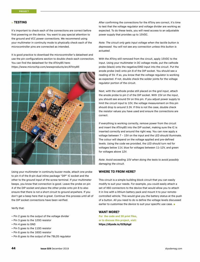
›› TESTING
It’s important to check each of the connections are correct before first powering on the device. You want to pay special attention to the ground and VCC power connections. We recommend using your multimeter in continuity mode to physically check each of the microcontroller pins are connected as intended.
It is good practice to download the microcontroller’s datasheet and use the pin configurations section to double check each connection. You can find the datasheet for the ATtiny85 here: https://www.microchip.com/wwwproducts/en/ATtiny85
Using your multimeter in continuity buzzer mode, attach one probe to pin 4 of the 8-pin dual inline package “DIP” IC socket and the other to the ground input of the screw terminal. If your multimeter beeps, you know that connection is good. Leave the probe on pin 4 of the DIP socket and place the other probe onto pin 8 to also ensure that there is not a short circuit to ground anywhere. If you don’t get a beep here that is great. Continue this process until all of the DIP socket connections have been verified.
Verify that:
• Pin 2 goes to the output of the voltage divider• Pin 3 goes to the 120Ω resistor• Pin 4 goes to GND• Pin 5 goes to the 110Ω resistor• Pin 6 goes to the 160Ω resistor• Pin 8 goes to the output of the 78L05 regulator
PROJECT
After confirming the connections for the ATtiny are correct, it’s time to test that the voltage regulator and voltage divider are working as expected. To do these tests, you will need access to an adjustable power supply that provides up to 15VDC.
Note: The circuit only gets input voltage when the tactile button is depressed. You will not see any connection unless this button is actuated.
With the ATtiny still removed from the circuit, apply 15VDC to the input. Using your multimeter in DC voltage mode, put the cathode probe (black) onto the negative/GND input into the circuit. Put the anode probe (red) onto pin 8 of the DIP socket. You should see a reading of 5V. If so, you know that the voltage regulator is working as expected. If not, double check the solder joints for the voltage regulator portion of the circuit.
Next, with the cathode probe still placed on the gnd input, attach the anode probe to pin 2 of the DIP socket. With 15V on the input, you should see around 5V on this pin. If you adjust power supply to limit the circuit input to 10V, the voltage measurement on this pin should drop to around 3.3V. If this is not the case, double check the resistor values you have used and ensure the connections are correct.
If everything is working correctly, remove power from the circuit and insert the ATtiny85 into the DIP socket, making sure the IC is inserted correctly and around the right way. You can now apply a voltage between 7 – 15V on the input and the LED should illuminate. The colour will depend on the voltage applied and pre-defined levels. Using the code we provided, the LED should turn red for voltages below 11V, blue for voltages between 11-12V, and green for voltages above 12V.
Note: Avoid exceeding 15V when doing the tests to avoid possibly damaging the circuit.
WHERE TO FROM HERE?
This circuit is a simple building block circuit that you can easily modify to suit your needs. For example, you could easily attach a set of X60 connectors to the device that would allow you to attach it in line with a lithium battery pack and mount it to your remote-controlled vehicle. This would give you the battery status at the push of a button. All you need to do is define the voltage levels discussed earlier to customise the device to suit your specific use case. ■
WANT MORE? For the code and 3D print files, or to discuss this project, visit: https://diyode.io/029yhgd
Issue 029 December 2019 diyodemag.com44

Free delivery on online orders over $70 Conditions apply - see page 50 for full T&Cs.Shop the catalogue online! www.jaycar.com.au 1800 022 888
Hardcore electronics by
On Sale 24 November to
26 December, 2019
Create, Build & Make this Christmas
new
DUINOTECH MAKEY MAKEY LEARNING KITHave fun using everyday objects to create innovative projects e.g make a piano using bananas. Supplied with six coloured leads with alligator clips, USB cable and jumper wires to provide even more output. XC3750
ONLY
$4995
3-IN-1 PRINTER:
3D PRINTER/ CNC/LASER ETCH3D print, engrave or laser cut with a single machine. Easy swap & interchangeable modules. Includes easy to use software. See website for details. TL4400
JUST
$1349
• LASER ENGRAVING• 3D PRINTING• CNC CARVING• 3.5" TOUCHSCREEN
WORKS WITH SCRATCH CODING
JUST$3495
BUILD YOUR OWN: MICRO:BIT CHRISTMAS TREE Combine a micro:bit (XC4320) and breakout board (XC4330) to create an electronic Christmas tree using up to 12 LEDs and your own imagination. Decorate the tree any way you like and make the LEDs dance around on your creation. Battery operated and no soldering required.
SKILL LEVEL: Beginner
FOR PARTS LIST AND STEP-BY-STEP INSTRUCTIONS VISIT:www.jaycar.com.au/microbit-christmas
SPARKLE STITCH KITKit includes everything you need to get started-felt cloth, needles, thimble, thread, glue gun, multimeter, electronic components, 62 page guide& more. KM1080DUINOTECH LILYPAD PLUSAdd a microcontroller to your Sparkle Stitch Kit for dazzling effects and control your e-wearable project or costume. 10 Mini RBG LEDs. Accelerometer. Microphone and more! XC3920Available early December.
new
MAKE THIS LIGHT-UP MASK!!
CLUB OFFER
$3495 SAVE 45% KIT VALUED AT $68.47
Repurpose or jazz up your low voltage Christmas lights with this Arduino-based Christmas lights controller project. It uses the traditional UNO prototyping board, and allows you to customise it with your own sensors, etc. Alternatively, you could even use the UNO with Wi-Fi (XC4411 $39.95 sold separately) to make it IoT controlled. It provides an adjustable voltage output between 12V and 40V, with two programmable outputs, suitable for most lights. Requires 5-12VDC power.
SKILL LEVEL: BeginnerTOOLS REQUIRED: Soldering Iron
FOR PARTS LIST AND STEP-BY-STEP INSTRUCTIONS VISIT:www.jaycar.com.au/christmas-light-controller
BUILD YOUR OWN: ARDUINO® CONTROLLED CHRISTMAS LIGHTS
CLUB OFFER
$4995 SAVE 25% KIT VALUED AT $71.15
BONUS
$100GIFT CARD
WITH PURCHASE
LEARN SIMPLE SEWING & ELECTRONICS & MAKE SPECTACULAR LIGHT-UP WEARABLE TECHNOLOGY
JUST
$99new

46 click & collect Buy online & collect in store ON SALE 24.11.19 - 26.12.19 3In the Trade?
YOUR DESTINATION FOR: Maker Kits & Bundles
DO MORE WITH YOUR: micro:bit
MAKE YOUR PROJECTS: MEGA
MICRO:BIT CREATOR KITAn excellent introduction to electronic construction and coding, ideal gift for a young maker! No soldering or prior programming knowledge is required. Kit includes micro:Bit board & common electronics components such as resistors and servo motor, and all the necessary prototyping accessories plus 36-page instruction guide. XC4322
MEGA EXPERIMENTERS KITContains a Arduino-compatible MEGA main board, a breadboard, jumper wires and a plethora of peripherals in a plastic organiser. See website for details. XC4286 WAS $109
NOW
$99SAVE $10
NOW
$69SAVE $30
JUST
$9995
DC VOLTAGE REGULATOR Use it to run your 5V Duinotech projects from a 6V, 9V or even 12V supply. Accepts any voltage from 4.5-35VDC, and outputs any higher voltage from 3-34VDC. XC4514 RRP $7.95 MEGA PROTOTYPE SHIELD
WITH BREADBOARDGives you plenty of room to
prototype your latest MEGA project. The stackable shield provides
access to all of the MEGA pins and plenty of solder pads to prototype
on. XC4416 RRP $12.95
240 X 320 LCD TOUCHSCREENLarge, colourful touch display shield which piggy-backs straight onto your UNO or MEGA. Fast parallel interface.microSD card slot. Resistive touch interface. XC4630 RRP $29.95
37-IN-1 SENSOR KITIncludes commonly used sensors and modules for Duinotech and Arduino®: joystick, magnetic, temperature, IR, LED and more. Packaged in a clear plastic organiser. XC4288 WAS $99 See website for details.
SENSOR SHIELDEnables you to connect multiple sensor modules to your micro:bit board. XC4336 RRP $14.95
BREAKOUT BOARD WITH 2 X AA BATTERY HOLDERProvides an independent 3V power supply to your micro:bit project and enables you to interface to other hardware. 170mm long power lead included. XC4330 RRP $19.95
PROTOTYPE BOARD WITH 400 PIN BREAKOUT BOARD
Designed to break out all of the IO pins on your micro:bit for you to create additional circuits and
hardware. Supplied with 400-hole breadboard. XC4332 RRP $23.95
BUNDLE DEAL
$3295 SAVE 40%
VALUED AT: $58.85INCLUDES 1 x XC4336,
XC4330 & XC4332
BUNDLE DEAL
$3995 SAVE 20%
VALUED AT: $50.85INCLUDES 1 x XC4514,
XC4630 & XC4416
JUMPER LEADS10 Leads supplied, 2 of each colour.STANDARD WC6010 $6.95HEAVY DUTY WC6020 $11.95
FROM$695
ARDUINO® STACKABLE HEADERBuild a stackable shield, or make your current shield stackable. Includes: 1 × 10-pin, 2 × 8-pin, 1 x 6-pin, 1 x 2x3-pin (for ICSP). HM3208
JUST$450
BREADBOARD POWER MODULEAdds a compact power supply to your breadboard. Power from a USB socket or DC. 3.3V or 5V switchable. XC4606
JUST$995
100-PCS LED PACK Contains 3mm and 5mm LEDs of mixed colours. Even includes 10 x 5mm mounting hardware FREE! Mix of red, green, yellow, orange LEDs. See website for full contents. ZD1694 WAS $29.95
NOW$1995
SAVE $10
EXPAND ON YOUR: Raspberry Pi
POWER SUPPLY FOR RASPBERRY PIUse with Raspberry Pi, charge power banks, portable speakers etc. Can also be used for other USB powered devices with a Micro USB connector. 5.1V 2.5A. MP3536 RRP $22.95
16GB MICROSD CARD WITH NOOBSComes pre-loaded with noobs software for easy install of raspbian operating system. Includes adaptor. XC9030 RRP $24.95
OFFICIAL RASPBERRY PI 3B CASE
Snap-together case with numerous removable panels. Stylish red and white
design. Easy no-tools assembly. Four Rubber feet included. XC9006 RRP $14.95
BUNDLE DEAL
$4995 SAVE 20%
VALUED AT: $62.85INCLUDES 1 x MP3536,
XC9030 & XC9006
INCLUDES MICRO:BIT BOARD
WC6010
2 click & collect Buy online & collect in store ON SALE 24.11.19 - 26.12.19
RETRO NES STYLE CONTROLLERSNES layout. Features A/B/X/Y buttons, start, select,
and direction controls. XC4404 RRP $9.95 ea.
BUY 1 GET 1
FREE
CONTROL USING YOUR SMARTPHONE
RGB LED CUBE KIT WITHOUT DRIVERStunning piece of art-meets-illumination that you can build yourself. 64 individually addressable RGB LEDs arranged as a 4x4x4 matrix. XC4624 Limited Stock.
1/2 PRICE ENCLOSUREWITH PURCHASE OF THIS LED CUBE KIT! (XC4625 valued at $14.95)
JUST
$2995
RETRO NES CASEIncludes access to all ports on your Raspberry Pi 3B+ and a handy storage slot for your spare memory cards. Just add a Raspberry Pi 3B+ and power supply for set-up, download games from web and start gaming! XC4403 RRP $39.95
YOUR DESTINATION FOR:
MAKER PROJECTS
RETRO GAMING BUNDLE
$4995
VALUED AT $59.85 Includes XC4403 +
2 × XC4404
SAVE $990
USB INTERFACE FOR JOYSTICK AND BUTTONSSuitable for any game that works with a USB joystick. XC9046 WAS $19.95
ARCADE JOYSTICK WITH MICROSWITCHES2 way, 4 way and 8 way options restrictor plate, metal mounting plate and main shaft, removable knob. SM1052 WAS $19.95
BUILD YOUR OWN:
CHRISTMAS TREELearn about electronics, soldering, and Arduino® all at the same time. This kit includes a tree shaped circuit board, coloured LEDs, and electronic components to produce amazing lighting effects when combined with an Arduino® UNO (XC4410 $29.95 sold separately).• 90(H) x 50(W) x 12(D)mm (including Pins)XC3754
BUILD YOUR OWN:
WI-FI ROVERControl our 4WD metal chassis car kit (KR3166) with Wi-Fi via the MEGA board with Wi-Fi (XC4421). Simple 2-board connection with motor shield, use this as a basis for your future robotic projects. Comes with mounting hardware. Requires 8 x AA batteries.
FOR PARTS LIST AND STEP-BY-STEP INSTRUCTIONS VISIT:www.jaycar.com.au/wifi-rover
NOW
$1295SAVE $7
NOW
$1495SAVE $5
ILLUMINATED ARCADE BUTTONSSuits 25mm mounting hole. Microswitch for reliable operation. Red, yellow, green, blue & white colours available. SP0662-SP0669 RRP $9.95 ea.
BUNDLE DEAL
$99 SAVE 30%
KIT VALUED AT: $146.17
Avai
labl
e Ea
rly D
ecem
ber
ONLY
$995
A GREAT WAY TO GET INTO THE CHRISTMAS SPIRIT
DON'T FORGET THESE MAKER ESSENTIALS
BREADBOARD JUMPER KITKit includes 70 stripped pieces of
single core sturdy wire. 5pc x 14 different lengths.
PB8850 WAS $13.50
NOW$950
SAVE $4JUST$1295HAND-HELD MAGNIFYING GLASSPowerful 3x magnification. Chip-On-Board LEDs. Lightweight. On/off switch. QM3535
JUST$1995DUST REMOVER 250GNon flammable gas which allows removal of dust from electronic, electrical and optical devices. NA1018
48W SOLDERING STATION
Adjustable temperature (150-450°C), ceramic element and a lightweight pencil for fatigue-free soldering.
Mains powered. TS1564 WAS $99.95
NOW
$8995SAVE $10
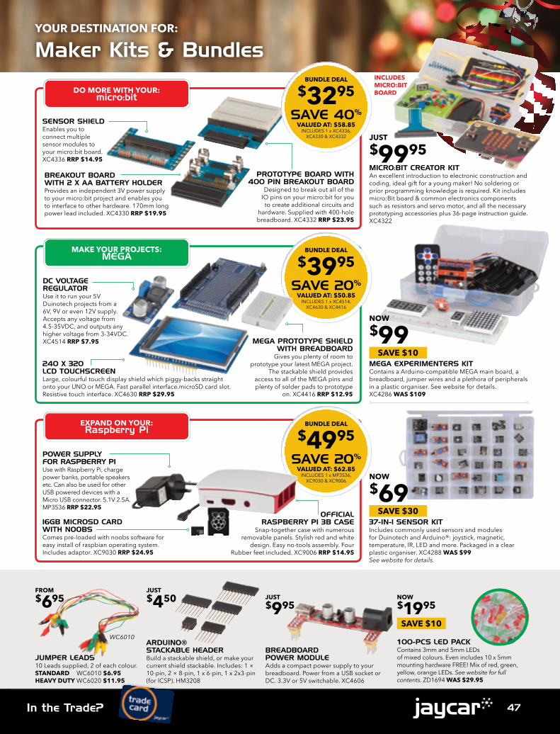
47In the Trade? 3In the Trade?
YOUR DESTINATION FOR: Maker Kits & Bundles
DO MORE WITH YOUR: micro:bit
MAKE YOUR PROJECTS: MEGA
MICRO:BIT CREATOR KITAn excellent introduction to electronic construction and coding, ideal gift for a young maker! No soldering or prior programming knowledge is required. Kit includes micro:Bit board & common electronics components such as resistors and servo motor, and all the necessary prototyping accessories plus 36-page instruction guide. XC4322
MEGA EXPERIMENTERS KITContains a Arduino-compatible MEGA main board, a breadboard, jumper wires and a plethora of peripherals in a plastic organiser. See website for details. XC4286 WAS $109
NOW
$99SAVE $10
NOW
$69SAVE $30
JUST
$9995
DC VOLTAGE REGULATOR Use it to run your 5V Duinotech projects from a 6V, 9V or even 12V supply. Accepts any voltage from 4.5-35VDC, and outputs any higher voltage from 3-34VDC. XC4514 RRP $7.95 MEGA PROTOTYPE SHIELD
WITH BREADBOARDGives you plenty of room to
prototype your latest MEGA project. The stackable shield provides
access to all of the MEGA pins and plenty of solder pads to prototype
on. XC4416 RRP $12.95
240 X 320 LCD TOUCHSCREENLarge, colourful touch display shield which piggy-backs straight onto your UNO or MEGA. Fast parallel interface.microSD card slot. Resistive touch interface. XC4630 RRP $29.95
37-IN-1 SENSOR KITIncludes commonly used sensors and modules for Duinotech and Arduino®: joystick, magnetic, temperature, IR, LED and more. Packaged in a clear plastic organiser. XC4288 WAS $99 See website for details.
SENSOR SHIELDEnables you to connect multiple sensor modules to your micro:bit board. XC4336 RRP $14.95
BREAKOUT BOARD WITH 2 X AA BATTERY HOLDERProvides an independent 3V power supply to your micro:bit project and enables you to interface to other hardware. 170mm long power lead included. XC4330 RRP $19.95
PROTOTYPE BOARD WITH 400 PIN BREAKOUT BOARD
Designed to break out all of the IO pins on your micro:bit for you to create additional circuits and
hardware. Supplied with 400-hole breadboard. XC4332 RRP $23.95
BUNDLE DEAL
$3295 SAVE 40%
VALUED AT: $58.85INCLUDES 1 x XC4336,
XC4330 & XC4332
BUNDLE DEAL
$3995 SAVE 20%
VALUED AT: $50.85INCLUDES 1 x XC4514,
XC4630 & XC4416
JUMPER LEADS10 Leads supplied, 2 of each colour.STANDARD WC6010 $6.95HEAVY DUTY WC6020 $11.95
FROM$695
ARDUINO® STACKABLE HEADERBuild a stackable shield, or make your current shield stackable. Includes: 1 × 10-pin, 2 × 8-pin, 1 x 6-pin, 1 x 2x3-pin (for ICSP). HM3208
JUST$450
BREADBOARD POWER MODULEAdds a compact power supply to your breadboard. Power from a USB socket or DC. 3.3V or 5V switchable. XC4606
JUST$995
100-PCS LED PACK Contains 3mm and 5mm LEDs of mixed colours. Even includes 10 x 5mm mounting hardware FREE! Mix of red, green, yellow, orange LEDs. See website for full contents. ZD1694 WAS $29.95
NOW$1995
SAVE $10
EXPAND ON YOUR: Raspberry Pi
POWER SUPPLY FOR RASPBERRY PIUse with Raspberry Pi, charge power banks, portable speakers etc. Can also be used for other USB powered devices with a Micro USB connector. 5.1V 2.5A. MP3536 RRP $22.95
16GB MICROSD CARD WITH NOOBSComes pre-loaded with noobs software for easy install of raspbian operating system. Includes adaptor. XC9030 RRP $24.95
OFFICIAL RASPBERRY PI 3B CASE
Snap-together case with numerous removable panels. Stylish red and white
design. Easy no-tools assembly. Four Rubber feet included. XC9006 RRP $14.95
BUNDLE DEAL
$4995 SAVE 20%
VALUED AT: $62.85INCLUDES 1 x MP3536,
XC9030 & XC9006
INCLUDES MICRO:BIT BOARD
WC6010
2 click & collect Buy online & collect in store ON SALE 24.11.19 - 26.12.19
RETRO NES STYLE CONTROLLERSNES layout. Features A/B/X/Y buttons, start, select,
and direction controls. XC4404 RRP $9.95 ea.
BUY 1 GET 1
FREE
CONTROL USING YOUR SMARTPHONE
RGB LED CUBE KIT WITHOUT DRIVERStunning piece of art-meets-illumination that you can build yourself. 64 individually addressable RGB LEDs arranged as a 4x4x4 matrix. XC4624 Limited Stock.
1/2 PRICE ENCLOSUREWITH PURCHASE OF THIS LED CUBE KIT! (XC4625 valued at $14.95)
JUST
$2995
RETRO NES CASEIncludes access to all ports on your Raspberry Pi 3B+ and a handy storage slot for your spare memory cards. Just add a Raspberry Pi 3B+ and power supply for set-up, download games from web and start gaming! XC4403 RRP $39.95
YOUR DESTINATION FOR:
MAKER PROJECTS
RETRO GAMING BUNDLE
$4995
VALUED AT $59.85 Includes XC4403 +
2 × XC4404
SAVE $990
USB INTERFACE FOR JOYSTICK AND BUTTONSSuitable for any game that works with a USB joystick. XC9046 WAS $19.95
ARCADE JOYSTICK WITH MICROSWITCHES2 way, 4 way and 8 way options restrictor plate, metal mounting plate and main shaft, removable knob. SM1052 WAS $19.95
BUILD YOUR OWN:
CHRISTMAS TREELearn about electronics, soldering, and Arduino® all at the same time. This kit includes a tree shaped circuit board, coloured LEDs, and electronic components to produce amazing lighting effects when combined with an Arduino® UNO (XC4410 $29.95 sold separately).• 90(H) x 50(W) x 12(D)mm (including Pins)XC3754
BUILD YOUR OWN:
WI-FI ROVERControl our 4WD metal chassis car kit (KR3166) with Wi-Fi via the MEGA board with Wi-Fi (XC4421). Simple 2-board connection with motor shield, use this as a basis for your future robotic projects. Comes with mounting hardware. Requires 8 x AA batteries.
FOR PARTS LIST AND STEP-BY-STEP INSTRUCTIONS VISIT:www.jaycar.com.au/wifi-rover
NOW
$1295SAVE $7
NOW
$1495SAVE $5
ILLUMINATED ARCADE BUTTONSSuits 25mm mounting hole. Microswitch for reliable operation. Red, yellow, green, blue & white colours available. SP0662-SP0669 RRP $9.95 ea.
BUNDLE DEAL
$99 SAVE 30%
KIT VALUED AT: $146.17
Avai
labl
e Ea
rly D
ecem
ber
ONLY
$995
A GREAT WAY TO GET INTO THE CHRISTMAS SPIRIT
DON'T FORGET THESE MAKER ESSENTIALS
BREADBOARD JUMPER KITKit includes 70 stripped pieces of
single core sturdy wire. 5pc x 14 different lengths.
PB8850 WAS $13.50
NOW$950
SAVE $4JUST$1295HAND-HELD MAGNIFYING GLASSPowerful 3x magnification. Chip-On-Board LEDs. Lightweight. On/off switch. QM3535
JUST$1995DUST REMOVER 250GNon flammable gas which allows removal of dust from electronic, electrical and optical devices. NA1018
48W SOLDERING STATION
Adjustable temperature (150-450°C), ceramic element and a lightweight pencil for fatigue-free soldering.
Mains powered. TS1564 WAS $99.95
NOW
$8995SAVE $10

48 click & collect Buy online & collect in store ON SALE 24.11.19 - 26.12.19 5More ways to pay:
YOUR DESTINATION FOR: Workbench Essentials
WORKBENCH BUNDLE PACKPackage includes the essentials you need to do any repair work without straining your eyes.KIT INCLUDES:1. Illuminated Gooseneck
Magnifier QM3532 $29.95
2. Desktop PCB Holder TH1980 $19.95
3. Benchtop Work Mat HM8100 $12.95
4. Electronic Cleaning Solvent 175g NA1004 $11.50
ENGINEERS RULER - 25CM WITH SCALEIncludes several charts and diagrams i.e angle gauges, IC pin spacing tables and chip resistor/capacitor package sizes. R-4 gold plated. TH2520
MODULAR STORAGE CABINET12 drawer system to get your work space tidied up and in order. Modular slide locking system allows stacking vertically and horizontally. Clear plastic drawers. HB6332
JUST
$1995
JUST
$595
48 PIECE SCREWDRIVER SETMade from S2 tool steel. Suitable for electronics gadget repairs. Includes carry case. TD2134
new
JUST
$2495
CAT-5 PUNCH-DOWN TOOLStrip wire up to 5-6mm, and doubles as a punch-down tool for 110/88-type terminals with blade. TH1738 WAS $8.95
127MM PRECISION SIDE CUTTERSEasily cut leads ideal for fine PCB work. Soft padded handles. Carbon steel. TH1897
WIRE STRIPPERStrip all sorts of cable without damaging the conductors. One hand operation. TH1824Colour may vary
CRIMPING TOOL Handles non-insulated lugs from 14-18 AWG and 22-26 AWG. Built-in wire cutter. Comfortable handles and spring-loaded. TH1834
CARBON STEEL
NOW$695
SAVE $2
JUST$1295
JUST$1695
JUST$1495
Bonus $100 Gift CardBonus $50 Gift CardADVENTURER 3 3D PRINTERControl print jobs via the cloud using FlashCloud and/or Polar Cloud. Small but compact structure with no angular design. Ready to use and no levelling printing. Removable, heatable and bendable plate. Built-in camera function. Prints up to 150(L) x 150(W) x 150(H)mm. TL4256
DUAL FILAMENT 3D PRINTER CR-XAllows you to combine colours and materials creating high-quality prints. 300 × 300 × 400mm print area. Oversized bed screws for leveling the print bed. Dual cooling fans. SD memory card slot. TL4410
• DUAL COLOUR PRINTING• 4.3" COLOUR TOUCH SCREEN• SILICON PRINTING
PLATFORM• LARGE POWER SUPPLY
• 2.8" TOUCHSCREEN PANEL • WI-FI, USB & ETHERNET CONNECT • LOW NOISE OPERATION • AUTOMATIC FILAMENT FEEDING
JUST
$899JUST
$1299
CUT, STRIP & CRIMPGIFTS FOR MODEL MAKERS
ARTWORK KNIFELight duty with safety cap. Ideal for fine angle cuts, etching, hollowing, scoring, scraping, scribing, stripping and trimming. HG9955
JUST$495
NEEDLE FILE KIT10 piece. All have integrated plastic handles and come in a handy storage wallet. 162mm long each. TD2128 WAS $14.95
MICRO ENGRAVEREngraves glass, ceramics, metals and plastics for security or insurance. Spins at 10,000 RPM. Batteries and case included. TD2468 WAS $24.95
NOW$1995
SAVE $5 ROTARY TOOL BIT SET 192 piece. Comes with a variety of components for sanding, engraving, cutting, grinding, and polishing. TD2455 See website for inclusion.
JUST$1495
NOW$1195
SAVE $3
BUNDLE DEAL
$4495 SAVE 35%
VALUED AT: $74.35
1
2
3
4
THE PERFECT GIFT FOR ELECTRONICS
ENTHUSIASTS & HOBBYIST
new
4 click & collect Buy online & collect in store ON SALE 24.11.19 - 26.12.19
ShopIn store & online
Earn PointsFor dollars spent1 point = $1
Get RewardseCoupons for future shops in store200 points = $10 eCoupon
+ PerksOffers, event invitations, account profile and more...
YOUR DESTINATION FOR THE BEST REWARDS & PERKS: Love jaycar? You’re going to love our rewards!
EXCLUSIVE CLUB OFFER
20% OFF3D PRINTER FILAMENT*
*Applies to All types. 1.75mm & 3.00mm.
Your Club. Your Perks!Keep up to date with the latest offers and what’s on!
visit www.jaycar.com.au/makerhub
CLUB OFFER SAVE
20%
CLUB OFFER SAVE
50%
CLUB OFFER SAVE
20%CLUB OFFER SAVE
30%
CLUB OFFER SAVE
40%
CLUB OFFER SAVE
20%
CLUB OFFER SAVE
20%
CLUB OFFER SAVE
20%
CLUB OFFER SAVE
25%
CLUB OFFER SAVE
15%
CLUB OFFER SAVE
35%
CLUB OFFER SAVE
20%
DESKTOP POWER SUPPLY High current 120W 12VDC 10A. MP3241 REG $84.95 CLUB $69.95
U16 FERRITE NOISE SUPPRESSORS Typical impedance at 25MHz 300Ω approx. Pk 4. LF1292 REG $12.95 CLUB $6.45
30M POLY WRAPPED CAT 5E NETWORK CABLE 4x24 AWG Solid Core twisted pairs. WB2023 REG $39.95 CLUB $24.95
HEAVY DUTY TERMINAL CRIMPERBuilt in rotating die. Hex crimper. 450mm long. TH1849 REG $49.95 CLUB 39.95
DIGITAL MULTIMETER KITIncludes DMM case, LCD, solder, battery, test leads, PCB, manual and electronic components. KG9250 REG $24.95 CLUB $19.95
IP65 SEALED ABS ENCLOSURE 222(W) x 146(D) x 75(H)mm. Dark grey. HB6132 REG $28.95 CLUB $19.95
10X LED MAGNIFIER WITH SCALE10x magnification. 180mm long. QM3539 REG $29.95 CLUB $22.95
SPEAKER GRILLE CLOTH High quality. Black. 1.5 x 1m. CF2752 REG $17.50 CLUB $10.50
25M GAFFER TAPE Waterproof. Low sheen. 48mm wide.NM2810 REG $14.95 CLUB $11.95
POCKET MOISTURE METERSuitable use for wood & building materials. QP2310 REG $34.95 CLUB $27.95
LED LIGHTING MODULE STRINGFlexible & weatherproof. 12VDC. Cool white or Blue colour available. ZD0590-ZD0593 REG $16.95 CLUB $12.95
HAND CRANK DYNAMOPre-assembled. Made from plastic to easily re-work to fit your projects. MD7000 REG $19.95 CLUB $14.95
CLUB OFFER
$4495SAVE 25%
FLEXIBLE EL WIRE LIGHTINGAdd colourful lighting to your Christmas
decorations, party, costume, signage etc. Includes 2 x EL wire light,
controller & splitter. See T&Cs for details.
Valued at $32.80
NON-CONTACT THERMOMETERMeasure temperature in hard to reach places, hot or hazardous areas.QM7215 REG $59.95
GAMER'S BUNDLEDesigned for hardcore gamers who enjoy many hours of gameplay. Includes: Keyboard & mouse, mouse pad & headphones. See T&Cs for details.Valued at $119.85
CLUB OFFER
$79SAVE OVER $40
CLUB OFFER
$1590HALF PRICE!

49More ways to pay: 5More ways to pay:
YOUR DESTINATION FOR: Workbench Essentials
WORKBENCH BUNDLE PACKPackage includes the essentials you need to do any repair work without straining your eyes.KIT INCLUDES:1. Illuminated Gooseneck
Magnifier QM3532 $29.95
2. Desktop PCB Holder TH1980 $19.95
3. Benchtop Work Mat HM8100 $12.95
4. Electronic Cleaning Solvent 175g NA1004 $11.50
ENGINEERS RULER - 25CM WITH SCALEIncludes several charts and diagrams i.e angle gauges, IC pin spacing tables and chip resistor/capacitor package sizes. R-4 gold plated. TH2520
MODULAR STORAGE CABINET12 drawer system to get your work space tidied up and in order. Modular slide locking system allows stacking vertically and horizontally. Clear plastic drawers. HB6332
JUST
$1995
JUST
$595
48 PIECE SCREWDRIVER SETMade from S2 tool steel. Suitable for electronics gadget repairs. Includes carry case. TD2134
new
JUST
$2495
CAT-5 PUNCH-DOWN TOOLStrip wire up to 5-6mm, and doubles as a punch-down tool for 110/88-type terminals with blade. TH1738 WAS $8.95
127MM PRECISION SIDE CUTTERSEasily cut leads ideal for fine PCB work. Soft padded handles. Carbon steel. TH1897
WIRE STRIPPERStrip all sorts of cable without damaging the conductors. One hand operation. TH1824Colour may vary
CRIMPING TOOL Handles non-insulated lugs from 14-18 AWG and 22-26 AWG. Built-in wire cutter. Comfortable handles and spring-loaded. TH1834
CARBON STEEL
NOW$695
SAVE $2
JUST$1295
JUST$1695
JUST$1495
Bonus $100 Gift CardBonus $50 Gift CardADVENTURER 3 3D PRINTERControl print jobs via the cloud using FlashCloud and/or Polar Cloud. Small but compact structure with no angular design. Ready to use and no levelling printing. Removable, heatable and bendable plate. Built-in camera function. Prints up to 150(L) x 150(W) x 150(H)mm. TL4256
DUAL FILAMENT 3D PRINTER CR-XAllows you to combine colours and materials creating high-quality prints. 300 × 300 × 400mm print area. Oversized bed screws for leveling the print bed. Dual cooling fans. SD memory card slot. TL4410
• DUAL COLOUR PRINTING• 4.3" COLOUR TOUCH SCREEN• SILICON PRINTING
PLATFORM• LARGE POWER SUPPLY
• 2.8" TOUCHSCREEN PANEL • WI-FI, USB & ETHERNET CONNECT • LOW NOISE OPERATION • AUTOMATIC FILAMENT FEEDING
JUST
$899JUST
$1299
CUT, STRIP & CRIMPGIFTS FOR MODEL MAKERS
ARTWORK KNIFELight duty with safety cap. Ideal for fine angle cuts, etching, hollowing, scoring, scraping, scribing, stripping and trimming. HG9955
JUST$495
NEEDLE FILE KIT10 piece. All have integrated plastic handles and come in a handy storage wallet. 162mm long each. TD2128 WAS $14.95
MICRO ENGRAVEREngraves glass, ceramics, metals and plastics for security or insurance. Spins at 10,000 RPM. Batteries and case included. TD2468 WAS $24.95
NOW$1995
SAVE $5 ROTARY TOOL BIT SET 192 piece. Comes with a variety of components for sanding, engraving, cutting, grinding, and polishing. TD2455 See website for inclusion.
JUST$1495
NOW$1195
SAVE $3
BUNDLE DEAL
$4495 SAVE 35%
VALUED AT: $74.35
1
2
3
4
THE PERFECT GIFT FOR ELECTRONICS
ENTHUSIASTS & HOBBYIST
new
4 click & collect Buy online & collect in store ON SALE 24.11.19 - 26.12.19
ShopIn store & online
Earn PointsFor dollars spent1 point = $1
Get RewardseCoupons for future shops in store200 points = $10 eCoupon
+ PerksOffers, event invitations, account profile and more...
YOUR DESTINATION FOR THE BEST REWARDS & PERKS: Love jaycar? You’re going to love our rewards!
EXCLUSIVE CLUB OFFER
20% OFF3D PRINTER FILAMENT*
*Applies to All types. 1.75mm & 3.00mm.
Your Club. Your Perks!Keep up to date with the latest offers and what’s on!
visit www.jaycar.com.au/makerhub
CLUB OFFER SAVE
20%
CLUB OFFER SAVE
50%
CLUB OFFER SAVE
20%CLUB OFFER SAVE
30%
CLUB OFFER SAVE
40%
CLUB OFFER SAVE
20%
CLUB OFFER SAVE
20%
CLUB OFFER SAVE
20%
CLUB OFFER SAVE
25%
CLUB OFFER SAVE
15%
CLUB OFFER SAVE
35%
CLUB OFFER SAVE
20%
DESKTOP POWER SUPPLY High current 120W 12VDC 10A. MP3241 REG $84.95 CLUB $69.95
U16 FERRITE NOISE SUPPRESSORS Typical impedance at 25MHz 300Ω approx. Pk 4. LF1292 REG $12.95 CLUB $6.45
30M POLY WRAPPED CAT 5E NETWORK CABLE 4x24 AWG Solid Core twisted pairs. WB2023 REG $39.95 CLUB $24.95
HEAVY DUTY TERMINAL CRIMPERBuilt in rotating die. Hex crimper. 450mm long. TH1849 REG $49.95 CLUB 39.95
DIGITAL MULTIMETER KITIncludes DMM case, LCD, solder, battery, test leads, PCB, manual and electronic components. KG9250 REG $24.95 CLUB $19.95
IP65 SEALED ABS ENCLOSURE 222(W) x 146(D) x 75(H)mm. Dark grey. HB6132 REG $28.95 CLUB $19.95
10X LED MAGNIFIER WITH SCALE10x magnification. 180mm long. QM3539 REG $29.95 CLUB $22.95
SPEAKER GRILLE CLOTH High quality. Black. 1.5 x 1m. CF2752 REG $17.50 CLUB $10.50
25M GAFFER TAPE Waterproof. Low sheen. 48mm wide.NM2810 REG $14.95 CLUB $11.95
POCKET MOISTURE METERSuitable use for wood & building materials. QP2310 REG $34.95 CLUB $27.95
LED LIGHTING MODULE STRINGFlexible & weatherproof. 12VDC. Cool white or Blue colour available. ZD0590-ZD0593 REG $16.95 CLUB $12.95
HAND CRANK DYNAMOPre-assembled. Made from plastic to easily re-work to fit your projects. MD7000 REG $19.95 CLUB $14.95
CLUB OFFER
$4495SAVE 25%
FLEXIBLE EL WIRE LIGHTINGAdd colourful lighting to your Christmas
decorations, party, costume, signage etc. Includes 2 x EL wire light,
controller & splitter. See T&Cs for details.
Valued at $32.80
NON-CONTACT THERMOMETERMeasure temperature in hard to reach places, hot or hazardous areas.QM7215 REG $59.95
GAMER'S BUNDLEDesigned for hardcore gamers who enjoy many hours of gameplay. Includes: Keyboard & mouse, mouse pad & headphones. See T&Cs for details.Valued at $119.85
CLUB OFFER
$79SAVE OVER $40
CLUB OFFER
$1590HALF PRICE!

AC2100 SMART WI-FI ROUTERIncredibly fast Wi-Fi speeds up to 2100Mbps for strong, steady signal throughout your home so you can enjoy exceptionally smooth, responsive gaming and uninterrupted streaming. 6 antennas to help boost signal strength and reduce dead-spots. YN8394
NEW RANGE HIGH POWER PLUGPACKS
AC1200 HIGH POWER DUAL BAND WI-FI EXTENDER
Quickly eliminate dead-spots and enhance your Wi-Fi signal or provide an access point on your
existing wired network. Plugs straight into mains power point. Supports wireless speed of up to
1200Mbps. YN8374 Due early December.
FAST WIRELESS QI CHARGER, CLOCK, RADIO & SPEAKER Keep track of the time and wirelessly charge your compatible Smartphone. AR1936 Available early December.
TRANSPARENT ON-GLASS UHF ANTENNASWith easy installation, these new antennas offer superior performance compared to the current on-glass antennas & are ideal for those in need of a discrete UHF antenna set-up. Mounted to the inside of the windshield to mitigate against theft, vandalism or wind noise.2DBI DC9062 $99.954DBI DC9064 $139 (Shown)
TERMS AND CONDITIONS: REWARDS / NERD PERKS CARD HOLDERS FREE GIFT, % SAVING DEALS, DOUBLE POINTS & MEMBERS OFFERS requires ACTIVE Jaycar Rewards / membership at time of purchase. Refer to website for Rewards / membership T&Cs. IN-STORE ONLY refers to company owned stores and not available to Resellers. Page 1: BONUS: $100 Giftcard applies for purchases of TL4400. Club Offer: Micro:Bit Christmas Tree Project includes 1 x XC4320 + 1 x XC4330 + 3 x ZD0185 + 3 x ZD0160 + 1 x WC6026 + 2 x ZD0170 for $49.95. Club Offer: Arduino Controlled Christmas Lights includes 1 each of ZK8880, XC4410, ZV1656, LF1276, ZR1020, XC4482, RE6310, RE6336, RT4652, RR0580, RZ6624 & PI6502. Page 3: Multibuys: 2 x SL3931 for $49.90. page 4: Retro Gaming Bundle includes 1 x XC4403 + 2 x XC4404 for $49.95. Wi-Fi Rover Bundle includes 1 each of KR3166, XC4421, XC4472, HP0418, HP0425, HP0148 & PH9200, 6 x RC5360 for $99. Page 4: Multibuys: Buy 1 Get 1 FREE applies to SP0662, SP0664-0666, SP0669 or combination. Page 5: Micro:Bit Bundle includes 1 each of XC4336, XC4330 & XC4332 for $32.95. Arduino Mega: 1 each of XC4514, XC4630 & XC4416 for $39.95. Raspberry Pi: 1 each of MP3536, XC9030 & XC9006 for $49.95. Page 6: Club Offer: Gamer’s Bundle includes 1 each of AA2126, XM5096 & XC5132 for $79. Club Offer: Flexible EL Wire Lighting Bundle includes 2 x EL Wire of your choice (SL2442-SL2448, 1 x SL2440 & 1 x SL2443. Club Offer: 20% OFF 3D Printer Filament applies to all types i.e ABS, PLA, PET etc. 1.75mm & 3.00mm dia. All colours & sizes. Page 7: Workbench Bundle pack includes 1 each of QM3532, TH1980, HM8100 & NA1004. Page 7: BONUS: $100 Giftcard applies for purchases of TL4410. $50 Giftcard applies for purchases of TL4256.
8 PLUGS TO SUIT POPULAR LAPTOPS
What's NEW for Christmas
SWITCHMODE MAINS ADAPTORS WITH 7 CHANGEABLE PLUGS12VDC 4A 48W MP3550 $39.9512VDC 5A 65W MP3560 $49.9524VDC 2.5A 65W MP3562 $49.9548VDC 1.25A 65W MP3564 $49.95
FROM
$3995
JUST
$9995
ONLY
$8995FROM
$9995FROM
$199
MORE EFFICIENT COMPARED TO OLDER MONOCRYSTALLINE DESIGNS
DC9064
• DUAL BAND TECHNOLOGY• 5 X GIGABIT PORTS• CONNECT MULTIPLE DEVICES
These slim mains power adaptors are lightweight and don’t block other appliances connected to your powerpoint or powerboard.
• Switchmode design• Low energy consumption• Regulated output voltage
65W UNIVERSAL LAPTOP POWER SUPPLY
WITH USB SOCKETSpare or replacement power supply for
your laptop, notebook, or ultrabook. MP3342
JUST
$5995
FOLDING SOLAR PANELS with Charge Controllers
Convenient and portable power solution for camping and outdoor power applications. Higher power
output compared to older models of the same size. Supplied with 10W PWM charge controller with
USB port, 5m extension lead with Anderson connectors and heavy duty bag for portability.
110W ZM9175 $199 130W ZM9177 $239
25 YEAR WARRANTY • NO MESSY CABLE
• REPLACE YOUR OLD "BRICK" STYLE POWER SUPPLIES
JUST
$169
Arrival dates of new products in this flyer were confirmed at the time of print but delays sometimes occur. Please ring your local store to check stock details. Occasionally there are discontinued items advertised on a special / lower price in this promotional flyer that has limited to nil stock in certain stores, including Jaycar Authorised Resellers. These stores may not have stock of these items and can not order or transfer stock. Savings off Original RRP. Prices and special offers are valid from catalogue sale 24.11.19 - 26.12.19.
HEAD OFFICE320 Victoria Road, Rydalmere NSW 2116Ph: (02) 8832 3100Fax: (02) 8832 3169
ONLINE [email protected]
Over 100 stores & 130 resellers nationwide
For your nearest store & opening hours:
1800 022 888 www.jaycar.com.au
NEW STORE Tamworth
Shop 1/454-456 Peel St, Tamworth, NSW
PH: (02) 6702 0197

CLASSROOM
THELM386 ICLow PowerAudio Amplifier
We’ve used the LM386 before in DIYODE projects. This time, however, we’re going to look at the IC itself, and some of the things you need to think about if you’re going to design it into your own projects. ››
We show you how to make a small amplifier using this versatile component. - Daniel Koch
Issue 029 December 2019diyodemag.com 51

CLASSROOM
›› WHY AN AMPLIFIER IC?
When many of us think of amplifiers, we think of home theatre systems, music to wake the neighbours, or a concert. However, in many cases for the maker, these are overkill and somewhat impractical. Yet many projects we make require some form of increase in audio power from the small signals generated by the circuits. This is particularly true of Arduino and Raspberry Pi boards. Both will drive a small speaker, but with minimal volume.
THE LM386
An amplifier integrated circuit (IC) is the answer, and the LM386 is one that is commonly available. It runs from a single-rail power supply and contains many of the components and circuits needed to drive a speaker or headphones to a reasonable volume. All that is left is a minimum of external components required for the user to have control over some functions. This avoids the bulk, weight, and power supply considerations of a larger amplifier that would simply be impractical and largely redundant for many projects.
While there are several variants of the LM386, we’re going to describe the LM386N-1, the most commonly retailed version. Most other variants can only be sourced through trade suppliers. The pin-outs and principles remain the same. However, some of the specifications differ for other variants.
The LM386 is designed to work without heatsinking, within its parameters. Several other audio ICs are designed to do this too, but most use additional pins connected to a metal plane inside the IC. The idea is to solder these pins to a large filled plane of copper on the underside of a PCB, which acts as a heatsink. This is altogether impractical for those working with prototyping boards such as veroboard, or solderless breadboards. The LM386 avoids this problem, although some application examples can be found online using the small stick-on heatsinks like those made for Raspberry Pi processors.
GainGain
- Input
+ Input
GND
Bypass
Vcc
Output
FEATURES AND SPECIFICATIONS
The biggest drawcard of the LM386 is that it is virtually all-in-one. There are no separate transistors needed, no matching of pairs, worry about interference or signal path lengths. Provided the device is used as designed, no heatsinking is required. This is because the package has a maximum dissipation of 1.25W. The actual power output can be determined from a series of graphs in the datasheet. The Texas Instruments datasheet has no impedances listed for its graphs, but National Semiconductor’s shows that for a 12V supply, the LM386 can drive 0.4W into 8Ω before exceeding the maximum dissipation, or 0.3W into 4Ω.
The lowest Total Harmonic Distortion of the LM386 is 0.2%, somewhere between 500 and 1000Hz. The curve starts at 20Hz, with 0.5%, which is reached again at 5kHz. After this, THD rises all the way to 1.5% at 20kHz. However, not many people older than 10 years old can hear above 15kHz, and most adults can only hear up to around 13kHz, despite what many think or claim. Hearing the effects of THD even at the levels present in the LM386 also takes some training, and can be considered low enough to be ignored by most makers. As an aside, the graph for THD rises almost vertically, leaving the scale at 10%, when power output increases over the 1.25W maximum. While overdriving amplifiers is sometimes desirable to musicians, and guitarists in particular, it would make for an interesting experiment with the LM386!
Frequency response for the LM386 is fairly flat until after 20kHz. As noted earlier, most of us can’t hear this high anyway. While the graphs themselves in the datasheets are relatively flat, the IC can have its bass frequency response boosted, which we discuss shortly.
SPECIFICATIONS
SUPPLY VOLTAGE 4 - 12V
MAX VOLTAGE GAIN 200
QUIESCENT CURRENT 4mA
MAX INPUT VOLTAGE 0.4V
MINIMUM LOAD IMPEDANCE 4Ω
MAX DISSIPATION 1.25W
TYPICAL OUTPUT POWER 325mW
INPUT RESISTANCE 50kΩ
RIGHT ►Heatsink with thermal transfer tape. CREDIT: Jaycar.
Issue 029 December 2019 diyodemag.com52

CLASSROOM
A NOTE ON AUDIO SIGNALS: Before moving on, it is worth recapping what audio signals are, for those who don’t work with them regularly or have never thought about it before. In general, audio signals are an Alternating Current (AC), in which current takes some sort of wave form, often a sine wave but there are plenty of others. At maximum amplitude, the high points (or positive peaks) of this wave are at the positive supply rail, and the negative peaks are at the negative supply rail. This is why many amplifiers have a dual rail power supply, with a negative rail, a positive rail, and 0V in the middle. The LM386, and other single-rail amplifiers are designed so that the middle of the waveform sits at the half-way point between the positive supply rail, and ground. An AC signal can still be input, and will still have the relevant output. There are some caveats to this, but they’re largely ignorable for a small, low-powered design such as this. However, it is worth noting that some input signals could be considered Direct Current (DC). DC is generally bad for speaker coils, as it turns them into heaters and leads to speaker degradation and failure. Sources of audio which are technically DC can be used with single rail amplifiers like the LM386, provided the duration of DC is not long. For example, a Pulse Width Modulated (PWM) signal, with a frequency in the audio range, would still produce a sound. The wave does not have a gradual rise and fall like a sine wave or even a triangular wave, but it turns on and off. This is exactly what’s happening in this month’s Kids’ Basics project.
0V
+V
-V
INPUTS
The LM386 has two inputs, an inverting input, and a non-inverting input. This is common for operational amplifiers and other small amplifier designs, but not generally seen on power amplifiers. In many amplifier circuits, one of the inputs is unused, but the design retains both for versatility. This allows some designs such as multivibrators that use both inputs such as comparators. In most cases, the non-inverting input is used, and most of the datasheet examples use this too.
Internally, both inputs have a pulldown resistor of 50kΩ. Open inputs sit at around 12mV, because the input transistors have a base current of 250nA. The resistance of the driving source interacts with the inputs, and can have offset effects at the output. To avoid this, you’ll need to know a little about the DC resistance of the source. If it is less than 10kΩ, then the unused input can be shorted to ground (which will also stop it amplifying any noise it picks up). Source resistance above 250kΩ requires no grounding, but a 0.1μF capacitor to ground is recommended for high gains. Any value in between can be compensated for by adding the same value of resistance between the unused input and ground.
For most makers, the 10kΩ or less category is the one we’re after. The 555 used in this month’s Kids’ Basics, for example, has a DC resistance of its output pin of around 100Ω when high, and somewhere around 10Ω when low. Sources actually differ on this point and the 555’s datasheets don’t directly confirm (though it can be calculated from other data given). Many microcontroller outputs are similar. Capacitive coupling, that is, connecting a capacitor in series with the input, eliminates the problem, but may not suit your application.
In terms of feeding a signal to the input, the maker has the option of directly connecting the source, using a voltage divider, or AC coupling. Direct connecting is not necessarily advisable, as signal adjustment isn’t possible. General practice is to use a voltage divider formed by a potentiometer, with one end connected to the source, the other end to ground, and the wiper to the input of the amplifier. AC coupling, where a capacitor is placed in series with the input, can be used on its own but is better combined with the potentiometer option to provide both DC blocking and volume control. As noted above, the LM386 can be used with DC signals such as PWM sources in the audio frequency. Using capacitive coupling ensures that there can never be too long a DC pulse, as current only flows while the capacitor is charging or discharging. ››
Input2
-
+
Out3
Middle of Wave
Half Supply
+V
0V
Half Supply
53Issue 029 December 2019diyodemag.com

›› GAIN
The voltage gain of the LM386 can be set easily by the manipulation of two pins. Internally, the gain is set at 20 by an internal resistor between pins 1 and 8. If a 10μF capacitor is connected between these two pins to bypass the internal resistor, the gain becomes 200. If a resistor is placed in series with this capacitor, gain can be set anywhere between 20 and 200. Although the datasheets do not say so, gain can be reduced below 20 by simply placing a resistor between pins 1 and 8. Because resistors in parallel divide the total resistance, any external resistor will have the effect of reducing the gain. Bob Harper’s Experimenter’s Amplifier from issue 20 uses a 1kΩ resistor to achieve a gain of 10.
While there is an internal 1.35kΩ resistor to set the gain, there are other current paths and factors involved. This means that, while externally setting the gain, the regular maths for resistors in parallel will give a fair indication of the total resistance (remember to include the series resistance of the capacitor if used), it won't be perfect.
OUTPUT
The output of the LM386 automatically centres to half the supply voltage. When configured as an amplifier (the LM386 can be used to build oscillators and other circuits besides amplifiers), the load connected to the IC should be capacitively coupled via an electrolytic capacitor, with its positive lead to the output, and its negative to the speaker. The other side of the speaker goes to ground. This ensures only AC signals get to the speaker, and any DC is blocked. Capacitor values are open to variation, but the datasheet examples all use 250μF values, and most designs around utilise values from 100μF to 330μF. Bigger is better, even over 1,000µF.
The output of the LM386 usually bypassed with a Resistor/Capacitor (RC) network. This stops frequencies that are too high from reaching the speaker, and generally consists of a 47nF capacitor and 10Ω resistor connected in series, between the output and ground.
CLASSROOM
FREQUENCY CONTROL
Gain control can also be achieved by using external components in parallel with the internal feedback network. In addition to connecting components between pins 1 and 8, as above, connections can be made between pin 1, and the output at pin 5. By using an RC network, this option can alter the frequency response. This is useful to, for example, boost the bass response of the amplifier to compensate for the poor bass performance of the small speakers often used in these situations. In some cases, this feedback PC network can be used on its on, but the datasheets make it clear that if this is the case, the resistance must not be lower than 10kΩ, and is generally around 15kΩ. If the resistor, capacitor, or RC option is used between pins 1 and 8 to bypass them, then the RC feedback network from the output to pin 1 can have a resistance as low as 2kΩ.
BYPASS
Pin 7 of the LM386 is the bypass pin. A capacitor connected between here and ground (with the positive to the IC if using a polarised capacitor) will help the amplifier maintain the ability to reject power supply noise. A graph in the datasheet tells us that with no bypass capacitor, rejection is around 5dB across the whole frequency range. With a 47μF (the datasheet says 50μF but those are uncommon on retail markets) we can get close to 50dB rejection across most of the audio spectrum, making the circuit far more immune to noise on the power supply rail. ››
2-
+
6
4
Speaker
53 +
2
- +
1
>10kΩ≤220nF5
3
2-
+
+V
0V
6
4
Out57
3
+
1
8
+
1
8
+
1
8
Issue 029 December 2019 diyodemag.com54

Sink your teeth in.Raspberry Pi 3 boards and accessories.
www.altronics.com.au | 1300 797 007 Raspberry Pi is a trademark of the Raspberry Pi Foundation.
DIYODE_Issue_001_Book_v3.indb 17 8/06/2017 12:33 PM

474
473
104
5V Input
Hands On:
LM386 Amplifier Circuit›› We present a simple amplifier that can run from 5V (although 12V would be better) and will handle signals from an Arduino or Raspberry Pi. There isn’t much to this amp, but it’s an integration of the things discussed above; some things just in case, and some necessary. As presented, this circuit will boost the volume of your microcontroller project to a useable level, such as for vocal feedback or playing MP3 alerts. You can alter some of the component values to see what effects you get. For example, bypass capacitors as big as 100μF are to be found online as ac input coupling capacitors. You can try it without the pin 7 bypass cap, alter the bypass network between the output and ground, change the gain components, or the RC network from the output to pin 5.
The circuit is largely from the datasheets, although with some changes and combinations. Rather than step by step instructions, this build should be achievable with just the parts list, schematic, and Fritzing. Try using it with the Tone function of an Arduino or similar, or see what effects you can get with a PWM output. We noticed quite a lot of noise during testing, and found that shielded wire for the input solved the problem.
CLASSROOM
PARTS REQUIRED: JAYCAR ALTRONICS CORE ELECTRONICS1 x Solderless Breadboard PB8820 P1002 CE05102
1 x Pack of Breadboard Wire Links PB8850 P1014A CE05631
4 x Pin to Pin Jumper Leads* WC6024 P1022 PRT-12795
1 x 5k Logarithmic Potentiometer RP7604 R2251 003-POT1KA
1 x 10Ω Resistor* RR0524 R7510 COM-05092
2 x 15kΩ Resistors* RR0600 R7586 COM-05092
1 x 47nF Capacitor RM7105 R3021B FIT0118
1 x 100nF Capacitor RM7125 R3025B FIT0118
1 x 470nF Capacitor RM7165 R3033B -
1 x 10μF Capacitor RE6066 R5065 CE05274
1 x 47μF Electrolytic Capacitor RE6100 R5102 CE05271
1 x 220μF Electrolytic Capacitor RE6312 R5143 CE05149
1 x LM386 Audio Amplifier IC ZL3386 Z2556 -
1 x Small Speaker AS3000 C0610 ADA1890*Quantity required, may only be sold in packs.
Issue 029 December 2019 diyodemag.com56

TESTING
There isn't much to be said as far as instructions for testing go. Check your connections, add a source, and power it up.
After initial power-up, we waited a minute or so to see if any smoke escaped. Even after checking and rechecking connections, mistakes can happen. The only people who don't make mistakes sometimes are in denial. While smoke did not escape this time, noise certainly did. It turns out our over-worked, fifteen year old lab power supply is getting a little noisy these days. What were perfectly smooth power rails when new, now display a scratchy and rapidly-changing line on an oscilloscope. A 1000μF and 100nF capacitor sorted that.
Next, it was time to plug in an audio source. To be honest, laziness was responsible for what happened next. A 3.5mm audio plug with speaker wire attached to tip and ground was already on the workbench. Using a phone as an audio source, this was connected to the amplifier's input. We should have made up an appropriate cable, as the lack of shielding on the input was very audible indeed. Screened cable solved the issue.
Now, we were able to test the circuit with both MP3 audio and tones from an Arduino. Both elicited adequate sound at a very usable volume. It could be heard at the other end of the office, with the single-frequency tones being more noticeable than music. The actual sound quality was really limited by the speaker. Just for the sake of it, we connected one of the monitor speakers we reviewed recently from Loudspeaker Kit. This speaker certainly determined that the amplifier is good, but understandably limited. The volume generated on these large speakers was also lower than the 57mm paper cone unit we used initially. The sound, however, was in line with the audio quality of the average mobile phone.
CLASSROOM
2-
+
7Input
+5V
0V
1kΩ
100nF
10µF
15kΩ
15kΩ 470nF
220µF
47µF
47nF
10Ω
81
6
4
53
+
+
+
Speaker
WHERE TO FROM HERE?
The main extensions of this project involve component value changes, both around the gain control, and the values of the bypass, input coupling, and output coupling areas. See what effects you can get from a 100μF input coupling capacitor.
The other logical extension is a commonly-powered twin unit, for stereo operation. While you won't often use a circuit like this for listening to music, the possibilities from a microcontroller with two outputs are interesting - perhaps a noise-cancelling circuit with an audio signal fed into one amp and a software-inverted microphone signal into the other? This isn't the only way to achieve this, of course. ■
GOT SOMETHING TO SAY?To discuss this edition of The Classroom, visit:https://diyode.io/029cdvv
57Issue 029 December 2019diyodemag.com

EXPLORING 3D
Masked Stereolithography 3D Printing We explain how this rapid prototyping technology works, and how it is now available to makers and hobbyists. - by Johann Wyss
Issue 029 December 2019 diyodemag.com58

EXPLORING 3D
If you have been involved with the 3D printing hobby for more than a few months you are sure to have heard the buzz around a seemingly “new” rapid prototyping technology often referred to as DLP or SLA 3D printing. In reality, both are in effect, a variation of the same technology, and neither of them are new.
SLA or Stereolithography Apparatus 3D printing for rapid prototyping was first developed in the 1970s and patented in the 1980s. Essentially, this technology uses light directed towards a build surface, which cures a very thin layer of a photoreactive liquid onto the build platform. The platform then moves away by a small amount and the process repeats until a 3D model is created.
This technology, for the most part, has only been used in the engineering industry due to the very high barrier to entry, which stems from the exorbitant cost of the machines and the photocurable material it uses. That has all changed drastically in the last few years with the machines now retailing for as little as $300 and the photosensitive resin dropping to around $50 for 500mL.
These affordable prices have put this impressive rapid prototyping technology into the hands of the average hobbyist and maker. As such, we figured it was a good opportunity to introduce our readers to the technology explain how it works, why it’s so popular right now, and what the risks are with using it.
HOW DOES IT WORK
There are three main types of Stereolithography 3D printers that are commonly available on the market today.
LASER SLA: LASER SLA uses a high precision LASER and mirror to aim the light at a precise location on an interface. The thin layer of resin cures on the build surface at the same wavelength as the LASER, and leaves just a 25-micron gap. The machine can then simply move the cured resin away from the interface and back to its new position where the process is repeated many times until the model is constructed.
This is an incredibly precise method that can produce an outstanding print resolution, however, it is very slow because the optics are constantly moving the LASER’s thin beam of light. This means that this style of machine, whilst available to the hobby market, remains significantly higher priced than the other forms of Stereolithography.
DLP: Digital light processing (DLP) stereolithography addresses the speed and cost issues with standard LASER SLA printing by using a light projector and in some cases mirrors to reflect the desired light onto the build area. This means an entire layer can be printed in one movement, drastically reducing the time taken to build a part.
The mirror and/or projector being fixed in place also significantly reduces the cost of the machines as they no longer need high precision positional control and motors, etc.
Masked SLA: Masked SLA takes this technology one step further, by removing the projector and mirror and replaces them with an LCD and a bright LED light.
A vat of resin sits above the LCD, separated by a very thin layer of Fluorinated Ethylene Propylene (FEP) plastic. The LCD displays the desired shape by turning off individual pixels where the resin needs to be cured, while all of the other pixels are illuminated.
The machine has a bright LED beneath this LCD, and light can only travel past the LCD via the pixels that are not illuminated. This light passes through the LCD and FEP sheet, allowing the resin squished between the build platform and the FEP sheet to be partially cured. The build platform then lifts to break the surface tension between the cured resin and the FEP sheet, and repositions itself for the next layer to be cured. Like the other methods, this process is repeated many times until the complete model has been printed.
Like DLP, the masked SLA process is many times quicker than the LASER SLA technology, owing to the fact it creates an entire layer with one pass. However, this technology introduces its own unique issues. The most obvious issue is that the LCD is a very fragile device, which is separated from the build platform by a very thin sheet of FEP film. When this film ruptures, the LCD will come into direct contact with the photosensitive resin. Naturally, this contact is likely to destroy the LCD.
Furthermore, the light used by the vast majority of these machines is a near UV light, ranging between 350 – 420nm. This near UV light will rapidly destroy the LCD, meaning the LCD module becomes a consumable item, which we assume is why all of the masked SLA machines on the market come with no more than a 3-month warranty on the LCD.
Another unique issue to the masked SLA system stems from the way an LCD works. An LCD creates an image by turning on or off individual square pixels arranged in a grid. This makes true curves impossible to recreate using this technology due to the 3D shape being constructed via square pixels. As a result, the shape is created using many squares or voxels. This, in effect, is minimised by using very high-resolution LCD displays and a digital processing technique called anti-aliasing, which averages out the pixels on the edge boundaries to provide a smoother look. ››
59Issue 029 December 2019diyodemag.com

EXPLORING 3D
›› However, whilst the effect is persistent with the masked SLA technology, it is insignificant compared to the similar effect we see with Fused Deposition Modelling (FDM) technology. With FDM, the effect is usually only present in the Z axis, while with Masked SLA, the voxel effect is visible in all axis.
To demonstrate the effect between Masked SLA and FDM, we printed this Holiday Christmas Deer by yeg3d via Thingiverse (http://thingiverse.com/thing:571949). We can see the effect is many times more obvious with FDM printing due to the layer heights being much larger.
NOTE: This Christmas Deer print was done without anti-aliasing to show the effect. With anti-aliasing enabled the effect is drastically reduced.
HOW DOES IT DIFFER TO FDM?
One of the most obvious points of differences between FDM and Masked SLA is the significantly higher resolutions that a masked SLA machine can replicate. Generally speaking, your FDM printer,
with its 400-micron nozzle diameter, will print each layer at around 100 to 300-microns thick. With masked SLA 3D printing, the layer height drops to an incredibly tiny 25 to 100-microns thick. For comparison, a human hair is on average 65-microns.
This means, not only is a masked SLA printer capable of printing models with significantly higher resolution, but it is also many times more capable of printing extremely high detail that FDM printing simply isn’t able to recreate.
Take, for example, this “Bluejay Guardian” tabletop miniature designed by Thingiverse user M3DM (http://thingiverse.com/thing:3689651). This tiny model is only a few centimetres tall and is incredibly detailed. Each feather on the wings is carefully modelled with detailed creases in her clothes and hair. With masked SLA 3D printing, the vast majority of this detail is replicated, even the tiny little bird in her hand as we can see here.
Printed at 50-micron layer height on a Masked SLA 3D printer.
Laser SLA
Masked SLA
Laser SLA
Masked SLA
Issue 029 December 2019 diyodemag.com60

EXPLORING 3D
SLA produced model before support material was removed.
FDM produced model before support material was removed.
In order to compare the technology, we printed the Bluejay guardian model at the draft setting of 50-microns for the masked SLA printer and at 100-microns on an FDM printer.
We were impressed with how the FDM printer performed, however, the differences when comparing the masked SLA and FDM print are significant. It’s easy to see that the level of detail is many times greater using the masked SLA machine.
Another very interesting point of difference between FDM and masked SLA is how support structures work. When we first started printing masked SLA prints, we would position the models exactly the same way we were used to positioning models for FDM printing. i.e. We would put the model flat on the build surface to reduce overall support material requirements. This often-produced unsightly bases, as can be seen on many of our first prints. We quickly discovered, to produce significantly better prints, it was better to have the entire model free from touching the build platform and fully suspended by support material. This produced
much more consistent models without the large clumps of excess cured resin at the bottom of the model. Of course, this need for support material significantly reduces the efficiency of using the machine and increases the wastage, as the support needs to be physically removed and discarded.
This image shows you how we positioned our models on the build platform for the best results. We found having the parts mounted on 45° angles (roughly) produced the best results and reduces the amount of support material required.
We also found that it was better to remove the support material before the final curing step, as the part becomes quite a bit brittle when fully cured. This way, you can clean the support blemishes easily with a hobby knife and cure the final result. Another thing we discovered during our experiments was that you can and should hollow out the models you're printing on masked SLA machines. These machines do not print internal infill so without hollowing the model they are printed at 100% infill by default. Not only is this incredibly wasteful, it also has the ability to prevent a model from curing properly when using non-transparent resins.
To clarify what this final curing process is; unlike 3D printing with FDM technology, the SLA process requires a few more steps before you get your final product. Like FDM, the model is sliced in a program that creates the toolpath for FDM and the layer illumination for SLA. The machine then creates the model as instructed by the slicer program.
In FDM, this is essentially the end of the process (ignoring support removal, of course). In SLA, however, there are a few more steps. The first is you need to clean the model in a solvent to wash all of the uncured resin from the model. This is usually done in 95% Isopropyl Alcohol, but we found using methylated spirits works just fine for a significantly reduced cost. After carefully washing the part, you then need to then expose it to light at the specified wavelength to fully cure it.
It’s advised that this should be done with a curing box containing a light source matching the wavelength the resin cures at. In most cases, the resin seems to be designed to cure at near UV ››
61Issue 029 December 2019diyodemag.com

EXPLORING 3D
›› wavelengths, as such, it should be ok to simply put the part in the sun to do this. However, this can easy overexpose the part and cause it to warp, discolour, and in extreme cases, fracture. As such, it’s best to have a specifically designed curing station that exposes the model to the correct wavelength light.
It’s also worth mentioning that the part will always be sensitive to light at, and around, the specific curing wavelength. This means parts that are likely to be regularly exposed to UV light need to be painted or coated to prevent the UV light from overexposing the model.
This part shown here has been left exposed to indirect natural UV light for too long, causing it to become discoloured, changing to an orange/brown colour. The enclosure in the foreground was printed on an FDM printer for comparison.
SAFETY
The resin used in the SLA additive manufacturing process is a toxic substance and needs to be handled with significantly more care than other hobby level additive manufacturing materials. Whilst it is true that the resin used in SLA 3D printing is no more toxic than common household items, such as oven or drain cleaner, the average person is unlikely to have any significant contact with these chemicals. As such, we feel it’s important to ensure people new to the technology are aware of the inherent risks.
The material safety datasheet for the resin we used states that when handling the material, the user should be wearing protective gloves, as well as wearing eye protection. Naturally, we fully agree with this recommendation, however, this resin can get EVERYWHERE. During our testing, we experienced several mild chemical burns due to accidental cross-contamination.
In one such instance, a drip from a finished but unwashed print, fell onto my sock unnoticed. Another time, I accidentally brushed my exposed forearm against the liquid resin. In both of these cases, the initial contact went unnoticed until a burning sensation was felt sometime later. The result was a very minor chemical burn, however, each person is very unique with their sensitivity to chemicals, and repeated exposure to the resin should be avoided at all costs.
We strongly recommend you follow the directions in the MSDS for the resin you’re using, the printer, or any tools that have been previously used on the printer.
NOTE: In our testing, we were using a clear resin, which was near impossible to notice when cross-contamination occurred. For this
GENERAL REQUIREMENTS
RESPIRATORY PROTECTIONFull face respiratory protection equipped with (US) or type AXBEK (EN 14387) respirator cartridges should be worn if the exposure limits are exceeded or the user experiences irritation or other symptoms.
EYE PROTECTIONProtective goggles that Conform to EC EN 166 or US-NIOSH standards should be worn when using the resin.
SKIN PROTECTIONGloves meeting or exceeding the EN 374(EU), US F739 or AS/NZS 2161.1 standards should be worn when handling the resin.
Issue 029 December 2019 diyodemag.com62

EXPLORING 3D
reason, we would strongly recommend that you avoid clear resins when first using this technology until you get acquainted with chemical safety practices.
We strongly recommend the use of nitrile/vinyl gloves. Do not use latex gloves.
Suitable chemical protective eyewear that sits flush against your face is also a must. Do not simply use safety glasses designed to protect against impacts, as these offer little protection from liquid chemicals and/or fumes.
This technology produces some quite noxious fumes during the printing process and should not be done in a living area of your home or in enclosed spaces. If you’re intending on using this technology in your home, ensure you have sufficient fume extraction that will exhaust the fumes outside.
There are also significant ecological concerns with this resin material. With a particular concern toward aquatic flora and fauna. At absolutely no point should uncured resin make its way to landfill or worse into a waterway.
Therefore, your gloves and the alcohol/methylated spirits you use to clean your parts and tools needs to be carefully disposed of, and should by no means be allowed to enter waterways or thrown into your household waste. We recommend washing your used gloves in a container of methylated spirits to remove all uncured resin before disposing of them. This will ensure that the resin does not enter the landfill.
The contaminated methylated spirits can be left to evaporate leaving the dried resin behind. This should then be collected and stored in a container labelled “Polyurethane acrylate” where it should be fully cured before being disposed of.
WHO CAN BENEFIT FROM THIS TECHNOLOGY?
Whilst this technology remains incredibly popular for industrial uses, especially in industries such as dentistry, architecture and rapid prototyping, the technology has also exploded in the hobbyist sphere. Many tabletop gamers and model builders have been embracing this technology for the incredibly high detail models it can reproduce.
We were interested in giving the technology a try to see how it can be useful in our workflow creating electronics enclosures. Whilst the technology was more than capable of producing high quality designs, the added cost and complexity of the workflow did not, for us, translate into a worthwhile investment.
For the most part, the enclosures we design and build are not complex designs that would benefit from the much higher resolution possible with this technology.
These images show you our Servo Tester and Calibrator from Issue 24 and Rage Maker from Issue 17 printed on the masked SLA machine. Whilst the results are very impressive, with nearly zero visible layer lines, we feel the added complexity and cost outweigh the benefit when creating our usual electronic enclosures. The benefit, however, does indeed increase when dealing with smaller enclosures, such as the Rage Maker project. This smaller enclosure was much easier to create on the masked SLA machine compared to an FDM printer, owing to the thin walls and higher need for close tolerances. As such, if you’re designing enclosures that require very high accuracy, then this technology is certainly leagues ahead of the FDM style of additive manufacturing.
Likewise, if you are creating very high detailed models, such as jewellery or tabletop miniatures, etc., this technology is likely to revolutionise your current workflow and produce amazing results.
With the machines and materials becoming much more affordable, we’re excited where this technology is headed. ■
GOT SOMETHING TO SAY?To discuss this edition of Exploring 3D, visit:https://diyode.io/029yscp
63Issue 029 December 2019diyodemag.com

TIC TAC TOEPortable Electronic
Game Machine
Build your own handheld Tic-Tac-Toe gaming console and play against your mates! Comes complete with a 9V battery and 3D-printed enclosure so you can bring the fun anywhere!
LIAM DAVIES17-year old high school student.
@TheMangoBox
PROJECT
BUILD TIME: 5 HOURS (NOT INCLUDING 3D PRINTING TIME) DIFFICULTY RATING: INTERMEDIATE
Issue 029 December 2019 diyodemag.com64

PROJECT
Tic Tac Toe - The timeless game played by thousands of bored kids (and adults too, we won’t judge) all over the world. Don’t you think it needs a bit of a modern update? In this project, we’ll make a fully portable Tic-Tac-Toe handheld console, complete with rainbow lights and a 3D-printed enclosure.
Our electronic Tic-Tac-Toe game has exactly the same rules as normal Tic-Tac-Toe, except with colours of RGB lights rather than naughts and crosses. We’ve even included a choose-your-character system for both Player 1 and Player 2 to choose their favourite colours to play with!
HOW IT WORKS
There are four main components that drive our Tic-Tac-Toe gaming board: The ATmega328P, the RGB LEDs, the pushbuttons and the IO extender. In our main build, we’ll mount all of the components onto two prototyping PCBs, stacked on top of each other with some PCB standoffs.
THE BAREBONE ARDUINO
Arduinos are great. They have just about as much functionality as any electronics enthusiast might need for any project, and much, much more. But for a project like this, where space is limited, we really don’t need all the features a normal Arduino board has. Features like USB-to-serial converters and USB ports just take up room in a packed project. Instead, we’ll be essentially making our own Arduino compatible Uno board, which will only have the features we need.
At the core of this project, we’ll be using the ATmega328P, which many of you will recognise as the microprocessor behind the Arduino Uno. All we need to add is:
• A 16MHz quartz crystal for the microprocessor clock
• A pullup resistor with button for the Reset pin
• A stable 5V power source & reference voltage
When you source your ATmega328P, make sure it has the Arduino bootloader preinstalled.
ADDRESSABLE RGB LEDS
For the LEDs, we’re using nine WS2811 5mm round LEDs. These WS2811 LEDs are commonly seen in addressable RGB light strips, where they’re in a flat package rather than a round package.
Normal common-anode RGB LEDs (shown here) have their anodes (+) connected together to the positive voltage rail. With these, it’s your responsibility to connect the cathodes (-) to ground through a resistor to light it up. By changing the resistance, and therefore current flow, you can vary the intensity of that light channel. Although simple, when driving more than a couple of these it starts to get very cluttered very quickly: Each LED needs a connection to the positive rail, and three wires for each of the colour channels.
Enter, the WS2811. It still has four leads on its base, but you’ll notice the way we interface with the LEDs is totally different. WS2811 LEDs are designed to be chained together, meaning each LED connects to the next. This means there is one lead for inputting data to the LED, and one lead for outputting data to the next LED. The other two leads are for 5V and ground. It also means that we need just one pin for controlling the entire array of LEDs from a microcontroller. Awesome!
IO EXTENDER
We’re using the MCP23017 I/O extender for the ATmega328P to add an extra 16 digital GPIO pins so we can read the button states on the game board. By hooking up pins 12 and 13 on the extender to the Arduino’s SDA and SCL pins, we use just two GPIO pins on the Arduino!
It’s worth noting this I/O extender isn’t strictly necessary. The ATmega328P has 20 digital I/O pins (including the 6 analogue ››
RR
Common Anode (+)
G+ B G
+
B
DIN 5V GND DOUT
ATmega328P IC with Arduino Uno bootloader. IMAGE CREDIT: Jaycar
IMAGE CREDIT: Adafruit Industries
65Issue 029 December 2019diyodemag.com

there’s no trouble: the microcontroller simply reads what digital state the button is connected to. However, when the switch is open (i.e. the pin isn’t connected to anything), who knows what the microcontroller will read? The pin will happily fluctuate to whatever value it wants. The purpose of a pullup or pulldown resistor is to set the value of the pin when it would otherwise be in a floating state, either pulling it to VCC (pullup), or ground (pulldown).
Although the MCP23017 does include 100kΩ pullup resistors internally, we did some research and found that some enthusiasts had trouble getting these to work reliably when reading digital inputs. Even the chip’s datasheet states that the pull-up resistors are weak! We are going to add some 4.7kΩ pulldown resistors to our buttons, although any decently high value of resistor will work, preferably in the thousands of ohms. We ran out of 4.7kΩ resistors in our main build and used 10kΩ instead.
Using four MCP23017's to create 64 I/O pins with just two Arduino pins!
GND
+5V +5V
GND
GND
+5V
MCP23017
Chip number: 011
A0
A1
A2
RESET#
INTB
INTA
GPA0
GPA1
GPA2
GPA3
GPA4
GPA5
GPA6
GPA7GPB0
GPB1
GPB2
GPB3
GPB4
GPB5
GPB6
GPB7
VDD
VSS
NC
SCL
SDA
NC15
16
17
18
19
20
21
22
23
24
25
26
27
281
2
3
4
5
6
7
8
9
10
11
12
13
1415
16
17
18
19
20
21
22
23
24
25
26
27
28
A0
A1
A2
RESET#
INTB
INTA
GPA0
GPA1
GPA2
GPA3
GPA4
GPA5
GPA6
GPA7GPB0
GPB1
GPB2
GPB3
GPB4
GPB5
GPB6
GPB7
VDD
VSS
NC
SCL
SDA
NC
MCP23017
Chip number: 010
1
2
3
4
5
6
7
8
9
10
11
12
13
14
GND
+5V
GND
+5V
MCP23017
GPB0
GPB1
GPB2
GPB3
GPB4
GPB5
GPB6
GPB7
VDD
VSS
NC
SCL
SDA
NC A0
A1
A2
RESET#
INTB
INTA
GPA0
GPA1
GPA2
GPA3
GPA4
GPA5
GPA6
GPA7
Chip number: 001
15
16
17
18
19
20
21
22
23
24
25
26
27
281
2
3
4
5
6
7
8
9
10
11
12
13
14
+5V
MCP23017
15
16
17
18
19
20
21
22
23
24
25
26
27
28
Chip number: 000
GND
+5V
GND
A0
A1
A2
RESET#
INTB
INTA
GPA0
GPA1
GPA2
GPA3
GPA4
GPA5
GPA6
GPA7GPB0
GPB1
GPB2
GPB3
GPB4
GPB5
GPB6
GPB7
VDD
VSS
NC
SCL
SDA
NC
7
8
9
10
11
12
13
14
+5V
1
2
3
4
5
6
SCL(To A5 on Arduino)
SDA(To A4 on Arduino)
GND
›› pins, A0-A5), and we only need 9 to read the inputs from all of the buttons on the Tic-Tac-Toe grid. However, we want to demonstrate how to use an I/O extender for any project, or even an upsized version of this one. The MCP23017 has a cool feature of being able to use up to eight extenders on the same two control pins (SDA and SCL). It has three ‘channel set’ pins, named A0-A2. Depending on the binary encoding of these pins which are either tied to the positive voltage rail or ground, you can set the I2C address of each chip. All you must do then is hook the SDA and SCL lines up to all your I/O extenders. If you have eight of these extenders, you can use up to a whopping 128 GPIO pins with just two GPIO pins on the Arduino!
The circuit configuration for hooking up four MCP23017’s is shown here. Notice the chip number (The last three bits of the I2C address) is the binary encoding of states of the A pins on each chip. For example, the second chip has only A0 connected to 5V and A1/A2 are connected to ground in order to represent “001” in binary. After connecting the SDA and SCL pins from the Arduino to all chips, we can use a total of 64 GPIO pins with the GPAx and GPBx pins!
As we said, we’re including this I/O extender mainly to demonstrate how to use it in your own projects. If you don’t want to use one of these extenders, just hook up the buttons directly to the digital pins on your ATmega and change the code accordingly. Easy peasy!
Whenever dealing with any type of switch with microcontrollers, it’s super important – and often forgotten by newbies – to add pull-up or pull-down resistors to the inputs. When the switch is closed, (pressed in the case of a Normally Open pushbutton)
Pullup Resistor
10kΩ
Digital Pin
GND
VCC
Pulldown Resistor
10kΩ
Digital Pin
GND
VCC
PROJECT
Issue 029 December 2019 diyodemag.com66

The Prototype:Our fundamental prototype build for this project will be essentially testing the core functionality of the project on a smaller scale. We’ll only use three LEDs and three buttons to make sure the IC’s we’re using work the way we want them to. We’ll also hook up the 9V battery and voltage regulator to make sure the LEDs and ATmega are running properly.
PARTS REQUIRED: JAYCAR ALTRONICS CORE ELECTRONICS1 x ATmega328P with Bootloader * ZZ8727 Z5126 000-ATMEGA328+UNO+CAPS
1 x 16MHz Oscillator Crystal * Included with part above V1289A Included with part above
2 x 22pf Ceramic Capacitors * RC5316 R2814 Included with part above
2 x 10µF Electrolytic Capacitor^ RE6070 R4767 CE05274
1 x 220Ω Resistor* RR0556 R0229 FIT0119
1 x 10kΩ Resistor* RR0596 R0058 FIT0119
3 x 4.7kΩ Resistors* RR0588 R7574 COM-10969
1 x MCP23017 I2C 16-bit IO Extender - - ADA732
1 x 7805 5V Voltage Regulator ZV1505 Z0505 ADA2164
1 x 3mm Round Red LED ZD0100 Z0004 CE05103
10 x 5mm WS2812B RGB LEDs* - - POLOLU-2535
1 x 1N4004 Diode* ZR1004 Z0109 COM-14884
3 x SPST PCB Mount Tactile Switch Square SP0608 S1135 -
1 x 9V Battery Clip to 2.1mm Barrel Connector - - PRT-09518
1 x 9V Battery SB2423 S4931 CE05337
2 x 28-pin IC Sockets PI6466 P0571 PRT-07942
1 x 2.1 DC Breadboard Barrel Jack Adapter # - - PRT-10811
1 x 3.5mm Micro SPST Tactile Switch SP0601 S1120 FIT0179
1 x FTDI USB to Serial Converter XC4464 Z6225 DFR0065* Quantity required, may only be sold in packs. Breadboard and prototyping hardware required. ^ These capacitors are for smoothing the output of the 7805 regulator. Feel free to substitute for something similar.# It's super important that these are breadboard compatible, not PCB-compatible, otherwise you won't be able to fit them into the breadboardNote: Depending on where you get your ATMega328P, 16MHz crystal and 22pF capacitors, some suppliers may include them in a bundle.
Note that while this build can be accomplished on one breadboard, we used two to help space everything out. We used solid-core breadboard wire to make this breadboard prototype to keep everything clean, however, you could use regular jumper wires just as easily to make the whole prototyping process faster. ››
PROJECT
67Issue 029 December 2019diyodemag.com

22pF
22pF
7805MCP23017ATmega328P
9V
16MHz
GND
GND
GND
10kΩ
Reset Button
+5V12
34
200Ω
456111213 232425262728
LED_DATA SCL SDA
INT0 PD2
INT1 PD3
T0 PD4
T1 PD5
AIN0 PD6
AIN1 PD7
PCINT0 PB0
PCINT1 PB1
PCINT2 PB2
PCINT3 PB3
PCINT4 PB4
PCINT5 PB5
PC0 ADC0
PC1 ADC1
PC2 ADC2
PC3 ADC3
PC4 ADC4
PC5 ADC5GND
GND
A0 A1 A2
RESET#
INTB
INTA
GPA0
GPA1
GPA2
GPA3
GPA4
GPA5
GPA6
GPA7GPB0
GPB1
GPB2
GPB3
GPB4
GPB5
GPB6
GPB7
VDD
VSS
NC
SCL
SDA
NC
BUTTON_2
BUTTON_1
BUTTON_0
15 16 17 18 19 20 21 22 23 24 25 26 27 28
+5V
123456789
1011121314
SCL
SDA
+5V
MCP23017
141516171819
GND
GND
VCC78
PB6 XTAL19
PB7 XTAL210
AVCC20
AREF2122
10µF
+5V22pF
22pF
16MH
z
ATMEGA328P-PU
PC6 RESET1
PD0 RXD2
PD1 TXD3
GND
1N4004
9V
12
7805
GND
IN1
4
OUT3
10µF
+5V
GND
GND
GND
GND
GND
GND
WS2812
Dout1
VDD2
GND
3
Din4
LED_DATA_3
WS2812
Dout
VDD
GND
Din
WS2812
Dout
VDD
GND
Din
LED_DATA_2
LED_DATA_3
LED_DATA_2
LED_DATA
12
34
4k7Ω
4k7Ω
12
34
+5V
BUTTON_1
+5V
+5V
BUTTON_0
4k7Ω
12
34
BUTTON_2
12341234
GND
+
+
PROJECT
Issue 029 December 2019 diyodemag.com68

›› POWER ELECTRONICS
We recommend starting with the power electronics on the breadboard for this project, it’ll make spacing out everything else easier.
We first added the 2.1mm barrel jack adapter and, through a 1N4004 diode to prevent reverse polarity problems, hooked up to the input pin of the 5V voltage regulator. After bridging the ground pin of the barrel jack and the voltage regulator to ground, we added a wire running to the red power line of the breadboard.
By the way, if you’re sourcing power from something that could have voltage fluctuations, add capacitors to the voltage regulator (both on the input and output side) that will help smooth out any spikes or drops. A significant change in voltage that makes it to the ATmega could cause a reset, and at worst, destroy the chip completely.
Since we’re using a 9V battery for this project, and aren’t expecting the voltage to fluctuate significantly, we added a 10µF electrolytic across the output and ground of the regulator just to be safe.
Check everything is working as it should by connecting the 9V battery to the barrel jack and measuring the voltage across the positive and negative line of the breadboard, it should be very close to 5V – perfect!
THE BAREBONES ARDUINO
The next step is to hook up our ATmega328P. We’re using the Duinotech clone from Jaycar, which includes a super handy sticky label on the top, labelling all the pins to simplify connecting everything up. Most pins on the ATmega are pretty self-explanatory: Tie the ground pins to ground, tie VCC, AVCC and AREF to 5V. We also added another 10µF capacitor between VCC and ground. Don’t forget to add a 10kΩ pullup resistor on the reset pin and tactile pushbutton when pushed, will reset the Arduino.
To add the 16MHz quartz crystal that oscillates as the clock of the ATmega, just connect it between the X1 and X2 pins, and add a 22pF ceramic capacitor from each pin to ground. Note that neither the crystal nor capacitors are polarised.
We also recommend adding the Arduino’s power LED to the breadboard so we can tell that everything is working properly. Just hook up any LED to pin D13 and tie it to ground with a 200Ω (or something similar) resistor.
In the code section of this build, we’ll talk about how you upload code to an Arduino without a USB port.
IO EXTENDER
The next step is to add the MCP23017 which will add an extra 16 GPIO pins to our Arduino at the cost of only two pins for I2C communication. After placing it on the breadboard, connect the GND, VCC and Reset pins. We also connected A0, A1 and A2 to ground which marks this extender chip as being the first chip. If you are using more, tie the consecutive chip pins to VCC or ground for the binary encoding of that chip number as we discussed in the ‘How It Works’ section.
After all the power pins are hooked up, we need to connect the actual inputs we want to use on the extender. The MCP23017 has two sets of eight pins for GPIO, GPA0 to GPA7 and GPB0 to GPB7. In our fundamental build, we’re only using the three pins GPA0, GPA1 and GPA2. One of these each will connect to one side of our buttons. ››
PROJECT
69Issue 029 December 2019diyodemag.com

›› BUTTONS
We’re adding only three buttons for the fundamental build just to make sure everything is working as it should be. To add them to the breadboard, orient the long side of the buttons across the breadboard. The buttons work by connecting the two long sides of the button’s pins together when pressed, so connect one side to VCC, and the other to the I/O extender pin and ground through a 10kohm resistor. This is a pulldown resistor, ensuring that the I/O extender reads the pin state as low unless connected directly to VCC in which case it reads the pin as high.
LEDS
As we discussed earlier, the WS2811 LEDs are fairly simple to hook up. They need just one GPIO pin and then they can be daisy chained to control multiple LEDs at the same time. Reading from left to right with the flat edge of the LED on the right, the pin order is Data In,
Ground, 5V and Data Out. After placing the LEDs in a row along the breadboard, we connected the first LEDs Data In pin to D12 on the ATmega. The Data Out pin can then be connected to the next LED’s Data In, and so forth. Don’t forget to connect all LEDs to both VCC and Ground!
THE CODE
The Arduino code for the fundamental build won’t have any functionality for the Tic Tac Toe game itself, rather we’ll just be testing both the buttons and the LEDs work as intended. The code is available to download from our website.
We’re using two libraries for this project, the Adafruit MCP23017 library to control the extender GPIO pins, and the FastLED library to control the WS2811 LEDs. To install them, navigate to Sketch > Libraries > Manage Libraries in the Arduino IDE and search and download them.
The setup function is very simple, we are just initialising both libraries for use - note that the FastLED library also needs the digital pin we are controlling the LEDs on. The loop function lets us test all buttons and LEDs by lighting up the colour channels on the LEDs in accordance with what buttons are pressed - one button controls the red channel, one controls the green channel, and so forth.
Uploading code to a breadboard Arduino is a little tricky. To make this work, we grabbed a FTDI micro-USB programmer that connects to the TX and RX pins on the ATmega. This converts USB data received into serial data that can write to the ATmega.
Note: The 328 can be programmed by plugging in to an Arduino board, via a USB breakout or by linking the arduino board USB controller to the 328 Tx/Rx pins and rails. Break Out Boards can be used or an AVR programmer used.
#include <FastLED.h>
#define NUM_LEDS 3
#include <Wire.h>
#include “Adafruit_MCP23017.h”
CRGBArray<NUM_LEDS> leds;
Adafruit_MCP23017 mcp;
void setup() {
mcp.begin();
FastLED.addLeds<NEOPIXEL,12>(leds, NUM_LEDS);
}
void loop(){
for(int i = 0; i < 3; i++) {
leds[i] = CRGB(mcp.digitalRead(0) * 255, mcp.
digitalRead(1) * 255, mcp.digitalRead(2) * 255);
FastLED.show();
}
delay(100);
}
PROJECT
Issue 029 December 2019 diyodemag.com70

Some of these USB-to-serial converters also include a DTR pin, which can be connected to the reset pin of the Arduino via a 0.1uF electrolytic capacitor. The purpose of the pin is to automatically reset the Arduino during the upload process so the user doesn’t have to do it. We had some trouble getting this to work, as the Arduino IDE would compile the code and then freeze when uploading it. If you encounter this problem, try using a different sized capacitor or tying the RX and TX lines to VCC via 10kΩ resistor.
Nonetheless, we still couldn’t get it to upload using the tutorials we found online for using a USB-to-serial converter with a DTR pin. We ended up disconnecting the DTR pin entirely, and following this process for uploading a program (this is also the process for uploading code if you don’t have a DTR pin):
• Disconnect the USB-to-serial converter from the computer - cut off power.
• Hold the reset button connected to the ATmega.
• Reconnect the power and upload the code via the Arduino IDE.
• When the IDE displays it is uploading, release the reset button.
The IDE should now upload the code to the Arduino and, when it’s done, the status LED on pin D13 should blink rapidly.
TESTING
The main issues we were looking for when testing our breadboard was any power or circuit problems. After checking the circuit and connecting a multimeter across 5V and ground to verify there’s no shorts, it’s time to connect the circuit to the 9V battery! The LED connected to D13 lights up, and the buttons and RGB LEDs should work as expected.
TROUBLESHOOTING
The most common area for troubles to arise in this build is the circuitry surrounding the ATmega. Check the 5V and GND pins are connected correctly and add a decoupling capacitor between 5V and ground in case your power supply voltage is fluctuating. Then, check the crystal and ceramic capacitors are connected to pins X1 and X2 on the Arduino. We had trouble getting the code to upload, so definitely add the debugging LED to pin D13 so you can tell what it’s doing and follow the programming steps.
Check that the input power diode oriented correctly, and make sure the 7805 is correctly inserted into the breadboard.
If you experience problems with the RGB LEDs, check the LED data pin is connected to the correct ATmega pin. Then, check the 5V and GND pins are connected correctly, and the flat side is facing the same way as the other LEDs so the data signal transfers between them.
If a pushbutton isn’t working, check the pulldown resistor and 5V wire is in the correct order (you might be accidentally pulling up the signal). Put a multimeter into continuity mode and verify that depressing the button shorts both sides of pins together, and make sure you’re using an appropriate value for the pullup resistors. If the value is too high, the input pins on the MCP23017 may not be able to read the tiny amount of current. The resistors should be in the 1000's of ohms. ››
PROJECT
71Issue 029 December 2019diyodemag.com

The Main Build:›› The wiring for the main build is virtually identical to the fundamental build, with the exception of nine LEDs and nine buttons to add into the mix. We’re also adding a buzzer to add an audible cue to game actions. We aren’t going to go over the intricacies of the
ADDITIONAL REQUIRED: JAYCAR ALTRONICS CORE ELECTRONICS6 x SPST PCB Mount Tactile Switch Square (9 in total required) SP0608 S1135 COM-09190
9 x 10kΩ Resistors (10 in total required) RR0596 R0058 FIT0119
4 x M3 x 4mm Threaded Brass Inserts* - - ADA4255
4 x M3 x 10mm PCB standoffs* HP0900 H1216 003-STOFFHEX_10MM
8 x M3 x 10mm/5mm Screws* HP0404 H3120A FIT0270
2 x 7cm x 9cm Prototyping PerfBoards* HP9550 - ADA2670
1 x PC Mount Piezo Buzzer AB3459 S6104 ADA1536
Hookup Wire WH3032 - PRT-11367
* Quantity required, may only be sold in packs. Breadboard and prototyping hardware required.
circuitry in this build, as we’ve already gone over the technical side in the fundamental prototype. Nonetheless, we’ve included a full circuit schematic if you want to refer to when building it. Let’s get to it! ››
ATmeg
a32
8P
MC
P2
30
17
7805
9V
16MHz
PROJECT
Issue 029 December 2019 diyodemag.com72
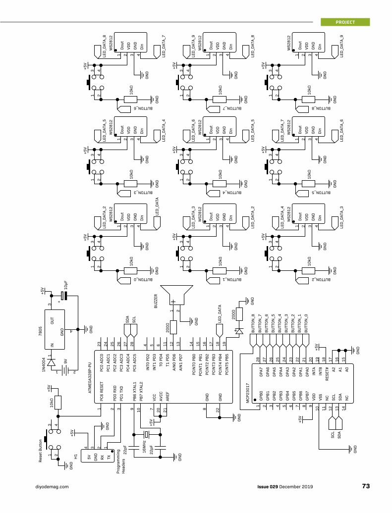
GND
GND
GND
GND
GND
GND
GND
GND
GND
GND
GND
GND
GND
GND
GND
GND
GND
GND
GND
GND
GND
GND
WS2
812
Dout
VDD
GND
Din
LED_
DATA
_7
LED_
DATA
_6
LED_
DATA
_5
LED_
DATA
_6
LED_
DATA
_5
LED_
DATA
_4
WS2
812
Dout
VDD
GND
Din
10kΩ
1 2
3 4
WS2
812
Dout
VDD
GND
Din
+5V
BUTTON_8BUTTON_7
WS2
812
WS2
812
WS2
812
LED_
DATA
LED_
DATA
_2
LED_
DATA
_3
LED_
DATA
_2
LED_
DATA
_3
LED_
DATA
_4
BUTTON_5
WS2
812
WS2
812
WS2
812
LED_
DATA
_9
LED_
DATA
_8
LED_
DATA
_9
LED_
DATA
_8
LED_
DATA
_7
10kΩ
1 2
3 4+5V
BUTTON_6
Dout
VDD
GND
Din
1 2 3 4
Dout
VDD
GND
Din
1 2 3 4
1 2 10kΩ
+5V
Dout
VDD
GND
Din
1 2 3 4
10kΩ
1 2
3 4
+5V
1 2
3 4
1 2 3 4
10kΩ
1 2
3 4
3 4
+5V
+5V
1 2 3 41 2 3 4
10kΩ
10kΩ
1 2 10kΩ
Dout
1
VDD
2
GND
3
Din
4
BUTTON_0 BUTTON_1 BUTTON_2
Dout
1
VDD
2
GND
3
Din
4
10kΩ
BUTTON_4BUTTON_3
Dout
VDD
GND
Din
1 2
3 4
+5V
1 2 3 4
3 4
+5V
1 2
3 4+5V
4 5 6 1123 24 25 26 27 28
BUZZ
ER
200Ω
SDA
SCL
12 13 14 15 16 17 18 19
1 2
200Ω
LED_
DATA
BUTT
ON_0
BUTT
ON_1
BUTT
ON_2
BUTT
ON_3
BUTT
ON_4
BUTT
ON_5
BUTT
ON_6
BUTT
ON_7
BUTT
ON_8
INT0
PD2
INT1
PD3
T0 P
D4
T1 P
D5
AIN
0 PD
6
AIN
1 PD
7
PCIN
T0 P
B0
PCIN
T1 P
B1
PCIN
T2 P
B2
PCIN
T3 P
B3
PCIN
T4 P
B4
PCIN
T5 P
B5
PC0
ADC0
PC1
ADC1
PC2
ADC2
PC3
ADC3
PC4
ADC4
PC5
ADC5
PC6
RESE
T
PD0
RXD
PD1
TXD
VCC
GND
PB6
XTAL
1
PB7
XTAL
2
AVCC
AREF
GND
ATM
EGA3
28P-
PU
1 2 3 7 89 10 20 21 22
16M
Hz
22pF
22pF
10kΩ
1 2
3 4
H1
1234
Rese
t But
ton
Prog
ram
min
gH
eade
rs
+5V
GND
+5V
+5V
MCP
2301
7
GPB0
GPB1
GPB2
GPB3
GPB4
GPB5
GPB6
GPB7
VDD
VSS
NC
SCL
SDA
NC
A0A1A2
RESE
T#
INTB
INTA
GPA0
GPA1
GPA2
GPA3
GPA4
GPA5
GPA6
GPA7
19202122232425262728
+5V
1 2 3 4 5 6 7 8 9
10 11 12 13 1415161718
+5V
TXRXGND
5VGN
D
7805
GND
IN
4
OUT
3
9V
1 2
10µF
1N40
04+5
V
1
SDA
SCL
GND
GND
GND
+
PROJECT
73Issue 029 December 2019diyodemag.com

›› CONTROL BOARD
The control board contains basically everything except the LEDs and buttons. That means the ATmega, the I/O extender board, and the power electronics are all kept together. This control board is the trickiest part of the project, so if you get stuck, take a look at the schematic.
The first thing we did was set up the power electronics. Positioning is quite important when beginning a soldered prototype, because once you’ve started, it’s going to be quite an arduous task moving everything around again. We added the barrel jack to begin with. Always remember that many connector, headers and jacks, the male side that plugs into the board will have some overhang, extending from the side of the board. We positioned the barrel jack adapter a couple of centimetres into the board to allow space for the male jack in the enclosure. (We had some problems with the jack later!)
We then soldered up the 7805 voltage regulator to the pins on the barrel jack adapter. Don’t forget the diode between the unregulated voltage rail and the Vin pin on the regulator – this will give us reverse polarity protection so we won’t accidentally destroy the circuit. Later on, we’ll add a 10µF capacitor between 5V and ground of the regulator to smooth out the output. We’re not doing it now so we don’t have to put stress on the capacitor when we flip over the circuit board to solder other components.
We then soldered in the two 28-pin IC sockets which will give us a guide to which pins connect where to the ATmega microcontroller and the I/O extender. It’s also a good idea not to solder all the pins on the sockets in all at once, as you might need to move it. Instead, solder one pin on each corner of the socket, which will loosely hold it in place until you’re confident it’s in a good position.
As we detailed in the prototype build, it’s more or less a matter of connecting 5V and ground to the pins of the ICs. We soldered the ATmega’s supporting circuitry in first, including the crystal, capacitors and red status LED. Don’t forget to insert the ATmega chip into the socket the right way! We also added four male headers connected to 5V, ground, TX and RX for programming the board.
At this point, you can connect the control board to the USB-to-Serial converter. Make sure that the RX and TX pins on the converter are connected to the opposite pin on the Arduino – i.e. RX to TX, TX to RX. You can then upload the default Blink sketch and, if everything is hooked up correctly, the red debug LED should blink!
When connecting up the I/O extender, there’s a couple of ground and 5V lines to connect. Connect the SDA and SCL lines of the extender to the ATmega and remember to pull the A0, A1 and A2 pins to ground which sets the chips address to 000.
We can then begin adding the wires that will lead to the button board, which we’ll make next. You’ll need a 5V and Ground wire, which we’ve colour-coded red and black, and a white wire connected to pin D12 of the Arduino which will control the daisy-chained LEDs. For the buttons, we’re running one yellow wire from each pin of the IO extender to each one of the buttons. To simplify
PROJECT
Issue 029 December 2019 diyodemag.com74

the circuitry on the button board, we also added 10kΩ pulldown resistors directly to the extender’s inputs. (Note that on the schematic, the 10kΩ resistors look as if they are placed close to the physical buttons. We placed them in a nine-long row directly in front of the MCP23017 in order to save space on the button board.)
BUTTON BOARD
The button board is where we’ll be putting the – you guessed it – buttons! The addressable LEDs will be mounted close to the buttons, so when we get to 3D printing the enclosure, the light from the LEDs will shine through the white button covers to get an awesome glowing effect. Although this board is easier to solder together than the control board, take your time! An LED soldered in around the wrong way will be the last thing you want to discover after connecting everything up.
The first step is to align the buttons on the 9cm x 7cm perfboard such that it’s an evenly spaced 3x3 grid. We found leaving four holes between each button seemed to space it out quite well. After that, we added the nine WS2812 5mm LEDs, placed directly next to the buttons. Make sure that the flat edge of all LEDs face to the next LED in the chain. We then linked them all together with some white solid-core wire, snaking through all nine LEDs.
After the white data wires are complete, add the power wires. The second pin of each LED is for 5V, and the third pin is for ground. While you’re at it, connect 5V to one side of each button. This will help us later when we connect the nine yellow button wires that will read the 5V when the button is pressed.
We had some trouble connecting ground for one row of the LEDs on the top side of the board, so we ended up adding some solid-core black wire on the underside. Remember, you can refer to the main build schematic to make sure the LEDs and buttons are wired properly. It’s a good idea to quickly run through the circuit with a multimeter to make sure there aren’t any shorts and all the LEDs are properly connected to the power rails.
To finish off the electronics for this build, simply join up the wires hanging from the control board to the button board. Connect the 5V (red) and ground (black) to the rails on the board, and connect the LED data wire (white) to the first LED’s Data In pin. Then, just hook up the nine yellow wires to the opposite signal side of the buttons. When the circuit is running and a button is pressed, the button will send a 5V signal through its yellow wire to the I/O extender.
To get the boards ready for the enclosure, we added a zip tie and some hot glue to the wires between the control board and the button board. This ensures the wires won’t get in the way when we insert the button covers into the top lid. We also carefully bent the LEDs down flat with the buttons, which makes sure they won’t interfere with the button covers.
CODE
It’s time to write the code for the final build! “But DIYODE!” we hear you ask, “Why are you writing the code before you’ve done the 3D printing!?” - Because our Arduino doesn’t have a USB port, we won’t be able to access the programming headers once it’s in the enclosure. We can also test our game logic is bug-free to make sure it works properly before packing all the electronics in. Let’s have a quick rundown of what we want our program to do:
1. Wait for any button to be pressed, which will start the program and light up the LEDs. Since our TicTacToe game board doesn’t have an on-off switch (Whoops!), if we leave the LEDs on all the time the 9V battery will run flat.
2. When the game starts, ask each player what colour they want to be in the game – display nine colours on the buttons and set the player colour to whichever one they press.
3. Start the game. The players take turns of pressing squares, which is then lit up to their colour. ››
PROJECT
75Issue 029 December 2019diyodemag.com

›› 4. Once a winning combination is detected, flash all squares the winning colour and go back into standby mode – turn the LEDs off.
Let’s get started! We aren’t going to show all 220 lines of code for this project, but we’ll look at some of the most important parts of it. You can download all code from the project files.
SETUP CODE
#include <FastLED.h>
#define NUM_LEDS 9
#include <Wire.h>
#include “Adafruit_MCP23017.h”
#include <avr/wdt.h>
CRGBArray<NUM_LEDS> leds;
Adafruit_MCP23017 mcp;
int board[3][3] = {{0,0,0},
{0,0,0},
{0,0,0}};
int playerColours[] = {0,32,64,96,128,160,192,22
4,255};
bool player1 = true;
int brightness = 160;
int player1Hue = 0;
int player2Hue = 0;
This code defines the variables and objects for our program. You’ll notice we’re using the FastLED library for controlling our LEDs and the Adafruit_MCP23017 library for controlling our buttons through the GPIO extender. Our “board” array defines a 3x3 array that lets us keep track of which player has pressed what. Zero means the square is empty; if a player presses a button, their player number is set to that square. The player1 variable is then toggled from False to True or vice versa, depending on which player is next.
At the beginning of the game, we show a selection of nine different colours that the player can choose from to act as their square colour. The “playerColours” array defines a list of hues the players can choose from, scattered throughout the colour spectrum. They’re then assigned to the player1Hue and player2Hue variables.
Our brightness variable defines how bright the WS2811 LEDs light up, on a scale of 0-255. If the brightness is too low, you won’t be able to see the game in daylight, and if the brightness is too high, it will drain our 9V battery much more quickly! We found 150-160 is a good value and prevents the LEDs from drawing too much current.
LOOP CODE
The code is a little lengthy to publish here, but check it out in the digital resources.
void loop(){
//Get inputs
for(int i = 0; i < 9; i++) {
int state = getButtonState(i);
int coordX = i % 3;
int coordY = int(i/3);
if(state == 1 && board[coordY][coordX] == 0)
{
board[coordY][coordX] = player1 ? 1 : 2;
//Set LED
leds[i] = CHSV(player1 ? player1Hue :
player2Hue, 255, brightness * (board[coordY]
[coordX] == 0 ? 0 : 1));
FastLED.show();
//Check Win State
int winState = checkWinState();
//Player 1 has won
if(winState == 1) {
delay(300);
playerWin(player1Hue);
}
//Player 2 has won
if(winState == 2) {
delay(300);
playerWin(player2Hue);
}
//TIE
if(winState == 3) {
delay(300);
flashMessage(0);
reset();
}
//Swap player
player1 = !player1;
}
}
}
There are a number of functions that this function calls, so take a look at the project files if you to want to have a look at how they work.
The loop revolves around iterating over all the buttons and checking if any are pressed. If a button is pressed, and that grid square is empty, the square will be assigned to that player. When assigned, the square lights up that players colour.
After a player has chosen a square, the code checks to whether any player has won or if there is a tie. You can look at the CheckWinState code below to see how it does this. It can return 1 or 2 if a certain player has won, 3 if the game is a tie or otherwise 0 if the game should continue. If the game continues, the players swap and the loop continues. If the game ends, an image is flashed - the colour of the player who won, or a white letter “T” if the game is a tie.
WIN CHECK CODE
The win check code is too long to show here. You can download it from our website.
This code is for determining the state of the game – whether a certain player has won, or the game is a tie. This code is slightly inefficient in order to make it clearer – we’ve defined quite a few variables so it’s easier to follow along. We refer to the “board” variable several times throughout this method, which is a 2-dimensional array containing which squares are empty or assigned to players. For example, calling the following would assign the middle square to Player 1:
Easy, right? The first case we check is horizontal wins, which is defined as when three squares in a horizontal row are assigned to one player. We iterate through each row and check if either player 1 or player 2 owns it, and then returns 1 or 2 if we find a player has won. Checking for vertical wins is very similar.
We then check for diagonal wins, of which there are two cases: Top left to bottom right, and top right to bottom left, checking if either player has won on either.
If no players have won, we check whether the board is filled to result in a tie. We set our “tie” variable to true by default, and then while we’re iterating through the board, if we find any empty squares, we set the variable to false. It’s important that we check for a tie after we check for wins, as the board could be filled because a player just won!
Finally, if none of those cases happened, we return 0 to let the loop function know the game is free to continue.
board[1][1] = 1;
PROJECT
Issue 029 December 2019 diyodemag.com76

UPLOADING THE CODE
Similar to the Fundamental build, connect the 5V, ground and RX/TX pins on the USB-to-Serial converter to the header pins on the control board. Follow the procedure we used for uploading code in the fundamental build, holding the reset button on the board while you do it – and voila, the game is good to go!
It’s a good idea to playtest the game before we put it into the enclosure, because the last thing you want to do is disassemble the entire project just to change a teeny-tiny bug in your code.
3D-PRINTED ENCLOSURE
The 3D-Printed enclosure for this project comes in three parts: the top lid, the enclosure, and the nine pushbutton covers. The .stl files are available on our website.
It’s worth noting that the enclosure we designed is specifically made for the 7cm x 9cm prototyping boards that we used for the control and button boards. Due to the rather poor machining of the prototyping boards, the four corner holes aren’t quite square, and so the screw holes on the enclosure can’t be either if we want a good fit. We designed our 3D printed file to support our particular prototyping board, however, we’ve included a file called MainBody_Exact.stl that has the exact measurements the prototyping board should ideally have.
We printed both the top lid and enclosure in lime green PLA plastic on our Flashforge Finder. They came out quite well, just remember to give the prints a quick clean up – removing any stringing, clearing screw holes with a hand drill, etc.
We’ve included a STL file for the button covers, which you can either print one-at-a-time or all together in the same print. You need to print nine, all of which can be printed with the top side facing down. Each should take around 15 minutes to print. White or translucent (“neutral” colour) PLA plastic works well for these buttons, which
lets the LED light shine through. Be aware that the infill type you choose will be visible when the LEDs light up – in our case, small hexagons.
BRASS INSERTS
If you’ve ever tried to print an object with some screw thread made from plastic, chances are it either didn’t work or degraded very quickly! The accuracy of 3D-printing and the durability of PLA/ABS simply can’t produce a good quality screw thread.
So how do we connect two 3D-printed objects together with screws? We could use nuts, but they’re ugly and is rather inconvenient where you don’t want the screw thread to show through on the other side of the object.
Brass inserts are a great way to add high-quality screw-in points for your project. If you haven’t seen them before, they’re essentially screw thread adapters for 3D-prints. On the inside of the inserts is a standard screw thread, and on the outside is knurled rings.
We’ve added four small holes in the top lid of the project, which are slightly smaller than the diameter of the brass inserts. By pushing the inserts into the holes with a hot soldering iron, the inserts conduct the heat into the plastic of the 3D print. This then slightly melts the plastic, allowing the insert to slide into the plastic and cool in place. The insert, if pushed in correctly, will provide a firm hold due to the knurled texture on the outside. ››
IMAGE CREDIT: Core Electronics
PROJECT
77Issue 029 December 2019diyodemag.com

›› After we added our inserts, we found that the lid didn’t align very well- there was quite a bit of ugly overhang that definitely isn’t welcome on our final build. After we heated up the inserts again with our soldering iron, we moved them until the lid mounts properly.
If you’d like to avoid the problems we had inserting them, you can buy brass insert tips for your soldering iron that hold the insert straight while pushing into plastic – definitely a necessity if you find yourself using them a lot.
FINAL ASSEMBLY
To throw the whole build together, we’ll first need to insert the control board into the enclosure. Insert four M3 x 10mm screws into the bottom of the enclosure, which should slot neatly into the control board. After that, we added 10mm PCB standoffs to the remaining screw thread, which allows us to screw in the button board over the top. If the screws are too long and hit the other screws on the bottom, grind them down with a rotary tool or use some 5mm ones instead.
Even though the screws were the right length, we still had problems getting the button board to sit properly. The buzzer on the control board was slightly too tall, which means the button board area above it was slightly lifted, and thus the lid also wasn’t closing properly. We put a rotary sanding bit onto our trusty Dremel and sanded the offending buttons down, which reduces their height and allows there to be enough space between it and the top lid for them to be pressed comfortably.
We then realised the 9V barrel connector and jack were sticking out too far, pressing against the wall of the enclosure and preventing the boards sitting properly. We ended up having to make some last-minute modifications to the control board, by de-soldering the jack and soldering the cables of the 9V battery clip directly to the board.
If you haven’t already, slot in the 9V battery and connect the clip terminals. We managed to jam it in between some cables which comfortably hold it in place, but if your battery wants to move around, put a dab of hot glue onto it to secure it into the enclosure.
PROJECT
Issue 029 December 2019 diyodemag.com78

The only thing left to do for the build is to close everything up! To prevent the button covers falling out when you screw on the lid, leave it upside down on your table and lie the enclosure face-down over the top of it. Then, insert four 10mm screws to the outer holes and lock them into the brass insert thread.
TESTING
Now comes the fun part! Our testing process was, of course, super scientific, and involved competing against family and friends to have some Tic-Tac-Toe fun and get their opinions. The project seems to hold up well to some throwing around, and we found we could leave the 9V battery connected to the board for about a week before it goes flat. In hindsight, we probably should have remembered to add an On/Off switch and an easy way to get access to the programming pins on the Arduino.
Overall, the project looks and works great! The 3D prints came out surprisingly high-quality on the entry-level printer we used for the project; the layer lines are hardly visible. The RGB LEDs are quite bright indoors (although they are sometimes difficult to see in direct sunlight) and the feel of the buttons is satisfyingly tactile. Thankfully, we didn’t find any bugs in the game; although players can accidentally choose similar colours, which makes it difficult to see who is who when playing.
WHERE TO FROM HERE?
We think there’s a wide variety of extra minigames you can write code for and program it onto the board.
How about a 4-player wack-a-mole game, where each player has a colour and must press any buttons that illuminate that colour. How long will it be before someone gets too competitive and presses someone else’s colour by accident?
You could even program the board to play a rudimentary roulette game! After the centre button is pressed, the lights around the outside illuminate in a spinning circular pattern until it lands on one of the eight squares. Place bets that it’s going to land on your square!
Even though there are 9 LEDs, it could become a DICE by using only those that are needed for the patterns. What about adding a Bluetooth or WiFi shield module to the ATmega and program it to interface with your computer, phone or tablet? Smart home control comes to mind – you have nine different buttons to activate or toggle power to appliances around the house! You could even build two of these game boards and add multiplayer compatibility over WiFi! ■
WANT MORE? For the code, 3D print files, additional build images, or to discuss this project, visit: https://diyode.io/029zfbp
PROJECT
ARE YOU A BRIGHT SPARK?Love building projects that solve real-world problems? Share your work with us and get paid! Simply email us with some of your recent projects, with photos and descriptions and you could be featured in DIYODE Magazine. Contact [email protected] today!
Our electronic Tic-Tac-Tie gameboard has been designed so that anybody can play!
When the 9V battery is connected to the game board, just press any button to start.
1. One white light will flash, which means it’s Player 1’s turn to play. The game board will light up nine different colours, simply press on the colour to select it as your player colour.
2. After Player 1 has selected their colour, two lights will flash and the game will let Player 2 select their colour.
3. The game begins! Player 1 is first; press any button to illuminate it your colour. Player 2 can then take their turn, pressing any unoccupied square. Try to select squares to outplay your opponent.
4. After any player has placed three squares in a row, they win the game! The game board will flash the winning players colour.
5. If no-one wins, the game board will flash a white “T”.
6. The game board goes back into standby mode, press any button to play again!
GAME INSTRUCTIONS
79Issue 029 December 2019diyodemag.com

FEATURE
OPEN SESAMEIoT Garage Door Opener
We last spoke to Simon in late 2017, when we published his PIC-based Badge of Horror Halloween project. What we didn’t know at the time, was that Simon was working on a wireless garage door opener, which could be operated using a smartphone.
After many years of perseverance, Simon has managed to get his door opener working, and wanted to share it with us.
You’ll read that Simon’s determination and ability to learn different coding languages, helped him to create a successful project, that even his wife approves of.
In true maker spirit, Simon persevered through many project setbacks to create his amazing ESP-12 based garage door opener.
SIMON LUDBORZSBusy Dad, tinkerer and engineering manager.
http://ludzinc.blogspot.com.au
@ludzinc
Issue 029 December 2019 diyodemag.com80

FEATURE
It’s great to hear from you again Simon. Can you remind our readers a little about yourself?
I’m a Dad, tinkerer and engineering manager in that order of preference :). I’ve been an Engineer for over 25 years, working with a large defence company, as well as smaller companies where we had to make professional looking products with hobby level equipment. As my work is more management than engineering, electronics is now my hobby. Along with wanting to get my shed sorted so I can work on my dream car.
It’s great to hear you find time to have electronics as your hobby. What got you on the path to electronics, coding and making?
I’ve always liked to make and fix things. As a kid I’d pull toys apart and then make other things from them, then as I grew older I started to tinker with cars. Electronics seemed to be the future when I was in school so I chose electronic engineering for my degree. As work moved to management my home projects became both my ‘fix’ and the opportunity to learn new things.
Great! And you’ve obviously used electronics in the garage with this project. Please give our readers a brief overview of your project.
It’s “Yet Another Internet of Things Garage Door Opener”. “Yet Another” because the IoT Garage Door Opener seems to be the “Hello World” of IoT / Home Automation projects.
Long story short, I wanted to be able to open my garage door with my mobile. But I did not want to use any cloud services – it had to be a stand alone device. The ESP8266 hit the market about the time I wanted to develop this and the community around it (and the ESP32) is just awesome.
When I started I didn’t know the first thing about HTML, CSS, Javascript or Websockets, and it was a steep learning curve. But a rewarding one!
The unit itself has 4 ‘dry contact’ relays and can be configured to open a door or run an external light. The red button is for the light, the left and right green buttons are for the left and right door. The middle button, now, does nothing but I might make it open both.
Wow! That was a serious learning curve. Thank goodness for the Internet and community groups willing to share their knowledge. What components have you used?
Only the best that Aliexpress can supply :). I use an ESP8266-12 module, an MCP23017 IO expander and LM2596 buck circuit to get a 3V3 rail. The IO expander was needed as the ESP8266 module soon runs out of IO. I also have an onboard Real Time Clock (DS1338Z) and a Temperature sensor (TCN75A). The clock is redundant as my plans to operate on timed events are now overtaken by my future plans to integrate the opener into a Node Red environment (on a Raspberry Pi).
Can you talk more about the ESP circuit and why you needed to clamp the VSUPPLY line?
In my work, I was caught out once with equipment in the field operating intermittently, all due to voltage drop on power supply cables (the equipment was far away from central power distribution). Ever since then, I’ve designed in the ability to measure the supply rail at each device. Of course, I’ve not actually implemented this in code... yet.
The clamping is there in case some noise is induced on the cable (if I fire up the stick welder in the garage for instance) and exceeds the 1V input allowed on the A2D on the ESP8266, or if I do something really stupid and try to run the unit off more than 12V (the LM2596 will cope with up to 30V but I’m guessing I’ll either destroy the A2D input or fry the ESP8266. Or both.).
It’s important not to let the smoke out. Did you need to add more IO using an MCP23017?
IO always adds up fast in these projects. 4 front panel status LEDs, 4 Relay Drives, 4 input buttons, 2 PWM outputs to control the illuminated button brightness, I2C lines, 4 slave button inputs... I may have over cooked it a bit :)
You’re right. It is easy to quickly run out of IO as we scope out our projects. Your temperature sensor is redundant?
It was added on a whim, but I was keen to understand how hot/cold it gets in the garage. I should write up about how I calibrated it one day on my blog. ››
81Issue 029 December 2019diyodemag.com

FEATURE
›› It’s great to hear you’re sharing your learnings with the maker community. How did you select the relays to trigger the door motors.?
They are nothing special, chosen for their cheap price and suitable size more than anything else. I did use 12V ones, so I can power them directly from the input power rail. If you look at the power supply schematic, you’ll see that I isolate the LM2596 (via diodes) and have a bulk reserve cap to keep the LM2596 happy should switching relays cause the supply rail to sag. Another lesson learnt the hard way in the past.....
A great tip, thanks! How is your project powered?
I have a ton of assorted DC wall warts. In this case I use a 12V one and then a LM2596 buck circuit to provide 3V3 for the ESP8266.
Can you give an overall explanation of how the circuit works, what each button does, and what the LED indicators show?
There are 4 front panel buttons. The green ones are used to trigger doors, the red to control the light. When a green button is pressed, a door control relay is triggered for 500ms and the light turns on for 5 minutes. You can choose to only operate the light with the red button, or turn it off with the red button after the green on is pressed.
There’s also 4 external button inputs on a terminal block that are driven from my home alarm panel. My alarm has a remote fob that turns the alarm on / off and has two spare outputs that I use to control the roller doors. Gives one fob on the key ring.
However, the real magic is the ESP8266 acting as webserver. If there isn’t a WiFi network present that it can connect to it will act as an access point. Otherwise it’s available on my WiFi network. Load
the page, press the button, open the door. Very handy when I catch the train to work and leave my car keys at home.
There are 4 status LEDs on the front too. I always have a blinking LED to let me know it’s not locked up. Lesson learnt the third. Blinking Green and Steady Blue show’s it’s running and connected to my WiFi. Blinking Blue and Steady Green shows it’s running as an access point.
The yellow LED is active when an external input is active (button, terminal block) and red means I have power. Slow blink is for low supply voltage, and fast blink is for high supply voltage.
It’s great that you’ve learnt and done all of the coding yourself too. How did you approach that?
I did it exactly the wrong way! For anyone interested, they can read about that in detail on my blog. I did mention it was a steep learning curve. It also took me 4 years to get there. I wish the DIYODE articles on Web App building blocks were around when I started. They are really good.
Great to hear you persevered. Some people would have put it into the too hard basket. Your interface looks straightforward. How does it work?
The GUI starts off simple and then I over-complicate it. The first page is a simple page of buttons. Press the button, toggle the door / light state.
I eschew the traditional approach of using a simple get request, but use ajax (to stop cached URLs causing issues) for the button presses and websockets passing JSON files for all the configuration options.
Issue 029 December 2019 diyodemag.com82

FEATURE
Well done working out how to overcome the caching issues using AJAX. Do you have any safety measures in place for anything failing?
It’s fail safe. Relays are normally open, so if they fail, the doors wont trigger. Power supply is limited by a poly-switch, and the supply rail for the external inputs are current limited to only a few mA so dead shorts won’t burn the house down.
Yes, very important not to burn down the house. We read on your blog that you burnt your original motors. What happened?
I did a dumb thing. I’d configured the relays to switch 12V (not current limited!) to control some LEDs to represent the doors while I was developing the code. Then I installed the unit, without removing the 12V solder blobs and promptly destroyed my roller door control boards. Expensive! Still learning lessons....
Ouch! Lesson learned the hard way there. We see you’re also handy with PCB design. What software did you use to design it, and where did you source your boards?
I designed the boards in Circuit Maker. Boards were ordered from Elecrow. But I tend to use JLCPCB these days.
Great! We notice there’s a parts list there also if any of our readers were interested in building on for themselves. Were there any challenges you needed to overcome with your build?
Nothing too out of the ordinary. The alignment of the front indicator LEDs was a bugger (took a few spins to get that right), but I have access to a PCB mill at work (very handy for testing mechanical fitment), and when assembled there’s no chance of non-destructively taking the top board out again.
Always helps when you have access to the right equipment. We notice you have two designs. What are the main differences and why?
First design was simply two dry contacts to run in parallel with my alarm panel, and drive the converted hot water heater box that I used to control my doors and run a LED light. You can read about that here: http://ludzinc.blogspot.com/2013/07/ive-seen-light.html
The first design was my first steps with the ESP8266 - so it was worth it just for that. At the time the plan was to use the AT command set to control the ESP module, but then the whole thing was ported to Arduino and hosting of webpages was something I just had to learn about!
But that was ugly as sin and had to go. So the second design incorporates the ‘user interface’ (front panel buttons and LEDs) and drives an external LED to light up the garage in the dark.
Your project build and installation does look very neat. Are all of your projects this neat?
Lol, no! Sometimes it’s a case of just get it done, pretty it up later. But I do try to make things that pass my wife's Acceptance Factor.
Ha Ha. Yes, it's important to keep your wife happy. What else should our readers know about this project that we haven’t already covered?
If nothing else, it’s a lesson in perseverance. Life can be busy and often projects are start / stop in nature as family priorities take preference, but I got there in the end and learnt a lot!
Good advice. Life can get busy, particularly with work and family. If our readers want to build their own IoT garage door opener where can they get more details about the build?
Yes! My blog has the PCB design, cases used, firmware and details available.
Fantastic! Thanks for sharing. What other amazing projects have you made?
I was quite chuffed that you’d featured my Halloween pumpkin badge in the past! I have a few in queue that I’ve built and want to write up on my blog. 'Learn to Solder' projects (for the kids), my take on the classic Atari Punk, RGB LED colour mixer, Hand Held Game of Simon, and RetroPi with custom power hat and ‘console case’.
They all sound great. We hope they all passed the Wife Acceptance Factor test. What projects are you working on next?
An “Electro Sketch” - electronic version of the classic Etch-a-sketch, Temperature and Humidity monitoring nodes for the house, learning Node Red & MQTT, and automating my home lighting.
You certainly like to keep yourself busy, building and learning. We hope you have inspired our readers to do the same. Good luck with your projects and keep in touch. ■
GOT SOMETHING TO SAY?To discuss this feature, visit:https://diyode.io/029kmzf
Reading & Resources:► SIMON'S BLOG
http://ludzinc.blogspot.com.au► PCB DESIGN AND SCHEMATIC
https://circuitmaker.com/User/Details/Simon-Ludborzs
83Issue 029 December 2019diyodemag.com

PROJECT
Raspberry Pi Media Centre with KODIPart 1
BUILD TIME: 30 MINUTES DIFFICULTY RATING: INTERMEDIATE
With streaming services increasing in popularity, the humble media centre has arguably become less useful. However, this project gives you apps, as well as hard drive storage capacity for your own content too!
THE BROAD OVERVIEW
This project uses the popular Raspberry Pi 3+ with the free and open source Kodi media player application to create a home theatre in your home (or bedroom).
We show you how to install the Kodi media player onto your RPi so you can play videos, music, podcasts and other media files from an SD card or hard drive onto a TV or monitor.
To get started, all that’s required is a Raspberry Pi 3+ and an SD Card. Next month, we will explore the option of adding an external HDD or two by building a powered USB Hub!
If you want to run more than a single USB Hard Drive from a Raspberry Pi, you’ll rapidly end up running into a power problem. Your Pi will struggle to keep the power going to a few drives. The build in next month's issue solves this by creating a USB power injection circuit to provide plenty of 5V power. This is then used to power the USB drives, and also the Raspberry Pi itself.
In next month’s article, we will also finish the build and provide a home theatre inspired 3D printed case with different hard drive configurations.
Build your own Raspberry Pi Media Centre with hard drive storage. - by Mike Lewis
MIKE LEWISStaff writer and programmer
Issue 029 December 2019 diyodemag.com84

PROJECT
HOW IT WORKS
For this project, we have decided to use KODI (formerly XBMC) and the easiest way to get Kodi up and running on your Raspberry Pi is to use the Linux distribution called LibreELEC “Just enough OS for Kodi”. This frees up resources and ensures the system isn’t full of bloated code that may perform functions you’d never use in a media centre.
Out of the many OS variations available for Raspberry Pi, LibreELEC is one of the simplest to roll out. But we’ll still detail the steps.
It’s worth pointing out that Kodi should only be used for content to which you have the legal right to access. Some countries allow you to make a digital backup of your DVD’s but unfortunately here in Australia, it’s illegal to do so. Please check your country's copyright laws and make smart decisions.
SOFTWARE INSTALLATION
LibreELEC makes it REALLY easy to get going with KODI, by providing a bunch of pre-packaged options for the OS you’re using.
First, head over to https://libreelec.tv and navigate to downloads then download the creator for your OS.
Once downloaded, open the LibreELEC SD Creator and select your Pi version then click Download. Once the download is complete, you can then select your SD Card and Write.
Alternatively, if you have trouble with the SD Creator, as we did using OSX (it kept crashing). On the downloads page, scroll down to the direct downloads section and select your Raspberry Pi version and download the correct image.
Flash the image onto your SD card using your preferred application. We recommend Etcher: https://www.balena.io/etcher/
START YOUR RASPBERRY PI ››
85Issue 029 December 2019diyodemag.com

PROJECT
INSTALLING KODI ADD-ONS
Now we have our media centre but nothing to watch! A great feature of Kodi is it’s very easy to install add-ons. There are loads of free add-ons to explore but we will get you started with a must have YouTube.
From the main menu, navigate to Add-ons > Install from repository.
Select Kodi Add-on repository, then choose Video add-ons.
Scroll down and select YouTube. Select Install and choose OK if it asks to install software dependencies. Lastly, select Yes to Execute setup-wizard.
After the app has installed, go back to the Add-ons view and open YouTube
›› Insert the newly formatted SD card, attach a keyboard and/or mouse and power on your Raspberry Pi. Once it boots up, you should be presented with a setup wizard. Complete the setup process with your preferred options. If changing the hostname, it cannot contain spaces.
Once complete you should be presented with the Kodi dashboard.
CONTROLLING YOUR MEDIA CENTRE
Chances are you will not want to control your media centre with a wired keyboard and mouse. Some good options are:
• Wireless USB keyboard with trackpad • Setup IR on your Pi and use a remote (beyond the scope of this project) • Download the app
The app is a great way to control your media centre.
IOS Official Kodi Remote: https://apps.apple.com/app/official-kodi-remote/id520480364
Android Kore, Official Remote for Kodi: https://play.google.com/store/apps/details?id=org.xbmc.kore
Issue 029 December 2019 diyodemag.com86

PROJECT
Click the settings cog, then select Interface.
Select screensaver > Screensaver mode, then select Get more. From here, you can download the screensaver of your choice.
Click preview to try it out! Now if you happen to leave your TV on, you won't be at risk of LCD burn in!
WHERE TO FROM HERE?
Next month, we're going to solve the issue of powering a Raspberry Pi with a few extra drives, and open up network sharing to load media in from your favourite computer. We'll also build our media centre into a really neat 3D printed case! In the meantime you can enjoy the system in its raw form! ■
NEXT MONTH: RASPBERRY PI MEDIA CENTRE WITH KODI PART 2
JOIN THE CONVERSATION?To discuss this project visit:https://diyode.io/029wcrb
Now you can watch all your favourite DIYODE videos from the comfort of your lounge, huzzah!
FINISHING TOUCHES
To load your own media, copy your media to the SD card or an external USB HDD under the relevant directories.
From Kodi, navigate to either Pictures or Videos, depending on what you have copied. Select Files and browse to their location.
SAVE YOUR SCREEN!
87Issue 029 December 2019diyodemag.com

GOING PRO
HACKING FOR THE HOMELESSGoing Socially Responsible with REO3
Based in the heart of the Brisbane CBD, REO3 is a new business aiming to combine social and environmental good. Greg Geering, the project lead, is working towards building a self-sufficient company selling refurbished e-waste while employing some of our communities most vulnerable to provide work and technical skill training. He’s also working on community projects for the homeless, including building functional, RFID lockers for deployment within Brisbane service providers.
When e-waste, the community, and hackers come together, we get exciting new initiatives like REO3. - by Steph Piper
http://www.reo3.com/
Level 1 / 19 Merivale St
South Brisbane, Australia
► GREG GEERING Manages E-Waste collection [email protected]
► CHRIS ASHFORD Manages sales and support [email protected]
► LENNY G Handles other enquiries [email protected]
Meet the Team:REO3
Issue 029 December 2019 diyodemag.com88

GOING PRO
After a rough patch years before, Greg found himself on the street. Through this experience, he found others like him in a similar position who had great skills and passions. While traditional ‘homeless help’ initiatives gave away blankets and food, he could see gaps in the way help was given. When given the opportunity, there were people living on the street who wanted to get back on their feet through meaningful work. When you’re learning new skills in tech, keeping yourself busy through work you’re excited about, and getting paid for it, vices like gambling, alcohol and drugs lose their grip.
The REO3 project began through inspiration at the Brisbane Hackerspace and Substation 33, an e-waste recycling space. Through the collaboration of these spaces and with the Brisbane Tool Library and Blind Eye, a homeless church initiative, the project came together.
As well as providing employment through e-waste refurbishment, the REO3 team is working on community projects like creating RFID lockers for the homeless.
The aim of this project is to pay and upskill homeless people to build the lockers so that each piece of the project has value to the community. So far, the locker prototype has come together with a Raspberry Pi, three Arduinos and an RFID access system. The aim is for users to be able to use a GO Card or other system to be able to access the locker, store their items and charge their devices. Currently the prototype uses 50% e-waste, but ideally, the finished versions will be built with as much e-waste and upcycled goods as possible.
In future, they’d like to build sleep pods to give more warmth, comfort and privacy in sleeping rough. REO3 aims to be fully self-funded and sustainable rather than relying on government grants.
REO3 has desktop computers, laptops, servers, tablets and more if you’d like to purchase upcycled e-waste.
"It’s important that our most vulnerable are given opportunities to help themselves while also being treated with dignity and respect. With paid work, they can re-gain their independence" - GREG GEERING
▲ABOVE RFID locker prototype for the homeless
▲ABOVE Greg showing just some of
the upcycled e-waste for sale
If you’d like to get involved, you can visit REO3 in Brisbane and contact Greg at [email protected]. They are currently looking for software and security developers to finalise the locker project prototype, and a new space to move into. ■
For more information, visit www.reo3.com
GOT SOMETHING TO SAY?To discuss this edition of Going Pro, visit:https://diyode.io/029pgsn
Issue 029 December 2019diyodemag.com 89

PROJECT
Sound Drawing
Kids' Basics:
BUILD TIME: 2 HOURS DIFFICULTY RATING: BEGINNER
This circuit has been around in various forms on the internet for many years. In fact, one company even makes a commercial kit for it. All are quite similar, however. We’re revisiting an old friend, the 555 timer IC, and introducing another Integrated Circuit (IC), the LM386 audio amplifier. By connecting your finger and a pencil to the 555, we can create some sounds like those in old space films, or draw shapes on paper that you can play like music by moving your pencil across the page. All you need besides the electronics is a soft graphite pencil (many people know these as ‘lead’ pencils), 2B or softer, and some imagination. We’ll take you through the build step by step, with no soldering required. You will need a responsible adult for one step, and a pencil that you have permission to modify. This month’s circuit fits on one solderless breadboard.
If you have never used a breadboard before you can check out our Breadboarding Basics Classroom from Issue 15. While we’re on the subject of breadboards, we use the terms ‘columns’ and ‘rows’ to describe the lines of connected spring clips. In the rest of the world, columns are vertical arrangements, and rows are horizontal. This is a mathematical convention, and you see it in information tables, as well as real-world things like rows and columns of seats in a theatre or cinema, or columns holding up a roof.
We refer to the power rails as columns, and the lengths of five connections that make up most of the board as rows. Although this might be confusing, look at the numbers and letters on your breadboard: The board is actually designed to be used with its long length up and down. We use it with its long length across. This makes the board easier to use, and many projects in many places show the boards this way. However, most instructions still refer to rows and columns (if they do at all) in the way the letters and numbers show. We stayed with the trend.
So, in our builds, we use the breadboard at a right angle to its designed use, which means that rows and columns also turn through a right angle. Our columns go across, and our rows down. ››
Make weird noises with a pencil as you draw, and turn patterns into music. - by Daniel Koch
90°
Row
How they are designed How we use them
Column
Issue 029 December 2019 diyodemag.com90

PROJECT
ELECTRONICS PARTS REQUIRED: JAYCAR ALTRONICS CORE ELECTRONICS1 x Solderless Breadboard PB8820 P1002 CE05102
2 x Plug-to-plug Jumper Wires WC6024 P1022 PRT-12795
1 x Breadboard Wire Links Pack PB8850 P1014A CE05631
1 x 9V Battery Snap PH9232 P0455 CE05205
1 x 9V Battery SB2423 S4970B CE05337
1m Twin-core Speaker Wire WB1702 W2100 -
1 x Small Speaker AS3000 C0610 ADA1890
1 x 10Ω Resistor* RR0524 R7510 COM-05092
1 x 1kΩ Resistor* RR0572 R7558 COM-05092
1 x 12kΩ Resistor* RR0598 R7584 COM-05092
1 x 330kΩ Resistor* RR0632 R7618 COM-05092
1 x 470pF Capacitor RC5332 R2830 FIT0118
2 x 680pF Capacitor RC5334 R2832 FIT0118
1 x 47nF Capacitor# RM7105 R3021B FIT0118
1 x 100nF Capacitor# RM7125 R3025B FIT0118
2 x 470nF Capacitor# RM7165 R3033B -
1 x 220μF Electrolytic Capacitor RE6312 R5143 CE05149
1 x 555 Timer IC ZL3555 Z2755 COM-09273
1 x LM386 Amplifier IC ZL3386 Z2556 -
*Quantity used, may be sold in packs. Values near but not exact will work. #We used MKT capacitors, but you can use any type with the correct value.
CRAFT MATERIALS & TOOLS REQUIRED:Soft Graphite Pencil (eg. 2B)Drawing PinSticky TapePaper to draw your designs
91Issue 029 December 2019diyodemag.com

PROJECT
4
4
471k
471k
k47
474J
474J
473J
104J
555 386
›› The whole circuit, operationally divided into two halves, fits on a standard solderless breadboard. We’re going to build both the oscillator (the 555 bit) and the amplifier at the same time.
When building, take care to place things exactly where they need to go, counting rows and columns to help you along.
The Build:
Issue 029 December 2019 diyodemag.com92

PROJECT
STEP 1
Place the breadboard in front of you with the outer red (+) rail furthest from you and the outer blue (-) rail closest to you. Insert wire links to join the upper and lower red rails, and blue rails.
STEP 2
Place the 555 and LM386 on the breadboard, counting rows from the ends. Take care of orientation as shown.
STEP 3
Insert these wire links, all of which start in a red (+) rail. Take note of which holes they end in.
STEP 4
Insert these wire links, all of which start in a blue (-) rail. Make sure the other ends go in the right holes.
STEP 5
Place the three wire links which connect pin 2 to pin 6 of the 555, and the two which reach to the right.
STEP 6
Place the two wire links around the LM386, one from pin 5 to the right, the other from pin 3 to the left. ››
4
4
471k
471k
k47
474J
474J
473J
104J
555 386
4
4
471k
471k
k47
474J
474J
473J
104J
555 386
93Issue 029 December 2019diyodemag.com
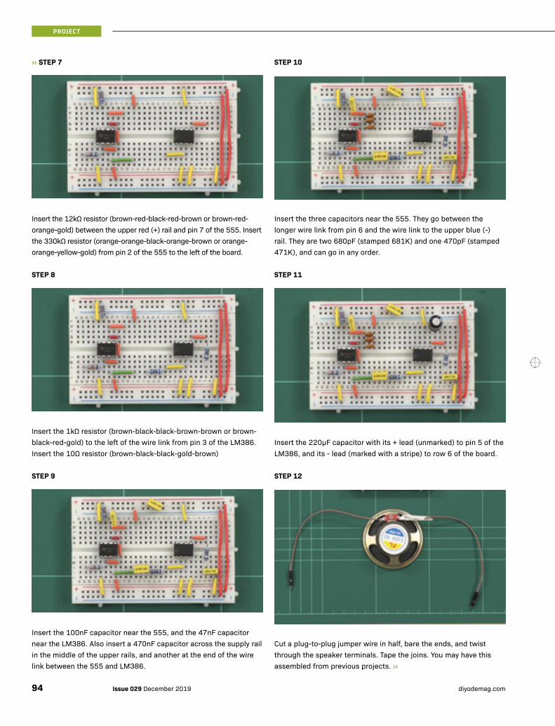
PROJECT
›› STEP 7
Insert the 12kΩ resistor (brown-red-black-red-brown or brown-red-orange-gold) between the upper red (+) rail and pin 7 of the 555. Insert the 330kΩ resistor (orange-orange-black-orange-brown or orange-orange-yellow-gold) from pin 2 of the 555 to the left of the board.
STEP 8
Insert the 1kΩ resistor (brown-black-black-brown-brown or brown-black-red-gold) to the left of the wire link from pin 3 of the LM386. Insert the 10Ω resistor (brown-black-black-gold-brown)
STEP 9
Insert the 100nF capacitor near the 555, and the 47nF capacitor near the LM386. Also insert a 470nF capacitor across the supply rail in the middle of the upper rails, and another at the end of the wire link between the 555 and LM386.
STEP 10
Insert the three capacitors near the 555. They go between the longer wire link from pin 6 and the wire link to the upper blue (-) rail. They are two 680pF (stamped 681K) and one 470pF (stamped 471K), and can go in any order.
STEP 11
Insert the 220μF capacitor with its + lead (unmarked) to pin 5 of the LM386, and its - lead (marked with a stripe) to row 6 of the board.
STEP 12
Cut a plug-to-plug jumper wire in half, bare the ends, and twist through the speaker terminals. Tape the joins. You may have this assembled from previous projects. ››
Dream like a child. Build like a machine.
www.altronics.com.au | 1300 797 007
DIYODE-Back_Cover_v1.indd 3 6/06/2017 1:02 PM
Issue 029 December 2019 diyodemag.com94

Dream like a child. Build like a machine.
www.altronics.com.au | 1300 797 007
DIYODE-Back_Cover_v1.indd 3 6/06/2017 1:02 PM

PROJECT
›› STEP 13
Plug one speaker wire into the board in row 6 to connect to the 220μF capacitor. Plug the other wire into the upper blue (-) rail.
STEP 14
Cut another plug-to-plug jumper wire in half and bare the ends. Cut a length of speaker cable, and bare about 5mm of one end, and 50mm of the other. You can use separate lengths of hook-up wire instead of speaker wire.
STEP 15
Join the ends of the jumper wire to the shorter stripped ends of the speaker wire. Tape the ends. Wrap one of the longer ends around a drawing pin or push pin.
STEP 16
Push the drawing pin into the end of a 2B or softer graphite pencil. Make sure the pin contacts the graphite core, not just wood.
STEP 17
Tape the other long stripped end to the pencil, wrap around once or twice, and tape near the sharp end of the pencil.
STEP 18
Plug the jumper wires from the pencil into pin 7 of the 555, and the 330kΩ resistor. Connect the battery and hold the pencil so your finger touches the bare wire. Touch the tip with your other hand, and listen. If all is connected properly, you should hear a sound. If not, check all connections and component placement.
Issue 029 December 2019 diyodemag.com96

HOW IT WORKS
We have used the 555 timer IC is several past projects: We used it to flash lights, then to generate a siren for them. We later used it to make a different sound in our war horn, and we have used it to make clock signals to drive other ICs. It is made by many manufacturers, with many prefixes and suffixes. Some manufacturers use the original Signetics ‘NE’, while others use the ‘LM’ prefix. Texas Instruments makes both LM and NE prefixed 555s with slightly different specifications. So whatever is printed on your IC, there just needs to be a 555 in it.
We are using the 555 in ‘astable’ mode, which means it switches on and off continuously. The on and off times can be independently set by the relationship of two resistors. Ordinarily, in astable operation, one resistor is connected between Vcc and pin 7, the discharge pin. Another connects between pin 7 and pin 6, the threshold pin. The discharge resistor controls how long the capacitor inside the 555 takes to discharge, while the resistor between there and the threshold pin controls when the state changes. Pin 6 is normally connected straight to pin 2, and this junction connects to a capacitor, the other end of which is grounded.
3
4
2
VCC
Out
0V
1
6
5
7
8
555
RA
RB
In this case, however, we have connected pin 7 to pin 2 by a resistor, but not as you know resistors. Pin 6 still connects straight to pin 2, and there is still a capacitor between these two pins and ground. This is the three capacitors inserted in parallel, because capacitances in parallel add up. More on this later.
Pin 7 is connected to pin 2 by a very special resistor - your body. That, and the graphite pencil. Graphite conducts electricity, and has a resistance, depending on binding agents, of around 1Ω (Ohm) per 25mm when it is in the core of a pencil. One end of this graphite rod is connected via a wire to pin 2 or pin 7, depending on which end you plugged in (though it doesn't matter which is which). The other wire from the pencil connects to your finger as you grip it.
When you touch the tip of the pencil, current flows from the drawing pin to the pencil tip, up your arm, across your chest, and down your other arm to the finger touching the wire on the pencil body. Your body’s resistance is now part of the circuit. As you’ll see in the ‘using it’ section, you must touch the line you draw with the pencil. As you draw, the graphite line has a much higher resistance than in the core of the pencil, and adds to that of your body. This is what changes the frequency of the sound you hear.
It is true that any current passing through your body can be dangerous. Even from a 9V battery, limited by the 555 and the 330,000Ω (330kΩ) resistor. While in very rare cases this can be dangerous, you are statistically more likely to get struck by lightning, and a healthy, typical body needs well over 10mA of current to arrive at the heart to cause problems. Our circuit is limited to 0.027mA by the 330kΩ resistor alone! Then there is further resistance from your own body and other components.
The three capacitors were chosen rather than one so that you can easily change the sound by playing with the combination. Remove one or more, try a 680pF with the 470pF, two 680pF, or one of either value on its own. You can also try other values.
The other half of the circuit is an amplifier based on the LM386 Integrated Circuit (IC), which is made for just this purpose. It helps boost the signal from the 555 to audible levels, but we don't have room to explain it all here. It's a means to an end to enable our project to be heard. However, we have covered it in this month's Classroom article, which you can read for a deeper explanation of the IC and how to use it. ››
3
4
2
VCC
To Pencil
To Pencil
0V
1
6
5
7
8
555
330kΩ 12kΩ 470nF
1kΩ 10Ω
220μF
Speaker47nF
2-
+
6
45
3
470nF
470pF
100nF
680pF 680pF
+
PROJECT
97Issue 029 December 2019diyodemag.com

PROJECT
›› USING IT
To get the best out of your musical pencil, you need to start by drawing a finger-sized circle. Really smooth paper, such as high-quality laser copy paper, is often too smooth to be effective. Something rougher, like sketchpad or drawing paper, or cheaper copy paper, engages better with the pencil, takes more graphite, and creates a more conductive line. Sometimes, you have to go over your line several times. The darker, the better.
After you have made a circle, you need to place your finger on it. Touch the pencil to the circle, which should elicit a sound from the speaker. Draw away from the circle without breaking the line. As before, you may need to go over the line a few times. As you take the pencil tip further from the circle, the sound’s frequency should decrease.
Of course, this on its own is novel, but soon you’ll be bored by drawing straight lines. Now you can challenge yourself, by drawing patterns that you can draw across to gain music. You may even be able to figure out where on a line certain real musical notes lay, and play them like a keyboard. We have some photos for reference, but above all else, explore and play!
As Albert Einstein said, “Play is the highest form of research”.
WHERE TO FROM HERE?
The varying content of moisture in your skin will change the resistance of the circuit and thus the frequency of the sound. When we are nervous, most people sweat at least slightly, and other reactions happen in the body to change how we conduct electricity. Try using masking tape to attach the wires to your forehead and have someone else ask you questions. Even little lies often change how much we sweat, and the forehead often changes first. The current will only flow across the skin, and not even though all its depth, so this is a safe experiment so long as you keep to the front of the forehead. You’ve made a very basic lie detector!
Lie detectors themselves are falling out of use (except on TV and in the movies) as research proves how inaccurate they are, but it could still be a fun experiment. Just don’t rely on it to prove your sibling stole your chocolate! ■
GOT SOMETHING TO SAY? To discuss this month’s Kids’ Basics, visit: https://diyode.io/029zmfs
By drawing enough lines, you can make a musical scale!
Issue 029 December 2019 diyodemag.com98