2001 SONRASI DÖNEMDE TÜRKİYE EKONOMİSİNDE KRİZDEN BÜYÜMEYE GEÇİŞ ÜZERİNE BİR TARTIŞMA
Upload
khangminh22Category
view
2download
0
ROAD BLOCKER
BOLLARD
ARM BARRIER
SYSTEMSACCESS CONTROL
VEHICLE
TEMSSSYSYSTETROLSS CONONTRACCCCESS
VEHICLEACCESS CONTROL
SYSTEMS

ozak-t.com

Extensive Facilities“Our 33.000 m² production facility having 21.000 m² covered area is one of the key fundaments of our success in manufacturing our products more modular, practical and fast.”
Sustainable and Strong“Everyday, in excess of 20 Million people are passing through more than 52.000 active OZAK products around the world which are activefor decades.”
Variety in Sectors“Our products are used in many sectors, facilities and buildings both indoors and outdoors.”
Strong R & D“Our in house R&D center develops products considering all possible factors after thorough investigations, stringent tests and extensive analyzes.”
3

Ozak was founded by Ozalp Family
Foundation1976
Started to produce turnstiles and gates.
First Turnstile1989
Production facilities reached 33.700 m2 of which 21.000 m2 is covered area.
Investment in Facility2018
New ProductLaunched Bollard
products.
2015
Reached 1.000 units per year.
Increase in Production2006
Production facilities reached 2.700 m2 from 500 m2.
Investment in Facility2008
Investment in FacilityProduction facilities
reached 3.600 m2 from 2.700 m2.
2010
Export sales reached more than 50% of turnover. NR-D Systeme GmbH was founded in Germany.
International Market Growth2012
Increase in Production
Reached 5.000 unitsper year.
2013
Launched Road Blocker products.
Production facilities reached 8.500 m2.
New Product2014
4
Timeline

5
Fields of Use
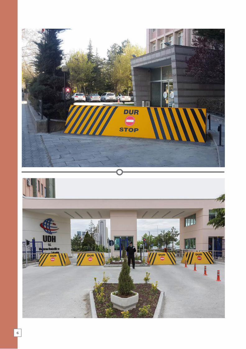
6

ROAD BLOCKER

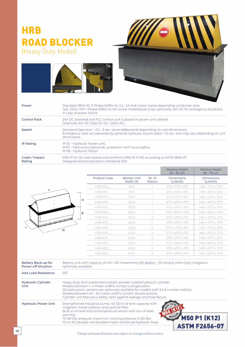
Battery Back-up forPower-off Situation
Battery unit with capacity of min. 100 movements (50 deploy + 50 retract) when fully charged isoptionally available.
Axle Load Resistance 50T
Hydraulic Cylinder Unit
Heavy duty, dust sealed electrostatic powder coated hydraulic cylinder.Models between 1- 4 meter widths contain a single piston.(Double piston versions are optionally available for models with 3,5 & 4 meter widths).Models between 4,5 - 6,5 meter widths contain double pistons.Cylinder unit features a safety valve against leakage and hose failure.
Hydraulic Power Unit Strengthened industrial pump, 40-120 lt oil tank capacity with magnetic metal collector and particle filter.Built-in oil level and oil temperature sensor with low oil level warning. 70-80 Bar pressure; maximum running pressure is 120 Bar.10 mt R2 (double wire braided mesh) reinforced hydraulic hose.
HRB ROAD BLOCKER(Heavy Duty Model)
*Design and specifications are subject to change without notice.
Power Standard 380V AC 3-Phase 50/60 Hz, 3,3 - 5,5 KvA motor (varies depending on blocker size).Opt. 220V, 110V 1-Phase 50/60 Hz (for some models/sizes only), optionally 24V DC for emergency situations in case of power failure.
Control Pack 24V DC powered and PLC control unit is placed in power unit cabinet.Solenoids 24V DC (Ops.12V DC / 220V AC).
Speed Standard Operation ~2,5 - 6 sec. (ascend/descend) depending on unit dimensions. Emergency raise up (upwards) by optional hydraulic accumulator ~1,5 sec. and may vary depending on unit dimensions.
IP Rating IP 55 - Hydraulic Power Unit,IP 67 - Electronics (optional), protection with housing/box,IP 68 - Hydraulic Piston
Crash / Impact Rating
M50 P1 (K-12) crash tested and certified (HRB 30 R 90) according to ASTM 2656-07, Designed and produced to withstand H30.
Raising Height 65 - 50 cm
Raising Height90 - 70 cm
Product Code Blocker Unit Width (X)
Nr. of Pistons
Dimensions(LxWxD)
Dimensions(LxWxD)
HRB 10R_ _ 1000 1 1275 x 1170 x 975 1481 x 1170 x 1270
HRB 15R_ _ 1500 1 1275 x 1670 x 975 1481 x 1670 x 1270
HRB 20R_ _ 2000 1 1275 x 2170 x 975 1481 x 2170 x 1270
HRB 25R_ _ 2500 1 1275 x 2670 x 975 1481 x 2670 x 1270
HRB 30R_ _ 3000 1 1275 x 3170 x 975 1481 x 3170 x 1270
HRB 35R_ _ 3500 1 1275 x 3670 x 975 1481 x 3670 x 1270
HRB 35R_ _ 3500 2 1275 x 3670 x 975 1481 x 3670 x 1270
HRB 40R_ _ 4000 1 1275 x 4170 x 975 1481 x 4170 x 1270
HRB 40R_ _ 4000 2 1275 x 4170 x 975 1481 x 4170 x 1270
HRB 45R_ _ 4500 2 1275 x 4670 x 975 1481 x 4670 x 1270
HRB 50R_ _ 5000 2 1275 x 5170 x 975 1481 x 5170 x 1270
HRB 55R_ _ 5500 2 1275 x 5670 x 975 1481 x 5670 x 1270
HRB 60R_ _ 6000 2 1275 x 6170 x 975 1481 x 6170 x 1270
HRB 65R_ _ 6500 2 1275 x 6670 x 975 1481 x 6670 x 1270
10
*Design and specifications are subject to change without notice.
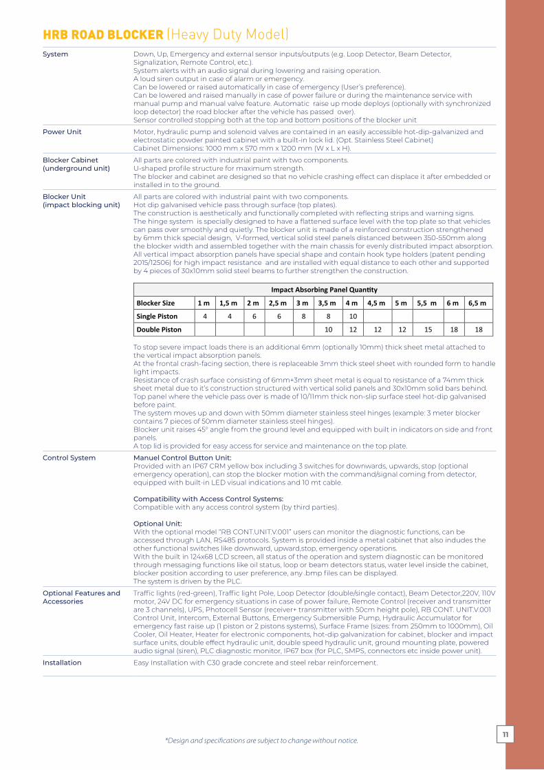
HRB ROAD BLOCKER (Heavy Duty Model)System Down, Up, Emergency and external sensor inputs/outputs (e.g. Loop Detector, Beam Detector,
Signalization, Remote Control, etc.). System alerts with an audio signal during lowering and raising operation.A loud siren output in case of alarm or emergency.Can be lowered or raised automatically in case of emergency (User’s preference).Can be lowered and raised manually in case of power failure or during the maintenance service with manual pump and manual valve feature. Automatic raise up mode deploys (optionally with synchronized loop detector) the road blocker after the vehicle has passed over).Sensor controlled stopping both at the top and bottom positions of the blocker unit
Power Unit Motor, hydraulic pump and solenoid valves are contained in an easily accessible hot-dip-galvanized and electrostatic powder painted cabinet with a built-in lock lid. (Opt. Stainless Steel Cabinet) Cabinet Dimensions: 1000 mm x 570 mm x 1200 mm (W x L x H).
Blocker Cabinet (underground unit)
All parts are colored with industrial paint with two components.U-shaped profile structure for maximum strength.The blocker and cabinet are designed so that no vehicle crashing effect can displace it after embedded or installed in to the ground.
Blocker Unit (impact blocking unit)
All parts are colored with industrial paint with two components.Hot dip galvanised vehicle pass through surface (top plates).The construction is aesthetically and functionally completed with reflecting strips and warning signs.The hinge system is specially designed to have a flattened surface level with the top plate so that vehicles can pass over smoothly and quietly. The blocker unit is made of a reinforced construction strengthened by 6mm thick special design, V-formed, vertical solid steel panels distanced between 350-550mm along the blocker width and assembled together with the main chassis for evenly distributed impact absorption. All vertical impact absorption panels have special shape and contain hook type holders (patent pending 2015/12506) for high impact resistance and are installed with equal distance to each other and supported by 4 pieces of 30x10mm solid steel beams to further strengthen the construction.
Impact Absorbing Panel Quan�ty
Blocker Size 1 m 1,5 m 2 m 2,5 m 3 m 3,5 m 4 m 4,5 m 5 m 5,5 m 6 m 6,5 m
Single Piston 4 4 6 6 8 8 10
Double Piston 10 12 12 12 15 18 18
To stop severe impact loads there is an additional 6mm (optionally 10mm) thick sheet metal attached to the vertical impact absorption panels.At the frontal crash-facing section, there is replaceable 3mm thick steel sheet with rounded form to handle light impacts. Resistance of crash surface consisting of 6mm+3mm sheet metal is equal to resistance of a 74mm thick sheet metal due to it’s construction structured with vertical solid panels and 30x10mm solid bars behind.Top panel where the vehicle pass over is made of 10/11mm thick non-slip surface steel hot-dip galvanised before paint.The system moves up and down with 50mm diameter stainless steel hinges (example: 3 meter blocker contains 7 pieces of 50mm diameter stainless steel hinges).Blocker unit raises 45° angle from the ground level and equipped with built in indicators on side and front panels.A top lid is provided for easy access for service and maintenance on the top plate.
Control System Manuel Control Button Unit:Provided with an IP67 CRM yellow box including 3 switches for downwards, upwards, stop (optional emergency operation), can stop the blocker motion with the command/signal coming from detector, equipped with built-in LED visual indications and 10 mt cable.
Compatibility with Access Control Systems: Compatible with any access control system (by third parties).
Optional Unit:With the optional model “RB CONT.UNIT.V.001” users can monitor the diagnostic functions, can be accessed through LAN, RS485 protocols. System is provided inside a metal cabinet that also indudes the other functional switches like downward, upward,stop, emergency operations.With the built in 124x68 LCD screen, all status of the operation and system diagnostic can be monitored through messaging functions like oil status, loop or beam detectors status, water level inside the cabinet, blocker position according to user preference, any .bmp files can be displayed.The system is driven by the PLC.
Optional Features and Accessories
Traffic lights (red-green), Traffic light Pole, Loop Detector (double/single contact), Beam Detector,220V, 110V motor, 24V DC for emergency situations in case of power failure, Remote Control (receiver and transmitter are 3 channels), UPS, Photocell Sensor (receiver+ transmitter with 50cm height pole), RB CONT. UNIT.V.001 Control Unit, Intercom, External Buttons, Emergency Submersible Pump, Hydraulic Accumulator for emergency fast raise up (1 piston or 2 pistons systems), Surface Frame (sizes: from 250mm to 1000mm), Oil Cooler, Oil Heater, Heater for electronic components, hot-dip galvanization for cabinet, blocker and impact surface units, double effect hydraulic unit, double speed hydraulic unit, ground mounting plate, powered audio signal (siren), PLC diagnostic monitor, IP67 box (for PLC, SMPS, connectors etc inside power unit).
Installation Easy Installation with C30 grade concrete and steel rebar reinforcement.
11


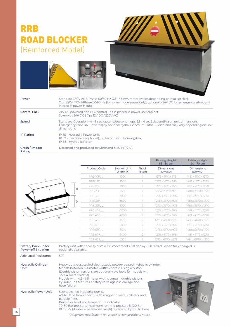
Battery Back-up forPower-off Situation
Battery unit with capacity of min.100 movements (50 deploy + 50 retract) when fully charged isoptionally available.
Axle Load Resistance 50T
Hydraulic Cylinder Unit
Heavy duty, dust sealed electrostatic powder coated hydraulic cylinder.Models between 1- 4 meter widths contain a single piston.(Double piston versions are optionally available for models with 3,5 & 4 meter widths).Models with 4,5 - 6,5 meter widths contain double pistons.Cylinder unit features a safety valve against leakage and hose failure.
Hydraulic Power Unit Strengthened industrial pump,40-120 lt oil tank capacity with magnetic metal collector and particle filter.Built-in oil level and temperature indicator, 70-80 Bar pressure; maximum running pressure is 120 Bar10 mt R2 (double wire braided mesh) reinforced hydraulic hose.
RRB ROAD BLOCKER(Reinforced Model)
Power Standard 380V AC 3-Phase 50/60 Hz, 3,3 - 5,5 KvA motor (varies depending on blocker size).Opt. 220V, 110V 1-Phase 50/60 Hz (for some models/sizes only), optionally 24V DC for emergency situations in case of power failure.
Control Pack 24V DC powered and PLC control unit is placed in power unit cabinet.Solenoids 24V DC ( Ops.12V DC / 220V AC)
Speed Standard Operation ~4 - 6 sec. (ascend/descend) (opt. 2,5 - 4 sec.) depending on unit dimensions. Emergency raise up (upwards) by optional hydraulic accumulator ~1,5 sec. and may vary depending on unit dimensions.
IP Rating IP 55 - Hydraulic Power Unit,IP 67 - Electronics (optional), protection with housing/box,IP 68 - Hydraulic Piston
Crash / Impact Rating
Designed and produced to withstand M50 P1 (K-12).
Raising Height 65 - 50 cm
Raising Height 90 - 70 cm
Product Code Blocker Unit Width (X)
Nr. of Pistons
Dimensions(LxWxD)
Dimensions(LxWxD)
RRB 10F_ _ 1000 1 1275 x 1170 x 975 1481 x 1170 x 1270
RRB 15F_ _ 1500 1 1275 x 1670 x 975 1481 x 1670 x 1270
RRB 20F_ _ 2000 1 1275 x 2170 x 975 1481 x 2170 x 1270
RRB 25F_ _ 2500 1 1275 x 2670 x 975 1481 x 2670 x 1270
RRB 30F_ _ 3000 1 1275 x 3170 x 975 1481 x 3170 x 1270
RRB 35F_ _ 3500 1 1275 x 3670 x 975 1481 x 3670 x 1270
RRB 35F_ _ 3500 2 1275 x 3670 x 975 1481 x 3670 x 1270
RRB 40F_ _ 4000 1 1275 x 4170 x 975 1481 x 4170 x 1270
RRB 40F_ _ 4000 2 1275 x 4170 x 975 1481 x 4170 x 1270
RRB 45F_ _ 4500 2 1275 x 4670 x 975 1481 x 4670 x 1270
RRB 50F_ _ 5000 2 1275 x 5170 x 975 1481 x 5170 x 1270
RRB 55F_ _ 5500 2 1275 x 5670 x 975 1481 x 5670 x 1270
RRB 60F_ _ 6000 2 1275 x 6170 x 975 1481 x 6170 x 1270
RRB 65F_ _ 6500 2 1275 x 6670 x 975 1481 x 6670 x 1270
*Design and specifications are subject to change without notice.14

*Design and specifications are subject to change without notice.
RRB ROAD BLOCKER (Reinforced Model)
System Down, Up, Emergency and external sensor inputs/outputs (e.g. Loop Detector, Beam Detector, Signalization, Remote Control, etc.). System alerts with an audio signal during lowering and raising operation.A loud siren output in case of alarm or emergency.Can be lowered or raised automatically in case of emergency (User’s preference).Can be lowered and raised manually in case of power failure or during the maintenance service with manual pump and manual valve feature. Automatic raise up mode deploys (optionally with synchronized loop detector) the road blocker after the vehicle has passed over.Sensor controlled stopping both at the top and bottom positions of the blocker unit
Power Unit Motor, hydraulic pump and solenoid valves are contained in an easily accessible hot-dip-galvanized and electrostatic powder painted cabinet with a built-in lock lid. (Opt. Stainless Steel Cabinet)Cabinet Dimensions: 1000 mm x 570 mm x 1200 mm (W x L x H).
Blocker Cabinet (underground unit)
All parts are colored with industrial paint with two components.U-shaped profile structure for maximum strength.The blocker and cabinet are designed so that no vehicle crashing effect can displace it after embedded or installed in to the ground.
Blocker Cabinet (underground unit)
All parts are colored with industrial paint with two components.Hot dip galvanised vehicle pass through surface (top plates).The construction is aesthetically and functionally completed with reflecting strips and warning signs.The hinge system is specially designed to have a flattened surface level with the top plate so that vehicles can pass over smoothly and quietly. The blocker unit is made of a reinforced construction strengthened by 6mm thick special design, vertical solid steel panels distanced between 350-550mm along the blocker width and assembled together with the main chassis for evenly distributed impact absorption. All vertical impact absorption panels have special shape and contain hook type holders (patent pending 2015/12506) for high impact resistance and are installed with equal distance to each other and supported by 4 pieces of 30x10mm solid steel beams to further strengthen the construction.
Impact Absorbing Panel Quan�ty
Blocker Size 1 mt 1,5 mt 2 mt 2,5 mt 3 mt 3,5 mt 4 mt 4,5 mt 5 mt 5,5 mt 6 mt 6,5 mt
Single Piston 4 4 6 6 8 8 10
Double Piston 10 12 12 12 15 18 18
To stop severe impact loads there is an additional 6mm thick sheet metal attached to the vertical impact absorption panels.Top panel where the vehicle pass over is made of 8/9mm thick non-slip surface steel hot-dip galvanised before paint.The system moves up and down with 50mm diameter stainless steel hinges (example: 3 meter blocker contains 7 pieces of 50mm diameter stainless steel hinges).Blocker unit raises 45° angle from the ground level and can be equipped with equipped with optional flashing light indicators on side and front panels.A top lid is provided for easy access for service and maintenance on the top plate.
Control System Manuel Control Button Unit:Provided with an IP67 CRM yellow box including 3 switches for downwards, upwards, stop (optional emergency operation), can stop the blocker motion with the command/signal coming from detector, equipped with built-in LED visual indications.
Compatibility with Access Control Systems: Compatible with any access control system (by third parties).
Optional Unit:With the optional model “RB CONT.UNIT.V.001” users can monitor the diagnostic functions, can be accessed through LAN, RS485 protocols. System is provided inside a metal cabinet that also indudes the other functional switches like downward, upward,stop, emergency operations.With the built in 124x68 LCD screen, all status of the operation and system diagnostic can be monitored through messaging functions like oil status, loop or beam detectors status, water level inside the cabinet, blocker position according to user preference, any .bmp files can be displayed. The system is driven by the PLC.
Optional Features and Accessories
Traffic lights (red-green), Traffic light Pole, Loop Detector (double/single contact), Beam Detector, 220V, 110V motor, 24V DC for emergency situations in case of power failure, Remote Control (receiver and transmitter are 3 channels), UPS, Photocell Sensor (receiver+ transmitter with 50cm height pole), RB CONT. UNIT.V.001 Control Unit, Intercom, External Buttons, Emergency Submersible Pump, Hydraulic Accumulator for emergency fast raise up (1 piston or 2 pistons systems), Surface Frame (sizes: from 250mm to 1000mm), Oil Cooler, Oil Heater, Heater for electronic components, hot-dip galvanization for cabinet, blocker and impact surface units, double effect hydraulic unit, double speed hydraulic unit, ground mounting plate, powered audio signal (siren), PLC diagnostic monitor, flashing light indicators, round shaped front panel, oil level sensor, optional speed, IP67 box (for PLC, SMPS, connectors etc inside power unit).
Installation Easy Installation with C30 grade concrete and steel rebar reinforcement.
15
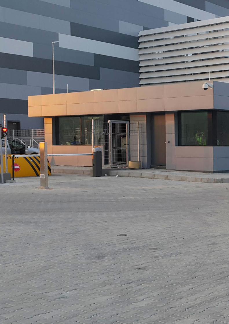
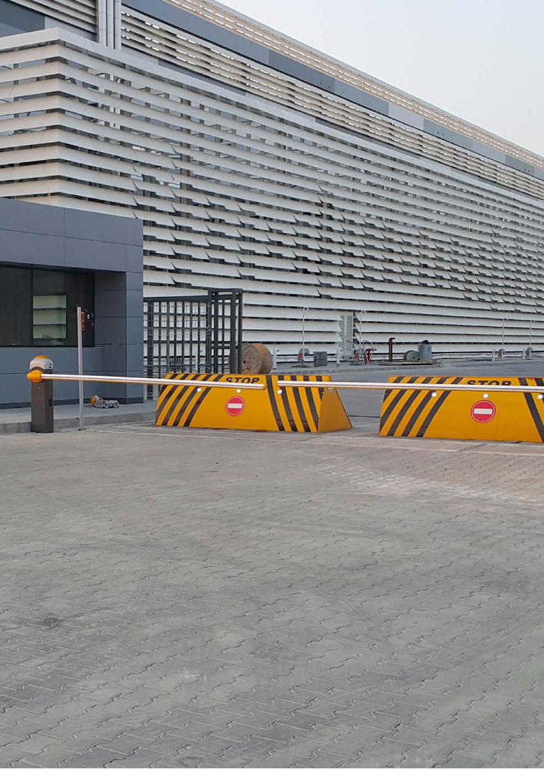
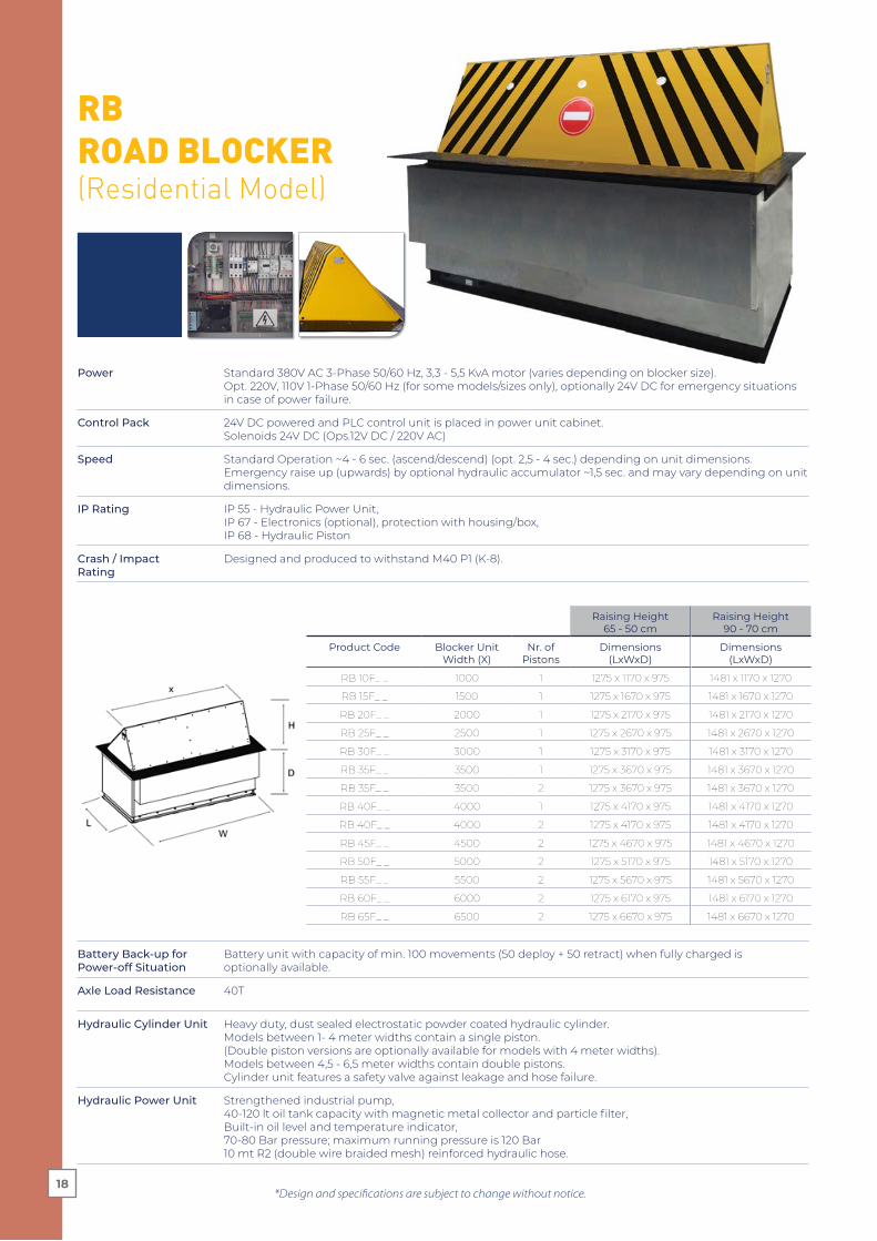
RB ROAD BLOCKER(Residential Model)
*Design and specifications are subject to change without notice.
Power Standard 380V AC 3-Phase 50/60 Hz, 3,3 - 5,5 KvA motor (varies depending on blocker size).Opt. 220V, 110V 1-Phase 50/60 Hz (for some models/sizes only), optionally 24V DC for emergency situations in case of power failure.
Control Pack 24V DC powered and PLC control unit is placed in power unit cabinet. Solenoids 24V DC (Ops.12V DC / 220V AC)
Speed Standard Operation ~4 - 6 sec. (ascend/descend) (opt. 2,5 - 4 sec.) depending on unit dimensions. Emergency raise up (upwards) by optional hydraulic accumulator ~1,5 sec. and may vary depending on unit dimensions.
IP Rating IP 55 - Hydraulic Power Unit,IP 67 - Electronics (optional), protection with housing/box,IP 68 - Hydraulic Piston
Crash / Impact Rating
Designed and produced to withstand M40 P1 (K-8).
Battery Back-up forPower-off Situation
Battery unit with capacity of min. 100 movements (50 deploy + 50 retract) when fully charged isoptionally available.
Axle Load Resistance 40T
Hydraulic Cylinder Unit Heavy duty, dust sealed electrostatic powder coated hydraulic cylinder.Models between 1- 4 meter widths contain a single piston.(Double piston versions are optionally available for models with 4 meter widths).Models between 4,5 - 6,5 meter widths contain double pistons.Cylinder unit features a safety valve against leakage and hose failure.
Hydraulic Power Unit Strengthened industrial pump,40-120 lt oil tank capacity with magnetic metal collector and particle filter,Built-in oil level and temperature indicator, 70-80 Bar pressure; maximum running pressure is 120 Bar10 mt R2 (double wire braided mesh) reinforced hydraulic hose.
Raising Height 65 - 50 cm
Raising Height 90 - 70 cm
Product Code Blocker Unit Width (X)
Nr. of Pistons
Dimensions(LxWxD)
Dimensions(LxWxD)
RB 10F_ _ 1000 1 1275 x 1170 x 975 1481 x 1170 x 1270
RB 15F_ _ 1500 1 1275 x 1670 x 975 1481 x 1670 x 1270
RB 20F_ _ 2000 1 1275 x 2170 x 975 1481 x 2170 x 1270
RB 25F_ _ 2500 1 1275 x 2670 x 975 1481 x 2670 x 1270
RB 30F_ _ 3000 1 1275 x 3170 x 975 1481 x 3170 x 1270
RB 35F_ _ 3500 1 1275 x 3670 x 975 1481 x 3670 x 1270
RB 35F_ _ 3500 2 1275 x 3670 x 975 1481 x 3670 x 1270
RB 40F_ _ 4000 1 1275 x 4170 x 975 1481 x 4170 x 1270
RB 40F_ _ 4000 2 1275 x 4170 x 975 1481 x 4170 x 1270
RB 45F_ _ 4500 2 1275 x 4670 x 975 1481 x 4670 x 1270
RB 50F_ _ 5000 2 1275 x 5170 x 975 1481 x 5170 x 1270
RB 55F_ _ 5500 2 1275 x 5670 x 975 1481 x 5670 x 1270
RB 60F_ _ 6000 2 1275 x 6170 x 975 1481 x 6170 x 1270
RB 65F_ _ 6500 2 1275 x 6670 x 975 1481 x 6670 x 1270
18
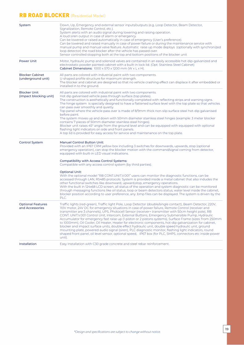
RB ROAD BLOCKER (Residential Model)
*Design and specifications are subject to change without notice.
System Down, Up, Emergency and external sensor inputs/outputs (e.g. Loop Detector, Beam Detector, Signalization, Remote Control, etc.). System alerts with an audio signal during lowering and raising operation.A loud siren output in case of alarm or emergency.Can be lowered or raised automatically in case of emergency (User’s preference).Can be lowered and raised manually in case of power failure or during the maintenance service with manual pump and manual valve feature. Automatic raise up mode deploys (optionally with synchronized loop detector) the road blocker after the vehicle has passed over.Sensor controlled stopping both at the top and bottom positions of the blocker unit
Power Unit Motor, hydraulic pump and solenoid valves are contained in an easily accessible hot-dip-galvanized and electrostatic powder painted cabinet with a built-in lock lid. (Opt. Stainless Steel Cabinet) Cabinet Dimensions: 1000 x 570 x 1200 mm (W x L x H).
Blocker Cabinet (underground unit)
All parts are colored with industrial paint with two components.U-shaped profile structure for maximum strength.The blocker and cabinet are designed so that no vehicle crashing effect can displace it after embedded or installed in to the ground.
Blocker Unit (impact blocking unit)
All parts are colored with industrial paint with two components.Hot dip galvanised vehicle pass through surface (top plates).The construction is aesthetically and functionally completed with reflecting strips and warning signs.The hinge system is specially designed to have a flattened surface level with the top plate so that vehicles can pass over smoothly and quietly. Top panel where the vehicle pass over is made of 8/9mm thick non-slip surface steel hot-dip galvanised before paint.The system moves up and down with 50mm diameter stainless steel hinges (example: 3 meter blocker contains 7 pieces of 50mm diameter stainless steel hinges).Blocker unit raises 45° angle from the ground level and can be equipped with equipped with optional flashing light indicators on side and front panels.A top lid is provided for easy access for service and maintenance on the top plate.
Control System Manuel Control Button Unit:Provided with an IP67 CRM yellow box including 3 switches for downwards, upwards, stop (optional emergency operation), can stop the blocker motion with the command/signal coming from detector, equipped with built-in LED visual indications.
Compatibility with Access Control Systems: Compatible with any access control system (by third parties).
Optional Unit:With the optional model “RB CONT.UNIT.V.001” users can monitor the diagnostic functions, can be accessed through LAN, RS485 protocols. System is provided inside a metal cabinet that also indudes the other functional switches like downward, upward,stop, emergency operations.With the built in 124x68 LCD screen, all status of the operation and system diagnostic can be monitored through messaging functions like oil status, loop or beam detectors status, water level inside the cabinet, blocker position according to user preference, any .bmp files can be displayed. The system is driven by the PLC.
Optional Features and Accessories
Traffic lights (red-green), Traffic light Pole, Loop Detector (double/single contact), Beam Detector, 220V, 110V motor, 24V DC for emergency situations in case of power failure, Remote Control (receiver and transmitter are 3 channels), UPS, Photocell Sensor (receiver+ transmitter with 50cm height pole), RB CONT. UNIT.V.001 Control Unit, Intercom, External Buttons, Emergency Submersible Pump, Hydraulic Accumulator for emergency fast raise up (1 piston or 2 pistons systems), Surface Frame (sizes: from 250mm to 1000mm), Oil Cooler, Oil Heater, Heater for electronic components, hot-dip galvanization for cabinet, blocker and impact surface units, double effect hydraulic unit, double speed hydraulic unit, ground mounting plate, powered audio signal (siren), PLC diagnostic monitor, flashing light indicators, round shaped front panel, oil level sensor, optional speed, IP67 box (for PLC, SMPS, connectors etc inside power unit).
Installation Easy Installation with C30 grade concrete and steel rebar reinforcement.
19
*Design and specifications are subject to change without notice.
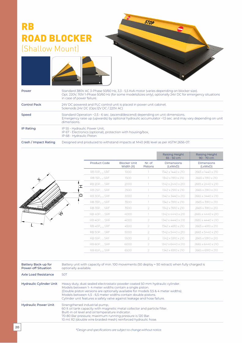
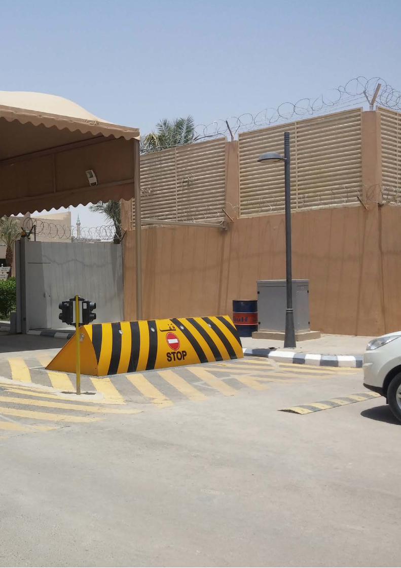
RB ROAD BLOCKER(Shallow Mount)
Power Standard 380V AC 3-Phase 50/60 Hz, 3,3 - 5,5 KvA motor (varies depending on blocker size).Opt. 220V, 110V 1-Phase 50/60 Hz (for some models/sizes only), optionally 24V DC for emergency situations in case of power failure.
Control Pack 24V DC powered and PLC control unit is placed in power unit cabinet.Solenoids 24V DC (Ops.12V DC / 220V AC)
Speed Standard Operation ~2,5 - 6 sec. (ascend/descend) depending on unit dimensions. Emergency raise up (upwards) by optional hydraulic accumulator ~1,5 sec. and may vary depending on unit dimensions.
IP Rating IP 55 - Hydraulic Power Unit,IP 67 - Electronics (optional), protection with housing/box,IP 68 - Hydraulic Piston
Crash / Impact Rating Designed and produced to withstand impacts at M40 (K8) level as per ASTM 2656-07.
Battery Back-up forPower-off Situation
Battery unit with capacity of min. 100 movements (50 deploy + 50 retract) when fully charged isoptionally available.
Axle Load Resistance 50T
Hydraulic Cylinder Unit Heavy duty, dust sealed electrostatic powder coated 50 mm hydraulic cylinder.Models between 1- 4 meter widths contain a single piston.(Double piston versions are optionally available for models 3,5 & 4 meter widths).Models between 4,5 - 6,5 meter widths contain double pistons.Cylinder unit features a safety valve against leakage and hose failure.
Hydraulic Power Unit Strengthened industrial pump,60 lt oil tank capacity with magnetic metal collector and particle filter.Built-in oil level and oil temperature indicator.70-80 Bar pressure; maximum running pressure is 120 Bar.10 mt R2 (double wire braided mesh) reinforced hydraulic hose.
Raising Height 65 - 50 cm
Raising Height 90 - 70 cm
Product Code Blocker Unit Width (X)
Nr. of Pistons
Dimensions(LxWxD)
Dimensions(LxWxD)
RB 10P_ _ SRF 1000 1 1342 x 1440 x 210 2665 x 1440 x 210
RB 15P_ _ SRF 1500 1 1342 x 1910 x 210 2665 x 1910 x 210
RB 20P_ _ SRF 2000 1 1342 x 2440 x 210 2665 x 2440 x 210
RB 25P_ _ SRF 2500 1 1342 x 2910 x 210 2665 x 2910 x 210
RB 30P_ _ SRF 3000 1 1342 x 3440 x 210 2665 x 3440 x 210
RB 35P_ _ SRF 3500 1 1342 x 3910 x 210 2665 x 3910 x 210
RB 35P_ _ SRF 3500 2 1342 x 3910 x 210 2665 x 3910 x 210
RB 40P_ _ SRF 4000 1 1342 x 4440 x 210 2665 x 4440 x 210
RB 40P_ _ SRF 4000 2 1342 x 4440 x 210 2665 x 4440 x 210
RB 45P_ _ SRF 4500 2 1342 x 4910 x 210 2665 x 4910 x 210
RB 50P_ _ SRF 5000 2 1342 x 5440 x 210 2665 x 5440 x 210
RB 55P_ _ SRF 5500 2 1342 x 5910 x 210 2665 x 5910 x 210
RB 60P_ _ SRF 6000 2 1342 x 6440 x 210 2665 x 6440 x 210
RB 65P_ _ SRF 6500 2 1342 x 6910 x 210 2665 x 6910 x 210
20

*Design and specifications are subject to change without notice.
RB ROAD BLOCKER (Shallow Mount)
System Down, Up, Emergency and external sensor inputs/outputs (e.g. Loop Detector, Beam Detector, Signalization, Remote Control, etc.). System alerts with an audio signal during lowering and raising operation.A loud siren output in case of alarm or emergency.Can be lowered or raised automatically in case of emergency (User’s preference).Can be lowered and raised manually in case of power failure or during the maintenance service with manual pump and manual valve feature. Automatic raise up mode deploys (optionally with synchronized loop detector) the road blocker after the vehicle has passed over).Sensor controlled stopping both at the top and bottom positions of the blocker unit.
Power Unit Motor, hydraulic pump and solenoid valves are contained in an easily accessible hot-dip-galvanized and electrostatic powder painted cabinet with a built-in lock lid. (Opt. Stainless Steel Cabinet)
Blocker Cabinet (underground unit)
All parts are colored with industrial paint with two components.U-shaped profile structure for maximum strength.The blocker and cabinet are designed so that no vehicle crashing effect can displace it after embedded or installed in to the ground.
Blocker Unit(impact blocking unit)
All parts are colored with industrial paint with two components.Hot dip galvanised vehicle pass through surface (top plates).The hinge system is specially designed to have a flattened surface level with the top plate so that vehicles can pass over smoothly and quietly. Top panel where the vehicle pass over is made of 8/9mm thick non-slip surface steel hot-dip galvanised before paint.The system moves up and down with 50mm diameter stainless steel hinges (example: 3 meter blocker contains 7 pieces of 50mm diameter stainless steel hinges).Blocker unit raises 45° angle from the ground level.A top lid is provided for easy access for service and maintenance on the top plate.Accordion type panel closure on front is optionally available.
Control System Manuel Control Button Unit:Provided with an IP67 CRM yellow box including 3 switches for downwards, upwards, stop (optional emergency operation), can stop the blocker motion with the command/signal coming from detector, equipped with built-in LED visual indications and 10 mt cable.
Compatibility with Access Control Systems: Compatible with any access control system (by third parties).
Optional Unit:With the optional model “RB CONT.UNIT.V.001” users can monitor the diagnostic functions, can be accessed through LAN, RS485 protocols. System is provided inside a metal cabinet that also indudes the other functional switches like downward, upward,stop, emergency operations.With the built in 124x68 LCD screen, all status of the operation and system diagnostic can be monitored through messaging functions like oil status, loop or beam detectors status, water level inside the cabinet, blocker position according to user preference, any .bmp files can be displayed.The system is driven by the PLC.
Optional Features and Accessories
Traffic lights (red-green), Traffic light Pole, Loop Detector (double/single contact), Beam Detector, 220V, 110V motor, 24V DC for emergency situations in case of power failure, Remote Control (receiver and transmitter are 3 channels), UPS, Photocell Sensor (receiver+ transmitter with 50cm height pole), RB CONT. UNIT.V.001 Control Unit, Intercom, External Buttons, Hydraulic Accumulator for emergency fast raise up (1 piston or 2 pistons systems), Surface Frame (sizes: from 250mm to 1000mm), Oil Cooler, Oil Heater, Heater for electronic components, hot-dip galvanization for cabinet, blocker and impact surface units, double effect hydraulic unit, double speed hydraulic unit, powered audio signal (siren), PLC diagnostic monitor, IP67 box (for PLC, SMPS, connectors etc inside power unit), LED indicator on front, oil level sensor, accordion type front closure.
Installation Easy Installation with C30 grade concrete and steel rebar reinforcement.Ground leveling and preparation works shall be done before concrete pouring.Allowable bearing value of the ground shall be minimum 1/2 kg/cm2.
21


Imp
act
Res
ista
nce
s A
ccor
din
g t
o P
rod
uct
Typ
es*
RO
AD
SU
RFA
CE
20 c
m
20 c
m
40
cm
150
cm
Inst
alla
tion
Dep
th /
Hei
gh
t
ASTM 2656
HR
BSe
ries
RR
BSe
ries
RB
Seri
es
HR
BSe
ries
(Sh
allo
w M
oun
t)
RB
Seri
es(S
hal
low
Mou
nt)
RB
Seri
es(S
urf
ace
Mou
nt)
Test
ed &
Cer
tifi
ed
Com
plia
nt
N/A
certified
Acc
ord
ing
to s
tan
dar
d s
pec
ifica
tion
s of
th
e p
rod
uct
s an
d fo
r 90
0 m
m ro
ad b
lock
er h
eig
hts
. Con
sult
wit
h O
ZAK
for
pro
du
cts
wit
h d
iffer
ent
dim
ensi
ons.
H30
Tru
ck29
.50
0 k
g -
30 m
ph
M4
0 (K
-8)
Tru
ck6.
800
kg
- 4
0 m
ph
M30
(K-4
)Tr
uck
6.80
0 k
g -
30 m
ph
PU
60P
ick-
up
2.30
0 k
g -
60 m
ph
PU
50P
ick-
up
2.30
0 k
g -
50 m
ph
PU
40
Pic
k-u
p2.
300
kg
- 4
0 m
ph
PU
30P
ick-
up
2.30
0 k
g -
30 m
ph
SC60
Ca
r1.1
00
kg
- 60
mp
h
SC50
Ca
r1.1
00
kg
- 50
mp
h
SC4
0C
ar
1.10
0 k
g -
40
mp
h
SC30
Ca
r1.1
00
kg
- 30
mp
h
certified
M50
(K-1
2)Tr
uck
6.80
0 k
g -
50 m
ph


Stan
dard
Fea
ture
s an
d Bu
ilt-i
n Pr
oper
ties
Gen
eral
Tec
hnic
al S
peci
�cat
ions
(em
bedd
ed s
erie
s)
Axl
e Lo
ad50
T.
50 T
.40
T.
Pane
l Thi
ckne
sses
Solid
6 m
m (a
t eve
ry 3
5-55
cm
)So
lid 6
mm
(at
eve
ry 3
5-55
cm
)So
lid 4
mm
pan
els
Flas
hing
Lig
htSt
anda
rdO
ptio
nal
Opt
iona
lRo
und
Fron
t Pan
elSt
anda
rdO
ptio
nal
Opt
iona
lTo
p Pl
ate
10/1
1 m
m8/
9 m
m8/
9 m
mO
il Le
vel S
enso
rSt
anda
rdO
ptio
nal
Opt
iona
lIm
pact
Res
ista
nce
(Cra
sh T
est)
M50
P1
(K-1
2) te
sted
& c
erti�
ed (H
RB 3
0 R
90).
Des
igne
d an
d pr
oduc
ed to
with
stan
d H
30.
Des
igne
d an
d pr
oduc
ed to
with
stan
dM
50 P
1 (K
-12)
.D
esig
ned
and
prod
uced
to w
ithst
and
M40
P1
(K-8
).
Fron
t Pan
el T
hick
ness
30+
6 (o
pt. 1
0)+3
mm
30+
6mm
4 (m
m)
Spee
d2,
5 / 6
sn4
/ 6 sn
(Opt
. 2,5
/ 4
sn)
4 / 6
sn (O
pt. 2
,5 /
4 sn
)
HRB
(Hea
vy D
uty
Road
Blo
cker
)RR
B(R
einf
orce
d Ro
ad B
lock
er)
RB(R
esid
enti
al T
ype
Road
Blo
cker
)
Out
puts
(sire
n, li
ght,
beam
, �as
hes)
.
Road
Blo
cker
s
380V
3-P
hase
AC.
IP 6
7 m
anua
l con
trol
but
ton
unit
3 fu
nctio
ns.
Emer
genc
y bu
tton
.D
own/
desc
end
butt
on (m
anua
l) in
cas
e of
pow
er o
� or
mai
nten
ance
. P
LC c
ontr
ol u
nit.
24 V
DC
cont
rol.
24 V
DC
sole
noid
s.A
utom
atic
/man
ual p
rogr
amm
able
acc
ess
auth
oris
atio
n.
Mov
emen
t buz
zer.
Spec
ial d
esig
n hi
nge
stru
ctur
e sp
read
on
the
tota
l wid
th o
f the
blo
cker
with
out g
ap.
Unl
aden
pis
ton
conn
ectio
n at
top
and
bott
om p
ositi
ons
of th
e bl
ocke
r ena
blin
g fr
ee-s
tand
ing
of th
e pi
ston
Gal
vani
sed
shee
t met
al m
ain
body
sid
e co
vers
.H
ot d
ip g
alva
nize
d ve
hicl
e pa
ss th
roug
h su
rfac
e (t
op p
late
s)
IP 5
5 - H
ydra
ulic
Pow
er U
nit,
IP 5
8 - B
lock
er C
abin
et (u
nder
grou
nd u
nit)
, IP
68 -
Hyd
raul
ic P
isto
n60
lt o
il ta
nk.

Gro
und
mou
ntin
g ap
para
tus.
Hos
e fo
r Hyd
raul
ic O
il (1
0mt)
25 c
c ha
nd p
ump
(man
ual).
Oil
leve
l and
tem
pera
ture
indi
cato
r.Pr
otec
tive
valv
e fo
r oil
hose
.O
il ta
nk w
ith p
artic
ule
�lte
r.O
il ta
nk w
ith m
agne
tic m
etal
col
lect
or.
Hot
dip
gal
vani
sed
pow
er &
con
trol
uni
t cab
in
-5°C
/ +5
5°C
(Opt
. -30
°C /
+70°
C)
Easy
inst
alla
tion.
Dou
ble
e�ec
t hyd
raul
ic m
ovem
ent.
Solid
impa
ct a
bsor
btio
n pa
nels
.M
axim
um re
info
rced
sta
tic c
onst
ruct
ion
cabi
n.Se
rvic
e ac
cess
lid
(scr
ewed
).Re
info
rced
indu
stria
l pai
nt w
ith tw
o co
mpo
nent
s in
yel
low
and
bla
ck c
olor
s.H
igh
visi
bilit
y w
ith y
ello
w a
nd b
lack
dia
gona
l str
ipes
on
impa
ct s
urfa
ce.
Re�e
ctiv
e m
arki
ng.
PLC
diag
nost
ic m
onito
r (LA
N).
Hot
dip
gal
vani
satio
n bo
th fo
r cab
inet
and
blo
cker
uni
tH
ot d
ip g
alva
nisa
tion
for i
mpa
ct s
urfa
ce
Gro
und
mou
ntin
g pl
ate.
Dou
ble
spee
d.O
ptio
nal s
peed
s for
RRB
and
RB.
Acc
umul
ator
for e
mer
genc
y fa
st ra
ise
up (a
pp.1
,5sn
spee
d).
Tra�
c lig
hts (
red-
gree
n).
Tra�
c lig
hts
(red
-gre
en),
dia:
100m
m o
r 200
mm
Loop
ded
ecto
r.Be
am d
edec
tor.
Phot
ocel
l.Re
mot
e co
ntro
l (w
irele
ss).
Rain
wat
er d
rain
age
pum
p (e
mer
genc
y su
bmer
sibl
e pu
mp)
.Ro
unde
d fr
ont p
anel
(rec
omm
ende
d fo
r res
iden
tial u
se fo
r saf
ety)
.
Surf
ace
fram
es in
opt
iona
l siz
es (2
5cm
to 1
00cm
).IP
67
cont
rol b
ox (f
or P
LC, S
MPS
, con
nect
ors,
circ
uit b
reak
ers,
loop
det
ecto
r (if
any)
, rel
ays)
.
Oil
leve
l sen
sor.
1 ph
ase
220
V A
C or
24
V D
C M
otor
.U
PS.
Oil
cool
er.
Oil
heat
er.
Com
pone
nt h
eate
r.
Aud
io S
igna
l (Si
ren,
pow
ered
).
Opt
iona
l Fea
ture
s

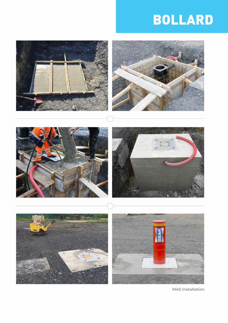
BOLLARD
M40 Installation


M50 Installation
32

33

Power Standard 380V AC 3-Phase 50/60 Hz, 2,2-5,5 kW motor (depending on the number of bollards in the set to be fed).Opt. 220V, 110V 1-Phase 50/60 Hz (for some models/sizes only), optionally 24V DC for emergency situations in case of power failure.
Control Pack 24V DC powered and PLC control unit is placed in power unit cabinet. Solenoids 24V DC (Ops.12V DC / 220V AC)
Speed Standard Operation ~2.5 - 5 sec. (ascend/descend) (depending on the number of bollards in the set to be fed).Emergency raise up (upwards) by optional hydraulic accumulator ~1,5 sec.
IP Rating IP 55 - Hydraulic Power Unit,IP 67 - Electronics (optional), protection with housing/box,IP 68 - Hydraulic Piston
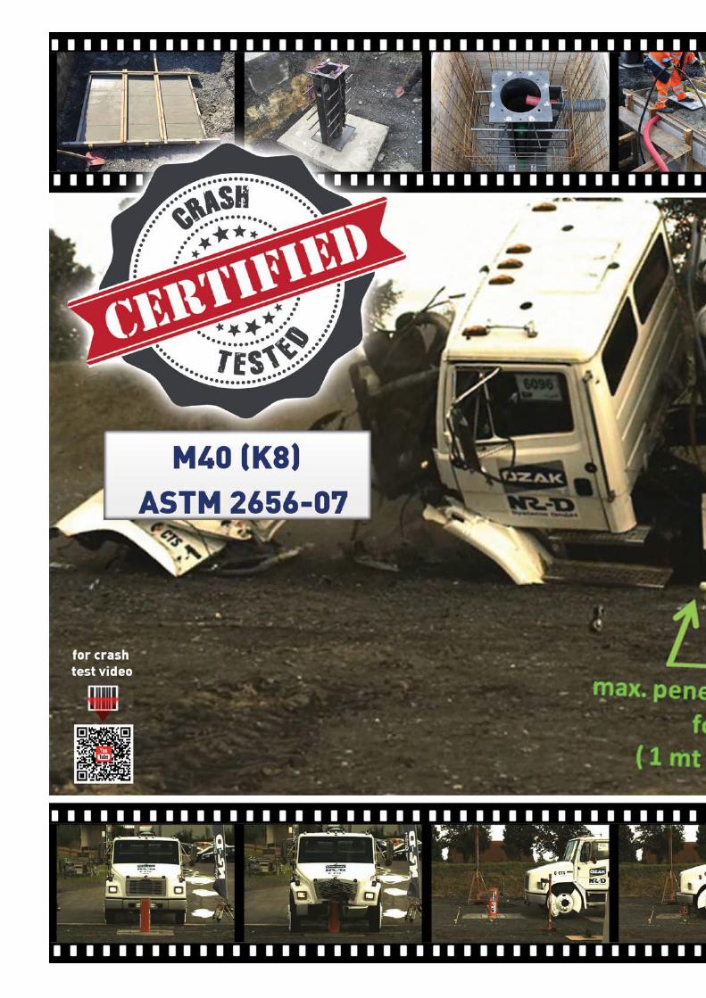
Crash / Impact Rating M50 (K-12) & M40 (K-8) crash tested and certified according to ASTM 2656-07 (HBD 275 H 90 only).
Axle Load Resistance 70T
Hydraulic Cylinder Unit Heavy duty, double acting, electrostatic powder coated, dust sealed hydraulic cylinder.
Hydraulic Power Unit Strengthened industrial pump,30-150 lt (depending on the number of bollards in the set to be fed) oil tank capacity with magnetic metal collector and particle filter.Built-in oil level and oil temperature indicators and oil level sensor with low oil level warning.20-120 Bar (depending on the number of bollards in the set to be fed) pressure (max. 160 bar);10mt R2 (double wire braided mesh) reinforced hydraulic hose. Interconnecting hoses for multiple bollard installations will be supplied.
System Down, Up, Emergency and external sensor inputs/outputs (e.g. Loop Detector, Beam Detector, Signalization, Remote Control, etc.). System alerts with an audio signal during lowering and raising operation. A loud siren output in case of alarm or emergency. Can be lowered or raised automatically in case of emergency (user’s preference, optional at no cost), programmed to stop as standard. Can be lowered and raised manually in case of power failure or during the maintenance service with manual pump and manual discharge feature. Automatic raise up mode deploys (optionally with synchronized loop detector) the bollard after the vehicle has passed over.
Power Unit Motor, hydraulic pump and solenoid valves are contained in an easily accessible hot-dip-galvanized and electrostatic powder painted cabinet with a built-in lock lid. (Opt. Stainless Steel Cabinet)Cabinet Dimensions: 1000 x 570 x 1200mm (W x L x H).
Underground Structure
Bollard Anchorage Casing:Ø338 / 420 mm steel casing hot dip galvanized and structured for maximum strength. Casing is designed so that no vehicle crashing effect can displace it after embedded or installed into the ground. Ground assembly is supported with bars. Hydraulic hose and cable entry openings enabling to use both of the directions as per hyraulic power unit position and site conditons.Designed for easy access to hydraulic hose and cable connections. Ground mounting plate with installation holes for bolt type easy ground fixing. Includes cut-out for connection of submersible pump for rainwater drainage.
Main Housing: Ø324 / 406 mm hot dip galvanised steel, structured to provide main housing for the bollard cylinder. Bollard cylinder pivoted with and moves through replaceable 5 rails (inner railing) made of special non-metal and positioned with equal distances from eachother for maximum rigidity and minimum material fraction. Contains the hydraulic cylinder lower connection. Thanks to the bollard anchorage casing, the main housing can be easily replaceable together with the bollard cylinder in case of a damage in any kind.
HBDHEAVY DUTY BOLLARD
*Design and specifications are subject to change without notice.34
HBD HEAVY DUTY BOLLARD
*Design and specifications are subject to change without notice.
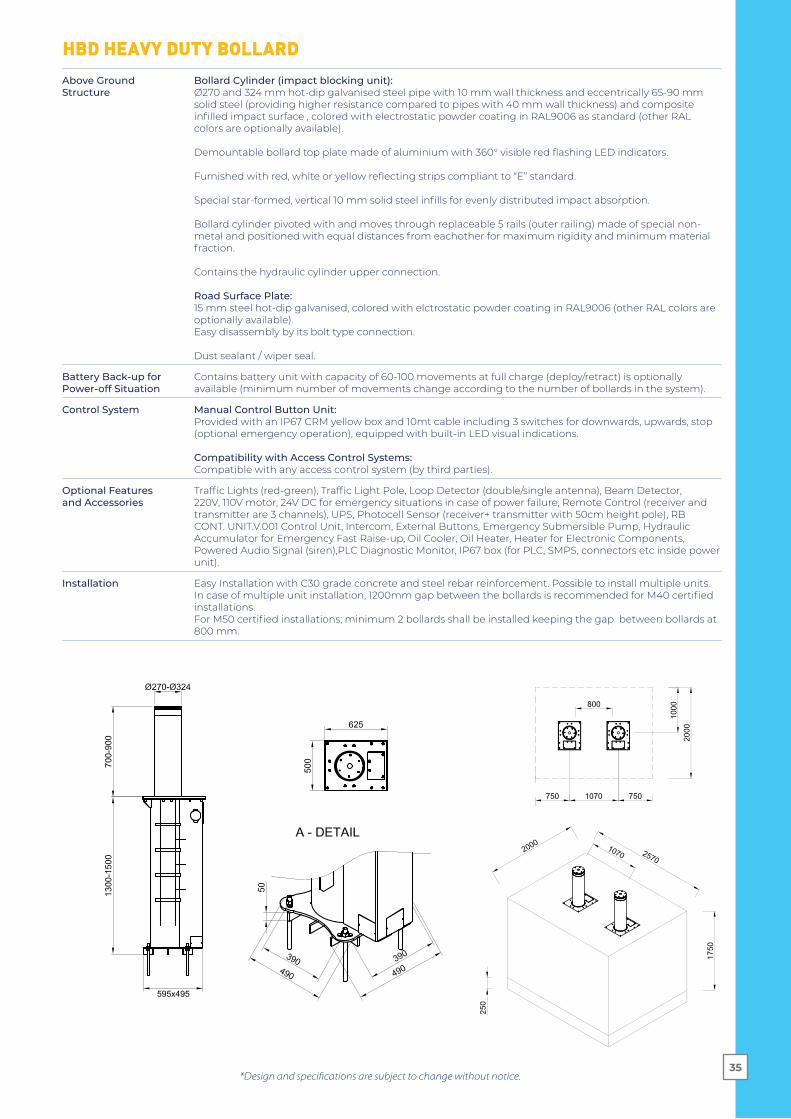
Above Ground Structure
Bollard Cylinder (impact blocking unit): Ø270 and 324 mm hot-dip galvanised steel pipe with 10 mm wall thickness and eccentrically 65-90 mm solid steel (providing higher resistance compared to pipes with 40 mm wall thickness) and composite infilled impact surface , colored with electrostatic powder coating in RAL9006 as standard (other RAL colors are optionally available). Demountable bollard top plate made of aluminium with 360° visible red flashing LED indicators. Furnished with red, white or yellow reflecting strips compliant to “E” standard. Special star-formed, vertical 10 mm solid steel infills for evenly distributed impact absorption. Bollard cylinder pivoted with and moves through replaceable 5 rails (outer railing) made of special non-metal and positioned with equal distances from eachother for maximum rigidity and minimum material fraction. Contains the hydraulic cylinder upper connection.
Road Surface Plate: 15 mm steel hot-dip galvanised, colored with elctrostatic powder coating in RAL9006 (other RAL colors are optionally available). Easy disassembly by its bolt type connection. Dust sealant / wiper seal.
Battery Back-up forPower-off Situation
Contains battery unit with capacity of 60-100 movements at full charge (deploy/retract) is optionally available (minimum number of movements change according to the number of bollards in the system).
Control System Manual Control Button Unit: Provided with an IP67 CRM yellow box and 10mt cable including 3 switches for downwards, upwards, stop (optional emergency operation), equipped with built-in LED visual indications.
Compatibility with Access Control Systems: Compatible with any access control system (by third parties).
Optional Featuresand Accessories
Traffic Lights (red-green), Traffic Light Pole, Loop Detector (double/single antenna), Beam Detector, 220V, 110V motor, 24V DC for emergency situations in case of power failure, Remote Control (receiver and transmitter are 3 channels), UPS, Photocell Sensor (receiver+ transmitter with 50cm height pole), RB CONT. UNIT.V.001 Control Unit, Intercom, External Buttons, Emergency Submersible Pump, Hydraulic Accumulator for Emergency Fast Raise-up, Oil Cooler, Oil Heater, Heater for Electronic Components, Powered Audio Signal (siren),PLC Diagnostic Monitor, IP67 box (for PLC, SMPS, connectors etc inside power unit).
Installation Easy Installation with C30 grade concrete and steel rebar reinforcement. Possible to install multiple units. In case of multiple unit installation, 1200mm gap between the bollards is recommended for M40 certified installations. For M50 certified installations; minimum 2 bollards shall be installed keeping the gap between bollards at 800 mm.
35
595x495

Power Standard 380V AC 3-Phase 50/60 Hz, 2,2-5,5 kW motor (depending on the number of bollards in the set to be fed).Opt. 220V, 110V 1-Phase 50/60 Hz (for some models/sizes only), optionally 24V DC for emergency situations in case of power failure.
Control Pack 24V DC powered and PLC control unit is placed in power unit cabinet. Solenoids 24V DC (Ops.12V DC / 220V AC)
Speed Standard Operation ~2.5 -5 sec. (ascend/descend) (depending on the number of bollards in the set to be fed). Emergency raise up (upwards) by optional hydraulic accumulator ~1,5 sec.
IP Rating IP 55 - Hydraulic Power Unit,IP 67 - Electronics (optional), protection with housing/box,IP 68 - Hydraulic Piston
Crash / Impact Rating
Designed and produced to stop a vehicle weighing 6800 kg and travelling with 30 miles/hour according to ASTM 2656-07 standard at M30 (K-4) level.
Axle Load Resistance 50T
Hydraulic Cylinder Unit Heavy duty, double acting electrostatic powder coated, dust sealed hydraulic cylinder.
Hydraulic Power Unit Strengthened industrial pump, 30-150 lt (depending on the number of bollards in the set to be fed) oil tank capacity with magnetic metal collector and particle filter. Built-in oil level and oil temperature indicators with low oil level warning. 20-120 Bar (depending on the number of bollards in the set to be fed) pressure (max. 160 bar); 10mt R2 (double wire braided mesh) reinforced hydraulic hose. Interconnecting hoses for multiple bollard installations will be supplied.
System Down, Up, Emergency and external sensor inputs/outputs (e.g. Loop Detector, Beam Detector, Signalization, Remote Control, etc.). System alerts with an audio signal during lowering and raising operation.A loud siren output in case of alarm or emergency.
Can be lowered or raised automatically in case of emergency (user’s preference, optional at no cost), programmed to stop as standard.Can be lowered and raised manually in case of power failure or during the maintenance service with manual pump and manual discharge feature.Automatic raise up mode deploys (optionally with synchronized loop detector) the bollard after the vehicle has passed over.
Power Unit Motor, hydraulic pump and solenoid valves are contained in an easily accessible hot-dip-galvanized and electrostatic powder painted cabinet with a built-in lock lid. (Opt. Stainless Steel Cabinet)Cabinet Dimensions: 1000 mm x 570 mm x 1200 mm (W x L x H).
Underground Structure Bollard Anchorage Casing:Ø338 / 420 mm steel casing hot dip galvanized and structured for maximum strength.Casing is designed so that no vehicle crashing effect can displace it after embedded installed into the ground. Ground assembly is supported with bars.Hydraulic hose and cable entry openings enabling to use both of the directions as per hyraulic power unit position and site conditons. Designed for easy access to hydraulic hose and cable connections. Ground mounting plate with installation holes for bolt type easy ground fixing. Includes cut-out for connection of submersible pump for rainwater drainage. Main Housing:Ø324 / 406 mm hot dip galvanised steel, structured to provide main housing for the bollard cylinder. Bollard cylinder pivoted with and moves through replaceable 5 rails (inner railing) made of special non-metal and positioned with equal distances from eachother for maximum rigidity and minimum material fraction. Contains the hydraulic cylinder lower connection. Thanks to the bollard anchorage casing, the main housing can be easily replaceable together with the bollard cylinder in case of a damage in any kind.
RBDREINFORCED BOLLARD
*Design and specifications are subject to change without notice.36
RBD REINFORCED BOLLARD
*Design and specifications are subject to change without notice.
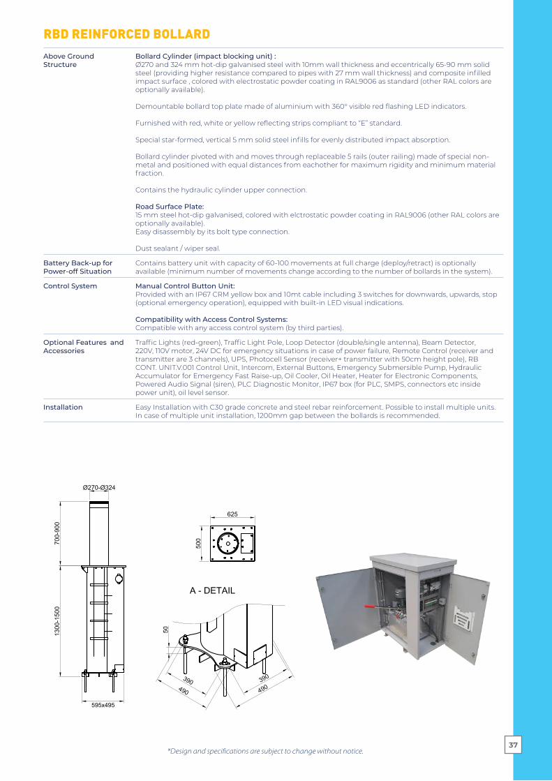
Above Ground Structure
Bollard Cylinder (impact blocking unit) :Ø270 and 324 mm hot-dip galvanised steel with 10mm wall thickness and eccentrically 65-90 mm solid steel (providing higher resistance compared to pipes with 27 mm wall thickness) and composite infilled impact surface , colored with electrostatic powder coating in RAL9006 as standard (other RAL colors are optionally available).
Demountable bollard top plate made of aluminium with 360° visible red flashing LED indicators. Furnished with red, white or yellow reflecting strips compliant to “E” standard. Special star-formed, vertical 5 mm solid steel infills for evenly distributed impact absorption. Bollard cylinder pivoted with and moves through replaceable 5 rails (outer railing) made of special non-metal and positioned with equal distances from eachother for maximum rigidity and minimum material fraction. Contains the hydraulic cylinder upper connection.
Road Surface Plate: 15 mm steel hot-dip galvanised, colored with elctrostatic powder coating in RAL9006 (other RAL colors are optionally available). Easy disassembly by its bolt type connection. Dust sealant / wiper seal.
Battery Back-up forPower-off Situation
Contains battery unit with capacity of 60-100 movements at full charge (deploy/retract) is optionally available (minimum number of movements change according to the number of bollards in the system).
Control System Manual Control Button Unit:Provided with an IP67 CRM yellow box and 10mt cable including 3 switches for downwards, upwards, stop (optional emergency operation), equipped with built-in LED visual indications.
Compatibility with Access Control Systems:Compatible with any access control system (by third parties).
Optional Features and Accessories
Traffic Lights (red-green), Traffic Light Pole, Loop Detector (double/single antenna), Beam Detector, 220V, 110V motor, 24V DC for emergency situations in case of power failure, Remote Control (receiver and transmitter are 3 channels), UPS, Photocell Sensor (receiver+ transmitter with 50cm height pole), RB CONT. UNIT.V.001 Control Unit, Intercom, External Buttons, Emergency Submersible Pump, Hydraulic Accumulator for Emergency Fast Raise-up, Oil Cooler, Oil Heater, Heater for Electronic Components, Powered Audio Signal (siren), PLC Diagnostic Monitor, IP67 box (for PLC, SMPS, connectors etc inside power unit), oil level sensor.
Installation Easy Installation with C30 grade concrete and steel rebar reinforcement. Possible to install multiple units. In case of multiple unit installation, 1200mm gap between the bollards is recommended.
37
595x495


Power Standard 380V AC 3-Phase 50/60 Hz, 2,2-5,5 kW motor (depending on the number of bollards in the set to be fed).Opt. 220V, 110V 1-Phase 50/60 Hz (for some models/sizes only), optionally 24V DC for emergency situations in case of power failure.
Control Pack 24V DC powered and PLC control unit placed in power unit cabinet. Solenoids 24V DC (Ops.12V DC / 220V AC)
Speed Standard Operation ~1,8 - 4 sec. (ascend/descend) (depending on the number of bollards in the set to be fed).Emergency raise up (upwards) by optional hydraulic accumulator ~1,5 sec.
IP Rating IP 55 - Hydraulic Power Unit,IP 67 - Electronics (optional), protection with housing/box,IP 68 - Hydraulic Piston
Crash / Impact Rating -
Axle Load Resistance 50T
Hydraulic Cylinder Unit Heavy duty, double acting electrostatic powder coated, dust sealed hydraulic cylinder.
Hydraulic Power Unit Strengthened industrial pump, 30-150 lt (depending on the number of bollards in the set to be fed) oil tank capacity with magnetic metal collector and particle filter. Built-in oil level and oil temperature indicators with low oil level warning. 20-120 Bar (depending on the number of bollards in the set to be fed) pressure (max. 160 bar); 10mt R2 (double wire braided mesh) reinforced hydraulic hose. Interconnecting hoses for multiple bollard installations will be supplied.
System Down, Up, Emergency and external sensor inputs/outputs (e.g. Loop Detector, Beam Detector, Signalization, Remote Control, etc.). System alerts with an audio signal during lowering and raising operation.A loud siren output in case of alarm or emergencyCan be lowered or raised automatically in case of emergency (user’s preference, optional at no cost), programmed to stop as standard. Can be lowered and raised manually in case of power failure or during the maintenance service with manual pump and manual discharge feature.Automatic raise up mode deploys (optionally with synchronized loop detector) the bollard after the vehicle has passed over.
Power Unit Motor, hydraulic pump and solenoid valves are contained in an easily accessible hot-dip-galvanized and electrostatic powder painted cabinet with a built-in lock lid. (Opt. Stainless Steel Cabinet) Cabinet Dimensions: 1000 mm x 570 mm x 1200 mm (W x L x H).
Underground Structure Bollard Anchorage Casing:Ø284 / 338 mm steel casing hot dip galvanized and structured for maximum strength.Casing is designed so that no vehicle crashing effect can displace it after embedded or installed into the ground.Hydraulic hose and cable entry openings enabling to use either of the three directions as per hyraulic power unit position and site conditons. Designed for easy access to hydraulic hose and cable connections. Ground mounting plate with installation holes for bolt type easy ground fixing. Includes cut-out for connection of submersible pump for rainwater drainage. Main Housing: Ø273 / 324 mm hot dip galvanised steel, structured to provide main housing for the bollard cylinder. Bollard cylinder pivoted with and moves through replaceable 5 rails (inner railing) made of special non-metal and positioned with equal distances from eachother for maximum rigidity and minimum material fraction. Contains the hydraulic cylinder lower connection. Thanks to the bollard anchorage casing, the main housing can be easily replaceable together with the bollard cylinder in case of a damage in any kind.
*Design and specifications are subject to change without notice.
TBDTRAFFIC BOLLARD
40

TBD TRAFFIC BOLLARD
*Design and specifications are subject to change without notice.
450 x 550 / 740 x 740
500
- 120
090
5 - 1
605
430 / 490
610 / 690
630 / 690
1405
/ 28
05
220 / 270
Above Ground Structure
Bollard Cylinder (impact blocking unit) :Ø220 / 270 mm stainless steel sleeve on hot-dip galvanised steel with 5 mm wall thickness.
Demountable bollard top plate made of aluminium with 360° visible red flashing LED indicators. Furnished with red, white or yellow reflecting strips compliant to “E” standard. Bollard cylinder pivoted with and moves through replaceable 5 rails (outer railing) made of special non-metal and positioned with equal distances from eachother for maximum rigidity and minimum material fraction. Contains the hydraulic cylinder upper connection. Road Surface Plate: 15 mm steel hot-dip galvanised, colored with elctrostatic powder coating in (other RAL colors are optionally available).Easy disassembly by its bolt type connection. Dust sealant / wiper seal.
Battery Back-up forPower-off Situation
Contains battery unit with capacity of 60-100 movements at full charge (deploy/retract) is optionally available (minimum number of movements change according to the number of bollards in the system).
Control System Manual Control Button Unit: Provided with an IP67 CRM yellow box and 10mt cable including 3 switches for downwards, upwards, stop (optional emergency operation), equipped with built-in LED visual indications.
Compatibility with Access Control Systems:Compatible with any access control system (by third parties).
Optional Featuresand Accessories
Traffic Lights (red-green), Traffic Light Pole, Loop Detector (double/single antenna), Beam Detector, 220V, 110V motor, 24V DC for emergency situations in case of power failure, Remote Control (receiver and transmitter are 3 channels), UPS, Photocell Sensor (receiver+ transmitter with 50cm height pole), RB CONT. UNIT.V.001 Control Unit, Intercom, External Buttons, Emergency Submersible Pump, Hydraulic Accumulator for Emergency Fast Raise-up, Oil Cooler, Oil Heater, Heater for Electronic Components, Powered Audio Signal (siren), PLC Diagnostic Monitor, IP67 box (for PLC, SMPS, connectors etc inside power unit), oil level sensor.
Installation Easy Installation with C30 grade concrete and steel rebar reinforcement. Possible to install multiple units. In case of multiple unit installation, 1200mm gap between the bollards is recommended.
41
HBD FIXED BOLLARD
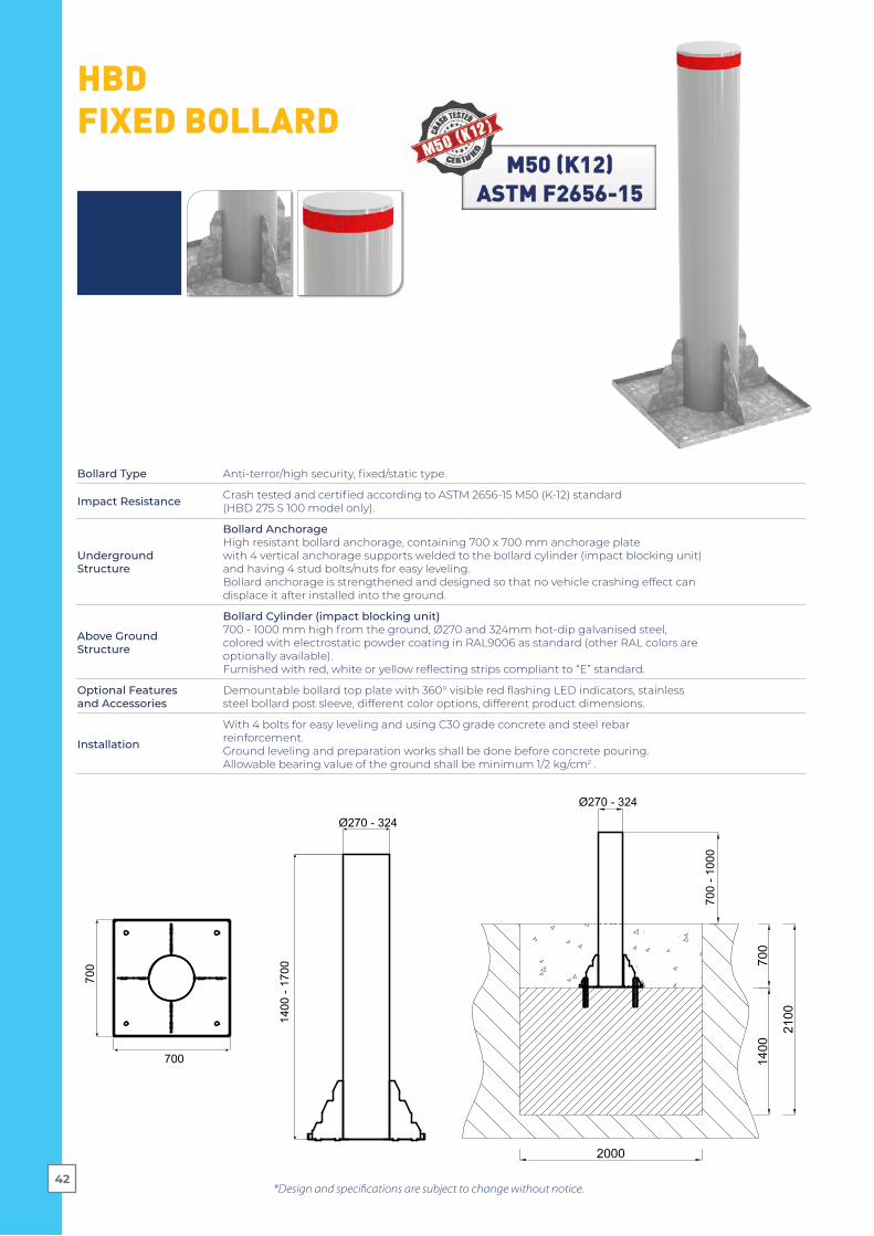
Bollard Type Anti-terror/high security, fixed/static type.
Impact Resistance Crash tested and certified according to ASTM 2656-15 M50 (K-12) standard(HBD 275 S 100 model only).
UndergroundStructure
Bollard AnchorageHigh resistant bollard anchorage, containing 700 x 700 mm anchorage platewith 4 vertical anchorage supports welded to the bollard cylinder (impact blocking unit)and having 4 stud bolts/nuts for easy leveling.Bollard anchorage is strengthened and designed so that no vehicle crashing effect candisplace it after installed into the ground.
Above GroundStructure
Bollard Cylinder (impact blocking unit)700 - 1000 mm high from the ground, Ø270 and 324mm hot-dip galvanised steel,colored with electrostatic powder coating in RAL9006 as standard (other RAL colors areoptionally available).Furnished with red, white or yellow reflecting strips compliant to “E” standard.
Optional Featuresand Accessories
Demountable bollard top plate with 360° visible red flashing LED indicators, stainlesssteel bollard post sleeve, different color options, different product dimensions.
Installation
With 4 bolts for easy leveling and using C30 grade concrete and steel rebarreinforcement.Ground leveling and preparation works shall be done before concrete pouring.Allowable bearing value of the ground shall be minimum 1/2 kg/cm2 .
Ø270 - 324
1400
- 17
00
700
700
Ø270 - 324
700
- 100
0
*Design and specifications are subject to change without notice.42

HBD FIXED BOLLARD(Shallow Mount)
250
- 300
40 -
90(x
)
3000 - 5500
750 - 2000750 - 2000
250
- 300
3000 - 5500
750 - 2000
750 - 2000
*Design and specifications are subject to change without notice.
certified
43
Bollard Type Anti-terror/high security, shallow mount type (bollard underground anchorage height of 210mm only).
Impact Resistance
Crash tested and certified according to;IWA 14-1:2013 Fixed Bollard V/7200[N3C]/64PAS68:2013 Fixed Bollard V/7500[N3]/64ASTM 2656-18 C740/7200 standards (HBD 275 S 95/8 SRF model).
UndergroundStructure
Bollard AnchorageHigh resistant bollard anchorage with 2 anchorage plates having gaps for easy andoverall penetration of the concrete, strengthened with 200mm thick “HEB” beams onimpact direction and having 4 stud bolts/nut for easy levelling. Providing shallowmounting with bollard underground anchorage height of 210mm only.Underground element connections are extra strengthened by fastening wedge type,10.9 grade bolted and welded together at the same time.Bollard post is hot-dip galvanised, strengthened and designed so that no vehiclecrashing effect can be displace it after installed into the ground.
Above GroundStructure
Bollard Cylinder (impact blocking unit)950mm high from the ground, Ø270 mm hot-dip galvanized steel in RAL9006 color asstandard (other RAL colors optionally available).Furnished with red, white or yellow reflecting strips compliant to “E” standard.
Optional Features and Accessories
Demountable bollard top plate with 360° visible red flashing LED indicators, stainlesssteel bollard post sleeve, different color options, different product dimensions.
Installation
With 4 bolts for easy leveling and gaps for easy and overall penetration of the concreteeasy installation using C30 grade concrete and steel rebar reinforcement.Ground leveling and preparation works shall be done before concrete pouring.Allowable bearing value of the ground shall be minimum 1/2 kg/cm2 .

FIXED BOLLARD
Wall Thickness
Impact Resistance Crash Test
Outer Body Surface
Designed and produced to withstand M40 (K8)
Can optionally be designed and produced to
withstand M30 (K4)
Visibility
Installation
Electrostatic powder coated hot dip galvanised steel.(opt. stainless steel)
Reflecting strips compliant to “E” standard, red/white/yellow colours.
Easy installation with adjustable balance pedestals and C30 grade concrete and steel rebar reinforcement.
Stainless steel sleeve on hot dip galvanised body.
10mm +65/90mm special star formed solid beams of 5mm
thickness.5 mm
RBD 270 S.../ RBD 324 S... TBD 220 S.../ TBD 270 S...
*Shape and sizes are for reference only. Fixed bollards can be identical with your retractable bollard or are available in any other specific shape and dimension.
*Design and specifications are subject to change without notice.
Operation Fixed, non-retractable
Diameter 220mm - 324mm (other diameters available optionally)
Height (Above Ground) 500-1200mm (other heights available optionally)
Installation Ground embedding, easy fixed.
Options and Accessories Different material and colour options, 360° visible LED indicator.
44
*Design and specifications are subject to change without notice.45
REMOVABLE BOLLARD
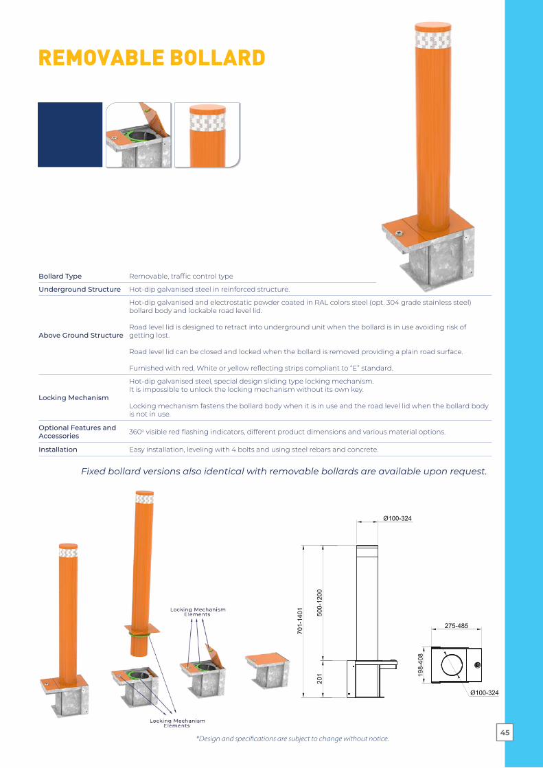
Bollard Type Removable, traffic control type
Underground Structure Hot-dip galvanised steel in reinforced structure.
Above Ground Structure
Hot-dip galvanised and electrostatic powder coated in RAL colors steel (opt. 304 grade stainless steel) bollard body and lockable road level lid.
Road level lid is designed to retract into underground unit when the bollard is in use avoiding risk of getting lost.
Road level lid can be closed and locked when the bollard is removed providing a plain road surface.
Furnished with red, White or yellow reflecting strips compliant to “E” standard.
Locking Mechanism
Hot-dip galvanised steel, special design sliding type locking mechanism. It is impossible to unlock the locking mechanism without its own key.
Locking mechanism fastens the bollard body when it is in use and the road level lid when the bollard body is not in use.
Optional Features and Accessories 360o visible red flashing indicators, different product dimensions and various material options.
Installation Easy installation, leveling with 4 bolts and using steel rebars and concrete.
Fixed bollard versions also identical with removable bollards are available upon request.

Imp
act
Res
ista
nce
s A
ccor
din
g t
o P
rod
uct
Typ
es*
RO
AD
SU
RFA
CE
210 cm
ASTM 2656
PAS 68
IWA 14
HB
D H
YDR
AU
LIC
Seri
esR
BD
HYD
RA
ULI
CSe
ries
TBD
HYD
RA
ULI
CSe
ries
HB
D F
IXE
DSe
ries
RB
D F
IXE
DSe
ries
TBD
FIX
ED
Seri
es
HB
D F
IXE
DSe
ries
(Sh
allo
w M
oun
t)
HB
D F
IXE
DSe
ries
(Sh
allo
w M
oun
t)
Test
ed &
Cer
tifi
ed
Com
plia
nt
N/A
certified
* Acc
ord
ing
to s
tan
dar
d s
pec
ifica
tion
s of
th
e p
rod
uct
s an
d 2
70m
m d
iam
eter
. Con
sult
wit
h O
ZAK
for
pro
du
cts
wit
h 10
0 -
324
mm
dia
met
ers
and
50
0 -
120
0 m
m h
eig
hts
fro
m g
rou
nd
.
M50
(K-1
2)Tr
uck
6.80
0 k
g -
50 m
ph
Bol
lard
Hei
gh
t90
0 m
m90
0 m
m80
0 m
m10
00
mm
950
mm
M4
0 (K
-8)
Tru
ck6.
800
kg
- 4
0 m
ph
M30
(K-4
)Tr
uck
6.80
0 k
g -
30 m
ph
PU
60P
ick-
up
2.30
0 k
g -
60 m
ph
PU
50P
ick-
up
2.30
0 k
g -
50 m
ph
PU
40
Pic
k-u
p2.
300
kg
- 4
0 m
ph
PU
30P
ick-
up
2.30
0 k
g -
30 m
ph
SC60
Ca
r1.1
00
kg
- 60
mp
h
SC50
Ca
r1.1
00
kg
- 50
mp
h
SC4
0C
ar
1.10
0 k
g -
40
mp
h
SC30
Ca
r1.1
00
kg
- 30
mp
h
PA
S 68
Tru
ck7.
500
kg
- 4
0 m
ph
IWA
14Tr
uck
7.20
0 k
g -
40
mp
h
certified
certified
certified
950
mm
certified
certified
certified
900
mm
900
mm
C74
0Tr
uck
7.20
0 k
g -
40
mp
h
140 cm
190 cm
30 c
m50
cm
69 cm
İnst
alla
tion
Dep
th

HBD
(Hea
vy D
uty
Bolla
rd)
RBD
(Rei
nfor
ced
Bolla
rd)
TBD
(Tra
ffic B
olla
rd)
Axle
Loa
d
Wal
l Thi
ckne
ss
Impa
ct R
esist
ance
Cras
h Te
st
Spee
d
70 T
.50
T.
50 T
.10
mm
+ 6
5/90
mm
spe
cial
sta
r for
med
so
lid b
eam
s of
10
mm
thic
knes
s(p
rovi
ding
hig
her r
esist
ance
com
pare
d to
pip
es w
ith 4
0 m
m w
all t
hick
ness
)
10 m
m +
65/
90 m
m s
peci
al s
tar f
orm
ed
solid
bea
ms
of 5
mm
thic
knes
s(p
rovi
ding
hig
her r
esist
ance
com
pare
d to
pip
es w
ith 2
7 m
m w
all t
hick
ness
)
5 m
m
Oil
Leve
l Sen
sor (
PLC)
Stan
dard
Op�
onal
Op�
onal
M50
(K 1
2) &
M40
(K 8
) te
sted
&ce
r�fie
d (H
BD 2
75 H
90)
. De
sign
ed a
nd p
rodu
ced
to w
ithst
and
M30
(K4)
Grou
nd A
ssem
bly
Supp
or�n
g Ba
rsSt
anda
rdSt
anda
rdV
form-
Fini
shEl
ectro
sta�
c po
wde
r coa
ted.
Elec
trost
a�c
pow
der c
oate
d.St
ainl
ess
stee
l sle
eve.
2.5
- 5 s
ec. (
sing
le u
nit i
nsta
lla�o
n)2.
5 - 5
sec
. (si
ngle
uni
t ins
talla
�on)
1,8
- 4 s
ec. (
sing
le u
nit i
nsta
lla�o
n)
Bolla
rds
Gene
ral T
echn
ical
Spe
cific
a�on
s (hy
drau
lic se
ries)
Stan
dard
Fea
ture
s and
Bui
lt-in
Pro
per�
es
Op�
onal
Fea
ture
s
UPS.
Rain
wat
er d
rain
age
pum
p (e
mer
genc
y su
bmer
sibl
e pu
mp)
.
Loop
ded
ecto
r.
PLC
diag
nos�
c m
onito
r (LA
N).
Traffi
c lig
ht p
ole.
Beam
ded
ecto
r.Ph
otoc
ell.
Accu
mul
ator
for e
mer
genc
y fa
st ra
ise
up (a
pp.1
,5sn
spe
ed).
Traffi
c lig
hts
(red-
gree
n), d
ia:1
00m
m o
r 200
mm
Rem
ote
cont
rol (
wire
less
).
Audi
o Si
gnal
(Sire
n, p
ower
ed).
IP 6
7 co
ntro
l box
(for
PLC
, SM
PS, c
onne
ctor
s, c
ircui
t bre
aker
s, lo
op d
etec
tor (
if an
y), r
elay
s) .
Oil
leve
l sen
sor.
1 ph
ase
220
V AC
or 2
4 V
DC M
otor
.
Oil
cool
er.
Oil
heat
er.
Com
pone
nt h
eate
r.
Diffe
rent
mat
eria
ls a
nd c
olor
s.
Out
puts
(sire
n, li
ght,
beam
, flas
hes)
.
380V
3-P
hase
AC.
IP 6
7 m
anua
l con
trol b
u�on
uni
t 3 fu
nc�o
ns.
Emer
genc
y bu
�on.
Doub
le a
c�ng
hyd
raul
ic m
ovem
ent.
Dow
n/de
scen
d va
lve
(man
ual)
in c
ase
of p
ower
off
or m
aint
enan
ce
PLC
con
trol u
nit.
24 V
DC
cont
rol.
24 V
DC
sole
noid
s.Au
tom
a�c/
man
ual p
rogr
amm
able
acc
ess
auth
oris
a�on
.
25 c
c ha
nd p
ump
(man
ual).
Mov
emen
t buz
zer.
Hot d
ip g
alva
nise
d st
eel m
ain
body
.Ea
sy a
cces
ibili
ty fo
r ser
vici
ng.
Alum
iniu
m to
p pl
ate
with
25m
m th
ickn
ess.
Hose
s fo
r Hyd
raul
ic O
il (fo
r int
erco
nnec
�on
in c
ase
of m
ul�p
le in
stal
la�o
ns).
360
°C w
ith h
igh
visi
bilit
y fla
shin
g LE
D's
in re
d.Re
flec�
ng s
trips
com
plia
nt to
"E" s
tand
ard,
red/
whi
te/y
ello
w c
olor
s.Ho
se fo
r Hyd
raul
ic O
il (1
0mt)
Oil
leve
l and
tem
pera
ture
indi
cato
r.
Oil
tank
with
par
�cul
e fil
ter.
Oil
tank
with
mag
ne�c
met
al c
olle
ctor
.Ho
t dip
gal
vani
sed
pow
er &
con
trol u
nit c
abin
. -5
°C /
+55°
C (O
pt. -
30°C
/ +7
0°C)
45 /
60 lt
oil
tank
cap
acity
(dep
endi
ng o
n th
e nu
mbe
r of b
olla
rds
in c
ase
of m
ul�p
le in
stal
la�o
ns).
Easy
inst
alla
�on.
IP 5
5 - H
ydra
ulic
Pow
er U
nit,
IP 5
8 - U
nder
grou
nd S
truc
ture
, IP
68 -
Hydr
aulic
Pist
on
certified

HBD
(Hea
vy D
uty
Bolla
rd)
RBD
(Rei
nfor
ced
Bolla
rd)
TBD
(Tra
ffic B
olla
rd)
Axle
Loa
d
Wal
l Thi
ckne
ss
Impa
ct R
esist
ance
Cras
h Te
st
Spee
d
70 T
.50
T.
50 T
.10
mm
+ 6
5/90
mm
spe
cial
sta
r for
med
so
lid b
eam
s of
10
mm
thic
knes
s(p
rovi
ding
hig
her r
esist
ance
com
pare
d to
pip
es w
ith 4
0 m
m w
all t
hick
ness
)
10 m
m +
65/
90 m
m s
peci
al s
tar f
orm
ed
solid
bea
ms
of 5
mm
thic
knes
s(p
rovi
ding
hig
her r
esist
ance
com
pare
d to
pip
es w
ith 2
7 m
m w
all t
hick
ness
)
5 m
m
Oil
Leve
l Sen
sor (
PLC)
Stan
dard
Op�
onal
Op�
onal
M50
(K 1
2) &
M40
(K 8
) te
sted
&ce
r�fie
d (H
BD 2
75 H
90)
. De
sign
ed a
nd p
rodu
ced
to w
ithst
and
M30
(K4)
Grou
nd A
ssem
bly
Supp
or�n
g Ba
rsSt
anda
rdSt
anda
rdV
form-
Fini
shEl
ectro
sta�
c po
wde
r coa
ted.
Elec
trost
a�c
pow
der c
oate
d.St
ainl
ess
stee
l sle
eve.
2.5
- 5 s
ec. (
sing
le u
nit i
nsta
lla�o
n)2.
5 - 5
sec
. (si
ngle
uni
t ins
talla
�on)
1,8
- 4 s
ec. (
sing
le u
nit i
nsta
lla�o
n)
Bolla
rds
Gene
ral T
echn
ical
Spe
cific
a�on
s (hy
drau
lic se
ries)
Stan
dard
Fea
ture
s and
Bui
lt-in
Pro
per�
es
Op�
onal
Fea
ture
s
UPS.
Rain
wat
er d
rain
age
pum
p (e
mer
genc
y su
bmer
sibl
e pu
mp)
.
Loop
ded
ecto
r.
PLC
diag
nos�
c m
onito
r (LA
N).
Traffi
c lig
ht p
ole.
Beam
ded
ecto
r.Ph
otoc
ell.
Accu
mul
ator
for e
mer
genc
y fa
st ra
ise
up (a
pp.1
,5sn
spe
ed).
Traffi
c lig
hts
(red-
gree
n), d
ia:1
00m
m o
r 200
mm
Rem
ote
cont
rol (
wire
less
).
Audi
o Si
gnal
(Sire
n, p
ower
ed).
IP 6
7 co
ntro
l box
(for
PLC
, SM
PS, c
onne
ctor
s, c
ircui
t bre
aker
s, lo
op d
etec
tor (
if an
y), r
elay
s) .
Oil
leve
l sen
sor.
1 ph
ase
220
V AC
or 2
4 V
DC M
otor
.
Oil
cool
er.
Oil
heat
er.
Com
pone
nt h
eate
r.
Diffe
rent
mat
eria
ls a
nd c
olor
s.
Out
puts
(sire
n, li
ght,
beam
, flas
hes)
.
380V
3-P
hase
AC.
IP 6
7 m
anua
l con
trol b
u�on
uni
t 3 fu
nc�o
ns.
Emer
genc
y bu
�on.
Doub
le a
c�ng
hyd
raul
ic m
ovem
ent.
Dow
n/de
scen
d va
lve
(man
ual)
in c
ase
of p
ower
off
or m
aint
enan
ce
PLC
con
trol u
nit.
24 V
DC
cont
rol.
24 V
DC
sole
noid
s.Au
tom
a�c/
man
ual p
rogr
amm
able
acc
ess
auth
oris
a�on
.
25 c
c ha
nd p
ump
(man
ual).
Mov
emen
t buz
zer.
Hot d
ip g
alva
nise
d st
eel m
ain
body
.Ea
sy a
cces
ibili
ty fo
r ser
vici
ng.
Alum
iniu
m to
p pl
ate
with
25m
m th
ickn
ess.
Hose
s fo
r Hyd
raul
ic O
il (fo
r int
erco
nnec
�on
in c
ase
of m
ul�p
le in
stal
la�o
ns).
360
°C w
ith h
igh
visi
bilit
y fla
shin
g LE
D's
in re
d.Re
flec�
ng s
trips
com
plia
nt to
"E" s
tand
ard,
red/
whi
te/y
ello
w c
olor
s.Ho
se fo
r Hyd
raul
ic O
il (1
0mt)
Oil
leve
l and
tem
pera
ture
indi
cato
r.
Oil
tank
with
par
�cul
e fil
ter.
Oil
tank
with
mag
ne�c
met
al c
olle
ctor
.Ho
t dip
gal
vani
sed
pow
er &
con
trol u
nit c
abin
. -5
°C /
+55°
C (O
pt. -
30°C
/ +7
0°C)
45 /
60 lt
oil
tank
cap
acity
(dep
endi
ng o
n th
e nu
mbe
r of b
olla
rds
in c
ase
of m
ul�p
le in
stal
la�o
ns).
Easy
inst
alla
�on.
IP 5
5 - H
ydra
ulic
Pow
er U
nit,
IP 5
8 - U
nder
grou
nd S
truc
ture
, IP
68 -
Hydr
aulic
Pist
on


CAR PARK
for PUBLIC &
RESIDENTIAL AREA
CAR PARKS...
360425
290
100
50
1010
900
Easy to install and use,
Durable body structure,
Wide options and accessories alternatives,
Compatible with any kind of access control system.
Up to 6000 mm.
BR1S / BR3S / BR6S ARM BARRIER
*Design and specifications are subject to change without notice.52

Folding Arm
Main Options and Accessories
Arm Resting Post
Safety Sensor (photocell)
FlashingIndicator
Rubber Cushion&
Impact SensorUnder Arm Curtain Barrier
Installation View
(1) : 500x500x250 mm concrete
(2) : 300x300x150 mm concrete
LED Indicator and Diffuser
Loop Dedector View
i
(1)
(2)
*Design and specifications are subject to change without notice.
General Features
Body Dimensions 360 x 290 x 1010(height) mm
Body Material – Finish Galvanised steel – electrostatic powder coated
Body Colour Orange (RAL 1033)
Access to Body Interiors Through locked lids on the top and side
Arm (Barrier) Length up to 6.0 m
Arm (Barrier) Material Aluminium
Arm Colour Anodized (opt. electrostatic powder coated in RAL colours)
Body Substructure / Stand Concrete, 500 x 500 x 250 (height) mm
Power 220 V. 60/50 Hz. AC (%±10)
Power ConsumptionStand-by: 8W, During operation: 220-270 W (depending on the arm length.)
Locking / Interlock Mechanical reduction
Operation Electromechanical
Operation Speed 1 - 6 sec.
Manual Control By manual lever
Operation Temperature , Humidity
-20°C/+68°C (Opt. -50°C with heater positive), RH 95% non-condensing.
IP Grade IP 54, suitable for outdoor usage
Net Weight ~45 kg (without arm)
Options and Accessories
Safety sensor (photocell), loop dedector, top flashing indicator, LED indicator and diffuser on the arm (flashing in 4 different types), traffic light, arm resting post, support leg, folding arm, underarm curtain barrier, rubber cushion for arm, under arm impact sensor, battery and charging unit, wireless remote control (receiver&transmitter), manual remote control
53


GEÇİŞ TEKNOLOJİLERİ SAN. TİC. A.Ş.
Köseköy, Çuhane Cd. N:130 41080 Kartepe Kocaeli / TURKEY
+90 262 373 48 48
ozak-t .comozak@ozak-t .com
@ozakmedia
www.kosgeb.gov.tr
23.08.2019DD-1302-0067 R(6)
Copyright © 2022 FDOKUMEN