T TIC 1068-12 - Elsewedy Electric
77
Version: 1 TYPE TEST CERTIFIC OBJECT Pow term Rated voltage, U0/U (Um) Conductor cross-sectio MANUFACTURERS Cab Acc Acc Acc Acc Ace CLIENT Else 10 th TESTED BY KEM Utre DATE(S) OF TESTS 19 J The object, constructed in accord this Certificate, has been subject IEC 62067:201 This Type Test Certificate has be The results are shown in the re The values obtained and the ge Standard and to justify the rati This Certificate applies only to th the same designations with that t This Certificate consists of 77 pa Copyright: Only integral reproduction copies in e.g. PDF-format or scanned v only”.The sealed and bound version o T ATE OF COMPLETE TYPE TESTS wer cable system consisting of single-core power minations, one joint with screen separation and tw ) 127/220 (245) kV Conductor material Cu n 1x2500 mm² Insulation material XLP ble Elsewedy Cables, 10 th of Ramadan City, Egypt essory 1 essory 2 essory 3 essory 4 eessory 5 nkt cables GmbH, Cologne, Germany nkt cables GmbH, Cologne, Germany Prysmian cables & systems, Milan, Italy nkt cables GmbH, Cologne, Germany nkt cables GmbH, Cologne, Germany ewedy Cables of Ramadan City, Egypt MA Nederland B.V., echtseweg 310, 6812 AR Arnhem, The Netherlan July 2012 to 26 November 2012 dance with the description, drawings and photogr ted to the series of proving tests in accordance wi 11 een issued by KEMA following exclusively the ST ecord of Proving Tests and the oscillograms a eneral performance are considered to comply ngs assigned by the manufacturer as listed o e object tested. The responsibility for conformity o tested rests with the Manufacturer. ges in total. of this Certificate is permitted without written permission version of this Certificate may be available and have the s of the Certificate is the only valid version. KEMA Nederland S.A.M. Verhoeve Director Testing, Certification The Arnhem, 18 Febru TIC 1068-12 S cable, two outdoor wo GIS terminations PE ds aphs incorporated in ith L Guides. attached hereto. y with the above n page 4. of any object having n from KEMA. Electronic status “for information d B.V. n Inspections & Netherlands uary 2013
-
Upload
khangminh22 -
Category
Documents
-
view
0 -
download
0
Transcript of T TIC 1068-12 - Elsewedy Electric
Ver
sion
: 1
TYPE TEST CERTIFIC
OBJECT Pow
term
Rated voltage, U0/U (Um)
Conductor cross-sectio MANUFACTURERS Cab
Acc Acc Acc Acc Ace
CLIENT Else10th
TESTED BY KEMUtre
DATE(S) OF TESTS 19 J
The object, constructed in accordthis Certificate, has been subject IEC 62067:201 This Type Test Certificate has be The results are shown in the reThe values obtained and the geStandard and to justify the rati
This Certificate applies only to ththe same designations with that t This Certificate consists of 77 pa Copyright: Only integral reproduction copies in e.g. PDF-format or scanned vonly”.The sealed and bound version o
T
ATE OF COMPLETE TYPE TESTS
wer cable system consisting of single-core power minations, one joint with screen separation and tw
) 127/220 (245) kV Conductor material Cu
n 1x2500 mm² Insulation material XLP
ble Elsewedy Cables, 10th of Ramadan City, Egypt
essory 1
essory 2
essory 3
essory 4
eessory 5
nkt cables GmbH, Cologne, Germany nkt cables GmbH, Cologne, Germany Prysmian cables & systems, Milan, Italy nkt cables GmbH, Cologne, Germany nkt cables GmbH, Cologne, Germany
ewedy Cables of Ramadan City, Egypt
MA Nederland B.V., echtseweg 310, 6812 AR Arnhem, The Netherlan
July 2012 to 26 November 2012
dance with the description, drawings and photogrted to the series of proving tests in accordance wi
11
een issued by KEMA following exclusively the ST
ecord of Proving Tests and the oscillograms aeneral performance are considered to complyngs assigned by the manufacturer as listed o
e object tested. The responsibility for conformity otested rests with the Manufacturer.
ges in total.
of this Certificate is permitted without written permissionversion of this Certificate may be available and have the s
of the Certificate is the only valid version.
KEMA Nederland S.A.M. VerhoeveDirector Testing, Certification The Arnhem, 18 Febru
TIC 1068-12
S
cable, two outdoor wo GIS terminations
PE
ds
aphs incorporated in ith
L Guides.
attached hereto. y with the above n page 4.
of any object having
n from KEMA. Electronic status “for information
d B.V.
n Inspections & Netherlands
uary 2013
-2- TIC 1068-12
Ver
sion
: 1
CONTENTS page
1 Identification of the object tested ......................................................................................... 4 1.1 Ratings/characteristics of the object tested ......................................................................... 4 1.1.1 Characteristics of the cable system ..................................................................................... 4 1.1.2 Characteristics of the cable .................................................................................................. 4 1.1.3 Characteristics of the accessories ....................................................................................... 7 1.2 List of drawings .................................................................................................................. 12
2 General information ........................................................................................................... 13 2.1 The tests were witnessed by .............................................................................................. 13 2.2 The tests were carried out by ............................................................................................. 13 2.3 Subcontracting ................................................................................................................... 13 2.4 Measurement uncertainty .................................................................................................. 13
3 Electrical type tests on complete cable system ................................................................. 14 3.1 Test arrangement ............................................................................................................... 14 3.1.1 Determination of the cable conductor temperature ............................................................ 14 3.1.2 Test set-up ......................................................................................................................... 15 3.1.3 Photograph of test set-up ................................................................................................... 16 3.2 Test voltage values ............................................................................................................ 17 3.3 Bending test ....................................................................................................................... 18 3.4 Partial discharge test at ambient temperature ................................................................... 19 3.5 Tan δ measurement ........................................................................................................... 20 3.6 Heating cycle voltage test .................................................................................................. 21 3.7 Partial discharge test at ambient temperature ................................................................... 22 3.8 Partial discharge test at high temperature ......................................................................... 23 3.9 Lightning impulse voltage test ............................................................................................ 24 3.10 Power frequency voltage test ............................................................................................. 27 3.11 Tests of outer protection for joints...................................................................................... 28 3.11.1 Thermal cycles without voltage on a separate joint ........................................................... 28 3.11.2 Water immersion and heat cycling ..................................................................................... 29 3.11.3 DC voltage tests on assemblies embodying sheath sectionalising insulation ................... 30 3.11.4 Impulse voltage tests of each part to earth ........................................................................ 31 3.11.5 Impulse voltage tests between parts.................................................................................. 36 3.11.6 Examination of test assembly ............................................................................................ 39 3.11.7 Photographs ....................................................................................................................... 40 3.12 Examination ....................................................................................................................... 42 3.12.1 Examination of cable and accessories .............................................................................. 42 3.12.2 Photographs ....................................................................................................................... 43 3.13 Resistivity of semi-conducting screens .............................................................................. 62
4 Non-electrical type tests on cable components and on complete cable ............................ 63 4.1 Check of cable construction ............................................................................................... 63 4.2 Tests for determining the mechanical properties of insulation before and after ageing .... 65 4.3 Tests for determining the mechanical properties of oversheaths before and after ageing 66 4.4 Ageing tests on pieces of complete cable to check compatibility of materials .................. 67
-3- TIC 1068-12
Ver
sion
: 1
4.5 Pressure test at high temperature on oversheath .............................................................. 68 4.6 Hot set test for XLPE insulation ......................................................................................... 69 4.7 Measurement of carbon black content of black PE oversheaths ....................................... 70 4.8 Water penetration test ........................................................................................................ 71
5 Drawings ............................................................................................................................ 72
6 Measurement uncertainty .................................................................................................. 77
-4- TIC 1068-12
Ver
sion
: 1
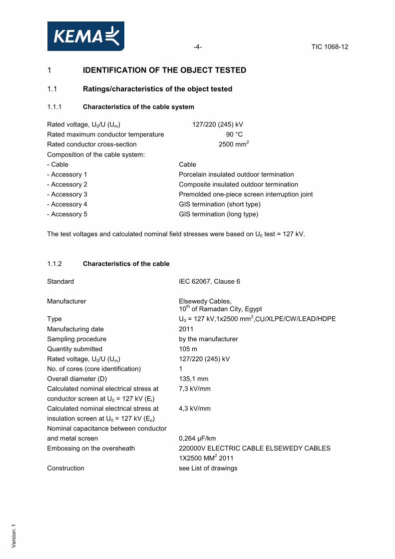
1 IDENTIFICATION OF THE OBJECT TESTED 1.1 Ratings/characteristics of the object tested 1.1.1 Characteristics of the cable system Rated voltage, U0/U (Um) 127/220 (245) kV Rated maximum conductor temperature 90 °C Rated conductor cross-section 2500 mm2 Composition of the cable system: - Cable Cable - Accessory 1 Porcelain insulated outdoor termination - Accessory 2 Composite insulated outdoor termination - Accessory 3 Premolded one-piece screen interruption joint - Accessory 4 GIS termination (short type) - Accessory 5 GIS termination (long type) The test voltages and calculated nominal field stresses were based on U0 test = 127 kV. 1.1.2 Characteristics of the cable Standard IEC 62067, Clause 6 Manufacturer Elsewedy Cables,
10th of Ramadan City, Egypt Type U0 = 127 kV,1x2500 mm2,CU/XLPE/CW/LEAD/HDPE Manufacturing date 2011 Sampling procedure by the manufacturer Quantity submitted 105 m Rated voltage, U0/U (Um) 127/220 (245) kV No. of cores (core identification) 1 Overall diameter (D) 135,1 mm Calculated nominal electrical stress at conductor screen at U0 = 127 kV (Ei)
7,3 kV/mm
Calculated nominal electrical stress at insulation screen at U0 = 127 kV (Eo)
4,3 kV/mm
Nominal capacitance between conductor and metal screen
0,264 µF/km
Embossing on the oversheath 220000V ELECTRIC CABLE ELSEWEDY CABLES 1X2500 MM2 2011
Construction see List of drawings
-5- TIC 1068-12
Ver
sion
: 1
Conductor - material annealed copper - DC conductor resistance 0,0072 Ω/km - cross-section 2500 mm2 - nominal diameter (d) 62,0 mm - type segmental compacted - number and nominal diameter of wires 324 wires, Ø 2,20 mm (middle) and Ø 3,14 mm (after
compaction) - maximum conductor temperature in normal operation
90 °C
- presence and nature of measures to reduce skin effect
yes
- presence and nature of measures to achieve longitudinal watertightness
yes
- swelling material water blocking tape - number of layers of swelling tapes 3 / segment + 1 / center - nominal thickness of tape 0,1 mm (overlap: 10 %) - material designation LNT-75SW - manufacturer of the material Loypos Conductor screen - material extruded semi-conducting XLPE - nominal thickness 1,8 mm - material designation LE 0500 - manufacturer of the material Borealis Insulation - material XLPE - nominal thickness 23,0 mm - nominal inner diameter of the insulation 66,8 mm - nominal outer diameter of the insulation 112,8 mm - material designation LE 4201 EHV - manufacturer of the material Borealis Insulation screen - material extruded semi-conducting XLPE - nominal thickness 1,4 mm - material designation LE 0500 - manufacturer of the material Borealis Longitudinally watertightness - presence and nature of measures to achieve longitudinal watertightness along insulation screen
yes
- swelling material swellable tapes - number of swelling tapes 2
-6- TIC 1068-12
Ver
sion
: 1
- nominal thickness and width 0,3 x 70 mm (overlap: 20%) - material designation BZSD50 - manufacturer of the material Tianrong Metal screen - material copper wires with open helix copper tape - number of wires 75 - nominal diameter of wires 1,75 mm - number of copper tapes 1 - nominal thickness and width of tape 0,1 x 20 mm - cross-sectional area 180,4 mm2 - DC resistance 0,985 Ω/km Longitudinally watertightness - presence and nature of measures to achieve longitudinal watertightness along insulation screen
yes
- swelling material swelling tapes - number of swelling tapes 1 - nominal thickness and width 0,3 x 70 mm (overlap: 20 %) - material designation BZSD50 Metal sheath - material lead alloy ½ C - nominal thickness 3,2 mm - minimum thickness 3,1 mm - manufacturer of the material British Oversheath - material PE type ST7 - nominal thickness 3,7 mm - nominal overall diameter of the cable (D) 135,1 mm - material designation HE 6062 - manufacturer of the material Borealis - colour black - graphite coating applied yes Manufacturing details insulation system - type of extrusion line VCV - type of extrusion triple common extrusion - manufacturer of the extrusion line Maillefer - curing means dry - cooling means dry
-7- TIC 1068-12
Ver
sion
: 1
1.1.3 Characteristics of the accessories Accessory 1 Outdoor termination with porcelain insulator for polymeric extruded power cable Standard IEC 62067, Clause 7 Manufacturer nkt cables GmbH,
Cologne, Germany Type Prefabricated porcelain outdoor termination Type designation FEV 300-P/3.75055-00 Manufacturing date 2011 Sampling procedure by the manufacturer Quantity submitted 2 Rated voltage, U0/U (Um) 127/220 (245) kV Creepage distance min. 8355 mm Flashover distance 2400 mm Number of sheds 58 Insulator - type of insulator porcelain housing - type designation IEC 62155 - manufacturer Lapp insulators - colour of insulator brown - number of cores 1 - pedestal insulators yes, 4 pieces Stress cone - type of stress cone silicon rubber - type designation AV 300 - manufacturer nkt cables GmbH,
Cologne, Germany Insulating medium - insulating medium silicon oil - type designation ISOLIERöL, HOBBOCK 12 L, D.C. 568 568 DI.FLUID
D.C Installation instruction see List of drawings
-8- TIC 1068-12
Ver
sion
: 1
Accessory 2 Outdoor termination with composite insulator for polymeric extruded power cable Standard IEC 62067, Clause 7 Manufacturer nkt cables GmbH,
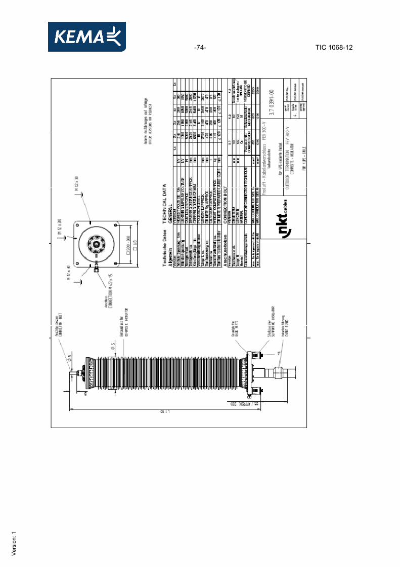
Cologne, Germany Type prefabricated composite outdoor termination Type designation FEV 300-V / 3.70391-00 Manufacturing date 2011 Sampling procedure by the manufacturer Quantity submitted 2 Rated voltage, U0/U (Um) 127/220 (245) kV Creepage distance min. 8400 mm Flashover distance 2415 mm Insulator - type of insulator composite housing - type designation IEC 62155 - manufacturer Lapp insulators - colour of insulator grey - number of cores 1 - pedestal insulators yes, 4 pieces Stress cone - type of stress cone silicon rubber - type designation AV 300 - manufacturer nkt cables GmbH,
Cologne, Germany Insulating medium - insulating medium silicon oil - type designation ISOLIERöL, HOBBOCK 12 L, D.C. 568 568 DI.FLUID
D.C Installation instruction see List of drawings
-9- TIC 1068-12
Ver
sion
: 1
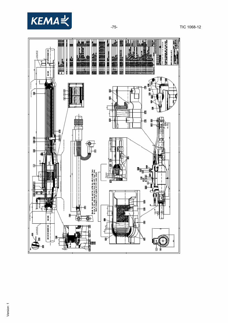
Accessory 3 Joint with screen interruption for polymeric extruded power cable Standard IEC 62067, Clause 7 Manufacturer Prysmian cables & systems,
Milan, Italy Type of joint screen interruption joint Type designation, reference number GMS 1245 CA + P.D. SENSOR Manufacturing date 2011 Sampling procedure by the manufacturer Quantity submitted 2 Rated voltage, U0/U (Um) 127/220 (300) kV Length of the bonding leads 5 m Insulator - type of insulator Epoxy resin - manufacturer Prysmian - colour of insulator Grey/Light green - number of cores 1 Conductor connector - type, reference number Punching Cu connector CIT9975530140C - manufacturer Prysmian - tooling, dies and necessary setting 30 Ton Monoram press with guiding block for 2500 sq
mm Milliken conductor Joint body - type One piece EPR premoulded - type designation GMS 1245 CA - manufacturer Prysmian Joint outer protection Coffin Box + Cold pouring resin May be subjected to wet conditions in service
yes
Installation instruction see List of drawings
-10- TIC 1068-12
Ver
sion
: 1
Accessory 4 Cable connection for gas-insulated metal-enclosed switchgear (short type) for polymeric extruded power cable Standard IEC 62067, Clause 7 Manufacturer nkt cables GmbH,
Cologne, Germany Type prefabricated GIS termination Type designation KSEV 245…300 Size 9 version 1 (short type) /
3.76522-00 Manufacturing date 2011 Sampling procedure by the manufacturer Quantity submitted HVL 2 Rated voltage, U0/U (Um) 127/220 (245) kV Insulator - type of insulator cast resin - manufacturer EPRO - colour of insulator white - number of cores 1 Stress cone - type of stress cone silicon rubber - type designation AV S 300 - manufacturer nkt cables GmbH,
Cologne, Germany Insulating medium - insulating medium dry type Installation instruction see List of drawings
-11- TIC 1068-12
Ver
sion
: 1
Accessory 5 Cable connection for gas-insulated metal-enclosed switchgear (long type) for polymeric extruded power cable Standard IEC 62067, Clause 7 Manufacturer nkt cables GmbH,
Cologne, Germany Type prefabricated GIS termination Type designation KSEV 245…300 Size 9 version 2 (long type) /
3.76522-00 Manufacturing date 2011 Sampling procedure by the manufacturer Quantity submitted HVL 2 Rated voltage, U0/U (Um) 127/220 (245) kV Insulator - type of insulator cast resin - manufacturer EPRO - colour of insulator white - number of cores 1 Stress cone - type of stress cone silicon rubber - type designation AV S 300 - manufacturer nkt cables GmbH,
Cologne, Germany Insulating medium - insulating medium dry type
-12- TIC 1068-12
Ver
sion
: 1
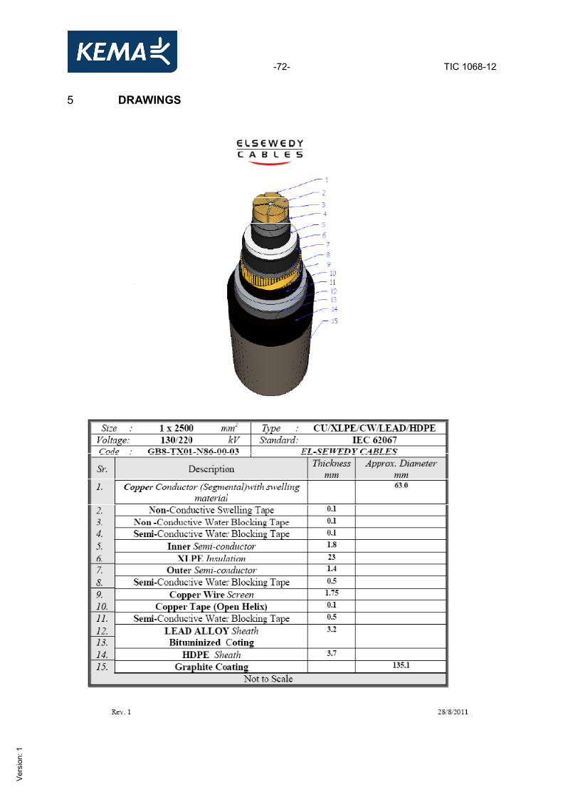
1.2 List of drawings The manufacturer has guaranteed that the object submitted for tests has been manufactured in accordance with the following drawings and/or documents. KEMA has verified that these drawings and/or documents adequately represent the object tested. The manufacturer is responsible for the correctness of these drawings and/or documents and the technical data presented. The following drawings and/or documents have been included in this Certificate: Drawing no./document no. Revision GB8-TX01-N86-00-03(Cable) 3.7 5055-00 (porcelain outdoor termination) 3.70391-00 (composite outdoor termination) 41.297.2.1114 (joint) 3.7 6522-00 (GIS terminations)
1 3 4 A b
The following drawings and/or documents are only listed for reference and are kept in KEMA’s files: Drawing no./document no. Revision M 5954 (installation instruction of porcelain outdoor termination) M 5674 (installation instruction of composite outdoor termination) 41.297.6.1078 (jointing instruction) M 5923/GA003820 (installation instruction of GIS termination short type) M 5923/GA003821 (installation instruction of GIS termination long type)
- - A - -
-13- TIC 1068-12
Ver
sion
: 1
2 GENERAL INFORMATION 2.1 The tests were witnessed by Name Company Mr Wael Mohamed Ali Mr Abokresha Omar
Elsewedy Cables 10th of Ramadan City, Egypt
Mr Jan Mossbauer Mr Saud Khalid
nkt cables Cologne, Germany
Mr Rashid Rahimi Mr Muthukuda Jayawardene
Kahramaa Doha, State of Qatar
2.2 The tests were carried out by Name Company Mr Chris Beverwijk Mr Bas Peters Mr Harry Arnoldus Mr Berry Jansen
KEMA Nederland B.V., Arnhem, The Netherlands
2.3 Subcontracting The following tests were subcontracted to KEMA Cleaner Energy Services, Arnhem, the Netherlands. • Measurement of resistivity of semi-conducting screens in accordance with Subclause 12.4.9 • Non-electrical type tests in accordance with Subclause 12.5, with the exception of the water
penetration test of Subclause 12.5.14. 2.4 Measurement uncertainty A table with measurement uncertainties is enclosed in this Certificate. Unless otherwise stated, the measurement uncertainties of the results presented in this Certificate are as indicated in that table.
-14- TIC 1068-12
Ver
sion
: 1
3 ELECTRICAL TYPE TESTS ON COMPLETE CABLE SYSTEM 3.1 Test arrangement 3.1.1 Determination of the cable conductor temperature Standard Standard IEC 62067, Annex A, Subclause A.3.1 For the tests with the cable system at elevated temperature, a reference loop for temperature control of the conductor was installed and conductor current was used for heating. The reference cable was cut from the total cable length intended for the type test. This reference loop was installed close to the main loop in order to create the same environmental conditions as for the test loop. The heating currents in both the reference loop and the test loop were kept equal at all times, thus the conductor temperature of the reference loop is representative for the conductor temperature of the test loop. Annex A was used as a guide and Subclause A.3.1, method 1 was applied. The tests at elevated temperature are carried out two hours after thermal equilibrium has been established.
-15- TIC 1068-12
Ver
sion
: 1
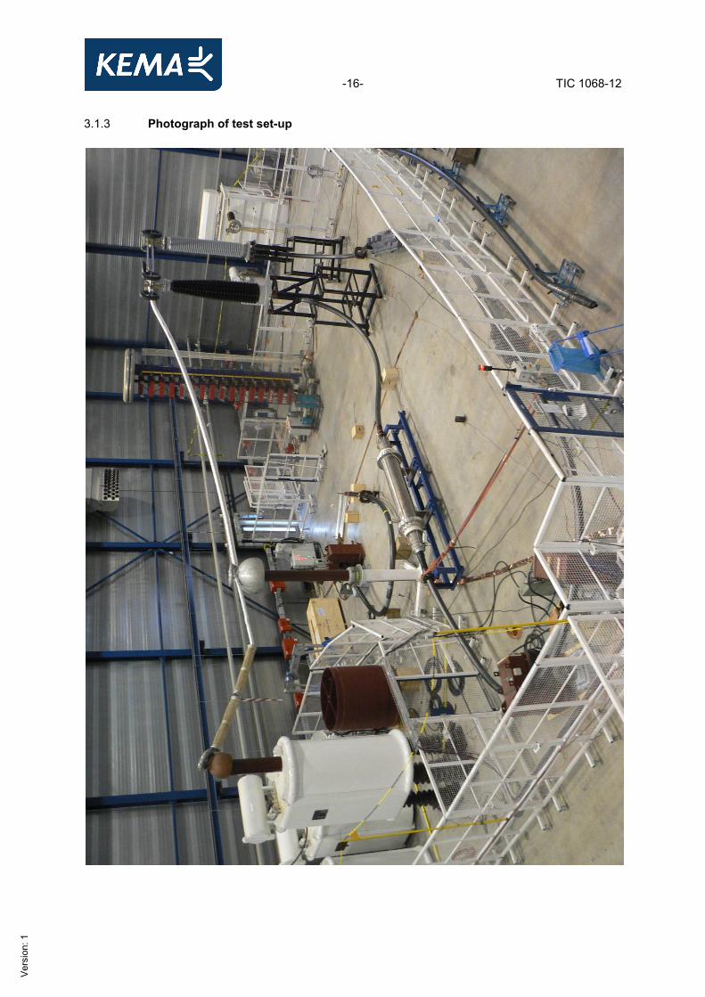
3.1.2 Test set-up In order to perform the test, the following test loop was prepared by the manufacturer’s representatives in the manner specified by the manufacturer’s instructions: • power cable type U0 = 127 kV,1x2500 mm2,CU/XLPE/CW/LEAD/HDPE • two outdoor terminations (one with porcelain insulator and one with composite insulator) • one screen interruption joint , type GMS 1245 CA + P.D. SENSOR • two SF6-insulated termination mounted in a back-to-back configuration inside a SF6-gas filled
container. The outer protection of the joints was fitted.
-16- TIC 1068-12
Ver
sion
: 1
3.1.3 Photograph of test set-up
-17- TIC 1068-12
Ver
sion
: 1
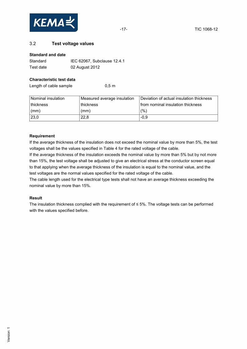
3.2 Test voltage values Standard and date Standard IEC 62067, Subclause 12.4.1 Test date 02 August 2012 Characteristic test dataLength of cable sample 0,5 m Nominal insulation thickness (mm)
Measured average insulation thickness (mm)
Deviation of actual insulation thickness from nominal insulation thickness (%)
23,0 22,8 -0,9 Requirement If the average thickness of the insulation does not exceed the nominal value by more than 5%, the test voltages shall be the values specified in Table 4 for the rated voltage of the cable. If the average thickness of the insulation exceeds the nominal value by more than 5% but by not more than 15%, the test voltage shall be adjusted to give an electrical stress at the conductor screen equal to that applying when the average thickness of the insulation is equal to the nominal value, and the test voltages are the normal values specified for the rated voltage of the cable. The cable length used for the electrical type tests shall not have an average thickness exceeding the nominal value by more than 15%. Result The insulation thickness complied with the requirement of ≤ 5%. The voltage tests can be performed with the values specified before.
-18- TIC 1068-12
Ver
sion
: 1
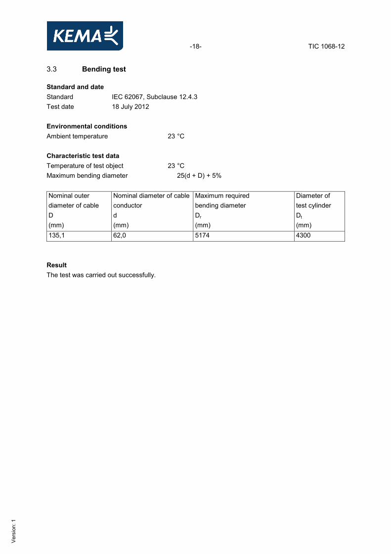
3.3 Bending test Standard and date Standard IEC 62067, Subclause 12.4.3 Test date 18 July 2012 Environmental conditions Ambient temperature 23 °C Characteristic test dataTemperature of test object 23 °C Maximum bending diameter 25(d + D) + 5% Nominal outer diameter of cable D (mm)
Nominal diameter of cable conductor d (mm)
Maximum required bending diameter Dr (mm)
Diameter of test cylinder Dt (mm)
135,1 62,0 5174 4300 Result The test was carried out successfully.
-19- TIC 1068-12
Ver
sion
: 1
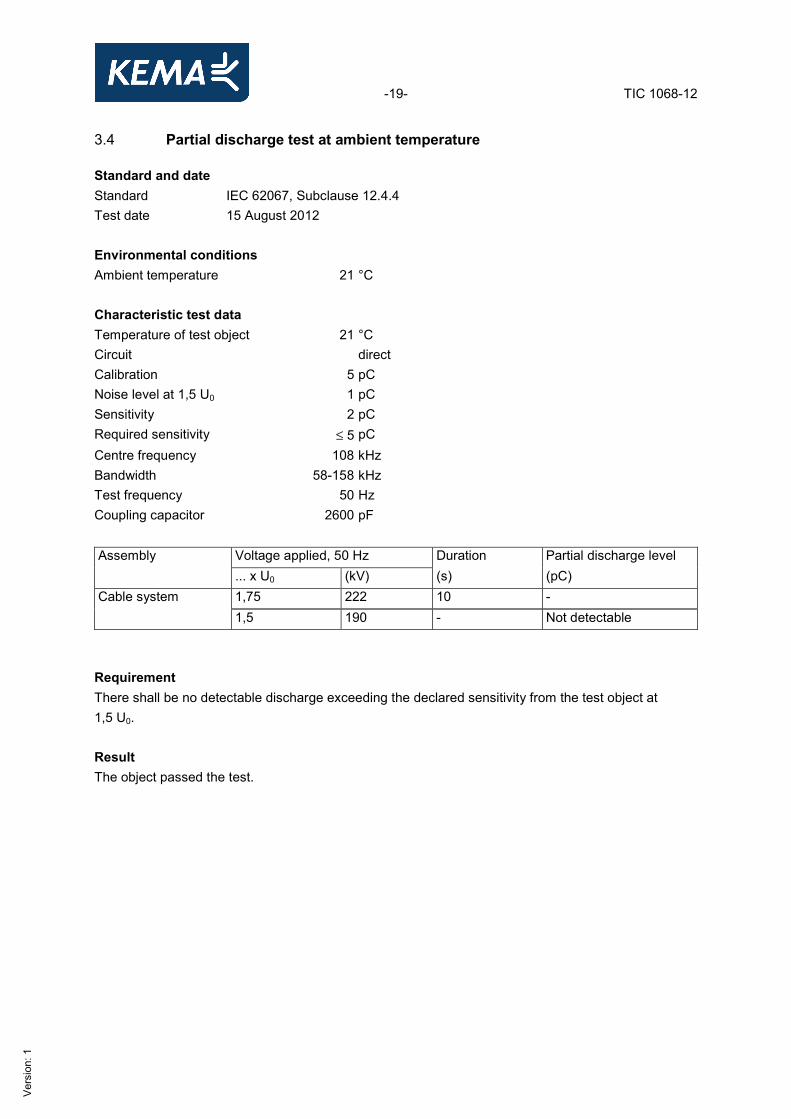
3.4 Partial discharge test at ambient temperature Standard and date Standard IEC 62067, Subclause 12.4.4 Test date 15 August 2012 Environmental conditions Ambient temperature 21 °C Characteristic test dataTemperature of test object 21 °C Circuit direct Calibration 5 pC Noise level at 1,5 U0 1 pC Sensitivity 2 pC Required sensitivity ≤ 5 pC Centre frequency 108 kHz Bandwidth 58-158 kHz Test frequency 50 Hz Coupling capacitor 2600 pF Assembly Voltage applied, 50 Hz Duration Partial discharge level ... x U0 (kV) (s) (pC) Cable system 1,75 222 10 -
1,5 190 - Not detectable Requirement There shall be no detectable discharge exceeding the declared sensitivity from the test object at 1,5 U0. Result The object passed the test.
-20- TIC 1068-12
Ver
sion
: 1
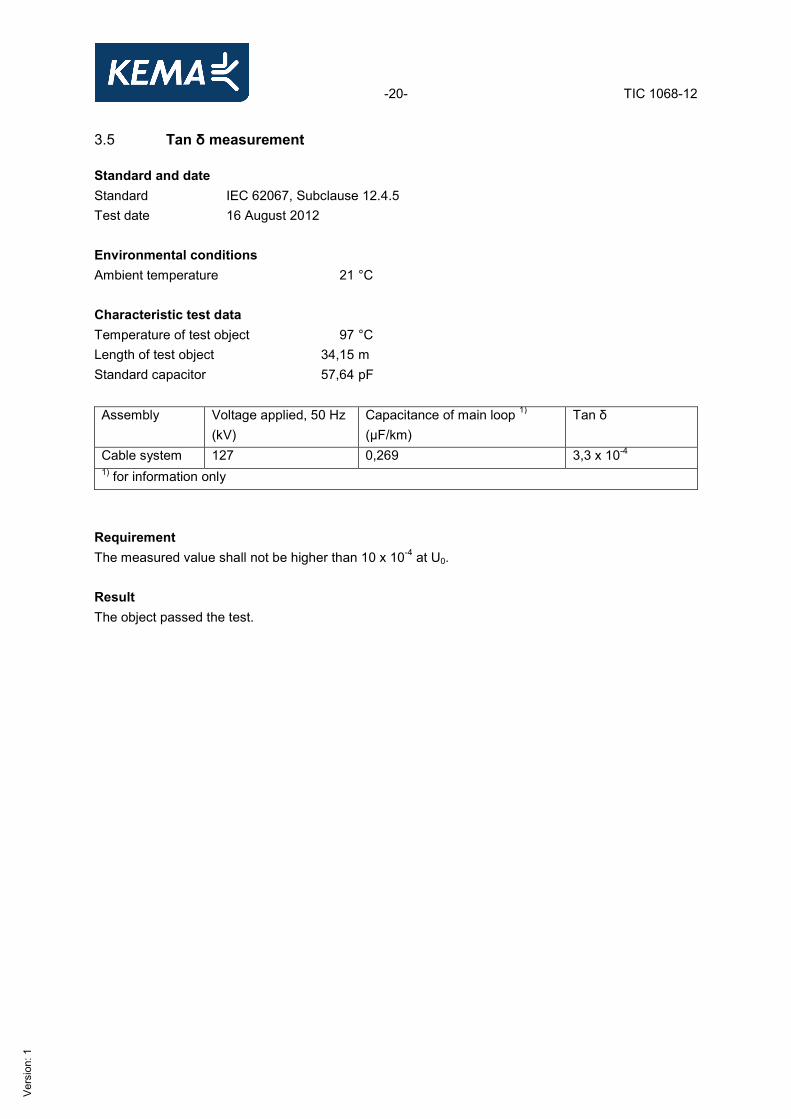
3.5 Tan δ measurement Standard and date Standard IEC 62067, Subclause 12.4.5 Test date 16 August 2012 Environmental conditions Ambient temperature 21 °C Characteristic test dataTemperature of test object 97 °C Length of test object 34,15 m Standard capacitor 57,64 pF Assembly Voltage applied, 50 Hz
(kV) Capacitance of main loop 1) (µF/km)
Tan δ
Cable system 127 0,269 3,3 x 10⁻⁴ 1) for information only
Requirement The measured value shall not be higher than 10 x 10-4 at U0. Result The object passed the test.
-21- TIC 1068-12
Ver
sion
: 1
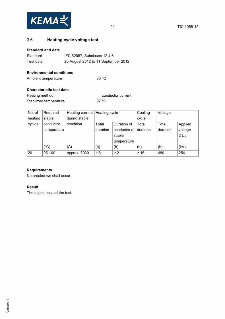
3.6 Heating cycle voltage test Standard and date Standard IEC 62067, Subclause 12.4.6 Test date 20 August 2012 to 11 September 2012 Environmental conditions Ambient temperature 20 °C Characteristic test dataHeating method conductor current Stabilized temperature 97 °C No. of heatingcycles
Required stable conductor temperature (°C)
Heating current during stable condition (A)
Heating cycle Cooling cycle
Voltage
Total duration (h)
Duration of conductor at stable temperature(h)
Total duration (h)
Total duration (h)
Applied voltage 2 U0 (kV)
20 95-100 approx. 3030 ≥ 8 ≥ 2 ≥ 16 480 254 Requirements No breakdown shall occur. Result The object passed the test.
-22- TIC 1068-12
Ver
sion
: 1
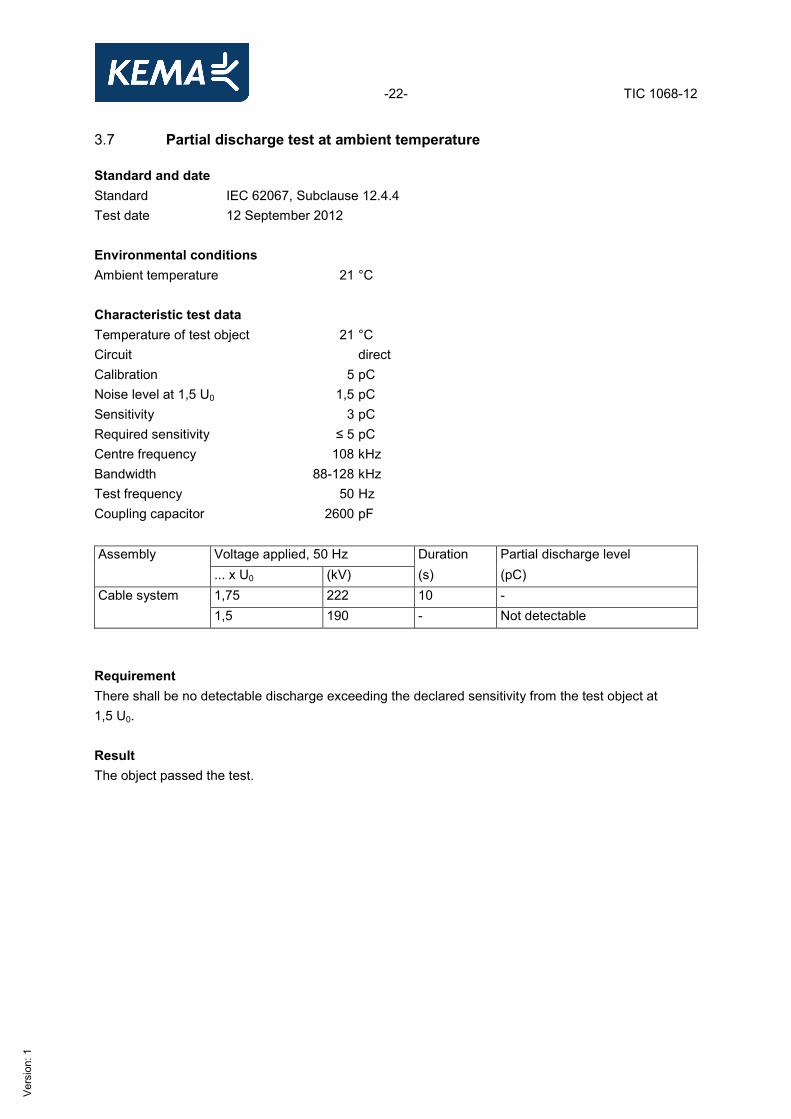
3.7 Partial discharge test at ambient temperature Standard and date Standard IEC 62067, Subclause 12.4.4 Test date 12 September 2012 Environmental conditions Ambient temperature 21 °C Characteristic test dataTemperature of test object 21 °C Circuit direct Calibration 5 pC Noise level at 1,5 U0 1,5 pC Sensitivity 3 pC Required sensitivity ≤ 5 pC Centre frequency 108 kHz Bandwidth 88-128 kHz Test frequency 50 Hz Coupling capacitor 2600 pF Assembly Voltage applied, 50 Hz Duration Partial discharge level ... x U0 (kV) (s) (pC) Cable system 1,75 222 10 -
1,5 190 - Not detectable Requirement There shall be no detectable discharge exceeding the declared sensitivity from the test object at 1,5 U0. Result The object passed the test.
-23- TIC 1068-12
Ver
sion
: 1
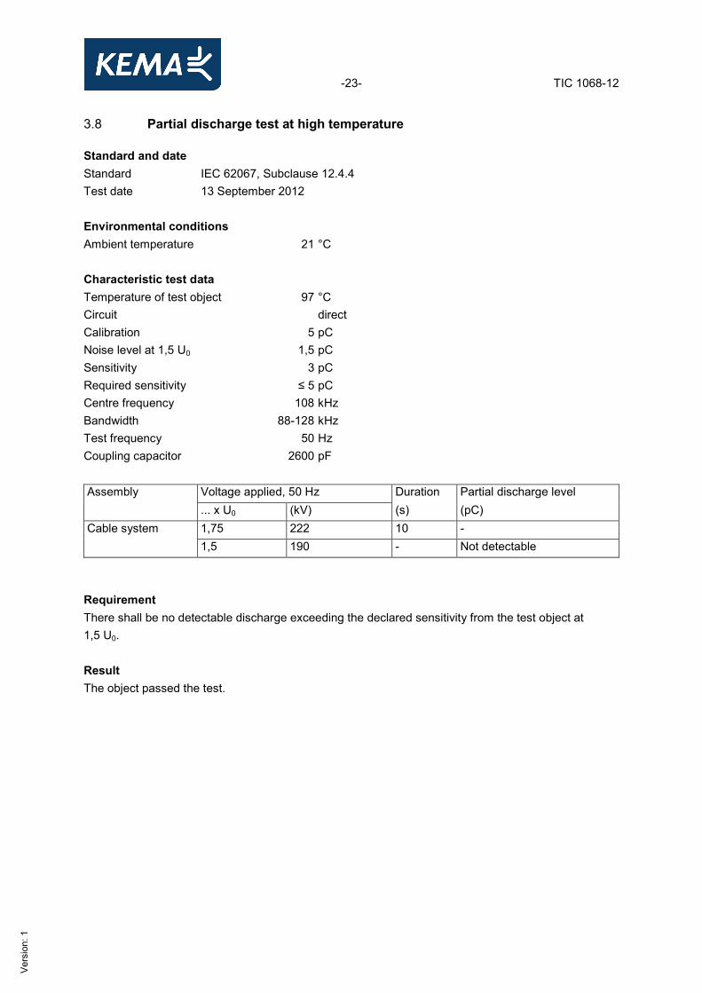
3.8 Partial discharge test at high temperature Standard and date Standard IEC 62067, Subclause 12.4.4 Test date 13 September 2012 Environmental conditions Ambient temperature 21 °C Characteristic test dataTemperature of test object 97 °C Circuit direct Calibration 5 pC Noise level at 1,5 U0 1,5 pC Sensitivity 3 pC Required sensitivity ≤ 5 pC Centre frequency 108 kHz Bandwidth 88-128 kHz Test frequency 50 Hz Coupling capacitor 2600 pF Assembly Voltage applied, 50 Hz Duration Partial discharge level ... x U0 (kV) (s) (pC) Cable system 1,75 222 10 -
1,5 190 - Not detectable Requirement There shall be no detectable discharge exceeding the declared sensitivity from the test object at 1,5 U0. Result The object passed the test.
-24- TIC 1068-12
Ver
sion
: 1
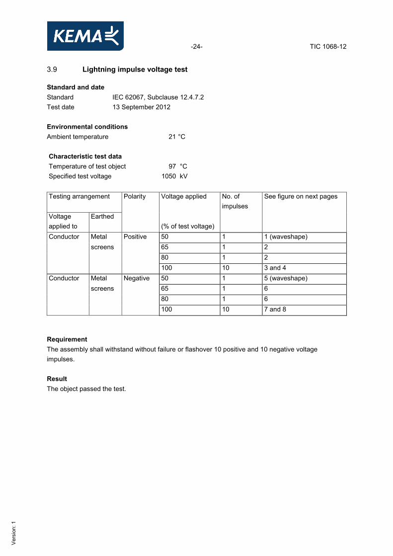
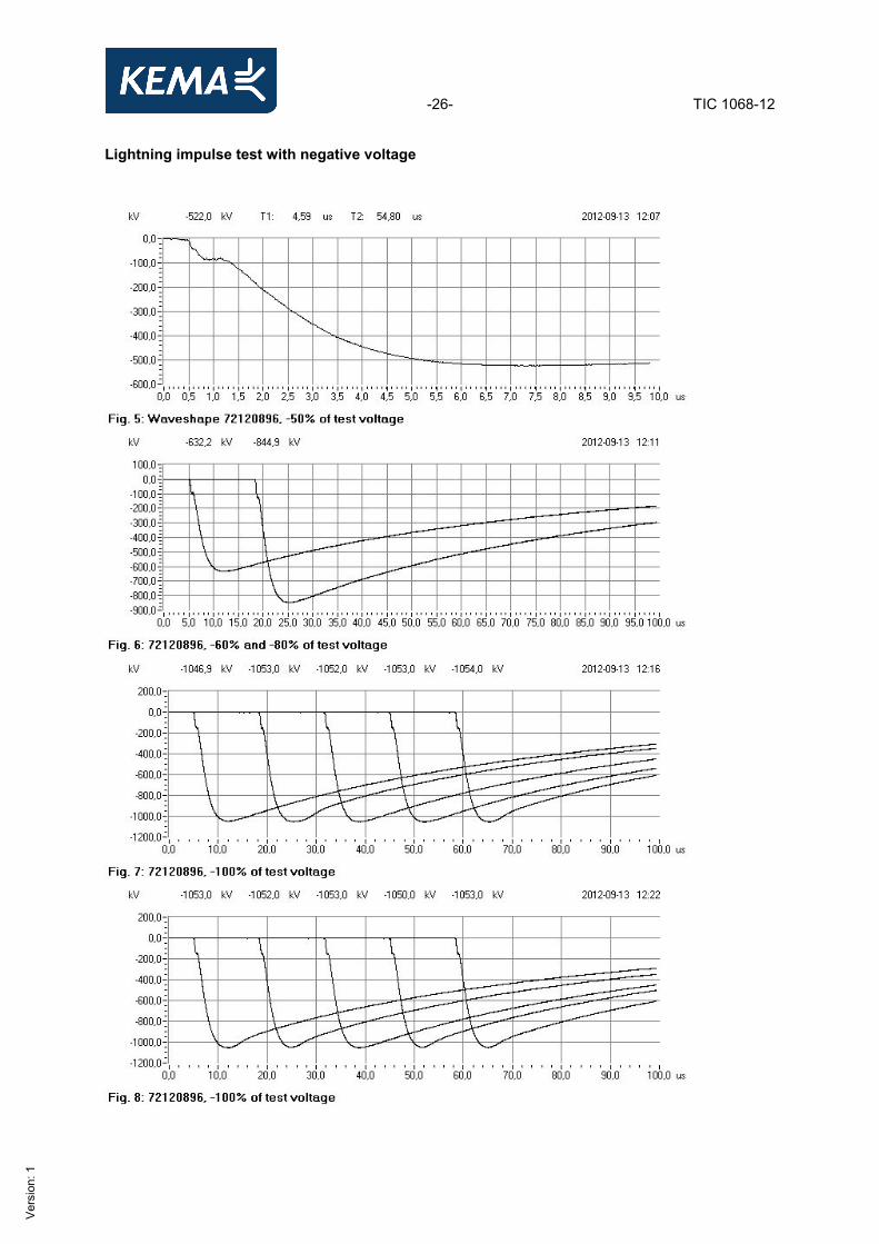
3.9 Lightning impulse voltage test Standard and date Standard IEC 62067, Subclause 12.4.7.2 Test date 13 September 2012 Environmental conditions Ambient temperature 21 °C Characteristic test data Temperature of test object 97 °C Specified test voltage 1050 kV
Testing arrangement Polarity Voltage applied
No. of impulses
See figure on next pages
Voltage applied to
Earthed (% of test voltage)
Conductor Metal Positive 50 1 1 (waveshape) screens 65 1 2 80 1 2 100 10 3 and 4 Conductor Metal Negative 50 1 5 (waveshape) screens 65 1 6 80 1 6 100 10 7 and 8
Requirement The assembly shall withstand without failure or flashover 10 positive and 10 negative voltage impulses. Result The object passed the test.

-25- TIC 1068-12
Ver
sion
: 1
Lightning impulse test with positive voltage
-26- TIC 1068-12
Ver
sion
: 1
Lightning impulse test with negative voltage
-27- TIC 1068-12
Ver
sion
: 1
3.10 Power frequency voltage test Standard and date Standard IEC 62067, Subclause 12.4.7.2 Test date 14 September 2012 Environmental conditions Ambient temperature 20 °C Characteristic test dataTemperature of test object 20 °C Testing arrangement Voltage applied, 50 Hz Duration Voltage applied to Earth connected to … x U0 (kV) (min) Conductors Metal screens 2 254 15
Requirement No breakdown of the insulation shall occur. Result The object passed the test.
-28- TIC 1068-12
Ver
sion
: 1
3.11 Tests of outer protection for joints These tests were applied to a separate joint. 3.11.1 Thermal cycles without voltage on a separate joint Standard and date Standard IEC 62067, Annex G, Clause G.2 Test date 04 October 2012 to 07 October 2012 Environmental conditions Ambient temperature 20 °C Characteristic test dataHeating method conductor current Stabilized temperature 97 °C No. of heating cycles
Required stable conductor temperature (°C)
Heating current during stable condition (A)
Heating cycle Cooling cycle Total duration (h)
Duration of conductor at stable temperature (h)
Total duration (h)
3 95 - 100 approx. 3050 ≥ 8 ≥ 2 ≥ 16 Result The test was carried out successfully.
-29- TIC 1068-12
Ver
sion
: 1
3.11.2 Water immersion and heat cycling Standard and date Standard IEC 62067, Annex G, Clause G.3 Test date 11 October 2012 to 20 October 2012 Environmental conditions Ambient temperature 20 °C Characteristic test dataHeating method raising the water temperature by heating Stabilized temperature 72 °C Cooling method diluting the water with water with a lower temperature No. of heating cycles
Required stable water temperature (°C)
Heating cycle Cooling cycle Total duration (h)
Duration of water stable temperature (h)
Total duration (h)
20 70 - 75 12 ≥ 5 3,5 Result The test was carried out successfully.
-30- TIC 1068-12
Ver
sion
: 1
3.11.3 DC voltage tests on assemblies embodying sheath sectionalising insulation Standard and date Standard IEC 62067, Annex G, Subclause G.4.3.1 Test date 29 October 2012 Environmental conditions Ambient temperature 19 °C Characteristic test dataWater temperature 19 °C Testing arrangement DC voltage applied Duration Voltage applied to Earth connected to (kV) (min) Metal screen/sheath of the power cable side A
Metal screen/sheath of the power cable side B + exterior of the outer protection
25 1
Metal screen/sheath of the power cable side B
Metal screen/sheath of the power cable side A + exterior of the outer protection
25 1
Requirement No breakdown shall occur during the tests. Result The object passed the test.
-31- TIC 1068-12
Ver
sion
: 1
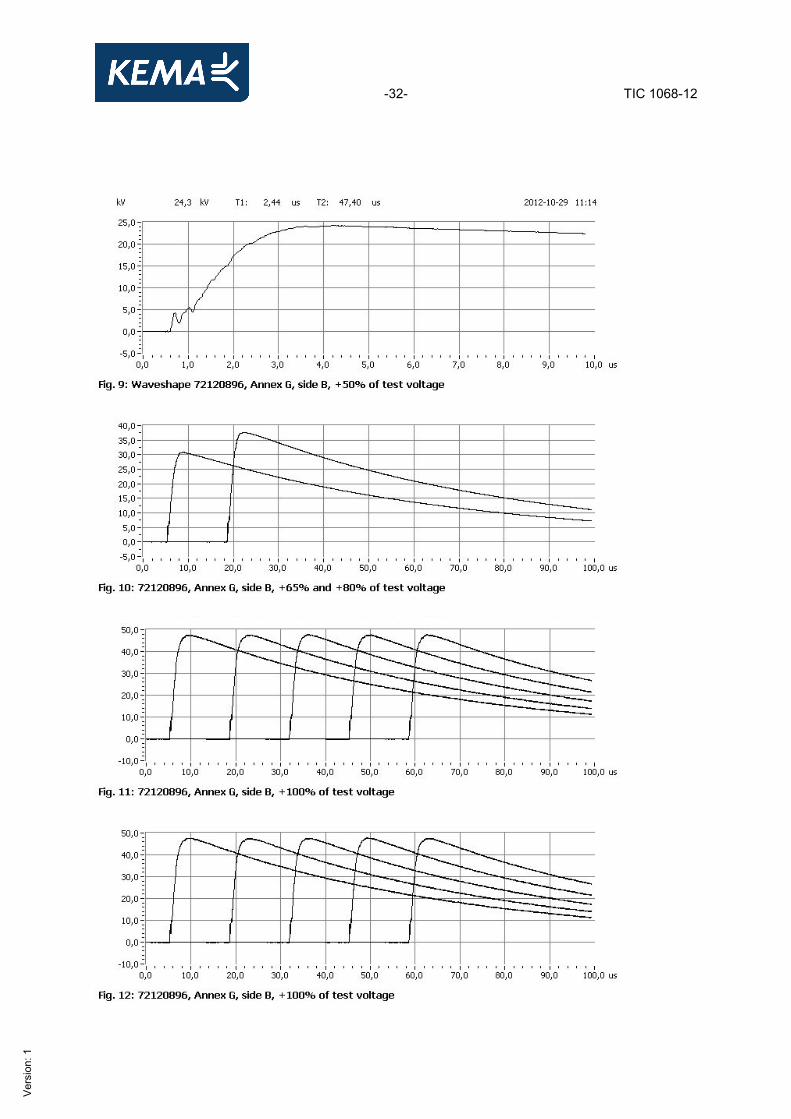
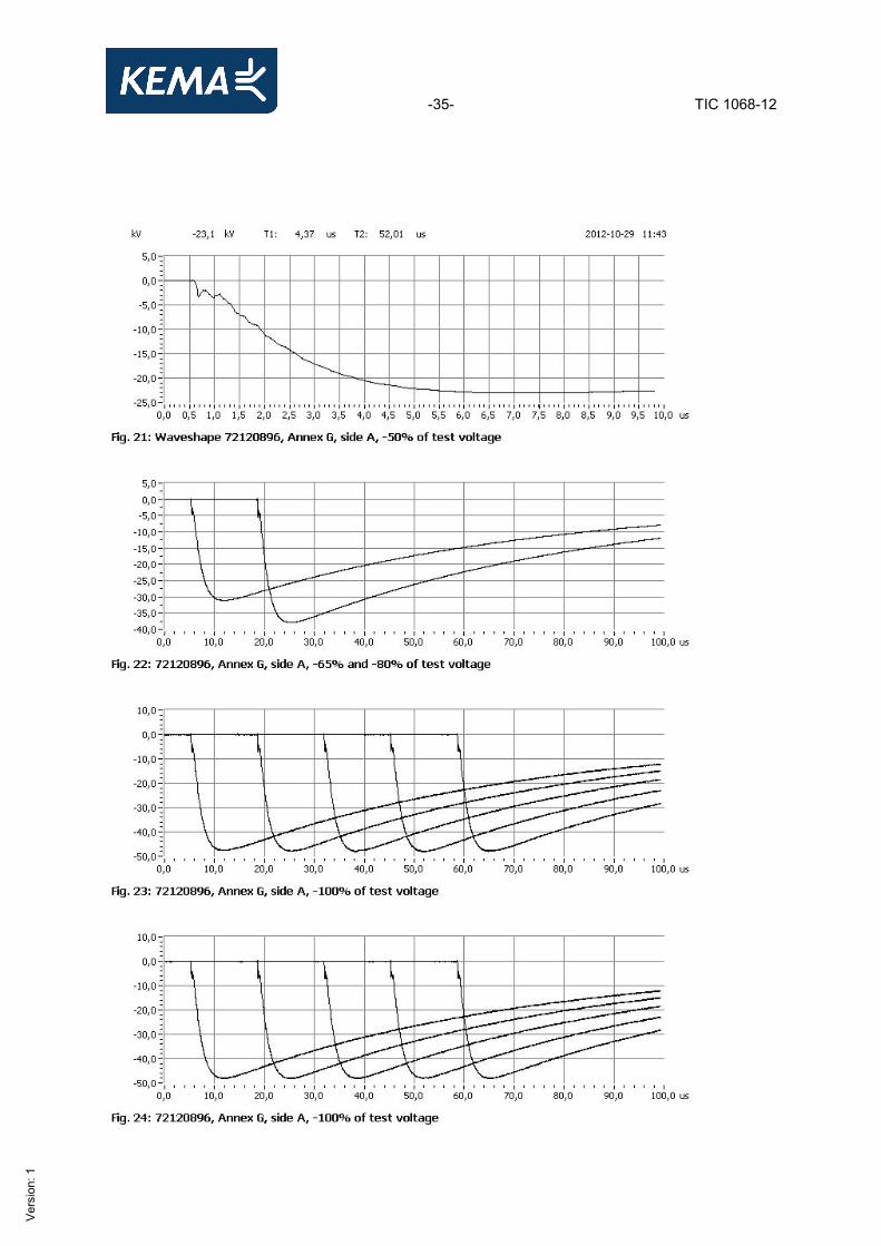
3.11.4 Impulse voltage tests of each part to earth Standard and date Standard IEC 62067, Annex G, Subclause G.4.3.2 Test date 29 October 2012 Environmental conditions Ambient temperature 19 °C Characteristic test dataLength of bonding leads > 3 and ≤ 10 m Specified test voltage 47,5 kV Testing arrangement Polarity Voltage applied
(% of test voltage) No. of impulses
See figure on next pages
Voltage applied to Earthed Metal screen/sheath of the power cable side B
Exterior of the outer protection and side A
Positive 50 1 9 (waveshape) 65 1 10 80 1 10 100 10 11 and 12
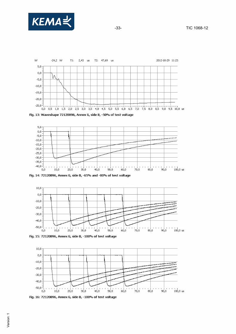
Metal screen/sheath of the power cable side B
Exterior of the outer protection and side A
Negative 50 1 13 (waveshape)65 1 14 80 1 14 100 10 15 and 16
Metal screen/sheath of the power cable side A
Exterior of the outer protection and side B
Positive 50 1 17 (waveshape)65 1 18 80 1 18 100 10 19 and 20
Metal screen/sheath of the power cable side A
Exterior of the outer protection and side B
Negative 50 1 21 (waveshape)65 1 22 80 1 22 100 10 23 and 24
Requirement No breakdown shall occur during the tests. Result The object passed the test.
-32- TIC 1068-12
Ver
sion
: 1
-33- TIC 1068-12
Ver
sion
: 1

-34- TIC 1068-12
Ver
sion
: 1
-35- TIC 1068-12
Ver
sion
: 1
-36- TIC 1068-12
Ver
sion
: 1
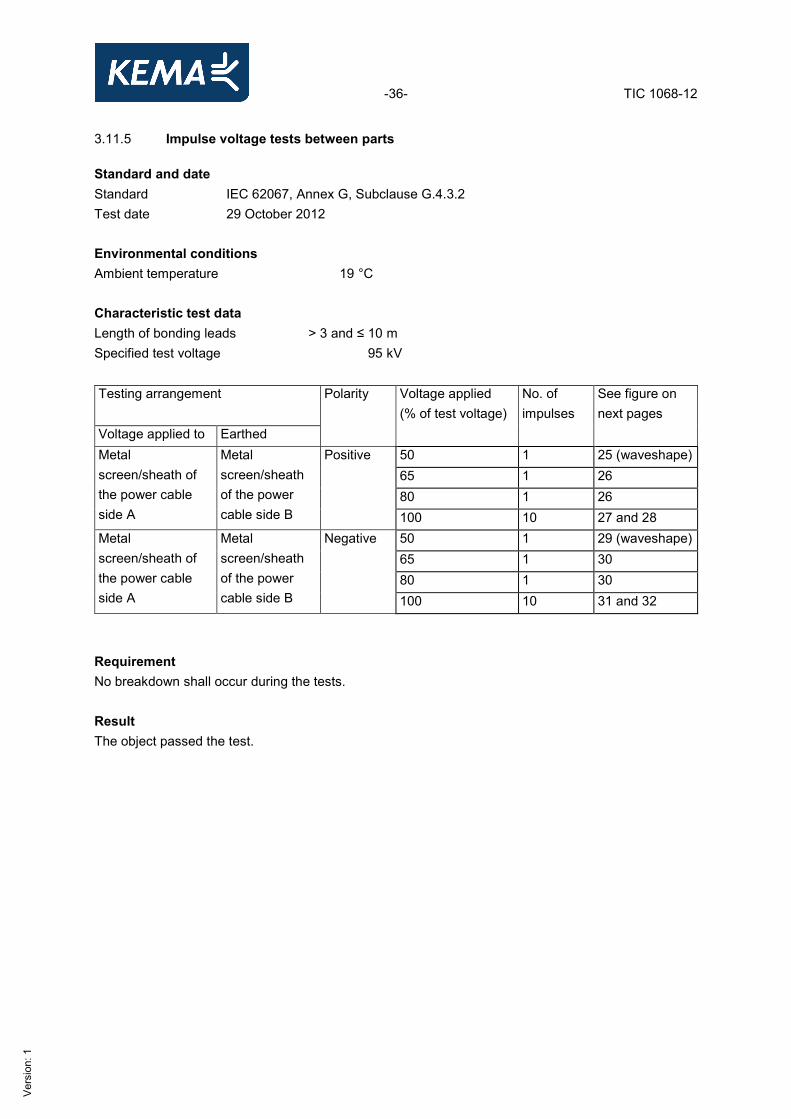
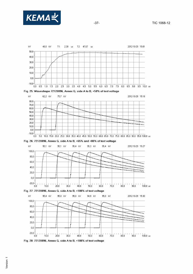
3.11.5 Impulse voltage tests between parts Standard and date Standard IEC 62067, Annex G, Subclause G.4.3.2 Test date 29 October 2012 Environmental conditions Ambient temperature 19 °C Characteristic test dataLength of bonding leads > 3 and ≤ 10 m Specified test voltage 95 kV Testing arrangement Polarity Voltage applied
(% of test voltage) No. of impulses
See figure on next pages
Voltage applied to Earthed Metal screen/sheath of the power cable side A
Metal screen/sheath of the power cable side B
Positive 50 1 25 (waveshape)65 1 26 80 1 26 100 10 27 and 28
Metal screen/sheath of the power cable side A
Metal screen/sheath of the power cable side B
Negative 50 1 29 (waveshape)65 1 30 80 1 30 100 10 31 and 32
Requirement No breakdown shall occur during the tests. Result The object passed the test.
-37- TIC 1068-12
Ver
sion
: 1

-38- TIC 1068-12
Ver
sion
: 1
-39- TIC 1068-12
Ver
sion
: 1
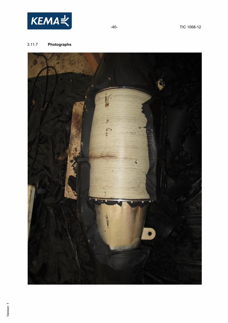
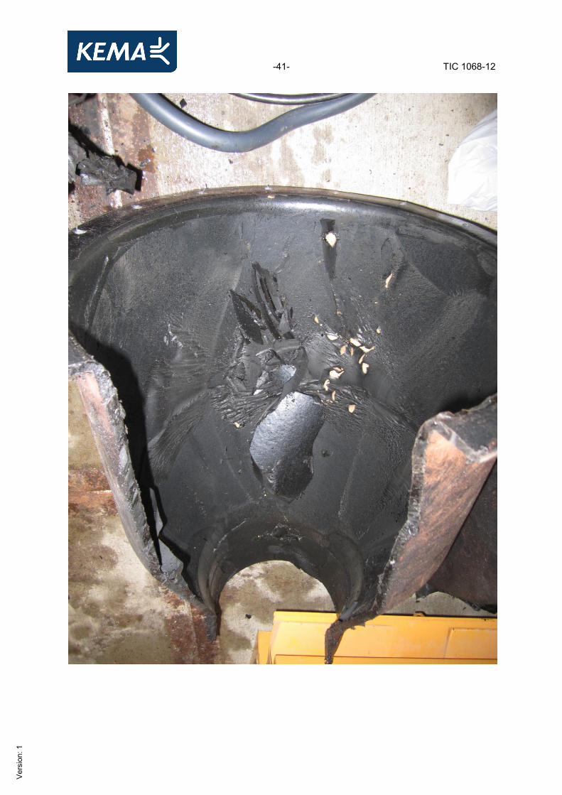
3.11.6 Examination of test assembly Standard and date Standard IEC 62067, Annex G, Clause G.5 Test date 26 November 2012 Requirement Joint outer protection boxes filled with removable compounds shall be regarded as satisfactory if there is no visible evidence of internal void or internal displacement of compound by water ingress, or of compound loss via the various seals or box walls. For joint outer protections employing alternative designs and materials, there shall be no evidence of water ingress or internal corrosion. Result The object passed the test.
-40- TIC 1068-12
Ver
sion
: 1
3.11.7 Photographs
-41- TIC 1068-12
Ver
sion
: 1
-42- TIC 1068-12
Ver
sion
: 1
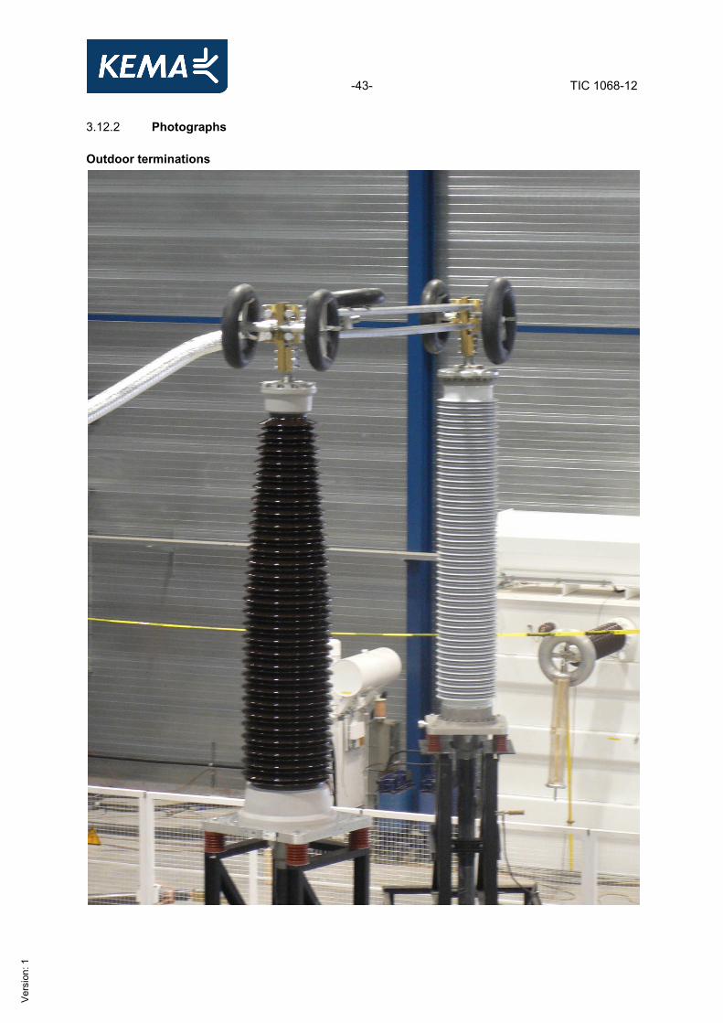
3.12 Examination 3.12.1 Examination of cable and accessories Standard and date Standard IEC 62067, Subclause 12.4.8.1 Test date 18 and 24 September 2012 Requirement Examination of the cable and accessories shall reveal no signs of deterioration (e.g. electrical degradation, leakage, corrosion or harmful shrinkage) which could affect the system in service operation. Result No signs of electrical degradation, leakage, corrosion or harmful shrinkage which could affect the system in service operation were detected.
-43- TIC 1068-12
Ver
sion
: 1
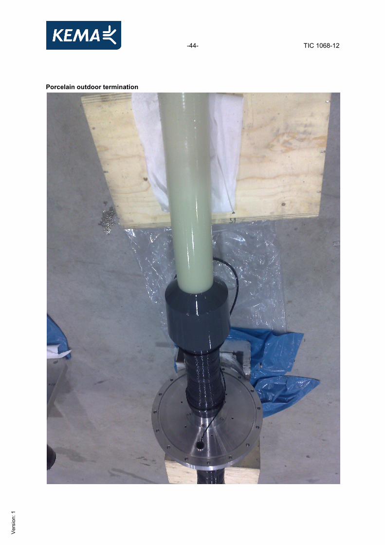
3.12.2 Photographs Outdoor terminations
-44- TIC 1068-12
Ver
sion
: 1
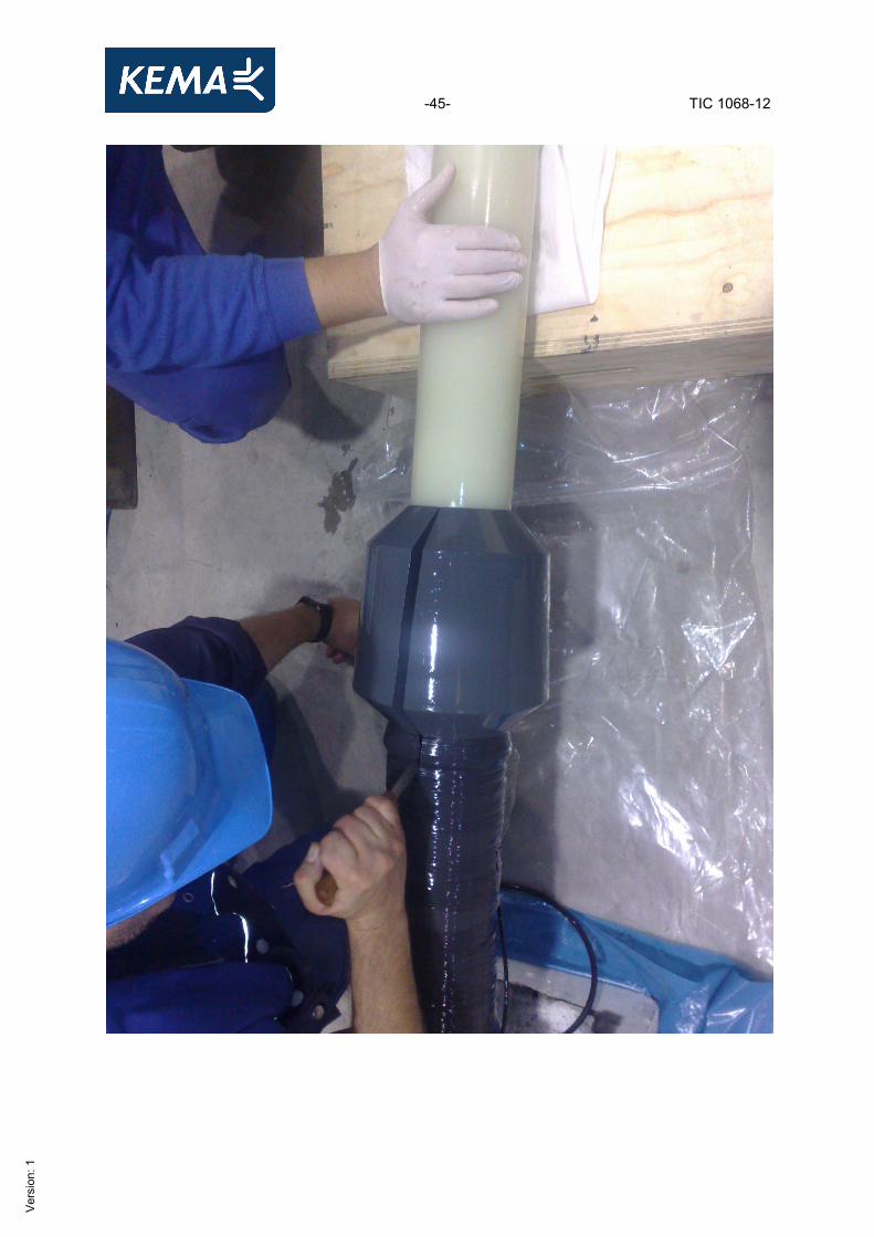
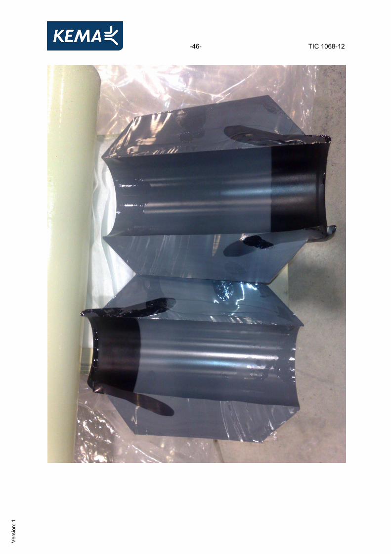
Porcelain outdoor termination
-45- TIC 1068-12
Ver
sion
: 1
-46- TIC 1068-12
Ver
sion
: 1
-47- TIC 1068-12
Ver
sion
: 1
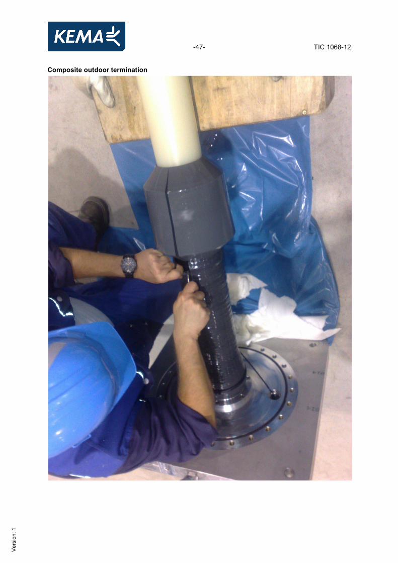
Composite outdoor termination
-48- TIC 1068-12
Ver
sion
: 1
-49- TIC 1068-12
Ver
sion
: 1
-50- TIC 1068-12
Ver
sion
: 1
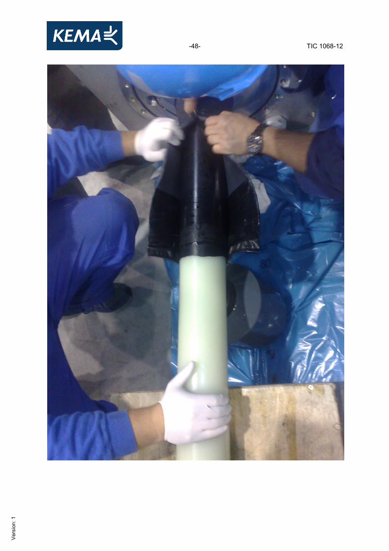
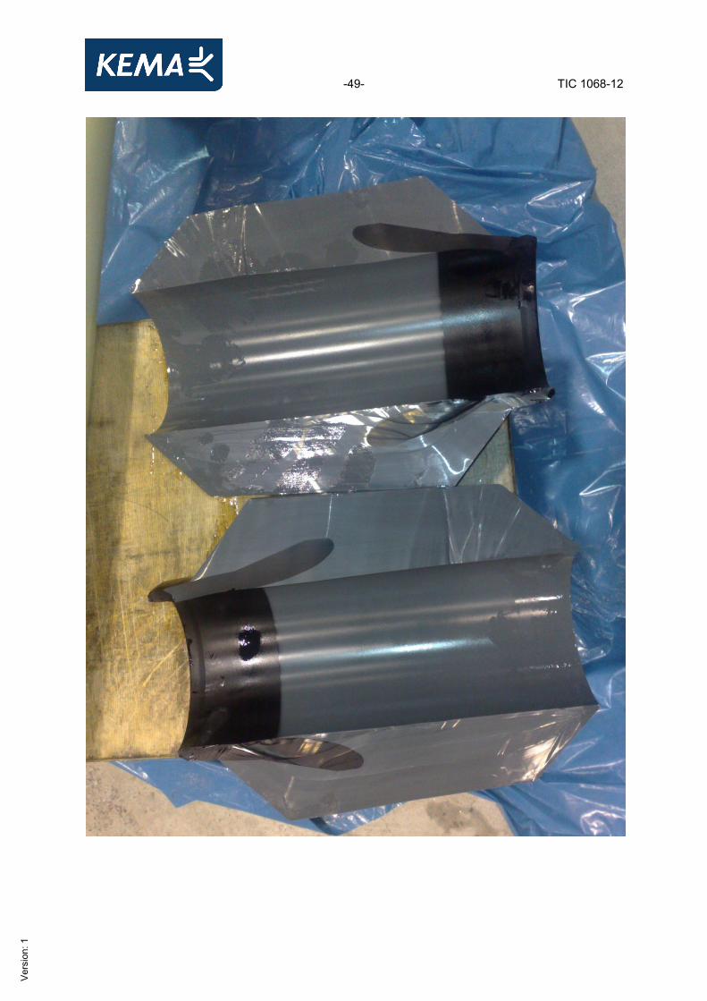
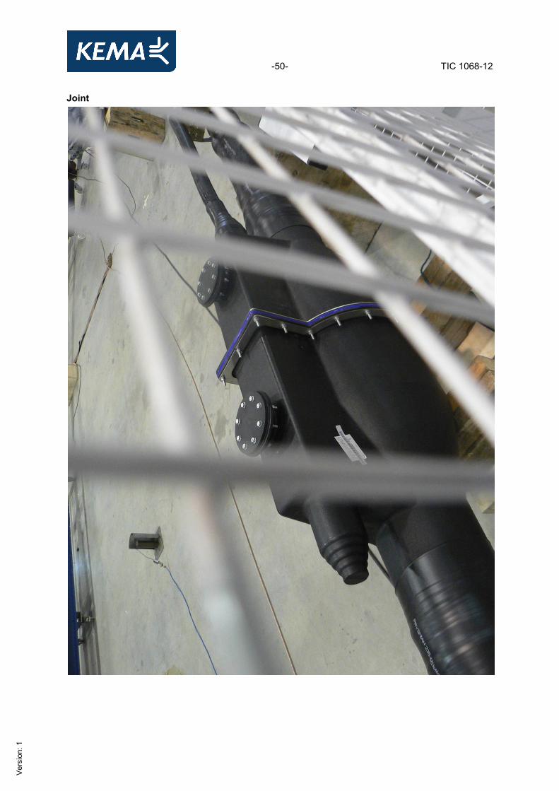
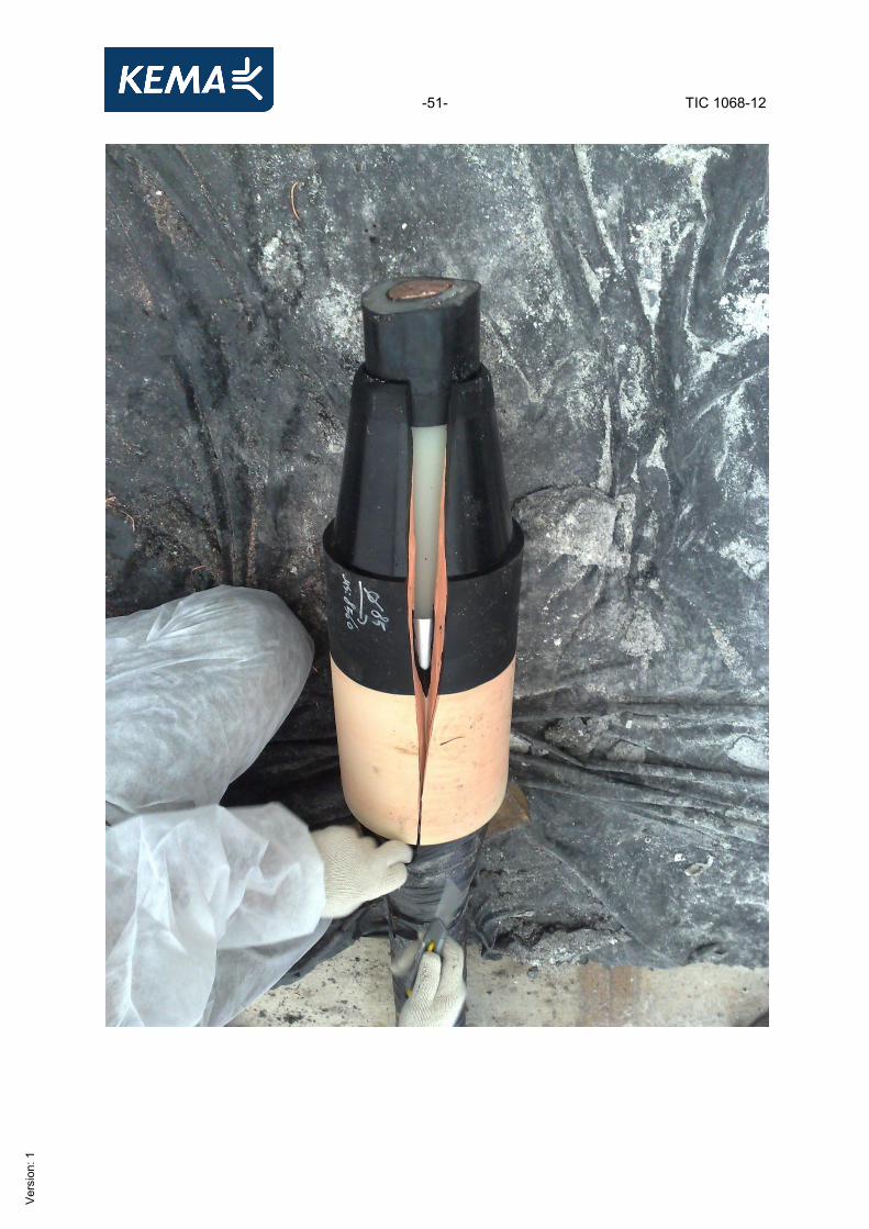
Joint
-51- TIC 1068-12
Ver
sion
: 1
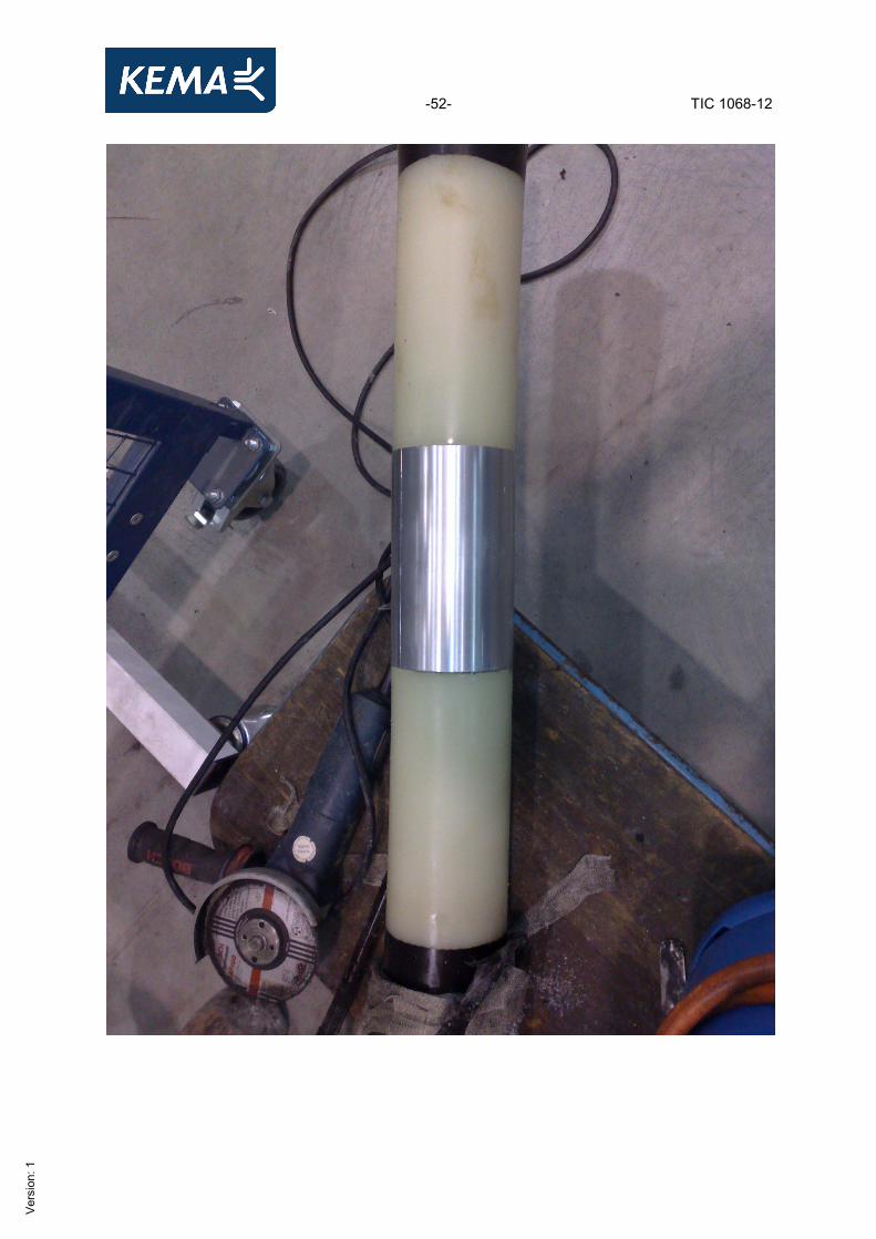
-52- TIC 1068-12
Ver
sion
: 1
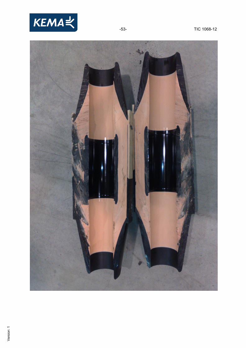
-53- TIC 1068-12
Ver
sion
: 1
-54- TIC 1068-12
Ver
sion
: 1
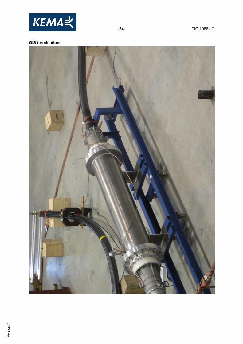
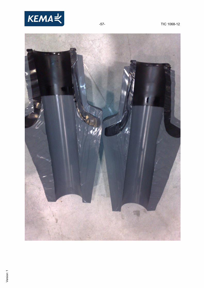
GIS terminations
-55- TIC 1068-12
Ver
sion
: 1
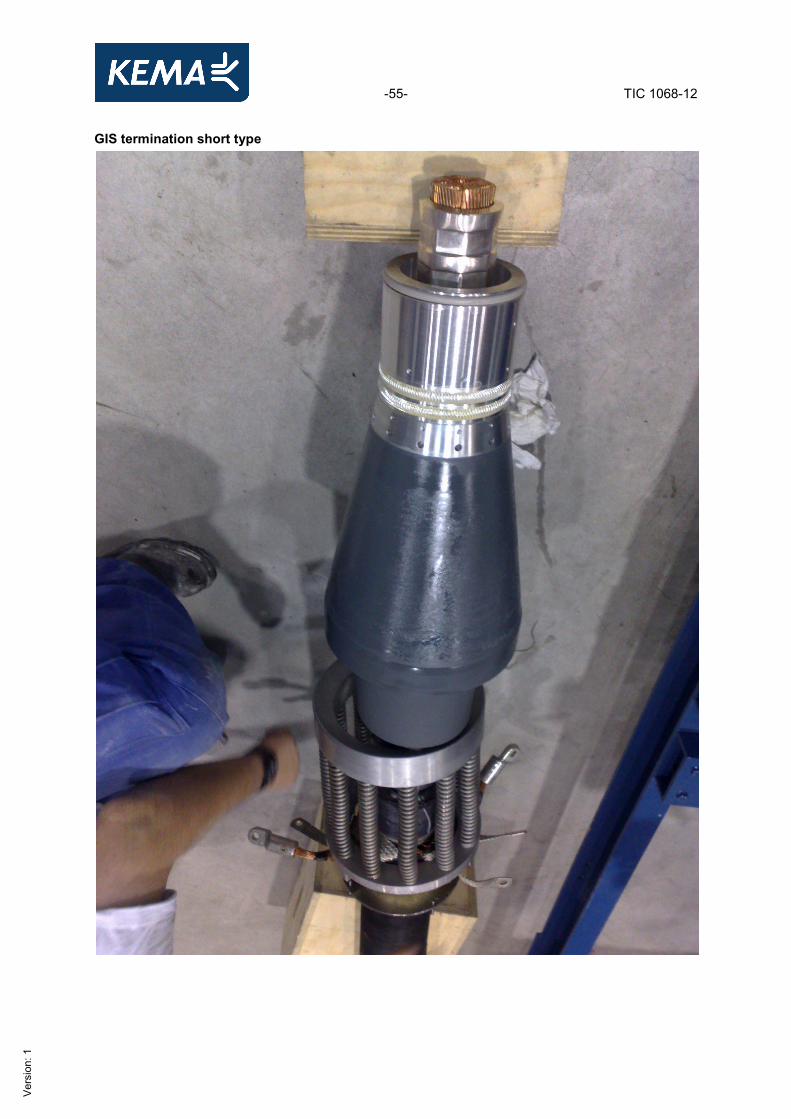
GIS termination short type

-56- TIC 1068-12
Ver
sion
: 1
-57- TIC 1068-12
Ver
sion
: 1
-58- TIC 1068-12
Ver
sion
: 1
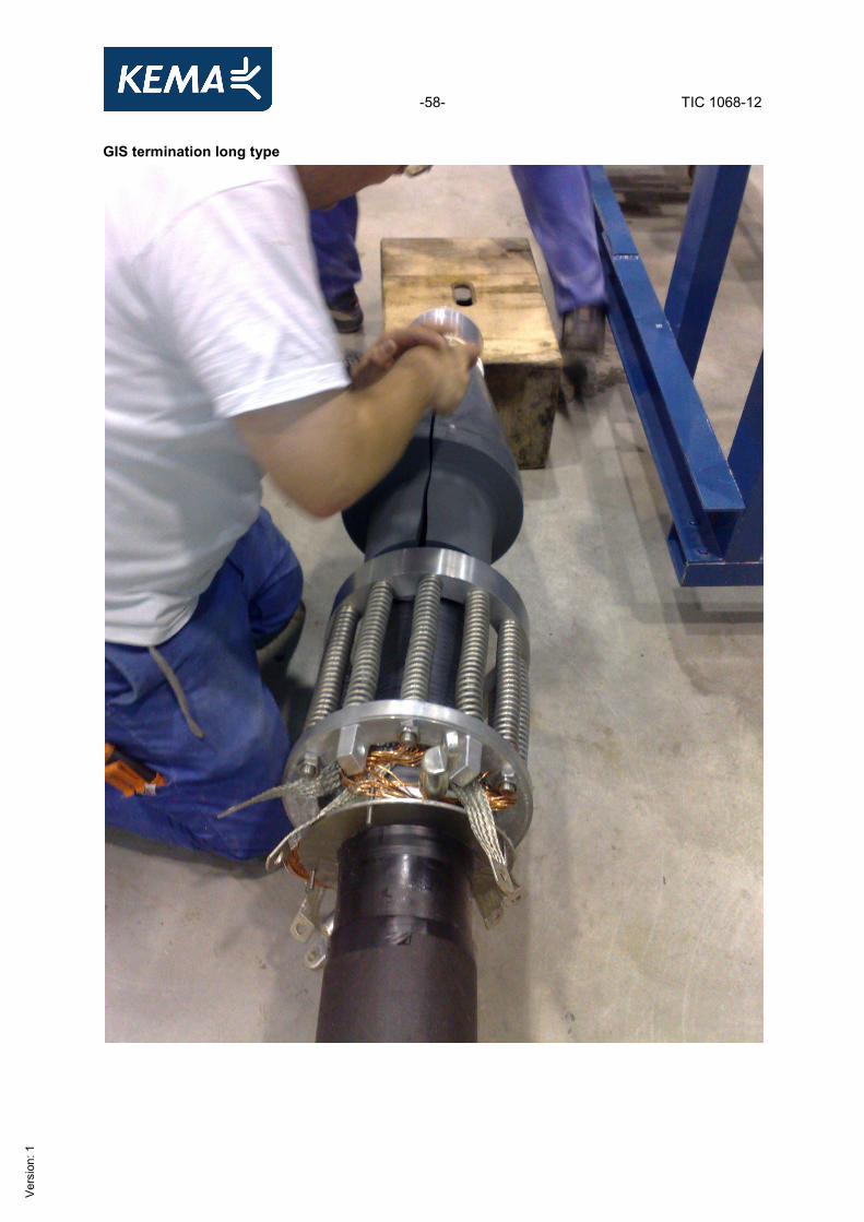
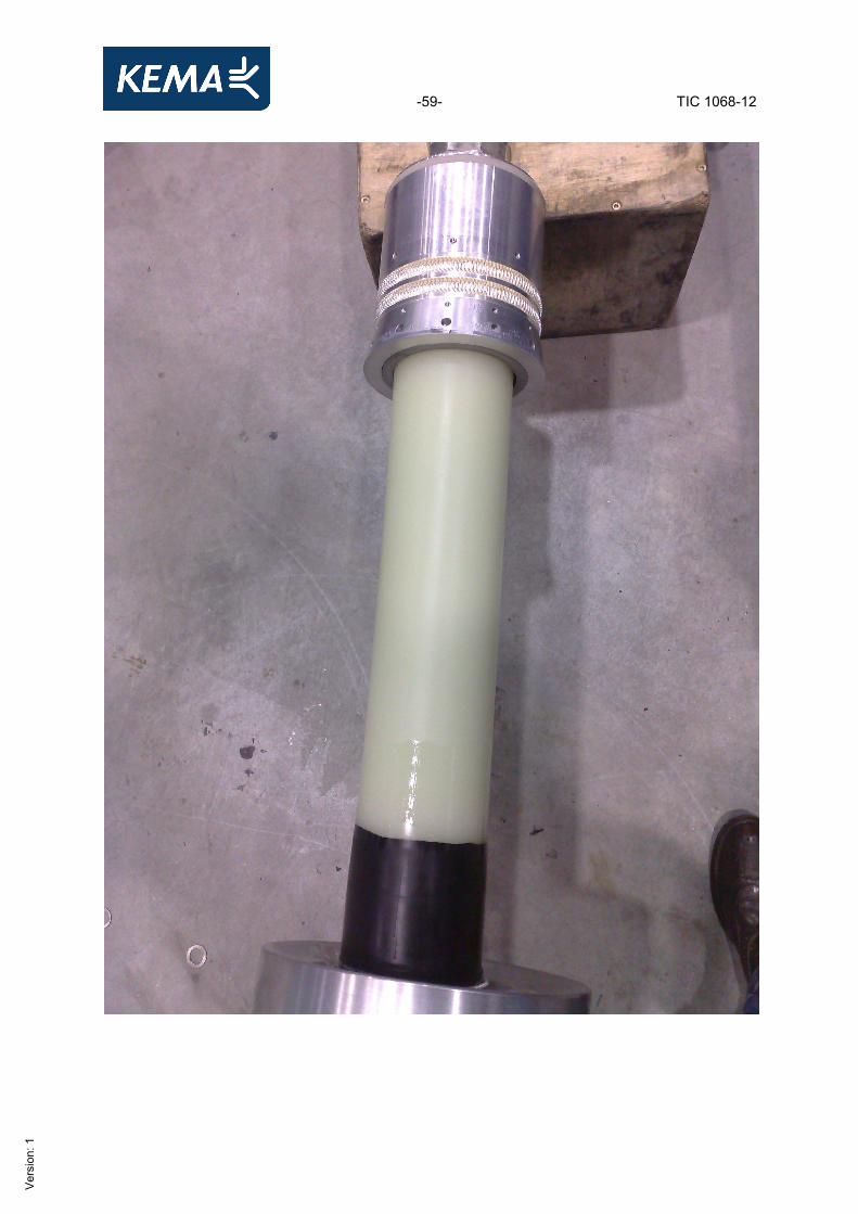
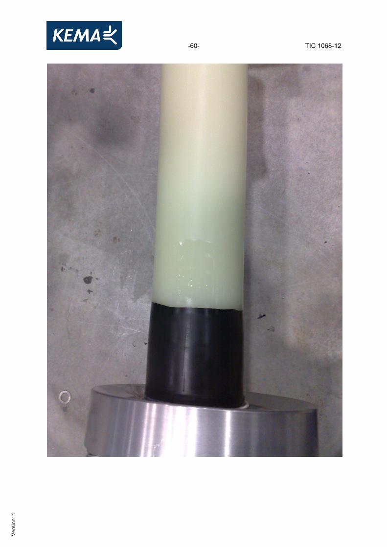
GIS termination long type
-59- TIC 1068-12
Ver
sion
: 1
-60- TIC 1068-12
Ver
sion
: 1
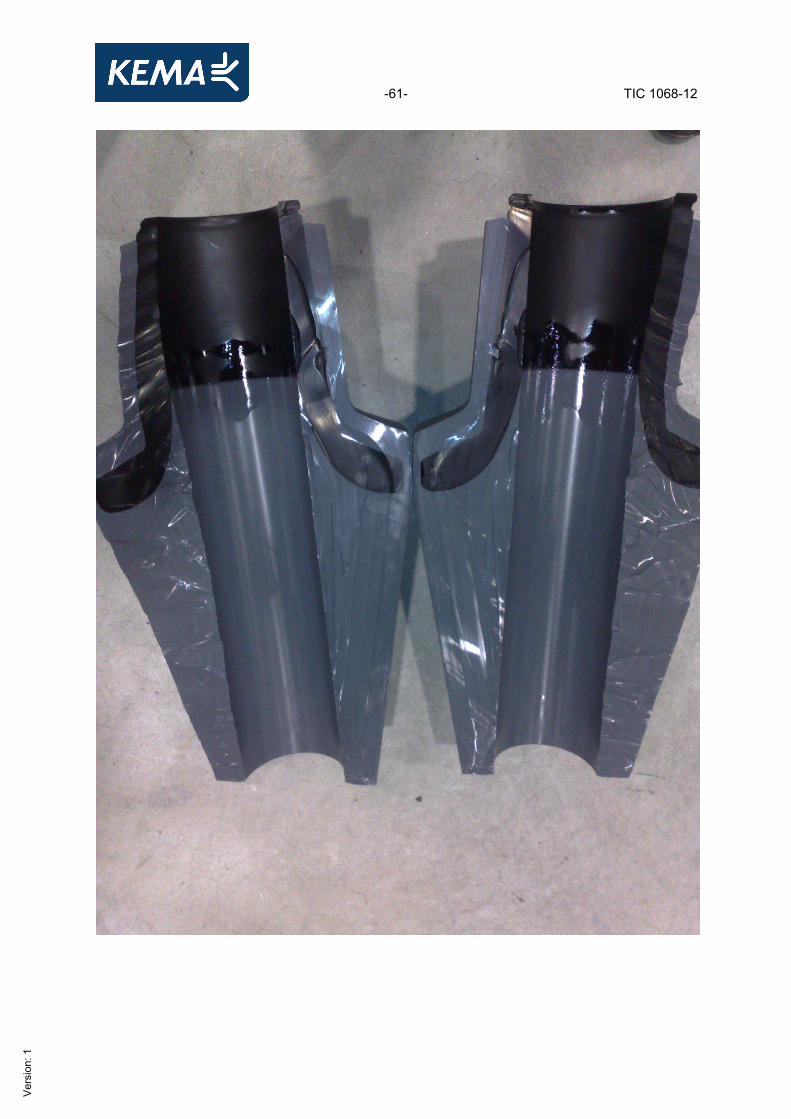
-61- TIC 1068-12
Ver
sion
: 1
-62- TIC 1068-12
Ver
sion
: 1
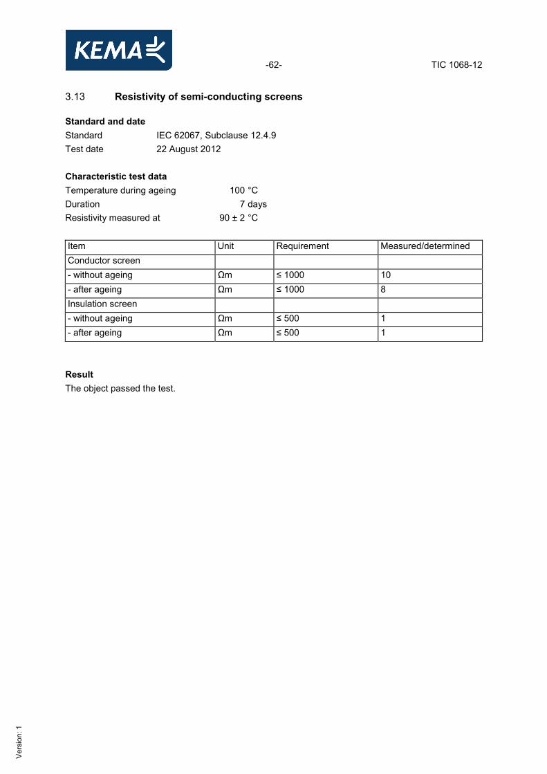
3.13 Resistivity of semi-conducting screens Standard and date Standard IEC 62067, Subclause 12.4.9 Test date 22 August 2012 Characteristic test dataTemperature during ageing 100 °C Duration 7 days Resistivity measured at 90 ± 2 °C Item Unit Requirement Measured/determined Conductor screen - without ageing Ωm ≤ 1000 10 - after ageing Ωm ≤ 1000 8 Insulation screen - without ageing Ωm ≤ 500 1 - after ageing Ωm ≤ 500 1 Result The object passed the test.
-63- TIC 1068-12
Ver
sion
: 1
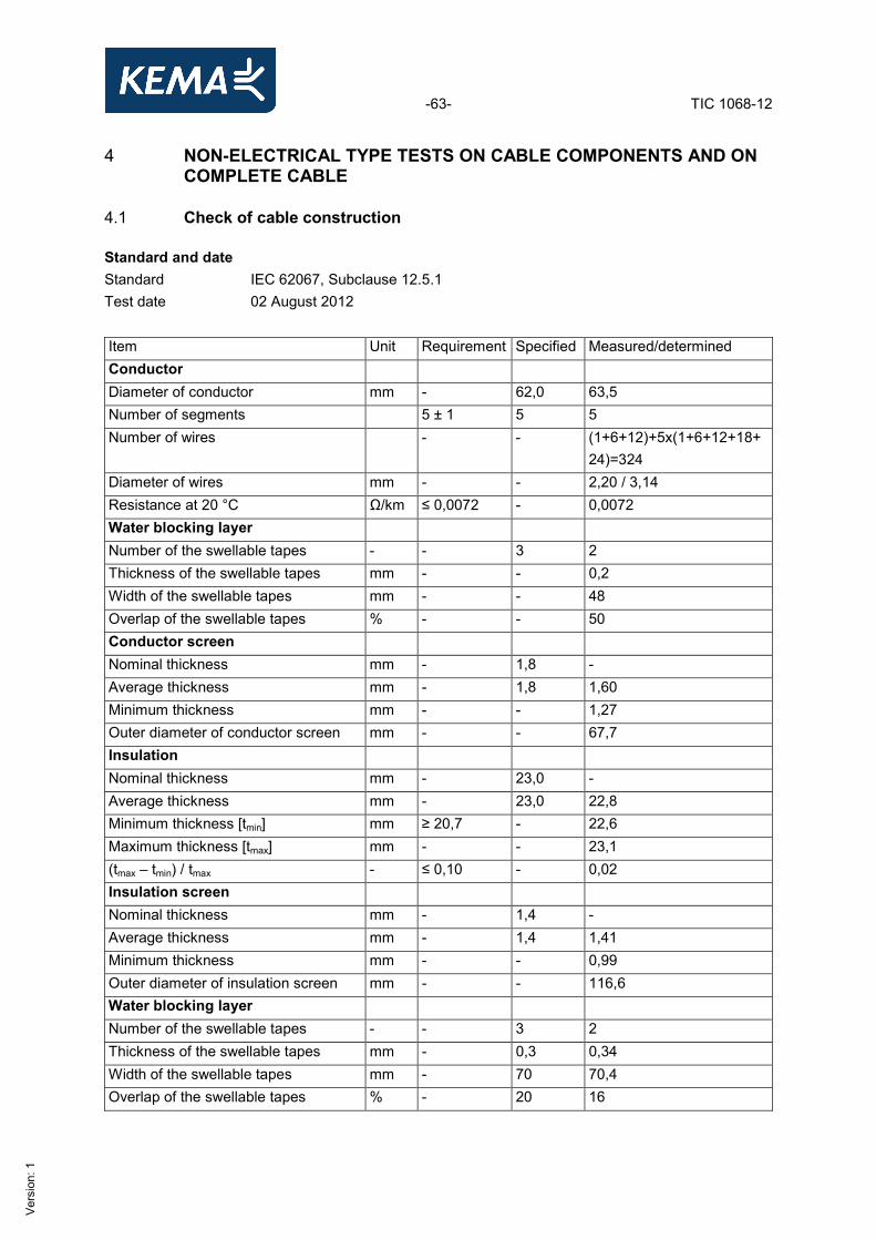
4 NON-ELECTRICAL TYPE TESTS ON CABLE COMPONENTS AND ON COMPLETE CABLE
4.1 Check of cable construction Standard and date Standard IEC 62067, Subclause 12.5.1 Test date 02 August 2012 Item Unit Requirement Specified Measured/determined Conductor Diameter of conductor mm - 62,0 63,5 Number of segments 5 ± 1 5 5 Number of wires - - (1+6+12)+5x(1+6+12+18+
24)=324 Diameter of wires mm - - 2,20 / 3,14 Resistance at 20 °C Ω/km ≤ 0,0072 - 0,0072 Water blocking layer Number of the swellable tapes - - 3 2 Thickness of the swellable tapes mm - - 0,2 Width of the swellable tapes mm - - 48 Overlap of the swellable tapes % - - 50 Conductor screen Nominal thickness mm - 1,8 - Average thickness mm - 1,8 1,60 Minimum thickness mm - - 1,27 Outer diameter of conductor screen mm - - 67,7 Insulation Nominal thickness mm - 23,0 - Average thickness mm - 23,0 22,8 Minimum thickness [tmin] mm ≥ 20,7 - 22,6 Maximum thickness [tmax] mm - - 23,1 (tmax – tmin) / tmax - ≤ 0,10 - 0,02 Insulation screen Nominal thickness mm - 1,4 - Average thickness mm - 1,4 1,41 Minimum thickness mm - - 0,99 Outer diameter of insulation screen mm - - 116,6 Water blocking layer Number of the swellable tapes - - 3 2 Thickness of the swellable tapes mm - 0,3 0,34 Width of the swellable tapes mm - 70 70,4 Overlap of the swellable tapes % - 20 16
-64- TIC 1068-12
Ver
sion
: 1
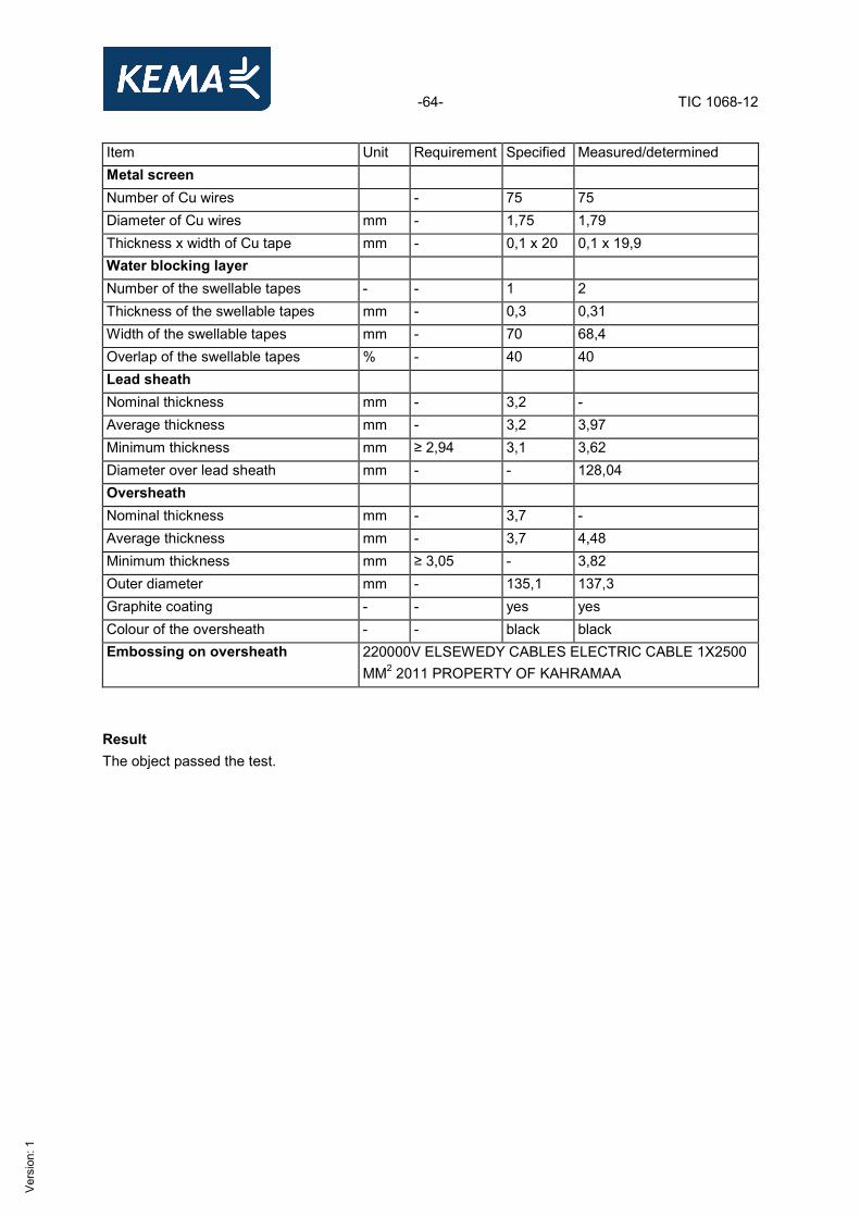
Item Unit Requirement Specified Measured/determined Metal screen Number of Cu wires - 75 75 Diameter of Cu wires mm - 1,75 1,79 Thickness x width of Cu tape mm - 0,1 x 20 0,1 x 19,9 Water blocking layer Number of the swellable tapes - - 1 2 Thickness of the swellable tapes mm - 0,3 0,31 Width of the swellable tapes mm - 70 68,4 Overlap of the swellable tapes % - 40 40 Lead sheath Nominal thickness mm - 3,2 - Average thickness mm - 3,2 3,97 Minimum thickness mm ≥ 2,94 3,1 3,62 Diameter over lead sheath mm - - 128,04 Oversheath Nominal thickness mm - 3,7 - Average thickness mm - 3,7 4,48 Minimum thickness mm ≥ 3,05 - 3,82 Outer diameter mm - 135,1 137,3 Graphite coating - - yes yes Colour of the oversheath - - black black Embossing on oversheath 220000V ELSEWEDY CABLES ELECTRIC CABLE 1X2500
MM2 2011 PROPERTY OF KAHRAMAA Result The object passed the test.
-65- TIC 1068-12
Ver
sion
: 1
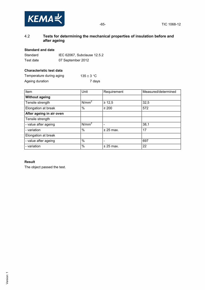
4.2 Tests for determining the mechanical properties of insulation before and after ageing
Standard and date Standard IEC 62067, Subclause 12.5.2 Test date 07 September 2012 Characteristic test data Temperature during aging 135 ± 3 °C Ageing duration 7 days Item Unit Requirement Measured/determined Without ageing Tensile strength N/mm2 ≥ 12,5 32,5 Elongation at break % ≥ 200 572 After ageing in air oven Tensile strength - value after ageing N/mm2 - 38,1 - variation % ± 25 max. 17 Elongation at break - value after ageing % - 697 - variation % ± 25 max. 22 Result The object passed the test.
-66- TIC 1068-12
Ver
sion
: 1
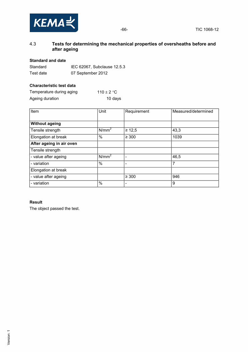
4.3 Tests for determining the mechanical properties of oversheaths before and after ageing
Standard and date Standard IEC 62067, Subclause 12.5.3 Test date 07 September 2012 Characteristic test data Temperature during aging 110 ± 2 °C Ageing duration 10 days Item Unit Requirement Measured/determined
Without ageing Tensile strength N/mm2 ≥ 12,5 43,3 Elongation at break % ≥ 300 1039 After ageing in air oven Tensile strength - value after ageing N/mm2 - 46,5 - variation % - 7 Elongation at break - value after ageing ≥ 300 946 - variation % - 9 Result The object passed the test.
-67- TIC 1068-12
Ver
sion
: 1
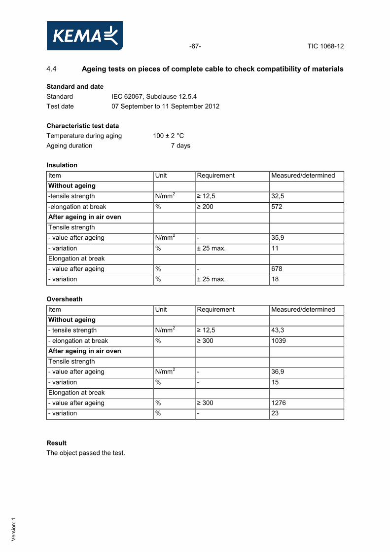
4.4 Ageing tests on pieces of complete cable to check compatibility of materials Standard and date Standard IEC 62067, Subclause 12.5.4 Test date 07 September to 11 September 2012 Characteristic test data Temperature during aging 100 ± 2 °C Ageing duration 7 days Insulation Item Unit Requirement Measured/determined Without ageing -tensile strength N/mm2 ≥ 12,5 32,5 -elongation at break % ≥ 200 572 After ageing in air oven Tensile strength - value after ageing N/mm2 - 35,9 - variation % ± 25 max. 11 Elongation at break - value after ageing % - 678 - variation % ± 25 max. 18 Oversheath Item Unit Requirement Measured/determined Without ageing - tensile strength N/mm2 ≥ 12,5 43,3 - elongation at break % ≥ 300 1039 After ageing in air oven Tensile strength - value after ageing N/mm2 - 36,9 - variation % - 15 Elongation at break - value after ageing % ≥ 300 1276 - variation % - 23 Result The object passed the test.
-68- TIC 1068-12
Ver
sion
: 1
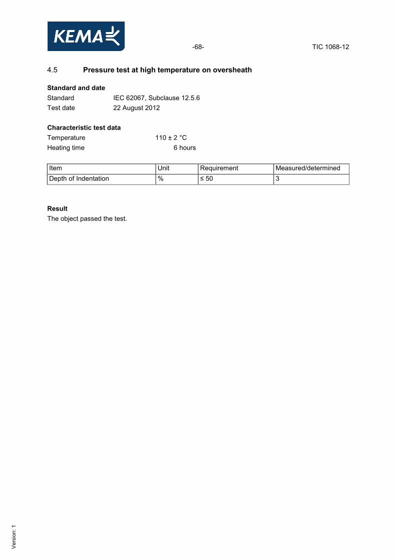
4.5 Pressure test at high temperature on oversheath Standard and date Standard IEC 62067, Subclause 12.5.6 Test date 22 August 2012 Characteristic test data Temperature 110 ± 2 °C Heating time 6 hours Item Unit Requirement Measured/determined Depth of Indentation % ≤ 50 3
Result The object passed the test.
-69- TIC 1068-12
Ver
sion
: 1
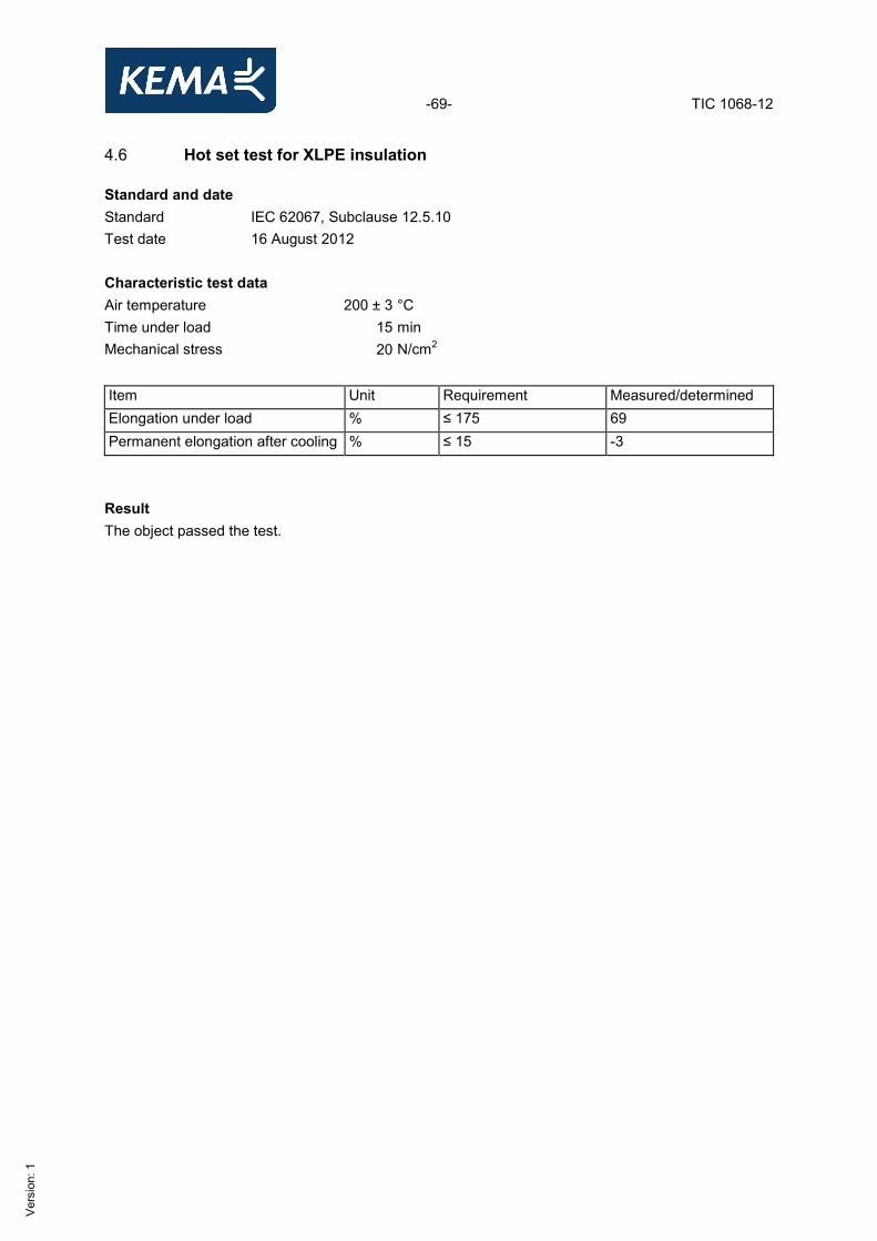
4.6 Hot set test for XLPE insulation Standard and date Standard IEC 62067, Subclause 12.5.10 Test date 16 August 2012 Characteristic test data Air temperature 200 ± 3 °C Time under load 15 min Mechanical stress 20 N/cm2 Item Unit Requirement Measured/determined Elongation under load % ≤ 175 69 Permanent elongation after cooling % ≤ 15 -3 Result The object passed the test.
-70- TIC 1068-12
Ver
sion
: 1
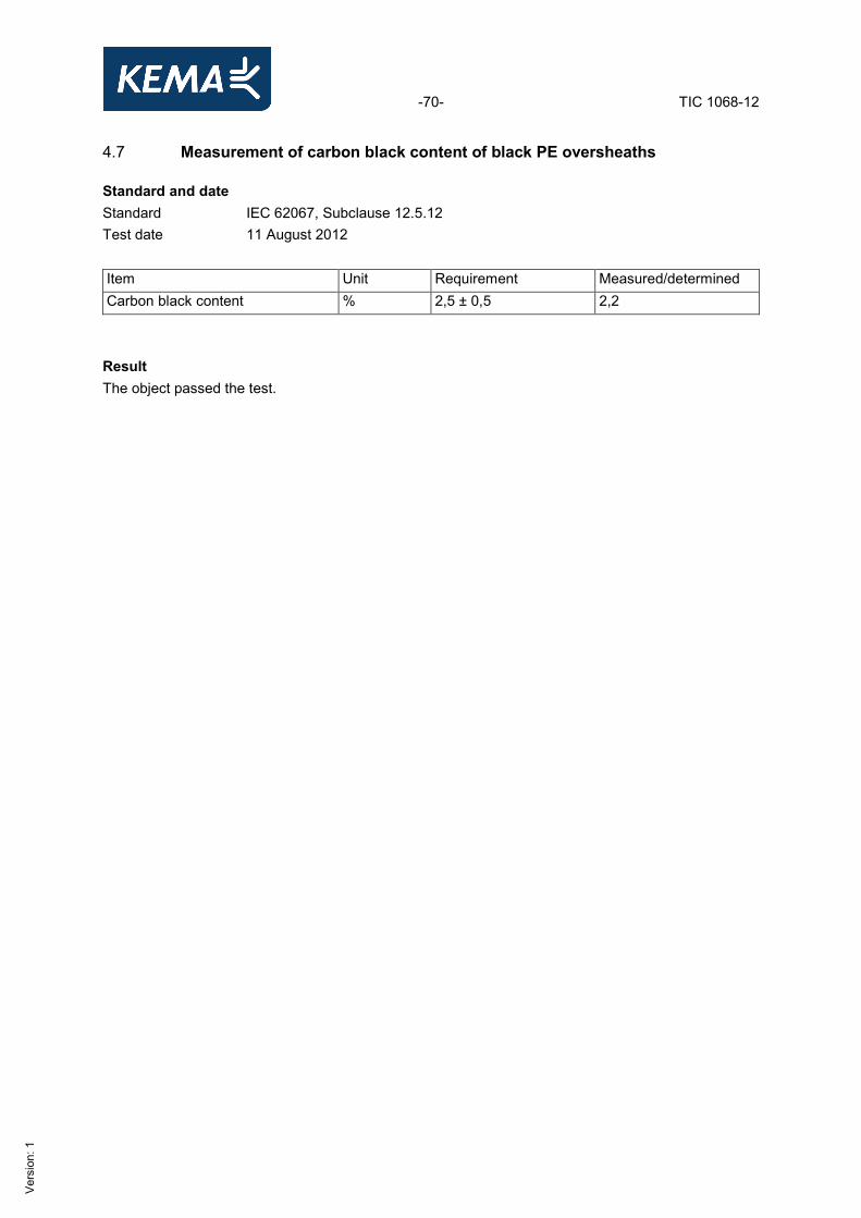
4.7 Measurement of carbon black content of black PE oversheaths Standard and date Standard IEC 62067, Subclause 12.5.12 Test date 11 August 2012 Item Unit Requirement Measured/determined Carbon black content % 2,5 ± 0,5 2,2 Result The object passed the test.
-71- TIC 1068-12
Ver
sion
: 1
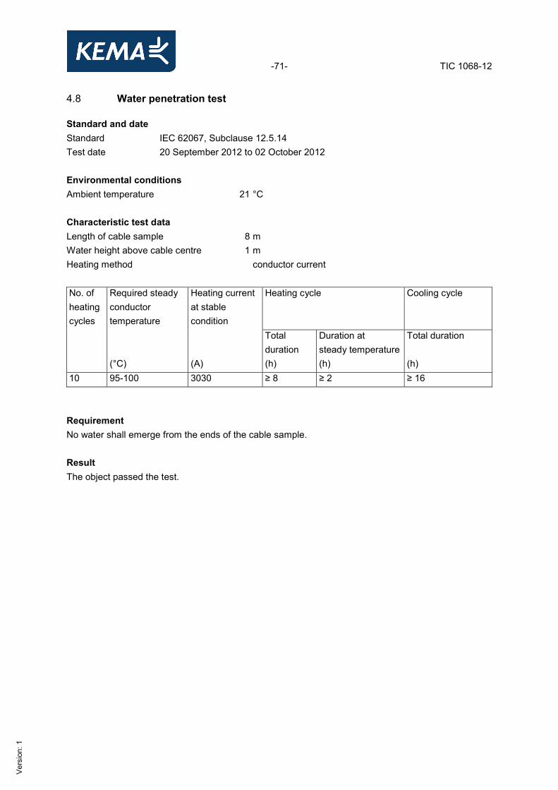
4.8 Water penetration test Standard and date Standard IEC 62067, Subclause 12.5.14 Test date 20 September 2012 to 02 October 2012 Environmental conditions Ambient temperature 21 °C Characteristic test dataLength of cable sample 8 m Water height above cable centre 1 m Heating method conductor current No. of heating cycles
Required steady conductor temperature
Heating current at stable condition
Heating cycle Cooling cycle
(°C)
(A)
Total duration (h)
Duration at steady temperature (h)
Total duration (h)
10 95-100 3030 ≥ 8 ≥ 2 ≥ 16 Requirement No water shall emerge from the ends of the cable sample. Result The object passed the test.
-72- TIC 1068-12
Ver
sion
: 1
5 DRAWINGS

-73- TIC 1068-12
Ver
sion
: 1
-74- TIC 1068-12
Ver
sion
: 1
-75- TIC 1068-12
Ver
sion
: 1

-76- TIC 1068-12
Ver
sion
: 1
-77- TIC 1068-12
Ver
sion
: 1
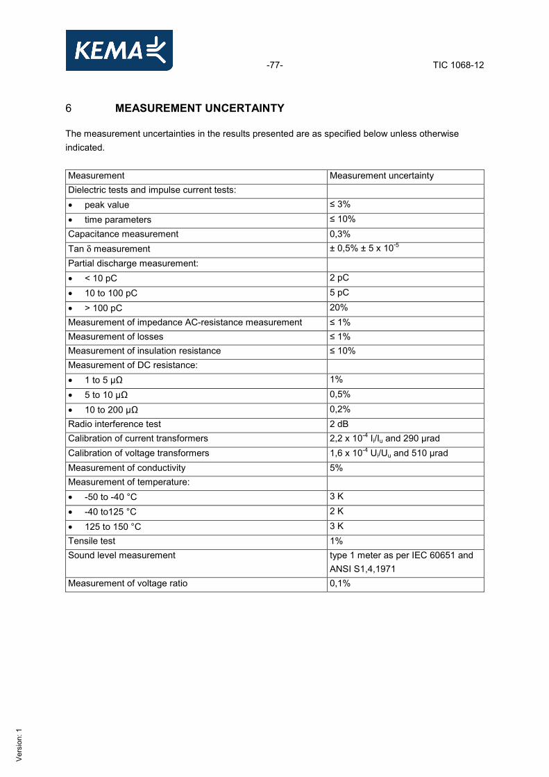
6 MEASUREMENT UNCERTAINTY The measurement uncertainties in the results presented are as specified below unless otherwise indicated. Measurement Measurement uncertainty Dielectric tests and impulse current tests: • peak value ≤ 3%
• time parameters ≤ 10% Capacitance measurement 0,3% Tan δ measurement ± 0,5% ± 5 x 10⁻⁵ Partial discharge measurement: • < 10 pC 2 pC
• 10 to 100 pC 5 pC
• > 100 pC 20% Measurement of impedance AC-resistance measurement ≤ 1% Measurement of losses ≤ 1% Measurement of insulation resistance ≤ 10% Measurement of DC resistance: • 1 to 5 µΩ 1%
• 5 to 10 µΩ 0,5%
• 10 to 200 µΩ 0,2% Radio interference test 2 dB Calibration of current transformers 2,2 x 10⁻⁴ Ii/Iu and 290 µrad Calibration of voltage transformers 1,6 x 10⁻⁴ Ui/Uu and 510 µrad Measurement of conductivity 5% Measurement of temperature: • -50 to -40 °C 3 K
• -40 to125 °C 2 K
• 125 to 150 °C 3 K Tensile test 1% Sound level measurement type 1 meter as per IEC 60651 and
ANSI S1,4,1971 Measurement of voltage ratio 0,1%