Robustness Assessment of Building Structures under Explosion
Upload
khangminh22Category
view
1download
0
Explosion Proof
Explosion Proof

Table of Contents
Lighting Fixtures………………………………………………………………………………..…….I
Panels…………………………………………………………………………………………..……..II
Sockets and Plugs…………………………………………………………………………..……...III
Motor Starters…………………………………………………………………………………...…..IV
Fittings…………………………………………………………………………………………………V
Junction Box………………………………………………………………………………...………VI
CMPHA
ZARD
OUSAR
EAPR
ODUC
TS
112
C A B L E G L A N D A N D C A B L E C O N N E C T I O N S P E C I A L I S T S CMP
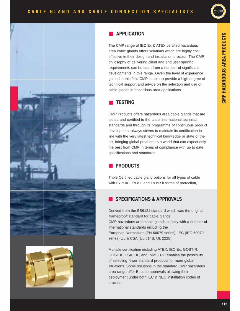
APPLICATION
The CMP range of IEC Ex & ATEX certified hazardous
area cable glands offers solutions which are highly cost
effective in their design and installation process. The CMP
philosophy of delivering client and end user specific
requirements can be seen from a number of significant
developments in this range. Given the level of experience
gained in this field CMP is able to provide a high degree of
technical support and advice on the selection and use of
cable glands in hazardous area applications.
PRODUCTS
Triple Certified cable gland options for all types of cable
with Ex d IIC, Ex e II and Ex nR II forms of protection,
SPECIFICATIONS & APPROVALS
Derived from the BS6121 standard which was the original
‘flameproof’ standard for cable glands
CMP hazardous area cable glands comply with a number of
international standards including the
European Normatives (EN 60079 series), IEC (IEC 60079
series) UL & CSA (UL 514B, UL 2225).
Multiple certification including ATEX, IEC Ex, GOST R,
GOST K, CSA, UL, and INMETRO enables the possibility
of selecting fewer standard products for more global
situations. Some solutions in the standard CMP hazardous
area range offer Bi-code approvals allowing their
deployment under both IEC & NEC installation codes of
practice.
TESTING
CMP Products offers hazardous area cable glands that are
tested and certified to the latest international technical
standards and through its programme of continuous product
development always strives to maintain its certification in
line with the very latest technical knowledge or state of the
art, bringing global products to a world that can expect only
the best from CMP in terms of compliance with up to date
specifications and standards.

CMP
CMPHA
ZARD
OUSAR
EAPR
ODUC
TSC A B L E G L A N D A N D C A B L E C O N N E C T I O N S P E C I A L I S T S
113 www.cmp-products.com
CMP Triton CDS Type T3CDS Triple Certified Flameproof (Type 'd'), Increased Safety (Type 'e') and Restricted Breathing (Type ‘nR’)indoor and outdoor cable gland for use in Zone 1, Zone 2, Zone 21 and Zone 22 Hazardous Areas with all types of armoured cableproviding a Flameproof seal on the cable inner bedding and an environmental seal on the cable outer sheath. This product utilises aunique Compensating Displacement Seal (CDS) system which provides full compatibility with Restricted Breathing equipment. Thecable gland provides mechanical cable retention and electrical continuity via armour wire termination. A reversible armour cone andAnyWay universal clamping ring arrangement allows the cable to be easily disconnected from the equipment, for maintenance andchange out etc., and re-connected with the same consummate ease. This feature also facilitates remote make off procedures whenthe termination is to be conducted in confined spaces or in areas of restricted access. Separate tightening actions for the innerCompensating Displacement Seal (CDS) system and the armour termination affords maximum control over the pressure applied tothe cable inner bedding. The CMP Triton CDS Cable Gland is suitable for use with all forms of equipment protection permitted inZone 1, Zone 2 , Zone 21 & Zone 22 provided always that the prevailing code of practice for selection and installation is observed,e.g. IEC 60079-14.
TECHNICAL DATAType T3CDSDesign Specification BS 6121:Part 1:1989, EN 50262:1999, UL 514BATEX Certification SIRA06ATEX1283X
Code of Protection Category ATEX II 2/3 GD Ex d IIC, Ex e II, Ex nR II, Ex tD A21 IP66, Equipment Zone 1,Zone 2, Zone 21, & Zone 22 - Gas Groups IIA, IIB, IIC
Compliance Standards EN 60079-0:2006, EN 60079-1:2004, EN 60079-7:2003, EN 60079-15:2005,EN 61241-0:2004, EN 61241-1:2004
IECEx Approval Number IECEx SIR 07.005XCode of Protection Category Ex d IIC / Ex e II / Ex nR II / Ex tD A21 IP66
Compliance Standards IEC 60079-0:2004, IEC 60079-1:2003, IEC 60079-7:2006, IEC 60079-15:2005,IEC 61241-0:2004, IEC 61241-1:2004
CSA Certification 1310517
Code of Protection Category Ex d IIC Ex e II, Class I, II, III, Class II Div 2 Groups EFG, Enclosure Type 3, 4 and 4X,Class I Div 2 Groups ABCD, Class III
Compliance Standards CSA C22.2 No. 174-M1984, CSA C22.2 No. 25-1966, CAN/CSA-C22.2 No. 18-92, CAN/CSA-C22.2 No. 94-M91, CAN/CSA-E60079-0-2001, IEC 60079-0 1998, CAN/CSA-E79-7-95
UL Listing File Number UBWE.E200163, CYMJ.E256366, FDJR.E256367Code of Protection Category Ordinary & Wet Locations, Class I, Zone 1, AEx e II, Class I, Zone 2, AEx e IICompliance Standards UL 514B, ANSI / UL 60079-0, ANSI / UL 60079-7GOST R Certificate Number POCC GB. 05.B01912Code of Protection Category Ex d IIC U / Ex e II UCompliance Standards P 52350.0-2005, P 52350.1-2005, P 52350.7-2005GGTN Permit Number PPC 00-18262GOST K Certificate Number KZ7500052.05.01.00063RoK Permit for Use Number 08-067693Lloyds Approval Number 01/00172DNV Approval Number E-6157ABS Approval Number 01-LD 234401-PDAContinuous Operating Temperature -60°C to +130°CIngress Protection Rating IP66, IP67, IP68Deluge Protection Compliance DTS01 : 91Deluge Protection Document ITS 01005029 - DCable Gland Material Brass, Electroless Nickel Plated Brass, Aluminium, Stainless SteelSeal Material CMP SOLO LSF Thermoplastic Elastomer
Cable TypeSingle Wire Armour (SWA), Aluminium Wire Armour (AWA), Pliable Wire Armour(PWA), Steel Tape Armour (STA), Wire Braid Armour, Aluminium Strip Armour (ASA),Screened Flexible Wire Braid (e.g. CY / SY), Armored & Jacketed
Armour Clamping Reversible Armour Cone & AnyWay Universal Clamping RingSealing Technique CMP Inner CDS System & Unique CMP "LRS" ™ Outer Seal (Load Retention Seal)Sealing Area(s) Cable Inner Bedding & Cable Outer SheathOptional Accessories Locknut, Shroud, Entry Thread Seal, Serrated Washer, Earth Tag, Adaptor/Reducer
Triton CDS (T3CDS) Flameproof Ex d, Increased Safety Ex e andRestricted Breathing Ex nR Cable GlandT3CDS GLAND
CableGlandSize
Available Entry Threads ‘C’MinimumThread
Length ‘E’
CableBedding
Diameter ‘A’
OverallCable
Diameter ‘B’
Armour Range † AcrossFlats‘D’
AcrossCorners‘D’
NominalProtrusionLength ‘F’
OrderingReference
(Brass Metric)#
CableGlandWeight(Kgs)
Standard Option Grooved Cone Stepped Cone
Metric NPT NPT Min Max Min Max Min Max Min Max Max Max
20S/16 M20 1/2” 3/4” 15.0 3.1 8.7 6.1 11.5 0.15 1.0 0.9 1.0 24.0 26.6 70.0 20S16T3CDS1RA 0.17020S M20 1/2” 3/4” 15.0 6.1 11.7 9.5 15.9 0.15 1.0 0.9 1.25 24.0 26.6 70.0 20ST3CDS1RA 0.17020 M20 1/2” 3/4” 15.0 6.5 14.0 12.5 20.9 0.15 1.0 0.9 1.25 30.5 33.3 72.0 20T3CDS1RA 0.25625S M25 3/4” 1” 15.0 11.1 20.0 14.0 22.0 0.15 1.0 1.25 1.6 37.5 40.5 82.0 25ST3CDS1RA 0.38425 M25 3/4” 1” 15.0 11.1 20.0 18.2 26.2 0.15 1.0 1.25 1.6 37.5 40.5 82.0 25T3CDS1RA 0.37932 M32 1” 1-1/4” 15.0 17.0 26.3 23.7 33.9 0.15 1.0 1.6 2.0 46.0 51.0 85.0 32T3CDS1RA 0.56040 M40 1-1/4” 1-1/2” 15.0 22.0 32.2 27.9 40.4 0.15 1.0 1.6 2.0 55.0 61.0 86.0 40T3CDS1RA 0.84850S M50 1-1/2” 2” 15.0 29.5 38.2 35.2 46.7 0.15 1.0 2.0 2.5 60.0 66.5 98.0 50ST3CDS1RA 1.05550 M50 2” 2-1/2” 15.0 35.6 44.1 40.4 53.1 0.15 1.0 2.0 2.5 70.0 78.6 100.0 50T3CDS1RA 1.52163S M63 2” 2-1/2” 15.0 40.1 50.0 45.6 59.4 0.15 1.0 2.0 2.5 75.0 83.2 108.0 63ST3CDS1RA 1.75063 M63 2-1/2” 3” 15.0 47.2 56.0 54.6 65.9 0.15 1.0 2.0 2.5 80.0 89.0 103.0 63T3CDS1RA 1.68575S M75 2-1/2” 3” 15.0 52.8 62.0 59.0 72.1 0.15 1.0 2.0 2.5 89.0 101.6 105.0 75ST3CDS1RA 2.34575 M75 3” 3-1/2” 15.0 59.1 68.0 66.7 78.5 0.15 1.0 2.0 2.5 99.0 111.1 114.0 75T3CDS1RA 3.20090 M90 3” 3-1/2” 15.0 66.6 80.0 76.2 90.4 0.25 1.6 3.15 3.15 114.0 128.6 140.0 90T3CDS1RA 5.100100 M100 4” 4-1/2” 15.0 80.0 91.0 86.1 101.5 0.25 1.6 3.15 4.0 123.0 138.0 170.0 100T3CDS1RA 6.500115 M115 4-1/2” 5” 15.0 90.0 98.0 101.5 110.3 0.25 1.6 3.15 4.0 133.4 147.6 210.0 115T3CDS1RA 7.000130 M130 5” 6” 15.0 100.0 115.0 114.2 123.3 0.25 1.6 3.15 4.0 146.1 161.9 250.0 130T3CDS1RA 7.800
All dimensions in millimetres
A
B
D
C
E
F
Note: †Alternative armour clamping range available for non-standard armour sizes. Marine approvals including Lloyds, DNV & ABS are also available from CMP Products. # Other thread forms are available.
Note: Versions with dedicated armour cones, Type T3CDSW – for SWA cables only, and Type T3CDSX for all other approved cabletypes also available.
Cable Gland Selection Table
LLU
OCTL
OCTL
OCTL
LLU05
Note: Stepped Cone is suitable for SWA cables, GroovedCone is suitable for all other approved armoured cables
CMPHA
ZARD
OUSAR
EAPR
ODUC
TS
CMPC A B L E G L A N D A N D C A B L E C O N N E C T I O N S P E C I A L I S T S
114www.cmp-products.com
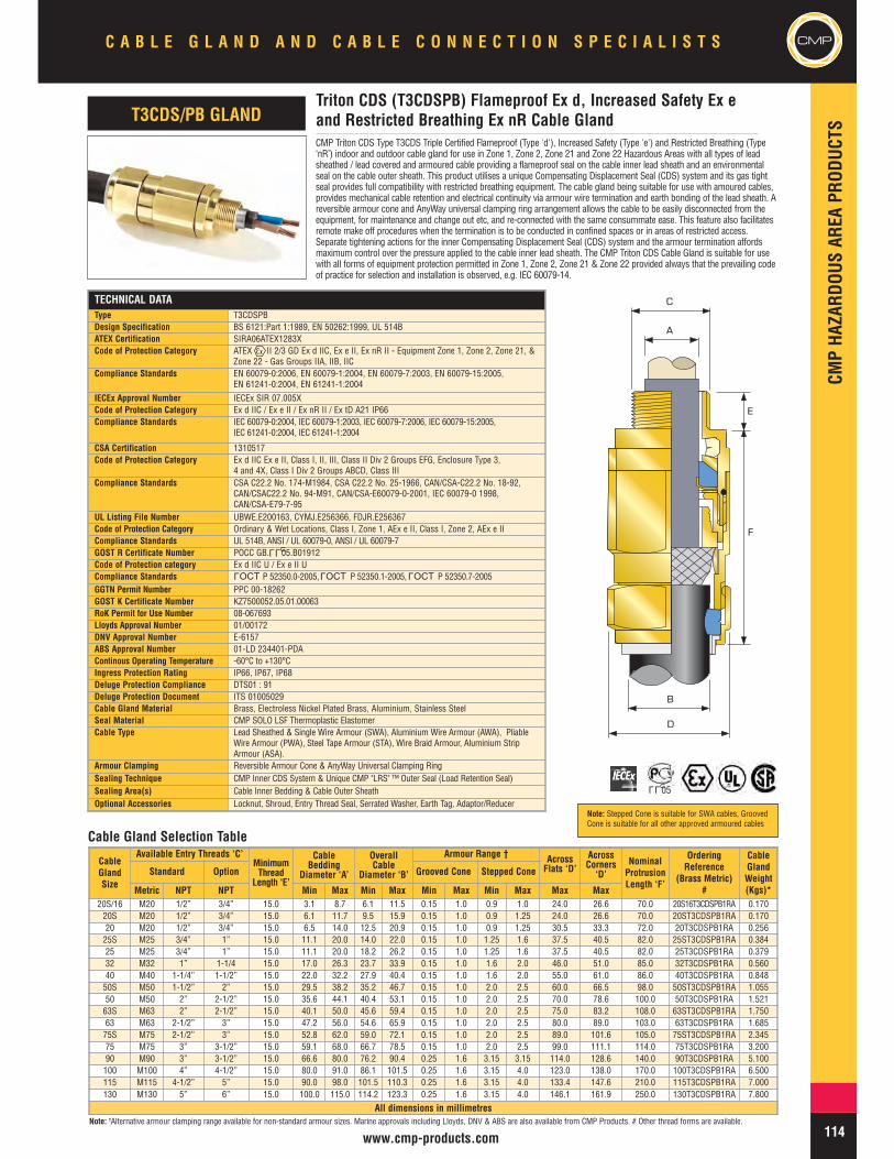
CMP Triton CDS Type T3CDS Triple Certified Flameproof (Type 'd'), Increased Safety (Type 'e') and Restricted Breathing (Type‘nR’) indoor and outdoor cable gland for use in Zone 1, Zone 2, Zone 21 and Zone 22 Hazardous Areas with all types of leadsheathed / lead covered and armoured cable providing a flameproof seal on the cable inner lead sheath and an environmentalseal on the cable outer sheath. This product utilises a unique Compensating Displacement Seal (CDS) system and its gas tightseal provides full compatibility with restricted breathing equipment. The cable gland being suitable for use with amoured cables,provides mechanical cable retention and electrical continuity via armour wire termination and earth bonding of the lead sheath. Areversible armour cone and AnyWay universal clamping ring arrangement allows the cable to be easily disconnected from theequipment, for maintenance and change out etc, and re-connected with the same consummate ease. This feature also facilitatesremote make off procedures when the termination is to be conducted in confined spaces or in areas of restricted access.Separate tightening actions for the inner Compensating Displacement Seal (CDS) system and the armour termination affordsmaximum control over the pressure applied to the cable inner lead sheath. The CMP Triton CDS Cable Gland is suitable for usewith all forms of equipment protection permitted in Zone 1, Zone 2, Zone 21 & Zone 22 provided always that the prevailing codeof practice for selection and installation is observed, e.g. IEC 60079-14.
TECHNICAL DATAType T3CDSPBDesign Specification BS 6121:Part 1:1989, EN 50262:1999, UL 514BATEX Certification SIRA06ATEX1283XCode of Protection Category ATEX II 2/3 GD Ex d IIC, Ex e II, Ex nR II - Equipment Zone 1, Zone 2, Zone 21, &
Zone 22 - Gas Groups IIA, IIB, IICCompliance Standards EN 60079-0:2006, EN 60079-1:2004, EN 60079-7:2003, EN 60079-15:2005,
EN 61241-0:2004, EN 61241-1:2004IECEx Approval Number IECEx SIR 07.005XCode of Protection Category Ex d IIC / Ex e II / Ex nR II / Ex tD A21 IP66Compliance Standards IEC 60079-0:2004, IEC 60079-1:2003, IEC 60079-7:2006, IEC 60079-15:2005,
IEC 61241-0:2004, IEC 61241-1:2004
CSA Certification 1310517Code of Protection Category Ex d IIC Ex e II, Class I, II, III, Class II Div 2 Groups EFG, Enclosure Type 3,
4 and 4X, Class I Div 2 Groups ABCD, Class IIICompliance Standards CSA C22.2 No. 174-M1984, CSA C22.2 No. 25-1966, CAN/CSA-C22.2 No. 18-92,
CAN/CSAC22.2 No. 94-M91, CAN/CSA-E60079-0-2001, IEC 60079-0 1998,CAN/CSA-E79-7-95
UL Listing File Number UBWE.E200163, CYMJ.E256366, FDJR.E256367Code of Protection Category Ordinary & Wet Locations, Class I, Zone 1, AEx e II, Class I, Zone 2, AEx e IICompliance Standards UL 514B, ANSI / UL 60079-0, ANSI / UL 60079-7GOST R Certificate Number POCC GB. 05.B01912Code of Protection category Ex d IIC U / Ex e II UCompliance Standards P 52350.0-2005, P 52350.1-2005, P 52350.7-2005GGTN Permit Number PPC 00-18262GOST K Certificate Number KZ7500052.05.01.00063RoK Permit for Use Number 08-067693Lloyds Approval Number 01/00172DNV Approval Number E-6157ABS Approval Number 01-LD 234401-PDAContinous Operating Temperature -60°C to +130°CIngress Protection Rating IP66, IP67, IP68Deluge Protection Compliance DTS01 : 91Deluge Protection Document ITS 01005029Cable Gland Material Brass, Electroless Nickel Plated Brass, Aluminium, Stainless SteelSeal Material CMP SOLO LSF Thermoplastic ElastomerCable Type Lead Sheathed & Single Wire Armour (SWA), Aluminium Wire Armour (AWA), Pliable
Wire Armour (PWA), Steel Tape Armour (STA), Wire Braid Armour, Aluminium StripArmour (ASA).
Armour Clamping Reversible Armour Cone & AnyWay Universal Clamping RingSealing Technique CMP Inner CDS System & Unique CMP "LRS" ™ Outer Seal (Load Retention Seal)Sealing Area(s) Cable Inner Bedding & Cable Outer SheathOptional Accessories Locknut, Shroud, Entry Thread Seal, Serrated Washer, Earth Tag, Adaptor/Reducer
CableGlandSize
Available Entry Threads ‘C’MinimumThread
Length ‘E’
CableBedding
Diameter ‘A’
OverallCable
Diameter ‘B’
Armour Range † AcrossFlats ‘D’
AcrossCorners‘D’
NominalProtrusionLength ‘F’
OrderingReference
(Brass Metric)#
CableGlandWeight(Kgs)*
Standard Option Grooved Cone Stepped Cone
Metric NPT NPT Min Max Min Max Min Max Min Max Max Max20S/16 M20 1/2” 3/4” 15.0 3.1 8.7 6.1 11.5 0.15 1.0 0.9 1.0 24.0 26.6 70.0 20S16T3CDSPB1RA 0.17020S M20 1/2” 3/4” 15.0 6.1 11.7 9.5 15.9 0.15 1.0 0.9 1.25 24.0 26.6 70.0 20ST3CDSPB1RA 0.17020 M20 1/2” 3/4” 15.0 6.5 14.0 12.5 20.9 0.15 1.0 0.9 1.25 30.5 33.3 72.0 20T3CDSPB1RA 0.25625S M25 3/4” 1” 15.0 11.1 20.0 14.0 22.0 0.15 1.0 1.25 1.6 37.5 40.5 82.0 25ST3CDSPB1RA 0.38425 M25 3/4” 1” 15.0 11.1 20.0 18.2 26.2 0.15 1.0 1.25 1.6 37.5 40.5 82.0 25T3CDSPB1RA 0.37932 M32 1” 1-1/4 15.0 17.0 26.3 23.7 33.9 0.15 1.0 1.6 2.0 46.0 51.0 85.0 32T3CDSPB1RA 0.56040 M40 1-1/4” 1-1/2” 15.0 22.0 32.2 27.9 40.4 0.15 1.0 1.6 2.0 55.0 61.0 86.0 40T3CDSPB1RA 0.84850S M50 1-1/2” 2” 15.0 29.5 38.2 35.2 46.7 0.15 1.0 2.0 2.5 60.0 66.5 98.0 50ST3CDSPB1RA 1.05550 M50 2” 2-1/2” 15.0 35.6 44.1 40.4 53.1 0.15 1.0 2.0 2.5 70.0 78.6 100.0 50T3CDSPB1RA 1.52163S M63 2” 2-1/2” 15.0 40.1 50.0 45.6 59.4 0.15 1.0 2.0 2.5 75.0 83.2 108.0 63ST3CDSPB1RA 1.75063 M63 2-1/2” 3” 15.0 47.2 56.0 54.6 65.9 0.15 1.0 2.0 2.5 80.0 89.0 103.0 63T3CDSPB1RA 1.68575S M75 2-1/2” 3” 15.0 52.8 62.0 59.0 72.1 0.15 1.0 2.0 2.5 89.0 101.6 105.0 75ST3CDSPB1RA 2.34575 M75 3” 3-1/2” 15.0 59.1 68.0 66.7 78.5 0.15 1.0 2.0 2.5 99.0 111.1 114.0 75T3CDSPB1RA 3.20090 M90 3” 3-1/2” 15.0 66.6 80.0 76.2 90.4 0.25 1.6 3.15 3.15 114.0 128.6 140.0 90T3CDSPB1RA 5.100100 M100 4” 4-1/2” 15.0 80.0 91.0 86.1 101.5 0.25 1.6 3.15 4.0 123.0 138.0 170.0 100T3CDSPB1RA 6.500115 M115 4-1/2” 5” 15.0 90.0 98.0 101.5 110.3 0.25 1.6 3.15 4.0 133.4 147.6 210.0 115T3CDSPB1RA 7.000130 M130 5” 6” 15.0 100.0 115.0 114.2 123.3 0.25 1.6 3.15 4.0 146.1 161.9 250.0 130T3CDSPB1RA 7.800
All dimensions in millimetres
Triton CDS (T3CDSPB) Flameproof Ex d, Increased Safety Ex eand Restricted Breathing Ex nR Cable GlandT3CDS/PB GLAND
A
B
D
C
E
F
Note: †Alternative armour clamping range available for non-standard armour sizes. Marine approvals including Lloyds, DNV & ABS are also available from CMP Products. # Other thread forms are available.
Cable Gland Selection Table
LLU
LLU05
OCTL
OCTL
OCTL
Note: Stepped Cone is suitable for SWA cables, GroovedCone is suitable for all other approved armoured cables
CMP
CMPHA
ZARD
OUSAR
EAPR
ODUC
TSC A B L E G L A N D A N D C A B L E C O N N E C T I O N S P E C I A L I S T S
115 www.cmp-products.com
TECHNICAL DATAType A2FDesign Specification BS 6121: Part 1: 1989, EN 50262:1999ATEX Certification SIRA06ATEX1097X
Code of Protection Category ATEX II 2/3 GD Ex d IIC, Ex e II, Ex nR II, Ex tD A21 IP66, - Equipment Zone 1,Zone 2, Zone 21, & Zone 22 - Gas Groups IIA, IIB, IIC, ATEX IM2, Ex d I, Ex e I
Compliance Standards EN 60079-0:2004, EN 60079-1:2004, EN 60079-7:2003, EN 60079-15:2003,EN 61241-0:2004 EN 61241-1:2004
IECEx Approval Number IECEx SIR 06.0039XCode of Protection Category Ex d IIC, Ex e II, Ex nR II, Ex tD A21 IP66, Ex d I, Ex e I
Compliance Standards IEC 60079-0:2004, IEC 60079-1:2003, IEC 60079-7:2001, IEC 60079-15:2005,IEC 61241-0:2004, IEC 61241-1:2004
CSA Approval Certificate Number 1211841CSA Code of Protection Category Ex d IIC, Ex e II, Enclosure Type 4X, Class II Div 2 Groups EFG
CSA Compliance Standards CSA C22.2 No. 174-M1984, CAN/CSA E79-0-95, CAN/CSA-C22.2 No. 0-M1991,CAN/CSA E79-1-95
INMETRO Approval Number MC, AEX-7619-XCode of Protection Category BR – Ex d IIC / BR – Ex e II / IP66WCompliance Standards IEC 60079-0/00, IEC 60079-1/01, IEC 60079-7/2001, NBR/IEC 60529/2005GOST R Certificate Number POCC GB. 05.B01912Code of Protection Category Ex d IIC U / Ex e II UCompliance Standards P 52350.0-2005, P 52350.1-2005, P 52350.7-2005
GGTN Permit Number PPC 00-18262GOST K Certificate Number KZ7500052.05.01.00063RoK Permit for Use Number 08-067693Lloyds Approval Number 01/00172DNV Approval Number E-6157ABS Approval Number 01-LD 234401-PDAContinuous Operating Temperature -60° to +130°Ingress Protection Rating IP66, IP67, IP68Deluge Protection Compliance DTS01 : 91Cable Gland Material Brass, Electroless Nickel Plated Brass, Aluminium, Stainless SteelSeal Material CMP SOLO LSF Thermoplastic ElastomerCable Type Unarmoured & BraidedSealing Technique CMP Displacement SealSealing Area(s) Cable Outer SheathOptional Accessories Locknut, Shroud, Entry Thread Seal, Serrated Washer, Earth Tag, Adaptor/Reducer
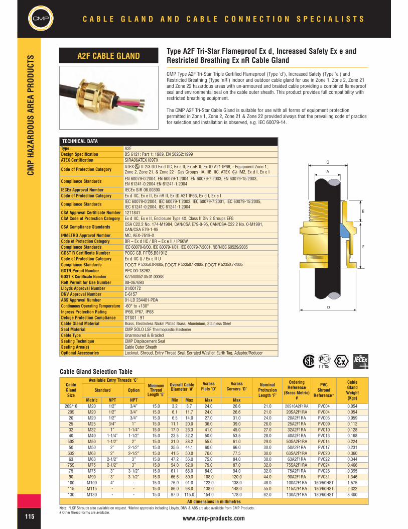
CMP Type A2F Tri-Star Triple Certified Flameproof (Type 'd'), Increased Safety (Type 'e') andRestricted Breathing (Type ‘nR’) indoor and outdoor cable gland for use in Zone 1, Zone 2, Zone 21and Zone 22 hazardous areas with un-armoured and braided cable providing a combined flameproofseal and environmental seal on the cable outer sheath. This product provides full compatibility withrestricted breathing equipment.
The CMP A2F Tri-Star Cable Gland is suitable for use with all forms of equipment protectionpermitted in Zone 1, Zone 2, Zone 21 & Zone 22 provided always that the prevailing code of practicefor selection and installation is observed, e.g. IEC 60079-14.
CableGlandSize
Available Entry Threads ‘C’MinimumThread
Length ‘E’
Overall CableDiameter ‘A’
AcrossFlats ‘D’
AcrossCorners ‘D’
NominalProtrusionLength ‘F’
OrderingReference
(Brass Metric)#
PVCShroud
Reference*
CableGlandWeight(Kgs)
Standard Option
Metric NPT NPT Min Max Max Max20S/16 M20 1/2” 3/4” 15.0 3.2 8.7 24.0 26.6 21.0 20S16A2F1RA PVC04 0.05420S M20 1/2” 3/4” 15.0 6.1 11.7 24.0 26.6 21.0 20SA2F1RA PVC04 0.05420 M20 1/2” 3/4” 15.0 6.5 14.0 27.0 31.0 24.0 20A2F1RA PVC05 0.05925 M25 3/4” 1” 15.0 11.1 20.0 36.0 39.0 26.0 25A2F1RA PVC09 0.11232 M32 1” 1-1/4” 15.0 17.0 26.3 41.0 45.0 27.0 32A2F1RA PVC10 0.12840 M40 1-1/4” 1-1/2” 15.0 23.5 32.2 50.0 53.5 28.0 40A2F1RA PVC13 0.16850S M50 1-1/2” 2” 15.0 31.0 38.2 55.0 61.0 29.0 50SA2F1RA PVC14 0.22450 M50 2” 2-1/2” 15.0 35.6 44.1 60.0 66.0 30.0 50A2F1RA PVC17 0.23163S M63 2” 2-1/2” 15.0 41.5 50.0 70.0 77.5 30.0 63SA2F1RA PVC20 0.36063 M63 2-1/2” 3” 15.0 47.2 56.0 75.0 84.0 30.0 63A2F1RA PVC22 0.34475S M75 2-1/2” 3” 15.0 54.0 62.0 79.0 87.0 32.0 75SA2F1RA PVC24 0.46675 M75 3” 3-1/2” 15.0 61.1 68.0 84.0 94.0 32.0 75A2F1RA PVC26 0.39590 M90 3” 3-1/2” 15.0 66.6 80.0 108.0 120.0 44.0 90A2F1RA PVC31 1.346100 M100 4” - 15.0 76.0 91.0 122.0 138.0 48.0 100A2F1RA 150/50HST 1.575115 M115 - - 15.0 86.0 98.0 138.0 148.0 55.0 115A2F1RA 180/60HST 2.322130 M130 - - 15.0 97.0 115.0 154.0 178.0 62.0 130A2F1RA 180/60HST 3.400
All dimensions in millimetres
Type A2F Tri-Star Flameproof Ex d, Increased Safety Ex e andRestricted Breathing Ex nR Cable GlandA2F CABLE GLAND
D
A
C
E
F
Cable Gland Selection Table
Note: *LSF Shrouds also available on request. †Marine approvals including Lloyds, DNV & ABS are also available from CMP Products.# Other thread forms are available.
LLU
OCTL
OCTL
OCTL
LLU05
CMPHA
ZARD
OUSAR
EAPR
ODUC
TS
CMPC A B L E G L A N D A N D C A B L E C O N N E C T I O N S P E C I A L I S T S
116www.cmp-products.com
TECHNICAL DATA
Type SS2KDesign Specification BS 6121:Part 1:1989, EN 50262:1999ATEX Certification SIRA06ATEX1097X
Code of Protection Category ATEX II 2 GD Ex d IIC, Ex e II, Ex nR II, Ex tD A21 IP66, - Equipment Zone 1,Zone 2, Zone 21, & Zone 22 - Gas Groups IIA, IIB, IIC, ATEX IM2, Ex d I, Ex e I
Compliance Standards EN 60079-0:2004, EN 60079-1:2004, EN 60079-7:2003, EN 60079-15:2003,EN 61241-0:2004, EN 61241-1:2004
IECEx Approval Number IECEx SIR 06.0041X
Code of Protection Category Ex d IIC, Ex e II, Ex nR II, Ex tD A21 IP66, Ex d I, Ex e I
Compliance Standards IEC 60079-0:2004, IEC 60079-1:2003, IEC 60079-7:2001, IEC 60079-15:2005,IEC 61241-0:2004, IEC 61241-1:2004
GOST R Certificate Number POCC GB. 05.B01912Code of Protection Category Ex d IIC U / Ex e II UCompliance Standards P 52350.0-2005, P 52350.1-2005, P 52350.7-2005
GGTN Permit Number PPC 00-18262GOST K Certificate Number KZ7500052.05.01.00063RoK Permit for Use Number 08-067693Lloyds Approval Number 01/00172DNV Approval Number E-6157ABS Approval Number 01-LD 234401-PDAContinuous Operating Temperature -60°C to +130°CIngress Protection Rating IP66, IP67, IP68Ingress Protection Document 5046 C549KDeluge Protection Compliance DTS01 : 91Deluge Protection Document 5046 C549K-DCable Gland Material Brass, Electroless Nickel Plated Brass, Aluminium, Stainless Steel
Seal Material CMP SOLO LSF Thermoplastic Elastomer
Cable Type Unarmoured & BraidedSealing Technique CMP Displacement SealSealing Area(s) Cable Inner Bedding and Cable Outer Sheath, or Double Seal on Cable Outer SheathOptional Accessories Locknut, Shroud, Entry Thread Seal, Serrated Washer, Earth Tag, Adaptor/Reducer
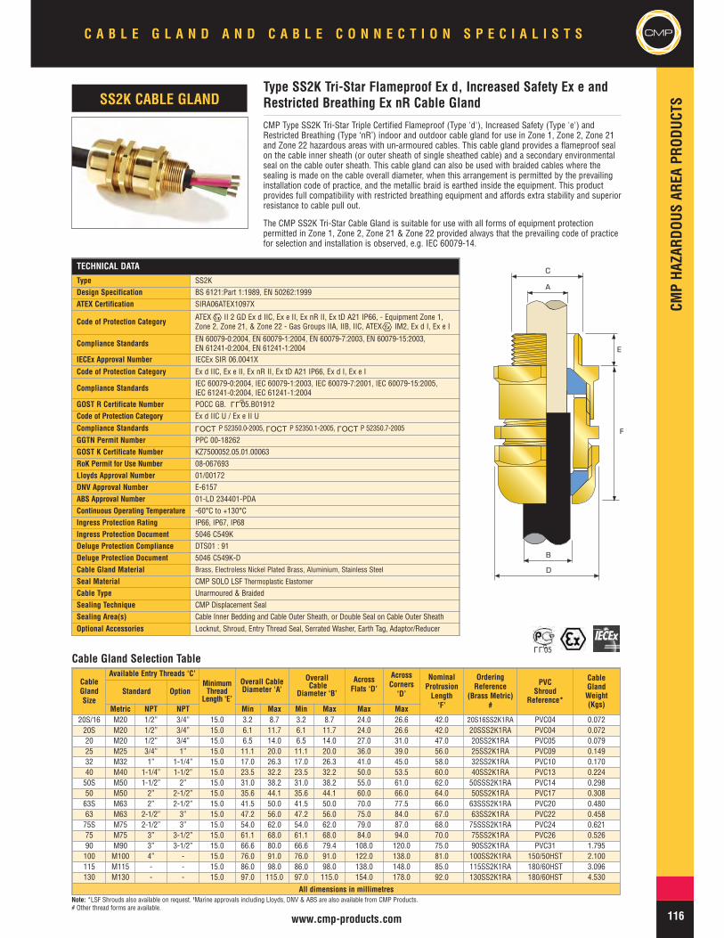
CMP Type SS2K Tri-Star Triple Certified Flameproof (Type 'd'), Increased Safety (Type 'e') andRestricted Breathing (Type ‘nR’) indoor and outdoor cable gland for use in Zone 1, Zone 2, Zone 21and Zone 22 hazardous areas with un-armoured cables. This cable gland provides a flameproof sealon the cable inner sheath (or outer sheath of single sheathed cable) and a secondary environmentalseal on the cable outer sheath. This cable gland can also be used with braided cables where thesealing is made on the cable overall diameter, when this arrangement is permitted by the prevailinginstallation code of practice, and the metallic braid is earthed inside the equipment. This productprovides full compatibility with restricted breathing equipment and affords extra stability and superiorresistance to cable pull out.
The CMP SS2K Tri-Star Cable Gland is suitable for use with all forms of equipment protectionpermitted in Zone 1, Zone 2, Zone 21 & Zone 22 provided always that the prevailing code of practicefor selection and installation is observed, e.g. IEC 60079-14.
CableGlandSize
Available Entry Threads ‘C’MinimumThread
Length ‘E’
Overall CableDiameter ‘A’
OverallCable
Diameter ‘B’
AcrossFlats ‘D’
AcrossCorners‘D’
NominalProtrusionLength‘F’
OrderingReference
(Brass Metric)#
PVCShroud
Reference*
CableGlandWeight(Kgs)
Standard Option
Metric NPT NPT Min Max Min Max Max Max20S/16 M20 1/2” 3/4” 15.0 3.2 8.7 3.2 8.7 24.0 26.6 42.0 20S16SS2K1RA PVC04 0.07220S M20 1/2” 3/4” 15.0 6.1 11.7 6.1 11.7 24.0 26.6 42.0 20SSS2K1RA PVC04 0.07220 M20 1/2” 3/4” 15.0 6.5 14.0 6.5 14.0 27.0 31.0 47.0 20SS2K1RA PVC05 0.07925 M25 3/4” 1” 15.0 11.1 20.0 11.1 20.0 36.0 39.0 56.0 25SS2K1RA PVC09 0.14932 M32 1” 1-1/4” 15.0 17.0 26.3 17.0 26.3 41.0 45.0 58.0 32SS2K1RA PVC10 0.17040 M40 1-1/4” 1-1/2” 15.0 23.5 32.2 23.5 32.2 50.0 53.5 60.0 40SS2K1RA PVC13 0.22450S M50 1-1/2” 2” 15.0 31.0 38.2 31.0 38.2 55.0 61.0 62.0 50SSS2K1RA PVC14 0.29850 M50 2” 2-1/2” 15.0 35.6 44.1 35.6 44.1 60.0 66.0 64.0 50SS2K1RA PVC17 0.30863S M63 2” 2-1/2” 15.0 41.5 50.0 41.5 50.0 70.0 77.5 66.0 63SSS2K1RA PVC20 0.48063 M63 2-1/2” 3” 15.0 47.2 56.0 47.2 56.0 75.0 84.0 67.0 63SS2K1RA PVC22 0.45875S M75 2-1/2” 3” 15.0 54.0 62.0 54.0 62.0 79.0 87.0 68.0 75SSS2K1RA PVC24 0.62175 M75 3” 3-1/2” 15.0 61.1 68.0 61.1 68.0 84.0 94.0 70.0 75SS2K1RA PVC26 0.52690 M90 3” 3-1/2” 15.0 66.6 80.0 66.6 79.4 108.0 120.0 75.0 90SS2K1RA PVC31 1.795100 M100 4” - 15.0 76.0 91.0 76.0 91.0 122.0 138.0 81.0 100SS2K1RA 150/50HST 2.100115 M115 - - 15.0 86.0 98.0 86.0 98.0 138.0 148.0 85.0 115SS2K1RA 180/60HST 3.096130 M130 - - 15.0 97.0 115.0 97.0 115.0 154.0 178.0 92.0 130SS2K1RA 180/60HST 4.530
All dimensions in millimetres
Type SS2K Tri-Star Flameproof Ex d, Increased Safety Ex e andRestricted Breathing Ex nR Cable GlandSS2K CABLE GLAND
A
C
E
B
D
F
Cable Gland Selection Table
Note: *LSF Shrouds also available on request. †Marine approvals including Lloyds, DNV & ABS are also available from CMP Products.# Other thread forms are available.
LLU
OCTL
OCTL
OCTL
LLU05
CMP
CMPHA
ZARD
OUSAR
EAPR
ODUC
TSC A B L E G L A N D A N D C A B L E C O N N E C T I O N S P E C I A L I S T S
117 www.cmp-products.com
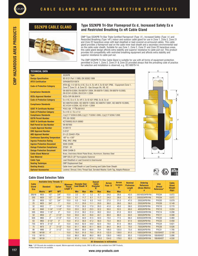
CMP Type SS2KPB Tri-Star Triple Certified Flameproof (Type 'd'), Increased Safety (Type 'e') andRestricted Breathing (Type ‘nR’) indoor and outdoor cable gland for use in Zone 1, Zone 2, Zone 21and Zone 22 hazardous areas with lead sheathed or lead covered un-armoured cables. This cablegland provides a flameproof seal on the cable inner lead sheath and a secondary environmental sealon the cable outer sheath. Suitable for use Zone 1, Zone 2, Zone 21 and Zone 22 hazardous areas,this cable gland design affords extra stability and superior resistance to cable pull out. This productprovides full compatibility with restricted breathing equipment and affords extra stability andsuperior resistance to cable pull out.
The CMP SS2KPB Tri-Star Cable Gland is suitable for use with all forms of equipment protectionpermitted in Zone 1, Zone 2, Zone 21 & Zone 22 provided always that the prevailing code of practicefor selection and installation is observed, e.g. IEC 60079-14.
Type SS2KPB Tri-Star Flameproof Ex d, Increased Safety Ex eand Restricted Breathing Ex nR Cable Gland
SS2KPB CABLE GLAND
A
C
E
B
D
F
Cable Gland Selection Table
Note: *LSF Shrouds also available on request. Marine approvals including Lloyds, DNV & ABS are also available from CMP Products.# Other thread forms are available.
TECHNICAL DATA
Type SS2KPBDesign Specification BS 6121:Part 1:1989, EN 50262:1999ATEX Certification SIRA06ATEX1097X
Code of Protection Category ATEX II 2 GD Ex d IIC, Ex e II, Ex nR II, Ex tD A21 IP66, - Equipment Zone 1,Zone 2, Zone 21, & Zone 22 - Gas Groups IIA, IIB, IIC
Compliance Standards EN 60079-0:2004, EN 60079-1:2004, EN 60079-7:2003, EN 60079-15:2003,EN 61241-0:2004, EN 61241-1:2004
IECEx Approval Number IECEx SIR 06.0041X
Code of Protection Category Ex d IIC, Ex e II, Ex nR II, Ex tD A21 IP66, Ex dI, Ex eI
Compliance Standards IEC 60079-0:2004, IEC 60079-1:2003, IEC 60079-7:2001, IEC 60079-15:2005,IEC 61241-0:2004, IEC 61241-1:2004
GOST R Certificate Number POCC GB. 05.B01912Code of Protection Category Ex d IIC U / Ex e II UCompliance Standards P 52350.0-2005, P 52350.1-2005, P 52350.7-2005
GGTN Permit Number PPC 00-18262GOST K Certificate Number KZ7500052.05.01.00063RoK Permit for Use Number 08-067693Lloyds Approval Number 01/00172DNV Approval Number E-6157ABS Approval Number 01-LD 234401-PDAContinuous Operating Temperature -60° to +130°Ingress Protection Rating IP66, IP67, IP68Ingress Protection Document 5046 C549KDeluge Protection Compliance DTS01 : 91Deluge Protection Document 5046 C549K-DCable Gland Material Brass, Electroless Nickel Plated Brass, Aluminium, Stainless Steel
Seal Material CMP SOLO LSF Thermoplastic Elastomer
Cable Type Lead Sheathed or Lead Covered & UnarmouredSealing Technique CMP Displacement SealSealing Area(s) Cable Inner Lead Sheath or Lead Covering and Cable Outer SheathOptional Accessories Locknut, Shroud, Entry Thread Seal, Serrated Washer, Earth Tag, Adaptor/Reducer
LLU
CableGlandSize
Available Entry Threads ‘C’MinimumThread
Length ‘E’
Diameter OverLead Sheath ‘A’
OverallCable
Diameter‘B’
AcrossFlats ‘D’
AcrossCorners‘D’
NominalProtrusionLength‘F’
OrderingReference
(Brass Metric)#
PVCShroud
Reference*
CableGlandWeight(Kgs)
Standard Option
Metric NPT NPT Min Max Min Max Max Max20S/16 M20 1/2” 3/4” 15.0 3.2 8.7 3.2 8.7 24.0 26.6 42.0 20S16SS2KPB1RA PVC04 0.07220S M20 1/2” 3/4” 15.0 6.1 11.7 6.1 11.7 24.0 26.6 42.0 20SSS2KPB1RA PVC04 0.07220 M20 1/2” 3/4” 15.0 6.5 14.0 6.5 14.0 27.0 31.0 47.0 20SS2KPB1RA PVC05 0.07925 M25 3/4” 1” 15.0 11.1 20.0 11.1 20.0 36.0 39.0 56.0 25SS2KPB1RA PVC09 0.14932 M32 1” 1-1/4” 15.0 17.0 26.3 17.0 26.3 41.0 45.0 58.0 32SS2KPB1RA PVC10 0.17040 M40 1-1/4” 1-1/2” 15.0 23.5 32.2 23.5 32.2 50.0 53.5 60.0 40SS2KPB1RA PVC13 0.22450S M50 1-1/2” 2” 15.0 31.0 38.2 31.0 38.2 55.0 61.0 62.0 50SSS2KPB1RA PVC14 0.29850 M50 2” 2-1/2” 15.0 35.6 44.1 35.6 44.1 60.0 66.0 64.0 50SS2KPB1RA PVC17 0.30863S M63 2” 2-1/2” 15.0 41.5 50.0 41.5 50.0 70.0 77.5 66.0 63SSS2KPB1RA PVC20 0.48063 M63 2-1/2” 3” 15.0 47.2 56.0 47.2 56.0 75.0 84.0 67.0 63SS2KPB1RA PVC22 0.45875S M75 2-1/2” 3” 15.0 54.0 62.0 54.0 62.0 79.0 87.0 68.0 75SSS2KPB1RA PVC24 0.62175 M75 3” 3-1/2” 15.0 61.1 68.0 61.1 68.0 84.0 94.0 70.0 75SS2KPB1RA PVC26 0.52690 M90 3” 3-1/2” 15.0 66.6 80.0 66.6 79.4 108.0 120.0 75.0 90SS2KPB1RA PVC31 1.795100 M100 4” - 15.0 76.0 91.0 76.0 91.0 122.0 138.0 81.0 100SS2KPB1RA 150/50HST 2.100115 M115 - - 15.0 86.0 98.0 86.0 98.0 138.0 148.0 85.0 115SS2KPB1RA 180/60HST 3.096130 M130 - - 15.0 97.0 115.0 97.0 115.0 154.0 178.0 92.0 130SS2KPB1RA 180/60HST 4.530
All dimensions in millimetres
OCTL
OCTL
OCTL
LLU05
CMPHA
ZARD
OUSAR
EAPR
ODUC
TS
CMPC A B L E G L A N D A N D C A B L E C O N N E C T I O N S P E C I A L I S T S
118www.cmp-products.com
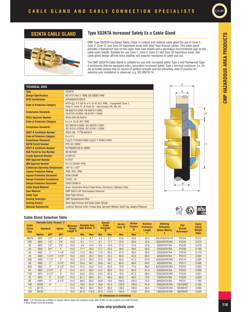
CMP Type SS2KTA Increased Safety (Type 'e') indoor and outdoor cable gland for use in Zone 1,Zone 2, Zone 21 and Zone 22 hazardous areas with Steel Tape Armour cables. This cable glandprovides a flameproof seal on the cable inner lead sheath and a secondary environmental seal on thecable outer sheath. Suitable for use Zone 1, Zone 2, Zone 21 and Zone 22 hazardous areas, thiscable gland design affords extra stability and superior resistance to cable pull out.
The CMP SS2KTA Cable Gland is suitable for use with Increased safety Type e and Flameproof Typed enclosures that are equipped with a secondary Increased Safety Type e terminal enclosure (i.e. Exde) provided always that no source of ignition prevails and the prevailing code of practice forselection and installation is observed, e.g. IEC 60079-14.
Type SS2KTA Increased Safety Ex e Cable GlandSS2KTA CABLE GLAND
A
C
E
B
D
F
Cable Gland Selection Table
Note: *LSF Shrouds also available on request. Marine approvals including Lloyds, DNV & ABS are also available from CMP Products.# Other thread forms are available.
TECHNICAL DATA
Type SS2KTADesign Specification BS 6121:Part 1:1989, EN 50262:1999ATEX Certification SIRA06ATEX1097X
Code of Protection Category ATEX II 2 GD Ex e II, Ex tD A21 IP66, - Equipment Zone 1,Zone 2, Zone 21, & Zone 22 - Gas Groups IIA, IIB, IIC
Compliance Standards EN 60079-0:2004, EN 60079-7:2003,EN 61241-0:2004, EN 61241-1:2004
IECEx Approval Number IECEx SIR 06.0041X
Code of Protection Category Ex e II, Ex tD A21 IP66
Compliance Standards IEC 60079-0:2004, IEC 60079-7:2001,IEC 61241-0:2004, IEC 61241-1:2004
GOST R Certificate Number POCC GB. 05.B01912Code of Protection Category Ex e II UCompliance Standards P 52350.0-2005, P 52350.7-2005
GGTN Permit Number PPC 00-18262GOST K Certificate Number KZ7500052.05.01.00063RoK Permit for Use Number 08-067693Lloyds Approval Number 01/00172DNV Approval Number E-6157ABS Approval Number 01-LD 234401-PDAContinuous Operating Temperature -60° to +130°Ingress Protection Rating IP66, IP67, IP68Ingress Protection Document 5046 C549KDeluge Protection Compliance DTS01 : 91Deluge Protection Document 5046 C549K-DCable Gland Material Brass, Electroless Nickel Plated Brass, Aluminium, Stainless Steel
Seal Material CMP SOLO LSF Thermoplastic Elastomer
Cable Type Steel Tape ArmourSealing Technique CMP Displacement SealSealing Area(s) Steel Tape Armour and Cable Outer SheathOptional Accessories Locknut, Shroud, Entry Thread Seal, Serrated Washer, Earth Tag, Adaptor/Reducer
LLU
CableGlandSize
Available Entry Threads ‘C’MinimumThread
Length ‘E’
Diameter OverTape Armour ‘A’
OverallCable
Diameter‘B’
AcrossFlats ‘D’
AcrossCorners‘D’
NominalProtrusionLength‘F’
OrderingReference
(Brass Metric)#
PVCShroud
Reference*
CableGlandWeight(Kgs)
Standard Option
Metric NPT NPT Min Max Min Max Max Max20S/16 M20 1/2” 3/4” 15.0 3.2 8.7 3.2 8.7 24.0 26.6 42.0 20S16SS2KTA1RA PVC04 0.07220S M20 1/2” 3/4” 15.0 6.1 11.7 6.1 11.7 24.0 26.6 42.0 20SSS2KTA1RA PVC04 0.07220 M20 1/2” 3/4” 15.0 6.5 14.0 6.5 14.0 27.0 31.0 47.0 20SS2KTA1RA PVC05 0.07925 M25 3/4” 1” 15.0 11.1 20.0 11.1 20.0 36.0 39.0 56.0 25SS2KTA1RA PVC09 0.14932 M32 1” 1-1/4” 15.0 17.0 26.3 17.0 26.3 41.0 45.0 58.0 32SS2KTA1RA PVC10 0.17040 M40 1-1/4” 1-1/2” 15.0 23.5 32.2 23.5 32.2 50.0 53.5 60.0 40SS2KTA1RA PVC13 0.22450S M50 1-1/2” 2” 15.0 31.0 38.2 31.0 38.2 55.0 61.0 62.0 50SSS2KTA1RA PVC14 0.29850 M50 2” 2-1/2” 15.0 35.6 44.1 35.6 44.1 60.0 66.0 64.0 50SS2KTA1RA PVC17 0.30863S M63 2” 2-1/2” 15.0 41.5 50.0 41.5 50.0 70.0 77.5 66.0 63SSS2KTA1RA PVC20 0.48063 M63 2-1/2” 3” 15.0 47.2 56.0 47.2 56.0 75.0 84.0 67.0 63SS2KTA1RA PVC22 0.45875S M75 2-1/2” 3” 15.0 54.0 62.0 54.0 62.0 79.0 87.0 68.0 75SSS2KTA1RA PVC24 0.62175 M75 3” 3-1/2” 15.0 61.1 68.0 61.1 68.0 84.0 94.0 70.0 75SS2KTA1RA PVC26 0.52690 M90 3” 3-1/2” 15.0 66.6 80.0 66.6 79.4 108.0 120.0 75.0 90SS2KTA1RA PVC31 1.795100 M100 4” - 15.0 76.0 91.0 76.0 91.0 122.0 138.0 81.0 100SS2KTA1RA 150/50HST 2.100115 M115 - - 15.0 86.0 98.0 86.0 98.0 138.0 148.0 85.0 115SS2KTA1RA 180/60HST 3.096130 M130 - - 15.0 97.0 115.0 97.0 115.0 154.0 178.0 92.0 130SS2KTA1RA 180/60HST 4.530
All dimensions in millimetres
OCTL
OCTL
LLU05

CMP
CMPHA
ZARD
OUSAR
EAPR
ODUC
TSC A B L E G L A N D A N D C A B L E C O N N E C T I O N S P E C I A L I S T S
119 www.cmp-products.com
TECHNICAL DATA
Type A2FRC
Design Specification BS 6121:Part 1:1989, EN 50262:1999
ATEX Cetification SIRA06ATEX1097X
Code of Protection Category ATEX II 2 GD Ex d IIC, Ex e II, Ex nR II, Ex tD A21 IP66, - EquipmentZone 1, Zone 2, Zone 21, & Zone 22 - Gas Groups IIA, IIB, IIC
Compliance Standards EN 60079-0:2004, EN 60079-1:2004, EN 60079-7:2003, EN 60079-15:2003,EN 61241-0:2004, EN 61241-1:2004
IECEx Approval Number IECEx SIR 06.0040X
Code of Protection Category Ex d IIC, Ex e II, Ex nR II, Ex tD A21 IP66
Compliance Standards IEC 60079-0:2004, IEC 60079-1:2003, IEC 60079-7:2001,IEC 60079-15:2005, IEC 61241-0:2004, IEC 61241-1:2004
INMETRO Approval Certificate Number MC, AEX-7619-X
Code of Protection Category BR – Ex d IIC / BR – Ex e II / IP66W
Compliance Standards IEC 60079-0/00, IEC 60079-1/01, IEC 60079-7/2001, NBR/IEC 60529/2005
GOST R Certificate Number POCC GB. 05.B01912
Code of Protection Category Ex d IIC U / Ex e II U
Compliance Standards P 52350.0-2005, P 52350.1-2005, P 52350.7-2005
GGTN Permit Number PPC 00-18262
GOST K Certificate Number KZ7500052.05.01.00063
RoK Permit for Use Number 08-067693
Lloyds Approval Number 01/00172
ABS Approval Number 01-LD 234401-PDA
Continuous Operating Temperature -60°C to +130°C
Ingress Protection Rating IP66
Cable Gland Material Brass, Electroless Nickel Plated Brass, Aluminium, Stainless Steel
Seal Material CMP SOLO LSF Thermoplastic Elastomer
Cable Type Unarmoured & Braided
Sealing Technique CMP Displacement Seal
Sealing Area(s) Outer Sheath
Optional Accessories Locknut, Entry Thread Seal, Serrated Washer, Earth Tag, Adaptor/Reducer
CMP Type A2FRC Tri-Star Triple Certified Flameproof (Type 'd'), Increased Safety (Type 'e') and RestrictedBreathing (Type ‘nR’) indoor and outdoor conduit connection cable gland for use in Zone 1, Zone 2, Zone21 and Zone 22 hazardous areas with un-armoured cable housed in rigid or flexible conduit systems. Thecable gland provides a combined flameproof seal and environmental seal on the cable outer sheath. Thisproduct provides full compatibility with restricted breathing equipment.
The CMP A2FRC Tri-Star Cable Gland is suitable for use with all forms of equipment protectionpermitted in Zone 1, Zone 2, Zone 21 & Zone 22 provided always that the prevailing code of practice forselection and installation is observed, e.g. IEC 60079-14.
CableGlandSize
Available Entry Threads ‘C’MinimumThread
Length ‘E’’
StandardFemale
ConnectionThread ‘G’
Overall CableDiameter
‘A’
AcrossFlats ‘D’
AcrossCorners ‘D’
NominalProtrusionLength‘F’
OrderingReference
(Brass Metric)Metric Mx NPT #
CableGlandWeight(Kgs)
Standard Option
Metric NPT NPT Min Max Max Max
20S/16 M20 1/2” 3/4” 15.0 1/2” 3.1 8.7 24.0 26.6 21.0 20S16A2FRC1RA031 0.060
20S M20 1/2” 3/4” 15.0 1/2” 6.1 11.7 24.0 26.6 21.0 20SA2FRC1RA031 0.075
20 M20 1/2” 3/4” 15.0 1/2” 6.5 14.0 27.0 31.0 24.0 20A2FRC1RA031 0.100
25 M25 3/4” 1” 15.0 3/4” 11.1 20.0 36.0 39.0 26.0 25A2FRC1RA032 0.232
32 M32 1” 1-1/4” 15.0 1” 17.0 26.3 41.0 45.0 27.0 32A2FRC1RA033 0.400
40 M40 1-1/4” 1-1/2” 15.0 1-1/4” 23.5 32.2 50.0 53.5 28.0 40A2FRC1RA034 0.560
50S M50 1-1/2” 2” 15.0 1-1/2” 31.0 38.2 55.0 61.0 29.0 50SA2FRC1RA035 0.600
50 M50 2” 2-1/2” 15.0 2” 35.6 44.1 60.0 66.0 30.0 50A2FRC1RA036 0.590
63S M63 2” 2-1/2” 15.0 2” 41.5 50.0 70.0 77.5 30.0 63SA2FRC1RA036 0.720
63 M63 2-1/2” 3” 15.0 2-1/2” 47.2 56.0 75.0 84.0 30.0 63A2FRC1RA037 0.690
75S M75 2-1/2” 3” 15.0 2-1/2” 54.0 62.0 79.0 87.0 32.0 75SA2FRC1RA037 0.850
75 M75 3” 3-1/2” 15.0 3” 61.1 68.0 84.0 94.0 32.0 75A2FRC1RA038 0.800
90 M90 3” 3-1/2” 15.0 3” 66.6 80.0 108.0 120.0 44.0 90A2FRC1RA038 1.120
All dimensions in millimetres
Type A2FRC Tri-Star Flameproof Ex d, Increased Safety Ex e andRestricted Breathing Ex nR Cable Gland for Conduit ConnectionA2FRC CABLE GLAND
A
C
E
D
G
F
Cable Gland Selection Table
Note: † Please specify male and female connection threads required when ordering. Marine approvals including Lloyds, DNV & ABS are also available from CMP Products.# Other thread forms are available.
LLU
OCTL
OCTL
OCTL
LLU05
CMPHA
ZARD
OUSAR
EAPR
ODUC
TS
CMPC A B L E G L A N D A N D C A B L E C O N N E C T I O N S P E C I A L I S T S
120www.cmp-products.com
TECHNICAL DATAType C2KDesign Specification BS 6121:Part 1:1989, EN 50262:1999ATEX Certification SIRA06ATEX1097X
Code of Protection Category ATEX II 2 GD Ex e II, Ex tD A21 IP66, - Equipment Zone 1, Zone 2, Zone 21,& Zone 22 - Gas Groups IIA, IIB, IIC
Compliance Standards EN 60079-0:2004, EN 60079-7:2003,EN 61241-0:2004, EN 61241-1:2004
IECEx Approval Number IECEx SIR 06.0042XCode of Protection Category Ex e II, Ex tD A21 IP66
Compliance Standards IEC 60079-0:2004, IEC 60079-7:2001,IEC 61241-0:2004, IEC 61241-1:2004
Lloyds Approval Number 01/00171INMETRO Approval Certificate Number MC, AEX-7620-XCode of Protection Category BR – Ex e II / IP66WCompliance Standards IEC 60079-0/00, IEC 60079-7/2001, NBR/IEC 60529/2005GOST R Certificate Number POCC GB. 05.B01912Code of Protection Category Ex e II UCompliance Standards P 52350.0-2005, P 52350.7-2005GOST K Certificate Number KZ7500052.05.01.00063RoK Permit for Use Number 08-067693DNV Approval Number E-6157ABS Approval Number 01-LD 234401-PDAContinuous Operating Temperature -60°C to +130°CIngress Protection Rating IP66, IP67, IP68Deluge Protection Compliance DTS01 : 91Cable Gland Material Brass, Electroless Nickel Plated Brass, Aluminium, Stainless SteelSeal Material CMP SOLO LSF Thermoplastic Elastomer
Cable TypeSingle Wire Armour (SWA), Aluminium Wire Armour (AWA), Pliable WireArmour (PWA), Steel Tape Armour (STA), Wire Braid Armour, Aluminium StripArmour (ASA), Screened Flexible Wire Braid (e.g. CY / SY), Armored & Jacketed
Armour Clamping Reversible Armour Cone & AnyWay Universal Clamping RingSealing Technique Unique CMP "LRS" ™ Outer Seal (Load Retention Seal)Sealing Area(s) Cable Outer Sheath
Optional Accessories Locknut, Adaptor/Reducer, Earth Tag, Shroud, Entry Thread Seal, SerratedWasher
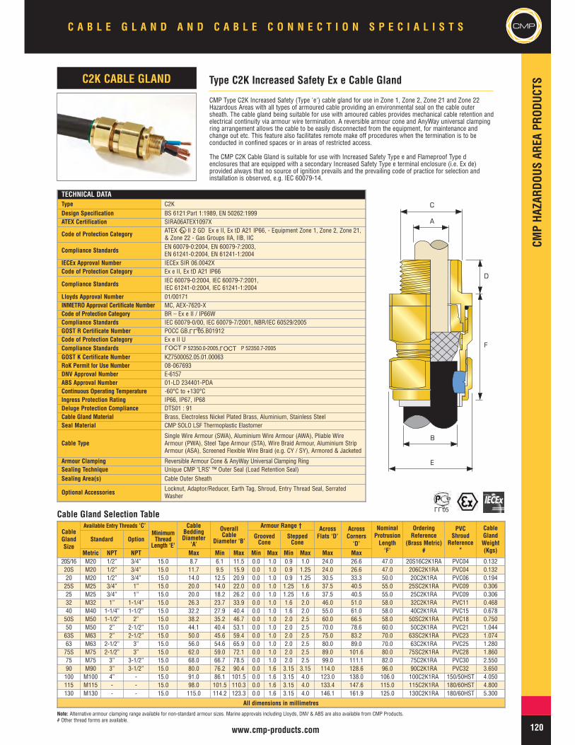
CMP Type C2K Increased Safety (Type 'e') cable gland for use in Zone 1, Zone 2, Zone 21 and Zone 22Hazardous Areas with all types of armoured cable providing an environmental seal on the cable outersheath. The cable gland being suitable for use with amoured cables provides mechanical cable retention andelectrical continuity via armour wire termination. A reversible armour cone and AnyWay universal clampingring arrangement allows the cable to be easily disconnected from the equipment, for maintenance andchange out etc. This feature also facilitates remote make off procedures when the termination is to beconducted in confined spaces or in areas of restricted access.
The CMP C2K Cable Gland is suitable for use with Increased Safety Type e and Flameproof Type denclosures that are equipped with a secondary Increased Safety Type e terminal enclosure (i.e. Ex de)provided always that no source of ignition prevails and the prevailing code of practice for selection andinstallation is observed, e.g. IEC 60079-14.
CableGlandSize
Available Entry Threads ‘C’MinimumThread
Length ‘E’
CableBeddingDiameter
‘A’
OverallCable
Diameter ‘B’
Armour Range † AcrossFlats ‘D’
AcrossCorners‘D’
NominalProtrusionLength‘F’
OrderingReference
(Brass Metric)#
PVCShroud
Reference*
CableGlandWeight(Kgs)
Standard Option GroovedCone
SteppedCone
Metric NPT NPT Max Min Max Min Max Min Max Max Max20S/16 M20 1/2” 3/4” 15.0 8.7 6.1 11.5 0.0 1.0 0.9 1.0 24.0 26.6 47.0 20S16C2K1RA PVC04 0.13220S M20 1/2” 3/4” 15.0 11.7 9.5 15.9 0.0 1.0 0.9 1.25 24.0 26.6 47.0 206C2K1RA PVC04 0.13220 M20 1/2” 3/4” 15.0 14.0 12.5 20.9 0.0 1.0 0.9 1.25 30.5 33.3 50.0 20C2K1RA PVC06 0.19425S M25 3/4” 1” 15.0 20.0 14.0 22.0 0.0 1.0 1.25 1.6 37.5 40.5 55.0 25SC2K1RA PVC09 0.30625 M25 3/4” 1” 15.0 20.0 18.2 26.2 0.0 1.0 1.25 1.6 37.5 40.5 55.0 25C2K1RA PVC09 0.30632 M32 1” 1-1/4” 15.0 26.3 23.7 33.9 0.0 1.0 1.6 2.0 46.0 51.0 58.0 32C2K1RA PVC11 0.46840 M40 1-1/4” 1-1/2” 15.0 32.2 27.9 40.4 0.0 1.0 1.6 2.0 55.0 61.0 58.0 40C2K1RA PVC15 0.67850S M50 1-1/2” 2” 15.0 38.2 35.2 46.7 0.0 1.0 2.0 2.5 60.0 66.5 58.0 50SC2K1RA PVC18 0.75050 M50 2” 2-1/2” 15.0 44.1 40.4 53.1 0.0 1.0 2.0 2.5 70.0 78.6 60.0 50C2K1RA PVC21 1.04463S M63 2” 2-1/2” 15.0 50.0 45.6 59.4 0.0 1.0 2.0 2.5 75.0 83.2 70.0 63SC2K1RA PVC23 1.07463 M63 2-1/2” 3” 15.0 56.0 54.6 65.9 0.0 1.0 2.0 2.5 80.0 89.0 70.0 63C2K1RA PVC25 1.28075S M75 2-1/2” 3” 15.0 62.0 59.0 72.1 0.0 1.0 2.0 2.5 89.0 101.6 80.0 75SC2K1RA PVC28 1.86075 M75 3” 3-1/2” 15.0 68.0 66.7 78.5 0.0 1.0 2.0 2.5 99.0 111.1 82.0 75C2K1RA PVC30 2.55090 M90 3” 3-1/2” 15.0 80.0 76.2 90.4 0.0 1.6 3.15 3.15 114.0 128.6 96.0 90C2K1RA PVC32 3.650100 M100 4” - 15.0 91.0 86.1 101.5 0.0 1.6 3.15 4.0 123.0 138.0 106.0 100C2K1RA 150/50HST 4.050115 M115 - - 15.0 98.0 101.5 110.3 0.0 1.6 3.15 4.0 133.4 147.6 115.0 115C2K1RA 180/60HST 4.800130 M130 - - 15.0 115.0 114.2 123.3 0.0 1.6 3.15 4.0 146.1 161.9 125.0 130C2K1RA 180/60HST 5.300
All dimensions in millimetres
Type C2K Increased Safety Ex e Cable GlandC2K CABLE GLAND
A
B
E
C
D
F
Cable Gland Selection Table
Note: Alternative armour clamping range available for non-standard armour sizes. Marine approvals including Lloyds, DNV & ABS are also available from CMP Products.# Other thread forms are available.
LLU
LLU05
OCTL
OCTL

CMP
CMPHA
ZARD
OUSAR
EAPR
ODUC
TSC A B L E G L A N D A N D C A B L E C O N N E C T I O N S P E C I A L I S T S
121 www.cmp-products.com
Note: *LSF Shrouds also available on request. Alternative armour clamping range available for non-standard armour sizes. Marine approvals including Lloyds, DNV & ABS are also available from CMP Products.
Cable Gland Selection Table
CMP Type CWe Increased Safety (Type 'e') cable gland for use in Zone 1, Zone 2, Zone 21 and Zone 22Hazardous Areas with Single Wire Armour (SWA) cable providing an environmental seal on the cable outersheath. The cable gland being suitable for armoured cables, provides mechanical cable retention andelectrical continuity via armour wire termination. A detachable armour cone and AnyWay universal clampingring arrangement allows the cable to be easily disconnected from the equipment, for maintenance andchange out etc., and re-connected with the same consummate ease. This feature also facilitates remotemake off procedures when the termination is to be conducted in confined spaces or in areas of restrictedaccess.
The CMP CWe Cable Gland is suitable for use with Increased Safety Type e and Flameproof Type denclosures that are equipped with a secondary Increased Safety Type e terminal enclosure (i.e. Ex de)provided always that no source of ignition prevails and the prevailing code of practice for selection andinstallation is observed, e.g. IEC 60079-14.
TECHNICAL DATAType CWeDesign Specification BS 6121:Part 1:1989, EN 50262:1999
ATEX Certification SIRA06ATEX1097X
Code of Protection Category ATEX II 2 GD Ex e II, Ex tD A21 IP66, Equipment Zone 1, Zone 2, Zone 21, &Zone 22 - Gas Groups IIA, IIB, IIC
Compliance Standards EN 60079-0:2004, EN 60079-7:2003, EN 61241-0:2004, EN 61241-1:2004
IECEx Approval Number IECEx SIR 06.0042XCode of Protection Category Ex e II, Ex tD A21 IP66
Compliance Standards IEC 60079-0:2004, IEC 60079-7:2001,IEC 61241-0:2004, IEC 61241-1:2004
GOST R Certificate Number POCC GB. 05.B01912INMETRO Approval Certificate Number MC, AEX-7618-XCode of Protection Category BR – Ex e II / IP66WCompliance Standards IEC 60079-0/00, IEC 60079-7/2001, NBR/IEC 60529/2005Code of Protection Category Ex e II UCompliance Standards P 52350.0-2005, P 52350.7-2005GGTN Permit Number PPC 00-18262GOST K Certificate Number KZ7500052.05.01.00063RoK Permit for Use Number 08-067693
Lloyds Approval Number 01/00172
DNV Approval Number E-6157
ABS Approval Number 01-LD 234401-PDAContinous Operating Temperature -60°C to +130°CIngress Protection Rating IP66Cable Gland Material Brass, Electroless Nickel Plated Brass, Aluminium, Stainless SteelSeal Material CMP SOLO LSF Thermoplastic ElastomerCable Type Single Wire Armour (SWA)Armour Clamping Detachable Armour Cone & AnyWay Universal Clamping Ring
Sealing Technique Unique CMP "LRS" ™ Outer Seal (Load Retention Seal)
Sealing Area(s) Cable Outer SheathOptional Accessories Locknut, Shroud, Entry Thread Seal, Serrated Washer, Earth Tag, Adaptor/Reducer
CWe Increased Safety Ex e Cable GlandCWe CABLE GLAND
CableGlandSize
Standard MetricEntry Threads ‘C’
MinimumThread
Length ‘E’
CableBedding
Diameter ‘A’
OverallCable
Diameter ‘B’
ArmourRange †
AcrossFlats ‘D’
AcrossCorners‘D’
NominalProtrusionLength‘F’
OrderingReference
(Brass Metric)
PVCShroud
Reference*
CableGlandWeight(Kgs)Max Min Max Min Max Max Max
20S/16 M20 15.0 8.7 6.1 11.5 0.90 1.00 24.0 26.6 21.0 20S16CWe1RA PVC04 0.05420S M20 15.0 11.7 9.5 15.9 0.90 1.25 24.0 26.6 21.0 20SCWe1RA PVC04 0.05420 M20 15.0 14.0 12.5 20.9 0.90 1.25 30.5 33.3 24.0 20CWe1RA PVC06 0.05925S M25 15.0 20.0 14.0 22.0 1.25 1.60 37.5 40.5 26.0 25SCWe1RA PVC09 0.11225 M25 15.0 20.0 18.2 26.2 1.25 1.60 37.5 40.5 26.0 25CWe1RA PVC09 0.12832 M32 15.0 26.3 23.7 33.9 1.60 2.00 46.0 51.0 27.0 32CWe1RA PVC11 0.12840 M40 15.0 32.2 27.9 40.4 1.60 2.00 55.0 61.0 28.0 40CWe1RA PVC15 0.16850S M50 15.0 38.2 35.2 46.7 2.00 2.50 60.0 66.5 29.0 50SCWe1RA PVC18 0.22450 M50 15.0 44.1 40.4 53.1 2.00 2.50 70.0 78.6 30.0 50CWe1RA PVC21 0.23163S M63 15.0 50.0 45.6 59.4 2.00 2.50 75.0 83.2 30.0 63SCWe1RA PVC23 0.36063 M63 15.0 56.0 54.6 65.9 2.00 2.50 80.0 89.0 30.0 63CWe1RA PVC25 0.34475S M75 15.0 62.0 59.0 72.1 2.00 2.50 89.0 101.6 32.0 75SCWe1RA PVC28 0.46675 M75 15.0 68.0 66.7 78.5 2.00 2.50 99.0 111.1 32.0 75CWe1RA PVC30 0.39590 M90 15.0 80.0 76.2 90.4 3.15 3.15 114.0 128.6 44.0 90CWe1RA PVC32 1.346100 M100 15.0 91.0 86.1 101.5 3.15 4.00 123.0 138.0 48.0 100CWe1RA 150/50HST 1.575115 M115 15.0 98.0 101.5 110.3 3.15 4.00 133.4 147.6 55.0 115CWe1RA 180/60HST 2.322130 M130 15.0 115.0 114.2 123.3 3.15 4.00 146.1 161.9 62.0 130CWe1RA 180/60HST 3.400
All dimensions in millimetres
A
B
D
C
E
FOCTL
OCTL
LLU
LLU05
CMPHA
ZARD
OUSAR
EAPR
ODUC
TS
CMPC A B L E G L A N D A N D C A B L E C O N N E C T I O N S P E C I A L I S T S
122www.cmp-products.com
Cable Gland Selection Table
Note: †Alternative armour clamping range available for non-standard armour sizes. Marine approvals including Lloyds, DNV & ABS are also available from CMP Products.
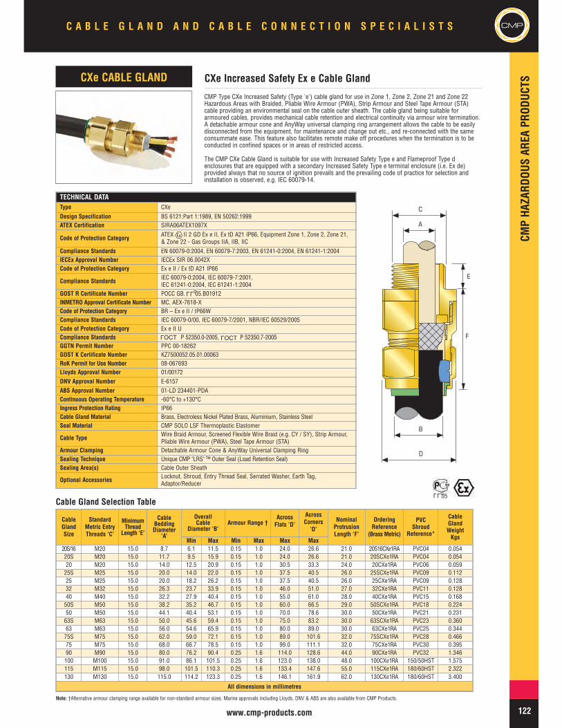
CMP Type CXe Increased Safety (Type 'e') cable gland for use in Zone 1, Zone 2, Zone 21 and Zone 22Hazardous Areas with Braided, Pliable Wire Armour (PWA), Strip Armour and Steel Tape Armour (STA)cable providing an environmental seal on the cable outer sheath. The cable gland being suitable forarmoured cables, provides mechanical cable retention and electrical continuity via armour wire termination.A detachable armour cone and AnyWay universal clamping ring arrangement allows the cable to be easilydisconnected from the equipment, for maintenance and change out etc., and re-connected with the sameconsummate ease. This feature also facilitates remote make off procedures when the termination is to beconducted in confined spaces or in areas of restricted access.
The CMP CXe Cable Gland is suitable for use with Increased Safety Type e and Flameproof Type denclosures that are equipped with a secondary Increased Safety Type e terminal enclosure (i.e. Ex de)provided always that no source of ignition prevails and the prevailing code of practice for selection andinstallation is observed, e.g. IEC 60079-14.
TECHNICAL DATAType CXe
Design Specification BS 6121:Part 1:1989, EN 50262:1999ATEX Certification SIRA06ATEX1097X
Code of Protection Category ATEX II 2 GD Ex e II, Ex tD A21 IP66, Equipment Zone 1, Zone 2, Zone 21,& Zone 22 - Gas Groups IIA, IIB, IIC
Compliance Standards EN 60079-0:2004, EN 60079-7:2003, EN 61241-0:2004, EN 61241-1:2004IECEx Approval Number IECEx SIR 06.0042XCode of Protection Category Ex e II / Ex tD A21 IP66
Compliance Standards IEC 60079-0:2004, IEC 60079-7:2001,IEC 61241-0:2004, IEC 61241-1:2004
GOST R Certificate Number POCC GB. 05.B01912INMETRO Approval Certificate Number MC, AEX-7618-XCode of Protection Category BR – Ex e II / IP66WCompliance Standards IEC 60079-0/00, IEC 60079-7/2001, NBR/IEC 60529/2005Code of Protection Category Ex e II UCompliance Standards P 52350.0-2005, P 52350.7-2005GGTN Permit Number PPC 00-18262GOST K Certificate Number KZ7500052.05.01.00063RoK Permit for Use Number 08-067693Lloyds Approval Number 01/00172DNV Approval Number E-6157ABS Approval Number 01-LD 234401-PDAContinuous Operating Temperature -60°C to +130°CIngress Protection Rating IP66Cable Gland Material Brass, Electroless Nickel Plated Brass, Aluminium, Stainless SteelSeal Material CMP SOLO LSF Thermoplastic Elastomer
Cable Type Wire Braid Armour, Screened Flexible Wire Braid (e.g. CY / SY), Strip Armour,Pliable Wire Armour (PWA), Steel Tape Armour (STA)
Armour Clamping Detachable Armour Cone & AnyWay Universal Clamping RingSealing Technique Unique CMP "LRS" ™ Outer Seal (Load Retention Seal)Sealing Area(s) Cable Outer Sheath
Optional Accessories Locknut, Shroud, Entry Thread Seal, Serrated Washer, Earth Tag,Adaptor/Reducer
CableGlandSize
StandardMetric EntryThreads ‘C’
MinimumThread
Length ‘E’
CableBeddingDiameter
‘A’
OverallCable
Diameter ‘B’Armour Range †
AcrossFlats ‘D’
AcrossCorners‘D’
NominalProtrusionLength ‘F’
OrderingReference
(Brass Metric)
PVCShroud
Reference*
CableGlandWeightKgsMin Max Min Max Max Max
20S/16 M20 15.0 8.7 6.1 11.5 0.15 1.0 24.0 26.6 21.0 20S16CXe1RA PVC04 0.05420S M20 15.0 11.7 9.5 15.9 0.15 1.0 24.0 26.6 21.0 20SCXe1RA PVC04 0.05420 M20 15.0 14.0 12.5 20.9 0.15 1.0 30.5 33.3 24.0 20CXe1RA PVC06 0.05925S M25 15.0 20.0 14.0 22.0 0.15 1.0 37.5 40.5 26.0 25SCXe1RA PVC09 0.11225 M25 15.0 20.0 18.2 26.2 0.15 1.0 37.5 40.5 26.0 25CXe1RA PVC09 0.12832 M32 15.0 26.3 23.7 33.9 0.15 1.0 46.0 51.0 27.0 32CXe1RA PVC11 0.12840 M40 15.0 32.2 27.9 40.4 0.15 1.0 55.0 61.0 28.0 40CXe1RA PVC15 0.16850S M50 15.0 38.2 35.2 46.7 0.15 1.0 60.0 66.5 29.0 50SCXe1RA PVC18 0.22450 M50 15.0 44.1 40.4 53.1 0.15 1.0 70.0 78.6 30.0 50CXe1RA PVC21 0.23163S M63 15.0 50.0 45.6 59.4 0.15 1.0 75.0 83.2 30.0 63SCXe1RA PVC23 0.36063 M63 15.0 56.0 54.6 65.9 0.15 1.0 80.0 89.0 30.0 63CXe1RA PVC25 0.34475S M75 15.0 62.0 59.0 72.1 0.15 1.0 89.0 101.6 32.0 75SCXe1RA PVC28 0.46675 M75 15.0 68.0 66.7 78.5 0.15 1.0 99.0 111.1 32.0 75CXe1RA PVC30 0.39590 M90 15.0 80.0 76.2 90.4 0.25 1.6 114.0 128.6 44.0 90CXe1RA PVC32 1.346100 M100 15.0 91.0 86.1 101.5 0.25 1.6 123.0 138.0 48.0 100CXe1RA 150/50HST 1.575115 M115 15.0 98.0 101.5 110.3 0.25 1.6 133.4 147.6 55.0 115CXe1RA 180/60HST 2.322130 M130 15.0 115.0 114.2 123.3 0.25 1.6 146.1 161.9 62.0 130CXe1RA 180/60HST 3.400
All dimensions in millimetres
CXe Increased Safety Ex e Cable GlandCXe CABLE GLAND
A
B
D
C
E
F
LLU
LLU05
OCTL
OCTL
CMP
CMPHA
ZARD
OUSAR
EAPR
ODUC
TSC A B L E G L A N D A N D C A B L E C O N N E C T I O N S P E C I A L I S T S
123 www.cmp-products.com
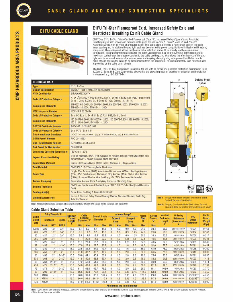
CMP Type E1FU Tri-Star Triple Certified Flameproof (Type ‘d’), Increased Safety (Type ‘e’) and RestrictedBreathing (Type ‘nR’) indoor and outdoor cable gland for use in Zone 1, Zone 2, Zone 21 and Zone 22Hazardous Areas with all types of armoured cable. This cable gland provides a Flameproof seal on the cableinner bedding and in addition the gas tight seal has been tested to prove compatibility with Restricted Breathingequipment. The cable gland allows mechanical cable retention and earth continuity via the cable armourtermination. Separate tightening actions for the inner Displacement Seal and the Armour Termination affordmaximum control over the pressure applied to the cable bedding, and also allows the effectiveness of the gastight seal to be tested. A reversible armour cone and AnyWay clamping ring arrangement facilitates remotemake off and enables the cable to be disconnected from the equipment. An environmental / load retention sealis provided on the cable outer sheath.
The CMP E1FU Tri-Star Cable Gland is suitable for use with all forms of equipment protection permitted in Zone1, Zone 2, Zone 21 & Zone 22 provided always that the prevailing code of practice for selection and installationis observed, e.g. IEC 60079-14.
TECHNICAL DATAType E1FU Tri-StarDesign Specification BS 6121: Part 1: 1989, EN 50262:1999ATEX Certification SIRA06ATEX1097X
Code of Protection Category ATEX II 2 GD / 3 GD Ex d IIC, Ex e II, Ex nR II, Ex tD A21 IP66, - EquipmentZone 1, Zone 2, Zone 21, & Zone 22 - Gas Groups IIA, IIB, IIC
Compliance Standards EN 60079-0: 2004, EN 60079-1:2004, EN 60079-7: 2003, EN 60079-15:2003,EN 61241-0:2004, EN 61241-1:2004
IECEx Approval Number IECEx SIR 06.0043X
Code of Protection Category Ex d IIC, Ex e II, Ex nR II, Ex tD A21 IP66, Ex d I, Ex e I
Compliance Standards IEC 60079-0:2004, IEC 60079-1:2003, IEC 60079-7:2001, IEC 60079-15:2005,IEC 61241-0:2004, IEC 61241-1:2004
GOST R Certificate Number POCC GB. 05.BO1912
Code of Protection Category Ex d IIC U / Ex e II U
Gost Compliance Standards P 52350.0-2005, P 52350.1-2005, P 52350.7-2005
GGTN Permit Number PPC 00-18262
GOST K Certificate Number KZ7500052.05.01.00063
RoK Permit for Use Number 08-067693
Continuous Operating Temperature -60°C to +130°C
Ingress Protection Rating IP66 as standard, IP67 / IP68 available on request. Deluge Proof when fitted withoptional CMP O-ring in the cable gland body joint
Cable Gland Material Brass, Electroless Nickel Plated Brass, Aluminium, Stainless Steel
Seal Material CMP SOLO LSF Thermoplastic Elastomer
Cable TypeSingle Wire Armour (SWA), Aluminium Wire Armour (AWA), Steel Tape Armour(STA), Wire Braid Armour, Aluminium Strip Armour (ASA), Pliable Wire Armour(PWA), Screened Flexible Wire Braid (e.g. CY / SY), Armoured & Jacketed
Armour Clamping Reversible Armour Cone & AnyWay Universal Clamping Ring
Sealing Technique CMP Inner Displacement Seal & Unique CMP "LRS" ™ Outer Seal (Load RetentionSeal)
Sealing Area(s) Cable Inner Bedding & Cable Outer Sheath
Optional Accessories Locknut, Shroud, Entry Thread Seaing Washer, Serrated Washer, Earth Tag,Adaptor/Reducer
CableGlandSize
Entry Threads ‘C’MinimumThreadLength‘E’
CableBedding
Diameter ‘A’
Overall CableDiameter ‘B’
Armour Range†
AcrossFlats‘D’
AcrossCorners‘D’
NominalProtrusionLength‘F’
OrderingReference
(Brass Metric)#
PVCShroud
Reference*
CableGlandWeight(Kgs)
Standard Option GroovedCone
SteppedCone
Metric NPT NPT 2 Min Max Min Max Min Max Min Max Max Max20S/16 M20 1/2” 3/4” 15.0 3.1 8.7 6.1 11.5 0 1.0 0.9 1.0 24.0 24.4 58.5 20S16E1FU1RA PVC04 0.16320S M20 1/2” 3/4” 15.0 6.1 11.7 9.5 15.9 0 1.0 0.9 1.25 24.0 26.6 58.5 20SE1FU1RA PVC04 0.16320 M20 1/2” 3/4” 15.0 6.5 14.0 12.5 20.9 0 1.0 0.9 1.25 30.5 33.3 60.5 20E1FU1RA PVC06 0.21725S M25 3/4” 1” 15.0 11.1 20.0 14.0 22.0 0 1.0 1.25 1.6 37.5 40.5 67.5 25SE1FU1RA PVC09 0.34525 M25 3/4” 1” 15.0 11.1 20.0 18.2 26.2 0 1.0 1.25 1.6 37.5 40.5 67.5 25E1FU1RA PVC09 0.34532 M32 1” 1-1/4” 15.0 17.0 26.3 23.7 33.9 0 1.0 1.6 2.0 46.0 51.0 69.5 32E1FU1RA PVC11 0.48440 M40 1-1/4” 1-1/2” 15.0 23.5 32.2 27.9 40.4 0 1.0 1.6 2.0 55.0 61.0 78.0 40E1FU1RA PVC15 0.70050S M50 1-1/2” 2” 15.0 31.0 38.2 35.2 46.7 0 1.0 2.0 2.5 60.0 66.5 75.5 50SE1FU1RA PVC18 0.80050 M50 2” 2-1/2” 15.0 35.6 44.1 40.4 53.1 0 1.0 2.0 2.5 70.0 78.6 80.5 50E1FU1RA PVC21 0.83063S M63 2” 2-1/2” 15.0 41.5 50.0 45.6 59.4 0 1.0 2.0 2.5 75.0 83.2 91.5 63SE1FU1RA PVC23 1.41563 M63 2-1/2” 3” 15.0 47.2 56.0 54.6 65.9 0 1.0 2.0 2.5 80.0 89.0 92.0 63E1FU1RA PVC25 1.51475S M75 2-1/2” 3” 15.0 54.0 62.0 59.0 72.1 0 1.0 2.0 2.5 89.0 101.6 99.0 75SE1FU1RA PVC28 2.19975 M75 3” 3-1/2” 15.0 61.1 68.0 66.7 78.5 0 1.0 2.0 2.5 99.0 111.1 102.0 75E1FU1RA PVC30 2.77090 M90 3-1/2” 4” 15.0 66.6 80.0 76.2 90.4 0 1.6 3.15 3.15 114.0 128.6 120.0 90E1FU1RA PVC32 4.350100 M100 - - 15.0 76.0 91.0 86.1 101.5 0 1.6 3.15 4.0 123.0 138.0 148.0 100E1FU1RA 150/50HST 4.750115 M115 - - 15.0 86.0 98.0 101.5 110.3 0 1.6 3.15 4.0 133.4 147.8 169.0 115E1FU1RA 180/60HST 7.300130 M130 - - 15.0 97.0 115.0 114.2 123.3 0 1.6 3.15 4.0 146.1 161.9 183.0 130E1FU1RA 180/60HST 8.600
All dimensions in millimetres
E1FU Tri-Star Flameproof Ex d, Increased Safety Ex e andRestricted Breathing Ex nR Cable Gland
A
B
D
C
E
F
E1FU CABLE GLAND
Deluge ProofOption
Cable Gland Selection Table
Note: *LSF Shrouds also available on request. Alternative armour clamping range available for non-standard armour sizes. Marine approvals including Lloyds, DNV & ABS are also available from CMP Products.# Other thread forms are available.
LLU
OCTL
OCTL
OCTL
LLU05
Note 1: Deluge Proof version available, ferrule colour coded“natural” for ease of identification.
Note 2: Stepped Cone is suitable for SWA cables, GroovedCone is suitable for all other approved armoured cables
Note: Ingress Protection and Deluge Protection are essentially different and should not be confused with each other.

CMPHA
ZARD
OUSAR
EAPR
ODUC
TS
124www.cmp-products.com
C A B L E G L A N D A N D C A B L E C O N N E C T I O N S P E C I A L I S T S
CMP Type E2FU Tri-Star Triple Certified Flameproof (Type ‘d’), Increased Safety (Type ‘e’) and Restricted Breathing(Type ‘nR’) indoor and outdoor cable gland for use in Zone 1, Zone 2, Zone 21 and Zone 22 Hazardous Areas withall types of Lead Covered or Lead Sheathed and armoured cable. This cable gland provides a Flameproof seal onthe cable inner lead covering and in addition the gas tight seal has been tested to prove compatibility withRestricted Breathing equipment. The cable gland allows mechanical cable retention and earth continuity via thecable armour termination, and also earth bonding of the inner Lead Covering or Lead Sheath. Separate tighteningactions for the inner Displacement Seal and the Armour Termination afford maximum control over the pressureapplied to the cable inner lead covering, and also allows the effectiveness of the gas tight seal to be tested. Adetachable universal armour cone and AnyWay clamping ring arrangement facilitates remote make off and enablesthe cable to be disconnected from the equipment. An environmental / load retention seal is provided on the cableouter sheath.
The CMP E2FU Tri-Star Cable Gland is suitable for use with all forms of equipment protection permitted in Zone 1,Zone 2, Zone 21 & Zone 22 provided always that the prevailing code of practice for selection and installation isobserved, e.g. IEC 60079-14.
TECHNICAL DATAType E2FU Tri-StarDesign Specification BS 6121: Part 1: 1989, EN 50262:1999ATEX Certification SIRA06ATEX1097X
Code of Protection Category ATEX II 2 GD / 3 GD Ex d IIC, Ex e II, Ex nR II, Ex tD A21 IP66, - EquipmentZone 1, Zone 2, Zone 21, & Zone 22 - Gas Groups IIA, IIB, IIC
Compliance Standards EN 60079-0: 2004, EN 60079-1:2004, EN 60079-7:2003, EN 60079-15:2003,EN 61241-0:2004, EN 61241-1:2004
IECEx Approval Number IECEx SIR 06.0043XCode of Protection Category Ex d IIC, Ex e II, Ex nR II, Ex tD A21 IP66, Ex d I, Ex e I
Compliance Standards IEC 60079-0:2004, IEC 60079-1:2003, IEC 60079-7:2003, IEC 60079-15:2005,IEC61241-0:2004, IEC 61241-1:2004
GOST R Certificate Number POCC GB. 05.BO1912Code of Protection Category Ex d IIC U / Ex e II UGost Compliance Standards P 52350.0-2005, P 52350.1-2005, P 52350.7-2005
GGTN Permit Number PPC 00-18262
GOST K Certificate Number KZ7500052.05.01.00063
RoK Permit for Use Number 08-067693INMETRO / UC Approval MC, AEX-7618-XCode of Protection Category BR-Ex d IIC / BR-Ex e IICompliance Standards IEC 60079-0/00, IEC 60079-1/01, IEC 60079-7/01, NBR IEC 60529/05Continuous Operating Temperature -60°C to +130°C
Ingress Protection Rating IP66 as standard, IP67 / IP68 available on request. Deluge Proof when fitted withoptional CMP O-ring in the cable gland body joint
Cable Gland Material Brass, Electroless Nickel Plated Brass, Aluminium, Stainless SteelSeal Material CMP SOLO LSF Thermoplastic Elastomer
Cable TypeLead Sheathed and Single Wire Armour (SWA), Aluminium Wire Armour (AWA),Steel Tape Armour (STA), Wire Braid Armour, Aluminium Strip Armour (ASA),Pliable Wire Armour (PWA)
Armour Clamping Reversible Armour Cone & AnyWay Universal Clamping RingSealing Technique CMP Inner Displacement Seal & Unique CMP "LRS" ™ Outer Seal (Load Retention Seal)Sealing Area(s) Cable Inner Lead Covering & Cable Outer Sheath
Optional Accessories Locknut, Shroud, Entry Thread Seaing Washer, Serrated Washer, Earth Tag,Adaptor/Reducer
CableGlandSize
Entry Threads ‘C’MinimumThreadLength‘E’
Lead SheathDiameter
‘A’
Overall CableDiameter ‘B’
Armour Range†AcrossFlats‘D’
AcrossCorners‘D’
NominalProtrusionLength‘F’
OrderingReference
(Brass Metric)#
PVCShroud
Reference*
CableGlandWeightKgs
Standard Option GroovedCone
SteppedCone
Metric NPT NPT 2 Min Max Min Max Min Max Min Max Max Max20S/16 M20 1/2” 3/4” 15.0 3.1 8.7 6.1 11.5 0.0 1.0 0.9 1.0 24.0 24.4 58.5 20S16E2FU1RA PVC04 0.16320S M20 1/2” 3/4” 15.0 6.1 11.7 9.5 15.9 0.0 1.0 0.9 1.25 24.0 26.6 58.5 20SE2FU1RA PVC04 0.16320 M20 1/2” 3/4” 15.0 6.5 14.0 12.5 20.9 0.0 1.0 0.9 1.25 30.5 33.3 60.5 20E2FU1RA PVC06 0.21725S M25 3/4” 1” 15.0 11.1 20.0 14.0 22.0 0.0 1.0 1.25 1.6 37.5 40.5 67.5 25SE2FU1RA PVC09 0.34525 M25 3/4” 1” 15.0 11.1 20.0 18.2 26.2 0.0 1.0 1.25 1.6 37.5 40.5 67.5 25E2FU1RA PVC09 0.34532 M32 1” 1-1/4” 15.0 17.0 26.3 23.7 33.9 0.0 1.0 1.6 2.0 46.0 51.0 69.5 32E2FU1RA PVC11 0.48440 M40 1-1/4” 1-1/2” 15.0 23.5 32.2 27.9 40.4 0.0 1.0 1.6 2.0 55.0 61.0 78.0 40E2FU1RA PVC15 0.70050S M50 1-1/2” 2” 15.0 31.0 38.2 35.2 46.7 0.0 1.0 2.0 2.5 60.0 66.5 75.5 50SE2FU1RA PVC18 0.80050 M50 2” 2-1/2” 15.0 35.6 44.1 40.4 53.1 0.0 1.0 2.0 2.5 70.0 78.6 80.5 50E2FU1RA PVC21 0.83063S M63 2” 2-1/2” 15.0 41.5 50.0 45.6 59.4 0.0 1.0 2.0 2.5 75.0 83.2 91.5 63SE2FU1RA PVC23 1.41563 M63 2-1/2” 3” 15.0 47.2 56.0 54.6 65.9 0.0 1.0 2.0 2.5 80.0 89.0 92.0 63E2FU1RA PVC25 1.51475S M75 2-1/2” 3” 15.0 54.0 62.0 59.0 72.1 0.0 1.0 2.0 2.5 89.0 101.6 99.0 75SE2FU1RA PVC28 2.19975 M75 3” 3-1/2” 15.0 61.1 68.0 66.7 78.5 0.0 1.0 2.0 2.5 99.0 111.1 102.0 75E2FU1RA PVC30 2.77090 M90 3-1/2” 4” 15.0 66.6 80.0 76.2 90.4 0.0 1.6 3.15 3.15 114.0 128.6 120.0 90E2FU1RA PVC32 4.350100 M100 - - 15.0 76.0 91.0 86.1 101.5 0.0 1.6 3.15 4.0 123.0 138.0 148.0 100E2FU1RA 150/50HST 4.750115 M115 - - 15.0 86.0 98.0 101.5 110.3 0.0 1.6 3.15 4.0 133.4 147.8 169.0 115E2FU1RA 180/60HST 7.300130 M130 - - 15.0 97.0 115.0 114.2 123.3 0.0 1.6 3.15 4.0 146.1 161.9 183.0 130E2FU1RA 180/60HST 8.600
All dimensions in millimetres
E2FU Tri-Star Flameproof Ex d, Increased Safety Ex e andRestricted Breathing Ex nR Cable Gland
A
B
D
C
E
F
E2FU CABLE GLAND
Deluge ProofOption
Cable Gland Selection Table
Note: *LSF Shrouds also available on request. Alternative armour clamping range available for non-standard armour sizes. Marine approvals including Lloyds, DNV & ABS are also available from CMP Products.# Other thread forms are available.
LLU
LLU05
OCTL
OCTL
OCTL
Note 1: Deluge Proof version available, ferrule colour coded“natural” for ease of identification.
Note 2: Stepped Cone is suitable for SWA cables, GroovedCone is suitable for all other approved armoured cables
Note: Ingress Protection and Deluge Protection are essentially different and should not be confused with each other.
CMP

CMP
CMPHA
ZARD
OUSAR
EAPR
ODUC
TSC A B L E G L A N D A N D C A B L E C O N N E C T I O N S P E C I A L I S T S
125 www.cmp-products.com
CMP Type E1FW Tri-Star Triple Certified Flameproof (Type ‘d’), Increased Safety (Type ‘e’) and Restricted Breathing(Type ‘nR’) cable gland for use in Zone 1, Zone 2, Zone 21 and Zone 22 Hazardous Areas with Single Wire Armour(SWA) cable. This cable gland provides a Flameproof seal on the cable inner bedding and in addition the gas tightseal has been tested to prove compatibility with Restricted Breathing equipment. The cable gland allowsmechanical cable retention and earth continuity via the cable armour termination. Separate tightening actions forthe inner displacement seal and the armour termination afford maximum control over the pressure applied to thecable bedding, and also allows the effectiveness of the gas tight seal to be tested. A detachable armour cone andAnyWay clamping ring arrangement facilitates remote make off and enables the cable to be disconnected from theequipment. An environmental / load retention seal is provided on the cable outer sheath.
The CMP E1FW Tri-Star Cable Gland is suitable for use with all forms of equipment protection permitted in Zone 1,Zone 2, Zone 21 & Zone 22 provided always that the prevailing code of practice for selection and installation isobserved, e.g. IEC 60079-14.
TECHNICAL DATA
Type E1FW Tri-Star
Design Specification BS 6121: Part 1: 1989, EN 50262:1999
ATEX Certification SIRA06ATEX1097X
Code of Protection CategoryATEX II 2GD / 3GD Ex d IIC, Ex e II, Ex nR II, Ex tD A21 IP66, - EquipmentZone 1, Zone 2, Zone 21, & Zone 22 - Gas Groups IIA, IIB, IIC,ATEX IM2 Exd I / Exe I
Compliance Standards EN 60079-0:2004, EN 60079-1:2004, EN 60079-7: 2003, EN 60079-15:2003,EN 61241-0:2004, EN 61241-1:2004
IECEx Approval Number IECEx SIR 06.0043XCode of Protection Category Ex d IIC, Ex e II, Ex nR II, Ex tD A21 IP66, Ex d I, Ex e I
Compliance Standards IEC 60079-0:2004, IEC 60079-1:2003, IEC 60079-7:2001, IEC 60079-15:2005,IEC 61241-0:2004, IEC 61241-1:2004
GOST R Certificate Number POCC GB. 05.B01912Code of Protection Category Ex d IIC U / Ex e II UGOST Compliance Standards P 52350.0-2005, P 52350.1-2005, P 52350.7-2005
GGTN Permit Number PPC 00-18262GOST K Certificate Number KZ7500052.05.01.00063RoK Permit for Use Number 08-067693
INMETRO / UC Approval MC, AEX-7618-X
Code of Protection Category BR-Ex d IIC / BR-Ex e II / IP66W
Compliance Standards IEC 60079-0/00, IEC 60079-1/01, IEC 60079-7/01, & NBR IEC 60529/05Continuous Operating Temperature -60°C to +130°C
Ingress Protection Rating IP66 as standard, IP67 / IP68 available on request. Deluge Proof when fittedwith optional CMP O-ring in the cable gland body joint
Cable Gland Material Brass, Electroless Nickel Plated Brass, Stainless Steel, Aluminium
Seal Material CMP SOLO LSF Thermoplastic Elastomer
Cable Type Single Wire Armour (SWA)
Armour Clamping Detachable Armour Cone & AnyWay Universal Clamping Ring
Sealing Technique CMP Inner Displacement Seal & Unique CMP "LRS"™ Outer Seal (LoadRetention Seal)
Sealing Area(s) Cable Inner Bedding & Cable Outer Sheath
Optional Accessories Locknut, Shroud, Entry Thread Sealing Washer, Serrated Washer, Earth Tag,Adaptor/Reducer
CableGlandSize
Available Entry Threads ‘C’MinimumThreadLength‘E’
CableBedding
Diameter ‘A’
OverallCable
Diameter ‘B’Armour Range †
AcrossFlats‘D’
AcrossCorners
‘D’
NominalProtrusionLength’F’
OrderingReference
(Brass Metric)#
PVCShroud
Reference*
CableGlandWeight(Kgs)
Standard Option
Metric NPT NPT 2 Min Max Min Max Min Max Max Max
20S/16 M20 1/2” 3/4” 15.0 3.1 8.7 6.1 11.5 0.90 1.00 24.0 24.4 58.5 20S16E1FW1RA PVC04 0.15720S M20 1/2” 3/4” 15.0 6.1 11.7 9.5 15.9 0.90 1.25 24.0 26.6 58.5 20SE1FW1RA PVC04 0.15720 M20 1/2” 3/4” 15.0 6.5 14.0 12.5 20.9 0.90 1.25 30.5 33.3 60.5 20E1FW1RA PVC06 0.20625S M25 3/4” 1” 15.0 11.1 20.0 14.0 22.0 1.25 1.60 37.5 40.5 67.5 25SE1FW1RA PVC09 0.32525 M25 3/4” 1” 15.0 11.1 20.0 18.2 26.2 1.25 1.60 37.5 40.5 67.5 25E1FW1RA PVC09 0.32532 M32 1” 1-1/4” 15.0 17.0 26.3 23.7 33.9 1.60 2.00 46.0 51.0 69.5 32E1FW1RA PVC11 0.45240 M40 1-1/4” 1-1/2” 15.0 22.0 32.2 27.9 40.4 1.60 2.00 55.0 61.0 78.0 40E1FW1RA PVC15 0.65750S M50 1-1/2” 2” 15.0 29.5 38.2 35.2 46.7 2.00 2.50 60.0 66.5 75.5 50SE1FW1RA PVC18 0.73450 M50 2” 2-1/2” 15.0 35.6 44.1 40.4 53.1 2.00 2.50 70.0 78.6 80.5 50E1FW1RA PVC21 0.74863S M63 2” 2-1/2” 15.0 40.1 50.0 45.6 59.4 2.00 2.50 75.0 83.2 91.5 63SE1FW1RA PVC23 1.33763 M63 2-1/2” 3” 15.0 47.2 56.0 54.6 65.9 2.00 2.50 80.0 89.0 92.0 63E1FW1RA PVC25 1.43675S M75 2-1/2” 3” 15.0 52.8 62.0 59.0 72.1 2.00 2.50 89.0 101.6 99.0 75SE1FW1RA PVC28 2.07375 M75 3” 3-1/2” 15.0 59.1 68.0 66.7 78.5 2.00 2.50 99.0 111.1 102.0 75E1FW1RA PVC30 2.62290 M90 3-1/2” 4” 15.0 66.6 80.0 76.2 90.4 3.15 3.15 114.0 128.6 120.0 90E1FW1RA PVC32 4.174100 M100 - - 15.0 76.0 91.0 86.1 101.5 3.15 4.00 123.0 138.0 148.0 100E1FW1RA 150/50HST 4.523115 M115 - - 15.0 86.0 98.0 101.5 110.3 3.15 4.00 133.4 147.8 169.0 115E1FW1RA 180/60HST 6.860130 M130 - - 15.0 97.0 115.0 114.2 123.3 3.15 4.00 146.1 161.9 183.0 130E1FW1RA 180/60HST 8.121
All dimensions in millimetres
E1FW Tri-Star Flameproof Ex d, Increased Safety Ex e andRestricted Breathing Ex nR Cable GlandE1FW CABLE GLAND
A
B
D
C
E
F
Cable Gland Selection Table
OCTL
OCTL
OCTL
Note: *LSF Shrouds also available on request. Alternative armour clamping range available for non-standard armour sizes. Marine approvals including Lloyds, DNV & ABS are also available from CMP Products.# Other thread forms are available.
LLU
Deluge ProofOption
LLU05
Note: Deluge Proof version available, ferrule colourcoded “natural” for ease of identification
Note: Ingress Protection and Deluge Protection are essentially different and should not be confused with each other.

CMPHA
ZARD
OUSAR
EAPR
ODUC
TS
CMPC A B L E G L A N D A N D C A B L E C O N N E C T I O N S P E C I A L I S T S
126www.cmp-products.com
CMP Type E2FW Tri-Star Triple Certified Flameproof (Type ‘d’), Increased Safety (Type ‘e’) and Restricted Breathing(Type ‘nR’) cable gland for use in Zone 1, Zone 2, Zone 21 and Zone 22 Hazardous Areas with lead covered or leadsheathed and single wire armour (SWA) cable. This cable gland provides a flameproof seal on the cable inner leadcovering and in addition the gas tight seal has been tested to prove compatibility with Restricted Breathingequipment that relies upon flammable gases being excluded from the main enclosure. The cable gland allowsmechanical cable retention and earth continuity via the cable armour termination, and also earth bonding of theinner lead covering or lead sheath. Separate tightening actions for the inner displacement seal and the armourtermination afford maximum control over the pressure applied to the cable inner lead covering, and also allows theeffectiveness of the gas tight seal to be tested. A detachable armour cone and AnyWay clamping ring arrangementfacilitates remote make off and enables the cable to be disconnected from the equipment. An environmental / loadretention seal is provided on the cable outer sheath.
The CMP E2FW Tri-Star Cable Gland is suitable for use with all forms of equipment protection permitted in Zone 1,Zone 2, Zone 21 & Zone 22 provided always that the prevailing code of practice for selection and installation isobserved, e.g. IEC 60079-14.
TECHNICAL DATA
Type E2FW Tri-Star
Design Specification BS 6121: Part 1: 1989, EN 50262:1999
ATEX Certification SIRA06ATEX1097X
Code of Protection Category ATEX II 2GD / 3 GD Ex d IIC, Ex e II, Ex nR II, Ex tD A21 IP66, - EquipmentZone 1, Zone 2, Zone 21, & Zone 22 - Gas Groups IIA, IIB, IIC
Compliance Standards EN 60079-0: 2004, EN 60079-1:2004, EN 60079-7: 2003, EN 60079-15:2003,EN 61241-0:2004, EN 61241-1:2004
IECEx Approval Number IECEx SIR 06.0043XCode of Protection Category Ex d IIC / Ex e II / Ex nR II / Ex tD A21 IP66, Ex d I / Ex e I
Compliance Standards IEC 60079-0:2004, IEC 60079-1:2003, IEC 60079-7:2001, IEC 60079-15:2005,IEC 61241-0:2004, IEC 61241-1:2004
GOST R Certificate Number POCC GB. 05.B01912
Code of Protection Category Ex d IIC U / Ex e II UGOST Compliance Standards P 52350.0-2005, P 52350.1-2005, P 52350.7-2005
GGTN Permit Number PPC 00-18262GOST K Certificate Number KZ7500052.05.01.00063RoK Permit for Use Number 08-067693INMETRO / UC Approval MC, AEX-7618-XCode of Protection Category BR-Ex d IIC / BR-Ex e II / IP66WCompliance Standards IEC 60079-0/00, IEC 60079-1/01, IEC 60079-7/01, & NBR IEC 60529/05Continuous Operating Temperature -60°C to +130°C
Ingress Protection Rating IP66 as standard, IP67 / IP68 available on request. Deluge Proof when fittedwith optional CMP O-ring in the cable gland body joint
Cable Gland Material Brass, Electroless Nickel Plated Brass, Stainless Steel, AluminiumSeal Material CMP SOLO LSF Thermoplastic ElastomerCable Type Lead Sheathed and Single Wire Armour (SWA)Armour Clamping Detachable Armour Cone & AnyWay Universal Clamping Ring
Sealing Technique CMP Inner Displacement Seal & Unique CMP "LRS"™ Outer Seal (LoadRetention Seal)
Sealing Area(s) Cable Inner Lead Covering & Cable Outer Sheath
Optional Accessories Locknut, Shroud, Entry Thread Sealing Washer, Serrated Washer, Earth Tag,Adaptor/Reducer
CableGlandSize
Available Entry Threads ‘C’MinimumThreadLength‘E’
CableLead SheathDiameter
‘A’
Overall CableDiameter ‘B’ Armour Range †
AcrossFlats‘D’
AcrossCorners‘D’
NominalProtrusionLength‘F’
OrderingReference
(Brass Metric)#
PVCShroud
Reference*
CableGlandWeight(Kgs)
Standard Option
Metric NPT NPT Min Max Min Max Min Max Max Max
20S/16 M20 1/2” 3/4” 15.0 3.1 8.7 6.1 11.5 0.90 1.00 24.0 24.4 58.5 20S16E2FW1RA PVC04 0.15720S M20 1/2” 3/4” 15.0 6.1 11.7 9.5 15.9 0.90 1.25 24.0 26.6 58.5 20SE2FW1RA PVC04 0.15720 M20 1/2” 3/4” 15.0 6.5 14.0 12.5 20.9 0.90 1.25 30.5 33.3 60.5 20E2FW1RA PVC06 0.20625S M25 3/4” 1” 15.0 11.1 20.0 14.0 22.0 1.25 1.60 37.5 40.5 67.5 25SE2FW1RA PVC09 0.32525 M25 3/4” 1” 15.0 11.1 20.0 18.2 26.2 1.25 1.60 37.5 40.5 67.5 25E2FW1RA PVC09 0.32532 M32 1” 1-1/4” 15.0 17.0 26.3 23.7 33.9 1.60 2.00 46.0 51.0 69.5 32E2FW1RA PVC11 0.45240 M40 1-1/4” 1-1/2” 15.0 22.0 32.2 27.9 40.4 1.60 2.00 55.0 61.0 78.0 40E2FW1RA PVC15 0.65750S M50 1-1/2” 2” 15.0 29.5 38.2 35.2 46.7 2.00 2.50 60.0 66.5 75.5 50SE2FW1RA PVC18 0.73450 M50 2” 2-1/2” 15.0 35.6 44.1 40.4 53.1 2.00 2.50 70.0 78.6 80.5 50E2FW1RA PVC21 0.74863S M63 2” 2-1/2” 15.0 40.1 50.0 45.6 59.4 2.00 2.50 75.0 83.2 91.5 63SE2FW1RA PVC23 1.33763 M63 2-1/2” 3” 15.0 47.2 56.0 54.6 65.9 2.00 2.50 80.0 89.0 92.0 63E2FW1RA PVC25 1.43675S M75 2-1/2” 3” 15.0 52.8 62.0 59.0 72.1 2.00 2.50 89.0 101.6 99.0 75SE2FW1RA PVC28 2.07375 M75 3” 3-1/2” 15.0 59.1 68.0 66.7 78.5 2.00 2.50 99.0 111.1 102.0 75E2FW1RA PVC30 2.62290 M90 3-1/2” 4 15.0 66.6 80.0 76.2 90.4 3.15 3.15 114.0 128.6 120.0 90E2FW1RA PVC32 4.174100 M100 - - 15.0 76.0 91.0 86.1 101.5 3.15 4.00 123.0 138.0 148.0 100E2FW1RA 150/50HST 4.523115 M115 - - 15.0 86.0 98.0 101.5 110.3 3.15 4.00 133.4 147.8 169.0 115E2FW1RA 180/60HST 6.860130 M130 - - 15.0 97.0 115.0 114.2 123.3 3.15 4.00 146.1 161.9 183.0 130E2FW1RA 180/60HST 8.121
All dimensions in millimetres
E2FW Tri-Star Flameproof Ex d, Increased Safety Ex e andRestricted Breathing Ex nR Cable GlandE2FW CABLE GLAND
B
D
A
C
E
F
Note: Alternative armour clamping range available for non-standard armour sizes. Marine approvals including Lloyds, DNV & ABS are also available from CMP Products.# Other thread forms are available
Cable Gland Selection Table
LLU
Deluge ProofOption
LLU05
OCTL
OCTL
OCTL
Note: Deluge Proof version available, ferrule colourcoded “natural” for ease of identification
Note: Ingress Protection and Deluge Protection are essentially different and should not be confused with each other.

CMP
CMPHA
ZARD
OUSAR
EAPR
ODUC
TSC A B L E G L A N D A N D C A B L E C O N N E C T I O N S P E C I A L I S T S
127 www.cmp-products.com
TECHNICAL DATAType E1FX Tri-StarDesign Specification BS 6121: Part 1: 1989, EN 50262:1999ATEX Certification SIRA06ATEX1097X
Code of Protection Category ATEX II 2GD / 3GD Ex d IIC, Ex e II, Ex nR II Ex tD A21 IP66, - EquipmentZone 1, Zone 2, Zone 21, & Zone 22 - Gas Groups IIA, IIB, IIC, IM2, Ex d I / Ex e I
Compliance Standards EN 60079-0: 2004, EN 60079-1:2004, EN 60079-7: 2003, EN 60079-15:2003,EN 61241-0:2004, EN 61241-1:2004
IECEx Approval Number IECEx SIR 06.0043XCode of Protection Category Ex d IIC, Ex e II, Ex nR II, Ex tD A21 IP66, Ex d I, Ex e I
Compliance Standards IEC 60079-0:2004, IEC 60079-1:2003, IEC 60079-7:2001, IEC 60079-15:2005,IEC61241-0:2004, IEC 61241-1:2004
GOST R Certificate Number POCC GB. 05.B01912Code of Protection Category Ex d IIC U / EX e II UCompliance Standards P 52350.0-2005, P 52350.1-2005, P 52350.7-2005
GGTN Permit Number PPC 00-18262
GOST K Certificate Number KZ7500052.05.01.00063
RoK Permit for Use Number 08-067693
INMETRO / UC Approval MC, AEX-7618-X
Code of Protection Category BR-Ex d IIC / BR-Ex e II / IP66W
Compliance Standards IEC 60079-0/00, IEC 60079-1/01, IEC 60079-7/01, & NBR IEC 60529/05
Continuous Operating Temperature -60°C to +130°C
Ingress Protection Rating IP66 as standard, IP67 / IP68 available on request. Deluge Proof when fitted withoptional CMP O-ring in the cable gland body joint
Cable Gland Material Brass, Electroless Nickel Plated Brass, Stainless Steel, Aluminium
Seal Material CMP SOLO LSF Thermoplastic Elastomer
Cable TypeWire Braid Armour, Screened Flexible Wire Braid (e.g. CY / SY), Pliable Wire ArmourPWA,), Steel Tape Armour (STA), Aluminium Strip Armour (ASA), Armored &Jacketed.
Armour Clamping Detachable Armour Cone & AnyWay Universal Clamping Ring
Sealing Technique CMP Inner Displacement Seal & Unique CMP "LRS" ™ Outer Seal (Load RetentionSeal)
Sealing Area(s) Cable Inner Bedding & Cable Outer Sheath
Optional Accessories Locknut, Shroud, Entry Thread Sealing Washer, Serrated Washer, Earth Tag,Adaptor/Reducer
CMP Type E1FX Tri-Star Triple Certified Flameproof (Type ‘d’), Increased Safety (Type ‘e’) and RestrictedBreathing (Type ‘nR’) indoor and outdoor cable gland for use in Zone 1, Zone 2, Zone 21 and Zone 22Hazardous Areas with Braided, Pliable Wire Armour (PWA), Strip Armour and Steel Tape Armour (STA) cable.This cable gland provides a Flameproof seal on the cable inner bedding and in addition the gas tight seal hasbeen tested to prove compatibility with Restricted Breathing equipment. The cable gland allows mechanicalcable retention and earth continuity via the cable armour termination. Separate tightening actions for the innerdisplacement seal and the armour termination afford maximum control over the pressure applied to cablebedding, and also allows the effectiveness of the gas tight seal to be tested. A detachable armour cone andAnyWay clamping ring arrangement facilitates remote make off and enables the cable to be disconnected fromthe equipment. An environmental / load retention seal is provided on the cable outer sheath.
The CMP E1FX Tri-Star Cable Gland is suitable for use with all forms of equipment protection permitted inZone 1, Zone 2, Zone 21 & Zone 22 provided always that the prevailing code of practice for selection andinstallation is observed, e.g. IEC 60079-14.
CableGlandSize
Available Entry Threads ‘C’MinimumThread
Length ‘E’
CableBedding
Diameter ‘A’
Overall CableDiameter ‘B’
ArmourRange
AcrossFlats‘D’
AcrossCorners
‘D’
NominalProtrusionLength‘F’
OrderingReference
(Brass Metric)#
PVCShroud
Reference*
CableGlandWeight(Kgs)
Standard Option
Metric NPT NPT Min Max Min Max Min Max Max Max20S/16 M20 1/2” 3/4” 15.0 3.1 8.7 6.1 11.5 0.0 1.0 24.0 24.4 58.5 20S16E1FX1RA PVC04 0.15820S M20 1/2” 3/4” 15.0 6.1 11.7 9.5 15.9 0.0 1.0 24.0 26.6 58.5 20SE1FX1RA PVC04 0.15820 M20 1/2” 3/4” 15.0 6.5 14.0 12.5 20.9 0.0 1.0 30.5 33.3 60.5 20E1FX1RA PVC06 0.20825S M25 3/4” 1” 15.0 11.1 20.0 14.0 22.0 0.0 1.0 37.5 40.5 67.5 25SE1FX1RA PVC09 0.33025 M25 3/4” 1” 15.0 11.1 20.0 18.2 26.2 0.0 1.0 37.5 40.5 67.5 25E1FX1RA PVC09 0.33032 M32 1” 1-1/4” 15.0 17.0 26.3 23.7 33.9 0.0 1.0 46.0 51.0 69.5 32E1FX1RA PVC11 0.46340 M40 1-1/4” 1-1/2” 15.0 22.0 32.2 27.9 40.4 0.0 1.0 55.0 61.0 78.0 40E1FX1RA PVC15 0.67150S M50 1-1/2” 2” 15.0 29.5 38.2 35.2 46.7 0.0 1.0 60.0 66.5 75.5 50SE1FX1RA PVC18 0.76050 M50 2” 2-1/2” 15.0 35.6 44.1 40.4 53.1 0.0 1.0 70.0 78.6 80.5 50E1FX1RA PVC21 0.77763S M63 2” 2-1/2” 15.0 40.1 50.0 45.6 59.4 0.0 1.0 75.0 83.2 91.5 63SE1FX1RA PVC23 1.36963 M63 2-1/2” 3” 15.0 47.2 56.0 54.6 65.9 0.0 1.0 80.0 89.0 92.0 63E1FX1RA PVC25 1.47275S M75 2-1/2” 3” 15.0 52.8 62.0 59.0 72.1 0.0 1.0 89.0 101.6 99.0 75SE1FX1RA PVC28 2.11975 M75 3” 3-1/2” 15.0 59.1 68.0 66.7 78.5 0.0 1.0 99.0 111.1 102.0 75E1FX1RA PVC30 2.68890 M90 3-1/2” 4” 15.0 66.6 80.0 76.2 90.4 0.0 1.6 114.0 128.6 120.0 90E1FX1RA PVC32 4.281100 M100 - - 15.0 76.0 91.0 86.1 101.5 0.0 1.6 123.0 138.0 148.0 100E1FX1RA 150/50HST 4.674115 M115 - - 15.0 86.0 98.0 101.5 110.3 0.0 1.6 133.4 147.8 169.0 115E1FX1RA 180/60HST 7.085130 M130 - - 15.0 97.0 115.0 114.2 123.3 0.0 1.6 146.1 161.9 183.0 130E1FX1RA 180/60HST 8.382
All dimensions in millimetres
E1FX Tri-Star Flameproof Ex d, Increased Safety Ex e andRestricted Breathing Ex nR Cable GlandE1FX CABLE GLAND
A
B
D
C
E
F
Cable Gland Selection Table
Note: *LSF Shrouds also available on request. Alternative armour clamping range available for non-standard armour sizes. Marine approvals including Lloyds, DNV & ABS are also available from CMP Products.# Other thread forms are available
LLU
Deluge ProofOption
LLU05
OCTL
OCTL
OCTL
Note: Ingress Protection and Deluge Protection are essentially different and should not be confused with each other. Note: Deluge Proof version available, ferrule colourcoded “natural” for ease of identification

CMPHA
ZARD
OUSAR
EAPR
ODUC
TS
CMPC A B L E G L A N D A N D C A B L E C O N N E C T I O N S P E C I A L I S T S
128www.cmp-products.com
Note: *LSF Shrouds also available on request. Alternative armour clamping range available for non-standard armour sizes. Marine approvals including Lloyds, DNV & ABS are also available from CMP Products.# Other thread forms are available
TECHNICAL DATAType E2FX Tri-StarDesign Specification BS 6121: Part 1: 1989, EN 50262:1999ATEX Certification SIRA06ATEX1097X
Code of Protection Category ATEX II 2GD / 3GD Ex d IIC, Ex e II, Ex nR II, Ex tD A21 IP66, - EquipmentZone 1, Zone 2, Zone 21, & Zone 22 - Gas Groups IIA, IIB, IIC
Compliance Standards EN 60079-0:2004, EN 60079-1:2004, EN 60079-7: 2003, EN 60079-15:2003,EN 61241-0:2004, EN 61241-1:2004
IECEx Approval Number IECEx SIR 06.0043XCode of Protection Category Ex d IIC, Ex e II, Ex nR II, Ex tD A21 IP66
Compliance Standards IEC 60079-0:2004, IEC 60079-1:2003, IEC 60079-7:2001, IEC 60079-15:2005,IEC61241-0:2004, IEC 61241-1:2004
GOST R Certificate Number POCC GB. 05.B01912Code of Protection Category Ex d IIC U / EX e II UCompliance Standards P 52350.0-2005, P 52350.1-2005, P 52350.7-2005
GGTN Permit Number PPC 00-18262
GOST K Certificate Number KZ7500052.05.01.00063
RoK Permit for Use Number 08-067693
INMETRO / UC Approval MC, AEX-7618-X
Code of Protection Category BR-Ex d IIC / BR-Ex e II / IP66W
Compliance Standards IEC 60079-0/00, IEC 60079-1/01, IEC 60079-7/01, & NBR IEC 60529/05
Continuous Operating Temperature -60°C to +130°C
Ingress Protection Rating IP66 as standard, IP67 / IP68 available on request. Deluge Proof when fittedwith optional CMP O-ring in the cable gland body joint
Cable Gland Material Brass, Electroless Nickel Plated Brass, Stainless Steel, Aluminium
Seal Material CMP SOLO LSF Thermoplastic Elastomer
Cable Type Lead Sheathed and Wire Braid Armour, Pliable Wire Armour (PWA), Steel TapeArmour (STA), Aluminium Strip Armour (ASA)
Armour Clamping Detachable Armour Cone & AnyWay Universal Clamping Ring
Sealing Technique CMP Inner Displacement Seal & Unique CMP "LRS" ™ Outer Seal (LoadRetention Seal)
Sealing Area(s) Cable Inner Lead Sheath & Outer Cable Sheath
Optional Accessories Locknut, Shroud, Entry Thread Sealing Washer, Serrated Washer, Earth Tag,Adaptor/Reducer
CMP Type E2FX Tri-Star Triple Certified Flameproof (Type ‘d’), Increased Safety (Type ‘e’) and Restricted Breathing(Type ‘nR’) cable gland for use in Zone 1, Zone 2, Zone 21 and Zone 22 Hazardous Areas with Lead Covered or LeadSheathed and Braided, Pliable Wire Armour (PWA), Strip Armour, or Steel Tape Armour (STA) cable. This cable glandprovides a Flameproof seal on the cable inner lead covering and in addition the gas tight seal has been tested to provecompatibility with restricted breathing equipment. The cable gland allows mechanical cable retention and earthcontinuity via the cable armour termination, and also earth bonding of the inner lead covering or lead sheath. Separatetightening actions for the inner displacement seal and the armour termination afford maximum control over thepressure applied to cable inner lead covering, and also allows the effectiveness of the gas tight seal to be tested. Adetachable armour cone and AnyWay clamping ring arrangement facilitates remote make off and enables the cable tobe disconnected from the equipment. An environmental / load retention seal is provided on the cable outer sheath.
The CMP E2FX Tri-Star Cable Gland is suitable for use with all forms of equipment protection permitted in Zone 1,Zone 2, Zone 21 & Zone 22 provided always that the prevailing code of practice for selection and installation isobserved, e.g. IEC 60079-14.
CableGlandSize
Available Entry Threads ‘C’MinimumThread
Length ‘E’
CableLead SheathDiameter
‘A’
Overall CableDiameter ‘B’
ArmourRange
AcrossFlats‘D’
AcrossCorners
‘D’
NominalProtrusionLength‘F’
OrderingReference
(Brass Metric)#
PVCShroud
Reference*
CableGlandWeight(Kgs)
Standard Option
Metric NPT NPT 2 Min Max Min Max Min Max Max Max20S/16 M20 1/2” 3/4” 15.0 3.1 8.7 6.1 11.5 0.0 1.0 24.0 24.4 58.5 20S16E2FX1RA PVC04 0.15820S M20 1/2” 3/4” 15.0 6.1 11.7 9.5 15.9 0.0 1.0 24.0 26.6 58.5 20SE2FX1RA PVC04 0.15820 M20 1/2” 3/4” 15.0 6.5 14.0 12.5 20.9 0.0 1.0 30.5 33.3 60.5 20E2FX1RA PVC06 0.20825S M25 3/4” 1” 15.0 11.1 20.0 14.0 22.0 0.0 1.0 37.5 40.5 67.5 25SE2FX1RA PVC09 0.33025 M25 3/4” 1” 15.0 11.1 20.0 18.2 26.2 0.0 1.0 37.5 40.5 67.5 25E2FX1RA PVC09 0.33032 M32 1” 1-1/4” 15.0 17.0 26.3 23.7 33.9 0.0 1.0 46.0 51.0 69.5 32E2FX1RA PVC11 0.46340 M40 1-1/4” 1-1/2” 15.0 22.0 32.2 27.9 40.4 0.0 1.0 55.0 61.0 78.0 40E2FX1RA PVC15 0.67150S M50 1-1/2” 2” 15.0 29.5 38.2 35.2 46.7 0.0 1.0 60.0 66.5 75.5 50SE2FX1RA PVC18 0.76050 M50 2” 2-1/2” 15.0 35.6 44.1 40.4 53.1 0.0 1.0 70.0 78.6 80.5 50E2FX1RA PVC21 0.77763S M63 2” 2-1/2” 15.0 40.1 50.0 45.6 59.4 0.0 1.0 75.0 83.2 91.5 63SE2FX1RA PVC23 1.36963 M63 2-1/2” 3” 15.0 47.2 56.0 54.6 65.9 0.0 1.0 80.0 89.0 92.0 63E2FX1RA PVC25 1.47275S M75 2-1/2” 3” 15.0 52.8 62.0 59.0 72.1 0.0 1.0 89.0 101.6 99.0 75SE2FX1RA PVC28 2.11975 M75 3” 3-1/2” 15.0 59.1 68.0 66.7 78.5 0.0 1.0 99.0 111.1 102.0 75E2FX1RA PVC30 2.68890 M90 3-1/2” 4” 15.0 66.6 80.0 76.2 90.4 0.0 1.6 114.0 128.6 120.0 90E2FX1RA PVC32 4.281100 M100 - - 15.0 76.0 91.0 86.1 101.5 0.0 1.6 123.0 138.0 148.0 100E2FX1RA 150/50HST 4.674115 M115 - - 15.0 86.0 98.0 101.5 110.3 0.0 1.6 133.4 147.8 169.0 115E2FX1RA 180/60HST 7.085130 M130 - - 15.0 97.0 115.0 114.2 123.3 0.0 1.6 146.1 161.9 183.0 130E2FX1RA 180/60HST 8.382
All dimensions in millimetres
E2FX Tri-Star Flameproof Ex d, Increased Safety Ex e andRestricted Breathing Ex nR Cable GlandE2FX CABLE GLAND
B
D
A
C
E
F
Cable Gland Selection Table
LLU
Deluge ProofOption
LLU05
OCTL
OCTL
OCTL
Note: Ingress Protection and Deluge Protection are essentially different and should not be confused with each other.Note: Deluge Proof version available, ferrule colour
coded “natural” for ease of identification

CMP
HAZA
RDOU
SAR
EACA
BLEGL
AND
C A B L E G L A N D A N D C A B L E C O N N E C T I O N S P E C I A L I S T S
129 www.cmp-products.com
The CMP V-TEC Type EX, EX L & M Range (A2Pe) of Increased Safety (Type ‘e’) Non-Metallic CableGlands for Unarmoured and Screened Flexible Cables, is endorsed by an EC design type approvalcertificate in accordance with the requirements of EN50014 : 1997 & EN50019 : 1994 and the ATEXDirective 94/9/EC, concerning safety of Electrical Equipment, Products and Protection Systems foruse in potentially explosive atmospheres (Hazardous Areas).
These Cable Gland products provide an environmental seal on the cable outer sheath and have beenintroduced as a cost effective solution for all indoor and outdoor cable installations in Zone 1 and Zone 2Hazardous Areas, where Ex e or EEx e Code of Protection has been permitted. This cable gland is alsosuitable for use in conjunction with Ex de or EEx de equipment and apparatus which has an increasedsafety terminal chamber.
EC design type approval certificate number : PTB 99 ATEX 3112X and 3113X.
Design Features & Benefits
Wide Cable Sealing range, and additional strain relief for twist protection and high sealing demandsSeal Material - chloroprene/nitrile rubber . Flame–retardant to VDE 0471/IEC 695 Part 21.
Proven sealing technique ensuring a highly effective and reliable high integrity solution.Metric Entry Threads to IEC 423, also available with Pg connecting thread to DIN 40430Tested to VDE 0619, protection IP 68 at 5 bar . Test temperature 750ºC
TECHNICAL DATAType Designation V-TEC EX, EX L & EX M (A2Pe)Classification,Hazardous Area II 2G EEx e IICompliance Code EN50014 & EN50019CENELEC Certification PTB 99 ATEX 3112X & ATEX 3113XUL Listing E170293Cable Gland Material PA Polyamide, (Colour Black)Seal Material Chloroprene / Nitrile RubberFlame Retardancy Specification VDE 0471/IEC 695 Part 2-1Withstand Temperature tested +750ºCCertified Continuous -20ºC to +70ºCOperating Temperature RangeIngress Protection IP68 (at 5 bar) to VDE 0619 / IEC529Cable Type UnarmouredSealing Area Outer SheathSealing Technique Controlled Seal with Strain ReliefOptional Accessories Locknut, Adaptor / Reducer
DV
Size Ref.Thread Thread Cable Acceptance Range ‘C’ Overall Length ‘D’ Across Across Weight PackSize ‘A’ Length ‘B’ Min Max Min Max Flats Corners (KG/100) QTY.
A2XMP1 M12 8.0 3.5 6.5 18.0 23.0 15.0 16.5 0.36 50A2XMP2 M16 8.0 5.0 8.0 21.0 27.0 19.0 21.0 0.63 50A2XMP3 M20 9.0 7.0 12.0 23.0 30.0 24.0 27.0 1.00 50A2XMP4 M25 11.0 12.0 18.0 28.0 38.0 33.0 37.5 2.35 25A2XMP5 M32 11.0 17.0 25.0 32.0 43.0 42.0 47.5 3.90 20
Size Ref.Thread Thread Length ‘B’ Cable Acceptance Range ‘C’ Overall Length ‘D’ Across Across Weight PackSize ‘A’ EX EX L Min Max Min Max Flats Corners (KG/100) QTY.
A2XP1 / A2XLP1 Pg 7 8.0 15.0 3.5 6.5 18.0 23.0 15.0 16.5 0.41 50A2XP2 / A2XLP2 Pg 9 8.0 15.0 5.0 8.0 21.0 27.0 19.0 21.0 0.67 50A2XP3 / A2XLP3 Pg 11 8.0 15.0 4.5 10.0 22.0 29.0 22.0 25.0 0.93 50A2XP4 / A2XLP4 Pg 13.5 9.0 15.0 6.5 12.0 22.0 30.0 24.0 27.0 1.09 50A2XP5 / A2XLP5 Pg 16 10.0 15.0 7.0 14.0 25.0 33.0 27.0 30.0 1.49 25A2XP6 / A2XLP6 Pg 21 11.0 15.0 12.0 18.0 28.0 38.0 33.0 37.5 2.33 25A2XP7 / A2XLP7 Pg 29 11.0 15.0 17.0 25.0 32.0 43.0 42.0 47.5 3.86 20A2XP9 / A2XLP9 Pg 42 13.0 18.0 24.0 38.0 42.0 57.0 60.0 68.5 10.07 5A2XP10 / A2XLP10 Pg 48 14.0 18.0 30.0 44.0 42.0 58.0 65.0 74.0 10.73 5
CMP V-TEC EX & EX L Cable Glands (A2Pe) - Code of protection EEx e II
CMP V-TEC EX M Cable Glands (A2Pe) - Code of protection EEx e II
CMP V-TEC EX, EX L & EX M Cable Gland (A2Pe)Code of protection EEx e IIA2Pe

INDU
STRIAL
CABL
EGL
ANDS
CMP
APPLICATION
The CMP Products range of industrial cable
glands embraces products used in a wide and
diverse variety of market sectors, in conjunction
with virtually every kind of industrial cable
installation. With a wealth of experience in
terminating all types of armoured and
unarmoured cables CMP has discovered that
when it comes to such critical installations,
quality and reliability really do count.
PRODUCTS
CMP cable gland options for all types of cables
are available in a wide range of sizes and are
supplied in a variety of thread forms. Cable
glands are available in various materials
including Brass, Electroless Nickel Plated Brass,
Aluminium and Stainless Steel. Significantly the
brass grade used in the production of all CMP
brass cable glands is CuZn39Pb3 (CW614N) to
EN12168, which is a highly desirable feature but
quite often overlooked.
SPECIFICATIONS & APPROVALS
CMP Products designs and manufactures cable
glands and accessories conforming to the
prevailing industry standards including
EN50262:1999 and the more onerous
BS6121:Part 1:1989. CMP Products holds a
host of internationally recognised approvals,
and its product range is manufactured under a
3rd Party approved Quality Managements
System conforming to ISO 9001 : 2000.
CMP
76
C A B L E G L A N D A N D C A B L E C O N N E C T I O N S P E C I A L I S T S
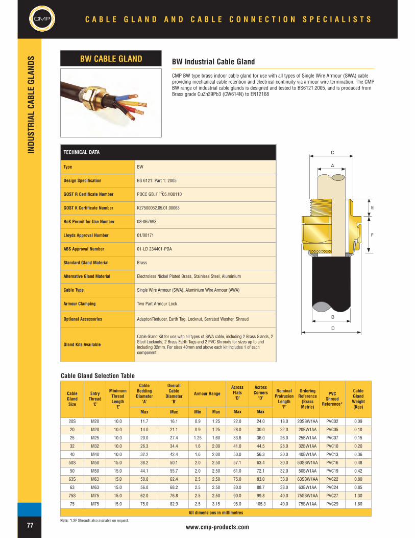
CableGlandSize
EntryThread‘C’
MinimumThreadLength‘E’
CableBeddingDiameter
‘A’
OverallCable
Diameter‘B’
Armour RangeAcrossFlats‘D’
AcrossCorners‘D’
NominalProtrusionLength‘F’
OrderingReference(BrassMetric)
PVCShroud
Reference*
CableGlandWeight(Kgs)
Max Max Min Max
20S M20 10.0 11.7 16.1 0.9 1.25 22.0 24.0 18.0 20SBW1AA PVC02 0.09
20 M20 10.0 14.0 21.1 0.9 1.25 28.0 30.0 22.0 20BW1AA PVC05 0.10
25 M25 10.0 20.0 27.4 1.25 1.60 33.6 36.0 26.0 25BW1AA PVC07 0.15
32 M32 10.0 26.3 34.4 1.6 2.00 41.0 44.5 28.0 32BW1AA PVC10 0.20
40 M40 10.0 32.2 42.4 1.6 2.00 50.0 56.3 30.0 40BW1AA PVC13 0.36
50S M50 15.0 38.2 50.1 2.0 2.50 57.1 63.4 30.0 50SBW1AA PVC16 0.48
50 M50 15.0 44.1 55.7 2.0 2.50 61.0 72.1 32.0 50BW1AA PVC19 0.42
63S M63 15.0 50.0 62.4 2.5 2.50 75.0 83.0 38.0 63SBW1AA PVC22 0.80
63 M63 15.0 56.0 68.2 2.5 2.50 80.0 88.7 38.0 63BW1AA PVC24 0.85
75S M75 15.0 62.0 76.8 2.5 2.50 90.0 99.8 40.0 75SBW1AA PVC27 1.30
75 M75 15.0 75.0 82.9 2.5 3.15 95.0 105.3 40.0 75BW1AA PVC29 1.60
All dimensions in millimetres
TECHNICAL DATA
Type BW
Design Specification BS 6121: Part 1: 2005
GOST R Certificate Number POCC GB. 05.H00110
GOST K Certificate Number KZ7500052.05.01.00063
RoK Permit for Use Number 08-067693
Lloyds Approval Number 01/00171
ABS Approval Number 01-LD 234401-PDA
Standard Gland Material Brass
Alternative Gland Material Electroless Nickel Plated Brass, Stainless Steel, Aluminium
Cable Type Single Wire Armour (SWA), Aluminium Wire Armour (AWA)
Armour Clamping Two Part Armour Lock
Optional Accessories Adaptor/Reducer, Earth Tag, Locknut, Serrated Washer, Shroud
Gland Kits Available
Cable Gland Kit for use with all types of SWA cable, including 2 Brass Glands, 2Steel Locknuts, 2 Brass Earth Tags and 2 PVC Shrouds for sizes up to andincluding 32mm. For sizes 40mm and above each kit includes 1 of eachcomponent.
CMP
INDU
STRIAL
CABL
EGL
ANDS
www.cmp-products.com
CMP BW type brass indoor cable gland for use with all types of Single Wire Armour (SWA) cableproviding mechanical cable retention and electrical continuity via armour wire termination. The CMPBW range of industrial cable glands is designed and tested to BS6121:2005, and is produced fromBrass grade CuZn39Pb3 (CW614N) to EN12168
BW Industrial Cable GlandBW CABLE GLAND
A
C
E
B
D
F
Cable Gland Selection Table
Note: *LSF Shrouds also available on request.
LLU
C A B L E G L A N D A N D C A B L E C O N N E C T I O N S P E C I A L I S T SCMP
77
Max Max

INDU
STRIAL
CABL
EGL
ANDS
TECHNICAL DATA
Type BWL
Design Specification BS 6121:Part 1:2005
GOST R Certificate Number POCC GB. 05.H00110
GOST K Certificate Number KZ7500052.05.01.00063
RoK Permit for Use Number 08-067693
Lloyds Approval Number 01/00171
ABS Approval Number 01-LD 234401-PDA
Standard Gland Material Brass
Alternative Gland Material Electroless Nickel Plated Brass, Stainless Steel, Aluminium
Cable Type Single Wire Armour (SWA), Aluminium Wire Armour (AWA)
Armour Clamping Detachable Armour Cone and Anyway Universal Clamping Ring
Optional Accessories Adaptor/Reducer, Earth Tag, Locknut, Serrated Washer, Shroud
LLU
CMP BWL type brass indoor cable gland for use with all types of Single Wire Armour (SWA) cableproviding mechanical cable retention and electrical continuity via armour wire termination. Theheavy duty BWL design offers the benefit of a longer body to protect the armour wires from impact.The CMP BWL range of industrial cable glands is designed and tested to BS6121:2005, and isproduced from Brass grade CuZn39Pb3 (CW614N) to EN12168
BWL Heavy Duty Industrial Cable GlandBWL CABLE GLAND
A
C
E
B
D
F
Cable Gland Selection Table
CableGlandSize
EntryThread‘C’
MinimumThreadLength‘E’
CableBedding
Diameter ‘A’
OverallCable
Diameter ‘B’Armour Range †
AcrossFlats‘D’
AcrossCorners‘D’
NominalProtrusionLength‘F’
OrderingReference
(Brass Metric)
PVCShroud
Reference*
CableGlandWeight(Kgs)Max Max Min Max
20S/16 M20 10.0 8.7 13.4 0.90 0.90 24.0 26.6 22.0 20S16BWL1RA PVC02 0.10020S M20 10.0 11.7 15.9 0.90 1.25 24.0 26.6 22.0 20SBWL1RA PVC02 0.10020 M20 10.0 14.0 20.9 0.90 1.25 30.5 33.3 28.0 20BWL1RA PVC04 0.13025 M25 10.0 20.0 26.2 1.25 1.60 37.5 39.9 32.0 25BWL1RA PVC09 0.17032 M32 10.0 26.3 33.9 1.60 2.00 46.0 51.0 34.0 32BWL1RA PVC11 0.28240 M40 15.0 32.2 40.4 1.60 2.00 55.0 56.3 36.0 40BWL1RA PVC13 0.41050S M50 15.0 38.2 46.7 2.00 2.50 60.0 66.5 36.0 50SBWL1RA PVC17 0.46950 M50 15.0 44.1 53.1 2.00 2.50 70.0 77.6 38.0 50BWL1RA PVC20 0.43463S M63 15.0 50.0 59.4 2.50 2.50 75.0 83.0 44.0 63SBWL1RA PVC22 0.88363 M63 15.0 56.0 65.9 2.50 2.50 80.0 88.7 44.0 63BWL1RA PVC25 0.99075S M75 15.0 62.0 72.1 2.50 2.50 89.0 99.8 50.0 75SBWL1RA PVC28 1.50675 M75 15.0 68.0 78.5 2.50 3.15 99.0 111.1 50.0 75BWL1RA PVC30 1.95490 M90 15.0 80.0 90.4 3.15 3.15 114.0 128.6 55.0 90BWL1RA PVC32 2.902
All dimensions in millimetres
www.cmp-products.com
CMP
Note: *LSF Shrouds also available on request. † Alternative armour clamping range available for non-standard armour sizes.
C A B L E G L A N D A N D C A B L E C O N N E C T I O N S P E C I A L I S T S CMP
78
Max Max

CableGlandSize
AvailableEntry
Threads‘C’
MinimumThreadLength‘E’
CableBeddingDiameter
‘A’
OverallCable
Diameter‘B’
Armour Range † AcrossFlats‘D’
AcrossCorners‘D’
NominalProtrusionLength‘F’
OrderingReference
(Brass Metric)#
PVCShroud
Reference*
CableGlandWeight(Kgs)Grooved Cone Stepped Cone
Metric Max Min Max Min Max Min Max20S/16 M20 10.0 8.7 6.1 11.5 0.0 1.0 0.90 1.00 30.5 33.3 47.0 20S16C2KGP1RA PVC04 0.13220S M20 10.0 11.7 9.5 15.9 0.0 1.0 0.90 1.25 30.5 33.3 47.0 20SC2KGP1RA PVC04 0.13220 M20 10.0 14.0 12.5 20.9 0.0 1.0 0.90 1.25 30.5 33.3 50.0 20C2KGP1RA PVC06 0.19425S M25 10.0 14.0 14.0 22.0 0.0 1.0 1.25 1.60 36.0 40.0 55.0 25SC2KGP1RA PVC09 0.30625 M25 10.0 20.0 18.2 26.2 0.0 1.0 1.25 1.60 36.0 40.0 55.0 25C2KGP1RA PVC09 0.30632 M32 10.0 26.3 23.7 33.9 0.0 1.0 1.60 2.00 46.0 51.0 58.0 32C2KGP1RA PVC11 0.46840 M40 10.0 32.2 27.9 40.4 0.0 1.0 1.60 2.00 55.0 61.0 58.0 40C2KGP1RA PVC15 0.67850S M50 10.0 38.2 35.2 46.7 0.0 1.0 2.00 2.50 60.0 66.5 58.0 50SC2KGP1RA PVC18 0.75050 M50 10.0 44.1 40.4 53.1 0.0 1.0 2.00 2.50 70.1 78.6 60.0 50C2KGP1RA PVC21 1.04463S M63 10.0 50.0 45.6 59.4 0.0 1.0 2.00 2.50 75.0 83.2 70.0 63SC2KGP1RA PVC23 1.07463 M63 10.0 56.0 54.6 65.9 0.0 1.0 2.00 2.50 80.0 89.0 70.0 63C2KGP1RA PVC25 1.28075S M75 15.0 62.0 59.0 72.1 0.0 1.0 2.00 2.50 90.0 99.8 80.0 75SC2KGP1RA PVC28 1.86075 M75 15.0 68.0 66.7 78.5 0.0 1.0 2.00 2.50 100.0 111.0 82.0 75C2KGP1RA PVC30 2.55090 M90 15.0 80.0 76.2 90.4 0.0 1.6 3.15 3.15 115.0 127.5 96.0 90C2KGP1RA PVC32 3.650100 M100 15.0 91.0 89.1 101.5 0.0 1.6 3.15 4.00 123.0 136.0 106.0 100C2KGP1RA 150/50HST 4.200115 M115 15.0 98.0 101.3 110.3 0.0 1.6 3.15 4.00 133.4 147.8 115.0 115C2KGP1RA 180/60HST 4.750130 M130 15.0 115.0 114.0 123.3 0.0 1.6 3.15 4.00 146.1 152.4 125.0 130C2KGP1RA 180/60HST 5.330
All dimensions in millimetres
CMP
INDU
STRIAL
CABL
EGL
ANDS
www.cmp-products.com
CMP C2KGP type brass indoor and outdoor cable gland for use with all types of Single Wire Armour(SWA), Wire Braid Armour, Strip Armour, Pliable Wire Armour & Steel Tape Armour (STA) cable,providing environmental seal on the cable outer sheath and additional deluge seal meeting the testrequirements of DTS01:91. The cable gland also provides mechanical cable retention and electricalcontinuity via armour termination. A reversible armour cone and AnyWay universal clamping ringarrangement allows the cable to be easily disconnected from the equipment, for maintenance andchange out etc. This feature also facilitates remote make off procedures when the termination is to beconducted in confined spaces or in areas of restricted access.
The CMP C2KGP range of industrial cable glands is designed and tested to BS 6121:Part 1:1989, meetsor surpasses the requirements of EN 50262 :1999, and is produced from Brass grade CuZn39Pb3(CW614N) to EN12168
C2KGP Industrial Cable GlandC2KGP CABLE GLAND
A
B
D
C
E
F
Cable Gland Selection Table
Note: *LSF Shrouds also available on request. † Alternative armour clamping range available for non-standard armour sizes. Marine approvals including Lloyds, DNV & ABS are also available from CMP Products.
TECHNICAL DATAType C2KGP
Design Specification BS 6121:Part 1:1989, EN 50262:1999
EN 50262 Mechanical Classifications Retention = Class B, Impact = Level 8,
EN 50262 Electrical Classifications Category A without use of an Earth Tag and Category B with an Earth Tag.
GOST R Certificate Number POCC GB. 05.H00110
GOST K Certificate Number KZ7500052.05.01.00063
RoK Permit for Use Number 08-067693
Continuous Operating Temperature -60°C to +150°C
Ingress Protection Rating IP66, IP67, IP68
Ingress Protection Document 5046/C549H
Deluge Protection Compliance DTS01 : 91
Deluge Protection Document 5046/C549H-D
Standard Gland Material Brass
Alternative Gland Material Electroless Nickel Plated Brass, Stainless Steel, Aluminium
Seal Material CMP Formulated Thermoplastic Elastomer
Cable TypeSingle Wire Armour (SWA), Aluminium Wire Armour (AWA), Steel Tape Armour(STA), Aluminium Strip Armour (ASA), Wire Braid Armour, Screened Flexible WireBraid (e.g. CY / SY)
Armour Clamping Reversible Armour Cone & AnyWay Universal Clamping Ring
Sealing Technique Unique CMP "LRS" ™ Outer Seal (Load Retention Seal)
Sealing Area(s) Cable Outer Sheath
Optional Accessories Adaptor/Reducer, Earth Tag, Entry Thread Seal, Locknut, Serrated Washer,Shroud
LLU
C A B L E G L A N D A N D C A B L E C O N N E C T I O N S P E C I A L I S T S
79
CMP
Max Max

INDU
STRIAL
CABL
EGL
ANDS
www.cmp-products.com
CMP
CMP CW type brass indoor and outdoor cable gland for use with all types of Single Wire Armour (SWA)cable, providing environmental seal on the cable outer sheath. The cable gland also providesmechanical cable retention and electrical continuity via armour wire termination. A detachable armourcone and AnyWay universal clamping ring arrangement allows the cable to be easily disconnected fromthe equipment, for maintenance and change out etc. This feature also facilitates remote make offprocedures when the termination is to be conducted in confined spaces or in areas of restricted access.
The CMP CW range of industrial cable glands is designed and tested to BS 6121:Part 1:1989, meets orsurpasses the requirements of EN 50262 :1999, and is produced from Brass grade CuZn39Pb3(CW614N) to EN12168. Other materials including Aluminium are also available in this standard design.
CW Industrial Cable GlandCW CABLE GLAND
A
C
E
B
D
F
Cable Gland Selection Table
TECHNICAL DATA
Type CW
Design Specification BS 6121:Part 1:1989, EN 50262:1999
EN 50262 Mechanical Classifications Retention = Class B, Impact = Level 8,
EN 50262 Electrical Classifications Category A without use of an Earth Tag and Category B with an Earth Tag.
GOST R Certificate Number POCC GB. 05.H00110
GOST K Certificate Number KZ7500052.05.01.00063
RoK Permit for Use Number 08-067693
ABS Approval Number 01-LD 234401-PDA
Continuous Operating Temperature -60°C to +150°C
Ingress Protection Rating IP66
Standard Gland Material Brass
Alternative Gland Material Electroless Nickel Plated Brass, Stainless Steel, Aluminium
Seal Material CMP Formulated Thermoplastic Elastomer
Cable Type Single Wire Armour (SWA)
Armour Clamping Detachable Armour Cone & AnyWay Universal Clamping Ring
Sealing Technique Unique CMP "LRS" ™ Outer Seal (Load Retention Seal)
Sealing Area(s) Cable Outer Sheath
Optional Accessories Locknut, Serrated Washer, Shroud, Adaptor/Reducer, Earth Tag, Entry ThreadSeal
Cable Gland Kits Available
Cable Gland kit for use with all types of SWA cable including 2 brass glands, 2steel locknuts, 2 brass earth tags and 2 PVC shrouds for sizes up to andincluding 32mm. For sizes 40mm and above each kit includes 1 of eachcomponent.
LLU
CableGlandSize
EntryThread‘C’
MinimumThreadLength‘E’
CableBedding
Diameter ‘A’
OverallCable
Diameter ‘B’
Armour Range †AcrossFlats‘D’
AcrossCorners‘D’
NominalProtrusionLength‘F’
OrderingReference
(Brass Metric)#
PVCShroud
Reference*
CableGlandWeight(Kgs)Stepped Cone
Max Min Max Min Max20S/16 M20 10.0 8.7 6.1 11.5 0.90 1.00 24.0 26.6 43.0 20S16CW1RA PVC04 0.11820S M20 10.0 11.7 9.5 15.9 0.90 1.25 24.0 26.6 43.0 20SCW1RA PVC04 0.11820 M20 10.0 14.0 12.5 20.9 0.90 1.25 30.5 33.3 50.0 20CW1RA PVC06 0.15925S M25 10.0 19.9 14.0 22.0 1.25 1.60 36.0 40.0 55.0 25SCW1RA PVC09 0.22825 M25 10.0 20.0 18.2 26.2 1.25 1.60 36.0 40.0 55.0 25CW1RA PVC09 0.22832 M32 10.0 26.3 23.7 33.9 1.60 2.00 46.0 51.0 55.0 32CW1RA PVC11 0.36240 M40 15.0 32.2 27.9 40.4 1.60 2.00 55.0 61.0 55.0 40CW1RA PVC15 0.52050S M50 15.0 38.2 35.2 46.7 2.00 2.50 60.0 66.5 56.0 50SCW1RA PVC18 0.57950 M50 15.0 44.1 40.4 53.1 2.00 2.50 70.1 78.6 70.0 50CW1RA PVC21 0.60163S M63 15.0 50.0 45.6 59.4 2.00 2.50 75.0 83.2 70.0 63SCW1RA PVC23 1.05463 M63 15.0 56.0 54.6 65.9 2.00 2.50 80.0 89.0 80.0 63CW1RA PVC25 1.20075S M75 15.0 62.0 59.0 72.1 2.00 2.50 90.0 101.6 81.0 75SCW1RA PVC28 1.77975 M75 15.0 68.0 66.7 78.5 2.00 2.50 100.0 111.1 96.0 75CW1RA PVC30 2.37090 M90 15.0 80.0 76.2 90.4 3.15 3.15 114.0 128.6 120.0 90CW1RA PVC32 3.515100 M100 15.0 91.0 89.1 101.5 3.15 4.00 123.0 136.0 140.0 100CW1RA 150/50HST 4.100115 M115 15.0 98.0 101.3 110.3 3.15 4.00 133.4 147.8 160.0 115CW1RA 180/60HST 4.600130 M130 15.0 115.0 114.0 123.3 3.15 4.00 146.1 152.4 169.0 130CW1RA 180/60HST 5.200
All dimensions in millimetres
Note: *LSF Shrouds also available on request. † Alternative armour clamping range available for non-standard armour sizes. Marine approvals including Lloyds, DNV & ABS are also available from CMP Products.
C A B L E G L A N D A N D C A B L E C O N N E C T I O N S P E C I A L I S T S CMP
80
Max Max

CMP
INDU
STRIAL
CABL
EGL
ANDS
www.cmp-products.com
A
C
E
B
D
F
Cable Gland Selection Table
TECHNICAL DATA
Type CX
Design Specification BS 6121:Part 1:1989, EN 50262:1999
EN 50262 Mechanical Classifications Retention = Class B, Impact = Level 8,
EN 50262 Electrical Classifications Category A without use of an Earth Tag and Category B with an Earth Tag.
GOST R Certificate Number POCC GB. 05.H00110
GOST K Certificate Number KZ7500052.05.01.00063
RoK Permit for Use Number 08-067693
Lloyds Approval Number 01/00171
ABS Approval Number 01-LD 234401-PDA
Continuous Operating Temperature -60°C to +150°C
Ingress Protection Rating IP66
Standard Gland Material Brass
Alternative Gland Material Electroless Nickel Plated Brass, Stainless Steel, Aluminium
Seal Material CMP Formulated Thermoplastic Elastomer
Cable Type Wire Braid Armour, Screened Flexible Wire Braid (e.g. CY / SY), Pliable WireArmour (PWA), Steel Tape Armour (STA)
Armour Clamping Detachable Armour Cone & AnyWay Universal Clamping Ring
Sealing Technique Unique CMP "LRS" ™ Outer Seal (Load Retention Seal)
Sealing Area(s) Cable Outer Sheath
Optional Accessories Adaptor/Reducer, Earth Tag, Entry Thread Seal, Locknut, Serrated Washer,Shroud
LLU
CX Industrial Cable GlandCX CABLE GLAND
CMP CX type brass indoor and outdoor cable gland for use with all types of Wire Braid Armour, StripArmour, Pliable Wire Armour & Steel Tape Armour (STA) cable, providing environmental seal on thecable outer sheath. The cable gland also provides mechanical cable retention and electrical continuityvia armour wire termination. A detachable armour cone and AnyWay universal clamping ringarrangement allows the cable to be easily disconnected from the equipment, for maintenance andchange out etc. This feature also facilitates remote make off procedures when the termination is to beconducted in confined spaces or in areas of restricted access.
The CMP CX range of industrial cable glands is designed and tested to BS 6121:Part 1:1989, meets orsurpasses the requirements of EN 50262 :1999, and is produced from Brass grade CuZn39Pb3(CW614N) to EN12168. Other materials including Aluminium are also available in this standard design.
C A B L E G L A N D A N D C A B L E C O N N E C T I O N S P E C I A L I S T S
81
CMP
CableGlandSize
EntryThread‘C’
MinimumThreadLength‘E’
CableBedding
Diameter ‘A’
OverallCable
Diameter ‘B’
ArmourRangeGrooved
AcrossFlats‘D’
AcrossCorners‘D’
NominalProtrusionLength‘F’
OrderingReference
(Brass Metric)
PVCShroud
Reference*
CableGlandWeight(Kgs)
Max Min Max
20S/16 M20 10.0 8.7 6.1 11.5 0 1.0 24.0 26.6 43.0 20S16CX1RA PVC04 0.11820S M20 10.0 11.7 9.5 15.9 0 1.0 24.0 26.6 43.0 20SCX1RA PVC04 0.11820 M20 10.0 14.0 12.5 20.9 0 1.0 30.5 33.3 50.0 20CX1RA PVC06 0.15925S M25 10.0 19.9 14.0 22.0 0 1.0 36.0 40.0 55.0 25SCX1RA PVC09 0.22825 M25 10.0 20.0 18.2 26.2 0 1.0 36.0 40.0 55.0 25CX1RA PVC09 0.22832 M32 10.0 26.3 23.7 33.9 0 1.0 46.0 51.0 55.0 32CX1RA PVC11 0.36240 M40 15.0 32.2 27.9 40.4 0 1.0 55.0 61.0 55.0 40CX1RA PVC15 0.52050S M50 15.0 38.2 35.2 46.7 0 1.0 60.0 66.5 56.0 50SCX1RA PVC18 0.57950 M50 15.0 44.1 40.4 53.1 0 1.0 70.1 78.6 70.0 50CX1RA PVC21 0.60163S M63 15.0 50.0 45.6 59.4 0 1.0 75.0 83.2 70.0 63SCX1RA PVC23 1.05463 M63 15.0 56.0 54.6 65.9 0 1.0 80.0 89.0 80.0 63CX1RA PVC25 1.20075S M75 15.0 62.0 59.0 72.1 0 1.0 90.0 101.6 81.0 75SCX1RA PVC28 1.77975 M75 15.0 68.0 66.7 78.5 0 1.0 100.0 111.1 96.0 75CX1RA PVC30 2.37090 M90 15.0 80.0 76.2 90.4 0 1.6 114.0 128.6 120.0 90CX1RA PVC32 3.515100 M100 15.0 91.0 89.1 101.5 0 1.6 123.0 136.0 140.0 100CX1RA 150/50HST 4.100115 M115 15.0 98.0 101.3 110.3 0 1.6 133.4 147.8 160.0 115CX1RA 180/60HST 4.600130 M130 15.0 115.0 114.0 123.3 0 1.6 146.1 152.4 169.0 130CX1RA 180/60HST 5.200
All dimensions in millimetresNote: *LSF Shrouds also available on request. Marine approvals including Lloyds, DNV & ABS are also available from CMP Products.
Min Max Max Max

INDU
STRIAL
CABL
EGL
ANDS
www.cmp-products.com
CMP
CMP A2 type brass indoor and outdoor cable gland for use with all types of Unarmoured cable,providing mechanical cable retention and an environmental seal on the cable outer sheath.
The CMP A2 range of industrial cable glands is designed and tested to BS 6121:Part 1:1989, meetsor surpasses the requirements of EN 50262 :1999, and is produced from Brass grade CuZn39Pb3(CW614N) to EN12168. Other materials including Aluminium are also available in this standarddesign.
A2 Industrial Cable GlandA2 CABLE GLAND
D
A
C
E
F
Cable Gland Selection Table
TECHNICAL DATA
Type A2
Design Specification BS 6121:Part 1:1989, EN 50262:1999
EN 50262 Mechanical Classifications Retention = Class B, Impact = Level 8,
GOST R Certificate Number POCC GB. 05.H00110
GOST K Certificate Number KZ7500052.05.01.00063
RoK Permit for Use Number 08-067693
Lloyds Approval Number 01/00171
ABS Approval Number 01-LD 234401-PDA
Continuous Operating Temperature -60°C to +150°C
Ingress Protection Rating IP66, IP67, IP68
Ingress Protection Document 5046 C549D
Deluge Protection Compliance DTS01 : 91
Deluge Protection Document 5046 C549-D
Standard Gland Material Brass
Alternative Gland Material Electroless Nickel Plated Brass, Stainless Steel, Aluminium
Seal Material CMP Formulated Thermoplastic Elastomer
Cable Type Unarmoured
Sealing Technique CMP Displacement Seal
Sealing Area(s) Cable Outer Sheath
Optional Accessories Adaptor/Reducer, Earth Tag, Entry Thread Seal, Locknut, Serrated Washer,Shroud
LLU
CableGlandSize
Available Entry Threads ‘C’ MinimumThreadLength‘E’
CableBedding
Diameter ‘A’
AcrossFlats‘D’
AcrossCorners‘D’
NominalProtrusionLength‘F’
OrderingReference
(Brass Metric)#
PVCShroud
Reference*
CableGlandWeight(Kgs)
Standard Option
Metric NPT NPT Min Min20S/16 M20 1/2” 3/4” 10.0 3.1 8.7 24.0 26.6 21.0 20S16A21RA PVC04 0.05420S M20 1/2” 3/4” 10.0 6.1 11.7 24.0 26.6 21.0 20SA21RA PVC04 0.05420 M20 1/2” 3/4” 10.0 6.5 14.0 27.0 30.0 24.0 20A21RA PVC05 0.05925 M25 3/4” 1” 10.0 11.1 20.0 36.0 39.9 26.0 25A21RA PVC09 0.11232 M32 1” 1 1/4” 10.0 17.0 26.3 41.0 45.5 27.0 32A21RA PVC10 0.12840 M40 1 1/4” 1 1/2” 15.0 23.5 32.2 50.0 55.4 28.0 40A21RA PVC13 0.16850S M50 1 1/2” 2” 15.0 31.0 38.2 55.0 61.0 29.0 50SA21RA PVC14 0.22450 M50 2” 2 1/2” 15.0 35.6 44.1 60.0 66.5 30.0 50A21RA PVC17 0.23163S M63 2” 2 1/2” 15.0 41.5 50.0 70.0 77.6 30.0 63SA21RA PVC20 0.36063 M63 2 1/2” 3” 15.0 47.2 56.0 75.0 83.2 30.0 63A21RA PVC22 0.34475S M75 2 1/2” 3” 15.0 54.0 62.0 80.0 88.7 32.0 75SA21RA PVC24 0.46675 M75 3” 3 1/2” 15.0 61.1 68.0 85.0 94.2 32.0 75A21RA PVC26 0.39590 M90 3” 3 1/2” 15.0 66.6 79.4 108.0 120.7 44.0 90A21RA PVC31 1.346100 M100 4” - 15.0 76.0 91.0 123.0 137.8 48.0 100A21RA 150/50HST 1.575115 M115 - - 15.0 86.0 98.0 133.4 147.6 55.0 115A21RA 180/60HST 2.322130 M130 - - 15.0 97.0 115.0 152.4 164.9 62.0 130A21RA 180/60HST 3.400
All dimensions in millimetres
C A B L E G L A N D A N D C A B L E C O N N E C T I O N S P E C I A L I S T S CMP
82Note: *LSF Shrouds also available on request. Marine approvals including Lloyds, DNV & ABS are also available from CMP Products. # Other thread forms are available.
Max Max

CMP
INDU
STRIAL
CABL
EGL
ANDS
www.cmp-products.com
CMP CXT type brass indoor and outdoor cable gland for use with all types of screened flexible wirebraid (e.g. CY/SY), or wire braid armour cable. The cable gland provides an environmental seal onthe cable outer sheath. The cable gland also provides mechanical cable retention and electricalcontinuity via internal pig-tail termination of the flexible wire braid.
The CMP CXT range of industrial cable glands is designed and tested to BS 6121:Part 1:1989,meets or surpasses the requirements of EN 50262 :1999, and is produced from Brass gradeCuZn39Pb3 (CW614N) to EN12168. Other materials including Aluminium are also available in thisstandard design.
CXT Industrial Cable GlandCXT CABLE GLAND
C
E
A
D
F
Cable Gland Selection Table
CableGlandSize
Entry Thread‘C’
MinimumThreadLength‘E’
CableBedding
Diameter ‘A’
AcrossFlats‘D’
AcrossCorners‘D’
NominalProtrusionLength‘F’
OrderingReference
(Brass Metric)
PVCShroud
Reference*
CableGlandWeight(Kgs)
Min Max20S/16 M20 15.0 3.1 8.7 24.0 26.6 18.0 20S16CXT1RA PVC04 0.05820S M20 15.0 6.1 11.7 24.0 26.6 18.0 20SCXT1RA PVC04 0.05820 M20 15.0 6.5 14.0 27.0 30.0 20.0 20CXT1RA PVC05 0.06225 M25 15.0 11.1 20.0 36.0 40.0 26.0 25CXT1RA PVC09 0.12032 M32 15.0 17.0 26.3 41.0 45.5 26.0 32CXT1RA PVC10 0.13440 M40 15.0 23.5 32.2 50.0 55.5 26.0 40CXT1RA PVC13 0.18250S M50 15.0 31.0 38.2 55.0 61.5 28.0 50SCXT1RA PVC14 0.23650 M50 15.0 35.6 44.1 60.0 66.5 28.0 50CXT1RA PVC17 0.24463S M63 15.0 41.5 50.0 70.0 77.6 28.0 63SCXT1RA PVC20 0.37763 M63 15.0 47.2 56.0 75.0 83.0 30.0 63CXT1RA PVC22 0.37475S M75 15.0 54.0 62.0 80.0 88.7 30.0 75SCXT1RA PVC24 0.45675 M75 15.0 61.1 68.0 85.0 94.3 32.0 75CXT1RA PVC26 0.38890 M90 15.0 66.6 79.4 108.0 119.7 40.0 90CXT1RA PVC31 1.480100 M100 15.0 76.0 91.0 123.0 136.0 45.0 100CXT1RA 150/50HST 1.575115 M115 15.0 89.0 98.0 133.4 148.0 48.0 115CXT1RA 180/60HST 2.322130 M130 15.0 97.0 115.0 146.1 162.0 52.0 130CXT1RA 180/60HST 3.400
All dimensions in millimetres
TECHNICAL DATA
Type CXT
Design Specification BS 6121:Part 1:1989, EN 50262:1999
EN 50262 Mechanical Classifications Retention = Class B, Impact = Level 8,
Continuous Operating Temperature -60°C to +150°C
Ingress Protection Rating IP66
Standard Gland Material Brass
Alternative Gland Material Electroless Nickel Plated Brass, Stainless Steel, Aluminium
Seal Material CMP Formulated Thermoplastic Elastomer
Cable Type Screened and Flexible Wire Braid (e.g CY / SY), Wire Braid Armour,Armored & Jacketed.
Sealing Technique CMP Displacement Seal
Sealing Area(s) Cable Outer Sheath
Optional Accessories Adaptor/Reducer, Earth Tag, Entry Thread Seal, Locknut, Serrated Washer, Shroud
C A B L E G L A N D A N D C A B L E C O N N E C T I O N S P E C I A L I S T S
83
CMP
Note: *LSF Shrouds also available on request. Marine approvals including Lloyds, DNV & ABS are also available from CMP Products.
Max Max
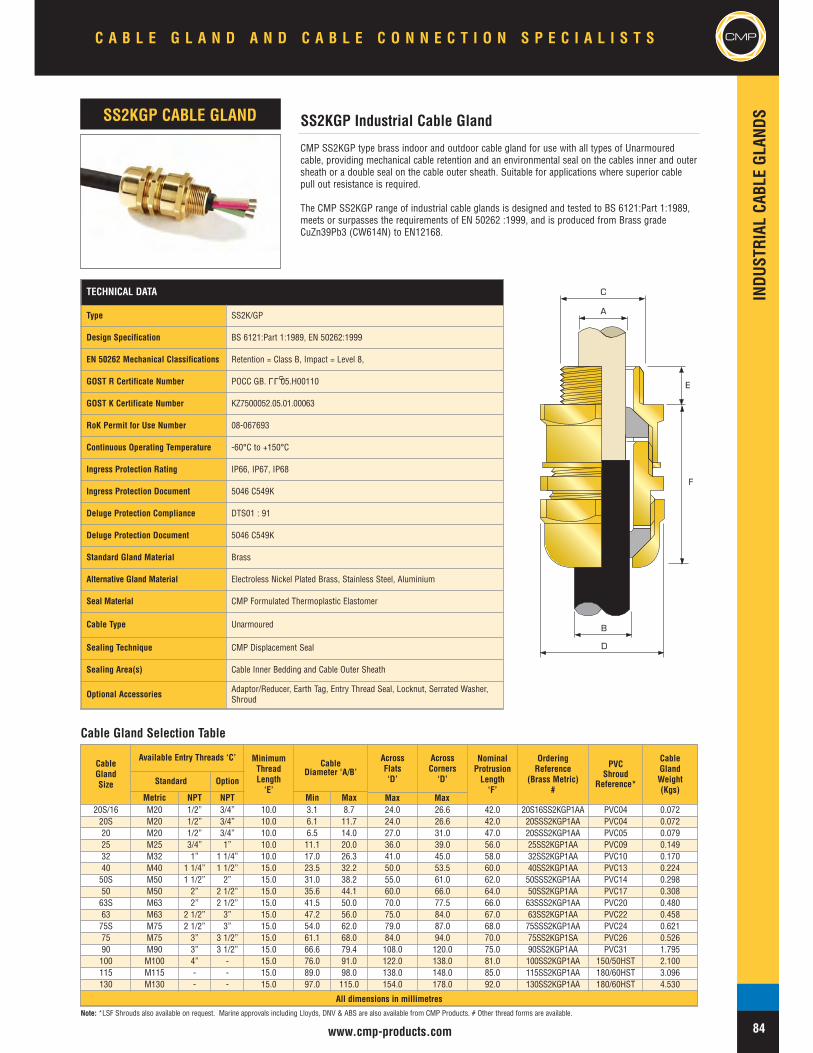
INDU
STRIAL
CABL
EGL
ANDS
www.cmp-products.com
CMP
CMP SS2KGP type brass indoor and outdoor cable gland for use with all types of Unarmouredcable, providing mechanical cable retention and an environmental seal on the cables inner and outersheath or a double seal on the cable outer sheath. Suitable for applications where superior cablepull out resistance is required.
The CMP SS2KGP range of industrial cable glands is designed and tested to BS 6121:Part 1:1989,meets or surpasses the requirements of EN 50262 :1999, and is produced from Brass gradeCuZn39Pb3 (CW614N) to EN12168.
SS2KGP Industrial Cable GlandSS2KGP CABLE GLAND
A
C
E
B
D
F
Cable Gland Selection Table
TECHNICAL DATA
Type SS2K/GP
Design Specification BS 6121:Part 1:1989, EN 50262:1999
EN 50262 Mechanical Classifications Retention = Class B, Impact = Level 8,
GOST R Certificate Number POCC GB. 05.H00110
GOST K Certificate Number KZ7500052.05.01.00063
RoK Permit for Use Number 08-067693
Continuous Operating Temperature -60°C to +150°C
Ingress Protection Rating IP66, IP67, IP68
Ingress Protection Document 5046 C549K
Deluge Protection Compliance DTS01 : 91
Deluge Protection Document 5046 C549K
Standard Gland Material Brass
Alternative Gland Material Electroless Nickel Plated Brass, Stainless Steel, Aluminium
Seal Material CMP Formulated Thermoplastic Elastomer
Cable Type Unarmoured
Sealing Technique CMP Displacement Seal
Sealing Area(s) Cable Inner Bedding and Cable Outer Sheath
Optional Accessories Adaptor/Reducer, Earth Tag, Entry Thread Seal, Locknut, Serrated Washer,Shroud
LLU
CableGlandSize
Available Entry Threads ‘C’ MinimumThreadLength‘E’
CableDiameter ‘A/B’
AcrossFlats‘D’
AcrossCorners‘D’
NominalProtrusionLength‘F’
OrderingReference
(Brass Metric)#
PVCShroud
Reference*
CableGlandWeight(Kgs)
Standard Option
Metric NPT NPT Min Max20S/16 M20 1/2” 3/4” 10.0 3.1 8.7 24.0 26.6 42.0 20S16SS2KGP1AA PVC04 0.07220S M20 1/2” 3/4” 10.0 6.1 11.7 24.0 26.6 42.0 20SSS2KGP1AA PVC04 0.07220 M20 1/2” 3/4” 10.0 6.5 14.0 27.0 31.0 47.0 20SSS2KGP1AA PVC05 0.07925 M25 3/4” 1” 10.0 11.1 20.0 36.0 39.0 56.0 25SS2KGP1AA PVC09 0.14932 M32 1” 1 1/4” 10.0 17.0 26.3 41.0 45.0 58.0 32SS2KGP1AA PVC10 0.17040 M40 1 1/4” 1 1/2” 15.0 23.5 32.2 50.0 53.5 60.0 40SS2KGP1AA PVC13 0.22450S M50 1 1/2” 2” 15.0 31.0 38.2 55.0 61.0 62.0 50SSS2KGP1AA PVC14 0.29850 M50 2” 2 1/2” 15.0 35.6 44.1 60.0 66.0 64.0 50SS2KGP1AA PVC17 0.30863S M63 2” 2 1/2” 15.0 41.5 50.0 70.0 77.5 66.0 63SSS2KGP1AA PVC20 0.48063 M63 2 1/2” 3” 15.0 47.2 56.0 75.0 84.0 67.0 63SS2KGP1AA PVC22 0.45875S M75 2 1/2” 3” 15.0 54.0 62.0 79.0 87.0 68.0 75SSS2KGP1AA PVC24 0.62175 M75 3” 3 1/2” 15.0 61.1 68.0 84.0 94.0 70.0 75SS2KGP1SA PVC26 0.52690 M90 3” 3 1/2” 15.0 66.6 79.4 108.0 120.0 75.0 90SS2KGP1AA PVC31 1.795100 M100 4” - 15.0 76.0 91.0 122.0 138.0 81.0 100SS2KGP1AA 150/50HST 2.100115 M115 - - 15.0 89.0 98.0 138.0 148.0 85.0 115SS2KGP1AA 180/60HST 3.096130 M130 - - 15.0 97.0 115.0 154.0 178.0 92.0 130SS2KGP1AA 180/60HST 4.530
All dimensions in millimetres
C A B L E G L A N D A N D C A B L E C O N N E C T I O N S P E C I A L I S T S CMP
84Note: *LSF Shrouds also available on request. Marine approvals including Lloyds, DNV & ABS are also available from CMP Products. # Other thread forms are available.
Max Max

CMP
INDU
STRIAL
CABL
EGL
ANDS
www.cmp-products.com
CMP SS2KGP-PB type brass indoor and outdoor cable gland for use with all types of LeadSheathed Unarmoured, providing mechanical cable retention and environmental seal on the cableinner lead sheath and cable outer sheath. The cable gland also provides earth bonding of the innerlead covering or lead sheath.
The CMP SS2KGP-PB range of industrial cable glands is designed and tested to BS 6121:Part1:1989, meets or surpasses the requirements of EN 50262 :1999, and is produced from Brassgrade CuZn39Pb3 (CW614N) to EN12168.
SS2KGP-PB Industrial Cable GlandSS2KGP-PB CABLE GLAND
A
C
E
B
D
F
Cable Gland Selection Table
TECHNICAL DATA
Type SS2K GPPB
Design Specification BS 6121:Part 1:1989, EN 50262:1999
EN 50262 Mechanical Classifications Retention = Class B, Impact = Level 8,
EN 50262 Electrical Classifications Category A without use of an Earth Tag and Category B with an Earth Tag.
GOST R Certificate Number POCC GB. 05.H00110
GOST K Certificate Number KZ7500052.05.01.00063
RoK Permit for Use Number 08-067693
Continuous Operating Temperature -60° to +150°
Ingress Protection Rating IP66, IP67, IP68
Ingress Protection Document 5046 C549K
Deluge Protection Compliance DTS01 : 91
Deluge Protection Document 5046 C549K-D
Standard Gland Material Brass
Alternative Gland Material Electroless Nickel Plated Brass, Stainless Steel, Aluminium
Seal Material CMP Formulated Thermoplastic Elastomer
Cable Type Unarmoured Lead Sheathed
Sealing Technique CMP Displacement Seal
Sealing Area(s) Cable Inner Lead Sheath and Cable Outer Sheath
Optional Accessories Adaptor/Reducer, Earth Tag, Entry Thread Seal, Locknut, Serrated Washer,Shroud
CableGlandSize
Available Entry Threads ‘C’ MinimumThreadLength‘E’
LeadSheath/Overall
Diameter‘A/B’
AcrossFlats‘D’
AcrossCorners‘D’
NominalProtrusionLength‘F’
OrderingReference
(Brass Metric)#
PVCShroud
Reference*
CableGlandWeight(Kgs)
Standard Option
Metric NPT NPT Min Max20S/16 M20 1/2” 3/4” 10.0 3.1 8.7 24.0 26.6 42.0 20S16SS2KGPPB1RA PVC04 0.07220S M20 1/2” 3/4” 10.0 6.1 11.7 24.0 26.6 42.0 20SSS2KGPPB1RA PVC04 0.07220 M20 1/2” 3/4” 10.0 6.5 14.0 27.0 31.0 47.0 20SSS2KGPPB1RA PVC05 0.07925 M25 3/4” 1” 10.0 11.1 20.0 36.0 39.0 56.0 25SS2KGPPB1RA PVC09 0.14932 M32 1” 1 1/4” 10.0 17.0 26.3 41.0 45.0 58.0 32SS2KGPPB1RA PVC10 0.17040 M40 1 1/4” 1 1/2” 15.0 23.5 32.2 50.0 53.5 60.0 40SS2KGPPB1RA PVC13 0.22450S M50 1 1/2” 2” 15.0 31.0 38.2 55.0 61.0 62.0 50SSS2KGPPB1RA PVC14 0.29850 M50 2” 2 1/2” 15.0 35.6 44.1 60.0 66.0 64.0 50SS2KGPPB1RA PVC17 0.30863S M63 2” 2 1/2” 15.0 41.5 50.0 70.0 77.5 66.0 63SSS2KGPPB1RA PVC20 0.48063 M63 2 1/2” 3” 15.0 47.2 56.0 75.0 84.0 67.0 63SS2KGPPB1RA PVC22 0.45875S M75 2 1/2” 3” 15.0 54.0 62.0 79.0 87.0 68.0 75SSS2KGPPB1RA PVC24 0.62175 M75 3” 3 1/2” 15.0 61.1 68.0 84.0 94.0 70.0 75SS2KGPPB1RA PVC26 0.52690 M90 3” 3 1/2” 15.0 66.6 79.4 108.0 120.0 75.0 90SS2KGPPB1RA PVC31 1.795100 M100 4” - 15.0 76.0 91.0 122.0 138.0 81.0 100SS2KGPPB1RA 150/50HST 2.100115 M115 - - 15.0 89.0 98.0 138.0 148.0 85.0 115SS2KGPPB1RA 180/60HST 3.096130 M130 - - 15.0 97.0 115.0 154.0 178.0 92.0 130SS2KGPPB1RA 180/60HST 4.530
All dimensions in millimetres
C A B L E G L A N D A N D C A B L E C O N N E C T I O N S P E C I A L I S T S
85
CMP
Note: *LSF Shrouds also available on request. Marine approvals including Lloyds, DNV & ABS are also available from CMP Products. # Other thread forms are available.
LLU
Max Max

INDU
STRIAL
CABL
EGL
ANDS
www.cmp-products.com
CMP
CMP A2RC type brass indoor and outdoor conduit connection cable gland for use with all types ofUnarmoured cables housed in rigid or flexible conduit systems. The cable gland is equipped with arotating male or female connection which is available in a variety of thread forms for ease of conduitinstallation, including NPT and Metric. Customers are requested to kindly specify the male andfemale thread form and sizes required when ordering.
The CMP A2RC range of industrial cable glands is designed and tested to BS 6121:Part 1:1989,meets or surpasses the requirements of EN 50262 :1999, and is produced from Brass gradeCuZn39Pb3 (CW614N) to EN12168.
A2RC Industrial Cable Gland With Conduit Connection FacilityA2RC CABLE GLAND
A
C
E
D
F
Cable Gland Selection Table
TECHNICAL DATA
Type A2RC
Design Specification BS 6121:Part 1:1989, EN 50262:1999
EN 50262 Mechanical Classifications Retention = Class B, Impact = Level 8,
EN 50262 Electrical Classifications Category A without use of an Earth Tag and Category B with an Earth Tag.
GOST R Certificate Number POCC GB. 05.H00110
GOST K Certificate Number KZ7500052.05.01.00063
RoK Permit for Use Number 08-067693
Continuous Operating Temperature -60°C to +150°C
Ingress Protection Rating IP66
Standard Gland Material Brass
Alternative Gland Material Electroless Nickel Plated Brass, Stainless Steel, Aluminium
Seal Material CMP Formulated Thermoplastic Elastomer
Cable Type Unarmoured
Sealing Technique CMP Displacement Seal
Sealing Area(s) Cable Outer Sheath
Optional Accessories Adaptor/Reducer, Earth Tag, Entry Thread Seal, Locknut, Serrated Washer,Shroud
LLU
CableGlandSize
Available Entry Threads ‘C’ StandardFemaleNPT
Thread
MinimumThreadLength‘E’
CableBeddingDiameter
‘A’
AcrossFlats‘D’
AcrossCorners‘D’
NominalProtrusionLength‘F’
OrderingReference
(Metric Mx NPT F)#
CableGlandWeight(Kgs)
Standard Option
Metric NPT NPT Min Max
20S/16 M20 1/2” 3/4” 1/2” 10.0 3.1 8.7 24.0 26.6 42.0 20S16A2RC1RA031 0.07520S M20 1/2” 3/4” 1/2” 10.0 6.1 11.7 24.0 26.6 42.0 20SA2RC1RA031 0.07520 M20 1/2” 3/4” 1/2” 10.0 6.5 14.0 27.0 30.0 47.0 20A2RC1RA031 0.08225 M25 3/4” 1” 3/4” 10.0 18.2 20.0 36.0 39.9 56.0 25A2RC1RA032 0.16532 M32 1” 1 1/4” 1” 10.0 23.7 26.3 41.0 45.5 58.0 32A2RC1RA033 0.18040 M40 1 1/4” 1 1/2” 1 1/4” 15.0 27.9 32.2 50.0 55.4 60.0 40A2RC1RA034 0.25050S M50 1 1/2” 2” 1 1/2” 15.0 35.2 38.2 55.0 61.0 62.0 50SA2RC1RA035 0.31050 M50 2” 2 1/2” 2” 15.0 40.4 44.1 60.0 66.5 64.0 50A2RC1RA036 0.33063S M63 2” 2 1/2” 2” 15.0 40.1 50.0 70.0 77.6 66.0 63SA2RC1RA036 0.48063 M63 2 1/2” 3” 2 1/2” 15.0 47.2 56.0 75.0 83.2 67.0 63A2RC1RA037 0.46075S M75 2 1/2” 3” 2 1/2” 15.0 59.0 62.0 80.0 88.7 68.0 75SA2RC1RA037 0.65075 M75 3” 3 1/2” 3” 15.0 66.7 68.0 85.0 94.2 70.0 75A2RC1RA038 0.58090 M90 3” 3 1/2” 3” 15.0 76.2 79.4 108.0 120.7 75.0 90A2RC1RA038 0.900
All dimensions in millimetres
C A B L E G L A N D A N D C A B L E C O N N E C T I O N S P E C I A L I S T S CMP
86Note: *LSF Shrouds also available on request. Marine approvals including Lloyds, DNV & ABS are also available from CMP Products. # Other thread forms are available.
Max Max

CMP
INDU
STRIAL
CABL
EGL
ANDS
www.cmp-products.com
TECHNICAL DATA
Type E1U
Design Specification BS 6121: Part 1: 1989, EN 50262:1999
EN 50262 Mechanical Classifications Retention = Class B, Impact = Level 8,
EN 50262 Electrical Classifications Category A without use of an Earth Tag and Category B with an Earth Tag.
GOST R Certificate Number POCC GB. 05.H00110
GOST K Certificate Number KZ7500052.05.01.00063
RoK Permit for Use Number 08-067693
Lloyds Approval Number 01/00171
ABS Approval Number 01-LD 234401-PDA
Continuous Operating Temperature -60°C to +150°C
Ingress Protection Rating IP66 (IP67/IP68 also available)
Standard Gland Material Brass
Alternative Gland Material Electroless Nickel Plated Brass, Stainless Steel, Aluminium
Seal Material CMP Formulated Thermoplastic Elastomer
Cable TypeSingle Wire Armour (SWA), Aluminium Wire Armour (AWA), Pliable WireArmour (PWA), Steel Tape Armour (STA), Wire Braid Armour, Aluminium StripArmour (ASA), Screened Flexible Wire Braid (e.g. CY / SY), Armored & Jacketed
Armour Clamping Reversible Armour Cone & AnyWay Universal Clamping Ring
Sealing Technique CMP Inner Displacement Seal & Unique CMP "LRS" ™ Outer Seal(Load Retention Seal)
Sealing Area(s) Cable Inner Bedding & Cable Outer Sheath
Optional Accessories Adaptor/Reducer, Earth Tag, Entry Thread Seal, Locknut, Serrated Washer,Shroud
CMP E1U type brass indoor and outdoor cable gland for use with all types of armoured cablesproviding an environmental seal on the cable inner bedding and on the cable outer sheath. Thecable gland provides mechanical cable retention and electrical continuity via the armour termination.A reversible armour cone and AnyWay universal clamping ring arrangement allows the cable to beeasily disconnected from the equipment, for maintenance and change out etc. This feature alsofacilitates remote make off procedures when the termination is to be conducted in confined spacesor in areas of restricted access. Separate tightening actions for the inner displacement seal and thearmour termination affords maximum control over the pressure applied to the cable inner bedding.
The CMP E1U range of industrial cable glands is designed and tested to BS 6121:Part 1:1989,meets or surpasses the requirements of EN 50262 :1999, and is produced from Brass gradeCuZn39Pb3 (CW614N) to EN12168.
CableGlandSize
Available Entry Threads ‘C’MinimumThreadLength‘E’
CableBeddingDiameter
‘A’
Overall CableDiameter
‘B’
Armour Range †AcrossFlats‘D’
AcrossCorners‘D’
NominalProtrusionLength‘F’
OrderingReference
(Brass Metric)#
PVCShroud
Reference*
CableGlandWeight(Kgs)
Standard Option GroovedCone
SteppedCone
Metric NPT NPT Min Max Min Max Min Max Min Max
20S/16 M20 1/2” 3/4” 10.0 3.1 8.7 6.1 11.5 0 1.0 0.9 1.0 24.0 26.6 63.0 20S16E1U1RA PVC04 0.16320S M20 1/2” 3/4” 10.0 6.1 11.7 9.5 15.9 0 1.0 0.9 1.25 24.0 26.6 63.0 20SE1U1RA PVC04 0.16320 M20 1/2” 3/4” 10.0 6.5 14.0 12.5 20.9 0 1.0 0.9 1.25 30.5 33.3 67.0 20E1U1RA PVC06 0.21725S M25 3/4” 1” 10.0 11.1 20.0 14.0 22.0 0 1.0 1.25 1.6 37.5 40.5 78.0 25SE1U1RA PVC09 0.34525 M25 3/4” 1” 10.0 11.1 20.0 18.2 26.2 0 1.0 1.25 1.6 37.5 40.5 78.0 25E1U1RA PVC09 0.34532 M32 1” 1-1/4” 15.0 17.0 26.3 23.7 33.9 0 1.0 1.6 2.0 46.0 51.0 78.0 32E1U1RA PVC11 0.48440 M40 1-1/4” 1-1/2” 15.0 22.0 32.2 27.9 40.4 0 1.0 1.6 2.0 55.0 61.0 83.0 40E1U1RA PVC15 0.70050S M50 1-1/2” 2” 15.0 29.5 38.2 35.2 46.7 0 1.0 2.0 2.5 60.0 66.5 78.0 50SE1U1RA PVC18 0.80050 M50 2” 2-1/2” 15.0 35.6 44.1 40.4 53.1 0 1.0 2.0 2.5 70.0 78.6 81.0 50E1U1RA PVC21 0.83063S M63 2” 2-1/2” 15.0 40.1 50.0 45.6 59.4 0 1.0 2.0 2.5 75.0 83.2 93.0 63SE1U1RA PVC23 1.41563 M63 2-1/2” 3” 15.0 47.2 56.0 54.6 65.9 0 1.0 2.0 2.5 80.0 89.0 95.0 63E1U1RA PVC25 1.51475S M75 2-1/2” 3” 15.0 52.8 62.0 59.0 72.1 0 1.0 2.0 2.5 89.0 101.6 103.0 75SE1U1RA PVC28 2.19975 M75 3” 3-1/2” 15.0 59.1 68.0 66.7 78.5 0 1.0 2.0 2.5 99.0 111.1 110.0 75E1U1RA PVC30 2.77090 M90 3 3-1/2” 15.0 66.6 79.4 76.2 90.4 0 1.6 3.15 3.15 114.0 128.6 136.0 90E1U1RA PVC32 4.478100 M100 4” - 15.0 76.0 91.0 89.1 101.5 0 1.6 3.15 4.0 123.0 138.0 145.0 100E1U1RA 150/50HST 4.700115 M115 - - 15.0 86.0 98.0 101.3 110.3 0 1.6 3.15 4.0 133.4 147.6 160.0 115E1U1RA 180/60HST 5.300130 M130 - - 15.0 97.0 115.0 114.0 123.3 0 1.6 3.15 4.0 146.1 161.9 185.0 130E1U1RA 180/60HST 5.900
All dimensions in millimetres
E1U Universal Industrial Cable GlandE1U CABLE GLAND
A
B
D
C
E
F
Cable Gland Selection Table
LLU
C A B L E G L A N D A N D C A B L E C O N N E C T I O N S P E C I A L I S T S
87
CMP
Note: *LSF Shrouds also available on request. † Alternative armour clamping range available for non-standard armour sizes. Marine approvals including Lloyds, DNV & ABS are also available from CMP Products.# Other thread forms are available.
Deluge ProofOption
Note:Deluge proof version available
Max Max
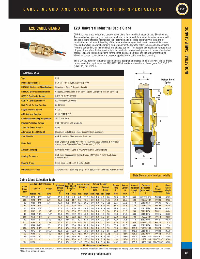
INDU
STRIAL
CABL
EGL
ANDS
www.cmp-products.com
CMP
CableGlandSize
Available Entry Threads ‘C’MinimumThreadLength‘E’
CableLead SheathDiameter
‘A’
Overall CableDiameter
‘B’
Armour Range † AcrossFlats‘D’
AcrossCorners‘D’
NominalProtrusionLength‘F’
OrderingReference
(Brass Metric)#
PVCShroud
Reference*
CableGlandWeight(Kgs)
Standard Option GroovedCone
SteppedCone
Metric NPT NPT Min Max Min Max Min Max Min Max
20S/16 M20 1/2” 3/4” 10.0 3.1 8.7 6.1 11.5 0.0 1.0 0.9 1.0 24.0 26.6 63.0 20S16E2U1RA PVC04 0.16320S M20 1/2” 3/4” 10.0 6.1 11.7 9.5 15.9 0.0 1.0 0.9 1.25 24.0 26.6 63.0 20SE2U1RA PVC04 0.16320 M20 1/2” 3/4” 10.0 6.5 14.0 12.5 20.9 0.0 1.0 0.9 1.25 30.5 33.3 67.0 20E2U1RA PVC06 0.21725S M25 3/4” 1” 10.0 11.1 20.0 14.0 22.0 0.0 1.0 1.25 1.6 37.5 40.5 78.0 25SE2U1RA PVC09 0.34525 M25 3/4” 1” 10.0 11.1 20.0 18.2 26.2 0.0 1.0 1.25 1.6 37.5 40.5 78.0 25E2U1RA PVC09 0.34532 M32 1” 1-1/4” 15.0 17.0 26.3 23.7 33.9 0.0 1.0 1.6 2.0 46.0 51.0 78.0 32E2U1RA PVC11 0.48440 M40 1-1/4” 1-1/2” 15.0 22.0 32.2 27.9 40.4 0.0 1.0 1.6 2.0 55.0 61.0 83.0 40E2U1RA PVC15 0.70050S M50 1-1/2” 2” 15.0 29.5 38.2 35.2 46.7 0.0 1.0 2.0 2.5 60.0 66.5 78.0 50SE2U1RA PVC18 0.80050 M50 2” 2-1/2” 15.0 35.6 44.1 40.4 53.1 0.0 1.0 2.0 2.5 70.0 78.6 81.0 50E2U1RA PVC21 0.83063S M63 2” 2-1/2” 15.0 40.1 50.0 45.6 59.4 0.0 1.0 2.0 2.5 75.0 83.2 93.0 63SE2U1RA PVC23 1.41563 M63 2-1/2” 3” 15.0 47.2 56.0 54.6 65.9 0.0 1.0 2.0 2.5 80.0 89.0 95.0 63E2U1RA PVC25 1.51475S M75 2-1/2” 3” 15.0 52.8 62.0 59.0 72.1 0.0 1.0 2.0 2.5 89.0 101.6 103.0 75SE2U1RA PVC28 2.19975 M75 3” 3-1/2” 15.0 59.1 68.0 66.7 78.5 0.0 1.0 2.0 2.5 99.0 111.1 110.0 75E2U1RA PVC30 2.77090 M90 3 3-1/2” 15.0 66.6 79.4 76.2 90.4 0.0 1.6 3.15 3.15 114.0 128.6 136.0 90E2U1RA PVC32 4.478100 M100 4” - 15.0 76.0 91.0 89.1 101.5 0.0 1.6 3.15 4.0 123.0 138.0 145.0 100E2U1RA 150/50HST 4.700115 M115 - - 15.0 86.0 98.0 101.3 110.3 0.0 1.6 3.15 4.0 133.4 147.6 160.0 115E2U1RA 180/60HST 5.300130 M130 - - 15.0 97.0 115.0 114.0 123.3 0.0 1.6 3.15 4.0 146.1 161.9 185.0 130E2U1RA 180/60HST 5.900
All dimensions in millimetres
TECHNICAL DATA
Type E2U
Design Specification BS 6121: Part 1: 1989, EN 50262:1999
EN 50262 Mechanical Classifications Retention = Class B, Impact = Level 8,
EN 50262 Electrical Classifications Category A without use of an Earth Tag and Category B with an Earth Tag.
GOST R Certificate Number POCC GB. 05.H00110
GOST K Certificate Number KZ7500052.05.01.00063
RoK Permit for Use Number 08-067693
Lloyds Approval Number 01/00171
ABS Approval Number 01-LD 234401-PDA
Continuous Operating Temperature -60°C to +150°C
Ingress Protection Rating IP66 (IP67/IP68 also available)
Standard Gland Material Brass
Alternative Gland Material Electroless Nickel Plated Brass, Stainless Steel, Aluminium
Seal Material CMP Formulated Thermoplastic Elastomer
Cable Type Lead Sheathed & Single Wire Armour (LC/SWA), Lead Sheathed & Wire BraidArmour, Lead Sheathed & Steel Tape Armour (LC/STA)
Armour Clamping Reversible Armour Cone & AnyWay Universal Clamping Ring
Sealing Technique CMP Inner Displacement Seal & Unique CMP "LRS" ™ Outer Seal (LoadRetention Seal)
Sealing Area(s) Cable Inner Lead Sheath & Outer Sheath
Optional Accessories Adaptor/Reducer, Earth Tag, Entry Thread Seal, Locknut, Serrated Washer, Shroud
LLU
CMP E2U type brass indoor and outdoor cable gland for use with all types of Lead Sheathed andArmoured cables providing an environmental seal on inner lead sheath and the cable outer sheath.The cable gland provides mechanical cable retention and electrical continuity via the armourtermination and also earth bonding of the inner lead covering or lead sheath. A reversible armourcone and AnyWay universal clamping ring arrangement allows the cable to be easily disconnectedfrom the equipment, for maintenance and change out etc. This feature also facilitates remote makeoff procedures when the termination is to be conducted in confined spaces or in areas of restrictedaccess. Separate tightening actions for the inner displacement seal and the armour terminationaffords maximum control over the pressure applied to the cable inner lead covering.
The CMP E2U range of industrial cable glands is designed and tested to BS 6121:Part 1:1989, meetsor surpasses the requirements of EN 50262 :1999, and is produced from Brass grade CuZn39Pb3(CW614N) to EN12168.
E2U Universal Industrial Cable GlandE2U CABLE GLAND
A
B
D
C
E
F
Cable Gland Selection Table
Note: *LSF Shrouds also available on request. † Alternative armour clamping range available for non-standard armour sizes. Marine approvals including Lloyds, DNV & ABS are also available from CMP Products.# Other thread forms are available.
C A B L E G L A N D A N D C A B L E C O N N E C T I O N S P E C I A L I S T S CMP
88
Note:Deluge proof version available
Deluge ProofOption
Max Max
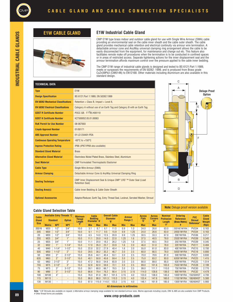
CMP
INDU
STRIAL
CABL
EGL
ANDS
www.cmp-products.com
CMP E1W type brass indoor and outdoor cable gland for use with Single Wire Armour (SWA) cableproviding an environmental seal on the cable inner sheath and the cable outer sheath. The cablegland provides mechanical cable retention and electrical continuity via armour wire termination. Adetachable armour cone and AnyWay universal clamping ring arrangement allows the cable to beeasily disconnected from the equipment, for maintenance and change out etc. This feature alsofacilitates remote make off procedures when the termination is to be conducted in confined spacesor in areas of restricted access. Separate tightening actions for the inner displacement seal and thearmour termination affords maximum control over the pressure applied to the cable inner bedding.
The CMP E1W range of industrial cable glands is designed and tested to BS 6121:Part 1:1989,meets or surpasses the requirements of EN 50262 :1999, and is produced from Brass gradeCuZn39Pb3 (CW614N) to EN12168. Other materials including Aluminium are also available in thisstandard design.
CableGlandSize
Available Entry Threads ‘C’ MinimumThreadLength‘E’
CableBedding
Diameter ‘A’
Overall CableDiameter
‘B’
ArmourRange †
NominalProtrusionLength‘F’
OrderingReference
(BrassMetric)#
PVCShroud
Reference*
CableGlandWeight(Kgs)
Standard Option
Metric NPT NPT Min Max Min Max Min Max20S/16 M20 1/2” 3/4” 10.0 3.1 8.7 6.1 11.5 0.9 1.0 24.0 26.6 63.0 20S16E1W1RA PVC04 0.16320S M20 1/2” 3/4” 10.0 6.1 11.7 9.5 15.9 0.9 1.25 24.0 26.6 63.0 20SE1W1RA PVC04 0.16320 M20 1/2” 3/4” 10.0 6.5 14.0 12.5 20.9 0.9 1.25 30.5 33.3 67.0 20E1W1RA PVC06 0.21725S M25 3/4” 1” 10.0 11.1 20.0 14.0 22.0 1.25 1.6 37.5 40.5 78.0 25SE1W1RA PVC09 0.34525 M25 3/4” 1” 10.0 11.1 20.0 18.2 26.2 1.25 1.6 37.5 40.5 78.0 25E1W1RA PVC09 0.34532 M32 1” 1-1/4” 15.0 17.0 26.3 23.7 33.9 1.6 2.0 46.0 51.0 78.0 32E1W1RA PVC11 0.48440 M40 1-1/4” 1-1/2” 15.0 22.0 32.2 27.9 40.4 1.6 2.0 55.0 61.0 83.0 40E1W1RA PVC15 0.70050S M50 1-1/2” 2” 15.0 29.5 38.2 35.2 46.7 2.0 2.5 60.0 66.5 78.0 50SE1W1RA PVC18 0.80050 M50 2” 2-1/2” 15.0 35.6 44.1 40.4 53.1 2.0 2.5 70.0 78.6 81.0 50E1W1RA PVC21 0.83063S M63 2” 2-1/2” 15.0 40.1 50.0 45.6 59.4 2.0 2.5 75.0 83.2 93.0 63SE1W1RA PVC23 1.41563 M63 2-1/2” 3” 15.0 47.2 56.0 54.6 65.9 2.0 2.5 80.0 89.0 95.0 63E1W1RA PVC25 1.51475S M75 2-1/2” 3” 15.0 52.8 62.0 59.0 72.1 2.0 2.5 89.0 101.6 103.0 75SE1W1RA PVC28 2.19975 M75 3” 3-1/2” 15.0 59.1 68.0 66.7 78.5 2.0 2.5 99.0 111.1 110.0 75E1W1RA PVC30 2.77090 M90 3” 3-1/2” 15.0 66.6 79.4 76.2 90.4 3.15 3.15 114.0 128.6 136.0 90E1W1RA PVC32 4.478100 M100 4” - 15.0 76.0 91.0 89.1 101.5 3.15 4.0 123.0 138.0 145.0 100E1W1RA 150/50HST 4.700115 M115 - - 15.0 86.0 98.0 101.3 110.3 3.15 4.0 133.4 147.6 160.0 115E1W1RA 180/60HST 5.300130 M130 - - 15.0 97.0 115.0 114.0 123.3 3.15 4.0 146.1 161.9 185.0 130E1W1RA 180/60HST 5.900
All dimensions in millimetres
E1W Industrial Cable GlandE1W CABLE GLAND
Cable Gland Selection Table
TECHNICAL DATA
Type E1W
Design Specification BS 6121:Part 1:1989, EN 50262:1999
EN 50262 Mechanical Classifications Retention = Class B, Impact = Level 8,
EN 50262 Electrical Classifications Category A without use of an Earth Tag and Category B with an Earth Tag.
GOST R Certificate Number POCC GB. 05.H00110
GOST K Certificate Number KZ7500052.05.01.00063
RoK Permit for Use Number 08-067693
Lloyds Approval Number 01/00171
ABS Approval Number 01-LD 234401-PDA
Continuous Operating Temperature -60°C to +150°C
Ingress Protection Rating IP66 (IP67/IP68 also available)
Standard Gland Material Brass
Alternative Gland Material Electroless Nickel Plated Brass, Stainless Steel, Aluminium
Seal Material CMP Formulated Thermoplastic Elastomer
Cable Type Single Wire Armour (SWA)
Armour Clamping Detachable Armour Cone & AnyWay Universal Clamping Ring
Sealing Technique CMP Inner Displacement Seal & Unique CMP "LRS" ™ Outer Seal (LoadRetention Seal)
Sealing Area(s) Cable Inner Bedding & Cable Outer Sheath
Optional Accessories Adaptor/Reducer, Earth Tag, Entry Thread Seal, Locknut, Serrated Washer, Shroud
LLU
C A B L E G L A N D A N D C A B L E C O N N E C T I O N S P E C I A L I S T S
89
CMP
A
B
D
C
E
F
Deluge ProofOption
Note: *LSF Shrouds also available on request. † Alternative armour clamping range available for non-standard armour sizes. Marine approvals including Lloyds, DNV & ABS are also available from CMP Products.# Other thread forms are available.
AcrossFlats‘D’
AcrossCorners‘D”
Note:Deluge proof version available
Max Max

INDU
STRIAL
CABL
EGL
ANDS
www.cmp-products.com
CMP
CableGlandSize
Available Entry Threads ‘C’ MinimumThreadLength‘E’
CableLead SheathDiameter ‘A’
Overall CableDiameter
‘B’
ArmourRange †
NominalProtrusionLength ‘F’
OrderingReference
(BrassMetric)#
PVCShroud
Reference*
CableGlandWeight(Kgs)
Standard Option
Metric NPT NPT Min Max Min Max Min Max
20S/16 M20 1/2” 3/4” 10.0 3.1 8.7 6.1 11.5 0.9 1.0 24.0 26.6 63.0 20S16E2W1RA PVC04 0.16320S M20 1/2” 3/4” 10.0 6.1 11.7 9.5 15.9 0.9 1.25 24.0 26.6 63.0 20SE2W1RA PVC04 0.16320 M20 1/2” 3/4” 10.0 6.5 14.0 12.5 20.9 0.9 1.25 30.5 33.3 67.0 20E2W1RA PVC06 0.21725S M25 3/4” 1” 10.0 11.1 20.0 14.0 22.0 1.25 1.6 37.5 40.5 78.0 25SE2W1RA PVC09 0.34525 M25 3/4” 1” 10.0 11.1 20.0 18.2 26.2 1.25 1.6 37.5 40.5 78.0 25E2W1RA PVC09 0.34532 M32 1” 1-1/4” 15.0 17.0 26.3 23.7 33.9 1.6 2.0 46.0 51.0 78.0 32E2W1RA PVC11 0.48440 M40 1-1/4” 1-1/2” 15.0 22.0 32.2 27.9 40.4 1.6 2.0 55.0 61.0 83.0 40E2W1RA PVC15 0.70050S M50 1-1/2” 2” 15.0 29.5 38.2 35.2 46.7 2.0 2.5 60.0 66.5 78.0 50SE2W1RA PVC18 0.80050 M50 2” 2-1/2” 15.0 35.6 44.1 40.4 53.1 2.0 2.5 70.0 78.6 81.0 50E2W1RA PVC21 0.83063S M63 2” 2-1/2” 15.0 40.1 50.0 45.6 59.4 2.0 2.5 75.0 83.2 93.0 63SE2W1RA PVC23 1.41563 M63 2-1/2” 3” 15.0 47.2 56.0 54.6 65.9 2.0 2.5 80.0 89.0 95.0 63E2W1RA PVC25 1.51475S M75 2-1/2” 3” 15.0 52.8 62.0 59.0 72.1 2.0 2.5 89.0 101.6 103.0 75SE2W1RA PVC28 2.19975 M75 3” 3-1/2” 15.0 59.1 68.0 66.7 78.5 2.0 2.5 99.0 111.1 110.0 75E2W1RA PVC30 2.77090 M90 3” 3-1/2” 15.0 66.6 79.4 76.2 90.4 3.15 3.15 114.0 128.6 136.0 90E2W1RA PVC32 4.478100 M100 4” - 15.0 76.0 91.0 89.1 101.5 3.15 4.0 123.0 138.0 145.0 100E2W1RA 150/50HST 4.700115 M115 - - 15.0 86.0 98.0 101.3 110.3 3.15 4.0 133.4 147.6 160.0 115E2W1RA 180/60HST 5.300130 M130 - - 15.0 97.0 115.0 114.0 123.3 3.15 4.0 146.1 161.9 185.0 130E2W1RA 180/60HST 5.900
All dimensions in millimetres
CMP E2W type brass indoor and outdoor cable gland for use with all types of Lead Sheathed andSingle Wire Armour (SWA) cable providing an environmental seal on the cable inner lead sheath andcable outer sheath. The cable gland provides mechanical cable retention and electrical continuity via thearmour termination and also earth bonding of the inner lead covering or lead sheath. A detachablearmour cone and AnyWay universal clamping ring arrangement allows the cable to be easilydisconnected from the equipment, for maintenance and change out etc. This feature also facilitatesremote make off procedures when the termination is to be conducted in confined spaces or in areas ofrestricted access. Separate tightening actions for the inner displacement seal and the armourtermination affords maximum control over the pressure applied to the cable inner lead covering.
The CMP E2W range of industrial cable glands is designed and tested to BS 6121:Part 1:1989, meets orsurpasses the requirements of EN 50262 :1999, and is produced from Brass grade CuZn39Pb3(CW614N) to EN12168. Other materials including Aluminium are also available in this standard design.
E2W Industrial Cable GlandE2W CABLE GLAND
B
D
A
C
E
F
Cable Gland Selection Table
TECHNICAL DATA
Type E2W
Design Specification BS 6121:Part 1:1989, EN 50262:1999
EN 50262 Mechanical Classifications Retention = Class B, Impact = Level 8,
EN 50262 Electrical Classifications Category A without use of an Earth Tag and Category B with an Earth Tag.
GOST R Certificate Number POCC GB. 05.H00110
GOST K Certificate Number KZ7500052.05.01.00063
RoK Permit for Use Number 08-067693
Lloyds Approval Number 01/00171
ABS Approval Number 01-LD 234401-PDA
Continuous Operating Temperature -60°C to +150°C
Ingress Protection Rating IP66 (IP67/IP68 also available)
Standard Gland Material Brass
Alternative Gland Material Aluminium, Electroless Nickel Plated Brass, Stainless Steel
Seal Material CMP Formulated Thermoplastic Elastomer
Cable Type Lead Sheathed & Single Wire Armour (LC/SWA)
Armour Clamping Detachable Armour Cone & AnyWay Universal Clamping Ring
Sealing Technique CMP Inner Displacement Seal & Unique CMP "LRS" ™ Outer Seal (LoadRetention Seal)
Sealing Area(s) Inner & Outer Sheath
Optional Accessories Adaptor/Reducer, Earth Tag, Entry Thread Seal, Locknut, Serrated Washer, Shroud
LLU
C A B L E G L A N D A N D C A B L E C O N N E C T I O N S P E C I A L I S T S CMP
90
Deluge ProofOption
Note: *LSF Shrouds also available on request. † Alternative armour clamping range available for non-standard armour sizes. Marine approvals including Lloyds, DNV & ABS are also available from CMP Products.# Other thread forms are available.
AcrossFlats‘D’
AcrossCorners‘D’
Note:Deluge proof version available
Max Max

CMP
INDU
STRIAL
CABL
EGL
ANDS
www.cmp-products.com
CMP E1X type brass indoor and outdoor cable gland for use with all types of Wire Braid Armour,Strip Armour, Pliable Wire Armour & Steel Tape Armour (STA) cable providing an environmentalseal on the cable inner bedding and cable outer sheath. The cable gland provides mechanical cableretention and electrical continuity via armour termination. A detachable armour cone and AnyWayuniversal clamping ring arrangement allows the cable to be easily disconnected from theequipment, for maintenance and change out etc. This feature also facilitates remote make offprocedures when the termination is to be conducted in confined spaces or in areas of restrictedaccess. Separate tightening actions for the inner displacement seal and the armour terminationaffords maximum control over the pressure applied to the cable inner bedding.
The CMP E1X range of industrial cable glands is designed and tested to BS 6121:Part 1:1989,meets or surpasses the requirements of EN 50262 :1999, and is produced from Brass gradeCuZn39Pb3 (CW614N) to EN12168. Other materials including Aluminium are also available in thisstandard design.
E1X Industrial Cable GlandE1X CABLE GLAND
A
B
D
C
E
F
Cable Gland Selection Table
CableGlandSize
Available Entry Threads ‘C’ MinimumThreadLength‘E’
CableBedding
Diameter ‘A’
Overall CableDiameter ‘B’
ArmourRange
AcrossFlats‘D’
AcrossCorners‘D’
NominalProtrusionLength ‘F’
OrderingReference(Brass
Metric) #
PVCShroud
Reference*
CableGlandWeight(Kgs)
Standard Option
Metric NPT NPT Min Max Min Max Min Max20S/16 M20 1/2” 3/4” 10.0 3.1 8.7 6.1 11.5 0.0 1.0 24.0 26.6 63.0 20S16E1X1RA PVC04 0.16320S M20 1/2” 3/4” 10.0 6.1 11.7 9.5 15.9 0.0 1.0 24.0 26.6 63.0 20SE1X1RA PVC04 0.16320 M20 1/2” 3/4” 10.0 6.5 14.0 12.5 20.9 0.0 1.0 30.5 33.3 67.0 20E1X1RA PVC06 0.21725S M25 3/4” 1” 10.0 11.1 20.0 14.0 22.0 0.0 1.0 37.5 40.5 78.0 25SE1X1RA PVC09 0.34525 M25 3/4” 1” 10.0 11.1 20.0 18.2 26.2 0.0 1.0 37.5 40.5 78.0 25E1X1RA PVC09 0.34532 M32 1” 1-1/4” 15.0 17.0 26.3 23.7 33.9 0.0 1.0 46.0 51.0 78.0 32E1X1RA PVC11 0.48440 M40 1-1/4” 1-1/2” 15.0 22.0 32.2 27.9 40.4 0.0 1.0 55.0 61.0 83.0 40E1X1RA PVC15 0.70050S M50 1-1/2” 2” 15.0 29.5 38.2 35.2 46.7 0.0 1.0 60.0 66.5 78.0 50SE1X1RA PVC18 0.80050 M50 2” 2-1/2” 15.0 35.6 44.1 40.4 53.1 0.0 1.0 70.0 78.6 81.0 50E1X1RA PVC21 0.83063S M63 2” 2-1/2” 15.0 40.1 50.0 45.6 59.4 0.0 1.0 75.0 83.2 93.0 63SE1X1RA PVC23 1.41563 M63 2-1/2” 3” 15.0 47.2 56.0 54.6 65.9 0.0 1.0 80.0 89.0 95.0 63E1X1RA PVC25 1.51475S M75 2-1/2” 3” 15.0 52.8 62.0 59.0 72.1 0.0 1.0 89.0 101.6 103.0 75SE1X1RA PVC28 2.19975 M75 3” 3-1/2” 15.0 59.1 68.0 66.7 78.5 0.0 1.0 99.0 111.1 110.0 75E1X1RA PVC30 2.77090 M90 3” 3-1/2” 15.0 66.6 79.4 76.2 90.4 0.0 1.6 114.0 128.6 136.0 90E1X1RA PVC32 4.478100 M100 4” - 15.0 76.0 91.0 89.1 101.5 0.0 1.6 123.0 138.0 145.0 100E1X1RA 150/50HST 4.700115 M115 - - 15.0 86.0 98.0 101.3 110.3 0.0 1.6 133.4 147.6 160.0 115E1X1RA 180/60HST 5.300130 M130 - - 15.0 97.0 115.0 114.0 123.3 0.0 1.6 146.1 161.9 185.0 130E1X1RA 180/60HST 5.900
All dimensions in millimetres
TECHNICAL DATA
Type E1X
Design Specification BS 6121:Part 1:1989, EN 50262:1999
EN 50262 Mechanical Classifications Retention = Class B, Impact = Level 8,
EN 50262 Electrical Classifications Category A without use of an Earth Tag and Category B with an Earth Tag.
GOST R Certificate Number POCC GB. 05.H00110
GOST K Certificate Number KZ7500052.05.01.00063
RoK Permit for Use Number 08-067693
Continuous Operating Temperature -60°C to +150°C
Ingress Protection Rating IP66 (IP67/IP68 also available)
Standard Gland Material Brass
Alternative Gland Material Electroless Nickel Plated Brass, Stainless Steel, Aluminium
Seal Material CMP Formulated Thermoplastic Elastomer
Cable Type Wire Braid Armour, Screened Flexible Wire Braid (e.g. CY / SY), Pliable WireArmour (PWA), Steel Tape Armour (STA)
Armour Clamping Detachable Armour Cone & AnyWay Universal Clamping Ring
Sealing Technique CMP Inner Displacement Seal & Unique CMP "LRS" ™ Outer Seal (LoadRetention Seal)
Sealing Area(s) Cable Inner Bedding & Cable Outer Sheath
Optional Accessories Adaptor/Reducer, Earth Tag, Entry Thread Seal, Locknut, Serrated Washer, Shroud
LLU
C A B L E G L A N D A N D C A B L E C O N N E C T I O N S P E C I A L I S T S
91
CMP
Deluge ProofOption
Note: *LSF Shrouds also available on request. Marine approvals including Lloyds, DNV & ABS are also available from CMP Products. # Other thread forms are available.
Note:Deluge proof version available
Max Max

INDU
STRIAL
CABL
EGL
ANDS
www.cmp-products.com
CMP
CMP E2X type brass indoor and outdoor cable gland for use with all types of Lead Sheathed and WireBraid Armour, Strip Armour, Pliable Wire Armour & Steel Tape Armour (STA) cable providing anenvironmental seal on the cable inner lead sheath and cable outer sheath. The cable gland providesmechanical cable retention and electrical continuity via the armour termination and also earth bonding ofthe inner lead covering or lead sheath. A detachable armour cone and AnyWay universal clamping ringarrangement allows the cable to be easily disconnected from the equipment, for maintenance and changeout etc. This feature also facilitates remote make off procedures when the termination is to be conductedin confined spaces or in areas of restricted access. Separate tightening actions for the inner displacementseal and the armour termination affords maximum control over the pressure applied to the cable innerbedding.
The CMP E2X range of industrial cable glands is designed and tested to BS 6121:Part 1:1989, meets orsurpasses the requirements of EN 50262 :1999, and is produced from Brass grade CuZn39Pb3(CW614N) to EN12168. Other materials including Aluminium are also available in this standard design.
E2X Industrial Cable GlandE2X CABLE GLAND
B
D
A
C
E
F
Cable Gland Selection Table
CableGlandSize
Available Entry Threads ‘C’ MinimumThreadLength‘E’
CableLead SheathDiameter ‘A’
Overall CableDiameter ‘B’
ArmourRange
AcrossFlats‘D’
AcrossCorners‘D’
NominalProtrusionLength ‘F’
OrderingReference(Brass
Metric) #
PVCShroud
Reference*
CableGlandWeight(Kgs)
Standard Option
Metric NPT NPT Min Max Min Max Min Max20S/16 M20 1/2” 3/4” 10.0 3.1 8.7 6.1 11.5 0.0 1.0 24.0 26.6 63.0 20S16E2X1RA PVC04 0.16320S M20 1/2” 3/4” 10.0 6.1 11.7 9.5 15.9 0.0 1.0 24.0 26.6 63.0 20SE2X1RA PVC04 0.16320 M20 1/2” 3/4” 10.0 6.5 14.0 12.5 20.9 0.0 1.0 30.5 33.3 67.0 20E2X1RA PVC06 0.21725S M25 3/4” 1” 10.0 11.1 20.0 14.0 22.0 0.0 1.0 37.5 40.5 78.0 25SE2X1RA PVC09 0.34525 M25 3/4” 1” 10.0 11.1 20.0 18.2 26.2 0.0 1.0 37.5 40.5 78.0 25E2X1RA PVC09 0.34532 M32 1” 1-1/4” 15.0 17.0 26.3 23.7 33.9 0.0 1.0 46.0 51.0 78.0 32E2X1RA PVC11 0.48440 M40 1-1/4” 1-1/2” 15.0 22.0 32.2 27.9 40.4 0.0 1.0 55.0 61.0 83.0 40E2X1RA PVC15 0.70050S M50 1-1/2” 2” 15.0 29.5 38.2 35.2 46.7 0.0 1.0 60.0 66.5 78.0 50SE2X1RA PVC18 0.80050 M50 2” 2-1/2” 15.0 35.6 44.1 40.4 53.1 0.0 1.0 70.0 78.6 81.0 50E2X1RA PVC21 0.83063S M63 2” 2-1/2” 15.0 40.1 50.0 45.6 59.4 0.0 1.0 75.0 83.2 93.0 63SE2X1RA PVC23 1.41563 M63 2-1/2” 3” 15.0 47.2 56.0 54.6 65.9 0.0 1.0 80.0 89.0 95.0 63E2X1RA PVC25 1.51475S M75 2-1/2” 3” 15.0 52.8 62.0 59.0 72.1 0.0 1.0 89.0 101.6 103.0 75SE2X1RA PVC28 2.19975 M75 3” 3-1/2” 15.0 59.1 68.0 66.7 78.5 0.0 1.0 99.0 111.1 110.0 75E2X1RA PVC30 2.77090 M90 3” 3-1/2” 15.0 66.6 79.4 76.2 90.4 0.0 1.6 114.0 128.6 136.0 90E2X1RA PVC32 4.478100 M100 4” - 15.0 76.0 91.0 89.1 101.5 0.0 1.6 123.0 138.0 145.0 100E2X1RA 150/50HST 4.700115 M115 - - 15.0 86.0 98.0 101.3 110.3 0.0 1.6 133.4 147.6 160.0 115E2X1RA 180/60HST 5.300130 M130 - - 15.0 97.0 115.0 114.0 123.3 0.0 1.6 146.1 161.9 185.0 130E2X1RA 180/60HST 5.900
All dimensions in millimetres
TECHNICAL DATA
Type E2X
Design Specification BS 6121:Part 1:1989, EN 50262:1999
EN 50262 Mechanical Classifications Retention = Class B, Impact = Level 8,
EN 50262 Electrical Classifications Category A without use of an Earth Tag and Category B with an Earth Tag.
GOST R Certificate Number POCC GB. 05.H00110
GOST K Certificate Number KZ7500052.05.01.00063
RoK Permit for Use Number 08-067693
Continuous Operating Temperature -60°C to +150°C
Ingress Protection Rating IP66 (IP67/IP68 also available)
Standard Gland Material Brass
Alternative Gland Material Electroless Nickel Plated Brass, Stainless Steel, Aluminium
Seal Material CMP Formulated Thermoplastic Elastomer
Cable Type Lead Sheathed & Wire Braid Armour, Lead Sheathed & Steel Tape Armour(LC/STA)
Armour Clamping Detachable Armour Cone & AnyWay Universal Clamping Ring
Sealing Technique CMP Inner Displacement Seal & Unique CMP "LRS" ™ Outer Seal (LoadRetention Seal)
Sealing Area(s) Cable Inner Lead Sheath and Cable
Optional Accessories Adaptor/Reducer, Earth Tag, Entry Thread Seal, Locknut, Serrated Washer, Shroud
LLU
C A B L E G L A N D A N D C A B L E C O N N E C T I O N S P E C I A L I S T S CMP
92
Deluge ProofOption
Note: *LSF Shrouds also available on request. Marine approvals including Lloyds, DNV & ABS are also available from CMP Products. # Other thread forms are available.
Note:Deluge proof version available
Max Max

CMP A2DG type indoor and outdoor non-metallic Dome Cap cable gland for use with all types ofUnarmoured cables, providing an environmental seal on the cable outer sheath. The A2DG cableglands are available in various colours and are supplied complete with sealing washer andlocknut. Standard thread forms are metric to EN 60423.
Standard versions are produced in Low Smoke and Fume (LSF) polymeric materials with UL 94V2 rating. Alternative versions are available in Red coloured Flame Retardant, Low Smoke andFume (LSF) and Halogen Free polymeric material with UL 94 V0 rating.
A2DG Dome Top Cable GlandA2DG CABLE GLAND
CMP
www.cmp-products.com
INDU
STRIAL
CABL
EGL
ANDS
CMP C A B L E G L A N D A N D C A B L E C O N N E C T I O N S P E C I A L I S T S
93
Standard Cable Gland Range
OrderingReference
Qty perBox
ThreadDiameter
‘C’
ThreadLength‘E’
Overall CableDiameter ‘A’
ProtrusionLength‘F’
Across Flats‘D’
Across Corners‘D’
Min Max Max MaxA2DG12S-X 100 M12 8.0 3.0 6.5 22.0 11.0 17.0
A2DG16S-X 100 M16 11.0 3.0 7.0 30.0 22.0 24.0
A2DG16L-X 100 M16 11.0 5.0 10.0 30.0 22.0 24.0
A2DG20S-X 100 M20 12.5 4.0 9.0 30.0 24.0 26.4
A2DG20M-X 100 M20 12.5 6.0 12.0 31.0 24.0 26.4
A2DG20L-X 100 M20 12.5 10.0 14.0 31.0 27.0 32.5
A2DG25L-X 100 M25 12.0 13.0 18.0 36.0 33.0 36.0
A2DG32S-X 75 M32 15.0 18.0 25.0 42.0 42.0 47.0
A2DG40S-X 60 M40 15.0 22.0 32.0 50.0 53.0 60.0
A2DG50S-X 50 M50 15.0 30.0 38.0 55.0 60.0 67.0
A2DG63S-X 50 M63 15.0 34.0 44.0 56.0 70.0 78.0
All dimensions in millimetres
Cable Gland Selection Table
Substitute X for the colour Black=BLK, Red=R, White=W, Light Grey=LG, Mid Grey=MG
TECHNICAL DATA
Type A2DG Dome Cable Gland
Design Specification EN 50262:1999
Ingress Protection Rating IP68 to a depth of 40 metres
Material Low Smoke & Fume Polymeric Material
Continuous OperatingTemperature Range -20°C to +80°C, Intermittent up to 120°C
Available Colours Black, White, Bright Red to Ral 3020, Light Grey to Ral 7035 and Mid Grey toRal 7001
Standard Cable GlandFlammability Rating UL 94 V2
Alternative Cable GlandFlammability Rating UL 94 V0 (Red Colour Only)
Cable Type Unarmoured
Sealing Area Cable Outer Sheath
Accessories Locknut & Sealing Washer (included)
E
F
C
D
A

CMPC A B L E G L A N D A N D C A B L E C O N N E C T I O N S P E C I A L I S T S CMP
www.cmp-products.com
INDU
STRIAL
CABL
EGL
ANDS
94
Standard Cable Gland Range
OrderingReference
BodySize
ThreadDiameter
‘C’
MinThreadLength‘E’
Overall CableDiameter ‘A’
ProtrusionLength‘F’
Across Flats‘B’
EnvelopeDiameter
‘D’Min Max Max
A2 - 248 - X 16 M16 11.0 4.0 7.0 24.0 19.0 22.5
A2 - 250 - X 16 M16 11.0 7.0 10.5 24.0 19.0 22.5
A2 - 249 - X 16 M20 11.0 4.0 7.0 27.0 19.0 25.4
A2 - 251 - X 16 M20 11.0 7.0 10.5 27.0 19.0 25.4
A2 - 252 - X 20 M20 11.0 8.0 13.0 31.0 22.5 26.8
A2 - 264 - X 20 M25 11.0 4.0 7.0 31.0 23.0 32.5
A2 - 265 - X 20 M25 11.0 7.0 10.5 31.0 23.0 32.5
A2 - 253 - X 20 M25 11.0 8.0 13.0 31.0 23.0 32.5
A2 - 254 - X 25 M25 11.0 13.0 18.0 32.5 28.0 32.5
A2 - 255 - X 32 M32 13.0 18.0 24.5 38.0 36.0 42.0
All dimensions in millimetres
CMP A2 200 type indoor and outdoor non-metallic Hex Head cable gland for use with all types ofUnarmoured cables, providing an environmental seal on the cable outer sheath. The A2 200 HexHead cable glands are available in various colours and are supplied complete with sealing washerand locknut. Standard thread forms are metric to EN 60423.
Standard versions are produced in Low Smoke and Fume (LSF) polymeric materials with UL 94V2 rating.
Alternative versions are available in Red coloured Flame Retardant, Low Smoke and Fume (LSF)and Halogen Free polymeric material with UL 94 V0 rating.
A2 200 Hex Head Series Cable GlandA2 200 HEX CABLE GLAND
Cable Gland Selection Table
Substitute X for the colour Black=BLK, Red=R, White=W, Light Grey=LG, Mid Grey=MG
E
F
C
B
D
A
TECHNICAL DATA
Type A2 200 Hex Head
Design Specification EN 50262:1999
Ingress Protection Rating IP55
Material Low Smoke & Fume (LSF) Polymeric Material
Continuous OperatingTemperature Range -20°C to +80°C, Intermittent up to 120°C
Available Colours Black, White, Bright Red to Ral 3020, Light Grey to Ral 7035 and Mid Grey toRal 7001
Standard Cable GlandFlammability Rating UL 94 V2
Alternative Cable GlandFlammability Rating UL 94 V0 (Red Colour Only)
Cable Type Unarmoured
Sealing Area Cable Outer Sheath
Accessories Locknut & Sealing Washer (included)

APPLICATION
The CMP range of Thread Conversion Adaptors,Reducers and associated products are availablefor use in Industrial, Marine and Hazardous Areaapplications, and are particularly suited toconstruction projects where a high volume ofcables of all types and sizes are being installed.When the cable gland fits the cable but itsconnecting thread differs from that of theequipment the best solution may be to use aCMP thread conversion adaptor, especially whenschedules are critical and time is of the essence.CMP thread conversion adaptors and reducersoffer the flexibility of allowing the job to progressby using a standard off the shelf product to savetime and ultimate cost compared with modifyinghole sizes in equipment.
PRODUCTS
In addition to Thread Conversion Adaptors andReducers, CMP Products also provides,Unions, Stopper Plugs, Breather / Drain Plugsand Insulated Adaptors. All products in this rangeare available in a variety of materials, bothmetallic and non-metallic, and can be supplied ina combination of different thread forms and sizesincluding Metric, PG, NPT, BSP etc.
SPECIFICATIONS & APPROVALS
CMP Industrial, Marine and Hazardous AreaThread Conversion Adaptors, Reducers, StopperPlugs and Breather Drain Plugs comply with thelatest IEC standards and are offered withcertification from a host of internationallyrecognised bodies. This range of certificationincludes ATEX, IEC Ex, CSA, UL, GOST R.GOST K and more.
THRE
ADCO
NVER
SION
ADAP
TORS
ANDRE
DUCE
RS
CMP
160
C A B L E G L A N D A N D C A B L E C O N N E C T I O N S P E C I A L I S T S

CMP
THRE
ADCO
NVER
SION
ADAP
TORS
ANDRE
DUCE
RSC A B L E G L A N D A N D C A B L E C O N N E C T I O N S P E C I A L I S T S
161 www.cmp-products.com
ORDERING DEFINITIONS (HOW TO ORDER)
DescriptionAllenkey
recess
Metallic Non-Metallic
Ex ‘d’ Ex ‘e’ Industrial Ex ‘e’ Industrial
747 RecessedNon-TamperProof Type ‘A’
747 RecessedTamper Proof
Type ‘B’
757Hexagon Head
757Hexagon Head
c/w ‘O’ ring seal (*)
767Dome Head
767Dome Head
c/w ‘O’ ring seal (*)
Code Form of ProtectionD Dual Certified Ex ‘d’ / Ex ‘e’E Increased Safety Ex ‘e’F Flameproof Ex ‘d’G General Purpose IndustrialM Group 1 Mining (Ex ‘d’)U UL Listed - Hazardous LocationsC CSA Approved - Ex d / Ex e
Code Options
A Externally Secured - Non Tamper ProofEx ‘d’ Stopper Plug (Type A)
B Internally Secured - Tamper ProofEx ‘d’ Stopper Plug (Type B)
R Optional ‘O’ ring
Code Thread FormM Metric
N NPSM
T NPT
P PG
B BSPP
I E.T. (Imperial)
S BSPT
Code Material- Brass
1 Aluminium
2 Nylon
3 Mild Steel
4 Stainless Steel
5 Nickel Plated Brass
CodeThread Size
Metric‘M’
NPSM‘N’
NPT‘T’
PG‘P’
BSP‘B’
Imperial‘I’
BSP‘S’
1A - - - 7 - - -
1 16 1/2” 1/2” 9 1/2” 5/8” 1/2”
2 20 3/4” 3/4” 11 3/4” 3/4” 3/4”
3 25 1” 1” 13.5 1” 1” 1”
4 32 1-1/4” 1-1/4” 16 1-1/4” 1-1/4” 1-1/4”
5 40 1-1/2” 1-1/2” 21 1-1/2” 1-1/2” 1-1/2”
6 50 2” 2” 29 2” 2” 2”
7 63 2-1/2” 2-1/2” 36 2-1/2” 2-1/2” 2-1/2”
8 75 3” 3” 42 3” 3” 3”
9 90 3 1/2” 3 1/2” 48 3 1/2” 3-1/2” 3 1/2”
10 100 4” 4” - 4” 4” 4”
KEY TO ORDERING REFERENCES FOR ADAPTORS, REDUCERS & STOPPER PLUGS
Other variations available on request
HOW TO ORDER - To determine ordering reference please select from the tables below in the following fashion :-Form of protection - Option (if required) - Thread Form - Thread Size - Material
Table A
Table B
Table C
Table D
Stopper Plug Options
Table E
FromIndex
Opposite
FromTable Abelow
FromTable Bbelow
FromTable Cbelow
FromTable Dbelow
FromTable Ebelow
757 E R M 2 5
ProductType
Form ofProtection
Options ThreadForm
ThreadSize Material
E - X - A - M - P - L - E
When selecting and installing certified electrical equipment and components in potentially explosive atmospheres, it is the users responsibility toensure that the local industry codes of practice are observed and followed, for example EN 60079-14, IEC 60079-14, or NFPA 70 / NEC 500.
Notes: Nominal dimensions shown in this catalogue may vary due to material availability. All dimensions shown are in millimetres unlessotherwise stated. Within the parameters of its hazardous area certification CMP products reserves the right to change the design and / ordimensions of any of the products illustrated without notice. For further information please contact CMP Products.
CMP Products Terms & Conditions will apply to all sales orders unless otherwise contractually agreed. These can be obtained form CMP offices oronline at www.cmp-products.com
Note * This option is available only with parallel thread Stopper Plugs

THRE
ADCO
NVER
SION
ADAP
TORS
ANDRE
DUCE
RS
CMPC A B L E G L A N D A N D C A B L E C O N N E C T I O N S P E C I A L I S T S
162www.cmp-products.com
781SERIESBreather/Drain Plugs
Technical Data
Type 781
Design Specification BS 6121: Part 1: 1989.
ATEX Certification Detail SIRA 01 ATEX 1284U
Code of Protection Category ATEX II 2 GD Ex e II Component, Zone 1, Zone 2, Zone 21, & Zone 22 - Gas Groups IIA, IIB, IIC
IECEx Certification Detail IECEx SIR07.0054U
Code of Protection Category Ex e II / Ex tD A21 IP6X
Compliance Standards EN 60079-0, EN 60079-7, EN 61241-1, IEC 60079-0, IEC 60079-7, IEC 61241-1
Continous Operating Temperature -60°C to +200°C
Ingress Protection Rating IP66 (When fitted in a bottom entry, perpendicular manner)
Materials Brass, Nickel Plated Brass, Aluminium, Stainless Steel, Nylon
Accessories Included Integral Entry Thread ‘O’ Ring Seal, Castellated Locknut
Marked with ATEX certification details as standard. Alternative certification marking shown in the table below can be applied if requested at the time of ordering.
Product Selection Table *OrderingReference
ThreadSize
MinimumThread Length Protrusion Height Across Flats
DimensionAcross CornersDimensions
InstallationTorque (Nm)
781EM2 M20 X 1.5 15 18.0 30.0 33.0 7
781EM3 M25 X 1.5 15 17.0 31.5 35.0 10
781ET1 1/2” NPT 15 18.0 30.0 33.0 7
781ET2 3/4” NPT 15 17.0 31.5 35.0 10
All dimensions shown are in millimetres unless otherwise stated
Additional Approvals
GOST Ex Approval Certificate POCC GB. 05.B01367, POCC GB. 05.B01369
CSA Approval Certificate 1055233 Ex e II, IP66
Note * Please refer to ordering guide tables on page 161 for reference definitions, denoting material variants
Breather / Drain Plug Type 781 with increased Safety Ex e II form of protection.
The CMP Type 781 Breather / Drain Plug is designed for Increased Safety Ex e apparatus that is susceptible to condensation or prone to moisture collection or ingressduring normal operation. The Type 781 is designed to act as both a drainage device, when mounted in a bottom entry of the equipment, and also to enable the inside air tobreathe with the external environment under normal ambient and atmospheric conditions, whilst excluding further dust and moisture from penetrating the enclosure. TheType 781 Breather / Drain Plug is supplied complete with an integral entry thread ‘O’ ring seal, and a castellated locknut to facilitate drainage from inside the enclosure. AGeneral Purpose Industrial version is also available.
Metallic Breather / Drain Plugs are available in Brass, Aluminium or Stainless Steel and can be supplied for both Industrial and Hazardous Area applications, with Ex eComponent Approval.
Other thread forms (equivalent to metric sizes M20 and M25 only), including PG, BSPP, NPSM and Imperial (ET) available on request. Please refer to Table D on page 161for further information on these options.
• Filter prevents any dirt or other foreign bodies from entering the enclosure
• Breathing capabilities help to combat the build up of moisture andpotential condensation in the apparatus.
• Slotted Entry Threads and Castellated Locknut allows excess waterto flow into inverted drain device.
• Draining features enable release of any water that has penetrated theapparatus whilst maintaining the Increased Safety form of protection.
• Integral ‘O’ Ring ensures an effective seal at the interface between theBreather/Drain device and the equipment.
Castellated LocknutSlotted Arrangement
‘O’ Ring
Filter
Drainage Hole
ProtrusionHeight
LLU LLU

CMP
THRE
ADCO
NVER
SION
ADAP
TORS
ANDRE
DUCE
RSC A B L E G L A N D A N D C A B L E C O N N E C T I O N S P E C I A L I S T S
163 www.cmp-products.com
737SERIESAdaptors & Reducers
HOW TO ORDER *e.g. 737 – D – M – 2 – M – 3 - 4= Dual Certified Ex d & Ex e – M20(M) x M25 (F) - Stainless Steel.
It should be noted that when using CMP Type 737 Thread Conversion Adaptors andReducers in association with Explosion Protected electrical equipment the following basicrules must be observed in line with good engineering practice:-
1. No more than one conversion adaptor or reducer should be used at one time on anygiven cable entry.
2. Stopping plugs should be fitted directly into unused entries of the equipment, and notinto an adaptor or reducer.
3. The female connection thread of a Thread Conversion Adaptor shall ‘step’ not morethan one ‘size’ up in the case of a thread gender change.
Example ; M20 (M) to M25 (F) or M20 (M) to 3/4” NPT (f) is permittedWhere as M20 (M) to M32 (F) or M20 (M) to 1” NPT (F) is not permitted
Additional ApprovalsIEC Approval Certificate SIRA 05 Y 1089U
GOST Ex Approval Certificate POCC GB. O5.BO1367, POCC GB. 05.BO1369
CSA Approval Certificate 1055233 Class I ABCD, Class II EFG, IP68 TYPE 4X Ex d / Ex e IIC
UL Listing File Reference EBNV.E214221 Class I ABCD, Class II EFG and Class III
Thread Conversion Adaptor & Reducer Type 737 with Flameproof Ex d IIC & Increased Safety Ex e II formsof protection.
The CMP Type 737 range of Thread Conversion Adaptors & Reducers is designed to provide flexibility and versatility in the execution of construction works when thereis a conflict between the type or size of the cable gland thread and the cable entry hole in the equipment. These Thread Conversion Adaptors & Reducers are availablewith Male to Female connection threads and can be supplied with thread conversion between the forward and rear threads to either an increased or reduced size or adifferent thread type, e.g. Metric to NPT, or NPT to Metric. Please refer to page 161 for further infromation on the options available. A General Purpose Industrialversion is also available.
CMP 737 Thread Conversion Adaptors & Reducers are available in Brass, Aluminium, Stainless Steel or Nylon and can be supplied for both Industrial and HazardousArea applications, with Ex ‘d’ & Ex ‘e’ Component Approval (Nylon Version is Ex e only).
The CMP 737 Adaptor & Reducer range is also optionally available with an integral ‘O’ Ring seal when the male thread is parallel. A non-metallic version is also availableon request to complement non metallic enclosures.
Note * : Please refer to the thread conversion options on page 164 opposite and the ordering guide tables on page 161 for reference definitions. OtherThread Variations available on request. Please refer to page 165 for dimensions of type 737 adaptor and reducer products.
Standard Hazardous Area Marking Includes for ATEXcertification. When ordering please notify CMP Products inyour order if alternative approval markings are required.
Note: When ordering Adaptors & Reducers always state the MaleThread size first.
Note: The ‘O’ ring detail illustrated is an optional extra.
CMP 737 AdaptorCMP 737 Reducer
with optional ‘O’ ring
FromIndex onPage 1
FromTable A
on Page 2
FromTable B
on Page 2
FromTable C
on Page 2
FromTable D
on Page 2
FromTable C
on Page 2
737 D R M 3 M
ProductType
Form ofProtection
OptionsMaleThreadForm
MaleThreadSize
FemaleThreadForm
Key to Ordering References for 737 Adaptors & Reducers
FromTable D
on Page 2
FromTable E
on Page 2
2 4
FemaleThreadSize
Material
ADAPTOR NYLON ADAPTOR REDUCER
Technical DataType 737
Design Specification BS 6121: Part 1: 189, EN 50262:1999
ATEX Certification Detail SIRA O1 ATEX 1284U, SIRA O1 ATEX 1003
Code of Protection CategoryATEX II 2 GD Ex d IIC & Ex e II, Component and Equipment, Zone 1, Zone 2, Zone 21, & Zone 22 - Gas Groups IIA, IIB, IICATEX IM 2 Ex d I & Ex e I. ATEX II 2 GD Ex e II only on Nylon version.
IECEx Certification Detail IECEx SIR07.0052U
Code of Protection Category Ex d I / Ex e I / Ex d IIC / Ex e II / Ex tD A21 IP6X (Ex e II / Ex tD A21 IP6X for Nylon only)Compliance Standards EN 60079-0, EN 60079-1, EN 60079-7, EN 61241-1, IEC 60079-0, IEC 60079-1, IEC60079-7, IEC 61241-1
Continous Operating Temperature -60°C to +200°C (Metallic), -20°C to +60°C (Nylon)
Ingress Protection Rating IP66 or IP68 when fitted with a CMP ‘O’ Ring or Entry Thread Sealing Washer
Materials Brass, Nickel Plated Brass, Aluminium, Stainless Steel
Optional Accessories Locknut, Serrated Washer, Earth Tag, Entry Thread Sealing Washer
LLU LLU
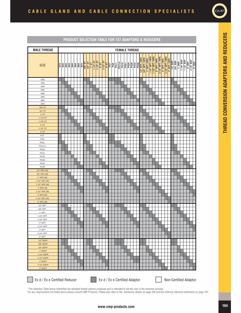
THRE
ADCO
NVER
SION
ADAP
TORS
ANDRE
DUCE
RS
164www.cmp-products.com
SIZE M16
M20
M25
M32
M40
M50
M63
M75
5/8"ET
3/4"ET
1"ET
11/4"ET
11/2"ET
2"ET
21/2"ET
3"ET
PG7
PG9
PG11
PG13.5
PG16
PG21
PG29
PG36
PG42
PG48
1/2"NPT/NPS
3/4"NPT/NPS
1"NPT/NPS
11/4"NPT/NPS
11/2"NPT/NPS
2"NPT/NPS
21/2"NPT/NPS
3"NPT/NPS
31/2"NPT/NPS
4"NPT/NPS
1/2"BSP
3/4"BSP
1"BSP
11/4"BSP
11/2"BSP
2"BSP
21/2"BSP
3"BSP
M16
M20
M25
M32
M40
M50
M63
M75
5/8" ET
3/4" ET
1" ET
1 1/4" ET
1 1/2" ET
2" ET
2 1/2" ET
3" ET
PG7
PG9
PG11
PG13.5
PG16
PG21
PG29
PG36
PG42
PG48
1/2" NPS (M)
3/4" NPS (M)
1" NPS (M)
1 1/4" NPS (M)
1 1/2" NPS (M)
2" NPS (M)
2 1/2" NPS (M)
3" NPS (M)
3 1/2" NPS (M)
4" NPS (M)
1/2" NPT
3/4" NPT
1" NPT
1 1/4" NPT
1 1/2" NPT
2" NPT
2 1/2" NPT
3" NPT
3 1/2" NPT
4" NPT
1/2" BSPP
5/8" BSPP
3/4" BSPP
1" BSPP
1 1/4" BSPP
1 1/2" BSPP
2" BSPP
2 1/2" BSPP
3" BSPP
Ex d / Ex e Certified Reducer Ex d / Ex e Certified Adaptor Non-Certified Adaptor
*The Selection Table above indentifies the standard thread options produced and is intended to aid the user in the selection process.For any requirements not listed above please consult CMP Products. Please also refer to the dimension details on page 165 and the ordering reference definitions on page 161.
PRODUCT SELECTION TABLE FOR 737 ADAPTORS & REDUCERS
MALE THREAD FEMALE THREADMALE THREAD FEMALE THREAD
C A B L E G L A N D A N D C A B L E C O N N E C T I O N S P E C I A L I S T S CMP
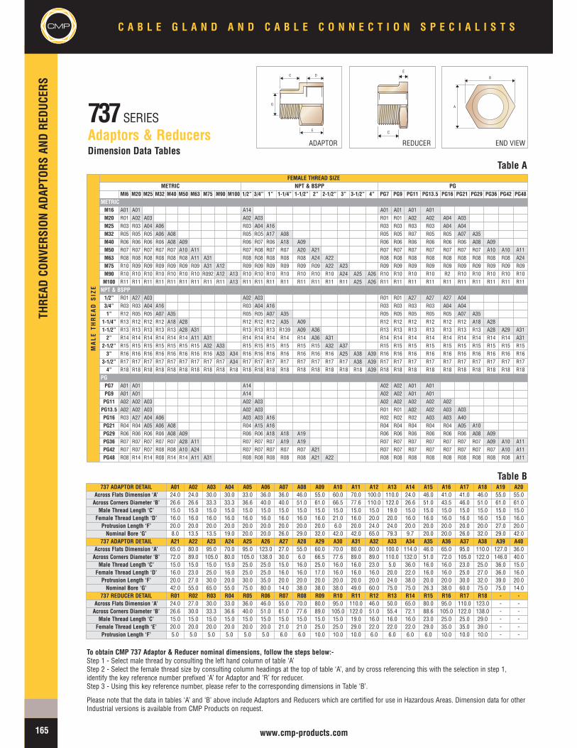
D
E
C
G
B
A
C
E
CMP
THRE
ADCO
NVER
SION
ADAP
TORS
ANDRE
DUCE
RSC A B L E G L A N D A N D C A B L E C O N N E C T I O N S P E C I A L I S T S
165 www.cmp-products.com
737SERIESAdaptors & Reducers
Table ADimension Data Tables
Table B737 ADAPTOR DETAIL A01 A02 A03 A04 A05 A06 A07 A08 A09 A10 A11 A12 A13 A14 A15 A16 A17 A18 A19 A20
Across Flats Dimension ‘A’ 24.0 24.0 30.0 30.0 33.0 36.0 36.0 46.0 55.0 60.0 70.0 100.0 110.0 24.0 46.0 41.0 41.0 46.0 55.0 55.0Across Corners Diameter ‘B’ 26.6 26.6 33.3 33.3 36.6 40.0 40.0 51.0 61.0 66.5 77.6 110.0 122.0 26.6 51.0 43.5 46.0 51.0 61.0 61.0Male Thread Length ‘C’ 15.0 15.0 15.0 15.0 15.0 15.0 15.0 15.0 15.0 15.0 15.0 15.0 19.0 15.0 15.0 15.0 15.0 15.0 15.0 15.0
Female Thread Length ‘D’ 16.0 16.0 16.0 16.0 16.0 16.0 16.0 16.0 16.0 21.0 16.0 20.0 20.0 16.0 16.0 16.0 16.0 16.0 15.0 16.0Protrusion Length ‘F’ 20.0 20.0 20.0 20.0 20.0 20.0 20.0 20.0 20.0 6.0 20.0 24.0 24.0 20.0 20.0 20.0 20.0 20.0 27.0 20.0Nominal Bore ‘G’ 8.0 13.5 13.5 19.0 20.0 20.0 26.0 29.0 32.0 42.0 42.0 65.0 79.3 9.7 20.0 20.0 26.0 32.0 29.0 42.0
737 ADAPTOR DETAIL A21 A22 A23 A24 A25 A26 A27 A28 A29 A30 A31 A32 A33 A34 A35 A36 A37 A38 A39 A40Across Flats Dimension ‘A’ 65.0 80.0 95.0 70.0 95.0 123.0 27.0 55.0 60.0 70.0 80.0 80.0 100.0 114.0 46.0 65.0 95.0 110.0 127.0 36.0Across Corners Diameter ‘B’ 72.0 89.0 105.0 80.0 105.0 138.0 30.0 6.0 66.5 77.6 89.0 89.0 110.0 132.0 51.0 72.0 105.0 122.0 146.0 40.0Male Thread Length ‘C’ 15.0 15.0 15.0 15.0 25.0 25.0 15.0 16.0 25.0 16.0 16.0 23.0 5.0 36.0 16.0 16.0 23.0 25.0 36.0 15.0
Female Thread Length ‘D’ 16.0 23.0 25.0 16.0 25.0 25.0 16.0 16.0 17.0 16.0 16.0 16.0 20.0 22.0 16.0 16.0 25.0 27.0 36.0 16.0Protrusion Length ‘F’ 20.0 27.0 30.0 20.0 30.0 35.0 20.0 20.0 20.0 20.0 20.0 20.0 24.0 38.0 20.0 20.0 30.0 32.0 39.0 20.0Nominal Bore ‘G’ 42.0 55.0 65.0 55.0 75.0 80.0 14.0 38.0 38.0 38.0 49.0 60.0 75.0 75.0 26.3 38.0 60.0 75.0 75.0 14.0
737 REDUCER DETAIL R01 R02 R03 R04 R05 R06 R07 R08 R09 R10 R11 R12 R13 R14 R15 R16 R17 R18 - -Across Flats Dimension ‘A’ 24.0 27.0 30.0 33.0 36.0 46.0 55.0 70.0 80.0 95.0 110.0 46.0 50.0 65.0 80.0 95.0 110.0 123.0 - -Across Corners Diameter ‘B’ 26.6 30.0 33.3 36.6 40.0 51.0 61.0 77.6 89.0 105.0 122.0 51.0 55.4 72.1 88.6 105.0 122.0 138.0 - -Male Thread Length ‘C’ 15.0 15.0 15.0 15.0 15.0 15.0 15.0 15.0 15.0 15.0 19.0 16.0 16.0 16.0 23.0 25.0 25.0 29.0 - -Female Thread Length ‘E’ 20.0 20.0 20.0 20.0 20.0 20.0 21.0 21.0 25.0 25.0 29.0 22.0 22.0 22.0 29.0 35.0 35.0 39.0 - -Protrusion Length ‘F’ 5.0 5.0 5.0 5.0 5.0 5.0 6.0 6.0 10.0 10.0 10.0 6.0 6.0 6.0 6.0 10.0 10.0 10.0 - -
To obtain CMP 737 Adaptor & Reducer nominal dimensions, follow the steps below:-Step 1 - Select male thread by consulting the left hand column of table ‘A’Step 2 - Select the female thread size by consulting column headings at the top of table ‘A’, and by cross referencing this with the selection in step 1,identify the key reference number prefixed ‘A’ for Adaptor and ‘R’ for reducer.Step 3 - Using this key reference number, please refer to the corresponding dimensions in Table ‘B’.
Please note that the data in tables ‘A’ and ‘B’ above include Adaptors and Reducers which are certified for use in Hazardous Areas. Dimension data for otherIndustrial versions is available from CMP Products on request.
ADAPTOR END VIEWREDUCER
FEMALE THREAD SIZEMETRIC NPT & BSPP PG
MI6 M20 M25 M32 M40 M50 M63 M75 M90 M100 1/2” 3/4” 1” 1-1/4” 1-1/2” 2” 2-1/2” 3” 3-1/2” 4” PG7 PG9 PG11 PG13.5 PG16 PG21 PG29 PG36 PG42 PG48METRICM16 A01 A01 A14 A01 A01 A01 A01M20 R01 A02 A03 A02 A03 R01 R01 A02 A02 A04 A03M25 R03 R03 A04 A06 R03 A04 A16 R03 R03 R03 R03 A04 A04M32 R05 R05 R05 A06 A08 R05 RO5 A17 A08 R05 R05 R07 R05 R05 A07 A35M40 R06 R06 R06 R06 A08 A09 R06 R07 R06 A18 A09 R06 R06 R06 R06 R06 R06 A08 A09M50 R07 R07 R07 R07 R07 A10 A11 R07 R08 R07 R07 A20 A21 R07 R07 R07 R07 R07 R07 R07 A10 A10 A11M63 R08 R08 R08 R08 R08 R08 A11 A31 R08 R08 R08 R08 R08 A24 A22 R08 R08 R08 R08 R08 R08 R08 R08 R08 A24M75 R10 R09 R09 R09 R09 R09 R09 A31 A12 R09 R09 R09 R09 R09 R09 A22 A23 R09 R09 R09 R09 R09 R09 R09 R09 R09 R09M90 R10 R10 R10 R10 R10 R10 R10 R092 A12 A13 R10 R10 R10 R10 R10 R10 R10 A24 A25 A26 R10 R10 R10 R10 R2 R10 R10 R10 R10 R10M100 R11 R11 R11 R11 R11 R11 R11 R11 R11 A13 R11 R11 R11 R11 R11 R11 R11 R11 A25 A26 R11 R11 R11 R11 R11 R11 R11 R11 R11 R11NPT & BSPP1/2” R01 A27 A03 A02 A03 R01 R01 A27 A27 A27 A043/4” R03 R03 A04 A16 R03 A04 A16 R03 R03 R03 R03 A04 A041” R12 R05 R05 A07 A35 R05 R05 A07 A35 R05 R05 R05 R05 R05 A07 A35
1-1/4” R13 R12 R12 R12 A18 A28 R12 R12 R12 A35 A09 R12 R12 R12 R12 R12 R12 A18 A281-1/2” R13 R13 R13 R13 R13 A28 A31 R13 R13 R13 R139 A09 A36 R13 R13 R13 R13 R13 R13 R13 A28 A29 A312” R14 R14 R14 R14 R14 R14 A11 A31 R14 R14 R14 R14 R14 A36 A31 R14 R14 R14 R14 R14 R14 R14 R14 R14 A31
2-1/2” R15 R15 R15 R15 R15 R15 R15 A32 A33 R15 R15 R15 R15 R15 R15 A32 A37 R15 R15 R15 R15 R15 R15 R15 R15 R15 R153” R16 R16 R16 R16 R16 R16 R16 R16 A33 A34 R16 R16 R16 R16 R16 R16 R16 A25 A38 A39 R16 R16 R16 R16 R16 R16 R16 R16 R16 R16
3-1/2” R17 R17 R17 R17 R17 R17 R17 R17 R17 A34 R17 R17 R17 R17 R17 R17 R17 R17 A38 A39 R17 R17 R17 R17 R17 R17 R17 R17 R17 R174” R18 R18 R18 R18 R18 R18 R18 R18 R18 R18 R18 R18 R18 R18 R18 R18 R18 R18 R18 A39 R18 R18 R18 R18 R18 R18 R18 R18 R18 R18
PGPG7 A01 A01 A14 A02 A02 A01 A01PG9 A01 A01 A14 A02 A02 A01 A01PG11 A02 A02 A03 A02 A03 A02 A02 A02 A02 A02PG13.5 A02 A02 A03 A02 A03 R01 R01 A02 A02 A03 A03PG16 R03 A27 A04 A06 A03 A03 A16 R02 R02 R02 A03 A03 A40PG21 R04 R04 A05 A06 A08 R04 A15 A16 R04 R04 R04 R04 R04 A05 A10PG29 R06 R06 R06 R06 A08 A09 R06 R06 A18 A18 A19 R06 R06 R06 R06 R06 R06 A08 A09PG36 R07 R07 R07 R07 R07 A28 A11 R07 R07 R07 A19 A19 R07 R07 R07 R07 R07 R07 R07 A09 A10 A11PG42 R07 R07 R07 R08 R08 A10 A24 R07 R07 R07 R07 R07 A21 R07 R07 R07 R07 R07 R07 R07 R07 A10 A11PG48 R08 R14 R14 R08 R14 R14 A11 A31 R08 R08 R08 R08 R08 A21 A22 R08 R08 R08 R08 R08 R08 R08 R08 R08 A11
MALE
THREAD
SIZ
E

THRE
ADCO
NVER
SION
ADAP
TORS
ANDRE
DUCE
RS
CMPC A B L E G L A N D A N D C A B L E C O N N E C T I O N S P E C I A L I S T S
166www.cmp-products.com
777SERIESInsulated Adaptors
Insulated Adaptor Type 777 with Flameproof Ex d IIC & Increased Safety Ex e II forms of protection.
The CMP Type 777 Insulated Adaptor allows the Metallic Cable Gland, and ultimately the cable armour, to be effectively isolated from the equipment. The use of theseAdaptors has proven to be an essential precaution in areas where electromagnetic ‘noise’ and circulating eddy currents ‘stray’ around any vulnerable cable system.Particularly relevant in Power Plants and in areas where highly sensitive instrumentation circuits are relied upon for interference free safety critical operations, the cablearmour can still be connected to ground externally with the use of an earth tag fitted between the cable gland and insulated adaptor. This allows the user to design hissystem around a single point earthing strategy and allows the operator to perform tests on the earth circuit without disconnection of the elements installed. A GeneralPurpose Industrial version is also available.
CMP 777 Insulated Adaptors are available in Brass, Aluminium or Stainless Steel and can be supplied for both Industrial and Hazardous Area applications, with Ex ‘d’ & Ex‘e’ Component Approval.
Product Selection Table *
OrderingReference
MaleThreadSize
MinimumThreadLength
FemaleThreadSize
MaximumBore
Diameter
NominalProtrusionLength
OverallEnvelopeDiameter
777DM2M2 M20 X 1.5 15 M20 X 1.5 14.3 36.1 40.0
777DM3M3 M25 X 1.5 15 M25 X 1.5 20.3 40.5 57.0
777DM4M4 M32 X 1.5 15 M32 X 1.5 26.8 40.6 57.0
777DM5M5 M40 X 1.5 15 M40 X 1.5 32.7 40.9 76.0
777DM6M6 M50 X 1.5 15 M50 X 1.5 44.6 41.2 76.0
777DM7M7 M63 X 1.5 15 M63 X 1.5 56.5 57.2 100.0
777DM8M8 M75 X 1.5 15 M75 X 1.5 65.2 57.2 100.0
All dimensions shown are in millimetres unless otherwise stated
Additional Approvals
GOST R Certificate Number POCC GB. 05.B01912
CSA Approval Certificate 1055233 Class I ABCD, Class II EFG, IP68 TYPE 4X Exd / Ex e IIC
Marked with ATEX certification details as standard. Alternative certification marking shown in the table below can be applied if requested at the time of ordering.
Note* : Other Thread Variations available on request. Please refer to ordering guide tables on page 161 for reference definitions
777 Insulated Adaptor
LLU
Technical Data
Type 777
Design Specification BS 6121: Part 1: 1989, EN 50262:1999
ATEX Certification Detail SIRA 05 ATEX 1233U
Code of Protection Category ATEX II 2 GD Ex d IIC & Ex e II Component, Zone 1, Zone 2, Zone 21, & Zone 22 - GasGroups IIA, IIB, IIC
IECEx Certification Detail IECEx SIR 05.0044U
Code of Protection Category Ex d IIC / Ex e II / Ex tD A21 IP6X
Compliance Standards EN 60079-0, EN 60079-1, EN 60079-7, EN 61241-0, EN 61241-1, IEC 60079-0, IEC 60079-1,IEC 60079-7, IEC 61241-0, IEC 61241-1
Continuous Operating Temperatures -20ºC to + 60ºC
Ingress Protection Rating IP68
Materials Brass, Nickel Plated Brass, Aluminium, Stainless Steel
Accessories Included Integral Entry Thread ‘O’ Ring Seal
Optional Accessories Locknut, Serrated Washer
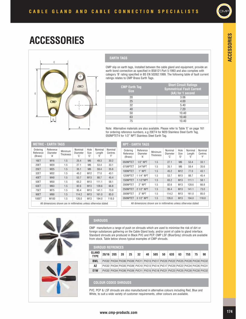
ACCE
SSOR
IES
CMPC A B L E G L A N D A N D C A B L E C O N N E C T I O N S P E C I A L I S T S
174www.cmp-products.com
CMP manufacture a range of push on shrouds which are used to minimise the risk of dirt orforeign substances gathering on the Cable Gland body, and/or point of cable to gland interface.Standard shrouds are produced in Black PVC and PCP. CMP LSF (Blue/Grey) shrouds are availablefrom stock. Table below shows typical examples of CMP shrouds.
PVC, PCP & LSF shrouds are also manufactured in alternative colours including Red, Blue andWhite, to suit a wide variety of customer requirements, other colours are available.
SHROUDS
COLOUR CODED SHROUDS
CMP slip on earth tags, Installed between the cable gland and equipment, provide anearth bond connection as specified in BS6121:Part 5:1993 and also complies withcategory ‘B’ rating specified in BS EN 50262:1999. The following table of fault currentratings relates to CMP Brass Earth Tags.
CMP Earth TagSize
Short Circuit RatingsSymmetrical Fault Current
(kA) for 1 second20 3.0625 4.0032 5.4040 7.2050 10.4063 10.4075 10.40
EARTH TAGS
METRIC - EARTH TAGSOrderingReference(Brass)
ReferenceDiameter
‘A’
MinimumThickness
NominalDiameter
‘C’
HoleSize‘D’
NominalLength‘E’
NominalCentres
‘F’
16ET M16 1.5 25.4 M6 49.3 30.2
20ET M20 1.5 27.1 M6 53.4 33.1
25ET M25 1.5 35.1 M6 59.4 35.6
32ET M32 1.5 45.2 M12 77.0 43.1
40ET M40 1.5 53.7 M13 88.7 45.4
50ET M50 1.5 65.2 M13 111.1 58.1
63ET M63 1.5 82.6 M13 128.6 66.8
75ET M75 1.5 95.4 M13 141.1 73.0
90ET M90 1.5 114.2 M13 161.0 85.0
100ET M100 1.5 126.0 M13 194.0 118.0
All dimensions shown are in millimetres unless otherwise stated
NPT - EARTH TAGS
OrderingReference(Brass)
ReferenceDiameter
‘A’
MinimumThickness
NominalDiameter
‘C’
HoleSize‘D’
NominalLength‘E’
NominalCentres
‘F’
050NPTET 1/2” NPT 1.5 27.1 M6 53.4 33.1
075NPTET 3/4”NPT 1.5 35.1 M6 59.4 35.6
100NPTET 1” NPT 1.5 45.2 M12 77.0 43.1
125NPTET 1 1/4” NPT 1.5 53.7 M13 88.7 45.4
150NPTET 1 1/2”NPT 1.5 65.2 M13 111.1 58.1
200NPTET 2” NPT 1.5 82.6 M13 128.6 66.8
250NPTET 2 1/2” NPT 1.5 95.4 M13 141.1 73.0
300NPTET 3” NPT 1.5 114.2 M13 161.0 85.0
350NPTET 3 1/2” NPT 1.5 126.0 M13 194.0 118.0
All dimensions shown are in millimetres unless otherwise stated
E
D
A
F
C
Note: Alternative materials are also available. Please refer to Table ‘E’ on page 161for ordering reference numbers, e.g 20ET4 for M20 Stainless Steel Earth Tag,050NPTET4 for 1/2” NPT Stainless Steel Earth Tag.
GLANDTYPE 20/16 20S 20 25 32 40 50S 50 63S 63 75S 75 90
BWL PVC02 PVC04 PVC06 PVC09 PVC11 PVC13 PVC17 PVC20 PVC22 PVC25 PVC28 PVC30 PVC32
A2 PVC02 PVC04 PVC05 PVC09 PVC10 PVC13 PVC14 PVC17 PVC20 PVC22 PVC24 PVC26 PVC31
E1W PVC02 PVC04 PVC06 PVC09 PVC11 PVC15 PVC18 PVC21 PVC23 PVC25 PVC28 PVC30 PVC32
SHROUD REFRENCES
ACCESSORIES
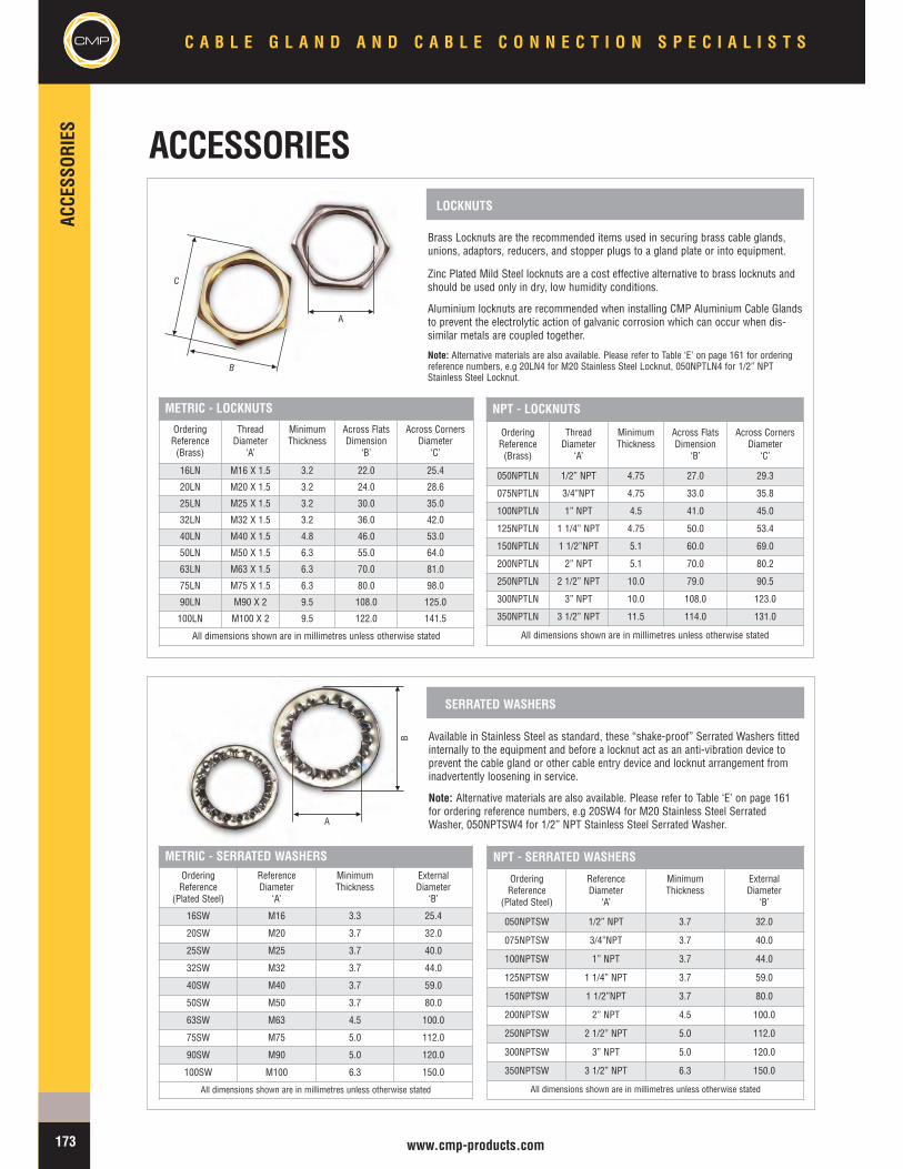
CMP
ACCE
SSOR
IES
C A B L E G L A N D A N D C A B L E C O N N E C T I O N S P E C I A L I S T S
173 www.cmp-products.com
Brass Locknuts are the recommended items used in securing brass cable glands,unions, adaptors, reducers, and stopper plugs to a gland plate or into equipment.
Zinc Plated Mild Steel locknuts are a cost effective alternative to brass locknuts andshould be used only in dry, low humidity conditions.
Aluminium locknuts are recommended when installing CMP Aluminium Cable Glandsto prevent the electrolytic action of galvanic corrosion which can occur when dis-similar metals are coupled together.
Note: Alternative materials are also available. Please refer to Table ‘E’ on page 161 for orderingreference numbers, e.g 20LN4 for M20 Stainless Steel Locknut, 050NPTLN4 for 1/2” NPTStainless Steel Locknut.
LOCKNUTS
METRIC - LOCKNUTS
OrderingReference(Brass)
ThreadDiameter
‘A’
MinimumThickness
Across FlatsDimension
‘B’
Across CornersDiameter
‘C’
16LN M16 X 1.5 3.2 22.0 25.4
20LN M20 X 1.5 3.2 24.0 28.6
25LN M25 X 1.5 3.2 30.0 35.0
32LN M32 X 1.5 3.2 36.0 42.0
40LN M40 X 1.5 4.8 46.0 53.0
50LN M50 X 1.5 6.3 55.0 64.0
63LN M63 X 1.5 6.3 70.0 81.0
75LN M75 X 1.5 6.3 80.0 98.0
90LN M90 X 2 9.5 108.0 125.0
100LN M100 X 2 9.5 122.0 141.5
All dimensions shown are in millimetres unless otherwise stated
NPT - LOCKNUTS
OrderingReference(Brass)
ThreadDiameter
‘A’
MinimumThickness
Across FlatsDimension
‘B’
Across CornersDiameter
‘C’
050NPTLN 1/2” NPT 4.75 27.0 29.3
075NPTLN 3/4”NPT 4.75 33.0 35.8
100NPTLN 1” NPT 4.5 41.0 45.0
125NPTLN 1 1/4” NPT 4.75 50.0 53.4
150NPTLN 1 1/2”NPT 5.1 60.0 69.0
200NPTLN 2” NPT 5.1 70.0 80.2
250NPTLN 2 1/2” NPT 10.0 79.0 90.5
300NPTLN 3” NPT 10.0 108.0 123.0
350NPTLN 3 1/2” NPT 11.5 114.0 131.0
All dimensions shown are in millimetres unless otherwise stated
Available in Stainless Steel as standard, these “shake-proof” Serrated Washers fittedinternally to the equipment and before a locknut act as an anti-vibration device toprevent the cable gland or other cable entry device and locknut arrangement frominadvertently loosening in service.
Note: Alternative materials are also available. Please refer to Table ‘E’ on page 161for ordering reference numbers, e.g 20SW4 for M20 Stainless Steel SerratedWasher, 050NPTSW4 for 1/2” NPT Stainless Steel Serrated Washer.
SERRATED WASHERS
METRIC - SERRATED WASHERSOrderingReference
(Plated Steel)
ReferenceDiameter
‘A’
MinimumThickness
ExternalDiameter
‘B’
16SW M16 3.3 25.4
20SW M20 3.7 32.0
25SW M25 3.7 40.0
32SW M32 3.7 44.0
40SW M40 3.7 59.0
50SW M50 3.7 80.0
63SW M63 4.5 100.0
75SW M75 5.0 112.0
90SW M90 5.0 120.0
100SW M100 6.3 150.0
All dimensions shown are in millimetres unless otherwise stated
NPT - SERRATED WASHERS
OrderingReference
(Plated Steel)
ReferenceDiameter
‘A’
MinimumThickness
ExternalDiameter
‘B’
050NPTSW 1/2” NPT 3.7 32.0
075NPTSW 3/4”NPT 3.7 40.0
100NPTSW 1” NPT 3.7 44.0
125NPTSW 1 1/4” NPT 3.7 59.0
150NPTSW 1 1/2”NPT 3.7 80.0
200NPTSW 2” NPT 4.5 100.0
250NPTSW 2 1/2” NPT 5.0 112.0
300NPTSW 3” NPT 5.0 120.0
350NPTSW 3 1/2” NPT 6.3 150.0
All dimensions shown are in millimetres unless otherwise stated
A
A
B
B
C
ACCESSORIES
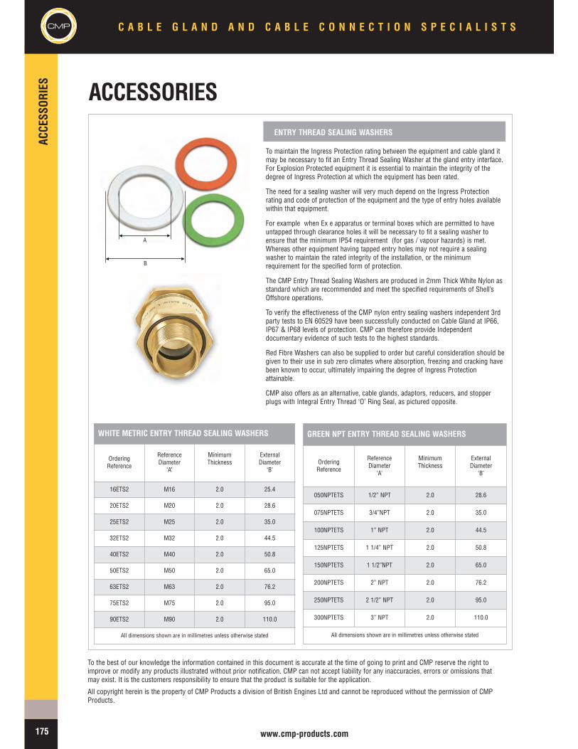
CMP
ACCE
SSOR
IES
C A B L E G L A N D A N D C A B L E C O N N E C T I O N S P E C I A L I S T S
175 www.cmp-products.com
To maintain the Ingress Protection rating between the equipment and cable gland itmay be necessary to fit an Entry Thread Sealing Washer at the gland entry interface.For Explosion Protected equipment it is essential to maintain the integrity of thedegree of Ingress Protection at which the equipment has been rated.
The need for a sealing washer will very much depend on the Ingress Protectionrating and code of protection of the equipment and the type of entry holes availablewithin that equipment.
For example when Ex e apparatus or terminal boxes which are permitted to haveuntapped through clearance holes it will be necessary to fit a sealing washer toensure that the minimum IP54 requirement (for gas / vapour hazards) is met.Whereas other equipment having tapped entry holes may not require a sealingwasher to maintain the rated integrity of the installation, or the minimumrequirement for the specified form of protection.
The CMP Entry Thread Sealing Washers are produced in 2mm Thick White Nylon asstandard which are recommended and meet the specified requirements of Shell’sOffshore operations.
To verify the effectiveness of the CMP nylon entry sealing washers independent 3rdparty tests to EN 60529 have been successfully conducted on Cable Gland at IP66,IP67 & IP68 levels of protection. CMP can therefore provide Independentdocumentary evidence of such tests to the highest standards.
Red Fibre Washers can also be supplied to order but careful consideration should begiven to their use in sub zero climates where absorption, freezing and cracking havebeen known to occur, ultimately impairing the degree of Ingress Protectionattainable.
CMP also offers as an alternative, cable glands, adaptors, reducers, and stopperplugs with Integral Entry Thread ‘O’ Ring Seal, as pictured opposite.
ENTRY THREAD SEALING WASHERS
WHITE METRIC ENTRY THREAD SEALING WASHERS
OrderingReference
ReferenceDiameter
‘A’
MinimumThickness
ExternalDiameter
‘B’
16ETS2 M16 2.0 25.4
20ETS2 M20 2.0 28.6
25ETS2 M25 2.0 35.0
32ETS2 M32 2.0 44.5
40ETS2 M40 2.0 50.8
50ETS2 M50 2.0 65.0
63ETS2 M63 2.0 76.2
75ETS2 M75 2.0 95.0
90ETS2 M90 2.0 110.0
All dimensions shown are in millimetres unless otherwise stated
GREEN NPT ENTRY THREAD SEALING WASHERS
OrderingReference
ReferenceDiameter
‘A’
MinimumThickness
ExternalDiameter
‘B’
050NPTETS 1/2” NPT 2.0 28.6
075NPTETS 3/4”NPT 2.0 35.0
100NPTETS 1” NPT 2.0 44.5
125NPTETS 1 1/4” NPT 2.0 50.8
150NPTETS 1 1/2”NPT 2.0 65.0
200NPTETS 2” NPT 2.0 76.2
250NPTETS 2 1/2” NPT 2.0 95.0
300NPTETS 3” NPT 2.0 110.0
All dimensions shown are in millimetres unless otherwise stated
To the best of our knowledge the information contained in this document is accurate at the time of going to print and CMP reserve the right toimprove or modify any products illustrated without prior notification. CMP can not accept liability for any inaccuracies, errors or omissions thatmay exist. It is the customers responsibility to ensure that the product is suitable for the application.
All copyright herein is the property of CMP Products a division of British Engines Ltd and cannot be reproduced without the permission of CMPProducts.
A
B
ACCESSORIES

CMP
THRE
ADCO
NVER
SION
ADAP
TORS
ANDRE
DUCE
RSC A B L E G L A N D A N D C A B L E C O N N E C T I O N S P E C I A L I S T S
167 www.cmp-products.com
747SERIESStopper Plugs
Stopper Plug Type 747 with Flameproof Ex d IIC form of protection, with and without Tamper-proof facility.
The CMP Type 747 range of Flameproof Ex d Stopper Plugs is designed to provide a permanent or temporary means of blanking unused cable entry holes in Flameproofenclosures enabling the equipment to be safely deployed in the hazardous area. A General Purpose Industrial version is also available.
Always inserted from the outside of the enclosure, these Stopper Plugs are available with both external (Type A) and internal (Type B) Allen Key facility. The 747 Type BStopper Plug is considered as tamper-proof since it can only be removed from the inside, after the equipment has been de-energised and the terminal chamber coverremoved.
CMP Type 747 Stopper Plugs are available in Brass, Aluminium, Stainless Steel or Nylon (Exe) and can be supplied for both Industrial and Hazardous Area applications,with a variety of thread forms and sizes, including NPT. Please refer to Table ‘D’ on page 161 for further information on these options.
Technical Data
Type 747 (Type A & Type B)
Design Specification BS 6121: Part 1: 1989, EN 50262:1999
ATEX Certification Detail SIRA 01 ATEX 1284U, SIRA 02 ATEX 1003X
Code of Protection CategoryATEX II 2 GD Ex d IIC & Ex e II Component & Equipment, Zone 1, Zone 2, Zone 21, & Zone 22 - Gas Groups IIA, IIB, IIC
ATEX IM 2 Ex d I & Ex e I
IECEx Certification Detail IECEx SIR07.0056U
Code of Protection Category Ex d I / Ex e I / Ex d IIC / Ex e II / Ex tD A21 IP6X
Compliance Standards EN 60079-0, EN 60079-1, EN 60079-7, EN 61241-1, IEC 60079-0, IEC 60079-1, IEC 60079-7, IEC 61241-1
Continous Operating Temperatures -60ºC to + 200ºC (-20ºC to +60ºC Nylon version)
Ingress Protection Rating IP66
Materials Brass, Nickel Plated Brass, Aluminium, Stainless Steel, Nylon
Additional Approvals
Gost Ex Approval Certificate POCC GB. 05.B01367, POCC GB. 05.B01369
CSA Approval Certificate 1055233 Class I ABCD, Class II EFG, IP68 TYPE 4X Ex d IIC
UL Listing file reference EBNV.E214221 Class I ABCD, Class II EFG, & Class III
Marked with ATEX certification details as standard. Alternative certification marking shown in the table below can be applied if requested at the time of ordering.
Note*: Other Thread Variations available on request. Please refer to ordering guide tables on page 161 for reference definitions
Standard Product Selection Table *
OrderingReference
ThreadSize
MinimumThreadLength
Allen KeySize A/F
747-F-A-M-1 M16 X 1.5 15 M8
747-F-A-M-2 M20 X 1.5 15 M10
747-F-A-M-3 M25 X 1.5 15 M10
747-F-A-M-4 M32 X 1.5 15 M10
747-F-A-M-5 M40 X 1.5 15 M10
747-F-A-M-6 M50 X 1.5 15 M10
747-F-A-M-7 M63 X 1.5 15 M14
747-F-A-M-8 M75 X 1.5 15 M14
747-F-A-M-9 M90 X 2 15 M14
747-F-A-M-10 M100 X 2 15 M14
All dimensions shown are in millimetres unless otherwise stated
HOW TO ORDER *e.g. 747 – F – A – M – M – 3 - 1= Ex d - Type A - M25 - Aluminium
Ex ‘d’ RecessedStopper Plug Type ‘A’
Ex ‘d’ RecessedStopper Plug Type ‘B’
Note: For Tamper Proof Type B Stopper Plugs please substitute the letter Awith the letter B in the Ordering Reference list opposite.
TYPE ‘A’ TYPE ‘B’
TYPE ‘A’ TYPE ‘B’
LLU LLU

THRE
ADCO
NVER
SION
ADAP
TORS
ANDRE
DUCE
RS
CMPC A B L E G L A N D A N D C A B L E C O N N E C T I O N S P E C I A L I S T S
168www.cmp-products.com
757SERIESStopper Plugs
Stopper Plug Type 757 with Flameproof Ex d IIC & Increased Safety Ex e II forms of protection
The CMP Type 757 range of Stopper Plugs is designed to provide a permanent or temporary means of blanking unused cable entry holes in Flameproof and IncreasedSafety enclosures, enabling the equipment to be safely deployed in the hazardous area. The 757 range of Stopper Plugs is produced with a Hexagon Head, making it possibleto install or remove with either an open ended or ring type spanner or wrench.
A General Purpose Industrial version is also available.
The CMP Type 757 Stopper Plug design allows for the addition of an entry thread sealing washer, which is available as an optional extra. Alternatively, this is also availablewith an optional Integral Entry Thread ‘O’ Ring seal.
CMP Type 757 Stopper Plugs are available in Brass, Aluminium, Stainless Steel or Nylon (Ex e), and can be supplied for both Industrial and Hazardous Areaapplications, in a variety of thread forms and sizes. Please refer to table ‘D’ on page 161 for further information on these options.
Technical DataType 757
Design Specification BS 6121: Part 1: 1989, EN 50262:1999
ATEX Certification Detail SIRA 01 ATEX 1284U, SIRA 02 ATEX 1003X
Code of Protection CategoryATEX II 2 GD Ex d IIC & Ex e II Component & Equipment, Zone 1, Zone 2, Zone 21, & Zone 22 - Gas Groups IIA, IIB, IIC
ATEX IM 2 Ex d I & Ex e I
IECEx Certification Detail IECEx SIR07.0056U
Code of Protection Category Ex d I / Ex e I / Ex d IIC / Ex e II / Ex tD A21 IP6X
Compliance Standards EN 60079-0, EN 60079-1, EN 60079-7, EN 61241-1, IEC 60079-0, IEC 60079-1, IEC 60079-7, IEC 61241-1
Continous Operating Temperatures -60ºC to + 200ºC (Metallic), -20ºC to +60ºC (Nylon)
Ingress Protection Rating IP66 or IP68 when fitted with a CMP ‘O’ Ring or Entry Thread Sealing Washer
Optional Accessories Locknut, Serrated Washer, Earth Tag, Entry Thread Sealing Washer
Materials Brass, Nickel Plated Brass, Aluminium, Stainless Steel, Nylon.
Additional Approvals
Gost Ex Approval Certificate POCC GB. 05.B01367, POCC GB. 05.B01369
CSA Approval Certificate 1055233 Ex e II, IP68, Type 4X
UL Listing file reference EBNV.E214221 Class I ABCD, Class II EFG & Class III
Marked with ATEX certification details as standard. Alternative certification marking shown in the table below can be applied if requested at the time of ordering.
Note: For Integral Entry Thread ‘O’Ring Seal option please add the letter‘R’ after the form of protection in theOrdering Reference list opposite, e.g757-D-R-M-3
Product Selection Table *
OrderingReference
ThreadSize
MinimumThreadLength
AcrossFlats‘A’
AcrossCorners
Diameter ‘B’
ProtrusionLength‘C’
757-D-M-1 M16 X 1.5 15 24.0 26.0 5.0
757-D-M-2 M20 X 1.5 15 24.0 26.0 5.0
757-D-M-3 M25 X 1.5 15 30.0 33.0 5.0
757-D-M-4 M32 X 1.5 15 36.0 40.0 5.0
757-D-M-5 M40 X 1.5 15 46.0 51.0 6.0
757-D-M-6 M50 X 1.5 15 55.0 61.0 6.0
757-D-M-7 M63 X 1.5 15 70.0 78.0 6.0
757-D-M-8 M75 X 1.5 15 80.0 89.0 6.0
757-D-M-9 M90 X 2 15 95.0 106.0 6.0
757-D-M-10 M100 X 2 15 110.0 123.0 6.0
All dimensions shown are in millimetres unless otherwise stated
HOW TO ORDER *e.g. 757 – E – M – 2 - 5= Ex E - M20 - Nickel Plated Brass
757 Series Stopper Plug757 Series Stopper Plugwith optional ‘O’ ring
Stopper Plug end view
B
A
Note * : Other Thread Variations available on request. Please refer to ordering guide tables on page 161 for reference definitions
A
C
LLU LLU
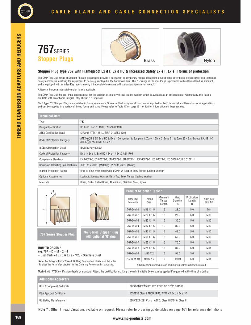
CMP
THRE
ADCO
NVER
SION
ADAP
TORS
ANDRE
DUCE
RSC A B L E G L A N D A N D C A B L E C O N N E C T I O N S P E C I A L I S T S
169 www.cmp-products.com
767SERIESStopper Plugs
Stopper Plug Type 767 with Flameproof Ex d I, Ex d IIC & Increased Safety Ex e I, Ex e II forms of protection
The CMP Type 767 range of Stopper Plugs is designed to provide a permanent or temporary means of blanking unused cable entry holes in Flameproof and IncreasedSafety enclosures, enabling the equipment to be safely deployed in the hazardous area. The 767 range of Stopper Plugs is produced with a Dome Head as standard,and is equipped with an Allen Key recess making it impossible to remove with a standard spanner or wrench.
A General Purpose Industrial version is also available.
The CMP Type 767 Stopper Plug design allows for the addition of an entry thread sealing washer, which is available as an optional extra. Alternatively, this is alsoavailable with an optional Integral Entry Thread ‘O’ Ring seal.
CMP Type 767 Stopper Plugs are available in Brass, Aluminium, Stainless Steel or Nylon (Ex e), can be supplied for both Industrial and Hazardous Area applications,and can be supplied in a variety of thread forms and sizes. Please refer to Table ‘D’ on page 161 for further information on these options.
Technical DataType 767
Design Specification BS 6121: Part 1: 1989, EN 50262:1999
ATEX Certification Detail SIRA 01 ATEX 1284U, SIRA 01 ATEX 1003
Code of Protection CategoryATEX II 2 GD Ex d IIC & Ex e II Component & Equipment, Zone 1, Zone 2, Zone 21, & Zone 22 - Gas Groups IIA, IIB, IICATEX I M2 Ex d I & Ex e I
IECEx Certification Detail IECEx SIR07.0056U
Code of Protection Category Ex d I / Ex e I / Ex d IIC / Ex e II / Ex tD A21 IP66
Compliance Standards EN 60079-0, EN 60079-1, EN 60079-7, EN 61241-1, IEC 60079-0, IEC 60079-1, IEC 60079-7, IEC 61241-1
Continous Operating Temperatures -60ºC to + 200ºC (Metallic), -20ºC to +60ºC (Nylon)
Ingress Protection Rating IP66 or IP68 when fitted with a CMP ‘O’ Ring or Entry Thread Sealing Washer
Optional Accessories Locknut, Serrated Washer, Earth Tag, Entry Thread Sealing Washer
Materials Brass, Nickel Plated Brass, Aluminium, Stainless Steel, Nylon.
Additional Approvals
Gost Ex Approval Certificate POCC GB. 05.B01367, POCC GB. 05.B01369
CSA Approval Certificate 1055233 Class I ABCD, IP68, TYPE 4X Ex d / Ex e IIC
UL Listing file reference EBNV.E214221 Class I ABCD, Class II EFG, & Class III
Marked with ATEX certification details as standard. Alternative certification marking shown in the table below can be applied if requested at the time of ordering.
767 Series Stopper Plug
Note: For Integral Entry Thread ‘O’ Ring Seal option please use the letter‘R’ after the form of protection in the Ordering Reference list opposite.
HOW TO ORDER *e.g. 767 – D – M – 2 - 4= Dual Certified Ex d & Ex e - M20 - Stainless Steel
767 Series Stopper Plugwith optional ‘O’ ring
Note * : Other Thread Variations available on request. Please refer to ordering guide tables on page 161 for reference definitions
Product Selection Table *
OrderingReference
ThreadSize
MinimumThreadLength
HeadDiameter
‘A’
ProtrusionLength‘B’
Allen KeySize A/F
767-D-M-1 M16 X 1.5 15 23.0 5.0 M8
767-D-M-2 M20 X 1.5 15 27.0 5.0 M10
767-D-M-3 M25 X 1.5 15 30.0 5.0 M10
767-D-M-4 M32 X 1.5 15 36.0 5.0 M10
767-D-M-5 M40 X 1.5 15 46.0 5.0 M10
767-D-M-6 M50 X 1.5 15 56.0 5.0 M10
767-D-M-7 M63 X 1.5 15 70.0 5.0 M14
767-D-M-8 M75 X 1.5 15 80.0 5.0 M14
767-D-M-9 M90 X 2 15 95.0 5.0 M14
767-D-M-10 M100 X 2 15 110.0 5.0 M14
All dimensions shown are in millimetres unless otherwise stated
A
B
Brass Nylon
LLU LLU
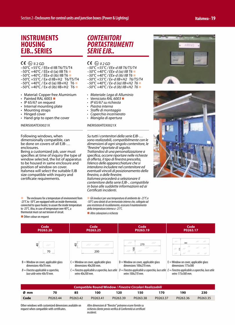
Section 2 • Enclosures for control units and junction boxes (Power & Lighting) Italsmea • 19
CONTENITORI PORTASTRUMENTI SERIE EJB..
II 2 GD –50°C +55°C / EEx-d IIB T6/T5/T4–50°C +40°C / EEx-d (ia) IIB T6 n–50°C +40°C / EEx-d (ib) IIB T6 n–50°C +55°C / Ex-d IIB+H2 T6/T5/T4–50°C +40°C / Ex-d (ia) IIB+H2 T6 n–50°C +40°C / Ex-d (ib) IIB+H2 T6 n
• Materiale: Lega di Alluminio• Verniciato RAL 6003 n• IP 65/67 su richiesta• Piastra interna• Staffe di montaggio• Coperchio incernierato• Maniglia di apertura
INERIS00ATEX0021X
Su tutti i contenitori della serie EJB-… sono realizzabili, compatibilmente con le dimensioni di ogni singolo contenitore, le “finestre” riportate di seguito.Trattandosi di una personalizzazione a specifica, occorre riportare nelle richieste di offerta, il tipo di finestra prescelta, l’elenco delle apparecchiature che si intendono includere nel contenitore ed eventuali vincoli di posizionamento della finestra, o delle finestre.Italsmea procederà a selezionare il contenitore della serie EJB-.. compatibile in base alle suddette informazioni ed ai Certificati incidenti.
INSTRUMENTS HOUSING EJB.. SERIES
II 2 GD –50°C +55°C / EEx-d IIB T6/T5/T4–50°C +40°C / EEx-d (ia) IIB T6 n–50°C +40°C / EEx-d (ib) IIB T6 n–50°C +55°C / Ex-d IIB+H2 T6/T5/T4–50°C +40°C / Ex-d (ia) IIB+H2 T6 n–50°C +40°C / Ex-d (ib) IIB+H2 T6 n
• Material: Copper free Aluminium• Painted RAL 6003 n• IP 65/67 on request• Internal mounting plate• Mounting straps• Hinged cover• Hand grip to open the cover
INERIS00ATEX0021X
Following windows, when dimensionally compatible, can be done on covers of all EJB-… enclosures.Being a customized job, user must specifies at time of inquiry the type of window selected, the list of apparatus to be housed in same enclosure and position of window on cover.Italsmea will select the suitable EJB size compatible with inquiry and certificate requirements.
Code P0263.26
Code P0263.25
Code P0263.19
Code P0263.17
B = Window on cover, applicable glass dimensions 40x70 mm.
B = Finestra applicabile a coperchio, luce utile vetro 40x70 mm.
C = Window on cover, applicable glass dimensions 40x200 mm.
C = Finestra applicabile a coperchio, luce utile vetro 40x200 mm.
D = Window on cover, applicable glass dimensions 100x270 mm.
D = Finestra applicabile a coperchio, luce utile vetro 100x270 mm.
E = Window on cover, applicable glass dimensions 175x380
E = Finestra applicabile a coperchio, luce utile vetro 175x380 mm.
Compatible Round Window / Finestre Circolari Realizzabili
Ø mm 70 85 100 120 150 170 190 230
Code P0263.44 P0263.42 P0263.41 P0263.39 P0263.38 P0263.37 P0263.36 P0263.35
Altre dimensioni di “finestra” potranno essere fornite su richiesta cliente previo verifica di Conformità ai certificati incidenti.
Other windows with customized dimensions available on request when compatible with certificates.
n The enclosures for a temperature of environment from -25°C to -50°C are equipped with an inside thermostat, connected to space heater, to assure the inside temperature to -25°C. Also, in case of temperature over 40°C, a thermostat must cut out tension of circuit.n Other colour on request
n Gli involucri per una temperatura di ambiente da -25°C a -50°C sono dotati di un termostato interno che, collegato ad una resistenza di riscaldamento, assicura il mantenimento della temperatura interna a -25°C.n Altre colorazioni a richiesta

Sezione 2 • Contenitori per unità di comando/potenza e controllo cassette di derivazione 20 • Italsmea
INTERRUTTORI AUTOMATICI SCATOLATI SERIE EJB… ENZM
Interruttori automatici scatolati serie EJB./ENZM..
II 2 GD –50°C +55°C / EEx-d IIB T6/T5/T4–50°C +40°C / EEx-d (ia) IIB T6–50°C +40°C / EEx-d (ib) IIB T6–50°C +55°C / Ex-d IIB+H2 T6/T5/T4–50°C +40°C / Ex-d (ia) IIB+H2 T6–50°C +40°C / Ex-d (ib) IIB+H2 T6
ü Materiale: Lega di Alluminioü Verniciati RAL 6003ü IP 65/67 su richiestaü Predisposti per interruttori automatici
scatolati da 16 a 800° di costruzione Moellerü 3 o 4 poliü 24V/690V ca ü 12V/440 ccü Comando rinviato a coperchio
INERIS00ATEX0021X
I contenitori della serie EJB, GUB, GUB-QL, sono previsti per la realizzazione di quadri elettrici di BT di qualsivoglia confi gurazione purchè nell’ambito dei limiti di dissipazione tecnica previsti nei certifi cati incidenti.Pertanto oltre alle tipologie di MCCB citati precedentemente ad esempio, sono proponibili personalizzazioni con MCCB di qualsiasi costruttore purchè rispondenti alle Norme EN/IEC incidenti.
MOULDED CASE AUTOMATIC CIRCUIT BREAKERS EJB... ENZM
Moulded case automatic circuit EJB./ENZM.. series
II 2 GD –50°C +55°C / EEx-d IIB T6/T5/T4–50°C +40°C / EEx-d (ia) IIB T6–50°C +40°C / EEx-d (ib) IIB T6–50°C +55°C / Ex-d IIB+H2 T6/T5/T4–50°C +40°C / Ex-d (ia) IIB+H2 T6–50°C +40°C / Ex-d (ib) IIB+H2 T6
ü Material: Copper free Aluminiumü Painted RAL 6003ü IP 65/67 on requestü Foreseen with moulded case
A.C.B. from 16A to 800A Moeller makeü 3 o 4 polesü 24V/690V ac ü 12V/440 dcü External operating handle
INERIS00ATEX0021X
EJB-GUB & GUB-QL enclosures are suitable to build EEx-d low voltage switchboards customer oriented, in between the heat dissipation listed in the relevant certifi cates.Therefore over the types of above mentioned MCCB.EJB-GUB & GUB-QL enclosures are compatible with any type of MCCB when according with relevant EN/IEC Standards.

Section 2 • Enclosures for control units and junction boxes (Power & Lighting) Italsmea • 21
SEZIONATORI SOTTOCARICO SERIE EJB .. / I ..
Sezionatori sottocarico serie EJB../I.. II 2 GD
–50°C +55°C / EEx-d IIB T6/T5/T4–50°C +40°C / EEx-d (ia) IIB T6–50°C +40°C / EEx-d (ib) IIB T6–50°C +55°C / Ex-d IIB+H2 T6/T5/T4–50°C +40°C / Ex-d (ia) IIB+H2 T6–50°C +40°C / Ex-d (ib) IIB+H2 T6
ü Materiale: Lega di Alluminioü Verniciati RAL 6003ü IP 65/67 su richiestaü Predisposti per sezionatori sottocarico
TECHNOELECTRIC/GROUPE SCHNEIDER/BREMAS da 32 a 800Aü 3 o 4 poliü 24V/690V ca ü 12V/440 ccü Comando rinviato a coperchio
INERIS00ATEX0021X
I sezionatori sottocarico EJB.../I..., sono previsti per la realizzazione di quadri elettrici di BT di qualsivoglia confi gurazione purchè nell’ambito dei limiti di dissipazione tecnica previsti nei certifi cati incidenti.Pertanto oltre alle tipologie di sezionatori sottocarico citati precedentemente, sono proponibili personalizzazioni con sezionatori sottocarico equivalenti di qualsiasi costruttore purchè rispondenti alle Norme EN/IEC incidenti.
ON LOAD SWITCHES EJB … /I … SERIES
On-load switches EJB./I.. series II 2 GD
–50°C +55°C / EEx-d IIB T6/T5/T4–50°C +40°C / EEx-d (ia) IIB T6–50°C +40°C / EEx-d (ib) IIB T6–50°C +55°C / Ex-d IIB+H2 T6/T5/T4–50°C +40°C / Ex-d (ia) IIB+H2 T6–50°C +40°C / Ex-d (ib) IIB+H2 T6
ü Material: Copper free Aluminiumü Painted RAL 6003ü IP 65/67 on requestü Foreseen for on load switches
TECHNOELECTRIC/GROUPE SCHNEIDER/BREMAS make from 32A to 800Aü 3 or 4 polesü 24V/690V ac ü 12V/440 dcü External operating handle
INERIS00ATEX0021X
On load switches /I... are suitable to build EEx-d low voltage switchboards customer oriented, in between the heat dissipation listed in the relevant certifi cates.Therefore over the above mentioned types, on load switches type EJB.../I... are compatible with any equivalent type of O.L.S. when according with relevant EN/IEC Standards.
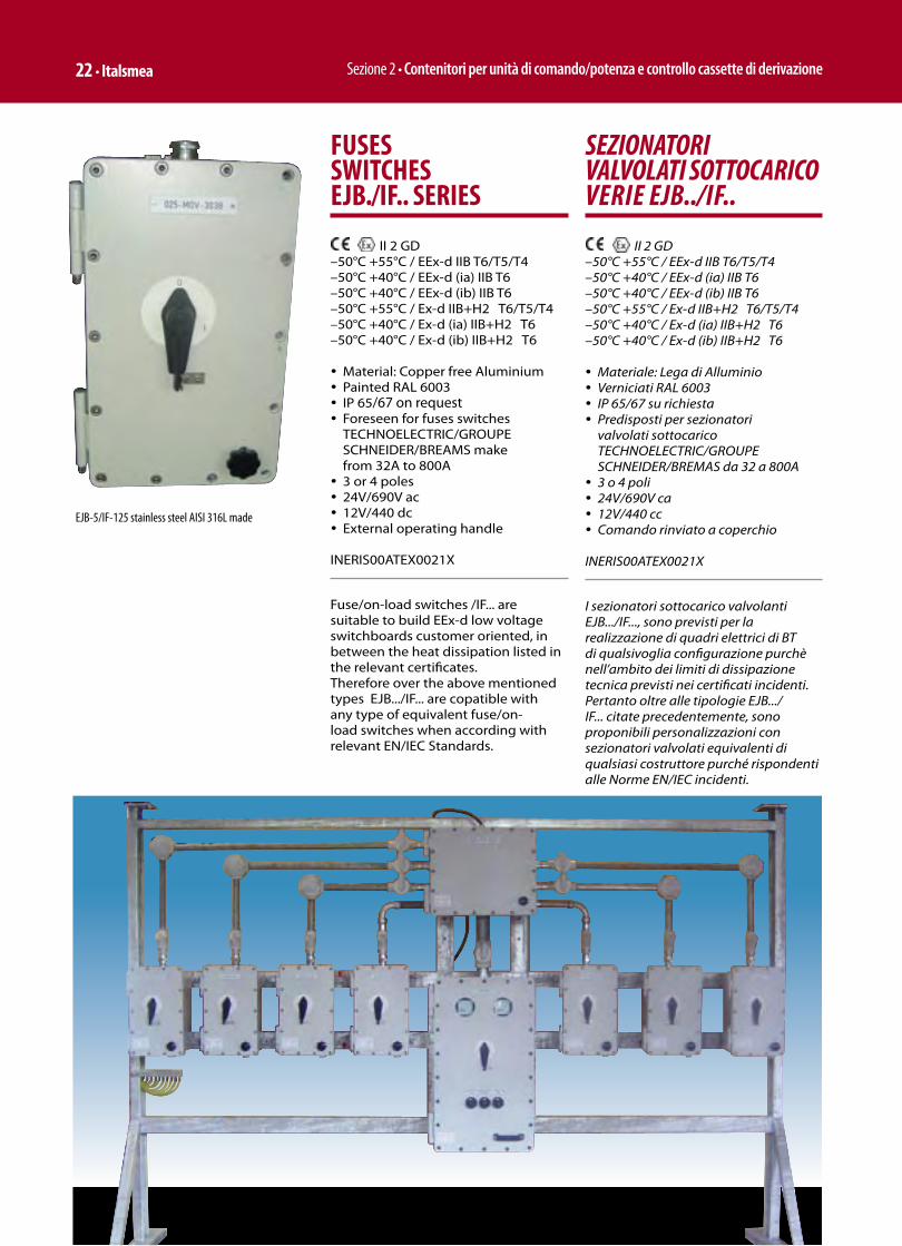
Sezione 2 • Contenitori per unità di comando/potenza e controllo cassette di derivazione 22 • Italsmea
FUSES SWITCHES EJB./IF.. SERIES
II 2 GD –50°C +55°C / EEx-d IIB T6/T5/T4–50°C +40°C / EEx-d (ia) IIB T6–50°C +40°C / EEx-d (ib) IIB T6–50°C +55°C / Ex-d IIB+H2 T6/T5/T4–50°C +40°C / Ex-d (ia) IIB+H2 T6–50°C +40°C / Ex-d (ib) IIB+H2 T6
ü Material: Copper free Aluminiumü Painted RAL 6003ü IP 65/67 on requestü Foreseen for fuses switches
TECHNOELECTRIC/GROUPE SCHNEIDER/BREAMS make from 32A to 800Aü 3 or 4 polesü 24V/690V ac ü 12V/440 dcü External operating handle
INERIS00ATEX0021X
Fuse/on-load switches /IF... are suitable to build EEx-d low voltage switchboards customer oriented, in between the heat dissipation listed in the relevant certificates.Therefore over the above mentioned types EJB.../IF... are copatible with any type of equivalent fuse/on-load switches when according with relevant EN/IEC Standards.
SEZIONATORI VALVOLATI SOTTOCARICO VERIE EJB../IF..
II 2 GD –50°C +55°C / EEx-d IIB T6/T5/T4–50°C +40°C / EEx-d (ia) IIB T6–50°C +40°C / EEx-d (ib) IIB T6–50°C +55°C / Ex-d IIB+H2 T6/T5/T4–50°C +40°C / Ex-d (ia) IIB+H2 T6–50°C +40°C / Ex-d (ib) IIB+H2 T6
ü Materiale: Lega di Alluminioü Verniciati RAL 6003ü IP 65/67 su richiestaü Predisposti per sezionatori
valvolati sottocarico TECHNOELECTRIC/GROUPE SCHNEIDER/BREMAS da 32 a 800Aü 3 o 4 poliü 24V/690V ca ü 12V/440 ccü Comando rinviato a coperchio
INERIS00ATEX0021X
I sezionatori sottocarico valvolanti EJB.../IF..., sono previsti per la realizzazione di quadri elettrici di BT di qualsivoglia configurazione purchè nell’ambito dei limiti di dissipazione tecnica previsti nei certificati incidenti.Pertanto oltre alle tipologie EJB.../IF... citate precedentemente, sono proponibili personalizzazioni con sezionatori valvolati equivalenti di qualsiasi costruttore purché rispondenti alle Norme EN/IEC incidenti.
EJB-5/IF-125 stainless steel AISI 316L made
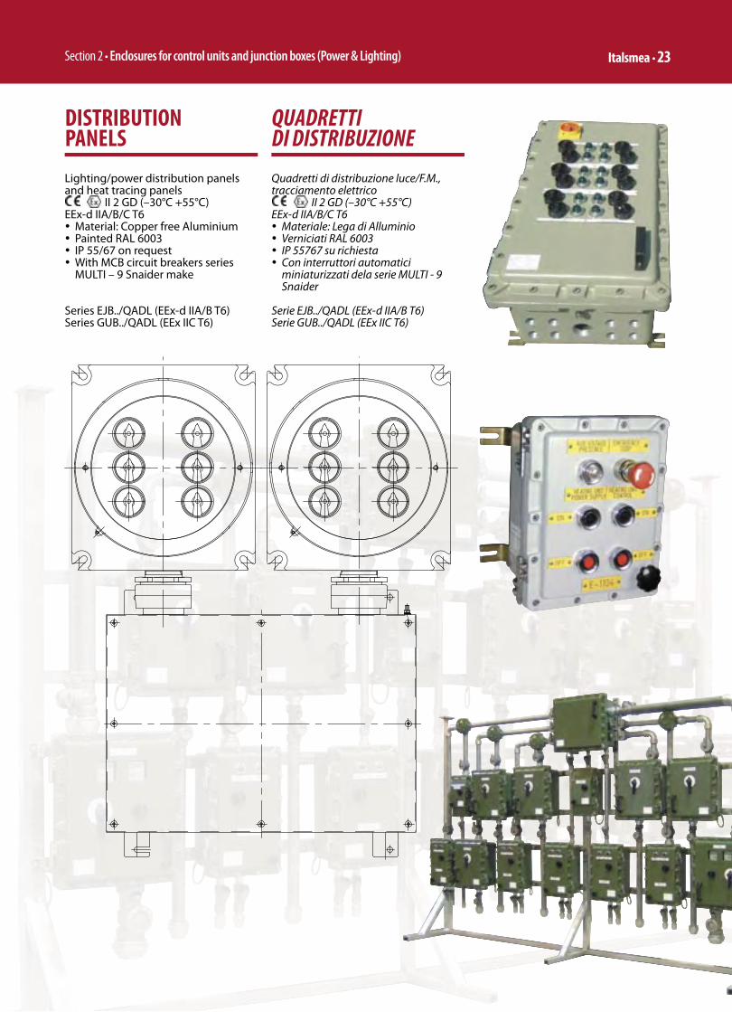
Section 2 • Enclosures for control units and junction boxes (Power & Lighting) Italsmea • 23
DISTRIBUTION PANELS
Lighting/power distribution panels and heat tracing panels
II 2 GD (–30°C +55°C)EEx-d IIA/B/C T6ü Material: Copper free Aluminiumü Painted RAL 6003ü IP 55/67 on requestü With MCB circuit breakers series
MULTI – 9 Snaider make
Series EJB../QADL (EEx-d IIA/B T6)Series GUB../QADL (EEx IIC T6)
QUADRETTI DI DISTRIBUZIONE
Quadretti di distribuzione luce/F.M., tracciamento elettrico
II 2 GD (–30°C +55°C)EEx-d IIA/B/C T6ü Materiale: Lega di Alluminioü Verniciati RAL 6003ü IP 55767 su richiestaü Con interruttori automatici
miniaturizzati dela serie MULTI - 9 Snaider
Serie EJB../QADL (EEx-d IIA/B T6)Serie GUB../QADL (EEx IIC T6)

Sezione 2 • Contenitori per unità di comando/potenza e controllo cassette di derivazione 24 • Italsmea
D.O.L. MOTOR CONTROL STARTER EJB … / TTB … SERIES
II 2 GD (–30°C +55°C)EEx-d IIA/B H2 T6ü Material: Copper free Aluminiumü Painted RAL 6003ü IP 65/67 on requestü Power from 0,12 to 132 kwü 220/500V
D.O.L. motor control starter EJB…/TTB… series are suitable to build EEx-d low voltage switchboard customer oriented, in between the heat dissipation listed in the relevant certifi cates.
TELESALVAMOTORI SERIE EJB.. / TTB..
II 2 GD (–30°C +55°C)EEx-d IIA/B H2 T6 ü Materiale: Lega di Alluminioü Verniciati RAL 6003ü IP 65/67 su richiestaü Potenza da 0,12 a 132 kwü 220/500V
I telesalvamotori invertitori serie EJB…/TTB…, sono previsti per la realizzazione di quadri elettrici di BT di qualsivoglia confi gurazione purchè nell’ambito dei limiti di dissipazione tecnica previsti nei certifi cati incidenti.
REVERSER MOTOR CONTROL STARTER EJB … / ITB … SERIES
II 2 GD (–30°C +55°C)EEx-d IIA/B H2 T6 ü Material: Copper free Aluminiumü Painted RAL 6003ü IP 65/67 on requestü Power from 0,12 to 132 kwü 220/500V
Reverser motor control starter EJB…/ITB8… series are suitable to build EEx-d low voltage switchboard customer oriented, in between the heat dissipation listed in the relevant certifi cates.
TELEINVERTITORI SERIE EJB .. / ITB..
II 2 GD (–30°C +55°C)EEx-d IIA/B H2 T6 ü Materiale: Lega di Alluminioü Verniciati RAL 6003ü IP 65/67 su richiestaü Potenza da 0,12 a 132 kwü 220/500V
I telesalvamotori invertitori serie EJB…/ITB8…, sono previsti per la realizzazione di quadri elettrici di BT di qualsivoglia confi gurazione purchè nell’ambito dei limiti di dissipazione tecnica previsti nei certifi cati incidenti.
STAR-DELTA MOTOR CONTROL STARTER EJB … / STB … SERIES
II 2 GD (–30°C +55°C)EEx-d IIA/B H2 T6 ü Material: Copper free Aluminiumü Painted RAL 6003ü IP 65/67 on requestü Power from 0,12 to 132 kwü 220/500V
Star/delta motor control starters EJB../ STB, series are suitable to build EEx-d low voltage switchboard customer oriented, in between the heat dissipation listed in the relevant certifi cates.
TELEAVVIATORI STELLA TRIANGOLO SERIE EJB .. / STB..
II 2 GD (–30°C +55°C)EEx-d IIA/B H2 T6 ü Materiale: Lega di Alluminioü Verniciati RAL 6003ü IP 65/67 su richiestaü Potenza da 0,12 a 132 kwü 220/500V
I telesalvamotori stella/tringolo serie EJB../STB, sono previsti per la realizzazione di quadri elettrici di BT di qualsivoglia confi gurazione purchè nell’ambito dei limiti di dissipazione tecnica previsti nei certifi cati incidenti.
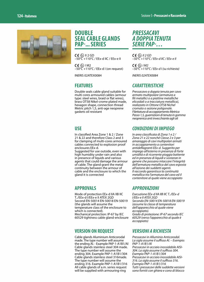
Sezione 5 • Pressacavi e Raccorderia124 • Italsmea
PRESSACAVI A DOPPIA TENUTA SERIE PAP-…
II 2 GD–50°C +110°C / EEx-d IIC / EEx-e II
I M2–50°C +110°C / EEx-d I (su richiesta)
INERIS 02ATEX0084
CARATTERISTICHEPressacavo a doppia tenuta per cavo armato multipolare (armatura a fili metallici o a piattine metalliche elicoidali o a tracciatura metallica), realizzato in Ottone OT58 Nichel cromato o sezione poligonale.Filettatura di accoppiamento Metrica Passo 1,5, guarnizioni di tenuta in gomma neoprenica anti invecchiante agli oli
CONDIZIONI DI IMPIEGOIn area classificata di Zona 1 e 2 / Zona 21 e 22 nonché Classe 2 e 3 per amaraggio di cavi multipolari armati in accoppiamento a contenitori antideflagranti EEx-d. Suggerito per impiego all’esterno in presenza di forte umidità e di ricorrente pioggia battente ed in presenza di liquidi e sostanze in genere che possano intaccare l’integrità dell’armatura metallica del cavo esposta all’azione dei suddetti agenti.Il raccordo garantisce la continuità metallica tra l’armatura del cavo ed il contenitore al quale viene accoppiato
APPROVAZIONIEsecuzione EEx-d IIA IIB IIC T../EEx-d I/EEx-e II ATEX 2GDSecondo EN-50014 EN-50018 EN-50019(assume la classe di temperatura dell’apparecchio al quale viene accoppiato).Grado di protezione: IP-67 secondo IEC 60529 (verso l’apparecchio al quale è accoppiato)
VERSIONI A RICHIESTAPressacavi in Alluminio Anticorodal. La sigla assume il suffisso Al. – Esempio: PAP-1-A1B1/AlPressacavi in acciaio inossidabile AISI-304. La sigla assume il suffisso 304. Esempio PAP-1-A1B1/304Pressacavi in acciaio inossidabile AISI-316. La sigla assume il suffisso 316. Esempio PAP-1-A1B1/316Tutti i pressacavi delle suddette versioni sono forniti con ghiera e cono di blocco
DOUBLE SEAL CABLE GLANDS PAP-... SERIES
II 2 GD–50°C +110°C / EEx-d IIC / EEx-e II
I M2–50°C +110°C / EEx-d I (on request)
INERIS 02ATEX0084
FEATURESDouble seals cable gland suitable for multi cores armoured cables (armour type: steel wires, braid or flat wires), brass OT58 Nikel-crome plated made, hexagon shape, connection thread Metric pitch 1,5, anti-age neoprene gaskets oil resistant
USEIn classified Area Zone 1 & 2 / Zone 21 & 22 and therefore Class 2 and 3 for clamping of multi-cores armoured cables connected to explosion proof enclosures EEx-d.Suggested for use outside, even with high humidity under rain and also in presence of liquids and various agents that could damage the armour of cable. The gland grant the metal continuity between the armour of cable and the enclosure to which the gland it is connected
APPROVALSMode of protection EEx-d IIA IIB IIC T../EEx-d I/EEx-e II ATEX 2GDSecond EN-50014 EN-50018 EN-50019(the glands will assume the temperature class of the enclosure to which is connected).Mechanical protection: IP-67 by IEC 60529 tightness cable gland-enclosure
VERSION ON REQUESTCable glands Aluminium Anticorodal made. The type number will assume the ending Al. - Example PAP-1-A1B1/AlCable glands stainless steel 304 made. The type number will assume the ending 304. Example PAP-1-A1B1/304Cable glands stainless steel 316made. The type number will assume the ending 316. Example PAP-1-A1B1/316All cable glands of a.m. series request will be supplied with armouring-ring

Section 5 • Cable Glands and Conduit Fittings Italsmea • 125
in ottone nichelcromato (salvo che specificatamente indicato su offerta e/o conferma d’ordine)
FILETTATUREAnsi B2.1 NPT (a stock) la sigla assume il suffisso NPTUNI 6125 conicaPG la sigla assume il suffisso PGAltre filettature previste dalla Norma EN-50014 in tolleranza ISO
ISTRUZIONI D’USOSguainare il rivestimento esterno del cavo quanto basta (tenendo conto della ricchezza richiesta per un agevole allacciamento dei tre fori all’apparecchio elettrico di riferimento). Tagliare il rivestimento avendo cura di eseguire il taglio in modo continuo e normale al cavo stesso, infilare la testina del pressacavo (dett.7) sul cavo, infilare il gommino di tenuta esterno (part.6). Infilare il corpo intermedio del pressacavo (part.5) infilare la ghiera di blocco sopra l’armatura (dett.4) fino a farle raggiungere la battuta creata dal taglio della guaina esterna.Infilare il cono di blocco (part.3) sotto l’armatura metallica, creando un’apertura “a fiore” dell’armatura fino a fare coincidere il più possibile ghiera con cono. Infilare il gommino di tenuta sotto armatura (part.2) sulla guaina del cavo sotto armatura, montare il corpo del pressacavo (part.1) sull’apparecchio corrispondente, infilare l’assieme 2-3-4 nel corpo pressacavo. Serrare il tutto con il corpo intermedio (part.5).Avvicinare il gommino di tenuta esterno all’assieme precostituito e serrare con la testina del pressacavo (part.7)
and cone brass nickelchrome plated (if not differently specified in offer or in order acknowledgment)
THREADSAnsi B2.1 NPT (normally in stock). The type number will assume the ending NPT.UNI 6125 PG the type number will assume the ending PGOther types of threads forseen in the Standard EN-50014 ISO tolerance
INSTRUCTIONS FOR USEPull over the outer cable-insulation the end cup of gland and the outer seal gasket (detail 7 and 6), pull again over the outer insulation of cable the middle body (detail 5), remove the outer insulation of cable of a suitable length (take care of length of cores needed for an easy electrical wiring to the terminals), cut the a.m. insulation making a circular continuous cutting, pull the armour clamping ring over the armour of cable (detail 4) up to the border of outer insulation previously cut, pull the armour clamping cone (detail 3) under the armour, creating a shape of a “open tulip” and a push up to close ring and cone with the armour in between, pull over the inner cable insulation (under armour) the inner gasket seal (detail 2), screw-on the body of gland (detail 1) on the relative EEx-d enclosure, pull-in to the gland body the assembling 2-3-4, lock the system by screwing on the middle body. Lock the outer seal jby screwing the end cup (detail 7)
1 2 3 4 5 6 7

Sezione 5 • Pressacavi e Raccorderia126 • Italsmea
Size Cable Gland
CodeCable gland entry
Code inner seal
Cable under
armour (inner seal)
Code outer seal
Cableoverall
diameter (outer seal)
∅ external
cable
Maximum o.d.Weight
Gr.
F A B C D E
1 = ½”–M20
UNI 6125 1801.1 PAP-1-A1B1 1A1 6-9 1B1 8-11 18 85 65 20 33 30 190
1801.2 PAP-1-A1B2 1A1 6-9 1B2 11-14 18 85 65 20 33 30 190
1801.3 PAP-1-A2B3 1A2 9-12 1B3 14-17 18 85 65 20 33 30 190
Metric Pitch 1800.18 PAP-1-A1B1 1A1 6-9 1B1 8-11 18 85 65 20 33 30 190
1800.19 PAP-1-A1B2 1A1 6-9 1B2 11-14 18 85 65 20 33 30 190
1800.21 PAP-1-A2B3 1A2 9-12 1B3 14-17 18 85 65 20 33 30 190
NPT 1801.51 PAP-1-A1B1 1A1 6-9 1B1 8-11 18 85 65 20 33 30 190
1801.52 PAP-1-A1B2 1A1 6-9 1B2 11-14 18 85 65 20 33 30 190
1801.53 PAP-1-A2B3 1A2 9-12 1B3 14-17 18 85 65 20 33 30 190
2 = ¾”–M25
UNI 6125 1802.1 PAP-2-A1B1 2A1 6-9 2B1 14-17 24 85 65 20 33 36 255
1802.2 PAP-2-A2B1 2A2 9-12 2B1 14-17 24 85 65 20 33 36 255
1802.3 PAP-2-A3B2 2A3 11-14 2B2 17-20 24 85 65 20 33 36 255
1802.4 PAP-2-A4B3 2A4 14-17 2B3 20-23 24 85 65 20 33 36 255
Metric Pitch 1800.23 PAP-2-A1B1 2A1 6-9 2B1 14-17 24 85 65 20 33 36 255
1800.24 PAP-2-A2B1 2A2 9-12 2B1 14-17 24 85 65 20 33 36 255
1800.27 PAP-2-A3B2 2A3 11-14 2B2 17-20 24 85 65 20 33 36 255
1800.28 PAP-2-A4B3 2A4 14-17 2B3 20-23 24 85 65 20 33 36 255
NPT 1802.51 PAP-2-A1B1 2A1 6-9 2B1 14-17 24 85 65 20 33 36 255
1802.52 PAP-2-A2B1 2A2 9-12 2B1 14-17 24 85 65 20 33 36 255
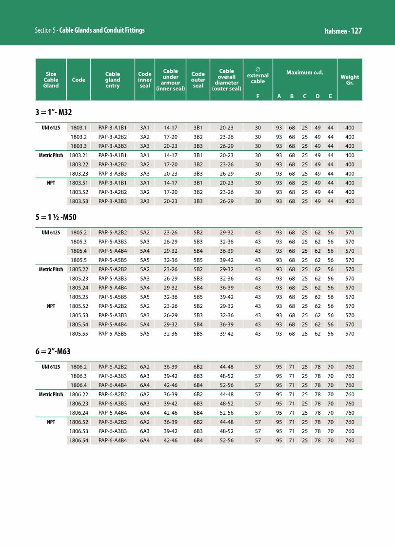
Section 5 • Cable Glands and Conduit Fittings Italsmea • 127
3 = 1”- M32
UNI 6125 1803.1 PAP-3-A1B1 3A1 14-17 3B1 20-23 30 93 68 25 49 44 400
1803.2 PAP-3-A2B2 3A2 17-20 3B2 23-26 30 93 68 25 49 44 400
1803.3 PAP-3-A3B3 3A3 20-23 3B3 26-29 30 93 68 25 49 44 400
Metric Pitch 1803.21 PAP-3-A1B1 3A1 14-17 3B1 20-23 30 93 68 25 49 44 400
1803.22 PAP-3-A2B2 3A2 17-20 3B2 23-26 30 93 68 25 49 44 400
1803.23 PAP-3-A3B3 3A3 20-23 3B3 26-29 30 93 68 25 49 44 400
NPT 1803.51 PAP-3-A1B1 3A1 14-17 3B1 20-23 30 93 68 25 49 44 400
1803.52 PAP-3-A2B2 3A2 17-20 3B2 23-26 30 93 68 25 49 44 400
1803.53 PAP-3-A3B3 3A3 20-23 3B3 26-29 30 93 68 25 49 44 400
Size Cable Gland
CodeCable gland entry
Code inner seal
Cable under
armour (inner seal)
Code outer seal
Cableoverall
diameter (outer seal)
∅ external
cable
Maximum o.d.Weight
Gr.
F A B C D E
5 = 1 ½ -M50
UNI 6125 1805.2 PAP-5-A2B2 5A2 23-26 5B2 29-32 43 93 68 25 62 56 570
1805.3 PAP-5-A3B3 5A3 26-29 5B3 32-36 43 93 68 25 62 56 570
1805.4 PAP-5-A4B4 5A4 29-32 5B4 36-39 43 93 68 25 62 56 570
1805.5 PAP-5-A5B5 5A5 32-36 5B5 39-42 43 93 68 25 62 56 570
Metric Pitch 1805.22 PAP-5-A2B2 5A2 23-26 5B2 29-32 43 93 68 25 62 56 570
1805.23 PAP-5-A3B3 5A3 26-29 5B3 32-36 43 93 68 25 62 56 570
1805.24 PAP-5-A4B4 5A4 29-32 5B4 36-39 43 93 68 25 62 56 570
1805.25 PAP-5-A5B5 5A5 32-36 5B5 39-42 43 93 68 25 62 56 570
NPT 1805.52 PAP-5-A2B2 5A2 23-26 5B2 29-32 43 93 68 25 62 56 570
1805.53 PAP-5-A3B3 5A3 26-29 5B3 32-36 43 93 68 25 62 56 570
1805.54 PAP-5-A4B4 5A4 29-32 5B4 36-39 43 93 68 25 62 56 570
1805.55 PAP-5-A5B5 5A5 32-36 5B5 39-42 43 93 68 25 62 56 570
6 = 2”-M63
UNI 6125 1806.2 PAP-6-A2B2 6A2 36-39 6B2 44-48 57 95 71 25 78 70 760
1806.3 PAP-6-A3B3 6A3 39-42 6B3 48-52 57 95 71 25 78 70 760
1806.4 PAP-6-A4B4 6A4 42-46 6B4 52-56 57 95 71 25 78 70 760
Metric Pitch 1806.22 PAP-6-A2B2 6A2 36-39 6B2 44-48 57 95 71 25 78 70 760
1806.23 PAP-6-A3B3 6A3 39-42 6B3 48-52 57 95 71 25 78 70 760
1806.24 PAP-6-A4B4 6A4 42-46 6B4 52-56 57 95 71 25 78 70 760
NPT 1806.52 PAP-6-A2B2 6A2 36-39 6B2 44-48 57 95 71 25 78 70 760
1806.53 PAP-6-A3B3 6A3 39-42 6B3 48-52 57 95 71 25 78 70 760
1806.54 PAP-6-A4B4 6A4 42-46 6B4 52-56 57 95 71 25 78 70 760

Sezione 5 • Pressacavi e Raccorderia128 • Italsmea
Size Cable Gland
CodeCable gland entry
Code inner seal
Cable under
armour (inner seal)
Code outer seal
Cableoverall
diameter (outer seal)
∅ external
cable
Maximum o.d.Weight
Gr.
F A B C D E
7 = 2 ½”-M75
UNI 6125 1807.2 PAP-7-A2B2 7A2 44-48 7B2 55-59 69 100 71 32 92 83 965
1807.3 PAP-7-A3B3 7A3 48-52 7B3 59-63 69 100 71 32 92 83 965
1807.4 PAP-7-A4B4 7A4 52-56 7B4 63-67 69 100 71 32 92 83 965
1807.5 PAP-7-A5B4 7A5 56-60 7B4 63-67 69 100 71 32 92 83 965
Metric Pitch 1807.22 PAP-7-A2B2 7A2 44-48 7B2 55-59 69 100 71 32 92 83 965
1807.23 PAP-7-A3B3 7A3 48-52 7B3 59-63 69 100 71 32 92 83 965
1807.24 PAP-7-A4B4 7A4 52-56 7B4 63-67 69 100 71 32 92 83 965
1807.25 PAP-7-A5B4 7A5 56-60 7B4 63-67 69 100 71 32 92 83 965
NPT 1807.52 PAP-7-A2B2 7A2 44-48 7B2 55-59 69 100 71 32 92 83 965
1807.53 PAP-7-A3B3 7A3 48-52 7B3 59-63 69 100 71 32 92 83 965
1807.54 PAP-7-A4B4 7A4 52-56 7B4 63-67 69 100 71 32 92 83 965
1807.55 PAP-7-A5B4 7A5 56-60 7B4 63-67 69 100 71 32 92 83 965
8 = 3”-M80
UNI 6125 1808.4 PAP-8-A4B4 8A4 56-60 8B4 63-67 79 100 71 32 103 93 1235
1808.5 PAP-8-A5B5 8A5 59-63 8B5 67-69 79 100 71 32 103 93 1235
1808.6 PAP-8-A6B6 8A6 63-67 8B6 69-73 79 100 71 32 103 93 1235
1808.7 PAP-8-A7B7 8A7 67-71 8B7 73-77 79 100 71 32 103 93 1235
Metric Pitch 1808.24 PAP-8-A4B4 8A4 56-60 8B4 63-67 79 100 71 32 103 93 1235
1808.25 PAP-8-A5B5 8A5 59-63 8B5 67-69 79 100 71 32 103 93 1235
1808.26 PAP-8-A6B6 8A6 63-67 8B6 69-73 79 100 71 32 103 93 1235
1808.27 PAP-8-A7B7 8A7 67-71 8B7 73-77 79 100 71 32 103 93 1235
NPT 1808.54 PAP-8-A4B4 8A4 56-60 8B4 63-67 79 100 71 32 103 93 1235
1808.55 PAP-8-A5B5 8A5 59-63 8B5 67-69 79 100 71 32 103 93 1235
1808.56 PAP-8-A6B6 8A6 63-67 8B6 69-73 79 100 71 32 103 93 1235
1808.57 PAP-8-A7B7 8A7 67-71 8B7 73-77 79 100 71 32 103 93 1235

Section 5 • Cable Glands and Conduit Fittings Italsmea • 129
PRESSACAVI A SEMPLICE TENUTA SERIE PNA-...
II 2 GD–50°C +110°C / EEx-d IIC / EEx-e II
I M2–50°C +110°C / EEx-d I (Su richiesta)
INERIS 02ATEX0084
CARATTERISTICHEPressacavo a semplice tenuta per cavo armato multipolare (armatura a fili metallici o a piattine metalliche elicoidali o a tracciatura metallica), realizzato in Ottone OT58 Nichel cromato o sezione poligonale.Filettatura di accoppiamento Metrica Passo 1,5, guarnizioni di tenuta in gomma neoprenica anti invecchiante agli oli
CONDIZIONI DI IMPIEGOIn area classificata di Zona 1 e 2 / Zona 21 e 22 nonché Classe 2 e 3 per amaraggio di cavi multipolari armati in accoppiamento a contenitori antideflagranti EEx-d. Suggerito per impiego all’interno.Il raccordo garantisce la continuità metallica tra l’armatura del cavo ed il contenitore al quale viene accoppiato
APPROVAZIONIEsecuzione EEx-d IIA IIB IIC T../EEx-d I/EEx-e II ATEX 2GDSecondo EN-50014 EN-50018 EN-50019(assume la classe di temperatura dell’apparecchio al quale viene accoppiato).Grado di protezione: IP-67 secondo IEC 60529 (verso l’apparecchio al quale è accoppiato)
VERSIONI A RICHIESTAPressacavi in Alluminio Anticorodal. La sigla assume il suffisso Al. – Esempio: PNA-1-A1/AlPressacavi in acciaio inossidabile AISI-304. La sigla assume il suffisso 304. Esempio PNA-1-A1/304Pressacavi in acciaio inossidabile AISI-316. La sigla assume il suffisso 316. Esempio PNA-1-A1/316Tutti i pressacavi delle suddette versioni sono forniti con ghiera e cono di blocco in ottone nichelcromato (salvo che specificatamente indicato su offerta e/o conferma d’ordine)
SINGLE SEAL CABLE GLANDS PNA-... SERIES
II 2 GD–50°C +110°C / EEx-d IIC / EEx-e II
I M2–50°C +110°C / EEx-d I (On request)
INERIS 02ATEX0084
FEATURESSingle seals cable gland suitable for multi cores armoured cables (armour type: steel wires braid or flat wires), brass OT58 Nikel-crome platedmade, hexagon shape, connection thread Metric pitch 1,5, anti-age neoprene gaskets oil resistant
USEIn classified Area Zone 1 & 2 / Zone 21 & 22 and therefore Class 2 and 3 for clamping of multi-cores armoured cables connected to explosion proof enclosures EEx-d.Suggested for use inside. The gland grant the metal continuity between the armour of cable and the enclosure to which the gland it is connected
APPROVALSMode of protection EEx-d IIA IIB IIC T../EEx-d I/EEx-e II ATEX 2GDSecond EN-50014 EN-50018 EN-50019(the glands will assume the temperature class of the enclosure to which is connected).Mechanical protection: IP-67 by IEC 60529 tightness cable gland-enclosure
VERSION ON REQUESTCable glands Aluminium Anticorodal made. The type number will assume the ending Al. – Example PNA-1-A1/AlCable glands stainless steel 304 made. The type number will assume the ending 304. Example PNA-1-A1/304Cable glands stainless steel 316made. The type number will assume the ending 304. Example PNA-1-A1/316All cable glands of a.m. series request will be supplied with armouring-ring and cone brass nickelchrome plated (if not differently specified in offer or in order acknowledgment)
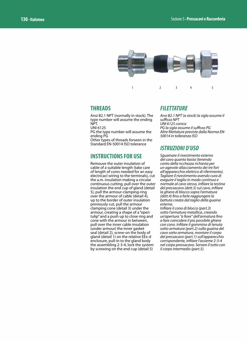
Sezione 5 • Pressacavi e Raccorderia130 • Italsmea
THREADSAnsi B2.1 NPT (normally in stock). The type number will assume the ending NPT.UNI 6125 PG the type number will assume the ending PGOther types of threads forseen in the Standard EN-50014 ISO tolerance
INSTRUCTIONS FOR USERemouve the outer insulation of cable of a suitable length (take care of length of cores needed for an easy electricacl wiring to the terminals), cut the a.m. insulation making a circular continuous cutting, pull over the outer insulation the end cup of gland (detail 5), pull the armour-clamping-ring over the armour of cable (detail 4), up to the border of outer insulation previously cut, pull the armour clamping cone (detail 3) under the armour, creating a shape of a “open tulip” and a push up to close ring and cone with the armour in between, pull over the inner cable insulation (under armour) the inner gasket seal (detail 2), screw-on the body of gland (detail 1) on the relative EEx-d enclosure, pull-in to the gland body the assembling 2-3-4, lock the system by screwing on the end cup (detail 5)
FILETTATUREAnsi B2.1 NPT (a stock) la sigla assume il suffisso NPTUNI 6125 conicaPG la sigla assume il suffisso PGAltre filettature previste dalla Norma EN-50014 in tolleranza ISO
ISTRUZIONI D’USOSguainare il rivestimento esterno del cavo quanto basta (tenendo conto della ricchezza richiesta per un agevole allacciamento dei tre fori all’apparecchio elettrico di riferimento). Tagliare il rivestimento avendo cura di eseguire il taglio in modo continuo e normale al cavo stesso, infilare la testina del pressacavo (dett.5) sul cavo, infilare la ghiera di blocco sopra l’armatura (dett.4) fino a farle raggiungere la battuta creata dal taglio della guaina esterna.Infilare il cono di blocco (part.3) sotto l’armatura metallica, creando un’apertura “a fiore” dell’armatura fino a fare coincidere il più possibile ghiera con cono. Infilare il gommino di tenuta sotto armatura (part.2) sulla guaina del cavo sotto armatura, montare il corpo del pressacavo (part.1) sull’apparecchio corrispondente, infilare l’assieme 2-3-4 nel corpo pressacavo. Serrare il tutto con il corpo intermedio (part.5).
1 2 3 4 5
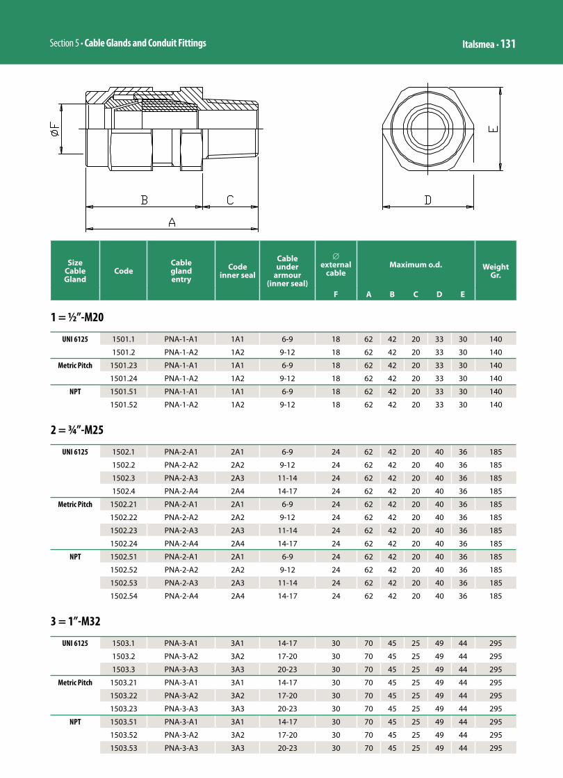
Section 5 • Cable Glands and Conduit Fittings Italsmea • 131
Size Cable Gland
CodeCable gland entry
Code inner seal
Cable under
armour (inner seal)
∅ external
cableMaximum o.d. Weight
Gr.
F A B C D E
1 = ½”-M20
UNI 6125 1501.1 PNA-1-A1 1A1 6-9 18 62 42 20 33 30 140
1501.2 PNA-1-A2 1A2 9-12 18 62 42 20 33 30 140
Metric Pitch 1501.23 PNA-1-A1 1A1 6-9 18 62 42 20 33 30 140
1501.24 PNA-1-A2 1A2 9-12 18 62 42 20 33 30 140
NPT 1501.51 PNA-1-A1 1A1 6-9 18 62 42 20 33 30 140
1501.52 PNA-1-A2 1A2 9-12 18 62 42 20 33 30 140
2 = ¾”-M25
UNI 6125 1502.1 PNA-2-A1 2A1 6-9 24 62 42 20 40 36 185
1502.2 PNA-2-A2 2A2 9-12 24 62 42 20 40 36 185
1502.3 PNA-2-A3 2A3 11-14 24 62 42 20 40 36 185
1502.4 PNA-2-A4 2A4 14-17 24 62 42 20 40 36 185
Metric Pitch 1502.21 PNA-2-A1 2A1 6-9 24 62 42 20 40 36 185
1502.22 PNA-2-A2 2A2 9-12 24 62 42 20 40 36 185
1502.23 PNA-2-A3 2A3 11-14 24 62 42 20 40 36 185
1502.24 PNA-2-A4 2A4 14-17 24 62 42 20 40 36 185
NPT 1502.51 PNA-2-A1 2A1 6-9 24 62 42 20 40 36 185
1502.52 PNA-2-A2 2A2 9-12 24 62 42 20 40 36 185
1502.53 PNA-2-A3 2A3 11-14 24 62 42 20 40 36 185
1502.54 PNA-2-A4 2A4 14-17 24 62 42 20 40 36 185
3 = 1”-M32
UNI 6125 1503.1 PNA-3-A1 3A1 14-17 30 70 45 25 49 44 295
1503.2 PNA-3-A2 3A2 17-20 30 70 45 25 49 44 295
1503.3 PNA-3-A3 3A3 20-23 30 70 45 25 49 44 295
Metric Pitch 1503.21 PNA-3-A1 3A1 14-17 30 70 45 25 49 44 295
1503.22 PNA-3-A2 3A2 17-20 30 70 45 25 49 44 295
1503.23 PNA-3-A3 3A3 20-23 30 70 45 25 49 44 295
NPT 1503.51 PNA-3-A1 3A1 14-17 30 70 45 25 49 44 295
1503.52 PNA-3-A2 3A2 17-20 30 70 45 25 49 44 295
1503.53 PNA-3-A3 3A3 20-23 30 70 45 25 49 44 295
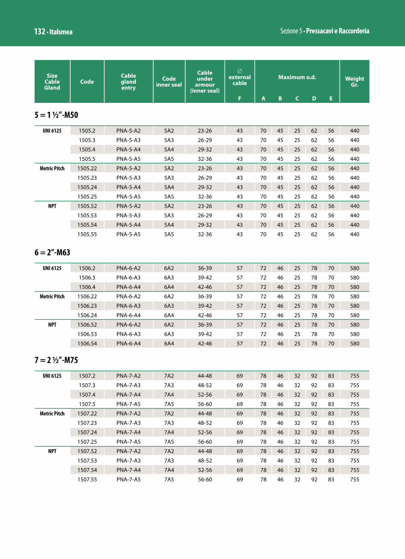
Sezione 5 • Pressacavi e Raccorderia132 • Italsmea
Size Cable Gland
CodeCable gland entry
Code inner seal
Cable under
armour (inner seal)
∅ external
cableMaximum o.d. Weight
Gr.
F A B C D E
5 = 1 ½”-M50
UNI 6125 1505.2 PNA-5-A2 5A2 23-26 43 70 45 25 62 56 440
1505.3 PNA-5-A3 5A3 26-29 43 70 45 25 62 56 440
1505.4 PNA-5-A4 5A4 29-32 43 70 45 25 62 56 440
1505.5 PNA-5-A5 5A5 32-36 43 70 45 25 62 56 440
Metric Pitch 1505.22 PNA-5-A2 5A2 23-26 43 70 45 25 62 56 440
1505.23 PNA-5-A3 5A3 26-29 43 70 45 25 62 56 440
1505.24 PNA-5-A4 5A4 29-32 43 70 45 25 62 56 440
1505.25 PNA-5-A5 5A5 32-36 43 70 45 25 62 56 440
NPT 1505.52 PNA-5-A2 5A2 23-26 43 70 45 25 62 56 440
1505.53 PNA-5-A3 5A3 26-29 43 70 45 25 62 56 440
1505.54 PNA-5-A4 5A4 29-32 43 70 45 25 62 56 440
1505.55 PNA-5-A5 5A5 32-36 43 70 45 25 62 56 440
6 = 2”-M63
UNI 6125 1506.2 PNA-6-A2 6A2 36-39 57 72 46 25 78 70 580
1506.3 PNA-6-A3 6A3 39-42 57 72 46 25 78 70 580
1506.4 PNA-6-A4 6A4 42-46 57 72 46 25 78 70 580
Metric Pitch 1506.22 PNA-6-A2 6A2 36-39 57 72 46 25 78 70 580
1506.23 PNA-6-A3 6A3 39-42 57 72 46 25 78 70 580
1506.24 PNA-6-A4 6A4 42-46 57 72 46 25 78 70 580
NPT 1506.52 PNA-6-A2 6A2 36-39 57 72 46 25 78 70 580
1506.53 PNA-6-A3 6A3 39-42 57 72 46 25 78 70 580
1506.54 PNA-6-A4 6A4 42-46 57 72 46 25 78 70 580
7 = 2 ½”-M75
UNI 6125 1507.2 PNA-7-A2 7A2 44-48 69 78 46 32 92 83 755
1507.3 PNA-7-A3 7A3 48-52 69 78 46 32 92 83 755
1507.4 PNA-7-A4 7A4 52-56 69 78 46 32 92 83 755
1507.5 PNA-7-A5 7A5 56-60 69 78 46 32 92 83 755
Metric Pitch 1507.22 PNA-7-A2 7A2 44-48 69 78 46 32 92 83 755
1507.23 PNA-7-A3 7A3 48-52 69 78 46 32 92 83 755
1507.24 PNA-7-A4 7A4 52-56 69 78 46 32 92 83 755
1507.25 PNA-7-A5 7A5 56-60 69 78 46 32 92 83 755
NPT 1507.52 PNA-7-A2 7A2 44-48 69 78 46 32 92 83 755
1507.53 PNA-7-A3 7A3 48-52 69 78 46 32 92 83 755
1507.54 PNA-7-A4 7A4 52-56 69 78 46 32 92 83 755
1507.55 PNA-7-A5 7A5 56-60 69 78 46 32 92 83 755

Section 5 • Cable Glands and Conduit Fittings Italsmea • 133
8 = 3”-M80
UNI 6125 1508.4 PNA-8-A4 8A4 56-60 79 78 46 32 103 93 900
1508.5 PNA-8-A5 8A5 59-63 79 78 46 32 103 93 900
1508.6 PNA-8-A6 8A6 63-67 79 78 46 32 103 93 900
1508.7 PNA-8-A7 8°7 67-71 79 78 46 32 103 93 900
Metric Pitch 1508.24 PNA-8-A4 8A4 56-60 79 78 46 32 103 93 900
1508.25 PNA-8-A5 8A5 59-63 79 78 46 32 103 93 900
1508.26 PNA-8-A6 8A6 63-67 79 78 46 32 103 93 900
1508.27 PNA-8-A7 8°7 67-71 79 78 46 32 103 93 900
NPT 1508.54 PNA-8-A4 8A4 56-60 79 78 46 32 103 93 900
1508.55 PNA-8-A5 8A5 59-63 79 78 46 32 103 93 900
1508.56 PNA-8-A6 8A6 63-67 79 78 46 32 103 93 900
1508.57 PNA-8-A7 8°7 67-71 79 78 46 32 103 93 900
Size Cable Gland
CodeCable gland entry
Code inner seal
Cable under
armour (inner seal)
∅ external
cableMaximum o.d. Weight
Gr.
F A B C D E

Sezione 5 • Pressacavi e Raccorderia134 • Italsmea
PRESSACAVI PASSANTE MASCHIO-FEMMINA SERIE PSF-…
II 2 GD–50°C +110°C / EEx-d IIC / EEx-e II
I M2–50°C +110°C / EEx-d I (Su richiesta)
INERIS 02ATEX0084
CARATTERISTICHEPressacavo passante maschio-femmina a semplice tenuta per cavo normale non armato multipolare, realizzato in Ottone OT58 Nichel cromato stampato a sezione esagonale, filettature di accoppiamento metrica passo 1,5, adatto per l’accoppiamento reversibile di due contenitori non attigui: EEx-d/EEx-d o EEx-d/EEx-e tramite l’interposizione di un tubo rigido o flessibile che a seconda del tripo di impianto sarà:• Conduit UNI-7683 o flessibile EEx-d
per impianto AD/PE • Tubo metallico leggero o flessibile
stagno per impianto AD/FE
CONDIZIONI DI IMPIEGOIn area classificata di Zona 1 e 2 / Zona 21 e 22, nonché classe 2 e 3 come giunto di tenuta EEx-d di cavi multipolari non armati in accoppiamento a contenitori antideflagranti EEx-d in sostituzione del tradizionale giunto di bloccaggio sigillato. Suggerito per impiego in qualsiasi condizione ambientale sia all’interno che all’esterno anche in presenza di elevata umidità e ricorrenza di pioggia battente.Il raccordo è particolarmente adatto a sostituire in uscita da contenitori EEx-d giunto di bloccaggio, giunto a tre pezzi e nipplo. Si elimina così l’esecuzione della miscelazione permanente sostituendola con giunto di tenuta reversibile. Il pressacavo svolge la doppia funzione di pressacavo e di giunto a tre pezzi maschio-femmina
APPROVAZIONIIniex: 91C.103.933 Esecuzione secondo EN-50014 EN-50018 EEx-d IIA IIB IIC T.. ATEX 2GD (assume la Classe di Temperatura dell’apparecchio al quale viene accoppiato, nonché EEx-d I T.. come sopra)Esecuzione secondo EN-50014 EN-50019 EEx-e II T.. ATEX 2GD (assume la Classe di Temperatura dell’apparecchio al quale viene accoppiato)Grado di protezione: IP-67 secondo IEC
THROUGH CABLE GLANDS MALE-FEMALE PSF-… SERIES
II 2 GD–50°C +110°C / EEx-d IIC / EEx-e II
I M2–50°C +110°C / EEx-d I (On request)
INERIS 02ATEX0084
FEATURESThrough cable gland male-female, single seal for normal unarmoured multi cores cable, brass OT-58 nikel-crome plated stamped hexagonal section, connection thread metric pitch 1,5, suitable for reversable assembling of 2 enclosures: EEx-d/ EEx-d or EEx-d/EEx-e by adding to the cable gland a rigid tube or flexible which it will be:• Conduit UNI-7683 or flexible
coupling EEx-d when the conduit duct it is integral part of explosion proof protection. Definition “AD/PE”
• Light metal tube (EMT) or water tight flexible coupling when the duct it is granting only a mechanical protection to the inner cable. Definition “AD/FE”
USEIn classified Area Zone 1 & 2 / Zone 21 & 22, like a joint with multicore unarmoured cables as alternative of traditional sealing box. Suitable for use in any environmental conditions, either inside or outside, even with high humidity and rains.The cable gland has been studied to seal reversibly the ways in/out of EEx-d enclosures instead of sealing box, union and nipple, therefore no more permanent seal. The cable gland grant the double funxtion of cable gland and male-female union.
APPROVALSIniex: 91C.103.933Compliance: EN-50014 & EN-50018 mode of protection EEx-d IIA IIB IIC T.. ATEX 2GD (it will assume the Temperature Class of enclosure to which will be connected) and EEx-d I T.. (as above)Compliance: EN-50014 & EN-50019 mode of protection EEx-e II T... ATEX 2GD (it will assume the Temperature Class of enclosure to which will be connected) Mechanical protection: IP-67 according to IEC-60529 (against

Section 5 • Cable Glands and Conduit Fittings Italsmea • 135
60529 (verso entrambe gli apparecchi ai quali è accoppiato)
VERSIONI A RICHIESTAPressacavi in acciaio inossidabile AISI-304. La sigla assume il suffisso 304. Esempio PSF-1-A1/304Pressacavi in acciaio inossidabile AISI-316. La sigla assume il suffisso 316. Esempio PSF-1-A1/316
TRATTAMENTI SUPERFICIALI A RICHIESTAGuarnizione di tenuta in gomma siliconica per basse ad alte temperature: da –60°C a +130°C
FILETTATURE DIVERSE DALLO STANDARDPressacavo con filetto maschio conico UNI-6125 e filetto femmina cilindrico UNI-338. In tale versione il condotto a valle del pressacavo sarà del tipo AD/FE solamente
ACCESSORIControdado di acciaio zincato serie DL... (vedi schema allegato)Guarnizione di battuta serie OR (vedi schema allegato)
ISTRUZIONI D’USOAvvitare il corpo del pressacavo al contenitore EEx-d/e (dett. 4).Avvitare la ghiera premitore (dett. 2) e la testina di raccordo (dett. 1) sul tubo della conduttura elettrica a seguire. Infilare il gommino di tenuta sull’esterno del cavo ed avvicinare il contenitore EEx-d/e al tubo avendo cura di infilare il cavo nel corpo del pressacavo (dett. 4) preventivamente assiepato. Raccordare il corpo del pressacavo alla testina (dett. 1) e serrare a fondo
NOTA IMPORTANTEFilettatura della ghiera femmina cilindrica ISO 228
both enclosures to which it will be connected
VERSION ON REQUESTCable glands stainless steel 304 made. The type number will assume the ending 304. Example PSF-1-A1/304Cable glands stainless steel 316made. The type number will assume the ending 316. Example PSF-1-A1/316
FINISH ON REQUESTSilicon rubber made gasket for low and high temperature, between –60°C to +130°C
THREADSCable glands with male thread conic UNI-6125 and female thread cylindrical UNI-338.
ACCESSORIESLocknut zinc galvanized DL... series (see catalogue data sheet)Sealing gasket OR series (see catalogue data sheet)
INSTRUCTIONS FOR USEScrew the body of gland on enclosure EEx-d/e (detail 4).Screw the free coupling (detail 2) and the end cup (detail 1) on the tube of following electrical duct. Pull the gasket over the cable. Approach the EEx-d/e enclosure with the tube taking care to push the cable in the body of gland (detail 4) previously assembled. Screw together the body of gland to the end cup (detail 1) up to the lock
IMPORTANT NOTE Female sleeve threaded cilindric ISO228
1 2 3 4

Sezione 5 • Pressacavi e Raccorderia136 • Italsmea
Size Cable Gland
CodeCable gland entry
Code gasket
Cable overall diam.
Free conpling
threading
Maximum o.d. WeightGr.
A B C D E
1 = ½”-M20
UNI 6125 2801.1 PSF-1-A1 1A1 6-9 ½” 73 53 20 33 30 13,5
2801.2 PSF-1-A2 1A2 9-12 ½” 73 53 20 33 30 13,5
Metric Pitch 2821.1 PSF-1-A1 1A1 6-9 ½” 73 53 20 33 30 13,5
2821.2 PSF-1-A2 1A2 9-12 ½” 73 53 20 33 30 13,5
NPT 2811.1 PSF-1-A1 1A1 6-9 ½” 73 53 20 33 30 13,5
2811.2 PSF-1-A2 1A2 9-12 ½” 73 53 20 33 30 13,5
2 = 3⁄4”-M25
UNI 6125 2802.1 PSF-2-A1 2A1 6-9 ¾” 73 53 20 40 36 18
2802.2 PSF-2-A2 2A2 9-12 ¾” 73 53 20 40 36 18
2802.3 PSF-2-A3 2A3 11-14 ¾” 73 53 20 40 36 18
2802.4 PSF-2-A4 2A4 14-17 ¾” 73 53 20 40 36 18
Metric Pitch 2822.1 PSF-2-A1 2A1 6-9 ¾” 73 53 20 40 36 18
2822.2 PSF-2-A2 2A2 9-12 ¾” 73 53 20 40 36 18
2822.3 PSF-2-A3 2A3 11-14 ¾” 73 53 20 40 36 18
2822.4 PSF-2-A4 2A4 14-17 ¾” 73 53 20 40 36 18
NPT 2812.1 PSF-2-A1 2A1 6-9 ¾” 73 53 20 40 36 18
2812.2 PSF-2-A2 2A2 9-12 ¾” 73 53 20 40 36 18
2812.3 PSF-2-A3 2A3 11-14 ¾” 73 53 20 40 36 18
2812.4 PSF-2-A4 2A4 14-17 ¾” 73 53 20 40 36 18
3 = 1”- M32
UNI 6125 2803.1 PSF-3-A1 3A1 14-17 1” 88 63 25 49 44 24
2803.2 PSF-3-A2 3A2 17-20 1” 88 63 25 49 44 24
2803.3 PSF-3-A3 3A3 20-23 1” 88 63 25 49 44 24
Metric Pitch 2823.1 PSF-3-A1 3A1 14-17 1” 88 63 25 49 44 24
2823.2 PSF-3-A2 3A2 17-20 1” 88 63 25 49 44 24
2823.3 PSF-3-A3 3A3 20-23 1” 88 63 25 49 44 24
NPT 2813.1 PSF-3-A1 3A1 14-17 1” 88 63 25 49 44 24
2813.2 PSF-3-A2 3A2 17-20 1” 88 63 25 49 44 24
2813.3 PSF-3-A3 3A3 20-23 1” 88 63 25 49 44 24
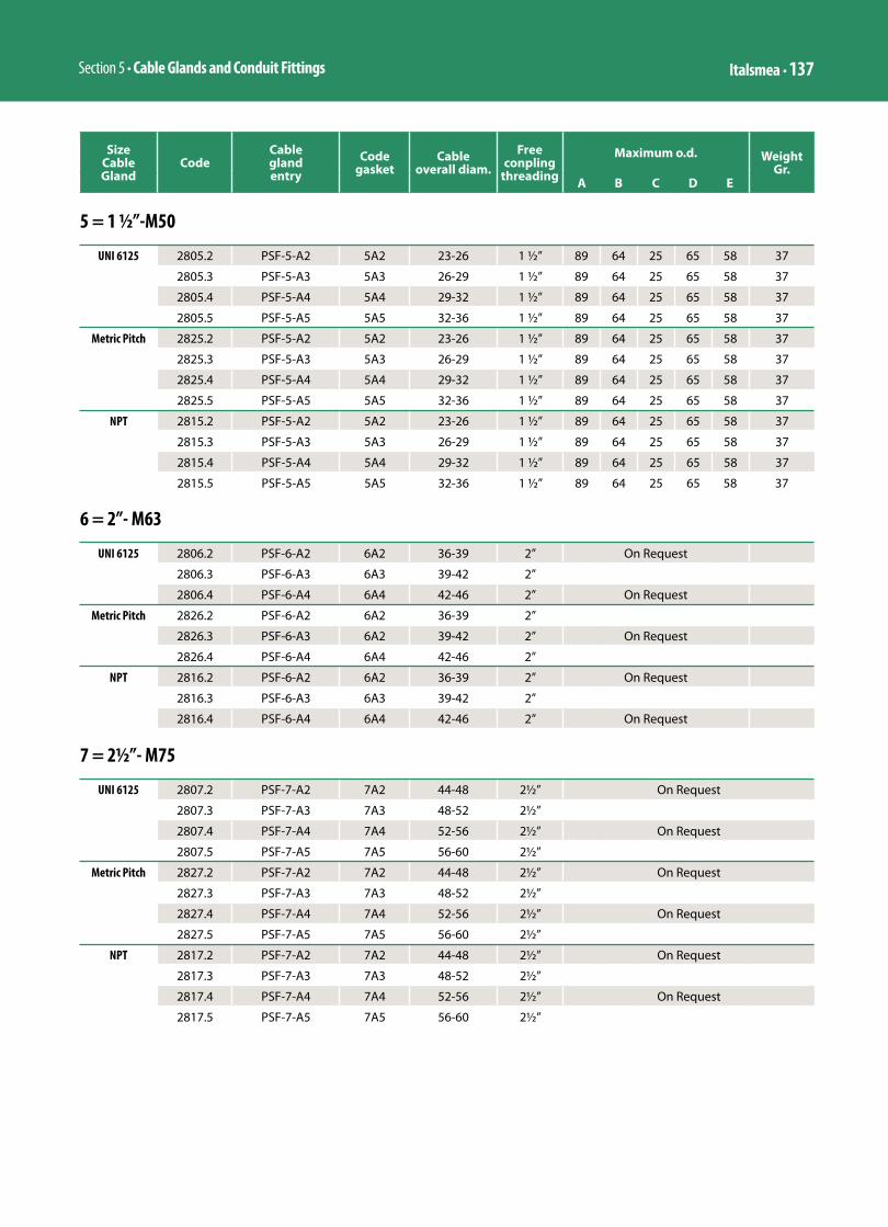
Section 5 • Cable Glands and Conduit Fittings Italsmea • 137
5 = 1 ½”-M50
UNI 6125 2805.2 PSF-5-A2 5A2 23-26 1 ½” 89 64 25 65 58 37
2805.3 PSF-5-A3 5A3 26-29 1 ½” 89 64 25 65 58 37
2805.4 PSF-5-A4 5A4 29-32 1 ½” 89 64 25 65 58 37
2805.5 PSF-5-A5 5A5 32-36 1 ½” 89 64 25 65 58 37
Metric Pitch 2825.2 PSF-5-A2 5A2 23-26 1 ½” 89 64 25 65 58 37
2825.3 PSF-5-A3 5A3 26-29 1 ½” 89 64 25 65 58 37
2825.4 PSF-5-A4 5A4 29-32 1 ½” 89 64 25 65 58 37
2825.5 PSF-5-A5 5A5 32-36 1 ½” 89 64 25 65 58 37
NPT 2815.2 PSF-5-A2 5A2 23-26 1 ½” 89 64 25 65 58 37
2815.3 PSF-5-A3 5A3 26-29 1 ½” 89 64 25 65 58 37
2815.4 PSF-5-A4 5A4 29-32 1 ½” 89 64 25 65 58 37
2815.5 PSF-5-A5 5A5 32-36 1 ½” 89 64 25 65 58 37
6 = 2”- M63
UNI 6125 2806.2 PSF-6-A2 6A2 36-39 2” On Request
2806.3 PSF-6-A3 6A3 39-42 2”
2806.4 PSF-6-A4 6A4 42-46 2” On Request
Metric Pitch 2826.2 PSF-6-A2 6A2 36-39 2”
2826.3 PSF-6-A3 6A2 39-42 2” On Request
2826.4 PSF-6-A4 6A4 42-46 2”
NPT 2816.2 PSF-6-A2 6A2 36-39 2” On Request
2816.3 PSF-6-A3 6A3 39-42 2”
2816.4 PSF-6-A4 6A4 42-46 2” On Request
Size Cable Gland
CodeCable gland entry
Code gasket
Cable overall diam.
Free conpling
threading
Maximum o.d. WeightGr.
A B C D E
7 = 2½”- M75
UNI 6125 2807.2 PSF-7-A2 7A2 44-48 2½” On Request
2807.3 PSF-7-A3 7A3 48-52 2½”
2807.4 PSF-7-A4 7A4 52-56 2½” On Request
2807.5 PSF-7-A5 7A5 56-60 2½”
Metric Pitch 2827.2 PSF-7-A2 7A2 44-48 2½” On Request
2827.3 PSF-7-A3 7A3 48-52 2½”
2827.4 PSF-7-A4 7A4 52-56 2½” On Request
2827.5 PSF-7-A5 7A5 56-60 2½”
NPT 2817.2 PSF-7-A2 7A2 44-48 2½” On Request
2817.3 PSF-7-A3 7A3 48-52 2½”
2817.4 PSF-7-A4 7A4 52-56 2½” On Request
2817.5 PSF-7-A5 7A5 56-60 2½”

Sezione 5 • Pressacavi e Raccorderia138 • Italsmea
8 = 3”- M80
UNI 6125 2808.4 PSF-8-A4 8A4 56-60 3” On Request
2808.5 PSF-8-A5 8A5 59-63 3”
2808.6 PSF-8-A6 8A6 63-67 3” On Request
2808.7 PSF-8-A7 8A7 67-71 3”
Metric Pitch 2828.4 PSF-8-A4 8A4 56-60 M80 On Request
2828.5 PSF-8-A5 8A5 59-63 M80
2828.6 PSF-8-A6 8A6 63-67 M80 On Request
2828.7 PSF-8-A7 8A7 67-71 M80
NPT 2818.4 PSF-8-A4 8A4 56-60 3” On Request
2818.5 PSF-8-A5 8A5 59-63 3”
2818.6 PSF-8-A6 8A6 63-67 3” On Request
2818.7 PSF-8-A7 8A7 67-71 3”
Size Cable Gland
CodeCable gland entry
Code gasket
Tolerance cable
overall diam.
Free compling threading
Maximum o.d. WeightGr.
A B C D E
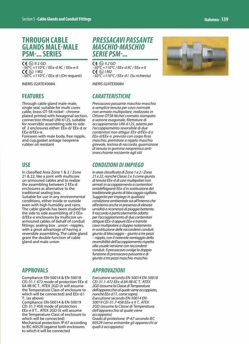
Section 5 • Cable Glands and Conduit Fittings Italsmea • 139
PRESSACAVI PASSANTE MASCHIO-MASCHIO SERIE PSM-...
II 2 GD–50°C +110°C / EEx-d IIC / EEx-e II
I M2–50°C +110°C / EEx-d I (Su richiesta)
INERIS 02ATEX0084
CARATTERISTICHEPressacavo passante maschio-maschio a semplice tenuta per cavo normale non armato multipolare, realizzato in Ottone OT58 Nichel cromato stampato a sezione esagonale, fi lettature di accoppiamento UNI-6125, adatto per l’accoppiamento reversibile di due contenitori non attigui: EEx-d/EEx-d o EEx-d/EEx-e. previsto con corpo fi sso maschio, premitore a nipplo maschio girevole, testina di raccordo, guarnizione di tenuta in gomma neoprenica anti-invecchiante resistente agli olii
CONDIZIONI DI IMPIEGOIn area classifi cata di Zona 1 e 2 / Zona 21 e 22, nonché Classe 2 e 3 come giunto di tenuta EEx-d di cavi multipolari non armati in accoppiamento a contenitori antidefl agranti EEx-d in sostituzione del tradizionale giunto di bloccaggio sigillato. Suggerito per impiego in qualsiasi condizione ambientale sia all’interno che all’esterno anche in presenza di elevata umidità e ricorrenza di pioggia battente. Il raccordo è particolarmente adatto per l’accoppiamento di due contenitori attiguei EEx-d oppure EEx-e tramite cavo multipolare a doppio isolamento in sostituzione delle raccorderei conduit: giunto di bloccaggio – giunto a tre pezzi – nipplo, con il notevole vantaggio della reversibilità dell’accoppiamento rispetto alla usuale versione con raccorderei conduit. Il pressacavo svolge la doppia funzione di pressacavo passante e di giunto a tre pezzi maschio-maschio
APPROVAZIONIEsecuzione secondo EN-50014 EN-50018 CEI-31.1-472 EEx-d IIA IIB IIC T.. ATEX 2GD (assume la Classe di Temperatura dell’apparecchio al quale viene accoppiato, nonché EEx-d I T.. come sopra).Esecuzione secondo EN-50014 EN-50019 CEI-31.7-458 EEx-e II T.. ATEX 2GD (assume la Classe di Temperatura dell’apparecchio al quale viene accoppiato)Grado di protezione: IP-67 secondo IEC 60529 (verso entrambe gli apparecchi ai quali è accoppiato)
THROUGH CABLE GLANDS MALE-MALE PSM-... SERIES
II 2 GD–50°C +110°C / EEx-d IIC / EEx-e II
I M2–50°C +110°C / EEx-d I (On request)
INERIS 02ATEX0084
FEATURESThrough cable gland male-male, single seal, suitable for multi cores cable, brass OT-58 nickel - chrome plated printed with hexagonal section, connection thread UNI-6125, suitable for reversible assembling side to side of 2 enclosures either: EEx-d/ EEx-d or EEx-d/EEx-e.Foreseen with male body, free nipple, and cup,gasket antiage neoprene rubber oil resistant
USEIn classifi ed Area Zone 1 & 2 / Zone 21 & 22, like a joint with multicore un-armoured cables and to realize the assembling between 2 EEx-d enclosures as alternative to the traditional sealing box.Suitable for use in any environmental conditions, either inside or outside even with high humidity and rains. The cable glands has been studied for the side to side assembling of 2 EEx-d/EEx-e enclosures by multicore un-armoured cables of behalf of conduit fi ttings: sealing box . union –nipples, with a great advantage of having a reversible assembling. The cable gland grant the double function of cable gland and male union
APPROVALSCompliance: EN-50014 & EN-50018 CEI-31.1 472 mode of protection EEx-d IIA IIB IIC T.. ATEX 2GD (it will assume the Temperature Class of enclosure to which will be connected) and EEx-d I T.. (as above)Compliance: EN-50014 & EN-50019 CEI-31.7 458 mode of protection EEx-e II T... ATEX 2GD (it will assume the Temperature Class of enclosure to which will be connected) Mechanical protection: IP-67 according to IEC-60529 (against both enclosures to which it will be connected

Sezione 5 • Pressacavi e Raccorderia140 • Italsmea
VERSION ON REQUESTCable glands stainless steel 304 made. The type number will assume the ending 304. Example PSM-1-A1/304Cable glands stainless steel 316made. The type number will assume the ending 316. Example PSM-1-A1/316
FINISH ON REQUESTSilicon rubber made gasket for low and high temperature, between –60°C to +130°C
THREADS SIDE FIXED MALEAnsi B2.1 NPT (normally in stock). The type number will assume the ending NPT.Metric ISO Table pitch 1,5. The type number will assume the ending M.
ACCESSORIESLocknut zinc galvanized DL... series (see catalogue data sheet)Sealing gasket OR series (see catalogue data sheet)
INSTRUCTIONS FOR USEPull over the cable the end cup (detail 1) and the free nipple (detail 2), pull over the cable the gasket (detail). Screw on the body of gland (detail 4) on one of the 2 enclosures to be connected. Screw on the second enclosure the free nipples and end cup (details 2 and 1). Push the cable in the body of gland (detail 4). Approach the 2 enclosures up to allow the connection between body and end cup (details 4 and 1). Screw on the assembling up to the lock.
NOTEfree nipple (2) is always UNI 6125 threaded
VERSIONI A RICHIESTAPressacavi in acciaio inossidabile AISI-304. La sigla assume il suffisso 304. Esempio PSM-1-A1/304Pressacavi in acciaio inossidabile AISI-316. La sigla assume il suffisso 316. Esempio PSM-1-A1/316
TRATTAMENTI SUPERFICIALI A RICHIESTAGuarnizione di tenuta in gomma siliconica per basse ad alte temperature: da –60°C a +130°C
FILETTATURE DIVERSE DALLO STANDARD SULLE PARTI MASCHIO FISSEA stock Ansi B2.1 NPT, la sigla assume il suffisso NPT.Su richiesta: metrica a tabella ISO passo 1,5, la sigla assume il suffisso M.
ACCESSORIControdado di acciaio zincato serie DL... (vedi schema allegato)Guarnizione di battuta serie OR (vedi schema allegato)
ISTRUZIONI D’USOInfilare la testina del pressacavo (dettaglio 1) ed il nipplo premitore girevole relativo (dettaglio 2) sul cavo, infilare il gommino di tenuta (particolare 3) sulla guaina esterna del cavo. Montare il corpo del pressacavo (dettaglio 4) su uno dei due contenitori da accoppiare. Avvitare assieme il nipplo premitore e la testina (dettaglio 2 e 1) sul secondo contenitore da accoppiare. Infilare il cavetto nel corpo del pressacavo (dettaglio 4), avvicinare i due contenitori fino a permettere il raccordo tra il corpo del pressavo e la testina dello stesso (dettaglio 4 e 1). Serrare a fondo la testina fino al massimo consentito
NOTAil maschio girevole (2) è sempre filettato UNI 6125
1 2 3 4

Section 5 • Cable Glands and Conduit Fittings Italsmea • 141
Size Cable Gland
CodeCable gland entry
Code gasket
Cable overall diam.
Free nipple
threading
Maximum o.d. WeightGr.
A B C D E
1 = ½”-M20
UNI 6125 2901.1 PSM-1-A1 1A1 6-9 ½” 90 70 20 33 30 13,5
2901.2 PSM-1-A2 1A2 9-12 ½” 90 70 20 33 30 13,5
Metric Pitch PSM-1-A1 1A1 6-9 ½” 90 70 20 33 30 13,5
PSM-1-A2 1A2 9-12 ½” 90 70 20 33 30 13,5
NPT 2911.1 PSM-1-A1 1A1 6-9 ½” 90 70 20 33 30 13,5
2911.2 PSM-1-A2 1A2 9-12 ½” 90 70 20 33 30 13,5
2 = ¾”-M25
UNI 6125 2902.1 PSM-2-A1 2A1 6-9 ¾” 90 70 20 40 36 18
2902.2 PSM-2-A2 2A2 9-12 ¾” 90 70 20 40 36 18
2902.3 PSM-2-A3 2A3 11-14 ¾” 90 70 20 40 36 18
2902.4 PSM-2-A4 2A4 14-17 ¾” 90 70 20 40 36 18
Metric Pitch PSM-2-A1 2A1 6-9 ¾” 90 70 20 40 36 18
PSM-2-A2 2A2 9-12 ¾” 90 70 20 40 36 18
PSM-2-A3 2A3 11-14 ¾” 90 70 20 40 36 18
PSM-2-A4 2A4 14-17 ¾” 90 70 20 40 36 18
NPT 2912.1 PSM-2-A1 2A1 6-9 ¾” 90 70 20 40 36 18
2912.2 PSM-2-A2 2A2 9-12 ¾” 90 70 20 40 36 18
2912.3 PSM-2-A3 2A3 11-14 ¾” 90 70 20 40 36 18
2912.4 PSM-2-A4 2A4 14-17 ¾” 90 70 20 40 36 18
3 = 1”-M32
UNI 6125 2903.1 PSM-3-A1 3A1 14-17 1” 104 79 25 49 44 24
2903.2 PSM-3-A2 3A2 17-20 1” 104 79 25 49 44 24
2903.3 PSM-3-A3 3A3 20-23 1” 104 79 25 49 44 24
Metric Pitch PSM-3-A1 3A1 14-17 1” 104 79 25 49 44 24
PSM-3-A2 3A2 17-20 1” 104 79 25 49 44 24
PSM-3-A3 3A3 20-23 1” 104 79 25 49 44 24
NPT 2913.1 PSM-3-A1 3A1 14-17 1” 104 79 25 49 44 24
2913.2 PSM-3-A2 3A2 17-20 1” 104 79 25 49 44 24
2913.3 PSM-3-A3 3A3 20-23 1” 104 79 25 49 44 24
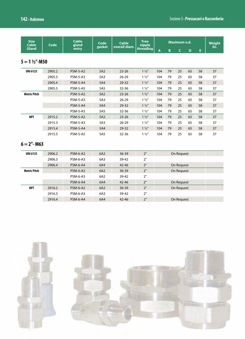
Sezione 5 • Pressacavi e Raccorderia142 • Italsmea
Size Cable Gland
CodeCable gland entry
Code gasket
Cable overall diam.
Free nipple
threading
Maximum o.d. WeightGr.
A B C D E
5 = 1 ½”-M50
UNI 6125 2905.2 PSM-5-A2 5A2 23-26 1 ½” 104 79 25 65 58 37
2905.3 PSM-5-A3 5A3 26-29 1 ½” 104 79 25 65 58 37
2905.4 PSM-5-A4 5A4 29-32 1 ½” 104 79 25 65 58 37
2905.5 PSM-5-A5 5A5 32-36 1 ½” 104 79 25 65 58 37
Metric Pitch PSM-5-A2 5A2 23-26 1 ½” 104 79 25 65 58 37
PSM-5-A3 5A3 26-29 1 ½” 104 79 25 65 58 37
PSM-5-A4 5A4 29-32 1 ½” 104 79 25 65 58 37
PSM-5-A5 5A5 32-36 1 ½” 104 79 25 65 58 37
NPT 2915.2 PSM-5-A2 5A2 23-26 1 ½” 104 79 25 65 58 37
2915.3 PSM-5-A3 5A3 26-29 1 ½” 104 79 25 65 58 37
2915.4 PSM-5-A4 5A4 29-32 1 ½” 104 79 25 65 58 37
2915.5 PSM-5-A5 5A5 32-36 1 ½” 104 79 25 65 58 37
6 = 2”- M63
UNI 6125 2906.2 PSM-6-A2 6A2 36-39 2” On Request
2906.3 PSM-6-A3 6A3 39-42 2”
2906.4 PSM-6-A4 6A4 42-46 2” On Request
Metric Pitch PSM-6-A2 6A2 36-39 2” On Request
PSM-6-A3 6A2 39-42 2”
PSM-6-A4 6A4 42-46 2” On Request
NPT 2916.2 PSM-6-A2 6A2 36-39 2” On Request
2916.3 PSM-6-A3 6A3 39-42 2”
2916.4 PSM-6-A4 6A4 42-46 2” On Request
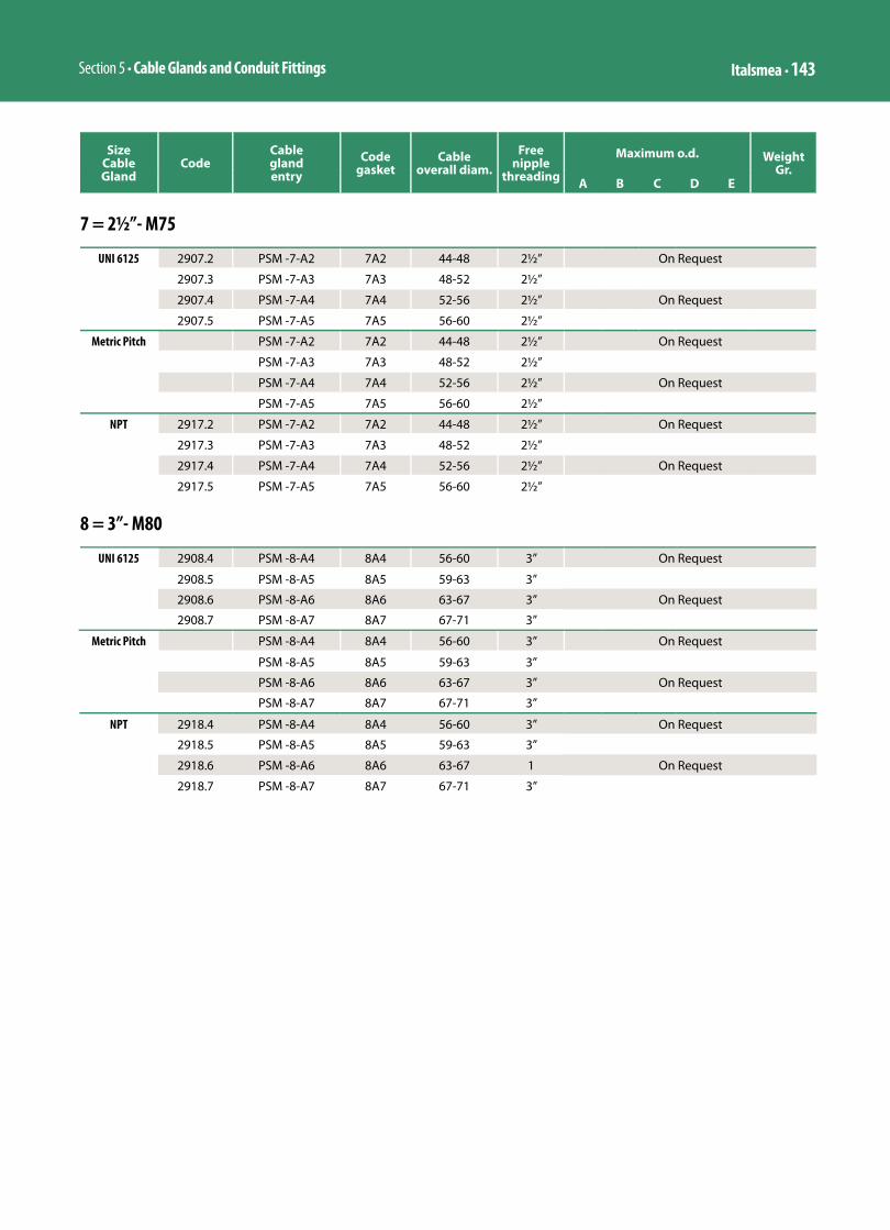
Section 5 • Cable Glands and Conduit Fittings Italsmea • 143
7 = 2½”- M75
UNI 6125 2907.2 PSM -7-A2 7A2 44-48 2½” On Request
2907.3 PSM -7-A3 7A3 48-52 2½”
2907.4 PSM -7-A4 7A4 52-56 2½” On Request
2907.5 PSM -7-A5 7A5 56-60 2½”
Metric Pitch PSM -7-A2 7A2 44-48 2½” On Request
PSM -7-A3 7A3 48-52 2½”
PSM -7-A4 7A4 52-56 2½” On Request
PSM -7-A5 7A5 56-60 2½”
NPT 2917.2 PSM -7-A2 7A2 44-48 2½” On Request
2917.3 PSM -7-A3 7A3 48-52 2½”
2917.4 PSM -7-A4 7A4 52-56 2½” On Request
2917.5 PSM -7-A5 7A5 56-60 2½”
8 = 3”- M80
UNI 6125 2908.4 PSM -8-A4 8A4 56-60 3” On Request
2908.5 PSM -8-A5 8A5 59-63 3”
2908.6 PSM -8-A6 8A6 63-67 3” On Request
2908.7 PSM -8-A7 8A7 67-71 3”
Metric Pitch PSM -8-A4 8A4 56-60 3” On Request
PSM -8-A5 8A5 59-63 3”
PSM -8-A6 8A6 63-67 3” On Request
PSM -8-A7 8A7 67-71 3”
NPT 2918.4 PSM -8-A4 8A4 56-60 3” On Request
2918.5 PSM -8-A5 8A5 59-63 3”
2918.6 PSM -8-A6 8A6 63-67 1 On Request
2918.7 PSM -8-A7 8A7 67-71 3”
Size Cable Gland
CodeCable gland entry
Code gasket
Cable overall diam.
Free nipple
threading
Maximum o.d. WeightGr.
A B C D E

Section 5 • Cable Glands and Conduit Fittings Italsmea • 149
RIDUZIONI AD ANELLO SERIE RE …
2 GDEEx-d IIC / EEx-e II / EEx-d I
Certificato INERIS 04ATEX9006U
Riduzione di filetto, maschio esterno con filetto maggiore / femmina interna con filetto minore• Materiale: Acciaio zincato• Filettatura UNI 6125 o NPT
RING REDUCERS RE … SERIES
2 GDEEx-d IIC / EEx-e II / EEx-d I
Certificate INERIS 04ATEX9006U
Ring reducers , largest external male thread / smallest inner female thread • Material: Galvanised steel• Thread UNI 6125 or NPT
CodeUNI 6125
CodeNPT Type Size Weight ≅ Kg
50.1 50.61 RE 21 3/4” X 1/2” 0,04
50.2 50.62 RE 31 1” X 1/2” 0,08
50.3 50.63 RE 32 1” X 3/4” 0,08
50.7 50.67 RE 51 1 ½” X 1/2” 0,27
50.8 50.68 RE 52 1 ½” X 3/4” 0,27
50.9 50.69 RE 53 1 ½” X 1” 0,27
50.12 50.72 RE 62 2” X 3/4” 0,48
50.13 50.73 RE 63 2” X 1” 0,48
50.15 50.75 RE 65 2” X 1 ½” 0,48
50.17 RE 72 2 ½” X 3/4” 0,80
50.18 50.78 RE 73 2 ½” X 1” 0,80
50.20 50.80 RE 75 2 ½” X 1 ½” 0,80
50.21 50.81 RE 76 2 ½” X 2” 0,80
50.23 RE 82 3” X 3/4” 1,00
50.24 50.84 RE 83 3” X 1” 1,00
50.26 50.86 RE 85 3” X 1 ½” 1,00
50.27 50.87 RE 86 3” X 2” 1,00
50.28 50.88 RE 87 3” X 2 ½” 1,00
RE

Sezione 5 • Pressacavi e Raccorderia150 • Italsmea
RIDUZIONI A BICCHIERE SERIE REB …
2 GDEEx-d IIC / EEx-e II / EEx-d I
Certifi cato INERIS 04ATEX9006U
Riduzione di fi letto, maschio con fi letto minore / femmina interna con fi letto maggiore • Materiale: Acciaio zincato• Filettatura UNI 6125 o NPT
REDUCERS REB … SERIES
2 GDEEx-d IIC / EEx-e II / EEx-d I
Certifi cate INERIS 04ATEX9006U
Reducers , smallest outer male thread / lagest inner female thread • Material: Galvanised steel• Threaded UNI 6125 or NPT
CodeUNI 6125
CodeNPT Type Size Weight ≅ Kg
51.1 51.71 REB 21 3/4” X 1/2” 0,12
51.2 51.40 REB 31 1” X 1/2” 0,15
51.3 51.73 REB 32 1” X 3/4” 0,15
51.8 51.78 REB 52 1 ½” X ¾” 0,27
51.9 51.79 REB 53 1 ½” X 1” 0,27
51.13 51.41 REB 63 2” X 1” 0,35
51.15 51.42 REB 65 2” X 1 ½” 0,35
51.18 51.43 REB 73 2 ½” X 1” 0,60
51.20 51.80 REB 75 2 ½” X 1 ½” 0,60
51.21 51.81 REB 76 2 ½” X 2” 0,60
51.24 51.84 REB 83 3” X 1” 0,70
51.26 51.86 REB 85 3” X 1 ½” 0,70
51.27 51.87 REB 86 3” X 2” 0,70
51.28 51.88 REB 87 3” X 2 ½” 0,70
REB
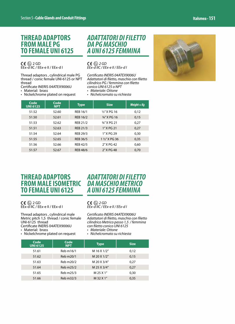
Section 5 • Cable Glands and Conduit Fittings Italsmea • 151
ADATTATORI DI FILETTO DA PG MASCHIO A UNI 6125 FEMMINA
2 GDEEx-d IIC / EEx-e II / EEx-d I
Certificato INERIS 04ATEX9006UAdattatori di filetto, maschio con filetto cilindrico PG / femmina con filetto conico UNI 6125 o NPT • Materiale: Ottone • Nichelcromato su richiesta
THREAD ADAPTORS FROM MALE PG TO FEMALE UNI 6125
2 GDEEx-d IIC / EEx-e II / EEx-d I
Thread adaptors , cylindrical male PG thread / conic female UNI-6125 or NPT thread Certificate INERIS 04ATEX9006U• Material: brass • Nickelchrome plated on request
CodeUNI 6125
CodeNPT Type Size Weight ≅ Kg
51.52 52.60 REB 16/1 ½” X PG 16 0,12
51.50 52.61 REB 16/2 ¾” X PG 16 0,15
51.53 52.62 REB 21/2 ¾” X PG 21 0,27
51.51 52.63 REB 21/3 1” X PG 21 0,27
51.54 52.64 REB 29/3 1” X PG 29 0,30
51.55 52.65 REB 36/5 1 ½” X PG 36 0,35
51.56 52.66 REB 42/5 2” X PG 42 0,60
51.57 52.67 REB 48/6 2” X PG 48 0,70
ADATTATORI DI FILETTO DA MASCHIO METRICO A UNI 6125 FEMMINA
2 GDEEx-d IIC / EEx-e II / EEx-d I
Certificato INERIS 04ATEX9006UAdattatori di filetto, maschio con filetto cilindrico Metrico passo 1,5 / femmina con filetto conico UNI 6125 • Materiale: Ottone • Nichelcromato su richiesta
THREAD ADAPTORS FROM MALE ISOMETRIC TO FEMALE UNI 6125
2 GDEEx-d IIC / EEx-e II / EEx-d I
Thread adaptors , cylindrical male Metric pitch 1,5 thread / conic female UNI-6125 thread Certificate INERIS 04ATEX9006U• Material: brass• Nickelchrome plated on request
CodeUNI 6125
CodeNPT Type Size
51.61 Reb m16/1 M 16 X 1/2” 0,12
51.62 Reb m20/1 M 20 X 1/2” 0,15
51.63 Reb m20/2 M 20 X 3/4” 0,27
51.64 Reb m25/2 M 25 X 3/4” 0,27
51.65 Reb m25/3 M 25 X 1” 0,30
51.66 Reb m32/3 M 32 X 1” 0,35

Sezione 5 • Pressacavi e Raccorderia152 • Italsmea
TAPPI MASCHIO
2 GDEEx-d IIC / EEx-e II / EEx-d I
Certificato INERIS 04ATEX9006UTappi maschio serie PLG con chiave ad esagono incassato • Materiale: Acciaio zincato• Filettatura UNI 6125 o NPT
MALE PLUGS
2 GDEEx-d IIC / EEx-e II / EEx-d I
Certificate INERIS 04ATEX9006UMale plugs PLG series with recessed exagonal key • Material: galvanised steel• Threaded UNI 6125 or NPT
CodeUNI 6125
CodeNPT Type Size Weight ≅ Kg
58.1 58.61 PLG 1 1/2” 0,038
58.2 58.62 PLG 2 3/4” 0,060
58.3 58.63 PLG 3 1” 0,110
58.5 58.65 PLG 5 1 ½” 0,200
58.6 58.66 PLG 6 2” 0,380
58.7 58.67 PLG 7 2 ½” 0,510
58.8 58.68 PLG 8 3” 0,760
58.10 58.70 PLG 10 4” 0,930
PLG
n On request / Su richiesta
TAPPI MASCHIO IN RESINA POLIESTERE
2 GDTappi maschio in resina poliestere EEx-e II ATEX 2 GD con filettatura metrica passo 1,5 o Pg
POLYESTER RESIN MALE PLUGS
2 GDPolyester resin male plugs EEx-e II ATEX 2GD with metric thread pitch 1,5 or PG
Code Type Size Weight ≅ Kg
2011.9 PG 9 - FN445 EN-B-SW PG 9 0,008
2011.11 PG 11 - FN445 EN-B-SW PG 11 0,008
2011.13 PG 13,5 - FN445 EN-B-SW PG 13,5 0,008
2011.16 PG 16 - FN445 EN-B-SW PG 16 0,008
2011.21 PG 21 - FN445 EN-B-SW PG 21 0,012
2011.29 PG 29 - FN445 EN-B-SW PG 29 0,027
2011.36 PG 36 - FN445 EN-B-SW PG 36 0,040
2011.51 M 20 - FN445 EN-B-SW M 20 X 1,5 0,008
2011.52 M 25 - FN445 EN-B-SW M 25 X 1,5 0,008
2011.53 M 32 - FN445 EN-B-SW M 32 X 1,5 0,012
2011.54 M 40 - FN445 EN-B-SW M 40 X 1,5 0,027
2011.55 M 50 - FN445 EN-B-SW M 50 X 1,5 0,040
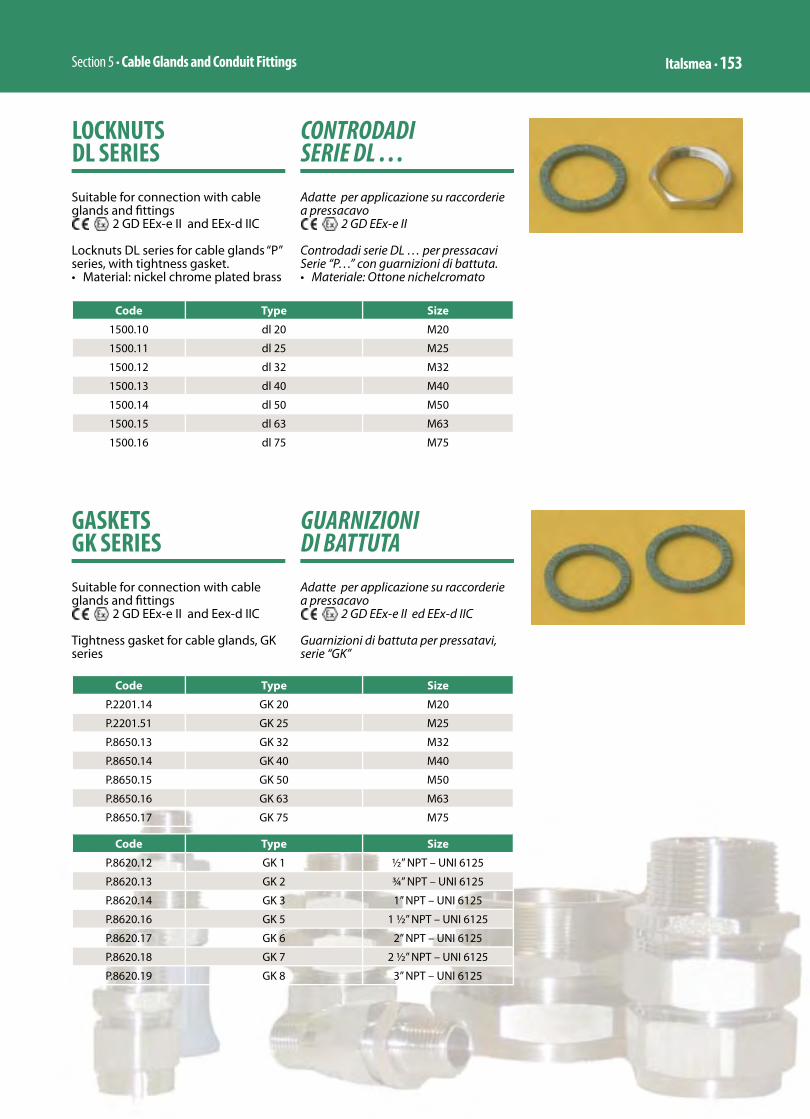
Section 5 • Cable Glands and Conduit Fittings Italsmea • 153
CONTRODADI SERIE DL …
Adatte per applicazione su raccorderie a pressacavo
2 GD EEx-e II
Controdadi serie DL … per pressacavi Serie “P…” con guarnizioni di battuta.• Materiale: Ottone nichelcromato
LOCKNUTS DL SERIES
Suitable for connection with cable glands and fi ttings
2 GD EEx-e II and EEx-d IIC
Locknuts DL series for cable glands “P” series, with tightness gasket.• Material: nickel chrome plated brass
Code Type Size
1500.10 dl 20 M20
1500.11 dl 25 M25
1500.12 dl 32 M32
1500.13 dl 40 M40
1500.14 dl 50 M50
1500.15 dl 63 M63
1500.16 dl 75 M75
GUARNIZIONI DI BATTUTA
Adatte per applicazione su raccorderie a pressacavo
2 GD EEx-e II ed EEx-d IIC
Guarnizioni di battuta per pressatavi, serie “GK”
GASKETS GK SERIES
Suitable for connection with cable glands and fi ttings
2 GD EEx-e II and Eex-d IIC
Tightness gasket for cable glands, GK series
Code Type Size
P.2201.14 GK 20 M20
P.2201.51 GK 25 M25
P.8650.13 GK 32 M32
P.8650.14 GK 40 M40
P.8650.15 GK 50 M50
P.8650.16 GK 63 M63
P.8650.17 GK 75 M75
Code Type Size
P.8620.12 GK 1 ½” NPT – UNI 6125
P.8620.13 GK 2 ¾” NPT – UNI 6125
P.8620.14 GK 3 1” NPT – UNI 6125
P.8620.16 GK 5 1 ½” NPT – UNI 6125
P.8620.17 GK 6 2” NPT – UNI 6125
P.8620.18 GK 7 2 ½” NPT – UNI 6125
P.8620.19 GK 8 3” NPT – UNI 6125
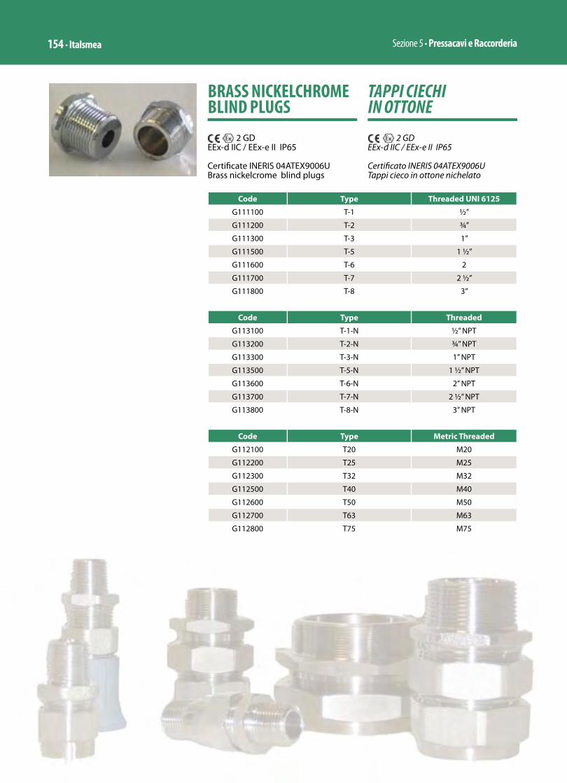
Sezione 5 • Pressacavi e Raccorderia154 • Italsmea
TAPPI CIECHI IN OTTONE
2 GDEEx-d IIC / EEx-e II IP65
Certifi cato INERIS 04ATEX9006UTappi cieco in ottone nichelato
BRASS NICKELCHROME BLIND PLUGS
2 GDEEx-d IIC / EEx-e II IP65
Certifi cate INERIS 04ATEX9006UBrass nickelcrome blind plugs
Code Type Threaded UNI 6125
G111100 T-1 ½”
G111200 T-2 ¾”
G111300 T-3 1”
G111500 T-5 1 ½”
G111600 T-6 2
G111700 T-7 2 ½”
G111800 T-8 3”
Code Type Threaded
G113100 T-1-N ½” NPT
G113200 T-2-N ¾” NPT
G113300 T-3-N 1” NPT
G113500 T-5-N 1 ½” NPT
G113600 T-6-N 2” NPT
G113700 T-7-N 2 ½” NPT
G113800 T-8-N 3” NPT
Code Type Metric Threaded
G112100 T20 M20
G112200 T25 M25
G112300 T32 M32
G112500 T40 M40
G112600 T50 M50
G112700 T63 M63
G112800 T75 M75

Section 5 • Cable Glands and Conduit Fittings Italsmea • 155
TAPPI CIECHI IN ACCIAIO INOSSIDABILE
2 GDEEx-d IIC / EEx-e II IP65
Certificato INERIS 04ATEX9006UTappi cieco in acciaio inossidabile
STAINLESS STEEL BLIND PLUGS
2 GDEEx-d IIC / EEx-e II IP65
Certificate INERIS 04ATEX9006UStainless steel blind plugs
Code Type Threaded UNI 6125
G141100 T-1 ½”
G141200 T-2 ¾”
G141300 T-3 1”
G141500 T-5 1 ½”
G141600 T-6 2
G141700 T-7 2 ½”
G141800 T-8 3”
Code Type Threaded
G143100 T-1-N ½” NPT
G143200 T-2-N ¾” NPT
G143300 T-3-N 1” NPT
G143500 T-5-N 1 ½” NPT
G143600 T-6-N 2” NPT
G143700 T-7-N 2 ½” NPT
G143800 T-8-N 3” NPT
Code Type Metric Threaded
G142100 T20 M20
G142200 T25 M25
G142300 T32 M32
G142500 T40 M40
G142600 T50 M50
G142700 T63 M63
G142800 T75 M75
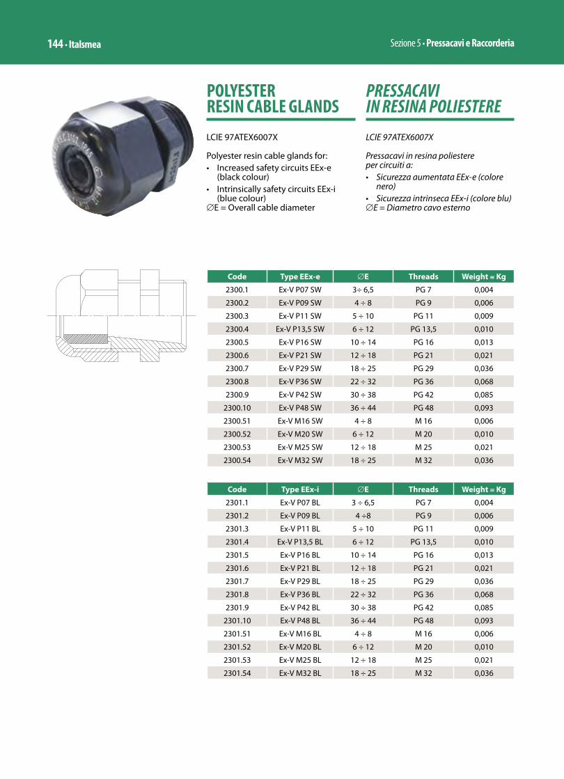
Sezione 5 • Pressacavi e Raccorderia144 • Italsmea
PRESSACAVI IN RESINA POLIESTERE
LCIE 97ATEX6007X
Pressacavi in resina poliestere per circuiti a:• Sicurezza aumentata EEx-e (colore
nero)• Sicurezza intrinseca EEx-i (colore blu)∅E = Diametro cavo esterno
POLYESTER RESIN CABLE GLANDS
LCIE 97ATEX6007X
Polyester resin cable glands for: • Increased safety circuits EEx-e
(black colour)• Intrinsically safety circuits EEx-i
(blue colour)∅E = Overall cable diameter
Code Type EEx-e ∅E Threads Weight ≅ Kg
2300.1 Ex-V P07 SW 3÷ 6,5 PG 7 0,004
2300.2 Ex-V P09 SW 4 ÷ 8 PG 9 0,006
2300.3 Ex-V P11 SW 5 ÷ 10 PG 11 0,009
2300.4 Ex-V P13,5 SW 6 ÷ 12 PG 13,5 0,010
2300.5 Ex-V P16 SW 10 ÷ 14 PG 16 0,013
2300.6 Ex-V P21 SW 12 ÷ 18 PG 21 0,021
2300.7 Ex-V P29 SW 18 ÷ 25 PG 29 0,036
2300.8 Ex-V P36 SW 22 ÷ 32 PG 36 0,068
2300.9 Ex-V P42 SW 30 ÷ 38 PG 42 0,085
2300.10 Ex-V P48 SW 36 ÷ 44 PG 48 0,093
2300.51 Ex-V M16 SW 4 ÷ 8 M 16 0,006
2300.52 Ex-V M20 SW 6 ÷ 12 M 20 0,010
2300.53 Ex-V M25 SW 12 ÷ 18 M 25 0,021
2300.54 Ex-V M32 SW 18 ÷ 25 M 32 0,036
Code Type EEx-i ∅E Threads Weight ≅ Kg
2301.1 Ex-V P07 BL 3 ÷ 6,5 PG 7 0,004
2301.2 Ex-V P09 BL 4 ÷8 PG 9 0,006
2301.3 Ex-V P11 BL 5 ÷ 10 PG 11 0,009
2301.4 Ex-V P13,5 BL 6 ÷ 12 PG 13,5 0,010
2301.5 Ex-V P16 BL 10 ÷ 14 PG 16 0,013
2301.6 Ex-V P21 BL 12 ÷ 18 PG 21 0,021
2301.7 Ex-V P29 BL 18 ÷ 25 PG 29 0,036
2301.8 Ex-V P36 BL 22 ÷ 32 PG 36 0,068
2301.9 Ex-V P42 BL 30 ÷ 38 PG 42 0,085
2301.10 Ex-V P48 BL 36 ÷ 44 PG 48 0,093
2301.51 Ex-V M16 BL 4 ÷ 8 M 16 0,006
2301.52 Ex-V M20 BL 6 ÷ 12 M 20 0,010
2301.53 Ex-V M25 BL 12 ÷ 18 M 25 0,021
2301.54 Ex-V M32 BL 18 ÷ 25 M 32 0,036
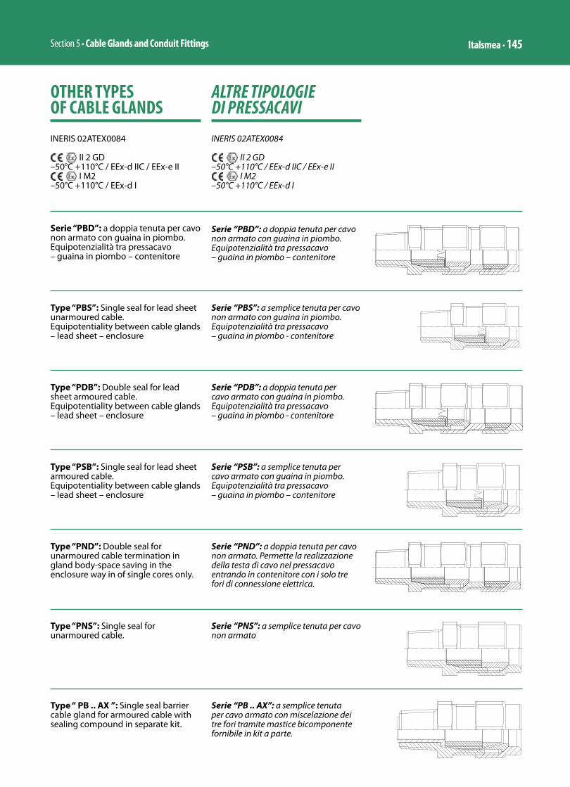
Section 5 • Cable Glands and Conduit Fittings Italsmea • 145
ALTRE TIPOLOGIE DI PRESSACAVI
INERIS 02ATEX0084
II 2 GD –50°C +110°C / EEx-d IIC / EEx-e II
I M2 –50°C +110°C / EEx-d I
OTHER TYPES OF CABLE GLANDS
INERIS 02ATEX0084
II 2 GD –50°C +110°C / EEx-d IIC / EEx-e II
I M2 –50°C +110°C / EEx-d I
Serie “PBD”: a doppia tenuta per cavo non armato con guaina in piombo. Equipotenzialità tra pressacavo – guaina in piombo – contenitore
Serie “PBD”: a doppia tenuta per cavo non armato con guaina in piombo. Equipotenzialità tra pressacavo – guaina in piombo – contenitore
Type “PBS”: Single seal for lead sheet unarmoured cable.Equipotentiality between cable glands – lead sheet – enclosure
Serie “PBS”: a semplice tenuta per cavo non armato con guaina in piombo. Equipotenzialità tra pressacavo – guaina in piombo - contenitore
Type “PND”: Double seal for unarmoured cable termination in gland body-space saving in the enclosure way in of single cores only.
Serie “PND”: a doppia tenuta per cavo non armato. Permette la realizzazione della testa di cavo nel pressacavo entrando in contenitore con i solo tre fori di connessione elettrica.
Type “PNS”: Single seal for unarmoured cable.
Serie “PNS”: a semplice tenuta per cavo non armato
Type “ PB .. AX ”: Single seal barrier cable gland for armoured cable with sealing compound in separate kit.
Serie “PB .. AX”: a semplice tenuta per cavo armato con miscelazione dei tre fori tramite mastice bicomponente fornibile in kit a parte.
Type “PDB”: Double seal for lead sheet armoured cable.Equipotentiality between cable glands – lead sheet – enclosure
Serie “PDB”: a doppia tenuta per cavo armato con guaina in piombo. Equipotenzialità tra pressacavo – guaina in piombo - contenitore
Type “PSB”: Single seal for lead sheet armoured cable.Equipotentiality between cable glands – lead sheet – enclosure
Serie “PSB”: a semplice tenuta per cavo armato con guaina in piombo. Equipotenzialità tra pressacavo – guaina in piombo – contenitore

Sezione 5 • Pressacavi e Raccorderia146 • Italsmea
Type “PMD”: Double seal barrier cable gland for unarmoured cable with sealing compound in separate kit.
Serie “PMD”: a doppia tenuta per cavo non armato con miscelazione dei tre fori tramite mastice bicomponente fornibile in kit a parte.
Type “PAT”: Single seal for unarmoured cable with resin trumpet used for connection with mouvable aparatus. Trumpet blue color for EEx-i circuits.
Serie “PAT”: a semplice tenuta per cavo armato, con tromboncino in resina. Indicato per cavi collegati ad apparecchi in movimento. Tromboncino blu per indicazione circuiti EEx-i
Type “PNT”: Single seal for unarmoured cable with resin trumpet used for connection with mouvable aparatus. Trumpet blue color for EEx-i circuits.
Serie “PNT”: a semplice tenuta per cavo non armato con tromboncino in resina. Indicato per cavi collegati ad apparecchi in movimento. Tromboncino blu per indicazione circuiti EEx-i
Type “PSC”: Single seal for unarmoured cable with end ring clamp used for cable under strong vibration
Serie “PSC”: a semplice tenuta per cavo armato, con testina terminale a collare. Indicato per cavi sottoposti a forti vibrazioni in condizione d’uso.
Type “PAC”: Single seal for unarmoured cable with end ring clamp used for cable under strong vibration
Serie “PAC”: a semplice tenuta per cavo non armato con testina terminale a collare. Indicato per cavi sottoposti a forti vibrazioni in condizione d’uso.
Type “PMS”: Single seal barrier cable gland for unarmoured cable with sealing compound in separate kit.
Serie “PMS”: a semplice tenuta per cavo non armato con miscelazione dei tre fori tramite mastice bicomponente fornibile in kit a parte.
Type “ PAB .. AX ”: Double seal barrier cable gland for armoured cable with sealing compound in separate kit.
Serie “PAB .. AX”: a doppia tenuta per cavo armato con miscelazione dei tre fori tramite mastice bicomponente fornibile in kit a parte.

Section 5 • Cable Glands and Conduit Fittings Italsmea • 147
Gland Size
Thread size for chosen threadUNI 6125-74 ISO 228 ANSI B1.20.1NPT ISO METRIC 261 DIN 40430 ISO 7 BET BS31
1 1/2” 1/2” 1/2” M 20 PG 16 1/2” Rc 3/4”
2 3/4” 3/4” 3/4” M 25 PG 21 3/4”Rc 1”
3 1” 1” 1” M 32 PG 29 1”Rc 1” 1/4
5 1” 1/2 1” 1/2 1” 1/2 M 50 PG 36 1” ½ Rc 2”
6 2” 2” 2” M 63 PG 42 2” Rc 2” 1/2
7 2” 1/2 2” 1/2 2” 1/2 M 75 PG 48 2” ½ Rc 3”
8 3” 3” 3” M 80 - 3” Rc -
FILETTATURE DISPONIBILI A RICHIESTA
THREADS AVAILABLE ON REQUEST
NOTE / NOTA: Valid for all types of cable glandsValido per tutti i tipi di pressacavo
PDB-2 PBS-2 PNS-2 PSB-2 PAB…AX PB..AX
PAB-2-AX PB-2-AX PNT-2

Section 3 • Lighting Italsmea • 53
APPARECCHI ILLUMINANTI PER LAMPADE AD INCANDESCENZA ED ALOGENE FINO A 300W-SERIE EVde ...
INERIS 01ATEX0019X
MODO DI PROTEZIONEEEx de IIC T3 / T200°CEEx de IIC T4 / T135°CTamb. – 50°C / 40°C
– 50°C / 60°C
IP 65in conformità alle Norme Europee:EN 50014 EN 50018 EN 50019 EN 50281-1-1 EN 60529
idonee per Zona 1 (gas) e Zona 21 (polveri)
0080 II 2GDin accordo alla Direttiva Europea 94/9/CE (ATEX)
LIGHTING FIXTURES FOR INCANDESCENT AND HALOGEN LAMPS UP TO 300W-EVde ... SERIES
INERIS 01ATEX0019X
MODE OF PROTECTIONEEx de IIC T3 / T200°CEEx de IIC T4 / T135°CTamb. – 50°C / 40°C
– 50°C / 60°C
IP 65compliance with European Standards:EN 50014 EN 50018 EN 50019 EN 50281-1-1 EN 60529
suitable for Zone 1 (gas) and Zone 21 (dusts)
0080 II 2GDaccording to European Directive 94/9/EC (ATEX)
EVde-1 ... EVde-2 ... EVde-3 ... EVde-4 ...
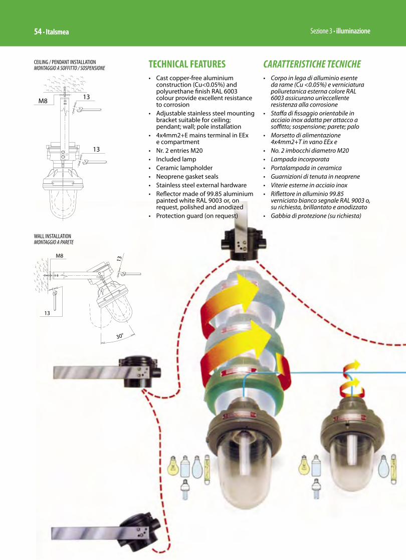
Sezione 3 • illuminazione54 • Italsmea
TECHNICAL FEATURES• Cast copper-free aluminium
construction (Cu<0.05%) and polyurethane finish RAL 6003 colour provide excellent resistance to corrosion
• Adjustable stainless steel mounting bracket suitable for ceiling; pendant; wall; pole installation
• 4x4mm2+E mains terminal in EEx e compartment
• Nr. 2 entries M20• Included lamp• Ceramic lampholder• Neoprene gasket seals• Stainless steel external hardware• Reflector made of 99.85 aluminium
painted white RAL 9003 or, on request, polished and anodized
• Protection guard (on request)
CARATTERISTICHE TECNICHE• Corpo in lega di alluminio esente
da rame (Cu <0.05%) e verniciatura poliuretanica esterna colore RAL 6003 assicurano un’eccellente resistenza alla corrosione
• Staffa di fissaggio orientabile in acciaio inox adatta per attacco a soffitto; sospensione; parete; palo
• Morsetto di alimentazione 4x4mm2+T in vano EEx e
• No. 2 imbocchi diametro M20• Lampada incorporata• Portalampada in ceramica• Guarnizioni di tenuta in neoprene• Viterie esterne in acciaio inox• Riflettore in alluminio 99.85
verniciato bianco segnale RAL 9003 o, su richiesta, brillantato e anodizzato
• Gabbia di protezione (su richiesta)
WALL INSTALLATIONMONTAGGIO A PARETE
CEILING / PENDANT INSTALLATIONMONTAGGIO A SOFFITTO / SOSPENSIONE
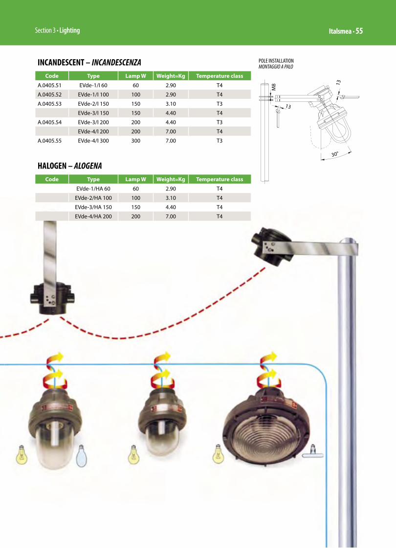
Section 3 • Lighting Italsmea • 55
INCANDESCENT – INCANDESCENZACode Type Lamp W Weight≅Kg Temperature class
A.0405.51 EVde-1/I 60 60 2.90 T4
A.0405.52 EVde-1/I 100 100 2.90 T4
A.0405.53 EVde-2/I 150 150 3.10 T3
EVde-3/I 150 150 4.40 T4
A.0405.54 EVde-3/I 200 200 4.40 T3
EVde-4/I 200 200 7.00 T4
A.0405.55 EVde-4/I 300 300 7.00 T3
HALOGEN – ALOGENACode Type Lamp W Weight≅Kg Temperature class
EVde-1/HA 60 60 2.90 T4
EVde-2/HA 100 100 3.10 T4
EVde-3/HA 150 150 4.40 T4
EVde-4/HA 200 200 7.00 T4
POLE INSTALLATIONMONTAGGIO A PALO
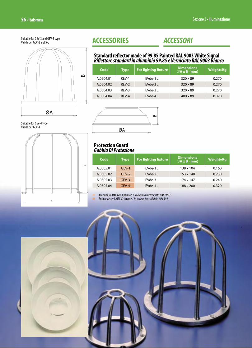
Sezione 3 • illuminazione56 • Italsmea
ACCESSORI ACCESSORIES
Standard refl ector made of 99.85 Painted RAL 9003 White SignalRifl ettore standard in alluminio 99.85 e Verniciato RAL 9003 Bianco
Code Type For lighting fi xture Dimensions∅A x B (mm) Weight≅Kg
A.0504.01 REV-1 EVde-1 ... 320 x 89 0.270
A.0504.02 REV-2 EVde-2 ... 320 x 89 0.270
A.0504.03 REV-3 EVde-3 ... 320 x 89 0.270
A.0504.04 REV-4 EVde-4 ... 400 x 89 0.370
Protection Guard Gabbia Di Protezione
Code Type For lighting fi xture Dimensions∅A x B (mm) Weight≅Kg
A.0505.01 GEV-1 EVde-1 ... 138 x 104 0.160
A.0505.02 GEV-2 EVde-2 ... 153 x 140 0.230
A.0505.03 GEV-3 EVde-3 ... 174 x 147 0.240
A.0505.04 GEV-4 EVde-4 ... 188 x 200 0.320
n Aluminium RAL 6003 painted / In alluminio verniciato RAL 6003n Stainless steel AISI 304 made / In acciaio inossidabile AISI 304
Suitable for GEV-3 and GEV-3 typeValida per GEV-2 e GEV-3
Suitable for GEV-4 typeValida per GEV-4

Sezione 3 • illuminazione50 • Italsmea
APPARECCHI ILLUMINANTI CON PARTI ELETTRICHE INCORPORATE PER LAMPADE A SCARICA FINO A 175W SERIE EVde ...
INERIS 01ATEX0019X
MODO DI PROTEZIONEEEx de IIC T3 / T200°CEEx de IIC T4 / T135°C(In accordo con quanto nelle successive tabelle per tipologia di lampada) Tamb. – 50°C / 40°C
– 50°C / 60°C
IP 65in conformità alle Norme Europee:EN 50014 EN 50018 EN 50019 EN 50281-1-1 EN 60529
idonee per Zona 1 (gas) e Zona 21 (polveri)
0080 II 2GDin accordo alla Direttiva Europea 94/9/CE (ATEX)
BUILT-IN CONTROL GEAR LIGHTING FIXTURES FOR HIGH INTENSITY DISCHARGE (H.I.D.) LAMPS UP TO 175W-EVde ... SERIES
INERIS 01ATEX0019X
MODE OF PROTECTIONEEx de IIC T3 / T200°CEEx de IIC T4 / T135°C(According with how much in the following tables for lamps typology)Tamb. – 50°C / 40°C
– 50°C / 60°C
IP 65compliance with European Standards:EN 50014 EN 50018 EN 50019 EN 50281-1-1 EN 60529
suitable for Zone 1 (gas) and Zone 21 (dusts)
0080 II 2GDaccording to European Directive 94/9/EC (ATEX)
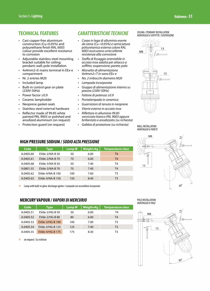
Section 3 • Lighting Italsmea • 51
HIGH PRESSURE SODIUM / SODIO ALTA PRESSIONECode Type Lamp W Weight≅Kg Temperature class
A.0405.60 EVde-2/NA-B 50 50 6.00 T4
A.0405.61 EVde-2/NA-B 70 70 6.00 T4
A.0405.68 EVde-3/NA-B 50 50 7.40 T4
9.0801.55 EVde-3/NA-B 70 70 7.40 T4
A.0405.62 EVde-4/NA-B 100 100 7.60 T3
A.0405.63 EVde-4/NA-B 150 150 8.40 T3
MERCURY VAPOUR / VAPORI DI MERCURIO Code Type Lamp W Weight≅Kg Temperature class
A.0405.51 EVde-2/HG-B 50 50 6.00 T4
A.0405.52 EVde-2/HG-B 80 80 6.00 T4
A.0405.53 EVde-3/HG-B 100 100 7.00 T3
A.0405.54 EVde-3/HG-B 125 125 7.40 T3
A.0405.55 EVde-4/HG-B 175 175 8.30 T3
n Lamp with built-in glow-discharge ignitor / Lampada con accenditore incorporato
TECHNICAL FEATURES• Cast copper-free aluminium
construction (Cu<0.05%) and polyurethane finish RAL 6003 colour provide excellent resistance to corrosion
• Adjustable stainless steel mounting bracket suitable for ceiling; pendant; wall; pole installation
• 4x4mm2+E mains terminal in EEx-e compartment
• Nr. 2 entries M20 • Included lamp• Built-in control gear on plate
(230V-50Hz)• Power factor ≥0.9• Ceramic lampholder• Neoprene gasket-seals• Stainless steel external hardware• Reflector made of 99.85 white
painted PAL 9003 or polished and anodized aluminium (on request)
• Protection guard (on request)
CARATTERISTICHE TECNICHE• Corpo in lega di alluminio esente
da rame (Cu <0.05%) e verniciatura poliuretanica esterna colore RAL 6003 assicurano un’eccellente resistenza alla corrosione
• Staffa di fissaggio orientabile in acciaio inox adatta per attacco a soffitto; sospensione; parete; palo
• Morsetto di alimentazione 4x4mm2+T in vano EEx-e
• No. 2 imbocchi diametro M20• Lampada incorporata• Gruppo di alimentazione interno su
piastra (230V-50Hz)• Fattore di potenza ≥0.9• Portalampada in ceramica• Guarnizioni di tenuta in neoprene• Viterie esterne in acciaio inox• Riflettore in alluminio 99.85
verniciato bianco PAL 9003 oppure brillantato e anodizzato (su richiesta)
• Gabbia di protezione (su richiesta)
n on request / Su richiesta
WALL INSTALLATIONMONTAGGIO A PARETE
CEILING / PENDANT INSTALLATIONMONTAGGIO A SOFFITTO / SOSPENSIONE
POLE INSTALLATIONMONTAGGIO A PALO

Sezione 3 • illuminazione52 • Italsmea
ACCESSORI ACCESSORIES
Standard refl ector made of 99.85 Painted Ral 9003 WhiteRifl ettore standard in alluminio 99.85 e Verniciato Ral 9003 Bianco Segnale
Code Type For lighting fi xture Dimensions∅A x B (mm) Weight≅Kg
A.0504.02 REV-2 EVde-2 ... 320 x 89 0.270
A.0504.03 REV-3 EVde-3 ... 320 x 89 0.270
A.0504.04 REV-4 EVde-4 ... 400 x 89 0.370
Protection Guard Gabbia di Protezione
Code Type For lighting fi xture Dimensions∅A x B (mm) Weight≅Kg
A.0505.02 GEV-2 EVde-2 ... 153 x 140 0.230
A.0505.03 GEV-3 EVde-3 ... 174 x 147 0.240
A.0505.04 GEV-4 EVde-4 ... 188 x 200 0.320
n Aluminium RAL 6003 painted / In alluminio verniciato RAL 6003n Stainless steel AISI 304 made / In acciaio inossidabile AISI 304
Suitable for GEV-3 and GEV-3 typeValida per GEV-2 e GEV-3
Suitable for GEV-4 typeValida per GEV-4
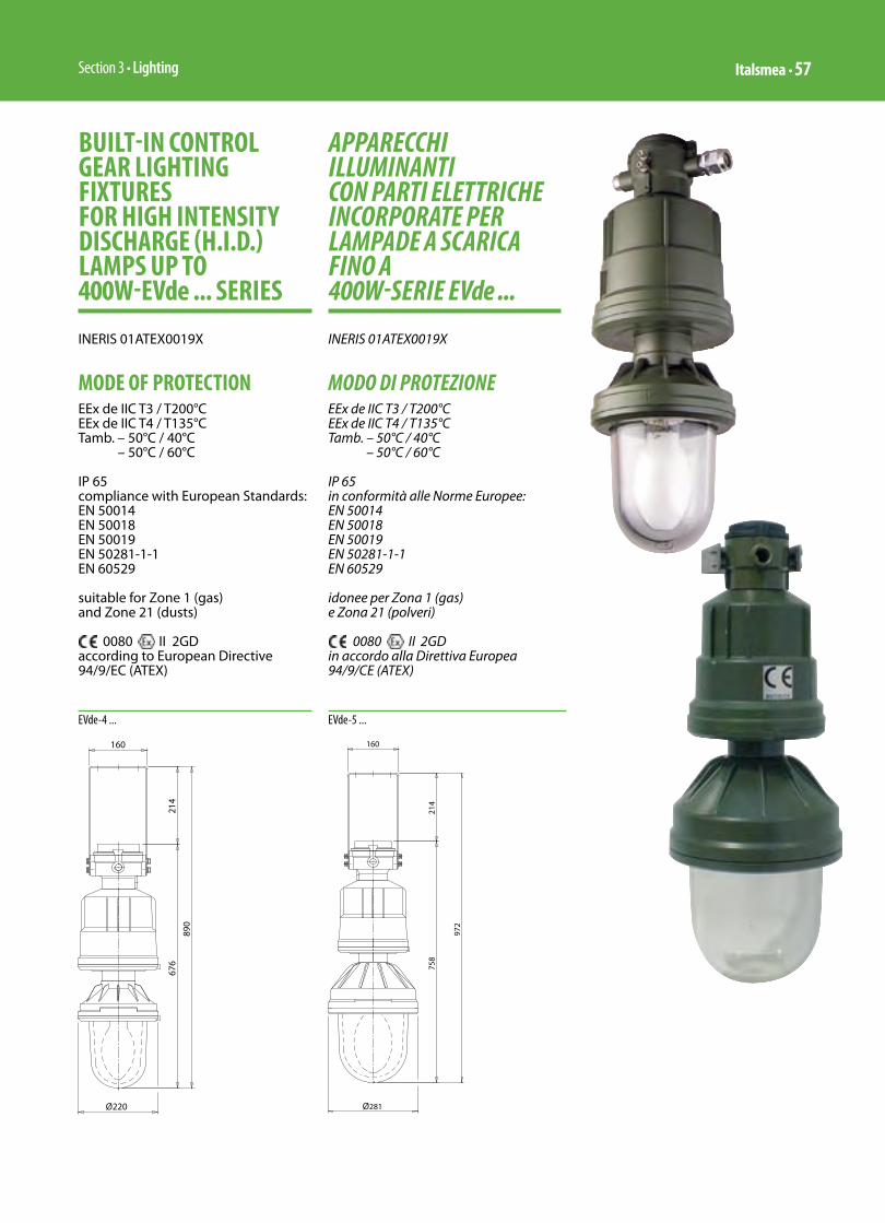
Section 3 • Lighting Italsmea • 57
APPARECCHI ILLUMINANTI CON PARTI ELETTRICHE INCORPORATE PER LAMPADE A SCARICA FINO A 400W-SERIE EVde ...
INERIS 01ATEX0019X
MODO DI PROTEZIONEEEx de IIC T3 / T200°CEEx de IIC T4 / T135°CTamb. – 50°C / 40°C
– 50°C / 60°C
IP 65in conformità alle Norme Europee:EN 50014 EN 50018 EN 50019 EN 50281-1-1 EN 60529
idonee per Zona 1 (gas) e Zona 21 (polveri)
0080 II 2GDin accordo alla Direttiva Europea 94/9/CE (ATEX)
BUILT-IN CONTROL GEAR LIGHTING FIXTURES FOR HIGH INTENSITY DISCHARGE (H.I.D.) LAMPS UP TO 400W-EVde ... SERIES
INERIS 01ATEX0019X
MODE OF PROTECTIONEEx de IIC T3 / T200°CEEx de IIC T4 / T135°CTamb. – 50°C / 40°C
– 50°C / 60°C
IP 65compliance with European Standards:EN 50014 EN 50018 EN 50019 EN 50281-1-1 EN 60529
suitable for Zone 1 (gas) and Zone 21 (dusts)
0080 II 2GDaccording to European Directive 94/9/EC (ATEX)
EVde-4 ... EVde-5 ...
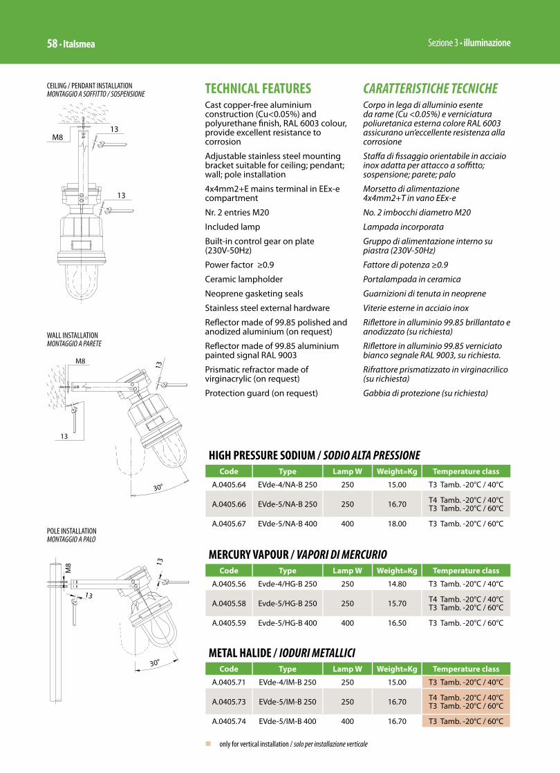
Sezione 3 • illuminazione58 • Italsmea
HIGH PRESSURE SODIUM / SODIO ALTA PRESSIONECode Type Lamp W Weight≅Kg Temperature class
A.0405.64 EVde-4/NA-B 250 250 15.00 T3 Tamb. -20°C / 40°C
A.0405.66 EVde-5/NA-B 250 250 16.70 T4 Tamb. -20°C / 40°CT3 Tamb. -20°C / 60°C
A.0405.67 EVde-5/NA-B 400 400 18.00 T3 Tamb. -20°C / 60°C
MERCURY VAPOUR / VAPORI DI MERCURIOCode Type Lamp W Weight≅Kg Temperature class
A.0405.56 Evde-4/HG-B 250 250 14.80 T3 Tamb. -20°C / 40°C
A.0405.58 Evde-5/HG-B 250 250 15.70 T4 Tamb. -20°C / 40°CT3 Tamb. -20°C / 60°C
A.0405.59 Evde-5/HG-B 400 400 16.50 T3 Tamb. -20°C / 60°C
METAL HALIDE / IODURI METALLICICode Type Lamp W Weight≅Kg Temperature class
A.0405.71 EVde-4/IM-B 250 250 15.00 T3 Tamb. -20°C / 40°C
A.0405.73 EVde-5/IM-B 250 250 16.70 T4 Tamb. -20°C / 40°CT3 Tamb. -20°C / 60°C
A.0405.74 EVde-5/IM-B 400 400 16.70 T3 Tamb. -20°C / 60°C
n only for vertical installation / solo per installazione verticale
TECHNICAL FEATURESCast copper-free aluminium construction (Cu<0.05%) and polyurethane fi nish, RAL 6003 colour, provide excellent resistance to corrosion
Adjustable stainless steel mounting bracket suitable for ceiling; pendant; wall; pole installation
4x4mm2+E mains terminal in EEx-e compartment
Nr. 2 entries M20
Included lamp
Built-in control gear on plate (230V-50Hz)
Power factor ≥0.9
Ceramic lampholder
Neoprene gasketing seals
Stainless steel external hardware
Refl ector made of 99.85 polished and anodized aluminium (on request)
Refl ector made of 99.85 aluminium painted signal RAL 9003
Prismatic refractor made of virginacrylic (on request)
Protection guard (on request)
CARATTERISTICHE TECNICHECorpo in lega di alluminio esente da rame (Cu <0.05%) e verniciatura poliuretanica esterna colore RAL 6003 assicurano un’eccellente resistenza alla corrosione
Staff a di fi ssaggio orientabile in acciaio inox adatta per attacco a soffi tto; sospensione; parete; palo
Morsetto di alimentazione 4x4mm2+T in vano EEx-e
No. 2 imbocchi diametro M20
Lampada incorporata
Gruppo di alimentazione interno su piastra (230V-50Hz)
Fattore di potenza ≥0.9
Portalampada in ceramica
Guarnizioni di tenuta in neoprene
Viterie esterne in acciaio inox
Rifl ettore in alluminio 99.85 brillantato e anodizzato (su richiesta)
Rifl ettore in alluminio 99.85 verniciato bianco segnale RAL 9003, su richiesta.
Rifrattore prismatizzato in virginacrilico (su richiesta)
Gabbia di protezione (su richiesta)
WALL INSTALLATIONMONTAGGIO A PARETE
CEILING / PENDANT INSTALLATIONMONTAGGIO A SOFFITTO / SOSPENSIONE
POLE INSTALLATIONMONTAGGIO A PALO

Section 3 • Lighting Italsmea • 59
ACCESSORI ACCESSORIES
Standard refl ector made of 99.85 painted RAL 9003 whiteRifl ettore standard in alluminio 99.85 e verniciato RAL 9003 bianco segnale
Code Type For lighting fi xture Dimensions∅A x B (mm) Weight≅Kg
A.0504.04 REV-4 EVde-4 ... 400 x 89 0.370
Dome refl ector made of 99.85 Polished and anodized aluminiumRifl ettore a duomo in alluminio 99.85 Brillantato e anodizzato
Code Type For lighting fi xture Weight≅Kg Note
A.0504.10 REVD-4 EVde-4 ... 0.800
Dome refl ector made of 99.85 Polished and anodized aluminiumRifl ettore a duomo in alluminio 99.85 Brillantato e anodizzato
Code Type For lighting fi xture Weight≅Kg Note
A.0530.79 REVD-5 Evde-5 ... 0.800
High bay refl ector made of 99.85 Polished and anodized aluminiumRifl ettore prismatizzato in alluminio 99.85 Brillantato e anodizzato
Code Type For lighting fi xture Weight≅Kg Note
A.0504.20 KFE EVde-4 ... / EVde-5 ... 1.150 available on request
Prismatic refractor made of virginacrylicRifrattore prismatizzato in virginacrilico
Code Type For lighting fi xture Weight≅Kg Note
A.0504.50 VERTEVA EVde-4 ... / EVde-5 ... 4.000 only for 250Wavailable on request

Sezione 3 • illuminazione82 • Italsmea
PROIETTORE SERIE FL..
INERIS 02ATEX0039
Proiettore per lampadine alogene ed a scarica
0080 II 2GD EEx-de IIB T3 T200°C
0080 II 2G Ex-de IIB+H2 T3
T amb. –50°C / +55°C
• Materiale: Lega di Alluminio • Verniciatura esterna RAL-6003• Verniciatura interna anticondensa• Viteria imperdibile e braccetto di
puntamento in acciaio inox• IP 65 con guarnizione su giunto
piano• Finestra incernierata• Riflettore interno in alluminio • Scatola di allacciamento linea
EEx-e con n.4 morsetti da 4 mm2. ponticellati due a due e corredata di No.2 imbocchi diam. M25 di cui uno con pressacavo a semplice tenuta tipo PNA 2 in ottone nichelcromato e uno con tappo in ottone nichelcromato
Completo di lampadina, di reattore, accenditore, condensatore di rifasamento
FLOODLIGHT FL..SERIES
INERIS 00ATEX0023X
Floodlight for halogen and discharge lamps
0080 II 2GD EEx-de IIB T3 T200°C
0080 II 2G Ex-de IIB+H2 T3
T amb. –50°C / +55°C
• Material: Copper free Aluminium• External painting RAL 6003• Internal paint anticondensation• Captive stainless steel screw and
stainless steel adjustable bracket• IP 65 with gasket on flat joint• Hinged window cover• Aluminium internal reflector• Power supply connection box EEx-e
with n.4 terminals 4 mm2 bridged two by two and No.2 M25 entries one plugged off and one with cable gland single seal PNA 2 brass nichel plated.
Complete with lamp, ballast, HPF capacitor, ignitor
Code Type Lamp Type Power W Voltage Weight ≅ Kg
418.14 FL 15 SA High Pressure Sodium 150 230-50Hz. 24,7
418.15 FL 25 SA High Pressure Sodium 250 230-50Hz. 25,8
418.19 FL 40 SA High Pressure Sodium 400 230-50Hz. 27,0
418.20 FL 25 IM Metal Halide 250 230-50Hz. 25,8
418.25 FL 40 IM Metal Halide 400 230-50Hz. 24,8
418.30 FL 25 HG Mercury Vapours 250 230-50Hz. 25,7
418.35 FL 40 HG Mercury Vapours 400 230-50Hz. 22,9
418.40 FL 50 HA Halogen 500 220 V 21,0
418.45 FL 14 HA Halogen 2x70 48 V 22,0

Section 3 • Lighting Italsmea • 83
Idoneo per:Zona 1 – Zona 21Zona 2 – Zona 22
Certifi cato di Esame CE del tipo:INERIS 00ATEX0023X
Suitable for:Zone 1 - Zone 21Zone 2 – Zone 22
Ec Type Examination Certifi cate: INERIS 00ATEX0023X
Code Type Lamp Type Power W Voltage
418.14 FL 15 SA High Pressure Sodium 150 220/230-50Hz.
418.15 FL 25 SA High Pressure Sodium 250 220/230-50Hz.
418.19 FL 40 SA High Pressure Sodium 400 220/230-50Hz.
418.20 FL 25 IM Metal Halide 250 220/230-50Hz.
418.25 FL 40 IM Metal Halide 400 220/230-50Hz.
418.30 FL 25 HG Mercury Vapours 250 220/230-50Hz.
418.35 FL 40 HG Mercury Vapours 400 220/230-50Hz.
418.40 FL 50 HA Halogen 500 220 V
418.45 FL 14 HA Halogen 2x70 48 V
Type CodeLamp Weight
Kg
Weight Package
Kg
O.D. Packing
Type Wattage Shape
FL 15 SA 418.14 S.A.P. 150 Tubular 22,7 24,7
FL 25 SA 418.15 S.A.P. 250 Tubular 23,8 25,8
FL 40 SA 418.19 S.A.P. 400 Tubular 25,0 27,0
FL 25 IM 418.20 I.M. 250 Tubular 23,8 25,8
FL 40 IM 418.25 I.M. 400 Tubular 22,8 24,8
FL 25 HG 418.30 V.M. 250 Ellipsoidal 23,7 25,7
FL 40 HG 418.35 V.M. 400 Tubular 20,9 22,9
FL 50 HA 418.40 AL. 500 T.D.E. 19,0 21,0
FL 14 HA* 418.45 2 AL. 2x70 Quarts UV fi lter 20,0 22,0
n voltage supply 48V / tensione di alimentazione 48Vn 560x360x320 mm.
LEGENDA:S.A.P High Pressure Sodium / Sodio Alta PressioneI.M . Metal Halide / Ioduri MetalliciV.M. Mercury Vapours / Vapori di MercurioAL. Halogen / Alogena2 AL. 2 Halogen / 2 AlogeneT.D.E. Tubular Double Envelope / Tubolare Doppio Involucro

Sezione 3 • illuminazione84 • Italsmea
Contenitore in fusione di lega leggera di Alluminio, titolata con bassa percentuale di Rame ( inferiore a 0,05%) GalSi- 9 UNI-3051 con alta resistenza alla corrosione sia da idrocarburi che da acqua di mare.
Trattamenti superficiali:esterno : verniciatura poliuretanica ciclo Italsmea colore verde oliva Ral-6003 spessore minimo garantito 80 ( Micron) applicazione a spruzzo in cabina climatizzata e polimerizzazione a forno.interno : verniciatura vellutato anticondensa colore Ral-7032superfici non verniciate ( giunti di laminazione ) : fosfatazione in bagno a ciclo controllato ; protezione successiva con gel anticorrosione stabilizzato per temperature da : -50 / +300°C ( chimicamente e fisicamente inerte )
Equipaggiamento elettrico interno:alimentatore 230V 50Hz. a basse perdite, di potenza correlata alla relativa lampadina a scarica accenditore a tre fili, atto a resistere alle sollecitazioni delle elevate temperature di eserciziocondensatore di rifasamento (fattore di potenza > 0,9), isolamento in polipropilene 450V con blindatura esterna per funzionamento continuo ad alta temperaturaportalampada ceramico E-40, antiallentante lampadina tubolare per tutte le grandezze ad esclusione della grandezza 250W Mercurio ( ellissoidale ) e 2 x 70 alogena tipo spot .cablaggio speciale in cavetto unipolare flessibile isolato in gomma siliconica e guaina esterna in fibra di vetro
Allacciamento alla rete elettrica di alimentazione in vano EEx-e posteriore ricavato sul corpo stesso dell’apparecchio corredato di :
• 4 morsetti da 4 mmq, ponticellati a due a due
• 2 morsetti di terra da 4 mmq. giallo verdi
• pressacavo a semplice tenuta tipo PNA-2 M25 x 1,5 atto a serrare un cavo diam. esterno da 6 a 17 mm. oppure dello stesso diametro, sotto armatura.
• 1 tappo M25 x 1,5 di chiusura del secondo ingresso disponibile per eventuale looping tra due o più proiettori attigui senza la necessita’ dell’aggiunta di una scatola di derivazione.
Peso dell’apparecchio ridotto a circa la metà rispetto alle proposte del mercato
Grado di protezione meccanica IP-65 in versione standard per tutte le posizioni di funzionamento
Enclosure copper free Aluminium, title of Copper less then 0,05%, LM-9 British Standard, high corrosion resistant for hydrocarbon and sea salt water
Surface treatment:outer : polyurethane paint Italsmea cycle color green Ral-6003granted minimum thickness 80(microns) spay cabinet with air-conditioned, polymerization in oven inner : anticondesation corrugated effect paint color Ral-7032unpainted surface (lamination joints) : phosphate bath with monitorcycle then protected stable between: -50 / + 300° C (Chemically and phisically stable)
Internal electrical components :low losses integral ballast 230V, power related the lamp sizeignitor 3 wires, suitable to withstand to high running temperature capacitor for power factor correction to 0,9, polypropylene insulated 450V, with outer enclosure for continuos running at high temperature,ceramic lampholder E-40 with antiloosening terminalstubular lamp for all sizes excluding the size 250 W Mercury (elliptical shape)and 2 x 70W spot halogen special wiring made by single core flexible cable silicon rubber isolated and glass fiber outer braided
Connection to electric network via the back side EEx-e compartment of floodlight body c/w:
• 4 terminals 4 sqmm, bridged 2 by 2
• 2 earth yellow green terminals 4 sqmm.
• 1 cable gland single seal PNA.2 M25 x 1,5 suitable to tight a cable with O.D. between 6 and 17 mm. or under armour OD of same size for armoured cable.
• 1 M25 x 1,5 blanking plug for available second entry (compchiem) looping between 2 or more floodlight on same grid without any added junction box.
Low weight, around 50 % lighter then similar items available in the market
Mechanical protection IP-65 standard version for all working positions.
Sealing between floodlight cover and body done by unloosable gasket housed in channel with special shape directly on flat flameproof joint (First realization certified EEx-d according to Cenelec).
FL.. PHOTOMETRIC CURVE FOR 1000 LMNARROW BEAM REFLECTORCURVA FOTOMETRICA PER 1000 LMRIFLETTORE CONCENTRANTE
Date: 24-03-2006
1. Luminaire Details
1.1 Project Luminaires
Luminaire Name : FL40SA/REFL'U'TYPELamp name : SON(T)400WNumber of lamps/luminaire : 1Lamp flux : 47500 lmLight output ratios DLOR : 0.68 ULOR : 0.00 TLOR : 0.68Luminaire wattage : 446.0 WMeasurement code : F532
Note: Luminaire data not from database.
500
0o 30o30o
60o 60o
90o 90o
120o 120o150o 150o180o
C = 180o C = 0o C = 270o C = 90o C = 280o Imax C = 100o
Luminous Intensity Diagram (candela/1000 lumen)
CalcuLuX Area 3.0 Philips Lighting B.V. Page: 1/1
Date: 24-03-2006
1. Luminaire Details
1.1 Project Luminaires
Luminaire Name : FL40SA/REFL'W'TYPELamp name : SON(T)400WNumber of lamps/luminaire : 1Lamp flux : 47500 lmLight output ratios DLOR : 0.54 ULOR : 0.00 TLOR : 0.54Luminaire wattage : 446.0 WMeasurement code : F531
Note: Luminaire data not from database.
250
0o 30o30o
60o 60o
90o 90o
120o 120o150o 150o180o
C = 180o Imax C = 0o C = 270o C = 90o
Luminous Intensity Diagram (candela/1000 lumen)
CalcuLuX Area 3.0 Philips Lighting B.V. Page: 1/1
MEDIUM BEAM REFLECTORRIFLETTORE SEMIDISSONDENTE

Section 3 • Lighting Italsmea • 85
Stainless steel (AISI 304) captive screws
Stainless steel (AISI-304) bracket, adjustable on vertical and horizontal plane over 360°, with U profi le of rugged construction.
Window-cover with hinged drop frame, borosilicate glass treated to withstand thermal and mechanical shocks.
Internal refl ector, symmetrical distribution with narrow beam pure polished aluminium, fi xed to body by a safe wire even when removed during maintenance.
ottenuto, nell’accoppiamento tra coperchio e corpo del proiettore, mediante una guarnizione imperdibile collocata in cava di allogiamento con sagoma speciale ricavato su giunto di laminazione piano. (prima realizzazione del genere certifi cata EEx-d a norme Cenelec)Viteria imperdibile in AISI-304
Staff a di robusta costruzione realizzata con profi lo a “U” in AISI 304 orientabile a 360° sui due piani.
Coperchio-fi nestra con montanti incernierati, completamente ribaltabile, parte trasparente in vetro-borosilicato opportunamente trattato per resistere agli shocks termici e meccanici
Rifl ettore interno, per distribuzione simmetrica a fascio concentrante, in alluminio brillantato, solidale, al corpo proiettore tramite fune di guardia anche quando rimosso per manutenzione alle parti elettriche.
ACCESSORI E VERSIONI A RICHIESTA• Esecuzione con trattamento delle
superfi ci per piattaforme marine a per ambienti particolarmente corrosivi: ciclo di verniciatura nomale con aggiunta di lavaggio demineralizzato e successiva fosfatocromatazione “O.P.S.E. Italsmea“
• colorazione esterna a richiesta nell’ambito della classifi cazione Ral
• rifl ettore satinato per distribuzione luce medio diff ondente
• rifl ettore bugnato per distribuzione luce diff ondente
• defl ettore luce frontale anti- abbagliamento a griglia orizzontale
• defl ettore luce frontale anti abbagliamento a griglia verticale
• accessorio per attacco testa.palo (palo da 2”)
• tensioni e frequenze di alimentazione SU RICHIESTA:- 240 V 50 o 60 Hz - 254 V 60 Hz- 120 V 60 Hz- 127 V 50 o 60 Hz- 208 V 60 Hz
• gabbia di protezione antivandalismo frontale in Aisi 304
• griglia testapalo per : - 2 proiettori in batteria - 4 proiettori in batteria- 2 proiettori contrapposti- 3 proiettori disposti a 120° - 2 proiettori disposti a 90°
ACCESSORIES AND VERSIONS ON REQUEST• off -shore version with surface
treatment for oil platforms and corrosive environments : standard painting cycle improved with demineralized wash and fosfatocromatization “ O.P.S.E. Italsmea“
• external color ON REQUEST choice between Ral classifi cation
• sand blasted refl ector for medium beam
• hammered refl ector for wide beam • front light horizontal antiglare grid • front light vertical antiglare grid• top-pole mounting kit (pole size 2”)• voltages and frequencies ON
REQUEST:- 240 V 50 o 60 Hz - 254 V 60 Hz- 120 V 60 Hz- 127 V 50 o 60 Hz- 208 V 60 Hz
• front protection guard Aisi 304 made
• top pole grid for - 2 fl oodlights on rack side to side- 4 fl oodlights on rack top/bottom
by 2 side to side- 2 fl oodlight on rack back to back- 3 fl oodlights on rack at 120°- 2 fl oodlights on rack at 90 °

Sezione 3 • illuminazione86 • Italsmea
Spare parts list floodligh FL seriesLista parti di ricambio proiettore serie FL
n Code Description
1 R041802 Floodlight Cover / Coperchio Proiettore
2 P041815 Cover Gasket / Guarnizione Coperchio
3 * Lamp / Lampadina
4 P041809 Reflector / Riflettore
5 * Ballast / Alimentatore
6 Ballast Mounting Bracket / Staffa montaggio alimentatore
7 R041801 Floodlight Body / Corpo proiettore
8 * Ignitor / Accenditore
9 A140011 Plug Gasket / Guarnizione Tappo
10 G122200 Plug / Tappo
11 P041816 Terminal box gasket / Guarnizione Scatola Morsettiera
12 5146023 Earth terminal / Morsetto di terra
13 R041803 Terminal box cover / Coperchio scatola morsettiera
14 A050804 Lampholder E40 / Portalampada E40
15 P041824 Sealed Nipple / Nipplo miscelato
16 P041810 Lampholder mounting racket / Staffa montaggio portalampada
17 * Capacitor / Condensatore
18 P041821 Floodlight mounting racket / Staffa montaggio proiettore
19 A140025 Cable Gland / Pressacavo
20 P008160 External earthing screw / Vite di terra esterna
21 P041857 Terminal Rail / Guida portamorsetti
22514600151183685168516
Terminals / MorsettiTerminals end bracket / Piastrina Terminale MorsettiTerminal Bridge / Ponticello Morsetti

Section 3 • Lighting Italsmea • 87
ESECUZIONI NORMALIZZATE PER IMPIEGHI SPECIALIProiettore con kit telescopico mobile normalizzato Italgas s.p.a.cod. Aplog/Log-Gestilog : GAS-D3
• proiettore FL-2x70-HA con due lampadine alogene da 70W, alimentazione 48V con griglia frontale in acciaio inossidabile
• cavo di allacciamento con armatura metallica a maglia, lunghezza 15 m., spina di connessione a generatore posto al di fuori della zona classifi cata o altra alimentazione elettrica, a passo CEE-17 x 48V braccetto orientabile con perno per innesto a cavalletto mobile
• cavalletto mobile telescopico con azionamento a manovella, in acciaio cromato , altezza massima di estensione 247cm.
Proiettori normalizzati a livello mondiale da shell oil m.e.s.c. No. 69.56.23.520.1 a 69.56.23.544.1.dettaglio per tipologia di lampada come da normalizzazione ShellProiettori normalizzati N.A.T.O. per impieghi su unità logistiche militari codice no. .NSN 5975-17-109-2235Proiettori per illuminazione zona abbandono piattaforma ammaraggio “Life boat” della serie FL-2x70-HA con lampade alogene da 50 o 70W con ciascuna retroparabola concentrante, adatti per collegamento a circuiti di emergenza alimentati da batterie di accumulatori previsti sui circuiti abbandono piattaforma/nave. Il fascio concentrante prodotto è studiato per illuminare la superfi cie di mare prospiciente la lancia di salvataggio per facilitare le operazione di ammaraggio della lancia stessa e costituire un punto di riferimento “lancia di salvataggio“ per “uomo in mare”.
SPECIFIED VERSION FOR SPECIAL SERVICESFloodlight with wind-up stand italgas specifi ed cod. Aplog/log-gestilog: GAS-d3
• fl oodlight FL-2x70-HA with 2 halogen spot lamps 70W, voltage supply 48V, with front stainless steel guard , steel wire braided cable 15mt. length, electrical plug for connection to generation set located in safe area or to any other compatible electrical supply contact confi guration CEE-17 x 48V.
• adjustable bracket with shaft for plug-in wind-up stand
• wind-up movable stand steel chrome plated, maximum high 247cm.
Floodlight world wide Shell Oil specifi ed M.e.s.c. no. 69.56.23.520.1 to 69.56.23.544.1 details with lamps in Shell standardizationN.A.T.O. standarization fl oodlight specifi ed for military purposes code NSN 5795-17-109-2235Floodlight for lighting the escape platform/ship area “Life boat”FL-2x70-HA series with 2 halogen lamps 50 or 70W each with backrefl ector for narrow beam , suitable for connection to emergency circuit powered by batteries always available on escape platform circuits. The narrow beam issued is lighting the sea surface below the safe boat to aid the life boat splash-down and as sign “ life boat “ for“ man in water “

Sezione 3 • illuminazione88 • Italsmea
PROIETTORI IN ACCIAIO INOSSIDABILE AISI-316 SERIE FL/316:Al fi ne di soddisfare alle crescenti richieste di un apparecchio assolutamente inattaccabile dalla corrosione di origine combinata: marina + idrocarburi, provenienti dal comparto off -shore dell’industria petrolifera in conseguenza degli altissimi costi di manutenzione sia ordinaria che, ancor più’ straordinaria, Italsmea a sviluppato ed ingegnerizzato la produzione di una serie di proiettori gemelli alla serie FL ove la lega titolata di Alluminio e stata completamente sostituita dall’impiego di acciaio inossidabile Aisi-316. Grazie ad una esclusiva tecnica di fonderia e’ stato possibile ottenere getti di fusione in 316 con titolo garantito e soprattutto renderli lavorabile alle macchine utensili, mantenendo spessori e forme della versione originale di alluminio e contenendo l’inevitabile aumento di peso conseguente alla diff erenza dei pesi specifi ci di acciaio e alluminio al minimo indispensabile.Nella tabella seguente ripetiamo le tipologie disponibili elencate a seconda della lampadina adottata; per tutte le altre caratteristiche ed accessori vale quanto indicato per la serie FL/Alluminio.
FLOODLIGHTS STAINLESS STEEL AISI-316 MADE FL/316 SERIESWith the intent to answer to the off shore market need of a totally corrosion proof apparatus able to withstand the combined action of salty marine and hydrocarbons environments has been studied and developed the FL/316 series. The high cost of ordinary and extraordinary maintenance on oil platforms fully justifi es the replacement of Aluminum light alloy with Stainless steel 316. The exclusive foundry know-how allowed Italsmea to cast and to machine units Aisi 316 made with L title and with same shape and thickens of Aluminum version also reducing to the lowest possible the weight.In the following table we are listed the fl oodlights type number identifi ed per lamp’s wattage and features : for all other data and accessories refers to FL/ Aluminum version.
TypeLamp Weight
Kg
Weight Package
Kg
O.D. Packing
Type Wattage Shape
FL 15 SA/316 S.A.P. 150 Tubular 48,2 50,2
FL 25 SA/316 S.A.P. 250 Tubular 49,3 51,3
FL 40 SA/316 S.A.P. 400 Tubular 50,5 52,5
FL 25 IM/316 I.M. 250 Tubular 49,3 51,3
FL 40 IM/316 I.M. 400 Tubular 48,3 50,3
FL 25 HG/316 V.M. 250 Ellipsoidal 49,2 51,2
FL 40 HG/316 V.M. 400 Tubular 45,5 47,5
FL 50 HA/316 AL. 500 T.D.P.
FL 14 HA/316 2 AL. 2x70 Quarts UV fi lter
n voltage supply 48V / tensione di alimentazione 48Vn 560x360x320 mm.
LEGENDA:S.A.P High Pressure Sodium / Sodio Alta PressioneI.M . Metal Halide / Ioduri MetalliciV.M. Mercury Vapours / Vapori di MercurioAL. Halogen / Alogena2 AL. 2 Halogen / 2 AlogeneT.D.P. Tubular Double Envelope / Tubolare Doppio Involucro
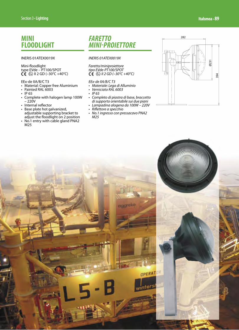
Section 3 • Lighting Italsmea • 89
MINI FLOODLIGHT
INERIS 01ATEX0019X
Mini-fl oodlight type EVde – PT100/SPOT
II 2 GD (–30°C +40°C)
EEx-de IIA/B/C T3 • Material: Copper free Aluminium• Painted RAL 6003• IP 65• Complete with halogen lamp 100W
– 220V• Internal refl ector• Base plate hot galvanized,
adjustable supporting bracket to adjust the fl oodlight on 2 position
• No.1 entry with cable gland PNA2 M25
FARETTOMINI-PROIETTORE
INERIS 01ATEX0019X
Faretto/miniproiettore tipo EVde-PT100/SPOT
II 2 GD (–30°C +40°C)
EEx-de IIA/B/C T3 • Materiale: Lega di Alluminio• Verniciato RAL 6003• IP 65• Completo di piastra di base, braccetto
di supporto orientabile sui due piani• Lampadina alogena da 100W – 220V• Rifl ettore a specchio • No.1 ingresso con pressacavo PNA2
M25
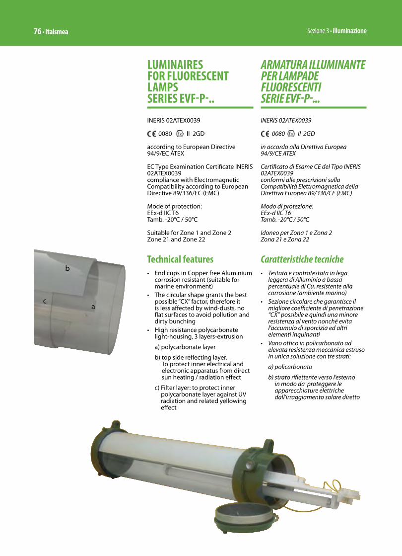
Sezione 3 • illuminazione76 • Italsmea
ARMATURA ILLUMINANTE PER LAMPADE FLUORESCENTI SERIE EVF-P-...
INERIS 02ATEX0039
0080 II 2GD
in accordo alla Direttiva Europea 94/9/CE ATEX
Certificato di Esame CE del Tipo INERIS 02ATEX0039conformi alle prescrizioni sulla Compatibilità Elettromagnetica della Direttiva Europea 89/336/CE (EMC)
Modo di protezione: EEx-d IIC T6 Tamb. -20°C / 50°C
Idoneo per Zona 1 e Zona 2 Zona 21 e Zona 22
Caratteristiche tecniche• Testata e controtestata in lega
leggera di Alluminio a bassa percentuale di Cu, resistente alla corrosione (ambiente marino)
• Sezione circolare che garantisce il migliore coefficiente di penetrazione “CX” possibile e quindi una minore resistenza al vento nonché evita l’accumulo di sporcizia ed altri elementi inquinanti
• Vano ottico in policarbonato ad elevata resistenza meccanica estruso in unica soluzione con tre strati:
a) policarbonato
b) strato riflettente verso l’esterno in modo da proteggere le apparecchiature elettriche dall’irraggiamento solare diretto
LUMINAIRES FOR FLUORESCENT LAMPS SERIES EVF-P-..
INERIS 02ATEX0039
0080 II 2GD
according to European Directive 94/9/EC ATEX
EC Type Examination Certificate INERIS 02ATEX0039compliance with Electromagnetic Compatibility according to European Directive 89/336/EC (EMC)
Mode of protection:EEx-d IIC T6 Tamb. -20°C / 50°C
Suitable for Zone 1 and Zone 2 Zone 21 and Zone 22
Technical features• End cups in Copper free Aluminium
corrosion resistant (suitable for marine environment)
• The circular shape grants the best possible “CX” factor, therefore it is less affected by wind-dusts, no flat surfaces to avoid pollution and dirty bunching
• High resistance polycarbonate light-housing, 3 layers-extrusion
a) polycarbonate layer
b) top side reflecting layer. To protect inner electrical and electronic apparatus from direct sun heating / radiation effect
c) Filter layer: to protect inner polycarbonate layer against UV radiation and related yellowing effect
a
b
c
Section 3 • Lighting Italsmea • 77
• Thanks to polycarbonate-made light housing the total weight is around 4 Kg. Less then traditional corresponding EEx-d lighting fixtures with heavy borosilicate tubes for twin lamp only
• Suitable for two pins fluorescent lamps G13 socket (not included)
• High frequency electronic ballast 220-240V + / - 10% (50/60 Hz)
• Power factor > 0,95• Two opposite M20 pitch 1,5 metric-
threaded entries. One plugged-off by brass nickel plated EEx-d plug with relevant gasket
• Mechanical protection IP-66• In all EVF-P, out of size of lamps
(18-36-58W), the length of O-ring gasket is only 396 millimetres; it is a continuous gasket, and it is totally protected against sun UV-radiations (responsible of the aging effects) by means of a cave in the aluminium body. The pressure on the gasket is constant all over its length.
• AISI 304 stainless steel external hardware and screws
• Aluminium end cups and cover painted by green colour polyurethane painting cycle, RAL 6003
• Steel made white coated internal reflector. Totally protected against pollution and corrosion. It is also a support for electrical equipment. Fully withdrawable in order to allow an easy re-lamping and maintenance.
• The screw-cover of EVFP, when opened, will stand linked to the body of the lighting fixtures by mean of a stainless steel chain
• Accessories available upon request: • Swiveling ceiling mouting kit,
stainless steel AISI 304 made, type G3
• suspension kit stainless steel AISI 304 made, type H
• pole mounting kit stainless steel AISI 304 made, type P14
• 3° bottom entry M20
c) strato “filtro” che protegge il policarbonato dalle radiazioni UV evitandone l’ingiallimento
• Il vano ottico in policarbonato fa si che il peso totale dello stesso sia di circa 4 Kg. Inferiore alla corrispondente tradizionale armatura EEx-d con tubi in vetro borosilicato per bilampada solamente
• Adatta per lampadine tubolari bi-spina con attacco G13 (escluse dalla fornitura)
• Alimentatore ad alta frequenza 220-240V + / - 10% (50/60 Hz)
• Fattore di potenza > 0,95• Ciascuna armatura è provvista di 2
imbocchi filettati M20, di cui uno chiuso con tappo EEx-d in ottone nichelato e relativa guarnizione di battuta
• Grado di protezione IP-66• In tutte le armature EVF-P,
indipendentemente dalla potenza delle lampade (18-36-58W), la lunghezza della guarnizione O-ring è di soli 396 millimetri; è una guarnizione continua ed è totalmente protetta dalle radiazioni solari (responsabili dell’invecchiamento della guarnizione). Infatti l’OR si trova protetto in una apposita cava, ricavata nel corpo di alluminio dell’armatura. La pressione esercitata sulla guarnizione del coperchio risulta costante e calibrata su tutta la lunghezza
• Viteria esterna in acciaio inossidabile AISI 304
• Verniciatura poliuretanica verde RAL 6003 delle testate
• Riflettore interno dell’armatura totalmente protetto dagli elementi atmosferici ed ambientali. Realizzato in lamiera verniciata colore bianco, semilucido, il riflettore svolge anche la funzione di supporto per l’equipaggiamento elettrico. E’ totalmente estraibile, per facilitare manutenzione e “re-lamping”
• Il coperchio di accesso ad accoppiamento filettato, rimane solidale al corpo dell’armatura anche in condizione di apertura, tramite apposita catenella in acciaio inossidabile
• Accessori disponibili su richiesta:• Kit per montaggio a soffitto,
basculante tipo G3• Kit per montaggio a sospesione
tipo H• Kit per montaggio a palo tipo P14• 3° imbocco, lato inferiore, M20
EVF-P 218-236-258PHOTOMETRIC CURVE FOR 1000 LM WITH 2 LAMPSCURVA FOTOMETRICA PER 1000 LM CON 2 LAMPADE
EVF-P 118-136-158PHOTOMETRIC CURVE FOR 1000 LM WITH 1 LAMPCURVA FOTOMETRICA PER 1000 LM CON 1 LAMPADA
Sezione 3 • illuminazione78 • Italsmea
Selection TableTabella di Selezione
TypeRMS-560* Code Number
of lampsLamps power
Overall Dimensions mm. Weight
Kgs.A B C
423.00 EVF-P 118 1 1x18W 764 176 194 6
424.00 EVF-P 136 1 1x36W 1374 176 194 8
425.00 EVF-P 158 1 1x58W 1680 176 194 9
426.00 EVF-P 218 2 2x18W 764 176 194 6
427.00 EVF-P 236 2 2x36W 1374 176 194 8
428.00 EVF-P 258 2 2x58W 1680 176 194 10

Sezione 3 • illuminazione60 • Italsmea
ARMATURE PER LAMPADE FLUORESCENTI SERIE RMS 540...
DATI TECNICI IP 65 – CLASSE I -
230V 50Hz con alimentatore elettromeccanico
Fattore di potenza ≥0,9Condensatore con resistenza di scarica incorporata
conformi alla Norma Europea EN 60598-1EN 60598-2-1
conformi alle prescrizioni sulla Compatibilità Elettromagnetica (EMC) della Direttiva 89/336/CE
CARATTERISTICHE• Corpo di acciaio inossidabile AISI
304 spessore 0,8 mm. ottenuto, da stampo per imbutitura profonda, in blocco unico senza saldature.
• Cornice portavetro di acciaio inossidabile AISI 304 spessore 1 mm. ottenuto, da stampo e trancia, in blocco unico senza saldature.
• Sistema di chiusura corpo-cornice a cerniera con serraggio mediante viti imperdibili tipo TCEI di acciaio inossidabile AISI 304.
• Vano ottico con finestra in vetro temperato spessore 4 mm. sigillato alla cornice tramite cordone continuo di silicone.
• Guarnizione di tenuta, tra cornice e corpo, di gomma siliconica (cellule chiuse) a sezione ogivale, alloggiata
LUMINAIRES FOR FLUORESCENT LAMPS RMS 540... SERIES
TECHNICAL DATA IP 65 – CLASS I
230V 50Hz with electromechanical ballast
Power factor ≥0,9Capacitor with incorporated discharge resistance
compliance with European Standard EN 60598-1EN 60598-2-1
compliance with Electromagnetic Compatibility (EMC) according to Directive 89/336/EC
FEATURES• Stainless steel AISI 304 th. 0,8 mm.
body, made by moulding for deep pressed, done in one unit without welding.
• Stainless steel AISI 304 th. 1 mm. glass-frame, pressed and cut by moulding, done in one unit without welding.
• Body/glass-frame hinged closing device, with cylindrical head recessed hexagonal key unloosable screws stainless steel AISI 304 made.
• Glass tempered window th. 4 mm, sealed on frame by a continuous silicon ring.
• Special cross section tightness gasket, silicon rubber made (closed cells), located in housing

Section 3 • Lighting Italsmea • 61
channel between body and window frame. When completely secured the closing between body and window frame, a mechanical contact between the metal parts stop the pressure on gasket. To grant it a maintained elastic memory.
• Stainless steel AISI 304 th. 1 mm internal “reglette” white painted fi xed on two supports with“screw-transfer” looking device system.
• The “reglette” is foreseen with two suspension wires granting the self support when lighting fi xtures is open for start-up operation or maintenance.
• Wiring by PVC 105°C rigid cable. Lampholder suitable for fl uorescent two-pins lamps type TL-D Philips or similar. Anti-loosening 2P+E (L-N-E) terminal strip, melamine made, for power supply connection. Yellow green single core earth wire for body and “reglette” equipotential connection. Spare for a loop to the earth tag of cable gland for power supply cable.
• Body complete of two diam. 21mm through holes for cable entries, one complete of metallic plug with lock nut and gasket, the other one with plastic plug for dust protection.
• Mechanical protection IP-65
in apposita canala. Battuta meccanica dell’accoppiamento atta a garantire il mantenimento della memoria elastica della guarnizione.
• Reglette-rifl ettore interna di acciaio inossidabile AISI 304 spessore 1 mm. verniciata “bianco” montata su due supporti con serraggio ad eccentrico traslato.
• La reglette, è prevista con due funi di sospensione, che ne consentono l’auto-supporto in condizione di armatura aperta per messa in servizio, o manutenzione.
• Cablaggio in cavetto rigido isolato in PVC 105°C alloggiato in canalina di resina con coperchio. Portalampada per lampada fl uorescente bispina TL-D Philips o similare. Morsetto antiallentante in melamina 2P+T (L-N-E) per allacciamento linea di alimentazione. Filo di terra giallo-verde, per equipotenzialità corpo-reglette, predisposto per la connessione al pressacavo di ingresso linea per messa a terra solidale dell’eventuale armatura metallica del cavo di alimentazione.
• Corpo previsto con due imbocchi passanti diam. 21mm per entrate cavo di cui, uno corredato di tappo metallico completo di controdado e guarnizione, l’altro di tappo salvapolvere in plastica.
• Grado di protezione IP-65
RMS..-1x18W/36PHOTOMETRIC CURVE FOR 1000 LM WITH 1 LAMPCURVA FOTOMETRICA PER 1000 LM CON 1 LAMPADA
RMS..-2x18W/36PHOTOMETRIC CURVE FOR 1000 LM WITH 1 LAMPCURVA FOTOMETRICA PER 1000 LM CON 1 LAMPADA

Sezione 3 • illuminazione62 • Italsmea
• The shapes of RMS lighting fi xtures has been studied to allow operator working with free hands and no need to support any part of lighting fi xtures. One person can take care of start-up or maintenance of a RMS lighting fi xture without any aid and assistance.
ADVANTAGES• High corrosion resistance due to
the components stainless steel AISI 304 and tempered glass made.
• No through holes between inside and outside of luminaries, out of hole for power supply cable whatever protected by a suitable waterproof cable gland (on request). Therefore, during the time, release would be possible where, for fi xing devices, there are through holes and relevant gaskets.
• Very low pollution at the end of operative life time of lighting fi xtures. The new European Directives will require, starting from 2005, that manufacturer, at time of supply, have to include in selling price, the cost for the buy-back and goods recycle. Recycle to be done according to pollution rules. The inorganic materials used for RMS, like stainless steel and glass, allow a recycle of 95%, only electrical components and insulation of single core wires need some more care.
• L’assetto dell’armatura RMS, è stato studiato in modo tale che, in tutte le condizioni d’uso, l’operatore sia in grado di lavorare con entrambe le mani libere dalla necessità di sostenere parti dell’armatura stessa. Un solo operatore, senza l’aiuto di un assistente, può installare o manutendere un’armatura RMS.
VANTAGGI• Elevata resistenza alla corrosione
stante la totalità dei componenti metallici in acciaio inossidabile AISI 304 in accoppiamento alla fi nestra in vetro temperato.
• Nessun foro passante tra interno ed esterno armatura ad esclusione dell’inevitabile ingresso per l’alimentazione elettrica, comunque protetto da pressacavo ad elevata tenuta stagna (fornibile su richiesta). Pertanto nel tempo non sono presumibili decadimenti del grado di protezione, prevedibili invece laddove, per staff aggi fossero previsti fori passanti tappati con viti e guarnizioni o rivetti.
• Ridottissimo inquinamento ambientale alla fi ne della vita operativa dell’armatura. Le nuove direttive Europee prevedono che dall’anno 2005 il costruttore, all’atto della vendita del prodotto, includa nel prezzo e quindi si impegni a ritirare e smaltire in modo corretto, il bene prodotto. La serie RMS è riciclabile al 95% essendo costruita con componenti del tutto inorganici: acciaio inossidabile e vetro. Un piccolo residuo è dovuto alla componentistica elettrica e all’isolamento dei cavi di cablaggio.
Section 3 • Lighting Italsmea • 63
MOUNTING ACCESSORIESThe base solution of lighting fixtures
foreseen the straps for ceiling suspension mounting. The straps are welded to the body (no throughholes and screws) and foreseen with half-open slot suitable to compensate up to 10 mm. of misalignment of supports.
ACCESSORIES ON REQUEST• Wiring with high frequency
electronic ballast 220-240V 50-60Hz.
• Kit for pole mounting 1 1⁄2” / 2” size, stainless steel AISI 304 made.
• Kit for wall mounting, stainless steel AISI 304 made.
• Stainless steel AISI-304 cable gland.
• Resin cable gland.
OVERALL DIMENSIONS OF EACH CARTON BOX• Size 20w:
260x760x180 mm. Medium weight: 5,5 KGs.
• Size 40w: 260x1370x180 mm. Medium weight: 10,5 KGs.
ACCESSORI DI MONTAGGIOL’armatura prevede nella versione base
le staffe per il montaggio a soffitto/sospensione. Le staffe sono solidali al corpo lampada (saldatura senza fori passanti) e previste con asola semiaperta atta a compensare eventuali disassamenti degli ancoraggi fino a 10 mm.
ACCESSORI A RICHIESTA• Cablaggio con alimentatore
elettronico ad alta frequenza 220-240V 50-60Hz.
• Kit per attacco a palina da 1 1⁄2” / 2”, di acciaio inossidabile AISI 304.
• Kit per montaggio a parete, di acciaio inossidabile AISI 304.
• Pressacavo di acciaio inossidabile AISI-304.
• Pressacavo in resina.
DIMENSIONI DELL’IMBALLO SINGOLO• Grandezza 20w:
260x760x180 mm. Peso medio: 5,5 Kg.
• Grandezza 40w: 260x1370x180 mm. Peso medio: 10,5 Kg
Lighting fixtures for normal service Armature per funzionamento normale
TypeRMS-540* Code Number
of lampsLamps power
Lamp type
Overall Dimensions mm. Weight
Kgs.A B C
* 03/IND A.2213.00 1 1x18W TL-D 737 239 123 5,10
* 04/IND A.2211.00 2 2x18W TL-D 737 239 123 5,20
* 01/IND A.2214.00 1 1x36W TL-D 1347 239 123 8,40
* 02/IND A.2212.00 2 2x36W TL-D 1347 239 123 8,60
Selection table Tabella di selezione
Lighting fixtures for emergency service Armature per funzionamento in emergenza
TypeRMS-540* Code Number
of lampsLamps power
Lamp type
Overall Dimensions mm. Weight
Kgs.A B C
* 01/IND/LE – P A.2223.00 1 1x36W TL-D 737 239 123 5,80
* 02/IND/LE – P A.2224.00 2 2x36W TL-D 737 239 123 5,90
* 03/IND/LE – P A.2221.00 1 1x18W TL-D 1347 239 123 9,10
* 04/IND/LE – P A.2222.00 2 2x18W TL-D 1347 239 123 9,30
Emergency service on one lamp for 60’ with constant lighting output, 90’ with lighting output decresing Funzionamento in emergenza su una lampadina per 60’ a flusso costante, 90’ a flusso decrescente

Sezione 3 • illuminazione64 • Italsmea
TIPICI DI MONTAGGIO PER ARMATURE RMS COMUNI ALLE SERIE RMS-540 RMS-550 RMS-560*
TYPICAL MOUNTING KIT FOR RMS LIGHTING FIX-TURES FOR ALL SERIES RMS-540 RMS-550 RMS-560*
Suspension mounting kit “G1 “ type on request code: A 0530 75*Montaggio a sospensione tipo “ G1“ su richiesta codice: A 0530 75*
Ceiling mounting included in standard versionMontaggio a soffitto incluso nella versione standard
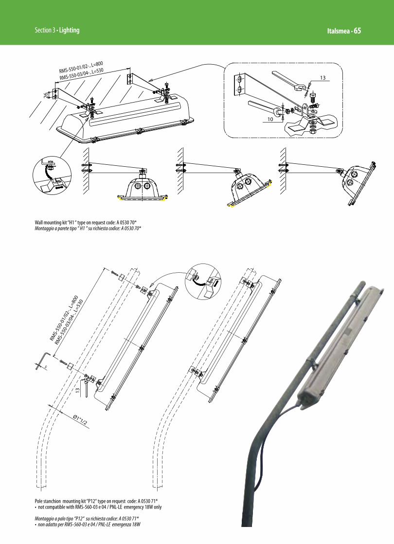
Section 3 • Lighting Italsmea • 65
Wall mounting kit “H1 “ type on request code: A 0530 70*Montaggio a parete tipo “ H1 “ su richiesta codice: A 0530 70*
Pole stanchion mounting kit “P12“ type on request code: A 0530 71*• not compatible with RMS-560-03 e 04 / PNL-LE emergency 18W only
Montaggio a palo tipo “P12“ su richiesta codice: A 0530 71*• non adatto per RMS-560-03 e 04 / PNL-LE emergenza 18W

Sezione 3 • illuminazione66 • Italsmea
RMS lighting fi xtures mounting pathSequenza di messa in servizio delle armature RMS
1 2 3
4 5 6
7 8
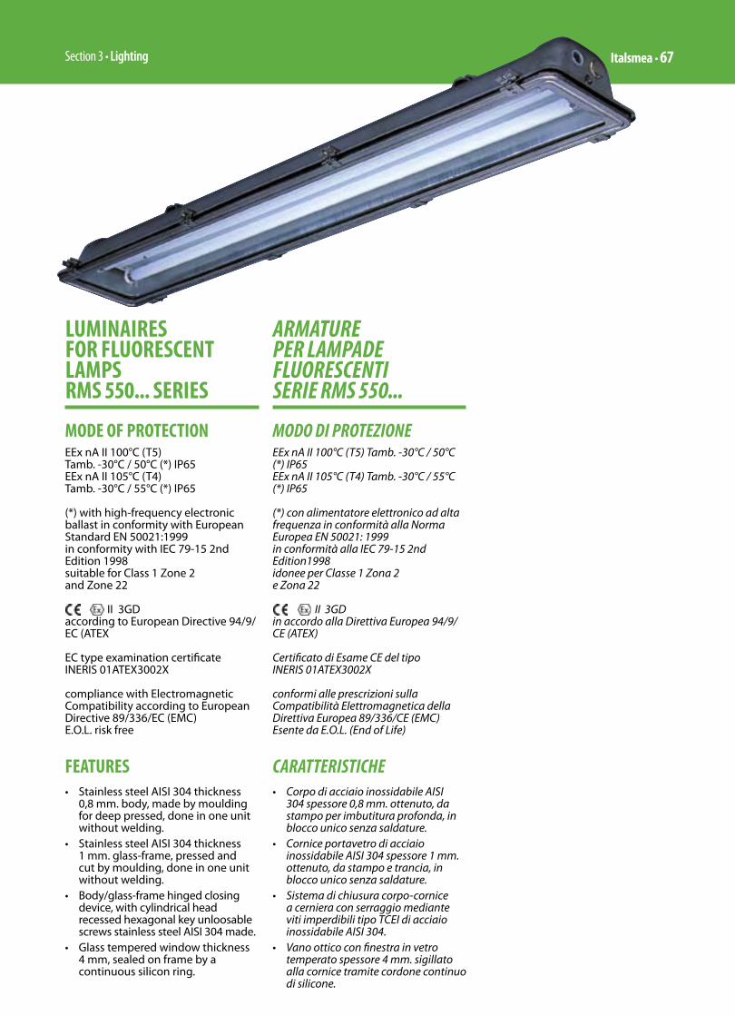
Section 3 • Lighting Italsmea • 67
ARMATURE PER LAMPADE FLUORESCENTI SERIE RMS 550...
MODO DI PROTEZIONEEEx nA II 100°C (T5) Tamb. -30°C / 50°C (*) IP65EEx nA II 105°C (T4) Tamb. -30°C / 55°C (*) IP65
(*) con alimentatore elettronico ad alta frequenza in conformità alla Norma Europea EN 50021: 1999in conformità alla IEC 79-15 2nd Edition1998idonee per Classe 1 Zona 2 e Zona 22
II 3GDin accordo alla Direttiva Europea 94/9/CE (ATEX)
Certificato di Esame CE del tipo INERIS 01ATEX3002X
conformi alle prescrizioni sulla Compatibilità Elettromagnetica della Direttiva Europea 89/336/CE (EMC)Esente da E.O.L. (End of Life)
CARATTERISTICHE• Corpo di acciaio inossidabile AISI
304 spessore 0,8 mm. ottenuto, da stampo per imbutitura profonda, in blocco unico senza saldature.
• Cornice portavetro di acciaio inossidabile AISI 304 spessore 1 mm. ottenuto, da stampo e trancia, in blocco unico senza saldature.
• Sistema di chiusura corpo-cornice a cerniera con serraggio mediante viti imperdibili tipo TCEI di acciaio inossidabile AISI 304.
• Vano ottico con finestra in vetro temperato spessore 4 mm. sigillato alla cornice tramite cordone continuo di silicone.
LUMINAIRES FOR FLUORESCENT LAMPS RMS 550... SERIES
MODE OF PROTECTIONEEx nA II 100°C (T5) Tamb. -30°C / 50°C (*) IP65EEx nA II 105°C (T4) Tamb. -30°C / 55°C (*) IP65
(*) with high-frequency electronic ballast in conformity with European Standard EN 50021:1999in conformity with IEC 79-15 2nd Edition 1998suitable for Class 1 Zone 2 and Zone 22
II 3GDaccording to European Directive 94/9/EC (ATEX
EC type examination certificate INERIS 01ATEX3002X
compliance with Electromagnetic Compatibility according to European Directive 89/336/EC (EMC)E.O.L. risk free
FEATURES• Stainless steel AISI 304 thickness
0,8 mm. body, made by moulding for deep pressed, done in one unit without welding.
• Stainless steel AISI 304 thickness 1 mm. glass-frame, pressed and cut by moulding, done in one unit without welding.
• Body/glass-frame hinged closing device, with cylindrical head recessed hexagonal key unloosable screws stainless steel AISI 304 made.
• Glass tempered window thickness 4 mm, sealed on frame by a continuous silicon ring.

Sezione 3 • illuminazione68 • Italsmea
• Special cross-section tightness gasket, Silicon rubber made (closed cells), located in housing channel between body and window frame. When completely secured the closing between body and window frame, a mechanical contact between the metal parts stop the pressure on gasket. To grant a maintained elastic memory.
• Stainless steel AISI 304 thickness 1 mm internal “reglette” white painted fixed on two supports with “screw-transfer” looking device system.
• The “reglette” is foreseen with two suspension wires granting the self-support when lighting fixtures is open for start-up operation or maintenance.
• Wiring by PVC 90°C rigid cable. Lampholder suitable for fluorescent two-pins lamps type TL-D Philips or similar. Anti-loosening 2P+E (L-N-E) terminal strip, melamine made, for power supply connection. Yellow green single core earth wire for body and “reglette” equipotential connection. Spare for a loop to the earth tag of cable gland for power supply cable.
• Body complete of two diam. 21mm through holes for cable entries, one complete of metallic plug with lock nut and gasket, and the other one with plastic plug for dust protection.
• Mechanical protection: IP65• Nominal voltage 220-240V ±10%
with high frequency electronic ballast.
• Frequency 50/60Hz• Power factor >0,95• The shapes of RMS lighting fixtures
has been studied to allow operator working with free hands and no need to support any part of lighting fixtures. One person can take care of start-up or maintenance of a RMS lighting fixture without any aid and assistance.
ADVANTAGES• High corrosion resistance due
to the fact that the components are stainless steel AISI 304 and tempered glass made.
• No through holes between inside and outside of luminaire, out of hole for power supply cable whatever protected by a suitable waterproof EEx-e cable gland (on request). Therefore, during the time, there is not tightness release as it would be possible where, for fixing devices, there are through holes and relevant gaskets.
• Guarnizione di tenuta, tra cornice e corpo, di gomma siliconica (cellule chiuse) a sezione ogivale, alloggiata in apposita canala. Battuta meccanica dell’accoppiamento atta a garantire il mantenimento della memoria elastica della guarnizione.
• Reglette-riflettore interna di acciaio inossidabile AISI 304 spessore 1 mm. verniciata “bianco” montata su due supporti con serraggio ad eccentrico traslato.
• La reglette, è prevista con due funi di sospensione, che ne consentono l’auto-supporto in condizione di armatura aperta per messa in servizio, o manutenzione.
• Cablaggio in cavetto rigido isolato in PVC 90°C. Portalampada per lampada fluorescente bispina TL-D Philips o similare. Morsetto antiallentante in melamina 2P+T (L-N-E) per allacciamento linea di alimentazione. Filo di terra giallo-verde, per equipotenzialità corpo-reglette, predisposto per la connessione al pressacavo di ingresso linea per messa a terra solidale dell’eventuale armatura metallica del cavo di alimentazione.
• Corpo previsto con due imbocchi passanti diam. 21mm per entrate cavo dei quali, il primo corredato di tappo metallico completo di controdado e guarnizione, il secondo di tappo salvapolvere in plastica.
• Grado di protezione IP65• Tensione nominale 220-240V ±10%
con alimentatore elettronico ad alta frequenza.
• Frequenza 50/60Hz • Fattore di potenza >0,95• L’assetto dell’armatura RMS, è stato
studiato in modo tale che, in tutte le condizioni d’uso, l’operatore sia in grado di lavorare con entrambe le mani libere dalla necessità di sostenere parti dell’armatura stessa. Un solo operatore, senza l’aiuto di un assistente, può installare o manutendere un’armatura RMS.
VANTAGGI• Elevata resistenza alla corrosione
stante la totalità dei componenti metallici in acciaio inossidabile AISI 304 in accoppiamento alla finestra in vetro temperato.
• Nessun foro passante tra interno ed esterno armatura ad esclusione dell’inevitabile ingresso per l’alimentazione elettrica, comunque protetto da pressacavo EEx e ad elevata tenuta stagna (fornibile su richiesta). Pertanto nel tempo non sono presumibili decadimenti del grado di protezione, prevedibili
RMS..-1x18W/36PHOTOMETRIC CURVE FOR 1000 LM WITH 1 LAMPCURVA FOTOMETRICA PER 1000 LM CON 1 LAMPADA
RMS..-2x18W/36PHOTOMETRIC CURVE FOR 1000 LM WITH 1 LAMPCURVA FOTOMETRICA PER 1000 LM CON 1 LAMPADA

Section 3 • Lighting Italsmea • 69
• Very low pollution at the end of operative lifetime of lighting fi xtures. The new European Directives will require, starting from 2005, that manufacturer, at time of supply, have to include in selling price, the cost for the buy-back and goods recycle. Recycle to be done according to pollution rules. The inorganic materials used for RMS, like stainless steel and glass, allow a recycle of 95%, only electrical components and insulation of single core wires need some more care.
MOUNTING ACCESSORIES• The base solution of lighting
fi xtures foreseen the straps for ceiling suspension mounting. The straps are welded to the body (no through holes and screws) and foreseen with half-open slot suitable to compensate up to 10 mm. of misalignment of supports.
ACCESSORIES ON REQUEST• Kit for pole mounting 1 1⁄2” / 2”
size, stainless steel AISI 304 made.• Kit for wall mounting, stainless steel
AISI 304 made.• EEx e stainless steel AISI-304 cable
gland.• EEx e resin cable gland.
OVERALL DIMENSIONS OF EACH CARTON BOX• Size 20w:
260x760x180 mm. Medium weight: 5,5 KGs.
• Size 40w: 260x1370x180 mm. Medium weight: 10,5 KGs.
invece laddove, per staff aggi fossero previsti fori passanti tappati con viti e guarnizioni o rivetti.
• Ridottissimo inquinamento ambientale alla fi ne della vita operativa dell’armatura. Le nuove direttive Europee prevedono che dall’anno 2005 il costruttore, all’atto della vendita del prodotto, includa nel prezzo e quindi si impegni a ritirare e smaltire in modo corretto, il bene prodotto. La serie RMS è riciclabile al 95% essendo costruita con componenti del tutto inorganici: acciaio inossidabile e vetro. Un piccolo residuo è dovuto alla componentistica elettrica, elettronica e all’isolamento dei cavi di cablaggio.
ACCESSORI DI MONTAGGIO• L’armatura prevede nella versione
base le staff e per il montaggio a soffi tto/sospensione. Le staff e sono solidali al corpo lampada (saldatura senza fori passanti) e previste con asola semiaperta atta a compensare eventuali disassamenti degli ancoraggi fi no a 10 mm.
ACCESSORI A RICHIESTA• Kit per attacco a palina da 1 1⁄2” / 2”,
di acciaio inossidabile AISI 304.• Kit per montaggio a parete, di acciaio
inossidabile AISI 304.• Pressacavo EEx e di acciaio
inossidabile AISI-304.• Pressacavo EEx e in resina.
DIMENSIONI DELL’IMBALLO SINGOLO• Grandezza 20w:
260x760x180 mm. Peso medio: 5,5 Kg.
• Grandezza 40w: 260x1370x180 mm. Peso medio: 10,5 Kg

Sezione 3 • illuminazione70 • Italsmea
Lighting fixtures for normal service Armature per funzionamento normale
TypeRMS-550* Code Number
of lampsLamps power
Lamp type
Overall Dimensions mm. Weight
Kgs.A B C
* 03/PNL A.2205.00 1 1x18W TL-D 737 239 123 5,10
* 04/PNL A.2201.00 2 2x18W TL-D 737 239 123 5,20
* 01/PNL A.2206.00 1 1x36W TL-D 1347 239 123 8,40
* 02/PNL A.2202.00 2 2x36W TL-D 1347 239 123 8,60
Selection table Tabella di selezione
Lighting fixtures for emergency service Armature per funzionamento in emergenza
TypeRMS-550* Code Number
of lampsLamps power
Lamp type
Overall Dimensions mm. Weight
Kgs.A B C
* 03/PNL/LE – P A.2236.0 1 1x18W TL-D 737 239 123 5,80
* 04/PNL/LE – P A.2233.0 2 2x18W TL-D 737 239 123 5,90
* 01/PNL/LE – P A.2235.0 1 1x36W TL-D 1347 239 123 9,10
* 02/PNL/LE – P A.2234.0 2 2x36W TL-D 1347 239 123 9,30
Emergency service on one lamp for 60’ with constant lighting output, 90’ with lighting output decreasing Funzionamento in emergenza su una lampadina per 60’ a flusso costante, 90’ a flusso decrescente
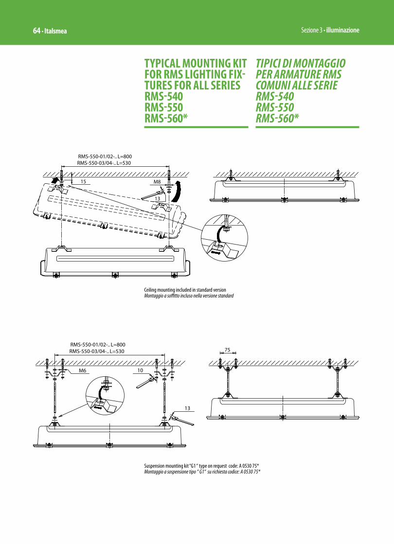
Sezione 3 • illuminazione64 • Italsmea
TIPICI DI MONTAGGIO PER ARMATURE RMS COMUNI ALLE SERIE RMS-540 RMS-550 RMS-560*
TYPICAL MOUNTING KIT FOR RMS LIGHTING FIX-TURES FOR ALL SERIES RMS-540 RMS-550 RMS-560*
Suspension mounting kit “G1 “ type on request code: A 0530 75*Montaggio a sospensione tipo “ G1“ su richiesta codice: A 0530 75*
Ceiling mounting included in standard versionMontaggio a soffitto incluso nella versione standard

Section 3 • Lighting Italsmea • 65
Wall mounting kit “H1 “ type on request code: A 0530 70*Montaggio a parete tipo “ H1 “ su richiesta codice: A 0530 70*
Pole stanchion mounting kit “P12“ type on request code: A 0530 71*• not compatible with RMS-560-03 e 04 / PNL-LE emergency 18W only
Montaggio a palo tipo “P12“ su richiesta codice: A 0530 71*• non adatto per RMS-560-03 e 04 / PNL-LE emergenza 18W

Sezione 3 • illuminazione66 • Italsmea
RMS lighting fi xtures mounting pathSequenza di messa in servizio delle armature RMS
1 2 3
4 5 6
7 8

Section 3 • Lighting Italsmea • 71
ARMATURE PER LAMPADE FLUORESCENTI SERIE RMS 560...
MODO DI PROTEZIONEEEx-ed IIC T6 Tamb. –20°C / +40°C IP65EEx-ed IIC T5 Tamb. –20°C / +55°C IP65EEx-ed IIC T4 Tamb. –20°C / +60°C IP65 (*) con alimentatore elettronico ad alta frequenzain conformità alle Norme Europee EN 50014/18/19 idonee per Zona 1 e Zona 2
0080 II 2Gin accordo alla Direttiva Europea 94/9/CE ATEX
Certifi cato di Esame CE del tipo INERIS 01ATEX0060conformi alle prescrizioni sulla Compatibilità Elettromagnetica della Direttiva Europea 89/336/CE (EMC)Esente da rischio E.O.L. (End of Life)
CARATTERISTICHE• Corpo di acciaio inossidabile AISI
304 spessore 0,8 mm. ottenuto, da stampo per imbutitura profonda, in blocco unico senza saldature.
• Cornice portavetro di acciaio inossidabile AISI 304 spessore 1 mm. ottenuto, da stampo e trancia, in blocco unico senza saldature.
• Sistema di chiusura corpo-cornice a cerniera con serraggio mediante viti imperdibili tipo TCEI di acciaio inossidabile AISI 304.
• Vano ottico con fi nestra in vetro temperato spessore 4 mm. sigillato
LUMINAIRES FOR FLUORESCENT LAMPSRMS 560... SERIES
MODE OF PROTECTIONEEx-ed IIC T6 Ambient Temperature –20°C / +40°C IP65EEx-ed IIC T5 Ambient Temperature –20°C / +55°C IP65EEx-ed IIC T4 Ambient Temperature –20°C / +60°C IP65
(*) with high-frequency electronic ballastin conformity with European Standard EN 50014/18/19 suitable for Zone 1 & Zone 2
0080 II 2Gaccording to European Directive 94/9/EC ATEX
EC type examination certifi cate INERIS 01ATEX0060 compliance with Electromagnetic Compatibility according to European Directive 89/336/EC (EMC)E.O.L. risk free
FEATURES• Stainless steel AISI 304 thickness
0,8 mm. body, made by moulding for deep pressed, done in one unit without welding.
• Stainless steel AISI 304 thickness 1 mm. glass-frame, pressed and cut by moulding, done in one unit without welding.
• Body/glass-frame hinged closing device, with cylindrical head recessed hexagonal key unloosable screws stainless steel AISI 304 made.
• Glass tempered window thickness
EMERGENCY VERSION 36WVERSIONE IN EMERGENZA 36W
DETAILED VIEW MICROSWITCHDETTAGLIO MICROINTERRUTTORE
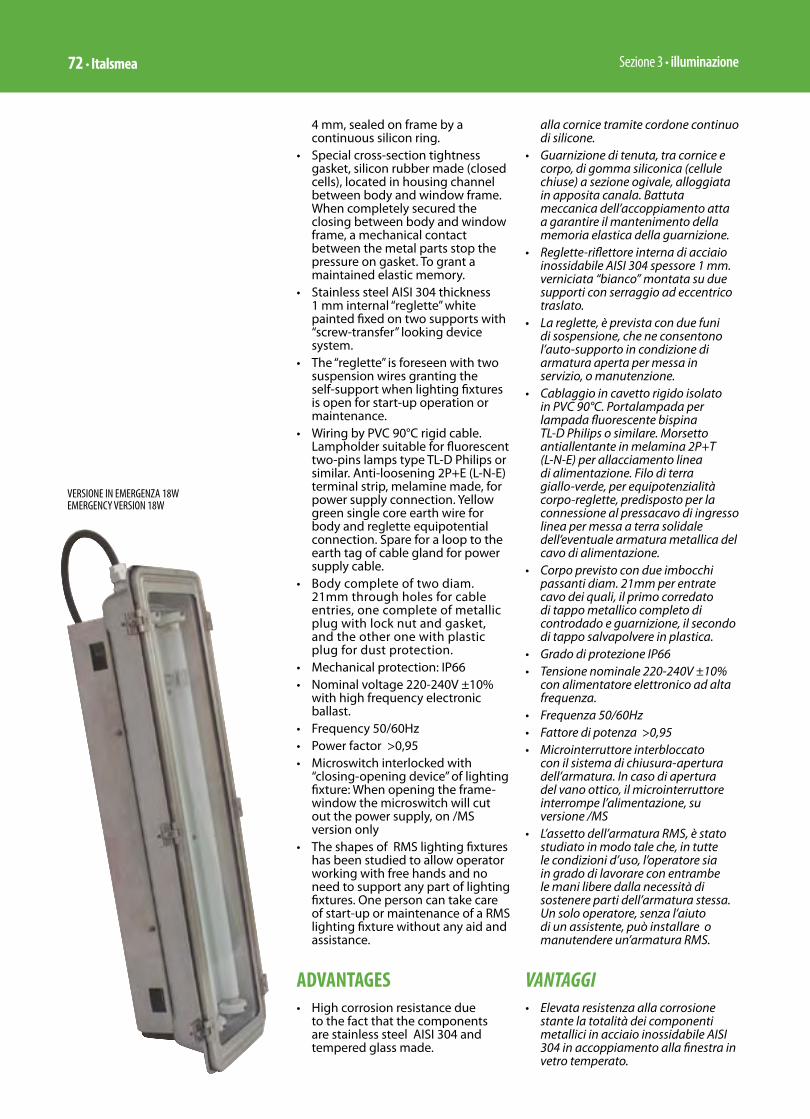
Sezione 3 • illuminazione72 • Italsmea
4 mm, sealed on frame by a continuous silicon ring.
• Special cross-section tightness gasket, silicon rubber made (closed cells), located in housing channel between body and window frame. When completely secured the closing between body and window frame, a mechanical contact between the metal parts stop the pressure on gasket. To grant a maintained elastic memory.
• Stainless steel AISI 304 thickness 1 mm internal “reglette” white painted fixed on two supports with “screw-transfer” looking device system.
• The “reglette” is foreseen with two suspension wires granting the self-support when lighting fixtures is open for start-up operation or maintenance.
• Wiring by PVC 90°C rigid cable. Lampholder suitable for fluorescent two-pins lamps type TL-D Philips or similar. Anti-loosening 2P+E (L-N-E) terminal strip, melamine made, for power supply connection. Yellow green single core earth wire for body and reglette equipotential connection. Spare for a loop to the earth tag of cable gland for power supply cable.
• Body complete of two diam. 21mm through holes for cable entries, one complete of metallic plug with lock nut and gasket, and the other one with plastic plug for dust protection.
• Mechanical protection: IP66• Nominal voltage 220-240V ±10%
with high frequency electronic ballast.
• Frequency 50/60Hz• Power factor >0,95• Microswitch interlocked with
“closing-opening device” of lighting fixture: When opening the frame-window the microswitch will cut out the power supply, on /MS version only
• The shapes of RMS lighting fixtures has been studied to allow operator working with free hands and no need to support any part of lighting fixtures. One person can take care of start-up or maintenance of a RMS lighting fixture without any aid and assistance.
ADVANTAGES• High corrosion resistance due
to the fact that the components are stainless steel AISI 304 and tempered glass made.
alla cornice tramite cordone continuo di silicone.
• Guarnizione di tenuta, tra cornice e corpo, di gomma siliconica (cellule chiuse) a sezione ogivale, alloggiata in apposita canala. Battuta meccanica dell’accoppiamento atta a garantire il mantenimento della memoria elastica della guarnizione.
• Reglette-riflettore interna di acciaio inossidabile AISI 304 spessore 1 mm. verniciata “bianco” montata su due supporti con serraggio ad eccentrico traslato.
• La reglette, è prevista con due funi di sospensione, che ne consentono l’auto-supporto in condizione di armatura aperta per messa in servizio, o manutenzione.
• Cablaggio in cavetto rigido isolato in PVC 90°C. Portalampada per lampada fluorescente bispina TL-D Philips o similare. Morsetto antiallentante in melamina 2P+T (L-N-E) per allacciamento linea di alimentazione. Filo di terra giallo-verde, per equipotenzialità corpo-reglette, predisposto per la connessione al pressacavo di ingresso linea per messa a terra solidale dell’eventuale armatura metallica del cavo di alimentazione.
• Corpo previsto con due imbocchi passanti diam. 21mm per entrate cavo dei quali, il primo corredato di tappo metallico completo di controdado e guarnizione, il secondo di tappo salvapolvere in plastica.
• Grado di protezione IP66• Tensione nominale 220-240V ±10%
con alimentatore elettronico ad alta frequenza.
• Frequenza 50/60Hz • Fattore di potenza >0,95• Microinterruttore interbloccato
con il sistema di chiusura-apertura dell’armatura. In caso di apertura del vano ottico, il microinterruttore interrompe l’alimentazione, su versione /MS
• L’assetto dell’armatura RMS, è stato studiato in modo tale che, in tutte le condizioni d’uso, l’operatore sia in grado di lavorare con entrambe le mani libere dalla necessità di sostenere parti dell’armatura stessa. Un solo operatore, senza l’aiuto di un assistente, può installare o manutendere un’armatura RMS.
VANTAGGI• Elevata resistenza alla corrosione
stante la totalità dei componenti metallici in acciaio inossidabile AISI 304 in accoppiamento alla finestra in vetro temperato.
VERSIONE IN EMERGENZA 18WEMERGENCY VERSION 18W
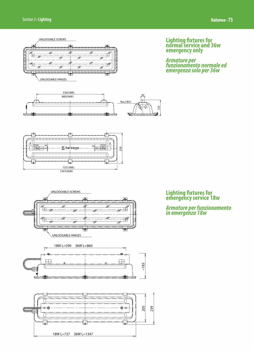
Section 3 • Lighting Italsmea • 73
Lighting fixtures for normal service and 36w emergency only Armature per funzionamento normale ed emergenza solo per 36w
Lighting fixtures for emergency service 18w Armature per funzionamento in emergenza 18w

Sezione 3 • illuminazione74 • Italsmea
• No through holes between inside and outside of luminaire, out of hole for power supply cable whatever protected by a suitable waterproof EEx-e cable gland (on request). Therefore, during the time, there is not tightness release as it would be possible where, for fixing devices, there are through holes and relevant gaskets.
• Very low pollution at the end of operative lifetime of lighting fixtures. The new European Directives will require, starting from 2006, that manufacturer, at time of supply, have to include in selling price, the cost for the buy-back and goods recycle. Recycle to be done according to pollution rules. The inorganic materials used for RMS, like stainless steel and glass, allow a recycle of 95%, only electrical components and insulation of single core wires need some more care.
MOUNTING ACCESSORIES• The base solution of lighting
fixtures foreseen the straps for ceiling suspension mounting. The straps are welded to the body (no through holes and screws) and foreseen with half-open slot suitable to compensate up to 10 mm. of misalignment of supports.
ACCESSORIES AND VERSIONS ON REQUEST• Emergency lighting fixture: 90’
(minutes) of light in blackout conditions, with one lamp operative at 25% of initial output
• Kit for pole mounting 1 1⁄2” / 2” size, stainless steel AISI 304 made.
• Kit for wall mounting, stainless steel AISI 304 made.
• EEx e stainless steel AISI-304 cable gland.
• EEx e resin cable gland.
OVERALL DIMENSIONS OF EACH CARTON BOX• Size 20w:
260x760x180 mm. Medium weight: 5,5 KGs.
• Size 40w: 260x1370x180 mm. Medium weight: 10,5 KGs.
• Nessun foro passante tra interno ed esterno armatura ad esclusione dell’inevitabile ingresso per l’alimentazione elettrica, comunque protetto da pressacavo EEx e ad elevata tenuta stagna (fornibile su richiesta). Pertanto nel tempo non sono presumibili decadimenti del grado di protezione, prevedibili invece laddove, per staffaggi fossero previsti fori passanti tappati con viti e guarnizioni o rivetti.
• Ridottissimo inquinamento ambientale alla fine della vita operativa dell’armatura. Le nuove direttive Europee prevedono che dall’anno 2006 il costruttore, all’atto della vendita del prodotto, includa nel prezzo e quindi si impegni a ritirare e smaltire in modo corretto, il bene prodotto. La serie RMS è riciclabile al 95% essendo costruita con componenti del tutto inorganici: acciaio inossidabile e vetro. Un piccolo residuo è dovuto alla componentistica elettrica, elettronica e all’isolamento dei cavi di cablaggio.
ACCESSORI DI MONTAGGIO• L’armatura prevede nella versione
base le staffe per il montaggio a soffitto/sospensione. Le staffe sono solidali al corpo lampada (saldatura senza fori passanti) e previste con asola semiaperta atta a compensare eventuali disassamenti degli ancoraggi fino a 10 mm.
ACCESSORI E VERSIONI A RICHIESTA• Armatura con circuito di emergenza,
con funzionamento autonomo: al mancare della alimentazione di rete, l’apparecchio rimane in funzione su una lampada per 90’ al 25% del flusso iniziale
• Kit per attacco a palina da 1 1⁄2” / 2”, di acciaio inossidabile AISI 304.
• Kit per montaggio a parete, di acciaio inossidabile AISI 304.
• Pressacavo EEx e di acciaio inossidabile AISI-304.
• Pressacavo EEx e in resina.
DIMENSIONI DELL’IMBALLO SINGOLO• Grandezza 20w:
260x760x180 mm. Peso medio: 5,5 Kg.
• Grandezza 40w: 260x1370x180 mm. Peso medio: 10,5 Kg

Section 3 • Lighting Italsmea • 75
Selection tableTabella di selezione
Lighting fi xtures for emergency serviceArmature per funzionamento in emergenza
TypeRMS-560* Code Number
of lampsLamps power
Lamp type
Overall Dimensions mm. Weight
Kgs.A B C
* 03/PNL/LE – P A.2227.02 1 1x18W TL-D 737 239 173 9,50
* 04/PNL/LE – P A.2230.02 2 2x18W TL-D 737 239 173 9,60
* 01/PNL/LE – P A.2231.02 1 1x36W TL-D 1347 239 173 14,10
* 02/PNL/LE – P A.2232.02 2 2x36W TL-D 1347 239 173 14,30
Emergency service on one lamp for 60’ with constant lighting output, 90’ with lighting output decreasing Funzionamento in emergenza su una lampadina per 60’ a fl usso costante, 90’ a fl usso decrescente
n With micro-switch / Con micro-interruttore
Lighting fi xtures for normal serviceArmature per funzionamento normale
TypeRMS-550* Code Number
of lampsLamps power
Lamp type
Overall Dimensions mm. Weight
Kgs.A B C
* 03/PNL A.2227.01 1 1x18W TL-D 737 239 123 5,60
* 04/PNL A.2230.01 2 2x18W TL-D 737 239 123 5,70
* 01/PNL A.2231.01 1 1x36W TL-D 1347 239 123 8,90
* 02/PNL A.2232.01 2 2x36W TL-D 1347 239 123 9,10
* 03/PNL/MS A.2227.00 1 1x18W TL-D 737 239 123 5,65
* 04/PNL/MS A.2230.00 2 2x18W TL-D 737 239 123 5,75
* 01/PNL/MS A.2231.00 1 1x36W TL-D 1347 239 123 8,95
* 02/PNL/MS A.2232.00 2 2x36W TL-D 1347 239 123 9,15
RMS..-1x18W/36PHOTOMETRIC CURVE FOR 1000 LM WITH 1 LAMPCURVA FOTOMETRICA PER 1000 LM CON 1 LAMPADA
RMS..-2x18W/36PHOTOMETRIC CURVE FOR 1000 LM WITH 1 LAMPCURVA FOTOMETRICA PER 1000 LM CON 1 LAMPADA

Sezione 3 • illuminazione64 • Italsmea
TIPICI DI MONTAGGIO PER ARMATURE RMS COMUNI ALLE SERIE RMS-540 RMS-550 RMS-560*
TYPICAL MOUNTING KIT FOR RMS LIGHTING FIX-TURES FOR ALL SERIES RMS-540 RMS-550 RMS-560*
Suspension mounting kit “G1 “ type on request code: A 0530 75*Montaggio a sospensione tipo “ G1“ su richiesta codice: A 0530 75*
Ceiling mounting included in standard versionMontaggio a soffitto incluso nella versione standard

Section 3 • Lighting Italsmea • 65
Wall mounting kit “H1 “ type on request code: A 0530 70*Montaggio a parete tipo “ H1 “ su richiesta codice: A 0530 70*
Pole stanchion mounting kit “P12“ type on request code: A 0530 71*• not compatible with RMS-560-03 e 04 / PNL-LE emergency 18W only
Montaggio a palo tipo “P12“ su richiesta codice: A 0530 71*• non adatto per RMS-560-03 e 04 / PNL-LE emergenza 18W
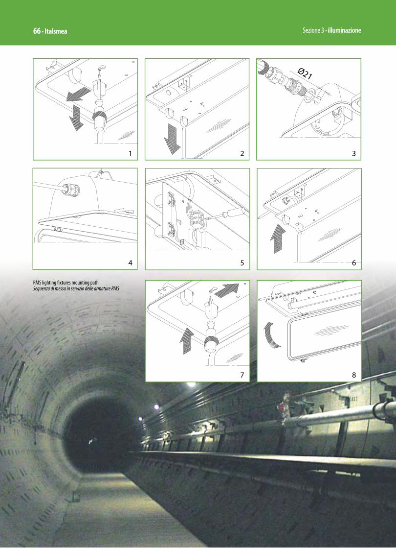
Sezione 3 • illuminazione66 • Italsmea
RMS lighting fi xtures mounting pathSequenza di messa in servizio delle armature RMS
1 2 3
4 5 6
7 8

Section 2 • Enclosures for control units and junction boxes (Power & Lighting) Italsmea • 27
ENCLOSURES AQ.. / AR.. SERIES
ü EEx-e increased safety ATEXü EEx-ia intrinsically safe ATEXü EEx-e ia in combination between
increased safety with intrinsically safe components ATEXü Industrial version IP-66
EC Type Examination Certifi cate INERIS 01ATEX0005X
APPLICATIONSJunction Boxes for:ü electrical, auxiliary, analogic signals,
thermocouple, telephonie multi-cores cables
ü single-core power cables up to 120 sqmm, without overheating risk due to induced currents (transformer eff ect)
ü multi-cores power cables up to 120 sqmm
ü multi-tubes cables for instrument air circuit
Enclosures for control panel stations:ü industrial motor startersü check and control units
industrial and EEx-de version with push-button – signalling lamps – selectors – metering instruments
Built in AISI 316L stainless steel, die-bent with NCS machines and robot welded by casting melting of material without any welding electrode, AQ/AR series junction boxes are especially recommended for:ü chemical agent environment ü sea-water corrosionü low and high temperatureü heavy dutiesü vibrations, inertial solid impacts, UV
radiations, sub-nuclear radiations
EEx version to prevent explosion or fi re risks in classifi ed areas
CUSTODIE SERIE AQ.. / AR..
ü EEx-e a sicurezza aumentata ATEXü EEx-ia a sicurezza intrinseca ATEXü EEx-e ia in combinazione a sicurezza
aumentata con componenti a sicurezza intrinseca ATEXü Industriali stagne IP-66
Certifi cato di Esame CE del Tipo
INERIS 01ATEX0005X
APPLICAZIONICassette di derivazione per:ü multi-cavi elettrici/strumentali,
ausiliari, segnali analogici, termocoppia, telefonici
ü cavi unipolari di potenza fi no a 120 mmq, senza rischio di surriscaldamento per correnti indotte (eff etto trasformatore)
ü cavi multi-polari di potenza fi no a 120 mmq
ü multi-tubi per circuito aria strumenti
Contenitori per unità di comando e controllo:ü avviamento motori industrialiü unità di controllo e comando in
versione industriale e di sicurezza EEx-de con pulsanti -lampade di segnalazione – selettori – strumenti di misura
Costruite in acciaio inossidabile AISI 316L, presso-piegate con macchine a NCS e saldate con robot di saldatura per fusione del materiale senza apporto di materiale estraneo, le cassette serie AQ/AR sono particolarmente adatte per:ü climi chimicamente aggressiviü corrosione da acqua di mareü bassa e alta temperaturaü sollecitazioni meccaniche elevate ü vibrazioni, urti da solidi inerti,
radiazioni UV, radiazioni subnucleari
Il tutto in versione EEx per aree classifi cate con pericolo di esplosione od incendio
3
4

Sezione 2 • Contenitori per unità di comando/potenza e controllo cassette di derivazione 28 • Italsmea
MODO DI PROTEZIONE
EEx e II T6 / T85°C Tamb. -50°C / 55°C IP 66EEx e II T5 / T100°C Tamb. -50°C / 55°C IP 66
EEx ia IIC T6 / T85°C Tamb. -50°C / 55°C IP 66EEx ia IIC T5 / T100°C Tamb. -50°C / 55°C IP 66
EEx e ia IIC T6 / T85°C Tamb. -50°C / 55°C IP 66EEx e ia IIC T5 / T100°C Tamb. -50°C / 55°C IP 66
in conformità alle Norme Europee:EN 50014 EN 50019 EN 50020 ; EN 50281-1-1 EN 60529
idonee per Zona 1 (gas) e Zona 21 (polveri)
0080 II 2GDin accordo alla Direttiva Europea 94/9/CE ATEX
CARATTERISTICHE TECNICHECorpo e coperchio in AISI 316L spessore 1.5 mm
Viti di chiusura imperdibili in AISI 316
Fissaggio custodia mediante 4 supporti esterni con fori/asole da 9 mm (Foto 3)
Guarnizione coperchio ed eventuali flangie asportabili in:EPDM per Temb. -30°C / 55°C (Foto 4 e 5)EVA per Temb. -50°C / 55°C
Piastra di fondo in AISI 316L spessore 1.5 mm (su richiesta) (Foto 6)
Vite antiallentante di terra interna ed esterna in AISI 316 per conduttore fino a 35 mm2 (Foto 7)
Numero di morsetti installabili basato sul valore della potenza dissipata all’interno della cassetta
Finitura: sabbiatura fine sia interna che esterna
Coperchio con: ü bassorilievo su viti di fissaggio
(Foto 8)
MODE OF PROTECTION
EEx e II T6 / T85°C Tamb. -50°C / 55°C IP 66EEx e II T5 / T100°C Tamb. -50°C / 55°C IP 66
EEx ia IIC T6 / T85°C Tamb. -50°C / 55°C IP 66EEx ia IIC T5 / T100°C Tamb. -50°C / 55°C IP 66
EEx e ia IIC T6 / T85°C Tamb. -50°C / 55°C IP 66EEx e ia IIC T5 / T100°C Tamb. -50°C / 55°C IP 66
in conformity with European Standards:EN 50014 EN 50019 EN 50020 EN 50281-1-1 EN 60529
suitable for Zone 1 (gas) and Zone 21 (dusts)
0080 II 2GDaccording to European Directive 94/9/EC ATEX
TECHNICAL FEATURESBody and cover made in AISI 316L thickness 1.5 mm
Captive screws AISI 316 made
Box mounting with 4 external lugs, 9 mm holes/slots (Pict.3)
Cover and gland plates (if any) gaskets made in:EPDM for Temb. -30°C / 55°C (Pict. 4 & 5)EVA for Temb. -50°C / 55°C
Mounting plate made in AISI 316L thickness 1.5 mm (on request) (Pict. 6)
Internal and external earth stud made in AISI 316 suitable for earth wire up to 35 sqmm (Pict. 7)
Number of terminals compatibles, based on the value of the lost-joule effect heat dissipator inside box
Finishing: internal and external light sandblasting
Cover with:ü shallow recess for fixing screws
(Pict. 8)
5
7
8
9
6

Section 2 • Enclosures for control units and junction boxes (Power & Lighting) Italsmea • 29
ü shallow recess for location of self-adhesive certifi cate label (Pict. 9), to avoid any label’s damage when overhead stored on job site. Protection against scratches due to cover contact with corrugated surfaces during installation and maintenance
ü Standard labels with certifi cate data, made by self-adhesive polyester fi lm suitable for extreme heavy duties as: high/low temperature, scratches, U.V. radiations and so on
Accessories on request:ü Identifi cation label resin/trafolite
made, with fi xing screw crossing cover plate, sealed by compound to restore the IP rating
ü Identifi cation label stainless steel made spot welded on cover plate
ü External painting Italsmea standard cycle, suggested in presence of cloride and cloride combination (as NaCl, sea-water, humid cloride, etc. etc.)
ü Inside anti-condensation paintingü Hinged cover by stainless steel
AISI 316 made hinges fi xed by spot welding (Pict. 10). On request.
ü Pad lockable cover (Pict. 13)ü Trough holes suitable for cable
glands, plugs and conduit fi tting, either for metric and gas thread (Pict. 11)
ü drain and/or breather valve, stainless steel AISI 316 made, with nut/locknut and gasket (Pict.12)
ü bassorilievo in corrispondenza dell’area fi ssaggio targhetta di certifi cato autoadesiva (Foto 9), onde evitare danneggiamento della targhetta in caso di sovrapposizione di altre cassette durante lo stoccaggio e la posa in opera, danneggiamenti dovuti a contatto del coperchio con superfi ci abrasive durante la messa in servizio e durante manutenzione.
ü Targhette di certifi cato: in poliestere autoadesivo ad elevata resistenza alla bassa temperatura, alta temperatura, abrasione, allo strappo, ai raggi UV e quant’altro possibile
Accessori a richiesta: ü Targhette di identifi cazione: in
trafolite fi ssata con viti autofi lettanti sigillate dall’interno con resina onde mantenere il grado di protezione dichiarato
ü targhetta di identifi cazione in acciaio inox fi ssata tramite saldatura a punto sul coperchio
ü verniciatura esterna con ciclo standard Italsmea, particolarmente consigliato in presenza di cloro e suoi derivati (cloruro di sodio, acqua di mare, ipoclorito, cloro umido etc ect.)
ü verniciatura interna anticondensaü coperchio incernierato con cerniere
in acciaio inox AISI 316 fi ssate con saldatura a punti (Foto 10). Si possono montare anche a cassetta fi nita presso offi cina Italsmea
ü coperchio lucchettabile. (Foto 13)ü imbocchi passanti adatti a ricevere
pressacavi o raccorderie con fi letto metrico o gas (Foto 11)
ü valvola di drenaggio e/o sfi ato in acciaio inossidabile AISI 316 applicata con controdado e guarnizione (Foto 12)
10
11
12
13

Sezione 2 • Contenitori per unità di comando/potenza e controllo cassette di derivazione 30 • Italsmea
ENCLOSURES WITH FIXED WALLS
CUSTODIE A PARETE FISSA
Box type Code Amm
Bmm
Cmm
Dmm
Emm
Fmm
Mounting platemm Code
Weight Kg
AQ 6 A.4110.06 270 270 130 325 177 350 222 x 222 P.4110.44 4.5
AQ 8 A.4110.08 350 350 160 405 257 430 302 x 302 P.4110.45 5.6
AR 2 A.4100.02 200 137 130 192 - 217 152 x 89 P.4100.46 4.0
AR 4 A.4100.04 270 200 130 255 177 280 222 x 152 P.4100.47 7.0
AR 6 A.4100.06 350 270 130 325 257 350 302 x 222 P.4100.48 9.5
AR 8 A.4100.08 500 350 160 405 407 430 452 x 302 P.4100.49 13.0
AR 8A A.4100.18 500 500 160 555 407 580 452 x 452 P.4100.50 14.5
Maximum number of entriesMassimo numero di imbocchi
Box type½” / M20 ¾” / M25 1” / M32 1 ¼” / M40 1 ½” / M50 2” / M63 2 ½” / M75 3” / M80
A B A B A B A B A B A B A B A B
AQ 6 12 12 10 10 4 4 4 4 3 3 3 3
AQ 8 24 24 14 14 12 12 5 5 4 4 3 3 3 3 2 2
AR 2 10 6 8 4 3 2 3 2 2 1 2 1
AR 4 12 10 10 8 4 3 4 3 3 2 3 2
AR 6 16 12 14 10 6 4 5 4 4 3 3 3
AR 8 36 24 20 14 18 12 7 5 6 4 5 3 4 3 4 2
AR 8A 36 36 20 20 18 18 7 7 6 6 5 5 4 4 4 4
n Located on two rows / Disposti su due fi len Located on three rows / Disposti su tre fi le

Section 2 • Enclosures for control units and junction boxes (Power & Lighting) Italsmea • 31
Invitiamo gli utilizzatori a rivolgersi alla casa per la verifi ca della compatibilità ai certifi cati di Tipo relativi all’esecuzione EEx-e, qualora necessitino di imbocchi di grandezza diversa sulla stessa piastra.Per tutte le altre applicazioni non EEx-e, e comunque quale contributo alla corretta stima dei contenitori necessari, si propone la seguente Regola per la combinazione di imbocchi di diff erenti misure
La nostra tabella evidenzia il massimo numero di entrate per ogni misura, quindi bisogna tenere conto della conversione, basata sulla seguente tabella rapportata alla misura più piccola = ½”¾” = 1,5 x ½”1” = 2 x ½”1 ¼” = 3 x ½”1 ½” = 3,5 x ½”2 = 5 x ½”2 ½” = 8 x ½”3” = 9,5 x ½”
per esempio:se servono 4 imbocchi da 1” + 2 imbocchi da 3/4 “ + 1x1 ½” su un lato sarà:4x1” = 4 x (2x1/2”) = 8 x ½”2x3/4” = 2 x (1,5x1/2”) = 3 x ½”1x 1 ½” = 1 x (3,5x1/2”) = 3,5 x ½”Il totale corrispondente saranno 14,5 imbocchi da ½ “.
Dovrete quindi scegliere la cassetta che può sostenere minimo 15 imbocchi da ½”, per far sì che la soluzione sia accettabile.
Per una veloce e accurata defi nizione delle cassette con imbocchi scaricate dal sito Italsmea il software “Calcubox” o richiederlo al servizio vendite Italsmea.
We invite users to contact us in order to verify compatibility to Type Certifi cates for EEx-e execution, in case they need for entries of diff erent sizes on same plate.For all other non-EEx-e applications, and as contribution to a correct estimation of proper enclosures, we propose the followingRule for combination of entries of diff erent sizes
Our table shows maximum number for each size of entry; therefore, for combination, take care to convert, based on the following table, all sizes requested to the smallest size = ½”¾” = 1,5 x ½”1” = 2 x ½”1 ¼” = 3 x ½”1 ½” = 3,5 x ½”2 = 5 x ½”2 ½” = 8 x ½”3” = 9,5 x ½”
for example:if you need 4x1” + 2x3/4” + 1x1 ½” on one side it will be:4x1” = 4 x (2x1/2”) = 8 x ½”2x3/4” = 2 x (1,5x1/2”) = 3 x ½”1x 1 ½” = 1 x (3,5x1/2”) = 3,5 x ½”Total of corresponding ½” entries is 14.5.
You must select on tables a box that can accept on one wall 15 x ½” entries minimum to make sure that the a.m. combination is compatible.
For a quick entries selection download from Italsmea web site the “Calcubox” software or require it to Italsmea sales service.
Maximum quantities of entries for JTTM itemsQuantità massima imbocchi in gestione JTTM
Box type ½” / M20 ¾” / M25 1” / M32 1 ¼” / M40 1 ½” / M50 2” / M63
A B A B A B A B A B A B
AQ 6 6 4 6 3 1 1 2 1 2 1 1 1
AQ 8 18 18 12 12 8 8 4 4 4 4 3 3
AR 2 6 4 6 3 1 1 2 1 2 1 1 1
AR 4 10 6 10 6 3 2 3 2 2 1 2 1
AR 6 12 10 11 10 5 3 4 2 3 2 3 2
AR 8 28 18 18 12 14 8 5 4 5 4 4 3
AR 8A 28 28 18 18 14 14 5 5 5 5 4 4
n Located on two rows / Disposti su due fi le
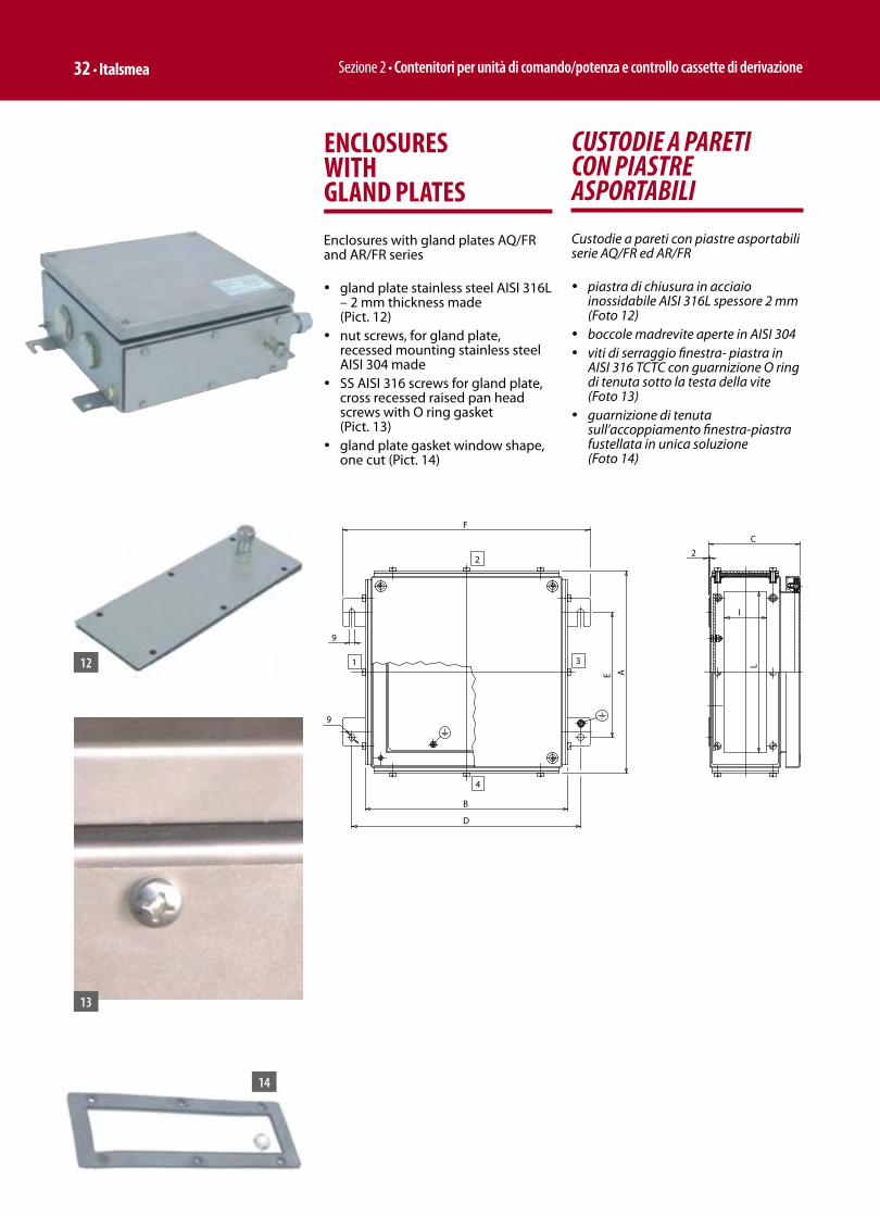
Sezione 2 • Contenitori per unità di comando/potenza e controllo cassette di derivazione 32 • Italsmea
CUSTODIE A PARETI CON PIASTRE ASPORTABILI
Custodie a pareti con piastre asportabili serie AQ/FR ed AR/FR
ü piastra di chiusura in acciaio inossidabile AISI 316L spessore 2 mm (Foto 12)
ü boccole madrevite aperte in AISI 304 ü viti di serraggio finestra- piastra in
AISI 316 TCTC con guarnizione O ring di tenuta sotto la testa della vite (Foto 13)
ü guarnizione di tenuta sull’accoppiamento finestra-piastra fustellata in unica soluzione (Foto 14)
ENCLOSURES WITH GLAND PLATES
Enclosures with gland plates AQ/FR and AR/FR series
ü gland plate stainless steel AISI 316L – 2 mm thickness made (Pict. 12)
ü nut screws, for gland plate, recessed mounting stainless steel AISI 304 made
ü SS AISI 316 screws for gland plate, cross recessed raised pan head screws with O ring gasket (Pict. 13)
ü gland plate gasket window shape, one cut (Pict. 14)
12
13
14
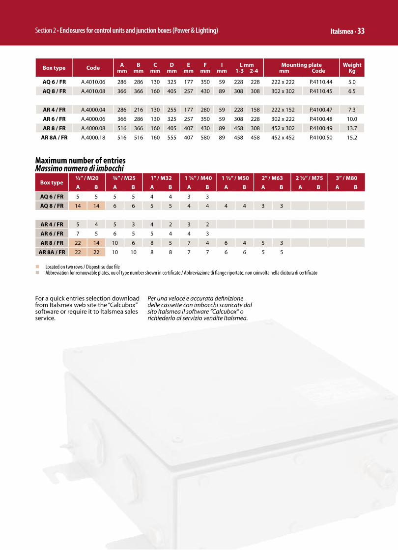
Section 2 • Enclosures for control units and junction boxes (Power & Lighting) Italsmea • 33
Maximum number of entriesMassimo numero di imbocchi
Box type½” / M20 ¾” / M25 1” / M32 1 ¼” / M40 1 ½” / M50 2” / M63 2 ½” / M75 3” / M80
A B A B A B A B A B A B A B A B
AQ 6 / FR 5 5 5 5 4 4 3 3
AQ 8 / FR 14 14 6 6 5 5 4 4 4 4 3 3
AR 4 / FR 5 4 5 3 4 2 3 2
AR 6 / FR 7 5 6 5 5 4 4 3
AR 8 / FR 22 14 10 6 8 5 7 4 6 4 5 3
AR 8A / FR 22 22 10 10 8 8 7 7 6 6 5 5
Box type Code Amm
Bmm
Cmm
Dmm
Emm
Fmm
Imm
L mm1-3 2-4
Mounting plate mm Code
Weight Kg
AQ 6 / FR A.4010.06 286 286 130 325 177 350 59 228 228 222 x 222 P.4110.44 5.0
AQ 8 / FR A.4010.08 366 366 160 405 257 430 89 308 308 302 x 302 P.4110.45 6.5
AR 4 / FR A.4000.04 286 216 130 255 177 280 59 228 158 222 x 152 P.4100.47 7.3
AR 6 / FR A.4000.06 366 286 130 325 257 350 59 308 228 302 x 222 P.4100.48 10.0
AR 8 / FR A.4000.08 516 366 160 405 407 430 89 458 308 452 x 302 P.4100.49 13.7
AR 8A / FR A.4000.18 516 516 160 555 407 580 89 458 458 452 x 452 P.4100.50 15.2
n Located on two rows / Disposti su due fi len Abbreviation for remouvable plates, ou of type number shown in certifi cate / Abbreviazione di fl ange riportate, non coinvolta nella dicitura di certifi cato
For a quick entries selection download from Italsmea web site the “Calcubox” software or require it to Italsmea sales service.
Per una veloce e accurata defi nizione delle cassette con imbocchi scaricate dal sito Italsmea il software “Calcubox” o richiederlo al servizio vendite Italsmea.

Sezione 2 • Contenitori per unità di comando/potenza e controllo cassette di derivazione 34 • Italsmea
JUNCTION BOXES
CASSETTE DI DERIVAZIONE
Maximum number of terminals in the AQ / AR boxes - Instrument cables connectionMassimo numero di morsetti nelle cassette AQ / AR – Collegamento cavi di strumentazione
Terminal section / Sezione morsetto 2,5 mm²Terminal thickness / Spessore morsetto 5 mm
Box type
EEx e II T6 (Tamb. 40°C)
EEx e II T6 (Tamb. 50°C)
EEx e II T6 (Tamb. 55°C)
EEx e II T5 (Tamb. 40°C)
EEx e II T5 (Tamb. 50°C)
EEx e II T5 (Tamb. 55°C)
TerminalsNo.
CurrentA
TerminalsNo.
CurrentA
TerminalsNo.
CurrentA
TerminalsNo.
CurrentA
TerminalsNo.
CurrentA
TerminalsNo.
CurrentA
AQ-6 70 8,5 70 7,5 70 7 70 11 70 9,5 70 8,5
AQ-8 102 8 102 7 102 6,5 102 10,5 102 9 102 8
AR-2 22 14 22 12 22 11,5 22 16 22 15,5 22 14
AR-4 35 11,5 35 10 35 9,5 35 14,5 35 13 35 11,5
AR-6 102 7 102 6 102 6 102 9 102 8 102 7
AR-8 162 6 162 5 162 4,5 162 8 162 6,5 162 6
AR-8A 243 5,5 243 4,5 243 4,5 243 6,5 243 6 243 · 5,5
n Located on two rows / Disposti su due fi len Located on three rows / Disposti su tre fi le
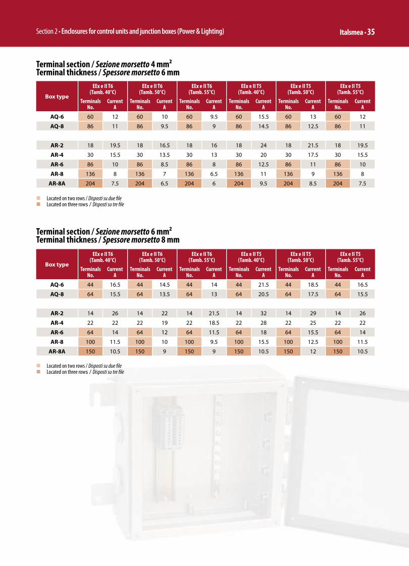
Section 2 • Enclosures for control units and junction boxes (Power & Lighting) Italsmea • 35
Box type
EEx e II T6 (Tamb. 40°C)
EEx e II T6 (Tamb. 50°C)
EEx e II T6 (Tamb. 55°C)
EEx e II T5 (Tamb. 40°C)
EEx e II T5 (Tamb. 50°C)
EEx e II T5 (Tamb. 55°C)
TerminalsNo.
CurrentA
TerminalsNo.
CurrentA
TerminalsNo.
CurrentA
TerminalsNo.
CurrentA
TerminalsNo.
CurrentA
TerminalsNo.
CurrentA
AQ-6 60 12 60 10 60 9.5 60 15.5 60 13 60 12
AQ-8 86 11 86 9.5 86 9 86 14.5 86 12.5 86 11
AR-2 18 19.5 18 16.5 18 16 18 24 18 21.5 18 19.5
AR-4 30 15.5 30 13.5 30 13 30 20 30 17.5 30 15.5
AR-6 86 10 86 8.5 86 8 86 12.5 86 11 86 10
AR-8 136 8 136 7 136 6.5 136 11 136 9 136 8
AR-8A 204 7.5 204 6.5 204 6 204 9.5 204 8.5 204 7.5
Terminal section / Sezione morsetto 4 mm²Terminal thickness / Spessore morsetto 6 mm
Box type
EEx e II T6 (Tamb. 40°C)
EEx e II T6 (Tamb. 50°C)
EEx e II T6 (Tamb. 55°C)
EEx e II T5 (Tamb. 40°C)
EEx e II T5 (Tamb. 50°C)
EEx e II T5 (Tamb. 55°C)
TerminalsNo.
CurrentA
TerminalsNo.
CurrentA
TerminalsNo.
CurrentA
TerminalsNo.
CurrentA
TerminalsNo.
CurrentA
TerminalsNo.
CurrentA
AQ-6 44 16.5 44 14.5 44 14 44 21.5 44 18.5 44 16.5
AQ-8 64 15.5 64 13.5 64 13 64 20.5 64 17.5 64 15.5
AR-2 14 26 14 22 14 21.5 14 32 14 29 14 26
AR-4 22 22 22 19 22 18.5 22 28 22 25 22 22
AR-6 64 14 64 12 64 11.5 64 18 64 15.5 64 14
AR-8 100 11.5 100 10 100 9.5 100 15.5 100 12.5 100 11.5
AR-8A 150 10.5 150 9 150 9 150 10.5 150 12 150 10.5
Terminal section / Sezione morsetto 6 mm²Terminal thickness / Spessore morsetto 8 mm
n Located on two rows / Disposti su due fi len Located on three rows / Disposti su tre fi le
n Located on two rows / Disposti su due fi len Located on three rows / Disposti su tre fi le

Sezione 2 • Contenitori per unità di comando/potenza e controllo cassette di derivazione 36 • Italsmea
Box type
EEx e II T6 (Tamb. 40°C)
EEx e II T6 (Tamb. 50°C)
EEx e II T6 (Tamb. 55°C)
EEx e II T5 (Tamb. 40°C)
EEx e II T5 (Tamb. 50°C)
EEx e II T5 (Tamb. 55°C)
TerminalsNo.
CurrentA
TerminalsNo.
CurrentA
TerminalsNo.
CurrentA
TerminalsNo.
CurrentA
TerminalsNo.
CurrentA
TerminalsNo.
CurrentA
AQ-6 34 16 25 16 23 16 56 16 42 16 34 16
AQ-8 42 16 31 16 29 16 72 16 52 16 42 16
AR-2 18 16 18 16 18 16 18 16 18 16 18 16
AR-4 29 16 22 16 21 16 30 16 30 16 29 16
AR-6 35 16 26 16 24 16 56 16 43 16 35 16
AR-8 36 16 27 16 25 16 65 16 45 16 36 16
AR-8A 73 16 35 16 33 16 73 16 58 16 47 16
Terminal section / Sezione morsetto 4 mm²Terminal thickness / Spessore morsetto 6 mm
n Located on two rows / Disposti su due fi le
Box type
EEx e II T6 (Tamb. 40°C)
EEx e II T6 (Tamb. 50°C)
EEx e II T6 (Tamb. 55°C)
EEx e II T5 (Tamb. 40°C)
EEx e II T5 (Tamb. 50°C)
EEx e II T5 (Tamb. 55°C)
TerminalsNo.
CurrentA
TerminalsNo.
CurrentA
TerminalsNo.
CurrentA
TerminalsNo.
CurrentA
TerminalsNo.
CurrentA
TerminalsNo.
CurrentA
AQ-6 55 10 41 10 38 10 70 10 68 10 55 10
AQ-8 68 10 50 10 47 10 102 10 85 10 68 10
AR-2 22 10 22 10 22 10 22 10 22 10 22 10
AR-4 35 10 35 10 34 10 35 10 35 10 35 10
AR-6 56 10 43 10 38 10 91 10 70 10 56 10
AR-8 58 10 43 10 40 10 105 10 72 10 58 10
AR-8A 76 10 56 10 53 10 117 10 94 10 76 10
Terminal section / Sezione morsetto 2.5 mm²Terminal thickness / Spessore morsetto 5 mm
Important NoteDecreasing the current intensity value of each terminal is possible to increase the number of terminalsDecreasing the number of terminals is possible to increase the current intensity value of each terminal
Nota ImportanteDiminuendo il valore d’intensità di corrente di ciascun morsetto è possibile aumentare il numero di morsettiDiminuendo il numero di morsetti è possibile aumentare il valore d’intensità di corrente di ciascun morsetto
n Located on two rows / Disposti su due fi le
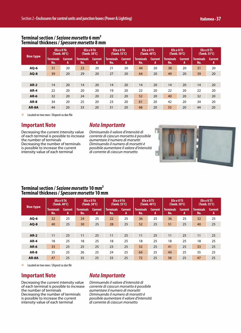
Section 2 • Enclosures for control units and junction boxes (Power & Lighting) Italsmea • 37
Box type
EEx e II T6 (Tamb. 40°C)
EEx e II T6 (Tamb. 50°C)
EEx e II T6 (Tamb. 55°C)
EEx e II T5 (Tamb. 40°C)
EEx e II T5 (Tamb. 50°C)
EEx e II T5 (Tamb. 55°C)
TerminalsNo.
CurrentA
TerminalsNo.
CurrentA
TerminalsNo.
CurrentA
TerminalsNo.
CurrentA
TerminalsNo.
CurrentA
TerminalsNo.
CurrentA
AQ-6 31 20 23 20 21 20 44 20 38 20 31 20
AQ-8 39 20 29 20 27 20 64 20 49 20 39 20
AR-2 14 20 14 20 14 20 14 20 14 20 14 20
AR-4 22 20 20 20 19 20 22 20 22 20 22 20
AR-6 32 20 24 20 22 20 52 20 40 20 32 20
AR-8 34 20 25 20 23 20 61 20 42 20 34 20
AR-8A 44 20 33 20 31 20 68 20 55 20 44 20
Terminal section / Sezione morsetto 6 mm²Terminal thickness / Spessore morsetto 8 mm
Important NoteDecreasing the current intensity value of each terminal is possible to increase the number of terminalsDecreasing the number of terminals is possible to increase the current intensity value of each terminal
Nota ImportanteDiminuendo il valore d’intensità di corrente di ciascun morsetto è possibile aumentare il numero di morsettiDiminuendo il numero di morsetti è possibile aumentare il valore d’intensità di corrente di ciascun morsetto
Box type
EEx e II T6 (Tamb. 40°C)
EEx e II T6 (Tamb. 50°C)
EEx e II T6 (Tamb. 55°C)
EEx e II T5 (Tamb. 40°C)
EEx e II T5 (Tamb. 50°C)
EEx e II T5 (Tamb. 55°C)
TerminalsNo.
CurrentA
TerminalsNo.
CurrentA
TerminalsNo.
CurrentA
TerminalsNo.
CurrentA
TerminalsNo.
CurrentA
TerminalsNo.
CurrentA
AQ-6 32 25 24 25 22 25 36 25 36 25 32 25
AQ-8 40 25 30 25 28 25 52 25 51 25 40 25
AR-2 11 25 11 25 11 25 11 25 11 25 11 25
AR-4 18 25 18 25 18 25 18 25 18 25 18 25
AR-6 33 25 25 25 23 25 52 25 41 25 33 25
AR-8 35 25 26 25 24 25 64 25 44 25 35 25
AR-8A 47 25 35 25 33 25 72 25 58 25 47 25
Terminal section / Sezione morsetto 10 mm²Terminal thickness / Spessore morsetto 10 mm
Important NoteDecreasing the current intensity value of each terminal is possible to increase the number of terminalsDecreasing the number of terminals is possible to increase the current intensity value of each terminal
Nota ImportanteDiminuendo il valore d’intensità di corrente di ciascun morsetto è possibile aumentare il numero di morsettiDiminuendo il numero di morsetti è possibile aumentare il valore d’intensità di corrente di ciascun morsetto
n Located on two rows / Disposti su due fi le
n Located on two rows / Disposti su due fi le
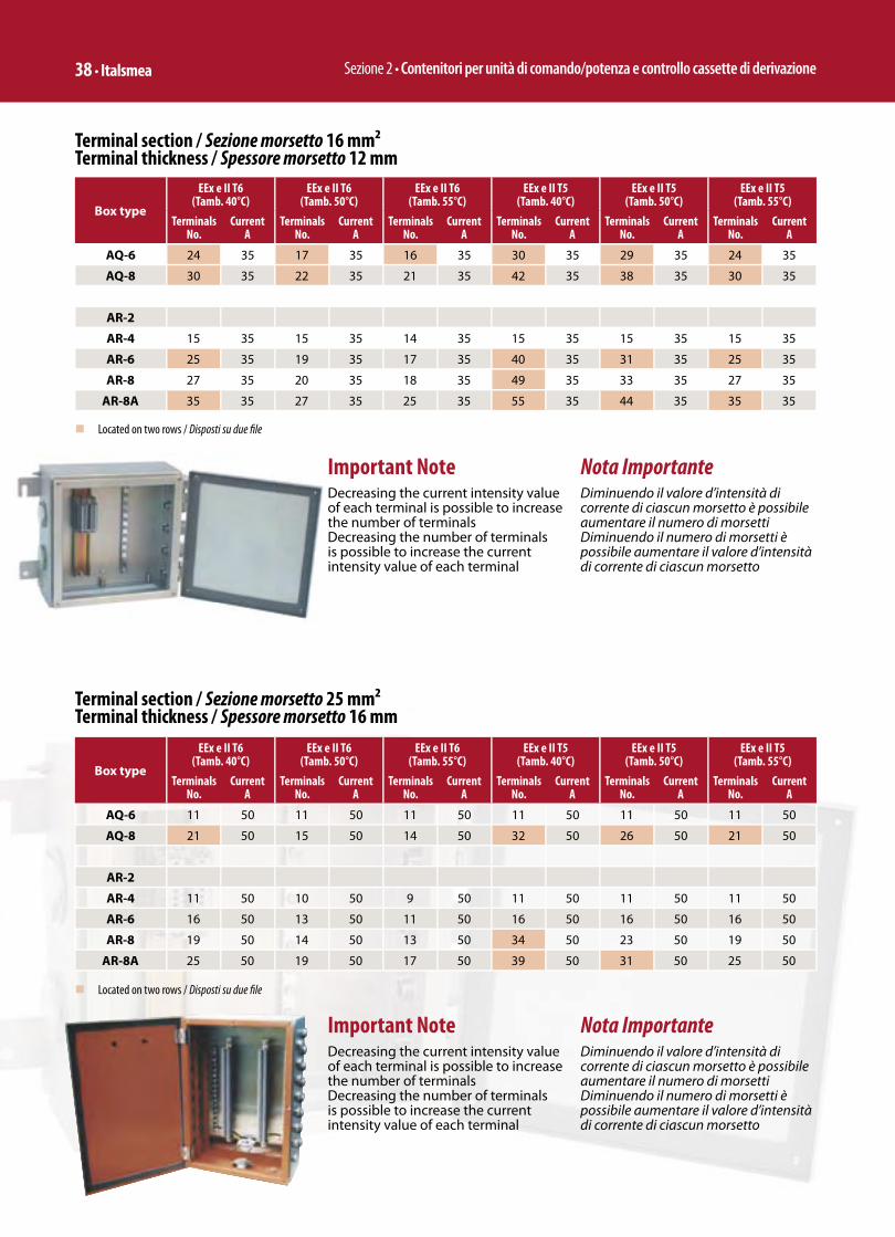
Sezione 2 • Contenitori per unità di comando/potenza e controllo cassette di derivazione 38 • Italsmea
Box type
EEx e II T6 (Tamb. 40°C)
EEx e II T6 (Tamb. 50°C)
EEx e II T6 (Tamb. 55°C)
EEx e II T5 (Tamb. 40°C)
EEx e II T5 (Tamb. 50°C)
EEx e II T5 (Tamb. 55°C)
TerminalsNo.
CurrentA
TerminalsNo.
CurrentA
TerminalsNo.
CurrentA
TerminalsNo.
CurrentA
TerminalsNo.
CurrentA
TerminalsNo.
CurrentA
AQ-6 11 50 11 50 11 50 11 50 11 50 11 50
AQ-8 21 50 15 50 14 50 32 50 26 50 21 50
AR-2
AR-4 11 50 10 50 9 50 11 50 11 50 11 50
AR-6 16 50 13 50 11 50 16 50 16 50 16 50
AR-8 19 50 14 50 13 50 34 50 23 50 19 50
AR-8A 25 50 19 50 17 50 39 50 31 50 25 50
Terminal section / Sezione morsetto 25 mm²Terminal thickness / Spessore morsetto 16 mm
n Located on two rows / Disposti su due fi le
Important NoteDecreasing the current intensity value of each terminal is possible to increase the number of terminalsDecreasing the number of terminals is possible to increase the current intensity value of each terminal
Nota ImportanteDiminuendo il valore d’intensità di corrente di ciascun morsetto è possibile aumentare il numero di morsettiDiminuendo il numero di morsetti è possibile aumentare il valore d’intensità di corrente di ciascun morsetto
Terminal section / Sezione morsetto 16 mm²Terminal thickness / Spessore morsetto 12 mm
Important NoteDecreasing the current intensity value of each terminal is possible to increase the number of terminalsDecreasing the number of terminals is possible to increase the current intensity value of each terminal
Nota ImportanteDiminuendo il valore d’intensità di corrente di ciascun morsetto è possibile aumentare il numero di morsettiDiminuendo il numero di morsetti è possibile aumentare il valore d’intensità di corrente di ciascun morsetto
n Located on two rows / Disposti su due fi le
Box type
EEx e II T6 (Tamb. 40°C)
EEx e II T6 (Tamb. 50°C)
EEx e II T6 (Tamb. 55°C)
EEx e II T5 (Tamb. 40°C)
EEx e II T5 (Tamb. 50°C)
EEx e II T5 (Tamb. 55°C)
TerminalsNo.
CurrentA
TerminalsNo.
CurrentA
TerminalsNo.
CurrentA
TerminalsNo.
CurrentA
TerminalsNo.
CurrentA
TerminalsNo.
CurrentA
AQ-6 24 35 17 35 16 35 30 35 29 35 24 35
AQ-8 30 35 22 35 21 35 42 35 38 35 30 35
AR-2
AR-4 15 35 15 35 14 35 15 35 15 35 15 35
AR-6 25 35 19 35 17 35 40 35 31 35 25 35
AR-8 27 35 20 35 18 35 49 35 33 35 27 35
AR-8A 35 35 27 35 25 35 55 35 44 35 35 35

Section 2 • Enclosures for control units and junction boxes (Power & Lighting) Italsmea • 39
Box type
EEx e II T6 (Tamb. 40°C)
EEx e II T6 (Tamb. 50°C)
EEx e II T6 (Tamb. 55°C)
EEx e II T5 (Tamb. 40°C)
EEx e II T5 (Tamb. 50°C)
EEx e II T5 (Tamb. 55°C)
TerminalsNo.
CurrentA
TerminalsNo.
CurrentA
TerminalsNo.
CurrentA
TerminalsNo.
CurrentA
TerminalsNo.
CurrentA
TerminalsNo.
CurrentA
AQ-6 11 63 9 63 8 63 11 63 11 63 11 63
AQ-8 16 63 12 63 11 63 28 63 21 63 16 63
AR-2
AR-4 10 63 8 63 7 63 11 63 11 63 10 63
AR-6 13 63 10 63 9 63 16 63 16 63 13 63
AR-8 15 63 11 63 10 63 27 63 19 63 15 63
AR-8A 20 63 15 63 14 63 32 63 25 63 20 63
Terminal section / Sezione morsetto 35 mm²Terminal thickness / Spessore morsetto 16 mm
n Located on two rows / Disposti su due fi le
Important NoteDecreasing the current intensity value of each terminal is possible to increase the number of terminalsDecreasing the number of terminals is possible to increase the current intensity value of each terminal
Nota ImportanteDiminuendo il valore d’intensità di corrente di ciascun morsetto è possibile aumentare il numero di morsettiDiminuendo il numero di morsetti è possibile aumentare il valore d’intensità di corrente di ciascun morsetto
Box type
EEx e II T6 (Tamb. 40°C)
EEx e II T6 (Tamb. 50°C)
EEx e II T6 (Tamb. 55°C)
EEx e II T5 (Tamb. 40°C)
EEx e II T5 (Tamb. 50°C)
EEx e II T5 (Tamb. 55°C)
TerminalsNo.
CurrentA
TerminalsNo.
CurrentA
TerminalsNo.
CurrentA
TerminalsNo.
CurrentA
TerminalsNo.
CurrentA
TerminalsNo.
CurrentA
AQ-6
AQ-8 10 100 7 100 7 100 11 100 11 100 10 100
AR-2
AR-4
AR-6 8 100 6 100 5 100 8 100 8 100 8 100
AR-8 9 100 7 100 6 100 17 100 11 100 9 100
AR-8A 13 100 10 100 9 100 18 100 16 100 13 100
Terminal section / Sezione morsetto 70 mm²Terminal thickness / Spessore morsetto 22 mm
Important NoteDecreasing the current intensity value of each terminal is possible to increase the number of terminalsDecreasing the number of terminals is possible to increase the current intensity value of each terminal
Nota ImportanteDiminuendo il valore d’intensità di corrente di ciascun morsetto è possibile aumentare il numero di morsettiDiminuendo il numero di morsetti è possibile aumentare il valore d’intensità di corrente di ciascun morsetto
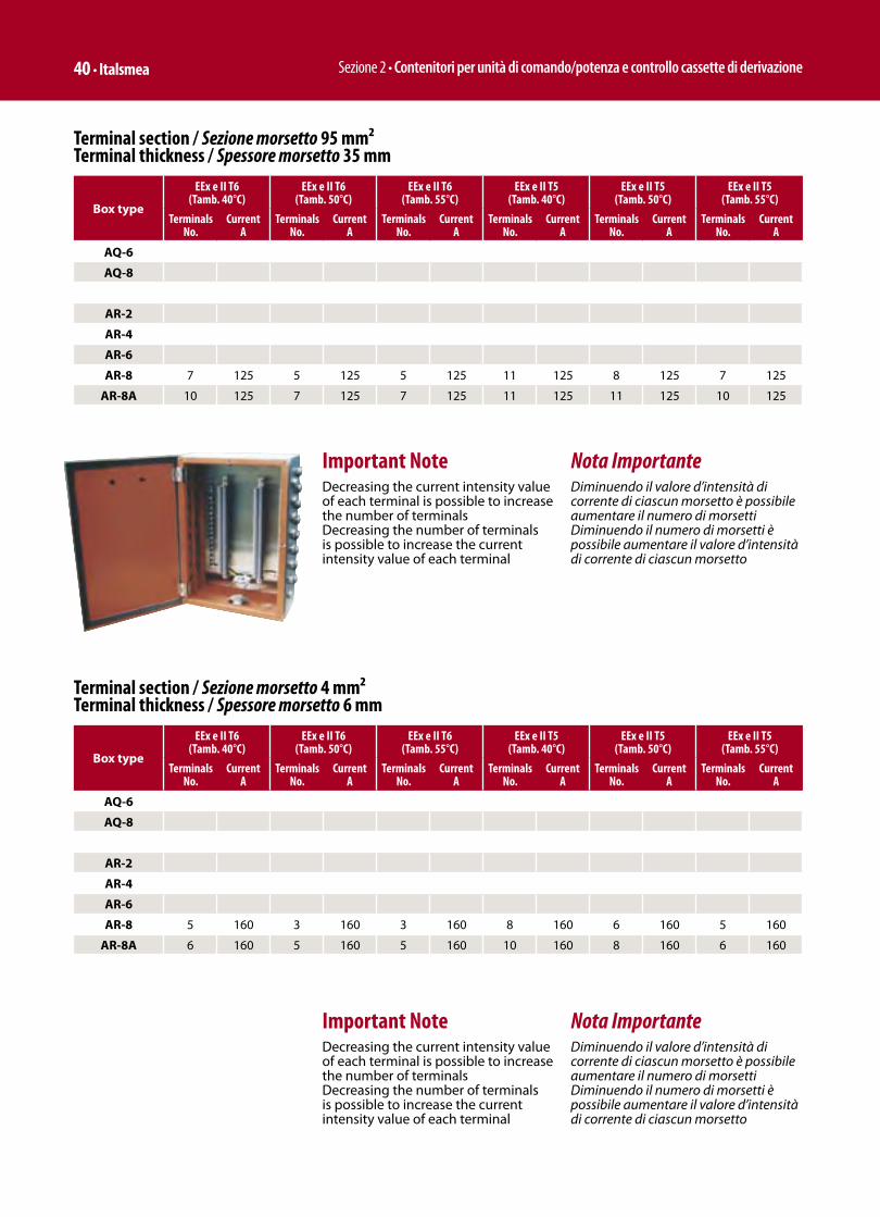
Sezione 2 • Contenitori per unità di comando/potenza e controllo cassette di derivazione 40 • Italsmea
Box type
EEx e II T6 (Tamb. 40°C)
EEx e II T6 (Tamb. 50°C)
EEx e II T6 (Tamb. 55°C)
EEx e II T5 (Tamb. 40°C)
EEx e II T5 (Tamb. 50°C)
EEx e II T5 (Tamb. 55°C)
TerminalsNo.
Current A
TerminalsNo.
Current A
TerminalsNo.
Current A
TerminalsNo.
Current A
TerminalsNo.
Current A
TerminalsNo.
Current A
AQ-6
AQ-8
AR-2
AR-4
AR-6
AR-8 5 160 3 160 3 160 8 160 6 160 5 160
AR-8A 6 160 5 160 5 160 10 160 8 160 6 160
Terminal section / Sezione morsetto 4 mm²Terminal thickness / Spessore morsetto 6 mm
Important NoteDecreasing the current intensity value of each terminal is possible to increase the number of terminalsDecreasing the number of terminals is possible to increase the current intensity value of each terminal
Nota ImportanteDiminuendo il valore d’intensità di corrente di ciascun morsetto è possibile aumentare il numero di morsettiDiminuendo il numero di morsetti è possibile aumentare il valore d’intensità di corrente di ciascun morsetto
Box type
EEx e II T6 (Tamb. 40°C)
EEx e II T6 (Tamb. 50°C)
EEx e II T6 (Tamb. 55°C)
EEx e II T5 (Tamb. 40°C)
EEx e II T5 (Tamb. 50°C)
EEx e II T5 (Tamb. 55°C)
TerminalsNo.
Current A
TerminalsNo.
Current A
TerminalsNo.
Current A
TerminalsNo.
Current A
TerminalsNo.
Current A
TerminalsNo.
Current A
AQ-6
AQ-8
AR-2
AR-4
AR-6
AR-8 7 125 5 125 5 125 11 125 8 125 7 125
AR-8A 10 125 7 125 7 125 11 125 11 125 10 125
Terminal section / Sezione morsetto 95 mm²Terminal thickness / Spessore morsetto 35 mm
Important NoteDecreasing the current intensity value of each terminal is possible to increase the number of terminalsDecreasing the number of terminals is possible to increase the current intensity value of each terminal
Nota ImportanteDiminuendo il valore d’intensità di corrente di ciascun morsetto è possibile aumentare il numero di morsettiDiminuendo il numero di morsetti è possibile aumentare il valore d’intensità di corrente di ciascun morsetto
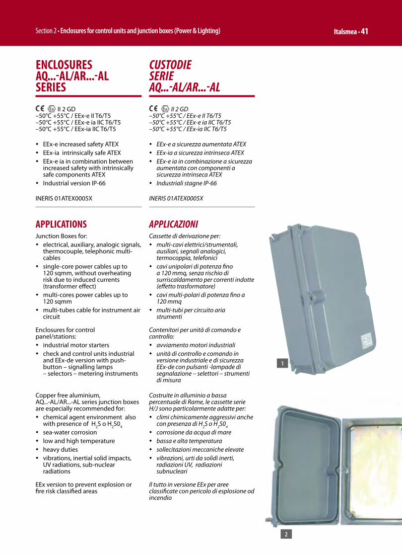
Section 2 • Enclosures for control units and junction boxes (Power & Lighting) Italsmea • 41
ENCLOSURES AQ...-AL/AR...-AL SERIES
II 2 GD –50°C +55°C / EEx-e II T6/T5–50°C +55°C / EEx-e ia IIC T6/T5 –50°C +55°C / EEx-ia IIC T6/T5
ü EEx-e increased safety ATEXü EEx-ia intrinsically safe ATEXü EEx-e ia in combination between
increased safety with intrinsically safe components ATEX
ü Industrial version IP-66
INERIS 01ATEX0005X
APPLICATIONSJunction Boxes for:ü electrical, auxiliary, analogic signals,
thermocouple, telephonic multi-cables
ü single-core power cables up to 120 sqmm, without overheating risk due to induced currents (transformer effect)
ü multi-cores power cables up to 120 sqmm
ü multi-tubes cable for instrument air circuit
Enclosures for control panel/stations:ü industrial motor startersü check and control units industrial
and EEx-de version with push-button – signalling lamps – selectors – metering instruments
Copper free aluminium, AQ...-AL/AR...-AL series junction boxes are especially recommended for:ü chemical agent environment also
with presence of H2S o H
2S0
4
ü sea-water corrosionü low and high temperatureü heavy dutiesü vibrations, inertial solid impacts,
UV radiations, sub-nuclear radiations
EEx version to prevent explosion or fire risk classified areas
CUSTODIE SERIE AQ...-AL/AR...-AL
II 2 GD –50°C +55°C / EEx-e II T6/T5–50°C +55°C / EEx-e ia IIC T6/T5 –50°C +55°C / EEx-ia IIC T6/T5
ü EEx-e a sicurezza aumentata ATEXü EEx-ia a sicurezza intrinseca ATEXü EEx-e ia in combinazione a sicurezza
aumentata con componenti a sicurezza intrinseca ATEX
ü Industriali stagne IP-66
INERIS 01ATEX0005X
APPLICAZIONICassette di derivazione per:ü multi-cavi elettrici/strumentali,
ausiliari, segnali analogici, termocoppia, telefonici
ü cavi unipolari di potenza fino a 120 mmq, senza rischio di surriscaldamento per correnti indotte (effetto trasformatore)
ü cavi multi-polari di potenza fino a 120 mmq
ü multi-tubi per circuito aria strumenti
Contenitori per unità di comando e controllo:ü avviamento motori industrialiü unità di controllo e comando in
versione industriale e di sicurezza EEx-de con pulsanti -lampade di segnalazione – selettori – strumenti di misura
Costruite in alluminio a bassa percentuale di Rame, le cassette serie H/J sono particolarmente adatte per:ü climi chimicamente aggressivi anche
con presenza di H2S o H
2S0
4
ü corrosione da acqua di mareü bassa e alta temperaturaü sollecitazioni meccaniche elevate ü vibrazioni, urti da solidi inerti,
radiazioni UV, radiazioni subnucleari
Il tutto in versione EEx per aree classificate con pericolo di esplosione od incendio
1
2
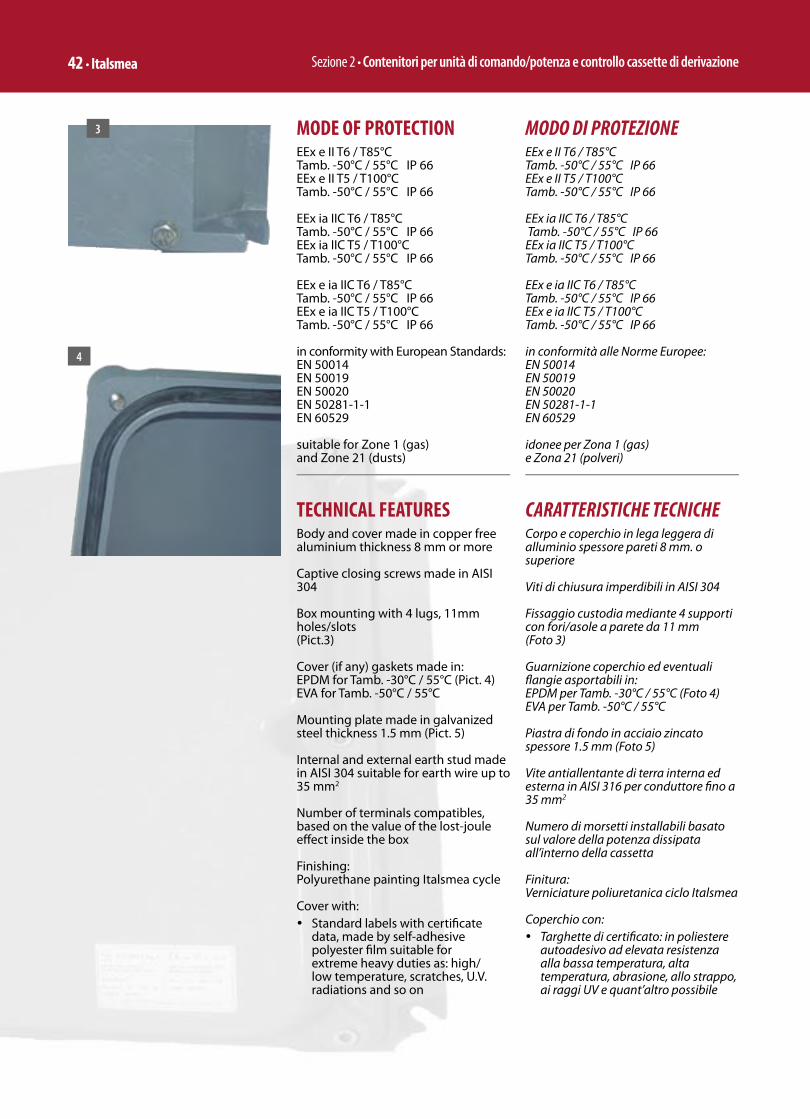
Sezione 2 • Contenitori per unità di comando/potenza e controllo cassette di derivazione 42 • Italsmea
MODO DI PROTEZIONEEEx e II T6 / T85°CTamb. -50°C / 55°C IP 66EEx e II T5 / T100°CTamb. -50°C / 55°C IP 66
EEx ia IIC T6 / T85°C Tamb. -50°C / 55°C IP 66EEx ia IIC T5 / T100°CTamb. -50°C / 55°C IP 66
EEx e ia IIC T6 / T85°CTamb. -50°C / 55°C IP 66EEx e ia IIC T5 / T100°CTamb. -50°C / 55°C IP 66
in conformità alle Norme Europee:EN 50014EN 50019EN 50020EN 50281-1-1EN 60529
idonee per Zona 1 (gas) e Zona 21 (polveri)
CARATTERISTICHE TECNICHECorpo e coperchio in lega leggera di alluminio spessore pareti 8 mm. o superiore
Viti di chiusura imperdibili in AISI 304
Fissaggio custodia mediante 4 supporti con fori/asole a parete da 11 mm (Foto 3)
Guarnizione coperchio ed eventuali fl angie asportabili in:EPDM per Tamb. -30°C / 55°C (Foto 4)EVA per Tamb. -50°C / 55°C Piastra di fondo in acciaio zincato spessore 1.5 mm (Foto 5)
Vite antiallentante di terra interna ed esterna in AISI 316 per conduttore fi no a 35 mm2
Numero di morsetti installabili basato sul valore della potenza dissipata all’interno della cassetta
Finitura: Verniciature poliuretanica ciclo Italsmea
Coperchio con: ü Targhette di certifi cato: in poliestere
autoadesivo ad elevata resistenza alla bassa temperatura, alta temperatura, abrasione, allo strappo, ai raggi UV e quant’altro possibile
MODE OF PROTECTIONEEx e II T6 / T85°CTamb. -50°C / 55°C IP 66EEx e II T5 / T100°CTamb. -50°C / 55°C IP 66
EEx ia IIC T6 / T85°CTamb. -50°C / 55°C IP 66EEx ia IIC T5 / T100°CTamb. -50°C / 55°C IP 66
EEx e ia IIC T6 / T85°CTamb. -50°C / 55°C IP 66EEx e ia IIC T5 / T100°CTamb. -50°C / 55°C IP 66
in conformity with European Standards:EN 50014EN 50019EN 50020EN 50281-1-1EN 60529
suitable for Zone 1 (gas) and Zone 21 (dusts)
TECHNICAL FEATURESBody and cover made in copper free aluminium thickness 8 mm or more
Captive closing screws made in AISI 304
Box mounting with 4 lugs, 11mm holes/slots (Pict.3)
Cover (if any) gaskets made in:EPDM for Tamb. -30°C / 55°C (Pict. 4)EVA for Tamb. -50°C / 55°C
Mounting plate made in galvanized steel thickness 1.5 mm (Pict. 5)
Internal and external earth stud made in AISI 304 suitable for earth wire up to 35 mm2
Number of terminals compatibles, based on the value of the lost-joule eff ect inside the box
Finishing: Polyurethane painting Italsmea cycle
Cover with:ü Standard labels with certifi cate
data, made by self-adhesive polyester fi lm suitable for extreme heavy duties as: high/low temperature, scratches, U.V. radiations and so on
3
4
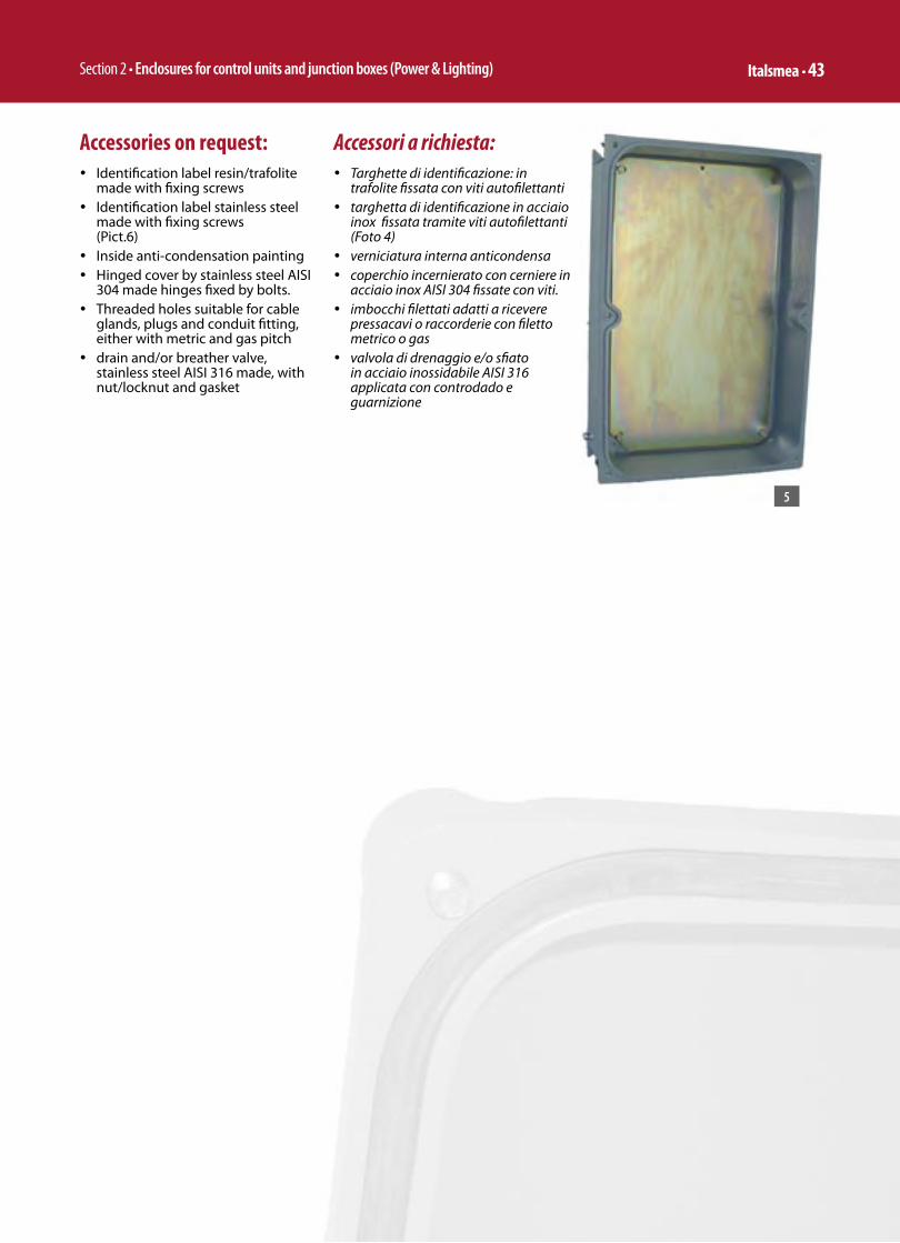
Section 2 • Enclosures for control units and junction boxes (Power & Lighting) Italsmea • 43
Accessories on request:ü Identifi cation label resin/trafolite
made with fi xing screws ü Identifi cation label stainless steel
made with fi xing screws (Pict.6)
ü Inside anti-condensation paintingü Hinged cover by stainless steel AISI
304 made hinges fi xed by bolts. ü Threaded holes suitable for cable
glands, plugs and conduit fi tting, either with metric and gas pitch
ü drain and/or breather valve, stainless steel AISI 316 made, with nut/locknut and gasket
Accessori a richiesta: ü Targhette di identifi cazione: in
trafolite fi ssata con viti autofi lettanti ü targhetta di identifi cazione in acciaio
inox fi ssata tramite viti autofi lettanti (Foto 4)
ü verniciatura interna anticondensa ü coperchio incernierato con cerniere in
acciaio inox AISI 304 fi ssate con viti. ü imbocchi fi lettati adatti a ricevere
pressacavi o raccorderie con fi letto metrico o gas
ü valvola di drenaggio e/o sfi ato in acciaio inossidabile AISI 316 applicata con controdado e guarnizione
5
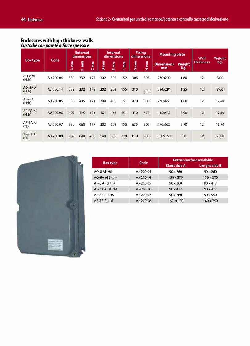
Sezione 2 • Contenitori per unità di comando/potenza e controllo cassette di derivazione 44 • Italsmea
Enclosures with high thickness walls Custodie con parete a forte spessore
Box type Code
External dimensions
Internal dimensions
Fixing dimensions Mounting plate
Wall thickness
WeightKg.
A m
m
B m
m
C m
m
D m
m
E m
m
F m
m
G m
m
H m
m Dimensionsmm
Weight Kg.
AQ-8 Al (Hth) A.4200.04 332 332 175 302 302 152 305 305 270x290 1.60 12 8,00
AQ-8A Al (Hth) A.4200.14 332 332 178 302 302 155 310 320 294x294 1.25 12 8,00
AR-8 Al (Hth) A.4200.05 330 495 171 304 455 151 470 305 270x455 1,80 12 12,40
AR-8A Al (Hth) A.4200.06 495 495 171 461 461 151 470 470 432x432 3,00 12 17,30
AR-8A Al (*)S A.4200.07 330 660 177 302 622 150 635 305 270x622 2,70 12 16,70
AR-8A Al (*)L A.4200.08 580 840 205 540 800 178 810 550 500x760 10 12 36,00
Box type CodeEntries surface available
Short side A Lenght side B
AQ-8 Al (Hth) A.4200.04 90 x 260 90 x 260
AQ-8A Al (Hth) A.4200.14 138 x 270 138 x 270
AR-8 Al (Hth) A.4200.05 90 x 260 90 x 417
AR-8A Al (Hth) A.4200.06 90 x 417 90 x 417
AR-8A Al (*)S A.4200.07 90 x 260 90 x 590
AR-8A Al (*)L A.4200.08 160 x 490 160 x 750

Section 2 • Enclosures for control units and junction boxes (Power & Lighting) Italsmea • 45
Morsetti Compatibili Vista la praticamente infi nita varietà di combinazioni tra: quantità di morsetti,sezione dei medesimi, Classe di Temperatura e Temperatura Ambiente, per la defi nizione delle morsettiere compatibili, si rimanda all’utilizzo del software Italsmea “Calcubox” normalmente fornito allegato al catalogo Cd e comunque scaricabile dal sito Italsmea.
Terminals CompatibleConsidering the never ending variety of combinations between: quantity of terminals, relevant cross section, Class of Temperature and Ambient Temperature, to set up the compatible terminals strips, we suggest to use the Italsmea software “Calcubox” usually supplied together with the Cd catalogue and nevertheless, downloadable from Italsmea web site Italsmea.
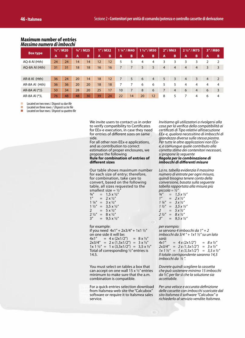
Sezione 2 • Contenitori per unità di comando/potenza e controllo cassette di derivazione 46 • Italsmea
Invitiamo gli utilizzatori a rivolgersi alla casa per la verifi ca della compatibilità ai certifi cati di Tipo relativi all’esecuzione EEx-e, qualora necessitino di imbocchi di grandezza diversa sulla stessa piastra.Per tutte le altre applicazioni non EEx-e, e comunque quale contributo alla corretta stima dei contenitori necessari, si propone la seguente Regola per la combinazione di imbocchi di diff erenti misure
La ns. tabella evidenzia il massimo numero di entrate per ogni misura, quindi bisogna tenere conto della conversione, basata sulla seguente tabella rapportata alla misura più piccola = ½”¾” = 1,5 x ½”1” = 2 x ½”1 ¼” = 3 x ½”1 ½” = 3,5 x ½”2 = 5 x ½”2 ½” = 8 x ½”3” = 9,5 x ½”
per esempio:se servono 4 imbocchi da 1” + 2 imbocchi da 3/4 “ + 1x1 ½” su un lato sarà:4x1” = 4 x (2x1/2”) = 8 x ½”2x3/4” = 2 x (1,5x1/2”) = 3 x ½”1x 1 ½” = 1 x (3,5x1/2”) = 3,5 x ½”Il totale corrispondente saranno 14,5 imbocchi da ½ “.
Dovrete quindi scegliere la cassetta che può sostenere minimo 15 imbocchi da ½”, per far sì che la soluzione sia accettabile.
Per una veloce e accurata defi nizione delle cassette con imbocchi scaricate dal sito Italsmea il software “Calcubox” o richiederlo al servizio vendite Italsmea.
We invite users to contact us in order to verify compatibility to Certifi cates for EEx-e execution, in case they need for entries of diff erent sizes on same side.For all other non-EEx-e applications, and as contribution to correct estimation of proper enclosures, we propose the followingRule for combination of entries of diff erent sizes
Our table shows maximum number for each size of entry; therefore, for combination, take care to convert, based on the following table, all sizes requested to the smallest size = ½”¾” = 1,5 x ½”1” = 2 x ½”1 ¼” = 3 x ½”1 ½” = 3,5 x ½”2 = 5 x ½”2 ½” = 8 x ½”3” = 9,5 x ½”
for example:if you need 4x1” + 2x3/4” + 1x1 ½” on one side it will be:4x1” = 4 x (2x1/2”) = 8 x ½”2x3/4” = 2 x (1,5x1/2”) = 3 x ½”1x 1 ½” = 1 x (3,5x1/2”) = 3,5 x ½”Total of corresponding ½” entries is 14.5.
You must select on tables a box that can accept on one wall 15 x ½” entries minimum to make sure that the a.m. combination is compatible.
For a quick entries selection download from Italsmea web site the “Calcubox” software or require it to Italsmea sales service.
Maximum number of entriesMassimo numero di imbocchi
Box type½” / M20 ¾” / M25 1” / M32 1 ¼” / M40 1 ½” / M50 2” / M63 2 ½” / M75 3” / M80
A B A B A B A B A B A B A B A B
AQ-8 Al (Hth) 24 24 14 14 12 12 5 5 4 4 3 3 3 3 2 2
AQ-8A Al (Hth) 31 31 18 18 16 16 7 7 5 5 4 4 4 4 3 3
AR-8 Al (Hth) 36 24 20 14 18 12 7 5 6 4 5 3 4 3 4 2
AR-8A Al (Hth) 36 36 20 20 18 18 7 7 6 6 5 5 4 4 4 4
AR-8A Al (*)S 50 34 28 20 25 17 10 7 8 6 7 4 6 4 6 3
AR-8A Al (*)L 76 48 48 30 39 24 22 14 20 12 8 5 7 4 6 4
n Located on two rows / Disposti su due fi len Located on three rows / Disposti su tre fi len Located on four rows / Disposti su quattro fi le

Section 2 • Enclosures for control units and junction boxes (Power & Lighting) Italsmea • 17
CONTENITORI PER UNITÀ DI DERIVAZIONE, COMANDO E CONTROLLO SERIE EJB…
II 2 GD –50°C +55°C / EEx-d IIB T6/T5/T4–50°C +40°C / EEx-d (ia) IIB T6 n–50°C +40°C / EEx-d (ib) IIB T6 n–50°C +55°C / Ex-d IIB+H2 T6/T5/T4–50°C +40°C / Ex-d (ia) IIB+H2 T6 n–50°C +40°C / Ex-d (ib) IIB+H2 T6 n• Materiale: Lega di alluminio• Non Verniciate• IP 65/67 su richiesta
INERIS00ATEX0021X
ENCLOSURES FOR CONTROL, CHECK AND CONNECTION UNITS EJB… SERIES
II 2 GD –50°C +55°C / EEx-d IIB T6/T5/T4–50°C +40°C / EEx-d (ia) IIB T6 n–50°C +40°C / EEx-d (ib) IIB T6 n–50°C +55°C / Ex-d IIB+H2 T6/T5/T4–50°C +40°C / Ex-d (ia) IIB+H2 T6 n–50°C +40°C / Ex-d (ib) IIB+H2 T6 n• Material: Copper free aluminium• Unpainted• IP 65/67 on request
INERIS00ATEX0021X
Type EJB 2
EJB 3
EJB 4
EJB 5
EJB 6
EJB 8
EJB 9
EJB 10
EJB 11
EJB 12
EJB 13
EJB 13a
Code 259.10 260.10 261.10 262.10 263.10 265.10 266.10 267.10 268.10 269.10 270.10 270.13
A 298 412 418 480 483 634 535 750 596 805 832 832
B 238 238 302 300 408 365 468 366 505 455 607 607
C 174 177 175 232 238 254 257 292 267 310 314 400
D 230 340 335 392 387 530 426 630 483 690 723 723
E 168 167 220 210 310 262 363 250 394 335 500 500
F 95 85 90 125 130 140 140 185 130 170 115 205
G 135 136 132 182 186 204 204 234 204 243 236 322
H 205 330 300 350 355 495 410 580 445 640 630 630
I 140 150 190 185 280 225 340 205 360 285 405 405
L 250 250 300 300 390 340 440 330 480 425 580 580
M 280 280 320 320 420 370 470 360 510 450 620 620
N 9 9 9 9 9 9 12 12 12 14 14 14
ØP M 6 M 8 M 8 M 8 M 8 M 8 M 10 M 10 M 10 M 12 M 12 M 12
R 20 20 20 20 20 20 20 20 20 20 20 20
Weight ≅ Kg 10,7 13,4 17,5 20,5 33 36,5 40,0 48,5 53,3 73 106 124
A* 12 18 20 22 28 36 34 34 44 54 76 76
E* 160 155 210 200 300 250 350 240 380 325 470 470
220 330 325 385 380 520 420 620 470 675 690 690
A*= Quantità massima di operatori pulsante – lampada selettore passo M32x1,5 prevedibili sul coperchio della cassetta.E*= Dimensioni della piastra interna in mm.
n Gli involucri per una temperatura di ambiente da -25°C a -50°C devono essere dotati di termostato interno che, collegato ad una resistenza di riscaldamento, assicura il mantenimento della temperatura interna a -25°C. Altresì, nel caso di temperatura superiore a 40°C, un termostato deve provvedere a togliere tensione al complesso.
A*= Max. quantity of M32X1,5 push button – pilot lamp – selector switch operators installed on the boxes coverE*= Internal mounting plate dimensions mm
n The enclosures for a temperature of environment from -25°C to -50°C are equipped with an inside thermostat, connected to space heater, to assure the inside temperature to -25°C. Also, in case of temperature over 40°C, a thermostat must cut out tension of circuit.

Sezione 2 • Contenitori per unità di comando/potenza e controllo cassette di derivazione 18 • Italsmea
Indicative maximum quantity of terminals per Size in sqmm(For specifi c quantity contact the our sales service)
Quantità massima indicativa di morsetti per sezione in mmq.(Per quantità specifi che contattare il ns. servizio vendite)
Type EJB 2 EJB 3 EJB 4 EJB 5 EJB 6 EJB 8 EJB 9 EJB 10 EJB 11 EJB 12 EJB 13 EJB 13a
2,5 mmq 48 84 84 96 96 134 96 100 100 180 180 180
4 mmq 48 42 84 96 96 134 96 100 100 180 180 180
6 mmq 40 36 68 80 80 90 80 80 80 90 90 90
10 mmq 32 26 52 60 60 64 60 60 60 108 108 108
16 mmq - 22 44 48 48 58 48 48 46 90 90 90
25 mmq - 10 16 32 18 36 26 36 36 46 70 70
35 mmq - 10 16 16 18 36 26 36 36 18 70 70
50 mmq - 6 12 12 14 14 16 14 25 12 37 37
70 mmq - - - 10 10 10 12 12 18 12 20 20
120 mmq - - - - 8 8 8 8 12 12 17 17
185 mmq - - - - - - - - - 8 14 14
Maximum quantity of entries sides A/BNumero massimo di imbocchi fi lettati sui lati A/B
Type EJB 2 EJB 3 EJB 4 EJB 5 EJB 6 EJB 8 EJB 9 EJB 10 EJB 11 EJB 12 EJB 13 EJB 13a
M20 1/2” 5/4 8/4 8/5 9/5 9/7 12/6 10/8 15/6 11/9 16/8 12/10 12/10
M25 3/4” 5/3 7/3 7/4 8/4 8/6 11/6 9/7 13/5 10/8 14/7 12/10 12/10
M3 21” 4/3 6/2 6/4 6/3 6/5 9/4 7/6 10/4 8/6 11/6 10/8 10/8
M50 1 ½” 3/2 4/2 4/3 5/2 4/4 6/3 5/4 8/3 6/4 8/4 7/5 7/5
M63 2” 2/1 3/1 3/2 4/2 4/3 5/3 4/4 6/2 5/3 7/4 7/4 7/4
M75 2 ½” - - - 3/1 3/2 3/1 3/3 5/1 3/2 4/2 5/4 5/4
M80 3” - - - 2/1 2/2 3/1 2/2 4/1 3/2 4/2 4/3 4/3
4” - - - 1/1 1/1 2/1 2/2 3/1 2/2 3/1 3/2 3/2
Se gli imbocchi fi lettati sono richiesti su uno dei lati, le suddette quantità potranno essere maggiorate (Per la versione con accoppiamento a pressacavi solamente e con defi nizione da parte Italsmea della compatibilità con la norma vigente)
If only one side of the box with entries, the above mentioned quantities may be increased (for cable glands only) with previous check of Italsmea
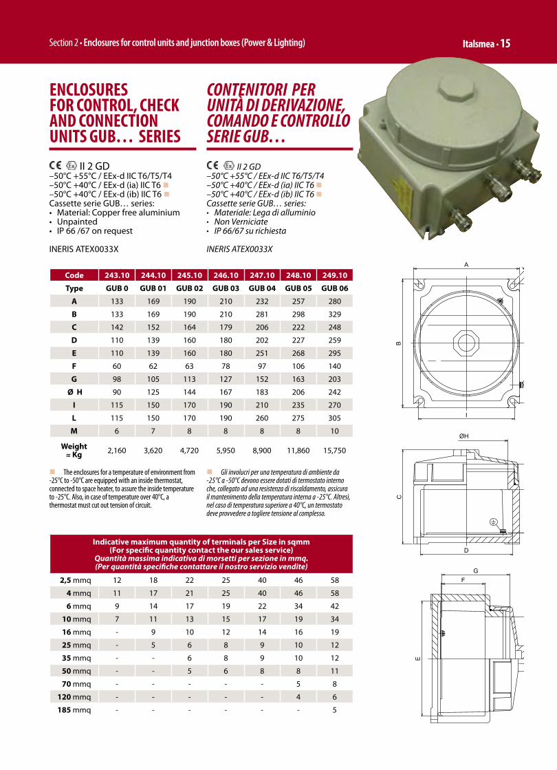
Section 2 • Enclosures for control units and junction boxes (Power & Lighting) Italsmea • 15
CONTENITORI PER UNITÀ DI DERIVAZIONE, COMANDO E CONTROLLO SERIE GUB…
II 2 GD –50°C +55°C / EEx-d IIC T6/T5/T4–50°C +40°C / EEx-d (ia) IIC T6 n–50°C +40°C / EEx-d (ib) IIC T6 nCassette serie GUB… series:• Materiale: Lega di alluminio• Non Verniciate • IP 66/67 su richiesta
INERIS ATEX0033X
ENCLOSURES FOR CONTROL, CHECK AND CONNECTION UNITS GUB… SERIES
II 2 GD –50°C +55°C / EEx-d IIC T6/T5/T4–50°C +40°C / EEx-d (ia) IIC T6 n–50°C +40°C / EEx-d (ib) IIC T6 nCassette serie GUB… series:• Material: Copper free aluminium• Unpainted• IP 66 /67 on request
INERIS ATEX0033X
Code 243.10 244.10 245.10 246.10 247.10 248.10 249.10
Type GUB 0 GUB 01 GUB 02 GUB 03 GUB 04 GUB 05 GUB 06
A 133 169 190 210 232 257 280
B 133 169 190 210 281 298 329
C 142 152 164 179 206 222 248
D 110 139 160 180 202 227 259
E 110 139 160 180 251 268 295
F 60 62 63 78 97 106 140
G 98 105 113 127 152 163 203
Ø H 90 125 144 167 183 206 242
I 115 150 170 190 210 235 270
L 115 150 170 190 260 275 305
M 6 7 8 8 8 8 10
Weight ≅ Kg 2,160 3,620 4,720 5,950 8,900 11,860 15,750
Indicative maximum quantity of terminals per Size in sqmm(For specific quantity contact the our sales service)
Quantità massima indicativa di morsetti per sezione in mmq. (Per quantità specifiche contattare il nostro servizio vendite)
2,5 mmq 12 18 22 25 40 46 58
4 mmq 11 17 21 25 40 46 58
6 mmq 9 14 17 19 22 34 42
10 mmq 7 11 13 15 17 19 34
16 mmq - 9 10 12 14 16 19
25 mmq - 5 6 8 9 10 12
35 mmq - - 6 8 9 10 12
50 mmq - - 5 6 8 8 11
70 mmq - - - - - 5 8
120 mmq - - - - - 4 6
185 mmq - - - - - - 5
G
F
F
G
C
D
E
L
I
B
AM
ØH
ØH
n Gli involucri per una temperatura di ambiente da -25°C a -50°C devono essere dotati di termostato interno che, collegato ad una resistenza di riscaldamento, assicura il mantenimento della temperatura interna a -25°C. Altresì, nel caso di temperatura superiore a 40°C, un termostato deve provvedere a togliere tensione al complesso.
n The enclosures for a temperature of environment from -25°C to -50°C are equipped with an inside thermostat, connected to space heater, to assure the inside temperature to -25°C. Also, in case of temperature over 40°C, a thermostat must cut out tension of circuit.

Sezione 2 • Contenitori per unità di comando/potenza e controllo cassette di derivazione 16 • Italsmea
Maximum quantity of entries sides B/A (*)Numero massimo di imbocchi fi lettati sui lati B/A (*)
Conduit Entries (one row)Imbocchi per raccorderie – conduit (su una fi la)
Cable Glands Entries (two rows)Imbocchi per pressacavi (su due fi le)
Type GUB0
GUB01
GUB02
GUB03
GUB04
GUB05
GUB06 Type GUB
0GUB
01GUB
02GUB
03GUB
04GUB
05GUB
06
M20 1/2” 3/3 3/3 3/3 4/4 5/4 5/4 6/5 M20
1/2” 3/3 3/3 5/5 5/5 7/5 9/7 9/7
M253/4” 2/2 2/2 2/2 4/4 5/4 5/4 5/4 M25
3/4” 2/2 3/3 5/5 5/5 7/5 9/7 9/7
M321” 1/1 2/2 2/2 3/3 4/3 4/3 4/4 M32
1” 1/1 2/2 3/3 3/3 5/5 7/5 7/5
M501 ½” 1/1 1/1 1/1 2/2 3/2 3/2 3/2 M50
1 ½” 1/1 1/1 2/2 2/2 3/2 3/2 5/3
M632” - 1/1 1/1 1/1 2/2 2/2 3/2 M63
2” - 1/1 1/1 1/1 2/2 2/2 3/2
M752 ½” - - - 1/1 2/1 2/2 2/2 M75
2 ½” - - - 1/1 2/1 2/2 2/2
M803” - - - - 1/1 2/1 2/1 M80
3” - - - - 1/1 2/1 2/1
4” - - - - - 1/1 1/1 4” - - - - - 1/1 1/1
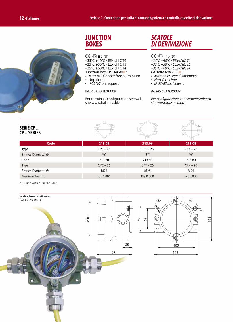
Sezione 2 • Contenitori per unità di comando/potenza e controllo cassette di derivazione 12 • Italsmea
SERIE CP ..CP .. SERIES
Code 213.02 213.06 213.08
Type CPC – 26 CPT – 26 CPX – 26
Entries Diameter Ø ¾” ¾” ¾”
Code 213.20 213.60 213.80
Type CPC – 26 CPT – 26 CPX – 26
Entries Diameter Ø M25 M25 M25
Medium Weight Kg. 0,880 Kg. 0,880 Kg. 0,880
* Su richiesta / On request
Junction boxes CP...-26 series Cassetta serie CP...-26
SCATOLE DI DERIVAZIONE
II 2 GD –35°C +40°C / EEx-d IIC T6–35°C +50°C / EEx-d IIC T5–35°C +60°C / EEx-d IIC T4Cassette serie CP...n :• Materiale: Lega di alluminio• Non Verniciate• IP 65/67 su richiesta
INERIS 03ATEX0009
Per configurazione morsettiere vedere il sito www.italsmea.biz
JUNCTION BOXES
II 2 GD –35°C +40°C / EEx-d IIC T6–35°C +50°C / EEx-d IIC T5–35°C +60°C / EEx-d IIC T4Junction box CP... seriesn :• Material: Copper free aluminium• Unpainted• IP65/67 on request
INERIS 03ATEX0009
For terminals configuration see web site www.italsmea.biz

Section 2 • Enclosures for control units and junction boxes (Power & Lighting) Italsmea • 13
SCATOLE DI DERIVAZIONE
II 2 GD –35°C +40°C / EEx-d IIC T6–35°C +50°C / EEx-d IIC T5–35°C +60°C / EEx-d IIC T4Cassette serie CPS...n :• Materiale: Lega di alluminio• Non Verniciate• IP 65/67 su richiesta
INERIS 03ATEX0009
Per confi gurazione morsettiere vedere il sito www.italsmea.biz
JUNCTION BOXES
II 2 GD –35°C +40°C / EEx-d IIC T6–35°C +50°C / EEx-d IIC T5–35°C +60°C / EEx-d IIC T4Junction box CPS... seriesn :• Material: Copper free aluminium• Unpainted• IP65/67 on request
INERIS 03ATEX0009
For terminals confi guration see web site www.italsmea.biz
SERIE CP ..CP .. SERIES
Code 212.01 212.05 212.07 214.01
Type CPSC – 26 CPST – 26 CPSX – 26 CPSG – 26
Entries Diameter Ø ¾” ¾” ¾” ¾”
Code 212.20 212.25 212.70 214.10
Type CPCS – 26 CPST – 26 CPSX – 26 CPSG – 26
Entries Diameter Ø M25 M25 M25 M25
Medium Weight Kg. 1,270 Kg. 1,270 Kg. 1,270 Kg. 1,270
n ¾” UNI 6125 ANSI B.20.1 NPT

Sezione 2 • Contenitori per unità di comando/potenza e controllo cassette di derivazione 14 • Italsmea
Junction boxes CPS…-26 seriesCassetta serie CPS...-26
SCATOLE DI DERIVAZIONE
II 2 GD –35°C +40°C / EEx-d IIC T6–35°C +50°C / EEx-d IIC T5–35°C +60°C / EEx-d IIC T4Cassette serie CPS… series:• Materiale: Lega di alluminio• Non Verniciate• IP 65/67 su richiesta
INERIS 03ATEX0009
SERIE CP ..CP .. SERIES
Code 212.2 212.6 212.8 215.1
Type CPSC – 36 CPST –36 CPSX – 36 CPSG – 36
Entries Diameter Ø 1”NPT ANSI B.20.1
1”NPT ANSI B.20.1
1”NPT ANSI B.20.1
1”NPT ANSI B.20.1
Medium Weight Kg. 1,270 Kg. 1,270 Kg. 1,270 Kg. 1,270
JUNCTION BOXES
II 2 GD –35°C +40°C / EEx-d IIC T6–35°C +50°C / EEx-d IIC T5–35°C +60°C / EEx-d IIC T4Junction box type CPS… series:• Material: Copper free aluminium• Unpainted• IP 65/67 on request
INERIS 03ATEX0009
Junction boxes CPS…-36 seriesCassetta serie CPS...-36
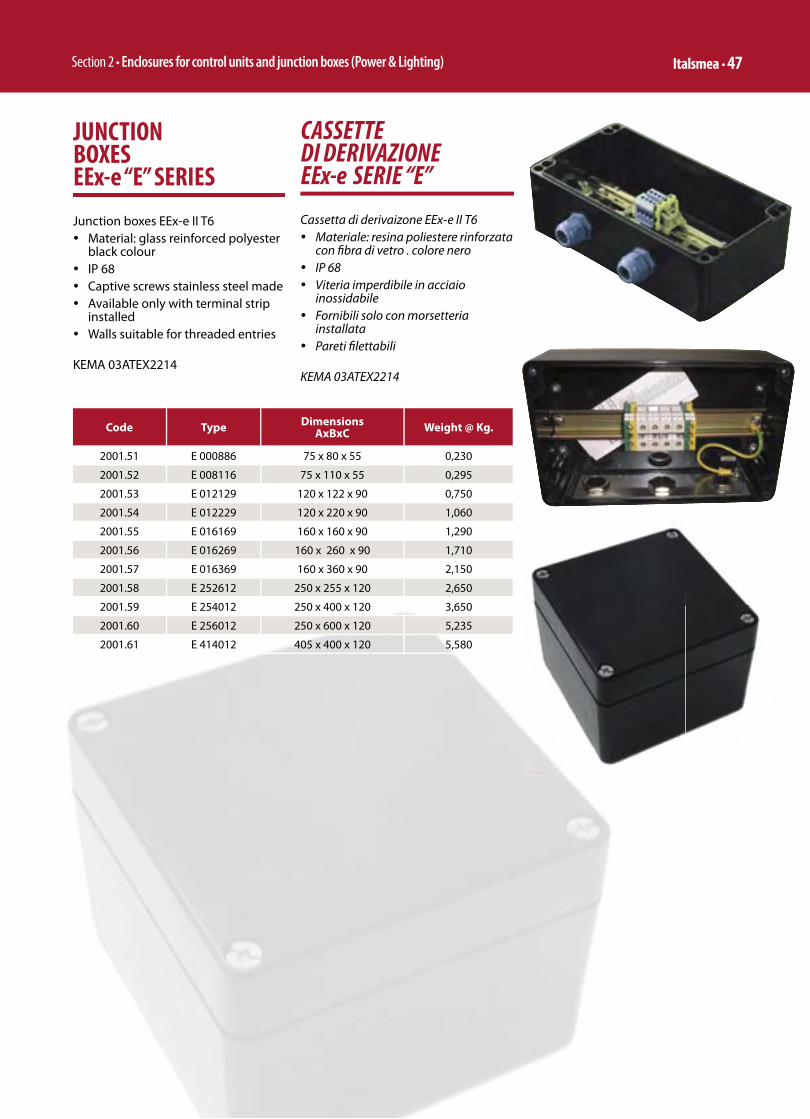
Section 2 • Enclosures for control units and junction boxes (Power & Lighting) Italsmea • 47
CASSETTE DI DERIVAZIONEEEx-e SERIE “E”
Cassetta di derivaizone EEx-e II T6ü Materiale: resina poliestere rinforzata
con fi bra di vetro . colore nero ü IP 68ü Viteria imperdibile in acciaio
inossidabileü Fornibili solo con morsetteria
installataü Pareti fi lettabili
KEMA 03ATEX2214
JUNCTION BOXES EEx-e “E” SERIES
Junction boxes EEx-e II T6ü Material: glass reinforced polyester
black colourü IP 68ü Captive screws stainless steel madeü Available only with terminal strip
installedü Walls suitable for threaded entries
KEMA 03ATEX2214
Code Type DimensionsAxBxC Weight @ Kg.
2001.51 E 000886 75 x 80 x 55 0,230
2001.52 E 008116 75 x 110 x 55 0,295
2001.53 E 012129 120 x 122 x 90 0,750
2001.54 E 012229 120 x 220 x 90 1,060
2001.55 E 016169 160 x 160 x 90 1,290
2001.56 E 016269 160 x 260 x 90 1,710
2001.57 E 016369 160 x 360 x 90 2,150
2001.58 E 252612 250 x 255 x 120 2,650
2001.59 E 254012 250 x 400 x 120 3,650
2001.60 E 256012 250 x 600 x 120 5,235
2001.61 E 414012 405 x 400 x 120 5,580
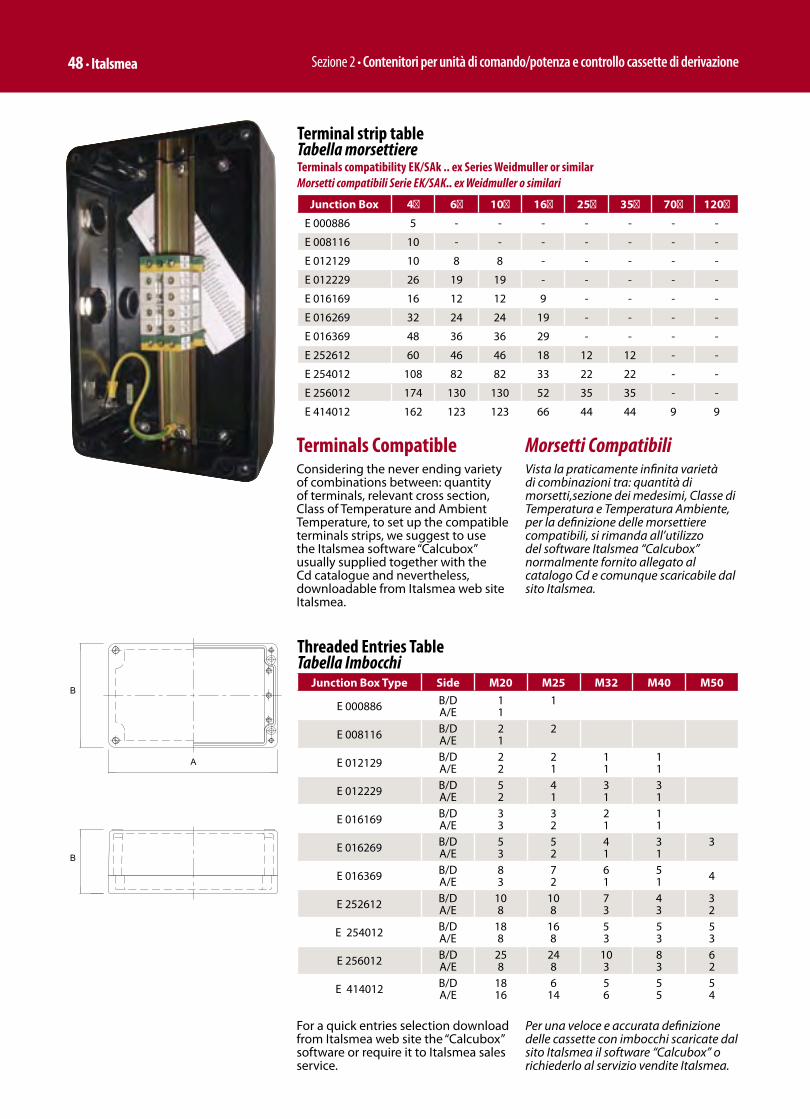
Sezione 2 • Contenitori per unità di comando/potenza e controllo cassette di derivazione 48 • Italsmea
Threaded Entries Table Tabella Imbocchi
Junction Box Type Side M20 M25 M32 M40 M50
E 000886 B/DA/E
1 1
1
E 008116 B/DA/E
2 1
2
E 012129 B/DA/E
2 2
2 1
1 1
1 1
E 012229 B/DA/E
5 2
4 1
3 1
3 1
E 016169 B/DA/E
3 3
3 2
2 1
1 1
E 016269 B/DA/E
5 3
5 2
4 1
3 1
3
E 016369 B/DA/E
8 3
7 2
6 1
5 1 4
E 252612 B/DA/E
10 8
10 8
7 3
4 3
3 2
E 254012 B/DA/E
18 8
16 8
5 3
5 3
53
E 256012 B/DA/E
25 8
24 8
10 3
8 3
6 2
E 414012 B/DA/E
18 16
6 14
5 6
5 5
5 4
A
B
B
Terminal strip table Tabella morsettiereTerminals compatibility EK/SAk .. ex Series Weidmuller or similarMorsetti compatibili Serie EK/SAK.. ex Weidmuller o similari
Junction Box 4 6 10 16 25 35 70 120
E 000886 5 - - - - - - -
E 008116 10 - - - - - - -
E 012129 10 8 8 - - - - -
E 012229 26 19 19 - - - - -
E 016169 16 12 12 9 - - - -
E 016269 32 24 24 19 - - - -
E 016369 48 36 36 29 - - - -
E 252612 60 46 46 18 12 12 - -
E 254012 108 82 82 33 22 22 - -
E 256012 174 130 130 52 35 35 - -
E 414012 162 123 123 66 44 44 9 9
Morsetti Compatibili Vista la praticamente infinita varietà di combinazioni tra: quantità di morsetti,sezione dei medesimi, Classe di Temperatura e Temperatura Ambiente, per la definizione delle morsettiere compatibili, si rimanda all’utilizzo del software Italsmea “Calcubox” normalmente fornito allegato al catalogo Cd e comunque scaricabile dal sito Italsmea.
Terminals CompatibleConsidering the never ending variety of combinations between: quantity of terminals, relevant cross section, Class of Temperature and Ambient Temperature, to set up the compatible terminals strips, we suggest to use the Italsmea software “Calcubox” usually supplied together with the Cd catalogue and nevertheless, downloadable from Italsmea web site Italsmea.
For a quick entries selection download from Italsmea web site the “Calcubox” software or require it to Italsmea sales service.
Per una veloce e accurata definizione delle cassette con imbocchi scaricate dal sito Italsmea il software “Calcubox” o richiederlo al servizio vendite Italsmea.
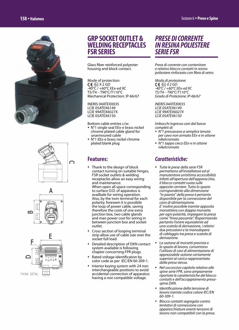
Sezione 6 ü Prese e Spine158 ü Italsmea
PRESE DI CORRENTE IN RESINA POLIESTERE SERIE FSR
Prese di corrente con contenitore e relativo blocco contatti in resina poliestere rinforzato con fi bra di vetro.
Modo di protezione: II 2 GD
-40°C / +60°C EEx-ed IIC T5/T4 – T90°C/T110°CGrado di Protezione: IP-66/67
INERIS 04ATEX0035LCIE 05ATEX6149LCIE 99ATEX6027XLCIE 05ATEX6150
Imbocchi ingresso cavi dal basso completi di:ü N°1 pressacavo a semplice tenuta
per cavo non armato EEx-e in ottone nikelcromatoü N°1 tappo cieco EEx-e in ottone
nikelcromato
Caratteristiche:ü Tutte le prese della serie FSR
permettono all’installatore ed al manutentore un’ottima accessibilità. Infatti all’apertura dell’apparecchio, il blocco contatti ruota sulle apposite cerniere. Tutto lo spazio corrispondente alla dimensione “in pianta” della presa è pertanto disponibile per la connessione del cavo di alimentazione.E’ inoltre possibile tramite apposita morsettiera con doppio morsetto per ogni polarità, impiegare la presa come “linea passante”. Risparmiando pertanto l’onere equivalente ad una scatola di derivazione, i relativi due pressatavi e la manodopera di cablaggio tra presa e scatola di derivazione.
ü La sezione di morsetti prevista e lo spazio di lavoro, consentono l’utilizzo di cavi di alimentazione di apprezzabile sezione certamente superiori al carico rappresentato dalla presa stessa.
ü Nel successivo capitolo relativo alle spine serie FPR, sono ampiamente riportate le caratteristiche del blocco contatti e dell’accoppiamento presa-spina DXN.
ü Identifi cazione della tensione di lavoro tramite codice colore IEC/EN 60-309-1.
ü Blocco contatti segregato contro tentativi di connessione con apparecchiature aventi tensioni di lavoro non compatibili con la presa.
GRP SOCKET OUTLET & WELDING RECEPTACLES FSR SERIES
Glass fi ber reinforced polyester housing and block contact.
Mode of protection: II 2 GD
-40°C / +60°C EEx-ed IIC T5/T4 – T90°C/T110°CMechanical Protection: IP-66/67
INERIS 04ATEX0035LCIE 05ATEX6149LCIE 99ATEX6027XLCIE 05ATEX6150
Bottom cable entries c/w:ü N°1 single seal EEx-e brass nickel
chrome plated cable gland for unarmoured cableü N°1 EEx-e brass nickel chrome
plated blank plug
Features:ü Thank to the design of block
contact turning on suitable hinges, FSR socket outlets & welding receptacles allow an easy wiring and maintenance.When open all space corresponding to surface O.D. of apparatus is availbale for wiring operation.Also, by the twin terminal for each polarity, foreseen it is possibile the loop of power cable, saving therefore the costs of one extra junction box, two cable glands and man power cost for wiring in between junction box and socket outlet.
ü Cross section of looping terminal strip allow use of cable size over the socket full load.
ü Detailed description of DXN contact system available is following chapter concerning FPR plugs.
ü Rated voltage identifi cation by color code as per IEC/EN 60-309-1.
ü Interior keying system with 24 non interchangeable positions to avoid accidental connection of apparatus having a non compatible voltage.
T5/T4 – T90°C/T110°C

Section 6 ü Receptacles and Plugs Italsmea ü 159
Type Enclosure E… series Code Colour
CodeVoltage
VContact
ArrangemntCurrent
A
Connection terminals cross section flexible
cores (rigid cores)mmq.
EntriesOverall
dimensionsAxBxC
Mounting interaxes
ExD
FSR-2-20-24-50 E 012129 A.4300.01 24 2P 20 10 / 10 2 x M25 140 x 120 x 218 106 x 82 - 6,3
FSR-3-20-110-50 E 012129 A.4300.02 110-130 1P+N+E 20 10 / 10 2 x M25 140 x 120 x 218 106 x 82 - 6,3
FSR-3-20-230-50 E 012129 A.4300.03 220-250 1P+N+E 20 10 / 10 2 x M25 140 x 120 x 218 106 x 82 - 6,3
FSR-4-20-400-50 E 016169 A.4300.04 380-440 3P+E 20 10 / 10 2 x M25 178 x 160 x 218 140x110 - 6,5
FSR-5-20-400-50 E016169 A.4300.05 380-440 3P+N+E 20 10 / 10 2 x M25 178 x 160 x 218 140x110 - 6,5
FSR-2-32-24-50 E 52612 A.4300.06 24 2P 32 16 / 16 2 x M32 273x250x259 235x200 - 6,5
FSR-3-32-110-50 E 52612 A.4300.07 110-130 1P+N+E 32 16 / 16 2 x M32 273x250x259 235x200 - 6,5
FSR-3-32-230-50 E 52612 A.4300.08 220-250 1P+N+E 32 16 / 16 2 x M32 273x250x259 235x200 - 6,5
FSR-4-32-400-50 E 52612 A.4300.09 380-440 3P+E 32 16 / 16 2 x M32 273x250x259 235x200 - 6,5
FSR-5-32-400-50 E 52612 A.4300.10 380-440 3P+N+E 32 16 / 16 2 x M32 273x250x259 235x200 - 6,5
FSR-2-63-24-50 E 52612 A.4300.11 24 2P 63 35 / 35 2 x M32 273x250x286 235x200 - 6,5
FSR-3-63-110-50 E 52612 A.4300.12 110-130 1P+N+E 63 35 / 35 2 x M32 273x250x286 235x200 - 6,5
FSR-3-63-230-50 E 52612 A.4300.13 220-250 1P+N+E 63 35 / 35 2 x M32 273x250x286 235x200 - 6,5
FSR-4-63-400-50 E 52612 A.4300.14 380-440 3P+E 63 35 / 35 2 x M50 273x250x286 235x200 - 6,5
FSR-5-63-400-50 E 52612 A.4300.15 380-440 3P+N+E 63 35 / 35 2 x M50 273x250x286 235x200 - 6,5
Earth Pin Position / Posizione Polo Terra – Central/CentraleFrequency / Frequenza Hz. – 50
IE/Esempio:FSR-3-20-230-50 FSR = Flameproof Socket Resin 3 = Poles Number / Numero poli 20 = Current / Corrente (A) 230 = Voltage / Tensione (V) 50 = Frequency / Frequenza (Hz.)
Type Enclosure E… series Code Colour
CodeVoltage
VContact
ArrangemntCurrent
A
Connection terminals cross section flexible
cores (rigid cores)mmq.
EntriesOverall
dimensionsAxBxC
Mounting interaxes
ExD
FSR-2-2a-32-24-50 E016269 A.4300.16 24 2P+2aux 32 16 / 16 / 4 2 x M25 + 1 x M20 273x250x259 235x200 - 6,5
FSR-3-2a-32-110-50 E016269 A.4300.17 110-130 1P+N+E+2aux 32 16 / 16 / 4 2 x M25 + 1 x M20 273x250x259 235x200 - 6,5
FSR-3-2a-32-230-50 E016269 A.4300.18 220-250 1P+N+E+2aux 32 16 / 16 / 4 2 x M25 + 1 x M20 273x250x259 235x200 - 6,5
FSR-4-2a-32-400-50 E254012 A.4300.19 380-440 3P+E+2aux 32 16 / 16 / 4 2 x M32 + 1 x M20 273x250x259 235x200 - 6,5
FSR-5-2a-32-400-50 E254012 A.4300.20 380-440 3P+N+E+2aux 32 16 / 16 / 4 2 x M32 + 1 x M20 273x250x259 235x200 - 6,5
FSR-2-2a-63-24-50 E016269 A.4300.21 24 2P+2aux 63 35 / 35 / 4 2 x M25 + 1 x M20 273x250x286 235x200 - 6,5
FSR-3-2a-63-110-50 E016269 A.4300.22 110-130 1P+N+E+2aux 63 35 / 35 / 4 2 x M25 + 1 x M20 273x250x286 235x200 - 6,5
FSR-3-2a-63-230-50 E016269 A.4300.23 220-250 1P+N+E+2aux 63 35 / 35 / 4 2 x M25 + 1 x M20 273x250x286 235x200 - 6,5
FSR-4-2a-63-400-50 E254012 A.4300.24 380-440 3P+E+2aux 63 35 / 35 / 4. 2 x M50 + 1 x M20 273x250x286 235x200 - 6,5
FSR-5-2a-63-400-50 E254012 A.4300.25 380-440 3P+N+E+2aux 63 35 / 35 / 4 2 x M50 + 1 x M20 273x250x286 235x200 - 6,5
IE/Esempio:FSR-5-2a-32-400-50 FSR = Flameproof Socket Resin 5 = Poles Number / Numero poli 2a = Number auxiliary contacts / Numero contatti ausiliari 32 = Current / Corrente (A) 400 = Voltage / Tensione (V) 50 = Frequency / Frequenza (Hz.)
Earth Pin Position / Posizione Polo Terra – Central/CentraleFrequency / Frequenza Hz. – 50

Sezione 6 ü Prese e Spine160 ü Italsmea
PRESE DI CORRENTE IN ACCIAIO INOSSIDABILE AISI 316L SERIE FSX
Prese di corrente in contenitore in acciaio inossidabile AISI 316L e relativo blocco con contatti in resina poliestere rinforzato con fibra di vetro.
Modo di protezione: II 2 GD
-40°C / +60°C EEx-ed IIC T5/T4 – T90°C/T110°CGrado di Protezione: IP-66/67
INERIS 04ATEX0036LCIE 05ATEX6149LCIE 99ATEX6027XLCIE 05ATEX6150
Imbocchi ingresso cavi dal basso completi di:ü N°1 pressacavo a doppia tenuta EEx-e in
acciaio inossidabile AISI 316ü N°1 tappo cieco in acciaio inossidabile
AISI 316 EEx-e
Caratteristiche:ü Tutte le prese della serie FSX
permettono all’installatore ed al manutentore un’ottima accessibilità. Infatti all’apertura dell’apparecchio, il blocco contatti ruota sulle apposite cerniere. Tutto lo spazio corrispondente alla dimensione “in pianta” della presa è pertanto disponibile per la connessione del cavo di alimentazione. E’ inoltre possibile tramite apposita morsettiera con doppio morsetto per ogni polarità, impiegare la presa come “linea passante”. Risparmiando pertanto l’onere equivalente ad una scatola di derivazione, i relativi due pressatavi e la manodopera di cablaggio tra presa e scatola di derivazione.
ü La sezione di morsetti prevista e lo spazio di lavoro, consentono l’utilizzo di cavi di alimentazione di apprezzabile sezione certamente superiori al carico rappresentato dalla presa stessa.
ü Nel successivo capitolo relativo alle spine serie FPR, sono ampiamente riportate le caratteristiche del blocco contatti e dell’accoppiamento presa-spina DXN.
ü Identificazione della tensione di lavoro tramite codice colore IEC/EN 60-309-1.
ü Blocco contatti segregato contro tentativi di connessione con apparecchiature aventi tensioni di lavoro non compatibili con la presa.
STAINLESS STEEL AISI 316L SOCKET OUTLET & WELDING RECEPTACLES FSX SERIES
Stainless steel AISI 316L housing and glass fiber reinforced polyester block contacts.
Mode of protection: II 2 GD
-40°C / +60°C EEx-ed IIC T5/T4 – T90°C/T110°CMechanical Protection: IP-66/67
INERIS 04ATEX0036LCIE 05ATEX6149LCIE 99ATEX6027XLCIE 05ATEX6150
Bottom cable entries c/w:ü N°1 double seal EEx-e stainless steel
AISI 316 cable gland ü N°1 EEx-e stainless steel AISI 316
blank plug
Features:ü Thank to the design of block
contact turning on suitable hinges, FSX socket outlets & welding receptacles allow an easy wiring and maintenance. When open all space corresponding to surface O.D. of apparatus is availbale for wiring operation Also, by the twin terminal for each polarità, foreseen it is possibile the loop of power cable, saving therefore the costs of one extra junction box, two cable glands and man power cost for wiring in between junction box and socket outlet.
ü Cross section of looping terminal strip allow use of cable size over the socket full load.
ü Detailed description of DXN contact system available is following chapter concerning FPR plugs.
ü Rated voltage identification by color code as per IEC/EN 60-309-1.
ü Interior keying system with 24 non interchangeable position sto avoid accidental connection of apparatus having a non compatible voltage.

Section 6 ü Receptacles and Plugs Italsmea ü 161
Type Enclosure Code Colour Code
VoltageV
Contact Arrangemnt
CurrentA
Connection terminals cross section flexible
cores (rigid cores)mmq.
EntriesOverall
dimensionsAxBxC
Mounting interaxes
DxE - F
FSX-2-20-24-50 AR-2 A.4300.26 24 2P 20 10 / 10 2 x M25 217 x 200 x 257 192 x 1 - 9
FSX-3-20-110-50 AR-2 A.4300.27 110-130 1P+N+E 20 10 / 10 2 x M25 217 x 200 x 257 192 x 1 - 9
FSX-3-20-230-50 AR-2 A.4300.28 220-250 1P+N+E 20 10 / 10 2 x M25 217 x 200 x 257 192 x 1 - 9
FSX-4-20-400-50 AR-4 A.4300.29 380-440 3P+E 20 10 / 10 2 x M25 280 x 270 x 257 255 x 177 - 9
FSX-5-20-400-50 AR-4 A.4300.30 380-440 3P+N+E 20 10 / 10 2 x M25 280 x 270 x 257 255 x 177 - 9
FSX-2-32-24-50 AR-4 A.4300.31 24 2P 32 16 / 16 2 x M32 280 x 270 x 268 255 x 177 - 9
FSX-3-32-110-50 AR-4 A.4300.32 110-130 1P+N+E 32 16 / 16 2 x M32 280 x 270 x 268 255 x 177 - 9
FSX-3-32-230-50 AR-4 A.4300.33 220-250 1P+N+E 32 16 / 16 2 x M32 280 x 270 x 268 255 x 177 - 9
FSX-4-32-400-50 AR-6 A.4300.34 380-440 3P+E 32 16 / 16 2 x M32 350 x 350 x 268 325 x 257 - 9
FSX-5-32-400-50 AR-6 A.4300.35 380-440 3P+N+E 32 16 / 16 2 x M32 350 x 350 x 268 325 x 257 - 9
FSX-2-63-24-50 AR-6 A.4300.36 24 2P 63 35 / 35 2 x M50 350 x 350 x 295 325 x 257 - 9
FSX-3-63-110-50 AR-6 A.4300.37 110-130 1P+N+E 63 35 / 35 2 x M50 350 x 350 x 295 325 x 257 - 9
FSX-3-63-230-50 AR-6 A.4300.38 220-250 1P+N+E 63 35 / 35 2 x M50 350 x 350 x 295 325 x 257 - 9
FSX-4-63-400-50 AR-8 A.4300.39 380-440 3P+E 63 35 / 35 2 x M50 430 x 500 x 325 405 x 407 - 9
FSX-5-63-400-50 AR-8 A.4300.40 380-440 3P+N+E 63 35 / 35 2 x M50 430 x 500 x 325 405 x 407 - 9
Earth Pin Position / Posizione Polo Terra – Central/CentraleFrequency / Frequenza Hz. – 50
IE/Esempio:FSX-3-20-230-50 FSX = Flameproof Socket Stainless stell 3 = Poles Number / Numero poli 20 = Current / Corrente (A) 230 = Voltage / Tensione (V) 50 = Frequency / Frequenza (Hz.)
Type Enclosure Code Colour Code
VoltageV
Contact Arrangemnt
CurrentA
Connection terminals cross section flexible
cores (rigid cores)mmq.
EntriesOverall
dimensionsAxBxC
Mounting interaxes
DxE - F
FSX-2-2a-32-24-50 AR-4 A.4300.40 24 2P+2aux 32 16 / 16 / 4 2 x M25 + 1 x M20 280 x 270 x 268 255 x 177 - 9
FSX-3-2a-32-110-50 AR-4 A.4300.41 110-130 1P+N+E+2aux 32 16 / 16 / 4 2 x M25 + 1 x M20 280 x 270 x 268 255 x 177 - 9
FSX-3-2a-32-230-50 AR-4 A.4300.42 220-250 1P+N+E+2aux 32 16 / 16 / 4 2 x M25 + 1 x M20 280 x 270 x 268 255 x 177 - 9
FSX-4-2a-32-400-50 AR-6 A.4300.43 380-440 3P+E+2aux 32 16 / 16 / 4 2 x M32 + 1 x M20 350 x 350 x 268 325 x 257 - 9
FSX-5-2a-32-400-50 AR-6 A.4300.44 3P+N+E+2aux 32 20 16 / 16 / 4 2 x M32 + 1 x M20 350 x 350 x 268 325 x 257 - 9
FSX-2-2a-63-24-50 AR-6 A.4300.45 24 2P+2aux 63 35 / 35 / 4 2 x M32 + 1 x M20 350 x 350 x 295 325 x 257 - 9
FSX-3-2a-63-110-50 AR-6 A.4300.46 110-130 1P+N+E+2aux 63 35 / 35 / 4 2 x M32 + 1 x M20 350 x 350 x 295 325 x 257 - 9
FSX-3-2a-63-230-50 AR-6 A.4300.47 220-250 1P+N+E+2aux 63 35 / 35 / 4 2 x M32 + 1 x M20 350 x 350 x 295 325 x 257 - 9
FSX-4-2a-63-400-50 AR-8 A.4300.48 380-440 3P+E+2aux 63 35 / 35 / 4 2 x M50 + 1 x M20 430 x 500 x 325 405 x 407 - 9
FSX-5-2a-63-400-50 AR-8 A.4300.49 3P+N+E+2aux 63 32 35 / 35 / 4 2 x M50 + 1 x M20 430 x 500 x 325 405 x 407 - 9
IE/Esempio:FSX-5-2a-32-400-50 FSX = Flameproof Socket Stainless stell 5 = Poles Number / Numero poli 2a = Number auxiliary contacts / Numero contatti ausiliari 32 = Current / Corrente (A) 400 = Voltage / Tensione (V) 50 = Frequency / Frequenza (Hz.)
Earth Pin Position / Posizione Polo Terra – Central/CentraleFrequency / Frequenza Hz. – 50

Sezione 6 ü Prese e Spine162 ü Italsmea
PRESE DI CORRENTE IN ALLUMINIO FSAL
Prese di corrente in contenitore in lega leggera di Alluminio e relativo blocco con contatti in resina poliestere rinforzato con fibra di vetro.
Modo di protezione: II 2 GD
-40°C / +60°C EEx-ed IIC T5/T4 – T90°C/T110°CGrado di Protezione: IP-66/67
INERIS 04ATEX0036LCIE 05ATEX6149LCIE 99ATEX6027XLCIE 05ATEX6150
Imbocchi ingresso cavi dal basso completi di:ü N°1 pressacavo a doppia tenuta
per cavo armato EEx-e in ottone nichelcromato ü N°1 tappo cieco EEx-e in ottone
nichelcromato
Caratteristiche:ü Tutte le prese della serie FSX
permettono all’installatore ed al manutentore un’ottima accessibilità. Infatti all’apertura dell’apparecchio, il blocco contatti ruota sulle apposite cerniere. Tutto lo spazio corrispondente alla dimensione “in pianta” della presa è pertanto disponibile per la connessione del cavo di alimentazione. E’ inoltre possibile tramite apposita morsettiera con doppio morsetto per ogni polarità, impiegare la presa come “linea passante”. Risparmiando pertanto l’onere equivalente ad una scatola di derivazione, i relativi due pressatavi e la manodopera di cablaggio tra presa e scatola di derivazione.
ü La sezione di morsetti prevista e lo spazio di lavoro, consentono l’utilizzo di cavi di alimentazione di apprezzabile sezione certamente superiori al carico rappresentato dalla presa stessa.
ü Nel successivo capitolo relativo alle spine serie FPR, sono ampiamente riportate le caratteristiche del blocco contatti e dell’accoppiamento presa-spina DXN.
ü Identificazione della tensione di lavoro tramite codice colore IEC/EN 60-309-1.
ü Blocco contatti segregato contro tentativi di connessione con apparecchiature aventi tensioni di lavoro non compatibili con la presa.
GRP SOCKET OUTLET & WELDING RECEPTACLES SERIES FSAL
Copper free aluminium housing & glass fiber reinforced polyester block contacts. Mode of protection:
II 2 GD-40°C / +60°C EEx-ed IIC T5/T4 – T90°C/T110°CMechanical Protection: IP-66/67
INERIS 04ATEX0036LCIE 05ATEX6149LCIE 99ATEX6027XLCIE 05ATEX6150 Bottom cable entries c/w:ü N°1 double seal EEx-e brass
nickelchrome plated cable gland for armoured cable ü N°1 EEx-e brass nichelchrome plated
blank plug
Features:ü Thank to the design of block
contact turning on suitable hinges, FSX socket outlets & welding receptacles allow an easy wiring and maintenance. When open all space corresponding to surface O.D. of apparatus is availbale for wiring operation. Also, by the twin terminal for each polarity, foreseen it is possibile the loop of power cable, saving therefore the costs of one extra junction box, two cable glands and man power cost for wiring in between junction box and socket outlet.
ü Cross section of looping terminal strip allow use of cable size over the socket full load.
ü Detailed description of DXN contact system available is following chapter concerning FPR plugs.
ü Rated voltage identification by color code as per IEC/EN 60-309-1.
ü Interior keying system with 24 non interchangeable position sto avoid accidental connection of apparatus having a non compatible voltage.
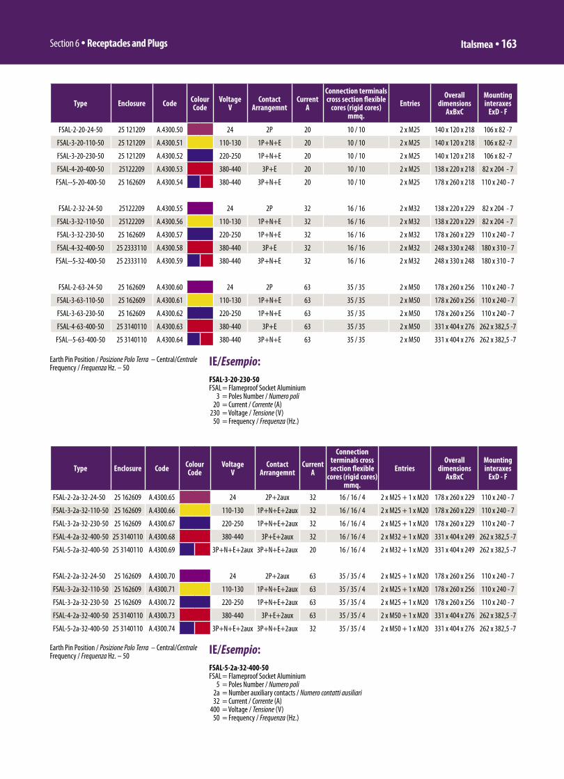
Section 6 ü Receptacles and Plugs Italsmea ü 163
Type Enclosure Code Colour Code
VoltageV
Contact Arrangemnt
CurrentA
Connection terminals cross section flexible
cores (rigid cores)mmq.
EntriesOverall
dimensionsAxBxC
Mounting interaxes
ExD - F
FSAL-2-20-24-50 25 121209 A.4300.50 24 2P 20 10 / 10 2 x M25 140 x 120 x 218 106 x 82 -7
FSAL-3-20-110-50 25 121209 A.4300.51 110-130 1P+N+E 20 10 / 10 2 x M25 140 x 120 x 218 106 x 82 -7
FSAL-3-20-230-50 25 121209 A.4300.52 220-250 1P+N+E 20 10 / 10 2 x M25 140 x 120 x 218 106 x 82 -7
FSAL-4-20-400-50 25122209 A.4300.53 380-440 3P+E 20 10 / 10 2 x M25 138 x 220 x 218 82 x 204 - 7
FSAL--5-20-400-50 25 162609 A.4300.54 380-440 3P+N+E 20 10 / 10 2 x M25 178 x 260 x 218 110 x 240 - 7
FSAL-2-32-24-50 25122209 A.4300.55 24 2P 32 16 / 16 2 x M32 138 x 220 x 229 82 x 204 - 7
FSAL-3-32-110-50 25122209 A.4300.56 110-130 1P+N+E 32 16 / 16 2 x M32 138 x 220 x 229 82 x 204 - 7
FSAL-3-32-230-50 25 162609 A.4300.57 220-250 1P+N+E 32 16 / 16 2 x M32 178 x 260 x 229 110 x 240 - 7
FSAL-4-32-400-50 25 2333110 A.4300.58 380-440 3P+E 32 16 / 16 2 x M32 248 x 330 x 248 180 x 310 - 7
FSAL--5-32-400-50 25 2333110 A.4300.59 380-440 3P+N+E 32 16 / 16 2 x M32 248 x 330 x 248 180 x 310 - 7
FSAL-2-63-24-50 25 162609 A.4300.60 24 2P 63 35 / 35 2 x M50 178 x 260 x 256 110 x 240 - 7
FSAL-3-63-110-50 25 162609 A.4300.61 110-130 1P+N+E 63 35 / 35 2 x M50 178 x 260 x 256 110 x 240 - 7
FSAL-3-63-230-50 25 162609 A.4300.62 220-250 1P+N+E 63 35 / 35 2 x M50 178 x 260 x 256 110 x 240 - 7
FSAL-4-63-400-50 25 3140110 A.4300.63 380-440 3P+E 63 35 / 35 2 x M50 331 x 404 x 276 262 x 382,5 -7
FSAL--5-63-400-50 25 3140110 A.4300.64 380-440 3P+N+E 63 35 / 35 2 x M50 331 x 404 x 276 262 x 382,5 -7
Earth Pin Position / Posizione Polo Terra – Central/CentraleFrequency / Frequenza Hz. – 50
IE/Esempio:FSAL-3-20-230-50FSAL = Flameproof Socket Aluminium 3 = Poles Number / Numero poli 20 = Current / Corrente (A) 230 = Voltage / Tensione (V) 50 = Frequency / Frequenza (Hz.)
Type Enclosure Code Colour Code
VoltageV
Contact Arrangemnt
CurrentA
Connection terminals cross section flexible
cores (rigid cores)mmq.
EntriesOverall
dimensionsAxBxC
Mounting interaxes
ExD - F
FSAL-2-2a-32-24-50 25 162609 A.4300.65 24 2P+2aux 32 16 / 16 / 4 2 x M25 + 1 x M20 178 x 260 x 229 110 x 240 - 7
FSAL-3-2a-32-110-50 25 162609 A.4300.66 110-130 1P+N+E+2aux 32 16 / 16 / 4 2 x M25 + 1 x M20 178 x 260 x 229 110 x 240 - 7
FSAL-3-2a-32-230-50 25 162609 A.4300.67 220-250 1P+N+E+2aux 32 16 / 16 / 4 2 x M25 + 1 x M20 178 x 260 x 229 110 x 240 - 7
FSAL-4-2a-32-400-50 25 3140110 A.4300.68 380-440 3P+E+2aux 32 16 / 16 / 4 2 x M32 + 1 x M20 331 x 404 x 249 262 x 382,5 -7
FSAL-5-2a-32-400-50 25 3140110 A.4300.69 3P+N+E+2aux 3P+N+E+2aux 20 16 / 16 / 4 2 x M32 + 1 x M20 331 x 404 x 249 262 x 382,5 -7
FSAL-2-2a-32-24-50 25 162609 A.4300.70 24 2P+2aux 63 35 / 35 / 4 2 x M25 + 1 x M20 178 x 260 x 256 110 x 240 - 7
FSAL-3-2a-32-110-50 25 162609 A.4300.71 110-130 1P+N+E+2aux 63 35 / 35 / 4 2 x M25 + 1 x M20 178 x 260 x 256 110 x 240 - 7
FSAL-3-2a-32-230-50 25 162609 A.4300.72 220-250 1P+N+E+2aux 63 35 / 35 / 4 2 x M25 + 1 x M20 178 x 260 x 256 110 x 240 - 7
FSAL-4-2a-32-400-50 25 3140110 A.4300.73 380-440 3P+E+2aux 63 35 / 35 / 4 2 x M50 + 1 x M20 331 x 404 x 276 262 x 382,5 -7
FSAL-5-2a-32-400-50 25 3140110 A.4300.74 3P+N+E+2aux 3P+N+E+2aux 32 35 / 35 / 4 2 x M50 + 1 x M20 331 x 404 x 276 262 x 382,5 -7
IE/Esempio:FSAL-5-2a-32-400-50 FSAL = Flameproof Socket Aluminium 5 = Poles Number / Numero poli 2a = Number auxiliary contacts / Numero contatti ausiliari 32 = Current / Corrente (A) 400 = Voltage / Tensione (V) 50 = Frequency / Frequenza (Hz.)
Earth Pin Position / Posizione Polo Terra – Central/CentraleFrequency / Frequenza Hz. – 50

Sezione 6 ü Prese e Spine164 ü Italsmea
SPINE IN RESINA POLIESTERE SERIE FPR
Spine con impugnatura in resina poliestere rinforzata con fibra di vetro compatibile con le prese di corrente serie: FSR, FSX, FSAL.
Modo di protezione: II 2 GD
-40°C / +60°C EEx-ed IIC T6 – T85°CGrado di Protezione: IP-66/67 (quando connessa alla presa relativa).
LCIE 05ATEX6149LCIE 99ATEX6027XLCIE 05ATEX6150
Imboccho per ingresso cavo completo di pressacavo a semplice tenuta per cavo non armato EEx-e in resina poliestere.
SISTEMA DXN I decontattori DXN sono una serie di prese e spine per impiego in area classificate con pericolo di esplosione ed incendio con un meccanismo di sezionamento integrato conforme alle prescrizioni di cui al comma 2.8 della Normativa IEC/EN 60309-9.Detto meccanismo e’ in grado di chiudere e sezionare sottocarico, in piena sicurezza sia, per utenze di tipi resistivo che induttivo.Quando la presa non e’ connessa il coperchio incernierato garantisce una protezione meccanica pari a IP-66/67. A coperchietto aperto, ante l’inserimento della spina, il blocco contatti mantiene comunque un grado di protezione IP4X, ovvero sarà protetto dall’ingresso di corpi solidi con diametro superiore ad 1 mm, così come definito dalla Norma IEC/EN50529. Il grado di protezione IP-66/67 sarà ripristinato non appena la spina sarà correttamente inserita nella presa.
L’involucro realizzato in poliestere rinforzato con fibre d i vetro, autoestinguente ed antistatico, dei decontattori DXN garantisce un ottima resistenza agli ambiente chimicamente aggressivi ed una capacità di sopportare elevate sollecitazioni meccaniche conseguenti ad impieghi particolarmente gravosi.
L’esperienza maturata con le versioni industriali della serie DSN ha consentito un ottimizzazione dell’accoppiamento tra l’involucro ed il blocco contatti vero e proprio.
A) Gruppo di sezionamento interno – presa: Il blocco contatti ad azione differita costituisce, per ciascuna polarità una, una microcamera
GRP PLUGS FPR SERIES
Plugs with glass fibres reinforced polyester handle, compatible with socket outlet & welding receptacles series: FSR, FSX, FSAL
Mode of protection: II 2 GD
-40°C / +60°C EEx-ed IIC T6 – T85°CMechanical protection: IP-66/67 (when connected to relevant socket outlet).
LCIE 05ATEX6149LCIE 99ATEX6027XLCIE 05ATEX6150
Bottom cable entries c/w single seal EEx-e GRP resin cable gland.
DXN SYSTEMDXN Decontractors are plugs and socket-outlets for use in explosive atmosphere with an integral switching device as defined in clause 2.8 of IEC/EN 60309-1 Standard.They can break either resistive and inductive loads in complete safe conditions. When the socket is closed, it has an IP66 and IP67 protection. Once the lid is opened, the live contacts are still protected against 1mm o.d dust (IP4X) as defined in IEC/EN 60529 Standard. The IP66 and IP67 rating is achieved when the lid is closed or the plug fully engaged.
Made of self-extinguishing non-static glass reinforced polyester (PBT), DXN Decontractors can withstand heavy duty, severe mechanical stress and presence chemical aggressive products . Being very close, in their design, to the DSN industrial range, the explosion proof protection is achieved by the combination of safety shutter and moulding.
A) Cross section view – socket moulding and contacts. The locked safety shutter achieves a “d” explosion-proof chamber.
As soon as a plug is fitted into the socket and turned in the “rest” position, the “d” explosion-proof chamber is maintained between the male contacts of plug and female contacts of socket safety shutter. The mechanical connection is established between plug and socket but not the yet the electrical contact
B) Cross section view – plug in “ rest “ position.
Then the e plug can be electrically connected or disconnected under
Di solito il pressacavo è di materiale plastico fornito dal costruttore e non metallico come indicato nella foto

Section 6 ü Receptacles and Plugs Italsmea ü 165
INERIS 04ATEX0035 + LCIE 00ATEX6010X + LCIE 99ATEX6027X + LCIE 02ATEX6029X
full load.C) Cross section view – plug is
electrically connected . The explosion-proof chamber is maintained.Only from the “rest” position, contacts electrically opened, the plug can be removed. Same as products of the DSN series, IP66/67 protection with DXN series is totally achieved as soon as the contacts are closed, and the plug engaged by the socket retaining latch. No additional manual operation is required to achieve the a.m. IP rating . The same rating is achieved by closing the socket spring loaded hinged cover. Conductors are terminated in “e” increased safety enclosures, therefore the fi nal assembling will be an EEx “ed” classifi cation. The same contacts manage both : movable connection as well as the making and the breaking activities .This technical solution allows an extremely compact design.
antidefl agrante “d”.Appena la spina sarà inserita nella presa ed opportunamente ruotata si stabilirà il contatto meccanico tra i contatti della spina ( “pin” maschio) e quelli della presa ( femmina ). In questa fase non c’è ancora alcun contatto elettrico.
B) Vista in sezione del dispositivo di sezionamento interno. La spina e’ in posizione “ Inserita-ruotata “ La spina potrà a questo punto essere connessa o disinserita sottocarico.
C) Vista in sezione del dispositivo di sezionamento interno : la spina e’ in posizione “ connessa“: La condizione di microcamera antidefl agrante “d” e mantenuta. Infatti dalla posizione “ Inserita-ruotata “ spingendo ulteriormente la spina nella presa si stabilisce il contatto elettrico. Allo stesso tempo vengono caricate le molle del meccanismo di sezionamento ed la levetta a gancio blocca la spina nella posizione “connessa”. I decontattori DXN racchiudono nello stesso meccanismo il sezionatore per l’apertura e la chiusura del circuito ed i contatti mobili e fi ssi classici di una connessione presa / spina. Premendo a fondo la levetta a gancio la spina si porta rapidamente dalla posizione “connessa “ alla posizione “ inserita –ruotata” e decade la connessione elettrica. La rapidità del sezionamento è dovuta all’azione delle molle del meccanismo di sezionamento precedentemente caricate all’inserzione della spina. Dalla posizione “ Inserita ruotata “ ruotando la spina in senso antiorario sarà possibile estrarla in piena sicurezza in quanto il contatto elettrico e’ stato precedentemente sezionato . Nella parte posteriore del blocco contatti sono allocati per ciascuna polarità i morsetti in esecuzione EEx-e cui sono collegati i conduttori di alimentazione. Il blocco presa e’ fl angiato ad una contenitore anch’esso EEx-e ( in resina poliestere per la serie FSR, in acciaio inossidabile aisi 316L per la serie FSX , in alluminio per la serie FSAL). In detto contenitore EEx-e sono alloggiati i morsetti di allacciamento cosi come descritto nei capitoli relativi alla prese.

Sezione 6 ü Prese e Spine166 ü Italsmea
Type Code Colour Code
Cable gland EEx-e
VoltageV
Contact Arrangemnt
CurrentA
Connection terminals cross section flexible
cores (rigid cores)mmq.
Overall dimensions
FPR-2-20-24-50 A.4301.01 M20 (8÷13) 24 2P 20 4 / 6 127x51x51
FPR-2-20-24-50 A.4301.02 M25 (13÷19) 24 2P 20 4 / 6 127x51x51
FPR-3-20-110-50 A.4301.03 M20 (8÷13) 110-130 1P+N+E 20 4 / 6 127x51x51
FPR-3-20-110-50 A.4301.04 M25 (13÷19) 110-130 1P+N+E 20 4 / 6 127x51x51
FPR-3-20-230-50 A.4301.05 M20 (8÷13) 220-250 1P+N+E 20 4 / 6 127x51x51
FPR-3-20-230-50 A.4301.06 M25 (13÷19) 220-250 1P+N+E 20 4 / 6 127x51x51
FPR-4-20-400-50 A.4301.07 M20 (8÷13) 380-440 3P+E 20 4 / 6 127x51x51
FPR-4-20-400-50 A.4301.08 M25 (13÷19) 380-440 3P+E 20 4 / 6 127x51x51
FPR-5-20-400-50 A.4301.09 M20 (8÷13) 380-440 3P+N+E 20 4 / 6 127x51x51
FPR-5-20-400-50 A.4301.10 M25 (13÷19) 380-440 3P+N+E 20 4 / 6 127x51x51
FPR-2-32-24-50 A.4301.11 M20 (8÷13) 24 2P 32 10 / 16 128x68x68
FPR-2-32-24-50 A.4301.12 M25 (13÷19) 24 2P 32 10 / 16 128x68x68
FPR-2-32-24-50 A.4301.13 M32 (17÷25) 24 2P 32 10 / 16 128x68x68
FPR-3-32-110-50 A.4301.14 M20 (8÷13) 110-130 1P+N+E 32 10 / 16 128x68x68
FPR-3-32-110-50 A.4301.15 M25 (13÷19) 110-130 1P+N+E 32 10 / 16 128x68x68
FPR-3-32-110-50 A.4301.16 M32 (17÷25) 110-130 1P+N+E 32 10 / 16 128x68x68
FPR-3-32-230-50 A.4301.17 M20 (8÷13) 220-250 1P+N+E 32 10 / 16 128x68x68
FPR-3-32-230-50 A.4301.18 M25 (13÷19) 220-250 1P+N+E 32 10 / 16 128x68x68
FPR-3-32-230-50 A.4301.19 M32 (17÷25) 220-250 1P+N+E 32 10 / 16 128x68x68
FPR-4-32-400-50 A.4301.20 M20 (8÷13) 380-440 3P+E 32 10 / 16 128x68x68
FPR-4-32-400-50 A.4301.21 M25 (13÷19) 380-440 3P+E 32 10 / 16 128x68x68
FPR-4-32-400-50 A.4301.22 M32 (17÷25) 380-440 3P+E 32 10 / 16 128x68x68
FPR-5-32-400-50 A.4301.23 M20 (8÷13) 380-440 3P+N+E 32 10 / 16 128x68x68
FPR-5-32-400-50 A.4301.24 M25 (13÷19) 380-440 3P+N+E 32 10 / 16 128x68x68
FPR-5-32-400-50 A.4301.25 M32 (17÷25) 380-440 3P+N+E 32 10 / 16 128x68x68
FPR-2-63-24-50 A.4301.26 M25 (13÷19) 24 2P 63 16 / 25 149x83x83
FPR-2-63-24-50 A.4301.27 M32 (17÷25) 24 2P 63 16 / 25 149x83x83
FPR-2-63-24-50 A.4301.28 M40 (24÷32) 24 2P 63 16 / 25 149x83x83
FPR-3-63-110-50 A.4301.29 M25 (13÷19) 110-130 1P+N+E 63 16 / 25 149x83x83
FPR-3-63-110-50 A.4301.30 M32 (17÷25) 110-130 1P+N+E 63 16 / 25 149x83x83
FPR-3-63-110-50 A.4301.31 M40 (24÷32) 110-130 1P+N+E 63 16 / 25 149x83x83
FPR-3-63-230-50 A.4301.32 M25 (13÷19) 220-250 1P+N+E 63 16 / 25 149x83x83
FPR-3-63-230-50 A.4301.33 M32 (17÷25) 220-250 1P+N+E 63 16 / 25 149x83x83
FPR-3-63-230-50 A.4301.34 M40 (24÷32) 220-250 1P+N+E 63 16 / 25 149x83x83
FPR-4-63-400-50 A.4301.35 M25 (13÷19) 380-440 3P+E 63 16 / 25 149x83x83
FPR-4-63-400-50 A.4301.36 M32 (17÷25) 380-440 3P+E 63 16 / 25 149x83x83
FPR-4-63-400-50 A.4301.37 M40 (24÷32) 380-440 3P+E 63 16 / 25 149x83x83
FPR-5-63-400-50 A.4301.38 M25 (13÷19) 380-440 3P+N+E 63 16 / 25 149x83x83
FPR-5-63-400-50 A.4301.39 M32 (17÷25) 380-440 3P+N+E 63 16 / 25 149x83x83
FPR-5-63-400-50 A.4301.40 M40 (24÷32) 380-440 3P+N+E 63 16 / 25 149x83x83
Earth Pin Position / Posizione Polo Terra – Central/CentraleFrequency / Frequenza Hz. – 50
IE/Esempio:FPR-3-20-230-50FPR = Flameproof Socket Resin 3 = Poles Number / Numero poli 20 = Current / Corrente (A) 230 = Voltage / Tensione (V) 50 = Frequency / Frequenza (Hz.)
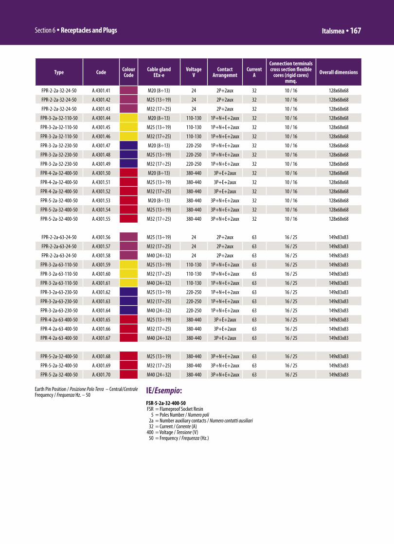
Section 6 ü Receptacles and Plugs Italsmea ü 167
Type Code Colour Code
Cable gland EEx-e
VoltageV
Contact Arrangemnt
CurrentA
Connection terminals cross section flexible
cores (rigid cores)mmq.
Overall dimensions
FPR-2-2a-32-24-50 A.4301.41 M20 (8÷13) 24 2P+2aux 32 10 / 16 128x68x68
FPR-2-2a-32-24-50 A.4301.42 M25 (13÷19) 24 2P+2aux 32 10 / 16 128x68x68
FPR-2-2a-32-24-50 A.4301.43 M32 (17÷25) 24 2P+2aux 32 10 / 16 128x68x68
FPR-3-2a-32-110-50 A.4301.44 M20 (8÷13) 110-130 1P+N+E+2aux 32 10 / 16 128x68x68
FPR-3-2a-32-110-50 A.4301.45 M25 (13÷19) 110-130 1P+N+E+2aux 32 10 / 16 128x68x68
FPR-3-2a-32-110-50 A.4301.46 M32 (17÷25) 110-130 1P+N+E+2aux 32 10 / 16 128x68x68
FPR-3-2a-32-230-50 A.4301.47 M20 (8÷13) 220-250 1P+N+E+2aux 32 10 / 16 128x68x68
FPR-3-2a-32-230-50 A.4301.48 M25 (13÷19) 220-250 1P+N+E+2aux 32 10 / 16 128x68x68
FPR-3-2a-32-230-50 A.4301.49 M32 (17÷25) 220-250 1P+N+E+2aux 32 10 / 16 128x68x68
FPR-4-2a-32-400-50 A.4301.50 M20 (8÷13) 380-440 3P+E+2aux 32 10 / 16 128x68x68
FPR-4-2a-32-400-50 A.4301.51 M25 (13÷19) 380-440 3P+E+2aux 32 10 / 16 128x68x68
FPR-4-2a-32-400-50 A.4301.52 M32 (17÷25) 380-440 3P+E+2aux 32 10 / 16 128x68x68
FPR-5-2a-32-400-50 A.4301.53 M20 (8÷13) 380-440 3P+N+E+2aux 32 10 / 16 128x68x68
FPR-5-2a-32-400-50 A.4301.54 M25 (13÷19) 380-440 3P+N+E+2aux 32 10 / 16 128x68x68
FPR-5-2a-32-400-50 A.4301.55 M32 (17÷25) 380-440 3P+N+E+2aux 32 10 / 16 128x68x68
FPR-2-2a-63-24-50 A.4301.56 M25 (13÷19) 24 2P+2aux 63 16 / 25 149x83x83
FPR-2-2a-63-24-50 A.4301.57 M32 (17÷25) 24 2P+2aux 63 16 / 25 149x83x83
FPR-2-2a-63-24-50 A.4301.58 M40 (24÷32) 24 2P+2aux 63 16 / 25 149x83x83
FPR-3-2a-63-110-50 A.4301.59 M25 (13÷19) 110-130 1P+N+E+2aux 63 16 / 25 149x83x83
FPR-3-2a-63-110-50 A.4301.60 M32 (17÷25) 110-130 1P+N+E+2aux 63 16 / 25 149x83x83
FPR-3-2a-63-110-50 A.4301.61 M40 (24÷32) 110-130 1P+N+E+2aux 63 16 / 25 149x83x83
FPR-3-2a-63-230-50 A.4301.62 M25 (13÷19) 220-250 1P+N+E+2aux 63 16 / 25 149x83x83
FPR-3-2a-63-230-50 A.4301.63 M32 (17÷25) 220-250 1P+N+E+2aux 63 16 / 25 149x83x83
FPR-3-2a-63-230-50 A.4301.64 M40 (24÷32) 220-250 1P+N+E+2aux 63 16 / 25 149x83x83
FPR-4-2a-63-400-50 A.4301.65 M25 (13÷19) 380-440 3P+E+2aux 63 16 / 25 149x83x83
FPR-4-2a-63-400-50 A.4301.66 M32 (17÷25) 380-440 3P+E+2aux 63 16 / 25 149x83x83
FPR-4-2a-63-400-50 A.4301.67 M40 (24÷32) 380-440 3P+E+2aux 63 16 / 25 149x83x83
FPR-5-2a-32-400-50 A.4301.68 M25 (13÷19) 380-440 3P+N+E+2aux 63 16 / 25 149x83x83
FPR-5-2a-32-400-50 A.4301.69 M32 (17÷25) 380-440 3P+N+E+2aux 63 16 / 25 149x83x83
FPR-5-2a-32-400-50 A.4301.70 M40 (24÷32) 380-440 3P+N+E+2aux 63 16 / 25 149x83x83
IE/Esempio:FSR-5-2a-32-400-50 FSR = Flameproof Socket Resin 5 = Poles Number / Numero poli 2a = Number auxiliary contacts / Numero contatti ausiliari 32 = Current / Corrente (A) 400 = Voltage / Tensione (V) 50 = Frequency / Frequenza (Hz.)
Earth Pin Position / Posizione Polo Terra – Central/CentraleFrequency / Frequenza Hz. – 50

Earthing
IntroductionHow to apply earthing equipment 114-115
Earthing design considerations 116-118
Earth rodsCopperbond, solid copper and stainless steel 119-120
Earthing accessoriesEarth plates and seals, Inspection pits, Earth rod clamps, Bonds and clamps, 121-133Earth points and bosses, Earth bars and disconnecting links, Soil conditioning agents,Rod hammer, Hammer rig, Earth resistance testers and Split bolt connectors
Static earthing kitsA range of static earth leads and discharge reels 134
Compression connectorsOverview 135
6, 8, C and G type connectors, and terminals 136-138
Compression toolsManual and battery operated compression and cutting tools 139-140
113

An effective earthing system is a fundamental requirement of anymodern structure or system for operational and/or safety reasons.Without such a system, the safety of a structure, the equipmentcontained within it and its occupants is compromised.
Earthing systems typically fall into (but are not limited to) one of thefollowing categories:- Power generation, transmission and distribution- Lightning protection- Control of undesirable static electricity- Telecommunications.
The following schematic illustrates the key elements of an effectiveearthing system.
Conductors and Earth rods
As with lightning protection, the first choice faced by the designer ofan earthing system is the type of conductor to be used.The correctchoice of conductor is extremely important, whether it be a simplebelow ground electrode or a complex computer room signalreference grid.
Conductors
Furse offer three types of conductor: Flat tape,Solid circular and Stranded cable.
A range of conductormaterials are available.Above ground, copper,aluminium and steel may be
used. Below ground, copper is the most commonchoice due to its high resistance to corrosion.
It is important that earthing conductors shouldbe correctly sized for their application, as theymay be required to carry a considerable currentfor several seconds. Specific data regardingconductor ratings can be found on page 40.
Earth rods and plates
In addition to the conductors outlined above,earth rods and plates or any combination thereofcan be used to achieve an effective earthdepending on the site conditions.
Earth rods take advantageof lower resistivity soils atgreater depths than normalexcavation will allow.
Earth plates are used toattain an effective earth inshallow soils withunderlying rocks or inlocations with largeamounts of buried services.They can also provide
protection at potentially dangerous placeseg HV switching positions.
How to apply earthing equipment
Connectors and terminations
An effective earthing system relies on joints and connections to havegood electrical conductivity with high mechanical strength.Poorly chosen or badly installed joints and connectors cancompromise the safe operation of an earthing system.
Furse offer a range of connectors and termination methods to suit awide range of applications.
FurseWELD exothermic welding
A simple, self-contained method of forming high quality electricalconnections which requires no external power or heat source.Connections are made using the high temperature reaction ofpowdered copper oxide and aluminium.
FurseWELD connections allow conductors tocarry higher currents than other types ofconnections.They will never loosen, are highlyconductive and have excellent corrosionresistance.
Earthing | How to apply earthing equipment www.furse.com114
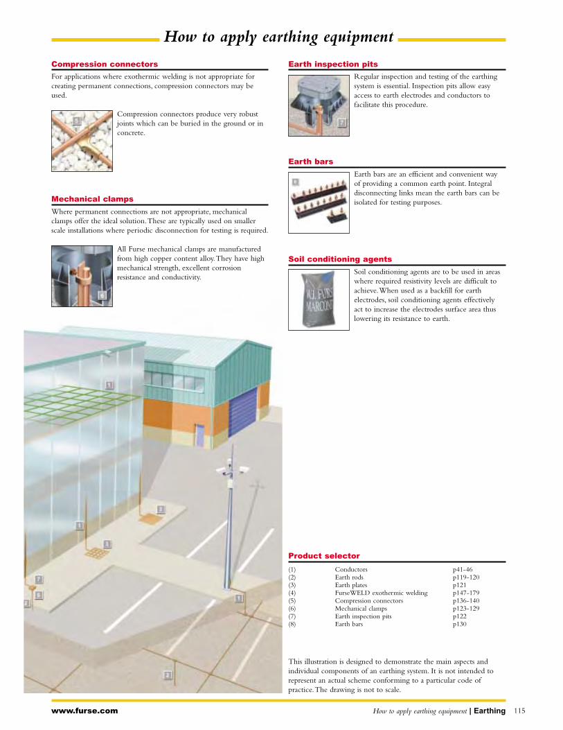
Earth inspection pits
Regular inspection and testing of the earthingsystem is essential. Inspection pits allow easyaccess to earth electrodes and conductors tofacilitate this procedure.
Earth bars
Earth bars are an efficient and convenient wayof providing a common earth point. Integraldisconnecting links mean the earth bars can beisolated for testing purposes.
Soil conditioning agents
Soil conditioning agents are to be used in areaswhere required resistivity levels are difficult toachieve.When used as a backfill for earthelectrodes, soil conditioning agents effectivelyact to increase the electrodes surface area thuslowering its resistance to earth.
Compression connectors
For applications where exothermic welding is not appropriate forcreating permanent connections, compression connectors may beused.
Compression connectors produce very robustjoints which can be buried in the ground or inconcrete.
Mechanical clamps
Where permanent connections are not appropriate, mechanicalclamps offer the ideal solution.These are typically used on smallerscale installations where periodic disconnection for testing is required.
All Furse mechanical clamps are manufacturedfrom high copper content alloy.They have highmechanical strength, excellent corrosionresistance and conductivity.
www.furse.com How to apply earthing equipment | Earthing 115
Product selector
(1) Conductors p41-46(2) Earth rods p119-120(3) Earth plates p121(4) FurseWELD exothermic welding p147-179(5) Compression connectors p136-140(6) Mechanical clamps p123-129(7) Earth inspection pits p122(8) Earth bars p130
How to apply earthing equipment
This illustration is designed to demonstrate the main aspects andindividual components of an earthing system. It is not intended torepresent an actual scheme conforming to a particular code ofpractice.The drawing is not to scale.

Earthing
Earthing design considerationsA correctly designed and installed earthing system will safeguard both lives and equipment.
A good earth connection should have:
Low electrical resistance to earth
Good corrosion resistance
Ability to carry the required current repeatedly
A reliable life of at least 30 years
The crucial factors that determine the resistance to earth of an electrode are:
Soil resistivity
Electrode dimensions
Area available
Soil resistivityPhysical composition
Different soil compositions give different average resistivities.
Moisture
Increased moisture content of the ground can rapidly
decrease its resistivity.
It is especially important to consider moisture contentin areas of high seasonal variation in rainfall.
Wherever possible the earth electrode should beinstalled deep enough to reach the “water table” or“permanent moisture level”.
Chemical composition
Certain minerals and salts can affect soil resistivity. Their
levels can vary with time due to rainfall or flowing water.
Note that although the addition of salts can lower soilresistivity, they are not recommended due to corrosion and leaching. (See section on soil conditioning on page 131.)
Soil type Typical resistivity Ohm-m
Marshy ground 2 – 2.7
Loam and clay 4 – 150
Chalk 60 – 400
Sand 90 – 8,000
Peat 200 upwards
Sandy gravel 300 – 500
Rock 1,000 upward
Added salt Resistivity (% by weight of moisture) Ohm-m
0 107
0.1 18
1 4.6
5 1.9
10 1.3
20 1.0
Moisture content % Resistivity Resistivity by weight Ohm-m Ohm-m
Top soil Sandy loam
0 1,000 x 104 1,000 x 104
2.5 2,500 1,500
5 1,650 430
10 530 185
15 310 105
20 120 63
30 64 42
Table 1 – Effect of soil type on resistivity
Table 2 – Effect of moisture on resistivity
Table 3 - Effect of salt on resistivity for sandy loam,15.2% moisture
Earthing www.furse.com116

www.furse.com Earthing 117
TemperatureWhen the ground becomes frozen, its resistivity risesdramatically.An earth that may be effective duringtemperate weather may become ineffective in winter.
Please note that, if your soil temperature decreases from+20°C to -5°C, the resistivity increases more than tentimes.
Electrode dimensionsThe most important dimension to consider when designing an earth electrode is its length.The greater the lengthof an electrode the lower the density of the current in soil in the immediate vicinity of that electrode.
For this reason a rod or strip type electrode will have a much lower resistance to earth than a plate type electrodeof the same surface area.
By reaching permanent moisture and frost free soil levels, low resistance should be achieved. Often these levels aresome metres below the surface and the most economical way of reaching them is by extensible deep driven earthrod electrodes.
Furse recommend the use of deep driven earth rod electrodes wherever conditions allow.
Where rocks lie just below the surface and deep driving is not possible, parallel driven shorter rods, plates, mats orburied conductors, or a combination of these can be used. However, these should still be buried as deep as possibleto avoid seasonal variations, damage from agricultural machinery etc.
Area availableOften a single earth rod, strip or plate will not achieve the desired resistance alone. If a number ofelectrodes can be installed in parallel the combinedresistance is then practically proportional to thereciprocal of the number employed.This is true so long as each electrode is situated outside the resistance area of any other. For rod electrodes thisseparation distance is considered to be equal to thedriven depth.When an earth electrode must becomposed of multiple parallel electrodes the areaavailable for earthing becomes of major importance.
Temperature Temperature Resistivity°C °F Ohm-m
20 68 72
10 50 99
0 32(water) 138
0 32(ice) 300
-5 23 790
-15 14 3300
Table 4 - Effect of temperature on resistivity for sandyloam, 15.2% moisture
Parallel rods
Earthing

Earth electrode materialsQuality earth rods are commonly made from either solid copper, stainless steel or
copperbonded steel.
Furse can supply all three types, but the copperbonded steel cored rod is by far themost popular, due to its combination of strength, corrosion resistance, andcomparatively low cost.
Solid copper and stainless steel rods offer a very high level of corrosion resistance atthe expense of lower strength and higher cost.
Diameter of rodOne common misconception is that the diameter of the rod has a drastic effect onlowering earth resistance.This is not true! As the graph shows, you only lower theresistance value by 9.5 per cent by doubling the diameter of the rod (which meansincreasing the weight and the cost of the rod by approximately 400 per cent!)
Thus the rationale is: Use the most economical rod that soil conditions will allowyou to drive.This is one of the ways to ensure that you don’t waste money on over-dimensioned rods.
Effect of electrode diameter on resistance.
Thread and shank diametersConfusion often arises between thread and shank diametersfor threaded rods.
The thread rolling process, used by quality rod manufacturers,raises the surface of the rod so that thread diameter (B) is greaterthan shank diameter (A) (see drawing).
All threads are Unified National Coarse (UNC-2A).
Earthing
Earthing | Earth rods www.furse.com
A
B
118
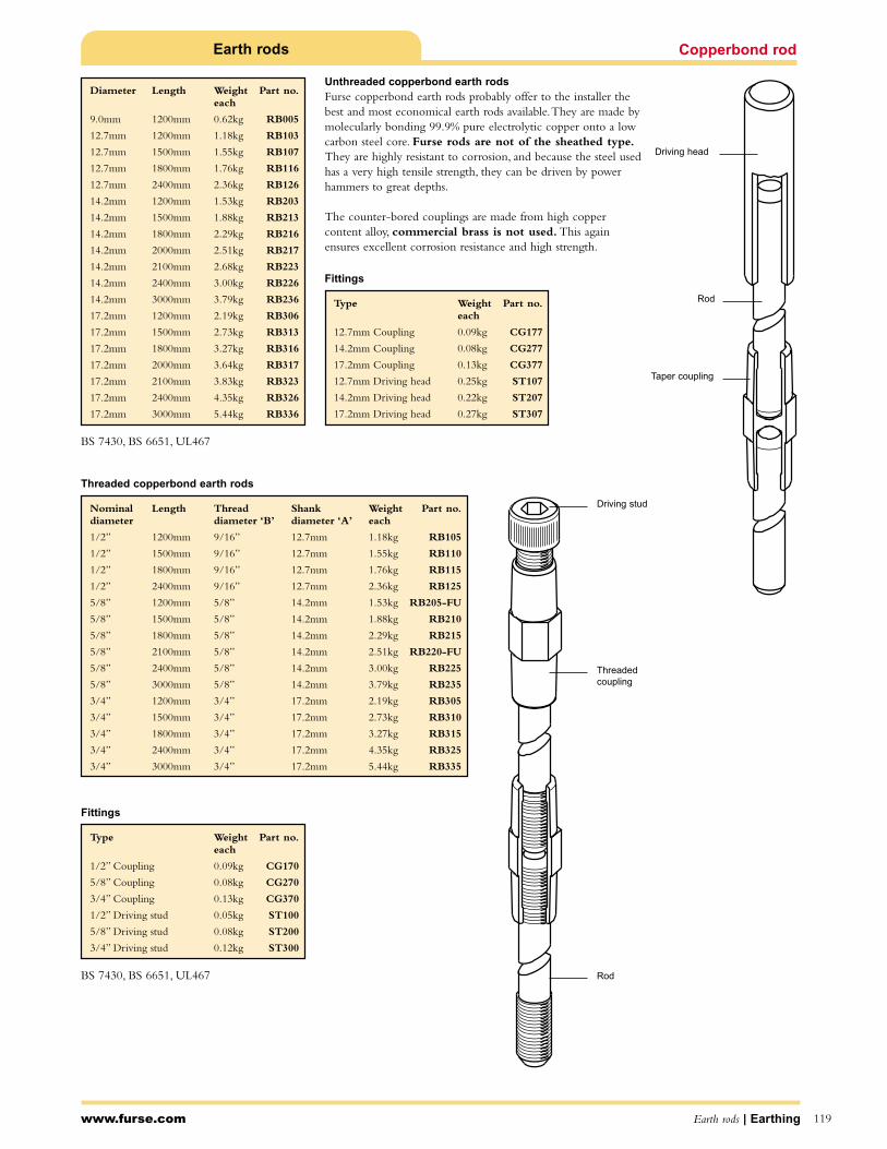
www.furse.com Earth rods | Earthing
Copperbond rod
119
Earth rods
Threaded copperbond earth rods
Fittings
Type Weight Part no.each
1/2” Coupling 0.09kg CG170
5/8” Coupling 0.08kg CG270
3/4” Coupling 0.13kg CG370
1/2” Driving stud 0.05kg ST100
5/8” Driving stud 0.08kg ST200
3/4” Driving stud 0.12kg ST300
Nominal Length Thread Shank Weight Part no.diameter diameter ‘B’ diameter ‘A’ each
1/2” 1200mm 9/16” 12.7mm 1.18kg RB105
1/2” 1500mm 9/16” 12.7mm 1.55kg RB110
1/2” 1800mm 9/16” 12.7mm 1.76kg RB115
1/2” 2400mm 9/16” 12.7mm 2.36kg RB125
5/8” 1200mm 5/8” 14.2mm 1.53kg RB205-FU
5/8” 1500mm 5/8” 14.2mm 1.88kg RB210
5/8” 1800mm 5/8” 14.2mm 2.29kg RB215
5/8” 2100mm 5/8” 14.2mm 2.51kg RB220-FU
5/8” 2400mm 5/8” 14.2mm 3.00kg RB225
5/8” 3000mm 5/8” 14.2mm 3.79kg RB235
3/4” 1200mm 3/4” 17.2mm 2.19kg RB305
3/4” 1500mm 3/4” 17.2mm 2.73kg RB310
3/4” 1800mm 3/4” 17.2mm 3.27kg RB315
3/4” 2400mm 3/4” 17.2mm 4.35kg RB325
3/4” 3000mm 3/4” 17.2mm 5.44kg RB335
Diameter Length Weight Part no.each
9.0mm 1200mm 0.62kg RB005
12.7mm 1200mm 1.18kg RB103
12.7mm 1500mm 1.55kg RB107
12.7mm 1800mm 1.76kg RB116
12.7mm 2400mm 2.36kg RB126
14.2mm 1200mm 1.53kg RB203
14.2mm 1500mm 1.88kg RB213
14.2mm 1800mm 2.29kg RB216
14.2mm 2000mm 2.51kg RB217
14.2mm 2100mm 2.68kg RB223
14.2mm 2400mm 3.00kg RB226
14.2mm 3000mm 3.79kg RB236
17.2mm 1200mm 2.19kg RB306
17.2mm 1500mm 2.73kg RB313
17.2mm 1800mm 3.27kg RB316
17.2mm 2000mm 3.64kg RB317
17.2mm 2100mm 3.83kg RB323
17.2mm 2400mm 4.35kg RB326
17.2mm 3000mm 5.44kg RB336
Fittings
Type Weight Part no.each
12.7mm Coupling 0.09kg CG177
14.2mm Coupling 0.08kg CG277
17.2mm Coupling 0.13kg CG377
12.7mm Driving head 0.25kg ST107
14.2mm Driving head 0.22kg ST207
17.2mm Driving head 0.27kg ST307
Driving stud
Driving head
Threaded coupling
Rod
Taper coupling
Rod
Unthreaded copperbond earth rods
Furse copperbond earth rods probably offer to the installer thebest and most economical earth rods available.They are made bymolecularly bonding 99.9% pure electrolytic copper onto a lowcarbon steel core. Furse rods are not of the sheathed type.They are highly resistant to corrosion, and because the steel usedhas a very high tensile strength, they can be driven by powerhammers to great depths.
The counter-bored couplings are made from high coppercontent alloy, commercial brass is not used. This againensures excellent corrosion resistance and high strength.
BS 7430, BS 6651, UL467
BS 7430, BS 6651, UL467
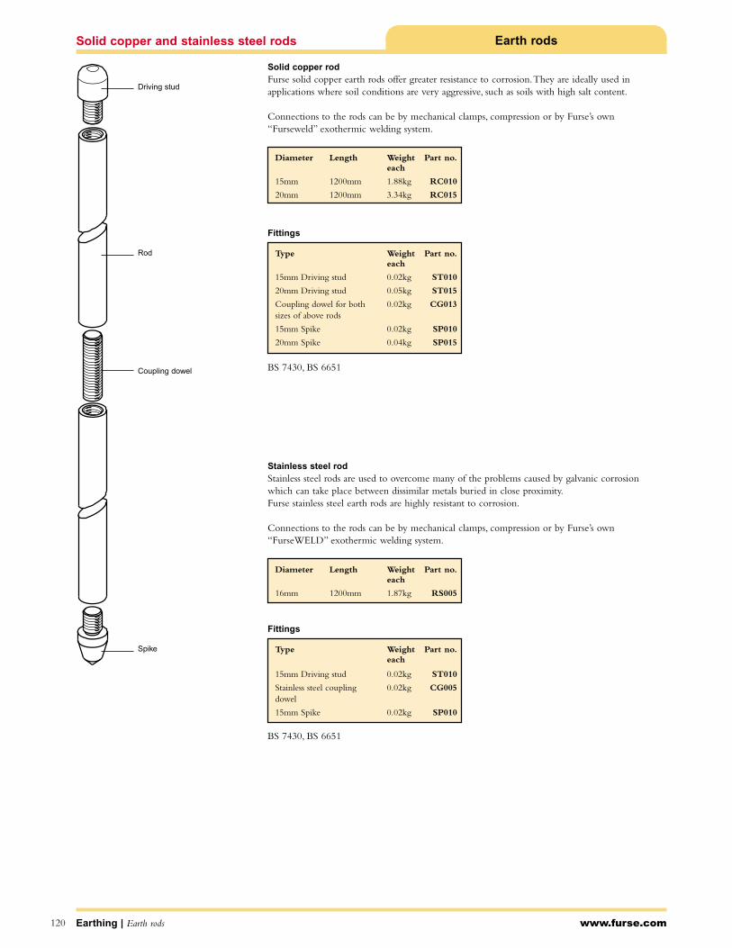
Solid copper and stainless steel rods Earth rods
Solid copper rod
Furse solid copper earth rods offer greater resistance to corrosion.They are ideally used in applications where soil conditions are very aggressive, such as soils with high salt content.
Connections to the rods can be by mechanical clamps, compression or by Furse’s own“Furseweld” exothermic welding system.
Stainless steel rod
Stainless steel rods are used to overcome many of the problems caused by galvanic corrosionwhich can take place between dissimilar metals buried in close proximity.Furse stainless steel earth rods are highly resistant to corrosion.
Connections to the rods can be by mechanical clamps, compression or by Furse’s own“FurseWELD” exothermic welding system.
Fittings
Fittings
Earthing | Earth rods www.furse.com
Diameter Length Weight Part no.each
15mm 1200mm 1.88kg RC010
20mm 1200mm 3.34kg RC015
Type Weight Part no.each
15mm Driving stud 0.02kg ST010
20mm Driving stud 0.05kg ST015
Coupling dowel for both 0.02kg CG013sizes of above rods
15mm Spike 0.02kg SP010
20mm Spike 0.04kg SP015
Diameter Length Weight Part no.each
16mm 1200mm 1.87kg RS005
Type Weight Part no.each
15mm Driving stud 0.02kg ST010
Stainless steel coupling 0.02kg CG005dowel
15mm Spike 0.02kg SP010
Driving stud
Rod
Coupling dowel
Spike
120
BS 7430, BS 6651
BS 7430, BS 6651
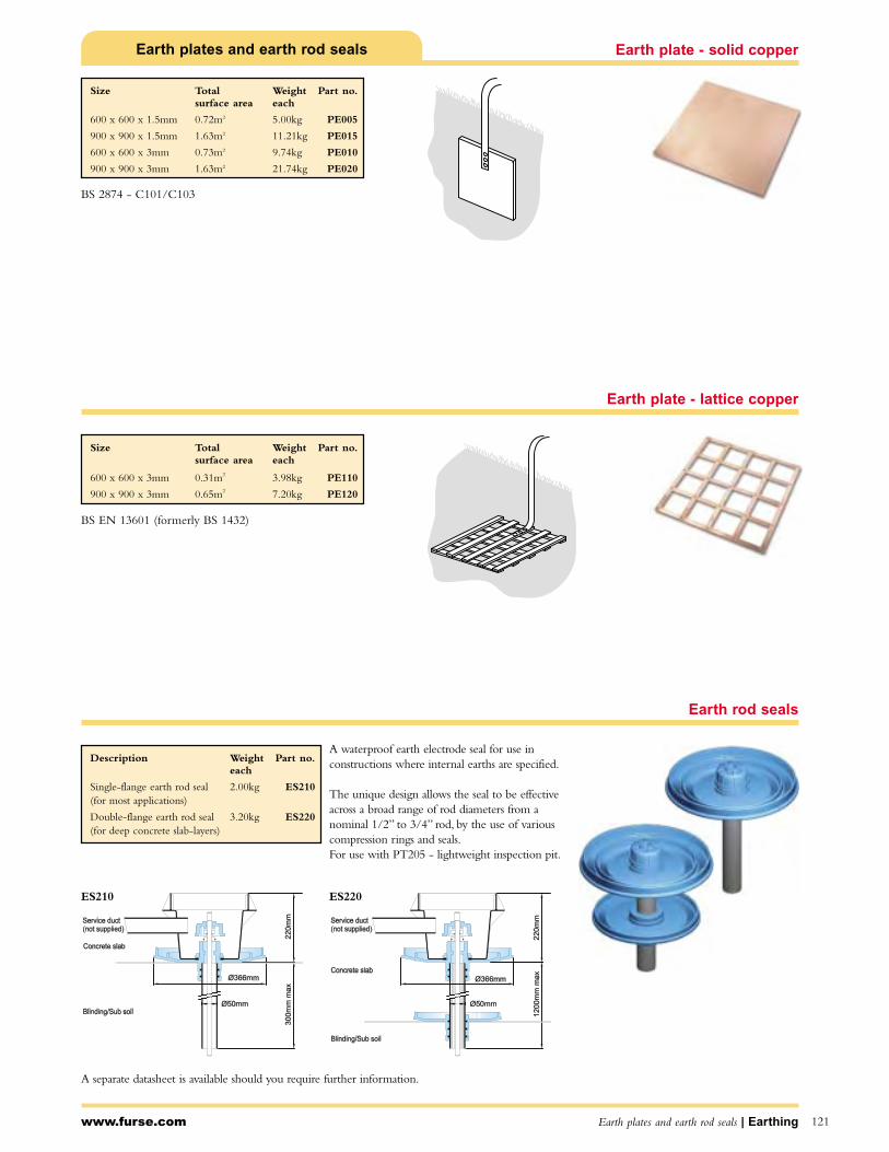
www.furse.com Earth plates and earth rod seals | Earthing 121
Earth plates and earth rod seals Earth plate - solid copper
Earth plate - lattice copper
Size Total Weight Part no.surface area each
600 x 600 x 1.5mm 0.72m2 5.00kg PE005
900 x 900 x 1.5mm 1.63m2 11.21kg PE015
600 x 600 x 3mm 0.73m2 9.74kg PE010
900 x 900 x 3mm 1.63m2 21.74kg PE020
Size Total Weight Part no.surface area each
600 x 600 x 3mm 0.31m2 3.98kg PE110
900 x 900 x 3mm 0.65m2 7.20kg PE120
Earth rod seals
A separate datasheet is available should you require further information.
ES210 ES220
A waterproof earth electrode seal for use inconstructions where internal earths are specified.
The unique design allows the seal to be effectiveacross a broad range of rod diameters from anominal 1/2” to 3/4” rod, by the use of variouscompression rings and seals.For use with PT205 - lightweight inspection pit.
Description Weight Part no.each
Single-flange earth rod seal 2.00kg ES210(for most applications)
Double-flange earth rod seal 3.20kg ES220(for deep concrete slab-layers)
BS 2874 - C101/C103
BS EN 13601 (formerly BS 1432)

Lightweight inspection pit with concrete lid
Earth inspection pitsLightweight inspection pit
Concrete inspection pit
192m
m
145mm
320mm
54
mm
300mm
ø200mm Nominal
ø70mm
256mm
158m
m
Accessories
Accessories
Accessories
www.furse.comEarthing | Earth inspection pits122
The lightweight inspection pit weighs only 1.8kg yet is loadrated to 5,000kg. It has a lockable lid and improved workingarea compared to the concrete inspection pit.
An integral earth bar is available as an optional extra.
Manufactured from high-performance polymer, the lightweightpit is UV stable and chemically resistant.
New to the range is a lightweight inspection pit with a concretelid. Suitable for use in pedestrianised and light vehicular areas,the pit is load rated to 1,200kg.
The lid can be locked in place, if required(order 2 x AS100 Allen caphead screws).
The concrete inspection pit is load rated to 4,500kgand is suitable for most types of earthing andlightning protection installations.
It is not suitable for use in areas where high load,small wheel vehicles are used.The Lightweightinspection pit (PT205) is recommended for this typeof application.
Description Weight Part no.each
5 hole earth bar 0.40kg PT004
M8 x 100mm lg mild steel 0.04kg JH100‘J’ bolt lifting hook
M8 x 60 stainless steel Allen 0.03kg AS100caphead screw (2 per lid)
Description Weight Part no.each
Lightweight inspection pit 7.50kg PT110with concrete lid
Description Weight Part no.each
Lightweight inspection pit 1.80kg PT205with grey lid
Lightweight inspection pit 1.80kg PT309-FUwith black (unbranded) lid
Description Weight Part no.each
5 hole earth bar 0.40kg PT004
6mm Allen key 0.03kg AK005
Description Weight Part no.each
Concrete inspection pit 30kg PT005
Description Weight Part no.each
5 hole earth bar 0.40kg PT006
7 hole earth bar 0.58kg PT007
54m
m1
58
mm ø200mm Nominal
300mm
256mm
ø70mm
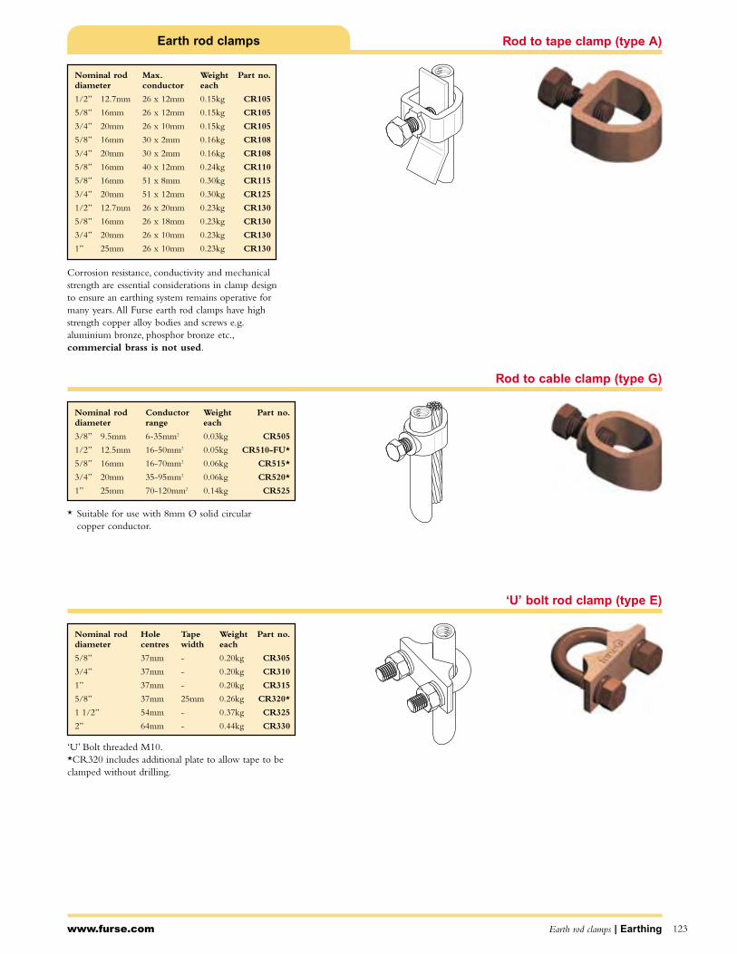
Rod to tape clamp (type A)
Rod to cable clamp (type G)
‘U’ bolt rod clamp (type E)
Earth rod clamps
‘U’ Bolt threaded M10.*CR320 includes additional plate to allow tape to beclamped without drilling.
* Suitable for use with 8mm Ø solid circular copper conductor.
Corrosion resistance, conductivity and mechanicalstrength are essential considerations in clamp designto ensure an earthing system remains operative formany years.All Furse earth rod clamps have highstrength copper alloy bodies and screws e.g.aluminium bronze, phosphor bronze etc.,commercial brass is not used.
www.furse.com Earth rod clamps | Earthing 123
Nominal rod Max. Weight Part no.diameter conductor each
1/2” 12.7mm 26 x 12mm 0.15kg CR105
5/8” 16mm 26 x 12mm 0.15kg CR105
3/4” 20mm 26 x 10mm 0.15kg CR105
5/8” 16mm 30 x 2mm 0.16kg CR108
3/4” 20mm 30 x 2mm 0.16kg CR108
5/8” 16mm 40 x 12mm 0.24kg CR110
5/8” 16mm 51 x 8mm 0.30kg CR115
3/4” 20mm 51 x 12mm 0.30kg CR125
1/2” 12.7mm 26 x 20mm 0.23kg CR130
5/8” 16mm 26 x 18mm 0.23kg CR130
3/4” 20mm 26 x 10mm 0.23kg CR130
1” 25mm 26 x 10mm 0.23kg CR130
Nominal rod Conductor Weight Part no.diameter range each
3/8” 9.5mm 6-35mm2 0.03kg CR505
1/2” 12.5mm 16-50mm2 0.05kg CR510-FU*
5/8” 16mm 16-70mm2 0.06kg CR515*
3/4” 20mm 35-95mm2 0.06kg CR520*
1” 25mm 70-120mm2 0.14kg CR525
Nominal rod Hole Tape Weight Part no.diameter centres width each
5/8” 37mm - 0.20kg CR305
3/4” 37mm - 0.20kg CR310
1” 37mm - 0.20kg CR315
5/8” 37mm 25mm 0.26kg CR320*
1 1/2” 54mm - 0.37kg CR325
2” 64mm - 0.44kg CR330
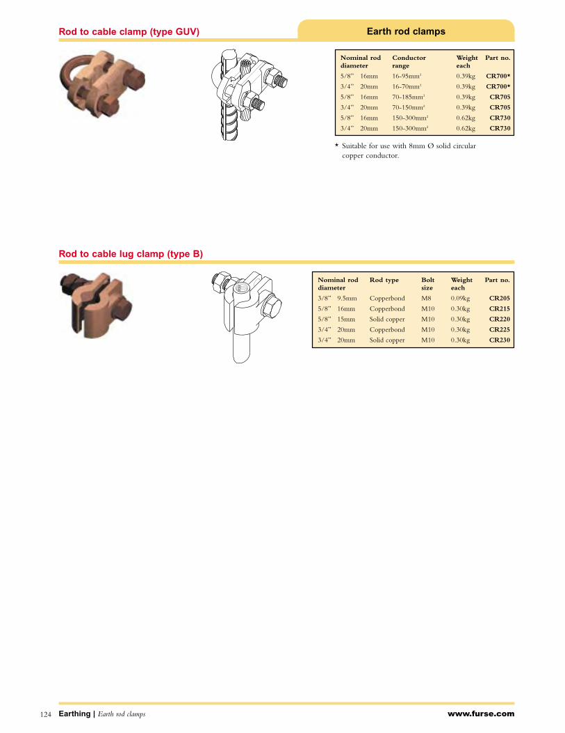
Earthing | Earth rod clamps www.furse.com124
Rod to cable clamp (type GUV) Earth rod clamps
* Suitable for use with 8mm Ø solid circular copper conductor.
Rod to cable lug clamp (type B)
Nominal rod Rod type Bolt Weight Part no.diameter size each
3/8” 9.5mm Copperbond M8 0.09kg CR205
5/8” 16mm Copperbond M10 0.30kg CR215
5/8” 15mm Solid copper M10 0.30kg CR220
3/4” 20mm Copperbond M10 0.30kg CR225
3/4” 20mm Solid copper M10 0.30kg CR230
Nominal rod Conductor Weight Part no.diameter range each
5/8” 16mm 16-95mm2 0.39kg CR700*
3/4” 20mm 16-70mm2 0.39kg CR700*
5/8” 16mm 70-185mm2 0.39kg CR705
3/4” 20mm 70-150mm2 0.39kg CR705
5/8” 16mm 150-300mm2 0.62kg CR730
3/4” 20mm 150-300mm2 0.62kg CR730

www.furse.com Bonds and clamps | Earthing
‘B’ bond
125
Bonds and clamps
RWP bond
Watermain bond
For bonding tape to steel structures.
For bonding tape to rainwater pipes, handrails etc.
For bonding tape to large diameter pipes.
For bonding copper tape to watermain pipes.
Maximum Bolt size Conductor Weight Part no.tape width material each
26mm M10 Copper 0.12kg BN105
26mm M10 Aluminium 0.06kg BN005
31mm M10 Copper 0.15kg BN113
Maximum Bolt size Conductor Weight Part no.tape width material each
26mm M10 Copper 0.12kg BN115
26mm M10 Aluminium 0.07kg BN010
Maximum Conductor Weight Part no.tape width material each
26mm Copper 0.26kg BN120

Bonds and clamps
Earthing | Bonds and clamps www.furse.com126
Tower earth clamps
For bonding copper cable or wire to steel structures.* Suitable for use with 8mm Ø solid circular conductor.
Eyebolt
Screws direct onto a copperbond earth rod, offering anearth point for boats, trucks etc.
Flexible copper braid bond
Flexible copper braid for bonding gates, doors, fencesetc. Equivalent cross sectional area 35mm2. Othermaterials, lengths and sections available as special items.
Overall braid Hole Hole Weight Part no.dimensions size centres each
25 x 3.5mm 11mm 200mm 0.09kg BN505
25 x 3.5mm 11mm 400mm 0.15kg BN510
Conductor Channel Bolt Conductor Weight Part no.range thickness size material each
16-70mm2 10mm M10 Copper 0.13kg BN125*
70-120mm2 10mm M12 Copper 0.22kg BN130
25-50mm2 10mm M10 Copper 0.08kg BN300-FU*
25-50mm2 10mm M10 Aluminium 0.05kg BN305*
120-185mm2 10mm M12 Copper 0.30kg BN320
185-240mm2 10mm M12 Copper 0.40kg BN325
Nominal copperbond Weight Part no.rod diameter each
5/8” 0.52kg BT150
3/4” 0.52kg BT160

www.furse.com Bonds and clamps | Earthing 127
Bonds and clamps Static earth receptacle
For setting into roadways or runways. Provides a staticdischarge point for aircraft, fuel tankers, etc.
Square tape clamp
For forming straight through, cross or tee joints in tapeand bar.
Conductor material Weight Part no.each
Copper 0.64kg RX005
Conductor Conductor Weight Part no.size material each
25 x 3mm Copper 0.22kg CT105-FU
25 x 6mm Copper 0.41kg CT110
31 x 3mm Copper 0.35kg CT113
50 x 6mm Copper 0.97kg CT115
Pipe clamp
Pipe diameter Conductor Weight Part no.range each
1/2” - 1” 13 - 25mm 25 - 95mm2 0.03kg 3902
1 1/4” - 2” 32 - 50mm 25 - 95mm2 0.04kg 3903
2 1/2 ” - 3 1/2” 65 - 90mm 25 - 95mm2 0.08kg 3904
4” - 5” 100 - 125mm 25 - 95mm2 0.06kg 3905-TB
6” 150mm 25 - 95mm2 0.08kg 3906-TB
8” 200mm 25 - 95mm2 0.10kg 3907
10” 250mm 25 - 95mm2 0.11kg 3908
12” 300mm 25 - 95mm2 0.15kg 3909-TB
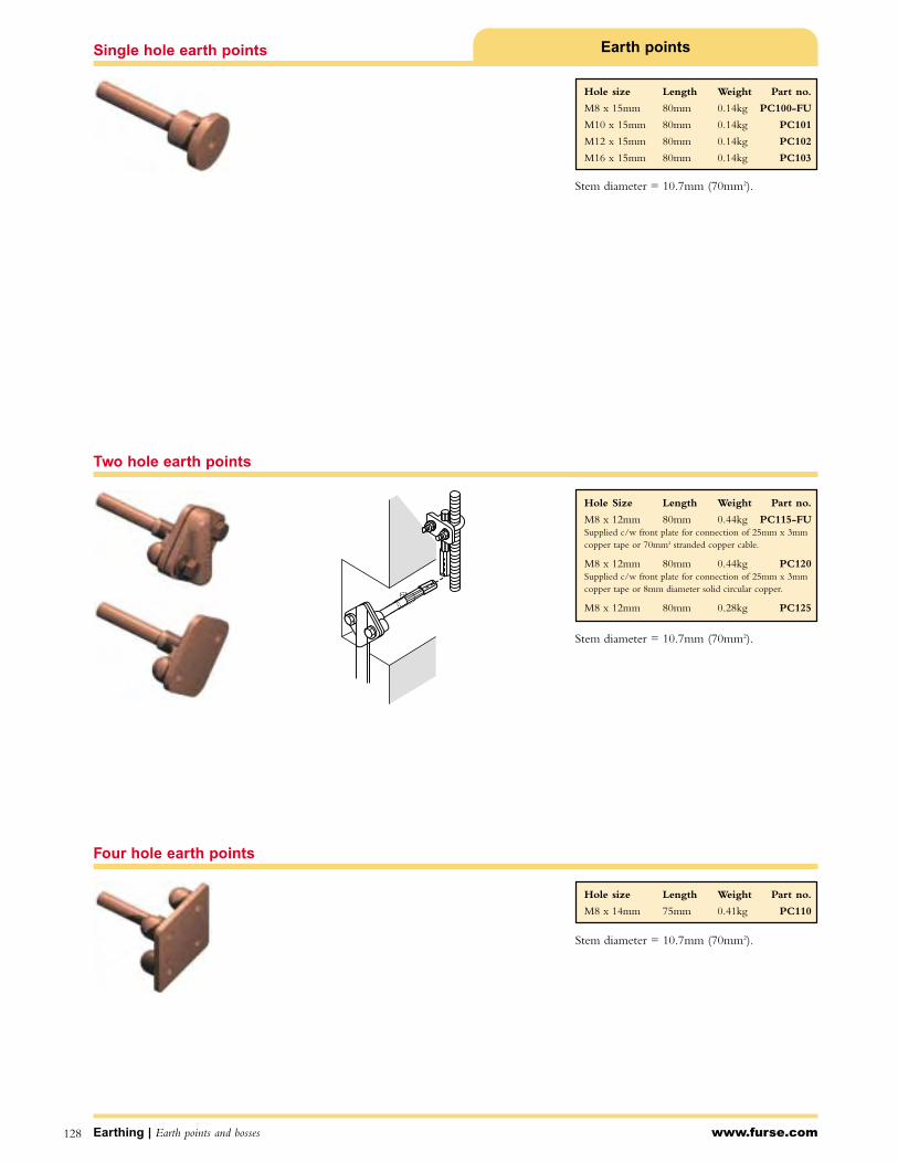
Earthing | Earth points and bosses www.furse.com128
Single hole earth points Earth points
Two hole earth points
Four hole earth points
Hole size Length Weight Part no.
M8 x 15mm 80mm 0.14kg PC100-FU
M10 x 15mm 80mm 0.14kg PC101
M12 x 15mm 80mm 0.14kg PC102
M16 x 15mm 80mm 0.14kg PC103
Hole Size Length Weight Part no.
M8 x 12mm 80mm 0.44kg PC115-FUSupplied c/w front plate for connection of 25mm x 3mmcopper tape or 70mm2 stranded copper cable.
M8 x 12mm 80mm 0.44kg PC120Supplied c/w front plate for connection of 25mm x 3mm copper tape or 8mm diameter solid circular copper.
M8 x 12mm 80mm 0.28kg PC125
Hole size Length Weight Part no.
M8 x 14mm 75mm 0.41kg PC110
Stem diameter = 10.7mm (70mm2).
Stem diameter = 10.7mm (70mm2).
Stem diameter = 10.7mm (70mm2).

www.furse.com Earth points, earth boss and insulator | Earthing 129
Earth points, earth boss and insulator
Made of mild steel to BS 970 230M07 (ENIA) withphosphor bronze stud and nuts. For welding to steelvessels/tanks/structures.Wrap connections with Densotape (see page 38).
Earth points with pre-welded tails
Earth boss
Description Weight Part no.each
As PC100-FU with prewelded 500mm long tail of 70mm2 0.56kg PC105PVC insulated earth cable
As PC101 with prewelded 500mm long tail of 70mm2 0.56kg PC106PVC insulated earth cable
As PC102 with prewelded 500mm long tail of 70mm2 0.56kg PC107PVC insulated earth cable
As PC103 with prewelded 500mm long tail of 70mm2 0.56kg PC108PVC insulated earth cable
As PC110 with prewelded 500mm long tail of 70mm2 1.14kg PC111PVC insulated earth cable
As PC115-FU with prewelded 500mm long tail of 70mm2 0.84kg PC116PVC insulated earth cable
As PC120 with prewelded 500mm long tail of 70mm2 0.84kg PC121PVC insulated earth cable
As PC125 with prewelded 500mm long tail of 70mm2 0.84kg PC126-FUPVC insulated earth cable
Length Diameter Thread Weight Part no.size each
50mm 50mm M10 0.79kg EB001
Insulator
Description Thread size Weight Part no.
Insulator with 2 studs and 3 nuts M10 0.22kg IN005
Insulator only M10 0.14kg IN013
M10 x 19mm
51mm
29
mm
36
mm

Earth bars
Earth bars with single disconnecting link
Earth bars with twin disconnecting links
Accessories
www.furse.comEarthing | Earth bars and disconnecting links130
Earth bars and disconnecting linksEarth bars and disconnecting links
Recommended fixing - roundhead woodscrew 1 1/2” x no.16and wall plug.All the above products consist of 50 x 6mmcopper bar.
Furse can offer a range of earth bars manufactured toyour individual requirements. Contact the sales office for further information.
LK245-6 LK205
LK243-6
LK207-6
Description Length Width Height Weight Part no.each
6 way 550mm 90mm 96mm 2.80kg LK207-68 way 650mm 90mm 96mm 3.20kg LK207-810 way 800mm 90mm 96mm 3.80kg LK207-1012 way 900mm 90mm 96mm 4.20kg LK207-1214 way 1000mm 90mm 96mm 4.60kg LK207-1416 way 1100mm 90mm 96mm 5.00kg LK207-1618 way 1200mm 90mm 96mm 5.40kg LK207-1820 way 1350mm 90mm 96mm 6.00kg LK207-2022 way 1450mm 90mm 96mm 6.40kg LK207-2224 way 1550mm 90mm 96mm 6.80kg LK207-2426 way 1650mm 90mm 96mm 7.20kg LK207-2628 way 1800mm 90mm 96mm 7.90kg LK207-2830 way 1900mm 90mm 96mm 8.30kg LK207-30
Description Length Width Height Weight Part no.each
Swan-neck 400mm 50mm 36mm 0.42kg LK004linkDisconnecting 125mm 90mm 90mm 0.59kg LK205link
Description Length Width Height Weight Part no.each
6 way 475mm 90mm 96mm 2.30kg LK243-68 way 575mm 90mm 96mm 2.70kg LK243-810 way 725mm 90mm 96mm 3.30kg LK243-1012 way 825mm 90mm 96mm 3.70kg LK243-1214 way 925mm 90mm 96mm 4.10kg LK243-1416 way 1025mm 90mm 96mm 4.50kg LK243-1618 way 1125mm 90mm 96mm 4.90kg LK243-1820 way 1275mm 90mm 96mm 5.50kg LK243-2022 way 1375mm 90mm 96mm 5.90kg LK243-2224 way 1475mm 90mm 96mm 6.30kg LK243-2426 way 1575mm 90mm 96mm 6.70kg LK243-2628 way 1725mm 90mm 96mm 7.40kg LK243-2830 way 1825mm 90mm 96mm 7.80kg LK243-30
Description Length Width Height Weight Part no.each
6 way 400mm 90mm 90mm 1.80kg LK245-68 way 500mm 90mm 90mm 2.20kg LK245-810 way 650mm 90mm 90mm 2.80kg LK245-1012 way 750mm 90mm 90mm 3.20kg LK245-1214 way 850mm 90mm 90mm 3.60kg LK245-1416 way 950mm 90mm 90mm 4.00kg LK245-1618 way 1050mm 90mm 90mm 4.40kg LK245-1820 way 1200mm 90mm 90mm 5.00kg LK245-2022 way 1300mm 90mm 90mm 5.40kg LK245-2224 way 1400mm 90mm 90mm 5.80kg LK245-2426 way 1500mm 90mm 90mm 6.20kg LK245-2628 way 1650mm 90mm 90mm 6.90kg LK245-2830 way 1750mm 90mm 90mm 7.30kg LK245-30

Soil conditioning agents | Earthingwww.furse.com
Marconite® conductive aggregate
131
Moisture retaining clay
Used as an earth-electrode backfill to reduce soilresistivity by retaining moisture.The clay consistslargely of sodium montmorillonite, which whenmixed with water swells to many times its dryvolume. It has the ability to hold its moisturecontent for a considerable period of time and toabsorb moisture from the surrounding soil (e.g.from rainfall).
For further information on Marconite, pleasecontact the Furse sales office.A separate data sheetis available. Marconite is a registered trademark ofMarconi Communications Ltd., and ismanufactured by PMC Holdings Ltd. -Conductive Products Division.
Marconite is a unique product, developed byMarconi Communications Ltd.
Certain ground conditions make it difficult toobtain a reliable earth resistance, whilst particularinstallations may require a very low resistance. Insuch cases, Marconite provides a convenient andpermanent solution.
By adding Marconite in place of sand andaggregate, to cement, a conductive concrete isformed.This electrically conductive medium hasmany applications in the electrical/constructionindustry, including RF and microwave screening,static control and of course earthing, for which itwas specifically developed.
When used as a backfill for earth electrodes,Marconite impregnated concrete greatly increasesthe electrodes surface area thus lowering itsresistance to earth.
No other product can offer the same benefits asMarconite in earthing applications.
Marconite concrete used as a backfillfor a conventional earth rod to achievea lower earth electrode resistance.
Soil conditioning agents
Sack weight Part no.
25kg CM025
Sack weight Part no.
25kg CM015
Topsoil
MarconiteConcrete
Earth RodElectrode
Rock,Sand,Shale,
etc.
Topsoil
MoistureRetaining
Earth RodElectrode
Rock,Sand,Shale,
etc.
Clay
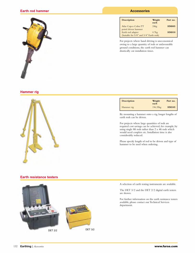
AccessoriesEarth rod hammer
Hammer rig
Earth resistance testers
www.furse.comEarthing | Accessories132
By mounting a hammer onto a rig, longer lengths ofearth rods can be driven.
For projects where large quantities of rods arerequired cost savings can be achieved, for example, byusing single 8ft rods rather than 2 x 4ft rods whichwould need couplers etc. Installation time is alsoconsiderably reduced.
Please specify length of rod to be driven and type ofhammer to be used when ordering.
A selection of earth testing instruments are available.
The DET 3/2 and the DET 2/2 digital earth testersare shown.
For further information on the earth resistance testersavailable, please contact our Technical Servicesdepartment.
For projects where hand driving is uneconomicalowing to a large quantity of rods or unfavourableground conditions, the earth rod hammer candrastically cut installation times.
DET 2/2 DET 3/2
Description Weight Part no.each
Atlas Copco Cobra TT 24kg HM005petrol driven hammerEarth rod adapter 0.7kg HM010(Suitable for 5/8” and 3/4” Earth rods)
Description Weight Part no.each
Hammer rig 196.35kg HM105

Accessories
www.furse.com
Type H - High strength splitbolt connector
133
B
For copper to copper connections. No special tools required.
Conductor rangeMain Tap Dimension Weight Part no.
Min Max Min Max B each
4mm2 10mm2 2.5mm2 10mm2 4.1mm 0.02kg 8H
10mm2 16mm2 2.5mm2 16mm2 5.5mm 0.03kg 4H
16mm2 25mm2 4mm2 25mm2 6.9mm 0.04kg 2H
25mm2 35mm2 4mm2 35mm2 8.4mm 0.06kg 1H
35mm2 50mm2 4mm2 50mm2 9.7mm 0.09kg 10H
35mm2 70mm2 4mm2 70mm2 11.2mm 0.14kg 20H
50mm2 95mm2 4mm2 95mm2 13.6mm 0.17kg 30H
50mm2 120mm2 6mm2 120mm2 14.7mm 0.18kg 40H
95mm2 185mm2 6mm2 185mm2 18.2mm 0.35kg 350M
Accessories | Earthing
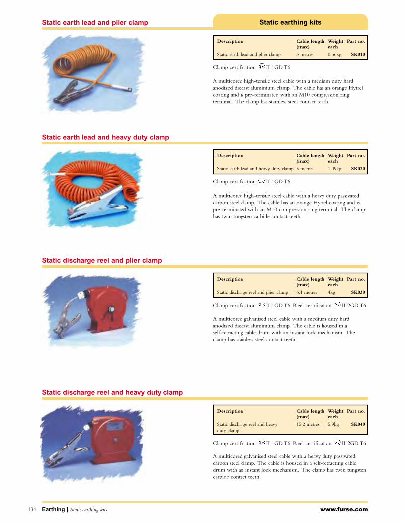
Clamp certification II 1GD T6
Clamp certification II 1GD T6. Reel certification II 2GD T6
www.furse.com134
Static discharge reel and plier clamp
Static earthing kits
A multicored high-tensile steel cable with a medium duty hardanodized diecast aluminium clamp. The cable has an orange Hytrelcoating and is pre-terminated with an M10 compression ringterminal. The clamp has stainless steel contact teeth.
A multicored high-tensile steel cable with a heavy duty passivatedcarbon steel clamp. The cable has an orange Hytrel coating and ispre-terminated with an M10 compression ring terminal. The clamphas twin tungsten carbide contact teeth.
A multicored galvanised steel cable with a medium duty hardanodized diecast aluminium clamp. The cable is housed in a self-retracting cable drum with an instant lock mechanism. Theclamp has stainless steel contact teeth.
Static discharge reel and heavy duty clamp
Static earth lead and heavy duty clamp
A multicored galvanised steel cable with a heavy duty passivatedcarbon steel clamp. The cable is housed in a self-retracting cabledrum with an instant lock mechanism. The clamp has twin tungstencarbide contact teeth.
Static earth lead and plier clamp
Description Cable length Weight Part no.(max) each
Static earth lead and plier clamp 3 metres 0.56kg SK010
Description Cable length Weight Part no.(max) each
Static earth lead and heavy duty clamp 5 metres 1.09kg SK020
Description Cable length Weight Part no.(max) each
Static discharge reel and plier clamp 6.1 metres 4kg SK030
Description Cable length Weight Part no.(max) each
Static discharge reel and heavy 15.2 metres 5.9kg SK040duty clamp
Earthing | Static earthing kits
Clamp certification II 1GD T6
Clamp certification II 1GD T6. Reel certification II 2GD T6

Compression connectors produce very robust joints which canbe buried in the ground or in concrete.They are ideal for usein situations where exothermic welding is not appropriateand periodic disconnection is not required.
A compression tool is required to make each joint - details ofour manual hydraulic and battery powered tools and cuttingtools can be found on pages 139-140.
Connector selector
www.furse.com Compression connectors | Earthing 135
“6” Shape connectors page 136
“8” Shape connectors page 136
“C” Shape connectors page 137
Grid connectors page 137
Terminals page 138
1
2
3
4
5
Compression connectors
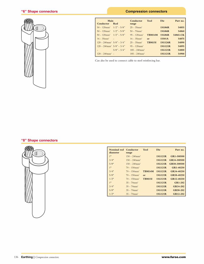
www.furse.comEarthing | Compression connectors136
Compression connectors“6” Shape connectors
“8” Shape connectors
Can also be used to connect cable to steel reinforcing bar.
Nominal rod Conductor Tool Die Part no.diameter range
1" 150 - 240mm2 15G121R GR1-300500
3/4" 150 - 240mm2 15G121R GR34-300500
5/8" 150 - 240mm2 15G121R GR58-300500
1" 70 - 150mm2 15G121R GR1-40250
3/4" 70 - 150mm2 TBM14M 15G121R GR34-40250
5/8" 70 - 150mm2 or 15G121R GR58-40250
1/2" 70 - 150mm2 TBM15I 15G121R GR12-40250
1" 35 - 70mm2 15G121R GR1-202
3/4" 35 - 70mm2 15G121R GR34-202
5/8" 35 - 70mm2 15G121R GR58-202
1/2" 35 - 70mm2 15G121R GR12-202
Main Conductor Tool Die Part no.Conductor Rod range
50 - 120mm2 1/2” - 5/8” 25 - 35mm2 15G86R 54855
50 - 120mm2 1/2” - 5/8” 50 - 70mm2 15G86R 54860
50 - 120mm2 1/2” - 5/8” 95 - 120mm2 TBM14M 15G86R 54865-CK
16 - 35mm2 - 16 - 35mm2 or 15501A 54875
120 - 240mm2 5/8” - 3/4” 25 - 35mm2 TBM15I 15G126R 54890
120 - 240mm2 5/8” - 3/4” 95 - 120mm2 15G121R 54895
- 5/8” - 3/4” 185 - 240mm2 15G121R 54800
120 - 240mm2 - 185 - 240mm2 15G121R 54900
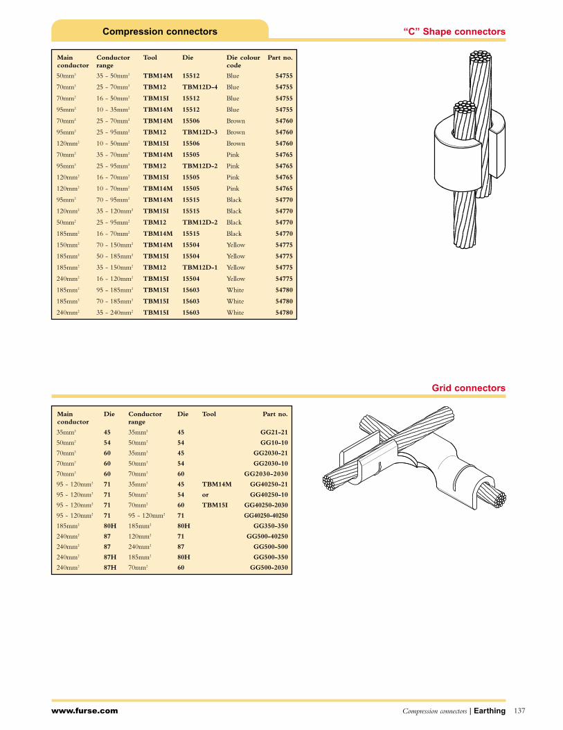
Compression connectors “C” Shape connectors
Grid connectors
www.furse.com Compression connectors | Earthing 137
Main Die Conductor Die Tool Part no.conductor range
35mm2 45 35mm2 45 GG21-21
50mm2 54 50mm2 54 GG10-10
70mm2 60 35mm2 45 GG2030-21
70mm2 60 50mm2 54 GG2030-10
70mm2 60 70mm2 60 GG2030-2030
95 - 120mm2 71 35mm2 45 TBM14M GG40250-21
95 - 120mm2 71 50mm2 54 or GG40250-10
95 - 120mm2 71 70mm2 60 TBM15I GG40250-2030
95 - 120mm2 71 95 - 120mm2 71 GG40250-40250
185mm2 80H 185mm2 80H GG350-350
240mm2 87 120mm2 71 GG500-40250
240mm2 87 240mm2 87 GG500-500
240mm2 87H 185mm2 80H GG500-350
240mm2 87H 70mm2 60 GG500-2030
Main Conductor Tool Die Die colour Part no.conductor range code
50mm2 35 - 50mm2 TBM14M 15512 Blue 54755
70mm2 25 - 70mm2 TBM12 TBM12D-4 Blue 54755
70mm2 16 - 50mm2 TBM15I 15512 Blue 54755
95mm2 10 - 35mm2 TBM14M 15512 Blue 54755
70mm2 25 - 70mm2 TBM14M 15506 Brown 54760
95mm2 25 - 95mm2 TBM12 TBM12D-3 Brown 54760
120mm2 10 - 50mm2 TBM15I 15506 Brown 54760
70mm2 35 - 70mm2 TBM14M 15505 Pink 54765
95mm2 25 - 95mm2 TBM12 TBM12D-2 Pink 54765
120mm2 16 - 70mm2 TBM15I 15505 Pink 54765
120mm2 10 - 70mm2 TBM14M 15505 Pink 54765
95mm2 70 - 95mm2 TBM14M 15515 Black 54770
120mm2 35 - 120mm2 TBM15I 15515 Black 54770
50mm2 25 - 95mm2 TBM12 TBM12D-2 Black 54770
185mm2 16 - 70mm2 TBM14M 15515 Black 54770
150mm2 70 - 150mm2 TBM14M 15504 Yellow 54775
185mm2 50 - 185mm2 TBM15I 15504 Yellow 54775
185mm2 35 - 150mm2 TBM12 TBM12D-1 Yellow 54775
240mm2 16 - 120mm2 TBM15I 15504 Yellow 54775
185mm2 95 - 185mm2 TBM15I 15603 White 54780
185mm2 70 - 185mm2 TBM15I 15603 White 54780
240mm2 35 - 240mm2 TBM15I 15603 White 54780

Compression connectorsTerminals
B
www.furse.comEarthing | Compression connectors138
Conductor Screw Weight Part no.size size (B) each
16mm2 6mm 0.01kg FCT166
16mm2 8mm 0.01kg FCT168
16mm2 10mm 0.01kg FCT1610
16mm2 12mm 0.01kg FCT1612
25mm2 6mm 0.01kg FCT256
25mm2 8mm 0.01kg FCT258
25mm2 10mm 0.01kg FCT2510
25mm2 12mm 0.01kg FCT2512
35mm2 6mm 0.01kg FCT356
35mm2 8mm 0.01kg FCT358
35mm2 10mm 0.01kg FCT3510
35mm2 12mm 0.01kg FCT3512
50mm2 6mm 0.02kg FCT506
50mm2 8mm 0.02kg FCT508
50mm2 10mm 0.02kg FCT5010
50mm2 12mm 0.02kg FCT5012
70mm2 8mm 0.04kg FCT708
70mm2 10mm 0.04kg FCT7010
70mm2 12mm 0.04kg FCT7012
70mm2 16mm 0.04kg FCT7016
95mm2 8mm 0.06kg FCT958
95mm2 10mm 0.06kg FCT9510
95mm2 12mm 0.06kg FCT9512
95mm2 14mm 0.06kg FCT9514
95mm2 16mm 0.06kg FCT9516
120mm2 10mm 0.06kg FCT12010
120mm2 12mm 0.06kg FCT12012
120mm2 14mm 0.06kg FCT12014
120mm2 16mm 0.06kg FCT12016
150mm2 10mm 0.09kg FCT15010
150mm2 12mm 0.09kg FCT15012
150mm2 14mm 0.09kg FCT15014
150mm2 16mm 0.09kg FCT15016
185mm2 12mm 0.11kg FCT18512
185mm2 14mm 0.11kg FCT18514
185mm2 16mm 0.11kg FCT18516
240mm2 12mm 0.14kg FCT24012
240mm2 14mm 0.14kg FCT24014
240mm2 16mm 0.14kg FCT24016
300mm2 12mm 0.17kg FCT30012
300mm2 14mm 0.17kg FCT30014
300mm2 16mm 0.17kg FCT30016
400mm2 12mm 0.21kg FCT40012
400mm2 14mm 0.21kg FCT40014
400mm2 16mm 0.21kg FCT40016
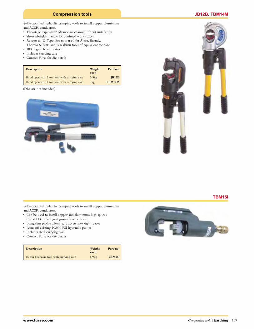
Compression tools JB12B, TBM14M
TBM15I
www.furse.com Compression tools | Earthing 139
Self-contained hydraulic crimping tools to install copper, aluminiumand ACSR conductors.• Two-stage 'rapid-ram' advance mechanism for fast installation• Short fibreglass handle for confined work spaces• Accepts all U-Type dies now used for Alcoa, Burndy,
Thomas & Betts and Blackburn tools of equivalent tonnage• 180 degree head rotation• Includes carrying case• Contact Furse for die details
Self-contained hydraulic crimping tools to install copper, aluminiumand ACSR conductors.• Can be used to install copper and aluminium lugs, splices,
C and H taps and grid ground connectors• Long, slim profile allows easy access into tight spaces• Runs off existing 10,000 PSI hydraulic pumps• Includes steel carrying case• Contact Furse for die details
(Dies are not included)
Description Weight Part no.each
15 ton hydraulic tool with carrying case 5.9kg TBM15l
Description Weight Part no.each
Hand operated 12 ton tool with carrying case 5.9kg JB12B
Hand operated 14 ton tool with carrying case 7kg TBM14M

Compression toolsTBM14BSCR, TBM15BSCR
Cutting toolTBM58BSCT
www.furse.comEarthing | Compression tools140
TBM14BSCR (Open head)This self-contained, compact tool makes crimping easy.• One finger trigger operation eliminates fatigue and muscle
related strains• Built-in, pre-set 10,000 psi bypass cartridge activates when the
14 ton pressure is achieved• Includes battery charger, two NiCad batteries and carrying case• Contact Furse for die details
TBM15BSCR (Closed head)Self-contained, state of the art hydraulic 15 ton tool.• Features superior hydraulics with an internally sealed oil circuit,
eliminating refilling• Solid state circuitry• High grade forged steel head rotates 180 degrees• High capacity battery offers 60% more compression cycles than
regular batteries and can be recharged in 25 minutes or less• Includes battery charger, two NiCad batteries and carrying case• Contact Furse for die details
Cuts ACSR, aluminium and copper cables up to 1.5" (37mm) and earth rods to 5/8" (16mm) diameter.• Ideal for aerial bucket work and trench operations• One-handed operation• Built-in bypass will activate if material is beyond the cutters
capacity• Includes battery charger, two NiCad batteries and carrying case
Standard kit includes:
1 battery powered tool
1 carrying strap
1 carrying case
2 CRCTBP batteries
1CRCTQC 15 minutes AC charger
(Dies are not included)
Description Weight Part no.
Battery powered 6 ton cutting tool 5.9kg TBM58BSCT
Description Weight Part no.
Battery powered, open head 14 ton tool 5.9kg TBM14BSCR
Battery powered, closed head 15 ton tool 7kg TBM15BSCR
FurseWELD
IntroductionThe Furseweld process 142
How it works 143
Connection selector 144-145
Product selector - how to use 146
ProductsFurseWELD products arranged by connection type 147-174
SureSHOTSureSHOT ‘single use’ exothermic welding system 175-176
Terminal lugsStraight, cranked and offset terminal lugs 177
Handle clampsHandle clamps and frames 178
AccessoriesCleaning brushes, Duxseal, flint gun and flints, packing, scrapers, 179copper sleeves and toolkits
141

FurseWELD
The FurseWELD system:
requires no external power or heat source
creates high quality electrical connections
is completely portable
can be used safely with minimum training
is cost effective
can be used for over 45 standardconnection configurations.
The FurseWELD connection
FurseWELD connections have several advantages:
tolerant to repeated fault currents
highly conductive
do not loosen
excellent corrosion resistance.
Most FurseWELD connections have at least twice thecross-sectional area of the conductors being joined,and an equivalent or greater current carrying capacity.Corrosion resistance is exceptional because of the veryhigh copper content (>90%) of the alloy.
www.furse.comFurseWELD 142
The FurseWELD process
Furseweld exothermic welding is a cost efficient method of making large or small numbers of high quality electrical connections. It is a simple,self-contained system that uses the high temperature reaction of powdered copper oxide and aluminium, within a mould, to form permanent electrical connections.
Typical applications include:
Earthing for power plants and sub-stations
Telecommunications
Transmission and power distribution lines
Cathodic protection
Rail connections
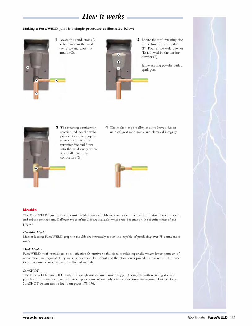
C
B A
A
F
E
D
G
Making a FurseWELD joint is a simple procedure as illustrated below:
1 Locate the conductors (A)to be joined in the weldcavity (B) and close themould (C).
2 Locate the steel retaining discin the base of the crucible(D). Pour in the weld powder(E) followed by the startingpowder (F).
Ignite starting powder with aspark gun.
4 The molten copper alloy cools to leave a fusionweld of great mechanical and electrical integrity.
3 The resulting exothermicreaction reduces the weld powder to molten copperalloy which melts theretaining disc and flowsinto the weld cavity whereit partially melts theconductors (G).
www.furse.com How it works | FurseWELD 143
How it works
Moulds
The FurseWELD system of exothermic welding uses moulds to contain the exothermic reaction that creates safeand robust connections. Different types of moulds are available, whose use depends on the requirements of theproject.
Graphite MouldsMarket leading FurseWELD graphite moulds are extremely robust and capable of producing over 75 connectionseach.
Mini-MouldsFurseWELD mini-moulds are a cost effective alternative to full-sized moulds, especially where lower numbers ofconnections are required.They are smaller overall, less robust and therefore lower priced. Care is required in orderto achieve similar service lives to full-sized moulds.
SureSHOTThe FurseWELD SureSHOT system is a single-use ceramic mould supplied complete with retaining disc andpowders. It has been designed for use in applications where only a few connections are required. Details of theSureSHOT system can be found on pages 175-176.

BB7 Page 148 BB14 Page 148BB1 Page 147 BB3 Page 147 BB41 Page 149
www.furse.comFurseWELD | Connection selector144
Bar to bar
BR1 Page 150 BR2 Page 151
Bar to earth rod
BS3 Page 153BS1 Page 152 BS2 Page 152
Bar to steel surface
CC4 Page 159 CC6 Page 160CC1 Page 157 CC2 Page 158
CC11 Page 162 CC14 Page 162
CC7 Page 161
Cable to cable
CR3 Page 165CR1 Page 163 CR2 Page 164
Cable to earth rod
CB5 Page 156CB1 Page 154 CB4 Page 155
Cable to bar
Connection selector
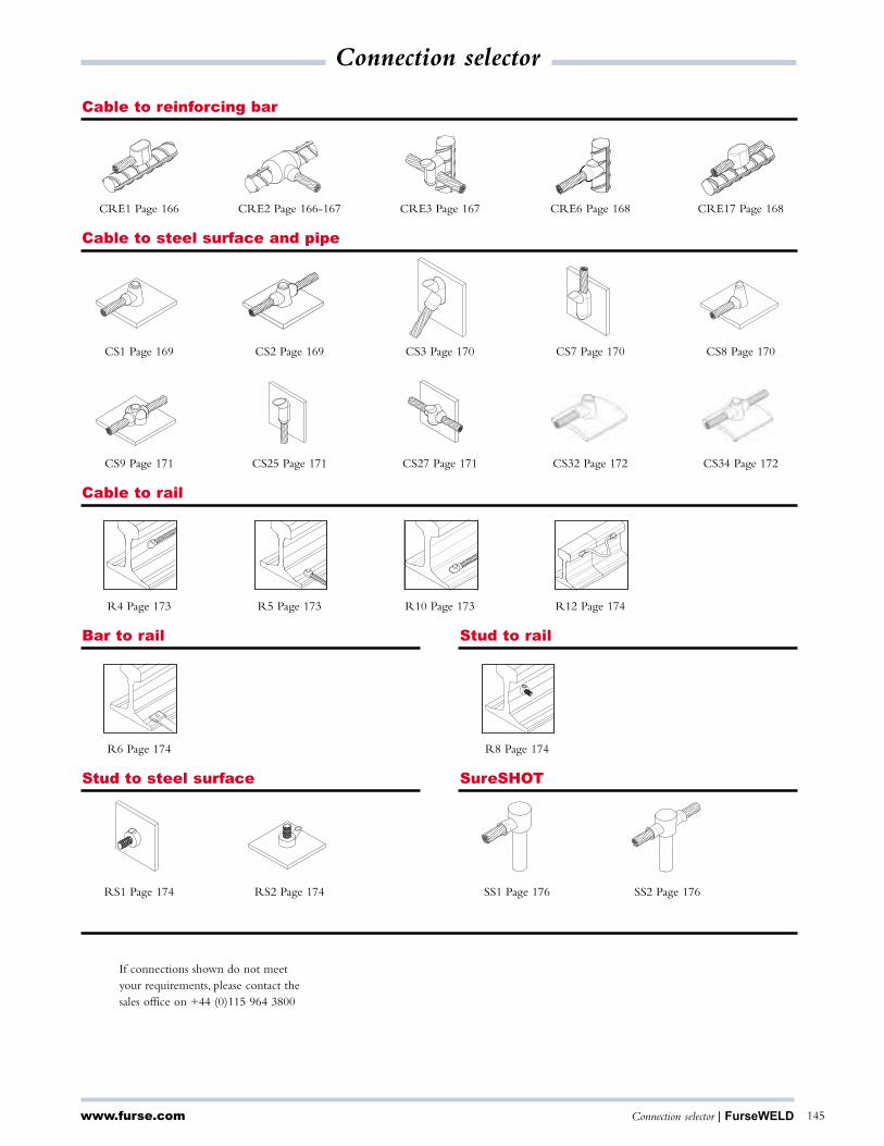
www.furse.com Connection selector | FurseWELD 145
CRE3 Page 167 CRE6 Page 168CRE1 Page 166 CRE2 Page 166-167 CRE17 Page 168
Cable to reinforcing bar
CS3 Page 170 CS7 Page 170CS1 Page 169 CS2 Page 169 CS8 Page 170
CS27 Page 171 CS32 Page 172CS9 Page 171 CS25 Page 171 CS34 Page 172
Cable to steel surface and pipe
RS1 Page 174 RS2 Page 174
Stud to steel surface
SS1 Page 176 SS2 Page 176
SureSHOT
R10 Page 173 R12 Page 174R4 Page 173 R5 Page 173
Cable to rail
R6 Page 174 R8 Page 174
Bar to rail Stud to rail
If connections shown do not meetyour requirements, please contact thesales office on +44 (0)115 964 3800
Connection selector
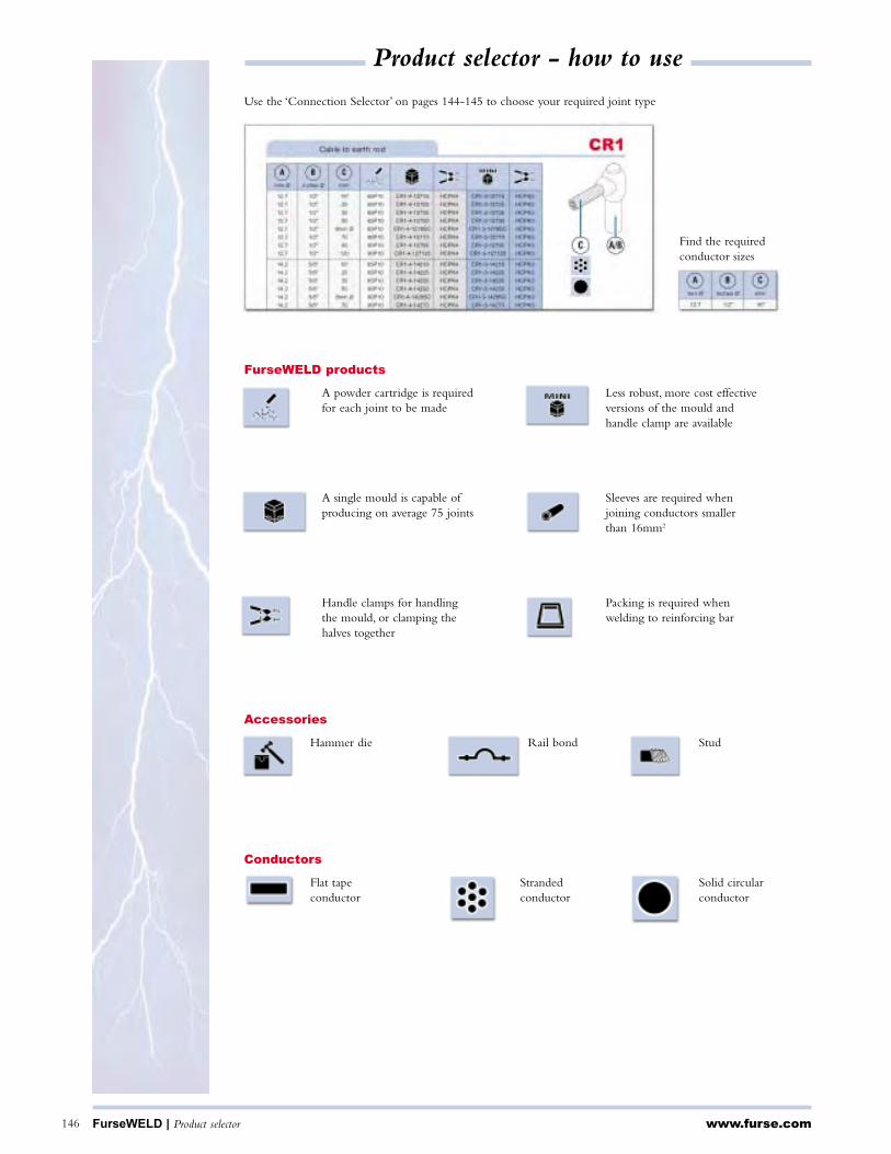
Use the ‘Connection Selector’ on pages 144-145 to choose your required joint type
FurseWELD products
Accessories
Conductors
A powder cartridge is requiredfor each joint to be made
A single mould is capable ofproducing on average 75 joints
Handle clamps for handlingthe mould, or clamping thehalves together
Less robust, more cost effectiveversions of the mould andhandle clamp are available
Flat tapeconductor
Strandedconductor
Packing is required whenwelding to reinforcing bar
www.furse.comFurseWELD | Product selector 146
Product selector - how to use
Find the required conductor sizes
Sleeves are required whenjoining conductors smallerthan 16mm2
Solid circularconductor
Hammer die Rail bond Stud

mm x mm
20 x 3 45P10 BB1-4-203 HCPK4 BB1-3-203 HCPK3
25 x 3 65P10 BB1-4-253 HCPK4 BB1-3-253 HCPK3
25 x 4 90P10 BB1-4-254 HCPK4 BB1-3-254 HCPK3
25 x 6 150P10 BB1-4-256 HCPK4 - -
30 x 2 65P10 BB1-4-302 HCPK4 BB1-3-302 HCPK3
30 x 3 90P10 BB1-4-303 HCPK4 BB1-3-303 HCPK3
30 x 4 115P10 BB1-4-304 HCPK4 BB1-3-304 HCPK3
30 x 5 115P10 BB1-4-305 HCPK4 BB1-3-305 HCPK3
31 x 3 90P10 BB1-4-313 HCPK4 BB1-3-313 HCPK3
31 x 6 150P10 BB1-4-316 HCPK4 - -
38 x 3 115P10 BB1-4-383 HCPK4 - -
38 x 5 150P10 BB1-4-385 HCPK4 - -
38 x 6 200P10 BB1-4-386 HCPK4 - -
40 x 3 115P10 BB1-4-403 HCPK4 - -
40 x 4 150P10 BB1-4-404 HCPK4 - -
40 x 5 150P10 BB1-4-405 HCPK4 - -
40 x 6 200P10 BB1-4-406 HCPK4 - -
50 x 3 150P10 BB1-4-503 HCPK4 - -
50 x 4 200P10 BB1-4-504 HCPK4 - -
50 x 5 200P10 BB1-4-505 HCPK4 - -
50 x 6 250P10 BB1-4-506 HCPK4 - -
Bar to bar
A
www.furse.com Bar to bar | FurseWELD 147
BB1
BB3
mm x mm mm x mm
20 x 3 20 x 3 65P10 BB3-4-203203 HCPK4 BB3-3-203203 HCPK3
25 x 3 25 x 3 65P10 BB3-4-253253 HCPK4 BB3-3-253253 HCPK3
25 x 4 25 x 4 90P10 BB3-4-254254 HCPK4 BB3-3-254254 HCPK3
25 x 6 25 x 6 150P10 BB3-4-256256 HCPK4 - -
30 x 2 30 x 2 65P10 BB3-4-302302 HCPK4 BB3-3-302302 HCPK3
30 x 3 30 x 3 90P10 BB3-4-303303 HCPK4 BB3-3-303303 HCPK3
30 x 4 30 x 4 115P10 BB3-4-304304 HCPK4 BB3-3-304304 HCPK3
30 x 5 30 x 5 115P10 BB3-4-305305 HCPK4 BB3-3-305305 HCPK3
31 x 3 31 x 3 115P10 BB3-4-313313 HCPK4 BB3-3-313313 HCPK3
31 x 6 31 x 6 200P10 BB3-4-316316 HCPK4 - -
38 x 3 38 x 3 115P10 BB3-4-383383 HCPK4 - -
38 x 5 38 x 5 150P10 BB3-4-385385 HCPK4 - -
38 x 6 38 x 6 200P10 BB3-4-386386 HCPK4 - -
40 x 3 40 x 3 115P10 BB3-4-403403 HCPK4 - -
40 x 4 40 x 4 150P10 BB3-4-404404 HCPK4 - -
40 x 5 40 x 5 150P10 BB3-4-405405 HCPK4 - -
40 x 6 40 x 6 200P10 BB3-4-406406 HCPK4 - -
50 x 3 50 x 3 200P10 BB3-4-503503 HCPK4 - -
50 x 4 50 x 4 200P10 BB3-4-504504 HCPK4 - -
50 x 5 50 x 5 200P10 BB3-4-505505 HCPK4 - -
50 x 6 50 x 6 250P10 BB3-4-506506 HCPK4 - -
A B
A B
A

www.furse.com148
mm x mm
20 x 3 45P10 BB7-4-203 HCPK4 BB7-3-203 HCPK3
25 x 3 65P10 BB7-4-253 HCPK4 BB7-3-253 HCPK3
25 x 4 90P10 BB7-4-254 HCPK4 BB7-3-254 HCPK3
25 x 6 115P10 BB7-4-256 HCPK4 BB7-3-256 HCPK3
30 x 2 65P10 BB7-4-302 HCPK4 BB7-3-302 HCPK3
30 x 3 65P10 BB7-4-303 HCPK4 BB7-3-303 HCPK3
30 x 4 90P10 BB7-4-304 HCPK4 BB7-3-304 HCPK3
30 x 5 115P10 BB7-4-305 HCPK4 BB7-3-305 HCPK3
31 x 3 65P10 BB7-4-313 HCPK4 BB7-3-313 HCPK3
31 x 6 150P10 BB7-4-316 HCPK4 - -
38 x 3 90P10 BB7-4-383 HCPK4 - -
38 x 5 150P10 BB7-4-385 HCPK4 - -
38 x 6 200P10 BB7-4-386 HCPK4 - -
40 x 3 90P10 BB7-4-403 HCPK4 - -
40 x 4 115P10 BB7-4-404 HCPK4 - -
40 x 5 150P10 BB7-4-405 HCPK4 - -
40 x 6 200P10 BB7-4-406 HCPK4 - -
50 x 3 150P10 BB7-5-503 HCPK5 - -
50 x 4 200P10 BB7-5-504 HCPK5 - -
50 x 5 200P10 BB7-5-505 HCPK5 - -
50 x 6 250P10 BB7-5-506 HCPK5 - -
Bar to bar
A
BB7
mm x mm mm x mm
20 x 3 20 x 3 45P10 BB14-4-203203 HCPK4 BB14-3-203203 HCPK3
25 x 3 25 x 3 65P10 BB14-4-253253 HCPK4 BB14-3-253253 HCPK3
25 x 4 25 x 4 90P10 BB14-4-254254 HCPK4 BB14-3-254254 HCPK3
25 x 6 25 x 6 115P10 BB14-4-256256 HCPK4 BB14-3-256256 HCPK3
30 x 2 30 x 2 65P10 BB14-4-302302 HCPK4 BB14-3-302302 HCPK3
30 x 3 30 x 3 65P10 BB14-4-303303 HCPK4 BB14-3-303303 HCPK3
30 x 4 30 x 4 90P10 BB14-4-304304 HCPK4 BB14-3-304304 HCPK3
30 x 5 30 x 5 115P10 BB14-4-305305 HCPK4 BB14-3-305305 HCPK3
31 x 3 31 x 3 90P10 BB14-4-313313 HCPK4 BB14-3-313313 HCPK3
31 x 6 31 x 6 150P10 BB14-4-316316 HCPK4 - -
38 x 3 38 x 3 90P10 BB14-4-383383 HCPK4 - -
38 x 5 38 x 5 150P10 BB14-4-385385 HCPK4 - -
38 x 6 38 x 6 200P10 BB14-4-386386 HCPK4 - -
40 x 3 40 x 3 90P10 BB14-4-403403 HCPK4 - -
40 x 4 40 x 4 115P10 BB14-4-404404 HCPK4 - -
40 x 5 40 x 5 150P10 BB14-4-405405 HCPK4 - -
40 x 6 40 x 6 200P10 BB14-4-406406 HCPK4 - -
50 x 3 50 x 3 150P10 BB14-5-503503 HCPK5 - -
50 x 4 50 x 4 200P10 BB14-5-504504 HCPK5 - -
50 x 5 50 x 5 200P10 BB14-5-505505 HCPK5 - -
50 x 6 50 x 6 250P10 BB14-5-506506 HCPK5 - -
A B
BB14
A
B A
FurseWELD | Bar to bar

www.furse.com Bar to bar | FurseWELD 149
Bar to bar BB41
mm x mm mm x mm
20 x 3 20 x 3 65P10 BB41-4-203203 HCPK4 BB41-3-203203 HCPK3
25 x 3 25 x 3 65P10 BB41-4-253253 HCPK4 BB41-3-253253 HCPK3
25 x 4 25 x 4 90P10 BB41-4-254254 HCPK4 BB41-3-254254 HCPK3
25 x 6 25 x 6 115P10 BB41-4-256256 HCPK4 BB41-3-256256 HCPK3
30 x 2 30 x 2 65P10 BB41-4-302302 HCPK4 BB41-3-302302 HPCK3
30 x 3 30 x 3 115P10 BB41-4-304304 HCPK4 BB41-3-303303 HPCK3
30 x 4 30 x 4 115P10 BB41-4-304304 HCPK4 BB41-3-304304 HCPK3
30 x 5 30 x 5 115P10 BB41-4-305305 HCPK4 BB41-3-305305 HCPK3
31 x 3 31 x 3 115P10 BB41-4-313313 HCPK4 BB41-3-313313 HCPK3
31 x 6 31 x 6 115P10 BB41-4-316316 HCPK4 BB41-3-316316 HCPK3
38 x 3 38 x 3 150P10 BB41-4-383383 HCPK4 - -
38 x 5 38 x 5 150P10 BB41-4-385385 HCPK4 - -
38 x 6 38 x 6 200P10 BB41-4-386386 HCPK4 - -
40 x 3 40 x 3 200P10 BB41-4-403-403 HCPK4 - -
40 x 4 40 x 4 200P10 BB41-4-404404 HCPK4 - -
40 x 5 40 x 5 200P10 BB41-4-405405 HCPK4 - -
40 x 6 40 x 6 200P10 BB41-4-406406 HCPK4 - -
50 x 3 50 x 3 200P10 BB41-5-503503 HCPK5 - -
50 x 4 50 x 4 200P10 BB41-5-504504 HCPK5 - -
50 x 5 50 x 5 200P10 BB41-5-505505 HCPK5 - -
50 x 6 50 x 6 200P10 BB41-5-506506 HCPK5 - -
A B
A B
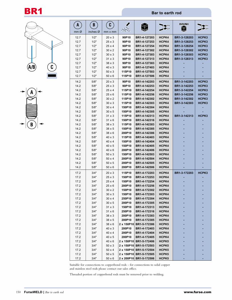
www.furse.comFurseWELD | Bar to earth rod150
Bar to earth rodBR1A B C
A/B
A
B
C
Suitable for connections to copperbond rods - for connections to solid copper and stainless steel rods please contact our sales office.
Threaded portion of copperbond rods must be removed prior to welding.
mm Ø inches Ø mm x mm
12.7 1/2" 20 x 3 90P10 BR1-4-127203 HCPK4 BR1-3-128203 HCPK3
12.7 1/2" 25 x 3 90P10 BR1-4-127253 HCPK4 BR1-3-128253 HCPK3
12.7 1/2" 25 x 4 90P10 BR1-4-127254 HCPK4 BR1-3-128254 HCPK3
12.7 1/2" 30 x 2 90P10 BR1-4-127302 HCPK4 BR1-3-128302 HCPK3
12.7 1/2" 30 x 3 90P10 BR1-4-127303 HCPK4 BR1-3-128303 HCPK3
12.7 1/2" 31 x 3 90P10 BR1-4-127313 HCPK4 BR1-3-128313 HCPK3
12.7 1/2" 38 x 3 90P10 BR1-4-127383 HCPK4 - -
12.7 1/2" 40 x 3 90P10 BR1-4-127403 HCPK4 - -
12.7 1/2" 50 x 3 115P10 BR1-4-127503 HCPK4 - -
12.7 1/2" 50 x 6 115P10 BR1-4-127506 HCPK4 - -
14.2 5/8" 20 x 3 90P10 BR1-4-142203 HCPK4 BR1-3-142203 HCPK3
14.2 5/8" 25 x 3 90P10 BR1-4-142253 HCPK4 BR1-3-142253 HCPK3
14.2 5/8" 25 x 4 115P10 BR1-4-142254 HCPK4 BR1-3-142254 HCPK3
14.2 5/8" 25 x 6 115P10 BR1-4-142256 HCPK4 BR1-3-142256 HCPK3
14.2 5/8" 30 x 2 115P10 BR1-4-142302 HCPK4 BR1-3-142302 HCPK3
14.2 5/8" 30 x 3 115P10 BR1-4-142303 HCPK4 BR1-3-142303 HCPK3
14.2 5/8" 30 x 4 150P10 BR1-4-142304 HCPK4 - -
14.2 5/8" 30 x 5 150P10 BR1-4-142305 HCPK4 - -
14.2 5/8" 31 x 3 115P10 BR1-4-142313 HCPK4 BR1-3-142313 HCPK3
14.2 5/8" 31 x 6 150P10 BR1-4-142316 HCPK4 - -
14.2 5/8" 38 x 3 115P10 BR1-4-142383 HCPK4 - -
14.2 5/8" 38 x 5 150P10 BR1-4-142385 HCPK4 - -
14.2 5/8" 38 x 6 200P10 BR1-4-142386 HCPK4 - -
14.2 5/8" 40 x 3 115P10 BR1-4-142403 HCPK4 - -
14.2 5/8" 40 x 4 150P10 BR1-4-142404 HCPK4 - -
14.2 5/8" 40 x 5 150P10 BR1-4-142405 HCPK4 - -
14.2 5/8" 40 x 6 200P10 BR1-4-142406 HCPK4 - -
14.2 5/8" 50 x 3 150P10 BR1-4-142503 HCPK4 - -
14.2 5/8" 50 x 4 200P10 BR1-4-142504 HCPK4 - -
14.2 5/8" 50 x 5 200P10 BR1-4-142505 HCPK4 - -
14.2 5/8" 50 x 6 200P10 BR1-4-142506 HCPK4 - -
17.2 3/4" 20 x 3 115P10 BR1-4-172203 HCPK4 BR1-3-172203 HCPK3
17.2 3/4" 25 x 3 150P10 BR1-4-172253 HCPK4 - -
17.2 3/4" 25 x 4 150P10 BR1-4-172254 HCPK4 - -
17.2 3/4" 25 x 6 200P10 BR1-4-172256 HCPK4 - -
17.2 3/4" 30 x 2 150P10 BR1-4-172302 HCPK4 - -
17.2 3/4" 30 x 3 150P10 BR1-4-172303 HCPK4 - -
17.2 3/4" 30 x 4 250P10 BR1-4-172304 HCPK4 - -
17.2 3/4" 30 x 5 200P10 BR1-4-172305 HCPK4 - -
17.2 3/4" 31 x 3 150P10 BR1-4-172313 HCPK4 - -
17.2 3/4" 31 x 6 250P10 BR1-4-172316 HCPK4 - -
17.2 3/4" 38 x 3 200P10 BR1-4-172383 HCPK4 - -
17.2 3/4" 38 x 5 200P10 BR1-4-172385 HCPK4 - -
17.2 3/4" 38 x 6 2 x 150P10 BR1-5-172386 HCPK5 - -
17.2 3/4" 40 x 3 200P10 BR1-4-172403 HCPK4 - -
17.2 3/4" 40 x 4 200P10 BR1-4-172404 HCPK4 - -
17.2 3/4" 40 x 5 200P10 BR1-4-172405 HCPK4 - -
17.2 3/4" 40 x 6 2 x 150P10 BR1-5-172406 HCPK5 - -
17.2 3/4" 50 x 3 2 x 150P10 BR1-5-172503 HCPK5 - -
17.2 3/4" 50 x 4 2 x 150P10 BR1-5-172504 HCPK5 - -
17.2 3/4" 50 x 5 2 x 150P10 BR1-5-172505 HCPK5 - -
17.2 3/4" 50 x 6 2 x 200P10 BR1-5-172506 HCPK5 - -

www.furse.com Bar to earth rod | FurseWELD 151
Bar to earth rod BR2
A B C
A
B
C A/B
Suitable for connections to copperbond rods - for connections to solid copper and stainless steel rods please contact our sales office.
Threaded portion of copperbond rods must be removed prior to welding.
mm Ø inches Ø mm x mm
12.7 1/2" 20 x 3 90P10 BR2-4-127203 HCPK4 BR2-3-128203 HCPK3
12.7 1/2" 25 x 3 90P10 BR2-4-127253 HCPK4 BR2-3-128253 HCPK3
12.7 1/2" 25 x 4 90P10 BR2-4-127254 HCPK4 BR2-3-128254 HCPK3
12.7 1/2" 30 x 2 90P10 BR2-4-127302 HCPK4 BR2-3-128302 HCPK3
12.7 1/2" 30 x 3 90P10 BR2-4-127303 HCPK4 BR2-3-128303 HCPK3
12.7 1/2" 31 x 3 90P10 BR2-4-127313 HCPK4 BR2-3-128313 HCPK3
12.7 1/2" 38 x 3 90P10 BR2-4-127383 HCPK4 BR2-3-128383 HCPK3
12.7 1/2" 40 x 3 90P10 BR2-4-127403 HCPK4 BR2-3-128403 HCPK3
12.7 1/2" 50 x 3 115P10 BR2-4-127503 HCPK4 - -
14.2 5/8" 20 x 3 90P10 BR2-4-142203 HCPK4 BR2-3-142203 HCPK3
14.2 5/8" 25 x 3 90P10 BR2-4-142253 HCPK4 BR2-3-142253 HCPK3
14.2 5/8" 25 x 4 115P10 BR2-4-142254 HCPK4 BR2-3-142254 HCPK3
14.2 5/8" 25 x 6 150P10 BR2-4-142256 HCPK4 - -
14.2 5/8" 30 x 2 90P10 BR2-4-142302 HCPK4 BR2-3-142302 HCPK3
14.2 5/8" 30 x 3 115P10 BR2-4-142303 HCPK4 BR2-3-142303 HCPK3
14.2 5/8" 30 x 4 150P10 BR2-4-142304 HCPK4 - -
14.2 5/8" 30 x 5 150P10 BR2-4-142305 HCPK4 - -
14.2 5/8" 31 x 3 115P10 BR2-4-142313 HCPK4 BR2-3-142313 HCPK3
14.2 5/8" 31 x 6 150P10 BR2-4-142316 HCPK4 - -
14.2 5/8" 38 x 3 150P10 BR2-4-142383 HCPK4 - -
14.2 5/8" 38 x 5 150P10 BR2-4-142385 HCPK4 - -
14.2 5/8" 38 x 6 200P10 BR2-4-142386 HCPK4 - -
14.2 5/8" 40 x 3 150P10 BR2-4-142403 HCPK4 - -
14.2 5/8" 40 x 4 150P10 BR2-4-142404 HCPK4 - -
14.2 5/8" 40 x 5 150P10 BR2-4-142405 HCPK4 - -
14.2 5/8" 40 x 6 200P10 BR2-4-142406 HCPK4 - -
14.2 5/8" 50 x 3 200P10 BR2-4-142503 HCPK4 - -
14.2 5/8" 50 x 4 200P10 BR2-4-142504 HCPK4 - -
14.2 5/8" 50 x 5 200P10 BR2-4-142505 HCPK4 - -
14.2 5/8" 50 x 6 250P10 BR2-4-142506 HCPK4 - -
17.2 3/4" 20 x 3 150P10 BR2-4-172203 HCPK4 - -
17.2 3/4" 25 x 3 150P10 BR2-4-172253 HCPK4 - -
17.2 3/4" 25 x 4 200P10 BR2-4-172254 HCPK4 - -
17.2 3/4" 25 x 6 200P10 BR2-4-172256 HCPK4 - -
17.2 3/4" 30 x 2 150P10 BR2-4-172302 HCPK4 - -
17.2 3/4" 30 x 3 150P10 BR2-4-172303 HCPK4 - -
17.2 3/4" 30 x 4 250P10 BR2-4-172304 HCPK4 - -
17.2 3/4" 30 x 5 200P10 BR2-4-172305 HCPK4 - -
17.2 3/4" 31 x 3 200P10 BR2-4-172313 HCPK4 - -
17.2 3/4" 31 x 6 250P10 BR2-4-172316 HCPK4 - -
17.2 3/4" 38 x 3 200P10 BR2-4-172383 HCPK4 - -
17.2 3/4" 38 x 5 200P10 BR2-4-172385 HCPK4 - -
17.2 3/4" 38 x 6 250P10 BR2-4-172386 HCPK4 - -
17.2 3/4" 40 x 3 200P10 BR2-4-172403 HCPK4 - -
17.2 3/4" 40 x 4 200P10 BR2-4-172404 HCPK4 - -
17.2 3/4" 40 x 5 200P10 BR2-4-172405 HCPK4 - -
17.2 3/4" 40 x 6 250P10 BR2-4-172406 HCPK4 - -
17.2 3/4" 50 x 3 2 x 150P10 BR2-5-172503 HCPK5 - -
17.2 3/4" 50 x 4 2 x 150P10 BR2-5-172504 HCPK5 - -
17.2 3/4" 50 x 5 2 x 150P10 BR2-5-172505 HCPK5 - -
17.2 3/4" 50 x 6 2 x 150P10 BR2-5-172506 HCPK5 - -
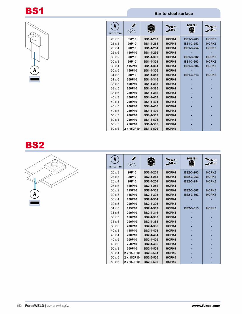
www.furse.comFurseWELD | Bar to steel surface152
mm x mm
20 x 3 65P10 BS1-4-203 HCPK4 BS1-3-203 HCPK3
25 x 3 90P10 BS1-4-253 HCPK4 BS1-3-253 HCPK3
25 x 4 90P10 BS1-4-254 HCPK4 BS1-3-254 HCPK3
25 x 6 150P10 BS1-4-256 HCPK4 - -
30 x 2 90P10 BS1-4-302 HCPK4 BS1-3-302 HCPK3
30 x 3 90P10 BS1-4-303 HCPK4 BS1-3-303 HCPK3
30 x 4 115P10 BS1-4-304 HCPK4 BS1-3-304 HCPK3
30 x 5 150P10 BS1-4-305 HCPK4 - -
31 x 3 90P10 BS1-4-313 HCPK4 BS1-3-313 HCPK3
31 x 6 200P10 BS1-4-316 HCPK4 - -
38 x 3 150P10 BS1-4-383 HCPK4 - -
38 x 5 200P10 BS1-4-385 HCPK4 - -
38 x 6 250P10 BS1-4-386 HCPK4 - -
40 x 3 150P10 BS1-4-403 HCPK4 - -
40 x 4 200P10 BS1-4-404 HCPK4 - -
40 x 5 200P10 BS1-4-405 HCPK4 - -
40 x 6 250P10 BS1-4-406 HCPK4 - -
50 x 3 200P10 BS1-4-503 HCPK4 - -
50 x 4 250P10 BS1-4-504 HCPK4 - -
50 x 5 250P10 BS1-4-505 HCPK4 - -
50 x 6 2 x 150P10 BS1-5-506 HCPK5 - -
Bar to steel surface
A
BS1
mm x mm
20 x 3 90P10 BS2-4-203 HCPK4 BS2-3-203 HCPK3
25 x 3 90P10 BS2-4-253 HCPK4 BS2-3-253 HCPK3
25 x 4 90P10 BS2-4-254 HCPK4 BS2-3-254 HCPK3
25 x 6 150P10 BS2-4-256 HCPK4 - -
30 x 2 115P10 BS2-4-302 HCPK4 BS2-3-302 HCPK3
30 x 3 115P10 BS2-4-303 HCPK4 BS2-3-303 HCPK3
30 x 4 150P10 BS2-4-304 HCPK4 - -
30 x 5 200P10 BS2-4-305 HCPK4 - -
31 x 3 115P10 BS2-4-313 HCPK4 BS2-3-313 HCPK3
31 x 6 200P10 BS2-4-316 HCPK4 - -
38 x 3 150P10 BS2-4-383 HCPK4 - -
38 x 5 200P10 BS2-4-385 HCPK4 - -
38 x 6 200P10 BS2-4-386 HCPK4 - -
40 x 3 115P10 BS2-4-403 HCPK4 - -
40 x 4 200P10 BS2-4-404 HCPK4 - -
40 x 5 200P10 BS2-4-405 HCPK4 - -
40 x 6 250P10 BS2-4-406 HCPK4 - -
50 x 3 200P10 BS2-4-503 HCPK4 - -
50 x 4 2 x 150P10 BS2-5-504 HCPK5 - -
50 x 5 2 x 150P10 BS2-5-505 HCPK5 - -
50 x 6 2 x 150P10 BS2-5-506 HCPK5 - -
A
BS2
A
A
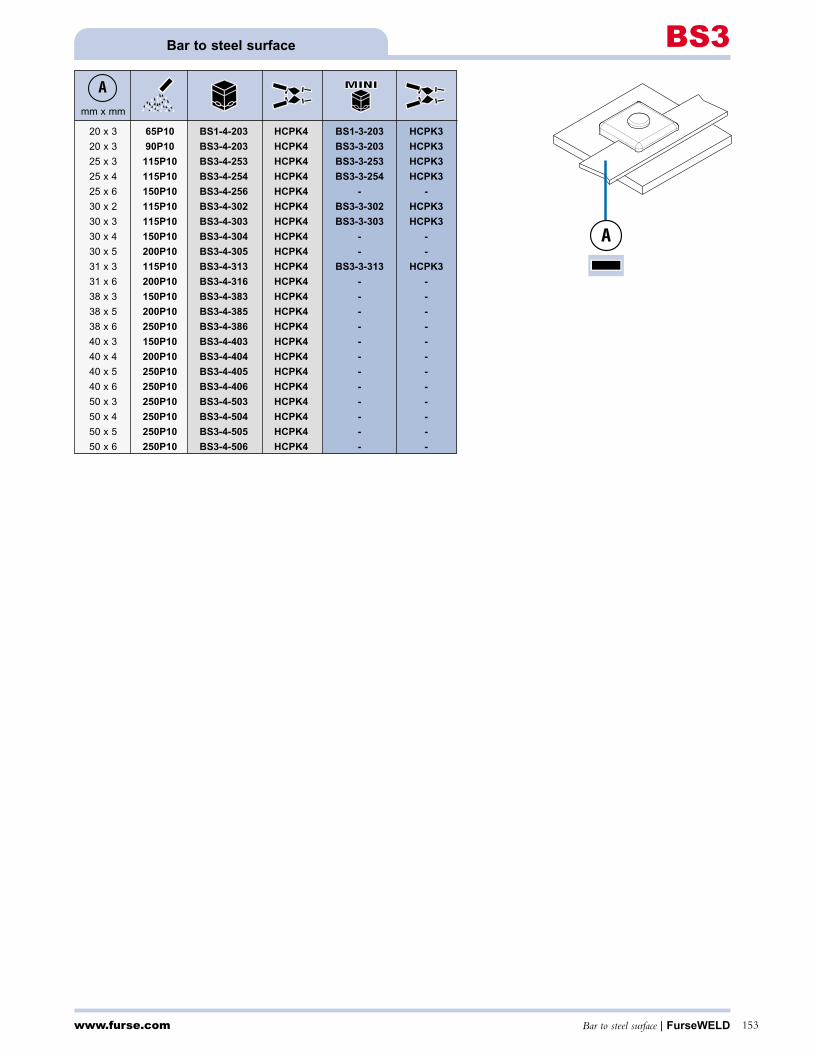
mm x mm
20 x 3 65P10 BS1-4-203 HCPK4 BS1-3-203 HCPK3
20 x 3 90P10 BS3-4-203 HCPK4 BS3-3-203 HCPK3
25 x 3 115P10 BS3-4-253 HCPK4 BS3-3-253 HCPK3
25 x 4 115P10 BS3-4-254 HCPK4 BS3-3-254 HCPK3
25 x 6 150P10 BS3-4-256 HCPK4 - -
30 x 2 115P10 BS3-4-302 HCPK4 BS3-3-302 HCPK3
30 x 3 115P10 BS3-4-303 HCPK4 BS3-3-303 HCPK3
30 x 4 150P10 BS3-4-304 HCPK4 - -
30 x 5 200P10 BS3-4-305 HCPK4 - -
31 x 3 115P10 BS3-4-313 HCPK4 BS3-3-313 HCPK3
31 x 6 200P10 BS3-4-316 HCPK4 - -
38 x 3 150P10 BS3-4-383 HCPK4 - -
38 x 5 200P10 BS3-4-385 HCPK4 - -
38 x 6 250P10 BS3-4-386 HCPK4 - -
40 x 3 150P10 BS3-4-403 HCPK4 - -
40 x 4 200P10 BS3-4-404 HCPK4 - -
40 x 5 250P10 BS3-4-405 HCPK4 - -
40 x 6 250P10 BS3-4-406 HCPK4 - -
50 x 3 250P10 BS3-4-503 HCPK4 - -
50 x 4 250P10 BS3-4-504 HCPK4 - -
50 x 5 250P10 BS3-4-505 HCPK4 - -
50 x 6 250P10 BS3-4-506 HCPK4 - -
A
www.furse.com Bar to steel surface | FurseWELD 153
Bar to steel surface BS3
A

www.furse.comFurseWELD | Cable to bar154
Cable to barCB1
Terminal lugs - see page 177 * 1 x S103
mm2 mm x mm
16* 20 x 3 45P10 CB1-4-16203 HCPK4 CB1-3-16203 HCPK3
16* 25 x 3 45P10 CB1-4-16253 HCPK4 CB1-3-16253 HCPK3
25 20 x 3 32P10 CB1-4-25203 HCPK4 CB1-3-25203 HCKP3
25 25 x 3 45P10 CB1-4-25253 HCPK4 CB1-3-25253 HCPK3
35 20 x 3 45P10 CB1-4-35203 HCPK4 CB1-3-35203 HCPK3
35 25 x 3 45P10 CB1-4-35253 HCPK4 CB1-3-35253 HCPK3
50 20 x 3 45P10 CB1-4-50203 HCPK4 CB1-3-50203 HCPK3
50 25 x 3 65P10 CB1-4-50253 HCPK4 CB1-3-50253 HCPK3
8mm Ø 20 x 3 45P10 CB1-4-8SC203 HCPK4 CB1-3-8SC203 HCPK3
8mm Ø 25 x 3 65P10 CB1-4-8SC253 HCPK4 CB1-3-8SC253 HCPK3
70 25 x 3 65P10 CB1-4-70253 HCPK4 CB1-3-70253 HCPK3
70 25 x 4 65P10 CB1-4-70254 HCPK4 CB1-3-70254 HCPK3
70 25 x 6 65P10 CB1-4-70256 HCPK4 CB1-3-70256 HCPK3
10mm Ø 25 x 3 65P10 CB1-4-10SC253 HCPK4 CB1-3-10SC253 HCPK3
10mm Ø 25 x 4 65P10 CB1-4-10SC254 HCPK4 CB1-3-10SC254 HCPK3
10mm Ø 25 x 6 65P10 CB1-4-10SC256 HCPK4 CB1-3-10SC256 HCPK3
95 25 x 4 90P10 CB1-4-95254 HCPK4 CB1-3-95254 HCPK3
95 25 x 6 90P10 CB1-4-95256 HCPK4 CB1-3-95256 HCPK3
120 25 x 6 90P10 CB1-4-120256 HCPK4 CB1-3-120256 HCPK3
120 30 x 5 115P10 CB1-4-120305 HCPK4 CB1-3-120305 HCPK3
150 25 x 6 115P10 CB1-4-150256 HCPK4 CB1-3-150256 HCPK3
150 30 x 5 115P10 CB1-4-150305 HCPK4 CB1-3-150305 HCPK3
150 40 x 5 150P10 CB1-4-150405 HCPK4 - -
185 31 x 6 150P10 CB1-4-185316 HCPK4 - -
185 40 x 5 150P10 CB1-4-185405 HCPK4 - -
185 50 x 5 200P10 CB1-5-185505 HCPK5 - -
240 50 x 5 200P10 CB1-5-240505 HCPK5 - -
240 50 x 6 2 x 150P10 CB1-5-240506 HCPK5 - -
300 50 x 6 2 x 150P10 CB1-5-300506 HCPK5 - -
A B
AB
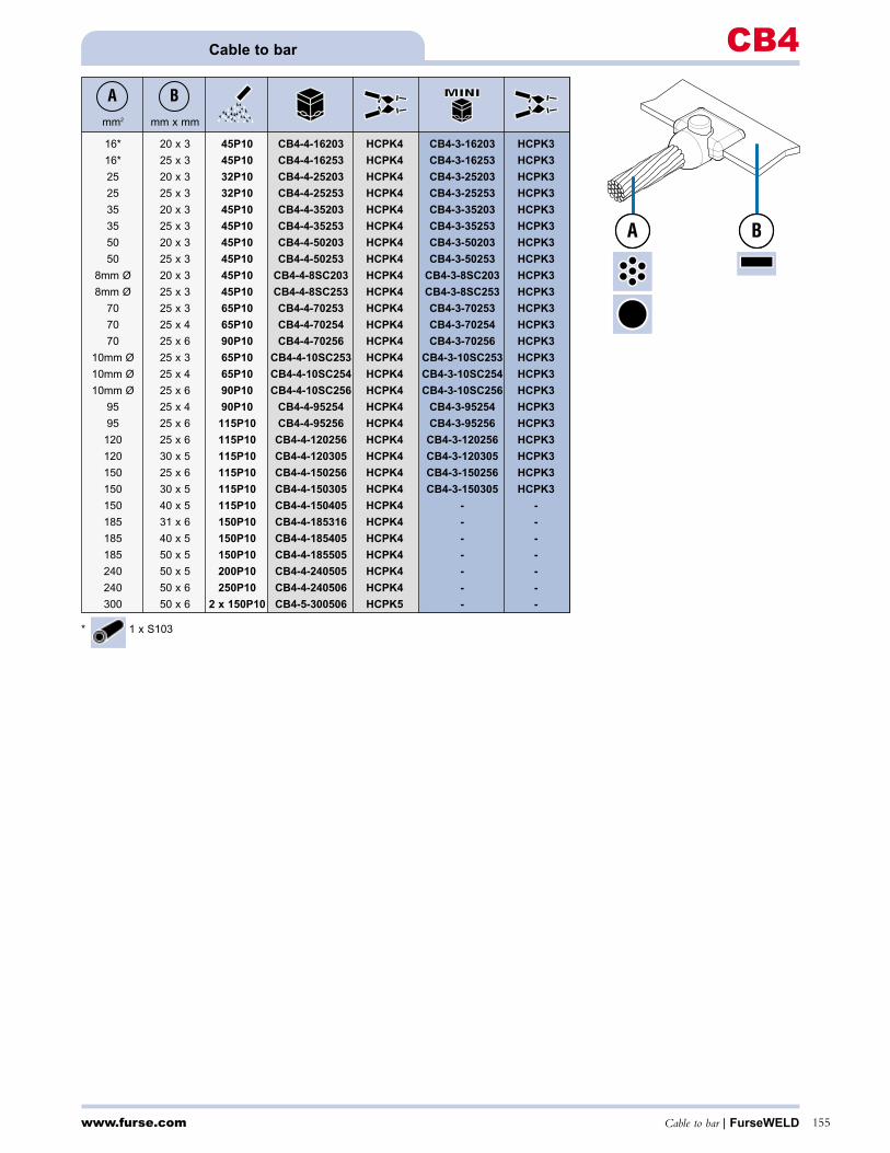
www.furse.com Cable to bar | FurseWELD 155
Cable to bar CB4
mm2 mm x mm
16* 20 x 3 45P10 CB4-4-16203 HCPK4 CB4-3-16203 HCPK3
16* 25 x 3 45P10 CB4-4-16253 HCPK4 CB4-3-16253 HCPK3
25 20 x 3 32P10 CB4-4-25203 HCPK4 CB4-3-25203 HCPK3
25 25 x 3 32P10 CB4-4-25253 HCPK4 CB4-3-25253 HCPK3
35 20 x 3 45P10 CB4-4-35203 HCPK4 CB4-3-35203 HCPK3
35 25 x 3 45P10 CB4-4-35253 HCPK4 CB4-3-35253 HCPK3
50 20 x 3 45P10 CB4-4-50203 HCPK4 CB4-3-50203 HCPK3
50 25 x 3 45P10 CB4-4-50253 HCPK4 CB4-3-50253 HCPK3
8mm Ø 20 x 3 45P10 CB4-4-8SC203 HCPK4 CB4-3-8SC203 HCPK3
8mm Ø 25 x 3 45P10 CB4-4-8SC253 HCPK4 CB4-3-8SC253 HCPK3
70 25 x 3 65P10 CB4-4-70253 HCPK4 CB4-3-70253 HCPK3
70 25 x 4 65P10 CB4-4-70254 HCPK4 CB4-3-70254 HCPK3
70 25 x 6 90P10 CB4-4-70256 HCPK4 CB4-3-70256 HCPK3
10mm Ø 25 x 3 65P10 CB4-4-10SC253 HCPK4 CB4-3-10SC253 HCPK3
10mm Ø 25 x 4 65P10 CB4-4-10SC254 HCPK4 CB4-3-10SC254 HCPK3
10mm Ø 25 x 6 90P10 CB4-4-10SC256 HCPK4 CB4-3-10SC256 HCPK3
95 25 x 4 90P10 CB4-4-95254 HCPK4 CB4-3-95254 HCPK3
95 25 x 6 115P10 CB4-4-95256 HCPK4 CB4-3-95256 HCPK3
120 25 x 6 115P10 CB4-4-120256 HCPK4 CB4-3-120256 HCPK3
120 30 x 5 115P10 CB4-4-120305 HCPK4 CB4-3-120305 HCPK3
150 25 x 6 115P10 CB4-4-150256 HCPK4 CB4-3-150256 HCPK3
150 30 x 5 115P10 CB4-4-150305 HCPK4 CB4-3-150305 HCPK3
150 40 x 5 115P10 CB4-4-150405 HCPK4 - -
185 31 x 6 150P10 CB4-4-185316 HCPK4 - -
185 40 x 5 150P10 CB4-4-185405 HCPK4 - -
185 50 x 5 150P10 CB4-4-185505 HCPK4 - -
240 50 x 5 200P10 CB4-4-240505 HCPK4 - -
240 50 x 6 250P10 CB4-4-240506 HCPK4 - -
300 50 x 6 2 x 150P10 CB4-5-300506 HCPK5 - -
A B
* 1 x S103
A BA B
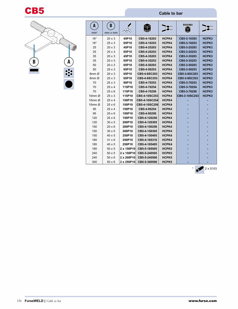
* 2 x S103
www.furse.comFurseWELD | Cable to bar156
Cable to barCB5
mm2 mm x mm
16* 20 x 3 45P10 CB5-4-16203 HCPK4 CB5-3-16303 HCPK3
16* 25 x 3 65P10 CB5-4-16253 HCPK4 CB5-3-16253 HCPK3
25 20 x 3 45P10 CB5-4-25203 HCPK4 CB5-3-25203 HCPK3
25 25 x 3 65P10 CB5-4-25253 HCPK4 CB5-3-25253 HCPK3
35 20 x 3 45P10 CB5-4-35203 HCPK4 CB5-3-35203 HCPK3
35 25 x 3 65P10 CB5-4-35253 HCPK4 CB5-3-35253 HCPK3
50 20 x 3 65P10 CB5-4-50203 HCPK4 CB5-3-50203 HCPK3
50 25 x 3 65P10 CB5-4-50253 HCPK4 CB5-3-50253 HCPK3
8mm Ø 20 x 3 65P10 CB5-4-8SC203 HCPK4 CB5-3-8SC203 HCPK3
8mm Ø 25 x 3 65P10 CB5-4-8SC253 HCPK4 CB5-3-8SC253 HCPK3
70 25 x 3 90P10 CB5-4-70253 HCPK4 CB5-3-70253 HCPK3
70 25 x 4 115P10 CB5-4-70254 HCPK4 CB5-3-70254 HCPK3
70 25 x 6 115P10 CB5-4-70256 HCPK4 CB5-3-70256 HCPK3
10mm Ø 25 x 3 115P10 CB5-4-10SC253 HCPK4 CB5-3-10SC253 HCPK3
10mm Ø 25 x 4 150P10 CB5-4-10SC254 HCPK4 - -
10mm Ø 25 x 6 150P10 CB5-4-10SC256 HCPK4 - -
95 25 x 4 150P10 CB5-4-95254 HCPK4 - -
95 25 x 6 150P10 CB5-4-95256 HCPK4 - -
120 25 x 6 150P10 CB5-4-120256 HCPK4 - -
120 30 x 5 200P10 CB5-4-120305 HCPK4 - -
150 25 x 6 200P10 CB5-4-150256 HCPK4 - -
150 30 x 5 200P10 CB5-4-150305 HCPK4 - -
150 40 x 5 250P10 CB5-4-150405 HCPK4 - -
185 31 x 6 250P10 CB5-4-185316 HCPK4 - -
185 40 x 5 250P10 CB5-4-185405 HCPK4 - -
185 50 x 5 2 x 150P10 CB5-5-185505 HCPK5 - -
240 50 x 5 2 x 150P10 CB5-5-240505 HCPK5 - -
240 50 x 6 2 x 200P10 CB5-5-240506 HCPK5 - -
300 50 x 6 2 x 250P10 CB5-5-300506 HCPK5 - -
A B
AB
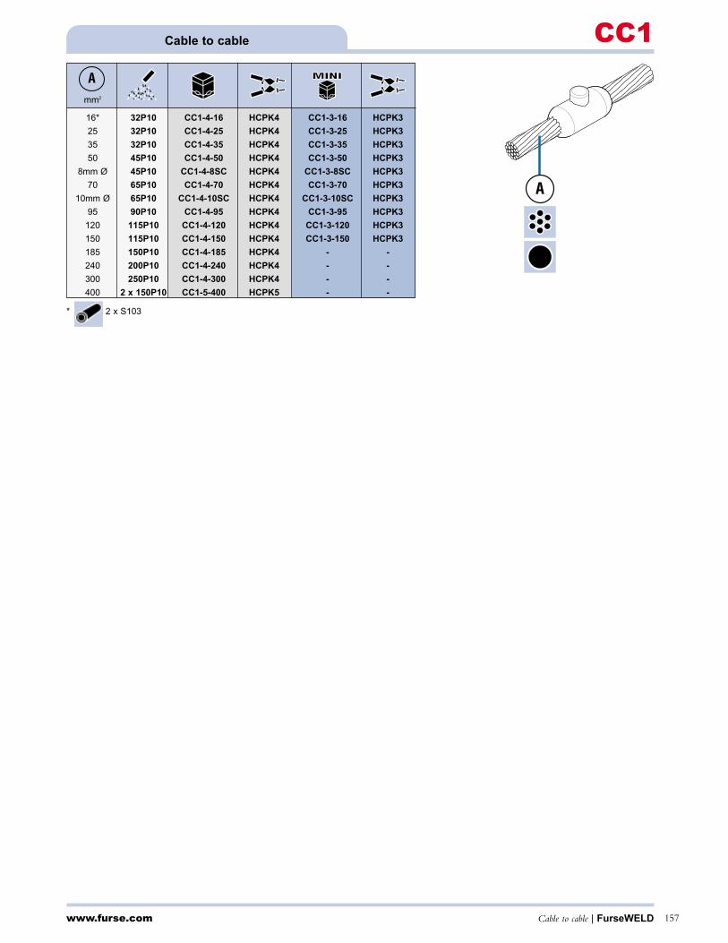
* 2 x S103
www.furse.com Cable to cable | FurseWELD 157
Cable to cable CC1
mm2
16* 32P10 CC1-4-16 HCPK4 CC1-3-16 HCPK3
25 32P10 CC1-4-25 HCPK4 CC1-3-25 HCPK3
35 32P10 CC1-4-35 HCPK4 CC1-3-35 HCPK3
50 45P10 CC1-4-50 HCPK4 CC1-3-50 HCPK3
8mm Ø 45P10 CC1-4-8SC HCPK4 CC1-3-8SC HCPK3
70 65P10 CC1-4-70 HCPK4 CC1-3-70 HCPK3
10mm Ø 65P10 CC1-4-10SC HCPK4 CC1-3-10SC HCPK3
95 90P10 CC1-4-95 HCPK4 CC1-3-95 HCPK3
120 115P10 CC1-4-120 HCPK4 CC1-3-120 HCPK3
150 115P10 CC1-4-150 HCPK4 CC1-3-150 HCPK3
185 150P10 CC1-4-185 HCPK4 - -
240 200P10 CC1-4-240 HCPK4 - -
300 250P10 CC1-4-300 HCPK4 - -
400 2 x 150P10 CC1-5-400 HCPK5 - -
A
A

* 3 x S103
www.furse.comFurseWELD | Cable to cable158
Cable to cableCC2
mm2 mm2
16* 16* 45P10 CC2-4-1616 HCPK4 CC2-3-1616 HCPK3
25 25 45P10 CC2-4-2525 HCPK4 CC2-3-2525 HCPK3
35 35 45P10 CC2-4-3535 HCPK4 CC2-3-3535 HCPK3
35 25 45P10 CC2-4-3525 HCPK4 CC2-3-3525 HCPK3
8mm Ø 8mm Ø 65P10 CC2-4-88SC HCPK4 CC2-3-88SC HCPK3
50 50 90P10 CC2-4-5050 HCPK4 CC2-3-5050 HCPK3
50 35 65P10 CC2-4-5035 HCPK4 CC2-3-5035 HCPK3
50 25 65P10 CC2-4-5025 HCPK4 CC2-3-5025 HCPK3
10mm Ø 10mm Ø 90P10 CC2-4-1010SC HCPK4 CC2-3-1010SC HCPK3
70 70 90P10 CC2-4-7070 HCPK4 CC2-3-7070 HCPK3
70 50 90P10 CC2-4-7050 HCPK4 CC2-3-7050 HCPK3
70 35 65P10 CC2-4-7035 HCPK4 CC2-3-7035 HCPK3
70 25 65P10 CC2-4-7025 HCPK4 CC2-3-7025 HCPK3
95 95 115P10 CC2-4-9595 HCPK4 CC2-3-9595 HCPK3
95 70 90P10 CC2-4-9570 HCPK4 CC2-3-9570 HCPK3
95 50 90P10 CC2-4-9550 HCPK4 CC2-3-9550 HCPK3
95 35 90P10 CC2-4-9535 HCPK4 CC2-3-9535 HCPK3
120 120 150P10 CC2-4-120120 HCPK4 - -
120 95 150P10 CC2-4-12095 HCPK4 - -
120 70 90P10 CC2-4-12070 HCPK4 CC2-3-12070 HCPK3
120 50 90P10 CC2-4-12050 HCPK4 CC2-3-12050 HCPK3
150 150 200P10 CC2-4-150150 HCPK4 - -
150 120 150P10 CC2-4-150120 HCPK4 - -
150 95 150P10 CC2-4-15095 HCPK4 - -
150 70 90P10 CC2-4-15070 HCPK4 CC2-3-15070 HCPK3
185 185 200P10 CC2-4-185185 HCPK4 - -
185 150 200P10 CC2-4-185150 HCPK4 - -
185 120 200P10 CC2-4-185120 HCPK4 - -
185 95 150P10 CC2-4-18595 HCPK4 - -
240 240 2 x 150P10 CC2-4-240240 HCPK4 - -
240 185 200P10 CC2-4-240185 HCPK4 - -
240 150 200P10 CC2-4-240150 HCPK4 - -
240 120 200P10 CC2-4-240120 HCPK4 - -
300 300 2 x 200P10 CC2-5-300300 HCPK5 - -
300 240 2 x 200P10 CC2-5-300240 HCPK5 - -
300 185 250P10 CC2-4-300185 HCPK4 - -
A B
BA

* 4 x S103
www.furse.com Cable to cable | FurseWELD 159
Cable to cable CC4
mm2 mm2
16* 16* 65P10 CC4-4-1616 HCPK4 CC4-3-1616 HCPK3
25 25 45P10 CC4-4-2525 HCPK4 CC4-3-2525 HCPK3
35 35 65P10 CC4-4-3535 HCPK4 CC4-3-3535 HCPK3
35 25 65P10 CC4-4-3525 HCPK4 CC4-3-3525 HCPK3
8mm Ø 8mm Ø 90P10 CC4-4-88SC HCPK4 CC4-3-88SC HCPK3
50 50 90P10 CC4-4-5050 HCPK4 CC4-3-5050 HCPK3
50 35 90P10 CC4-4-5035 HCPK4 CC4-3-5035 HCPK3
50 25 90P10 CC4-4-5025 HCPK4 CC4-3-5025 HCPK3
10mm Ø 10mm Ø 115P10 CC4-4-1010SC HCPK4 CC4-3-1010SC HCPK3
70 70 115P10 CC4-4-7070 HCPK4 CC4-3-7070 HCPK3
70 50 115P10 CC4-4-7050 HCPK4 CC4-3-7050 HCPK3
70 35 115P10 CC4-4-7035 HCPK4 CC4-3-7035 HCPK3
70 25 115P10 CC4-4-7025 HCPK4 CC4-3-7025 HCPK3
95 95 150P10 CC4-4-9595 HCPK4 - -
95 70 150P10 CC4-4-9570 HCPK4 - -
95 50 115P10 CC4-4-9550 HCPK4 - -
95 35 115P10 CC4-4-9535 HCPK4 - -
120 120 200P10 CC4-4-120120 HCPK4 - -
120 95 200P10 CC4-4-12095 HCPK4 - -
120 70 150P10 CC4-4-12070 HCPK4 - -
120 50 150P10 CC4-4-12050 HCPK4 - -
150 150 250P10 CC4-4-150150 HCPK4 - -
150 120 250P10 CC4-4-150120 HCPK4 - -
150 95 200P10 CC4-4-15095 HCPK4 - -
150 70 150P10 CC4-4-15070 HCPK4 - -
185 185 2 x 150P10 CC4-4-185185 HCPK4 - -
185 150 250P10 CC4-4-185150 HCPK4 - -
185 120 250P10 CC4-4-185120 HCPK4 - -
185 95 200P10 CC4-4-18595 HCPK4 - -
185 70 200P10 CC4-4-18570 HCPK4 - -
240 240 2 x 250P10 CC4-5-240240 HCPK5 - -
240 185 2 x 200P10 CC4-5-240185 HCPK5 - -
240 150 2 x 200P10 CC4-5-240150 HCPK5 - -
240 120 2 x 150P10 CC4-5-240120 HCPK5 - -
A B
A B

* 3 x S103
www.furse.comFurseWELD | Cable to cable160
Cable to cableCC6
mm2 mm2
16* 16* 65P10 CC6-4-1616 HCPK4 CC6-3-1616 HCPK3
25 25 45P10 CC6-4-2525 HCPK4 CC6-3-2525 HCPK3
35 35 65P10 CC6-4-3535 HCPK4 CC6-3-3535 HCPK3
35 25 65P10 CC6-4-3525 HCPK4 CC6-3-3525 HCPK3
50 50 90P10 CC6-4-5050 HCPK4 CC6-3-5050 HCPK3
50 35 65P10 CC6-4-5035 HCPK4 CC6-3-5035 HCPK3
50 25 65P10 CC6-4-5025 HCPK4 CC6-3-5025 HCPK3
70 70 115P10 CC6-4-7070 HCPK4 CC6-3-7070 HCPK3
70 50 115P10 CC6-4-7050 HCPK4 CC6-3-7050 HCPK3
70 35 90P10 CC6-4-7035 HCPK4 CC6-3-7035 HCPK3
70 25 90P10 CC6-4-7025 HCPK4 CC6-3-7025 HCPK3
95 95 150P10 CC6-4-9595 HCPK4 - -
95 70 115P10 CC6-4-9570 HCPK4 CC6-3-9570 HCPK3
95 50 115P10 CC6-4-9550 HCPK4 CC6-3-9550 HCPK3
95 35 115P10 CC6-4-9535 HCPK4 CC6-3-9535 HCPK3
120 120 200P10 CC6-4-120120 HCPK4 - -
120 95 200P10 CC6-4-12095 HCPK4 - -
120 70 150P10 CC6-4-12070 HCPK4 - -
120 50 115P10 CC6-4-12050 HCPK4 CC6-3-12050 HCPK3
A B
BA
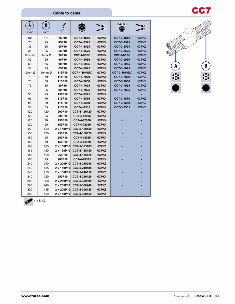
www.furse.com Cable to cable | FurseWELD 161
Cable to cable CC7
mm2 mm2
16* 16* 65P10 CC7-4-1616 HCPK4 CC7-3-1616 HCPK3
25 25 45P10 CC7-4-2525 HCPK4 CC7-3-2525 HCPK3
35 35 65P10 CC7-4-3535 HCPK4 CC7-3-3535 HCPK3
35 25 65P10 CC7-4-3525 HCPK4 CC7-3-3525 HCPK3
8mm Ø 8mm Ø 90P10 CC7-4-88SC HCPK4 CC7-3-88SC HCPK3
50 50 90P10 CC7-4-5050 HCPK4 CC7-3-5050 HCPK3
50 35 90P10 CC7-4-5035 HCPK4 CC7-3-5035 HCPK3
50 25 65P10 CC7-4-5025 HCPK4 CC7-3-5025 HCPK3
10mm Ø 10mm Ø 115P10 CC7-4-1010SC HCPK4 CC7-3-1010SC HCPK3
70 70 115P10 CC7-4-7070 HCPK4 CC7-3-7070 HCPK3
70 50 115P10 CC7-4-7050 HCPK4 CC7-3-7050 HCPK3
70 35 90P10 CC7-4-7035 HCPK4 CC7-3-7035 HCPK3
70 25 90P10 CC7-4-7025 HCPK4 CC7-3-7025 HCPK3
95 95 150P10 CC7-4-9595 HCPK4 - -
95 70 115P10 CC7-4-9570 HCPK4 CC7-3-9570 HCPK3
95 50 115P10 CC7-4-9550 HCPK4 CC7-3-9550 HCPK3
95 35 115P10 CC7-4-9535 HCPK4 CC7-3-9535 HCPK3
120 120 200P10 CC7-4-120120 HCPK4 - -
120 95 200P10 CC7-4-12095 HCPK4 - -
120 70 150P10 CC7-4-12070 HCPK4 - -
120 50 150P10 CC7-4-12050 HCPK4 - -
150 150 2 x 150P10 CC7-5-150150 HCPK5 - -
150 120 250P10 CC7-4-150120 HCPK4 - -
150 95 200P10 CC7-4-15095 HCPK4 - -
150 70 150P10 CC7-4-15070 HCPK4 - -
185 185 2 x 150P10 CC7-5-185185 HCPK5 - -
185 150 2 x 150P10 CC7-5-185150 HCPK5 - -
185 120 250P10 CC7-4-185120 HCPK4 - -
185 95 200P10 CC7-4-18595 HCPK4 - -
240 240 2 x 200P10 CC7-5-240240 HCPK5 - -
240 185 2 x 150P10 CC7-5-240185 HCPK5 - -
240 150 2 x 150P10 CC7-5-240150 HCPK5 - -
240 120 250P10 CC7-4-240120 HCPK4 - -
300 300 2 x 250P10 CC7-5-300300 HCPK5 - -
300 240 2 x 250P10 CC7-5-300240 HCPK5 - -
300 185 2 x 200P10 CC7-5-300185 HCPK5 - -
300 150 2 x 150P10 CC7-5-300150 HCPK5 - -
A B
BA
* 4 x S103
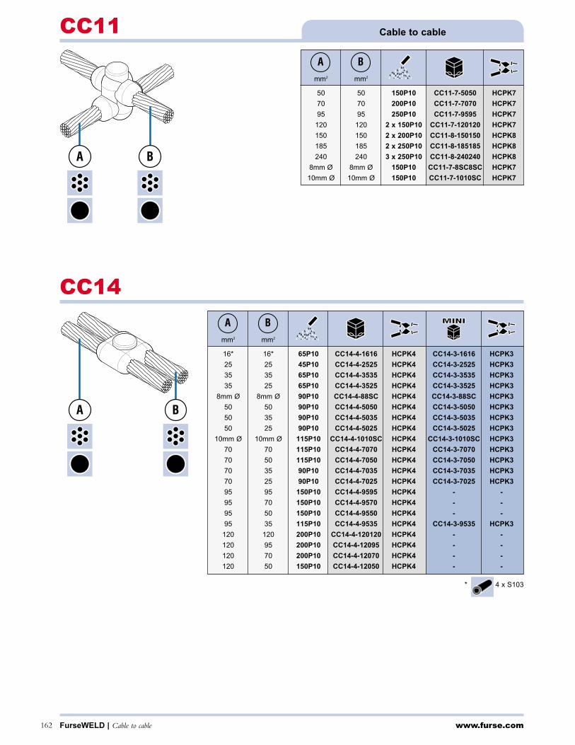
www.furse.comFurseWELD | Cable to cable162
Cable to cableCC11
CC14
mm2 mm2
50 50 150P10 CC11-7-5050 HCPK7
70 70 200P10 CC11-7-7070 HCPK7
95 95 250P10 CC11-7-9595 HCPK7
120 120 2 x 150P10 CC11-7-120120 HCPK7
150 150 2 x 200P10 CC11-8-150150 HCPK8
185 185 2 x 250P10 CC11-8-185185 HCPK8
240 240 3 x 250P10 CC11-8-240240 HCPK8
8mm Ø 8mm Ø 150P10 CC11-7-8SC8SC HCPK7
10mm Ø 10mm Ø 150P10 CC11-7-1010SC HCPK7
mm2 mm2
16* 16* 65P10 CC14-4-1616 HCPK4 CC14-3-1616 HCPK3
25 25 45P10 CC14-4-2525 HCPK4 CC14-3-2525 HCPK3
35 35 65P10 CC14-4-3535 HCPK4 CC14-3-3535 HCPK3
35 25 65P10 CC14-4-3525 HCPK4 CC14-3-3525 HCPK3
8mm Ø 8mm Ø 90P10 CC14-4-88SC HCPK4 CC14-3-88SC HCPK3
50 50 90P10 CC14-4-5050 HCPK4 CC14-3-5050 HCPK3
50 35 90P10 CC14-4-5035 HCPK4 CC14-3-5035 HCPK3
50 25 90P10 CC14-4-5025 HCPK4 CC14-3-5025 HCPK3
10mm Ø 10mm Ø 115P10 CC14-4-1010SC HCPK4 CC14-3-1010SC HCPK3
70 70 115P10 CC14-4-7070 HCPK4 CC14-3-7070 HCPK3
70 50 115P10 CC14-4-7050 HCPK4 CC14-3-7050 HCPK3
70 35 90P10 CC14-4-7035 HCPK4 CC14-3-7035 HCPK3
70 25 90P10 CC14-4-7025 HCPK4 CC14-3-7025 HCPK3
95 95 150P10 CC14-4-9595 HCPK4 - -
95 70 150P10 CC14-4-9570 HCPK4 - -
95 50 150P10 CC14-4-9550 HCPK4 - -
95 35 115P10 CC14-4-9535 HCPK4 CC14-3-9535 HCPK3
120 120 200P10 CC14-4-120120 HCPK4 - -
120 95 200P10 CC14-4-12095 HCPK4 - -
120 70 200P10 CC14-4-12070 HCPK4 - -
120 50 150P10 CC14-4-12050 HCPK4 - -
A B
A B
BA
BA
* 4 x S103

www.furse.com Cable to earth rod | FurseWELD 163
Cable to earth rod CR1
mm Ø inches Ø mm2
12.7 1/2" 16* 65P10 CR1-4-12716 HCPK4 CR1-3-12716 HCPK3
12.7 1/2" 25 65P10 CR1-4-12725 HCPK4 CR1-3-12725 HCPK3
12.7 1/2" 35 65P10 CR1-4-12735 HCPK4 CR1-3-12735 HCPK3
12.7 1/2" 50 65P10 CR1-4-12750 HCPK4 CR1-3-12750 HCPK3
12.7 1/2" 8mm Ø 65P10 CR1-4-1278SC HCPK4 CR1-3-1278SC HCPK3
12.7 1/2" 70 90P10 CR1-4-12770 HCPK4 CR1-3-12770 HCPK3
12.7 1/2" 95 90P10 CR1-4-12795 HCPK4 CR1-3-12795 HCPK3
12.7 1/2" 120 90P10 CR1-4-127120 HCPK4 CR1-3-127120 HCPK3
14.2 5/8" 16* 65P10 CR1-4-14216 HCPK4 CR1-3-14216 HCPK3
14.2 5/8" 25 65P10 CR1-4-14225 HCPK4 CR1-3-14225 HCPK3
14.2 5/8" 35 65P10 CR1-4-14235 HCPK4 CR1-3-14235 HCPK3
14.2 5/8" 50 90P10 CR1-4-14250 HCPK4 CR1-3-14250 HCPK3
14.2 5/8" 8mm Ø 90P10 CR1-4-1428SC HCPK4 CR1-3-1428SC HCPK3
14.2 5/8" 70 90P10 CR1-4-14270 HCPK4 CR1-3-14270 HCPK3
14.2 5/8" 95 90P10 CR1-4-14295 HCPK4 CR1-3-14295 HCPK3
14.2 5/8" 120 90P10 CR1-4-142120 HCPK4 CR1-3-142120 HCPK3
14.2 5/8" 150 115P10 CR1-4-142150 HCPK4 CR1-3-142150 HCPK3
14.2 5/8" 185 115P10 CR1-4-142185 HCPK4 CR1-3-142185 HCKP3
14.2 5/8" 240 150P10 CR1-4-142240 HCPK4 - -
17.2 3/4" 16* 65P10 CR1-4-17216 HCPK4 CR1-3-17216 HCPK3
17.2 3/4" 25 65P10 CR1-4-17225 HCPK4 CR1-3-17225 HCPK3
17.2 3/4" 35 65P10 CR1-4-17235 HCPK4 CR1-3-17235 HCPK3
17.2 3/4" 50 90P10 CR1-4-17250 HCPK4 CR1-3-17250 HCPK3
17.2 3/4" 8mm Ø 90P10 CR1-4-1728SC HCPK4 CR1-3-1728SC HCPK3
17.2 3/4" 70 90P10 CR1-4-17270 HCPK4 CR1-3-17270 HCPK3
17.2 3/4" 95 90P10 CR1-4-17295 HCPK4 CR1-3-17295 HCPK3
17.2 3/4" 120 90P10 CR1-4-172120 HCPK4 CR1-3-172120 HCPK3
17.2 3/4" 150 115P10 CR1-4-172150 HCPK4 CR1-3-172150 HCPK3
17.2 3/4" 185 115P10 CR1-4-172185 HCPK4 CR1-3-172185 HCPK3
17.2 3/4" 240 150P10 CR1-4-172240 HCPK4 - -
17.2 3/4" 300 200P10 CR1-4-172300 HCPK4 - -
BA C
A/BC
* 1 x S103
Suitable for connections to copperbond rods - for connections to solid copperand stainless steel rods please contact our sales office.
Threaded portion of copperbond rods must be removed prior to welding.
A
B
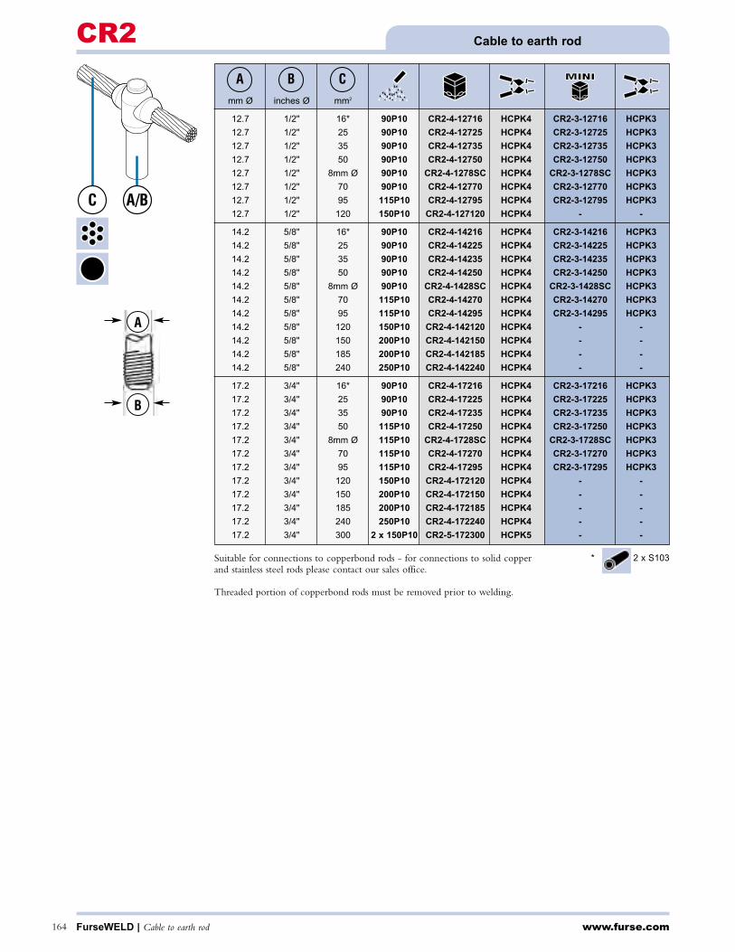
www.furse.comFurseWELD | Cable to earth rod164
Cable to earth rodCR2
mm Ø inches Ø mm2
12.7 1/2" 16* 90P10 CR2-4-12716 HCPK4 CR2-3-12716 HCPK3
12.7 1/2" 25 90P10 CR2-4-12725 HCPK4 CR2-3-12725 HCPK3
12.7 1/2" 35 90P10 CR2-4-12735 HCPK4 CR2-3-12735 HCPK3
12.7 1/2" 50 90P10 CR2-4-12750 HCPK4 CR2-3-12750 HCPK3
12.7 1/2" 8mm Ø 90P10 CR2-4-1278SC HCPK4 CR2-3-1278SC HCPK3
12.7 1/2" 70 90P10 CR2-4-12770 HCPK4 CR2-3-12770 HCPK3
12.7 1/2" 95 115P10 CR2-4-12795 HCPK4 CR2-3-12795 HCPK3
12.7 1/2" 120 150P10 CR2-4-127120 HCPK4 - -
14.2 5/8" 16* 90P10 CR2-4-14216 HCPK4 CR2-3-14216 HCPK3
14.2 5/8" 25 90P10 CR2-4-14225 HCPK4 CR2-3-14225 HCPK3
14.2 5/8" 35 90P10 CR2-4-14235 HCPK4 CR2-3-14235 HCPK3
14.2 5/8" 50 90P10 CR2-4-14250 HCPK4 CR2-3-14250 HCPK3
14.2 5/8" 8mm Ø 90P10 CR2-4-1428SC HCPK4 CR2-3-1428SC HCPK3
14.2 5/8" 70 115P10 CR2-4-14270 HCPK4 CR2-3-14270 HCPK3
14.2 5/8" 95 115P10 CR2-4-14295 HCPK4 CR2-3-14295 HCPK3
14.2 5/8" 120 150P10 CR2-4-142120 HCPK4 - -
14.2 5/8" 150 200P10 CR2-4-142150 HCPK4 - -
14.2 5/8" 185 200P10 CR2-4-142185 HCPK4 - -
14.2 5/8" 240 250P10 CR2-4-142240 HCPK4 - -
17.2 3/4" 16* 90P10 CR2-4-17216 HCPK4 CR2-3-17216 HCPK3
17.2 3/4" 25 90P10 CR2-4-17225 HCPK4 CR2-3-17225 HCPK3
17.2 3/4" 35 90P10 CR2-4-17235 HCPK4 CR2-3-17235 HCPK3
17.2 3/4" 50 115P10 CR2-4-17250 HCPK4 CR2-3-17250 HCPK3
17.2 3/4" 8mm Ø 115P10 CR2-4-1728SC HCPK4 CR2-3-1728SC HCPK3
17.2 3/4" 70 115P10 CR2-4-17270 HCPK4 CR2-3-17270 HCPK3
17.2 3/4" 95 115P10 CR2-4-17295 HCPK4 CR2-3-17295 HCPK3
17.2 3/4" 120 150P10 CR2-4-172120 HCPK4 - -
17.2 3/4" 150 200P10 CR2-4-172150 HCPK4 - -
17.2 3/4" 185 200P10 CR2-4-172185 HCPK4 - -
17.2 3/4" 240 250P10 CR2-4-172240 HCPK4 - -
17.2 3/4" 300 2 x 150P10 CR2-5-172300 HCPK5 - -
BA C
A
B
A/BC
* 2 x S103Suitable for connections to copperbond rods - for connections to solid copperand stainless steel rods please contact our sales office.
Threaded portion of copperbond rods must be removed prior to welding.

www.furse.com Cable to earth rod | FurseWELD 165
Cable to earth rod CR3
mm Ø inches Ø mm2
12.7 1/2" 16* 90P10 CR3-9-12716 HCPK4+F1
12.7 1/2" 25 90P10 CR3-9-12725 HCPK4+F1
12.7 1/2" 35 90P10 CR3-9-12735 HCPK4+F1
12.7 1/2" 50 115P10 CR3-9-12750 HCPK4+F1
12.7 1/2" 8mm Ø 115P10 CR3-9-1278SC HCPK4+F1
12.7 1/2" 70 115P10 CR3-9-12770 HCPK4+F1
12.7 1/2" 95 115P10 CR3-9-12795 HCPK4+F1
12.7 1/2" 120 150P10 CR3-9-127120 HCPK4+F1
14.2 5/8" 16* 90P10 CR3-9-14216 HCPK4+F1
14.2 5/8" 25 90P10 CR3-9-14225 HCPK4+F1
14.2 5/8" 35 90P10 CR3-9-14235 HCPK4+F1
14.2 5/8" 50 115P10 CR3-9-14250 HCPK4+F1
14.2 5/8" 8mm Ø 115P10 CR3-9-1428SC HCPK4+F1
14.2 5/8" 70 115P10 CR3-9-14270 HCPK4+F1
14.2 5/8" 95 115P10 CR3-9-14295 HCPK4+F1
14.2 5/8" 120 150P10 CR3-9-142120 HCPK4+F1
14.2 5/8" 150 150P10 CR3-9-142150 HCPK4+F1
14.2 5/8" 185 250P10 CR3-9-142185 HCPK4+F1
14.2 5/8" 240 2 x 200P10 CR3-10-142240 HCPK5+F2
17.2 3/4" 16* 90P10 CR3-9-17216 HCPK4+F1
17.2 3/4" 25 90P10 CR3-9-17225 HCPK4+F1
17.2 3/4" 35 90P10 CR3-9-17235 HCPK4+F1
17.2 3/4" 50 115P10 CR3-9-17250 HCPK4+F1
17.2 3/4" 8mm Ø 115P10 CR3-9-1728SC HCPK4+F1
17.2 3/4" 70 150P10 CR3-9-17270 HCPK4+F1
17.2 3/4" 95 150P10 CR3-9-17295 HCPK4+F1
17.2 3/4" 120 200P10 CR3-9-172120 HCPK4+F1
17.2 3/4" 150 250P10 CR3-9-172150 HCPK4+F1
17.2 3/4" 185 2 x 200P10 CR3-10-172185 HCPK5+F2
17.2 3/4" 240 2 x 250P10 CR3-10-172240 HCPK5+F2
17.2 3/4" 300 3 x 200P10 CR3-10-172300 HCPK5+F2
BA C
A
B
A/B C
* 2 x S103
Suitable for connections to copperbond rods - for connections to solid copperand stainless steel rods please contact our sales office.
Threaded portion of copperbond rods must be removed prior to welding.

www.furse.comFurseWELD | Cable to reinforcing bar166
Cable to reinforcing barCRE1
CRE2
mm Ø mm2
10 - 40 16* 45P10 CRE1-3-16 HCPK3-B PACK-A
10 - 40 25 45P10 CRE1-3-25 HCPK3-B PACK-A
10 - 40 35 45P10 CRE1-3-35 HCPK3-B PACK-A
10 - 40 8mm Ø 90P10 CRE1-3-8SC HCPK3-B PACK-A
10 - 40 50 90P10 CRE1-3-50 HCPK3-B PACK-A
10 - 40 10mm Ø 90P10 CRE1-3-10SC HCPK3-B PACK-A
10 - 40 70 90P10 CRE1-3-70 HCPK3-B PACK-A
10 - 40 95 90P10 CRE1-3-95 HCPK3-B PACK-A
10 - 40 120 90P10 CRE1-3-120 HCPK3-B PACK-A
BA
mm Ø mm2
16 16* 90P10 CRE2-4-16R16 HCPK4
16 25 90P10 CRE2-4-16R25 HCPK4
16 35 90P10 CRE2-4-16R35 HCPK4
16 8mm Ø 115 P10 CRE2-4-16R8SC HCPK4
16 50 115P10 CRE2-4-16R50 HCPK4
16 10mm Ø 115P10 CRE2-4-16R10SC HCPK4
16 70 115P10 CRE2-4-16R70 HCPK4
16 95 150P10 CRE2-4-16R95 HCPK4
16 120 150P10 CRE2-4-16R120 HCPK4
16 150 200P10 CRE2-4-16R150 HCPK4
16 185 200P10 CRE2-4-16R185 HCPK4
16 240 250P10 CRE2-4-16R240 HCPK4
16 300 2 x 150P10 CRE2-4-16R300 HCPK4
18 16* 115P10 CRE2-4-18R16 HCPK4
18 25 115P10 CRE2-4-18R25 HCPK4
18 35 115P10 CRE2-4-18R35 HCPK4
18 8mm Ø 150P10 CRE2-4-18R8SC HCPK4
18 50 150P10 CRE2-4-18R50 HCPK4
18 10mm Ø 150P10 CRE2-4-18R10SC HCPK4
18 70 150P10 CRE2-4-18R70 HCPK4
18 95 150P10 CRE2-4-18R95 HCPK4
18 120 200P10 CRE2-4-18R120 HCPK4
18 150 200P10 CRE2-4-18R150 HCPK4
18 185 200P10 CRE2-4-18R185 HCPK4
18 240 250P10 CRE2-4-18R240 HCPK4
18 300 2 x 150P10 CRE2-4-18R300 HCPK4
20 16* 115P10 CRE2-4-20R16 HCPK4
20 25 115P10 CRE2-4-20R25 HCPK4
20 35 115P10 CRE2-4-20R35 HCPK4
20 8mm Ø 150P10 CRE2-4-20R8SC HCPK4
20 50 150P10 CRE2-4-20R50 HCPK4
20 10mm Ø 150P10 CRE2-4-20R10SC HCPK4
20 70 150P10 CRE2-4-20R70 HCPK4
20 95 200P10 CRE2-4-20R95 HCPK4
20 120 200P10 CRE2-4-20R120 HCPK4
20 150 200P10 CRE2-4-20R150 HCPK4
20 185 250P10 CRE2-4-20R185 HCPK4
BA
BA
A
B* 1 x S103
* 1 x S103

www.furse.com Cable to reinforcing bar | FurseWELD 167
Cable to reinforcing bar CRE2
CRE3
mm Ø mm2
10 - 40 16* 45P10 CRE3-3-16 HCPK3-A PACK-A
10 - 40 25 45P10 CRE3-3-25 HCPK3-A PACK-A
10 - 40 35 45P10 CRE3-3-35 HCPK3-A PACK-A
10 - 40 8mm Ø 90P10 CRE3-3-8SC HCPK3-A PACK-A
10 - 40 50 90P10 CRE3-3-50 HCPK3-A PACK-A
10 - 40 10mm Ø 90P10 CRE3-3-10SC HCPK3-A PACK-A
10 - 40 70 90P10 CRE3-3-70 HCPK3-A PACK-A
10 - 40 95 90P10 CRE3-3-95 HCPK3-A PACK-A
10 - 40 120 90P10 CRE3-3-120 HCPK3-A PACK-A
BA
mm Ø mm2
20 240 2 x 150P10 CRE2-4-20R240 HCPK4
20 300 2 x 200P10 CRE2-5-20R300 HCPK5
25 16* 200P10 CRE2-4-25R16 HCPK4
25 25 200P10 CRE2-4-25R25 HCPK4
25 35 200P10 CRE2-4-25R35 HCPK4
25 8mm Ø 200P10 CRE2-4-25R8SC HCPK4
25 50 200P10 CRE2-4-25R50 HCPK4
25 10mm Ø 250P10 CRE2-4-25R10SC HCPK4
25 70 250P10 CRE2-4-25R70 HCPK4
25 95 250P10 CRE2-4-25R95 HCPK4
25 120 250P10 CRE2-4-25R120 HCPK4
25 150 2 x 150P10 CRE2-4-25R150 HCPK4
25 185 2 x 150P10 CRE2-5-25R185 HCPK5
25 240 2 x 200P10 CRE2-5-25R240 HCPK5
25 300 2 x 200P10 CRE2-5-25R300 HCPK5
30 16* 250P10 CRE2-4-30R16 HCPK4
30 25 250P10 CRE2-4-30R25 HCPK4
30 35 250P10 CRE2-4-30R35 HCPK4
30 8mm Ø 2 x 150P10 CRE2-4-30R8SC HCPK4
30 50 2 x 150P10 CRE2-4-30R50 HCPK4
30 10mm Ø 2 x 150P10 CRE2-4-30R10SC HCPK4
30 70 2 x 150P10 CRE2-4-30R70 HCPK4
30 95 2 x 150P10 CRE2-5-30R95 HCPK5
30 120 2 x 200P10 CRE2-5-30R120 HCPK5
30 150 2 x 200P10 CRE2-5-30R150 HCPK5
30 185 2 x 250P10 CRE2-5-30R185 HCPK5
30 240 3 x 200P10 CRE2-5-30R240 HCPK5
30 300 3 x 200P10 CRE2-5-30R300 HCPK5
BA
BA
AB
* 1 x S103
* 2 x S103

www.furse.comFurseWELD | Cable to reinforcing bar168
Cable to reinforcing barCRE6
CRE17
mm Ø mm2
10 - 40 16* 45P10 CRE6-3-16 HCPK3-A PACK-A
10 - 40 25 45P10 CRE6-3-25 HCPK3-A PACK-A
10 - 40 35 45P10 CRE6-3-35 HCPK3-A PACK-A
10 - 40 8mm Ø 65P10 CRE6-3-8SC HCPK3-A PACK-A
10 - 40 50 65P10 CRE6-3-50 HCPK3-A PACK-A
10 - 40 10mm Ø 90P10 CRE6-3-10SC HCPK3-A PACK-A
10 - 40 70 90P10 CRE6-3-70 HCPK3-A PACK-A
10 - 40 95 90P10 CRE6-4-95 HCPK3-A PACK-A
10 - 40 120 90P10 CRE6-4-120 HCPK3-A PACK-A
BA
mm Ø mm2
10 - 40 16* 45P10 CRE17-3-16 HCPK3-B PACK-A
10 - 40 25 45P10 CRE17-3-25 HCPK3-B PACK-A
10 - 40 35 45P10 CRE17-3-35 HCPK3-B PACK-A
10 - 40 8mm Ø 90P10 CRE17-3-8SC HCPK3-B PACK-A
10 - 40 50 90P10 CRE17-3-50 HCPK3-B PACK-A
10 - 40 10mm Ø 90P10 CRE17-3-10SC HCPK3-B PACK-A
10 - 40 70 90P10 CRE17-3-70 HCPK3-B PACK-A
10 - 40 95 90P10 CRE17-3-95 HCPK3-B PACK-A
10 - 40 120 90P10 CRE17-3-120 HCPK3-B PACK-A
BA
A B
A B
* 1 x S103
* 2 x S103
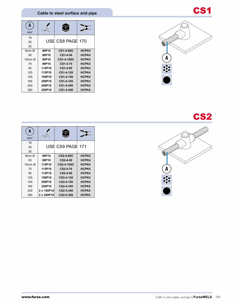
www.furse.com Cable to steel surface and pipe | FurseWELD 169
Cable to steel surface and pipe CS1
mm2
16
25
35
8mm Ø 90P10 CS1-4-8SC HCPK4
50 90P10 CS1-4-50 HCPK4
10mm Ø 90P10 CS1-4-10SC HCPK4
70 90P10 CS1-4-70 HCPK4
95 115P10 CS1-4-95 HCPK4
120 115P10 CS1-4-120 HCPK4
150 150P10 CS1-4-150 HCPK4
185 200P10 CS1-4-185 HCPK4
240 200P10 CS1-4-240 HCPK4
300 250P10 CS1-4-300 HCPK4
A
USE CS8 PAGE 170
CS2A
A
A
mm2
16
25
35
8mm Ø 90P10 CS2-4-8SC HCPK4
50 90P10 CS2-4-50 HCPK4
10mm Ø 115P10 CS2-4-10SC HCPK4
70 115P10 CS2-4-70 HCPK4
95 115P10 CS2-4-95 HCPK4
120 150P10 CS2-4-120 HCPK4
150 200P10 CS2-4-150 HCPK4
185 250P10 CS2-4-185 HCPK4
240 2 x 150P10 CS2-5-240 HCPK5
300 2 x 200P10 CS2-5-300 HCPK5
USE CS9 PAGE 171
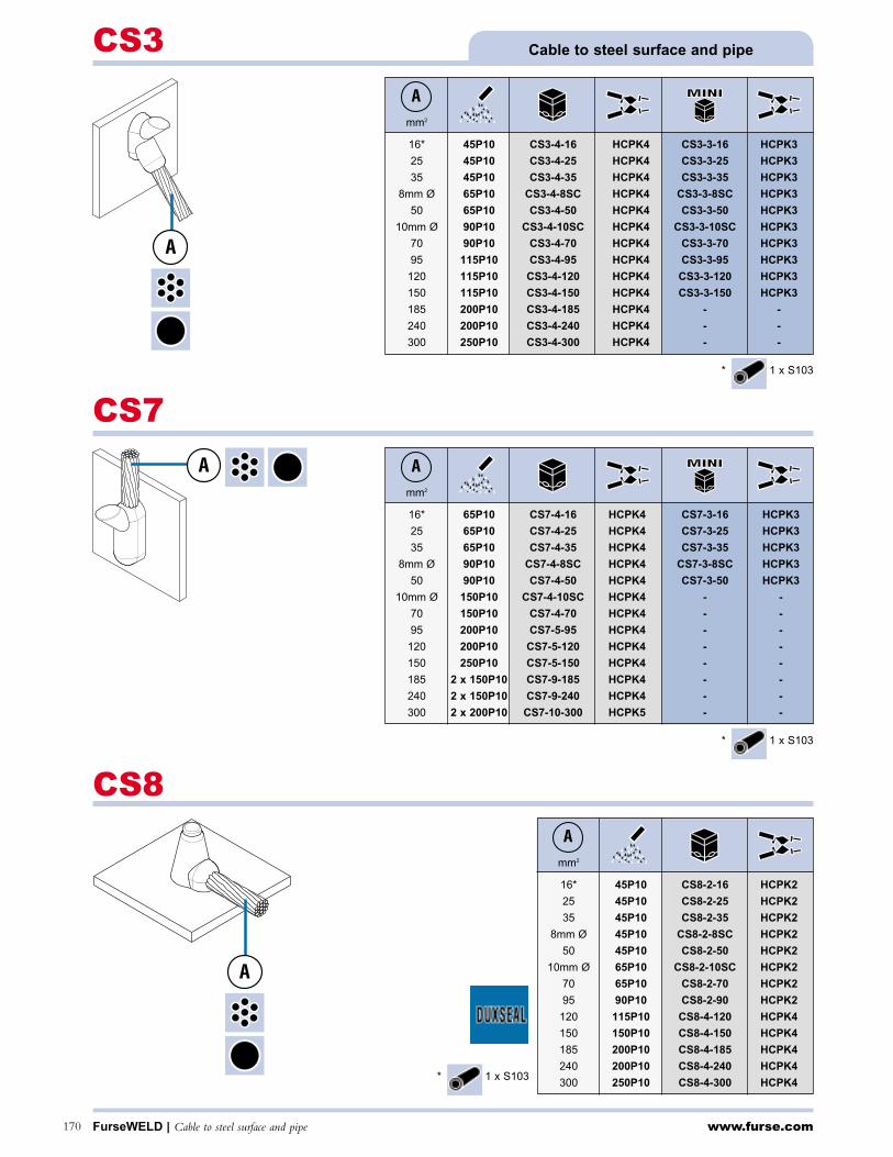
www.furse.comFurseWELD | Cable to steel surface and pipe170
Cable to steel surface and pipeCS3
mm2
16* 45P10 CS3-4-16 HCPK4 CS3-3-16 HCPK3
25 45P10 CS3-4-25 HCPK4 CS3-3-25 HCPK3
35 45P10 CS3-4-35 HCPK4 CS3-3-35 HCPK3
8mm Ø 65P10 CS3-4-8SC HCPK4 CS3-3-8SC HCPK3
50 65P10 CS3-4-50 HCPK4 CS3-3-50 HCPK3
10mm Ø 90P10 CS3-4-10SC HCPK4 CS3-3-10SC HCPK3
70 90P10 CS3-4-70 HCPK4 CS3-3-70 HCPK3
95 115P10 CS3-4-95 HCPK4 CS3-3-95 HCPK3
120 115P10 CS3-4-120 HCPK4 CS3-3-120 HCPK3
150 115P10 CS3-4-150 HCPK4 CS3-3-150 HCPK3
185 200P10 CS3-4-185 HCPK4 - -
240 200P10 CS3-4-240 HCPK4 - -
300 250P10 CS3-4-300 HCPK4 - -
A
CS7
Amm2
16* 65P10 CS7-4-16 HCPK4 CS7-3-16 HCPK3
25 65P10 CS7-4-25 HCPK4 CS7-3-25 HCPK3
35 65P10 CS7-4-35 HCPK4 CS7-3-35 HCPK3
8mm Ø 90P10 CS7-4-8SC HCPK4 CS7-3-8SC HCPK3
50 90P10 CS7-4-50 HCPK4 CS7-3-50 HCPK3
10mm Ø 150P10 CS7-4-10SC HCPK4 - -
70 150P10 CS7-4-70 HCPK4 - -
95 200P10 CS7-5-95 HCPK4 - -
120 200P10 CS7-5-120 HCPK4 - -
150 250P10 CS7-5-150 HCPK4 - -
185 2 x 150P10 CS7-9-185 HCPK4 - -
240 2 x 150P10 CS7-9-240 HCPK4 - -
300 2 x 200P10 CS7-10-300 HCPK5 - -
A
CS8
mm2
16* 45P10 CS8-2-16 HCPK2
25 45P10 CS8-2-25 HCPK2
35 45P10 CS8-2-35 HCPK2
8mm Ø 45P10 CS8-2-8SC HCPK2
50 45P10 CS8-2-50 HCPK2
10mm Ø 65P10 CS8-2-10SC HCPK2
70 65P10 CS8-2-70 HCPK2
95 90P10 CS8-2-90 HCPK2
120 115P10 CS8-4-120 HCPK4
150 150P10 CS8-4-150 HCPK4
185 200P10 CS8-4-185 HCPK4
240 200P10 CS8-4-240 HCPK4
300 250P10 CS8-4-300 HCPK4
A
A
A
* 1 x S103
* 1 x S103
* 1 x S103

Cable to steel surface and pipe | FurseWELD 171
Cable to steel surface and pipe CS9
mm2
16* 45P10 CS25-4-16 HCPK4 CS25-3-16 HCPK3
25 45P10 CS25-4-25 HCPK4 CS25-3-25 HCPK3
35 45P10 CS25-4-35 HCPK4 CS25-3-35 HCPK3
8mm Ø 65P10 CS25-4-8SC HCPK4 CS25-3-8SC HCPK3
50 65P10 CS25-4-50 HCPK4 CS25-3-50 HCPK3
10mm Ø 90P10 CS25-4-10SC HCPK4 - -
70 90P10 CS25-4-70 HCPK4 CS25-3-70 HCPK3
95 115P10 CS25-4-95 HCPK4 - -
120 115P10 CS25-4-120 HCPK4 - -
150 150P10 CS25-4-150 HCPK4 - -
185 200P10 CS25-4-185 HCPK4 - -
240 200P10 CS25-4-240 HCPK4 - -
300 250P10 CS25-4-300 HCPK4 - -
A
mm2
16* 45P10 CS9-2-16 HCPK2
25 45P10 CS9-2-25 HCPK2
35 45P10 CS9-2-35 HCPK2
8mm Ø 90P10 CS9-4-8SC HCPK4
50 90P10 CS9-4-50 HCPK4
10mm Ø 115P10 CS9-4-10SC HCPK4
70 115P10 CS9-4-70 HCPK4
95 115P10 CS9-4-95 HCPK4
120 150P10 CS9-4-120 HCPK4
150 200P10 CS9-4-150 HCPK4
185 250P10 CS9-4-185 HCPK4
240 2 x 150P10 CS9-5-240 HCPK5
A
CS25
mm2
16* 45P10 CS27-4-16 HCPK4 CS27-3-16 HCPK3
25 45P10 CS27-4-25 HCPK4 CS27-3-25 HCPK3
35 45P10 CS27-4-35 HCPK4 CS27-3-35 HCPK3
8mm Ø 65P10 CS27-4-8SC HCPK4 CS27-3-8SC HCPK3
50 65P10 CS27-4-50 HCPK4 CS27-3-50 HCPK3
10mm Ø 115P10 CS27-4-10SC HCPK4 - -
70 115P10 CS27-4-70 HCPK4 - -
95 150P10 CS27-4-95 HCPK4 - -
120 150P10 CS27-4-120 HCPK4 - -
150 200P10 CS27-5-150 HCPK5 - -
185 250P10 CS27-5-185 HCPK5 - -
240 2 x 150P10 CS27-5-240 HCPK5 - -
300 2 x 200P10 CS27-5-300 HCPK5 - -
A
CS27
A
A
A
* 2 x S103
* 1 x S103
* 2 x S103

www.furse.comFurseWELD | Cable to steel surface and pipe172
Cable to steel surface and pipeCS32
B
mm2 mm Ø
2.5 <125 15P10 CS32-1-2.5-A HCPK1 1 x S105
2.5 >125 15P10 CS32-1-2.5-B HCPK1 1 x S105
4 <125 15P10 CS32-1-4-A HCPK1 1 x S105
4 >125 15P10 CS32-1-4-B HCPK1 1 x S105
6 <125 15P10 CS32-1-6-A HCPK1 1 x S105
6 >125 15P10 CS32-1-6-B HCPK1 1 x S105
10 <125 25P10 CS32-1-10-A HCPK1 1 x S102
10 >125 25P10 CS32-1-10-B HCPK1 1 x S102
16 <125 45P10 CS32-2-16-A HCPK2 1 x S103
16 >125 45P10 CS32-2-16-B HCPK2 1 x S103
25 <70 25P10 CS32-1-25-C HCPK1 -
25 70 - 165 25P10 CS32-1-25-D HCPK1 -
25 >165 25P10 CS32-1-25-E HCPK1 -
35 <70 45P10 CS32-2-35-C HCPK2 -
35 70 - 165 45P10 CS32-2-35-D HCPK2 -
35 165 - 250 45P10 CS32-2-35-F HCPK2 -
35 >250 45P10 CS32-2-35-G HCPK2 -
50 <70 45P10 CS32-2-50-C HCPK2 -
50 70 - 165 45P10 CS32-2-50-D HCPK2 -
50 165 - 250 45P10 CS32-2-50-F HCPK2 -
50 >250 45P10 CS32-2-50-G HCPK2 -
70 <70 65P10 CS32-2-70-C HCPK2 -
70 70 - 165 65P10 CS32-2-70-D HCPK2 -
70 165 - 250 65P10 CS32-2-70-F HCPK2 -
70 >250 65P10 CS32-2-70-G HCPK2 -
A B
CS34
mm2 mm Ø
2.5 <125 15P10 CS34-2-2.5-A HCPK2 2 x S105
2.5 >125 15P10 CS34-2-2.5-B HCPK2 2 x S105
4 <125 15P10 CS34-2-4-A HCPK2 2 x S105
4 >125 15P10 CS34-2-4-B HCPK2 2 x S105
6 <125 15P10 CS34-2-6-A HCPK2 2 x S105
6 >125 15P10 CS34-2-6-B HCPK2 2 x S105
10 <125 32P10 CS34-2-10-A HCPK2 2 x S102
10 >125 32P10 CS34-2-10-B HCPK2 2 x S102
16 <125 45P10 CS34-2-16-A HCPK2 2 x S103
16 >125 45P10 CS34-2-16-B HCPK2 2 x S103
25 <70 32P10 CS34-2-25-C HCPK2 -
25 70 - 165 32P10 CS34-2-25-D HCPK2 -
25 >165 32P10 CS34-2-25-E HCPK2 -
35 <70 45P10 CS34-2-35-C HCPK2 -
35 70 - 165 45P10 CS34-2-35-D HCPK2 -
35 165 - 250 45P10 CS34-2-35-F HCPK2 -
35 >250 45P10 CS34-2-35-G HCPK2 -
50 <70 65P10 CS34-2-50-C HCPK2 -
50 70 - 165 65P10 CS34-2-50-D HCPK2 -
50 165 - 250 65P10 CS34-2-50-F HCPK2 -
50 >250 65P10 CS34-2-50-G HCPK2 -
A B
A
B A
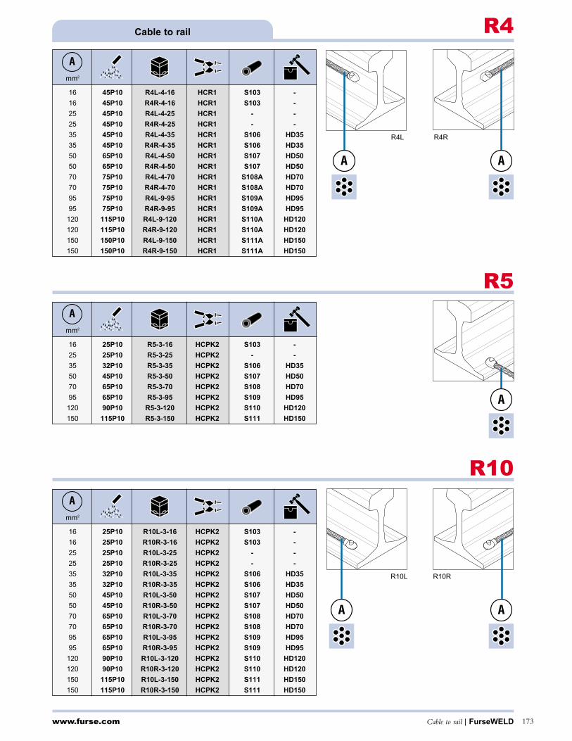
R10L R10R
A A
www.furse.com Cable to rail | FurseWELD 173
Cable to rail R4
mm2
16 45P10 R4L-4-16 HCR1 S103 -
16 45P10 R4R-4-16 HCR1 S103 -
25 45P10 R4L-4-25 HCR1 - -
25 45P10 R4R-4-25 HCR1 - -
35 45P10 R4L-4-35 HCR1 S106 HD35
35 45P10 R4R-4-35 HCR1 S106 HD35
50 65P10 R4L-4-50 HCR1 S107 HD50
50 65P10 R4R-4-50 HCR1 S107 HD50
70 75P10 R4L-4-70 HCR1 S108A HD70
70 75P10 R4R-4-70 HCR1 S108A HD70
95 75P10 R4L-9-95 HCR1 S109A HD95
95 75P10 R4R-9-95 HCR1 S109A HD95
120 115P10 R4L-9-120 HCR1 S110A HD120
120 115P10 R4R-9-120 HCR1 S110A HD120
150 150P10 R4L-9-150 HCR1 S111A HD150
150 150P10 R4R-9-150 HCR1 S111A HD150
A
R4L R4R
A
R5
mm2
16 25P10 R5-3-16 HCPK2 S103 -
25 25P10 R5-3-25 HCPK2 - -
35 32P10 R5-3-35 HCPK2 S106 HD35
50 45P10 R5-3-50 HCPK2 S107 HD50
70 65P10 R5-3-70 HCPK2 S108 HD70
95 65P10 R5-3-95 HCPK2 S109 HD95
120 90P10 R5-3-120 HCPK2 S110 HD120
150 115P10 R5-3-150 HCPK2 S111 HD150
A
A
A
R10
mm2
16 25P10 R10L-3-16 HCPK2 S103 -
16 25P10 R10R-3-16 HCPK2 S103 -
25 25P10 R10L-3-25 HCPK2 - -
25 25P10 R10R-3-25 HCPK2 - -
35 32P10 R10L-3-35 HCPK2 S106 HD35
35 32P10 R10R-3-35 HCPK2 S106 HD35
50 45P10 R10L-3-50 HCPK2 S107 HD50
50 45P10 R10R-3-50 HCPK2 S107 HD50
70 65P10 R10L-3-70 HCPK2 S108 HD70
70 65P10 R10R-3-70 HCPK2 S108 HD70
95 65P10 R10L-3-95 HCPK2 S109 HD95
95 65P10 R10R-3-95 HCPK2 S109 HD95
120 90P10 R10L-3-120 HCPK2 S110 HD120
120 90P10 R10R-3-120 HCPK2 S110 HD120
150 115P10 R10L-3-150 HCPK2 S111 HD150
150 115P10 R10R-3-150 HCPK2 S111 HD150
A

mm2
M6 45P10 R8-4-M6 HCPK4 RSSM6
M8 45P10 R8-4-M8 HCPK4 RSSM8
M10 65P10 R8-4-M10 HCPK4 RSSM10
M12 90P10 R8-4-M12 HCPK4 RSSM12
M16 115P10 R8-4-M16 HCPK4 RSSM16
A
www.furse.comFurseWELD | Cable, bar and stud to rail and stud to steel surface174
Stud to steel surfaceRS1
R12
mm2
25 32P10 R12-8-25 HCR2 RB25
35 32P10 R12-8-35 HCR2 RB35
50 45P10 R12-8-50 HCR2 RB50
70 65P10 R12-8-70 HCR2 RB70
95 75P10 R12-8-95 HCR2 RB95
120 115P10 R12-8-120 HCR2 RB120
A
mm2
M6 25P10 RS1-4-M6 HCPK4 RSSM6
M8 32P10 RS1-4-M8 HCPK4 RSSM8
M10 45P10 RS1-4-M10 HCPK4 RSSM10
M12 65P10 RS1-4-M12 HCPK4 RSSM12
M16 115P10 RS1-4-M16 HCPK4 RSSM16
A
RS2
mm2
M6 25P10 RS2-4-M6 HCPK4 RSSM6
M8 32P10 RS2-4-M8 HCPK4 RSSM8
M10 45P10 RS2-4-M10 HCPK4 RSSM10
M12 65P10 RS2-4-M12 HCPK4 RSSM12
M16 115P10 RS2-5-M16 HCPK5 RSSM16
A
Cable to rail
A
A
A
Bar to railR6
mm x mm
25 x 3 65P10 R6-3-253 HCPK2
A
Stud to railR8
A
A
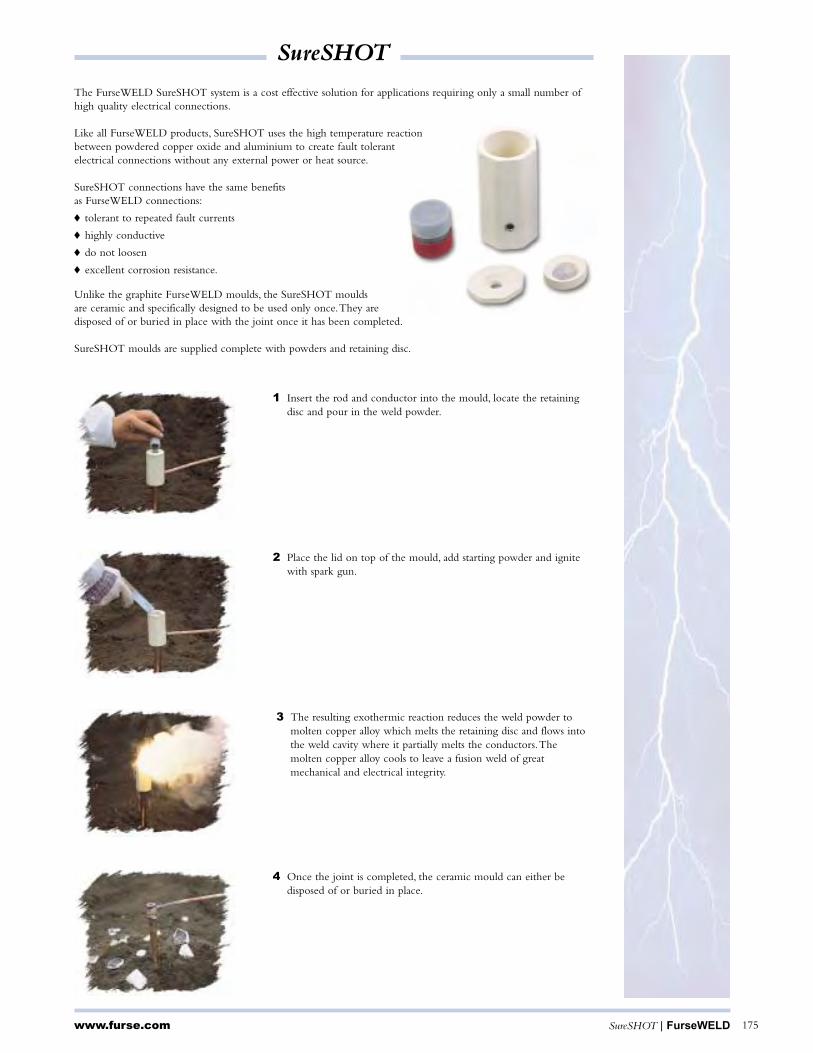
SureSHOT
www.furse.com SureSHOT | FurseWELD 175
The FurseWELD SureSHOT system is a cost effective solution for applications requiring only a small number ofhigh quality electrical connections.
Like all FurseWELD products, SureSHOT uses the high temperature reactionbetween powdered copper oxide and aluminium to create fault tolerantelectrical connections without any external power or heat source.
SureSHOT connections have the same benefitsas FurseWELD connections:
tolerant to repeated fault currents
highly conductive
do not loosen
excellent corrosion resistance.
Unlike the graphite FurseWELD moulds, the SureSHOT mouldsare ceramic and specifically designed to be used only once.They aredisposed of or buried in place with the joint once it has been completed.
SureSHOT moulds are supplied complete with powders and retaining disc.
1 Insert the rod and conductor into the mould, locate the retainingdisc and pour in the weld powder.
2 Place the lid on top of the mould, add starting powder and ignitewith spark gun.
4 Once the joint is completed, the ceramic mould can either bedisposed of or buried in place.
3 The resulting exothermic reaction reduces the weld powder tomolten copper alloy which melts the retaining disc and flows intothe weld cavity where it partially melts the conductors.Themolten copper alloy cools to leave a fusion weld of greatmechanical and electrical integrity.
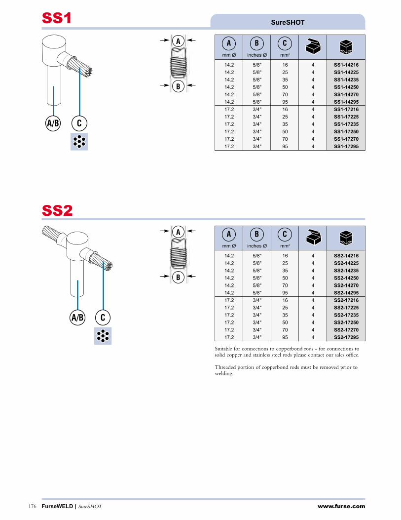
www.furse.comFurseWELD | SureSHOT176
SureSHOTSS1
mm Ø inches Ø mm2
14.2 5/8" 16 4 SS1-14216
14.2 5/8" 25 4 SS1-14225
14.2 5/8" 35 4 SS1-14235
14.2 5/8" 50 4 SS1-14250
14.2 5/8" 70 4 SS1-14270
14.2 5/8" 95 4 SS1-14295
17.2 3/4" 16 4 SS1-17216
17.2 3/4" 25 4 SS1-17225
17.2 3/4" 35 4 SS1-17235
17.2 3/4" 50 4 SS1-17250
17.2 3/4" 70 4 SS1-17270
17.2 3/4" 95 4 SS1-17295
BA C
SS2
mm Ø inches Ø mm2
14.2 5/8" 16 4 SS2-14216
14.2 5/8" 25 4 SS2-14225
14.2 5/8" 35 4 SS2-14235
14.2 5/8" 50 4 SS2-14250
14.2 5/8" 70 4 SS2-14270
14.2 5/8" 95 4 SS2-14295
17.2 3/4" 16 4 SS2-17216
17.2 3/4" 25 4 SS2-17225
17.2 3/4" 35 4 SS2-17235
17.2 3/4" 50 4 SS2-17250
17.2 3/4" 70 4 SS2-17270
17.2 3/4" 95 4 SS2-17295
BA C
A/B C
A/B C
A
B
A
B
Suitable for connections to copperbond rods - for connections tosolid copper and stainless steel rods please contact our sales office.
Threaded portion of copperbond rods must be removed prior towelding.

www.furse.com Terminal lugs | FurseWELD 177
Terminal lugs
A B C D E
mm mm mm mm mm
20 3 45 10 8.5 LS101
25 3 50 12 8.5 LS102
25 3 50 12 10.5 LS103
31 6 75 15 10.5 LS104
31 6 75 15 12.5 LS105
38 5 75 18 10.5 LS106
38 6 75 18 10.5 LS107
38 6 75 20 12.5 LS108
50 6 95 25 10.5 LS109
50 6 95 25 12.5 LS110
Straight type lug
A B C D E F
mm mm mm mm mm mm
20 3 40 10 8.5 40 LO101
25 3 45 12 8.5 40 LO102
25 3 45 12 10.5 40 LO103
31 6 50 15 10.5 40 LO104
31 6 50 16 12.5 40 LO105
38 5 55 18 10.5 40 LO106
38 6 55 18 10.5 40 LO107
38 6 55 20 12.5 40 LO108
50 6 75 25 10.5 60 LO109
50 6 75 25 12.5 60 LO110
A B C D E F G
mm mm mm mm mm mm mm
20 3 40 10 8.5 40 10 LC101
25 3 45 12 8.5 40 10 LC102
25 3 45 12 10.5 40 10 LC103
31 6 50 15 10.5 40 15 LC104
31 6 50 16 12.5 40 15 LC105
38 5 55 18 10.5 40 15 LC106
38 6 55 18 10.5 40 15 LC107
38 6 55 20 12.5 40 15 LC108
50 6 75 25 10.5 60 20 LC109
50 6 75 25 12.5 60 20 LC110
Cranked type lug
A
D
E
B
C
A
D
E
B
C
F
45°G
A
D
E
B
C
45°
F
Part no.
Part no.
Part no.
Offset type lug
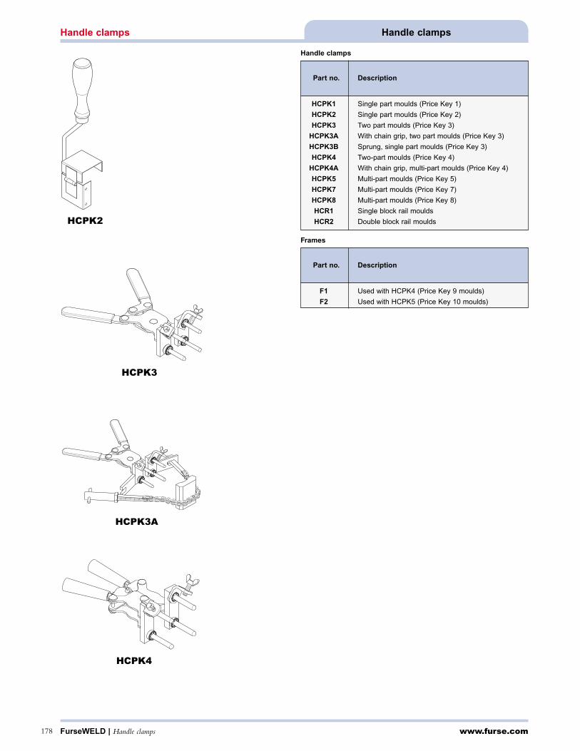
www.furse.comFurseWELD | Handle clamps178
Handle clampsHandle clamps
HCPK2
HCPK3
HCPK3A
HCPK4
Handle clamps
Frames
Part no. Description
HCPK1 Single part moulds (Price Key 1)
HCPK2 Single part moulds (Price Key 2)
HCPK3 Two part moulds (Price Key 3)
HCPK3A With chain grip, two part moulds (Price Key 3)
HCPK3B Sprung, single part moulds (Price Key 3)
HCPK4 Two-part moulds (Price Key 4)
HCPK4A With chain grip, multi-part moulds (Price Key 4)
HCPK5 Multi-part moulds (Price Key 5)
HCPK7 Multi-part moulds (Price Key 7)
HCPK8 Multi-part moulds (Price Key 8)
HCR1 Single block rail moulds
HCR2 Double block rail moulds
Part no. Description
F1 Used with HCPK4 (Price Key 9 moulds)
F2 Used with HCPK5 (Price Key 10 moulds)

E A R L Y S T R E A M E R E M I S S I O N L I G H T N I N G C O N D U C T O R S
Protection areasFrench Standard NFC 17-102 requires that every ESE Lightning Conductor first undergo a series
of high-voltage laboratory tests to determine the gain in triggering time in comparison to a
simple rod. The value obtained - referred to as ∆t - equals the average trigger time over a run of
100 electrical discharges in the laboratory, minus a 35% safety margin. This figure is then used
to calculate each conductor’s protection area according to the standardized formula.
From the outset, INDELEC subjected the PREVECTRON®2 to independent
testing in laboratories across France (EDF facility at Renardières &
Cediver Laboratory at Bazet) and internationally (Louvain University
in Belgium, IREQ in Canada & KERI in South Korea). The tests
highlighted the advantages of the PREVECTRON®2’s early triggering
system compared to a passive rod and allowed each model’s average
∆t value to be measured. The results of the tests have all been approved
by the CNRS and are available on request.
InstallationInstallation procedure for the PREVECTRON®2 is governed by French standard
NFC 17-102 and follows a series of simple rules catering for all types of structure:
• the tip should be positioned at least 2m above the structure to be protected;
• with heights less than 28m, a single down conductor is sufficient
(as long as the conductor’s horizontal projection is less than its vertical projection);
• the resistance of the grounding system should be less than 10Ω;
• PREVECTRON®2 activity can be recorded by installing a lightning strike counter;
• the PREVECTRON®2 has been designed for the most extreme climatic conditions (see the
results of our real-life lightning tests). INDELEC also markets a tester allowing clients
to regularly check the air terminal on-site.
TS 2.25 TS 3.40
Ø 100 mm / H = 330 mm
TS SERIESPrevectron® 2 MILLENIUM
S 3.40
TS SERIES

S 4.50 S 6.60
S SERIESPrevectron® 2 MILLENIUM
Ø 185 mm / H = 385 mm
S SERIES
Key benefits
The skills of INDELEC’s engineers, the variety of tests carried out in both high-voltage
laboratories and real-life lightning conditions, and the experience gained from the thousands
of PREVECTRON®2 installations around the world, have allowed us to develop a complete
range of lightning conductors offering a host of key benefits:
• 5-MODEL RANGE OFFERING CUSTOMIZED SOLUTIONS FOR EACH PROJECT
(EASTHETIC CONSTRAINTS, REQUIRED PROTECTION AREA, ETC.);
• FULLY AUTONOMOUS OPERATION;
• TOTAL RELIABILITY, EVEN IN EXTREME CLIMATIC CONDITIONS;
• PROVEN, ROBUST DESIGN ABLE TO WITHSTAND MULTIPLE LIGHTNING STRIKES;
• LIGHTNING CONDUCTOR ONLY BECOMES ACTIVE WHEN ELECTRICAL FIELD INTENSITY RISES
(LIGHTNING DISCHARGE LIKELY), THE PREVECTRON®2 PRESENTS NO DANGER TO THE SITE;
• STRAIGHTFORWARD INSTALLATION & MAINTENANCE USING TOOLS SPECIALLY DEVELOPED BY INDELEC,
INCLUDING PROTECTION CALCULATION SOFTWARE, STRIKE COUNTER AND PREVECTRON® TESTER;
• HIGH-VOLTAGE LABORATORY TEST RESULTS AVAILABLE ON REQUEST;
• REAL-LIFE TEST RESULTS & SCIENTIFIC REPORTS AVAILABLE ON REQUEST;
• ULTRA-SAFE CAPTURE TIP THANKS TO FULL ELECTRICAL CONTINUITY BETWEEN THE TIP AND THE
EARTH POINT;
• ISO 9001-2000 MANUFACTURING PROCESS (CERTIFICATE #116884).
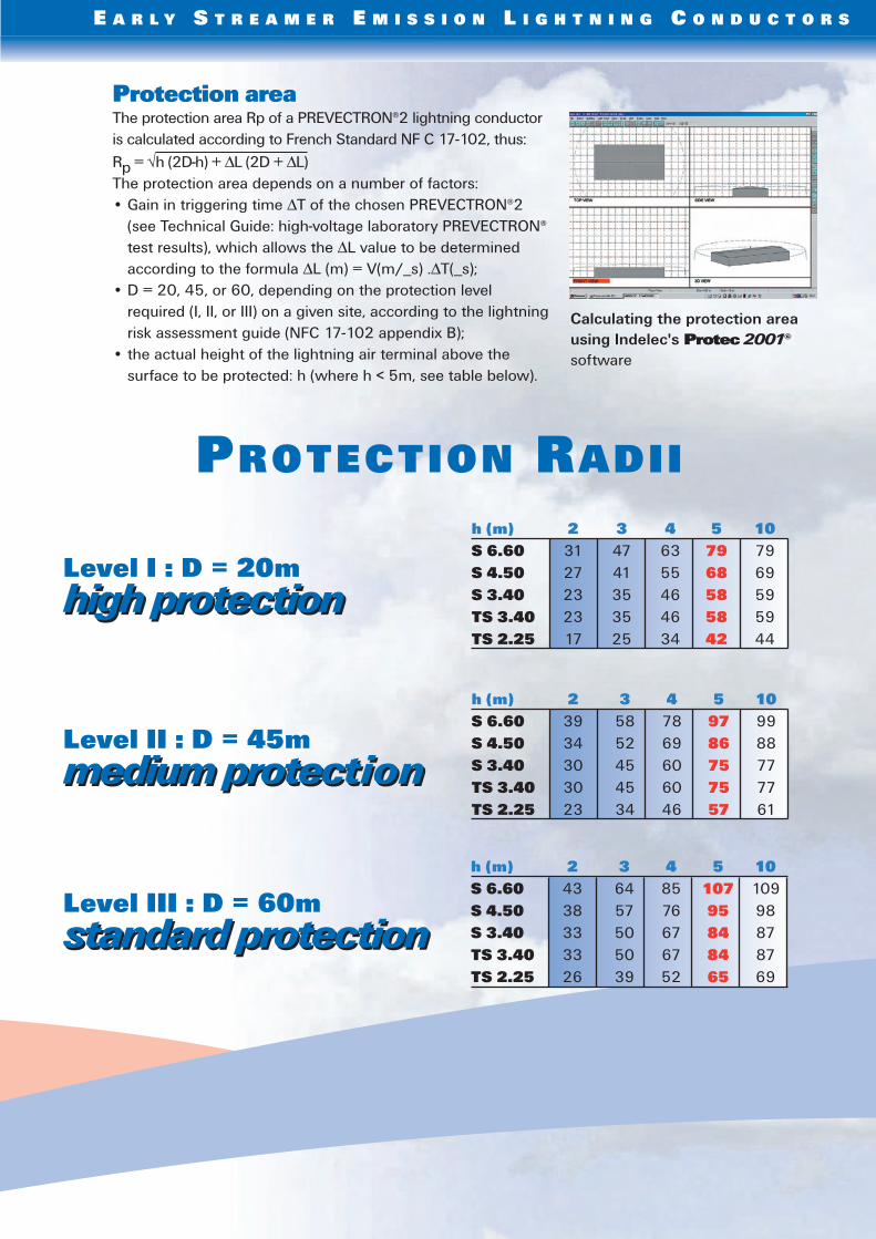
Protection areaThe protection area Rp of a PREVECTRON®2 lightning conductor
is calculated according to French Standard NF C 17-102, thus:
Rp = √h (2D-h) + ∆L (2D + ∆L)
The protection area depends on a number of factors:
• Gain in triggering time ∆T of the chosen PREVECTRON®2
(see Technical Guide: high-voltage laboratory PREVECTRON®
test results), which allows the ∆L value to be determined
according to the formula ∆L (m) = V(m/_s) .∆T(_s);
• D = 20, 45, or 60, depending on the protection level
required (I, II, or III) on a given site, according to the lightning
risk assessment guide (NFC 17-102 appendix B);
• the actual height of the lightning air terminal above the
surface to be protected: h (where h < 5m, see table below).
Calculating the protection area
using Indelec's Protec 2001©
software
E A R L Y S T R E A M E R E M I S S I O N L I G H T N I N G C O N D U C T O R S
h (m) 2 3 4 5 10
S 6.60 31 47 63 79 79
S 4.50 27 41 55 68 69
S 3.40 23 35 46 58 59
TS 3.40 23 35 46 58 59
TS 2.25 17 25 34 42 44
h (m) 2 3 4 5 10
S 6.60 39 58 78 97 99
S 4.50 34 52 69 86 88
S 3.40 30 45 60 75 77
TS 3.40 30 45 60 75 77
TS 2.25 23 34 46 57 61
h (m) 2 3 4 5 10
S 6.60 43 64 85 107 109
S 4.50 38 57 76 95 98
S 3.40 33 50 67 84 87
TS 3.40 33 50 67 84 87
TS 2.25 26 39 52 65 69
medium protection
standard protection
high protection
Level I : D = 20m
high protection
PROTECTION RADII
Level II : D = 45m
medium protection
Level III : D = 60m
standard protection

E A R L Y S T R E A M E R E M I S S I O N L I G H T N I N G C O N D U C T O R S
France’s leading lightning protection network
61, chemin des Postes - 59500 Douai - France
Tel. +33 327 944 944 - Fax. +33 327 944 955 - e-mail : [email protected]
Co
pyri
gh
t In
de
lec /
IN
PE
Real lightning condition test campaignsThe decision to go ahead with real lightning tests was based on a simple premise: laboratory
testing cannot reproduce the complete parameters and constraints of a real lightning discharge.
In addition to the extensive tests carried out in the laboratory in pursuance of French Standard
NFC 17-102, INDELEC is one of the only lightning rod manufacturers to actively pursue real-life
testing.
The test campaigns were originally developed in close cooperation with a team of engi-
neers from the Atomic Energy Commission (C.E.A.) in Grenoble. As work progressed, other
companies, universities and scientists joined in the test campaigns, providing a wealth of
experience in the field of lightning phenomena.
In order to gather as many data as possible, the tests were performed in America, Europe and
Asia, with each site offering very different lightning conditions. The first tests were carried out in
1993 at Camp Blanding in Florida, since when experimentation has moved on to Cachoeira
Paulista in Brazil and Nadachi in Japan.
Each test campaign has provided invaluable results, including:
• highlighting the performance of the PREVECTRON®2 through measuring and comparing
electrical activity at the tips of various lightning rods;
• operation of the PREVECTRON®2’s triggering system;
• confirmation of the PREVECTRON®2’s robust design by exposing it to repeated strikes;
• total reliability provided by the PREVECTRON®2 in a wide range of situations representative
of all types of lightning conditions, including upward & downward lightning strikes and
tropical & winter storms.
A number of scientific reports have been produced in relation to this research, which has also
allowed the PREVECTRON® to be continuously developed from the initial design through to
the latest Millenium model.
Ivo
i’Art
- L
ille
- 0
3 2
8 5
2 6
7 5
4

SECTION 4
EEx-de GRP PUSH BUTTON STATION EFE… SERIES
PUSHBUTTON STATIONS CP… SERIES SERIES
EEx-d ENCLOSURE FOR PUSH BUTTON STATIONS CP../EFDCN… SERIES
OPERATORS FOR PUSH BUTTON STATIONS
SELECTOR SWITCHES
PILOT LAMPS PLD… SERIES
INCANDESCENT LAMP FOR PILOT LAMP PLD
LED LAMPS FOR PILOT LAMP PLD
POWER DISTRIBUTION
IMOTOR PROTECTIVE CIRCUITS BREAKERS COMPACT TYPE
PUSH BUTTON STATIONS AND MOTOR CONTROL STATION
PULSANTERIA E POSTI DI COMANDO E COLONNINE COMANDO MOTORI
PULSANTIERE EEx-de IN RESINA SERIE EFE…
POSTI DI COMANDO E SEGNALAZIONE TIPO CP…
CONTENITORI PER POSTI DI COMANDO E SEGNALAZIONE EEx-d SERIE CP../EFDCN…
OPERATORI PER POSTI DI COMANDO E SEGNALAZIONE
SELETTORI ROTATIVI
LAMPADINE DI SEGNALAZIONE TIPO PLD…
LAMPADINE AD INCANDESCENZA PER LAMPADE DI SEGNALAZIONE PLD
LED LAMPADE PER LAMPADE DI SEGNALAZIONE PLD
UNITÀ DI POTENZA
INTERRUTTORI AUTOMATICI SALVAMOTORI DI TIPO MONOBLOCCO
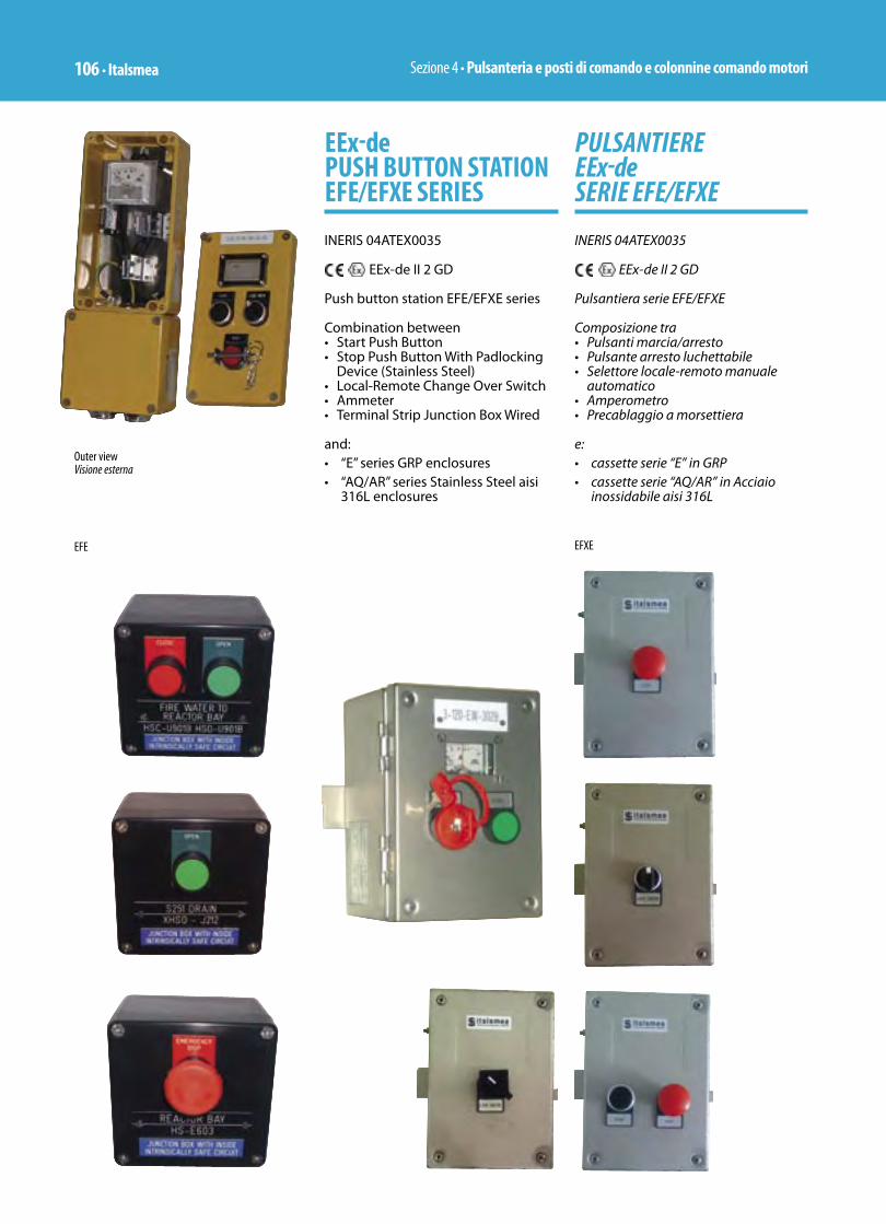
Sezione 4 • Pulsanteria e posti di comando e colonnine comando motori106 • Italsmea
PULSANTIERE EEx-de SERIE EFE/EFXE
INERIS 04ATEX0035
EEx-de II 2 GD
Pulsantiera serie EFE/EFXE
Composizione tra• Pulsanti marcia/arresto• Pulsante arresto luchettabile • Selettore locale-remoto manuale
automatico• Amperometro• Precablaggio a morsettiera
e:• cassette serie “E” in GRP • cassette serie “AQ/AR” in Acciaio
inossidabile aisi 316L
EEx-de PUSH BUTTON STATION EFE/EFXE SERIES
INERIS 04ATEX0035
EEx-de II 2 GD
Push button station EFE/EFXE series
Combination between• Start Push Button• Stop Push Button With Padlocking
Device (Stainless Steel)• Local-Remote Change Over Switch• Ammeter• Terminal Strip Junction Box Wired
and: • “E” series GRP enclosures • “AQ/AR” series Stainless Steel aisi
316L enclosures
Outer viewVisione esterna
EFE EFXE
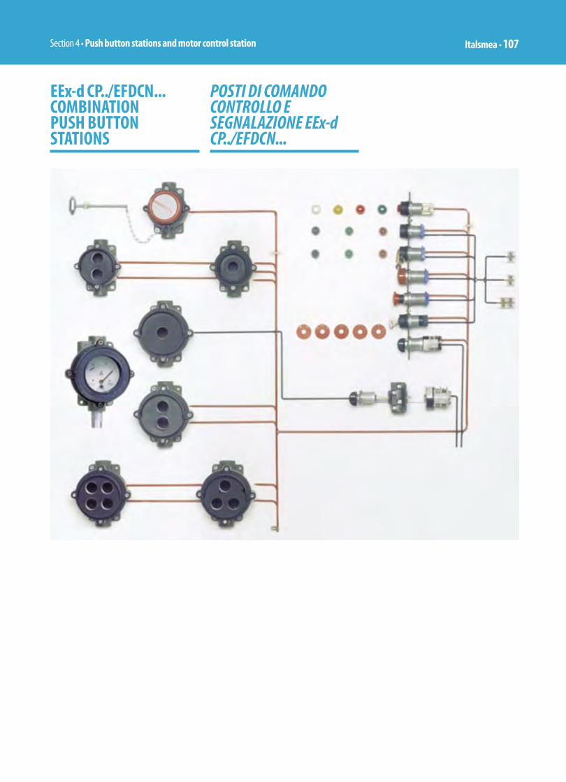
Section 4 • Push button stations and motor control station Italsmea • 107
EEx-d CP../EFDCN... COMBINATION PUSH BUTTON STATIONS
POSTI DI COMANDO CONTROLLO E SEGNALAZIONE EEx-d CP../EFDCN...

Sezione 4 • Pulsanteria e posti di comando e colonnine comando motori108 • Italsmea
POSTI DI COMANDO E SEGNALAZIONE
Istruzioni per composizione posti di comando e segnalazioneLe pulsantiere sono di seguito descritte in versione non assiemata, pertanto la composizione prevede nell’ordine: l’identificazione dei contenitori base della serie CPC-26 / CPSC-26 di cui dal cod. 451.10 al cod. 452.80 riferiti alle scatole base rotonde ad accoppiamento cilindrico, con il numero di operatori ammissibili compreso tra 1 o 2 o 3 o 4. Nella sigla della scatola potranno essere definiti il numero egli operatori ammessi, identificabile nel numero che segue il numero degli operatori, attraverso la lettera che segue il diametro della scatola.L’identificazione degli operatori necessari alla composizione del posto di comando desiderato, sono riportati di seguito dal cod. 276.11 al cod. 545.53. Per i pulsanti precisiamo che non comprendono i contatti elettrici che vanno quantificati a parte tramite i cod. 280.1 e 280.2.Le lampade di segnalazione sono previste senza lampadina, in caso di richiesta specifica vanno valorizzate a parte a seconda della tensione e la tipologia della lampadina/e: incandescenza o multiled.
Esempio di composizione : • Operatori richiesti 4 = contenitore
CPSC-26 / EFDCN – 4 – 120 Contenitore rotondo = CPSC-26EFDCN Posto per operatori = 4 Diametro scatola = 120 = Codice 452.40
• Operatore pulsante marcia = colore nero = PLA 10 = Codice 276.11
• Contatto per pulsante marcia = normalmente aperto = ELC-NO = Codice 280.1
• Operatore pulsante arresto = colore rosso = PLA 20 = Codice 276.12
• Contatto per pulsante arresto = normalmente chiuso = ELC-NC = Codice 280.2
• Lampada di segnalazione marcia (*)= colore rosso = PLD 20 = Codice 277.12
• Lampada di segnalazione arresto (*)= colore verde = PLD 30 = Codice 277.13
PUSH BUTTON STATIONS
Instruction on how to realize a push button stationsThe push button stations listed here following are “NOT ASSEMBLED” therefore to realize a complete unit it must take care following: to identify the base serie CPC-26 / CPSC-26 from code 451.10 to code 452.80 enclosure with round shape, cylindrical cover, with number of places for assemblies barrels (operators) between 1 or 2 or 3 or 4.Reading the type number of enclosure it will be identified the number of places available, the diameter of enclosure. The assemblies barrels (operators) are listed between the code 276.11 and code 545.53. For the assemblies barrels it must take care of following notes: the push button operators are codified without block-contact that must be listed separately using the code 280.1 and 280.2.The pilot lamp operators are codified without lamp, that, if required must be listed separately specifying the voltage and type: incandescent or multiled.
Example of composition :• Requested number of operators 4
= Enclosure CPSC-26 / EFDCN – 4 – 120 Enclosure round shape = CPSC-26/EFDCN Place for operators = 4 Diameter of enclosure = 120 = Code 452.40
• Start push button operator = black colour – PLA 10 = Code 276.11
• Block contact for start = normally open = ELC-NO = Code 280.1
• Stop push button operator = red colour = PLA 20 = Code 276.12
• Block contact for stop = normally closed = ELC-NC = Code 280.2
• Start pilot lamp (*) = red colour = PLD 20 = Code 277.12
• Stop pilot lamp (*) = green colour = PLD 30 = Code. 277.13
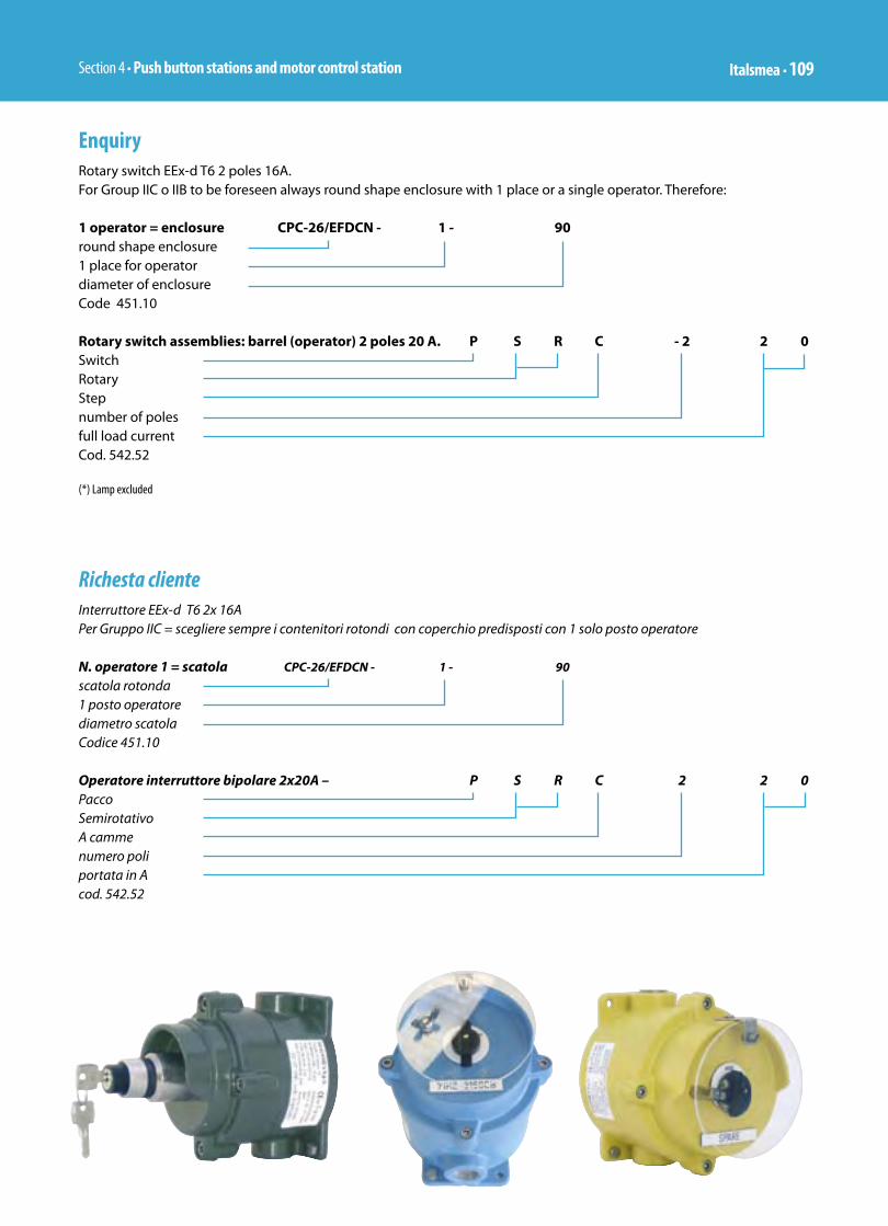
Section 4 • Push button stations and motor control station Italsmea • 109
EnquiryRotary switch EEx-d T6 2 poles 16A.For Group IIC o IIB to be foreseen always round shape enclosure with 1 place or a single operator. Therefore:
1 operator = enclosure CPC-26/EFDCN - 1 - 90round shape enclosure1 place for operatordiameter of enclosureCode 451.10
Rotary switch assemblies: barrel (operator) 2 poles 20 A. P S R C - 2 2 0SwitchRotaryStepnumber of polesfull load currentCod. 542.52
(*) Lamp excluded
Richesta clienteInterruttore EEx-d T6 2x 16APer Gruppo IIC = scegliere sempre i contenitori rotondi con coperchio predisposti con 1 solo posto operatore
N. operatore 1 = scatola CPC-26/EFDCN - 1 - 90
scatola rotonda1 posto operatorediametro scatolaCodice 451.10
Operatore interruttore bipolare 2x20A – P S R C 2 2 0PaccoSemirotativoA camme numero poliportata in Acod. 542.52

Sezione 4 • Pulsanteria e posti di comando e colonnine comando motori110 • Italsmea
INTERRUTTORI/SELETTORIPOSTI DI COMANDO E SEGNALAZIONE SERIE CP../EFSRC..
INERIS 03ATEX0009
II 2 GD –35°C +40°C / EEx-d IIC T6–35°C +50°C / EEx-d IIC T5–35°C +60°C / EEx-d IIC T4
Posti di comando e segnalazione• Materiale: Lega di Alluminio• Composizione standard• IP 65• No.2 imbocchi diam. M25• Verniciati RAL 6003• Lampadine escluse
SWITCHES/SELECTOR SWITCHESPUSHBUTONS STATIONS CP../EFSRC.. SERIES
INERIS 03ATEX0009
II 2 GD –35°C +40°C / EEx-d IIC T6–35°C +50°C / EEx-d IIC T5–35°C +60°C / EEx-d IIC T4
Pushbuttons stations • Material: Copper free Aluminium • Standard type• IP 65• No.2 entries diam. M25• Paitend RAL 6003• Lamps excluded
CODE TYPE RATINGAC1-600V DIAGRAM DIMENSION WEIGHT
=KG.
451.2 CPC26/EFSRC-220 20 1 1,100
451.4 CPC 26/EFSRC-420 20 1 1,150
452.4 CPC 26/EFSRC-432 32 2 1,300
453.2 CPC 26/EFSRC-D-220 20 1 1,150
453.3 CPC 26/EFSRC-D-320 20 2 1,200
454.2 CPC 26/EFSRC-C-220 20 1 1,150
454.3 CPC 26/EFSRC-C-320 20 2 1,300
539.17 CPC 26/EFSRM-R 20 1 1,100
539.16 CPC 26/EFSRM-X 20 1 1,100
n Padlockable on “STOP” positionLucchettabile in posizione di “ARRESTO”
n Padlockable on “O” positionLucchettabile in posizione di “O”
CPC26/EFSRC-…

Section 4 • Push button stations and motor control station Italsmea • 111
Code Type Diagram Weight=kg. Dimensions Note
460.1 CPC 26/EFDCN –P 1,080 1
461.11 CPC 26/EFDCN -PP 1,220 1
CPC 26/EFDCN-PPL
1,730 2 T5
CPC 26/EFDCN-L 1,060 1
493.1
CPC 26/EFDCN-EM(Emergency push button complete with breakable glass and hammer)(Pulsante di emergenza completo di vetro a rompere con martelletto)
1,200 3
494.1
CPC 26/EFDCN-PE(Footswitch wih safety guard) (Pulsante per comando a pedale con gabbia di protezione)
3,200 4
Dimension 1 Dimension 3
Dimension 2 Dimension 4
CPSG/EFDCN-G-2-120
CPC26/EFDCN-P
CPC 26/EFDCN-EM
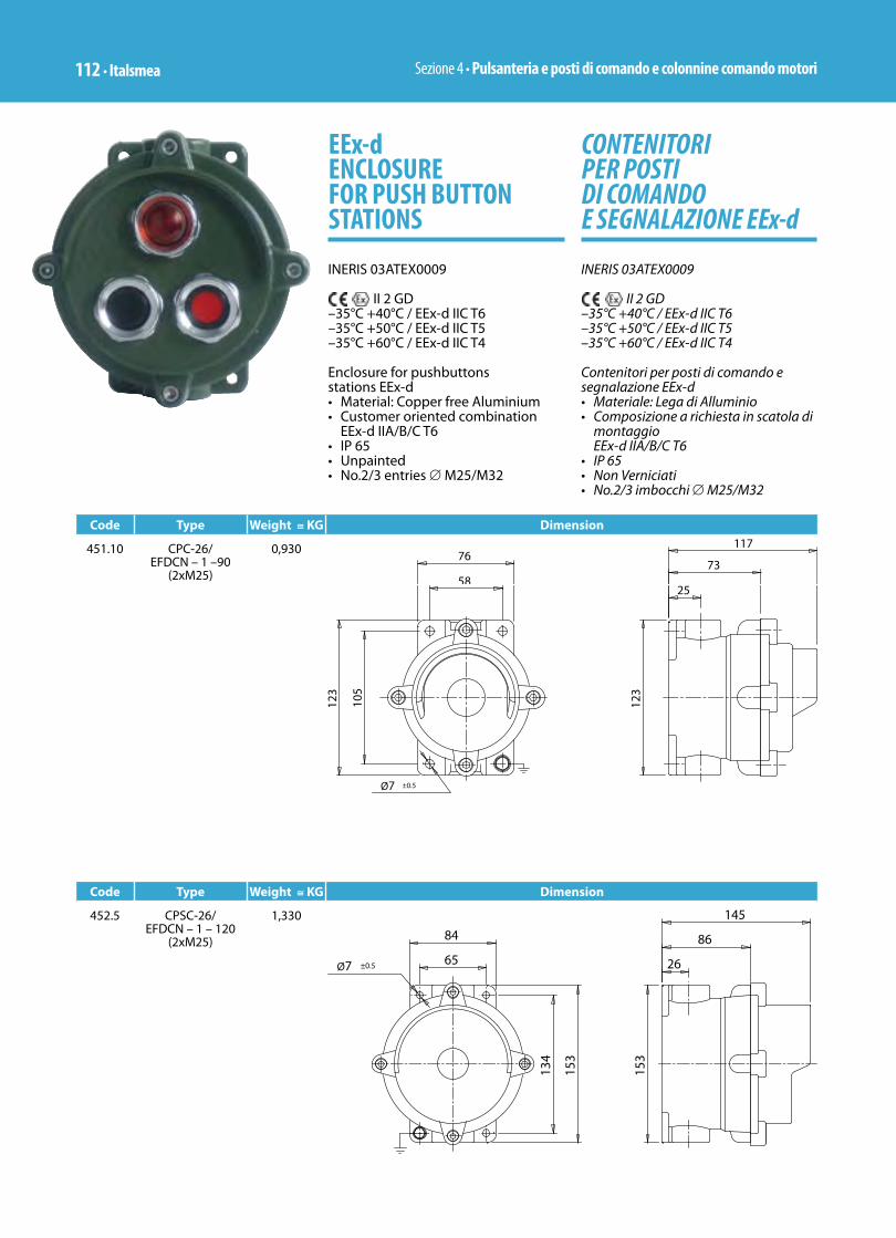
Sezione 4 • Pulsanteria e posti di comando e colonnine comando motori112 • Italsmea
CONTENITORI PER POSTI DI COMANDO E SEGNALAZIONE EEx-d
INERIS 03ATEX0009
II 2 GD –35°C +40°C / EEx-d IIC T6–35°C +50°C / EEx-d IIC T5–35°C +60°C / EEx-d IIC T4
Contenitori per posti di comando e segnalazione EEx-d• Materiale: Lega di Alluminio• Composizione a richiesta in scatola di
montaggio EEx-d IIA/B/C T6
• IP 65• Non Verniciati• No.2/3 imbocchi ∅ M25/M32
EEx-d ENCLOSURE FOR PUSH BUTTON STATIONS
INERIS 03ATEX0009
II 2 GD –35°C +40°C / EEx-d IIC T6–35°C +50°C / EEx-d IIC T5–35°C +60°C / EEx-d IIC T4
Enclosure for pushbuttons stations EEx-d • Material: Copper free Aluminium• Customer oriented combination
EEx-d IIA/B/C T6• IP 65• Unpainted• No.2/3 entries ∅ M25/M32
Code Type Weight ≅ KG Dimension
451.10 CPC-26/ EFDCN – 1 –90
(2xM25)
0,930
Code Type Weight ≅ KG Dimension
452.5 CPSC-26/EFDCN – 1 – 120
(2xM25)
1,330

Section 4 • Push button stations and motor control station Italsmea • 113
Code Type Weight ≅ KG Dimension
452.20 CPSC-26/EFDCN – 2 – 120
(2xM25)
1,280
Code Type Weight ≅ KG Dimension
452.30 CPSC-36/EFDCN – 3 – 120
(2xM32)
1,300
Code Type Weight ≅ Kg Dimension
452.40 CPSC-36/EFDCN – 4 – 120
(2xM32)
1,320

Sezione 4 • Pulsanteria e posti di comando e colonnine comando motori114 • Italsmea
Code Type Weight ≅ Kg Dimension
452.50 CPSG-26/EFDCN – G – 1 - 120
(3xM25)
1,500
Code Type Weight ≅ Kg Dimension
452.60 CPSG-36/EFDCN – G – 2 – 120
(3xM25)
1,450
Code Type Weight ≅ KG Dimension
452.70 CPSG-36/EFDCN – G – 3 – 120
(3xM32)
1,470

Section 4 • Push button stations and motor control station Italsmea • 115
Code Type Weight ≅ KG Dimension
452.80 CPSG-36/EFDCN – G – 4 – 120
(3xM32)
1,490
Plug In / Plug off Push Button Stations
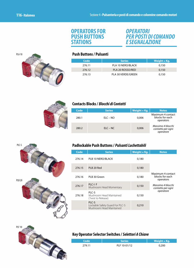
Sezione 4 • Pulsanteria e posti di comando e colonnine comando motori116 • Italsmea
OPERATORI PER POSTI DI COMANDO E SEGNALAZIONE
OPERATORS FOR PUSH BUTTONS STATIONS
Push Buttons / PulsantiCode Series Weight ≅ Kg.
276.11 PLA 10 NERO/BLACK 0,150
276.12 PLA 20 ROSSO/RED 0,150
276.13 PLA 30 VERDE/GREEN 0,150
PLA 10
Contacts Blocks / Blocchi di Contatti Code Series Weight ≅ Kg. Notes
280.1 ELC – NO 0,006Maximum 4 contact
blocks for each operators
Massimo 4 blocchi contatto per ogni
operatore280.2 ELC – NC 0,006
Padlockable Push Buttons / Pulsanti LuchettabiliCode Series Weight ≅ Kg. Notes
276.14 PLB 10 NERO/BLACK 0,180
Maximum 4 contact blocks for each
operators
Massimo 4 blocchi contatto per ogni
operatore
276.15 PLB 20 Red 0,180
276.16 PLB 30 Green 0,180
276.17 PLC-I F Mushroom Head Momentary 0,150
276.18PLC-S Mushroom Head Maintained (Twist to Release)
0,150
PLC-SLockable Safety Guard For PLC-S Mushroom Head Maintained
0,210
PLC-S
PLB 20
Key Operator Selector Switches / Selettori A Chiave Code Series Weight ≅ Kg.
279.11 PLF 10-01/12 0,200
PLF 10
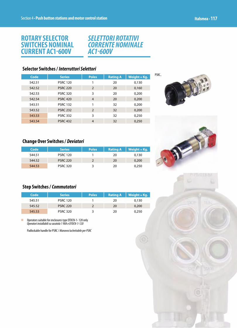
Section 4 • Push button stations and motor control station Italsmea • 117
Selector Switches / Interruttori SelettoriCode Series Poles Rating A Weight ≅ Kg.
542.51 PSRC 120 1 20 0,130
542.52 PSRC 220 2 20 0,160
542.53 PSRC 320 3 20 0,200
542.54 PSRC 420 4 20 0,200
543.51 PSRC 132 1 32 0,200
543.52 PSRC 232 2 32 0,200
543.53 PSRC 332 3 32 0,250
543.54 PSRC 432 4 32 0,250
SELETTORI ROTATIVI CORRENTE NOMINALE AC1-600V
ROTARY SELECTOR SWITCHES NOMINAL CURRENT AC1-600V
Change Over Switches / DeviatoriCode Series Poles Rating A Weight ≅ Kg.
544.51 PSRC 120 1 20 0,130
544.52 PSRC 220 2 20 0,200
544.53 PSRC 320 3 20 0,250
Step Switches / CommutatoriCode Series Poles Rating A Weight ≅ Kg.
545.51 PSRC 120 1 20 0,130
545.52 PSRC 220 2 20 0,200
545.53 PSRC 320 3 20 0,250
n Operators suitable for enclosures type EFDCN-1- 120 onlyOperatori installabili su sacatola 1 90A e EFDCN-1-120
Padlockable handle for PSRC / Manovra luchettabile per PSRC
PSRC..

Sezione 4 • Pulsanteria e posti di comando e colonnine comando motori118 • Italsmea
LAMPADE DI SEGNALAZIONE E RELATIVE LAMPADINE TUBOLARI
PILOT LAMPS AND RELATIVE TUBOLAR LAMPS
Push Buttons / PulsantiCode Series Weight ≅ Kg.
277.11 PLD 10 White 0,130
277.12 PLD 20 Red 0,130
277.13 PLD 30 Green 0,130
277.14 PLD 40 Yellow 0,130
PLD 20
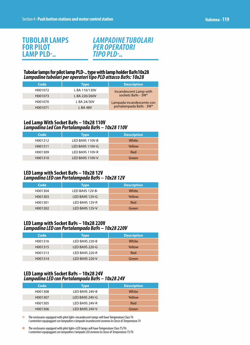
Section 4 • Push button stations and motor control station Italsmea • 119
Tubolar lamps for pilot lamp PLD-.. type with lamp holder Ba9s10x28Lampadine tubolari per operatori tipo PLD attacco Ba9s: 10x28
Code Type Description
H001072 L BA 110/130V Incandescent Lamp with sockets Ba9s - 3W*
Lampada incandescente con portalampada Ba9s - 3W*
H001073 L BA 220/260V
H001070 L BA 24/30V
H001071 L BA 48V
TUBOLAR LAMPS FOR PILOT LAMP PLD-..
LAMPADINE TUBOLARI PER OPERATORI TIPO PLD-..
Led Lamp With Socket Ba9s – 10x28 110V Lampadina Led Con Portalampada Ba9s – 10x28 110V
Code Type Description
H001312 LED BA9S 110V-B White
H001311 LED BA9S 110V-G Yellow
H001309 LED BA9S 110V-R Red
H001310 LED BA9S 110V-V Green
LED Lamp with Socket Ba9s – 10x28 12V Lampadina LED con Portalampada Ba9s – 10x28 12V
Code Type Description
H001304 LED BA9S 12V-B- White
H001303 LED BA9S 12V-G Yellow
H001301 LED BA9S 12V-R Red
H001302 LED BA9S 12V-V Green
LED Lamp with Socket Ba9s – 10x28 220V Lampadina LED con Portalampada Ba9s – 10x28 220V
Code Type Description
H001316 LED BA9S 220-B White
H001315 LED BA9S 220-G Yellow
H001313 LED BA9S 220-R Red
H001314 LED BA9S 220-V Green
LED Lamp with Socket Ba9s – 10x28 24V Lampadina LED con Portalampada Ba9s – 10x28 24V
Code Type Description
H001308 LED BA9S 24V-B White
H001307 LED BA9S 24V-G Yellow
H001305 LED BA9S 24V-R Red
H001306 LED BA9S 24V-V Green
n The enclosures equipped with pilot light+incandescent lamps will have Temperature Class T4 I contenitori equipaggiati con lampadine e lampade incandescenti avranno la Classe di Temperatura T4
n The enclosures equipped with pilot light+LED lamps will have Temperature Class T5/T6 I contenitori equipaggiati con lampadine e lampade LED avranno la Classe di Temperatura T5/T6
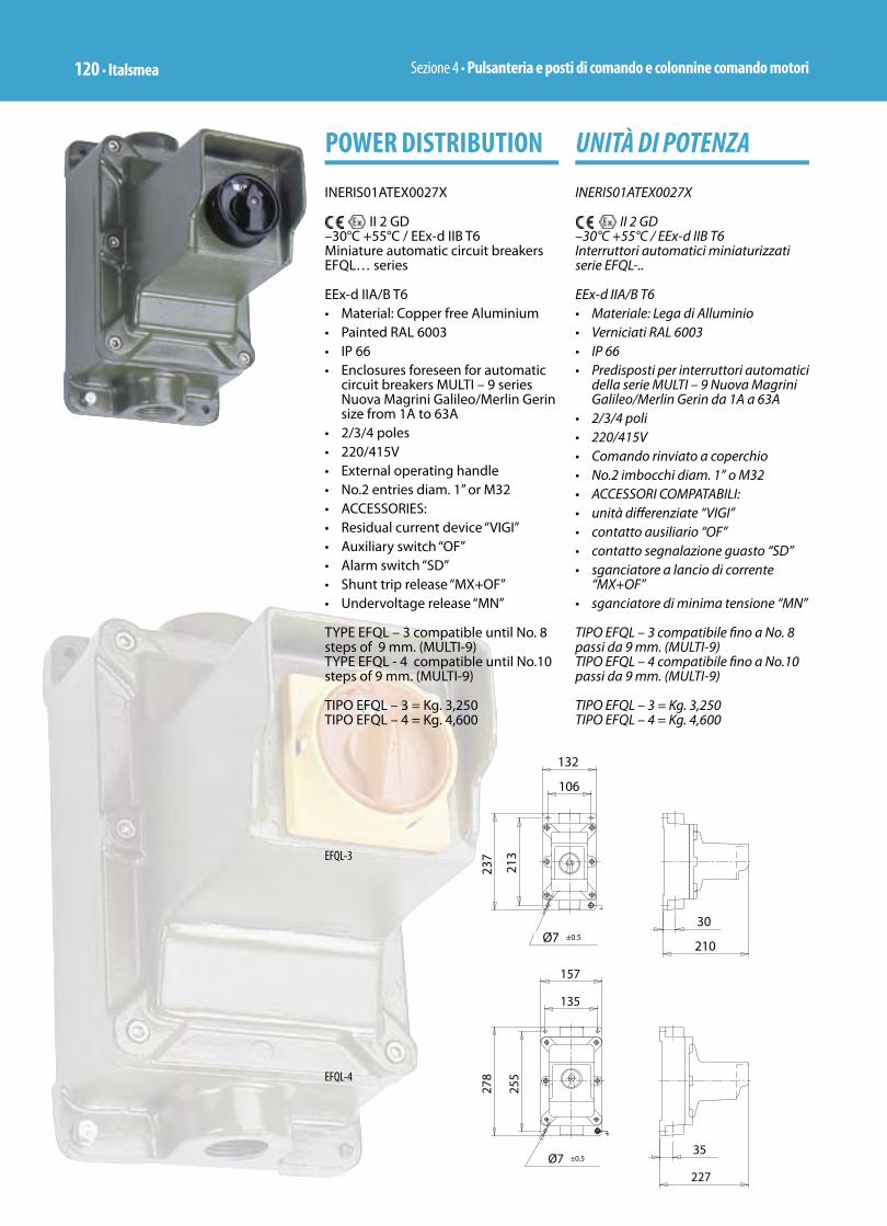
Sezione 4 • Pulsanteria e posti di comando e colonnine comando motori120 • Italsmea
UNITÀ DI POTENZA
INERIS01ATEX0027X
II 2 GD –30°C +55°C / EEx-d IIB T6Interruttori automatici miniaturizzati serie EFQL-..
EEx-d IIA/B T6 • Materiale: Lega di Alluminio• Verniciati RAL 6003• IP 66• Predisposti per interruttori automatici
della serie MULTI – 9 Nuova Magrini Galileo/Merlin Gerin da 1A a 63A
• 2/3/4 poli• 220/415V• Comando rinviato a coperchio• No.2 imbocchi diam. 1” o M32• ACCESSORI COMPATABILI: • unità diff erenziate “VIGI”• contatto ausiliario “OF”• contatto segnalazione guasto “SD”• sganciatore a lancio di corrente
“MX+OF”• sganciatore di minima tensione “MN”
TIPO EFQL – 3 compatibile fi no a No. 8 passi da 9 mm. (MULTI-9)TIPO EFQL – 4 compatibile fi no a No.10 passi da 9 mm. (MULTI-9)
TIPO EFQL – 3 = Kg. 3,250TIPO EFQL – 4 = Kg. 4,600
POWER DISTRIBUTION
INERIS01ATEX0027X
II 2 GD –30°C +55°C / EEx-d IIB T6Miniature automatic circuit breakers EFQL… series
EEx-d IIA/B T6• Material: Copper free Aluminium• Painted RAL 6003• IP 66• Enclosures foreseen for automatic
circuit breakers MULTI – 9 series Nuova Magrini Galileo/Merlin Gerin size from 1A to 63A
• 2/3/4 poles• 220/415V• External operating handle• No.2 entries diam. 1” or M32• ACCESSORIES: • Residual current device “VIGI”• Auxiliary switch “OF”• Alarm switch “SD”• Shunt trip release “MX+OF”• Undervoltage release “MN” TYPE EFQL – 3 compatible until No. 8 steps of 9 mm. (MULTI-9)TYPE EFQL - 4 compatible until No.10 steps of 9 mm. (MULTI-9)
TIPO EFQL – 3 = Kg. 3,250TIPO EFQL – 4 = Kg. 4,600
EFQL-3
EFQL-4
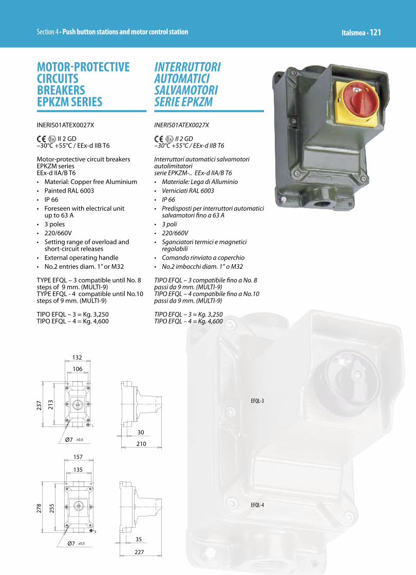
Section 4 • Push button stations and motor control station Italsmea • 121
INTERRUTTORI AUTOMATICI SALVAMOTORI SERIE EPKZM
INERIS01ATEX0027X
II 2 GD –30°C +55°C / EEx-d IIB T6
Interruttori automatici salvamotori autolimitatori serie EPKZM-.. EEx-d IIA/B T6 • Materiale: Lega di Alluminio• Verniciati RAL 6003• IP 66• Predisposti per interruttori automatici
salvamotori fi no a 63 A• 3 poli• 220/660V• Sganciatori termici e magnetici
regolabili • Comando rinviato a coperchio• No.2 imbocchi diam. 1” o M32
TIPO EFQL – 3 compatibile fi no a No. 8 passi da 9 mm. (MULTI-9)TIPO EFQL – 4 compatibile fi no a No.10 passi da 9 mm. (MULTI-9)
TIPO EFQL – 3 = Kg. 3,250TIPO EFQL – 4 = Kg. 4,600
MOTOR-PROTECTIVE CIRCUITS BREAKERS EPKZM SERIES
INERIS01ATEX0027X
II 2 GD –30°C +55°C / EEx-d IIB T6
Motor-protective circuit breakers EPKZM series EEx-d IIA/B T6• Material: Copper free Aluminium• Painted RAL 6003• IP 66• Foreseen with electrical unit
up to 63 A• 3 poles• 220/660V• Setting range of overload and
short-circuit releases • External operating handle• No.2 entries diam. 1” or M32
TYPE EFQL – 3 compatible until No. 8 steps of 9 mm. (MULTI-9)TYPE EFQL - 4 compatible until No.10 steps of 9 mm. (MULTI-9)
TIPO EFQL – 3 = Kg. 3,250TIPO EFQL – 4 = Kg. 4,600
EFQL-3
EFQL-4
Sezione 4 • Pulsanteria e posti di comando e colonnine comando motori122 • Italsmea
NOTE
Copyright © 2022 FDOKUMEN