Defender a universidade dos grilhões do controle e da burocracia
Upload
khangminh22Category
view
0download
0
Defender 6000 Indicators Instruction Manual
5 Commonwealth Ave Woburn, MA 01801 Phone 781-665-1400 Toll Free 1-800-517-8431
Visit us at www.TestEquipmentDepot.com


Defender 6000 Indicators EN-1
Table of Contents 1. INTRODUCTION ................................................................................................................................................ 3
1.1. SAFETY PRECAUTIONS ................................................................................................................................................... 3 1.2. INTENDED USE ............................................................................................................................................................ 3 1.3. OVERVIEW OF PARTS AND CONTROLS .............................................................................................................................. 4 1.4. MAINBOARD ............................................................................................................................................................... 5 1.5. CONTROL FUNCTIONS ................................................................................................................................................... 6
2. INSTALLATION .................................................................................................................................................. 9 2.1 UNPACKING ................................................................................................................................................................ 9 2.2 EXTERNAL CONNECTIONS............................................................................................................................................... 9 2.2.1 Scale Base with EasyConnectTM Connector...................................................................................................... 9 2.2.2 Power input to i-DT61PW ................................................................................................................................ 9 2.2.3 AC Power to i-DT61XWE .................................................................................................................................. 9 2.3 INTERNAL CONNECTIONS ............................................................................................................................................... 9 2.3.1 Opening the Housing ....................................................................................................................................... 9 2.3.2 Scale Base without EasyConnectTM Connector .............................................................................................. 11 2.3.3 Communication Interface Cable to i-DT61PW ............................................................................................... 14 2.3.4 RS232 Interface Cable to i-DT61XWE ............................................................................................................ 15 2.4 MOUNTING BRACKET.................................................................................................................................................. 15
3. OPERATION .................................................................................................................................................... 16 3.1 TURNING THE SCALE ON/OFF ....................................................................................................................................... 16 3.2 WEIGHING MODE ...................................................................................................................................................... 16 3.2.1 Enter the Mode and Start Weighing ............................................................................................................. 16 3.2.2 Accumulation and Statistics .......................................................................................................................... 16 3.2.3 Check ............................................................................................................................................................. 17 3.2.4 Application Settings ...................................................................................................................................... 18 3.3 COUNTING MODE ...................................................................................................................................................... 19 3.3.1 Enter the Mode ............................................................................................................................................. 19 3.3.2 Establish an APW .......................................................................................................................................... 19 3.3.3 Start Counting ............................................................................................................................................... 19 3.3.4 Application Settings ...................................................................................................................................... 19 3.4 PERCENT MODE ........................................................................................................................................................ 20 3.4.1 Enter the Mode ............................................................................................................................................. 20 3.4.2 Establish a Reference Weight ........................................................................................................................ 20 3.4.3 Start Percent Weighing ................................................................................................................................. 20 3.4.4 Application Settings ...................................................................................................................................... 20 3.5 DYNAMIC MODE ........................................................................................................................................................ 21 3.5.1 Enter the Mode ............................................................................................................................................. 21 3.5.2 Start Dynamic Weighing ............................................................................................................................... 21 3.5.3 Application Settings ...................................................................................................................................... 21 3.6 FILLING MODE........................................................................................................................................................... 22 3.6.1 Enter the Mode ............................................................................................................................................. 22 3.6.2 Start Filling .................................................................................................................................................... 22 3.6.3 Resume and Pause Filling .............................................................................................................................. 22 3.6.4 Display of the Dot Matrix Screen ................................................................................................................... 22 3.6.5 Application Settings ...................................................................................................................................... 23
4. MENU SETTINGS ............................................................................................................................................. 24 4.1 MENU NAVIGATION ................................................................................................................................................... 24 4.1.1 User Menu ..................................................................................................................................................... 24 4.1.2 Button Navigation ......................................................................................................................................... 25 4.2 CALIBRATION MENU ................................................................................................................................................... 26 4.2.1 Initial Calibration ........................................................................................................................................... 26 4.2.2 Zero Calibration [ZErO] .................................................................................................................................. 26 4.2.3 Span Calibration [SpaN] ................................................................................................................................. 26 4.2.4 Linearity Calibration [LIN] ............................................................................................................................. 27 4.2.5 GEO Adjustment [GEO] ................................................................................................................................... 27 4.2.6 Calibration Test [C.test] ............................................................................................................................... 28

EN-2 Defender 6000 Indicators
4.2.7 End Cal [End] ................................................................................................................................................. 28 4.3 SETUP MENU ............................................................................................................................................................ 29 4.4 READOUT MENU ....................................................................................................................................................... 33 4.5 UNIT MENU .............................................................................................................................................................. 35 4.6 GLP/GMP MENU ..................................................................................................................................................... 35 4.7 COMMUNICATION ...................................................................................................................................................... 36 4.7.1 RS232 Menu .................................................................................................................................................. 36 4.7.2 Print Menu .................................................................................................................................................... 37 4.7.3 RS485 Configuration ..................................................................................................................................... 40 4.7.4 Ethernet Configuration .................................................................................................................................. 40 4.7.5 Analog Configuration .................................................................................................................................... 40 4.8 MEMORY ................................................................................................................................................................. 40 4.8.1 Memory menu (for i-DT61PW model) ........................................................................................................... 40 4.8.2 USB memory (for i-DT61XWE model) ............................................................................................................ 40 4.8.3 Alibi Memory (for i-DT61XWE model) ........................................................................................................... 41 4.9 DISCRETE I/O (FOR I-DT61XWE MODEL) ...................................................................................................................... 46 4.9.1 I/O Type ......................................................................................................................................................... 46 4.9.2 Input .............................................................................................................................................................. 47 4.9.3 Output ........................................................................................................................................................... 47 4.10 LOCK KEY CONFIGURATION .......................................................................................................................................... 47 4.11 LIBRARY (FOR I-DT61XWE MODEL) .............................................................................................................................. 48 4.12 USER (FOR I-DT61XWE MODEL) .................................................................................................................................. 50 4.13 USB (FOR I-DT61XWE MODEL) .................................................................................................................................. 52 4.13.1 USB Flash Drive ............................................................................................................................................. 52 4.13.2 RFID ............................................................................................................................................................... 52 4.13.3 Barcode ......................................................................................................................................................... 52 4.13.4 Keyboard ....................................................................................................................................................... 52 4.13.5 Wi-Fi/Bluetooth Dongle (Optional) ............................................................................................................... 53
5. LEGAL FOR TRADE ........................................................................................................................................... 55 5.1 SETTINGS .................................................................................................................................................................. 55 5.2 VERIFICATION ............................................................................................................................................................ 55 5.3 SEALING ................................................................................................................................................................... 55
6. MAINTENANCE ............................................................................................................................................... 57 6.1 CLEANING ................................................................................................................................................................. 57 6.1.1 Cleaning for i-DT61PW Model ....................................................................................................................... 57 6.1.2 Cleaning for i-DT61XWE Model ..................................................................................................................... 57 6.2 TROUBLESHOOTING .................................................................................................................................................... 58 6.3 SERVICE INFORMATION ............................................................................................................................................... 58
7. TECHNICAL DATA ............................................................................................................................................ 59 7.1 SPECIFICATIONS ......................................................................................................................................................... 59 7.2 TABLE OF GEO VALUES ................................................................................................................................................ 61
8. COMPLIANCE .................................................................................................................................................. 62 9. APPENDICES ................................................................................................................................................... 64
9.1 APPENDIX A .............................................................................................................................................................. 64 9.2 APPENDIX B .............................................................................................................................................................. 66

Defender 6000 Indicators EN-3
1. INTRODUCTION This manual contains installation, operation and maintenance instructions for i-DT61PW and i-DT61XWE indicators. Please read it completely before installation and operation.
1.1. Safety Precautions Definition of Signal Warnings and Symbols Safety notes are marked with signal words and warning symbols. These show safety issues and warnings. Ignoring the safety notes may lead to personal injury, damage to the instrument, malfunctions and false results.
WARNING For a hazardous situation with medium risk, possibly resulting in severe injuries or death if not avoided.
CAUTION For a hazardous situation with low risk, resulting in damage to the device or the property or in loss of data, or minor or medium injuries if not avoided.
ATTENTION For important information about the product. May lead to equipment damage if not avoided.
NOTE For useful information about the product. Warning Symbols
General hazard Explosion hazard
Electrical shock hazard
Safety Precautions CAUTION: Read all safety warnings before installing, making connections, or servicing this equipment. Failure to comply with these warnings could result in personal injury and/or property damage. Retain all instructions for future reference.
Before connecting power, verify that the AC adapter’s input voltage range and plug type are compatible with the local AC mains power supply.
Do not position the equipment such that it is difficult to reach the power connection. Only connect the power cord to a compatible grounded electrical outlet. Make sure that the power cord does not pose a potential obstacle or tripping hazard. Operate the equipment only under ambient conditions specified in these instructions. The equipment is for indoor use only. Do not operate the equipment in hazardous or unstable environments. Do not place the equipment upside down on the platform. Use only approved accessories and peripherals. Disconnect the equipment from the power supply when cleaning. Service should only be performed by authorized personnel.
WARNING: Never work in an environment subject to explosion hazards! The housing of the instrument is not gas tight. (Explosion hazard due to spark formation, corrosion caused by the ingress of gases).
WARNING: Electrical shock hazards exist within the housing. The housing should only be opened by authorized and qualified personnel. Remove all power connections to the unit before opening.
1.2. Intended Use This instrument is intended for use in light industry. It must only be used for measuring the parameters described in these operating instructions. Any other type of use and operation beyond the limits of technical specifications, without written consent from OHAUS, is considered as not intended. This instrument complies with current industry standards and the recognized safety regulations; however, it can constitute a hazard in use. If the instrument is not used according to these operating instructions, the intended protection provided by the instrument may be impaired.
EN-4 Defender 6000 Indicators
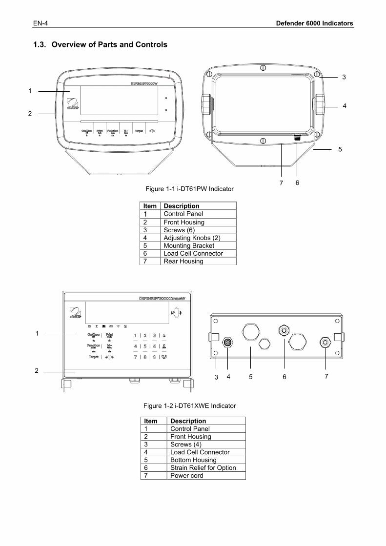
1.3. Overview of Parts and Controls
Figure 1-1 i-DT61PW Indicator
Figure 1-2 i-DT61XWE Indicator
Item Description 1 Control Panel 2 Front Housing 3 Screws (4) 4 Load Cell Connector 5 Bottom Housing 6 Strain Relief for Option 7 Power cord
Item Description 1 Control Panel 2 Front Housing 3 Screws (6) 4 Adjusting Knobs (2) 5 Mounting Bracket 6 Load Cell Connector 7 Rear Housing
1
2
3
4
5
6 7
1v
2 3 4 5 6 7

Defender 6000 Indicators EN-5
1.4. Mainboard
.Figure 1-3 i-DT61PW Mainboard
Item Description 1 IR Communication connector (J6) 2 Security Switch (SW1) 3 Load Cell connector (J7) 4 Load Cell Terminal Block (J8)
Figure 1-4 i-DT61XWE Mainboard
Item Description Item Description 1 Alibi Memory Board connector (J19) 6 Keyboard connector (J1)
2 Discrete I/O/Analog/RS232-RS485-USB Device connector (J11) 7 Load Cell connector (J12)
3 Display Board connector (J2) 8 Load Cell Terminal Block (J3) 4 Ethernet connector (J10) 9 Security Switch connector (SW1) 5 RS232 connector (J5) 10 Discrete Input0 (J16)
1 2
3
4
1 2 3
4
5 6
9
7
8
10

EN-6 Defender 6000 Indicators
1.5. Control Functions
i-DT61PW Control Panel i-DT61XWE Control Panel
Button
Primary Function (Short Press)
On/Zero If the terminal is Off, press to power on;
If the terminal is On, press to set the zero point.
Print Sends the current value to the selected COM ports if AUTOPRINT is disabled.
Function Initiates an application mode.
M+ Accumulates the weight or displays the accumulated information with no load on the pan.
Target Sets under/over limit value for Check.
Tare Enters/clears a tare value;
When the accumulation data is displayed, press to clear them.
Secondary Function (Long Press)
Off If the terminal is On, press to power off.
Units Changes the weighing unit.
Mode Allows changing the application mode.
Menu Enters the user menu.
Target Shows under/over limit value for Check.
Tare Displays the tare weight.
Menu Function (Short Press)
Yes Accepts the current setting on the display.
No Advances to the next menu or menu item.
Rejects the current setting on the display and advances to the next available one.
Back Moves back to the previous menu item.
Exit Exits the user menu.
Aborts the calibration in progress.
Notes: Short Press: press less than 1 second. Long Press: press and hold for more than 2 seconds.
Defender 6000 Indicators EN-7
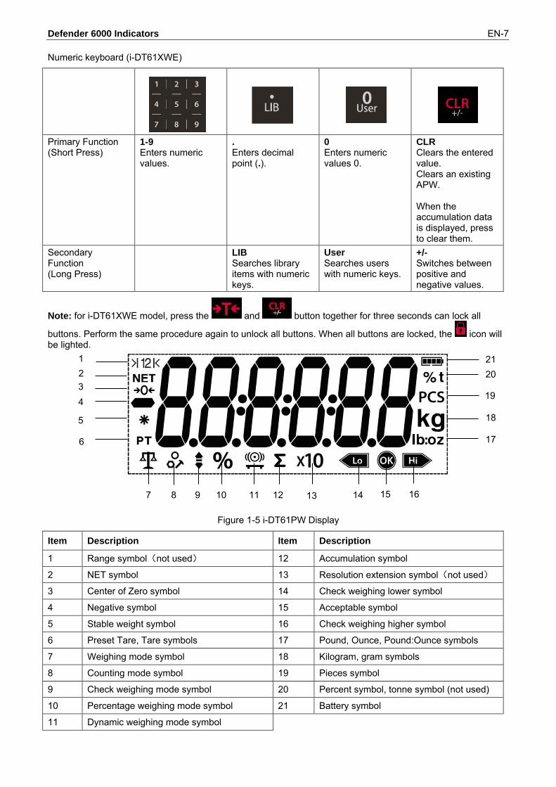
Numeric keyboard (i-DT61XWE)
Primary Function (Short Press)
1-9 Enters numeric values.
. Enters decimal point (.).
0 Enters numeric values 0.
CLR Clears the entered value. Clears an existing APW. When the accumulation data is displayed, press to clear them.
Secondary Function (Long Press)
LIB Searches library items with numeric keys.
User Searches users with numeric keys.
+/- Switches between positive and negative values.
Note: for i-DT61XWE model, press the and button together for three seconds can lock all
buttons. Perform the same procedure again to unlock all buttons. When all buttons are locked, the icon will be lighted.
Figure 1-5 i-DT61PW Display
Item Description Item Description
1 Range symbol(not used) 12 Accumulation symbol
2 NET symbol 13 Resolution extension symbol(not used)
3 Center of Zero symbol 14 Check weighing lower symbol
4 Negative symbol 15 Acceptable symbol
5 Stable weight symbol 16 Check weighing higher symbol
6 Preset Tare, Tare symbols 17 Pound, Ounce, Pound:Ounce symbols
7 Weighing mode symbol 18 Kilogram, gram symbols
8 Counting mode symbol 19 Pieces symbol
9 Check weighing mode symbol 20 Percent symbol, tonne symbol (not used)
10 Percentage weighing mode symbol 21 Battery symbol
11 Dynamic weighing mode symbol
1 2 3 4
5
6
7 8 9 10 11 12 13 14 15 16
17
18
19
20 21

EN-8 Defender 6000 Indicators
Figure 1-6 i-DT61XWE Display
Item Description Item Description
1 NET symbol 11 Wi-Fi symbol
2 Center of Zero symbol 12 Lock symbol
3 Negative symbol 13 Dynamic (tilde) symbol
4 Stable weight symbol 14 Battery symbol (not use)
5 Preset Tare, Tare symbols 15 Pound, Ounce, Pound:Ounce symbols
6 Pointer symbols 16 Percent symbol
7 ID symbol 17 Kilogram, gram symbols
8 Accumulation symbol 18 Pieces symbol, tonne symbol (not used)
9 Library symbol 19 Scale symbol (not used)
10 User symbol
1 2 3 4 5
6
7 8 9 10 11 12 13
14 15 16 17 18
19

Defender 6000 Indicators EN-9
2. INSTALLATION 2.1 Unpacking Unpack the following items:
i-DT61PW or i-DT61XWE indicator 6 cells of D size dry batteries (i-DT61PW only) Mounting bracket Knobs (2) Quick installation guide Instruction manual
2.2 External Connections 2.2.1 Scale Base with EasyConnectTM Connector To connect the OHAUS scale base with EasyConnectTM connector to the terminal, plug the base's connector onto the external load cell connector located at the bottom of the terminal. Then rotate the base connector’s locking ring clockwise. Check the following illustration for details.
2.2.2 Power input to i-DT61PW Use 6 cells of D size dry batteries. During battery operation, the battery symbol indicates the battery status.
Battery 5%~25% remaining
Battery 25%~50% remaining
Battery 50%~75% remaining
Battery 75%~100% remaining
2.2.3 AC Power to i-DT61XWE Connect the AC plug to an electrical outlet.
2.3 Internal Connections Some connections require the housing to be opened.
2.3.1 Opening the Housing CAUTION: ELECTRICAL SHOCK HAZARD. REMOVE ALL POWER CONNECTIONS TO THE INDICATOR BEFORE SERVICING OR MAKING INTERNAL CONNECTIONS. THE HOUSING SHOULD ONLY BE OPENED BY AUTHORIZED AND QUALIFIED PERSONNEL, SUCH AS AN ELECTRICAL TECHNICIAN.
i-DT61PW 1. Remove the six Phillips head screws from the rear housing. 2. Remove the front housing. Be careful not to disturb the internal connections.
i-DT61XWE
i-DT61PW

EN-10 Defender 6000 Indicators
3. Once all connections are made, re-attach the front housing. i-DT61XWE 1. Remove the four hex head screws from the bottom housing.
2. Open the housing by carefully pulling the bottom housing backward.
3. Once all connections are made, re-attach the bottom housing.
Note: The screws should be tightened to 2.5 N•m (20-25 in-lb) torque to ensure a watertight seal.

Defender 6000 Indicators EN-11
2.3.2 Scale Base without EasyConnectTM Connector For connecting bases (which do not have the EasyConnectTM connector) to an i-DT61PW or an i-DT61XWE, a load cell cable gland kit (P/N 30379716) is available as an accessory. Removing the pre-installed Load Cell connector and wiring harness. Before making the connections, remove the pre-installed load cell connector and wiring harness by following the following steps. i-DT61PW
1. Remove the 6 Phillips head screws, and open the rear housing by carefully pulling the front housing forward.
2. Unplug the white load cell connectors from the main housing (two circles).
3. Open the front housing by removing the 12 Phillips head screws. 4. Unplug the white load cell connectors from the main PCBA board.

EN-12 Defender 6000 Indicators
i-DT61XWE 1. Place the terminal down, and unscrew the screws marked in the following graphic.
2. Pull out the bottom of the terminal.
3. Use a screw driver to unscrew the sealing cover.

Defender 6000 Indicators EN-13
4. Pull the protruding part of the sealing cover a little forward to release it.
5. Remove the sealing cover and then unplug the white load cell connectors.
Installing Load Cell Cable and Connectors In order to meet certain electrical noise emission limits and to protect i-DT61PW and i-DT61XWE from external influences, it is necessary to install a ferrite core on the load cell cable connected to the terminal. The ferrite core is included with the terminal. To install the ferrite, simply route the cable through the center of the core and then take one wrap around the outside of the core and route the cable through the center again. Either the complete cable or the individual wires can be wrapped through the ferrite. This should be done as close to the enclosure as possible. See Figure 2-1.
Figure 2-1

EN-14 Defender 6000 Indicators
Load Cell Terminal Blocks
Main Board Wiring Connections Once the i-DT61PW and i-DT61XWE enclosure is opened, connections can be made to the terminal blocks on the main board as shown in Figure 2-2.
i-DT61PW i-DT61XWE
Figure 2-2
Jumper Connections The i-DT61PW and i-DT61XWE indicators are designed to support both 2mV/V and 3mV/V load cells from the same circuitry. A load cell output rating selection jumper is not required. Figure 2-3 shows the terminal definitions for the analog load cell terminal blocks. Note that when using four -wire load cells, jumpers must be placed between the +Excitation and +Sense terminals and between the -Excitation and -Sense terminals.
Figure 2-3 Jumper Connections
After wiring is completed, replace the indicator housing screws. Make sure the water-proof cable gland is properly tightened.
2.3.3 Communication Interface Cable to i-DT61PW Attach the IR Communication cable (P/N: 30572910) to the indicator front panel, make sure the two holes in the interface cable module match the two bolts which located in the front panel.
Pin Connection J3-1 +EXC J3-2 +SEN J3-3 +SIN J3-4 GND J3-5 -SIN J3-6 -SEN J3-7 -EXC
Figure 2-4
J3-1
J3-2
J3-3
J3-4
J3-5
J3-6
J3-7

Defender 6000 Indicators EN-15
2.3.4 RS232 Interface Cable to i-DT61XWE Pass the optional RS232 cable through the strain relief and attach it to the RS232 connector on the mainboard. Tighten the strain relief to maintain a watertight seal. Please refer to Figure 2-7 for the postion of the serial port connector RXD TXD and GND. Note:
Please refer to Opeing the Housing section for how to open the case of the terminal. For details about Discrete Input0 function, please refer to the Discrete I/O (for i-DT61XWE) section for
details.
2.4 Mounting Bracket Attach the bracket to a wall or table using fasteners (not supplied) that are appropriate for the type of mounting surface. The bracket will accommodate up to 6 mm (1/4”) diameter screws. Locate the mounting holes as shown in Figure 2-8 and 2-9.
Figure 2-8 i-DT61PW Mounting Bracket Dimensions
RS232 connector
Figure 2-5 Strain Relief for Option
Figure 2-6 RS232 connector on the mainboard
Figure 2-9 i-DT61XWE Mounting Bracket Dimensions
Figure 2-7 RS232 connector
Discrete Input0
EN-16 Defender 6000 Indicators
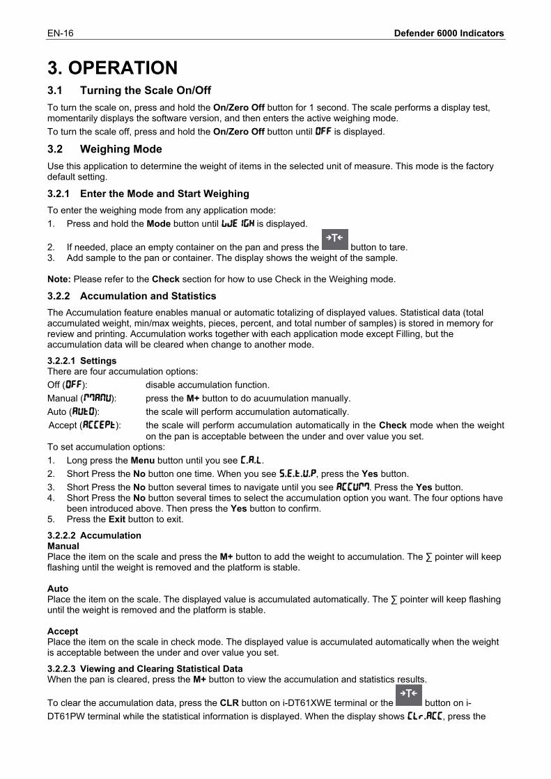
3. OPERATION 3.1 Turning the Scale On/Off To turn the scale on, press and hold the On/Zero Off button for 1 second. The scale performs a display test, momentarily displays the software version, and then enters the active weighing mode. To turn the scale off, press and hold the On/Zero Off button until OFF is displayed.
3.2 Weighing Mode Use this application to determine the weight of items in the selected unit of measure. This mode is the factory default setting.
3.2.1 Enter the Mode and Start Weighing To enter the weighing mode from any application mode: 1. Press and hold the Mode button until wWeIGH is displayed.
2. If needed, place an empty container on the pan and press the button to tare. 3. Add sample to the pan or container. The display shows the weight of the sample.
Note: Please refer to the Check section for how to use Check in the Weighing mode.
3.2.2 Accumulation and Statistics The Accumulation feature enables manual or automatic totalizing of displayed values. Statistical data (total accumulated weight, min/max weights, pieces, percent, and total number of samples) is stored in memory for review and printing. Accumulation works together with each application mode except Filling, but the accumulation data will be cleared when change to another mode.
3.2.2.1 Settings There are four accumulation options: Off (OFF): disable accumulation function. Manual (mMANU): press the M+ button to do acuumulation manually. Auto (AUtO): the scale will perform accumulation automatically. Accept (ACCEPt): the scale will perform accumulation automatically in the Check mode when the weight
on the pan is acceptable between the under and over value you set. To set accumulation options: 1. Long press the Menu button until you see C.A.L. 2. Short Press the No button one time. When you see S.E.t.U.P, press the Yes button. 3. Short Press the No button several times to navigate until you see ACCUmM. Press the Yes button. 4. Short Press the No button several times to select the accumulation option you want. The four options have
been introduced above. Then press the Yes button to confirm. 5. Press the Exit button to exit.
3.2.2.2 Accumulation Manual Place the item on the scale and press the M+ button to add the weight to accumulation. The ∑ pointer will keep flashing until the weight is removed and the platform is stable. Auto Place the item on the scale. The displayed value is accumulated automatically. The ∑ pointer will keep flashing until the weight is removed and the platform is stable. Accept Place the item on the scale in check mode. The displayed value is accumulated automatically when the weight is acceptable between the under and over value you set. 3.2.2.3 Viewing and Clearing Statistical Data When the pan is cleared, press the M+ button to view the accumulation and statistics results.
To clear the accumulation data, press the CLR button on i-DT61XWE terminal or the button on i-DT61PW terminal while the statistical information is displayed. When the display shows Clr.aCC, press the

Defender 6000 Indicators EN-17
Yes button to clear the stored data and return to current mode. Notes: The item must be removed from the pan before the next item can be accumulated. Only stable weights are stored. Changing modes will clear the stored accumulation data. When Legal for Trade is turned ON, for NTEP, gross and net weight cannot be added to the same total.
If the first weight is recorded in gross, the future ones should be recorded in the same way. It is the same for net weight.
3.2.3 Check Use this application to compare the weight of items to a target weight range. This mode is available for Weighing, Counting, Percent, and Dynamic.
3.2.3.1 Set Check Limits i-DT61PW 1. Press the Target button from Weighing, Counting, Percent or Dynamic mode to set check limits. 2. The display shows UNDEr. 3. Press the Yes button to edit the under value. 4. If there is a stored under value of the last time, the display will show it. For example: 1.0kg.
Press the Yes button if you want to use this value. Then the display shows OuEr. Press the No button if you do not want to use this value, and skip to step 6.
5. If there is no stored value, the display shows 000000. 6. To set a new under value, short press the No button several times until the desired number appears. Short
press the Yes button to accept the number and move to the next digit. Repeat the process until all the digits are correct. Press the Yes button to accept the value. Then the display shows OuEr.
7. Repeat step 2 to 6 to set the over value. 8. If the values you set are invalid, the display will show --NO-- and go back to reset. 9. If the values you set are valid, the display will go to check weighing screen.
i-DT61XWE 1. Press the Target button from Weighing, Counting, Percent or Dynamic mode to set check limits. 2. The display shows UNDEr. 3. Press the Yes button to edit the under value. 4. If there is a stored under value of the last time, the display will show it.
Press the Yes button if you want to use this value. Press the No button if you do not want to use this value or do not have a stored value. Input the
needed one with the numeric keypad. Press the Yes button to accept the under value. 5. The display will show OuEr. 6. Repeat step 2 and 3 to set the over value. 7. If the values you set are invalid, the display will show --NO-- and go back to reset. 8. If the values you set are valid, the display will go to check weighing screen.
3.2.3.2 Positive Check Positive check is used to determine when the material added to the scale is within the target range. In this case the under and over values must be positive values. (The over value must be greater than the under value.) Add material to the scale platform until the display shows it is within the Accept (green) range.
3.2.3.3 Negative Check Negative check is used to determine when the material removed from the scale is within the target range. In this case the under and over values are both negative values. The under value must be greater than the over value. (For example: the under value is -10; the over value is -15).
Place the item to be weighed on the scale and press the button. Remove a portion of the item until it is within the acceptable range.
3.2.3.4 Zero Check Zero check is used when comparing subsequent samples to an initial reference sample. In this case, the under value must be a negative value and the over value must be a positive one.
Place the reference item on the scale and press the button. Remove material from the scale platform until the display shows it is within the Accept (green) range.

EN-18 Defender 6000 Indicators
3.2.3.5 Clear Check Limits Long press the Target button until the display shows the under and over values.
Press the CLR button of i-DT61XWE indicator or the button of i-DT61PW indicator, the display shows Clr.CHk. Press the Yes button to clear both the under and over values.
3.2.4 Application Settings The application can be customized for user preferences. To enter application settings: 1. Long press the Menu button until you see C.A.L. Short press the No button several times until you see
mM.O.d.E. Press the Yes button to enter the application mode settings. 2. Short press the No button several times to navigate until you see the selection you want. 3. Press the Yes button to select. 4. Repeat step 2 and 3 several times until you finish all settings. 5. Press the Exit button to exit.
The Weighing Configurations are defined below (defaults in Bold). Item Available Settings Comments Weighing (wWeIGH) On, Off To enable Weighing Note: you cannot disable Weighing if you are in the mode currently.

Defender 6000 Indicators EN-19
3.3 Counting Mode Use this application to count samples of uniform weight.
3.3.1 Enter the Mode To enter the mode: 1. Press and hold the Mode button until COUNt is displayed. 2. When the Mode button is released, the display shows CLr.PwW. 3. If you need to clear the stored APW of the last time, press the Yes button. Then go to Establish an APW
section. Note: if the weight on the pan is larger than 1d, the display will show CLr.PAN until the weight is removed from the pan.
4. If you need to recall the stored APW of the last time and continue to use it, press the No button to start counting. Note: if no APW has been set before, step 3 and 4 will be omitted.
3.3.2 Establish an APW To establish an APW: 1. Follow the previous step 4.
i-DT61PW: The display shows the sample size PUt.10. To change it, short press the No button several times until you see the value you want. Note: available sample size selections are 5, 10, 20, 50 and 100 (The default is 10). i-DT61XWE: The display flashes with the current sample size, such as 10 Pcs. To change it, input the new sample size through the numeric keyboard. Do not press the Yes button until you finish the next step.
2. Place the specified quantity of samples on the pan and press the Yes button to capture the current stable weight.
Note: During the capture process, the display shows - - - - -. (i-DT61PW)
You can press the button to tare. The center of zero, PT or NET icons will light as appropriate. If the APW is between 0.1d and 1d, the display shows LO.rEF for 1.5 seconds. Then it will start counting. If the APW is less than 0.1d, the display shows rEF.Err for 1.5 seconds and then return to showing what
is displayed on step 1. Please replace the samples on the pan and press the Yes button to re-establish an APW value.
3.3.3 Start Counting 1. Place parts on the pan and read the number. The number of pieces and the Pcs icon are displayed. 2. Press the Function button to temporarily display the APW. APwW is displayed for 0.5 seconds. Then the
APW value is displayed for 1.5 seconds using the current unit of measurement.
Note: Please refer to Check in the Weighing Mode section for how to use Check in the Counting mode.
3.3.4 Application Settings The application can be customized for user preferences. Please refer to Application Settings section in Weighing Mode for details about how to enter application settings. The Counting Configurations are defined below (defaults in Bold). Item Available Settings Comments Count (COUNt) On, Off To enable Counting
Auto Opt.(A.OPt) On, Off Off: Auto Opt. is off. On: The APW will be optimized automatically during count weighing.
Note: you cannot disable Count if you are in the mode currently.

EN-20 Defender 6000 Indicators
3.4 Percent Mode Use this application to measure the weight of a sample displayed as a percentage of a pre-established reference weight.
3.4.1 Enter the Mode To enter the percent mode from any application mode: 1. Press and hold the Mode button until PErCNt is displayed. 2. When the Mode button is released, the display shows CLr.rEF and the % icon. 3. If you need to clear the stored reference weight of the last time, press the Yes button. Then go to step 5.
Note: If captured weight is more than or equal to 1d or is less than or equal to -1d, the display will show CLr.PAN until the sample is removed from the pan.
4. If you need to recall the stored reference weight of the last time and continue to use it, press the No button and start percent weighing. Note: If no reference weight has been previously stored, step 3 and 4 will be omitted.
5. The display shows the PUt.rEF and the % icon.
3.4.2 Establish a Reference Weight To establish a reference weight: Follow the previous step 5. When you see PUt.rEF displayed on the screen, place the specified quantity of samples on the pan and press the Yes button to capture the current stable weight. Note: You can press the【】 button to tare. The center of zero, PT or NET icons will light as appropriate. For i-DT61PW model, during the capture process, the display shows - - - - -. If the reference weight is less than 100d during the capture process, the display will show rEF.Err for 1.5
seconds and then return to showing PUt.rEF. Please replace the samples on the pan and press the Yes button to re-establish a reference weight.
3.4.3 Start Percent Weighing 1. Place a sample on the pan and read the percent. The current percent value and % icon are displayed. 2. Press the Function button to temporarily display the reference weight. rEF.wWt is displayed for 0.5
seconds. Then the reference weight value is displayed for 1.5 seconds in the current unit of measurement.
Note: Please refer to Check in the Weighing Mode section for how to use Check in the Percent Weighing mode.
3.4.4 Application Settings The application can be customized for user preferences. Please refer to Application Settings section in Weighing Mode for details about how to enter application settings. The Percent Weighing Configurations are defined below (defaults in Bold).
Note: you cannot disable Percent if you are in the mode currently.
Item Available Settings Comments Percent (PerCNt) On, Off To enable Percent Weighing

Defender 6000 Indicators EN-21
3.5 Dynamic Mode Use this application to weigh an unstable load, such as a moving animal.
3.5.1 Enter the Mode To enter the Dynamic Weighing Mode from any application mode: 1. Press and hold the Mode button until dYNAmM is displayed. 2. The display shows rEADY.
3.5.2 Start Dynamic Weighing 1. To start:
When operation type is manual. Place the load (more than or equal to 5d) on the pan and press the Function button to start the averaging process.
When operation type is semi-automatic/automatic. Place the load (more than or equal to the Start Weight) on the pan, and the terminal will start averaging process automatically Note: The display must be at zero gross or net value before placing the load on the pan.
2. During the averaging period, the countdown timer decreases in one second increments (For example, the set average time is 5s). Note: If the set average time is 0s, the countdown timer is not displayed.
3. The readings are averaged and held on the display when the countdown has completed in both Countdown and Continuous mode. In addition, for DT61XWE model: The tilde symbol will blink indicating that the current weight is being held in Countdown Mode. The tilde symbol will blink indicating that the current weight is being averaged in real time in Continuous
Mode. Note: If the set average time is 0s, the first weight larger than 5d will be displayed and hold.
4. To reset the countdown timer: When the operation type is manual/semi-automatic, press the Function button to reset the countdown
timer when the countdown is running. The display shows rEAdY, and start to re-count. When operation type is automatic, remove the load from the pan, and the average weight will still be
displayed until the duration time is over. Then the display shows rEAdY, and start to re-count. Note: The rEADY display must be at zero gross or net value in order to reset the countdown timer. Please refer to Check in the Weighing Mode section for how to use Check in the Dynamic
Weighing mode.
3.5.3 Application Settings The application can be customized for user preferences. Please refer to Application Settings section in Weighing Mode for details about how to enter application settings. The Dynamic Weighing Configurations are defined below (defaults in Bold). Item Available Settings Comments Dynamic Mode(dyNAmM)
Countdown (C.DOwWN)/ Continues (CONt)/ Off (OFF)
Count down: There is a countdown time. Continuous: Averaging will be continued after the countdown time.
Dynamic Operation Type (d.tyPE)
Manul (mMAN)/ Semi-auto (semMI)/ Auto (AUtO)
Manual: The averaging process is started and reset manually. Semi-auto: The averaging process is started automatically and reset manually. Auto: The averaging process is started and reset automatically.
Start Weight (S.wWGt)
0 ~ Capacity Weight Dynamic weighing will start when the load is bigger than the start weight (for Semi-auto and Auto mode).
Duration Time (d.tImME)
1 ~ 10 s It is the time for the display to remain the dynamic weighing result after the load is removed.
Average Time (A.tImME)
0 ~ 30 s Time in Seconds. If the average time is 0, the first stable weight (more than or equal to 5d) will be the result.

EN-22 Defender 6000 Indicators
Note: you cannot disable Dynamic if you are in the mode currently.
3.6 Filling Mode Use this application to fill a container to a pre-determined target weight. Note: filling mode is only available for i-DT61XWE model.
3.6.1 Enter the Mode To enter the Filling mode from any application mode: 1. Press and hold the Mode button until FIll is displayed. 2. The actual weight is displayed on the display.
3.6.2 Start Filling 1 When the scale is in stop or pause status, press the Function button to start filling process. The output
port will be enabled. 2 Add weight on the pan. When one set point (SP1/SP2/SP3/SP4) is reached, the related output port will be
disabled. 3 When the scale is in start or pause status, press the Function button to stop filling process. The output
port will be all disabled.
3.6.3 Resume and Pause Filling 1 When the scale is in pause status, press the Target button to resume the filling process. The output port
will be enabled or disabled according to the current load value. 2 When the scale is in start status, press the Target button to pause the filling process. The output port will
be all disabled, and the display will be frozen.
3.6.4 Display of the Dot Matrix Screen The Dot Matrix Display will be divided into one to four columns according to how many set points (SP) are valid. The maximum is four columns. For example, if you set four SPs, then the screen will be divided into four columns. In addition, the screen will display different colors according to the load value. For example: 1. You set four valid SP values and SP1 is less than SP2, SP2 less than SP3,
SP3 less than SP4. Then the screen will be divided into four columns.
2. To start filling, if the first load is less than SP1, the first column displays
orange, and others red.
3. If continue to fill the second time, and the total load is now more than or equal to SP1 while less than SP2, the first column displays green, the second orange, and others red.

Defender 6000 Indicators EN-23
4. After that to fill the third time, if the total load is now more than or equal to SP2 while less than SP3, the first two columns display green, the third orange, and others red.
5. To load the fourth time, if the total load is now more than or equal to SP3 while less than SP4, the first three columns display green, and the forth one orange.
6. Nevertheless, if the total load is more than SP4, all the four columns turn to red and the instrument will be in a stop state.
3.6.5 Application Settings The application can be customized for user preferences. Please refer to Application Settings section in Weighing Mode for details about how to enter application settings. The Filling Configurations are defined below (defaults in Bold)
Note: you cannot disable Filling if you are in the mode currently.
Item Available Settings Comments Filling (FIll) On, Off To enable Filling Weighing

EN-24 Defender 6000 Indicators
4. MENU SETTINGS The User Menu allows the customizing of scale settings. Note: Additional Sub-Menus may be available if Interface Options are installed. See Interface User Manual for the additional setting information.
4.1 Menu Navigation 4.1.1 User Menu For i-DT61PW model C.A.L S.E.t.U.P r.E.A.d mM.O.d.E U.n.i.t G.mM.P R.s.2.3.2 P.r.I.N.t L.o.c.k E.n.d
ZErO
SpaN
LINE
GEO
C.test
End
reset
C.UNIt
CAP
Grad
P.ZerO
P.UNIt
A.tare ACCUmM
t.CNt
t.NEXt
End
reset
Stable
ZErO
FIltEr
AZt
B.LIGHt
S.SAuEr
A.Off
P.SAuER
End
reset
wWeIGH
COUNt
A.Opt
PErCNt
dyNAmM
d.tyPE
d.tImME
A.tImME
End
reset kg g lb oz
lb;oz End
reset
d.FmMt
dAtE
t.FmMt
tImMe
p.Id
S.ID
End
reset
BAUd
PArItY
StOP
H.SHAKE
ALt.P
ALt.t
ALt.Z
End
reset
ASSIGN
Stable
mMODE
tImME
C.SUmM
tEmMp
End
reset
L.ALL
L.OFF
L.ZErO
L.PrINt
L.UNIt
L.mModE
L.mMeNU
L.tArE
L.tArGe
End
For i-DT61XWE model
C.A.L S.E.t.U.P r.E.A.d mM.O.d.E U.n.i.t G.mM.P R.s.2.3.2 P.r.I.N.t I.O. L.o.c.k L.I.b U.S.E.r U.S.B E.n.d
ZErO
SpaN
LINE
GEO
C.test
End
reset
C.UNIt
raNGe
CAP1
Grad1
CAP2
Grad2
P.ZErO
P.UNIt
A.tare ACCUmM
K.beep
K.CLICK
BP.SIG
L.SIGN
Ir.FUNC
Ir.Adj
t.CNt
t.NEHt
PwWd.EN
PwWD
End
reset
Stable
ZerO
FIltEr
AZt
LIGHt
S.SAuEr
A.Off
L.KEY
End
reset
wWeIGH
PErCNt
dyNAmM
d.tyPE
s.wWt
d.tImME
A.tImME
FILL
End
reset kg g lb oz
lb;oz End
reset
d.FmMt
dAtE
t.FmMt
tImMe
p.ID
S.Id
End
reset
BAUd
PArItY
StOP
H.SHAKE
ALt.P
ALt.t
ALt.Z
End
reset
ASSIGN
Stable
mMODE
tImME
C.SUmM
tEmMp
End
reset
tYPE
INPUt1
INPUt2
OUt1
OUt2
OUt3
OUt4
End
reset
L.ALL
L.OFF
L.ZErO
L.PrINt
L.UNIt
L.FUNC
L.mModE
L.mMeNU
L.tArE
L.tArGt
End
NEwW
Edit
End
NEwW
Edit
End
reset
tYPE
E.mMENU
I.mMENU
E.LIB
I.LIB
E.USEr
I.USEr
LENGtH
S.DIGIt
Notes: Some modes/units may not be available in all models. When LEGAL FOR TRADE is turned ON (the lock switch is in the locked position), the menu settings will be affected as below:
Calibration (C.A.L) menu is not accessible.

Defender 6000 Indicators EN-25
Zero Range setting is locked at 2%. Stable Range setting is locked at 1d. Auto-Zero Tracking setting is locked at 0.5d. Filter and Units are locked at their current settings. Stable Only is locked to be On. Auto Print/Continuous is disabled. Lb;oz unit is locked Off.
4.1.2 Button Navigation The Yes button: allows entry into the displayed menu.
Accepts the displayed setting and advances to the next item. The No button: rejects entry into the displayed menu.
Rejects the displayed menu and move on to the next selection. The Back button: moves backwards through the upper and middle level menus. Backs out of a list of selectable items to the previous middle level menu. The Exit button: exits from menu directly to the active weighing mode. For menu items with numeric settings such as Capacity, the current setting is displayed with all digits flashing. To revise: 1. Press the No button to begin editing.
2. The first digit is displayed flashing.
3. Press the No button to increase the digit or press the
Yes button to accept the digit and move to the next one.
4. Repeat this process for all digits.
5. Press the Yes button when the last digit has been set.
6. The new setting is displayed with all digits flashing. Press the Yes button to accept the setting or press the No button to resume editing.
7. To end the current menu selection, press the Yes button to advance to the next menu, or press the No button to return to the top of the current menu.
Note: For i-DT61XWE model, the numeric value can be input by the numeric keypad directly.

EN-26 Defender 6000 Indicators
4.2 Calibration Menu Enter this menu to perform calibrations.
4.2.1 Initial Calibration When the scale is operated for the first time, a zero and span calibration are recommended to ensure accurate weighing results.
Before performing the calibration, be sure to have the appropriate calibration weights as listed in table 4-1. Ensure that the LFT switch/calibration lock is set to the unlocked position.
Or adjust the GEO setting according to your location. TABLE 4-1
Required Span Calibration Mass (sold separately)
Max Mass* Max Mass* 3000g 3kg / 5lb 30000g 30kg / 50lb 6000g 6kg / 10lb 60000g 60kg / 100lb 15000g 15kg/25lb 150000g 150kg / 250lb
Note: When active unit is g or kg, the calibrating unit will be in kg. When active unit is lb, oz or lb:oz, the calibrating unit will be in lb. For linearity calibration, the calibration Mass is fixed. The Mid-point is always half of the full capacity.
4.2.2 Zero Calibration [ZErO] Zero calibration uses one calibration point. The zero calibration point is established with no weight on the scale. Use this calibration method to adjust for a different static load without affecting the span or linearity calibration. Calibration procedures: 1. Long press the Menu button until you see C.A.L. Press the Yes button. 2. The display shows ZErO. Press the Yes button. 3. The display flashes 0 kg and the calibration unit. With no weight on the pan, press the Yes button to
establish the zero point. 4. The display shows --C--, and then -DONE- when the Zero calibration is finished.
Note: If zero calibration is failed or if after 40 seconds the calibration is still not successful, CAL E is displayed for 3 seconds and the previous calibration data is restored. The scale exits to the active weighing mode and displays the actual weight value in the current weighing unit.
5. Then the display shows SPAN. Press the Exit button to exit.
4.2.3 Span Calibration [SpaN] Span calibration uses one point. The span calibration point is established with a calibration mass placed on the scale. Note: Span calibration should be performed after zero calibration. Calibration procedures: 1. Long press the Menu button until you see C.A.L. Press the Yes button. 2. Short press the No button to navigate until you see SPAN. Press the Yes button. 3. The display flashes with the calibration point and calibration unit based on the capacity and unit set in the
capacity menu. (e.g. 030.000 kg). If you do not need to change the calibration point, skip to step 5. 4. To change the calibration point:
i-DT61PW: short press the No button several times until the desired digit appears. Short press the Yes button to accept the digit and move to the next one. Repeat the process until all the digits are correct. Press the Yes button to accept the calibration point. The display flashes with the calibration point you set.
i-DT61XWE: input the calibration point through the numeric keys. (Do not press the Yes button until you finish step 5.)
5. Place a calibration mass of the specified weight on the pan and press the Yes button.

Defender 6000 Indicators EN-27
6. The display shows --C--, and then -DONE- when the calibration is finished. 7. Then the display shows Lin. Press the Exit button to exit.
Note:
If calibration is failed, CAL E is displayed for 3 seconds and the previous calibration data is restored. The scale exits to the active weighing mode and displays the actual weight value in the current weighing unit.
If after waiting for 40s the calibration is still not successful, CAL E is displayed for 3 seconds and the previous calibration data is restored. The scale exits to the active weighing mode and displays the actual weight value in the current weighing unit.
4.2.4 Linearity Calibration [LIN] Linearity calibration uses 3 calibration points. The full calibration point is established with a weight on the scale. The mid calibration point is established with a weight equal to half of the full calibration weight on the scale. The zero calibration point is established with no weight on the scale. The full calibration and mid calibration points can be altered by the user during the calibration procedure. Calibration procedures: 1. Long press the Menu button until you see C.A.L. Press the Yes button. 2. Short press the No button several times to navigate until you see LIN. Press the Yes button. 3. The display flashes with 0 kg and the calibration unit. With no weight on the pan, press the Yes button to
establish the zero point. 4. The display shows --C--, and then moves to flash with the first calibration point and calibration unit based
on the capacity and unit you set in the capacity menu. (For example, 015.000 kg). If you do not need to change the calibration point, skip to step 6.
5. To change the calibration point: i-DT61PW: short press the No button several times until the desired digit appears. Short press the Yes
button to accept the digit and move to the next one. Repeat the process until all the digits are correct. Press the Yes button to accept the calibration point. The display flashes with the calibration point you set.
i-DT61XWE: input the calibration point through the numeric keys. (Do not press the Yes button here until you finish step 6).
6. Place a calibration mass of the specified weight on the pan and press the Yes button. 7. The display shows --C--, and then moves to flash with the second calibration point and calibration unit
based on the capacity and unit you set in the capacity menu. (For example, 030.000 kg). Note: If after waiting for 40s the calibration is still not successful, CAL E is displayed for 3 seconds and the previous calibration data is restored. The scale exits to the active weighing mode and displays the actual weight value in the currently selected weighing unit.
8. Repeat step 5 and 6. 9. The display shows --C--, and then -DONE- when the Linearity calibration is finished. 10. Then the display shows GEO. Press the Exit button to exit.
4.2.5 GEO Adjustment [GEO] Geographical Adjustment Factor (GEO) is used to adjust the calibration based on the current location. Settings from 0 to 31 are available with 12 being the default. Please refer to the Table of Geo Values section in the Technical Data chapter to determine the GEO factor that corresponds to your location. To set the GEO factor: 1. Long press the Menu button until you see C.A.L. Press the Yes button. 2. Short press the No button several times to navigate until you see GEO. Press the Yes button. 3. The display flashes with the Geo point (For example, 12). 4. Short press the No button several times until the desired GEO number appears. Press the Yes button to
finish setting. 5. Then the display shows C.test. Press the Exit button to exit.

EN-28 Defender 6000 Indicators
4.2.6 Calibration Test [C.test] Calibration test procedures: 1. Long press the Menu button until you see C.A.L. Press the Yes button. 2. Short press the No button several times to navigate until you see C.test. Press the Yes button. 3. The display flashes with 0 and the calibration unit based on the capacity and unit you set in the capacity
menu. With no weight on the pan, press the Yes button to establish the zero point. 4. The display shows --t-- while the zero point is recorded. 5. The display flashes with the calibration weight and the unit of the last time. (For example, 015.000 kg). 6. To change the test calibration weight:
i-DT61PW: short press the No button several times until the desired digit appears. Short press the Yes button to accept the digit and move to the next one. Repeat the process until all the digits are correct. Press the Yes button to accept the calibration point.
i-DT61XWE: press the numeric keys to edit the weight. (Do not press the Yes button here until you finish step 7).
7. Place the specified test weight on the pan and press the Yes button. 8. The display flashes with the difference between the calibration data and the test weight. (For example,
0.010 kg). If the terminal is connected to a printer or other devices, the result of the Calibration Test will be printed.
9. After 5 seconds, the test ends and the scale returns to the active weighing mode with the display of the current weight.
4.2.7 End Cal [End]
When End is displayed, press the Yes button to exit this menu and advance to the next Sub-menu or press the No button to advance to the first menu item in the this Sub-menu.

Defender 6000 Indicators EN-29
4.3 Setup Menu Enter this menu S.E.t.U.P to set scale parameters. Default settings are in bold. For i-DT61PW model
Menu Sub-Menu Sub-Menu (in segment) Options Options (in segment)
Setup S.E.t.U.P
Reset reset no, yes NO, yes Capacity Unit C.UNIt kg, lb, t, g / Capacity CAP 1-999999 / Graduation Grad 0.0001~100 / Power On Zero P.ZerO Off, On Off, ON Power On Unit P.UNIt Auto, g, kg, lb, oz,lb:oz,t AUtO
Auto Tare A.tare Off, On, Accept Off, ON, ACCept Accumulation ACCUmM Off, Auto, Manual, Accept OFF, mMAN, aUtO, ACCEPt Transaction Counter t.CNt Off, On Off, ON Next Transaction t.NEXt 1-999999 / End End \ /
For i-DT61XWE model
Menu Sub-Menu Sub-Menu (in segment)
Options Options (in segment)
Setup S.E.t.U.P
Reset reset no, yes NO, yes Capacity Unit C.UNIt kg, lb / Range raNGe Single, Dual SINGLe, DUal >|1|< Capacity CAP1 1-999999 / >|1|<Graduation Grad1 0.0001~100 / >|2|< Capacity [Range=Dual] CAP2 1-999999 / >|2|<Graduation [Range=Dual] Grad2 0.0001~100 / Power On Zero P.ZErO Off, On Off, ON Power On Unit P.UNIt Auto, g, kg, lb, oz, lb:oz AUtO Auto Tare A.tare Off, On, Accept Off, ON, ACCept
Accumulation ACCUmM Off, Auto, Manual, Accept
OFF, mMAN, aUtO, ACCEPt
Key Beep K.beep Off, On Off, ON Key Click Type K.CLICK single, double SINGLE, dOUbLE
Check beep signal BP.SIG off, under, over ,accept, under-over
OFF, UNder, Ouer, aCCept, UN-Ou
Check light signal L.SIGN block, bar, segment blOCk, bar, sEGmENt
IR Func Ir.FUNC Disp, Zero, Tare, Print DIsp, ZerO, tare, PrINt
IR Adjust Ir.Adj OFF, LOW, HI OFF, LOwW, HI Transaction Counter t.CNt Off, On Off, ON Next Transaction t.NEHt 1-999999 / PasswordEnable PwWd.EN Off, On Off, ON End End \
EN-30 Defender 6000 Indicators
Reset [reset] Reset the Setup menu to factory defaults. NO = do not reset yes = reset Capacity Unit [C.UNIt] Select the unit used for calibration.
t (Metric Tonne) g kg lb
Note: t and g are not available for i-DT61XWE model.
Range [rANGE] Note: This setting is only avaliable for i-DT61XWE model. Set the number of weighing intervals. This terminals can be configured to use single or dual interval. Each interval can be assigned its own graduation. If dual interval is selected, the graduation will change when the weight reaches the second interval. When Single interval is selected, the additional parameters available are:
>|1|< Capacity >|1|< Graduation
When Dual interval is selected, the terminal functions with two intervals, each with its own capacity and graduation. In addition to the Interval 1 capacity and graduation parameters, the following two parameters are available:
>|2|< Capacity >|2|< Graduation
Capacity [Cap] / Capacity1 [Cap1] Set the capacity of the scale or the capacity of the first scale (for i-DT61XWE model). 1…999999 Grad [GrAd] / Grad1 [GrAd1] Set the scale readability or the readability of the first scale for i-DT61XWE model from 0.0001 to 100. 0.0001~100 Capacity2 [Cap2] Set the capacity of the second scale for i-DT61XWE model. Grad2 [GrAd2] Set the readability of the second scale for i-DT61XWE model. Power On Zero [P.ZerO] Zero the scale at Power On. Off = disabled. ON = enabled. Power On Unit [P.UNIt] Set the unit that will be displayed at Power On. AUtO = last unit in use when turned off kg = kilograms g = grams lb = pounds oz = ounces lb:oz = pound ounces t = metric tonne (only available for i-DT61PW model)
Defender 6000 Indicators EN-31
Auto Tare [A.tArE] Set the automatic tare functionality. Off = automatic tare is disabled. ON = the first stable gross weight is tared. ACCept = stable gross weights within the acceptable limits are tared (in Check mode). Accumulation [ACCUmM] Set the accumulation functionality. OFF = accumulation is disabled. aUtO = perform accumulation automatically. mMAN = perform accumulation manually. ACCEPt = perform accumulation when weights are within the acceptable limits (in Check mode). Note: For details about accumulation, pleaser refer to Accumulation and Statistics in Weighing Mode section. Transaction Counter [t.CNt] The transaction counter is a seven-digit counter that tracks the total transactions. When the value reaches 9,999,999, the next transaction causes a roll-over to 0000001. Off = the transaction counter will not increase. ON = the transaction counter will increase with the additional menu item Next Transaction available. Note: If the transaction counter is set to be ON, the count number will increase when press the Print button. Next Transaction Counter [t.NEXt] Set the value of the next transaction displays in the Next Transaction field. 1~999999
Key Beeper [K.Beep] Set whether the beeper is enabled when a button is pressed. Off = no sound ON = sound Note: This setting is only avaliable for i-DT61XWE model. Key Click Type [K.CLICK] SINGLE = single click the button to execute operation. dOUbLE = double click the button to execute operation. Note: This setting is only avaliable for i-DT61XWE model. Beeper Signal [bp.SIG] Set the condition for beeper sound in Check Weighing mode. OFF = the beeper is disabled. UNder = the beeper sound is enabled when the weight is below the under value you set. Ouer = the beeper sound is enabled when the weight is above the over value you set. aCCept = the beeper sound is enabled when the weight is within the acceptable range you set. UN-Ou = the beeper sound is enabled when the weight is below the under value or above the over value
you set. Note: This setting is only avaliable for i-DT61XWE model. Check Light signal [L.SIGN] Set how the display shows in Check mode for over, under and acceptable weight. blOCk = the light is shown in block. bar = the light is shown in bar. sEGmENt = the light is shown in segment. Note: This setting is only avaliable for i-DT61XWE model.

EN-32 Defender 6000 Indicators
IR Function [Ir.FUNC] Define the operation for the Infrared Radiation Sensor. ZerO = the scale performs zero operation equal to pressing the Zero button.
tare = the scale performs tare operation equal to pressing the button. Print = the scale performs print operation equal to pressing the Print button. Display = turns on the backlight.
Wave you hand before the icon on the control panel to perform the operation you set. Note: This setting is only avaliable for i-DT61XWE model. IR Adjust [Ir.AdJ] Define the response distance of the Infrared Radiation Sensor. OFF = the IR sensor is disabled. LOW = the sensor will respond within 50mm/2 inches. HIGH = the sensor will respond within 100mm/4 inches. Note: This setting is only avaliable for i-DT61XWE model. Password Enable [PwWd.En] Define if you need password to enter menu. When is it turned on, you need to input the password each time you enter menu. OFF = to disable password function. ON = to enable password function. Password [PwWd] This sub-menu will only appear when Password Enable menu is selected to be on. The display flashes with _, input the new password through the numeric keyboard. Press the CLR button to change your inputs. Press the Yes button when you finish. End Setup [End] Advance to the next menu or return to the top of the current menu.

Defender 6000 Indicators EN-33
4.4 Readout Menu Enter this menu to set user preferences. Default settings are in bold.
Menu Sub-Menu Sub-Menu (in segment)
Options Options ( in segment)
Read Out (r.E.A.d)
Reset reset no, yes NO, yes Stability Stable 0.5d, 1d, 2d, 5d 0.5d, 1d, 2d, 5d Zero Range ZErO 2%, 100% 2, 100 Filter Level FIltEr Low, Medium, High LOwW mMEd, HIGH Auto Zero Track AZt Off, 0.5d, 1d, 3d OFF, 0.5d, 1d, 3d Bright Level (i-DT61XWE) LIGHt Low, Medium, High mMEd, HIGH, LOwW Back Light (i-DT61PW) B.LIGHt Off, On, Auto OFF, ON, AUtO
Screen
S.SAuEr Off, 1min, 2min, 5min (i-DT61PW) Off, 5min, 10min, 30min (i-DT61XW)
OFF, 1, 2, 5 (i-DT61PW) OFF, 5, 10, 30 (i-DT61XW)
Auto Off A.Off Off, 5min, 10min, 30min OFF, 5, 10, 30 P.SAVE (i-DT61PW) P.SAuER ON, OFF ON, OFF
L.KEY (i-DT61XWE) L.KEY
Off, 0.5min, 1min, 2min, 5min OFF, 0.5,1, 2, 5
End End \
Reset [reset] Reset the readout menu to factory defaults. NO = do not reset. YES = reset Stability [StAblE] Set the amount the reading can vary before the stability symbol turns off. 0.5d = 0.5 scale division 1d = 1 scale division 2d = 2 scale division 5d = 5 scale division Zero [ZErO] Set the percentage of scale capacity that may be zeroed. 2% = zero range is +/-2% 100% = zero range is +/-100% Filter [FILtEr] Set the amount of signal filtering. LOwW = faster stabilization time with less stability. mMEd = normal stabilization time with normal stability. HIGH = slower stabilization time with more stability. AZT [AZt] Set the automatic zero tracking functionality. OFF = disabled 0.5d = the display will maintain zero until a change of 0.5 divisions per second has been exceeded. 1d = the display will maintain zero until a change of 1 divisions per second has been exceeded. 3d = the display will maintain zero until a change of 3 divisions per second has been exceeded.

EN-34 Defender 6000 Indicators
Bright Level [LIGHt] Set the display bright level. LOwW = bright Level is low mMEd = bright Level is medium HIGH = bright Level is high Note: This setting is only avaliable for i-DT61XWE model.
Backlight [B.LIGHt] Set the display backlight functionality. OFF = backlight is disabled. ON = backlight is enabled. AUtO = backlight is disabled after 5 seconds of no activity. Note: This setting is only avaliable for i-DT61PW model. Screen [SCreeN] Set whether the screensaver is enabled after the selected time period. For i-DT61PW: OFF = screensaver is disabled 1 = the screensaver is enabled after 1 minute of no activity. 2 = the screensaver is enabled after 2 minute of no activity. 5 = the screensaver is enabled after 5 minute of no activity. For i-DT61XWE: OFF = screensaver is disabled 5 = the screensaver is enabled after 5 minute of no activity. 10 = the screensaver is enabled after 10 minute of no activity. 30 = the screensaver is enabled after 30 minute of no activity. Lock Key [L.kEy] Set to lock all keys after the selected time period. OFF = disabled 0.5 = keys are locked after 30 seconds of no activity. 1 = keys are locked after 1 minutes of no activity. 2 = keys are locked after 2 minutes of no activity. 5 = keys are locked after 5 minutes of no activity. Auto Off [A.OFF] Set whether the display enters sleep mode after the selected time period. OFF = disabled 5 = the display enters sleep mode after 5 minute of no activity. 10 = the display enters sleep mode after 10 minute of no activity. 30 = the display enters sleep mode after 30 minute of no activity. P.SAVE [P.SAuER] Set whether to enable power saving mode after the scale enters standby mode. ON = power saving is enabled. OFF = power saving is disabled. Note: this setting is only for i-DT61PW model. End Readout [End] Advance to the next menu or return to the top of the current menu.
Defender 6000 Indicators EN-35
4.5 Unit Menu Enter this menu U.N.I.t to activate the desired units. Reset Gram (g) Kilogram (kg) Pound (lb) Ounce (oz) Pound:Ounce (lb:oz) Tonne (t) (only available for i-DT61PW model) End
Note: Due to national laws, the indicator may not include some of the units listed. If the Security Switch is turned on, the Units are locked at their current setting. Available units vary by model and local regulations.
4.6 GLP/GMP Menu Enter this menu to set the Good Laboratory Practice (GLP) or Good Manufacturing Practice (GMP) data.
Reset [rESEt] If Reset is selected and confirmed, all the submenu value will be set to default.
Data Format [d.FmMt] Set the date format.
MDY [mMDY] = Month.Day.Year
DMY [DmMY] = Day.Month.Year
YMD [YmMd] = Year.Month.Day
Date [Date] Set the date according to the previous Date Format you set. For example, you set YMD (Year. Month. Day) for the Date Format, and the data you are going to input is 2020/4/17. Then set the date as: 20.04.17 (Year. Month. Day)
Time Format [t.FmMt] Set the time format.
24 hr = 24 hour format. 12 hr = 12 hour format.
Time [timMe] Set the time. 24 hour format
00 to 23 = hour position 00 to 59 = minute position
12 hour format: 00 to 12 = hour position 00 to 59 = minute position
For how to input the number of the time, please refer to the following project ID section for details. Note: for i-DT61XWE model, you cannot use the numeric keyboard to input the time.
EN-36 Defender 6000 Indicators
Project ID [P.ID] Set the Project identification number. To set the number, short press the No button several times until the desired number appears. Short press the Yes button to accept the number and move to the next digit. Repeat the process until all the digits are correct. Press the Yes button to accept the value.
For i-DT61XWE model, you can input the Project ID through the numeric keyboard.
Scale ID [S.ID] Set the scale identification. Please refer to the Porject ID section about how to set the number.
For i-DT61XWE model, you can input the Scale ID through the numeric keyboard.
End [End] Advance to the next menu or return to the top of the current menu.
4.7 Communication Enter this menu to define external communication methods and to set printing parameters. Data may be output to either a printer or PC. Factory default settings are shown in bold.
4.7.1 RS232 Menu Enter this menu to define communication parameters. Note: 2nd RS232 is only available for i-DT61XWE model.
Menu Sub-Menu Sub-Menu (in segment) Options Options (in segment)
RS232 (r.S.2.3.2 )/
2nd SERIAL PORT
(2.S.E.r.I.A)
Baud Rate BAUd 300, 600, 1200, 2400, 4800, 9600, 19200,38400, 57600 /
Parity PArItY 7 Even, 7 Odd, 7 None, 8 None
7 EuEN, 7 Odd, 7 NONe, 8 NONE
Stop Bit StOP 1 bit, 2 bit / Handshake H.SHAKE None, Xon/Xoff NONe, ONOFF Alt Print CMD ALt.P 'A' ~ 'Z', P / Alt Tare CMD ALt.t 'A' ~ 'Z', T / Alt Zero CMD ALt.Z 'A' ~ 'Z', Z / Reset reset \ / End End \ /
Reset [reset] Reset the RS232 menu to factory defaults. NO = do not reset. YES = reset Baud Rate [BAUd] Set the baud rate (bits per second). 300 = 300 bps 600 = 600 bps 1200 = 1200 bps 2400 = 2400 bps 4800 = 4800 bps 9600 = 9600 bps 19200 = 19200 bps 38400 = 38400 bps 57600 = 57600 bps

Defender 6000 Indicators EN-37
Parity [PArItY] Set the data bits and parity. 7 EVEN = 7 data bits, even parity 7 ODD = 7 data bits, odd parity 7 NONE = 7 data bits, no parity 8 NONE = 8 data bits, no parity Stop bit [StOP] Set the number of stop bits. 1 = 1 stop bits 2 = 2 stop bits Handshake [H.SHAKE] Set the flow control method. Hardware handshaking is only available for COM1 menu. NONE = no handshaking ONOFF = XON/XOFF software handshaking
Alternate Print command [Alt.P] Set the alternate command character for Print. Settings of A (a) to Z (z) are available. The default setting is P. Alternate Tare command [Alt.t] Set the alternate command character for Tare. Settings of A(a) to Z(z) are available. The default setting is T. Alternate Zero command [Alt.z] Set the alternate command character for Zero. Settings of A (a) to Z (z) are available. The default setting is Z.
End [End] Advance to the next menu or return to the top of the current menu.
4.7.2 Print Menu Enter this menu to set printing parameters. Default settings are bold.
Menu Sub-Menu Sub-Menu (in segment)
Options Options (in segment)
Print (P.r.I.N.t.I)/ 2nd Print (P.r.I.N.t.2)
Assignment
ASSIGN Demand, Auto On Stable, Auto On Accept, Interval(seconds), MT-Continuous, OH-Continuous, SICS
DemMaN, ON.Stab, ON.ACep, INter, mMt.CON, OH.CON, SICS
Stable Weight Only [Demand]
Stable Off, On(LFT Force On) OFF, ON
Mode [Auto On Stable]
mMODE Load, Load and Zero LOAD, LOAD,;2r
Time [Interval (seconds)]
tImME 1~50000 /
Checksum [MT-Continuous]
C.SUmM On, Off ON, OFF
Template tEmMp Simple, Custom 1, Custom
2, Custom 3, Custom 4, Custom 5
SImMp, CUst1, CUst2, CUst3, CUst4, CUst5
Reset reset \ / End End \ /

EN-38 Defender 6000 Indicators
Reset [reset] Reset the Print menu to factory defaults. NO = do not reset. YES = reset Assignment [ASSIGN] Demand [dEmMAN] If Demand is selected, the sub-menu Stable Only will display.
Set the printing criteria. OFF = values are printed immediately, regardless of stability. ON = values are printed only when the stability criteria is met. Auto On Stable [ON.StAb] If Auto On Stable is selected, the sub-menu Mode will display.
Set the printing mode. Load = prints when the displayed load is stable. LOAD,;2r = prints when the displayed load and zero reading are stable. Auto On Accept [ON.ACEP] If Auto On Accept is selected and the weighing mode is Check, values will be printed when the weight is accepted. ON.ACep = printing occurs each time the display is within the acceptable range and stability criteria is
met. Interval [IntEr] If Interval is selected, the sub-menu Time will display.
IntEr = printing occurs at the defined time interval. The time interval can be set through the numeric keypad(i-DT61XWE). Settings of 1 to 50000 seconds are available. Default is 1. Printing occurs at the defined time interval. MT-Continuous [mMt.Con] If MT-Continuous is selected, the print output will be in the MT-Continuous format.
mMt.Con = printing occurs continuously. Note: Refer to Appendix A for MT-Continuous format.
C.SUmM Off = disabled On = enabled
OH-Continuous [OH.Con] If OH-Continuous is selected, the print output will be in the OH-Continuous format.
Note: Refer to Appendix A for OH-Continuous format. OH.Con = printing occurs continuously. SICS [SICS] OFF = disable MT-SICS command ON = enable MT-SICS command Note: Refer to Appendix B for SICS commands.
End Print [End] Advance to the next menu or return to the top of the current menu.

Defender 6000 Indicators EN-39
Template [tEmMp]
This sub-menu is used to define the format of the data output to a printer or computer. SImMp = only prints result and unit CUst1 = customized printout format. CUst2 = customized printout format. CUst3 = customized printout format. CUst4 = customized printout format. CUst5 = customized printout format. Print template example:
0.000 kg 0.300 kg G 0.000 kg N 0.100 kg T
To customize print template, you need to go to the ScaleMate software, Select Print Template on the top bar, and then double click items in the left column to select which ones you want to put in your print template.
Alternatively, you can also input the items in the middle column directly to customize, using $[XXXX]! format. XXXX refers to the index number of each print item, please check the following table for each item's index number.
Index Number Print Items 5000 Result 5001 Gross 5002 Net 5003 Tare 5004 Displayed Wt 5005 Displayed Digit 5006 Accumulate 5100 ID 5101 PN 5102 Lib Name 5200 Date 5201 Time 5202 Project ID

EN-40 Defender 6000 Indicators
5203 Scale ID 5204 User ID 5205 User Name 5206 Transaction ID 5300 Mode 5301 Information 5302 Target 5400 Alibi ID 5401 Input Status 5402 Output Status 5403 SN 5900 NewLine 5901 End
Note: For ScaleMate's other functions, please contact an authorized dealer to obtain the software's instruction.
4.7.3 RS485 Configuration
Please refer to RS485 Configuration in the Defender 6000 RS232/RS485/USB Interface Instruction Manual.
4.7.4 Ethernet Configuration
Please refer to Configuration in the Defender 6000 Ethernet Interface Instruction Manual.
4.7.5 Analog Configuration
Please refer to Analog Configuration in the Defender 6000 Analog Kit Instruction Manual.
4.8 Memory
The Memory menu is different for i-DT61PW and i-DT61XWE. Please check the following sections for details.
4.8.1 Memory menu (for i-DT61PW model)
Status [StatUs] To enable or disable the memory function. OFF = to disable memory function. ON = to enable memory function. Press the Print button to save weighing data. Export [EHPort] To export weighing data. NO = to export weighing data function is disabled. Yes = to export weighing data function is enabled. Delete [dELEtE] To delete weighing data. NO = to not delete weighing data Yes = to delete weighing data
4.8.2 USB memory (for i-DT61XWE model)
USB memory is used to store the weight readings for future reference. By connecting a USB flash drive to the scale the weight readings can now be stored directly on the USB flash drive. Note: this menu is only visible after a USB flash drive is detected. The data will be stored in the flash drive in the following location: \SYSTEM\DATA A new file will be created monthly (one txt file stores a whole month’s output data…). The name of the txt file will be year plus month.TXT. For example, the name of the txt file for 2020.6 will be 202006.TXT.

Defender 6000 Indicators EN-41
To enable USB memory: 1. After you insert a USB flash drive, long press the Menu button until you see C.A.L. 2. Short press the No button several times to navigate until you see mM.e.mM.O. Press the Yes button. 3. Short press the No button to navigate until you see USb. Press the Yes button. 4. The display flashes with ON. Press the Yes button to enable. 5. Sub-menu Link to (LINK) appears. Press the Yes button to enable. 6. Then the sub-menu appears with selections of RS232 (rS232), 2nd Serial (2.SErIA) and Ethernet
(EtHNEt). Choose the one you want and press the Yes button. 7. The display shows END. Press the Yes button. The display shows the next menu. Press the Exit button to
exit.
4.8.3 Alibi Memory (for i-DT61XWE model) Note: This menu is only visible if the Alibi memory hardware option has been installed. See below for installation instructions. Alibi memory is used to store the weight history for reference. Each Alibi record contains the following:
• ID • Gross /Net weight, tare weight and weight unit • Date and time
To check Alibi records, you need to install the ScaleMate software. Please contact an authorized dealer to obtain the software The maximum number of record is 262112. When the memory is full and another record is stored, the first record will automatically be deleted. At this time a warning message will appear, asking for the user’s confirmation.
4.8.3.1 Enable Alibi To enable: 1. After you install the hardware, long press the Menu button until you see C.A.L. 2. Short press the No button several times to navigate until you see mM.e.mM.O. Press the Yes button. 3. Short press the No button to navigate until you see ALIBI. Press the Yes button. 4. The display flashes with ON. Press the Yes button to enable Alibi. 5. The display shows END. Press the Yes button. The display shows the next menu L.I.b. Press the Exit
button to exit.
4.8.3.2 Install Alibi To install: 1. Power off and unplug the terminal. Disconnect the terminal with a weighing pan if it is connected to one. 2. Place the terminal down, and unscrew the screws marked in the following graphic.

EN-42 Defender 6000 Indicators
3. Pull out the bottom of the terminal.
4. Take out the Alibi memory board and prepare to install it in the circled place.
5. Insert the Alibi memory board into the slot as shown below. Please make sure the pins are properly
inserted.

Defender 6000 Indicators EN-43
6. Use a screwdriver to tighten the screw and make sure the Alibi memory board is installed properly.
7. Pull the bottom of the terminal in, and make sure all the screws marked in step 2 are tightened.
Note: There is possibility that the button cable is detached from the bottom of the terminal when you pull it out. In that case, please follow the following steps to re-attach the button cable:

EN-44 Defender 6000 Indicators
1. When you finish to install the Albi memory board, pass the button cable through the bottom of the meter.
2. And pull it under the FPC socket. Push the button cable further under the FPC socket so that the cable is
firmly attached.
3. Use a tweezers or other tools to pull the right and left side of the FPC socket in.

Defender 6000 Indicators EN-45
4. Make sure the whole FPC socket are pushed in and the button cable is attached to it firmly. 5. Repeat the previous step 7 to push in the bottom of the terminal and tighten all the screws.

EN-46 Defender 6000 Indicators
4.9 Discrete I/O (for i-DT61XWE model) Discrete I/O menu allows the configuration of 3 inputs and 4 outputs. The Discrete Input0 is located at J16 on the mainboard (please refer to the Mainboard section for where it is located), while other Discrete Inputs & Outputs are located at the Discrete I/O optional board.
Menu Sub-Menu Sub-Menu (in segment) Options Options ( in segment)
I.O. I.O.
Reset reset no, yes NO, YES TYPE tYPE OPEN, CLOSED OPEN, CLOSED
Discrete Input0 INPUt0 Off, Zero, Tare, Clear Tare,
Print, Unit, Accumulate, Start, Reset, Start/Stop, Pause/Resume
OFF, ZErO, tArE, CLr.tAr, PrINt, UNIt, ACCUmM, StArt rESEt, StA-SP, PA-rE
Discrete Input1 INPUt1 Off, Zero, Tare, Clear Tare,
Print, Unit, Accumulate, Start, Reset, Start/Stop, Pause/Resume
OFF, ZErO, tArE, CLr.tAr, PrINt, UNIt, ACCUmM, StArt rESEt, StA-SP, PA-rE
Discrete Input2 INPUt2 Off, Zero, Tare, Clear Tare,
Print, Unit, Accumulate, Start, Reset, Start/Stop, Pause/Resume
OFF, ZErO, tArE, CLr.tAr, PrINt, UNIt, ACCUmM, StArt rESEt, StA-SP, PA-rE
Discrete Output1
OUt1 Off, Overload, Underload, Over, Under, Accept, Under/Over, SP1, SP2, SP3, SP4, Alarm
OFF, OU.LOAD, UN.LOAD, over, UNDEr, ACCEPt, UN-OU, F.SP1, F.SP2, F.SP3, F.SP4, ALArmM
Discrete Output2
OUt2 Off, Overload, Underload, Over, Under, Accept, Under/Over, SP1, SP2, SP3, SP4, Alarm
OFF, OU.LOAD, UN.LOAD, over, UNDEr, ACCEPt, UN-OU, F.SP1, F.SP2, F.SP3, F.SP5, ALArmM
Discrete Output3
OUt3 Off, Overload, Underload, Over, Under, Accept, Under/Over, SP1, SP2, SP3, SP4, Alarm
OFF, OU.LOAD, UN.LOAD, over, UNDEr, ACCEPt, UN-OU, F.SP1, F.SP2, F.SP3, F.SP5, ALArmM
Discrete Output4
OUt4 Off, Overload, Underload, Over, Under, Accept, Under/Over, SP1, SP2, SP3, SP4, Alarm
OFF, OU.LOAD, UN.LOAD, over, UNDEr, ACCEPt, UN-OU, F.SP1, F.SP2, F.SP3, F.SP5, ALArmM
End End \ /
4.9.1 I/O Type Set the status of the relay output. OPEN = the initial state of the relay output is normally open. CLOSED = the initial state of the relay output is normally closed.

Defender 6000 Indicators EN-47
4.9.2 Input The input I/O’s function is defined below.
4.9.3 Output
4.10 Lock Key Configuration This menu L.O.C.k is used to lock access to certain keys. When you select ON for one selection, the associated key press will be ignored. If you select Lock All Keys, you will lose function of all keys. To unlock, long press the Menu key for 30 seconds to enter the settings to unlock it.
Item Available Settings (bold is the default settings)
Lock All Keys [L.ALL] OFF, ON
Lock Off Key [L.OFF] OFF, ON
Lock Zero Key [L.ZErO] OFF, ON
Lock Print Key [L.PrINt] OFF, ON
Lock Unit Key [L.UNIt] OFF, ON
Lock Mode Key [L.mModE] OFF, ON
Lock Menu Key [L.mMeNU] OFF, ON
Lock Tare key [L.tarE] OFF, ON
Lock Target key [L.tArGE] OFF, ON
Lock Numeric Key [L.NUmM] OFF, ON Reset NO, YES
Note: If the Menu key has been locked, long press the Menu key for 30 seconds to enter the settings to unlock it.
OFF The input connection is disabled. ZErO The external input initiates a Zero function tArE The external input initiates a Tare function CLr.tAr The external input initiates a Clear Tare function PrINt The external input initiates a Print function UNIt The external input initiates a Unit function ACCUmM The external input initiates an Accumulate function StArt The external input initiates a Start function rESEt The external input initiates a Reset function StA-SP The external input initiates a Start function, the second external input initiates a Stop
function. PA-rE The external input initiates a pause function, the second external input initiates a
resume function.
OFF The output connection is disabled. OU.LOAD If the weight is overloaded, the instrument will perfom a relay output. UN.LOAD If the weight is underloaded, the instrument will perfom a relay output. over If the weight is above the over value you set, the instrument will perfom a relay output. UNDEr If the weight is below the under value you set, the instrument will perfom a relay
output. ACCEPt If the weight is within the acceptable range you set, the instrument will perfom a relay
output. UN-OU The weight value is below the under value or above the over value you set, the
instrument will perfom a relay output. F.SP1, The weight value is >=SP1, the instrument will perfom a relay output. F.SP2 The weight value is >=SP2, the instrument will perfom a relay output. F.SP3 The weight value is >=SP3, the instrument will perfom a relay output. F.SP4 The weight value is >=SP4, the instrument will perfom a relay output.

EN-48 Defender 6000 Indicators
4.11 Library (for i-DT61XWE model) The library supports up to 400 records. The application modes share one library. The Library can be cloned through below methods: 1. Copy all files to a USB device. 2. Use ScaleMate software (version 2.3.0 or higher) to read all files in the Library. Please contact an authorized
dealer to obtain the software.
Directory
Library I-DT61XW\LIB
Library Items The libraries have several items PN, Name, Tare, Under, Over, Reference weight, APW, F.SP1, F.SP2, F.SP3 and F.SP4 PN (PN): The part number of the material (unique). Name (NAmME): The name of the material. Under (UNDEr): The under limit of the check. Over (OuEr): The over limit of the check. Tare (tArE): The tare weight of the material. Reference weight (ref.wWt): the reference weight for Percent weighing. APW(APwW):the average piece weight of for Counting. F.SP1 (F.SP1): the first target weight for Filling. F.SP2 (F.SP2): the second target weight for Filling. F.SP3 (F.SP3): the third target weight for Filling. F.SP4 (F.SP4): the forth target weight for Filling. Each weighing mode supports different items. See the table below:
Item
Mode PN Name Under Over Tare Reference
weight APW F.SP1 F.SP2 F.SP3 F.SP4
Weighing X
X
X
X
X
Percent X
X
X
X
X
X
Dynamic X
X
X
X
X
Fill X
X X
X
X
X
X
Counting X
X
X
X
X X
Create a new library item To create a new library item: 1. Long press the Menu button until you see C.A.L. Short press the No button several times to navigate until
you see L.I.b. Press the Yes button. 2. Press the Yes button when you see NEwW. 3. The display shows type. Press the Yes button to select. Short press the No button to select from
Weighing (wWeIGH), Percent (PErCNt), Dynamic (dYNAmM) and Filling (FILL). When you see the type you want, press the Yes button to select.
4. The display shows PN. Press the Yes button to input the PN number. Input by using the numeric keyboard. Press the Yes button when you finish.
5. The display shows NamME. Press the Yes button to input the name. Input by using the numeric keyboard. Press the Yes button when you finish.
6. Then the display shows other values as listed in the previous table for each mode. Press the Yes button to input each value. Input by using the numeric keyboard. Press the Yes button when you finish.
7. The display shows END when you finish all the settings. Press the Yes button to confirm.

Defender 6000 Indicators EN-49
8. The display shows SAuE. Press the Yes button to save. 9. The display shows the next menu EdIt. Press the Exit button to exit. Note: If you do not need to input values for some items from step 5 to 7, you can press the No button to skip to the next item. Edit a library item To edit a library item: 1. Long press the Menu button until you see C.A.L. Short press the No button several times to navigate until
you see L.I.b. Press the Yes button. 2. Press the No button to select until you see EdIt. Press the Yes button. 3. The display shows SEArCH. Press the Yes button. 4. Input the PN number for the library item you need to edit. Use the numeric keyboard to input and press the
Yes button when you finish. Search also supports inputting abbreviated PN. If you need to search the PN number, input at least one number of the PN of that item through the numeric keyboard and then press the Yes button. The first PN includes the number you input will be displayed. Short press the No button to navigate between different product numbers. When you see the one you want, press the Yes button to confirm.
If you input more than one number of the PN, make sure they are consequent. For example, if you want to search a library item with PN 76543, to input only one number, you can input 7, 6, 5, 4 or 3. To input more than one number, you can input 76, 765, 54, 543 etc. Please avoid inputting inconsequent numbers, such as 74, 753 etc. The result will not appear.
5. The display shows the PN number of the library item to edit. Press the Yes button to confirm. 6. The display shows type.
Press the Yes button if you need to edit it. Then short press the No button to select from Weighing (wWeIGH), Percent (PErCNt), Dynamic (dYNAmM) and Filling (FILL). When you see the type you want, press the Yes button.
Press the No button if you do not need to edit it and move on to the next item. 7. Repeat step 6 to edit all the items you need to. 8. When you finish, continue to press the No button until you see END. Press the Yes button to confirm. 9. The display shows SAuE. Press the Yes button to save. 10. The display shows END. Press the Exit button to exit. Recall a library item To recall and use a library item when in Weighing, Counting, Percent, Dynamic and Fill mode: Through input: Input the PN for the library item through the numeric keyboard in those weighing modes. Then long press
the Lib button until you see the product number on the display. Press the Yes button to confirm.
Search also supports inputting abbreviated PN. To do this, you can input at least one number of the PN through the numeric keyboard and then long press the Lib button. The first product number includes the number you input will be displayed. Short press the No button to navigate between different product numbers. When you see the one you want, press the Yes button to confirm.
If you input more than one number of the PN, make sure they are consequent. For example, if you want to search a library item with PN 76543, you can input 76, 765, 54, 543 etc. Please avoid inputting inconsequent numbers, such as 74, 753 etc. The result will not appear.
Through RFID or Barcoder When the product number input through an RFID or a Barcoder matches a product number in the library, the terminal will recall the library record.
When a library record is in use, an arrow on the screen will point to the library icon . Disuse a library item To disuse a library item when in Weighing, Counting, Percent, Dynamic or Fill mode: 1. When weighing in the modes above, long press the Lib button. The display shows the product number of
the library item in use.

EN-50 Defender 6000 Indicators
2. Press the CLR button when you see the product number displayed. The display shows CLR.LIB. Press the Yes button to clear. Press the No button to return to the active application mode.
4.12 User (for i-DT61XWE model) Enter this menu U.S.E.r to add or edit users. The maximum user number is 100. The record contains ID and name. The lenght of ID and name is about 32 characters. Add a user To add a new user: 1. Long press the Menu button until you see C.A.L. Short press the No button several times until you see
U.S.E.r. Press the Yes button. 2. The display shows NewW. Press the Yes button. 3. The display shows ID. Press the Yes button, and then input the new id through the numeric keyboard.
Press the Yes button when you finish. 4. The display shows NAmME. Press the Yes button, and then input the new name through the numeric
keyboard. Press the Yes button when you finish. 5. The display shows END. Press the Yes button. 6. The display shows SAuE. Press the Yes button to save, and the display moves to the next menu EDIt.
Edit a user To edit a user: 1. Long press the Menu button until you see C.A.L. Short press the No button several times until you see
U.S.E.r. Press the Yes button. 2. The display shows NewW. Short press the No button to select EDIt. Press the Yes button. 3. The display shows SEArCH. Press the Yes button. 4. Input the user id through the numeric keyboard. Press the Yes button. The display shows the id of the user.
Press the Yes button. Alternatively, search also supports inputting abbreviated ID. You can input at least one number of the id through the numeric keyboard and then press the Yes button. The first user id includes the number you input will be displayed. Short press the No button to navigate between different ids. When you see the one you want, press the Yes button to confirm. If you input more than one number of the id, make sure they are consequent. For example, if you want to search an id 76543, to input only one number, you can input 7, 6, 5, 4 or 3. To input more than one number, you can input 76, 765, 54, 543 etc. Please avoid inputting inconsequent numbers, such as 74, 753 etc. The result will not appear.
5. The display shows ID. Press the Yes button, and then input the new id through the numeric keyboard. Press the Yes button when you finish.
6. The display shows NAmME. Press the Yes button, and then input the new name through the numeric keyboard. Press the Yes button when you finish.
7. The display shows END. Press the Yes button. 8. The display shows SAuE. Press the Yes button to save. 9. The display shows END. Press the Yes button and the display shows E.N.D. Press the Yes button to exit.
Recall a user To recall a user when in Weighing, Counting, Percent, Dynamic or Fill mode: Through input: Input the user ID through the numeric keyboard in those weighing modes. Then long press the User button
until you see the ID on the display. Press the Yes button to confirm.
Search also supports inputting abbreviated ID. To do this, you can input at least one number of the ID through the numeric keyboard and then long press the User button. The first product number includes the number you input will be displayed. Short press the No button to navigate between different IDs. When you see the one you want, press the Yes button to confirm.

Defender 6000 Indicators EN-51
If you input more than one number of the ID, make sure they are consequent. For example, if you want to search a user ID 76543, you can input 76, 765, 54, 543 etc. Please avoid inputting inconsequent numbers, such as 74, 753 etc. The result will not appear.
Through RFID or Barcoder When the user id input through an RFID or a Barcoder matches a user id in the library, the terminal will recall the user.
When a user is in use, an arrow on the screen will point to the user icon . Later when you select user in the printing template, the user's ID will be printed. Disuse a user To disuse a user when in Weighing, Percent, Dynamic or Fill mode: 1. When weighing in the modes above, long press the User button. The display shows the currently used
user ID. 2. Press the CLR button when you see the ID displayed. The display shows CLR.LIB. Press the Yes button
to clear. Press the No button to return to the active application mode.

EN-52 Defender 6000 Indicators
4.13 USB (for i-DT61XWE model) This menu will display when plug in a USB Flash Drive, RFID, Barcode Scanner, Keyboard or a Wi-Fi/Bluetooth Dongle (optional).
Menu Sub-Menu Sub-Menu(in segment) Options Options ( in
segment)
USB U.S.B
Reset reset No, Yes NO, YES
TYPE tYPE Flash Drive /RFID /Barcode Scanner /Keyboard
DISK, rFID, BArCOD, KEYBD
export menu[Flash Drive] E.mMENU \ import menu[Flash Drive] I.mMENU \
export lib[Flash Drive] E.LIB \ import lib[Flash Drive] I.LIB \
export user[Flash Drive] E.USEr \ import user[Flash Drive] I.USEr \
Length[Barcode] LENGtH XXXXXXX Start digit[Barcode] S.DIGIt XX
End End \ /
4.13.1 USB Flash Drive The function of the USB Flash Drive menu is defined below:
Note: The Menu Settings /User /Library can be exported to a flash drive. This flash drive can be inserted into another terminal, and the Menu Settings can be imported to the terminal. After the import is finished, the terminal will restart. After that the menu configurations of the two terminals are the same.
4.13.2 RFID Use an RFID reader to search PN (product number) / user ID to recall and use the related library item or user during weighing. Use an RFID reader to input numbers when in the input mode. Since there are many brands of RFID device in the market, OHAUS tested and confirmed that below one from RFIDeas (www.RFIDeas.com) is compatible: RDR-6081AKU-C06.
4.13.3 Barcode Use a barcode scanner to search PN (product number) / user ID to recall and use the related library item or user during weighing. Use a barcode scanner to input numbers when in the input mode.
Since there are many brands of barcode scanners in the market, OHAUS tested and confirmed that below Barcode scanners from Datalogic® is compatible: QuickScan series
4.13.4 Keyboard Use a keyboard to input numbers when in the input mode.
E.mMENU Export Menu Settings to a USB flash drive I.mMENU Import Menu Settings from a USB flash drive E.LIB Export Libraries to a USB flash drive I.LIB Import Libraries from a USB flash drive E.USEr Export User Profiles to a USB flash drive I.USEr Import User Profiles from a USB flash drive
LENGtH Specify the length of the string read from the barcode scanner. S.DIGIt Specify the start digit of the string read from the barcode scanner. The barcode
scanner will only response when the start digit matches your setting.

Defender 6000 Indicators EN-53
4.13.5 Wi-Fi/Bluetooth Dongle (Optional) A Wi-Fi/Bluetooth USB Dongle can help the terminal to receive data transmitted through Wi-Fi or Bluetooth. It is an option and you can contact an authorized OHAUS dealer to get it.
4.13.5.1 Install a Wi-Fi/Bluetooth USB Dongle 1 Remove the M25 cover located at the bottom of the indicator.
2 Plug the Wi-Fi/Bluetooth USB Dongle through M25 hole.
3 Close the USB Dongle Cover.
Note: This cover is also an option, please contact an authorized OHAUS dealer to get it.
4.13.5.2 Configuration After inserting the dongle, the indicator will recognize it and add relevant items to the menu. The indicator will display the IP address, and you need to set other parameters through the OHAUS ScaleMate software. To get the software, please contact an OHAUS authorized dealer. Note: for how to set parameters in the ScaleMate software, please check the software's instruction video via an authorized OHAUS dealer.
Wi-Fi/Bluetooth USB Dongle Cover

EN-54 Defender 6000 Indicators
Wireless setup
Menu Sub-Menu Sub-Menu ( in segment) Options Options ( in segment)
Wireless wW.I.-B.t
Reset rESEt No, Yes NO, YES Type tYPE wifi, bluetooth wWIFI, BLUEtH
IP Address[Wifi] IP.ADDr XXXXXX-XXXX (169.254.1.1-6060) /
Device name[bt] D.NAmME XXXXXX / Pincode[bt] PIN XXXXXX /
Alt Pirnt CMD ALt.P A~Z, P / Alt Tare CMD ALt.t A~Z, T / Alt Zero CMD ALt.Z A~Z, Z / End END \ /
MAC Address The Medium Access Control (MAC) Address of the Wi-Fi/Bluetooth is not editable. Port The default value of IP port is 6060. DHCP If DHCP is set to be ON, the IP share or router will automatically assign IP Address. If the DHCP is set to be OFF, users need to setup the IP Address, Subnet Mask, Gateway, Primary DNS and Secondary DNS. If there is no DHCP server in the network, the DHCP server of the Ethernet option board will become it. Note: After the setup of IP Address, Subnet Mask, Gateway, Primary DNS and Secondary DNS, please reboot the indicator to enable the setting. IP Address IP is 192.168.1.2 by default. Subnet Mask Subnet mask is 255.255.255.0 by default. Gateway Gateway is 192.168.1.1 by default. Primary DNS & Secondary DNS DNS value is not needed when the system connects to a LAN, and it is assigned by the ISP when connected to the internet. Alternative Command The alternative command of Print, Tare, Zero can be set to 'a' ~ 'z' or 'A' ~ 'Z'. Note: The submenu will display after the installation of the dongle. Print Setup For Wi-Fi and Bluetooth printing setup, please refer to the Print Menu section in the Communication part for details about printing settings. Bluetooth setup To pair your device with the terminal through Bluetooth, take Windows 10 as an example: 1. Click Settings in the Start menu. 2. Select Devices (Bluetooth, printers, mouse) in the pop out Settings window or type Bluetooth in the
search bar of the window to launch Bluetooth & other devices program. 3. Click Add Bluetooth or other device. 4. Select Bluetooth in the pop up Add a device window. 5. Select the Bluetooth name of your terminal to pair, and then check the pin code appeared with it. 6. Input the pin code through the numeric keyboard on your terminal. 7. If Your device is ready to go appears on your computer, it implies the connection is successful.

Defender 6000 Indicators EN-55
8. If you need to check which COM (serial) ports your computer's Bluetooth is using, please follow the following steps: a) On the Bluetooth & other devices page, instead of clicking Add Bluetooth or other device, turn
down the page and find More Bluetooth options under Related settings. b) Click More Bluetooth options. c) Select COM Ports on the top bar, and you will see the using COM (serial) ports displayed.
Note: if you use other device to pair with the terminal, please follow the specific device's Bluetooth pairing method.
5. LEGAL FOR TRADE When the indicator is used in trade or a legally controlled application, it must be set up, verified and sealed in accordance with local weights and measures regulations. It is the responsibility of the purchaser to ensure that all pertinent legal requirements are met.
5.1 Settings Before verification and sealing, perform the following steps: 1. Verify that the menu settings meet the local weights and measures regulations. 2. Perform a calibration as explained in Calibration Menu section. 3. Turn the indicator off. To turn on the security switch: 1. Disconnect power from the indicator and open the housing as explained in Opening the Housing section in
the Installation chapter. (Remove the batteries for i-DT61PW model). 2. Set the position of the security switch SW1 to ON. (Check Mainboard section for where SW1 is located on
the mainboard). 3. Close the housing. 4. Reconnect power and turn the indicator on. (Re-install the batteries for i-DT61PW model).
5.2 Verification The local weights and measures official or authorized service agent must perform the verification procedure.
5.3 Sealing After the scale has been verified, it must be sealed to prevent undetected access to the legally controlled settings. Refer to the illustrations below for sealing methods.
Figure 5-1. i-DT61PW Wire Sealing Figure 5-2. i-DT61PW paper Sealing

EN-56 Defender 6000 Indicators
Figure 5-3. i-DT61PW Wire Sealing Figure 5-4. i-DT61XWE Paper Sealing
When the i-DT61PW or i-DT61XWE indicator is connected to an OHAUS Defender 6000 series base boasting EasyConnectTM function. It has a memory module on the load cell cable, and the connection cable is sealed by software pairing, so no hardware sealing of the cable is needed. Once the indicator or the base is replaced by a new one, an error message (Error 8.9) will pop up in the indicator's displayed window. When the i-DT61PW or i-DT61XWE indicator is connected to an outside base that does not include a memory module, the connection between the indicator and load receptor shall be sealed by using a connector cover (P/N: 30538022), sealing sticker or wire seal.
Figure 5-5. Connecting cable with connector and memory module
Figure 5-6. Connecting cable with connector and without memory module

Defender 6000 Indicators EN-57
6. MAINTENANCE CAUTION: DISCONNECT THE UNIT FROM THE POWER SUPPLY BEFORE CLEANING.
6.1 Cleaning WARNING: Electric Shock Hazard. Disconnect the equipment from the power
supply before cleaning. Make sure that no liquid enters the interior of the instrument.
Attention: Do not use solvents, harsh chemicals, ammonia or abrasive cleaning agents.
The housing may be cleaned with a cloth dampened with a mild detergent if necessary.
6.1.1 Cleaning for i-DT61PW Model The housing may be cleaned with a cloth dampened with a mild detergent if necessary. Do not use solvents, chemicals, alcohol, ammonia or abrasives to clean the housing or the control panel.
6.1.2 Cleaning for i-DT61XWE Model Use approved cleaning solutions for the stainless-steel Indicator housing and rinse with water.
Dry thoroughly. Do not use solvents, chemicals, alcohol, ammonia or abrasives to clean the control panel.

EN-58 Defender 6000 Indicators
6.2 Troubleshooting TABLE 6-1 Troubleshooting
SYMPTOM PROBABLE CAUSE (s) REMEDY EEP Error EEPROM Checksum Error Corrupted EEPROM data Unit will not turn on. 1. Power cord not plugged in or
properly connected. 2. Power outlet not supplying
electricity. 3. Battery discharged (i-DT61PW). 4. Other failure.
1. Check power cord connections. Make sure power cord is plugged in properly into the power outlet.
2. Check power source. 3. Replace batteries (i-DT61PW). 4. Service required.
Cannot zero the Scale, or will not zero when turned on.
1. Load on Scale exceeds allowable limits.
2. Load on Scale is not stable. 3. Load Cell damage.
1. Remove load on Scale. 2. Wait for load to become stable. 3. Service required.
Unable to calibrate. 1. Lock Calibration Menu set to On. 2. LFT menu set to On. 3. Incorrect value for calibration
mass.
1. Set Lock Calibration Menu to Off. 2. Refer to Section 3.12 Menu Lock. 3. Set LFT menu to Off. 4. Use correct calibration mass.
Cannot display weight in desired weighing unit.
Unit not set to On. Enable unit in the Units Menu. Refer to Unit Menu section for help.
Cannot change menu settings. Menu has been locked. 1. Set selected menu to Off in the Lock Menu.
2. Lockout Switch on the circuit board may need to be set to the Off position.
Error 8.1 Weight reading exceeds Power On Zero limit.
1. Remove load from scale. 2. Recalibrate scale.
Error 8.2 Weight reading below Power On Zero limit.
1. Add load to scale. 2. Recalibrate scale.
Error 8.3 Weight reading exceeds Overload limit.
Reduce load on scale.
Error 8.4 Weight reading below Underload limit. 1. Add load to scale. 2. Recalibrate scale.
Error 8.6 Weight exceeds six digits. Display overflow.
Reduce load on scale.
Error 8.8 Factory calibration data in memory module at the end of the load cell cable is not valid under LFT OFF status.
Calibrate scale.
Error 8.9 Fail to read serial number from memory module or serial number does not match the indicator's under LFT ON status.
Break the seal or replace the original base/indicator.
Error 9.5 Calibration data not present. Calibrate scale. Battery symbol flashing Batteries are discharged. Replace batteries (i-DT61PW). CAL E Calibration value outside allowable
limits Use correct calibration weight.
NO.SwW Attempting to exit the menu with the LFT setting ON and the security switch OFF.
Refer to LEGAL FOR TRADE chapter for details about how to set the security switch to the ON position.
REF wWt Err Reference Weight too small. The weight on the platform is too small to define a valid reference weight.
Use a heavier weight for sample.
6.3 Service Information If the troubleshooting section does not resolve your problem, contact an authorized OHAUS Service Agent. For Service assistance in the United States, call toll-free 1-800-526-0659 between 8:00 AM and 5:00 PM Eastern Standard Time. An OHAUS Product Service Specialist will be available to assist you. Outside the USA, please visit our website www.ohaus.com to locate the OHAUS office nearest you.

Defender 6000 Indicators EN-59
7. TECHNICAL DATA 7.1 Specifications Materials I-DT61XWE Housing: stainless-steel 316 I-DT61PW Housing: polycarbonate (PC) Display window: polycarbonate (PC) Keypad: polycarbonate (PC)
Equipment Ratings: Indoor use only Altitude: 2,000m Operating temperature: -10°C to 40°C
Humidity: maximum relative humidity 80% for temperatures up to 31 °C decreasing linearly to 50% relative humidity at 40°C.
Electrical supply: 100 - 240V~, 0.5A, 50/60Hz (i-DT61XWE); 6 x D alkaline battery (i-DT61PW). Voltage fluctuations: Mains supply voltage fluctuations up to ±10% of the nominal voltage. Overvoltage category (Installation category): II
Pollution degree: 2 Model i-DT61PW Construction Polycarbonate plastic housing, 304 stainless steel bracket
Protection IP68/IP69k
Maximum displayed resolution 1:75,000
Maximum approved resolution 1:10,000 (EC, OIML & NTEP) Class III
Weighing Units Kilogram, Gram, Pound, Ounce, Pound: Ounce, Tonne (Metric Tonne)
Modes Basic weighing, Percent weighing, Piece Counting with Optimized APW, Check weighing/counting, Dynamic weighing
Display 6-digit, 7-segment LCD display with white backlight, 45 mm high digits
Check Indicator 3 color (red, green, yellow) bar LED
Keyboard 6 function mechanical keys
Auto-zero Tracking Off, 0.5 d, 1 d or 3 d
Load cell excitation voltage 3.3VDC
Load cell drive Up to 4 x 350 ohm load cells
Load cell input sensitivity Up to 3 mV/V
Power 6 x D alkaline battery
Battery Life 1,500 hours continuous use with backlight off
Interface Infrared USB communication port
Shipping Dimensions 300 x 265 x 135 mm 11.8 x 10.4 x 5.3 in
Product Dimensions (with bracket) 10.4 x 8.9 x 3.3 in / 265 x 225 x 85 mm Approx. Net Weight 2.7 kg / 6.0 lb Approx. Shipping Weight 3.8 kg / 8.4 lb Operating Temperature Range 14°F to 104°F / -10°C to 40°C

EN-60 Defender 6000 Indicators
Model i-DT61XWE Construction 316 Stainless steel housing, 316 stainless steel bracket
Protection IP68/IP69k
Maximum displayed resolution 1:75,000
Maximum approved resolution 1:10,000 (EC, OIML & NTEP) Class III
Weighing Units Kilogram, Gram, Pound, Ounce, Pound: Ounce
Modes Basic weighing, Percent weighing, Check weighing/percent, Dynamic weighing, Filling weighing, Counting
Display 6-digit, 7-segment white LED, 20 mm high digits
Check Indicator 3 color (red, green, orange) 8x16 dot matrix LED
Keyboard 6 function keys + 12 alpha numeric capacitive keypad
Auto-zero Tracking Off, 0.5 d, 1 d or 3 d
Load cell excitation voltage 5VDC
Load cell drive Up to 4 x 350 ohm load cells
Load cell input sensitivity Up to 3 mV/V
Stabilization time Within 2 seconds
Power 100-240 VAC / 50/60 Hz Universal Power Supply, hardwired
Interface
Standard: RS232, USB Host Optional: Ethernet, Wi-Fi/Bluetooth, 2nd RS232/RS485/USB,
Analog output, 2 In/4 Out Discrete I/O
Shipping Dimensions 300 x 265 x 135 mm 11.8 x 10.4 x 5.3 in
Product Dimensions (with bracket) 11.4 x 9.3 x 3.1 in / 290 x 235 x 80 mm Approx. Net Weight 3.2 kg / 7.0 lb Approx. Shipping Weight 3.5 kg / 7.7 lb Operating Temperature Range 14°F to 104°F / -10°C to 40°C

Defender 6000 Indicators EN-61
7.2 Table of Geo Values
TABLE 7-1 GEO CODES
0 325 650 975 1300 1625 1950 2275 2600 2925 3250325 650 975 1300 1625 1950 2275 2600 2925 3250 3575
0 1060 2130 3200 4260 5330 6400 7460 8530 9600 106601060 2130 3200 4260 5330 6400 7460 8530 9600 10660 11730
0°00' 5°46' 5 4 4 3 3 2 2 1 1 0 05°46' 9°52' 5 5 4 4 3 3 2 2 1 1 09°52' 12°44' 6 5 5 4 4 3 3 2 2 1 1
12°44' 15°06' 6 6 5 5 4 4 3 3 2 2 115°06' 17°10' 7 6 6 5 5 4 4 3 3 2 217°10' 19°02' 7 7 6 6 5 5 4 4 3 3 219°02' 20°45' 8 7 7 6 6 5 5 4 4 3 320°45' 22°22' 8 8 7 7 6 6 5 5 4 4 322°22' 23°54' 9 8 8 7 7 6 6 5 5 4 423°54' 25°21' 9 9 8 8 7 7 6 6 5 5 425°21' 26°45' 10 9 9 8 8 7 7 6 6 5 526°45' 28°06' 10 10 9 9 8 8 7 7 6 6 528°06' 29°25' 11 10 10 9 9 8 8 7 7 6 629°25' 30°41' 11 11 10 10 9 9 8 8 7 7 630°41' 31°56' 12 11 11 10 10 9 9 8 8 7 731°56' 33°09' 12 12 11 11 10 10 9 9 8 8 733°09' 34°21' 13 12 12 11 11 10 10 9 9 8 834°21' 35°31' 13 13 12 12 11 11 10 10 9 9 835°31' 36°41' 14 13 13 12 12 11 11 10 10 9 936°41' 37°50' 14 14 13 13 12 12 11 11 10 10 937°50' 38°58' 15 14 14 13 13 12 12 11 11 10 1038°58' 40°05' 15 15 14 14 13 13 12 12 11 11 1040°05' 41°12' 16 15 15 14 14 13 13 12 12 11 1141°12' 42°19' 16 16 15 15 14 14 13 13 12 12 1142°19' 43°26' 17 16 16 15 15 14 14 13 13 12 1243°26' 44°32' 17 17 16 16 15 15 14 14 13 13 1244°32' 45°38' 18 17 17 16 16 15 15 14 14 13 1345°38' 46°45' 18 18 17 17 16 16 15 15 14 14 1346°45' 47°51' 19 18 18 17 17 16 16 15 15 14 1447°51' 48°58' 19 19 18 18 17 17 16 16 15 15 1448°58' 50°06' 20 19 19 18 18 17 17 16 16 15 1550°06' 51°13' 20 20 19 19 18 18 17 17 16 16 1551°13' 52°22' 21 20 20 19 19 18 18 17 17 16 1652°22' 53°31' 21 21 20 20 19 19 18 18 17 17 1653°31' 54°41' 22 21 21 20 20 19 19 18 18 17 1754°41' 55°52' 22 22 21 21 20 20 19 19 18 18 1755°52' 57°04' 23 22 22 21 21 20 20 19 19 18 1857°04' 58°17' 23 23 22 22 21 21 20 20 19 19 1858°17' 59°32' 24 23 23 22 22 21 21 20 20 19 1959°32' 60°49' 24 24 23 23 22 22 21 21 20 20 1960°49' 62°90' 25 24 24 23 23 22 22 21 21 20 2062°90' 63°30' 25 25 24 24 23 23 22 22 21 21 2063°30' 64°55' 26 25 25 24 24 23 23 22 22 21 2164°55' 66°24' 26 26 25 25 24 24 23 23 22 22 2166°24' 67°57' 27 26 26 25 25 24 24 23 23 22 2267°57' 69°35' 27 27 26 26 25 25 24 24 23 23 2269°35' 71°21' 28 27 27 26 26 25 25 24 24 23 2371°21' 73°16' 28 28 27 27 26 26 25 25 24 24 2373°16' 75°24' 29 28 28 27 27 26 26 25 25 24 2475°24' 77°52' 29 29 28 28 27 27 26 26 25 25 2477°52' 80°56' 30 29 29 28 28 27 27 26 26 25 2580°56' 85°45' 30 30 29 29 28 28 27 27 26 26 2585°45' 90°00' 31 30 30 29 29 28 28 27 27 26 26
Elevation in meters
Elevation in feet
GEO valueLatitude

EN-62 Defender 6000 Indicators
8. COMPLIANCE Compliance to the following standards is indicated by the corresponding mark on the product. Mark Standard
This product complies with the applicable harmonized standards of EU Directives 2011/65/EU (RoHS), 2014/30/EU (EMC), 2014/35/EU (LVD) and 2014/31/EU (NAWI). The EU Declaration of Conformity is available online at www.ohaus.com/ce.
This product complies with the EU Directive 2012/19/EU (WEEE) and 2006/66/EC (Batteries). Please dispose of this product in accordance with local regulations at the collecting point specified for electrical and electronic equipment. For disposal instructions in Europe, refer to www.ohaus.com/weee.
EN 61326-1
UL Std. No. 61010-1 CAN/CSA-C22.2 No. 61010-1
ISED Canada Compliance Statement: This Class A digital apparatus complies with Canadian ICES-003.
ISO 9001 Registration The management system governing the production of this product is ISO 9001 certified.

Defender 6000 Indicators EN-63
FCC Supplier Declaration of Conformity Unintentional Radiator per 47CFR Part B Trade Name: OHAUS CORPORATION Model or Family identification: Defender6000 Issuing Party that Assembled the Product: Ohaus Instruments (Changzhou) Co., Ltd. 2F, 22 Block, 538 West Hehai Road, Xinbei District, Changzhou Jiangsu 213022 China Phone: +86 519 85287270 Responsible Party – U.S. Contact Information: Ohaus Corporation 7 Campus Drive, Suite 310 Parsippany, NJ 07054 United States Phone: +1 973 377 9000 Web: www.ohaus.com FCC Compliance Statement: Note: This equipment has been tested and found to comply with the limits for a Class A digital device, pursuant to part 15 of the FCC Rules. These limits are designed to provide reasonable protection against harmful interference when the equipment is operated in a commercial environment. This equipment generates, uses, and can radiate radio frequency energy and, if not installed and used in accordance with the instruction manual, may cause harmful interference to radio communications. Operation of this equipment in a residential area is likely to cause harmful interference in which case the user will be required to correct the interference at his own expense. Changes or modifications not expressly approved by the party responsible for compliance could void the user’s authority to operate the equipment.

EN-64 Defender 6000 Indicators
9. APPENDICES9.1 Appendix A MT Standard Continuous Output A checksum character can be enabled or disabled with continuous output. The data consists of 17 or 18 bytes as shown in the standard continuous output.
Table 9-1. Non-significant weight data and tare data digits are transmitted as spaces. The continuous output mode provides compatibility with OHAUS products that require real-time weight data. the standard continuous output. Table 9-1 shows the format for the standard continuous output.
Table 9-1: Standard Continuous Output Format
Status2 Indicated Weight3 Tare Weight4 Character 1 2 3 4 5 6 7 8 9 10 11 12 13 14 15 16 17 18 Data STX1 SB-A SB-B SB-C MSD - - - - LSD MSD - - - - LSD CR5 CHK6
Continuous Output Format Notes: 1. ASCII Start of Text character (02 hex), always transmitted.2. Status bytes A, B and C. Refer to Table 5-2, Table 5-3, and Table 5-4 for details of the structure.3. Displayed weight. Either gross or net weight. Six digits, no decimal point or sign. Insignificant leading
zeroes are replaced with spaces.4. Tare weight. Six digits of tare weight data. No decimal point in field.5. ASCII Carriage Return <CR> character (0D hex).6. Checksum, transmitted only if enabled in setup. Checksum is used to detect errors in the transmission
of data. Checksum is defined as the 2’s complement of the seven low order bits of the binary sum of allcharacters preceding the checksum character, including the <STX> and <CR> characters.
Table 9-2, Table 9-3, and Table 9-4 detail the status bytes for standard continuous output. Table 9-2: Status Byte A Bit Definitions
Bits 2, 1, and 0 2 1 0 Decimal Point Location 0 0 0 XXXXX00 0 0 1 XXXXX0 0 1 0 XXXXXX 0 1 1 XXXXX.X 1 0 0 XXXX.XX1 0 1 XXX.XXX1 1 0 XX.XXXX1 1 1 X.XXXXXBits 4 and 3 4 3 Build Code 0 1 X1 1 0 X2 1 1 X5 Bit 5 Always = 1 Bit 6 Always = 0
Table 9-3: Status Byte B Bit Definitions Status Bits Function
Bit 0 Gross = 0, Net = 1 Bit 1 Sign, Positive = 0, Negative = 1 Bit 2 Out of Range = 1 (Over capacity or Under Zero) Bit 3 Motion = 1, Stable = 0 Bit 4 lb = 0, kg = 1 (see also Status Byte C, bits 0, 1, 2) Bit 5 Always = 1
Bit 6 Zero Not Captured after power-up = 1

Defender 6000 Indicators EN-65
Table 9-4: Status Byte C Bit Definitions
Bits 2, 1, and 0 Weight Description 2 1 0 0 0 0 lb or kg, selected by Status Byte B, bit 4 0 0 1 grams (g) 0 1 0 metric tons (t) 0 1 1 ounces (oz) 1 0 0 not used 1 0 1 not used 1 1 1 tons (ton) 1 1 1 no units Bit 3 Print Request = 1 Bit 4 Expand Data x 10 = 1, Normal = 0 Bit 5 Always = 1 Bit 6 Always = 0

EN-66 Defender 6000 Indicators
9.2 Appendix B
MT-SICS Commands Command Function
LEVEL 0 @ Reset the scale I0 Inquiry of all available SICS commands I1 Inquiry of SICS level and SICS versions I2 Inquiry of scale data I3 Inquiry of scale software version I4 Inquiry of serial number S Send stable weight value SI Send weight value immediately SIR Send weight value repeatedly Z Zero the scale ZI Zero immediately
LEVEL 1 D Write text into display DW Weight display SR Send and repeat stable weight value T Tare TA Tare value TAC Clear tare TI Tare immediately
Command Function LEVEL 2 C2 Calibrate with the external calibration weight
C3 Calibrate with the internal calibration weight I10 Inquire or set scale ID I11 Inquire of scale type P100 Print out on the printer P101 Print out stable weight value P102 Print out current weight value immediately SIRU Send weight value in the current unit immediately and repeat SIU Send weight value in the current unit immediately SNR Send stable weight value and repeat after every weight change SNRU Send stable weight value in the current unit and repeat after every weight change SRU Send weight value in the current unit and repeat ST After pressing the Transfer key, send the stable weight value SU Send stable weight value in the current unit
LEVEL 3 M01 Weighing mode M02 Stability setting M03 Autozero function M19 Send calibration weight M21 Inquire/set weight unit PRN Print out at every printer interface RST Restart SFIR Send weight value immediately and repeat quickly SIH Send weight value immediately in high resolution SWU Switch weight unit SX Send stable data record SXI Send data record immediately SXIR Send data record immediately and repeat U Switch weight unit
Copyright © 2022 FDOKUMEN


![Centurion: Defender Of Rome - User Manual [EN, FR]](https://static.fdokumen.com/doc/165x107/63388088c5ddac3e970cf85d/centurion-defender-of-rome-user-manual-en-fr.jpg)