
The Balanced Unicast and Multicast Capacity Regions of Large Wireless Networks
38
arXiv:0809.1344v3 [cs.IT] 24 Jun 2009 1 The Balanced Unicast and Multicast Capacity Regions of Large Wireless Networks Urs Niesen, Piyush Gupta, and Devavrat Shah Abstract We consider the question of determining the scaling of the n 2 -dimensional balanced unicast and the n2 n - dimensional balanced multicast capacity regions of a wireless network with n nodes placed uniformly at random in a square region of area n and communicating over Gaussian fading channels. We identify this scaling of both the balanced unicast and multicast capacity regions in terms of Θ(n), out of 2 n total possible, cuts. These cuts only depend on the geometry of the locations of the source nodes and their destination nodes and the traffic demands between them, and thus can be readily evaluated. Our results are constructive and provide optimal (in the scaling sense) communication schemes. We illustrate the strength of these results by computing the capacity scaling in a number of scenarios with non-uniform traffic patterns for which no such results have been available before. I. I NTRODUCTION Characterizing the capacity region of wireless networks is a long standing open problem in information theory. The exact capacity region is, in fact, not known for even simple networks like a three node relay channel or a four node interference channel. In this paper, we consider the question of approximately determining the unicast and multicast capacity regions of wireless networks by identifying their scaling in terms of the number n of nodes in the network. A. Related Work In the last decade or so, exciting progress has been made towards approximating the capacity region of wireless networks. We shall briefly recall a small subset of work related to this paper. We first consider unicast traffic. The unicast capacity region of a wireless network with n nodes is the set of all simultaneously achievable rates between all possible n 2 source-destination pairs. Since finding this unicast capacity region of a wireless network exactly seems to be intractable, Gupta and Kumar proposed a simpler but insightful question in [1]. First, instead of asking for the entire n 2 -dimensional unicast capacity region of a wireless network with n nodes, attention was restricted to the scenario where each node is source exactly once and chooses its destination uniformly at random from among all the other nodes. All these n source-destination pairs want to communicate at the same rate, and the interest is in finding the maximal achievable such rate. Second, instead of insisting on finding this maximal rate exactly, they focused on its asymptotic behavior as the number of nodes n grows to infinity. This setup has indeed turned out to be more amenable to analysis. In [1], it was shown that under random placement of nodes in a given region and under certain models of communication motivated by current technology (called protocol channel model in the following), the per-node rate for random source- destination pairing with uniform traffic can scale at most as O(n −1/2 ) and this can be achieved (within poly-logarithmic factor in n) by a simple scheme based on multi-hop communication. Many works since then have broadened the channel and communication models under which similar results can be proved (for example, see [2]–[13]). In particular, under the Gaussian fading channel model with a power-loss of U. Niesen and D. Shah are with the Laboratory for Information and Decision Systems, Department of EECS at the Massachusetts Institute of Technology. Email: {uniesen,devavrat}@mit.edu P. Gupta is with the Mathematics of Networks and Communications Research Department, Bell Labs, Alcatel-Lucent. Email: [email protected] The work of U. Niesen and D. Shah was supported by DARPA grant (ITMANET) 18870740-37362-C; the work of P. Gupta was supported in part by NSF Grants CCR-0325673 and CNS-0519535.
Transcript of The Balanced Unicast and Multicast Capacity Regions of Large Wireless Networks

arX
iv:0
809.
1344
v3 [
cs.IT
] 24
Jun
200
91
The Balanced Unicast and Multicast CapacityRegions of Large Wireless Networks
Urs Niesen, Piyush Gupta, and Devavrat Shah
Abstract
We consider the question of determining thescaling of the n2-dimensional balanced unicast and then2n-
dimensional balanced multicast capacity regions of a wireless network withn nodes placed uniformly at random ina square region of arean and communicating over Gaussian fading channels. We identify this scaling of both thebalanced unicast and multicast capacity regions in terms ofΘ(n), out of 2n total possible, cuts. These cuts onlydepend on the geometry of the locations of the source nodes and their destination nodes and the traffic demandsbetween them, and thus can be readily evaluated. Our resultsare constructive and provide optimal (in the scalingsense) communication schemes. We illustrate the strength of these results by computing the capacity scaling in anumber of scenarios with non-uniform traffic patterns for which no such results have been available before.
I. INTRODUCTION
Characterizing the capacity region of wireless networks isa long standing open problem in informationtheory. The exact capacity region is, in fact, not known for even simple networks like a three node relaychannel or a four node interference channel. In this paper, we consider the question of approximatelydetermining the unicast and multicast capacity regions of wireless networks by identifying their scalingin terms of the numbern of nodes in the network.
A. Related Work
In the last decade or so, exciting progress has been made towards approximating the capacity regionof wireless networks. We shall briefly recall a small subset of work related to this paper.
We first consider unicast traffic. The unicast capacity region of a wireless network withn nodes is theset of all simultaneously achievable rates between all possible n2 source-destination pairs. Since findingthis unicast capacity region of a wireless network exactly seems to be intractable, Gupta and Kumarproposed a simpler but insightful question in [1]. First, instead of asking for the entiren2-dimensionalunicast capacity region of a wireless network withn nodes, attention was restricted to the scenario whereeach node is source exactly once and chooses its destinationuniformly at random from among all theother nodes. All thesen source-destination pairs want to communicate at the same rate, and the interestis in finding the maximal achievable such rate. Second, instead of insisting on finding this maximal rateexactly, they focused on its asymptotic behavior as the number of nodesn grows to infinity.
This setup has indeed turned out to be more amenable to analysis. In [1], it was shown that underrandom placement of nodes in a given region and under certainmodels of communication motivated bycurrent technology (calledprotocol channel modelin the following), the per-node rate for random source-destination pairing with uniform traffic can scale at most asO(n−1/2) and this can be achieved (withinpoly-logarithmic factor inn) by a simple scheme based on multi-hop communication. Many works sincethen have broadened the channel and communication models under which similar results can be proved(for example, see [2]–[13]). In particular, under theGaussian fading channel modelwith a power-loss of
U. Niesen and D. Shah are with the Laboratory for Informationand Decision Systems, Department of EECS at the Massachusetts Instituteof Technology. Email:{uniesen,devavrat}@mit.edu
P. Gupta is with the Mathematics of Networks and Communications Research Department, Bell Labs, Alcatel-Lucent. Email:[email protected]
The work of U. Niesen and D. Shah was supported by DARPA grant (ITMANET) 18870740-37362-C; the work of P. Gupta was supportedin part by NSF Grants CCR-0325673 and CNS-0519535.

2
r−α for signals sent over a distance ofr, [12], [13] have shown that in extended wireless networks (i.e.,nnodes are located in a region of areaΘ(n)) the largest uniformly achievable per-node rate under randomsource-destination pairing scales essentially likeΘ
(n1−min{3,α}/2
).
Analyzing such random source-destination pairing with uniform traffic yields information about then2-dimensional unicast capacity region along one dimension.Hence, the results in [1] and in [12], [13]mentioned above provide a complete characterization of thescaling of this one-dimensional slice of thecapacity region for the protocol and Gaussian fading channel models, respectively. It is therefore naturalto ask if the scaling of the entiren2-dimensional unicast capacity region can be characterized. To thisend, we describe two related approaches taken in recent works.
One approach, taken by Madan, Shah, and Leveque [14], builds upon the celebrated works of Leightonand Rao [15] and Linial, London, and Rabinovich [16] on the approximate characterization of the unicastcapacity region of capacitated wireline networks. For suchwireline networks, the scaling of the unicastcapacity region is determined (within alog(n) factor) by the minimum weighted cut of the network graph.As shown in [14], this naturally extends to wireless networks under the protocol channel model, providingan approximation of the unicast capacity region in this case.
Another approach, first introduced by Gupta and Kumar [1], utilizes geometric properties of the wirelessnetwork. Specifically, the notion of thetransport capacityof a network, which is the rate-distance productsummed over all source-destination pairs, was introduced in [1]. It was shown that in an extended wirelessnetwork withn nodes and under the protocol channel model, the transport capacity can scale at most asΘ(n). This bound on the transport capacity provides a hyper-plane which has the capacity region andorigin on the same side. Through a repeated application of this transport capacity bound at different scales[17], [18] obtained an implicit characterization of the unicast capacity region under the protocol channelmodel.
For the Gaussian fading channel model, asymptotic upper bounds for the transport capacity wereobtained in [2], [3], and for more general distance weightedsum rates in [19].
So far, we have only considered unicast traffic. We now turn tomulticast traffic. The multicast capacityregion of a wireless network withn nodes is the set of all simultaneously achievable rates between allpossiblen2n source–multicast-group pairs. Instead of considering this multicast capacity region directly,various authors have analyzed the scaling of restricted traffic patterns under a protocol channel modelassumption (see [20]–[24], among others). For example, in [20], Li, Tang, and Frieder obtained a scalingcharacterization under a protocol channel model and randomnode placement for multicast traffic wheneach node chooses a certain number of its destinations uniformly at random. Independently, in [21],Shakkottai, Liu, and Srikant considered a similar setup andalso obtained the precise scaling when sourcesand their multicast destinations are chosen at random. Bothof these results are non information-theoretic(in that they assume a protocol channel model). Furthermore, they provide information about the scalingof then2n-dimensional multicast capacity region only along one particular dimension.
B. Our Contributions
Despite the long list of results, the question of approximately characterizing the unicast capacity regionunder the Gaussian fading channel model remains far from being resolved. In fact, for Gaussian fadingchannels, the only traffic pattern that is well understood israndom source-destination pairing with uniformrate. This is limiting in several aspects. First, by choosing for each source a destination at random,most source-destination pairs will be at a distance of the diameter of the network with high probability,i.e., at distanceΘ(
√n) for an extended network. However, in many wireless networkssome degree of
locality of source-destination pairs can be expected. Second, all source-destination pairs are assumed to becommunicating at uniform rate. Again, in many settings we would expect nodes to be generating traffic atwidely varying rates. Third, each node is source exactly once, and destination on average once. However,in many scenarios the same node (e.g., a server) might transmit data to many different destination nodes, orthe same destination node might request data from many different source nodes. All these heterogeneities

3
in the traffic demands can result in different scaling behavior of the performance of the wireless networkthan what is obtained for random source-destination pairing with uniform rate.
As is pointed out in the last section, even less is known aboutthe multicast capacity region underGaussian fading. In fact, the only available results are forthe protocol channel model, and even thereonly for special traffic patterns resulting from randomly choosing sources and their multicast groups andassuming uniform rate. To the best of our knowledge, no information-theoretic results (i.e., assumingGaussian fading channels) are available even for special traffic patterns.
We address these issues by analyzing the scaling of a broad class of traffic, termedbalanced trafficinthe following, in a wireless network ofn randomly placed nodes under a Gaussian fading channel model.We analyze the scaling of the set of achievable balanced unicast traffic (thebalanced unicast capacityregion) and achievable balanced multicast traffic (thebalanced multicast capacity region). The balancedunicast capacity region provides information aboutn2 − n of the n2 dimensions of the unicast capacityregion; the balanced multicast capacity region provides information aboutn2n −n of then2n dimensionsof the multicast capacity region.
As a first result of this paper, we present an approximate characterization of the balanced unicast andmulticast capacity regions. We show that both regions can beapproximated by a polytope with less than2nfaces, each corresponding to a distinct cut (i.e., a subset of nodes) in the wireless network. This polyhedralcharacterization provides a succinct approximate description of the balanced unicast and multicast capacityregions even for large values ofn. Moreover, it shows that only2n out of 2n possible cuts in the wirelessnetwork are asymptotically relevant and reveals the geometric structure of these relevant cuts.
Second, we establish the approximate equivalence of the wireless network and a wireline tree graph,in the sense that balanced traffic can be transmitted reliably over the wireless network if and only ifapproximately the same traffic can be routed over the tree graph. This equivalence is the key componentin the derivation of the approximation result for the balanced unicast and multicast capacity regions andprovides insight into the structure of large wireless networks.
Third, we propose a novel three-layer communication architecture that achieves (in the scaling sense)the entire balanced unicast and multicast capacity regions. The top layer of this scheme treats the wirelessnetwork as the aforementioned tree graph and routes messages between sources and their destinations —dealing with heterogeneous traffic demands. The middle layer of this scheme provides this tree abstractionto the top layer by appropriately distributing and concentrating traffic over the wireless network —choosing the level of cooperation in the network. The bottomlayer implements this distribution andconcentration of messages in the wireless network — dealingwith interference and noise. The approximateoptimality of this three-layer architecture implies that aseparation based approach, in which routing isperformed independently of the physical layer, is order-optimal. In other words, techniques such as networkcoding can provide at most a small (in the scaling sense) multiplicative gain for transmission of balancedunicast or multicast traffic in wireless networks.
C. Organization
The remainder of this paper is organized as follows. SectionII introduces the network model andnotation. Section III presents our main results. We illustrate the strength of these results in Section IV byanalyzing various example scenarios with heterogeneous unicast and multicast traffic patterns for whichno scaling results were previously known. Section V provides a high level description of the proposedcommunication schemes. Sections VI-VIII contain proofs. Finally, Sections IX and X contain discussionsand concluding remarks.
II. M ODELS AND NOTATION
In this section, we discuss network and traffic models, and weintroduce some notational conventions.

4
A. Network Model
Consider the square regionA(n) , [0,
√n]2
and letV (n) ⊂ A(n) be a set of|V (n)| = n nodes onA(n). Each such node represents a wireless device,and then nodes together form a wireless network. This setting withn nodes on a square of arean isreferred to as anextended network. Throughout this paper, we consider this extended network setting.However, all results carry over fordense networks, wheren nodes are placed on a square of unit area(see Section IX-D for the details).
We use the same channel model as in [12]. Namely, the (sampled) received signal at nodev and timet is
yv[t] =∑
u∈V (n)\{v}hu,v[t]xu[t] + zv[t]
for all v ∈ V (n), t ∈ N, where the{xu[t]}u,t are the (sampled) signals sent by the nodes inV (n).Here{zv[t]}v,t are independent and identically distributed (i.i.d.) circularly symmetric complex Gaussianrandom variables with mean0 and variance1, and
hu,v[t] = r−α/2u,v exp(
√−1θu,v[t]),
for path-loss exponentα > 2, and whereru,v is the Euclidean distance betweenu andv. As a function ofu, v ∈ V (n), we assume that{θu,v[t]}u,v are i.i.d.1 with uniform distribution on[0, 2π). As a function oft,we either assume that{θu,v[t]}t is stationary and ergodic, which is calledfast fadingin the following, orwe assume{θu,v[t]}t is constant, which is calledslow fadingin the following. In either case, we assumefull channel state information (CSI) is available at all nodes, i.e., each node knows all{hu,v[t]}u,v attime t. This full CSI assumption is rather strong, and so it is worthcommenting on. All the converseresults presented are proved under the full CSI assumption and are hence also valid under more realisticassumptions on the availability of CSI. Moreover, it can be shown that for achievability only2-bit quantizedCSI is necessary for path-loss exponentα ∈ (2, 3] and no CSI is necessary forα > 3 to achieve the samescaling behavior. We also impose an average power constraint of 1 on the signal{xu[t]}t for every nodeu ∈ V (n).
B. Traffic Model
A unicast traffic matrixλUC ∈ Rn×n+ associates to each pairu, w ∈ V (n) the rateλUC
u,w at which nodeu wants to communicate to nodew. We assume that messages for distinct source-destination pairs (u, w)are independent. However, we allow the same nodeu to be source for multiple destinations, and the samenodew to be destination for multiple sources. In other words, we consider the most general form ofunicast traffic. Theunicast capacity regionΛUC(n) ⊂ R
n×n+ of the wireless network is the collection of
unicast traffic matrices that are achievable, i.e.,λUC ∈ ΛUC(n) if and only if every source-destination pair(u, w) ∈ V (n) × V (n) can reliably communicate independent messages at rateλUC
u,w.A multicast traffic matrixλMC ∈ R
n×2n
+ associates to each pairu ∈ V (n),W ⊂ V (n) the rateλMCu,W
at which nodeu wants to multicast a message to the nodes inW . In other words, all nodes inW wantto obtain the same message fromu. We assume that messages for distinct source–multicast-group pairs(u,W ) are independent. However, we allow the sameu to be source for several multicast-groups, and thesame setW of nodes to be multicast destination for multiple sources. In other words, we consider themost general form of multicast traffic. Themulticast capacity regionΛMC(n) ⊂ R
n×2n
+ is the collection
1It is worth pointing out that recent results [25] suggest that under certain assumptions on scattering elements, forα ∈ (2, 3) and verylarge values ofn, the i.i.d. phase assumption does not accurately reflect thephysical behavior of the wireless channel. However, in follow-upwork [26] the authors show that under different assumptionson the scatterers this assumption is still justified in theα ∈ (2, 3) regime evenfor very large values ofn. This indicates that the issue of channel modeling for largenetworks in the low path-loss regime is somewhatdelicate and requires further investigation.

5
of multicast traffic matrices that are achievable, i.e,.λMC ∈ ΛMC(n) if and only if λMC every source–multicast-group pair(u,W ) can reliably communicate independent messages at rateλUC
u,W .The following example illustrates the concept of unicast and multicast traffic matrices.
Example 1. Assumen = 4, and label the nodes as{ui}4i=1 = V (n). Assume further nodeu1 needs to
transmit a messagem1,2 to nodeu2 at rate1 bit per channel use, and an independent messagem1,3 tonodeu3 at rate2 bits per channel use. Nodeu2 needs to transmit a messagem2,3 to nodeu3 at rate4 bitsper channel use. All the messagesm1,2, m1,3, m2,3 are independent. This traffic pattern can be describedby a unicast traffic matrixλUC ∈ R
4×4+ with λUC
u1,u2= 1, λUC
u1,u3= 2, λUC
u2,u3= 4, andλUC
u,w = 0 otherwise.Note that in this example nodeu1 is source for two (independent) messages, and nodeu3 is destinationfor two (again independent) messages. Nodeu4 in this example is neither source nor destination for anymessage, and can be understood as a helper node.
Assume now that nodeu1 needs to transmit the same messagem1,{2,3,4} to all nodesu2, u3, u4 at a rateof 1 bit per channel use, and an independent messagem1,{2} to only node2 at rate2 bits per channeluse. Node2 needs to transmit a messagem2,{1,3} to both u1, u3 at rate4 bits per channel use. All themessagesm1,{2,3,4}, m1,{2}, m2,{1,3} are independent. This traffic pattern can be described by a multicasttraffic matrix λMC ∈ R
4×16+ with λMC
u1,{u2,u3,u4} = 1, λMCu1,{u2} = 2, λMC
u2,{u1,u3} = 4, andλMCu,W = 0 otherwise.
Note that in this example nodeu1 is source for two (independent) multicast messages, and node 2 and3 are destinations for more than one message. The messagem1,{2,3,4} is destined for all the nodes in thenetwork, and can hence be understood as a broadcast message.The messagem1,{2} is only destined forone node, and can hence be understood as a private message. ♦
In the following, we will be interested inbalanced traffic matrices that satisfy certain symmetryproperties. Consider a symmetric unicast traffic matrixλUC satisfying λUC
u,v = λUCv,u for all node pairs
u, v ∈ V (n). The notion of a balanced traffic matrix generalizes this idea of symmetric traffic.Before we provide a precise definition of balanced traffic, weneed to introduce some notation. Partition
A(n) into several square-grids. Theℓ-th square-grid dividesA(n) into 4ℓ squares, each of sidelength2−ℓ
√n, denoted by{Aℓ,i(n)}4ℓ
i=1. Let Vℓ,i(n) ⊂ V (n) be the nodes inAℓ,i(n) (see Figure 1). The squaregrids in levelsℓ ∈ {1, . . . , L(n)} with2
L(n) ,1
2log(n)
(1 − log−1/2(n)
),
will be of particular importance. Note thatL(n) is chosen such that
4−L(n)n = nlog−1/2(n),
and hencelim
n→∞
∣∣AL(n),i(n)∣∣ = lim
n→∞4−L(n)n = ∞.
while at the same time ∣∣AL(n),i(n)∣∣ = 4−L(n)n ≤ no(1),
asn→ ∞. In other words, the area of the regionAL(n),i(n) at levelℓ = L(n) grows to infinity asn→ ∞,but much slower thann.
A unicast traffic matrixλUC is γ-balancedif∑
u/∈Vℓ,i(n)
∑
v∈Vℓ,i(n)
λUCu,v ≤ γ
∑
u∈Vℓ,i(n)
∑
v/∈Vℓ,i(n)
λUCu,v, (1)
for all ℓ ∈ {1, . . . , L(n)} and i ∈ {1, . . . 4ℓ}. In other words, for balanced traffic the amount of trafficinto a square regionVℓ,i is not much larger than the amount of traffic out of that region. In particular,
2All logarithms are with respect to base2.

6
Fig. 1. Square-grids with0 ≤ ℓ ≤ 2. The grid at levelℓ = 0 is the areaA(n) itself. The grid at levelℓ = 1 is indicated by the dashedlines. The grid at levelℓ = 2 by the dashed and the dotted lines. Assume for the sake of example that the subsquares are numbered fromleft to right and then from bottom to top (the precise order ofnumbering is immaterial). ThenV0,1(n) are all the nodesV (n), V1,1(n) arethe nine nodes in the lower left corner (separated by dashed lines), andV2,1(n) are the three nodes in the lower left corner (separated bydotted lines).
all symmetric traffic matrices, i.e., satisfyingλUCu,v = λUC
v,u, are1-balanced. Denote byBUC(n) ⊂ Rn×n+ the
collection of allγ(n)-balanced unicast traffic matrices for some fixedγ(n) = no(1). In the following, werefer to traffic matricesλUC ∈ BUC(n) simply as balanced traffic matrices. Thebalanced unicast capacityregion ΛBUC(n) ⊂ R
n×n+ of the wireless network is the collection of balanced unicast traffic matrices that
are achievable, i.e.,ΛBUC(n) , ΛUC(n) ∩ BUC(n).
Note that (1) imposes at mostn linear inequality constraints, and henceΛUC(n) and ΛBUC(n) coincidealong at leastn2 − n of n2 total dimensions.
We call a multicast traffic matrixλMC γ-balancedif∑
u∈V cℓ,i(n)
∑
W⊂V (n):W∩Vℓ,i(n)6=∅
λMCu,W ≤ γ
∑
u∈Vℓ,i(n)
∑
W⊂V (n):W∩V c
ℓ,i(n)6=∅
λMCu,W (2)
for all ℓ ∈ {1, . . . , L(n)}, i ∈ {1, . . . 4ℓ}. This is the natural generalization of the notion ofγ-balancedunicast traffic to the multicast case. Denote byBMC(n) ⊂ R
n×2n
+ the collection of allγ(n)-balancedmulticast traffic matrices for some fixedγ(n) = no(1). As before, we will refer to a multicast trafficmatrix λMC ∈ BMC(n) simply as balanced multicast traffic matrix. Thebalanced multicast capacity regionΛBMC(n) ⊂ R
n×2n
+ of the wireless network is the collection of balanced multicast traffic matrices that areachievable, i.e.,
ΛBMC(n) , ΛMC(n) ∩ BMC(n).
Equation (2) imposes at mostn linear inequality constraints, and henceΛMC(n) and ΛBMC(n) coincidealong at leastn2n − n of n2n total dimensions.
C. Notational Conventions
Throughout,{Ki}i, K, K, . . . , indicate strictly positive finite constants independent of n and ℓ. Tosimplify notation, we assume, when necessary, that fractions are integers and omit⌈·⌉ and⌊·⌋ operators.For the same reason, we also suppress dependence onn within proofs whenever this dependence is clearfrom the context.

7
III. M AIN RESULTS
In this section, we present the main results of this paper. InSection III-A, we provide an approximate(i.e., scaling) characterization of the entire balanced unicast capacity regionΛBUC(n) of the wirelessnetwork, and in Section III-B, we provide a scaling characterization of the entire balanced multicastcapacity regionΛBMC(n). In Section III-C, we discuss implications of these resultson the behavior of theunicast and multicast capacity regions for large values ofn. In Section III-D, we consider computationalaspects.
A. Balanced Unicast Capacity Region
Here we present a scaling characterization of the complete balanced unicast capacity regionΛBUC(n).Define
ΛBUC(n) ,{λUC ∈ BUC(n) :
∑
u∈Vℓ,i(n)
∑
v/∈Vℓ,i(n)
λUCu,v ≤ (4−ℓn)2−min{3,α}/2
∀ℓ ∈ {1, . . . , L(n)}, i ∈ {1, . . . , 4ℓ},∑
u∈Vlog(n),i(n)
∑
v/∈Vlog(n),i(n)
(λUCu,v + λUC
v,u) ≤ 1
∀i ∈ {1, . . . , n2}},
(3)
ΛBUC(n) is the collection of all balanced unicast traffic matricesλUC such that for various cutsS ⊂ V (n)in the network, the total traffic demand (in either one or bothdirections)
∑
u∈S
∑
v/∈S
λUCu,v,
∑
u∈S
∑
v/∈S
(λUCu,v + λUC
v,u),
across the cutS is not too big. Note that the number of cutsS we need to consider is actually quitesmall. In fact, there are at mostn sets{Vℓ,i(n)}ℓ,i for ℓ ∈ {1, . . . , L(n)}. Moreover, forℓ = log(n), thereare at mostn values ofi such that
∣∣Vlog(n),i(n)∣∣ > 0. HenceΛBUC(n) is described by at most2n cuts.
The next theorem shows thatΛBUC(n) is approximately (in the scaling sense) equal to the balancedunicast capacity regionΛBUC(n) of the wireless network.
Theorem 1. Under either fast or slow fading, for anyα > 2, there exist
b1(n) ≥ n−o(1),
b2(n) = O(log6(n)),
such thatb1(n)ΛBUC(n) ⊂ ΛBUC(n) ⊂ b2(n)ΛBUC(n),
with probability 1 − o(1) as n→ ∞.
We point out that Theorem 1 holds only with probability1− o(1) for different reasons for the fast andslow fading cases. Under fast fading, the theorem holds onlyfor node placements that are “regular enough”.The node placement itself is random, and we show that the required regularity property is satisfied withhigh probability asn→ ∞. Under slow fading, the theorem holds under the same regularity requirementson the node placement, but now it also only holds with high probability for the realization of the fading{θu,v}u,v.
Theorem 1 provides a tight scaling characterization of the entire balanced unicast capacity regionΛBUC(n) of the wireless network as depicted in Figure 2. The approximation is within a factorn±o(1).This factor can be sharpened as is discussed in detail in Section IX-B.

8
λUC1,2
b2(n)bΛUC(n)
ΛUC(n)
b1(n)bΛUC(n)
λUC2,1
Fig. 2. The setbΛBUC(n) approximates the balanced unicast capacity regionΛBUC(n) of the wireless network in the sense thatb1(n)bΛBUC(n)(with b1(n) ≥ n−o(1)) provides an inner bound toΛBUC(n) and b2(n)bΛBUC(n) (with b2(n) = O
`log6(n)
´) provides an outer bound to
ΛBUC(n). The figure shows two dimensions (namelyλUC1,2 andλUC
2,1) of the n2-dimensional setΛBUC(n).
We point out that for large values of path-loss exponent (α > 5) the restriction to balanced traffic canbe removed, yielding a tight scaling characterization of the entiren2-dimensional unicast capacity regionΛUC(n). See Section IX-C for the details.
B. Balanced Multicast Capacity Region
We now present an approximate characterization of the complete balanced multicast capacity regionΛBMC(n).
Define
ΛBMC(n) ,{λMC ∈ BMC(n) :
∑
u∈Vℓ,i(n)
∑
W⊂V (n):W∩V c
ℓ,i(n)6=∅
λMCu,W ≤ (4−ℓn)2−min{3,α}/2
∀ℓ ∈ {1, . . . , L(n)}, i ∈ {1, . . . , 4ℓ},∑
u∈Vlog(n),i(n)
∑
W⊂V (n):W∩V c
log(n),i(n)6=∅
λMCu,W +
∑
u∈V clog(n),i
(n)
∑
W⊂V (n):W∩Vlog(n),i(n)6=∅
λMCu,W ≤ 1
∀i ∈ {1, . . . , n2}}.
(4)
The definition ofΛBMC(n) is similar to the definition ofΛBUC(n) in (3). ΛBMC(n) is the collection ofall balanced multicast traffic matricesλMC such that for various cutsS ⊂ V (n) in the network, the totaltraffic demand (in either one or both directions)
∑
u∈S
∑
W⊂V (n):W∩Sc 6=∅
λMCu,W ,
∑
u∈S
∑
W⊂V (n):W∩Sc 6=∅
λMCu,W +
∑
u/∈S
∑
W⊂V (n):W∩S 6=∅
λMCu,W ,
across the cutS is not too big. Note that, unlike in the definition ofΛBUC(n), we countλu,W as crossingthe cutS if u ∈ S andW ∩Sc 6= ∅, i.e., if there is at least one nodew in the multicast destination group

9
W that lies outsideS. The number of such cutsS we need to consider is at most2n, as in the unicastcase.
The next theorem shows thatΛBMC(n) is approximately (in the scaling sense) equal to the balancedmulticast capacity regionΛBMC(n) of the wireless network.
Theorem 2. Under either fast or slow fading, for anyα > 2, there exist
b3(n) ≥ n−o(1),
b4(n) = O(log6(n)),
such thatb3(n)ΛBMC(n) ⊂ ΛBMC(n) ⊂ b4(n)ΛBMC(n),
with probability 1 − o(1) as n→ ∞.
As with Theorem 1, Theorem 2 holds only with probability1 − o(1) for different reasons for the fastand slow fading cases.
Theorem 2 implies that the quantityΛBMC(n) determines the scaling of the balanced multicast capacityregion ΛBMC(n). The approximation is up to a factorn±o(1) as in the unicast case, and can again besharpened (see the discussion in Section IX-B).
As in the unicast case, forα > 5 the restriction of balanced traffic can be dropped resultingin a scalingcharacterization of the entiren2n-dimensional multicast capacity regionΛMC(n). The details can be foundin Section IX-C.
C. Implications of Theorems 1 and 2
Theorems 1 and 2 can be applied in two ways. First, the theorems can be used to analyze the asymptoticachievability of a sequence of traffic matrices. Consider the unicast case, and let{λUC(n)}n≥1 be asequence of balanced unicast traffic matrices withλUC(n) ∈ R
n×n+ . Define
ρ∗λUC(n) , sup{ρ : ρλUC(n) ∈ ΛBUC(n)},ρ∗λUC(n) , sup{ρ : ρλUC(n) ∈ ΛBUC(n)},
i.e., ρ∗λUC(n) is the largest multiplierρ such that the scaled traffic matrixρλUC(n) is contained inΛBUC(n)
(and similar forρ∗λUC(n) with respect toΛBUC(n)). Then Theorem 1 provides asymptotic information about
the achievability of{λUC(n)}n≥1 in the sense that3
limn→∞
log(ρ∗λUC(n))
log(n)= lim
n→∞
log(ρ∗λUC(n))
log(n).
Theorem 2 can be used similarly to analyze sequences of balanced multicast traffic matrices. Severalapplications of this approach are explored in Section IV.
Second, Theorems 1 and 2 provide information about the shapeof the balanced unicast and multicastcapacity regionsΛBUC(n) andΛBMC(n). Consider again the unicast case. We now argue that even thoughthe approximationΛBUC(n) of ΛBUC(n) is only up ton±o(1) scaling, its shape is largely preserved.
To illustrate this point, consider a rectangle
R(n) , [0, r1(n)] × [0, r2(n)],
and letR(n) , [0, r1(n)] × [0, r2(n)],
3We assume here that the limits exist, otherwise the same statement holds forlim sup and lim inf.

10
whereri , bi(n)ri(n)
for somebi(n) = n±o(1), be its approximation. The shape ofR(n) is then determined by the ratio betweenr1(n) andr2(n). For example, assumer1(n) = nβr2(n). Then
r1(n)
r2(n)= nβ±o(1) = n±o(1) r1(n)
r2(n),
i.e.,
limn→∞
log(r1(n)/r2(n)
)
log(n)= β = lim
n→∞
log(r1(n)/r2(n)
)
log(n),
and hence the approximationR(n) preserves the exponent of the ratio of sidelengths ofR(n). In otherwords, if the two sidelengthsr1(n) andr2(n) differ on exponential scale (i.e., by a factornβ for β 6= 0)then this shape information is preserved by the approximation R(n).
Let us now return to the balanced unicast capacity regionΛBUC(n) and its approximationΛBUC(n).We consider several boundary points ofΛBUC(n) and show that their behavior varies at scalenβ. Fromthe discussion in the previous paragraph, this implies thata significant part of the shape ofΛBUC(n) ispreserved by its approximationΛBUC(n). First, letλUC , ρ(n)1 for some scalarρ(n) depending only onn, and where1 is then×n matrix of all ones. IfλUC ∈ ΛBUC(n) then the largest achievable value ofρ(n)is ρ∗(n) ≤ n−min{3,α}/2+o(1) (by applying Theorem 1). Second, letλUC such thatλUC
u∗,w∗ = λUCw∗,u∗ = ρ(n)
for only one source-destination pair(u∗, w∗) with u∗ 6= w∗ and λUCu,w = 0 otherwise. Thenρ∗(n), the
largest achievable value ofρ(n), satisfiesρ∗(n) ≥ n−o(1). Hence the boundary points ofΛBUC(n) vary atleast fromn−min{3,α}/2+o(1) to n−o(1), and this variation on exponential scale is preserved byΛBUC(n).
Again, a similar analysis is possible also for the multicastcapacity region, showing that the approximatebalanced multicast capacity regionΛBMC(n) preserves the shape of the balanced multicast capacity regionΛBMC(n) on exponential scale.
D. Computational Aspects
Since we are interested in large wireless networks, computational aspects are of importance. In thissection, we show that the approximate characterizationsΛBUC(n) and ΛBMC(n) in Theorems 1 and 2provide a computationally efficient approximate description of the balanced unicast and multicast capacityregionsΛBUC(n) andΛBMC(n), respectively.
Consider first the unicast case. Note thatΛBUC(n) is a n2-dimensional set, and hence its shape couldbe rather complex. In particular, in the special cases wherethe capacity region is known, its descriptionis often in terms of cut-set bounds. Since there are2n possible subsets ofn nodes, there are2n possiblecut-set bounds to be considered. In other words, the description complexity ofΛBUC(n) is likely to begrowing exponentially inn. On the other hand, as was pointed out in Section III-A, the description ofΛBUC(n) is in terms of only2n cuts. This implies thatΛBUC(n) can be computed efficiently (i.e., inpolynomial time inn). Hence even though the description complexity ofΛBUC(n) is likely to be of orderΘ(2n), the description complexity of its approximationΛBUC(n) is only of orderΘ(n) — an exponentialreduction. In particular, this implies that membershipλUC ∈ ΛBUC(n) (and hence by Theorem 1 also theapproximate achievability of the balanced unicast traffic matrix λUC) can be computed in polynomial timein the network sizen. More precisely, evaluating each of theΘ(n) cuts takes at mostΘ(n2) operations,yielding aΘ(n3)-time algorithm for approximate testing of membership inΛBUC(n).
Consider now the multicast case.ΛBMC(n) is a n2n-dimensional set, i.e., the number of dimensions isexponentially large inn. Nevertheless, its approximationΛBMC(n) can (as in the unicast case) be computedby evaluating at most2n cuts. This yields a very compact approximate representation of the balancedmulticast capacity regionΛBMC(n) (i.e., we represent a region of exponential size inn as an intersection

11
of only linearly many halfspaces — one halfspace corresponding to each cut). Moreover, it implies thatmembershipλMC ∈ ΛBMC(n) can be computed efficiently. More precisely, evaluating each of the Θ(n)cuts takes at most|{(u,W ) : λMC
u,W > 0}| operations. Thus membershipλMC ∈ ΛBMC(n) (and hence byTheorem 2 also the approximate achievability of the balanced multicast traffic matrixλMC) can be testedin at mostΘ(n) times more operations than required to just read the problemparameters. In other words,we have a linear time (in the length of the input) algorithm for testing membership of a multicast trafficmatrix λMC in ΛBMC(n), and hence for approximate testing of membership inΛBMC(n). However, thisalgorithm is not necessarily linear time inn, since reading just the inputλMC ∈ R
n×2n
+ itself might takeexponential time inn.
IV. EXAMPLE SCENARIOS
We next illustrate the strength of the above results by determining achievable rates in a few specificwireless network scenarios with non-uniform traffic patterns. We consider unicast traffic in Section IV-Aand multicast traffic in Section IV-B.
A. Unicast Traffic
Here we discuss several unicast example scenarios, illustrating the impact on achievable rates of varioussources of traffic heterogeneities — variation of distance between source-destination pairs, variation ofamount of traffic between different pairs, sources with multiple destinations.
Example 2. Multiple classes of source-destination pairsThere areK classes of source-destination pairs, for some fixedK. Each source node in classi generates
traffic at the same rateρi(n) for a destination node that is chosen randomly within distanceΘ(nβi/2), forsome fixedβi ∈ [0, 1]. Each node randomly picks the class it belongs to. The resulting traffic matrix isbalanced (withγ(n) = no(1)) with high probability, and applying Theorem 1 shows thatρ∗i (n), the largestachievable value ofρi(n), satisfies
ρ∗i (n) = nβi(1−α/2)±o(1),
with probability 1 − o(1) for all i, and where
α , min{3, α}. (5)
Hence, for a fixed number of classesK, source nodes in each class can obtain rates as a function of onlythe source-destination separation in that class.
Set ni , nβi, and note thatni is on the order of the expected number of nodes that are closerto asource than its destination. Then
ρ∗i (n) = n±o(1)n1−α/2i .
Now n1−α/2i is precisely the per-node rate that is achievable for an extended network withni nodes under
random source-destination pairing [12], [13]. In other words, the local traffic pattern here allows us toobtain a rate that is as good as the one achievable under random source-destination pairing for a muchsmaller network. ♦
Example 3. Traffic variation with source-destination separationAssume each node is source for exactly one destination, chosen uniformly at random from among all
the other nodes (as in the traditional setting). However, instead of all sources generating traffic at thesame rate, source nodeu generates traffic at a rate that is a function of its separation from destinationw,i.e., the traffic matrix is given byλUC
u,w = ψ(ru,w) for some functionψ. In particular, let us consider
ψ(r) , ρ(n) ×{rβ if r ≥ 1,
1 else

12
for some fixedβ ∈ R and someρ(n) depending only onn. The traditional setting corresponds toβ = 0,in which case alln source-destination pairs communicate at uniform rate. Such traffic is balanced withhigh probability, and using Theorem 1 establishes the scaling of ρ∗(n), the largest achievable value ofρ(n), as
ρ∗(n) =
{n1−(α+β)/2±o(1) if β ≥ 2 − α,
n±o(1) else,
with probability 1− o(1). For β = 0, and noting that2− α ≤ 0, this recovers the results from [12], [13]for random source-destination pairing with uniform rate. ♦
Example 4. Source-destination separation variationEach node generates traffic at the same rateρ(n). For each sourceu we pick one destinationw(u)
independently at randomly such that for allr ∈ [0,√n]
P(ru,w(u) ≤ r|V (n)) ≈ 1
Z(n)
∫ r
s=1
ψ(s)ds, (6)
for ψ(r) = rβ, for some fixedβ ∈ R, and for normalization constant
Z(n) ,
∫ √n
s=1
ψ(s)ds
(the relation is only approximate since the number of nodes is finite; appropriately normalized it becomestight as n → ∞). In other words, the functionψ is the probability density of the source-destinationseparation. Note that the node placementV (n) in (6) is fixed, and hence so areru,v for all pairsu, v ∈ V (n).The randomness in (6) is due to the random choice of destination w(u) for sourceu. Note also that thetraditional setup of choosing destinations uniformly at random from among all other nodes correspondsessentially toβ = 1. Finally, note that this traffic is balanced with high probability. The scaling ofρ∗(n),the largest achievableρ(n), is given by Theorem 1 as
ρ∗(n) =
n1−α/2±o(1) if β ≥ −1,
n(1−α−β)/2±o(1) if 1 − α ≤ β < −1,n±o(1) else,
with probability 1 − o(1). For β = 1 this coincides again with the results from [12], [13] for randomsource-destination pairing with uniform rate. ♦
Example 5. Sources with multiple destinationsAll the example scenarios so far are concerned with traffic inwhich each node is source exactly once.
Here we consider more general traffic patterns. There areK classes of source nodes, for some fixedK. Each source node in classi hasΘ(nβi) destination nodes for some fixedβi ∈ [0, 1] and generatesindependent traffic at the same rateρi(n) for each of them (i.e., we still consider unicast traffic). Each ofthese destination nodes is chosen uniformly at random amongthen−1 other nodes. Every node randomlypicks the class it belongs to. Noting that the resulting traffic matrix is balanced with high probability,Theorem 1 provides the following scaling of the rates achievable by different classes:
ρ∗i (n) = n1−βi−α/2±o(1),
with probability1−o(1) for all i. In other words, for each source node time sharing between all K classesand then (within each class) between all itsΘ(nβi) destination nodes is order-optimal in this scenario.However, different sources are operating simultaneously. ♦

13
B. Multicast Traffic
We now consider several multicast scenarios.
Example 6. Multicast from many sourcesAssume each node is a source, generating independent multicast traffic for a set ofnβ destinations.
For each source, all its destinations are chosen independently and uniformly at random fromV (n). Let{u1, . . . , un} be the source nodes and{W1, . . . ,Wn}, with |Wi| = nβ , be the corresponding destinationnodes. Then the multicast traffic matrixλMC is of the form
λMCu,W =
{ρ(n) if u = ui,W = Wi for somei,
0 else,(7)
for someρ(n) > 0. This traffic matrix is balanced (withγ(n) = no(1)) with high probability, and henceapplying Theorem 2 yields thatρ∗(n) satisfies
ρ∗(n) = min{n±o(1), n(1−β)(2−α/2)−1±o(1)
}(8)
with probability 1 − o(1) asn→ ∞, with α as defined in (5).Note that forβ = 0, we recover the result for unicast traffic with random source-destination pairing
and uniform rate. ♦
Example 7. Localized multicast from many sourcesConsider the setup of Example 6 above, except now each sourcepicks nβ1 destinations uniformly at
random from among nodes within a distance ofnβ22 , whereβ2 > β1. In other words, each source node
performs localized multicast. Again, let{u1, . . . , un} denote the source nodes and{W1, . . . ,Wn}, with|Wi| = nβ1, denote the corresponding destination nodes, where nowrui,w ≤ n
β22 , for eachw ∈ Wi. The
multicast traffic matrixλMC is of the form (7). This traffic matrix is again balanced with high probability,and an application of Theorem 2 shows thatρ∗(n) satisfies
ρ∗(n) = min{n±o(1), n(β2−β1)(2−α/2)−β2±o(1)
}
with probability 1 − o(1) as n → ∞. Note that settingβ2 = 1, i.e., each source picks its destinationsuniformly over the entire regionA(n), yields the same scaling ofρ∗(n) as in Example 6. Similarly, forβ1 = 0, andβ2 = β, we recover the unicast scenario withK = 1 in Example 2. ♦
V. COMMUNICATION SCHEMES
In this section, we provide a high-level description of the communication schemes used to proveachievability (i.e., the inner bound) in Theorems 1 and 2. InSection V-A, we present a communicationscheme for general unicast traffic, in Section V-B we show howthis scheme can be adapted for generalmulticast traffic. Both schemes use as a building block a communication scheme introduced in prior workfor a particular class of traffic, calleduniform permutation traffic. In such uniform permutation traffic,each node in the network is source and destination exactly once, and all these source-destination pairscommunicate at equal rate. Forα ∈ (2, 3], the order-optimal scheme for such uniform permutation traffic(called hierarchical relayingscheme in the following) enables global cooperation in the network. Forα > 3, the order-optimal scheme is multi-hop routing. We recall these two schemes for permutationtraffic in Section V-C.

14
A. Communication Scheme for Unicast Traffic
In this section, we present a scheme to transmit general unicast traffic. This scheme has a tree structure,that makes it convenient to work with. This tree structure iscrucial in proving the compact approximationof the balanced unicast capacity regionΛBUC(n) in Theorem 1.
The communication scheme consists of three layers: A top or routing layer, a middle or cooperationlayer, and a bottom or physical layer. The routing layer of this scheme treats the wireless network as atree graphG and routes messages between sources and their destinations— dealing with heterogeneoustraffic demands. The cooperation layer of this scheme provides this tree abstractionG to the top layerby appropriately distributing and concentrating traffic over the wireless network — choosing the level ofcooperation in the network. The physical layer implements this distribution and concentration of messagesin the wireless network — dealing with interference and noise.
Seen from the routing layer, the network consists of a noiseless capacitated graphG. This graph is atree, whose leaf nodes are the nodesV (n) in the wireless network. The internal nodes ofG representlarger clusters of nodes (i.e., subsets ofV (n)) in the wireless network. More precisely, each internal nodein G represents a setVℓ,i(n) for ℓ ∈ {1, . . . , L(n)} andi ∈ {1, . . . , 4ℓ}. Consider two setsVℓ,i(n), Vℓ+1,j(n)and letν, µ be the corresponding internal nodes inG. Thenν andµ are connected by an edge inG ifVℓ+1,j(n) ⊂ Vℓ,i(n). Similarly, for VL(n),i(n) and corresponding internal nodeν in G, a leaf nodeu inG is connected by an edge toν if u ∈ VL(n),i(n) (recall that the leaf nodes ofG are the nodesV (n)in the wireless network). This construction is shown in Figure 3. In the routing layer, messages are sent
Fig. 3. Construction of the tree graphG. We consider the same nodes as in Figure 1 withL(n) = 2. The leaves ofG are the nodesV (n)of the wireless network. They are always at levelℓ = L(n) + 1 (i.e., 3 in this example). At level0 ≤ ℓ ≤ L(n) in G, there are4ℓ nodes.The tree structure is the one induced by the grid decomposition {Vℓ,i(n)}ℓ,i as shown in Figure 1. Level0 contains the root node ofG.
from each source to its destination by routing them overG. To send information along an edge ofG, therouting layer calls upon the cooperation layer.
The cooperation layer implements the tree abstractionG. This is done by ensuring that whenever amessage is located at a node inG, it es evenly distributed over the corresponding cluster inthe wirelessnetwork, i.e., every node in the cluster has access to a distinct part of equal length of the message. Tosend information from a child node to its parent inG (i.e., towards the root node ofG), the messageat the cluster inV (n) represented by the child node is distributed evenly among all nodes in the biggercluster inV (n) represented by the parent node. More precisely, letν be a child node ofµ in G, and letVℓ+1,i(n), Vℓ,j(n) the corresponding subsets ofV (n). Consider the cooperation layer being called by therouting layer to send a message fromν to its parentµ overG. In the wireless network, we assume eachnode inVℓ+1,i(n) has access to a distinct1/ |Vℓ+1,i(n)| fraction of the message to be sent. Each node inVℓ+1,i(n) splits its message part into four distinct parts of equal length. It keeps one part for itself andsends the other three parts to three nodes inVℓ,j(n) \ Vℓ+1,i(n). After each node inVℓ+1,i(n) has senttheir message parts, each node inVℓ,j(n) now as access to a distinct1/ |Vℓ,j(n)| fraction of the message.To send information from a parent node to a child node inG (i.e., away from the root node ofG), themessage at the cluster inV (n) represented by the parent node is concentrated on the cluster in V (n)

15
represented by the child node. More precisely, consider thesame nodesν andµ in G corresponding toVℓ+1,i(n) andVℓ,j(n) in V (n). Consider the cooperation layer being called by the routinglayer to senda message fromµ to its child ν. In the wireless network, we assume each node inVℓ,j(n) has access toa distinct1/ |Vℓ,j(n)| fraction of the message to be sent. Each node inVℓ,j(n) sends its message part toanother node inVℓ+1,i(n). After each node inVℓ,j(n) has sent their message part, each node inVℓ+1,i(n)now as access to a distinct1/ |Vℓ+1,i(n)| fraction of the message. To implement this distribution andconcentration of messages, the cooperation layer calls upon the physical layer.
The physical layer performs the distribution and concentration of messages. Note that the traffic inducedby the cooperation layer in the physical layer is very uniform, and closely resembles a permutation traffic(in which each node in the wireless network is source and destination once and all these source-destinationpairs want to communicate at equal rate). Hence we can use either cooperative communication (forα ∈ (2, 3]) or multi-hop communication (forα > 3) for the transmission of this traffic. See Section V-Cfor a detailed description of these two schemes. It is this operation in the physical layer that determinesthe edge capacities of the graphG as seen from the routing layer.
The operation of this three-layer architecture is illustrated in the following example.
Example 8. Consider a single source-destination pair(u, v). The corresponding operation of the three-layer architecture is depicted in Figure 4.
u
w
Fig. 4. Example operation of the three-layer architecture under unicast traffic. The three layers depicted are (from topto bottom in thefigure) the routing layer, the cooperation layer, and the physical layer.
In the routing layer, the message is routed over the tree graph G betweenu andw (indicated in blackin the figure). The middle plane in the figure shows the inducedbehavior from using the second edgealong this path (indicated in solid black in the figure) in thecooperation layer. The bottom plane in thefigure shows (part of) the corresponding actions induced in the physical layer. Let us now consider thespecific operations of the three layers for the single message betweenu andv. SinceG is a tree, there isa unique path betweenu andv, and the routing layer sends the message over the edges alongthis path.Consider now the first such edge. Using this edge in the routing layer induces the following actions inthe cooperation layer. The nodeu, having access to the entire message, splits that message into 3 distinctparts of equal length. It keeps one part, and sends the other two parts to the two other nodes inV2,1(n)
16
(i.e., lower left square at levelℓ = 2 in the hierarchy). In other words, after the message has traversed theedge betweenu and its parent node in the routing layer, all nodes inV2,1(n) in the cooperation layer haveaccess to a distinct1/3 fraction of the original message. The edges in the routing layer leading up thetree (i.e., towards the root node) are implemented in the cooperation layer in a similar fashion by furtherdistributing the message over the wireless network. By the time the message reaches the root node ofGin the routing layer, the cooperation layer has distributedthe message over the entire network and everynode inV (n) has access to a distinct1/n fraction of the original message. Communication down thetree in the routing layer is implemented in the cooperation layer by concentrating messages over smallerregions in the wireless network. To physically perform thisdistribution and concentration of messages,the cooperation layer calls upon the physical layer, which uses either hierarchical relaying or multi-hopcommunication. ♦
B. Communication Scheme for Multicast Traffic
Here we show that the same communication scheme presented inthe last section for general unicasttraffic can also be used to transmit general multicast traffic. Again it is the tree structure of the scheme thatis critically exploited in the proof of Theorem 2 providing an approximation for the balanced multicastcapacity regionΛBMC(n).
We will use the same three-layer architecture as for unicasttraffic presented in Section V-A. Note thatfor this, we only need to modify the operation of the top or routing layer. Indeed, no matter how weoperate the routing layer, the lower layers can operate as before.
We now outline how the routing layer needs to be adapted for the multicast case. Consider a multicastmessage that needs to be transmitted from a source nodeu ∈ V (n) to its set of intended destinationsW ⊂ V (n). In the routing layer, we want to route this message fromu to W overG. SinceG is a tree,the routing part is simple. In fact, betweenu and everyw ∈W there exists only one path inG. Considerthe union of all those paths. It is easy to see that this union is a subtree ofG. Indeed, it is the smallestsubtree ofG that covers{u} ∪W . Traffic is optimally routed overG from u to W by sending it alongthe edges of this subtree.
The next example illustrates the operation of the routing layer under multicast traffic.
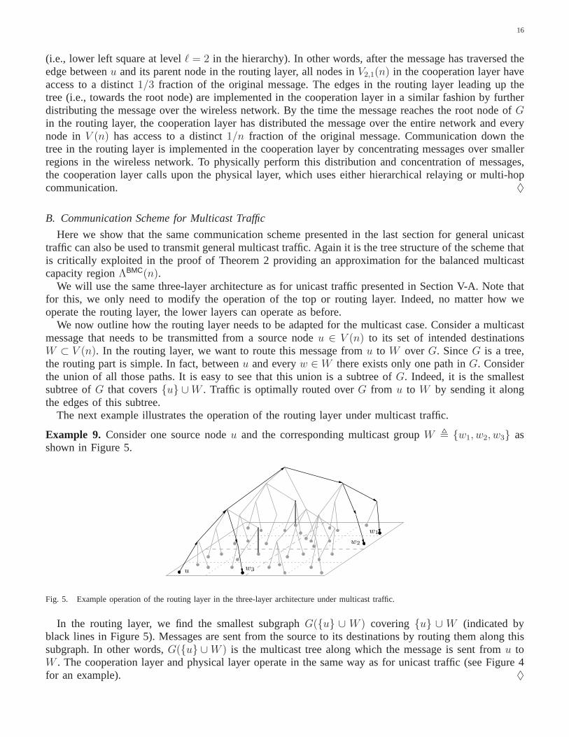
Example 9. Consider one source nodeu and the corresponding multicast groupW , {w1, w2, w3} asshown in Figure 5.
u
w1
w2
w3
Fig. 5. Example operation of the routing layer in the three-layer architecture under multicast traffic.
In the routing layer, we find the smallest subgraphG({u} ∪ W ) covering {u} ∪ W (indicated byblack lines in Figure 5). Messages are sent from the source toits destinations by routing them along thissubgraph. In other words,G({u} ∪W ) is the multicast tree along which the message is sent fromu toW . The cooperation layer and physical layer operate in the same way as for unicast traffic (see Figure 4for an example). ♦

17
C. Communication Schemes for Uniform Permutation Traffic
Here we discuss (asymptotically) optimal communication schemes for uniform permutation traffic onA(n) in which a constant fraction of source-destination pairs are at a distance ofΘ(
√n). Permutation
traffics of this sort occur with high probability if they are generated uniformly at random, and they areclosely related to traffic arising from random source-destination pairing with uniform rate. As pointed outin Sections V-A and V-B, these communication schemes as usedas building blocks in the communicationarchitecture for general unicast and multicast traffic.
The structure of the optimal communication scheme depends drastically on the path-loss exponentα. Forα ∈ (2, 3] (small path-loss exponent), cooperative communication ona global scale is necessary to achieveoptimal performance. Forα > 3 (large path-loss exponent), local communication between neighboringnodes is sufficient, and traffic is routed in a multi-hop fashion from the source to the destination. Wewill refer to the order-optimal scheme forα ∈ (2, 3] as hierarchical relaying scheme, and to the orderoptimal scheme forα > 3 as multi-hop scheme. For a uniform permutation traffic onV (n), hierarchicalrelaying achieves a per-node rate ofn1−α/2−o(1); multi-hop communication achieves a per-node rate ofn−1/2−o(1). By choosing the appropriate scheme (hierarchical relaying for α ∈ (2, 3], multi-hop forα > 3),we can thus achieve a per-node rate ofn1−min{3,α}/2−o(1). We provide a short description of the hierarchicalrelaying scheme in the following. The details can be found in[13].
Considern nodes placed independently and uniformly at random onA(n). Divide A(n) into
n1
1+log1/3(n)
squarelets of equal size. Call a squareletdense, if it contains a number of nodes proportional to its area.For each source-destination pair, choose such a dense squarelet as arelay, over which it will transmitinformation (see Figure 6).
u1
u2
u3
v1
MAC
v2
v3
BC
Fig. 6. Sketch of one level of the hierarchical relaying scheme. Here{(ui, vi)}3i=1 are three source-destination pairs. Groups of source-
destination pairs relay their traffic over dense squarelets(shaded), which contain a number of nodes proportional to their area. We time sharebetween the different relay squarelets. Within all relay squarelets the scheme is used recursively to enable joint decoding and encoding ateach relay.
Consider now one such relay squarelet and the nodes that are transmitting information over it. If weassume for the moment that the nodes within the relay squarelets could cooperate, then between the sourcenodes and the relay squarelet we would have a multiple accesschannel (MAC), where each of the sourcenodes has one transmit antenna, and the relay squarelet (acting as one node) has many receive antennas.Between the relay squarelet and the destination nodes, we would have a broadcast channel (BC), whereeach destination node has one receive antenna, and the relaysquarelet (acting again as one node) hasmany transmit antennas. The cooperation gain from using this kind of scheme arises from the use ofmultiple antennas for this MAC and BC.

18
To actually enable this kind of cooperation at the relay squarelet, local communication within the relaysquarelets is necessary. It can be shown that this local communication problem is actually the same asthe original problem, but at a smaller scale. Indeed, we are now considering a square of size
n1− 1
1+log1/3(n)
with equal number of nodes (at least order wise). Hence we canuse the same scheme recursively to solvethis subproblem. We terminate the recursion after
log1/3(n)
iterations, at which point we use simple TDMA to bootstrap the scheme.Observe that at the final level of the scheme, we have dividedA(n) into
(n
11+log1/3(n)
)log1/3(n)
= n1
1+log−1/3(n)
squarelets. A sufficient condition for the scheme to succeedis that all these squarelets are dense (i.e.,contain a number of nodes proportional to their area). However much weaker conditions are sufficient aswell [13].
For any permutation traffic, the per-node rate achievable with this scheme is at least
n1−α/2−o(1)
for any α > 2 and under fast fading. Under slow fading the same per-node rate is achievable for allpermutation traffic with probability at least
1 − exp(− 2O(log2/3(n))
).
Moreover, whenα ∈ (2, 3] and for permutation traffic, where a constant fraction of source-destinationpairs are at distanceΘ(
√n) (as is the case with high probability if the permutation traffic is chosen at
random), this is asymptotically the best uniformly achievable per-node rate.
VI. A UXILIARY LEMMAS
In this section, we provide auxiliary results, which will beused several times in the following. Theseresults are grouped into three parts. In Section VI-A, we describe regularity properties exhibited with highprobability by the random node placement. In Section VI-B, we provide auxiliary upper bounds on theperformance of any scheme in terms of cut-set bounds. Finally, in Section VI-C, we describe auxiliaryresults on the performance of hierarchical relaying and multi-hop communication as described in SectionV-C.
A. Regularity Lemmas
Here we prove several regularity properties that are satisfied with high probability by a random nodeplacement. Formally, defineV(n) to be the collection of all node placementsV (n) that satisfy the followingconditions:
ru,v > n−1 for all u, v ∈ V (n),∣∣Vℓ,i(n)
∣∣ ≤ log(n) for ℓ =1
2log(n) and all i ∈ {1, . . . , 4ℓ},
∣∣Vℓ,i(n)∣∣ ≥ 1 for ℓ =
1
2log
( n
2 log(n)
)and all i ∈ {1, . . . , 4ℓ},
∣∣Vℓ,i(n)∣∣ ∈ [4−ℓ−1n, 4−ℓ+1n] for all ℓ ∈
{1, . . . ,
1
2log(n)
(1 − log5/6(n)
)}, i ∈ {1, . . . , 4ℓ}.

19
The first condition is that the minimum distance between nodepairs is not too small. The second conditionis that all squares of area1 contain at mostlog(n) nodes. The third condition is that all squares of area2 log(n) contain at least one node. The fourth condition is that all squares up to level1
2log(n)
(1−log5/6(n)
)
contain a number of nodes proportional to their area. Note that, since
L(n) ≤ 1
2log(n)
(1 − log5/6(n)
),
this holds in particular for nodes up to levelL(n). The goal of this section is to prove that
P(V (n) ∈ V(n)) = 1 − o(1),
asn→ ∞.The first lemma shows that the minimum distance in a random node placement is at leastn−1 with
high probability.
Lemma 3.P
(min
u∈V (n),v∈V (n)\{u}ru,v > n−1
)= 1 − o(1),
as n→ ∞.
Proof. For u, v ∈ V , letBu,v , {ru,v ≤ r}
for somer (depending only onn). Fix a nodeu ∈ V , then
P(Bu,v|u) ≤r2π
n,
(the inequality being due to boundary effects). Moreover, the events{Bu,v}v∈V \{u} are independentconditioned onu, and thus
P
(∩v∈V \{u} B
cu,v
∣∣u)
=∏
v∈V \{u}P(Bc
u,v|u) ≥(1 − r2π
n
)n
.
From this,
P
(min
u∈V,v∈V \{u}ru,v ≤ r
)= P
(∪u∈V,v∈V \{u} Bu,v
)
≤∑
u∈V
P
(∪v∈V \{u} Bu,v
)
=∑
u∈V
(1 − P
(∩v∈V \{u} B
cu,v
))
=∑
u∈V
(1 − E
(P
(∩v∈V \{u} B
cu,v
∣∣u)))
≤∑
u∈V
(1 −
(1 − r2π
n
)n)
= n(1 −
(1 − r2π
n
)n),
which converges to zero forr = n−1.
The next lemma asserts that ifL(n) is not too large then all squares{Vℓ,i(n)}ℓ,i for ℓ ∈ {1, . . . , L(n)}and i ∈ {1, . . . , 4ℓ} in the grid decomposition ofV (n) contain a number of nodes that is proportional totheir area.

20
Lemma 4. If L(n) satisfies
limn→∞
L(n)
4−eL(n)n= 0
then
P
( eL(n)⋂
ℓ=1
4ℓ⋂
i=1
{|Vℓ,i(n)| ∈ [4−ℓ−1n, 4−ℓ+1n]
})= 1 − o(1)
as n→ ∞. In particular, this holds for
L(n) =1
2log(n)
(1 − log−5/6(n)
),
and for L(n) = L(n).
Proof. Consider thej-th node and letBj be the event that this node lies inAℓ,i for fixed ℓ, i. Note thatn∑
j=1
11Bj= |Vℓ,i|
by definition, and thatP(Bj) = 4−ℓ.
Hence using the Chernoff bound
P
( n∑
j=1
11Bj6∈ [4−ℓ−1n, 4−ℓ+1n]
)≤ exp(−K4−ℓn),
for some constantK. From this, we obtain forℓ = L(n),
P
( 4eL(n)⋂
i=1
{|VeL(n),i| ∈ [4−
eL(n)−1n, 4−eL(n)+1n]
})≥ 1 −
4eL(n)∑
i=1
P(|VeL(n),i| 6∈ [4−
eL(n)−1n, 4−eL(n)+1n]
)
≥ 1 − 4eL(n) exp(−K4−
eL(n)n)
≥ 1 − exp(KL(n) −K4−eL(n)n),
(9)
for some constantK. By assumption
limn→∞
L(n)
4−eL(n)n= 0,
and hence
P
( 4eL(n)⋂
i=1
{|VeL(n),i| ∈ [4−
eL(n)−1n, 4−eL(n)+1n]
})≥ 1 − o(1),
asn→ ∞. Since the{Aℓ,i}ℓ,i are nested as a function ofℓ, we have
eL(n)⋂
ℓ=1
4ℓ⋂
i=1
{|Vℓ,i| ∈ [4−ℓ−1n, 4−ℓ+1n]
}=
4eL(n)⋂
i=1
{|VeL(n),i| ∈ [4−
eL(n)−1n, 4−eL(n)+1n]
},
which, combined with (9), proves the first part of the lemma.For the second part, note that for
L(n) =1
2log(n)
(1 − log−5/6(n)
),

21
we have
L(n)
4−eL(n)n=
12log(n)
(1 − log−5/6(n)
)
2log1/6(n)
≤ log(n)
2log1/6(n)
= 2log log(n)−log1/6(n) → 0,
and hence the lemma is valid in this case. The same holds forL(n) = L(n) since
L(n) ≤ 1
2log(n)
(1 − log−5/6(n)
).
We are now ready to prove that a random node placementV (n) is in V(n) with high probability asn→ ∞ (i.e., is fairly “regular” with high probability).
Lemma 5.P(V (n) ∈ V(n)) = 1 − o(1),
as n→ ∞.
Proof. The first condition,
ru,v > n−1 for all u, v ∈ V ,
holds with probability1 − o(1) by Lemma 3. The second and third conditions,
∣∣Vℓ,i
∣∣ ≤ log(n) for ℓ =1
2log(n) and all i ∈ {1, . . . , 4ℓ},
∣∣Vℓ,i
∣∣ ≥ 1 for ℓ =1
2log
( n
2 log(n)
)and all i ∈ {1, . . . , 4ℓ},
are shown in [12, Lemma 5.1] to hold with probability1 − o(1). The fourth condition,
∣∣Vℓ,i
∣∣ ∈ [4−ℓ−1n, 4−ℓ+1n] for all ℓ ∈{
1, . . . ,1
2log(n)
(1 − log−5/6(n)
)}, i ∈ {1, . . . , 4ℓ},
holds with probability1 − o(1) by Lemma 4. Together, this proves the desired result.
B. Converse Lemmas
Here we prove several auxiliary converse results. The first lemma bounds the maximal achievable sumrate for every individual node (i.e., the total traffic for which a fixed node is either source or destination).Equivalently, forV (n) ∈ V(n), since the minimum distance between nodes is at leastn−1, this can beunderstood as an upper bound on the maximal achievable traffic across the boundary of the subsquaresVlog(n),i for any i ∈ {1, . . . , n2}.
Lemma 6. Under either fast or slow fading, for anyα > 2, there existsb(n) = O(log(n)) such that forall V (n) ∈ V(n), λUC ∈ ΛUC(n), u ∈ V (n),
∑
v∈V (n)\{u}λUC
u,v ≤ b(n), (10)
∑
v∈V (n)\{u}λUC
v,u ≤ b(n). (11)

22
Proof. The argument follows the one in [12, Theorem 3.1]. Denote byC(S1, S2) the MIMO capacitybetween nodes inS1 and nodes inS2, for S1, S2 ⊂ V . Consider first (10). By the cut-set bound [27,Theorem 14.10.1], ∑
v 6=u
λUCu,v ≤ C({u}, {u}c).
HereC({u}, {u}c) is the SIMO capacity betweenu and the nodes in{u}c, i.e.,
C({u}, {u}c) = log(1 +
∑v 6=u |hu,v|2
)
≤ log(1 + (n− 1)nα)
≤ K log(n),
withK , 2 + α,
and where for the first inequality we have used that sinceV ∈ V, we haveru,v ≥ n−1 for all u, v ∈ V .Similarly, for (11), ∑
v 6=u
λUCv,u ≤ C({u}c, {u}).
HereC({u}, {u}c) is the MISO capacity between the nodes in{u}c andu, i.e.,
C({u}c, {u}) ≤ log(1 + (n− 1)
∑v 6=u |hv,u|2
)
≤ log(1 + (n− 1)2nα)
≤ K log(n).
The next lemma bounds the maximal achievable sum rate acrossthe boundary out of the subsquaresVℓ,i(n) for ℓ ∈ {1, . . . , L(n)}, and i ∈ {1, . . . , 4ℓ}.
Lemma 7. Under either fast or slow fading, for anyα > 2, there existsb(n) = O(log6(n)
)such that
for all V (n) ∈ V(n), λUC ∈ ΛUC(n), ℓ ∈ {1, . . . , L(n)}, and i ∈ {1, . . . , 4ℓ}, we have∑
u∈Vℓ,i(n)
∑
v/∈Vℓ,i(n)
λUCu,v ≤ b(n)(4−ℓn)2−min{3,α}/2.
Proof. As before, denote byC(S1, S2) the MIMO capacity between nodes inS1 and nodes inS2. By thecut-set bound [27, Theorem 14.10.1],
∑
u∈Vℓ,i
∑
v/∈Vℓ,i
λUCu,v ≤ C(Vℓ,i, V
cℓ,i). (12)
LetHS1,S2 , [hu,v]u∈S1,v∈S2
be the matrix of channel gains between the nodes inS1 andS2. Under fast fading
C(S1, S2) , maxQ(H)≥0:
E(qu,u)≤P ∀u∈S1
E
(log det
(I + H
†S1,S2
Q(H)HS1,S2
)),
and under slow fading
C(S, Sc) , maxQ≥0:
qu,u≤P ∀u∈S1
log det(I + H
†S1,S2
QHS1,S2
).

23
Denote by∂(V cℓ,i) the nodes inV c
ℓ,i that are within distance one of the boundary betweenAcℓ,i andAℓ,i.
Using the generalized Hadamard’s inequality yields then that under either fast or slow fading
C(Vℓ,i, Vcℓ,i) ≤ C(Vℓ,i, ∂(V
cℓ,i)) + C(Vℓ,i, V
cℓ,i \ ∂(V c
ℓ,i)). (13)
We start by analyzing the first term in the sum in (13). Applying Hadamard’s inequality again yields
C(Vℓ,i, ∂(Vcℓ,i)) ≤
∑
v∈∂(V cℓ,i)
C(Vℓ,i, {v}).
SinceV ∈ V, we have ∣∣∂(V cℓ,i)
∣∣ ≤ 5 log(n)(4−ℓn)1/2.
and by the same analysis as in Lemma 6, we obtain
C(Vℓ,i, {v}) ≤ C({v}c, {v}) ≤ K
5log(n)
for some constantK (independent ofv). Therefore
C(Vℓ,i, ∂(Vcℓ,i)) ≤ 5 log(n)(4−ℓn)1/2K
5log(n)
≤ K log2(n)(4−ℓn)1/2. (14)
We now analyze the second term in the sum in (13). The arguments of [13, Lemma 12] (buildingon [12, Theorem 5.2]) show that under either fast or slow fading there existsK > 0 such that for anyV ∈ V, ℓ ∈ {0, . . . , L(n)},
C(Vℓ,i, Vcℓ,i \ ∂(V c
ℓ,i)) ≤ K log3(n)∑
u∈Vℓ,i
∑
v∈V cℓ,i\∂(V c
ℓ,i)
r−αu,v . (15)
Moreover, using again the same arguments as in [12, Theorem 5.2] shows that there exists a constantK ′ > 0 and for adjacent squares (i.e., sharing a side)Aℓ,i, Aℓ,j,
∑
u∈Vℓ,i
∑
v∈Vℓ,j\∂(V cℓ,i)
r−αu,v ≤ K ′ log3(n)(4−ℓn)2−min{3,α}/2. (16)
Consider now two diagonal squares (i.e., sharing a corner point) Aℓ,i, Aℓ,j, and chooseı, such thatAℓ,i ∪ Aℓ,ı and Aℓ,j ∪ Aℓ, are adjacent rectangles. Using the same arguments to these rectangles andsuitably redefiningK ′ shows that (16) holds for diagonal squares as well.
Using this, we now compute the summation in (15). Consider “rings” of squares aroundAℓ,i. The firstsuch “ring” contains the (at most)8 squares neighboringAℓ,i. The next “ring” contains at most16 squares.In general, “ring”k contains at most8k squares. Let
{Aℓ,j}j∈Ik
be the squares in “ring”k. Then∑
u∈Vℓ,i
∑
v∈V cℓ,i\∂(V c
ℓ,i)
r−αu,v =
∑
k≥1
∑
j∈Ik
∑
u∈Vℓ,i
∑
v∈Vℓ,j\∂(V cℓ,i)
r−αu,v . (17)
By (16), ∑
j∈I1
∑
u∈Vℓ,i
∑
v∈Vℓ,j\∂(V cℓ,i)
r−αu,v ≤ 8K ′ log3(n)(4−ℓn)2−min{3,α}/2. (18)

24
Now note that fork > 1 and j ∈ Ik, nodesu ∈ Vℓ,i and v ∈ Vℓ,j are at least at distanceru,v ≥(k − 1)(2−ℓ
√n). Moreover, sinceV ∈ V, each{Vℓ,j}ℓ,j has cardinality at most4−ℓ+1n. Thus
∑
k>1
∑
j∈Ik
∑
u∈Vℓ,i
∑
v∈Vℓ,j\∂(V cℓ,i)
r−αu,v ≤
∑
k>1
8k(4−ℓ+1n
)2((k − 1)(2−ℓ
√n)
)−α
= 128(4−ℓn
)2−α/2∑
k>1
k(k − 1)−α
= K ′′(4−ℓn)2−α/2
, (19)
for someK ′′ > 0, and where we have used thatα > 2. Substituting (18) and (19) into (17) yields∑
u∈Vℓ,i
∑
v∈V cℓ,i\∂(V c
ℓ,i)
r−αu,v ≤ 8K ′ log3(n)(4−ℓn)2−min{3,α}/2 +K ′′(4−ℓn
)2−α/2,
and hence by (15)
C(Vℓ,i, Vcℓ,i \ ∂(V c
ℓ,i)) ≤ K log3(n)(8K ′ log3(n)(4−ℓn)2−min{3,α}/2 +K ′′(4−ℓn
)2−α/2). (20)
Combining (20) and (14) with (12) shows that∑
u∈Vℓ,i
∑
v/∈Vℓ,i
λUCu,v ≤ b(n)(4−ℓn)2−min{3,α}/2.
for everyℓ ∈ {1, . . . , L(n)}, i ∈ {1, . . . , 4ℓ}, and under either fast or slow fading.
The following lemma bounds the maximal achievable sum rate across the boundary into the subsquaresVℓ,i(n) for ℓ ∈ {1, . . . , L(n)}, and i ∈ {1, . . . , 4ℓ}. Note that this lemma is only valid forα > 5.
Lemma 8. Under either fast or slow fading, for anyα > 5, there existsb(n) = O(log6(n)
)such that
for all V (n) ∈ V(n), λUC ∈ ΛUC(n), ℓ ∈ {1, . . . , L(n)}, and i ∈ {1, . . . , 4ℓ}, we have∑
u/∈Vℓ,i(n)
∑
v∈Vℓ,i(n)
λUCu,v ≤ b(n)(4−ℓn)1/2.
Proof. By the cut-set bound [27, Theorem 14.10.1],∑
u/∈Vℓ,i
∑
v∈Vℓ,i
λUCu,v ≤ C(V c
ℓ,i, Vℓ,i). (21)
Denote by∂Vℓ,i the nodes inVℓ,i that are within distance one of the boundary betweenAcℓ,i andAℓ,i.
Applying the generalized Hadamard inequality as in Lemma 7,we have under either fast or slow fading
C(V cℓ,i, Vℓ,i) ≤ C(V c
ℓ,i, ∂Vℓ,i) + C(V cℓ,i, Vℓ,i \ ∂Vℓ,i)
≤ K log2(n)(4−ℓn)1/2 + C(V cℓ,i, Vℓ,i \ ∂Vℓ,i),
(22)
for some constantK > 0.For the second term in (22), we have by slightly adapting the upper bound from Theorem 2.1 in [3]:
C(V cℓ,i, Vℓ,i \ ∂Vℓ,i) ≤
∑
v∈Vℓ,i\∂Vℓ,i
( ∑
u∈V cℓ,i
r−α/2u,v
)2
.
Now, considerv ∈ Vℓ,i \ ∂Vℓ,i and letdv be the distance ofv from the closest node inV cℓ,i. UsingV ∈ V,
∑
u∈V cℓ,i
r−α/2u,v ≤ K log(n)d2−α/2
v ,

25
for some constantK > 0, and hence forα > 5,
C(V cℓ,i, Vℓ,i \ ∂Vℓ,i) ≤
∑
v∈Vℓ,i\∂Vℓ,i
K2 log2(n)d4−αv
≤ K ′ log3(n)(4−ℓn)1/2,
for some constantK ′ > 0. Combined with (22) and (21), this proves Lemma 8.
C. Achievability Lemmas
In this section, we prove auxiliary achievability results.Recall that a permutation traffic is a traffic patternin which each node is source and destination exactly once. Call the corresponding source-destinationpairingΠ ⊂ V (n)×V (n) a permutation pairing. The lemma below analyzes the performance achievablewith either hierarchical relaying (forα ∈ (2, 3]) or multi-hop communication (forα > 3) appliedsimultaneously to transmit permutation traffic in several disjoint regions in the network. See SectionV-C for a description of these communication schemes.
Lemma 9. Under fast fading, for anyα > 2, there existsb(n) ≥ n−o(1) such that for allV (n) ∈ V(n),ℓ ∈ {0, . . . , L(n)}, i ∈ {1, . . . , 4ℓ}, and all permutation source-destination pairingsΠi on Vℓ,i(n), thereexistsλUC ∈ ΛUC(n) such that
mini∈{1,...,4ℓ}
min(u,v)∈Πi
λUCu,v ≥ b(n)(4−ℓn)1−min{3,α}/2.
The same statement holds with probability1 − o(1) as n→ ∞ in the slow fading case.
Consider the source-destination pairingΠ , ∪iΠi with Πi as in Lemma 9. This is a permutation pairing,since eachΠi is a permutation pairing onVℓ,i(n) and since the{Vℓ,i(n)}i are disjoint. Lemma 9 states thatall source-destination pairs inΠ can communicate at a per-node rate of at leastn−o(1)(4−ℓn)1−min{3,α}/2.Note that, due to the locality of the traffic pattern, this canbe considerably better than then1−min{3,α}/2−o(1)
per-node rate achieved by standard hierarchical relaying or multi-hop communication.
Proof. We shall use either hierarchical relaying (forα ∈ (2, 3]) or multi-hop (forα > 3) to communicatewithin each squareVℓ,i. We operate every fourth of theVℓ,i simultaneously, and show that the addedinterference due to this spatial re-use results only in a constant factor loss in rate.
Consider firstα ∈ (2, 3] and fast fading. The squaresAℓ,i at levelℓ have an area of
nℓ , 4−ℓn.
In order to be able to use hierarchical relaying within each of the {Aℓ,i}i, it is sufficient to show that wecan partition eachAℓ,i into
n1
1+log−1/3(nℓ)
ℓ
squarelets, each of which contains a number of nodes proportional to the area (see Section V-C). In otherwords, we partitionA into squarelets of size
n1− 1
1+log−1/3(nℓ)
ℓ ≥ nlog−1/3(n)
1+log−1/3(n)
L(n)
≥ n12
log−1/3(n)
L(n)
= 212
log1/6(n)
≥ n4−12
log(n)(1−log−5/6(n)).

26
SinceV ∈ V, all these squarelets contain a number of nodes proportional to their area, and hence thisshows that all
{Ai,ℓ}ℓ∈{0,...,L(n)},i∈{1,...,4ℓ}
are simultaneously regular enough for hierarchical relaying to be successful under fast fading. This achievesa per-node rate of
λUCu,v ≥ n−o(1)(4−ℓn)1−α/2 (23)
for any (u, v) ∈ Πi (see also [13, Theorem 1]).We now show that (23) holds with high probability also under slow fading. ForV ∈ V hierarchical
relaying is successful under slow fading for all permutation traffic onV with probability at least
1 − exp(− 2K log2/3(n)
)
for some constantK (see again Section V-C). Hence, hierarchical relaying is successful for all permutationtraffic on Vℓ,i with probability at least
1 − exp(− 2K log2/3(4−ℓn)
)≥ 1 − exp
(− 2K log2/3(4−L(n)n)
)
= 1 − exp(− 2K log1/3(n)
).
And hence hierarchical relaying is successful under slow fading for all ℓ ∈ {1, . . . , L(n)} and allpermutation traffic on every{Vℓ,i}4ℓ
i=1 with probability at least
1 − L(n)4L(n) exp(− 2K log1/3(n)
)≥ 1 − n2 exp
(− 2K log1/3(n)
)
≥ 1 − o(1)
asn→ ∞.We now argue that the additional interference from spatial re-use results only in a constant loss in
rate. This follows from the same arguments as in the proof of [13, Theorem 1] (with the appropriatemodifications for slow fading as described there). Intuitively, this is the case since the interference from asquare at distancer is attenuated by a factorr−α, which, sinceα > 2, is summable. Hence the combinedinterference has power on the order of the receiver noise, resulting in only a constant factor loss in rate.
For α > 3, the argument is similar — instead of hierarchical relayingwe now use multi-hop commu-nication. ForV ∈ V and under either fast or slow fading, this achieves a per-node rate of
λUCu,v ≥ n−o(1)(4−ℓn)−1/2 (24)
for any (u, v) ∈ Πi. Combining (23) and (24) yields the desired result.
VII. PROOF OFTHEOREM 1
The proof of Theorem 1 relies on the construction of a capacitated (noiseless, wireline) graphG andlinking its performance under routing to the performance ofthe wireless network. This graphG = (VG, EG)is constructed as follows.G is a full tree (i.e., all its leaf nodes are on the same level).G hasn leaves,each of them representing an element ofV (n). To simplify notation, we assume thatV (n) ⊂ VG, so thatthe leaves ofG are exactly the elements ofV (n) ⊂ VG. Whenever the distinction is relevant, we useu, v for nodes inV (n) ⊂ VG andµ, ν for nodes inVG \ V (n) in the following. The internal nodes ofGcorrespond toVℓ,i(n) for all ℓ ∈ {0, . . . , L(n)}, i ∈ {1, . . . , 4ℓ}, with hierarchy induced by the one onA(n). In particular, letµ andν be internal nodes inVG and letVℓ,i(n) andVℓ+1,j(n) be the correspondingsubsets ofV (n). Thenν is a child node ofµ if Vℓ+1,j(n) ⊂ Vℓ,i(n).
In the following, we will assumeV ∈ V, which holds with probability1−o(1) asn→ ∞ by Lemma 5.With this assumption, nodes inVG at levelℓ < L(n) have4 children each, nodes inVG at levelℓ = L(n)

27
...
ℓ = 0
ℓ = 1
ℓ = L(n)
ℓ = L(n) + 1
Fig. 7. Communication graphG constructed in the proof of Theorem 1. Nodes on levelsℓ ∈ {0, . . . , L(n) − 1} have four children each,nodes on levelℓ = L(n) haveΘ
`nlog−1/2(n)
´children each. The total number of leaf nodes isn, one representing each node in the wireless
networkV (n). An internal node inG at levelℓ ∈ {0, . . . , L(n)} represents the collection of nodes inVℓ,i(n) for somei.
have between4−L(n)−1n and4−L(n)+1n children, and nodes inVG at levelℓ = L(n) + 1 are the leaves ofthe tree (see Figure 7 below and Figure 3 in Section V-A).
For µ ∈ VG, denote byL(µ) the leaf nodes of the subtree ofG rooted atµ. Note that, by constructionof the graphG, L(µ) = Vℓ,i(n) for someℓ and i. To understand the relation betweenVG andV (n), wedefine therepresentativeR : VG → 2V (n) of µ as follows. For a leaf nodeu ∈ V (n) ⊂ VG of G, let
R(u) , {u}.For µ ∈ VG at levelL(n), chooseR(µ) ⊂ L(µ) ⊂ V (n) such that
|R(µ)| = 4−L(n)−1n.
This is possible sinceV (n) ∈ V(n) by assumption. Finally, forµ ∈ VG at level ℓ < L(n), and withchildren{νi}4
j=1, let
R(µ) ,
4⋃
j=1
R(νj).
We now define an edge capacitycµ,ν for each edge(µ, ν) ∈ EG. If µ is a leaf ofG and ν its parent,set
cµ,ν = cν,µ , 1. (25)
If µ is an internal node at levelℓ in G andν its parent, then set
cµ,ν = cν,µ , (4−ℓn)2−min{3,α}/2. (26)
Having chosen edge capacities onG, we can now define the setΛBUCG (n) ⊂ R
n×n+ of feasible unicast
traffic matrices between leaf nodes ofG. In other words,λUC ∈ ΛBUCG (n) if messages at the leaf nodes
of G can be routed to their destinations (which are also leaf nodes) overG at ratesλUC while respectingthe capacity constraints on the edges ofG.
We first prove the achievability part of Theorem 1. The next lemma shows that if traffic can be routedover the treeG, then approximately the same traffic can be transmitted reliably over the wireless network.
Lemma 10. Under fast fading, for anyα > 2, there existsb(n) ≥ n−o(1) such that for anyV (n) ∈ V(n),
b(n)ΛBUCG (n) ⊂ ΛBUC(n).
The same statement holds for slow fading with probability1 − o(1) as n→ ∞.
Proof. AssumeλUC ∈ ΛBUCG , i.e., traffic can be routed between the leaf nodes ofG at a rateλUC, we need
to show thatn−o(1)λUC ∈ ΛBUC (i.e., almost the same flow can be reliably transmitted over the wireless

28
network). We use the three-layer communication architecture introduced in Section V-A to establish thisresult.
Recall the three layers of this architecture: the routing, cooperation, and physical layers. The layers ofthis communication scheme operate as follows. In the routing layer, we treat the wireless network as thegraphG and route the messages between over the edges ofG. The cooperation layer provides this treeabstraction to the routing layer by distributing and concentrating messages over subsets of the wirelessnetworks. The physical layer implements this distributionand concentration of messages by dealing withinterference and noise.
Consider first the routing layer, and assume that the tree abstractionG can be implemented in thewireless network with only an−o(1) factor loss. SinceλUC ∈ ΛBUC
G by assumption, we then know that therouting layer will be able to reliably transmit messages at ratesn−o(1)λUC. We now show that the treeabstraction can indeed be implemented in the wireless network.
This tree abstraction is provided to the routing layer by thecooperation layer. We will show that theoperation of the cooperation layer satisfies the following invariance property: If a message is located at anodeµ ∈ G in the routing layer, then the same message is evenly distributed over all nodes inR(µ) inthe wireless network. In other words, all nodesu ∈ R(µ) ⊂ V contain a distinct part of length1/ |R(µ)|of the message.
Consider first a leaf nodeu ∈ V ⊂ VG in G, and assume the routing layer calls upon the cooperationlayer to send a message to its parentν ∈ VG in G. Note first thatu is also an element ofV , and it hasaccess to the entire message to be sent overG. Since for leaf nodesR(u) = {u}, this shows that theinvariance property is satisfied atu. The message is split atu into |R(ν)| parts of equal length, and onepart is sent to each node inR(ν) over the wireless network. In other words, we distribute themessageover the wireless network by a factor of|R(ν)|. Hence the invariance property is also satisfied atµ.
Consider now an internal nodeµ ∈ VG, and assume the routing layer calls upon the cooperation layer tosend a message to its parent nodeν ∈ VG. Note that since all traffic inG originates at the leaf nodes ofG(which are the actual nodes in the wireless network), a message atµ had to traverse all levels belowµ inthe treeG. We assume that the invariance property holds up to levelµ in the tree, and show that it is thenalso satisfied at levelν. By the induction hypothesis, each nodeu ∈ R(µ) has access to a distinct part oflength1/ |R(µ)|. Each such nodeu splits its message part into four distinct parts of equal length. Nodeu keeps one part for itself, and sends the other three parts to nodes inR(ν). Since|R(ν)| = 4 |R(µ)|,this can be performed such that each node inR(ν) obtains exactly one message part. In other words, wedistribute the message by a factor four over the wireless network, and the invariance property is satisfiedat ν ∈ VG.
Operation along edges down the tree (i.e., towards the leaf nodes) is similar, but instead of distributingmessages, we now concentrate them over the wireless network. To route a message from a nodeµ ∈ VG
with internal children{νj}4j=1 to one of them (sayν1) in the routing layer, the cooperation layer sends
the message parts from each{R(νj)}4j=2 to a corresponding node inR(ν1) and combines them there. In
other words, we concentrate the message by a factor four overthe wireless network.To route a message to a leaf nodeu ∈ V ⊂ VG from its parentν in G in the routing layer, the cooperation
layer sends the corresponding message parts at each nodeR(ν) to u over the wireless network. Thus, againwe concentrate the message over the network, but this time bya factor of|R(ν)|. Both these operationsalong edges down the tree preserve the invariance property.This shows that the invariance property ispreserved by all operations induced by the routing layer in the cooperation layer.
Finally, to actually implement this distribution and concentration of messages, the cooperation layercalls upon the physical layer. Note that at the routing layer, all edges of the tree can be routed over simul-taneously. Therefore, the cooperation layer can potentially call the physical layer to perform distributionand concentration of messages over all sets{R(µ)}µ∈VG
simultaneously. The function of the physicallayer is to schedule all these operations and to deal with theresulting interference as well as with channelnoise.
This scheduling is done as follows. First, the physical layer time shares between communication up the

29
tree and communication down the tree (i.e., between distribution and concentration of messages). Thisresults in a loss of a factor1/2 in rate. The physical layer further time shares between all theL(n) + 1internal levels of the tree, resulting in a further1
L(n)+1factor loss in rate. Hence, the total rate loss by
this time sharing is1
2(L(n) + 1). (27)
Consider now the operations within some levelℓ ∈ 1, . . . , L(n) in the tree (i.e., for edge(µ, ν) on thislevel, neitherµ nor ν is a leaf node). We show that the rate at which the physical layer implements theedge(µ, ν) is equal ton−o(1)cµ,ν , i.e., only a small factor less than the capacity of the edge(µ, ν) inthe treeG. Note first that the distribution or concentration of trafficinduced by the cooperation layer toimplement one edgee at levelℓ is restricted toVℓ−1,i for somei = i(e). We can thus partition the edgesat levelℓ into {Ej
G}4j=1 such that the four sets
⋃
e∈EjG
Vℓ−1,i(e)
of nodes are disjoint. Time sharing between these four sets yields an additional loss of a factor1/4 inrate. Fix one such value ofj, and consider the operations induced by the cooperation layer in the setcorresponding toj. We consider communication up the tree (i.e., distributionof messages), the analysisfor communication down the tree is similar. For a particularedge(µ, ν) ∈ Ej
G with ν the parent ofµ, eachnodeu ∈ R(µ) has split its message part into four parts, three of which need to be sent to other nodesin R(ν). Moreover, this assignment of destination nodes inR(ν) to u is performed such that no node inR(ν) is destination more than once. In other word, each node inR(µ) is source exactly three times andeach node inR(ν) is destination at most once. This can be written as three source-destination pairings{Πk
i(µ,ν)}3k=1, on Vℓ−1,i(µ,ν). Moreover, each suchΠk
i(µ,ν) can be understood as a subset of a permutationsource-destination pairing. We time share between the three values ofk (yielding an additional loss of afactor 1/3 in rate). Now, for each value ofk, Lemma 9 shows that by using either hierarchical relaying(for α ∈ (2, 3]) or multi-hop communication for (α > 3), we can communicate according to{Πk
i(e)}e∈EjG
at a per-node rate ofn−o(1)(4−ℓ−1n)1−min{3,α}/2
under fast fading, and with probability4 1 − o(1) also under slow fading. SinceR(µ) contains4−ℓ−1nnodes, and accounting for the loss (27) for time sharing between the levels inG and the additional lossof factors1/4 and1/3 for time sharing betweenj andk, the physical layer implements an edge capacityfor e at levelℓ of
1
2(L(n) + 1)· 1
4· 1
3· 4−ℓ−1n · n−o(1)(4−ℓ−1n)1−min{3,α}/2 = n−o(1)(4−ℓn)2−min{3,α}/2 = n−o(1)ce.
Consider now the operations within levelℓ = L(n) + 1 in the tree (i.e., for edge(u, ν) on this level,u is a leaf node). We show that the rate at which the physical layer implements the edge(u, ν) is equalto n−o(1)cu,ν . We again consider only communication up the tree (i.e., distribution of messages in thecooperation layer), communication down the tree is performed in a similar manner. The traffic inducedby the cooperation layer at levelL(n) + 1 is within the setsVL(n),i for i = {1, . . . , 4L(n)}. We operateevery fourth of these sets simultaneously. This time sharing results in a factor1/4 rate loss. Using thesame arguments as in Lemma 9, it can be shown that the additional interference from this spatial re-useis constant, and hence results in an additional rate loss of at most a constant factorK. Consider now
4Note that Lemma 9 actually shows that all permutation trafficfor every value ofℓ can be transmitted with high probability under slowfading. In other words, with high probability all levels ofG can be implemented successfully under slow fading.

30
communication within oneVL(n),i. We time share between all the source nodesu ∈ VL(n),i, resulting inat most a factor4L(n)−1n−1 loss. Consider a nodev ∈ R(ν) ⊂ VL(n),i. Note thatu, v ∈ VL(n),i, and hence
ru,v ≤ 2(4−L(n)n)1/2.
Therefore, communicating betweenu andv, we incur a power loss of
r−αu,v ≥ 2−α(4−L(n)n)−α/2 ≥ 2−αn−α log−1/2(n)/2.
Hence we can communicate betweenu andv at a rate of at least
log(1 + 2−αn−α log−1/2(n)/2) ≥ n−o(1).
Accounting for the loss (27) for time sharing between the levels inG, the additional factor1/4 andKlosses for time sharing within each level and for interference, respectively, and a factor4L(n)−1n−1 loss fortime sharing within eachVL(n),i, the physical layer implements an edge capacity fore at levelℓ = L(n)+1of
1
2(L(n) + 1)· 1
4·K · 4L(n)−1n−1 · n−o(1) = n−o(1) = n−o(1)ce,
under either fast or slow fading.Together, this shows that the physical and cooperation layers provide the tree abstractionG to the
routing layer with edge capacities of only a factorn−o(1) loss. Hence, if messages can be routed at ratesλUC between the leaf nodes ofG, then messages can be reliably transmitted over the wireless network atratesn−o(1)λUC. Noting that then−o(1) factor is uniform inλUC, this shows that
λUC ∈ ΛBUCG ⇒ n−o(1)λUC ∈ ΛBUC.
We have seen that the unicast capacity regionΛBUCG (n) of the graphG under routing is (appropriately
scaled) an inner bound to the unicast capacity regionΛBUC(n) of the wireless network. The next lemmashows that2ΛBUC
G (n) is an outer bound to the approximate unicast capacity regionΛBUC(n) of the wirelessnetwork as defined in (3) (in fact, the two regions can be shownto be equal, but the weaker resultpresented here is sufficient for our purposes). Combining Lemmas 5, 10, and 11 below, yields that withhigh probability
n−o(1)ΛBUC(n) ⊂ n−o(1)ΛBUCG (n) ⊂ ΛBUC(n),
proving the achievability part of Theorem 1.
Lemma 11. For anyα > 2 and anyV (n) ∈ V(n),
ΛBUC(n) ⊂ (γ(n) + 1)ΛBUCG (n),
whereγ(n) is the factor in the definition ofBUC(n) in (1).
Proof. We first relate the total traffic across an edgee in the graphG to the total traffic across a cutVℓ,i
for someℓ and i.Consider an edgee = (µ, ν) ∈ EG, and assume first thate connects a node at levelℓ+ 1 and ℓ in the
tree withℓ > L(n). We slight abuse of notation, set
ce , cµ,ν .
Note first that by (26) we havece = (4−ℓn)2−min{3,α}/2. (28)
Moreover, sinceG is a tree, removing the edgee from EG separates the tree into two connectedcomponents, sayS1, S2 ⊂ VG. Consider now the leaf nodes inS1. By the construction of the tree structure

31
of G, these leaf nodes are either equal toVℓ,i or V cℓ,i for somei ∈ {1, . . . , 4ℓ}. Assume without loss of
generality that they are equal toVℓ,i. ThenV cℓ,i are the leaf nodes inS2. Now since traffic is only assumed
to be between leaf nodes ofG, the total traffic demand betweenS1 andS2 is equal to∑
u∈Vℓ,i
∑
w∈V cℓ,i
(λUCu,w + λUC
w,u). (29)
By the tree structure ofG, all this traffic has to be routed over edgee.Consider now an edgee connecting a node at levelL(n) + 1 andL(n), i.e., a leaf nodeu to its parent
ν. Then, by (25),ce = 1. (30)
Moreover, sinceV ∈ V we haveru,v > n−1 for all u, v ∈ V . Hence there existsi ∈ {1, . . . , 4log(n)} suchthat Vlog(n),i = {u}. For thisi, the total traffic crossing the edgee is equal to
∑
u∈Vlog(n),i
∑
w∈V clog(n),i
(λUCu,w + λUC
w,u). (31)
We now show thatΛBUC ⊂ (γ(n) + 1)ΛBUC
G . (32)
AssumeλUC ∈ ΛBUC, then
∑
u∈Vℓ,i
∑
w∈V cℓ,i
λUCu,w ≤
{(4−ℓn)2−min{3,α} if ℓ ≤ L(n),
1 else,
for all ℓ ∈ {1, . . . , L(n)} ∪ {log(n)}, i ∈ {1, . . . , 4ℓ}. SinceλUC is balanced, this implies that
1
γ(n) + 1
∑
u∈Vℓ,i
∑
w∈V cℓ,i
(λUCu,w + λUC
w,u) ≤{
(4−ℓn)2−min{3,α} if ℓ ≤ L(n),
1 else,
In particular, this holds for those values ofℓ and i such that|Vℓ,i| > 0. By (28), (29), (30), (31), thisimplies that the traffic demand across each edgee of the graphG is less thanγ(n) + 1 times its capacityce. Therefore 1
γ(n)+1λUC can be routed overG, i.e., λUC ∈ (γ(n) + 1)ΛBUC
G . This proves (32).
We now turn to the converse part of Theorem 1. The next lemma shows thatΛBUC(n) (appropriatelyscaled) is an outer bound to the unicast capacity regionΛBUC(n) of the wireless network. Combined withLemma 5, this shows that with high probability
ΛBUC(n) ⊂ O(log6(n))ΛBUC(n),
proving the converse part of Theorem 1.
Lemma 12. Under either fast or slow fading, for anyα > 2, there existsb(n) = O(log6(n)) such thatfor any V (n) ∈ V(n),
ΛBUC(n) ⊂ b(n)ΛBUC(n).
Proof. AssumeλUC ∈ ΛBUC. By Lemma 7, we have for anyℓ ∈ {1, . . . , L(n)} and i ∈ {1, . . . , 4ℓ},∑
u∈Vℓ,i
∑
v∈V cℓ,i
λUCu,v ≤ K log6(n)(4−ℓn)2−min{3,α}/2 (33)
for some constantK not depending onλUC.

32
Now let ℓ = log(n) and i ∈ {1, . . . , 4log(n)} such that∣∣Vlog(n),i
∣∣ > 0. Then Lemma 6 shows that∑
u∈Vlog(n),i
∑
v∈V clog(n),i
λUCu,v ≤
∑
u∈Vℓ,i
∑
v 6=u
λUCu,v
≤ K∣∣Vlog(n),i
∣∣ log(n)
≤ K log(n), (34)
with constantK not depending onλUC, and where we have used that∣∣Vlog(n),i
∣∣ ≤ 1 since V ∈ V.Equation (34) holds trivially if
∣∣Vlog(n),i
∣∣ = 0. By a similar argument, we have forℓ = log(n) and alli ∈ {1, . . . , 4log(n)}
∑
u∈V clog(n),i
∑
v∈Vlog(n),i
λUCu,v ≤ K log(n).
Together, this shows that ∑
u∈V clog(n),i
∑
v∈Vlog(n),i
(λUCu,v + λUC
v,u) ≤ 2K log(n). (35)
Combining (33) and (35) proves that there existsb(n) = O(log6(n)) such thatλUC ∈ ΛBUC impliesλUC ∈ b(n)ΛBUC, proving the lemma.
VIII. PROOF OFTHEOREM 2
Consider again the tree graphG = (VG, EG) with leaf nodesV ⊂ VG constructed in Section VII. Asbefore, we consider traffic between leaf nodes ofG. In particular, any multicast traffic matrixλMC ∈ R
n×2n
+
for the wireless network is also a multicast traffic matrix for the graphG. Denote byΛBMCG (n) ⊂ R
n×2n
+
the set of feasible (under routing) balanced multicast traffic matrices between leaf nodes ofG.The next lemma shows that if multicast traffic can be routed over G then approximately the same
multicast traffic can be transmitted reliably over the wireless network.
Lemma 13. Under fast fading, for anyα > 2, there existsb(n) ≥ n−o(1) such that for allV (n) ∈ V(n),
b(n)ΛBMCG (n) ⊂ ΛBMC(n).
The same statement holds under slow fading with probability1 − o(1) as n→ ∞.
Proof. The proof follows using the same construction as in Lemma 10.
We now show that sinceG is a tree graph,ΛBMC(n) is an inner bound (up to a factorγ(n) + 1) to thethe multicast capacity regionΛBMC
G (n). The fact thatG is a tree is critical for this result to hold.
Lemma 14. For anyα > 2,ΛBMC(n) ⊂ (γ(n) + 1)ΛBMC
G (n).
whereγ(n) is the factor in the definition ofBMC(n) in (2).
Proof. AssumeλMC ∈ BMC \ΛMCG . SinceG is a tree, there is only one way to route multicast traffic from
u to W , namely along the subtreeG({u} ∪W ) induced by{u} ∪W (i.e., the smallest subtree ofG thatcovers{u} ∪W ). Hence for any edgee ∈ EG, the trafficdλMC(e) that needs to be routed overe is equalto
dλMC(e) =∑
u∈V,W⊂V :e∈EG({u}∪W )
λMCu,W .

33
Now, sinceλMC ∈ BMC \ ΛBMCG , there existse ∈ EG such that
dλMC(e) > ce. (36)
Let ℓ and i be such that the removal of the edgee in G disconnects the leave nodes inG correspondingto Vℓ,i andV c
ℓ,i. Then we have
dλMC(e) =∑
u∈Vℓ,i
∑
W⊂V :W∩V c
ℓ,i 6=∅
λMCu,W +
∑
u∈V cℓ,i(n)
∑
W⊂V :W∩Vℓ,i 6=∅
λMCu,W , (37)
and
ce =
{(4−ℓn
)2−min{3,α}/2if ℓ ≤ L(n),
1 else.(38)
If ℓ = log(n), then (36), (37), and (38) imply thatλMC /∈ λBMC and thereforeλMC /∈ 1γ(n)+1
λBMC. Ifℓ ≤ L(n), then sinceλMC is γ(n)-balanced, we have
∑
u∈Vℓ,i
∑
W⊂V :W∩V c
ℓ,i 6=∅
λMCu,W +
∑
u∈V cℓ,i(n)
∑
W⊂V :W∩Vℓ,i 6=∅
λMCu,W ≤ (γ(n) + 1)
∑
u∈Vℓ,i
∑
W⊂V :W∩V c
ℓ,i 6=∅
λMCu,W . (39)
Combining (36), (37), (38), and (39) shows thatλMC /∈ 1γ(n)+1
ΛBMC for ℓ ≤ L(n) as well, proving thelemma.
Combining Lemmas 13, and 14, and 5 shows that
n−o(1)ΛBMC(n) ⊂ n−o(1)ΛBMCG (n) ⊂ ΛBMC(n),
proving the inner bound in Theorem 2.We now turn to the proof of the outer bound toΛMC(n). The next lemma combined with Lemma 5,
proves the outer bound in Theorem 2.
Lemma 15. Under fast fading, for anyα > 2, there existsb(n) = O(log6(n)) such that for allV (n) ∈V(n),
ΛBMC(n) ⊂ b(n)ΛMC(n).
The same statement holds under slow fading with probability1 − o(1) as n→ ∞.
Proof. We say that a unicast traffic matrixλUC is compatiblewith a multicast traffic matrixλMC if thereexists a mappingf : V (n) × 2V (n) → V (n) such thatf(u,W ) ∈W ∪ {u}, for all (u,W ), and
λUCu,v =
∑
W⊂V (n):f(u,W )=v
λMCu,W
for all (u, v). In words,λMC is compatible withλUC if we can create the unicast traffic matrixλUC fromλMC by simply discarding the traffic for the pair(u,W ) at all the nodesW \ {f(u,W )}.
Note that ifλMC ∈ ΛBMC and if λUC is compatible withλMC thenλUC ∈ ΛUC. Indeed, we can reliablytransmit at rateλUC by using the communication scheme forλMC and simply discarding all the unwantedmessages delivered by this scheme. Now consider a cutVℓ,i in the wireless network, and choose a mappingf : V (n) × 2V (n) → V (n) such that
∑
u∈Vℓ,i
∑
w∈V cℓ,i
λUCu,w =
∑
u∈Vℓ,i
∑
W⊂V :W∩V c
ℓ,i 6=∅
λMCu,W .

34
SinceλUC ∈ ΛUC, we can apply Lemmas 6 and 7 to obtain
∑
u∈Vℓ,i
∑
W⊂V :W∩V c
ℓ,i 6=∅
λMCu,W =
∑
u∈Vℓ,i
∑
w∈V cℓ,i
λUCu,w ≤ b(n)
{(4−ℓn
)2−min{3,α}/2if ℓ ≤ L(n),
1 else,
with b(n) = O(log6(n)). Repeating the same argument for cutsV clog(n),i, shows thatλMC ∈ b(n)ΛBMC.
Noting that theb(n) term is uniform inλMC yields that
ΛMC ⊂ b(n)ΛMC,
concluding the proof of the lemma.
IX. D ISCUSSION
We discuss several aspects and extensions of the three-layer architecture introduced in Section V-C andused in the achievability parts of Theorems 1 and 2. In Section IX-A, we comment on the various treestructures used in the three-layer architecture. In Section IX-B we show that for certain values ofα thebounds in the theorems can be significantly sharpened. In Section IX-C, we show that for large valuesof path-loss exponent (α > 5), the requirement of balanced traffic is not necessary, and provide a scalingcharacterization of the entire unicast and multicast capacity regions. In Section IX-D, we point out howthe results discussed so far can be used to obtain the scalingof the balanced unicast and multicast capacityregions of dense networks (wheren nodes are randomly placed on a square of unit area).
A. Tree Structures
There are two distinct tree structures that are used in the construction of the three-layer communicationscheme proposed in this paper — one explicit and one implicit. These two tree structures appear indifferent layers of the communication scheme and serve different purposes.
The first (explicit) tree structure is given by the treeG utilized in the routing layer and implementedin the cooperation layer. The main purpose of this tree structure is to perform localized load balancing.In fact, the distribution and concentration of traffic is used to avoid unnecessary bottlenecks. Note thatthe treeG is used by the scheme for any value ofα.
The second (implicit) tree structure occurs in the physicallayer. This tree structure appears only forvalues ofα ∈ (2, 3], when the physical layer operates using the hierarchical relaying scheme. It isthis hierarchical structure of this scheme that can equivalently be understood as a tree. The purposeof this second tree structure is to enable multiple antenna communication, i.e., to perform cooperativecommunication.
B. Second-Order Asymptotics
The scaling results in Theorems 1 and 2 are up to a factorn±o(1) and hence preserve information atscalenβ for constantβ (see also the discussion in Section III-C). Here we take a closer look at thebehavior of thisn±o(1) factor, and show that in certain situations it can be significantly sharpened.
Note first that the outer bound in Theorems 1 and 2 hold up to a factor log6(n), i.e., poly-logarithmicin n. However, the inner bound holds only up to the aforementioned n−o(1) factor. A closer look at theproofs of the two theorems reveals that the precise inner bound is of order
γ−1(n)n−O(
log−1/3(n)),
whereγ(n) is the factor in the definition ofBUC(n) andBMC(n) (see (1) and (2)). With a more carefulanalysis (see [13] for the details), this can be sharpened toessentially
γ−1(n)n−O(
log−1/2(n)).

35
The exponentlog−1/2(n) in the inner bound has two causes. The first is the use of hierarchical relaying(for α ∈ (2, 3]). The second is the operation of the physical layer at levelL(n) + 1 of the tree (i.e., toimplement communication between the leaf nodes ofG and their parents). Indeed at that level, we areoperating on a square of area
4−L(n)n = nlog1/2(n),
and the loss is essentially inversely proportional to that area. Now, the reason whyL(n) can not bechosen to be larger (to make this loss smaller), is because hierarchical relaying requires a certain amountof regularity in the node placement, which can only be guaranteed for large enough areas.
This suggests that for theα > 3 regime, where multi-hop communication is used at the physical layerinstead of hierarchical relaying, we might be able to significantly improve the inner bound. To this end, wehave to choose more levels in the treeG, such that at the last level before the tree nodes, we are operatingon a square that has an area of orderlog(n). Changing the three-layer architecture in this manner, andchoosingγ(n) appropriately, forα > 3 the inner bound can be improved to be poly-logarithmic inn aswell. Combined with the poly-logarithmic outer bound, thisyields a poly-logarithmic approximation ofthe balanced unicast and multicast capacity regions forα > 3.
C. Large Path-Loss Exponent Regime
Theorems 1 and 2 describe the scaling of the balanced unicastand multicast capacity regionsΛBUC(n)and ΛBMC(n), respectively. As we have argued, the balanced unicast region ΛBUC(n) coincides with theunicast capacity regionΛUC(n) along at leastn2−n out ofn2 total dimensions, and the balanced multicastregionΛBMC(n) coincides with the multicast capacity regionΛUC(n) along at leastn2n − n out of n2n
total dimensions.A closer look at the proofs of Theorems 1 and 2 reveals that in order to obtain scaling information
along the remaining at mostn dimensions ofΛUC(n) and ΛMC(n), a stronger version of the converseresults in Lemma 7 is needed. In particular, Lemma 7 bounds the sum-rate
∑
u∈Vℓ,i(n)
∑
v/∈Vℓ,i(n)
λUCu,v
for λUC ∈ ΛUC(n). The required stronger version of the lemma would also need to bound sum rates inthe other direction, i.e., ∑
u/∈Vℓ,i(n)
∑
v∈Vℓ,i(n)
λUCu,v.
For large path-loss exponentsα > 5, such a stronger version of Lemma 7 holds (see Lemma 8). Thisresults in the following approximate capacity regions:
ΛUC(n) ,{λUC ∈ R
n×n+ :
∑
u∈Vℓ,i(n)
∑
v/∈Vℓ,i(n)
(λUCu,v + λUC
v,u) ≤ (4−ℓn)2−min{3,α}/2
∀ℓ ∈ {1, . . . , L(n)}, i ∈ {1, . . . , 4ℓ},∑
u∈Vlog(n),i(n)
∑
v/∈Vlog(n),i(n)
(λUCu,v + λUC
v,u) ≤ 1
∀i ∈ {1, . . . , n2}},

36
and
ΛMC(n) ,{λMC ∈ R
n×2n
+ :∑
u∈Vℓ,i(n)
∑
W⊂V (n):W∩V c
ℓ,i(n)6=∅
λMCu,W +
∑
u/∈Vℓ,i(n)
∑
W⊂V (n):W∩Vℓ,i(n)6=∅
λMCu,W ≤ (4−ℓn)2−min{3,α}/2
∀ℓ ∈ {1, . . . , L(n)}, i ∈ {1, . . . , 4ℓ},∑
u∈Vlog(n),i(n)
∑
W⊂V (n):W∩V c
log(n),i(n)6=∅
λMCu,W +
∑
u∈V clog(n),i
(n)
∑
W⊂V (n):W∩Vlog(n),i(n)6=∅
λMCu,W ≤ 1
∀i ∈ {1, . . . , n2}},
and for anyα > 5,
n−o(1)ΛUC(n) ⊂ ΛUC(n) ⊂ O(log6(n))ΛUC(n),
n−o(1)ΛMC(n) ⊂ ΛMC(n) ⊂ O(log6(n))ΛMC(n),
with probability1−o(1) asn→ ∞. In other words, in the high path-loss exponent regimeα > 5, ΛUC(n)and ΛMC(n) characterize the scaling of the entire unicast and multicast capacity regions, respectively.
D. Dense Networks
So far, we have only discussextendednetworks, i.e.,n nodes are located on a square of arean. Wenow briefly sketch how these results can be recast fordensenetworks, in whichn nodes are located ona square of unit area. It suffices to notice that by rescaling power by a factorn−α/2, a dense network canessentially be transformed into an equivalent extended network with path-loss exponentα (see also [12]).Hence the scaling of the unicast and multicast capacity regions for dense networks can be obtained fromthe ones for extended networks by taking a limit asα→ 2.
The resulting approximate balanced capacity regionsΛBUC(n) and ΛBMC(n) have particularly simpleshapes in this limit. In fact, the only constraints in (3) and(4) that can be tight are at levelℓ = log(n).Moreover, as in Section IX-C, it can be shown that the restriction of balanced traffic is not necessary fordense networks. This results in the following approximate capacity regions for dense networks:
ΛUC(n) ,{λUC ∈ R
n×n+ :
∑
v 6=u
(λUCu,v + λUC
v,u) ≤ 1, ∀ u ∈ V (n)}
for unicast, and
ΛMC(n) ,{λMC ∈ R
n×2n
+ :∑
W⊂V (n):W\{w}6=∅
λMCu,W +
∑
v 6=u
∑
W⊂V (n):u∈W
λMCv,W ≤ 1, ∀u ∈ V (n)
}
for multicast. We obtain that for dense networks, for anyα > 2,
n−o(1)ΛUC(n) ⊂ ΛUC(n) ⊂ O(log6(n))ΛUC(n),
n−o(1)ΛMC(n) ⊂ ΛMC(n) ⊂ O(log6(n))ΛMC(n),
with probability 1 − o(1) asn→ ∞.

37
X. CONCLUSIONS
In this paper, we have obtained an explicit information-theoretic characterization of the scaling of then2-dimensional balanced unicast andn2n-dimensional balanced multicast capacity regions of a wirelessnetwork withn randomly placed nodes and assuming a Gaussian fading channel model. These regionsspan at leastn2 − n andn2n − n dimensions ofRn×n
+ andRn×2n
+ , respectively, and hence determine thescaling of the unicast capacity region along at leastn2 − n out of n2 dimensions and the scaling of themulticast capacity region along at leastn2n − n out of n2n dimensions. The characterization is in termsof 2n weighted cuts, which are based on the geometry of the locations of the source nodes and theirdestination nodes and on the traffic demands between them, and thus can be readily evaluated.
This characterization is obtained by establishing that theunicast and multicast capacity regions of acapacitated (wireline, noiseless) tree graph under routing have essentially the same scaling as that of theoriginal network. The leaf nodes of this tree graph correspond to the nodes in the wireless network, andinternal nodes of the tree graph correspond to hierarchically growing sets of nodes.
This equivalence suggests a three-layer communication architecture for achieving the entire unicast andmulticast capacity regions (in the scaling sense). The top or routing layer establishes paths from each ofthe source nodes to its destination (for unicast) or set of destinations (for multicast) over the tree graph.The middle or cooperation layer provides this tree abstraction to the routing layer by distributing thetraffic among the corresponding set of nodes as a message travels up the tree graph, and by concentratingthe traffic on to the corresponding subset of nodes when the message travels down the tree. The bottomor physical layer implements this distribution/concentration of traffic over the wireless network. Theimplementation depends on the path-loss exponent: For low path loss,α ∈ (2, 3], hierarchical relaying isused, while for high path loss (α > 3), multi-hop communication is used.
This scheme also establishes that a separation based approach, where the routing layer works essentiallyindependently of the physical layer, can achieve nearly theentire balanced unicast and multicast capacityregions in the scaling sense. Thus, for balanced traffic, such techniques as network coding can provide atmost a small increase in the scaling.
XI. A CKNOWLEDGMENTS
The authors would like to thank David Tse, Greg Wornell, and Lizhong Zheng for helpful discussions,and the anonymous reviewers for their help improving the presentation of this paper.
REFERENCES
[1] P. Gupta and P. R. Kumar. The capacity of wireless networks. IEEE Transactions on Information Theory, 46(2):388–404, March 2000.[2] L.-L. Xie and P. R. Kumar. A network information theory for wireless communication: Scaling laws and optimal operation. IEEE
Transactions on Information Theory, 50(5):748–767, May 2004.[3] A. Jovicic, P. Viswanath, and S. R. Kulkarni. Upper bounds to transport capacity of wireless networks.IEEE Transactions on
Information Theory, 50(11):2555– 2565, November 2004.[4] F. Xue, L.-L. Xie, and P. R. Kumar. The transport capacityof wireless networks over fading channels.IEEE Transactions on Information
Theory, 51(3):834–847, March 2005.[5] O. Leveque andI. E. Telatar. Information-theoretic upper bounds on the capacity of large extended ad hoc wireless networks.IEEE
Transactions on Information Theory, 51(3):858–865, March 2005.[6] L.-L. Xie and P. R. Kumar. On the path-loss attenuation regime for positive cost and linear scaling of transport capacity in wireless
networks. IEEE Transactions on Information Theory, 52(6):2313–2328, June 2006.[7] M. Franceschetti, O. Dousse, D. N. C. Tse, and P. Thiran. Closing the gap in the capacity of wireless networks via percolation theory.
IEEE Transactions on Information Theory, 53(3):1009–1018, March 2007.[8] P. Gupta and P. R. Kumar. Towards an information theory oflarge networks: An achievable rate region.IEEE Transactions on
Information Theory, 49(8):1877–1894, August 2003.[9] L.-L Xie and P. R. Kumar. An achievable rate for the multiple-level relay channel. IEEE Transactions on Information Theory,
51(4):1348–1358, April 2005.[10] G. Kramer, M. Gastpar, and P. Gupta. Cooperative strategies and capacity theorems for relay networks.IEEE Transactions on
Information Theory, 51(9):3037–3063, September 2005.[11] S. Aeron and V. Saligrama. Wireless ad hoc networks: Strategies and scaling laws for the fixed SNR regime.IEEE Transactions on
Information Theory, 53(6):2044–2059, June 2007.

38
[12] A. Ozgur, O. Leveque, and D. N. C. Tse. Hierarchical cooperation achieves optimal capacity scaling in ad hoc networks.IEEETransactions on Information Theory, 53(10):3549–3572, October 2007.
[13] U. Niesen, P. Gupta, and D. Shah. On capacity scaling in arbitrary wireless networks.accepted for publication in IEEE Transactionson Information Theory, March 2009. Available online at http://arxiv.org/abs/0711.2745.
[14] R. Madan, D. Shah, and O. Leveque. Product multicommodity flow in wireless networks.IEEE Transactions on Information Theory,54(4):1460–1476, April 2008.
[15] F. T. Leighton and S. Rao. Multicommodity max-flow min-cut theorems and their use in designing approximation algorithms. Journalof the ACM, 46(6):787–832, November 1999.
[16] N. Linial, E. London, and Y. Rabinovich. The geometry ofgraphs and some of its algorithmic applications.Combinatorica, 15(2):215–245, June 1995.
[17] S. Subramanian, S. Shakkottai, and P. Gupta. On optimalgeographic routing in wireless networks with holes and non-uniform traffic.In Proc. IEEE Infocom, May 2007.
[18] S. Subramanian, S. Shakkottai, and P. Gupta. Optimal geographic routing for wireless networks with near-arbitrary holes and traffic.In Proc. IEEE Infocom, April 2008.
[19] S. H. A. Ahmad, A. Jovicic, and P. Viswanath. On outer bounds to the capacity region of wireless networks.IEEE Transactions onInformation Theory, 52(6):2770–2776, June 2006.
[20] X-Y. Li, S-J. Tang, and O. Frieder. Multicast capacity for large scale wireless ad hoc networks. InACM MobiCom, pages 263–277,2007.
[21] S. Shakkottai, X. Liu, and R. Srikant. The multicast capacity of large multihop wireless networks. InACM MobiHoc, 2007.[22] A. Keshavarz-Haddad, V. Ribeiro, and R. Riedi. Broadcast capacity in multihop wireless networks. InProc. ACM MobiCom, 2006.[23] P. Chaporkar and S. Sarkar. Wireless multicast: Theoryand approaches.IEEE Transactions on Information Theory, 51(6):1954–1972,
June 2005.[24] P. Jacquet and G. Rodolakis. Multicast scaling properties in massively dense ad hoc networks. InProc. International Conference on
Parallel and Distributed Systems, 2005.[25] M. Franceschetti, M. D. Migliore, and P. Minero. The capacity of wireless networks; information-theoretic and physical limits. In
Allerton Conference on Communication, Control, and Computing, September 2007.[26] M. Franceschetti, M. D. Migliore, and P. Minero. The degrees of freedom of wireless networks: Information theoretic and physical
limits. In Allerton Conference on Communication, Control, and Computing, September 2008.[27] T. M. Cover and J. A. Thomas.Elements of Information Theory. Wiley, 1991.