Hop by hop multicast routing protocol
11
Hop By Hop Multicast Routing Protocol ∗ Lu´ ıs Henrique M. K. Costa 1,2 , Serge Fdida 1 , and Otto Carlos M. B. Duarte 2 [email protected], [email protected], [email protected] 1 Laboratoire d’Informatique de Paris 6 2 Grupo de Teleinform´ atica e Automac ¸˜ ao Université Pierre et Marie Curie Universidade Federal do Rio de Janeiro 4, place Jussieu - 75252 P.O. Box 68504 - 21945-970 Paris Cedex 05 - France Rio de Janeiro - RJ - Brasil ABSTRACT IP Multicast is facing a slow take-off although it is a hotly debated topic since more than a decade. Many reasons are responsible for this status. Hence, the Internet is likely to be organized with both unicast and multicast enabled net- works. Thus, it is of utmost importance to design protocols that allow the progressive deployment of the multicast ser- vice by supporting unicast clouds. This paper proposes HBH (Hop-By-Hop multicast routing protocol). HBH adopts the source-specific channel abstraction to simplify address allo- cation and implements data distribution using recursive uni- cast trees, which allow the transparent support of unicast- only routers. Additionally, HBH is original because its tree construction algorithm takes into account the unicast rout- ing asymmetries. As most multicast routing protocols rely on the unicast infrastructure, these asymmetries impact the structure of the multicast trees. We show through simula- tion that HBH outperforms other multicast routing proto- cols in terms of the delay experienced by the receivers and the bandwidth consumption of the multicast trees. 1. INTRODUCTION IP Multicast is facing a slow take-off although it is a hotly debated topic since more than a decade. Many reasons are responsible for this status. The IP Multicast architecture is composed of a service model that defines a group as an open conversation from M sources to N receivers, an ad- dressing scheme based on IP class-D addresses, and routing protocols. In IP Multicast any host can send to a multicast group and any host can join it and receive data [5]. The IP Unicast service model is also completely open, but the po- tential burden caused by unauthorized senders is amplified by the group size in multicast. ∗ This work was sponsored by FUJB, CNPq, CAPES, COFECUB, and IST Project GCAP N 0 1999-10504. Permission to make digital or hard copies of all or part of this work for personal or classroom use is granted without fee provided that copies are not made or distributed for pro£t or commercial advantage and that copies bear this notice and the full citation on the £rst page. To copy otherwise, to republish, to post on servers or to redistribute to lists, requires prior speci£c permission and/or a fee. SIGCOMM’01, August 27-31, 2001, San Diego, California, USA.. Copyright 2001 ACM 1-58113-411-8/01/0008 ...$5.00. The IP Multicast architecture is completed by group ad- dressing and routing protocols. A multicast group is iden- tified by a class-D IP address which is not related to any topological information, as opposed to the hierarchical uni- cast addressing model. Therefore, multicast address alloca- tion is complicated and multicast forwarding state is diffi- cult to aggregate. Currently, there is no scalable solution to inter-domain multicast routing. The approach used is to connect different domains through MBGP (Multiprotocol Extensions to BGP)[2] and MSDP (Multicast Source Dis- covery Protocol)[18]. MBGP is used to announce differ- ent unicast and multicast-capable routes whereas MSDP is able to exchange active source information among the differ- ent domains. The configuration complexity of this solution works against multicast deployment. On the other hand, backbone operators are currently overprovisioning their net- works so they have little interest in using multicast. Nevertheless, ISPs (Internet Service Providers) could be interested in multicast to face the increasing demand for network resources and content distribution. As a conse- quence, the Internet is likely to be organized with both uni- cast and multicast enabled networks. Therefore, it is of utmost importance to design protocols that allow the pro- gressive deployment of the multicast service by supporting unicast clouds. Different solutions that simplify the multicast service by reducing the distribution model were proposed [8]. EX- PRESS [16] restricts the multicast conversation to 1 to N (the channel abstraction), simplifying address allocation and data distribution, and still covering most of the current mul- ticast applications. The source-specific multicast service, currently being standardized at the IETF (Internet Engi- neering Task Force), can be implemented by Version 3 of IGMP (Internet Group Management Protocol)[4] and by a modified version of PIM-SM (Protocol Independent Multi- cast - Sparse Mode)[11], named PIM-SSM [3]. Neverthe- less, source-specific multicast does not allow the progressive deployment of the multicast service. Currently, the only alternative is to use tunnels to go through unicast-only net- works. There is some work in progress specific to multi- cast tunnelling. One such mechanism is the UDP Multi- cast Tunneling Protocol (UMTP)[13]. UMTP encapsulates UDP multicast datagrams inside UDP unicast datagrams, so it can be implemented as a user-level process at end- hosts. The work in [14, 17] propose different mechanisms to automate the generation of UMTP tunnels. Automatic 249
-
Upload
independent -
Category
Documents
-
view
2 -
download
0
Transcript of Hop by hop multicast routing protocol

Hop By Hop Multicast Routing Protocol ∗
Luıs Henrique M. K. Costa1,2, Serge Fdida1, and Otto Carlos M. B. Duarte2
[email protected], [email protected], [email protected] Laboratoire d’Informatique de Paris 6 2 Grupo de Teleinformatica e Automacao
Université Pierre et Marie Curie Universidade Federal do Rio de Janeiro4, place Jussieu - 75252 P.O. Box 68504 - 21945-970Paris Cedex 05 - France Rio de Janeiro - RJ - Brasil
ABSTRACTIP Multicast is facing a slow take-off although it is a hotlydebated topic since more than a decade. Many reasons areresponsible for this status. Hence, the Internet is likely tobe organized with both unicast and multicast enabled net-works. Thus, it is of utmost importance to design protocolsthat allow the progressive deployment of the multicast ser-vice by supporting unicast clouds. This paper proposes HBH(Hop-By-Hop multicast routing protocol). HBH adopts thesource-specific channel abstraction to simplify address allo-cation and implements data distribution using recursive uni-cast trees, which allow the transparent support of unicast-only routers. Additionally, HBH is original because its treeconstruction algorithm takes into account the unicast rout-ing asymmetries. As most multicast routing protocols relyon the unicast infrastructure, these asymmetries impact thestructure of the multicast trees. We show through simula-tion that HBH outperforms other multicast routing proto-cols in terms of the delay experienced by the receivers andthe bandwidth consumption of the multicast trees.
1. INTRODUCTIONIP Multicast is facing a slow take-off although it is a hotly
debated topic since more than a decade. Many reasons areresponsible for this status. The IP Multicast architectureis composed of a service model that defines a group as anopen conversation from M sources to N receivers, an ad-dressing scheme based on IP class-D addresses, and routingprotocols. In IP Multicast any host can send to a multicastgroup and any host can join it and receive data [5]. The IPUnicast service model is also completely open, but the po-tential burden caused by unauthorized senders is amplifiedby the group size in multicast.
∗This work was sponsored by FUJB, CNPq, CAPES,COFECUB, and IST Project GCAP N0 1999-10504.
Permission to make digital or hard copies of all or part of this work forpersonal or classroom use is granted without fee provided that copies arenot made or distributed for pro£t or commercial advantage and that copiesbear this notice and the full citation on the £rst page. To copy otherwise, torepublish, to post on servers or to redistribute to lists, requires prior speci£cpermission and/or a fee.SIGCOMM’01, August 27-31, 2001, San Diego, California, USA..Copyright 2001 ACM 1-58113-411-8/01/0008 ...$5.00.
The IP Multicast architecture is completed by group ad-dressing and routing protocols. A multicast group is iden-tified by a class-D IP address which is not related to anytopological information, as opposed to the hierarchical uni-cast addressing model. Therefore, multicast address alloca-tion is complicated and multicast forwarding state is diffi-cult to aggregate. Currently, there is no scalable solutionto inter-domain multicast routing. The approach used is toconnect different domains through MBGP (MultiprotocolExtensions to BGP)[2] and MSDP (Multicast Source Dis-covery Protocol)[18]. MBGP is used to announce differ-ent unicast and multicast-capable routes whereas MSDP isable to exchange active source information among the differ-ent domains. The configuration complexity of this solutionworks against multicast deployment. On the other hand,backbone operators are currently overprovisioning their net-works so they have little interest in using multicast.Nevertheless, ISPs (Internet Service Providers) could be
interested in multicast to face the increasing demand fornetwork resources and content distribution. As a conse-quence, the Internet is likely to be organized with both uni-cast and multicast enabled networks. Therefore, it is ofutmost importance to design protocols that allow the pro-gressive deployment of the multicast service by supportingunicast clouds.Different solutions that simplify the multicast service by
reducing the distribution model were proposed [8]. EX-PRESS [16] restricts the multicast conversation to 1 to N(the channel abstraction), simplifying address allocation anddata distribution, and still covering most of the current mul-ticast applications. The source-specific multicast service,currently being standardized at the IETF (Internet Engi-neering Task Force), can be implemented by Version 3 ofIGMP (Internet Group Management Protocol)[4] and by amodified version of PIM-SM (Protocol Independent Multi-cast - Sparse Mode)[11], named PIM-SSM [3]. Neverthe-less, source-specific multicast does not allow the progressivedeployment of the multicast service. Currently, the onlyalternative is to use tunnels to go through unicast-only net-works. There is some work in progress specific to multi-cast tunnelling. One such mechanism is the UDP Multi-cast Tunneling Protocol (UMTP)[13]. UMTP encapsulatesUDP multicast datagrams inside UDP unicast datagrams,so it can be implemented as a user-level process at end-hosts. The work in [14, 17] propose different mechanismsto automate the generation of UMTP tunnels. Automatic
249

Multicast Tunnelling (AMT)[22] is an alternative schemethat does not rely on UDP, it provides tunneling capabil-ity through pseudo network interfaces that serve as defaultroutes to multicast traffic. We do not propose a new au-tomatic tunnelling scheme to connect the multicast-enabledparts of the Internet, but instead proposes a new multicastrouting protocol that inherently supports unicast routers.Additionally, the protocol design takes into account the uni-cast routing asymmetries that may affect the structure of themulticast distribution tree, especially if unicast-only routersare present.The ability to transparently support unicast routers is the
main motivation of the Hop-By-Hop multicast routing pro-tocol (HBH) we propose in this paper. HBH implementsmulticast distribution through recursive unicast trees, ap-proach originally proposed in REUNITE [21]. REUNITEdoes not use class-D IP addresses for group identification,completely abandoning the IP Multicast addressing model.HBH uses the unicast infrastructure to do packet forward-
ing with smaller routing tables, just as REUNITE does, butuses EXPRESS’ channel abstraction to identify a group.Thus HBH preserves compatibility with IP Multicast as ituses class-D IP addresses in group identification. HBH con-structs Shortest-Path Trees (SPT) instead of Reverse SPTsas most routing protocols do [6, 7, 9, 23]. Consequently,HBH potentially provides best routes in asymmetric net-works and is suitable for an eventual implementation ofQuality of Service (QoS) based routing. Additionally, HBHhas a tree management algorithm that provides enhancedtree stability in the presence of group dynamics and poten-tially reduces tree bandwidth consumption in asymmetricnetworks.This paper is organized as follows: Section 2 presents the
related work, motivations and basic ideas of HBH, Section3 describes the HBH protocol and Section 4 presents a per-formance comparison of HBH and other multicast protocolsthrough simulation. Section 5 concludes the paper.
2. THE BASIC PRINCIPLES OF HOP-BY-HOP MULTICAST
This section presents previous work related to this pa-per, namely the EXPRESS and REUNITE protocols, andthen introduce the basic principles of HBH and the prob-lems caused by asymmetric unicast routing that motivatedthe design of HBH.
2.1 Related WorkEXPRESS [16] provides a simple solution to the multicast
address allocation problem, introducing the channel abstrac-tion that reduces the multicast conversation from M to N to1 to N. A channel is identified by the pair <S, G> whereS is the unicast address of the source and G is a class-Dmulticast address. The concatenation of a unicast addresswith a class-D address solves the address allocation problemsince the unicast address is unique. The channel model alsosimplifies group management issues such as sender accesscontrol, although its implementation (PIM-SSM - ProtocolIndependent Multicast-Source Specific Multicast [3]) addsno group management support.REUNITE (REcursive UNIcast TrEes) [21] implements
multicast distribution based on the unicast routing infras-tructure. REUNITE’s basic motivation is that in typical
multicast trees, the majority of routers simply forward pack-ets from one incoming interface to one outgoing interface, inother words, the minority of routers are branching nodes.Nevertheless, all multicast protocols keep per group infor-mation in all routers of the multicast tree. Therefore theidea is to separate multicast routing information in two ta-bles: a Multicast Control Table (MCT) that is stored inthe control plane and a Multicast Forwarding Table (MFT)installed in the data plane. Non-branching routers simplykeep group information in their MCT, as branching nodeskeep MFT entries which are used to recursively create packetcopies as to reach all group members.REUNITE identifies a conversation by a <S, P > tuple,
where S is the unicast address of the source and P is a portnumber allocated by the source. Class-D IP addresses arenot used. As receivers join the group REUNITE populatesits tables to construct the distribution tree. REUNITE usestwo message types: join and tree. Join messages travel up-stream from the receivers to the source, as tree messages areperiodically multicast by the source to refresh soft-state ofthe tree. Only the branching nodes for the group <S1, P1>keep < S1, P1 > entries in their MFT. The control table,MCT, is not used for packet forwarding. Non-branchingrouters in the <S1, P1> tree have MCT entries for <S1, P1>but no MFT entry.
2.2 Multicast distribution through recursiveunicast
The basic idea of the recursive unicast approach is thatpackets have unicast destination addresses. The routers thatact as branching nodes for a specific multicast group are re-sponsible of creating packet copies with modified destinationaddress in such a way that all group members receive theinformation.Figure 1(a) shows how the recursive unicast data distri-
bution works for HBH. S sends data addressed to H1. H1
creates two packet copies and sends them to H4 and H5 (thenext branching nodes). H3 simply forwards the packets inunicast. H5 receives the data and sends a modified packetcopy to H7 and r8. Finally, H7 creates one packet copy tor4, r5, and r6. Data distribution is symmetric on the otherside of the tree.Figure 1(b) gives an example of the recursive unicast data
distribution in REUNITE. The source sends data in unicastto the first receiver that joined the group. At a branchingnode, RB , incoming packets are addressed to the first re-ceiver, ri, that joined the group in the sub-tree below RB .ri is stored in a special MFT entry, MFT<S>.dst. RB cre-ates one packet copy for each receiver in its MFT (the des-tination address of each packet copy is set to the receiver’sunicast address). The original packet is also forwarded tori. In the example, S produces data packets addressed to r1
(these packets reach r1 unchanged). R1 creates one packetcopy and sends it to r4. Since R3 is a non-branching node, itsimply forwards the packets without consulting its MFT. R5
creates one packet copy to r8 and finally R7 creates copiesto r5 and r6.The recursive unicast technique allows the progressive de-
ployment of the multicast service because data forwardingis based on unicast addresses. Unicast-only routers in thedistribution tree are transparently supported. These routersare unable to be branching nodes of the tree but can forwarddata since unicast destination addresses are used.
250

(a) HBH tree. (b) REUNITE tree.
Figure 1: Data distribution in the recursive unicast approach.
2.3 The risks of asymmetric routingAsymmetric routing means that the unicast path from A
to B may differ from the path from B to A. In the Internet,it may be due to different reasons [20]. The simplest caseis that of asymmetric or unidirectional links (e.g., ADSLlines or satellite links). There are also less obvious sourcesof asymmetric routes: routing misconfiguration and routesintentionally configured asymmetric. One such mechanismis known as ”hot-potato routing” and is used because ofeconomical reasons. For example, suppose two ISPs, A andB, that both provide connectivity through the US territory.Traffic generated at the East Coast in A’s network, anddestined to a customer in the West Coast connected to Bwill be routed to B’s network as soon as possible, i.e., in apeering point located at the East Coast. This way, A avoidsusing its own links to cross the country since these links area scarce resource. On the other direction, B uses the samestrategy causing routes between A and B to be asymmetric.Real routing measurements have shown that the percent-
age of asymmetric routes in the Internet is high. The anal-ysis in [20] evaluated about 10,000 pairs of sites. Only ma-jor routing asymmetries were considered, where the virtualpaths differ by one city or AS (Autonomous System). Abouta half of the measures revealed routes that differ by one cityor more. In a different level of granularity, about 30% of theroutes were asymmetric with at least one AS of difference,which still is high a percentage.Asymmetric unicast routing affects multicast routing since
the majority of multicast routing protocols construct Re-verse Shortest-Path Trees [6, 9, 23]. Data packets from the
source to a receiver follow the unicast route used to go fromthe receiver to the source. If these paths have different char-acteristics, e.g. different delays, the use of the reverse SPTmay be problematic to QoS deployment. The ability to con-struct Shortest-Path Trees is therefore advantageous for amulticast routing protocol.REUNITE differs from previous routing protocols because
it potentially constructs SPTs. (MOSPF - Multicast OpenShortest Path First [19] is the only Internet protocol thatconstructs SPTs.) This is possible because the tree mes-sages that travel from the source to the destination nodesinstall forwarding state and not the join messages that fol-low the inverse direction. Nevertheless, REUNITE may failto construct shortest-path branches in the presence of uni-cast routing asymmetries. A second undesirable behaviorof REUNITE is that the route for one receiver may changeafter the departure of another receiver. This is undesirableif some QoS mechanism is to be implemented.Figure 2 illustrates the tree construction mechanism of
REUNITE with an example where it fails to construct aSPT. Suppose the unicast routes: r1 → R2 → R1 → S ;S → R1 → R3 → r1 ; r2 → R3 → R1 → S ; S → R4 → r2.Suppose the following events: r1 joins < S, P >, r2 joins<S, P>, and r1 leaves the group.Receiver r1 subscribes to the multicast channel by send-
ing a join(S, r1)1 message to S. This message reaches S
since there is no previous tree state for this channel in therouters. We say that r1 joined <S, P> at S. S then starts
1In the rest of the paper, we interchangeably use <S> and<S, P> to refer to the multicast channel.
251

Figure 2: REUNITE’s tree construction mechanism.
sending tree(S, r1) messages to r1 (in unicast). These treemessages install soft-state for <S, P > in the routers tra-versed downstream. R1 and R3 create a <S, r1> entry intheir MCT. Now r2 joins the group. The join(S, r2) travelsin the direction of S reaching the tree at R3. R3 drops thejoin(S, r2), creates a MFT<S> with r1 as dst, adds r2 toMFT<S>, and removes <S, r1> from its MCT. R3 becomesa branching node and will consequently forward tree(S, r2)messages downstream (upon the reception of tree(S, r1)).We say that r2 joined the channel at R3. Data packets sentto the group (addressed to r1) are duplicated at R3 and ad-dressed to r2. Subsequent join messages sent by r1 and r2
refresh the MFT entries at S and R3 respectively.In this configuration, r1 receives data from S through the
shortest-path, but not r2. Because the unicast routes be-tween S and r2 are asymmetric and because R3 interceptsjoin(S, r2), data follows the path S → R1 → R3 → r2, thesame as tree messages from S down to r2 (Figure 2(a)).MCT and MFT states are soft. Receivers periodically
send join(S, ri) messages and the source periodically multi-casts a tree(S, ri) message. The receiver simply stops send-ing join messages to leave the channel. When the tree struc-ture is stable, a tree(S, ri) message refreshes the ri MCTentries and the MFT.dst = ri entries down the tree. Thejoin(S, rj) messages refresh the rj entry in the MFT of thenode where rj joined <S> (in Figure 2, join(S, r1) refreshesthe r1 entry in S’s MFT and join(S, r2) refreshes the r2 en-try in R3’s MFT).Now r1 leaves the group: it stops sending join(S, r1) mes-
sages. As the r1 entry in S’s MFT is not refreshed, after theexpiration of timer t1 the r1 entry becomes stale. A secondtimer, t2, is created and will eventually destroy the r1 en-try. As r1 is stale, S now sends marked tree(S, r1) messages(Figure2(b)). The marked tree(S, r1) means that data flow
addressed to r1 will stop soon, so the tree portion based onr1 has to be reconfigured. At the branching nodes, MFTtables that have MFT<S >.dst = r1 become stale as themarked tree travels down the tree. At non-branching nodes,the reception of a stale tree(S, r1) causes the destruction ofany r1 MCT entries. Consequently, join(S, r2) messages areno more intercepted by R3 (as its MFT<S> is stale) andreach S. r2 now joins <S, P> at S (Figure2(c)). Eventuallyt2 times out resulting in the deletion of r1 from S’s and R3’sMFTs. As R3 stops receiving tree messages, its MFT<S>is destroyed (Figure 2(d)). Now, r2 receives data throughthe shortest-path from S.Asymmetric routing may also lead REUNITE to unneeded
packet duplications on certain links.2 Figure 3 gives an ex-ample. The first receiver, r1, sends a join(S, r1) that followsthe path r1 → R4 → R2 → R1 → S. The tree(S, r1) mes-sages follow the route S → R1 → R6 → R4 → r1. Supposenow that r2 joins and that join(S, r2) follows r2 → R5 →R3 → R1 → S. The tree(S, r1) (produced by S) and thetree(S, r2) (created at R1) both traverse the link R1-R6. AsR6 does not receive join messages from these receivers, it isnot identified as a branching node. S creates data packetsto r1 and R1 creates packets to r2. So there is two packetcopies on the link R1-R6.Consequently, the cost (the number of packet copies in the
network) of a REUNITE tree may be larger than that of asource tree constructed by a classic protocol as PIM-SM(Protocol Independent Multicast - Sparse Mode)[9], since
2In fact, this possibility also exists when the network haspure unicast routers or when the REUNITE router is over-loaded. In both cases, the branching node must migrate toanother router and may cause packet duplications in somelinks. For a more detailed description, the reader is referredto [21].
252

Figure 3: Packet duplication due to asymmetricroutes in REUNITE.
the RPF (Reverse Path Forwarding) algorithm ensures oneunique packet copy over each network link.The next section describes HBH protocol functioning and
how its tree construction mechanism is able to cope with theproblems due to asymmetric unicast routing.
3. HOP-BY-HOP MULTICAST PROTOCOLHBH has a tree construction algorithm that is able to bet-
ter treat the pathological cases due to asymmetric unicastroutes. HBH uses two tables, one MCT and one MFT thathave nearly the same function as in REUNITE. The differ-ence is that one entry table in HBH stores the address of anext branching node instead of the address of a receiver (ex-cepted the branching router nearest the receiver). The MFThas no dst entry. Data received by a branching router, HB ,has unicast destination address set to HB (in REUNITEdata is addressed to MFT<S>.dst). This choice turns thetree structure more stable than in REUNITE. A multicastchannel in HBH is identified by <S, G>, where S is theunicast address of the source and G is a class-D IP addressallocated by the source. This definition solves the addressallocation problem while being compatible with IP Multi-cast. Therefore HBH can support IP Multicast clouds asleaves of the distribution tree.HBH’s tree structure has the advantage of an enhanced
stability of the table entries when compared to REUNITE.The tradeoff is that in HBH each data packet received by abranching node produces n+1 modified packet copies whilein REUNITE it produces n modified packets. The tree man-agement scheme of HBH minimizes the impact of memberdepartures in the tree structure. This is possible because theMFT receiver entry is located at the branching node near-est the receiver. For example, the departure of r1 in Figure4 has a greater impact in the tree structure of REUNITEthan in that of HBH. In the worst case, HBH may need onemore change than REUNITE (it happens when a branchingnode becomes a non-branching one, e.g. after the departureof r8). In this example routes are symmetric so there is noroute changes for other members when a member leaves thegroup. Nevertheless, tree reconfiguration in REUNITE may
cause route changes to the remaining receivers, as for r2 inthe example of Figure 2. This is avoided in HBH.
3.1 Tree management in HBHHBH has three message types: join, tree, and fusion.
Join messages are periodically unicast by the receivers inthe direction of the source and refresh the forwarding state(MFT entry) at the router where the receiver joined. Abranching router “joins” the group itself at the next up-stream branching router. Thus the join messages may beintercepted by the branching nodes which sign themselvesjoin messages. The source periodically multicasts a treemessage that refreshes the rest of the tree structure. Fusionmessages are sent by potential branching routers and con-struct the distribution tree together with the tree messages.Each HBH router in S’s distribution tree has either a
MCT<S> or a MFT<S>. A non-branching node in S’sdistribution tree has a MCT<S>. MCT<S> has one singleentry to which two timers are associated, t1 and t2. At theexpiration of t1 the MCT becomes stale and at the expira-tion of t2 the MCT is destroyed.A branching node in S’s distribution tree has a MFT<S>.
Two timers, t1 and t2, are associated to each entry in MFT<S>. When t1 times out the MFT entry becomes stale and itis destroyed when t2 expires. In HBH, a stale entry is usedfor data forwarding but produces no downstream tree mes-sage. A MFT entry in HBH can also be marked. A markedentry is used to forward tree messages but not for data for-warding. The Appendix A gives a detailed description of themessage processing rules of HBH. The basic ideas are: thefirst join issued by a receiver is never intercepted, reachingthe source; the tree messages are periodically multicast bythe source; these are combined with fusion messages sent bypotential branching nodes to construct and refine the treestructure.We come back to the first example of Section 2.3 to show
how the tree management of HBH works. Figure 5 repeatsthe scenario of Figure 2. r1 joins the multicast channel atS which starts sending tree(S, r1) messages. These mes-sages create a MCT<S> containing r1 at H1 and H3 (Fig-ure 2(a)). When r2 joins the group by sending the firstjoin(S, r2), this message is not intercepted and reaches S(the first join message is never intercepted). The tree(S, r2)produced by the source create MCT<S> state at H4 (Figure5(b)). Both receivers are connected to the source throughthe shortest-path.Suppose now that r3 (unicast routes: S → H1 → H3 → r3
and r3 → H3 → H1 → S) joins the channel. It sendsa join(S, r3) to S, which starts sending tree(S, r3) mes-sages. As H1 receives two different tree messages, it sends afusion(S, r1, r3) to the source. The reception of the fusioncauses S to mark the r1 and r3 entries in its MFT and toadd H1 to it. In the same way as H1, H3 receives tree(S, r1)and tree(S, r3) messages and thus send a fusion(S, r1, r3) tothe source (Figure 5(c)). H3’s MFT now contains r1 and r3.Subsequent join(S, r1) messages are intercepted by H1 andrefresh the r1 marked entry in H1’s MFT. The join(S, r3)messages refresh the r3 MFT entry at H3. S sends dataaddressed to H1, that sends it addressed to H3. H3 sendscopies to r1 and r3. Subsequently, as S receives no morejoin(S, r1) neither join(S, r3) messages, its correspondingMFT entries are destroyed. The final structure is shownin Figure 5(d). In this way, HBH is able to use the good
253
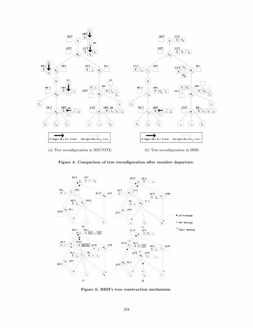
(a) Tree reconfiguration in REUNITE. (b) Tree reconfiguration in HBH.
Figure 4: Comparison of tree reconfiguration after member departure.
Figure 5: HBH’s tree construction mechanism.
254

branching point to the distribution tree. The problem ofFigure 3 is simply resolved through the transmission of afusion(S, r1, r2) from H6 upstream to the source, similarlyto the example just presented.
4. PERFORMANCE ANALYSISWe used NS (Network Simulator)[10] to simulate HBH.
Our objectives were to experiment HBH’s tree mechanismsas well as to compare HBH and REUNITE through the anal-ysis of the constructed trees. We analyzed the average delayexperienced by all the receivers of the group and the numberof copies of the same packet that are transmitted to reachall receivers.
4.1 Simulation scenarioThe first topology used in our simulations is shown in
Figure 6. This topology is typical of a large ISP’s network[1]. Without loss of generality, we suppose that only onereceiver is connected to each node in the topology. Thepresence of one or many receivers attached to a border routerthrough IGMP [12] does not influence the cost of the tree, sowe do not consider the aggregation provided by the multicastservice at the local network level. Nodes 0 to 17 in Figure6 are routers whereas nodes 18 to 35 are potential receiversof the multicast channel. We have also simulated a random-generated topology with 50 nodes and higher connectivity(8.6 versus 3.3).
Figure 6: The ISP topology.
We associate two costs, c(n1, n2) and c(n2, n1), to link n1-n2. Each cost is an integer randomly chosen in the interval[1, 10]. Simulations consider one multicast group from 1 toN where node 18 is fixed as source. A variable numberof randomly chosen receivers join the channel. For eachgroup size we realized 500 simulation runs per protocol. Theplotted results are the average of the 500 experiments.
4.2 ResultsWe compared HBH to REUNITE and two classical mul-
ticast approaches that are available in NS. NS has a multi-cast routing protocol that is able to construct shared treesand source trees with the same structure as the trees con-structed by the PIM-SM protocol. The difference is thatNS’s implementation is centralized and the change from theshared tree to the source tree is realized through an explicitcommand, and not automatically as in the original PIM-SM [9]. Therefore, PIM-SM in our simulations refers to aprotocol that constructs exclusively shared trees, whereasPIM-SS is a protocol that only constructs source trees. Thetree structure of PIM-SS is the same as that of PIM-SSM[3], i.e., a reverse SPT. In addition to HBH, we implementedREUNITE according to [21]. All routers implement the mul-ticast service in our experiments.
20
30
40
50
60
70
80
90
100
110
2 4 6 8 10 12 14 16
Num
ber
of p
acke
t cop
ies
Number of receivers
Tree cost
PIM−SMPIM−SS
REUNITEHBH
(a) ISP topology.
50
100
150
200
250
300
350
5 10 15 20 25 30 35 40 45
Num
ber
of p
acke
t cop
ies
Number of receivers
Tree cost
PIM-SMPIM-SS
REUNITEHBH
(b) 50-node random topology.
Figure 7: Average number of packet copies.
255

4.2.1 Tree costWe first evaluated the cost of the trees constructed by the
different multicast routing protocols. We define the cost ofa tree as the number of copies of the same packet that aretransmitted in the network links. Therefore, the tree costis different from the number of links in the tree since therecursive unicast technique may send more than one copyof the same packet over a specific link. This may be dueto the network’s routing asymmetries (as shown is Section2.3) but also to unicast routers inside the network that arenot able to be branching nodes. In this case, the locationof a branching node may not be the ideal. Nevertheless, asin our experiments all routers are multicast capable, extrapacket copies are always due to routing asymmetries.Figure 7 shows the average cost of the multicast trees
constructed by the different protocols as the number of re-ceivers varies. For the ISP topology, PIM-SM constructs thetrees with the highest cost in most cases. This result wasexpected since PIM-SM constructs shared trees. As we sim-ulated the distribution from one source to many receivers,the utilization of a shared tree is disadvantageous since thetree is centered on a rendez-vous point (RP). With a highprobability this tree has a higher cost than the equivalentsource tree. HBH and PIM-SS construct the cheapest trees.This result is expected since PIM-SS constructs source treesbased on the RPF algorithm, which guarantees that at themaximum one copy of the same packet is transmitted ateach link, and that each receiver is connected to the sourcetrough the reverse shortest-path. HBH performs similar toPIM-SS because in HBH each receiver is connected to thesource through the shortest path. Using this path or thereverse shortest path does not influence tree cost.The REUNITE curves in Figure 7 demonstrate that the
tree construction mechanism of REUNITE effectively suf-fers from the pathological cases produced by asymmetricunicast routing, as we presented in Section 2.3. The phe-nomenon is less frequent with a small number of receivers,since the probability that two receivers share the same linkin the multicast tree is smaller. For the ISP topology, theproblem is also less severe when the number of receiversis huge (receiver distribution is dense) since a big percent-age of network links is anyway used in the distribution tree.Nevertheless, this is not the case for the 50-node topology.This topology has a much higher connectivity, which meansthat a smaller percentage of network links is used. In thistopology HBH’s advantage increases with the group size.REUNITE also performs worse than PIM-SM shared treesas a consequence of badly placed branching nodes which leadto useless packet duplications.The analysis of the HBH curve shows the enhanced effi-
ciency of HBH’s tree construction mechanism. In terms oftree cost, the advantage of HBH over REUNITE is as largeas 5% for the ISP topology and 18% for the 50-node topol-ogy, in average over all group sizes. We conclude that HBHpotentially provides a better bandwidth utilization than RE-UNITE for asymmetric networks.
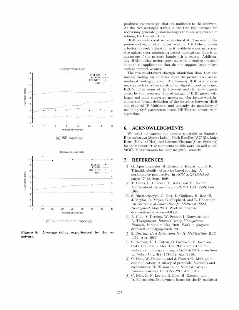
4.2.2 DelayFigure 8 presents the average delay experienced by the
receivers in the multicast channel for the same set of sim-ulations. The curves show that HBH is effectively able togenerate better quality routes than REUNITE in the pres-ence of asymmetric unicast routing.
Figure 8(a) shows two unexpected results. First, PIM-SM performs better that PIM-SS in terms of delay for theISP topology (in other words, the shared trees have a bet-ter delay performance than the source trees). This fact isexplained because PIM-SS tree is a reverse SPT and not aSPT. So delay is not minimized. Delay is not minimizedeither in the shared tree constructed by PIM-SM. But inthe shared tree, the paths from the source to the differentreceivers all have one common portion, namely, the pathbetween the source and the RP. As data is encapsulated inunicast between the source and the RP, delay is minimizedbetween the source and the RP. Consequently, paths in thePIM-SM tree have two parts: from the source to the RPwhere delay is minimized and from the RP to the receiverwhere it is not minimized since it is a reverse shortest path.This explains the advantage of PIM-SM over PIM-SS. Thesame was not observed for the 50-node topology because thistopology is larger and has a higher connectivity. Thereforegoing through the RP is likely to result in a longer path thangoing directly from the source to the receiver. The expectedresult is observed, the shared tree having the worst delayperformance in this case.The second important remark for the ISP topology is that
the effect of the network asymmetries in the quality of RE-UNITE trees may be strong, as REUNITE performed worsethan PIM-SM when the receiver set is large. REUNITE per-forms better than PIM-SM in the 50-node topology, as thistopology has a higher connectivity.The delay performance of HBH is better than that of RE-
UNITE for all group sizes, in both topologies. The advan-tage becomes larger as the number of receivers grows, beingof 14% in average for the ISP topology. The absolute valuesfor the 50-node topology are smaller as this topology has ahigher connectivity. On the other hand, the advantage ob-tained by HBH over REUNITE for this topology is larger(30% in average). This is a consequence of its richer connec-tivity, as the routing protocol has more choices to constructthe distribution tree, and is consequently more vulnerableto unicast routing asymmetries.
5. CONCLUSIONSWe presented HBH, a multicast routing protocol that im-
plements multicast distribution through recursive unicasttrees, idea originally proposed in REUNITE [21]. HBH al-lows the incremental deployment of the multicast service asunicast routers inside the network are transparently sup-ported. The observation of the strengths and weaknesses ofREUNITE and EXPRESS directed the design of HBH. Theobjectives of HBH are:
• to go through unicast clouds;
• member departure should have minimum impact onthe tree structure;
• to provide lower cost trees in the cases where RE-UNITE tree construction fails;
• to guarantee that members receive data through theshortest path from the source.
HBH has an original tree management algorithm that isbased on three messages. Join messages are periodicallysent to the source by the receivers. The source periodically
256
10
11
12
13
14
15
16
17
18
2 4 6 8 10 12 14 16
Del
ay (
time
units
)
Number of receivers
Receiver Average delay
PIM−SMPIM−SS
REUNITEHBH
(a) ISP topology.
0
2
4
6
8
10
12
14
16
5 10 15 20 25 30 35 40 45
Del
ay (
time
units
)
Number of receivers
Receiver average delay
PIM-SMPIM-SS
REUNITEHBH
(b) 50-node random topology.
Figure 8: Average delay experienced by the re-ceivers.
produces tree messages that are multicast to the receivers.As the tree messages travels in the tree the intermediatenodes may generate fusion messages that are responsible ofrefining the tree structure.HBH is able to construct a Shortest-Path Tree even in the
presence of asymmetric unicast routing. HBH also providesa better network utilization as it is able to construct recur-sive unicast trees minimizing packet duplication. This is anadvantage if the network bandwidth is scarce. Addition-ally, HBH’s delay performance makes it a routing protocoladapted to applications that do not support large delayssuch as interactive ones.The results obtained through simulation show that the
unicast routing asymmetries affect the performance of themulticast routing protocol. Additionally, HBH is a promis-ing approach as its tree construction algorithm outperformedREUNITE in terms of the tree cost and the delay experi-enced by the receivers. The advantage of HBH grows withlarger and more connected networks. Our future work in-cludes the formal definition of the interface between HBHand classical IP Multicast, and to study the possibility ofincluding QoS parameters inside HBH’s tree constructionalgorithm.
6. ACKNOWLEDGMENTSWe insist to express our sincere gratitude to Supratik
Bhattacharyya (Sprint Labs.), Mark Handley (ACIRI), LuigiRizzo (Univ. of Pisa), and Lorenzo Vicisano (Cisco Systems)for their constructive comments on this work, as well as theSIGCOMM reviewers for their insightful remarks.
7. REFERENCES[1] G. Apostolopoulos, R. Guerin, S. Kamat, and S. K.
Tripathi. Quality of service based routing: Aperformance perspective. In ACM SIGCOMM’98,pages 17–28, Sept. 1998.
[2] T. Bates, R. Chandra, D. Katz, and Y. Rekhter.Multiprotocol Extensions for BGP-4. RFC 2283, Feb.1998.
[3] S. Bhattacharyya, C. Diot, L. Giuliano, R. Rockell,J. Meylor, D. Meyer, G. Shepherd, and B. Haberman.An Overview of Source-Specific Multicast (SSM)Deployment, May 2001. Work in progress:draft-ietf-ssm-overview-00.txt.
[4] B. Cain, S. Deering, W. Fenner, I. Kouvelas, andA. Thyagarajan. Internet Group ManagementProtocol, Version 3, Mar. 2001. Work in progress:draft-ietf-idmr-igmp-v3-07.txt.
[5] S. Deering. Host Extensions for IP Multicasting. RFC1112, Aug. 1989.
[6] S. Deering, D. L. Estrin, D. Farinacci, V. Jacobson,C.-G. Liu, and L. Mei. The PIM architecture forwide-area multicast routing. IEEE/ACM Transactionson Networking, 4(2):153–162, Apr. 1996.
[7] C. Diot, W. Dabbous, and J. Crowcroft. Multipointcommunication: A survey of protocols, functions andmechanisms. IEEE Journal on Selected Areas inCommunications, 15(3):277–290, Apr. 1997.
[8] C. Diot, B. N. Levine, B. Liles, H. Kassem, andD. Balensiefen. Deployment issues for the IP multicast
257
service and architecture. IEEE Network, pages 78–88,Jan. 2000.
[9] D. Estrin, D. Farinacci, A. Helmy, D. Thaler,S. Deering, M. Handley, V. Jacobson, C. Liu,P. Sharma, and L. Wei. Protocol IndependentMulticast-Sparse Mode (PIM-SM): ProtocolSpecification. RFC 2362, June 1998.
[10] K. Fall and K. Varadhan. The ns Manual. UCBerkeley, LBL, USC/ISI, and Xerox PARC, Jan. 2001.Available at http://www.isi.edu/nsnam/ns/ns-documentation.html.
[11] B. Fenner, M. Handley, H. Holbrook, and I. Kouvelas.Protocol Independent Multicast - Sparse Mode(PIM-SM): Protocol Specification (Revised), Mar.2001. Work in progress:draft-ietf-pim-sm-v2-new-02.txt.
[12] W. Fenner. Internet Group Management Protocol,Version 2. RFC 2236, Nov. 1997.
[13] R. Finlayson. The UDP Multicast Tunneling Protocol,Mar. 2001. Work in progress:draft-finlayson-umtp-06.txt.
[14] R. Finlayson, R. Perlman, and D. Rajwan.Accelerating the Deployment of Multicast UsingAutomatic Tunneling, Feb. 2001. Work in progress:draft-finlayson-mboned-autotunneling-00.txt.
[15] S. Hanks, T. Li, D. Farinacci, and P. Traina. GenericRouting Encapsulation (GRE). RFC 1701, Oct. 1994.
[16] H. W. Holbrook and D. R. Cheriton. IP multicastchannels: EXPRESS support for large-scalesingle-source applications. In ACM SIGCOMM’99,Sept. 1999.
[17] P. Liefooghe and M. Goossens. An architecture forseamless access to multicast content. In IEEEConference on Local Computer Networks, Nov. 2000.
[18] D. Meyer (Editor) and B. Fenner (Editor). MulticastSource Discovery Protocol (MSDP), May 2001. Workin progress: draft-ietf-msdp-spec-10.txt.
[19] J. Moy. Multicast Extensions to OSPF. RFC 1584,Mar. 1994.
[20] V. Paxson. End-to-end routing behavior in theinternet. IEEE/ACM Transactions on Networking,5(5):601–615, Oct. 1997.
[21] I. Stoica, T. S. E. Ng, and H. Zhang. REUNITE: Arecursive unicast approach to multicast. In IEEEINFOCOM’2000, Mar. 2000.
[22] D. Thaler, M. Talwar, L. Vicisano, and D. Ooms. IPv4Automatic Multicast Without Explicit Tunnels, Feb.2001. Work in progress:draft-ietf-mboned-auto-multicast-00.txt.
[23] D. Waitzman, C. Partridge, and S. Deering. DistanceVector Multicast Routing Protocol. RFC 1075, Nov.1988.
APPENDIX
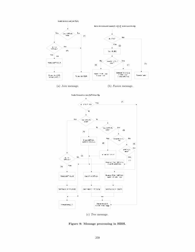
A. MESSAGE PROCESSING IN HBHFigure 9 presents the processing rules of the three message
types used by HBH to construct the distribution tree. Eachreceiver r periodically sends a join(S, r) in unicast to thesource. The source periodically multicasts a tree messagefor each <S, G> channel.
Join message (Figure 9(a)) - When router B receives ajoin(S, R), it should forward this message unchanged if Bhas no MFT (1) or if R is not in B’s MFT (2). Only if B’sMFT has a R entry, B intercepts the join(S, R) and sends ajoin(S, B) afterwards. It means that B is a branching nodeof the channel <S, G> (3).
Tree message (Figure 9(c)) - A tree(S, R) message re-ceived by router B is treated and forwarded in multicast.If B is a branching node, it may receive a tree messageaddressed to B. In this case B discards the message andsends a tree message to each node present in its MFT (1).If B is a branching node and tree(S, R) is not addressed toB, there is two possibilities: R is a new receiver (in whichcase B inserts R in its MFT and sends a fusion messageupstream) (2) or R is present in B’s MFT - which meansthat B does not receive join(S, R) messages from R - andin this case B simply has to refresh the R entry in its MFTand to send a fusion message upstream (3). If B is not abranching node, there is two possible cases: B was not in S’sdistribution tree in which case B creates a MCT containingR (4), or B was already in the distribution tree but was nota branching node (in which case B has a MCT<S>) (5).If R was already present in B’s MCT, nothing has changedand B simply refreshes its MCT (6). If R is not presentin the MCT, then maybe the MCT is stale in which caseR replaces the previous MCT entry, or the MCT is up todate which means that there is a second receiver that willreceive data through B, so B becomes a branching node.This implies the creation of a MFT, the destruction of theMCT, and a fusion message to be sent upstream (8). Thefusion messages produced by B contain all the nodes thatB maintains in its MFT - the nodes for which B is branch-ing node.
Fusion message (Figure 9(b)) - Suppose router B receivesa fusion(S, R, ...Rn) from node Bp. If the message is notaddressed to B, then B simply forwards it upstream (1). Ifthe message is addressed to B, then B marks the receiverentries in its MFT that are listed in the fusion message(2). A marked entry in the MFT is used to tree messageforwarding but not for data distribution. Bp is added to B’sMFT if it was not previously present. In addition, Bp’s t1timer is expired - Bp becomes stale (3). Consequently, Bp
will be used for data forwarding, but not for tree messageforwarding. If Bp was already present in B’s MFT, thenBp’s t2 timer is refreshed (it avoids the destruction of theBp entry), but its t1 timer is kept expired (4).If afterwards Bp (the node that produced the fusion for
R, ...Rn) receives the join messages produced by any ofR, ...Rn, it intercepts them and send a join(S, Bp) upstream.In this case the R, ...Rn entries in B’s MFT will eventuallytimeout and be destroyed, while the Bp entry in B’s MFTis refreshed by the join(S, Bp). If Bp does not receive joinmessages from R, ...Rn, the emission of fusion messagescontinues since there is another node upper in the tree thatreceives the join(S, R, ...Rn) and periodically produce thetree(S, R, ...Rn) messages to these receivers. Nevertheless,this node will not forward data to these receivers, but toBp instead since the receivers’ entries are marked. Bp isresponsible for data duplication. It is in this way that HBHis able to manage the second asymmetry problem presentedin Section 2.3.
258
(a) Join message. (b) Fusion message.
(c) Tree message.
Figure 9: Message processing in HBH.
259