
Implementing Layer-3 Multicast Routing on Cisco IOS XR ...
276
Implementing Layer-3 Multicast Routing on Cisco IOS XR Software This module describes how to implement Layer 3 multicast routing on Cisco ASR 9000 Series Routers running Cisco IOS XR Software. Multicast routing is a bandwidth-conserving technology that reduces traffic by simultaneously delivering a single stream of information to potentially thousands of corporate recipients and homes. Applications that take advantage of multicast routing include video conferencing, corporate communications, distance learning, and distribution of software, stock quotes, and news. This document assumes that you are familiar with IPv4 and IPv6 multicast routing configuration tasks and concepts for Cisco IOS XR Software . Multicast routing allows a host to send packets to a subset of all hosts as a group transmission rather than to a single host, as in unicast transmission, or to all hosts, as in broadcast transmission. The subset of hosts is known as group members and are identified by a single multicast group address that falls under the IP Class D address range from 224.0.0.0 through 239.255.255.255. For detailed conceptual information about multicast routing and complete descriptions of the multicast routing commands listed in this module, you can refer to the Related Documents, on page 274. Feature History for Configuring Multicast Routing on the Cisco ASR 9000 Series Routers Modification Release This feature was introduced. Release 3.7.2 Support was added for these features: • Flow-based multicast only fast reroute (MoFRR). • IGMP VRF override. Release 3.9.0 Support was added for the Multicast VPN feature. (For IPv4 address family) Release 3.9.1 Support was added for IPv4 Multicast routing, Multicast VPN basic and InterAS option A on Cisco ASR 9000 Series SPA Interface Processor-700 linecard and MVPN Hub and Spoke Topology. Release 4.0.0 Support was added for IPv6 Multicast routing. Release 4.0.1 Implementing Layer-3 Multicast Routing on Cisco IOS XR Software 1
-
Upload
khangminh22 -
Category
Documents
-
view
0 -
download
0
Transcript of Implementing Layer-3 Multicast Routing on Cisco IOS XR ...

Implementing Layer-3 Multicast Routing on CiscoIOS XR Software
This module describes how to implement Layer 3 multicast routing on Cisco ASR 9000 Series Routers runningCisco IOS XR Software.
Multicast routing is a bandwidth-conserving technology that reduces traffic by simultaneously delivering asingle stream of information to potentially thousands of corporate recipients and homes. Applications thattake advantage of multicast routing include video conferencing, corporate communications, distance learning,and distribution of software, stock quotes, and news.
This document assumes that you are familiar with IPv4 and IPv6 multicast routing configuration tasks andconcepts for Cisco IOS XR Software .
Multicast routing allows a host to send packets to a subset of all hosts as a group transmission rather than toa single host, as in unicast transmission, or to all hosts, as in broadcast transmission. The subset of hosts isknown as group members and are identified by a single multicast group address that falls under the IP ClassD address range from 224.0.0.0 through 239.255.255.255.
For detailed conceptual information about multicast routing and complete descriptions of the multicast routingcommands listed in this module, you can refer to the Related Documents, on page 274.
Feature History for Configuring Multicast Routing on the Cisco ASR 9000 Series Routers
ModificationRelease
This feature was introduced.Release 3.7.2
Support was added for these features:
• Flow-based multicast only fast reroute (MoFRR).
• IGMP VRF override.
Release 3.9.0
Support was added for the Multicast VPN feature. (For IPv4 address family)Release 3.9.1
Support was added for IPv4 Multicast routing, Multicast VPN basic and InterAS option Aon Cisco ASR 9000 Series SPA Interface Processor-700 linecard and MVPN Hub and SpokeTopology.
Release 4.0.0
Support was added for IPv6 Multicast routing.Release 4.0.1
Implementing Layer-3 Multicast Routing on Cisco IOS XR Software1

ModificationRelease
Support was added for Label SwitchedMulticast using Point-to-Multipoint Traffic Engineeringin global context only (not in VRF).
Release 4.1.0
Support was added for these features:
• Label Switched Multicast using MLDP (Multicast Label Distribution Protocol).
• Multicast VPN for IPv6 address family.
• Support for Satellite nV.
• InterAS Support on Multicast VPN.
Release 4.2.1
Support was added for these features:
• Support for IPv4 traffic on Multicast over unicast GRE was introduced.
• Support was added for TI (Topology Independent) MoFRR.
Release 4.3.2
Support was introduced for Bidirectional Global Protocol Independent Multicast.Release 5.2.0
Support for IPv6 traffic and ECMP on Multicast over unicast GRE was introduced.Release 5.3.2
Support for Segmented Multicast Stitching with Inter AS was introduced.Release 6.0.0
Support for MLDP Carrier Supporting Carrier based MVPN was introduced.Release 6.0.0
Layer 3 Multicast Bundle Subinterface Load Balancing feature was introduced.Release 6.1.2
Segmented Multicast Stitching with Inter AS and MLDP Carrier Supporting Carrier basedMVPN feature support was extended to support Cisco IOS XR 64 bit.
Release 6.1.2
MVPN,MoGRE,MoFRR andGlobal TableMulticast feature support was extended to supportCisco IOS XR 64 bit.
Release 6.1.2
• Prerequisites for Implementing Multicast Routing, on page 3• Information About Implementing Multicast Routing, on page 3• Layer 3 Multicast Bundle Subinterface Load Balancing, on page 125• How to Implement Multicast Routing, on page 128• Multicast only fast reroute (MoFRR), on page 195• Enabling multicast on PW-HE interfaces, on page 201• Configuring Route Policy for Static RPF, on page 204• Point-to-Multipoint Traffic Engineering Label-Switched Multicast, on page 205• Configuring IGMP VRF Override, on page 209• MVPN GRE over PWHE with CSI, on page 212• Configuration Examples for Implementing Multicast Routing on Software, on page 213• Additional References, on page 274
Implementing Layer-3 Multicast Routing on Cisco IOS XR Software2
Implementing Layer-3 Multicast Routing on Cisco IOS XR Software

Prerequisites for Implementing Multicast Routing• You must install and activate the multicast pie.
• For detailed information about optional PIE installation, see Cisco ASR 9000 Series Aggregation ServicesRouter Getting Started Guide
• For MLDP, an MPLS PIE has to be installed.
• You must be in a user group associated with a task group that includes the proper task IDs. The commandreference guides include the task IDs required for each command. If you suspect user group assignmentis preventing you from using a command, contact your AAA administrator for assistance.
• You must be familiar with IPv4 and IPv6 multicast routing configuration tasks and concepts.
• Unicast routing must be operational.
• To enable multicast VPN, you must configure a VPN routing and forwarding (VRF) instance.
Information About Implementing Multicast Routing
Key Protocols and Features Supported in the Cisco IOS XR Software MulticastRouting Implementation
Table 1: Supported Features for IPv4 and IPv6
IPv6Support
IPv4 SupportFeature
YesYes (IGMP v1/2/3)Dynamic host registration
YesYes (IGMP v3)Explicit tracking of hosts, groups, and channels
YesYesPIM-SM1
YesYesPIM-SSM
YesYesPIM-SSM Mapping
NoYesAuto-RP
YesYesMulticast VPN
YesYesInterAS Option A
YesYesBSR
YesYesBGP
NoYesMSDP
Implementing Layer-3 Multicast Routing on Cisco IOS XR Software3
Implementing Layer-3 Multicast Routing on Cisco IOS XR SoftwarePrerequisites for Implementing Multicast Routing

IPv6Support
IPv4 SupportFeature
YesYesMulticast NSF
YesYesOOR handling
YesYesGlobal Protocol Independent Multicast Bidirectional support
1
Multicast Routing Functional OverviewTraditional IP communication allows a host to send packets to a single host (unicast transmission) or to allhosts (broadcast transmission). Multicast provides a third scheme, allowing a host to send a single data streamto a subset of all hosts (group transmission) at about the same time. IP hosts are known as group members.
Packets delivered to group members are identified by a single multicast group address. Multicast packets aredelivered to a group using best-effort reliability, just like IP unicast packets.
The multicast environment consists of senders and receivers. Any host, regardless of whether it is a memberof a group, can send to a group. However, only the members of a group receive the message.
A multicast address is chosen for the receivers in a multicast group. Senders use that group address as thedestination address of a datagram to reach all members of the group.
Membership in a multicast group is dynamic; hosts can join and leave at any time. There is no restriction onthe location or number of members in a multicast group. A host can be a member of more than one multicastgroup at a time.
How active a multicast group is and what members it has can vary from group to group and from time to time.A multicast group can be active for a long time, or it may be very short-lived. Membership in a group canchange constantly. A group that has members may have no activity.
Routers use the Internet GroupManagement Protocol (IGMP) (IPv4) andMulticast Listener Discovery (MLD)(IPv6) to learn whether members of a group are present on their directly attached subnets. Hosts join multicastgroups by sending IGMP or MLD report messages.
Many multimedia applications involve multiple participants. Multicast is naturally suitable for thiscommunication paradigm.
Multicast Routing ImplementationCisco IOS XR Software supports the following protocols to implement multicast routing:
• IGMP is used between hosts on a LAN and the routers on that LAN to track the multicast groups ofwhich hosts are members.
• Protocol Independent Multicast in sparse mode (PIM-SM) is used between routers so that they can trackwhich multicast packets to forward to each other and to their directly connected LANs.
• Protocol Independent Multicast in Source-Specific Multicast (PIM-SSM) is similar to PIM-SM with theadditional ability to report interest in receiving packets from specific source addresses (or from all butthe specific source addresses), to an IP multicast address.
Implementing Layer-3 Multicast Routing on Cisco IOS XR Software4
Implementing Layer-3 Multicast Routing on Cisco IOS XR SoftwareMulticast Routing Functional Overview

• PIM-SSM is made possible by IGMPv3 and MLDv2. Hosts can now indicate interest in specific sourcesusing IGMPv3 and MLDv2. SSM does not require a rendezvous point (RP) to operate.
• PIM Bidirectional is a variant of the Protocol Independent Multicast suit of routing protocols for IPmulticast. PIM-BIDIR is designed to be used for many-to-many applications within individual PIMdomains.
This image shows IGMP and PIM-SM operating in a multicast environment.
Figure 1: Multicast Routing Protocols
PIM-SM, PIM-SSM, and PIM-BIDIRProtocl Independent Multicast (PIM) is a multicast routing protocol used to create multicast distribution trees,which are used to forward multicast data packets. PIM is an efficient IP routing protocol that is “independent”of a routing table, unlike other multicast protocols such as Multicast Open Shortest Path First (MOSPF) orDistance Vector Multicast Routing Protocol (DVMRP).
Cisco IOS XR Software supports Protocol Independent Multicast in sparse mode (PIM-SM), ProtocolIndependent Multicast in Source-Specific Multicast (PIM-SSM), and Protocol Independent Multicast inBi-directional mode (BIDIR) permitting these modes to operate on your router at the same time.
PIM-SM and PIM-SSM supports one-to-many applications by greatly simplifying the protocol mechanics fordeployment ease. Bidir PIM helps deploy emerging communication and financial applications that rely on amany-to-many applications model. BIDIR PIM enables these applications by allowing them to easily scaleto a very large number of groups and sources by eliminating the maintenance of source state.
PIM-SM OperationsPIM in sparse mode operation is used in a multicast network when relatively few routers are involved in eachmulticast and these routers do not forward multicast packets for a group, unless there is an explicit requestfor the traffic.
For more information about PIM-SM, see the PIM-Sparse Mode, on page 9.
Implementing Layer-3 Multicast Routing on Cisco IOS XR Software5
Implementing Layer-3 Multicast Routing on Cisco IOS XR SoftwarePIM-SM, PIM-SSM, and PIM-BIDIR

PIM-SSM OperationsPIM in Source-Specific Multicast operation uses information found on source addresses for a multicast groupprovided by receivers and performs source filtering on traffic.
• By default, PIM-SSM operates in the 232.0.0.0/8 multicast group range for IPv4 and ff3x::/32 (where xis any valid scope) in IPv6. To configure these values, use the ssm range command.
• If SSM is deployed in a network already configured for PIM-SM, only the last-hop routers must beupgraded with Cisco IOS XR Software that supports the SSM feature.
• No MSDP SA messages within the SSM range are accepted, generated, or forwarded.
PIM-Bidirectional OperationsPIM Bidirectional (BIDIR) has one shared tree from sources to RP and from RP to receivers. This is unlikethe PIM-SM, which is unidirectional by nature with multiple source trees - one per (S,G) or a shared tree fromreceiver to RP and multiple SG trees from RP to sources.
Benefits of PIM BIDIR are as follows:
• As many sources for the same group use one and only state (*, G), only minimal states are required ineach router.
• No data triggered events.
• Rendezvous Point (RP) router not required. The RP address only needs to be a routable address and neednot exist on a physical device.
Restrictions for PIM-SM and PIM-SSM, and PIM BIDIR
Interoperability with SSM
PIM-SM operations within the SSM range of addresses change to PIM-SSM. In this mode, only PIM (S,G)join and prune messages are generated by the router, and no (S,G) RP shared tree or (*,G) shared tree messagesare generated.
IGMP Version
To report multicast memberships to neighboring multicast routers, hosts use IGMP, and all routers on thesubnet must be configured with the same version of IGMP.
A router running Cisco IOS XR Software does not automatically detect Version 1 systems. You must use theversion command in router IGMP configuration submode to configure the IGMP version.
PIM-Bidir Restrictions
PIM-Bidir is not supported on MVPN.
Internet Group Management ProtocolCisco IOS XR Software provides support for Internet Group Management Protocol (IGMP) over IPv4.
Implementing Layer-3 Multicast Routing on Cisco IOS XR Software6
Implementing Layer-3 Multicast Routing on Cisco IOS XR SoftwarePIM-SSM Operations

IGMP provides a means for hosts to indicate which multicast traffic they are interested in and for routers tocontrol and limit the flow of multicast traffic throughout the network. Routers build state by means of IGMPand MLD messages; that is, router queries and host reports.
A set of queries and hosts that receive multicast data streams from the same source is called amulticast group.Hosts use IGMP and MLD messages to join and leave multicast groups.
IGMP messages use group addresses, which are Class D IP addresses. The high-order four bits of a Class Daddress are 1110. Host group addresses can be in the range 224.0.0.0 to 239.255.255.255. The address 224.0.0.0is guaranteed not to be assigned to any group. The address 224.0.0.1 is assigned to all systems on a subnet.The address 224.0.0.2 is assigned to all routers on a subnet.
Note
IGMP VersionsThe following points describe IGMP versions 1, 2, and 3:
• IGMP Version 1 provides for the basic query-response mechanism that allows the multicast router todetermine which multicast groups are active and for other processes that enable hosts to join and leavea multicast group.
• IGMP Version 2 extends IGMP allowing such features as the IGMP query timeout and the maximumquery-response time. See RFC 2236.
• IGMP Version 3 permits joins and leaves for certain source and group pairs instead of requesting trafficfrom all sources in the multicast group.
IGMP Routing ExampleFigure 2: IGMPv3 Signaling, on page 8 illustrates two sources, 10.0.0.1 and 10.0.1.1, that are multicastingto group 239.1.1.1. The receiver wants to receive traffic addressed to group 239.1.1.1 from source 10.0.0.1but not from source 10.0.1.1. The host must send an IGMPv3 message containing a list of sources and groups(S, G) that it wants to join and a list of sources and groups (S, G) that it wants to leave. Router C can now usethis information to prune traffic from Source 10.0.1.1 so that only Source 10.0.0.1 traffic is being deliveredto
Router C.
Implementing Layer-3 Multicast Routing on Cisco IOS XR Software7
Implementing Layer-3 Multicast Routing on Cisco IOS XR SoftwareIGMP Versions

Figure 2: IGMPv3 Signaling
When configuring IGMP, ensure that all systems on the subnet support the same IGMP version. The routerdoes not automatically detect Version 1 systems. Configure the router for Version 2 if your hosts do notsupport Version 3.
Note
Configuring IGMP Per Interface States LimitThe IGMP Per Interface States Limit sets a limit on creating OLEs for the IGMP interface. When the set limitis reached, the group is not accounted against this interface but the group can exist in IGMP context for someother interface.
The following configuration sets a limit on the number of group memberships created on an interface as aresult of receiving IGMP or MLD membership reports.
router igmp | mld [vrf <vrfname>]interface <ifname>
(no) maximum groups-per-interface <max> [threshold <threshold>][<acl>]
!!
where,
<ifname> is the interface name
<max> is the maximum limit on the groups
<threshold> is the threshold number of groups at which point a syslog warning message will be issued
Implementing Layer-3 Multicast Routing on Cisco IOS XR Software8
Implementing Layer-3 Multicast Routing on Cisco IOS XR SoftwareConfiguring IGMP Per Interface States Limit

<acl> provides an option for selective accounting. If provided, only groups or (S,G)s that are permitted bythe ACL is accounted against the limit. Groups or (S, G)s that are denied by the ACL are not accounted againstthe limit. If not provided, all the groups are accounted against the limit.
The following messages are displayed when the threshold limit is reached for IGMP:
igmp[1160]: %ROUTING-IPV4_IGMP-4-OOR_THRESHOLD_REACHED : Threshold for Maximum number ofgroup per interface has been reached 3: Groups joining will soon be throttled.Config a higher max or take steps to reduce states
igmp[1160]: %ROUTING-IPV4_IGMP-4-OOR_LIMIT_REACHED : Maximum number of group per interfacehas been reached 6: Groups joining is throttled.Config a higher max or take steps to reduce states
Limitations
• If a user has configured a maximum of 20 groups and has reached the maximum number of groups, thenno more groups can be created. If the user reduces the maximum number of groups to 10, the 20 joinswill remain and a message of reaching the maximum is displayed. No more joins can be added until thenumber of groups has reached less than 10.
• If a user already has configured a maximum of 30 joins and add a max of 20, the configuration occursdisplaying a message that the maximum has been reached. No state change occurs and also no more joinscan occur until the threshold number of groups is brought down below the maximum number of groups.
Protocol Independent MulticastProtocol Independent Multicast (PIM) is a routing protocol designed to send and receive multicast routingupdates. Proper operation of multicast depends on knowing the unicast paths towards a source or an RP. PIMrelies on unicast routing protocols to derive this reverse-path forwarding (RPF) information. As the namePIM implies, it functions independently of the unicast protocols being used. PIM relies on the RoutingInformation Base (RIB) for RPF information.
If the multicast subsequent address family identifier (SAFI) is configured for Border Gateway Protocol (BGP),or if multicast intact is configured, a separate multicast unicast RIB is created and populated with the BGPmulticast SAFI routes, the intact information, and any IGP information in the unicast RIB. Otherwise, PIMgets information directly from the unicast SAFI RIB. Both multicast unicast and unicast databases are outsideof the scope of PIM.
The Cisco IOS XR implementation of PIM is based on RFC 4601 Protocol Independent Multicast - SparseMode (PIM-SM): Protocol Specification. For more information, see RFC 4601 and the Protocol IndependentMulticast (PIM): Motivation and Architecture Internet Engineering Task Force (IETF) Internet draft.
Cisco IOSXR Software supports PIM-SM, PIM-SSM, and PIMVersion 2 only. PIMVersion 1 hello messagesthat arrive from neighbors are rejected.
Note
PIM-Sparse ModeTypically, PIM in sparse mode (PIM-SM) operation is used in a multicast network when relatively few routersare involved in each multicast. Routers do not forward multicast packets for a group, unless there is an explicit
Implementing Layer-3 Multicast Routing on Cisco IOS XR Software9
Implementing Layer-3 Multicast Routing on Cisco IOS XR SoftwareProtocol Independent Multicast

request for traffic. Requests are accomplished using PIM join messages, which are sent hop by hop towardthe root node of the tree. The root node of a tree in PIM-SM is the rendezvous point (RP) in the case of ashared tree or the first-hop router that is directly connected to the multicast source in the case of a shortestpath tree (SPT). The RP keeps track of multicast groups, and the sources that send multicast packets areregistered with the RP by the first-hop router of the source.
As a PIM join travels up the tree, routers along the path set up the multicast forwarding state so that therequested multicast traffic is forwarded back down the tree. When multicast traffic is no longer needed, arouter sends a PIM prune message up the tree toward the root node to prune (or remove) the unnecessarytraffic. As this PIM prune travels hop by hop up the tree, each router updates its forwarding state appropriately.Ultimately, the forwarding state associated with a multicast group or source is removed. Additionally, if prunesare not explicitly sent, the PIM state will timeout and be removed in the absence of any further join messages.
PIM-SM is the best choice for multicast networks that have potential members at the end of WAN links.
PIM-Source Specific MulticastIn many multicast deployments where the source is known, protocol-independent multicast-source-specificmulticast (PIM-SSM)mapping is the obvious multicast routing protocol choice to use because of its simplicity.Typical multicast deployments that benefit from PIM-SSM consist of entertainment-type solutions like theETTH space, or financial deployments that completely rely on static forwarding.
PIM-SSM is derived from PIM-SM. However, whereas PIM-SM allows for the data transmission of all sourcessending to a particular group in response to PIM join messages, the SSM feature forwards traffic to receiversonly from those sources that the receivers have explicitly joined. Because PIM joins and prunes are sentdirectly towards the source sending traffic, an RP and shared trees are unnecessary and are disallowed. SSMis used to optimize bandwidth utilization and deny unwanted Internet broadcast traffic. The source is providedby interested receivers through IGMPv3 membership reports.
In SSM, delivery of datagrams is based on (S,G) channels. Traffic for one (S,G) channel consists of datagramswith an IP unicast source address S and the multicast group address G as the IP destination address. Systemsreceive traffic by becoming members of the (S,G) channel. Signaling is not required, but receivers mustsubscribe or unsubscribe to (S,G) channels to receive or not receive traffic from specific sources. Channelsubscription signaling uses IGMP to include mode membership reports, which are supported only in Version3 of IGMP (IGMPv3).
To run SSM with IGMPv3, SSM must be supported on the multicast router, the host where the application isrunning, and the application itself. Cisco IOS XR Software allows SSM configuration for an arbitrary subsetof the IP multicast address range 224.0.0.0 through 239.255.255.255.When an SSM range is defined, existingIP multicast receiver applications do not receive any traffic when they try to use addresses in the SSM range,unless the application is modified to use explicit (S,G) channel subscription.
DNS-based SSM Mapping
DNS-based SSM mapping enables you to configure the last hop router to perform a reverse DNS lookup todetermine sources sending to groups (see the figure below). When DNS-based SSM mapping is configured,the router constructs a domain name that includes the group address G and performs a reverse lookup into theDNS. The router looks up IP address resource records (IP A RRs) to be returned for this constructed domainname and uses the returned IP addresses as the source addresses associated with this group. SSM mappingsupports up to 20 sources for each group. The router joins all sources configured for a group.
Implementing Layer-3 Multicast Routing on Cisco IOS XR Software10
Implementing Layer-3 Multicast Routing on Cisco IOS XR SoftwarePIM-Source Specific Multicast

Figure 3: DNS-based SSM Mapping
The SSMmapping mechanism that enables the last hop router to join multiple sources for a group can be usedto provide source redundancy for a TV broadcast. In this context, the redundancy is provided by the last hoprouter using SSM mapping to join two video sources simultaneously for the same TV channel. However, toprevent the last hop router from duplicating the video traffic, it is necessary that the video sources utilize aserver-side switchover mechanism where one video source is active while the other backup video source ispassive. The passive source waits until an active source failure is detected before sending the video traffic forthe TV channel. The server-side switchover mechanism, thus, ensures that only one of the servers is activelysending the video traffic for the TV channel.
To look up one or more source addresses for a group G that includes G1, G2, G3, and G4, the following DNSresource records (RRs) must be configured on the DNS server:
IN A source-address-1G4.G3.G2.G1 [ multicast-domain ] [ timeout ]
IN A source-address-2
IN A source-address-n
The multicast-domain argument is a configurable DNS prefix. The default DNS prefix is in-addr.arpa. Youshould only use the default prefix when your installation is either separate from the internet or if the groupnames that you map are global scope group addresses (RFC 2770 type addresses that you configure for SSM)that you own.
The timeout argument configures the length of time for which the router performing SSMmapping will cachethe DNS lookup. This argument is optional and defaults to the timeout of the zone in which this entry isconfigured. The timeout indicates how long the router will keep the current mapping before querying the DNSserver for this group. The timeout is derived from the cache time of the DNS RR entry and can be configuredfor each group/source entry on the DNS server. You can configure this time for larger values if you want tominimize the number of DNS queries generated by the router. Configure this time for a low value if you wantto be able to quickly update all routers with new source addresses.
See your DNS server documentation for more information about configuring DNS RRs.Note
Implementing Layer-3 Multicast Routing on Cisco IOS XR Software11
Implementing Layer-3 Multicast Routing on Cisco IOS XR SoftwareDNS-based SSM Mapping

To configure DNS-based SSM mapping in the software, you must configure a few global commands but noper-channel specific configuration is needed. There is no change to the configuration for SSM mapping ifadditional channels are added. When DNS-based SSM mapping is configured, the mappings are handledentirely by one or more DNS servers. All DNS techniques for configuration and redundancy managementcan be applied to the entries needed for DNS-based SSM mapping.
PIM-Bidirectional ModePIMBIDIR is a variant of the Protocol IndependentMulticast (PIM) suite of routing protocols for IP multicast.In PIM, packet traffic for a multicast group is routed according to the rules of the mode configured for thatmulticast group. In bidirectional mode, traffic is only routed along a bidirectional shared tree that is rooted atthe rendezvous point (RP) for the group. In PIM-BIDIR, the IP address of the RP acts as the key to havingall routers establish a loop-free spanning tree topology rooted in that IP address. This IP address does notneed to be a router, but can be any unassigned IP address on a network that is reachable throughout the PIMdomain. Using this technique is the preferred configuration for establishing a redundant RP configuration forPIM-BIDIR.
In Cisco IOS XR Release 4.2.1, Anycast RP is not supported on PIM Bidirectional mode.Note
PIM-BIDIR is designed to be used for many-to-many applications within individual PIM domains. Multicastgroups in bidirectional mode can scale to an arbitrary number of sources without incurring overhead due tothe number of sources. PIM-BIDIR is derived from the mechanisms of PIM-sparse mode (PIM-SM) andshares many SPT operations. PIM-BIDIR also has unconditional forwarding of source traffic toward the RPupstream on the shared tree, but no registering process for sources as in PIM-SM. These modifications arenecessary and sufficient to allow forwarding of traffic in all routers solely based on the (*, G) multicast routingentries. This feature eliminates any source-specific state and allows scaling capability to an arbitrary numberof sources.
The traditional PIM protocols (dense-mode and sparse-mode) provided two models for forwarding multicastpackets, source trees and shared trees. Source trees are rooted at the source of the traffic while shared treesare rooted at the rendezvous point. Source trees achieve the optimum path between each receiver and thesource at the expense of additional routing information: an (S,G) routing entry per source in the multicastrouting table. The shared tree provides a single distribution tree for all of the active sources. This means thattraffic from different sources traverse the same distribution tree to reach the interested receivers, thereforereducing the amount of routing state in the network. This shared tree needs to be rooted somewhere, and thelocation of this root is the rendezvous point. PIMBIDIR uses shared trees as their main forwardingmechanism.
The algorithm to elect the designated forwarder is straightforward, all the PIM neighbors in a subnet advertisetheir unicast route to the rendezvous point and the router with the best route is elected. This effectively buildsa shortest path between every subnet and the rendezvous point without consuming any multicast routing state(no (S,G) entries are generated). The designated forwarder electionmechanism expects all of the PIM neighborsto be BIDIR enabled. In the case where one of more of the neighbors is not a BIDIR capable router, the electionfails and BIDIR is disabled in that subnet.
Configuring PIM Per Interface States LimitThe PIM Per Interface States Limit sets a limit on creating OLEs for the PIM interface. When the set limit isreached, the group is not accounted against this interface but the group can exist in PIM context for someother interface.
Implementing Layer-3 Multicast Routing on Cisco IOS XR Software12
Implementing Layer-3 Multicast Routing on Cisco IOS XR SoftwarePIM-Bidirectional Mode

The following configuration sets a limit on the number of routes for which the given interface may be anoutgoing interface as a result of receiving a PIM J/P message.
router pim | pim6 [vrf <vrfname>]interface <ifname>
maximum route-interfaces <max> [threshold <threshold>] [<acl>]!!
where,
<ifname> is the interface name
<max> is the maximum limit on the groups
<threshold> is the threshold number of groups at which point a syslog warning message will be issued
<acl> provides an option for selective accounting. If provided, only groups or (S,G)s that are permitted bythe ACL is accounted against the limit. Groups or (S, G)s that are denied by the ACL are not accounted againstthe limit. If not provided, all the groups are accounted against the limit.
The following messages are displayed when the threshold limit is reached for PIM:
pim[1157]: %ROUTING-IPV4_PIM-4-CAC_STATE_THRESHOLD : The interface GigabitEthernet0_2_0_0threshold number (4) allowed states has been reached.State creation will soon be throttled. Configure a higher state limit value or take stepsto reduce the number of states.
pim[1157]: %ROUTING-IPV4_PIM-3-CAC_STATE_LIMIT : The interface GigabitEthernet0_2_0_0 maximumnumber (5) of allowed states has been reached.State creation will not be allowed from here on. Configure a higher maximum value or takesteps to reduce the number of states
Limitations
• If a user has configured a maximum of 20 groups and has reached the maximum number of groups, thenno more groups/OLEs can be created. If the user now decreases the maximum number to 10, the 20joins/OLEwill remain and a message of reaching the max is displayed. No more joins/OLE can be addedat this point until it has reached less than 10.
• If a user already has configured a maximum of 30 joins/OLEs and add a max of 20, the configurationoccurs displaying a message that the max has been reached. No states will change but no more joins/OLEscan happen until the number is brought down below the maximum number of groups.
• Local interest joins are added, even if the limit has reached and is accounted for it.
PIM Shared Tree and Source Tree (Shortest Path Tree)In PIM-SM, the rendezvous point (RP) is used to bridge sources sending data to a particular group withreceivers sending joins for that group. In the initial setup of state, interested receivers receive data from sendersto the group across a single data distribution tree rooted at the RP. This type of distribution tree is called ashared tree or rendezvous point tree (RPT) as illustrated in Figure 4: Shared Tree and Source Tree (ShortestPath Tree), on page 14 . Data from senders is delivered to the RP for distribution to group members joinedto the shared tree.
Implementing Layer-3 Multicast Routing on Cisco IOS XR Software13
Implementing Layer-3 Multicast Routing on Cisco IOS XR SoftwarePIM Shared Tree and Source Tree (Shortest Path Tree)

Figure 4: Shared Tree and Source Tree (Shortest Path Tree)
Unless the spt-threshold infinity command is configured, this initial state gives way as soon as traffic isreceived on the leaf routers (designated router closest to the host receivers). When the leaf router receivestraffic from the RP on the RPT, the router initiates a switch to a data distribution tree rooted at the sourcesending traffic. This type of distribution tree is called a shortest path tree or source tree. By default, theCisco IOS XR Software switches to a source tree when it receives the first data packet from a source.
The following process describes the move from shared tree to source tree in more detail:
1. Receiver joins a group; leaf Router C sends a join message toward RP.
2. RP puts link to Router C in its outgoing interface list.
3. Source sends data; Router A encapsulates data in Register and sends it to RP.
4. RP forwards data down the shared tree to Router C and sends a join message toward Source. At this point,data may arrive twice at the RP, once encapsulated and once natively.
5. When data arrives natively (unencapsulated) at RP, RP sends a register-stop message to Router A.
6. By default, receipt of the first data packet prompts Router C to send a join message toward Source.
7. When Router C receives data on (S,G), it sends a prune message for Source up the shared tree.
8. RP deletes the link to Router C from outgoing interface of (S,G). RP triggers a prune message towardSource.
Join and prune messages are sent for sources and RPs. They are sent hop by hop and are processed by eachPIM router along the path to the source or RP. Register and register-stop messages are not sent hop by hop.They are exchanged using direct unicast communication between the designated router that is directly connectedto a source and the RP for the group.
Implementing Layer-3 Multicast Routing on Cisco IOS XR Software14
Implementing Layer-3 Multicast Routing on Cisco IOS XR SoftwarePIM Shared Tree and Source Tree (Shortest Path Tree)

The spt-threshold infinity command lets you configure the router so that it never switches to the shortestpath tree (SPT).
Tip
Multicast-IntactThemulticast-intact feature provides the ability to run multicast routing (PIM) when Interior Gateway Protocol(IGP) shortcuts are configured and active on the router. Both Open Shortest Path First, version 2 (OSPFv2),and Intermediate System-to-Intermediate System (IS-IS) support the multicast-intact feature. MultiprotocolLabel Switching Traffic Engineering (MPLS-TE) and IP multicast coexistence is supported in Cisco IOS XRSoftware by using the mpls traffic-eng multicast-intact IS-IS or OSPF router command. See RoutingConfiguration Guide for Cisco ASR 9000 Series Routers for information on configuring multicast intact usingIS-IS and OSPF commands.
You can enable multicast-intact in the IGP when multicast routing protocols (PIM) are configured and IGPshortcuts are configured on the router. IGP shortcuts are MPLS tunnels that are exposed to IGP. The IGPsroute the IP traffic over these tunnels to destinations that are downstream from the egress router of the tunnel(from an SPF perspective). PIM cannot use IGP shortcuts for propagating PIM joins because reverse pathforwarding (RPF) cannot work across a unidirectional tunnel.
When you enable multicast-intact on an IGP, the IGP publishes a parallel or alternate set of equal-cost next-hopsfor use by PIM. These next-hops are called mcast-intact next-hops. The mcast-intact next-hops have thefollowing attributes:
• They are guaranteed not to contain any IGP shortcuts.
• They are not used for unicast routing but are used only by PIM to look up an IPv4 next hop to a PIMsource.
• They are not published to the Forwarding Information Base (FIB).
• When multicast-intact is enabled on an IGP, all IPv4 destinations that were learned through link-stateadvertisements are published with a set equal-cost mcast-intact next-hops to the RIB. This attributeapplies even when the native next-hops have no IGP shortcuts.
• In IS-IS, the max-paths limit is applied by counting both the native and mcast-intact next-hops together.(In OSPFv2, the behavior is slightly different.)
Designated RoutersCisco routers use PIM-SM to forward multicast traffic and follow an election process to select a designatedrouter (DR) when there is more than one router on a LAN segment.
The designated router is responsible for sending PIM register and PIM join and prune messages toward theRP to inform it about host group membership.
If there are multiple PIM-SM routers on a LAN, a designated router must be elected to avoid duplicatingmulticast traffic for connected hosts. The PIM router with the highest IP address becomes the DR for the LANunless you choose to force the DR election by use of the dr-priority command. The DR priority option allowsyou to specify the DR priority of each router on the LAN segment (default priority = 1) so that the router withthe highest priority is elected as the DR. If all routers on the LAN segment have the same priority, the highestIP address is again used as the tiebreaker.
Implementing Layer-3 Multicast Routing on Cisco IOS XR Software15
Implementing Layer-3 Multicast Routing on Cisco IOS XR SoftwareMulticast-Intact

Figure 5: Designated Router Election on a Multiaccess Segment, on page 16 illustrates what happens on amultiaccess segment. Router A (10.0.0.253) and Router B (10.0.0.251) are connected to a commonmultiaccessEthernet segment with Host A (10.0.0.1) as an active receiver for Group A. As the Explicit Join model is used,only Router A, operating as the DR, sends joins to the RP to construct the shared tree for Group A. If RouterB were also permitted to send (*, G) joins to the RP, parallel paths would be created and Host A would receiveduplicate multicast traffic. When Host A begins to source multicast traffic to the group, the DR’s responsibilityis to send register messages to the RP. Again, if both routers were assigned the responsibility, the RP wouldreceive duplicate multicast packets.
If the DR fails, the PIM-SM provides a way to detect the failure of Router A and to elect a failover DR. If theDR (Router A) were to become inoperable, Router B would detect this situation when its neighbor adjacencywith Router A timed out. Because Router B has been hearing IGMP membership reports from Host A, italready has IGMP state for Group A on this interface and immediately sends a join to the RP when it becomesthe new DR. This step reestablishes traffic flow down a new branch of the shared tree using Router B.Additionally, if Host A were sourcing traffic, Router B would initiate a new register process immediatelyafter receiving the next multicast packet from Host A. This action would trigger the RP to join the SPT toHost A, using a new branch through Router B.
Two PIM routers are neighbors if there is a direct connection between them. To display your PIM neighbors,use the show pim neighbor command in EXEC mode.
Tip
Figure 5: Designated Router Election on a Multiaccess Segment
DR election process is required only on multiaccess LANs. The last-hop router directly connected to the hostis the DR.
Note
Implementing Layer-3 Multicast Routing on Cisco IOS XR Software16
Implementing Layer-3 Multicast Routing on Cisco IOS XR SoftwareDesignated Routers

Designated Router Election Using StickyDRTable 2: Feature History Table
Feature DescriptionRelease InformationFeature Name
With this feature, the router sendsa PIM hellomessage with a specialPIM DR priority value on amulti-access LAN. The router withthis special DR priority value isalways elected as the designatedrouter. The traffic now flows in thesame path even when a new routeris added.
This feature introduces thesticky-dr command.
Release 7.4.1Designated Router Election UsingStickyDR
When you enable PIM on an interface or reload a router, router periodically sends the PIM Hello messageson each interface. PIM Hello messages allow a router to learn neighboring PIM routers on each interface andelects a Designated Router (DR) based on the DR Priority. The DR election avoids duplicating multicasttraffic for connected hosts.
Each time the DR is reelected, the multicast control tree sets up a new path and the multicast traffic flows indifferent direction.
With Sticky DR feature, the designated router remains the same and doesn't allow any other router to becomethe designated router. The multicast control tree does not set up a new path and the multicast traffic flows insame direction, thus avoids traffic loss. DR election isn't based on DR priority.
After you enable the sticky DR feature, the elected DR no longer advertises configured DR. Instead the routersends PIM Hello message with special PIM DR priority value which is reserved for Sticky PIM DR.
Restrictions
• The Sticky DR priority value is 4294967294. You must not configure DR priority with the value4294967294 or any number greater than this value.
Topology
In this topology, PE1, PE2, PE3 are three PIM routers connected on a LAN. PE3 has the maximum priorityand hence PE3 is elected as DR.
Implementing Layer-3 Multicast Routing on Cisco IOS XR Software17
Implementing Layer-3 Multicast Routing on Cisco IOS XR SoftwareDesignated Router Election Using StickyDR

Now, when you configure PE1 with DR priority 1000, DR election process is re-initiated and PE1 becomesthe new DR.
Every time a new DR is elected, the control tree computes a new path for traffic flow.
Now if you enable sticky DR on PE3, the PE3 remains the designated router irrespective of the DR priorityof the PE devices.
In this example, the sticky DR is configured on PE3 and PE3 always remains as the DR.
Implementing Layer-3 Multicast Routing on Cisco IOS XR Software18
Implementing Layer-3 Multicast Routing on Cisco IOS XR SoftwareDesignated Router Election Using StickyDR

Configuration
Let’s configure sticky DR on PE3. To configure sticky DR on an interface, perform the following task:
Router# configureRouter(config)# router pimRouter(config-pim-default)# address-family ipv4Router(config-pim-default-ipv4)# interface bundle-ether 72.1Router(config-pim-ipv4-if)# sticky-drRouter(config-ipv4-acl)# commit
Verification
The following output specifies that the Sticky DR is enabled on the interface and active:Router# show pim interface bundle-ether 72.1 detail
PIM interfaces in VRF defaultIP PIM Multicast Interface StateFlag: B - Bidir enabled, NB - Bidir disabled
P - PIM Proxy enabled, NP - PIM Proxy disabledV - Virtual Interface, S - Sticky DR enabled
BFD State - State/Interval/Multiplier
Interface PIM Nbr Hello DRCount Intvl Prior
Bundle-Ether72.1 on 2 30 100000Primary Address : 200.1.72.1
Flags : B NP S VBFD : On/150 ms/3DR : this system
Propagation delay : 500Override Interval : 2500
Hello Timer : 00:00:24Neighbor Filter : -
Sticky DR : Configured, Active since Mon Jul 26 16:53:01 2021
-----------------------Sticky DR Event History-----------------------Event State Time----- ----- ----Dynamic Batch Active (null)
The following output specifies that the Sticky DR is enabled on the interface and is inactive:Router# show pim interface bundle-ether 72.1 detail
PIM interfaces in VRF defaultIP PIM Multicast Interface StateFlag: B - Bidir enabled, NB - Bidir disabled
P - PIM Proxy enabled, NP - PIM Proxy disabledV - Virtual Interface, S - Sticky DR enabled
BFD State - State/Interval/Multiplier
Interface PIM Nbr Hello DRCount Intvl Prior
Bundle-Ether72.1 on 2 30 1Primary Address : 200.1.72.1
Flags : B NP S VBFD : On/150 ms/3
Implementing Layer-3 Multicast Routing on Cisco IOS XR Software19
Implementing Layer-3 Multicast Routing on Cisco IOS XR SoftwareDesignated Router Election Using StickyDR

DR : 200.1.72.2Propagation delay : 500Override Interval : 2500
Hello Timer : 00:00:18Neighbor Filter : -
Sticky DR : Configured, Inactive
Router# show pim neighor detail
PIM neighbors in VRF defaultFlag: B - Bidir capable, P - Proxy capable, DR - Designated Router,
E - ECMP Redirect capable, S - Sticky DR Neighbor* indicates the neighbor created for this router
Neighbor Address Interface Uptime Expires DR pri Flags
201.7.7.7* tunnel-mte1019 2d17h 00:01:36 1 (DR) BEExpiry Timer: 00:01:05
201.7.7.7* tunnel-mte1001 2d17h 00:01:36 1 (DR) BEExpiry Timer: 00:01:12
200.1.71.1* Bundle-Ether71.1 2d17h 00:01:31 99 (DR) BExpiry Timer: 00:00:02
200.1.71.2 Bundle-Ether71.1 2d17h 00:01:19 1 BBFD State: enabled201.7.7.7* Loopback0 2d17h 00:01:41 1 (DR) BEExpiry Timer: 00:01:12
201.202.7.7* Loopback1 2d17h 00:01:40 1 (DR) BEExpiry Timer: 00:01:11
200.1.72.1* Bundle-Ether72.1 2d17h 00:01:15 - (DR) BSExpiry Timer: 00:01:21
Disable Sticky DR
To disable the sticky DR feature, perform the following task:
Router# configureRouter(config)# router pimRouter(config-pim-default)# address-family ipv4Router(config-pim-default-ipv4)# interface bundle-ether 72.1Router(config-pim-ipv4-if)# no sticky-drRouter(config-ipv4-acl)# commit
To clear the DR stickiness and force the DR reelection, use the following command:
Router# clear pim interface bundle-ether 72.1 sticky-dr
Rendezvous PointsWhen PIM is configured in sparse mode, you must choose one or more routers to operate as a rendezvouspoint (RP). A rendezvous point is a single common root placed at a chosen point of a shared distribution tree,as illustrated in Figure 4: Shared Tree and Source Tree (Shortest Path Tree), on page 14. A rendezvous pointcan be either configured statically in each box or learned through a dynamic mechanism.
PIM DRs forward data from directly connected multicast sources to the rendezvous point for distributiondown the shared tree. Data is forwarded to the rendezvous point in one of two ways:
Implementing Layer-3 Multicast Routing on Cisco IOS XR Software20
Implementing Layer-3 Multicast Routing on Cisco IOS XR SoftwareRendezvous Points

• Encapsulated in register packets and unicast directly to the rendezvous point by the first-hop routeroperating as the DR
• Multicast forwarded by the RPF forwarding algorithm, described in the Reverse-Path Forwarding, onpage 22, if the rendezvous point has itself joined the source tree.
The rendezvous point address is used by first-hop routers to send PIM register messages on behalf of a hostsending a packet to the group. The rendezvous point address is also used by last-hop routers to send PIM joinand prune messages to the rendezvous point to inform it about group membership. You must configure therendezvous point address on all routers (including the rendezvous point router).
A PIM router can be a rendezvous point for more than one group. Only one rendezvous point address can beused at a time within a PIM domain. The conditions specified by the access list determine for which groupsthe router is a rendezvous point.
You can either manually configure a PIM router to function as a rendezvous point or allow the rendezvouspoint to learn group-to-RP mappings automatically by configuring Auto-RP or BSR. (For more information,see the Auto-RP, on page 21 section that follows and PIM Bootstrap Router, on page 22.)
Auto-RPAutomatic route processing (Auto-RP) is a feature that automates the distribution of group-to-RP mappingsin a PIM network. This feature has these benefits:
• It is easy to use multiple RPs within a network to serve different group ranges.
• It allows load splitting among different RPs.
• It facilitates the arrangement of RPs according to the location of group participants.
• It avoids inconsistent, manual RP configurations that might cause connectivity problems.
Multiple RPs can be used to serve different group ranges or to serve as hot backups for each other. To ensurethat Auto-RP functions, configure routers as candidate RPs so that they can announce their interest in operatingas an RP for certain group ranges. Additionally, a router must be designated as an RP-mapping agent thatreceives the RP-announcement messages from the candidate RPs, and arbitrates conflicts. The RP-mappingagent sends the consistent group-to-RP mappings to all remaining routers. Thus, all routers automaticallydetermine which RP to use for the groups they support.
By default, if a given group address is covered by group-to-RP mappings from both static RP configuration,and is discovered using Auto-RP or PIM BSR, the Auto-RP or PIM BSR range is preferred. To override thedefault, and use only the RP mapping, use the rp-address override keyword.
Tip
If you configure PIM in sparse mode and do not configure Auto-RP, you must statically configure an RP asdescribed in the Configuring a Static RP and Allowing Backward Compatibility, on page 133. When routerinterfaces are configured in sparse mode, Auto-RP can still be used if all routers are configured with a staticRP address for the Auto-RP groups.
Note
Implementing Layer-3 Multicast Routing on Cisco IOS XR Software21
Implementing Layer-3 Multicast Routing on Cisco IOS XR SoftwareAuto-RP

Auto-RP is not supported on VRF interfaces. Auto-RP Lite allows you to configure auto-RP on the CE router.It allows the PE router that has the VRF interface to relay auto-RP discovery, and announce messages acrossthe core and eventually to the remote CE. Auto-RP is supported in only the IPv4 address family.
Note
PIM Bootstrap RouterThe PIM bootstrap router (BSR) provides a fault-tolerant, automated RP discovery and distributionmechanismthat simplifies the Auto-RP process. This feature is enabled by default allowing routers to dynamically learnthe group-to-RP mappings.
PIM uses the BSR to discover and announce RP-set information for each group prefix to all the routers in aPIM domain. This is the same function accomplished by Auto-RP, but the BSR is part of the PIM Version 2specification. The BSR mechanism interoperates with Auto-RP on Cisco routers.
To avoid a single point of failure, you can configure several candidate BSRs in a PIM domain. A BSR iselected among the candidate BSRs automatically. Candidates use bootstrap messages to discover which BSRhas the highest priority. The candidate with the highest priority sends an announcement to all PIM routers inthe PIM domain that it is the BSR.
Routers that are configured as candidate RPs unicast to the BSR the group range for which they are responsible.The BSR includes this information in its bootstrap messages and disseminates it to all PIM routers in thedomain. Based on this information, all routers are able to map multicast groups to specific RPs. As long as arouter is receiving the bootstrap message, it has a current RP map.
Reverse-Path ForwardingReverse-path forwarding (RPF) is an algorithm used for forwarding multicast datagrams. It functions asfollows:
• If a router receives a datagram on an interface it uses to send unicast packets to the source, the packethas arrived on the RPF interface.
• If the packet arrives on the RPF interface, a router forwards the packet out the interfaces present in theoutgoing interface list of a multicast routing table entry.
• If the packet does not arrive on the RPF interface, the packet is silently discarded to prevent loops.
PIM uses both source trees and RP-rooted shared trees to forward datagrams; the RPF check is performeddifferently for each, as follows:
• If a PIM router has an (S,G) entry present in the multicast routing table (a source-tree state), the routerperforms the RPF check against the IP address of the source for the multicast packet.
• If a PIM router has no explicit source-tree state, this is considered a shared-tree state. The router performsthe RPF check on the address of the RP, which is known when members join the group.
Sparse-mode PIM uses the RPF lookup function to determine where it needs to send joins and prunes. (S,G)joins (which are source-tree states) are sent toward the source. (*,G) joins (which are shared-tree states) aresent toward the RP.
Implementing Layer-3 Multicast Routing on Cisco IOS XR Software22
Implementing Layer-3 Multicast Routing on Cisco IOS XR SoftwarePIM Bootstrap Router

Multicast Non-Stop RoutingMulticast Non-Stop Routing (NSR) enables the router to synchronize the multicast routing tables on both theactive and standby RSPs so that during an HA scenario like an RSP failover there is no loss of multicast data.Multicast NSR is enabled through the multicast processes being hot standby. Multicast NSR supports bothZero Packet Loss (ZPL) and Zero Topology Loss (ZTL). With Multicast NSR, there is less CPU churn andno multicast session flaps during a failover event.
Multicast NSR is enabled by default, however, if any unsupported features like BNG or Snooping areconfigured, Multicast performs Non-Stop Forwarding (NSF) functionality during failover events. WhenMulticast NSR is enabled, multicast routing state is synchronized between the active and standby RSPs. Oncethe synchronization occurs, each of the multicast processes signal the NSR readiness to the system. For themulticast processes to support NSR, the processes must be hot standby compliant. That is, the processes onactive and standby RSPs both have to be in synchronization at all times. The active RSP receives packetsfrom the network and makes local decisions while the standby receives packet from the network andsynchronizes it with the active RSPs for all the local decisions. Once the state is determined, a check isperformed to verify if the states are synchronized. If the states are synchronized, a signal in the formNSR_READY is conveyed to the NSR system.
With NSR, in the case of a failover event, routing changes are updated to the forwarding plane immediately.With NSF, there is an NSF hold time delay before routing changes can be updated.
Non-Supported Features
The following features are unsupported on NG NSR:
• IGMP and MLD Snooping
• BNG
Restriction
NSF is enabled by default. You can’t configure nsr under multicast-routing manually.
Failure Scenarios in NSRIf a switchover occurs before all multicast processes issue an NSR_READY signal, the proceedings revertback to the existing NSF behavior. Also, on receiving the GO_ACTIVE signal from the multicast processes,the following events occur in processes that have not signaled NSR_READY:
1. IGMP starts the NSF timer for one minute.
2. PIM starts the NSF timer for two minutes.
3. MSDP resets all peer sessions that are not synchronized.
Multicast VPNMulticast VPN (MVPN) provides the ability to dynamically provide multicast support over MPLS networks.MVPN introduces an additional set of protocols and procedures that help enable a provider to support multicasttraffic in a VPN.
Implementing Layer-3 Multicast Routing on Cisco IOS XR Software23
Implementing Layer-3 Multicast Routing on Cisco IOS XR SoftwareMulticast Non-Stop Routing

PIM-Bidir is not supported on MVPN.Note
There are two ways MCAST VPN traffic can be transported over the core network:
• Rosen GRE (native): MVPN uses GRE with unique multicast distribution tree (MDT) forwarding toenable scalability of native IP Multicast in the core network. MVPN introduces multicast routinginformation to the VPN routing and forwarding table (VRF), creating a Multicast VRF. In Rosen GRE,theMCAST customer packets (c-packets) are encapsulated into the providerMCAST packets (p-packets),so that the PIM protocol is enabled in the provider core, and mrib/mfib is used for forwarding p-packetsin the core.
• MLDP ones (Rosen, partition): MVPN allows a service provider to configure and support multicasttraffic in an MPLS VPN environment. This type supports routing and forwarding of multicast packetsfor each individual VPN routing and forwarding (VRF) instance, and it also provides a mechanism totransport VPN multicast packets across the service provider backbone. In the MLDP case, the regularlabel switch path forwarding is used, so core does not need to run PIM protocol. In this scenario, thec-packets are encapsulated in the MPLS labels and forwarding is based on the MPLS Label SwitchedPaths (LSPs) ,similar to the unicast case.
In both the above types, theMVPN service allows you to build a Protocol IndependentMulticast (PIM) domainthat has sources and receivers located in different sites.
To provide Layer 3 multicast services to customers with multiple distributed sites, service providers look fora secure and scalable mechanism to transmit customer multicast traffic across the provider network. MulticastVPN (MVPN) provides such services over a shared service provider backbone, using native multicasttechnology similar to BGP/MPLS VPN.
In addition to all the ethernet based line cards, Multicast VPN is also supported on the Cisco ASR 9000 SeriesSPA Interface Processor-700 card from the Cisco IOS XR Software Release 4.0 onwards. Cisco ASR 9000Series SPA Interface Processor-700 enables the Cisco ASR 9000 Series Routers to support multiple legacyservices (such as TDM and ATM) on a router that is primarily designed for Ethernet networks. Cisco ASR9000 Series SPA Interface Processor-700 is QFP-based and therefore has the flexibility and service scaleoffered by Cisco ASIC and the reliability of Cisco IOS XR Software.
MVPN emulates MPLS VPN technology in its adoption of the multicast domain (MD) concept, in whichprovider edge (PE) routers establish virtual PIM neighbor connections with other PE routers that are connectedto the same customer VPN. These PE routers thereby form a secure, virtual multicast domain over the providernetwork. Multicast traffic is then transmitted across the core network from one site to another, as if the trafficwere going through a dedicated provider network.
Multi-instance BGP is supported on multicast and MVPN. Multicast-related SAFIs can be configured onmultiple BGP instances.
Multicast VPN Routing and ForwardingDedicated multicast routing and forwarding tables are created for each VPN to separate traffic in one VPNfrom traffic in another.
The VPN-specific multicast routing and forwarding database is referred to as MVRF. On a PE router, anMVRF is created when multicast is enabled for a VRF. Protocol Independent Multicast (PIM), and InternetGroup Management Protocol (IGMP) protocols run in the context of MVRF, and all routes created by anMVRF protocol instance are associated with the corresponding MVRF. In addition to VRFs, which hold
Implementing Layer-3 Multicast Routing on Cisco IOS XR Software24
Implementing Layer-3 Multicast Routing on Cisco IOS XR SoftwareMulticast VPN Routing and Forwarding

VPN-specific protocol states, a PE router always has a global VRF instance, containing all routing andforwarding information for the provider network.
Multicast Distribution Tree TunnelsThe multicast distribution tree (MDT) can span multiple customer sites through provider networks, allowingtraffic to flow from one source to multiple receivers. For MLDP, the MDT tunnel are called Labeled MDT(LMDT).
Secure data transmission of multicast packets sent from the customer edge (CE) router at the ingress PE routeris achieved by encapsulating the packets in a provider header and transmitting the packets across the core. Atthe egress PE router, the encapsulated packets are decapsulated and then sent to the CE receiving routers.
Multicast distribution tree (MDT) tunnels are point-to-multipoint. AMDT tunnel interface is an interface thatMVRF uses to access the multicast domain. It can be deemed as a passage that connects an MVRF and theglobal MVRF. Packets sent to an MDT tunnel interface are received by multiple receiving routers. Packetssent to an MDT tunnel interface are encapsulated, and packets received from a MDT tunnel interface aredecapsulated.
Figure 6: Virtual PIM Peer Connection over an MDT Tunnel Interface
Encapsulating multicast packets in a provider header allows PE routers to be kept unaware of the packets’origin—all VPN packets passing through the provider network are viewed as native multicast packets andare routed based on the routing information in the core network. To support MVPN, PE routers only need tosupport native multicast routing.
MVPN also supports optimized VPN traffic forwarding for high-bandwidth applications that have sparselydistributed receivers. A dedicated multicast group can be used to encapsulate packets from a specific source,and an optimized MDT can be created to send traffic only to PE routers connected to interested receivers.This is referred to data MDT.
InterAS Support on Multicast VPNThe Multicast VPN Inter-AS Support feature enables service providers to provide multicast connectivity toVPN sites that span across multiple autonomous systems. This feature was added toMLDP profile that enablesMulticast Distribution Trees (MDTs), used for Multicast VPNs (MVPNs), to span multiple autonomoussystems.
There are two types of MVPN inter-AS deployment scenarios:
• Single-Provider Inter-AS—A service provider whose internal network consists of multiple autonomoussystems.
Implementing Layer-3 Multicast Routing on Cisco IOS XR Software25
Implementing Layer-3 Multicast Routing on Cisco IOS XR SoftwareMulticast Distribution Tree Tunnels

• Intra-Provider Inter-AS—Multiple service providers that need to coordinate their networks to provideinter-AS support.
To establish aMulticast VPN between two autonomous systems, aMDT-default tunnel must be setup betweenthe two PE routers. The PE routers accomplish this by joining the configured MDT-default group. ThisMDT-default group is configured on the PE router and is unique for each VPN. The PIM sends the join basedon the mode of the groups, which can be PIM SSM, or sparse mode.
PIM-Bidir is not supported on MVPN.Note
Benefits of MVPN Inter-AS Support
The MVPN Inter-AS Support feature provides these benefits to service providers:
• Increased multicast coverage to customers that require multicast to span multiple services providers inan MPLS Layer 3 VPN service.
• The ability to consolidate an existing MVPN service with another MVPN service, as in the case of acompany merger or acquisition.
InterAS Option A
InterAS Option A is the basic Multicast VPN configuration option. In this option, the PE router partially playsthe Autonomous System Border Router (ASBR) role in each Autonomous System (AS). Such a PE router ineach AS is directly connected through multiple VRF bearing subinterfaces. MPLS label distribution protocolneed not run between these InterAS peering PE routers. However, an IGP or BGP protocol can be used forroute distribution under the VRF.
The Option A model assumes direct connectivity between PE routers of different autonomous systems. ThePE routers are attached by multiple physical or logical interfaces, each of which is associated with a givenVPN (through a VRF instance). Each PE router, therefore, treats the adjacent PE router like a customer edge(CE) router. The standard Layer 3 MPLS VPN mechanisms are used for route redistribution with eachautonomous system; that is, the PEs use exterior BGP (eBGP) to distribute unlabeled IPv4 addresses to eachother.
Option A allows service providers to isolate each autonomous system from the other. This provides bettercontrol over routing exchanges and security between the two networks. However, Option A is considered theleast scalable of all the inter-AS connectivity options.
Note
InterAS Option B
InterAS Option B is a model that enables VPNv4 route exchanges between the ASBRs. This model alsodistributes BGP MVPN address family. In this model, the PE routers use internal BGP (iBGP) to redistributelabeled VPNv4 routes either to an ASBR or to route reflector of which an ASBR is a client. These ASBRsuse multiprotocol eBGP (MP-eBGP) to advertise VPNv4 routes into the local autonomous systems. TheMP-eBGP advertises VPNv4 prefix and label information across the service provider boundaries. Theadvertising ASBR router replaces the two-level label stack, which it uses to reach the originating PE routerand VPN destination in the local autonomous system, with a locally allocated label before advertising the
Implementing Layer-3 Multicast Routing on Cisco IOS XR Software26
Implementing Layer-3 Multicast Routing on Cisco IOS XR SoftwareInterAS Support on Multicast VPN

VPNv4 route. This replacement happens because the next-hop attribute of all routes advertised between thetwo service providers is reset to the ASBR router's peering address, thus making the ASBR router thetermination point of the label-switched path (LSP) for the advertised routes. To preserve the LSP betweeningress and egress PE routers, the ASBR router allocates a local label that is used to identify the label stackof the route within the local VPN network. This newly allocated label is set on packets sent towards the prefixfrom the adjacent service provider.
Option B enables service providers to isolate both autonomous systems with the added advantage that it scalesto a higher degree than Option A.
Note
In the InterAS Option B model, only BGP-AD profiles are supported:
• MLDP MS-PMSI MP2MP with BGP-AD (profile 4)
• Rosen GRE with or without BGP-AD (profile 9)
Profile 9 is only supported with leaking root address into IGP.Note
MLDP MS-PMSI MP2MP with BGP-AD (profile 5) is not supported.Note
InterAS Option C
InterAS Option C allows exchange of VPNv4 routes between router reflectors (RRs) using multihop eBGPpeering sessions. In this model, the MP-eBGP exchange of VPNv4 routes between the RRs of differentautonomous systems is combied with the next hops for these routes exchanges between corresponding ASBRrouters. This model also distributes BGPMVPN address family along with VPNv4. This model neither allowsthe VPNv4 routes to be maintained nor distributes by the ASBRs. ASBRs maintains labeled IPv4 routes tothe PE routers within its autonomous system and uses eBGP to distribute these routes to other autonomoussystems. In any transit autonomous systems, the ASBRs uses eBGP to pass along the labeled IPv4 routes,resulting in the creation of a LSP from the ingress PE router to the egress PE router.
Option C model uses the multihop functionality to allow the establishment for MP-eBGP peering sessions asthe RRs of different autonomous systems are not directly connected. The RRs also do not reset the next-hopattribute of the VPNv4 routes when advertising them to adjacent autonomous systems as these do not attractthe traffic for the destinations that they advertise, making it mandatory to enable the exchange of next hops.These are just a relay station between the source and receiver PEs. The PE router next-hop addresses for theVPNv4 routes, thus, are exchanged between ASBR routers. The exchange of these addresses betweenautonomous systems is accomplished by redistributing the PE router /32 addresses between the autonomoussystems or by using BGP label distribution.
Option C normally is deployed only when each autonomous system belongs to the same overall authority,such as a global Layer 3 MPLS VPN service provider with global autonomous systems.
Note
Implementing Layer-3 Multicast Routing on Cisco IOS XR Software27
Implementing Layer-3 Multicast Routing on Cisco IOS XR SoftwareInterAS Support on Multicast VPN

Supported profiles for Inter-AS models
The table below displays supported profiles for each Inter-AS models:
InterAS Option Cmodel
InterAS Option Bmodel
InterAS Option Amodel
Profiles
SupportedNot supportedSupportedProfile 0
SupportedSupportedSupportedProfile 1
SupportedSupportedSupportedProfile 2
SupportedNot supportedSupportedProfile 3
SupportedSupportedSupportedProfile 4
SupportedSupportedSupportedProfile 5
SupportedSupportedSupportedProfile 6
SupportedSupportedSupportedProfile 7
Not supportedNot supportedSupportedProfile 8
SupportedSupportedSupportedProfile 9
Not supportedNot supportedSupportedProfile10
SupportedNot supportedSupportedProfile11
SupportedSupportedSupportedProfile12
SupportedSupportedSupportedProfile13
SupportedSupportedSupportedProfile14
SupportedSupportedSupportedProfile15
Not supportedNot supportedSupportedProfile16
SupportedSupportedSupportedProfile17
Not supportedNot supportedSupportedProfile18
Not supportedNot supportedSupportedProfile19
Implementing Layer-3 Multicast Routing on Cisco IOS XR Software28
Implementing Layer-3 Multicast Routing on Cisco IOS XR SoftwareInterAS Support on Multicast VPN

InterAS Option Cmodel
InterAS Option Bmodel
InterAS Option Amodel
Profiles
Not supportedNot supportedSupportedProfile20
Not supportedNot supportedSupportedProfile21
Not supportedNot supportedSupportedProfile22
Not supportedNot supportedSupportedProfile24
Not supportedNot supportedSupportedProfile26
IPv6 Connectivity over MVPNOn the Cisco ASR 9000 Series Routers, in Cisco IOS XR Software starting Release 4.2.1, IPv6 connectivityis supported between customer sites over an IPv4-only core network with a default VRF. VPN PE routersinteroperate between the two address families, with control and forwarding actions between IPv4-encapsulatedMDTs and IPv6 customer routes. IPv6 users can configure IPv6-over-IPv4 multicast VPN support throughBGP.
In Cisco IOS XR Software, MVPNv6 can have a separate data mdt group configured, which can be differentfrom MVPNv4. But both MVPNv6 and MVPNv4 must have the same default mdt group configured.
The configuration example below shows MVPNv6 data mdt :
vrf cisco-sjc1address-family ipv4mdt data 226.8.3.0/24 threshold 5mdt default ipv4 226.8.0.1!address-family ipv6mdt data 226.8.4.0/24 threshold 5mdt default ipv4 226.8.0.1!
BGP RequirementsPE routers are the only routers that need to be MVPN-aware and able to signal remote PEs with informationregarding the MVPN. It is fundamental that all PE routers have a BGP relationship with each other, eitherdirectly or through a route reflector, because the PE routers use the BGP peering address information to derivethe RPF PE peer within a given VRF.
PIM-SSM MDT tunnels cannot be set up without a configured BGP MDT address-family, because youestablish the tunnels, using the BGP connector attribute.
See the Implementing BGP on Cisco IOS XR Software module of the Routing Configuration Guide for CiscoASR 9000 Series Routers for information on BGP support for Multicast VPN.
Implementing Layer-3 Multicast Routing on Cisco IOS XR Software29
Implementing Layer-3 Multicast Routing on Cisco IOS XR SoftwareIPv6 Connectivity over MVPN

Segmented Multicast - OverviewIOS-XR supports the NextGen (NG) Multicast VPNs with BGP (Border Gateway Protocol) MVPN SAFI(Sub AFI). NextGenMVPN defines a set of auto-discovery and C-multicast Route types that supports differentMVPN features. The set of standards that extend MVPN-SAFI for Global Table Multicast (GTM) and tosupport MVPN in the presence of Segmented Cores is called as Segmented Multicast.
In Segmented Core MVPN, the Layer-3 VPN core or the GTM core is divided into multiple Segments. Thesesegments can be multiple OSPF areas, Intermediate System - Intermediate System (IS-IS) levels, or multipleIGP instances, within an Autonomous System (AS) or across multiple ASes. Multicast core-trees are generallybuilt from Ingress-PE to Egress-PE. With Segmented cores, separate multicast trees are present in eachsegment, and the border routers stitch the multicast trees between segments.
Border router refers to an Area Border Router (ABR) or an Autonomous System Border Router (ASBR). Incertain cases, the routers are the aggregation routers, connected to two segments in a network. These borderrouters are attached to two Intra-AS segments. They may also be connected to ASBRs in other ASes at thesame time.
To support Segmented Core, BGP has to be enabled between the Provider Edge (PE) and the Border Routers,and between the Border routers as well. BGP sessions are used to exchange Unicast routing information (forsources, RPs, and so on) and MVPN SAFI. Unicast routing information is exchanged with either MulticastSAFI (SAFI-2) or Unicast SAFI (SAFI-1) protocols.
The Segmented Core procedures change the way BGP A-D routes are sent between PEs. The C-multicastRoutes (Types 6 and 7) are unaffected and only required on the PEs. An additional support is provided tofacilitate the split behavior, where Types 1, 3, 4, 5 are to be sent from PEs to Border routers, while Types 6and 7 are sent to a Service RR. The Service RR only peers with the PEs. This is achieved by adding theInter-Area Segmented NH EC (SNH-EC) to the A-D routes alone and having a BGP policy to announce orblock MVPN SAFI routes with and without SNH-ECs. Segmented Multicast and MVPNs are supported forLSM trees only.
Segmented Multicast - Examples
Segmented Core Single AS
In the following figure, a single AS runs OSPF in the core. The core has a Backbone Area (0) andnon-zero Areas for each site. A path from an Ingress PE to an Egress PE traverses through an Ingressnon-zero Area (iPE to iABRs), Area 0 (iABR to eABRs), and the Egress non-zero Area (eABR toePEs). In the following figure, only the PEs and the border routers (ABRs) are used, however, therecan be multiple P-routers between the PE and ABR or between ABRs.
With Segmented Multicast, when there is a need to build an I-PMSI or S-PMSI tunnel between iPEand ePE, the tunnel is built with multiple core-trees. The iPE builds a core-tree to iABRs, and laterthe iABR builds a separate core-tree to the set of eABRs. The iABR then stitches the two core-trees,such that packets arriving on the non-zero Area core-tree will be forwarded out of the Area-0 core-tree.The Egress ABR (eABR) also performs a similar stitching between two core-trees to forward trafficto the Egress PEs (ePEs).
The example shows OSPF areas, however, the same concept is supported on IS-IS IGP as well.
Implementing Layer-3 Multicast Routing on Cisco IOS XR Software30
Implementing Layer-3 Multicast Routing on Cisco IOS XR SoftwareSegmented Multicast - Overview

Multiple ASes
The following example shows the case of segments spanning across multiple ASes. In most of thecases, the core tree on the DMZ link is Ingress Replication.
Segmented Multicast - Examples
Segmented Core Single AS
In the following figure, a single AS runs OSPF in the core. The core has a Backbone Area (0) andnon-zero Areas for each site. A path from an Ingress PE to an Egress PE traverses through an Ingressnon-zero Area (iPE to iABRs), Area 0 (iABR to eABRs), and the Egress non-zero Area (eABR toePEs). In the following figure, only the PEs and the border routers (ABRs) are used, however, therecan be multiple P-routers between the PE and ABR or between ABRs.
Implementing Layer-3 Multicast Routing on Cisco IOS XR Software31
Implementing Layer-3 Multicast Routing on Cisco IOS XR SoftwareSegmented Multicast - Examples

With Segmented Multicast, when there is a need to build an I-PMSI or S-PMSI tunnel between iPEand ePE, the tunnel is built with multiple core-trees. The iPE builds a core-tree to iABRs, and laterthe iABR builds a separate core-tree to the set of eABRs. The iABR then stitches the two core-trees,such that packets arriving on the non-zero Area core-tree will be forwarded out of the Area-0 core-tree.The Egress ABR (eABR) also performs a similar stitching between two core-trees to forward trafficto the Egress PEs (ePEs).
The example shows OSPF areas, however, the same concept is supported on IS-IS IGP as well.
Multiple ASes
The following example shows the case of segments spanning across multiple ASes. In most of thecases, the core tree on the DMZ link is Ingress Replication.
Implementing Layer-3 Multicast Routing on Cisco IOS XR Software32
Implementing Layer-3 Multicast Routing on Cisco IOS XR SoftwareSegmented Multicast - Examples

Segmented Multicast Stitching with inter-AS SolutionThe segmented multicast stitching with inter-AS solution ensures that the ABR and ASBR having an incomingcore type is switched to a different or same core type. iABR is the tail for the P2MP/mLDP tree of the ingressnon-zero area, however, it can be a bud for the P2MP/mLDP tree on the ingress ASBR. The ingress LCdecapsulates the incoming packet, and the encapsulated ID model is used to encapsulate the packet with theegress core type. When the egress core type is P2MP, the incoming label is replaced with the head local labelof the outgoing P2MP core.
In the case where there are label receivers for the same core, the ingress LC creates two copies - one for thebud case and the other for encapsulation of the next core. The impact of sending two copies to the fabric willbe similar to that of other existing implementations such as IRB and PBB-EVPN.
Working of Segmented Multicast Stitching
The working of the Segmented Multicast stitching is explained in the following steps:
1. iABR is the tail for the P2MP/MLDP tree of the ingress non-zero area. Similarly, eABR is the tail for theP2MP/MLDP tree of the zero-area core. At the iABR tail node's ingress LC, the encapsulation ID of thecore zero area tree is downloaded.
2. The incoming label lookup on the tail node indicates that this is a stitching case, and decapsulates, andpicks up the tunnel label/encapsulation ID of the next segment and initiate forwarding on to the next coretype.
3. In the case of a bud scenario, the ingress LC at the ABR creates two copies when the incoming labelindicates the need for stitching. One copy is used for stitching, and the other copy for regular bud nodeforwarding. For the bud scenario, 2 sets of (FGID, MGID) is required
• one for the stitching
• other for regular bud node forwarding
4. Control packets: PIM packets are exchanged between iPE and ePE. BGP packets are exchanged betweeniPE/iABR, iABR/eABR, and eABR/ePE.
5. OAM packets: OAM packets are placed on the incoming core and stitched across to the next core.
Configuring Segmented Multicast StitchingYou must configure segmented color on the PEs and optionally segment-border route policy on theABRs/ASBRs for Segmented Multicast. When the segment-border router policy is not configured, thedownstream core inherits the core type of the upstream core.
Configuration on a PE Router
SUMMARY STEPS
1. configure2. multicast-routing vrf<vrf-name>
3. address-family ipv44. bgp auto-discovery mldp5. segmented color color
6. commit
Implementing Layer-3 Multicast Routing on Cisco IOS XR Software33
Implementing Layer-3 Multicast Routing on Cisco IOS XR SoftwareSegmented Multicast Stitching with inter-AS Solution

DETAILED STEPS
PurposeCommand or Action
configureStep 1
Enters multicast configuration mode for the specified VRF.Note that the default configuration mode for multicast
multicast-routing vrf<vrf-name>
Example:
Step 2
routing is default vrf (if the non-default VRF name is notspecified).RP/0/RSP0/CPU0:router(config)# multicast-routing
vrf red
Enters the address-family submode.address-family ipv4
Example:
Step 3
RP/0/RSP0/CPU0:router(config-mcast-red)#address-family ipv4
Enables BGP auto discovery on the MLDP core tree.bgp auto-discovery mldp
Example:
Step 4
RP/0/RSP0/CPU0:router(config-mcast-red-ipv4)# bgpauto-discovery mldp
Enables segmentedmulticast and also enables Color OpaqueExtended Community. The range of the color is 0 to4294967295.
segmented color color
Example:RP/0/RSP0/CPU0:router(config-mcast-red-ipv4)#segmented color 256
Step 5
commitStep 6
Configuration on a ABR/ASBR
SUMMARY STEPS
1. configure2. multicast-routing3. address-family ipv44. mdt segment-border route-policy route-policy-name
5. commit
DETAILED STEPS
PurposeCommand or Action
configureStep 1
Enters the multicast configuration mode.multicast-routing
Example:
Step 2
RP/0/RSP0/CPU0:router(config)# multicast-routing
Enters the address-family submode.address-family ipv4
Example:
Step 3
Implementing Layer-3 Multicast Routing on Cisco IOS XR Software34
Implementing Layer-3 Multicast Routing on Cisco IOS XR SoftwareConfiguration on a ABR/ASBR

PurposeCommand or ActionRP/0/RSP0/CPU0:router(config-mcast)# address-familyipv4
Enables segmented multicast on the border router for thespecified route policy.
mdt segment-border route-policy route-policy-name
Example:
Step 4
RP/0/RSP0/CPU0:router(config-mcast-default-ipv4)#mdt segment-border route-policy blue
commitStep 5
MVPN Static P2MP TEThis feature describes the Multicast VPN (MVPN) support for Multicast over Point-to-Multipoint -TrafficEngineering (P2MP-TE). Currently, Cisco IOS-XR Software supports P2MP-TE only in the Global table andthe (S,G) route in the global table can be mapped to P2MP-TE tunnels. However, this feature now enablesservice providers to use P2MP-TE tunnels to carry VRF multicast traffic. Static mapping is used to map VRF(S, G) traffic to P2MP-TE tunnels, and BGP-AD is used to send P2MP BGP opaque that includes VRF-basedP2MP FEC as MDT Selective Provider Multicast Service Interface (S-PMSI).
The advantages of the MVPN support for Multicast over P2MP-TE are:
• Supports traffic engineering such as bandwidth reservation, bandwidth sharing, forwarding replication,explicit routing, and Fast ReRoute (FRR).
• Supports the mapping of multiple multicast streams onto tunnels.
Figure 7: Multicast VRF
On PE1 router, multicast S,G (video) traffic is received on a VRF interface. The multicast S,G routes arestatically mapped to P2MP-TE tunnels. The head-end then originates an S-PMSI (Type-3) BGP-AD route,for each of the S,Gs, with a PMSI Tunnel Attribute (PTA) specifying the P2MP-TE tunnel as the core-tree.The type of the PTA is set to RSVP-TE P2MP LSP and the format of the PTA Tunnel-identifier <ExtendedTunnel ID, Reserved, Tunnel ID, P2MP ID>, as carried in the RSVP-TE P2MPLSP SESSIONObject.MultipleS,G A-D routes can have the same PMSI Tunnel Attribute.
The tail-end PEs (PE2, PE3) receive and cache these S-PMSI updates (sent by all head-end PEs). If there isan S,G Join present in the VRF, with the Upstream Multicast Hop (UMH) across the core, then the PE looks
Implementing Layer-3 Multicast Routing on Cisco IOS XR Software35
Implementing Layer-3 Multicast Routing on Cisco IOS XR SoftwareMVPN Static P2MP TE

for an S-PMSI announcement from the UMH. If an S-PMSI route is found with a P2MP-TE PTA, then thePE associates the tail label(s) of the Tunnel, with that VRF. When a packet arrives on the P2MP-TE tunnel,the tail-end removes the label and does an S,G lookup in the 'associated' VRF. If a match is found, the packetis forwarded as per its outgoing information.
Multitopology RoutingMultitopology routing allows you to manipulate network traffic flowwhen desirable (for example, to broadcastduplicate video streams) to flow over non-overlapping paths.
At the core of multitopology routing technology is router space infrastructure (RSI). RSI manages the globalconfiguration of routing tables. These tables are hierarchically organized into VRF tables under logical routers.By default, RSI creates tables for unicast and multicast for both IPv4 and IPv6 under the default VRF. Usingmultitopology routing, you can configure named topologies for the default VRF.
PIM uses a routing policy that supports matching on source or group address to select the topology in whichto look up the reverse-path forwarding (RPF) path to the source. If you do not configure a policy, the existingbehavior (to select a default table) remains in force.
Currently, IS-IS and PIM routing protocols alone support multitopology-enabled network.
Multicast VPN Extranet RoutingMulticast VPN (MVPN) extranet routing lets service providers distribute IP multicast content from oneenterprise site to another across a multicast VRF. In other words, this feature provides capability to seamlesslyhop VRF boundaries to distribute multicast content end to end.
Unicast extranet can be achieved simply by configuring matching route targets across VRFs. However,multicast extranet requires such configuration to resolve route lookups across VRFs in addition to the following:
• Maintain multicast topology maps across VRFs.
• Maintain multicast distribution trees to forward traffic across VRFs.
Information About ExtranetsAn extranet can be viewed as part of an enterprise intranet that is extended to users outside the enterprise. AVPN is used as a way to do business with other enterprises and with customers, such as selling products andmaintaining strong business partnerships. An extranet is a VPN that connects to one or more corporate sitesto external business partners or suppliers to securely share a designated part of the enterprise’s businessinformation or operations.
MVPN extranet routing can be used to solve such business problems as:
• Inefficient content distribution between enterprises.
• Inefficient content distribution from service providers or content providers to their enterprise VPNcustomers.
MVPN extranet routing provides support for IPv4 and IPv6 address family.
An extranet network requires the PE routers to pass traffic across VRFs (labeled “P” in Figure 8: Componentsof an Extranet MVPN, on page 37). Extranet networks can run either IPv4 or IPv6, but the core networkalways runs only IPv4 active multicast.
Implementing Layer-3 Multicast Routing on Cisco IOS XR Software36
Implementing Layer-3 Multicast Routing on Cisco IOS XR SoftwareMultitopology Routing

Multicast extranet routing is not supported on BVI interfaces.Note
Extranet Components
Figure 8: Components of an Extranet MVPN
MVRF—Multicast VPN routing and forwarding (VRF) instance. An MVRF is a multicast-enabled VRF. AVRF consists of an IP routing table, a derived forwarding table, a set of interfaces that use the forwardingtable, and a set of rules and routing protocols that determine what goes into the forwarding table. In general,a VRF includes the routing information that defines a customer VPN site that is attached to a provider edge(PE) router.
SourceMVRF—AnMVRF that can reach the source through a directly connected customer edge (CE) router.
Receiver MVRF—An MVRF to which receivers are connected through one or more CE devices.
Source PE—A PE router that has a multicast source behind a directly connected CE router.
Receiver PE—A PE router that has one or more interested receivers behind a directly connected CE router.
Information About the Extranet MVPN Routing TopologyIn unicast routing of peer-to-peer VPNs, BGP routing protocol is used to advertise VPN IPv4 and IPv6customer routes between provider edge (PE) routers. However, in an MVPN extranet peer-to-peer network,PIM RPF is used to determine whether the RPF next hop is in the same or a different VRF and whether thatsource VRF is local or remote to the PE.
Source MVRF on a Receiver PE Router
To provide extranetMVPN services to enterprise VPN customers by configuring a sourceMVRF on a receiverPE router, you would complete the following procedure:
• On a receiver PE router that has one or more interested receivers in an extranet site behind a directlyconnected CE router, configure an MVRF that has the same default MDT group as the site connected tothe multicast source.
• On the receiver PE router, configure the same unicast routing policy to import routes from the sourceMVRF to the receiver MVRF.
Implementing Layer-3 Multicast Routing on Cisco IOS XR Software37
Implementing Layer-3 Multicast Routing on Cisco IOS XR SoftwareInformation About the Extranet MVPN Routing Topology

If the originating MVRF of the RPF next hop is local (source MVRF at receiver PE router), the join state ofthe receiver VRFs propagates over the core by using the default multicast distribution tree (MDT) of thesource VRF. Figure 9: Source MVRF at the Receiver PE Router, on page 38 illustrates the flow of multicasttraffic in an extranet MVPN topology where the source MVRF is configured on a receiver PE router (sourceat receiver MVRF topology). An MVRF is configured for VPN-A and VPN-B on PE2, a receiver PE router.A multicast source behind PE1, the source PE router, is sending out a multicast stream to the MVRF forVPN-A, and there are interested receivers behind PE2, the receiver PE router for VPN-B, and also behindPE3, the receiver PE router for VPN-A. After PE1 receives the packets from the source in the MVRF forVPN-A, it replicates and forwards the packets to PE2 and PE3. The packets received at PE2 in VPN-A aredecapsulated and replicated to receivers in VPN-B.
Figure 9: Source MVRF at the Receiver PE Router
Receiver MVRF on the Source PE Router
To provide extranet MVPN services to enterprise VPN customers by configuring the receiver MVRF on thesource PE router, complete the following procedure:
• For each extranet site, you would configure an additional MVRF on the source PE router, which has thesame default MDT group as the receiver MVRF, if the MVRF is not already configured on the sourcePE.
• In the receiver MVRF configuration, you would configure the same unicast routing policy on the sourceand receiver PE routers to import routes from the source MVRF to the receiver MVRF.
If the originating MVRF of the RPF next-hop is remote (receiver MVRF on the source PE router), then thejoin state of receiver VRFs propagates over the core through the MDT of each receiver.
Figure 10: Receiver MVRF at the Source PE Router Receiver, on page 39 illustrates the flow of multicasttraffic in an extranet MVPN topology where a receiver MVRF is configured on the source PE router. AnMVRF is configured for VPN-A and VPN-B on PE1, the source PE router. A multicast source behind PE1is sending out a multicast stream to the MVRF for VPN-A, and there are interested receivers behind PE2 andPE3, the receiver PE routers for VPN-B and VPN-A, respectively. After PE1 receives the packets from thesource in the MVRF for VPN-A, it independently replicates and encapsulates the packets in the MVRF for
Implementing Layer-3 Multicast Routing on Cisco IOS XR Software38
Implementing Layer-3 Multicast Routing on Cisco IOS XR SoftwareInformation About the Extranet MVPN Routing Topology

VPN-A and VPN-B and forwards the packets. After receiving the packets from this source, PE2 and PE3decapsulate and forward the packets to the respective MVRFs.
Figure 10: Receiver MVRF at the Source PE Router Receiver
For more information, see also Configuring MVPN Extranet Routing, on page 186 and Configuring MVPNExtranet Routing: Example, on page 240.
RPF Policies in an ExtranetRPF policies can be configured in receiver VRFs to bypass RPF lookup in receiver VRFs and staticallypropagate join states to specified source VRF. Such policies can be configured to pick a source VRF basedon either multicast group range, multicast source range, or RP address.
For more information about configuration of RFP policies in extranets, see Configuring RPL Policies inReceiver VRFs to Propagate Joins to a Source VRF: Example, on page 242 and Configuring RPL Policies inReceiver VRFs on Source PE Routers to Propagate Joins to a Source VRF: Example, on page 245.
Multicast VPN Hub and Spoke TopologyHub and spoke topology is an interconnection of two categories of sites — Hub sites and Spoke sites. Theroutes advertised across sites are such that they achieve connectivity in a restricted hub and spoke fashion. Aspoke can interact only with its hub because the rest of the network (that is, other hubs and spokes) appearshidden behind the hub.
The hub and spoke topology can be adopted for these reasons:
• Spoke sites of a VPN customer receives all their traffic from a central (or Hub) site hosting services suchas server farms.
• Spoke sites of a VPN customer requires all the connectivity between its spoke sites through a centralsite. This means that the hub site becomes a transit point for interspoke connectivity.
• Spoke sites of a VPN customer do not need any connectivity between spoke sites. Hubs can send andreceive traffic from all sites but spoke sites can send or receive traffic only to or from Hub sites.
Implementing Layer-3 Multicast Routing on Cisco IOS XR Software39
Implementing Layer-3 Multicast Routing on Cisco IOS XR SoftwareRPF Policies in an Extranet

Realizing the Hub and Spoke TopologyHub and Spoke implementation leverages the infrastructure built for MVPN Extranet. The regular MVPNfollows the model in which packets can flow from any site to the other sites. But Hub and Spoke MVPN willrestrict traffic flows based on their subscription.
A site can be considered to be a geographic location with a group of CE routers and other devices, such asserver farms, connected to PE routers by PE-CE links for VPN access. Either every site can be placed in aseparate VRF, or multiple sites can be combined in one VRF on the PE router.
By provisioning every site in a separate VRF, you can simplify the unicast and multicast Hub and Spokeimplementation. Such a configuration brings natural protection from traffic leakage - from one spoke site toanother. Cisco IOS XR Software implementation of hub and spoke follows the one- site-to-one VRF model.Any site can be designated as either a hub or spoke site, based on how the import or export of routes is setup.Multiple hub and spoke sites can be collated on a given PE router.
Unicast Hub and Spoke connectivity is achieved by the spoke sites importing routes from only Hub sites, andHub sites importing routes from all sites. As the spoke sites do not exchange routes, spoke to spoke site trafficcannot flow. If interspoke connectivity is required, hubs can choose to re-inject routes learned from one spokesite into other spoke site.
MVPN Hub and Spoke is achieved by separating core tunnels, for traffic sourced from hub sites, and spokesites. MDT hub is the tunnel carrying traffic sourced from all Hub sites, andMDT spoke carries traffic sourcedfrom all spoke sites. Such tunnel end-points are configured on all PEs participating in hub and spoke topology.If spoke sites do not host any multicast sources or RPs, provisioning ofMDT Spoke can be completely avoidedat all such routers.
Once these tunnels are provisioned, multicast traffic path will be policy routed in this manner:
1. Hub sites will send traffic to only MDT Hub.
2. Spoke sites will send traffic to only MDT Spoke.
3. Hub sites will receive traffic from both tunnels.
4. Spoke sites will receive traffic from only MDT Hub.
These rules ensure that hubs and spokes can send and receive traffic to or from each other, but direct spoketo spoke communication does not exist. If required, interspoke multicast can flow by turning around the trafficat Hub sites.
These enhancements are made to the Multicast Hub and Spoke topology in Cisco IOS XR Software Release4.0:
• Auto-RP and BSR are supported across VRFs that are connected through extranet. It is no longer restrictedto using static RP only.
• MP-BGP can publish matching import route-targets while passing prefix nexthop information to RIB.
• Route policies can use extended community route targets instead of IP address ranges.
• Support for extranet v4 data mdt was included so that data mdt in hub and spoke can be implemented.
Implementing Layer-3 Multicast Routing on Cisco IOS XR Software40
Implementing Layer-3 Multicast Routing on Cisco IOS XR SoftwareRealizing the Hub and Spoke Topology

Flexible Algorithm for MLDPTable 3: Feature History Table
Feature DescriptionRelease InformationFeature Name
This feature gives you theflexibility to customize the metricsthat IGP uses to route traffic forMLDP tunnels. With this feature,your router can generate twomulticast streams for the same feed,thus ensuring low latency and highavailability of multicast traffic.
This feature introduces theflex-algo keyword.
Release 7.5.1Flexible Algorithm for MLDP
IGP determines the shortest path to send traffic through MLDP tunnels. However, at times, you may requireto choose a path other than the shortest one. For instance, when you want to achieve low latency or want tosend the traffic on a specific path to avoid a set of links or build totally two or more disjoint paths.
Multipoint LDP (mLDP) flexible algorithm allows you to customize the IGP path computation based on thebusiness needs.
With this feature, you can get disjoint paths for two multicast streams. Each stream carries traffic within aseparate network and helps reduce a connection loss or delay ensuring low latency and high availability ofmulticast traffic. This feature allows you to segregate multicast traffic to specific regions.
mLDP flexible algorithm is based on Segment Routing flexible algorithm that allows operators to customizeIGP shortest path computation according to their own needs. For more information, see Enabling SegmentRouting Flexible Algorithm.
To compute two different paths, the mLDP flexible algorithm uses a 2-tuple hash algorithm, which includesMPLS Multi-Topology Identifier (MT-ID) and IGP algorithm.
MPLS multi topology Identifier (MT-ID) is a unique identifier that is used to associate an LSP with multitopology. This identifier is part of the mLDP FEC encoding so that LDP peers are able to set up an MP LSPthrough their own defined policy and avoid conflicting policies for the same mLDP FEC. The MT-ID andIGP Algorithm must be part of the FEC so that different values result in unique MP-LSP FEC elements.
mLDP flexible algorithm is stored in IGP Algorithm (IPA) Registry field. A 16-bit reserved field is includedand out of which 8 bits are used for flexible algorithm. The root is an IP address identifying the Root of anMLDP-P2MP tree. Only IPv4 address is supported.
0 1 2 30 1 2 3 4 5 6 7 8 9 0 1 2 3 4 5 6 7 8 9 0 1 2 3 4 5 6 7 8 9 0 1+-+-+-+-+-+-+-+-+-+-+-+-+-+-+-+-+-+-+-+-+-+-+-+-+-+-+-+-+-+-+-+-+| MP FEC type | Address Family | AF Length |+-+-+-+-+-+-+-+-+-+-+-+-+-+-+-+-+-+-+-+-+-+-+-+-+-+-+-+-+-+-+-+-+| Root Node Address |+-+-+-+-+-+-+-+-+-+-+-+-+-+-+-+-+-+-+-+-+-+-+-+-+-+-+-+-+-+-+-+-+| Reserved | Flex-Algo | MT-ID |+-+-+-+-+-+-+-+-+-+-+-+-+-+-+-+-+-+-+-+-+-+-+-+-+-+-+-+-+-+-+-+-+| Opaque Length | Opaque Value |+-+-+-+-+-+-+-+-+-+-+-+-+-+-+-+-+ +
Implementing Layer-3 Multicast Routing on Cisco IOS XR Software41
Implementing Layer-3 Multicast Routing on Cisco IOS XR SoftwareFlexible Algorithm for MLDP

~ ~+-+-+-+-+-+-+-+-+-+-+-+-+-+-+-+-+-+-+-+-+-+-+-+-+-+-+-+-+-+-+-+-+
For example, two flexible algorithms are required to implement a disjoint paths scenario.
Leafs belonging to the first plane are associated with flexible algorithm 130 and leafs belonging another planeare associated with flexible algorithm 128.
Restrictions
The following features are not supported with flexible algorithm:
• PIM BiDir in the core
• LFA FRR
• Carrier supporting carrier (CSC)
• Inter-AS
• Extranet
• Default MDT
• MVPN profiles except profile-14
How to configure mLDP Flexible Algorithm?
Configure partitioned MDT with flexible algorithm MVPN profile:
Router #configureRouter(config)# multicast-routingRouter(config-mcast)# vrf redRouter(config-mcast-red)# address-family ipv4Router(config-mcast-red-ipv4)# mdt partitioned mldp ipv4 p2mp flex-algo 128
Configure data MDT with flexible algorithm:
Router# configureRouter(config)# multicast-routingRouter(config-mcast)# vrf redRouter(config-mcast-red)# address-family ipv4Router(config-mcast-red-ipv4)# mdt data mldp 10 flex-algo 130
Configure route policy for Data MDT with flexible algorithm:
Router # configureRouter(config)# multicast-routing vrf red address-family ipv4Router(config-mcast-red-ipv4)# mdt data mldp 10 route-policy rpl-for-red flex-algo 130
We recommend having 1:1 allocation of Data MDTs with number of flows. However, you can configure lessData MDTs than the number of flows. But you may not see the expected results. You cannot modify theflexible algorithm configuration without removing the MDT configuration. You must reconfigure MDT withthe new flexible algorithm. Other combinations like no flexible algorithm to flexible algorithm are notsupported.
Note
Implementing Layer-3 Multicast Routing on Cisco IOS XR Software42
Implementing Layer-3 Multicast Routing on Cisco IOS XR SoftwareFlexible Algorithm for MLDP

Configuration Example
The route-policy and flexible algorithm are configured on Data MDT CLI.
In this example,
• Multicast groups 232.1.1.1 and 232.1.1.2 match the route policy it uses the Data MDT created withflexible algorithm 128.
• Multicast groups 232.1.1.3 and 232.1.1.4 also match the route-policy it uses the Data MDT created withflexible algorithm 129.
All other groups do not match the route-policy so it uses the Data MDT created with flexible algorithm130 which is configured in Data MDT CLI.
route-policy c1-data-mdtif destination in (232.1.1.1, 232.1.1.2) thenset flex-algo 128
elseif destination in (232.1.1.3, 232.1.1.4) thenset flex-algo 129
endifend-policy!multicast-routingvrf redaddress-family ipv4mdt partitioned mldp ipv4 p2mp flex-algo 131mdt data mldp 100 route-policy c1-data-mdt flex-algo 130!!!
In the following example, route-policy is configured on Data MDT CLI but without flexible algorithm.
route-policy c1-data-mdtif destination in (232.1.1.1, 232.1.1.2) thenset flex-algo 128
elseif destination in (232.1.1.3, 232.1.1.4) thenset flex-algo 129
endifend-policy!multicast-routingvrf redaddress-family ipv4mdt partitioned mldp ipv4 p2mp flex-algo 131mdt data mldp 100 route-policy c1-data-mdt!!!
Flexible algorithm is configured on Data MDT CLI and all groups uses the Data MDT created with flexiblealgorithm 130.
multicast-routingvrf redaddress-family ipv4mdt partitioned mldp ipv4 p2mp flex-algo 131mdt data mldp 100 flex-algo 130
Implementing Layer-3 Multicast Routing on Cisco IOS XR Software43
Implementing Layer-3 Multicast Routing on Cisco IOS XR SoftwareFlexible Algorithm for MLDP

In the following example, flexible algorithms are configured in Partitioned MDT. All groups use the DataMDT created with Flexible Algorithm 131 which is configured in Partitioned MDT CLI.
multicast-routingvrf redaddress-family ipv4mdt partitioned mldp ipv4 p2mp flex-algo 131mdt data mldp 100
Verification
Router# show mvpn vrf red context private
MVPN context information for VRF red (0xa99dbf8)
RD: 1:1 (Valid, IID 0x1), VPN-ID: 0:0Import Route-targets : 2RT:1.1.1.1:0, BGP-ADRT:1.1.1.1:17, BGP-AD
BGP Auto-Discovery Enabled (I-PMSI added) , MS-PMSI sentMLDP Core-tree data:MDT Name: Lmdtred, Handle: 0x8041b0, idb: 0xa9b1c18MTU: 1376, MaxAggr: 255, SW_Int: 30, AN_Int: 60RPF-ID: 9/0, C:0, O:1, D:0, CP:0MLDP Number of Roots: 0 (Local: 0), HLI: 0x00000, Rem HLI: 0x00000Discovery Type,Value: Flex-Algo,131Data MDT Discovery Type,Value: Flex-Algo,130Partitioned MDT: Configured, P2MP (RD:Not added, ID:Added), HLI: 0x00005, Loc Label:
24017, Remote: NoneID: 2 (0xa79ce90), Ctrl Trees : 0/0/0, Ctrl ID: 0 (0x0), IR Ctrl ID: 0 (0x0), Ctrl HLI:
0x00000P2MP Def MDT ID: 0 (0x0), added: 0, HLI: 0x00000, Cfg: 0/0
Router# show mpls mldp database root 1.1.1.21 opaquetype global-id 5
mLDP databaseLSM-ID: 0x00020 Type: P2MP Uptime: 2d17hFEC Root : 1.1.1.21IGP Algorithm : Flex-Algo 129Opaque decoded : [global-id 5]Upstream neighbor(s) :
1.1.1.1:0 [Active] Uptime: 1d22hLocal Label (D) : 24040
Downstream client(s):PIM MDT Uptime: 2d17hEgress intf : LmdtWHITETable ID : IPv4: 0xe0000012 IPv6: 0xe0800012RPF ID : 15RD : 257:18154475
Router# show pim vrf vpn1 mdt cacheCore Source Cust (Source, Group) Core Data Expires5.15.15.15 (100.0.1.1, 233.1.1.1) [global-id 17, Flex-Algo 129] never
5.15.15.15 (100.0.1.1, 233.1.1.2) [global-id 18, Flex-Algo 129] never
5.15.15.15 (100.0.1.1, 233.1.1.3) [global-id 19, Flex-Algo 129] never
Implementing Layer-3 Multicast Routing on Cisco IOS XR Software44
Implementing Layer-3 Multicast Routing on Cisco IOS XR SoftwareFlexible Algorithm for MLDP

5.15.15.15 (100.0.1.1, 233.1.1.4) [global-id 20, Flex-Algo 129] never
5.15.15.15 (100.0.1.1, 233.1.1.5) [global-id 21, Flex-Algo 129] never
Label Switched Multicast (LSM) Multicast Label Distribution Protocol (mLDP)based Multicast VPN (mVPN) Support
Label SwitchMulticast (LSM) isMPLS technology extensions to support multicast using label encapsulation.Next-generation MVPN is based on Multicast Label Distribution Protocol (mLDP), which can be used tobuild P2MP and MP2MP LSPs through a MPLS network. These LSPs can be used for transporting both IPv4and IPv6 multicast packets, either in the global table or VPN context.
For more information about the characteristics of each of the mLDP Profiles, see Characteristics of mLDPProfiles section in the Implementing Layer-3 Multicast Routing on Cisco IOS XR Software chapter of theMulticast Configuration Guide for Cisco ASR 9000 Series Routers, IOS XR Release 6.5.x.
Benefits of LSM MLDP based MVPNLSM provides these benefits when compared to GRE core tunnels that are currently used to transport customertraffic in the core:
• It leverages the MPLS infrastructure for transporting IP multicast packets, providing a common dataplane for unicast and multicast.
• It applies the benefits of MPLS to IP multicast such as Fast ReRoute (FRR) and
• It eliminates the complexity associated PIM.
Configuring MLDP MVPNThe MLDP MVPN configuration enables IPv4 multicast packet delivery using MPLS. This configurationuses MPLS labels to construct default and data Multicast Distribution Trees (MDTs). The MPLS replicationis used as a forwarding mechanism in the core network. For MLDPMVPN configuration to work, ensure thatthe global MPLSMLDP configuration is enabled. To configure MVPN extranet support, configure the sourcemulticast VPN Routing and Forwarding (mVRF) on the receiver Provider Edge (PE) router or configure thereceiver mVRF on the source PE. MLDP MVPN is supported for both intranet and extranet.
Implementing Layer-3 Multicast Routing on Cisco IOS XR Software45
Implementing Layer-3 Multicast Routing on Cisco IOS XR SoftwareLabel Switched Multicast (LSM) Multicast Label Distribution Protocol (mLDP) based Multicast VPN (mVPN) Support

Figure 11: MLDP based MPLS Network
P2MP and MP2MP Label Switched PathsmLDP is an application that sets up Multipoint Label Switched Paths (MP LSPs) in MPLS networks withoutrequiring multicast routing protocols in theMPLS core. mLDP constructs the P2MP orMP2MP LSPs withoutinteracting with or relying upon any other multicast tree construction protocol. Using LDP extensions for MPLSPs and Unicast IP routing, mLDP can setup MP LSPs. The two types of MP LSPs that can be setup arePoint-to-Multipoint (P2MP) and Multipoint-to-Multipoint (MP2MP) type LSPs.
A P2MP LSP allows traffic from a single root (ingress node) to be delivered to a number of leaves (egressnodes), where each P2MP tree is uniquely identified with a 2-tuple (root node address, P2MP LSP identifier).A P2MP LSP consists of a single root node, zero or more transit nodes, and one or more leaf nodes, wheretypically root and leaf nodes are PEs and transit nodes are P routers. A P2MP LSP setup is receiver-drivenand is signaled usingmLDP P2MP FEC, where LSP identifier is represented by theMPOpaque Value element.MPOpaque Value carries information that is known to ingress LSRs and Leaf LSRs, but need not be interpretedby transit LSRs. There can be several MP LSPs rooted at a given ingress node, each with its own identifier.
A MP2MP LSP allows traffic from multiple ingress nodes to be delivered to multiple egress nodes, where aMP2MP tree is uniquely identified with a 2-tuple (root node address, MP2MP LSP identifier). For a MP2MPLSP, all egress nodes, except the sending node, receive a packet sent from an ingress node.
A MP2MP LSP is similar to a P2MP LSP, but each leaf node acts as both an ingress and egress node. Tobuild an MP2MP LSP, you can setup a downstream path and an upstream path so that:
• Downstream path is setup just like a normal P2MP LSP
• Upstream path is setup like a P2P LSP towards the upstream router, but inherits the downstream labelsfrom the downstream P2MP LSP.
Packet Flow in mLDP-based Multicast VPNFor each packet coming in, MPLS creates multiple out-labels. Packets from the source network are replicatedalong the path to the receiver network. The CE1 router sends out the native IP multicast traffic. The ProviderEdge1 (PE1) router imposes a label on the incoming multicast packet and replicates the labeled packet towards
Implementing Layer-3 Multicast Routing on Cisco IOS XR Software46
Implementing Layer-3 Multicast Routing on Cisco IOS XR SoftwareP2MP and MP2MP Label Switched Paths

the MPLS core network. When the packet reaches the core router (P), the packet is replicated with theappropriate labels for the MP2MP default MDT or the P2MP data MDT and transported to all the egress PEs.Once the packet reaches the egress PE , the label is removed and the IP multicast packet is replicated onto theVRF interface.
Realizing a mLDP-based Multicast VPNThere are different ways a Label Switched Path (LSP) built bymLDP can be used depending on the requirementand nature of application such as:
• P2MP LSPs for global table transit Multicast using in-band signaling.
• P2MP/MP2MP LSPs for MVPN based on MI-PMSI or Multidirectional Inclusive Provider MulticastService Instance (Rosen Draft).
• P2MP/MP2MP LSPs for MVPN based on MS-PMSI or Multidirectional Selective Provider MulticastService Instance (Partitioned E-LAN).
The router performs the following important functions for the implementation of MLDP:
1. Encapsulating VRF multicast IP packet with GRE/Label and replicating to core interfaces (impositionnode).
2. Replicating multicast label packets to different interfaces with different labels (Mid node).
3. Decapsulate and replicate label packets into VRF interfaces (Disposition node).
Characteristics of mLDP ProfilesThe characteristics of various mLDP profiles are listed in this section.
Profile 1:Rosen-mLDP (with no BGP-AD)
These are the characteristics of this profile:
• MP2MP mLDP trees are used in the core.
• VPN-ID is used as the VRF distinguisher.
• Configuration based on Default MDTs.
• Same Default-MDT core-tree used for IPv4 and IPv6 traffic.
• Data-MDT announcements sent by PIM (over Default-MDT).
• The multicast traffic can either be SM or SSM.
• Inter-AS Options A, B, and C are supported. Connector Attribute is announced in VPN-IP routes.
Profile 2:MS-PMSI-mLDP-MP2MP (No BGP-AD)
These are the characteristics of this profile:
• MP2MP mLDP trees are used in the core.
• Different MS-PMSI core-trees for IPv4 and IPv6 traffic.
• The multicast traffic can be SM or SSM.
Implementing Layer-3 Multicast Routing on Cisco IOS XR Software47
Implementing Layer-3 Multicast Routing on Cisco IOS XR SoftwareRealizing a mLDP-based Multicast VPN

• Extranet, Hub and Spoke are supported.
• Inter-AS Options A, B, and C are supported. Connector Attribute is announced in VPN-IP routes.
Profile 3:Rosen-GRE with BGP-AD
These are the characteristics of this profile:
• PIM-trees are used in the core. The data encapsulation method used is GRE.
• SM or SSM used in the core.
• Configuration is based on Default-MDTs.
• The multicast traffic can be SM or SSM.
• MoFRR in the core is supported.
• Extranet, Hub and Spoke, CsC, Customer-RP-discovery (Embedded-RP, AutoRP and BSR) are supported.
• Inter-AS Options A, and C are supported. VRF-Route-Import EC is announced in VPN-IP routes.
Profile 4: MS-PMSI-mLDP-MP2MP with BGP-AD
These are the characteristics of this profile:
• MP2MP mLDP trees are used in the core.
• The multicast traffic can be SM or SSM.
• Extranet, Hub and Spoke, CsC, Customer-RP-discovery (Embedded-RP, AutoRP, and BSR) are supported.
• Inter-AS Options A, B, and C are supported. VRF-Route-Import EC is announced in VPN-IP routes.
Profile 5: MS-PMSI-mLDP-P2MP with BGP-AD
These are the characteristics of this profile:
• P2MP mLDP trees are used in the core.
• The multicast traffic can be SM or SSM.
• Extranet, Hub and Spoke, CsC, Customer-RP-discovery (Embedded-RP, AutoRP and BSR) are supported.
• Inter-AS Options A, B, and C are supported. VRF-Route-Import EC is announced in VPN-IP routes.
Profile 6: VRF In-band Signaling (No BGP-AD)
These are the characteristics of this profile:
• P2MP mLDP trees are used in the core.
• MoFRR in the core is supported.
• There is one core tree built per VRF-S,G route. There can be no ( *,G) routes in VRF, with RPFreachability over the core.
• The multicast traffic can be SM S,G or SSM.
Implementing Layer-3 Multicast Routing on Cisco IOS XR Software48
Implementing Layer-3 Multicast Routing on Cisco IOS XR SoftwareCharacteristics of mLDP Profiles

• Inter-AS Options A, B, and C are supported.
Profile 7: Global Inband Signalling
These are the characteristics of this profile:
• P2MP mLDP inband tree in the core; no C-multicast Routing.
• Customer traffic can be SM S,G or SSM.
• Support for global table S,Gs on PEs.
• Inter-AS Options A, B, and C are supported.
For more information on MLDP implementation and OAM concepts, see the Cisco IOS XR MPLSConfiguration Guide for the Cisco ASR 9000 Series Router
Profile 8: Global P2MP-TE
These are the characteristics of this profile:
• P2MP-TE tree, with static Destination list, in the core; no C-multicast Routing.
• Static config of (S,G) required on Head-end PE.
• Only C-SSM support on PEs.
• Support for global table S,Gs on PEs.
• Inter-AS Options A is supported.
Profile 9: Rosen-mLDP with BGP-AD
These are the characteristics of this profile:
• Single MP2MP mLDP core-tree as the Default-MDT, with PIM C-multicast Routing.
• All UMH options supported.
• Default and Data MDT supported.
• Customer traffic can be SM or SSM .
• RIB-Extranet, RPL-Extranet, Hub & Spoke supported.
• Customer-RP-discovery (Embedded-RP, AutoRP & BSR) is supported.
• Inter-AS Options A, B, and C are supported.
Profile 10 : VRF Static-P2MP-TE with BGP AD
These are the characteristics of this profile:
• P2MP-TE tree, with static Destination list, in the core; no C-multicast Routing.
• Static config of (S,G) required on Head-end PE.• Only C-SSM support on PEs.• Support for IPv4 MVPN S,Gs on PEs. No support for IPv6 MVPN routes.
Implementing Layer-3 Multicast Routing on Cisco IOS XR Software49
Implementing Layer-3 Multicast Routing on Cisco IOS XR SoftwareCharacteristics of mLDP Profiles

• Inter-AS Options A is supported.
Profile 11 : Rosen-PIM/GRE with BGP C-multicast Routing
These are the characteristics of this profile:
• PIM-trees in the core, data encapsulation is GRE, BGP C-multicast Routing.• Static config of (S,G) required on Head-end PE.• For PIM-SSM core-tree and PIM-SM core-tree with no spt-infinity, all UMH options are supported.• For PIM-SM core-tree with spt-infinity case, only SFS (Highest PE or Hash-of-BGP-paths) is supported.Hash of installed-paths method is not supported.
• Default and Data MDTs supported.
• Customer traffic can be SM or SSM .
• Inter-AS Options A, and C are supported. Options B is not supported.
• All PEs must have a unique BGP Route Distinguisher (RD) value. To configure BGP RD value, referCisco ASR 9000 Series Aggregation Services Router Routing Configuration Guide .
Profile 12 : Rosen-mLDP-P2MP with BGP C-multicast Routing
These are the characteristics of this profile:
• Full mesh of P2MP mLDP core-tree as the Default-MDT, with BGP C-multicast Routing.• All UMH options supported.• Default and Data MDT supported.• Customer traffic can be SM or SSM .• RPL-Tail-end-Extranet supported.• Inter-AS Option A, B and C supported.• All PEs must have a unique BGP Route Distinguisher (RD) value. To configure BGP RD value, refer
Cisco ASR 9000 Series Aggregation Services Router Routing Configuration Guide .
Profile 13 : Rosen-mLDP-MP2MP with BGP C-multicast Routing
These are the characteristics of this profile:
• Single MP2MP mLDP core-tree as the Default-MDT, with BGP C-multicast Routing.• Only SFS (Highest PE or Hash-of-BGP-paths) is supported. Hash of Installed-paths method is notsupported.
• Default and Data MDT supported.
• Customer traffic can be SM or SSM .• RIB-Tail-end-Extranet, RPL-Tail-end-Extranet supported.• Customer-RP-discovery (Embedded-RP, AutoRP & BSR) is supported.
• Inter-AS Option A, B and C supported. For Options B and C, Root has to be on a PE or the roor-addressreachability has to be leaked across all autonomous systems.
• All PEs must have a unique BGP Route Distinguisher (RD) value. To configure BGP RD value, referCisco ASR 9000 Series Aggregation Services Router Routing Configuration Guide .
Implementing Layer-3 Multicast Routing on Cisco IOS XR Software50
Implementing Layer-3 Multicast Routing on Cisco IOS XR SoftwareCharacteristics of mLDP Profiles

Profile 14 : MP2MP-mLDP-P2MP with BGP C-multicast Routing
These are the characteristics of this profile:
• Full mesh of P2MP mLDP core-tree as the Default-MDT, with BGP C-multicast Routing.
A type 7 IPv4 mVPN route is not advertised by a RR, which is alsoa PE router, if the PE router has the VRF locally configured and whenthere is a local receiver.
Use full mesh for iBGP mVPN address-family or elect any core (P)router to be the RR.
Note
• All UMH options supported.
• Default and Data MDT supported.
• Customer traffic can be SM or SSM .
• RPL-Tail-end-Extranet supported.• Customer-RP-discovery (Embedded-RP, AutoRP & BSR) is supported.
• Inter-AS Option A, B and C supported.• All PEs must have a unique BGP Route Distinguisher (RD) value. To configure BGP RD value, refer
Cisco ASR 9000 Series Aggregation Services Router Routing Configuration Guide .
Profile 15 : MP2MP-mLDP-MP2MP with BGP C-multicast Routing
These are the characteristics of this profile:
• Full mesh of MP2MP mLDP core-tree as the Default-MDT, with BGP C-multicast Routing.• All UMH options supported.
• Default and Data MDT supported.
• Customer traffic can be SM or SSM .
• RPL-Tail-end-Extranet supported.• Customer-RP-discovery (Embedded-RP, AutoRP & BSR) is supported.
• Inter-AS Option A, B and C supported.• All PEs must have a unique BGP Route Distinguisher (RD) value. To configure BGP RD value, refer
Cisco ASR 9000 Series Aggregation Services Router Routing Configuration Guide .
Profile 16 : Rosen-Static-P2MP-TE with BGP C-multicast Routing
These are the characteristics of this profile:
• Full mesh of Static-P2MP-TE core-trees, as the Default-MDT, with BGP C-multicast Routing.• All UMH options supported.
• Support for Data MDT, Default MDT.
• Customer traffic can be SM, SSM .
Implementing Layer-3 Multicast Routing on Cisco IOS XR Software51
Implementing Layer-3 Multicast Routing on Cisco IOS XR SoftwareCharacteristics of mLDP Profiles

• RPL-Tail-end-Extranet supported.• Customer-RP-discovery (Embedded-RP, AutoRP & BSR) is supported.
• Inter-AS Option A supported. Options B and C not supported.• All PEs must have a unique BGP Route Distinguisher (RD) value. To configure BGP RD value, refer
Cisco ASR 9000 Series Aggregation Services Router Routing Configuration Guide .
Whenever multicast stream crosses configured threshold on encap PE(Head PE), S-PMSI is announced. Coretunnel is static P2MP-TE tunnel configured under route-policy for the stream. Static P2MP-TE data mdt isimplemented in such a way that it can work with dynamic data mdt, dynamic default mdtand default staticP2MP.
Note
Profile 17: Rosen-mLDP-P2MP with BGP AD/PIM C-multicast Routing
These are the characteristics of this profile:
• Full mesh of P2MP mLDP core-tree as the Default-MDT, with PIM C-multicast Routing.• All UMH options supported.
• Default and Data MDT supported.
• Customer traffic can be SM or SSM .
• RPL-Extranet, Hub & Spoke supported.
• Customer-RP-discovery (Embedded-RP, AutoRP & BSR) is supported.
• Inter-AS Option A, B and C supported.
Profile 18 : Rosen-Static-P2MP-TE with BGP AD/PIM C-multicast Routing
These are the characteristics of this profile:
• Full mesh of Static-P2MP-TE core-trees, as the Default-MDT, with PIM C-multicast Routing.
• All UMH options supported.
• Default MDT supported; Data MDT is not supported.
• Customer traffic can be SM, SSM .
• RPL-Extranet, Hub & Spoke supported.
• Customer-RP-discovery (Embedded-RP, AutoRP & BSR) is supported.
• Inter-AS Option A supported. Options B and C not supported.
Profile 19: Rosen-mLDP-P2MP with BGP AD/PIM C-multicast Routing
These are the characteristics of this profile:
• IR tunnels as the Core-tree protocol.• Only SFS (Highest PE or Hash-of-BGP-paths) is supported. Hash of Installed-paths method is notsupported.
• Default and Data MDT supported.
Implementing Layer-3 Multicast Routing on Cisco IOS XR Software52
Implementing Layer-3 Multicast Routing on Cisco IOS XR SoftwareCharacteristics of mLDP Profiles

• Customer traffic can be SM, SSM .
• RPL-Extranet, Hub & Spoke supported.
• Customer-RP-discovery (Embedded-RP, AutoRP & BSR) is supported.
• Inter-AS Option A supported. Options B and C not supported.
Profile 20 : Rosen-P2MP-TE with BGP AD/PIM C-multicast Routing
These are the characteristics of this profile:
• Dynamic P2MP-TE tunnels setup on demand, with PIM C-multicast Routing• All UMH options supported.
• Default and Data MDT supported.
• Customer traffic can be SM, SSM .
• RPL-Extranet, Hub & Spoke supported.
• Customer-RP-discovery (Embedded-RP, AutoRP & BSR) is supported.
• Inter-AS Option A supported. Options B and C not supported.
Profile 21 : Rosen-IR with BGP C-multicast Routing
These are the characteristics of this profile:
• Full mesh of P2MP IR core-tree as the Default-MDT, with BGP C-multicast Routing.• Only SFS (Highest PE or Hash-of-BGP-paths) is supported. Hash of Installed-paths method is notsupported.
• Default and Data MDT supported.
• Customer traffic can be SM, SSM .
• RPL-Tail-end-Extranet supported.• Customer-RP-discovery (Embedded-RP, AutoRP & BSR) is supported.
• Inter-AS Option A supported. Options B and C not supported.
Profile 22 : Rosen-P2MP-TE with BGP C-multicast Routing
These are the characteristics of this profile:
• Dynamic P2MP-TE tunnels with BGP C-multicast Routing• All UMH options supported.
• Default and Data MDT supported.
• Customer traffic can be SM or SSM .
• RIB-Tail-end-Extranet, RPL-Tail-end-Extranet supported.• Customer-RP-discovery (Embedded-RP, AutoRP & BSR) is supported.
• Inter-AS Option A supported. Options B and C not supported.• All PEs must have a unique BGP Route Distinguisher (RD) value. To configure BGP RD value, refer
Cisco ASR 9000 Series Aggregation Services Router Routing Configuration Guide .
Implementing Layer-3 Multicast Routing on Cisco IOS XR Software53
Implementing Layer-3 Multicast Routing on Cisco IOS XR SoftwareCharacteristics of mLDP Profiles

Profile 24: Partitioned-P2MP-TE with BGP AD/PIM C-multicast Routing
These are the characteristics of this profile:
• Dynamic P2MP-TE tunnels setup on demand, with PIM C-multicast Routing
• All UMH options supported.
• Default and Data MDT supported.
• Customer traffic can be SM or SSM .
• RPL-Extranet, Hub & Spoke supported.• Customer-RP-discovery (Embedded-RP, AutoRP & BSR) is supported.
• Inter-AS Option A supported. Options B and C not supported.
Profile 26 : Partitioned-P2MP-TE with BGP C-multicast Routing
These are the characteristics of this profile:
• Dynamic P2MP-TE tunnels with BGP C-multicast Routing
• All UMH options supported.
• Default and Data MDT supported.
• Customer traffic can be SM, SSM.
• RIB-Tail-end-Extranet, RPL-Tail-end-Extranet supported.• Customer-RP-discovery (Embedded-RP, AutoRP & BSR) is supported.
• Inter-AS Option A supported. Options B and C not supported.• All PEs must have a unique BGP Route Distinguisher (RD) value. To configure BGP RD value, refer
Cisco ASR 9000 Series Aggregation Services Router Routing Configuration Guide .
Configuration rules for profiles
Rules for Rosen-mGRE profiles (profiles- 0, 3, 11)
• All profiles require VPNv4 or v6 unicast reachability.
• By default, encap 1400-byte size c-multicast IP packet is supported. To support decap or encap largerpacket size, mdt mtu command.
• Loopback configuration is required. Use the mdt source loopback0 command. Other loopbacks canbe used for different VRFs, but this is not recommended.
Rules for Rosen-mLDP profiles (profiles- 1, 9, 12, 13, 17)
• mLDP must be globally enabled.
• VPN-id is mandatory for Rosen-mLDP MP2MP profiles.
• Root node must be specified manually. Multiple root nodes can be configured for Root Node Redundancy.• If only profile 1 is configured, MVPN must be enabled under bgp.• For BGP-AD profiles, the remote PE address is required.
Rules for mLDP profiles (profiles- 2, 4, 5, 14, 15)
Implementing Layer-3 Multicast Routing on Cisco IOS XR Software54
Implementing Layer-3 Multicast Routing on Cisco IOS XR SoftwareConfiguration rules for profiles

• MVPN must be enabled under bgp, if only profile 2 is configured.• Support only for static RP for customer RP.
Rules for inband mLDP profiles (profiles- 6, 7)
• MVPN must be enabled under bgp for vrf-inband profiles.
• Data MDT is not supported.• Backbone facing interface (BFI) must be enabled on tail PE.• Source route of SSM must be advertise to tail PE by iBGP.
MLDP inband signaling
MLDP Inband signaling allows the core to create (S,G) or (*,G) state without using out-of-band signalingsuch as BGP or PIM. It is supported in VRF (and in the global context). Both IPv4 and IPv6 multicast groupsare supported.
In MLDP Inband signaling, one can configure an ACL range of multicast (S,G). This (S,G) can be transportedin MLDP LSP. Each multicast channel (S,G), is 1 to 1 mapped to each tree in the inband tree. The (S,G) join,through IGMP/MLD/PIM, will be registered in MRIB, which is the client of MLDP.
MLDP In-band signalling supports transiting PIM (S,G) or (*,G) trees across a MPLS core without the needfor an out-of-band protocol. In-band signaling is only supported for shared-tree-only forwarding (also knownas sparse-mode threshold infinity). PIM Sparse-mode behavior is not supported (switching from (*,G) to(S,G).
The details of the MLDP profiles are discussed in the Multicast Configuration Guide for Cisco ASR 9000Series Routers
Summary of Supported MVPN ProfilesThis tables summarizes the supported MVPN profiles:
Data-MDTBGP-ADOpaque-valueNameProfileNumber
PIM TLVs overdefault MDT
N/AN/ARosen GRE0
PIM TLVs overdefault MDT
N/AType 2 - RootAddress:VPN-ID:0-n
Rosen MLDP1
N/AN/ACisco proprietary -Source- PE:RD:0
MS- PMSI (Partition)MLDP MP2MP
2
PIM or BGP -AD(knob controlled)
• Intra-AS MI- PMSI
• S- PMSI forData-MDT
N/ARosen GRE with BGP-AD
3
Implementing Layer-3 Multicast Routing on Cisco IOS XR Software55
Implementing Layer-3 Multicast Routing on Cisco IOS XR SoftwareMLDP inband signaling

Data-MDTBGP-ADOpaque-valueNameProfileNumber
BGP-AD• I- PMSI with emptyPTA
• MS- PMSI forpartition mdt
• S- PMSI fordata-mdt
• S- PMSI custRP-discovery trees
Type 1 - Source-PE:Global -ID
MS- PMSI (Partition)MLDP MP2MP withBGP -AD
4
BGP-AD• I- PMSI with emptyPTA
• MS- PMSI forpartition mdt
• S- PMSI fordata-mdt
• S- PMSI custRP-discovery trees
Type 1 - Source-PE:Global -ID
MS- PMSI (Partition)MLDPP2MPwithBGP-AD
5
N/AN/ARD:S,GVRF Inband MLDP6
N/AN/AS,GGlobal Inband7
N/AN/AN/AGlobal P2MP TE8
PIM or BGP-AD(knob controlled)
• Intra-AS MI- PMSI
• S- PMSI forData-MDT
Type 2 -RootAddresss:VPN -ID:0 -n
RosenMLDPwithBGP-AD
9
LSP-switch for P2MP-TETurnaround for P2MP-TE can be handled by LSP-switch with a partitioned profile. For partitioned profiles,there is no core tree (where all the PEs join). When the traffic arrives at the ingress PE, it is forwarded to theRP-PE on a LSP. The RP-PE must then switch the traffic to a different LSP for all the non-RP PE receivers.
Configuration Process for MLDP MVPN (Intranet)These steps provide a broad outline of the different configuration process of MLDP MVPN for intranet:
For detailed summary of the various MVPN profiles, see the Summary of Supported MVPN Profiles.Note
• Enabling MPLS MLDP
• configure
Implementing Layer-3 Multicast Routing on Cisco IOS XR Software56
Implementing Layer-3 Multicast Routing on Cisco IOS XR SoftwareLSP-switch for P2MP-TE

• mpls ldp mldp
• Configuring a VRF entry
• configure
• vrf vrf_name
• address-family ipv4/ipv6 unicast
• import route-target route-target-ext-community
• export route-target route-target-ext-community
• Configuring VPN ID
• configure
• vrf vrf_name
• vpn id vpn_id
• Configuring MVPN Routing and Forwarding instance
• configure
• multicast-routing vrf vrf_name
• address-family ipv4
• mdt default mldp ipv4 root-node
• Configuring the Route Distinguisher
• configure
• router bgp AS Number
• vrf vrf_name
• rd rd_value
• Configuring Data MDTs (optional)
• configure
• multicast-routing vrf vrf_name
• address-family ipv4
• mdt data <1-255>
• Configuring BGP MDT address family
• configure
• router bgp AS Number
• address-family ipv4 mdt
Implementing Layer-3 Multicast Routing on Cisco IOS XR Software57
Implementing Layer-3 Multicast Routing on Cisco IOS XR SoftwareConfiguration Process for MLDP MVPN (Intranet)

• Configuring BGP vpnv4 address family
• configure
• router bgp AS Number
• address-family vpnv4 unicast
• Configuring BGP IPv4 VRF address family
• configure
• router bgp AS Number
• vrf vrf_name
• address-family ipv4 unicast
• Configuring PIM SM/SSM Mode for the VRFs
• configure
• router pim
• vrf vrf_name
• address-family ipv4
• rpf topology route-policy rosen_mvpn_mldp
For each profile, a different route-policy is configured.
• Configuring route-policy
• route-policy rosen_mvpn_mldp
• set core-tree tree-type
• pass
• end-policy
The configuration of the above procedures depends on the profile used for each configuration.Note
mLDP Loop-Free Alternative Fast Reroute
Background
Generally, in a network, a network topology change, caused by a failure in a network, results in a loss ofconnectivity until the control plane convergence is complete. There can be various levels of loss of connectivitydepending on the performance of the control plane, fast convergence tuning, and leveraged technologies ofthe control plane on each node in the network.
Implementing Layer-3 Multicast Routing on Cisco IOS XR Software58
Implementing Layer-3 Multicast Routing on Cisco IOS XR SoftwaremLDP Loop-Free Alternative Fast Reroute

The amount of loss of connectivity impacts some loss-sensitive applications, which have severe fault tolerance(typically of the order of hundreds of milliseconds and up to a few seconds). In order to ensure that the lossof connectivity conforms to such applications, a technology implementation for data plane convergence isessential. Fast Reroute (FRR) is one of such technologies that is primarily applicable to the network core.
With the FRR solution, at each node, the backup path is precomputed, and the traffic is routed through thisbackup path. As a result, the reaction to failure is local; immediate propagation of the failure and subsequentprocessing on to other nodes is not required. With FRR, if the failure is detected quickly, a loss of connectivityas low as 10s of milliseconds is achieved.
Loop-Free Alternative Fast Reroute
IP Loop Free Alternative FRR is a mechanism that enables a router to rapidly switch traffic to a pre-computedor a pre-programmed loop-free alternative (LFA) path (Data Plane Convergence), following either an adjacentlink and node failure, or an adjacent link or node failure in both IP and LDP networks. The LFA path is usedto switch traffic till the router installs the new primary next-hops based upon the changed network topology(Control Plane Convergence).
The goal of LFA FRR is to reduce the loss of connectivity to tens of milliseconds by using a pre-computedalternative next-hop, in the case where the selected primary next-hop fails.
There are two approaches to computing LFA paths:
• Link-based (per-link): In link-based LFA paths, all prefixes reachable through the primary (protected)link share the same backup information. This means that the whole set of prefixes sharing the sameprimary also shares the repair and FRR ability.
• Prefix-based (per-prefix): Prefix-based LFAs allow computing backup information for each prefix.This means that the repair and backup information computed for a given prefix using prefix-based LFAmay be different from the one computed by link-based LFA.
Node-protection support is available with per-prefix LFA FRR on ISIS currently. It uses a tie-breakermechanism in the code to select node-protecting backup paths.
The per-prefix LFA approach is preferred to the per-link LFA approach for the following reasons:
• Better node failure resistance.
• Better coverage: Each prefix is analyzed independently.
• Better capacity planning: Each flow is backed up on its own optimized shortest path.
mLDP LFA FRR
The point-to-point physical or bundle interface FRRmechanism is supported onmLDP. FRRwith LFA backupis supported on mLDP. When there is a link failure, mLDP automatically sets up and chooses the backuppath. With this implementation, you must configure the physical or bundle interface for unicast traffic, so thatthe mLDP can act as an mLDP FRR.
LFA FRR support on mLDP is a per-prefix backup mechanism. As part of computing the LFA backup for aremote IP, the LFA backup paths for the loopback address of the downstream intermediate nodes are alsocomputed. MLDP uses this small subset of information, by using the loopback address of the peer to computethe LFA backup path.
Implementing Layer-3 Multicast Routing on Cisco IOS XR Software59
Implementing Layer-3 Multicast Routing on Cisco IOS XR SoftwaremLDP Loop-Free Alternative Fast Reroute

Both IPv4 and IPv6 traffic is supported on the mLDP LFA FRR solution.Note
Supported MLDP Profiles
The list of supported mLDP profiles is:
• MVPN-MLDP Inband Signaling
• Global Inband Profile
• VRF Inband Profile
• MVPN Rosen MLDP
Supported Line Cards And Interfaces
The supported line cards include Cisco ASR 9000 Enhanced Ethernet Line Card and Cisco ASR 9000 HighDensity 100GE Ethernet line cards; and the supported interface types include: Physical interface, Bundleinterface, and the Bundle VLANs (Local Shut).
Advantages of LFA FRRThe following are the advantages of the LFA FRR solution:
• The backup path for the traffic flow is pre-computed.
• Reaction to failure is local, an immediate propagation and processing of failure on to other nodes is notrequired.
• If the failure is detected in time, the loss of connectivity of up to 10s of milliseconds can be achieved.Prefix independency is the key for a fast switchover in the forwarding table.
• The mechanism is locally significant and does not impact the Interior Gateway Protocol (IGP)communication channel.
• LFA next-hop can protect against:
• a single link failure
• failure of one of more links within a shared risk link group (SRLG)
• any combination of the above
MLDP LFA FRR - FeaturesThe following are the features of mLDP LFA FRR solution:
• Supports both IPv4 and IPv6 traffic
• Supports all the mLDP profiles
• Supports the LAG interfaces and sub-interfaces in the core
• Supports ECMP primary paths
Implementing Layer-3 Multicast Routing on Cisco IOS XR Software60
Implementing Layer-3 Multicast Routing on Cisco IOS XR SoftwareAdvantages of LFA FRR

• Supports both ISIS and OSPF routing protocols
• Supports switchover time of less than 50 milliseconds
• Supports switchover time to be independent of the number of multicast routes that has to be switchedover
Limitations of LFA FRRThe following are some of the known limitations of the LFA FRR solution:
• When a failure that is more extensive than that which the alternate was intended to protect occurs, thereis the possibility of temporarily looping traffic (micro looping until Control Plane Convergence).
• Topology dependent. For example, either MPLS or MLDP dependent.
• Complex implementation.
• The solution is currently not supported on all platforms.
MLDP LFA FRR - WorkingTo enable FRR for mLDP over physical or bundle interfaces, LDP session-protection has to be configured.The sequence of events that occur in an mLDP LFA FRR scenario is explained with the following example:
Figure 12: MLDP LFA FRR - Setup
In this figure:
1. Router A is the source provider edge router, and the next Hop is Router B.
2. The primary path is Router A -> Router B - > Router D, and the backup path is from Router A -> RouterC -> Router B -> Router D. The backup path is pre-computed by IGP through LFA prefix-based selection.
3. Backup tunnels are configured for Link A or auto-tunnels are enabled.
4. MLDP LSP is build from D, B, and A towards the root.
5. Router A installs a downstream forwarding replication over link A to Router B. This entry has both theprimary interface (Link A) and the backup tunnel programmed.
Implementing Layer-3 Multicast Routing on Cisco IOS XR Software61
Implementing Layer-3 Multicast Routing on Cisco IOS XR SoftwareLimitations of LFA FRR

Figure 13: Link Failure
When a ink failure occurs on Link A:
1. Traffic over Link A is rerouted over the backup tunnel by imposing the traffic engineering (TE) label 20towards mid Router C.
2. Router C performs penultimate hop popping (PHP) and removes the outer label 20.
3. Router B receives the mLDP packets with label 17 and forwards to Router D.
Figure 14: Re-optimization - Make-Before-Break
During re-optimization:
1. mLDP is notified that the root is reachable through Router C, and mLDP converges. With this, a newmLDP path is built to router A through Router C.
2. Router A forwards packets natively with old label 17 and also new label 22.
3. Router B drops traffic carried from new label 22 and forwards traffic with label 17.
4. Router B uses make-before-break (MBB) trigger to switch from either physical or bundle interface tonative, label 17 to 21.
5. Router B prunes off the physical or bundle interface with a label withdraw to router A.
MLDP LFA FRR - BehaviorIn the following scenarios, S is source router, D is the destination router, E is primary next hop, and N_1 isthe alternative next hop.
Implementing Layer-3 Multicast Routing on Cisco IOS XR Software62
Implementing Layer-3 Multicast Routing on Cisco IOS XR SoftwareMLDP LFA FRR - Behavior

Figure 15: LFA FRR Behavior - LFA Available
With LFA FRR, the source router S calculates an alternative next hop N_1 to forward traffic towards thedestination router D through N_1, and installs N_1 as a the alternative next hop. On detecting the link failurebetween routers S and E, router S stops forwarding traffic destined for router D towards E through the failedlink; instead it forwards the traffic to a pre-computed alternate next hop N_1, until a new SPF is run and theresults are installed.
Figure 16: LFA FRR Behavior - LFA Not Available
In the above scenario, if the link cost between the next hop N_1 and the destination router D is increased to30, then the next hop N_1 would no longer be a loop-free alternative. (The cost of the path, from the next hopN_1 to the destination D through the source S, would be 17, while the cost from the next hop N_1 directly todestination Dwould be 30). Thus, the existence of a LFA next hop is dependent on the topology and the natureof the failure, for which the alternative is calculated.
LFA Criteria
In the above example, the LFA criteria of whether N is to be the LFA next-hop is met, when:
Cost of path (N_1, D) < Cost of path (N_1, S) + Cost of path (E, S) + Cost of path (D, E)
Downstream Path criteria, which is subset of LFA, is met when:
Cost of path (N_1, D) < Cost of path (E, S) + Cost of path (D, E)
Link Protecting LFA
Implementing Layer-3 Multicast Routing on Cisco IOS XR Software63
Implementing Layer-3 Multicast Routing on Cisco IOS XR SoftwareMLDP LFA FRR - Behavior

Figure 17: Link Protecting LFA
In the above illustration, if router E fails, then both router S and router N detects a failure and switch to theiralternates, causing a forwarding loop between both routers S and N. Thus, the Link Protecting LFA causesLoop on Node Failure; however, this can be avoided by using a down-stream path, which can limit the coverageof alternates. Router S will be able to use router N as a downstream alternate, however, router N cannot useS. Therefore, N would have no alternate and would discard the traffic, thus avoiding the micro-looping.
Node Protecting LFA
Link and node protecting LFA guarantees protection against either link or node failure. Depending on theprotection available at the downstream node, the downstream path provides protection against a link failure;however, it does not provide protection against a node failure, thereby preventing micro looping.
The criteria for LFA selection priority is that: the Link and Node protecting LFA is greater than the LinkProtecting Downstream is greater than the Link Protecting LFA.
Configurations to Enable LFA FRR
Key Configurations To Enable LFA FRR
The key configurations to enable LFA FRR feature include:
• Router OSPF configuration
The various configurations available under OSPF are:
• Enabling Per-Prefix LFA
• Excluding Interface from Using Backup
• Adding Interfaces to LFA Candidate List
• Restricting LFA Candidate List
• Limiting Per-Prefix Calculation by Prefix Priority
• Disabling Load Sharing of Backup Paths
• Router ISIS configuration
• Bidirectional Forwarding Detection (BFD) configuration
• MPLS configuration
Implementing Layer-3 Multicast Routing on Cisco IOS XR Software64
Implementing Layer-3 Multicast Routing on Cisco IOS XR SoftwareConfigurations to Enable LFA FRR

The various configurations available under MPLS are:
• MBB (MLDP) configuration
• Make Before Break (MBB) Delay X <sec> Delete Y <sec>
• Configure FRR Timer for Scale Number of MLDP LSPs
Configuring Router OSPF LFA FRR
In OSPF configuration, configure per-prefix link based LFA to enable the LFA FRR feature. The detailedconfiguration steps with an example follows:
Step 1 configure
Example:RP/0/RSP0/CPU0:router# configure
Enters global configuration mode.
Step 2 router ospf 0
Example:RP/0/RSP0/CPU0:router(config)#router ospf 0
Enters the OSPF configuration mode.
Step 3 area 0
Example:RP/0/RSP0/CPU0:router(config-ospf)# area 0
Enters the area submode under the OSPF configuration mode.
Step 4 interface Bundle-Ether10
Example:RP/0/RSP0/CPU0:router(config-ospf-ar)# interface Bundle-Ether10
Enters the interface submode configuration, under OSPF area submode.
Step 5 fast-reroute per-prefix
Example:RP/0/RSP0/CPU0:router(config-ospf-ar-if)# fast-reroute per-prefix
Enables the per-prefix mode of LFA calculation on the specified interface.
Step 6 commit
Example
Example: Configuration to Enable OSPF LFA FRR
Implementing Layer-3 Multicast Routing on Cisco IOS XR Software65
Implementing Layer-3 Multicast Routing on Cisco IOS XR SoftwareConfiguring Router OSPF LFA FRR

!router ospf {tag}area {area-id}interface {interface}fast-reroute per-prefix enable!!
Enabling Per Prefix LFA
Lists the steps required to enable per-prefix LFA mode of LFA calculation using OSPF configuration.
Step 1 configure
Example:RP/0/RSP0/CPU0:router# configure
Enters global configuration mode.
Step 2 router ospf 0
Example:RP/0/RSP0/CPU0:router(config)#router ospf 0
Enters the OSPF configuration mode.
Step 3 area 0
Example:RP/0/RSP0/CPU0:router(config-ospf)# area 0
Enters the area sub mode under the OSPF configuration mode.
Step 4 interface Bundle-Ether10
Example:RP/0/RSP0/CPU0:router(config-ospf-ar)# interface Bundle-Ether10
Enters the interface sub mode configuration, under OSPF area sub mode.
Step 5 fast-reroute per-prefix
Example:RP/0/RSP0/CPU0:router(config-ospf-ar-if)# fast-reroute per-prefix
Enables the per-prefix mode of LFA backup path calculation on the specified interface.
Step 6 commit
Adding Interfaces to LFA Candidate List
Lists the steps required to add an interface to the LFA candidate list.
Step 1 configure
Implementing Layer-3 Multicast Routing on Cisco IOS XR Software66
Implementing Layer-3 Multicast Routing on Cisco IOS XR SoftwareEnabling Per Prefix LFA

Example:RP/0/RSP0/CPU0:router# configure
Enters global configuration mode.
Step 2 router ospf 0
Example:RP/0/RSP0/CPU0:router(config)#router ospf 0
Enters the OSPF configuration mode.
Step 3 area 0
Example:RP/0/RSP0/CPU0:router(config-ospf)# area 0
Enters the area submode under the OSPF configuration mode.
Step 4 interface Bundle-Ether10
Example:RP/0/RSP0/CPU0:router(config-ospf-ar)# interface Bundle-Ether10
Enters the interface submode configuration, under OSPF area submode.
Step 5 fast-reroute per-prefix lfa-candidate
Example:RP/0/RSP0/CPU0:router(config-ospf-ar-if)# fast-reroute per-prefix lfa-candidate Bundle-Ether10
Adds the listed interface to the LFA candidate list to compute backup paths.
By default, no interfaces are on the LFA candidate list.Note
Step 6 commit
Exclude Interface from Backup
Lists the steps required to exclude an interface from using backup paths for LFA calculation using OSPFconfiguration.
Step 1 configure
Example:RP/0/RSP0/CPU0:router# configure
Enters global configuration mode.
Step 2 router ospf 0
Example:RP/0/RSP0/CPU0:router(config)#router ospf 0
Enters the OSPF configuration mode.
Implementing Layer-3 Multicast Routing on Cisco IOS XR Software67
Implementing Layer-3 Multicast Routing on Cisco IOS XR SoftwareExclude Interface from Backup

Step 3 area 0
Example:RP/0/RSP0/CPU0:router(config-ospf)# area 0
Enters the area submode under the OSPF configuration mode.
Step 4 interface Bundle-Ether10
Example:RP/0/RSP0/CPU0:router(config-ospf-ar)# interface Bundle-Ether10
Enters the interface submode configuration, under OSPF area submode.
Step 5 fast-reroute per-prefix exclude
Example:RP/0/RSP0/CPU0:router(config-ospf-ar-if)# fast-reroute per-prefix exclude Bundle-Ether10
Excludes the specific listed interface while calculating the LFA backup paths.
By default, no interfaces are excluded from the LFA backup path calculation.Note
Step 6 commit
Restricting the Backup Interfaces to the LFA Candidate List
Lists the steps required to restrict the backup interface to the LFA candidate list.
Step 1 configure
Example:RP/0/RSP0/CPU0:router# configure
Enters global configuration mode.
Step 2 router ospf 0
Example:RP/0/RSP0/CPU0:router(config)#router ospf 0
Enters the OSPF configuration mode.
Step 3 area 0
Example:RP/0/RSP0/CPU0:router(config-ospf)# area 0
Enters the area submode under the OSPF configuration mode.
Step 4 interface Bundle-Ether10
Example:RP/0/RSP0/CPU0:router(config-ospf-ar)# interface Bundle-Ether10
Enters the interface submode configuration, under OSPF area submode.
Implementing Layer-3 Multicast Routing on Cisco IOS XR Software68
Implementing Layer-3 Multicast Routing on Cisco IOS XR SoftwareRestricting the Backup Interfaces to the LFA Candidate List

Step 5 fast-reroute per-prefix use-candidate-only
Example:RP/0/RSP0/CPU0:router(config-ospf-ar-if)# fast-reroute per-prefix use-candidate-only
Restricts the calculation of the backup paths to only the interfaces listed on the LFA candidate list.
By default, the fast-reroute per-prefix use-candidate-only is disabled.Note
Step 6 commit
Limiting the Per-Prefix Calculation by Prefix-Priority
Lists the steps required to limit the per-prefix calculation by prefix-priority.
Step 1 configure
Example:RP/0/RSP0/CPU0:router# configure
Enters global configuration mode.
Step 2 router ospf 0
Example:RP/0/RSP0/CPU0:router(config)#router ospf 0
Enters the OSPF configuration mode.
Step 3 area 0
Example:RP/0/RSP0/CPU0:router(config-ospf)# area 0
Enters the area submode under the OSPF configuration mode.
Step 4 interface Bundle-Ether10
Example:RP/0/RSP0/CPU0:router(config-ospf-ar)# interface Bundle-Ether10
Enters the interface submode configuration, under OSPF area submode.
Step 5 fast-reroute per-prefix prefix-limit {priority}
Example:RP/0/RSP0/CPU0:router(config-ospf-ar-if)# fast-reroute per-prefix prefix-limit{priority}
Limits the per-prefix LFA backup path calculation by prefix-priority.
Only prefixes with the same or higher priority as specified are subjected to the per-prefix backup paths calculation.
By default, backup path is calculated for prefixes regardless of their priority.Note
Implementing Layer-3 Multicast Routing on Cisco IOS XR Software69
Implementing Layer-3 Multicast Routing on Cisco IOS XR SoftwareLimiting the Per-Prefix Calculation by Prefix-Priority

Step 6 commit
Disabling Load Sharing of the Backup Paths
Lists the steps required to disable the load sharing of the backup paths.
Step 1 configure
Example:RP/0/RSP0/CPU0:router# configure
Enters global configuration mode.
Step 2 router ospf 0
Example:RP/0/RSP0/CPU0:router(config)#router ospf 0
Enters the OSPF configuration mode.
Step 3 area 0
Example:RP/0/RSP0/CPU0:router(config-ospf)# area 0
Enters the area submode under the OSPF configuration mode.
Step 4 interface Bundle-Ether10
Example:RP/0/RSP0/CPU0:router(config-ospf-ar)# interface Bundle-Ether10
Enters the interface submode configuration, under OSPF area submode.
Step 5 fast-reroute per-prefix load-sharing disable
Example:RP/0/RSP0/CPU0:router(config-ospf-ar-if)# fast-reroute per-prefix load-sharing disable
Disables the load sharing of the backup paths.
It is used to control the load-balancing of the backup paths on a per-prefix basis.
By default, load-balancing of per-prefixes across all backup paths is enabled.Note
Step 6 commit
Configuring Router ISIS LFA FRR
In ISIS configuration, configure fast-reroute per-prefix to enable the LFA FRR feature.
Step 1 configure
Example:
Implementing Layer-3 Multicast Routing on Cisco IOS XR Software70
Implementing Layer-3 Multicast Routing on Cisco IOS XR SoftwareDisabling Load Sharing of the Backup Paths

RP/0/RSP0/CPU0:router# configure
Enters the global configuration mode.
Step 2 router isis instance id
Example:RP/0/RSP0/CPU0:router(config)# router isis MCAST
Enables IS-IS routing for the specified routing instance, and places the router in router configuration mode.
Step 3 net network-entity-title
Example:RP/0/RSP0/CPU0:router(config-isis)# net 49.0001.0000.0000.0001.00
Configures network entity titles (NETs) for the routing instance.
• Specify a NET for each routing instance if you are configuring multi-instance IS-IS.
• This example, configures a router with area ID 49.0001.0000.0000 and system ID 0000.0001.0000.0000
• To specify more than one area address, specify additional NETs. Although the area address portion of the NETdiffers for all of the configured items, the system ID portion of the NET must match exactly.
Step 4 nsr
Example:RP/0/RSP0/CPU0:router(config-isis)# nsr
Enables nonstop routing.
Step 5 nsf cisco
Example:RP/0/RSP0/CPU0:router(config-isis)# nsr cisco
Specifies that nonstop forwarding.
Step 6 address-family ipv4 unicast
Example:RP/0/RSP0/CPU0:router(config-isis)# address-family ipv4 unicast
Enters the address-family submode. This is supported only on unicast topologies.
Step 7 commit
Step 8 interfaceGigabitEthernet0/0/1/1
Example:RP/0/RSP0/CPU0:router(config-isis-af)# interface GigabitEthernet0/0/1/1
Enters the interface submode.
Step 9 address-family ipv4 unicast
Example:RP/0/RSP0/CPU0:router(config-isis-if-af)# address-family ipv4 unicast
Enters the address-family submode. This is supported on unicast topologies only.
Implementing Layer-3 Multicast Routing on Cisco IOS XR Software71
Implementing Layer-3 Multicast Routing on Cisco IOS XR SoftwareConfiguring Router ISIS LFA FRR

Step 10 fast-reroute per-prefix
Example:RP/0/RSP0/CPU0:router(config-isis-if-af)# fast-reroute per-prefix
Enables LFA FRR.
Step 11 interfaceGigabitEthernet0/0/1/7
Example:RP/0/RSP0/CPU0:router(config-isis-af)# interface GigabitEthernet0/0/1/7
Enters the interface submode.
Step 12 commit
Configuring Bidirectional Forwarding Detection
When a local interface is down, that is, due to either a fiber cut or because of interface shutdown configurationis run, it can take a long delay in the order of tens of milliseconds for the remote peer to detect the linkdisconnection; so, to quickly detect the remote shut on physical port or on bundle interfaces, the physical portand bundle interfaces must be running Bidirectional Forwarding Detection (BFD) to ensure faster failuredetection.
Step 1 configure
Example:RP/0/RSP0/CPU0:router# configure
Enters global configuration mode.
Step 2 router ospf instance id
Example:RP/0/RSP0/CPU0:router(config)#router ospf 0
Enters the OSPF routing configuration mode.
Step 3 nsr
Example:RP/0/RSP0/CPU0:router(config-ospf)# nsr
Enables nonstop routing.
Step 4 router-id instance id
Example:RP/0/RSP0/CPU0:router(config-ospf)# router-id 21.21.21.21
Specifies the router ID of the particular IPv4 address.
Step 5 nsf instance name
Example:RP/0/RSP0/CPU0:router(config-ospf)# interface cisco
Implementing Layer-3 Multicast Routing on Cisco IOS XR Software72
Implementing Layer-3 Multicast Routing on Cisco IOS XR SoftwareConfiguring Bidirectional Forwarding Detection

Enters the interface submode configuration, under OSPF mode.
Step 6 address-family ipv4 unicast
Example:RP/0/RSP0/CPU0:router(config-ospf)# address-family ipv4 unicast
Enters the address-family submode. This is supported only on unicast topologies.
Step 7 area instance id
Example:RP/0/RSP0/CPU0:router(config-ospf-af)# area 0
Enters the area submode under the OSPF configuration mode.
Step 8 bfd minimum-interval value
Example:RP/0/RSP0/CPU0:router(config-ospf-af)# bfd minimum-interval 3
Sets the bidirectional forwarding detection minimum-interval value to 3.
Step 9 bfd fast-detect
Example:RP/0/RSP0/CPU0:router(config-ospf-af)# bfd fast-detect
Configures bidirectional forwarding detection to fast detection.
Step 10 bfd multiplier value
Example:RP/0/RSP0/CPU0:router(config-ospf-af)# bfd multiplier 2
Configures bidirectional forwarding detection to fast detection.
Step 11 fast-reroute per-prefix
Example:RP/0/RSP0/CPU0:router(config-ospf-af)# fast-reroute per-prefix
Enables the per-prefix mode of LFA calculation on the specified interface.
Step 12 mpls traffic-eng
Example:RP/0/RSP0/CPU0:router(config-ospf-af)# mpls traffic-eng
Configures the MPLS TE under the OSPF area.
Step 13 interface instance id
Example:RP/0/RSP0/CPU0:router(config-ospf-af)# interface Bundle-Ether100.1
Configures the specified interface.
Step 14 bfd fast-detect
Example:
Implementing Layer-3 Multicast Routing on Cisco IOS XR Software73
Implementing Layer-3 Multicast Routing on Cisco IOS XR SoftwareConfiguring Bidirectional Forwarding Detection

RP/0/RSP0/CPU0:router(config-ospf-af-if)# bfd fast-detect
Configures bidirectional forwarding detection to fast detection.
Step 15 fast-reroute per-prefix
Example:RP/0/RSP0/CPU0:router(config-ospf-af-if)# fast-reroute per-prefix
Enables the per-prefix mode of LFA calculation on the specified interface.
Step 16 commit
Step 17 interface instance id
Example:RP/0/RSP0/CPU0:router(config-ospf-af)# interface Bundle-Ether100.1
Configures the specified interface.
Step 18 bfd fast-detect
Example:RP/0/RSP0/CPU0:router(config-ospf-af-if)# bfd fast-detect
Configures bidirectional forwarding detection to fast detection.
Step 19 fast-reroute per-prefix
Example:RP/0/RSP0/CPU0:router(config-ospf-af-if)# fast-reroute per-prefix
Enables the per-prefix mode of LFA calculation on the specified interface.
Step 20 commit
Step 21 interface loopback0
Example:RP/0/RSP0/CPU0:router(config)# interface loopback0
Example
router ospf 0nsrrouter-id 21.21.21.21nsf ciscoaddress-family ipv4 unicastarea 0bfd minimum-interval 3bfd fast-detectbfd multiplier 2fast-reroute per-prefixmpls traffic-enginterface Bundle-Ether100.1bfd fast-detectfast-reroute per-prefix
!
Implementing Layer-3 Multicast Routing on Cisco IOS XR Software74
Implementing Layer-3 Multicast Routing on Cisco IOS XR SoftwareConfiguring Bidirectional Forwarding Detection

interface Bundle-Ether100.2bfd fast-detectfast-reroute per-prefix
!interface Loopback0!
In the above configuration example, bfd minimum-interval 3 and bfd multiplier 2 is configured;this means, that when a core-facing interface of a remote peer is down, the router detects thisdisconnect event in as short a time as 6 milliseconds.
Configuring MPLS LFA FRR
Before you begin
In MPLS configuration, configure session protection to support LFA FRR feature. The detailed configurationsteps and an example follows.
Step 1 configure
Example:RP/0/RSP0/CPU0:router# configure
Enters global configuration mode.
Step 2 router ospf 0
Example:RP/0/RSP0/CPU0:router(config)#mpls ldp
Enters the LDP configuration mode.
Step 3 nsr
Example:RP/0/RSP0/CPU0:router(config-ldp)# nsr
Configures non-stop routing.
Step 4 graceful-restart
Example:RP/0/RSP0/CPU0:router(config-ldp)# graceful-restart
Restarts the interface.
Step 5 router-id 20.20.20.20
Example:RP/0/RSP0/CPU0:router(config-ldp)# router-id 20.20.20.20
Configures a router-id for the LDP process.
Step 6 session protection
Example:RP/0/RSP0/CPU0:router(config-ldp)# session protection
Implementing Layer-3 Multicast Routing on Cisco IOS XR Software75
Implementing Layer-3 Multicast Routing on Cisco IOS XR SoftwareConfiguring MPLS LFA FRR

Enables LFA FRR in the per-prefix mode.
Step 7 address-family ipv4
Example:RP/0/RSP0/CPU0:router(config-ldp)# address-family ipv4
Enters address family configuration mode.
Step 8 commit
Example
Example: Configuration to enable MLDP LFA FRR
mpls ldpnsrgraceful-restart!router-id 20.20.20.20session protectionaddress-family ipv4!!
Make Before Break Configuration for LFA FRR
Make Before Break (MBB) is an inherent nature of MLDP. In MBB configuration, configure forwardingrecursive to enable LFA FRR feature. If forwarding recursive is not configured, MLDP uses non-recursivemethod to select MLDP core facing interface towards next hop. The detailed configuration steps and anexample follows.
Procedure
PurposeCommand or Action
Enters global configuration mode.configure
Example:
Step 1
RP/0/RSP0/CPU0:router# configure
Enters the LDP configuration mode.mpls ldp
Example:
Step 2
RP/0/RSP0/CPU0:router(config)#mpls ldp
Enters the log sub mode under the LDP sub mode.log
Example:
Step 3
RP/0/RSP0/CPU0:router(config-ldp)# log
Configures the specified neighbor to the MLDP policy.neighbor
Example:
Step 4
RP/0/RSP0/CPU0:router(config-ldp-log)# neighbor
Implementing Layer-3 Multicast Routing on Cisco IOS XR Software76
Implementing Layer-3 Multicast Routing on Cisco IOS XR SoftwareMake Before Break Configuration for LFA FRR

PurposeCommand or Action
Configures non-stop routing.nsr
Example:
Step 5
RP/0/RSP0/CPU0:router(config-ldp-log)# nsr
Restarts the interface.graceful-restart
Example:
Step 6
RP/0/RSP0/CPU0:router(config-ldp)#graceful-restart
commitStep 7
Enters the MLDP sub mode under the LDP sub mode.mldp
Example:
Step 8
RP/0/RSP0/CPU0:router(config-ldp)# mldp
Enters the Address Family sub mode under theMLDP submode.
address-family ipv4
Example:
Step 9
RP/0/RSP0/CPU0:router(config-ldp-mldp-af)#address-family ipv4
Enables LFA FRR.forwarding recursive
Example:
Step 10
RP/0/RSP0/CPU0:router(config-ldp-mldp-af)#forwarding recursive
Sets the make-before-break delay to the specified numberof seconds.
make-before-break delay {seconds}
Example:
Step 11
RP/0/RSP0/CPU0:router(config-ldp-mldp-af)#make-before-break delay 60
commitStep 12
Example
Example Configuration Example of MBB for LFA FRR
mpls ldplogneighbornsrgraceful-restart!mldpaddress-family ipv4forwarding recursivemake-before-break delay 60!!
Implementing Layer-3 Multicast Routing on Cisco IOS XR Software77
Implementing Layer-3 Multicast Routing on Cisco IOS XR SoftwareMake Before Break Configuration for LFA FRR

Configuring Make Before Break Delay and Delete
By default, MBB is set to 10 seconds. You can configure different MBB timing to determine when the mergenode starts to accept the new label.
Procedure
PurposeCommand or Action
Enters global configuration mode.configure
Example:
Step 1
RP/0/RSP0/CPU0:router# configure
Enters the LDP configuration mode.mpls ldp
Example:
Step 2
RP/0/RSP0/CPU0:router(config)#mpls ldp
Enters the MLDP sub mode under the LDP sub mode.mldp
Example:
Step 3
RP/0/RSP0/CPU0:router(config-ldp)# mldp
Enters the Address Family sub mode under the MLDP submode.
address-family ipv4
Example:
Step 4
RP/0/RSP0/CPU0:router(config-ldp-mldp)#address-family ipv4
Sets the Make Before Break delay to 90 seconds.make-before-break delay {seconds}
Example:
Step 5
RP/0/RSP0/CPU0:router(config-ldp-mldp-af)#make-before-break delay 90
Sets the Make Before Break delete delay to 60 seconds.make-before-break delay {seconds} delete {seconds}
Example:
Step 6
RP/0/RSP0/CPU0:router(config-ldp-mldp-af)#make-before-break delay 90 delete 60
commitStep 7
Example
Example: Make Before Break Delay And Delete
mldpaddress-family ipv4make-before-break delay ?<0-600> Forwarding delay in secondsmake-before-break delay 90 ?<0-60> Delete delay in secondsmake-before-break delay 90 delete 60!!
Implementing Layer-3 Multicast Routing on Cisco IOS XR Software78
Implementing Layer-3 Multicast Routing on Cisco IOS XR SoftwareConfiguring Make Before Break Delay and Delete

In the above configuration example, the MBB (delay) period is set of 90 seconds. The merge nodestarts accepting new label 90 seconds after detecting the link disconnection towards the head node.The delete delay is set to 60 seconds; that is, when MBB expires, the time period after which themerge node sends old label delete request to head node is 60 seconds. The default value is zero. Therange of delete delay is from 30 to 60, for scale LSPs.
Configuring FRR Time for Scalable Number of mLDP LSPs
In a scalable setup with more than 500 LSPs, when an FRR occurs, the unicast Internet Gateway Protocol(IGP) converges faster than multicast updates (LMRIB to FIB) for MLDP label updates. As a result, FIB canmark off FRR bit in 2 seconds after an FRR event, where MLDP label hardware programing is not completein the egress LC hosting backup path.
The command frr-holdtime configures frr-holdtime to be proportional to the scale number of LSPs. Therecommended frr-holdtime value is either the same, or lesser than the MBB delay timer. This ensures that theegress LC is in FRR state after the primary path down event.
When not configured, the default frr-holdtimer, in seconds, is set to 2.
Procedure
PurposeCommand or Action
Enters global configuration mode.configure
Example:
Step 1
RP/0/RSP0/CPU0:router# configure
Configures frr-holdtime to be proportional to the scalenumber of LSPs. In this case, configures the frr-holdtimeto 30 seconds.
cef platform lsm frr-holdtime <seconds>
Example:RP/0/RSP0/CPU0:router(config)# cef platform lsmfrr-holdtime 30
Step 2
commitStep 3
Example: Configure FRR Holdtime
cef platform lsm frr-holdtime ?<3-180> Time in seconds
cef platform lsm frr-holdtime 45commit!!
MLDP Carrier Supporting Carrier Based MVPNThe carrier-supporting-carrier (CSC) feature enables one MPLS VPN-based service provider to allow otherservice providers to use a segment of its backbone network. The service provider that provides the segmentof backbone network to the other provider is called the backbone carrier, whereas the service provider thatuses the backbone network is called the customer carrier. The customer carrier can be either an ISP itself or
Implementing Layer-3 Multicast Routing on Cisco IOS XR Software79
Implementing Layer-3 Multicast Routing on Cisco IOS XR SoftwareConfiguring FRR Time for Scalable Number of mLDP LSPs

a BGP or MPLS VPN service provider, and can run an IP or MPLS in its network in former and later casesrespectively. In either case, MPLS is run in backbone network and between the backbone and the customercarrier (on PE-CE link).
Figure 18: MLDP CSC based MVPN
In the above illustration, P-PE and P routers are a part of backbone carrier. Customer carrier PEs is labeledC-PE. The Link between P-PE and C-PE is on VRF on P-PE and global table on C-PE. LDP/MLDP sessionsrun in VRF context on P-PEs link towards C-PE. There is an iBGP sessions between P-PEs exchanging vpnv4addresses.
MLDP CsC - RestrictionsThe following are the limitations of the MLDP CsC solution:
• P2MP LSPs are supported for CsC, however, no MP2MP support is provided.
• MBB cannot be enabled per VRF. It is either to be enabled for all VRFs or none can be enabled.
• MBB delay can be configured per VRF only.
CsC Configuration Example - OverviewThe following figure describes an example configuration of the CsC feature:
Implementing Layer-3 Multicast Routing on Cisco IOS XR Software80
Implementing Layer-3 Multicast Routing on Cisco IOS XR SoftwareMLDP CsC - Restrictions

Figure 19: CsC - Configuration Overview
The network is consists of:
• Two cores: Inner and outer cores.
• Inner Core: includes P-PE and P routers.
• Outer Core: includes P-PE routers which are connected directly to C-PE routers.
• VRF-lite: more than one C-PE connected to the same P-PE.
• IGP: [OSPF] on inner core routers in the global table (not on VRFs)
• BGP:
• BGP/iBGP between P-PE routers.
• eBGP between C-PE and P-PE routers.
C-PE and P-PE are directly connected.Note
• Static Routing: between C-PE and P-PE to trigger a creation of a label
• MLDP/MPLS:
• Two types of sessions: Global table of P-PE and P routers (of the inner core) and VRF of the P-PErouters and the global table of the C-PE routers.
• Peer model: a P2MP tree is created in the inner core for each P2MP that exists in the outer core.When data MDT is selected, one LSP is created for each Mroute.
• PIM/Multicast: Not run either in the inner or outer cores. The inner core is transparent to PIM. Onlyprofiles 12 and 14 are applicable.
MC-15: Basic VRF and Interface Configuration
Implementing Layer-3 Multicast Routing on Cisco IOS XR Software81
Implementing Layer-3 Multicast Routing on Cisco IOS XR SoftwareCsC Configuration Example - Overview

vrf vpn101vpn id 1:1address-family ipv4 unicastimport route-target1:1!export route-target1:1!!!! Loopback interfacesinterface Loopback0ipv4 address 15.15.15.15 255.255.255.255 !interface Loopback101vrf vpn101ipv4 address 101.1.1.1 255.255.255.255!
! core interfaceinterface TenGigE0/0/1/3ipv4 address 192.168.7.1 255.255.255.0!
! vrf interfaceinterface TenGigE0/1/0/23vrf vpn101ipv4 address 192.168.89.1 255.255.255.0 transceiver permit pid all !
route-policy p2mpset core-tree mldp-default
end-policy!route-policy pass-allpass
end-policy!router staticaddress-family ipv4 unicast0.0.0.0/0 172.18.51.1!vrf vpn101address-family ipv4 unicast192.168.89.2/32 TenGigE0/1/0/23192.168.90.2/32 TenGigE0/1/0/21!!!router ospf 0nsrrouter-id 15.15.15.15area 0mpls traffic-enginterface Loopback0!interface TenGigE0/0/1/3!!mpls traffic-eng router-id 15.15.15.15!router bgp 100nsrmvpn
Implementing Layer-3 Multicast Routing on Cisco IOS XR Software82
Implementing Layer-3 Multicast Routing on Cisco IOS XR SoftwareCsC Configuration Example - Overview

bgp router-id 15.15.15.15bgp graceful-restartaddress-family vpnv4 unicast!neighbor 17.17.17.17remote-as 100update-source Loopback0address-family vpnv4 unicast!!vrf vpn101rd 1:1address-family ipv4 unicastredistribute connectedredistribute staticallocate-label all!neighbor 192.168.89.2remote-as 101address-family ipv4 labeled-unicastroute-policy pass-all inroute-policy pass-all outas-override!!neighbor 192.168.90.2remote-as 101address-family ipv4 labeled-unicastroute-policy pass-all inroute-policy pass-all outas-override!!!!mpls traffic-enginterface TenGigE0/0/1/3!!mpls ldplogneighbor!nsrgraceful-restartmldpaddress-family ipv4carrier-supporting-carriermake-before-break delay 100recursive-fec!!router-id 15.15.15.15session protectioninterface TenGigE0/0/1/3!vrf vpn101router-id 101.1.1.1address-family ipv4!interface TenGigE0/1/0/21address-family ipv4!!
Implementing Layer-3 Multicast Routing on Cisco IOS XR Software83
Implementing Layer-3 Multicast Routing on Cisco IOS XR SoftwareCsC Configuration Example - Overview

interface TenGigE0/1/0/23address-family ipv4!!!!
MC-30: Basic VRF and Interface Configuration
vrf vpn101vpn id 10:1address-family ipv4 unicastimport route-target10:1!export route-target10:1!!address-family ipv6 unicastimport route-target10:1!export route-target10:1!!!interface Loopback0ipv4 address 30.30.30.30 255.255.255.255 !interface Loopback101ipv4 address 101.4.1.1 255.255.255.255!interface Loopback1100vrf vpn101ipv4 address 101.4.100.1 255.255.255.255 !interface Loopback1111ipv4 address 101.4.1.11 255.255.255.255 !
! Core interfaceinterface TenGigE0/7/1/3ipv4 address 192.168.89.2 255.255.255.0 transceiver permit pid all !route-policy p2mpset core-tree mldp-default
end-policy!route-policy CSC-PEERif destination in (192.168.89.1/32) thenpass
endifend-policy!route-policy pass-allpass
end-policy!route-policy rosen-mldpset core-tree mldp-default
end-policy!router staticaddress-family ipv4 unicast0.0.0.0/0 172.18.51.1192.168.89.1/32 TenGigE0/7/1/3
Implementing Layer-3 Multicast Routing on Cisco IOS XR Software84
Implementing Layer-3 Multicast Routing on Cisco IOS XR SoftwareCsC Configuration Example - Overview

!!router bgp 101nsrbgp router-id 192.168.89.2bgp graceful-restartaddress-family ipv4 unicastredistribute connectedredistribute static route-policy CSC-PEERallocate-label all!address-family vpnv4 unicast!address-family vpnv6 unicast!address-family ipv4 mvpn!address-family ipv6 mvpn!neighbor 101.3.1.1remote-as 101update-source Loopback101address-family vpnv4 unicast!address-family vpnv6 unicast!address-family ipv4 mvpn!address-family ipv6 mvpn!!neighbor 101.5.1.1remote-as 101update-source Loopback101address-family vpnv4 unicast!address-family vpnv6 unicast!address-family ipv4 mvpn!address-family ipv6 mvpn!!neighbor 192.168.89.1remote-as 100ebgp-multihop 55address-family ipv4 labeled-unicastroute-policy pass-all inroute-policy pass-all out!!vrf vpn101rd 10:1address-family ipv4 unicastredistribute connected!address-family ipv6 unicastredistribute connected!address-family ipv4 mvpn!address-family ipv6 mvpn!!
Implementing Layer-3 Multicast Routing on Cisco IOS XR Software85
Implementing Layer-3 Multicast Routing on Cisco IOS XR SoftwareCsC Configuration Example - Overview

!mpls ldplogneighbor!nsrgraceful-restartmldpaddress-family ipv4!!router-id 101.4.1.1session protectioninterface TenGigE0/7/1/3!!multicast-routingaddress-family ipv4mdt source Loopback101interface all enable!address-family ipv6mdt source Loopback101interface all enable!vrf vpn101address-family ipv4mdt source Loopback1111rate-per-routeinterface all enableaccounting per-prefixbgp auto-discovery mldp!mdt default mldp p2mp!address-family ipv6mdt source Loopback1112rate-per-routeinterface all enableaccounting per-prefixbgp auto-discovery mldpinter-as!mdt default mldp p2mpmdt data 5!!!router pimaddress-family ipv4hello-interval 600join-prune-interval 180nsf lifetime 180!vrf vpn101address-family ipv4rpf topology route-policy p2mphello-interval 600join-prune-interval 180mdt c-multicast-routing bgp!rp-address 101.3.1.11log neighbor changesbsr candidate-bsr 101.4.100.1 hash-mask-len 32 priority 1
Implementing Layer-3 Multicast Routing on Cisco IOS XR Software86
Implementing Layer-3 Multicast Routing on Cisco IOS XR SoftwareCsC Configuration Example - Overview
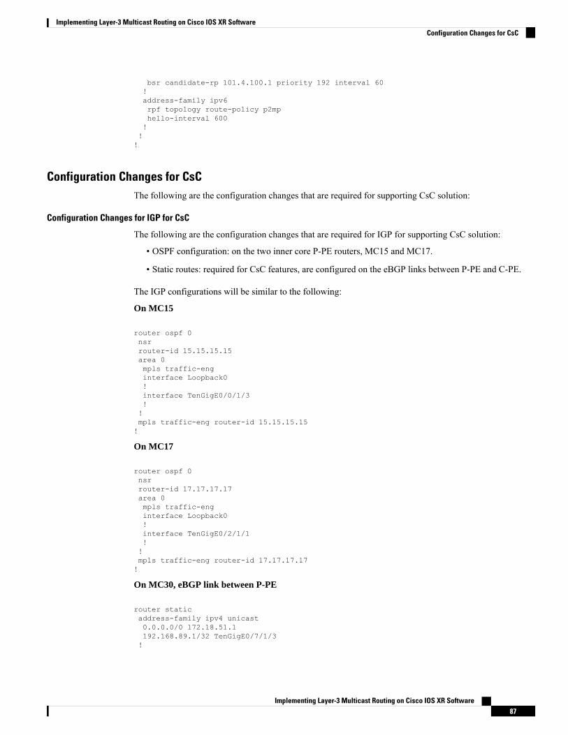
bsr candidate-rp 101.4.100.1 priority 192 interval 60!address-family ipv6rpf topology route-policy p2mphello-interval 600!!!
Configuration Changes for CsCThe following are the configuration changes that are required for supporting CsC solution:
Configuration Changes for IGP for CsC
The following are the configuration changes that are required for IGP for supporting CsC solution:
• OSPF configuration: on the two inner core P-PE routers, MC15 and MC17.
• Static routes: required for CsC features, are configured on the eBGP links between P-PE and C-PE.
The IGP configurations will be similar to the following:
On MC15
router ospf 0nsrrouter-id 15.15.15.15area 0mpls traffic-enginterface Loopback0!interface TenGigE0/0/1/3!!mpls traffic-eng router-id 15.15.15.15!
On MC17
router ospf 0nsrrouter-id 17.17.17.17area 0mpls traffic-enginterface Loopback0!interface TenGigE0/2/1/1!!mpls traffic-eng router-id 17.17.17.17!
On MC30, eBGP link between P-PE
router staticaddress-family ipv4 unicast0.0.0.0/0 172.18.51.1192.168.89.1/32 TenGigE0/7/1/3!
Implementing Layer-3 Multicast Routing on Cisco IOS XR Software87
Implementing Layer-3 Multicast Routing on Cisco IOS XR SoftwareConfiguration Changes for CsC

On MC15, eBGP link between C-PE
router staticaddress-family ipv4 unicast0.0.0.0/0 172.18.51.1!vrf vpn101address-family ipv4 unicast192.168.89.2/32 TenGigE0/1/0/23192.168.90.2/32 TenGigE0/1/0/21
!
Configuration Changes for Supporting MLDP CsC
The following are the configuration changes that are required for supporting mLDP CsC solution:
• Enable MLDP globally.
• Enable LDP under VRF. This enables MLDP on same VRF.
• Enable the MLDP-specific VRF configurations (like the MBB, recursive forwarding, and so on) underthe MLDP VRF submode.
• Configure the new Carrier supporting Carrier knob, added under global MLDP submode, on ingressP-PE routers.
The MLDP configuration will be similar to the following:
On MC30, C-PE router
mpls ldplogneighbor!nsrgraceful-restartmldpaddress-family ipv4!!router-id 101.4.1.1session protectioninterface TenGigE0/7/1/3!!
On MC15, P-PE router
mpls traffic-enginterface TenGigE0/0/1/3!!mpls ldplogneighbor!nsrgraceful-restartmldpaddress-family ipv4carrier-supporting-carrier
Implementing Layer-3 Multicast Routing on Cisco IOS XR Software88
Implementing Layer-3 Multicast Routing on Cisco IOS XR SoftwareConfiguration Changes for Supporting MLDP CsC

make-before-break delay 100recursive-fec!!router-id 15.15.15.15session protectioninterface TenGigE0/0/1/3!vrf vpn101router-id 101.1.1.1address-family ipv4!interface TenGigE0/1/0/21address-family ipv4!!interface TenGigE0/1/0/23address-family ipv4
Configuration Changes for iBGP and eBGP for CsC
The following are the configuration changes that are required for iBGP and eBGP for supporting CsC solution:
• Configure iBGP between P-PE routers.
• Configure eBGP between P-PE and C-PE.
The configurations will be similar to the following:
On MC15, iBGP between P-PE
router bgp 100nsrmvpnbgp router-id 15.15.15.15bgp graceful-restartaddress-family vpnv4 unicast!neighbor 17.17.17.17remote-as 100update-source Loopback0address-family vpnv4 unicast!!vrf vpn101rd 1:1address-family ipv4 unicastredistribute connectedredistribute staticallocate-label all!neighbor 192.168.89.2remote-as 101address-family ipv4 labeled-unicastroute-policy pass-all inroute-policy pass-all outas-override!!neighbor 192.168.90.2remote-as 101address-family ipv4 labeled-unicastroute-policy pass-all in
Implementing Layer-3 Multicast Routing on Cisco IOS XR Software89
Implementing Layer-3 Multicast Routing on Cisco IOS XR SoftwareConfiguration Changes for iBGP and eBGP for CsC

route-policy pass-all outas-override!
On MC30, eBGP between P-PE and C-PE
router bgp 101nsrbgp router-id 192.168.89.2bgp graceful-restartaddress-family ipv4 unicastredistribute connectedredistribute static route-policy CSC-PEERallocate-label all!address-family vpnv4 unicast!address-family vpnv6 unicast!address-family ipv4 mvpn!address-family ipv6 mvpn!neighbor 101.3.1.1remote-as 101update-source Loopback101address-family vpnv4 unicast!address-family vpnv6 unicast!address-family ipv4 mvpn!address-family ipv6 mvpn!!neighbor 101.5.1.1remote-as 101update-source Loopback101address-family vpnv4 unicast!address-family vpnv6 unicast!address-family ipv4 mvpn!address-family ipv6 mvpn!!neighbor 192.168.89.1remote-as 100address-family ipv4 labeled-unicastroute-policy pass-all inroute-policy pass-all out!!vrf vpn101rd 10:1address-family ipv4 unicastredistribute connected!address-family ipv6 unicastredistribute connected!address-family ipv4 mvpn!
Implementing Layer-3 Multicast Routing on Cisco IOS XR Software90
Implementing Layer-3 Multicast Routing on Cisco IOS XR SoftwareConfiguration Changes for iBGP and eBGP for CsC

address-family ipv6 mvpn
Configuration Changes for Multicast for CsC
The following are the configuration changes that are required for Multicast for supporting CsC solution.
Multicast is active only in C-network on C-PE routers.
The configurations will be similar to the following:
Note
On MC27
multicast-routingaddress-family ipv4mdt source Loopback101interface all enable!address-family ipv6mdt source Loopback101interface all enable!vrf vpn101address-family ipv4mdt source Loopback1111rate-per-routeinterface all enableaccounting per-prefixbgp auto-discovery mldp!mdt default mldp p2mpmdt data 5!address-family ipv6mdt source Loopback1112rate-per-routeinterface all enableaccounting per-prefixbgp auto-discovery mldpinter-as!mdt default mldp p2mpmdt data 5!!!
router pimaddress-family ipv4auto-rp mapping-agent TenGigE0/0/2/0 scope 11 interval 60auto-rp candidate-rp TenGigE0/0/2/0 scope 10 group-list 224-4 interval 60nsf lifetime 180!vrf vpn101address-family ipv4rpf topology route-policy p2mphello-interval 1mdt c-multicast-routing bgp
Implementing Layer-3 Multicast Routing on Cisco IOS XR Software91
Implementing Layer-3 Multicast Routing on Cisco IOS XR SoftwareConfiguration Changes for Multicast for CsC

!bsr candidate-bsr 101.3.100.1 hash-mask-len 32 priority 1bsr candidate-rp 101.3.100.1 priority 192 interval 60!address-family ipv6rpf topology route-policy p2mphello-interval 3600mdt c-multicast-routing pim!!!!
Multipoint Label Distribution Protocol Route Policy MapMulticast supports Multipoint Label Distribution Protocol Route Policy Map, wherein Multipoint LabelDistribution Protocol uses the route policymaps to filter LabelMappings and selectively apply the configurationfeatures on Cisco IOS-XR operating system.
Route policy map for configuration commands:
The route policy map for the configuration commands provide you the flexibility to selectively enable someof the mLDP features such as Make Before Break (MBB), Multicast only FRR (MoFRR) features, and so on,on the applicable LSPs. Features like Make Before Break (MBB), Multicast only FRR (MoFRR), etc. can beenabled on mLDP on IOS-XR operating system. When each of these features are enabled, they are enabledfor all of themLDPLabeled-Switched Paths (LSPs) irrespective of whether they are applicable for the particularLSP or not. For example, MoFRR is used for IPTV over mLDP in-band signaled P2MP LSPs, but not for thegeneric MVPN using a MP2MP LSPs. Using the route policy map, you can configure mLDP to to selectivelyenable some of the features.
Route policy for label mapping filtering:
The route policy map for the Label Mapping filtering provides a way to prevent the mLDP from crossing overfrom one plane to another in the event of a failure.
Generally, the LSPs based onmLDP are built on unicast routing principle, and the LSPs follow unicast routingas well. However, some networks are built on the concept of dual-plane design, where an mLDP LSP is createdin each of the planes to provide redundancy. In the event of a failure, mLDP crosses over to another plane.To prevent mLDP from crossing over, mLDP Label Mappings are filtered either in an inbound or outbounddirection.
mLDP uses the existing RPL policy infrastructure in IOS-XR. With the existing RPL policy, mLDP FECsare created and compared with the real mLDP FEC for filtering and configuration commands. (To createmLDP FECs for filtering, create a new RPL policy (specific for mLDP FECs) with the necessary show andconfiguration commands.) An mLDP FEC consists of 3 tuples: a tree type, root node address, and the opaqueencoding, which uniquely identifies the mLDP LSP. An opaque encoding has a different TLV encodingassociated with it. For each of the different opaque TLV, a unique RPL policy is to be created since theinformation in the mLDP opaque encoding is different.
The implementation of mLDP FEC based RPL filter is done in both RPL and LDP components.
• mLDP FEC
The mLDP FEC Route Policy Filtering is a combination of a root node and opaque types.
• Root Node:
Filtering is allowed only at the root node in combination with opaque types.
Implementing Layer-3 Multicast Routing on Cisco IOS XR Software92
Implementing Layer-3 Multicast Routing on Cisco IOS XR SoftwareMultipoint Label Distribution Protocol Route Policy Map

• Opaque Types:
The following are the opaque types allowed to create the Route Policies.
• IPV4 In-band type
• IPV6 In-band type
• VPNv4 In-band type
• VPNv6 In-band type
• MDT Rosen model (VPN-ID) type
• Global ID type
• Static ID type
• Recursive FEC type
• VPN Recursive FEC type
• mLDP Label Mapping Filtering:
Label mapping filtering is supported either in inbound or outbound directions, based on the user preference.All default policies applicable in the neighborhood are supported by Label Mapping Filtering.
• mLDP Feature Filtering:
The RPL policy allows selective features to be enabled, applies to the following feature configurationcommands:
• MoFRR
• Make Before Break
• Recursive FEC
Configuring mLDP User Interface (Opaque Types) Using the Routing PolicyPerform this task to configure the LDP user interface using the route policy to filter Label Mappings andselectively apply the configuration features. LDP interface can be configured using the various availablemLDP opaque parameters like the Global ID, IPv4, IPv6, MDT, Recursive, Recursive RD, Static ID, VPNv4,and VPNv6.
See the Implementing Routing Policy on Cisco ASR 9000 Series Router module of Cisco ASR 9000 SeriesAggregation Services Router Routing Configuration Guide for a list of the supported attributes and operationsthat are valid for policy filtering.
Configuring the mLDP User Interface for LDP Opaque Global ID Using the Routing Policy
SUMMARY STEPS
1. configure2. route-policy mldp_policy3. if mldp opaque global-id 32-bit decimal number then pass endif4. end-policy
Implementing Layer-3 Multicast Routing on Cisco IOS XR Software93
Implementing Layer-3 Multicast Routing on Cisco IOS XR SoftwareConfiguring mLDP User Interface (Opaque Types) Using the Routing Policy

5. commit6. Use the show command to verify the configuration: show running-config route-policy
mldp_policy
DETAILED STEPS
PurposeCommand or Action
Enters global configuration mode.configure
Example:
Step 1
RP/0/RSP0/CPU0:router# configure
Enters the Route-policy configurationmode, where you candefine the route policy.
route-policy mldp_policy
Example:
Step 2
RP/0/RSP0/CPU0:router(config)#route-policymldp_policy
Configures the mLDP global id to the specific global-id.if mldp opaque global-id 32-bit decimal number then passendif
Step 3
Example:RP/0/RSP0/CPU0:router(config-rpl)# if mldp opaqueglobal-id then pass endif
end-policyStep 4
Example:RP/0/RSP0/CPU0:router(config-rpl)# end-policy
commitStep 5
An example output is as shown:
Wed Jun 18 11:41:09.333 IST
Use the show command to verify the configuration: showrunning-config route-policy mldp_policy
Step 6
route-policy mldp_policyif mldp opaque global-id 10 thenpass
endifend-policy!
Configuring the mLDP User Interface for LDP Opaque IPv4 Using the Routing Policy
SUMMARY STEPS
1. configure2. route-policy mldp_policy3. if mldp opaque ipv4 [ipv4 address| ipv4 address range] then pass endif4. end-policy5. commit6. Use the show command to verify the configuration: show running-config route-policy
mldp_policy
Implementing Layer-3 Multicast Routing on Cisco IOS XR Software94
Implementing Layer-3 Multicast Routing on Cisco IOS XR SoftwareConfiguring the mLDP User Interface for LDP Opaque IPv4 Using the Routing Policy

DETAILED STEPS
PurposeCommand or Action
Enters global configuration mode.configure
Example:
Step 1
RP/0/RSP0/CPU0:router# configure
Enters the Route-policy configurationmode, where you candefine the route policy.
route-policy mldp_policy
Example:
Step 2
RP/0/RSP0/CPU0:router(config)#route-policymldp_policy
Configures the mLDP ipv4 address variable to the specifiedrange of IPv4 IP address.
if mldp opaque ipv4 [ipv4 address| ipv4 address range]then pass endif
Example:
Step 3
RP/0/RSP0/CPU0:router(config-rpl)# if mldp opaqueipv4 then pass endif
end-policyStep 4
Example:RP/0/RSP0/CPU0:router(config-rpl)# end-policy
commitStep 5
An example output is as shown:
Sun Jun 22 20:03:34.308 IST
Use the show command to verify the configuration: showrunning-config route-policy mldp_policy
Step 6
route-policy mldp_policyif mldp opaque ipv4 10.0.0.1 224.1.1.1 thenpass
endifend-policy!
Configuring the mLDP User Interface for LDP Opaque IPv6 Using the Routing Policy
SUMMARY STEPS
1. configure2. route-policy mldp_policy3. if mldp opaque ipv6 [ipv6 address| ipv6 address range] then pass endif4. end-policy5. commit6. Use the show command to verify the configuration: show running-config route-policy
mldp_policy
Implementing Layer-3 Multicast Routing on Cisco IOS XR Software95
Implementing Layer-3 Multicast Routing on Cisco IOS XR SoftwareConfiguring the mLDP User Interface for LDP Opaque IPv6 Using the Routing Policy

DETAILED STEPS
PurposeCommand or Action
Enters global configuration mode.configure
Example:
Step 1
RP/0/RSP0/CPU0:router# configure
Enters the Route-policy configurationmode, where you candefine the route policy.
route-policy mldp_policy
Example:
Step 2
RP/0/RSP0/CPU0:router(config)#route-policymldp_policy
Configures the mLDP ipv6 variable to the specified rangeof IPv6 IP address.
if mldp opaque ipv6 [ipv6 address| ipv6 address range]then pass endif
Example:
Step 3
RP/0/RSP0/CPU0:router(config-rpl)# if mldp opaqueipv6 then pass endif
end-policyStep 4
Example:RP/0/RSP0/CPU0:router(config-rpl)# end-policy
commitStep 5
An example output is as shown:
Sun Jun 22 20:03:34.308 IST
Use the show command to verify the configuration: showrunning-config route-policy mldp_policy
Step 6
route-policy mldp_policyif mldp opaque ipv6 10::1 ff05::1 thenpass
endifend-policy!
Configuring the mLDP User Interface for LDP Opaque MDT Using the Routing Policy
SUMMARY STEPS
1. configure2. route-policy mldp_policy3. if mldp opaque mdt [1:1] then pass endif4. end-policy5. commit6. Use the show command to verify the configuration: show running-config route-policy
mldp_policy
Implementing Layer-3 Multicast Routing on Cisco IOS XR Software96
Implementing Layer-3 Multicast Routing on Cisco IOS XR SoftwareConfiguring the mLDP User Interface for LDP Opaque MDT Using the Routing Policy

DETAILED STEPS
PurposeCommand or Action
Enters global configuration mode.configure
Example:
Step 1
RP/0/RSP0/CPU0:router# configure
Enters the Route-policy configurationmode, where you candefine the route policy.
route-policy mldp_policy
Example:
Step 2
RP/0/RSP0/CPU0:router(config)#route-policymldp_policy
Configures the mLDPVPNID to the specificMDT number.if mldp opaque mdt [1:1] then pass endif
Example:
Step 3
RP/0/RSP0/CPU0:router(config-rpl)# if mldp opaquemdt then pass endif
end-policyStep 4
Example:RP/0/RSP0/CPU0:router(config-rpl)# end-policy
commitStep 5
Example outputs are as shown:
Sun Jun 22 20:03:34.308 IST
Use the show command to verify the configuration: showrunning-config route-policy mldp_policy
Step 6
route-policy mldp_policyif mldp opaque mdt 1:1 0 thenpass
endifend-policy
route-policy mldp_policyif mldp opaque mdt any 10 thenpass
endifend-policy!
Configuring the mLDP User Interface for LDP Opaque Static ID Using the Routing Policy
SUMMARY STEPS
1. configure2. route-policy mldp_policy3. if mldp opaque static-id 32-bit decimal number then pass endif4. end-policy5. commit6. Use the show command to verify the configuration: show running-config route-policy
mldp_policy
Implementing Layer-3 Multicast Routing on Cisco IOS XR Software97
Implementing Layer-3 Multicast Routing on Cisco IOS XR SoftwareConfiguring the mLDP User Interface for LDP Opaque Static ID Using the Routing Policy

DETAILED STEPS
PurposeCommand or Action
Enters global configuration mode.configure
Example:
Step 1
RP/0/RSP0/CPU0:router# configure
Enters the Route-policy configurationmode, where you candefine the route policy.
route-policy mldp_policy
Example:
Step 2
RP/0/RSP0/CPU0:router(config)#route-policymldp_policy
Configures the mLDP static id to the specific static id.if mldp opaque static-id 32-bit decimal number then passendif
Step 3
Example:RP/0/RSP0/CPU0:router(config-rpl)# if mldp opaquestatic-id then pass endif
end-policyStep 4
Example:RP/0/RSP0/CPU0:router(config-rpl)# end-policy
commitStep 5
An example output is as shown below:
Wed Jun 18 11:41:09.333 IST
Use the show command to verify the configuration: showrunning-config route-policy mldp_policy
Step 6
route-policy mldp_policyif mldp opaque static-id 10 thenpass
endifend-policy!
Configuring the mLDP User Interface for LDP Opaque Recursive Using the Routing Policy
SUMMARY STEPS
1. configure2. route-policy mldp_policy3. if mldp opaque recursive then pass endif4. end-policy5. commit6. Use the show command to verify the configuration: show running-config route-policy
mldp_policy
Implementing Layer-3 Multicast Routing on Cisco IOS XR Software98
Implementing Layer-3 Multicast Routing on Cisco IOS XR SoftwareConfiguring the mLDP User Interface for LDP Opaque Recursive Using the Routing Policy

DETAILED STEPS
PurposeCommand or Action
Enters global configuration mode.configure
Example:
Step 1
RP/0/RSP0/CPU0:router# configure
Enters the Route-policy configurationmode, where you candefine the route policy.
route-policy mldp_policy
Example:
Step 2
RP/0/RSP0/CPU0:router(config)#route-policymldp_policy
Configures the mLDP recursive variable.if mldp opaque recursive then pass endif
Example:
Step 3
RP/0/RSP0/CPU0:router(config-rpl)# if mldp opaquerecursive then pass endif
end-policyStep 4
Example:RP/0/RSP0/CPU0:router(config-rpl)# end-policy
commitStep 5
An example output is as shown:
Mon Jun 23 11:46:15.559 IST
Use the show command to verify the configuration: showrunning-config route-policy mldp_policy
Step 6
route-policy mldp_policyif mldp opaque recursive thenpass
endifend-policy!
Configuring the mLDP User Interface for LDP Opaque Recursive-RD Using the Routing Policy
SUMMARY STEPS
1. configure2. route-policy mldp_policy3. if mldp opaque recursive -rd [2:2] then pass endif4. end-policy5. commit6. Use the show command to verify the configuration: show running-config route-policy
mldp_policy
Implementing Layer-3 Multicast Routing on Cisco IOS XR Software99
Implementing Layer-3 Multicast Routing on Cisco IOS XR SoftwareConfiguring the mLDP User Interface for LDP Opaque Recursive-RD Using the Routing Policy

DETAILED STEPS
PurposeCommand or Action
Enters global configuration mode.configure
Example:
Step 1
RP/0/RSP0/CPU0:router# configure
Enters the Route-policy configurationmode, where you candefine the route policy.
route-policy mldp_policy
Example:
Step 2
RP/0/RSP0/CPU0:router(config)#route-policymldp_policy
Configures the mLDP recursive to the specified variable.if mldp opaque recursive -rd [2:2] then pass endif
Example:
Step 3
RP/0/RSP0/CPU0:router(config-rpl)# if mldp opaquerecursive-rd then pass endif
end-policyStep 4
Example:RP/0/RSP0/CPU0:router(config-rpl)# end-policy
commitStep 5
An example output is as shown:
Mon Jun 23 12:15:37.512 IST
Use the show command to verify the configuration: showrunning-config route-policy mldp_policy
Step 6
route-policy mldp_policyif mldp opaque recursive-rd 2:2 thenpass
endifend-policy!
Configuring the mLDP User Interface for LDP Opaque VPNv4 Using the Routing Policy
SUMMARY STEPS
1. configure2. route-policy mldp_policy3. if mldp opaque vpnv4 [2:2] then pass endif4. if mldp opaque vpnv4 [2:2 10.1.1.1 232.1.1.1] then pass endif5. end-policy6. commit7. Use the show command to verify the configuration: show running-config route-policy
mldp_policy
Implementing Layer-3 Multicast Routing on Cisco IOS XR Software100
Implementing Layer-3 Multicast Routing on Cisco IOS XR SoftwareConfiguring the mLDP User Interface for LDP Opaque VPNv4 Using the Routing Policy

DETAILED STEPS
PurposeCommand or Action
Enters global configuration mode.configure
Example:
Step 1
RP/0/RSP0/CPU0:router# configure
Enters the Route-policy configurationmode, where you candefine the route policy.
route-policy mldp_policy
Example:
Step 2
RP/0/RSP0/CPU0:router(config)#route-policymldp_policy
Configures the mLDP vpnv4 variable to the specifiedvariable.
if mldp opaque vpnv4 [2:2] then pass endif
Example:
Step 3
RP/0/RSP0/CPU0:router(config-rpl)# if mldp opaquevpnv4 then pass endif
Configures the mLDP vpnv4 variable to the specified rangeof variable addresses.
if mldp opaque vpnv4 [2:2 10.1.1.1 232.1.1.1] then passendif
Example:
Step 4
RP/0/RSP0/CPU0:router(config-rpl)# if mldp opaquevpnv4 then pass endif
end-policyStep 5
Example:RP/0/RSP0/CPU0:router(config-rpl)# end-policy
commitStep 6
Example outputs are as shown:
Sun Jun 22 20:03:34.308 IST
Use the show command to verify the configuration: showrunning-config route-policy mldp_policy
Step 7
route-policy mldp_policyif mldp opaque vpnv4 2:2 10.1.1.1 232.1.1.1 then
passendif
end-policy
route-policy mldp_policyif mldp opaque vpnv4 any 0.0.0.0 224.1.1.1 thenpass
endifend-policy!
Configuring the mLDP User Interface for LDP Opaque VPNv6 Using the Routing Policy
SUMMARY STEPS
1. configure2. route-policy mldp_policy
Implementing Layer-3 Multicast Routing on Cisco IOS XR Software101
Implementing Layer-3 Multicast Routing on Cisco IOS XR SoftwareConfiguring the mLDP User Interface for LDP Opaque VPNv6 Using the Routing Policy

3. if mldp opaque vpnv6 [2:2] then pass endif4. if mldp opaque vpnv6 [2:2 10::1 FF05::1] then pass endif5. end-policy6. commit7. Use the show command to verify the configuration: show running-config route-policy
mldp_policy
DETAILED STEPS
PurposeCommand or Action
Enters global configuration mode.configure
Example:
Step 1
RP/0/RSP0/CPU0:router# configure
Enters the Route-policy configurationmode, where you candefine the route policy.
route-policy mldp_policy
Example:
Step 2
RP/0/RSP0/CPU0:router(config)#route-policymldp_policy
Configures the mLDP vpnv6 variable to the specifiedvariable.
if mldp opaque vpnv6 [2:2] then pass endif
Example:
Step 3
RP/0/RSP0/CPU0:router(config-rpl)# if mldp opaquevpnv4 then pass endif
Configures the mLDP vpnv6 variable to the specifiedvariable range of addresses.
if mldp opaque vpnv6 [2:2 10::1 FF05::1] then pass endif
Example:
Step 4
RP/0/RSP0/CPU0:router(config-rpl)# if mldp opaquevpnv6 then pass endif
end-policyStep 5
Example:RP/0/RSP0/CPU0:router(config-rpl)# end-policy
commitStep 6
An example output is as shown:
Sun Jun 22 20:03:34.308 IST
Use the show command to verify the configuration: showrunning-config route-policy mldp_policy
Step 7
route-policy mldp_policyif mldp opaque vpnv6 2:2 10::1 ff05::1 thenpass
endifend-policy!
Configuring mLDP FEC at the Root NodePerform this task to configure mLDP FEC at the root node using the route policy to filter Label Mappingsand selectively apply the configuration features. Currently, mLDP FEC is configured to filter at the IPV4 rootnode address along with the mLDP opaque types.
Implementing Layer-3 Multicast Routing on Cisco IOS XR Software102
Implementing Layer-3 Multicast Routing on Cisco IOS XR SoftwareConfiguring mLDP FEC at the Root Node

Configuring the mLDP FEC at the Root Node Using the Route Policy
SUMMARY STEPS
1. configure2. route-policy mldp_policy3. if mldp root4. end-policy5. commit6. Use the show command to verify the configuration: show running-config route-policy
mldp_policy
DETAILED STEPS
PurposeCommand or Action
Enters global configuration mode.configure
Example:
Step 1
RP/0/RSP0/CPU0:router# configure
Enters the Route-policy configurationmode, where you candefine the route policy.
route-policy mldp_policy
Example:
Step 2
RP/0/RSP0/CPU0:router(config)#route-policymldp_policy
Configures the mLDP root address to the specified IPv4 IPaddress.
if mldp root
Example:
Step 3
RP/0/RSP0/CPU0:router(config-rpl)# if mldproot[ipv4 address]then pass endif
end-policyStep 4
Example:RP/0/RSP0/CPU0:router(config-rpl)# end-policy
commitStep 5
The current configuration output is as shown:
route-policy mldp_policy
Use the show command to verify the configuration: showrunning-config route-policy mldp_policy
Step 6
if mldp root 10.0.0.1 thenpass
endifend-policy!
Example of an MLDP Route Policy which shows the filtering option of a Root Node IPv4 addressand mLDP Opaque IPv4 address
Show configuration output for the mLDP root IPv4 address and mLDP opaque IPv4 address range
Implementing Layer-3 Multicast Routing on Cisco IOS XR Software103
Implementing Layer-3 Multicast Routing on Cisco IOS XR SoftwareConfiguring the mLDP FEC at the Root Node Using the Route Policy

route-policy mldp_policyif mldp root 10.0.0.1 and mldp opaque ipv4 192.168.3.1 232.2.2.2 thenpass
endifend-policy!
Configuring the mLDP User Interface to Filter Label MappingsLabel mapping filtering is supported either in inbound or outbound directions, based on the user preference.All default policies applicable in the neighborhood are supported by Label Mapping Filtering.
Configuring the mLDP User Interface to Filter Label Mappings
SUMMARY STEPS
1. configure2. mpls ldp mldp3. address-family ipv44. neighbor[ipv4 ip address]route-policy mldp_policy in | out5. end-policy6. commit7. Use the show command to verify the configuration: show running-config route-policy
mldp_policy
DETAILED STEPS
PurposeCommand or Action
Enters global configuration mode.configure
Example:
Step 1
RP/0/RSP0/CPU0:router# configure
Enters the LDP configuration mode.mpls ldp mldp
Example:
Step 2
RP/0/RSP0/CPU0:router(config)#mpls ldp mldp
Enters the MLDP address family configuration mode.address-family ipv4
Example:
Step 3
RP/0/RSP0/CPU0:router(config-ldp-mldp)#address-family ipv4
Configures the specified neighborhood IPv4 IP address tothe MLDP policy as either inbound or outbound routepolicy.
neighbor[ipv4 ip address]route-policy mldp_policy in |out
Example:
Step 4
RP/0/RSP0/CPU0:router(config-ldp-mldp)# neighboripv4 ip address route-policy mldp_policy in | out
end-policyStep 5
Implementing Layer-3 Multicast Routing on Cisco IOS XR Software104
Implementing Layer-3 Multicast Routing on Cisco IOS XR SoftwareConfiguring the mLDP User Interface to Filter Label Mappings

PurposeCommand or Action
Example:RP/0/RSP0/CPU0:router(config-ldp-mldp)# end-policy
commitStep 6
Example outputs are as shown:
Wed Jun 18 11:41:09.333 IST
Use the show command to verify the configuration: showrunning-config route-policy mldp_policy
Step 7
mpls ldpmldpneighbor route-policy mldp_policy out
!
mpls ldpmldpneighbor 1.1.1.1 route-policy mldp_policy in
!
Configuring the mLDP User Interface for Feature FilteringRPL policy allows the user to selectively enable features for filtering.
Configuring the mLDP User Interface for Feature Filtering - MoFRR
SUMMARY STEPS
1. configure2. mpls ldp mldp3. mofrr route-policy mldp_policy4. end5. commit6. Use the show command to verify the configuration: show running-config mpls ldp mldp
DETAILED STEPS
PurposeCommand or Action
Enters global configuration mode.configure
Example:
Step 1
RP/0/RSP0/CPU0:router# configure
Enters the LDP configuration mode.mpls ldp mldp
Example:
Step 2
RP/0/RSP0/CPU0:router(config)#mpls ldp mldp
Configures the specified feature to the MLDP policy to beallowed to be selected for filtering.
mofrr route-policy mldp_policy
Example:
Step 3
RP/0/RSP0/CPU0:router(config-ldp-mldp)# mofrrroute-policy mldp_policy
Implementing Layer-3 Multicast Routing on Cisco IOS XR Software105
Implementing Layer-3 Multicast Routing on Cisco IOS XR SoftwareConfiguring the mLDP User Interface for Feature Filtering

PurposeCommand or Action
endStep 4
Example:RP/0/RSP0/CPU0:router(config-ldp-mldp)# end
commitStep 5
An example output is as shown:
Wed Jun 25 12:46:52.177 IST
Use the show command to verify the configuration: showrunning-config mpls ldp mldp
Step 6
mpls ldpmldpaddress-family ipv4make-before-break delay 0mofrr route-policy mldp_policyneighbor route-policy mldp_policy outneighbor 1.1.1.1 route-policy mldp_policy inneighbor 1.1.1.1 route-policy mldp_policy outneighbor 2.2.2.2 route-policy mldp_policy outrecursive-fec route-policy mldp_policy!!!
An example output showing the mLDP MoFRR output
RP/0/1/CPU0:GSR3#sh mpls mldp database opaquetype ipv4mLDP databaseLSM-ID: 0x00019 Type: P2MP Uptime: 03:25:15FEC Root : 10.0.0.1Opaque decoded : [ipv4 0.0.0.0 224.1.1.1]Features : MoFRRUpstream neighbor(s) :10.0.0.1:0 [Active] Uptime: 03:25:15Next Hop : 10.0.3.3Interface : GigabitEthernet0/2/1/1Local Label (D) : 16028
Downstream client(s):LDP 10.0.0.2:0 Uptime: 03:25:15Next Hop : 10.0.4.2Interface : GigabitEthernet0/2/1/2Remote label (D) : 16029
Configuring the mLDP User Interface for Feature Filtering - Make-before-break
SUMMARY STEPS
1. configure2. mpls ldp mldp3. address-family ipv44. make-before-break route-policy mldp_policy5. end6. commit
Implementing Layer-3 Multicast Routing on Cisco IOS XR Software106
Implementing Layer-3 Multicast Routing on Cisco IOS XR SoftwareConfiguring the mLDP User Interface for Feature Filtering - Make-before-break

7. Use the show command to verify the configuration: show running-config mpls ldp mldp
DETAILED STEPS
PurposeCommand or Action
Enters global configuration mode.configure
Example:
Step 1
RP/0/RSP0/CPU0:router# configure
Enters the LDP configuration mode.mpls ldp mldp
Example:
Step 2
RP/0/RSP0/CPU0:router(config)#mpls ldp mldp
Enters the LDP address family configuration mode.address-family ipv4
Example:
Step 3
RP/0/RSP0/CPU0:router(config-ldp-mldp)#address-familyipv4
Configures the specified feature to the MLDP policy to beallowed to be selected for filtering.
make-before-break route-policy mldp_policy
Example:
Step 4
RP/0/RSP0/CPU0:router(config-ldp-mldp-af)#make-before-break route-policy mldp_policy
endStep 5
Example:RP/0/RSP0/CPU0:router(config-ldp-mldp-af)# end
commitStep 6
An example output is as shown:
Wed Jun 25 13:05:31.303 IST
Use the show command to verify the configuration: showrunning-config mpls ldp mldp
Step 7
mpls ldpmldpaddress-family ipv4make-before-break delay 0make-before-break route-policy mldp_policymofrr route-policy mldp_policyneighbor route-policy mldp_policy outneighbor 1.1.1.1 route-policy mldp_policy inneighbor 1.1.1.1 route-policy mldp_policy outneighbor 2.2.2.2 route-policy mldp_policy out!!!
An example output showing the mLDP make-before-break output
RP/0/1/CPU0:GSR3#sh mpls mldp database opaquetype ipv4mLDP database
Implementing Layer-3 Multicast Routing on Cisco IOS XR Software107
Implementing Layer-3 Multicast Routing on Cisco IOS XR SoftwareConfiguring the mLDP User Interface for Feature Filtering - Make-before-break

LSM-ID: 0x00019 Type: P2MP Uptime: 03:25:15FEC Root : 10.0.0.1Opaque decoded : [ipv4 0.0.0.0 224.1.1.1]Features : MoFRR MBBUpstream neighbor(s) :10.0.0.1:0 [Active] Uptime: 03:25:15Next Hop : 10.0.3.3Interface : GigabitEthernet0/2/1/1Local Label (D) : 16028
Downstream client(s):LDP 10.0.0.2:0 Uptime: 03:25:15Next Hop : 10.0.4.2Interface : GigabitEthernet0/2/1/2Remote label (D) : 16029
Configuring the mLDP User Interface for Feature Filtering - Recursive FEC
SUMMARY STEPS
1. configure2. mpls ldp mldp3. address-family ipv44. recursive-fec route-policy rfec5. end6. commit7. Use the show command to verify the configuration: show running-config mpls ldp mldp
DETAILED STEPS
PurposeCommand or Action
Enters global configuration mode.configure
Example:
Step 1
RP/0/RSP0/CPU0:router# configure
Enters the LDP configuration mode.mpls ldp mldp
Example:
Step 2
RP/0/RSP0/CPU0:router(config)#mpls ldp mldp
Enters the LDP address family configuration mode.address-family ipv4
Example:
Step 3
RP/0/RSP0/CPU0:router(config-ldp-mldp)#address-familyipv4
Configures the specified feature to the MLDP policy to beallowed to be selected for filtering.
recursive-fec route-policy rfec
Example:
Step 4
RP/0/RSP0/CPU0:router(config-ldp-mldp-af)#recursive-fec route-policy rfec
endStep 5
Example:
Implementing Layer-3 Multicast Routing on Cisco IOS XR Software108
Implementing Layer-3 Multicast Routing on Cisco IOS XR SoftwareConfiguring the mLDP User Interface for Feature Filtering - Recursive FEC

PurposeCommand or ActionRP/0/RSP0/CPU0:router(config-ldp-mldp-af)# end
commitStep 6
An example output is as shown:
Wed Jun 25 13:05:31.303 IST
Use the show command to verify the configuration: showrunning-config mpls ldp mldp
Step 7
mpls ldpmldpaddress-family ipv4make-before-break delay 0make-before-break route-policy mldp_policymofrr route-policy mldp_policyneighbor route-policy mldp_policy outneighbor 1.1.1.1 route-policy mldp_policy inneighbor 1.1.1.1 route-policy mldp_policy outneighbor 2.2.2.2 route-policy mldp_policy outrecursive-fec route-policy rfec!!!
An example output showing the mLDP make-before-break output
RP/0/1/CPU0:GSR3#sh mpls mldp database opaquetype ipv4mLDP databaseLSM-ID: 0x00019 Type: P2MP Uptime: 03:25:15FEC Root : 10.0.0.1Opaque decoded : [ipv4 0.0.0.0 224.1.1.1]Features : MoFRR MBB RFECUpstream neighbor(s) :10.0.0.1:0 [Active] Uptime: 03:25:15Next Hop : 10.0.3.3Interface : GigabitEthernet0/2/1/1Local Label (D) : 16028
Downstream client(s):LDP 10.0.0.2:0 Uptime: 03:25:15Next Hop : 10.0.4.2Interface : GigabitEthernet0/2/1/2Remote label (D) : 16029
Limitations of Route Policy MapLimitations:
The following are the limitations of the route policy map:
• After changing the Route Policy filter to be more restrictive, the mLDP label bindings that were earlierallowed are not removed. You have to run the clear mpls ldp neighbor command to clear themLDP database.
• If you select a less restrictive filter, mLDP initiates a wildcard label request in order to install the mLDPlabel bindings that were denied earlier.
Implementing Layer-3 Multicast Routing on Cisco IOS XR Software109
Implementing Layer-3 Multicast Routing on Cisco IOS XR SoftwareLimitations of Route Policy Map

• Creating an RPL policy that allows filtering based on the recursive FEC content is not supported.
• Applying an RPL policy to configuration commands impacts the performance to a limited extent.
Next-Generation Multicast VPNNext-Generation Multicast VPN (NG-MVPN) offers more scalability for Layer 3 VPN multicast traffic. Itallows point-to-multipoint Label Switched Paths (LSP) to be used to transport the multicast traffic betweenPEs, thus allowing the multicast traffic and the unicast traffic to benefit from the advantages ofMPLS transport,such as traffic engineering and fast re-route. This technology is ideal for video transport as well as offeringmulticast service to customers of the layer 3 VPN service.
NG-MVPN supports:
• VRF Route-Import and Source-AS Extended Communities
• Upstream Multicast Hop (UMH) and Duplicate Avoidance
• Leaf AD (Type-4) and Source-Active (Type-5) BGP AD messages
• Default-MDT with mLDP P2MP trees and with Static P2MP-TE tunnels
• BGP C-multicast Routing
• RIB-based Extranet with BGP AD
• Accepting (*,G) S-PMSI announcements
• Egress-PE functionality for Ingress Replication (IR) core-trees
• Enhancements for PIM C-multicast Routing
• Migration of C-multicast Routing protocol
• PE-PE ingress replication
• Dynamic P2MP-TE tunnels
• Flexible allocation of P2MP-TE attribute-sets
• Data and partitioned MDT knobs
• Multi-instance BGP support
• SAFI-129 and VRF SAFI-2 support
• Anycast-RP using MVPN SAFI
Supported FeaturesThe following are the supported features on next generation Multicast MVPN on IOS-XR:
• GTM using MVPN SAFI
• MVPN enhancements
GTM Using MVPN SAFI
Implementing Layer-3 Multicast Routing on Cisco IOS XR Software110
Implementing Layer-3 Multicast Routing on Cisco IOS XR SoftwareNext-Generation Multicast VPN

In a GTM procedure, special RD values are used that are created in BGP. The values used are all 0's RD. Anew knob, global-table-multicast is introduced under BGP to create the contexts for these RDs.
MVPN procedures require addition of VRF Route-Import EC, Source-AS EC, and so on to the VPNv4 routesoriginated by PEs. With GTM, there are no VRFs and no VPNv4 routes. The multicast specific attributeshave to be added to Global table iBGP routes (either SAFI-1 or SAFI-2). These routes are learnt througheBGP (from a CE) or from a different Unicast routing protocol.
• The single forwarder selection is not supported for GTM.
• Route Targets:With GTM, there are no VRFs, hence the export and import RTs configured under VRFsare not reliable. For MVPN SAFI routes, RT(s) must be attached. Export and import Route Targetsconfiguration under multicast routing is supported. These are the RTs used for Type 1, 3, and 5 routes.MVPN SAFI routes received without any RTs will not be accepted by an XR PE.
• Core-Tree Protocols: mLDP, P2MP-TE (static and dynamic), and IR core-trees are supported.
• C-multicast Routing: PIM and BGP C-multicast routing are supported.
• MDT Models:Default-MDT and Partitioned-MDTmodels are supported. Data-MDT is supported, withits various options (threshold zero, immediate-switch, starg s-pmsi, and so on.)
The configuration is as shown below for Ingress or Egress PEs:
multicast-routingaddress-family [ipv4| ipv6]mdt source Loopback0mdt default <MLDP | P2MP-TE | ingress-replication>mdt partitioned <MLDP | P2MP-TE | ingress-replication>bgp auto-discovery [mldp | p2mp-te | ingress-replication]export-rt <value>import-rt <value>!!!
Themdt default, mdt partitioned, and the bgp auto-discovery configurations, are present under VRFs, however,with GTM Using MVPN SAFI, the configurations are reflected in global table as well.
Note
router bgp 100address-family [ipv4| ipv6] mvpnglobal-table-multicast!!
The global-table-multicast configuration enables processing of All-0's RD.
MVPN enhancements
• Anycast RP using MVPN SAFI This procedure uses Type-5 MVPN SAFI routes to convey sourceinformation between RPs. Use this method to support Anycast-RP, instead of usingMSDP. This supportsAnycast-RP for both IPv4 and IPv6. Currently, Anycast-RP is supported for IPv4 (using MSDP). BGPmethod is supported for GTM using MVPN SAFI and MVPNs.
Implementing Layer-3 Multicast Routing on Cisco IOS XR Software111
Implementing Layer-3 Multicast Routing on Cisco IOS XR SoftwareSupported Features

The configuration is as shown below for Ingress or Egress PEs:
multicast-routingaddress-family [ipv4| ipv6]bgp auto-discovery [mldp | p2mp-te | ingress-replication]anycast-rp route-policy <anycast-policy>!!vrf <name>address-family [ipv4| ipv6]bgp auto-discovery [mldp | p2mp-te | ingress-replication]anycast-rp route-policy <anycast-policy>
!!!
The route-policy for anycast RP is as defined below.
route-policy anycast-policyif destination in group-set thenpass
endifend-policy!
The group-set command is a XR prefix-set configuration, an example is as shown below:
prefix-set group-set227.1.1.1/32end-set
An alternate way of performing this procedure is using export-rt and import-rt configuration commands.Here, the router announcing the Type-5 route must have the export-rt configured, and the router learningthe source must have the import-rt configured.
multicast-routingvrf oneaddress-family ipv4export-rt 51.52.53.54:0 <<<<<<<interface all enablebgp auto-discovery ingress-replicationinter-asanycast-rp <<<<<<<<<!mdt partitioned ingress-replication!!!
multicast-routingvrf oneaddress-family ipv4import-rt 51.52.53.54:0 <<<<<<<<<<<interface all enablebgp auto-discovery ingress-replicationinter-asanycast-rp <<<<<<<<<<<<<<<!mdt partitioned ingress-replication
Implementing Layer-3 Multicast Routing on Cisco IOS XR Software112
Implementing Layer-3 Multicast Routing on Cisco IOS XR SoftwareSupported Features

!!!
• Receiver-only VRFs Supports receiver-only VRFs. In receiver-only VRFs, the I-PMSI or theMS-PMSIroutes do not carry any tunnel information. This reduces the state on the P routers.
The configuration is as shown below:
multicast-routingaddress-family [ipv4| ipv6]bgp auto-discovery [mldp | p2mp-te | ingress-replication]receiver-site!!vrf <name>address-family [ipv4| ipv6]bgp auto-discovery [mldp | p2mp-te | ingress-replication]receiver-site
!!!
• RPF vector insertion in Global TableUnifiedMPLS deployments, for example, UMMT or EPNmodelface issues, where some of the PEs do not support the enhancement procedures. In this case, to retainBGP-free core in the Ingress and Egress segments, the PEs send PIM Joins with RPF-proxy vector. Tointeroperate in such scenarios, the XR border acts as a transit node for RPF vector. This can be used inother cases of BGP-free core as well. The RPF-vector support is only for GTM and not for MVPNs(Inter-AS Option B). Support is enabled for the RPF-vector address-family being same as the MulticastJoin address-family.
IOS-XR supports termination of RPF vectors as well as acts as atransit router for RPF vector. The termination of RPF vectors wasintroduced from release 4.3.1, however, the support for acting as atransit router existed in earlier releases as well.
Note
The configuration is as shown below:
router pimaddress-family [ipv4|ipv6]rpf-vector!!
RPF Vector Encoding Using IETF StandardRPF vector is a PIM proxy that lets core routers without RPF information forward join and prune messagesfor external sources (for example, a MPLS-based BGP-free core, where the MPLS core router is withoutexternal routes learned from BGP). The RPF vector encoding is now compatible with the new IETF encoding.The new IETF standard encodes PIM messages using PIM Hello option 26.
Implementing Layer-3 Multicast Routing on Cisco IOS XR Software113
Implementing Layer-3 Multicast Routing on Cisco IOS XR SoftwareRPF Vector Encoding Using IETF Standard

Configuring RPF Vector (IETF Standard Encoding)This example shows how to enable RPF encoding using IETF standard:(config)# router pim(config-pim-default-ipv4)# address-family ipv4(config-pim-default-ipv4)# rpf-vector use-standard-encoding!(config)# multicast-routing(config-mcast)# interface TenGigE(config-mcast)# interface TenGigE
Verification
Router#show pim neighborTue Apr 17 10:15:40.961 PDT
PIM neighbors in VRF defaultFlag: B - Bidir capable, P - Proxy capable, DR - Designated Router,
E - ECMP Redirect capable* indicates the neighbor created for this router
Neighbor Address Interface Uptime Expires DR pri Flags
25.25.25.1 TenGigE 1w3d 00:01:36 1 B P25.25.25.2* TenGigE 1w3d 00:01:41 1 (DR) B P E32.32.32.2* TenGigE
1w4d 00:01:40 1 B P E32.32.32.3 TenGigE
1w4d 00:01:42 1 (DR) B P
In the above output, you can see "P" tag on the multicast enabled interfaces.
PE-PE Ingress ReplicationThe ingress PE replicates a C-multicast data packet belonging to a particular MVPN and sends a copy to allor a subset of the PEs that belong to theMVPN. A copy of the packet is tunneled to a remote PE over a UnicastTunnel to the remote PE.
IR-MDT represents a tunnel that uses IR as the forwarding method. It is usually, one IR-MDT per VRF, withmultiple labeled switch paths (LSP) under the tunnel.
When PIM learns of Joins over the MDT (using either PIM or BGP C-multicast Routing), it downloads IPS,G routes to the VRF table inMRIB, with IR-MDT forwarding interfaces. Each IR-MDT forwarding interfacehas a LSM-ID allocated by PIM. Currently, LSM-ID is managed by mLDP and can range from 0 to 0xFFFFF(20-bits). For IR, the LSM-ID space is partitioned between mLDP and IR. For IR tunnels, the top (20th) bitis always be set, leading to a range of 0x80000 to 0xFFFFF. mLDP’s limit is 0 to 0x7FFFF.
MVPN over GREA unicast GRE tunnel could be the accepting or forwarding interface for either a mVPN-GRE VRF route ora core route. When multicast packets arrive on the VRF interface with the intent of crossing the core, they arefirst encapsulated with a multicast GRE header (S,G) which are applicable to the VRF’s MDT. Then, beforethe packets are actually forwarded , they are encapsulated in a unicast GRE header. The (S,D) in this packetare the origination and termination addresses for the unicast GRE tunnel.
Implementing Layer-3 Multicast Routing on Cisco IOS XR Software114
Implementing Layer-3 Multicast Routing on Cisco IOS XR SoftwareConfiguring RPF Vector (IETF Standard Encoding)

GRE tunnel stitching is when both the accepting and forwarding interfaces are unicast GRE tunnels. Here,the packet has two GRE encaps. The outer encap is the unicast header for the GRE tunnel. The inner encapis the multicast GRE header for the MDT. This is called as double encap. There is a loss in terms of bothbandwidth and throughput efficiency. The bandwidth efficiency loss is because 48 bytes of encap headers arebeing added to the original (VRF) packet. The throughput efficiency loss is the result of the processing timerequired to apply two encaps.
For the mVPN-GRE, if the VRF interface is a GRE tunnel, the protocol packets received from LPTS will beaccompanied with the receiving unicast GRE tunnel interface and the VRF id of the VRF in which the GREtunnel is configured. Thus VRF specific processing can be done on the packet.
Restrictions
• MVPN over GRE is supported only on ASR 9000 Enhanced Ethernet LCs.
Native MulticastGRE tunneling provides a method to transport native multicast traffic across a non-Multicast enabled IPnetwork. Once the multicast traffic in encapsulated with GRE, it appears as an IP packet to the core transportnetwork.
A GRE tunnel can be a forwarding interface when the router is the imposition (or encap) router for that GREtunnel. The imposition router must prepend a unicast IPv4 header and GRE header to the multicast packet.The source and destination IPv4 addresses for the added header are determined by the user configuration ofthe tunnel. The newly encapsulated packet is then forwarded as a unicast packet.
When a GRE tunnel is an accepting interface for a multicast route, the router is the disposition (or decap)router for the tunnel. The outer IPv4 header and GRE header must be removed to expose the inner multicastpacket. The multicast packet will then be forwarded just as any other multicast packet that arrives on anon-tunnel interface.
Forwarding behavior
Figure depicts a Unicast GRE tunnel between two routers. The imposition router has a multicast (S,G) routewhich has the GRE tunnel as a forwarding interface. At the disposition router, the GRE tunnel is an acceptinginterface for the multicast (S,G). As seen, the packet is unicast GRE encapsulated when it traverses the tunnel.
Implementing Layer-3 Multicast Routing on Cisco IOS XR Software115
Implementing Layer-3 Multicast Routing on Cisco IOS XR SoftwareNative Multicast

Figure 20: Unicast GRE tunnel between two routers
Starting with IOS XR 5.3.2 release, IPv6 traffic is supported.Note
GRE LimitationsListed below are the limitations for unicast GRE tunnels:
• GRE unicast tunnel supports IPv4 encapsulation only.
Starting from the IOS XR 5.3.2 release, GRE unicast tunnels supportIPv6 encapsulation.
Note
• Native and mVPN traffic over underlying ECMP links are not supported.
Starting with IOS XR 5.3.2 release, native and mVPN traffic overunderlying ECMP links, including bundles is supported.
Note
• IPv6 multicast for GRE unicast tunnels is not supported, in releases prior to IOS XR 5.3.2.
• Transport header support is limited to IPv4.
• Path MTU discovery will not be supported over GRE tunnel interfaces. When size of the packet goingover GRE tunnel interface exceeds the tunnel MTU, the microcode will punt the packet to the slow path
Implementing Layer-3 Multicast Routing on Cisco IOS XR Software116
Implementing Layer-3 Multicast Routing on Cisco IOS XR SoftwareGRE Limitations

for best effort fragmentation. Since punted packets are policed, this doesn't provide real fragmentationsupport. This combined with no support for path MTU discovery means that user is responsible formaking sure the MTUs configured along the tunnel path are large enough to guarantee the GRE packetwill not be fragmented between tunnel source and destination routers.
• No support for optional checksum, key, and sequence number fields.
• No support for nested and concatenated GRE tunnels. If packets with nested GRE header are receivedthey will be dropped.
• No L3 features (like QoS, ACL and netflow) support for GRE tunnel interfaces. Features configured onthe underlying physical interface will be applied.
• ASR9000 SIP-700 linecard unicast GRE is NOT supported on VRFs.
• Support for up to 500 GRE tunnels per system for multicast.
• Multicast forwarding over a GRE tunnel on a NV Satellite access interface is not supported.
Signaling and RPF on GRE TunnelsSignaling will use the samemechanismwhen a unicast GRE tunnel terminated at an ingress linecard regardlessof whether the GRE tunnel interface belongs to a VRF or not. In the case of mVPN-GRE the Primary Linecard/ Primary NP mechanism must still be used for egress punts of decapsulated VRF packets.
RPF selection can be static configured via a route policy configuration. Static RPF is more preferred andexpected if the RPF should be the GRE tunnel. RPF may be selected dynamically via RIB updates for theupstream router’s unicast reach-ability, although this is not preferred.
PIM RegistrationPIM registration packets can be forwarded on a unicast GRE tunnel as long as the IPv4 unicast GRE interfaceis selected by FIB for unicast forwarding of the encapsulated PIM registration packets toward the PIM RP.In this case, the packet is essentially double encapsulated with unicast, ie, the original multicast packet isencapsulated by PIM in a unicast PIM register packet. This is then encapsulated with the unicast GRE tunnelheader.
At the PIM RP, outermost unicast header will be removed and the PIM registration packets will be deliveredto PIM via LPTS as in the current PIM registration packet processing. It’s advisable to avoid any MTU/TTLor ACL/QoS configuration issues that result in the registration packets getting dropped.
Configuration Example
PIM registration fails if the GRE interface MTU is greater than the physical interface. In such cases, ensureto adjust the PIM MTU, as shown in this example:router pimvrf VRF6address-family ipv4rpf topology route-policy prof3-pim-defaulthello-interval 1join-prune-mtu 576rp-address 130.0.6.1!address-family ipv6rpf topology route-policy prof3-pim-defaultjoin-prune-mtu 576
Implementing Layer-3 Multicast Routing on Cisco IOS XR Software117
Implementing Layer-3 Multicast Routing on Cisco IOS XR SoftwareSignaling and RPF on GRE Tunnels

rp-address 130::6:1!
!
Auto-RPAuto-RP lite on PEs, Auto-RP/BSR/static-RP/ Anycast-RP with MSDP peering etc can be supported overGRE tunnels withMFIB netio chain support. It is advisable to avoid anyMTU/TTL or ACL/QoS configurationissues that result in the registration packets getting dropped. Auto-RP routes will flood autp-rp packets toevery multicast egress interface including IPv4 unicast GRE tunnels.
Multicast IRBMulticast IRB provides the ability to route multicast packets between a bridge group and a routed interfaceusing a bridge-group virtual interface (BVI). It can be enabled with multicast-routing. THE BVI is a virtualinterface within the router that acts like a normal routed interface. For details about BVI, refer Interface andHardware Component Configuration Guide for Cisco ASR 9000 Series Routers
BV interfaces are added to the existing VRF routes and integrated with the replication slot mask. After thisintegration, the traffic coming from a VRF BVI is forwarded to the VPN.
Supported Bridge Port Types• Bundles
• Satellites
• EFPs (physical, vlans, etc)
Restrictions• Supported only on Ethernet line cards and enhanced ethernet line cards.
• Support only for IPv4
ExampleThe CE-PE is collapsed into 1 router (IRB) and IGMP snooping is enabled on the BVIs.
BVI type is included in a multicast VRF. After the BVI slot mask is included in the VRF route slot mask, thetraffic from the VRF BVI is forwarded to the VPN/ core.
Multicast support for PW-HE interfacesMulticast support for Pseudowire Head-end (PW-HE) interfaces is available only on the enhanced ethernetcards.
Multicast support is available under these circumstances:
• IPv4 and IPv6 multicast traffic forwarding over the L3 PW-HE interface/sub-interface. PW-HE interfacetype can be PW-ether (VC4 or VC5) or PW-iw (VC11). IPv6 multicast is not available on VC11.
• L3 PW-HE interfaces/sub-interfaces in global , MVPNv4 and MVPNv6 VRFs.
Implementing Layer-3 Multicast Routing on Cisco IOS XR Software118
Implementing Layer-3 Multicast Routing on Cisco IOS XR SoftwareAuto-RP

• L3 PW-HE interface/sub-interfaces in MVPNv4 and MVPNv6 where the core can be GRE or MLDP.
• PIM-SM, PIM-SSM (PE-CE) , MSDP and PIM Auto-RP over the PW-HE interface.
• IGMP/ MLD snooping on L2 PW-HE VC5 sub-interface.
• VC label-based load balancing.
Multicast Source Discovery ProtocolMulticast Source Discovery Protocol (MSDP) is a mechanism to connect multiple PIM sparse-mode domains.MSDP allows multicast sources for a group to be known to all rendezvous points (RPs) in different domains.Each PIM-SM domain uses its own RPs and need not depend on RPs in other domains.
An RP in a PIM-SM domain has MSDP peering relationships with MSDP-enabled routers in other domains.Each peering relationship occurs over a TCP connection, which is maintained by the underlying routingsystem.
MSDP speakers exchange messages called Source Active (SA) messages. When an RP learns about a localactive source, typically through a PIM register message, the MSDP process encapsulates the register in anSAmessage and forwards the information to its peers. Themessage contains the source and group informationfor the multicast flow, as well as any encapsulated data. If a neighboring RP has local joiners for the multicastgroup, the RP installs the S, G route, forwards the encapsulated data contained in the SA message, and sendsPIM joins back towards the source. This process describes how amulticast path can be built between domains.
Although you should configure BGP or Multiprotocol BGP for optimal MSDP interdomain operation, this isnot considered necessary in the Cisco IOS XR Software implementation. For information about how BGP orMultiprotocol BGPmay be used withMSDP, see theMSDPRPF rules listed in theMulticast Source DiscoveryProtocol (MSDP), Internet Engineering Task Force (IETF) Internet draft.
Note
VRF-aware MSDPVRF (VPN Routing and Forwarding) -aware MSDP enables MSDP to function in the VRF context. This inturn, helps the user to locate the PIM (protocol Independent Multicast) RP on the Provider Edge and useMSDP for anycast-RP.
MSDP needs to be VRF-aware when:
• Anycast-RP is deployed in an MVPN (Multicast MVPN) in such a manner that one or more PIM RPsin the anycast-RP set are located on a PE. In such a deployment, MSDP needs to operate in the VRFcontext on the PE.
• The PIM RP is deployed in an MVPN in such a manner that it is not on a PE and when the customermulticast routing type for theMVPN is BGP and the PEs have suppress-shared-tree-join option configured.In this scenario, there is no PE-shared tree link, so traffic may stop at the RP and it does not flow to otherMVPN sites. An MSDP peering between the PIM RP and one or more PEs resolves the issue.
Implementing Layer-3 Multicast Routing on Cisco IOS XR Software119
Implementing Layer-3 Multicast Routing on Cisco IOS XR SoftwareMulticast Source Discovery Protocol

Multicast Nonstop ForwardingThe Cisco IOS XR Software nonstop forwarding (NSF) feature for multicast enhances high availability (HA)of multicast packet forwarding. NSF prevents hardware or software failures on the control plane from disruptingthe forwarding of existing packet flows through the router.
The contents of the Multicast Forwarding Information Base (MFIB) are frozen during a control plane failure.Subsequently, PIM attempts to recover normal protocol processing and state before the neighboring routerstime out the PIM hello neighbor adjacency for the problematic router. This behavior prevents the NSF-capablerouter from being transferred to neighbors that will otherwise detect the failure through the timed-out adjacency.Routes in MFIB are marked as stale after entering NSF, and traffic continues to be forwarded (based on thoseroutes) until NSF completion. On completion, MRIB notifies MFIB and MFIB performs a mark-and-sweepto synchronize MFIB with the current MRIB route information.
Multicast Configuration SubmodesCisco IOS XR Software moves control plane CLI configurations to protocol-specific submodes to providemechanisms for enabling, disabling, and configuring multicast features on a large number of interfaces.
Cisco IOSXR Software allows you to issue most commands available under submodes as one single commandstring from the global or XR config mode.
For example, the ssm command could be executed from the PIM configuration submode like this:RP/0/RSP0/CPU0:router(config)# router pimRP/0/RSP0/CPU0:router(config-pim)# address-family ipv4RP/0/RSP0/CPU0:router(config-pim-default-ipv4)# ssm range
Alternatively, you could issue the same command from the global or XR config mode like this:RP/0/RSP0/CPU0:router(config)# router pim ssm range
The following multicast protocol-specific submodes are available through these configuration submodes:
Multicast-Routing Configuration SubmodeIn Cisco IOSXR software release 3.7.2 and later, basic multicast services start automatically when the multicastPIE (asr9k-mcast-p.pie) is installed, without any explicit configuration required. The following multicastservices are started automatically:
• MFWD
• MRIB
• PIM
• IGMP
Other multicast services require explicit configuration before they start. For example, to start the MSDPprocess, you must enter the router msdp command and explicitly configure it.
When you issue the multicast-routing ipv4 or multicast-routing ipv6 command, all default multicastcomponents (PIM, IGMP, MLD, MFWD, and MRIB) are automatically started, and the CLI prompt changesto “config-mcast-ipv4” or “config-mcast-ipv6”, indicating that you have enteredmulticast-routing configurationsubmode.
Implementing Layer-3 Multicast Routing on Cisco IOS XR Software120
Implementing Layer-3 Multicast Routing on Cisco IOS XR SoftwareMulticast Nonstop Forwarding

PIM Configuration SubmodeWhen you issue the router pim command, the CLI prompt changes to “config-pim-ipv4,” indicating that youhave entered the default pim address-family configuration submode.
To enter pim address-family configuration submode for IPv6, type the address-family ipv6 keyword togetherwith the router pim command before pressing Enter.
IGMP Configuration SubmodeWhen you issue the router igmp command, the CLI prompt changes to “config-igmp,” indicating that youhave entered IGMP configuration submode.
MLD Configuration SubmodeWhen you issue the router mld command, the CLI prompt changes to “config-mld,” indicating that you haveentered MLD configuration submode.
MSDP Configuration SubmodeWhen you issue the router msdp command, the CLI prompt changes to “config-msdp,” indicating that youhave entered router MSDP configuration submode.
Understanding Interface Configuration InheritanceCisco IOS XR Software allows you to configure commands for a large number of interfaces by applyingcommand configuration within a multicast routing submode that could be inherited by all interfaces. Tooverride the inheritance mechanism, you can enter interface configuration submode and explicitly enter adifferent command parameter.
For example, in the following configuration you could quickly specify (under router PIM configurationmode)that all existing and new PIM interfaces on your router will use the hello interval parameter of 420 seconds.However, Packet-over-SONET/SDH (POS) interface 0/1/0/1 overrides the global interface configuration anduses the hello interval time of 210 seconds.
RP/0/RSP0/CPU0:router(config)# router pimRP/0/RSP0/CPU0:router(config-pim-default-ipv4)# hello-interval 420RP/0/RSP0/CPU0:router(config-pim-default-ipv4)# interface pos 0/1/0/1RP/0/RSP0/CPU0:router(config-pim-ipv4-if)# hello-interval 210
The following is a listing of commands (specified under the appropriate router submode) that use the inheritancemechanism:
router pimdr-priorityhello-intervaljoin-prune-interval
multicast-routingversionquery-intervalquery-max-response-timeexplicit-tracking
router mld
Implementing Layer-3 Multicast Routing on Cisco IOS XR Software121
Implementing Layer-3 Multicast Routing on Cisco IOS XR SoftwarePIM Configuration Submode

interface all disableversionquery-intervalquery-max-response-timeexplicit-tracking
router msdpconnect-sourcesa-filterfilter-sa-request listremote-asttl-threshold
Understanding Interface Configuration Inheritance DisablementAs stated elsewhere, Cisco IOS XR Software allows you to configure multiple interfaces by applyingconfigurations within a multicast routing submode that can be inherited by all interfaces.
To override the inheritance feature on specific interfaces or on all interfaces, you can enter the address-familyIPv4 or IPv6 submode of multicast routing configuration mode, and enter the interface-inheritance disablecommand together with the interface type interface-path-id or interface all command. This causes PIM orIGMP protocols to disallow multicast routing and to allow only multicast forwarding on those interfacesspecified. However, routing can still be explicitly enabled on specified individual interfaces.
The following configuration disables multicast routing interface inheritance under PIM and IGMP generally,although forwarding enablement continues. The example shows interface enablement under IGMP ofGigabitEthernet 0/6/0/3:
RP/0/RSP0/CPU0:router# multicast-routing address-family ipv4RP/0/RSP0/CPU0:router(config-mcast-default-ipv4)# interface all enableRP/0/RSP0/CPU0:router(config-mcast-default-ipv4)# interface-inheritance disable
!
!RP/0/RSP0/CPU0:router(config)# router igmpRP/0/RSP0/CPU0:router(config-igmp)# vrf defaultRP/0/RSP0/CPU0:router(config-igmp)# interface GigabitEthernet0/6/0/0RP/0/RSP0/CPU0:router(config-igmp-name-if)# router enable
For related information, see Understanding Enabling and Disabling Interfaces, on page 122
Understanding Enabling and Disabling InterfacesWhen the Cisco IOS XR Software multicast routing feature is configured on your router, by default, nointerfaces are enabled.
To enable multicast routing and protocols on a single interface or multiple interfaces, you must explicitlyenable interfaces using the interface command in multicast routing configuration mode.
To set up multicast routing on all interfaces, enter the interface all command in multicast routing configurationmode. For any interface to be fully enabled for multicast routing, it must be enabled specifically (or be default)in multicast routing configurationmode, and it must not be disabled in the PIM and IGMP/MLD configurationmodes.
Implementing Layer-3 Multicast Routing on Cisco IOS XR Software122
Implementing Layer-3 Multicast Routing on Cisco IOS XR SoftwareUnderstanding Interface Configuration Inheritance Disablement

For example, in the following configuration, all interfaces are explicitly configured from multicast routingconfiguration submode:
RP/0/RSP0/CPU0:router(config)# multicast-routingRP/0/RSP0/CPU0:router(config-mcast)# interface all enable
To disable an interface that was globally configured from the multicast routing configuration submode, enterinterface configuration submode, as illustrated in the following example:
RP/0/RSP0/CPU0:router(config-mcast)# interface GigabitEthernet0pos 0/1/0/0RP/0/RSP0/CPU0:router(config-mcast-default-ipv4-if)# disable
Multicast Routing Information BaseThe Multicast Routing Information Base (MRIB) is a protocol-independent multicast routing table thatdescribes a logical network in which one or more multicast routing protocols are running. The tables containgeneric multicast routes installed by individual multicast routing protocols. There is anMRIB for every logicalnetwork (VPN) in which the router is configured. MRIBs do not redistribute routes among multicast routingprotocols; they select the preferred multicast route from comparable ones, and they notify their clients ofchanges in selected attributes of any multicast route.
Multicast Forwarding Information BaseMulticast Forwarding Information Base (MFIB) is a protocol-independent multicast forwarding system thatcontains unique multicast forwarding entries for each source or group pair known in a given network. Thereis a separate MFIB for every logical network (VPN) in which the router is configured. Each MFIB entryresolves a given source or group pair to an incoming interface (IIF) for reverse forwarding (RPF) checkingand an outgoing interface list (olist) for multicast forwarding.
MSDP MD5 Password AuthenticationMSDP MD5 password authentication is an enhancement to support Message Digest 5 (MD5) signatureprotection on a TCP connection between twoMulticast Source Discovery Protocol (MSDP) peers. This featureprovides added security by protecting MSDP against the threat of spoofed TCP segments being introducedinto the TCP connection stream.
MSDPMD5 password authentication verifies each segment sent on the TCP connection betweenMSDP peers.The password clear command is used to enableMD5 authentication for TCP connections between twoMSDPpeers. When MD5 authentication is enabled between two MSDP peers, each segment sent on the TCPconnection between the peers is verified.
MSDP MD5 authentication must be configured with the same password on both MSDP peers to enable theconnection between them. The 'password encrypted' command is used only for applying the stored runningconfiguration. Once you configure the MSDP MD5 authentication, you can restore the configuration usingthis command.
Note
Implementing Layer-3 Multicast Routing on Cisco IOS XR Software123
Implementing Layer-3 Multicast Routing on Cisco IOS XR SoftwareMulticast Routing Information Base

MSDP MD5 password authentication uses an industry-standard MD5 algorithm for improved reliability andsecurity.
Overriding VRFs in IGMP InterfacesAll unicast traffic on the user-to-network interfaces of next-generation aggregation or core networks must bemapped to a specific VRF. They must then be mapped to an MPLS VPN on the network-to-network side.This requires the configuration of a physical interface in this specific VRF.
This feature allows mapping of IGMP packets entering through a user-to-user interface to the multicast routesin the global multicast routing table. This ensures that the interface in a specific VRF can be part of the outgoinglist of interfaces in the table for a multicast route.
IGMP packets entering through a non-default VRF interface in the default (global) VRF are processed, withIGMP later distributing the interface-related multicast state (route/interface) to MRIB. This occurs throughthe default VRF rather than through the VRF to which the interface belongs. MRIB, PIM, MSDP, and MFIBthen process the multicast state for this interface through the default VRF.
When an IGMP join for a specific (S, G) is received on the configured interface, IGMP stores this informationin its VRF-specific databases. But, when sending an update to MRIB, IGMP sends this route through thedefault VRF. MRIB then programs this (S, G) along with this interface as an OLIST member in the defaultmulticast routing table.
Similarly, when PIM requests information about IGMP routes from MRIB, MRIB sends this update to PIMin the context of the default VRF.
This feature specifically supports:
• Mapping of IGMP requests on an interface in a non-default VRF to the default VRF multicast routingtable.
• Enabling and disabling of VRF override functionality at run time.
• Routing policy configuration at the global (default) VRF level, because routing policy configurationcannot be done at the granularity of an individual interface.
• Enablement and disablement of an IGMP VRF override on all Layer- 3 and Layer- 2 interface types,including physical Ethernet, VLAN sub-interface, bundles and VLANs over bundles.
• The same scale of multicast routes and OLIST interfaces currently supported by the platform even whenVRF override functionality is operational.
Restriction
IGMP VRF Override is not supported with BVI interfaces.
VRF support for MLDMLD receives MLD joins, membership queries and membership reports under VRF. The MLD process willhave LPTS entries per VRF and traffic is redirected based on the matching VRF entry to the correct interfaceconfigured under the given VRF. Support for Source-Specific Multicast(SSM) is also provided under VRF .
Implementing Layer-3 Multicast Routing on Cisco IOS XR Software124
Implementing Layer-3 Multicast Routing on Cisco IOS XR SoftwareOverriding VRFs in IGMP Interfaces

Layer 3 Multicast Bundle Subinterface Load BalancingThe Layer 3 (L3) Multicast Bundle Subinterface Load Balancing feature allows you statically configure hashvalues to gain more control for bandwidth allocation (that is to ensure there is no oversubscription) and QoS(Quality of Service).
L3 native multicast and MVPN Rosen GRE traffic, for which the L3 bundle subinterface is an OIF (OutgoingInterface), honor the bundle load-balancing hash configuration, and traffic egresses out of the physicalmember associated with the bundle hash specified in the configuration.
Benefit of Bundle Subinterface Load BalancingBundle subinterface load balancing associates all traffic with a bundle subinterface to a given underlyingbundle member to get more control of bandwidth allocation, while still having redundancy.
Enable/Disable Bundle Subinterface Load BalancingBy default, the bundle subinterface load balancing feature is not enabled. The feature is enabled by using thebundle load-balancing hash command in the subinterface configuration mode. The feature is disabled if youremove or change the configuration.
The configuration is applicable to only a bundle subinterface.Note
Bundle Load Balance Auto OptionThe configuration option for bundle VLANs is bundle load-balancing hash auto. When this option isspecified, a static hash value is used instead of the normal (S,G) hash. This ensures that all the traffic thategresses out of this bundle VLAN interface, selects the same bundle member.
Bundle Load Balance ValueThe bundle load balance value configuration is similar to bundle load balance auto configuration. However,instead of a generated value, you specify a hash value for use. The supplied hash value is used instead of thenormal (S,G) hash. As in bundle load balance auto, this configuration too ensures that all the traffic thategresses out of this bundle VLAN interface selects the same bundle member.
Restrictions of Bundle Subinterface Load BalancingBundle subinterface load balancing has these restrictions:
• Applicable for only bundle subinterfaces.
• Only Cisco ASR 9000 Enhanced Ethernet Line Cards and Cisco ASR 9000 High Density 100GE EthernetLine Cards are supported.
• Only L3 IP multicast and Rosen GRE MVPN are supported. P2MP and MLDP are not supported.
Implementing Layer-3 Multicast Routing on Cisco IOS XR Software125
Implementing Layer-3 Multicast Routing on Cisco IOS XR SoftwareLayer 3 Multicast Bundle Subinterface Load Balancing

• PWHE bundles and BNG interfaces with bundles are not supported.
• Satellite and bundle over bundle for Satellite are not supported.
To Configure Bundle Subinterface Load BalancePerform this task to statically configure the hash values for a bundle subinterface.
This configuration is applicable to only a bundle subinterface.Note
SUMMARY STEPS
1. configure2. interface Bundle-Ether interface-number
3. bundle load-balancing hash { hash-value | auto }4. encapsulation dot1q vlan-id
5. commit
DETAILED STEPS
PurposeCommand or Action
Enters global configuration mode.configure
Example:
Step 1
RP/0/RSP0/CPU0:router# configure
Enters subinterface configuration mode.interface Bundle-Ether interface-number
Example:
Step 2
RP/0/RSP0/CPU0:router(config)# interfaceBundle-Ether 200.200
Specifies the hash function used for traffic forwarded overthe bundle.
bundle load-balancing hash { hash-value | auto }
Example:
Step 3
When a hash value is specified, the specified hash value isused instead of the normal (S,G) hash. The range is from 1to 64.
RP/0/RSP0/CPU0:router(config-subif)# bundleload-balancing hash auto (OR)
When the auto option is specified, a static hash value isused instead of the normal (S,G) hash.
RP/0/RSP0/CPU0:router(config-subif)# bundleload-balancing hash 2
Defines the encapsulation format as IEEE 802.1Q (dot1q),and specifies the VLAN ID (identifier). VLAN ID range isfrom 1 to 4094.
encapsulation dot1q vlan-id
Example:
RP/0/RSP0/CPU0:router(config-subif)# encapsulation
Step 4
Implementing Layer-3 Multicast Routing on Cisco IOS XR Software126
Implementing Layer-3 Multicast Routing on Cisco IOS XR SoftwareTo Configure Bundle Subinterface Load Balance

PurposeCommand or Actiondot1q 200
commitStep 5
Verify Bundle Subinterface Load Balance: ExamplesThe following examples show how to verify bundle subinterface load balance:
For MRIB:
RP/0/RSP0/CPU0:RTP-VIKING-MCAST-33# show mrib platform interface bundle-ether 2
Mon Oct 5 14:37:14.853 EDT--------------------------------------------------------------Bundle-Ether2.1 (0x2000220)--------------------------------------------------------------Bundle Interface: Bundle-Ether2 (0x20001a0)Root Interface: Bundle-Ether2 (0x20001a0)LAG Hash: 0x20RT OLE Refcount: 1--------------------------------------------------------------Bundle-Ether2.1 (0x2000220) RT OLE List--------------------------------------------------------------Route OLE on Bundle-Ether2.1 (0x2000220)Route: 0xe0000000:(20.1.1.2, 232.0.0.1)/32UL Interface: HundredGigE0/0/0/6 (0x100)Bundle Member: HundredGigE0/0/0/6 (0x100)Raw hash: 0x53ad810dIntrf Handle: 0x10077d28Entry Handle: 0x100473e4
--------------------------------------------------------------
For MFIB:RP/0/RSP0/CPU0:RTP-VIKING-MCAST-33# show mfib hardware route olist location 0/0/CPU0
Source: 20.1.1.2 Group: 232.0.0.1 Mask: 64 RPF Int: BE1.1
Route Information---------------------------------------------------------------------------NP B S DC PL PR PF DR BD RI FS G M T OC Base---------------------------------------------------------------------------0 F F F F F F F F 0x20001e0 0x1 16902 6 0 0 0xc68c6b1 F F F F F F F F 0x20001e0 0x1 16902 6 0 0 0xc68ce32 F F F F F F F F 0x20001e0 0x1 16902 6 0 0 0xc68c6b3 F F F F F F F F 0x20001e0 0x1 16902 6 0 1 0xc68ce3---------------------------------------------------------------------------
Interface Information---------------------------------------------------------------------------------------NP Intf OT U T IC B EU IB EH OIDX PT VRF Base RM(P,B) L------------------------------------------------------------------------------3 BE2.1 REG 14 0 F F 14 T T/T 0 T 0 0xc68ceb 0x0,0x0 0x20---------------------------------------------------------------------------------------
Software OLIST Information--------------------------------NP SW OC HW OC T SD
Implementing Layer-3 Multicast Routing on Cisco IOS XR Software127
Implementing Layer-3 Multicast Routing on Cisco IOS XR SoftwareVerify Bundle Subinterface Load Balance: Examples

--------------------------------3 1 1 0 T--------------------------------
Virtual Interface Local Presence--------------------------------------------------------NP Intf UL Intf Bundle Parent--------------------------------------------------------3 Bundle-Ether2.1 Hu0/0/0/6 Bundle-Ether2--------------------------------------------------------
How to Implement Multicast RoutingThis section contains instructions for both building a basic multicast configuration, as well as optional tasksto help you to optimize, debug, and discover the routers in your multicast network.
Configuring PIM-SM and PIM-SSM
SUMMARY STEPS
1. configure2. multicast-routing [address-family {ipv4 | ipv6}]3. interface all enable4. exit5. Use router igmp for IPv4 hosts or use router mld for IPv66. version {1 | 2 | 3} for IPv4 (IGMP) hosts or version {1 | 2} for IPv6 (MLD) hosts.7. commit8. show pim [ipv4 | ipv6] group-map [ip-address-name] [info-source]9. show pim [vrf vrf-name] [ipv4 | ipv6] topology [source-ip-address [group-ip-address] | entry-flag flag
| interface-flag | summary] [route-count]
DETAILED STEPS
PurposeCommand or Action
configureStep 1
Enters multicast routing configuration mode.multicast-routing [address-family {ipv4 | ipv6}]Step 2
Example: • The following multicast processes are started: MRIB,MFWD, PIM, and IGMP.
RP/0/RSP0/CPU0:router(config)# multicast-routing• For IPv4, IGMP version 3 is enabled by default.
Enables multicast routing and forwarding on all new andexisting interfaces.
interface all enable
Example:
Step 3
RP/0/RSP0/CPU0:router(config-mcast-ipv4)# interfaceall enable
Implementing Layer-3 Multicast Routing on Cisco IOS XR Software128
Implementing Layer-3 Multicast Routing on Cisco IOS XR SoftwareHow to Implement Multicast Routing

PurposeCommand or Action
Exits multicast routing configuration mode, and returns therouter to the source configuration mode.
exit
Example:
Step 4
RP/0/RSP0/CPU0:router(config-mcast-ipv4)# exit
(Optional) Enters router IGMP configuration mode (forIPv4 hosts), or enters router MLD configuration mode (forIPv6 hosts).
Use router igmp for IPv4 hosts or use router mld for IPv6
Example:
RP/0/RSP0/CPU0:router(config)# router igmp
Step 5
RP/0/RSP0/CPU0:router(config)# router mld
(Optional) Selects the IGMP orMLD version that the routerinterface uses.
version {1 | 2 | 3} for IPv4 (IGMP) hosts or version {1 |2} for IPv6 (MLD) hosts.
Step 6
Example: • The version range for IGMP is 1-3; the range forMLDis 1-2.
RP/0/RSP0/CPU0:router(config-igmp)# version 3RP/0/RSP0/CPU0:router(config-mld)# version 2 • The default for IGMP is version 3; the default forMLD
is version 1.
• Host receivers must support IGMPv3 for PIM-SSMoperation.
• If this command is configured in router IGMP or routerMLD configuration mode, parameters are inherited byall new and existing interfaces. You can override theseparameters on individual interfaces from interfaceconfiguration mode.
commitStep 7
(Optional) Displays group-to-PIM mode mapping.show pim [ipv4 | ipv6] group-map [ip-address-name][info-source]
Step 8
Example:
RP/0/RSP0/CPU0:router# show pim ipv4 group-map
(Optional) Displays PIM topology table information for aspecific group or all groups.
show pim [vrf vrf-name] [ipv4 | ipv6] topology[source-ip-address [group-ip-address] | entry-flag flag |interface-flag | summary] [route-count]
Step 9
Example:
RP/0/RSP0/CPU0:router# show pim topology
Implementing Layer-3 Multicast Routing on Cisco IOS XR Software129
Implementing Layer-3 Multicast Routing on Cisco IOS XR SoftwareConfiguring PIM-SM and PIM-SSM

Configuring PIM-SSM for Use in a Legacy Multicast DeploymentDeploying PIM-SSM in legacy multicast-enabled networks can be problematic, because it requires changesto the multicast group management protocols used on the various devices attached to the network. Host,routers, and switches must all be upgraded in such cases.
To support legacy hosts and switches in a PIM-SSM deployment,Cisco ASR 9000 Series Routers offer aconfigurable mapping feature. Legacy group membership reports for groups in the SSM group range aremapped to a set of sources providing service for that set of (S,G) channels.
This configuration consists of two tasks:
Restrictions for PIM-SSM MappingPIM-SSM mapping does not modify the SSM group range. Instead, the legacy devices must report groupmembership for desired groups in the SSM group range .
Configuring a Set of Access Control Lists for Static SSM MappingThis tasks configures a set of access control lists (ACLs) where each ACL describes a set of SSM groups tobe mapped to one or more sources.
SUMMARY STEPS
1. configure2. ipv4 access-list acl-name
3. [sequence-number] permit source [source-wildcard]4. Repeat Step 3, on page 130 to add more entries to the ACL.5. Repeat Step 2, on page 130 through Step 4, on page 130 until you have entered all the ACLs you want to
be part of the set.6. commit
DETAILED STEPS
PurposeCommand or Action
configureStep 1
Enters IPv4ACL configuration submode and creates a namefor an IPv4 access list.
ipv4 access-list acl-name
Example:
Step 2
RP/0/RSP0/CPU0:router(config)# ipv4 access-listmc3
Sets conditions for the access list to recognize the sourceas part of the specified access list set, in which each ACLdescribes a set of SSM groups to be mapped.
[sequence-number] permit source [source-wildcard]
Example:
RP/0/RSP0/CPU0:router(config-ipv4-acl)# permit 1
Step 3
host 232.1.1.2 any
—Repeat Step 3, on page 130 to add more entries to the ACL.Step 4
Implementing Layer-3 Multicast Routing on Cisco IOS XR Software130
Implementing Layer-3 Multicast Routing on Cisco IOS XR SoftwareConfiguring PIM-SSM for Use in a Legacy Multicast Deployment

PurposeCommand or Action
—Repeat Step 2, on page 130 through Step 4, on page 130 untilyou have entered all the ACLs you want to be part of theset.
Step 5
commitStep 6
Configuring a Set of Sources for SSM MappingThis task consists of configuring a set of sources mapped by SSM groups, as described by access lists (ACLs).
SUMMARY STEPS
1. configure2. router igmp [vrf vrf-name]3. ssm map static source-address access-list
4. Repeat Step 3, on page 131 as many times as you have source addresses to include in the set for SSMmapping.
5. commit6. show igmp [vrf vrf-name] ssm map [group-address][detail]
DETAILED STEPS
PurposeCommand or Action
configureStep 1
Enters router IGMP configuration mode.router igmp [vrf vrf-name]
Example:
Step 2
RP/0/RSP0/CPU0:router(config)# router igmp vrfvrf20
Configures a source as part of a set of sources that mapSSM groups described by the specified access list.
ssm map static source-address access-list
Example:
Step 3
RP/0/RSP0/CPU0:router(config-igmp)# ssm map static232.1.1.1 mc2
—Repeat Step 3, on page 131 as many times as you havesource addresses to include in the set for SSM mapping.
Step 4
commitStep 5
(Optional) Queries the mapping state.show igmp [vrf vrf-name] ssm map [group-address][detail]Step 6
Example: • When you provide one address for mapping, youreceive the state for that address alone.
RP/0/RSP0/CPU0:router# show igmp vrf vrf20 ssm map• When you provide no address for mapping, you receivethe state for all sources.
232.1.1.1
232.1.1.1 is static with 1 source
Implementing Layer-3 Multicast Routing on Cisco IOS XR Software131
Implementing Layer-3 Multicast Routing on Cisco IOS XR SoftwareConfiguring a Set of Sources for SSM Mapping

PurposeCommand or Action
or
RP/0/RSP0/CPU0:router# show igmp vrf vrf20 ssm map232.1.1.0 is static with 3 sources232.1.1.1 is static with 1 source
Configuring the DNS-based SSM MappingPerform this task to configure the last hop router to performDNS look-ups to learn the IP addresses of sourcessending to a group.
Before you begin
• Enable IP multicast routing, enable PIM sparse mode, and configure SSM before performing this task.For more information, see Configuring PIM-SM and PIM-SSM, on page 128 and Configuring PIM-SSMfor Use in a Legacy Multicast Deployment, on page 130.
• Before you can configure and use SSM mapping with DNS lookups, you need to be able to add recordsto a running DNS server. If you do not already have a DNS server running, you need to install one. TheCisco IOS XR software does not provide for DNS server functionality.
SUMMARY STEPS
1. configure2. (Optional) domain multicast domain-prefix
3. domain name-server server-address
4. router igmp5. ssm map query dns6. commit
DETAILED STEPS
PurposeCommand or Action
configureStep 1
Specifies the domain prefix used for DNS-based SSMmapping.
(Optional) domain multicast domain-prefix
Example:
Step 2
RP/0/RSP0/CPU0:router(config)# domain multicastcisco.com
Specifies the IPv4 or IPv6 address of the domain nameserver to use for name and address resolution. Repeat thisstep to specify additional domain name servers.
domain name-server server-address
Example:RP/0/RSP0/CPU0:router(config)# domain name-server10.10.10.1
Step 3
Enters router IGMP configuration mode.router igmp
Example:
Step 4
Implementing Layer-3 Multicast Routing on Cisco IOS XR Software132
Implementing Layer-3 Multicast Routing on Cisco IOS XR SoftwareConfiguring the DNS-based SSM Mapping

PurposeCommand or ActionRP/0/RSP0/CPU0:router(config)# router igmp
Enables DNS-based ssm mapping.ssm map query dns
Example:
Step 5
RP/0/RSP0/CPU0:router(config-igmp)# ssm map querydns
commitStep 6
Configuring a Static RP and Allowing Backward CompatibilityWhen PIM is configured in sparse mode, you must choose one or more routers to operate as a rendezvouspoint (RP) for a multicast group. An RP is a single common root placed at a chosen point of a shared distributiontree. An RP can either be configured statically in each router, or learned through Auto-RP or BSR.
This task configures a static RP. For more information about RPs, see the Rendezvous Points, on page 20.For configuration information for Auto-RP, see the Configuring Auto-RP to Automate Group-to-RPMappings,on page 134.
SUMMARY STEPS
1. configure2. router pim [address-family {ipv4 | ipv6}]3. rp-address ip-address [group-access-list] [bidir] [override]4. old-register-checksum5. exit6. {ipv4 | ipv6} access-list name
7. [sequence-number] permit source [source-wildcard]8. commit
DETAILED STEPS
PurposeCommand or Action
configureStep 1
Enters PIM configuration mode, or PIM address-familyconfiguration submode.
router pim [address-family {ipv4 | ipv6}]
Example:
Step 2
RP/0/RSP0/CPU0:router(config)# router pim
Assigns an RP to multicast groups.rp-address ip-address [group-access-list] [bidir][override]
Step 3
• If you specify a group-access-list-number value, youmust configure that access list using the ipv4access-list command.
Example:
RP/0/RSP0/CPU0:router(config-pim-default-ipv4)#
Implementing Layer-3 Multicast Routing on Cisco IOS XR Software133
Implementing Layer-3 Multicast Routing on Cisco IOS XR SoftwareConfiguring a Static RP and Allowing Backward Compatibility

PurposeCommand or Actionrp-address 172.16.6.22 rp-access
(Optional) Allows backward compatibility on the RP thatuses old register checksum methodology.
old-register-checksum
Example:
Step 4
RP/0/RSP0/CPU0:router(config-pim-ipv4)#old-register-checksum
Exits PIM configuration mode, and returns the router to thesource configuration mode.
exit
Example:
Step 5
RP/0/RSP0/CPU0:router(config-pim-ipv4)# exit
(Optional) Enters access list configuration mode andconfigures the RP access list.
{ipv4 | ipv6} access-list name
Example:
Step 6
• The access list called “rp-access” permits multicastgroup 239.1.1.0 0.0.255.255.RP/0/RSP0/CPU0:router(config)# ipv4 access-list
rp-access
(Optional) Permits multicast group 239.1.1.0 0.0.255.255for the “rp-access” list.
[sequence-number] permit source [source-wildcard]
Example:
Step 7
The commands in Step 6, on page 134 and Step 7,on page 134 can be combined in one commandstring like this: ipv4 access-list rp-access permit239.1.1.0 0.0.255.255.
TipRP/0/RSP0/CPU0:router(config-ipv4-acl)# permit239.1.1.0 0.0.255.255
commitStep 8
Configuring Auto-RP to Automate Group-to-RP MappingsThis task configures the Auto-RP mechanism to automate the distribution of group-to-RP mappings in yournetwork. In a network running Auto-RP, at least one router must operate as an RP candidate and anotherrouter must operate as an RP mapping agent. The VRF interface on Cisco ASR 9000 Series Routers cannotbe an auto-rp candidate- rp.
SUMMARY STEPS
1. configure2. router pim [address-family ipv4]3. auto-rp candidate-rp type instance scope ttl-value [group-list access-list-name] [interval seconds]
bidir4. auto-rp mapping-agent type number scope ttl-value [interval seconds]5. exit6. ipv4 access-list name
Implementing Layer-3 Multicast Routing on Cisco IOS XR Software134
Implementing Layer-3 Multicast Routing on Cisco IOS XR SoftwareConfiguring Auto-RP to Automate Group-to-RP Mappings

7. [sequence-number] permit source [source-wildcard]8. commit
DETAILED STEPS
PurposeCommand or Action
configureStep 1
Enters PIM configuration mode, or PIM address-familyconfiguration submode.
router pim [address-family ipv4]
Example:
Step 2
RP/0/RSP0/CPU0:router(config)# router pim
Configures an RP candidate that sends messages to theCISCO-RP-ANNOUNCE multicast group (224.0.1.39).
auto-rp candidate-rp type instance scope ttl-value[group-list access-list-name] [interval seconds] bidir
Step 3
Example: • This example sends RP announcements out allPIM-enabled interfaces for a maximum of 31 hops.
RP/0/RSP0/CPU0:router(config-pim-ipv4)# auto-rp The IP address by which the router wants to becandidate-rp GigabitEthernet0/1/0/1 scope 31 identified as an RP is the IP address associated with
GigabitEthernet interface 0/1/0/1.group-list 2 bidir
• Access list 2 designates the groups this router servesas RP.
• If you specify group-list, you must configure theoptional access-list command.
Configures the router to be an RP mapping agent on aspecified interface.
auto-rp mapping-agent type number scope ttl-value[interval seconds]
Step 4
Example: • After the router is configured as an RP mapping agentand determines the RP-to-groupmappings through the
RP/0/RSP0/CPU0:router(config-pim-ipv4)# auto-rp CISCO-RP-ANNOUNCE (224.0.1.39) group, themapping-agent GigabitEthernet0/1/0/1 scope 20 router sends the mappings in an Auto-RP discovery
message to the well-known groupCISCO-RP-DISCOVERY (224.0.1.40).
• A PIM DR listens to this well-known group todetermine which RP to use.
• This example limits Auto-RP discovery messages to20 hops.
Exits PIM configuration mode and returns the router to thesource configuration mode.
exit
Example:
Step 5
RP/0/RSP0/CPU0:router(config-pim-ipv4)# exit
Implementing Layer-3 Multicast Routing on Cisco IOS XR Software135
Implementing Layer-3 Multicast Routing on Cisco IOS XR SoftwareConfiguring Auto-RP to Automate Group-to-RP Mappings

PurposeCommand or Action
(Optional) Defines the RP access list.ipv4 access-list name
Example:
Step 6
RP/0/RSP0/CPU0:router(config)# ipv4 access-list 2
(Optional) Permits multicast group 239.1.1.1 for the RPaccess list.
[sequence-number] permit source [source-wildcard]
Example:
Step 7
The commands in Step 6, on page 136 and Step 7,on page 136 can be combined in one commandstring and entered from the global or XR configmode like this: ipv4 access-list rp-access permit239.1.1.1 0.0.0.0
TipRP/0/RSP0/CPU0:router(config-ipv4-acl)# permit239.1.1.1 0.0.0.0
commitStep 8
Configuring the Bootstrap RouterThis task configures one or more candidate bootstrap routers (BSRs) and a BSR mapping agent. This taskalso connects and locates the candidate BSRs in the backbone portion of the network.
For more information about BSR, see the PIM Bootstrap Router, on page 22.
SUMMARY STEPS
1. configure2. router pim [address-family {ipv4 | ipv6}]3. bsr candidate-bsr ip-address [hash-mask-len length] [priority value]4. bsr candidate-rp ip-address [group-list access-list interval seconds] [priority value] bidir5. interface type interface-path-id
6. bsr-border7. exit8. exit9. {ipv4 | ipv6} access-list name
10. Do one of the following:
• [sequence-number] permit source [source-wildcard]• [sequence-number] permit source-prefix dest-prefix
11. commit12. clear pim [vrf vrf-name] [ipv4 | ipv6] bsr13. show pim [vrf vrf-name] [ipv4 | ipv6] bsr candidate-rp14. show pim [vrf vrf-name] [ipv4 | ipv6] bsr election15. show pim [vrf vrf-name][ipv4 | ipv6] bsr rp-cache16. show pim [vrf vrf-name][ipv4 | ipv6] group-map [ip-address-name] [info-source]
Implementing Layer-3 Multicast Routing on Cisco IOS XR Software136
Implementing Layer-3 Multicast Routing on Cisco IOS XR SoftwareConfiguring the Bootstrap Router

DETAILED STEPS
PurposeCommand or Action
configureStep 1
Enters PIM configuration mode, or address-familyconfiguration submode.
router pim [address-family {ipv4 | ipv6}]
Example:
Step 2
RP/0/RSP0/CPU0:router(config)# router pim
Configures the router to announce its candidacy as a BSR.bsr candidate-bsr ip-address [hash-mask-len length][priority value]
Step 3
Example:
RP/0/RSP0/CPU0:router(config-pim-default-ipv4)#bsr candidate-bsr 10.0.0.1 hash-mask-len 30
Configures the router to advertise itself as a PIM Version2 candidate RP to the BSR.
bsr candidate-rp ip-address [group-list access-listinterval seconds] [priority value] bidir
Step 4
Example: • See Step 9, on page 138 for group list 4 configuration.
RP/0/RSP0/CPU0:router(config-pim-default-ipv4)#bsr candidate-rp 172.16.0.0 group-list 4 bidir
(Optional) Enters interface configurationmode for the PIMprotocol.
interface type interface-path-id
Example:
Step 5
RP/0/RSP0/CPU0:router(config-pim-default-ipv4)#interface GigE 0/1/0/0
(Optional) Stops the forwarding of bootstrap router (BSR)messages on a Protocol IndependentMulticast (PIM) routerinterface.
bsr-border
Example:
RP/0/RSP0/CPU0:router(config-pim-ipv4-if)#bsr-border
Step 6
(Optional) Exits PIM interface configuration mode, andreturns the router to PIM configuration mode.
exit
Example:
Step 7
RP/0/RSP0/CPU0:router(config-pim-ipv4-if)# exit
Exits PIM configuration mode.exit
Example:
Step 8
RP/0/RSP0/CPU0:router(config-pim-default-ipv4)#
Implementing Layer-3 Multicast Routing on Cisco IOS XR Software137
Implementing Layer-3 Multicast Routing on Cisco IOS XR SoftwareConfiguring the Bootstrap Router

PurposeCommand or Actionexit
(Optional) Defines the candidate group list to the BSR.{ipv4 | ipv6} access-list nameStep 9
Example: • Access list number 4 specifies the group prefixassociated with the candidate RP address 172.16.0.0.(See Step 4, on page 137).RP/0/RSP0/CPU0:router(config)# ipv4 access-list
4• This RP is responsible for the groups with the prefix239.
(Optional) Permits multicast group 239.1.1.1 for thecandidate group list.
Do one of the following:Step 10
• [sequence-number] permit source [source-wildcard]The commands in Step 6, on page 137 andStep 7, on page 137 can be combined in onecommand string and entered from globalconfiguration mode like this: ipv4 access-listrp-access permit 239.1.1.1 0.255.255.255
Tip• [sequence-number] permit source-prefix dest-prefix
Example:
RP/0/RSP0/CPU0:router(config-ipv4-acl)# permit239.1.1.1 0.255.255.255
commitStep 11
(Optional) Clears BSR entries from the PIM RP groupmapping cache.
clear pim [vrf vrf-name] [ipv4 | ipv6] bsr
Example:
Step 12
RP/0/RSP0/CPU0:router# clear pim bsr
(Optional) Displays PIM candidate RP information for theBSR.
show pim [vrf vrf-name] [ipv4 | ipv6] bsr candidate-rp
Example:
Step 13
RP/0/RSP0/CPU0:router# show pim bsr candidate-rp
(Optional) Displays PIM candidate election informationfor the BSR.
show pim [vrf vrf-name] [ipv4 | ipv6] bsr election
Example:
Step 14
RP/0/RSP0/CPU0:router# show pim bsr election
(Optional) Displays PIM RP cache information for theBSR.
show pim [vrf vrf-name][ipv4 | ipv6] bsr rp-cache
Example:
Step 15
RP/0/RSP0/CPU0:router# show pim bsr rp-cache
(Optional) Displays group-to-PIM mode mapping.show pim [vrf vrf-name][ipv4 | ipv6] group-map[ip-address-name] [info-source]
Step 16
Example:
Implementing Layer-3 Multicast Routing on Cisco IOS XR Software138
Implementing Layer-3 Multicast Routing on Cisco IOS XR SoftwareConfiguring the Bootstrap Router

PurposeCommand or Action
RP/0/RSP0/CPU0:router# show pim ipv4 group-map
Calculating Rates per RouteThis procedure enables multicast hardware forward-rate counters on a per-VRF-family basis.
SUMMARY STEPS
1. configure2. multicast-routing [vrf vrf-name] [address-family {ipv4 | ipv6}]3. rate-per-route4. interface {type interface-path-id | all} enable5. Do one of the following:
• accounting per-prefix• accounting per-prefix forward-only
6. commit7. show mfib [vrf vrf-name] [ipv4 | ipv6] route [rate | statistics] [* | source-address] [group-address
[/prefix-length] [detail | old-output] | summary] [location node-id]
DETAILED STEPS
PurposeCommand or Action
configureStep 1
Enters multicast routing configuration mode.multicast-routing [vrf vrf-name] [address-family {ipv4| ipv6}]
Step 2
• The following multicast processes are started: MRIB,MFWD, PIM, and IGMP.Example:
RP/0/RSP0/CPU0:router(config)# multicast-routing • For IPv4, IGMP version 3 is enabled by default.address-family ipv4
Enables a per (S,G) rate calculation for a particular route.rate-per-route
Example:
Step 3
RP/0/RSP0/CPU0:router(config-mcast-default-ipv4)#rate-per-route
Enables multicast routing on all interfaces.interface {type interface-path-id | all} enable
Example:
Step 4
RP/0/RSP0/CPU0:router(config-mcast-default-ipv4)#interface all enable
Implementing Layer-3 Multicast Routing on Cisco IOS XR Software139
Implementing Layer-3 Multicast Routing on Cisco IOS XR SoftwareCalculating Rates per Route

PurposeCommand or Action
or
RP/0/RSP0/CPU0:router(config-mcast-default-ipv4)#interface FastEthernet0/3/3/1 enable
Do one of the following:Step 5 • Enables per-prefix counters present in hardware,assigning every existing and new (S, G) route forward,• accounting per-prefix punt, and drop counters on the ingress route and
• accounting per-prefix forward-only forward and punt counters on the egress route. The (*,G) routes are assigned a single counter.Example:
RP/0/RSP0/CPU0:router(config-mcast-default-ipv)#• Enables per-prefix counters present in hardwareaccounting per-prefix—Enables three counters onaccounting per-prefixingress (forward, punt and drop, and two on egress(forward and punt) on every existing and new (S, G)route. The (*, G) routes are assigned a single counter.
• accounting per-prefix forward-only—Enables onecounter on ingress and one on egress in hardware toconserve hardware statistics resources. (Recommendedfor configuration of multicast VPN routing or for anyline card that has a route-intensive configuration.)
commitStep 6
Displays route entries in the Multicast ForwardingInformation Base (MFIB) table.
show mfib [vrf vrf-name] [ipv4 | ipv6] route [rate |statistics] [* | source-address] [group-address
Step 7
[/prefix-length] [detail | old-output] | summary] [locationnode-id] • When the rate keyword is used with the source- and
group-address, the command displays the cumulativeExample: rates per route for all line cards in the Multicast
Forwarding Information Base (MFIB) table.RP/0/RSP0/CPU0:router# show mfib vrf 12 route
• When the statistics keyword is used, the commanddisplays the rate per route for one line card in theMulticast Forwarding Information Base (MFIB) table.
statistics location 0/1/cpU0
Configuring Multicast Nonstop ForwardingThis task configures the nonstop forwarding (NSF) feature for multicast packet forwarding for the purposeof alleviating network failures, or software upgrades and downgrades.
Although we strongly recommend that you use the NSF lifetime default values, the optional Step 3, on page141 through Step 6, on page 142 allow you tomodify the NSF timeout values for Protocol IndependentMulticast(PIM) and Internet Group Management Protocol (IGMP) or Multicast Listener Discovery (MLD). Use thesecommands when PIM and IGMP (or MLD) are configured with nondefault interval or query intervals for joinand prune operations.
Generally, configure the IGMP NSF and PIM NSF lifetime values to equal or exceed the query or join queryinterval. For example, if you set the IGMP query interval to 120 seconds, set the IGMP NSF lifetime to 120seconds (or greater).
Implementing Layer-3 Multicast Routing on Cisco IOS XR Software140
Implementing Layer-3 Multicast Routing on Cisco IOS XR SoftwareConfiguring Multicast Nonstop Forwarding

If the Cisco IOS XR Software control plane does not converge and reconnect after NSF is enabled on yourrouter, multicast packet forwarding continues for up to 15 minutes, then packet forwarding stops.
Before you begin
For NSF to operate in your multicast network, you must also enable NSF for the unicast protocols (such asIS-IS, OSPF, and BGP) that PIM relies on for Reverse Path Forwarding (RPF) information. See the appropriateconfiguration modules to learn how to configure NSF for unicast protocols.
SUMMARY STEPS
1. configure2. router pim [address-family {ipv4 | ipv6}]3. nsf lifetime seconds
4. exit5. router {igmp | mld}6. nsf lifetime seconds
7. commit8. show {igmp nsf9. show mfib [ipv4 | ipv6] nsf [location node-id]10. show mrib [ipv4 | ipv6] nsf11. show pim [ipv4 | ipv6] nsf
DETAILED STEPS
PurposeCommand or Action
configureStep 1
(Optional) Enters PIM address-family configurationsubmode.
router pim [address-family {ipv4 | ipv6}]
Example:
Step 2
RP/0/RSP0/CPU0:router(config)# router pimaddress-family ipv4
(Optional) Configures the NSF timeout value for multicastforwarding route entries under the PIM process.
nsf lifetime seconds
Example:
Step 3
If you configure the PIM hello interval to anondefault value, configure the PIM NSFlifetime to a value less than the hello hold time.Typically the value of the hold-time field is 3.5times the interval time value, or 120 seconds ifthe PIM hello interval time is 30 seconds.
NoteRP/0/RSP0/CPU0:router(config-pim-default-ipv4)#nsf lifetime 30
(Optional) Exits PIM configuration mode and returns therouter to the source configuration mode.
exit
Example:
Step 4
RP/0/RSP0/CPU0:router(config-pim-default-ipv4)#
Implementing Layer-3 Multicast Routing on Cisco IOS XR Software141
Implementing Layer-3 Multicast Routing on Cisco IOS XR SoftwareConfiguring Multicast Nonstop Forwarding

PurposeCommand or Actionexit
(Optional) Enters router IGMP or MLD configurationmode.
router {igmp | mld}
Example:
Step 5
RP/0/RSP0/CPU0:router(config)# router igmp
(Optional) Configures the NSF timeout value for multicastforwarding route entries under the IGMP process.
nsf lifetime seconds
Example:
Step 6
RP/0/RSP0/CPU0:router(config-igmp)# nsf lifetime30
commitStep 7
(Optional) Displays the state of NSF operation in IGMP.show {igmp nsf
Example:
Step 8
RP/0/RSP0/CPU0:router# show igmp nsf
(Optional) Displays the state of NSF operation for theMFIB line cards.
show mfib [ipv4 | ipv6] nsf [location node-id]
Example:
Step 9
RP/0/RSP0/CPU0:router# show mfib nsf
(Optional) Displays the state of NSF operation in theMRIB.
show mrib [ipv4 | ipv6] nsf
Example:
Step 10
RP/0/RSP0/CPU0:router# show mrib nsf
(Optional) Displays the state of NSF operation for PIM.show pim [ipv4 | ipv6] nsf
Example:
Step 11
RP/0/RSP0/CPU0:router# show pim nsf
Configuring Multicast VPN• Enabling a VPN for Multicast Routing, on page 144 (required)
• “Configuring BGP to Advertise VRF Routes for Multicast VPN from PE to PE” (required)
See the module “Implementing BGP on Cisco IOS XR Software in Routing Configuration Guide forCisco ASR 9000 Series Routers.
Implementing Layer-3 Multicast Routing on Cisco IOS XR Software142
Implementing Layer-3 Multicast Routing on Cisco IOS XR SoftwareConfiguring Multicast VPN

• Configuring an MDT Address Family Session in BGP as a PE-to- PE Protocol (optional for PIM-SMMDT groups; required for PIM-SSM MDT groups)
See the “Configuring anMDTAddress Family Session in BGP” section in Routing Configuration Guidefor Cisco ASR 9000 Series Routers.
• Configuring a provider-edge-to-customer-edge protocol (optional)
See the “Configuring BGP as a PE-CE Protocol,” “Configuring OSPF as a PE-to-CE Protocol,” and“Configuring EIGRP as a PE-to CE Protocol” sections in Routing Configuration Guide for Cisco ASR9000 Series Routers.
• Specifying the PIM VRF Instance, on page 146 (optional)
Prerequisites for Multicast VPN• PIM andmulticast forwarding must be configured on all interfaces used by multicast traffic. In anMVPN,you must enable PIM and multicast forwarding for the following interfaces:
• Physical interface on a provider edge (PE) router that is connected to the backbone.
• Interface used for BGP peering source address.
• Any interfaces configured as PIM rendezvous points.
PIM and multicast forwarding are enabled in multicast routingconfiguration mode. No additional configuration is required in routerpim mode to enable the PIM protocol.
Note
• Interfaces in the VPN intended for use in forwarding multicast traffic must be enabled for PIM andmulticast forwarding.
• BGP should already be configured and operational on all routers that are sending or receiving multicasttraffic.
• To enable MVPN, you must include a VPN IPv4 address-family (AFI) in your BGP configuration. SeeRestrictions forMulticast VPN forMulticast Routing, on page 144. (See also the “Enabling BGPRouting”section in Cisco IOS XR Routing Configuration Guide.)
• All PE routers in the multicast domain must be running a Cisco IOS XR Software image that supportsMVPN.
• Multicast forwarding must be configured for the global IPv4 address family.
• Each multicast SM VRF domain must have an associated PIM rendezvous point (RP) definition. UsingAuto-RP and the bootstrap router (BSR), you may configure RP services in the MVPN on thecustomer-edge (CE) device because the MVPN learns about the RP dynamically. The VRF interface canbe used as a listener on the PE device.
To enable static RP services, you must configure every device in the domain for this purpose.
Implementing Layer-3 Multicast Routing on Cisco IOS XR Software143
Implementing Layer-3 Multicast Routing on Cisco IOS XR SoftwarePrerequisites for Multicast VPN

Restrictions for Multicast VPN for Multicast Routing• Configuration of the MDT source on a per-VRF basis is only supported on IPv4.
• The MDT group address should be the same for both the address families in the same VRF.
• The nV satellite access interfaces are expected to tbe deployed as the access or edge interfaces and hencedo not support functionalities of core interfaces on multicast topologies.
Enabling a VPN for Multicast RoutingThis task enables multicast VPN routing for IPv4.
The MDT group address is used by provider edge (PE) routers to form a virtual PIM “neighborship” for theMDT. This enables the PEs to communicate with other PEs in the VRF as if they shared a LAN.
When sending customer VRF traffic, PEs encapsulate the traffic in their own (S,G) state, where the G is theMDT group address, and the S is the MDT source for the PE. By joining the (S,G) MDT of its PE neighbors,a PE router is able to receive the encapsulated multicast traffic for that VRF.
Although the VRF itself may have many multicast sources sending to many groups, the provider networkneeds only to install state for one group per VRF, in other words, the MDT group.
SUMMARY STEPS
1. configure2. multicast-routing3. address-family ipv44. nsf5. mdt source type interface-path-id
6. interface all enable7. vrf vrf-name
8. address-family {ipv4}]9. mdt default mdt-group-address
10. mdt data mdt-group-address/prefix-length threshold threshold acl-name
11. mdt mtu size
12. interface all enable13. commit
DETAILED STEPS
PurposeCommand or Action
configureStep 1
Enters multicast routing configuration mode.multicast-routing
Example:
Step 2
RP/0/RSP0/CPU0:router(config)# multicast-routing
Implementing Layer-3 Multicast Routing on Cisco IOS XR Software144
Implementing Layer-3 Multicast Routing on Cisco IOS XR SoftwareRestrictions for Multicast VPN for Multicast Routing

PurposeCommand or Action
Enters ipv4 address-family submode.address-family ipv4
Example:
Step 3
RP/0/RSP0/CPU0:router(config-mcast)#address-family ipv4
Specifies that nonstop forwarding (NSF) maintains theforwarding state in case of a disruption to a multicastprocess.
nsf
Example:
RP/0/RSP0/CPU0:router(config-mcast-default-ipv4)#
Step 4
nsf
Specifies the MDT source address.mdt source type interface-path-idStep 5
Example: The MDT source interface name should be thesame as the one used for BGP.
Note
RP/0/RSP0/CPU0:router(config-mcast-default-ipv4)#mdt source GigE 0/1/0/0
Enables multicast routing and forwarding on all new andexisting interfaces. You can also enable individualinterfaces.
interface all enable
Example:
RP/0/RSP0/CPU0:router(config-mcast-default-ipv4)#
Step 6
To avoid any possibility of a reverse-pathforwarding (RPF) failure, you shouldproactively enable any interfaces that mightpossibly carry multicast traffic.
Cautioninterface all enable
Configures a VPN routing and forwarding (VRF) instanceand enters VRF configuration mode.
vrf vrf-name
Example:
Step 7
RP/0/RSP0/CPU0:router(config-mcast-default-)# vrfvrf_A
Specifies the virtual routing and forwarding instance forthe ipv4 address family.
address-family {ipv4}]Step 8
Specifies the multicast distribution tree (MDT) defaultgroup address.
mdt default mdt-group-address
Example:
Step 9
RP/0/RSP0/CPU0:router(config-mcast-vrf_A-ipv4)#mdt default 239.23.2.1
(IPv4 MVPN configuration only) Specifies the multicastgroup address range to be used for data MDT traffic.
mdt data mdt-group-address/prefix-length thresholdthreshold acl-name
Step 10
Example:
Implementing Layer-3 Multicast Routing on Cisco IOS XR Software145
Implementing Layer-3 Multicast Routing on Cisco IOS XR SoftwareEnabling a VPN for Multicast Routing

PurposeCommand or Action
RP/0/RSP0/CPU0:router(config-mcast-vrf_A-ipv4)#This group range should not overlap the MDTdefault group.
Note
mdt data 239.23.3.0/24 threshold 1200 acl-A
This is an optional command. The default threshold beyondwhich traffic is sent using a data MDT group is 1 kbps.However, youmay configure a higher threshold, if desired.
You may also, optionally, configure an access list to limitthe number of groups to be tunneled through a data MDTgroup. Traffic from groups not on the access-list continuesto be tunneled using the default MDT group.
This is an optional step.mdt mtu sizeStep 11
Example: Specifies the MTU size. It is recommended to configurea high value, to accommodate the maximum multicastpacket size.RP/0/RSP0/CPU0:router(config-mcast-default-ipv4)#
mdt mtu 1550The default MTU for PIM/GRE MDT is 1376and the default value formLDP/P2MP-TEMDTis 9000 for Multicast VPN.
Note
Enables multicast routing and forwarding on all new andexisting interfaces.
interface all enable
Example:
Step 12
RP/0/RSP0/CPU0:router(config-mcast-default-ipv4)#interface all enable
commitStep 13
Specifying the PIM VRF InstanceIf you are configuring Protocol Independent Multicast in sparse mode (PIM-SM) in the MVPN, you may alsoneed to configure a rendezvous point (RP). This task specifies the optional PIM VPN instance.
SUMMARY STEPS
1. configure2. router pim vrf vrf-name address-family {ipv4 | ipv6}3. rp-address ip-address [group-access-list-name] [bidir] [override]4. commit
DETAILED STEPS
PurposeCommand or Action
configureStep 1
Implementing Layer-3 Multicast Routing on Cisco IOS XR Software146
Implementing Layer-3 Multicast Routing on Cisco IOS XR SoftwareSpecifying the PIM VRF Instance

PurposeCommand or Action
Enters PIM address-family configuration submode andconfigures the PIM VRF for either an IPv4 or IPv6 addressfamily.
router pim vrf vrf-name address-family {ipv4 | ipv6}
Example:
RP/0/RSP0/CPU0:router(config)# router pim vrf vrf_A
Step 2
address-family ipv4
Configures the PIM rendezvous point (RP) address:rp-address ip-address [group-access-list-name] [bidir][override]
Step 3
• group-access-list-name = Specifies an access list ofgroups to be mapped to a given RP.Example:
RP/0/RSP0/CPU0:router(config-pim-vrf_A-ipv4)# • bidir = Specifies a bidirectional RP.rp-address 10.0.0.0 • override = Specifies that a static RP configuration
should override auto-RP and the bootstrap router(BSR).
commitStep 4
Specifying the IGMP VRF Instance
SUMMARY STEPS
1. configure2. router igmp3. vrf vrf-name
4. commit
DETAILED STEPS
PurposeCommand or Action
configureStep 1
Enters IGMP configuration mode.router igmp
Example:
Step 2
RP/0/RSP0/CPU0:router(config)# router igmp
Configures a VRF instance.vrf vrf-name
Example:
Step 3
RP/0/RSP0/CPU0:router(config-igmp)# vrf vrf_B
commitStep 4
Implementing Layer-3 Multicast Routing on Cisco IOS XR Software147
Implementing Layer-3 Multicast Routing on Cisco IOS XR SoftwareSpecifying the IGMP VRF Instance

Configuring the MDT Source per VRFThis optional feature lets you change the default routing mechanism in a multicast VPN network topology,which routes all unicast traffic through a BGP peering loopback configured on a default VRF. Instead, youmay configure a loopback that allows you to specify the MDT source using a specific VRF, as opposed to thedefault VRF. This overrides the current behavior and updates BGP as part of aMDT group. BGP then modifiesthe source and connector attributes in the MDT SAFI and VPN IPv4 updates.
For VRFs on which the MDT source is not configured, the MDT source for the default VRF is applied. Also,when the MDT source on a VRF is unconfigured, the configuration of the MDT source default VRF takeseffect.
In the configuration below, the default VRF does not require explicit reference in Step 5.Note
SUMMARY STEPS
1. configure2. multicast-routing3. address-family [ ipv4 | ipv6 ]4. mdt source loopback 05. exit6. vrf 1017. address-family ipv48. mdt source loopback 19. Repeat the steps 6 to 8, as many times as needed to create other VRFs.10. commit11. show pim vrf all mdt interface
DETAILED STEPS
PurposeCommand or Action
configureStep 1
Enables IP multicast routing and forwarding.multicast-routing
Example:
Step 2
RP/0/RSP0/CPU0:router(config)# multicast-routingRP/0/RSP0/CPU0:router(config-mcast)#
Enters ipv4 (or ipv6) address-family submode.address-family [ ipv4 | ipv6 ]
Example:
Step 3
RP/0/RSP0/CPU0:router(config-mcast)#address-family ipv4
Implementing Layer-3 Multicast Routing on Cisco IOS XR Software148
Implementing Layer-3 Multicast Routing on Cisco IOS XR SoftwareConfiguring the MDT Source per VRF

PurposeCommand or Action
Configures the interface used to set the MDT sourceaddress for MVPN, using the default VRF.
mdt source loopback 0
Example:
Step 4
RP/0/RSP0/CPU0:router(config-mcast-default-ipv4)#mdt source loopback 0
Exits from the current mode.exit
Example:
Step 5
RP/0/RSP0/CPU0:router(config-mcast-default-ipv4)#exit
vrf 101Step 6
Example:
RP/0/RSP0/CPU0:router(config-mcast)# vrf 101
Enters the IPv4 address-family mode.address-family ipv4
Example:
Step 7
RP/0/RSP0/CPU0:router(config-mcast-101)#address-family ipv4
Configures the interface used to set the MDT sourceaddress for MVPN.
mdt source loopback 1
Example:
Step 8
RP/0/RSP0/CPU0:router(config-mcast-101-ipv4)# mdtsource loopback 1
—Repeat the steps 6 to 8, as many times as needed to createother VRFs.
Step 9
Example:
RP/0/RSP0/CPU0:router(config-mcast)# vrf 102 mdtsource loopback 2
commitStep 10
To verify the MDT source per VRF configuration, use theshow pim vrf all mdt interface command.
show pim vrf all mdt interface
Example:
Step 11
RP/0/RSP0/CPU0:router# show pim vrf all mdtinterface
GroupAddress Interface Source
Implementing Layer-3 Multicast Routing on Cisco IOS XR Software149
Implementing Layer-3 Multicast Routing on Cisco IOS XR SoftwareConfiguring the MDT Source per VRF

PurposeCommand or ActionVrf
239.0.0.239 mdtVRF_NAME Loopback1VRF_NAME
Configuring Label Switched MulticastDeployment of an LSM MLDP-based MVPN involves configuring a default MDT and one or more dataMDTs. A static default MDT is established for each multicast domain. The default MDT defines the pathused by PE routers to send multicast data and control messages to other PE routers in the multicast domain.A default MDT is created in the core network using a single MP2MP LSP.
An LSP MLDP-based MVPN also supports dynamic creation of the data MDTs for high-bandwidthtransmission. For high-rate data sources, a data MDT is created using the P2MP LSPs to off-load the trafficfrom the default MDT to avoid unnecessary waste of bandwidth to PEs that are not part of the stream. Youcan configure MLDP MVPN for both the intranet or extranet. This configuration section covers the rosenbasedMLDP profile. For configuration examples of otherMLDP profiles, see Configuring LSM basedMLDP:Examples, on page 263.
Before configuring MLDP based MVPN, ensure that the MPLS is enabled on the core facing interface. Forinformation in MPLS configuration, see Cisco IOS XR MPLS Configuration Guide. Also, ensure that BGPand any interior gateway protocol (OSPF or ISIS) is enabled on the core router. For more information on BGPand route-policy configuration, see Cisco IOS XR Routing Configuration Guide.
Note
Perform this task to configure label switched multicast:
SUMMARY STEPS
1. configure2. mpls ldp mldp3. root4. vrf vrf_name
5. vpn id vpn-id
6. address-family [ipv4 | ipv6 ] unicast7. import route-target [xx.yy.nn | as-number:nn | ip-address:nn ]8. export route-target [xx.yy.nn | as-number:nn | ip-address:nn ]9. root10. multicast-routing vrf vrf_name
11. address-family [ipv4 | ipv6 ]12. mdt default mldp ipv4 root-node
13. mdt data mdt-group-address threshold value
14. root15. router bgp as-number vrf vrf-name
16. rd route-distinguisher
Implementing Layer-3 Multicast Routing on Cisco IOS XR Software150
Implementing Layer-3 Multicast Routing on Cisco IOS XR SoftwareConfiguring Label Switched Multicast

17. address-family ipv4 mdt18. address-family vpnv4 unicast19. root20. router pim21. vrf vrf_name
22. address-family [ipv4 | ipv6 ]23. rpf topology route-policy route_policy_name
24. root25. route-policy route_policy_name
26. set core-tree tree_type
27. commit
DETAILED STEPS
PurposeCommand or Action
configureStep 1
Enables MPLS MLDP support.mpls ldp mldp
Example:
Step 2
RP/0/RSP0/CPU0:router(config)# mpls ldp mldp
Takes the user to the global configuration level.root
Example:
Step 3
RP/0/RSP0/CPU0:router(config-ldp-mldp)# root
Configures a VRF instance. The vrf-name argument is thename assigned to a VRF.
vrf vrf_name
Example:
Step 4
RP/0/RSP0/CPU0:router(config)# vrf vrf1
Sets or updates a VPN identifier on a VRF.vpn id vpn-id
Example:
Step 5
RP/0/RSP0/CPU0:router(config-vrf)# vpn id 1:1
Enters the address-family submode.address-family [ipv4 | ipv6 ] unicast
Example:
Step 6
RP/0/RSP0/CPU0:router(config-vrf)# address-familyipv4 unicast
Implementing Layer-3 Multicast Routing on Cisco IOS XR Software151
Implementing Layer-3 Multicast Routing on Cisco IOS XR SoftwareConfiguring Label Switched Multicast

PurposeCommand or Action
Imports the selected route target, optionally expressed asone of the following:
import route-target [xx.yy.nn | as-number:nn |ip-address:nn ]
Example:
Step 7
• 4-byte AS number of the route target in xx.yy:nnformat. Range is 0-65535.0-65535:0-65535
RP/0/RSP0/CPU0:router(config-vrf-af)# import• AS number of the route target in nn format. Range is0-65535.
route-target import 1:1
• IP address of the route target in A.B.C.D. format.
Exports the selected route target, optionally expressed asone of the following:
export route-target [xx.yy.nn | as-number:nn |ip-address:nn ]
Example:
Step 8
• 4-byte AS number of the route target in xx.yy:nnformat. Range is 0-65535.0-65535:0-65535
RP/0/RSP0/CPU0:router(config-vrf-af)# export• AS number of the route target in nn format. Range is0-65535.
route-target export 1:1
• IP address of the route target in A.B.C.D. format.
Takes the user to the global configuration level.root
Example:
Step 9
RP/0/RSP0/CPU0:router(config-vrf-af)# root
Enables multicast routing for the specified VRF.multicast-routing vrf vrf_name
Example:
Step 10
RP/0/RSP0/CPU0:router(config)# multicast-routingvrf vrf1
Enters the address-family submode.address-family [ipv4 | ipv6 ]
Example:
Step 11
RP/0/RSP0/CPU0:router(config-mcast-vrf1)#address-family ipv4
Configures MLDPMDT for a VRF. The root node can beIP address of a loopback or physical interface on any router
mdt default mldp ipv4 root-node
Example:
Step 12
(source PE, receiver PE or core router) in the provider
RP/0/RSP0/CPU0:router(config-mcast-vrf1-ipv4)#network. The root node address should be reachable by allthe routers in the network. The router from where thesignalling occurs functions as the root node.
mdt default mldp ipv4 2.2.2.2
The default MDT must be configured on each PE routerto enable the PE routers to receive multicast traffic for thisparticular MVRF.
Implementing Layer-3 Multicast Routing on Cisco IOS XR Software152
Implementing Layer-3 Multicast Routing on Cisco IOS XR SoftwareConfiguring Label Switched Multicast

PurposeCommand or Action
By defaultMPLSMLDP is enabled. To disable,use the no mpls ldp mldp command.
Note
LSPVIF tunnel is created as a result of mdtdefault mldp root-node command.
Note
Configures the threshold value for data MDT.mdt data mdt-group-address threshold value
Example:
Step 13
RP/0/RSP0/CPU0:router(config-mcast-vrf1-ipv4)#mdt data 239.0.0.0/24 threshold 1000
Takes the user to the global configuration mode.root
Example:
Step 14
RP/0/RSP0/CPU0:router(config-mcast-vrf1-ipv4)#root
Enters the BGP configuration mode.router bgp as-number vrf vrf-name
Example:
Step 15
RP/0/RSP0/CPU0:router(config)# router bgp 1 vrfvrf1
Creates routing and forwarding tables. Specify theroute-distinguisher argument to add an 8-byte value to an
rd route-distinguisher
Example:
Step 16
IPv4 prefix to create a VPN IPv4 prefix. You can enter anRD value in either of these formats:
RP/0/RSP0/CPU0:router(config-bgp-vrf)# rd1.1.1.1:1 • 16-bit autonomous system number. For example,
101:3.
• 32-bit IP address: your 16-bit number. For example,192.168.122.15:1.
Configures the BGP MDT address family.address-family ipv4 mdt
Example:
Step 17
RP/0/RSP0/CPU0:router(config-bgp-vrf)#address-family ipv4 mdt
Configures the BGP vpnv4 address family.address-family vpnv4 unicast
Example:
Step 18
RP/0/RSP0/CPU0:router(config-bgp-af)#address-family vpnv4 unicast
Implementing Layer-3 Multicast Routing on Cisco IOS XR Software153
Implementing Layer-3 Multicast Routing on Cisco IOS XR SoftwareConfiguring Label Switched Multicast

PurposeCommand or Action
Takes the user to the global configuration mode.root
Example:
Step 19
RP/0/RSP0/CPU0:router(config-bgp-af)# root
Enters the PIM configuration mode.router pim
Example:
Step 20
RP/0/RSP0/CPU0:router(config)# router pim
Specifies the VRF instance. .vrf vrf_name
Example:
Step 21
RP/0/RSP0/CPU0:router(config-pim)# vrf vrf1
Enters the address-family submode.address-family [ipv4 | ipv6 ]
Example:
Step 22
RP/0/RSP0/CPU0:router(config-pim-vrf1)#address-family ipv4
Assigns a given routing policy to an RPF topology table.rpf topology route-policy route_policy_name
Example:
Step 23
RP/0/RSP0/CPU0:router(config-pim-vrf1-af)# rpftopology route-policy FOO
Takes the user to the global configuration mode.root
Example:
Step 24
RP/0/RSP0/CPU0:router(config-pim-vrf1-af)# root
Configures the route policy for a profile. For moreinformation about configuring route policy, seeCisco IOSXR Routing Configuration Guide.
route-policy route_policy_name
Example:
RP/0/RSP0/CPU0:router(config)# route-policy FOO
Step 25
Specifies the MDT type for the route policy.set core-tree tree_type
Example:
Step 26
RP/0/RSP0/CPU0:router(config-rpl)# set core-treemldp-rosen
Implementing Layer-3 Multicast Routing on Cisco IOS XR Software154
Implementing Layer-3 Multicast Routing on Cisco IOS XR SoftwareConfiguring Label Switched Multicast

PurposeCommand or Action
commitStep 27
Verification of LSM mLDP based MVPN ConfigurationUse these commands to verify the LSM mLDP based MVPN intranet configuration:
• To check the MLDP neighbors, use the show mpls mldp neighbors command:
Router# show mpls mldp neighborsmLDP neighbor databaseMLDP peer ID : 1.0.0.1:0, uptime 15:36:30 Up,Capabilities : GR, Typed Wildcard FEC, P2MP, MP2MP, MBBTarget Adj : NoUpstream count : 0Branch count : 0LDP GR : Enabled
: Instance: 1Label map timer : neverPolicy filter in : NonePath count : 1Path(s) : 11.11.11.10 GigabitEthernet0/2/0/0 LDPAdj list : 11.11.11.10 GigabitEthernet0/2/0/0Peer addr list : 8.39.21.2
: 1.0.0.1: 1.1.1.1: 1.2.2.1: 1.3.3.1: 1.4.4.1: 1.5.5.1: 1.6.6.1: 1.7.7.1: 1.8.8.1: 1.9.9.1: 1.10.10.1: 1.11.11.1: 1.12.12.1: 1.13.13.1: 1.14.14.1: 1.15.15.1: 1.16.16.1: 1.17.17.1: 1.18.18.1: 1.19.19.1: 1.20.20.1: 1.21.21.1: 1.22.22.1: 1.23.23.1: 1.24.24.1: 1.25.25.1: 1.26.26.1: 1.27.27.1: 1.28.28.1: 1.29.29.1: 1.30.30.1: 11.11.11.10: 111.113.1.5: 111.112.1.1: 8.39.21.222
MLDP peer ID : 3.0.0.1:0, uptime 15:36:31 Up,
Implementing Layer-3 Multicast Routing on Cisco IOS XR Software155
Implementing Layer-3 Multicast Routing on Cisco IOS XR SoftwareVerification of LSM mLDP based MVPN Configuration

Capabilities : GR, Typed Wildcard FEC, P2MP, MP2MP, MBBTarget Adj : NoUpstream count : 334Branch count : 328LDP GR : Enabled
: Instance: 1Label map timer : neverPolicy filter in : NonePath count : 1Path(s) : 11.113.1.2 GigabitEthernet0/2/0/3 LDPAdj list : 11.113.1.2 GigabitEthernet0/2/0/3Peer addr list : 8.39.15.2
: 3.0.0.1: 189.189.189.189: 13.13.13.18: 11.113.1.2: 22.113.1.2: 111.113.1.6: 112.113.1.6
• To check the PIM neighbors, use the show pim vrf vrf-name neighbor command:
Router# show pim vrf A1_MIPMSI neighborPIM neighbors in VRF A1_MIPMSI
Neighbor Address Interface Uptime Expires DR pri s
101.2.2.101* Loopback2 15:54:43 00:00:02 1 (DR) BP101.0.0.101* LmdtA1/MIPMSI 15:54:43 00:00:02 1 B102.0.0.102 LmdtA1/MIPMSI 03:52:08 00:00:02 1 B103.0.0.103 LmdtA1/MIPMSI 15:28:13 00:00:02 1 (DR) B60.3.0.1 Multilink0/2/1/0/3 15:54:39 00:01:21 1 B60.3.0.2* Multilink0/2/1/0/3 15:54:43 00:00:02 1 (DR) BP60.1.0.5 Serial0/2/2/0/1:1.16 15:54:42 00:01:42 1 B60.1.0.6* Serial0/2/2/0/1:1.16 15:54:43 00:00:02 1 (DR) BP60.2.0.1 Serial0/5/0/0/1 15:54:42 00:01:17 1 B60.2.0.2* Serial0/5/0/0/1 15:54:43 00:00:02 1 (DR) BP
• To check the multicast routes for a given VRF, use show mrib vrf vrf_name route command:
Router# show mrib vrf A1_MIPMSI routeIP Multicast Routing Information BaseEntry flags: L - Domain-Local Source, E - External Source to the Domain,
C - Directly-Connected Check, S - Signal, IA - Inherit Accept,IF - Inherit From, D - Drop, MA - MDT Address, ME - MDT Encap,MD - MDT Decap, MT - MDT Threshold Crossed, MH - MDT interface handleCD - Conditional Decap, MPLS - MPLS Decap, MF - MPLS Encap, EX - ExtranetMoFE - MoFRR Enabled, MoFS - MoFRR State
Interface flags: F - Forward, A - Accept, IC - Internal Copy,NS - Negate Signal, DP - Don't Preserve, SP - Signal Present,II - Internal Interest, ID - Internal Disinterest, LI - Local Interest,LD - Local Disinterest, DI - Decapsulation InterfaceEI - Encapsulation Interface, MI - MDT Interface, LVIF - MPLS Encap,EX - Extranet, A2 - Secondary Accept
(*,224.0.0.0/24) Flags: DUp: 15:57:19
(*,224.0.1.39) Flags: SUp: 15:57:19
Implementing Layer-3 Multicast Routing on Cisco IOS XR Software156
Implementing Layer-3 Multicast Routing on Cisco IOS XR SoftwareVerification of LSM mLDP based MVPN Configuration

(*,224.0.1.40) Flags: SUp: 15:57:19
Outgoing Interface ListSerial0/5/0/0/1 Flags: II LI, Up: 15:57:12
(*,225.0.0.0/19) RPF nbr: 101.2.2.101 Flags: L CUp: 15:57:19
Outgoing Interface ListDecapstunnel98 Flags: NS DI, Up: 15:57:10
(*,225.0.32.0/19) RPF nbr: 102.0.0.102 Flags: CUp: 15:57:19
(*,225.0.32.1) RPF nbr: 102.0.0.102 Flags: CUp: 04:08:30
Incoming Interface ListLmdtA1/MIPMSI Flags: A LMI, Up: 04:08:30
Outgoing Interface ListSerial0/2/2/0/1:1.16 Flags: F NS, Up: 04:08:30
(*,225.0.32.2) RPF nbr: 102.0.0.102 Flags: CUp: 04:08:30
Incoming Interface ListLmdtA1/MIPMSI Flags: A LMI, Up: 04:08:30
Outgoing Interface ListSerial0/2/2/0/1:1.16 Flags: F NS, Up: 04:08:30
(*,225.0.32.3) RPF nbr: 102.0.0.102 Flags: CUp: 04:08:30
Incoming Interface ListLmdtA1/MIPMSI Flags: A LMI, Up: 04:08:30
Outgoing Interface ListSerial0/2/2/0/1:1.16 Flags: F NS, Up: 04:08:30
(*,225.0.32.4) RPF nbr: 102.0.0.102 Flags: CUp: 04:08:30
Incoming Interface ListLmdtA1/MIPMSI Flags: A LMI, Up: 04:08:30
Outgoing Interface ListSerial0/2/2/0/1:1.16 Flags: F NS, Up: 04:08:30
• To check the MPLS forwarding status, use show mpls forwarding command:
Router# show mpls forwardingLocal Outgoing Prefix Outgoing Next Hop BytesLabel Label or ID Interface Switched------ ----------- ------------------ ------------ --------------- ------------16000 16255 MLDP LSM ID: 0x1 Gi0/2/0/3 11.113.1.2 34872724016001 16254 MLDP LSM ID: 0x3 Gi0/2/0/3 11.113.1.2 34872723416002 16253 MLDP LSM ID: 0x5 Gi0/2/0/3 11.113.1.2 34872723416003 16252 MLDP LSM ID: 0x7 Gi0/2/0/3 11.113.1.2 34872723416004 16251 MLDP LSM ID: 0x9 Gi0/2/0/3 11.113.1.2 42187688216005 16250 MLDP LSM ID: 0xb Gi0/2/0/3 11.113.1.2 348726916
Implementing Layer-3 Multicast Routing on Cisco IOS XR Software157
Implementing Layer-3 Multicast Routing on Cisco IOS XR SoftwareVerification of LSM mLDP based MVPN Configuration

Configuring RPF Vector (IETF Standard Encoding)This example shows how to enable RPF encoding using IETF standard:(config)# router pim(config-pim-default-ipv4)# address-family ipv4(config-pim-default-ipv4)# rpf-vector use-standard-encoding!(config)# multicast-routing(config-mcast)# interface TenGigE(config-mcast)# interface TenGigE
Verification
Router#show pim neighborTue Apr 17 10:15:40.961 PDT
PIM neighbors in VRF defaultFlag: B - Bidir capable, P - Proxy capable, DR - Designated Router,
E - ECMP Redirect capable* indicates the neighbor created for this router
Neighbor Address Interface Uptime Expires DR pri Flags
25.25.25.1 TenGigE 1w3d 00:01:36 1 B P25.25.25.2* TenGigE 1w3d 00:01:41 1 (DR) B P E32.32.32.2* TenGigE
1w4d 00:01:40 1 B P E32.32.32.3 TenGigE
1w4d 00:01:42 1 (DR) B P
In the above output, you can see "P" tag on the multicast enabled interfaces.
Configuring MVPN Static P2MP-TEPerform these steps to configure the multicast VPN for static point-to-multipoint (P2MP) traffic engineering(TE).
Configuring MVPN P2MP on Ingress PEPerform this task to configure MVPN P2MP on Ingress PE.
SUMMARY STEPS
1. configure2. multicast-routing3. address-family {ipv4|ipv6}4. mdt source type interface-path-id
5. interface all enable6. vrf vrf-name
7. address-family {ipv4 | ipv6}8. bgp auto-discovery rsvpte9. mdt static p2mp-te tunnel-mte value
10. interface all enable11. router igmp
Implementing Layer-3 Multicast Routing on Cisco IOS XR Software158
Implementing Layer-3 Multicast Routing on Cisco IOS XR SoftwareConfiguring RPF Vector (IETF Standard Encoding)

12. vrf name
13. interface type interface-path-id
14. static-group ip_group_address source-address
15. commit
DETAILED STEPS
PurposeCommand or Action
configureStep 1
Enters multicast routing configuration mode.multicast-routing
Example:
Step 2
RP/0/RSP0/CPU0:router(config)# multicast-routing
Enters ipv4 or ipv6 address-family submode.address-family {ipv4|ipv6}
Example:
Step 3
RP/0/RSP0/CPU0:router(config-mcast)#address-family ipv4
Specifies the MDT source address.mdt source type interface-path-idStep 4
Example: The MDT source interface name should be thesame as the one used for BGP peerings.
Note
RP/0/RSP0/CPU0:router(config-mcast-default-ipv4)#mdt source Loopback 0
Enables multicast routing and forwarding on all new andexisting interfaces. You can also enable individualinterfaces.
interface all enable
Example:
RP/0/RSP0/CPU0:router(config-mcast-default-ipv4)#
Step 5
interface all enable
Configures a VPN routing and forwarding (VRF) instanceand enters VRF configuration mode.
vrf vrf-name
Example:
Step 6
RP/0/RSP0/CPU0:router(config-mcast)# vrf vrf1
Enters ipv4 (or ipv6)address-family submode.address-family {ipv4 | ipv6}
Example:
Step 7
RP/0/RSP0/CPU0:router(config-mcast-vrf1)#address-family ipv4
Implementing Layer-3 Multicast Routing on Cisco IOS XR Software159
Implementing Layer-3 Multicast Routing on Cisco IOS XR SoftwareConfiguring MVPN P2MP on Ingress PE

PurposeCommand or Action
Enables the RSVP-TE I-PMSI core tree.bgp auto-discovery rsvpte
Example:
Step 8
RP/0/RSP0/CPU0:router(config-mcast-vrf1-ipv4)#bgp auto-discovery rsvp-te
Specifies the static p2mp-te mpls traffic engineering P2MPtunnel interface.
mdt static p2mp-te tunnel-mte value
Example:
Step 9
RP/0/RSP0/CPU0:router(config-mcast-default-ipv4)#mdt static p2mp-te tunnel-mte 1
Enables multicast routing and forwarding on all new andexisting interfaces. You can also enable individualinterfaces.
interface all enable
Example:
RP/0/RSP0/CPU0:router(config-mcast-default-ipv4)#
Step 10
interface all enable
Configures router igmp and enters the igmp configurationmode.
router igmp
Example:
Step 11
RP/0/RSP0/CPU0:router(config)# router igmp
Sets conditions for the access list to recognize the sourceas part of the specified access list set, in which each ACLdescribes a set of SSM groups to be mapped.
vrf name
Example:
RP/0/RSP0/CPU0:router(config-igmp)# vrf vrf1
Step 12
Configures the MPLS Traffic Engineering P2MP tunnelinterface.
interface type interface-path-id
Example:
Step 13
RP/0/RSP0/CPU0:router(config-igmp)# interfacetunnel-mte1
Configures the IGMP static multicast group.static-group ip_group_address source-address
Example:
Step 14
RP/0/RSP0/CPU0:router(config-igmp-default-if)#static-group 232.1.1.1 192.1.1.2
commitStep 15
Implementing Layer-3 Multicast Routing on Cisco IOS XR Software160
Implementing Layer-3 Multicast Routing on Cisco IOS XR SoftwareConfiguring MVPN P2MP on Ingress PE

Configuring MVPN P2MP BGPPerform this task to configure MVPN P2MP BGP.
SUMMARY STEPS
1. configure2. router bgp 1003. bgp router-id ip_address
4. address-family {ipv4 | ipv6} unicast5. address-family {vpnv4 | vpnv6} unicast6. address-family {ipv4 | ipv6} mvpn7. neighbor address
8. remote-as 2-byte AS number
9. update-source interface type interface-path-id
10. address-family {ipv4 | ipv6} unicast11. address-family {vpnv4 | vpnv6} unicast12. address-family {ipv4 | ipv6} mvpn13. vrf name
14. rd x.y format
15. bgp router-id ip_address
16. address-family {ipv4 | ipv6} unicast17. redistribute connected18. address-family {ipv4 | ipv6} mvpn19. commit
DETAILED STEPS
PurposeCommand or Action
configureStep 1
Configures the BGP routing process.router bgp 100
Example:
Step 2
RP/0/RSP0/CPU0:router(config)# router bgp 100
Configures the router-id for the BGP protocol.bgp router-id ip_address
Example:
Step 3
RP/0/RSP0/CPU0:router(config-bgp)# bgp router-id12.33.42.34
Configures ipv4 address-family for unicast and enters theaddress family command mode.
address-family {ipv4 | ipv6} unicast
Example:
Step 4
RP/0/RSP0/CPU0:router(config-bgp)# address-family
Implementing Layer-3 Multicast Routing on Cisco IOS XR Software161
Implementing Layer-3 Multicast Routing on Cisco IOS XR SoftwareConfiguring MVPN P2MP BGP

PurposeCommand or Actionipv4 unicast
Configures vpnv4 address-family for unicast and entersthe address family command mode.
address-family {vpnv4 | vpnv6} unicast
Example:
Step 5
RP/0/RSP0/CPU0:router(config-bgp)# address-familyvpnv4 unicast
Configures ipv4 address-family for mvpn and enters theaddress family command mode.
address-family {ipv4 | ipv6} mvpn
Example:
Step 6
RP/0/RSP0/CPU0:router(config-bgp)# address-familyipv4 mvpn
Specifies a neighbor router.neighbor address
Example:
Step 7
RP/0/RSP0/CPU0:router(config-bgp)# neighbor1.3.45.6
Set remote AS with the specified 2-byte AS number.remote-as 2-byte AS number
Example:
Step 8
RP/0/RSP0/CPU0:router(config-bgp-nbr)# remote-as100
Set remote AS with the specified 2-byte AS number.update-source interface type interface-path-id
Example:
Step 9
RP/0/RSP0/CPU0:router(config-bgp-nbr)#update-source Loopback 1
Configures ipv4 address-family for unicast and enters theaddress family command mode.
address-family {ipv4 | ipv6} unicast
Example:
Step 10
RP/0/RSP0/CPU0:router(config-bgp)# address-familyipv4 unicast
Configures vpnv4 address-family for unicast and entersthe address family command mode.
address-family {vpnv4 | vpnv6} unicast
Example:
Step 11
RP/0/RSP0/CPU0:router(config-bgp)# address-familyvpnv4 unicast
Implementing Layer-3 Multicast Routing on Cisco IOS XR Software162
Implementing Layer-3 Multicast Routing on Cisco IOS XR SoftwareConfiguring MVPN P2MP BGP

PurposeCommand or Action
Configures ipv4 address-family for mvpn and enters theaddress family command mode.
address-family {ipv4 | ipv6} mvpn
Example:
Step 12
RP/0/RSP0/CPU0:router(config-bgp)# address-familyipv4 mvpn
Configures the VRF.vrf name
Example:
Step 13
RP/0/RSP0/CPU0:router(config-bgp)# vrf vrf1
Configures the route distinguisher.rd x.y format
Example:
Step 14
RP/0/RSP0/CPU0:router(config-bgp-vrf)# rd 1:1
Configures the router-id for the BGP protocol.bgp router-id ip_address
Example:
Step 15
RP/0/RSP0/CPU0:router(config-bgp)# bgp router-id12.33.42.34
Configures ipv4 address-family for unicast and enters theaddress family command mode.
address-family {ipv4 | ipv6} unicast
Example:
Step 16
RP/0/RSP0/CPU0:router(config-bgp)# address-familyipv4 unicast
Redistributes information from another routing protocolthrough connected routes.
redistribute connected
Example:
Step 17
RP/0/RSP0/CPU0:router(config-bgp-af)# redistributeconnected
Configures ipv4 address-family for mvpn and enters theaddress family command mode.
address-family {ipv4 | ipv6} mvpn
Example:
Step 18
RP/0/RSP0/CPU0:router(config-bgp)# address-familyipv4 mvpn
commitStep 19
Implementing Layer-3 Multicast Routing on Cisco IOS XR Software163
Implementing Layer-3 Multicast Routing on Cisco IOS XR SoftwareConfiguring MVPN P2MP BGP

Configuring MVPN P2MP on Egress PEPerform this task to configure MVPN P2MP on egress PE.
SUMMARY STEPS
1. configure2. multicast-routing3. address-family {ipv4|ipv6}4. mdt source type interface-path-id
5. interface all enable6. vrf vrf-name
7. address-family {ipv4 | ipv6}8. core-tree-protocol rsvp-te group-list name
9. interface all enable10. ipv4 access-list acl-name
11. [sequence-number] permit ipv4 host source_address host [destination_address]12. [sequence-number] permit ipv4 any host destination_address
13. commit
DETAILED STEPS
PurposeCommand or Action
configureStep 1
Enters multicast routing configuration mode.multicast-routing
Example:
Step 2
RP/0/RSP0/CPU0:router(config)# multicast-routing
Enters ipv4 or ipv6 address-family submode.address-family {ipv4|ipv6}
Example:
Step 3
RP/0/RSP0/CPU0:router(config-mcast)#address-family ipv4
Specifies the MDT source address.mdt source type interface-path-idStep 4
Example: The MDT source interface name should be thesame as the one used for BGP peerings.
Note
RP/0/RSP0/CPU0:router(config-mcast-default-ipv4)#mdt source Loopback 1
Enables multicast routing and forwarding on all new andexisting interfaces. You can also enable individualinterfaces.
interface all enable
Example:
RP/0/RSP0/CPU0:router(config-mcast-default-ipv4)#
Step 5
Implementing Layer-3 Multicast Routing on Cisco IOS XR Software164
Implementing Layer-3 Multicast Routing on Cisco IOS XR SoftwareConfiguring MVPN P2MP on Egress PE

PurposeCommand or Actioninterface all enable
Configures a VPN routing and forwarding (VRF) instanceand enters VRF configuration mode.
vrf vrf-name
Example:
Step 6
RP/0/RSP0/CPU0:router(config-mcast)# vrf vrf1
Enters ipv4 (or ipv6)address-family submode.address-family {ipv4 | ipv6}
Example:
Step 7
RP/0/RSP0/CPU0:router(config-mcast-vrf1)#address-family ipv4
Configures RSVP-TE as the core-tree-protocol and entersthe core-tree-protocol configuration mode.
core-tree-protocol rsvp-te group-list name
Example:
Step 8
RP/0/RSP0/CPU0:router(config-mcast-vrf1-ipv4)#core-tree-protocol rsvp-te group-list mvpn_acl
Enables multicast routing and forwarding on all new andexisting interfaces. You can also enable individualinterfaces.
interface all enable
Example:
RP/0/RSP0/CPU0:router(config-mcast-default-ipv4)#
Step 9
interface all enable
Enters IPv4 ACL configuration submode and creates aname for an IPv4 access list.
ipv4 access-list acl-name
Example:
Step 10
RP/0/RSP0/CPU0:router(config)# ipv4 access-listmvpn_acl
Sets conditions for the access list to recognize the sourceas part of the specified access list set.
[sequence-number] permit ipv4 host source_addresshost [destination_address]
Example:
Step 11
RP/0/RSP0/CPU0:router(config-ipv4-acl)# permit 1host 232.1.1.2 any
Sets conditions for the access list to recognize the sourceas part of the specified access list set.
[sequence-number] permit ipv4 any hostdestination_address
Example:
Step 12
RP/0/RSP0/CPU0:router(config-ipv4-acl)# 20 permit
Implementing Layer-3 Multicast Routing on Cisco IOS XR Software165
Implementing Layer-3 Multicast Routing on Cisco IOS XR SoftwareConfiguring MVPN P2MP on Egress PE

PurposeCommand or Actionipv4 any host 232.1.1.2
commitStep 13
Configuring MVPN InterAS OptionsPerform these steps to configure the various MVPN InterAS options:
Configuring a PE Router for MVPN InterAS Option B or CPerform this step to configure a PE router for MVPN InterAS option B or C:
SUMMARY STEPS
1. configure2. vrf vpn13. address-family ipv4 unicast4. import route-target 2-byte AS number
5. export route-target 2-byte AS number
6. router bgp 2-byte AS number
7. bgp router-id ipv4 address
8. address-family ipv4 unicast9. allocate-label all10. address-family vpnv4 unicast11. address-family ipv4 mvpn12. neighbor neighbor_address
13. remote-as 2-byte AS number
14. update-source Loopback 0-655335
15. address-family ipv4 labeled-unicast16. address-family vpnv4 unicast17. inter-as install18. address-family ipv4 mvpn19. vrf vpn1
20. rd 2-byte AS number
21. address-family ipv4 unicast22. route-target download23. address-family ipv4 mvpn24. inter-as install25. mpls ldp26. router-id ip address
27. mldp recursive-fec28. interface type interface-path-id
29. multicast-routing30. address-family ipv4
Implementing Layer-3 Multicast Routing on Cisco IOS XR Software166
Implementing Layer-3 Multicast Routing on Cisco IOS XR SoftwareConfiguring MVPN InterAS Options

31. mdt source type interface-path-id
32. interface all enable33. vrf vpn134. address-family ipv435. bgp auto-discovery mldp inter-as36. mdt partitioned mldp ipv4 mp2mp37. interface all enable38. router pim39. vrf vrf140. address-family ipv441. rpf toplogy route-policy policy_name
42. route-policy policy_name
43. set core-tree mldp-partitioned-mp2mp44. commit
DETAILED STEPS
PurposeCommand or Action
configureStep 1
Configures the vrf and enters the vrf configuration mode.vrf vpn1
Example:
Step 2
RP/0/RSP0/CPU0:router(config)# vrf vpn1
Configures the ipv4 address-family for a unicast topologyand enters the ipv4 address-family submode.
address-family ipv4 unicast
Example:
Step 3
RP/0/RSP0/CPU0:router(config-vrf)# address-familyipv4 unicast
Specifies the 2-byte AS number for the import route targetextended communities.
import route-target 2-byte AS number
Example:
Step 4
RP/0/RSP0/CPU0:router(config-vrf-af)# importroute-target 20:1
Specifies the 2-byte AS number for the export route targetextended communities.
export route-target 2-byte AS number
Example:
Step 5
RP/0/RSP0/CPU0:router(config-vrf-af)# exportroute-target 10:1
Configures the router bgp and enters the router bgpconfiguration mode.
router bgp 2-byte AS number
Example:
Step 6
Implementing Layer-3 Multicast Routing on Cisco IOS XR Software167
Implementing Layer-3 Multicast Routing on Cisco IOS XR SoftwareConfiguring a PE Router for MVPN InterAS Option B or C

PurposeCommand or Action
RP/0/RSP0/CPU0:router(config)# router bgp 100
Configures the bgp router id with the ipv4 address.bgp router-id ipv4 addressStep 7
Example: Steps 1 to 7 are common for both Option B andC.
Note
RP/0/RSP0/CPU0:router(config-bgp)# bgp router-id10.10.10.1
Configures the ipv4 address-family with the unicasttopology.
address-family ipv4 unicast
Example:
Step 8
RP/0/RSP0/CPU0:router(config-bgp)# address-familyipv4 unicast
Allocates label for all prefixes.allocate-label allStep 9
Example: Steps 8 and 9 are part of the Option Cconfiguration.
Note
RP/0/RSP0/CPU0:router(config-bgp)# allocate-labelall
Configures the vpnv4 address-family with the unicasttopology.
address-family vpnv4 unicast
Example:
Step 10
RP/0/RSP0/CPU0:router(config-bgp)# address-familyvpnv4 unicast
Configures the ipv4 address-family with the mvpn.address-family ipv4 mvpn
Example:
Step 11
RP/0/RSP0/CPU0:router(config-bgp)# address-familyipv4 mvpn
Specifies and configures a neighbor router with theneighbor address.
neighbor neighbor_address
Example:
Step 12
RP/0/RSP0/CPU0:router(config-bgp)# neighbor10.10.10.02
Sets remote AS with the mentioned 2-byte AS number.remote-as 2-byte AS number
Example:
Step 13
RP/0/RSP0/CPU0:router(config-bgp-nbr)# remote-as
Implementing Layer-3 Multicast Routing on Cisco IOS XR Software168
Implementing Layer-3 Multicast Routing on Cisco IOS XR SoftwareConfiguring a PE Router for MVPN InterAS Option B or C

PurposeCommand or Action100
Specifies the source of routing updates using the Loopbackinterface.
update-source Loopback 0-655335
Example:
Step 14
Steps 10 to 14 are common to both Option Band C.
NoteRP/0/RSP0/CPU0:router(config-bgp-nbr)#update-source Loopback 0
Configures the ipv4 address-family with the labeled unicasttopology.
address-family ipv4 labeled-unicast
Example:
Step 15
Step 15 is only performed for Option Cconfiguration.
NoteRP/0/RSP0/CPU0:router(config-bgp-nbr)#address-family ipv4 labeled-unicast
Configures the vpnv4 address-family with the unicasttopology.
address-family vpnv4 unicast
Example:
Step 16
Step 16 is common to both Option B and C.NoteRP/0/RSP0/CPU0:router(config-bgp-nbr)#address-family vpnv4 unicast
Installs Inter-AS option.inter-as installStep 17
Example: Step 17 is only for Option B configuration.Note
RP/0/RSP0/CPU0:router(config-bgp-nbr)# inter-asinstall
Configures the ipv4 address-family with the mvpn.address-family ipv4 mvpn
Example:
Step 18
RP/0/RSP0/CPU0:router(config-bgp)# address-familyipv4 mvpn
Configures the vrf and enters the vrf configuration mode.vrf vpn1
Example:
Step 19
RP/0/RSP0/CPU0:router(config-bgp)# vrf vpn1
Configures the route distinguisher with a 2-byte ASnumber.
rd 2-byte AS number
Example:
Step 20
RP/0/RSP0/CPU0:router(config-bgp-vrf)# rd 10:1
Implementing Layer-3 Multicast Routing on Cisco IOS XR Software169
Implementing Layer-3 Multicast Routing on Cisco IOS XR SoftwareConfiguring a PE Router for MVPN InterAS Option B or C

PurposeCommand or Action
Configures the ipv4 address-family for a unicast topologyand enters the ipv4 address-family submode.
address-family ipv4 unicast
Example:
Step 21
RP/0/RSP0/CPU0:router(config-bgp-vrf)#address-family ipv4 unicast
Installs and configures the route-targets in RIB.route-target download
Example:
Step 22
RP/0/RSP0/CPU0:router(config-bgp-vrf-af)#route-target download
Configures the ipv4 address-family with the mvpn.address-family ipv4 mvpnStep 23
Example: Steps 18 to 23 are common to both Option Band C.
Note
RP/0/RSP0/CPU0:router(config-bgp-vrf)#address-family ipv4 mvpn
Installs Inter-AS option.inter-as installStep 24
Example: Step 24 is only for Option C configuration.Note
RP/0/RSP0/CPU0:router(config-bgp-nbr)# inter-asinstall
Configures the MPLS label distribution protocol (ldp).mpls ldpStep 25
Example: Steps 25 till 44 are common to both Option Band C.
Note
RP/0/RSP0/CPU0:router(config)# mpls ldp
Configures the router id with the ip address.router-id ip address
Example:
Step 26
RP/0/RSP0/CPU0:router(config-ldp)# router-id10.10.10.1
Configures the mLDP recursive FEC support.mldp recursive-fec
Example:
Step 27
RP/0/RSP0/CPU0:router(config-ldp)# mldprecursive-fec
Configures the GigabitEthernet/IEEE 802.3 interface(s).interface type interface-path-id
Example:
Step 28
Implementing Layer-3 Multicast Routing on Cisco IOS XR Software170
Implementing Layer-3 Multicast Routing on Cisco IOS XR SoftwareConfiguring a PE Router for MVPN InterAS Option B or C

PurposeCommand or Action
RP/0/RSP0/CPU0:router(config-ldp)# interfaceGigabitEthernet 0/1/0/0
Enbales IP Multicast forwarding and enters the multicastrouting configuration mode.
multicast-routing
Example:
Step 29
RP/0/RSP0/CPU0:router(config)# multicast-routing
Configures the ipv4 address-family and enters ipv4address-family submode.
address-family ipv4
Example:
Step 30
RP/0/RSP0/CPU0:router(config-mcast)#address-family ipv4
Configures mvpn and specifies the interface used to setMDT source address.
mdt source type interface-path-id
Example:
Step 31
RP/0/RSP0/CPU0:router(config-mcast-default-ipv4)#mdt source Loopback 0
Enables multicast routing and forwarding on all new andexisting interfaces. You can also enable individualinterfaces.
interface all enable
Example:
RP/0/RSP0/CPU0:router(config-mcast-default-ipv4)#
Step 32
interface all enable
Configures the vrf and enters the vrf configuration mode.vrf vpn1
Example:
Step 33
RP/0/RSP0/CPU0:router(config-mcast)# vrf vpn1
Configures the ipv4 address-family and enters the ipv4address-family submode.
address-family ipv4
Example:
Step 34
RP/0/RSP0/CPU0:router(config-mcast-vpn1)#address-family ipv4
enables BGP MVPN auto-discovery.bgp auto-discovery mldp inter-as
Example:
Step 35
RP/0/RSP0/CPU0:router(config-mcast-vpn1-ipv4)#bgp auto-discovery mldp inter-as
Implementing Layer-3 Multicast Routing on Cisco IOS XR Software171
Implementing Layer-3 Multicast Routing on Cisco IOS XR SoftwareConfiguring a PE Router for MVPN InterAS Option B or C

PurposeCommand or Action
Enables MLDP MP2MP signaled partitioned distributiontree for ipv4 core.
mdt partitioned mldp ipv4 mp2mp
Example:
Step 36
This configuration varies depending on whatcore tree option is being used. For example, theabove step enables MLDP MP2MP core tree.Instead, if you select, P2MP core tree, theconfiguration enables MLDP P2MP core tree.
NoteRP/0/RSP0/CPU0:router(config-mcast-vpn1-ipv4)#mdt partitioned mldp ipv4 mp2mp
Enables multicast routing and forwarding on all new andexisting interfaces. You can also enable individualinterfaces.
interface all enable
Example:
RP/0/RSP0/CPU0:router(config-mcast-vpn1-ipv4)#
Step 37
interface all enable
Configures the router pim and enters the pim configurationmode.
router pim
Example:
Step 38
RP/0/RSP0/CPU0:router(config)# router pim
Configures the vrf and enters the vrf configuration mode.vrf vrf1
Example:
Step 39
RP/0/RSP0/CPU0:router(config-pim)# vrf vrf1
Configures the ipv4 address-family and enters the ipv4address-family submode.
address-family ipv4
Example:
Step 40
RP/0/RSP0/CPU0:router(config-pim-vrf1)#address-family ipv4
Configures the route-policy to select RPF topology.rpf toplogy route-policy policy_name
Example:
Step 41
RP/0/RSP0/CPU0:router(config-pim-vrf1-ipv4)# rpftopology route-policy MSPMSI_MP2MP
Configures the route-policy to select RPF topology.route-policy policy_name
Example:
Step 42
RP/0/RSP0/CPU0:router(config)# route-policyMSPMSI_MP2MP
Implementing Layer-3 Multicast Routing on Cisco IOS XR Software172
Implementing Layer-3 Multicast Routing on Cisco IOS XR SoftwareConfiguring a PE Router for MVPN InterAS Option B or C

PurposeCommand or Action
Sets a MLDP Partitioned MP2MP core multicastdistribution tree type.
set core-tree mldp-partitioned-mp2mp
Example:
Step 43
RP/0/RSP0/CPU0:router(config-rpl)# set core-treemldp-partitioned-mp2mp
commitStep 44
Configuring ASBR Router for MVPN InterAS Option B or CPerform this step to configure ASBR router for MVPN InterAS Option B or C:
Before you begin
Perform these steps prior to starting the Configuring ASBR Router for MVPN InterAS Option B or C:
prefix-set IGP_leaks10.10.10.1/32,10.10.10.2/32,10.10.10.3/32end-set
!route-policy IGP_INTER_AS_C_OUTif destination in IGP_leaks thenpass
elsedrop
endifend-policy
!
SUMMARY STEPS
1. configure2. router static3. address-family ipv4 unicast destination prefix interface-type interface-path-id
4. router bgp 2-byte AS number
5. bgp router-id ipv4 address
6. address-family vpnv4 unicast7. retain route-target all8. address-family ipv4 mvpn9. retain route-target all10. address-family ipv4 unicast11. redistribute ospf router_tag
12. route-policy policy_name
13. allocate-label all14. neighbor neighbor_address
15. remote-as 2-byte AS number
Implementing Layer-3 Multicast Routing on Cisco IOS XR Software173
Implementing Layer-3 Multicast Routing on Cisco IOS XR SoftwareConfiguring ASBR Router for MVPN InterAS Option B or C

16. update-source interface 0-655335
17. address-family vpnv4 unicast18. address-family ipv4 labeled-unicast19. route-policy policy_name in20. route-policy policy_name out21. neighbor neighbor_address
22. remote-as 2-byte AS number
23. update-source Loopback 0-655335
24. address-family vpnv4 unicast25. address-family ipv4 labeled-unicast26. next-hop-self27. address-family ipv4 mvpn28. next-hop-self29. mpls ldp30. router-id ip address
31. mldp recursive-fec32. interface type interface-path-id
33. discovery transport-address ip_address
34. interface type interface-path-id
35. commit
DETAILED STEPS
PurposeCommand or Action
configureStep 1
Enables a static routing process.router static
Example:
Step 2
RP/0/RSP0/CPU0:router(config)# router static
Configures the ipv4 address-family for the unicast topologywith a destination prefix.
address-family ipv4 unicast destination prefixinterface-type interface-path-id
Example:
Step 3
RP/0/RSP0/CPU0:router(config-static)#address-family ipv4 unicast 3.3.3.3/32GigabitEthernet 0/1/0/1
Configures the router bgp and enters the router bgpconfiguration mode.
router bgp 2-byte AS number
Example:
Step 4
RP/0/RSP0/CPU0:router(config)# router bgp 100
Configures the bgp router id with the ipv4 address.bgp router-id ipv4 addressStep 5
Implementing Layer-3 Multicast Routing on Cisco IOS XR Software174
Implementing Layer-3 Multicast Routing on Cisco IOS XR SoftwareConfiguring ASBR Router for MVPN InterAS Option B or C

PurposeCommand or Action
Example: Steps 1 to 5 are common for both Option B andC.
Note
RP/0/RSP0/CPU0:router(config-bgp)# bgp router-id10.10.10.1
Configures the vpnv4 address-family with the unicasttopology.
address-family vpnv4 unicast
Example:
Step 6
RP/0/RSP0/CPU0:router(config-bgp)# address-familyvpnv4 unicast
Accepts or retains the received updates containing at leastone route target.
retain route-target all
Example:
Step 7
RP/0/RSP0/CPU0:router(config-bgp-af)# retainroute-target all
Configures the ipv4 address-family with the mvpn.address-family ipv4 mvpn
Example:
Step 8
RP/0/RSP0/CPU0:router(config-bgp)# address-familyipv4 mvpn
Accepts or retains the received updates containing at leastone route target.
retain route-target all
Example:
Step 9
Steps 6 to 9 are only for Option BConfiguration.
NoteRP/0/RSP0/CPU0:router(config-bgp-af)# retainroute-target all
Configures the ipv4 address-family for a unicast topologyand enters the ipv4 address-family submode.
address-family ipv4 unicast
Example:
Step 10
RP/0/RSP0/CPU0:router(config-bgp)# address-familyipv4 unicast
Redistributes information from another routing protocol.redistribute ospf router_tag
Example:
Step 11
RP/0/RSP0/CPU0:router(config-bgp-af)# redistributeospf 100
Configures the route-policy to select RPF topology.route-policy policy_name
Example:
Step 12
Implementing Layer-3 Multicast Routing on Cisco IOS XR Software175
Implementing Layer-3 Multicast Routing on Cisco IOS XR SoftwareConfiguring ASBR Router for MVPN InterAS Option B or C

PurposeCommand or Action
RP/0/RSP0/CPU0:router(config)# route-policyIGP_INTER_AS_C_OUT
Allocates label for all prefixes.allocate-label allStep 13
Example: Steps 10 and 13 are part of the Option Cconfiguration.
Note
RP/0/RSP0/CPU0:router(config-bgp)# allocate-labelall
Specifies and configures a neighbor router with theneighbor address.
neighbor neighbor_address
Example:
Step 14
RP/0/RSP0/CPU0:router(config-bgp)# neighbor10.10.10.02
Sets remote AS with the mentioned 2-byte AS number.remote-as 2-byte AS numberStep 15
Example: Steps 14 and 15 are common to both Option Band C.
Note
RP/0/RSP0/CPU0:router(config-bgp-nbr)# remote-as100
Specifies the source of routing updates using theGigabitEthernet interface.
update-source interface 0-655335
Example:
Step 16
RP/0/RSP0/CPU0:router(config-bgp-nbr)#update-source GigabitEthernet 0/1/0/1
Configures the vpnv4 address-family with the unicasttopology.
address-family vpnv4 unicast
Example:
Step 17
Steps 16 and 17 are for Option B configuration.NoteRP/0/RSP0/CPU0:router(config-bgp-nbr)#address-family vpnv4 unicast
Configures the ipv4 address-family with the labeled unicasttopology.
address-family ipv4 labeled-unicast
Example:
Step 18
Step 18 is only performed for Option Cconfiguration.
NoteRP/0/RSP0/CPU0:router(config-bgp-nbr)#address-family ipv4 labeled-unicast
Applies route-policy to inbound routes.route-policy policy_name in
Example:
Step 19
RP/0/RSP0/CPU0:router(config-bgp-nbr-af)#
Implementing Layer-3 Multicast Routing on Cisco IOS XR Software176
Implementing Layer-3 Multicast Routing on Cisco IOS XR SoftwareConfiguring ASBR Router for MVPN InterAS Option B or C

PurposeCommand or Actionroute-policy pass-all in
Applies route-policy to outbound routes.route-policy policy_name outStep 20
Example: Steps 19 and 20 are common to both Option Band C.
Note
RP/0/RSP0/CPU0:router(config-bgp-nbr-af)#route-policy pass-all out
Specifies and configures a neighbor router with theneighbor address.
neighbor neighbor_address
Example:
Step 21
RP/0/RSP0/CPU0:router(config-bgp)# neighbor10.10.10.02
Sets remote AS with the mentioned 2-byte AS number.remote-as 2-byte AS number
Example:
Step 22
RP/0/RSP0/CPU0:router(config-bgp-nbr)# remote-as100
Specifies the source of routing updates using the Loopbackinterface.
update-source Loopback 0-655335
Example:
Step 23
RP/0/RSP0/CPU0:router(config-bgp-nbr)#update-source Loopback 0/1/0/1
Configures the vpnv4 address-family with the unicasttopology.
address-family vpnv4 unicast
Example:
Step 24
RP/0/RSP0/CPU0:router(config-bgp)# address-familyvpnv4 unicast
Configures the ipv4 address-family with the labeled unicasttopology.
address-family ipv4 labeled-unicast
Example:
Step 25
Step 25 is only performed for Option Cconfiguration.
NoteRP/0/RSP0/CPU0:router(config-bgp-nbr)#address-family ipv4 labeled-unicast
Disables the next hop calculation for this neighbor.next-hop-selfStep 26
Example: Steps 21 to 26 are common to both Option Band C, except 25 that is only applicable forOption C.
Note
RP/0/RSP0/CPU0:router(config-bgp-nbr-af)#next-hop-self
Implementing Layer-3 Multicast Routing on Cisco IOS XR Software177
Implementing Layer-3 Multicast Routing on Cisco IOS XR SoftwareConfiguring ASBR Router for MVPN InterAS Option B or C

PurposeCommand or Action
Configures the ipv4 address-family with the mvpn.address-family ipv4 mvpn
Example:
Step 27
RP/0/RSP0/CPU0:router(config-bgp-nbr)#address-family ipv4 mvpn
Disables the next hop calculation for this neighbor.next-hop-selfStep 28
Example: Steps 25 and 26 are applicable only for OptionB configuration.
Note
RP/0/RSP0/CPU0:router(config-bgp-nbr-af)#next-hop-self
Configures the MPLS label distribution protocol (ldp).mpls ldpStep 29
Example: Steps 27 to 33 are common to both Option Band C.
Note
RP/0/RSP0/CPU0:router(config)# mpls ldp
Configures the router id with the ip address.router-id ip address
Example:
Step 30
RP/0/RSP0/CPU0:router(config-ldp)# router-id10.10.10.1
Configures the mLDP recursive FEC support.mldp recursive-fec
Example:
Step 31
RP/0/RSP0/CPU0:router(config-ldp)# mldprecursive-fec
Configures the GigabitEthernet/IEEE 802.3 interface(s).interface type interface-path-id
Example:
Step 32
RP/0/RSP0/CPU0:router(config-ldp)# interfaceGigabitEthernet 0/1/0/0
Configures interface LDP discovery parameters byspecifying the interface LDP transport address.
discovery transport-address ip_address
Example:
Step 33
RP/0/RSP0/CPU0:router(config-ldp-if)# discoverytransport-address 3.3.3.2
Configures the GigabitEthernet/IEEE 802.3 interface(s).interface type interface-path-id
Example:
Step 34
Implementing Layer-3 Multicast Routing on Cisco IOS XR Software178
Implementing Layer-3 Multicast Routing on Cisco IOS XR SoftwareConfiguring ASBR Router for MVPN InterAS Option B or C

PurposeCommand or Action
RP/0/RSP0/CPU0:router(config-ldp)# interfaceGigabitEthernet 0/1/0/1
commitStep 35
Configuring RR for MVPN InterAS Option CPerform this step to configure RR for MVPN InterAS Option C:
SUMMARY STEPS
1. configure2. router bgp 2-byte AS number
3. bgp router-id ipv4 address
4. address-family ipv4 unicast5. allocate-label all6. address-family vpnv4 unicast7. address-family ipv4 mvpn8. neighbor neighbor_address
9. remote-as 2-byte AS number
10. update-source Loopback 0-655335
11. address-family ipv4 labeled-unicast12. route-reflector-client13. address-family vpnv4 unicast14. route-reflector-client15. address-family ipv4 mvpn16. route-reflector-client17. neighbor neighbor_address
18. remote-as 2-byte AS number
19. update-source Loopback 0-655335
20. address-family ipv4 labeled-unicast21. route-reflector-client22. neighbor neighbor_address
23. remote-as 2-byte AS number
24. update-source Loopback 0-655335
25. address-family vpnv4 unicast26. route-policy policy_name in27. route-policy policy_name out28. next-hop-unchanged29. commit
Implementing Layer-3 Multicast Routing on Cisco IOS XR Software179
Implementing Layer-3 Multicast Routing on Cisco IOS XR SoftwareConfiguring RR for MVPN InterAS Option C

DETAILED STEPS
PurposeCommand or Action
configureStep 1
Configures the router bgp and enters the router bgpconfiguration mode.
router bgp 2-byte AS number
Example:
Step 2
RP/0/RSP0/CPU0:router(config)# router bgp 100
Configures the bgp router id with the ipv4 address.bgp router-id ipv4 address
Example:
Step 3
RP/0/RSP0/CPU0:router(config-bgp)# bgp router-id10.10.10.1
Configures the ipv4 address-family for a unicast topologyand enters the ipv4 address-family submode.
address-family ipv4 unicast
Example:
Step 4
RP/0/RSP0/CPU0:router(config-bgp)# address-familyipv4 unicast
Allocates label for all prefixes.allocate-label all
Example:
Step 5
RP/0/RSP0/CPU0:router(config-bgp-af)#allocate-label all
Configures the vpnv4 address-family with the unicasttopology.
address-family vpnv4 unicast
Example:
Step 6
RP/0/RSP0/CPU0:router(config-bgp)# address-familyvpnv4 unicast
Configures the ipv4 address-family with the mvpn.address-family ipv4 mvpn
Example:
Step 7
RP/0/RSP0/CPU0:router(config-bgp)# address-familyipv4 mvpn
Specifies and configures a neighbor router with theneighbor address.
neighbor neighbor_address
Example:
Step 8
RP/0/RSP0/CPU0:router(config-bgp)# neighbor10.10.10.1
Implementing Layer-3 Multicast Routing on Cisco IOS XR Software180
Implementing Layer-3 Multicast Routing on Cisco IOS XR SoftwareConfiguring RR for MVPN InterAS Option C

PurposeCommand or Action
Sets remote AS with the mentioned 2-byte AS number.remote-as 2-byte AS number
Example:
Step 9
RP/0/RSP0/CPU0:router(config-bgp-nbr)# remote-as100
Specifies the source of routing updates using the Loopbackinterface.
update-source Loopback 0-655335
Example:
Step 10
RP/0/RSP0/CPU0:router(config-bgp-nbr)#update-source Loopback 0
Configures the ipv4 address-family with the labeled unicasttopology.
address-family ipv4 labeled-unicast
Example:
Step 11
RP/0/RSP0/CPU0:router(config-bgp-nbr)#address-family ipv4 labeled-unicast
Configures a neighbor as route reflector client.route-reflector-client
Example:
Step 12
RP/0/RSP0/CPU0:router(config-bgp-nbr)#route-reflector-client
Configures the vpnv4 address-family with the unicasttopology.
address-family vpnv4 unicast
Example:
Step 13
RP/0/RSP0/CPU0:router(config-bgp)# address-familyvpnv4 unicast
Configures a neighbor as route reflector client.route-reflector-client
Example:
Step 14
RP/0/RSP0/CPU0:router(config-bgp-nbr-af)#route-reflector-client
Configures the ipv4 address-family with the mvpn.address-family ipv4 mvpn
Example:
Step 15
RP/0/RSP0/CPU0:router(config-bgp-nbr)#address-family ipv4 mvpn
Implementing Layer-3 Multicast Routing on Cisco IOS XR Software181
Implementing Layer-3 Multicast Routing on Cisco IOS XR SoftwareConfiguring RR for MVPN InterAS Option C

PurposeCommand or Action
Configures a neighbor as route reflector client.route-reflector-client
Example:
Step 16
RP/0/RSP0/CPU0:router(config-bgp-nbr-af)#route-reflector-client
Specifies and configures a neighbor router with theneighbor address.
neighbor neighbor_address
Example:
Step 17
RP/0/RSP0/CPU0:router(config-bgp)# neighbor10.10.10.2
Sets remote AS with the mentioned 2-byte AS number.remote-as 2-byte AS number
Example:
Step 18
RP/0/RSP0/CPU0:router(config-bgp-nbr)# remote-as100
Specifies the source of routing updates using the Loopbackinterface.
update-source Loopback 0-655335
Example:
Step 19
RP/0/RSP0/CPU0:router(config-bgp-nbr)#update-source Loopback 0
Configures the ipv4 address-family with the labeled unicasttopology.
address-family ipv4 labeled-unicast
Example:
Step 20
RP/0/RSP0/CPU0:router(config-bgp-nbr)#address-family ipv4 labeled-unicast
Configures a neighbor as route reflector client.route-reflector-client
Example:
Step 21
RP/0/RSP0/CPU0:router(config-bgp-nbr)#route-reflector-client
Specifies and configures a neighbor router with theneighbor address.
neighbor neighbor_address
Example:
Step 22
RP/0/RSP0/CPU0:router(config-bgp)# neighbor20.20.20.3
Implementing Layer-3 Multicast Routing on Cisco IOS XR Software182
Implementing Layer-3 Multicast Routing on Cisco IOS XR SoftwareConfiguring RR for MVPN InterAS Option C

PurposeCommand or Action
Sets remote AS with the mentioned 2-byte AS number.remote-as 2-byte AS number
Example:
Step 23
RP/0/RSP0/CPU0:router(config-bgp-nbr)# remote-as200
Specifies the source of routing updates using the Loopbackinterface.
update-source Loopback 0-655335
Example:
Step 24
RP/0/RSP0/CPU0:router(config-bgp-nbr)#update-source Loopback 0
Configures the vpnv4 address-family with the unicasttopology.
address-family vpnv4 unicast
Example:
Step 25
RP/0/RSP0/CPU0:router(config-bgp-nbr)#address-family ipv4 labeled-unicast
Applies route-policy to inbound routes.route-policy policy_name in
Example:
Step 26
RP/0/RSP0/CPU0:router(config-bgp-nbr-af)#route-policy pass-all in
Applies route-policy to outbound routes.route-policy policy_name out
Example:
Step 27
RP/0/RSP0/CPU0:router(config-bgp-nbr-af)#route-policy pass-all out
Indicates that the next hop should be kept as is and notoverwritten, before advertising to eBGP peers.
next-hop-unchanged
Example:
Step 28
RP/0/RSP0/CPU0:router(config-bgp-nbr-af)#next-hop-unchanged
commitStep 29
Configuring Multitopology RoutingThis set of procedures configures multitopology routing, which is used by PIM for reverse-path forwarding(RPF) path selection.
• “Configuring a Global Topology and Associating It with an Interface” (required)
Implementing Layer-3 Multicast Routing on Cisco IOS XR Software183
Implementing Layer-3 Multicast Routing on Cisco IOS XR SoftwareConfiguring Multitopology Routing

For information, see Routing Configuration Guide for Cisco ASR 9000 Series Routers.
• “Enabling an IS-IS Topology” (required)
For information, see Routing Configuration Guide for Cisco ASR 9000 Series Routers.
• “Placing an Interface in a Topology in IS-IS” (required)
For information, see Routing Configuration Guide for Cisco ASR 9000 Series Routers.
• “Configuring a Routing Policy” (required)
For information, see Routing Configuration Guide for Cisco ASR 9000 Series Routers.
Restrictions for Configuring Multitopology Routing• Only the default VRF is currently supported in a multitopology solution.
• Only protocol-independent multicast (PIM) and intermediate system-intermediate system (IS-IS) routingprotocols are currently supported.
• Topology selection is restricted solely to (S, G) route sources for both SM and SSM. Static and IS-ISare the only interior gateway protocols (IGPs) that support multitopology deployment.
For non-(S, G) route sources like a rendezvous point or bootstrap router (BSR), or when a route policyis not configured, the current policy default remains in effect. In other words, either a unicast-default ormulticast-default table is selected for all sources based on any of the following configurations:
• Open Shortest Path First (OSPF)
• Intermediate System-to-Intermediate System (IS-IS)
• Multiprotocol Border Gateway Protocol (MBGP)
Although both multicast and unicast keywords are available when using the address-family {ipv4 | ipv6}command in routing policy language (RPL), only topologies under multicast SAFI can be configured globally.
Note
Information About Multitopology RoutingConfiguring multitopology networks requires the following tasks:
• “Configuring a Global Topology and Associating It with an Interface” (required)
For information, see Routing Configuration Guide for Cisco ASR 9000 Series Routers.
• “Enabling an IS-IS Topology” (required)
For information, see Routing Configuration Guide for Cisco ASR 9000 Series Routers.
• “Placing an Interface in a Topology in IS-IS” (required)
For information, see Routing Configuration Guide for Cisco ASR 9000 Series Routers.
• “Configuring a Routing Policy” (required)
For information, see Routing Configuration Guide for Cisco ASR 9000 Series Routers.
Implementing Layer-3 Multicast Routing on Cisco IOS XR Software184
Implementing Layer-3 Multicast Routing on Cisco IOS XR SoftwareRestrictions for Configuring Multitopology Routing

Configuring an RPF Topology in PIM
SUMMARY STEPS
1. configure2. router pim address-family {ipv4 | ipv6}3. rpf topology route-policy policy-name
4. exit5. multicast-routing address-family {ipv4 | ipv6}6. interface all enable7. commit8. show pim [vrf vrf-name] [ipv4 | ipv6] [{unicast | multicast | safi-all} topology {table-name | all}] rpf
[ip-address | hash | summary | route-policy]
DETAILED STEPS
PurposeCommand or Action
configureStep 1
Enters PIM address-family configuration submode for theIP prefix you select.
router pim address-family {ipv4 | ipv6}
Example:
Step 2
RP/0/RSP0/CPU0:router(config)#RP/0/RSP0/CPU0:router(config-pim-default-ipv4)#
Assigns a given routing policy to an RPF topology table.rpf topology route-policy policy-name
Example:
Step 3
RP/0/RSP0/CPU0:router(config-pim-default-ipv)# rpftopology route-policy mtpolicy
Exits pim address-family configuration submode.exit
Example:
Step 4
RP/0/RSP0/CPU0:router(config-pim-default-ipv6)#exitRP/0/RSP0/CPU0:router(config)#
Enters multicast address-family configuration submode.multicast-routing address-family {ipv4 | ipv6}
Example:
Step 5
RP/0/RSP0/CPU0:router(config)# multicast-routingaddress-family ipv4
Enables multicast routing and forwarding on all new andexisting interfaces.
interface all enable
Example:
Step 6
Implementing Layer-3 Multicast Routing on Cisco IOS XR Software185
Implementing Layer-3 Multicast Routing on Cisco IOS XR SoftwareConfiguring an RPF Topology in PIM

PurposeCommand or Action
RP/0/RSP0/CPU0:router(config-mcast-default- ipv4))#interface all enable
commitStep 7
Shows PIM RPF entries for one or more tables.show pim [vrf vrf-name] [ipv4 | ipv6] [{unicast |multicast | safi-all} topology {table-name | all}] rpf[ip-address | hash | summary | route-policy]
Step 8
Example:
RP/0/RSP0/CPU0:router# show pim vrf mtt rpf ipv4multicast topology all rpf
Configuring MVPN Extranet RoutingTo be able to import unicast routes from source VRFs to receiver VRFs, the import route targets of receiverVRFs must match the export route targets of a source VRF. Also, all VRFs on the PEs where the extranetsource-receiver switchover takes place should be added to the BGP router configuration on those PEs.
ConfiguringMVPN extranet routing consists of thesemandatory and optional tasks, which should be performedin the sequence shown:
• “Configuring a Routing Policy” (required only if performing the following task)
For information, see Routing Configuration Guide for Cisco ASR 9000 Series Routers.
For examples of an end-to-end configuration of each of the two available MVPN extranet topology solutions,see Configuring MVPN Extranet Routing: Example, on page 240.
Prerequisites for MVPN Extranet Routing• PIM-SM and PIM-SSM are supported. You must configure the multicast group range in the source andreceiver VRFs with a matching PIM mode.
• Because only static RP configuration is currently supported for a given multicast group range, both sourceand receiver MVRFs must be configured with the same RP.
• In the IPv6 Connectivity over MVPN topology model, the data MDT encapsulation range should belarge enough to accommodate extranet streams without any aggregation. This prevents extranet traffic,flowing to multiple VRFs, from being carried into only one data MDT.
• Data MDT configuration is required on only the Source VRF and Source PE Router.
Restrictions for MVPN Extranet Routing• PIM-DM and PIM-BIDIR are not supported.
• Cisco IOS XR Software software supports only IPv4 extranet multicast routing over IPv4 core multicastrouting.
Implementing Layer-3 Multicast Routing on Cisco IOS XR Software186
Implementing Layer-3 Multicast Routing on Cisco IOS XR SoftwareConfiguring MVPN Extranet Routing

• Any PE can be configured as an RP except a PE in the “Receiver VRF on the Source PE Router” modelwhere the extranet switchover occurs, and where the source VRF has no interfaces. This is because thesource VRF must have some physical interface to signal the data packets being received from the firsthop.
• Cisco IOS XR Software currently supports only one encapsulation of VRF traffic on an extranet. Thismeans that only one encapsulation interface (or MDT) is allowed in the outgoing forwarding interfacelist of the multicast route. If, for a given stream, there are multiple receiver VRFs joining the same sourceVRF, only the first receiver VRF receives traffic; other receiver VRF joins are discarded.
This limitation applies only to IPv6 Connectivity over MVPNtopology model.
Note
Configuring VPN Route TargetsThis procedure demonstrates how to configure a VPN route target for each topology.
Route targets should be configured so that the receiver VRF has unicast reachability to prefixes in the sourceVRF. These configuration steps can be skipped if prefixes in the source VRF are already imported to thereceiver VRF.
Note
SUMMARY STEPS
1. configure2. vrf source-vrf
3. address-family [ipv4 | ipv6} unicast4. import route-target [xx.yy:nn | as-number:nn | ip-address:nn]5. export route-target [xx.yy:nn | as-number:nn | ip-address:nn]6. commit7. configure8. vrf receiver-vrf
9. Repeat Step 3 through Step 6.
DETAILED STEPS
PurposeCommand or Action
configureStep 1
Configures a VRF instance for the source PE router.vrf source-vrf
Example:
Step 2
RP/0/RSP0/CPU0:router(config)# vrf greenRP/0/RSP0/CPU0:router(config-vrf)#
Implementing Layer-3 Multicast Routing on Cisco IOS XR Software187
Implementing Layer-3 Multicast Routing on Cisco IOS XR SoftwareConfiguring VPN Route Targets

PurposeCommand or Action
Specifies a unicast IPv4 or IPv6 address family and entersaddress family configuration submode.
address-family [ipv4 | ipv6} unicast
Example:
Step 3
Only IPv4 addressing is supported for extranet.NoteRP/0/RSP0/CPU0:router(config-vrf)# address-familyipv4 unicast
Imports the selected route target, optionally expressed asone of the following :
import route-target [xx.yy:nn | as-number:nn |ip-address:nn]
Step 4
Example: • 4-byte AS number of the route target in xx.yy:nnformat. Range is 0-65535.0-65535:0-65535
RP/0/RSP0/CPU0:router(config-vrf-af)# import• AS number of the route target in nn format. Range is0-65535.
route-target 234:222RP/0/RSP0/CPU0:router(config-vrf-af)# importroute-target 100:100
• IP address of the route target in A.B.C.D. format.
Exports the selected route target, optionally expressed asone of the following:
export route-target [xx.yy:nn | as-number:nn |ip-address:nn]
Step 5
Example: • 4-byte AS number of the route target in xx.yy:nnformat. Range is 0-65535.0-65535:0-65535
RP/0/RSP0/CPU0:router(config-vrf-af)# export• AS number of the route target in nn format. Range is0-65535.
route-target 100:100
• IP address of the route target in A.B.C.D. format.
commitStep 6
configureStep 7
Configures a VRF instance for the receiver PE router.vrf receiver-vrf
Example:
Step 8
RP/0/RSP0/CPU0:router(config)# vrf redRP/0/RSP0/CPU0:router(config-vrf)#
—Repeat Step 3 through Step 6.Step 9
Interconnecting PIM-SM Domains with MSDPTo set up an MSDP peering relationship with MSDP-enabled routers in another domain, you configure anMSDP peer to the local router.
If you do not want to have or cannot have a BGP peer in your domain, you could define a default MSDP peerfrom which to accept all Source-Active (SA) messages.
Finally, you can change the Originator ID when you configure a logical RP on multiple routers in an MSDPmesh group.
Implementing Layer-3 Multicast Routing on Cisco IOS XR Software188
Implementing Layer-3 Multicast Routing on Cisco IOS XR SoftwareInterconnecting PIM-SM Domains with MSDP

Before you begin
You must configure MSDP default peering, if the addresses of all MSDP peers are not known in BGP ormultiprotocol BGP.
SUMMARY STEPS
1. configure2. interface type interface-path-id
3. ipv4 address address mask
4. exit5. router msdp6. default-peer ip-address [prefix-list list]7. originator-id type interface-path-id
8. peer peer-address
9. connect-source type interface-path-id
10. mesh-group name
11. remote-as as-number
12. commit13. show msdp [ipv4] globals14. show msdp [ipv4] peer [peer-address]15. show msdp [ipv4] rpf rpf-address
DETAILED STEPS
PurposeCommand or Action
configureStep 1
(Optional) Enters interface configuration mode to definethe IPv4 address for the interface.
interface type interface-path-id
Example:
Step 2
This step is required if you specify an interfacetype and number whose primary addressbecomes the source IP address for the TCPconnection.
NoteRP/0/RSP0/CPU0:router(config)# interface loopback0
(Optional) Defines the IPv4 address for the interface.ipv4 address address maskStep 3
Example: This step is required only if you specify aninterface type and number whose primaryaddress becomes the source IP address for theTCP connection. See optional for informationabout configuring the connect-sourcecommand.
Note
RP/0/RSP0/CPU0:router(config-if)# ipv4 address10.0.1.3 255.255.255.0
Exits interface configuration mode.exit
Example:
Step 4
RP/0/RSP0/CPU0:router(config-if)# end
Implementing Layer-3 Multicast Routing on Cisco IOS XR Software189
Implementing Layer-3 Multicast Routing on Cisco IOS XR SoftwareInterconnecting PIM-SM Domains with MSDP

PurposeCommand or Action
Enters MSDP protocol configuration mode.router msdp
Example:
Step 5
RP/0/RSP0/CPU0:router(config)# router msdp
(Optional) Defines a default peer from which to accept allMSDP SA messages.
default-peer ip-address [prefix-list list]
Example:
Step 6
RP/0/RSP0/CPU0:router(config-msdp)# default-peer172.23.16.0
(Optional) Allows an MSDP speaker that originates a(Source-Active) SA message to use the IP address of theinterface as the RP address in the SA message.
originator-id type interface-path-id
Example:
RP/0/RSP0/CPU0:router(config-msdp)# originator-id
Step 7
GigabitEthernet0/1/1/0
Enters MSDP peer configuration mode and configures anMSDP peer.
peer peer-address
Example:
Step 8
• Configure the router as a BGP neighbor.RP/0/RSP0/CPU0:router(config-msdp)# peer
• If you are also BGP peering with this MSDP peer,use the same IP address for MSDP and BGP. You are
172.31.1.2
not required to run BGP or multiprotocol BGP withthe MSDP peer, as long as there is a BGP ormultiprotocol BGP path between the MSDP peers.
(Optional) Configures a source address used for anMSDPconnection.
connect-source type interface-path-id
Example:
Step 9
RP/0/RSP0/CPU0:router(config-msdp-peer)#connect-source loopback 0
(Optional) Configures an MSDP peer to be a member ofa mesh group.
mesh-group name
Example:
Step 10
RP/0/RSP0/CPU0:router(config-msdp-peer)#mesh-group internal
(Optional) Configures the remote autonomous systemnumber of this peer.
remote-as as-number
Example:
Step 11
RP/0/RSP0/CPU0:router(config-msdp-peer)# remote-as250
Implementing Layer-3 Multicast Routing on Cisco IOS XR Software190
Implementing Layer-3 Multicast Routing on Cisco IOS XR SoftwareInterconnecting PIM-SM Domains with MSDP

PurposeCommand or Action
commitStep 12
Displays the MSDP global variables.show msdp [ipv4] globals
Example:
Step 13
RP/0/RSP0/CPU0:router# show msdp globals
Displays information about the MSDP peer.show msdp [ipv4] peer [peer-address]
Example:
Step 14
RP/0/RSP0/CPU0:router# show msdp peer 172.31.1.2
Displays the RPF lookup.show msdp [ipv4] rpf rpf-address
Example:
Step 15
RP/0/RSP0/CPU0:router# show msdp rpf 172.16.10.13
Controlling Source Information on MSDP Peer RoutersYourMSDP peer router can be customized to control source information that is originated, forwarded, received,cached, and encapsulated.
When originating Source-Active (SA)messages, you can control to whom youwill originate source information,based on the source that is requesting information.
When forwarding SA messages you can do the following:
• Filter all source/group pairs
• Specify an extended access list to pass only certain source/group pairs
• Filter based on match criteria in a route map
When receiving SA messages you can do the following:
• Filter all incoming SA messages from an MSDP peer
• Specify an extended access list to pass certain source/group pairs
• Filter based on match criteria in a route map
In addition, you can use time to live (TTL) to control what data is encapsulated in the first SA message forevery source. For example, you could limit internal traffic to a TTL of eight hops. If you want other groupsto go to external locations, you send those packets with a TTL greater than eight hops.
By default, MSDP automatically sends SA messages to peers when a new member joins a group and wantsto receive multicast traffic. You are no longer required to configure an SA request to a specified MSDP peer.
Implementing Layer-3 Multicast Routing on Cisco IOS XR Software191
Implementing Layer-3 Multicast Routing on Cisco IOS XR SoftwareControlling Source Information on MSDP Peer Routers

SUMMARY STEPS
1. configure2. router msdp3. sa-filter {in | out} {ip-address | peer-name} [list access-list-name] [rp-list access-list-name]4. cache-sa-state [list access-list-name] [rp-list access-list-name]5. ttl-threshold ttl-value
6. exit7. ipv4 access-list name [sequence-number] permit source [source-wildcard]8. commit
DETAILED STEPS
PurposeCommand or Action
configureStep 1
Enters MSDP protocol configuration mode.router msdp
Example:
Step 2
RP/0/RSP0/CPU0:router(config)# router msdp
Configures an incoming or outgoing filter list for messagesreceived from the specified MSDP peer.
sa-filter {in | out} {ip-address | peer-name} [listaccess-list-name] [rp-list access-list-name]
Step 3
Example: • If you specify both the list and rp-list keywords, allconditions must be true to pass any source, group(S, G) pairs in outgoing Source-Active (SA)messages.RP/0/RSP0/CPU0:router(config-msdp)# sa-filter out
router.cisco.com list 100• You must configure the ipv4 access-list command inStep 7, on page 193.
• If all match criteria are true, a permit from the routemap passes routes through the filter. A deny filtersroutes.
• This example allows only (S, G) pairs that pass accesslist 100 to be forwarded in an SA message to the peernamed router.cisco.com.
Creates and caches source/group pairs from receivedSource-Active (SA) messages and controls pairs throughaccess lists.
cache-sa-state [list access-list-name] [rp-listaccess-list-name]
Example:
Step 4
RP/0/RSP0/CPU0:router(config-msdp)# cache-sa-statelist 100
(Optional) Limits which multicast data is sent in SAmessages to an MSDP peer.
ttl-threshold ttl-value
Example:
Step 5
Implementing Layer-3 Multicast Routing on Cisco IOS XR Software192
Implementing Layer-3 Multicast Routing on Cisco IOS XR SoftwareControlling Source Information on MSDP Peer Routers

PurposeCommand or Action
RP/0/RSP0/CPU0:router(config-msdp)# ttl-threshold• Only multicast packets with an IP header TTL greaterthan or equal to the ttl-value argument are sent to theMSDP peer specified by the IP address or name.
8
• Use this command if you want to use TTL to examineyour multicast data traffic. For example, you couldlimit internal traffic to a TTL of 8. If you want othergroups to go to external locations, send those packetswith a TTL greater than 8.
• This example configures a TTL threshold of eighthops.
Exits the current configuration mode.exit
Example:
Step 6
RP/0/RSP0/CPU0:router(config-msdp)# exit
Defines an IPv4 access list to be used by SA filtering.ipv4 access-list name [sequence-number] permit source[source-wildcard]
Step 7
• In this example, the access list 100 permits multicastgroup 239.1.1.1.Example:
RP/0/RSP0/CPU0:router(config)# ipv4 access-list • The ipv4 access-list command is required if thekeyword list is configured for SA filtering in Step 3,on page 192.
100 20 permit 239.1.1.1 0.0.0.0
commitStep 8
Configuring MSDP MD5 Password Authentication
SUMMARY STEPS
1. configure2. router msdp3. peer peer-address
4. password {clear | encrypted} password
5. commit6. show mfib [vrf vrf-name] [ipv4 | ipv6] hardware route {* | source-address |
group-address[/prefix-length]} location node-id
DETAILED STEPS
PurposeCommand or Action
configureStep 1
Implementing Layer-3 Multicast Routing on Cisco IOS XR Software193
Implementing Layer-3 Multicast Routing on Cisco IOS XR SoftwareConfiguring MSDP MD5 Password Authentication

PurposeCommand or Action
Enters MSDP configuration mode.router msdp
Example:
Step 2
RP/0/RSP0/CPU0:router(config)# router msdp
Configures the MSDP peer.peer peer-address
Example:
Step 3
RP/0/RSP0/CPU0:router(config-msdp)# peer 10.0.5.4
Configures the password.password {clear | encrypted} password
Example:
Step 4
RP/0/RSP0/CPU0:router(config-msdp-peer)# passwordencrypted a34bi5m
commitStep 5
Displays multicast routes configured with multicast QoSand the associated parameters.
show mfib [vrf vrf-name] [ipv4 | ipv6] hardware route{* | source-address | group-address[/prefix-length]}location node-id
Step 6
Example:
RP/0/RSP0/CPU0:router# show mfib hardware route *location 0/1/cpu0
Configuring VRF for MSDPUse the vrf keyword in the MSDP configuration mode to enable VRF for MSDP.
SUMMARY STEPS
1. configure2. router msdp3. vrf vrf-name
4. peer peer-address
5. commit
DETAILED STEPS
PurposeCommand or Action
configureStep 1
Implementing Layer-3 Multicast Routing on Cisco IOS XR Software194
Implementing Layer-3 Multicast Routing on Cisco IOS XR SoftwareConfiguring VRF for MSDP

PurposeCommand or Action
Enters MSDP configuration mode.router msdp
Example:
Step 2
RP/0/RSP0/CPU0:router(config)# router msdp
Enables VRF configuration for MSDP.vrf vrf-name
Example:
Step 3
RP/0/RSP0/CPU0:router(config-msdp) # vrf vrf1
Configures the VRF MSDP peer .peer peer-address
Example:
Step 4
RP/0/RSP0/CPU0:router(config-msdp) # peer 1.1.1.1
commitStep 5
Multicast only fast reroute (MoFRR)MoFRR allows fast reroute for multicast traffic on a multicast router. MoFRR minimizes packet loss in anetworkwhen node or link failures occur(at the topologymerge point). It works bymaking simple enhancementsto multicast routing protocols.
MoFRR involves transmitting a multicast join message from a receiver towards a source on a primary pathand transmitting a secondary multicast join message from the receiver towards the source on a backup path.Data packets are received from the primary and secondary paths. The redundant packets are discarded attopology merge points with the help of Reverse Path Forwarding (RPF) checks. When a failure is detectedon the primary path, the repair occurs locally by changing the interface on which packets are accepted to thesecondary interface, thus improving the convergence times in the event of a node or link failure on the primarypath.
MoFRR supports ECMP (Equal Cost Multipath) and non-ECMP topologies as well.
TI (Topology Independent) MoFRR is a multicast feature that performs fast convergence (Fast ReRoute) forspecified routes/flows when failure is detected on one of the paths between the router and the source.
Operating Modes of MoFRR• Flow-based MoFRR— exposes the primary and secondary RPF interfaces to the forwarding plane, withswitchover occurring entirely at the hardware level.
Faster convergence is obtainable in Flow-based MoFRR by monitoring the packet counts of the primarystream. If no activity is detected for 30 ms, the switch over is triggered to the backup stream and the trafficloss is within 50 ms.
RestrictionsThese limitations apply toMoFRR deployments when the Cisco ASR 9000 Series SPA Interface Processor-700linecard is used in the Cisco ASR 9000 Series Router chassis.
Implementing Layer-3 Multicast Routing on Cisco IOS XR Software195
Implementing Layer-3 Multicast Routing on Cisco IOS XR SoftwareMulticast only fast reroute (MoFRR)

1. Cisco ASR 9000 Series SPA Interface Processor-700 cannot be used on ingress interface as either theprimary or backup (ECMP paths) path back to the multicast source.
2. The egress interfaces on Cisco ASR 9000 Series SPA Interface Processor-700 may lead to duplicatemulticast streams for short periods of time (the time between the switch from Trident primary to Tridentbackup paths on ingress).
Non-ECMP MoFRRTI (Topology-Independent) MoFRR is a multicast feature that performs fast convergence (Fast ReRoute) forspecified routes/flows when failure is detected on one of the paths between the router and the source.
Flow based non-ECMP approach uses a mechanism where two copies of the same multicast stream flowthrough disjoint paths in the network. At the point in the network (usually the tail PE that is closer to thereceivers) where the two streams merge, one of the streams is accepted and forwarded on the downstreamlinks, while the other stream is discarded. When a failure is detected in the primary stream due to a link ornode failure in the network, MoFRR instructs the forwarding plane to start accepting packets from the backupstream (which now becomes the primary stream).
For more information about topology independentMoFRR, refer the Multicast Configuration Guide for CiscoASR 9000 Series Routers.
Implementing Non-ECMP MoFRRThe config handler in PIM creates a mapping between (S1, G) and (S2, G) in an internal mapping database.No explicit route is created till a downstream join / data signal is received for (S1, G).
Downstream (S, G) join
The tail PE on receipt of (S, G) JOIN looks up the mapping database and,
• Creates the (S1, G) route entry with proxy info and marks it as primary mofrr route.
• Creates the (S2, G) route entry with the proxy info and marks it as backup mofrr route.
• Creates reference to (S2, G) from (S1, G) route and vice versa.
• Redistributes route with MoFRR primary & backup flags to PD.
Downstream (S,G) prune
The tail PE on receipt of (S, G) PRUNE looks up the mapping database and,
• Deletes the (S1, G) route entry with proxy info and redistributes the route delete.•
• Deletes the (S2, G) route entry with proxy info and redistributes the route delete.
Data Signaling
Head PE on receipt of (S, G) traffic will clone the traffic as (S1, G) and (S2, G) and send it out on the interfaceson which (S1, G) / (S2, G) join has been received. This is done because the (S, G) entry is created with anencap-id with 2 encap-oles corresponding to (S1, G) and (S2, G).
On Tail PE on receipt of (S1, G) traffic the header is replaced as (S, G) and sent out on the interfaces on which(S, G) join has been received. If traffic is not received on (S1, G) on tail node for 50 ms then ucode initiatesa switchover event and starts accepting traffic on (S2, G) and sends switchover notifications to control plane.
Implementing Layer-3 Multicast Routing on Cisco IOS XR Software196
Implementing Layer-3 Multicast Routing on Cisco IOS XR SoftwareNon-ECMP MoFRR

Configuring MoFRR
RIB-based MoFRR
SUMMARY STEPS
1. configure2. router pim3. mofrr rib acl-name
4. commit
DETAILED STEPS
PurposeCommand or Action
configureStep 1
Enters the PIM configuration mode.router pim
Example:
Step 2
RP/0/RSP0/CPU0:router(config)# router pim
Enter the ACL name.mofrr rib acl-name
Example:
Step 3
RP/0/RSP0/CPU0:router(pim)# mofrr rib acl1
commitStep 4
Flow-based MoFRR
SUMMARY STEPS
1. configure2. ipv4 access-list acl-name
3. sequence number [permit|deny] ipv4 host address [host address | any]4. exit5. router pim6. mofrr acl-name
7. commit8. show mfib hardware route summary location
DETAILED STEPS
PurposeCommand or Action
configureStep 1
Implementing Layer-3 Multicast Routing on Cisco IOS XR Software197
Implementing Layer-3 Multicast Routing on Cisco IOS XR SoftwareConfiguring MoFRR

PurposeCommand or Action
Enters IPv4 access list configuration mode and configuresthe named access list.
ipv4 access-list acl-name
Example:
Step 2
RP/0/RSP0/CPU0:router (config)# ipv4 access-listflow_mofrr
Specifies one or more conditions allowed or denied in thecreated IPv4 access list.
sequence number [permit|deny] ipv4 host address [hostaddress | any]
Example:
Step 3
RP/0/RSP0/CPU0:router(config-ipv4-acl) #10 permitipv4 host 20.0.0.2 any
Saves the MoFRR acl configuration and exists the IPv4 aclconfiguration mode. You need to exit twice here.
exit
Example:
Step 4
RP/0/RSP0/CPU0:router(config-ipv4-acl)# exit
Enters the PIM configuration mode.router pim
Example:
Step 5
RP/0/RSP0/CPU0:router(config)# router pim
Enables MoFRR for the specified access list source groupwith hardware switchover triggers. This is supported onIPv4 only.
mofrr acl-name
Example:
RP/0/RSP0/CPU0:router(pim)# mofrr flow_mofrr
Step 6
commitStep 7
Displays the number of enabled MoFRR routes.show mfib hardware route summary location
Example:
Step 8
RP/0/RSP0/CPU0:router# show mfib hardwareroute 4
Configuring Head PE Router (for MoFRR)Pre-requisites
• ACL configurations. (for detailed information on how to configure ACLs, refer the Configuring ACLschapter of the IP Addresses and Services configuration guide.)
The head PE router can be configured as follows:
Implementing Layer-3 Multicast Routing on Cisco IOS XR Software198
Implementing Layer-3 Multicast Routing on Cisco IOS XR SoftwareConfiguring Head PE Router (for MoFRR)

SUMMARY STEPS
1. configure2. router pim [address-family ipv4]3. mofrr4. mofrr acl-name
5. clone source S to S1 S2masklenn
6. commit7. show pim topology route
DETAILED STEPS
PurposeCommand or Action
configureStep 1
Enters PIM configuration mode, or PIM address-familyconfiguration submode.
router pim [address-family ipv4]
Example:
Step 2
RP/0/RSP0/CPU0:router(config)# router pim
Enters PIM Multicast only FRR configuration mode.mofrr
Example:
Step 3
RP/0/RSP0/CPU0:router(config-pim)# mofrr
Enables MoFRR with hardware switchover triggers for thespecified access-list.
mofrr acl-name
Example:
Step 4
RP/0/RSP0/CPU0:router(config-pim-ipv4-mofrr)# flowacl1
Duplicates source (S) to S1 and S2 with the specified masklength. A mapping is created between (S,G) , (S1,G) and(S2,G). S1 is the primary path and S2 is the secondary path.
clone source S to S1 S2masklenn
Example:
RP/0/RSP0/CPU0:router(config-pim-ipv4-mofrr)# clone
Step 5
source 10.1.1.1 to 20.2.2.2 50.5.5.5 masklen 32
commitStep 6
This command verifies the mapping between the source Sand S1 and S2. S, S1, S2 entries are updated in the displayedMoFRR details.
show pim topology route
Example:
RP/0/RSP0/CPU0:router# show pim topology 232.0.0.1
Step 7
Implementing Layer-3 Multicast Routing on Cisco IOS XR Software199
Implementing Layer-3 Multicast Routing on Cisco IOS XR SoftwareConfiguring Head PE Router (for MoFRR)

Configuring Tail PE Router (for MoFRR)•
SUMMARY STEPS
1. configure2. router pim [address-family ipv4]3. mofrr4. mofrr acl-name
5. clone join S to S1 S2masklenlength
6. rpf-vector sourcemasklenlength
7. commit8. show mfib hardware router mofrr routelocationinterface-path-id
DETAILED STEPS
PurposeCommand or Action
configureStep 1
Enters PIM configuration mode, or PIM address-familyconfiguration submode.
router pim [address-family ipv4]
Example:
Step 2
RP/0/RSP0/CPU0:router(config)# router pim
Enters PIM Multicast only FRR configuration mode.mofrr
Example:
Step 3
RP/0/RSP0/CPU0:router(config-pim)# mofrr
Enables MoFRR with hardware switchover triggers for thespecified access-list.
mofrr acl-name
Example:
Step 4
RP/0/RSP0/CPU0:router(config-pim-ipv4-mofrr)# flowacl1
Duplicates source to S1 and S2 with the specified masklength. A mapping is created between (S,G) ,(S1,G) and(S2,G).
clone join S to S1 S2masklenlength
Example:
RP/0/RSP0/CPU0:router(config-pim-ipv4-mofrr)# clone
Step 5
join 10.1.1.1 to 20.2.2.2 50.5.5.5 masklen 32
Configures the reachability of the tail-node.rpf-vector sourcemasklenlengthStep 6
Example:
RP/0/RSP0/CPU0:router(config-pim-ipv4-mofrr)#
Implementing Layer-3 Multicast Routing on Cisco IOS XR Software200
Implementing Layer-3 Multicast Routing on Cisco IOS XR SoftwareConfiguring Tail PE Router (for MoFRR)

PurposeCommand or Actionrpf-vector 10.1.1.1 masklen 10 R1, R2.....
commitStep 7
This command verifies the mapping between the source Sand S1 and S2. S, S1, S2 entries are updated in the displayedMoFRR details.
show mfib hardware router mofrrroutelocationinterface-path-id
Example:
Step 8
RP/0/RSP0/CPU0:router# show mfib hardware routermofrr 232.0.0.1 location 0/1/1/1
Enabling multicast on PW-HE interfacesThis task enables multicast on PW-HE interfaces.
SUMMARY STEPS
1. configure2. multicast-routing [address-family {ipv4 | ipv6}]3. interface pw-ether14. enable5. exit6. vrf vrf-name
7. address-family ipv48. interface type interface path-id
9. enable10. exit11. commit
DETAILED STEPS
PurposeCommand or Action
configureStep 1
Enters multicast routing configuration mode.multicast-routing [address-family {ipv4 | ipv6}]
Example:
Step 2
RP/0/RSP0/CPU0:router(config)# multicast-routingaddress-family ipv4
Enters the pseudowire interface configuration mode.interface pw-ether1
Example:
Step 3
Implementing Layer-3 Multicast Routing on Cisco IOS XR Software201
Implementing Layer-3 Multicast Routing on Cisco IOS XR SoftwareEnabling multicast on PW-HE interfaces

PurposeCommand or Action
RP/0/RSP0/CPU0:router(config-mcast-ipv4)#interface pw-ether1
Enables multicast routing on pseudowire interfaces.enable
Example:
Step 4
RP/0/RSP0/CPU0:router(config-mcast-ipv4)# enable
Exits the current configuration mode.exit
Example:
Step 5
RP/0/RSP0/CPU0:router(config-mcast-ipv4)# exit
Enters the vrf configuration mode.vrf vrf-name
Example:
Step 6
RP/0/RSP0/CPU0:router (config-mcast) # vrf v1
Enters the IPv4 address-family configuration mode.address-family ipv4
Example:
Step 7
RP/0/RSP0/CPU0:router(config)# address-family ipv4
Enters the vrf mode for the specified pw interface.interface type interface path-id
Example:
Step 8
RP/0/RSP0/CPU0:router (config-mcast-vrf-v4) #interface pw-ether2
Enables multicast routing on the pw interface in the vrf.enable
Example:
Step 9
RP/0/RSP0/CPU0:router(config-mcast-ipv4)# enable
Exits the current configuration mode.exit
Example:
Step 10
This step can be used, more than once.Note
RP/0/RSP0/CPU0:router(config-mcast-ipv4)# exit
commitStep 11
Implementing Layer-3 Multicast Routing on Cisco IOS XR Software202
Implementing Layer-3 Multicast Routing on Cisco IOS XR SoftwareEnabling multicast on PW-HE interfaces

Static joinThe static join can be achieved with IGMP or MLD. The router mld or router igmp commands can beused to enter the MLD or IGMP modes respectively. The examples section (later in this chapter) includes theexamples for both the cases.
SUMMARY STEPS
1. configure2. router mld3. interface type interface-path-id
4. static-group ip-group-address source-address
5. exit6. commit
DETAILED STEPS
PurposeCommand or Action
configureStep 1
Enters the MLD multicast routing configuration mode.router mld
Example:
Step 2
RP/0/RSP0/CPU0:router(config)# router mld
Enters the pseudowire interface configuration mode.interface type interface-path-id
Example:
Step 3
RP/0/RSP0/CPU0:router(config-mld)# interfacepw-ether1
Enables pw-ether1 interface to statistically join a multicastgroup.
static-group ip-group-address source-address
Example:
Step 4
RP/0/RSP0/CPU0:router(config-mld-default-if)#static-group ff35::e100 2000:10::1
Exits the current configuration mode.exit
Example:
Step 5
This step can be used, more than once.Note
RP/0/RSP0/CPU0:router(config-mcast-ipv4)# exit
commitStep 6
Implementing Layer-3 Multicast Routing on Cisco IOS XR Software203
Implementing Layer-3 Multicast Routing on Cisco IOS XR SoftwareStatic join

Configuring Route Policy for Static RPFSUMMARY STEPS
1. configure2. router static3. address-family[ipv4 | ipv6][ multicast |unicast]destination prefix interface-typeinterface-path-id
4. exit5. route-policypolicy-name
6. set rpf-topology policy-nameaddress-family[ipv4 |ipv6]multicast | unicasttopologyname
7. end route-policy8. router pim address-family[ipv4 |ipv6]9. rpf topology route-policypolicy-namepim policy
DETAILED STEPS
PurposeCommand or Action
configureStep 1
Enables a static routing process.router static
Example:
Step 2
RP/0/RSP0/CPU0:router(config) # router static
Configures the ipv4multicast address-family topology witha destination prefix.
address-family[ipv4 | ipv6][ multicast|unicast]destination prefix interface-typeinterface-path-id
Example:
Step 3
RP/0/RSP0/CPU0:router(config-static) #address-family ipv4 multicast 202.93.100.4/ 32202.95.1.1
Exits from the address family configuration mode.exit
Example:
Step 4
RP/0/RSP0/CPU0:router(config-ipv4-afi) # exit
Configures the route policy to select the RPF topology.route-policypolicy-name
Example:
Step 5
RP/0/RSP0/CPU0:router(config) # route-policy r1
Configures the PIM rpf-topology attributes for the selectedmulticast address-family.
set rpf-topology policy-nameaddress-family[ipv4|ipv6]multicast | unicasttopologyname
Example:
Step 6
RP/0/RSP0/CPU0:router(config-rpl) # setrpf-topology p1 ipv4 multicast topology t1
Ends the route policy.end route-policy
Example:
Step 7
Implementing Layer-3 Multicast Routing on Cisco IOS XR Software204
Implementing Layer-3 Multicast Routing on Cisco IOS XR SoftwareConfiguring Route Policy for Static RPF

PurposeCommand or ActionRP/0/RSP0/CPU0:router(config-rpl) # endroute-policy r1
Enters the PIM address-family configuration sub-mode.router pim address-family[ipv4 |ipv6]
Example:
Step 8
RP/0/RSP0/CPU0:router(config) # router pimaddress-family ipv4
Selects the RPF topology for the configured route-policy.rpf topology route-policypolicy-namepim policy
Example:
Step 9
RP/0/RSP0/CPU0:router(config) # rpf topologyroute-policy r1 pim policy
Point-to-Multipoint Traffic Engineering Label-SwitchedMulticast
IP multicast was traditionally used for IPTV broadcasting and content delivery services. MPLS-TE (trafficengineering) is fast replacing the IP multicast technique because of the various advantages of MPLS-TE, suchas:
• Fast re-routing and restoration in case of link/ node failure
• Bandwidth guarantee
• Explicit path setting along with off-line computation
MPLS supports point-to-point path. However, in order to use MPLS for multicast service, MPLS has to beextended to handle point-to-multipoint paths. A reliable solution to signal Point-to-Multipoint (P2MP) labelswitched paths(LSP) is the Point-to-Multipoint TE LSP. This solution uses the Resource Reservation Protocol-Traffic Engineering (RSVP-TE) extension as the signaling protocol for establishing P2MP TE LSPs.
Point to Multipoint LSP(P2MP)P2MP LSP is unidirectional. In case of native IP multicast, the multicast forwarding always has to performan acceptance check. This check ensures all multicast packets undergo a RPF check to ensure that the packetshave arrived on the correct interface in the direction of the source. However, the acceptance check withMPLSforwarding may be different in case of an unicast or upstream label.
Depending on the multicast signaling protocol, the labeled packet may require an additional L3 lookup at theP and PE routers in order to forward the multicast packet to the physical interfaces according to multicastrouting. In this case, the incoming P2MP LSP as the incoming interface for the received multicast packet mustalso be available to the multicast forwarding plane during the L3 lookup. For more details on RSVP-TE andP2MP LSP, refer the MPLS Configuration Guide for Cisco ASR 9000 Series Routers
Implementing Layer-3 Multicast Routing on Cisco IOS XR Software205
Implementing Layer-3 Multicast Routing on Cisco IOS XR SoftwarePoint-to-Multipoint Traffic Engineering Label-Switched Multicast

Multicast Routing Protocol support for P2MPAll multicast routing protocols support P2MP TE LSP. At ingress node, a multicast protocol must make amapping between the multicast traffic and the P2MP TE LSP with the configuration of static-join. At egressnode, the multicast protocol must conduct a special RPF check for the multicast packet which is received fromMPLS core and forward it to the customer facing interface. The RPF check is based on the configuration ofstatic-rpf. These multicast groups which are forwarded over the P2MP TE LSPs can be specified with thestatic-rpf configuration in case of PIM-SSM.
Enabling Multicast Forwarding Over Tunnel Interface (at Ingress Node)This configuration is used for allowing the forwarding of the multicast packet over the specified interface.
SUMMARY STEPS
1. configure2. multicast-routing3. address-family {ipv4|ipv6}4. interface tunnel-mte range
5. enable | disable6. commit
DETAILED STEPS
PurposeCommand or Action
configureStep 1
Enters multicast routing configuration mode.multicast-routing
Example:
Step 2
RP/0/RSP0/CPU0:router(config)# multicast-routing
Enters ipv4 or ipv6 address-family submode.address-family {ipv4|ipv6}
Example:
Step 3
RP/0/RSP0/CPU0:router(config-mcast)# address-familyipv4
Specify the range. The range is 0 to 65535.interface tunnel-mte range
Example:
Step 4
RP/0/RSP0/CPU0:router(config-mcast-default-ipv4)#interface tunnel-mte 100
Implementing Layer-3 Multicast Routing on Cisco IOS XR Software206
Implementing Layer-3 Multicast Routing on Cisco IOS XR SoftwareMulticast Routing Protocol support for P2MP

PurposeCommand or Action
If enable is set, MFIB forwards multicast packets over theinterface. If disable is set, MFIB stops forwarding multicastpackets over the interface.
enable | disable
Example:
RP/0/RSP0/CPU0:router(config-mcast-default-ipv4)#
Step 5
enable
commitStep 6
P2MP configurations at egress node and bud node
Configuring Static Reverse Path Forwarding (RPF)
SUMMARY STEPS
1. configure2. multicast-routing3. address-family {ipv4 | ipv6}4. static-rpf address range prefix
5. mpls address6. commit
DETAILED STEPS
PurposeCommand or Action
configureStep 1
Enters multicast routing configuration mode.multicast-routing
Example:
Step 2
RP/0/RSP0/CPU0:router(config)# multicast-routing
Enters ipv4 (or ipv6) address-family submode.address-family {ipv4 | ipv6}
Example:
Step 3
RP/0/RSP0/CPU0:router(config-mcast)# address-familyipv4
Enter the source and prefix length.static-rpf address range prefix
Example:
Step 4
RP/0/RSP0/CPU0:router(config-mcast-default-ipv4)#static-rpf 10.1.1.1 32
Implementing Layer-3 Multicast Routing on Cisco IOS XR Software207
Implementing Layer-3 Multicast Routing on Cisco IOS XR SoftwareP2MP configurations at egress node and bud node

PurposeCommand or Action
Enter the source PE address of the MPLS P2MP tunnel.mpls address
Example:
Step 5
RP/0/RSP0/CPU0:router(config-mcast-default-ipv4)#mpls 10.2.2.2
commitStep 6
Configuring Core Tree Protocol
SUMMARY STEPS
1. configure2. multicast-routing3. address-family {ipv4 | ipv6}4. core-tree-protocol rsvp-te group-list name
5. commit
DETAILED STEPS
PurposeCommand or Action
configureStep 1
Enters multicast routing configuration mode.multicast-routing
Example:
Step 2
RP/0/RSP0/CPU0:router(config)# multicast-routing
Enters ipv4 (or ipv6)address-family submode.address-family {ipv4 | ipv6}
Example:
Step 3
RP/0/RSP0/CPU0:router(config-mcast)# address-familyipv4
Enters the core-tree-protocol configuration mode.core-tree-protocol rsvp-te group-list name
Example:
Step 4
RP/0/RSP0/CPU0:router(config-mcast-default-ipv4)#core-tree-protocol rsvp-te group-list acl1
commitStep 5
Implementing Layer-3 Multicast Routing on Cisco IOS XR Software208
Implementing Layer-3 Multicast Routing on Cisco IOS XR SoftwareConfiguring Core Tree Protocol

Configuring IGMP VRF OverrideThis process consists of the following tasks:
Specifying VRF definition
SUMMARY STEPS
1. configure2. vrf vrf-name
3. address-family ipv4 unicast4. import route-target 1:15. export route-target 1:16. commit
DETAILED STEPS
PurposeCommand or Action
configureStep 1
Enters the VRF configuration sub mode.vrf vrf-name
Example:
Step 2
RP/0/RSP0/CPU0:router(config)# vrf name1
AFI configuration for IPv4. This is supported on unicasttopologies only.
address-family ipv4 unicast
Example:
Step 3
RP/0/RSP0/CPU0:router(config-vrf)# address-familyipv4 unicast
Enables VRF import.import route-target 1:1
Example:
Step 4
RP/0/RSP0/CPU0:router(config-vrf-af)# importroute-target 1:1
Enables VRF export.export route-target 1:1
Example:
Step 5
RP/0/RSP0/CPU0:router(config-vrf-af)# exportroute-target 1:1
commitStep 6
Implementing Layer-3 Multicast Routing on Cisco IOS XR Software209
Implementing Layer-3 Multicast Routing on Cisco IOS XR SoftwareConfiguring IGMP VRF Override

Enabling Multicast Routing on default and non-default VRFsThis task enables multicast routing and forwarding on all new and existing interfaces. For the VRF overridefeature, multicast routing needs to be enabled on both, the default and the non-default VRFs.
SUMMARY STEPS
1. configure2. multicast-routing vrf [vrf-name | default]
3. interface {type interface-path-id | all} enable4. commit
DETAILED STEPS
PurposeCommand or Action
configureStep 1
Enters multicast configuration mode for the specified VRF.Note that the default configuration mode for multicast
multicast-routing vrf [vrf-name | default]
Example:
Step 2
routing is default vrf (if the non-default VRF name is notspecified).
RP/0/RSP0/CPU0:router(config)# multicast-routingvrf green
Enables multicast routing and forwarding on one or on allnew and existing interfaces.
interface {type interface-path-id | all} enable
Example:
Step 3
RP/0/RSP0/CPU0:router(config-mcast-green)#interface all enable
commitStep 4
Configuring an Interface for a Non-default VRF Instance
SUMMARY STEPS
1. configure2. interface type interface-path-id
3. vrf vrf-name
4. ipv4 address address mask
5. commit
DETAILED STEPS
PurposeCommand or Action
configureStep 1
Implementing Layer-3 Multicast Routing on Cisco IOS XR Software210
Implementing Layer-3 Multicast Routing on Cisco IOS XR SoftwareEnabling Multicast Routing on default and non-default VRFs

PurposeCommand or Action
Enters PIM address-family IPv4 submode.interface type interface-path-id
Example:
Step 2
RP/0/RSP0/CPU0:router(config)# interface tengige0/1/0/0
Sets the VRF for the interface.vrf vrf-name
Example:
Step 3
RP/0/RSP0/CPU0:router(config-if)# vrf name1
Sets the IPv4 address for the interface.ipv4 address address mask
Example:
Step 4
RP/0/RSP0/CPU0:router(config-if)# ipv4 address10.1.1.1 255.0.0.0
commitStep 5
Configuring route-policy
SUMMARY STEPS
1. configure2. route-policy policy-name
3. set rpf-topology vrf default4. end-policy5. commit
DETAILED STEPS
PurposeCommand or Action
configureStep 1
Defines a route policy.route-policy policy-name
Example:
Step 2
RP/0/RSP0/CPU0:router(config)# route-policy policy1
Sets the PIM RPF topology attributes for the default VRF.set rpf-topology vrf default
Example:
Step 3
RP/0/RSP0/CPU0:router(config-rpl)# set rpf-topology
Implementing Layer-3 Multicast Routing on Cisco IOS XR Software211
Implementing Layer-3 Multicast Routing on Cisco IOS XR SoftwareConfiguring route-policy

PurposeCommand or Actionvrf default
Ends the route-policy definition configuration.end-policy
Example:
Step 4
RP/0/RSP0/CPU0:router(config-rpl)# end-policy
commitStep 5
Associating a route policy to PIM configuration for the VRF receiving IGMPreports
SUMMARY STEPS
1. configure2. router pim vrf vrf-name address-family ipv43. rpf-topology route-policy policy-name
4. commit
DETAILED STEPS
PurposeCommand or Action
configureStep 1
Enters PIM address-family IPv4 submode.router pim vrf vrf-name address-family ipv4Step 2
Associates a previously defined route-policy with thenon-default VRF that receives the IGMP reports.
rpf-topology route-policy policy-name
Example:
Step 3
RP/0/RSP0/CPU0:router(config-rpl)# rpf-topologyroute-policy policy1
commitStep 4
MVPN GRE over PWHE with CSIMVPN GRE over PWHE is supported on CSI interface.
The Multicast VPN (MVPN) feature provides the ability to support multicast over a Layer 3 VPN. Whereas,Pseudowire Headend (PWHE) allows termination of access pseudowires (PWs) into a Layer 3 (VRF or global)domain or into a Layer 2 domain.
Restrictions
• Only SSM is supported on PE-CE multicast
Implementing Layer-3 Multicast Routing on Cisco IOS XR Software212
Implementing Layer-3 Multicast Routing on Cisco IOS XR SoftwareAssociating a route policy to PIM configuration for the VRF receiving IGMP reports

• Only IPv4 is supported on PE-CE multicast over PWHE interfaces
• Only IPv4 SM is supported on provider multicast
• Does not support SM on PE-CE multicast
• Does not support ISSU
• IPv6 is not supported
Configuration Example
interface PW-Ether1 vrf vrf1ipv4 address 192.0.2.1 255.255.255.252ipv6 address 2001:DB8:1::1/32attach generic-interface-list Bundle311!
Configuration Examples for Implementing Multicast Routing onSoftware
This section provides the following configuration examples:
DNS-based SSM Mapping: ExampleThe following example illustrates DNS-based SSM Mapping configuration.
multicast-routingaddress-family ipv4nsfmdt source Loopback5maximum disableinterface all enableaccounting per-prefix!address-family ipv6nsfmaximum disableinterface all enableaccounting per-prefix!vrf p11_1address-family ipv4ssm range ssm_aclinterface all enablemdt default ipv4 235.1.1.1!
ipv4 access-list ssm_acl10 permit ipv4 225.11.1.0 0.0.0.255 any20 permit ipv4 225.11.2.0 0.0.0.255 any!
Implementing Layer-3 Multicast Routing on Cisco IOS XR Software213
Implementing Layer-3 Multicast Routing on Cisco IOS XR SoftwareConfiguration Examples for Implementing Multicast Routing on Software

router mldvrf p11_1ssm map query dns
router igmp
!vrf p11_1ssm map query dns!
domain vrf p11_1 name-server 100.1.1.2domain multicast cisco.comdomain name-server 10.10.10.1
Calculating Rates per Route: ExampleThe following example illustrates output from hardware counters based on rate per route for a specific sourceand group address location:
RP/0/RSP0/CPU0:router# configureRP/0/RSP0/CPU0:router(config)# multicast-routing vrf vpn12 address-family ipv4RP/0/RSP0/CPU0:router(config-mcast-default-ipv4)# rate-per-routeRP/0/RSP0/CPU0:router(config-mcast-default-ipv4)# interface all enableRP/0/RSP0/CPU0:router(config-mcast-default-ipv4)# accounting per-prefixRP/0/RSP0/CPU0:router(config-mcast-default-ipv4)# commitRP/0/RSP0/CPU0:router(config-mcast-default-ipv4)# exitRP/0/RSP0/CPU0:router(config-mcast)# exitRP/0/RSP0/CPU0:router(config)# exitRP/0/RSP0/CPU0:router# show mfib route rate
IP Multicast Forwarding Rates Source Address, Group Address HW Forwarding Rates: bps In/ppsIn/bps Out/pps Out
(*,224.0.0.0/24)bps_in /pps_in /bps_out /pps_outN/A / N/A / N/A / N/A
(*,224.0.1.39)bps_in /pps_in /bps_out /pps_outN/A / N/A / N/A / N/A
(*,224.0.1.40)bps_in /pps_in /bps_out /pps_outN/A / N/A / N/A / N/A
(*,232.0.0.0/8)bps_in /pps_in /bps_out /pps_outN/A / N/A / N/A / N/A(10.0.70.2,225.0.0.0)bps_in /pps_in /bps_out /pps_out22649 / 50 / 22951 / 50
(10.0.70.2,225.0.0.1)bps_in /pps_in /bps_out /pps_out22649 / 50 / 22951 / 50
Implementing Layer-3 Multicast Routing on Cisco IOS XR Software214
Implementing Layer-3 Multicast Routing on Cisco IOS XR SoftwareCalculating Rates per Route: Example

(10.0.70.2,225.0.0.2)bps_in /pps_in /bps_out /pps_out22649 / 50 / 22951 / 50
(10.0.70.2,225.0.0.3)bps_in /pps_in /bps_out /pps_out22649 / 50 / 22951 / 50
(10.0.70.2,225.0.0.4)bps_in /pps_in /bps_out /pps_out22649 / 50 / 22951 / 50
(10.0.70.2,225.0.0.5)bps_in /pps_in /bps_out /pps_out22649 / 50 / 22951 / 50
(10.0.70.2,225.0.0.6)bps_in /pps_in /bps_out /pps_out
Preventing Auto-RP Messages from Being Forwarded on Software: ExampleThis example shows that Auto-RPmessages are prevented from being sent out of the GigabitEthernet interface0/3/0/0. It also shows that access list 111 is used by the Auto-RP candidate and access list 222 is used by theboundary command to contain traffic on GigabitEthernet interface 0/3/0/0.
ipv4 access-list 11110 permit 224.1.0.0 0.0.255.255 any20 permit 224.2.0.0 0.0.255.255 any!!Access list 111 is used by the Auto-RP candidate.!ipv4 access-list 22210 deny any host 224.0.1.3920 deny any host 224.0.1.40!!Access list 222 is used by the boundary command to contain traffic (onGigabitEthernet0/3/0/0) that is sent to groups 224.0.1.39 and 224.0.1.40.!router pimauto-rp mapping-agent loopback 2 scope 32 interval 30auto-rp candidate-rp loopback 2 scope 15 group-list 111 interval 30multicast-routinginterface GigabitEthernet0/3/0/0boundary 222!
Inheritance in MSDP on Software: ExampleThe following MSDP commands can be inherited by all MSDP peers when configured under router MSDPconfiguration mode. In addition, commands can be configured under the peer configuration mode for specificpeers to override the inheritance feature.
• connect-source
• sa-filter
• ttl-threshold
Implementing Layer-3 Multicast Routing on Cisco IOS XR Software215
Implementing Layer-3 Multicast Routing on Cisco IOS XR SoftwarePreventing Auto-RP Messages from Being Forwarded on Software: Example

If a command is configured in both the router msdp and peer configuration modes, the peer configurationtakes precedence.
In the following example, MSDP on Router A filters Source-Active (SA) announcements on all peer groupsin the address range 226/8 (except IP address 172.16.0.2); and filters SAs sourced by the originator RP172.16.0.3 to 172.16.0.2.
MSDP peers (172.16.0.1, 172.16.0.2, and 172.17.0.1) use the loopback 0 address of Router A to set up peering.However, peer 192.168.12.2 uses the IPv4 address configured on the GigabitEthernet interface to peer withRouter A.
Router A
!ipv4 access-list 11110 deny ip host 172.16.0.3 any20 permit any any!
ipv4 access-list 11210 deny any 226.0.0.0 0.255.255.25530 permit any any!router msdpconnect-source loopback 0sa-filter in rp-list 111sa-filter out rp-list 111peer 172.16.0.1!peer 172.16.0.2sa-filter out list 112!peer 172.17.0.1!peer 192.168.12.2connect-source GigabitEthernet0/2/0/0!
MSDP-VRF: Example
This is an example where, peer 1.1.1.1 is configured in the VRF context for vrf1.configrouter msdpvrf vrf1peer 1.1.1.1
exitend!
•
Implementing Layer-3 Multicast Routing on Cisco IOS XR Software216
Implementing Layer-3 Multicast Routing on Cisco IOS XR SoftwareMSDP-VRF: Example

MoFRR Provider Edge Configuration: Example
The following example shows Tail PE configuration details. Here, joins for (1.1.1.1, 232.1.1.1) willbe sent as joins for (1.1.1.1, 232.1.1.1.1) and joins for (3.3.1.1, 232.1.1.1).configrouter pimmofrrflow mofrr_acljoin source 1.1.1.1 to 3.3.0.0 masklen 16rpf-vector 1.1.1.1 masklen 16 10.1.1.1 20.1.1.1rpf-vector 3.3.1.1 masklen 16 30.1.1.1 40.1.1.1ipv4 access-list extended mofrr_acl! 10 permit ipv4 any 232.1.1.1
Configuring Route Policy for Static RPF: Example
router staticaddress-family ipv4 multicast202.93.192.74 /32 202.40.148.11
!route-policy pim-policyset rpf-topology ipv4 multicast topology default
end-policy!router pimaddress-family ipv4rpf topology route-policy pim-policy
Configuring IPv4 Multicast VPN: ExampleCisco ASR 9000 Series Routers support only IPv4 addressing.
This end-to-end configuration example shows how to establish a multicast VPN topology (Figure 21: Topologyin CE4PE1PE2 CE3MVPNConfiguration, on page 217), using two different routing protocols (OSPF or BGP)to broadcasting traffic between customer-edge(CE) routers and provider-edge (PE) routers:
Figure 21: Topology in CE4PE1PE2 CE3MVPN Configuration
CE4------------------ PE1 ------------------------------------------------ PE2 ------------------ CE3
For more configuration information, see the Configuring Multicast VPN, on page 142 of this module and alsorelated configuration information in Routing Configuration Guide for Cisco ASR 9000 Series Routers .
Configuring MVPN to Advertise Routes Between the CE and the PE Using OSPF: Example
PE1:
!vrf vpn1address-family ipv4 unicastimport route-target
Implementing Layer-3 Multicast Routing on Cisco IOS XR Software217
Implementing Layer-3 Multicast Routing on Cisco IOS XR SoftwareMoFRR Provider Edge Configuration: Example

1:1!export route-target1:1!!!interface Loopback0ipv4 address 1.1.1.1 255.255.255.255!interface Loopback1vrf vpn1ipv4 address 2.2.2.2 255.255.255.255!interface GigabitEthernet0/5/0/0vrf vpn1ipv4 address 101.1.1.1 255.255.255.0!interface TenGigE0/6/0/0ipv4 address 12.1.1.1 255.255.255.0!mpls ldprouter-id 1.1.1.1interface TenGigE0/6/0/0!!multicast-routingvrf vpn1 address-family ipv4mdt data 233.1.0.0/16 threshold 3mdt default ipv4 232.1.1.1rate-per-routeinterface all enableaccounting per-prefix!address-family ipv4nsfmdt source Loopback0interface all enableaccounting per-prefix!!router bgp 100bgp router-id 1.1.1.1address-family ipv4 unicast!address-family vpnv4 unicast!address-family ipv4 mdt!neighbor 9.9.9.9remote-as 100update-source Loopback0address-family ipv4 unicast!address-family vpnv4 unicast!address-family ipv4 mdt!!vrf vpn1rd 1:1address-family ipv4 unicastredistribute ospf 1!
Implementing Layer-3 Multicast Routing on Cisco IOS XR Software218
Implementing Layer-3 Multicast Routing on Cisco IOS XR SoftwareConfiguring MVPN to Advertise Routes Between the CE and the PE Using OSPF: Example

!!router ospf 1vrf vpn1router-id 2.2.2.2redistribute bgp 100area 0interface Loopback1!interface GigabitEthernet0/5/0/0!!!!router ospf 100router-id 1.1.1.1area 0interface Loopback0!interface TenGigE0/6/0/0!!!router pim vrf vpn1 address-family ipv4rp-address 2.2.2.2log neighbor changes!router pim vrf default address-family ipv4rp-address 1.1.1.1!end
PE2:
!vrf vpn1address-family ipv4 unicastimport route-target1:1!export route-target1:1!!!interface Loopback0ipv4 address 9.9.9.9 255.255.255.255!interface Loopback1vrf vpn1ipv4 address 10.10.10.10 255.255.255.255!interface GigabitEthernet0/2/2/7vrf vpn1ipv4 address 122.1.1.1 255.255.255.0negotiation auto!interface TenGigE0/3/0/0ipv4 address 12.1.1.2 255.255.255.0!mpls ldprouter-id 9.9.9.9
Implementing Layer-3 Multicast Routing on Cisco IOS XR Software219
Implementing Layer-3 Multicast Routing on Cisco IOS XR SoftwareConfiguring MVPN to Advertise Routes Between the CE and the PE Using OSPF: Example

interface TenGigE0/3/0/0!!multicast-routingvrf vpn1 address-family ipv4mdt data 233.1.0.0/16 threshold 3mdt default ipv4 232.1.1.1rate-per-routeinterface all enableaccounting per-prefix!address-family ipv4nsfmdt source Loopback0interface all enableaccounting per-prefix!!router bgp 100bgp router-id 9.9.9.9address-family ipv4 unicast!address-family vpnv4 unicast!address-family ipv4 mdt!neighbor 1.1.1.1remote-as 100update-source Loopback0address-family ipv4 unicast!address-family vpnv4 unicast!address-family ipv4 mdt!!vrf vpn1rd 1:1address-family ipv4 unicastredistribute ospf 1!!!router ospf 1vrf vpn1router-id 10.10.10.10redistribute bgp 100area 0interface Loopback1!interface GigabitEthernet0/2/2/7!!!!router ospf 100router-id 9.9.9.9area 0interface Loopback0!interface TenGigE0/3/0/0!!!
Implementing Layer-3 Multicast Routing on Cisco IOS XR Software220
Implementing Layer-3 Multicast Routing on Cisco IOS XR SoftwareConfiguring MVPN to Advertise Routes Between the CE and the PE Using OSPF: Example

router pim vrf vpn1 address-family ipv4rp-address 2.2.2.2!router pim vrf default address-family ipv4rp-address 1.1.1.1!end
CE4:
For information about configuring the CE router, using Cisco IOS software, see the appropriate Cisco IOSsoftware configuration documentation.
!interface Loopback0ipv4 address 101.101.101.101 255.255.255.255!interface GigabitEthernet0/0/0/0ipv4 address 101.1.1.2 255.255.255.0!interface GigabitEthernet0/0/0/3ipv4 address 11.1.1.1 255.255.255.0!multicast-routingaddress-family ipv4interface all enable!!router ospf 1router-id 101.101.101.101area 0interface Loopback0!interface GigabitEthernet0/0/0/0!interface GigabitEthernet0/0/0/3!!!router pim vrf default address-family ipv4rp-address 2.2.2.2interface Loopback0!interface GigabitEthernet0/0/0/0!interface GigabitEthernet0/0/0/3!!end
CE3:
For information about configuring the CE router, using Cisco IOS software, see the appropriate Cisco IOSsoftware configuration documentation.
interface Loopback0ipv4 address 122.122.122.122 255.255.255.255!
interface GigabitEthernet0/1/3/0
Implementing Layer-3 Multicast Routing on Cisco IOS XR Software221
Implementing Layer-3 Multicast Routing on Cisco IOS XR SoftwareConfiguring MVPN to Advertise Routes Between the CE and the PE Using OSPF: Example

ipv4 address 22.1.1.1 255.255.255.0!
interface GigabitEthernet0/2/3/0ipv4 address 122.1.1.2 255.255.255.0
multicast-routingaddress-family ipv4interface all enable
!router ospf 1router-id 122.122.122.122area 0interface Loopback0!interface GigabitEthernet0/1/3/0!interface GigabitEthernet0/2/3/0!!!router pim vrf default address-family ipv4rp-address 2.2.2.2interface Loopback0!interface GigabitEthernet0/1/3/0!interface GigabitEthernet0/2/3/0!!end
Configuring MVPN to Advertise Routes Between the CE and the PE Using BGP: Example
PE1:
vrf vpn1address-family ipv4 unicastimport route-target1:1!export route-target1:1!!!interface Loopback0ipv4 address 1.1.1.1 255.255.255.255!interface Loopback1vrf vpn1ipv4 address 2.2.2.2 255.255.255.255!interface GigabitEthernet0/5/0/0vrf vpn1ipv4 address 101.1.1.1 255.255.255.0!interface TenGigE0/6/0/0ipv4 address 12.1.1.1 255.255.255.0!mpls ldp
Implementing Layer-3 Multicast Routing on Cisco IOS XR Software222
Implementing Layer-3 Multicast Routing on Cisco IOS XR SoftwareConfiguring MVPN to Advertise Routes Between the CE and the PE Using BGP: Example

router-id 1.1.1.1interface TenGigE0/6/0/0!!multicast-routingvrf vpn1 address-family ipv4mdt data 233.1.0.0/16 threshold 3mdt default ipv4 232.1.1.1rate-per-routeinterface all enableaccounting per-prefix!address-family ipv4nsfmdt source Loopback0interface all enableaccounting per-prefix!!!route-policy pass-allpass
end-policy!router bgp 100bgp router-id 1.1.1.1address-family ipv4 unicast!address-family vpnv4 unicast!address-family ipv4 mdt!neighbor 9.9.9.9remote-as 100update-source Loopback0address-family ipv4 unicast!address-family vpnv4 unicast!address-family ipv4 mdt!!vrf vpn1rd 1:1address-family ipv4 unicastredistribute connected!neighbor 101.1.1.2remote-as 400address-family ipv4 unicastroute-policy pass-all inroute-policy pass-all out!!!!router ospf 100router-id 1.1.1.1area 0interface Loopback0!interface TenGigE0/6/0/0!!
Implementing Layer-3 Multicast Routing on Cisco IOS XR Software223
Implementing Layer-3 Multicast Routing on Cisco IOS XR SoftwareConfiguring MVPN to Advertise Routes Between the CE and the PE Using BGP: Example

!router pim vrf vpn1 address-family ipv4rp-address 2.2.2.2log neighbor changes!router pim vrf default address-family ipv4rp-address 1.1.1.1!end
PE2:
!vrf vpn1address-family ipv4 unicastimport route-target1:1!export route-target1:1!!!interface Loopback0ipv4 address 9.9.9.9 255.255.255.255!interface Loopback1vrf vpn1ipv4 address 10.10.10.10 255.255.255.255!interface GigabitEthernet0/2/2/7vrf vpn1ipv4 address 122.1.1.1 255.255.255.0negotiation auto!interface TenGigE0/3/0/0ipv4 address 12.1.1.2 255.255.255.0!mpls ldprouter-id 9.9.9.9interface TenGigE0/3/0/0!!multicast-routingvrf vpn1 address-family ipv4mdt data 233.1.0.0/16 threshold 3mdt default ipv4 232.1.1.1rate-per-routeinterface all enableaccounting per-prefix!address-family ipv4nsfmdt source Loopback0interface all enableaccounting per-prefix!!!route-policy pass-allpass
end-policy
Implementing Layer-3 Multicast Routing on Cisco IOS XR Software224
Implementing Layer-3 Multicast Routing on Cisco IOS XR SoftwareConfiguring MVPN to Advertise Routes Between the CE and the PE Using BGP: Example

!router bgp 100bgp router-id 9.9.9.9address-family ipv4 unicast!address-family vpnv4 unicast!address-family ipv4 mdt!neighbor 1.1.1.1remote-as 100update-source Loopback0address-family ipv4 unicast!address-family vpnv4 unicast!address-family ipv4 mdt!!vrf vpn1rd 1:1address-family ipv4 unicastredistribute connected!neighbor 122.1.1.2remote-as 500address-family ipv4 unicastroute-policy pass-all inroute-policy pass-all out!!!!router ospf 100router-id 9.9.9.9area 0interface Loopback0!interface TenGigE0/3/0/0!!!router pim vrf vpn1 address-family ipv4rp-address 2.2.2.2!router pim vrf default address-family ipv4rp-address 1.1.1.1!end
CE4:
For information about configuring the CE router, using Cisco IOS software, see the appropriate Cisco IOSsoftware configuration documentation.
interface Loopback0ipv4 address 101.101.101.101 255.255.255.255!interface GigabitEthernet0/0/0/0ipv4 address 101.1.1.2 255.255.255.0!interface GigabitEthernet0/0/0/3
Implementing Layer-3 Multicast Routing on Cisco IOS XR Software225
Implementing Layer-3 Multicast Routing on Cisco IOS XR SoftwareConfiguring MVPN to Advertise Routes Between the CE and the PE Using BGP: Example

ipv4 address 11.1.1.1 255.255.255.0!multicast-routingaddress-family ipv4interface all enable!!!route-policy pass-allpass
end-policy!router bgp 400bgp router-id 101.101.101.101address-family ipv4 unicastredistribute connected!neighbor 101.1.1.1remote-as 100address-family ipv4 unicastroute-policy pass-all inroute-policy pass-all out!!!router pim vrf default address-family ipv4rp-address 2.2.2.2interface Loopback0!interface GigabitEthernet0/0/0/0!interface GigabitEthernet0/0/0/3!!end
CE3:
For information about configuring the CE router, using Cisco IOS software, see the appropriate Cisco IOSsoftware configuration documentation.
interface Loopback0ipv4 address 122.122.122.122 255.255.255.255!
interface GigabitEthernet0/1/3/0ipv4 address 22.1.1.1 255.255.255.0!
interface GigabitEthernet0/2/3/0ipv4 address 122.1.1.2 255.255.255.0
multicast-routingaddress-family ipv4interface all enable
!!!route-policy pass-allpass
end-policy!
Implementing Layer-3 Multicast Routing on Cisco IOS XR Software226
Implementing Layer-3 Multicast Routing on Cisco IOS XR SoftwareConfiguring MVPN to Advertise Routes Between the CE and the PE Using BGP: Example

router bgp 500bgp router-id 122.122.122.122address-family ipv4 unicastredistribute connected!neighbor 122.1.1.1remote-as 100address-family ipv4 unicastroute-policy pass-all inroute-policy pass-all out!!!!router pim vrf default address-family ipv4rp-address 2.2.2.2interface Loopback0!interface GigabitEthernet0/1/3/0!interface GigabitEthernet0/2/3/0!!end
Configuration Examples for MVPN ProfilesThis section provides profile-wise configuration examples for the various MVPN profiles.
Configuration Examples for Inband mLDP ProfilesProfile-6: VRF Inband mLDProuter bgp 100mvpn!multicast-routingvrf v61address-family ipv4
mdt source Loopback0mdt mtu 1600mdt mldp in-band-signaling ipv4interface all enable!address-family ipv6mdt mtu 1600mdt mldp in-band-signaling ipv4interface all enable
!!router pimvrf v61address-family ipv4rpf topology route-policy mldp-inband!address-family ipv6rpf topology route-policy mldp-inband!
!route-policy mldp-inbandset core-tree mldp-inband
Implementing Layer-3 Multicast Routing on Cisco IOS XR Software227
Implementing Layer-3 Multicast Routing on Cisco IOS XR SoftwareConfiguration Examples for MVPN Profiles

end-policy!
Profile-7: Global Inband mLDPmulticast-routingaddress-family ipv4mdt source Loopback0mdt mldp in-band-signaling ipv4ssm range Global-SSM-Groupinterface all enable
!address-family ipv6mdt source Loopback0mdt mldp in-band-signaling ipv4ssm range Global-SSM-Group-V6interface all enable
!router pimaddress-family ipv4rpf topology route-policy mldp-inband!address-family ipv6rpf topology route-policy mldp-inband
!!route-policy mldp-inbandset core-tree mldp-inband
end-policy!
Configuration Examples for P2MP-TE profilesProfile-8: Global Static P2MP-TEinterface Loopback0ipv4 address 200.200.1.1 255.255.255.255!multicast-routingaddress-family ipv4mdt source Loopback0ssm range Global-SSM-Groupinterface all enable
!address-family ipv6mdt source Loopback0ssm range Global-SSM-Group-V6interface all enable
!router igmpinterface tunnel-mte1static-group 228.1.1.1 2.2.2.1
!router mldinterface tunnel-mte1static-group ff3e:0:228::1 2001:2:2:2::1
Profile-10: VRF static P2MP-TE with BGP-AD
!multicast-routingmdt source Loopback0vrf v101address-family ipv4
Implementing Layer-3 Multicast Routing on Cisco IOS XR Software228
Implementing Layer-3 Multicast Routing on Cisco IOS XR SoftwareConfiguration Examples for P2MP-TE profiles

mdt static p2mp-te tunnel-mte10interface all enablebgp auto-discovery pim!
!router igmpvrf v101interface tunnel-mte10static-group 227.101.1.1 101.7.1.1
!!
Profile-18: Rosen Static P2MP-TE with BGP-AD and PIM signalingmulticast-routingmdt source Loopback0vrf v181address-family ipv4mdt default p2mp-te static tunnel-mte18interface all enablebgp auto-discovery pim!address-family ipv6mdt default p2mp-te static tunnel-mte181interface all enablebgp auto-discovery pim
!!router pimvrf v181address-family ipv4rpf topology route-policy p2mp-te-default!
address-family ipv6rpf topology route-policy p2mp-te-default!
!route-policy p2mp-te-defaultset core-tree p2mp-te-default
end-policy!
Profile-16: Rosen Static P2MP-TE with BGP-Ad and BGP signaling!multicast-routingmdt source Loopback0vrf v161address-family ipv4mdt default p2mp-te static tunnel-mte16interface all enablebgp auto-discovery pim!address-family ipv6mdt default p2mp-te static tunnel-mte161interface all enablebgp auto-discovery pim
!!router pimvrf v161address-family ipv4rpf topology route-policy p2mp-te-default
Implementing Layer-3 Multicast Routing on Cisco IOS XR Software229
Implementing Layer-3 Multicast Routing on Cisco IOS XR SoftwareConfiguration Examples for P2MP-TE profiles

mdt c-multicast-routing bgp!address-family ipv6rpf topology route-policy p2mp-te-defaultmdt c-multicast-routing bgp
!!route-policy p2mp-te-defaultset core-tree p2mp-te-default
end-policy!
Profile-20: Default MDT - P2MP-TE - BGP-AD - PIM
multicast-routingmdt source Loopback0vrf p20_vrf1address-family ipv4 unicastimport route-target20:1!export route-target20:1!
route-policy rpf-for-p20_vrf1set core-tree p2mp-te-default
end-policy!vrf p20_vrf1rd 20:1address-family ipv4 unicastredistribute connected!address-family ipv4 mvpn!!rsvpinterface Bundle-Ether1bandwidth!!vrf p20_vrf1address-family ipv4mdt source Loopback0rate-per-routeinterface all enableaccounting per-prefixbgp auto-discovery p2mp-te!mdt default p2mp-te!!vrf p20_vrf1address-family ipv4rpf topology route-policy rpf-for-p20_vrf1rp-address 100.1.20.1 static_p20vrf1_v4log neighbor changesinterface GigabitEthernet0/0/0/0.202enable!interface GigabitEthernet0/0/0/0.203enable!interface GigabitEthernet0/0/0/1.202
Implementing Layer-3 Multicast Routing on Cisco IOS XR Software230
Implementing Layer-3 Multicast Routing on Cisco IOS XR SoftwareConfiguration Examples for P2MP-TE profiles

enable!interface GigabitEthernet0/0/0/1.203enable!
Configuration examples for Partitioned mLDP profilesProfile-2: Partitioned mLDP MP2MP without BGP-AD
router bgp 100mvpn
!multicast-routingvrf v21address-family ipv4mdt mtu 1600mdt partitioned mldp ipv4 mp2mpinterface all enable!address-family ipv6mdt mtu 1600mdt partitioned mldp ipv4 mp2mpinterface all enable
!!router pimvrf v21address-family ipv4rpf topology route-policy mldp-partitioned-mp2mp!address-family ipv6rpf topology route-policy mldp-partitioned-mp2mp
!!route-policy mldp-partitioned-mp2mpset core-tree mldp-partitioned-mp2mp
end-policy!
Profile-4: Partitioned mLDP MP2MP with BGP-AD and PIM signaling!multicast-routingmdt source Loopback0vrf v41address-family ipv4mdt mtu 1600
mdt partitioned mldp ipv4 mp2mpmdt data 255
interface all enablebgp auto-discovery mldp!address-family ipv6mdt mtu 1600
mdt partitioned mldp ipv4 mp2mpmdt data 255
interface all enablebgp auto-discovery mldp!
!router pimvrf v41
Implementing Layer-3 Multicast Routing on Cisco IOS XR Software231
Implementing Layer-3 Multicast Routing on Cisco IOS XR SoftwareConfiguration examples for Partitioned mLDP profiles

address-family ipv4rpf topology route-policy mldp-partitioned-mp2mp!address-family ipv6rpf topology route-policy mldp-partitioned-mp2mp
!!route-policy mldp-partitioned-mp2mpset core-tree mldp-partitioned-mp2mp
end-policy!
Profile-15: Partitioned mLDP MP2MP with BGP-AD and BGP signaling!multicast-routingmdt source Loopback0vrf v151address-family ipv4mdt mtu 1600
mdt partitioned mldp ipv4 mp2mpmdt data 255
interface all enablebgp auto-discovery mldp!address-family ipv6mdt mtu 1600
mdt partitioned mldp ipv4 mp2mpmdt data 255
interface all enablebgp auto-discovery mldp
!!router pimvrf v151address-family ipv4rpf topology route-policy mldp-partitioned-mp2mpmdt c-multicast-routing bgp!address-family ipv6rpf topology route-policy mldp-partitioned-mp2mpmdt c-multicast-routing bgp!
!route-policy mldp-partitioned-mp2mpset core-tree mldp-partitioned-mp2mp
end-policy!
Profile-5: Partitioned mLDP P2MP with BGP-AD and PIM signaling!multicast-routingmdt source Loopback0vrf v51address-family ipv4mdt mtu 1600
mdt partitioned mldp ipv4 p2mpmdt data 255
interface all enablebgp auto-discovery mldp!address-family ipv6mdt mtu 1600
mdt partitioned mldp ipv4 p2mp
Implementing Layer-3 Multicast Routing on Cisco IOS XR Software232
Implementing Layer-3 Multicast Routing on Cisco IOS XR SoftwareConfiguration examples for Partitioned mLDP profiles

mdt data 255interface all enablebgp auto-discovery mldp!
!router pimvrf v51address-family ipv4rpf topology route-policy mldp-partitioned-p2mp!address-family ipv6rpf topology route-policy mldp-partitioned-p2mp
!!route-policy mldp-partitioned-p2mpset core-tree mldp-partitioned-p2mp
end-policy
Profile-14: Partitioned mLDP P2MP with BGP-AD and BGP siganling!multicast-routingmdt source Loopback0vrf v141address-family ipv4mdt mtu 1600mdt partitioned mldp ipv4 p2mpmdt data 255interface all enablebgp auto-discovery mldp!address-family ipv6mdt mtu 1600
mdt partitioned mldp ipv4 p2mpmdt data 255
interface all enablebgp auto-discovery mldp
!!router pimvrf v141address-family ipv4rpf topology route-policy mldp-partitioned-p2mpmdt c-multicast-routing bgp!address-family ipv6rpf topology route-policy mldp-partitioned-p2mpmdt c-multicast-routing bgp
!!route-policy mldp-partitioned-p2mpset core-tree mldp-partitioned-p2mp
end-policy!
Configuration Examples for Rosen-mGRE profiles
Profile-0: Rosen mGRE with MDT SAFIrouter bgp 100address-family ipv4 mdt!neighbor X.X.X.X < -----RR or Remote PE ip address
Implementing Layer-3 Multicast Routing on Cisco IOS XR Software233
Implementing Layer-3 Multicast Routing on Cisco IOS XR SoftwareConfiguration Examples for Rosen-mGRE profiles

address-family ipv4 mdt!!
multicast-routingaddress-family ipv4mdt source Loopback0interface all enable
!address-family ipv6mdt source Loopback0interface all enable
!vrf v1address-family ipv4mdt mtu 1600mdt data 231.1.1.2/32mdt default ipv4 231.1.1.1interface all enable!address-family ipv6mdt mtu 1600mdt data 231.1.1.2/32mdt default ipv4 231.1.1.1interface all enable
!!
Profile-3: Rosen mGRE with BGP-AD and PIM signalingrouter bgp 100!address-family ipv4 mvpn!address-family ipv6 mvpn!neighbor X.X.X.X < -----RR or Remote PE ip addressaddress-family ipv4 mvpn!address-family ipv6 mvpn!!vrf v31rd 100:31address-family ipv4 mvpn!address-family ipv6 mvpn!!!multicast-routingmdt source Loopback0vrf v31address-family ipv4mdt mtu 1600mdt data 232.31.1.2/32mdt default ipv4 232.31.1.1interface all enablebgp auto-discovery pim!address-family ipv6mdt mtu 1600mdt data 232.31.1.2/32mdt default ipv4 232.31.1.1interface all enable
Implementing Layer-3 Multicast Routing on Cisco IOS XR Software234
Implementing Layer-3 Multicast Routing on Cisco IOS XR SoftwareConfiguration Examples for Rosen-mGRE profiles

bgp auto-discovery pim!!
Profile-11: Rosen mGRE with BGP-AD and BGP signalingrouter bgp 100!address-family ipv4 mvpn!address-family ipv6 mvpn!neighbor X.X.X.X < -----RR or Remote PE ip addressaddress-family ipv4 mvpn!address-family ipv6 mvpn!!vrf v111rd 100:111address-family ipv4 mvpn!address-family ipv6 mvpn!!!multicast-routingmdt source Loopback0vrf v111address-family ipv4mdt mtu 1600mdt data 232.111.1.2/32mdt default ipv4 232.111.1.1interface all enablebgp auto-discovery pim!address-family ipv6mdt mtu 1600mdt data 232.111.1.2/32mdt default ipv4 232.111.1.1interface all enablebgp auto-discovery pim
!!router pimvrf v111address-family ipv4mdt c-multicast-routing bgp!address-family ipv6mdt c-multicast-routing bgp
!
Configuration Examples for Rosen mLDP profilesProfile-1: Rosen mLDP with M2MP without BGP-ADvrf v11vpn id 100:11!router bgp 100mvpn
!
Implementing Layer-3 Multicast Routing on Cisco IOS XR Software235
Implementing Layer-3 Multicast Routing on Cisco IOS XR SoftwareConfiguration Examples for Rosen mLDP profiles

multicast-routingmdt source Loopback0vrf v11address-family ipv4mdt mtu 1600mdt default mldp ipv4 100.100.1.1mdt default mldp ipv4 100.100.1.2mdt data 255interface all enable!address-family ipv6mdt mtu 1600mdt default mldp ipv4 100.100.1.1mdt default mldp ipv4 100.100.1.2mdt data 255interface all enable
!!router pimvrf v11address-family ipv4rpf topology route-policy rosen-mldp!address-family ipv6rpf topology route-policy rosen-mldp
!!route-policy rosen-mldpset core-tree mldp-default
end-policy!
Profile-9: Rosen mLDP MP2MP with BGP-AD and PIM signalingvrf v91vpn id 100:91
!!multicast-routingmdt source Loopback0vrf v91address-family ipv4mdt mtu 1600mdt default mldp ipv4 100.100.1.1mdt default mldp ipv4 100.100.1.2mdt data 255interface all enablebgp auto-discovery mldp!address-family ipv6mdt mtu 1600mdt default mldp ipv4 100.100.1.1mdt default mldp ipv4 100.100.1.2mdt data 255interface all enablebgp auto-discovery mldp!
!router pimvrf v91address-family ipv4rpf topology route-policy rosen-mldp!address-family ipv6rpf topology route-policy rosen-mldp
Implementing Layer-3 Multicast Routing on Cisco IOS XR Software236
Implementing Layer-3 Multicast Routing on Cisco IOS XR SoftwareConfiguration Examples for Rosen mLDP profiles

!!route-policy rosen-mldpset core-tree mldp-default
end-policy
Profile-13: Rosen mLDP MP2MP with BGP-AD and BGP signalingvrf v131vpn id 100:131!
!multicast-routingmdt source Loopback0vrf v131address-family ipv4mdt mtu 1600mdt default mldp ipv4 100.100.1.1mdt default mldp ipv4 100.100.1.2mdt data 255interface all enablebgp auto-discovery mldp!address-family ipv6mdt mtu 1600mdt default mldp ipv4 100.100.1.1mdt default mldp ipv4 100.100.1.2mdt data 255interface all enablebgp auto-discovery mldp!
!router pimvrf v131address-family ipv4rpf topology route-policy rosen-mldpmdt c-multicast-routing bgp!address-family ipv6rpf topology route-policy rosen-mldpmdt c-multicast-routing bgp!
!route-policy rosen-mldpset core-tree mldp-default
end-policy
Profile-17: Rosen mLDP P2MP with BGP-AD and PIM signaling
!multicast-routingmdt source Loopback0vrf v171address-family ipv4mdt mtu 1600
mdt default mldp p2mpmdt data 255
interface all enablebgp auto-discovery mldp!address-family ipv6mdt mtu 1600
Implementing Layer-3 Multicast Routing on Cisco IOS XR Software237
Implementing Layer-3 Multicast Routing on Cisco IOS XR SoftwareConfiguration Examples for Rosen mLDP profiles

mdt default mldp p2mpmdt data 255
interface all enablebgp auto-discovery mldp
!!router pimvrf v171address-family ipv4rpf topology route-policy rosen-mldp!address-family ipv6rpf topology route-policy rosen-mldp
!!route-policy rosen-mldpset core-tree mldp-default
end-policy!
Profile-12: Rosen mLDP P2MP with BGP-AD and BGP signaling!multicast-routingmdt source Loopback0vrf v121address-family ipv4mdt mtu 1600
mdt default mldp p2mpmdt data 255
interface all enablebgp auto-discovery mldp!address-family ipv6mdt mtu 1600
mdt default mldp p2mpmdt data 255
interface all enablebgp auto-discovery mldp
!!router pimvrf v121address-family ipv4rpf topology route-policy rosen-mldpmdt c-multicast-routing bgp!address-family ipv6rpf topology route-policy rosen-mldpmdt c-multicast-routing bgp!!route-policy rosen-mldpset core-tree mldp-default
end-policy!
Configuration Examples for multicast support on PW-HEEnabling multicast
configure
Implementing Layer-3 Multicast Routing on Cisco IOS XR Software238
Implementing Layer-3 Multicast Routing on Cisco IOS XR SoftwareConfiguration Examples for multicast support on PW-HE

multicast-routingaddress-family ipv4interface pw-ether1enablevrf v1address-family ipv4interface pw-ether2enable!!
Configuring Static Join (with IGMP)
configurerouter igmpinterface pw-ether1static-group 225.0.0.1static-group 225.0.0.2 10.1.1.1!!
Configuring Static Join (with MLD)
configurerouter mldinterface pw-ether2static-group ff15::e100static-group ff15::e100 2000:10::1!
!
Configuring MVPN Static P2MP TE: Examples
Configuring MVPN P2MP on Ingress PE: Example
multicast-routingaddress-family ipv4mdt source Loopback0interface all enable!vrf vrf1address-family ipv4bgp auto-discovery rsvptemdt static p2mp-te tunnel-mte1interface all enable!
router igmpvrf vrf1interface tunnel-mte1static-group 232.1.1.1 192.1.1.2!
Configuring MVPN P2MP BGP: Example
router bgp 100bgp router-id 110.110.110.110address-family ipv4 unicastaddress-family vpnv4 unicast
Implementing Layer-3 Multicast Routing on Cisco IOS XR Software239
Implementing Layer-3 Multicast Routing on Cisco IOS XR SoftwareConfiguring MVPN Static P2MP TE: Examples

address-family ipv4 mvpn!neighbor 130.130.130.130remote-as 100update-source Loopback0address-family ipv4 unicastaddress-family vpnv4 unicastaddress-family ipv4 mvpn!vrf vrf1rd 1:1bgp router-id 110.110.110.110address-family ipv4 unicastredistribute connectedaddress-family ipv4 mvpn!!
Configuring MVPN P2MP on Egress PE: Example
multicast-routingaddress-family ipv4mdt source Loopback0interface all enable!vrf vrf1address-family ipv4core-tree-protocol rsvp-te group-list mvpn-aclinterface all enable!
ipv4 access-list mvpn-acl10 permit ipv4 host 192.1.1.2 host 232.1.1.120 permit ipv4 any host 232.1.1.2
Configuring MVPN Extranet Routing: ExampleThese examples describe two ways to configure MVPN extranet routing:
For the full set of configuration tasks, see Configuring MVPN Extranet Routing, on page 186.
Configuring the Source MVRF on the Receiver PE Router: ExampleThe following examples show how to configure MVPN extranet routing by specifying the source MVRF onthe receiver PE router.
You must configure both the source PE router and the receiver PE router.
Configure the Source PE Router Using Route Targets
interface Loopback5ipv4 address 201.5.5.201 255.255.255.255!interface Loopback22vrf provider-vrfipv4 address 201.22.22.201 255.255.255.255!interface GigabitEthernet0/6/0/0
Implementing Layer-3 Multicast Routing on Cisco IOS XR Software240
Implementing Layer-3 Multicast Routing on Cisco IOS XR SoftwareConfiguring MVPN P2MP on Egress PE: Example

vrf provider-vrfipv4 address 10.10.10.1 255.255.0.0!vrf provider-vrfaddress-family ipv4 unicastimport route-target1100:1!export route-target1100:1!!router bgp 1regular BGP MVPN configvrf provider-vrfrd 1100:1address-family ipv4 unicastredistribute connected
!!multicast-routingvrf provider-vrf address-family ipv4mdt data 226.1.4.0/24 threshold 3log-trapsmdt default ipv4 226.0.0.4rate-per-routeinterface all enableaccounting per-prefix!!address-family ipv4nsfmdt source Loopback5interface all enable!!router pim vrf provider-vrf address-family ipv4rp-address 201.22.22.201!
Configure the Receiver PE Router Using Route Targets
interface Loopback5ipv4 address 202.5.5.202 255.255.255.255!interface GigabitEthernet0/3/0/2vrf receiver-vrfipv4 address 20.20.20.1 255.255.0.0!vrf provider-vrfaddress-family ipv4 unicastimport route-target1100:1!export route-target1100:1!!vrf receiver-vrfaddress-family ipv4 unicastimport route-target
Implementing Layer-3 Multicast Routing on Cisco IOS XR Software241
Implementing Layer-3 Multicast Routing on Cisco IOS XR SoftwareConfiguring the Source MVRF on the Receiver PE Router: Example

1100:11101:1!export route-target1101:1!!multicast-routingvrf provider-vrf address-family ipv4log-trapsmdt default ipv4 226.0.0.4rate-per-routeinterface all enableaccounting per-prefix!
vrf receiver_vrf address-family ipv4log-trapsmdt default ipv4 226.0.0.5rate-per-routeinterface all enableaccounting per-prefix!address-family ipv4nsfmdt source Loopback5interface all enable!router pim vrf provider-vrf address-family ipv4rp-address 201.22.22.201!
router pim vrf receiver_vrf address-family ipv4rp-address 201.22.22.201!router bgp 1regular BGP MVPN configvrf provider-vrfrd 1100:1address-family ipv4 unicastredistribute connected!
vrf receiver_vrfrd 1101:1address-family ipv4 unicastredistribute connected!
Configuring RPL Policies in Receiver VRFs to Propagate Joins to a Source VRF: Example
In addition to configuring route targets, Routing Policy Language (RPL) policies can be configured in receiverVRFs on receiver PE routers to propagate joins to a specified source VRF. However, this configuration isoptional.
The following configuration example shows a policy where the receiver VRF can pick either “provider_vrf_1”or “provider_vrf_2” to propogate PIM joins.
In this example, provider_vrf_1 is used for multicast streams in the range of from 227.0.0.0 to 227.255.255.255,while provider_vrf_2 is being used for streams in the range of from 228.0.0.0 to 228.255.255.255.
Implementing Layer-3 Multicast Routing on Cisco IOS XR Software242
Implementing Layer-3 Multicast Routing on Cisco IOS XR SoftwareConfiguring the Source MVRF on the Receiver PE Router: Example

route-policy extranet_streams_from_provider_vrfif destination in (227.0.0.0/32 ge 8 le 32) thenset rpf-topology vrf provider_vrf_1elseif destination in (228.0.0.0/32 ge 8 le 32) thenset rpf-topology vrf provider_vrf_2elsepassendifend-policy!router pim vrf receiver_vrf address-family ipv4rpf topology route-policy extranet_streams_from_provider_vrf!
Configuring the Receiver MVRF on the Source PE Router: ExampleThe following examples show how to configure MVPN extranet routing by specifying the receiver MVRFon the source PE router.
You must configure both the source PE router and the receiver PE router.Note
Configure the Source PE Router Using Route Targets
interface Loopback5ipv4 address 202.5.5.202 255.255.255.255!interface GigabitEthernet0/3/0/2vrf provider-vrfipv4 address 20.20.20.1 255.255.0.0!vrf provider-vrfaddress-family ipv4 unicastimport route-target1100:1!export route-target1100:1!!
vrf receiver-vrfaddress-family ipv4 unicastimport route-target1100:11101:1!export route-target1101:1!!
router bgp 1regular BGP MVPN configvrf provider-vrfrd 1100:1address-family ipv4 unicast
Implementing Layer-3 Multicast Routing on Cisco IOS XR Software243
Implementing Layer-3 Multicast Routing on Cisco IOS XR SoftwareConfiguring the Receiver MVRF on the Source PE Router: Example

redistribute connected!
vrf receiver-vrfrd 1101:1address-family ipv4 unicastredistribute connected!!
multicast-routingvrf provider-vrf address-family ipv4log-trapsmdt default ipv4 226.0.0.4rate-per-routeinterface all enableaccounting per-prefix!
vrf receiver_vrf address-family ipv4log-trapsmdt default ipv4 226.0.0.5rate-per-routeinterface all enableaccounting per-prefix!address-family ipv4nsfmdt source Loopback5interface all enable!router pim vrf provider-vrf address-family ipv4rp-address 201.22.22.201!router pim vrf receiver_vrf address-family ipv4rp-address 201.22.22.201!
Configure the Receiver PE Router Using Route Targets
interface Loopback5ipv4 address 201.5.5.201 255.255.255.255!interface Loopback22vrf receiver_vrfipv4 address 201.22.22.201 255.255.255.255!interface GigabitEthernet0/6/0/0vrf receiver_vrfipv4 address 10.10.10.1 255.255.0.0!
vrf receiver_vrfaddress-family ipv4 unicastimport route-target1100:11101:1!export route-target1101:1!!
Implementing Layer-3 Multicast Routing on Cisco IOS XR Software244
Implementing Layer-3 Multicast Routing on Cisco IOS XR SoftwareConfiguring the Receiver MVRF on the Source PE Router: Example

router bgp 1regular BGP MVPN configvrf receiver_vrfrd 1101:1address-family ipv4 unicastredistribute connected!
multicast-routingvrf receiver_vrf address-family ipv4log-trapsmdt default ipv4 226.0.0.5rate-per-routeinterface all enableaccounting per-prefix!address-family ipv4nsfmdt source Loopback5interface all enable!
router pim vrf receiver_vrf address-family ipv4rp-address 201.22.22.201!
Configuring RPL Policies in Receiver VRFs on Source PE Routers to Propagate Joins to a Source VRF: Example
In addition to configuring route targets , RPL policies can be configured in receiver VRFs on a ource PErouter to propagate joins to a specified source VRF. However, this configuration is optional.
The configuration below shows a policy in which the receiver VRF can select either “provider_vrf_1” or“provider_vrf_2” to propagate PIM joins. Provider_vrf_1 will be selected if the rendezvous point (RP) for amulticast stream is 201.22.22.201, while provider_vrf_2 will be selected if the RP for a multicast stream is202.22.22.201.
As an alternative, you can configure a multicast group-based policy as shown in the Configuring RPL Policiesin Receiver VRFs to Propagate Joins to a Source VRF: Example, on page 242.
route-policy extranet_streams_from_provider_rpif source in (201.22.22.201) thenset rpf-topology vrf provider_vrf_1else if source in (202.22.22.201) thenset rpf-topology vrf provider_vrf_2elsepassendifend-policy!router pim vrf receiver_vrf address-family ipv4rpf topology route-policy extranet_streams_from_provider_rprp-address 201.22.22.201 grange_227rp-address 202.22.22.201 grange_228!
Implementing Layer-3 Multicast Routing on Cisco IOS XR Software245
Implementing Layer-3 Multicast Routing on Cisco IOS XR SoftwareConfiguring the Receiver MVRF on the Source PE Router: Example

Configuring Multicast Hub and Spoke Topology: ExampleThese examples describe two ways to configure Multicast Hub and Spoke:
Figure 22: Example for CE1 PE1PE3 CE3Multicast Hub and Spoke Topology
CE1------------------ PE1 ------------------------------------------------ PE3 ------------------ CE3
CE1, PE1, and PE3 are all on Cisco IOS XR Software, CE3 has Cisco IOS Software in order to configureautorp on VRF interface. For information about configuring the CE router, using Cisco IOS software, see theappropriate Cisco IOS software documentation.
Hub and Spoke Non-Turnaround Configuration: ExampleA1-Hub-1 (bsr RP) A1-Hub-4 (auto-rp RP)
A1-Spoke-3
No turnaround case with bsr and autorp relay
PE1:
vrf A1-Hub-1address-family ipv4 unicastimport route-target
1000:10
1001:10
!
export route-target
1000:10
!
!
vrf A1-Hub-Tunneladdress-family ipv4 unicast
import route-target
1000:10
!
!
!
vrf A1-Spoke-Tunneladdress-family ipv4 unicast
import route-target
1001:10
Implementing Layer-3 Multicast Routing on Cisco IOS XR Software246
Implementing Layer-3 Multicast Routing on Cisco IOS XR SoftwareConfiguring Multicast Hub and Spoke Topology: Example

!
!
!
router pim
vrf A1-Hub-1
address-family ipv4
rpf topology route-policy A1-Hub-Policy
bsr relay vrf A1-Hub-Tunnel
bsr candidate-bsr 201.10.10.201 hash-mask-len 30 priority 4
bsr candidate-rp 201.10.10.201 group-list A1_PE1_RP_grange priority 4 interval 60
auto-rp relay vrf A1-Hub-Tunnel
!
!
!
router pim
vrf A1-Hub-Tunnel
address-family ipv4
!
!
!
multicast-routing
vrf A1-Hub-1
address-family ipv4
log-traps
multipath
rate-per-route
interface all enable
accounting per-prefix
!
!
!multicast-routing
vrf A1-Hub-Tunnel
Implementing Layer-3 Multicast Routing on Cisco IOS XR Software247
Implementing Layer-3 Multicast Routing on Cisco IOS XR SoftwareHub and Spoke Non-Turnaround Configuration: Example

address-family ipv4
mdt data 226.202.1.0/24 threshold 10
log-traps
mdt default ipv4 226.202.0.0
rate-per-route
accounting per-prefix
!
!
!
multicast-routing
vrf A1-Spoke-Tunnel
address-family ipv4
mdt mtu 2000
mdt data 226.202.2.0/24 threshold 5
log-traps
mdt default ipv4 226.202.0.1
rate-per-route
accounting per-prefix
!
!
!
router bgp 1
vrf A1-Hub-1
rd 1000:1
address-family ipv4 unicast
route-target download
redistribute connected
redistribute eigrp 20 match internal external metric 1000
!
!
!router bgp 1
Implementing Layer-3 Multicast Routing on Cisco IOS XR Software248
Implementing Layer-3 Multicast Routing on Cisco IOS XR SoftwareHub and Spoke Non-Turnaround Configuration: Example

vrf A1-Hub-Tunnel
rd 1002:1
address-family ipv4 unicast
redistribute connected
!
!
!
router bgp 1
vrf A1-Spoke-Tunnel
rd 1002:2
address-family ipv4 unicast
redistribute connected
!
!
!
route-policy A1-Hub-Policy
if extcommunity rt matches-any (1000:10) then
set rpf-topology vrf A1-Hub-Tunnel
elseif extcommunity rt matches-any (1001:10) then
set rpf-topology vrf A1-Spoke-Tunnel
else
pass
endif
end-policy
!
route-policy A1-Spoke-Policy
if extcommunity rt matches-any (1000:10) then
set rpf-topology vrf A1-Hub-Tunnel
else
pass
endifend-policy
!
Implementing Layer-3 Multicast Routing on Cisco IOS XR Software249
Implementing Layer-3 Multicast Routing on Cisco IOS XR SoftwareHub and Spoke Non-Turnaround Configuration: Example

PE3:
vrf A1-Hub-4address-family ipv4 unicastimport route-target
1000:10
1001:10
!
export route-target
1000:10
!
!
!
vrf A1-Spoke-2address-family ipv4 unicastimport route-target
1000:10!
export route-target
1001:10
!
!
!
vrf A1-Hub-Tunneladdress-family ipv4 unicastimport route-target
1000:10
!
!
!
vrf A1-Spoke-Tunneladdress-family ipv4 unicastimport route-target
1001:10
!
!
!
Implementing Layer-3 Multicast Routing on Cisco IOS XR Software250
Implementing Layer-3 Multicast Routing on Cisco IOS XR SoftwareHub and Spoke Non-Turnaround Configuration: Example

router pim
vrf A1-Hub-4
address-family ipv4
rpf topology route-policy A1-Hub-Policy
bsr relay vrf A1-Hub-Tunnel listen
auto-rp relay vrf A1-Hub-Tunnel
!
!
!
router pim
vrf A1-Spoke-2
address-family ipv4
rpf topology route-policy A1-Spoke-Policy
bsr relay vrf A1-Hub-Tunnel listen
auto-rp relay vrf A1-Hub-4
!
!
!multicast-routing
vrf A1-Hub-4
address-family ipv4
log-traps
rate-per-route
interface all enable
accounting per-prefix
!
!
!
multicast-routing
vrf A1-Spoke-2
address-family ipv4
log-traps
rate-per-route
Implementing Layer-3 Multicast Routing on Cisco IOS XR Software251
Implementing Layer-3 Multicast Routing on Cisco IOS XR SoftwareHub and Spoke Non-Turnaround Configuration: Example

interface all enable
accounting per-prefix
!
!
!
multicast-routing
vrf A1-Hub-Tunnel
address-family ipv4
mdt data 226.202.1.0/24 threshold 10
log-traps
mdt default ipv4 226.202.0.0
rate-per-route
accounting per-prefix
!
!
!
multicast-routing
vrf A1-Spoke-Tunnel
address-family ipv4
mdt data 226.202.2.0/24 threshold 5
log-traps
mdt default ipv4 226.202.0.1
rate-per-route
accounting per-prefix
!
!
!router bgp 1
vrf A1-Hub-4
rd 1000:4
address-family ipv4 unicast
route-target download
Implementing Layer-3 Multicast Routing on Cisco IOS XR Software252
Implementing Layer-3 Multicast Routing on Cisco IOS XR SoftwareHub and Spoke Non-Turnaround Configuration: Example

redistribute connected
redistribute eigrp 4 match internal external metric 1000
!
!
!router bgp 1
vrf A1-Spoke-2
rd 1001:2
address-family ipv4 unicast
route-target download
redistribute connected
redistribute eigrp 6 match internal external metric 1000
!
!router bgp 1
vrf A1-Hub-Tunnel
rd 1002:1
address-family ipv4 unicast
redistribute connected
!
!
!
router bgp 1
vrf A1-Spoke-Tunnel
rd 1002:2
address-family ipv4 unicast
redistribute connected
!
!
!route-policy A1-Hub-Policy
if extcommunity rt matches-any (1000:10) then
set rpf-topology vrf A1-Hub-Tunnel
elseif extcommunity rt matches-any (1001:10) then
Implementing Layer-3 Multicast Routing on Cisco IOS XR Software253
Implementing Layer-3 Multicast Routing on Cisco IOS XR SoftwareHub and Spoke Non-Turnaround Configuration: Example

set rpf-topology vrf A1-Spoke-Tunnel
else
pass
endif
end-policy
!
route-policy A1-Spoke-Policy
if extcommunity rt matches-any (1000:10) then
set rpf-topology vrf A1-Hub-Tunnel
else
pass
endif
end-policy
!
CE1:
vrf A1-Hub-1
address-family ipv4 unicast
import route-target
1000:10
1001:10
!
export route-target
1000:10
!
!
!multicast-routing
vrf A1-Hub-1
address-family ipv4
log-traps
rate-per-route
interface all enable
Implementing Layer-3 Multicast Routing on Cisco IOS XR Software254
Implementing Layer-3 Multicast Routing on Cisco IOS XR SoftwareHub and Spoke Non-Turnaround Configuration: Example

accounting per-prefix
!
!
!No router pim configuration required
CE3: Where autorp is configured (this is an Cisco IOS Software example, because auto-rp on vrf interface isnot supported in Cisco IOS XR Software)
ip vrf A1-Hub-4
rd 1000:4
route-target export 1000:10
route-target import 1000:10
route-target import 1001:10
!
ip vrf A1-Spoke-2
rd 1001:2
route-target export 1001:10
route-target import 1000:10
!
ip multicast-routing vrf A1-Hub-4
ip multicast-routing vrf A1-Spoke-2
interface Loopback10
ip vrf forwarding A1-Hub-4
ip address 103.10.10.103 255.255.255.255
ip pim sparse-mode
!
ip pim vrf A1-Hub-4 autorp listener
ip pim vrf A1-Hub-4 send-rp-announce Loopback10 scope 32
ip pim vrf A1-Hub-4 send-rp-discovery Loopback10 scope 32
Hub and Spoke with Turnaround: ExampleMulticast turnaround mandates a 2-interface connection to the hub site
Implementing Layer-3 Multicast Routing on Cisco IOS XR Software255
Implementing Layer-3 Multicast Routing on Cisco IOS XR SoftwareHub and Spoke with Turnaround: Example

To configure a CE as a turnaround router, it is connected to its respective PE through two interfaces and eachinterface is placed in a separate hub site vrf called hub-x-in vrf and hub-x-out vrf. Hub-x-in vrf carries joinsthat come from the receiver spoke site through the Hub Tunnel and hub-x-out vrf will carry the same joinstowards the source spoke site through the Spoke Tunnel without violating the four basic rules below. Thesource spoke sends traffic to the spoke tunnel to hub-x-out which is turned around to the hub-tunnel on thehub-x-in interface.
1. Hub sites sends traffic only to MDTHub.
2. Spoke sites sends traffic only to MDTspoke.
3. Hub sites receives traffic from both tunnels.
4. Spoke sites receives traffic only from MDTHub.
A2-Spoke-1 A2-Hub-2
A2-Spoke-2 A2-Hub-3in
A2-Hub-2out
A2-Spoke-3 (spoke has auto-rp)
Figure 23: Example for CE1PE1PE2 CE2Multicast Hub and Spoke Topology with Turnaround
CE1------------------ PE1 ------------------------------------------------ PE2 ------------------ CE2
Routes exported by hub sites are imported by hub sites and spoke sites. Routes exported by spoke sites areimported by both hub-x-out and hub-x-in and hub site exports spoke routes back into the core by hub VRFroute targets. This causes routes originated from one spoke site to be learned by all other spoke sites but withthe nexthop of hub-x-out. For example, Spoke2 will see the RPF for Spoke1 reachable with nexthop ofA2-Hub-3in. This is the fundamental difference in leaking of routes which helps in achieving turnaround ofmulticast traffic.
PE1:
vrf A2-Spoke-1
address-family ipv4 unicast
import route-target
4000:1
4000:2
4000:3
4000:4
!
export route-target
4001:1
!
!
Implementing Layer-3 Multicast Routing on Cisco IOS XR Software256
Implementing Layer-3 Multicast Routing on Cisco IOS XR SoftwareHub and Spoke with Turnaround: Example

!
vrf A2-Spoke-2
address-family ipv4 unicast
import route-target
4000:1
4000:2
4000:3
4000:4
!
export route-target
4001:2
!
!
!
PE2:
vrf A2-Hub-2
address-family ipv4 unicast
import route-target
4000:1
4000:2
4000:3
4000:4
4001:1
4001:2
4001:3
4001:4
!
export route-target
4000:2
!
Implementing Layer-3 Multicast Routing on Cisco IOS XR Software257
Implementing Layer-3 Multicast Routing on Cisco IOS XR SoftwareHub and Spoke with Turnaround: Example

!
!
vrf A2-Hub-3out
address-family ipv4 unicast
import route-target
4000:1
4000:2
4000:3
4000:4
4001:1 --------à exports the spoke routes into CE2 into vrf default
4001:2 --------à exports the spoke routes into CE2 into vrf default
4001:3 --------à exports the spoke routes into CE2 into vrf default
4001:4 --------à exports the spoke routes into CE2 into vrf default
!
export route-target
4000:4
!
!
!vrf A2-Hub-3in
address-family ipv4 unicast
import route-target
4000:1
4000:2
4000:3
4000:4
!
export route-target
4000:3--------à selected spoke routes (in the prefix-set below) can be re-exported withhub route target so other spokes can reach them via A2-Hub-3in
!
!
Implementing Layer-3 Multicast Routing on Cisco IOS XR Software258
Implementing Layer-3 Multicast Routing on Cisco IOS XR SoftwareHub and Spoke with Turnaround: Example

!
prefix-set A2-Spoke-family
112.31.1.0/24,
112.32.1.0/24,
152.31.1.0/24,
132.30.1.0/24,
102.9.9.102/32,
103.31.31.103/32,
183.31.1.0/24,
183.32.1.0/24
end-set
!route-policy A2-Spoke-family
if destination in A2-Spoke-family then
pass
else
drop
endif
end-policy
!
router bgp 1
vrf A2-Hub-3in
rd 4000:3
address-family ipv4 unicast
route-target download
redistribute connected
!
neighbor 113.113.114.9
remote-as 12
address-family ipv4 unicast
route-policy A2-Spoke-family in ------à leaking the selected spoke routes with hub route targets so they canbe imported by the spoke sites with RPF A2-Hub-3in.
Implementing Layer-3 Multicast Routing on Cisco IOS XR Software259
Implementing Layer-3 Multicast Routing on Cisco IOS XR SoftwareHub and Spoke with Turnaround: Example

route-policy pass-all out
!
!
!
!
router bgp 1
vrf A2-Hub-3out
rd 4000:4
address-family ipv4 unicast
route-target download
redistribute connected
!
!
!router bgp 1
vrf A2-Hub-2
rd 4000:2
address-family ipv4 unicastroute-target download
redistribute connected
redistribute eigrp 20 match internal external metric 1000
!
!
!
multicast-routing
vrf A2-Hub-2
address-family ipv4
log-traps
rate-per-route
interface all enable
accounting per-prefix
!
Implementing Layer-3 Multicast Routing on Cisco IOS XR Software260
Implementing Layer-3 Multicast Routing on Cisco IOS XR SoftwareHub and Spoke with Turnaround: Example

!
!
multicast-routing
vrf A2-Hub-3in
address-family ipv4
log-traps
rate-per-route
interface all enable
accounting per-prefix
!
!
!
multicast-routing
vrf A2-Hub-3out
address-family ipv4
log-traps
rate-per-route
interface all enable
accounting per-prefix
!
!
!router pim
vrf A2-Hub-2
address-family ipv4
rpf topology route-policy A2-Hub-Policy
bsr relay vrf A2-Spoke-3 listen
auto-rp relay vrf A2-Hub-Tunnel
!
!
!router pim
Implementing Layer-3 Multicast Routing on Cisco IOS XR Software261
Implementing Layer-3 Multicast Routing on Cisco IOS XR SoftwareHub and Spoke with Turnaround: Example

vrf A2-Hub-3inaddress-family ipv4rpf topology route-policy A2-Hub-Policy!!!router pimvrf A2-Hub-3outaddress-family ipv4rpf topology route-policy A2-Hub-Policy!!!
route-policy A2-Hub-Policyif extcommunity rt matches-any (4000:1, 4000:2, 4000:3, 4000:4) thenset rpf-topology vrf A2-Hub-Tunnelelseif extcommunity rt matches-any (4001:1, 4001:2, 4001:3, 4001:4) thenset rpf-topology vrf A2-Spoke-Tunnelelsepassendifend-policy
!
Any CE-PE protocol can be used. In this example, A2-Hub-3out exports all the hub and spoke routes to CE2through EIGRP.
A2-Hub-3in uses route policy A2-Spoke-family to re-import selected spoke routes into PE2 through BGP.
router eigrp 20vrf A2-Hub-3outaddress-family ipv4default-metric 1000 1 255 1 1500autonomous-system 20redistribute bgp 1interface GigabitEthernet0/1/0/1.13hold-time 60
!
!
!
!
CE2:
Here A2-Hub-3in and A2-Hub-3out interfaces are in vrf default and not in a hub site vrf.
interface GigabitEthernet0/12/1/0.12description To PE2 or vrf A2-Hub-3inipv4 address 113.113.114.9 255.255.255.252encapsulation dot1q 3001
!interface GigabitEthernet0/12/1/0.13description To PE2 or vrf A2-Hub-3out
Implementing Layer-3 Multicast Routing on Cisco IOS XR Software262
Implementing Layer-3 Multicast Routing on Cisco IOS XR SoftwareHub and Spoke with Turnaround: Example

ipv4 address 113.113.114.13 255.255.255.252encapsulation dot1q 3002!router bgp 12nsrbgp graceful-restart
address-family ipv4 unicastredistribute connectedredistribute eigrp 20!neighbor 113.113.114.10 --à this is the A2-Hub-3in neighbor on PE2.remote-as 1address-family ipv4 unicastroute-policy pass-all inroute-policy pass-all out!!!
Configuring LSM based MLDP: ExamplesThese examples describe multiple profiles to configure MLDP based MVPN:
Rosen MLDP without BGP-Advertisement
vrf 1vpn id 1:1address-family ipv4 unicastimport route-target1:1!export route-target1:1!!!interface Loopback0ipv4 address 1.1.1.1 255.255.255.255!route-policy mldp-1set core-tree mldp-default
end-policy!router ospf 1address-family ipv4 unicastarea 0mpls traffic-eng!!router bgp 100 mvpnaddress-family ipv4 unicastredistribute connected!address-family vpnv4 unicast!address-family vpnv6 unicast!address-family ipv4 mdt!
Implementing Layer-3 Multicast Routing on Cisco IOS XR Software263
Implementing Layer-3 Multicast Routing on Cisco IOS XR SoftwareConfiguring LSM based MLDP: Examples

neighbor 5.5.5.5remote-as 100update-source Loopback0address-family ipv4 unicast!address-family vpnv4 unicast!address-family vpnv6 unicast!address-family ipv4 mdt!!vrf 1rd 1:1address-family ipv4 unicastredistribute connected!!mpls traffic-enginterface GigabitEthernet0/0/2/0!!mpls ldprouter-id 1.1.1.1graceful-restartmldplogging internal!<all core-facing interfaces>!multicast-routingaddress-family ipv4nsfmdt source Loopback0interface all enableaccounting per-prefix!vrf 1address-family ipv4interface all enablemdt default mldp ipv4 1.1.1.1accounting per-prefix!!router pimvrf 1address-family ipv4rpf topology route-policy mldp-1rp-address 10.1.1.1!!
Rosen MLDP with BGP Advertisement
vrf 101vpn id 101:101address-family ipv4 unicastimport route-target101:101!export route-target101:101!
Implementing Layer-3 Multicast Routing on Cisco IOS XR Software264
Implementing Layer-3 Multicast Routing on Cisco IOS XR SoftwareConfiguring LSM based MLDP: Examples

!!interface Loopback0ipv4 address 1.1.1.1 255.255.255.255!interface Loopback101vrf 101ipv4 address 10.1.101.1 255.255.255.255!route-policy mldp-101set core-tree mldp-default
end-policy!router ospf 1address-family ipv4 unicastarea 0mpls traffic-enginterface Loopback0!interface Loopback1!interface GigabitEthernet0/0/2/0!interface GigabitEthernet0/3/2/1!interface GigabitEthernet0/3/2/2!!mpls traffic-eng router-id Loopback0!router bgp 100 mvpnaddress-family ipv4 unicastredistribute connected!address-family vpnv4 unicast!address-family vpnv6 unicast!address-family ipv4 mvpn!neighbor 5.5.5.5remote-as 100update-source Loopback0address-family ipv4 unicast!address-family vpnv4 unicast!address-family vpnv6 unicast!address-family ipv4 mvpn!!vrf 101rd 101:101address-family ipv4 unicastredistribute connected!address-family ipv4 mvpn!!mpls traffic-enginterface GigabitEthernet0/0/2/0!!
Implementing Layer-3 Multicast Routing on Cisco IOS XR Software265
Implementing Layer-3 Multicast Routing on Cisco IOS XR SoftwareConfiguring LSM based MLDP: Examples

mpls ldprouter-id 1.1.1.1graceful-restartmldplogging internal!<all core-facing interfaces>!!multicast-routingaddress-family ipv4nsfmdt source Loopback0interface all enableaccounting per-prefix!!router pimvrf 101address-family ipv4rpf topology route-policy mldp-101vpn-id 101rp-address 10.1.101.1!!
VRF In-band Profile
vrf 250address-family ipv4 unicastimport route-target250:250!export route-target250:250!!!interface Loopback0ipv4 address 1.1.1.1 255.255.255.255!interface Loopback250vrf 250ipv4 address 10.1.250.1 255.255.255.255!route-policy mldp-250set core-tree mldp-inband
end-policy!router ospf 1address-family ipv4 unicastarea 0mpls traffic-enginterface Loopback0!interface Loopback1!interface GigabitEthernet0/0/2/0!interface GigabitEthernet0/3/2/1!interface GigabitEthernet0/3/2/2!
Implementing Layer-3 Multicast Routing on Cisco IOS XR Software266
Implementing Layer-3 Multicast Routing on Cisco IOS XR SoftwareConfiguring LSM based MLDP: Examples

!mpls traffic-eng router-id Loopback0!router bgp 100address-family ipv4 unicastredistribute connected!address-family vpnv4 unicast!address-family vpnv6 unicast!neighbor 5.5.5.5remote-as 100update-source Loopback0address-family ipv4 unicast!address-family vpnv4 unicast!address-family vpnv6 unicast!!vrf 250rd 250:250address-family ipv4 unicastredistribute connected!address-family ipv4 mvpn!!mpls traffic-enginterface GigabitEthernet0/0/2/0!!mpls ldprouter-id 1.1.1.1graceful-restartmldplogging internal!<all core-facing interfaces>!!multicast-routingaddress-family ipv4nsfmdt source Loopback0interface all enableaccounting per-prefix!vrf 250address-family ipv4mdt mldp in-band-signalinginterface all enable!!router pimvrf 250address-family ipv4rpf topology route-policy mldp-250rp-address 10.1.250.1!!
Implementing Layer-3 Multicast Routing on Cisco IOS XR Software267
Implementing Layer-3 Multicast Routing on Cisco IOS XR SoftwareConfiguring LSM based MLDP: Examples

Partitioned-MDT MP2MP without BGP-AD
vrf 251address-family ipv4 unicastimport route-target251:251!export route-target251:251!!!interface Loopback0ipv4 address 1.1.1.1 255.255.255.255!interface Loopback251vrf 251ipv4 address 10.11.1.1 255.255.255.255!route-policy mldp-251set core-tree mldp-partitioned-mp2mp
end-policy!router ospf 1address-family ipv4 unicastarea 0mpls traffic-enginterface Loopback0!interface Loopback1!interface GigabitEthernet0/0/2/0!interface GigabitEthernet0/3/2/1!interface GigabitEthernet0/3/2/2!!mpls traffic-eng router-id Loopback0!router bgp 100address-family ipv4 unicastredistribute connected!address-family vpnv4 unicast!address-family vpnv6 unicast!!neighbor 5.5.5.5remote-as 100update-source Loopback0address-family ipv4 unicast!address-family vpnv4 unicast!address-family vpnv6 unicast!!vrf 251rd 251:251address-family ipv4 unicastredistribute connected
Implementing Layer-3 Multicast Routing on Cisco IOS XR Software268
Implementing Layer-3 Multicast Routing on Cisco IOS XR SoftwareConfiguring LSM based MLDP: Examples

!!mpls traffic-enginterface GigabitEthernet0/0/2/0!!mpls ldprouter-id 1.1.1.1graceful-restartmldplogging internal!<all core-facing interfaces>!!multicast-routingaddress-family ipv4nsfmdt source Loopback0interface all enableaccounting per-prefix!vrf 251address-family ipv4mdt partitioned mldp ipv4 mp2mpinterface all enable!!router pimvrf 251address-family ipv4rpf topology route-policy mldp-251rp-address 10.11.1.1!!
Partitioned-MDT MP2MP with BGP-AD
vrf 301address-family ipv4 unicastimport route-target301:301!export route-target301:301!!!interface Loopback0ipv4 address 1.1.1.1 255.255.255.255!interface Loopback301vrf 301ipv4 address 10.11.51.1 255.255.255.255!route-policy mldp-301set core-tree mldp-partitioned-mp2mp
end-policy!router ospf 1address-family ipv4 unicastarea 0mpls traffic-eng
Implementing Layer-3 Multicast Routing on Cisco IOS XR Software269
Implementing Layer-3 Multicast Routing on Cisco IOS XR SoftwareConfiguring LSM based MLDP: Examples

interface Loopback0!interface Loopback1!interface GigabitEthernet0/0/2/0!interface GigabitEthernet0/3/2/1!interface GigabitEthernet0/3/2/2!!mpls traffic-eng router-id Loopback0!router bgp 100address-family ipv4 unicastredistribute connected!address-family vpnv4 unicast!address-family vpnv6 unicast!address-family ipv4 mvpn!neighbor 5.5.5.5remote-as 100update-source Loopback0address-family ipv4 unicast!address-family vpnv4 unicast!address-family vpnv6 unicast!address-family ipv4 mvpn!!vrf 301rd 301:301address-family ipv4 unicastredistribute connected!address-family ipv4 mvpn!!mpls traffic-enginterface GigabitEthernet0/0/2/0!!mpls ldprouter-id 1.1.1.1graceful-restartmldplogging internal!<all core-facing interfaces>!!
multicast-routingaddress-family ipv4nsfmdt source Loopback0interface all enableaccounting per-prefix!
Implementing Layer-3 Multicast Routing on Cisco IOS XR Software270
Implementing Layer-3 Multicast Routing on Cisco IOS XR SoftwareConfiguring LSM based MLDP: Examples

vrf 301address-family ipv4bgp auto-discovery mldpmdt partitioned mldp ipv4 mp2mpinterface all enable!!router pimvrf 301address-family ipv4rpf topology route-policy mldp-301rp-address 10.11.51.1!!
Multidirectional Selective Provider Multicast Service Instance mLDP-P2MP with BGP-Advertisement
vrf 401address-family ipv4 unicastimport route-target401:401!export route-target401:401!!!interface Loopback0ipv4 address 1.1.1.1 255.255.255.255!interface Loopback401vrf 401ipv4 address 10.11.151.1 255.255.255.255!route-policy mldp-401set core-tree mldp-partitioned-p2mp
end-policy!router ospf 1address-family ipv4 unicastarea 0mpls traffic-enginterface Loopback0!interface Loopback1!interface GigabitEthernet0/0/2/0!interface GigabitEthernet0/3/2/1!interface GigabitEthernet0/3/2/2!!mpls traffic-eng router-id Loopback0!router bgp 100address-family ipv4 unicastredistribute connected!address-family vpnv4 unicast!address-family vpnv6 unicast!
Implementing Layer-3 Multicast Routing on Cisco IOS XR Software271
Implementing Layer-3 Multicast Routing on Cisco IOS XR SoftwareConfiguring LSM based MLDP: Examples

address-family ipv4 mvpn!neighbor 5.5.5.5remote-as 100update-source Loopback0address-family ipv4 unicast!address-family vpnv4 unicast!address-family vpnv6 unicast!address-family ipv4 mvpn!!vrf 401rd 401:401address-family ipv4 unicastredistribute connected!address-family ipv4 mvpn!!mpls traffic-enginterface GigabitEthernet0/0/2/0!!mpls ldprouter-id 1.1.1.1graceful-restartmldplogging internal!<all core-facing interfaces>!!multicast-routingaddress-family ipv4nsfmdt source Loopback0interface all enableaccounting per-prefix!vrf 401address-family ipv4bgp auto-discovery mldpmdt partitioned mldp ipv4 p2mpinterface all enable!!router pimvrf 401address-family ipv4rpf topology route-policy mldp-401rp-address 10.11.151.1!
Rosen-GRE with BGP-Advertisement
vrf 501address-family ipv4 unicastimport route-target501:501!
Implementing Layer-3 Multicast Routing on Cisco IOS XR Software272
Implementing Layer-3 Multicast Routing on Cisco IOS XR SoftwareConfiguring LSM based MLDP: Examples

export route-target501:501!!!interface Loopback0ipv4 address 1.1.1.1 255.255.255.255!interface Loopback501vrf 501ipv4 address 10.111.1.1 255.255.255.255!
<no route policy?>
vrf 501rd 501:501address-family ipv4 unicastredistribute connected!address-family ipv4 mvpn!!router ospf 1address-family ipv4 unicastarea 0mpls traffic-enginterface Loopback0!interface Loopback1!interface GigabitEthernet0/0/2/0!interface GigabitEthernet0/3/2/1!interface GigabitEthernet0/3/2/2!!mpls traffic-eng router-id Loopback0!router bgp 100address-family ipv4 unicastredistribute connected!address-family vpnv4 unicast!address-family vpnv6 unicast!address-family ipv4 mvpn!neighbor 5.5.5.5remote-as 100update-source Loopback0address-family ipv4 unicast!address-family vpnv4 unicast!address-family vpnv6 unicast!address-family ipv4 mvpn!!vrf 501rd 501:501
Implementing Layer-3 Multicast Routing on Cisco IOS XR Software273
Implementing Layer-3 Multicast Routing on Cisco IOS XR SoftwareConfiguring LSM based MLDP: Examples

address-family ipv4 unicastredistribute connected!address-family ipv4 mvpn!!mpls traffic-enginterface GigabitEthernet0/0/2/0!!mpls ldprouter-id 1.1.1.1graceful-restartmldplogging internal!<all core-facing interfaces>!!multicast-routingaddress-family ipv4nsfmdt source Loopback0interface all enableaccounting per-prefix!vrf 501address-family ipv4bgp auto-discovery pimmdt default ipv4 232.1.1.1interface all enable!!router pimvrf 501address-family ipv4rp-address 10.111.1.1!!
Additional ReferencesRelated Documents
Document TitleRelated Topic
Multicast Command Reference for Cisco ASR 9000 SeriesRouters
Multicast command reference document
Cisco ASR 9000 Series Aggregation Services Router GettingStarted Guide
Getting started material
Cisco ASR 9000 Series Aggregation Services Router ModularQuality of Service Command Reference
Modular quality of service commandreference document
Implementing Layer-3 Multicast Routing on Cisco IOS XR Software274
Implementing Layer-3 Multicast Routing on Cisco IOS XR SoftwareAdditional References

Document TitleRelated Topic
Routing Command Reference for Cisco ASR 9000 SeriesRouters
Routing Configuration Guide for Cisco ASR 9000 SeriesRouters
Routing command reference andconfiguration documents
System Security Configuration Guide for Cisco ASR 9000Series Routers
Information about user groups and task IDs
Implementing Layer-3 Multicast Routing on Cisco IOS XR Software275
Implementing Layer-3 Multicast Routing on Cisco IOS XR SoftwareAdditional References

Implementing Layer-3 Multicast Routing on Cisco IOS XR Software276
Implementing Layer-3 Multicast Routing on Cisco IOS XR SoftwareAdditional References