Cisco IOS AppleTalk Configuration Guide
96
Corporate Headquarters Cisco Systems, Inc. 170 West Tasman Drive San Jose, CA 95134-1706 USA http://www.cisco.com Tel: 408 526-4000 800 553-NETS (6387) Fax: 408 526-4100 Cisco IOS AppleTalk Configuration Guide Release 12.4 Customer Order Number: DOC-7817505= Text Part Number: 78-17505-01
-
Upload
khangminh22 -
Category
Documents
-
view
4 -
download
0
Transcript of Cisco IOS AppleTalk Configuration Guide

Corporate HeadquartersCisco Systems, Inc.170 West Tasman DriveSan Jose, CA 95134-1706 USAhttp://www.cisco.comTel: 408 526-4000
800 553-NETS (6387)Fax: 408 526-4100
Cisco IOS AppleTalkConfiguration GuideRelease 12.4
Customer Order Number: DOC-7817505=Text Part Number: 78-17505-01

THE SPECIFICATIONS AND INFORMATION REGARDING THE PRODUCTS IN THIS MANUAL ARE SUBJECT TO CHANGE WITHOUT NOTICE. ALL STATEMENTS, INFORMATION, AND RECOMMENDATIONS IN THIS MANUAL ARE BELIEVED TO BE ACCURATE BUT ARE PRESENTED WITHOUT WARRANTY OF ANY KIND, EXPRESS OR IMPLIED. USERS MUST TAKE FULL RESPONSIBILITY FOR THEIR APPLICATION OF ANY PRODUCTS.
THE SOFTWARE LICENSE AND LIMITED WARRANTY FOR THE ACCOMPANYING PRODUCT ARE SET FORTH IN THE INFORMATION PACKET THAT SHIPPED WITH THE PRODUCT AND ARE INCORPORATED HEREIN BY THIS REFERENCE. IF YOU ARE UNABLE TO LOCATE THE SOFTWARE LICENSE OR LIMITED WARRANTY, CONTACT YOUR CISCO REPRESENTATIVE FOR A COPY.
The Cisco implementation of TCP header compression is an adaptation of a program developed by the University of California, Berkeley (UCB) as part of UCB’s public domain version of the UNIX operating system. All rights reserved. Copyright © 1981, Regents of the University of California.
NOTWITHSTANDING ANY OTHER WARRANTY HEREIN, ALL DOCUMENT FILES AND SOFTWARE OF THESE SUPPLIERS ARE PROVIDED “AS IS” WITH ALL FAULTS. CISCO AND THE ABOVE-NAMED SUPPLIERS DISCLAIM ALL WARRANTIES, EXPRESSED OR IMPLIED, INCLUDING, WITHOUT LIMITATION, THOSE OF MERCHANTABILITY, FITNESS FOR A PARTICULAR PURPOSE AND NONINFRINGEMENT OR ARISING FROM A COURSE OF DEALING, USAGE, OR TRADE PRACTICE.
IN NO EVENT SHALL CISCO OR ITS SUPPLIERS BE LIABLE FOR ANY INDIRECT, SPECIAL, CONSEQUENTIAL, OR INCIDENTAL DAMAGES, INCLUDING, WITHOUT LIMITATION, LOST PROFITS OR LOSS OR DAMAGE TO DATA ARISING OUT OF THE USE OR INABILITY TO USE THIS MANUAL, EVEN IF CISCO OR ITS SUPPLIERS HAVE BEEN ADVISED OF THE POSSIBILITY OF SUCH DAMAGES.
Any Internet Protocol (IP) addresses used in this document are not intended to be actual addresses. Any examples, command display output, and figures included in the document are shown for illustrative purposes only. Any use of actual IP addresses in illustrative content is unintentional and coincidental.
Cisco IOS AppleTalk Configuration Guide© 2005–2006, Cisco Systems, Inc. All rights reserved.
CCSP, CCVP, the Cisco Square Bridge logo, Follow Me Browsing, and StackWise are trademarks of Cisco Systems, Inc.; Changing the Way We Work, Live, Play, and Learn, and iQuick Study are service marks of Cisco Systems, Inc.; and Access Registrar, Aironet, BPX, Catalyst, CCDA, CCDP, CCIE, CCIP, CCNA, CCNP, Cisco, the Cisco Certified Internetwork Expert logo, Cisco IOS, Cisco Press, Cisco Systems, Cisco Systems Capital, the Cisco Systems logo, Cisco Unity, Enterprise/Solver, EtherChannel, EtherFast, EtherSwitch, Fast Step, FormShare, GigaDrive, GigaStack, HomeLink, Internet Quotient, IOS, IP/TV, iQ Expertise, the iQ logo, iQ Net Readiness Scorecard, LightStream, Linksys, MeetingPlace, MGX, the Networkers logo, Networking Academy, Network Registrar, Packet, PIX, Post-Routing, Pre-Routing, ProConnect, RateMUX, ScriptShare, SlideCast, SMARTnet, The Fastest Way to Increase Your Internet Quotient, and TransPath are registered trademarks of Cisco Systems, Inc. and/or its affiliates in the United States and certain other countries.
All other trademarks mentioned in this document or Website are the property of their respective owners. The use of the word partner does not imply a partnership relationship between Cisco and any other company. (0601R)

iiiCisco IOS AppleTalk Configuration Guide
C O N T E N T S
About Cisco IOS Software Documentation for Release 12.4 vii
Documentation Objectives vii
Audience vii
Documentation Organization for Cisco IOS Release 12.4 viii
Document Conventions xiv
Obtaining Documentation xv
Cisco.com xv
Product Documentation DVD xvi
Ordering Documentation xvi
Documentation Feedback xvi
Cisco Product Security Overview xvii
Reporting Security Problems in Cisco Products xvii
Obtaining Technical Assistance xviii
Cisco Technical Support & Documentation Website xviii
Submitting a Service Request xviii
Definitions of Service Request Severity xix
Obtaining Additional Publications and Information xix
Using Cisco IOS Software for Release 12.4 xxi
Understanding Command Modes xxi
Getting Help xxii
Example: How to Find Command Options xxiii
Using the no and default Forms of Commands xxvi
Saving Configuration Changes xxvi
Filtering Output from the show and more Commands xxvii
Finding Additional Feature Support Information xxvii
AppleTalk Overview 1
AppleTalk 1
Background on AppleTalk 1
The Cisco Implementation of AppleTalk 2
Media Support 2
Standard AppleTalk Services 2
Enhancements to Standard AppleTalk Services 3

Contents
ivCisco IOS AppleTalk Configuration Guide
Security 3
Configuring AppleTalk 5
AppleTalk Phases 5
AppleTalk Phase 1 5
AppleTalk Phase 2 5
Types of AppleTalk Phase 2 Networks 6
AppleTalk Addresses 7
Network Numbers 7
Node Numbers 8
AppleTalk Address Example 8
AppleTalk Zones 8
Configuration Guidelines and Compatibility Rules 8
AppleTalk Configuration Task List 9
Configuring AppleTalk Routing 9
Enabling AppleTalk Routing 10
Configuring an Interface for AppleTalk 10
Selecting an AppleTalk Routing Protocol 13
Configuring Transition Mode 13
Enabling Concurrent Routing and Bridging 14
Configuring Integrated Routing and Bridging 14
Controlling Access to AppleTalk Networks 14
Types of Access Lists 14
Types of Filters 16
Implementation Considerations 16
Controlling Access to AppleTalk Networks Task List 17
Creating Access Lists 17
Creating Filters 19
Configuring the Name Display Facility 23
Setting Up Special Configurations 23
Configuring Free-Trade Zones 24
Configuring SNMP over DDP in AppleTalk Networks 24
Configuring AppleTalk Tunneling 25
Configuring AppleTalk MacIP 28
Configuring AppleTalk MacIP Task List 29
Configuring IPTalk 31
Configuring AppleTalk Control Protocol for PPP 34
Tuning AppleTalk Network Performance 34
Controlling Routing Updates 35
Assigning Proxy Network Numbers 37

Contents
vCisco IOS AppleTalk Configuration Guide
Enabling Round-Robin Load Sharing 37
Disabling Checksum Generation and Verification 38
Controlling the AppleTalk ARP Table 38
Controlling the Delay Between ZIP Queries 39
Logging Significant Network Events 39
Disabling Fast Switching 39
Configuring AppleTalk Interenterprise Routing 40
Understanding AppleTalk Domains 40
Understanding Domain Routers 40
AppleTalk Interenterprise Routing Features 40
Redundant Paths Between Domains 41
AppleTalk Interenterprise Routing Task List 41
Configuring AppleTalk over WANs 43
AppleTalk over DDR 43
AppleTalk over X.25 44
Configuring AppleTalk Between LANs 44
Configuring AppleTalk Between VLANs 44
Monitoring and Maintaining the AppleTalk Network 45
Monitoring and Maintaining the AppleTalk Network Using Cisco IOS Software Commands 45
Monitoring the AppleTalk Network Using Network Monitoring Packages 46
AppleTalk Configuration Examples 47
Extended AppleTalk Network Example 47
Nonextended AppleTalk Network Example 48
Nonextended Network in Discovery Mode Example 48
AppleTalk Access List Examples 49
Defining an Access List to Filter Data Packets Example 49
Defining an Access List to Filter Incoming Routing Table Updates Example 50
Comparison of Alternative Segmentation Solutions 51
Defining an Access List to Filter NBP Packets Example 52
Configuring Partial Zone Advertisement Example 54
Transition Mode Example 55
Hiding and Sharing Resources with Access List Examples 56
Establishing a Free-Trade Zone Example 56
Restricting Resource Availability Example 57
GZL and ZIP Reply Filter Examples 59
AppleTalk Interenterprise Routing over AURP Example 60
SNMP Example 60
MacIP Examples 61
IPTalk Example 61
AppleTalk Control Protocol Example 64

Contents
viCisco IOS AppleTalk Configuration Guide
Proxy Network Number Example 64
AppleTalk Interenterprise Routing Example 65
AppleTalk over DDR Example 65
AppleTalk Control Protocol for PPP Example 66

viiCisco IOS AppleTalk Configuration Guide
About Cisco IOS Software Documentation for Release 12.4
This chapter describes the objectives, audience, organization, and conventions of Cisco IOS software documentation. It also provides sources for obtaining documentation, technical assistance, and additional publications and information from Cisco Systems. It contains the following sections:
• Documentation Objectives, page vii
• Audience, page vii
• Documentation Organization for Cisco IOS Release 12.4, page viii
• Document Conventions, page xiv
• Obtaining Documentation, page xv
• Documentation Feedback, page xvi
• Cisco Product Security Overview, page xvii
• Obtaining Technical Assistance, page xviii
• Obtaining Additional Publications and Information, page xix
Documentation ObjectivesCisco IOS software documentation describes the tasks and commands available to configure and maintain Cisco networking devices.
AudienceThe Cisco IOS software documentation set is intended primarily for users who configure and maintain Cisco networking devices (such as routers and switches) but who may not be familiar with the configuration and maintenance tasks, the relationship among tasks, or the Cisco IOS software commands necessary to perform particular tasks. The Cisco IOS software documentation set is also intended for those users experienced with Cisco IOS software who need to know about new features, new configuration options, and new software characteristics in the current Cisco IOS software release.

About Cisco IOS Software Documentation for Release 12.4Documentation Organization for Cisco IOS Release 12.4
viiiCisco IOS AppleTalk Configuration Guide
Documentation Organization for Cisco IOS Release 12.4The Cisco IOS Release 12.4 documentation set consists of the configuration guide and command reference pairs listed in Table 1 and the supporting documents listed in Table 2. The configuration guides and command references are organized by technology. For the configuration guides:
• Some technology documentation, such as that for DHCP, contains features introduced in Releases 12.2T and 12.3T and, in some cases, Release 12.2S. To assist you in finding a particular feature, a roadmap document is provided.
• Other technology documentation, such as that for OSPF, consists of a chapter and accompanying Release 12.2T and 12.3T feature documents.
Note In some cases, information contained in Release 12.2T and 12.3T feature documents augments or supersedes content in the accompanying documentation. Therefore it is important to review all feature documents for a particular technology.
Table 1 lists the Cisco IOS Release 12.4 configuration guides and command references.
Table 1 Cisco IOS Release 12.4 Configuration Guides and Command References
Configuration Guide and Command Reference Titles
Description
IP
Cisco IOS IP Addressing Services Configuration Guide, Release 12.4
Cisco IOS IP Addressing Services Command Reference, Release 12.4
The configuration guide is a task-oriented guide to configuring IP addressing and services, including Network Address Translation (NAT), Domain Name System (DNS), and Dynamic Host Configuration Protocol (DHCP). The command reference provides detailed information about the commands used in the configuration guide.
Cisco IOS IP Application Services Configuration Guide, Release 12.4
Cisco IOS IP Application ServicesCommand Reference, Release 12.4
The configuration guide is a task-oriented guide to configuring IP application services, including IP access lists, Web Cache Communication Protocol (WCCP), Gateway Load Balancing Protocol (GLBP), Server Load Balancing (SLB), Hot Standby Router Protocol (HSRP), and Virtual Router Redundancy Protocol (VRRP). The command reference provides detailed information about the commands used in the configuration guide.
Cisco IOS IP Mobility Configuration Guide, Release 12.4
Cisco IOS IP Mobility Command Reference, Release 12.4
The configuration guide is a task-oriented guide to configuring Mobile IP and Cisco Mobile Networks. The command reference provides detailed information about the commands used in the configuration guide.
Cisco IOS IP MulticastConfiguration Guide, Release 12.4
Cisco IOS IP Multicast Command Reference, Release 12.4
The configuration guide is a task-oriented guide to configuring IP multicast, including Protocol Independent Multicast (PIM), Internet Group Management Protocol (IGMP), Distance Vector Multicast Routing Protocol (DVMRP), and Multicast Source Discovery Protocol (MSDP). The command reference provides detailed information about the commands used in the configuration guide.
Cisco IOS IP Routing Protocols Configuration Guide, Release 12.4
Cisco IOS IP Routing Protocols Command Reference, Release 12.4
The configuration guide is a task-oriented guide to configuring IP routing protocols, including Border Gateway Protocol (BGP), Intermediate System-to-Intermediate System (IS-IS), and Open Shortest Path First (OSPF). The command reference provides detailed information about the commands used in the configuration guide.

About Cisco IOS Software Documentation for Release 12.4Documentation Organization for Cisco IOS Release 12.4
ixCisco IOS AppleTalk Configuration Guide
Cisco IOS IP Switching Configuration Guide, Release 12.4
Cisco IOS IP Switching Command Reference, Release 12.4
The configuration guide is a task-oriented guide to configuring IP switching features, including Cisco Express Forwarding, fast switching, and Multicast Distributed Switching (MDS). The command reference provides detailed information about the commands used in the configuration guide.
Cisco IOS IPv6 Configuration Guide, Release 12.4
Cisco IOS IPv6 Command Reference, Release 12.4
The configuration guide is a task-oriented guide to configuring IP version 6 (IPv6), including IPv6 broadband access, IPv6 data-link layer, IPv6 multicast routing, IPv6 quality of service (QoS), IPv6 routing, IPv6 services and management, and IPv6 tunnel services. The command reference provides detailed information about the commands used in the configuration guide.
Cisco IOS Optimized Edge Routing Configuration Guide, Release 12.4
Cisco IOS Optimized Edge Routing Command Reference, Release 12.4
The configuration guide is a task-oriented guide to configuring Optimized Edge Routing (OER) features, including OER prefix learning, OER prefix monitoring, OER operational modes, and OER policy configuration. The command reference provides detailed information about the commands used in the configuration guide.
Security and VPN
Cisco IOS Security Configuration Guide, Release 12.4
Cisco IOS Security Command Reference, Release 12.4
The configuration guide is a task-oriented guide to configuring various aspects of security, including terminal access security, network access security, accounting, traffic filters, router access, and network data encryption with router authentication. The command reference provides detailed information about the commands used in the configuration guide.
QoS
Cisco IOS Quality of Service Solutions Configuration Guide, Release 12.4
Cisco IOS Quality of Service Solutions Command Reference, Release 12.4
The configuration guide is a task-oriented guide to configuring quality of service (QoS) features, including traffic classification and marking, traffic policing and shaping, congestion management, congestion avoidance, and signaling. The command reference provides detailed information about the commands used in the configuration guide.
LAN Switching
Cisco IOS LAN Switching Configuration Guide, Release 12.4
Cisco IOS LAN Switching Command Reference, Release 12.4
The configuration guide is a task-oriented guide to local-area network (LAN) switching features, including configuring routing between virtual LANs (VLANs) using Inter-Switch Link (ISL) encapsulation, IEEE 802.10 encapsulation, and IEEE 802.1Q encapsulation. The command reference provides detailed information about the commands used in the configuration guide.
Multiprotocol Label Switching (MPLS)
Cisco IOS Multiprotocol Label Switching Configuration Guide, Release 12.4
Cisco IOS Multiprotocol Label Switching Command Reference, Release 12.4
The configuration guide is a task-oriented guide to configuring Multiprotocol Label Switching (MPLS), including MPLS Label Distribution Protocol, MPLS traffic engineering, and MPLS Virtual Private Networks (VPNs). The command reference provides detailed information about the commands used in the configuration guide.
Network Management
Cisco IOS IP SLAs Configuration Guide, Release 12.4
Cisco IOS IP SLAs Command Reference, Release 12.4
The configuration guide is a task-oriented guide to configuring the Cisco IOS IP Service Level Assurances (IP SLAs) feature. The command reference provides detailed information about the commands used in the configuration guide.
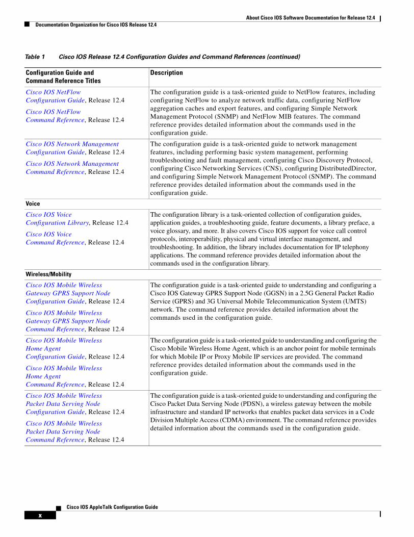
Table 1 Cisco IOS Release 12.4 Configuration Guides and Command References (continued)
Configuration Guide and Command Reference Titles
Description
About Cisco IOS Software Documentation for Release 12.4Documentation Organization for Cisco IOS Release 12.4
xCisco IOS AppleTalk Configuration Guide
Cisco IOS NetFlow Configuration Guide, Release 12.4
Cisco IOS NetFlow Command Reference, Release 12.4
The configuration guide is a task-oriented guide to NetFlow features, including configuring NetFlow to analyze network traffic data, configuring NetFlow aggregation caches and export features, and configuring Simple Network Management Protocol (SNMP) and NetFlow MIB features. The command reference provides detailed information about the commands used in the configuration guide.
Cisco IOS Network Management Configuration Guide, Release 12.4
Cisco IOS Network Management Command Reference, Release 12.4
The configuration guide is a task-oriented guide to network management features, including performing basic system management, performing troubleshooting and fault management, configuring Cisco Discovery Protocol, configuring Cisco Networking Services (CNS), configuring DistributedDirector, and configuring Simple Network Management Protocol (SNMP). The command reference provides detailed information about the commands used in the configuration guide.
Voice
Cisco IOS Voice Configuration Library, Release 12.4
Cisco IOS Voice Command Reference, Release 12.4
The configuration library is a task-oriented collection of configuration guides, application guides, a troubleshooting guide, feature documents, a library preface, a voice glossary, and more. It also covers Cisco IOS support for voice call control protocols, interoperability, physical and virtual interface management, and troubleshooting. In addition, the library includes documentation for IP telephony applications. The command reference provides detailed information about the commands used in the configuration library.
Wireless/Mobility
Cisco IOS Mobile Wireless Gateway GPRS Support Node Configuration Guide, Release 12.4
Cisco IOS Mobile Wireless Gateway GPRS Support Node Command Reference, Release 12.4
The configuration guide is a task-oriented guide to understanding and configuring a Cisco IOS Gateway GPRS Support Node (GGSN) in a 2.5G General Packet Radio Service (GPRS) and 3G Universal Mobile Telecommunication System (UMTS) network. The command reference provides detailed information about the commands used in the configuration guide.
Cisco IOS Mobile Wireless Home Agent Configuration Guide, Release 12.4
Cisco IOS Mobile Wireless Home Agent Command Reference, Release 12.4
The configuration guide is a task-oriented guide to understanding and configuring the Cisco Mobile Wireless Home Agent, which is an anchor point for mobile terminals for which Mobile IP or Proxy Mobile IP services are provided. The command reference provides detailed information about the commands used in the configuration guide.
Cisco IOS Mobile Wireless Packet Data Serving Node Configuration Guide, Release 12.4
Cisco IOS Mobile Wireless Packet Data Serving Node Command Reference, Release 12.4
The configuration guide is a task-oriented guide to understanding and configuring the Cisco Packet Data Serving Node (PDSN), a wireless gateway between the mobile infrastructure and standard IP networks that enables packet data services in a Code Division Multiple Access (CDMA) environment. The command reference provides detailed information about the commands used in the configuration guide.
Table 1 Cisco IOS Release 12.4 Configuration Guides and Command References (continued)
Configuration Guide and Command Reference Titles
Description
http://lbj.cisco.com/push_targets1/ucdit/cc/td/doc/product/software/ios123/123cgcr/voice_c/index.htm

About Cisco IOS Software Documentation for Release 12.4Documentation Organization for Cisco IOS Release 12.4
xiCisco IOS AppleTalk Configuration Guide
Cisco IOS Mobile Wireless Radio Access Networking Configuration Guide, Release 12.4
Cisco IOS Mobile Wireless Radio Access Networking Command Reference, Release 12.4
The configuration guide is a task-oriented guide to understanding and configuring Cisco IOS Radio Access Network products. The command reference provides detailed information about the commands used in the configuration guide.
Long Reach Ethernet (LRE) and Digital Subscriber Line (xDSL)
Cisco IOS Broadband and DSL Configuration Guide, Release 12.4
Cisco IOS Broadband and DSL Command Reference, Release 12.4
The configuration guide is a task-oriented guide to configuring broadband access aggregation and digital subscriber line features. The command reference provides detailed information about the commands used in the configuration guide.
Cisco IOS Service Selection GatewayConfiguration Guide, Release 12.4
Cisco IOS Service Selection Gateway Command Reference, Release 12.4
The configuration guide is a task-oriented guide to configuring Service Selection Gateway (SSG) features, including subscriber authentication, service access, and accounting. The command reference provides detailed information about the commands used in the configuration guide.
Dial—Access
Cisco IOS Dial Technologies Configuration Guide, Release 12.4
Cisco IOS Dial Technologies Command Reference, Release 12.4
The configuration guide is a task-oriented guide to configuring lines, modems, and ISDN services. This guide also contains information about configuring dialup solutions, including solutions for remote sites dialing in to a central office, Internet service providers (ISPs), ISP customers at home offices, enterprise WAN system administrators implementing dial-on-demand routing, and other corporate environments. The command reference provides detailed information about the commands used in the configuration guide.
Cisco IOS VPDN Configuration Guide, Release 12.4
Cisco IOS VPDN Command Reference, Release 12.4
The configuration guide is a task-oriented guide to configuring Virtual Private Dialup Networks (VPDNs), including information about Layer 2 tunneling protocols, client-initiated VPDN tunneling, NAS-initiated VPDN tunneling, and multihop VPDN. The command reference provides detailed information about the commands used in the configuration guide.
Asynchronous Transfer Mode (ATM)
Cisco IOS Asynchronous Transfer Mode Configuration Guide, Release 12.4
Cisco IOS Asynchronous Transfer Mode Command Reference, Release 12.4
The configuration guide is a task-oriented guide to configuring Asynchronous Transfer Mode (ATM), including WAN ATM, LAN ATM, and multiprotocol over ATM (MPOA). The command reference provides detailed information about the commands used in the configuration guide.
WAN
Cisco IOS Wide-Area Networking Configuration Guide, Release 12.4
Cisco IOS Wide-Area Networking Command Reference, Release 12.4
The configuration guide is a task-oriented guide to configuring wide-area network (WAN) features, including Layer 2 Tunneling Protocol Version 3 (L2TPv3); Frame Relay; Link Access Procedure, Balanced (LAPB); and X.25. The command reference provides detailed information about the commands used in the configuration guide.
Table 1 Cisco IOS Release 12.4 Configuration Guides and Command References (continued)
Configuration Guide and Command Reference Titles
Description

About Cisco IOS Software Documentation for Release 12.4Documentation Organization for Cisco IOS Release 12.4
xiiCisco IOS AppleTalk Configuration Guide
System Management
Cisco IOS Configuration Fundamentals Configuration Guide, Release 12.4
Cisco IOS Configuration Fundamentals Command Reference, Release 12.4
The configuration guide is a task-oriented guide to using Cisco IOS software to configure and maintain Cisco routers and access servers, including information about using the Cisco IOS command-line interface (CLI), loading and maintaining system images, using the Cisco IOS file system, using the Cisco IOS Web browser user interface (UI), and configuring basic file transfer services. The command reference provides detailed information about the commands used in the configuration guide.
Cisco IOS Interface and Hardware Component Configuration Guide, Release 12.4
Cisco IOS Interface and Hardware Component Command Reference, Release 12.4
The configuration guide is a task-oriented guide to configuring and managing interfaces and hardware components, including dial shelves, LAN interfaces, logical interfaces, serial interfaces, and virtual interfaces. The command reference provides detailed information about the commands used in the configuration guide.
IBM Technologies
Cisco IOS Bridging and IBM Networking Configuration Guide, Release 12.4
Cisco IOS Bridging Command Reference, Release 12.4
Cisco IOS IBM Networking Command Reference, Release 12.4
The configuration guide is a task-oriented guide to configuring:
• Bridging features, including transparent and source-route transparent (SRT) bridging, source-route bridging (SRB), Token Ring Inter-Switch Link (TRISL), and Token Ring Route Switch Module (TRRSM).
• IBM network features, including data-link switching plus (DLSw+), serial tunnel (STUN), and block serial tunnel (BSTUN); Logical Link Control, type 2 (LLC2), and Synchronous Data Link Control (SDLC); IBM Network Media Translation, including SDLC Logical Link Control (SDLLC) and Qualified Logical Link Control (QLLC); downstream physical unit (DSPU), Systems Network Architecture (SNA) service point, SNA Frame Relay Access, Advanced Peer-to-Peer Networking (APPN), native client interface architecture (NCIA) client/server topologies, and IBM Channel Attach.
The two command references provide detailed information about the commands used in the configuration guide.
Additional and Legacy Protocols
Cisco IOS AppleTalk Configuration Guide, Release 12.4
Cisco IOS AppleTalkCommand Reference, Release 12.4
The configuration guide is a task-oriented guide to configuring the AppleTalk protocol. The command reference provides detailed information about the commands used in the configuration guide.
Cisco IOS DECnet Configuration Guide, Release 12.4
Cisco IOS DECnet Command Reference, Release 12.4
The configuration guide is a task-oriented guide to configuring the DECnet protocol. The command reference provides detailed information about the commands used in the configuration guide.
Cisco IOS ISO CLNS Configuration Guide, Release 12.4
Cisco IOS ISO CLNS Command Reference, Release 12.4
The configuration guide is a task-oriented guide to configuring International Organization for Standardization (ISO) Connectionless Network Service (CLNS). The command reference provides detailed information about the commands used in the configuration guide.
Table 1 Cisco IOS Release 12.4 Configuration Guides and Command References (continued)
Configuration Guide and Command Reference Titles
Description

About Cisco IOS Software Documentation for Release 12.4Documentation Organization for Cisco IOS Release 12.4
xiiiCisco IOS AppleTalk Configuration Guide
Table 2 lists the documents and resources that support the Cisco IOS Release 12.4 software configuration guides and command references.
Cisco IOS Novell IPX Configuration Guide, Release 12.4
Cisco IOS Novell IPX Command Reference, Release 12.4
The configuration guide is a task-oriented guide to configuring the Novell Internetwork Packet Exchange (IPX) protocol. The command reference provides detailed information about the commands used in the configuration guide.
Cisco IOS Terminal Services Configuration Guide, Release 12.4
Cisco IOS Terminal Services Command Reference, Release 12.4
The configuration guide is a task-oriented guide to configuring terminal services, including DEC, local-area transport (LAT), and X.25 packet assembler/disassembler (PAD). The command reference provides detailed information about the commands used in the configuration guide.
Table 1 Cisco IOS Release 12.4 Configuration Guides and Command References (continued)
Configuration Guide and Command Reference Titles
Description
Table 2 Cisco IOS Release 12.4 Supporting Documents and Resources
Document Title Description
Cisco IOS Master Commands List, Release 12.4
An alphabetical listing of all the commands documented in the Cisco IOS Release 12.4 command references.
Cisco IOS New, Modified, Replaced, and Removed Commands, Release 12.4
A listing of all the new, modified, replaced and removed commands since Cisco IOS Release 12.3, grouped by Release 12.3T maintenance release and ordered alphabetically within each group.
Cisco IOS New and Modified Commands, Release 12.3
A listing of all the new, modified, and replaced commands since Cisco IOS Release 12.2, grouped by Release 12.2T maintenance release and ordered alphabetically within each group.
Cisco IOS System Messages, Volume 1 of 2
Cisco IOS System Messages, Volume 2 of 2
Listings and descriptions of Cisco IOS system messages. Not all system messages indicate problems with your system. Some are purely informational, and others may help diagnose problems with communications lines, internal hardware, or the system software.
Cisco IOS Debug Command Reference, Release 12.4
An alphabetical listing of the debug commands and their descriptions. Documentation for each command includes a brief description of its use, command syntax, and usage guidelines.
Release Notes, Release 12.4 A description of general release information, including information about supported platforms, feature sets, platform-specific notes, and Cisco IOS software defects.
Internetworking Terms and Acronyms Compilation and definitions of the terms and acronyms used in the internetworking industry.

About Cisco IOS Software Documentation for Release 12.4Document Conventions
xivCisco IOS AppleTalk Configuration Guide
Document ConventionsWithin Cisco IOS software documentation, the term router is generally used to refer to a variety of Cisco products (for example, routers, access servers, and switches). Routers, access servers, and other networking devices that support Cisco IOS software are shown interchangeably within examples. These products are used only for illustrative purposes; that is, an example that shows one product does not necessarily indicate that other products are not supported.
The Cisco IOS documentation set uses the following conventions:
Command syntax descriptions use the following conventions:
RFCs RFCs are standards documents maintained by the Internet Engineering Task Force (IETF). Cisco IOS software documentation references supported RFCs when applicable. The full text of referenced RFCs may be obtained at the following URL:
http://www.rfc-editor.org/
MIBs MIBs are used for network monitoring. To locate and download MIBs for selected platforms, Cisco IOS releases, and feature sets, use Cisco MIB Locator found at the following URL:
http://www.cisco.com/go/mibs
Table 2 Cisco IOS Release 12.4 Supporting Documents and Resources (continued)
Document Title Description
Convention Description
^ or Ctrl The ^ and Ctrl symbols represent the Control key. For example, the key combination ^D or Ctrl-D means hold down the Control key while you press the D key. Keys are indicated in capital letters but are not case sensitive.
string A string is a nonquoted set of characters shown in italics. For example, when setting an SNMP community string to public, do not use quotation marks around the string or the string will include the quotation marks.
Convention Description
bold Bold text indicates commands and keywords that you enter literally as shown.
italics Italic text indicates arguments for which you supply values.
[x] Square brackets enclose an optional element (keyword or argument).
| A vertical line indicates a choice within an optional or required set of keywords or arguments.
[x | y] Square brackets enclosing keywords or arguments separated by a vertical line indicate an optional choice.
{x | y} Braces enclosing keywords or arguments separated by a vertical line indicate a required choice.

About Cisco IOS Software Documentation for Release 12.4Obtaining Documentation
xvCisco IOS AppleTalk Configuration Guide
Nested sets of square brackets or braces indicate optional or required choices within optional or required elements. For example:
Examples use the following conventions:
The following conventions are used to attract the attention of the reader:
Caution Means reader be careful. In this situation, you might do something that could result in equipment damage or loss of data.
Note Means reader take note. Notes contain suggestions or references to material not covered in the manual.
Timesaver Means the described action saves time. You can save time by performing the action described in the paragraph.
Obtaining DocumentationCisco documentation and additional literature are available on Cisco.com. Cisco also provides several ways to obtain technical assistance and other technical resources. These sections explain how to obtain technical information from Cisco Systems.
Cisco.comYou can access the most current Cisco documentation and technical support at this URL:
http://www.cisco.com/techsupport
Convention Description
[x {y | z}] Braces and a vertical line within square brackets indicate a required choice within an optional element.
Convention Descriptionscreen Examples of information displayed on the screen are set in Courier font.
bold screen Examples of text that you must enter are set in Courier bold font.
< > Angle brackets enclose text that is not printed to the screen, such as passwords, and are used in contexts in which the italic document convention is not available, such as ASCII text.
! An exclamation point at the beginning of a line indicates a comment line. (Exclamation points are also displayed by the Cisco IOS software for certain processes.)
[ ] Square brackets enclose default responses to system prompts.

About Cisco IOS Software Documentation for Release 12.4Documentation Feedback
xviCisco IOS AppleTalk Configuration Guide
You can access the Cisco website at this URL:
http://www.cisco.com
You can access international Cisco websites at this URL:
http://www.cisco.com/public/countries_languages.shtml
Product Documentation DVDCisco documentation and additional literature are available in the Product Documentation DVD package, which may have shipped with your product. The Product Documentation DVD is updated regularly and may be more current than printed documentation.
The Product Documentation DVD is a comprehensive library of technical product documentation on portable media. The DVD enables you to access multiple versions of hardware and software installation, configuration, and command guides for Cisco products and to view technical documentation in HTML. With the DVD, you have access to the same documentation that is found on the Cisco website without being connected to the Internet. Certain products also have .pdf versions of the documentation available.
The Product Documentation DVD is available as a single unit or as a subscription. Registered Cisco.com users (Cisco direct customers) can order a Product Documentation DVD (product number DOC-DOCDVD=) from Cisco Marketplace at this URL:
http://www.cisco.com/go/marketplace/
Ordering DocumentationBeginning June 30, 2005, registered Cisco.com users may order Cisco documentation at the Product Documentation Store in the Cisco Marketplace at this URL:
http://www.cisco.com/go/marketplace/
Nonregistered Cisco.com users can order technical documentation from 8:00 a.m. to 5:00 p.m. (0800 to 1700) PDT by calling 1 866 463-3487 in the United States and Canada, or elsewhere by calling 011 408 519-5055. You can also order documentation by e-mail at [email protected] or by fax at 1 408 519-5001 in the United States and Canada, or elsewhere at 011 408 519-5001.
Documentation FeedbackYou can rate and provide feedback about Cisco technical documents by completing the online feedback form that appears with the technical documents on Cisco.com.
You can send comments about Cisco documentation to [email protected].
You can submit comments by using the response card (if present) behind the front cover of your document or by writing to the following address:
Cisco SystemsAttn: Customer Document Ordering170 West Tasman DriveSan Jose, CA 95134-9883
We appreciate your comments.

About Cisco IOS Software Documentation for Release 12.4Cisco Product Security Overview
xviiCisco IOS AppleTalk Configuration Guide
Cisco Product Security OverviewCisco provides a free online Security Vulnerability Policy portal at this URL:
http://www.cisco.com/en/US/products/products_security_vulnerability_policy.html
From this site, you can perform these tasks:
• Report security vulnerabilities in Cisco products.
• Obtain assistance with security incidents that involve Cisco products.
• Register to receive security information from Cisco.
A current list of security advisories and notices for Cisco products is available at this URL:
http://www.cisco.com/go/psirt
If you prefer to see advisories and notices as they are updated in real time, you can access a Product Security Incident Response Team Really Simple Syndication (PSIRT RSS) feed from this URL:
http://www.cisco.com/en/US/products/products_psirt_rss_feed.html
Reporting Security Problems in Cisco ProductsCisco is committed to delivering secure products. We test our products internally before we release them, and we strive to correct all vulnerabilities quickly. If you think that you might have identified a vulnerability in a Cisco product, contact PSIRT:
• Emergencies— [email protected]
An emergency is either a condition in which a system is under active attack or a condition for which a severe and urgent security vulnerability should be reported. All other conditions are considered nonemergencies.
• Nonemergencies— [email protected]
In an emergency, you can also reach PSIRT by telephone:
• 1 877 228-7302
• 1 408 525-6532
Tip We encourage you to use Pretty Good Privacy (PGP) or a compatible product to encrypt any sensitive information that you send to Cisco. PSIRT can work from encrypted information that is compatible with PGP versions 2.x through 8.x.
Never use a revoked or an expired encryption key. The correct public key to use in your correspondence with PSIRT is the one linked in the Contact Summary section of the Security Vulnerability Policy page at this URL:
http://www.cisco.com/en/US/products/products_security_vulnerability_policy.html
The link on this page has the current PGP key ID in use.

About Cisco IOS Software Documentation for Release 12.4Obtaining Technical Assistance
xviiiCisco IOS AppleTalk Configuration Guide
Obtaining Technical AssistanceCisco Technical Support provides 24-hour-a-day award-winning technical assistance. The Cisco Technical Support & Documentation website on Cisco.com features extensive online support resources. In addition, if you have a valid Cisco service contract, Cisco Technical Assistance Center (TAC) engineers provide telephone support. If you do not have a valid Cisco service contract, contact your reseller.
Cisco Technical Support & Documentation WebsiteThe Cisco Technical Support & Documentation website provides online documents and tools for troubleshooting and resolving technical issues with Cisco products and technologies. The website is available 24 hours a day, at this URL:
http://www.cisco.com/techsupport
Access to all tools on the Cisco Technical Support & Documentation website requires a Cisco.com user ID and password. If you have a valid service contract but do not have a user ID or password, you can register at this URL:
http://tools.cisco.com/RPF/register/register.do
Note Use the Cisco Product Identification (CPI) tool to locate your product serial number before submitting a web or phone request for service. You can access the CPI tool from the Cisco Technical Support & Documentation website by clicking the Tools & Resources link. Choose Cisco Product Identification Tool from the Alphabetical Index drop-down list, or click the Cisco Product Identification Tool link under Alerts & RMAs. The CPI tool offers three search options: by product ID or model name; by tree view; or for certain products, by copying and pasting show command output. Search results show an illustration of your product with the serial number label location highlighted. Locate the serial number label on your product and record the information before placing a service call.
Submitting a Service RequestUsing the online TAC Service Request Tool is the fastest way to open S3 and S4 service requests. (S3 and S4 service requests are those in which your network is minimally impaired or for which you require product information.) After you describe your situation, the TAC Service Request Tool provides recommended solutions. If your issue is not resolved using the recommended resources, your service request is assigned to a Cisco engineer. The TAC Service Request Tool is located at this URL:
http://www.cisco.com/techsupport/servicerequest
For S1 or S2 service requests or if you do not have Internet access, contact the Cisco TAC by telephone. (S1 or S2 service requests are those in which your production network is down or severely degraded.) Cisco engineers are assigned immediately to S1 and S2 service requests to help keep your business operations running smoothly.
To open a service request by telephone, use one of the following numbers:
Asia-Pacific: +61 2 8446 7411 (Australia: 1 800 805 227)EMEA: +32 2 704 55 55USA: 1 800 553-2447

About Cisco IOS Software Documentation for Release 12.4Obtaining Additional Publications and Information
xixCisco IOS AppleTalk Configuration Guide
For a complete list of Cisco TAC contacts, go to this URL:
http://www.cisco.com/techsupport/contacts
Definitions of Service Request SeverityTo ensure that all service requests are reported in a standard format, Cisco has established severity definitions.
Severity 1 (S1)—Your network is “down,” or there is a critical impact to your business operations. You and Cisco will commit all necessary resources around the clock to resolve the situation.
Severity 2 (S2)—Operation of an existing network is severely degraded, or significant aspects of your business operation are negatively affected by inadequate performance of Cisco products. You and Cisco will commit full-time resources during normal business hours to resolve the situation.
Severity 3 (S3)—Operational performance of your network is impaired, but most business operations remain functional. You and Cisco will commit resources during normal business hours to restore service to satisfactory levels.
Severity 4 (S4)—You require information or assistance with Cisco product capabilities, installation, or configuration. There is little or no effect on your business operations.
Obtaining Additional Publications and InformationInformation about Cisco products, technologies, and network solutions is available from various online and printed sources.
• Cisco Marketplace provides a variety of Cisco books, reference guides, documentation, and logo merchandise. Visit Cisco Marketplace, the company store, at this URL:
http://www.cisco.com/go/marketplace/
• Cisco Press publishes a wide range of general networking, training and certification titles. Both new and experienced users will benefit from these publications. For current Cisco Press titles and other information, go to Cisco Press at this URL:
http://www.ciscopress.com
• Packet magazine is the Cisco Systems technical user magazine for maximizing Internet and networking investments. Each quarter, Packet delivers coverage of the latest industry trends, technology breakthroughs, and Cisco products and solutions, as well as network deployment and troubleshooting tips, configuration examples, customer case studies, certification and training information, and links to scores of in-depth online resources. You can access Packet magazine at this URL:
http://www.cisco.com/packet
• iQ Magazine is the quarterly publication from Cisco Systems designed to help growing companies learn how they can use technology to increase revenue, streamline their business, and expand services. The publication identifies the challenges facing these companies and the technologies to help solve them, using real-world case studies and business strategies to help readers make sound technology investment decisions. You can access iQ Magazine at this URL:
http://www.cisco.com/go/iqmagazine
or view the digital edition at this URL:
http://ciscoiq.texterity.com/ciscoiq/sample/

About Cisco IOS Software Documentation for Release 12.4Obtaining Additional Publications and Information
xxCisco IOS AppleTalk Configuration Guide
• Internet Protocol Journal is a quarterly journal published by Cisco Systems for engineering professionals involved in designing, developing, and operating public and private internets and intranets. You can access the Internet Protocol Journal at this URL:
http://www.cisco.com/ipj
• Networking products offered by Cisco Systems, as well as customer support services, can be obtained at this URL:
http://www.cisco.com/en/US/products/index.html
• Networking Professionals Connection is an interactive website for networking professionals to share questions, suggestions, and information about networking products and technologies with Cisco experts and other networking professionals. Join a discussion at this URL:
http://www.cisco.com/discuss/networking
• World-class networking training is available from Cisco. You can view current offerings at this URL:
http://www.cisco.com/en/US/learning/index.html

xxiCisco IOS AppleTalk Configuration Guide
Using Cisco IOS Software for Release 12.4
This chapter provides tips for understanding and configuring Cisco IOS software using the command-line interface (CLI). It contains the following sections:
• Understanding Command Modes, page xxi
• Getting Help, page xxii
• Using the no and default Forms of Commands, page xxvi
• Saving Configuration Changes, page xxvi
• Filtering Output from the show and more Commands, page xxvii
• Finding Additional Feature Support Information, page xxvii
For an overview of Cisco IOS software configuration, see the Cisco IOS Configuration Fundamentals Configuration Guide.
For information on the conventions used in the Cisco IOS software documentation set, see the “About Cisco IOS Software Documentation for Release 12.4” chapter.
Understanding Command ModesYou use the CLI to access Cisco IOS software. Because the CLI is divided into many different modes, the commands available to you at any given time depend on the mode that you are currently in. Entering a question mark (?) at the CLI prompt allows you to obtain a list of commands available for each command mode.
When you log in to a Cisco device, the device is initially in user EXEC mode. User EXEC mode contains only a limited subset of commands. To have access to all commands, you must enter privileged EXEC mode by entering the enable command and a password (when required). From privileged EXEC mode you have access to both user EXEC and privileged EXEC commands. Most EXEC commands are used independently to observe status or to perform a specific function. For example, show commands are used to display important status information, and clear commands allow you to reset counters or interfaces. The EXEC commands are not saved when the software reboots.
Configuration modes allow you to make changes to the running configuration. If you later save the running configuration to the startup configuration, these changed commands are stored when the software is rebooted. To enter specific configuration modes, you must start at global configuration mode. From global configuration mode, you can enter interface configuration mode and a variety of other modes, such as protocol-specific modes.

Using Cisco IOS Software for Release 12.4Getting Help
xxiiCisco IOS AppleTalk Configuration Guide
ROM monitor mode is a separate mode used when the Cisco IOS software cannot load properly. If a valid software image is not found when the software boots or if the configuration file is corrupted at startup, the software might enter ROM monitor mode.
Table 1 describes how to access and exit various common command modes of the Cisco IOS software. It also shows examples of the prompts displayed for each mode.
For more information on command modes, see the “Using the Cisco IOS Command-Line Interface” chapter in the Cisco IOS Configuration Fundamentals Configuration Guide.
Getting HelpEntering a question mark (?) at the CLI prompt displays a list of commands available for each command mode. You can also get a list of keywords and arguments associated with any command by using the context-sensitive help feature.
To get help specific to a command mode, a command, a keyword, or an argument, use one of the following commands:
Table 1 Accessing and Exiting Command Modes
Command Mode
Access Method Prompt Exit Method
User EXEC Log in. Router> Use the logout command.
Privileged EXEC
From user EXEC mode, use the enable command.
Router# To return to user EXEC mode, use the disable command.
Global configuration
From privileged EXEC mode, use the configure terminal command.
Router(config)# To return to privileged EXEC mode from global configuration mode, use the exit or end command.
Interface configuration
From global configuration mode, specify an interface using an interface command.
Router(config-if)# To return to global configuration mode, use the exit command.
To return to privileged EXEC mode, use the end command.
ROM monitor From privileged EXEC mode, use the reload command. Press the Break key during the first 60 seconds while the system is booting.
> To exit ROM monitor mode, use the continue command.
Command Purpose
help Provides a brief description of the help system in any command mode.
abbreviated-command-entry? Provides a list of commands that begin with a particular character string. (No space between command and question mark.)
abbreviated-command-entry<Tab> Completes a partial command name.

Using Cisco IOS Software for Release 12.4Getting Help
xxiiiCisco IOS AppleTalk Configuration Guide
Example: How to Find Command OptionsThis section provides an example of how to display syntax for a command. The syntax can consist of optional or required keywords and arguments. To display keywords and arguments for a command, enter a question mark (?) at the configuration prompt or after entering part of a command followed by a space. The Cisco IOS software displays a list and brief description of available keywords and arguments. For example, if you were in global configuration mode and wanted to see all the keywords or arguments for the arap command, you would type arap ?.
The <cr> symbol in command help output stands for “carriage return.” On older keyboards, the carriage return key is the Return key. On most modern keyboards, the carriage return key is the Enter key. The <cr> symbol at the end of command help output indicates that you have the option to press Enter to complete the command and that the arguments and keywords in the list preceding the <cr> symbol are optional. The <cr> symbol by itself indicates that no more arguments or keywords are available and that you must press Enter to complete the command.
Table 2 shows examples of how you can use the question mark (?) to assist you in entering commands. The table steps you through configuring an IP address on a serial interface on a Cisco 7206 router that is running Cisco IOS Release 12.0(3).
? Lists all commands available for a particular command mode.
command ? Lists the keywords or arguments that you must enter next on the command line. (Space between command and question mark.)
Command Purpose
Table 2 How to Find Command Options
Command Comment
Router> enablePassword: <password>Router#
Enter the enable command and password to access privileged EXEC commands. You are in privileged EXEC mode when the prompt changes to Router#.
Router# configure terminalEnter configuration commands, one per line. End with CNTL/Z.Router(config)#
Enter the configure terminal privileged EXEC command to enter global configuration mode. You are in global configuration mode when the prompt changes to Router(config)#.

Using Cisco IOS Software for Release 12.4Getting Help
xxivCisco IOS AppleTalk Configuration Guide
Router(config)# interface serial ?<0-6> Serial interface number
Router(config)# interface serial 4 ?/
Router(config)# interface serial 4/ ?<0-3> Serial interface number
Router(config)# interface serial 4/0 ?<cr>Router(config)# interface serial 4/0Router(config-if)#
Enter interface configuration mode by specifying the serial interface that you want to configure using the interface serial global configuration command.
Enter ? to display what you must enter next on the command line. In this example, you must enter the serial interface slot number and port number, separated by a forward slash.
When the <cr> symbol is displayed, you can press Enter to complete the command.
You are in interface configuration mode when the prompt changes to Router(config-if)#.
Router(config-if)# ?Interface configuration commands:
.
.
.ip Interface Internet Protocol config commandskeepalive Enable keepalivelan-name LAN Name commandllc2 LLC2 Interface Subcommandsload-interval Specify interval for load calculation for an
interfacelocaddr-priority Assign a priority grouplogging Configure logging for interfaceloopback Configure internal loopback on an interfacemac-address Manually set interface MAC addressmls mls router sub/interface commandsmpoa MPOA interface configuration commandsmtu Set the interface Maximum Transmission Unit (MTU)netbios Use a defined NETBIOS access list or enable
name-cachingno Negate a command or set its defaultsnrzi-encoding Enable use of NRZI encodingntp Configure NTP...
Router(config-if)#
Enter ? to display a list of all the interface configuration commands available for the serial interface. This example shows only some of the available interface configuration commands.
Table 2 How to Find Command Options (continued)
Command Comment

Using Cisco IOS Software for Release 12.4Getting Help
xxvCisco IOS AppleTalk Configuration Guide
Router(config-if)# ip ?Interface IP configuration subcommands:
access-group Specify access control for packetsaccounting Enable IP accounting on this interfaceaddress Set the IP address of an interfaceauthentication authentication subcommandsbandwidth-percent Set EIGRP bandwidth limitbroadcast-address Set the broadcast address of an interfacecgmp Enable/disable CGMPdirected-broadcast Enable forwarding of directed broadcastsdvmrp DVMRP interface commandshello-interval Configures IP-EIGRP hello intervalhelper-address Specify a destination address for UDP broadcastshold-time Configures IP-EIGRP hold time...
Router(config-if)# ip
Enter the command that you want to configure for the interface. This example uses the ip command.
Enter ? to display what you must enter next on the command line. This example shows only some of the available interface IP configuration commands.
Router(config-if)# ip address ?A.B.C.D IP addressnegotiated IP Address negotiated over PPP
Router(config-if)# ip address
Enter the command that you want to configure for the interface. This example uses the ip address command.
Enter ? to display what you must enter next on the command line. In this example, you must enter an IP address or the negotiated keyword.
A carriage return (<cr>) is not displayed; therefore, you must enter additional keywords or arguments to complete the command.
Router(config-if)# ip address 172.16.0.1 ?A.B.C.D IP subnet mask
Router(config-if)# ip address 172.16.0.1
Enter the keyword or argument that you want to use. This example uses the 172.16.0.1 IP address.
Enter ? to display what you must enter next on the command line. In this example, you must enter an IP subnet mask.
A <cr> is not displayed; therefore, you must enter additional keywords or arguments to complete the command.
Table 2 How to Find Command Options (continued)
Command Comment

Using Cisco IOS Software for Release 12.4Using the no and default Forms of Commands
xxviCisco IOS AppleTalk Configuration Guide
Using the no and default Forms of CommandsAlmost every configuration command has a no form. In general, use the no form to disable a function. Use the command without the no keyword to reenable a disabled function or to enable a function that is disabled by default. For example, IP routing is enabled by default. To disable IP routing, use the no ip routing command; to reenable IP routing, use the ip routing command. The Cisco IOS software command reference publications provide the complete syntax for the configuration commands and describe what the no form of a command does.
Configuration commands can also have a default form, which returns the command settings to the default values. Most commands are disabled by default, so in such cases using the default form has the same result as using the no form of the command. However, some commands are enabled by default and have variables set to certain default values. In these cases, the default form of the command enables the command and sets the variables to their default values. The Cisco IOS software command reference publications describe the effect of the default form of a command if the command functions differently than the no form.
Saving Configuration ChangesUse the copy system:running-config nvram:startup-config command or the copy running-config startup-config command to save your configuration changes to the startup configuration so that the changes will not be lost if the software reloads or a power outage occurs. For example:
Router# copy system:running-config nvram:startup-configBuilding configuration...
It might take a minute or two to save the configuration. After the configuration has been saved, the following output appears:
[OK]Router#
On most platforms, this task saves the configuration to NVRAM. On the Class A flash file system platforms, this task saves the configuration to the location specified by the CONFIG_FILE environment variable. The CONFIG_FILE variable defaults to NVRAM.
Router(config-if)# ip address 172.16.0.1 255.255.255.0 ?secondary Make this IP address a secondary address<cr>
Router(config-if)# ip address 172.16.0.1 255.255.255.0
Enter the IP subnet mask. This example uses the 255.255.255.0 IP subnet mask.
Enter ? to display what you must enter next on the command line. In this example, you can enter the secondary keyword, or you can press Enter.
A <cr> is displayed; you can press Enter to complete the command, or you can enter another keyword.
Router(config-if)# ip address 172.16.0.1 255.255.255.0Router(config-if)#
In this example, Enter is pressed to complete the command.
Table 2 How to Find Command Options (continued)
Command Comment
Using Cisco IOS Software for Release 12.4Filtering Output from the show and more Commands
xxviiCisco IOS AppleTalk Configuration Guide
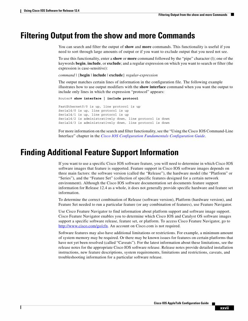
Filtering Output from the show and more CommandsYou can search and filter the output of show and more commands. This functionality is useful if you need to sort through large amounts of output or if you want to exclude output that you need not see.
To use this functionality, enter a show or more command followed by the “pipe” character (|); one of the keywords begin, include, or exclude; and a regular expression on which you want to search or filter (the expression is case-sensitive):
command | {begin | include | exclude} regular-expression
The output matches certain lines of information in the configuration file. The following example illustrates how to use output modifiers with the show interface command when you want the output to include only lines in which the expression “protocol” appears:
Router# show interface | include protocol
FastEthernet0/0 is up, line protocol is upSerial4/0 is up, line protocol is upSerial4/1 is up, line protocol is upSerial4/2 is administratively down, line protocol is downSerial4/3 is administratively down, line protocol is down
For more information on the search and filter functionality, see the “Using the Cisco IOS Command-Line Interface” chapter in the Cisco IOS Configuration Fundamentals Configuration Guide.
Finding Additional Feature Support InformationIf you want to use a specific Cisco IOS software feature, you will need to determine in which Cisco IOS software images that feature is supported. Feature support in Cisco IOS software images depends on three main factors: the software version (called the “Release”), the hardware model (the “Platform” or “Series”), and the “Feature Set” (collection of specific features designed for a certain network environment). Although the Cisco IOS software documentation set documents feature support information for Release 12.4 as a whole, it does not generally provide specific hardware and feature set information.
To determine the correct combination of Release (software version), Platform (hardware version), and Feature Set needed to run a particular feature (or any combination of features), use Feature Navigator.
Use Cisco Feature Navigator to find information about platform support and software image support. Cisco Feature Navigator enables you to determine which Cisco IOS and Catalyst OS software images support a specific software release, feature set, or platform. To access Cisco Feature Navigator, go to http://www.cisco.com/go/cfn. An account on Cisco.com is not required.
Software features may also have additional limitations or restrictions. For example, a minimum amount of system memory may be required. Or there may be known issues for features on certain platforms that have not yet been resolved (called “Caveats”). For the latest information about these limitations, see the release notes for the appropriate Cisco IOS software release. Release notes provide detailed installation instructions, new feature descriptions, system requirements, limitations and restrictions, caveats, and troubleshooting information for a particular software release.

Using Cisco IOS Software for Release 12.4Finding Additional Feature Support Information
xxviiiCisco IOS AppleTalk Configuration Guide

1Cisco IOS AppleTalk Configuration Guide
78-17505-01
AppleTalk Overview
The Cisco IOS software supports a variety of routing protocols. The Cisco IOS AppleTalk Configuration Guide discusses AppleTalk network protocols; it contains these sections:
• AppleTalk
• Configuring AppleTalk
The Cisco IOS IP Configuration Guide discusses the following network protocols:
• IP
• IP Routing
This overview chapter provides a high-level description of AppleTalk. For configuration information, see the appropriate section in this publication.
To identify the hardware platform or software image information associated with a feature, use the Feature Navigator on Cisco.com to search for information about the feature or refer to the software release notes for a specific release. For more information, see the “Finding Additional Feature Support Information” section on page xxvii in the Using Cisco IOS Software for Release 12.4 chapter.
AppleTalkThis section provides background on AppleTalk and briefly describes the Cisco implementation of AppleTalk.
Background on AppleTalkAppleTalk is a LAN system designed and developed by Apple Computer, Inc. It can run over Ethernet, Token Ring, and FDDI networks, and over the Apple proprietary twisted-pair media access system (LocalTalk). AppleTalk specifies a protocol stack comprising several protocols that direct the flow of traffic over the network.
Apple Computer uses the name AppleTalk to refer to the Apple network protocol architecture. Apple Computer refers to the actual transmission media used in an AppleTalk network as LocalTalk, TokenTalk (AppleTalk over Token Ring), EtherTalk (AppleTalk over Ethernet), and FDDITalk (AppleTalk over FDDI).

AppleTalk OverviewAppleTalk
2Cisco IOS AppleTalk Configuration Guide
78-17505-01
The Cisco Implementation of AppleTalkCisco IOS software supports AppleTalk Phase 1 and AppleTalk Phase 2. For AppleTalk Phase 2, Cisco devices support both extended and nonextended networks.
A Cisco router or access server may receive equivalent routes advertised by neighboring routers with one router giving an AppleTalk Phase 1 form of the route (for example, 101), and another giving an AppleTalk Phase 2 form of the route (for example, 101-101). When neighboring routers advertise equivalent overlapping routes to a router, the router always uses the AppleTalk Phase 2 form of the route and discards the AppleTalk Phase 1 route.
Media Support
The Cisco implementation of AppleTalk routes packets over Ethernet, Token Ring, and FDDI LANs, and over X.25, High-Level Data Link Control (HDLC), Frame Relay, and Switched Multimegabit Data Service (SMDS) WANs.
Standard AppleTalk Services
The Cisco implementation of AppleTalk supports the following standard AppleTalk protocols:
• AppleTalk Address Resolution Protocol (AARP)
• AppleTalk Port Group
• Datagram Delivery Protocol (DDP)
• Routing Table Maintenance Protocol (RTMP)
• Name Binding Protocol (NBP)
• Zone Information Protocol (ZIP)
• AppleTalk Echo Protocol (AEP)
• AppleTalk Transaction Protocol (ATP)
AARP, DDP, and RTMP provide end-to-end connectivity between internetworked nodes. AARP maps AppleTalk node addresses to the addresses of the underlying data link, thus making it possible for AppleTalk to run on several data links. DDP provides socket-to-socket delivery of packets. RTMP establishes and maintains routing tables.
NBP and ZIP maintain node name and zone information. NBP maps network names to AppleTalk addresses. ZIP tracks which networks are in which zones.
AEP is an echo (or ping-type) protocol. It generates packets that test the reachability of network nodes.
ATP is a reliable transport protocol that provides data acknowledgment and retransmission for transaction-based applications, such as file services provided by the AppleTalk Filing Protocol (AFP) and print services provided by the Printer Access Protocol (PAP).
Our software provides support for the AppleTalk MIB variables as described in RFC 1243.

AppleTalk OverviewAppleTalk
3Cisco IOS AppleTalk Configuration Guide
78-17505-01
Enhancements to Standard AppleTalk Services
The Cisco AppleTalk implementation includes the following enhancements to standard AppleTalk support:
• Support for EtherTalk 1.2 and EtherTalk 2.0 without the need for translation or transition routers.
• Support for Ethernet-emulated LANs. For more information on emulated LANs (ELANs) and routing AppleTalk between them, refer to the “Configuring LAN Emulation” chapter of the Cisco IOS Switching Services Configuration Guide.
• Support for VLANs. For more information on VLANs and routing AppleTalk between them over Inter-Switch Link (ISL) or IEEE 802.10, refer to the “Configuring Routing Between VLANs with ISL Encapsulation” and “Configuring Routing Between VLANs with IEEE 802.10 Encapsulation” chapters of the Cisco IOS Switching Services Configuration Guide.
• Support for WAN protocols, including SMDS, Frame Relay, X.25, and HDLC.
• Configurable protocol constants (including the control of the aging of entries in the routing table and control of the AARP interval and number of retransmissions).
• No software limits on the number of zones or routes. However, per AppleTalk specification you can only have a maximum of 255 zones per segment.
• MacTCP support via a MacIP server.
• Support of IPTalk, which provides IP encapsulation of AppleTalk, IPTalk, and the Columbia AppleTalk Package (CAP).
• Access control for filtering network traffic by network number, ZIP filtering, by NBP entity names, filtering routing table updates, and filtering GetZoneList (GZL) responses.
• Integrated node name support to simplify AppleTalk network management.
• Interactive access to AEP and NBP provided by the test appletalk command.
• Configured (seed) and discovered interface configuration.
• Support for the AppleTalk Responder, which is used by network monitoring packages such as Inter•Poll.
• Simple Network Management Protocol (SNMP) over AppleTalk.
• Encapsulation (tunneling) of AppleTalk RTMP packets over an IP backbone.
• Support for AppleTalk static routes.
Security
AppleTalk, like many network protocols, makes no provisions for network security. The design of the AppleTalk protocol architecture requires that security measures be implemented at higher application levels. Cisco supports AppleTalk distribution lists, allowing control of routing updates on a per-interface basis. This security feature is similar to those that Cisco provides for other protocols.
Note that the Cisco implementation of AppleTalk does not forward packets with local source and destination network addresses. This behavior does not conform with the definition of AppleTalk in the Apple Computer Inside AppleTalk publication. However, this behavior is designed to prevent any possible corruption of the AARP table in any AppleTalk node that is performing address gleaning through MAC.

AppleTalk OverviewAppleTalk
4Cisco IOS AppleTalk Configuration Guide
78-17505-01

5Cisco IOS AppleTalk Configuration Guide
78-17505-01
Configuring AppleTalk
This chapter describes how to configure AppleTalk and provides configuration examples. For a complete description of the AppleTalk commands mentioned in this chapter, refer to the Cisco IOS AppleTalk Command Reference publication. To locate documentation for other commands that appear in this chapter, use the command reference master index or search online.
To identify the hardware platform or software image information associated with a feature, use the Feature Navigator on Cisco.com to search for information about the feature or refer to the software release notes for a specific release. For more information, see the “Finding Additional Feature Support Information” section on page xxvii in the Using Cisco IOS Software for Release 12.4 chapter.
AppleTalk PhasesThe AppleTalk network architecture has the following two phases:
• AppleTalk Phase 1
• AppleTalk Phase 2
AppleTalk Phase 1AppleTalk Phase 1 is the initial implementation of AppleTalk and is designed for logical workgroups. AppleTalk Phase 1 supports a single physical network that can have one network number and be in one zone. This network can have up to 254 devices, which can consist of 127 end nodes and 127 servers.
AppleTalk Phase 2AppleTalk Phase 2 is an enhancement to AppleTalk Phase 1 and is designed for larger networks and has improved routing capabilities. It supports multiple logical networks on a single physical network and multiple logical networks in a given zone, which means that one cable segment can have multiple network numbers. Each logical network in Phase 2 can support up to 253 devices, with no restrictions on the type of devices (end nodes or servers). Also, in AppleTalk Phase 2, a network can be in more than one zone.

Configuring AppleTalkAppleTalk Phases
6Cisco IOS AppleTalk Configuration Guide
78-17505-01
Types of AppleTalk Phase 2 Networks
AppleTalk Phase 2 distinguishes between two types of networks based on their media-level encapsulation and cable addressing methods. The two types of networks are as follows:
• Nonextended
• Extended
Table 3 compares the attributes of nonextended and extended networks.
Nonextended networks were the sole network type defined in AppleTalk Phase 1. You can consider AppleTalk Phase 1 networks to be nonextended networks.
You can consider AppleTalk Phase 2 networks to be extended networks.
Table 4 compares the capabilities of AppleTalk Phase 1 and Phase 2.
Table 3 Comparison of Nonextended and Extended Networks
Attribute Nonextended Extended
Media-level encapsulation method Encapsulation of the 3-byte LocalTalk packet in an Ethernet frame
ISO-type encapsulations only (that is, no encapsulation of the 3-byte LocalTalk packets)
Physical media that supports media-level encapsulation methods
LocalTalk All physical media except LocalTalk
Node addressing method Each node number is unique
Each network.node combination is unique
Cable addressing method A single number per cable
A number range corresponding to one or more logical networks
Table 4 Comparison of AppleTalk Phase 1 and Phase 2
Capability AppleTalk Phase 1 AppleTalk Phase 2
Networks, nodes, and zones
Number of logical networks (cable segments) 1 65,2791
Maximum number of devices 2542 2533
Maximum number of end nodes 127 Does not apply4
Maximum number of servers 127 Does not apply
Number of zones in which a network can be 15 1 (nonextended)255 (extended)

Configuring AppleTalkAppleTalk Addresses
7Cisco IOS AppleTalk Configuration Guide
78-17505-01
Routers running Cisco IOS software Release 8.2 or later support AppleTalk Phase 1 and Phase 2.
AppleTalk AddressesAn AppleTalk address consists of a network number and a node number expressed in decimal in the format network.node.
Network NumbersThe network number identifies a network, or cable segment. A network is a single logical cable. Although the logical cable is frequently a single physical cable, bridges and routers can interconnect several physical cables.
The network number is a 16-bit decimal number that must be unique throughout the entire AppleTalk internetwork.
In AppleTalk Phase 1, networks are identified by a single network number that corresponds to a physical network. In AppleTalk Phase 1, the network number 0 is reserved.
In AppleTalk Phase 2, networks are identified by a cable range that corresponds to one or more logical networks. In Phase 2, a single cable can have multiple network numbers.
A cable range is either one network number or a contiguous sequence of several network numbers in the format start–end. For example, the cable range 4096–4096 identifies a logical network that has a single network number, and the cable range 10–12 identifies a logical network that spans three network numbers.
In AppleTalk Phase 2, the network number 0 is reserved.
Media-level encapsulation
Nonextended network Does not apply Yes
Extended network Does not apply Yes
Cable addressing Does not apply; uses network numbers
Single network number (nonextended)
Cable range of 1 or more (extended)
1. The 65,279 value is per AppleTalk specifications.
2. The node addresses 0 and 255 are reserved.
3. The node addresses 0, 254, and 255 are reserved.
4. There is no restriction on the types of devices. There can be a total of 253 end nodes and servers.
5. In terms of zones, an AppleTalk Phase 1 network can be thought of as a nonextended AppleTalk Phase 2 network.
Table 4 Comparison of AppleTalk Phase 1 and Phase 2 (continued)
Capability AppleTalk Phase 1 AppleTalk Phase 2

Configuring AppleTalkAppleTalk Zones
8Cisco IOS AppleTalk Configuration Guide
78-17505-01
Node NumbersThe node number identifies the node, which is any device connected to the AppleTalk network. The node number is an 8-bit decimal number that must be unique on that network.
In AppleTalk Phase 1, node numbers 1 through 127 are for user nodes, node numbers 128 through 254 are for servers, and node numbers 0 and 255 are reserved.
In AppleTalk Phase 2, you can use node numbers 1 through 253 for any nodes attached to the network. Node numbers 0, 254, and 255 are reserved.
AppleTalk Address ExampleThe following is an example of an AppleTalk network address:
3.45
In this example, the network number is 3 and the node number is 45. You enter both numbers in decimal. Cisco IOS software also displays them in decimal.
AppleTalk ZonesA zone is a logical group of networks. The networks in a zone can be contiguous or noncontiguous. A zone is identified by a zone name, which can be up to 32 characters long. The zone name can include standard characters and AppleTalk special characters. To include a special character, type a colon followed by two hexadecimal characters that represent the special character in the Macintosh character set.
An AppleTalk Phase 1 network can have only one zone.
In AppleTalk Phase 2, an extended network can have up to 255 zones; a nonextended network can have only 1 zone.
Configuration Guidelines and Compatibility RulesAppleTalk Phase 1 and AppleTalk Phase 2 networks are incompatible and cannot run simultaneously on the same internetwork. As a result, all routers in an internetwork must support AppleTalk Phase 2 before the network can use Phase 2 routing.
If your internetwork has a combination of AppleTalk Phase 1 and Phase 2 routers, you must observe the following configuration guidelines. If you do not follow these guidelines, unpredictable behavior might result. Note, however, that you do not need to upgrade all end nodes to use the features provided by our AppleTalk enhancements.
• The cable range must be one (for example, 23–23).
• Each AppleTalk network can be a member of only one zone.

Configuring AppleTalkAppleTalk Configuration Task List
9Cisco IOS AppleTalk Configuration Guide
78-17505-01
When using Cisco routers with implementations of AppleTalk by other vendors, follow these guidelines:
• For a Macintosh with an Ethernet card to support extended AppleTalk, the Macintosh must be running EtherTalk Version 2.0 or later. This restriction does not apply to Macintoshes with only LocalTalk interfaces.
• Shiva FastPath routers must run K-Star Version 8.0 or later, and must be explicitly configured for extended AppleTalk.
• Apple Internet Router software Version 2.0 supports a transition mode for translation between nonextended AppleTalk and extended AppleTalk on the same network. Transition mode requires the Apple upgrade utility and a special patch file from Apple.
AppleTalk Configuration Task List To configure AppleTalk routing, perform the tasks in the following sections:
• Configuring AppleTalk Routing (Required)
• Controlling Access to AppleTalk Networks (Optional)
• Configuring the Name Display Facility (Optional)
• Setting Up Special Configurations (Optional)
• Configuring AppleTalk Control Protocol for PPP (Optional)
• Tuning AppleTalk Network Performance (Optional)
• Configuring AppleTalk Interenterprise Routing (Optional)
• Configuring AppleTalk over WANs (Optional)
• Configuring AppleTalk Between LANs (Optional)
• Configuring AppleTalk Between VLANs (Optional)
• Monitoring and Maintaining the AppleTalk Network (Optional)
See the “AppleTalk Configuration Examples” section at the end of this chapter for configuration examples.
Configuring AppleTalk RoutingYou configure AppleTalk routing by first enabling it on the router and then configuring it on each interface.
To configure the AppleTalk routing protocol, perform the tasks in the following sections. The first two tasks are required; the rest are optional.
• Enabling AppleTalk Routing (Required)
• Configuring an Interface for AppleTalk (Required)
• Selecting an AppleTalk Routing Protocol (Optional)
• Configuring Transition Mode (Optional)
• Enabling Concurrent Routing and Bridging (Optional)
• Configuring Integrated Routing and Bridging (Optional)
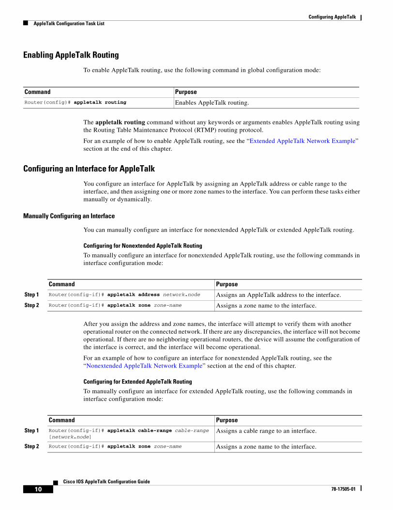
Configuring AppleTalkAppleTalk Configuration Task List
10Cisco IOS AppleTalk Configuration Guide
78-17505-01
Enabling AppleTalk Routing
To enable AppleTalk routing, use the following command in global configuration mode:
The appletalk routing command without any keywords or arguments enables AppleTalk routing using the Routing Table Maintenance Protocol (RTMP) routing protocol.
For an example of how to enable AppleTalk routing, see the “Extended AppleTalk Network Example” section at the end of this chapter.
Configuring an Interface for AppleTalk
You configure an interface for AppleTalk by assigning an AppleTalk address or cable range to the interface, and then assigning one or more zone names to the interface. You can perform these tasks either manually or dynamically.
Manually Configuring an Interface
You can manually configure an interface for nonextended AppleTalk or extended AppleTalk routing.
Configuring for Nonextended AppleTalk Routing
To manually configure an interface for nonextended AppleTalk routing, use the following commands in interface configuration mode:
After you assign the address and zone names, the interface will attempt to verify them with another operational router on the connected network. If there are any discrepancies, the interface will not become operational. If there are no neighboring operational routers, the device will assume the configuration of the interface is correct, and the interface will become operational.
For an example of how to configure an interface for nonextended AppleTalk routing, see the “Nonextended AppleTalk Network Example” section at the end of this chapter.
Configuring for Extended AppleTalk Routing
To manually configure an interface for extended AppleTalk routing, use the following commands in interface configuration mode:
Command Purpose
Router(config)# appletalk routing Enables AppleTalk routing.
Command Purpose
Step 1 Router(config-if)# appletalk address network.node Assigns an AppleTalk address to the interface.
Step 2 Router(config-if)# appletalk zone zone-name Assigns a zone name to the interface.
Command Purpose
Step 1 Router(config-if)# appletalk cable-range cable-range [network.node]
Assigns a cable range to an interface.
Step 2 Router(config-if)# appletalk zone zone-name Assigns a zone name to the interface.
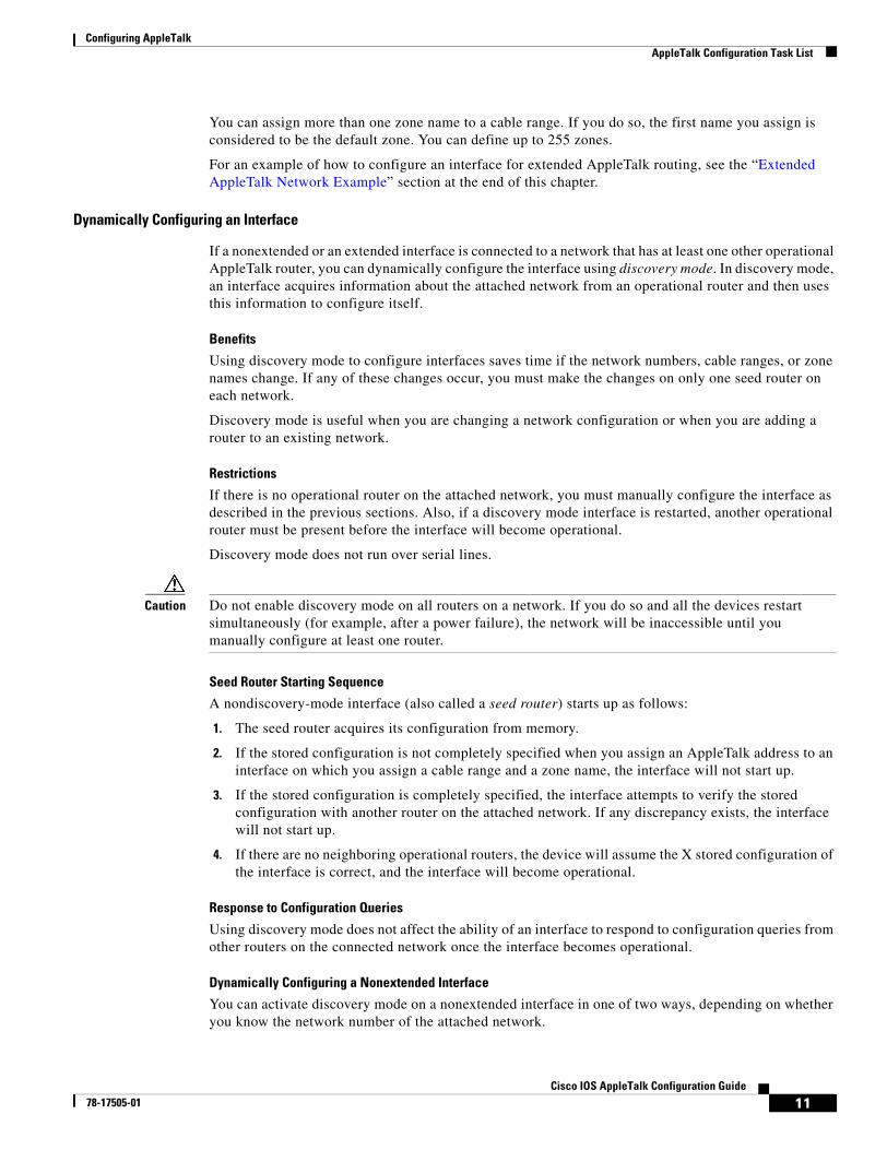
Configuring AppleTalkAppleTalk Configuration Task List
11Cisco IOS AppleTalk Configuration Guide
78-17505-01
You can assign more than one zone name to a cable range. If you do so, the first name you assign is considered to be the default zone. You can define up to 255 zones.
For an example of how to configure an interface for extended AppleTalk routing, see the “Extended AppleTalk Network Example” section at the end of this chapter.
Dynamically Configuring an Interface
If a nonextended or an extended interface is connected to a network that has at least one other operational AppleTalk router, you can dynamically configure the interface using discovery mode. In discovery mode, an interface acquires information about the attached network from an operational router and then uses this information to configure itself.
Benefits
Using discovery mode to configure interfaces saves time if the network numbers, cable ranges, or zone names change. If any of these changes occur, you must make the changes on only one seed router on each network.
Discovery mode is useful when you are changing a network configuration or when you are adding a router to an existing network.
Restrictions
If there is no operational router on the attached network, you must manually configure the interface as described in the previous sections. Also, if a discovery mode interface is restarted, another operational router must be present before the interface will become operational.
Discovery mode does not run over serial lines.
Caution Do not enable discovery mode on all routers on a network. If you do so and all the devices restart simultaneously (for example, after a power failure), the network will be inaccessible until you manually configure at least one router.
Seed Router Starting Sequence
A nondiscovery-mode interface (also called a seed router) starts up as follows:
1. The seed router acquires its configuration from memory.
2. If the stored configuration is not completely specified when you assign an AppleTalk address to an interface on which you assign a cable range and a zone name, the interface will not start up.
3. If the stored configuration is completely specified, the interface attempts to verify the stored configuration with another router on the attached network. If any discrepancy exists, the interface will not start up.
4. If there are no neighboring operational routers, the device will assume the X stored configuration of the interface is correct, and the interface will become operational.
Response to Configuration Queries
Using discovery mode does not affect the ability of an interface to respond to configuration queries from other routers on the connected network once the interface becomes operational.
Dynamically Configuring a Nonextended Interface
You can activate discovery mode on a nonextended interface in one of two ways, depending on whether you know the network number of the attached network.

Configuring AppleTalkAppleTalk Configuration Task List
12Cisco IOS AppleTalk Configuration Guide
78-17505-01
In the first method, you immediately place the interface into discovery mode by specifying an AppleTalk address of 0.0. Use this method when you do not know the network number of the attached network. To activate discovery mode for this method, use the following command in interface configuration mode:
For an example of how to configure discovery mode using this method, see the “Nonextended Network in Discovery Mode Example” section at the end of this chapter.
For the second method, you first assign an address to the interface and then explicitly enable discovery mode. Use this method when you know the network number of the attached network. Note, however, that you are not required to use this method when you know the network number. To activate discovery mode for this method, use the following commands in interface configuration mode:
Dynamically Configuring an Extended Interface
You can activate discovery mode on an extended interface in one of two ways, depending on whether you know the cable range of the attached network.
In the first method, you immediately place the interface into discovery mode by specifying a cable range of 0–0. Use this method when you do not know the network number of the attached network. To activate discovery mode for this method, use the following command in interface configuration mode:
In the second method, you first assign cable ranges and then explicitly enable discovery mode. Use this method when you know the cable range of the attached network. Note, however, that you are not required to use this method if you know the cable range. To activate discovery mode for this method, use the following commands in interface configuration mode:
Command PurposeRouter(config-if)# appletalk address 0.0 Places the interface into discovery mode by assigning it the
AppleTalk address 0.0.
Command Purpose
Step 1 Router(config-if)# appletalk address network.node Assigns an AppleTalk address to the interface.
Step 2 Router(config-if)# appletalk discovery Places the interface into discovery mode.
Command Purpose
Router(config-if)# appletalk cable-range 0–0 Places the interface into discovery mode by assigning it the cable range 0–0.
Command Purpose
Step 1 Router(config-if)# appletalk cable-range cable-range [network.node]
Assigns an AppleTalk address to the interface.
Step 2 Router(config-if)# appletalk discovery Places the interface into discovery mode.

Configuring AppleTalkAppleTalk Configuration Task List
13Cisco IOS AppleTalk Configuration Guide
78-17505-01
Selecting an AppleTalk Routing Protocol
Once you configure AppleTalk on an interface, you can select a routing protocol for the interface. You can enable the RTMP routing protocol on any interface. You can also enable the AppleTalk Update-Based Routing Protocol (AURP) on a tunnel interface.
With the appletalk protocol command, you can enable some AppleTalk interfaces to use RTMP and others to use AURP as required by your network topology.
To select an AppleTalk routing protocol for an interface, use the following command in interface configuration mode:
This command is optional. If you do not select a routing protocol for an interface, Cisco IOS software uses RTMP by default.
Configuring Transition Mode
The Cisco IOS software can route packets between extended and nonextended AppleTalk networks that coexist on the same cable. This type of routing is referred to as transition mode.
To use transition mode, you must have two router ports connected to the same physical cable. One port is configured as a nonextended AppleTalk network, and the other port is configured as an extended AppleTalk network. Each port must have a unique network number, because you are routing between two separate AppleTalk networks: the extended network and the nonextended network.
To configure transition mode, you must have two ports on the same router that are connected to the same physical cable. To configure one port as a nonextended AppleTalk network, use the following commands in interface configuration mode:
To configure the second port as an extended AppleTalk network, use the following commands in interface configuration mode:
When you enter interface configuration mode, the type of interface must be the same for both ports (for example, both could be Ethernet) and the interface number must be different (for example, 0 and 1).
For an example of how to configure transition mode, see the “Transition Mode Example” section at the end of this chapter.
Command PurposeRouter(config-if)# appletalk protocol {aurp | rtmp} Creates an AppleTalk routing process.
Command Purpose
Step 1 Router(config-if)# appletalk address network.node Assigns an AppleTalk address to the interface.
Step 2 Router(config-if)# appletalk zone zone-name Assigns a zone name to the interface.
Command Purpose
Step 1 Router(config-if)# appletalk cable-range cable-range [network.node]
Assigns an AppleTalk cable range to the interface.
Step 2 Router(config-if)# appletalk zone zone-name Assigns a zone name to the interface.

Configuring AppleTalkAppleTalk Configuration Task List
14Cisco IOS AppleTalk Configuration Guide
78-17505-01
Enabling Concurrent Routing and Bridging
You can route AppleTalk on some interfaces and transparently bridge it on other interfaces simultaneously. To enable this type of routing, you must enable concurrent routing and bridging.
To enable concurrent routing and bridging, use the following command in global configuration mode:
Configuring Integrated Routing and Bridging
Integrated routing and bridging (IRB) enables a user to route AppleTalk traffic between routed interfaces and bridge groups, or route AppleTalk traffic between bridge groups. Specifically, local or unroutable traffic is bridged among the bridged interfaces in the same bridge group, while routable traffic is routed to other routed interfaces or bridge groups.
Using IRB, you can do the following:
• Switch packets from a bridged interface to a routed interface
• Switch packets from a routed interface to a bridged interface
• Switch packets within the same bridge group
For more information about configuring integrated routing and bridging, refer to the “Configuring Transparent Bridging” chapter in the Cisco IOS Bridging and IBM Networking Configuration Guide.
Controlling Access to AppleTalk Networks An access list is a list of AppleTalk network numbers, zones, or Name Binding Protocol (NBP) named entities that is maintained by the Cisco IOS software and used to control access to or from specific zones, networks, and NBP named entities.
Types of Access Lists
The software supports the following two general types of AppleTalk access lists:
• AppleTalk-style access lists, which are based on AppleTalk zones or NBP named entities
• IP-style access lists, which are based on network numbers
AppleTalk-Style Access Lists
AppleTalk-style access lists regulate the internetwork using zone names and NBP named entities. The main advantage of AppleTalk-style access lists is that they allow you to define access regardless of the existing network topology or any changes in future topologies—because they are based on zones and NBP named entities. A zone access list is essentially a dynamic list of network numbers. The user specifies a zone name, but the effect is as if the user had specified all the network numbers belonging to that zone. An NBP named entity access list provides a means of controlling access at the network entity level.
Command Purpose
Router(config)# bridge crb Enables concurrent routing and bridging.

Configuring AppleTalkAppleTalk Configuration Task List
15Cisco IOS AppleTalk Configuration Guide
78-17505-01
Using Zone Names
Zone names and NBP named entities are good control points because they allow for network-level abstractions that users can access.
You can express zone names either explicitly or by using generalized-argument keywords. Thus, using AppleTalk zone name access lists simplifies network management and allows for greater flexibility when adding segments, because reconfiguration requirements are minimal. Using AppleTalk zone name access lists allows you to manage and control whole sections of the network.
Using NBP Named Entities
NBP named entities allow you to control access at the object level. Using NBP named entities, you can permit or deny NBP packets from a class of objects based on the type portion of the NBP tuple name, from a particular NBP named entity based on the object portion of the NBP tuple name, or from all NBP named entities within a particular area based on the zone portion of the NBP tuple name. You can fully or partially qualify an NBP tuple name to refine the access control by specifying one, two, or three parts of the NBP name tuple as separate access list entries tied together by the same sequence number.
IP-Style Access Lists
IP-style access lists control network access based on network numbers. This feature can be useful in defining access lists that control the disposition of networks that overlap, are contained by, or exactly match a specific network number range.
Additionally, you can use IP-style access lists to resolve conflicting network numbers. You can use an access list to restrict the network numbers and zones that a department can advertise, thereby limiting advertisement to an authorized set of networks. AppleTalk-style access lists are typically insufficient for this purpose.
In general, however, using IP-style access lists is not recommended because the controls are not optimal; they ignore the logical mapping provided by AppleTalk zones. One problem with IP-style access lists is that when you add networks to a zone, you must reconfigure each secure router. Another problem is that, because anyone can add network segments (for example, when one group of users gets a LaserWriter and installs a Cayman GatorBox, creating a new network segment), the potential for confusion and misconfiguration is substantial.
Combining AppleTalk-Style and IP-Style Entries
You can combine zone, network, and NBP named entity entries in a single access list. Cisco IOS software performs NBP filtering independently on only NBP packets. The software applies network filtering in conjunction with zone filtering. However, for optimal performance, access lists should not include both zones (AppleTalk-style) and numeric network (IP-style) entries.
Because the Cisco IOS software applies network filtering and zone filtering simultaneously, be sure to add the appropriate access-list permit other-access or access-list permit additional-zones statement to the end of the access list when using only one type of filtering. For example, suppose you want to deny only zone Z. You do not want any network filtering, but the software by default automatically includes an access-list deny other-access entry at the end of each access list. You must then create an access list that explicitly permits access of all networks. Therefore, the access list for this example would have an access-list deny zone Z entry to deny zone Z, an access-list permit additional-zones entry to permit all other zones, and an access-list permit other-access entry to explicitly permit all networks.
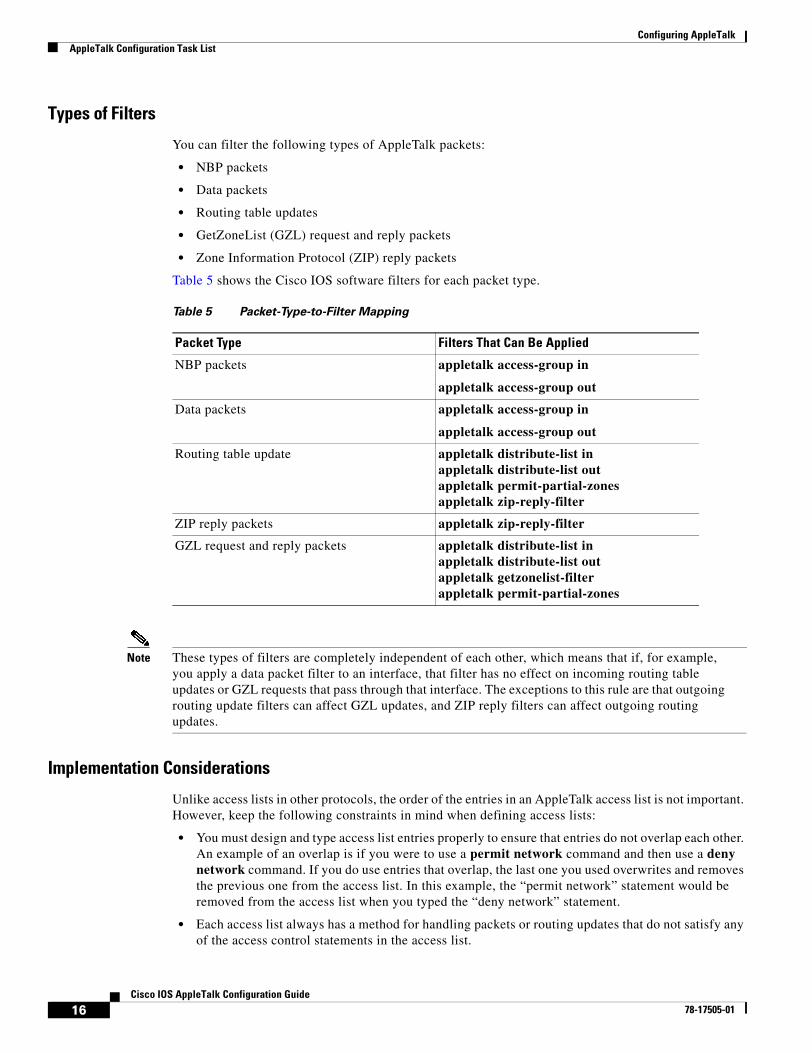
Configuring AppleTalkAppleTalk Configuration Task List
16Cisco IOS AppleTalk Configuration Guide
78-17505-01
Types of Filters
You can filter the following types of AppleTalk packets:
• NBP packets
• Data packets
• Routing table updates
• GetZoneList (GZL) request and reply packets
• Zone Information Protocol (ZIP) reply packets
Table 5 shows the Cisco IOS software filters for each packet type.
Note These types of filters are completely independent of each other, which means that if, for example, you apply a data packet filter to an interface, that filter has no effect on incoming routing table updates or GZL requests that pass through that interface. The exceptions to this rule are that outgoing routing update filters can affect GZL updates, and ZIP reply filters can affect outgoing routing updates.
Implementation Considerations
Unlike access lists in other protocols, the order of the entries in an AppleTalk access list is not important. However, keep the following constraints in mind when defining access lists:
• You must design and type access list entries properly to ensure that entries do not overlap each other. An example of an overlap is if you were to use a permit network command and then use a deny network command. If you do use entries that overlap, the last one you used overwrites and removes the previous one from the access list. In this example, the “permit network” statement would be removed from the access list when you typed the “deny network” statement.
• Each access list always has a method for handling packets or routing updates that do not satisfy any of the access control statements in the access list.
Table 5 Packet-Type-to-Filter Mapping
Packet Type Filters That Can Be Applied
NBP packets appletalk access-group in
appletalk access-group out
Data packets appletalk access-group in
appletalk access-group out
Routing table update appletalk distribute-list inappletalk distribute-list outappletalk permit-partial-zonesappletalk zip-reply-filter
ZIP reply packets appletalk zip-reply-filter
GZL request and reply packets appletalk distribute-list inappletalk distribute-list outappletalk getzonelist-filterappletalk permit-partial-zones

Configuring AppleTalkAppleTalk Configuration Task List
17Cisco IOS AppleTalk Configuration Guide
78-17505-01
To explicitly specify how you want these packets or routing updates to be handled, use the access-list other-access global configuration command when defining access conditions for networks and cable ranges, use the access-list additional-zones global configuration command when defining access conditions for zones, and use the access-list other-nbps global configuration command when defining access conditions for NBP packets from named entities. If you use one of these commands, it does not matter where in the list you place it. The Cisco IOS software automatically places an access-list deny other-access command at the end of the list. It also places access-list deny additional-zones and access-list deny other-nbps commands at the end of the access list when zones and NBP access conditions are denied, respectively. (With other protocols, you must type the equivalent commands last.)
If you do not explicitly specify how to handle packets or routing updates that do not satisfy any of the access control statements in the access list, the packets or routing updates are automatically denied access and, in the case of data packets, are discarded.
Controlling Access to AppleTalk Networks Task List
To control access to AppleTalk networks, perform the tasks in the following sections:
• Creating Access Lists (Optional)
• Creating Filters (Optional)
Creating Access Lists
An access list defines the conditions used to filter packets sent into or out of the interface. Each access list is identified by a number. All access-list commands that specify the same access list number create a single access list.
A single access list can contain any number and any combination of access-list commands. You can include network and cable range access-list commands, zone access-list commands, and NBP named entity access-list commands in the same access list.
However, you can specify only one each of the commands that specify default actions to take if none of the access conditions are matched. For example, a single access list can include only one access-list other-access command to handle networks and cable ranges that do not match the access conditions, only one access-list additional-zones command to handle zones that do not match the access conditions, and only one access-list other-nbps command to handle NBP packets from named entities that do not match the access conditions.
You can also set priorities for the order in which outgoing packets destined for a specific network are queued, based on the access list.
Note For priority queueing, the Cisco IOS software applies the access list to the destination network.
AppleTalk access lists are automatically fast switched. Access list fast switching improves the performance of AppleTalk traffic when access lists are defined on an interface.
Creating AppleTalk-Style Access Lists
To create AppleTalk-style access lists, perform the tasks in the following sections:
• Creating Zone Access Lists (Optional)
• Creating Priority Queueing Access Lists (Optional)

Configuring AppleTalkAppleTalk Configuration Task List
18Cisco IOS AppleTalk Configuration Guide
78-17505-01
• Creating NBP Access Lists (Optional)
Creating Zone Access Lists
To create access lists that define access conditions for zones (AppleTalk-style access lists), use one or more of the following commands in global configuration mode:
For examples of how to create access lists, see the “AppleTalk Access List Examples” and “Hiding and Sharing Resources with Access List Examples” sections at the end of this chapter.
Creating Priority Queueing Access Lists
To assign a priority in which packets destined for a specific zone will be queued, based on the zone access list, use the following command in global configuration mode:
Creating NBP Access Lists
To create access lists that define access conditions for NBP packets based on the NBP packet type, from particular NBP named entities, from classes of NBP named entities, or from NBP named entities within particular zones, use one or both of the following commands in global configuration mode:
For an example of how to create NBP packet filtering access lists, see the “Defining an Access List to Filter NBP Packets Example” section at the end of this chapter.
Creating IP-Style Access Lists
To create access lists that define access conditions for networks and cable ranges (IP-style access lists), use one or more of the following commands in global configuration mode:
Command Purpose
Router(config)# access-list access-list-number {deny | permit} zone zone-name
Defines access for a zone.
Router(config)# access-list access-list-number {deny | permit} additional-zones
Defines the default action to take for access checks that apply to zones.
Command Purpose
Router(config)# priority-list list-number protocol protocol-name {high | medium | normal | low} list access-list-number
Defines access for a single network number.
Command Purpose
Router(config)# access-list access-list-number {deny | permit} nbp sequence-number {BrRq | FwdRq | Lookup | LkReply | object string | type string | zone string}
Defines access for an NBP packet type, NBP named entity, type of named entity, or named entities within a specific zone.
Router(config)# access-list access-list-number {deny | permit} other-nbps
Defines the default action to take for access checks that apply to NBP named entities.
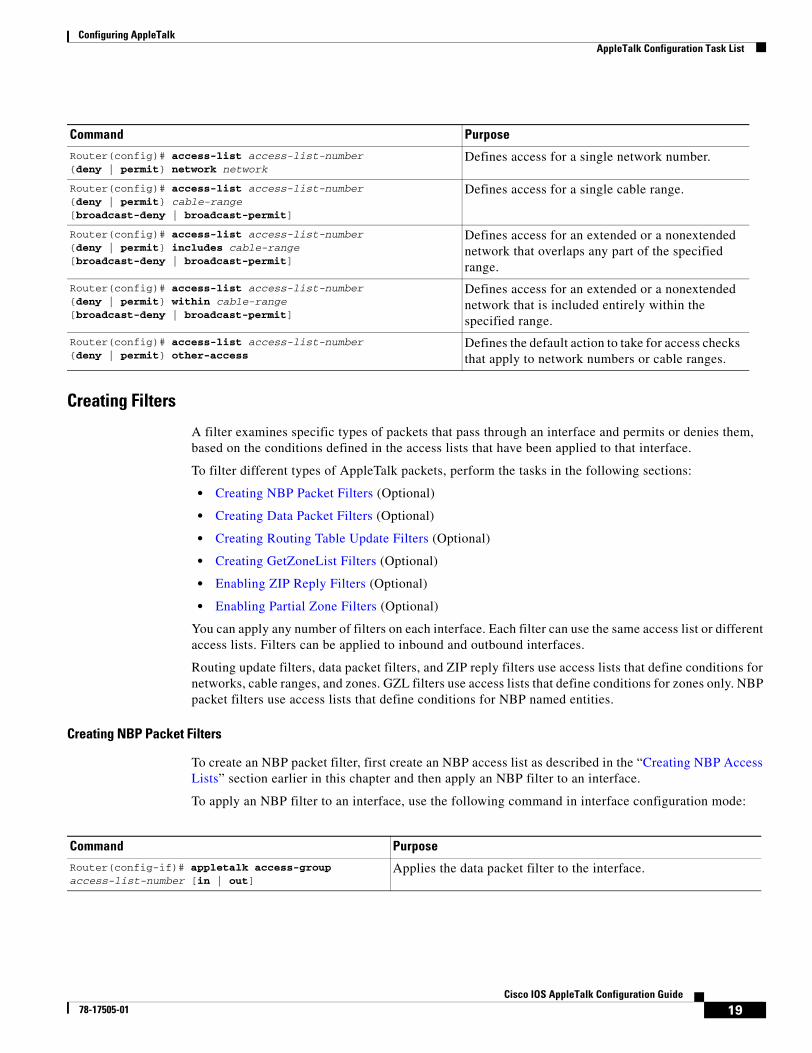
Configuring AppleTalkAppleTalk Configuration Task List
19Cisco IOS AppleTalk Configuration Guide
78-17505-01
Creating Filters
A filter examines specific types of packets that pass through an interface and permits or denies them, based on the conditions defined in the access lists that have been applied to that interface.
To filter different types of AppleTalk packets, perform the tasks in the following sections:
• Creating NBP Packet Filters (Optional)
• Creating Data Packet Filters (Optional)
• Creating Routing Table Update Filters (Optional)
• Creating GetZoneList Filters (Optional)
• Enabling ZIP Reply Filters (Optional)
• Enabling Partial Zone Filters (Optional)
You can apply any number of filters on each interface. Each filter can use the same access list or different access lists. Filters can be applied to inbound and outbound interfaces.
Routing update filters, data packet filters, and ZIP reply filters use access lists that define conditions for networks, cable ranges, and zones. GZL filters use access lists that define conditions for zones only. NBP packet filters use access lists that define conditions for NBP named entities.
Creating NBP Packet Filters
To create an NBP packet filter, first create an NBP access list as described in the “Creating NBP Access Lists” section earlier in this chapter and then apply an NBP filter to an interface.
To apply an NBP filter to an interface, use the following command in interface configuration mode:
Command Purpose
Router(config)# access-list access-list-number {deny | permit} network network
Defines access for a single network number.
Router(config)# access-list access-list-number {deny | permit} cable-range [broadcast-deny | broadcast-permit]
Defines access for a single cable range.
Router(config)# access-list access-list-number {deny | permit} includes cable-range [broadcast-deny | broadcast-permit]
Defines access for an extended or a nonextended network that overlaps any part of the specified range.
Router(config)# access-list access-list-number {deny | permit} within cable-range [broadcast-deny | broadcast-permit]
Defines access for an extended or a nonextended network that is included entirely within the specified range.
Router(config)# access-list access-list-number {deny | permit} other-access
Defines the default action to take for access checks that apply to network numbers or cable ranges.
Command Purpose
Router(config-if)# appletalk access-group access-list-number [in | out]
Applies the data packet filter to the interface.

Configuring AppleTalkAppleTalk Configuration Task List
20Cisco IOS AppleTalk Configuration Guide
78-17505-01
Note Prior to Cisco IOS Release 11.2 F, all NBP access lists were applied to inbound interfaces by default. When Cisco IOS Release 11.2 F or later software is used, the default interface direction for all access lists, including NBP access lists, is outbound. In order to retain the inbound direction of access lists created with previous Cisco IOS software releases, you must specify an inbound interface for all NBP access lists by using the appletalk access-group command.
Creating Data Packet Filters
A data packet filter checks data packets being received on an interface or sent out an interface. If the source network for the packets has access denied, these packets are discarded.
Data packet filters use access lists that define conditions for networks, cable ranges, and zones.
When you apply a data packet filter to an interface, ensure that all networks or cable ranges within a zone are governed by the same filters. For example, create a filter that works in the following way. If the router receives a packet from a network that is in a zone that contains an explicitly denied network, the router discards the packet.
To create a data packet filter, first create a network-only access list as described in the “Creating Zone Access Lists” and “Creating IP-Style Access Lists” sections earlier in this chapter and then apply a data packet filter to an interface.
To apply the data packet filter to an interface, use the following command in interface configuration mode:
For an example of how to create data packet filters, see the “AppleTalk Access List Examples” section at the end of this chapter.
Creating Routing Table Update Filters
Routing table update filters control which updates the local routing table accepts and which routes the local router advertises in its routing updates. You create distribution lists to control the filtering of routing updates.
Filters for incoming routing updates use access lists that define conditions for networks and cable ranges only. Filters for outgoing routing updates use access lists that define conditions for networks and cable ranges, and for zones.
When filtering incoming routing updates, each network number and cable range in the update is checked against the access list. If you have not applied an access list to the interface, all network numbers and cable ranges in the routing update are added to the routing table. If an access list has been applied to the interface, only network numbers and cable ranges that are not explicitly or implicitly denied are added to the routing table.
The following conditions are also applied when routing updates generated by the local router are filtered:
• The network number or cable range is not a member of a zone that is explicitly or implicitly denied.
• If partial zones are permitted, at least one network number or cable range that is a member of the zone is explicitly or implicitly permitted. If partial zones are not permitted (the default), all network numbers or cable ranges that are members of the zone are explicitly or implicitly permitted.
Command Purpose
Router(config-if)# appletalk access-group access-list-number [in | out]
Applies the data packet filter to the interface.

Configuring AppleTalkAppleTalk Configuration Task List
21Cisco IOS AppleTalk Configuration Guide
78-17505-01
Creating Routing Table Update Filters for Incoming Updates
To create a filter for routing table updates received on an interface, create an access list as described in the “Creating IP-Style Access Lists” section earlier in this chapter and then apply a routing table update filter to an interface.
Note Cisco IOS software ignores zone entries. Therefore, ensure that access lists used to filter incoming routing updates do not contain any zone entries.
To apply the filter to incoming routing updates on an interface, use the following command in interface configuration mode:
For an example of how to create a filter for incoming routing table updates, see the “AppleTalk Access List Examples” section at the end of this chapter.
Creating Routing Table Update Filters for Outgoing Updates
To create a filter for routing table updates sent out from an interface, create an access list as described in the “Creating Zone Access Lists” and “Creating IP-Style Access Lists” sections earlier in this chapter and then apply a routing table update filter to an interface.
Note You can use zone entries in access lists used to filter outgoing routing updates.
To apply a filter to routing updates sent out from an interface, use the following command in interface configuration mode:
Creating GetZoneList Filters
The Macintosh Chooser uses ZIP GZL requests to compile a list of zones from which the user can select services. Any router on the same network as the Macintosh can respond to these requests with a GZL reply. You can create a GZL filter to control which zones the Cisco IOS software mentions in its GZL replies. Creating this type of filter has the effect of controlling the list of zones that are displayed by the Chooser.
When defining GZL filters, you should ensure that all routers on the same network filter GZL replies identically. Otherwise, the Chooser will list different zones depending on which device responded to the request. Also, inconsistent filters can result in zones appearing and disappearing every few seconds when the user remains in the Chooser. Because of these inconsistencies, you should normally apply GZL filters only when all routers in the internetwork are Cisco routers, unless the routers from other vendors have a similar feature.
When a ZIP GZL reply is generated, only zones that satisfy the following conditions are included:
• If partial zones are permitted, at least one network number or cable range that is a member of the zone is explicitly or implicitly permitted.
Command Purpose
Router(config-if)# appletalk distribute-list access-list-number in Applies the routing update filter.
Command Purpose
Router(config-if)# appletalk distribute-list access-list-number out Applies the routing update filter.

Configuring AppleTalkAppleTalk Configuration Task List
22Cisco IOS AppleTalk Configuration Guide
78-17505-01
• If partial zones are not permitted (the default), all network numbers or cable ranges that are members of the zone are explicitly or implicitly permitted.
• The zone is explicitly or implicitly permitted.
Replies to GZL requests also are filtered by any outgoing routing update filter that has been applied to the same interface. You must apply a GZL filter only if you want additional filtering to be applied to GZL replies. This filter is rarely needed, except to eliminate zones that do not contain user services.
Using a GZL filter is not a complete replacement for anonymous network numbers. To prevent users from seeing a zone, all routers must implement the GZL filter. If any devices on the network are from other vendors, the GZL filter will not have a consistent effect.
To create a GZL filter, create an access list as described in the “Creating Zone Access Lists” section earlier in this chapter and then apply a GZL filter to an interface.
To apply the GZL filter to an interface, use the following command in interface configuration mode:
For an example of how to create a GZL filters, see the “GZL and ZIP Reply Filter Examples” section at the end of this chapter.
Enabling ZIP Reply Filters
ZIP reply filters limit the visibility of zones from routers in unprivileged regions throughout the internetwork. These filters filter the zone list for each network provided by a router to neighboring devices to remove restricted zones.
ZIP reply filters apply to downstream routers, not to end stations on networks attached to the local router. With ZIP reply filters, when downstream routers request the names of zones in a network, the local router replies with the names of visible zones only. It does not reply with the names of zones that have been hidden with a ZIP reply filter. To filter zones from end stations, use GZL filters.
ZIP reply filters determine which networks and cable ranges the Cisco IOS software sends out in routing updates. Before sending out routing updates, the software excludes the networks and cable ranges whose zones have been completely denied access by ZIP reply filters. Excluding this information ensures that routers receiving these routing updates do not send unnecessary ZIP requests.
To create a ZIP reply filter, create an access list as described in the “Creating Zone Access Lists” section earlier in this chapter and then apply a ZIP reply filter to an interface.
To apply the ZIP reply filter to an interface, use the following command in interface configuration mode:
For an example of how to create GZL and ZIP reply filters, see the “GZL and ZIP Reply Filter Examples” section at the end of this chapter.
Enabling Partial Zone Filters
If access to any network in a zone is denied, access to that zone is also denied by default. However, if you enable partial zones, access to other networks in that zone is no longer denied.
Command Purpose
Router(config-if)# appletalk getzonelist-filter access-list-number Applies the GZL filter.
Command PurposeRouter(config-if)# appletalk zip-reply-filter access-list-number Applies the ZIP reply filter.

Configuring AppleTalkAppleTalk Configuration Task List
23Cisco IOS AppleTalk Configuration Guide
78-17505-01
The permitting of partial zones provides IP-style access control. If enabled, the access control list behavior associated with prior software releases is restored. In addition, NBP cannot ensure consistency and uniqueness of name bindings.
If you permit partial zones, AppleTalk cannot maintain consistency for the nodes in the affected zones, and the results are undefined. With this option enabled, an inconsistency is created for the zone, and several assumptions made by some AppleTalk protocols are no longer valid.
To enable partial zone filters, use the following command in global configuration mode:
Permitting partial zones affects the outgoing routing update and GZL filters.
Configuring the Name Display Facility The AppleTalk NBP associates AppleTalk network entity names (that is, AppleTalk network-addressable services) with network addresses. NBP allows you to specify descriptive or symbolic names for entities instead of their numerical addresses. When you specify the name of an AppleTalk device, NBP translates the entity name of the device into the network address of the device. The name binding process includes name registration, name confirmation, name deletion, and name lookup.
Node addresses can change frequently because AppleTalk uses dynamic addresses. Therefore, NBP associates numerical node addresses with aliases that continue to reference the correct addresses if the addresses change. These node addresses do not change very frequently because each device keeps track of the last node number it was assigned. Typically, node numbers change only if a device is shut down for an extended period of time, or if the device is moved to another network segment.
To control the name display facility, use one or both of the following commands in global configuration mode:
Setting Up Special ConfigurationsTo set up special configurations, perform the tasks in the following sections, based on desired service implementations:
• Configuring Free-Trade Zones (Optional)
• Configuring SNMP over DDP in AppleTalk Networks (Optional)
• Configuring AppleTalk Tunneling (Optional)
• Configuring AppleTalk MacIP (Optional)
Command Purpose
Router(config)# appletalk permit-partial-zones Permits access to networks in a zone in which access to another network in that zone is denied.
Command Purpose
Router(config)# appletalk lookup-type service-type Specifies which service types are retained in the name cache.
Router(config)# appletalk name-lookup-interval seconds Sets the interval between service pollings by the router on its AppleTalk interfaces.

Configuring AppleTalkAppleTalk Configuration Task List
24Cisco IOS AppleTalk Configuration Guide
78-17505-01
• Configuring IPTalk (Optional)
Configuring Free-Trade Zones
A free-trade zone is a part of an AppleTalk internetwork that is accessible by two other parts of the internetwork, neither of which can access the other. You might want to create a free-trade zone to allow the exchange of information between two organizations that otherwise want to keep their internetworks isolated from each other, or that do not have physical connectivity with one another.
To establish a free-trade zone, use the following command in interface configuration mode:
For an example of how to configure a free-trade zone, see the “Hiding and Sharing Resources with Access List Examples” section and the “Establishing a Free-Trade Zone Example” section at the end of this chapter.
Configuring SNMP over DDP in AppleTalk Networks
The Simple Network Management Protocol (SNMP) normally uses the IP connectionless datagram service, the User Datagram Protocol (UDP), to monitor network entities. The Cisco IOS software lets you run SNMP using Datagram Delivery Protocol (DDP), the AppleTalk datagram service. Use DDP if you have SNMP consoles running on a Macintosh.
You must configure AppleTalk routing globally and on an interface basis before you configure SNMP for the router; therefore, you need to disable SNMP as shown in the following command table.
To configure SNMP in AppleTalk networks, use the following commands beginning in global configuration mode:
For an example of how to configure SNMP, see the “SNMP Example” section at the end of this chapter.
For information about configuring SNMP, refer to the “Monitoring the Router and Network” chapter in the Cisco IOS Configuration Fundamentals Configuration Guide.
Command Purpose
Router(config-if)# appletalk free-trade-zone Establishes a free-trade zone.
Command Purpose
Step 1 Router(config)# no snmp server Disables SNMP.
Step 2 Router(config)# appletalk routing Enables AppleTalk routing.
Step 3 Router(config)# appletalk event-logging Enables AppleTalk event logging.
Step 4 Router(config)# interface type number Enters interface configuration mode.
Step 5 Router(config-if)# ip address ip-address mask Enables IP routing on the interface.
Step 6 Router(config-if)# appletalk cable-range cable-range [network.node]
Enables AppleTalk routing on the interface.
Step 7 Router(config-if)# appletalk zone zone-name Sets a zone name for the AppleTalk network.
Step 8 Router(config-if)# snmp-server community string [RO] [RW] [number]
Enables SNMP server operations.

Configuring AppleTalkAppleTalk Configuration Task List
25Cisco IOS AppleTalk Configuration Guide
78-17505-01
Configuring AppleTalk Tunneling
Tunneling provides a means for encapsulating packets inside a routable protocol via virtual interfaces. Encapsulation takes packets or frames from one network system and places them inside frames from another network system. There are three ways to configure AppleTalk tunneling so that you can connect remote AppleTalk networks across a foreign protocol backbone such as the Internet or IP:
• Configuring AURP
• Configuring GRE
• Configuring Cayman Tunneling
The method of tunneling is chosen based on the end destination and your encapsulation type.
Multiple tunnels originating from the router are supported. Logically, tunnels are point-to-point links and therefore require that you configure a separate tunnel for each link.
If you are experiencing traffic congestion due to RTMP overhead, you can resolve this problem by using one of two AppleTalk tunneling methods—AppleTalk Update-Based Routing Protocol (AURP) or GRE tunneling. The AppleTalk packets will be tunneled through a foreign protocol, such as IP. Tunneling encapsulates an AppleTalk packet inside the foreign protocol packet, which is then sent across the backbone to a destination router. The destination router then de-encapsulates the AppleTalk packet and, if necessary, routes the packet to a normal AppleTalk network. The encapsulated packet benefits from any features normally enjoyed by IP packets, including default routes and load balancing.
Configuring AURP
The first and most often recommended AppleTalk tunneling method is to enable AppleTalk Update-Based Routing Protocol (AURP). When two AppleTalk networks are connected with a non-AppleTalk backbone such as IP, the relatively high bandwidth consumed by the broadcasting of RTMP data packets may impact the network performance of the backbone. Using AURP will lower the routing protocol overhead across a WAN or backbone because it changes the encapsulation method as well as the routing algorithm to something more like link state routing.
Note Bandwidth is usually more constrained in a WAN than on a backbone.
AURP is a standard Apple Computer routing protocol that provides enhancements to the AppleTalk routing protocols that are compatible with AppleTalk Phase 2. The primary function of AURP is to connect two or more noncontiguous AppleTalk internetworks that are separated by a non-AppleTalk network (such as IP). In these configurations, you would want to use AURP instead of RTMP, because AURP sends fewer routing packets than RTMP.
You configure AURP on a tunnel interface. Tunneling encapsulates an AppleTalk packet inside an IP packet, which is sent across the backbone to a destination router. The destination device then extracts the AppleTalk packet and, if necessary, routes it to an AppleTalk network. The encapsulated packet benefits from any features normally applied to IP packets, including fragmentation, default routes, and load balancing.
After you configure an AppleTalk domain for AppleTalk interenterprise features, you can apply the features to a tunnel interface configured for AURP by assigning the domain number to the interface.
Because route redistribution is disabled by default, you need to enable it by using the appletalk route-redistribution command.

Configuring AppleTalkAppleTalk Configuration Task List
26Cisco IOS AppleTalk Configuration Guide
78-17505-01
To configure AURP, use the following commands beginning in global configuration mode:
You can configure AURP on a tunnel interface to inherit AppleTalk interenterprise routing remapping, hop count reduction, and loop detection characteristics configured for a specific AppleTalk domain. To do so, these features must first be configured for the AppleTalk domain using the commands described in the tasks “Enabling AppleTalk Interenterprise Routing,” “Remapping Network Numbers,” and “Controlling Hop Count” within the section “Configuring AppleTalk Interenterprise Routing” later in this chapter.
To configure AURP for AppleTalk interenterprise routing features, use the following commands in interface configuration mode:
For an example of how to configure AURP on a tunnel interface to inherit AppleTalk interenterprise routing features for a specific AppleTalk domain, see the “AppleTalk Interenterprise Routing over AURP Example” section at the end of this chapter.
Command Purpose
Step 1 Router(config)# appletalk route-redistribution Enables route redistribution.
Step 2 Router(config)# interface type number Configures an interface to be used by the tunnel.
Step 3 Router(config-if)# ip address ip-address mask Configures an IP address.
Step 4 Router(config-if)# interface tunnel number Configures tunnel interface.
Step 5 Router(config-if)# appletalk protocol aurp Creates an AURP routing process.
Step 6 Router(config-if)# tunnel source {ip-address | type number}
Specifies the interface out of which the encapsulated packets will be sent.
Step 7 Router(config-if)# tunnel destination {hostname | ip-address}
Specifies the IP address of the router at the far end of the tunnel.
Step 8 Router(config-if)# tunnel mode aurp Enables AURP tunneling.
Command Purpose
Step 1 Router(config-if)# interface tunnel number Specifies the tunnel interface.
Step 2 Router(config-if)# appletalk protocol aurp Creates an AURP routing process.
Step 3 Router(config-if)# tunnel mode aurp Enables AURP tunneling.
Step 4 Router(config-if)# tunnel source {ip-address | type number}
Specifies the interface out of which the encapsulated packets will be sent.
Step 5 Router(config-if)# tunnel destination {hostname | ip-address}
Specifies the IP address of the router at the far end of the tunnel.
Step 6 Router(config-if)# appletalk domain-group domain-number
Assigns the number of the predefined AppleTalk domain to which the AppleTalk interenterprise features are configured to the tunnel interface configured for AURP.

Configuring AppleTalkAppleTalk Configuration Task List
27Cisco IOS AppleTalk Configuration Guide
78-17505-01
By default, AURP sends routing updates every 30 seconds. To modify this interval, use the following command in global configuration mode:
To set the AURP last-heard-from timer value, use the following command in interface configuration mode:
Configuring GRE
The second AppleTalk tunneling method, a proprietary tunnel protocol known as generic routing encapsulation (GRE), is recommended when you want to use tunneling to connect one Cisco router to another. When you use GRE tunneling, you must have Cisco routers at both ends of the tunnel connection. You can also reduce RTMP overhead by using GRE tunneling. Since you do not need to run RTMP through GRE tunnels, you can significantly improve the network traffic.
To configure a GRE tunnel, use the following commands in interface configuration mode:
Configuring Cayman Tunneling
The third AppleTalk tunneling method, Cayman tunneling, enables routers to interoperate with Cayman GatorBoxes. Cayman tunneling is used to connect remote AppleTalk networks across a foreign protocol backbone, such as the Internet or a backbone that is IP-only, for administrative or security reasons. You can tunnel AppleTalk by using Cayman tunneling as designed by Cayman Systems.
When you use Cayman tunneling, you can have Cisco routers at either end of the tunnel, or you can have a GatorBox at one end and a Cisco router at the other end.
To configure a Cayman tunnel, use the following commands in interface configuration mode:
Command PurposeRouter(config)# appletalk aurp update-interval seconds Sets the minimum interval between AURP routing updates.
Command PurposeRouter(config-if)# appletalk aurp tickle-time seconds Sets the AURP last-heard-from timer value.
Command Purpose
Step 1 Router(config-if)# interface tunnel number Configures a tunnel interface.
Step 2 Router(config-if)# tunnel source {ip-address | type number}
Specifies the interface out of which the encapsulated packets will be sent.
Step 3 Router(config-if)# tunnel destination {hostname | ip-address}
Specifies the IP address of the router at the far end of the tunnel.
Step 4 Router(config-if)# tunnel mode gre ip Enables GRE tunneling.
Command Purpose
Step 1 Router(config-if)# interface tunnel number Configures a tunnel interface.
Step 2 Router(config-if)# tunnel source {ip-address | type number}
Specifies the interface out of which the encapsulated packets will be sent.

Configuring AppleTalkAppleTalk Configuration Task List
28Cisco IOS AppleTalk Configuration Guide
78-17505-01
Caution Do not configure a Cayman tunnel with an AppleTalk network address.
Configuring AppleTalk MacIP
Cisco IOS software implements MacIP, which is a protocol that allows routing of IP datagrams to IP clients using the DDP for low-level encapsulation.
The Cisco Implementation of AppleTalk MacIP
Cisco IOS software implements the MacIP address management and routing services described in the draft Internet RFC, A Standard for the Transmission of Internet Packets over AppleTalk Networks. Our implementation of MacIP conforms to the September 1991 draft RFC with the following exceptions:
• The software does not fragment IP datagrams that exceed the DDP maximum transmission unit (MTU) and that are bound for DDP clients of MacIP.
• The software does not route to DDP clients outside of configured MacIP client ranges.
When to Use AppleTalk MacIP
Some situations require the use of MacIP. For example, if some of your Macintosh users use AppleTalk Remote Access (ARA) or are connected to the network using LocalTalk or PhoneNet cabling systems, then MacIP is required to provide access to IP network servers for those users.
MacIP services also can be useful when you are managing IP address allocations for a large, dynamic Macintosh population.
Advantages of Using MacIP
The following are advantages to using MacIP when you are managing IP address allocations for a large, dynamic Macintosh population:
• Macintosh TCP/IP drivers can be configured in a completely standard way, regardless of the location of the Macintosh. Essentially, the dynamic properties of AppleTalk address management become available for IP address allocation.
• You can modify all global parameters, such as IP subnet masks, Domain Name System (DNS) services, and default routers. Macintosh IP users receive the updates by restarting their local TCP/IP drivers.
• The network administrator can monitor MacIP address allocations and packet statistics remotely by using the Telnet application to attach to the console, allowing central administration of IP allocations in remote locations. For Internet sites, it allows remote technical assistance.
Step 3 Router(config-if)# tunnel destination {hostname | ip-address}
Specifies the IP address of the router at the far end of the tunnel.
Step 4 Router(config-if)# tunnel mode cayman Enables Cayman tunneling.
Command Purpose
Configuring AppleTalkAppleTalk Configuration Task List
29Cisco IOS AppleTalk Configuration Guide
78-17505-01
Implementation Considerations
Consider the following items when implementing MacIP on Cisco routers:
• Each packet from a Macintosh client destined for an IP host or vice versa must pass through the router if the client is using the device as a MacIP server. The router is not always a necessary hop, so passing through the router increases traffic through the device. There is also a slight increase in CPU use that is directly proportional to the number of packets delivered to and from active MacIP clients.
• Memory usage increases in direct proportion to the total number of active MacIP clients (about 80 bytes per client).
Also, when you configure MacIP on the Cisco IOS software, you must configure AppleTalk as follows:
• AppleTalk routing must be enabled on at least one interface.
• IP routing must be enabled on at least one interface.
• The MacIP zone name you configure must be associated with a configured or seeded zone name.
• The MacIP server must reside in the AppleTalk zone.
• Any IP address specified in configuring a MacIP server using an appletalk macip command must be associated to a specific IP interface on the router. Because the Cisco IOS software is acting as a proxy for MacIP clients, you must use an IP address to which Address Resolution Protocol (ARP) can respond.
• If you are using MacIP to allow Macintoshes to communicate with IP hosts on the same LAN segment (that is, the Macintoshes are on the router interface on which MacIP is configured) and the IP hosts have extended IP access lists, these access lists should include entries to permit IP traffic destined for these IP hosts from the MacIP addresses. If these entries are not present, packets destined for IP hosts on the local segment will be blocked (that is, they will not be forwarded).
When setting up MacIP routing, keep the following address range issues in mind:
• Static and dynamic resource statements are cumulative, and you can specify as many as necessary. However, if possible, you should specify a single all-inclusive range rather than several adjacent ranges. For example, specifying the range 172.31.121.1 to 172.31.121.10 is preferable to specifying the ranges 172.31.121.1 to 172.31.121.5 and 172.31.121.6 to 172.31.121.10.
• Overlapping resource ranges (for example, 172.31.121.1 to 172.31.121.5 and 172.31.121.5 to 172.31.121.10) are not allowed. If it is necessary to change a range in a running server, use the negative form of the resource address assignment command (such as no appletalk macip dynamic ip-address ip-address zone server-zone) to delete the original range, followed by the corrected range statement.
• You can add IP address allocations to a running server at any time as long as the new address range does not overlap with one of the current ranges.
Configuring AppleTalk MacIP Task List
To configure MacIP, perform the tasks in the following sections:
• Establishing a MacIP Server for a Zone (Required)
• Allocating IP Addresses for Macintosh Users (Required)

Configuring AppleTalkAppleTalk Configuration Task List
30Cisco IOS AppleTalk Configuration Guide
78-17505-01
Establishing a MacIP Server for a Zone
To establish a MacIP server for a specific zone, use the following command in global configuration mode:
Note Note that the MacIP server must reside in the default AppleTalk zone.
You can configure multiple MacIP servers for a router, but you can assign only one MacIP server to a zone, and you can assign only one IP interface to a MacIP server. In general, you must be able to establish an alias between the IP address you assign with the appletalk macip server global configuration command and an existing IP interface. For implementation simplicity, the address you specify in this command should match an existing IP interface address.
A server is not registered by NBP until at least one MacIP resource is configured.
Allocating IP Addresses for Macintosh Users
You allocate IP addresses for Macintosh users by specifying at least one dynamic or static resource address assignment command for each MacIP server.
Allocating IP Addresses Using Dynamic Addresses
Dynamic clients are those that accept any IP address assignment within the dynamic range specified. Dynamic addresses are for users that do not require a fixed address, but can be assigned addresses from a pool.
To allocate IP addresses for Macintosh users if you are using dynamic addresses, use the following command in global configuration mode:
For an example of configuring MacIP with dynamic addresses, see the “AppleTalk Interenterprise Routing over AURP Example” section at the end of this chapter.
Allocating IP Addresses Using Static Addresses
Static addresses are for users that require fixed addresses for IP DNS services and for administrators that do not want addresses to change so they always know the IP addresses of the devices on their network.
Command Purpose
Router(config)# appletalk macip server ip-address zone server-zone
Establishes a MacIP server for a zone.
Command Purpose
Router(config)# appletalk macip dynamic ip-address [ip-address] zone server-zone
Allocates an IP address to a MacIP client.

Configuring AppleTalkAppleTalk Configuration Task List
31Cisco IOS AppleTalk Configuration Guide
78-17505-01
To allocate IP addresses for Macintosh users if you are using static addresses, use the following command in global configuration mode:
For an example of configuring MacIP with static addresses, see the “MacIP Examples” section at the end of this chapter.
In general, it is recommended that you do not use fragmented address ranges in configuring ranges for MacIP. However, if fragmented address ranges are unavoidable, use the appletalk macip dynamic command to specify as many addresses or ranges as required, and use the appletalk macip static command to assign a specific address or address range.
Configuring IPTalk
IPTalk is a protocol for encapsulating AppleTalk packets in IP datagrams. IPTalk is used to route AppleTalk packets across non-AppleTalk backbones and to communicate with applications on hosts that cannot otherwise communicate via AppleTalk, such as the Columbia AppleTalk Package (CAP). IPTalk also allows serial connections to use IPTalk Serial Line Internet Protocol (SLIP) drivers.
If your system is a Sun or Digital Equipment Corporation ULTRIX system, it may be possible to run CAP directly in a mode that supports EtherTalk. In this case, your system would look like any other AppleTalk node and does not need any special IPTalk support. However, other UNIX systems for which EtherTalk support is not available in CAP must run CAP in a mode that depends upon IPTalk.
For installation instructions for CAP, refer to Kinetics IP (KIP) gateways and the file atalkatab. If you use Cisco IPTalk support, it is not necessary (nor is it desirable) to use atalkatab. Cisco IPTalk support assumes that you want to use the standard AppleTalk routing protocols to perform all wide-area AppleTalk routing. KIP and atalkatab are based on an alternative routing strategy in which AppleTalk packets are sent using IP routing. It is possible to use both strategies at the same time; however, the interaction between the two routing techniques is not well defined.
If your network has routers from other vendors that support atalkatab, you should disable atalkatab support on them to avoid mixing the routing strategies. The installation instructions provided with some of these products encourage you to use atalkatab for complex networks. However, with Cisco routers it is not necessary, because our implementation of IPTalk integrates IPTalk into the standard AppleTalk network routing.
The network diagram in Figure 1 illustrates how you should set up IPTalk. In this configuration, you enable both standard AppleTalk (EtherTalk) and IPTalk on the Ethernet networks on Router A and Router B. These routers then use EtherTalk to communicate with the LocalTalk routers and Macintosh computers, and IPTalk to communicate with the UNIX systems. On the LocalTalk routers, you also should enable both EtherTalk and IPTalk, making sure you configure IPTalk with atalkatab disabled. These routers then use IPTalk to communicate with the UNIX systems adjacent to them and EtherTalk to communicate with the remainder of the AppleTalk network. This configuration strategy minimizes the number of hops between routers. If you did not enable IPTalk on the LocalTalk routers, systems on the LocalTalk router that wanted to communicate with the adjacent UNIX system would need to go through Router A or Router B, creating an unnecessary extra hop.
Command PurposeRouter(config)# appletalk macip static ip-address [ip-address] zone server-zone
Allocates an IP address to be used by a MacIP client that has reserved a static IP address.

Configuring AppleTalkAppleTalk Configuration Task List
32Cisco IOS AppleTalk Configuration Guide
78-17505-01
Note In the configuration shown in Figure 1, all traffic between systems on the left and right sides of the packet-switched network transit via Router A and Router B using AppleTalk routing. If you were to enable atalkatab support on the LocalTalk routers, a hidden path would be established between Router A and Router B, unknown to the standard AppleTalk routing protocols. In a large network, this hidden path could result in traffic taking inexplicable routes.
Figure 1 IPTalk Configuration Example
To configure IPTalk on an interface, perform the following tasks:
• Configuring IP Encapsulation of AppleTalk Packets (Required)
• Specifying the UDP Port Ranges (Required)
Configuring IP Encapsulation of AppleTalk Packets
To allow AppleTalk to communicate with UNIX hosts running older versions of CAP that do not support native AppleTalk EtherTalk encapsulations, you must configure IP encapsulation of AppleTalk packets. (Typically, Apple Macintosh users would communicate with these servers by routing their connections through a Kinetics FastPath router running KIP software.) Newer versions of CAP provide native AppleTalk EtherTalk encapsulations, so the IPTalk encapsulation is no longer required. The Cisco implementation of IPTalk assumes that AppleTalk is already being routed on the backbone, because there is currently no LocalTalk hardware interface for our routers.
You configure IPTalk on a tunnel interface. Tunneling encapsulates an AppleTalk packet inside an IP packet, which is sent across the backbone to a destination router. The destination device then extracts the AppleTalk packet and, if necessary, routes it to an AppleTalk network. The encapsulated packet benefits from any features normally applied to IP packets, including fragmentation, default routes, and load balancing.
The Cisco implementation of IPTalk does not support manually configured AppleTalk-to-IP-address mapping. The address mapping provided is the same as the Kinetics IPTalk implementation when AppleTalk-to-IP-address mapping is not enabled. This address mapping works as follows:
1. The IP subnet mask used on the router tunnel source interface on which IPTalk is enabled is inverted (ones complement).
2. The result is then masked against 255 (0xFF hexadecimal).
LocalTalkrouter
LocalTalkrouter
Router A Router B
Packet-switchednetwork
UNIX system Macintosh UNIX systemMacintosh
Ethernet 0 Ethernet 1
3102
2
LocalTalk 0 LocalTalk 1

Configuring AppleTalkAppleTalk Configuration Task List
33Cisco IOS AppleTalk Configuration Guide
78-17505-01
3. The result of this is then masked against the low-order 8 bits of the IP address to give the AppleTalk node number.
The following example shows how to configure address mapping:
interface Ethernet0ip address 172.16.1.118 255.255.255.0appletalk address 20.129appletalk zone Native AppleTalkinterface Tunnel0tunnel source Ethernet0tunnel mode iptalkappletalk iptalk 30 UDPZone
First, the IP subnet mask of 255.255.255.0 is inverted to 0.0.0.255. This value is then masked with 255 to give 255. Next, 255 is masked with the low-order 8 bits of the interface IP address (118) to yield an AppleTalk node number of 118, which means that the AppleTalk address of the Ethernet interface 0 seen in the UDPZone zone is 30.118.
Note If the host field of an IP subnet mask for an interface is longer than 8 bits, it will be possible to obtain conflicting AppleTalk node numbers. For instance, if the subnet mask for the Ethernet interface 0 above is 255.255.240.0, the host field is 12 bits wide.
To configure IP encapsulation of AppleTalk packets, use the following commands in interface configuration mode:
For an example of configuring IPTalk, see the “IPTalk Example” section at the end of this chapter.
Specifying the UDP Port Ranges
Implementations of IPTalk prior to April 1988 mapped well-known DDP socket numbers to privileged UDP ports starting at port number 768. In April 1988, the Network Information Center (NIC) assigned a range of UDP ports for the defined DDP well-known sockets starting at UDP port number 200 and assigned these ports the names at-nbp, at-rtmp, at-echo, and at-zis. Release 6 and later of the CAP program dynamically decides which port mapping to use. If there are no AppleTalk service entries in the /etc/services file of the UNIX system, CAP uses the older mapping starting at UDP port number 768.
The default UDP port mapping supported by our implementation of IPTalk is 768. If there are AppleTalk service entries in the /etc/services file of the UNIX system, you should specify the beginning of the UDP port mapping range.
Command Purpose
Step 1 Router(config-if)# interface type number Configures an interface to be used by the tunnel.
Step 2 Router(config-if)# ip address ip-address mask Configures an IP address.
Step 3 Router(config-if)# interface tunnel number Configures tunnel interface.
Step 4 Router(config-if)# tunnel source {ip-address | type number}
Specifies the interface out of which the encapsulated packets will be sent.
Step 5 Router(config-if)# tunnel mode iptalk Enables IPTalk tunneling.

Configuring AppleTalkAppleTalk Configuration Task List
34Cisco IOS AppleTalk Configuration Guide
78-17505-01
To specify the UDP port number that is the beginning of the range of UDP ports used in mapping AppleTalk well-known DDP socket numbers to UDP ports, use the following command in global configuration mode:
For an example of configuring IPTalk, see the “IPTalk Example” section at the end of this chapter.
Configuring AppleTalk Control Protocol for PPPYou can configure an asynchronous interface (including the auxiliary port on some Cisco routers) to use AppleTalk Control Protocol (ATCP) so that users can access AppleTalk zones by dialing into the router via PPP to this interface. Asynchronous interfaces are configured with ATCP through a negotiation protocol, as defined in RFC 1378. Users accessing the network with ATCP can run AppleTalk and IP natively on a remote Macintosh, access any available AppleTalk zones from the Chooser, use networked peripherals, and share files with other Macintosh users.
You create an internal network with the appletalk internal-network command. This network is a virtual network and exists only for accessing an AppleTalk internetwork through the server.
To create a new AppleTalk zone, enter the appletalk virtual-net command and use a new zone name; this network number is then the only one associated with this zone. To add network numbers to an existing AppleTalk zone, use the existing zone name in the command; the network number is then added to the existing zone.
Routing is not supported on these interfaces.
To enable ATCP for PPP, use the following commands in interface configuration (asynchronous) mode:
For an example of configuring ATCP, see the “AppleTalk Control Protocol Example” section at the end of this chapter.
Tuning AppleTalk Network Performance To tune AppleTalk network performance, perform one or more of the tasks described in the following sections:
• Controlling Routing Updates (Optional)
• Assigning Proxy Network Numbers (Optional)
• Enabling Round-Robin Load Sharing (Optional)
Command PurposeRouter(config)# appletalk iptalk-baseport Specifies the starting UDP port number.
Command Purpose
Step 1 Router(config-if)# interface async number Specifies an asynchronous interface.
Step 2 Router(config-if)# appletalk virtual-net network-number zone-name
Creates an internal network on the server.
Step 3 Router(config-if)# encapsulation ppp Enables PPP encapsulation on the interface.
Step 4 Router(config-if)# appletalk client-mode Enables client-mode on the interface.

Configuring AppleTalkAppleTalk Configuration Task List
35Cisco IOS AppleTalk Configuration Guide
78-17505-01
• Disabling Checksum Generation and Verification (Optional)
• Controlling the AppleTalk ARP Table (Optional)
• Controlling the Delay Between ZIP Queries (Optional)
• Logging Significant Network Events (Optional)
• Disabling Fast Switching (Optional)
Controlling Routing Updates
RTMP establishes and maintains the AppleTalk routing table. To control packet routing and control routing updates, perform the tasks in the following sections:
• Disabling the Processing of Routed RTMP Packets (Optional)
• Enabling RTMP Stub Mode (Optional)
• Disabling the Transmission of Routing Updates (Optional)
• Preventing the Advertisement of Routes to Networks with No Associated Zones (Optional)
• Setting Routing Table Update Timers (Optional)
• Setting the Routing Update Interval Timer (Optional)
Disabling the Processing of Routed RTMP Packets
By default, the Cisco IOS software performs strict RTMP checking, which discards any RTMP packets sent by routers not directly connected to the local device (that is, sent by devices that are not neighbors). In this case, the local router does not accept any routed RTMP packets whose source is a remote network.
In almost all situations, you should leave RTMP checking enabled.
To disable RTMP checking and enable the processing of routed RTMP packets, use the following command in global configuration mode:
Enabling RTMP Stub Mode
You can enable AppleTalk RTMP stub mode. This mode allows routers running Enhanced IGRP and RTMP to reduce the amount of CPU time that RTMP modules use. In this mode, RTMP modules send and receive only “stub” RTMP packets.
A stub packet is only the first tuple of an RTMP packet. The first tuple indicates the network number range assigned to that network. End nodes use stub packets to determine if their node number is in the correct network range.
To enable AppleTalk RTMP stub mode, use the following command in interface configuration mode:
Command Purpose
Router(config)# no appletalk strict-rtmp-checking Disables strict checking of RTMP updates.
Command Purpose
Router(config-if)# appletalk rtmp-stub Enables RTMP stub mode.

Configuring AppleTalkAppleTalk Configuration Task List
36Cisco IOS AppleTalk Configuration Guide
78-17505-01
Disabling the Transmission of Routing Updates
By default, routers receive routing updates from their neighboring devices and periodically send routing updates to their neighbors. You can configure the Cisco IOS software so that it only receives routing updates, but does not send any updates. You might want to use this type of configuration to keep a particular router that is unreliable from sending routing updates to its neighbors.
To disable the transmission of routing updates, use the following command in interface configuration mode:
Preventing the Advertisement of Routes to Networks with No Associated Zones
NBP uses ZIP to determine which networks belong to which zones. The Cisco IOS software uses ZIP to maintain a table of the AppleTalk internetwork that maps network numbers to zone names.
By default, the software does not advertise routes to networks that have no associated zones and therefore prevents the occurrence of ZIP protocol storms, which can arise when corrupt routes are propagated and routers broadcast ZIP requests to determine the network-zone associations. By not advertising routes to networks that do not have associated zones, you limit any ZIP protocol storms to a single network, rather than allowing them to spread to the entire internetwork.
To allow the advertisement of routes to networks that have no associated zones, use the following command in global configuration mode:
The user zone lists can be configured to vary from interface to interface. However, this practice is discouraged because AppleTalk users expect to have the same user zone lists at any end node in the internetwork. This kind of filtering does not prevent explicit access via programmatic methods, but should be considered a user optimization whereby unused zones are suppressed. Use other forms of AppleTalk access control lists to actually secure a zone or network.
Setting Routing Table Update Timers
Cisco IOS software sends routing table updates at regular intervals. In rare instances, you might want to change this interval, such as when a router is busy and cannot send routing updates every 10 seconds, or when slower devices are incapable of processing received routing updates in a large network. If you do change the routing update interval, you must do so for all devices on the network.
Caution Modifying the routing timers can degrade or destroy AppleTalk network connectivity. Many other AppleTalk router vendors provide no facility for modifying their routing timers, so adjusting Cisco AppleTalk timers such that routing updates do not arrive at these other routers within the normal interval might result in loss of information about the network or loss of connectivity.
Command Purpose
Router(config-if)# no appletalk send-rtmps Disables the transmission of routing updates on an interface.
Command Purpose
Router(config)# no appletalk require-route-zones Allows the advertisement of routes to networks that have no associated zones.

Configuring AppleTalkAppleTalk Configuration Task List
37Cisco IOS AppleTalk Configuration Guide
78-17505-01
To change the routing table update timers, use the following command in global configuration mode:
Setting the Routing Update Interval Timer
The interval between subsequent routing updates is randomized to reduce the probability of synchronization with the routing updates from other routers on the same link. This randomization is achieved by maintaining a separate transmission interval timer for each advertising interface.
To set the interval timer on a router between subsequent routing updates, use the following command in global configuration mode:
Assigning Proxy Network Numbers
It is possible to have an AppleTalk internetwork in which some routers support only nonextended AppleTalk and others support only extended AppleTalk. You can enable interoperability between these two types of AppleTalk networks by assigning a proxy network number for each zone in which there is a device that supports only nonextended AppleTalk.
To assign proxy network numbers, use the following command in global configuration mode:
For an example of how to configure proxy network numbers, see the “Proxy Network Number Example” section at the end of this chapter.
Caution Do not also assign the proxy network number to a router or to a physical network.
You must assign one proxy network number for each zone. You can optionally define additional proxies with different network numbers to provide redundancy. Each proxy network number generates one or more packets for each forward request it receives, but discards all other packets sent to it. Thus, defining redundant proxy network numbers increases the NBP traffic linearly.
Enabling Round-Robin Load Sharing
In order to increase throughput in the network, a router can use multiple equal-cost paths to reach a destination. By default, the router picks one best path and sends all traffic using this path. You can configure the router to remember two or more paths that have equal costs, and to balance the traffic load across all of the available paths. (Note that when paths have differing costs, the Cisco IOS software chooses lower-cost routes in preference to higher-cost routes.)
Command PurposeRouter(config)# appletalk timers update-interval valid-interval invalid-interval
Changes the routing update timers.
Command PurposeRouter(config)# appletalk rtmp jitter percent Sets the interval timer between subsequent routing updates.
Command Purpose
Router(config)# appletalk proxy-nbp network-number zone-name
Assigns a proxy network number for each zone in which there is a device that supports only nonextended AppleTalk.

Configuring AppleTalkAppleTalk Configuration Task List
38Cisco IOS AppleTalk Configuration Guide
78-17505-01
The software then distributes output on a packet-by-packet basis in round-robin fashion. That is, the first packet is sent along the first path, the second packet along the second path, and so on. When the final path is reached, the next packet is sent to the first path, the next to the second path, and so on. This round-robin scheme is used regardless of whether fast switching is enabled.
Limiting the number of equal-cost paths can save memory on routers with limited memory or with very large configurations. Additionally, in networks with a large number of multiple paths and systems with limited ability to cache out-of-sequence packets, performance might suffer when traffic is split between many paths.
To set the maximum number of paths, use the following command in global configuration mode:
Disabling Checksum Generation and Verification
By default, the Cisco IOS software generates and verifies checksums for all AppleTalk packets (except routed packets). You might want to disable checksum generation and verification if you have older devices (such as LaserWriter printers) that cannot receive packets with checksums.
To disable checksum generation and verification, use the following command in global configuration mode:
Controlling the AppleTalk ARP Table
To control the AppleTalk ARP table, you can use the following tasks:
• Set the timeout for ARP table entries
• Specify the time interval between the retransmission of ARP packets
• Specify the number of ARP retransmissions
• Disable the gleaning of ARP information from incoming packets
By default, entries in the AppleTalk ARP table are removed from the table if no update has been received in the last 4 hours. To change the ARP timeout interval, use the following command in interface configuration mode:
AppleTalk ARP associates AppleTalk network addresses with media (data link) addresses. When AppleTalk must send a packet to another network node, the protocol address is passed to AppleTalk ARP, which undertakes a series of address negotiations to associate the protocol address with the media address.
Command Purpose
Router(config)# appletalk maximum-paths paths Sets the maximum number of equal-cost paths to a destination.
Command Purpose
Router(config)# no appletalk checksum Disables the generation and verification of checksums for all AppleTalk packets.
Command Purpose
Router(config-if)# appletalk arp-timeout interval Sets the timeout for ARP table entries.

Configuring AppleTalkAppleTalk Configuration Task List
39Cisco IOS AppleTalk Configuration Guide
78-17505-01
If your AppleTalk network has devices that respond slowly (such as printers and overloaded file servers), you can lengthen the interval between AppleTalk ARP packets in order to allow the responses from these devices to be received. To lengthen the interval between AppleTalk ARP packets, use one or both of the following commands in global configuration mode:
The Cisco IOS software automatically derives ARP table entries from incoming packets. This process is referred to as gleaning. Gleaning speeds up the process of populating the ARP table. To disable the gleaning of ARP table entries, use the following command in interface configuration mode:
Controlling the Delay Between ZIP Queries
By default, the Cisco IOS software sends ZIP queries every 10 seconds and uses the information received to update its zone table. To change the ZIP query interval, use the following command in global configuration mode:
Logging Significant Network Events
You can log information about significant network events performed on the router, including routing changes, zone creation, port status, and address. To log information about significant network events, use the following command in global configuration mode:
Disabling Fast Switching
Fast switching allows higher throughput by switching a packet using a cache created by previous packets. Fast switching is enabled by default on all interfaces that support fast switching.
Packet transfer performance is generally better when fast switching is enabled. However, you may want to disable fast switching in order to save memory space on interface cards and to help avoid congestion when high-bandwidth interfaces are writing large amounts of information to low-bandwidth interfaces.
Command PurposeRouter(config)# appletalk arp [probe | request] interval interval
Specifies the time interval between retransmission of ARP packets.
Router(config)# appletalk arp [probe | request] retransmit-count number
Specifies the number of retransmissions that will occur before abandoning address negotiations and using the selected address.
Command Purpose
Router(config-if)# no appletalk glean-packets Disables the gleaning of ARP information from incoming packets.
Command Purpose
Router(config)# appletalk zip-query-interval interval
Sets the ZIP query interval.
Command Purpose
Router(config)# appletalk event-logging Logs significant events.
Configuring AppleTalkAppleTalk Configuration Task List
40Cisco IOS AppleTalk Configuration Guide
78-17505-01
To disable AppleTalk fast switching on an interface, use the following command in interface configuration mode:
Configuring AppleTalk Interenterprise RoutingAppleTalk interenterprise routing provides support for AppleTalk internets, or domains. AppleTalk interenterprise routing allows two or more AppleTalk domains to be connected through a domain router (which can also be a Cisco access server). AppleTalk interenterprise routing allows the resolution of conflicting AppleTalk network numbers or cable ranges from different domains and hop-count reduction between domains.
Understanding AppleTalk Domains
An AppleTalk domain is a group of AppleTalk networks or cable ranges that are connected and that have the following characteristics:
• Each network number or cable range within a domain is unique within that domain.
• Each domain is separated from another domain by a domain router.
• There is no physical or virtual connection between the two AppleTalk domains other than through a domain router.
Understanding Domain Routers
The domain router uses split horizon across the entire domain, not just across an interface, which means that domain routers do not propagate routes learned from an interface in one domain back into that domain. Rather, domain routers propagate routes only to other domains.
AppleTalk Interenterprise Routing Features
AppleTalk interenterprise routing provides the following features:
• Network remapping—Allows you to remap remote network numbers to resolve numbering conflicts with network numbers on the local network segment.
• Hop-count reduction—Allows the creation of larger internetworks. When you enable hop-count reduction, the hop count in a packet is set to 1 as it passes from one domain to another, therefore allowing you to circumvent the 15-hop limit imposed by DDP and RTMP when forwarding packets.
• Loop detection—Avoids having multiple routing table entries to the same remote network segment (domain). If the domain router detects a loop, it displays an error message on the domain router and shuts off domains. The presence of a loop implies that there is a connection between two separate domains that was not learned through any of the interfaces of the domain router.
• Fast switching—Has been implemented for networks that have been remapped or on which hop-count reduction has been configured.
Command PurposeRouter(config-if)# no appletalk route-cache Disables AppleTalk fast switching.

Configuring AppleTalkAppleTalk Configuration Task List
41Cisco IOS AppleTalk Configuration Guide
78-17505-01
Redundant Paths Between Domains
Note that only one domain router can separate two domains. That is, you cannot have two or more domain routers to create redundant paths between domains. You can, however, establish redundant paths between domains by connecting them through more than one interface on the domain router that separates them. Figure 2 illustrates this configuration. In this figure, one domain router separates domains A and B. Two of the interfaces of the router are in Domain A (Ethernet interfaces 3 and 4), and three are in Domain B (Ethernet interfaces 0, 1, and 2), thus providing redundant connections between the domains. Figure 3 illustrates an improper configuration. This configuration will create adverse effects, because domains A and B are connected by two domain routers.
Figure 2 Allowed Configuration of Domain Router Connecting Two Domains
Figure 3 Improper Configuration of Domain Routers Connecting Two Domains
Currently, you can configure AppleTalk interenterprise routing only on routers that run RTMP.
AppleTalk Interenterprise Routing Task List
To configure AppleTalk interenterprise routing, perform the tasks described in the following sections. At a minimum, you must enable AppleTalk interenterprise routing. The remaining tasks are optional.
• Enabling AppleTalk Interenterprise Routing (Required)
• Remapping Network Numbers (Optional)
• Controlling Hop Count (Optional)
After you assign AppleTalk interenterprise routing remapping, hop-count reduction, and loop-detection features to an AppleTalk domain, you can attribute those characteristics to a tunnel interface configured for AURP by assigning the AppleTalk domain group number to the AURP tunnel interface.
Enabling AppleTalk Interenterprise Routing
To enable AppleTalk interenterprise routing, perform the following tasks:
• Enable AppleTalk interenterprise routing on the router. (Required)
• Enable AppleTalk interenterprise routing on an interface. (Required)
Domainrouter
Domain A Domain B
3102
4
E3
E4 S0E1E0
S0
Domainrouter
E1E0
Domain A Domain B
E1
E3
E4
S0
E3
Domainrouter
E0
3102
5
Configuring AppleTalkAppleTalk Configuration Task List
42Cisco IOS AppleTalk Configuration Guide
78-17505-01
To enable AppleTalk interenterprise routing, use the following command in global configuration mode:
To enable AppleTalk interenterprise routing on an interface, use the following command in interface configuration mode:
For an example of how to configure AppleTalk interenterprise routing, see the “AppleTalk Interenterprise Routing Example” section at the end of this chapter.
Remapping Network Numbers
When two AppleTalk networks are connected, a conflict can arise between network numbers or between cable ranges on one network and those on the other. You can avoid conflicts by remapping the network numbers or cable ranges of the remote network.
Each domain can have two mapping ranges to which to remap all incoming or outgoing network numbers or cable ranges.
To remap the network numbers or cable ranges on inbound packets, use the following command in global configuration mode:
To remap the network numbers or cable ranges on outbound packets, use the following command in global configuration mode:
Controlling Hop Count
When you join AppleTalk network segments to create domains, the distance across the combined internetworks is likely to exceed 15 hops, which is the maximum number of hops supported by RTMP. You can extend the network topology by configuring the Cisco IOS software to reduce the hop-count value of packets that traverse it.
Command PurposeRouter(config)# appletalk domain domain-number name domain-name Creates a domain and assigns it a name and
number.
Command PurposeRouter(config-if)# appletalk domain-group domain-number Assigns a predefined domain number to an
interface.
Command Purpose
Router(config)# appletalk domain domain-number remap-range in cable-range
Remaps packets inbound to the domain.
Command PurposeRouter(config)# appletalk domain domain-number remap-range out cable-range
Remaps packets outbound from the domain.

Configuring AppleTalkAppleTalk Configuration Task List
43Cisco IOS AppleTalk Configuration Guide
78-17505-01
Reducing the hop-count value allows an AppleTalk router to control the hop-count field in DDP packets so as to ensure that the packet reaches its final AppleTalk destination. Hop-count reduction allows the router to bypass the limitation of 16 hops before aging out packets. This feature is supported only on access servers and routers configured for AppleTalk Enhanced IGRP.
To enable hop-count reduction, use the following command in global configuration mode:
Configuring AppleTalk over WANsYou can configure AppleTalk over dial-on-demand routing (DDR), Frame Relay, SMDS, and X.25 networks. For more information about dial-on-demand routing (DDR), refer to the Cisco IOS Dial Technologies Configuration Guide. For more information about Frame Relay, SMDS, and X.25, refer to the Cisco IOS Wide-Area Networking Configuration Guide.
AppleTalk over DDR
To use AppleTalk over DDR, you must define AppleTalk static routes. You can configure the following two types of static routes:
• Static routes—These routes have absolute precedence (that is, they always override any dynamically learned routes).
• Floating static routes—These routes can be overridden by dynamically learned routes.
Be careful when assigning static routes. When links associated with these static routes are lost, traffic may stop being forwarded or traffic may be forwarded to a nonexistent destination, even though an alternative path might be available.
Note When you configure AppleTalk over DDR, the zone name assigned to the interface must be unique. It cannot be the same as a zone name assigned to a static route. If the zone names are not unique, the sequence of AppleTalk initialization and dialer operation will cause the DDR interface to go up and down.
Configuring Static Routes
To add a static route for an extended or nonextended AppleTalk network, use one of the following commands in global configuration mode:
Command Purpose
Router(config)# appletalk domain domain-number hop-reduction Enables hop-count reduction.
Command Purpose
Router(config)# appletalk static cable-range cable-range to network.node zone zone-name
Defines a static route on an extended AppleTalk network.
Router(config)# appletalk static network network-number to network.node zone zone-name
Defines a static route on a nonextended AppleTalk network.

Configuring AppleTalkAppleTalk Configuration Task List
44Cisco IOS AppleTalk Configuration Guide
78-17505-01
Configuring Floating Static Routes
You can use a floating static route to create a path of last resort that is used only when no dynamic routing information is available. To avoid the possibility of a routing loop occurring, floating static routes by default are not redistributed into other dynamic protocols.
To add a floating static route for an extended or nonextended AppleTalk network, use one of the following commands in global configuration mode:
For an example of how to configure AppleTalk over DDR, see the “AppleTalk over DDR Example” section at the end of this chapter.
AppleTalk over X.25
For X.25, you can configure only a nonextended AppleTalk network. Logically, this network is the same as a LocalTalk network, because both are always nonextended networks. All AppleTalk nodes within an X.25 network must be configured with the same AppleTalk network number. Also, the network numbers and zone names on both sides of the serial link must be the same. When mapping the AppleTalk address to the X.121 address of the router with the x25 map command, include the keyword broadcast to simulate the AppleTalk broadcast capability. This keyword is necessary because X.25 does not support broadcasts, but AppleTalk does. The broadcast simulation operates as follows: If the broadcast flag is set, whenever a broadcast packet is sent, each X.121 address specified will receive it.
Configuring AppleTalk Between LANsFor more information on Ethernet-emulated LANs and routing AppleTalk between them, refer to the “Configuring LAN Emulation” chapter of the Cisco IOS Switching Services Configuration Guide.
Configuring AppleTalk Between VLANsFor more information on VLANs and routing AppleTalk between them over Inter-Switch Link (ISL) or IEEE 802.10, refer to the “Configuring Routing Between VLANs with ISL Encapsulation” and “Configuring Routing Between VLANs with IEEE 802.10 Encapsulation” chapters of the Cisco IOS Switching Services Configuration Guide.
Command Purpose
Router(config)# appletalk static cable-range cable-range to network.node floating zone zone-name
Defines a floating static route on an extended AppleTalk network.
Router(config)# appletalk static network network-number to network.node floating zone zone-name
Defines a floating static route on a nonextended AppleTalk network.

Configuring AppleTalkAppleTalk Configuration Task List
45Cisco IOS AppleTalk Configuration Guide
78-17505-01
Monitoring and Maintaining the AppleTalk Network The Cisco IOS software provides several commands that you can use to monitor and maintain an AppleTalk network. In addition, you can use network monitoring packages (such as Inter•Poll by Apple Computer) to verify that a router is configured and operating properly. Use the commands described in this section to monitor an AppleTalk network using both Cisco IOS software commands and network monitoring packages.
Monitoring and Maintaining the AppleTalk Network Using Cisco IOS Software Commands
To monitor and maintain the AppleTalk network, use one or more of the following commands in EXEC configuration mode:
Command Purpose
Router(config)# appletalk pre-fdditalk Enables recognition of pre-FDDITalk packets.
Router> clear appletalk arp [network.node] Deletes entries from the AppleTalk ARP (AARP) table.
Router> clear appletalk neighbor [neighbor-address | all]
Deletes entries from the neighbor table.
Router> clear appletalk route network Deletes entries from the routing table.
Router> clear appletalk traffic Resets AppleTalk traffic counters.
Router> ping appletalk network.node Diagnoses basic AppleTalk network connectivity (user-level command).
Router> ping [appletalk] [network.node] Diagnoses basic AppleTalk network connectivity (privileged command).
Router# show appletalk access-lists Displays the AppleTalk access lists currently defined.
Router# show appletalk adjacent-routes Displays the routes to networks that are directly connected or that are one hop away.
Router# show appletalk arp Lists the entries in the AppleTalk ARP table.
Router# show appletalk aurp events Displays pending events in the AppleTalk AURP update-events queue.
Router# show appletalk aurp topology Displays entries in the AURP private path database.
Router> show appletalk cache Displays the contents of the AppleTalk fast-switching cache.
Router> show appletalk domain [domain-number] Displays domain-related information.
Router> show appletalk globals Displays information about AppleTalk internetwork and other parameters of the router.
Router# show appletalk interface [brief] [type number] Displays AppleTalk-related interface settings.
Router> show appletalk macip-clients Displays the status of all known MacIP clients.
Router> show appletalk macip-servers Displays the status of MacIP servers of a device.
Router> show appletalk macip-traffic Displays statistics about MacIP traffic.
Router# show appletalk name-cache Displays a list of NBP services offered by nearby routers and by other devices that support NBP.
Router> show appletalk nbp Displays the contents of the NBP name registration table.

Configuring AppleTalkAppleTalk Configuration Task List
46Cisco IOS AppleTalk Configuration Guide
78-17505-01
Monitoring the AppleTalk Network Using Network Monitoring Packages
The Cisco IOS software supports network monitoring packages (such as Inter•Poll by Apple Computer), which are tools that use the AppleTalk responder and listener for verifying the configuration and operation of a router. The software answers AppleTalk responder request packets. These request packets are received by the listener, which is installed on the AppleTalk interface name registration socket. The responder request packets include the bootstrap firmware version string, followed by the operating software version string. These strings are displayed in the Macintosh system version and the Macintosh printer driver version fields, respectively, and in applications such as Inter•Poll by Apple Computer. The response packet contains strings similar to those displayed by the show version EXEC command.
The Cisco IOS software returns the following information in response to responder request packets:
• System bootstrap version (ROM version)
• Software version
• AppleTalk version (always version 56, which is the first Apple Macintosh version that contained AppleTalk Phase 2 support)
• AppleTalk responder version (always version 100, which indicates support of Version 1.0 responder packets)
• AppleShare status (reported as “not installed”)
Figure 4 illustrates a typical output display for Inter•Poll that lists this information.
Router> show appletalk neighbors [neighbor-address] Displays information about the AppleTalk routers directly connected to any network to which the router is directly connected.
Router> show appletalk remap [domain domain-number [{in | out} [{to | from} domain-network]]]
Displays domain remapping information.
Router> show appletalk route [network | type number] Displays the contents of the AppleTalk routing table.
Router# show appletalk sockets [socket-number] Displays the process-level operations in all sockets in an interface.
Router> show appletalk static Displays the defined static routes.
Router> show appletalk traffic Displays the statistics about AppleTalk protocol traffic, including MacIP traffic.
Router> show appletalk zone [zone-name] Displays the contents of the zone information table.
Router# test appletalk Enters test mode to test NBP protocols.
Command Purpose

Configuring AppleTalkAppleTalk Configuration Examples
47Cisco IOS AppleTalk Configuration Guide
78-17505-01
Figure 4 Inter•Poll Output
AppleTalk Configuration Examples To help you configure AppleTalk routing, use the configuration examples in the following sections:
• Extended AppleTalk Network Example
• Nonextended AppleTalk Network Example
• Nonextended Network in Discovery Mode Example
• Transition Mode Example
• AppleTalk Access List Examples
• Hiding and Sharing Resources with Access List Examples
• GZL and ZIP Reply Filter Examples
• AppleTalk Interenterprise Routing over AURP Example
• SNMP Example
• MacIP Examples
• IPTalk Example
• AppleTalk Control Protocol Example
• Proxy Network Number Example
• AppleTalk Interenterprise Routing Example
• AppleTalk over DDR Example
• AppleTalk Control Protocol for PPP Example
Extended AppleTalk Network ExampleThe following example shows how to configure an extended AppleTalk network. It defines the zones Accounting and Personnel. The cable range of 1 allows compatibility with nonextended AppleTalk networks.
Device:
Packets:
Interval:
Timeout:
20
2.5
1.5
Net: 4042 Node: 9router1.Ethernet3-ciscoRouter-Twilight Zone
Using:
Echo Pkts
Printer Status Packets
System Info Packets
Secs
Secs
Stop
Done
Packets Sent:Rcvd: 4Left: 16
Lost: 0Total: 4
Current Average Minimum Maximum
3 3.00 3 3
0.02 0.02 0.02 0.02
Hops Away
Delay (secs)Clear
System Bootstrap. Version 4.4(5.0), © 1986-1991 b…GS Software (GS3), Version 9.21(3110), Development Software © 1991
Responder INIT Version: 100AppleTalk Driver Version: 56 AppleShare not installed
Status:
S23
01
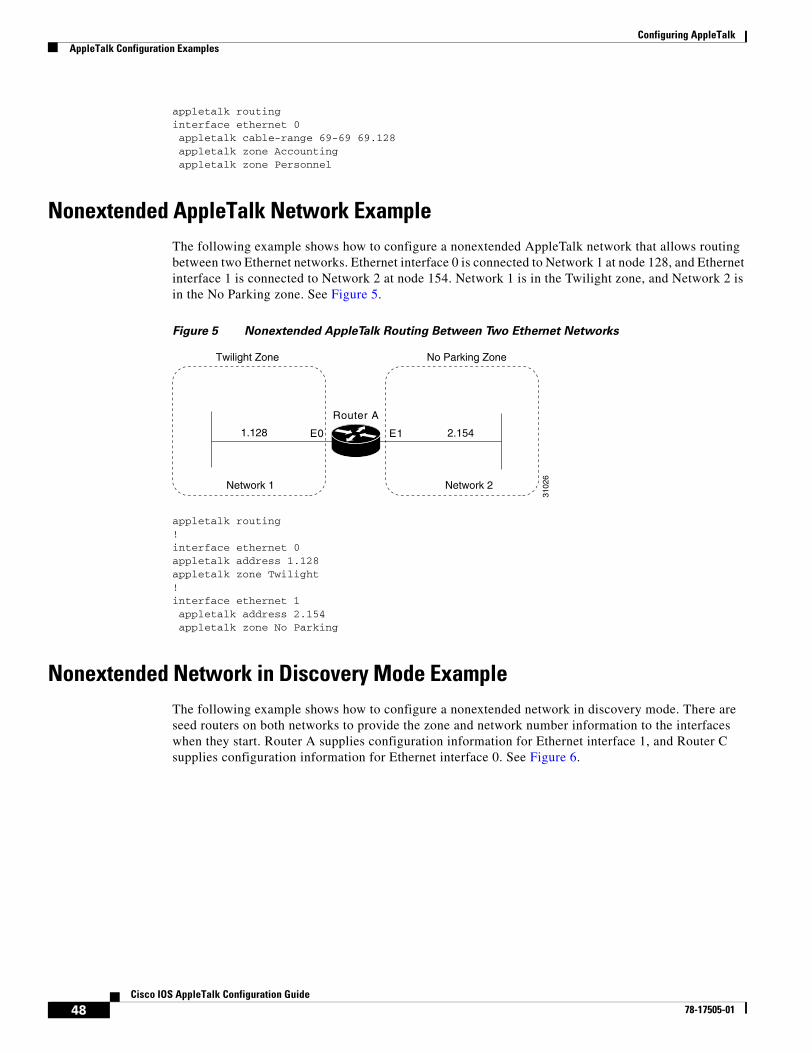
Configuring AppleTalkAppleTalk Configuration Examples
48Cisco IOS AppleTalk Configuration Guide
78-17505-01
appletalk routinginterface ethernet 0 appletalk cable-range 69-69 69.128 appletalk zone Accounting appletalk zone Personnel
Nonextended AppleTalk Network ExampleThe following example shows how to configure a nonextended AppleTalk network that allows routing between two Ethernet networks. Ethernet interface 0 is connected to Network 1 at node 128, and Ethernet interface 1 is connected to Network 2 at node 154. Network 1 is in the Twilight zone, and Network 2 is in the No Parking zone. See Figure 5.
Figure 5 Nonextended AppleTalk Routing Between Two Ethernet Networks
appletalk routing!interface ethernet 0appletalk address 1.128appletalk zone Twilight!interface ethernet 1 appletalk address 2.154 appletalk zone No Parking
Nonextended Network in Discovery Mode ExampleThe following example shows how to configure a nonextended network in discovery mode. There are seed routers on both networks to provide the zone and network number information to the interfaces when they start. Router A supplies configuration information for Ethernet interface 1, and Router C supplies configuration information for Ethernet interface 0. See Figure 6.
1.128
Network 1
Twilight Zone
2.154
Network 2
No Parking Zone
E0
Router A
E1
3102
6

Configuring AppleTalkAppleTalk Configuration Examples
49Cisco IOS AppleTalk Configuration Guide
78-17505-01
Figure 6 Routing in Discovery Mode
The following example shows how to configure this nonextended network in discovery mode:
appletalk routing!interface ethernet 0 appletalk address 0.0!interface ethernet 1 appletalk address 0.0
AppleTalk Access List ExamplesOur implementation of AppleTalk provides several methods using access lists to control access to AppleTalk networks. The following sections show these methods and different approaches in applying access lists.
Defining an Access List to Filter Data Packets Example
The following commands create access list 601:
! Permit packets to be routed from network 55.access-list 601 permit network 55
! Permit packets to be routed from network 500.access-list 601 permit network 500
! Permit packets to be routed from networks 900 through 950.access-list 601 permit cable-range 900-950
! Do not permit packets to be routed from networks 970 through 990.access-list 601 deny includes 970-990
! Do not permit packets to be routed from networks 991 through 995.access-list 601 permit within 991-995
! Deny routing to any network and cable range not specifically enumerated.access-list 601 deny other-access
Router A
Router C
E0 E1
Router B
3102
7

Configuring AppleTalkAppleTalk Configuration Examples
50Cisco IOS AppleTalk Configuration Guide
78-17505-01
The following example shows how to use access list 601 to filter data packets by applying an interface (for example, Ethernet interface 0):
appletalk routinginterface ethernet 0 appletalk cable-range 50-50 appletalk zone No Parking appletalk access-group 601 out
The following examples show how Ethernet interface 0 would handle outgoing data packets:
• Packets sourced from cable range 50–50 are permitted.
• Packets sourced from any network in the cable range 972–980 are denied because they explicitly match the access-list deny includes 970-990 command.
Defining an Access List to Filter Incoming Routing Table Updates Example
The following example shows how to create access list 602. This example shows how packets are processed by access lists; you cannot create such a redundant access list.
access-list 602 permit network 55access-list 602 permit cable 55-55access-list 602 permit includes 55-55access-list 602 permit within 55-55
The following example shows how to use this access list to filter routing table updates received on Ethernet interface 0:
appletalk routinginterface ethernet 0 appletalk cable-range 55-55 appletalk zone No Parking appletalk distribute-list 602 in
The following tables show the process for accepting or rejecting routing update information. If the outcome of a test is true, the condition passes the access list specification and the distribute-list command specification is then applied.
Routing updates that contain network 55 would be processed as follows:
Routing updates that contain cable range 55–55 would be processed as follows:
Access List Command Outcome of Test
access-list 602 permit network 55 True
access-list 602 permit cable range 55–55 False
access-list 602 permit includes 55–55 True
access-list 602 permit within 55–55 True
Access List Command Outcome of Test
access-list 602 permit network 55 False
access-list 602 permit cable range 55–55 True

Configuring AppleTalkAppleTalk Configuration Examples
51Cisco IOS AppleTalk Configuration Guide
78-17505-01
Routing updates that contain cable range 55–56 would be processed as follows:
Comparison of Alternative Segmentation Solutions
With the flexibility allowed by our access list implementation, determining the optimal method to segment an AppleTalk environment using access control lists can be unclear. The following scenario and configuration examples illustrate two solutions to a particular problem, and point out the inherent advantages of using AppleTalk-style access lists.
Consider a situation in which a company wants to permit customers to have direct access to several corporate file servers. Access is to be permitted to all devices in the zones named MIS and Corporate, but access is restricted to the Engineering zone because the file servers in these zones contain sensitive information. The solution is to create the appropriate access lists to enforce these access policies.
The AppleTalk internetwork of the company consists of the following networks and zones:
The router named Gatekeeper is placed between the World zone and the various company-specific zones. An arbitrary number of routers can be on either side of Gatekeeper. An Ethernet backbone exists on each side of Gatekeeper, connecting these other routers to Gatekeeper. On the router Gatekeeper, Ethernet interface 0 connects to the World backbone and Ethernet interface 1 connects to the Corporate backbone.
access-list 602 permit includes 55–55 True
access-list 602 permit within 55–55 True
Access List Command Outcome of Test
Access List Command Outcome of Test
access-list 602 permit network 55 False
access-list 602 permit cable-range 55–55 False
access-list 602 permit includes 55–55 True
access-list 602 permit within 55–55 False
Zone Network Number or Cable Range
Engineering 69–6934160–416015
MIS 666–777
Corporate 70–7055510044262–4262
World 88–8899000–9999 (multiple networks exist in this range)

Configuring AppleTalkAppleTalk Configuration Examples
52Cisco IOS AppleTalk Configuration Guide
78-17505-01
For the purposes of this configuration, assume Gatekeeper is the only router that needs any access list configuration. There are two solutions, depending on the level of security desired.
The following example shows a minimal configuration, in which the Engineering zone is secured, but all other zones are publicly accessible:
appletalk routingaccess-list 603 deny zone Engineeringaccess-list 603 permit additional-zonesaccess-list 603 permit other-access
interface ethernet 0appletalk network 3 appletalk distribute-list 603 out appletalk access-group 603
The following example shows a more comprehensive configuration, in which the Corporate and MIS zones are public and all other zones are secured:
appletalk routingaccess-list 603 permit zone Corporateaccess-list 603 permit zone MISaccess-list 603 deny additional-zonesaccess-list 603 permit other-access
interface ethernet 0appletalk network 3 appletalk distribute-list 603 out appletalk access 603
Both configurations satisfy the basic goal of isolating the Engineering servers, but the second example will continue to be secure when more zones are added.
Defining an Access List to Filter NBP Packets Example
The following example shows how to add entries to access list number 607 to allow forwarding of NBP packets from specific sources and deny forwarding of NBP packets from all other sources. The first command adds an entry that allows NBP packets from all printers of type LaserWriter. The second command adds an entry that allows NBP packets from all AppleTalk file servers of type AFPServer. The third command adds an entry that allows NBP packets from all applications called HotShotPaint. For example, an application might have a zone name of Accounting and an application might have a zone name of Engineering, both having the object name of HotShotPaint. NBP packets forwarded from both applications will be allowed.
The final access-list other-nbps command denies forwarding of NBP packets from all other sources.
access-list 607 permit nbp 1 type LaserWriteraccess-list 607 permit nbp 2 type AFPServeraccess-list 607 permit nbp 3 object HotShotPaintaccess-list 607 deny other-nbps
The following example shows how to use this access list to filter inbound NBP packets on Ethernet interface 0:
appletalk routinginterface ethernet 0 appletalk cable-range 55-55 appletalk zone No Parking appletalk access-group 607 in

Configuring AppleTalkAppleTalk Configuration Examples
53Cisco IOS AppleTalk Configuration Guide
78-17505-01
The following example shows how to add entries to access list number 608 to deny forwarding of NBP packets from two specific servers whose fully qualified NBP names are specified. It permits forwarding of NBP packets from all other sources.
access-list 608 deny nbp 1 object ServerAaccess-list 608 deny nbp 1 type AFPServeraccess-list 608 deny nbp 1 zone Bld3access-list 608 deny nbp 2 object ServerBaccess-list 608 deny nbp 2 type AFPServeraccess-list 608 deny nbp 2 zone Bld3access-list 608 permit other-nbpsaccess-list 608 permit other-access
The following example shows how to use this access list to filter NBP packets on Ethernet interface 0:
appletalk routinginterface ethernet 0 appletalk cable-range 55-55 appletalk zone No Parking appletalk access-group 608 in
Note Prior to Cisco IOS Release 11.2 F, all NBP access lists were applied to inbound interfaces by default. When Cisco IOS Release 11.2 F or later software is used, the default interface direction for all access lists, including NBP access lists, is outbound. In order to retain the inbound direction of access lists created with previous Cisco IOS software releases, you must specify an inbound interface for all NBP access lists using the appletalk access-group command.
The following example shows how to create an access list that denies forwarding of the following:
• All NBP Lookup Reply packets
• NBP packets from the server named Bob’s Server
• Packets from all AppleTalk file servers of type AFPServer
• All NBP Lookup Reply packets that contain the specified named entities belonging to the zone twilight:
access-list 600 deny nbp 1 LkReplyaccess-list 600 deny nbp 1 object Bob’s Serveraccess-list 600 deny nbp 1 type AFPServeraccess-list 600 deny nbp 1 zone twilightaccess-list 600 permit other-nbps
There may be a case where a fully qualified filter for Bob’s Server:AFPServer@twilight will not work for an NBP Lookup Reply in response to a Lookup generated by the Chooser application. This case would occur because the Lookup Request is sent as =:AFPServer@twilight, and the Lookup Reply from Bob’s Server comes back as Bob’s Server:AFPServer@*.
The following example shows how to create an access list to filter a Lookup Reply generated by Bob’s Server to a request by the Chooser application:
access-list 609 deny nbp 1 LkReplyaccess-list 609 deny nbp 1 object Bob’s Serveraccess-list 609 deny nbp 1 type AFPServeraccess-list 609 permit other-nbpsaccess-list 609 permit other-access

Configuring AppleTalkAppleTalk Configuration Examples
54Cisco IOS AppleTalk Configuration Guide
78-17505-01
Configuring Partial Zone Advertisement Example
Figure 7 illustrates a configuration in which you might want to allow partial advertisement of a particular zone.
Figure 7 Example Topology of Partially Obscured Zone
Assume that Router B includes a router-update filter (applied with the appletalk distribute-list interface configuration command) on the Ethernet interface 3 that does not accept routing table updates from network 10, nor does it send routing table updates to that network.
access-list 612 deny network 10access-list 612 permit other-accessinterface ethernet 3 appletalk distribute-list 612 out appletalk distribute-list 612 in
For Network 30, normal (default) behavior would be for Network 10 and Network 20 to be eliminated from any routing updates sent, although Network 15 would be included in routing updates (same zone as Network 30). Using the appletalk permit-partial-zones global configuration command has the following effects:
• If the appletalk permit-partial-zones command is enabled, the routing updates exclude Network 10, but include Network 15 and Network 20.
• If the no appletalk permit-partial-zones command is enabled, the routing updates exclude both Network 10 and Network 20, but still include Network 15. This configuration is generally considered the preferred behavior and is the default.
Table 6 summarizes the associations between the networks shown in Figure 7. Table 7 details the effects of enabling and disabling partial-zone advertisement with the appletalk permit-partial-zones global configuration command.
Network 10Zone A
Network 20Zone A
Network 30Zone B
3102
9
Network 15Zone B
E0 E1
E4
Router AE2 E3
Router B
Table 6 Zone and Interface Associations for Partial Zone Advertisement Example
Network Network 10 Network 15 Network 20 Network 30
Zone A B A B
Interfaces Ethernet 0 Ethernet 4 Ethernet 1Ethernet 2
Ethernet 3

Configuring AppleTalkAppleTalk Configuration Examples
55Cisco IOS AppleTalk Configuration Guide
78-17505-01
Transition Mode ExampleWhen in transition mode, the Cisco IOS software can route packets between extended and nonextended AppleTalk networks that exist on the same cable.
To configure transition mode, you must have two ports connected to the same physical cable. One port is configured as a nonextended AppleTalk network, and the other is configured as an extended AppleTalk network. Both ports must have unique network numbers, because they are two separate networks. Figure 8 shows an example of the topology of this configuration.
Figure 8 Transition Mode Topology and Configuration
The following example shows how to configure the network shown in Figure 8. Note that networks 2-2 and 4-4 must have a cable range of 1 and a single zone in their zone lists. These parameters are required to maintain compatibility with the nonextended network, network 3.
! This is an extended network.interface ethernet 0 appletalk cable-range 2-2 appletalk zone No Parking!! This is a nonextended network.interface ethernet 1 appletalk address 3.128 appletalk zone Twilight!! This is an extended network.interface ethernet 2 appletalk cable-range 4-4 appletalk zone Do Not Enter
Table 7 Partial Zone Advertisement Control on Network 30
Command Condition Network 10 Network 15 Network 20 Network 30
Enabled Not advertised on Network 30
Advertised on Network 30
Advertised on Network 30
—
Disabled Not advertised on Network 30
Advertised on Network 30
Not advertised on Network 30
—
Router
3102
8
E2
E0 E1

Configuring AppleTalkAppleTalk Configuration Examples
56Cisco IOS AppleTalk Configuration Guide
78-17505-01
Hiding and Sharing Resources with Access List ExamplesThe following examples show how to use AppleTalk access lists to manage access to certain resources.
Establishing a Free-Trade Zone Example
The goal of the configuration shown in Figure 9 is to allow all users on all the networks connected to Router A and Router B to be able to access the AppleShare servers AS1 and AS2 in the zone FreeAccessZone. A second requirement is to block cross access through this zone. In other words, users in the zones MIS1, MIS2, and LocalTalk (which are connected to Ethernet interface 0 on Router A) are not allowed access to any of the resources on networks connected to Ethernet interface 4 on Router B. Similarly, users in the zones Engineering, Test, and LocalTalk (which are connected to Ethernet interface 4 on Router B, interface E4) are not allowed access to any of the resources on networks connected to Ethernet interface 0 on Router A.
Figure 9 Controlling Access to a Common AppleTalk Network
Note Although there are networks that share the same number on interfaces E0 and E4 and there are zones that have the same name, none have the same network number and zone specification (except FreeAccessZone). The two routers do not broadcast information about these networks through FreeAccessZone. The routers only broadcast the cable range 5–5. As configured, FreeAccessZone sees only itself. However, because no other limitations have been placed on advertisements, the FreeAccessZone range of 5–5 propagates out to the networks attached to E0 (Router A) and E4 (Router B); thus, resources in FreeAccessZone are made accessible to users on all those networks.
The following examples configure Router A and Router B for access control illustrated in Figure 9. You must configure only Ethernet interface 1 on Router A and Ethernet interface 2 on Router B to provide the desired access.
Configuration for Router A appletalk routing!interface ethernet 1
3103
0
Zone: MIS2Network: 4081
Zone: MIS1Network: 4083
Zone: LocalTalkNetwork: 3
Zone: EngineeringNetwork: 20
Zone: LocalTalkNetwork: 10
Zone: TestNetwork: 3
AS1 AS2
AppleShare serversin FreeAccessZone
Zone: FreeAccessZoneCable range: 5−5
Access out blocked
Access allowed into FreeAccessZone
E0 E1
Router A
E2 E4
Router B
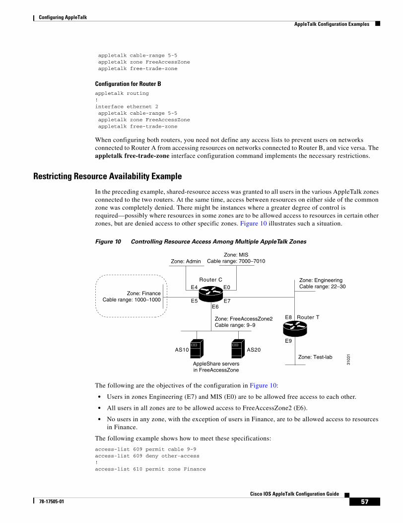
Configuring AppleTalkAppleTalk Configuration Examples
57Cisco IOS AppleTalk Configuration Guide
78-17505-01
appletalk cable-range 5-5 appletalk zone FreeAccessZone appletalk free-trade-zone
Configuration for Router B appletalk routing!interface ethernet 2 appletalk cable-range 5-5 appletalk zone FreeAccessZone appletalk free-trade-zone
When configuring both routers, you need not define any access lists to prevent users on networks connected to Router A from accessing resources on networks connected to Router B, and vice versa. The appletalk free-trade-zone interface configuration command implements the necessary restrictions.
Restricting Resource Availability Example
In the preceding example, shared-resource access was granted to all users in the various AppleTalk zones connected to the two routers. At the same time, access between resources on either side of the common zone was completely denied. There might be instances where a greater degree of control is required—possibly where resources in some zones are to be allowed access to resources in certain other zones, but are denied access to other specific zones. Figure 10 illustrates such a situation.
Figure 10 Controlling Resource Access Among Multiple AppleTalk Zones
The following are the objectives of the configuration in Figure 10:
• Users in zones Engineering (E7) and MIS (E0) are to be allowed free access to each other.
• All users in all zones are to be allowed access to FreeAccessZone2 (E6).
• No users in any zone, with the exception of users in Finance, are to be allowed access to resources in Finance.
The following example shows how to meet these specifications:
access-list 609 permit cable 9-9access-list 609 deny other-access! access-list 610 permit zone Finance
3103
1
Zone: AdminZone: MIS
Cable range: 7000−7010
Zone: EngineeringCable range: 22−30
Zone: Test-lab
Zone: FinanceCable range: 1000−1000
AppleShare serversin FreeAccessZone
Zone: FreeAccessZone2Cable range: 9−9
E5
Router C
E7
AS10 AS20
E4
E6
E0
E8
E9
Router T

Configuring AppleTalkAppleTalk Configuration Examples
58Cisco IOS AppleTalk Configuration Guide
78-17505-01
access-list 610 permit zone FreeAccessZone2access-list 610 deny additional-zones! access-list 611 deny cable-range 1000-1000access-list 611 deny cable-range 9-9access-list 611 permit cable-range 7000-7010access-list 611 permit cable-range 22-30
The effects of these access lists are as follows:
• Access list 609 is intended to be used to allow access to resources on FreeAccessZone2.
• Access list 610 is intended to be used to control access in and out of the zone Finance.
• Access list 611 is intended to be used to accommodate the requirement to allow users in zones Engineering and MIS to mutually access network resources.
Configuration for Ethernet Interface 0
Ethernet interface 0 is associated with the MIS zone. The following example shows how to configure this interface:
interface ethernet 0 appletalk cable-range 7000-7010 appletalk zone MIS appletalk distribute-list 611 out appletalk distribute-list 611 in
Specifying access list 611 results in the following filtering:
• Advertisements of Finance are blocked.
• Advertisements between Engineering and MIS are allowed.
Configuration for Ethernet Interface 5
Ethernet interface 5 is associated with the Finance zone. The following example shows how to configure this interface:
interface ethernet 5 appletalk cable-range 1000-1000 appletalk zone Finance appletalk distribute-list 610 out appletalk access-group 610
The effects of these access lists are as follows:
• With the appletalk distribute-list out interface configuration command, Finance is limited to accessing Finance and FreeAccessZone2 only.
• The appletalk access-group interface configuration command filters packet traffic. Thus, it blocks access to any devices in Finance from outside of this zone.
Configuration for Ethernet Interface 6
Ethernet interface 6 is associated with the FreeAccessZone2 zone. The following example shows how to configure this interface:
interface ethernet 6 appletalk cable 9-9 appletalk zone FreeAccessZone2 appletalk distribute-list 609 out appletalk distribute-list 609 in

Configuring AppleTalkAppleTalk Configuration Examples
59Cisco IOS AppleTalk Configuration Guide
78-17505-01
Configuration for Ethernet Interface 7
Ethernet interface 7 is associated with the Engineering zone. The configuration for this interface mirrors that for Ethernet interface 0, because the users in both the MIS and Engineering zones must have access to resources from each other. The following example shows how to configure Ethernet interface 7:
interface ethernet 7 appletalk cable-range 22-30 appletalk zone Engineering appletalk distribute-list 611 out appletalk distribute-list 611 in
Implicit Configuration of the Admin and Test-Lab Zones
Omitted from the configuration example in Figure 10 are any specific configuration commands pertaining to the zones Test-Lab (Ethernet interface 9 on Router T) and Admin (Ethernet interface 4 on Router C). No configuration is done for these zones because there are no requirements relating to them listed in the original objectives. The following access control is implicitly handled with the assignment of the stated access lists:
• Users in the Admin zone can see the Finance zone, but cannot see resources in that zone. However, as for all zones, resources in FreeAccessZone2 are available, but none of the users in any of the other zones can access resources in Admin.
• In the absence of the assignment of access lists on Router T, users in Test-Lab can access the resources in the FreeAccessZone2 and Engineering zones. With the exception of Engineering, no other zones can access resources in Test-Lab.
GZL and ZIP Reply Filter ExamplesThe following examples show how to configure GZL and ZIP reply filters and the differences between these two types of filters. Both examples use the configuration shown in Figure 11.
Figure 11 Sample Topology for GZL and ZIP Reply Filters
Both GZL and ZIP reply filters control the zones that can be seen on a network segment. GZL filters control which zones can be seen by Macintoshes on local network segments. These filters have no effect on adjacent routers. In order for GZL filters to work properly, all routers on the local segment must be configured with the same access list.
ZIP reply filters control which zones can be seen by adjacent routers and by all routers downstream from adjacent routers. You can use these filters to hide zones from all Macintoshes on all networks on adjacent routers and from all their downstream routers.
Zones: Marketing Accounting Engineering
3103
2Network 600
Router A
Router B
E0
Router C Router D

Configuring AppleTalkAppleTalk Configuration Examples
60Cisco IOS AppleTalk Configuration Guide
78-17505-01
Using the configuration shown in Figure 11, you would use a GZL filter to prevent the Macintosh on the Ethernet 0 network segment from viewing the zones Engineering and Accounting on network 600. These zones would not be visible via the Macintosh Chooser. The following example shows how to configure Router A:
access-list 600 deny zone Engineeringaccess-list 600 deny zone Accountingaccess-list 600 permit additional-zonesaccess-list 600 permit other-access!interface ethernet 0appletalk getzonelist-filter 600
Again using the configuration shown in Figure 11, you would use a ZIP reply filter to hide the Engineering and Accounting zones from Router B and Router C. This filter would also hide the zones from Router D, which is downstream from Router C. The effect of this filter is that when these routers request the names of zones on network 600, the zones names Engineering and Accounting will not be returned.
access-list 600 deny zone Engineeringaccess-list 600 deny zone Accountingaccess-list 600 permit additional-zonesaccess-list 600 permit other-access!interface ethernet 0appletalk zip-reply-filter 600
AppleTalk Interenterprise Routing over AURP ExampleAfter you configure an AppleTalk domain for AppleTalk interenterprise features, you can apply the features to a tunnel interface configured for AURP by assigning the domain number to the interface.
The following example shows how to define tunnel interface 0 and configure it for AURP. Then, it shows how to apply the features configured for domain 1 to tunnel interface 1 by assigning the AppleTalk domain group 1 to the tunnel interface.
appletalk domain 1 name Franceappletalk domain 1 remap-range in 10000-19999appletalk domain 1 remap-range out 200-299!interface Tunnel 0tunnel source ethernet 0tunnel destination 172.19.1.17tunnel mode aurpappletalk protocol aurpappletalk domain-group 1
SNMP ExampleThe following example shows how to activate SNMP and AppleTalk:
! Disable SNMP on the router.no snmp-server!! Enable AppleTalk routing and event logging on the router.appletalk routingappletalk event-logging!! Configure IP and AppleTalk on Ethernet interface 0.

Configuring AppleTalkAppleTalk Configuration Examples
61Cisco IOS AppleTalk Configuration Guide
78-17505-01
interface Ethernet 0ip address 131.108.29.291 255.255.255.0appletalk cable-range 29-29 29.180appletalk zone MarketingA1
!! Enable SNMP on the router.snmp-server community MarketingA2 RWsnmp-server trap-authenticationsnmp server host 131.108.2.160 MarketingA2
MacIP Examples The following example shows how to configure MacIP support for dynamically addressed MacIP clients with dynamically allocated IP addresses in the range 172.18.0.2 to 172.18.0.10:
! Specify server address and zone.appletalk macip server 172.18.0.1 zone Marketing!! Specify dynamically addressed clients.appletalk macip dynamic 172.18.0.2 172.18.0.10 zone Marketing!! Assign the address and subnet mask for Ethernet interface 0.interface ethernet 0ip address 172.18.0.2 255.255.255.0!! Enable AppleTalk routing.appletalk routing!interface ethernet 0appletalk cable range 69-69 69.128appletalk zone Marketing
The following example shows how to configure MacIP support for MacIP clients with statically allocated IP addresses:
! Specify the server address and zone.appletalk macip server 172.18.0.1 zone Marketing!! Specify statically addressed clients.appletalk macip static 172.18.0.11 172.18.0.20 zone Marketingappletalk macip static 172.18.0.31 zone Marketingappletalk macip static 172.18.0.41 zone Marketingappletalk macip static 172.18.0.49 zone Marketing!! Assign the address and subnet mask for Ethernet interface 0.interface ethernet 0ip address 172.18.0.1 255.255.255.0!! Enable AppleTalk routing.appletalk routing!interface ethernet 0appletalk cable range 69-69 69.128appletalk zone Marketing
IPTalk Example This section describes how to set up UNIX-based systems and our Cisco IOS software to use CAP IPTalk and other IPTalk implementations.

Configuring AppleTalkAppleTalk Configuration Examples
62Cisco IOS AppleTalk Configuration Guide
78-17505-01
The following procedure outlines the basic steps for setting up our software and UNIX hosts for operation using IPTalk implementations.
Note This procedure does not provide full instructions about how to install CAP on the UNIX system. However, it does address the requirements for setting up the configuration file of the UNIX system that defines addresses and other network information. Generally, this is the only file that relies on the address and configuration information of the router. Refer to your UNIX system and CAP software manuals for information about building the CAP software and setting up the UNIX startup scripts.
Step 1 Enable AppleTalk routing on all the routers that will use IPTalk and any routers between these routers.
Step 2 Enable IP routing on the interfaces that will communicate with the UNIX system. (Refer to the Cisco IOS IP and IP Routing Configuration Guide for more information about configuring IP.) These interfaces must be on the same subnet as the UNIX system. Also, ensure that IP is enabled on the UNIX system.
Step 3 Allocate an AppleTalk network number for IPTalk. You need a separate AppleTalk network number for each IP subnet that is to run IPTalk.
You can have a number of UNIX machines on the same subnet. They all use the same AppleTalk network number for IPTalk. However, they must have their own individual node identifiers.
It is possible for the same router to have IPTalk enabled on several interfaces. Each interface must have a different AppleTalk network number allocated to IPTalk, because each interface will be using a different IP subnet.
Step 4 Determine the CAP format of the AppleTalk network number. The CAP software is based on an older AppleTalk convention that expresses AppleTalk network numbers as two octets (decimal numbers from 0 to 255) separated by a dot. The current AppleTalk convention uses decimal numbers from 1 to 65,279. Use the following formula to convert between the two:
CAP format: x.yApple format: d
To convert from AppleTalk to CAP: x = d/256 (/ represents truncating integer division)y = d%256 (% represents the remainder of the division)
To convert from CAP to AppleTalk: d = x * 256 + y
Example:AppleTalk format: 14087CAP format: 55.7
Step 5 Choose a zone name for IPTalk. No special constraints are placed on zone name choices. You can use the same zone name for several networks, and you can combine IPTalk and normal AppleTalk networks in the same zone.
Step 6 Decide which UDP ports to use for IPTalk. The default is to use ports beginning with 768. Thus, RTMP uses port 769, NBP port 770, and so on. These are the original AppleTalk ports, and their numbers are hardcoded into older versions of CAP. The only problem with using them is that they are not officially assigned by the Internet’s NIC, which has assigned a set of UDP ports beginning with 200. Thus, other applications could use them, possibly causing conflicts—although this is unlikely. With CAP releases 5.0 and later, you can configure CAP to use the officially allocated ports. If you do so, RTMP will use port 201, NBP port 202, and so on. Whichever ports you use, you must configure both CAP and the router to use the same ones.

Configuring AppleTalkAppleTalk Configuration Examples
63Cisco IOS AppleTalk Configuration Guide
78-17505-01
The following example shows how to enable IPTalk on each interface of the router as required:
appletalk routing!interface ethernet 0 ip address 172.16.7.22 255.255.255.0 appletalk cable 1792-1792 1792.22 appletalk zone MIS-Developmentinterface Tunnel0tunnel source Ethernet0tunnel mode iptalkappletalk iptalk 14087 MIS-UNIX
In this example, AppleTalk routing is enabled on the interface in the following two ways:
• Via EtherTalk phase 2, using the cable range 1792–1792 and the zone MIS-Development
• Via IPTalk, using the network number 14087 and the zone MIS-UNIX
Note The IPTalk node identifier is chosen automatically, based on the IP address. It is normally the host number portion of the IP address. For example, with an IP address of 172.16.7.22 and a subnet mask of 255.255.255.0, the host number is 22. Thus, the IPTalk node identifier would be 22. If the IP host number is larger than 255, the low-order 8 bits are used, although fewer than 8 bits may be available, depending on the IP subnet mask. If the mask leaves fewer bits, the node number will be quietly truncated. Be sure to use a node address that is compatible with the subnet mask. In any event, you may experience problems when using IPTalk with host numbers larger than 255.
If you choose to use the official UDP ports (those beginning with 200), include the following global configuration command in your configuration:
appletalk iptalk-baseport 200
Step 7 Configure each UNIX host with a network number, zone name, and router.
The following example shows the contents of the /etc/atalk.local file from a UNIX system with the IP address 172.19.7.26 and a network mask of 255.255.255.0:
# IPTalk on net 172.19.7.0:# mynet mynode myzone55.7 26 MIS-UNIX# bridgenet bridgenode bridgeIP55.7 22 172.19.7.22
The first noncommented line defines the address of the UNIX system, and the second noncommented line defines the address of the router. In both cases, the first number is 55.7, which is the AppleTalk network number (in CAP format) for use by IPTalk. The second number is the AppleTalk node identifier, which must be the same as the IP host number. The last number on the first line is the zone name, and on the second line it is the IP address of the router.
Note the following about the entries in the /etc/atalk.local file:
• The AppleTalk network number in the first column in both lines must agree with the AppleTalk network number used in the appletalk iptalk command. However, in the /etc/atalk.local file, the number must be in the CAP format, while in the configuration command, it must be in the Apple format.
• The host number in the second column in both lines must agree with the IP host number of the corresponding system. That is, on the first line it must be the IP host number of the UNIX machine, and on the second line it must be the IP host number for the router.

Configuring AppleTalkAppleTalk Configuration Examples
64Cisco IOS AppleTalk Configuration Guide
78-17505-01
• The zone name in the third column on the first line must agree with the zone name used in the appletalk iptalk command.
• The IP address in the third column of the second line must be the IP address of the router.
Step 8 Ensure that your CAP software is using the same UDP port numbers as the router. Currently, the CAP default is the same as the router default, which is port numbers beginning with 768. If you want to use this default, you need not take any further action. However, if you want to use the official UDP port numbers (port numbers beginning with 200), ensure that you have included the following command in your configuration:
appletalk iptalk-baseport 200
Step 9 On the UNIX system, add the following lines to the /etc/services file:
at-rtmp 201/udpat-nbp 202/udpat-3 203/udpat-echo 204/udpat-5 205/udpat-zis 206/udpat-7 207/udpat-8 208/udp
If you are using Network Information Services (NIS), previously known as the Yellow Pages, remember to do a make in /var/yp after changing /etc/services. If you are using the default ports (those starting with 768), you need not modify /etc/services.
AppleTalk Control Protocol ExampleThe following example shows how to set up a router to accept AppleTalk client requests on asynchronous interface 1 and create virtual network number 3 and the AppleTalk zone Twiddledee:
appletalk virtual-net 3 Twiddledeeinterface async 1 encapsulation ppp appletalk client-mode
Proxy Network Number Example Assume that your network topology looks like the one in Figure 12. Also assume that Router A supports only nonextended AppleTalk, that Router B supports only extended AppleTalk (not in transition mode), and that Router C supports only extended AppleTalk.

Configuring AppleTalkAppleTalk Configuration Examples
65Cisco IOS AppleTalk Configuration Guide
78-17505-01
Figure 12 Sample Network Topology
If Router C generates an NBP hookup request for Zone A, Router B will convert this request to a forward request and send it to Router A. Because Router A supports only nonextended AppleTalk, it does not handle the forward request and ignores it. Hence, the NBP lookup from Router C fails.
To work around this problem without putting a transition router adjacent to the nonextended-only router (Router A), you could configure Router D with an NBP proxy.
If you configured Router D with an NBP proxy as follows, any forward requests received for Zone A are converted into lookup requests, and, therefore, the nonextended router for Network 60 can properly respond to NBP hookup requests generated beyond Router C. The following example shows the command needed to describe this configuration:
appletalk proxy 60 A
AppleTalk Interenterprise Routing ExampleThe following example shows how to configure AppleTalk interenterprise routing. It configures domain 1, which is named “France,” and places Ethernet interface 2 into this domain.
appletalk domain 1 name Franceappletalk domain 1 remap-range in 10000-19999appletalk domain 1 remap-range out 200-299appletalk domain 1 hop-reduction!interface ethernet 2no ip addressno keepaliveappletalk cable-range 300-300 300.6appletalk zone Europeappletalk domain-group 1
AppleTalk over DDR ExampleThe following example describes how to configure AppleTalk to run over a DDR interface, as illustrated in Figure 13. When configuring AppleTalk over DDR, you must specify DDR on the interface on which the static neighbor resides before you specify the static route itself. Also, the Cisco IOS software must know the network address of the static neighbor before you specify the static route. Otherwise, the software will not know to which interface the static neighbor is connected. To open an AppleTalk DDR link, there must be at least one AppleTalk access list bound to a dialer group.
Router A
Cisco Phase 1Router
Cable/Range70−70
Cable/Range80−90
Cable/Range200−201Network 60
Zone A
3103
3
Cable/Range100−100
Router B
Router E Router D
Cisco Phase 2Router
Cisco Phase 2Router
Cisco Phase 2Router
Router C
AppleTalkPhase 2 Router

Configuring AppleTalkAppleTalk Configuration Examples
66Cisco IOS AppleTalk Configuration Guide
78-17505-01
Figure 13 AppleTalk over DDR Configuration
The following example shows the steps required to configure AppleTalk over DDR on Router A:
Step 1 Configure an access list and dialer group.
access-list 601 permit cable 100-110dialer-list 4 list 601
Step 2 Configure the serial interface.
interface serial 0 dialer in-band dialer string 1234 appletalk cable 1-1 1.1 appletalk zone DDR dialer-group 4 apple distribute-list 601 in
Step 3 Create the static route.
appletalk static cable 100-110 to 1.2 zone Remote
Step 4 Open the Chooser on the Macintosh.
Step 5 Select any AppleTalk service (such as AppleShare, LaserWriter, and so on) in zone Remote to cause Router A to dial up Router B to open a DDR link between them.
Step 6 Select an AppleTalk file server in the zone Remote. After some time, AppleTalk services appear in zone Remote. Select the one that you need.
Step 7 Close the Chooser.
Step 8 Open the AppleTalk session to the remote service.
Step 9 After the AppleTalk session is finished, close the connection to the remote service. The DDR link should go down after the DDR idle time has elapsed.
Instead of creating a static route in Step 3, you can create a floating static route. The following example adds a floating static route to cable-range 10-11 in the Eng zone with AppleTalk address 6.5 as the next hop router:
appletalk static cable-range 10-11 to 6.5 floating zone Eng
AppleTalk Control Protocol for PPP ExampleThe following example shows how to set up your router to accept AppleTalk client requests on interfaces 1 and 3, using the virtual network number 3 and the AppleTalk zone Twiddledee:
Router> enableRouter# config terminalRouter(config)# appletalk virtual-net 3 TwiddledeeRouter(config)# interface async 1
Macintosh
Zone: DDRCable Range = 1−1
AppleShare server
Zone: RemoteCable Range = 100−110 31
034
1.11.2
Router A
S0Router B

Configuring AppleTalkAppleTalk Configuration Examples
67Cisco IOS AppleTalk Configuration Guide
78-17505-01
Router(config-int)# encapsulation pppRouter(config-int)# appletalk client-modeRouter(config-int)# interface async 3Router(config-int)# encapsulation pppRouter(config-int)# appletalk client-mode

Configuring AppleTalkAppleTalk Configuration Examples
68Cisco IOS AppleTalk Configuration Guide
78-17505-01