Layer 2 Configuration Guide, Cisco IOS XE Gibraltar 16.10.x ...
Upload
khangminh22Category
view
6download
0
LAN Switching Configuration Guide, Cisco IOS XE 17 (Cisco ASR 920Series)First Published: 2019-11-14
Americas HeadquartersCisco Systems, Inc.170 West Tasman DriveSan Jose, CA 95134-1706USAhttp://www.cisco.comTel: 408 526-4000
800 553-NETS (6387)Fax: 408 527-0883

THE SPECIFICATIONS AND INFORMATION REGARDING THE PRODUCTS IN THIS MANUAL ARE SUBJECT TO CHANGE WITHOUT NOTICE. ALL STATEMENTS,INFORMATION, AND RECOMMENDATIONS IN THIS MANUAL ARE BELIEVED TO BE ACCURATE BUT ARE PRESENTED WITHOUT WARRANTY OF ANY KIND,EXPRESS OR IMPLIED. USERS MUST TAKE FULL RESPONSIBILITY FOR THEIR APPLICATION OF ANY PRODUCTS.
THE SOFTWARE LICENSE AND LIMITED WARRANTY FOR THE ACCOMPANYING PRODUCT ARE SET FORTH IN THE INFORMATION PACKET THAT SHIPPED WITHTHE PRODUCT AND ARE INCORPORATED HEREIN BY THIS REFERENCE. IF YOU ARE UNABLE TO LOCATE THE SOFTWARE LICENSE OR LIMITED WARRANTY,CONTACT YOUR CISCO REPRESENTATIVE FOR A COPY.
The Cisco implementation of TCP header compression is an adaptation of a program developed by the University of California, Berkeley (UCB) as part of UCB's public domain version ofthe UNIX operating system. All rights reserved. Copyright © 1981, Regents of the University of California.
NOTWITHSTANDING ANY OTHERWARRANTY HEREIN, ALL DOCUMENT FILES AND SOFTWARE OF THESE SUPPLIERS ARE PROVIDED “AS IS" WITH ALL FAULTS.CISCO AND THE ABOVE-NAMED SUPPLIERS DISCLAIM ALL WARRANTIES, EXPRESSED OR IMPLIED, INCLUDING, WITHOUT LIMITATION, THOSE OFMERCHANTABILITY, FITNESS FOR A PARTICULAR PURPOSE AND NONINFRINGEMENT OR ARISING FROM A COURSE OF DEALING, USAGE, OR TRADE PRACTICE.
IN NO EVENT SHALL CISCO OR ITS SUPPLIERS BE LIABLE FOR ANY INDIRECT, SPECIAL, CONSEQUENTIAL, OR INCIDENTAL DAMAGES, INCLUDING, WITHOUTLIMITATION, LOST PROFITS OR LOSS OR DAMAGE TO DATA ARISING OUT OF THE USE OR INABILITY TO USE THIS MANUAL, EVEN IF CISCO OR ITS SUPPLIERSHAVE BEEN ADVISED OF THE POSSIBILITY OF SUCH DAMAGES.
Any Internet Protocol (IP) addresses and phone numbers used in this document are not intended to be actual addresses and phone numbers. Any examples, command display output, networktopology diagrams, and other figures included in the document are shown for illustrative purposes only. Any use of actual IP addresses or phone numbers in illustrative content is unintentionaland coincidental.
All printed copies and duplicate soft copies of this document are considered uncontrolled. See the current online version for the latest version.
Cisco has more than 200 offices worldwide. Addresses and phone numbers are listed on the Cisco website at www.cisco.com/go/offices.
Cisco and the Cisco logo are trademarks or registered trademarks of Cisco and/or its affiliates in the U.S. and other countries. To view a list of Cisco trademarks, go to this URL:https://www.cisco.com/c/en/us/about/legal/trademarks.html. Third-party trademarks mentioned are the property of their respective owners. The use of the word partner does not imply apartnership relationship between Cisco and any other company. (1721R)
© 2020 Cisco Systems, Inc. All rights reserved.
C O N T E N T S
Configuring Resilient Ethernet Protocol 1C H A P T E R 1
Restrictions for Resilient Ethernet Protocol 1
Information About REP 2
REP Segments 2
Link Integrity 3
Fast Convergence 4
VLAN Load Balancing 4
Spanning Tree Protocol Interaction 5
REP Ports 5
REP Integrated with VPLS 6
Default REP Configuration 6
REP Segments and REP Administrative VLANs 6
REP Configuration Guidelines 6
REP Support on a Trunk EFP 7
REP Configurable Timers 8
SSO Support for REP Fast Hello 8
REP Edge No-Neighbor Support 8
How to Configure REP 9
Configuring the REP Administrative VLAN 9
Configuring Trunk EFP on an Interface 10
Configuring REP Support on a Trunk EFP 12
Setting the Preemption for VLAN Load Balancing 15
Restrictions 15
Configuring SNMP Traps for REP 16
Monitoring the REP Configuration 17
Configuring REP Configurable Timers 18
LAN Switching Configuration Guide, Cisco IOS XE 17 (Cisco ASR 920 Series)iii
Configuring REP as an Edge No-Neighbor Port 21
Configuration Examples for REP 23
Configuring the REP Administrative VLAN 23
Configuring REP Support on a Trunk EFP 23
Setting the Preemption for VLAN Load Balancing 24
Configuring SNMP Traps for REP 24
Monitoring the REP Configuration 24
Configuring REP Configurable Timers 25
Configuring REP Edge No-Neighbor Support 25
Additional References 25
Feature Information for Resilient Ethernet Protocol 26
REP Access Gateway 27C H A P T E R 2
Prerequisites for REP Access Gateway 27
Restrictions for REP Access Gateway 27
Information About REP Access Gateway 28
REP Access Gateway Enhancements 28
How to Configure REP Access Gateway 29
Enabling EFD Notifications 29
Configuration Examples 30
Example: Configuring REP AG EFD 30
Verifying REP Access Gateway 31
Example: Verifying REP AG EFD Notifications 31
Additional References 32
UniDirectional Link Detection (UDLD) Protocol 35C H A P T E R 3
Restrictions for the UDLD Protocol 35
Information About the UDLD Protocol 35
UDLD Overview 35
UDLD Normal Mode 36
UDLD Aggressive Mode 36
UDLD Functions 37
Detecting Unidirectional Links 37
How to Configure UDLD Protocol 38
LAN Switching Configuration Guide, Cisco IOS XE 17 (Cisco ASR 920 Series)iv
Contents

Enabling UDLD Protocol 38
Enabling UDLD Protocol at Interface Level 38
Enabling UDLD Protocol at Interface Level 39
Enabling UDLD Probe Message Interval 40
Recovering the UDLD Protocol 41
Resetting Ports 41
Configuration Examples 42
Example: Configuring UDLD Protocol 42
Verifying UDLD Protocol 42
Example: Verifying UDLD Protocol 42
Configuring Auto Media Sense 47C H A P T E R 4
Restrictions for Configuring Auto Media Sense 47
Information About Auto Media Sense 47
How to Configure Auto Media Sense 48
Configuring Media-Type 48
Verifying Media-Type 49
Example for Verifying Media-Type Configuration 50
Troubleshooting Media-Type Configuration 51
Configuring Flex Links 53C H A P T E R 5
Restrictions for Configuring Flex Links 53
Information About Flex Links 53
Active-Alone forwarding Method 54
Configuring Active Alone Forwarding Method 54
Verifying Active Alone Forwarding Method Configuration 56
Active-Backup-Both forwarding Method 56
Configuring Active Backup Both Forwarding Method 57
Verifying Active-Backup-Both Forwarding Method Configuration 58
Unsupported Functions 59
Additional References 60
ITU-T G.8032 Ethernet Ring Protection Switching 61C H A P T E R 6
Prerequisites for Configuring ITU-T G.8032 Ethernet Ring Protection Switching 61
LAN Switching Configuration Guide, Cisco IOS XE 17 (Cisco ASR 920 Series)v
Contents

About ITU-T G.8032 Ethernet Ring Protection Switching 61
Ring Protection Links 61
ITU-T G.8032 Ethernet Ring Protection Switching Functionality 61
R-APS Control Messages 62
CFM Protocols and Link Failures 62
G.8032 Ring-Supported Commands and Functionality 63
G.8032 ERP Timers 64
Protection Switching Functionality in a Single Link Failure and Recovery 64
Ethernet Flow Points 67
Service Instances and Associated EFPs 68
Restrictions for Configuring ITU-T G.8032 Ethernet Ring Protection Switching 68
How to Configure ITU-T G.8032 Ethernet Ring Protection Switching 69
Configuring the Ethernet Ring Profile 69
Configuring Ethernet CFM MEPs 70
Enabling Ethernet Fault Detection for a Service 70
Configuring the Ethernet Protection Ring 72
Configuring Topology Change Notification Propagation 75
Configuring a Service Instance 76
Verifying the Ethernet Ring Protection (ERP) Switching Configuration 77
Configuration Examples for ITU-T G.8032 Ethernet Ring Protection Switching 79
Example: Configuring Ethernet Ring Protection Switching 79
Example: Enabling Ethernet Fault Detection for a Service 80
Example: Verifying the Ethernet Ring Protection Configuration 81
Multiple Spanning Tree Protocol 83C H A P T E R 7
Restrictions for configuring MSTP 83
How to Configure MST Protocol 83
Enabling Multiple Spanning Tree Protocol 83
Configuring Multiple Spanning Tree Protocol 84
Configuring Untagged EFP over MST Interface 85
Configuring PVST+ and RPVST+ 87C H A P T E R 8
STP Overview 88
Spanning-Tree Topology and BPDUs 88
LAN Switching Configuration Guide, Cisco IOS XE 17 (Cisco ASR 920 Series)vi
Contents
Bridge ID, Switch Priority, and Extended System ID 89
Spanning-Tree Interface States 90
Blocking State 91
Listening State 91
Learning State 92
Forwarding State 92
Disabled State 92
How a Switch or Port Becomes the Root Switch or Root Port 92
Spanning Tree and Redundant Connectivity 93
Spanning-Tree Modes and Protocols 94
Restrictions for PVST+ and RPVST+ 94
Spanning-Tree Interoperability and Backward Compatibility 95
Default Spanning-Tree Configuration 95
Configuring PVST+ and RPVST+ 96
Configuring STP Peer Under EFP/TEFP 96
Disabling Spanning Tree 98
Verifying PVST/RPVST Settings 98
Configuring the Root Switch 99
Configuring a Secondary Root Switch 101
Configuring Port Priority 102
Configuring Path Cost 103
Configuring the Switch Priority of a VLAN 105
Configuring Spanning-Tree Timers 106
Configuring the Hello Time 106
Configuring the Forwarding-Delay Time for a VLAN 107
Configuring the Maximum-Aging Time for a VLAN 108
Displaying the Spanning-Tree Status 108
LAN Switching Configuration Guide, Cisco IOS XE 17 (Cisco ASR 920 Series)vii
Contents

LAN Switching Configuration Guide, Cisco IOS XE 17 (Cisco ASR 920 Series)viii
Contents
C H A P T E R 1Configuring Resilient Ethernet Protocol
The Resilient Ethernet Protocol (REP) is a Cisco proprietary protocol that provides an alternative to theSpanning Tree Protocol (STP). REP provides a way to control network loops, handle link failures, and improveconvergence time. It controls a group of ports connected in a segment, ensures that the segment does notcreate any bridging loops, and responds to link failures within the segment. REP provides a basis forconstructing complex networks and supports VLAN load balancing.
The convergence value is improved from Cisco IOS XE 3.17 release.Note
• Restrictions for Resilient Ethernet Protocol, on page 1• Information About REP, on page 2• How to Configure REP, on page 9• Configuration Examples for REP, on page 23• Additional References, on page 25• Feature Information for Resilient Ethernet Protocol, on page 26
Restrictions for Resilient Ethernet Protocol• With respect to control frames, REP ALT port will block only tagged (part of Trunk EFP) control framesand not untagged (part of Untagged EFP) control frames.
• Youmust configure each segment port; an incorrect configuration can cause forwarding loops in networks.
• REP can manage only a single failed port within the segment; multiple port failures within the REPsegment causes high loss of network connectivity.
• You should configure REP only in networks with redundancy. Configuring REP in a network withoutredundancy causes loss of network connectivity.
• Use LSL timers greater than 280mseconds to avoid REP flaps with IGMP snooping.
• Use LSL timers of 520mseconds to avoid REP flaps.
• The rate at which the layer 3 packets are punted to Host Q must be lesser than 1000 packets/second toavoid REP flap. The credit limit for Host Q is 1000 packets/second.
• There is no drop in REP LSL packet in STP Queue.
LAN Switching Configuration Guide, Cisco IOS XE 17 (Cisco ASR 920 Series)1
• REP is supported only on Trunk EFPs configured on the interfaces.
• REP enabled port do not support EFP configuration.
• The recommended minimum REP LSL timer value is 200 ms.
• The REP ports are removed from the topology list during the following situations:It is designed to avoidthe traffic loop based on the above behavior to adopt dynamic REP configuration changes.
• New port is added after the removal of the old port.
• Both REP ports are removed.
• The port is an Edge or Edge no neighbor port.
Information About REP
REP SegmentsA REP segment is a chain of ports connected to each other and configured with a segment ID. Each segmentconsists of standard (nonedge) segment ports and two user-configured edge ports. A router can have no morethan two ports that belong to the same segment, and each segment port can have only one external neighbor.A segment can go through a shared medium, but on any link, only two ports can belong to the same segment.REP is supported only on Trunk Ethernet Flow Point (EFP) interfaces.
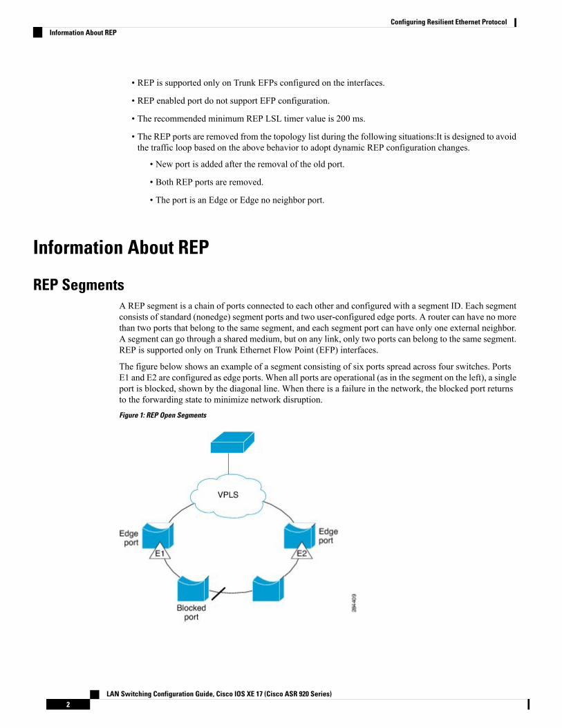
The figure below shows an example of a segment consisting of six ports spread across four switches. PortsE1 and E2 are configured as edge ports. When all ports are operational (as in the segment on the left), a singleport is blocked, shown by the diagonal line. When there is a failure in the network, the blocked port returnsto the forwarding state to minimize network disruption.
Figure 1: REP Open Segments
LAN Switching Configuration Guide, Cisco IOS XE 17 (Cisco ASR 920 Series)2
Configuring Resilient Ethernet ProtocolInformation About REP
The segment shown in the figure above is an open segment; there is no connectivity between the two edgeports. The REP segment cannot cause a bridging loop, and you can safely connect the segment edges to anynetwork. All hosts connected to routers inside the segment have two possible connections to the rest of thenetwork through the edge ports, but only one connection is accessible at any time. If a failure occurs on anysegment or on any port on a REP segment, REP unblocks all ports to ensure that connectivity is availablethrough the other gateway.
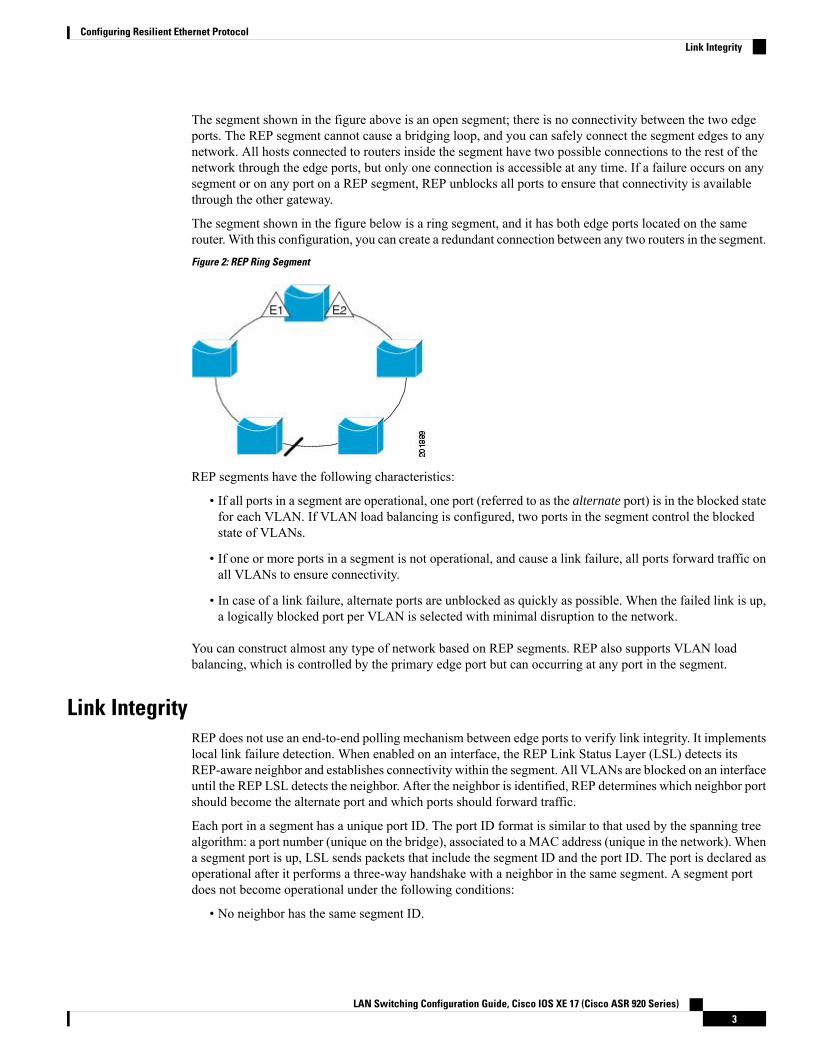
The segment shown in the figure below is a ring segment, and it has both edge ports located on the samerouter. With this configuration, you can create a redundant connection between any two routers in the segment.
Figure 2: REP Ring Segment
REP segments have the following characteristics:
• If all ports in a segment are operational, one port (referred to as the alternate port) is in the blocked statefor each VLAN. If VLAN load balancing is configured, two ports in the segment control the blockedstate of VLANs.
• If one or more ports in a segment is not operational, and cause a link failure, all ports forward traffic onall VLANs to ensure connectivity.
• In case of a link failure, alternate ports are unblocked as quickly as possible. When the failed link is up,a logically blocked port per VLAN is selected with minimal disruption to the network.
You can construct almost any type of network based on REP segments. REP also supports VLAN loadbalancing, which is controlled by the primary edge port but can occurring at any port in the segment.
Link IntegrityREP does not use an end-to-end polling mechanism between edge ports to verify link integrity. It implementslocal link failure detection. When enabled on an interface, the REP Link Status Layer (LSL) detects itsREP-aware neighbor and establishes connectivity within the segment. All VLANs are blocked on an interfaceuntil the REP LSL detects the neighbor. After the neighbor is identified, REP determines which neighbor portshould become the alternate port and which ports should forward traffic.
Each port in a segment has a unique port ID. The port ID format is similar to that used by the spanning treealgorithm: a port number (unique on the bridge), associated to a MAC address (unique in the network). Whena segment port is up, LSL sends packets that include the segment ID and the port ID. The port is declared asoperational after it performs a three-way handshake with a neighbor in the same segment. A segment portdoes not become operational under the following conditions:
• No neighbor has the same segment ID.
LAN Switching Configuration Guide, Cisco IOS XE 17 (Cisco ASR 920 Series)3
Configuring Resilient Ethernet ProtocolLink Integrity

• More than one neighbor has the same segment ID.
• The neighbor does not acknowledge the local port as a peer.
Each port creates an adjacency with its immediate neighbor. Once the neighbor adjacencies are created, theports negotiate to determine one blocked port for the segment, which is the alternate port. All other portsbecome unblocked. By default, REP packets are sent to a PortFast Bridge Protocol Data Unit (BPDU) classMAC address. The packets can also be sent to the Cisco multicast address, which at present is used only tosend blocked port advertisement (BPA) messages when there is a failure in the segment. The packets aredropped by devices not running REP.
Fast ConvergenceBecause REP runs on a physical-link basis and not on a per-VLAN basis, only one hello message is requiredfor all VLANs, thus reducing the load on the protocol. We recommend that you create VLANs consistentlyon all switches in a given segment and configure VLANs on REP trunk ports. To avoid the delay introducedby relaying messages in software, REP also allows some packets to be flooded to a regular multicast address.These messages operate at the hardware flood layer (HFL) and are flooded to the whole network, not just theREP segment. Switches that do not belong to the segment treat the messages as data traffic. You can controlflooding of these messages by configuring a dedicated administrative VLAN for the whole domain.
The estimated convergence recovery time is less than 200 milliseconds (ms) for the local segment.
VLAN Load BalancingOne edge port in a REP segment acts as the primary edge port and the other as the secondary edge port. It isthe primary edge port that always participates in VLAN load balancing in the segment. REP VLAN loadbalancing is achieved by blocking some VLANs at a configured alternate port and all other VLANs at theprimary edge port. When you configure VLAN load balancing, you can specify the alternate port using anyone of the following ways:
• By entering the port ID of the interface. To identify the port ID of a port in the segment, enter the showinterface rep detail command for the port.
• By entering the neighbor offset number of a port in the segment, which identifies the downstream neighborport of an edge port. The neighbor offset number range is -256 to +256; a value of 0 is invalid. Theprimary edge port has an offset number of 1; positive numbers above 1 identify downstream neighborsof the primary edge port. Negative numbers indicate the secondary edge port (offset number -1) and itsdownstream neighbors.
You configure offset numbers on the primary edge port by identifying a port’sdownstream position from the primary (or secondary) edge port. You cannotenter an offset value of 1 because 1 is the offset number of the primary edge port.
Note
• By entering the preferred keyword to select the port that you previously configured as the preferredalternate port in the rep segment preferred command.
LAN Switching Configuration Guide, Cisco IOS XE 17 (Cisco ASR 920 Series)4
Configuring Resilient Ethernet ProtocolFast Convergence
When the REP segment is complete, all VLANs are blocked. VLAN load balancing can be triggered in oneof the following two ways:
• You can manually trigger VLAN load balancing at any time by entering the rep preempt segmentsegment-id command on the router that has the primary edge port.
• You can configure a preempt delay time by entering the rep preempt delay seconds command. After alink failure and recovery, VLAN load balancing begins after the configured preemption time periodelapses. The delay timer restarts if another port fails before the time has elapsed.
A VLAN load balancing does not start working until triggered by either a manualintervention or a link failure and recovery.
Note
When VLAN load balancing is triggered, the primary edge port sends out a message to alert all interfaces inthe segment about the preemption. When the message is received by the secondary edge port, a message isgenerated in the network to notify the alternate port to block the set of VLANs specified in the message andto notify the primary edge port to block the remaining VLANs.
You can also configure a particular port in the segment to block all VLANs. VLAN load balancing is initiatedonly by the primary edge port and is not possible if the segment is not terminated by an edge port on eachend. The primary edge port determines the local VLAN load balancing configuration.
To reconfigure VLAN load balancing, you must reconfigure the primary edge port. When you change theVLAN-load balancing configuration, the primary edge port again waits for the rep preempt segment commandor for the configured preempt delay period after a port failure and recovery before executing the new VLANload balancing configuration. If you change an edge port to a regular segment port, the existing VLAN loadbalancing status does not change. Configuring a new edge port might cause a new topology configuration.
Spanning Tree Protocol InteractionREP does not interact with STP or with Flex Links but can coexist with both of them. A port that belongs toa segment is removed from spanning tree control, and STP BPDUs are not accepted or sent from segmentports. Therefore, STP cannot run on a segment.
To migrate from an STP ring configuration to a REP segment configuration, begin by configuring a singleport in the ring as part of the segment and continue by configuring contiguous ports to minimize the numberof segments. Each segment always contains a blocked port, so multiple segments mean multiple blocked portsand a potential loss of connectivity. You can configure the edge ports when the segment has been configuredin both directions up to the location of the edge ports.
REP PortsPorts in REP segments take one of following three roles or states: Failed, Open, or Alternate.
• A port configured as a regular segment port starts as a failed port.
• After neighbor adjacencies are determined, the port transitions to the alternate port state, blocking allVLANs on the interface. Blocked port negotiations occur, and when the segment settles, one blockedport remains in the alternate role, and all other ports become open ports.
LAN Switching Configuration Guide, Cisco IOS XE 17 (Cisco ASR 920 Series)5
Configuring Resilient Ethernet ProtocolSpanning Tree Protocol Interaction
• When a failure occurs in a link, all ports move to the failed state. When the alternate port receives thefailure notification, the port changes to the open state forwarding all VLANs.
A regular segment port converted to an edge port, or an edge port converted to a regular segment port, doesnot always result in a topology change. If you convert an edge port into a regular segment port, VLAN loadbalancing is not implemented unless it has been configured. For VLAN load balancing, you must configuretwo edge ports in the segment.
A segment port that is reconfigured as a spanning tree port restarts according to the spanning tree configuration.By default, this port is a designated blocking port. If the PortFast BPDU Guard Enhancement feature isconfigured or if STP is disabled, the port goes into the forwarding state.
REP Integrated with VPLSNormally, in a Virtual Private LAN Service (VPLS) network core, all nodes are connected in a full-meshtopology and each node has connectivity to all other nodes. In the full-mesh topology, there is no need for anode to retransmit data to another node. In Figure 3, the common ring provides a path where the packet canbe forwarded to another network provider edge (N-PE) router, breaking split horizon model.
REP emulates a common link connection the REP ring supports the VPLS full-mesh model, but maintainsthe split horizon properties so the super-loop does not exist. The emulated common link uses the Clusteringover the WAN (CWAN) line card, which is also used for the VPLS uplink. This emulated common linkforwards data from the ring to either the VPLS uplink or to the other side of the ring; blocks data coming fromthe VPLS core network; and handles access to pseudowire for Hierarchical-VPLS (H-VPLS) topologies.
Default REP ConfigurationREP is disabled on all interfaces. When enabled, the interface is a regular segment port unless it is configuredas an edge port.
When REP is enabled, the sending of segment topology change notices (STCNs) is disabled, all VLANs areblocked, and the administrative VLAN is VLAN 1.
When VLAN load balancing is enabled, the default is manual preemption with the delay timer disabled. IfVLAN load balancing is not configured, the default after manual preemption is to block all VLANs at theprimary edge port.
REP Segments and REP Administrative VLANsA segment is a collection of ports connected in a chain and configured with a segment ID. To configure REPsegments, you should configure the REP administrative VLAN (or use the default VLAN 1) and then addports to the segment in interface configuration mode. You should configure two edge ports in the segment,with one as the primary edge port and the other, by default, as the secondary edge port. A segment has onlyone primary edge port. If you configure two ports in a segment as primary edge ports, for example, ports ondifferent switches, REP selects one of them to serve as the primary edge port. You can also optionally configurewhere to send segment STCNs and VLAN load balancing. For more information about configuring REPAdministrative VLANs, see the Configuring the REP Administrative VLAN section.
REP Configuration GuidelinesFollow these guidelines when configuring REP:
LAN Switching Configuration Guide, Cisco IOS XE 17 (Cisco ASR 920 Series)6
Configuring Resilient Ethernet ProtocolREP Integrated with VPLS
• We recommend that you begin by configuring one port and then configure contiguous ports to minimizethe number of segments and the number of blocked ports.
• If more than two ports in a segment fail when no external neighbors are configured, one port goes intoa forwarding state for the data path to help maintain connectivity during configuration. In the show repinterface command output, the Port Role for this port shows as “Fail Logical Open”; the Port Role forthe other failed port shows as “Fail No Ext Neighbor”. When the external neighbors for the failed portsare configured, the ports go through the alternate port state transitions and eventually go to an open stateor remain as the alternate port, based on the alternate port selection mechanism.
• REP ports must be Layer 2 IEEE 802.1Q or Trunk EFP ports.
• We recommend that you configure all trunk ports in the segment with the same set of allowed VLANs.
• Be careful when configuring REP through a Telnet connection. Because REP blocks all VLANs untilanother REP interface sends a message to unblock it. You might lose connectivity to the router if youenable REP in a Telnet session that accesses the router through the same interface.
• You cannot run REP and STP on the same segment or interface.
• If you connect an STP network to a REP segment, be sure that the connection is at the segment edge.An STP connection that is not at the edge could cause a bridging loop because STP does not run on REPsegments. All STP BPDUs are dropped at REP interfaces.
• If REP is enabled on two ports on a router, both ports must be either regular segment ports or edge ports.REP ports follow these rules:
• If only one port on a router is configured in a segment, the port should be an edge port.• If two ports on a router belong to the same segment, both ports must be edge ports or must be regularsegment ports.
• If two ports on a router belong to the same segment and one is configured as an edge port and theother as a regular segment port (a misconfiguration), the edge port is treated as a regular segmentport.
• REP interfaces come up in a blocked state and remain in a blocked state until they are safe to be unblocked.You need to be aware of this status to avoid sudden connection losses.
• REP ports cannot be configured as one of the following port types:
• Switched Port Analyzer (SPAN) destination port• Tunnel port• Access port
• There can be a maximum of 22 REP segments per router.
REP Support on a Trunk EFPResilient Ethernet Protocol (REP) can be configured on Trunk EFP ports at the interface level on Cisco ASR920 Series Router. Trunk EFP ports can have several bridged VLAN services running on them. Trunk EFPsupports only 1000 VLANs. VLANs can be set to blocking and forwarding state on a Trunk EFP port. A usermust enable REP on a port. By default, REP is disabled on all ports.
LAN Switching Configuration Guide, Cisco IOS XE 17 (Cisco ASR 920 Series)7
Configuring Resilient Ethernet ProtocolREP Support on a Trunk EFP
REP Configurable TimersIn a ring network topology, the Fast Last Link Status (LSL) process detects a neighboring port and maintainsa connection with it. The timer on a port can be configured within 200-10000 ms to receive LSL frames. Ifno LSL frames are received from 200 to10000 ms from the neighboring port, the link between routers isconsidered as down. The tear-down operation and action is taken to bring up the link and restore traffic.
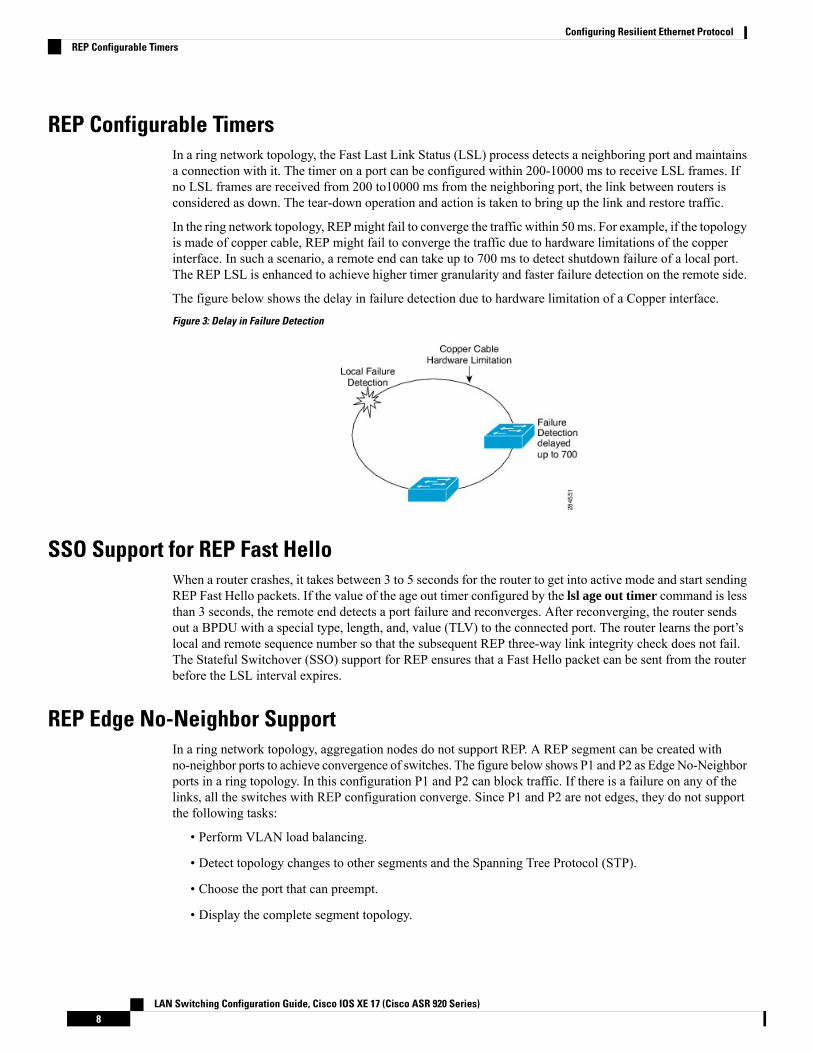
In the ring network topology, REPmight fail to converge the traffic within 50 ms. For example, if the topologyis made of copper cable, REP might fail to converge the traffic due to hardware limitations of the copperinterface. In such a scenario, a remote end can take up to 700 ms to detect shutdown failure of a local port.The REP LSL is enhanced to achieve higher timer granularity and faster failure detection on the remote side.
The figure below shows the delay in failure detection due to hardware limitation of a Copper interface.
Figure 3: Delay in Failure Detection
SSO Support for REP Fast HelloWhen a router crashes, it takes between 3 to 5 seconds for the router to get into active mode and start sendingREP Fast Hello packets. If the value of the age out timer configured by the lsl age out timer command is lessthan 3 seconds, the remote end detects a port failure and reconverges. After reconverging, the router sendsout a BPDU with a special type, length, and, value (TLV) to the connected port. The router learns the port’slocal and remote sequence number so that the subsequent REP three-way link integrity check does not fail.The Stateful Switchover (SSO) support for REP ensures that a Fast Hello packet can be sent from the routerbefore the LSL interval expires.
REP Edge No-Neighbor SupportIn a ring network topology, aggregation nodes do not support REP. A REP segment can be created withno-neighbor ports to achieve convergence of switches. The figure below shows P1 and P2 as Edge No-Neighborports in a ring topology. In this configuration P1 and P2 can block traffic. If there is a failure on any of thelinks, all the switches with REP configuration converge. Since P1 and P2 are not edges, they do not supportthe following tasks:
• Perform VLAN load balancing.
• Detect topology changes to other segments and the Spanning Tree Protocol (STP).
• Choose the port that can preempt.
• Display the complete segment topology.
LAN Switching Configuration Guide, Cisco IOS XE 17 (Cisco ASR 920 Series)8
Configuring Resilient Ethernet ProtocolREP Configurable Timers

The Edge No-Neighbor support enables defining a new type of edge that has an internal neighbor. In the figurebelow, P1 and P2 are configured as Edge No-Neighbor ports rather than intermediate segment ports. Theseports inherit properties of edge ports and overcome the limitations listed above. Thus, the Edge No-Neighborport (P1 or P2) can send theMultiple Spanning Tree (MST) protocol, a Topology Change Notification (TCN),and a REP TCN for another segment towards the aggregation switch.
Figure 4: Ring Topology with Edge No-Neighbor Ports
How to Configure REP
Configuring the REP Administrative VLANTo avoid the delay introduced by relaying messages that are related to link-failures or VLAN-blockingnotifications during VLAN load balancing, REP floods packets at the hardware flood layer (HFL) to a regularmulticast address. These messages are flooded to the whole network and not just the REP segment. You cancontrol flooding of these messages by configuring an administrative VLAN for the whole domain.
Follow these guidelines when configuring the REP administrative VLAN:
• There can be only one administrative VLAN on a router and on a segment. However, this is not enforcedby the software.
• If you do not configure an administrative VLAN, the default is VLAN 1.
• If you want to configure REP on an interface, ensure that the REP administrative VLAN is part of theTrunk EFP encapsulation list.
SUMMARY STEPS
1. enable
LAN Switching Configuration Guide, Cisco IOS XE 17 (Cisco ASR 920 Series)9
Configuring Resilient Ethernet ProtocolHow to Configure REP
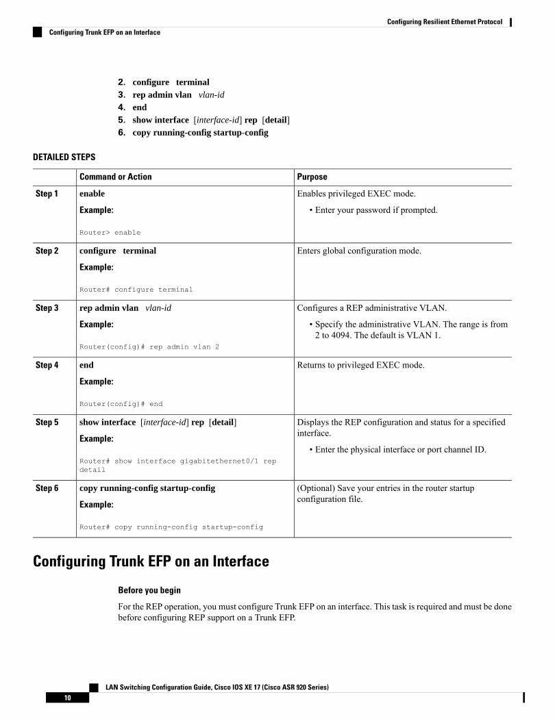
2. configure terminal3. rep admin vlan vlan-id
4. end5. show interface [interface-id] rep [detail]6. copy running-config startup-config
DETAILED STEPS
PurposeCommand or Action
Enables privileged EXEC mode.enableStep 1
Example: • Enter your password if prompted.
Router> enable
Enters global configuration mode.configure terminal
Example:
Step 2
Router# configure terminal
Configures a REP administrative VLAN.rep admin vlan vlan-idStep 3
Example: • Specify the administrative VLAN. The range is from2 to 4094. The default is VLAN 1.
Router(config)# rep admin vlan 2
Returns to privileged EXEC mode.end
Example:
Step 4
Router(config)# end
Displays the REP configuration and status for a specifiedinterface.
show interface [interface-id] rep [detail]
Example:
Step 5
• Enter the physical interface or port channel ID.Router# show interface gigabitethernet0/1 repdetail
(Optional) Save your entries in the router startupconfiguration file.
copy running-config startup-config
Example:
Step 6
Router# copy running-config startup-config
Configuring Trunk EFP on an Interface
Before you begin
For the REP operation, you must configure Trunk EFP on an interface. This task is required and must be donebefore configuring REP support on a Trunk EFP.
LAN Switching Configuration Guide, Cisco IOS XE 17 (Cisco ASR 920 Series)10
Configuring Resilient Ethernet ProtocolConfiguring Trunk EFP on an Interface

SUMMARY STEPS
1. enable2. configure terminal3. interface type number
4. service instance trunk service-instance-id ethernet5. encapsulation dot1q vlan range
6. rewrite ingress tag pop 1 symmetric7. bridge-domain from-encapsulation8. end
DETAILED STEPS
PurposeCommand or Action
Enables privileged EXEC mode.enableStep 1
Example: • Enter your password if prompted.Router> enable
Enters global configuration mode.configure terminal
Example:
Step 2
Router# configure terminal
Specifies the interface, and enters interface configurationmode.
interface type number
Example:
Step 3
• Enter the interface ID.Router(config)# interface GigabitEthernet 0/0/1
Configures a service instance on an interface and entersservice instance configuration mode.
service instance trunk service-instance-id ethernet
Example:
Step 4
Router(config-if)# service instance trunk 1ethernet
Defines the match criteria to be used to map dot1q framesingress on an interface to the appropriate service instance.
encapsulation dot1q vlan range
Example:
Step 5
• The range of VLAN-IDs is from 1 to 20.Router(config-if-srv)# encapsulation dot1q vlan 10
Specifies the encapsulation adjustment to be performed onthe frames ingress to the service instance.
rewrite ingress tag pop 1 symmetric
Example:
Step 6
Router(config-if-srv)# rewrite ingress tag pop 1symmetric
Derives bridge domains from encapsulation.bridge-domain from-encapsulation
Example:
Step 7
Router(config-if-srv)# bridge-domainfrom-encapsulation
LAN Switching Configuration Guide, Cisco IOS XE 17 (Cisco ASR 920 Series)11
Configuring Resilient Ethernet ProtocolConfiguring Trunk EFP on an Interface

PurposeCommand or Action
Returns to privileged EXEC mode.end
Example:
Step 8
Router (config-if-srv)end
Configuring REP Support on a Trunk EFP
Before you begin
For the REP operation, you must enable REP on each segment interface and identify the segment ID. Thistask is required and must be done before other REP configurations. You must also configure a primary andsecondary edge port on each segment. All other steps are optional.
SUMMARY STEPS
1. enable2. configure terminal3. interface interface type number
4. rep segment segment-id [edge [primary]] [preferred]5. rep stcn {interface type number | segment id-list | stp}6. rep block port {id port-id | neighbor-offset | preferred} vlan {vlan-list | all}7. rep preempt delay seconds
8. end9. show interface type number rep [detail]10. copy running-config startup-config
DETAILED STEPS
PurposeCommand or Action
Enables privileged EXEC mode.enableStep 1
Example: • Enter your password if prompted.Router> enable
Enters global configuration mode.configure terminal
Example:
Step 2
Router# configure terminal
Specifies the interface and enters interface configurationmode.
interface interface type number
Example:
Step 3
• Enter the interface type and number.Router(config)# interface GigabitEthernet 0/0/1
Enables REP on the interface and identifies a segmentnumber.
rep segment segment-id [edge [primary]] [preferred]
Example:
Step 4
• The segment ID range is from 1 to 1024.Router(config-if)# rep segment 3 edge preferred
LAN Switching Configuration Guide, Cisco IOS XE 17 (Cisco ASR 920 Series)12
Configuring Resilient Ethernet ProtocolConfiguring REP Support on a Trunk EFP
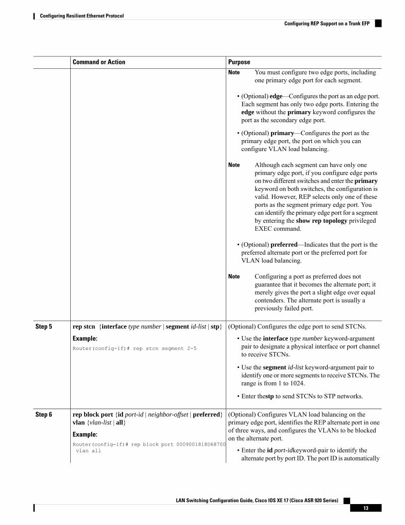
PurposeCommand or Action
You must configure two edge ports, includingone primary edge port for each segment.
Note
• (Optional) edge—Configures the port as an edge port.Each segment has only two edge ports. Entering theedge without the primary keyword configures theport as the secondary edge port.
• (Optional) primary—Configures the port as theprimary edge port, the port on which you canconfigure VLAN load balancing.
Although each segment can have only oneprimary edge port, if you configure edge portson two different switches and enter the primarykeyword on both switches, the configuration isvalid. However, REP selects only one of theseports as the segment primary edge port. Youcan identify the primary edge port for a segmentby entering the show rep topology privilegedEXEC command.
Note
• (Optional) preferred—Indicates that the port is thepreferred alternate port or the preferred port forVLAN load balancing.
Configuring a port as preferred does notguarantee that it becomes the alternate port; itmerely gives the port a slight edge over equalcontenders. The alternate port is usually apreviously failed port.
Note
(Optional) Configures the edge port to send STCNs.rep stcn {interface type number | segment id-list | stp}Step 5
Example: • Use the interface type number keyword-argumentpair to designate a physical interface or port channelto receive STCNs.
Router(config-if)# rep stcn segment 2-5
• Use the segment id-list keyword-argument pair toidentify one or more segments to receive STCNs. Therange is from 1 to 1024.
• Enter thestp to send STCNs to STP networks.
(Optional) Configures VLAN load balancing on theprimary edge port, identifies the REP alternate port in one
rep block port {id port-id | neighbor-offset | preferred}vlan {vlan-list | all}
Step 6
of three ways, and configures the VLANs to be blockedon the alternate port.Example:
Router(config-if)# rep block port 0009001818D68700vlan all • Enter the id port-idkeyword-pair to identify the
alternate port by port ID. The port ID is automatically
LAN Switching Configuration Guide, Cisco IOS XE 17 (Cisco ASR 920 Series)13
Configuring Resilient Ethernet ProtocolConfiguring REP Support on a Trunk EFP
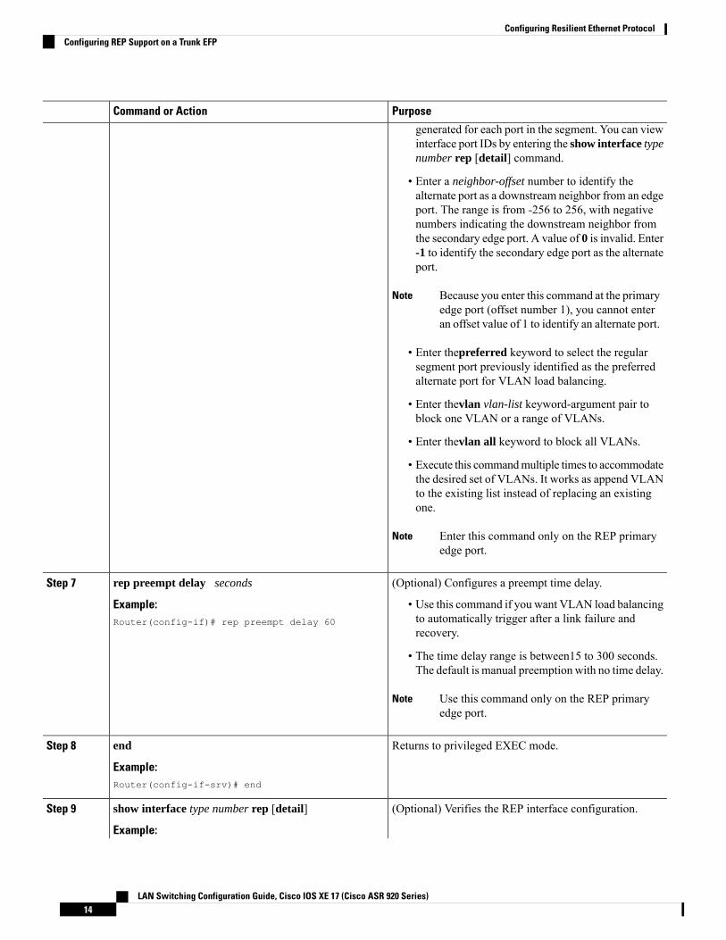
PurposeCommand or Action
generated for each port in the segment. You can viewinterface port IDs by entering the show interface typenumber rep [detail] command.
• Enter a neighbor-offset number to identify thealternate port as a downstream neighbor from an edgeport. The range is from -256 to 256, with negativenumbers indicating the downstream neighbor fromthe secondary edge port. A value of 0 is invalid. Enter-1 to identify the secondary edge port as the alternateport.
Because you enter this command at the primaryedge port (offset number 1), you cannot enteran offset value of 1 to identify an alternate port.
Note
• Enter thepreferred keyword to select the regularsegment port previously identified as the preferredalternate port for VLAN load balancing.
• Enter thevlan vlan-list keyword-argument pair toblock one VLAN or a range of VLANs.
• Enter thevlan all keyword to block all VLANs.
• Execute this commandmultiple times to accommodatethe desired set of VLANs. It works as append VLANto the existing list instead of replacing an existingone.
Enter this command only on the REP primaryedge port.
Note
(Optional) Configures a preempt time delay.rep preempt delay secondsStep 7
Example: • Use this command if you want VLAN load balancingto automatically trigger after a link failure andrecovery.
Router(config-if)# rep preempt delay 60
• The time delay range is between15 to 300 seconds.The default is manual preemption with no time delay.
Use this command only on the REP primaryedge port.
Note
Returns to privileged EXEC mode.end
Example:
Step 8
Router(config-if-srv)# end
(Optional) Verifies the REP interface configuration.show interface type number rep [detail]Step 9
Example:
LAN Switching Configuration Guide, Cisco IOS XE 17 (Cisco ASR 920 Series)14
Configuring Resilient Ethernet ProtocolConfiguring REP Support on a Trunk EFP
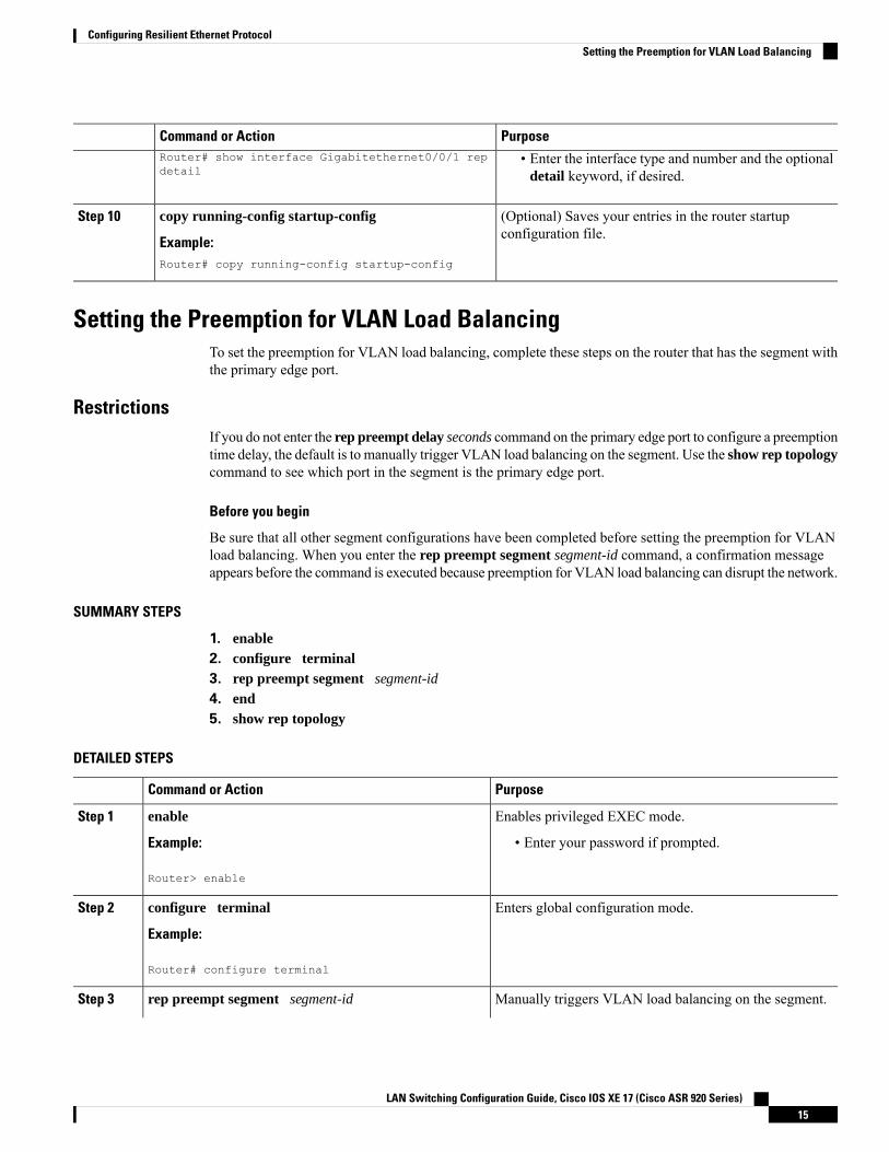
PurposeCommand or ActionRouter# show interface Gigabitethernet0/0/1 repdetail
• Enter the interface type and number and the optionaldetail keyword, if desired.
(Optional) Saves your entries in the router startupconfiguration file.
copy running-config startup-config
Example:
Step 10
Router# copy running-config startup-config
Setting the Preemption for VLAN Load BalancingTo set the preemption for VLAN load balancing, complete these steps on the router that has the segment withthe primary edge port.
RestrictionsIf you do not enter the rep preempt delay seconds command on the primary edge port to configure a preemptiontime delay, the default is to manually trigger VLAN load balancing on the segment. Use the show rep topologycommand to see which port in the segment is the primary edge port.
Before you begin
Be sure that all other segment configurations have been completed before setting the preemption for VLANload balancing. When you enter the rep preempt segment segment-id command, a confirmation messageappears before the command is executed because preemption for VLAN load balancing can disrupt the network.
SUMMARY STEPS
1. enable2. configure terminal3. rep preempt segment segment-id
4. end5. show rep topology
DETAILED STEPS
PurposeCommand or Action
Enables privileged EXEC mode.enableStep 1
Example: • Enter your password if prompted.
Router> enable
Enters global configuration mode.configure terminal
Example:
Step 2
Router# configure terminal
Manually triggers VLAN load balancing on the segment.rep preempt segment segment-idStep 3
LAN Switching Configuration Guide, Cisco IOS XE 17 (Cisco ASR 920 Series)15
Configuring Resilient Ethernet ProtocolSetting the Preemption for VLAN Load Balancing

PurposeCommand or Action
Example: • Enter the segment ID.
Router(config)# rep preempt segment 1 You will be asked to confirm the action beforethe command is executed.
Note
Returns to privileged EXEC mode.end
Example:
Step 4
Router(config)# end
Displays the REP topology information.show rep topology
Example:
Step 5
Router# show rep topology
Configuring SNMP Traps for REPYou can configure the router to send REP-specific traps to notify the Simple Network Management Protocol(SNMP) server of link operational status changes and any port role changes.
SUMMARY STEPS
1. enable2. configure terminal3. snmp mib rep trap-rate value
4. end5. show running-config6. copy running-config startup-config
DETAILED STEPS
PurposeCommand or Action
Enables privileged EXEC mode.enableStep 1
Example: • Enter your password if prompted.Router> enable
Enters global configuration mode.configure terminal
Example:
Step 2
Router# configure terminal
Enables the router to send REP traps, and sets the numberof traps sent per second.
snmp mib rep trap-rate value
Example:
Step 3
• Enter the number of traps sent per second. The rangeis from 0 to 1000. The default is 0 (no limit imposed;a trap is sent at every occurrence).
Router(config)# snmp mib rep trap-rate 500
LAN Switching Configuration Guide, Cisco IOS XE 17 (Cisco ASR 920 Series)16
Configuring Resilient Ethernet ProtocolConfiguring SNMP Traps for REP
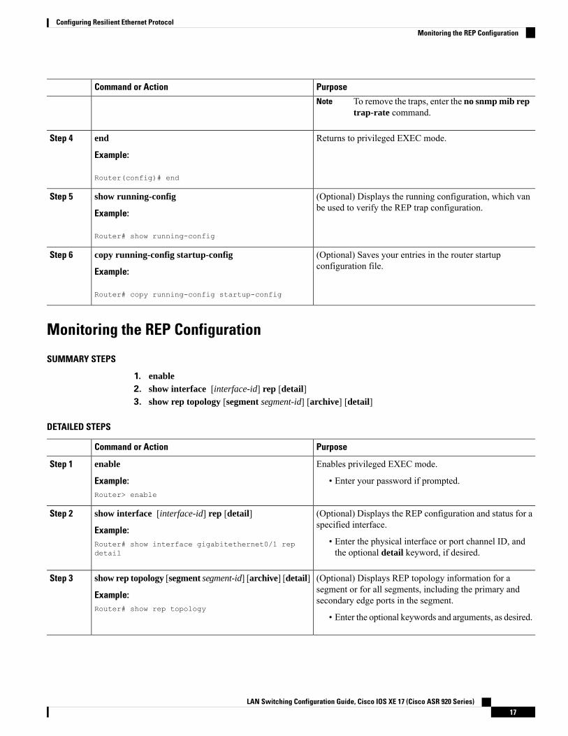
PurposeCommand or Action
To remove the traps, enter the no snmp mib reptrap-rate command.
Note
Returns to privileged EXEC mode.end
Example:
Step 4
Router(config)# end
(Optional) Displays the running configuration, which vanbe used to verify the REP trap configuration.
show running-config
Example:
Step 5
Router# show running-config
(Optional) Saves your entries in the router startupconfiguration file.
copy running-config startup-config
Example:
Step 6
Router# copy running-config startup-config
Monitoring the REP Configuration
SUMMARY STEPS
1. enable2. show interface [interface-id] rep [detail]3. show rep topology [segment segment-id] [archive] [detail]
DETAILED STEPS
PurposeCommand or Action
Enables privileged EXEC mode.enableStep 1
Example: • Enter your password if prompted.Router> enable
(Optional) Displays the REP configuration and status for aspecified interface.
show interface [interface-id] rep [detail]
Example:
Step 2
• Enter the physical interface or port channel ID, andthe optional detail keyword, if desired.
Router# show interface gigabitethernet0/1 repdetail
(Optional) Displays REP topology information for asegment or for all segments, including the primary andsecondary edge ports in the segment.
show rep topology [segment segment-id] [archive] [detail]
Example:Router# show rep topology
Step 3
• Enter the optional keywords and arguments, as desired.
LAN Switching Configuration Guide, Cisco IOS XE 17 (Cisco ASR 920 Series)17
Configuring Resilient Ethernet ProtocolMonitoring the REP Configuration
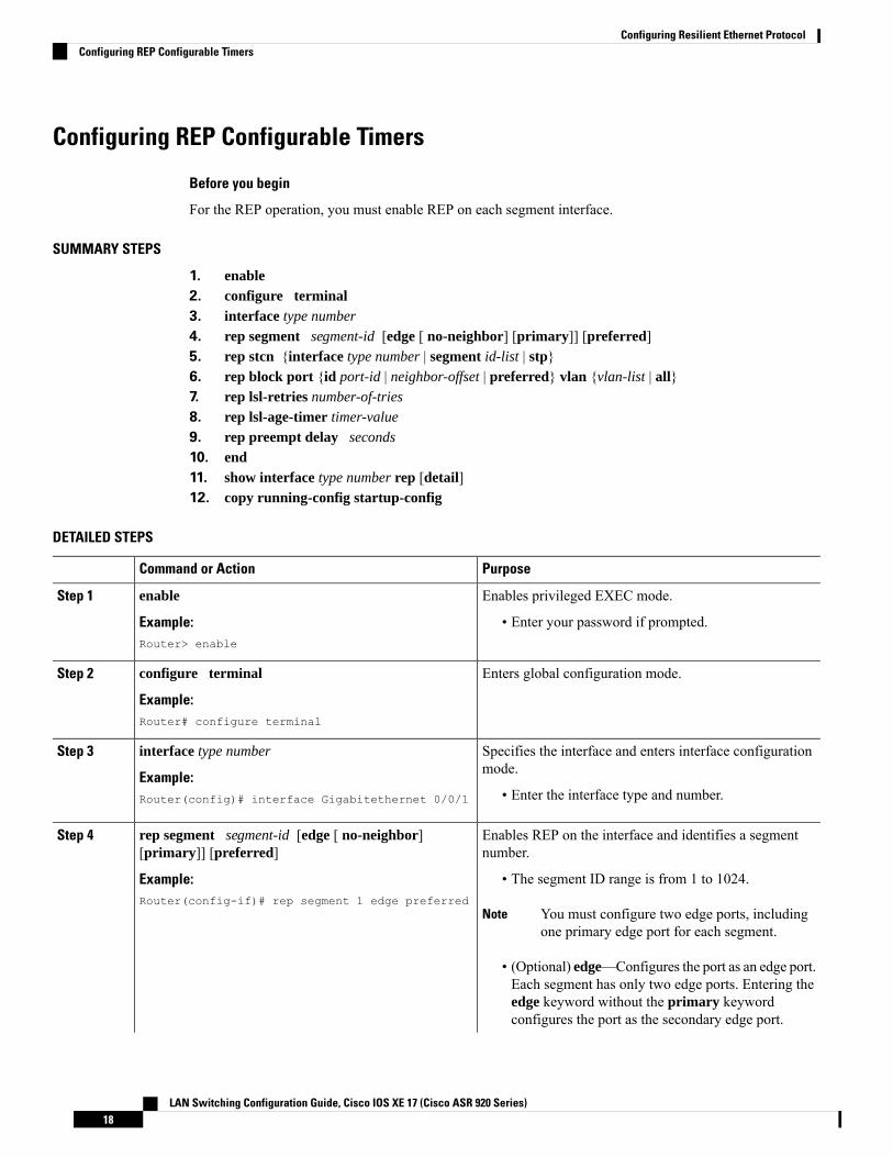
Configuring REP Configurable Timers
Before you begin
For the REP operation, you must enable REP on each segment interface.
SUMMARY STEPS
1. enable2. configure terminal3. interface type number
4. rep segment segment-id [edge [ no-neighbor] [primary]] [preferred]5. rep stcn {interface type number | segment id-list | stp}6. rep block port {id port-id | neighbor-offset | preferred} vlan {vlan-list | all}7. rep lsl-retries number-of-tries
8. rep lsl-age-timer timer-value
9. rep preempt delay seconds
10. end11. show interface type number rep [detail]12. copy running-config startup-config
DETAILED STEPS
PurposeCommand or Action
Enables privileged EXEC mode.enableStep 1
Example: • Enter your password if prompted.Router> enable
Enters global configuration mode.configure terminal
Example:
Step 2
Router# configure terminal
Specifies the interface and enters interface configurationmode.
interface type number
Example:
Step 3
• Enter the interface type and number.Router(config)# interface Gigabitethernet 0/0/1
Enables REP on the interface and identifies a segmentnumber.
rep segment segment-id [edge [ no-neighbor][primary]] [preferred]
Step 4
Example: • The segment ID range is from 1 to 1024.Router(config-if)# rep segment 1 edge preferred
You must configure two edge ports, includingone primary edge port for each segment.
Note
• (Optional) edge—Configures the port as an edge port.Each segment has only two edge ports. Entering theedge keyword without the primary keywordconfigures the port as the secondary edge port.
LAN Switching Configuration Guide, Cisco IOS XE 17 (Cisco ASR 920 Series)18
Configuring Resilient Ethernet ProtocolConfiguring REP Configurable Timers

PurposeCommand or Action
• (Optional)no-neighbor—Configures the segmentedge as one with no external REP neighbor on a port.
• (Optional) primary—Configures the port as theprimary edge port, the port on which you canconfigure VLAN load balancing.
Although each segment can have only oneprimary edge port, if you configure edge portson two different switches and enter the primarykeyword on both switches, the configuration isvalid. However, REP selects only one of theseports as the segment primary edge port. Youcan identify the primary edge port for a segmentby entering the show rep topology privilegedEXEC command.
Note
• (Optional) preferred—Indicates that the port is thepreferred alternate port or the preferred port forVLAN load balancing.
Configuring a port as preferred does notguarantee that it becomes the alternate port; itmerely gives the port a slight edge over equalcontenders. The alternate port is usually apreviously failed port.
Note
(Optional) Configures the edge port to send STCNs.rep stcn {interface type number | segment id-list | stp}Step 5
Example: • Use the interface type number keyword andarguments pair to designate a physical interface orport channel to receive STCNs.
Router(config-if)# rep stcn segment 2-5
• Use the segment id-list keyword and arguments pairto identify one or more segments to receive STCNs.The range is from 1 to 1024.
• Enter the stp keyword to send STCNs to STPnetworks.
(Optional) Configures VLAN load balancing on theprimary edge port, identifies the REP alternate port in one
rep block port {id port-id | neighbor-offset | preferred}vlan {vlan-list | all}
Step 6
of three ways, and configures VLANs to be blocked onthe alternate port.Example:
Router(config-if)# rep block port 0009001818D68700vlan all • Enter the id port-id keyword and arguments pair to
identify the alternate port by port ID. The port ID isautomatically generated for each port in the segment.You can view interface port IDs by entering the showinterface type number rep [detail] command.
LAN Switching Configuration Guide, Cisco IOS XE 17 (Cisco ASR 920 Series)19
Configuring Resilient Ethernet ProtocolConfiguring REP Configurable Timers
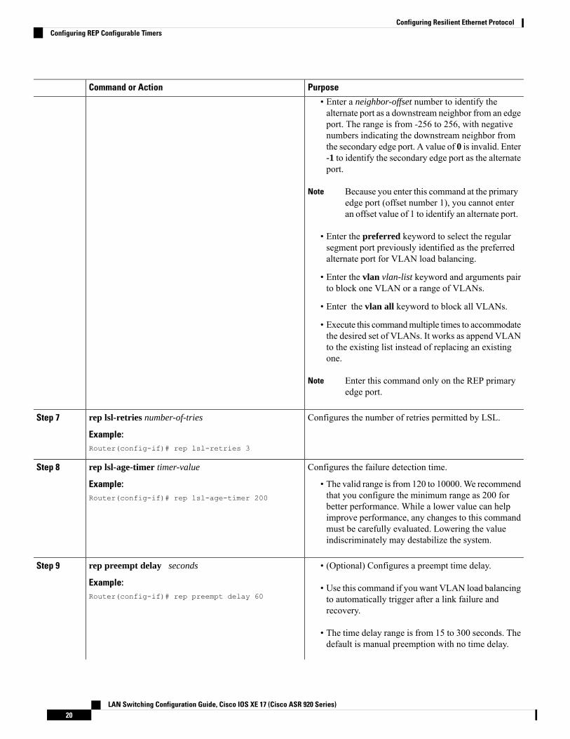
PurposeCommand or Action
• Enter a neighbor-offset number to identify thealternate port as a downstream neighbor from an edgeport. The range is from -256 to 256, with negativenumbers indicating the downstream neighbor fromthe secondary edge port. A value of 0 is invalid. Enter-1 to identify the secondary edge port as the alternateport.
Because you enter this command at the primaryedge port (offset number 1), you cannot enteran offset value of 1 to identify an alternate port.
Note
• Enter the preferred keyword to select the regularsegment port previously identified as the preferredalternate port for VLAN load balancing.
• Enter the vlan vlan-list keyword and arguments pairto block one VLAN or a range of VLANs.
• Enter the vlan all keyword to block all VLANs.
• Execute this commandmultiple times to accommodatethe desired set of VLANs. It works as append VLANto the existing list instead of replacing an existingone.
Enter this command only on the REP primaryedge port.
Note
Configures the number of retries permitted by LSL.rep lsl-retries number-of-tries
Example:
Step 7
Router(config-if)# rep lsl-retries 3
Configures the failure detection time.rep lsl-age-timer timer-valueStep 8
Example: • The valid range is from 120 to 10000.We recommendthat you configure the minimum range as 200 forRouter(config-if)# rep lsl-age-timer 200better performance. While a lower value can helpimprove performance, any changes to this commandmust be carefully evaluated. Lowering the valueindiscriminately may destabilize the system.
rep preempt delay secondsStep 9 • (Optional) Configures a preempt time delay.
Example: • Use this command if you want VLAN load balancingto automatically trigger after a link failure andrecovery.
Router(config-if)# rep preempt delay 60
• The time delay range is from 15 to 300 seconds. Thedefault is manual preemption with no time delay.
LAN Switching Configuration Guide, Cisco IOS XE 17 (Cisco ASR 920 Series)20
Configuring Resilient Ethernet ProtocolConfiguring REP Configurable Timers
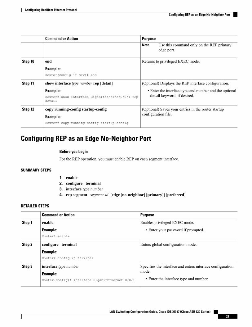
PurposeCommand or Action
Use this command only on the REP primaryedge port.
Note
Returns to privileged EXEC mode.end
Example:
Step 10
Router(config-if-srv)# end
(Optional) Displays the REP interface configuration.show interface type number rep [detail]Step 11
Example: • Enter the interface type and number and the optionaldetail keyword, if desired.Router# show interface Gigabitethernet0/0/1 rep
detail
(Optional) Saves your entries in the router startupconfiguration file.
copy running-config startup-config
Example:
Step 12
Router# copy running-config startup-config
Configuring REP as an Edge No-Neighbor Port
Before you begin
For the REP operation, you must enable REP on each segment interface.
SUMMARY STEPS
1. enable2. configure terminal3. interface type number
4. rep segment segment-id [edge [no-neighbor] [primary]] [preferred]
DETAILED STEPS
PurposeCommand or Action
Enables privileged EXEC mode.enableStep 1
Example: • Enter your password if prompted.Router> enable
Enters global configuration mode.configure terminal
Example:
Step 2
Router# configure terminal
Specifies the interface and enters interface configurationmode.
interface type number
Example:
Step 3
• Enter the interface type and number.Router(config)# interface GigabitEthernet 0/0/1
LAN Switching Configuration Guide, Cisco IOS XE 17 (Cisco ASR 920 Series)21
Configuring Resilient Ethernet ProtocolConfiguring REP as an Edge No-Neighbor Port
PurposeCommand or Action
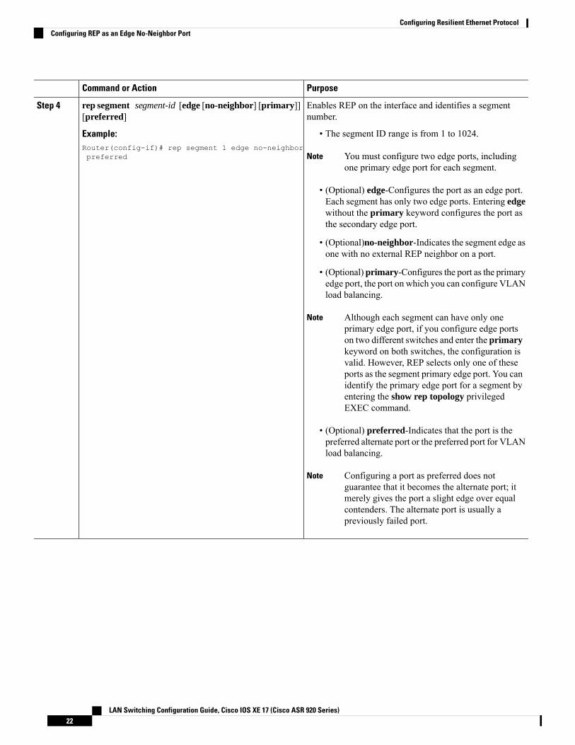
Enables REP on the interface and identifies a segmentnumber.
rep segment segment-id [edge [no-neighbor] [primary]][preferred]
Step 4
Example: • The segment ID range is from 1 to 1024.Router(config-if)# rep segment 1 edge no-neighborpreferred You must configure two edge ports, including
one primary edge port for each segment.Note
• (Optional) edge-Configures the port as an edge port.Each segment has only two edge ports. Entering edgewithout the primary keyword configures the port asthe secondary edge port.
• (Optional)no-neighbor-Indicates the segment edge asone with no external REP neighbor on a port.
• (Optional) primary-Configures the port as the primaryedge port, the port on which you can configure VLANload balancing.
Although each segment can have only oneprimary edge port, if you configure edge portson two different switches and enter the primarykeyword on both switches, the configuration isvalid. However, REP selects only one of theseports as the segment primary edge port. You canidentify the primary edge port for a segment byentering the show rep topology privilegedEXEC command.
Note
• (Optional) preferred-Indicates that the port is thepreferred alternate port or the preferred port for VLANload balancing.
Configuring a port as preferred does notguarantee that it becomes the alternate port; itmerely gives the port a slight edge over equalcontenders. The alternate port is usually apreviously failed port.
Note
LAN Switching Configuration Guide, Cisco IOS XE 17 (Cisco ASR 920 Series)22
Configuring Resilient Ethernet ProtocolConfiguring REP as an Edge No-Neighbor Port
Example
Configuration Examples for REP
Configuring the REP Administrative VLANThis example shows how to configure the administrative VLAN as VLAN 100.
Router# configure terminalRouter(config)# rep admin vlan 100Router(config-if)# end
Configuring REP Support on a Trunk EFPThis example shows how to configure REP support on a Trunk EFP. An interface is configured as the primaryedge port for segment 1 to send STCNs to segments 2 through 5; the alternate port is configured as the portwith port ID 0009001818D68700 to block all VLANs after a preemption delay of 60 seconds after a segmentport failure and recovery.
Router# configure terminalRouter(config)# interface gigabitethernet0/0/1Router(config-if)# rep segment 1 edge primaryRouter(config-if)# rep stcn segment 2-5Router(config-if)# rep block port id 0009001818D68700 vlan allRouter(config-if)# rep preempt delay 60Router(config-if)# service instance trunk 1 ethernetRouter(config-if-srv)# encapsulation dot1qRouter(config-if-srv)# rewrite ingress tag pop 1 symmetricRouter(config-if-srv)# bridge-domain from-encapsulationRouter(config-if-srv)# end
This example shows how to configure the VLAN blocking configuration as shown in the figure below. Thealternate port is the neighbor with neighbor offset number 4. After manual preemption, VLANs 100 to 200are blocked at this port and all other VLANs are blocked at the primary edge port E1 (Gigabit Ethernet port0/0/1).
LAN Switching Configuration Guide, Cisco IOS XE 17 (Cisco ASR 920 Series)23
Configuring Resilient Ethernet ProtocolConfiguration Examples for REP

Figure 5: Example of VLAN Blocking
Router# configure terminalRouter(config)# interface gigabitethernet0/0/1Router(config-if)# rep segment 1 edge primaryRouter(config-if)# rep block port 4 vlan 100-200Router(config-if)# end
Setting the Preemption for VLAN Load BalancingRouter>endRouter# configure terminalRouter(config)rep preempt segment 1Router(config)# end
Configuring SNMP Traps for REPThis example shows how to configure the router to send REP traps at a rate of 10 traps per second:Router> enableRouter# configure terminalRouter(config)# snmp mib rep trap-rate 10Router(config)# end
Monitoring the REP ConfigurationThe following is sample output of the show interface rep detail command. Use the show interface rep detailcommand on one of the REP interfaces to monitor and verify the REP configuration.
Router# show interface GigabitEthernet 0/0/1 rep detail
GigabitEthernet0/1 REP enabledSegment-id: 2 (Edge)PortID: 00010019E7144680Preferred flag: NoOperational Link Status: TWO_WAYCurrent Key: 0002001121A2D5800E4DPort Role: OpenBlocked Vlan: <empty>Admin-vlan: 100Preempt Delay Timer: disabledLoad-balancing block port: none
LAN Switching Configuration Guide, Cisco IOS XE 17 (Cisco ASR 920 Series)24
Configuring Resilient Ethernet ProtocolSetting the Preemption for VLAN Load Balancing
Load-balancing block vlan: noneSTCN Propagate to: noneLSL PDU rx: 3322, tx: 1722HFL PDU rx: 32, tx: 5BPA TLV rx: 16849, tx: 508BPA (STCN, LSL) TLV rx: 0, tx: 0BPA (STCN, HFL) TLV rx: 0, tx: 0EPA-ELECTION TLV rx: 118, tx: 118EPA-COMMAND TLV rx: 0, tx: 0EPA-INFO TLV rx: 4214, tx: 4190
Configuring REP Configurable TimersRouter# configure terminalRouter(config)# interface GigabitEthernet 0/0/4Router(config-if)# rep segment 4 edge preferredRouter(config-if)# rep stcn segment 2-5Router(config-if)# rep block port 0009001818D68700 vlan allRouter(config-if)# rep lsl-retries 3Router(config-if)# rep lsl-age-timer 200Router(config-if)# rep preempt delay 300Router(config-if)# exitRouter# show interface GigabitEthernet 0/0/1 rep detailRouter# copy running-config startup-config
Configuring REP Edge No-Neighbor SupportRouter> enableRouter# configure terminalRouter(config)# interface GigabitEthernet0/2Router(config-if)# rep segment t1 edge no-neighbor primary
Additional ReferencesRelated Documents
Document TitleRelated Topic
Cisco IOS Master Commands List, All ReleasesCisco IOS commands
Cisco IOS LAN Switching Command ReferenceLAN Switching commands: complete command syntax,command modes, command history, defaults, usageguidelines, and examples.
Spanning Tree Protocol (STP)/802.1DIntroduction to spanning tree protocols
Spanning Tree PortFast BPDU GuardEnhancement
Spanning Tree PortFast BPDU Guard Enhancementfeature
LAN Switching Configuration Guide, Cisco IOS XE 17 (Cisco ASR 920 Series)25
Configuring Resilient Ethernet ProtocolConfiguring REP Configurable Timers
Technical Assistance
LinkDescription
http://www.cisco.com/cisco/web/support/index.htmlTheCisco Support andDocumentationwebsite providesonline resources to download documentation, software,and tools. Use these resources to install and configurethe software and to troubleshoot and resolve technicalissues with Cisco products and technologies. Access tomost tools on the Cisco Support and Documentationwebsite requires a Cisco.com user ID and password.
Feature Information for Resilient Ethernet ProtocolThe following table provides release information about the feature or features described in this module. Thistable lists only the software release that introduced support for a given feature in a given software releasetrain. Unless noted otherwise, subsequent releases of that software release train also support that feature.
Use Cisco Feature Navigator to find information about platform support and Cisco software image support.To access Cisco Feature Navigator, go to www.cisco.com/go/cfn. An account on Cisco.com is not required.
Table 1: Feature Information for Resilient Ethernet Protocol
Feature InformationReleasesFeature Name
This feature was introduced on the Cisco ASR 920Series Aggregation Services Router(ASR-920-12CZ-A, ASR-920-12CZ-D,ASR-920-4SZ-A, ASR-920-4SZ-D).
Cisco IOS XE Release3.13.0S
Resilient EthernetProtocol
LAN Switching Configuration Guide, Cisco IOS XE 17 (Cisco ASR 920 Series)26
Configuring Resilient Ethernet ProtocolFeature Information for Resilient Ethernet Protocol
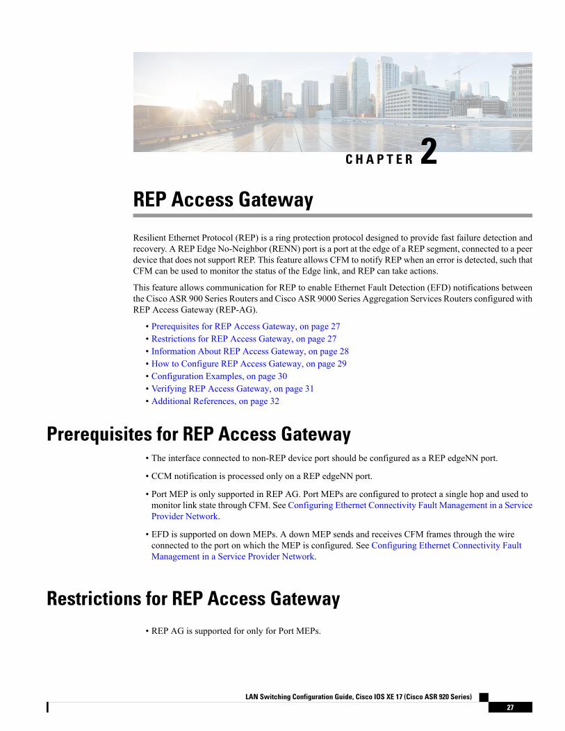
C H A P T E R 2REP Access Gateway
Resilient Ethernet Protocol (REP) is a ring protection protocol designed to provide fast failure detection andrecovery. A REP Edge No-Neighbor (RENN) port is a port at the edge of a REP segment, connected to a peerdevice that does not support REP. This feature allows CFM to notify REP when an error is detected, such thatCFM can be used to monitor the status of the Edge link, and REP can take actions.
This feature allows communication for REP to enable Ethernet Fault Detection (EFD) notifications betweenthe Cisco ASR 900 Series Routers and Cisco ASR 9000 Series Aggregation Services Routers configured withREP Access Gateway (REP-AG).
• Prerequisites for REP Access Gateway, on page 27• Restrictions for REP Access Gateway, on page 27• Information About REP Access Gateway, on page 28• How to Configure REP Access Gateway, on page 29• Configuration Examples, on page 30• Verifying REP Access Gateway, on page 31• Additional References, on page 32
Prerequisites for REP Access Gateway• The interface connected to non-REP device port should be configured as a REP edgeNN port.
• CCM notification is processed only on a REP edgeNN port.
• Port MEP is only supported in REP AG. Port MEPs are configured to protect a single hop and used tomonitor link state through CFM. See Configuring Ethernet Connectivity Fault Management in a ServiceProvider Network.
• EFD is supported on down MEPs. A down MEP sends and receives CFM frames through the wireconnected to the port on which the MEP is configured. See Configuring Ethernet Connectivity FaultManagement in a Service Provider Network.
Restrictions for REP Access Gateway• REP AG is supported for only for Port MEPs.
LAN Switching Configuration Guide, Cisco IOS XE 17 (Cisco ASR 920 Series)27
• When a link down is observed between the REP and Non-REP device, the convergence time is greaterwith a Copper connection.
• EFD is supported on Port MEPs and EFP MEPs.
• CCM interval for MAs on which EFD is supported is limited.
• EFD is not supported on Trunk EFPs.
• EFD notifications are only supported for a single client per MA. EFD notifications are not supported forboth G-8032 and REP simultaneously.
• Only a single MEP can be configured on a the interface or EFP for EFD.
• REP Edge No-Neighbour (ENN) configured ports receiving Link Status Layer (LSL) frames from thepeer node will automatically be converted to REP ports.
You will see the log message %REP-6-AUTOCONFIG: Interface GigabitEthernet< > automaticallyconfigured to the REP device.
• REP is supported on port-channel interface, without efd notify rep (CCM).
• The convergence time is between 100miliseconds to 200miliseconds.
Information About REP Access GatewayIn a network when a link failure occurs, a Non-REP device network (access gateway) directly connected toREP network sends failure notification, so that REP network can reroute the traffic to alternate route. But,access devices supporting REP Edge No-Neighbor (REP ENN) only support one interface configured as aREP Edge No-Neighbor port resulting in an unsupported architecture with the REP Access Gateway (REPAG) device.
Fast failure detection can be established by enabling communication between Connectivity Fault Manager(CFM) and REP. CFM on the edge ports can notify REP if any failures are detected on the monitored links,allowing the appropriate re-convergence actions to be taken.
The mechanism for the communication is for REP to register as an Ethernet Fault Detection (EFD) client, sothat any CFM defects above a configurable threshold triggers a notification to REP.
To trigger EFD notifications on the router, CFM must be configured.Note
REP Access Gateway EnhancementsIn a network where a REP and non-REP devices are connected and when a link failure occurs, a Non-REPdevice network (access gateway) directly connected to REP network sends failure notification, so that REPnetwork can reroute the traffic to an alternate route. But, access devices supporting REP Edge No-Neighbor(REP ENN) only support one interface configured as a REPEdgeNo-Neighbor port, resulting in an unsupportedarchitecture with the REP Access Gateway (REP AG) device.
LAN Switching Configuration Guide, Cisco IOS XE 17 (Cisco ASR 920 Series)28
REP Access GatewayInformation About REP Access Gateway
Fast failure detection in a REP-AG configured device can be achieved by enabling communication betweenConnectivity Fault Manager (CFM) and REP. CFM on the edge ports can notify REP if any failure is detectedon the monitored links, allowing the appropriate re-convergence actions to be taken.
The mechanism for the communication is for REP to register as an Ethernet Fault Detection (EFD) client, sothat any CFM defects above a configurable threshold triggers a notification to REP.
How to Configure REP Access Gateway
Enabling EFD Notifications
Before you begin
CFM IEEE must be enabled before enabling EFD notifications. For information, see Configuring EthernetConnectivity Fault Management in a Service Provider Network.
For information on CFM configuration, see Carrier Ethernet Configuration Guide, Cisco IOS XE Release(Cisco ASR 900 Series) .
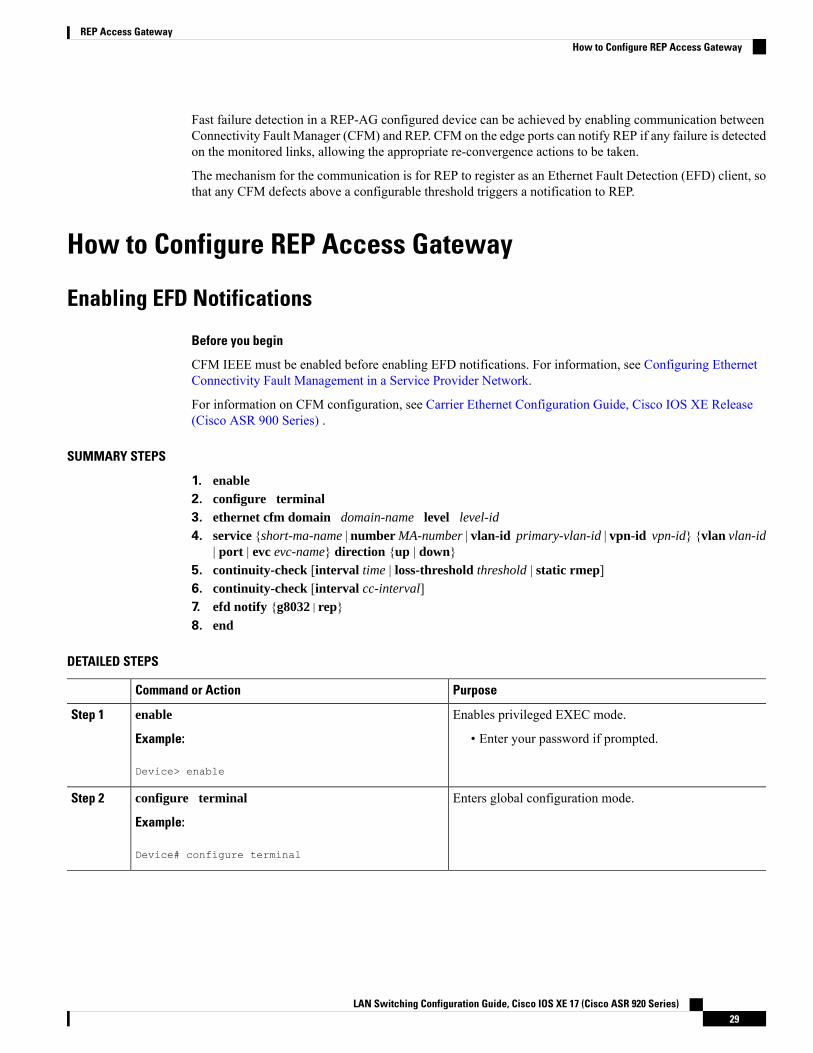
SUMMARY STEPS
1. enable2. configure terminal3. ethernet cfm domain domain-name level level-id
4. service {short-ma-name | number MA-number | vlan-id primary-vlan-id | vpn-id vpn-id} {vlan vlan-id| port | evc evc-name} direction {up | down}
5. continuity-check [interval time | loss-threshold threshold | static rmep]6. continuity-check [interval cc-interval]7. efd notify {g8032|rep}8. end
DETAILED STEPS
PurposeCommand or Action
Enables privileged EXEC mode.enableStep 1
Example: • Enter your password if prompted.
Device> enable
Enters global configuration mode.configure terminal
Example:
Step 2
Device# configure terminal
LAN Switching Configuration Guide, Cisco IOS XE 17 (Cisco ASR 920 Series)29
REP Access GatewayHow to Configure REP Access Gateway
PurposeCommand or Action
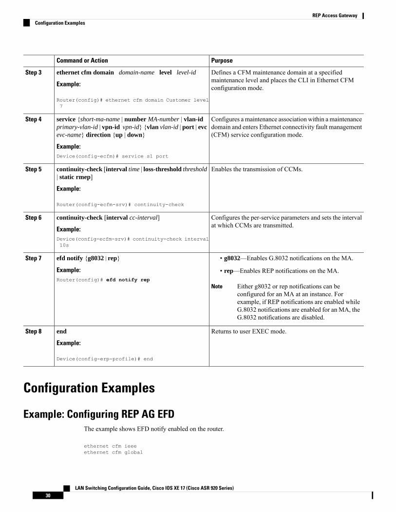
Defines a CFM maintenance domain at a specifiedmaintenance level and places the CLI in Ethernet CFMconfiguration mode.
ethernet cfm domain domain-name level level-id
Example:
Router(config)# ethernet cfm domain Customer level7
Step 3
Configures a maintenance association within a maintenancedomain and enters Ethernet connectivity fault management(CFM) service configuration mode.
service {short-ma-name | number MA-number | vlan-idprimary-vlan-id | vpn-id vpn-id} {vlan vlan-id | port | evcevc-name} direction {up | down}
Example:
Step 4
Device(config-ecfm)# service s1 port
Enables the transmission of CCMs.continuity-check [interval time | loss-threshold threshold| static rmep]
Step 5
Example:
Router(config-ecfm-srv)# continuity-check
Configures the per-service parameters and sets the intervalat which CCMs are transmitted.
continuity-check [interval cc-interval]
Example:
Step 6
Device(config-ecfm-srv)# continuity-check interval10s
efd notify {g8032|rep}Step 7 • g8032—Enables G.8032 notifications on the MA.
Example: • rep—Enables REP notifications on the MA.Router(config)# efd notify rep
Either g8032 or rep notifications can beconfigured for an MA at an instance. Forexample, if REP notifications are enabled whileG.8032 notifications are enabled for an MA, theG.8032 notifications are disabled.
Note
Returns to user EXEC mode.end
Example:
Step 8
Device(config-erp-profile)# end
Configuration Examples
Example: Configuring REP AG EFDThe example shows EFD notify enabled on the router.
ethernet cfm ieeeethernet cfm global
LAN Switching Configuration Guide, Cisco IOS XE 17 (Cisco ASR 920 Series)30
REP Access GatewayConfiguration Examples
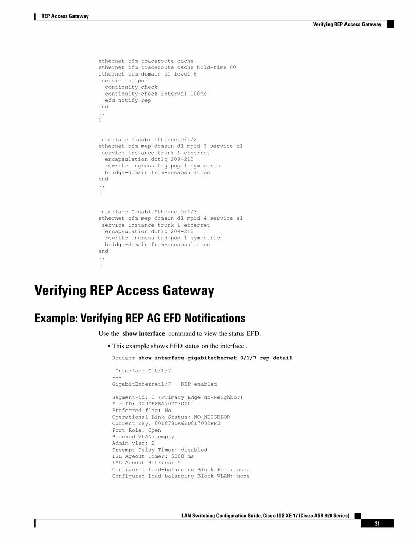
ethernet cfm traceroute cacheethernet cfm traceroute cache hold-time 60ethernet cfm domain d1 level 6service s1 portcontinuity-checkcontinuity-check interval 100msefd notify rep
end..1
interface GigabitEthernet0/1/2ethernet cfm mep domain d1 mpid 3 service s1service instance trunk 1 ethernetencapsulation dot1q 209-212rewrite ingress tag pop 1 symmetricbridge-domain from-encapsulation
end..!
interface GigabitEthernet0/1/3ethernet cfm mep domain d1 mpid 4 service s1service instance trunk 1 ethernetencapsulation dot1q 209-212rewrite ingress tag pop 1 symmetricbridge-domain from-encapsulation
end..!
Verifying REP Access Gateway
Example: Verifying REP AG EFD NotificationsUse the show interface command to view the status EFD.
• This example shows EFD status on the interface .Router# show interface gigabitethernet 0/1/7 rep detail
Interface Gi0/1/7---GigabitEthernet1/7 REP enabled
Segment-id: 1 (Primary Edge No-Neighbor)PortID: 000DE8BA70DD3000Preferred flag: NoOperational Link Status: NO_NEIGHBORCurrent Key: 001878DA6ED817002FF3Port Role: OpenBlocked VLAN: emptyAdmin-vlan: 2Preempt Delay Timer: disabledLSL Ageout Timer: 5000 msLSL Ageout Retries: 5Configured Load-balancing Block Port: noneConfigured Load-balancing Block VLAN: none
LAN Switching Configuration Guide, Cisco IOS XE 17 (Cisco ASR 920 Series)31
REP Access GatewayVerifying REP Access Gateway
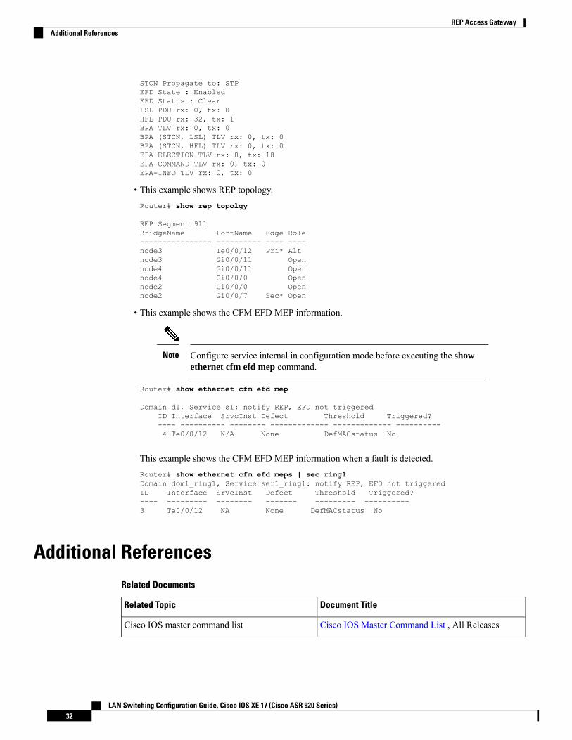
STCN Propagate to: STPEFD State : EnabledEFD Status : ClearLSL PDU rx: 0, tx: 0HFL PDU rx: 32, tx: 1BPA TLV rx: 0, tx: 0BPA (STCN, LSL) TLV rx: 0, tx: 0BPA (STCN, HFL) TLV rx: 0, tx: 0EPA-ELECTION TLV rx: 0, tx: 18EPA-COMMAND TLV rx: 0, tx: 0EPA-INFO TLV rx: 0, tx: 0
• This example shows REP topology.Router# show rep topolgy
REP Segment 911BridgeName PortName Edge Role---------------- ---------- ---- ----node3 Te0/0/12 Pri* Altnode3 Gi0/0/11 Opennode4 Gi0/0/11 Opennode4 Gi0/0/0 Opennode2 Gi0/0/0 Opennode2 Gi0/0/7 Sec* Open
• This example shows the CFM EFD MEP information.
Configure service internal in configuration mode before executing the showethernet cfm efd mep command.
Note
Router# show ethernet cfm efd mep
Domain d1, Service s1: notify REP, EFD not triggeredID Interface SrvcInst Defect Threshold Triggered?---- ---------- -------- ------------- ------------- ----------4 Te0/0/12 N/A None DefMACstatus No
This example shows the CFM EFD MEP information when a fault is detected.Router# show ethernet cfm efd meps | sec ring1Domain dom1_ring1, Service ser1_ring1: notify REP, EFD not triggeredID Interface SrvcInst Defect Threshold Triggered?---- --------- -------- ------- --------- ----------3 Te0/0/12 NA None DefMACstatus No
Additional ReferencesRelated Documents
Document TitleRelated Topic
Cisco IOS Master Command List , All ReleasesCisco IOS master command list
LAN Switching Configuration Guide, Cisco IOS XE 17 (Cisco ASR 920 Series)32
REP Access GatewayAdditional References
Document TitleRelated Topic
Carrier Ethernet Configuration Guide, Cisco IOS XERelease (Cisco ASR 900 Series)
Carrier Ethernet Configuration Guide, Cisco IOSXE Release (Cisco ASR 900 Series)
Standards
TitleStandard
--No new or modified standards are supported, and support for existing standards has not been modified.
MIBs
MIBs LinkMIB
To locate and download MIBs for selected platforms, CiscoIOS releases, and feature sets, use Cisco MIB Locator foundat the following URL:
http://www.cisco.com/go/mibs
No new ormodifiedMIBs are supported, andsupport for existing MIBs has not beenmodified.
RFCs
TitleRFC
--No new or modified RFCs are supported, and support for existing RFCs has not been modified.
Technical Assistance
LinkDescription
http://www.cisco.com/cisco/web/support/index.htmlTheCisco Support andDocumentationwebsite providesonline resources to download documentation, software,and tools. Use these resources to install and configurethe software and to troubleshoot and resolve technicalissues with Cisco products and technologies. Access tomost tools on the Cisco Support and Documentationwebsite requires a Cisco.com user ID and password.
LAN Switching Configuration Guide, Cisco IOS XE 17 (Cisco ASR 920 Series)33
REP Access GatewayAdditional References

LAN Switching Configuration Guide, Cisco IOS XE 17 (Cisco ASR 920 Series)34
REP Access GatewayAdditional References
C H A P T E R 3UniDirectional Link Detection (UDLD) Protocol
TheUniDirectional Link Detection protocol is a Layer 2 protocol that detects and disables one-way connectionsbefore they create undesired situation such as Spanning Tree loops.
• Restrictions for the UDLD Protocol, on page 35• Information About the UDLD Protocol, on page 35• How to Configure UDLD Protocol, on page 38• Configuration Examples, on page 42• Verifying UDLD Protocol, on page 42
Restrictions for the UDLD Protocol• Only Gigabit Ethernet, 10 Gigabit Ethernet, and Fast Ethernet interfaces are supported.• Supports only the basic UDLD functions.
Information About the UDLD Protocol
UDLD OverviewThe Cisco-proprietary UDLD protocol allows the devices connected through fiber optic or copper (for example,Category 5 cabling) Ethernet cables that are connected to the LAN ports to monitor the physical configurationof the cables and detect whether a unidirectional link exists. When a unidirectional link is detected, the UDLDshuts down the affected LAN port and alerts the corresponding user, because unidirectional links cause avariety of problems, including spanning tree topology loops.
UDLD is a Layer 2 protocol that works with the Layer 1 protocols to determine the physical status of a link.In Layer 1, auto negotiation takes care of physical signaling and fault detection. UDLD performs tasks thatauto negotiation cannot perform, such as detecting the identities of neighbors and shutting downmisconnectedLAN ports. When you enable both auto negotiation and UDLD, the Layer 1 and Layer 2 detections worktogether to prevent physical and logical unidirectional connections and the malfunctioning of other protocols.
A unidirectional link occurs whenever the traffic transmitted by a local device over a link is received by aneighbor, but traffic transmitted from the neighbor is not received by the local device. If one of the fiberstrands in a pair is disconnected, the link does not stay up as long as the auto negotiation is active. In such ascenario, the logical link is undetermined, and the UDLD does not take any action. If both the fibers areworking normally in Layer 1, the UDLD in Layer 2 determines whether those fibers are connected correctly
LAN Switching Configuration Guide, Cisco IOS XE 17 (Cisco ASR 920 Series)35
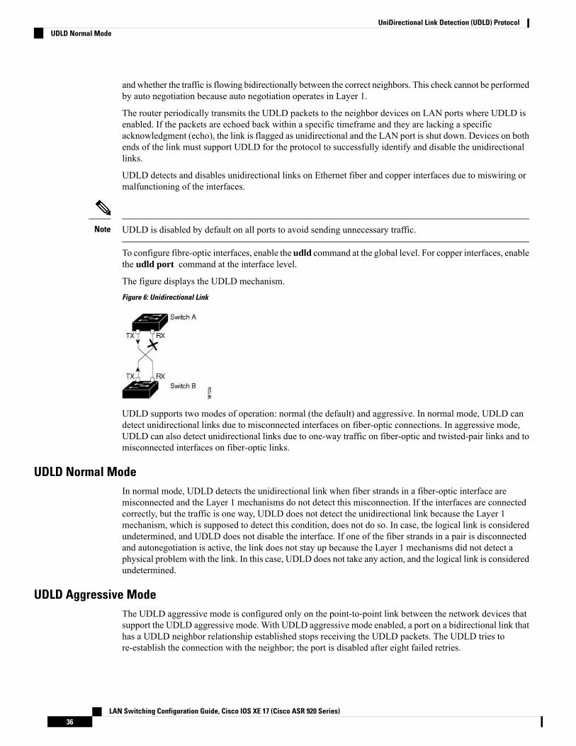
andwhether the traffic is flowing bidirectionally between the correct neighbors. This check cannot be performedby auto negotiation because auto negotiation operates in Layer 1.
The router periodically transmits the UDLD packets to the neighbor devices on LAN ports where UDLD isenabled. If the packets are echoed back within a specific timeframe and they are lacking a specificacknowledgment (echo), the link is flagged as unidirectional and the LAN port is shut down. Devices on bothends of the link must support UDLD for the protocol to successfully identify and disable the unidirectionallinks.
UDLD detects and disables unidirectional links on Ethernet fiber and copper interfaces due to miswiring ormalfunctioning of the interfaces.
UDLD is disabled by default on all ports to avoid sending unnecessary traffic.Note
To configure fibre-optic interfaces, enable the udld command at the global level. For copper interfaces, enablethe udld port command at the interface level.
The figure displays the UDLD mechanism.
Figure 6: Unidirectional Link
UDLD supports two modes of operation: normal (the default) and aggressive. In normal mode, UDLD candetect unidirectional links due to misconnected interfaces on fiber-optic connections. In aggressive mode,UDLD can also detect unidirectional links due to one-way traffic on fiber-optic and twisted-pair links and tomisconnected interfaces on fiber-optic links.
UDLD Normal ModeIn normal mode, UDLD detects the unidirectional link when fiber strands in a fiber-optic interface aremisconnected and the Layer 1 mechanisms do not detect this misconnection. If the interfaces are connectedcorrectly, but the traffic is one way, UDLD does not detect the unidirectional link because the Layer 1mechanism, which is supposed to detect this condition, does not do so. In case, the logical link is consideredundetermined, and UDLD does not disable the interface. If one of the fiber strands in a pair is disconnectedand autonegotiation is active, the link does not stay up because the Layer 1 mechanisms did not detect aphysical problem with the link. In this case, UDLD does not take any action, and the logical link is consideredundetermined.
UDLD Aggressive ModeThe UDLD aggressive mode is configured only on the point-to-point link between the network devices thatsupport the UDLD aggressive mode. With UDLD aggressive mode enabled, a port on a bidirectional link thathas a UDLD neighbor relationship established stops receiving the UDLD packets. The UDLD tries tore-establish the connection with the neighbor; the port is disabled after eight failed retries.
LAN Switching Configuration Guide, Cisco IOS XE 17 (Cisco ASR 920 Series)36
UniDirectional Link Detection (UDLD) ProtocolUDLD Normal Mode
To prevent spanning tree loops, nonaggressive UDLD with the default interval of 15 seconds is fast enoughto shut down a unidirectional link before a blocking port transitions to the forwarding state (with defaultspanning tree parameters).
The UDLD can error disable the ports on the link to prevent the traffic from being discarded under the followingscenarios, when either of the modes is enabled. That is normal or aggressive mode:
• One side of a link has a port (either Tx and Rx) stuck.
• One side of a link remains up while the other side of the link has gone down.
UDLD FunctionsUDLD performs the following functions
• Sends a probe packet on every active interface on which UDLD is configured to keep each device informedabout its neighbors.
• Learns about the neighbors and keeps the updated neighbor information in a cache table
• Sends several echo messages whenever it detects a new neighbor sending UDLD packets or whenevera neighbor requests a resynchronization of the caches
• Shuts down the affected port and notifies the user when one-way connection is detected. Devices on bothends of the link must support UDLD in order for the protocol to successfully identify and disableunidirectional links
• Reestablishes the connection with the neighbor when a port on a bidirectional link stops receiving UDLDpackets if aggressive mode is enabled. After eight failed retries, the port goes into disabled state
Detecting Unidirectional LinksUDLD operates by using two mechanisms:
Neighbor database maintenance
UDLD learns about other UDLD-capable neighbors by periodically sending a hello packet (also called anadvertisement or probe) on every active interface to keep each device informed about its neighbors. Whenthe switch receives a hello message, it caches the information until the age time (hold time or time-to-live)expires. If the switch receives a new hello message before an older cache entry ages, the switch replaces theolder entry with the new one. Whenever an interface is disabled and UDLD is running, whenever UDLD isdisabled on an interface, or whenever the switch is reset, UDLD clears all existing cache entries for theinterfaces affected by the configuration change. UDLD sends at least one message to inform the neighbors toflush the part of their caches affected by the status change. The message is intended to keep the cachessynchronized.
Event-driven detection and echoing
UDLD relies on echoing as its detection mechanism. Whenever a UDLD device learns about a new neighboror receives a resynchronization request from an out-of-sync neighbor, it restarts the detection window on itsside of the connection and sends echo messages in reply. Because this behavior is the same on all UDLDneighbors, the sender of the echoes expects to receive an echo in reply. If the detection window ends and novalid reply message is received, the link might shut down, depending on the UDLD mode. When UDLD isin normal mode, the link might be considered undetermined and might not be shut down. When UDLD is in
LAN Switching Configuration Guide, Cisco IOS XE 17 (Cisco ASR 920 Series)37
UniDirectional Link Detection (UDLD) ProtocolUDLD Functions
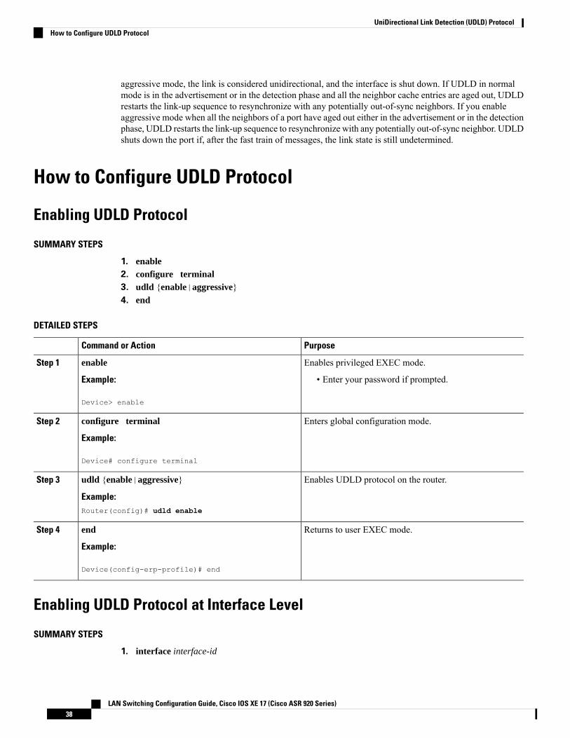
aggressive mode, the link is considered unidirectional, and the interface is shut down. If UDLD in normalmode is in the advertisement or in the detection phase and all the neighbor cache entries are aged out, UDLDrestarts the link-up sequence to resynchronize with any potentially out-of-sync neighbors. If you enableaggressive mode when all the neighbors of a port have aged out either in the advertisement or in the detectionphase, UDLD restarts the link-up sequence to resynchronize with any potentially out-of-sync neighbor. UDLDshuts down the port if, after the fast train of messages, the link state is still undetermined.
How to Configure UDLD Protocol
Enabling UDLD Protocol
SUMMARY STEPS
1. enable2. configure terminal3. udld {enable|aggressive}4. end
DETAILED STEPS
PurposeCommand or Action
Enables privileged EXEC mode.enableStep 1
Example: • Enter your password if prompted.
Device> enable
Enters global configuration mode.configure terminal
Example:
Step 2
Device# configure terminal
Enables UDLD protocol on the router.udld {enable|aggressive}
Example:
Step 3
Router(config)# udld enable
Returns to user EXEC mode.end
Example:
Step 4
Device(config-erp-profile)# end
Enabling UDLD Protocol at Interface Level
SUMMARY STEPS
1. interface interface-id
LAN Switching Configuration Guide, Cisco IOS XE 17 (Cisco ASR 920 Series)38
UniDirectional Link Detection (UDLD) ProtocolHow to Configure UDLD Protocol
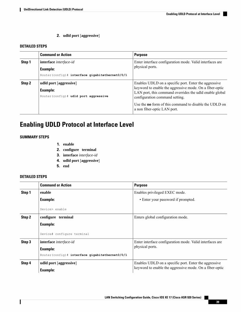
2. udld port [aggressive]
DETAILED STEPS
PurposeCommand or Action
Enter interface configuration mode. Valid interfaces arephysical ports.
interface interface-id
Example:
Step 1
Router(config)# interface gigabitethernet0/0/1
Enables UDLD on a specific port. Enter the aggressivekeyword to enable the aggressive mode. On a fiber-optic
udld port [aggressive]
Example:
Step 2
LAN port, this command overrides the udld enable globalconfiguration command setting.Router(config)# udld port aggressive
Use the no form of this command to disable the UDLD ona non fiber-optic LAN port.
Enabling UDLD Protocol at Interface Level
SUMMARY STEPS
1. enable2. configure terminal3. interface interface-id
4. udld port [aggressive]5. end
DETAILED STEPS
PurposeCommand or Action
Enables privileged EXEC mode.enableStep 1
Example: • Enter your password if prompted.
Device> enable
Enters global configuration mode.configure terminal
Example:
Step 2
Device# configure terminal
Enter interface configuration mode. Valid interfaces arephysical ports.
interface interface-id
Example:
Step 3
Router(config)# interface gigabitethernet0/0/1
Enables UDLD on a specific port. Enter the aggressivekeyword to enable the aggressive mode. On a fiber-optic
udld port [aggressive]
Example:
Step 4
LAN Switching Configuration Guide, Cisco IOS XE 17 (Cisco ASR 920 Series)39
UniDirectional Link Detection (UDLD) ProtocolEnabling UDLD Protocol at Interface Level
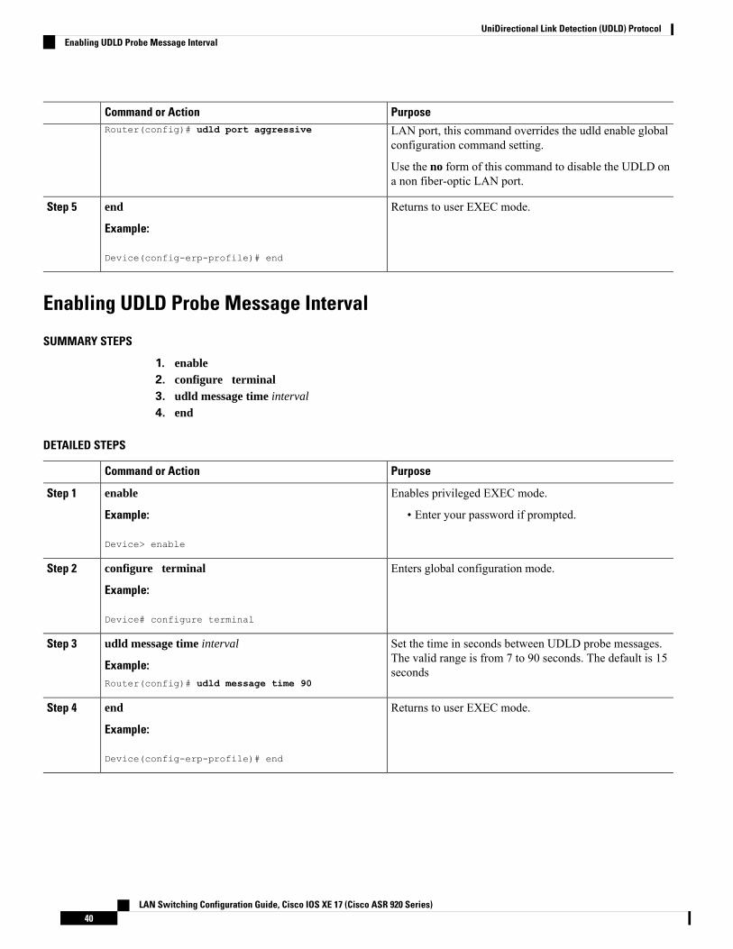
PurposeCommand or Action
LAN port, this command overrides the udld enable globalconfiguration command setting.
Router(config)# udld port aggressive
Use the no form of this command to disable the UDLD ona non fiber-optic LAN port.
Returns to user EXEC mode.end
Example:
Step 5
Device(config-erp-profile)# end
Enabling UDLD Probe Message Interval
SUMMARY STEPS
1. enable2. configure terminal3. udld message time interval
4. end
DETAILED STEPS
PurposeCommand or Action
Enables privileged EXEC mode.enableStep 1
Example: • Enter your password if prompted.
Device> enable
Enters global configuration mode.configure terminal
Example:
Step 2
Device# configure terminal
Set the time in seconds between UDLD probe messages.The valid range is from 7 to 90 seconds. The default is 15seconds
udld message time interval
Example:Router(config)# udld message time 90
Step 3
Returns to user EXEC mode.end
Example:
Step 4
Device(config-erp-profile)# end
LAN Switching Configuration Guide, Cisco IOS XE 17 (Cisco ASR 920 Series)40
UniDirectional Link Detection (UDLD) ProtocolEnabling UDLD Probe Message Interval
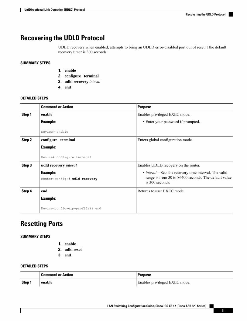
Recovering the UDLD ProtocolUDLD recovery when enabled, attempts to bring an UDLD error-disabled port out of reset. Tthe defaultrecovery timer is 300 seconds.
SUMMARY STEPS
1. enable2. configure terminal3. udld recovery inteval
4. end
DETAILED STEPS
PurposeCommand or Action
Enables privileged EXEC mode.enableStep 1
Example: • Enter your password if prompted.
Device> enable
Enters global configuration mode.configure terminal
Example:
Step 2
Device# configure terminal
Enables UDLD recovery on the router.udld recovery intevalStep 3
Example: • inteval—Sets the recovery time interval. The validrange is from 30 to 86400 seconds. The default valueis 300 seconds.
Router(config)# udld recovery
Returns to user EXEC mode.end
Example:
Step 4
Device(config-erp-profile)# end
Resetting Ports
SUMMARY STEPS
1. enable2. udld reset3. end
DETAILED STEPS
PurposeCommand or Action
Enables privileged EXEC mode.enableStep 1
LAN Switching Configuration Guide, Cisco IOS XE 17 (Cisco ASR 920 Series)41
UniDirectional Link Detection (UDLD) ProtocolRecovering the UDLD Protocol
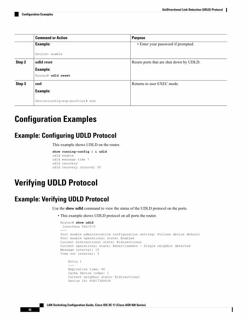
PurposeCommand or Action
Example: • Enter your password if prompted.
Device> enable
Resets ports that are shut down by UDLD.udld reset
Example:
Step 2
Router# udld reset
Returns to user EXEC mode.end
Example:
Step 3
Device(config-erp-profile)# end
Configuration Examples
Example: Configuring UDLD ProtocolThis example shows UDLD on the router.show running-config | i udldudld enableudld message time 7udld recoveryudld recovery interval 30
Verifying UDLD Protocol
Example: Verifying UDLD ProtocolUse the show udld command to view the status of the UDLD protocol on the ports.
• This example shows UDLD protocol on all ports the router.Router# show udldInterface Te0/0/0---Port enable administrative configuration setting: Follows device defaultPort enable operational state: EnabledCurrent bidirectional state: BidirectionalCurrent operational state: Advertisement - Single neighbor detectedMessage interval: 15Time out interval: 5
Entry 1---Expiration time: 40Cache Device index: 1Current neighbor state: BidirectionalDevice ID: FOX1736P0JP
LAN Switching Configuration Guide, Cisco IOS XE 17 (Cisco ASR 920 Series)42
UniDirectional Link Detection (UDLD) ProtocolConfiguration Examples

Port ID: Te0/1/0Neighbor echo 1 device: FOX1709P3D0Neighbor echo 1 port: Te0/0/0
Message interval: 15Time out interval: 5CDP Device name: RSP1B
Interface Gi0/2/0---Port enable administrative configuration setting: Follows device defaultPort enable operational state: EnabledCurrent bidirectional state: BidirectionalCurrent operational state: Advertisement - Single neighbor detectedMessage interval: 15Time out interval: 5
Entry 1---Expiration time: 33Cache Device index: 1Current neighbor state: BidirectionalDevice ID: FOC1528V27KPort ID: Gi0/2Neighbor echo 1 device: FOX1709P3D0Neighbor echo 1 port: Gi0/2/0
Message interval: 15Time out interval: 5CDP Device name: RSP1A
Interface Gi0/2/1---Port enable administrative configuration setting: Follows device defaultPort enable operational state: EnabledCurrent bidirectional state: BidirectionalCurrent operational state: Advertisement - Single neighbor detectedMessage interval: 15Time out interval: 5
Entry 1---Expiration time: 33Cache Device index: 1Current neighbor state: BidirectionalDevice ID: FOC1639V1Z4Port ID: Gi0/4Neighbor echo 1 device: FOX1709P3D0Neighbor echo 1 port: Gi0/2/1
Message interval: 15Time out interval: 5CDP Device name: RSP1A
Interface Gi0/2/2---Port enable administrative configuration setting: Follows device defaultPort enable operational state: EnabledCurrent bidirectional state: UnknownCurrent operational state: AdvertisementMessage interval: 15Time out interval: 5No neighbor cache information stored
LAN Switching Configuration Guide, Cisco IOS XE 17 (Cisco ASR 920 Series)43
UniDirectional Link Detection (UDLD) ProtocolExample: Verifying UDLD Protocol
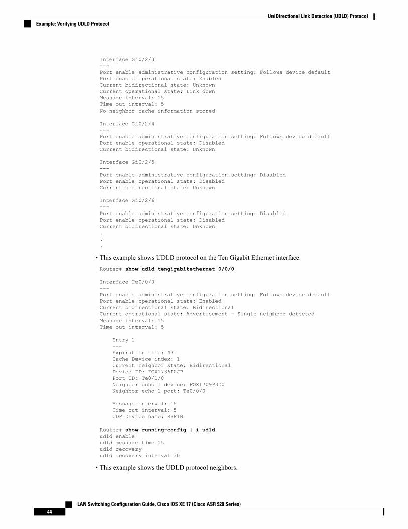
Interface Gi0/2/3---Port enable administrative configuration setting: Follows device defaultPort enable operational state: EnabledCurrent bidirectional state: UnknownCurrent operational state: Link downMessage interval: 15Time out interval: 5No neighbor cache information stored
Interface Gi0/2/4---Port enable administrative configuration setting: Follows device defaultPort enable operational state: DisabledCurrent bidirectional state: Unknown
Interface Gi0/2/5---Port enable administrative configuration setting: DisabledPort enable operational state: DisabledCurrent bidirectional state: Unknown
Interface Gi0/2/6---Port enable administrative configuration setting: DisabledPort enable operational state: DisabledCurrent bidirectional state: Unknown...
• This example shows UDLD protocol on the Ten Gigabit Ethernet interface.Router# show udld tengigabitethernet 0/0/0
Interface Te0/0/0---Port enable administrative configuration setting: Follows device defaultPort enable operational state: EnabledCurrent bidirectional state: BidirectionalCurrent operational state: Advertisement - Single neighbor detectedMessage interval: 15Time out interval: 5
Entry 1---Expiration time: 43Cache Device index: 1Current neighbor state: BidirectionalDevice ID: FOX1736P0JPPort ID: Te0/1/0Neighbor echo 1 device: FOX1709P3D0Neighbor echo 1 port: Te0/0/0
Message interval: 15Time out interval: 5CDP Device name: RSP1B
Router# show running-config | i udldudld enableudld message time 15udld recoveryudld recovery interval 30
• This example shows the UDLD protocol neighbors.
LAN Switching Configuration Guide, Cisco IOS XE 17 (Cisco ASR 920 Series)44
UniDirectional Link Detection (UDLD) ProtocolExample: Verifying UDLD Protocol

Router# show udld neighbors
Port Device Name Device ID Port ID Neighbor State------------ ------------- ------------ ------------ ----------------Te0/0/0 FOX1736P0JP 1 Te0/1/0 BidirectionalGi0/2/0 FOC1528V27K 1 Gi0/2 BidirectionalGi0/2/1 FOC1639V1Z4 1 Gi0/4 Bidirectional
LAN Switching Configuration Guide, Cisco IOS XE 17 (Cisco ASR 920 Series)45
UniDirectional Link Detection (UDLD) ProtocolExample: Verifying UDLD Protocol

LAN Switching Configuration Guide, Cisco IOS XE 17 (Cisco ASR 920 Series)46
UniDirectional Link Detection (UDLD) ProtocolExample: Verifying UDLD Protocol

C H A P T E R 4Configuring Auto Media Sense
Cisco ASR 920 Series ( ASR-920-12CZ-A and ASR-920-12CZ-D) supports eight dual media ports. The dualmedia ports can operate either in RJ45 mode or in SFP (fiber) mode. The AMS detects the presence of a linkactivity on any of the media dual ports, and enables the link for communication. By default, if there is no linkconnection, the link state goes down. When media is connected, the AMS detects the connection, establishesthe link, and brings the link state to UP. When for the same port, both RJ45 and fiber links are connected, theport goes UP in the fiber mode.
• Restrictions for Configuring Auto Media Sense, on page 47• Information About Auto Media Sense, on page 47• How to Configure Auto Media Sense, on page 48
Restrictions for Configuring Auto Media Sense• When the media-type is changed from RJ45 to SFP or vice versa with 100% line rate, the port goesDOWN. The workaround is to stop the traffic, and to perform shut/no shut operation on the port.
• By default, the auto negotiation is always enabled when the media-type is selected as auto-select.
• For ports 4 to 11, the same port cannot be used as RJ45 or SFP at the same time.
Information About Auto Media SenseDual-media is the support given at the PHY level. The Cisco ASR 920 Series ( ASR-920-12CZ-A andASR-920-12CZ-D) supports eight dual media ports. All the media typemodes are driven through IOS Interfaceconfiguration command:
• Media-type 'auto' is for auto-media sense• Media-type 'rj45' is for rj45 mode• Media-type 'sfp' is for SFP mode.
Port numbers from 4 - 11 can operate either in RJ45 or in Fiber mode.
Table 2: Cisco ASR 920 Series Front Panel Port mapping
10GSFP+
1G AMS Ports1G SFP Only
LAN Switching Configuration Guide, Cisco IOS XE 17 (Cisco ASR 920 Series)47
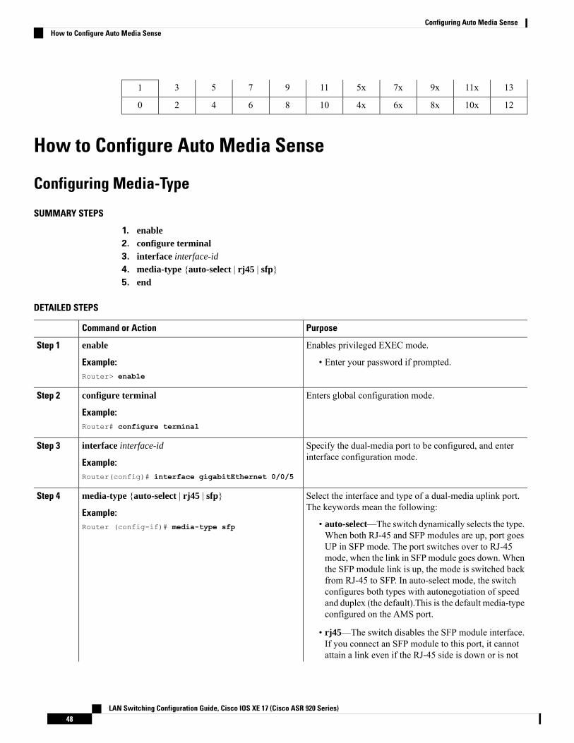
1311x9x7x5x1197531
1210x8x6x4x1086420
How to Configure Auto Media Sense
Configuring Media-Type
SUMMARY STEPS
1. enable2. configure terminal3. interface interface-id
4. media-type {auto-select | rj45 | sfp}5. end
DETAILED STEPS
PurposeCommand or Action
Enables privileged EXEC mode.enableStep 1
Example: • Enter your password if prompted.Router> enable
Enters global configuration mode.configure terminal
Example:
Step 2
Router# configure terminal
Specify the dual-media port to be configured, and enterinterface configuration mode.
interface interface-id
Example:
Step 3
Router(config)# interface gigabitEthernet 0/0/5
Select the interface and type of a dual-media uplink port.The keywords mean the following:
media-type {auto-select | rj45 | sfp}
Example:
Step 4
• auto-select—The switch dynamically selects the type.When both RJ-45 and SFP modules are up, port goes
Router (config-if)# media-type sfp
UP in SFP mode. The port switches over to RJ-45mode, when the link in SFPmodule goes down.Whenthe SFP module link is up, the mode is switched backfrom RJ-45 to SFP. In auto-select mode, the switchconfigures both types with autonegotiation of speedand duplex (the default).This is the default media-typeconfigured on the AMS port.
• rj45—The switch disables the SFP module interface.If you connect an SFP module to this port, it cannotattain a link even if the RJ-45 side is down or is not
LAN Switching Configuration Guide, Cisco IOS XE 17 (Cisco ASR 920 Series)48
Configuring Auto Media SenseHow to Configure Auto Media Sense
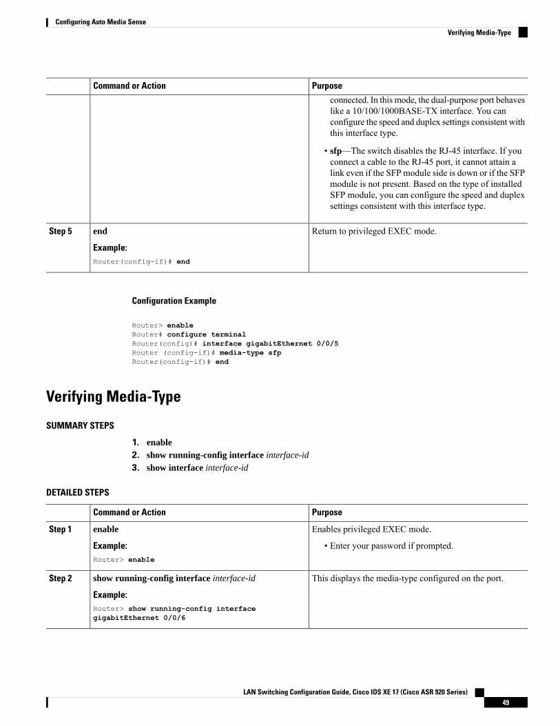
PurposeCommand or Action
connected. In this mode, the dual-purpose port behaveslike a 10/100/1000BASE-TX interface. You canconfigure the speed and duplex settings consistent withthis interface type.
• sfp—The switch disables the RJ-45 interface. If youconnect a cable to the RJ-45 port, it cannot attain alink even if the SFP module side is down or if the SFPmodule is not present. Based on the type of installedSFP module, you can configure the speed and duplexsettings consistent with this interface type.
Return to privileged EXEC mode.end
Example:
Step 5
Router(config-if)# end
Configuration Example
Router> enableRouter# configure terminalRouter(config)# interface gigabitEthernet 0/0/5Router (config-if)# media-type sfpRouter(config-if)# end
Verifying Media-Type
SUMMARY STEPS
1. enable2. show running-config interface interface-id
3. show interface interface-id
DETAILED STEPS
PurposeCommand or Action
Enables privileged EXEC mode.enableStep 1
Example: • Enter your password if prompted.Router> enable
This displays the media-type configured on the port.show running-config interface interface-id
Example:
Step 2
Router> show running-config interfacegigabitEthernet 0/0/6
LAN Switching Configuration Guide, Cisco IOS XE 17 (Cisco ASR 920 Series)49
Configuring Auto Media SenseVerifying Media-Type
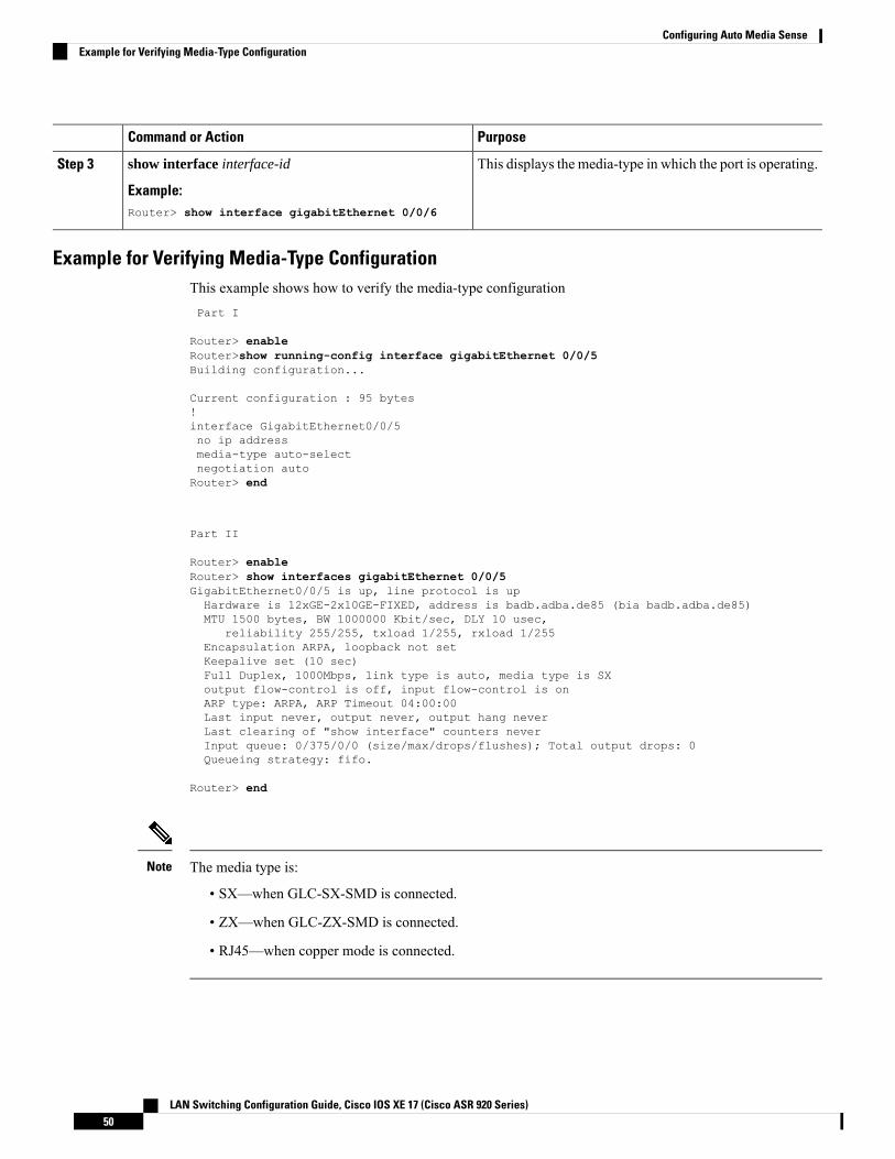
PurposeCommand or Action
This displays the media-type in which the port is operating.show interface interface-id
Example:
Step 3
Router> show interface gigabitEthernet 0/0/6
Example for Verifying Media-Type ConfigurationThis example shows how to verify the media-type configurationPart I
Router> enableRouter>show running-config interface gigabitEthernet 0/0/5Building configuration...
Current configuration : 95 bytes!interface GigabitEthernet0/0/5no ip addressmedia-type auto-selectnegotiation autoRouter> end
Part II
Router> enableRouter> show interfaces gigabitEthernet 0/0/5GigabitEthernet0/0/5 is up, line protocol is upHardware is 12xGE-2x10GE-FIXED, address is badb.adba.de85 (bia badb.adba.de85)MTU 1500 bytes, BW 1000000 Kbit/sec, DLY 10 usec,
reliability 255/255, txload 1/255, rxload 1/255Encapsulation ARPA, loopback not setKeepalive set (10 sec)Full Duplex, 1000Mbps, link type is auto, media type is SXoutput flow-control is off, input flow-control is onARP type: ARPA, ARP Timeout 04:00:00Last input never, output never, output hang neverLast clearing of "show interface" counters neverInput queue: 0/375/0/0 (size/max/drops/flushes); Total output drops: 0Queueing strategy: fifo.
Router> end
The media type is:
• SX—when GLC-SX-SMD is connected.
• ZX—when GLC-ZX-SMD is connected.
• RJ45—when copper mode is connected.
Note
LAN Switching Configuration Guide, Cisco IOS XE 17 (Cisco ASR 920 Series)50
Configuring Auto Media SenseExample for Verifying Media-Type Configuration
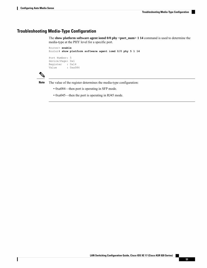
Troubleshooting Media-Type ConfigurationThe show platform software agent iomd 0/0 phy <port_num> 1 14 command is used to determine themedia-type at the PHY level for a specific port.Router> enableRouter# show platform software agent iomd 0/0 phy 5 1 14
Port Number: 5Device/Page: 0x1Register : 0x14Value : 0xa084
The value of the register determines the media-type configuration:
• 0xa084—then port is operating in SFP mode.
• 0xa045—then the port is operating in RJ45 mode.
Note
LAN Switching Configuration Guide, Cisco IOS XE 17 (Cisco ASR 920 Series)51
Configuring Auto Media SenseTroubleshooting Media-Type Configuration

LAN Switching Configuration Guide, Cisco IOS XE 17 (Cisco ASR 920 Series)52
Configuring Auto Media SenseTroubleshooting Media-Type Configuration
C H A P T E R 5Configuring Flex Links
This chapter describes how to configure Flex Links, a pair of Layer 2 interfaces, where one interface isconfigured to act as a backup to the other.
• Restrictions for Configuring Flex Links, on page 53• Information About Flex Links, on page 53• Additional References, on page 60
Restrictions for Configuring Flex Links• Flex Links is supported on NCS 4201 and NCS 4202 routers only.
• You can configure only one Flex Link backup link for any active link, and it must be a different interfacefrom the active interface.
• An interface can belong to only one Flex Link pair. An interface can be a backup link for only one activelink. An active link cannot belong to another Flex Link pair.
• Neither of the links can be a port that belongs to an EtherChannel nor port channel
• A backup link does not have to be the same type (Fast Ethernet, Gigabit Ethernet) as the active link.
• STP is disabled on Flex Link ports. If STP is configured on the switch, Flex Links do not participate inSTP in all VLANs in which STP is configured. With STP not running, be sure that there are no loops inthe configured topology.
• Flex link is only supported on trunk EFP.
• In bi-directional traffic, FlexLink Convergence will be high in one-direction due to mac address blackholing.
Information About Flex LinksThe feature provides an alternative solution to the Spanning Tree Protocol (STP), allowing you to turn offSTP and still provide basic link redundancy. Flex Links are typically configured in service provider or enterprisenetworks, where, you do not want to run STP on the router. If the router is running STP, it is not necessaryto configure Flex Links, because STP already provides link-level redundancy or backup. Flex Links aresupported only on Trunk EFP and are not supported on other EVCs.
LAN Switching Configuration Guide, Cisco IOS XE 17 (Cisco ASR 920 Series)53

Following are the two flex link modes supported:
• Active-Alone Forwarding Method
• Active-Backup-Both Forwarding Method
Active-Alone forwarding MethodFrom the schematic representation, ports 1 and 2 on switch A are connected to uplink switches B and C.Because they are configured as Flex Link in active-backup both forwarding mode, both the interfaces will beforwarding traffic. If port 1 is the active link, all mutually inclusive VLANs (common VLANs configured inboth active / backup interface) would be forwarded on active interface and mutually exclusive VLANs wouldbe forwarded from the respective active / backup interfaces. If port 1 goes down, then port 2 will start forwardingonly the traffic for the common VLANs along with its specific exclusive vlans. All traffic belonging to theexclusive VLANS as part of active interface configuration would be dropped until port 1 comes back tooperational state.
Figure 7: Active-Alone Forwarding Method
Configuring Active Alone Forwarding Method
SUMMARY STEPS
1. enable2. configure terminal3. interface interface-id
4. no shutdown5. ethernet backup interface interface-id
6. end
DETAILED STEPS
PurposeCommand or Action
Enables privileged EXEC mode.enableStep 1
Example: • Enter your password if prompted.Router> enable
Enters global configuration mode.configure terminal
Example:
Step 2
Router# configure terminal
LAN Switching Configuration Guide, Cisco IOS XE 17 (Cisco ASR 920 Series)54
Configuring Flex LinksActive-Alone forwarding Method
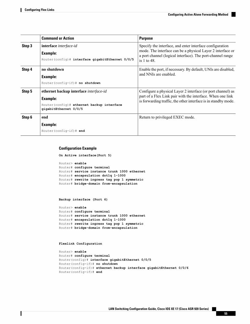
PurposeCommand or Action
Specify the interface, and enter interface configurationmode. The interface can be a physical Layer 2 interface or
interface interface-id
Example:
Step 3
a port channel (logical interface). The port-channel rangeis 1 to 48.Router(config)# interface gigabitEthernet 0/0/5
Enable the port, if necessary. By default, UNIs are disabled,and NNIs are enabled.
no shutdown
Example:
Step 4
Router(config-if)# no shutdown
Configure a physical Layer 2 interface (or port channel) aspart of a Flex Link pair with the interface. When one linkis forwarding traffic, the other interface is in standbymode.
ethernet backup interface interface-id
Example:Router(config)# ethernet backup interfacegigabitEthernet 0/0/5
Step 5
Return to privileged EXEC mode.end
Example:
Step 6
Router(config-if)# end
Configuration Example
On Active interface(Port 5)
Router> enableRouter# configure terminalRouter# service instance trunk 1000 ethernetRouter# encapsulation dot1q 1-1000Router# rewrite ingress tag pop 1 symmetricRouter# bridge-domain from-encapsulation
Backup interface (Port 6)
Router> enableRouter# configure terminalRouter# service instance trunk 1000 ethernetRouter# encapsulation dot1q 1-1000Router# rewrite ingress tag pop 1 symmetricRouter# bridge-domain from-encapsulation
Flexlink Configuration
Router> enableRouter# configure terminalRouter(config)# interface gigabitEthernet 0/0/5Router(config-if)# no shutdownRouter(config-if)# ethernet backup interface gigabitEthernet 0/0/6Router(config-if)# end
LAN Switching Configuration Guide, Cisco IOS XE 17 (Cisco ASR 920 Series)55
Configuring Flex LinksConfiguring Active Alone Forwarding Method

Verifying Active Alone Forwarding Method Configuration
SUMMARY STEPS
1. enable2. configure terminal3. show ethernet backup detail
DETAILED STEPS
PurposeCommand or Action
Enables privileged EXEC mode.enableStep 1
Example: • Enter your password if prompted.Router> enable
Enters global configuration mode.configure terminal
Example:
Step 2
Router# configure terminal
This displays the flex link configuration.show ethernet backup detail
Example:
Step 3
Router# show ethernet backup detail
Configuration Output
Switch Backup Interface Pairs:Active Interface Backup Interface State------------------------------------------------------------------------GigabitEthernet0/0/5 Te0/0/12 Active Up/Backup Standby
Preemption Mode : offMulticast Fast Convergence : OffBandwidth : 1000000 Kbit (Gi0/0/3), 1000000 Kbit (Te0/0/12)Mac Address Move Update Vlan : autoForwarding : Active-Only
Active-Backup-Both forwarding MethodFrom the schematic representation, ports 1 and 2 on switch A are connected to uplink switches B and C.Because they are configured as Flex Link in active-backup both forwarding mode, both the interfaces will beforwarding traffic. If port 1 is the active link, all mutually inclusive vlans (common vlans configured in bothactive / backup interface) would be forwarded on active interface and mutually exclusive vlans would beforwarded from the respective active / backup interfaces. If port 1 goes down, then port 2 will start forwardingonly the traffic for the common vlans along with its specific exclusive vlans. All traffic belonging to theexclusive vlans as part of active interface configuration would be dropped until port 1 comes back to operationalstate.
LAN Switching Configuration Guide, Cisco IOS XE 17 (Cisco ASR 920 Series)56
Configuring Flex LinksVerifying Active Alone Forwarding Method Configuration
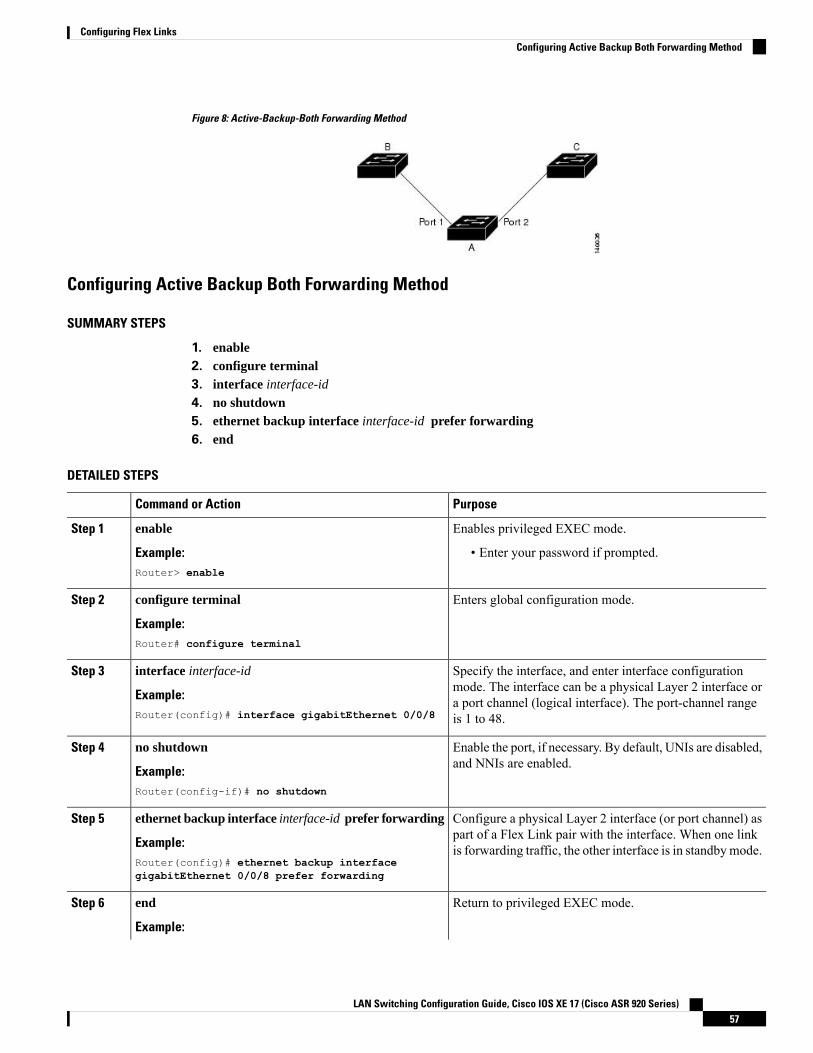
Figure 8: Active-Backup-Both Forwarding Method
Configuring Active Backup Both Forwarding Method
SUMMARY STEPS
1. enable2. configure terminal3. interface interface-id
4. no shutdown5. ethernet backup interface interface-id prefer forwarding6. end
DETAILED STEPS
PurposeCommand or Action
Enables privileged EXEC mode.enableStep 1
Example: • Enter your password if prompted.Router> enable
Enters global configuration mode.configure terminal
Example:
Step 2
Router# configure terminal
Specify the interface, and enter interface configurationmode. The interface can be a physical Layer 2 interface or
interface interface-id
Example:
Step 3
a port channel (logical interface). The port-channel rangeis 1 to 48.Router(config)# interface gigabitEthernet 0/0/8
Enable the port, if necessary. By default, UNIs are disabled,and NNIs are enabled.
no shutdown
Example:
Step 4
Router(config-if)# no shutdown
Configure a physical Layer 2 interface (or port channel) aspart of a Flex Link pair with the interface. When one linkis forwarding traffic, the other interface is in standbymode.
ethernet backup interface interface-id prefer forwarding
Example:Router(config)# ethernet backup interfacegigabitEthernet 0/0/8 prefer forwarding
Step 5
Return to privileged EXEC mode.end
Example:
Step 6
LAN Switching Configuration Guide, Cisco IOS XE 17 (Cisco ASR 920 Series)57
Configuring Flex LinksConfiguring Active Backup Both Forwarding Method
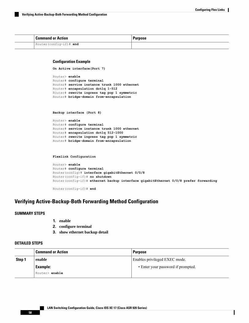
PurposeCommand or ActionRouter(config-if)# end
Configuration Example
On Active interface(Port 7)
Router> enableRouter# configure terminalRouter# service instance trunk 1000 ethernetRouter# encapsulation dot1q 1-512Router# rewrite ingress tag pop 1 symmetricRouter# bridge-domain from-encapsulation
Backup interface (Port 8)
Router> enableRouter# configure terminalRouter# service instance trunk 1000 ethernetRouter# encapsulation dot1q 512-1000Router# rewrite ingress tag pop 1 symmetricRouter# bridge-domain from-encapsulation
Flexlink Configuration
Router> enableRouter# configure terminalRouter(config)# interface gigabitEthernet 0/0/8Router(config-if)# no shutdownRouter(config-if)# ethernet backup interface gigabitEthernet 0/0/8 prefer forwarding
Router(config-if)# end
Verifying Active-Backup-Both Forwarding Method Configuration
SUMMARY STEPS
1. enable2. configure terminal3. show ethernet backup detail
DETAILED STEPS
PurposeCommand or Action
Enables privileged EXEC mode.enableStep 1
Example: • Enter your password if prompted.Router> enable
LAN Switching Configuration Guide, Cisco IOS XE 17 (Cisco ASR 920 Series)58
Configuring Flex LinksVerifying Active-Backup-Both Forwarding Method Configuration
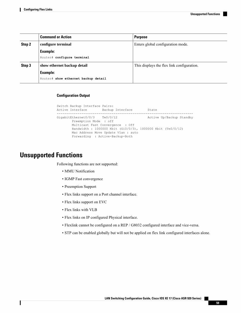
PurposeCommand or Action
Enters global configuration mode.configure terminal
Example:
Step 2
Router# configure terminal
This displays the flex link configuration.show ethernet backup detail
Example:
Step 3
Router# show ethernet backup detail
Configuration Output
Switch Backup Interface Pairs:Active Interface Backup Interface State------------------------------------------------------------------------GigabitEthernet0/0/3 Te0/0/12 Active Up/Backup Standby
Preemption Mode : offMulticast Fast Convergence : OffBandwidth : 1000000 Kbit (Gi0/0/3), 1000000 Kbit (Te0/0/12)Mac Address Move Update Vlan : autoForwarding : Active-Backup-Both
Unsupported FunctionsFollowing functions are not supported:
• MMU Notification
• IGMP Fast convergence
• Preemption Support
• Flex links support on a Port channel interface.
• Flex links support on EVC
• Flex links with VLB
• Flex links on IP configured Physical interface.
• Flexlink cannot be configured on a REP / G8032 configured interface and vice-versa.
• STP can be enabled globally but will not be applied on flex link configured interfaces alone.
LAN Switching Configuration Guide, Cisco IOS XE 17 (Cisco ASR 920 Series)59
Configuring Flex LinksUnsupported Functions

Additional ReferencesRelated Documents
Document TitleRelated Topic
https://www.cisco.com/c/en/us/td/docs/ios-xml/ios/mcl/allreleasemcl/all-book.htmlCisco IOS commands
Standards and RFCs
TitleStandard/RFC
—No specific Standards and RFCs are supported by the features in this document.
MIBs
MIBs LinkMIB
To locate and download MIBs for selected platforms, Cisco IOS releases, and feature sets, use CiscoMIB Locator found at the following URL:
http://www.cisco.com/go/mibs
—
Technical Assistance
LinkDescription
http://www.cisco.com/cisco/web/support/index.html
The Cisco Support website provides extensive online resources, includingdocumentation and tools for troubleshooting and resolving technical issues withCisco products and technologies.
To receive security and technical information about your products, you cansubscribe to various services, such as the Product Alert Tool (accessed from FieldNotices), the Cisco Technical Services Newsletter, and Really Simple Syndication(RSS) Feeds.
Access to most tools on the Cisco Support website requires a Cisco.com user IDand password.
LAN Switching Configuration Guide, Cisco IOS XE 17 (Cisco ASR 920 Series)60
Configuring Flex LinksAdditional References
C H A P T E R 6ITU-T G.8032 Ethernet Ring Protection Switching
The ITU-T G.8032 Ethernet Ring Protection Switching feature implements protection switching mechanismsfor Ethernet layer ring topologies. This feature uses the G.8032 Ethernet Ring Protection (ERP) protocol,defined in ITU-T G.8032, to provide protection for Ethernet traffic in a ring topology, while ensuring that noloops are within the ring at the Ethernet layer. The loops are prevented by blocking traffic on either apredetermined link or a failed link.
• Prerequisites for Configuring ITU-T G.8032 Ethernet Ring Protection Switching, on page 61• About ITU-T G.8032 Ethernet Ring Protection Switching, on page 61• Restrictions for Configuring ITU-T G.8032 Ethernet Ring Protection Switching, on page 68• How to Configure ITU-T G.8032 Ethernet Ring Protection Switching, on page 69• Configuration Examples for ITU-T G.8032 Ethernet Ring Protection Switching, on page 79
Prerequisites for Configuring ITU-T G.8032 Ethernet RingProtection Switching
• The Ethernet Flow Points (EFPs) and Trunk Ethernet Flow Points (TEFPs) must be configured.
About ITU-T G.8032 Ethernet Ring Protection Switching
Ring Protection LinksAn Ethernet ring consists of multiple Ethernet ring nodes. Each Ethernet ring node is connected to adjacentEthernet ring nodes using two independent ring links. A ring link prohibits formation of loops that affect thenetwork. The Ethernet ring uses a specific link to protect the entire Ethernet ring. This specific link is calledthe Ring Protection Link (RPL). A ring link is bound by two adjacent Ethernet ring nodes and a port for aring link (also known as a ring port). There must be at least two Ethernet ring nodes in an Ethernet ring.
ITU-T G.8032 Ethernet Ring Protection Switching FunctionalityThe Ethernet ring protection functionality includes the following:
• Loop avoidance
LAN Switching Configuration Guide, Cisco IOS XE 17 (Cisco ASR 920 Series)61

• The use of learning, forwarding, and Filtering Database (FDB) mechanisms
Loop avoidance in an Ethernet ring is achieved by ensuring that, at any time, traffic flows on all but the RingProtection Link (RPL).
The following is a list of RPL types (or RPL nodes) and their functions:
• RPL owner—Responsible for blocking traffic over the RPL so that no loops are formed in the Ethernettraffic. There can be only one RPL owner in a ring.
• RPL neighbor node—An Ethernet ring node adjacent to the RPL. It is responsible for blocking its endof the RPL under normal conditions. This node type is optional and prevents RPL usage when protected.
• RPL next-neighbor node—Next-neighbor node is an Ethernet ring node adjacent to an RPL owner nodeor RPL neighbor node. It is mainly used for FDB flush optimization on the ring. This node is also optional.
The following figure illustrates the G.8032 Ethernet ring topology.
Figure 9: G.8032 Ethernet Ring Topology
R-APS Control MessagesNodes on the ring use control messages called Ring Automatic Protection Switching (R-APS) messages tocoordinate the activities of switching the ring protection link (RPL) on and off. Any failure along the ringtriggers a R-APS Signal Failure (R-APS SF) message in both directions of the nodes adjacent to the failedlink, after the nodes have blocked the port facing the failed link. On obtaining this message, the RPL ownerunblocks the RPL port.
A single link failure in the ring ensures a loop-free topology.Note
CFM Protocols and Link FailuresConnectivity Fault Management (CFM) and line status messages are used to detect ring link and node failure.During the recovery phase, when the failed link is restored, the nodes adjacent to the restored link send RingAutomatic Protection Switching (R-APS) No Request (R-APS NR) messages. On obtaining this message, the
LAN Switching Configuration Guide, Cisco IOS XE 17 (Cisco ASR 920 Series)62
ITU-T G.8032 Ethernet Ring Protection SwitchingR-APS Control Messages
ring protection link (RPL) owner blocks the RPL port and sends R-APS NR and R-APS RPL (R-APS NR,RB) messages. These messages cause all other nodes, other than the RPL owner in the ring, to unblock allblocked ports. The Ethernet Ring Protection (ERP) protocol works for both unidirectional failure and multiplelink failure scenarios in a ring topology.
The G.8032 Ethernet Ring Protection (ERP) protocol uses CFM Continuity Check Messages (CCMs) at aninterval of 3.3 milliseconds (ms). At this interval (which is supported only on selected platforms), SONET-likeswitching time performance and loop-free traffic can be achieved.
Note
G.8032 Ring-Supported Commands and FunctionalityA G.8032 ring supports these basic operator administrative commands:
• Force switch (FS)—Allows the operator to forcefully block a particular ring port. Note the followingpoints about Force Switch commands:
• Effective even if there is an existing SF condition
• Multiple FS commands for ring are supported
• May be used to allow immediate maintenance operations
• Manual switch (MS)—Allows the operator to manually block a particular ring port. Note the followingpoints about MS commands:
• Ineffective in an existing FS or signal failure (SF) condition
• Overridden by new FS or SF conditions
• When multiple MS commands are executed more than once on the same device, all MS commandsare cancelled.
When multiple MS commands are executed on different devices in the ring, for the same instance,then the command executed on the second device is rejected.
• Clear—Cancels an existing FS or MS command on the ring port. The Clear command is used at the ringprotection link (RPL) owner to clear a nonrevertive mode condition.
A G.8032 ring can support multiple instances. An instance is a logical ring running over a physical ring. Suchinstances are used for various reasons, such as load-balancing VLANs over a ring. For example, odd-numberedVLANsmay go in one direction of the ring, and even-numbered VLANsmay go in the other direction. SpecificVLANs can be configured under only one instance. They cannot overlap multiple instances. Otherwise, datatraffic or Ring Automatic Protection Switching (R-APS) messages may cross logical rings, which is notdesirable.
G.8032 Ethernet Ring Protection Switching Version 1 and Version 2 are supported.Note
LAN Switching Configuration Guide, Cisco IOS XE 17 (Cisco ASR 920 Series)63
ITU-T G.8032 Ethernet Ring Protection SwitchingG.8032 Ring-Supported Commands and Functionality
G.8032 ERP TimersThe G.8032 Ethernet Ring Protection (ERP) protocol specifies the use of different timers to avoid raceconditions and unnecessary switching operations:
• Delay timers—Used by the Ring Protection Link (RPL) owner to verify that the network has stabilizedbefore blocking the RPL. Note the following points about delay timers.
• After a signal failure (SF) condition, a Wait-to-Restore (WTR) timer is used to verify that the SFis not intermittent.
• The WTR timer can be configured by the operator. The default time interval is 5 minutes; the timeinterval ranges from 1 to 12 minutes.
• After a force switch (FS) or a manual switch (MS) command is issued, a Wait-to-Block (WTB)timer is used to verify that no background condition exists.
The WTB timer interval may be shorter than the WTR timer interval.Note
• Guard timer—Used by all nodes when changing state; the guard timer blocks latent outdated messagesfrom causing unnecessary state changes. The guard timer can be configured. The default time intervalis 500 ms; the time interval ranges from 10 to 2000 ms.
• The recommended Guard Timer for Cisco RSP2 and RSP3 routers is 500 ms.
• Hold-off timers—Used by the underlying Ethernet layer to filter out intermittent link faults. The hold-offtimer can be configured. The default time interval is 0 seconds; the time interval ranges from 0 to 10seconds. Faults are reported to the ring protection mechanism only if this timer expires.
Protection Switching Functionality in a Single Link Failure and RecoveryThe following figure illustrates protection switching functionality in a single-link failure.
LAN Switching Configuration Guide, Cisco IOS XE 17 (Cisco ASR 920 Series)64
ITU-T G.8032 Ethernet Ring Protection SwitchingG.8032 ERP Timers
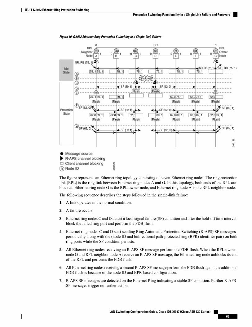
Figure 10: G.8032 Ethernet Ring Protection Switching in a Single-Link Failure
The figure represents an Ethernet ring topology consisting of seven Ethernet ring nodes. The ring protectionlink (RPL) is the ring link between Ethernet ring nodes A and G. In this topology, both ends of the RPL areblocked. Ethernet ring node G is the RPL owner node, and Ethernet ring node A is the RPL neighbor node.
The following sequence describes the steps followed in the single-link failure:
1. A link operates in the normal condition.
2. A failure occurs.
3. Ethernet ring nodes C and D detect a local signal failure (SF) condition and after the hold-off time interval,block the failed ring port and perform the FDB flush.
4. Ethernet ring nodes C and D start sending Ring Automatic Protection Switching (R-APS) SF messagesperiodically along with the (node ID and bidirectional path-protected ring (BPR) identifier pair) on bothring ports while the SF condition persists.
5. All Ethernet ring nodes receiving an R-APS SF message perform the FDB flush. When the RPL ownernode G and RPL neighbor node A receive an R-APS SF message, the Ethernet ring node unblocks its endof the RPL and performs the FDB flush.
6. All Ethernet ring nodes receiving a second R-APS SFmessage perform the FDB flush again; the additionalFDB flush is because of the node ID and BPR-based configuration.
7. R-APS SF messages are detected on the Ethernet Ring indicating a stable SF condition. Further R-APSSF messages trigger no further action.
LAN Switching Configuration Guide, Cisco IOS XE 17 (Cisco ASR 920 Series)65
ITU-T G.8032 Ethernet Ring Protection SwitchingProtection Switching Functionality in a Single Link Failure and Recovery
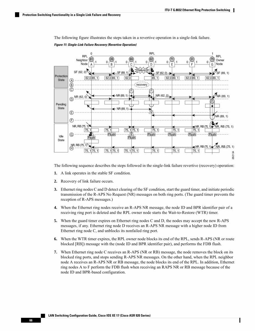
The following figure illustrates the steps taken in a revertive operation in a single-link failure.
Figure 11: Single-Link Failure Recovery (Revertive Operation)
The following sequence describes the steps followed in the single-link failure revertive (recovery) operation:
1. A link operates in the stable SF condition.
2. Recovery of link failure occurs.
3. Ethernet ring nodes C and D detect clearing of the SF condition, start the guard timer, and initiate periodictransmission of the R-APS No Request (NR) messages on both ring ports. (The guard timer prevents thereception of R-APS messages.)
4. When the Ethernet ring nodes receive an R-APS NR message, the node ID and BPR identifier pair of areceiving ring port is deleted and the RPL owner node starts the Wait-to-Restore (WTR) timer.
5. When the guard timer expires on Ethernet ring nodes C and D, the nodes may accept the new R-APSmessages, if any. Ethernet ring node D receives an R-APS NR message with a higher node ID fromEthernet ring node C, and unblocks its nonfailed ring port.
6. When the WTR timer expires, the RPL owner node blocks its end of the RPL, sends R-APS (NR or routeblocked [RB]) message with the (node ID and BPR identifier pair), and performs the FDB flush.
7. When Ethernet ring node C receives an R-APS (NR or RB) message, the node removes the block on itsblocked ring ports, and stops sending R-APS NR messages. On the other hand, when the RPL neighbornode A receives an R-APS NR or RB message, the node blocks its end of the RPL. In addition, Ethernetring nodes A to F perform the FDB flush when receiving an RAPS NR or RB message because of thenode ID and BPR-based configuration.
LAN Switching Configuration Guide, Cisco IOS XE 17 (Cisco ASR 920 Series)66
ITU-T G.8032 Ethernet Ring Protection SwitchingProtection Switching Functionality in a Single Link Failure and Recovery
Ethernet Flow PointsAn Ethernet flow point (EFP) is a forwarding decision point in the provider edge (PE) router, which givesnetwork designers flexibility to make many Layer 2 flow decisions within the interface. Many EFPs can beconfigured on a single physical port. (The number varies from one device to another.) EFPs are the logicaldemarcation points of an Ethernet virtual connection (EVC) on an interface. An EVC that uses two or moreuser network interfaces (UNIs) requires an EFP on the associated ingress and egress interfaces of every devicethat the EVC passes through.
EFPs can be configured on any Layer 2 traffic port; however, they are usually configured on UNI ports. Thefollowing parameters (matching criteria) can be configured on the EFP:
• Frames of a specific VLAN, a VLAN range, or a list of VLANs (100-150 or 100,103,110)
• Frames with no tags (untagged)
• Frames with identical double-tags (VLAN tags) as specified
• Frames with identical Class of Service (CoS) values
A frame passes each configured match criterion until the correct matching point is found. If a frame does notfit any of the matching criteria, it is dropped. Default criteria can be configured to avoid dropping frames.
You can configure a new type of TEFP called TEFP with encapsulation from bridge domain (BD). All theBDs configured on the switch are part of the VLAN list of the encapsulated TEFP. The TEFP is encapsulatedusing the encapsulation dot1q from-bd command. The feature brings about the following interaction betweenthe Ethernet-EFP and Layer2-bridge domain components:
• If BDs exist in the system and a TEFP with encapsulation from bridge domain is created, then all theBDs get added to the VLAN list of TEFP with encapsulation from bridge domain.
• If TEFP with encapsulation from bridge domain exists in the system and a new BD is created, then theBD is added to the VLAN list of all the TEFP with encapsulation from bridge domain in the system.
• If TEFP with encapsulation from bridge domain exists in the system and a BD gets deleted, and if thedeleted BD is not part of an existing TEFP or EFP then it gets deleted from all the TEFPwith encapsulationfrom bridge domain in the system.
The following types of commands can be used in an EFP:
• Rewrite commands—In each EFP, VLAN tag management can be specified with the following actions:
• Pop—1) pops out a tag; 2) pops out two tags
• Push— pushes in a tag
• Translate—1 to 1) changes a tag value; 1 to 2) pops one tag and pushes two tags; 2 to 1) pops twotags and pushes one tag; 2 to 2) changes the value for two tags
• Forwarding commands—Each EFP specifies the forwarding command for the frames that enter the EFP.Only one forwarding command can be configured per EFP. The forwarding options are as follows:
• Layer 2 point-to-point forwarding to a pseudowire tunnel
• Multipoint bridge forwarding to a bridge domain entity
• Local switch-to-switch forwarding between two different interfaces
LAN Switching Configuration Guide, Cisco IOS XE 17 (Cisco ASR 920 Series)67
ITU-T G.8032 Ethernet Ring Protection SwitchingEthernet Flow Points
• Feature commands—In each EFP, the QoS features or parameters can be changed and the ACL can beupdated.
Service Instances and Associated EFPsConfiguring a service instance on a Layer 2 port creates a pseudoport or EFP on which you configure EVCfeatures. Each service instance has a unique number per interface, but you can use the same number on differentinterfaces because service instances on different ports are not related.
An EFP classifies frames from the same physical port to one of the multiple service instances associated withthat port, based on user-defined criteria. Each EFP can be associated with different forwarding actions andbehavior.
When an EFP is created, the initial state is UP. The state changes to DOWN under the following circumstances:
• The EFP is explicitly shut down by a user.
• The main interface to which the EFP is associated is down or removed.
• If the EFP belongs to a bridge domain, the bridge domain is down.
• The EFP is forced down as an error-prevention measure of certain features.
Use the service instance ethernet interface configuration command to create an EFP on a Layer 2 interfaceand to enter service instance configuration mode. Service instance configuration mode is used to configureall management and control data plane attributes and parameters that apply to the service instance on aper-interface basis. The service instance number is the EFP identifier.
After the device enters service instance configuration mode, you can configure these options:
• default--Sets a command to its defaults
• description--Adds a service instance-specific description
• encapsulation--Configures Ethernet frame match criteria
• exit--Exits from service instance configuration mode
• no--Negates a command or sets its defaults
• shutdown--Takes the service instance out of service
Restrictions for Configuring ITU-T G.8032 Ethernet RingProtection Switching
• G.8032 is supported only on EFP bridge domains on the physical interface and port-channel interface.
• G.8032 is supported only on EFP with dot1q, dot1ad, QinQ, or dot1ad-dot1Q encapsulation type.
• G.8032 is not supported on cross-connect interface.
• G.8032 supports a maximum of eight ERP rings with a maximum of two ERP instances per ring.
• Link flap occurs while configuring the inclusion or exclusion VLAN list.
LAN Switching Configuration Guide, Cisco IOS XE 17 (Cisco ASR 920 Series)68
ITU-T G.8032 Ethernet Ring Protection SwitchingService Instances and Associated EFPs

• Admin shutdown is highly recommended before making any changes in Connectivity Fault Management(CFM) configuration.
• The efd notify command must be used under CFM configuration to notify G.8032 of failures, if any.
• G.8032 support is claimed only over the normal interfaces and not on the port-channels.
• G.8032 Ethernet Ring Protection Switching Version 1 and Version 2 are supported.
• BFD IPv4 and IPv6 Single Hop is supported. BFD Echo Mode is not supported.
How to Configure ITU-T G.8032 Ethernet Ring ProtectionSwitching
Configuring the Ethernet Ring ProfileTo configure the Ethernet ring profile, complete the following steps.
SUMMARY STEPS
1. enable2. configure terminal3. ethernet ring g8032 profile profile-name
4. timer {guard seconds | hold-off seconds | wtr minutes}5. non-revertive6. end
DETAILED STEPS
PurposeCommand or Action
Enables privileged EXEC mode.enableStep 1
Example: • Enter your password if prompted.
Device> enable
Enters global configuration mode.configure terminal
Example:
Step 2
Device# configure terminal
Creates the Ethernet ring profile and enters Ethernet ringprofile configuration mode.
ethernet ring g8032 profile profile-name
Example:
Step 3
Device(config)# ethernet ring g8032 profileprofile1
LAN Switching Configuration Guide, Cisco IOS XE 17 (Cisco ASR 920 Series)69
ITU-T G.8032 Ethernet Ring Protection SwitchingHow to Configure ITU-T G.8032 Ethernet Ring Protection Switching
PurposeCommand or Action
Specifies the time interval for the guard, hold-off, andWait-to-Restore (WTR) timers.
timer {guard seconds | hold-off seconds |wtr minutes}
Example:
Step 4
Device(config-erp-profile)# timer hold-off 5
Specifies a nonrevertive Ethernet ring instance.non-revertive
Example:
Step 5
• By default, Ethernet ring instances are revertive.
Device(config-erp-profile)# non-revertive
Returns to user EXEC mode.end
Example:
Step 6
Device(config-erp-profile)# end
Configuring Ethernet CFM MEPsConfiguring Ethernet Connectivity Fault Management (CFM) maintenance endpoints (MEPs) is optionalalthough recommended for fast failure detection and CFMmonitoring. When CFMmonitoring is configured,note the following points:
• Static remote MEP (RMEP) checking should be enabled.
• The MEPs should be configured to enable Ethernet fault detection.
For information about configuring Ethernet Connectivity Fault Management (CFM) maintenance endpoints(MEPs), see the “Configuring Ethernet Connectivity Fault Management in a Service Provider Network”module of the Carrier Ethernet Configuration Guide.
Enabling Ethernet Fault Detection for a ServiceTo enable Ethernet Fault Detection (EFD) for a service to achieve fast convergence, complete the followingsteps
Link protection is not supported on the RSP3 Module.Note
SUMMARY STEPS
1. enable2. configure terminal3. ethernet cfm global4. link-protection enable5. link-protection group management vlan vlan-id
6. link-protection group group-number pccm vlan vlan-id
7. ethernet cfm domaindomain-name level level-id [direction outward]
LAN Switching Configuration Guide, Cisco IOS XE 17 (Cisco ASR 920 Series)70
ITU-T G.8032 Ethernet Ring Protection SwitchingConfiguring Ethernet CFM MEPs
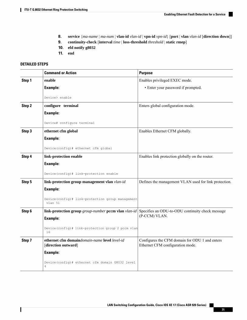
8. service {ma-name | ma-num | vlan-id vlan-id | vpn-id vpn-id} [port | vlan vlan-id [direction down]]9. continuity-check [interval time | loss-threshold threshold | static rmep]10. efd notify g803211. end
DETAILED STEPS
PurposeCommand or Action
Enables privileged EXEC mode.enableStep 1
Example: • Enter your password if prompted.
Device> enable
Enters global configuration mode.configure terminal
Example:
Step 2
Device# configure terminal
Enables Ethernet CFM globally.ethernet cfm global
Example:
Step 3
Device(config)# ethernet cfm global
Enables link protection globally on the router.link-protection enable
Example:
Step 4
Device(config)# link-protection enable
Defines the management VLAN used for link protection.link-protection group management vlan vlan-id
Example:
Step 5
Device(config)# link-protection group managementvlan 51
Specifies an ODU-to-ODU continuity check message(P-CCM) VLAN.
link-protection group group-number pccm vlan vlan-id
Example:
Step 6
Device(config)# link-protection group 2 pccm vlan16
Configures the CFM domain for ODU 1 and entersEthernet CFM configuration mode.
ethernet cfm domaindomain-name level level-id[direction outward]
Example:
Step 7
Device(config)# ethernet cfm domain G8032 level4
LAN Switching Configuration Guide, Cisco IOS XE 17 (Cisco ASR 920 Series)71
ITU-T G.8032 Ethernet Ring Protection SwitchingEnabling Ethernet Fault Detection for a Service
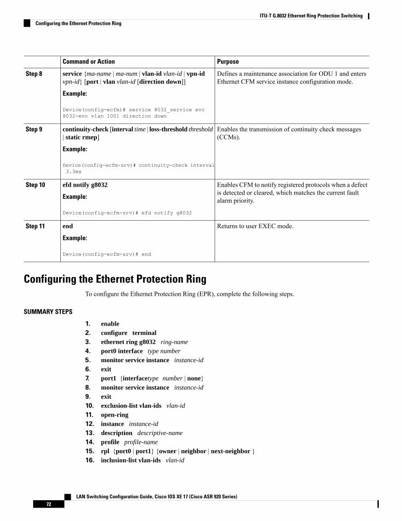
PurposeCommand or Action
Defines a maintenance association for ODU 1 and entersEthernet CFM service instance configuration mode.
service {ma-name | ma-num | vlan-id vlan-id | vpn-idvpn-id} [port | vlan vlan-id [direction down]]
Example:
Step 8
Device(config-ecfm)# service 8032_service evc8032-evc vlan 1001 direction down
Enables the transmission of continuity check messages(CCMs).
continuity-check [interval time | loss-threshold threshold| static rmep]
Example:
Step 9
Device(config-ecfm-srv)# continuity-check interval3.3ms
Enables CFM to notify registered protocols when a defectis detected or cleared, which matches the current faultalarm priority.
efd notify g8032
Example:
Device(config-ecfm-srv)# efd notify g8032
Step 10
Returns to user EXEC mode.end
Example:
Step 11
Device(config-ecfm-srv)# end
Configuring the Ethernet Protection RingTo configure the Ethernet Protection Ring (EPR), complete the following steps.
SUMMARY STEPS
1. enable2. configure terminal3. ethernet ring g8032 ring-name
4. port0 interface type number
5. monitor service instance instance-id
6. exit7. port1 {interfacetype number | none}8. monitor service instance instance-id
9. exit10. exclusion-list vlan-ids vlan-id
11. open-ring12. instance instance-id
13. description descriptive-name
14. profile profile-name
15. rpl {port0 | port1} {owner | neighbor | next-neighbor }16. inclusion-list vlan-ids vlan-id
LAN Switching Configuration Guide, Cisco IOS XE 17 (Cisco ASR 920 Series)72
ITU-T G.8032 Ethernet Ring Protection SwitchingConfiguring the Ethernet Protection Ring
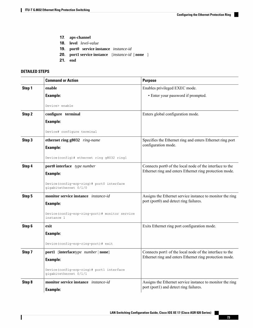
17. aps-channel18. level level-value
19. port0 service instance instance-id
20. port1 service instance {instance-id | none }21. end
DETAILED STEPS
PurposeCommand or Action
Enables privileged EXEC mode.enableStep 1
Example: • Enter your password if prompted.
Device> enable
Enters global configuration mode.configure terminal
Example:
Step 2
Device# configure terminal
Specifies the Ethernet ring and enters Ethernet ring portconfiguration mode.
ethernet ring g8032 ring-name
Example:
Step 3
Device(config)# ethernet ring g8032 ring1
Connects port0 of the local node of the interface to theEthernet ring and enters Ethernet ring protection mode.
port0 interface type number
Example:
Step 4
Device(config-erp-ring)# port0 interfacegigabitethernet 0/1/0
Assigns the Ethernet service instance to monitor the ringport (port0) and detect ring failures.
monitor service instance instance-id
Example:
Step 5
Device(config-erp-ring-port)# monitor serviceinstance 1
Exits Ethernet ring port configuration mode.exit
Example:
Step 6
Device(config-erp-ring-port)# exit
Connects port1 of the local node of the interface to theEthernet ring and enters Ethernet ring protection mode.
port1 {interfacetype number | none}
Example:
Step 7
Device(config-erp-ring)# port1 interfacegigabitethernet 0/1/1
Assigns the Ethernet service instance to monitor the ringport (port1) and detect ring failures.
monitor service instance instance-id
Example:
Step 8
LAN Switching Configuration Guide, Cisco IOS XE 17 (Cisco ASR 920 Series)73
ITU-T G.8032 Ethernet Ring Protection SwitchingConfiguring the Ethernet Protection Ring
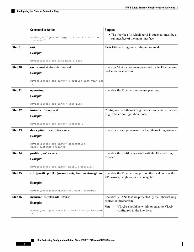
PurposeCommand or Action
Device(config-erp-ring-port)# monitor serviceinstance 2
• The interface (to which port1 is attached) must be asubinterface of the main interface.
Exits Ethernet ring port configuration mode.exit
Example:
Step 9
Device(config-erp-ring-port)# exit
Specifies VLANs that are unprotected by the Ethernet ringprotection mechanism.
exclusion-list vlan-ids vlan-id
Example:
Step 10
Device(config-erp-ring)# exclusion-list vlan-ids2
Specifies the Ethernet ring as an open ring.open-ring
Example:
Step 11
Device(config-erp-ring)# open-ring
Configures the Ethernet ring instance and enters Ethernetring instance configuration mode.
instance instance-id
Example:
Step 12
Device(config-erp-ring)# instance 1
Specifies a descriptive name for the Ethernet ring instance.description descriptive-name
Example:
Step 13
Device(config-erp-inst)# descriptioncisco_customer_instance
Specifies the profile associated with the Ethernet ringinstance.
profile profile-name
Example:
Step 14
Device(config-erp-inst)# profile profile1
Specifies the Ethernet ring port on the local node as theRPL owner, neighbor, or next neighbor.
rpl {port0 | port1} {owner | neighbor | next-neighbor}
Example:
Step 15
Device(config-erp-inst)# rpl port0 neighbor
Specifies VLANs that are protected by the Ethernet ringprotection mechanism.
inclusion-list vlan-ids vlan-id
Example:
Step 16
VLANs should be within or equal to VLANconfigured in the interface.
NoteDevice(config-erp-inst)# inclusion-list vlan-ids11
LAN Switching Configuration Guide, Cisco IOS XE 17 (Cisco ASR 920 Series)74
ITU-T G.8032 Ethernet Ring Protection SwitchingConfiguring the Ethernet Protection Ring
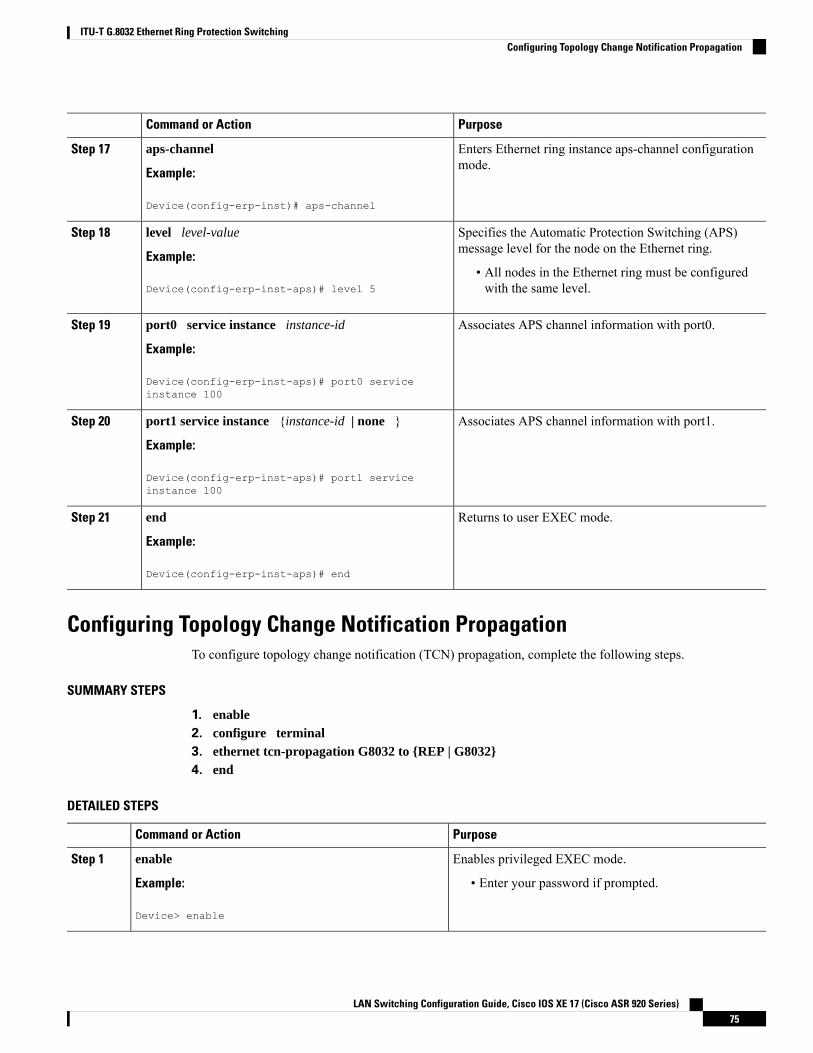
PurposeCommand or Action
Enters Ethernet ring instance aps-channel configurationmode.
aps-channel
Example:
Step 17
Device(config-erp-inst)# aps-channel
Specifies the Automatic Protection Switching (APS)message level for the node on the Ethernet ring.
level level-value
Example:
Step 18
• All nodes in the Ethernet ring must be configuredwith the same level.Device(config-erp-inst-aps)# level 5
Associates APS channel information with port0.port0 service instance instance-id
Example:
Step 19
Device(config-erp-inst-aps)# port0 serviceinstance 100
Associates APS channel information with port1.port1 service instance {instance-id | none }
Example:
Step 20
Device(config-erp-inst-aps)# port1 serviceinstance 100
Returns to user EXEC mode.end
Example:
Step 21
Device(config-erp-inst-aps)# end
Configuring Topology Change Notification PropagationTo configure topology change notification (TCN) propagation, complete the following steps.
SUMMARY STEPS
1. enable2. configure terminal3. ethernet tcn-propagation G8032 to {REP | G8032}4. end
DETAILED STEPS
PurposeCommand or Action
Enables privileged EXEC mode.enableStep 1
Example: • Enter your password if prompted.
Device> enable
LAN Switching Configuration Guide, Cisco IOS XE 17 (Cisco ASR 920 Series)75
ITU-T G.8032 Ethernet Ring Protection SwitchingConfiguring Topology Change Notification Propagation
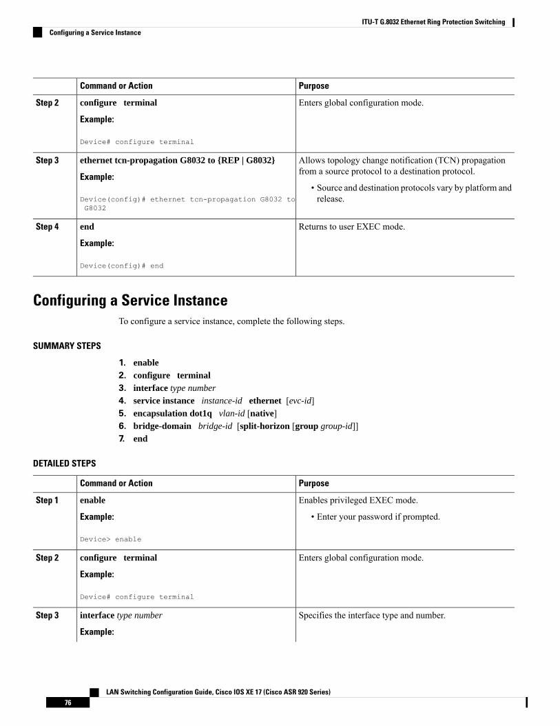
PurposeCommand or Action
Enters global configuration mode.configure terminal
Example:
Step 2
Device# configure terminal
Allows topology change notification (TCN) propagationfrom a source protocol to a destination protocol.
ethernet tcn-propagation G8032 to {REP | G8032}
Example:
Step 3
• Source and destination protocols vary by platform andrelease.Device(config)# ethernet tcn-propagation G8032 to
G8032
Returns to user EXEC mode.end
Example:
Step 4
Device(config)# end
Configuring a Service InstanceTo configure a service instance, complete the following steps.
SUMMARY STEPS
1. enable2. configure terminal3. interface type number
4. service instance instance-id ethernet [evc-id]5. encapsulation dot1q vlan-id [native]6. bridge-domain bridge-id [split-horizon [group group-id]]7. end
DETAILED STEPS
PurposeCommand or Action
Enables privileged EXEC mode.enableStep 1
Example: • Enter your password if prompted.
Device> enable
Enters global configuration mode.configure terminal
Example:
Step 2
Device# configure terminal
Specifies the interface type and number.interface type number
Example:
Step 3
LAN Switching Configuration Guide, Cisco IOS XE 17 (Cisco ASR 920 Series)76
ITU-T G.8032 Ethernet Ring Protection SwitchingConfiguring a Service Instance
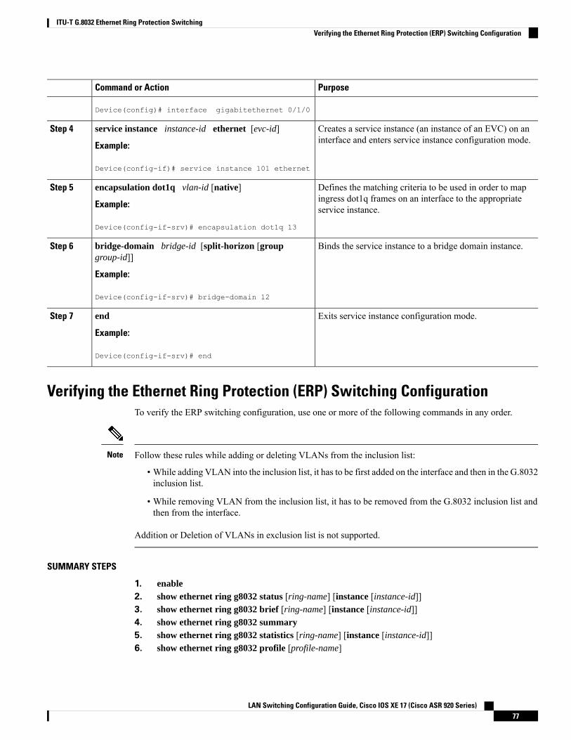
PurposeCommand or Action
Device(config)# interface gigabitethernet 0/1/0
Creates a service instance (an instance of an EVC) on aninterface and enters service instance configuration mode.
service instance instance-id ethernet [evc-id]
Example:
Step 4
Device(config-if)# service instance 101 ethernet
Defines the matching criteria to be used in order to mapingress dot1q frames on an interface to the appropriateservice instance.
encapsulation dot1q vlan-id [native]
Example:
Device(config-if-srv)# encapsulation dot1q 13
Step 5
Binds the service instance to a bridge domain instance.bridge-domain bridge-id [split-horizon [groupgroup-id]]
Step 6
Example:
Device(config-if-srv)# bridge-domain 12
Exits service instance configuration mode.end
Example:
Step 7
Device(config-if-srv)# end
Verifying the Ethernet Ring Protection (ERP) Switching ConfigurationTo verify the ERP switching configuration, use one or more of the following commands in any order.
Follow these rules while adding or deleting VLANs from the inclusion list:
• While adding VLAN into the inclusion list, it has to be first added on the interface and then in the G.8032inclusion list.
• While removing VLAN from the inclusion list, it has to be removed from the G.8032 inclusion list andthen from the interface.
Addition or Deletion of VLANs in exclusion list is not supported.
Note
SUMMARY STEPS
1. enable2. show ethernet ring g8032 status [ring-name] [instance [instance-id]]3. show ethernet ring g8032 brief [ring-name] [instance [instance-id]]4. show ethernet ring g8032 summary5. show ethernet ring g8032 statistics [ring-name] [instance [instance-id]]6. show ethernet ring g8032 profile [profile-name]
LAN Switching Configuration Guide, Cisco IOS XE 17 (Cisco ASR 920 Series)77
ITU-T G.8032 Ethernet Ring Protection SwitchingVerifying the Ethernet Ring Protection (ERP) Switching Configuration
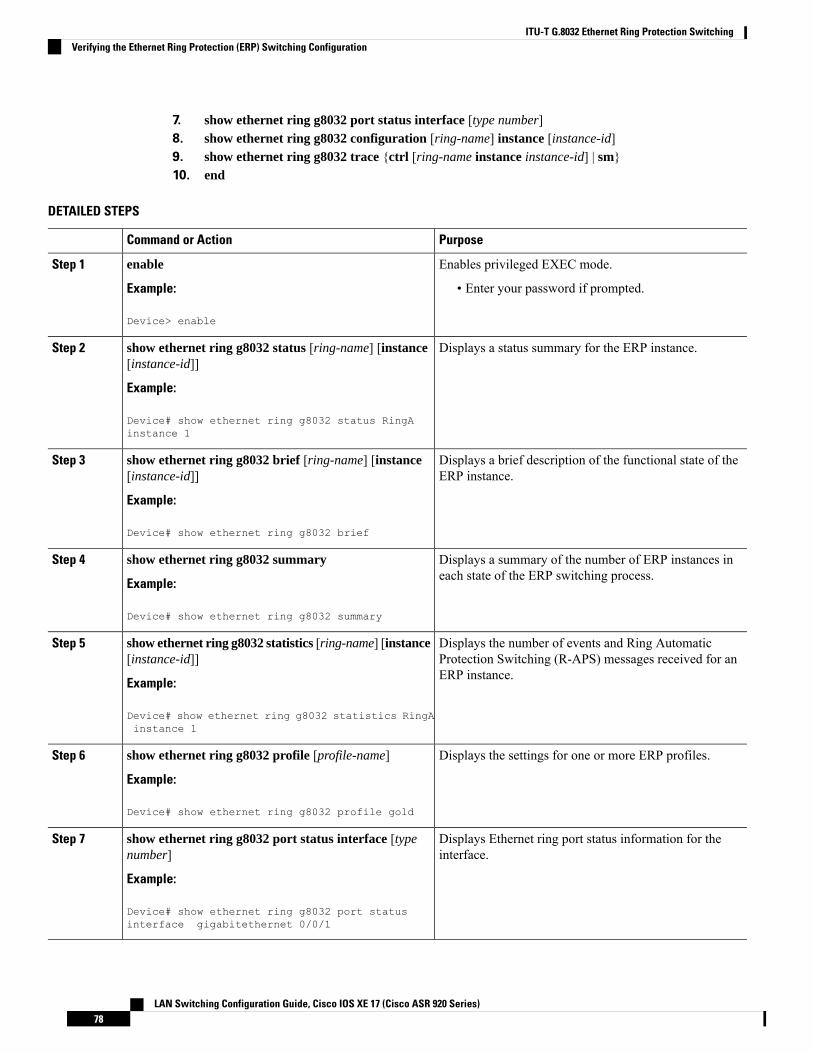
7. show ethernet ring g8032 port status interface [type number]8. show ethernet ring g8032 configuration [ring-name] instance [instance-id]9. show ethernet ring g8032 trace {ctrl [ring-name instance instance-id] | sm}10. end
DETAILED STEPS
PurposeCommand or Action
Enables privileged EXEC mode.enableStep 1
Example: • Enter your password if prompted.
Device> enable
Displays a status summary for the ERP instance.show ethernet ring g8032 status [ring-name] [instance[instance-id]]
Step 2
Example:
Device# show ethernet ring g8032 status RingAinstance 1
Displays a brief description of the functional state of theERP instance.
show ethernet ring g8032 brief [ring-name] [instance[instance-id]]
Example:
Step 3
Device# show ethernet ring g8032 brief
Displays a summary of the number of ERP instances ineach state of the ERP switching process.
show ethernet ring g8032 summary
Example:
Step 4
Device# show ethernet ring g8032 summary
Displays the number of events and Ring AutomaticProtection Switching (R-APS) messages received for anERP instance.
show ethernet ring g8032 statistics [ring-name] [instance[instance-id]]
Example:
Step 5
Device# show ethernet ring g8032 statistics RingAinstance 1
Displays the settings for one or more ERP profiles.show ethernet ring g8032 profile [profile-name]
Example:
Step 6
Device# show ethernet ring g8032 profile gold
Displays Ethernet ring port status information for theinterface.
show ethernet ring g8032 port status interface [typenumber]
Example:
Step 7
Device# show ethernet ring g8032 port statusinterface gigabitethernet 0/0/1
LAN Switching Configuration Guide, Cisco IOS XE 17 (Cisco ASR 920 Series)78
ITU-T G.8032 Ethernet Ring Protection SwitchingVerifying the Ethernet Ring Protection (ERP) Switching Configuration
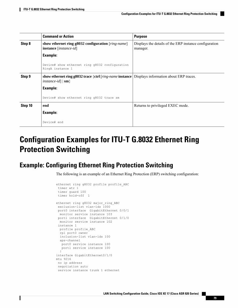
PurposeCommand or Action
Displays the details of the ERP instance configurationmanager.
show ethernet ring g8032 configuration [ring-name]instance [instance-id]
Example:
Step 8
Device# show ethernet ring g8032 configurationRingA instance 1
Displays information about ERP traces.show ethernet ring g8032 trace {ctrl [ring-name instanceinstance-id] | sm}
Step 9
Example:
Device# show ethernet ring g8032 trace sm
Returns to privileged EXEC mode.end
Example:
Step 10
Device# end
Configuration Examples for ITU-T G.8032 Ethernet RingProtection Switching
Example: Configuring Ethernet Ring Protection SwitchingThe following is an example of an Ethernet Ring Protection (ERP) switching configuration:
ethernet ring g8032 profile profile_ABCtimer wtr 1timer guard 100timer hold-off 1
ethernet ring g8032 major_ring_ABCexclusion-list vlan-ids 1000port0 interface GigabitEthernet 0/0/1monitor service instance 103port1 interface GigabitEthernet 0/1/0monitor service instance 102instance 1profile profile_ABCrpl port0 ownerinclusion-list vlan-ids 100aps-channelport0 service instance 100port1 service instance 100!
interface GigabitEthernet0/1/0mtu 9216no ip addressnegotiation autoservice instance trunk 1 ethernet
LAN Switching Configuration Guide, Cisco IOS XE 17 (Cisco ASR 920 Series)79
ITU-T G.8032 Ethernet Ring Protection SwitchingConfiguration Examples for ITU-T G.8032 Ethernet Ring Protection Switching
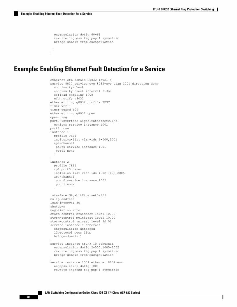
encapsulation dot1q 60-61rewrite ingress tag pop 1 symmetricbridge-domain from-encapsulation
!!
Example: Enabling Ethernet Fault Detection for a Serviceethernet cfm domain G8032 level 4service 8032_service evc 8032-evc vlan 1001 direction downcontinuity-checkcontinuity-check interval 3.3msoffload sampling 1000efd notify g8032
ethernet ring g8032 profile TESTtimer wtr 1timer guard 100ethernet ring g8032 openopen-ringport0 interface GigabitEthernet0/1/3monitor service instance 1001
port1 noneinstance 1profile TESTinclusion-list vlan-ids 2-500,1001aps-channelport0 service instance 1001port1 none!
!instance 2profile TESTrpl port0 ownerinclusion-list vlan-ids 1002,1005-2005aps-channelport0 service instance 1002port1 none!
interface GigabitEthernet0/1/3no ip addressload-interval 30shutdownnegotiation autostorm-control broadcast level 10.00storm-control multicast level 10.00storm-control unicast level 90.00service instance 1 ethernetencapsulation untaggedl2protocol peer lldpbridge-domain 1
!service instance trunk 10 ethernetencapsulation dot1q 2-500,1005-2005rewrite ingress tag pop 1 symmetricbridge-domain from-encapsulation
!service instance 1001 ethernet 8032-evcencapsulation dot1q 1001rewrite ingress tag pop 1 symmetric
LAN Switching Configuration Guide, Cisco IOS XE 17 (Cisco ASR 920 Series)80
ITU-T G.8032 Ethernet Ring Protection SwitchingExample: Enabling Ethernet Fault Detection for a Service

bridge-domain 1001cfm mep domain G8032 mpid 20
!service instance 1002 ethernet 8032-evc-1encapsulation dot1q 1002rewrite ingress tag pop 1 symmetricbridge-domain 1002
!End
Example: Verifying the Ethernet Ring Protection ConfigurationThe following is sample output from the show ethernet ring g8032 configuration command. Use thiscommand to verify if the configuration entered is valid and to check for anymissing configuration parameters.
Device# show ethernet ring g8032 configuration
ethernet ring ring0Port0: GigabitEthernet0/0/0 (Monitor: GigabitEthernet0/0/0)Port1: GigabitEthernet0/0/4 (Monitor: GigabitEthernet0/0/4)Exclusion-list VLAN IDs: 4001-4050Open-ring: noInstance 1Description:Profile: oppRPL:Inclusion-list VLAN IDs: 2,10-500APS channelLevel: 7Port0: Service Instance 1Port1: Service Instance 1State: configuration resolved
LAN Switching Configuration Guide, Cisco IOS XE 17 (Cisco ASR 920 Series)81
ITU-T G.8032 Ethernet Ring Protection SwitchingExample: Verifying the Ethernet Ring Protection Configuration

LAN Switching Configuration Guide, Cisco IOS XE 17 (Cisco ASR 920 Series)82
ITU-T G.8032 Ethernet Ring Protection SwitchingExample: Verifying the Ethernet Ring Protection Configuration
C H A P T E R 7Multiple Spanning Tree Protocol
TheMultiple Spanning Tree Protocol (MSTP) is an STP variant that allowsmultiple and independent spanningtrees to be created over the same physical network. The parameters for each spanning tree can be configuredseparately, so as to cause a different network devices to be selected as the root bridge or different paths to beselected to form the loop-free topology. Consequently, a given physical interface can be blocked for some ofthe spanning trees and unblocked for others.
Having set up multiple spanning trees, the set of VLANs in use can be partitioned among them; for example,VLANs 1 - 100 can be assigned to spanning tree 1, VLANs 101 - 200 can be assigned to spanning tree 2,VLANs 201 - 300 can be assigned to spanning tree 3, and so on. Since each spanning tree has a differentactive topology with different active links, this has the effect of dividing the data traffic among the availableredundant links based on the VLAN - a form of load balancing.
• Restrictions for configuring MSTP, on page 83• How to Configure MST Protocol, on page 83
Restrictions for configuring MSTP• RSTP is not supported. To support RSTP, all vlans are mapped to MSTI 0 when no instance is createdfor MSTP.
• PVSTP is not supported.
• Supports only 16 instances.
• Untagged EVCs do not participate in MST loop detection.
How to Configure MST ProtocolThis section describes the procedure for configuring MSTP:
Enabling Multiple Spanning Tree ProtocolBy default, MSTP is disabled on all interfaces. MSTP need not be enabled explicitly on each interfaces. Byturning the global configuration on, it is enabled on all interfaces.
LAN Switching Configuration Guide, Cisco IOS XE 17 (Cisco ASR 920 Series)83
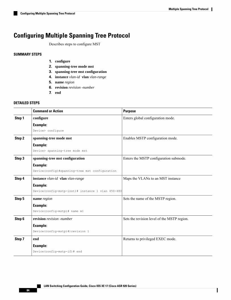
Configuring Multiple Spanning Tree ProtocolDescribes steps to configure MST
SUMMARY STEPS
1. configure2. spanning-tree mode mst3. spanning-tree mst configuration4. instance vlan-id vlan vlan-range
5. name region
6. revision revision -number
7. end
DETAILED STEPS
PurposeCommand or Action
Enters global configuration mode.configure
Example:
Step 1
Device> configure
Enables MSTP configuration mode.spanning-tree mode mst
Example:
Step 2
Device> spanning-tree mode mst
Enters the MSTP configuration submode.spanning-tree mst configuration
Example:
Step 3
Device(config)#spanning-tree mst configuration
Maps the VLANs to an MST instanceinstance vlan-id vlan vlan-range
Example:
Step 4
Device(config-mstp-inst)# instance 1 vlan 450-480
Sets the name of the MSTP region.name region
Example:
Step 5
Device(config-mstp)# name m1
Sets the revision level of the MSTP region.revision revision -number
Example:
Step 6
Device(config-mstp)#)revision 1
Returns to privileged EXEC mode.end
Example:
Step 7
Device(config-mstp-if)# end
LAN Switching Configuration Guide, Cisco IOS XE 17 (Cisco ASR 920 Series)84
Multiple Spanning Tree ProtocolConfiguring Multiple Spanning Tree Protocol
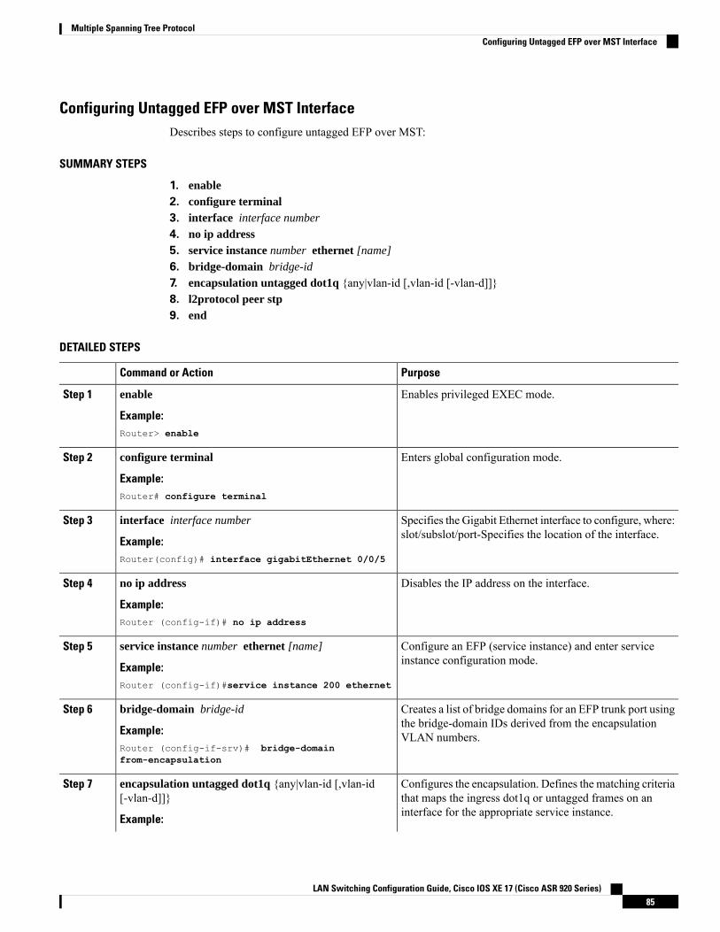
Configuring Untagged EFP over MST InterfaceDescribes steps to configure untagged EFP over MST:
SUMMARY STEPS
1. enable2. configure terminal3. interface interface number
4. no ip address5. service instance number ethernet [name]
6. bridge-domain bridge-id
7. encapsulation untagged dot1q {any|vlan-id [,vlan-id [-vlan-d]]}8. l2protocol peer stp9. end
DETAILED STEPS
PurposeCommand or Action
Enables privileged EXEC mode.enable
Example:
Step 1
Router> enable
Enters global configuration mode.configure terminal
Example:
Step 2
Router# configure terminal
Specifies the Gigabit Ethernet interface to configure, where:slot/subslot/port-Specifies the location of the interface.
interface interface number
Example:
Step 3
Router(config)# interface gigabitEthernet 0/0/5
Disables the IP address on the interface.no ip address
Example:
Step 4
Router (config-if)# no ip address
Configure an EFP (service instance) and enter serviceinstance configuration mode.
service instance number ethernet [name]
Example:
Step 5
Router (config-if)#service instance 200 ethernet
Creates a list of bridge domains for an EFP trunk port usingthe bridge-domain IDs derived from the encapsulationVLAN numbers.
bridge-domain bridge-id
Example:Router (config-if-srv)# bridge-domainfrom-encapsulation
Step 6
Configures the encapsulation. Defines the matching criteriathat maps the ingress dot1q or untagged frames on aninterface for the appropriate service instance.
encapsulation untagged dot1q {any|vlan-id [,vlan-id[-vlan-d]]}
Example:
Step 7
LAN Switching Configuration Guide, Cisco IOS XE 17 (Cisco ASR 920 Series)85
Multiple Spanning Tree ProtocolConfiguring Untagged EFP over MST Interface
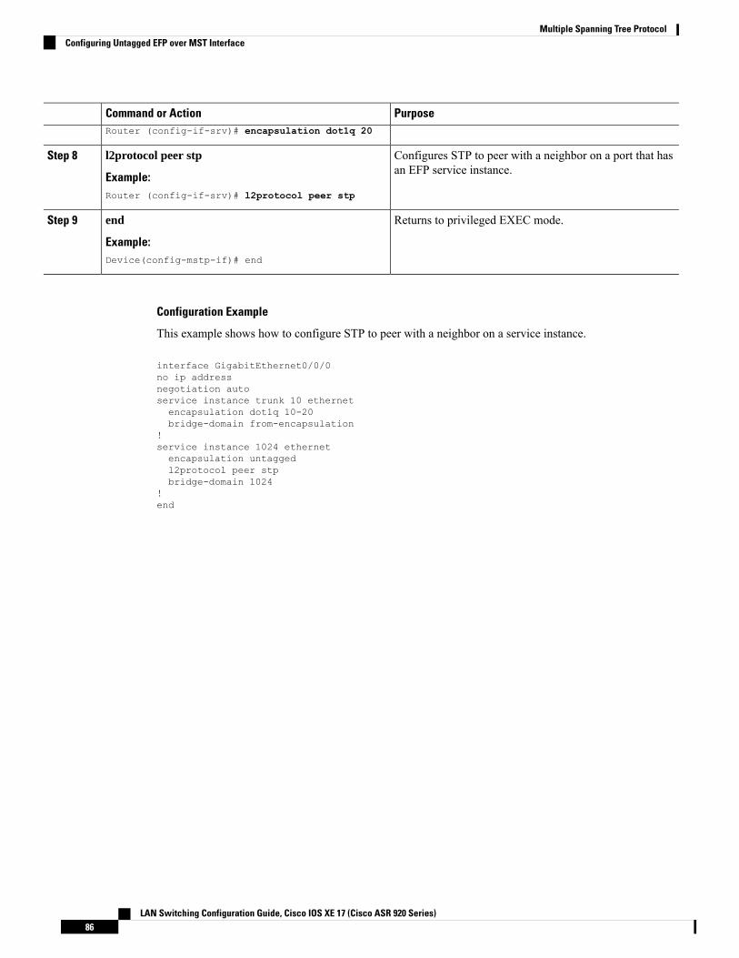
PurposeCommand or ActionRouter (config-if-srv)# encapsulation dot1q 20
Configures STP to peer with a neighbor on a port that hasan EFP service instance.
l2protocol peer stp
Example:
Step 8
Router (config-if-srv)# l2protocol peer stp
Returns to privileged EXEC mode.end
Example:
Step 9
Device(config-mstp-if)# end
Configuration Example
This example shows how to configure STP to peer with a neighbor on a service instance.
interface GigabitEthernet0/0/0no ip addressnegotiation autoservice instance trunk 10 ethernetencapsulation dot1q 10-20bridge-domain from-encapsulation
!service instance 1024 ethernetencapsulation untaggedl2protocol peer stpbridge-domain 1024
!end
LAN Switching Configuration Guide, Cisco IOS XE 17 (Cisco ASR 920 Series)86
Multiple Spanning Tree ProtocolConfiguring Untagged EFP over MST Interface
C H A P T E R 8Configuring PVST+ and RPVST+
This chapter describes how to configure the Spanning Tree Protocol (STP) on port-based VLANs on the Ciscorouter. The router can use the per-VLAN spanning-tree plus (PVST+) protocol based on the IEEE 802.1Dstandard and Cisco proprietary extensions, or the rapid per-VLAN spanning-tree plus (rapid-PVST+) protocolbased on the IEEE 802.1w standard.
For information about the Multiple Spanning Tree Protocol (MSTP) and how to map multiple VLANs to thesame spanning-tree instance, see the Multiple Spanning Tree Protocol chapter.
For complete syntax and usage information for the commands used in this chapter, see the command referencefor this release.
Note
This feature is only applicable for Cisco NCS 4201 and NCS 4202.Note
• STP Overview, on page 88• Spanning-Tree Topology and BPDUs, on page 88• Bridge ID, Switch Priority, and Extended System ID, on page 89• Spanning-Tree Interface States, on page 90• How a Switch or Port Becomes the Root Switch or Root Port, on page 92• Spanning Tree and Redundant Connectivity, on page 93• Spanning-Tree Modes and Protocols, on page 94• Restrictions for PVST+ and RPVST+, on page 94• Spanning-Tree Interoperability and Backward Compatibility, on page 95• Default Spanning-Tree Configuration, on page 95• Configuring PVST+ and RPVST+, on page 96• Configuring STP Peer Under EFP/TEFP, on page 96• Disabling Spanning Tree, on page 98• Verifying PVST/RPVST Settings, on page 98• Configuring the Root Switch, on page 99• Configuring a Secondary Root Switch, on page 101• Configuring Port Priority, on page 102• Configuring Path Cost, on page 103
LAN Switching Configuration Guide, Cisco IOS XE 17 (Cisco ASR 920 Series)87
• Configuring the Switch Priority of a VLAN, on page 105• Configuring Spanning-Tree Timers, on page 106• Displaying the Spanning-Tree Status, on page 108
STP OverviewSTP is a Layer 2 link management protocol that provides path redundancy while preventing loops in thenetwork. For a Layer 2 Ethernet network to function properly, only one active path can exist between anytwo stations. Multiple active paths among end stations cause loops in the network. If a loop exists in thenetwork, end stations might receive duplicate messages. Switches might also learn end-stationMAC addresseson multiple Layer 2 interfaces. These conditions result in an unstable network. Spanning-tree operation istransparent to end stations, which cannot detect whether they are connected to a single LAN segment or aswitched LAN of multiple segments.
The STP uses a spanning-tree algorithm to select one switch of a redundantly connected network as the rootof the spanning tree. The algorithm calculates the best loop-free path through a switched Layer 2 network byassigning a role to each port based on the role of the port in the active topology:
• Root—A forwarding port elected for the spanning-tree topology• Designated—A forwarding port elected for every switched LAN segment• Alternate—A blocked port providing an alternate path to the root bridge in the spanning tree• Backup—A blocked port in a loopback configuration
The switch that has all of its ports as the designated role or the backup role is the root switch. The switch thathas at least one of its ports in the designated role is called the designated switch.
Spanning tree forces redundant data paths into a standby (blocked) state. If a network segment in the spanningtree fails and a redundant path exists, the spanning-tree algorithm recalculates the spanning-tree topology andactivates the standby path. Switches send and receive spanning-tree frames, called bridge protocol data units(BPDUs), at regular intervals. The switches do not forward these frames but use them to construct a loop-freepath. BPDUs contain information about the sending switch and its ports, including switch andMAC addresses,switch priority, port priority, and path cost. Spanning tree uses this information to elect the root switch androot port for the switched network and the root port and designated port for each switched segment.
When two ports on a switch are part of a loop, the spanning-tree port priority and path cost settings controlwhich port is put in the forwarding state and which is put in the blocking state. The spanning-tree port priorityvalue represents the location of a port in the network topology and how well it is located to pass traffic. Thepath cost value represents the media speed.
Spanning-Tree Topology and BPDUsThe stable, active spanning-tree topology of a switched network is controlled by these elements:
• The unique bridge ID (switch priority and MAC address) associated with each VLAN on each switch.• The spanning-tree path cost to the root switch.• The port identifier (port priority and MAC address) associated with each Layer 2 STP-enabled interface.
When the switches in a network are powered up, each functions as the root switch. Each switch sends aconfiguration BPDU through all of its ports only through the STP-enabled ports. The BPDUs communicateand compute the spanning-tree topology. Each configuration BPDU contains this information:
• The unique bridge ID of the switch that the sending switch identifies as the root switch
LAN Switching Configuration Guide, Cisco IOS XE 17 (Cisco ASR 920 Series)88
Configuring PVST+ and RPVST+STP Overview
• The spanning-tree path cost to the root• The bridge ID of the sending switch• Message age• The identifier of the sending interface• Values for the hello, forward delay, and max-age protocol timers
When a switch receives a configuration BPDU that contains superior information (lower bridge ID, lowerpath cost, and so forth), it stores the information for that port. If this BPDU is received on the root port of theswitch, the switch also forwards it with an updated message to all attached LANs for which it is the designatedswitch.
If a switch receives a configuration BPDU that contains inferior information to that currently stored for thatport, it discards the BPDU. If the switch is a designated switch for the LAN from which the inferior BPDUwas received, it sends that LAN a BPDU containing the up-to-date information stored for that port. In thisway, inferior information is discarded, and superior information is propagated on the network.
A BPDU exchange results in these actions:
• One switch in the network is elected as the root switch (the logical center of the spanning-tree topologyin a switched network).
For each VLAN, the switch with the highest switch priority (the lowest numerical priority value) is electedas the root switch. If all switches are configured with the default priority (32768), the switch with the lowestMAC address in the VLAN becomes the root switch. The switch priority value occupies the most significantbits of the bridge ID, as shown in tables Switch Priority Value and Extended System ID and Spanning-TreeTimer.
• A root port is selected for each switch (except the root switch). This port provides the best path (lowestcost) when the switch forwards packets to the root switch.
• The shortest distance to the root switch is calculated for each switch based on the path cost.• A designated switch for each LAN segment is selected. The designated switch incurs the lowest pathcost when forwarding packets from that LAN to the root switch. The port through which the designatedswitch is attached to the LAN is called the designated port.
All paths that are not needed to reach the root switch from anywhere in the switched network are placed inthe spanning-tree blocking mode.
Bridge ID, Switch Priority, and Extended System IDThe IEEE 802.1D standard requires that each switch has an unique bridge identifier (bridge ID), which controlsthe selection of the root switch. Because each VLAN is considered as a different logical bridge with PVST+and rapid PVST+, the same switch must have as many different bridge IDs as VLANs configured on it. EachVLAN on the switch has a unique 8-byte bridge ID. The two most-significant bytes are used for the switchpriority, and the remaining six bytes are derived from the switch MAC address.
The switch supports the IEEE 802.1t spanning-tree extensions, and some of the bits previously used for theswitch priority are now used as the VLAN identifier. The result is that fewer MAC addresses are reserved forthe switch, and a larger range of VLAN IDs can be supported, all while maintaining the uniqueness of thebridge ID. As shown in table Switch Priority Value and Extended System ID, the two bytes previously usedfor the switch priority are reallocated into a 4-bit priority value and a 12-bit extended system ID value equalto the VLAN ID.
LAN Switching Configuration Guide, Cisco IOS XE 17 (Cisco ASR 920 Series)89
Configuring PVST+ and RPVST+Bridge ID, Switch Priority, and Extended System ID
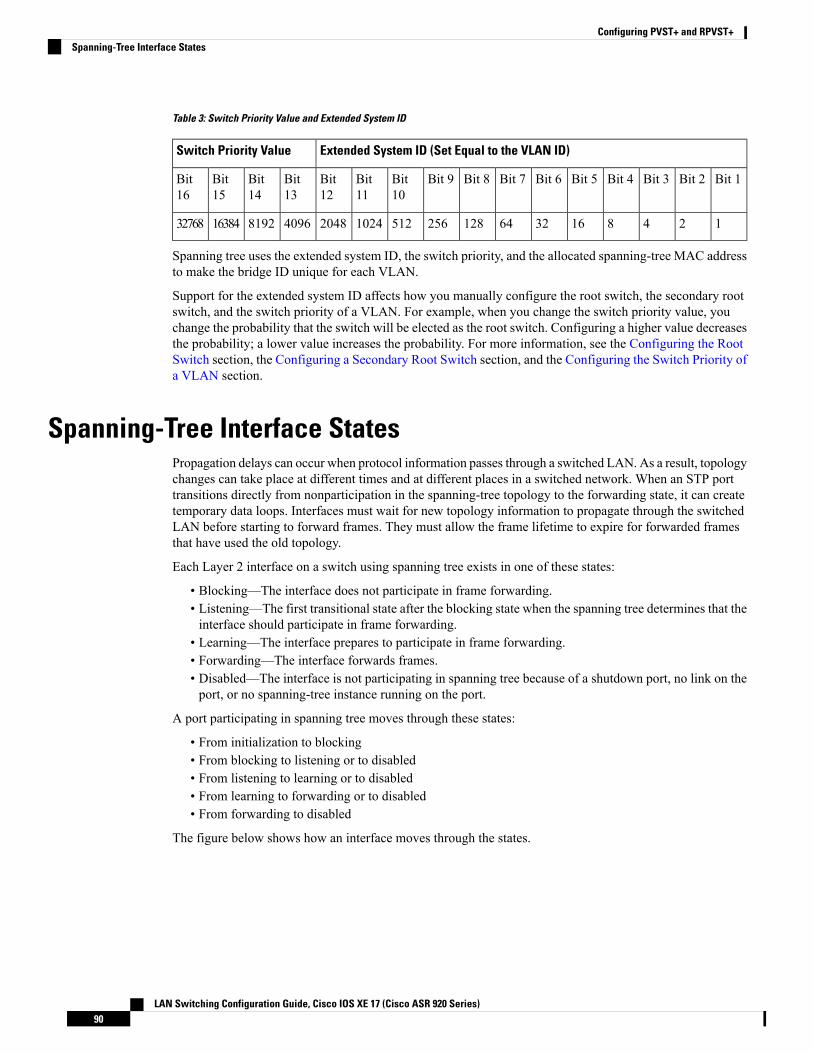
Table 3: Switch Priority Value and Extended System ID
Extended System ID (Set Equal to the VLAN ID)Switch Priority Value
Bit 1Bit 2Bit 3Bit 4Bit 5Bit 6Bit 7Bit 8Bit 9Bit10
Bit11
Bit12
Bit13
Bit14
Bit15
Bit16
124816326412825651210242048409681921638432768
Spanning tree uses the extended system ID, the switch priority, and the allocated spanning-tree MAC addressto make the bridge ID unique for each VLAN.
Support for the extended system ID affects how you manually configure the root switch, the secondary rootswitch, and the switch priority of a VLAN. For example, when you change the switch priority value, youchange the probability that the switch will be elected as the root switch. Configuring a higher value decreasesthe probability; a lower value increases the probability. For more information, see the Configuring the RootSwitch section, the Configuring a Secondary Root Switch section, and the Configuring the Switch Priority ofa VLAN section.
Spanning-Tree Interface StatesPropagation delays can occur when protocol information passes through a switched LAN. As a result, topologychanges can take place at different times and at different places in a switched network. When an STP porttransitions directly from nonparticipation in the spanning-tree topology to the forwarding state, it can createtemporary data loops. Interfaces must wait for new topology information to propagate through the switchedLAN before starting to forward frames. They must allow the frame lifetime to expire for forwarded framesthat have used the old topology.
Each Layer 2 interface on a switch using spanning tree exists in one of these states:
• Blocking—The interface does not participate in frame forwarding.• Listening—The first transitional state after the blocking state when the spanning tree determines that theinterface should participate in frame forwarding.
• Learning—The interface prepares to participate in frame forwarding.• Forwarding—The interface forwards frames.• Disabled—The interface is not participating in spanning tree because of a shutdown port, no link on theport, or no spanning-tree instance running on the port.
A port participating in spanning tree moves through these states:
• From initialization to blocking• From blocking to listening or to disabled• From listening to learning or to disabled• From learning to forwarding or to disabled• From forwarding to disabled
The figure below shows how an interface moves through the states.
LAN Switching Configuration Guide, Cisco IOS XE 17 (Cisco ASR 920 Series)90
Configuring PVST+ and RPVST+Spanning-Tree Interface States

Figure 12: Spanning-Tree Interface States
Spanning tree is not enabled by default. Once the spanning tree mode is selected, each VLAN on ports goesthrough the blocking state and the transitionary states of listening and learning. Spanning tree stabilizes eachinterface at the forwarding or blocking state.
When the spanning-tree algorithm places a Layer 2 spanning-tree interface in the forwarding state, this processoccurs:
1. The interface is in the listening state while spanning tree waits for protocol information to transition theinterface to the blocking state.
2. While spanning tree waits the forward-delay timer to expire, it moves the interface to the learning stateand resets the forward-delay timer.
3. In the learning state, the interface continues to block frame forwarding as the switch learns end-stationlocation information for the forwarding database.
4. When the forward-delay timer expires, spanning tree moves the interface to the forwarding state, whereboth learning and frame forwarding are enabled.
Blocking StateALayer 2 interface in the blocking state does not participate in frame forwarding. After initialization, a BPDUis sent to each switch interface, or to each switch STP port. A switch initially functions as the root until itexchanges BPDUs with other switches. This exchange establishes which switch in the network is the root orroot switch. If there is only one switch in the network, no exchange occurs, the forward-delay timer expires,and the interface moves to the listening state. An interface participating in spanning tree always enters theblocking state after switch initialization.
An interface in the blocking state performs these functions:
• Discards frames received on the interface• Discards frames switched from another interface for forwarding• Does not learn addresses• Receives BPDUs
Listening StateThe listening state is the first state a Layer 2 interface enters after the blocking state. The interface enters thisstate when the spanning tree decides that the interface should participate in frame forwarding.
LAN Switching Configuration Guide, Cisco IOS XE 17 (Cisco ASR 920 Series)91
Configuring PVST+ and RPVST+Blocking State
An interface in the listening state performs these functions:
• Discards frames received on the interface• Discards frames switched from another interface for forwarding• Does not learn addresses• Receives BPDUs
Learning StateA Layer 2 interface in the learning state prepares to participate in frame forwarding. The interface enters thelearning state from the listening state.
An interface in the learning state performs these functions:
• Discards frames received on the interface• Discards frames switched from another interface for forwarding• Learns addresses• Receives BPDUs
Forwarding StateA Layer 2 interface in the forwarding state forwards frames. The interface enters the forwarding state fromthe learning state.
An interface in the forwarding state performs these functions:
• Receives and forwards frames received on the interface• Forwards frames switched from another interface• Learns addresses• Receives BPDUs
Disabled StateA Layer 2 interface in the disabled state does not participate in frame forwarding or in the spanning tree. Aninterface in the disabled state is non operational.
A disabled interface performs these functions:
• Discards frames received on the interface• Discards frames switched from another interface for forwarding• Does not learn addresses• Does not receive BPDUs
How a Switch or Port Becomes the Root Switch or Root PortIf all switches in a network are enabled with default spanning-tree settings, the switch with the lowest MACaddress becomes the root switch. In the figure below , Switch A is elected as the root switch because theswitch priority of all the switches is set to the default (32768) and Switch A has the lowest MAC address.However, because of traffic patterns, number of forwarding interfaces, or link types, Switch A might not bethe ideal root switch. By increasing the priority (lowering the numerical value) of the ideal switch so that it
LAN Switching Configuration Guide, Cisco IOS XE 17 (Cisco ASR 920 Series)92
Configuring PVST+ and RPVST+Learning State
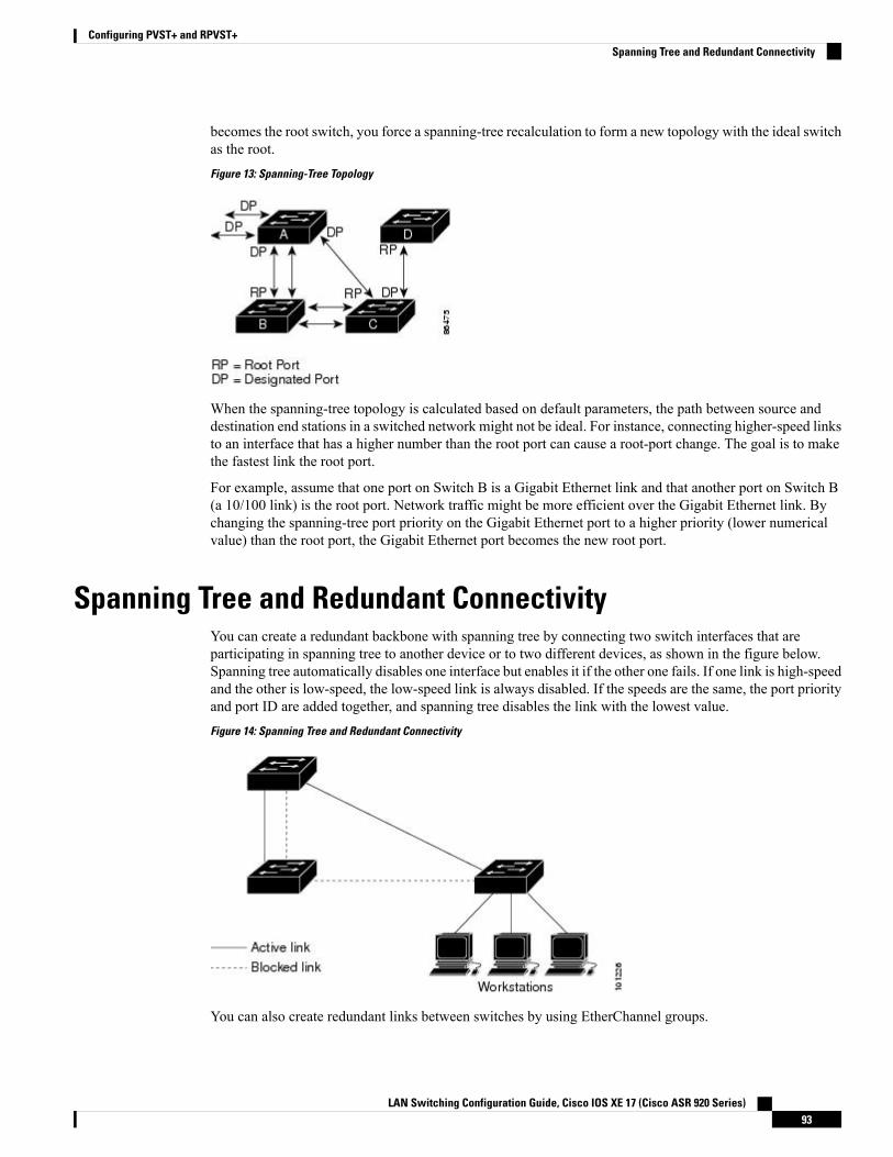
becomes the root switch, you force a spanning-tree recalculation to form a new topology with the ideal switchas the root.
Figure 13: Spanning-Tree Topology
When the spanning-tree topology is calculated based on default parameters, the path between source anddestination end stations in a switched network might not be ideal. For instance, connecting higher-speed linksto an interface that has a higher number than the root port can cause a root-port change. The goal is to makethe fastest link the root port.
For example, assume that one port on Switch B is a Gigabit Ethernet link and that another port on Switch B(a 10/100 link) is the root port. Network traffic might be more efficient over the Gigabit Ethernet link. Bychanging the spanning-tree port priority on the Gigabit Ethernet port to a higher priority (lower numericalvalue) than the root port, the Gigabit Ethernet port becomes the new root port.
Spanning Tree and Redundant ConnectivityYou can create a redundant backbone with spanning tree by connecting two switch interfaces that areparticipating in spanning tree to another device or to two different devices, as shown in the figure below.Spanning tree automatically disables one interface but enables it if the other one fails. If one link is high-speedand the other is low-speed, the low-speed link is always disabled. If the speeds are the same, the port priorityand port ID are added together, and spanning tree disables the link with the lowest value.
Figure 14: Spanning Tree and Redundant Connectivity
You can also create redundant links between switches by using EtherChannel groups.
LAN Switching Configuration Guide, Cisco IOS XE 17 (Cisco ASR 920 Series)93
Configuring PVST+ and RPVST+Spanning Tree and Redundant Connectivity

Spanning-Tree Modes and ProtocolsThe following spanning-tree modes and protocols are supported:
• PVST+—This spanning-treemode is based on the IEEE 802.1D standard and Cisco proprietary extensions.The PVST+ runs on each VLAN on the switch up to the maximum supported, ensuring that each has aloop-free path through the network.
The PVST+ provides Layer 2 load balancing for the VLAN on which it runs. You can create differentlogical topologies by using the VLANs on your network to ensure that all of your links are used but thatno one link is oversubscribed. Each instance of PVST+ on a VLAN has a single root switch. This rootswitch propagates the spanning-tree information associated with that VLAN to all other switches in thenetwork. Because each switch has the same information about the network, this process ensures that thenetwork topology is maintained.
• Rapid PVST+—This spanning-tree mode is the same as PVST+ except that is uses a rapid convergencebased on the IEEE 802.1w standard. Rapid PVST+ is compatible with PVST+. To provide rapidconvergence, the rapid PVST+ immediately deletes dynamically learned MAC address entries on aper-port basis upon receiving a topology change. By contrast, PVST+ uses a short aging time fordynamically learned MAC address entries.
The rapid PVST+ uses the same configuration as PVST+ (except where noted), and the switch needsonly minimal extra configuration. The benefit of rapid PVST+ is that you can migrate a large PVST+install base to rapid PVST+ without having to learn the complexities of the MSTP configuration andwithout having to reprovision your network. In rapid-PVST+mode, eachVLAN runs its own spanning-treeinstance up to the maximum supported.
• MSTP—This spanning-tree mode is based on the IEEE 802.1s standard. You can map multiple VLANsto the same spanning-tree instance, which reduces the number of spanning-tree instances required tosupport a large number of VLANs. The MSTP runs on top of the RSTP (based on IEEE 802.1w), whichprovides for rapid convergence of the spanning tree by eliminating the forward delay and by quicklytransitioning root ports and designated ports to the forwarding state. You cannot run MSTP withoutRSTP.
The most common initial deployment of MSTP is in the backbone and distribution layers of a Layer 2switched network. For more information, see Multiple Spanning Tree Protocol chapter.
For information about the number of supported spanning-tree instances, see Restrictions for PVST+ andRPVST+, on page 94.
Restrictions for PVST+ and RPVST+• In PVST+ or rapid-PVST+ mode, the switch supports up to 128 spanning-tree instances.
• You must configure l2protocol peer stp command under all the EFP where you prefer to run STP.
The l2protocol peer stp influences how STP BPDUs are treated in ingress direction [drop or process],however it has no effect on STP BPDU in egress direction. The ASR 920 router always transmits STPBPDUs is the egress direction.
• Port fast trunk works only if you configure it under interface mode and not under global mode.
• ROOT guard works only if you configure it under interface mode and not under global mode.
LAN Switching Configuration Guide, Cisco IOS XE 17 (Cisco ASR 920 Series)94
Configuring PVST+ and RPVST+Spanning-Tree Modes and Protocols

Spanning-Tree Interoperability and Backward CompatibilityThe table below lists the interoperability and compatibility among the supported spanning-tree modes in anetwork.
Table 4: PVST+, MSTP, and Rapid-PVST+ Interoperability
Rapid PVST+MSTPPVST+
Yes (reverts to PVST+)Yes (with restrictions)YesPVST+
Yes (reverts to PVST+)YesYes (with restrictions)MSTP
YesYes (with restrictions)Yes (reverts to PVST+)Rapid PVST+
In a mixed MSTP and PVST+ network, the common spanning-tree (CST) root must be inside the MSTbackbone, and a PVST+ switch cannot connect to multiple MST regions.
When a network contains switches running rapid PVST+ and switches running PVST+, we recommend thatthe rapid-PVST+ switches and PVST+ switches be configured for different spanning-tree instances. In therapid-PVST+ spanning-tree instances, the root switch must be a rapid-PVST+ switch. In the PVST+ instances,the root switch must be a PVST+ switch. The PVST+ switches should be at the edge of the network.
Default Spanning-Tree ConfigurationThe table below shows the default spanning-tree configuration.
Table 5: Default Spanning-Tree Configuration
Default SettingFeature
Enabled on ports in VLAN 1.Enable state
Disabled.Spanning-tree mode
32768.Switch priority
128.Spanning-tree port priority (configurable on a per-interface basis)
1000 Mbps: 4.
100 Mbps: 19.
10 Mbps: 100.
Spanning-tree port cost (configurable on a per-interface basis)
128.Spanning-tree VLAN port priority (configurable on a per-VLAN basis)
1000 Mbps: 4.
100 Mbps: 19.
10 Mbps: 100.
Spanning-tree VLAN port cost (configurable on a per-VLAN basis)
LAN Switching Configuration Guide, Cisco IOS XE 17 (Cisco ASR 920 Series)95
Configuring PVST+ and RPVST+Spanning-Tree Interoperability and Backward Compatibility
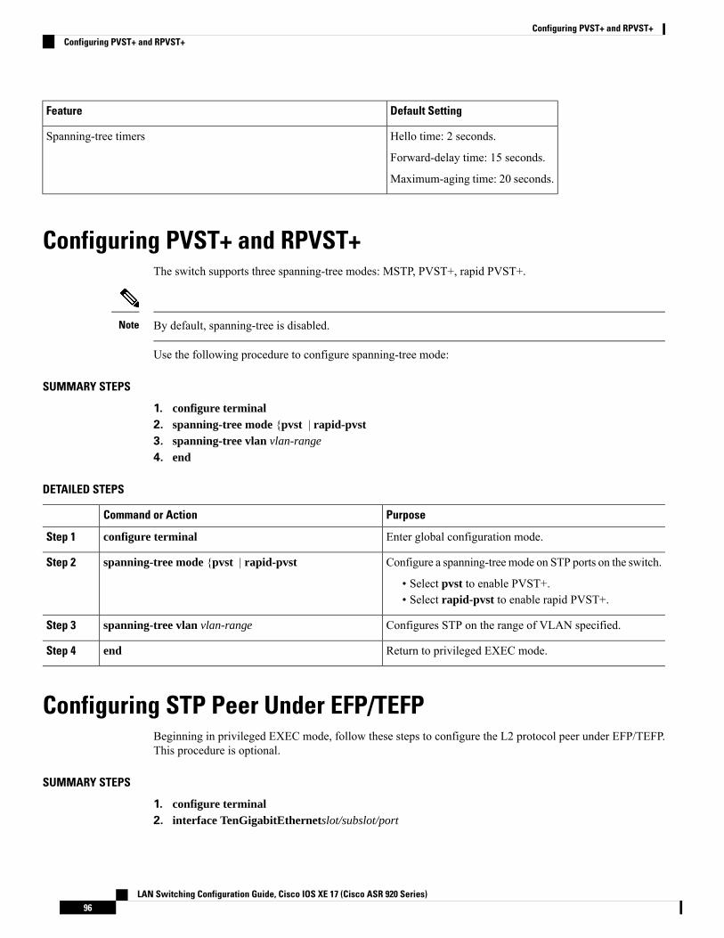
Default SettingFeature
Hello time: 2 seconds.
Forward-delay time: 15 seconds.
Maximum-aging time: 20 seconds.
Spanning-tree timers
Configuring PVST+ and RPVST+The switch supports three spanning-tree modes: MSTP, PVST+, rapid PVST+.
By default, spanning-tree is disabled.Note
Use the following procedure to configure spanning-tree mode:
SUMMARY STEPS
1. configure terminal2. spanning-tree mode {pvst | rapid-pvst3. spanning-tree vlan vlan-range
4. end
DETAILED STEPS
PurposeCommand or Action
Enter global configuration mode.configure terminalStep 1
Configure a spanning-treemode on STP ports on the switch.spanning-tree mode {pvst | rapid-pvstStep 2
• Select pvst to enable PVST+.• Select rapid-pvst to enable rapid PVST+.
Configures STP on the range of VLAN specified.spanning-tree vlan vlan-rangeStep 3
Return to privileged EXEC mode.endStep 4
Configuring STP Peer Under EFP/TEFPBeginning in privileged EXEC mode, follow these steps to configure the L2 protocol peer under EFP/TEFP.This procedure is optional.
SUMMARY STEPS
1. configure terminal2. interface TenGigabitEthernetslot/subslot/port
LAN Switching Configuration Guide, Cisco IOS XE 17 (Cisco ASR 920 Series)96
Configuring PVST+ and RPVST+Configuring PVST+ and RPVST+
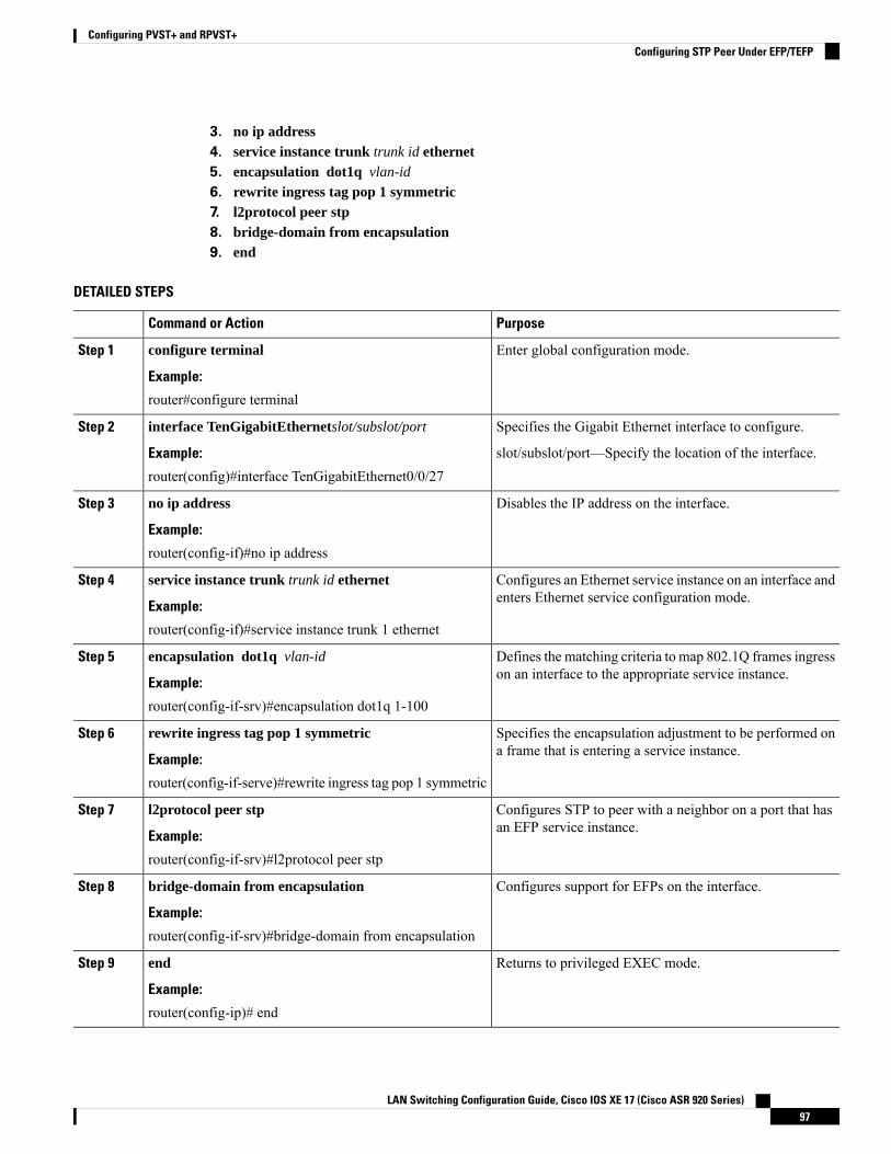
3. no ip address4. service instance trunk trunk id ethernet5. encapsulation dot1q vlan-id
6. rewrite ingress tag pop 1 symmetric7. l2protocol peer stp8. bridge-domain from encapsulation9. end
DETAILED STEPS
PurposeCommand or Action
Enter global configuration mode.configure terminal
Example:
Step 1
router#configure terminal
Specifies the Gigabit Ethernet interface to configure.interface TenGigabitEthernetslot/subslot/portStep 2
Example: slot/subslot/port—Specify the location of the interface.router(config)#interface TenGigabitEthernet0/0/27
Disables the IP address on the interface.no ip address
Example:
Step 3
router(config-if)#no ip address
Configures an Ethernet service instance on an interface andenters Ethernet service configuration mode.
service instance trunk trunk id ethernet
Example:
Step 4
router(config-if)#service instance trunk 1 ethernet
Defines the matching criteria to map 802.1Q frames ingresson an interface to the appropriate service instance.
encapsulation dot1q vlan-id
Example:
Step 5
router(config-if-srv)#encapsulation dot1q 1-100
Specifies the encapsulation adjustment to be performed ona frame that is entering a service instance.
rewrite ingress tag pop 1 symmetric
Example:
Step 6
router(config-if-serve)#rewrite ingress tag pop 1 symmetric
Configures STP to peer with a neighbor on a port that hasan EFP service instance.
l2protocol peer stp
Example:
Step 7
router(config-if-srv)#l2protocol peer stp
Configures support for EFPs on the interface.bridge-domain from encapsulation
Example:
Step 8
router(config-if-srv)#bridge-domain from encapsulation
Returns to privileged EXEC mode.end
Example:
Step 9
router(config-ip)# end
LAN Switching Configuration Guide, Cisco IOS XE 17 (Cisco ASR 920 Series)97
Configuring PVST+ and RPVST+Configuring STP Peer Under EFP/TEFP
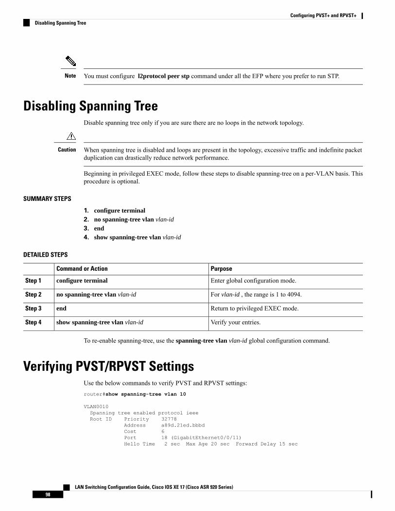
You must configure l2protocol peer stp command under all the EFP where you prefer to run STP.Note
Disabling Spanning TreeDisable spanning tree only if you are sure there are no loops in the network topology.
When spanning tree is disabled and loops are present in the topology, excessive traffic and indefinite packetduplication can drastically reduce network performance.
Caution
Beginning in privileged EXEC mode, follow these steps to disable spanning-tree on a per-VLAN basis. Thisprocedure is optional.
SUMMARY STEPS
1. configure terminal2. no spanning-tree vlan vlan-id
3. end4. show spanning-tree vlan vlan-id
DETAILED STEPS
PurposeCommand or Action
Enter global configuration mode.configure terminalStep 1
For vlan-id , the range is 1 to 4094.no spanning-tree vlan vlan-idStep 2
Return to privileged EXEC mode.endStep 3
Verify your entries.show spanning-tree vlan vlan-idStep 4
To re-enable spanning-tree, use the spanning-tree vlan vlan-id global configuration command.
Verifying PVST/RPVST SettingsUse the below commands to verify PVST and RPVST settings:router#show spanning-tree vlan 10
VLAN0010Spanning tree enabled protocol ieeeRoot ID Priority 32778
Address a89d.21ed.bbbdCost 6Port 18 (GigabitEthernet0/0/11)Hello Time 2 sec Max Age 20 sec Forward Delay 15 sec
LAN Switching Configuration Guide, Cisco IOS XE 17 (Cisco ASR 920 Series)98
Configuring PVST+ and RPVST+Disabling Spanning Tree
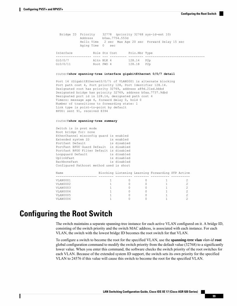
Bridge ID Priority 32778 (priority 32768 sys-id-ext 10)Address b0aa.7754.553dHello Time 2 sec Max Age 20 sec Forward Delay 15 secAging Time 0 sec
Interface Role Sts Cost Prio.Nbr Type------------------- ---- --- --------- -------- --------------------------------Gi0/0/7 Altn BLK 4 128.14 P2pGi0/0/11 Root FWD 4 128.18 P2p
router#show spanning-tree interface gigabitEthernet 0/0/7 detail
Port 14 (GigabitEthernet0/0/7) of VLAN0001 is alternate blockingPort path cost 4, Port priority 128, Port Identifier 128.14.Designated root has priority 32769, address a89d.21ed.bbbdDesignated bridge has priority 32769, address b0aa.7737.9dbdDesignated port id is 128.14, designated path cost 4Timers: message age 4, forward delay 0, hold 0Number of transitions to forwarding state: 1Link type is point-to-point by defaultBPDU: sent 91, received 8394
router#show spanning-tree summary
Switch is in pvst modeRoot bridge for: noneEtherChannel misconfig guard is enabledExtended system ID is enabledPortfast Default is disabledPortFast BPDU Guard Default is disabledPortfast BPDU Filter Default is disabledLoopguard Default is disabledUplinkFast is disabledBackboneFast is disabledConfigured Pathcost method used is short
Name Blocking Listening Learning Forwarding STP Active---------------------- -------- --------- -------- ---------- ----------VLAN0001 1 0 0 1 2VLAN0002 1 0 0 1 2VLAN0003 1 0 0 1 2VLAN0004 1 0 0 1 2VLAN0005 1 0 0 1 2VLAN0006 1 0 0 1 2
Configuring the Root SwitchThe switch maintains a separate spanning-tree instance for each active VLAN configured on it. A bridge ID,consisting of the switch priority and the switch MAC address, is associated with each instance. For eachVLAN, the switch with the lowest bridge ID becomes the root switch for that VLAN.
To configure a switch to become the root for the specified VLAN, use the spanning-tree vlan vlan-id rootglobal configuration command to modify the switch priority from the default value (32768) to a significantlylower value. When you enter this command, the software checks the switch priority of the root switches foreach VLAN. Because of the extended system ID support, the switch sets its own priority for the specifiedVLAN to 24576 if this value will cause this switch to become the root for the specified VLAN.
LAN Switching Configuration Guide, Cisco IOS XE 17 (Cisco ASR 920 Series)99
Configuring PVST+ and RPVST+Configuring the Root Switch

If any root switch for the specified VLAN has a switch priority lower than 24576, the switch sets its ownpriority for the specified VLAN to 4096 less than the lowest switch priority. (4096 is the value of theleast-significant bit of a 4-bit switch priority value as shown in Table 14-1 on page 14-4 .)
The spanning-tree vlan vlan-id root global configuration command fails if the value necessary to be the rootswitch is less than 1.
Note
If your network consists of switches that both do and do not support the extended system ID, it is unlikelythat the switch with the extended system ID support will become the root switch. The extended system IDincreases the switch priority value every time the VLAN number is greater than the priority of the connectedswitches running older software.
The root switch for each spanning-tree instance should be a backbone or distribution switch. Do not configurean access switch as the spanning-tree primary root.
Note
Use the diameter keyword to specify the Layer 2 network diameter (that is, the maximum number of switchhops between any two end stations in the Layer 2 network). When you specify the network diameter, theswitch automatically sets an optimal hello time, forward-delay time, and maximum-age time for a networkof that diameter, which can significantly reduce the convergence time. You can use the hello keyword tooverride the automatically calculated hello time.
After configuring the switch as the root switch, we recommend that you avoid manually configuring the hellotime, forward-delay time, and maximum-age time through the spanning-tree vlanvlan-id hello-time,spanning-tree vlanvlan-id forward-time, and the spanning-tree vlanvlan-id max-age global configurationcommands.
Note
Beginning in privileged EXEC mode, follow these steps to configure a switch to become the root for thespecified VLAN. This procedure is optional.
SUMMARY STEPS
1. configure terminal2. spanning-tree vlan vlan-id root primary [diameter net-diameter [hello-time seconds ]]3. end4. show spanning-tree detail5. copy running-config startup-config
DETAILED STEPS
PurposeCommand or Action
Enter global configuration mode.configure terminalStep 1
Configure a switch to become the root for the specifiedVLAN.
spanning-tree vlan vlan-id root primary [diameternet-diameter [hello-time seconds ]]
Step 2
LAN Switching Configuration Guide, Cisco IOS XE 17 (Cisco ASR 920 Series)100
Configuring PVST+ and RPVST+Configuring the Root Switch
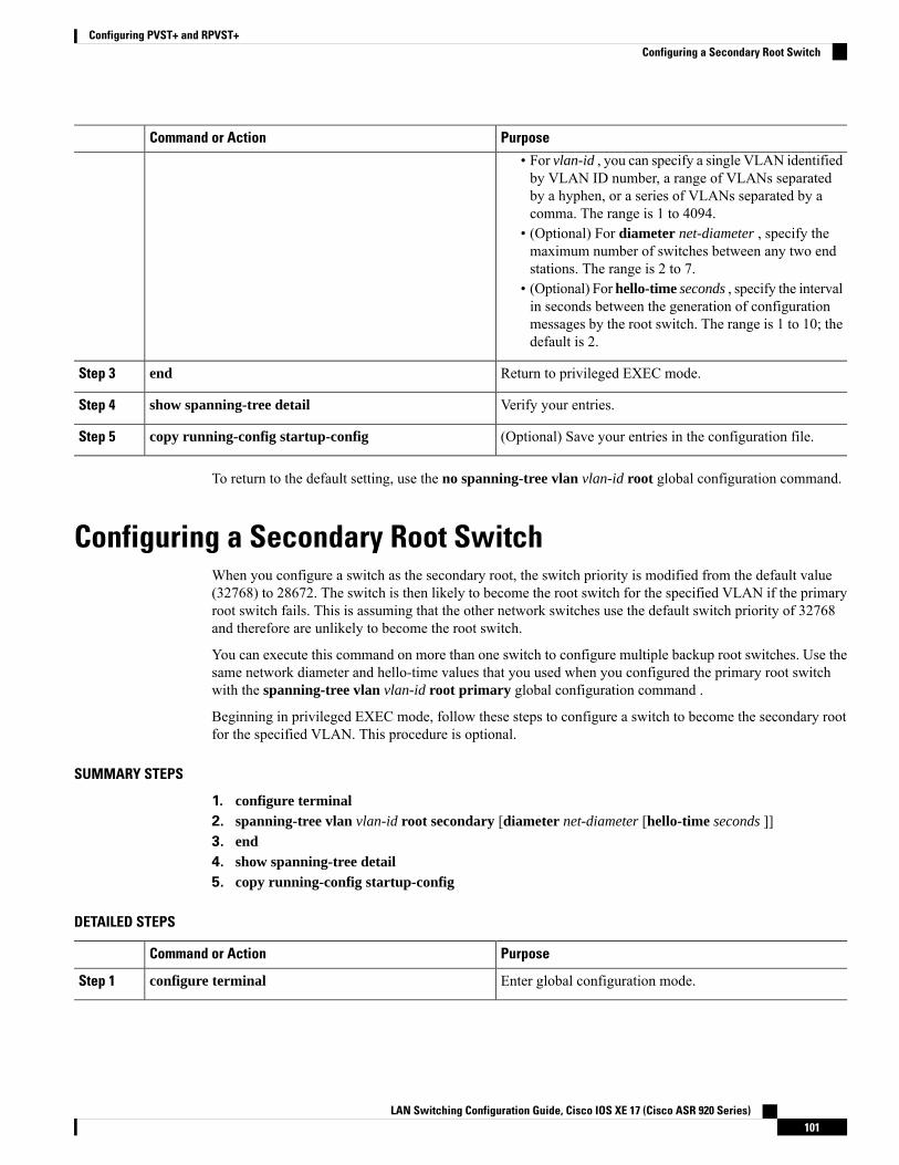
PurposeCommand or Action
• For vlan-id , you can specify a single VLAN identifiedby VLAN ID number, a range of VLANs separatedby a hyphen, or a series of VLANs separated by acomma. The range is 1 to 4094.
• (Optional) For diameter net-diameter , specify themaximum number of switches between any two endstations. The range is 2 to 7.
• (Optional) For hello-time seconds , specify the intervalin seconds between the generation of configurationmessages by the root switch. The range is 1 to 10; thedefault is 2.
Return to privileged EXEC mode.endStep 3
Verify your entries.show spanning-tree detailStep 4
(Optional) Save your entries in the configuration file.copy running-config startup-configStep 5
To return to the default setting, use the no spanning-tree vlan vlan-id root global configuration command.
Configuring a Secondary Root SwitchWhen you configure a switch as the secondary root, the switch priority is modified from the default value(32768) to 28672. The switch is then likely to become the root switch for the specified VLAN if the primaryroot switch fails. This is assuming that the other network switches use the default switch priority of 32768and therefore are unlikely to become the root switch.
You can execute this command on more than one switch to configure multiple backup root switches. Use thesame network diameter and hello-time values that you used when you configured the primary root switchwith the spanning-tree vlan vlan-id root primary global configuration command .
Beginning in privileged EXEC mode, follow these steps to configure a switch to become the secondary rootfor the specified VLAN. This procedure is optional.
SUMMARY STEPS
1. configure terminal2. spanning-tree vlan vlan-id root secondary [diameter net-diameter [hello-time seconds ]]3. end4. show spanning-tree detail5. copy running-config startup-config
DETAILED STEPS
PurposeCommand or Action
Enter global configuration mode.configure terminalStep 1
LAN Switching Configuration Guide, Cisco IOS XE 17 (Cisco ASR 920 Series)101
Configuring PVST+ and RPVST+Configuring a Secondary Root Switch
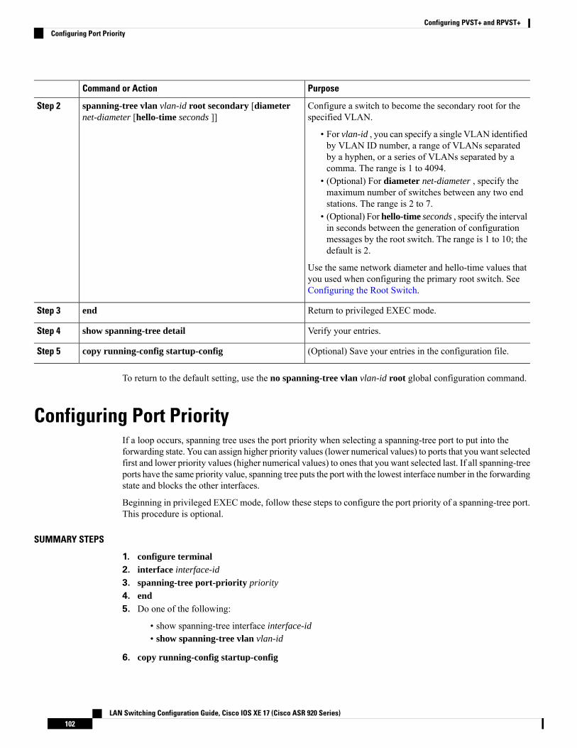
PurposeCommand or Action
Configure a switch to become the secondary root for thespecified VLAN.
spanning-tree vlan vlan-id root secondary [diameternet-diameter [hello-time seconds ]]
Step 2
• For vlan-id , you can specify a single VLAN identifiedby VLAN ID number, a range of VLANs separatedby a hyphen, or a series of VLANs separated by acomma. The range is 1 to 4094.
• (Optional) For diameter net-diameter , specify themaximum number of switches between any two endstations. The range is 2 to 7.
• (Optional) For hello-time seconds , specify the intervalin seconds between the generation of configurationmessages by the root switch. The range is 1 to 10; thedefault is 2.
Use the same network diameter and hello-time values thatyou used when configuring the primary root switch. SeeConfiguring the Root Switch.
Return to privileged EXEC mode.endStep 3
Verify your entries.show spanning-tree detailStep 4
(Optional) Save your entries in the configuration file.copy running-config startup-configStep 5
To return to the default setting, use the no spanning-tree vlan vlan-id root global configuration command.
Configuring Port PriorityIf a loop occurs, spanning tree uses the port priority when selecting a spanning-tree port to put into theforwarding state. You can assign higher priority values (lower numerical values) to ports that you want selectedfirst and lower priority values (higher numerical values) to ones that you want selected last. If all spanning-treeports have the same priority value, spanning tree puts the port with the lowest interface number in the forwardingstate and blocks the other interfaces.
Beginning in privileged EXEC mode, follow these steps to configure the port priority of a spanning-tree port.This procedure is optional.
SUMMARY STEPS
1. configure terminal2. interface interface-id
3. spanning-tree port-priority priority
4. end5. Do one of the following:
• show spanning-tree interface interface-id• show spanning-tree vlan vlan-id
6. copy running-config startup-config
LAN Switching Configuration Guide, Cisco IOS XE 17 (Cisco ASR 920 Series)102
Configuring PVST+ and RPVST+Configuring Port Priority
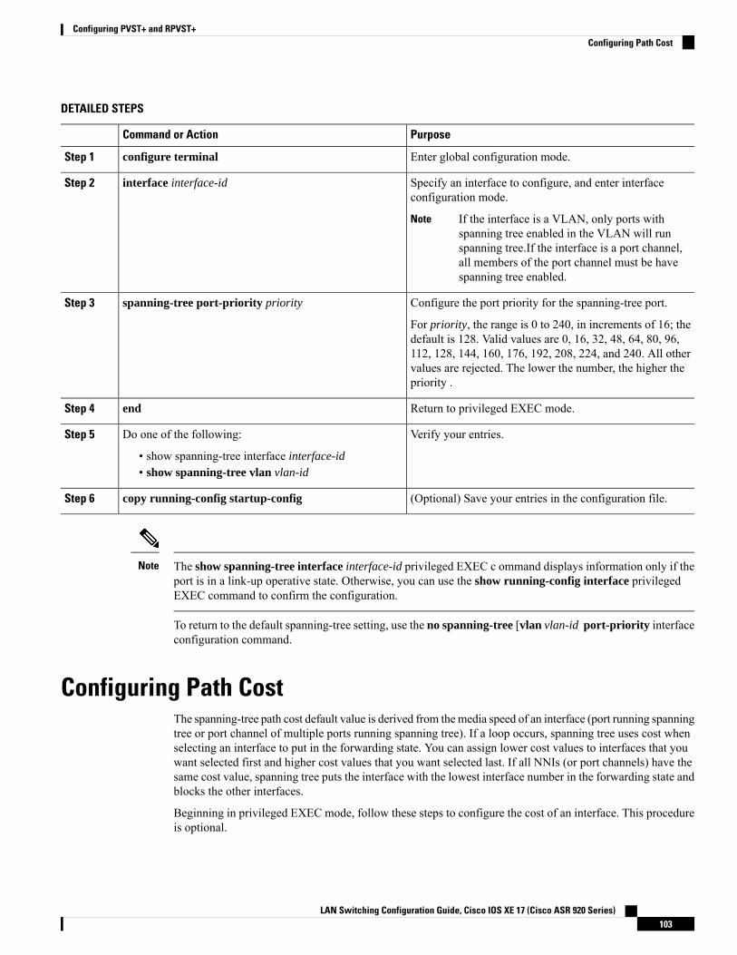
DETAILED STEPS
PurposeCommand or Action
Enter global configuration mode.configure terminalStep 1
Specify an interface to configure, and enter interfaceconfiguration mode.
interface interface-idStep 2
If the interface is a VLAN, only ports withspanning tree enabled in the VLAN will runspanning tree.If the interface is a port channel,all members of the port channel must be havespanning tree enabled.
Note
Configure the port priority for the spanning-tree port.spanning-tree port-priority priorityStep 3
For priority, the range is 0 to 240, in increments of 16; thedefault is 128. Valid values are 0, 16, 32, 48, 64, 80, 96,112, 128, 144, 160, 176, 192, 208, 224, and 240. All othervalues are rejected. The lower the number, the higher thepriority .
Return to privileged EXEC mode.endStep 4
Verify your entries.Do one of the following:Step 5
• show spanning-tree interface interface-id• show spanning-tree vlan vlan-id
(Optional) Save your entries in the configuration file.copy running-config startup-configStep 6
The show spanning-tree interface interface-id privileged EXEC c ommand displays information only if theport is in a link-up operative state. Otherwise, you can use the show running-config interface privilegedEXEC command to confirm the configuration.
Note
To return to the default spanning-tree setting, use the no spanning-tree [vlan vlan-id port-priority interfaceconfiguration command.
Configuring Path CostThe spanning-tree path cost default value is derived from themedia speed of an interface (port running spanningtree or port channel of multiple ports running spanning tree). If a loop occurs, spanning tree uses cost whenselecting an interface to put in the forwarding state. You can assign lower cost values to interfaces that youwant selected first and higher cost values that you want selected last. If all NNIs (or port channels) have thesame cost value, spanning tree puts the interface with the lowest interface number in the forwarding state andblocks the other interfaces.
Beginning in privileged EXEC mode, follow these steps to configure the cost of an interface. This procedureis optional.
LAN Switching Configuration Guide, Cisco IOS XE 17 (Cisco ASR 920 Series)103
Configuring PVST+ and RPVST+Configuring Path Cost
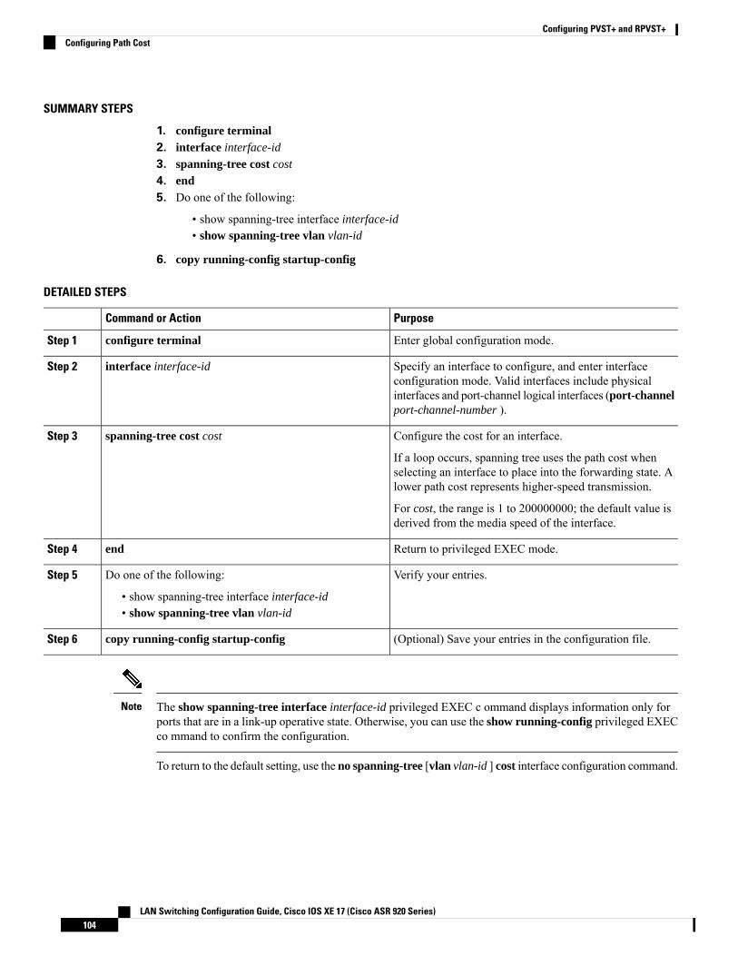
SUMMARY STEPS
1. configure terminal2. interface interface-id
3. spanning-tree cost cost
4. end5. Do one of the following:
• show spanning-tree interface interface-id• show spanning-tree vlan vlan-id
6. copy running-config startup-config
DETAILED STEPS
PurposeCommand or Action
Enter global configuration mode.configure terminalStep 1
Specify an interface to configure, and enter interfaceconfiguration mode. Valid interfaces include physical
interface interface-idStep 2
interfaces and port-channel logical interfaces (port-channelport-channel-number ).
Configure the cost for an interface.spanning-tree cost costStep 3
If a loop occurs, spanning tree uses the path cost whenselecting an interface to place into the forwarding state. Alower path cost represents higher-speed transmission.
For cost, the range is 1 to 200000000; the default value isderived from the media speed of the interface.
Return to privileged EXEC mode.endStep 4
Verify your entries.Do one of the following:Step 5
• show spanning-tree interface interface-id• show spanning-tree vlan vlan-id
(Optional) Save your entries in the configuration file.copy running-config startup-configStep 6
The show spanning-tree interface interface-id privileged EXEC c ommand displays information only forports that are in a link-up operative state. Otherwise, you can use the show running-config privileged EXECco mmand to confirm the configuration.
Note
To return to the default setting, use the no spanning-tree [vlan vlan-id ] cost interface configuration command.
LAN Switching Configuration Guide, Cisco IOS XE 17 (Cisco ASR 920 Series)104
Configuring PVST+ and RPVST+Configuring Path Cost
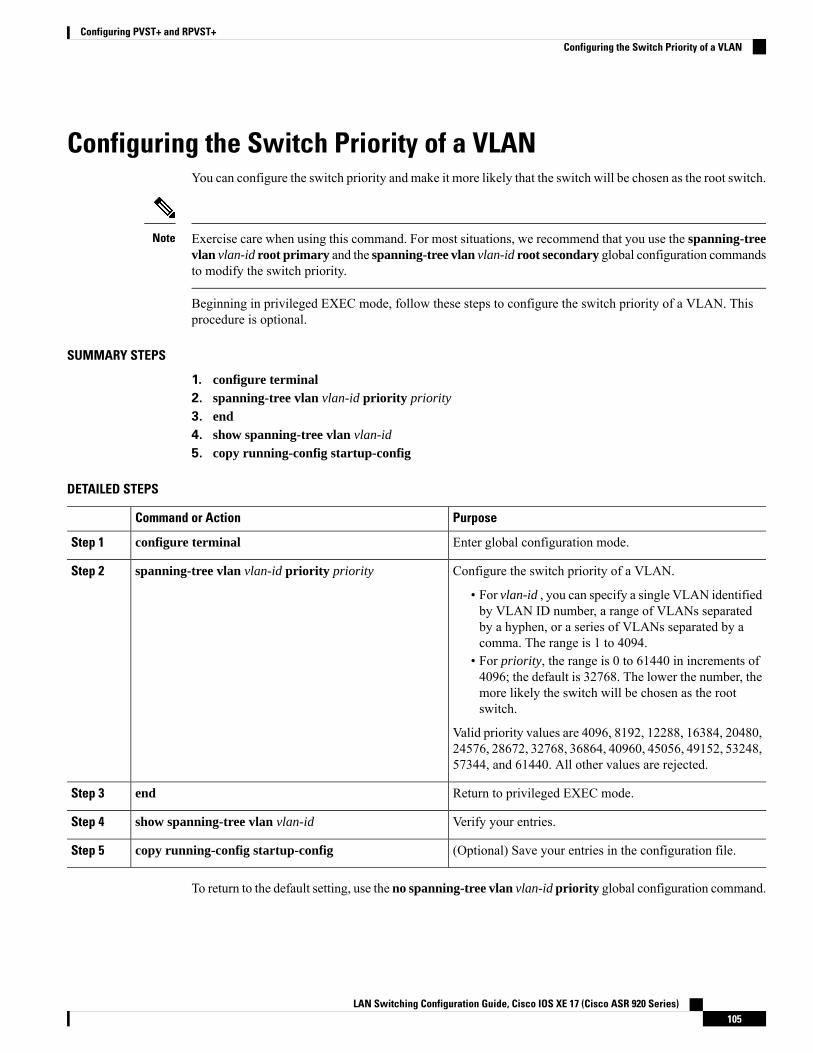
Configuring the Switch Priority of a VLANYou can configure the switch priority and make it more likely that the switch will be chosen as the root switch.
Exercise care when using this command. For most situations, we recommend that you use the spanning-treevlan vlan-id root primary and the spanning-tree vlan vlan-id root secondary global configuration commandsto modify the switch priority.
Note
Beginning in privileged EXEC mode, follow these steps to configure the switch priority of a VLAN. Thisprocedure is optional.
SUMMARY STEPS
1. configure terminal2. spanning-tree vlan vlan-id priority priority
3. end4. show spanning-tree vlan vlan-id
5. copy running-config startup-config
DETAILED STEPS
PurposeCommand or Action
Enter global configuration mode.configure terminalStep 1
Configure the switch priority of a VLAN.spanning-tree vlan vlan-id priority priorityStep 2
• For vlan-id , you can specify a single VLAN identifiedby VLAN ID number, a range of VLANs separatedby a hyphen, or a series of VLANs separated by acomma. The range is 1 to 4094.
• For priority, the range is 0 to 61440 in increments of4096; the default is 32768. The lower the number, themore likely the switch will be chosen as the rootswitch.
Valid priority values are 4096, 8192, 12288, 16384, 20480,24576, 28672, 32768, 36864, 40960, 45056, 49152, 53248,57344, and 61440. All other values are rejected.
Return to privileged EXEC mode.endStep 3
Verify your entries.show spanning-tree vlan vlan-idStep 4
(Optional) Save your entries in the configuration file.copy running-config startup-configStep 5
To return to the default setting, use the no spanning-tree vlan vlan-id priority global configuration command.
LAN Switching Configuration Guide, Cisco IOS XE 17 (Cisco ASR 920 Series)105
Configuring PVST+ and RPVST+Configuring the Switch Priority of a VLAN
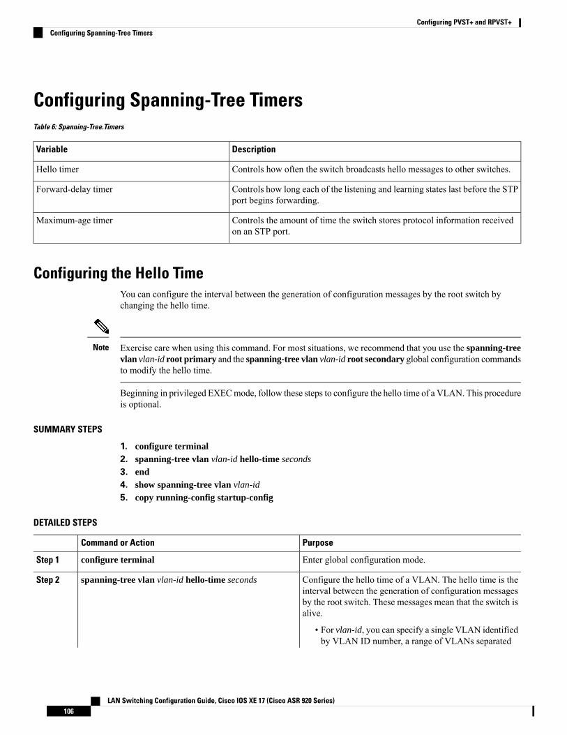
Configuring Spanning-Tree TimersTable 6: Spanning-Tree.Timers
DescriptionVariable
Controls how often the switch broadcasts hello messages to other switches.Hello timer
Controls how long each of the listening and learning states last before the STPport begins forwarding.
Forward-delay timer
Controls the amount of time the switch stores protocol information receivedon an STP port.
Maximum-age timer
Configuring the Hello TimeYou can configure the interval between the generation of configuration messages by the root switch bychanging the hello time.
Exercise care when using this command. For most situations, we recommend that you use the spanning-treevlan vlan-id root primary and the spanning-tree vlan vlan-id root secondary global configuration commandsto modify the hello time.
Note
Beginning in privileged EXECmode, follow these steps to configure the hello time of a VLAN. This procedureis optional.
SUMMARY STEPS
1. configure terminal2. spanning-tree vlan vlan-id hello-time seconds
3. end4. show spanning-tree vlan vlan-id
5. copy running-config startup-config
DETAILED STEPS
PurposeCommand or Action
Enter global configuration mode.configure terminalStep 1
Configure the hello time of a VLAN. The hello time is theinterval between the generation of configuration messages
spanning-tree vlan vlan-id hello-time secondsStep 2
by the root switch. These messages mean that the switch isalive.
• For vlan-id, you can specify a single VLAN identifiedby VLAN ID number, a range of VLANs separated
LAN Switching Configuration Guide, Cisco IOS XE 17 (Cisco ASR 920 Series)106
Configuring PVST+ and RPVST+Configuring Spanning-Tree Timers
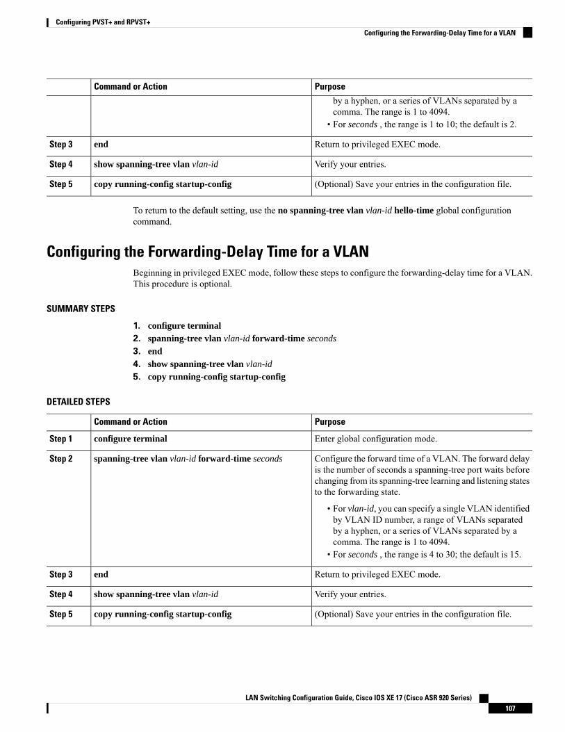
PurposeCommand or Action
by a hyphen, or a series of VLANs separated by acomma. The range is 1 to 4094.
• For seconds , the range is 1 to 10; the default is 2.
Return to privileged EXEC mode.endStep 3
Verify your entries.show spanning-tree vlan vlan-idStep 4
(Optional) Save your entries in the configuration file.copy running-config startup-configStep 5
To return to the default setting, use the no spanning-tree vlan vlan-id hello-time global configurationcommand.
Configuring the Forwarding-Delay Time for a VLANBeginning in privileged EXEC mode, follow these steps to configure the forwarding-delay time for a VLAN.This procedure is optional.
SUMMARY STEPS
1. configure terminal2. spanning-tree vlan vlan-id forward-time seconds
3. end4. show spanning-tree vlan vlan-id
5. copy running-config startup-config
DETAILED STEPS
PurposeCommand or Action
Enter global configuration mode.configure terminalStep 1
Configure the forward time of a VLAN. The forward delayis the number of seconds a spanning-tree port waits before
spanning-tree vlan vlan-id forward-time secondsStep 2
changing from its spanning-tree learning and listening statesto the forwarding state.
• For vlan-id, you can specify a single VLAN identifiedby VLAN ID number, a range of VLANs separatedby a hyphen, or a series of VLANs separated by acomma. The range is 1 to 4094.
• For seconds , the range is 4 to 30; the default is 15.
Return to privileged EXEC mode.endStep 3
Verify your entries.show spanning-tree vlan vlan-idStep 4
(Optional) Save your entries in the configuration file.copy running-config startup-configStep 5
LAN Switching Configuration Guide, Cisco IOS XE 17 (Cisco ASR 920 Series)107
Configuring PVST+ and RPVST+Configuring the Forwarding-Delay Time for a VLAN
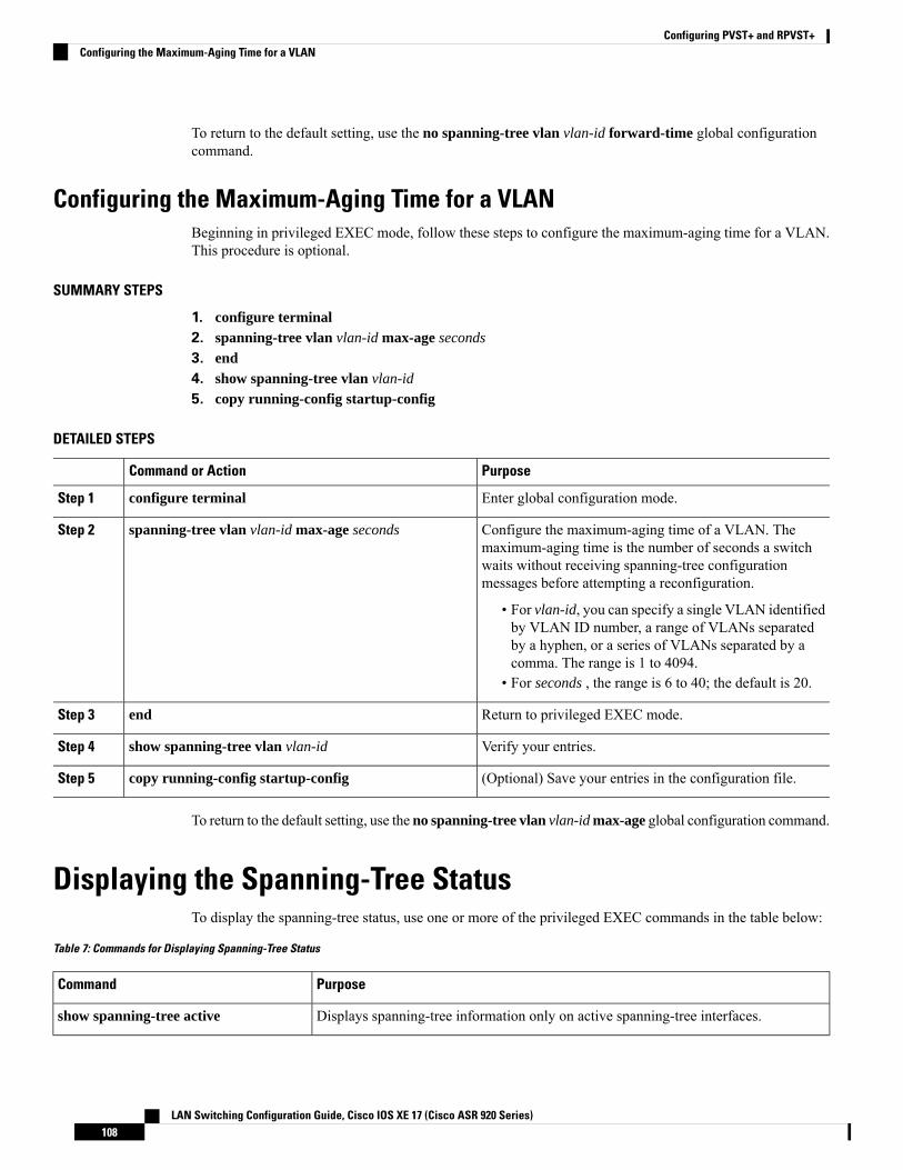
To return to the default setting, use the no spanning-tree vlan vlan-id forward-time global configurationcommand.
Configuring the Maximum-Aging Time for a VLANBeginning in privileged EXEC mode, follow these steps to configure the maximum-aging time for a VLAN.This procedure is optional.
SUMMARY STEPS
1. configure terminal2. spanning-tree vlan vlan-id max-age seconds
3. end4. show spanning-tree vlan vlan-id
5. copy running-config startup-config
DETAILED STEPS
PurposeCommand or Action
Enter global configuration mode.configure terminalStep 1
Configure the maximum-aging time of a VLAN. Themaximum-aging time is the number of seconds a switch
spanning-tree vlan vlan-id max-age secondsStep 2
waits without receiving spanning-tree configurationmessages before attempting a reconfiguration.
• For vlan-id, you can specify a single VLAN identifiedby VLAN ID number, a range of VLANs separatedby a hyphen, or a series of VLANs separated by acomma. The range is 1 to 4094.
• For seconds , the range is 6 to 40; the default is 20.
Return to privileged EXEC mode.endStep 3
Verify your entries.show spanning-tree vlan vlan-idStep 4
(Optional) Save your entries in the configuration file.copy running-config startup-configStep 5
To return to the default setting, use the no spanning-tree vlan vlan-id max-age global configuration command.
Displaying the Spanning-Tree StatusTo display the spanning-tree status, use one or more of the privileged EXEC commands in the table below:
Table 7: Commands for Displaying Spanning-Tree Status
PurposeCommand
Displays spanning-tree information only on active spanning-tree interfaces.show spanning-tree active
LAN Switching Configuration Guide, Cisco IOS XE 17 (Cisco ASR 920 Series)108
Configuring PVST+ and RPVST+Configuring the Maximum-Aging Time for a VLAN
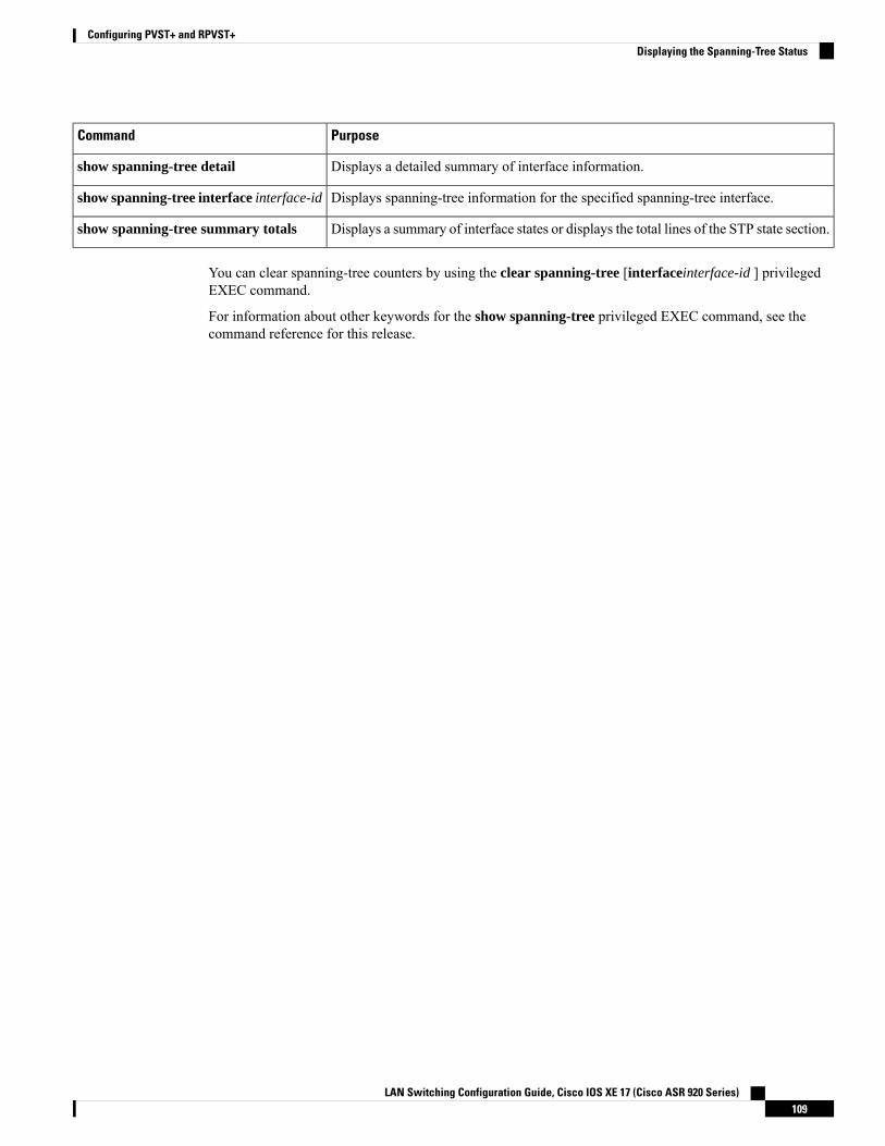
PurposeCommand
Displays a detailed summary of interface information.show spanning-tree detail
Displays spanning-tree information for the specified spanning-tree interface.show spanning-tree interface interface-id
Displays a summary of interface states or displays the total lines of the STP state section.show spanning-tree summary totals
You can clear spanning-tree counters by using the clear spanning-tree [interfaceinterface-id ] privilegedEXEC command.
For information about other keywords for the show spanning-tree privileged EXEC command, see thecommand reference for this release.
LAN Switching Configuration Guide, Cisco IOS XE 17 (Cisco ASR 920 Series)109
Configuring PVST+ and RPVST+Displaying the Spanning-Tree Status

LAN Switching Configuration Guide, Cisco IOS XE 17 (Cisco ASR 920 Series)110
Configuring PVST+ and RPVST+Displaying the Spanning-Tree Status
Copyright © 2022 FDOKUMEN