OCx CEM Interface Module Configuration Guide, Cisco IOS ...
278
OCx CEM Interface Module Configuration Guide, Cisco IOS XE 17 (Cisco NCS 4200 Series) First Published: 2021-07-30 Last Modified: 2022-04-11 Americas Headquarters Cisco Systems, Inc. 170 West Tasman Drive San Jose, CA 95134-1706 USA http://www.cisco.com Tel: 408 526-4000 800 553-NETS (6387) Fax: 408 527-0883
-
Upload
khangminh22 -
Category
Documents
-
view
3 -
download
0
Transcript of OCx CEM Interface Module Configuration Guide, Cisco IOS ...

OCx CEM Interface Module Configuration Guide, Cisco IOS XE 17 (CiscoNCS 4200 Series)First Published: 2021-07-30
Last Modified: 2022-04-11
Americas HeadquartersCisco Systems, Inc.170 West Tasman DriveSan Jose, CA 95134-1706USAhttp://www.cisco.comTel: 408 526-4000
800 553-NETS (6387)Fax: 408 527-0883

THE SPECIFICATIONS AND INFORMATION REGARDING THE PRODUCTS IN THIS MANUAL ARE SUBJECT TO CHANGE WITHOUT NOTICE. ALL STATEMENTS,INFORMATION, AND RECOMMENDATIONS IN THIS MANUAL ARE BELIEVED TO BE ACCURATE BUT ARE PRESENTED WITHOUT WARRANTY OF ANY KIND,EXPRESS OR IMPLIED. USERS MUST TAKE FULL RESPONSIBILITY FOR THEIR APPLICATION OF ANY PRODUCTS.
THE SOFTWARE LICENSE AND LIMITED WARRANTY FOR THE ACCOMPANYING PRODUCT ARE SET FORTH IN THE INFORMATION PACKET THAT SHIPPED WITHTHE PRODUCT AND ARE INCORPORATED HEREIN BY THIS REFERENCE. IF YOU ARE UNABLE TO LOCATE THE SOFTWARE LICENSE OR LIMITED WARRANTY,CONTACT YOUR CISCO REPRESENTATIVE FOR A COPY.
The Cisco implementation of TCP header compression is an adaptation of a program developed by the University of California, Berkeley (UCB) as part of UCB's public domain version ofthe UNIX operating system. All rights reserved. Copyright © 1981, Regents of the University of California.
NOTWITHSTANDING ANY OTHERWARRANTY HEREIN, ALL DOCUMENT FILES AND SOFTWARE OF THESE SUPPLIERS ARE PROVIDED “AS IS" WITH ALL FAULTS.CISCO AND THE ABOVE-NAMED SUPPLIERS DISCLAIM ALL WARRANTIES, EXPRESSED OR IMPLIED, INCLUDING, WITHOUT LIMITATION, THOSE OFMERCHANTABILITY, FITNESS FOR A PARTICULAR PURPOSE AND NONINFRINGEMENT OR ARISING FROM A COURSE OF DEALING, USAGE, OR TRADE PRACTICE.
IN NO EVENT SHALL CISCO OR ITS SUPPLIERS BE LIABLE FOR ANY INDIRECT, SPECIAL, CONSEQUENTIAL, OR INCIDENTAL DAMAGES, INCLUDING, WITHOUTLIMITATION, LOST PROFITS OR LOSS OR DAMAGE TO DATA ARISING OUT OF THE USE OR INABILITY TO USE THIS MANUAL, EVEN IF CISCO OR ITS SUPPLIERSHAVE BEEN ADVISED OF THE POSSIBILITY OF SUCH DAMAGES.
Any Internet Protocol (IP) addresses and phone numbers used in this document are not intended to be actual addresses and phone numbers. Any examples, command display output, networktopology diagrams, and other figures included in the document are shown for illustrative purposes only. Any use of actual IP addresses or phone numbers in illustrative content is unintentionaland coincidental.
All printed copies and duplicate soft copies of this document are considered uncontrolled. See the current online version for the latest version.
Cisco has more than 200 offices worldwide. Addresses and phone numbers are listed on the Cisco website at www.cisco.com/go/offices.
The documentation set for this product strives to use bias-free language. For purposes of this documentation set, bias-free is defined as language that does not imply discrimination based onage, disability, gender, racial identity, ethnic identity, sexual orientation, socioeconomic status, and intersectionality. Exceptions may be present in the documentation due to language thatis hardcoded in the user interfaces of the product software, language used based on standards documentation, or language that is used by a referenced third-party product.
Cisco and the Cisco logo are trademarks or registered trademarks of Cisco and/or its affiliates in the U.S. and other countries. To view a list of Cisco trademarks, go to this URL:https://www.cisco.com/c/en/us/about/legal/trademarks.html. Third-party trademarks mentioned are the property of their respective owners. The use of the word partner does not imply apartnership relationship between Cisco and any other company. (1721R)
© 2022 Cisco Systems, Inc. All rights reserved.
C O N T E N T S
Feature History 1C H A P T E R 1
Preface 5C H A P T E R 2
Document Organization 5
Related Documentation 7
Overview of the OCx Interface Module 9P A R T I
Overview of the OCx Interface Module 11C H A P T E R 3
Support for OCx CEM Interface Modules 15C H A P T E R 4
Configuring Support of 1 port OC-48/STM-16 or 4 port OC-12/OC-3 / STM-1/STM-4 + 12 port T1/E1+ 4 port T3/E3 CEM Interface Module 15
Configuring Support of 1-Port OC-192 or 8-Port Low Rate CEM Interface Module 16
Configuring Support for NCS 4200 1-Port OC-192 or 8-Port Low Rate CEM 20G Bandwidth InterfaceModule (NCS4200-1T8S-20CS) 16
Modes of Operation 17
Restrictions and Limitations for NCS 4200 1-Port OC-192 or 8-Port Low Rate CEM 20G BandwidthInterface Module (NCS4200-1T8S-20CS) 18
Features supported on OCx CEM Interface Module 20
Restrictions for Configuring OCx CEM Interface Modules 22
SONET and SDH 25P A R T I I
Configuring SONET 27C H A P T E R 5
Overview of SONET 27
Restrictions for SONET 27
OCx CEM Interface Module Configuration Guide, Cisco IOS XE 17 (Cisco NCS 4200 Series)iii

SONET Switching 28
SONET Hierarchy 29
Section 29
Line 30
Path 30
SONET Line and Section Configuration Parameters 30
SONET Path Level Configuration Parameters 31
SONET T1 Configuration Parameters 31
SONET T3 Configuration Parameters 31
SONET VT Configuration Parameters 32
How to Configure SONET 32
Prerequisites for Configuring SONET 32
Configuring MediaType Controller 32
Configuring SONET Ports 33
Managing and Monitoring SONET Line 33
Configuring Line and Section Overhead 33
Configuring Line Loopback 33
Configuring AIS Shut 33
Configuring Shut 34
Configuring Alarm Reporting 34
Configuring Clock 34
Configuring STS-1 Modes 35
Verification of SONET Configuration 36
Configuring CEM Group for Framed SAToP 41
Configuring VT-15 mode of STS-1 for Framed SAToP 41
Configuring DS1/T1 CT3 mode of STS-1 for Framed SAToP 41
Performance Monitoring Use Cases or Deployment Scenarios 42
Configuring Port Rate and Verifying Pluggables 53
Configuring Port Rate for SONET 53
Verifying the Pluggables 53
Loopback Remote on T1 and T3 Interfaces 55
Restrictions for Loopback Remote 55
Configuring Loopback Remote in Sonet 55
Verifying the Loopback Remote Configuration 56
OCx CEM Interface Module Configuration Guide, Cisco IOS XE 17 (Cisco NCS 4200 Series)iv
Contents

Associated Commands 57
Configuring SDH 61C H A P T E R 6
Overview of SDH 61
Basic SDH Signal 62
SDH Hierarchy 62
Modes of CEM 62
Services Provided by SDH Configuration 63
SDH Multiplexing 65
Modes of SDH 66
Configuring AUG Mapping 67
Configuring AU-3 or AU-4 Mapping 67
Configuring Mixed AU-3 and AU-4 Mapping 67
Verifying AUG Mapping Configuration 68
Configuring Modes under AU-4 Mapping 68
Configuring Mode VC-4 CEP 68
Configuring Mode TUG-3 69
Configuring Mode VC-1x 71
Configuring Mode VC-4 Nc 73
Configuring AU-3 — VC-3 — DS3 74
Configuring AU-3 — VC-3 — E3 74
Configuring Modes under AU-3 Mapping 74
Configuring Mode VC-1x 74
Configuring AU-4 — TUG-3 — TUG-2 — VC-12 for Framed SAToP 76
Configuring AU-3 — TUG-2 — VC-11 — T1 for Framed SAToP 77
Verifying SDH Configuration for Framed SAToP 77
Restrictions for SDH 78
Configuring Mediatype Controller 79
Configuring Rate on SDH Ports 79
SDH Line and Section Configuration Parameters 79
Overhead 79
Configuring Line and Section Overhead 80
Threshold 80
Configuring Line and Section Threshold 80
OCx CEM Interface Module Configuration Guide, Cisco IOS XE 17 (Cisco NCS 4200 Series)v
Contents

Loopback 81
Configuring Line Loopback 81
AIS-Shut 81
Configuring AIS Shut 81
Shutdown 81
Configuring Shut 81
Alarm Reporting 82
Configuring Alarm Reporting 82
Clock Source 83
Configuring Clock 83
Verifying SDH Line and Section Parameters Configuration 83
Configuring SDH Path Parameters 95
Path Overhead 95
Path Threshold 96
Path Loopback 96
Verifying Path Parameters Configuration 97
Configuring BERT in SDH for SAToP 97
BERT Patterns on 1-Port OC-48 or 4-Port OC-12/OC-3 CEM Interface Module 98
Configuring BERT in Modes VC-4 and VC Nc 99
Verifying BERT Configuration in Modes VC-4 and VC Nc 99
Configuring E1 Bert 100
Configuring T1 Bert 100
Configuring BERT in Mode T3/E3 100
Verifying BERT Configuration in Mode T3 or E3 100
Configuring BERT in Mode VC-1x 101
Verifying BERT Configuration in Mode VC-1x 101
SDH T1/E1 Configuration Parameters 101
Configuring T1/E1 Parameters 102
Verifying T1 or E1 Parameters Configuration 102
SDH T3/E3 Configuration Parameters 102
Configuring SDH T3/E3 Parameters Configuration 103
Verifying SDH T3 or E3 Parameters Configurations 103
SDH VC Configuration Parameters for SAToP 103
Configuring VC Parameters 104
OCx CEM Interface Module Configuration Guide, Cisco IOS XE 17 (Cisco NCS 4200 Series)vi
Contents

Verifying VC Configuration Parameters Configurations 104
Configuring ACR on SDH 105
Verifying ACR Configuration on SDH 105
Configuring DCR on SDH 106
Verifying DCR Configuration on SDH 107
Loopback Remote on T1 and T3 Interfaces 107
Restrictions for Loopback Remote 107
Configuring Loopback Remote in SDH 107
Verifying the Loopback Remote Configuration 108
Interworking Multiservice Gateway 113P A R T I I I
Serial Interfaces 115C H A P T E R 7
Serial Interface Supported Modes 115
Creating T1 or E1 Serial Interfaces on T1 or E1 Ports 119
Creating T3 or E3 Serial Interfaces on T3 or E3 Ports 120
Creating an E1 Serial Interface in Unframed Mode 122
Creating Serial Interfaces on SDH 122
Creating Serial Interfaces on SONET 124
Modifying Encapsulation to PPP 126
IPv4 or IPv6 Interworking Multiservice Gateway Pseudowire over HDLC or PPP 126
L2VPN Interworking Multiservice Gateway 126
L2VPN iMSG Mode 126
IP Interworking Mode 127
HDLC or PPP to Ethernet IPv4 or IPv6 iMSG Pseudowire 127
IPv4 or IPv6 iMSG Pseudowire Supported Modes 127
Limitations of IPv4 or IPv6 iMSG Pseudowire on HDLC or PPP Serial Interfaces 128
How to Configure IPv4 or IPv6 iMSG Pseudowire on HDLC or PPP Interface 128
Configuring L2VPN iMSG 129
Configuring Cross-Connect Under Attachment Circuit 129
Verifying IPv4 or IPv6 iMSG Pseudowire over HDLC or PPP Configuration 130
IPv4 or IPv6 Interworking Multiservice Gateway Pseudowire over Frame Relay 132
Frame Relay for iMSG 132
Limitations of IPv4 or IPv6 iMSG Pseudowire on Frame Relay Serial Interfaces 132
OCx CEM Interface Module Configuration Guide, Cisco IOS XE 17 (Cisco NCS 4200 Series)vii
Contents
Scale Supported for iMSG Pseudowire on Frame Relay Serial Interfaces 133
How to Configure IPv4 or IPv6 iMSG Pseudowire on Frame Relay Serial Interface 133
Modifying Encapsulation to Frame Relay 133
Configuring Frame Relay 134
Configuring L2VPN iMSG Using Local Connect for Frame Relay 136
Configuring L2VPN iMSG Using Cross Connect for Frame Relay 136
Verifying IPv4 or IPv6 iMSG Pseudowire over Frame Relay Configuration 137
Configuring Frame Relay for APS Protection 140
Configuring Frame Relay for UPSR Protection 140
Configuring Frame Relay L2VPN iMSG for APS Protection 140
Configuring Frame Relay L2VPN iMSG for UPSR Protection 140
Verifying Frame Relay for APS Protection 140
Verifying Frame Relay for UPSR Protection 142
Scenario 1–Configure L2VPN iMSG Using Local Connect for Frame Relay 144
Scenario 2–Configure L2VPN iMSG Using Cross Connect for Frame Relay 145
IPv4 Layer 3 Termination on HDLC or PPP Serial Interfaces 146
IPv4 Layer 3 Termination on HDLC or PPP Serial Interfaces 146
Restrictions for IPv4 Layer 3 Termination on HDLC or PPP Serial Interfaces 146
How to Configure IPv4 Layer 3 Termination on HDLC or PPP Serial Interfaces 147
Configuring Protocols 147
Configuring VRF 147
Configuring IPv4 Unicast Layer 3 Termination on HDLC or PPP Interfaces 148
Verifying IPv4 Layer 3 Termination on HDLC or PPP 148
Interworking Multiservice Gateway Access Circuit Redundancy 149C H A P T E R 8
SONET Supported Modes 149
SDH Supported Modes 150
Restrictions for iMSG ACR 151
How to Configure iMSG ACR 151
Creating ACR Group 151
Configuring ACR Group on APS 152
Creating Serial Interface for SONET ACR 153
Creating Serial Interface for SONET ACR on VT 1.5 Mode 153
Creating Serial Interface for SONET ACR on CT3 Mode 154
OCx CEM Interface Module Configuration Guide, Cisco IOS XE 17 (Cisco NCS 4200 Series)viii
Contents

Creating Serial Interface for SONET ACR on T3 Mode 154
Creating Serial Interface for SONET ACR on PoS Mode 154
Creating Serial Interface for SONET non-ACR on PoS Mode 154
Creating Serial Interface for SDH ACR 155
Creating Serial Interface for SDH ACR on PoS Mode 156
Creating Serial Interface for SDH non-ACR on PoS Mode 156
Modifying Encapsulation to PPP 156
Configuring IPv4 and IPv6 Interworking Pseudowire 156
Configuring Cross-Connect on Serial Interface 157
Verifying iMSG ACR 158
Verifying iMSG ACR with HDLC Encapsulation 158
Verifying iMSG ACR with PPP Encapsulation 159
Verifying iMSG ACR with HDLC Encapsulation on PoS Mode 160
Verifying iMSG ACR with PPP Encapsulation on PoS Mode 160
Multilink Interfaces 163C H A P T E R 9
MLPPP 163
MLPPP Interworking 163
MLPPP Layer 3 Termination 164
MLPPP ACR Support for iMSG 165
Multilink PPP Minimum Links Mandatory 165
Restrictions for MLPPP 165
Restrictions for MLPPP Interworking 166
Restrictions for MLPPP Layer 3 Termination 166
Restriction for MLPPP ACR 166
How to Configure MLPPP 167
Configuring MLPPP 167
Configuring MLPPP ACR 168
Deleting Serial Interface from an Active MLPPP Bundle 168
Removing MLPPP Configuration 168
Verifying MLPPP Configuration 169
How to Configure MLPPP Interworking 169
Configuring L2VPN Interworking and Cross Connection under the Attachment Circuit for MultilinkInterfaces 169
OCx CEM Interface Module Configuration Guide, Cisco IOS XE 17 (Cisco NCS 4200 Series)ix
Contents

Verifying L2VPN Interworking and Cross-Connect Configuration 170
How to Configure MLPPP Layer 3 Termination 171
Configuring MLPPP Layer 3 Termination 171
How to Configure Multilink PPP Minimum Links Mandatory 172
Configuring Multilink PPP Minimum Links Mandatory 172
Verifying the Multilink PPP Minimum Links Mandatory Configuration 172
VLAN Handoff 173C H A P T E R 1 0
Overview of VLAN Handoff 173
IP Interworking Switching on Single Router 174
Restrictions for VLAN Handoff 174
Enabling the VLAN Handoff 174
Configuring VLAN Handoff for IPv4 Local Connect 175
Example - VLAN Handoff for IPv4 Local Connect 176
Configuring VLAN Handoff for IPv4 Cross Connect 177
Configuring VLAN Handoff for IPv6 Local Connect 179
Configuring VLAN Handoff for IPv6 Cross Connect 181
OCx Protection 185P A R T I V
Automatic Protection Switching 187C H A P T E R 1 1
1+1 APS 188
Benefits of APS 188
APS 1+1 for SONET Layer 1 traffic 189
Scenario for Bidirectional APS 1+1 189
Scenario for Unidirectional APS 1+1 190
Restrictions for APS 190
Configuring CEM APS for Framed SAToP 191
Verifying SONET Configuration for Framed SAToP 191
Provisioning APS 1+1 192
Deprovisioning APS 1+1 193
Configuring APS for SAToP 194
Configuring Bi-directional ACR (SONET Framing) 194
Configuring Unidirectional APS 194
OCx CEM Interface Module Configuration Guide, Cisco IOS XE 17 (Cisco NCS 4200 Series)x
Contents

Verifying ACR Configurations 195
Configuring VT 1.5-T1 Loopback 197
Configuring VT 1.5-T1 BERT 197
Configuring Path Overhead 198
Configuring Path Threshold 198
Configuring MSP 199C H A P T E R 1 2
1+1 MSP 199
Benefits of MSP 200
Restrictions for MSP 200
MSP 1+1 for SDH Layer 1 traffic 200
Scenario for Bidirectional MSP 1+1 201
Scenario for Unidirectional MSP 1+1 201
Configuring MSP for SAToP 201
Verifying MSP Configuration for SAToP 203
Configuring MSP for CESoPSN 204
Configuring CEM Group for MSP on Virtual ACR AU3-T1 in CESoPSN 204
Verifying CEM Group for MSP on Virtual ACR AU3-T1 in CESoPSN 205
Configuring CEM Group for MSP on Virtual ACR AU4-E1 in CESoPSN 205
Verifying CEM Group for MSP on Virtual ACR AU4-E1 in CESoPSN 206
Configuring Clocking ACR for MSP AU3-T1 in CESoPSN 206
Verifying Clocking ACR for MSP AU3-T1 in CESoPSN 207
Configuring Clocking DCR for MSP AU3-T1 in CESoPSN 207
Verifying Clocking DCR for MSP AU3-T1 in CESoPSN 208
Configuring Clocking ACR for MSP AU4-E1 in CESoPSN 208
Verifying Clocking ACR for MSP AU4-E1 in CESoPSN 209
Configuring Clocking DCR for MSP AU4-E1 in CESoPSN 209
Verifying Clocking DCR for MSP AU4-E1 in CESoPSN 210
UPSR Path Protection 211C H A P T E R 1 3
Restrictions for iMSG UPSR Path Protection 212
Configuring iMSG UPSR 212
Configuring UPSR 213
Configuring UPSR Work and Protection Path Configuration 213
OCx CEM Interface Module Configuration Guide, Cisco IOS XE 17 (Cisco NCS 4200 Series)xi
Contents

Verifying UPSR Configuration 214
Unidirectional Path Switching Ring Over HDLC 215C H A P T E R 1 4
Unidirectional Path Switching Ring Over HDLC Overview 215
Limitations for HDLC UPSR 215
How to Configure UPSR over HDLC 216
Configuring Protection Group 216
Configuring Channel Group 216
Creating Protection Group Serial Interface for VT 1.5 T1 Mode 216
Creating Protection Group Serial Interface for T3 or STS-3c Mode 216
Creating Protection Group Serial Interface for VT 1.5 T1 Mode 217
Creating Protection Group Serial Interface for T3 or STS-3c Mode 217
Adding Protection Group to Controller Under VT 1.5 Mode 218
Adding Protection Group to Controller Under T3 Mode 218
Adding Protection Group to Controller Under STS-3c Mode 218
Configuring Cross-Connect Under Protection Group Serial Interface Pseudowire 218
Verifying UPSR Over HDLC Configuration 219
Configuration Examples for HDLC UPSR 219
Use Case 1 219
Use Case 2 220
Configuring SNCP 223C H A P T E R 1 5
Restrictions for SNCP 223
SNCP Path Protection 223
Configuring SNCP 224
Verification of SNCP Configuration 225
DCC and TARP 227P A R T V
Configuring Data Communication Channel 229C H A P T E R 1 6
Restrictions of DCC 231
Configuring PPP 231
Configuring CLNS or LAPD 232
Verification of DCC Configuration 232
OCx CEM Interface Module Configuration Guide, Cisco IOS XE 17 (Cisco NCS 4200 Series)xii
Contents

Transparent Overhead Tunneling Data Communication Channel 233C H A P T E R 1 7
Transparent Overhead Tunneling Data Communication Channel Overview 233
Transparent Overhead Tunnel DCC Types 234
Prerequisites for Transparent Overhead Tunnel 235
Limitations of Transparent Overhead Tunnel 236
How to Configure Transparent Overhead Tunnel 237
Configuring Mode for Controller 237
Creating Transparent Overhead Tunnel 237
Configuring DCC Interface in IP Domain 238
Configuring TOH Tunnelling 238
Creating Transparent Overhead Tunnel Pseudowire 238
Verifying Transparent Overhead Tunnel and Pseudowire Configuration 238
Target Identifier Address Resolution Protocol 241C H A P T E R 1 8
Prerequisites for TARP Support 241
Restrictions and Limitations 241
Types of TARP PDU's 242
TARP Features 242
TARP Caching 242
TARP Timers 243
TARP Counters 243
NSAP Address Format 243
Determining TIDs and NSAPs 244
Understanding NSAP 244
How To Configure TARP 245
Enabling TARP and Configuring a TARP TID 245
TARP on Gigabit Ethernet Interface 246
TARP on SDCC 246
How to Configure TARP 247
TARP Configuration Examples 247
Configuring TARP Features 248
Configuring Static TARP Adjacency and Blacklist Adjacency 248
Configuring TARP Timers 248
OCx CEM Interface Module Configuration Guide, Cisco IOS XE 17 (Cisco NCS 4200 Series)xiii
Contents

Configuring Miscellaneous TARP PDU Information 249
TARP Configuration Task List 249
Disabling TARP Caching 250
Disabling TARP PDU Origination and Propagation 250
Bandwidth for OCx Modules 251P A R T V I
Configuring 5G Mode 253C H A P T E R 1 9
Supported Traffic Combinations 255
Restrictions for Configuring 1-Port OC-192/STM-64 or 8-Port OC-3/12/48/STM-1/-4/-16 InterfaceModule 256
Important Notes on Configuration 256
Configuring 5G Mode from 10G Mode 256
Configuring 10G Mode from 5G Mode 256
Verification of 5G Traffic Configuration 257
Associated Commands 257
Additional References 259P A R T V I I
Additional References for SONET/SDH Frame Structures 261C H A P T E R 2 0
SONET Frame Structure 261
STS-1 and STS-3 Frames 261
Concatenated SONET Frames 262
Channelized SONET Frames 263
SDH Frame Structure 263
VC 264
OCx CEM Interface Module Configuration Guide, Cisco IOS XE 17 (Cisco NCS 4200 Series)xiv
Contents

C H A P T E R 1Feature History
The following table lists the new and modified features supported on the following OCx CEM InterfaceModule Configuration Guide in Cisco IOS XE 17 on Cisco NCS 4201 and Cisco NCS 4202 routers.
The OCx Interface Modules supported are:
• 1-port OC-192 or 8-9ort Low Rate CEM Interface Module
• 1-port OC-48/STM-16 or 4-port OC-12/OC-3 / STM-1/STM-4 + 12-port T1/E1 + 4-port T3/E3 CEMInterface Module
• NCS 4200 1-port OC-192 or 8-port Low Rate CEM 20G Bandwidth Interface Module
DescriptionFeature
Cisco IOS XE Cupertino 17.8.1
Support for frame relay encapsulation on iMSG serial interface for the followinginterface modules:
• 1-port OC-48/STM-16 or 4-port OC-12/OC-3 / STM-1/STM-4 + 12 port T1/E1+ 4-port T3/E3 CEM interface module
• NCS 4200 1-port OC-192 or 8-port low rate CEM 20G bandwidth interfacemodule
Frame Relay being a streamlined protocol facilitates higher performance and greaterefficiency.
FrameRelay Supportfor IP Interworking
The following table lists the new and modified features supported on the following OCx CEM InterfaceModule Configuration Guide in Cisco IOS XE 17 on Cisco NCS 4206 and Cisco NCS 4216 routers.
The OCx Interface Modules supported are:
• 1-port OC-192 or 8-9ort Low Rate CEM Interface Module
• 1-port OC-48/STM-16 or 4-port OC-12/OC-3 / STM-1/STM-4 + 12-port T1/E1 + 4-port T3/E3 CEMInterface Module
• NCS 4200 1-port OC-192 or 8-port Low Rate CEM 20G Bandwidth Interface Module
OCx CEM Interface Module Configuration Guide, Cisco IOS XE 17 (Cisco NCS 4200 Series)1

DescriptionFeature
Cisco IOS XE Cupertino 17.8.1
Support for frame relay encapsulation on iMSG serial interface for the followinginterface modules:
• 1-port OC-48/STM-16 or 4-port OC-12/OC-3 / STM-1/STM-4 + 12 port T1/E1+ 4-port T3/E3 CEM interface module
• NCS 4200 1-port OC-192 or 8-port low rate CEM 20G bandwidth interfacemodule
Frame Relay being a streamlined protocol facilitates higher performance and greaterefficiency.
FrameRelay Supportfor IP Interworking
Cisco IOS XE Bengaluru 17.5.1
Theshow controller tabular command enables you to view the performancemonitoring details in tabular form as per GR-820-Core standards.
GR-820-COREPerformanceMonitoring
This release supports Layer 3 termination using IPv6 addressing onMLPPP interfacesfor the 1 port OC-48/STM-16 or 4 port OC-12/OC-3 / STM-1/STM-4 + 12 port T1/E1+ 4 port T3/E3 CEM interface module. In releases earlier, with IPv4 addressing, youcan scale up to 512 MLPPP bundles. Now with IPv6 addressing, the MLPPP bundlescan be scaled up to 1024.
MLPPP IPTermination on allSerial Physical andLogical Interfaces
In this release, a new framing mode unframed is supported for the 1 portOC-48/STM-16 or 4 port OC-12/OC-3 / STM-1/STM-4 + 12 port T1/E1 + 4 portT3/E3CEM InterfaceModule.With the unframedmode, you can create serial interfacesunder the electrical E1 mode.
Unframed FramingSupport on E1 andChannel STM links
Cisco IOS XE Bengaluru 17.4.1
• APS and non-APS Support—APS and non-APS support for SDH and SONETfor iMSG IPv6 interworking
• APS and NxDS0 iMSG IPv4—NxDS0 iMSG IPv4 and NxDS0 APS iMSG IPv4
• UPSR IPv6—UPSR IPv6
• VLANHandoff—IPv4 and IPv6 with VLAN handoff for both cross connect andlocal connect
CEM and IP IWFeature Parity forA900-IMA1Z8S-CXMSandA900-IMA3G-IMSGInterface Modules
Support for DCC Termination on 1 port OC-48/STM-16 or 4 port OC-12/OC-3 /STM-1/STM-4 + 12 port T1/E1 + 4 port T3/E3 CEM Interface Module.
The Data Communication Channel (DCC) feature uses the SONET or SDHOperationAdministration and Maintenance (OAM) channel to manage devices that supportSONET or SDH interfaces. SONET or SDH standards support extensive operations,administration, management, and provisioning (OAM&P) capabilities.
DCC Termination
VLAN handoff supports IPv4 and IPv6 local connect and cross connect.IPv6VLANHandoffSupport
OCx CEM Interface Module Configuration Guide, Cisco IOS XE 17 (Cisco NCS 4200 Series)2
Feature History

DescriptionFeature
Cisco IOS XE Amsterdam 17.3.1
Adaptive Clock Recovery (ACR) and Differential Clock Recovery (DCR) aretechniques used for Circuit Emulation (CEM) to recover clocks on the Cisco RSP3module.
ACR andDCRScaleSupport
The Data Communication Channel (DCC) feature uses the SONET or SDHOperationAdministration and Maintenance (OAM) channel to manage devices that supportSONET or SDH interfaces on the Cisco RSP3 module.
DCC Support
The iMSG ACR feature is supported on serial interfaces for SONET and SDH ACRon the Cisco ASR RSP3 module. DCC and MS features are also supported.
InterworkingMultiserviceGateway AccessCircuit Redundancy(iMSG ACR)support for NCS4200 1-Port OC-192or 8-Port Low RateCEM 20GBandwidth InterfaceModule(NCS4200-1T8S-20CS)
VLAN handoff enables the support for IP interworking Pseudowire. IP interworkingPseudowire enables the service provider to terminate the TDM circuit early in thenetwork and transport the IP payload on HDLC, PPP, or MLPPP links, over theMPLScore to the Ethernet network.
IP Interworking withVLAN Handoff
Interworking function (IWF) for PPP/HDLC is supported on Ethernet for E1/STM1ports. This support is extended at nxDS0 level to speed up the GSR TDM migration.
InterworkingSupport for nxDS0
MLPPP ACR is supported for IPv4 or IPv6 iMSG on the Cisco ASR RSP3 module.The restrictions for MLPPP interworking are applicable to iMSG ACR.
MLPPP ACRsupport for IPv4 orIPv6 InterworkingMultiserviceGateway (iMSG)
Cisco IOS XE Amsterdam 17.1.1
The Multilink Point-to-Point (MLPPP) interworking supports IPv4 Layer 2 VPNInterworking with T1 or E1 bundles on the Cisco RSP3 module. The MLPPPinterworking enables service providers (offering relatively low-speed links) to useMLP and spread traffic across them in their MPLS networks. The MPLS MultilinkPPP feature reduces the number of Interior Gateway Protocol (IGP) adjacencies andfacilitates load sharing of traffic.
IPv4 InterworkingSupport for MLPPPInterfaces
OCx CEM Interface Module Configuration Guide, Cisco IOS XE 17 (Cisco NCS 4200 Series)3
Feature History

DescriptionFeature
The Multilink Point-to-Point (MLPPP) interworking supports IPv6 Layer 2 VPNInterworking with T1 or E1 bundles on the Cisco RSP3 module. The MLPPPinterworking enables service providers (offering relatively low-speed links) to useMLP and spread traffic across them in their MPLS networks. The MPLS MultilinkPPP feature reduces the number of Interior Gateway Protocol (IGP) adjacencies andfacilitates load sharing of traffic.
IPv6 InterworkingSupport for MLPPPInterfaces
The IPv6 interworking is supported for Layer 2 VPN interworking mode. The IPv6interworking is supported only for HDLC or PPP to Ethernet. Layer 3 termination issupported with serial interfaces with HDLC or PPP encapsulation.
IPv6 InterworkingPseudowire Supporton HDLC or PPPSerial Interfaces
The IPv6 interworking is supported with ACR for Layer 2 VPN.IPv6 Support forInterworkingMultiserviceGateway AccessCircuit Redundancy
OCx CEM Interface Module Configuration Guide, Cisco IOS XE 17 (Cisco NCS 4200 Series)4
Feature History

C H A P T E R 2Preface
This guide provides an overview and explains how to configure various features for the following OCxinterface modules:
Table 1: Supported Interface Module
ModePart NumberInterface Module
• T1/E1
• T3/E3
• NCS4200-3GMS1 port OC-48/STM-16 or 4 portOC-12/OC-3 / STM-1/STM-4 + 12port T1/E1 + 4 port T3/E3 CEMInterface Module
• NCS4200-1T8S-10CS1-Port OC-192 or 8-Port Low RateCEM Interface Module
• NCS4200-1T8S-20CSNCS 4200 1-Port OC-192 or 8-PortLow Rate CEM 20G BandwidthInterface Module
• Document Organization, on page 5• Related Documentation, on page 7
Document OrganizationDescriptionChapter
Provides a high-level overview of OCxCEM interfacemodules. Also provides additional information suchas restrictions, benefits, and so on.
Overview of the OCx Interface Modules
OCx CEM Interface Module Configuration Guide, Cisco IOS XE 17 (Cisco NCS 4200 Series)5
DescriptionChapter
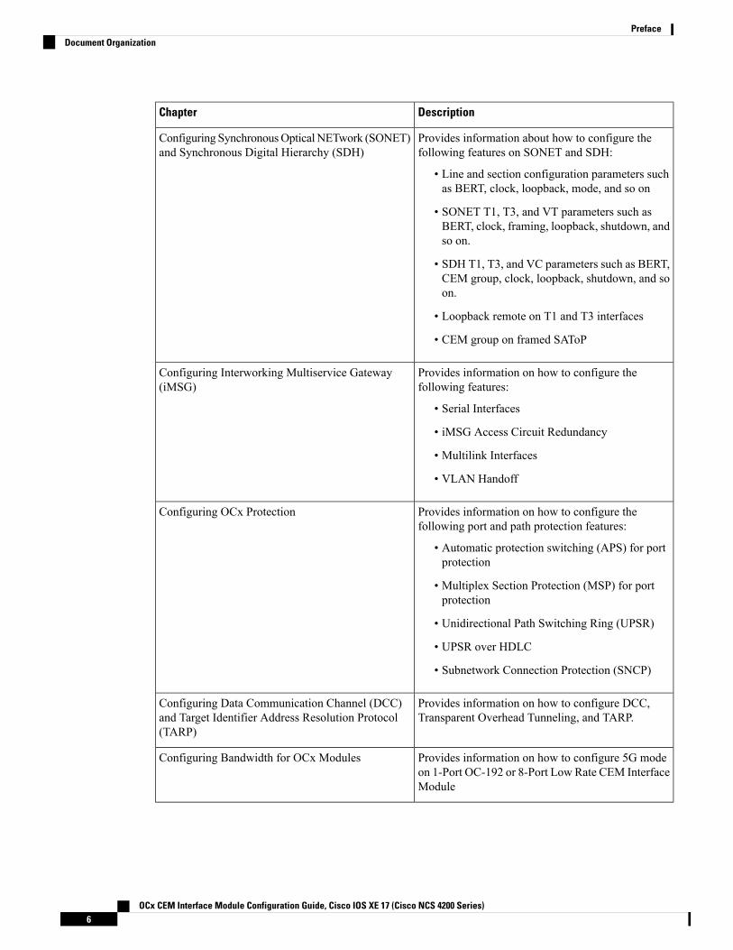
Provides information about how to configure thefollowing features on SONET and SDH:
• Line and section configuration parameters suchas BERT, clock, loopback, mode, and so on
• SONET T1, T3, and VT parameters such asBERT, clock, framing, loopback, shutdown, andso on.
• SDH T1, T3, and VC parameters such as BERT,CEM group, clock, loopback, shutdown, and soon.
• Loopback remote on T1 and T3 interfaces
• CEM group on framed SAToP
Configuring SynchronousOpticalNETwork (SONET)and Synchronous Digital Hierarchy (SDH)
Provides information on how to configure thefollowing features:
• Serial Interfaces
• iMSG Access Circuit Redundancy
• Multilink Interfaces
• VLAN Handoff
Configuring Interworking Multiservice Gateway(iMSG)
Provides information on how to configure thefollowing port and path protection features:
• Automatic protection switching (APS) for portprotection
• Multiplex Section Protection (MSP) for portprotection
• Unidirectional Path Switching Ring (UPSR)
• UPSR over HDLC
• Subnetwork Connection Protection (SNCP)
Configuring OCx Protection
Provides information on how to configure DCC,Transparent Overhead Tunneling, and TARP.
Configuring Data Communication Channel (DCC)and Target Identifier Address Resolution Protocol(TARP)
Provides information on how to configure 5G modeon 1-Port OC-192 or 8-Port Low Rate CEM InterfaceModule
Configuring Bandwidth for OCx Modules
OCx CEM Interface Module Configuration Guide, Cisco IOS XE 17 (Cisco NCS 4200 Series)6
PrefaceDocument Organization

DescriptionChapter
Provides information about SONET and SDH frames.
• SONET Frame Structure—Details on STS-1 andSTS-3 frames , concatenated, and ChannelizedSONET frames.
• SDH Frame Structure—Details on STM-1 frameand Virtual Container (VC).
Additional References
Related Documentation• Alarm Configuring and Monitoring Guide
• CEM Generic Guide
• 48-Port T1 or E1 CEM Interface Module Configuration Guide
• 48-Port T3 or E3 CEM Interface Module Configuration Guide
OCx CEM Interface Module Configuration Guide, Cisco IOS XE 17 (Cisco NCS 4200 Series)7
PrefaceRelated Documentation

OCx CEM Interface Module Configuration Guide, Cisco IOS XE 17 (Cisco NCS 4200 Series)8
PrefaceRelated Documentation

P A R T IOverview of the OCx Interface Module
• Overview of the OCx Interface Module, on page 11• Support for OCx CEM Interface Modules, on page 15


C H A P T E R 3Overview of the OCx Interface Module
The features of the following OCx interface modules are configured based on the SONET and SDH modesupport:
• 1-port OC-48/STM-16 or 4-port OC-12/OC-3 / STM-1/STM-4 + 12-port T1/E1 + 4-port T3/E3 CEMInterface ModuleNCS4200-3GMS
• 1-Port OC-192 or 8-Port Low Rate CEM Interface Module NCS4200-1T8S-10CS
• NCS 4200 1-Port OC-192 or 8-Port Low Rate CEM 20G Bandwidth Interface Module(NCS4200-1T8S-20CS)
SONET Modes
SONET supports the following Circuit Emulation over Packet (CEP), Structure- Agnostic TDM over Packet(SATOP), and Circuit Emulation over Packet-Switched Network (CESoPSN) modes:
CEP Modes
• STS-48C
• STS-12C
• STS-3C
• STS-1
• VT 1.5
SAToP or CESoP
• VT1.5-T1
• T3
• CT3-T1
The following table provides required clock and CEM configuration that is supported on each of the SONETmode:
OCx CEM Interface Module Configuration Guide, Cisco IOS XE 17 (Cisco NCS 4200 Series)11

Table 2: Modes Supported on SONET
CT3-T1T3VT 1.5 T1VT 1.5STS-1STS-3CSTS-12CSTS-48C
Required Configuration
YesYesYesYesYesYesYesYesMode
YesYesYesInternalInternalInternalInternalInternalInternal/LineClockSource
YesYesYesNANANANANAACR/DCRClock
CEM Configurations
NAYesNAYesYesYesYesYesCEP
YesYesYesNANANANANASAToPFramed
YesYesYesNANANANANASAToPUnframed
YesYesYesNANANANANACESoPSN
Interworking Multiservice Gateway (iMSG)1
YesYesYesYesYesYesYesYesiMSG
YesYesYesYesYesYesYesYesSerialInterfaces
YesYesYesYesYesYesYesYesiMSGACR
YesYesYesYesYesYesYesYesMultilinkInterfaces
YesYesYesYesYesYesYesYesVLANHandoff
OCx Port Protection
YesYesYesYesYesYesYesYesAPS
OCx Path Protection
YesYesYesYesYesYesYesYesUPSR
YesYesYesYesYesYesYesYesUPSRoverHDLC
OCx CEM Interface Module Configuration Guide, Cisco IOS XE 17 (Cisco NCS 4200 Series)12
Overview of the OCx Interface Module
1 Supports Channelized T3/E3or T1/E1
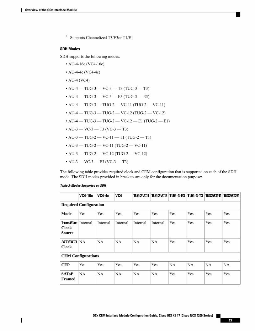
SDH Modes
SDH supports the following modes:
• AU-4-16c (VC4-16c)
• AU-4-4c (VC4-4c)
• AU-4 (VC4)
• AU-4 — TUG-3 — VC-3 — T3 (TUG-3 — T3)
• AU-4 — TUG-3 — VC-3 — E3 (TUG-3 — E3)
• AU-4 — TUG-3 — TUG-2 — VC-11 (TUG-2 — VC-11)
• AU-4 — TUG-3 — TUG-2 — VC-12 (TUG-2 — VC-12)
• AU-4 — TUG-3 — TUG-2 — VC-12 — E1 (TUG-2 — E1)
• AU-3 — VC-3 — T3 (VC-3 — T3)
• AU-3 — TUG-2 — VC-11 — T1 (TUG-2 — T1)
• AU-3 — TUG-2 — VC-11 (TUG-2 — VC-11)
• AU-3 — TUG-2 — VC-12 (TUG-2 — VC-12)
• AU-3 — VC-3 — E3 (VC-3 — T3)
The following table provides required clock and CEM configuration that is supported on each of the SDHmode. The SDH modes provided in brackets are only for the documentation purpose:
Table 3: Modes Supported on SDH
TUG-2-VC12-E1TUG-2-VC11-T1TUG-3-T3TUG-3-E3TUG-2-VC12TUG-2-VC11VC4VC4-4cVC4-16c
Required Configuration
YesYesYesYesYesYesYesYesYesMode
YesYesYesYesInternalInternalInternalInternalInternalInternal/LineClockSource
YesYesYesYesNANANANANAACR/DCRClock
CEM Configurations
NANANANAYesYesYesYesYesCEP
YesYesYesYesNANANANANASAToPFramed
OCx CEM Interface Module Configuration Guide, Cisco IOS XE 17 (Cisco NCS 4200 Series)13
Overview of the OCx Interface Module

TUG-2-VC12-E1TUG-2-VC11-T1TUG-3-T3TUG-3-E3TUG-2-VC12TUG-2-VC11VC4VC4-4cVC4-16c
YesYesYesYesNANANANANASAToPUnframed
YesYesYesYesNANANANANACESoPSN
Interworking Multiservice Gateway (iMSG)
YesYesYesYesYesYesYesYesYesiMSG
YesYesYesYesYesYesYesYesYesSerialInterfaces
YesYesYesYesYesYesYesYesYesiMSGACR
OCx Port Protection
YesYesYesYesYesYesYesYesYesMSP
OCx Path Protection
NANANANAYesYesYesYesYesSNCP
OCx CEM Interface Module Configuration Guide, Cisco IOS XE 17 (Cisco NCS 4200 Series)14
Overview of the OCx Interface Module

C H A P T E R 4Support for OCx CEM Interface Modules
This chapter provides a high-level description and restricions for the following OCx CEM interface modules:
• 1 port OC-48/STM-16 or 4 port OC-12/OC-3 / STM-1/STM-4 + 12 port T1/E1 + 4 port T3/E3 CEMInterface ModuleNCS4200-3GMS
• 1-Port OC-192 or 8-Port Low Rate CEM Interface Module NCS4200-1T8S-10CS
• NCS 4200 1-Port OC-192 or 8-Port Low Rate CEM 20G Bandwidth Interface Module(NCS4200-1T8S-20CS)
• Configuring Support of 1 port OC-48/STM-16 or 4 port OC-12/OC-3 / STM-1/STM-4 + 12 port T1/E1+ 4 port T3/E3 CEM Interface Module, on page 15
• Configuring Support of 1-Port OC-192 or 8-Port Low Rate CEM Interface Module, on page 16• Configuring Support for NCS 4200 1-Port OC-192 or 8-Port Low Rate CEM 20G Bandwidth InterfaceModule (NCS4200-1T8S-20CS) , on page 16
• Features supported on OCx CEM Interface Module, on page 20• Restrictions for Configuring OCx CEM Interface Modules, on page 22
Configuring Support of 1 port OC-48/STM-16 or 4 port OC-12/OC-3/ STM-1/STM-4 + 12 port T1/E1 + 4 port T3/E3 CEM InterfaceModule
The 1 port OC-48/STM-16 or 4 port OC-12/OC-3 / STM-1/STM-4 + 12 port T1/E1 + 4 port T3/E3 CEMInterface Module has 12XDS1, 4XDS3, electrical interfaces, and 4XSFP ports that can provide multiplefunctions such as 1XOC-48/12/3 and 3XOC-12/3. The maximum speed supported on OCx ports is OC-48.The interface module supports a maximum of 3G CEM traffic.
In addition to support on RSP2 module, the IM is supported on RSP3 from the Cisco IOS XE 16.9.x release.Note
OCx CEM Interface Module Configuration Guide, Cisco IOS XE 17 (Cisco NCS 4200 Series)15

Configuring Support of 1-Port OC-192 or 8-Port Low Rate CEMInterface Module
The OC-192 interface module with 8-port low rate CEM interface module delivers one active port of OC192or STM-64 connectivity, or up to eight ports of OC3/12 or STM-1/-4 or up to 4 ports of OC48 or STM-16connectivity on the router with RSP3. The module can be clocked from a line or from an internal clock source.This module delivers true high density, multiservice and multi-rate capabilities in a small form factor. Theinterface module can be software configured as either Synchronous Optical Networking (SONET) mode orSynchronous Digital Hierarchy (SDH) mode per module in the ASR 900 Series configuration.
Configuring Support for NCS 4200 1-Port OC-192 or 8-Port LowRate CEM 20G Bandwidth Interface Module(NCS4200-1T8S-20CS)
The NCS 4200 1-Port OC-192 or 8-Port Low Rate CEM 20G Bandwidth Interface Module(NCS4200-1T8S-20CS) is supported on the RSP3module and has the capability for SONET or SDH terminationwith SAToP, CESoP, and CEP traffic types.
The Ethernet and Multiservice Gateway features are not supported on this IM for the Cisco IOS XE 16.12.1Release.
Note
The IM is capable of processing a maximum of 20G with different types of traffic such as 10G CEM, 2.5GiMSG, 2.5G Ethernet, and 6.9Mbps DCC. However for the Cisco IOS XE Release 16.12.1, only the 10GCEM traffic is supported. In the 10G mode, 7.5G CEM traffic is supported.
In this IM, all the eight 1G ports can be configured as OC-48 and you can utilize a maximum of 192 STS-1.
The NCS 42001-port OC-192 or 8-port Low Rate CEM 20G Bandwidth interface module functions similarto the 1-port OC-192/STM-64 or 8-port OC-3/12/48/STM-1/-4/-16 interface module. The configurationsremain the same.
The following TDM features are supported:
• SNMP
• Local, network, or remote loopback
• BERT (both system and line). The system side BERT is not supported in the framed SAToP mode.
• OH config
• Network synchronization
• SSM
• Shut at port and CEM-group level
• DCC is supported starting from Cisco IOS XE Amsterdam 17.3.1 release
OCx CEM Interface Module Configuration Guide, Cisco IOS XE 17 (Cisco NCS 4200 Series)16
Overview of the OCx Interface ModuleConfiguring Support of 1-Port OC-192 or 8-Port Low Rate CEM Interface Module

• Interworking Multiservice Gateway Access Circuit Redundancy (iMSG ACR) support starting with theCisco IOS XE 17.3.1 release.
The following TDM features are supported starting from Cisco IOS XE Bengaluru 17.4.1 release:
• APS and non-APS for SDH and SONET for iMSG IPv6 interworking.
• NxDS0 iMSG IPv4 and NxDS0 APS iMSG IPv4.
• UPSR IPv6.
• IPv4 with VLAN handoff for cross connect and local connect.
The CEM features such as SAToP, CESoP, and CEP are supported in the following modes:
• Unprotected CEM with ACR or DCR are supported in the following modes:
• T1, T3, E1, E3, DS0, DS1, and DS3
• CEM Payload size configurable.
APS CEM with ACR or DCR are supported in the following modes
• DS0, DS1, DS3, T1, T3, E1, E3, AU-3, and AU-4
• CEM payload size configurable.
• UPSR at VT or STS mode.
• DS1 (with VT Protection) or DS3 (STS Protection) with ACR or DCR
• CEM Class with configurable payload size or jitter buffer
Modes of OperationThe interface module operates in following two modes:
• Single XFI or 10 G mode
• Dual XFI or 20 G mode
Single XFI or 10 G mode
Consider the following requirement while working on the 10 G mode:
• OC-192 or SFP+ port is supported on the 10G GE port. In the 10G mode, 7.5G for CEM traffic issupported.
• If bandwidth is available to accommodate a particular circuit or Ethernet port, then configuration isallowed, and it can be performed. Otherwise, the configuration is rejected due to bandwidth limitation.
• When there is a change in the payload size, the required bandwidth gets modified accordingly. This inturn checks for the bandwidth and if the sufficient bandwidth is not available, the configuration is rejected.
• You can remove or delete the existing configuration from the port and perform new configuration on theport.
Dual XFI or 20 G mode
OCx CEM Interface Module Configuration Guide, Cisco IOS XE 17 (Cisco NCS 4200 Series)17
Overview of the OCx Interface ModuleModes of Operation

You can convert the IM into dual mode. In 20G mode of operation, channelized (xfi0) and non-channelized(xfi1) bandwidth are available.
Enter the following commands to convert into dual mode and then reload the IM:
router (config)# platform hw-module configurationPE1(conf-plat-hw-conf)# hw-module <slot/subslot> NCS4200-1T8S-20CS mode 10G_CEM
Consider the following requirements while working on the 20-G mode:
• For configuring CEM group, the software performs bandwidth check. If the required bandwidth is notavailable, you cannot configure the CEM group.
• If a maximum capacity configuration is already performed on the IM and you update the payload size,then the update is not accepted on the same channel (xfi). You need to remove some configurations oncircuits and then update the payload again.
For slot compatibility, refer Supported RSP and Slots in and Cisco Interface Module Hardware InstallationGuide.
Restrictions and Limitations for NCS 4200 1-Port OC-192 or 8-Port Low RateCEM 20G Bandwidth Interface Module (NCS4200-1T8S-20CS)
Feature Restrictions
The following features are not supported:
• Ethernet
• EOS L1 or L2
• MS features are not supported for the Cisco IOS XE 16.12.1 release. Starting with the Cisco IOS XEAmsterdam 17.3.1 release, MS features are supported.
• DCC is not supported until the Cisco IOS XE 16.12.1 release.
• IPv4 or IPv6 iMSG is not supported for the Cisco IOS XE 16.12.1 release.
Starting with the Cisco IOS XE Amsterdam 17.3.1 release, IPv4 iMSG is supported.
Starting with the Cisco IOS XE Bengaluru 17.4.1 release, IPv6 iMSG is supported.
For iMSG IPv6 MTU, the change in configuring MTU value is not supported. Ensure that you configurethe circuit with the default MTU value.
• MLPPP for serial interface is not supported for the Cisco IOS XE Amsterdam 17.3.1 release.
• MLPPP is not supported on the NCS4200-1T8S-20CS for the Cisco IOS XE Amsterdam 17.4.1.
• STS-192c or VC-4-64c concatenation
• Low-order path concatenation (VCAT)
• Fractional CEP
• BLSR for SONET or MSSP ring for SDH
• SyncE and PTP Support on EoS (L1 or L2/L3 Terminated)
OCx CEM Interface Module Configuration Guide, Cisco IOS XE 17 (Cisco NCS 4200 Series)18
Overview of the OCx Interface ModuleRestrictions and Limitations for NCS 4200 1-Port OC-192 or 8-Port Low Rate CEM 20G Bandwidth Interface Module (NCS4200-1T8S-20CS)

• Card level protection
• Nonstandard concatenation such as STS-6c, STS-9c, STS-15c, STS-18c, and so on
• APS or MSP 1:N, where N is greater than 1.
• TSOP support
• Auto detection support
• SONET to SDH and SDH to SONET Translation
• CAS Signaling
• HSPW
• Scrambling is not supported in the POS mode.
Management Restrictions
The following are some management restrictions to consider while configuring the module:
• The ports can be configured and used regardless of available backplane bandwidth or HO Path resources.
• Provisioning a new CEM circuit and payload size change to the new CEM circuit is allowed as long asbandwidth is available.
• Gigabit Ethernet configuration is allowed if required bandwidth is available. Bandwidth reallocation canbe performed based on some following scenarios:
• The required bandwidth is not available on channelized xfi, but sufficient bandwidth is availableon nonchannelized xfi. In such cases, you should remove some configuration from circuits on thechannelized xfi and then provision Gigabit Ethernet followed by CEM circuit provision.
Scale Restrictions
• The maximum number of supported VT1.5 CESoP circuits are 672 per interface module for Cisco IOSXE 16.12.x release.
• For the Cisco IOS XEAmsterdam 17.3.1 release, a maximum of 1000 serial interfaces can be configuredon RSP2 module as 1000 internal VLANs are reserved for serial interfaces. The same scale limit isapplicable for RSP3 module.
• For the Cisco IOS XE Amsterdam 17.3.1 release, CEM FPGA supports up to 1016 data channels perinterface module.
• For the Cisco IOS XE Amsterdam 17.3.x release, a maximum of 5376 ACR and DCR session scale issupported on the Cisco 1-port OC-192 Interface module or 8-port Low Rate Interface Module (ASR 900Combo 8-port SFP GE and 1-port 10GE IM with CEM, 10G). For releases before the Cisco IOS XEAmsterdam 17.3.1 release, only 2000 session are supported.
Table 4: Dual Mode Restrictions for Gigabit Ethernet port
Scale SupportedCircuit Type
2800DS1 SAToP
2800VT 1.5 CEP Pseudowire
OCx CEM Interface Module Configuration Guide, Cisco IOS XE 17 (Cisco NCS 4200 Series)19
Overview of the OCx Interface ModuleRestrictions and Limitations for NCS 4200 1-Port OC-192 or 8-Port Low Rate CEM 20G Bandwidth Interface Module (NCS4200-1T8S-20CS)

Scale SupportedCircuit Type
1 x 10 G and 8 x 1 GGigabit Ethernet
2000 per interface moduleACR or DCR
672 per interface moduleDS1 CESoP Pseudowire
Features supported on OCx CEM Interface ModuleTable 5: Features supported on OCx CEM Interface Module on NCS 4200 Router
OCx CEM Interface ModuleFeature
• 1-port OC-48/STM-16 or 4-port OC-12/OC-3 /STM-1/STM-4 + 12-port T1/E1 + 4-port T3/E3module
• 1-port OC-192 or 8-port low rate module
• NCS 4200 1-port OC-192 or 8-port low rateCEM 20G bandwidth module
SONET
• 1-port OC-48/STM-16 or 4-port OC-12/OC-3 /STM-1/STM-4 + 12-port T1/E1 + 4-port T3/E3module
• 1-port OC-192 or 8-port low rate module
• NCS 4200 1-port OC-192 or 8-port low rateCEM 20G bandwidth module
SDH
CEM Features
• 1-port OC-48/STM-16 or 4-port OC-12/OC-3 /STM-1/STM-4 + 12-port T1/E1 + 4-port T3/E3module
• 1-port OC-192 or 8-port low rate module
• NCS 4200 1-port OC-192 or 8-port low rateCEM 20G bandwidth module
Automatic Protection Switching
• 1-port OC-48/STM-16 or 4-port OC-12/OC-3 /STM-1/STM-4 + 12-port T1/E1 + 4-port T3/E3module
• 1-port OC-192 or 8-port low rate module
• NCS 4200 1-port OC-192 or 8-port low rateCEM 20G bandwidth module
Multiplex Section Protection
OCx CEM Interface Module Configuration Guide, Cisco IOS XE 17 (Cisco NCS 4200 Series)20
Overview of the OCx Interface ModuleFeatures supported on OCx CEM Interface Module

OCx CEM Interface ModuleFeature
• 1-port OC-48/STM-16 or 4-port OC-12/OC-3 /STM-1/STM-4 + 12-port T1/E1 + 4-port T3/E3module
• 1-port OC-192 or 8-port low rate module
• NCS 4200 1-port OC-192 or 8-port low rateCEM 20G bandwidth module
Unidirectional Path Switching Ring Path Protection
• 1-port OC-48/STM-16 or 4-port OC-12/OC-3 /STM-1/STM-4 + 12-port T1/E1 + 4-port T3/E3module
• 1-port OC-192 or 8-port low rate module
• NCS 4200 1-port OC-192 or 8-port low rateCEM 20G bandwidth module
UPSR Over HDLC
• 1-port OC-48/STM-16 or 4-port OC-12/OC-3 /STM-1/STM-4 + 12-port T1/E1 + 4-port T3/E3module
• 1-port OC-192 or 8-port low rate module
• NCS 4200 1-port OC-192 or 8-port low rateCEM 20G bandwidth module
Subnetwork Connection Protection
• 1-port OC-48/STM-16 or 4-port OC-12/OC-3 /STM-1/STM-4 + 12-port T1/E1 + 4-port T3/E3module
• 1-port OC-192 or 8-port low rate module
• NCS 4200 1-port OC-192 or 8-port low rateCEM 20G bandwidth module
Data Communication Channel
• 1-port OC-48/STM-16 or 4-port OC-12/OC-3 /STM-1/STM-4 + 12-port T1/E1 + 4-port T3/E3module
• 1-port OC-192 or 8-port low rate module
• NCS 4200 1-port OC-192 or 8-port low rateCEM 20G bandwidth module
Transparent Overhead Tunneling DataCommunication Channel
OCx CEM Interface Module Configuration Guide, Cisco IOS XE 17 (Cisco NCS 4200 Series)21
Overview of the OCx Interface ModuleFeatures supported on OCx CEM Interface Module

OCx CEM Interface ModuleFeature
• 1-port OC-48/STM-16 or 4-port OC-12/OC-3 /STM-1/STM-4 + 12-port T1/E1 + 4-port T3/E3module
• 1-port OC-192 or 8-port low rate module
• NCS 4200 1-port OC-192 or 8-port low rateCEM 20G bandwidth module
Target Identifier Address Resolution Protocol
• 1-port OC-192 or 8-port low rate module5G Mode
iMSG Features
• 1-port OC-48/STM-16 or 4-portOC-12/OC-3/STM-1/STM-4 + 12-port T1/E1 +4-port T3/E3 module
• NCS 4200 1-port OC-192 or 8-port low rateCEM 20G bandwidth module
Serial Interfaces
• 1-port OC-48/STM-16 or 4-portOC-12/OC-3/STM-1/STM-4 + 12-port T1/E1 +4-port T3/E3 module
• NCS 4200 1-port OC-192 or 8-port low rateCEM 20G bandwidth module
iMSG ACR
• 1-port OC-48/STM-16 or 4-portOC-12/OC-3/STM-1/STM-4 + 12-port T1/E1 +4-port T3/E3 CEM IM module
Multilink Interfaces
• 1-port OC-48/STM-16 or 4-portOC-12/OC-3/STM-1/STM-4 + 12-port T1/E1 +4-port T3/E3 module
• NCS 4200 1-port OC-192 or 8-port low rateCEM 20G bandwidth module
VLAN Handoff
For more information on the features supported with release versions, see Cisco Network Convergence SystemRouters NCS 4201-02 Series Feature Compatibility Matrix and Cisco Network Convergence System RoutersNCS 4206-16 Series Feature Compatibility Matrix.
Restrictions for Configuring OCx CEM Interface Modules• Mixed mode support, for example, T1 and E1 or T3 and E3 or SONET and SDH simultaneously ondifferent ports is not available.
OCx CEM Interface Module Configuration Guide, Cisco IOS XE 17 (Cisco NCS 4200 Series)22
Overview of the OCx Interface ModuleRestrictions for Configuring OCx CEM Interface Modules

• E1 or E3, Unidirectional Path Switching Ring (UPSR), and Data Communication Channel (DCC) arenot supported.
• Multiservice functionality: MLPPP, FR, and MLFR are not supported.
Starting with Cisco IOS XE Amsterdam 17.1.x, MLPPP is supported.
• EoS and EoPDH are not supported.
• The configure replace command is not supported.
• On the Cisco ASR907 router, the CEM OCx IM is not supported in the default license mode but the IMis supported in the service-offload license mode.
• Synchronization Status Message (SSM) is not supported on T3 ports for 48-port T3 and E3 CEM IMand 1-port OC-48/STM-16 or 4-port OC-12/OC-3/STM-1/STM-4 + 12-port T1/E1 + 4-port T3/E3 CEMIM.
OCx CEM Interface Module Configuration Guide, Cisco IOS XE 17 (Cisco NCS 4200 Series)23
Overview of the OCx Interface ModuleRestrictions for Configuring OCx CEM Interface Modules

OCx CEM Interface Module Configuration Guide, Cisco IOS XE 17 (Cisco NCS 4200 Series)24
Overview of the OCx Interface ModuleRestrictions for Configuring OCx CEM Interface Modules

P A R T IISONET and SDH
• Configuring SONET, on page 27• Configuring SDH, on page 61


C H A P T E R 5Configuring SONET
This module describes how to configure Synchronous Optical NETwork (SONET). SONET defines opticalsignals and a synchronous frame structure for multiplexed digital traffic. SONET equipment is generally usedin North America.
The transport network using SONET provides much more powerful networking capabilities than existingasynchronous systems.
• Overview of SONET, on page 27• Restrictions for SONET, on page 27• SONET Switching , on page 28• SONET Hierarchy, on page 29• SONET Line and Section Configuration Parameters, on page 30• SONET Path Level Configuration Parameters, on page 31• SONET T1 Configuration Parameters, on page 31• SONET T3 Configuration Parameters, on page 31• SONET VT Configuration Parameters, on page 32• How to Configure SONET, on page 32• Configuring Port Rate and Verifying Pluggables, on page 53• Loopback Remote on T1 and T3 Interfaces, on page 55• Associated Commands, on page 57
Overview of SONETSONET is a set of standards that define the rates and formats for optical networks specified in GR–253–CORE.SONET is based on a structure that has a basic frame format and speed. The frame format used by SONETis the Synchronous Transport Signal (STS), with STS-1 as the base-level signal at 51.84 Mbps. An STS-1frame can be carried in an OC-1 signal.
SONET has a hierarchy of signaling speeds.
Restrictions for SONET• Rate combinations are 1 port of OC-48 or 4 ports of OC-12 or OC-3.
• Only 16 BERT Patterns can be configured at a time.
OCx CEM Interface Module Configuration Guide, Cisco IOS XE 17 (Cisco NCS 4200 Series)27

• VT1.5 VT cannot be configured if VT1.5 T1/DS1 is configured with the same KLM value.
• PMON fields are not supported for VT1.5 VT and DS3 or T3.
• PMON Far-end parameters are not supported.
Restrictions on Bandwidth
• Total available bandwidth is 10G.
The following configuration is blocked and an error message is displayed after the maximum bandwidthis utilized:rate OC3| OC12| OC48| OC192
The bandwidth of adjacent ports should not exceed OC-48.
The following table shows the bandwidth used by different rates:
Table 6: Bandwidth Used by Different Rates
BandwidthRate
155.52 MbpsOC-3
622.08 MbpsOC-12
2.4 GbpsOC-48
Restrictions for Clock Source Configuration
• Only 4 ports can be configured in SONET line for clock source configuration per chassis.• You should configure the clock source line and network-clock sync together to receive the clock froma remote port that is connected to the SONET port.
SONET SwitchingSONET Switching is achieved on optical interface modules by circuit emulation. Circuit Emulation (CEM)is a way to carry TDMcircuits over packet switched network. CEM embeds TDMbits into packets, encapsulatesthem into an appropriate header and then sends that through Packet Switched Network (PSN). The receiverside of CEM restores the TDM bit stream from packets.
Modes of CEM:
• Structure Agnostic TDM over Packet (SAToP) (RFC 4553) – Structure-Agnostic TDM over Packet(SAToP) mode is used to encapsulate T1 or T3 unstructured (unchannelized) services over packet switchednetworks. In SAToP mode, the bytes are sent out as they arrive on the TDM line. Bytes do not have tobe aligned with any framing.
In this mode, the interface is considered as a continuous framed bit stream. The packetization of thestream is done according to IETF RFC 4553. All signaling is carried transparently as a part of a bit stream.
• Circuit Emulation Service over Packet (CEP) (RFC 4842) - CEP mode is used to encapsulate SONETpayload envelopes (SPEs) like VT1.5 or VT2 or STS-1 or STS-Nc over packet switched networks. Inthis mode, the bytes from the corresponding SPE are sent out as they arrive on the TDM line. The interface
OCx CEM Interface Module Configuration Guide, Cisco IOS XE 17 (Cisco NCS 4200 Series)28
SONET and SDHSONET Switching

is considered as a continuous framed bit stream. The packetization of the stream is done according toIETF RFC 4842.
Table 7: Modes of CEM
PortsCEMMode
OC-48, OC-192CEPSTS-48C
OC-12, OC-48, OC-192CEPSTS-12C
OC-3, OC-12, OC-48, OC-192CEPSTS-3C
OC-3, OC-12, OC-48, OC-192CEPSTS-1
OC-3, OC-12, OC-48, OC-192SAToPDS3
OC-3, OC-12, OC-48, OC-192SAToPDS3-T1
OC-3, OC-12, OC-48, OC-192CEPVT 1.5
OC-3, OC-12, OC-48, OC-192SAToPVT DS1
SONET HierarchyFigure 1: A SONET Link
Each level of the SONET hierarchy terminates its corresponding fields in the SONET payload, as follows:
SectionA section is a single fiber run that can be terminated by a network element (Line or Path) or an opticalregenerator.
OCx CEM Interface Module Configuration Guide, Cisco IOS XE 17 (Cisco NCS 4200 Series)29
SONET and SDHSONET Hierarchy

The main function of the section layer is to properly format the SONET frames, and to convert the electricalsignals to optical signals. Section Terminating Equipment (STE) can originate, access, modify, or terminatethe section header overhead.
LineLine-Terminating Equipment (LTE) originates or terminates one or more sections of a line signal. The LTEdoes the synchronization and multiplexing of information on SONET frames. Multiple lower-level SONETsignals can be mixed together to form higher-level SONET signals. An Add/Drop Multiplexer (ADM) is anexample of LTE.
PathPath-Terminating Equipment (PTE) interfaces non-SONET equipment to the SONET network. At this layer,the payload is mapped and demapped into the SONET frame. For example, an STS PTE can assemble 251.544 Mbps DS1 signals and insert path overhead to form an STS-1 signal.
This layer is concerned with end-to-end transport of data.
SONET Line and Section Configuration ParametersThe following parameters affect SONET configuration at the line and section levels:
• Overhead — Sets the SONET overhead bytes in the frame header to a specific standards requirement,or to ensure interoperability with equipment from another vendors.
• J0 — Sets the J0 or C1 byte value in the SONET section overhead.
1 byte, 16 bytes, and 64 bytes are the supported values for J0.Note
• S1S0 — Sets the SS bits value of the H1 byte in the SONET line overhead.
• Loopback — Sets a loopback to test the SONET port.
• AIS-Shut —Configures the SONET port to send the Alarm Indication Signal (AIS) at shutdown.
• Shut —Disables an interface.
• Alarm Reporting — Enables reporting for all or selected alarms.
• lias —Enables line alarm indication signal.
• lrdi — Enables line remote defect indication signal.
• pais — Enables path alarm indication signal.
• plop — Enables loss of pointer failure signal for a path.
• pplm — Enables path payload mismatch indication.
• prdi — Enables path remote defect indication signal.
OCx CEM Interface Module Configuration Guide, Cisco IOS XE 17 (Cisco NCS 4200 Series)30
SONET and SDHLine

• sd-ber — Sets Signal Degrade BER threshold.
• Clock — Specifies the clock source, where:
• line —The link uses the recovered clock from the line.
• internal — The link uses the internal clock source. This is the default setting.
SONET Path Level Configuration ParametersThe following parameters affect SONET configuration at the path level:
• BERT — Starts the BERT test.
• Clock — Specifies the clock source for a path.
• Exit — Exits from SONET path configuration mode.
• Loopback — Sets the entire path in the loopback mode.
• Mode — Specifies the path operation mode.
• No —Negates a command or sets its defaults.
• Overhead —Configures SONET path overhead flags.
• Shutdown —Disables the SONET path.
• Threshold — Sets the path BER threshold values.
• vtg — Sets the VT-15 configuration.
SONET T1 Configuration ParametersThe following parameters affect SONET T1 configuration:
• BERT — Starts the BERT test.
• Clock — Specifies the clock source for T1 interface.
• Description — Specifies the description of the controller.
• Framing — Specifies the type of a framing on T1 interface.
• Loopback — Sets the T1 interface in the loopback mode.
• Shutdown —Disables the T1 interface.
SONET T3 Configuration ParametersThe following parameters affect SONET T3 configuration:
OCx CEM Interface Module Configuration Guide, Cisco IOS XE 17 (Cisco NCS 4200 Series)31
SONET and SDHSONET Path Level Configuration Parameters

• Clock — Specifies the clock source for T3 link.
• Description — Specifies the description of the controller.
• Framing — Specifies the type of a framing on T3 interface.
• Loopback — Sets the T3 link in the loopback mode.
• Shutdown —Disables the T3 interface.
SONET VT Configuration ParametersThe following parameters affect SONET VT configuration:
• BERT — Starts the BERT test.
CEM Group — Specifies the time slots for CEM group mapping.
• Clock — Specifies the clock source for VT.
• Description — Specifies the description of the controller.
• Loopback — Sets the VT in the loopback mode.
• Overhead —Configures VT line path overhead flags.
• Shutdown —Disables the VT interface.
• Threshold —Configures the VT threshold values.
How to Configure SONETThis section describes how to configure SONET.
Each SFP port (0-7) can be configured as OC-3, OC-12, OC-48, or Gigabit Ethernet. SFP+ port (8) can beconfigured as OC-192 or 10 Gigabit Ethernet.
Prerequisites for Configuring SONETYou must select the MediaType controller to configure and enter the controller configuration mode.
You must configure the controller as a SONET port.
Configuring MediaType ControllerTo configure MediaType Controller, use the following commands:enableconfigure terminalcontroller MediaType 0/0/16mode sonetend
OCx CEM Interface Module Configuration Guide, Cisco IOS XE 17 (Cisco NCS 4200 Series)32
SONET and SDHSONET VT Configuration Parameters

Configuring SONET PortsTo configure SONET ports, use the following commands:enableconfigure terminalcontroller MediaType 0/0/16mode sonetcontroller sonet 0/0/16rate OC12end
The above example shows how to configure SONET ports in OC-12 mode.
Managing and Monitoring SONET LineThis section describes how to manage and monitor SONET.
Configuring Line and Section OverheadTo configure line and section overhead, use the following commands:enableconfigure terminalcontroller MediaType 0/0/16mode sonetcontroller sonet 0/0/16overhead s1s0 2overhead j0 tx length 1-byteend
To restore the system to its default condition, use the no form of the command.Note
Configuring Line LoopbackTo configure loopback, use the following commands:enableconfigure terminalcontroller sonet 0/0/16loopback localend
To restore the system to its default condition, use the no form of the command.Note
Configuring AIS ShutTo configure AIS-Shut, use the following commands:enableconfigure terminalcontroller sonet 0/0/16
OCx CEM Interface Module Configuration Guide, Cisco IOS XE 17 (Cisco NCS 4200 Series)33
SONET and SDHConfiguring SONET Ports

ais-shutend
The no ais-shut command will not send AIS.Note
Configuring ShutTo configure Shut, use the following commands:enableconfigure terminalcontroller sonet 0/0/16shutdownend
Use the no shutdown command to disable the interface.Note
Configuring Alarm ReportingTo configure alarm reporting, use the following commands:enableconfigure terminalcontroller sonet 0/0/16alarm-report b2-tcsend
To restore the system to its default condition, use the no form of the command.Note
Configuring ClockTo configure clock, use the following commands:enableconfigure terminalcontroller MediaType 0/0/16mode sonetcontroller sonet 0/0/16clock source lineend
The default mode is internal.Note
To restore the system to its default condition, use the no form of the command.Note
OCx CEM Interface Module Configuration Guide, Cisco IOS XE 17 (Cisco NCS 4200 Series)34
SONET and SDHConfiguring Shut

Configuring Network-Clock SONET
To configure network-clock SONET, use the following commands:enableconfigure terminalnetwork-clock input-source 1 controller sonet 0/0/16end
Configuring STS-1 ModesTo configure STS-1 modes, use the following commands:enableconfigure terminalcontroller sonet 0/0/16sts-1 1mode vt-15end
There is no default mode. The following modes are supported:
• mode vt-15
• mode ct3
• mode t3
• mode unframed
Note
To restore the system to its default condition, use the no form of the command.Note
Configuring DS1/T1 CT3 mode of STS-1
To configure DS1/T1 CT3 mode of STS-1, you can configure the T1 link using the following steps:enableconfigure terminalcontroller sonet 0/0/16sts-1 1mode ct3t1 1 clock source internalt1 1 framing unframedend
To restore the system to its default condition, use the no form of the command.Note
Configuring STS-Nc - Contiguous Concatenation
To configure STS-Nc - contiguous concatenation, use the following commands:
OCx CEM Interface Module Configuration Guide, Cisco IOS XE 17 (Cisco NCS 4200 Series)35
SONET and SDHConfiguring STS-1 Modes

enableconfigure terminalcontroller sonet 0/0/16sts-1 1-3 mode sts-3cend
To restore the system to its default condition, use the no form of the command.Note
To configure STS-3c or STS-12c, use the numbers as multiples for 3 or 12, respectively.Note
Verification of SONET ConfigurationThe following sample output shows the verification of SONET configuration:Router#show controllers sonet 0/0/16SONET 0/0/16 is up. ======> this is the controller/portstatus.Hardware is
Port configured rate: OC3 =======> this is the rate the port is configuredon it.Applique type is Channelized Sonet / SDHClock Source is Line ===> the clocking configMedium info:Type: Sonet, Line Coding: NRZ,SECTION:LOS = 0 LOF = 0 =======> the section level alarm
counter (from last clear counters)
SONET Section TablesINTERVAL CV ES SES SEFS12:00-12:07 0 0 0 011:45-12:00 15 1 0 0
Total of Data in Current and Previous Intervals11:45-12:07 15 1 0 0 ===> PMON forthe port
LINE:AIS = 0 RDI = 0 REI = 0 BIP(B2) = 0 =======> the line levelalarm counter (from last clear counters)Active Defects: NoneDetected Alarms: NoneAsserted/Active Alarms: None =========> present activealarms on the port.Alarm reporting enabled for: SLOS SLOF SF B2-TCABER thresholds: SF = 10e-3 SD = 10e-6 ====> ber thresholdsTCA thresholds: B2 = 10e-6Rx: S1S0 = 00
K1 = 00, K2 = 00 ===> k1k2 valuesJ0 = 00RX S1 = 00
Tx: S1S0 = 00K1 = 00, K2 = 00J0 = 00
Tx J0 Length : 64Tx J0 Trace :
OCx CEM Interface Module Configuration Guide, Cisco IOS XE 17 (Cisco NCS 4200 Series)36
SONET and SDHVerification of SONET Configuration

52 6F 75 74 65 72 20 20 20 20 20 20 20 20 20 20 Router20 20 20 20 20 20 20 20 20 20 20 20 20 20 20 2020 20 20 20 20 20 20 20 20 20 20 20 20 20 20 2020 20 20 20 20 20 20 20 20 20 20 20 20 20 00 00 ..
Expected J0 Length : 64Expected J0 Trace :
52 6F 75 74 65 72 20 20 20 20 20 20 20 20 20 20 Router20 20 20 20 20 20 20 20 20 20 20 20 20 20 20 2020 20 20 20 20 20 20 20 20 20 20 20 20 20 20 2020 20 20 20 20 20 20 20 20 20 20 20 20 20 00 00 ..
Rx J0 Length : 64Rx J0 Trace :
01 01 01 01 01 01 01 01 01 01 01 01 01 01 01 01 ................01 01 01 01 01 01 01 01 01 01 01 01 01 01 01 01 ................01 01 01 01 01 01 01 01 01 01 01 01 01 01 01 01 ................01 01 01 01 01 01 01 01 01 01 01 01 01 01 01 00 ................
SONET Line TablesINTERVAL CV ES SES UAS CVFE ESFE SESFE UASFE12:00-12:07 0 0 0 0 0 0 0 011:45-12:00 48 1 0 0 53 1 0 0
Total of Data in Current and Previous Intervals11:45-12:07 48 1 0 0 53 1 0 0
High Order Path:
PATH 1:Clock Source is internal ====> path level clock
AIS = 0 RDI = 0 REI = 0 BIP(B3) = 0 ======> pathlayer alarms counterLOP = 0 PSE = 0 NSE = 0 NEWPTR = 0LOM = 0 PLM = 0 UNEQ = 0
Active Defects: NoneDetected Alarms: NoneAsserted/Active Alarms: None ======> present alarmson the path.Alarm reporting enabled for: PAIS PRDI PUNEQ PLOP PPLM LOM B3-TCA
TCA threshold: B3 = 10e-6Rx: C2 = 00 =====> rx and tx C2 byte..Tx: C2 = 02PATH TRACE BUFFER : UNSTABLE
00 00 00 00 00 00 00 00 00 00 00 00 00 00 00 00 ……………. ====> path trace of thepath00 00 00 00 00 00 00 00 00 00 00 00 00 00 00 00 ................00 00 00 00 00 00 00 00 00 00 00 00 00 00 00 00 ................00 00 00 00 00 00 00 00 00 00 00 00 00 00 00 00 ................
SONET Path TablesINTERVAL CV ES SES UAS CVFE ESFE SESFE UASFE12:00-12:07 0 0 0 0 0 0 0 38911:45-12:00 0 1 1 0 0 0 0 900
Total of Data in Current and Previous Intervals11:45-12:07 0 1 1 0 0 0 0 1289
OCx CEM Interface Module Configuration Guide, Cisco IOS XE 17 (Cisco NCS 4200 Series)37
SONET and SDHVerification of SONET Configuration

PATH 2:Clock Source is internal
AIS = 0 RDI = 0 REI = 0 BIP(B3) = 0LOP = 0 PSE = 0 NSE = 0 NEWPTR = 0LOM = 0 PLM = 0 UNEQ = 0
Active Defects: NoneDetected Alarms: NoneAsserted/Active Alarms: PLOPAlarm reporting enabled for: PAIS PRDI PUNEQ PLOP PPLM LOM B3-TCA
TCA threshold: B3 = 10e-6Rx: C2 = 00Tx: C2 = 0452 6F 75 74 65 72 20 30 2F 32 2F 30 2E 32 00 00 Router 0/2/0.2..00 00 00 00 00 00 00 00 00 00 00 00 00 00 00 00 ................00 00 00 00 00 00 00 00 00 00 00 00 00 00 00 00 ................00 00 00 00 00 00 00 00 00 00 00 00 00 00 00 00 ................
Expected J1 Length : 64Expected J1 Trace
52 6F 75 74 65 72 20 30 2F 32 2F 30 2E 32 00 00 Router 0/2/0.2..00 00 00 00 00 00 00 00 00 00 00 00 00 00 00 00 ................00 00 00 00 00 00 00 00 00 00 00 00 00 00 00 00 ................00 00 00 00 00 00 00 00 00 00 00 00 00 00 00 00 ................
PATH TRACE BUFFER : UNSTABLE
Rx J1 Length : 0Rx J1 Trace
SONET Path TablesINTERVAL CV ES SES UAS CVFE ESFE SESFE UASFE12:00-12:07 0 0 0 389 0 0 0 011:45-12:00 0 0 0 900 0 0 0 0
Total of Data in Current and Previous Intervals11:45-12:07 0 0 0 1289 0 0 0 0
PATH 3:Clock Source is internal
AIS = 0 RDI = 0 REI = 0 BIP(B3) = 0LOP = 1 PSE = 0 NSE = 0 NEWPTR = 0LOM = 0 PLM = 0 UNEQ = 1
Active Defects: NoneDetected Alarms: PLOP LOMAsserted/Active Alarms: PLOPAlarm reporting enabled for: PAIS PRDI PUNEQ PLOP PPLM LOM B3-TCA
TCA threshold: B3 = 10e-6Rx: C2 = 00Tx: C2 = 02
Tx J1 Length : 64Tx J1 Trace
52 6F 75 74 65 72 20 30 2F 32 2F 30 2E 33 00 00 Router 0/2/0.3..00 00 00 00 00 00 00 00 00 00 00 00 00 00 00 00 ................00 00 00 00 00 00 00 00 00 00 00 00 00 00 00 00 ................00 00 00 00 00 00 00 00 00 00 00 00 00 00 00 00 ................
OCx CEM Interface Module Configuration Guide, Cisco IOS XE 17 (Cisco NCS 4200 Series)38
SONET and SDHVerification of SONET Configuration

Expected J1 Length : 64Expected J1 Trace
52 6F 75 74 65 72 20 30 2F 32 2F 30 2E 33 00 00 Router 0/2/0.3..00 00 00 00 00 00 00 00 00 00 00 00 00 00 00 00 ................00 00 00 00 00 00 00 00 00 00 00 00 00 00 00 00 ................00 00 00 00 00 00 00 00 00 00 00 00 00 00 00 00 ................
PATH TRACE BUFFER : UNSTABLE
Rx J1 Length : 0Rx J1 Trace
SONET Path TablesINTERVAL CV ES SES UAS CVFE ESFE SESFE UASFE12:00-12:07 0 0 0 389 0 0 0 011:45-12:00 0 0 0 894 0 0 0 0
Total of Data in Current and Previous Intervals11:45-12:07 0 0 0 1283 0 0 0 0
OC3.STS1 0/0/16 is up. ======> present status of the pathHardware is
Applique type is VT1.5 =====> mode of the path
STS-1 1, VTG 1, T1 1 (VT1.5 1/1/1) is down ====> status of the SPE (t1)VT Receiver has no alarm.Receiver is getting AIS. ===> alarm of the SPE (t1)Framing is unframed, Clock Source is Internal =====> framing of the T1, clock of thet1Data in current interval (230 seconds elapsed):Near End0 Line Code Violations, 0 Path Code Violations0 Slip Secs, 0 Fr Loss Secs, 0 Line Err Secs, 0 Degraded Mins0 Errored Secs, 0 Bursty Err Secs, 0 Severely Err Secs, 0 Unavailable Secs0 Path Failures, 0 SEF/AIS Secs
Far End0 Line Code Violations, 0 Path Code Violations0 Slip Secs, 0 Fr Loss Secs, 0 Line Err Secs, 0 Degraded Mins0 Errored Secs, 0 Bursty Err Secs, 0 Severely Err Secs, 0 Unavailable Secs0 Path Failures
Data in Interval 1:Near End0 Line Code Violations, 0 Path Code Violations0 Slip Secs, 0 Fr Loss Secs, 14 Line Err Secs, 0 Degraded Mins0 Errored Secs, 0 Bursty Err Secs, 0 Severely Err Secs, 15 Unavailable Secs1 Path Failures, 0 SEF/AIS Secs
Far End Data0 Line Code Violations, 0 Path Code Violations0 Slip Secs, 4 Fr Loss Secs, 2 Line Err Secs, 0 Degraded Mins4 Errored Secs, 0 Bursty Err Secs, 4 Severely Err Secs, 0 Unavailable Secs0 Path Failures
Total Data (last 1 15 minute intervals):Near End0 Line Code Violations, 0 Path Code Violations,0 Slip Secs, 0 Fr Loss Secs, 14 Line Err Secs, 0 Degraded Mins,0 Errored Secs, 0 Bursty Err Secs, 0 Severely Err Secs, 15 Unavailable Secs1 Path Failures, 0 SEF/AIS Secs
Far End0 Line Code Violations, 0 Path Code Violations,0 Slip Secs, 4 Fr Loss Secs, 2 Line Err Secs, 0 Degraded Mins,4 Errored Secs, 0 Bursty Err Secs, 4 Severely Err Secs, 0 Unavailable Secs
OCx CEM Interface Module Configuration Guide, Cisco IOS XE 17 (Cisco NCS 4200 Series)39
SONET and SDHVerification of SONET Configuration

0 Path Failures
STS-1 1, VTG 1, T1 2 (VT1.5 1/1/2) is downVT Receiver has no alarm.Receiver is getting AIS.
The following table shows each field and its description.
Table 8: Field Description
DescriptionField
Shows that the SONET controller is operating. Thecontroller's state can be up, down, or administrativelydown.
SONET 0/0/16 is up
Shows the rate configured on the port.Port configured rate: OC3
Shows the section level alarm counters.SECTION: LOS = 0 LOF = 0 BIP = 0
Shows the PMON for the port.SONET Section Tables:
INTERVAL CV ES SES SEFS
05:50-05:58 0 0 0 0
Shows the line level alarm counters.LINE:
AIS = 0 RDI = 0 REI = 0 BIP(B2) = 0
Shows the active alarms on the port.Asserted/Active Alarms: None
Shows BER thresholds.BER thresholds: SF = 10e-3 SD = 10e-6
Shows the K1 and K2 values.K1 = 00, K2 = 00
Shows the path level clock.PATH 1:
Clock Source is internal
Shows the path layer alarm counters.AIS = 0 RDI = 0 REI = 0 BIP(B3) = 0 LOP = 0 PSE= 0NSE = 0NEWPTR = 0 LOM= 0 PLM= 0UNEQ= 0
Shows the alarms on the path.Active Defects: None
Detected Alarms: None
Asserted/Active Alarms: None
Alarm reporting enabled for: PLOP LOM B3-TCA
shows the Rx and Tx C2 bytes.TCA threshold: B3 = 10e-6
Rx: C2 = 00 =====> rx and tx C2 byte..
Tx: C2 = 02
PATH TRACE BUFFER : UNSTABLE
OCx CEM Interface Module Configuration Guide, Cisco IOS XE 17 (Cisco NCS 4200 Series)40
SONET and SDHVerification of SONET Configuration

DescriptionField
Shows the path trace.00 00 00 00 00 00 00 00 00 00 00 00 00 00 00 00…………….
Shows the status of the path.OC3.STS1 0/3/3.1 is up.
Shows the mode of the path.Applique type is VT1.5
Shows the status of SPE (T1).STS-1 1, VTG 1, T1 1 (VT1.5 1/1/1) is down
Shows the alarm of SPE (T1).Receiver is getting AIS.
Shows the framing of T1 and clock of the T1.Framing is unframed, Clock Source is Internal
Configuring CEM Group for Framed SAToPTo configure a CEM group for Framed SAToP:
enableconfigure terminalcontroller mediatype 0/4/16mode sonetcontroller sonet 0/4/16rate oc12sts-1 1mode vt-15vtg 1 t1 1 cem-group 0 framedend
Configuring VT-15 mode of STS-1 for Framed SAToPTo configure VT-15 mode of STS-1 for framed SAToP:enableconfigure terminalcontroller mediatype 0/0/16mode sonetcontroller sonet 0/0/16rate oc3sts-1 1mode vt-15vtg 1 t1 1 cem-group 0 framedend
Configuring DS1/T1 CT3 mode of STS-1 for Framed SAToPTo configure DS1/T1 CT3 mode of STS-1 for framed SAToP:enableconfigure terminalcontroller mediatype 0/0/16mode sonetcontroller sonet 0/0/16rate oc3
OCx CEM Interface Module Configuration Guide, Cisco IOS XE 17 (Cisco NCS 4200 Series)41
SONET and SDHConfiguring CEM Group for Framed SAToP

sts-1 2mode ct3t3 framing c-bitt1 1 cem-group 1 framedend
Performance Monitoring Use Cases or Deployment ScenariosYou can view the statistics or error count generated on the TDM lines.
To view the statistics or error count generated, use the show controller sonet command:
Router# show controller sonet 0/2/0SONET 0/2/0 is up.Hardware is NCS4200-1T8S-10CS
Port configured rate: OC3Applique type is Channelized SonetClock Source is InternalMedium info:Type: Sonet, Line Coding: NRZ,Alarm Throttling: OFFSECTION:LOS = 0 LOF = 0 BIP(B1) = 0
SONET Section TablesINTERVAL CV ES SES SEFS12:00-12:07 0 0 0 011:45-12:00 15 1 0 0
Total of Data in Current and Previous Intervals11:45-12:07 15 1 0 0
LINE:AIS = 0 RDI = 0 REI = 0 BIP(B2) = 0
Active Defects: NoneDetected Alarms: NoneAsserted/Active Alarms: NoneAlarm reporting enabled for: SLOS SLOF LAIS SF SD LRDI B1-TCA B2-TCABER thresholds: SF = 10e-3 SD = 10e-6TCA thresholds: B1 = 10e-6 B2 = 10e-6Rx: S1S0 = 00
K1 = 00, K2 = 00J0 = 00
RX S1 = 00
Tx: S1S0 = 00K1 = 00, K2 = 00J0 = 04
Tx J0 Length : 64Tx J0 Trace :
52 6F 75 74 65 72 20 20 20 20 20 20 20 20 20 20 Router20 20 20 20 20 20 20 20 20 20 20 20 20 20 20 2020 20 20 20 20 20 20 20 20 20 20 20 20 20 20 2020 20 20 20 20 20 20 20 20 20 20 20 20 20 00 00 ..
Expected J0 Length : 64Expected J0 Trace :
OCx CEM Interface Module Configuration Guide, Cisco IOS XE 17 (Cisco NCS 4200 Series)42
SONET and SDHPerformance Monitoring Use Cases or Deployment Scenarios

52 6F 75 74 65 72 20 20 20 20 20 20 20 20 20 20 Router20 20 20 20 20 20 20 20 20 20 20 20 20 20 20 2020 20 20 20 20 20 20 20 20 20 20 20 20 20 20 2020 20 20 20 20 20 20 20 20 20 20 20 20 20 00 00 ..
Rx J0 Length : 64Rx J0 Trace :
01 01 01 01 01 01 01 01 01 01 01 01 01 01 01 01 ................01 01 01 01 01 01 01 01 01 01 01 01 01 01 01 01 ................01 01 01 01 01 01 01 01 01 01 01 01 01 01 01 01 ................01 01 01 01 01 01 01 01 01 01 01 01 01 01 01 00 ................
SONET Line TablesINTERVAL CV ES SES UAS CVFE ESFE SESFE UASFE12:00-12:07 0 0 0 0 0 0 0 011:45-12:00 48 1 0 0 53 1 0 0
Total of Data in Current and Previous Intervals11:45-12:07 48 1 0 0 53 1 0 0
High Order Path:
PATH 1:Clock Source is internal
AIS = 0 RDI = 0 REI = 41350871 BIP(B3) = 9LOP = 0 PSE = 0 NSE = 0 NEWPTR = 0LOM = 0 PLM = 0 UNEQ = 1
Active Defects: NoneDetected Alarms: NoneAsserted/Active Alarms: NoneAlarm reporting enabled for: PAIS PRDI PUNEQ PLOP PPLM LOM B3-TCA
TCA threshold: B3 = 10e-6Rx: C2 = 04Tx: C2 = 04
Tx J1 Length : 64Tx J1 Trace
52 6F 75 74 65 72 20 30 2F 32 2F 30 2E 31 00 00 Router 0/2/0.1..00 00 00 00 00 00 00 00 00 00 00 00 00 00 00 00 ................00 00 00 00 00 00 00 00 00 00 00 00 00 00 00 00 ................00 00 00 00 00 00 00 00 00 00 00 00 00 00 00 00 ................
Expected J1 Length : 64Expected J1 Trace
52 6F 75 74 65 72 20 30 2F 32 2F 30 2E 31 00 00 Router 0/2/0.1..00 00 00 00 00 00 00 00 00 00 00 00 00 00 00 00 ................00 00 00 00 00 00 00 00 00 00 00 00 00 00 00 00 ................00 00 00 00 00 00 00 00 00 00 00 00 00 00 00 00 ................
PATH TRACE BUFFER : UNSTABLE
Rx J1 Length : 64Rx J1 Trace
BB 43 45 5F 31 5F 31 20 30 2F 34 2F 33 2E 31 00 .CE_1_1 0/4/3.1.00 00 00 00 00 00 00 00 00 00 00 00 00 00 00 00 ................00 00 00 00 00 00 00 00 00 00 00 00 00 00 00 00 ................00 00 00 00 00 00 00 00 00 00 00 00 00 00 00 00 ................
OCx CEM Interface Module Configuration Guide, Cisco IOS XE 17 (Cisco NCS 4200 Series)43
SONET and SDHPerformance Monitoring Use Cases or Deployment Scenarios

SONET Path TablesINTERVAL CV ES SES UAS CVFE ESFE SESFE UASFE12:00-12:07 0 0 0 0 0 0 0 38911:45-12:00 0 1 1 0 0 0 0 900
Total of Data in Current and Previous Intervals11:45-12:07 0 1 1 0 0 0 0 1289
PATH 2:Clock Source is internal
AIS = 0 RDI = 0 REI = 0 BIP(B3) = 0LOP = 1 PSE = 0 NSE = 0 NEWPTR = 0LOM = 0 PLM = 0 UNEQ = 1
Active Defects: NoneDetected Alarms: PLOPAsserted/Active Alarms: PLOPAlarm reporting enabled for: PAIS PRDI PUNEQ PLOP PPLM LOM B3-TCA
TCA threshold: B3 = 10e-6Rx: C2 = 00Tx: C2 = 04
Tx J1 Length : 64Tx J1 Trace
52 6F 75 74 65 72 20 30 2F 32 2F 30 2E 32 00 00 Router 0/2/0.2..00 00 00 00 00 00 00 00 00 00 00 00 00 00 00 00 ................00 00 00 00 00 00 00 00 00 00 00 00 00 00 00 00 ................00 00 00 00 00 00 00 00 00 00 00 00 00 00 00 00 ................
Expected J1 Length : 64Expected J1 Trace
52 6F 75 74 65 72 20 30 2F 32 2F 30 2E 32 00 00 Router 0/2/0.2..00 00 00 00 00 00 00 00 00 00 00 00 00 00 00 00 ................00 00 00 00 00 00 00 00 00 00 00 00 00 00 00 00 ................00 00 00 00 00 00 00 00 00 00 00 00 00 00 00 00 ................
PATH TRACE BUFFER : UNSTABLE
Rx J1 Length : 0Rx J1 Trace
SONET Path TablesINTERVAL CV ES SES UAS CVFE ESFE SESFE UASFE12:00-12:07 0 0 0 389 0 0 0 011:45-12:00 0 0 0 900 0 0 0 0
Total of Data in Current and Previous Intervals11:45-12:07 0 0 0 1289 0 0 0 0
PATH 3:Clock Source is internal
AIS = 0 RDI = 0 REI = 0 BIP(B3) = 0LOP = 1 PSE = 0 NSE = 0 NEWPTR = 0LOM = 0 PLM = 0 UNEQ = 1
Active Defects: NoneDetected Alarms: PLOP LOMAsserted/Active Alarms: PLOPAlarm reporting enabled for: PAIS PRDI PUNEQ PLOP PPLM LOM B3-TCA
OCx CEM Interface Module Configuration Guide, Cisco IOS XE 17 (Cisco NCS 4200 Series)44
SONET and SDHPerformance Monitoring Use Cases or Deployment Scenarios

TCA threshold: B3 = 10e-6Rx: C2 = 00Tx: C2 = 02
Tx J1 Length : 64Tx J1 Trace
52 6F 75 74 65 72 20 30 2F 32 2F 30 2E 33 00 00 Router 0/2/0.3..00 00 00 00 00 00 00 00 00 00 00 00 00 00 00 00 ................00 00 00 00 00 00 00 00 00 00 00 00 00 00 00 00 ................00 00 00 00 00 00 00 00 00 00 00 00 00 00 00 00 ................
Expected J1 Length : 64Expected J1 Trace
52 6F 75 74 65 72 20 30 2F 32 2F 30 2E 33 00 00 Router 0/2/0.3..00 00 00 00 00 00 00 00 00 00 00 00 00 00 00 00 ................00 00 00 00 00 00 00 00 00 00 00 00 00 00 00 00 ................00 00 00 00 00 00 00 00 00 00 00 00 00 00 00 00 ................
PATH TRACE BUFFER : UNSTABLE
Rx J1 Length : 0Rx J1 Trace
SONET Path TablesINTERVAL CV ES SES UAS CVFE ESFE SESFE UASFE12:00-12:07 0 0 0 389 0 0 0 011:45-12:00 0 0 0 894 0 0 0 0
Total of Data in Current and Previous Intervals11:45-12:07 0 0 0 1283 0 0 0 0
SONET 0/2/0.1 T3 is down.NCS4200-1T8S-10CS
Applique type is T3Receiver is getting AIS.MDL transmission is disabled
FEAC code received: No code is being receivedFraming is C-BIT Parity, Cablelength is 224BER thresholds: SF = 10e-3 SD = 10e-6Clock Source is internalEquipment customer loopbackData in current interval (390 seconds elapsed):Near End0 Line Code Violations, 0 P-bit Coding Violations0 C-bit Coding Violations, 0 P-bit Err Secs0 P-bit Severely Err Secs, 0 Severely Err Framing Secs389 Unavailable Secs, 0 Line Errored Secs0 C-bit Errored Secs, 0 C-bit Severely Errored Secs0 Severely Errored Line Secs, 0 Path Failures0 AIS Defect Secs, 0 LOS Defect Secs
Far End0 Errored Secs, 0 Severely Errored Secs0 C-bit Unavailable Secs, 0 Path Failures0 Code Violations, 0 Service Affecting Secs
Data in Interval 1:Near End0 Line Code Violations, 0 P-bit Coding Violations0 C-bit Coding Violations, 0 P-bit Err Secs
OCx CEM Interface Module Configuration Guide, Cisco IOS XE 17 (Cisco NCS 4200 Series)45
SONET and SDHPerformance Monitoring Use Cases or Deployment Scenarios

0 P-bit Severely Err Secs, 0 Severely Err Framing Secs910 Unavailable Secs, 0 Line Errored Secs0 C-bit Errored Secs, 0 C-bit Severely Errored Secs0 Severely Errored Line Secs, 1 Path Failures0 AIS Defect Secs, 0 LOS Defect Secs
Far End0 Errored Secs, 0 Severely Errored Secs0 C-bit Unavailable Secs, 0 Path Failures0 Code Violations, 0 Service Affecting Secs
Total Data (last 1 15 minute intervals):Near End0 Line Code Violations, 0 P-bit Coding Violations,0 C-bit Coding Violations, 0 P-bit Err Secs,0 P-bit Severely Err Secs, 0 Severely Err Framing Secs,910 Unavailable Secs, 0 Line Errored Secs,0 C-bit Errored Secs, 0 C-bit Severely Errored Secs0 Severely Errored Line Secs, 1 path failures0 AIS Defect Secs, 0 LOS Defect Secs
Far End0 Errored Secs, 0 Severely Errored Secs0 C-bit Unavailable Secs, 0 Path Failures0 Code Violations, 0 Service Affecting Secs
T1 1 is uptimeslots:FDL per AT&T 54016 spec.No alarms detected.Framing is ESF, Clock Source is InternalData in current interval (250 seconds elapsed):Near End0 Line Code Violations, 0 Path Code Violations0 Slip Secs, 0 Fr Loss Secs, 0 Line Err Secs, 0 Degraded Mins0 Errored Secs, 0 Bursty Err Secs, 0 Severely Err Secs0 Unavailable Secs, 0 Stuffed Secs0 Path Failures, 0 SEF/AIS Secs
Far End0 Line Code Violations, 0 Path Code Violations0 Slip Secs, 0 Fr Loss Secs, 0 Line Err Secs, 0 Degraded Mins0 Errored Secs, 0 Bursty Err Secs, 0 Severely Err Secs0 Unavailable Secs 0 Path Failures
Data in Interval 1:Near End0 Line Code Violations, 0 Path Code Violations0 Slip Secs, 2 Fr Loss Secs, 0 Line Err Secs, 0 Degraded Mins2 Errored Secs, 0 Bursty Err Secs, 2 Severely Err Secs0 Unavailable Secs, 0 Stuffed Secs1 Path Failures, 2 SEF/AIS Secs
Far End0 Line Code Violations, 0 Path Code Violations0 Slip Secs, 2 Fr Loss Secs, 0 Line Err Secs, 0 Degraded Mins3 Errored Secs, 0 Bursty Err Secs, 3 Severely Err Secs0 Unavailable Secs 0 Path Failures
Total Data (last 1 15 minute intervals):Near End0 Line Code Violations,0 Path Code Violations,0 Slip Secs, 2 Fr Loss Secs, 0 Line Err Secs, 0 Degraded Mins,2 Errored Secs, 0 Bursty Err Secs, 2 Severely Err Secs0 Unavailable Secs, 0 Stuffed Secs1 Path Failures, 2 SEF/AIS Secs
Far End0 Line Code Violations,0 Path Code Violations0 Slip Secs, 2 Fr Loss Secs, 0 Line Err Secs, 0 Degraded Mins,3 Errored Secs, 0 Bursty Err Secs, 3 Severely Err Secs0 Unavailable Secs, 0 Path Failures
OCx CEM Interface Module Configuration Guide, Cisco IOS XE 17 (Cisco NCS 4200 Series)46
SONET and SDHPerformance Monitoring Use Cases or Deployment Scenarios

SONET 0/2/0.2 T3 is down.Hardware is NCS4200-1T8S-10CS
Applique type is Channelized T3 to T1Receiver is getting AIS.MDL transmission is disabled
FEAC code received: No code is being receivedFraming is C-BIT Parity, Cablelength is 224BER thresholds: SF = 10e-3 SD = 10e-6Clock Source is internalEquipment customer loopbackData in current interval (400 seconds elapsed):Near End0 Line Code Violations, 0 P-bit Coding Violations0 C-bit Coding Violations, 0 P-bit Err Secs0 P-bit Severely Err Secs, 0 Severely Err Framing Secs399 Unavailable Secs, 0 Line Errored Secs0 C-bit Errored Secs, 0 C-bit Severely Errored Secs0 Severely Errored Line Secs, 0 Path Failures0 AIS Defect Secs, 0 LOS Defect Secs
Far End0 Errored Secs, 0 Severely Errored Secs0 C-bit Unavailable Secs, 0 Path Failures0 Code Violations, 0 Service Affecting Secs
Data in Interval 1:Near End0 Line Code Violations, 0 P-bit Coding Violations0 C-bit Coding Violations, 0 P-bit Err Secs0 P-bit Severely Err Secs, 0 Severely Err Framing Secs910 Unavailable Secs, 0 Line Errored Secs0 C-bit Errored Secs, 0 C-bit Severely Errored Secs0 Severely Errored Line Secs, 1 Path Failures0 AIS Defect Secs, 0 LOS Defect Secs
Far End0 Errored Secs, 0 Severely Errored Secs0 C-bit Unavailable Secs, 0 Path Failures0 Code Violations, 0 Service Affecting Secs
Total Data (last 1 15 minute intervals):Near End0 Line Code Violations, 0 P-bit Coding Violations,0 C-bit Coding Violations, 0 P-bit Err Secs,0 P-bit Severely Err Secs, 0 Severely Err Framing Secs,910 Unavailable Secs, 0 Line Errored Secs,0 C-bit Errored Secs, 0 C-bit Severely Errored Secs0 Severely Errored Line Secs, 1 path failures0 AIS Defect Secs, 0 LOS Defect Secs
Far End0 Errored Secs, 0 Severely Errored Secs0 C-bit Unavailable Secs, 0 Path Failures0 Code Violations, 0 Service Affecting Secs
T1 1 is uptimeslots:FDL per AT&T 54016 spec.No alarms detected.Framing is ESF, Clock Source is InternalData in current interval (250 seconds elapsed):Near End0 Line Code Violations, 0 Path Code Violations0 Slip Secs, 0 Fr Loss Secs, 0 Line Err Secs, 0 Degraded Mins0 Errored Secs, 0 Bursty Err Secs, 0 Severely Err Secs0 Unavailable Secs, 0 Stuffed Secs0 Path Failures, 0 SEF/AIS Secs
OCx CEM Interface Module Configuration Guide, Cisco IOS XE 17 (Cisco NCS 4200 Series)47
SONET and SDHPerformance Monitoring Use Cases or Deployment Scenarios

Far End0 Line Code Violations, 0 Path Code Violations0 Slip Secs, 0 Fr Loss Secs, 0 Line Err Secs, 0 Degraded Mins0 Errored Secs, 0 Bursty Err Secs, 0 Severely Err Secs0 Unavailable Secs 0 Path Failures
Data in Interval 1:Near End0 Line Code Violations, 0 Path Code Violations0 Slip Secs, 2 Fr Loss Secs, 0 Line Err Secs, 0 Degraded Mins2 Errored Secs, 0 Bursty Err Secs, 2 Severely Err Secs0 Unavailable Secs, 0 Stuffed Secs1 Path Failures, 2 SEF/AIS Secs
Far End0 Line Code Violations, 0 Path Code Violations0 Slip Secs, 2 Fr Loss Secs, 0 Line Err Secs, 0 Degraded Mins3 Errored Secs, 0 Bursty Err Secs, 3 Severely Err Secs0 Unavailable Secs 0 Path Failures
Total Data (last 1 15 minute intervals):Near End0 Line Code Violations,0 Path Code Violations,0 Slip Secs, 2 Fr Loss Secs, 0 Line Err Secs, 0 Degraded Mins,2 Errored Secs, 0 Bursty Err Secs, 2 Severely Err Secs0 Unavailable Secs, 0 Stuffed Secs1 Path Failures, 2 SEF/AIS Secs
Far End0 Line Code Violations,0 Path Code Violations0 Slip Secs, 2 Fr Loss Secs, 0 Line Err Secs, 0 Degraded Mins,3 Errored Secs, 0 Bursty Err Secs, 3 Severely Err Secs0 Unavailable Secs, 0 Path Failures
STS-1 2, T1 1 (CT3 2-1) is downtimeslots:FDL per ANSI T1.403 and AT&T 54016 spec.Receiver is getting AIS.Framing is ESF, Clock Source is InternalData in current interval (390 seconds elapsed):Near End0 Line Code Violations, 0 Path Code Violations0 Slip Secs, 0 Fr Loss Secs, 0 Line Err Secs, 0 Degraded Mins0 Errored Secs, 0 Bursty Err Secs, 0 Severely Err Secs389 Unavailable Secs, 0 Stuffed Secs
Far End0 Line Code Violations, 0 Path Code Violations0 Slip Secs, 0 Fr Loss Secs, 0 Line Err Secs, 0 Degraded Mins0 Errored Secs, 0 Bursty Err Secs, 0 Severely Err Secs0 Unavailable Secs
Data in Interval 1:Near End0 Line Code Violations, 0 Path Code Violations0 Slip Secs, 0 Fr Loss Secs, 0 Line Err Secs, 0 Degraded Mins0 Errored Secs, 0 Bursty Err Secs, 0 Severely Err Secs900 Unavailable Secs, 0 Stuffed Secs
Far End0 Line Code Violations, 0 Path Code Violations0 Slip Secs, 0 Fr Loss Secs, 0 Line Err Secs, 0 Degraded Mins0 Errored Secs, 0 Bursty Err Secs, 0 Severely Err Secs0 Unavailable Secs
Total Data (last 1 15 minute intervals):Near End0 Line Code Violations,0 Path Code Violations,0 Slip Secs, 0 Fr Loss Secs, 0 Line Err Secs, 0 Degraded Mins,0 Errored Secs, 0 Bursty Err Secs, 0 Severely Err Secs900 Unavailable Secs, 0 Stuffed Secs
Far End0 Line Code Violations,0 Path Code Violations
OCx CEM Interface Module Configuration Guide, Cisco IOS XE 17 (Cisco NCS 4200 Series)48
SONET and SDHPerformance Monitoring Use Cases or Deployment Scenarios

0 Slip Secs, 0 Fr Loss Secs, 0 Line Err Secs, 0 Degraded Mins,0 Errored Secs, 0 Bursty Err Secs, 0 Severely Err Secs0 Unavailable Secs
To view the performance monitoring details on SONET, use the show controller sonet tabular command:Router#show controllers sonet 0/7/19 tabular
SONET 0/7/19 is up.Hardware is A900-IMA3G-IMSG NCS4200-3GMS
Port configured rate: OC3Applique type is Channelized SonetClock Source is InternalMedium info:Type: Sonet, Line Coding: NRZ,Alarm Throttling: OFFSECTION:LOS = 0 LOF = 0 BIP(B1) = 0
SONET Section TablesINTERVAL CV-S ES-S SES-S SEFS-S11:33-11:47 0 0 0 0
LINE:AIS = 0 RDI = 0 REI = 0 BIP(B2) = 0
Active Defects: NoneDetected Alarms: NoneAsserted/Active Alarms: NoneAlarm reporting enabled for: SLOS SLOF LAIS SF SD LRDI B1-TCA B2-TCABER thresholds: SF = 10e-3 SD = 10e-6TCA thresholds: B1 = 10e-6 B2 = 10e-6Rx: S1S0 = NA
K1 = 00, K2 = 00J0 = 00
RX S1 = 00
Tx: S1S0 = NAK1 = 00, K2 = 00J0 = 04
Tx J0 Length : 64Tx J0 Trace :
50 45 32 20 20 20 20 20 20 20 20 20 20 20 20 20 PE220 20 20 20 20 20 20 20 20 20 20 20 20 20 20 2020 20 20 20 20 20 20 20 20 20 20 20 20 20 20 2020 20 20 20 20 20 20 20 20 20 20 20 20 20 00 00 ..
Expected J0 Length : 64Expected J0 Trace :
50 45 32 20 20 20 20 20 20 20 20 20 20 20 20 20 PE220 20 20 20 20 20 20 20 20 20 20 20 20 20 20 2020 20 20 20 20 20 20 20 20 20 20 20 20 20 20 2020 20 20 20 20 20 20 20 20 20 20 20 20 20 00 00 ..
Rx J0 Length : 64Rx J0 Trace :
50 45 32 20 20 20 20 20 20 20 20 20 20 20 20 20 PE220 20 20 20 20 20 20 20 20 20 20 20 20 20 20 2020 20 20 20 20 20 20 20 20 20 20 20 20 20 20 20
OCx CEM Interface Module Configuration Guide, Cisco IOS XE 17 (Cisco NCS 4200 Series)49
SONET and SDHPerformance Monitoring Use Cases or Deployment Scenarios

20 20 20 20 20 20 20 20 20 20 20 20 20 20 0D 00 ..
SONET Line TablesINTERVAL CV-L ES-L SES-L UAS-L CV-LFE ES-LFE SES-LFE UAS-LFE11:33-11:47 0 0 0 0 0 0 0 0
APSBERSF = 0 BERSD = 0Active Alarms: None
PATH 1:Clock Source is internal
AIS = 0 RDI = 0 REI = 0 BIP(B3) = 0LOM = 0 PLM = 0 UNEQ = 0 LOP = 0
Active Defects: NoneDetected Alarms: NoneAsserted/Active Alarms: NoneAlarm reporting enabled for: PAIS PRDI PUNEQ PLOP PPLM LOM B3-SF B3-SD B3-TCA
BER threshold: SF = 10e-3 SD = 10e-6TCA threshold: B3 = 10e-6Rx: C2 = 04Tx: C2 = 04
Tx J1 Length : 64Tx J1 Trace
50 45 32 20 30 2F 37 2F 31 39 2E 31 00 00 00 00 PE2 0/7/19.1....00 00 00 00 00 00 00 00 00 00 00 00 00 00 00 00 ................00 00 00 00 00 00 00 00 00 00 00 00 00 00 00 00 ................00 00 00 00 00 00 00 00 00 00 00 00 00 00 00 00 ................
Expected J1 Length : 64Expected J1 Trace
50 45 32 20 30 2F 37 2F 31 39 2E 31 00 00 00 00 PE2 0/7/19.1....00 00 00 00 00 00 00 00 00 00 00 00 00 00 00 00 ................00 00 00 00 00 00 00 00 00 00 00 00 00 00 00 00 ................00 00 00 00 00 00 00 00 00 00 00 00 00 00 00 00 ................
Rx J1 Length : 64Rx J1 Trace
50 45 32 20 30 2F 39 2F 37 2E 31 00 00 00 00 00 PE2 0/9/7.1.....00 00 00 00 00 00 00 00 00 00 00 00 00 00 00 00 ................00 00 00 00 00 00 00 00 00 00 00 00 00 00 00 00 ................00 00 00 00 00 00 00 00 00 00 00 00 00 00 00 00 ................
SONET Path TablesINTERVAL CV-P ES-P SES-P UAS-P CV-PFE ES-PFE SES-PFE UAS-PFE11:33-11:47 0 0 0 0 0 0 0 0
PATH 2:Clock Source is internal
AIS = 0 RDI = 0 REI = 0 BIP(B3) = 0LOM = 0 PLM = 0 UNEQ = 0 LOP = 0
Active Defects: NoneDetected Alarms: NoneAsserted/Active Alarms: None
OCx CEM Interface Module Configuration Guide, Cisco IOS XE 17 (Cisco NCS 4200 Series)50
SONET and SDHPerformance Monitoring Use Cases or Deployment Scenarios

Alarm reporting enabled for: PAIS PRDI PUNEQ PLOP PPLM LOM B3-SF B3-SD B3-TCA
BER threshold: SF = 10e-3 SD = 10e-6TCA threshold: B3 = 10e-6Rx: C2 = 00Tx: C2 = 00
Tx J1 Length : 64Tx J1 Trace
50 45 32 20 30 2F 37 2F 31 39 2E 32 00 00 00 00 PE2 0/7/19.2....00 00 00 00 00 00 00 00 00 00 00 00 00 00 00 00 ................00 00 00 00 00 00 00 00 00 00 00 00 00 00 00 00 ................00 00 00 00 00 00 00 00 00 00 00 00 00 00 00 00 ................
Expected J1 Length : 64Expected J1 Trace
50 45 32 20 30 2F 37 2F 31 39 2E 32 00 00 00 00 PE2 0/7/19.2....00 00 00 00 00 00 00 00 00 00 00 00 00 00 00 00 ................00 00 00 00 00 00 00 00 00 00 00 00 00 00 00 00 ................00 00 00 00 00 00 00 00 00 00 00 00 00 00 00 00 ................
Rx J1 Length : 0Rx J1 Trace
SONET Path TablesINTERVAL CV-P ES-P SES-P UAS-P CV-PFE ES-PFE SES-PFE UAS-PFE11:47-11:47 0 0 0 0 0 0 0 0
PATH 3:Clock Source is internal
AIS = 0 RDI = 0 REI = 0 BIP(B3) = 0LOM = 0 PLM = 0 UNEQ = 0 LOP = 0
Active Defects: NoneDetected Alarms: NoneAsserted/Active Alarms: NoneAlarm reporting enabled for: PAIS PRDI PUNEQ PLOP PPLM LOM B3-SF B3-SD B3-TCA
BER threshold: SF = 10e-3 SD = 10e-6TCA threshold: B3 = 10e-6Rx: C2 = 00Tx: C2 = 00
Tx J1 Length : 64Tx J1 Trace
50 45 32 20 30 2F 37 2F 31 39 2E 33 00 00 00 00 PE2 0/7/19.3....00 00 00 00 00 00 00 00 00 00 00 00 00 00 00 00 ................00 00 00 00 00 00 00 00 00 00 00 00 00 00 00 00 ................00 00 00 00 00 00 00 00 00 00 00 00 00 00 00 00 ................
Expected J1 Length : 64Expected J1 Trace
50 45 32 20 30 2F 37 2F 31 39 2E 33 00 00 00 00 PE2 0/7/19.3....00 00 00 00 00 00 00 00 00 00 00 00 00 00 00 00 ................00 00 00 00 00 00 00 00 00 00 00 00 00 00 00 00 ................00 00 00 00 00 00 00 00 00 00 00 00 00 00 00 00 ................
Rx J1 Length : 0
OCx CEM Interface Module Configuration Guide, Cisco IOS XE 17 (Cisco NCS 4200 Series)51
SONET and SDHPerformance Monitoring Use Cases or Deployment Scenarios

Rx J1 Trace
SONET Path TablesINTERVAL CV-P ES-P SES-P UAS-P CV-PFE ES-PFE SES-PFE UAS-PFE11:47-11:47 0 0 0 0 0 0 0 0
SONET 0/7/19.1 T3 is up.Hardware is NCS4200-3GMS
Applique type is T3No alarms detected.MDL transmission is disabled
FEAC code received: No code is being receivedFraming is C-BIT Parity, Cablelength is 224BER thresholds: SF = 10e-3 SD = 10e-6Clock Source is internalEquipment customer loopbackNear End DataINTERVAL CV-L ES-L SES-L LOSS-L CVP-P CVCP-P ESP-P ESCP-P SESP-P SESCP-P SAS-PAISS-P FC-P UASP-P UASCP-P11:33-11:47 0 0 0 0 0 0 0 0 0 0 0
0 0 0 0Far End DataINTERVAL CVCP-PFE ESCP-PFE SESCP-PFE UASCP-PFE FCCP-PFE SASCP-PFE11:33-11:47 0 0 0 0 0 0
Table 9: Feature History
DescriptionRelease InformationFeature Name
The show controller tabularenables you toview the performance monitoring details intabular form as per GR-820-Core standards.
Cisco IOS XE Bengaluru17.5.1
GR-820-CORE specificPerformance Monitoring
To view the performance monitoring details on T3 interface, use the show controller t3 tabular command:Router#show controllers t3 0/7/12 tabularT3 0/7/12 is down.Hardware is NCS4200-3GMSApplique type is Subrate T3Receiver has loss of signal.MDL transmission is disabled
FEAC code received: No code is being receivedFraming is C-BIT Parity, Line Code is B3ZS, Cablelength Short less than 225ftBER thresholds: SF = 10e-3 SD = 10e-6Clock Source is internalEquipment customer loopbackNear End DataINTERVAL CV-L ES-L SES-L LOSS-L CVP-P CVCP-P ESP-P ESCP-P SESP-P SESCP-P SAS-PAISS-P FC-P UASP-P UASCP-P11:33-11:46 0 779 779 779 0 0 0 0 0 0 0
0 0 779 779Far End DataINTERVAL CVCP-PFE ESCP-PFE SESCP-PFE UASCP-PFE FCCP-PFE SASCP-PFE11:33-11:46 0 0 0 0 0 0
To view the performance monitoring details on T1 interface, use the show controller t1 tabular command:
OCx CEM Interface Module Configuration Guide, Cisco IOS XE 17 (Cisco NCS 4200 Series)52
SONET and SDHPerformance Monitoring Use Cases or Deployment Scenarios

Router#show controllers t1 0/7/0 tabularT1 0/7/0 is downApplique type is NCS4200-3GMSReceiver has loss of signal.alarm-trigger is not setSoaking time: 3, Clearance time: 10Framing is ESF, Line Code is B8ZS, Clock Source is Line.BER thresholds: SF = 10e-3 SD = 10e-6Near End DataINTERVAL CV-L ES-L CV-P ES-P SES-P CSS-P SAS-P UAS-P FC-P10:48-10:57 0 530 0 0 0 0 0 530 1Far End DataINTERVAL ES-LFE ES-PFE SES-PFE SEFS-PFE CSS-PFE UAS-PFE FC-PFE10:48-10:57 0 0 0 0 0 0 0
Configuring Port Rate and Verifying PluggablesA comprehensive range of pluggable optical modules is available. For more information, seeCisco NCS 4200Series - Supported Optics.
Configuring Port Rate for SONETTo configure port rate for SONET, use the following commands:enableconfigure terminalcontroller mediatype 0/0/16mode sonetexitcontroller sonet 0/0/16rate oc3
Verifying the PluggablesBefore you configure the pluggables, use the following commands to verify the supported plugables:
show hw-module subslot <slot/bay> transceiver <port> status:The Transceiver in slot 0 subslot 7 port 4 is enabled.Module temperature = +46.636 CTransceiver Tx supply voltage = 3291.5 mVoltsTransceiver Tx bias current = 17264 uAmpsTransceiver Tx power = -2.9 dBmTransceiver Rx optical power = -7.4 dBm
The show hw-module subslot <slot/bay> transceiver <port> status displays as Enabled if the pluggablesare supported and the command displays as Disabled if the pluggables are not supported.
Note
show hw-module subslot <slot/bay> transceiver <port> idprom:show hw-module subslot 0/7 transceiver 6 idprom detailIDPROM for transceiver SPA-1T8S-10CS_7/6:Description = SFP or SFP+ optics (type 3)Transceiver Type: = ONS SE Z1 (406)Product Identifier (PID) = ONS-SE-Z1
OCx CEM Interface Module Configuration Guide, Cisco IOS XE 17 (Cisco NCS 4200 Series)53
SONET and SDHConfiguring Port Rate and Verifying Pluggables

Vendor Revision = ASerial Number (SN) = FNS19251NPMVendor Name = CISCO-FINISARVendor OUI (IEEE company ID) = 00.90.65 (36965)CLEI code = WMOTCZPAAACisco part number = 10-1971-04Device State = Enabled.Date code (yy/mm/dd) = 15/06/19Connector type = LC.Encoding = 8B10B
NRZManchester
Nominal bitrate = OC48/STM16 (2500 Mbits/s)Minimum bit rate as % of nominal bit rate = not specifiedMaximum bit rate as % of nominal bit rate = not specifiedThe transceiver type is 406Link reach for 9u fiber (km) = IR-1(15km) (15)Link reach for 50u fiber (m) = SR(2km) (0)
IR-1(15km) (0)IR-2(40km) (0)LR-1(40km) (0)LR-2(80km) (0)LR-3(80km) (0)DX(40KM) (0)HX(40km) (0)ZX(80km) (0)VX(100km) (0)1xFC, 2xFC-SM(10km) (0)ESCON-SM(20km) (0)
Link reach for 62.5u fiber (m) = SR(2km) (0)IR-1(15km) (0)IR-2(40km) (0)LR-1(40km) (0)LR-2(80km) (0)LR-3(80km) (0)DX(40KM) (0)HX(40km) (0)ZX(80km) (0)VX(100km) (0)1xFC, 2xFC-SM(10km) (0)ESCON-SM(20km) (0)
Nominal laser wavelength = 1310 nm.DWDM wavelength fraction = 1310.0 nm.Supported options = Tx disable
Tx fault signalLoss of signal (standard implementation)
Supported enhanced options = Alarms for monitored parametersSoftware Rx LOS monitoring
Diagnostic monitoring = Digital diagnostics supportedDiagnostics are externally calibratedRx power measured is "Average power"
Transceiver temperature operating range = -40 C to 85 C (industrial)Minimum operating temperature = -40 CMaximum operating temperature = 85 CHigh temperature alarm threshold = +90.000 CHigh temperature warning threshold = +85.000 CLow temperature warning threshold = -40.000 CLow temperature alarm threshold = -45.000 CHigh voltage alarm threshold = 3630.0 mVoltsHigh voltage warning threshold = 3470.0 mVoltsLow voltage warning threshold = 3140.0 mVoltsLow voltage alarm threshold = 2971.2 mVoltsHigh laser bias current alarm threshold = 85.000 mAmpsHigh laser bias current warning threshold = 65.000 mAmps
OCx CEM Interface Module Configuration Guide, Cisco IOS XE 17 (Cisco NCS 4200 Series)54
SONET and SDHVerifying the Pluggables

Low laser bias current warning threshold = 4.000 mAmpsLow laser bias current alarm threshold = 2.000 mAmpsHigh transmit power alarm threshold = 4.0 dBmHigh transmit power warning threshold = 2.0 dBmLow transmit power warning threshold = -7.0 dBmLow transmit power alarm threshold = -9.0 dBmHigh receive power alarm threshold = 1.0 dBmLow receive power alarm threshold = -26.0 dBmHigh receive power warning threshold = -1.0 dBmLow receive power warning threshold = -24.9 dBmExternal Calibration: bias current slope = 1.000External Calibration: bias current offset = 0
show hw-module subslot <slot/bay> transceiver <port> idprom brief:sh hw-module subslot 0/7 transceiver 6 idprom briefIDPROM for transceiver SPA-1T8S-10CS_7/6:Description = SFP or SFP+ optics (type 3)Transceiver Type: = ONS SE Z1 (406)Product Identifier (PID) = ONS-SE-Z1Vendor Revision = ASerial Number (SN) = FNS19251NQ0Vendor Name = CISCO-FINISARVendor OUI (IEEE company ID) = 00.90.65 (36965)CLEI code = WMOTCZPAAACisco part number = 10-1971-04Device State = Enabled.Date code (yy/mm/dd) = 15/06/19Connector type = LC.Encoding = 8B10B
NRZManchester
Nominal bitrate = OC48/STM16 (2500 Mbits/s)Minimum bit rate as % of nominal bit rate = not specifiedMaximum bit rate as % of nominal bit rate = not specified
Loopback Remote on T1 and T3 InterfacesThe remote loopback configuration attempts to put the far-end T1 or T3 into a loopback.
The remote loopback setting loops back the far-end at line or payload, using IBOC (inband bit-orientatedCDE) or the ESF loopback codes to communicate the request to the far-end.
Restrictions for Loopback Remote• E1 and E3 loopback remote are not supported until Cisco IOSXE Fuji 16.9.4 release. Starting fromCiscoIOS XE Fuji 16.9.5 release, E1 and E3 loopback remote are supported.
• IBOC loopcode configuration is not supportedwhenCESoP or SATOP (framed or unframed) is configured.
• ESF loopcode configuration is not supported when SAToP is configured.
Configuring Loopback Remote in SonetTo set T1 loopback remote iboc fac1/fac2/csu for OCX sonet, perform the following tasks in globalconfiguration mode:
OCx CEM Interface Module Configuration Guide, Cisco IOS XE 17 (Cisco NCS 4200 Series)55
SONET and SDHLoopback Remote on T1 and T3 Interfaces
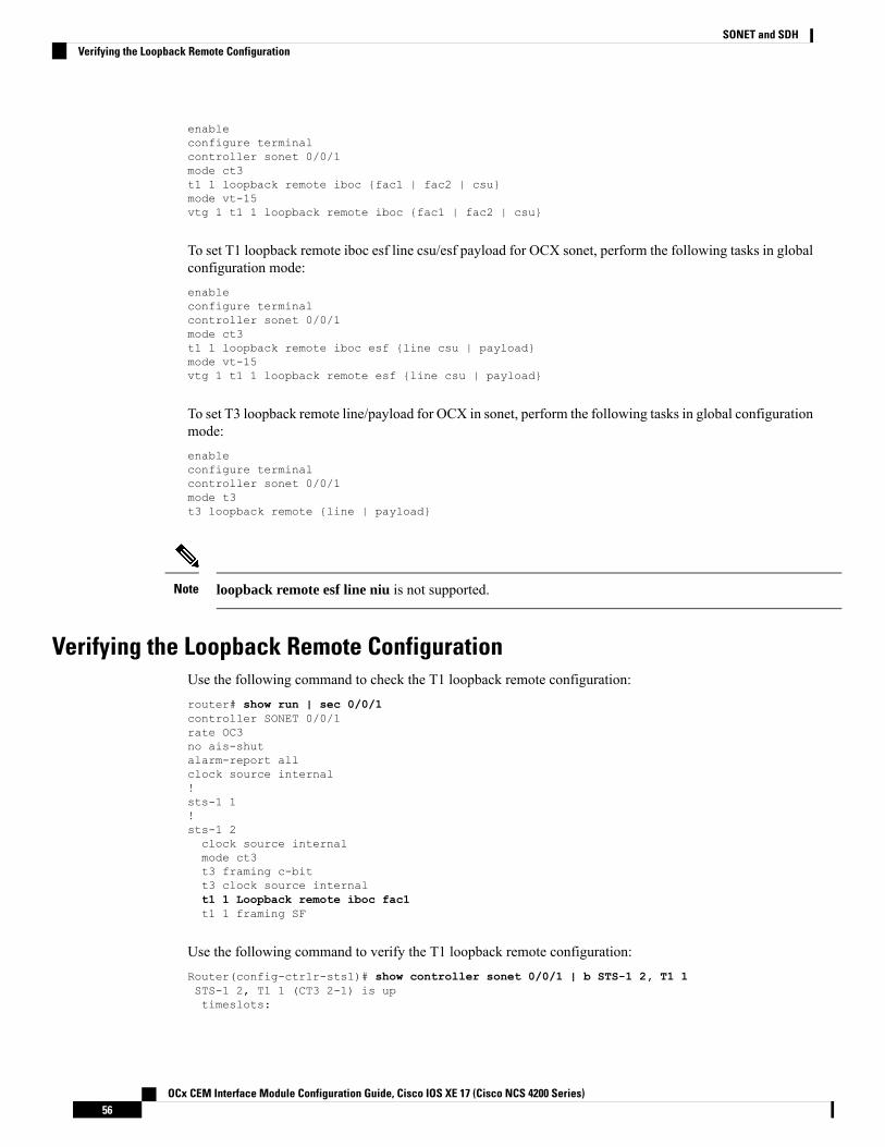
enableconfigure terminalcontroller sonet 0/0/1mode ct3t1 1 loopback remote iboc {fac1 | fac2 | csu}mode vt-15vtg 1 t1 1 loopback remote iboc {fac1 | fac2 | csu}
To set T1 loopback remote iboc esf line csu/esf payload for OCX sonet, perform the following tasks in globalconfiguration mode:enableconfigure terminalcontroller sonet 0/0/1mode ct3t1 1 loopback remote iboc esf {line csu | payload}mode vt-15vtg 1 t1 1 loopback remote esf {line csu | payload}
To set T3 loopback remote line/payload for OCX in sonet, perform the following tasks in global configurationmode:enableconfigure terminalcontroller sonet 0/0/1mode t3t3 loopback remote {line | payload}
loopback remote esf line niu is not supported.Note
Verifying the Loopback Remote ConfigurationUse the following command to check the T1 loopback remote configuration:router# show run | sec 0/0/1controller SONET 0/0/1rate OC3no ais-shutalarm-report allclock source internal!sts-1 1!sts-1 2clock source internalmode ct3t3 framing c-bitt3 clock source internalt1 1 Loopback remote iboc fac1t1 1 framing SF
Use the following command to verify the T1 loopback remote configuration:Router(config-ctrlr-sts1)# show controller sonet 0/0/1 | b STS-1 2, T1 1STS-1 2, T1 1 (CT3 2-1) is uptimeslots:
OCx CEM Interface Module Configuration Guide, Cisco IOS XE 17 (Cisco NCS 4200 Series)56
SONET and SDHVerifying the Loopback Remote Configuration

Configured for NIU FAC1 Line Loopback with IBOCCurrently in Inband Remotely Line LoopedReceiver has no alarms.Framing is SF, Clock Source is Internal
Use the following command to check T3 loopback remote configuration:Router# show run | sec 0/0/1controller SONET 0/0/1rate OC3no ais-shutalarm-report allclock source internal!sts-1 1!sts-1 2!sts-1 3clock source internalmode t3t3 framing c-bitt3 loop remote linet3 clock source internal
Use the following command to verify T3 loopback remote configuration:
Router(config-ctrlr-sts1)# do show controller sonet 0/0/1 | b Path 3OC3.STS1 0/0/1 Path 3 is up. (Configured for Remotely Looped)Currently in Remotely Line LoopedHardware is NCS4200-1T8S-10CS
Applique type is T3Receiver has no alarms.MDL transmission is disabled
Associated CommandsThe following table shows the Associated Commands for SONET configuration:
LinksCommands
http://www.cisco.com/c/en/us/td/docs/ios-xml/ios/interface/command/ir-cr-book/ir-a1.html#wp7654966010
ais-shut
http://www.cisco.com/c/en/us/td/docs/ios-xml/ios/interface/command/ir-cr-book/ir-a1.html#wp2800999060
alarm-report
http://www.cisco.com/c/en/us/td/docs/ios-xml/ios/interface/command/ir-cr-book/ir-a1.html#wp8015117230
aps adm
OCx CEM Interface Module Configuration Guide, Cisco IOS XE 17 (Cisco NCS 4200 Series)57
SONET and SDHAssociated Commands
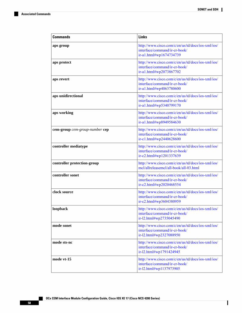
LinksCommands
http://www.cisco.com/c/en/us/td/docs/ios-xml/ios/interface/command/ir-cr-book/ir-a1.html#wp1674734739
aps group
http://www.cisco.com/c/en/us/td/docs/ios-xml/ios/interface/command/ir-cr-book/ir-a1.html#wp2073867702
aps protect
http://www.cisco.com/c/en/us/td/docs/ios-xml/ios/interface/command/ir-cr-book/ir-a1.html#wp4063780600
aps revert
http://www.cisco.com/c/en/us/td/docs/ios-xml/ios/interface/command/ir-cr-book/ir-a1.html#wp5340799170
aps unidirectional
http://www.cisco.com/c/en/us/td/docs/ios-xml/ios/interface/command/ir-cr-book/ir-a1.html#wp8949584630
aps working
http://www.cisco.com/c/en/us/td/docs/ios-xml/ios/interface/command/ir-cr-book/ir-c1.html#wp2440628600
cem-group cem-group-number cep
http://www.cisco.com/c/en/us/td/docs/ios-xml/ios/interface/command/ir-cr-book/ir-c2.html#wp1201337639
controller mediatype
http://www.cisco.com/c/en/us/td/docs/ios-xml/ios/mcl/allreleasemcl/all-book/all-03.html
controller protection-group
http://www.cisco.com/c/en/us/td/docs/ios-xml/ios/interface/command/ir-cr-book/ir-c2.html#wp2020468554
controller sonet
http://www.cisco.com/c/en/us/td/docs/ios-xml/ios/interface/command/ir-cr-book/ir-c2.html#wp3604380959
clock source
http://www.cisco.com/c/en/us/td/docs/ios-xml/ios/interface/command/ir-cr-book/ir-l2.html#wp2735045490
loopback
http://www.cisco.com/c/en/us/td/docs/ios-xml/ios/interface/command/ir-cr-book/ir-l2.html#wp2327088950
mode sonet
http://www.cisco.com/c/en/us/td/docs/ios-xml/ios/interface/command/ir-cr-book/ir-l2.html#wp1791424945
mode sts-nc
http://www.cisco.com/c/en/us/td/docs/ios-xml/ios/interface/command/ir-cr-book/ir-l2.html#wp1137973905
mode vt-15
OCx CEM Interface Module Configuration Guide, Cisco IOS XE 17 (Cisco NCS 4200 Series)58
SONET and SDHAssociated Commands

LinksCommands
http://www.cisco.com/c/en/us/td/docs/ios-xml/ios/interface/command/ir-cr-book/ir-o1.html#wp1973678817
overhead c2
http://www.cisco.com/c/en/us/td/docs/ios-xml/ios/interface/command/ir-cr-book/ir-o1.html#wp4338698890
overhead j0
http://www.cisco.com/c/en/us/td/docs/ios-xml/ios/interface/command/ir-cr-book/ir-o1.html#wp1987243836
overhead j1
http://www.cisco.com/c/en/us/td/docs/ios-xml/ios/interface/command/ir-cr-book/ir-o1.html#wp2779929239
overhead s1s0
http://www.cisco.com/c/en/us/td/docs/ios-xml/ios/mcl/allreleasemcl/all-book/all-10.html
protection-group
http://www.cisco.com/c/en/us/td/docs/ios-xml/ios/mcl/allreleasemcl/all-book/all-10.html
protection-group [working | protect]
http://www.cisco.com/c/en/us/td/docs/ios-xml/ios/interface/command/ir-cr-book/ir-o1.html#wp4442889730
rate [OC3 | OC12 | OC48 | OC192]
http://www.cisco.com/c/en/us/td/docs/ios-xml/ios/interface/command/ir-cr-book/ir-s6.html#wp3364503641
shutdown
http://www.cisco.com/c/en/us/td/docs/ios-xml/ios/interface/command/ir-cr-book/ir-s3.html#wp1341372847
show controllers sonet
http://www.cisco.com/c/en/us/td/docs/ios-xml/ios/interface/command/ir-cr-book/ir-s4.html#wp6553420000
show hw-module subslot transceiver
http://www.cisco.com/c/en/us/td/docs/ios-xml/ios/mcl/allreleasemcl/all-book/all-14.html
show protection-group
http://www.cisco.com/c/en/us/td/docs/ios-xml/ios/interface/command/ir-cr-book/ir-s6.html#wp2423232697
sts-1
http://www.cisco.com/c/en/us/td/docs/ios-xml/ios/interface/command/ir-cr-book/ir-t1.html#wp2623191253
t1 t1-line-number framing
http://www.cisco.com/c/en/us/td/docs/ios-xml/ios/interface/command/ir-cr-book/ir-t1.html#wp3480850667
t1 t1-line-number clock source
http://www.cisco.com/c/en/us/td/docs/ios-xml/ios/interface/command/ir-cr-book/ir-t1.html#wp2311589330
threshold
OCx CEM Interface Module Configuration Guide, Cisco IOS XE 17 (Cisco NCS 4200 Series)59
SONET and SDHAssociated Commands

LinksCommands
http://www.cisco.com/c/en/us/td/docs/ios-xml/ios/mcl/allreleasemcl/all-book/all-15.html
type sts48c
http://www.cisco.com/c/en/us/td/docs/ios-xml/ios/interface/command/ir-cr-book/ir-t2.html#wp3494199143
vtg vtg-line-number t1 t1-line-number loopback
OCx CEM Interface Module Configuration Guide, Cisco IOS XE 17 (Cisco NCS 4200 Series)60
SONET and SDHAssociated Commands

C H A P T E R 6Configuring SDH
SDH is a standard that defines optical signals as well as a synchronous frame structure for multiplexed digitaltraffic. It is is used in Europe by the International Telecommunication Union TelecommunicationStandardization Sector (ITU-T). The SDH equipment is used everywhere except North America. The IMsupports the entire SDH hierarchy (except VC-2/C-2).
• Overview of SDH, on page 61• Services Provided by SDH Configuration, on page 63• SDH Multiplexing, on page 65• Configuring AU-4 — TUG-3 — TUG-2 — VC-12 for Framed SAToP, on page 76• Configuring AU-3 — TUG-2 — VC-11 — T1 for Framed SAToP, on page 77• Verifying SDH Configuration for Framed SAToP, on page 77• Restrictions for SDH, on page 78• Configuring Mediatype Controller, on page 79• Configuring Rate on SDH Ports, on page 79• SDH Line and Section Configuration Parameters, on page 79• Configuring BERT in SDH for SAToP, on page 97• SDH T1/E1 Configuration Parameters, on page 101• SDH T3/E3 Configuration Parameters, on page 102• SDH VC Configuration Parameters for SAToP, on page 103• Configuring ACR on SDH, on page 105• Configuring DCR on SDH, on page 106• Loopback Remote on T1 and T3 Interfaces, on page 107
Overview of SDHSDH was defined by European Telecommunications Standards Institute (ETSI) and is now being controlledby the ITU-T standards body. SDH standard is prevalently used everywhere outside North America and Japan.
The following are true for SDH:
• Network Node Interface (NNI) defined by CCITT/ITU-TS for worldwide use and partly aompatible withSONET
• One of the two options for the User-Network Interface (UNI) (the customer connection) and formallythe U reference point interface for support of BISDN
OCx CEM Interface Module Configuration Guide, Cisco IOS XE 17 (Cisco NCS 4200 Series)61

Basic SDH SignalThe basic format of an SDH signal allows it to carry many different services in its VC because SDH signalis bandwidth-flexible. This capability allows the transmission of high-speed packet-switched services, ATM,contribution video, and distribution video. However, SDH still permits transport and networking at the 2Mbit/s, 34 Mbit/s, and 140 Mbit/s levels, accommodating the existing digital hierarchy signals. In addition,SDH supports the transport of signals based on the 1.5 Mbit/s hierarchy.
SDH Hierarchy
Modes of CEM• Structure Agnostic TDM over Packet (SAToP) (RFC 4553) – SAToP mode is used to encapsulateT1/E1 or T3/E3 unstructured (unchannelized) services over packet switched networks. In SAToP mode,the bytes are sent out as they arrive on the TDM line. Bytes do not have to be aligned with any framing.
In this mode, the interface is considered as a continuous framed bit stream. The packetization of thestream is done according to IETF RFC 4553. All signaling is carried transparently as a part of a bit stream.
• Circuit Emulation Service over Packet (CEP) (RFC 4842) - CEP mode is used to encapsulate SDHpayload envelopes (SPEs) like VC11, VC12, VC4, or VC4-Nc over PSN. In this mode, the bytes fromthe corresponding SPE are sent out as they arrive on the TDM line. The interface is considered as acontinuous framed bit stream. The packetization of the stream is done according to IETF RFC 4842.
Table 10: SDH CEM Channelization Modes
PortsCEMSDH Modes
STM16CEPVC4-16c
STM4, STM16CEPVC4-4c
STM1, STM4, STM16CEPVC4
OCx CEM Interface Module Configuration Guide, Cisco IOS XE 17 (Cisco NCS 4200 Series)62
SONET and SDHBasic SDH Signal

PortsCEMSDH Modes
STM1, STM4, STM16SAToPTUG-3-E3
STM1, STM4, STM16SAToPTUG-3-T3
STM1, STM4, STM16CEPTUG-2-VC11
STM1, STM4, STM16CEPTUG-2-VC12
STM1, STM4, STM16SAToPTUG-2-T1
STM1, STM4, STM16SAToPTUG-2-E1
Services Provided by SDH ConfigurationThe following services are provided by SDH Configuration:
Configuration DetailsSDH Circuits
• Configuring Mediatype Controller
• Configuring Rate on SDH Ports
• Configurin AU-3 or AU-4 Mapping
• Configuring Modes under AU-4 Mapping
• Configuring Mode VC4 CEP
Configuring VC4 CEP circuit
• Configuring Mediatype Controller
• Configuring Rate on SDH Ports
• Configuring AU-3 or AU-4 Mapping
• Configuring Modes under AU-4 Mapping
• Configuring Mode VC-4 Nc
Configuring VC4-4c circuit or Configuring VC4-16ccircuit
• Configuring Mediatype Controller
• Configuring Rate on SDH Ports
• Configuring AU-3 or AU-4 Mapping
• Configuring Mode TUG-3
Configuring VC4—TUG3—E3 circuit
OCx CEM Interface Module Configuration Guide, Cisco IOS XE 17 (Cisco NCS 4200 Series)63
SONET and SDHServices Provided by SDH Configuration

Configuration DetailsSDH Circuits
• Configuring Mediatype Controller
• Configuring Rate on SDH Ports
• Configuring AU-3 or AU-4 Mapping
• Configuring Mode TUG-3
• Configuring AU-4—TUG-3—VC-3—DS3
Configuring VC4—TUG3—T3 circuit
• Configuring Mediatype Controller
• Configuring Rate on SDH Ports
• Configuring AU-3 or AU-4 Mapping
• Configuring Mode TUG-3
• ConfiguringVC4—TUG-3—TUG-2—VC-12—VC
ConfiguringVC4—TUG-3—TUG-2—VC-12 circuit
• Configuring Mediatype Controller
• Configuring Rate on SDH Ports
• Configuring AU-3 or AU-4 Mapping
• Configuring Mode TUG-3
• Configuring AU-4—TUG-3—TUG-2—VC-12
Configuring VC4— TUG-3— TUG-2—VC-12—E1 circuit
• Configuring Mediatype Controller
• Configuring Rate on SDH Ports
• Configuring AU-3 or AU-4 Mapping
• Configuring Mode TUG-3
• ConfiguringAU-4—VC4—TUG-3—TUG-2—VC-11—T1
ConfiguringVC4—TUG-3—TUG-2—VC-11 circuit
• Configuring Mediatype Controller
• Configuring Rate on SDH Ports
• Configuring AU-3 or AU-4 Mapping
• Configuring AU-3—VC-3—E3
Configuring AU-3—VC-3—E3 circuit
OCx CEM Interface Module Configuration Guide, Cisco IOS XE 17 (Cisco NCS 4200 Series)64
SONET and SDHServices Provided by SDH Configuration

Configuration DetailsSDH Circuits
• Configuring Mediatype Controller
• Configuring Rate on SDH Ports
• Configuring AU-3 or AU-4 Mapping
• Configuring AU-3—VC-3—DS3 circuit
Configuring AU-3—VC-3—DS3 circuit
• Configuring Mediatype Controller
• Configuring Rate on SDH Ports
• Configuring AU-3 or AU-4 Mapping
• Configuring Mode VC-1x
• Configuring AU-3—TUG-2—VC-11—T1
Configuring (AU-3) VC-3—TUG-2—VC-12—T1circuit
• Configuring Mediatype Controller
• Configuring Rate on SDH Ports
• Configuring AU-3 or AU-4 Mapping
• Configuring Mode VC-1x
• Configuring AU-3—TUG-2—VC-12—E1
Configuring (AU-3) VC-3—TUG-2—VC-12 circuit
• Configuring Mediatype Controller
• Configuring Rate on SDH Ports
• Configuring AU-3 or AU-4 Mapping
• Configuring Mode VC-1x
• Configuring AU-3—TUG-2—VC-11—T1
Configuring (AU-3) VC-3—TUG-2—VC11 circuit
• Configuring Mediatype Controller
• Configuring Rate on SDH Ports
• Configuring AU-3 or AU-4 Mapping
• Configuring Mode VC-1x
• Configuring AU-3—TUG-2—VC-12—E1
Configuring (AU-3) VC-3—TUG-2—VC11—E1circuit
SDH MultiplexingThe terms and definitions of SDH multiplexing principles are:
OCx CEM Interface Module Configuration Guide, Cisco IOS XE 17 (Cisco NCS 4200 Series)65
SONET and SDHSDH Multiplexing

• Mapping – A process used when tributaries are adapted into VCs by adding justification bits and PathOverhead (POH) information.
• Aligning – This process takes place when a pointer is included in a Tributary Unit (TU) or anAdministrative Unit (AU), to allow the first byte of the VC to be located.
• Multiplexing – This process is used when multiple lower-order path layer signals are adapted into ahigher-order path signal, or when the higher-order path signals are adapted into a Multiplex Section.
• Stuffing – As the tributary signals are multiplexed and aligned, some spare capacity is designed into theSDH frame to provide enough space for all the various tributary rates. Therefore, at certain points in themultiplexing hierarchy, this space capacity is filled with “fixed stuffing” bits that carry no information,but are required to fill up the particular frame.
Modes of SDHA Synchronous Transport Module (STM) signal is the Synchronous Digital Hierarchy (SDH) equivalent ofthe SONET STS. In this document, STM term refers to both path widths and optical line rates. The pathswithin an STM signals are called administrative units (AUs).
An AU is the information structure that provides adaptation between the higher-order path layer and themultiplex section layer. It consists of an information payload (the higher-order VC) and an AU pointer, whichindicates the offset of the payload frame start relative to the multiplex section frame start.
The AU-3 pointer is composed of 3 bytes; the AU-4 pointer is composed of 9 bytes.
The payload of the STM-1 frame consists of one AU-4 unit or three AU-3 units.
Augment Mapping
An administrative unit group (AUG) consists of one or more administrative units occupying fixed, definedpositions in an STM payload. Augment mapping is supported at STM1 level.The following types of augmentmapping are supported:
• Augment Mapping AU-4
This is the default augment mapping mode.Note
• Augment Mapping AU-3
• Mixed (AU-3 and AU-4) Augment Mapping
The supported modes of SDH are:
• AU-4-16c (VC4-16c)
• AU-4-4c (VC4-4c)
• AU-4 (VC4)
• AU-4 — TUG-3 — VC-3 — DS3
• AU-4 — TUG-3 — VC-3 — E3
• AU-4 — TUG-3 — TUG-2 — VC-11 — T1
OCx CEM Interface Module Configuration Guide, Cisco IOS XE 17 (Cisco NCS 4200 Series)66
SONET and SDHModes of SDH

• AU-4 — TUG-3 — TUG-2 — VC-12 — E1
• AU-4 — TUG-3 — TUG-2 — VC-11
• AU-4 — TUG-3 — TUG-2 — VC-12
• AU-3 — VC-3 — DS3
• AU-3 — TUG-2 — VC-11 — T1
• AU-3 — TUG-2 — VC-12 — E1
• AU-3 — TUG-2 — VC-11
• AU-3 — TUG-2 — VC-12
• AU-3 — VC-3 — E3
Configuring AUG MappingThis section describes the configuration of Administration Units Group (AUG) mapping.
Configuring AU-3 or AU-4 MappingTo configure AU-3 or AU-4 mapping:configure terminalaug mapping [au-3 | au-4]end
The aug mapping command is available only when SDH framing is configured.Note
The AUG mapping mode is AU-4 by default. AUG mapping is supported at STM-1 level.Note
Configuring Mixed AU-3 and AU-4 MappingTo configure mixed AU-3 and AU-4 mapping:configure terminalaug mapping [au-3 | au-4] stm [1-1] stm1 number [1-4]end
Use the following command to change the AUG mapping of a particular STM-1 to AU-3:
aug mapping au-3 stm [1-16] path number 1-16
After configuring this command for STM-4 the AUG mapping of path 2, 3, and 4 is AU-4 and for path 1 itis AU-3.
Note
OCx CEM Interface Module Configuration Guide, Cisco IOS XE 17 (Cisco NCS 4200 Series)67
SONET and SDHConfiguring AUG Mapping

Verifying AUG Mapping ConfigurationUse show running-configuration command to verify the AUG mapping configuration.show running-config | sec 0/3/4PDT: %SYS-5-CONFIG_I: Configured from console by consolecontroller MediaType 0/0/16mode sdhcontroller SDH 0/0/16rate STM4no ais-shutalarm-report allthreshold sf-ber 3clock source internaloverhead s1s0 0aug mapping au-4 stm 1aug mapping au-3 stm 2aug mapping au-4 stm 3aug mapping au-4 stm 4au-4 1!au-3 4!au-3 5!au-3 6!au-4 3!au-4 4!
Configuring Modes under AU-4 MappingThis section describes the configuration of modes under AU-4 mapping.
Configuring Mode VC-4 CEPTo configure mode VC-4 CEP:enableconfigure terminalcontroller sdh 0/0/16rate stm 4aug mapping au-4au-4 1mode vc4cem-group 100 cepend
Overhead C2 should match with the peer end else it will result in PPLM alarm.Note
Verifying Mode VC-4 Configuration
Use the show running-configuration command to verify the mode VC-4 configuration.#show running-config | sec 0/3/4PDT: %SYS-5-CONFIG_I: Configured from console by consoleplatform enablecontroller MediaType 0/0/16 oc12
OCx CEM Interface Module Configuration Guide, Cisco IOS XE 17 (Cisco NCS 4200 Series)68
SONET and SDHVerifying AUG Mapping Configuration

controller MediaType 0/0/16mode sdhcontroller SDH 0/0/16rate STM4no ais-shutalarm-report allthreshold sf-ber 3clock source internaloverhead s1s0 0aug mapping au-4au-4 1mode vc4clock source internalau-4 2!au-4 3!au-4 4
Configuring Mode TUG-3To configure mode TUG-3:enableconfigure terminalcontroller sdh 0/0/16rate stm4au-4 1mode tug-3end
Mode TUG-3 creates three TUG-3 paths. TUG-3 range is 1 to 3.Note
Configuring AU-4 — TUG-3 — VC-3 — DS3
To configure AU-4 — TUG-3 — VC-3 — DS3:enableconfigure terminalcontroller sdh 0/0/16rate stm4au-4 1mode tug-3tug-3 1mode t3cem-group 100 unframedend
Verifying DS3 Configuration
Use show running-configuration command to verify DS3 configuration:#show running-configuration | sec 0/3/4platform enable controller MediaType 0/0/16 oc12controller MediaType 0/0/16mode sdhcontroller SDH 0/0/16rate STM4no ais-shutalarm-report all
OCx CEM Interface Module Configuration Guide, Cisco IOS XE 17 (Cisco NCS 4200 Series)69
SONET and SDHConfiguring Mode TUG-3

threshold sf-ber 3clock source internaloverhead s1s0 0aug mapping au-4au-4 1mode tug-3clock source internaltug-3 1mode T3t3 clock source internalt3 framing c-bit!tug-3 2!tug-3 3!au-4 2!au-4 3!au-4 4
Configuring AU-4 — TUG-3 — VC-3 — E3
To configure AU-4 — TUG-3 — VC-3 — E3:enableconfigure terminalcontroller sdh 0/0/16rate stm4au-4 1mode tug-3tug-3 1mode e3cem-group 100 unframedend
Verifying E3 Configuration
Use show running-configuration command to verify E3 configuration.#show running-configuration | sec 0/0/16platform enablecontroller MediaType 0/0/16 oc12controller MediaType 0/0/16mode sdhcontroller SDH 0/0/16rate STM4no ais-shutalarm-report allthreshold sf-ber 3clock source internaloverhead s1s0 0aug mapping au-4au-4 1mode tug-3clock source internaltug-3 1mode E3e3 clock source internale3 framing g751!tug-3 2!tug-3 3
OCx CEM Interface Module Configuration Guide, Cisco IOS XE 17 (Cisco NCS 4200 Series)70
SONET and SDHConfiguring AU-4 — TUG-3 — VC-3 — E3

!au-4 2
Configuring Mode VC-1xTo configure mode VC-1x:enableconfigure terminalcontroller sdh 0/0/16rate stm1no ais-shutalarm-report allclock source internaloverhead s1s0 0aug mapping au-4au-4 1clock source internalmode tug-3tug-3 1mode VC1xtug-2 1 payload VC11tug-2 2 payload VC11tug-2 3 payload VC11tug-2 4 payload VC11tug-2 5 payload VC11tug-2 6 payload VC11tug-2 7 payload VC11end
When you configure mode VC-1x, seven TUG-2 payloads are created. TUG-2 payloads can be of two types,VC-11 and VC-12. Default for TUG-2 payload mode is VC-11.
TUG-2 payload VC-11 can be configured as VC or T1 and the range is 1 to 4.
TUG-2 payload VC-12 can be configured as VC or E1 and the range is 1 to 3.
Note
Configuring AU-4 — TUG-3 — TUG-2 — VC-11 — T1
To configure AU-4 — TUG-3 — TUG-2 — VC-11 — T1:enableconfigure terminalcontroller sdh 0/0/16rate stm4au-4 1mode tug-3tug-3 1mode vc1xtug-2 1 payload vc11t1 1 cem-group 10 unframedvc 1 overhead v5 2interface cem 0/0/16cem 100xconnect 10.2.2.2 10 encapsulation mplsend
OCx CEM Interface Module Configuration Guide, Cisco IOS XE 17 (Cisco NCS 4200 Series)71
SONET and SDHConfiguring Mode VC-1x

Overhead v5 has to be matched with the peer end.Note
Configuring AU-4 — TUG-3 — TUG-2 — VC-12
Use the following commands to configure AU-4 — TUG-3 — TUG-2 — VC-12:enableconfigure terminalcontroller sdh 0/0/16rate stm4au-4 1mode tug-3tug-3 1mode vc1xtug-2 3 payload vc12e1 1 cem-group 10 unframedvc 1 overhead v5 2end
Overhead v5 should match with the peer end.Note
Configuring AU-4 — TUG-3 — TUG-2 — VC-11 — VC
To configure AU-4 — TUG-3 — TUG-2 — VC-11 — VC:enableconfigure terminalcontroller sdh 0/0/16rate stm4au-4 1mode tug-3tug-3 1mode vc1xtug-2 2 payload vc11vc 1 cem-group 2 cepend
Configuring AU-4 — TUG-3 — TUG-2 — VC-12 — VC
To configure AU-4 — TUG-3 — TUG-2 — VC-12 — VC:enableconfigure terminalcontroller sdh 0/0/16rate stm4au-4 1mode tug-3tug-3 1mode vc1xtug-2 4 payload vc12vc 1 cem-group 10 cepend
OCx CEM Interface Module Configuration Guide, Cisco IOS XE 17 (Cisco NCS 4200 Series)72
SONET and SDHConfiguring AU-4 — TUG-3 — TUG-2 — VC-12

Verifying Mode VC-1x Configuration
Use show running-configuration command to verify mode VC-1x configuration.#show running-configurationcontroller MediaType 0/3/4mode sdhcontroller SDH 0/3/4rate STM4no ais-shutalarm-report allthreshold sf-ber 3clock source internaloverhead s1s0 0aug mapping au-4au-4 1clock source internalmode tug-3tug-3 1mode VC1xtug-2 1 payload VC11t1 1 cem-group 1 unframedtug-2 2 payload VC11vc 1 cem-group 2 ceptug-2 3 payload VC12e1 1 cem-group 3 unframedtug-2 4 payload VC12vc 1 cem-group 4 ceptug-2 5 payload VC11tug-2 6 payload VC11tug-2 7 payload VC11!tug-3 2!tug-3 3!au-4 2!au-4 3!au-4 4
Configuring Mode VC-4 NcTo configure mode VC-4 Nc:enableconfigure terminalcontroller sdh 0/0/16au-4 1 - 4 mode vc4-4ccem-group 100 cepend
Overhead C2 should match with the peer end else it will result in PPLM alarm.Note
Verifying Mode VC-4 Nc Configuration
Use show running-configuration command to verify mode VC-4 Nc configuration.
OCx CEM Interface Module Configuration Guide, Cisco IOS XE 17 (Cisco NCS 4200 Series)73
SONET and SDHVerifying Mode VC-1x Configuration

#show running-configurationplatform enablecontroller MediaType 0/0/16 oc12controller MediaType 0/0/16mode sdhcontroller SDH 0/0/16rate STM4no ais-shutalarm-report allthreshold sf-ber 3clock source internaloverhead s1s0 0aug mapping au-4au-4 1 - 4 mode vc4-4cclock source internalcem-group 10 cepinterface CEM 0/0/16no ip addresscem 10
Configuring AU-3 — VC-3 — DS3To configure AU-3 — VC-3 — DS3:enableconfigure terminalcontroller MediaType 0/0/16mode sdhcontroller sdh 0/0/16rate stm4au-3 1mode t3cem-group 100 unframedend
Configuring AU-3 — VC-3 — E3To configure AU-3 — VC-3 — E3:enableconfigure terminalcontroller sdh 0/0/16rate stm4au-3 1mode e3cem-group 100 unframedend
Configuring Modes under AU-3 MappingThis section describes the configuration of modes under AU-3 mapping.
Configuring Mode VC-1xTo configure mode VC-1x:enableconfigure terminalcontroller sdh 0/0/16rate stm4
OCx CEM Interface Module Configuration Guide, Cisco IOS XE 17 (Cisco NCS 4200 Series)74
SONET and SDHConfiguring AU-3 — VC-3 — DS3

au-3 1mode VC1xtug-2 1 payload VC11tug-2 2 payload VC11tug-2 3 payload VC11tug-2 4 payload VC11tug-2 5 payload VC11tug-2 6 payload VC11tug-2 7 payload VC11endend
Configuring AU-3 — TUG-2 — VC-11 — VC
To configure AU-3 — TUG-2 — VC-11 — VC:configure terminalcontroller MediaType 0/0/16mode sdhcontroller sdh 0/0/16rate stm4au-3 1mode vc1xtug-2 1 payload vc11vc 1 cem-group 10 cepend
Configuring AU-3 — TUG-2 — VC-12 — VC
To configure AU-3 — TUG-2 — VC-12 — VC:configure terminalcontroller MediaType 0/0/16mode sdhcontroller sdh 0/0/16rate stm4au-3 1mode vc1xtug-2 1 payload vc12vc 1 cem-group 10 cepend
Configuring AU-3 — TUG-2 — VC-11 — T1
To configure AU-3 — TUG-2 — VC-11 — T1:configure terminalcontroller MediaType 0/0/16mode sdhcontroller sdh 0/0/16rate stm4au-3 1mode vc1xtug-2 1 payload vc11t1 1 cem-group 10 unframedvc 1 overhead v5 2interface cem 0/0/16cem 100xconnect 10.2.2.2 10 encapsulation mplsend
OCx CEM Interface Module Configuration Guide, Cisco IOS XE 17 (Cisco NCS 4200 Series)75
SONET and SDHConfiguring AU-3 — TUG-2 — VC-11 — VC

Configuring AU-3 — TUG-2 — VC-12 — E1
To configure AU-3 — TUG-2 — VC-12 — E1:configure terminalcontroller MediaType 0/0/16mode sdhcontroller sdh 0/0/16rate stm4au-3 1mode vc1xtug-2 3 payload vc12e1 1 cem-group 10 unframedvc 1 overhead v5 2end
Verifying Mode VC-1x Configuration
Use show running-configuration command to verify mode VC-1x configuration.#show running-configurationcontroller MediaType 0/0/16mode sdhcontroller SDH 0/0/16rate STM4no ais-shutalarm-report allthreshold sf-ber 3clock source internaloverhead s1s0 0aug mapping au-3au-3 1clock source internalmode VC1xtug-2 1 payload VC11t1 1 cem-group 1 unframedtug-2 2 payload VC11vc 1 cem-group 2 ceptug-2 3 payload VC12tug-2 4 payload VC12vc 1 cem-group 4 ceptug-2 5 payload VC11tug-2 6 payload VC11tug-2 7 payload VC11
Configuring AU-4 — TUG-3 — TUG-2 — VC-12 for Framed SAToPUse the following commands to configure AU-4 — TUG-3 — TUG-2 — VC-12 for framed SAToP undermode VC-1x (AU-4 mapping):enableconfigure terminalcontroller sdh 0/0/16rate stm4au-4 1mode tug-3tug-3 1mode vc1xtug-2 3 payload vc12e1 1 cem-group 1 framed
OCx CEM Interface Module Configuration Guide, Cisco IOS XE 17 (Cisco NCS 4200 Series)76
SONET and SDHConfiguring AU-3 — TUG-2 — VC-12 — E1

vc 1 overhead v5 2end
Configuring AU-3 — TUG-2 — VC-11 — T1 for Framed SAToPTo configure AU-3 — TUG-2 — VC-11 — T1 for framed SAToP under mode VC-1x (AU-3 mapping):configure terminalcontroller MediaType 0/0/16mode sdhcontroller sdh 0/0/16rate stm4au-3 1mode vc1xtug-2 1 payload vc11t1 1 cem-group 0 framedvc 1 overhead v5 2interface cem 0/0/16cem 100xconnect 10.2.2.2 10 encapsulation mplsend
Verifying SDH Configuration for Framed SAToPUse show running configuration command to verify SDH configuration for Framed SAToP:Router#show running configuration | sec 0/0/16platform enable controller mediatype 0/0/16 oc3controller mediatype 0/0/16mode sdhcontroller sdh 0/0/16rate stm1no ais-shutalarm-report allclock source internaloverhead s1s0 0aug mapping au-4au-4 1clock source internalmode tug-3tug-3 1mode vc1xtug-2 1 payload vc11tug-2 2 payload vc12e1 1 cem-group 1 framedtug-2 3 payload vc11tug-2 4 payload vc11tug-2 5 payload vc11tug-2 6 payload vc11tug-2 7 payload vc11!interface cem 0/0/16no ip addresscem 0!cem 1!cem 2!
OCx CEM Interface Module Configuration Guide, Cisco IOS XE 17 (Cisco NCS 4200 Series)77
SONET and SDHConfiguring AU-3 — TUG-2 — VC-11 — T1 for Framed SAToP

cem 3!Router#
Restrictions for SDH• The maximum supported bandwidth is STM-16.
• Any Port (16-19) is configurable for STM-1, STM-4 or STM-16.
• The IM has 4 X STM-4 ports. You can configure STM-1 or STM-4 on all four ports. If you configurerate STM-16 on any of the four ports, others ports will not be available.
• This IM does not support CEP on AU-4 — VC-4 — TUG-3 — VC-3.
• This IM does not support CT3, CE3, CT3-E1 under the VC3 container. Only clear channel T3 servicesare supported.
• This IM does not support the framed SAToP CESoPSN.
• Eight BERT engines are supported for Higher Order and 16 BERT engines are supported for LowerOrder hierarchy.
• If a port is configured as SDH, all ports can only be configured as SDH unless the mode SDH is removedfrom all the ports on the IM.
• VC-4-64c and VC-2 are not supported.
• AU-4 CT3, AU-4 CE3, AU-4 CT3-E1, AU-3-CT3, AU-3-CE3, and AU-3 CT3-E1 are not supported.
AU-4 — VC-4 — TUG-3 — VC-3 — DS3 — T1/E1, AU-4 — VC-4 — TUG-3 — VC-3 — E3— E1,AU-3 — VC-3 — DS3 — T1/E1, and AU-3 — VC-3 — E3 — E1 are not supported.
• Concatenation VC-4-Nc is only supported for augment mapping AU-4.
• MDL is not supported.
• SNCP is not supported.
Restrictions on Bandwidth
• Total available bandwidth is 2.5G.
The following configuration is blocked and an error message is displayed after the maximum bandwidthis utilized:rate stm1 | rate stm4 | rate stm16
Table 11: Bandwidth Used by Different Rates
Bandwidth (kbit/s)Rate
150,336STM-1
601,344STM-4
2,405,376STM-16
OCx CEM Interface Module Configuration Guide, Cisco IOS XE 17 (Cisco NCS 4200 Series)78
SONET and SDHRestrictions for SDH

Restrictions for Scale PW Circuits
• Only 1000 CEM PW Circuits per OCN Interface modules are supported.
Configuring Mediatype ControllerEach SFP port (16-19) can be configured as STM-1, STM-4, STM-16.
You must select the MediaType controller to configure and enter the controller configuration mode.
You must configure the controller as a SDH port.
To configure MediaType Controller:enableconfigure terminalcontroller MediaType 0/0/16mode sdhend
Configuring Rate on SDH PortsTo configure rate on SDH ports:enableconfigure terminalcontroller MediaType 0/0/16mode sdhcontroller sdh 0/0/16rate [stm1 | stm4 | stm16]end
The configuration of no form of the command is not suported. To restore to the default condition, use nomode sdh command under Mediatype controller after removing all configuration under that port. .
Note
SDH Line and Section Configuration ParametersThe following parameters affect SDH configuration at the line and section levels.
OverheadSets the SDH overhead bytes in the frame header to a specific standards requirement, or to ensureinteroperability with equipment from another vendors.
• J0 — Sets the J0 or C1 byte value in the SDH section overhead.
The supported values of J0 are 1 byte, 16 bytes, and 64 bytes.Note
OCx CEM Interface Module Configuration Guide, Cisco IOS XE 17 (Cisco NCS 4200 Series)79
SONET and SDHConfiguring Mediatype Controller

• S1S0 — Sets the SS bits value of the H1 byte in the SDH line overhead.
Configuring Line and Section OverheadTo configure line and section overhead:enableconfigure terminalcontroller sdh 0/0/16overhead s1s0 2overhead j0 expected length 16-byteoverhead j0 expected tracebuffer rx Messageoverhead j0 tx length 1-byteoverhead j0 tx tracebuffer tx Messageend
To restore the system to its default condition, use the no form of the overhead j0 command.Note
ThresholdSet the path BER threshold values.
• b1-tca — Enables Bit Error Rate (BER) threshold crossing alerts for B1.
• b2-tca — Enables BER threshold crossing alerts for B2.
• sd-ber —Enables the threshold of the Signal Degrade (SD) BER that is used to trigger a signal degradealarm.
• sf-ber —Configures the threshold of the Signal Failure (SF) BER that is used to trigger a link statechange.
Configuring Line and Section ThresholdTo configure line and section threshold:enableconfigure terminalmode sdhcontroller sdh 0/0/16threshold b1-tca 5threshold b2-tca 5threshold sd-ber 5threshold sf-ber 5end
To restore the system to its default condition, use the no form of the threshold command.Note
OCx CEM Interface Module Configuration Guide, Cisco IOS XE 17 (Cisco NCS 4200 Series)80
SONET and SDHConfiguring Line and Section Overhead

LoopbackSets a loopback to test the SDH port.
• local — Loops the signal from Tx to Rx path. Sends alarm indication signal (AIS) to network.
• network — Loops the signal from Rx to Tx path.
Configuring Line LoopbackTo configure loopback:enableconfigure terminalcontroller sdh 0/0/16loopback [local | network]end
To restore the system to its default condition, use the no form of the loopback command.Note
When loopback is configured as network, it is recommended to use the configuration of clock source as line.Note
AIS-ShutEnables automatic insertion of a Line Alarm Indication Signal (LAIS) in the sent SDH signal whenever theSDH port enters the administrative shutdown state.
Configuring AIS ShutTo configure AIS-Shut:enableconfigure terminalcontroller sdh 0/0/16ais-shutend
The no ais-shut command does not send AIS.Note
ShutdownDisables the interface.
Configuring ShutTo configure Shut:
OCx CEM Interface Module Configuration Guide, Cisco IOS XE 17 (Cisco NCS 4200 Series)81
SONET and SDHLoopback

enableconfigure terminalcontroller sdh 0/0/16shutdownend
Use the no shutdown command to disable the interface.Note
Alarm ReportingEnables reporting for all or selected alarms.
• b1-tca — Enables BER threshold crossing alarm for B1.
• b2-tca — Enables BER threshold crossing alarm for B2.
• b3-tca — Enables BER threshold crossing alarm for B3.
• lais —Enables line alarm indication signal.
• lom — Enables loss of multiframe signal.
• lrdi — Enables line remote defect indication signal.
• pais — Enables path alarm indication signal.
• plop — Enables loss of pointer failure signal for a path.
• pplm — Enables path payload mismatch indication.
• prdi — Enables path remote defect indication signal.
• puneq — Enables path unequipped (path label equivalent to zero) signal.
• sd-ber — Enables LBIP BER in excess of SD threshold.
• sf-ber — Enables LBIP BER in excess of SF threshold.
• slof — Enables section loss of frame signal.
• slos — Enables section loss of signal.
Configuring Alarm ReportingTo configure alarm reporting:enableconfigure terminalcontroller sdh 0/0/16alarm-report [b1-tca | b2-tca | b3-tca | lais | lom | lrdi | pais | plop | pplm | prdi |puneq | sd-ber | sf-ber | lof | los]end
To restore the system to its default condition, use the no form of the alarm report command.Note
OCx CEM Interface Module Configuration Guide, Cisco IOS XE 17 (Cisco NCS 4200 Series)82
SONET and SDHAlarm Reporting

Clock SourceSpecifies the clock source, where
• line —The link uses the recovered clock from the line.
• internal — The link uses the internal clock source. This is the default setting.
Configuring ClockTo configure clock, use the following commands:enableconfigure terminalcontroller sdh 0/0/16clock source [line | internal]end
The default mode is internal.Note
To restore the system to its default condition, use the no form of the command.Note
Configuring Network-Clock SDH
To configure network-clock SDH, use the following commands:enableconfigure terminalcontroller sdh 0/0/16clock source lineendenableconfigure terminalnetwork-clock input-source 1 controller sdh 0/0/16end
Verifying SDH Line and Section Parameters ConfigurationUse show controllers command to verify SDH Line and Section Parameters Configuration:Rotuer#show controller sdh 0/7/7SDH 0/7/7 is up.Hardware is NCS4200-1T8S-10CSPort configured rate: STM16Applique type is Channelized SDHClock Source is Internal, AUG mapping is AU4.Medium info:Type: SDH, Line Coding: NRZ,Alarm Throttling: OFFRegenerator Section:LOS = 0 LOF = 0 BIP(B1) = 0
SDH Section TablesINTERVAL CV ES SES SEFS
OCx CEM Interface Module Configuration Guide, Cisco IOS XE 17 (Cisco NCS 4200 Series)83
SONET and SDHClock Source

21:24-21:24 0 0 0 0
Multiplex Section:AIS = 0 RDI = 0 REI = 0 BIP(B2) = 0
Active Defects: NoneDetected Alarms: NoneAsserted/Active Alarms: NoneAlarm reporting enabled for: SLOS SLOF LAIS SF SD LRDI B1-TCA B2-TCABER thresholds: SF = 10e-3 SD = 10e-6TCA thresholds: B1 = 10e-6 B2 = 10e-6Rx: S1S0 = 00
K1 = 00, K2 = 00J0 = 00
RX S1 = 00
Tx: S1S0 = 00K1 = 00, K2 = 00J0 = 04
Tx J0 Length : 16Tx J0 Trace :
50 45 31 20 20 20 20 20 20 20 20 20 20 20 20 00 PE1 .
Expected J0 Length : 16Expected J0 Trace :
50 45 31 20 20 20 20 20 20 20 20 20 20 20 20 00 PE1 .
Rx J0 Length : 0Rx J0 Trace :
SDH Line TablesINTERVAL CV ES SES UAS CVFE ESFE SESFE UASFE21:24-21:24 0 0 0 0 0 0 0 0
High Order Path:
PATH 1:Clock Source is internal
AIS = 0 RDI = 0 REI = 0 BIP(B3) = 0LOP = 0 PSE = 0 NSE = 0 NEWPTR = 0LOM = 0 PLM = 0 UNEQ = 0
Active Defects: NoneDetected Alarms: PPLMAsserted/Active Alarms: PPLMAlarm reporting enabled for: PAIS PRDI PUNEQ PLOP PPLM LOM B3-TCA
TCA threshold: B3 = 10e-6Rx: C2 = FETx: C2 = 01
Tx J1 Length : 16Tx J1 Trace
50 45 31 20 30 2F 37 2F 37 2E 31 00 00 00 00 00 PE1 0/7/7.1.....
Expected J1 Length : 16Expected J1 Trace
OCx CEM Interface Module Configuration Guide, Cisco IOS XE 17 (Cisco NCS 4200 Series)84
SONET and SDHVerifying SDH Line and Section Parameters Configuration

50 45 31 20 30 2F 37 2F 37 2E 31 00 00 00 00 00 PE1 0/7/7.1.....
PATH TRACE BUFFER : UNSTABLE
Rx J1 Length : 16Rx J1 TraceCRC-7: 0xBA OK
4F 4E 54 20 48 4F 2D 54 52 41 43 45 20 20 20 00 ONT HO-TRACE .
SDH Path TablesINTERVAL CV ES SES UAS CVFE ESFE SESFE UASFE21:24-21:24 0 0 0 0 0 0 0 0
PATH 4:Clock Source is internal
AIS = 0 RDI = 0 REI = 0 BIP(B3) = 0LOP = 0 PSE = 0 NSE = 0 NEWPTR = 0LOM = 0 PLM = 0 UNEQ = 0
Active Defects: NoneDetected Alarms: PPLM LOMAsserted/Active Alarms: PPLM LOMAlarm reporting enabled for: PAIS PRDI PUNEQ PLOP PPLM LOM B3-TCA
TCA threshold: B3 = 10e-6Rx: C2 = FETx: C2 = 02
Tx J1 Length : 16Tx J1 Trace
50 45 31 20 30 2F 37 2F 37 2E 32 00 00 00 00 00 PE1 0/7/7.2.....
Expected J1 Length : 16Expected J1 Trace
50 45 31 20 30 2F 37 2F 37 2E 32 00 00 00 00 00 PE1 0/7/7.2.....
PATH TRACE BUFFER : UNSTABLE
Rx J1 Length : 16Rx J1 TraceCRC-7: 0xBA OK
4F 4E 54 20 48 4F 2D 54 52 41 43 45 20 20 20 00 ONT HO-TRACE .
SDH Path TablesINTERVAL CV ES SES UAS CVFE ESFE SESFE UASFE21:23-21:24 0 0 0 382 0 0 0 0
PATH 7:Clock Source is internal
AIS = 0 RDI = 0 REI = 0 BIP(B3) = 0LOP = 0 PSE = 0 NSE = 0 NEWPTR = 0LOM = 0 PLM = 0 UNEQ = 0
Active Defects: NoneDetected Alarms: NoneAsserted/Active Alarms: NoneAlarm reporting enabled for: PAIS PRDI PUNEQ PLOP PPLM LOM B3-TCA
OCx CEM Interface Module Configuration Guide, Cisco IOS XE 17 (Cisco NCS 4200 Series)85
SONET and SDHVerifying SDH Line and Section Parameters Configuration

TCA threshold: B3 = 10e-6Rx: C2 = 00Tx: C2 = 00
Tx J1 Length : 16Tx J1 Trace
50 45 31 20 30 2F 37 2F 37 2E 33 00 00 00 00 00 PE1 0/7/7.3.....
Expected J1 Length : 16Expected J1 Trace
50 45 31 20 30 2F 37 2F 37 2E 33 00 00 00 00 00 PE1 0/7/7.3.....
PATH TRACE BUFFER : UNSTABLE
Rx J1 Length : 0Rx J1 Trace
SDH Path TablesINTERVAL CV ES SES UAS CVFE ESFE SESFE UASFE21:24-21:25 0 0 0 0 0 0 0 0
PATH 10:Clock Source is internal
AIS = 0 RDI = 0 REI = 0 BIP(B3) = 0LOP = 0 PSE = 0 NSE = 0 NEWPTR = 0LOM = 0 PLM = 0 UNEQ = 0
Active Defects: NoneDetected Alarms: NoneAsserted/Active Alarms: NoneAlarm reporting enabled for: PAIS PRDI PUNEQ PLOP PPLM LOM B3-TCA
TCA threshold: B3 = 10e-6Rx: C2 = 00Tx: C2 = 00
Tx J1 Length : 16Tx J1 Trace
50 45 31 20 30 2F 37 2F 37 2E 34 00 00 00 00 00 PE1 0/7/7.4.....
Expected J1 Length : 16Expected J1 Trace
50 45 31 20 30 2F 37 2F 37 2E 34 00 00 00 00 00 PE1 0/7/7.4.....
PATH TRACE BUFFER : UNSTABLE
Rx J1 Length : 0Rx J1 Trace
SDH Path TablesINTERVAL CV ES SES UAS CVFE ESFE SESFE UASFE21:25-21:25 0 0 0 0 0 0 0 0
PATH 13:Clock Source is internal
OCx CEM Interface Module Configuration Guide, Cisco IOS XE 17 (Cisco NCS 4200 Series)86
SONET and SDHVerifying SDH Line and Section Parameters Configuration

AIS = 0 RDI = 0 REI = 0 BIP(B3) = 0LOP = 0 PSE = 0 NSE = 0 NEWPTR = 0LOM = 0 PLM = 0 UNEQ = 0
Active Defects: NoneDetected Alarms: NoneAsserted/Active Alarms: NoneAlarm reporting enabled for: PAIS PRDI PUNEQ PLOP PPLM LOM B3-TCA
TCA threshold: B3 = 10e-6Rx: C2 = 00Tx: C2 = 00
Tx J1 Length : 16Tx J1 Trace
50 45 31 20 30 2F 37 2F 37 2E 35 00 00 00 00 00 PE1 0/7/7.5.....
Expected J1 Length : 16Expected J1 Trace
50 45 31 20 30 2F 37 2F 37 2E 35 00 00 00 00 00 PE1 0/7/7.5.....
PATH TRACE BUFFER : UNSTABLE
Rx J1 Length : 0Rx J1 Trace
SDH Path TablesINTERVAL CV ES SES UAS CVFE ESFE SESFE UASFE21:25-21:25 0 0 0 0 0 0 0 0
PATH 16:Clock Source is internal
AIS = 0 RDI = 0 REI = 0 BIP(B3) = 0LOP = 0 PSE = 0 NSE = 0 NEWPTR = 0LOM = 0 PLM = 0 UNEQ = 0
Active Defects: NoneDetected Alarms: NoneAsserted/Active Alarms: NoneAlarm reporting enabled for: PAIS PRDI PUNEQ PLOP PPLM LOM B3-TCA
TCA threshold: B3 = 10e-6Rx: C2 = 00Tx: C2 = 00
Tx J1 Length : 16Tx J1 Trace
50 45 31 20 30 2F 37 2F 37 2E 36 00 00 00 00 00 PE1 0/7/7.6.....
Expected J1 Length : 16Expected J1 Trace
50 45 31 20 30 2F 37 2F 37 2E 36 00 00 00 00 00 PE1 0/7/7.6.....
PATH TRACE BUFFER : UNSTABLE
Rx J1 Length : 0Rx J1 Trace
OCx CEM Interface Module Configuration Guide, Cisco IOS XE 17 (Cisco NCS 4200 Series)87
SONET and SDHVerifying SDH Line and Section Parameters Configuration
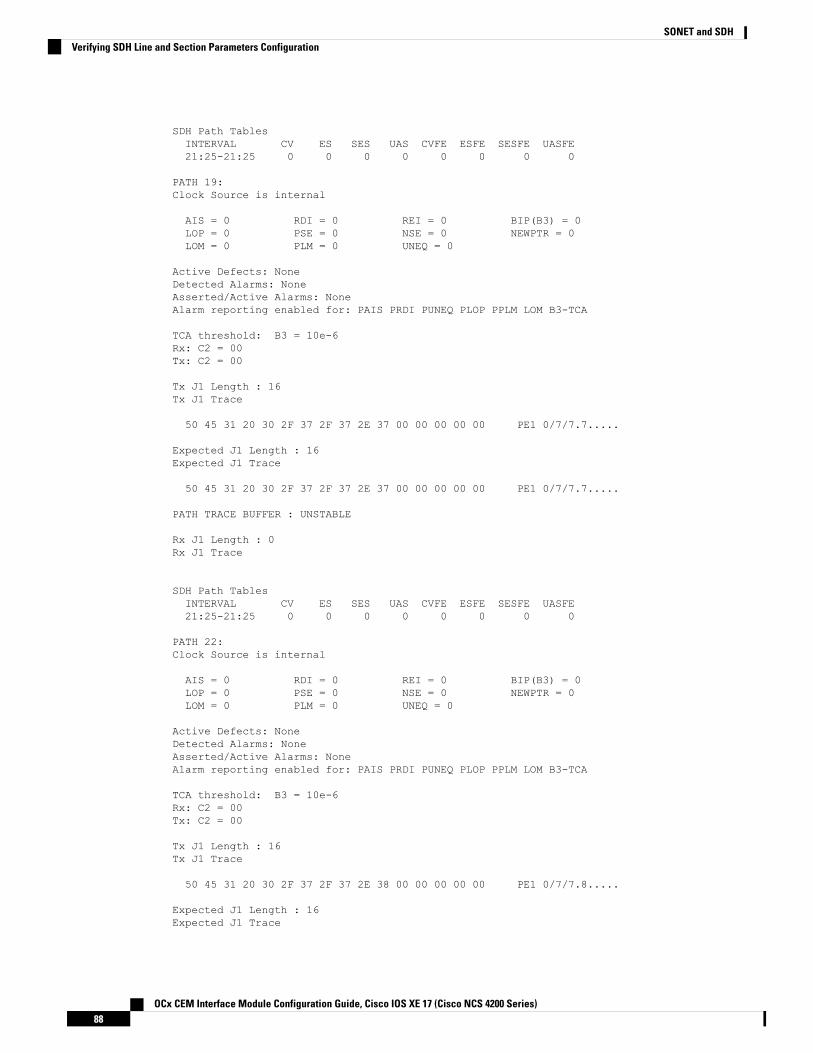
SDH Path TablesINTERVAL CV ES SES UAS CVFE ESFE SESFE UASFE21:25-21:25 0 0 0 0 0 0 0 0
PATH 19:Clock Source is internal
AIS = 0 RDI = 0 REI = 0 BIP(B3) = 0LOP = 0 PSE = 0 NSE = 0 NEWPTR = 0LOM = 0 PLM = 0 UNEQ = 0
Active Defects: NoneDetected Alarms: NoneAsserted/Active Alarms: NoneAlarm reporting enabled for: PAIS PRDI PUNEQ PLOP PPLM LOM B3-TCA
TCA threshold: B3 = 10e-6Rx: C2 = 00Tx: C2 = 00
Tx J1 Length : 16Tx J1 Trace
50 45 31 20 30 2F 37 2F 37 2E 37 00 00 00 00 00 PE1 0/7/7.7.....
Expected J1 Length : 16Expected J1 Trace
50 45 31 20 30 2F 37 2F 37 2E 37 00 00 00 00 00 PE1 0/7/7.7.....
PATH TRACE BUFFER : UNSTABLE
Rx J1 Length : 0Rx J1 Trace
SDH Path TablesINTERVAL CV ES SES UAS CVFE ESFE SESFE UASFE21:25-21:25 0 0 0 0 0 0 0 0
PATH 22:Clock Source is internal
AIS = 0 RDI = 0 REI = 0 BIP(B3) = 0LOP = 0 PSE = 0 NSE = 0 NEWPTR = 0LOM = 0 PLM = 0 UNEQ = 0
Active Defects: NoneDetected Alarms: NoneAsserted/Active Alarms: NoneAlarm reporting enabled for: PAIS PRDI PUNEQ PLOP PPLM LOM B3-TCA
TCA threshold: B3 = 10e-6Rx: C2 = 00Tx: C2 = 00
Tx J1 Length : 16Tx J1 Trace
50 45 31 20 30 2F 37 2F 37 2E 38 00 00 00 00 00 PE1 0/7/7.8.....
Expected J1 Length : 16Expected J1 Trace
OCx CEM Interface Module Configuration Guide, Cisco IOS XE 17 (Cisco NCS 4200 Series)88
SONET and SDHVerifying SDH Line and Section Parameters Configuration

50 45 31 20 30 2F 37 2F 37 2E 38 00 00 00 00 00 PE1 0/7/7.8.....
PATH TRACE BUFFER : UNSTABLE
Rx J1 Length : 0Rx J1 Trace
SDH Path TablesINTERVAL CV ES SES UAS CVFE ESFE SESFE UASFE21:25-21:25 0 0 0 0 0 0 0 0
PATH 25:Clock Source is internal
AIS = 0 RDI = 0 REI = 0 BIP(B3) = 0LOP = 0 PSE = 0 NSE = 0 NEWPTR = 0LOM = 0 PLM = 0 UNEQ = 0
Active Defects: NoneDetected Alarms: NoneAsserted/Active Alarms: NoneAlarm reporting enabled for: PAIS PRDI PUNEQ PLOP PPLM LOM B3-TCA
TCA threshold: B3 = 10e-6Rx: C2 = 00Tx: C2 = 00
Tx J1 Length : 16Tx J1 Trace
50 45 31 20 30 2F 37 2F 37 2E 39 00 00 00 00 00 PE1 0/7/7.9.....
Expected J1 Length : 16Expected J1 Trace
50 45 31 20 30 2F 37 2F 37 2E 39 00 00 00 00 00 PE1 0/7/7.9.....
PATH TRACE BUFFER : UNSTABLE
Rx J1 Length : 0Rx J1 Trace
SDH Path TablesINTERVAL CV ES SES UAS CVFE ESFE SESFE UASFE21:25-21:25 0 0 0 0 0 0 0 0
PATH 28:Clock Source is internal
AIS = 0 RDI = 0 REI = 0 BIP(B3) = 0LOP = 0 PSE = 0 NSE = 0 NEWPTR = 0LOM = 0 PLM = 0 UNEQ = 0
Active Defects: NoneDetected Alarms: NoneAsserted/Active Alarms: NoneAlarm reporting enabled for: PAIS PRDI PUNEQ PLOP PPLM LOM B3-TCA
TCA threshold: B3 = 10e-6Rx: C2 = 00Tx: C2 = 00
OCx CEM Interface Module Configuration Guide, Cisco IOS XE 17 (Cisco NCS 4200 Series)89
SONET and SDHVerifying SDH Line and Section Parameters Configuration

Tx J1 Length : 16Tx J1 Trace
50 45 31 20 30 2F 37 2F 37 2E 31 30 00 00 00 00 PE1 0/7/7.10....
Expected J1 Length : 16Expected J1 Trace
50 45 31 20 30 2F 37 2F 37 2E 31 30 00 00 00 00 PE1 0/7/7.10....
PATH TRACE BUFFER : UNSTABLE
Rx J1 Length : 0Rx J1 Trace
SDH Path TablesINTERVAL CV ES SES UAS CVFE ESFE SESFE UASFE21:25-21:25 0 0 0 0 0 0 0 0
PATH 31:Clock Source is internal
AIS = 0 RDI = 0 REI = 0 BIP(B3) = 0LOP = 0 PSE = 0 NSE = 0 NEWPTR = 0LOM = 0 PLM = 0 UNEQ = 0
Active Defects: NoneDetected Alarms: NoneAsserted/Active Alarms: NoneAlarm reporting enabled for: PAIS PRDI PUNEQ PLOP PPLM LOM B3-TCA
TCA threshold: B3 = 10e-6Rx: C2 = 00Tx: C2 = 00
Tx J1 Length : 16Tx J1 Trace
50 45 31 20 30 2F 37 2F 37 2E 31 31 00 00 00 00 PE1 0/7/7.11....
Expected J1 Length : 16Expected J1 Trace
50 45 31 20 30 2F 37 2F 37 2E 31 31 00 00 00 00 PE1 0/7/7.11....
PATH TRACE BUFFER : UNSTABLE
Rx J1 Length : 0Rx J1 Trace
SDH Path TablesINTERVAL CV ES SES UAS CVFE ESFE SESFE UASFE21:25-21:25 0 0 0 0 0 0 0 0
PATH 34:Clock Source is internal
AIS = 0 RDI = 0 REI = 0 BIP(B3) = 0LOP = 0 PSE = 0 NSE = 0 NEWPTR = 0LOM = 0 PLM = 0 UNEQ = 0
OCx CEM Interface Module Configuration Guide, Cisco IOS XE 17 (Cisco NCS 4200 Series)90
SONET and SDHVerifying SDH Line and Section Parameters Configuration

Active Defects: NoneDetected Alarms: NoneAsserted/Active Alarms: NoneAlarm reporting enabled for: PAIS PRDI PUNEQ PLOP PPLM LOM B3-TCA
TCA threshold: B3 = 10e-6Rx: C2 = 00Tx: C2 = 00
Tx J1 Length : 16Tx J1 Trace
50 45 31 20 30 2F 37 2F 37 2E 31 32 00 00 00 00 PE1 0/7/7.12....
Expected J1 Length : 16Expected J1 Trace
50 45 31 20 30 2F 37 2F 37 2E 31 32 00 00 00 00 PE1 0/7/7.12....
PATH TRACE BUFFER : UNSTABLE
Rx J1 Length : 0Rx J1 Trace
SDH Path TablesINTERVAL CV ES SES UAS CVFE ESFE SESFE UASFE21:25-21:25 0 0 0 0 0 0 0 0
PATH 37:Clock Source is internal
AIS = 0 RDI = 0 REI = 0 BIP(B3) = 0LOP = 0 PSE = 0 NSE = 0 NEWPTR = 0LOM = 0 PLM = 0 UNEQ = 0
Active Defects: NoneDetected Alarms: NoneAsserted/Active Alarms: NoneAlarm reporting enabled for: PAIS PRDI PUNEQ PLOP PPLM LOM B3-TCA
TCA threshold: B3 = 10e-6Rx: C2 = 00Tx: C2 = 00
Tx J1 Length : 16Tx J1 Trace
50 45 31 20 30 2F 37 2F 37 2E 31 33 00 00 00 00 PE1 0/7/7.13....
Expected J1 Length : 16Expected J1 Trace
50 45 31 20 30 2F 37 2F 37 2E 31 33 00 00 00 00 PE1 0/7/7.13....
PATH TRACE BUFFER : UNSTABLE
Rx J1 Length : 0Rx J1 Trace
SDH Path TablesINTERVAL CV ES SES UAS CVFE ESFE SESFE UASFE21:25-21:25 0 0 0 0 0 0 0 0
OCx CEM Interface Module Configuration Guide, Cisco IOS XE 17 (Cisco NCS 4200 Series)91
SONET and SDHVerifying SDH Line and Section Parameters Configuration

PATH 40:Clock Source is internal
AIS = 0 RDI = 0 REI = 0 BIP(B3) = 0LOP = 0 PSE = 0 NSE = 0 NEWPTR = 0LOM = 0 PLM = 0 UNEQ = 0
Active Defects: NoneDetected Alarms: NoneAsserted/Active Alarms: NoneAlarm reporting enabled for: PAIS PRDI PUNEQ PLOP PPLM LOM B3-TCA
TCA threshold: B3 = 10e-6Rx: C2 = 00Tx: C2 = 00
Tx J1 Length : 16Tx J1 Trace
50 45 31 20 30 2F 37 2F 37 2E 31 34 00 00 00 00 PE1 0/7/7.14....
Expected J1 Length : 16Expected J1 Trace
50 45 31 20 30 2F 37 2F 37 2E 31 34 00 00 00 00 PE1 0/7/7.14....
PATH TRACE BUFFER : UNSTABLE
Rx J1 Length : 0Rx J1 Trace
SDH Path TablesINTERVAL CV ES SES UAS CVFE ESFE SESFE UASFE21:26-21:26 0 0 0 0 0 0 0 0
PATH 43:Clock Source is internal
AIS = 0 RDI = 0 REI = 0 BIP(B3) = 0LOP = 0 PSE = 0 NSE = 0 NEWPTR = 0LOM = 0 PLM = 0 UNEQ = 0
Active Defects: NoneDetected Alarms: NoneAsserted/Active Alarms: NoneAlarm reporting enabled for: PAIS PRDI PUNEQ PLOP PPLM LOM B3-TCA
TCA threshold: B3 = 10e-6Rx: C2 = 00Tx: C2 = 00
Tx J1 Length : 16Tx J1 Trace
50 45 31 20 30 2F 37 2F 37 2E 31 35 00 00 00 00 PE1 0/7/7.15....
Expected J1 Length : 16Expected J1 Trace
50 45 31 20 30 2F 37 2F 37 2E 31 35 00 00 00 00 PE1 0/7/7.15....
PATH TRACE BUFFER : UNSTABLE
OCx CEM Interface Module Configuration Guide, Cisco IOS XE 17 (Cisco NCS 4200 Series)92
SONET and SDHVerifying SDH Line and Section Parameters Configuration
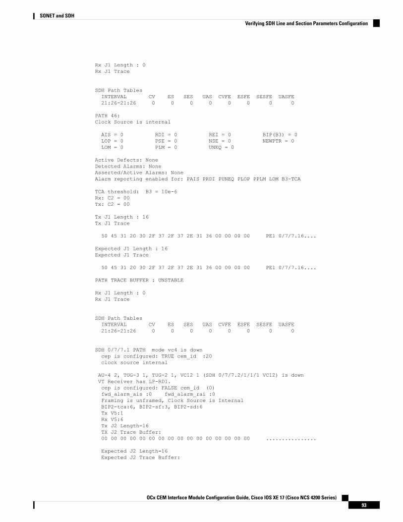
Rx J1 Length : 0Rx J1 Trace
SDH Path TablesINTERVAL CV ES SES UAS CVFE ESFE SESFE UASFE21:26-21:26 0 0 0 0 0 0 0 0
PATH 46:Clock Source is internal
AIS = 0 RDI = 0 REI = 0 BIP(B3) = 0LOP = 0 PSE = 0 NSE = 0 NEWPTR = 0LOM = 0 PLM = 0 UNEQ = 0
Active Defects: NoneDetected Alarms: NoneAsserted/Active Alarms: NoneAlarm reporting enabled for: PAIS PRDI PUNEQ PLOP PPLM LOM B3-TCA
TCA threshold: B3 = 10e-6Rx: C2 = 00Tx: C2 = 00
Tx J1 Length : 16Tx J1 Trace
50 45 31 20 30 2F 37 2F 37 2E 31 36 00 00 00 00 PE1 0/7/7.16....
Expected J1 Length : 16Expected J1 Trace
50 45 31 20 30 2F 37 2F 37 2E 31 36 00 00 00 00 PE1 0/7/7.16....
PATH TRACE BUFFER : UNSTABLE
Rx J1 Length : 0Rx J1 Trace
SDH Path TablesINTERVAL CV ES SES UAS CVFE ESFE SESFE UASFE21:26-21:26 0 0 0 0 0 0 0 0
SDH 0/7/7.1 PATH mode vc4 is downcep is configured: TRUE cem_id :20clock source internal
AU-4 2, TUG-3 1, TUG-2 1, VC12 1 (SDH 0/7/7.2/1/1/1 VC12) is downVT Receiver has LP-RDI.cep is configured: FALSE cem_id (0)fwd_alarm_ais :0 fwd_alarm_rai :0Framing is unframed, Clock Source is InternalBIP2-tca:6, BIP2-sf:3, BIP2-sd:6Tx V5:1Rx V5:6Tx J2 Length=16TX J2 Trace Buffer:00 00 00 00 00 00 00 00 00 00 00 00 00 00 00 00 ................
Expected J2 Length=16Expected J2 Trace Buffer:
OCx CEM Interface Module Configuration Guide, Cisco IOS XE 17 (Cisco NCS 4200 Series)93
SONET and SDHVerifying SDH Line and Section Parameters Configuration

00 00 00 00 00 00 00 00 00 00 00 00 00 00 00 00 ................
Rx J2 Length=16RX J2 Trace Buffer:CRC-7: 0x81 OK
4F 4E 54 20 4C 4F 2D 54 52 41 43 45 20 20 20 00 ONT LO-TRACE .
Data in curerent interval (140 seconds elapsed)Near End0 CodeViolations, 0 ErrorSecs, 0 Severly Err Secs, 269 Unavailable SecsFar End0 CodeViolations, 0 ErrorSecs, 0 Severly Err Secs, 0 Unavailable Secs
AU-4 2, TUG-3 1, TUG-2 1, E1 1 (SDH 0/7/7.2/1/1/1 E1) is downReceiver is getting AIS.Framing is unframed, Clock Source is InternalData in current interval (140 seconds elapsed):Near End0 Line Code Violations, 0 Path Code Violations0 Slip Secs, 0 Fr Loss Secs, 0 Line Err Secs, 0 Degraded Mins0 Errored Secs, 0 Bursty Err Secs, 0 Severely Err Secs293 Unavail Secs, 0 Stuffed Secs
Far End0 Line Code Violations, 0 Path Code Violations0 Slip Secs, 0 Fr Loss Secs, 0 Line Err Secs, 0 Degraded Mins0 Errored Secs, 0 Bursty Err Secs, 0 Severely Err Secs0 Unavail Secs
AU-4 2, TUG-3 1, TUG-2 1, VC12 2 (SDH 0/7/7.2/1/1/2 VC12) is downVT Receiver has LP-RDI.cep is configured: FALSE cem_id (0)fwd_alarm_ais :0 fwd_alarm_rai :0Framing is unframed, Clock Source is InternalBIP2-tca:6, BIP2-sf:3, BIP2-sd:6Tx V5:1Rx V5:6Tx J2 Length=16TX J2 Trace Buffer:00 00 00 00 00 00 00 00 00 00 00 00 00 00 00 00 ................
Expected J2 Length=16Expected J2 Trace Buffer:00 00 00 00 00 00 00 00 00 00 00 00 00 00 00 00 ................
Rx J2 Length=16RX J2 Trace Buffer:CRC-7: 0x81 OK
4F 4E 54 20 4C 4F 2D 54 52 41 43 45 20 20 20 00 ONT LO-TRACE .
Data in curerent interval (150 seconds elapsed)Near End0 CodeViolations, 0 ErrorSecs, 0 Severly Err Secs, 483 Unavailable SecsFar End0 CodeViolations, 0 ErrorSecs, 0 Severly Err Secs, 0 Unavailable Secs
AU-4 2, TUG-3 1, TUG-2 1, E1 2 (SDH 0/7/7.2/1/1/2 E1) is downReceiver is getting AIS.Framing is unframed, Clock Source is InternalData in current interval (150 seconds elapsed):Near End0 Line Code Violations, 0 Path Code Violations0 Slip Secs, 0 Fr Loss Secs, 0 Line Err Secs, 0 Degraded Mins
OCx CEM Interface Module Configuration Guide, Cisco IOS XE 17 (Cisco NCS 4200 Series)94
SONET and SDHVerifying SDH Line and Section Parameters Configuration

0 Errored Secs, 0 Bursty Err Secs, 0 Severely Err Secs90 Unavail Secs, 0 Stuffed Secs
Far End0 Line Code Violations, 0 Path Code Violations0 Slip Secs, 0 Fr Loss Secs, 0 Line Err Secs, 0 Degraded Mins0 Errored Secs, 0 Bursty Err Secs, 0 Severely Err Secs0 Unavail Secs
Configuring SDH Path ParametersThis section describes the configuration of SDH path parameters.
Path OverheadJ1 Flag
Sets the message length and the message text of the High Order Path Trace identifier (J1).
C2 Flag
Sets the C2 byte in the Path OverHead (POH) to indicate the contents of the payload inside the frame.
The path overheads, C2 flag and J1 flag can be configured for the following modes:
• AU-4 Mapping
• Mode VC-4
• Mode VC-4 Nc
• Mode TUG-3
For more information, refer Configuring Modes under AU-4 Mapping, on page 68.
• AU-3 Mapping
• Mode E3
• Mode T3
For more information, refer Configuring Modes under AU-3 Mapping.
Configuring C2 Flag
To configure the C2 flag:enableconfigure terminalcontroller Mediatype 0/0/16mode sdhcontroller sdh 0/0/16au-4 1overhead c2 10end
J1 Flag
To configure the J1 flag:
OCx CEM Interface Module Configuration Guide, Cisco IOS XE 17 (Cisco NCS 4200 Series)95
SONET and SDHConfiguring SDH Path Parameters

enableconfigure terminalcontroller MediaType 0/0/16mode sdhcontroller sdh 0/0/16au-4 1overhead j1 expected length 16overhead j1 expected message expectedmessageoverhead j1 tx length 16overhead j1 tx message testmessageend
Path ThresholdSet the path BER threshold values.
• b3-tca — Enables BER threshold crossing alerts for B3.
• sd-ber —Enables the threshold of the Signal Degrade (SD) BER that is used to trigger a signal degradealarm.
• sf-ber —Configures the threshold of the Signal Failure (SF) BER that is used to trigger a link statechange.
The path threshold can be configured for the following modes:
• AU-4 Mapping
• Mode VC-4
• Mode VC-4 Nc
• Mode TUG-3
For more information, refer Configuring Modes under AU-4 Mapping, on page 68.
• AU-3 Mapping
• For more information, refer Configuring Modes under AU-3 Mapping.
Configuring Path Threshold
To configure path threshold:enableconfigure terminalcontroller MediaType 0/0/16mode sdhcontroller sdh 0/0/16au-4 1threshold b3-ber_sd 7threshold b3-ber_sf 7end
Path LoopbackSets a loopback to test the SDH port.
• local — Loops the signal from Tx to Rx path. Sends alarm indication signal (AIS) to network.
OCx CEM Interface Module Configuration Guide, Cisco IOS XE 17 (Cisco NCS 4200 Series)96
SONET and SDHPath Threshold

• network — Loops the signal from Rx to Tx path.
Configuring Path Loopback
To configure path loopback:enableconfigure terminalcontroller sdh 0/0/16au-4 1loopback [local | network]end
To restore the system to its default condition, use the no form of the command.Note
Configuring Path BERT
For more information on BERT configuration, see Configuring BERT in SDH for SAToP, on page 97 section.
Verifying Path Parameters ConfigurationUse show running-configuration command to verify path parameters configuration.#show running-configurationcontroller MediaType 0/0/16mode sdhcontroller SDH 0/0/16rate STM16no ais-shutalarm-report allclock source internaloverhead s1s0 0aug mapping au-4au-4 1mode vc4clock source internalloopback localoverhead c2 10threshold b3-ber_sd 7threshold b3-ber_sf 7overhead j1 tx message STRINGoverhead j1 expected message STRINGthreshold b3-tca 5au-4 2
Configuring BERT in SDH for SAToPBit-Error Rate Testing (BERT) is used to analyze quality and to resolve problems of digital transmissionequipment. BERT tests the quality of an interface by directly comparing a pseudorandom or repetitive testpattern with an identical locally generated test pattern.
The BERT operation is data-intensive. Regular data cannot flow on the path while the test is in progress. Thepath is reported to be in alarm state when BERT is in progress and restored to a normal state after BERT hasterminated.
OCx CEM Interface Module Configuration Guide, Cisco IOS XE 17 (Cisco NCS 4200 Series)97
SONET and SDHConfiguring Path Loopback
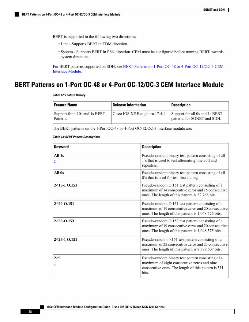
BERT is supported in the following two directions:
• Line - Supports BERT in TDM direction.
• System - Supports BERT in PSN direction. CEM must be configured before running BERT towardssystem direction.
For BERT patterns supported on SDH, see BERT Patterns on 1-Port OC-48 or 4-Port OC-12/OC-3 CEMInterface Module.
BERT Patterns on 1-Port OC-48 or 4-Port OC-12/OC-3 CEM Interface ModuleTable 12: Feature History
DescriptionRelease InformationFeature Name
Support for all 0s and 1s BERTpatterns for SONET and SDH.
Cisco IOS XE Bengaluru 17.4.1Support for all 0s and 1s BERTPatterns
The BERT patterns on the 1-Port OC-48 or 4-Port OC-12/OC-3 interface module are:
Table 13: BERT Pattern Descriptions
DescriptionKeyword
Pseudo-random binary test pattern consisting of all1’s that is used to test alternating line volt andrepeaters.
All 1s2
Pseudo-random binary test pattern consisting of all0’s that is used for test line coding.
All 0s
Pseudo-random O.151 test pattern consisting of amaximum of 14 consecutive zeros and 15 consecutiveones. The length of this pattern is 32,768 bits.
2^15-1 O.151
Pseudo-random O.151 test pattern consisting of amaximum of 19 consecutive zeros and 20 consecutiveones. The length of this pattern is 1,048,575 bits.
2^20-O.151
Pseudo-random O.153 test pattern consisting of amaximum of 19 consecutive zeros and 20 consecutiveones. The length of this pattern is 1,048,575 bits.
2^20-O.153
Pseudo-random 0.151 test pattern consisting of amaximum of 22 consecutive zeros and 23 consecutiveones. The length of this pattern is 8,388,607 bits.
2^23-1 O.151
Pseudo-random binary test pattern consisting of amaximum of eight consecutive zeros and nineconsecutive ones. The length of this pattern is 511bits.
2^93
OCx CEM Interface Module Configuration Guide, Cisco IOS XE 17 (Cisco NCS 4200 Series)98
SONET and SDHBERT Patterns on 1-Port OC-48 or 4-Port OC-12/OC-3 CEM Interface Module

DescriptionKeyword
Pseudo-random binary test pattern consisting of amaximum of ten consecutive zeros and elevenconsecutive ones. The length of this pattern is 2048bits.
2^114
2 All 1s are supported only on SONET CT3, SDH AU-3 - CT3/CE3 - T1/E1, and SDH AU-3 - VC3.Starting with Cisco IOS XE Bengaluru 17.4.1, All Is are supported on all modes.
3 Starting with Cisco IOS XE Bengaluru 17.4.1, 2^9 mode is supported.
2^9 is not supported on the following modes:
• SONET—Unframed, STS-3c, STS-12c, and STS-48c.
• SDH AU-4—VC4, TUG-3-VC3, TUG-3-E3, TUG-3-T3, and TUG-3 - VC1x.
• SDH AU-3—VC3, VC4-4c, VC4-16c, and VC1x.
4 Starting with Cisco IOS XE Bengaluru 17.4.1, 2^11 mode is supported.
2^11 is not supported on the following modes:
• SONET—Unframed, STS-3c, STS-12c, and STS-48c.
• SDH AU-4—VC4 and TUG-3-VC3.
• SDH AU-3—VC3, VC4-4c, and VC4-16c.
Configuring BERT in Modes VC-4 and VC NcTo configure BERT in modes VC-4 and VC Nc:configure terminalcontroller sdh 0/0/16rate STM1no ais-shutalarm-report allclock source internaloverhead s1s0 0aug mapping au-4au-4 1mode vc4clock source internalbert pattern 2^15 internal 10 direction [line | system]
Verifying BERT Configuration in Modes VC-4 and VC NcUse show controllers command to verify BERT Configuration in Modes VC-4 and VC Nc:#show controller sdh 0/0/16 | sec BERTBERT test result (running)Test Pattern : 2^15,Status : Sync, Sync Detected : 0Interval : 10 minute(s),Time Remain : 00:09:47Bit Errors (since BERT started): 0 Mbits,Bits Received (since BERT started): 0 MbitsBit Errors (since last sync): 1943 bitsBits Received (since last sync): 1943 KbitsDirection : LineRouter#
OCx CEM Interface Module Configuration Guide, Cisco IOS XE 17 (Cisco NCS 4200 Series)99
SONET and SDHConfiguring BERT in Modes VC-4 and VC Nc

Configuring E1 BertTo configure E1 Bert:enableconfigure terminalcontroller MediaType 0/0/16mode sdhcontroller sdh 0/0/16rate stm4au-3 1mode vc1xtug-2 1 payload vc12e1 1 bert pattern 2^11 interval 10end
Configuring T1 BertTo configure T1 Bert:enableconfigure terminalcontroller sdh 0/0/16rate stm4au-3 1mode vc1xtug-2 1 payload vc11t1 1 bert pattern 2^11 interval 10end
Configuring BERT in Mode T3/E3To configure BERT in Mode T3/E3 for both AUG mapping AU-3 and AU-4:configure terminalcontroller sdh 0/0/16rate STM1no ais-shutalarm-report allclock source internaloverhead s1s0 0aug mapping au-4au-4 1mode tug-3clock source internaltug-3 1mode t3threshold b3-tca 0overhead c2 0t3 clock source internalt3 bert pattern 2^15 internal 10 direction [line | system]
Verifying BERT Configuration in Mode T3 or E3Use show controllers command to verify BERT configuration in mode T3 or E3:show controller sdh 0/0/16 | sec BERTBERT test result (running)Test Pattern : 2^15,Status : Sync, Sync Detected : 0Interval : 10 minute(s),
OCx CEM Interface Module Configuration Guide, Cisco IOS XE 17 (Cisco NCS 4200 Series)100
SONET and SDHConfiguring E1 Bert

Time Remain : 00:09:47Bit Errors (since BERT started): 0 Mbits,Bits Received (since BERT started): 0 MbitsBit Errors (since last sync): 1943 bitsBits Received (since last sync): 1943 KbitsDirection : Line
Configuring BERT in Mode VC-1xTo configure BERT in mode VC-1x for both AUG mapping AU-3 and AU-4:configure terminalcontroller sdh 0/0/16rate STM1no ais-shutalarm-report allclock source internaloverhead s1s0 0aug mapping au-4au-4 1mode tug-3clock source internaltug-3 1mode vc-1xtug-2 1 payload VC11vc 1 bert pattern 2^15 internal 10 direction [line | system]
Verifying BERT Configuration in Mode VC-1xUse show controllers command to verify BERT configuration in mode VC-1x:#show controller sdh 0/0/16 | sec BERTBERT test result (running)Test Pattern : 2^15,Status : Sync, Sync Detected : 0Interval : 10 minute(s),Time Remain : 00:09:47Bit Errors (since BERT started): 0 Mbits,Bits Received (since BERTstarted): 0 MbitsBit Errors (since last sync): 1943 bitsBits Received (since last sync): 1943 KbitsDirection : Line
SDH T1/E1 Configuration ParametersThe following parameters affect SDH T1/E1 configuration:
• BERT — Starts the BERT test.
• CEM Group —Creates a circuit emulation (CEM) channel from one or more time slots of a T1 or E1line of an NM-CEM-4TE1 network module,
• Clock — Specifies the clock source for T1 or E1 interface.
• Description — Specifies the description of the controller.
• Loopback — Sets the T1 or E1 interface in the loopback mode.
OCx CEM Interface Module Configuration Guide, Cisco IOS XE 17 (Cisco NCS 4200 Series)101
SONET and SDHConfiguring BERT in Mode VC-1x

Configuring T1/E1 ParametersTo configure T1/E1 parameters:enableconfigure terminalcontroller sdh 0/0/16rate stm4au-3 1mode vc1xtug-2 1 payload vc11t1 1 loopback [local | network line]t1 1 clock source [line | internal | recovered]end
Loopback network payload is not supported. This is applicable for AU-4 Vc-1x and AU-3 Vc-1x modes.Note
If T1/E1 is enabled on a particular J/K/L/M, you can only configure overhead and threshold for that J/K/L/Mvalue.
Note
Verifying T1 or E1 Parameters ConfigurationUse show running-configuration command to verify T1 or E1 parameters configuration:#show running-configurationcontroller SDH 0/0/16rate STM1no ais-shutalarm-report allclock source internaloverhead s1s0 0aug mapping au-4au-4 1clock source internalmode tug-3tug-3 2mode VC1xtug-2 1 payload VC11t1 1 loopback network linet1 1 clock source line
SDH T3/E3 Configuration ParametersThe following parameters affect SDH T3/E3 configuration:
• Clock — Specifies the clock source for T3 or E3 link.
• Loopback — Sets the T3 or E3 link in the loopback mode.
• CEM Group —Creates a circuit emulation (CEM) channel from one or more time slots of a T1 or E1line.
OCx CEM Interface Module Configuration Guide, Cisco IOS XE 17 (Cisco NCS 4200 Series)102
SONET and SDHConfiguring T1/E1 Parameters

• BERT —Bit-Error Rate Testing (BERT) is used for analyzing quality and for problem resolution ofdigital transmission equipment.
Configuring SDH T3/E3 Parameters ConfigurationTo configure SDH T3/E3 parameters configuration:enableconfigure terminalcontroller sdh 0/0/16rate stm4au-4 1mode tug 3tug-3 1mode e3e3 1 clock source [line | internal | recovered]e3 framing [m13 | c-bit ] (applicable to for mode e3)e3 1 loopback [local | network line]e3 bert pattern 0s interval 2tug-3 2mode t3t3 1 clock source [line | internal | recovered]t3 framing [m13 | c-bit ] (applicable to for mode t3)t3 1 loopback [local | network line]t3 bert pattern 0s interval 2end
This is applicable to AUG mappaing AU-4 mode T3 and AU-3 mode T3.Note
Verifying SDH T3 or E3 Parameters ConfigurationsUse show running-configuration command to verify SDH T3 or E3 parameters configurations:
# show running-configurationcontroller sdh 0/0/16rate stm1au-4 2mode tug-3clock source internaltug-3 1mode E3threshold b3-tca 0overhead c2 0e3 clock source internale3 framing g751!tug-3 2mode T3threshold b3-tca 0overhead c2 0t3 clock source internalt3 framing c-bit!
SDH VC Configuration Parameters for SAToPThe following parameters affect SDH VC configuration:
OCx CEM Interface Module Configuration Guide, Cisco IOS XE 17 (Cisco NCS 4200 Series)103
SONET and SDHConfiguring SDH T3/E3 Parameters Configuration

• BERT — Starts the BERT test.
• CEM Group — Specifies the time slots for CEM group mapping.
• Clock — Specifies the clock source for VC.
• Loopback — Sets the VC in the loopback mode.
• Overhead —Configures VC line path overhead flags.
• Shutdown —Disables the VC interface.
Configuring VC ParametersTo configure VC parameters:enableconfigure terminalcontroller sdh 0/0/16rate stm4au-3 1mode vc1xtug-2 1 payload vc11vc 1 loopback [local | network]vc 1 clock source internalvc 1 overhead j2 expected [16 | 64]vc 1 overhead j2 expected message STRINGvc 1 overhead j2 tx [16 | 64]vc 1 overhead j2 tx message STRINGvc 1 overhead v5 [0 - 7]vc 1 [threshold bip2-sd 4 | threshold bip2-sf 4 | threshold bip2-tca 9]end
v5 overhead should match with the far end tx v5.Note
Verifying VC Configuration Parameters ConfigurationsUse show running-configuration command to verify VC configuration parameters configuration:#show running-configurationcontroller SDH 0/0/16rate STM1no ais-shutalarm-report allclock source internaloverhead s1s0 0aug mapping au-4au-4 1clock source internalmode tug-3tug-3 1mode VC1xtug-2 1 payload VC11vc 1 overhead j2 tx message STRINGvc 1 overhead j2 expected message STRINGvc 1 threshold bip2-sd 4
OCx CEM Interface Module Configuration Guide, Cisco IOS XE 17 (Cisco NCS 4200 Series)104
SONET and SDHConfiguring VC Parameters

vc 1 threshold bip2-sf 4vc 1 threshold bip2-tca 9
Configuring ACR on SDHTo configure E1 ACR:enableconfigure terminalcontroller sdh 0/0/16rate STM1no ais-shutalarm-report allclock source internaloverhead s1s0 0aug mapping au-4au-4 1clock source internalmode tug-3tug-3 1mode vc1xtug-2 1 payload vc12e1 1 cem-group 1 unframede1 1 clock source recovered 1tug-2 2 payload vc11tug-2 3 payload vc11tug-2 4 payload vc11end
To configure E3 ACR:enableconfigure terminalcontroller sdh 0/0/16rate STM1no ais-shutalarm-report allclock source internaloverhead s1s0 0aug mapping au-4au-4 1clock source internalmode tug-3tug-3 1mode e3overhead c2 0cem-group 1 unframede3 clock source recovered 1
ACR Global Configurationenableconfigure terminalrecovered-clock 0 4clock recovered 1 adaptive cem 0 1end
Verifying ACR Configuration on SDHUse show recovered clock command to verify E1 ACR configuration:
OCx CEM Interface Module Configuration Guide, Cisco IOS XE 17 (Cisco NCS 4200 Series)105
SONET and SDHConfiguring ACR on SDH

#show recovered clockRecovered clock status for subslot 0/16----------------------------------------Clock Type Mode CEM Status Frequency Offset(ppb) Circuit-No1 STMx-E1 ADAPTIVE 1 ACQUIRED n/a 0/1/1/1/1(Port/au-4/tug3/tug2/e1)
Use show recovered clock command to verify T3 ACR configuration:
#show recovered clockRecovered clock status for subslot 0/16----------------------------------------Clock Type Mode CEM Status Frequency Offset(ppb) Circuit-No1 STMx-E3 ADAPTIVE 1 ACQUIRED n/a 0/1/1 (Port/au-4/tug3)
Configuring DCR on SDHTo configure E1 DCR:enableconfigure terminalcontroller sdh 0/0/16rate STM1no ais-shutalarm-report allclock source internaloverhead s1s0 0aug mapping au-4au-4 1clock source internalmode tug-3tug-3 1mode vc1xtug-2 1 payload vc12e1 1 cem-group 1 unframede1 1 clock source recovered 1tug-2 2 payload vc11tug-2 3 payload vc11tug-2 4 payload vc11end
To configure E3 DCR:enableconfigure terminalcontroller sdh 0/0/16rate STM1no ais-shutalarm-report allclock source internaloverhead s1s0 0aug mapping au-4au-4 1clock source internalmode tug-3tug-3 1mode e3overhead c2 0cem-group 1 unframede3 clock source recovered 1
OCx CEM Interface Module Configuration Guide, Cisco IOS XE 17 (Cisco NCS 4200 Series)106
SONET and SDHConfiguring DCR on SDH

DCR Global Configurationenableconfigure terminalrecovered-clock 0 4clock recovered 1 differential cem 0 1end
Verifying DCR Configuration on SDHUse show recovered clock command to verify E1 DCR configuration:
#show recovered clockRecovered clock status for subslot 0/16----------------------------------------Clock Type Mode CEM Status Frequency Offset(ppb) Circuit-No1 STMx-E1 DIFFERENTIAL 1 ACQUIRED n/a 0/1/1/1/1(Port/au-4/tug3/tug2/e1)
Use show recovered clock command to verify T3 DCR configuration:
#show recovered clockRecovered clock status for subslot 0/16----------------------------------------Clock Type Mode CEM Status Frequency Offset(ppb) Circuit-No1 STMx-E3 DIFFERENTIAL 1 ACQUIRED n/a 0/1/1(Port/au-4/tug3)
Loopback Remote on T1 and T3 InterfacesThe remote loopback configuration attempts to put the far-end T1 or T3 into a loopback.
The remote loopback setting loops back the far-end at line or payload, using IBOC (inband bit-orientatedCDE) or the ESF loopback codes to communicate the request to the far-end.
Restrictions for Loopback Remote• E1 and E3 loopback remote are not supported until Cisco IOSXE Fuji 16.9.4 release. Starting fromCiscoIOS XE Fuji 16.9.5 release, E1 and E3 loopback remote are supported.
• IBOC loopcode configuration is not supportedwhenCESoP or SATOP (framed or unframed) is configured.
• ESF loopcode configuration is not supported when SAToP is configured.
Configuring Loopback Remote in SDHTo set T1 loopback remote iboc fac1/fac2/csu for OCX in SDH, perform the following tasks in globalconfiguration mode:enableconfigure terminalcontroller sdh 0/2/0mode vc1xtug-2 1 payload vc1xt1 1 loopback remote iboc {fac1 | fac2 | csu}
OCx CEM Interface Module Configuration Guide, Cisco IOS XE 17 (Cisco NCS 4200 Series)107
SONET and SDHVerifying DCR Configuration on SDH

To set T1 loopback remote iboc esf line csu/esf payload for OCX in SDH, perform the following tasks inglobal configuration mode:enableconfigure terminalcontroller sdh 0/2/0mode vc1xtug-2 1 payload vc1xt1 1 loopback remote esf {line csu | payload}
To set T3 loopback remote line/payload for OCX in SDH, perform the following tasks in global configurationmode:enableconfigure terminalcontroller sdh 0/2/0mode t3t3 loopback remote {line | payload}
loopback remote esf line niu is not supported.Note
Verifying the Loopback Remote ConfigurationUse the following command to check the T1 loopback remote configuration:router# show run | sec 0/2/0controller SDH 0/2/0rate STM1no ais-shutalarm-report allclock source internaloverhead s1s0 0aug mapping au-4au-4 1clock source internalmode tug-3tug-3 1mode VC1xtug-2 1 payload VC11t1 1 Loopback remote iboc fac1
Use the following command to verify the T1 loopback remote configuration:Router(config-ctrlr-tug2-vcx)#do show controller sdh 0/2/0 | be T1 1AU-4 1, TUG-3 1, TUG-2 1, T1 1 (C-11 1/1/1/1) is uptimeslots:Configured for NIU FAC1 Line Loopback with IBOCCurrently in Inband Remotely Line LoopedReceiver has no alarms.Framing is SF, Clock Source is InternalData in current interval (250 seconds elapsed):Near End0 Line Code Violations, 0 Path Code Violations0 Slip Secs, 0 Fr Loss Secs, 0 Line Err Secs, 0 Degraded Mins0 Errored Secs, 0 Bursty Err Secs, 0 Severely Err Secs0 Unavailable Secs, 0 Stuffed Secs0 Path Failures, 0 SEF/AIS Secs
OCx CEM Interface Module Configuration Guide, Cisco IOS XE 17 (Cisco NCS 4200 Series)108
SONET and SDHVerifying the Loopback Remote Configuration

Far End0 Line Code Violations, 0 Path Code Violations0 Slip Secs, 0 Fr Loss Secs, 0 Line Err Secs, 0 Degraded Mins0 Errored Secs, 0 Bursty Err Secs, 0 Severely Err Secs0 Unavailable Secs 0 Path Failures
Data in Interval 1:Near End0 Line Code Violations, 0 Path Code Violations0 Slip Secs, 2 Fr Loss Secs, 0 Line Err Secs, 0 Degraded Mins2 Errored Secs, 0 Bursty Err Secs, 2 Severely Err Secs0 Unavailable Secs, 0 Stuffed Secs1 Path Failures, 2 SEF/AIS Secs
Far End0 Line Code Violations, 0 Path Code Violations0 Slip Secs, 2 Fr Loss Secs, 0 Line Err Secs, 0 Degraded Mins3 Errored Secs, 0 Bursty Err Secs, 3 Severely Err Secs0 Unavailable Secs 0 Path Failures
Total Data (last 1 15 minute intervals):Near End0 Line Code Violations,0 Path Code Violations,0 Slip Secs, 2 Fr Loss Secs, 0 Line Err Secs, 0 Degraded Mins,2 Errored Secs, 0 Bursty Err Secs, 2 Severely Err Secs0 Unavailable Secs, 0 Stuffed Secs1 Path Failures, 2 SEF/AIS Secs
Far End0 Line Code Violations,0 Path Code Violations0 Slip Secs, 2 Fr Loss Secs, 0 Line Err Secs, 0 Degraded Mins,3 Errored Secs, 0 Bursty Err Secs, 3 Severely Err Secs0 Unavailable Secs, 0 Path Failures
Use the following command to check the T3 loopback remote configuration:Router#show run | sec 0/4/7platform enable controller MediaType 0/4/7 oc3controller MediaType 0/4/7mode sdhcontroller SDH 0/4/7rate STM1no ais-shutalarm-report allclock source internaloverhead s1s0 0aug mapping au-4au-4 1clock source internalmode tug-3tug-3 1mode T3t3 clock source internalt3 framing c-bitt3 loopback remote line
Use the following command to verify the T3 loopback remote configuration:
Router#show controll sdh 0/4/7 | be T3SDH 0/4/7.1/1 T3 is up. (Configured for Remotely Looped)Hardware is NCS4200-1T8S-10CSApplique type is T3Receiver has no alarms.Data in current interval (240 seconds elapsed):Near End
OCx CEM Interface Module Configuration Guide, Cisco IOS XE 17 (Cisco NCS 4200 Series)109
SONET and SDHVerifying the Loopback Remote Configuration

0 Line Code Violations, 0 P-bit Coding Violations0 C-bit Coding Violations, 0 P-bit Err Secs0 P-bit Severely Err Secs, 0 Severely Err Framing Secs0 Unavailable Secs, 0 Line Errored Secs0 C-bit Errored Secs, 0 C-bit Severely Errored Secs0 Severely Errored Line Secs, 0 Path Failures0 AIS Defect Secs, 0 LOS Defect Secs
Far End0 Errored Secs, 0 Severely Errored Secs0 C-bit Unavailable Secs, 0 Path Failures0 Code Violations, 0 Service Affecting Secs
Data in Interval 1:Near End0 Line Code Violations, 0 P-bit Coding Violations0 C-bit Coding Violations, 0 P-bit Err Secs0 P-bit Severely Err Secs, 0 Severely Err Framing Secs20 Unavailable Secs, 20 Line Errored Secs0 C-bit Errored Secs, 0 C-bit Severely Errored Secs20 Severely Errored Line Secs, 1 Path Failures0 AIS Defect Secs, 20 LOS Defect Secs
Far End0 Errored Secs, 0 Severely Errored Secs0 C-bit Unavailable Secs, 0 Path Failures0 Code Violations, 0 Service Affecting Secs
Total Data (last 1 15 minute intervals):Near End0 Line Code Violations, 0 P-bit Coding Violations,0 C-bit Coding Violations, 0 P-bit Err Secs,0 P-bit Severely Err Secs, 0 Severely Err Framing Secs,20 Unavailable Secs, 20 Line Errored Secs,0 C-bit Errored Secs, 0 C-bit Severely Errored Secs20 Severely Errored Line Secs, 1 path failures0 AIS Defect Secs, 20 LOS Defect Secs
Far End0 Errored Secs, 0 Severely Errored Secs0 C-bit Unavailable Secs, 0 Path Failures0 Code Violations, 0 Service Affecting Secs
T1 1 is uptimeslots:FDL per AT&T 54016 spec.No alarms detected.Framing is ESF, Clock Source is InternalData in current interval (250 seconds elapsed):Near End0 Line Code Violations, 0 Path Code Violations0 Slip Secs, 0 Fr Loss Secs, 0 Line Err Secs, 0 Degraded Mins0 Errored Secs, 0 Bursty Err Secs, 0 Severely Err Secs0 Unavailable Secs, 0 Stuffed Secs0 Path Failures, 0 SEF/AIS Secs
Far End0 Line Code Violations, 0 Path Code Violations0 Slip Secs, 0 Fr Loss Secs, 0 Line Err Secs, 0 Degraded Mins0 Errored Secs, 0 Bursty Err Secs, 0 Severely Err Secs0 Unavailable Secs 0 Path Failures
Data in Interval 1:Near End0 Line Code Violations, 0 Path Code Violations0 Slip Secs, 2 Fr Loss Secs, 0 Line Err Secs, 0 Degraded Mins2 Errored Secs, 0 Bursty Err Secs, 2 Severely Err Secs0 Unavailable Secs, 0 Stuffed Secs1 Path Failures, 2 SEF/AIS Secs
Far End0 Line Code Violations, 0 Path Code Violations
OCx CEM Interface Module Configuration Guide, Cisco IOS XE 17 (Cisco NCS 4200 Series)110
SONET and SDHVerifying the Loopback Remote Configuration

0 Slip Secs, 2 Fr Loss Secs, 0 Line Err Secs, 0 Degraded Mins3 Errored Secs, 0 Bursty Err Secs, 3 Severely Err Secs0 Unavailable Secs 0 Path Failures
Total Data (last 1 15 minute intervals):Near End0 Line Code Violations,0 Path Code Violations,0 Slip Secs, 2 Fr Loss Secs, 0 Line Err Secs, 0 Degraded Mins,2 Errored Secs, 0 Bursty Err Secs, 2 Severely Err Secs0 Unavailable Secs, 0 Stuffed Secs1 Path Failures, 2 SEF/AIS Secs
Far End0 Line Code Violations,0 Path Code Violations0 Slip Secs, 2 Fr Loss Secs, 0 Line Err Secs, 0 Degraded Mins,3 Errored Secs, 0 Bursty Err Secs, 3 Severely Err Secs0 Unavailable Secs, 0 Path Failures
OCx CEM Interface Module Configuration Guide, Cisco IOS XE 17 (Cisco NCS 4200 Series)111
SONET and SDHVerifying the Loopback Remote Configuration

OCx CEM Interface Module Configuration Guide, Cisco IOS XE 17 (Cisco NCS 4200 Series)112
SONET and SDHVerifying the Loopback Remote Configuration

P A R T IIIInterworking Multiservice Gateway
• Serial Interfaces, on page 115• Interworking Multiservice Gateway Access Circuit Redundancy, on page 149• Multilink Interfaces, on page 163• VLAN Handoff, on page 173


C H A P T E R 7Serial Interfaces
You can create the serial interface on T1 or E1, T3 or E3, SDH, or SONET interface. Each serial interfaceconfiguration differs based on the interface mode.
The channel identifier configuration differs based on the interface mode. For more information, refer serialinterface supported modes.
• Serial Interface Supported Modes, on page 115• Creating T1 or E1 Serial Interfaces on T1 or E1 Ports, on page 119• Creating T3 or E3 Serial Interfaces on T3 or E3 Ports, on page 120• Creating an E1 Serial Interface in Unframed Mode, on page 122• Creating Serial Interfaces on SDH, on page 122• Creating Serial Interfaces on SONET, on page 124• Modifying Encapsulation to PPP, on page 126• IPv4 or IPv6 Interworking Multiservice Gateway Pseudowire over HDLC or PPP, on page 126• IPv4 or IPv6 Interworking Multiservice Gateway Pseudowire over Frame Relay, on page 132• IPv4 Layer 3 Termination on HDLC or PPP Serial Interfaces, on page 146
Serial Interface Supported ModesThe serial interface name is specified as interface serial0/bay/port. The zero specifies the slotnumber, bay specifies the bay number in the slot, and port specifies the port number in the bay.
The channel identifier varies depending on port type and supported port modes.
The following table details the values for the channel ID depending on the port modes:
Table 14: Channel Identifier Supported on T1 or E1 Interface
Serial Interface with supportedChannel Identifier
InterfaceMode
Serial0/bay/port.1
The port value ranges from 0 to 11.
T1 or E1T1 or E1
OCx CEM Interface Module Configuration Guide, Cisco IOS XE 17 (Cisco NCS 4200 Series)115

Table 15: Channel Identifier Supported on T3 or E3 Interface
Serial Interface with supportedChannel Identifier
InterfaceMode
Serial0/bay/port.1
The port value ranges from 12 to15.
T3 or E3T3 or E3
Serial0/bay/port.<t1 number>
Serial0/bay/port.<e1 number>
T1 or E1 number specifies the VTGnumber with TUG number and T1channels. The T1 or E1 number thatis supported are as follows:
• VTG 1/TUG2 1: T1{1,8,15,22}
• VTG 2/TUG2 2: T1{2,9,16,23}
• VTG 3/TUG2 3: T1{3,10,17,24}
• VTG 4/TUG2 4: T1{4,11,18,25}
• VTG 5/TUG2 5: T1{5,12,19,26}
• VTG 6/TUG2 6: T1{6,13,20,27}
• VTG 7/TUG2 7: T1{7,14,21,28
Channelized T3 or E3CT3 or CE3
OCx CEM Interface Module Configuration Guide, Cisco IOS XE 17 (Cisco NCS 4200 Series)116
Interworking Multiservice GatewaySerial Interface Supported Modes

Table 16: Channel Identifier Supported on SDH or SONET Interface
Serial Interface with supportedChannel Identifier
Interface ModeMode
Serial0/bay/port.<channel-id>
For SONET, the <channel-id> iscalculated based on the followingformula:
Channel-id = (start_sts_number −1) x 28 + 1
For SDH, the <channel-id> iscalculated based on the followingformula:
Channel-id = (start_aug4 − 1) x 28x 3 + 1
STS-3c or VC-4SONET or SDH
Serial0/bay/port.<channel-id>
For SONET, the <channel-id> iscalculated based on the followingformula:
Channel-id = (start_sts_number −1) x 28 + 1
For SDH AU-4 mapping in TUG3mode, the <channel-id> iscalculated based on the followingformula:
Channel-id = (AUG 4 − 1) x 28 x3 + (TUG 3 − 1) x 28 + (e1 − 1) x7 + TUG 2
For SDH AU-3 mapping, the<channel-id> is calculated basedon the following formula:
Channel-id = (AUG 3 − 1) x 28 +(e1 − 1) x 7 + TUG 2
T3 or E3SONET or SDH
OCx CEM Interface Module Configuration Guide, Cisco IOS XE 17 (Cisco NCS 4200 Series)117
Interworking Multiservice GatewaySerial Interface Supported Modes

Serial Interface with supportedChannel Identifier
Interface ModeMode
For SONET, the <channel-id> iscalculated based on the followingformula:
Channel-id = (start_sts_number −1) x 28 + 1
For SDH, the <channel-id> iscalculated based on the followingformula:
Channel-id = (start_aug4 −1) x 28x 3 + 1
Concatenated ModeSONET or SDH
Serial0/bay/port.<channel-id>
<channel-id> is the channel IDcalculated based on the followingformula:
Channel-id = (sts_number − 1) x28 + (T1/E1 − 1) x 7 + VTG
The following example describeshow the channel ID is calculatedfor a given configuration.
sts-1 2mode vt-15vtg 2 t1 3 channel-group 0timeslots 1-24
Inter serial interface channel-id =(2 − 1) x 28 + (3 − 1) x 7 + 2 = 44
• VTG 1 1: T1 {1,8,15,22}
• VTG 2 2: T1 {2,9,16,23}
• VTG 3 3: T1 {3,10,17,24}
• VTG 4 4: T1 {4,11,18,25}
• VTG 5 5: T1 {5,12,19,26}
• VTG 6 6: T1 {6,13,20,27}
• VTG 7 7: T1 {7,14,21,28
VT1.5SONET
For the CT3 mode, the<channel-id> is calculated basedon the following formula:
((STS - 1) x 28) + T1
CT3SONET
OCx CEM Interface Module Configuration Guide, Cisco IOS XE 17 (Cisco NCS 4200 Series)118
Interworking Multiservice GatewaySerial Interface Supported Modes

Serial Interface with supportedChannel Identifier
Interface ModeMode
For the SDH AU4-T3 or E3 mode,the <channel-id> is calculatedbased on the following formula:
((AU Mapping - 1) x 28 x 3) +((TUG3 - 1) x 28) + 1
AU4-T3 or E3SDH
T1 number with Vc11 supported:
• TUG2 1: T1 {1,8,15,22}
• TUG2 2: T1 {2,9,16,23}
• TUG2 3: T1 {3,10,17,24}
• TUG2 4: T1 {4,11,18,25}
• TUG2 5: T1 {5,12,19,26}
• TUG2 6: T1 {6,13,20,27}
• TUG2 7: T1 {7,14,21,28
E1 number with Vc12 supported:
• TUG2 1: E1 {1,8,15}
• TUG2 2: E1 {2,9,16}
• TUG2 3: E1 {3,10,17}
• TUG2 4: E1 {4,11,18}
• TUG2 5: E1 {5,12,19}
• TUG2 6: E1 {6,13,20}
• TUG2 7: E1 {7,14,21}
Depending on the modeselected, the number ofE1 changes.
Note
Vc11 and Vc12SDH
Creating T1 or E1 Serial Interfaces on T1 or E1 PortsCreating T1 Serial Interface
To create a channel group on a T1 interface, use the following commands:
router(config)#controller t1 0/2/0router(config-controller)#channel-group 0 timeslots 1-24
OCx CEM Interface Module Configuration Guide, Cisco IOS XE 17 (Cisco NCS 4200 Series)119
Interworking Multiservice GatewayCreating T1 or E1 Serial Interfaces on T1 or E1 Ports

For T1, the channel-group ID ranges from 0 to 23.Note
Creating E1 Serial Interface
To create a channel group on an E1 interface, use the following commands:
router(config)#controller e1 0/2/0router(config-controller)#channel-group 0 timeslots 1-31
For E1, the channel-group ID ranges from 0 to 30.Note
The following example explains a channel group of number 2 with time slot 1-24 is configured onthe T1 interface of the controller. The default encapsulation of HDLC is used.
router(config)#controller t1 0/2/0router(config-controller)#channel-group 2 timeslots 1-24router(config-controller)#end
While specifying time slot, use the complete range, for example, 1-24 for T1 and 1-31 for E1.Note
The following example explains a channel group of number 10 with time slot 1-31 is configured onthe E1 interface of the controller. The default encapsulation of HDLC is used.
router(config)#controller e1 0/3/2router(config-controller)#channel-group 10 timeslots 1-31router(config-controller)#end
Creating T3 or E3 Serial Interfaces on T3 or E3 PortsConfiguring Mode to T3 or E3
To configure T3 mode, use the following commands:
router(config)#controller mediatype 0/2/12router(config-controller)#mode t3router(config-controller)#exit
To configure E3 mode, use the following commands:
router(config)#controller mediatype 0/2/12router(config-controller)#mode e3router(config-controller)#exit
Creating T3 Serial Interface
OCx CEM Interface Module Configuration Guide, Cisco IOS XE 17 (Cisco NCS 4200 Series)120
Interworking Multiservice GatewayCreating T3 or E3 Serial Interfaces on T3 or E3 Ports
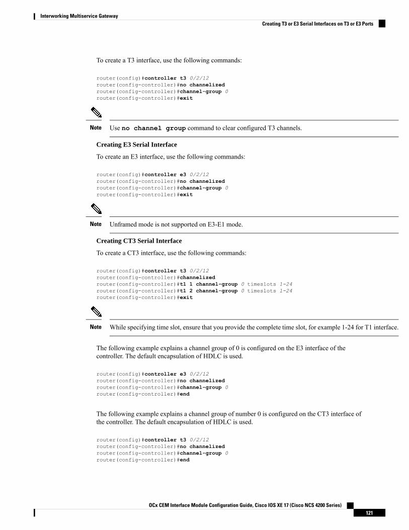
To create a T3 interface, use the following commands:
router(config)#controller t3 0/2/12router(config-controller)#no channelizedrouter(config-controller)#channel-group 0router(config-controller)#exit
Use no channel group command to clear configured T3 channels.Note
Creating E3 Serial Interface
To create an E3 interface, use the following commands:
router(config)#controller e3 0/2/12router(config-controller)#no channelizedrouter(config-controller)#channel-group 0router(config-controller)#exit
Unframed mode is not supported on E3-E1 mode.Note
Creating CT3 Serial Interface
To create a CT3 interface, use the following commands:
router(config)#controller t3 0/2/12router(config-controller)#channelizedrouter(config-controller)#t1 1 channel-group 0 timeslots 1-24router(config-controller)#t1 2 channel-group 0 timeslots 1-24router(config-controller)#exit
While specifying time slot, ensure that you provide the complete time slot, for example 1-24 for T1 interface.Note
The following example explains a channel group of 0 is configured on the E3 interface of thecontroller. The default encapsulation of HDLC is used.
router(config)#controller e3 0/2/12router(config-controller)#no channelizedrouter(config-controller)#channel-group 0router(config-controller)#end
The following example explains a channel group of number 0 is configured on the CT3 interface ofthe controller. The default encapsulation of HDLC is used.
router(config)#controller t3 0/2/12router(config-controller)#no channelizedrouter(config-controller)#channel-group 0router(config-controller)#end
OCx CEM Interface Module Configuration Guide, Cisco IOS XE 17 (Cisco NCS 4200 Series)121
Interworking Multiservice GatewayCreating T3 or E3 Serial Interfaces on T3 or E3 Ports

Creating an E1 Serial Interface in Unframed ModeTable 17: Feature History
DescriptionRelease InformationFeature Name
In this release, a new framingmodeunframed is supported for the 1 portOC-48/STM-16 or 4 portOC-12/OC-3 / STM-1/STM-4 + 12port T1/E1 + 4 port T3/E3 CEMInterface Module. With theunframed mode, you can createserial interfaces under the electricalE1 mode.
Cisco IOS XE Bengaluru 17.5.1Unframed Framing Support on anE1 and Channel STM links
Starting with Cisco IOS XE 17.5.1, you can create a channel group in the unframed mode only on the E1interface.
To create channel group in the unframed mode, use the following commands:
router(config)#controller e1 0/2/0router(config-controller)#framing unframedrouter(config-controller)#channel-group channel-grp-no unframed
The following example explains a channel group of number 10 configured on the unframed modeof E1 interface. The default encapsulation of HDLC is used.
router(config)#controller e1 0/2/0router(config-controller)#framing unframedrouter(config-controller)#channel-group 10 unframed
Creating Serial Interfaces on SDHConfiguring Mode to SDH
To enter into SDH mode, use the following commands:
router(config)#controller mediatype 0/bay/portrouter(config-controller)#mode sdhrouter(config-controller)#exit
Creating SDH T3 Interface
To create an SDH T3 interface, use the following commands:
router(config)#controller sdh 0/bay/portrouter(config-controller)#rate {stm1 | stm4 | stm16}router(config-controller)#aug mapping au-4router(config-controller)#au-4 1router(config-ctrlr-au4)#mode tug-3
OCx CEM Interface Module Configuration Guide, Cisco IOS XE 17 (Cisco NCS 4200 Series)122
Interworking Multiservice GatewayCreating an E1 Serial Interface in Unframed Mode

router(config-ctrlr-au4)#tug-3 1router(config-ctrlr-tug3)#[no]mode t3router(config-ctrlr-tug3)#[no]t3 channel-group 0router(config-ctrlr-tug3)#exit
Creating SDH E3 Interface
To create an SDH E3 interface, use the following commands:
router(config)#controller sdh 0/bay/portrouter(config-controller)#rate {stm1 | stm4 | stm16}router(config-controller)#aug mapping au-4router(config-controller)#au-4 1router(config-ctrlr-au4)#mode tug-3router(config-ctrlr-au4)#tug-3 1router(config-ctrlr-tug3)#[no]mode e3router(config-ctrlr-tug3)#[no]e3 channel-group 0router(config-ctrlr-tug3)#exit
Creating SDH VC11 Interface
To create an SDH VC11 interface, use the following commands:
router(config)#controller sdh 0/bay/portrouter(config-controller)#rate {stm1 | stm4 | stm16}router(config-controller)#aug mapping au-4router(config-controller)#au-4 1router(config-ctrlr-au4)#[no]mode tug-3router(config-ctrlr-au4)#tug-3 1router(config-ctrlr-tug3)#[no]mode vc1xrouter(config-ctrlr-tug3)#tug-2 1 payload vc11router(config-ctrlr-tug2-vcx)#[no]t1 1 channel-group 0 timeslots 1-24router(config-ctrlr-tug3)#exit
Creating SDH VC12 Interface
To create an SDH VC12 interface, use the following commands:
router(config)#controller sdh 0/bay/portrouter(config-controller)#rate {stm1 | stm4 | stm16}router(config-controller)#aug mapping au-4router(config-controller)#au-4 1router(config-ctrlr-au4)#[no]mode tug-3router(config-ctrlr-au4)#tug-3 1router(config-ctrlr-tug3)#[no]mode vc1xrouter(config-ctrlr-tug3)#tug-2 1 payload vc12router(config-ctrlr-tug2-vcx)#[no]e1 1 channel-group 0 timeslots 1-31router(config-ctrlr-tug3)#exit
Creating SDH VC4-nc Interface
To create an SDH VC4-nc concatenated interface, use the following commands:
router(config)#controller sdh 0/bay/portrouter(config-controller)#rate {stm1 | stm4 | stm16}router(config-controller)#aug mapping au-4router(config-controller)#au-4 1router(config-ctrlr-au4)#[no]mode vc4router(config-ctrlr-au4)#[no]channel-group 0router(config-ctrlr-tug3)#exit
Creating SDH T3 Interface with AUG-3 Mapping
OCx CEM Interface Module Configuration Guide, Cisco IOS XE 17 (Cisco NCS 4200 Series)123
Interworking Multiservice GatewayCreating Serial Interfaces on SDH

To create an SDH T3 interface with AUG-3 AUG mapping, use the following commands:
router(config)#controller sdh 0/bay/portrouter(config-controller)#aug mapping au-3router(config-controller)#au-3 1router(config-ctrlr-au3)#[no]mode t3router(config-ctrlr-au3)#[no]t3 channel-group 0router(config-ctrlr-au3)#exit
Creating SDH VC11 Interface with AUG-3 Mapping
To create an SDH VC11 interface with AUG-3 AUG mapping, use the following commands:
router(config)#controller sdh 0/bay/portrouter(config-controller)#au-3 1router(config-ctrlr-au3)#[no]mode vc1xrouter(config-ctrlr-au3)#tug-2 1 payload vc11router(config-ctrlr-tug2-vcx)#[no] t1 1 channel-group 0 timeslots 1-24router(config-ctrlr-tug3)#exit
Creating SDH VC12 Interface with AUG-3 Mapping
To create an SDH VC12 interface with AUG-3 AUG mapping, use the following commands:
router(config)#controller sdh 0/bay/portrouter(config-controller)#au-3 1router(config-ctrlr-au3)#[no]mode vc1xrouter(config-ctrlr-au3)#tug-2 1 payload vc12router(config-ctrlr-tug2-vcx)#[no]e1 1 channel-group 0 timeslots 1-31router(config-ctrlr-tug3)#exit
The following example explains SDH serial interface is configured with rate STM1 with AU-4mapping and TUG-3 and T3 mode:
router(config)#controller sdh 0/3/4router(config-controller)#rate stm1router(config-controller)#aug mapping au-4router(config-controller)#au-4 1router(config-ctrlr-au4)#mode tug-3router(config-ctrlr-au4)#tug-3 1router(config-ctrlr-tug3)#mode t3router(config-ctrlr-tug3)#t3 channel-group 0router(config-ctrlr-tug3)#exit
Creating Serial Interfaces on SONETSetting Controller Mode to SONET
To enter into SONET mode, use the following commands:
router(config)#controller mediatype 0/bay/portrouter(config-controller)#mode sonetrouter(config-controller)#exit
Creating T3 Serial Interface
OCx CEM Interface Module Configuration Guide, Cisco IOS XE 17 (Cisco NCS 4200 Series)124
Interworking Multiservice GatewayCreating Serial Interfaces on SONET
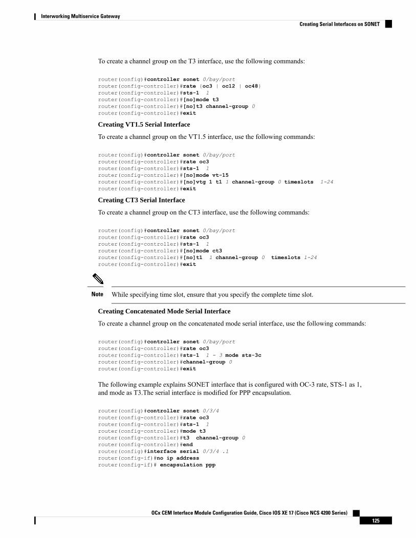
To create a channel group on the T3 interface, use the following commands:
router(config)#controller sonet 0/bay/portrouter(config-controller)#rate {oc3 | oc12 | oc48}router(config-controller)#sts-1 1router(config-controller)#[no]mode t3router(config-controller)#[no]t3 channel-group 0router(config-controller)#exit
Creating VT1.5 Serial Interface
To create a channel group on the VT1.5 interface, use the following commands:
router(config)#controller sonet 0/bay/portrouter(config-controller)#rate oc3router(config-controller)#sts-1 1router(config-controller)#[no]mode vt-15router(config-controller)#[no]vtg 1 t1 1 channel-group 0 timeslots 1-24router(config-controller)#exit
Creating CT3 Serial Interface
To create a channel group on the CT3 interface, use the following commands:
router(config)#controller sonet 0/bay/portrouter(config-controller)#rate oc3router(config-controller)#sts-1 1router(config-controller)#[no]mode ct3router(config-controller)#[no]t1 1 channel-group 0 timeslots 1-24router(config-controller)#exit
While specifying time slot, ensure that you specify the complete time slot.Note
Creating Concatenated Mode Serial Interface
To create a channel group on the concatenated mode serial interface, use the following commands:
router(config)#controller sonet 0/bay/portrouter(config-controller)#rate oc3router(config-controller)#sts-1 1 - 3 mode sts-3crouter(config-controller)#channel-group 0router(config-controller)#exit
The following example explains SONET interface that is configured with OC-3 rate, STS-1 as 1,and mode as T3.The serial interface is modified for PPP encapsulation.
router(config)#controller sonet 0/3/4router(config-controller)#rate oc3router(config-controller)#sts-1 1router(config-controller)#mode t3router(config-controller)#t3 channel-group 0router(config-controller)#endrouter(config)#interface serial 0/3/4 .1router(config-if)#no ip addressrouter(config-if)# encapsulation ppp
OCx CEM Interface Module Configuration Guide, Cisco IOS XE 17 (Cisco NCS 4200 Series)125
Interworking Multiservice GatewayCreating Serial Interfaces on SONET

Modifying Encapsulation to PPPBy default, HDLC is used for encapsulation. You can modify encapsulation to PPP on a serial interface usingthe encapsulation ppp command.
The channel-id varies based on the mode set and the circuit type. For more information, see the SerialInterface Supported Modes section.
To modify encapsulation on the serial interface, use the following commands:
router(config)#interface serial 0/bay/port.channel-idrouter(config-if)#no ip addressrouter(config-if)# encapsulation ppp
IPv4 or IPv6 Interworking Multiservice Gateway Pseudowireover HDLC or PPP
L2VPN Interworking Multiservice GatewayTable 18: Feature History
Feature DescriptionRelease InformationFeature Name
Support for NxDS0 iMSG IPv4 andNxDS0 APS iMSG IPv4 onNCS4200-1T8S-20CS andNCS4200-3GMS InterfaceModule.
Cisco IOS XE Bengaluru 17.4.1CEM and IP IW Feature Parity forNCS4200-1T8S-20CS andNCS4200-3GMS InterfaceModules
Layer 2 transport over MPLS and IP already exists for like-to-like attachment circuits, such asEthernet-to-Ethernet or PPP-to-PPP. Layer 2 Virtual Private Network (L2VPN) Interworking MultiserviceGateway (iMSG) builds on this functionality by allowing disparate attachment circuits to be connected. AniMSG function facilitates the translation between the different Layer 2 encapsulations.
L2VPN iMSG ModeL2VPN iMSG works in IP (routed) mode that facilitates transport of IPv4 or IPv6 payload in HDLC or PPPframes to Ethernet, over an MPLS network. The configuration is supported on NCS4200-3GMS. You specifythe mode by issuing the interworking ip command in pseudowire-class configuration mode.
Starting with Cisco IOS XE 17.1.x release, the IPv6 iMSG is supported.
The interworking command causes the attachment circuits to be terminated locally. The ip keywordcauses IP packets to be extracted from the attachment circuit and sent over the pseudowire. Packets with IPv4or IPv6 payload only are transported over pseudowire.
OCx CEM Interface Module Configuration Guide, Cisco IOS XE 17 (Cisco NCS 4200 Series)126
Interworking Multiservice GatewayModifying Encapsulation to PPP

IP Interworking ModeThe CE routers encapsulate the IP on the link between the CE router and PE router. A new VC type is usedto signal the IP pseudowire inMPLS. Translation between the L2 and IP encapsulations across the pseudowireis required. Special consideration is given to the address resolution and routing protocol operation, becausethese operations are handled differently on different L2 encapsulations.
In routed iMSG, IP packets that are extracted from the ACs are sent over the pseudowire. The pseudowireworks in the IP Layer 2 transport (VC type 0x000B) like-to-like mode. The iMSG function at the networkservice provider's (NSP) end performs the required adaptation that is based on the AC technology. Non-IPv4or non-IPv6 packets are not forwarded on pseudowire. Only packets with the IPv4 or IPv6 payload aretransported over the pseudowire.
The following table details on the packets that are terminated locally:
Table 19: List of Packets Locally Terminated
PID NumberPackets (Locally Terminated)Protocol
0x8035SLARP, LCP, or RARPCisco HDLC
0x0806NCP or ARPCisco HDLC
0xCxxx to 0xFxxxLCPPPP
0x8xxx to 0xBxxxNCPPPP
HDLC or PPP to Ethernet IPv4 or IPv6 iMSG PseudowireStarting with Cisco IOS XE 16.9.1 release, the L2VPN iMSG allows you to connect disparate attachmentcircuits, for example, TDM and Ethernet attachment circuits.
For pseudowires operated in the IP (routed) mode, the IP packets are extracted from the attachment circuitand sent over the pseudowire.
Once IPv4 or IPv6 iMSG is configured, create a serial interface with specific channel identifier.
When a serial interface is UP, an internal label is allocated and LDP negotiation with a peer is performed fora remote label. A pseudowire is created and bound to HDLC or PPP channel. Based on the pseudowireconfiguration, you can permit IPv4 payload traffic with an allocated internal MPLS label.
The default encapsulation for all serial interfaces is HDLC. You can change the encapsulation to PPP. Youcan cross connect the attachment circuit segment with specific VC identifier and the pseudowire segment.
IPv4 or IPv6 iMSG Pseudowire Supported ModesIPv4 or IPv6 iMSG pseudowire is supported on the following modes:
• T1 or E1
• T3 or E3
• Channelized T3 or E3 (channelized to T1 or E1)
• SDH
• SONET
OCx CEM Interface Module Configuration Guide, Cisco IOS XE 17 (Cisco NCS 4200 Series)127
Interworking Multiservice GatewayIP Interworking Mode

Limitations of IPv4 or IPv6 iMSG Pseudowire on HDLC or PPP Serial InterfacesThe following limitations apply to IPv4 or IPv6 iMSG pseudowire on HDLC or PPP serial interfaces:
• IPv4 or IPv6 iMSG pseudowire with HDLC or PPP attachment circuit is supported only on theNCS4200-3GMS.
• L3 termination, bridging, and local switching on SERIAL-ACR interfaces (IPv4 and IPv6) are notsupported, only L3 termination is supported on IPv4 serial interfaces.
• IPv4 or IPv6 over HDLC or PPP is not supported on Nx DS0 serial interfaces.
• T1 framing SF is not supported.
• Serial-ACR HDLC or PPP is not supported for STS-12C or VC4-4C and STS-48C or VC4-16C modes.
• HDLC or PPP is not supported for CE3 modes.
• Modifying MTU value is not supported for IPv6 iMSG pseudowire.
• Scrambling is not supported in the POS mode.
iMSG Restrictions for NCS 4200 1-Port OC-192 or 8-Port Low Rate CEM 20G Bandwidth Interface Module(NCS4200-1T8S-20CS)
iMSG Restrictions - Cisco IOS XE Amsterdam 17.3.1 release
• MLPPP is not supported for iMSG.
• MLPPP ACR is not supported.
• nxDS0 iMSG is not supported until Cisco IOS XE Amsterdam 17.3.1.
Starting with Cisco IOS XE Bengaluru 17.4.1, nxDS0 iMSG IPv4 is supported and.iMSG IPv6 is notsupported.
• UPSR-only SONET modes such as VT1.5, STS-3C, STS-12C, and STS-48C are supported.
Bandwidth Restrictions - Cisco IOS XE Amsterdam 17.3.1 release
• Supports 2.5 G for iMSG
• iMSG supports upto STS-48c for concatenation
How to Configure IPv4 or IPv6 iMSG Pseudowire on HDLC or PPP InterfaceThis section provides the following information about configuring an IPv4 or IPv6 iMSG pseudowire on anHLDC or PPP interface:
• Configuring L2VPN iMSG, on page 129
• Configuring Cross-Connect Under Attachment Circuit, on page 129
OCx CEM Interface Module Configuration Guide, Cisco IOS XE 17 (Cisco NCS 4200 Series)128
Interworking Multiservice GatewayLimitations of IPv4 or IPv6 iMSG Pseudowire on HDLC or PPP Serial Interfaces

Configuring L2VPN iMSGTo configure L2VPN iMSG, create a pseudowire class with the tunneling encapsulation as MPLS. Theinterworking command specifies the type of payload traffic that flows across the pseudowire tunnel. Configurepseudowire class only once on a device.
You can also configure control-word as an optional command.
To configure L2VPN IPv4 iMSG, use the following commands:
router>enablerouter#configure terminalrouter(config)#pseudowire-class pw-class-namerouter(config-pw)#encapsulation mplsrouter(config-pw)# interworking iprouter(config-pw)# control-word
To configure L2VPN IPv6 iMSG, use the following commands:
router>enablerouter#configure terminalrouter(config)#interface pseudowire pw-numberrouter(config-if)# encapsulation mplsrouter(config-if)# neighbor <peer-address><vcid-value>router(config-xconnect)# control-word include
Based on the far-end router, the control-word needs to be enabled or disabled.Note
The following example shows how to configure L2VPN IPv6 iMSG:
interface pseudowire30encapsulation mplsneighbor 10.2.2.2 30control-word include
Configuring Cross-Connect Under Attachment CircuitThe xconnect command binds the attachment circuit to an L2VPN pseudowire for cross connect service. Thevirtual circuit identifier creates the binding between a pseudowire that is configured on a PE router and anattachment circuit in a CE device.
To perform IPv4 cross connection between an AToM routed pseudowire and attachment circuit, use thefollowing commands:
router(config)#interface serial 0/bay/port.channel-idrouter(config-if)#xconnect ip-address vc-id pw-class atom-iw-routed
To perform IPv6 cross connection between pseudowire and attachment circuit, use the following commands:
router(config)#l2vpn xconnect context xconnect-namerouter(config-xconnect)#interworking ipv6
OCx CEM Interface Module Configuration Guide, Cisco IOS XE 17 (Cisco NCS 4200 Series)129
Interworking Multiservice GatewayConfiguring L2VPN iMSG

router(config-xconnect)#member pseudowire pw-numberrouter(config-xconnect)#member serial 0/bay/port.channel-id
Verifying IPv4 or IPv6 iMSG Pseudowire over HDLC or PPP ConfigurationThe following show interface serial 0/bay/port.vc-number command displays information about encapsulationand statistics of a serial interface.
To display configuration information on the serial interface, use the show interface serial command:Router# show interface serial 0/5/19.8Serial0/5/19.8 is up, line protocol is upHardware is NCS4200-3GMSMTU 1500 bytes, BW 1536 Kbit/sec, DLY 20000 usec,
reliability 255/255, txload 1/255, rxload 1/255Encapsulation PPP, LCP OpenStopped: TAGCPOpen: IPCP, crc 16, loopback not setKeepalive set (10 sec)Last input 00:00:04, output 00:00:04, output hang neverLast clearing of "show interface" counters 23:52:46Input queue: 0/375/0/0 (size/max/drops/flushes); Total output drops: 0Queueing strategy: fifoOutput queue: 0/40 (size/max)5 minute input rate 0 bits/sec, 0 packets/sec5 minute output rate 0 bits/sec, 0 packets/sec
16201 packets input, 712844 bytes, 0 no bufferReceived 0 broadcasts (0 IP multicasts)0 runts, 0 giants, 0 throttles0 input errors, 0 CRC, 0 frame, 0 overrun, 0 ignored, 0 abort16205 packets output, 696835 bytes, 0 underruns0 output errors, 0 collisions, 1 interface resets0 unknown protocol drops0 output buffer failures, 0 output buffers swapped out1 carrier transitions
PW stats
0 input packets ,0 output packets,0 input bytes, 0 output bytes, 0 input packet dropno alarm presentVC 2: timeslot(s): 1-24, Transmitter delay 0, non-inverted data
The show platform software tdm-combo vc info command helps you to identify the bay, port,STS path, T1, and channel group associated with a serial interface:
router#show platform software tdm-combo vc infoBAY PORT PATH T1 CHANNEL VC HWIDBspa in bay:0 is NULLspa in bay:1 is NULL5 19 1 1 0 Serial0/5/19.1 15 19 1 8 0 Serial0/5/19.8 2TOTAL ENTRIES :2
Theshow running-config interface serial 0/5/19.8 command provides information aboutthe current configuration under the serial interface 0/5/19.8:
router#show running-config interface serial 0/5/19.8Building configuration...
Current configuration : 147 bytes!interface Serial0/5/19.8
OCx CEM Interface Module Configuration Guide, Cisco IOS XE 17 (Cisco NCS 4200 Series)130
Interworking Multiservice GatewayVerifying IPv4 or IPv6 iMSG Pseudowire over HDLC or PPP Configuration

no ip addressencapsulation pppppp authentication chapxconnect 192.168.2.6 207 encapsulation mpls pw-class ip-iwend
BYOS-RSP3#sh xconnect allLegend: XC ST=Xconnect State S1=Segment1 State S2=Segment2 StateUP=Up DN=Down AD=Admin Down IA=InactiveSB=Standby HS=Hot Standby RV=Recovering NH=No Hardware
XC ST Segment 1 S1 Segment 2 S2------+---------------------------------+--+---------------------------------+--UP pri ac Se0/5/19.8(PPP) UP mpls 192.168.2.6:207 UP
The show mpls l2transport vc 207 detail command provides information on pseudowirecorresponding to VC ID 207:
Local interface: Se0/5/19.8 up, line protocol up, PPP upInterworking type is IPDestination address: 192.168.2.6, VC ID: 207, VC status: upOutput interface: Gi0/3/7, imposed label stack {16}Preferred path: not configuredDefault path: activeNext hop: 209.165.202.129
Create time: 23:31:56, last status change time: 23:31:54Last label FSM state change time: 23:31:56
Signaling protocol: LDP, peer 192.168.2.6:0 upTargeted Hello: 192.168.2.10(LDP Id) -> 192.168.2.6, LDP is UPGraceful restart: configured and not enabledNon stop routing: not configured and not enabledStatus TLV support (local/remote) : enabled/supportedLDP route watch : enabledLabel/status state machine : established, LruRruLast local dataplane status rcvd: No faultLast BFD dataplane status rcvd: Not sentLast BFD peer monitor status rcvd: No faultLast local AC circuit status rcvd: No faultLast local AC circuit status sent: No faultLast local PW i/f circ status rcvd: No faultLast local LDP TLV status sent: No faultLast remote LDP TLV status rcvd: No faultLast remote LDP ADJ status rcvd: No fault
MPLS VC labels: local 512, remote 16Group ID: local n/a, remote 0MTU: local 1500, remote 1500Remote interface description:
Sequencing: receive disabled, send disabledControl Word: OnSSO Descriptor: 192.168.2.6/207, local label: 512Dataplane:SSM segment/switch IDs: 8219/8218 (used), PWID: 1
VC statistics:transit packet totals: receive 0, send 0transit byte totals: receive 0, send 0transit packet drops: receive 0, seq error 0, send 0
OCx CEM Interface Module Configuration Guide, Cisco IOS XE 17 (Cisco NCS 4200 Series)131
Interworking Multiservice GatewayVerifying IPv4 or IPv6 iMSG Pseudowire over HDLC or PPP Configuration

IPv4 or IPv6 Interworking Multiservice Gateway Pseudowireover Frame Relay
Frame Relay for iMSGTable 20: Feature History
DescriptionRelease InformationFeature Name
Support for frame relayencapsulation on iMSG serialinterface for the following interfacemodules:
• 1-port OC-48/STM-16 or4-port OC-12/OC-3 /STM-1/STM-4 + 12 portT1/E1 + 4-port T3/E3 CEMinterface module
• NCS 4200 1-port OC-192 or8-port Low Rate CEM 20Gbandwidth interface module
Frame Relay being a streamlinedprotocol facilitates higherperformance and greater efficiency.
Cisco IOS XE Cupertino 17.8.1Frame Relay Support for IPInterworking
Frame Relay is an industry-standard, switched data link layer protocol that handles multiple virtual circuitsusing encapsulation between connected devices.
Frame Relay provides a packet-switching data communications capability that is used across the interfacebetween user devices (such as routers, bridges, host machines) and network equipment (such as switchingnodes). User devices are often referred to as data terminal equipment (DTE), while network equipment thatinterfaces to DTE is often referred to as data circuit-terminating equipment (DCE). The network providingthe Frame Relay interface can be either a carrier-provided public network or a network of privately ownedequipment serving a single enterprise.
As an interface between user and network equipment, Frame Relay provides a means for statisticallymultiplexingmany logical data conversations (referred to as virtual circuits) over a single physical transmissionlink. This contrasts with systems that use only time-division-multiplexing (TDM) techniques for supportingmultiple data streams. Frame Relay's statistical multiplexing provides more flexible and efficient use ofavailable bandwidth. It can be used without TDM techniques or on top of channels provided by TDM systems.
Frame relay is supported only on the RSP3 module.
Limitations of IPv4 or IPv6 iMSG Pseudowire on Frame Relay Serial Interfaces• Subinterfaces with point-to-multipoint isn’t supported. Only point-to-point subinterfaces are supported.
OCx CEM Interface Module Configuration Guide, Cisco IOS XE 17 (Cisco NCS 4200 Series)132
Interworking Multiservice GatewayIPv4 or IPv6 Interworking Multiservice Gateway Pseudowire over Frame Relay

• Subinterface number and data-link connection identifier (DLCI) number should be same for local connectand cross connect.
• DTE interface type for frame relay isn’t supported.
• Local connect is supported with IETF only, and not with CISCO (default).
• Local connect protection isn’t supported.
• On frame relay subinterface, any functional and maintenance configurations (for example, shut or noshut, or DLCI) aren’t supported.
• The cross connect configuration using the l2vpn xconnect context xconnect-name command formatisn’t supported.
Scale Supported for iMSG Pseudowire on Frame Relay Serial InterfacesThe following table describes the scale information that is applicable for serial interface (includes both mainand subinterface):
Table 21: Scale Supported on iMSG Frame Relay Serial Interfaces
Scale SupportedInterface Module/System
1000Frame Relay Pseudowire supported per InterfaceModule
4000Frame Relay Pseudowire supported per System
25Number of DLCI supported per interface
1000Number of DLCI supported per Interface Module
4000Number of DLCI supported per System
How to Configure IPv4 or IPv6 iMSG Pseudowire on Frame Relay SerialInterface
Modifying Encapsulation to Frame RelayBy default, HDLC is used for encapsulation. You can modify encapsulation to frame relay on a serial interfaceusing the encapsulation frame-relay command. You can configure the frame relay encapsulationfor the interface as Cisco or IETF. The default encapsulation type for frame relay is Cisco. On the frame relayinterface, you can configure interface type and Local Management Interface (LMI) type. With interface type,you can set the interface as Data Communications Equipment (DCE). Though the default option displays asData Transmission Equipment (DTE), the DTE is not supported. The LMI types that are supported are CISCO,ANSI, and q933A, and the default value is Cisco.
The channel-id varies based on the mode set and the circuit type.
To modify encapsulation on the serial interface to frame relay, use the following commands:
OCx CEM Interface Module Configuration Guide, Cisco IOS XE 17 (Cisco NCS 4200 Series)133
Interworking Multiservice GatewayScale Supported for iMSG Pseudowire on Frame Relay Serial Interfaces

router(config)#interface serial 0/bay/port.channel-idrouter(config-if)#no ip addressrouter(config-if)# encapsulation frame-relay (cisco | ietf)router(config-if)# frame-relay intf-typedcerouter(config-if)# frame-relay lmi-type(cisco | ansi | q033a}router(config-if)# end
Configuring Frame RelayConfiguring Frame Relay for T1 or E1 Serial Interface and Configuring Sub-interface for SerialInterface
controller T1 0/4/0threshold sd-ber 6threshold sf-ber 3framing esflinecode b8zscablelength short 110channel-group 0 timeslots 1-24no snmp trap link-status
interface Serial0/4/0.1no ip addressencapsulation frame-relayframe-relay lmi-type q933a
interface Serial0/4/0.1/21 point-to-point
Configuring Frame Relay for T3 or E3 Serial Interface and Configuring Sub-interface for SerialInterface
controller T3 0/4/12no snmp trap link-statusthreshold sd-ber 6threshold sf-ber 3no channelizedframing c-bitcablelength shortchannel-group 0
interface Serial0/4/12.1no ip addressencapsulation frame-relay IETFframe-relay lmi-type ansi
interface Serial0/4/12.1/25 point-to-point
Configuring Frame Relay for OCx Serial Interface and Configuring Sub-interface for Serial Interface
controller SONET 0/4/19no snmp trap link-statusrate OC3no ais-shutalarm-report allclock source internal!sts-1 1clock source internalmode ct3
OCx CEM Interface Module Configuration Guide, Cisco IOS XE 17 (Cisco NCS 4200 Series)134
Interworking Multiservice GatewayConfiguring Frame Relay

t3 framing c-bitt3 clock source internalt1 1 channel-group 1 timeslots 1-24!sts-1 2clock source internalmode vt-15vtg 1 t1 1 channel-group 2 timeslots 1-24!sts-1 3clock source internalmode t3t3 framing c-bitt3 channel-group 0t3 clock source internal
interface Serial0/4/19.1no ip addressencapsulation frame-relayinterface Serial0/4/19.1/32 point-to-pointinterface Serial0/4/19.29no ip addressencapsulation frame-relay IETFframe-relay lmi-type ansiinterface Serial0/4/19.29/33 point-to-pointinterface Serial0/4/19.57no ip addressencapsulation frame-relayframe-relay lmi-type q933ainterface Serial0/4/19.57/34 point-to-point
Configuring Frame Relay for POS Serial Interface and Configuring Sub-interface for Serial Interface
controller SONET 0/4/18no snmp trap link-statusrate OC3no ais-shutalarm-report allclock source internal!sts-1 1 - 3 mode sts-3cclock source internaloverhead c2 207
channel-group 0interface Serial0/4/18.1no ip addressencapsulation frame-relaypos report pplmpos report ptiminterface Serial0/4/18.1/40 point-to-point
Configuring Frame Relay for NxDS0 Serial Interface and Configuring Sub-interface for Serial Interface
controller T1 0/4/1threshold sd-ber 6threshold sf-ber 3framing esflinecode b8zscablelength short 110channel-group 4 timeslots 1-10no snmp trap link-status
interface Serial0/4/1.1:4
OCx CEM Interface Module Configuration Guide, Cisco IOS XE 17 (Cisco NCS 4200 Series)135
Interworking Multiservice GatewayConfiguring Frame Relay

no ip addressencapsulation frame-relay
interface Serial0/4/1.1:4/45 point-to-point
Configuring L2VPN iMSG Using Local Connect for Frame Relay
Configuring L2VPN iMSG Using IPv4 Local Connect for Frame Relay
Once you configure frame relay and subinterface for serial interface, you can configure L2VPN iMSG localconnect.
connect <local-connect-keyword> GigabitEthernet slot/bay/port vc-number Serialslot/bay/port.channel.id/sub-interface-number dlci-number interworking ip
Example
connect frsub21vlcv4 GigabitEthernet0/0/3 100 Serial0/2/19.1/21 21 interworking ip
Configuring L2VPN iMSG Using IPv6 Local Connect for Frame Relay
connect <local-connect-keyword> GigabitEthernet slot/bay/port vc-number Serialslot/bay/port.channel.id/sub-interface-number dlci-number interworking ipv6
Example
connect frsub21vlcv6 GigabitEthernet0/0/3 150 Serial0/2/19.8/21 21 interworking ipv6
Configuring L2VPN iMSG Using Cross Connect for Frame Relay
Ensure that you create pseudowire class template before proceeding to cross connect step for IPv4 and IPv6 L2VPN.
Create Pseudowire Class Template for IPv4 and IPv6
pseudowire-class <pseudowire-class-name>encapsulation mplsinterworking {ip | ipv6}control-word
Example
Create Pseudowire Class Template for IPv4
pseudowire-class serial_testencapsulation mplsinterworking ipcontrol-word
Create Pseudowire Class Template for IPv6
pseudowire-class serial_testipv6encapsulation mplsinterworking ipv6control-word
OCx CEM Interface Module Configuration Guide, Cisco IOS XE 17 (Cisco NCS 4200 Series)136
Interworking Multiservice GatewayConfiguring L2VPN iMSG Using Local Connect for Frame Relay

Configuring L2VPN iMSG Using IPv4 Cross Connect for Frame Relay
Once you configure frame relay and subinterface for serial interface, you can configure L2VPN iMSG crossconnect.
The cross connect configuration using the l2vpn xconnect context xconnect-name command format is notsupported. Ensure that you use the following command format to perform cross connect configuration:
connect <cross-connect-keyword> Serial slot/bay/port.channel.id/sub-interface-numberdlci-number l2transportxconnect ipv4-address vc-number encapsulation mpls pw-class pw-name
Example
connect frsub21ipv4 Serial0/2/19.43/21 21 l2transportxconnect 10.2.2.2 400 encapsulation mpls pw-class serial_test
Configuring L2VPN iMSG Using IPv6 Cross Connect for Frame Relay
connect <local-connect-keyword> Serial slot/bay/port.channel.id/sub-interface-numberdlci-number l2transportxconnect ipv4-address vc-number encapsulation mpls pw-class pw-name
Example
connect frsub21ipv6 Serial0/2/19.50/21 21 l2transportxconnect 10.2.2.2 450 encapsulation mpls pw-class serial_testipv6
Verifying IPv4 or IPv6 iMSG Pseudowire over Frame Relay ConfigurationUse the following show commands to verify the frame relay configuration on iMSG pseudowire:
• show interface Serial <slot/bay/port.channel.id>
• show ip interface brief | interface <slot/bay/port.channel.id>
• show frame-relay lmi interface Serial <slot/bay/port.channel.id>
• show frame-relay pvc interface Serial <slot/bay/port.channel.id>
• show xconnect all
• show platform software tdm-combo vc info
• show mpls l2transport vc <vc-id> detail
Router#show ip interface brief | interface 0/4/16.28Serial0/4/16.28 unassigned YES unset up upSerial0/4/16.28/21 unassigned YES unset up up
Router#show interface Serial0/4/16.28Serial0/4/16.28 is up, line protocol is upHardware is NCS4200-3GMSMTU 1500 bytes, BW 1536 Kbit/sec, DLY 20000 usec,
OCx CEM Interface Module Configuration Guide, Cisco IOS XE 17 (Cisco NCS 4200 Series)137
Interworking Multiservice GatewayVerifying IPv4 or IPv6 iMSG Pseudowire over Frame Relay Configuration

reliability 252/255, txload 138/255, rxload 255/255Encapsulation FRAME-RELAY IETF, crc 16, loopback not setKeepalive set (10 sec)LMI enq sent 0, LMI stat recvd 0, LMI upd recvd 0LMI enq recvd 25, LMI stat sent 25, LMI upd sent 0, DCE LMI upLMI DLCI 0 LMI type is CCITT frame relay DCE segmentation inactiveBroadcast queue 0/64, broadcasts sent/dropped 0/0, interface broadcasts 0Last input 00:00:02, output 00:00:02, output hang neverLast clearing of "show interface" counters 00:04:06Input queue: 0/375/0/0 (size/max/drops/flushes); Total output drops: 0Queueing strategy: fifoOutput queue: 0/40 (size/max)5 minute input rate 11661000 bits/sec, 4824731 packets/sec5 minute output rate 833000 bits/sec, 554183 packets/sec
25 packets input, 375 bytes, 0 no bufferReceived 0 broadcasts (0 IP multicasts)0 runts, 0 giants, 0 throttles1 input errors, 1 CRC, 0 frame, 0 overrun, 0 ignored, 0 abort25 packets output, 400 bytes, 0 underrunsOutput 0 broadcasts (0 IP multicasts)0 output errors, 0 collisions, 0 interface resets0 unknown protocol drops0 output buffer failures, 0 output buffers swapped out0 carrier transitions
no alarm presentVC 7: timeslot(s): 1-24, Transmitter delay 0, non-inverted data
Router#show frame-relay lmi interface Serial0/4/16.28
LMI Statistics for interface Serial0/4/16.28 (Frame Relay DCE) LMI TYPE = CCITTInvalid Unnumbered info 0 Invalid Prot Disc 0Invalid dummy Call Ref 0 Invalid Msg Type 0Invalid Status Message 0 Invalid Lock Shift 0Invalid Information ID 0 Invalid Report IE Len 0Invalid Report Request 0 Invalid Keep IE Len 0Num Status Enq. Rcvd 17 Num Status msgs Sent 17Num Update Status Sent 0 Num St Enq. Timeouts 0
Router#show frame-relay pvc interface Serial0/4/16.28
PVC Statistics for interface Serial0/4/16.28 (Frame Relay DCE)
Active Inactive Deleted StaticLocal 0 0 0 0Switched 1 0 0 0Unused 0 0 0 0
DLCI = 21, DLCI USAGE = SWITCHED, PVC STATUS = ACTIVE, INTERFACE = Serial0/4/16.28/21
input pkts 0 output pkts 0 in bytes 0out bytes 0 dropped pkts 0 in pkts dropped 0out pkts dropped 0 out bytes dropped 0in FECN pkts 0 in BECN pkts 0 out FECN pkts 0out BECN pkts 0 in DE pkts 0 out DE pkts 0out bcast pkts 0 out bcast bytes 030 second input rate 0 bits/sec, 0 packets/sec30 second output rate 0 bits/sec, 0 packets/secswitched pkts 0 FECNs set 0 BECNs set 0Detailed packet drop counters:no out intf 0 out intf down 0 no out PVC 0in PVC down 0 out PVC down 0 pkt too big 0shaping Q full 0 pkt above DE 0 policing drop 0
OCx CEM Interface Module Configuration Guide, Cisco IOS XE 17 (Cisco NCS 4200 Series)138
Interworking Multiservice GatewayVerifying IPv4 or IPv6 iMSG Pseudowire over Frame Relay Configuration

connected to pseudowire 10.3.3.3 vcid 700, interworking IPpvc create time 00:02:03, last time pvc status changed 00:01:45
Router#show xconnect allLegend: XC ST=Xconnect State S1=Segment1 State S2=Segment2 StateUP=Up DN=Down AD=Admin Down IA=InactiveSB=Standby HS=Hot Standby RV=Recovering NH=No Hardware
XC ST Segment 1 S1 Segment 2 S2------+---------------------------------+--+---------------------------------+--UP pri ac Se0/4/16.28/21:21(FR DLCI) UP mpls 10.3.3.3:700 UP
Router#show platform software tdm-combo vc infoMedia: Path: AUG: Mode: Channel: VC: Timeslots:Serial-Interface:SONET SONET 0/4/16.1/7/4 NONE VT1.5 1 7 1-24Serial0/4/16.28TOTAL ENTRIES :1
Router#sh mpls l2transport vc 700 detailLocal interface: Se0/4/16.28/21 up, line protocol up, FR DLCI 21 upInterworking type is IPDestination address: 10.3.3.3, VC ID: 700, VC status: upOutput interface: Gi0/3/0, imposed label stack {17}Preferred path: not configuredDefault path: activeNext hop: 209.165.200.225
Create time: 00:00:45, last status change time: 00:00:44Last label FSM state change time: 00:00:45
Signaling protocol: LDP, peer 10.3.3.3:0 upTargeted Hello: 10.2.2.2(LDP Id) -> 10.3.3.3, LDP is UPGraceful restart: configured and not enabledNon stop routing: configured and enabledStatus TLV support (local/remote) : enabled/supportedLDP route watch : enabledLabel/status state machine : established, LruRruLast local dataplane status rcvd: No faultLast BFD dataplane status rcvd: Not sentLast BFD peer monitor status rcvd: No faultLast local AC circuit status rcvd: No faultLast local AC circuit status sent: No faultLast local PW i/f circ status rcvd: No faultLast local LDP TLV status sent: No faultLast remote LDP TLV status rcvd: No faultLast remote LDP ADJ status rcvd: No fault
MPLS VC labels: local 16, remote 17Group ID: local 71, remote 9MTU: local 1500, remote 1500Remote interface description:
Sequencing: receive disabled, send disabledControl Word: OnSSO Descriptor: 10.3.3.3/700, local label: 16Dataplane:SSM segment/switch IDs: 4103/4102 (used), PWID: 2
VC statistics:transit packet totals: receive 0, send 0transit byte totals: receive 0, send 0transit packet drops: receive 0, seq error 0, send 0
OCx CEM Interface Module Configuration Guide, Cisco IOS XE 17 (Cisco NCS 4200 Series)139
Interworking Multiservice GatewayVerifying IPv4 or IPv6 iMSG Pseudowire over Frame Relay Configuration

Configuring Frame Relay for APS ProtectionConfiguring APS on Frame Relay Serial Interface and Configuring Subinterface for Serial Interface
controller SONET-ACR 10!sts-1 1mode vt-15vtg 1 t1 1 channel-group 1 timeslots 1-24!sts-1 2
!sts-1 3
interface SERIAL-ACR10.1no ip addressencapsulation frame-relay
interface SERIAL-ACR10.1/21 point-to-point
Configuring Frame Relay for UPSR ProtectionConfiguring UPSR on Frame Relay Serial Interface and Configuring Subinterface for Serial Interface
controller protection-group 20type vt1.5channel-group 20 timeslots 1-24!
interface Serial-PG20.20no ip addressencapsulation frame-relay!interface Serial-PG20.20/39 point-to-point
Configuring Frame Relay L2VPN iMSG for APS ProtectionConfiguring Frame Relay L2VPN iMSG Using Cross Connect on ACR Interface - APS
connect frsubacripv4 SERIAL-ACR10.1/21 21 l2transportxconnect 10.2.2.2 402 encapsulation mpls pw-class serial_test
Configuring Frame Relay L2VPN iMSG for UPSR ProtectionConfiguring Frame Relay L2VPN iMSG Using Cross Connect on ACR Interface - UPSR
connect frsubupsripv4 Serial-PG20.20/39 39 l2transportxconnect 10.2.2.2 403 encapsulation mpls pw-class serial_test
Verifying Frame Relay for APS Protection
Router#show ip interface brief | in ACR10SERIAL-ACR10.1 unassigned YES unset up downSERIAL-ACR10.1/21 unassigned YES unset down down
Router#show interface SERIAL-ACR10.1
OCx CEM Interface Module Configuration Guide, Cisco IOS XE 17 (Cisco NCS 4200 Series)140
Interworking Multiservice GatewayConfiguring Frame Relay for APS Protection

SERIAL-ACR10.1 is up, line protocol is downHardware is N/AMTU 1500 bytes, BW 1536 Kbit/sec, DLY 20000 usec,
reliability 255/255, txload 1/255, rxload 1/255Encapsulation FRAME-RELAY, crc 16, loopback not setKeepalive set (10 sec)LMI enq sent 63, LMI stat recvd 0, LMI upd recvd 0, DTE LMI downLMI enq recvd 0, LMI stat sent 0, LMI upd sent 0LMI DLCI 1023 LMI type is CISCO frame relay DTEBroadcast queue 0/64, broadcasts sent/dropped 0/0, interface broadcasts 0Last input never, output 00:00:04, output hang neverLast clearing of "show interface" counters 00:10:34Input queue: 0/375/0/0 (size/max/drops/flushes); Total output drops: 0Queueing strategy: fifoOutput queue: 0/40 (size/max)5 minute input rate 0 bits/sec, 0 packets/sec5 minute output rate 0 bits/sec, 0 packets/sec
0 packets input, 0 bytes, 0 no bufferReceived 0 broadcasts (0 IP multicasts)0 runts, 0 giants, 0 throttles0 input errors, 0 CRC, 0 frame, 0 overrun, 0 ignored, 0 abort0 packets output, 0 bytes, 0 underrunsOutput 0 broadcasts (0 IP multicasts)0 output errors, 0 collisions, 0 interface resets0 unknown protocol drops0 output buffer failures, 0 output buffers swapped out0 carrier transitions
alarm presentVC 1: timeslot(s): 1-24, Transmitter delay 0, non-inverted data
Router#show frame-relay lmi | beg SERIAL-ACR10.1LMI Statistics for interface SERIAL-ACR10.1 (Frame Relay DTE) LMI TYPE = CISCOInvalid Unnumbered info 0 Invalid Prot Disc 0Invalid dummy Call Ref 0 Invalid Msg Type 0Invalid Status Message 0 Invalid Lock Shift 0Invalid Information ID 0 Invalid Report IE Len 0Invalid Report Request 0 Invalid Keep IE Len 0Num Status Enq. Sent 75 Num Status msgs Rcvd 0Num Update Status Rcvd 0 Num Status Timeouts 74
Router#show platform software tdm-combo vc info | in ACRSONET SONET-ACR 10.1/1/1 NONE VT1.5 1 2 1-24SERIAL-ACR10.1
Router#show xconnect all | in ACRDN pri ac SE-ACR10.1/21:21(FR DLCI) DN mpls 10.2.2.2:402 DN
Router#show mpls l2transport vc 402 detailLocal interface: SE-ACR10.1/21 down, line protocol down, FR DLCI 21 downInterworking type is IPDestination address: 10.2.2.2, VC ID: 402, VC status: downLast error: Local peer access circuit is downOutput interface: none, imposed label stack {}Preferred path: not configuredDefault path: no routeNo adjacency
Create time: 00:09:32, last status change time: 00:09:32Last label FSM state change time: 00:09:32
Signaling protocol: LDP, peer unknownTargeted Hello: 10.1.1.1(LDP Id) -> 10.2.2.2, LDP is DOWN, no bindingGraceful restart: not configured and not enabledNon stop routing: not configured and not enabled
OCx CEM Interface Module Configuration Guide, Cisco IOS XE 17 (Cisco NCS 4200 Series)141
Interworking Multiservice GatewayVerifying Frame Relay for APS Protection

Status TLV support (local/remote) : enabled/None (no remote bindingLDP route watch : enabledLabel/status state machine : local standby, AC-ready, LndRndLast local dataplane status rcvd: No faultLast BFD dataplane status rcvd: Not sentLast BFD peer monitor status rcvd: No faultLast local AC circuit status rcvd: DOWN AC(rx/tx faults)Last local AC circuit status sent: DOWN(not-forwarding)Last local PW i/f circ status rcvd: No faultLast local LDP TLV status sent: No statusLast remote LDP TLV status rcvd: None (no remote binding)Last remote LDP ADJ status rcvd: None (no remote binding)
MPLS VC labels: local 16, remote unassignedGroup ID: local 57, remote unknownMTU: local 1500, remote unknownRemote interface description:
Sequencing: receive disabled, send disabledControl Word: OnSSO Descriptor: 10.2.2.2/402, local label: 16Dataplane:SSM segment/switch IDs: 0/0 (used), PWID: 1
VC statistics:transit packet totals: receive 0, send 0transit byte totals: receive 0, send 0transit packet drops: receive 0, seq error 0, send 0
Verifying Frame Relay for UPSR Protection
Router#show ip interface brief | in PG20Serial-PG20.20 unassigned YES unset down downSerial-PG20.20/39 unassigned YES unset down down
Router#show interface Serial-PG20.20Serial-PG20.20 is down, line protocol is downHardware is NCS4200-3GMSMTU 1500 bytes, BW 1536 Kbit/sec, DLY 20000 usec,
reliability 128/255, txload 1/255, rxload 1/255Encapsulation FRAME-RELAY, crc 16, loopback not setKeepalive set (10 sec)LMI enq sent 0, LMI stat recvd 0, LMI upd recvd 0, DTE LMI downLMI enq recvd 0, LMI stat sent 0, LMI upd sent 0LMI DLCI 1023 LMI type is CISCO frame relay DTEBroadcast queue 0/64, broadcasts sent/dropped 0/0, interface broadcasts 0Last input never, output never, output hang neverLast clearing of "show interface" counters 00:09:23Input queue: 0/375/0/0 (size/max/drops/flushes); Total output drops: 0Queueing strategy: fifoOutput queue: 0/40 (size/max)5 minute input rate 0 bits/sec, 0 packets/sec5 minute output rate 0 bits/sec, 0 packets/sec
0 packets input, 0 bytes, 0 no bufferReceived 0 broadcasts (0 IP multicasts)0 runts, 0 giants, 0 throttles0 input errors, 0 CRC, 0 frame, 0 overrun, 0 ignored, 0 abort0 packets output, 0 bytes, 0 underrunsOutput 0 broadcasts (0 IP multicasts)0 output errors, 0 collisions, 0 interface resets0 unknown protocol drops0 output buffer failures, 0 output buffers swapped out0 carrier transitions
OCx CEM Interface Module Configuration Guide, Cisco IOS XE 17 (Cisco NCS 4200 Series)142
Interworking Multiservice GatewayVerifying Frame Relay for UPSR Protection

Router#show frame-relay lmi | beg Serial-PG20.20LMI Statistics for interface Serial-PG20.20 (Frame Relay DTE) LMI TYPE = CISCOInvalid Unnumbered info 0 Invalid Prot Disc 0Invalid dummy Call Ref 0 Invalid Msg Type 0Invalid Status Message 0 Invalid Lock Shift 0Invalid Information ID 0 Invalid Report IE Len 0Invalid Report Request 0 Invalid Keep IE Len 0Num Status Enq. Sent 0 Num Status msgs Rcvd 0Num Update Status Rcvd 0 Num Status Timeouts 0
Router#show platform software tdm-combo vc info | in PGSONET SONET 0/4/17.1/1/1 NONE VT1.5 20 3 1-24Serial-PG20.20
Router#show xconnect all | in PGDN pri ac Se-PG20.20/39:39(FR DLCI) DN mpls 10.2.2.2:403 DN
Router#show mpls l2transport vc 403 detailLocal interface: Se-PG20.20/39 down, line protocol down, FR DLCI 39 downInterworking type is IPDestination address: 10.2.2.2, VC ID: 403, VC status: downLast error: Local peer access circuit is downOutput interface: none, imposed label stack {}Preferred path: not configuredDefault path: no routeNo adjacency
Create time: 00:09:27, last status change time: 00:09:27Last label FSM state change time: 00:09:27
Signaling protocol: LDP, peer unknownTargeted Hello: 10.1.1.1(LDP Id) -> 10.2.2.2, LDP is DOWN, no bindingGraceful restart: not configured and not enabledNon stop routing: not configured and not enabledStatus TLV support (local/remote) : enabled/None (no remote bindingLDP route watch : enabledLabel/status state machine : local standby, AC-ready, LndRndLast local dataplane status rcvd: No faultLast BFD dataplane status rcvd: Not sentLast BFD peer monitor status rcvd: No faultLast local AC circuit status rcvd: DOWN AC(rx/tx faults)Last local AC circuit status sent: DOWN(not-forwarding)Last local PW i/f circ status rcvd: No faultLast local LDP TLV status sent: No statusLast remote LDP TLV status rcvd: None (no remote binding)Last remote LDP ADJ status rcvd: None (no remote binding)
MPLS VC labels: local 17, remote unassignedGroup ID: local 62, remote unknownMTU: local 1500, remote unknownRemote interface description:
Sequencing: receive disabled, send disabledControl Word: OnSSO Descriptor: 10.2.2.2/403, local label: 17Dataplane:SSM segment/switch IDs: 0/0 (used), PWID: 2
VC statistics:transit packet totals: receive 0, send 0transit byte totals: receive 0, send 0transit packet drops: receive 0, seq error 0, send 0
OCx CEM Interface Module Configuration Guide, Cisco IOS XE 17 (Cisco NCS 4200 Series)143
Interworking Multiservice GatewayVerifying Frame Relay for UPSR Protection

Scenario 1–Configure L2VPN iMSG Using Local Connect for Frame RelayConsider a cross connect scenario with the following frame relay configurations on serial interfaceSerial0/4/16.28:
• Frame relay encapsulation type is set to IETF
• Frame relay LMI type is set to ANSI
Configure T3 Interface
controller T3 0/4/12no snmp trap link-statusthreshold sd-ber 6threshold sf-ber 3no channelizedframing c-bitcablelength shortchannel-group 0
Configure Serial Interface for Frame Relay and Create Sub Interface
interface Serial0/4/12.1no ip addressencapsulation frame-relay IETFframe-relay lmi-type ansiinterface Serial0/4/12.1/25 point-to-point
Configure L2VPN iMSG Using Local Connect for Frame Relay
connect frsub21vlcv4 GigabitEthernet0/0/3 100 Serial0/4/12.1/25 21 interworking ip
Verify Frame Relay Configuration on iMSG Pseudowire
Router#show interface Serial0/4/12.1Serial0/4/12.1 is up, line protocol is upHardware is NCS4200-3GMSMTU 1500 bytes, BW 1536 Kbit/sec, DLY 20000 usec,
reliability 252/255, txload 138/255, rxload 255/255Encapsulation FRAME-RELAY IETF, crc 16, loopback not setKeepalive set (10 sec)LMI enq sent 0, LMI stat recvd 0, LMI upd recvd 0LMI enq recvd 25, LMI stat sent 25, LMI upd sent 0, DCE LMI upLMI DLCI 0 LMI type is CCITT frame relay DCE segmentation inactiveBroadcast queue 0/64, broadcasts sent/dropped 0/0, interface broadcasts 0Last input 00:00:02, output 00:00:02, output hang neverLast clearing of "show interface" counters 00:04:06Input queue: 0/375/0/0 (size/max/drops/flushes); Total output drops: 0Queueing strategy: fifoOutput queue: 0/40 (size/max)5 minute input rate 11661000 bits/sec, 4824731 packets/sec5 minute output rate 833000 bits/sec, 554183 packets/sec
25 packets input, 375 bytes, 0 no bufferReceived 0 broadcasts (0 IP multicasts)0 runts, 0 giants, 0 throttles1 input errors, 1 CRC, 0 frame, 0 overrun, 0 ignored, 0 abort25 packets output, 400 bytes, 0 underrunsOutput 0 broadcasts (0 IP multicasts)0 output errors, 0 collisions, 0 interface resets0 unknown protocol drops
OCx CEM Interface Module Configuration Guide, Cisco IOS XE 17 (Cisco NCS 4200 Series)144
Interworking Multiservice GatewayScenario 1–Configure L2VPN iMSG Using Local Connect for Frame Relay

0 output buffer failures, 0 output buffers swapped out0 carrier transitions
no alarm presentVC 7: timeslot(s): 1-24, Transmitter delay 0, non-inverted data
Scenario 2–Configure L2VPN iMSG Using Cross Connect for Frame RelayConsider a cross connect scenario with the following frame relay configurations on serial interfaceSerial0/4/16.28:
• Frame relay encapsulation type is set to IETF
• Frame relay LMI type is set to q933a
• Frame relay interface type is set to DCE
Configure T1 Interface
controller T1 0/4/16threshold sd-ber 6threshold sf-ber 3framing esflinecode b8zscablelength short 110channel-group 0 timeslots 1-24no snmp trap link-status
Configure Serial Interface for Frame Relay and Create Sub Interface
interface Serial0/4/16.28no ip addressencapsulation frame-relay IETFipv6 enableframe-relay lmi-type q933aframe-relay intf-type dceinterface Serial0/4/16.28/21 point-to-point
Create Pseudowire Class Template for IPv6
pseudowire-class serial_testipv6encapsulation mplsinterworking ipv6control-word
Configure L2VPN iMSG Using Cross Connect for Frame Relay
connect test Serial0/4/16.28/21 21 l2transportxconnect 10.3.3.3 700 encapsulation mpls pw-class serial_testipv6
Verify Frame Relay Configuration on iMSG Pseudowire
Router#show interface Serial0/4/16.28Serial0/4/16.28 is up, line protocol is upHardware is NCS4200-3GMSMTU 1500 bytes, BW 1536 Kbit/sec, DLY 20000 usec,
reliability 252/255, txload 138/255, rxload 255/255Encapsulation FRAME-RELAY IETF, crc 16, loopback not setKeepalive set (10 sec)LMI enq sent 0, LMI stat recvd 0, LMI upd recvd 0
OCx CEM Interface Module Configuration Guide, Cisco IOS XE 17 (Cisco NCS 4200 Series)145
Interworking Multiservice GatewayScenario 2–Configure L2VPN iMSG Using Cross Connect for Frame Relay

LMI enq recvd 25, LMI stat sent 25, LMI upd sent 0, DCE LMI upLMI DLCI 0 LMI type is CCITT frame relay DCE segmentation inactiveBroadcast queue 0/64, broadcasts sent/dropped 0/0, interface broadcasts 0Last input 00:00:02, output 00:00:02, output hang neverLast clearing of "show interface" counters 00:04:06Input queue: 0/375/0/0 (size/max/drops/flushes); Total output drops: 0Queueing strategy: fifoOutput queue: 0/40 (size/max)5 minute input rate 11661000 bits/sec, 4824731 packets/sec5 minute output rate 833000 bits/sec, 554183 packets/sec
25 packets input, 375 bytes, 0 no bufferReceived 0 broadcasts (0 IP multicasts)0 runts, 0 giants, 0 throttles1 input errors, 1 CRC, 0 frame, 0 overrun, 0 ignored, 0 abort25 packets output, 400 bytes, 0 underrunsOutput 0 broadcasts (0 IP multicasts)0 output errors, 0 collisions, 0 interface resets0 unknown protocol drops0 output buffer failures, 0 output buffers swapped out0 carrier transitions
no alarm presentVC 7: timeslot(s): 1-24, Transmitter delay 0, non-inverted data
Router#show frame-relay lmi interface Serial0/4/16.28
LMI Statistics for interface Serial0/4/16.28 (Frame Relay DCE) LMI TYPE = CCITTInvalid Unnumbered info 0 Invalid Prot Disc 0Invalid dummy Call Ref 0 Invalid Msg Type 0Invalid Status Message 0 Invalid Lock Shift 0Invalid Information ID 0 Invalid Report IE Len 0Invalid Report Request 0 Invalid Keep IE Len 0Num Status Enq. Rcvd 17 Num Status msgs Sent 17Num Update Status Sent 0 Num St Enq. Timeouts 0
Router#show xconnect allLegend: XC ST=Xconnect State S1=Segment1 State S2=Segment2 StateUP=Up DN=Down AD=Admin Down IA=InactiveSB=Standby HS=Hot Standby RV=Recovering NH=No Hardware
XC ST Segment 1 S1 Segment 2 S2------+---------------------------------+--+---------------------------------+--UP pri ac Se0/4/16.28/21:21(FR DLCI) UP mpls 10.3.3.3:700 UP
IPv4 Layer 3 Termination on HDLC or PPP Serial Interfaces
IPv4 Layer 3 Termination on HDLC or PPP Serial InterfacesIPv4 routing can be performed using standard routing protocols such as OSPF, BGP, IS-IS, EIGRP, and RIP.
A maximum of 1020 serial interfaces are supported on the Cisco RSP3 module.
This feature supports MPLS IP.
Restrictions for IPv4 Layer 3 Termination on HDLC or PPP Serial Interfaces• Multicast and QoS features are not supported.
OCx CEM Interface Module Configuration Guide, Cisco IOS XE 17 (Cisco NCS 4200 Series)146
Interworking Multiservice GatewayIPv4 Layer 3 Termination on HDLC or PPP Serial Interfaces

• Frame-relay is not supported.
• BFD is not supported on serial interfaces.
• IPv6 is not supported for layer 3 termination.
How to Configure IPv4 Layer 3 Termination on HDLC or PPP Serial Interfaces
Configuring ProtocolsConfiguring Routing Protocol
You should configure routing protocols such as OSPF, BGP, IS-IS, EIGRP, and RIP.
For more information on configuring IP Routing protocols, refer the respective Guides:
https://www.cisco.com/c/en/us/support/ios-nx-os-software/ios-xe-3s/products-installation-and-configuration-guides-list.html
Configuring Layer 3 VPN
To configure Layer 3 VPN, refer the MPLS Virtual Private Networks chapter in the MPLS: Layer 3 VPNsConfiguration Guide.
Configuring VRFBefore configuring IPv4 Layer 3 flow on a serial interface, ensure that you have configured VRF forwarding.For more information, refer Configuring VFR.
VRF-lite is a feature that enables a service provider to support two or more VPNs, where IP addresses can beoverlapped among the VPNs. VRF-lite uses input interfaces to distinguish routes for different VPNs and formsvirtual packet-forwarding tables by associating one or more Layer 3 interfaces with each VRF.
With the VRF-lite feature, the router supports multiple VPN routing or forwarding instances in customer edgedevices. VRF-lite allows a service provider to support two or more VPNs with overlapping IP addresses usingone interface.
To configure VRF, enter the following commands:
router#configure terminalrouter(config)#vrf definition vrf_testrouter(config-vrf)#rd 1:1router(config-vrf)#address-family ipv4
Once VRF is configured, ensure that you specify the Layer 3 interface to be associated with the VRF and thenassociate the VRF with the Layer 3 interface using the vrf forwarding vrf-name command. Theinterface can be a routed port or SVI.
To configure VRF forwarding, enter the following commands:
router#configure terminalrouter (config-vrf)# interface interface-idrouter (config-if)#vrf forwarding vrf-name
OCx CEM Interface Module Configuration Guide, Cisco IOS XE 17 (Cisco NCS 4200 Series)147
Interworking Multiservice GatewayHow to Configure IPv4 Layer 3 Termination on HDLC or PPP Serial Interfaces

Configuring IPv4 Unicast Layer 3 Termination on HDLC or PPP InterfacesYou can enable or disable IPv4 Layer 3 flow onHDLC or PPP serial interfaces. You can use the vrf forwarding<vrf name> command optionally on the serial interface.
You can also modify the default MTU 1500 bytes optionallyusing the mtu command.
To enable IPv4 Layer 3 flow on a serial interface, enter the following commands:
router(config)#interface serial x/y/z.channel-idrouter(config-if)#vrf forwarding <vrf name> (optional)router(config-if)#ip address <ipv4 address> <mask>/<ip address>router(config-if)#mtu <bytes>
To disable IPv4 Layer 3 flow on a serial interface, enter the no form of the command:
router(config)#interface serial x/y/z.channel-idrouter(config-if)#vrf forwarding <vrf name>router(config-if)#no ip address <ipv4 address> <mask>/<ip address>
router(config)#interface serial x/y/z.channel-idrouter(config-if)#no vrf forwarding <vrf name>
Verifying IPv4 Layer 3 Termination on HDLC or PPPThe following show interface serial 0/bay/port.vc-number command displays information about PPPencapsulation and statistics of a serial interface.
To display configuration information on the serial interface, use the show interface serial command:Router# show interface serial 0/5/16.1Serial0/5/16.1 is up, line protocol is upHardware is NCS4200-3GMSInternet address is 172.16.0.1/24MTU 1500 bytes, BW 44210 Kbit/sec, DLY 20000 usec,
reliability 255/255, txload 1/255, rxload 1/255Encapsulation HDLC, crc 16, loopback not setKeepalive set (10 sec)Last input 00:00:03, output 00:00:02, output hang neverLast clearing of "show interface" counters neverInput queue: 0/375/0/0 (size/max/drops/flushes); Total output drops: 0Queueing strategy: fifoOutput queue: 0/40 (size/max)5 minute input rate 76000 bits/sec, 298 packets/sec5 minute output rate 0 bits/sec, 0 packets/sec
99332 packets input, 983489 bytes, 0 no bufferReceived 0 broadcasts (0 IP multicasts)0 runts, 0 giants, 0 throttles0 input errors, 0 CRC, 0 frame, 0 overrun, 0 ignored, 0 abort62 packets output, 4832 bytes, 0 underruns0 output errors, 0 collisions, 3 interface resets0 unknown protocol drops0 output buffer failures, 0 output buffers swapped out0 carrier transitions
no alarm presentDSU mode 0, bandwidth 0 Kbit, scramble 0, VC 3, non-inverted data
OCx CEM Interface Module Configuration Guide, Cisco IOS XE 17 (Cisco NCS 4200 Series)148
Interworking Multiservice GatewayConfiguring IPv4 Unicast Layer 3 Termination on HDLC or PPP Interfaces

C H A P T E R 8Interworking Multiservice Gateway AccessCircuit Redundancy
Table 22: Feature History
DescriptionRelease InformationFeature Name
The iMSG ACR feature issupported on serial interfaces forSONET and SDH ACR. DCC andMS features are also supported.
Cisco IOS XE Amsterdam 17.3.1InterworkingMultiserviceGatewayAccess Circuit Redundancy (iMSGACR) support for NCS 4200 1-PortOC-192 or 8-Port Low Rate CEM20G Bandwidth Interface Module(NCS4200-1T8S-20CS)
Interworking Multiservice Gateway Access Circuit Redundancy (iMSG ACR) enables local switching forserial interfaces by creating a virtual serial-ACR interface. All configuration changes made on the virtualserial-ACR interface are applied automatically on both the working and protect interfaces. Switching fromworking to protect or protect to working interface occurs within 250 milliseconds at different scaled levelswith line rate traffic. For more information, see Serial Interfaces.
Interworking Multiservice Gateway Access Circuit Redundancy (iMSG ACR) is supported on Cisco NCS4200 series routers from Cisco IOS XE Everest 16.5.1 release.
Note
• SONET Supported Modes, on page 149• SDH Supported Modes , on page 150• Restrictions for iMSG ACR, on page 151• How to Configure iMSG ACR, on page 151
SONET Supported ModesTable 23: SONET Supported Modes for iMSG ACR
PortsMode
OC-3, OC-12, OC-48STS-3C
OCx CEM Interface Module Configuration Guide, Cisco IOS XE 17 (Cisco NCS 4200 Series)149

PortsMode
OC-3, OC-12, OC-48DS3
OC-3, OC-12, OC-48DS3-T1
OC-3, OC-12, OC-48VT 1.5
Table 24: SONET Supported Modes for iMSG non-ACR
PortsMode
OC-3, OC-12, OC-48STS-3C
OC-12, OC-48STS-12C
OC-48STS-48C
OC-3, OC-12, OC-48DS3
OC-3, OC-12, OC-48DS3-T1
OC-3, OC-12, OC-48VT 1.5
SDH Supported ModesTable 25: SDH Supported Modes for iMSG ACR
PortsMode
STM1, STM4, STM16VC4
STM1, STM4, STM16TUG-3-E3
STM1, STM4, STM16TUG-3-T3
STM1, STM4, STM16TUG-2-E1
STM1, STM4, STM16TUG-2-T1
Table 26: SDH Supported Modes for iMSG non-ACR
PortsMode
STM1, STM4, STM16VC4
STM4, STM16VC4-4c
STM16VC4-16c
Modes not supported on SDH for iMSG ACR
OCx CEM Interface Module Configuration Guide, Cisco IOS XE 17 (Cisco NCS 4200 Series)150
Interworking Multiservice GatewaySDH Supported Modes
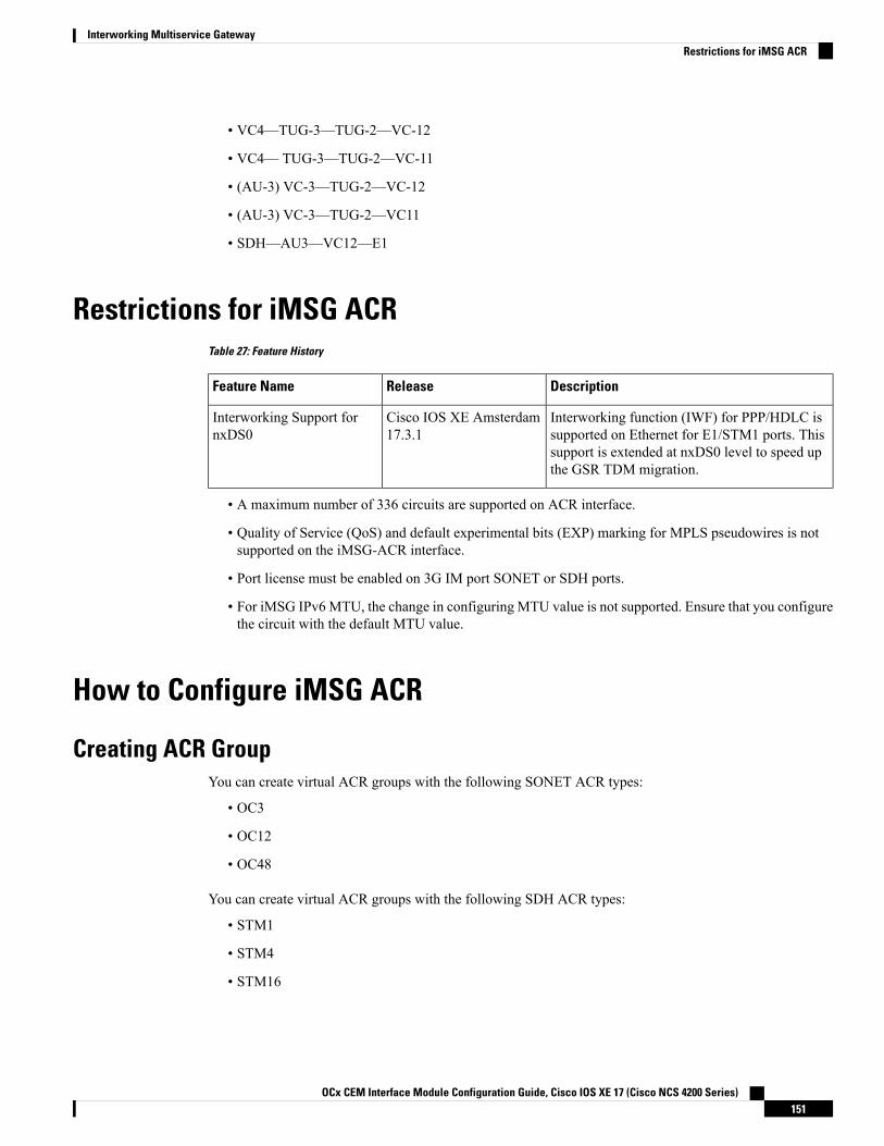
• VC4—TUG-3—TUG-2—VC-12
• VC4— TUG-3—TUG-2—VC-11
• (AU-3) VC-3—TUG-2—VC-12
• (AU-3) VC-3—TUG-2—VC11
• SDH—AU3—VC12—E1
Restrictions for iMSG ACRTable 27: Feature History
DescriptionReleaseFeature Name
Interworking function (IWF) for PPP/HDLC issupported on Ethernet for E1/STM1 ports. Thissupport is extended at nxDS0 level to speed upthe GSR TDM migration.
Cisco IOS XE Amsterdam17.3.1
Interworking Support fornxDS0
• A maximum number of 336 circuits are supported on ACR interface.
• Quality of Service (QoS) and default experimental bits (EXP) marking for MPLS pseudowires is notsupported on the iMSG-ACR interface.
• Port license must be enabled on 3G IM port SONET or SDH ports.
• For iMSG IPv6 MTU, the change in configuring MTU value is not supported. Ensure that you configurethe circuit with the default MTU value.
How to Configure iMSG ACR
Creating ACR GroupYou can create virtual ACR groups with the following SONET ACR types:
• OC3
• OC12
• OC48
You can create virtual ACR groups with the following SDH ACR types:
• STM1
• STM4
• STM16
OCx CEM Interface Module Configuration Guide, Cisco IOS XE 17 (Cisco NCS 4200 Series)151
Interworking Multiservice GatewayRestrictions for iMSG ACR

To create ACR group, enter the following commands:
rotuer(config)#ACR <id> type <type-id>
Configuring ACR Group on APSYou can configure ACR group on APS. The ACR group supported range is from 1 to 96. Any group numberexceeding the range is not supported. You can configure the interface as working using the circuit number.The circuit number identies a particular channel in the APS pair. Since the interface only supports 1 + 1redundancy, the only valid and the default value for working interface is 1.
The APS group created can be active or inactive:
• Active—The interface that is currently sending and receiving data.
• Inactive—The interface that is currently standing by to take over when the active fails.
APS is supported in revertive and non-revertive mode and can be configured as undirectional and bidirectional.Note
To configure ACR group on APSwith SONET interface as a working interface, enter the following commands:
configure terminalcontroller sonet slot/subslot/portaps group acr-idaps working circuit-numberaps group acr <acr_id>
To configure ACR group on APS with SDH interface as a working interface, enter the following commands:
configure terminalcontroller sdh slot/subslot/portaps group acr-idaps working circuit-numberaps group acr <acr_id>
You can configure an interface to be protect interface in the APS pair. Because only 1+1 redundancy issupported, the only valid value is 1, and the protect interface defaults to 1.
While specifying ACR ID, you need to specify an IP address for the loopback interface. The protect interfaceuses this IP address to communicate with the working interface.
To configure ACR group on APS with SONET interface as a protect interface, enter the following commands:
configure terminalcontroller sonet slot/subslot/portaps group acr-idaps protect <acr_id> <any-loopback-ip-address>aps group acr <acr_id>
To configure ACR group on APS with SDH interface as a protect interface, enter the following commands:
configure terminalcontroller sdh slot/subslot/port
OCx CEM Interface Module Configuration Guide, Cisco IOS XE 17 (Cisco NCS 4200 Series)152
Interworking Multiservice GatewayConfiguring ACR Group on APS

aps group acr-idaps protect <acr_id> <any-loopback-ip-address>aps group acr <acr_id>
The following example explains how to configure ACR group on APS with SONET interface asworking interface:Router# configure terminalRouter (config)# controller sonet 0/1/0Router(config-controller)# aps group 1Router (config-controller)# aps working 1Router (config-controller)# aps group acr 1
The following example explains how to configure ACR group on APS with SONET interface asprotect interface:Router# configure terminalRouter (config)# controller sonet 0/2/0Router(config-controller)# aps group 1Router (config-controller)# aps protect 1 10.1.1.1Router (config-controller)# aps group acr 1
The following example explains how to configure ACR group on APSwith SDH interface as workinginterface:Router# configure terminalRouter (config)# controller sdh 0/3/0Router(config-controller)# aps group 1Router (config-controller)# aps working 1Router (config-controller)# aps group acr 1
The following example explains how to configure ACR group on APS with SDH interface as protectinterface:Router# configure terminalRouter (config)# controller sdh 0/4/0Router(config-controller)# aps group 1Router (config-controller)# aps protect 1 10.1.1.1Router (config-controller)# aps group acr 1
Creating Serial Interface for SONET ACRYou can create serial interface for SONET ACR on VT 1.5, CT-3, and T3 modes.
Creating Serial Interface for SONET ACR on VT 1.5 ModeTo create serial interface for SONET ACR on VT 1.5 mode, enter the following commands:
controller SONET-ACR <ACR-ID>sts-1 1mode vt-15vtg <vtg_num> t1 <t1_num> channel-group <channel_num> timeslots 1-24vtg <vtg_num> t1 <t1_num> channel-group <channel_num> timeslots 1
The following example describes how to create serial interface on VT 1.5mode for SONET controller:
controller SONET-ACR 100sts-1 2
OCx CEM Interface Module Configuration Guide, Cisco IOS XE 17 (Cisco NCS 4200 Series)153
Interworking Multiservice GatewayCreating Serial Interface for SONET ACR

mode vt-15vtg 1 t1 1 channel-group 0 timeslots 1-24vtg 2 t1 2 channel-group 1 timeslots 1
Creating Serial Interface for SONET ACR on CT3 ModeTo create serial interface for SONET ACR on CT-3 mode, enter the following commands:
controller SONET-ACR <ACR-ID>sts-1 1mode ct3t3 framing c-bitt1 <t1_num> channel-group <channel_num> timeslots 1-24
The following example describes how to create serial interface on CT-3mode for SONET controller:
controller SONET-ACR 100sts-1 1mode ct3t3 framing c-bitt1 1 channel-group 0 timeslots 1-24
Creating Serial Interface for SONET ACR on T3 ModeTo create serial interface for SONET ACR on T3 mode, enter the following commands:
controller SONET-ACR <ACR-ID>sts-1 3mode t3t3 framing c-bitt3 channel-group 0
The following example describes how to create serial interface on T3 mode for SONET controller:
controller SONET-ACR 100sts-1 3mode t3t3 framing c-bitt3 channel-group 0!
Creating Serial Interface for SONET ACR on PoS ModeTo create serial interface for SONET ACR on PoS mode, enter the following commands
controller SONET-ACR 50sts-1 1 - 3 mode sts-3cchannel-group 0
Creating Serial Interface for SONET non-ACR on PoS ModeTo create serial interface for SONET non-ACR on STS-12c mode, enter the following commands:
OCx CEM Interface Module Configuration Guide, Cisco IOS XE 17 (Cisco NCS 4200 Series)154
Interworking Multiservice GatewayCreating Serial Interface for SONET ACR on CT3 Mode

configure terminalcontroller SONET <slot>/<subslot>/<port>
rate OC12sts-1 1 – 12 mode sts-12cchannel-group 0
To create serial interface for SONET non-ACR on STS-48c mode, enter the following commands:
configure terminalcontroller SONET <slot>/<subslot>/<port>rate OC48sts-1 1 – 48 mode sts-48cchannel-group 0
Creating Serial Interface for SDH ACRTo create serial interface for SDH ACR on T1, enter the following commands:
configure terminalcontroller sdh-acr <acr-ID>aug mapping au-4au-4 1mode tug-3tug-3 1mode vc1xTug-2 1 payload vc12t1 1 channel-group 0 timeslots 1 - 24
To create serial interface for SDH ACR on E1, enter the following commands:
enableconfigure terminalcontroller sdh-acr 200aug mapping au-4au-4 1mode tug-3tug-3 1mode vc1xTug-2 1 payload vc12e1 1 channel-group 0 timeslots 1 - 31
The following example explains how to create serial interface for SDH ACR on T1:
configure terminalcontroller sdh-acr 200aug mapping au-4au-4 1mode tug-3tug-3 1mode vc1xTug-2 1 payload vc12t1 1 channel-group 0 timeslots 1 - 24
The following example explains how to create serial interface for SDH ACR on E1:
enableconfigure terminal
OCx CEM Interface Module Configuration Guide, Cisco IOS XE 17 (Cisco NCS 4200 Series)155
Interworking Multiservice GatewayCreating Serial Interface for SDH ACR

controller sdh-acr 300aug mapping au-4au-4 1mode tug-3tug-3 1mode vc1xTug-2 1 payload vc12e1 1 channel-group 0 timeslots 1 - 31
Creating Serial Interface for SDH ACR on PoS ModeTo create serial interface for SDH ACR on PoS mode, enter the following commands
controller SDH-ACR 50aug mapping au-4au-4 1mode vc4Channel-group 0
Creating Serial Interface for SDH non-ACR on PoS ModeTo create serial interface for SDH non-ACR on VC4-4c Mode, enter following commands under physicalcontroller:
configure terminalcontroller SDH <slot>/<subslot>/<port>rate STMau-4 1 – 4 mode vc4-4cchannel-group 0
To create serial interface for SDH non-ACR on VC4-16c Mode, enter following commands under physicalcontroller:
configure terminalcontroller SDH <slot>/<subslot>/<port>rate STM16au-4 1 - 16 mode vc4-16cchannel-group 0
Modifying Encapsulation to PPPBy default the encapsulation is HDLC, and you can change the encapsulation to PPP.
To modify encapsulation to PPP, enter the following commands:
router(config)#interface SERIAL-ACR148.1router(config-if)#no ip addressrouter(config-if)# encapsulation ppp
Configuring IPv4 and IPv6 Interworking PseudowireTo configure IPv4 interworking pseudowire class, enter the following commands:
pseudowire-class <PW_class_name>
OCx CEM Interface Module Configuration Guide, Cisco IOS XE 17 (Cisco NCS 4200 Series)156
Interworking Multiservice GatewayCreating Serial Interface for SDH ACR on PoS Mode

encapsulation mplsinterworking ipcontrol-word
To configure IPv6 interworking pseudowire interface, enter the following commands:
interface pseudowire<pw-number>encapsulation mplsneighbor <peer-address> <vcid-value>control-word include
Based on the far-end router, the control-word needs to be enabled or disabled.Note
The following example describes how to configure IPv4 interworking pseudowire class:
pseudowire-class PW_class_nameencapsulation mplsinterworking ipcontrol-word
The following example describes how to configure IPv6 interworking pseudowire interface:
interface pseudowire30encapsulation mplsneighbor 10.2.2.2 30control-word include
Configuring Cross-Connect on Serial InterfaceThe xconnect command binds the attachment circuit to a pseudowire for cross connect service. The identifiercreates the binding between a pseudowire that is configured on a PE router and an attachment circuit in a CEdevice.
To perform IPv4 cross connection between a pseudowire and attachment circuit, use the following commands:
router(config)#interface serial-ACR1.29router(config-if)#xconnect ip-address vc_num pw-class class-name
To perform IPv6 cross connection between a pseudowire and attachment circuit, use the following commands:
router(config)#l2vpn xconnect context <xconnect name>router(config-xconnect)#interworking ipv6router(config-xconnect)#member pseudowire pw-numberrouter(config-xconnect)#member serial-ACR
The following example shows IPv6 cross connection between a pseudowire and attachment circuit:
l2vpn xconnect context pw_30_acr_vt15interworking ipv6member pseudowire30member serial-ACR1.29
OCx CEM Interface Module Configuration Guide, Cisco IOS XE 17 (Cisco NCS 4200 Series)157
Interworking Multiservice GatewayConfiguring Cross-Connect on Serial Interface

Verifying iMSG ACR
Verifying iMSG ACR with HDLC EncapsulationUse the following show aps group and show interface SERIAL-ACR commands to verify iMSGACR with HDLC encapsulation on the SONET or SDH controller:
router# show aps group 100SONET 0/1/16 APS Group 100: protect channel 0 (Inactive) (HA)
Working channel 1 at 10.1.1.3 (Enabled) (HA)unidirectional, ADM, non-revertivePGP timers (extended for HA): hello time=1; hold time=10
hello fail revert time=120SONET framing; SONET APS signalling by defaultReceived K1K2: 0x11 0x04
Do Not Revert (working)Transmitted K1K2: 0x00 0x04
No Request (Null)Remote APS configuration: (null)
SONET 0/4/16 APS Group 100: working channel 1 (Active) (HA)Protect at 10.1.1.3 (unidirectional, non-revertive)PGP timers (from protect): hello time=1; hold time=10SONET framingRemote APS configuration: (null)
router# show aps group 300SDH 0/3/0 APS Group 300: protect channel 0 (Inactive) (HA)
Working channel 1 at 10.1.1.3 (Enabled) (HA)unidirectional, ADM, non-revertivePGP timers (extended for HA): hello time=1; hold time=10
hello fail revert time=120SDH framing; SDH APS signalling by defaultReceived K1K2: 0x11 0x04
Do Not Revert (working)Transmitted K1K2: 0x00 0x04
No Request (Null)Remote APS configuration: (null)
SDH 0/3/1 APS Group 300: working channel 1 (Active) (HA)Protect at 10.1.1.3 (unidirectional, non-revertive)PGP timers (from protect): hello time=1; hold time=10SDH framingRemote APS configuration: (null)
router#show interface SERIAL-ACR100.1SERIAL-ACR100.1 is up, line protocol is upHardware is N/AMTU 1500 bytes, BW 1536 Kbit/sec, DLY 20000 usec,
reliability 255/255, txload 1/255, rxload 1/255Encapsulation HDLC, crc 16, loopback not setKeepalive set (10 sec)Last input 00:00:05, output 00:00:02, output hang neverLast clearing of "show interface" counters neverInput queue: 0/375/0/0 (size/max/drops/flushes); Total output drops: 0Queueing strategy: fifoOutput queue: 0/40 (size/max)30 second input rate 0 bits/sec, 0 packets/sec30 second output rate 0 bits/sec, 0 packets/sec
70 packets input, 10902 bytes, 0 no buffer
OCx CEM Interface Module Configuration Guide, Cisco IOS XE 17 (Cisco NCS 4200 Series)158
Interworking Multiservice GatewayVerifying iMSG ACR

Received 0 broadcasts (0 IP multicasts)0 runts, 0 giants, 0 throttles0 input errors, 0 CRC, 0 frame, 0 overrun, 0 ignored, 0 abort57 packets output, 2508 bytes, 0 underruns0 output errors, 0 collisions, 0 interface resets20 unknown protocol drops0 output buffer failures, 0 output buffers swapped out7 carrier transitions no alarm present
VC 1: timeslot(s): 1-24, Transmitter delay 0, non-inverted data
Use the following show interface SERIAL-ACR commands to verify HDLC ACR configuration onthe SDH controller:
router#show int SERIAL-ACR148.1SERIAL-ACR148.1 is up, line protocol is upHardware is N/AMTU 1500 bytes, BW 44210 Kbit/sec, DLY 20000 usec,
reliability 255/255, txload 1/255, rxload 1/255Encapsulation HDLC, crc 16, loopback not setKeepalive set (10 sec)Last input 00:00:07, output 00:00:06, output hang neverLast clearing of "show interface" counters 01:16:15Input queue: 0/375/0/0 (size/max/drops/flushes); Total output drops: 0Queueing strategy: fifoOutput queue: 0/40 (size/max)30 second input rate 0 bits/sec, 0 packets/sec30 second output rate 0 bits/sec, 0 packets/sec
122925 packets input, 16492939 bytes, 0 no bufferReceived 0 broadcasts (0 IP multicasts)0 runts, 0 giants, 0 throttles0 input errors, 0 CRC, 0 frame, 0 overrun, 0 ignored, 0 abort744239 packets output, 41162791 bytes, 0 underruns0 output errors, 0 collisions, 0 interface resets85 unknown protocol drops0 output buffer failures, 0 output buffers swapped out0 carrier transitions alarm present
DSU mode 0, bandwidth 0 Kbit, scramble 0, VC 1, non-inverted data
Verifying iMSG ACR with PPP EncapsulationUse the followingshow interface SERIAL-ACR command to verify iMSGACRwith PPP encapsulationon the SONET or SDH controller:
router#show interface SERIAL-ACR100.1SERIAL-ACR100.1 is up, line protocol is upHardware is N/AMTU 1500 bytes, BW 1536 Kbit/sec, DLY 20000 usec,
reliability 255/255, txload 2/255, rxload 2/255Encapsulation PPP, LCP OpenStopped: TAGCPOpen: IPCP, crc 16, loopback not setKeepalive set (10 sec)Last input 00:00:00, output 00:00:00, output hang neverLast clearing of "show interface" counters 03:28:29Input queue: 0/375/0/0 (size/max/drops/flushes); Total output drops: 0Queueing strategy: fifoOutput queue: 0/40 (size/max)5 minute input rate 14000 bits/sec, 1185 packets/sec5 minute output rate 14000 bits/sec, 1185 packets/sec
14628274 packets input, 25965577 bytes, 0 no bufferReceived 0 broadcasts (0 IP multicasts)
OCx CEM Interface Module Configuration Guide, Cisco IOS XE 17 (Cisco NCS 4200 Series)159
Interworking Multiservice GatewayVerifying iMSG ACR with PPP Encapsulation

0 runts, 0 giants, 0 throttles0 input errors, 0 CRC, 0 frame, 0 overrun, 0 ignored, 0 abort14628402 packets output, 26013374 bytes, 0 underruns0 output errors, 0 collisions, 1 interface resets0 unknown protocol drops0 output buffer failures, 0 output buffers swapped out2 carrier transitions
PW stats14625804 input packets ,14625930 output packets,1872102912 input bytes, 1872119040 output bytes, 0 input packet dropno alarm presentVC 1: timeslot(s): 1-24, Transmitter delay 0, non-inverted data
Verifying iMSG ACR with HDLC Encapsulation on PoS ModeUse the following show interfaces SERIAL-ACR<acr-id>.<path-number> command to verify iMSG ACRwith HDLC encapsulation on PoS mode for SONET or SDH controller.
Router#show interfaces serial-acr50.1SERIAL-ACR50.1 is up, line protocol is upHardware is N/AMTU 1500 bytes, BW 155000 Kbit/sec, DLY 100 usec,
reliability 255/255, txload 1/255, rxload 1/255Encapsulation HDLC, crc 16, loopback not setKeepalive set (10 sec)Last input 00:00:09, output 00:00:05, output hang neverLast clearing of "show interface" counters 00:00:27Input queue: 0/375/0/0 (size/max/drops/flushes); Total output drops: 0Queueing strategy: fifoOutput queue: 0/40 (size/max)5 minute input rate 0 bits/sec, 0 packets/sec5 minute output rate 0 bits/sec, 0 packets/sec
102 packets input, 10688 bytesReceived 0 broadcasts (0 IP multicasts)0 runts, 0 giants, 0 throttles0 input errors, 0 CRC, 0 frame, 0 overrun, 0 ignored, 0 abort103 packets output, 10732 bytes, 0 underruns0 output errors, 0 collisions, 0 interface resets0 unknown protocol drops0 output buffer failures, 0 output buffers swapped out0 carrier transitions
PW stats100 input packets ,100 output packets,10000 input bytes, 10000 output bytes, 0 input packet dropno alarm presentVC:1, Non-inverted data
Verifying iMSG ACR with PPP Encapsulation on PoS ModeUse the following show interfaces SERIAL-ACR<acr-id>.<path-number> command to verify iMSG ACRwith PPP encapsulation on PoS mode for SONET or SDH controller.
Router#show interfaces serial-acr50.85SERIAL-ACR50.85 is up, line protocol is upHardware is N/AMTU 1500 bytes, BW 155000 Kbit/sec, DLY 100 usec,
reliability 255/255, txload 1/255, rxload 1/255Encapsulation PPP, LCP OpenStopped: TAGCP
OCx CEM Interface Module Configuration Guide, Cisco IOS XE 17 (Cisco NCS 4200 Series)160
Interworking Multiservice GatewayVerifying iMSG ACR with HDLC Encapsulation on PoS Mode

Open: IPCP, crc 16, loopback not setKeepalive set (10 sec)Last input 00:00:01, output 00:00:01, output hang neverLast clearing of "show interface" counters 00:00:11Input queue: 0/375/0/0 (size/max/drops/flushes); Total output drops: 0Queueing strategy: fifoOutput queue: 0/40 (size/max)5 minute input rate 0 bits/sec, 0 packets/sec5 minute output rate 0 bits/sec, 0 packets/sec
104 packets input, 10776 bytesReceived 0 broadcasts (0 IP multicasts)0 runts, 0 giants, 0 throttles0 input errors, 0 CRC, 0 frame, 0 overrun, 0 ignored, 0 abort104 packets output, 10776 bytes, 0 underruns0 output errors, 0 collisions, 0 interface resets0 unknown protocol drops0 output buffer failures, 0 output buffers swapped out0 carrier transitions
PW stats100 input packets ,100 output packets,10000 input bytes, 10000 output bytes, 0 input packet dropno alarm presentVC:85, Non-inverted data
OCx CEM Interface Module Configuration Guide, Cisco IOS XE 17 (Cisco NCS 4200 Series)161
Interworking Multiservice GatewayVerifying iMSG ACR with PPP Encapsulation on PoS Mode

OCx CEM Interface Module Configuration Guide, Cisco IOS XE 17 (Cisco NCS 4200 Series)162
Interworking Multiservice GatewayVerifying iMSG ACR with PPP Encapsulation on PoS Mode

C H A P T E R 9Multilink Interfaces
Starting with Cisco IOS XE Amsterdam 17.1.x, the router supports configuring the multilink interfaces.
• MLPPP, on page 163• MLPPP Interworking, on page 163• MLPPP Layer 3 Termination, on page 164• MLPPP ACR Support for iMSG, on page 165• Multilink PPP Minimum Links Mandatory, on page 165• Restrictions for MLPPP, on page 165• Restrictions for MLPPP Interworking, on page 166• Restrictions for MLPPP Layer 3 Termination, on page 166• Restriction for MLPPP ACR, on page 166• How to Configure MLPPP, on page 167• How to Configure MLPPP Interworking, on page 169• How to Configure MLPPP Layer 3 Termination, on page 171• How to Configure Multilink PPP Minimum Links Mandatory, on page 172
MLPPPTheMultilink Point-to-Point (MLPPP) feature enables you to create multilinks using an LCP option negotiationbetween two end points. The router A indicates to its peer router B that it is capable of combining multiplephysical links into a logical bundle. Once the LCP negotiation is complete, the router A sends the multilinkoption to the router B and creates multilinks.
Starting with Cisco IOS XE 17.1.x, Multiprotocol Label Switching (MPLS) is supported over Multilink PPP(MLP) links in an access interface.
MLPPP InterworkingThe MLPPP interworking supports IPv4 or IPv6 Layer 2 VPN Interworking with T1 or E1 bundles on theCisco RSP3 module.
The MLPPP interworking enables service providers (offering relatively low-speed links) to use MLP andspread traffic across them in their MPLS networks. The MPLS Multilink PPP feature reduces the number ofInterior Gateway Protocol (IGP) adjacencies and facilitates load sharing of traffic.
OCx CEM Interface Module Configuration Guide, Cisco IOS XE 17 (Cisco NCS 4200 Series)163

The MLPPP creates bundle in the following manner:
• T1 and E1 members should be from the same interface module.
• T1 and E1 members should be of the same port type. For example, if MLPPP link is from the T1, E1, orOCx ports, then only the links from the respective T1, E1, or OCx ports can be bundled together.
• Supports a maximum of 510 MLPPP pseudowires per interface module and 510 MLPPP pseudowiresper router.
The following table details the number of bundles created in a module.
Table 28: MLPPP Bundle Created for Cisco RSP3 Module:
Maximum Number of Bundles inCisco RSP3 Module
Number of VLANs UsedNumber of Links in a Bundle
1020/2 = 51021
1020/3 = 34032
1020/17 = 601716
MLPPP Layer 3 TerminationTable 29: Feature History
DescriptionRelease InformationFeature Name
This release supports Layer 3termination using IPv6 addressingon MLPPP interfaces for the 1 portOC-48/STM-16 or 4 portOC-12/OC-3 / STM-1/STM-4 + 12port T1/E1 + 4 port T3/E3 CEMinterface module. In releasesearlier, with IPv4 addressing, youcan scale up to 512 MLPPPbundles. Now with IPv6addressing, theMLPPP bundles canbe scaled up to 1024.
Cisco IOS XE Bengaluru 17.5.1MLPPP IP Termination on allSerial Physical and LogicalInterfaces
Starting with Cisco IOS XE Bengaluru 17.5.1, you can perform Layer 3 termination using IPv6 addressingon MLPPP interfaces on Cisco RSP3 modules. In releases earlier, with IPv4 addressing, you can scale up to512 MLPPP bundles. Now with IPv6 addressing, the MLPPP bundles can be scaled up to 1024.
OCx CEM Interface Module Configuration Guide, Cisco IOS XE 17 (Cisco NCS 4200 Series)164
Interworking Multiservice GatewayMLPPP Layer 3 Termination
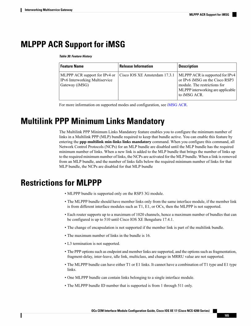
MLPPP ACR Support for iMSGTable 30: Feature History
DescriptionRelease InformationFeature Name
MLPPPACR is supported for IPv4or IPv6 iMSG on the Cisco RSP3module. The restrictions forMLPPP interworking are applicableto iMSG ACR.
Cisco IOS XE Amsterdam 17.3.1MLPPP ACR support for IPv4 orIPv6 Interworking MultiserviceGateway (iMSG)
For more information on supported modes and configuration, see iMSG ACR.
Multilink PPP Minimum Links MandatoryThe Multilink PPP Minimum Links Mandatory feature enables you to configure the minimum number oflinks in a Multilink PPP (MLP) bundle required to keep that bundle active. You can enable this feature byentering the ppp multilink min-links links mandatory command. When you configure this command, allNetwork Control Protocols (NCPs) for an MLP bundle are disabled until the MLP bundle has the requiredminimum number of links. When a new link is added to the MLP bundle that brings the number of links upto the required minimum number of links, the NCPs are activated for theMLP bundle.When a link is removedfrom an MLP bundle, and the number of links falls below the required minimum number of links for thatMLP bundle, the NCPs are disabled for that MLP bundle
Restrictions for MLPPP• MLPPP bundle is supported only on the RSP3 3G module.
• The MLPPP bundle should have member links only from the same interface module, if the member linkis from different interface modules such as T1, E1, or OCx, then the MLPPP is not supported.
• Each router supports up to a maximum of 1020 channels, hence a maximum number of bundles that canbe configured is up to 510 until Cisco IOS XE Bengaluru 17.4.1.
• The change of encapsulation is not supported if the member link is part of the multilink bundle.
• The maximum number of links in the bundle is 16.
• L3 termination is not supported.
• The PPP options such as endpoint and member links are supported, and the options such as fragmentation,fragment-delay, inter-leave, idle link, multiclass, and change in MRRU value are not supported.
• The MLPPP bundle can have either T1 or E1 links. It cannot have a combination of T1 type and E1 typelinks.
• One MLPPP bundle can contain links belonging to a single interface module.
• The MLPPP bundle ID number that is supported is from 1 through 511 only.
OCx CEM Interface Module Configuration Guide, Cisco IOS XE 17 (Cisco NCS 4200 Series)165
Interworking Multiservice GatewayMLPPP ACR Support for iMSG
• Fragmentation is not supported.
• NCP, queue, and slippage are not supported.
• Change in MRRU and MTU values on multilink interface is not supported.
• The maximum number of multilink (max-link) configuration is supported in the MLPPP bundle. If themax-link value is configured as five, then the five links are active in the bundle. If one of five activelinks goes down, then there is no back-up link to become active..
• The member links of the MLPPP bundle cannot be combined from different port types such as T1, T3,and SONET.
• Multiport is not supported for MLPPP.
Restrictions for MLPPP Interworking• The router supports links equal to T1 or E1 for MLPPP bundling. You cannot bundle high-speed links(for example, E3) as the interface module can store only 50 ms of data based on the E1 speed.
• Each MLPPP bundle supports up to a maximum of 16 member links.
• Each MLP Bundle can have serial links from the same interface module or port type only.
• The MTU value supported is 1500 and MRRU should be more than the value of MTU, which is 1504.
• The jumbo frames are not supported.
• The keepalive is based on the first serial link attached to the MLP bundle.
Restrictions for MLPPP Layer 3 Termination• In the Cisco IOS XE Bengaluru 17.5.1, the maximum number of Layer 3 MLPPP interfaces that aresupported is 1000.
• MTU cannot be configured on the MLPPP bundle, and can be configured only on individual members.
• NxDS0 serial interfaces cannot be part of the MLPPP bundle.
• Starting with Cisco IOS XE Bengaluru 17.5.1, when you scale up MLPPP, ensure that you use thefollowing commands under the interface:
• ppp timeout retry <retry no>
• keepalive <keepalive no>
Restriction for MLPPP ACR• The MLPPP ACR is supported only on the RSP3 3G module.
OCx CEM Interface Module Configuration Guide, Cisco IOS XE 17 (Cisco NCS 4200 Series)166
Interworking Multiservice GatewayRestrictions for MLPPP Interworking

• Each router supports upto a total of 510 serial ACR interfaces. Hence, a total of 255 bundles can beconfigured, provided each MLPPP bundle has two links.
• Serial ACR and the other serial interface cannot be a part of the same bundle.
• Layer 3 termination not supported.
• A maximum number of links supported in an MLPPP bundle is 16.
• The change of encapsulation is not supported if the serial ACR interface is a part of the MLPPP bundle.
Restrictions for MLPPP interworking and iMSG ACR are applicable for MLPPP ACR.Note
How to Configure MLPPP
Configuring MLPPPTo create the MLP interface, enter the following commands:
router(config)#interface multilink <group_number>
To add a PPP member to the channel, use the ppp multilink group <group_number> command. Thiscommand binds the serial interface with the corresponding multilink number (it typically adds the interfaceto the multilink). The PPP timeout retry should be added under the link if it’s a part of the MLPPP ACRbundle.
The same configuration should be performed on the CE bundle links serial interface.
interface serial x/y/z.<channel_id>encapsulation pppppp multilink group <group_number>ppp timeout retry 1
Two keys define the identity of a remote system: the PPP username andMultilink PPP endpoint discriminator.PPP authenticationmechanisms (for example, password authentication protocol [PAP] or Challenge-HandshakeAuthentication Protocol [CHAP]) learn the PPP username. The endpoint discriminator is an option negotiatedby the Link Control Protocol (LCP). Therefore, a bundle consists of links that have the same PPP usernamesand endpoint discriminators.
The multilink group number is local to the system. However, for links to be a part of the bundle, the end-pointdiscriminator helps to correctly identify which bundle the link needs to be part of. This end-point discriminatorneeds to be the same on both ends of the multilink.
interface serial<interface-name>ppp multilink group <>ppp multilink endpoint string <unique string>
The following example shows how to configure multilink interface:
interface multilink 30
OCx CEM Interface Module Configuration Guide, Cisco IOS XE 17 (Cisco NCS 4200 Series)167
Interworking Multiservice GatewayHow to Configure MLPPP

ppp multilink endpoint string T1_multilinkinterface serial0/3/4.1encapsulation pppppp multilink group 30ppp timeout retry 1
Configuring MLPPP ACRTo create the MLP interface, enter the following commands:
router(config)#interface multilink <group_number>
To configure MLPPP ACR, enter the following commands:
The PPP timeout retry should be added under the link if it is a part of the MLPPP ACR bundle.
The same configuration should be performed on the CE bundle links serial interface.
serial-acr<group number.channel id>encapsulation pppppp multilink group <group_number>ppp timeout retry 1
The following example shows how to configure MLPPP ACR:
inter SERIAL-ACR3.1encapsulation pppppp multilink group 1ppp timeout retry 1
For more information to create serial ACR interface, see iMSG ACR.
Deleting Serial Interface from an Active MLPPP BundleTo remove a serial interface from the member link bundle, perform the following steps:
1. Shut the member link and ensure that the serial interface moves to down state on the other side of thebundle.
2. Remove the serial interface link from the MLPPP bundle using the no ppp multilink group <group-id>command.
Removing MLPPP ConfigurationTo delete the MLPPP bundle, you need to remove the serial interfaces linked to the bundle, and then removelink from the the serial interfaces.
To delete the MLPPP bundle, enter the following commands:
Router#configure terminalrouter(config)#interface multilink <group_number>router(config)#interface serial x/y/z.<channel_id>router(config-if)#no ppp multilink group <multilink-id>router(config-if)#no ppp multilink
OCx CEM Interface Module Configuration Guide, Cisco IOS XE 17 (Cisco NCS 4200 Series)168
Interworking Multiservice GatewayConfiguring MLPPP ACR

To delete the multilink interface, you need to shut the multilink interface, and then delete the interface.
To delete the multilink interface, enter the following commands:
Router#config terminalRouter(config)#interface multilink <multilink-id>Router(config-if)#shutdownRouter(config-if)#exitRouter(config)#no interface multilink <multilink-id>
Verifying MLPPP ConfigurationTo view the multilink bundle status and describes all the bundle parameter and details, use the Show pppmultilink active command:
router#Show ppp multilink activeBundle name: rsp3-vz-pe1Remote Endpoint Discriminator: [1] rsp3-vz-pe1Local Endpoint Discriminator: [1] ASR_1000_CE_1Bundle up for 00:07:00, total bandwidth 1536, load 1/255Receive buffer limit 12000 bytes, frag timeout 1000 msBundle is Distributed0/0 fragments/bytes in reassembly list0 lost fragments, 0 reordered0/0 discarded fragments/bytes, 0 lost received0x53 received sequence, 0x0 sent sequence
Platform Specific Multilink PPP infoNOTE: internal keyword not applicable on this platformInterleaving: Disabled, Fragmentation: Disabled
Member links: 1 active, 0 inactive (max 16, min not set)Se0/1/0.1/1/1:1, since 00:07:00
How to Configure MLPPP Interworking
Configuring L2VPN Interworking and Cross Connection under the AttachmentCircuit for Multilink Interfaces
Configuring L2VPN Interworking
To configure L2VPN interworking, create a pseudowire class with the tunneling encapsulation as MPLS. Theinterworking command specifies the type of payload traffic that flows across the pseudowire tunnel. Configurepseudowire class only once on a device.
You can also configure control-word as an optional command.
To configure L2VPN interworking, use the following commands:
router>enablerouter#configure terminalrouter(config)#interface pseudowire pw-numberrouter(config-if)# encapsulation mpls
OCx CEM Interface Module Configuration Guide, Cisco IOS XE 17 (Cisco NCS 4200 Series)169
Interworking Multiservice GatewayVerifying MLPPP Configuration

router(config-if)# neighbor <peer-address><vcid-value>router(config-xconnect)# control-word include
The following example shows how to configure L2VPN interworking:
interface pseudowire30encapsulation mplsneighbor 10.2.2.2 30control-word include
Configuring Cross-Connect Under Attachment Circuit
The xconnect command binds the attachment circuit to an L2VPN pseudowire for cross connect service.
The virtual circuit identifier creates the binding between a pseudowire that is configured on a PE router andan attachment circuit in a CE device.
To perform IPv4 cross connection between an AToM routed pseudowire and attachment circuit, use thefollowing commands:
router(config)#l2vpn xconnect context xconnect-namerouter(config-xconnect)#interworking iprouter(config-xconnect)#member pseudowire pw-numberrouter(config-xconnect)#member multilink <multilink-id>
To perform IPv6 cross connection between an AToM routed pseudowire and attachment circuit, use thefollowing commands:
router(config)#l2vpn xconnect context xconnect-namerouter(config-xconnect)#interworking ipv6router(config-xconnect)#member pseudowire pw-numberrouter(config-xconnect)#member multilink <multilink-id>
The following example shows how to configure IPv6 interworking and cross connection under theattahment circuit for multilink interfaces:
l2vpn xconnect context tempinterworking ipv6member Multilink1member Pseudowire 1
Verifying L2VPN Interworking and Cross-Connect ConfigurationYou can verify L2VPN interworking configuration using the following show commands:
• show mpls l2 vc <vc-id> detail
• show xconnect all—Displays cross connect configuration.
• show interfaces serial <interface-name>—Provides interface details such as encapsulation, loopback,payload, MTU, bandwidth, and so on for a specific port.
router#show interfaces serial0/1/12.1Serial0/1/12.1 is down, line protocol is downHardware is unknown
OCx CEM Interface Module Configuration Guide, Cisco IOS XE 17 (Cisco NCS 4200 Series)170
Interworking Multiservice GatewayVerifying L2VPN Interworking and Cross-Connect Configuration

MTU 1500 bytes, BW 44210 Kbit/sec, DLY 20000 usec,reliability 255/255, txload 1/255, rxload 1/255
Encapsulation HDLC, crc 16, loopback not setKeepalive set (10 sec)Last input never, output never, output hang neverLast clearing of "show interface" counters neverInput queue: 0/375/0/0 (size/max/drops/flushes); Total output drops: 0Queueing strategy: fifoOutput queue: 0/40 (size/max)5 minute input rate 0 bits/sec, 0 packets/sec5 minute output rate 0 bits/sec, 0 packets/sec
0 packets input, 0 bytes, 0 no bufferReceived 0 broadcasts (0 IP multicasts)0 runts, 0 giants, 0 throttles0 input errors, 0 CRC, 0 frame, 0 overrun, 0 ignored, 0 abort0 packets output, 0 bytes, 0 underruns0 output errors, 0 collisions, 1 interface resets0 unknown protocol drops0 output buffer failures, 0 output buffers swapped out0 carrier transitions alarm present
DSU mode 0, bandwidth 0 Kbit, scramble 0, VC 3, non-inverted data
router#show xconnect allLegend: XC ST=Xconnect State S1=Segment1 State S2=Segment2 StateUP=Up DN=Down AD=Admin Down IA=InactiveSB=Standby HS=Hot Standby RV=Recovering NH=No Hardware
XC ST Segment 1 S1 Segment 2 S2------+---------------------------------+--+---------------------------------+--DN pri mpls 10.2.2.2:30 DN ac Mu30(PPP) UP
How to Configure MLPPP Layer 3 Termination
Configuring MLPPP Layer 3 TerminationTo configure MLPPP Layer 3 termination, use the following commands:
router#configure terminalrouter(config)#interface Multilink multilinknorouter(config-if)#ip address ip-address subnetmaskrouter(config-if)#commit
The following example shows how to configure MLPPP Layer 3 termination for IPv4 address:
router#configure terminalrouter#interface Multilink 1001router#ip address 10.10.10.1 255.0.0.0
The following example shows how to configure MLPPP Layer 3 termination for IPv6 address:
router#configure terminalrouter#interface Multilink 1001router#ipv6 address 4001:1::2/64
OCx CEM Interface Module Configuration Guide, Cisco IOS XE 17 (Cisco NCS 4200 Series)171
Interworking Multiservice GatewayHow to Configure MLPPP Layer 3 Termination

How to Configure Multilink PPP Minimum Links Mandatory
Configuring Multilink PPP Minimum Links MandatoryBefore configuring multilink PPP minimum links mandatory, ensure that PPP and MLPPP are configured.
To configure the minimum number of links in an MLP bundle required to keep the bundle active, enter thefollowing commands:
Router(config-if)#interface multilink multilink-idRouter(config-if)#ppp multilink links minimum <nooflinks> mandatory
The following example shows the multilink PPP minimum links mandatory configuration:
interface multilink 3ppp multilinkppp multilink min-links 5 mandatory
Verifying the Multilink PPP Minimum Links Mandatory ConfigurationTo verify the multilink PPP minimum links mandatory configuration, use the following show commands:
• show running-config [interface type number] [linenum]—Displays the contents of the currentlyrunning configuration file or the configuration for a specific interface, or map class information.
• show interfaces multilink group-number—Displays statistics for the specified multilink bundle.
• show ppp multilink—Displays information about all existing multilink bundles and their member links.
• show interfaces multilink group-number stat—Displays traffic statistics for a multilink bundle.
Router# show run int multilink 10...Building configuration...
Current configuration : 160 bytes!interface Multilink10no ip addressppp multilinkppp multilink links minimum 3 mandatoryppp multilink group 10ppp multilink endpoint string TESTend
OCx CEM Interface Module Configuration Guide, Cisco IOS XE 17 (Cisco NCS 4200 Series)172
Interworking Multiservice GatewayHow to Configure Multilink PPP Minimum Links Mandatory

C H A P T E R 10VLAN Handoff
Table 31: Feature History
DescriptionReleaseFeature Name
Support for IPv4 and IPv6 with VLAN handofffor both cross connect and local connect onNCS4200-1T8S-20CS and NCS4200-3GMSInterface Module.
Cisco IOS XE Bengaluru17.4.1
CEM and IP IW FeatureParity forNCS4200-1T8S-20CS andNCS4200-3GMS InterfaceModules
VLAN handoff enables the support for IPinterworking Pseudowire. IP interworkingPseudowire enables the service provider toterminate the TDM circuit early in the networkand transport the IP payload on HDLC, PPP, orMLPPP links, over theMPLS core to the Ethernetnetwork.
Cisco IOS XE Amsterdam17.3.1
IP Interworking with VLANHandoff
This module describes the configuration of the VLAN handoff, which is an extension of the IP interworkingpseudowire. The VLAN handoff enables the support for IP interworking pseudowire between HDLC, PPP,or MLPPP channel links to Ethernet virtual circuits (EVC).
• Overview of VLAN Handoff, on page 173• IP Interworking Switching on Single Router, on page 174• Restrictions for VLAN Handoff, on page 174• Enabling the VLAN Handoff, on page 174• Configuring VLAN Handoff for IPv4 Local Connect, on page 175• Configuring VLAN Handoff for IPv4 Cross Connect, on page 177• Configuring VLAN Handoff for IPv6 Local Connect, on page 179• Configuring VLAN Handoff for IPv6 Cross Connect, on page 181
Overview of VLAN HandoffIP interworking pseudowire enables the service provider to terminate the TDM circuit early in the networkand transport the IP payload on HDLC, PPP, or MLPPP links to the Ethernet network.
OCx CEM Interface Module Configuration Guide, Cisco IOS XE 17 (Cisco NCS 4200 Series)173

IP Interworking Switching on Single RouterFigure 2: Local Connect Setup
IP PW (Type 11) terminated2Terminate the circuit locally. IP keywordextracts the IP packets and transports it overPW and creates PW (Type 11)
1
Restrictions for VLAN Handoff• Ingress logical interface range must be reserved, with not more than 4K EVCs that can be supported perASIC. This reduces the EVC scale from 16K to 8K, with a maximum of 4K EVCs per ASIC.
• You can configure only a maximum of 3998 serial interface or Interworking Multiservice Gateway(iMSG).
• For a ping to work, resolve the ARP from the Ethernet interface.
• VLAN handoff with a local connect over HDLC, PPP, or MLPPP is not supported when configured withport channel.
• Only IPv4 is supported until Cisco IOS XE Amsterdam 17.3.1.
Enabling the VLAN HandoffUse the enable_tdm_to_ip_iw command to enable the SDM template.
Router# config terminalRouter(config)# sdm prefer enable_tdm_to_ip_iw
Reload the router after you enable the template.
The new template is added and the ROMMON variable is set to 28.
TDM_TO_IP_FEAT_EXT_TEMPLATE = 28
OCx CEM Interface Module Configuration Guide, Cisco IOS XE 17 (Cisco NCS 4200 Series)174
Interworking Multiservice GatewayIP Interworking Switching on Single Router

You must reload the router for the new template to be effective.Note
Configuring VLAN Handoff for IPv4 Local ConnectBefore you begin
Interface module must be free from all configurations.
Procedure
Step 1 Configure the serial or MLPPP interface on a customer edge (CE).
To configure the interface on CE1, enter the following commands:
controller SONET 4/0/0framing sonetclock source line!sts-1 1mode vt-15vtg 1 t1 1 channel-group 0 timeslots 1-24
Step 2 Configure the serial or MLPPP interface on a provide edge (PE).
To configure the interface on PE, enter the following commands:
controller SONET 0/4/17framing sonetclock source line!sts-1 1mode vt-15vtg 1 t1 1 channel-group 0 timeslots 1-24
Step 3 Configure service instance on the Ethernet interface.
To configure service instance on the Ethernet interface, enter the following commands:
interface TenGigabitEthernet0/1/1no ip address
service instance 10 ethernetencapsulation dot1q 10rewrite ingress tag pop 1 symmetric!end
Only single tag EPF is supported.Note
Step 4 Bind the service instance and the serial interface under L2VPN xconnect.
OCx CEM Interface Module Configuration Guide, Cisco IOS XE 17 (Cisco NCS 4200 Series)175
Interworking Multiservice GatewayConfiguring VLAN Handoff for IPv4 Local Connect

To create L2VPN for local connect and bind the service instance and serial interface, enter the followingcommands:
l2vpn xconnect context vlan_handoff_10interworking ipmember Serial0/4/17.1member TenGigabitEthernet0/1/1 service-instance 10
Step 5 Configure the service instance on CE2 to terminate the traffic on BDI or VLAN.
To configure the service instance, enter the following commands:
interface TenGigabitEthernet0/12/1no ip addressservice instance 10 ethernetencapsulation dot1q 10rewrite ingress tag pop 1 symmetricbridge-domain 10!endinterface BDI10ip address 10.12.12.2 255.0.0.0no shut
Example - VLAN Handoff for IPv4 Local ConnectThe following is a sample VLAN handoff configuration for CE and PE respectively.Router# show running-config | sec 4/0/0controller SONET 4/0/0framing sonetclock source line!sts-1 1mode vt-15vtg 1 t1 1 channel-group 0 timeslots 1-24
Router# show ip int brief | i SeSerial4/0/0.1/1/1:0 10.12.12.1 YES manual up up
Serial Interface Configurationplatform enable controller MediaType 0/4/17 oc12controller MediaType 0/4/17mode sonetcontroller SONET 0/4/17no snmp trap link-statusrate OC12no ais-shutalarm-report allthreshold sf-ber 3clock source internal!sts-1 1clock source internalmode vt-15vtg 1 t1 1 channel-group 0 timeslots 1-24!
Gigabit Ethernet Configuration
OCx CEM Interface Module Configuration Guide, Cisco IOS XE 17 (Cisco NCS 4200 Series)176
Interworking Multiservice GatewayExample - VLAN Handoff for IPv4 Local Connect

interface TenGigabitEthernet0/1/1no ip addressservice instance 10 ethernetencapsulation dot1q 10rewrite ingress tag pop 1 symmetric!end
L2vpn xconnectl2vpn xconnect context vlan_handoff_10interworking ipmember Serial0/4/17.1member TenGigabitEthernet0/1/1 service-instance 10
Configuration on CE2
interface TenGigabitEthernet0/12/1no ip addressservice instance 10 ethernetencapsulation dot1q 10rewrite ingress tag pop 1 symmetricbridge-domain 10!end
interface BDI10ip address 10.12.12.2 255.0.0.0no shut
Router# show ip int brief | i BDIBDI10 10.12.12.2 YES manual up up
Configuring VLAN Handoff for IPv4 Cross ConnectFigure 3: Cross Connect Setup
Before you begin
Interface module must be free from all configurations.
OCx CEM Interface Module Configuration Guide, Cisco IOS XE 17 (Cisco NCS 4200 Series)177
Interworking Multiservice GatewayConfiguring VLAN Handoff for IPv4 Cross Connect
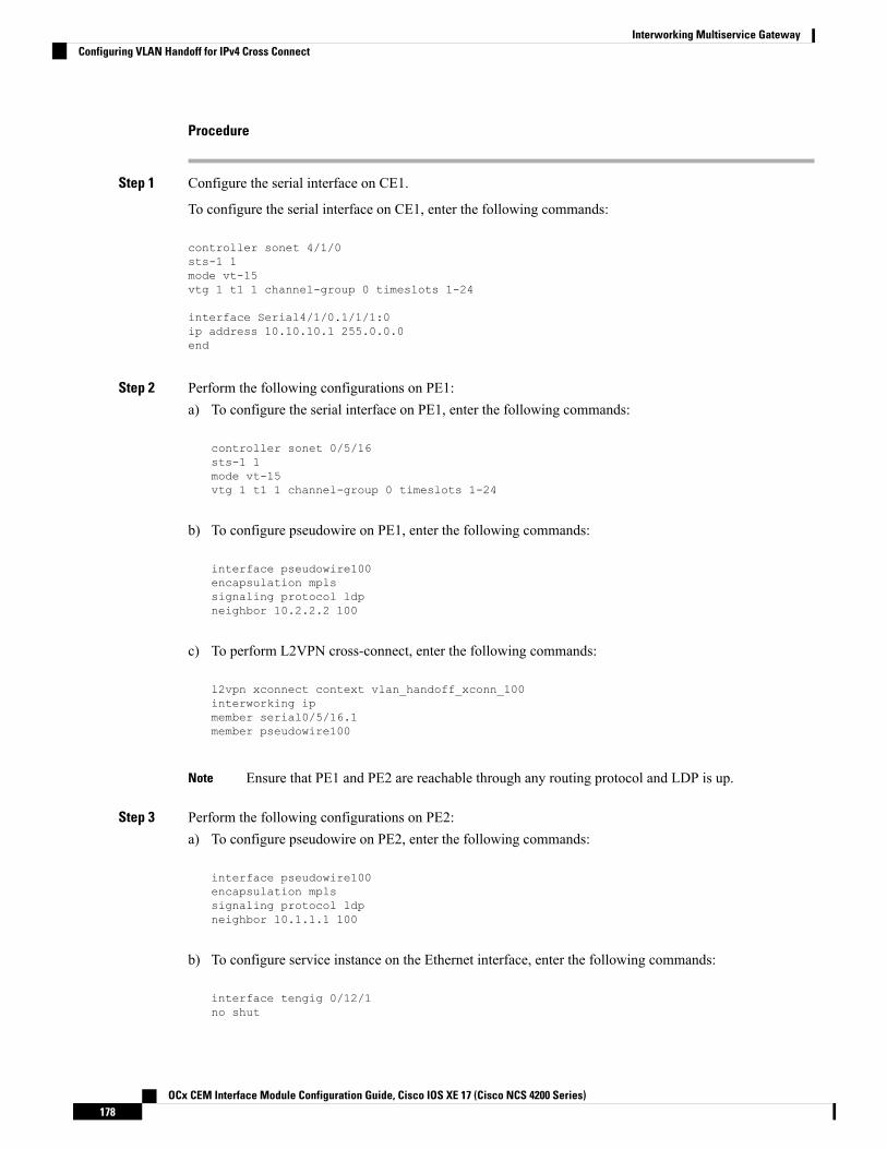
Procedure
Step 1 Configure the serial interface on CE1.
To configure the serial interface on CE1, enter the following commands:
controller sonet 4/1/0sts-1 1mode vt-15vtg 1 t1 1 channel-group 0 timeslots 1-24
interface Serial4/1/0.1/1/1:0ip address 10.10.10.1 255.0.0.0end
Step 2 Perform the following configurations on PE1:a) To configure the serial interface on PE1, enter the following commands:
controller sonet 0/5/16sts-1 1mode vt-15vtg 1 t1 1 channel-group 0 timeslots 1-24
b) To configure pseudowire on PE1, enter the following commands:
interface pseudowire100encapsulation mplssignaling protocol ldpneighbor 10.2.2.2 100
c) To perform L2VPN cross-connect, enter the following commands:
l2vpn xconnect context vlan_handoff_xconn_100interworking ipmember serial0/5/16.1member pseudowire100
Ensure that PE1 and PE2 are reachable through any routing protocol and LDP is up.Note
Step 3 Perform the following configurations on PE2:a) To configure pseudowire on PE2, enter the following commands:
interface pseudowire100encapsulation mplssignaling protocol ldpneighbor 10.1.1.1 100
b) To configure service instance on the Ethernet interface, enter the following commands:
interface tengig 0/12/1no shut
OCx CEM Interface Module Configuration Guide, Cisco IOS XE 17 (Cisco NCS 4200 Series)178
Interworking Multiservice GatewayConfiguring VLAN Handoff for IPv4 Cross Connect

interface tengig 0/12/1service instance 100 ethernetencapsulation dot1q 100rewrite ingress tag pop 1 symmetric
c) To perform L2VPN cross-connect, enter the following commands:
l2vpn xconnect context vlan_handoff_xconn_100interworking ipmember tengig0/12/1 service-instance 100member pseudowire100
Step 4 Terminate the serial interface on the Ethernet interface.
Terminate the serial interface on the Ethernet interface, enter the following commands:
interface tengig 0/4/0no shut
interface tengig 0/4/0service instance 100 ethernetencapsulation dot1q 100rewrite ingress tag pop 1 symmetricbridge-domain 100
interface BDI100ip add 10.10.10.2 255.0.0.0no shut
Configuring VLAN Handoff for IPv6 Local ConnectTable 32: Feature History
Before you begin
Interface module must be free from all configurations.
Procedure
Step 1 Configure the serial or MLPPP interface on a customer edge (CE).
To configure the interface on CE1, enter the following commands:
controller SONET 4/0/0framing sonetclock source line!sts-1 1mode vt-15vtg 1 t1 1 channel-group 0 timeslots 1-24
OCx CEM Interface Module Configuration Guide, Cisco IOS XE 17 (Cisco NCS 4200 Series)179
Interworking Multiservice GatewayConfiguring VLAN Handoff for IPv6 Local Connect

Step 2 Configure the serial or MLPPP interface on a provide edge (PE).
To configure the interface on PE, enter the following commands:
controller SONET 0/4/17framing sonetclock source line!sts-1 1mode vt-15vtg 1 t1 1 channel-group 0 timeslots 1-24
Step 3 Configure service instance on the Ethernet interface.
To configure service instance on the Ethernet interface, enter the following commands:
interface TenGigabitEthernet0/1/1no ip address
service instance 10 ethernetencapsulation dot1q 10rewrite ingress tag pop 1 symmetric!end
Only single tag EPF is supported.Note
Step 4 Bind the service instance and the serial interface under L2VPN xconnect.
To create L2VPN for local connect and bind the service instance and serial interface, enter the followingcommands:
l2vpn xconnect context vlan_handoff_10interworking ipv6interface Serial4/1/0.1/1/1:0ipv6 address 2001:1::1/64ipv6 enable
Step 5 Configure the service instance on CE2 to terminate the traffic on BDI or VLAN.
To configure the service instance, enter the following commands:
interface TenGigabitEthernet0/12/1no ip addressservice instance 10 ethernetencapsulation dot1q 10rewrite ingress tag pop 1 symmetricbridge-domain 10!endinterface BDI10ipv6 address 2001:1::2/64ipv6 enableno shut
OCx CEM Interface Module Configuration Guide, Cisco IOS XE 17 (Cisco NCS 4200 Series)180
Interworking Multiservice GatewayConfiguring VLAN Handoff for IPv6 Local Connect

• Ensure that atleast one interface is enabled with IPv6 on the TDM routers, for example:
loopback 111ipv6 enable
• IPv6 unicast routing has to be enabled on all the routers.
Note
Configuring VLAN Handoff for IPv6 Cross ConnectFigure 4: Cross Connect Setup
Before you begin
Interface module must be free from all configurations.
Procedure
Step 1 Configure the serial interface on CE1.
To configure the serial interface on CE1, enter the following commands:
controller sonet 4/1/0sts-1 1mode vt-15vtg 1 t1 1 channel-group 0 timeslots 1-24
interface Serial4/1/0.1/1/1:0ipv6 address 2001:1::1/64ipv6 enableend
Step 2 Perform the following configurations on PE1:a) To configure the serial interface on PE1, enter the following commands:
OCx CEM Interface Module Configuration Guide, Cisco IOS XE 17 (Cisco NCS 4200 Series)181
Interworking Multiservice GatewayConfiguring VLAN Handoff for IPv6 Cross Connect

controller sonet 0/5/16sts-1 1mode vt-15vtg 1 t1 1 channel-group 0 timeslots 1-24
b) To configure pseudowire on PE1, enter the following commands:
interface pseudowire100encapsulation mplssignaling protocol ldpneighbor 10.2.2.2 100
c) To perform L2VPN cross-connect, enter the following commands:
l2vpn xconnect context vlan_handoff_xconn_100interworking ipmember serial0/5/16.1member pseudowire100
Ensure that PE1 and PE2 are reachable through any routing protocol and LDP is up.Note
Step 3 Perform the following configurations on PE2:a) To configure pseudowire on PE2, enter the following commands:
interface pseudowire100encapsulation mplssignaling protocol ldpneighbor 10.1.1.1 100
b) To configure service instance on the Ethernet interface, enter the following commands:
interface tengig 0/12/1no shutinterface tengig 0/12/1service instance 100 ethernetencapsulation dot1q 100rewrite ingress tag pop 1 symmetric
c) To perform L2VPN cross-connect, enter the following commands:
l2vpn xconnect context vlan_handoff_xconn_100interworking ipv6member tengig0/12/1 service-instance 100member pseudowire100
Step 4 Terminate the serial interface on the Ethernet interface.
To terminate the serial interface on the Ethernet interface, enter the following commands:
interface tengig 0/4/0no shut
OCx CEM Interface Module Configuration Guide, Cisco IOS XE 17 (Cisco NCS 4200 Series)182
Interworking Multiservice GatewayConfiguring VLAN Handoff for IPv6 Cross Connect

interface tengig 0/4/0service instance 100 ethernetencapsulation dot1q 100rewrite ingress tag pop 1 symmetricbridge-domain 100
interface BDI100ipv6 address 2001:1::1/64ipv6 enableno shut
OCx CEM Interface Module Configuration Guide, Cisco IOS XE 17 (Cisco NCS 4200 Series)183
Interworking Multiservice GatewayConfiguring VLAN Handoff for IPv6 Cross Connect

OCx CEM Interface Module Configuration Guide, Cisco IOS XE 17 (Cisco NCS 4200 Series)184
Interworking Multiservice GatewayConfiguring VLAN Handoff for IPv6 Cross Connect

P A R T IVOCx Protection
• Automatic Protection Switching , on page 187• Configuring MSP, on page 199• UPSR Path Protection, on page 211• Unidirectional Path Switching Ring Over HDLC, on page 215• Configuring SNCP, on page 223


C H A P T E R 11Automatic Protection Switching
Table 33: Feature History
Feature DescriptionRelease InformationFeature Name
Automatic protection switching(APS) is a protection mechanismfor SONET networks that enablesSONET connections to switch toanother SONET circuit when acircuit failure occurs. Thisprotection schemes allows a pair ofSONET lines or paths to beconfigured for line or pathredundancy. In the event of a fibercut, the active line or path switchesautomatically to the standby line orpath. In the 1+1 architecture, thereis one working interface (circuit)and one protection interface, andthe same payload from thetransmitting end is sent to both thereceiving ends. The receiving enddecides which interface to use.
Cisco IOS XE Amsterdam 17.3.1IMA3G 1+1 OC3/12 Single CardAPS Support
Support for APS and non-APS onSDH and SONET for iMSG IPv6interworking onNCS4200-1T8S-20CS andNCS4200-3GMS InterfaceModule.
Cisco IOS XE Bengaluru 17.4.1CEM and IP IW Feature Parity forNCS4200-1T8S-20CS andNCS4200-3GMS InterfaceModules
Automatic protection switching (APS) is a protection mechanism for SONET networks that enables SONETconnections to switch to another SONET circuit when a circuit failure occurs. A protection interface servesas the backup interface for the working interface. When the working interface fails, the protection interfacequickly assumes its traffic load.
The SONET protection schemes comply with GR-253 and ITU-T G.783. It allows Optical Interface Moduleto work seamlessly as SONETAdd or DropMultiplexers (ADMs). The implementation of the above protectionschemes allows a pair of SONET lines or paths to be configured for line or path redundancy. In the event of
OCx CEM Interface Module Configuration Guide, Cisco IOS XE 17 (Cisco NCS 4200 Series)187

a fiber cut, the active line or path switches automatically to the standby line or path in up to 60 milliseconds(2/5/10 millisecond for holdover and 50 millisecond switchovers).
Optical Interface Module supports the following SONET protection switching schemes:
• Linear Bidirectional 1+1 APS
• Linear Unidirectional 1+1 APS
• UPSR Path Protection at STS Level
• UPSR Path Protection at VT Level
• 1+1 APS, on page 188• Restrictions for APS, on page 190• Configuring CEM APS for Framed SAToP, on page 191• Provisioning APS 1+1, on page 192• Deprovisioning APS 1+1, on page 193• Configuring APS for SAToP, on page 194
1+1 APSIn the 1+1 architecture, there is one working interface (circuit) and one protection interface, and the samepayload from the transmitting end is sent to both the receiving ends. The receiving end decides which interfaceto use. The line overhead (LOH) bytes (K1 and K2) in the SONET frame indicate both status and action.
The protection interfaces need to be configured with an IP address of the chassis that has the working interface,using APS commands. The APS Protect Group Protocol, which runs on top of UDP, provides communicationbetween the process controlling the working interface and the process controlling the protection interface.Using this protocol, interfaces can be switched because of a chassis failure, degradation or loss of channelsignal, or manual intervention. In bidirectional mode, the receive and transmit channels are switched as a pair.
Two SONET connections are required to support APS.
The following option is available for linear bidirectional 1+1 APS:
• Revertive option — For any failure on working line, the software switches to protection line and whenthe working line recovers, it waits based on the revertive timer and reverts back to working line as activelink.
• Non-revertive option —When the signal fails, the software switches to the protection line and does notautomatically revert back to the working line. This is the default option.
The following features are supported on 1+1 APS:
• SONET PW (SAToP or CEP)
• SONET local connect
Benefits of APSThe following lists the benefits of APS:
• APS performs switchovers with minimal loss of data and time-consuming reroutes are avoided.
OCx CEM Interface Module Configuration Guide, Cisco IOS XE 17 (Cisco NCS 4200 Series)188
OCx Protection1+1 APS

• There is no visibility that a failure has occurred beyond the network element in which it is residing; othernodes are not affected by the failure.
• Implementation of APS guards a network against complex restarts and resynchronizations since failuresare isolated to a local device.
• With APS, the effect of a failure is greatly minimized and a fast switchover guarantees minimal effecton the network.
APS 1+1 for SONET Layer 1 trafficSONET linear APS 1+1 provides protection against both fiber cuts and front card or back card failures. APS1+1 requires a redundant protection line for every working line. The traffic is simultaneously carried by theworking and the protection lines. Hence, the receiver that terminates the APS 1+1 should select the trafficfrom one of the lines and continue to forward the traffic. APS 1+1 provides protection in unidirectional andbi-directional modes:
• Uni-directional Protection: The receiving end can switch from working to protection line without anycoordination at the transmit end since both lines transmit the same information.
• Bi-directional Protection: The receiving end switches from working to protection line by coordinatingat the transmit end.
Scenario for Bidirectional APS 1+1Figure 5: Bidirectional APS 1+1
In the above figure, two NCS 4200 chassis are connected to provide APS 1+1 bi-directional protection. Thehighlighted one is the working line and the other is the protection line. The traffic is transmitted on bothworking and protection lines and received only on one line.
In a scenario where you encounter a fiber cut,
1. There is a cable cut in the working line. So, the NCS 4200 chassis 2 receives a Loss of Signal (LOS) onworking line.
2. NCS 4200 chassis 2 starts generating K2 byte and sends it to the NCS 4200 chassis 1 over the protectionline.
3. NCS 4200 chassis 1 receives the K2 byte and reacts on the receiving K2 byte.
4. NCS 4200 chassis 1 starts sending K1 byte to the NCS 4200 chassis 2 on the protection line.
OCx CEM Interface Module Configuration Guide, Cisco IOS XE 17 (Cisco NCS 4200 Series)189
OCx ProtectionAPS 1+1 for SONET Layer 1 traffic

5. NCS 4200 chassis 1 starts sending K2 byte to NCS 4200 chassis 2 on the protection line.
6. NCS 4200 chassis 2 receives the K1/K2 byte and starts receiving the data from protection line. Theprotection line now acts as the active line.
7. NCS 4200 chassis 2 sends K2 byte over the new active line to NCS 4200 chassis 1. NCS 4200 chassis 1receives this signal and starts accepting the data from this new active line.
Scenario for Unidirectional APS 1+1Figure 6: Unidirectional APS 1+1
In the above figure, two NCS 4200 chassis are connected to provide APS 1+1 unidirectional protection. Thefigure shows a working line and a protection line. The traffic is transmitted on both working and protectionline and received only on one line.
In a scenario where you encounter a fiber cut,
1. NCS 4200 chassis 1 receives a LOS on RX working line.
2. NCS 4200 chassis 2 detects LOS and starts receiving the data from the protection line. The protectionline now becomes the active line.
3. NCS 4200 chassis 1 receives the K2 byte and knows about switching event on device 2.
Restrictions for APS• APS group number of 255 and UPSR group ID of 1 cannot be configured on the same router.
OCx CEM Interface Module Configuration Guide, Cisco IOS XE 17 (Cisco NCS 4200 Series)190
OCx ProtectionScenario for Unidirectional APS 1+1

Configuring CEM APS for Framed SAToPTo configure unidirectional ACR (SONET Framing) for framed SAToP:enableconfigure terminalcontroller sonet 0/4/16rate OC3clock source internalaps group acr 1aps working 1exitcontroller sonet 0/4/17rate OC3aps group acr 1aps unidirectionalaps protect 1 10.7.7.7aps revert 3aps admcontroller sonet-acr 1sts-1 1mode vt-15vtg 1 t1 1 cem-group 0 framedend
To configure bi-directional ACR (SONET Framing) for Framed SAToP:enableconfigure terminalcontroller sonet 0/4/16rate OC3clock source internalaps group acr 1aps working 1exitcontroller sonet 0/4/17rate OC3aps group acr 1aps protect 1 10.7.7.7controller sonet-acr 1sts-1 1mode vt-15vtg 1 t1 1 cem-group 0 framedend
Verifying SONET Configuration for Framed SAToPTo verify SONET configuration for Framed SAToP:Router# show running configuration | sec 0/0/16platform enable controller mediatype 0/0/16 oc3controller mediatype 0/0/16mode sonetcontroller sonet 0/0/16rate oc3no ais-shutalarm-report allclock source internal!sts-1 1
OCx CEM Interface Module Configuration Guide, Cisco IOS XE 17 (Cisco NCS 4200 Series)191
OCx ProtectionConfiguring CEM APS for Framed SAToP

clock source internalmode vt-15vtg 1 t1 1 cem-group 0 framed!sts-1 2clock source internalmode ct3t3 framing c-bitt3 clock source internalt1 1 cem-group 1 framed!sts-1 3clock source internalmode ct3-e1t3 framing c-bitt3 clock source internale1 1 cem-group 2 framedinterface cem 0/0/16no ip addresscem 0!cem 1!cem 2
#Router
Provisioning APS 1+1
Ensure to follow the steps only in the order provided.Note
Perform the following generic steps to provision APS 1+1.
Procedure
Step 1 Provision a physical controller with mode and rate.Step 2 Put controllers into the APS group and define as working or protect.Step 3 Setup STS1s on the sonet-acr controller. Cem-group placement is done on the logical port.Step 4 Setup ACR or DCR clocking on the physical controllers.Step 5 Provision clock recovered configuration under the recovered-clock section.Step 6 Apply xconnect under the cem-acr interface.
OCx CEM Interface Module Configuration Guide, Cisco IOS XE 17 (Cisco NCS 4200 Series)192
OCx ProtectionProvisioning APS 1+1

Deprovisioning APS 1+1
Ensure to follow the steps only in the order provided.Note
Perform the following generic steps to deprovision APS 1+1.
Procedure
Step 1 Remove all xconnect under the cem-acr interface.Step 2 Remove clock source for all ACR or DCR services under the physical controllers.Step 3 Remove the clock recovered lines under the recovered-clock ACR section.Step 4 Remove all provisioning under the sonet-acr controller. This step includes cem-group information and mode
settings.Step 5 Shut down the physical controller setup for Protect, remove APS provisioning, and apply no shut controller.Step 6 Shut down the physical controller setup for Working, remove APS provisioning and apply no shut controller.Step 7 Remove the acr XX type line in the configuration.Step 8 Remove the mode SONET from each physical controller media type to restore the controller to its default
setup.Step 9 Remove ACR completely from the SONET or SDH interfaces. Ensure that you remove ACR from the virtual
SONET and SDH controllers.
SONET Controller
config terminalno controller sonet-acr <group-id>end
The following example shows how to remove ACR completely from the SONET controller:config terminalno controller sonet-acr 100end
SDH Controller
config terminalno controller sdh-acr <group-id>end
The following example shows how to remove ACR completely from the SDH controller:config terminalno controller sdh-acr 100end
OCx CEM Interface Module Configuration Guide, Cisco IOS XE 17 (Cisco NCS 4200 Series)193
OCx ProtectionDeprovisioning APS 1+1

Configuring APS for SAToPThis section describes the configuration of APS for SAToP.
Configuring Bi-directional ACR (SONET Framing)To configure bi-directional ACR (SONET Framing), use the following commands:enableconfigure terminalcontroller sonet 0/0/16clock source internalaps group acr 1aps working 1exitcontroller sonet 0/0/17aps group acr 1aps protect 1 10.7.7.7end
To restore the system to its default condition, use the no form of the command.Note
Configuring Unidirectional APSTo configure unidirectional ACR (SONET Framing), use the following commands:enableconfigure terminalcontroller sonet 0/0/16clock source internalaps group acr 1aps working 1aps unidirectionalexitcontroller sonet 0/0/17aps group acr 1aps protect 1 10.7.7.7aps revert 3aps admend
To restore the system to its default condition, use the no form of the command.Note
Ensure that you use same interface modules for both work and protect links.Note
OCx CEM Interface Module Configuration Guide, Cisco IOS XE 17 (Cisco NCS 4200 Series)194
OCx ProtectionConfiguring APS for SAToP

Verifying ACR ConfigurationsThis section includes show commands for ACR: The following example shows the ACR groups that havebeen configured or deleted:Router# show acr group
ACR Group Working I/f Protect I/f Currently Active Status
--------------------------------------------------------------------------
1 SONET 0/0/16 SONET 0/0/16 SONET 0/0/16
The following example shows the configured working and protect CEM interfaces under the ACR controller:Router# show acr group 1 detail cemACR Group Working I/f Protect I/f Currently Active Status--------------------------------------------------------------------------CE1 CEM 0/0/16 CEM 0/0/17 CEM 0/0/16
CEM CKT DetailsCktid State on Working State on Protect1 Enable Success Enable Success
The following example shows the configuration under the ACR controller:Router#show running-config | sec ACRcontroller SONET-ACR 1framing sonet!sts-1 1mode vt-15vtg 1 vt 1 cem-group 1 cep
!sts-1 2!sts-1 3interface CEM-ACR1no ip addresscem 1!
The following example shows the loopback IP address for the router:Router# show ip interface brief | i Loopback
Loopback0 172.16.0.1 YES NVRAM up up
The following example shows the CEM-ACR circuit status:Router# show cem circuit
CEM Int. ID Ctrlr Admin Circuit AC--------------------------------------------------------------CEM-ACR1 1 UP UP Active UPCEM-ACR1 2 UP UP Active UPCEM-ACR1 3 UP UP Active UPCEM-ACR1 4 UP UP Active UPCEM-ACR1 5 UP UP Active UPCEM-ACR1 6 UP UP Active UPCEM-ACR1 7 UP UP Active UPCEM-ACR1 8 UP UP Active UP
The following example shows the CEM-ACR circuit details for CEM group 0 under the CEM-ACR interface:
OCx CEM Interface Module Configuration Guide, Cisco IOS XE 17 (Cisco NCS 4200 Series)195
OCx ProtectionVerifying ACR Configurations

Router# #show cem circuit interface cem-acr 1 1
CEM-ACR1, ID: 0, Line: UP, Admin: UP, Ckt: ACTIVEPath Mode : VT15, STS: 1, VTG: 1, T1: 1, CEM Mode: T1-SAToPController state: up, T1/E1 state: upIdle Pattern: 0xFF, Idle CAS: 0x8Dejitter: 6 (In use: 0)Payload Size: 192Framing: UnframedCEM Defects SetNone
Signalling: No CASRTP: Configured, RTP-HDR Compression: Disabled
Ingress Pkts: 8186065 Dropped: 0Egress Pkts: 8186065 Dropped: 0
CEM Counter DetailsInput Errors: 0 Output Errors: 0Pkts Missing: 0 Pkts Reordered: 0Misorder Drops: 0 JitterBuf Underrun: 0Error Sec: 0 Severly Errored Sec: 0Unavailable Sec: 0 Failure Counts: 0Pkts Malformed: 0 JitterBuf Overrun: 0Generated Lbits: 0 Received Lbits: 0Generated Rbits: 0 Received Rbits: 0
The following example shows the MPLS L2 transport vc details for the specified vc. In this case it is the vcwith vc-id = 1001:Router# sh mpls l2 vc 1 detLocal interface: CE1 up, line protocol up, SATOP T1 1 upDestination address: 10.2.2.2, VC ID: 1, VC status: upOutput interface: Te 0/0/16, imposed label stack {100}Preferred path: not configuredDefault path: activeNext hop: 192.168.1.2
Create time: 02:48:15, last status change time: 02:47:26Last label FSM state change time: 02:47:26
Signaling protocol: LDP, peer 10.2.2.2:0 upTargeted Hello: 10.1.1.1(LDP Id) -> 10.2.2.2, LDP is UPGraceful restart: not configured and not enabledNon stop routing: configured and enabledStatus TLV support (local/remote) : enabled/supportedLDP route watch : enabledLabel/status state machine : established, LruRruLast local dataplane status rcvd: No faultLast BFD dataplane status rcvd: Not sentLast BFD peer monitor status rcvd: No faultLast local AC circuit status rcvd: No faultLast local AC circuit status sent: No faultLast local PW i/f circ status rcvd: No faultLast local LDP TLV status sent: No statusLast remote LDP TLV status rcvd: No faultLast remote LDP ADJ status rcvd: No fault
MPLS VC labels: local 16, remote 100Group ID: local 38, remote 36MTU: local 0, remote 0Remote interface description:
Sequencing: receive disabled, send disabledControl Word: On (configured: autosense)SSO Descriptor: 10.2.2.2/1, local label: 16Dataplane:
OCx CEM Interface Module Configuration Guide, Cisco IOS XE 17 (Cisco NCS 4200 Series)196
OCx ProtectionVerifying ACR Configurations

SSM segment/switch IDs: 274581/4096 (used), PWID: 1VC statistics:transit packet totals: receive 0, send 0transit byte totals: receive 0, send 0transit packet drops: receive 0, seq error 0, send 0
The following example shows the currently configured APS groups on the router:Router# show aps
SONET 0/0/16 APS Group 25: protect channel 0 (Inactive) (HA)Working channel 1 at 10.1.1.1 (Enabled) (HA)bidirectional, non-revertivePGP timers (extended for HA): hello time=1; hold time=10hello fail revert time=120Received K1K2: 0x00 0x05No Request (Null)Transmitted K1K2: 0x00 0x00No Request (Null)Remote APS configuration: (null)SONET 0/0/2 APS Group 25: working channel 1 (Active) (HA)Protect at 10.1.1.1PGP timers (from protect): hello time=1; hold time=10Remote APS configuration: (null)
Configuring VT 1.5-T1 LoopbackTo configure VT 1.5-T1 loopback, use the following commands:enableconfigure terminalcontroller sonet 0/0/16rate oc3no ais shutalarm- report allframing sonetclock source internalsts-1 1clock source internalmode vt-15vtg 1 t1 1 loopback localend
Configuring VT 1.5-T1 BERTTo configure VT 1.5-T1 BERT, use the following commands:enableconfigure terminalcontroller sonet 0/0/16rate oc3no ais shutalarm- report allframing sonetclock source internalsts-1 1clock source internalmode vt-15vtg 1 t1 1 bert pattern 2^11 interval 10end
OCx CEM Interface Module Configuration Guide, Cisco IOS XE 17 (Cisco NCS 4200 Series)197
OCx ProtectionConfiguring VT 1.5-T1 Loopback

Configuring Path OverheadThis section describes the configuration of path overhead.
C2 Flag
To configure the C2 flag, use the following commands:enableconfigure terminalcontroller sonet 0/0/16sts-1 1overhead c2 10end
J1 Flag
To configure the J1 flag, use the following commands:enableconfigure terminalcontroller sonet 0/0/16sts-1 1overhead j1 expected lengthend
Configuring Path ThresholdTo configure path threshold, use the following commands:enableconfigure terminalcontroller sonet 0/0/16sts-1 1threshold b3-tca 3end
OCx CEM Interface Module Configuration Guide, Cisco IOS XE 17 (Cisco NCS 4200 Series)198
OCx ProtectionConfiguring Path Overhead

C H A P T E R 12Configuring MSP
Multiplex Section Protection (MSP) is a protectionmechanism for SDH networks that enables SDH connectionsto switch to another SDH circuit when a port failure occurs. A protection interface serves as the backupinterface for the working interface.When the working interface fails, the protection interface quickly assumesits traffic load.
The SDH protection schemes comply with GR-253 and ITU-T G.783. It allows Optical Interface Module towork seamlessly as SDH Add or Drop Multiplexers (ADMs). The implementation of the above protectionschemes allows a pair of SDH lines or paths to be configured for line or path redundancy. In the event of afiber cut, the active line or path switches automatically to the standby line or path up to 60 milliseconds (2/5/10millisecond for holdover and 50 millisecond switchovers).
Optical Interface Module supports the following SDH protection switching schemes:
• Linear Bidirectional 1+1 MSP
• Linear Unidirectional 1+1 MSP
• 1+1 MSP, on page 199• Benefits of MSP, on page 200• Restrictions for MSP, on page 200• MSP 1+1 for SDH Layer 1 traffic , on page 200• Scenario for Bidirectional MSP 1+1, on page 201• Scenario for Unidirectional MSP 1+1, on page 201• Configuring MSP for SAToP, on page 201• Configuring MSP for CESoPSN, on page 204
1+1 MSPIn the 1+1 architecture, there is one working interface (circuit) and one protection interface, and the samepayload from the transmitting end is sent to both the receiving ends. The receiving end decides which interfaceto use. The line overhead (LOH) bytes (K1 and K2) in the SDH frame indicate both status and action.
The protection interfaces need to be configured with an IP address of the chassis that has the working interface,usingMSP commands. TheMSP Protect Group Protocol, which runs on top of UDP, provides communicationbetween the process controlling the working interface and the process controlling the protection interface.Using this protocol, interfaces can be switched because of a chassis failure, degradation or loss of channelsignal, or manual intervention. In bidirectional mode, the receive and transmit channels are switched as a pair.
OCx CEM Interface Module Configuration Guide, Cisco IOS XE 17 (Cisco NCS 4200 Series)199

Two SDH connections are required to support MSP.
The following option is available for linear bidirectional 1+1 MSP:
• Revertive option — For any failure on working line, the software switches to protection line and whenthe working line recovers, it waits based on the revertive timer and reverts back to working line as activelink.
• Non-revertive option —When the signal fails, the software switches to the protection line and does notautomatically revert back to the working line. This is the default option.
The following features are supported on 1+1 MSP:
• SDH PW (SAToP or CEP)
• SDH local connect
Benefits of MSPThe following lists the benefits of MSP:
• MSP performs switchovers with minimal loss of data, and time-consuming reroutes are avoided.• There is no visibility that a failure has occurred beyond the network element in which it is residing; othernodes are not affected by the failure.
• Implementation of MSP guards a network against complex restarts and resynchronizations since failuresare isolated to a local device.
• With MSP, the effect of a failure is greatly minimized, and a fast switchover guarantees minimal effecton the network.
Restrictions for MSP• MSP is supported on all the ports except on the 8th port with STM-64.
• Loopback, BERT, ACR and DCR, and Clocking should be configured on physical member controllers.
MSP 1+1 for SDH Layer 1 trafficSDH linear MSP 1+1 provides protection against both fiber cuts and front card or back card failures. MSP1+1 requires a redundant protection line for every working line. The traffic is simultaneously carried by theworking and the protection lines. Hence, the receiver that terminates the MSP 1+1 should select the trafficfrom one of the line and continue to forward the traffic. MSP 1+1 provides protection in unidirectional andbi-directional modes:
• Uni-directional Protection: The receiving end can switch from working to protection line without anycoordination at the transmit end since both lines transmit the same information.
• Bi-directional Protection: The receiving end switches from working to protection line by coordinatingat the transmit end.
OCx CEM Interface Module Configuration Guide, Cisco IOS XE 17 (Cisco NCS 4200 Series)200
OCx ProtectionBenefits of MSP
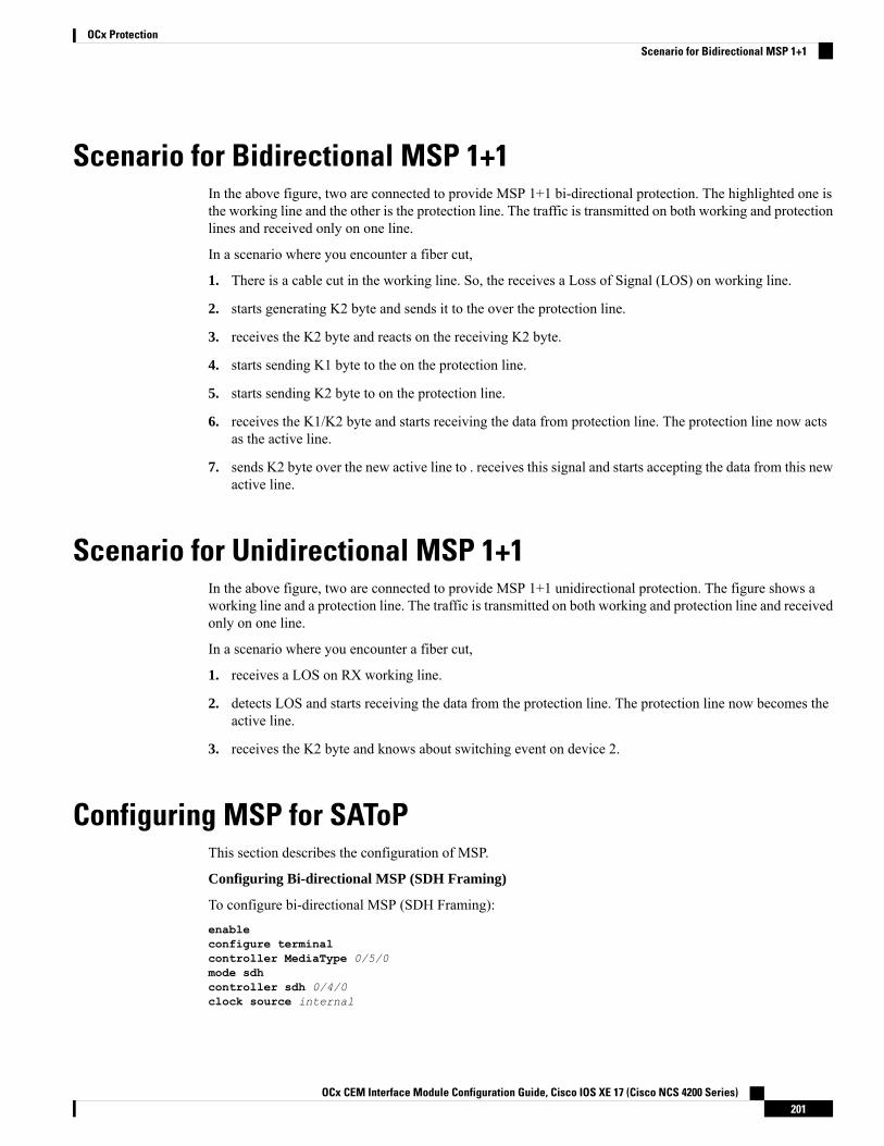
Scenario for Bidirectional MSP 1+1In the above figure, two are connected to provide MSP 1+1 bi-directional protection. The highlighted one isthe working line and the other is the protection line. The traffic is transmitted on both working and protectionlines and received only on one line.
In a scenario where you encounter a fiber cut,
1. There is a cable cut in the working line. So, the receives a Loss of Signal (LOS) on working line.
2. starts generating K2 byte and sends it to the over the protection line.
3. receives the K2 byte and reacts on the receiving K2 byte.
4. starts sending K1 byte to the on the protection line.
5. starts sending K2 byte to on the protection line.
6. receives the K1/K2 byte and starts receiving the data from protection line. The protection line now actsas the active line.
7. sends K2 byte over the new active line to . receives this signal and starts accepting the data from this newactive line.
Scenario for Unidirectional MSP 1+1In the above figure, two are connected to provide MSP 1+1 unidirectional protection. The figure shows aworking line and a protection line. The traffic is transmitted on both working and protection line and receivedonly on one line.
In a scenario where you encounter a fiber cut,
1. receives a LOS on RX working line.
2. detects LOS and starts receiving the data from the protection line. The protection line now becomes theactive line.
3. receives the K2 byte and knows about switching event on device 2.
Configuring MSP for SAToPThis section describes the configuration of MSP.
Configuring Bi-directional MSP (SDH Framing)
To configure bi-directional MSP (SDH Framing):enableconfigure terminalcontroller MediaType 0/5/0mode sdhcontroller sdh 0/4/0clock source internal
OCx CEM Interface Module Configuration Guide, Cisco IOS XE 17 (Cisco NCS 4200 Series)201
OCx ProtectionScenario for Bidirectional MSP 1+1

aps group acr 1aps working 1exitcontroller sdh 0/5/0aps group acr 1aps protect 1 10.7.7.7end
To restore the system to its default condition, use the no form of the command.
'10.7.7.7' is the loopback interface IP address on the same router.Note
Note
Configuring Revertive Mode
To configure revertive mode:enableconfigure terminalcontroller MediaType 0/5/0mode sdhcontroller sdh 0/5/0clock source internalaps group acr 1aps working 1exitcontroller sdh 0/5/0aps group acr 1aps protect 1 10.7.7.7aps revert 3aps admend
3 is the time in minutes for reverting back to the working port after it becomes available.Note
Configuring Unidirectional MSP (SDH Framing)
To configure unidirectional MSP (SDH Framing):enableconfigure terminalcontroller MediaType 0/5/0mode sdhcontroller sdh 0/5/0clock source internalaps group acr 1aps working 1exitcontroller sdh 0/5/0aps group acr 1aps protect 1 10.7.7.7aps unidirectionalaps admend
OCx CEM Interface Module Configuration Guide, Cisco IOS XE 17 (Cisco NCS 4200 Series)202
OCx ProtectionConfiguring MSP for SAToP

To restore the system to its default condition, use the no form of the command.Note
APS operational commands are supported only on protect controller. The following are the operationalcommands for MSP with APS.
• aps lockout:
This command locks the switch to protect port so that APS does not switch to protect controller for anyfailure on working port or IM.
• aps force 1:
This command forces the traffic to switch from active working controller to switch to protect controller.
• aps force 0:
This command forces the traffic to switch from active protect controller to switch to working controller.
• aps manual 1:
This command switches the traffic from active protect controller to work controller in the absence ofaps force and aps lockout commands.
• aps manual 0:
This command switches the traffic from active protect controller to work controller in the absence ofaps force and aps lockout commands.
Verifying MSP Configuration for SAToPUse show aps and show cem circuit commands to verify MSP configuration:Device#show apsSDH 0/4/6 APS Group 1: protect channel 0 (Active)Working channel 1 at 10.1.1.1 (Disabled)bidirectional, non-revertivePGP timers (default): hello time=1; hold time=3hello fail revert time=120SDH framing; SDH MSP signalling by defaultReceived K1K2: 0x21 0x15Reverse Request (working); Bridging workingTransmitted K1K2: 0x11 0x10Do Not Revert (working); Bridging workingRemote APS configuration: (null)SDH 0/3/6 APS Group 1: working channel 1 (Inactive)Protect at 10.1.1.1PGP timers (from protect): hello time=1; hold time=3SDH framingRemote APS configuration: (null)Device#
Device#show cem circuit int cem-acr 1 1CEM-ACR1, ID: 1, Line: UP, Admin: UP, Ckt: ACTIVEController state: up, CEP state: upIdle Pattern: 0xFF, Idle CAS: 0x8Dejitter: 6 (In use: 0)Payload Size: 783Framing: Not-Applicable
OCx CEM Interface Module Configuration Guide, Cisco IOS XE 17 (Cisco NCS 4200 Series)203
OCx ProtectionVerifying MSP Configuration for SAToP

CEM Defects SetNoneSignalling: No CASRTP: No RTPIngress Pkts: 111851780 Dropped: 0Egress Pkts: 111851778 Dropped: 0CEM Counter DetailsInput Errors: 0 Output Errors: 0Pkts Missing: 0 Pkts Reordered: 0Misorder Drops: 0 JitterBuf Underrun: 0Error Sec: 0 Severly Errored Sec: 0Unavailable Sec: 0 Failure Counts: 0Pkts Malformed: 0 JitterBuf Overrun: 0Generated Lbits: 0 Received Lbits: 0Generated Rbits: 0 Received Rbits: 0Generated Nbits: 10950 Received Nbits: 9093Generated Pbits: 0 Received Pbits: 0Device#
Configuring MSP for CESoPSNThis section describes the configuration of MSP for CESoPSN.
Configuring CEM Group for MSP on Virtual ACR AU3-T1 in CESoPSNTo configure CEM group on MSP, use the following commands:
enableconfigure terminalcontroller sdh-acr 200aug mapping au-3au-3 1mode vc1xTug-2 1 payload vc11T1 1 cem-group 0 timeslots 1 - 7
To configure the working controller, use the following commands:
enableconfigure terminalcontroller sdh 0/3/6au-3 1Tug-2 1 payload vc11vc 1 overhead v5 2
To configure the protect controller, use the following commands:
enableconfigure terminalcontroller sdh 0/4/6au-3 1Tug-2 1 payload vc11vc 1 overhead v5 2
OCx CEM Interface Module Configuration Guide, Cisco IOS XE 17 (Cisco NCS 4200 Series)204
OCx ProtectionConfiguring MSP for CESoPSN
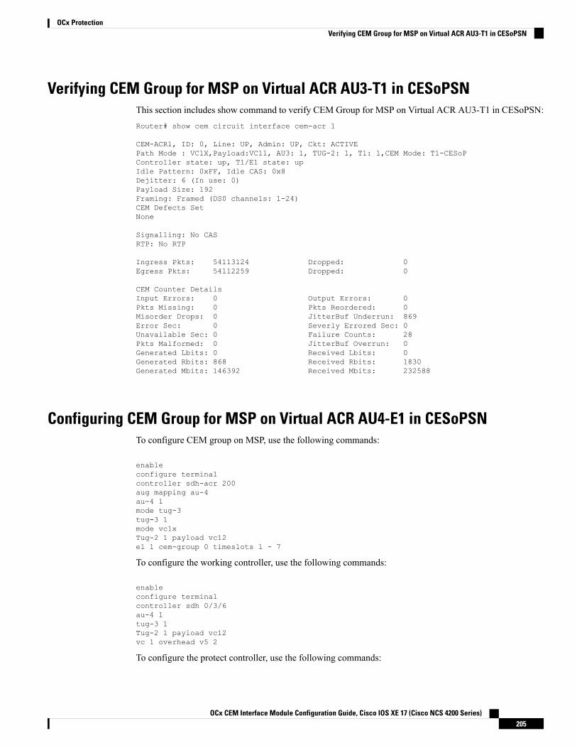
Verifying CEM Group for MSP on Virtual ACR AU3-T1 in CESoPSNThis section includes show command to verify CEM Group for MSP on Virtual ACR AU3-T1 in CESoPSN:Router# show cem circuit interface cem-acr 1
CEM-ACR1, ID: 0, Line: UP, Admin: UP, Ckt: ACTIVEPath Mode : VC1X,Payload:VC11, AU3: 1, TUG-2: 1, T1: 1,CEM Mode: T1-CESoPController state: up, T1/E1 state: upIdle Pattern: 0xFF, Idle CAS: 0x8Dejitter: 6 (In use: 0)Payload Size: 192Framing: Framed (DS0 channels: 1-24)CEM Defects SetNone
Signalling: No CASRTP: No RTP
Ingress Pkts: 54113124 Dropped: 0Egress Pkts: 54112259 Dropped: 0
CEM Counter DetailsInput Errors: 0 Output Errors: 0Pkts Missing: 0 Pkts Reordered: 0Misorder Drops: 0 JitterBuf Underrun: 869Error Sec: 0 Severly Errored Sec: 0Unavailable Sec: 0 Failure Counts: 28Pkts Malformed: 0 JitterBuf Overrun: 0Generated Lbits: 0 Received Lbits: 0Generated Rbits: 868 Received Rbits: 1830Generated Mbits: 146392 Received Mbits: 232588
Configuring CEM Group for MSP on Virtual ACR AU4-E1 in CESoPSNTo configure CEM group on MSP, use the following commands:
enableconfigure terminalcontroller sdh-acr 200aug mapping au-4au-4 1mode tug-3tug-3 1mode vc1xTug-2 1 payload vc12e1 1 cem-group 0 timeslots 1 - 7
To configure the working controller, use the following commands:
enableconfigure terminalcontroller sdh 0/3/6au-4 1tug-3 1Tug-2 1 payload vc12vc 1 overhead v5 2
To configure the protect controller, use the following commands:
OCx CEM Interface Module Configuration Guide, Cisco IOS XE 17 (Cisco NCS 4200 Series)205
OCx ProtectionVerifying CEM Group for MSP on Virtual ACR AU3-T1 in CESoPSN

enableconfigure terminalcontroller sdh 0/4/6au-4 1tug-3 1Tug-2 1 payload vc12vc 1 overhead v5 2
Verifying CEM Group for MSP on Virtual ACR AU4-E1 in CESoPSNThis section includes show command to verify CEM group for MSP on Virtual ACR AU4-E1 in CESoPSN:Router# show cem circuit interface cem-acr 1
CEM-ACR1, ID: 0, Line: UP, Admin: UP, Ckt: ACTIVEPath Mode : VC1X,Payload:VC11, AU4: 1, TUG-3: 1, E1: 1,CEM Mode: E1-CESoPController state: up, T1/E1 state: upIdle Pattern: 0xFF, Idle CAS: 0x8Dejitter: 6 (In use: 0)Payload Size: 56Framing: Framed (DS0 channels: 1-7)CEM Defects SetNone
Signalling: No CASRTP: No RTP
Ingress Pkts: 54113124 Dropped: 0Egress Pkts: 54112259 Dropped: 0
CEM Counter DetailsInput Errors: 0 Output Errors: 0Pkts Missing: 0 Pkts Reordered: 0Misorder Drops: 0 JitterBuf Underrun: 869Error Sec: 0 Severly Errored Sec: 0Unavailable Sec: 0 Failure Counts: 28Pkts Malformed: 0 JitterBuf Overrun: 0Generated Lbits: 0 Received Lbits: 0Generated Rbits: 868 Received Rbits: 1830Generated Mbits: 146392 Received Mbits: 232588
Configuring Clocking ACR for MSP AU3-T1 in CESoPSNTo configure clock source on MSP for the working controller, use the following commands:
enableconfigure terminalcontroller sdh 0/3/6au-3 1tug-2 1 payload vc11t1 1 clock source recovered 1end
To configure the recovered clock, use the following commands:
enableconfigure terminal
OCx CEM Interface Module Configuration Guide, Cisco IOS XE 17 (Cisco NCS 4200 Series)206
OCx ProtectionVerifying CEM Group for MSP on Virtual ACR AU4-E1 in CESoPSN

recovered-clock acr 200clock recovered 1 adaptive cem 1 priority 1end
To configure clock source on MSP for the protect controller, use the following commands:
enableconfigure terminalcontroller sdh 0/4/6au-3 1tug-2 1 payload vc11t1 1 clock source recovered 1end
To configure the recovered clock, use the following commands:
enableconfigure terminalrecovered-clock acr 200clock recovered 1 adaptive cem 2 priority 2end
Verifying Clocking ACR for MSP AU3-T1 in CESoPSNUse the show recovered-clock command to verify the ACR for AU3-T1 in CESoPSN:Router# show recovered-clock
Recovered clock status for MSP-ACR 200----------------------------------------Clock Type Mode CEM Status Circuit-No Working Protect
Priority4 OCx-T1 ADAPTIVE 38 ACQUIRING 200/3/1/1(acr/path/vtg/t1) ACQUIRING ACQUIRING1
Configuring Clocking DCR for MSP AU3-T1 in CESoPSNTo configure clock source on MSP for the working controller, use the following commands:
enableconfigure terminalcontroller sdh 0/3/6au-3 1tug-2 1 payload vc11t1 1 clock source recovered 1end
To configure CEM interface, use the following commands:
interface cem <bay>/<slot>/<port>cem <cem-group-no>rtp-present
To configure the recovered clock with priority 1, use the following commands:
enableconfigure terminalrecovered-clock acr 200
OCx CEM Interface Module Configuration Guide, Cisco IOS XE 17 (Cisco NCS 4200 Series)207
OCx ProtectionVerifying Clocking ACR for MSP AU3-T1 in CESoPSN

clock recovered 1 differential cem 1 priority 1end
To configure clock source on MSP for the protect controller, use the following commands:
enableconfigure terminalcontroller sdh 0/4/6au-3 1tug-2 1 payload vc11t1 1 clock source recovered 1end
To configure CEM interface, use the following commands:
interface cem <bay>/<slot>/<port>cem <cem-group-no>rtp-present
To configure the recovered clock with priority 1, use the following commands:
enableconfigure terminalrecovered-clock acr 200clock recovered 1 differential cem 2 priority 2end
Verifying Clocking DCR for MSP AU3-T1 in CESoPSNUse the show recovered-clock command to verify the DCR for AU3-T1 in CESoPSN:Router# show recovered-clock
Recovered clock status for MSP-DCR 200----------------------------------------Clock Type Mode CEM Status Circuit-No Working Protect
Priority5 OCx-T1 DIFFERENTIAL 44 ACQUIRING 200/4/1/1(acr/path/vtg/t1) ACQUIRING ACQUIRING1
Configuring Clocking ACR for MSP AU4-E1 in CESoPSNTo configure clock source on MSP for the working controller, use the following commands:
enableconfigure terminalcontroller sdh 0/3/6au-4 1tug-3 1tug-2 1 payload vc12e1 1 clock source recovered 5end
To configure the recovered clock, use the following commands:
enableconfigure terminal
OCx CEM Interface Module Configuration Guide, Cisco IOS XE 17 (Cisco NCS 4200 Series)208
OCx ProtectionVerifying Clocking DCR for MSP AU3-T1 in CESoPSN

recovered-clock acr 200clock recovered 5 adaptive cem 1 priority 1end
To configure clock source on MSP for the protect controller, use the following commands:
enableconfigure terminalcontroller sdh 0/4/6au-4 1tug-3 1tug-2 1 payload vc12e1 1 clock source recovered 5end
To configure the recovered clock, use the following commands:
enableconfigure terminalrecovered-clock acr 200clock recovered 5 adaptive cem 2 priority 2end
Verifying Clocking ACR for MSP AU4-E1 in CESoPSNUse the show recovered-clock command to verify the ACR for AU4-E1 in CESoPSN:Router# show recovered-clockRecovered clock status for MSP-ACR 200----------------------------------------Clock Type Mode CEM Status Circuit-No Working Protect
Priority4 OCx-T1 ADAPTIVE 38 ACQUIRING 200/3/1/1(acr/path/vtg/t1) ACQUIRING ACQUIRING1
Configuring Clocking DCR for MSP AU4-E1 in CESoPSNTo configure clock source on MSP for the working controller, use the following commands:
enableconfigure terminalcontroller sdh 0/3/6au-4 1tug-3 1tug-2 1 payload vc12e1 1 clock source recovered 5end
To configure CEM interface, use the following commands:
interface cem <bay>/<slot>/<port>cem <cem-group-no>rtp-present
To configure the recovered clock with priority 1, use the following commands:
enable
OCx CEM Interface Module Configuration Guide, Cisco IOS XE 17 (Cisco NCS 4200 Series)209
OCx ProtectionVerifying Clocking ACR for MSP AU4-E1 in CESoPSN

configure terminalrecovered-clock acr 200clock recovered 5 differential cem 1 priority 1end
To configure clock source on MSP for the protect controller, use the following commands:
enableconfigure terminalcontroller sdh 0/4/6au-4 1tug-3 1tug-2 1 payload vc12e1 1 clock source recovered 5end
To configure CEM interface, use the following commands:
interface cem <bay>/<slot>/<port>cem <cem-group-no>rtp-present
To configure the recovered clock with priority 1, use the following commands:
enableconfigure terminalrecovered-clock acr 200clock recovered 5 differential cem 2 priority 2end
Verifying Clocking DCR for MSP AU4-E1 in CESoPSNUse the show recovered-clock command to verify the DCR for AU4-E1 in CESoPSN:Router# show recovered-clockRecovered clock status for MSP-DCR 200----------------------------------------Clock Type Mode CEM Status Circuit-No Working Protect
Priority5 OCx-T1 DIFFERENTIAL 44 ACQUIRING 200/4/1/1(acr/path/vtg/t1) ACQUIRING ACQUIRING1
OCx CEM Interface Module Configuration Guide, Cisco IOS XE 17 (Cisco NCS 4200 Series)210
OCx ProtectionVerifying Clocking DCR for MSP AU4-E1 in CESoPSN

C H A P T E R 13UPSR Path Protection
Table 34: Feature History
Feature DescriptionRelease InformationFeature Name
Support for UPSR IPv6 onNCS4200-1T8S-20CS andNCS4200-3GMS InterfaceModule.
Cisco IOS XE Bengaluru 17.4.1CEM and IP IW Feature Parity forNCS4200-1T8S-20CS andNCS4200-3GMS InterfaceModules
A Unidirectional Path Switching Ring (UPSR) is a unidirectional network with two rings, one ring used asthe working ring and the other as the protection ring. The same signal flows through both rings, one clockwiseand the other counterclockwise. It is called UPSR because monitoring is done at the path layer. A node receivestwo copies of the electrical signals at the path layer, compares them, and chooses the one with the betterquality. If part of a ring between two ADMs fails, the other ring still can guarantee the continuation of dataflow. UPSR, like the one-plus-one scheme, has fast failure recovery.
Once a signal fail condition or a signal degrade condition is detected, the hardware initiates an interrupt tosoftware that switches from the working path to the protection path. Nonrevertive options are valid for UPSRpath protection.
1X OC-192 and 8X OC-48 interface modules only supports the nonrevertive option. The nonrevertive optionis the default mode.
Note
When an active link of UPSR and APS is configured on the same interface module and the interface modulereloads, the convergence number for UPSR circuits to switch to backup is high ranging 100–200 ms. Wheneach circuit is configured separately, the convergence time is always under 50 ms.
Note
The below table gives the maximum number of path level circuits that are supported in each mode.
Supported ScaleModes
84VT 1.5
48STS-1
OCx CEM Interface Module Configuration Guide, Cisco IOS XE 17 (Cisco NCS 4200 Series)211

Supported ScaleModes
16STS 3c
4STS 12c
1STS 48c
The UPSR path protection supports the following feature:
• SONET local connect and cross connect are supported at VT-15 CEP, STS-1c, STS-3c, STS-12c, andSTS-48c levels. UPSR is also supported on TDM endpoints that are mapped to a pseudowire. T1 SAToP,T3 SAToP, and CT3 are supported on an UPSR ring only with local connect mode. Cross connect of T1,T3, and CT3 circuits to UPSR are not supported until Cisco IOS XE Fuji 16.8.x.
Starting with Cisco IOS XE Fuji 16.9.x, the cross connect of T1, T3, and CT3 circuits to UPSR issupported. For xconnect with the CT3mode, the CEM protection group interface only supports the VT-15mode. For cross-connect configuration, see Configuring UPSR.
• Restrictions for iMSG UPSR Path Protection, on page 212• Configuring iMSG UPSR, on page 212• Configuring UPSR, on page 213
Restrictions for iMSG UPSR Path Protection• UPSR Dual Ring Interconnect (DRI) is not supported.
• UPSR Dual Node Interconnect (DNI) is not supported.
• T1 or E1 and T3 or E3 configurations are not supported, and only the OCx-related configuration issupported.
• HDLC UPSR supports 510 PPP or HDLC pseudowire per group for an interface module and 1020 PPPor HDLC pseudowire for a router.
• APS group number of 255 and UPSR group ID of 1 cannot be configured on the same router.
Configuring iMSG UPSRTo configure protection group for iMSG UPSR, enter the following commands:
enableconfigure terminalprotection-group 401 type STS48ccontroller protection-group 401type STS48cchannel-group 0end
OCx CEM Interface Module Configuration Guide, Cisco IOS XE 17 (Cisco NCS 4200 Series)212
OCx ProtectionRestrictions for iMSG UPSR Path Protection

Configuring UPSRProtection Group Configuration
enableconfigure terminalprotection-group 401 type STS48ccontroller protection-group 401type STS48ccem-group 19001 cepend
Cross-connect Configuration with the CT3 mode
For cross connect with the CT3 mode, the CEM protection group interface supports only the VT-15 mode.
protection-group 2 type vt1.5controller protection-group 2type vt1.5cem-group 16002 unframed
controller sonet 0/4/0sts-1 1mode vt-15vtg 1 t1 2 protection-group 2 working
controller sonet 0/5/0sts-1 1mode vt-15vtg 1 t1 2 protection-group 2 protect
Configuring UPSR Work and Protection Path ConfigurationUPSR Work Path Configuration:enableconfigure terminalcontroller MediaType 0/3/6mode sonetcontroller sonet 0/3/6rate oc48sts-1 1 - 48 mode sts-48cprotection-group 401 workingend
UPSR Protect Path Configuration:enableconfigure terminalcontroller MediaType 0/12/6mode sonetcontroller sonet 0/12/6rate oc48sts-1 1 - 48 mode sts-48cprotection-group 401 protectend
OCx CEM Interface Module Configuration Guide, Cisco IOS XE 17 (Cisco NCS 4200 Series)213
OCx ProtectionConfiguring UPSR

Verifying UPSR ConfigurationUse the show protection-group command to verify UPSR configuration:show protection-groupPGN Type Working I/f Protect I/f Active Status-------------------------------------------------------------------------------401 STS48C SONET0/3/6.1-48 SONET0/12/6.1-48 W A-------------------------------------------------------------------------------Status legend:D=Deleted FO=Force SF=SignalFailure SD=SignalDegrade
FL=Fail M=Manual L=Lockout C=Clear A=Auto(W)=working, (P)=protect
OCx CEM Interface Module Configuration Guide, Cisco IOS XE 17 (Cisco NCS 4200 Series)214
OCx ProtectionVerifying UPSR Configuration
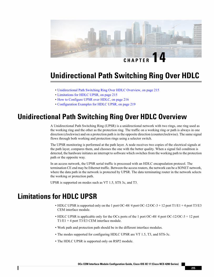
C H A P T E R 14Unidirectional Path Switching Ring Over HDLC
• Unidirectional Path Switching Ring Over HDLC Overview, on page 215• Limitations for HDLC UPSR, on page 215• How to Configure UPSR over HDLC, on page 216• Configuration Examples for HDLC UPSR, on page 219
Unidirectional Path Switching Ring Over HDLC OverviewA Unidirectional Path Switching Ring (UPSR) is a unidirectional network with two rings, one ring used asthe working ring and the other as the protection ring. The traffic on a working ring or path is always in onedirection (clockwise) and on a protection path is in the opposite direction (counterclockwise). The same signalflows through both working and protection rings using a selector switch.
The UPSR monitoring is performed at the path layer. A node receives two copies of the electrical signals atthe path layer, compares them, and chooses the one with the better quality. When a signal fail condition isdetected, the hardware initiates an interrupt to software which switches from the working path to the protectionpath or the opposite way.
In an access network, the UPSR serial traffic is processed with an HDLC encapsulation protocol. Thetermination CE endmay be Ethernet traffic. Between the access routers, the network can be a SONET network,where the data path in the network is protected by UPSR. The data terminating router in the network selectsthe working or protection path.
UPSR is supported on modes such as VT 1.5, STS 3c, and T3.
Limitations for HDLC UPSR• HDLCUPSR is supported only on the 1 port OC-48/ 4 port OC-12/OC-3 + 12 port T1/E1 + 4 port T3/E3CEM interface module.
• HDLC UPSR is applicable only for the OCx ports of the 1 port OC-48/ 4 port OC-12/OC-3 + 12 portT1/E1 + 4 port T3/E3 CEM interface module.
• Work path and protection path should be in the different interface modules.
• The modes supported for configuring HDLC UPSR are VT 1.5, T3, and STS-3c.
• The HDLC UPSR is supported only on RSP2 module.
OCx CEM Interface Module Configuration Guide, Cisco IOS XE 17 (Cisco NCS 4200 Series)215

• HDLC UPSR switching does not happen when there is any alarm at PDH level, for example T1 or T3.The switching happens at VT or STS path alarm.
How to Configure UPSR over HDLCYou can configure HDLC UPSR in anyone of the following ways:
• Create protection group first and then add working or protect member under physical controller. Thechannel group can be configured under protection group controller once the protection group is created.
• Add working or protect member under physical controller which creates the protection group controller.The channel group can be added under the protection group controller once protection group is created.
Configuring Protection GroupYou need to create protection group serial interface.
You can create protection group for anyone of the following types: T3, VT 1.5 T1, and STS-3c.enableconfigure terminalcontroller protection-group 401 type STS3cchannel-group chan-num timeslots 1-24end
Configuring Channel GroupYou can configure channel group under protection controller to create a protection group (PG) serial interface.
Creating Protection Group Serial Interface for VT 1.5 T1 ModeOnce the protection group is created, you can configure the controller using the protection group name andmode. You need to specify the channel group number with timeslots to create a PG serial interface.
To configure the channel group under the controller for VT 1.5 T1 mode, enter the following commands:enableconfigure terminalcontroller protection-group pg_grp_num type vt1.5channel-group chan_num timeslots 1-24end
Creating Protection Group Serial Interface for T3 or STS-3c ModeYou can configure protection group for the controller mode types T3 or STS-3c using specific channel group.
To configure channel group under protection controller for mode T3, enter the following commands:enableconfigure terminalprotection-group pg_grp_num type sts1controller sonet x/y/zsts-1 3mode t3
OCx CEM Interface Module Configuration Guide, Cisco IOS XE 17 (Cisco NCS 4200 Series)216
OCx ProtectionHow to Configure UPSR over HDLC

protection-grouppg_grp_numworkingend
To configure channel group under protection controller for mode types STS-3c, enter the following commands:enableconfigure terminalprotection-group pg_grp_num type sts1controller sonet x/y/zsts-3cmode t3protection-grouppg_grp_numworkingend
The following example details on how to create protection group serial interface for T3 mode:
Router(config)#protection-group 6 type stS1Router(config-ctrlr-sts1)#controller sonet 0/5/17Router(config-controller)#sts-1 3Router(config-ctrlr-sts1)#mode t3Router(config-ctrlr-sts1)#protection-group 6 working
Creating Protection Group Serial Interface for VT 1.5 T1 ModeOnce the protection group is created, you can configure the controller using the protection group name andmode. You need to specify the channel group number with timeslots to create a PG serial interface.
To configure the channel group under the controller for VT 1.5 T1 mode, enter the following commands:enableconfigure terminalcontroller protection-group pg_grp_num type vt1.5channel-group chan_num timeslots 1-24end
Creating Protection Group Serial Interface for T3 or STS-3c ModeYou can configure protection group for the controller mode types T3 or STS-3c using specific channel group.
To configure channel group under protection controller for mode T3, enter the following commands:enableconfigure terminalprotection-group pg_grp_num type sts1controller sonet x/y/zsts-1 3mode t3protection-grouppg_grp_numworkingend
To configure channel group under protection controller for mode types STS-3c, enter the following commands:enableconfigure terminalprotection-group pg_grp_num type sts1controller sonet x/y/zsts-3cmode t3protection-grouppg_grp_numworkingend
OCx CEM Interface Module Configuration Guide, Cisco IOS XE 17 (Cisco NCS 4200 Series)217
OCx ProtectionCreating Protection Group Serial Interface for VT 1.5 T1 Mode

The following example details on how to create protection group serial interface for T3 mode:
Router(config)#protection-group 6 type stS1Router(config-ctrlr-sts1)#controller sonet 0/5/17Router(config-controller)#sts-1 3Router(config-ctrlr-sts1)#mode t3Router(config-ctrlr-sts1)#protection-group 6 working
Adding Protection Group to Controller Under VT 1.5 ModeYou can add protection group as working or protect under specific SONET controller mode on the SONETcontroller interface.
To add protection group to SONET controller under VT 1.5 mode, enter the following commands:enableconfigure terminalcontroller sonet <x/y/z>sts-1 1mode vt-15vtg 1 t1 1protection-group pg_grp_num type {working | protect}end
Adding Protection Group to Controller Under T3 ModeYou can add protection group for T3 framing type such as M13, c-bit.
To add protection group to SONET controller under T3 mode, enter the following commands:enableconfigure terminalcontroller sonet <x/y/z>sts-1 1mode t3protection-group pg_grp_num type {working | protect}end
Adding Protection Group to Controller Under STS-3c ModeTo add protection group to SONET controller under STS-3c mode, enter the following commands:enableconfigure terminalcontroller sonet <x/y/z>sts-1 1 - 3mode sts-3cprotection-group pg_grp_num type {working | protect}end
ConfiguringCross-ConnectUnderProtectionGroupSerialInterfacePseudowireThe xconnect command binds the attachment circuit to a pseudowire for cross connect service. The identifiercreates the binding between a pseudowire that is configured on a PE router and an attachment circuit in a CEdevice.
To perform cross connection between a pseudowire and attachment circuit, use the following commands:
OCx CEM Interface Module Configuration Guide, Cisco IOS XE 17 (Cisco NCS 4200 Series)218
OCx ProtectionAdding Protection Group to Controller Under VT 1.5 Mode

router(config)#interface serial-pg <pg-group-name>.<chan_num>router(config-if)#xconnect ip-address id encapsulation type pw-class pw-class
Verifying UPSR Over HDLC ConfigurationUse the following show commands to verify the UPSR over HDLC configuration:
Router#show ip int br | sec PGSerial-PG1.0 unassigned YES unset up upSerial-PG2.0 unassigned YES unset up upRouter#sh protection-groupPGN Type Working I/f Protect I/f Active Status-------------------------------------------------------------------------------1 VT15 SONET0/5/17.1/1/1 W A2 VT15 SONET0/5/17.2/2/2 W A
Router#show xconnect all | sec PGDN pri ac Se-PG1.0(HDLC) UP mpls 10.10.10.10:2 DN
Router#sh controller sonet 0/5/17 | sec protWorking member of protection-group: 1Working member of protection-group: 2
Router#show run | sec 0/5/17platform enable controller MediaType 0/5/17 oc3controller MediaType 0/5/17mode sonetcontroller SONET 0/5/17rate OC3no ais-shutalarm-report allclock source internal!sts-1 1clock source internalmode vt-15vtg 1 t1 1 protection-group 1 working
!sts-1 2clock source internalmode vt-15vtg 2 t1 2 protection-group 2 working
Configuration Examples for HDLC UPSRThis section provides examples to configure HDLC UPSR:
Use Case 1The following example details on how UPSR is configured over HDLC:
• Protection group of 3 configured under VT 1.5 T1 mode.
OCx CEM Interface Module Configuration Guide, Cisco IOS XE 17 (Cisco NCS 4200 Series)219
OCx ProtectionVerifying UPSR Over HDLC Configuration

• Channel group of zero with timeslot configured under the protection group created.
• SONET controller is configured for mode VT 1.5 T1 on interface 0/5/17.
• Protection group of 3 added as working ring under SONET controller mode VT 1.5 T1.
• Perform cross connection under attachment circuit
Router(config)#protection-group 3 type vt1.5Router(config)#controller protection-group 3Router(config-controller)#type vt1.5Router(config-ctrlr-sts1)#channel-group 0 timeslots 1-24Router(config-ctrlr-sts1)#controller sonet 0/5/17Router(config-controller)#sts-1 1Router(config-ctrlr-sts1)#mode vt-15Router(config-ctrlr-sts1)#vtg 1 t1 1 protection-group 3 working
Verify the configuration using the following show commands:
Router#show protection-groupPGN Type Working I/f Protect I/f Active Status-------------------------------------------------------------------------------1 VT15 - A2 VT15 - A3 VT15 SONET0/5/17.1/1/1 W A
Router#show controller sonet 0/5/17 | sec protectionWorking member of protection-group: 3
Router#show ip int br | sec PGSerial-PG3.0 unassigned YES unset up up
Router(config)#interface Serial-PG3.0Router(config-if)#xconnect 10.10.10.10 1 encapsulation mpls pw-Router(config-if)#$.10.10.10 1 encapsulation mpls pw-class serial_pg
If you want to remove the configuration performed, use the following commands:
Router(config-if-xconn)#int Serial-PG3.0Router(config-if)#no xconnect
Router(config)#controller sonet 0/5/17Router(config-controller)#sts-1 1Router(config-ctrlr-sts1)#no vtg 1 t1 1 protection-group 3 working
Router(config)#controller protection-group 3Router(config-controller)#type vt1.5Router(config-ctrlr-sts1)#no channel-group 0Router(config-ctrlr-sts1)#no protection-group 3
Use Case 2The following example details on how UPSR is configured over HDLC:
• SONET controller is configured for mode VT 1.5 T1 on interface 0/5/17.
• Protection group of 3 added as working ring under SONET controller mode VT 1.5 T1.
OCx CEM Interface Module Configuration Guide, Cisco IOS XE 17 (Cisco NCS 4200 Series)220
OCx ProtectionUse Case 2

• Protection group of 3 configured under VT 1.5 T1 mode.
• Channel group of zero with timeslot configured under the protection group created.
• Perform cross connection under attachment circuit
Router(config)#controller sonet 0/5/17Router(config-controller)#sts-1 1Router(config-ctrlr-sts1)#mode vt-15Router(config-ctrlr-sts1)#vtg 1 t1 1 protection-group 3 workingRouter(config-ctrlr-sts1)#exitRouter(config-controller)#exitRouter(config)#controller protection-group 3Router(config-controller)#type vt1.5Router(config-ctrlr-sts1)#channel-group 0 timeslots 1-24
Verify the configuration using the following show commands:
Router#show protection-groupPGN Type Working I/f Protect I/f Active Status-------------------------------------------------------------------------------1 VT15 - A2 VT15 - A3 VT15 SONET0/5/17.1/1/1 W A
Router#show controller sonet 0/5/17 | sec protectionWorking member of protection-group: 3
Router#show ip int br | sec PGSerial-PG3.0 unassigned YES unset up up
Router(config)#int Serial-PG3.0Router(config-if)#xconnect 10.10.10.10 1 encapsulation mpls pw-Router(config-if)#$.10.10.10 1 encapsulation mpls pw-class serial_pg
OCx CEM Interface Module Configuration Guide, Cisco IOS XE 17 (Cisco NCS 4200 Series)221
OCx ProtectionUse Case 2

OCx CEM Interface Module Configuration Guide, Cisco IOS XE 17 (Cisco NCS 4200 Series)222
OCx ProtectionUse Case 2
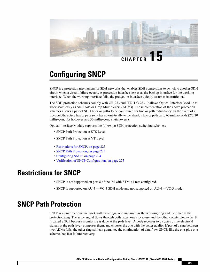
C H A P T E R 15Configuring SNCP
SNCP is a protection mechanism for SDH networks that enables SDH connections to switch to another SDHcircuit when a circuit failure occurs. A protection interface serves as the backup interface for the workinginterface. When the working interface fails, the protection interface quickly assumes its traffic load.
The SDH protection schemes comply with GR-253 and ITU-T G.783. It allows Optical Interface Module towork seamlessly as SDH Add or Drop Multiplexers (ADMs). The implementation of the above protectionschemes allows a pair of SDH lines or paths to be configured for line or path redundancy. In the event of afiber cut, the active line or path switches automatically to the standby line or path up to 60 milliseconds (2/5/10millisecond for holdover and 50 millisecond switchovers).
Optical Interface Module supports the following SDH protection switching schemes:
• SNCP Path Protection at STS Level
• SNCP Path Protection at VT Level
• Restrictions for SNCP, on page 223• SNCP Path Protection, on page 223• Configuring SNCP, on page 224• Verification of SNCP Configuration, on page 225
Restrictions for SNCP• SNCP is not supported on port 8 of the IM with STM-64 rate configured.
• SNCP is supported on AU-3 —VC-3 SDH mode and not supported on AU-4 —VC-3 mode.
SNCP Path ProtectionSNCP is a unidirectional network with two rings, one ring used as the working ring and the other as theprotection ring. The same signal flows through both rings, one clockwise and the other counterclockwise. Itis called SNCP because monitoring is done at the path layer. A node receives two copies of the electricalsignals at the path layer, compares them, and chooses the one with the better quality. If part of a ring betweentwo ADMs fails, the other ring still can guarantee the continuation of data flow. SNCP, like the one-plus-onescheme, has fast failure recovery.
OCx CEM Interface Module Configuration Guide, Cisco IOS XE 17 (Cisco NCS 4200 Series)223

Once a signal fail condition or a signal degrade condition is detected, the hardware initiates an interrupt tosoftware that switches from the working path to the protection path. Non-revertive options are valid for SNCPpath protection.
1XOC-192 and 8XOC-48 interface modules only supports the non-revertive option. The non-revertive optionis the default mode.
Note
The following table shows the scales of SNCP supported on different modes:
Supported ScalesModes
252AU4-VC12
336AU4-VC11
16AU4-VC4
252AU3-VC12
336AU3-VC11
4VC4-4c
1VC4-16c
Configuring SNCPProtection Group Controller Configuration
enableconfigure terminalprotection group 1 type vc4-16ccontroller protection group 1type vc4-16ccem-group 16001 cepend
Working Path Configuration
enableconfigure terminalcontroller sdh 0/3/6au-4 1-16 mode vc4-16cprotection group 1 workingend
Protect Path Configuration
enableconfigure terminalcontroller sdh 0/12/6au-4 1-16 mode vc4-16cprotection group 1 protectend
OCx CEM Interface Module Configuration Guide, Cisco IOS XE 17 (Cisco NCS 4200 Series)224
OCx ProtectionConfiguring SNCP

CEM Group Configuration
enableconfigure terminalcontroller sdh 0/4/1au-4 1-16 mode vc4-16ccem-group 1 cepend
Local Connect Configuration
enableconfigure terminalconnect lc cem 0/4/1 1 cem-pg 1 16001end
Verification of SNCP ConfigurationUse show protection-group command to verify SNCP configuration:#show protection-groupPGN Type Working I/f Protect I/f Active Status-------------------------------------------------------------------------------1 VC4-16C SDH0/3/6.1-48 SDH0/12/6.1-48 P A-------------------------------------------------------------------------------Status legend:D=Deleted FO=Force SF=SignalFailure SD=SignalDegrade
FL=Fail M=Manual L=Lockout C=Clear A=Auto(W)=working, (P)=protect
OCx CEM Interface Module Configuration Guide, Cisco IOS XE 17 (Cisco NCS 4200 Series)225
OCx ProtectionVerification of SNCP Configuration

OCx CEM Interface Module Configuration Guide, Cisco IOS XE 17 (Cisco NCS 4200 Series)226
OCx ProtectionVerification of SNCP Configuration

P A R T VDCC and TARP
• Configuring Data Communication Channel, on page 229• Transparent Overhead Tunneling Data Communication Channel, on page 233• Target Identifier Address Resolution Protocol, on page 241


C H A P T E R 16Configuring Data Communication Channel
Table 35: Feature History
DescriptionRelease InformationFeature Name
DCC Termination is supported onthe OCx ports for followinginterface modules:
• 1-port OC-48/STM-16 or4-port OC-12/OC-3 /STM-1/STM-4 + 12-portT1/E1 + 4-port T3/E3 module
• 1-port OC-192 or 8-port lowrate module
• NCS 4200 1-port OC-192 or8-port low rate CEM 20Gbandwidth module
Cisco IOS XE Bengaluru 17.4.1DCC Termination
The Data Communication Channel(DCC) feature uses the SONET orSDHOperationAdministration andMaintenance (OAM) channel tomanage devices that supportSONET or SDH interfaces on thefollowing Cisco RSP3 module:
• NCS 4200 1-port OC-192 or8-port low rate CEM 20Gbandwidth module
Cisco IOS XE Amsterdam 17.3.1DCC Support
The Data Communication Channel (DCC) feature uses the SONET or SDH Operation Administration andMaintenance (OAM) channel to manage devices that support SONET or SDH interfaces. SONET or SDHstandards support extensive operations, administration, management, and provisioning (OAM&P) capabilities.
The following overhead bytes are specified in the standards as the OAM channels that carry managementinformation, alarms, and management commands:
• D1 to D3 bytes of the Section overhead
OCx CEM Interface Module Configuration Guide, Cisco IOS XE 17 (Cisco NCS 4200 Series)229

• D4 to D12 bytes of the Line overhead
These overhead bytes are referred to as the Data Communication Channel (DCC). The Line-level DCC is a576 kbps OAM channel; the Section-level DCC is a 192 kbps OAM channel. DCC feature uses the datacommunications channel to access network devices that are connected through SONET/SDH interfaces formanagement access.
ITU-G.7712 has defined the following three DCC network domains:
• OSI DCC network
• IP DCC network
• OSI+IP DCC network
Effective Cisco IOS XE Everest 16.6.1 release, only OSI DCC network and IP DCC network are supported,which implies that same type of network resides on either side of the router.
Figure 7: Implementation of DCC
As shown in the figure above, the logical interface for DCC channels is called a SONETData CommunicationsChannel (SDCC). Each SDCC interface is assigned an IP address. The Routing Information Protocol (RIP)is used as the routing protocol for the IP DCC network.
For OSI network, CLNS or ISIS protocol is used for routing and node discovery. The data layer encapsulationis LAPD.
Figure 8: DCC for OSI Network
For IP netwok, IP or OSPF protocol is used for routing and node discovery. The data layer encapsulation isPPP.
Figure 9: DCC for IP Network
OCx CEM Interface Module Configuration Guide, Cisco IOS XE 17 (Cisco NCS 4200 Series)230
DCC and TARP

Static IP configuration and PPP authentication are also supported. DCC also works with APS 1+1 protectioninfrastructure.
• Restrictions of DCC, on page 231• Configuring PPP, on page 231• Configuring CLNS or LAPD, on page 232• Verification of DCC Configuration, on page 232
Restrictions of DCC• Only routing IP and OSI domains are supported; layers 4–7 of OSI model is not supported.
• Interworking of OSPI and IP domains is not supported.
• CLNS MTU supported is 1489 on NCS4206 and NCS 4216 routers.
• CLNS interoperability with ONS is not supported.
• IS-IS packet bigger than LAPD MTU is not dropped.
• 1+1 APS with CLNS mode is not supported.
• During a CRC mismatch, the interface reaches Up state under the LAPD UITS mode after SSO.
• Under LAPD encapsulation mode, the default LAPD role and modes are not displayed in the runningconfiguration.
• DCC termination on APS controllers is not supported.
Configuring PPPTo configure PPP:enableconfigure terminalcontroller mediatype 0/3/4mode sonetcontroller sonet 0/3/4rate oc48dcc enable [section | line]interface [sdcc | ldcc] 0/3/4ip unnumbered loopback 1encapsulation pppcrc 16 | 32exitinterface loopback 1ip address 10.2.2.2 255.0.0.0router ospf 1network 10.2.2.0 255.0.0.0 area 0end
CRC 32 is for SDCC and CRC 16 is for LDCC.Note
OCx CEM Interface Module Configuration Guide, Cisco IOS XE 17 (Cisco NCS 4200 Series)231
DCC and TARPRestrictions of DCC

Configuring CLNS or LAPDTo configure CLNS or LAPD:enableconfigure terminalcontroller mediatype 0/3/4mode sonetcontroller sonet 0/3/4rate oc48dcc enable [section | line]interface [sdcc | ldcc] 0/3/4encapsulation lapdclns mtu 1489lapd role userclns router isis R1_R2router isis R1_R2net 47.0039.3333.3333.3333.00end
When you configure LAPD role user on router, you should not configure the other router as LAPD role user.It should be network and not user.
Note
Verification of DCC ConfigurationUse show clns neighbors, show ip ospf neighbor, show ip int br | I DCC, and show interface SDCCcommands to verify DCC configuration.#show clns neighborsTag R1_R2:
Tag null:System Id Interface SNPA State Holdtime Type ProtocolNCS4216_2 LD0/3/4 *LAPD* Up 9 L1L2 IS-IS
Tag ethernet:System Id Interface SNPA State Holdtime Type ProtocolNCS4216_1 Te0/1/8 5006.ab62.6062 Up 54 L1 IS-IS#show ip ospf neighborNeighbor ID Pri State Dead Time Address Interface10.3.3.4 1 FULL/BDR 00:00:35 10.3.3.4 TenGigabitEthernet0/1/810.6.6.2 0 FULL/ - 00:00:37 10.2.2.1 SDCC0/3/4#show ip int br | i DCCLDCC0/3/4 10.5.5.2 YES NVRAM up upSDCC0/3/6 10.2.2.1 YES TFTP up downSDCC0/3/7 10.2.2.1 YES TFTP up upSDCC0/4/7 10.8.8.8 YES TFTP down down
OCx CEM Interface Module Configuration Guide, Cisco IOS XE 17 (Cisco NCS 4200 Series)232
DCC and TARPConfiguring CLNS or LAPD

C H A P T E R 17Transparent Overhead Tunneling DataCommunication Channel
This chapter provides information about the transparent overhead tunneling data communication channel.
• Transparent Overhead Tunneling Data Communication Channel Overview, on page 233• Transparent Overhead Tunnel DCC Types, on page 234• Prerequisites for Transparent Overhead Tunnel, on page 235• Limitations of Transparent Overhead Tunnel, on page 236• How to Configure Transparent Overhead Tunnel, on page 237
Transparent Overhead Tunneling Data Communication ChannelOverview
SONET or SDH frame provides data communications channel (DCC) bytes for network element operationssuch as administration, maintenance, and provisioning.
Each SONET or SDH frame includes two DCCs—Section DCC (SDCC or RS-DCC) and Line DCC (LDCCor MS-DCC). The section and line DCCs are used for transporting management messages between NetworkElements (NEs) and between NEs and Network Management System (NMS).
Each SONET or SDH frame uses these DCC bytes in overhead of the frame to carry management informationfor SONET or SDH networks, or Add or Drop multiplexers (ADMs). These DCC bytes traverse throughhop-by-hop between ADMs and perform a path discovery and end-to-end provisioning in SONET or SDHnetwork.
The behavior without DCC tunneling is that the NMS discovers the connected ADM but could not reach theADM at the remote end of the TDM circuit.
With the introduction of DCC tunneling, the NMS discovers the existing topology and the insertion of ASRnodes are transparent to the DCC bytes. These ASR nodes help to tunnel DCC bytes and the NMS connectivityremains intact.
In the following diagram, the ADM-1 reaches the ADM-2 through transparent overhead (TOH) tunnel thatis established between provider edges (PE1 and PE2).
The DCC bytes from ADM-1 reach ADM-2 through the TOH tunnel. Therefore, the NMS could reach theADM-2 and the topology across ADMs remains intact.
OCx CEM Interface Module Configuration Guide, Cisco IOS XE 17 (Cisco NCS 4200 Series)233

Figure 10: Transparent Overhead Tunneling-SONET
TOH tunneling DCC is supported on the OCx ports for following CEM interface modules:
• 1-port OC-48/STM-16 or 4-port OC-12/OC-3 / STM-1/STM-4 + 12-port T1/E1 + 4-port T3/E3 module
• 1-port OC-192 or 8-port low rate module
• NCS 4200 1-port OC-192 or 8-port low rate CEM 20G bandwidth module
Transparent Overhead Tunnel DCC TypesThe transparent overhead tunnel supports the following DCC types that are embedded in the transport overheadof STS-1 frame:
• Section DCC—Supports 3 bytes, D1, D2, and D3 responsible for message-based administration,monitoring, alarm maintenance, and other communication requirements. The section DCC provides abandwidth of 192 Kbit/s between each pair of SONET section termination equipment. Any SONETequipment that can extract these 3 bytes from the STS-1 frame overhead and process them is consideredto support a DCC interface.
• Line DCC—Supports D4 to D12 bytes with bandwidth of 576 Kbit/s.
In the following diagram, STS-1 Transport and Path Overhead are displayed.
OCx CEM Interface Module Configuration Guide, Cisco IOS XE 17 (Cisco NCS 4200 Series)234
DCC and TARPTransparent Overhead Tunnel DCC Types

Figure 11: STS-1 Frame Structure
The following table describes the transparent overhead tunnel segments with the supported tunnel types andthe respective tunnel header bytes.
Table 36: Tunnel Segments with Tunnel Types and Supported Header Bytes
Header BytesTunnel TypeTunnel Segment
D1, D2, D3SDCC for SONET
RS-DCC for SDH
Section Header
E1, F1, D1, D2, D3SOHSection Header
K1K2K1K2Line Header
D4 to D12LDCC for SONET
MS-DCC for SDH
Line Header
K1, K2, D4 to D12, E2LOHLine Header
E1, F1, D1, D2, D3, K1, K2, D4 toD12, M0, E2
ALLSection and Line Header
Prerequisites for Transparent Overhead TunnelBefore creating transparent overhead tunnel, ensure that you perform the following steps:
• Set mode under the STS path for SONET before enabling the overhead tunnel.
The following example details on how to set STS-1 mode on SONET.
OCx CEM Interface Module Configuration Guide, Cisco IOS XE 17 (Cisco NCS 4200 Series)235
DCC and TARPPrerequisites for Transparent Overhead Tunnel
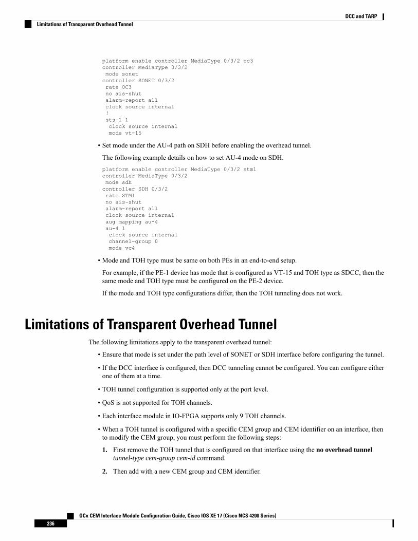
platform enable controller MediaType 0/3/2 oc3controller MediaType 0/3/2mode sonetcontroller SONET 0/3/2rate OC3no ais-shutalarm-report allclock source internal!sts-1 1clock source internalmode vt-15
• Set mode under the AU-4 path on SDH before enabling the overhead tunnel.
The following example details on how to set AU-4 mode on SDH.platform enable controller MediaType 0/3/2 stm1controller MediaType 0/3/2mode sdhcontroller SDH 0/3/2rate STM1no ais-shutalarm-report allclock source internalaug mapping au-4au-4 1clock source internalchannel-group 0mode vc4
• Mode and TOH type must be same on both PEs in an end-to-end setup.
For example, if the PE-1 device has mode that is configured as VT-15 and TOH type as SDCC, then thesame mode and TOH type must be configured on the PE-2 device.
If the mode and TOH type configurations differ, then the TOH tunneling does not work.
Limitations of Transparent Overhead TunnelThe following limitations apply to the transparent overhead tunnel:
• Ensure that mode is set under the path level of SONET or SDH interface before configuring the tunnel.
• If the DCC interface is configured, then DCC tunneling cannot be configured. You can configure eitherone of them at a time.
• TOH tunnel configuration is supported only at the port level.
• QoS is not supported for TOH channels.
• Each interface module in IO-FPGA supports only 9 TOH channels.
• When a TOH tunnel is configured with a specific CEM group and CEM identifier on an interface, thento modify the CEM group, you must perform the following steps:
1. First remove the TOH tunnel that is configured on that interface using the no overhead tunneltunnel-type cem-group cem-id command.
2. Then add with a new CEM group and CEM identifier.
OCx CEM Interface Module Configuration Guide, Cisco IOS XE 17 (Cisco NCS 4200 Series)236
DCC and TARPLimitations of Transparent Overhead Tunnel

• When DCC tunneling is set, you cannot configure payload and dejitter buffer under the CEM interface.
• The K1 and K2 bytes are not transparent over APS-enabled channels.
How to Configure Transparent Overhead TunnelThis section provides information about configuring the transparent overhead tunnel.
Configuring Mode for ControllerConfiguring Mode for SONET Controller
Before configuring transparent overhead tunnel, ensure that mode for the controller is configured.
To configure mode for the SONET controller, use the following commands:
controller sonet interfacests-1 1mode vt-15
end
Configuring Mode for SDH Controller
To configure mode for the SDH controller, use the following commands:
controller sdh interfaceaug mapping au-4au-4 1clock source internalchannel-group 0mode vc4end
Any path-level mode can be set for SONET or SDH.Note
Creating Transparent Overhead TunnelTo configure a transparent overhead tunnel, specify the tunnel type of the line or section header and CEMgroup with identifier.
To configure the transparent overhead tunnel on the SONET interface, use the following commands:
router(config)#controller sonet interface-namerouter(config-controller)#overhead tunnel <All | SDCC | LDCC | K1K2 | LOH | SOH> cem-groupcem-id unframedrouter(config-controller)#end
To configure the transparent overhead tunnel on the SDH interface, use the following commands:
router(config)#controller sdh interface-namerouter(config-controller)#overhead tunnel <All | RS-DCC | MS-DCC | K1K2 | LOH | SOH> cem-group
OCx CEM Interface Module Configuration Guide, Cisco IOS XE 17 (Cisco NCS 4200 Series)237
DCC and TARPHow to Configure Transparent Overhead Tunnel

cem-id unframedrouter(config-controller)#end
Configuring DCC Interface in IP DomainTo configure DCC Interface in IP domain controller, use the following commands:router ospf 100interface sdcc/ldcc
encapsulation pppip address 10.2.2.1 255.0.0.0crc <16/32 >ip ospf 100 area 0
Configuring TOH TunnellingTo configure TOH Tunnelling use the following commands:controller SONET/SDH < >no snmp trap link-statusrate < >no ais-shutalarm-report allclock source internaloverhead tunnel sdcc/ldcc/k1k2/soh/toh/all/aps_all cem-group 0 unframed
Creating Transparent Overhead Tunnel PseudowireTo configure a transparent overhead tunnel pseudowire, first configure the CEM interface and then performcross connect to a peer device with a remote IP address and specific virtual circuit identifier using MPLSencapsulation. The pseudowire carry forward specific TOH types as configured.
To configure the transparent overhead tunnel pseudowire, use the following commands:
router(config)#interface cem 0/3/4router(config-if)#cem cem-idrouter(config-if)#xconnect remote-ip-address virtual-connect-ID encapsulation MPLSrouter(config-controller)#end
router(config)#interface cem 0/3/4router(config-if)#cem 1router(config-if)#xconnect 192.168.0.2 2 encapsulation MPLSrouter(config-controller)#end
Verifying Transparent Overhead Tunnel and Pseudowire ConfigurationThe following show cem circuit interface cem interface-name command displays that CEM interface isconfigured for a transparent overhead tunnel.Router# show cem circuit interface cem 0/7/7CEM0/7/7, ID: 100, Line: UP, Admin: UP, Ckt: ACTIVE, TOH Type: LOHController state: upIdle Pattern: 0xFF, Idle CAS: 0x8Dejitter: 6 (In use: 0)
OCx CEM Interface Module Configuration Guide, Cisco IOS XE 17 (Cisco NCS 4200 Series)238
DCC and TARPConfiguring DCC Interface in IP Domain

Payload Size: 8Framing: UnframedCEM Defects SetNone
Signalling: No CASRTP: No RTP
Ingress Pkts: 3001 Dropped: 0Egress Pkts: 3001 Dropped: 0
CEM Counter DetailsInput Errors: 0 Output Errors: 0Pkts Missing: 0 Pkts Reordered: 0Misorder Drops: 0 JitterBuf Underrun: 0Error Sec: 0 Severly Errored Sec: 0Unavailable Sec: 0 Failure Counts: 0Pkts Malformed: 0 JitterBuf Overrun: 0Generated Lbits: 0 Received Lbits: 0Generated Rbits: 0 Received Rbits: 0
OCx CEM Interface Module Configuration Guide, Cisco IOS XE 17 (Cisco NCS 4200 Series)239
DCC and TARPVerifying Transparent Overhead Tunnel and Pseudowire Configuration

OCx CEM Interface Module Configuration Guide, Cisco IOS XE 17 (Cisco NCS 4200 Series)240
DCC and TARPVerifying Transparent Overhead Tunnel and Pseudowire Configuration

C H A P T E R 18Target Identifier Address Resolution Protocol
Some appications running on SONET devices identify these devices by a Target Identifier (TID). Therefore,it is necessary for the router to cache TID-to-network address mappings. As these devices usually run overOSI, the network addresses involved in the mapping are OSI Network Service Access Points (NSAP).
When a device sends a packet to another device, the device needs a way to request this information directlyfrom the device, or from an intermediate device in the network. This functionality is provided by an addressresolution protocol called TID Address Resolution Protocol (TARP).
Service providers need a dynamic method to map TIDS to NSAPs, and TARP serves this purpose. TARPruns over the Connectionless Network Protocol (CLNP) as a router must support CLN Service Routing tosupport TARP.
• Prerequisites for TARP Support, on page 241• Restrictions and Limitations, on page 241• Types of TARP PDU's, on page 242• TARP Features, on page 242• How To Configure TARP, on page 245• Configuring TARP Features, on page 248
Prerequisites for TARP SupportIf the router is configured as an IS, the router must be running IS-IS.
If the router is configured as an ED, then the router must be running ES-IS.
Restrictions and Limitations• The commands “tarp allow caching” and “no tarp allow caching” may result in tarp resolution failures.
• Configuring multiple NSAP addresses are not supported.
• Avoid multiple configuring or changing tid and NSAP.
• DCC tarp is supported only on NCS4200-1T8S-10CS.
OCx CEM Interface Module Configuration Guide, Cisco IOS XE 17 (Cisco NCS 4200 Series)241

Types of TARP PDU's• Type 1—Sent when a device has a TID for which it has no matching NSAP. Type 1 PDUs are sent toall Level 1 (IS-IS and ES-IS) neighbors. If no response is received within the specified time limit, a Type2 PDU is sent. To prevent packet looping, a loop detection buffer is maintained on the router. A Type 1PDU is sent when you use the tarp resolve command.
A Type 1 PDU is sent when a device has a TID for which it has no matching NET information and issent to all L1 neighbors. When a device receives a Type 1 PDU, it checks if the PDU matches the targetTID of the device. When they match, a type 3 PDU is created and unicasted directly to the sender of theTARP PDU. In addition, if the update remote cache is set in the incoming PDU, the receiver updates (orcreates) the cache entry for the originator. If the target TID does not match, the device propagates thisPDU to all its L1 neighbors (except the originator of this PDU). If no response is received within thetimeout period (15 seconds), a Type 2 PDU is originated.
To prevent packet looping, a Loop Detection Buffer (LDB) is maintained. This consists of system ID -sequence number mappings. A packet is discarded if its sequence number is less than or equal to thatfound in the LDB for this system ID. If no entry is present, the LDB is updated, and the packet is processed.A sequence number of zero is treated specially, and will cause the entry in the cache to be superseded.
• Type 2—Sent when a device has a TID for which it has no matching NSAP and no response was receivedfrom a Type 1 PDU. Type 2 PDUs are sent to all Level 1 and Level 2 neighbors. A time limit for Type2 PDUs can also be specified. A Type 2 PDU is sent when you use the tarp resolve command and specifythe option 2.
A Type 2 PDU is same as a Type 1, except that this PDU is sent to all (L1 and L2) neighbors. The defaulttimeout is 25 seconds.
• Type 3—Sent as a response to a Type 1, Type 2, or Type 5 PDU. Type 3 PDUs are sent directly to theoriginator of the request.
• Type 4—Sent as a notification when a change occurs locally (for example, a TID or NSAP change). AType 4 PDU usually occurs when a device is powered up or brought online.
• Type 5—Sent when a device needs a TID that corresponds to a specific NSAP. Unlike Type 1 and Type2 PDUs that are sent to all Level 1 and Level 2 neighbors, a Type 5 PDU is sent only to a particularrouter. In addition to the type, TARP PDUs contain the sender NSAP, the sender TID, and the targetTID (if the PDU is a Type 1 or Type 2). A Type 5 PDU is sent when you use the tarp query command.
TARP FeaturesThe following are the features of TARP:
TARP CachingTID - Network addresses mappings are stored in a cache, implemented as a hash table. A cache entry can becreated dynamically when a router hears from another TARP device (e.g. as a result of a query addressed tothe router), or statically via TARP "map" commands. All dynamically created TARP cache entries (i.e. thosethat are not static or flagged as "LOCAL") are aged out. The time out value is configurable.
OCx CEM Interface Module Configuration Guide, Cisco IOS XE 17 (Cisco NCS 4200 Series)242
DCC and TARPTypes of TARP PDU's

TARP TimersConfigure the amount of time that the router waits to receive a response from a Type 1 PDU, a Type 2 PDU,and a Type 5 PDU and also configure the lifetime of the PDU based on the number of hops.
Set timers that control how long dynamically created TARP entries remain in the TID cache, and how longthe system ID-to-sequence number mapping entry remains in the loop detection buffer table. The loop detectionbuffer table prevents TARP PDUs from looping.
TARP CountersTARP will maintain a list of useful counters, and will increment the relevant counter. There will also beextensive debugging support that will facilitate troubleshooting
NSAP Address FormatThe OSI network address is referred to as a network service access point (NSAP). The NSAP is assigned tothe end system (ES) or intermediate system (IS) device. Unlike in IP, which has an address for every networkinterface, the OSI network device receives only one address, the NSAP address. The NSAP address has twoparts, the Initial Domain Part (IDP) and Domain Specific Part (DSP).
OCx CEM Interface Module Configuration Guide, Cisco IOS XE 17 (Cisco NCS 4200 Series)243
DCC and TARPTARP Timers

Determining TIDs and NSAPsTo determine an NSAP address for a TID or a TID for an NSAP address, use the following commands inEXEC mode:
PurposeCommand
Gets the TID associated with a specific NSAP.Router # tarp query nsap
Gets the NSAP associated with a specific TID.Router #
tarp resolve neighbour tid
To determine the TID, the router first checks the local TID cache. If there is a TID entry in the local TIDcache, the requested information is displayed. If there is no TID entry in the local TID cache, a TARP Type5 PDU is sent out to the specified NSAP address.
To determine the NSAP address, the router first checks the local TID cache. If there is an NSAP entry in thelocal TID cache, the requested information is displayed. If there is no NSAP entry in the local TID cache, aTARP Type 1 or Type 2 PDU is sent out. By default, a Type 1 PDU is sent to all Level 1 (IS-IS and ES-IS)neighbors. If a response is received, the requested information is displayed. If a response is not received withinthe response time, a Type 2 PDU is sent to all Level 1 and Level 2 neighbors. Specifying the tarp resolvetid 2 EXEC command causes only a Type 2 PDU to be sent.
You can configure the length of time that the router will wait for a response (in the form of a Type 3 PDU).
Understanding NSAPAddresses in the ISO network architecture are referred to as network service access point (NSAP)addressesand network entity titles (NETs). Each node in an OSI network has one or more NETs. In addition, each nodehas many NSAP addresses. Each NSAP address differs from one of the NETs for that node in only the lastbyte. This byte is called the N-selector. Its function is similar to the port number in other protocol suites.
Our implementation supports all NSAP address formats that are defined by ISO 8348/Ad2; however, Ciscoprovides ISO Interior Gateway Routing Protocol (IGRP) or Intermediate System-to-Intermediate System(IS-IS) dynamic routing only for NSAP addresses that conform to the address constraints defined in the ISOstandard for IS-IS (ISO 10589).
An NSAP address consists of the following two major fields, as shown in Figure 1:
• The initial domain part (IDP) is made up of 1-byte authority and format identifier (AFI) and avariable-length initial domain identifier (IDI). The length of the IDI and the encoding format for thedomain specific part (DSP) are based on the value of the AFI.
• The DSP is made up of a High Order DSP (HO-DSP), an area identifier, a system identifier, and a 1-byteN-selector (labeled S).
OCx CEM Interface Module Configuration Guide, Cisco IOS XE 17 (Cisco NCS 4200 Series)244
DCC and TARPDetermining TIDs and NSAPs

Assign addresses or NETs for your domains and areas. The domain address uniquely identifies the routingdomain. All routers within a given domain are given the same domain address. Within each routing domain,you can set up one or more areas, as shown in Figure 2. Determine which routers are to be assigned to whichareas. The area address uniquely identifies the routing area and the system ID identifies each node.
The key difference between the ISO IGRP and IS-IS NSAP addressing schemes is in the definition of areaaddresses. Both use the system ID for Level 1 routing (routing within an area). However, they differ in theway addresses are specified for area routing. An ISO IGRP NSAP address includes three separate fields forrouting: the domain, area, and system ID. An IS-IS address includes two fields: a single continuous area field(comprising the domain and area fields) and the system ID.
How To Configure TARPTo configure TARP on the router, perform the tasks in the following sections:
Enabling TARP and Configuring a TARP TIDTARP must be explicitly enabled before the TARP functionality becomes available, and the router must havea TID assigned. Also, before TARP packets can be sent out on an interface, each interface must have TARPenabled and the interface must be able to propagate TARP PDUs.
The router will use the CLNS capability to send and receive TARP PDUs. If the router is configured as anIS, the router must be running IS-IS. If the router is configured as an ES, the router must be running ES-IS.
To turn on the TARP functionality, use the following commands in global configuration mode:
OCx CEM Interface Module Configuration Guide, Cisco IOS XE 17 (Cisco NCS 4200 Series)245
DCC and TARPHow To Configure TARP

PurposeCommand
Turns on the TARP functionality.Router(config)# tarp run
Assigns a TID to the router.Router(config)# tarp tidtid
To enable TARP on one or more interfaces, use the following command in interface configuration mode
Table 37:
PurposeCommand
Enables TARP on the interface.Router(config-if)# tarpenable
TARP on Gigabit Ethernet InterfaceThe following example shows how to enable TARP on the router and Ethernet interface 0. The router isassigned the TID name.interface GigabitEthernet0/2/5ip address 172.16.1.2 255.240.0.0 àip address for gigip router isis 1 -- to enable the isis configured under gignegotiation autoclns router isis 1 --- to assign it to clnsisis circuit-type level-1 --- isis level typetarp enable
TARP on SDCCThe following example shows how to enable TARP on the SDCC interface. The router is assigned the TIDname.interface SDCC0/3/3ip address 192.168.10.7 255.255.0.0encapsulation lapdlapd t200 200lapd role user‘lapd role network’ by defaultclns mtu 512clns router isis 1isis circuit-type level-1no isis hello paddingisis retransmit-interval 10isis lsp-interval 512tarp enable
tunnel source GigabitEthernet0/4/7interface GigabitEthernet0/4/7ip address 172.16.1.1 255.240.0.0negotiation auto
Router#sh run | sec Tunnel1interface Tunnel1ip address 172.16.2.2 255.240.0.0ip router isis 1
OCx CEM Interface Module Configuration Guide, Cisco IOS XE 17 (Cisco NCS 4200 Series)246
DCC and TARPTARP on Gigabit Ethernet Interface

tunnel source GigabitEthernet0/4/7tunnel destination 192.168.1.2clns router isis 1isis circuit-type level-1tarp enable
For more information on SDCC, Configuring Data Communication Channel
How to Configure TARPTARP must be explicitly enabled before the TARP functionality becomes available, and the router must havea TID assigned. Also, before TARP packets can be sent out on an interface, each interface must have TARPenabled and the interface must be able to propagate TARP PDUs.
The router uses the CLNS capability to transfer and receive TARP PDUs. If the router is configured as an IS,the router must be running IS-IS. If the router is configured as an ES, the router must be running ES-IS.
TARP feature can be optionally enabled or disabled through CLI. Furthermore, all interfaces over whichTARP packets that need to be sent must have TARP configured. Propagation of TARP packets can be disabledon an interface basis, on an adjacency basis, or on a global basis. Origination of TARP packets can be disabledon a global basis.
To configure TARP on a Gigabit Ethernet Interface, use the following commands:
Procedure
Step 1 configure terminal
Enter global configuration mode.
Step 2 tarp run
Router (config)# tarp run
Enable TARP functionality.
Step 3 tarp tid id
Router (config)# tarp tid 500
Assign TID to the router.
Step 4 tarp enable interface name
Router (config)#tarp enable Te0/12/0
Enables TARP on an interface.
TARP Configuration ExamplesThe following example shows how to enable TARP on the router and Ethernet interface 0. The router isassigned the TID myname.clns routingtarp runtarp tid myname
OCx CEM Interface Module Configuration Guide, Cisco IOS XE 17 (Cisco NCS 4200 Series)247
DCC and TARPHow to Configure TARP

interface ethernet 0tarp enable
Configuring TARP FeaturesTo configure TARP features on the router, perform the tasks in the following sections.
Configuring Static TARP Adjacency and Blacklist AdjacencyIn addition to all its IS-IS/ES-IS adjacencies, a TARP router propagates PDUs to all its static TARP adjacencies.If a router is not running TARP, the router discards TARP PDUs rather than propagating the PDUs to all itsadjacencies. To allow TARP to bypass routers en route that may not have TARP running, TARP provides astatic TARP adjacency capability. Static adjacencies are maintained in a special queue.
To create a static TARP adjacency, use the following command in global configuration mode:
PurposeCommand
Enters a static TARP adjacency.Router(config)# tarp route-static nsap [all | message-type {unknowns
| type-number} [type-number] [type-number]]
To stop TARP from propagating PDUs to an IS-IS/ES-IS adjacency that may not have TARP running, TARPprovides a blacklist adjacency capability. The router will not propagate TARP PDUs to blacklisted routers.To blacklist a router, use the following command in global configuration mode:
To blacklist a router, use the following command in global configuration mode:
PurposeCommand
Bypasses a router not running TARP.Router(config)# tarp blacklist-adjacency
nsap
Configuring TARP TimersTARP timers provide default values and typically need not be changed.
You can configure the amount of time that the router waits to receive a response from a Type 1 PDU, a Type2 PDU, and a Type 5 PDU. You can also configure the lifetime of the PDU based on the number of hops.
You can also set timers that control how long dynamically created TARP entries remain in the TID cache,and how long the system ID-to-sequence number mapping entry remains in the loop detection buffer table.The loop detection buffer table prevents TARP PDUs from looping.
To configure TARP PDU timers, control PDU lifetime, and set how long entries remain in cache, use thefollowing commands in global configuration mode:
PurposeCommand
Configures the number of seconds that the router will wait for aresponse from a TARP Type 1 PDU.
Router(config)# tarp t1-response-timerseconds
OCx CEM Interface Module Configuration Guide, Cisco IOS XE 17 (Cisco NCS 4200 Series)248
DCC and TARPConfiguring TARP Features

PurposeCommand
Configures the number of seconds that the router will wait for aresponse from a TARP Type 2 PDU.
Router(config)# tarp t2-response-timerseconds
Configures the number of seconds that the router will wait for aresponse from a TARP Type 2 PDU after the default timer hasexpired.
Router(config)# tarppost-t2-response-timer seconds
Configures the number of seconds that the router will wait for aresponse from a TARP Type 5 PDU.
Router(config)# tarp arp-request-timerseconds
Configures the number of routers that a TARP PDU can traversebefore it is discarded.
Router(config)# tarp lifetime hops
Configures the number of seconds a dynamically created TARPentry remains in the TID cache.
Router(config)# tarp cache-timer seconds
Configures the number of seconds that a system ID-to-sequencenumber mapping entry remains in the loop detection buffer table.
Router(config)# tarp ldb-timer seconds
Configuring Miscellaneous TARP PDU InformationTARP default PDU values typically need not be changed.
You can configure the sequence number of the TARP PDU, set the update remote cache bit used to controlwhether the remote router updates its cache, specify the N-selector used in the PDU to indicate a TARP PDU,and specify the network protocol type used in outgoing PDUs.
To configure miscellaneous PDU information, use the following commands in global configuration mode:
Table 38:
PurposeCommand
Changes the sequence number in the next outgoing TARP PDU.Router(config)# tarp sequence-numbernumber
Sets the update remote cache bit in all subsequent outgoingTARP PDUs so that the remote router does or does not updatethe cache.
Router(config)# tarp urc [0 | 1]
Specifies the N-selector used to identify TARP PDUs.Router(config)# tarp nselector-typehex-digit
Specifies the protocol type used in outgoing TARP PDUs. Onlythe hexadecimal value 0xFE (to indicate the CLNP) is supported.
Router(config)# tarpprotocol-typehex-digit
TARP Configuration Task ListTo configure TARP on the router, perform the tasks in the following sections. Only the first task is required;all other tasks are optional.
OCx CEM Interface Module Configuration Guide, Cisco IOS XE 17 (Cisco NCS 4200 Series)249
DCC and TARPConfiguring Miscellaneous TARP PDU Information

Disabling TARP CachingBy default, TID-to-NSAP address mappings are stored in the TID cache. Disabling this capability clears theTID cache. Reenabling this capability restores any previously cleared local entry and all static entries.
To disable TID-to-NSAP address mapping in the TID cache, use the following command in global configurationmode:
PurposeCommand
Disables TARPTID-to-NSAP address mapping.Router(config)# no tarp allow-caching
Disabling TARP PDU Origination and PropagationBy default, the router originates TARP PDUs and propagates TARP PDUs to its neighbors, and the interfacepropagates TARP PDUs to its neighbor. Disabling these capabilities means that the router no longer originatesTARP PDUs, and the router and the specific interface no longer propagate TARP PDUs received from otherrouters.
To disable origination and propagation of TARP PDUs, use the following commands in global configurationmode:
PurposeCommand
Disables TARP PDU origination.Router(config)# no tarp originate
Disables global propagation of TARP PDUs.Router(config)# no tarp global-propagate
To disable propagation of TARP PDUs on a specific interface, use the following command in interfaceconfiguration mode:
PurposeCommand
Disables propagation of TARP PDUs on theinterface.
Router(config-if)# no tarp propagateall | message-type{unknownstype-number} [type-number] [type-number]]
OCx CEM Interface Module Configuration Guide, Cisco IOS XE 17 (Cisco NCS 4200 Series)250
DCC and TARPDisabling TARP Caching

P A R T VIBandwidth for OCx Modules
• Configuring 5G Mode, on page 253


C H A P T E R 19Configuring 5G Mode
Effective Cisco IOS XE Everest 16.5.1, 5G mode is supported on 1-Port OC-192/STM-64 or 8-PortOC-3/12/48/STM-1/-4/-16 InterfaceModule. Previously, only 10Gmodewas supported. 5Gmode is supportedon those interface module slots that do not support 10G mode.
On the NCS 4216 Routers, if the interface module is inserted in the slots 3, 4, 7, 8, 11, or 12, the interfacemodule comes up in 10G mode by default. Use the mode conversion command to use the interface modulein 5G mode. If the interface module is inserted in the slots 2, 5, 6, 9, 10, 13, 14, and 15, the interface modulecomes up in 5G mode by default. Hence, there is no need to apply the mode conversion command.
Slot 1 on the NCS 4216 Router is supported for the 5G mode for 1-Port OC-192/STM-64 or 8-PortOC-3/12/48/STM-1/-4/-16 Interface module on the chassis.
Note
OC-192/STM-64 port is disabled in 5G mode.Note
Table 39: Default 5G Slots on NCS 4206 Routers
5G Mode CommandSupport
Default ModeInterface Module SupportBays
NoNoNo0
NoNoNo1
Yes10G_CEMYes2
Yes10G_CEMYes3
Yes10G_CEMYes4
Yes10G_CEMYes5
OCx CEM Interface Module Configuration Guide, Cisco IOS XE 17 (Cisco NCS 4200 Series)253

Table 40: Default 10G Slots on NCS 4216 Routers
5G Mode CommandSupport
Default ModeInterface Module SupportBays
NoNoNo0
NoNoNo1
No need to use thecommand as the interfacemodule is in 5G mode bydefault
5G_CEMYes2
Yes10G_CEMYes3
Yes10G_CEMYes4
No need to use thecommand as the interfacemodule is in 5G mode bydefault
5G_CEMYes5
No need to use thecommand as the interfacemodule is in 5G mode bydefault
5G_CEMYes6
Yes10G_CEMYes7
Yes10G_CEMYes8
No need to use thecommand as the interfacemodule is in 5G mode bydefault
5G_CEMYes9
No need to use thecommand as the interfacemodule is in 5G mode bydefault
5G_CEMYes10
Yes10G_CEMYes11
Yes10G_CEMYes12
No need to use thecommand as the interfacemodule is in 5G mode bydefault
5G_CEMYes13
OCx CEM Interface Module Configuration Guide, Cisco IOS XE 17 (Cisco NCS 4200 Series)254
Bandwidth for OCx Modules

5G Mode CommandSupport
Default ModeInterface Module SupportBays
No need to use thecommand as the interfacemodule is in 5G mode bydefault
5G_CEMYes14
No need to use thecommand as the interfacemodule is in 5G mode bydefault
5G_CEMYes15
Features of the Interface Module:
• This IM supports 8 ports with 5G CEM traffic.
• This IM supports a maximum of 5Gbps traffic throughput with the following services:
• 5G HO CEP
• 5G LO CES/CEP
• Supported Traffic Combinations, on page 255• Restrictions for Configuring 1-Port OC-192/STM-64 or 8-Port OC-3/12/48/STM-1/-4/-16 InterfaceModule, on page 256
• Important Notes on Configuration, on page 256• Configuring 5G Mode from 10G Mode, on page 256• Configuring 10G Mode from 5G Mode, on page 256• Verification of 5G Traffic Configuration, on page 257• Associated Commands, on page 257
Supported Traffic CombinationsThe following traffic combination is supported:
• CEM Traffic - SONET:
Ports 0-7 are available as OC-48/OC-12/OC-3/1GE ports. To achieve 5G traffic on the card, four portsare grouped. For example, 0-3 and 4-7 can provide a maximum traffic of 2.5G. For example, OC-48 portis allocated in each group. Hence, if one of the ports is configured as OC-48, the other ports in the groupcannot be configured. If OC-12 or OC-3 rate is configured in any of the port groups, OC-48 cannot beconfigured.
• CEM Traffic - SDH:
Ports 0-7 are available as STM-16, STM-4, and STM-1 ports. To achieve 5G traffic on the card, fourports are grouped. For example, 0-3 and 4-7 can provide a maximum traffic of 2.5G. For example,STM-16 port is allocated in each group. Hence, if one of the ports is configured as STM-16, the otherports in the group cannot be configured. If STM-4 or STM-1 rate is configured in any of the port groups,STM-16 cannot be configured.
OCx CEM Interface Module Configuration Guide, Cisco IOS XE 17 (Cisco NCS 4200 Series)255
Bandwidth for OCx ModulesSupported Traffic Combinations
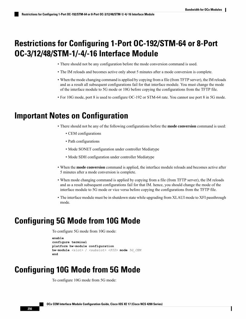
Restrictions for Configuring 1-Port OC-192/STM-64 or 8-PortOC-3/12/48/STM-1/-4/-16 Interface Module
• There should not be any configuration before the mode conversion command is used.
• The IM reloads and becomes active only about 5 minutes after a mode conversion is complete.
• When the mode changing command is applied by copying from a file (from TFTP server), the IM reloadsand as a result all subsequent configurations fail for that interface module. You must change the modeof the interface module to 5G mode or 10G before copying the configurations from the TFTP file.
• For 10G mode, port 8 is used to configure OC-192 or STM-64 rate. You cannot use port 8 in 5G mode.
Important Notes on Configuration• There should not be any of the following configurations before the mode conversion command is used:
• CEM configurations
• Path configurations
• Mode SONET configuration under controller Mediatype
• Mode SDH configuration under controller Mediatype
• When the mode conversion command is applied, the interface module reloads and becomes active after5 minutes after a mode conversion is complete.
• When mode changing command is applied by copying from a file (from TFTP server), the IM reloadsand as a result subsequent configurations fail for that IM. hence, you should change the mode of theinterface module to 5G mode or vice versa before copying the configurations from the TFTP file.
• The interface module must be in shutdown state while upgrading from XLAUI mode to XFI passthroughmode.
Configuring 5G Mode from 10G ModeTo configure 5G mode from 10G mode:enableconfigure terminalplatform hw-module configurationhw-module <slot> / <subslot> <PID> mode 5G_CEMend
Configuring 10G Mode from 5G ModeTo configure 10G mode from 5G mode:
OCx CEM Interface Module Configuration Guide, Cisco IOS XE 17 (Cisco NCS 4200 Series)256
Bandwidth for OCx ModulesRestrictions for Configuring 1-Port OC-192/STM-64 or 8-Port OC-3/12/48/STM-1/-4/-16 Interface Module

enableconfigure terminalplatform hw-module configurationhw-module <slot> / <subslot> <PID>end
Verification of 5G Traffic ConfigurationUse the show running configuration command to verify 5G traffic configuration:Router#show running-config | include modehw-module 0/bay PID mode 5G_CEMRouter#
Associated CommandsThe following table shows the associated commands for 5G traffic configuration:
LinksCommands
http://www.cisco.com/c/en/us/td/docs/ios-xml/ios/mcl/allreleasemcl/all-book/all-06.html
hw-module mode
http://www.cisco.com/c/en/us/td/docs/ios-xml/ios/mcl/allreleasemcl/all-book/all-10.html
platform hw-module configuration
http://www.cisco.com/c/en/us/td/docs/ios-xml/ios/mcl/allreleasemcl/all-book/all-14.html
show running configuration | include mode
OCx CEM Interface Module Configuration Guide, Cisco IOS XE 17 (Cisco NCS 4200 Series)257
Bandwidth for OCx ModulesVerification of 5G Traffic Configuration

OCx CEM Interface Module Configuration Guide, Cisco IOS XE 17 (Cisco NCS 4200 Series)258
Bandwidth for OCx ModulesAssociated Commands

P A R T VIIAdditional References
• Additional References for SONET/SDH Frame Structures, on page 261


C H A P T E R 20Additional References for SONET/SDH FrameStructures
This section provides information about STS-1 and STS-3 frame structures for SONET with concatenatedand channelized details, and STM-1 frame with VC details for SDH frame.
For more information on the basic CEM features such as CEM classes and CEM parameters (payload sizeand dejitter buffer), configuration, and verfication, see the CEMGeneric Configuration Guide, Cisco IOS XE17 (Cisco NCS 4200 Series).
• SONET Frame Structure, on page 261• SDH Frame Structure, on page 263
SONET Frame Structure
STS-1 and STS-3 FramesA standard STS-1 frame is nine rows by 90 bytes. The first three bytes of each row represent the Section andLine overhead. These overhead bits comprise framing bits and pointers to different parts of the SONET frame.
Figure 12: STS-1 Frame Structure
OCx CEM Interface Module Configuration Guide, Cisco IOS XE 17 (Cisco NCS 4200 Series)261

There is one column of bytes in the payload that represents the STS path overhead. This column frequently"floats" throughout the frame. Its location in the frame is determined by a pointer in the Section and Lineoverhead.
The combination of the Section and Line overhead comprises the transport overhead, and the remainder isthe SPE.
Figure 13: STS-1 SONET Overhead
For STS-1, a single SONET frame is transmitted in 125 microseconds, or 8000 frames per second. 8000 fps* 810 B/frame = 51.84 Mbs, of which the payload is roughly 49.5 Mbs, enough to encapsulate 28 DS-1s, afull DS-3, or 21 CEPT-1s.
An STS-3 frame is nine rows by 270 bytes. The first nine columns contain the transport overhead section,and the rest is SPE. For both STS-3 and STS-3c, the transport overhead (Line and Section) is the same.
For an STS-3 frame, the SPE contains three separate payloads and three separate path overhead fields. Inessence, it is the SPE of three separate STS-1s packed together, one after another.
For more information on Section Overhead, Line Overhead, and Path Overhead, refer the following:
• http://www.cisco.com/c/en/us/support/docs/optical/synchronous-digital-hierarchy-sdh/5462-sdh-overview.html
• http://www.cisco.com/c/en/us/support/docs/optical/synchronous-optical-network-sonet/13567-sonet-tech-tips.html
• http://www.cisco.com/c/en/us/tech/optical/synchronous-optical-network-sonet/tsd-technology-support-troubleshooting-technotes-list.html
Concatenated SONET FramesTwenty-eight VTs make up one STS-1. Three STS-1s made up an STS-3 and so on. Any one byte within theSTS frame has a direct relationship to a base VT that helps to make up the STS.
A lower-case "c" in the STS rate stands for "concatenated", and indicates that the interface hardware is notchannelized. Examples of concatenated interfaces are STS-3c and STS-12c.
The STS-1s may be concatenated into sets of 3 or 12 or 24 or 48 or 192 to form STS-3c, STS-12c, and so on.The STS-1s may be combined only at specific STS-n boundaries within an OC port.
OCx CEM Interface Module Configuration Guide, Cisco IOS XE 17 (Cisco NCS 4200 Series)262
Additional ReferencesConcatenated SONET Frames

Channelized SONET FramesA channelized SONET interface is a composite of lower-speed STS streams. However, a channelized SONETinterface maintains the streams as independent frames with unique payload pointers. The frames are simplymultiplexed before transmission to increase the carrying capacity of the physical fiber. This process is similarto multiplexing 24 digital signal level 0 channels into a DS1 or multiplexing 28 DS1 streams into a DS3.
SDH Frame StructureThe STM-1 frame is the basic transmission format for SDH. The frame lasts for 125 microseconds, therefore,there are 8000 frames per second. The STM-1 frame consists of overhead plus a Virtual Container (VC)capacity.
The SDH frame consists of 270 columns. The first nine columns of each framemake up the Section Overhead,and the last 261 columns make up the VC capacity. The VC plus the pointers (H1, H2, H3 bytes) are calledthe Administrative Unit (AU). Carried within the VC capacity, which has its own frame structure of nine rowsand 261 columns, is the Path Overhead and the Container. The first column is for Path Overhead; it is followedby the payload container, which can itself carry other containers. VCs can have any phase alignment withinthe Administrative Unit, and this alignment is indicated by the Pointer in row four.Within the Section Overhead,the first three rows are used for the Regenerator Section Overhead, and the last five rows are used for theMultiplex Section Overhead. The STM frame is transmitted in a byte-serial fashion, row-by-row, and isscrambled immediately prior to transmission to ensure adequate clock timing content for downstreamregenerators.
Figure 14: STM1 Frame Structure
OCx CEM Interface Module Configuration Guide, Cisco IOS XE 17 (Cisco NCS 4200 Series)263
Additional ReferencesChannelized SONET Frames

Figure 15: STM1 Section Overhead
VCSDH supports a concept called VC. Through the use of pointers and offset values, VCs can be carried in theSDH payload as independent data packages. VCs are used to transport lower-speed tributary signals. Notethat it can start (indicated by the J1 path overhead byte) at any point within the STM-1 frame. The start locationof the J1 byte is indicated by the pointer byte values. VCs can also be concatenated to provide more capacityin a flexible fashion.
OCx CEM Interface Module Configuration Guide, Cisco IOS XE 17 (Cisco NCS 4200 Series)264
Additional ReferencesVC