Cisco SD-WAN Policies Configuration Guide, Cisco IOS XE ...
236
Cisco SD-WAN Policies Configuration Guide, Cisco IOS XE Release 17.x First Published: 2020-03-17 Last Modified: 2021-12-17 Americas Headquarters Cisco Systems, Inc. 170 West Tasman Drive San Jose, CA 95134-1706 USA http://www.cisco.com Tel: 408 526-4000 800 553-NETS (6387) Fax: 408 527-0883
-
Upload
khangminh22 -
Category
Documents
-
view
4 -
download
0
Transcript of Cisco SD-WAN Policies Configuration Guide, Cisco IOS XE ...

Cisco SD-WAN Policies Configuration Guide, Cisco IOS XE Release17.xFirst Published: 2020-03-17
Last Modified: 2021-12-17
Americas HeadquartersCisco Systems, Inc.170 West Tasman DriveSan Jose, CA 95134-1706USAhttp://www.cisco.comTel: 408 526-4000
800 553-NETS (6387)Fax: 408 527-0883

THE SPECIFICATIONS AND INFORMATION REGARDING THE PRODUCTS IN THIS MANUAL ARE SUBJECT TO CHANGE WITHOUT NOTICE. ALL STATEMENTS,INFORMATION, AND RECOMMENDATIONS IN THIS MANUAL ARE BELIEVED TO BE ACCURATE BUT ARE PRESENTED WITHOUT WARRANTY OF ANY KIND,EXPRESS OR IMPLIED. USERS MUST TAKE FULL RESPONSIBILITY FOR THEIR APPLICATION OF ANY PRODUCTS.
THE SOFTWARE LICENSE AND LIMITED WARRANTY FOR THE ACCOMPANYING PRODUCT ARE SET FORTH IN THE INFORMATION PACKET THAT SHIPPED WITHTHE PRODUCT AND ARE INCORPORATED HEREIN BY THIS REFERENCE. IF YOU ARE UNABLE TO LOCATE THE SOFTWARE LICENSE OR LIMITED WARRANTY,CONTACT YOUR CISCO REPRESENTATIVE FOR A COPY.
The Cisco implementation of TCP header compression is an adaptation of a program developed by the University of California, Berkeley (UCB) as part of UCB's public domain version ofthe UNIX operating system. All rights reserved. Copyright © 1981, Regents of the University of California.
NOTWITHSTANDING ANY OTHERWARRANTY HEREIN, ALL DOCUMENT FILES AND SOFTWARE OF THESE SUPPLIERS ARE PROVIDED “AS IS" WITH ALL FAULTS.CISCO AND THE ABOVE-NAMED SUPPLIERS DISCLAIM ALL WARRANTIES, EXPRESSED OR IMPLIED, INCLUDING, WITHOUT LIMITATION, THOSE OFMERCHANTABILITY, FITNESS FOR A PARTICULAR PURPOSE AND NONINFRINGEMENT OR ARISING FROM A COURSE OF DEALING, USAGE, OR TRADE PRACTICE.
IN NO EVENT SHALL CISCO OR ITS SUPPLIERS BE LIABLE FOR ANY INDIRECT, SPECIAL, CONSEQUENTIAL, OR INCIDENTAL DAMAGES, INCLUDING, WITHOUTLIMITATION, LOST PROFITS OR LOSS OR DAMAGE TO DATA ARISING OUT OF THE USE OR INABILITY TO USE THIS MANUAL, EVEN IF CISCO OR ITS SUPPLIERSHAVE BEEN ADVISED OF THE POSSIBILITY OF SUCH DAMAGES.
Any Internet Protocol (IP) addresses and phone numbers used in this document are not intended to be actual addresses and phone numbers. Any examples, command display output, networktopology diagrams, and other figures included in the document are shown for illustrative purposes only. Any use of actual IP addresses or phone numbers in illustrative content is unintentionaland coincidental.
All printed copies and duplicate soft copies of this document are considered uncontrolled. See the current online version for the latest version.
Cisco has more than 200 offices worldwide. Addresses and phone numbers are listed on the Cisco website at www.cisco.com/go/offices.
Cisco and the Cisco logo are trademarks or registered trademarks of Cisco and/or its affiliates in the U.S. and other countries. To view a list of Cisco trademarks, go to this URL:https://www.cisco.com/c/en/us/about/legal/trademarks.html. Third-party trademarks mentioned are the property of their respective owners. The use of the word partner does not imply apartnership relationship between Cisco and any other company. (1721R)
© 2019–2021 Cisco Systems, Inc. All rights reserved.

C O N T E N T S
Read Me First 1C H A P T E R 1
What's New in Cisco IOS XE (SD-WAN) 3C H A P T E R 2
Policy Overview 5C H A P T E R 3
Policy Architecture 7
Centralized Control Policy Architecture 7
Route Types 8
Default Behavior Without Centralized Control Policy 9
Behavior Changes with Centralized Control Policy 9
Examples of Modifying Traffic Flow with Centralized Control Policy 10
Configure Centralized Policy Based on Prefixes and IP Headers 12
Cisco vSmart Policy Components 13
TLOC Attributes Used in Policies 16
vRoute Attributes Used in Policies 17
Design Cisco vSmart Controller Policy Processing and Application 18
Cisco vSmart Policy Operation 19
Control Policy 20
Data Policy 22
VPN Membership Policy Operation 24
Configure and Execute Cisco vSmart Policies 25
Centralized Policy 27C H A P T E R 4
Overview of Centralized Policies 27
Types of Centralized Policies 27
Configure Centralized Policies Using Cisco vManage 28
Cisco SD-WAN Policies Configuration Guide, Cisco IOS XE Release 17.xiii

Start the Policy Configuration Wizard 28
Configure Groups of Interest for Centralized Policy 28
Configure Topology and VPN Membership 34
Import Existing Topology 36
Create a VPN Membership Policy 37
Configure Traffic Rules 37
Match Parameters - Control Policy 41
Match Parameters - Data Policy 43
Action Parameters - Control Policy 48
Action Parameters - Data Policy 49
Apply Policies to Sites and VPNs 52
NAT Fallback on Cisco IOS XE SD-WAN Devices 53
Activate a Centralized Policy 54
Configure Centralized Policies Using the CLI 56
Centralized Policies Configuration Examples 59
Localized Policy 67C H A P T E R 5
Overview of Localized Policies 67
Types of Localized Policies 67
Configure Localized Policy Using Cisco vManage 68
Start the Policy Configuration Wizard 69
Configure Groups of Interest for Localized Policy 69
Configure Forwarding Classes/QoS 72
Configure ACLs 73
Explicit and Implicit Access Lists 75
Configure Route Policies 76
Match Parameters 77
Action Parameters 79
Configure Policy Settings 80
Apply Localized Policy in a Device Template 81
Activate a Localized Policy 81
Configure Localized Policy for IPv4 Using the CLI 83
Configure Localized Policy for IPv6 Using the CLI 85
Localized Data Policy Configuration Examples 86
Cisco SD-WAN Policies Configuration Guide, Cisco IOS XE Release 17.xiv
Contents

Default AAR and QoS Policies 87C H A P T E R 6
Information About Default AAR and QoS Policies 87
Benefits of Default AAR and QoS Policies 88
Prerequisites for Default AAR and QoS Policies 88
Restrictions for Default AAR and QoS Policies 89
Supported Devices for Default AAR and QoS Policies 89
Use Cases for Default AAR and QoS Policies 89
Configure Default AAR and QoS Policies Using Cisco vManage 89
Monitor Default AAR and QoS Policies 93
Device Access Policy 95C H A P T E R 7
Device Access Policy Overview 95
Configure Device Access Policy Using Cisco vManage 96
Configure Device Access Policy Using the CLI 97
Examples for ACL Statistics and Counters 97
Verifying ACL Policy on an SNMP Server 99
Verifying ACL Policy on SSH 100
Deep Packet Inspection 103C H A P T E R 8
Deep Packet Inspection Overview 103
Configure Deep Packet Inspection Using Cisco vManage 103
Apply Centralized Policy for Deep Packet Inspection 104
Monitor Running Applications 104
View DPI Applications 104
Action Parameters for Configuring Deep Packet Inspection 105
Configure Deep Packet Inspection Using the CLI 107
Application-Aware Routing 111C H A P T E R 9
Application-Aware Routing Overview 111
Application-Aware Routing Support for Multicast Protocols 112
Restrictions for Multicast Protocols 112
Components of Application-Aware Routing 112
SLA Classes 113
Cisco SD-WAN Policies Configuration Guide, Cisco IOS XE Release 17.xv
Contents

Classification of Tunnels into SLA Classes 116
Measure Loss, Latency, and Jitter 116
Calculate Average Loss, Latency, and Jitter 117
Determine SLA Classification 117
Per-Class Application-Aware Routing 118
Per-Class Application-Aware Routing Overview 118
Application Probe Class 118
Default DSCP Values 119
Configure Application-Aware Routing 119
Configure Application-Aware Routing Policies Using Cisco vManage 119
Configure Best Tunnel Path 120
Best Tunnel Path Overview 120
Recommendation for the Best Tunnel Path 121
Configure SLA Class 121
Configure Traffic Rules 122
Default Action of Application-Aware Routing Policy 126
Configure Application Probe Class through vManage 126
Add App-Probe-Class to an SLA Class 127
Configure Default DSCP on Cisco BFD Template 127
Apply Policies to Sites and VPNs 128
How Application-Aware Routing Policy is Applied in Combination with Other Data Policies 129
Activate an Application-Aware Routing Policy 130
Monitor Data Plane Tunnel Performance 130
Enable Application Visibility on Cisco IOS XE SD-WAN Devices 132
Configure Application-Aware Routing Using CLIs 132
Configure Application Probe Class Using CLI 134
Application-Aware Routing Policy Configuration Example 135
Traffic Flow Monitoring with cFlowd 139C H A P T E R 1 0
Information about Traffic Flow Monitoring 140
Traffic Flow Monitoring with Cflowd Overview 140
IPFIX Information Elements for Cisco IOS XE SD-WAN Devices 141
Flexible Netflow for VPN0 Interface 144
Limitations of Flexible Netflow on VPN0 Interface 145
Cisco SD-WAN Policies Configuration Guide, Cisco IOS XE Release 17.xvi
Contents

Configure Traffic Flow Monitoring on Cisco IOS XE SD-WAN Devices 146
Configure Global Flow Visibility 146
Configure Global Application Visibility 147
Configure Cflowd Monitoring Policy 148
View Cflowd Information 149
Configure Cflowd Traffic Flow Monitoring Using the CLI 150
Configure Flexible Netflow on VPN0 Interface 151
Verify Flexible Netflow Configuration on VPN0 Interface 152
Apply and Enable Cflowd Policy 155
Cflowd Traffic Flow Monitoring Configuration Example 156
Application Performance Monitor 161C H A P T E R 1 1
Overview of Application Performance Monitor 161
Limitations and Restrictions 163
Configure Application Performance Monitor 164
Verify Performance Monitoring Configuration 165
Enhanced Policy Based Routing 177C H A P T E R 1 2
Overview of ePBR 177
Configure ePBR 179
Monitor ePBR 182
Forward Error Correction 185C H A P T E R 1 3
Configure Forward Error Correction for a Policy 185
Monitor Forward Error Correction Tunnel Information 186
Monitor Forward Error Application Family Information 187
Packet Duplication for Noisy Channels 189C H A P T E R 1 4
Information about Packet Duplication 189
Configure Packet Duplication 189
Monitor Packet Duplication Per Application 190
Integrate Cisco IOS XE SD-WAN Device with Cisco ACI 193C H A P T E R 1 5
Cisco SD-WAN Policies Configuration Guide, Cisco IOS XE Release 17.xvii
Contents

Guidelines to Integrate with Cisco ACI 194
Verify Cisco ACI Registration 194
SLA Classes 194
Data Prefixes 195
VPNs 195
Map Data Prefix and VPN to SLA 195
Create an App-Route-Policy 195
Map ACI Sites 196
Unmap ACI Sites 197
Delete a Controller 197
Define Custom Applications 199C H A P T E R 1 6
Overview 199
Define Custom Applications Using Cisco vManage 201
View Custom Applications 203
Service Chaining 205C H A P T E R 1 7
Configure Service Chaining 208
Service Chaining Configuration Examples 210
Monitor Service Chaining 215
Lawful Intercept 219C H A P T E R 1 8
Information About Lawful Intercept 219
Prerequisites for Lawful Intercept 222
Install Lawful Intercept using vManage 223
Lawful Intercept MIBs 223
Restrict Access to Trusted Hosts (Without Encryption) 224
Restrict Trusted Mediation Device 224
Configure Lawful Intercept 225
Configure Lawful Intercept Using CLI 225
Encrypt Lawful Intercept Traffic 226
Configure Encryption in the Device 226
Configure Lawful Intercept Encryption using CLI 227
Verify Static Tunnel with Media Device Gateway 228
Cisco SD-WAN Policies Configuration Guide, Cisco IOS XE Release 17.xviii
Contents
C H A P T E R 1Read Me First
Related References
• Release Notes
• Cisco SD-WAN Controller Compatibility Matrix and Server Recommendations
User Documentation
• Cisco IOS XE (Cisco IOS XE SD-WAN Devices)
• Cisco IOS XE (SD-WAN) Qualified Command Reference
• User Documentation for Cisco IOS XE (SD-WAN) Release 17
Communications, Services, and Additional Information
• Sign up for Cisco email newsletters and other communications at: Cisco Profile Manager.
• For information on the latest technical, advanced, and remote services to increase the operational reliabilityof your network visit Cisco Services.
• To browse and discover secure, validated enterprise-class apps, products, solutions, and services, visitCisco Devnet.
• To obtain general networking, training, and certification titles from Cisco Press Publishers, visit CiscoPress.
• To find warranty information for a specific product or product family, visit Cisco Warranty Finder.
• To view open and resolved bugs for a release, access the Cisco Bug Search Tool.
• To submit a service request, visit Cisco Support.
Documentation Feedback
To provide feedback about Cisco technical documentation use the feedback form available in the right paneof every online document.
Cisco SD-WAN Policies Configuration Guide, Cisco IOS XE Release 17.x1

Cisco SD-WAN Policies Configuration Guide, Cisco IOS XE Release 17.x2
Read Me First
C H A P T E R 2What's New in Cisco IOS XE (SD-WAN)
The documentation set for this product strives to use bias-free language. For purposes of this documentationset, bias-free is defined as language that does not imply discrimination based on age, disability, gender, racialidentity, ethnic identity, sexual orientation, socioeconomic status, and intersectionality. Exceptions may bepresent in the documentation due to language that is hardcoded in the user interfaces of the product software,language used based on standards documentation, or language that is used by a referenced third-party product.
Note
Cisco is constantly enhancing the SD-WAN solution with every release and we try and keep the content inline with the latest enhancements. The following table lists new and modified features we documented in theConfiguration, Command Reference, and Hardware Installation guides. For information on additional featuresand fixes that were committed to the Cisco SD-WAN solution, see the Resolved and Open Bugs section inthe Release Notes.
What's New in Cisco IOS XE (SD-WAN) Release 17.x
Cisco SD-WAN Policies Configuration Guide, Cisco IOS XE Release 17.x3
Cisco SD-WAN Policies Configuration Guide, Cisco IOS XE Release 17.x4
What's New in Cisco IOS XE (SD-WAN)

C H A P T E R 3Policy Overview
Policy influences the flow of data traffic and routing information among Cisco IOS XE SD-WAN devices inthe overlay network.
Policy comprises:
• Routing policy—which affects the flow of routing information in the network's control plane.
• Data policy—which affects the flow of data traffic in the network's data plane.
To implement enterprise-specific traffic control requirements, you create basic policies, and deploy advancedfeatures that are activated by means of the policy configuration infrastructure.
Just as the Cisco SD-WAN overlay network architecture clearly separates the control plane from the dataplane and control between centralized and localized functions, the Cisco SD-WAN policy is cleanly separated.Policies apply either to control plane or data plane traffic, and they are configured either centrally on CiscovSmart Controllers or locally on Cisco IOSXE SD-WAN devices. The following figure illustrates the divisionbetween control and data policy, and between centralized and local policy.
Figure 1: Policy Architecture
Control and Data Policy
Control policy is the equivalent of routing protocol policy, and data policy is equivalent to what are commonlycalled access control lists (ACLs) and firewall filters.
Centralized and Localized Policy
The Cisco SD-WAN policy design provides a clear separation between centralized and localized policy. Inshort, centralized policy is provisioned on the centralized Cisco vSmart Controllers in the overlay network,and the localized policy is provisioned on Cisco IOS XE SD-WAN devices, which sit at the network edgebetween a branch or enterprise site and a transport network, such as the Internet, MPLS, or metro Ethernet.
Cisco SD-WAN Policies Configuration Guide, Cisco IOS XE Release 17.x5
Centralized Policy
Centralized policy refers to policy provisioned on Cisco vSmart Controllers, which are the centralized controllersin the Cisco SD-WAN overlay network. Centralized policy comprises two components:
• Control policy, which affects the overlay network–wide routing of traffic
• Data policy, which affects the data traffic flow throughout the VPN segments in the network
Centralized control policy applies to the network-wide routing of traffic by affecting the information that isstored in the Cisco vSmart Controller's route table and that is advertised to the Cisco IOS XE SD-WANdevices. The effects of centralized control policy are seen in how Cisco IOS XE SD-WAN devices direct theoverlay network's data traffic to its destination.
The centralized control policy configuration itself remains on the Cisco vSmart Controller and is never pushedto local devices.
Note
Centralized data policy applies to the flow of data traffic throughout the VPNs in the overlay network. Thesepolicies can permit and restrict access based either on a 6-tuple match (source and destination IP addressesand ports, DSCP fields, and protocol) or on VPNmembership. These policies are pushed to the selected CiscoIOS XE SD-WAN devices.
Localized Policy
Localized policy refers to a policy that is provisioned locally through the CLI on the Cisco IOS XE SD-WANdevices, or through a Cisco vManage device template.
Localized control policy is also called as route policy, which affects (BGP and OSPF) routing behavior onthe site-local network.
Localized data policy allows you to provision access lists and apply them to a specific interface or interfaceson the device. Simple access lists permit and restrict access based on a 6-tuple match (source and destinationIP addresses and ports, DSCP fields, and protocol), in the same way as with centralized data policy. Accesslists also allow provisioning of class of service (CoS), policing, which control how data traffic flows out ofand in to the device's interfaces and interface queues.
The design of the Cisco SD-WAN policy distinguishes basic and advanced policies. Basic policy allows youto influence or determine basic traffic flow through the overlay network. Here, you perform standard policytasks, such as managing the paths along which traffic is routed through the network, and permitting or blockingtraffic based on the address, port, and DSCP fields in the packet's IP header. You can also control the flow ofdata traffic into and out of a Cisco IOS XE SD-WAN device's interfaces, enabling features such as class ofservice and queuing, and policing.
• Application-aware routing, which selects the best path for traffic based on real-time network and pathperformance characteristics.
• Cflowd, for monitoring traffic flow.
By default, no policy of any kind is configured on Cisco IOS XE SD-WAN devices, either on the centralizedCisco vSmart Controllers or the local Cisco IOS XE SD-WAN devices. When control plane traffic, whichdistributes route information, is unpolicied:
Cisco SD-WAN Policies Configuration Guide, Cisco IOS XE Release 17.x6
Policy Overview
• All route information that OMP propagates among the Cisco IOS XE SD-WAN devices is shared,unmodified, among all Cisco vSmart Controllers and all Cisco IOS XE SD-WAN devices in the overlaynetwork domain.
• No BGP or OSPF route policies are in place to affect the route information that Cisco IOS XE SD-WANdevices propagate within their local site network.
When data plane traffic is unpolicied, all data traffic is directed towards its destination based solely on theentries in the local Cisco IOS XE SD-WAN device's route table, and all VPNs in the overlay network canexchange data traffic.
• Policy Architecture, on page 7• Cisco vSmart Policy Components, on page 13• Design Cisco vSmart Controller Policy Processing and Application, on page 18• Cisco vSmart Policy Operation, on page 19• Configure and Execute Cisco vSmart Policies, on page 25
Policy ArchitectureThis topic offers an orientation about the architecture of the Cisco SD-WAN policy used to implement overlaynetwork-wide policies. These policies are called vSmart policy or centralized policy, because you configurethem centrally on a Cisco vSmart Controller. Cisco vSmart policy affects the flow of both control plane traffic(routing updates carried by Overlay Management Protocol (OMP) and used by the Cisco vSmart Controllersto determine the topology and status of the overlay network) and data plane traffic (data traffic that travelsbetween the Cisco IOS XE SD-WAN devices across the overlay network).
With Cisco SD-WAN, you can also create routing policies on the Cisco IOS XE SD-WAN devices. Thesepolicies are simply traditional routing policies that are associated with routing protocol (BGP or OSPF) locallyon the devices. You use them in the traditional sense for controlling BGP and OSPF, for example, to affectthe exchange of route information, to set route attributes, and to influence path selection.
Centralized Control Policy ArchitectureIn the Cisco IOS XE SD-WAN network architecture, centralized control policy is handled by the Cisco vSmartController, which effectively is the routing engine of the network. The Cisco vSmart Controller is the centralizedmanager of network-wide routes, maintaining a primary route table for these routes. The Cisco vSmartController builds its route table based on the route information advertised by the Cisco IOS XE SD-WANdevices in its domain, using these routes to discover the network topology and to determine the best paths tonetwork destinations. The Cisco vSmart Controller distributes route information from its route table to thedevices in its domain which in turn use these routes to forward data traffic through the network. The resultof this architecture is that networking-wide routing decisions and routing policy are orchestrated by a centralauthority instead of being implemented hop by hop, by the devices in the network.
Centralized control policy allows you to influence the network routes advertised by the Cisco vSmartControllers. This type of policy, which is provisioned centrally on the Cisco vSmart Controller, affects boththe route information that the Cisco vSmart Controller stores in its primary route table and the route informationthat it distributes to the devices.
Centralized control policy is provisioned and applied only on the Cisco vSmart Controller. The control policyconfiguration itself is never pushed to devices in the overlay network. What is pushed to the devices, usingthe Overlay Management Protocol (OMP), are the results of the control policy, which the devices then install
Cisco SD-WAN Policies Configuration Guide, Cisco IOS XE Release 17.x7
Policy OverviewPolicy Architecture

in their local route tables and use for forwarding data traffic. This design means that the distribution ofnetwork-wide routes is always administered centrally, using policies designed by network administrators.These policies are always implemented by centralized Cisco vSmart Controllers, which are responsible fororchestrating the routing decisions in the Cisco IOS XE SD-WAN overlay network.
Within a network domain, the network topology map on all Cisco vSmart Controllers must be synchronized.To support this, you must configure identical policies on all the Cisco vSmart Controllers in the domain.
Figure 2: Centralized Control Policy
All centralized control plane traffic, including route information, is carried by OMP peering sessions that runwithin the secure, permanent DTLS connections between devices and the Cisco vSmart Controllers in theirdomain. The end points of an OMP peering session are identified by the system IDs of the devices, and thepeering sessions carry the site ID, which identifies the site in which the device is located. A DTLS connectionand the OMP session running over it remain active as long as the two peers are operational.
Control policy can be applied both inbound, to the route advertisements that the Cisco vSmart Controllerreceives from the devices, and outbound, to advertisements that it sends to them. Inbound policy controlswhich routes and route information are installed in the local routing database on the Cisco vSmart Controller,and whether this information is installed as-is or is modified. Outbound control policy is applied after a routeis retrieved from the routing database, but before a Cisco vSmart Controller advertises it, and affects whetherthe route information is advertised as-is or is modified.
Route TypesThe Cisco vSmart Controller learns the network topology from OMP routes, which are Cisco IOS XESD-WAN-specific routes carried by OMP. There are three types of OMP routes:
• Cisco IOS XE SD-WANOMP routes—These routes carry prefix information that the devices learn fromthe routing protocols running on its local network, including routes learned from BGP and OSPF, as wellas direct, connected, and static routes. OMP advertises OMP routes to the Cisco vSmart Controller bymeans of an OMP route SAFI (Subsequent Address Family Identifier). These routes are commonlysimply called OMP routes.
• TLOC routes—These routes carry properties associated with transport locations, which are the physicalpoints at which the devices connect to theWAN or the transport network. Properties that identify a TLOCinclude the IP address of the WAN interface and a color that identifies a particular traffic flow. OMPadvertises TLOC routes using a TLOC SAFI.
• Service routes—These routes identify network services, such as firewalls and IDPs, that are availableon the local-site network to which the devices are connected. OMP advertises these routes using a serviceSAFI.
The difference in these three types of routes can be viewed by using the various show sdwan omp operationalcommands when you are logged in to the CLI on a Cisco vSmart Controller or a Cisco IOS XE SD-WANdevice. The show sdwan omp routes command displays information sorted by prefix, the show sdwan omp
Cisco SD-WAN Policies Configuration Guide, Cisco IOS XE Release 17.x8
Policy OverviewRoute Types

services command displays route information sorted by service, and the show sdwan omp tlocs commandsorts route information by TLOC.
Default Behavior Without Centralized Control PolicyBy default, no centralized control policy is provisioned on the Cisco vSmart Controller. This results in thefollowing route advertisement and redistribution behavior within a domain:
• All Cisco IOS XE SD-WAN devices redistribute all the route-related prefixes that they learn from theirsite-local network to the Cisco vSmart Controller. This route information is carried by OMP routeadvertisements that are sent over the DTLS connection between the devices and the Cisco vSmartController. If a domain contains multiple Cisco vSmart Controllers, the devices send all OMP routeadvertisements to all the controllers.
• All the devices send all TLOC routes to the Cisco vSmart Controller or controllers in their domain, usingOMP.
• All the devices send all service routes to advertise any network services, such as firewalls and IDPs, thatare available at the local site where the device is located. Again, these are carried by OMP.
• The Cisco vSmart Controller accepts all the OMP, TLOC, and service routes that it receives from all thedevices in its domain, storing the information in its route table. The Cisco vSmart Controller tracks whichOMP routes, TLOCs, and services belong to which VPNs. The Cisco vSmart Controller uses all theroutes to develop a topology map of the network and to determine routing paths for data traffic throughthe overlay network.
• The Cisco vSmart Controller redistributes all information learned from the OMP, TLOC, and serviceroutes in a particular VPN to all the devices in the same VPN.
• The devices regularly send route updates to the Cisco vSmart Controller.
• The Cisco vSmart Controller recalculates routing paths, updates its route table, and advertises new andchanged routing information to all the devices.
Behavior Changes with Centralized Control PolicyWhen you do not want to redistribute all route information to all Cisco IOS XE SD-WAN devices in a domain,or when you want to modify the route information that is stored in the Cisco vSmart Controller's route tableor that is advertised by the Cisco vSmart Controller, you design and provision a centralized control policy.To activate the control policy, you apply it to specific sites in the overlay network in either the inbound or theoutbound direction. The direction is with respect to the Cisco vSmart Controller. All provisioning of centralizedcontrol policy is done on the Cisco vSmart Controller.
Applying a centralized control policy in the inbound direction filters or modifies the routes being advertisedby the Cisco IOS XE SD-WAN device before they are placed in the route table on the Cisco vSmart Controller.As the first step in the process, routes are either accepted or rejected. Accepted routes are installed in the routetable on the Cisco vSmart Controller either as received or as modified by the control policy. Routes that arerejected by a control policy are silently discarded.
Applying a control policy in outbound direction filters or modifies the routes that the Cisco vSmart Controllerredistributes to the Cisco IOS XE SD-WAN devices. As the first step of an outbound policy, routes are eitheraccepted or rejected. For accepted routes, centralized control policy can modify the routes before they aredistributed by the Cisco vSmart Controller. Routes that are rejected by an outbound policy are not advertised.
Cisco SD-WAN Policies Configuration Guide, Cisco IOS XE Release 17.x9
Policy OverviewDefault Behavior Without Centralized Control Policy

VPN Membership Policy
A second type of centralized data policy is VPN membership policy. It controls whether a Cisco IOS XESD-WAN device can participate in a particular VPN. VPN membership policy defines which VPNs of adevice is allowed and which is not allowed to receive routes from.
VPN membership policy can be centralized, because it affects only the packet headers and has no impact onthe choice of interface that a Cisco IOS XE SD-WAN device uses to transmit traffic. What happens insteadis that if, because of a VPNmembership policy, a device is not allowed to receive routes for a particular VPN,the Cisco vSmart Controller never forwards those routes to that driver.
Examples of Modifying Traffic Flow with Centralized Control PolicyThis section provides some basic examples of how you can use centralized control policies to modify the flowof data traffic through the overlay network.
Create an Arbitrary Topology
When data traffic is exchanged between two Cisco IOS XE SD-WAN devices, if you have provisioned nocontrol policy, the two devices establish an IPsec tunnel between them and the data traffic flows directly fromone device to the next. For a network with only two devices or with just a small number of devices, establishingconnections between each pair of devices is generally not been an issue. However, such a solution does notscale. In a network with hundreds or even thousands of branches, establishing a full mesh of IPsec tunnelstax the CPU resources of each device.
Figure 3: Arbitrary Topology
One way to minimize this overhead is to create a hub-and-spoke type of topology in which one of the devicesacts as a hub site that receives the data traffic from all the spoke, or branch, devices and then redirects thetraffic to the proper destination. This example shows one of the ways to create such a hub-and-spoke topology,which is to create a control policy that changes the address of the TLOC associated with the destination.
The figure illustrates how such a policy might work. The topology has two branch locations, West and East.When no control policy is provisioned, these two devices exchange data traffic with each other directly bycreating an IPsec tunnel between them (shown by the red line). Here, the route table on the Device Westcontains a route to Device East with a destination TLOC of 203.0.113.1, color gold (which we write as thetuple {192.0.2.1, gold}), and Device East route table has a route to the West branch with a destination TLOCof {203.0.113.1, gold}.
To set up a hub-and-spoke–type topology here, we provision a control policy that causes the West and Eastdevices to send all data packets destined for the other device to the hub device. (Remember that becausecontrol policy is always centralized, you provision it on the Cisco vSmart Controller.) On the Device West,the policy simply changes the destination TLOC from {203.0.113.1, gold} to {209.165.200.225, gold}, whichis the TLOC of the hub device, and on the Device East, the policy changes the destination TLOC from{192.0.2.1, gold} to the hub's TLOC, {209.165.200.225, gold}. If there were other branch sites on the west
Cisco SD-WAN Policies Configuration Guide, Cisco IOS XE Release 17.x10
Policy OverviewExamples of Modifying Traffic Flow with Centralized Control Policy

and east sides of the network that exchange data traffic, you could apply these same two control policies tohave them redirect all their data traffic through the hub.
Set Up Traffic Engineering
Control policy allows you to design and provision traffic engineering. In a simple case, suppose that you havetwo devices acting as hub devices. If you want data traffic destined to a branch Cisco IOS XE SD-WANdevice to always transit through one of the hub devices, set the TLOC preference value to favor the desiredhub device.
Figure 4: Traffic Engineering Topology
The figure shows that Site ID 100 has two hub devices, one that serves the West side of the network and asecond that serves the East side. Data traffic from the Device West must be handled by the Device West hub,and similarly, data traffic from the Device East branch must go through the Device East hub.
To engineer this traffic flow, you provision two control policies, one for Site ID 1, where the Device Westdevice is located, and a second one for Site ID 2. The control policy for Site ID 1 changes the TLOC for trafficdestined to the Device East to {209.165.200.225, gold}, and the control policy for Site ID 2 changes the TLOCfor traffic destined for Site ID 1 to {198.51.100.1, gold}. One additional effect of this traffic engineeringpolicy is that it load-balances the traffic traveling through the two hub devices.
With such a traffic engineering policy, a route from the source device to the destination device is installed inthe local route table, and traffic is sent to the destination regardless of whether the path between the sourceand destination devices is available. Enabling end-to-end tracking of the path to the ultimate destination allowsthe Cisco vSmart Controller to monitor the path from the source to the destination, and to inform the sourcedevice when that path is not available. The source device can then modify or remove the path from its routetable.
Figure 5: Traffic Engineering 2
The figure Traffic Engineering 2 illustrates end-to-end path tracking. It shows that traffic from Device-A thatis destined for Device-D first goes to an intermediate device, Device-B, perhaps because this intermediatedevice provides a service, such as a firewall. (You configure this traffic engineering with a centralized controlpolicy that is applied to Device-A, at Site 1.) Then Device-B, which has a direct path to the ultimate destination,forwards the traffic to Device-D. So, in this example, the end-to-end path between Device-A and Device-Dcomprises two tunnels, one between Device-A and Device-B, and the second between Device-B and Device-D.
Cisco SD-WAN Policies Configuration Guide, Cisco IOS XE Release 17.x11
Policy OverviewSet Up Traffic Engineering

The Cisco vSmart Controller tracks this end-to-end path, and it notifies Device-A if the portion of the pathbetween Device-B and Device-D becomes unavailable.
As part of end-to-end path tracking, you can specify how to forwarded traffic from the source to the ultimatedestination using an intermediate device. The default method is strict forwarding, where traffic is always sentfrom Device-A to Device-B, regardless of whether Device-B has a direct path to Device-D or whether thetunnel between Device-B and Device-D is up. More flexible methods forward some or all traffic directly fromDevice-A to Device-D. You can also set up a second intermediate device to provide a redundant path withthe first intermediate device is unreachable and use an ECMPmethod to forward traffic between the two. Thefigure Traffic Engineering3 adds Device-C as a redundant intermediate device.
Figure 6: Traffic Engineering 3
Centralized control policy, which you configure on Cisco vSmart Controllers, affects routing policy based oninformation in OMP routes and OMP TLOCs.
In domains with multiple Cisco vSmart Controllers, all the controllers must have the same centralized controlpolicy configuration to ensure that routing within the overlay network remains stable and predictable.
Configure Centralized Policy Based on Prefixes and IP HeadersA centralized data policy based on source and destination prefixes and on headers in IP packets consists of aseries of numbered (ordered) sequences of match-action pair that are evaluated in order, from lowest sequencenumber to highest sequence number. When a packet matches one of the match conditions, the associatedaction is taken and policy evaluation on that packets stops. Keep this in mind as you design your policies toensure that the desired actions are taken on the items subject to policy.
If a packet matches no parameters in any of the sequences in the policy configuration, it is dropped anddiscarded by default.
Configuration Components
The following figure illustrates the configuration components for a centralized data policy:
Cisco SD-WAN Policies Configuration Guide, Cisco IOS XE Release 17.x12
Policy OverviewConfigure Centralized Policy Based on Prefixes and IP Headers

Cisco vSmart Policy ComponentsThe Cisco vSmart policies that implement overlay network-wide policies are implemented on a Cisco vSmartController. Because Cisco vSmart Controllers are centralized devices, you can manage and maintain CiscovSmart policies centrally, and you can ensure consistency in the enforcement of policies across the overlaynetwork.
The implementation of Cisco vSmart policy is done by configuring the entire policy on the Cisco vSmartController. Cisco vSmart policy configuration is accomplished with three building blocks:
• Lists define the targets of policy application or matching.
• Policy definition, or policies, controls aspects of control and forwarding. There are different types ofpolicy, including:
• app-route-policy (for application-aware routing)
• cflowd-template (for cflowd flow monitoring)
• control-policy (for routing and control plane information)
• data-policy (for data traffic)
• vpn-membership-policy (for limiting the scope of traffic to specific VPNs)
• Policy application controls what a policy is applied towards. Policy application is site-oriented, and isdefined by a specific list called a site-list.
You assemble these three building blocks to Cisco vSmart policy. More specifically, policy is the sum of oneor more lists, one policy definition, and at least one policy applications, as shown in the table below.
Table 1: The Three Building Blocks of Cisco vSmart Policies
Policy ApplicationPolicy DefinitionLists
apply-policy: Used with asite-list to determine wherepolicies are applied
+
app-route-policy: Used withsla-classes forapplication-aware routing
cflowd-template: Configuresthe cflowd agents on the CiscoIOS XE SD-WAN devices
control-policy: Controls OMProuting control
data-policy: Providesvpn-wide policy-based routing
vpn-membership-policy:Controls vpnmembership acrossnodes
+
data-prefix-list: List ofprefixes for use with adata-policy
prefix-list: List of prefixesfor use with any other policy
site-list: List of site-id:s foruse in policy and apply-policy
tloc-list : List of tloc:s for usein policy
vpn-list : List of vpn:s for usein policy
=
Cisco SD-WAN Policies Configuration Guide, Cisco IOS XE Release 17.x13
Policy OverviewCisco vSmart Policy Components
Policy ApplicationPolicy DefinitionLists
Complete policy definition configured on Cisco vSmart and enforced either on Cisco vSmart or on CiscoIOS XE SD-WAN devices.
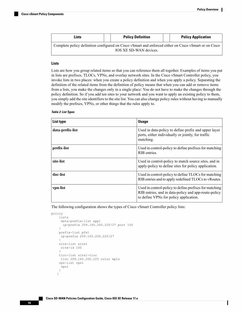
Lists
Lists are how you group related items so that you can reference them all together. Examples of items you putin lists are prefixes, TLOCs, VPNs, and overlay network sites. In the Cisco vSmart Controller policy, youinvoke lists in two places: when you create a policy definition and when you apply a policy. Separating thedefinition of the related items from the definition of policy means that when you can add or remove itemsfrom a lists, you make the changes only in a single place: You do not have to make the changes through thepolicy definition. So if you add ten sites to your network and you want to apply an existing policy to them,you simply add the site identifiers to the site list. You can also change policy rules without having to manuallymodify the prefixes, VPNs, or other things that the rules apply to.
Table 2: List Types
UsageList type
Used in data-policy to define prefix and upper layerports, either individually or jointly, for trafficmatching.
data-prefix-list
Used in control-policy to define prefixes for matchingRIB entries.
prefix-list
Used in control-policy to match source sites, and inapply-policy to define sites for policy application.
site-list
Used in control-policy to define TLOCs for matchingRIB entries and to apply redefined TLOCs to vRoutes.
tloc-list
Used in control-policy to define prefixes for matchingRIB entries, and in data-policy and app-route-policyto define VPNs for policy application.
vpn-list
The following configuration shows the types of Cisco vSmart Controller policy lists:policy
listsdata-prefix-list app1ip-prefix 209.165.200.225/27 port 100
!prefix-list pfx1ip-prefix 209.165.200.225/27!site-list site1site-id 100!tloc-list site1-tloctloc 209.165.200.225 color mplsvpn-list vpn1vpn1!!
Cisco SD-WAN Policies Configuration Guide, Cisco IOS XE Release 17.x14
Policy OverviewCisco vSmart Policy Components

Policy Definition
The policy definition is where you create the policy rules. You specify match conditions (route-relatedproperties for control policy and data-related fields for data policy) and actions to perform when a matchoccurs. A policy contains match–action pairings that are numbered and that are examined in sequential order.When a match occurs, the action is performed, and the policy analysis on that route or packet terminates.Some types of policy definitions apply only to specific VPNs.
Table 3: Policy Types
UsagePolicy type
Can be control-policy, data-policy, orvpn-menbership—dictates the type of policy. Eachtype has a particular syntax and a particular set ofmatch conditions and settable actions.
policy-type
Used by data-policy and app-route-policy to list theVPNs for which the policy is applicable.
vpn-list
Defines each sequential step of the policy by sequencenumber.
sequence
Decides what entity to match on in the specific policysequence.
match
Determines the action that corresponds to thepreceding match statement.
action
Action to take for any entity that is not matched inany sequence of the policy. By default, the action isset to reject.
default-action
The following configuration shows the components of the Cisco vSmart Controller policy definition. Theseitems are listed in the logical order you should use when designing policy, and this order is also how the itemsare displayed in the configuration, regardless of the order in which you add them to the configuration.policy
policy-type namevpn-list vpn-listsequence numbermatch<route | tloc vpn | other>
!action <accept reject drop>set attribute value!default-action <reject accept>!!!
Policy Application
The following are the configuration components:
Cisco SD-WAN Policies Configuration Guide, Cisco IOS XE Release 17.x15
Policy OverviewCisco vSmart Policy Components

UsageComponent
Determines the sites to which a given policy is applies.The direction (in | out) applies only to control-policy.
site-list
The policy type can be control-policy, data-policy,or vpn-membership—and name refer to an alreadyconfigured policy to be applied to the sites specifiedin the site-list for the section.
policy-type
For a policy definition to take effect, you associate it with sites in the overlay network.apply-policysite-list namecontrol-policy name <inout>!site-list namedata-policy namevpn-membership name!!
Policy Example
For a complete policy, which consists of lists, policy definition, and policy application. The example illustratedbelow creates two lists (a site-list and a tloc-list), defines one policy (a control policy), and applies the policyto the site-list. In the figure, the items are listed as they are presented in the node configuration. In a normalconfiguration process, you create lists first (group together all the things you want to use), then define thepolicy itself (define what things you want to do), and finally apply the policy (specify the sites that theconfigured policy affects).apply-policy
site-list site1 ––––––––→ Apply the defined policy towards the sites in site-listcontrol-policy prefer_local out!
policylistssite-list site1site-id 100
tloc-list prefer_site1 –––→ Define the lists required for apply-policy and for use withinthe policytloc 192.0.2.1 color mols encap ipsec preference 400control-policy prefer_localsequence 10match routesite-list sitele ––––––->Lists previously defined used within policy
!action acceptsettloc-list prefer_site!!!
TLOC Attributes Used in PoliciesA transport location, or TLOC, defines a specific interface in the overlay network. Each TLOC consists of aset of attributes that are exchanged in OMP updates among the Cisco SD-WAN devices. Each TLOC is
Cisco SD-WAN Policies Configuration Guide, Cisco IOS XE Release 17.x16
Policy OverviewTLOC Attributes Used in Policies
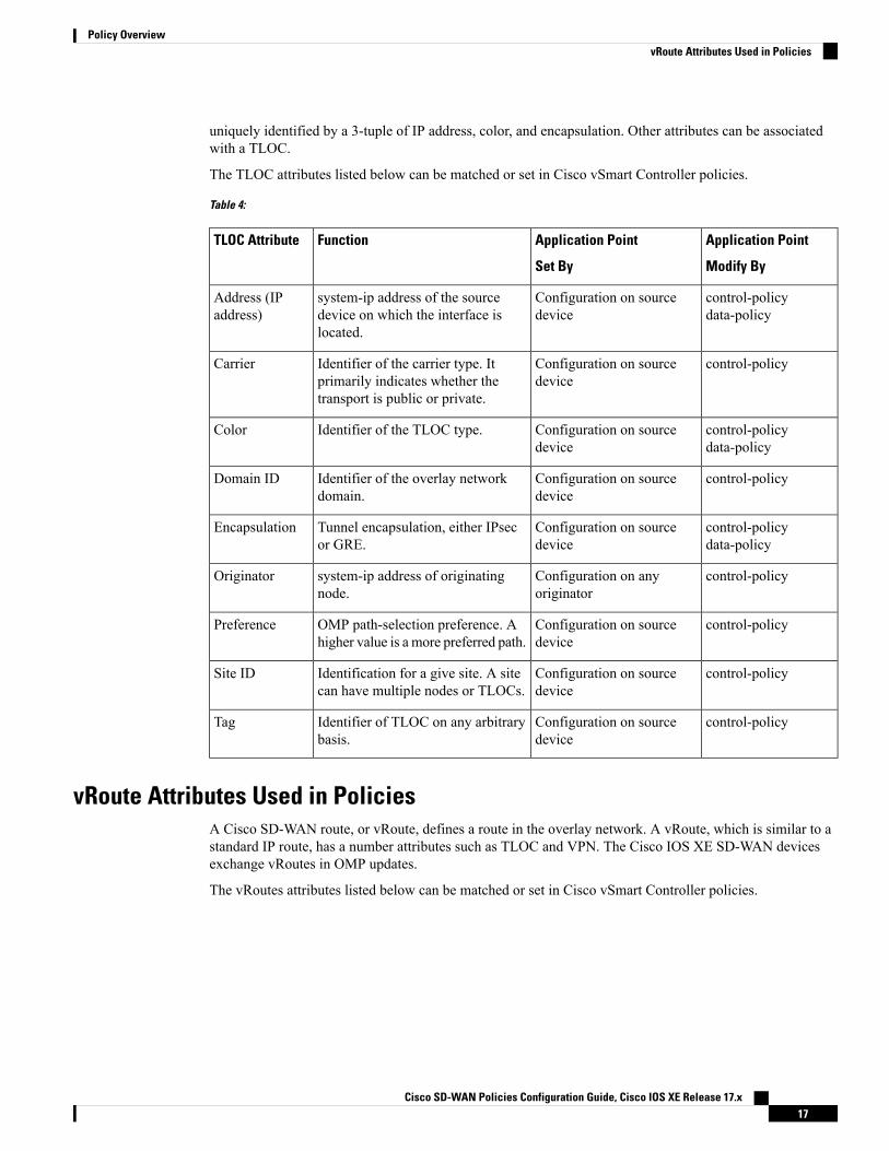
uniquely identified by a 3-tuple of IP address, color, and encapsulation. Other attributes can be associatedwith a TLOC.
The TLOC attributes listed below can be matched or set in Cisco vSmart Controller policies.
Table 4:
Application Point
Modify By
Application Point
Set By
FunctionTLOC Attribute
control-policydata-policy
Configuration on sourcedevice
system-ip address of the sourcedevice on which the interface islocated.
Address (IPaddress)
control-policyConfiguration on sourcedevice
Identifier of the carrier type. Itprimarily indicates whether thetransport is public or private.
Carrier
control-policydata-policy
Configuration on sourcedevice
Identifier of the TLOC type.Color
control-policyConfiguration on sourcedevice
Identifier of the overlay networkdomain.
Domain ID
control-policydata-policy
Configuration on sourcedevice
Tunnel encapsulation, either IPsecor GRE.
Encapsulation
control-policyConfiguration on anyoriginator
system-ip address of originatingnode.
Originator
control-policyConfiguration on sourcedevice
OMP path-selection preference. Ahigher value is a more preferred path.
Preference
control-policyConfiguration on sourcedevice
Identification for a give site. A sitecan have multiple nodes or TLOCs.
Site ID
control-policyConfiguration on sourcedevice
Identifier of TLOC on any arbitrarybasis.
Tag
vRoute Attributes Used in PoliciesA Cisco SD-WAN route, or vRoute, defines a route in the overlay network. A vRoute, which is similar to astandard IP route, has a number attributes such as TLOC and VPN. The Cisco IOS XE SD-WAN devicesexchange vRoutes in OMP updates.
The vRoutes attributes listed below can be matched or set in Cisco vSmart Controller policies.
Cisco SD-WAN Policies Configuration Guide, Cisco IOS XE Release 17.x17
Policy OverviewvRoute Attributes Used in Policies

Table 5:
Application Point
Modify By
Application Point
Set By
FunctionvRouteAttribute
control-policySource deviceSource of the route, either BGP,OSPF, connected, static.
Origin
control-policyAny originatorSource of the update carrying theroute.
Originator
control-policyConfiguration on sourcedevice or policy
OMP path-selection preference. Ahigher value is a more preferredpath.
Preference
control-policyConfiguration on sourcedevice
Advertised service associated withthe vRoute.
Service
control-policyConfiguration on sourcedevice
Identifier for a give site. A site canhave multiple nodes or TLOCs.
Site ID
control-policyConfiguration on sourcedevice
Identification on any arbitrary basis.Tag
control-policydata-policy
Configuration on sourcedevice or policy
TLOC used as next hop for thevRoute.
TLOC
control-policydata-policy
Configuration on sourcedevice or policy
VPN to which the vRoute belongs.VPN
Design Cisco vSmart Controller Policy Processing andApplication
Understanding how a Cisco vSmart Controller policy is processed and applied allows for proper design ofpolicy and evaluation of how policy is implemented across the overlay network.
Policy is processed as follows:
• A policy definition consists of a numbered, ordered sequence of match–action pairings. Within eachpolicy, the pairings are processed in sequential order, starting with the lowest number and incrementing.
• As soon as a match occurs, the matched entity is subject to the configured action of the sequence and isthen no longer subject to continued processing.
• Any entity not matched in a sequence is subject to the default action for the policy. By default, this actionis reject.
Cisco vSmart Controller policy is applied on a per-site-list basis, so:
• When applying policy to a site-list, you can apply only one of each type of policy. For example, you canhave one control-policy and one data-policy, or one control-policy in and one control-policy out. Youcannot have two data policies or two outbound control policies.
Cisco SD-WAN Policies Configuration Guide, Cisco IOS XE Release 17.x18
Policy OverviewDesign Cisco vSmart Controller Policy Processing and Application

• Because a site-list is a grouping of many sites, you should be careful about including a site in more thanone site-list. When the site-list includes a range of site identifiers, ensure that there is no overlap. If thesame site is part of two site-lists and the same type of policy is applied to both site-lists, the policybehavior is unpredictable and possibly catastrophic.
• Control-policy is unidirectional, being applied either inbound to the vSmart controller or outbound fromit. When control-policy is needed in both directions, configure two control policies.
• Data-policy is bidirectional and can be applied either to traffic received from the service side of the CiscoIOS XE SD-WAN device, traffic received from the tunnel side, or all of these combinations.
• VPN membership policy is always applied to traffic outbound from the Cisco vSmart Controller.
• Control-policy remains on the Cisco vSmart Controller and affects routes that the controller sends andreceives.
• Data-policy is sent to either the Cisco IOS XE SD-WAN devices in the site-list. The policy is sent inOMP updates, and it affects the data traffic that the devices send and receive.
• When any node in the overlay network makes a routing decision, it uses any and all available routinginformation. In the overlay network, it is the Cisco vSmart Controller that distributes routing informationto the Cisco IOS XE SD-WAN device nodes.
• In a network deployment that has two ormore Cisco vSmart Controllers, each controller acts independentlyto disseminate routing information to other Cisco vSmart Controllers and to Cisco IOS XE SD-WANdevices in the overlay network. So, to ensure that the Cisco vSmart Controller policy has the desiredeffect in the overlay network, each Cisco vSmart Controller must be configured with the same policy,and the policy must be applied identically. For any given policy, you must configure the identical policyand apply it identically across all the Cisco vSmart Controllers.
When you deploy a policy, the deployment status is updated only for 30 minutes, which is the timeout limitfor policies. After the timeout period, the deployment task status is not monitored. If you are deploying abigger policy with more number of lines, and if it takes more than 30 minutes, the task status will not bemonitored.
Note
Cisco vSmart Policy OperationAt a high level, control policy operates on routing information, which in the Cisco IOS XE SD-WAN networkis carried in OMP updates. Data policy affects data traffic, and VPN membership controls the distribution ofVPN routing tables.
The basic Cisco vSmart policies are:
• Control Policy
• Data Policy
• VPN Membership
Cisco SD-WAN Policies Configuration Guide, Cisco IOS XE Release 17.x19
Policy OverviewCisco vSmart Policy Operation
Control PolicyControl policy, which is similar to standard routing policy, operates on routes and routing information in thecontrol plane of the overlay network. Centralized control policy, which is provisioned on the Cisco vSmartController, is the Cisco SD-WAN technique for customizing network-wide routing decisions that determineor influence routing paths through the overlay network. Local control policy, which is provisioned on a CiscoIOS XE SD-WAN device, allows customization of routing decisions made by BGP and OSPF on site-localbranch or enterprise networks.
The routing information that forms the basis of centralized control policy is carried in Cisco IOSXE SD-WANroute advertisements, which are transmitted on the DTLS or TLS control connections between Cisco vSmartControllers and Cisco IOS XE SD-WAN devices. Centralized control policy determines which routes androute information are placed into the centralized route table on the Cisco vSmart Controller and which routesand route information are advertised to the Cisco IOS XE SD-WAN devices in the overlay network. Basiccentralized control policy establish traffic engineering, to set the path that traffic takes through the network.Advanced control policy supports a number of features, which allows Cisco IOS XE SD-WAN devices in theoverlay network to share network services, such as firewalls and load balancers.
Centralized control policy affects the OMP routes that are distributed by the Cisco vSmart Controller throughoutthe overlay network. The Cisco vSmart Controller learns the overlay network topology from OMP routes thatare advertised by the Cisco IOS XE SD-WAN devices over the OMP sessions inside the DTLS or TLSconnections between the Cisco vSmart Controller and the devices.
Three types of OMP routes carry the information that the Cisco vSmart Controller uses to determine thenetwork topology:
• Cisco SD-WANOMP routes, which are similar to IP route advertisements, advertise routing informationthat the devices have learned from their local site and the local routing protocols (BGP and OSPF) to theCisco vSmart Controller. These routes are also referred to as OMP routes or vRoutes.
• TLOC routes carry overlay network–specific locator properties, including the IP address of the interfacethat connects to the transport network, a link color, which identifies a traffic flow, and the encapsulationtype. (A TLOC, or transport location, is the physical location where a Cisco IOS XE SD-WAN deviceconnects to a transport network. It is identified primarily by IP address, link color, and encapsulation,but a number of other properties are associated with a TLOC.)
• Service routes advertise the network services, such as firewalls, available to VPN members at the localsite.
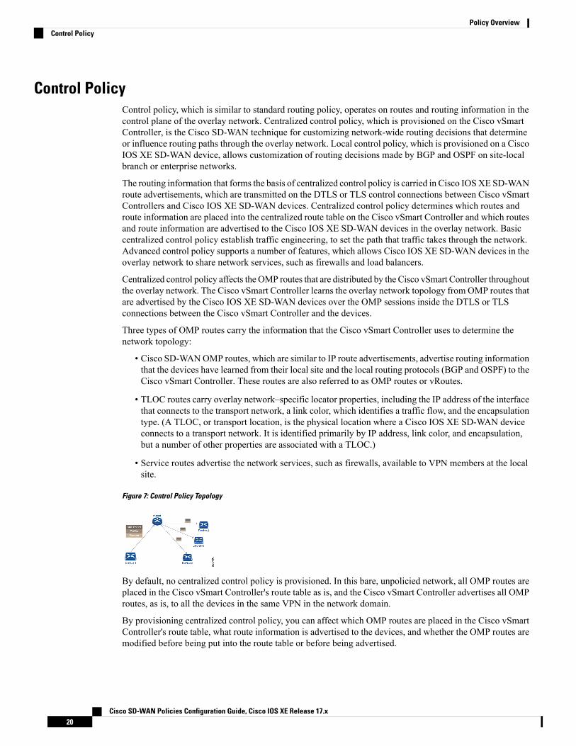
Figure 7: Control Policy Topology
By default, no centralized control policy is provisioned. In this bare, unpolicied network, all OMP routes areplaced in the Cisco vSmart Controller's route table as is, and the Cisco vSmart Controller advertises all OMProutes, as is, to all the devices in the same VPN in the network domain.
By provisioning centralized control policy, you can affect which OMP routes are placed in the Cisco vSmartController's route table, what route information is advertised to the devices, and whether the OMP routes aremodified before being put into the route table or before being advertised.
Cisco SD-WAN Policies Configuration Guide, Cisco IOS XE Release 17.x20
Policy OverviewControl Policy
Cisco IOS XE SD-WAN devices place all the route information learned from the Cisco vSmart Controllers,as is, into their local route tables, for use when forwarding data traffic. Because the Cisco vSmart Controller'srole is to be the centralized routing system in the network, Cisco IOS XE SD-WAN devices can never modifythe OMP route information that they learn from the Cisco vSmart Controllers.
The Cisco vSmart Controller regularly receives OMP route advertisements from the devices and, afterrecalculating and updating the routing paths through the overlay network, it advertises new routing informationto the devices.
The centralized control policy that you provision on the Cisco vSmart Controller remains on the Cisco vSmartController and is never downloaded to the devices. However, the routing decisions that result from centralizedcontrol policy are passed to the devices in the form of route advertisements, and so the affect of the controlpolicy is reflected in how the devices direct data traffic to its destination.
Localized control policy, which is provisioned locally on the devices, is called route policy. This policy issimilar to the routing policies that you configure on a regular driver, allowing you to modify the BGP andOSPF routing behavior on the site-local network. Whereas centralized control policy affects the routingbehavior across the entire overlay network, route policy applies only to routing at the local branch.
The Cisco IOS XE SD-WAN devices periodically exchange OMP updates, which carry routing informationpertaining to the overlay network. Two of the things that these updates contain are vRoute attributes andTransport Locations (TLOC) attributes.
The Cisco vSmart Controller uses these attributes from the OMP updates to determine the topology and statusof the overlay network, and installs routing information about the overlay network into its route table. Thecontroller then advertises the overlay topology to the Cisco IOS XE SD-WAN devices in the network bysending OMP updates to them.
Control policy examines the vRoute and TLOC attributes carried in OMP updates and can modify attributesthat match the policy. Any changes that results from control policy are applied directionally, either inboundor outbound.
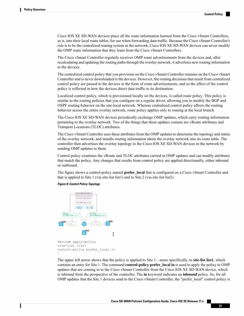
The figure shows a control-policy named prefer_local that is configured on a Cisco vSmart Controller andthat is applied to Site 1 (via site-list list1) and to Site 2 (via site-list list2).
Figure 8: Control Policy Topology
Device# apply-policysite-list list1control-policy prefer_local in!
The upper left arrow shows that the policy is applied to Site 1—more specifically, to site-list list1, whichcontains an entry for Site 1. The command control-policy prefer_local in is used to apply the policy to OMPupdates that are coming in to the Cisco vSmart Controller from the Cisco IOS XE SD-WAN device, whichis inbound from the perspective of the controller. The in keyword indicates an inbound policy. So, for allOMP updates that the Site 1 devices send to the Cisco vSmart Controller, the "prefer_local" control policy is
Cisco SD-WAN Policies Configuration Guide, Cisco IOS XE Release 17.x21
Policy OverviewControl Policy

applied before the updates reach the route table on the Cisco vSmart Controller. If any vRoute or TLOCattributes in an OMP update match the policy, any changes that result from the policy actions occur beforethe Cisco vSmart Controller installs the OMP update information into its route table.
The route table on the Cisco vSmart Controller is used to determine the topology of the overlay network. TheCisco vSmart Controller then distributes this topology information, again via OMP updates, to all the devicesin the network. Because applying policy in the inbound direction influences the information available to theCisco vSmart Controller. It determines the network topology and network reachablity, modifying vRoute andTLOC attributes before they are placed in the controller’s route table.apply-policysite-list list2control-policy prefer_local out!
On the right side of the figure above, the "prefer_local" policy is applied to Site 2 via the control-policyprefer_local out command. The out keyword in the command indicates an outbound policy, which meansthat the policy is applied to OMP updates that the Cisco vSmart Controller is sending to the devices at Site2. Any changes that result from the policy occur, after the information from the Cisco vSmart Controller'sroute table is placed in to an OMP update and before the devices receive the update. Again, note that thedirection is outbound from the perpspective of the Cisco vSmart Controller.
In contrast to an inbound policy, which affects the centralized route table on the Cisco vSmart Controller andhas a broad effect on the route attributes advertised to all the devices in the overlay network. A control policyapplied in the outbound direction influences only the route tables on the individual devices included in thesite-list.
The same control policy (the prefer_local policy) is applied to both the inbound and outbound OMP updates.However, the effects of applying the same policy to inbound and outbound are different. The usage shown inthe figure illustrates the flexibility of the Cisco IOS XE SD-WAN control policy design architecture andconfiguration.
Data PolicyData policy influences the flow of data traffic traversing the network based either on fields in the IP headerof packets or the router interface on which the traffic is being transmitted or received. Data traffic travels overthe IPsec connections between Cisco IOS XE SD-WAN devices, shown in purple in the adjacent figure.
The Cisco IOS XE SD-WAN architecture implements two types of data policy:
• Centralized data policy controls the flow of data traffic based on the source and destination addressesand ports and DSCP fields in the packet's IP header (referred to as a 5-tuple), and based on networksegmentation and VPN membership. These types of data policy are provisioned centrally, on the CiscovSmart controller, and they affect traffic flow across the entire network.
• Localized data policy controls the flow of data traffic into and out of interfaces and interface queues ona Cisco IOS XE SD-WAN device. This type of data policy is provisioned locally using access lists. Itallows you to classify traffic and map different classes to different queues. It also allows you to mirrortraffic and to police the rate at which data traffic is transmitted and received.
Cisco SD-WAN Policies Configuration Guide, Cisco IOS XE Release 17.x22
Policy OverviewData Policy
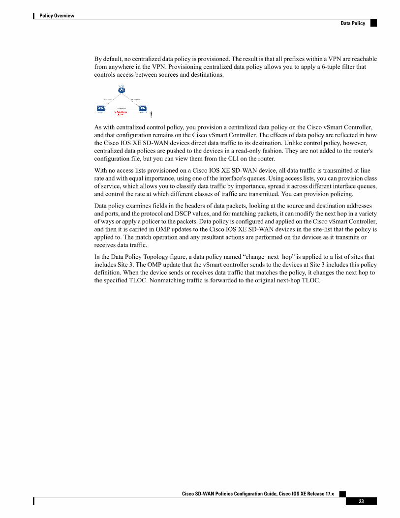
By default, no centralized data policy is provisioned. The result is that all prefixes within a VPN are reachablefrom anywhere in the VPN. Provisioning centralized data policy allows you to apply a 6-tuple filter thatcontrols access between sources and destinations.
As with centralized control policy, you provision a centralized data policy on the Cisco vSmart Controller,and that configuration remains on the Cisco vSmart Controller. The effects of data policy are reflected in howthe Cisco IOS XE SD-WAN devices direct data traffic to its destination. Unlike control policy, however,centralized data polices are pushed to the devices in a read-only fashion. They are not added to the router'sconfiguration file, but you can view them from the CLI on the router.
With no access lists provisioned on a Cisco IOS XE SD-WAN device, all data traffic is transmitted at linerate and with equal importance, using one of the interface's queues. Using access lists, you can provision classof service, which allows you to classify data traffic by importance, spread it across different interface queues,and control the rate at which different classes of traffic are transmitted. You can provision policing.
Data policy examines fields in the headers of data packets, looking at the source and destination addressesand ports, and the protocol and DSCP values, and for matching packets, it can modify the next hop in a varietyof ways or apply a policer to the packets. Data policy is configured and applied on the Cisco vSmart Controller,and then it is carried in OMP updates to the Cisco IOS XE SD-WAN devices in the site-list that the policy isapplied to. The match operation and any resultant actions are performed on the devices as it transmits orreceives data traffic.
In the Data Policy Topology figure, a data policy named “change_next_hop” is applied to a list of sites thatincludes Site 3. The OMP update that the vSmart controller sends to the devices at Site 3 includes this policydefinition. When the device sends or receives data traffic that matches the policy, it changes the next hop tothe specified TLOC. Nonmatching traffic is forwarded to the original next-hop TLOC.
Cisco SD-WAN Policies Configuration Guide, Cisco IOS XE Release 17.x23
Policy OverviewData Policy
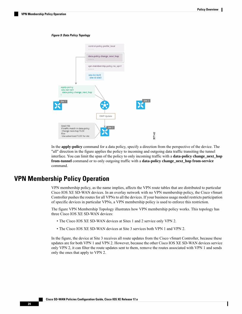
Figure 9: Data Policy Topology
In the apply-policy command for a data policy, specify a direction from the perspective of the device. The"all" direction in the figure applies the policy to incoming and outgoing data traffic transiting the tunnelinterface. You can limit the span of the policy to only incoming traffic with a data-policy change_next_hopfrom-tunnel command or to only outgoing traffic with a data-policy change_next_hop from-servicecommand.
VPN Membership Policy OperationVPN membership policy, as the name implies, affects the VPN route tables that are distributed to particularCisco IOS XE SD-WAN devices. In an overlay network with no VPN membership policy, the Cisco vSmartController pushes the routes for all VPNs to all the devices. If your business usage model restricts participationof specific devices in particular VPNs, a VPN membership policy is used to enforce this restriction.
The figure VPN Membership Topology illustrates how VPN membership policy works. This topology hasthree Cisco IOS XE SD-WAN devices:
• The Cisco IOS XE SD-WAN devices at Sites 1 and 2 service only VPN 2.
• The Cisco IOS XE SD-WAN devices at Site 3 services both VPN 1 and VPN 2.
In the figure, the device at Site 3 receives all route updates from the Cisco vSmart Controller, because theseupdates are for both VPN 1 and VPN 2. However, because the other Cisco IOS XE SD-WAN devices serviceonly VPN 2, it can filter the route updates sent to them, remove the routes associated with VPN 1 and sendsonly the ones that apply to VPN 2.
Cisco SD-WAN Policies Configuration Guide, Cisco IOS XE Release 17.x24
Policy OverviewVPN Membership Policy Operation

Figure 10: VPN Membership Topology
Notice that here, direction is not set when applying VPN membership policy. The Cisco vSmart Controlleralways applies this type of policy to the OMP updates that it sends outside to the Cisco IOS XE SD-WANdevices.
Configure and Execute Cisco vSmart PoliciesAll Cisco vSmart Controller policies are configured on the Cisco IOS XE SD-WAN devices, using acombination of policy definition and lists. All Cisco vSmart Controller policies are also applied on the CiscoIOS XE SD-WAN devices, with a combination of apply-policy and lists. However, where the actual CiscovSmart Controller policy executes depends on the type of policy, as shown in this figure:
Figure 11: Cisco vSmart Policy
For control policy and VPN membership policy, the entire policy configuration remains on the Cisco vSmartController, and the actions taken as a result of routes or VPNs that match a policy are performed on the CiscovSmart Controller.
For the other three policy types—application-aware routing, cflowd templates, and data policy—the policiesare transmitted in OMP updates to the Cisco IOS XE SD-WAN devices, and any actions taken as a result ofthe policies are performed on the devices.
Cisco SD-WAN Policies Configuration Guide, Cisco IOS XE Release 17.x25
Policy OverviewConfigure and Execute Cisco vSmart Policies

Cisco SD-WAN Policies Configuration Guide, Cisco IOS XE Release 17.x26
Policy OverviewConfigure and Execute Cisco vSmart Policies

C H A P T E R 4Centralized Policy
The topics in this section provide overview information about the different types of centralized policies, thecomponents of centralized policies, and how to configure centralized policies using Cisco vManage or theCLI.
• Overview of Centralized Policies, on page 27• Configure Centralized Policies Using Cisco vManage, on page 28• Configure Centralized Policies Using the CLI, on page 56• Centralized Policies Configuration Examples, on page 59
Overview of Centralized PoliciesCentralized policies refer to policies that are provisioned on Cisco vSmart Controllers, which are the centralizedcontrollers in the Cisco SD-WAN overlay network.
Types of Centralized Policies
Centralized Control Policy
Centralized control policy applies to the network-wide routing of traffic by affecting the information that isstored in the Cisco vSmart Controller's route table and that is advertised to the Cisco IOS XE SD-WANdevices. The effects of centralized control policy are seen in how Cisco IOS XE SD-WAN devices direct theoverlay network's data traffic to its destination.
The centralized control policy configuration itself remains on the Cisco vSmart Controller and is never pushedto local devices.
Note
Centralized Data Policy
Centralized data policy applies to the flow of data traffic throughout the VPNs in the overlay network. Thesepolicies can permit and restrict access based either on a 6-tuple match (source and destination IP addressesand ports, DSCP fields, and protocol) or on VPNmembership. These policies are pushed to the selected CiscoIOS XE SD-WAN devices.
Cisco SD-WAN Policies Configuration Guide, Cisco IOS XE Release 17.x27
Centralized Data Policy Based on Packet Header Fields
Policy decisions affecting data traffic can be based on the packet header fields, specifically, on the source anddestination IP prefixes, the source and destination IP ports, the protocol, and the DSCP.
This type of policy is often used to modify traffic flow in the network. Here are some examples of the typesof control that can be effected with a centralized data policy:
• Which set of sources are allowed to send traffic to any destination outside the local site. For example,local sources that are rejected by such a data policy can communicate only with hosts on the local network.
• Which set of sources are allowed to send traffic to a specific set of destinations outside the local site. Forexample, local sources that match this type of data policy can send voice traffic over one path and datatraffic over another.
• Which source addresses and source ports are allowed to send traffic to any destination outside the localsite or to a specific port at a specific destination.
Configure Centralized Policies Using Cisco vManageTo configure a centralized policy, use the Cisco vManage policy configuration wizard. The wizard consistsof the following operations that guide you through the process of creating and editing policy components:
• Create Groups of Interest: Create lists that group together related items and that you call in the match oraction components of a policy.
• Configure Topology and VPN Membership: Create the network structure to which the policy applies.
• Configure Traffic Rules: Create the match and action conditions of a policy.
• Apply Policies to Sites and VPNs: Associate the policy with sites and VPNs in the overlay network.
• Activate the centralized policy.
For a centralized policy to take effect, you must activate the policy.
To configure centralized policies using Cisco vManage, use the steps identified in the procedures that followthis section.
Start the Policy Configuration WizardTo start the policy configuration wizard:
1. From the Cisco vManage menu, choose Configuration > Policies.
2. Click Centralized Policy.
3. Click Add Policy.
The policy configuration wizard appears, and the Create Groups of Interest window is displayed.
Configure Groups of Interest for Centralized PolicyIn Create Groups of Interest, create new groups of list types as described in the following sections to usein a centralized policy:
Cisco SD-WAN Policies Configuration Guide, Cisco IOS XE Release 17.x28
Centralized PolicyConfigure Centralized Policies Using Cisco vManage

Configure Application
1. In the groups of interest list, click Application list type.
2. Click New Application List.
3. Enter a name for the list.
4. Choose either Application or Application Family .
Application can be the names of one or more applications, such as Third Party Control, ABC News,Mircosoft Teams and so on. The Cisco IOS XE SD-WAN devices support about 2300 differentapplications. To list the supported applications, use the ? in the CLI.
Application Family can be one or more of the following: antivirus, application-service, audio_video,authentication, behavioral, compression, database, encrypted, erp, file-server, file-transfer, forum,game, instant-messaging,mail,microsoft-office,middleware, network-management, network-service,peer-to-peer, printer, routing, security-service, standard, telephony, terminal, thin-client, tunneling,wap, web, and webmail.
5. From the Select drop-down, in the 'Search' filter, select the required applications or application families.
6. Click Add.
A few application lists are preconfigured. You cannot edit or delete these lists.
Microsoft_Apps—Includes Microsoft applications, such as Excel, Skype, and Xbox. To display a full list ofMicrosoft applications, click the list in the Entries column.
Google_Apps—Includes Google applications, such as gmail, Google maps, and YouTube. To display a fulllist of Google applications, click the list in the Entries column.
Configure Color
1. In the groups of interest list, click Color.
2. Click New Color List.
3. Enter a name for the list.
4. From the Select Color drop-down, in the 'Search' filter select the required colors.
Colors can be: 3g, biz-internet, blue, bronze, custom1 through custom3, default, gold, green, lte,metro-ethernet, mpls, private1 through private6, public-internet, red, and silver.
5. Click Add.
To configure multiple colors in a single list, you can select multiple colors from the drop-down.
Cisco SD-WAN Policies Configuration Guide, Cisco IOS XE Release 17.x29
Centralized PolicyConfigure Groups of Interest for Centralized Policy
Configure Community
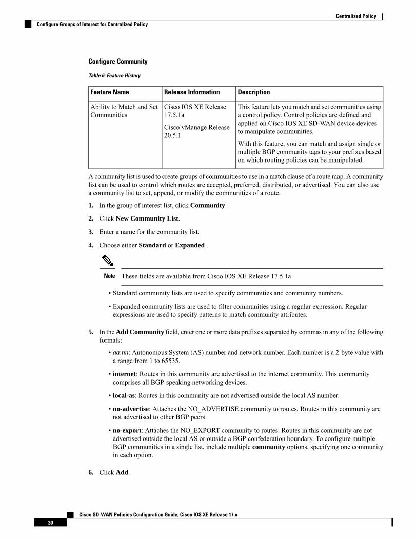
Table 6: Feature History
DescriptionRelease InformationFeature Name
This feature lets youmatch and set communities usinga control policy. Control policies are defined andapplied on Cisco IOS XE SD-WAN device devicesto manipulate communities.
With this feature, you can match and assign single ormultiple BGP community tags to your prefixes basedon which routing policies can be manipulated.
Cisco IOS XE Release17.5.1a
Cisco vManage Release20.5.1
Ability to Match and SetCommunities
A community list is used to create groups of communities to use in a match clause of a route map. A communitylist can be used to control which routes are accepted, preferred, distributed, or advertised. You can also usea community list to set, append, or modify the communities of a route.
1. In the group of interest list, click Community.
2. Click New Community List.
3. Enter a name for the community list.
4. Choose either Standard or Expanded .
These fields are available from Cisco IOS XE Release 17.5.1a.Note
• Standard community lists are used to specify communities and community numbers.
• Expanded community lists are used to filter communities using a regular expression. Regularexpressions are used to specify patterns to match community attributes.
5. In theAdd Community field, enter one or more data prefixes separated by commas in any of the followingformats:
• aa:nn: Autonomous System (AS) number and network number. Each number is a 2-byte value witha range from 1 to 65535.
• internet: Routes in this community are advertised to the internet community. This communitycomprises all BGP-speaking networking devices.
• local-as: Routes in this community are not advertised outside the local AS number.
• no-advertise: Attaches the NO_ADVERTISE community to routes. Routes in this community arenot advertised to other BGP peers.
• no-export: Attaches the NO_EXPORT community to routes. Routes in this community are notadvertised outside the local AS or outside a BGP confederation boundary. To configure multipleBGP communities in a single list, include multiple community options, specifying one communityin each option.
6. Click Add.
Cisco SD-WAN Policies Configuration Guide, Cisco IOS XE Release 17.x30
Centralized PolicyConfigure Groups of Interest for Centralized Policy

Configure Data Prefix
1. In the Groups of Interest list, click Data Prefix.
2. Click New Data Prefix List.
3. Enter a name for the list.
4. Choose either IPv4 or IPv6.
5. In the Add Data Prefix field, enter one or more data prefixes separated by commas.
6. Click Add.
Configure Policer
1. In the groups of interest list, click Policer.
2. Click New Policer List.
3. Enter a name for the list.
4. Define the policing parameters:
a. In the Burst field, enter the maximum traffic burst size, a value from 15,000 to 10,000,000 bytes.
b. In the Exceed field, select the action to take when the burst size or traffic rate is exceeded. It can bedrop, which sets the packet loss priority (PLP) to low.
You can use the remark action to set the packet loss priority (PLP) to high.
c. In theRate field, enter the maximum traffic rate, a value from 0 through 264 – 1 bits per second (bps).
5. Click Add.
Configure Prefix
1. In the groups of interest list, click Prefix.
2. Click New Prefix List.
3. Enter a name for the list.
4. In the Add Prefix field, enter one or more data prefixes separated by commas.
5. Click Add.
Configure Site
1. In the groups of interest list, click Site.
2. Click New Site List.
3. Enter a name for the list.
4. In the Add Site field, enter one or more site IDs separated by commas.
For example, 100 or 200 separated by commas or in the range, 1- 4294967295.
Cisco SD-WAN Policies Configuration Guide, Cisco IOS XE Release 17.x31
Centralized PolicyConfigure Groups of Interest for Centralized Policy

5. Click Add.
Configure App Probe Class
1. In the groups of interest list, click App Probe Class.
2. Click New App Probe Class.
3. Enter the probe class name in the Probe Class Name field.
4. Select the required forwarding class from the Forwarding Class drop-down list.
5. In theEntries pane, select the appropriate color from theColor drop-down list and enter theDSCP value.
You can add more entries if needed by clicking on + symbol.
6. Click Save.
Configure SLA Class
1. In the groups of interest list, click SLA Class.
2. Click New SLA Class List.
3. Enter a name for the list.
4. Define the SLA class parameters:
a. In the Loss field, enter the maximum packet loss on the connection, a value from 0 through 100percent.
b. In the Latency field, enter the maximum packet latency on the connection, a value from 0 through1,000 milliseconds.
c. In the Jitter field, enter the maximum jitter on the connection, a value from 1 through 1,000milliseconds.
d. Select the required app probe class from the App Probe Class drop-down list.
5. (Optional) Select the Fallback Best Tunnel checkbox to enable the best tunnel criteria.
This optional filed is available from Cisco IOS XE Release 17.5.1a to pick the best path or color from theavailable colors when SLA is not met. When this option is selected, you can choose the required criteriafrom the drop-down. The criteria are a combination of one or more of loss, latency, and, jitter values.
6. Select the Criteria from the drop-down list. The available criteria are:
• Latency
• Loss
• Jitter
• Latency, Loss
• Latency, Jitter
• Loss, Latency
Cisco SD-WAN Policies Configuration Guide, Cisco IOS XE Release 17.x32
Centralized PolicyConfigure Groups of Interest for Centralized Policy

• Loss, Jitter
• Jitter, Latency
• Jitter, Loss
• Latency, Loss, Jitter
• Latency, Jitter, Loss
• Loss, Latency, Jitter
• Loss, Jitter, Latency
• Jitter, Latency, Loss
• Jitter, Loss, Latency
7. Enter the Loss Variance (%), Latency Variance (ms), and the Jitter Variance (ms) for the selectedcriteria.
8. Click Add.
Configure TLOC
1. In the groups of interest list, click TLOC.
2. Click New TLOC List. The TLOC List popup displays.
3. Enter a name for the list.
4. In the TLOC IP field, enter the system IP address for the TLOC.
5. In the Color field, select the TLOC's color.
6. In the Encap field, select the encapsulation type.
7. In the Preference field, optionally select a preference to associate with the TLOC.
The range is 0 to 4294967295.
8. Click Add TLOC to add another TLOC to the list.
9. Click Save.
To use the set tloc and set tloc-list commands, you must use the set-vpn command.Note
For each TLOC, specify its address, color, and encapsulation. Optionally, set a preference value (from 0 to232 – 1) to associate with the TLOC address. When you apply a TLOC list in an action accept condition,when multiple TLOCs are available and satisfy the match conditions, the TLOC with the highest preferencevalue is used. If two or more of TLOCs have the highest preference value, traffic is sent among them in anECMP fashion.
Configure VPN
1. In the groups of interest list, click VPN.
Cisco SD-WAN Policies Configuration Guide, Cisco IOS XE Release 17.x33
Centralized PolicyConfigure Groups of Interest for Centralized Policy
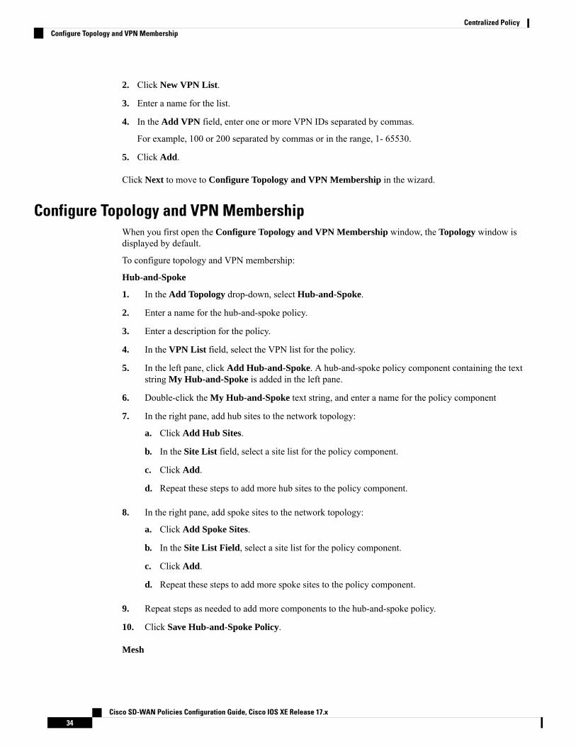
2. Click New VPN List.
3. Enter a name for the list.
4. In the Add VPN field, enter one or more VPN IDs separated by commas.
For example, 100 or 200 separated by commas or in the range, 1- 65530.
5. Click Add.
Click Next to move to Configure Topology and VPN Membership in the wizard.
Configure Topology and VPN MembershipWhen you first open the Configure Topology and VPN Membership window, the Topology window isdisplayed by default.
To configure topology and VPN membership:
Hub-and-Spoke
1. In the Add Topology drop-down, select Hub-and-Spoke.
2. Enter a name for the hub-and-spoke policy.
3. Enter a description for the policy.
4. In the VPN List field, select the VPN list for the policy.
5. In the left pane, click Add Hub-and-Spoke. A hub-and-spoke policy component containing the textstring My Hub-and-Spoke is added in the left pane.
6. Double-click the My Hub-and-Spoke text string, and enter a name for the policy component
7. In the right pane, add hub sites to the network topology:
a. Click Add Hub Sites.
b. In the Site List field, select a site list for the policy component.
c. Click Add.
d. Repeat these steps to add more hub sites to the policy component.
8. In the right pane, add spoke sites to the network topology:
a. Click Add Spoke Sites.
b. In the Site List Field, select a site list for the policy component.
c. Click Add.
d. Repeat these steps to add more spoke sites to the policy component.
9. Repeat steps as needed to add more components to the hub-and-spoke policy.
10. Click Save Hub-and-Spoke Policy.
Mesh
Cisco SD-WAN Policies Configuration Guide, Cisco IOS XE Release 17.x34
Centralized PolicyConfigure Topology and VPN Membership

1. In the Add Topology drop-down, select Mesh.
2. Enter a name for the mesh region policy component.
3. Enter a description for the mesh region policy component.
4. In the VPN List field, select the VPN list for the policy.
5. Click New Mesh Region.
6. In the Mesh Region Name field, enter a name for the individual mesh region.
7. In the Site List field, select one or more sites to include in the mesh region.
8. Click Add.
9. Repeat these steps to add more mesh regions to the policy.
10. Click Save Mesh Topology.
Custom Control (Route & TLOC): Centralized route control policy (for matching OMP routes)
1. In the Add Topology drop-down, select Custom Control (Route & TLOC).
2. Enter a name for the control policy.
3. Enter a description for the policy.
4. In the left pane, click Sequence Type. The Add Custom Control Policy popup displays.
5. Select Route. A policy component containing the text string Route is added in the left pane.
6. Double-click the Route text string, and enter a name for the policy component.
7. In the right pane, click Sequence Rule. TheMatch/Actions box opens, andMatch is selected by default.
8. From the boxes under the Match box, select the desired policy match type. Then select or enter thevalue for that match condition. Configure additional match conditions for the sequence rule, as desired.
9. Click Actions. The Reject option is selected by default. To configure actions to perform on acceptedpackets, click the Accept option. Then select the action or enter a value for the action.
10. Click Save Match and Actions.
11. Click Sequence Rule to configure more sequence rules, as desired. Drag and drop to re-order them.
12. Click Sequence Type to configure more sequences, as desired. Drag and drop to re-order them.
13. Click Save Control Policy.
Custom Control (Route & TLOC): Centralized TLOC control policy (for matching TLOC routes)
1. In the Add Topology drop-down, select Custom Control (Route & TLOC).
2. Enter a name for the control policy.
3. Enter a description for the policy.
4. In the left pane, click Sequence Type. The Add Custom Control Policy popup displays.
5. Select TLOC. A policy component containing the text string TLOC is added in the left pane.
Cisco SD-WAN Policies Configuration Guide, Cisco IOS XE Release 17.x35
Centralized PolicyConfigure Topology and VPN Membership

6. Double-click the TLOC text string, and enter a name for the policy component.
7. In the right pane, click Sequence Rule. TheMatch/Actions box opens, andMatch is selected by default.
8. From the boxes under the Match box, select the desired policy match type. Then select or enter thevalue for that match condition. Configure additional match conditions for the sequence rule, as desired.
9. Click Actions. The Reject option is selected by default. To configure actions to perform on acceptedpackets, click the Accept option. Then select the action or enter a value for the action.
10. Click Save Match and Actions.
11. Click Sequence Rule to configure more sequence rules, as desired. Drag and drop to re-order them.
12. Click Sequence Type to configure more sequences, as desired. Drag and drop to re-order them.
13. Click Save Control Policy.
A centralized control policy contains sequences of match–action pairs. The sequences are numbered to setthe order in which a route or TLOC is analyzed by the match–action pairs in the policy.
Sequence can have either match app-list or dns-app-list configured for a policy, but not both. Configuringboth match app-list and dns-app-list for a policy is not supported.
Note
Each sequence in a centralized control policy can contain one match condition (either for a route or for aTLOC) and one action condition.
Default Action
If a selected route or TLOC does not match any of the match conditions in a centralized control policy, adefault action is applied to it. By default, the route or TLOC is rejected.
If a selected data packet does not match any of the match conditions in a data policy, a default action is appliedto the packet. By default, the data packet is dropped.
Import Existing Topology1. In the Add Topology drop-down, click Import Existing Topology. The Import Existing Topology
popup appears.
2. Select the type of topology.
3. For Policy Type, choose the name of the topology you want to import.
4. In the Policy drop-down, select a policy to import.
The policy configuration wizard does not let you import an already configured policy as in otherinstances of centralized policies (data, control, or application-aware routing). The policy must beconfigured in its entirety.
Note
5. Click Import.
Cisco SD-WAN Policies Configuration Guide, Cisco IOS XE Release 17.x36
Centralized PolicyImport Existing Topology

Click Next to move to Configure Traffic Rules in the wizard.
Create a VPN Membership Policy1. In the Specify your network topology area, click VPN Membership.
2. Click Add VPN Membership Policy.
You can add only one VPN membership at a time, therefore all site lists and VPN lists must beincluded in a single policy.
Note
The Add VPN Membership Policy popup displays.
3. Enter a name and description for the VPN membership policy.
4. In the Site List field, select the site list.
5. In the VPN Lists field, select the VPN list.
6. Click Add List to add another VPN to the VPN membership.
7. Click Save.
8. Click Next to move to Configure Traffic Rules in the wizard.
Configure Traffic RulesTable 7: Feature History
DescriptionRelease InformationFeature Name
This feature provides support for a new match conditionthat you can use to specify a list of ICMP messages forcentralized data policies, localized data policies, andApplication-Aware Routing policies.
Cisco IOS XE Release17.4.1
Cisco vManageRelease 20.4.1
Policy Matching withICMP Message
When you first open the Configure Traffic Rules window, Application-Aware Routing is selected bydefault. For more information on configuring traffic rules for deep packet inspection, see Deep PacketInspection.
To configure traffic rules for a centralized data policy:
1. Click Traffic Data.
2. Click the Add Policy drop-down.
3. Click Create New. The Add Data Policy window displays.
4. Enter a name and a description for the data policy.
5. In the right pane, click Sequence Type. The Add Data Policy popup opens.
Cisco SD-WAN Policies Configuration Guide, Cisco IOS XE Release 17.x37
Centralized PolicyCreate a VPN Membership Policy

6. Select the type of data policy you want to create, Application Firewall, QoS, Traffic Engineering, orCustom.
If you want to configure multiple types of data policies for the same match condition, you needto configure a custom policy.
Note
7. A policy sequence containing the text string Application, Firewall, QoS, Traffic Engineering, orCustom is added in the left pane.
8. Double-click the text string, and enter a name for the policy sequence. The name you type is displayedboth in the Sequence Type list in the left pane and in the right pane.
9. In the right pane, click Sequence Rule. TheMatch/Action box opens, andMatch is selected by default.The available policy match conditions are listed below the box.
ProcedureMatch Condition
Do not specify any match conditions.None (match all packets)
a. In the Match conditions, click Applications/Application Family List.
b. In the drop-down, select the application family.
c. To create an application list:
1. Click New Application List.
2. Enter a name for the list.
3. Click Application to create a list of individual applications. Click Application Familyto create a list of related applications.
4. In the Select Application drop-down, select the desired applications or applicationfamilies.
5. Click Save.
Applications /Application FamilyList
a. In the Match conditions, click Destination Data Prefix.
b. To match a list of destination prefixes, select the list from the drop-down.
c. To match an individual destination prefix, enter the prefix in the Destination: IP Prefixfield.
Destination Data Prefix
a. In the Match conditions, click Destination Port.
b. In the Destination Port field, enter the port number. Specify a single port number, a list ofport numbers (with numbers separated by a space), or a range of port numbers (with thetwo numbers separated with a hyphen [-]).
Destination Port
Add an application list to enable split DNS.
a. In the Match conditions, click DNS Application List.
b. In the drop-down, select the application family.
DNS Application List
Cisco SD-WAN Policies Configuration Guide, Cisco IOS XE Release 17.x38
Centralized PolicyConfigure Traffic Rules
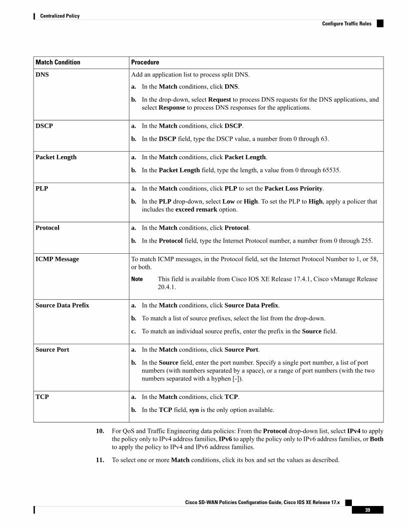
ProcedureMatch Condition
Add an application list to process split DNS.
a. In the Match conditions, click DNS.
b. In the drop-down, select Request to process DNS requests for the DNS applications, andselect Response to process DNS responses for the applications.
DNS
a. In the Match conditions, click DSCP.
b. In the DSCP field, type the DSCP value, a number from 0 through 63.
DSCP
a. In the Match conditions, click Packet Length.
b. In the Packet Length field, type the length, a value from 0 through 65535.
Packet Length
a. In the Match conditions, click PLP to set the Packet Loss Priority.
b. In the PLP drop-down, select Low or High. To set the PLP to High, apply a policer thatincludes the exceed remark option.
PLP
a. In the Match conditions, click Protocol.
b. In the Protocol field, type the Internet Protocol number, a number from 0 through 255.
Protocol
To match ICMP messages, in the Protocol field, set the Internet Protocol Number to 1, or 58,or both.
This field is available from Cisco IOS XE Release 17.4.1, Cisco vManage Release20.4.1.
Note
ICMP Message
a. In the Match conditions, click Source Data Prefix.
b. To match a list of source prefixes, select the list from the drop-down.
c. To match an individual source prefix, enter the prefix in the Source field.
Source Data Prefix
a. In the Match conditions, click Source Port.
b. In the Source field, enter the port number. Specify a single port number, a list of portnumbers (with numbers separated by a space), or a range of port numbers (with the twonumbers separated with a hyphen [-]).
Source Port
a. In the Match conditions, click TCP.
b. In the TCP field, syn is the only option available.
TCP
10. For QoS and Traffic Engineering data policies: From the Protocol drop-down list, select IPv4 to applythe policy only to IPv4 address families, IPv6 to apply the policy only to IPv6 address families, or Bothto apply the policy to IPv4 and IPv6 address families.
11. To select one or more Match conditions, click its box and set the values as described.
Cisco SD-WAN Policies Configuration Guide, Cisco IOS XE Release 17.x39
Centralized PolicyConfigure Traffic Rules

Not all match conditions are available for all policy sequence types.Note
12. To select actions to take on matching data traffic, click the Actions box.
13. To drop matching traffic, click Drop. The available policy actions are listed in the right side.
14. To accept matching traffic, click Accept. The available policy actions are listed in the right side.
15. Set the policy action as described.
Not all actions are available for all match conditions.Note
ProcedureDescriptionActionCondition
a. In the Action conditions, click Counter.
b. In theCounter Name field, enter the nameof the file in which to store packet counters.
Count matching data packets.Counter
a. In the Action conditions, click DSCP.
b. In the DSCP field, type the DSCP value,a number from 0 through 63.
Assign a DSCP value to matching data packets.DSCP
a. In theMatch conditions, clickForwardingClass.
b. In the Forwarding Class field, type theclass value, which can be up to 32characters long.
Assign a forwarding class to matching data packets.ForwardingClass
a. In the Action conditions, click Log toenable logging.
Place a sampled set of packets that match the SLA class rule intosystem logging (syslog) files. In addition to logging the packetheaders, a syslog message is generated the first time a packet headeris logged and then every 5 minutes thereafter, as long as the flowis active.
Log
a. In the Match conditions, click Policer.
b. In the Policer drop-down field, select thename of a policer.
Apply a policer to matching data packets.Policer
Cisco SD-WAN Policies Configuration Guide, Cisco IOS XE Release 17.x40
Centralized PolicyConfigure Traffic Rules

ProcedureDescriptionActionCondition
a. In the Match conditions, click LossCorrection.
b. In the Loss Correction field, select FECAdaptive, FEC Always, or PacketDuplication.
Apply loss correction to matching data packets.
Forward Error Correction (FEC) recovers lost packets on a link bysending redundant data, enabling the receiver to correct errorswithout the need to request retransmission of data.
FEC is supported only for IPSEC tunnels, it is not supported forGRE tunnels.
• FEC Adaptive – Corresponding packets are subjected to FEConly if the tunnels that they go through have been deemedunreliable based on measured loss.
If you choose FEC Adaptive, an additional field, LossThreshold, displays that allows you to specify the packet lossthreshold for automatically enabling FEC.
Adaptive FEC starts to work at 2% packet loss; this value isconfigurable.
You can specify a loss threshold of 1 to 5%. The default packetloss threshold is 2%.
• FEC Always – Corresponding packets are always subjectedto FEC.
• Packet Duplication – Sends duplicate packets over a singletunnel. If more than one tunnel is available, duplicated packetswill be sent over the tunnel with the best parameters.
LossCorrection
Click Save Match and Actions.
16. Create additional sequence rules as desired. Drag and drop to re-arrange them.
17. Click Save Data Policy.
18. Click Next to move to Apply Policies to Sites and VPNs in the wizard.
Match Parameters - Control PolicyFor OMP and TLOC routes , you can match the following attributes:
DescriptionMatch Condition
One or more colors. The available colors are: 3g,biz-internet, blue, bronze, custom1,custom2, custom3,default, gold, green, lte, metro-ethernet, mpls, private1through private6, public-internet, red and silver.
Color List
Cisco SD-WAN Policies Configuration Guide, Cisco IOS XE Release 17.x41
Centralized PolicyMatch Parameters - Control Policy

DescriptionMatch Condition
List of one or more BGP communities. In theCommunity List field, you can specify:
• aa:nn: AS number and network number. Eachnumber is a 2-byte value with a range from 1 to 65535.
• internet: Routes in this community are advertisedto the internet community. This community comprisesall BGP-speaking networking devices.
• local-as: Routes in this community are not advertisedoutside the local AS.
• no-advertise: Attach the NO_ADVERTISEcommunity to routes. Routes in this community arenot advertised to other BGP peers.
• no-export: Attach the NO_EXPORT community toroutes. Routes in this community are not advertisedoutside the local AS or outside a BGP confederationboundary. To configure multiple BGP communitiesin a single list, include multiple community options,specifying one community in each option.
Community List
Specifies the community type. Choose Standard tospecify communities and community numbers or,Expanded to filter communities using a regularexpression. Regular expressions are used to specifypatterns to match community attributes.
Types
Compares each regex string in the community listagainst the community string of the route.
The OR condition is applicable across multiplecommunity lists and is valid for all devices.
Starting from Cisco IOS XE Release 17.5.1a, theCommunity Types and Criteria fields are available.
Criteria OR
Tag value associated with the route or prefix in therouting database on the device.
The range is 0 through 4294967295.
OMP Tag
Protocol from which the route was learned.Origin
IP address from which the route was learned.Originator
How preferred a prefix is. This is the preference valuethat the route or prefix has in the local site, that is, inthe routing database on the device. A higherpreference value is more preferred.The range is 0through 255.
Preference
Cisco SD-WAN Policies Configuration Guide, Cisco IOS XE Release 17.x42
Centralized PolicyMatch Parameters - Control Policy

DescriptionMatch Condition
One or more prefixes. Specifies the name of a prefixlist.
Prefix List
Individual site identifier.
The range is 0 through 4294967295.
Not available in Cisco vManage.
One or more overlay network site identifiers.Site
Region defined for Hierarchical SD-WAN.
The range is 1 to 63.
This option is available beginning withCisco vManage Release 20.7.1.
Note
Region
Individual TLOC address.
To use the set tloc and set tloc-list
commands, you must use the set-vpncommand.
Note
TLOC
Individual VPN identifier. The range is 0 through65535.
VPN
Carrier for the control traffic. Values are: default,carrier1 through carrier8.
Carrier
Domain identifier associated with a TLOC.
The range is 0 through 4294967295.
Domain ID
Tag value associated with the TLOC route in the routetable on the device.
The range is 0 through 4294967295.
OMP Tag
Individual site contributor or more overlay networksite identifiers..
The range is 0 through 4294967295.
Site
In the CLI, you configure the OMP route attributes to match with the policy control-policy sequence matchroute command, and you configure the TLOC attributes to match with the policy control-policy sequencematch tloc command.
Match Parameters - Data PolicyA centralized data policy can match IP prefixes and fields in the IP headers, as well as applications. You canalso enable split DNS.
Each sequence in a policy can contain one match condition.
Cisco SD-WAN Policies Configuration Guide, Cisco IOS XE Release 17.x43
Centralized PolicyMatch Parameters - Data Policy
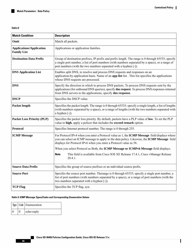
Table 8:
DescriptionMatch Condition
Match all packets.Omit
Applications or application families.Applications/ApplicationFamily List
Group of destination prefixes, IP prefix and prefix length. The range is 0 through 65535; specifya single port number, a list of port numbers (with numbers separated by a space), or a range ofport numbers (with the two numbers separated with a hyphen [-]).
Destination Data Prefix
Enables split DNS, to resolve and process DNS requests and responses on anapplication-by-application basis. Name of an app-list list . This list specifies the applicationswhose DNS requests are processed.
DNS Application List
Specify the direction in which to process DNS packets. To process DNS requests sent by theapplications (for outbound DNS queries), specify dns request. To process DNS responses returnedfrom DNS servers to the applications, specify dns response.
DNS
Specifies the DSCP value.DSCP
Specifies the packet length. The range is 0 through 65535; specify a single length, a list of lengths(with numbers separated by a space), or a range of lengths (with the two numbers separated witha hyphen [-]).
Packet length
Specifies the packet loss priority. By default, packets have a PLP value of low. To set the PLPvalue to high, apply a policer that includes the exceed remark option.
Packet Loss Priority (PLP)
Specifies Internet protocol number. The range is 0 through 255.Protocol
For Protocol IPv4 when you enter a Protocol value as 1, the ICMP Message field displays whereyou can select an ICMP message to apply to the data policy. Likewise, the ICMP Message fielddisplays for Protocol IPv6 when you enter a Protocol value as 58.
When you select Protocol as Both, the ICMP Message or ICMPv6 Message field displays.
This field is available from Cisco IOS XE Release 17.4.1, Cisco vManage Release20.4.1.
Note
ICMP Message
Specifies the group of source prefixes or an individual source prefix.Source Data Prefix
Specifes the source port number. Therange is 0 through 65535; specify a single port number, alist of port numbers (with numbers separated by a space), or a range of port numbers (with thetwo numbers separated with a hyphen [-]).
Source Port
Specifies the TCP flag, syn.TCP Flag
Table 9: ICMP Message Types/Codes and Corresponding Enumeration Values
EnumerationCodeType
echo-reply00
Cisco SD-WAN Policies Configuration Guide, Cisco IOS XE Release 17.x44
Centralized PolicyMatch Parameters - Data Policy

unreachable3
net-unreachable0
host-unreachable1
protocol-unreachable2
port-unreachable3
packet-too-big4
source-route-failed5
network-unknown6
host-unknown7
host-isolated8
dod-net-prohibited9
dod-host-prohibited10
net-tos-unreachable11
host-tos-unreachable12
administratively-prohibited13
host-precedence-unreachable14
precedence-unreachable15
redirect5
net-redirect0
host-redirect1
net-tos-redirect2
host-tos-redirect3
echo08
router-advertisement09
router-solicitation010
time-exceeded11
ttl-exceeded0
reassembly-timeout1
parameter-problem12
general-parameter-problem0
option-missing1
no-room-for-option2
timestamp-request013
Cisco SD-WAN Policies Configuration Guide, Cisco IOS XE Release 17.x45
Centralized PolicyMatch Parameters - Data Policy
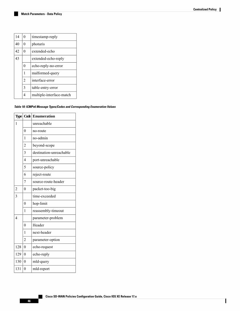
timestamp-reply014
photuris040
extended-echo042
extended-echo-reply43
echo-reply-no-error0
malformed-query1
interface-error2
table-entry-error3
multiple-interface-match4
Table 10: ICMPv6 Message Types/Codes and Corresponding Enumeration Values
EnumerationCodeType
unreachable1
no-route0
no-admin1
beyond-scope2
destination-unreachable3
port-unreachable4
source-policy5
reject-route6
source-route-header7
packet-too-big02
time-exceeded3
hop-limit0
reassembly-timeout1
parameter-problem4
Header0
next-header1
parameter-option2
echo-request0128
echo-reply0129
mld-query0130
mld-report0131
Cisco SD-WAN Policies Configuration Guide, Cisco IOS XE Release 17.x46
Centralized PolicyMatch Parameters - Data Policy

mld-reduction0132
router-solicitation0133
router-advertisement0134
nd-ns0135
nd-na0136
redirect0137
router-renumbering138
renum-command0
renum-result1
renum-seq-number255
ni-query139
ni-query-v6-address0
ni-query-name1
ni-query-v4-address2
ni-response140
ni-response-success0
ni-response-refuse1
ni-response-qtype-unknown2
ind-solicitation0141
ind-advertisement0142
mldv2-report143
dhaad-request0144
dhaad-reply0145
mpd-solicitation0146
mpd-advertisement0147
cp-solicitation0148
cp-advertisement0149
mr-advertisement0151
mr-solicitation0152
mr-termination0153
rpl-control0155
Cisco SD-WAN Policies Configuration Guide, Cisco IOS XE Release 17.x47
Centralized PolicyMatch Parameters - Data Policy

Action Parameters - Control PolicyFor each match condition, you configure a corresponding action to take if the route or TLOC matches for acontrol policy.
In the CLI, you configure actions with the policy control-policy action command.
Each sequence in a centralized control policy can contain one action condition.
In the action, you first specify whether to accept or reject a matching route or TLOC:
Table 11:
Cisco vManageDescription
Click Accept.Accept the route. An accepted route is eligible to be modified by the additional parametersconfigured in the action portion of the policy configuration.
Click Reject.Discard the packet.
Then, for a route or TLOC that is accepted, you can configure the following actions:
DescriptionAction Condition
Export the route the the specified VPN or list of VPNs (for a match route match condition only).
The range is 0 through 65535 or list name.
Export To
Change the tag string in the route, prefix, or TLOC.
The range is 0 through 4294967295.
OMP Tag
Change the preference value in the route, prefix, or TLOC to the specified value. A higher preference value ismore preferred. The range is 0 through 255.
Preference
Specify a service to redirect traffic to before delivering the traffic to its destination.
The TLOC address or list of TLOCs identifies the TLOCs to which the traffic should be redirected to reach theservice. In the case of multiple TLOCs, the traffic is load-balanced among them.
The VPN identifier is where the service is located.
Standard services: FW, IDS, IDP Custom services: netsvc1, netsvc2, netsvc3, netsvc4
Configure the services themselves on the Cisco IOS XE SD-WAN devices that are collocated with the servicedevices, using the vpn service configuration command.
Service
Change the TLOC address, color, and encapsulation to the specified address and color.
For each TLOC, specify its address, color, and encapsulation. address is the system IP address. color can be oneof 3g, biz-internet, blue, bronze, custom1, custom2, custom3, default, gold, green, lte, metro-ethernet,mpls, private1 through private6, public-internet, red, and silver. encapsulation can be gre or ipsec. Optionally,set a preference value (from 0 to 232 – 1) to associate with the TLOC address. When you apply a TLOC list inan action accept condition, when multiple TLOCs are available and satisfy the match conditions, the TLOCwith the highest preference value is used. If two or more of TLOCs have the highest preference value, traffic issent among them in an ECMP fashion.
TLOC
Cisco SD-WAN Policies Configuration Guide, Cisco IOS XE Release 17.x48
Centralized PolicyAction Parameters - Control Policy
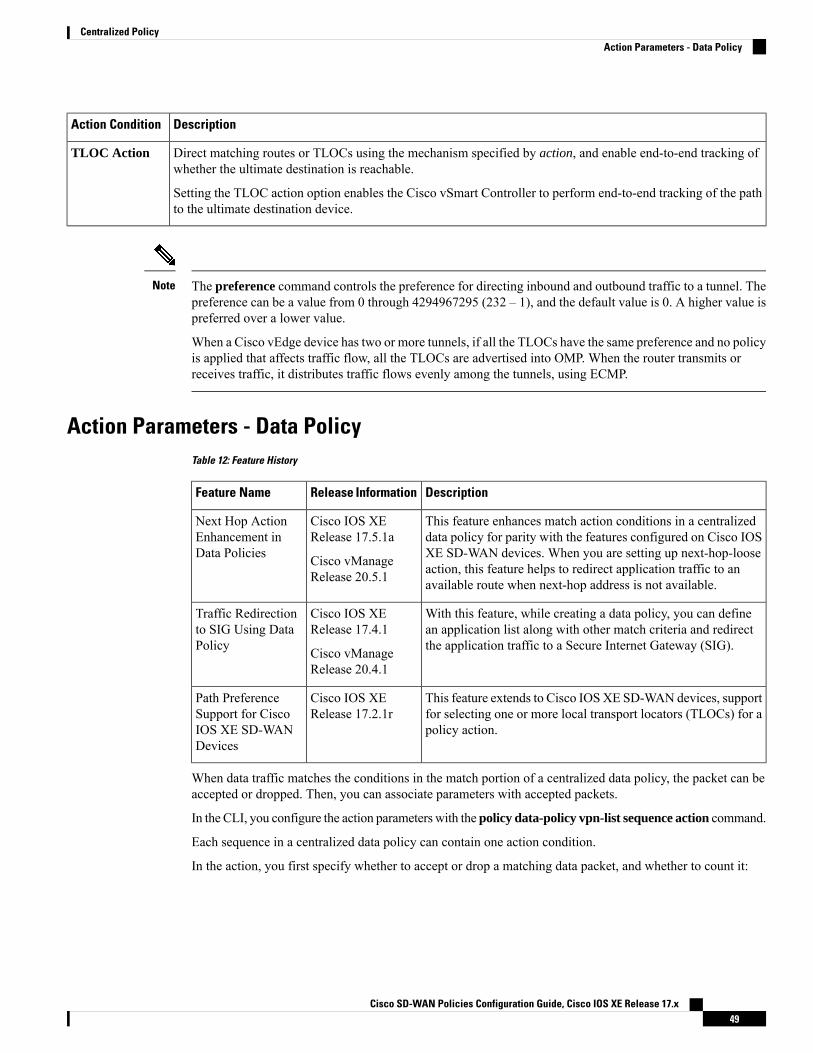
DescriptionAction Condition
Direct matching routes or TLOCs using the mechanism specified by action, and enable end-to-end tracking ofwhether the ultimate destination is reachable.
Setting the TLOC action option enables the Cisco vSmart Controller to perform end-to-end tracking of the pathto the ultimate destination device.
TLOC Action
The preference command controls the preference for directing inbound and outbound traffic to a tunnel. Thepreference can be a value from 0 through 4294967295 (232 – 1), and the default value is 0. A higher value ispreferred over a lower value.
When a Cisco vEdge device has two or more tunnels, if all the TLOCs have the same preference and no policyis applied that affects traffic flow, all the TLOCs are advertised into OMP. When the router transmits orreceives traffic, it distributes traffic flows evenly among the tunnels, using ECMP.
Note
Action Parameters - Data PolicyTable 12: Feature History
DescriptionRelease InformationFeature Name
This feature enhances match action conditions in a centralizeddata policy for parity with the features configured on Cisco IOSXE SD-WAN devices. When you are setting up next-hop-looseaction, this feature helps to redirect application traffic to anavailable route when next-hop address is not available.
Cisco IOS XERelease 17.5.1a
Cisco vManageRelease 20.5.1
Next Hop ActionEnhancement inData Policies
With this feature, while creating a data policy, you can definean application list along with other match criteria and redirectthe application traffic to a Secure Internet Gateway (SIG).
Cisco IOS XERelease 17.4.1
Cisco vManageRelease 20.4.1
Traffic Redirectionto SIG Using DataPolicy
This feature extends to Cisco IOSXE SD-WAN devices, supportfor selecting one or more local transport locators (TLOCs) for apolicy action.
Cisco IOS XERelease 17.2.1r
Path PreferenceSupport for CiscoIOS XE SD-WANDevices
When data traffic matches the conditions in the match portion of a centralized data policy, the packet can beaccepted or dropped. Then, you can associate parameters with accepted packets.
In the CLI, you configure the action parameters with the policy data-policy vpn-list sequence action command.
Each sequence in a centralized data policy can contain one action condition.
In the action, you first specify whether to accept or drop a matching data packet, and whether to count it:
Cisco SD-WAN Policies Configuration Guide, Cisco IOS XE Release 17.x49
Centralized PolicyAction Parameters - Data Policy

DescriptionAction Condition
Accepts the packet. An accepted packet is eligible to be modified by theadditional parameters configured in the action portion of the policyconfiguration.
Click Accept
Enables cflowd traffic monitoring.Cflowd
Counts the accepted or dropped packets. Specifies the name of a counter.Use the show policy access-lists counters command on the Cisco IOSXE SD-WAN device.
Counter
Discards the packet. This is the default action.Click Drop
Logs the packet. Packets are placed into the messages and syslog systemlogging (syslog) files. To view the packet logs, use the show app logflows and show log commands.
Log
Redirects DNS requests to a particular DNS server. Redirecting requestsis optional, but if you do so, you must specify both actions.
For an inbound policy, redirect-dns host allows the DNS response to becorrectly forwarded back to the requesting service VPN.
For an outbound policy, specify the IP address of the DNS server.
You can set only local TLOC preferences with redirect-dns asactions on the same sequence, but not remote TLOC.
Note
Redirect DNS
Fine-tune TCP to decrease round-trip latency and improve throughout formatching TCP traffic.
TCP Optimization
Redirects application traffic to a SIG
Note: Before you apply a data policy for redirecting application traffic toa SIG, you must have configured the SIG tunnels.
For more information on configuring Automatic SIG tunnels, seeAutomatic Tunnels . For more information on configuring Manual SIGtunnels, see Manual Tunnels.
Secure Internet Gateway
OnCisco IOSXE SD-WAN devices, all the ongoing optimized flows are dropped when the TCPOptimizationis removed.
Note
Then, for a packet that is accepted, the following parameters can be configured:
DescriptionAction Condition
Enables cflowd traffic monitoring.Cflowd
Enables NAT functionality, so that traffic can be redirected directly tothe internet or other external destination.
NAT Pool or NAT VPN
DSCP value. The range is 0 through 63.DSCP
Cisco SD-WAN Policies Configuration Guide, Cisco IOS XE Release 17.x50
Centralized PolicyAction Parameters - Data Policy

DescriptionAction Condition
Name of the forwarding class.Forwarding Class
Enables sending packets to one of the TLOCs that matches the colorand encapsulation. The available colors are: 3g, biz-internet, blue,bronze, custom1,custom2, custom3, default, gold, green, lte,metro-ethernet, mpls, private1 through private6, public-internet, redand silver.
The encapsulation options are: ipsec and gre.
By default, if the TLOC is not available, traffic is forwarded using analternate TLOC. To drop traffic if a TLOC is unavailable, include therestrict option.
By default, encapsulation is ipsec.
Local TLOC
Sets the next hop IP address to which the packet should be forwarded.
Starting from Cisco IOS XE Release 17.5.1a and CiscovManage Release 20.5.1, theUse Default Route when NextHop is not available field is available next to the Next Hopaction parameter. This option is available only when thesequence type is Traffic Engineering or Custom, and theprotocol is either IPv4 or IPv6, but not both.
Note
Next Hop
Applies a policer. Specifies the name of policer configured with thepolicy policer command.
Policer
Specifies a service to redirect traffic to before delivering the traffic toits destination.
The TLOC address or list of TLOCs identifies the remote TLOCs towhich the traffic should be redirected to reach the service. In the caseof multiple TLOCs, the traffic is load-balanced among them.
The VPN identifier is where the service is located.
Standard services: FW, IDS, IDP
Custom services: netsvc1, netsvc2,netsvc3, netsvc4
TLOC list is configured with a policy lists tloc-list list.
Configure the services themselves on the Cisco IOS XE SD-WANdevices that are collocated with the service devices, using the vpnservice command.
Service
Direct traffic to a remote TLOC that matches the IP address, color, andencapsulation of one of the TLOCs in the list. If a preference value isconfigured for the matching TLOC, that value is assigned to the traffic.
TLOC
Set the VPN that the packet is part of. The range is 0 through 65530.Click Accept, then action VPN.
Cisco SD-WAN Policies Configuration Guide, Cisco IOS XE Release 17.x51
Centralized PolicyAction Parameters - Data Policy

Data policies are applicable on locally generated packets, including routing protocol packets, when the matchconditions are generic.
Example configuration:sequence 21
matchsource-ip 10.0.0.0/8action accept
In such situations, it may be necessary to add a sequence in the data policy to escape the routing protocolpackets. For example to skip OSPF, use the following configuration:sequence 20
matchsource-ip 10.0.0.0/8protocol 89action accept
sequence 21matchsource-ip 10.0.0.0/8action accept
Note
The following table describes the IPv4 and IPv6 actions.
Table 13:
IPv6 ActionsIPv4 Actions
N/Adrop, dscp, next-hop (from-service only)/vpn, count,forwarding class, policer (only in interface ACL),App-route SLA (only)
N/AApp-route preferred color, app-route sla strict, cflowd,nat, redirect-dns
drop, dscp, next-hop/vpn, count, forwarding class,policer (only in interface ACL)
App-route SLA (only), App-route preferred color,app-route sla strict
N/A
policer (DataPolicy)policer (DataPolicy), tcp-optimization, fec-always,
tloc, tloc-list (set tloc, set tloc-list)tloc, tloc-list (set tloc, set tloc-list)
App-Route backup-preferred color, local-tloc,local-tloc-list
App-Route backup-preferred color, local-tloc,local-tloc-list
Apply Policies to Sites and VPNsIn the Apply Policies to Sites and VPNs page, apply a policy to sites and VPNs:
Cisco SD-WAN Policies Configuration Guide, Cisco IOS XE Release 17.x52
Centralized PolicyApply Policies to Sites and VPNs

1. In the Policy Name field, enter a name for the policy. This field is mandatory and can contain onlyuppercase and lowercase letters, the digits 0 through 9, hyphens (–), and underscores (_). It cannot containspaces or any other characters.
2. In the Policy Description field, enter a description of the policy. It can contain up to 2048 characters.This field is mandatory, and it can contain any characters and spaces.
3. Associate the policy with VPNs and sites. The choice of VPNs and sites depends on the type of policyblock:
a. For a Topology policy block, click New Site List, Inbound Site List, Outbound Site List, or VPNList. Some topology blocks might have no Add buttons. Choose one or more site lists, and chooseone or more VPN lists. Click Add.
b. For an Application-Aware Routing policy block, click New Site List and VPN list. Choose one ormore site lists, and choose one or more VPN lists. Click Add.
c. For aTraffic Data policy block, clickNew Site List and VPN List. Choose the direction for applyingthe policy (From Service, From Tunnel, or All), choose one or more site lists, and choose one ormore VPN lists. Click Add.
d. For a cflowd policy block, click New Site List. Choose one or more site lists, and click Add.
4. Click Preview to view the configured policy. The policy appears in CLI format.
5. Click Save Policy. The Configuration > Policies page appears, and the policies table includes the newlycreated policy.
NAT Fallback on Cisco IOS XE SD-WAN DevicesRelease Information
Cisco IOS XE SD-WAN devicessupport the NAT fallback featurefor Direct Internet Access (DIA).The NAT fallback feature providesa routing-based mechanism for alltraffic that is sent to the DIA routeto use an alternative route whenrequired.With this release, fallbackis supported on the service andtunnel side.
Cisco IOS XE Release 17.3.2
Cisco vManage Release 20.3.2
NAT Fallback on Cisco IOS XESD-WAN Devices
To use Cisco vManage to configure NAT DIA fallback, Cisco vManage must manage your Cisco vSmartController.
Note
To enable NAT fallback using Cisco vManage, create and configure a data policy by doing the following:
1. From the Cisco vManage menu, choose Configuration > Policies.
2. From the Custom options drop-down, under Centralized Policy, select Traffic Policy.
Cisco SD-WAN Policies Configuration Guide, Cisco IOS XE Release 17.x53
Centralized PolicyNAT Fallback on Cisco IOS XE SD-WAN Devices

3. Click Traffic Data.
4. From the Add Policy drop-down, clickCreate New.
5. Click Sequence Type and select Custom.
6. Click (+) Sequence Rule to create a new sequence rule.
7. After adding match conditions, click Actions and click Accept.
8. Click NAT VPN and select the Fallback checkbox.
9. Click Save and Match Actions.
10. Click Save Data Policy.
Edit your existitng centralized policy and import the policy:
1. Click Centralized Policy and for the required centralized policy, click ... and select Edit.
2. Click Traffic Rules and select Traffic Data.
3. From the Add Policy drop-down, select Import Existing.
4. Select the NAT policy that you created from the Policy drop-down.
5. Click Policy Application and select Traffic Data.
6. Click + New Site List and VPN List.
7. Select the direction, VPN, and site as required.
8. Click Add.
9. Click Save Policy Changes.
10. Click to select VPN, and Site from the drop-down.
The following NAT fallback actions/commands are now supported:Note
• Action: nat fallback
• When applying a policy: direction from-tunnel
Activate a Centralized PolicyActivating a centralized policy sends that policy to all connected Cisco vSmart Controllers. To activate acentralized policy:
1. From the Cisco vManage menu, choose Configuration > Policies. Centralized Policy is selected anddisplayed by default.
2. For the required policy, click ... and select Activate. The Activate Policy popup appears. It lists the IPaddresses of the reachable Cisco vSmart Controllers to which the policy must be applied.
3. Click Activate.
Cisco SD-WAN Policies Configuration Guide, Cisco IOS XE Release 17.x54
Centralized PolicyActivate a Centralized Policy

View Centralized Policies
To view centralized policies:
1. From the Centralized Policy, select a policy.
2. For a policy created using the UI policy builder or using the CLI, click ... and select View. The policycreated using the UI policy builder is displayed in graphical format while the policy created using the CLImethod is displayed in text format.
3. For a policy created using Cisco vManage policy configuration wizard, click ... and select Preview. Thispolicy is displayed in text format.
Copy, Edit, and Delete Policies
To copy a policy:
1. From the Centralized Policy, select a policy.
2. For the desired policy, click ... and select Copy.
3. In the Policy Copy popup window, enter the policy name and a description of the policy.
Starting with the Cisco IOS XE Release 17.2, 127 characters are supported for policy names forthe following policy types:
• Central route policy
• Local route policy
• Local Access Control lOst (ACL)
• Local IPv6 ACL
• Central data policy
• Central app route policy
• QoS map
• Rewrite rule
All other policy names support 32 characters.
Note
4. Click Copy.
To edit policies created using the Cisco vManage policy configuration wizard:
1. For the desired policy, click ... and select Edit.
2. Edit the policy as needed.
3. Click Save Policy Changes.
To edit polices created using the CLI method:
1. In the Custom Options drop-down, click CLI Policy.
Cisco SD-WAN Policies Configuration Guide, Cisco IOS XE Release 17.x55
Centralized PolicyActivate a Centralized Policy
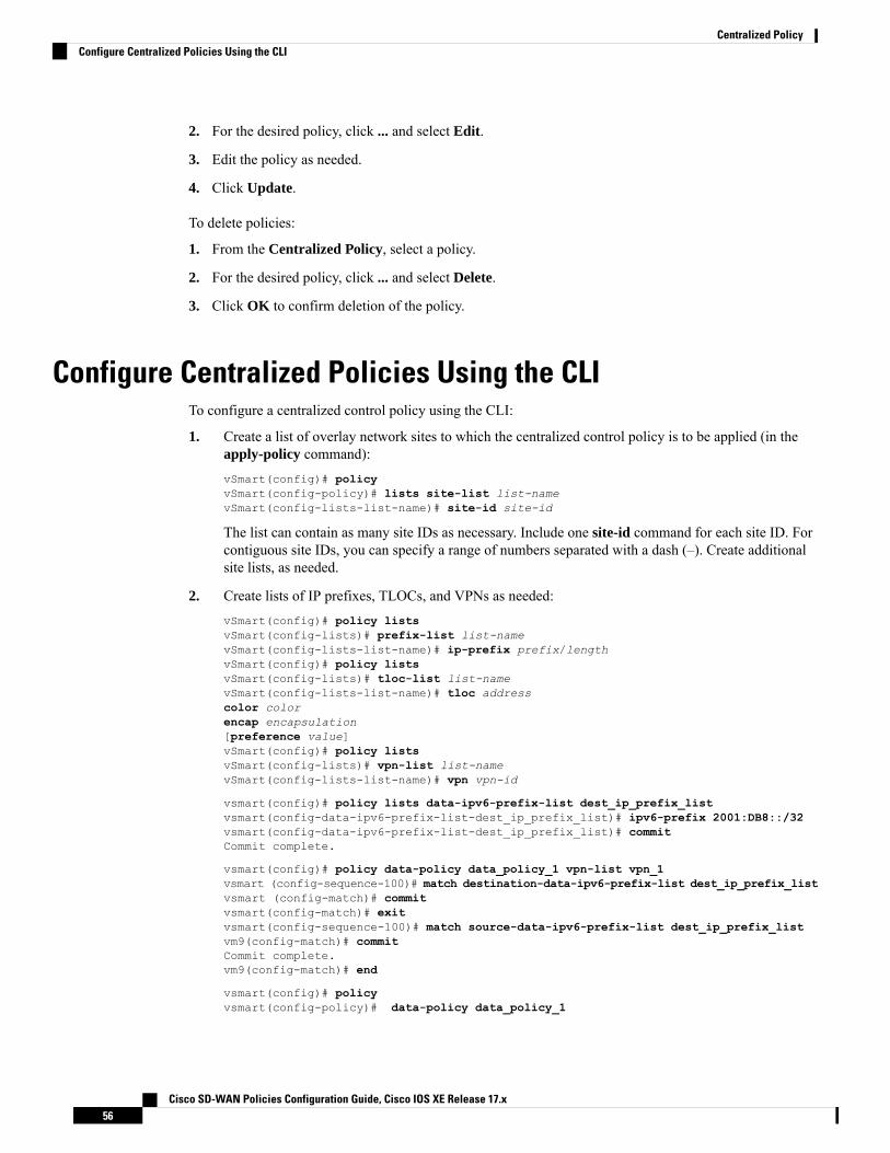
2. For the desired policy, click ... and select Edit.
3. Edit the policy as needed.
4. Click Update.
To delete policies:
1. From the Centralized Policy, select a policy.
2. For the desired policy, click ... and select Delete.
3. Click OK to confirm deletion of the policy.
Configure Centralized Policies Using the CLITo configure a centralized control policy using the CLI:
1. Create a list of overlay network sites to which the centralized control policy is to be applied (in theapply-policy command):vSmart(config)# policyvSmart(config-policy)# lists site-list list-namevSmart(config-lists-list-name)# site-id site-id
The list can contain as many site IDs as necessary. Include one site-id command for each site ID. Forcontiguous site IDs, you can specify a range of numbers separated with a dash (–). Create additionalsite lists, as needed.
2. Create lists of IP prefixes, TLOCs, and VPNs as needed:vSmart(config)# policy listsvSmart(config-lists)# prefix-list list-namevSmart(config-lists-list-name)# ip-prefix prefix/lengthvSmart(config)# policy listsvSmart(config-lists)# tloc-list list-namevSmart(config-lists-list-name)# tloc addresscolor colorencap encapsulation[preference value]vSmart(config)# policy listsvSmart(config-lists)# vpn-list list-namevSmart(config-lists-list-name)# vpn vpn-id
vsmart(config)# policy lists data-ipv6-prefix-list dest_ip_prefix_listvsmart(config-data-ipv6-prefix-list-dest_ip_prefix_list)# ipv6-prefix 2001:DB8::/32vsmart(config-data-ipv6-prefix-list-dest_ip_prefix_list)# commitCommit complete.
vsmart(config)# policy data-policy data_policy_1 vpn-list vpn_1vsmart (config-sequence-100)# match destination-data-ipv6-prefix-list dest_ip_prefix_listvsmart (config-match)# commitvsmart(config-match)# exitvsmart(config-sequence-100)# match source-data-ipv6-prefix-list dest_ip_prefix_listvm9(config-match)# commitCommit complete.vm9(config-match)# end
vsmart(config)# policyvsmart(config-policy)# data-policy data_policy_1
Cisco SD-WAN Policies Configuration Guide, Cisco IOS XE Release 17.x56
Centralized PolicyConfigure Centralized Policies Using the CLI

vsmart(config-data-policy-data_policy_1)# vpn-list vpn_1vsmart(config-vpn-list-vpn_1)# sequence 101vsmart(config-sequence-101)# match source-ipv6 2001:DB8::/32vsmart(config-match)# exitvsmart(config-sequence-101)# match destination-ipv6 2001:DB8::/32vsmart(config-match)#
3. Create a control policy instance:vSmart(config)# policy control-policy policy-namevSmart(config-control-policy-policy-name)#
4. Create a series of match–action pair sequences:vSmart(config-control-policy-policy-name)# sequencenumbervSmart(config-sequence-number)#
The match–action pairs are evaluated in order, by sequence number, starting with the lowest numberedpair and ending when the route matches the conditions in one of the pairs. Or if no match occurs, thedefault action is taken (either rejecting the route or accepting it as is).
5. Define match parameters for routes and for TLOCs:vSmart(config-sequence-number)# match route route-parametervSmart(config-sequence-number)# match tloc tloc-parameter
6. Define actions to take when a match occurs:vSmart(config-sequence-number)# action rejectvSmart(config-sequence-number)# action accept export-to (vpnvpn-id | vpn-list list-name)vSmart(config-sequence-number)# action accept set omp-tagnumber
vSmart(config-sequence-number)# action accept setpreference value
vSmart(config-sequence-number)# action accept setservice service-name(tloc ip-address |tloc-list list-name)[vpn vpn-id]
vSmart(config-sequence-number)# action accept set tlocip-addresscolor color[encap encapsulation]vSmart(config-sequence-number)# action accept set tloc-actionaction
vSmart(config-sequence-number)# action accept set tloc-list list-name
7. Create additional numbered sequences of match–action pairs within the control policy, as needed.
8. If a route does not match any of the conditions in one of the sequences, it is rejected by default. If youwant nonmatching routes to be accepted, configure the default action for the policy:vSmart(config-policy-name)# default-action accept
9. Apply the policy to one or more sites in the Cisco SD-WAN overlay network:vSmart(config)# apply-policy site-listlist-namecontrol-policypolicy-name (in | out)
Cisco SD-WAN Policies Configuration Guide, Cisco IOS XE Release 17.x57
Centralized PolicyConfigure Centralized Policies Using the CLI

10. If the action you are configuring is a service, configure the required services on the Cisco IOS XESD-WAN devices so that the Cisco vSmart Controller knows how to reach the services:vsmart(config)# policy data-policy data_policy_1 vpn-list vpn_1 sequence 100vsmart(config-sequence-100)# action accept set next-hop-ipv6 2001:DB8::/32vsmart(config-set)#
Specify the VPN is which the service is located and one to four IP addresses to reach the service deviceor devices. If multiple devices provide the same service, the device load-balances the traffic amongthem. Note that the Cisco IOS XE SD-WAN device keeps track of the services, advertising them to theCisco vSmart Controller only if the address (or one of the addresses) can be resolved locally, that is, atthe device's local site, and not learned through OMP. If a previously advertised service becomesunavailable, the Cisco IOS XE SD-WAN device withdraws the service advertisement.
Following are the high-level steps for configuring a VPN membership data policy:
1. Create a list of overlay network sites to which the VPN membership policy is to be applied (in theapply-policy command):vSmart(config)# policyvSmart (config-policy)# lists site-list list-namevSmart(config-lists-list-name)# site-id site-id
The list can contain as many site IDs as necessary. Include one site-id command for each site ID. Forcontiguous site IDs, you can specify a range of numbers separated with a dash (–). Create additionalsite lists, as needed.
2. Create lists of IP prefixes and VPNs, as needed:vSmart(config)# policy listsvSmart(config-lists)# data-prefix-list list-namevSmart(config-lists-list-name)# ip-prefix prefix/length
vSmart(config)# policy listsvSmart(config-lists)# vpn-list list-namevSmart(config-lists-list-name)# vpn vpn-id
vsmart(config)# policy lists data-ipv6-prefix-list dest_ip_prefix_listvsmart(config-data-ipv6-prefix-list-dest_ip_prefix_list)# ipv6-prefix 2001:DB8:19::1vsmart(config-data-ipv6-prefix-list-dest_ip_prefix_list)# commitCommit complete.
vsmart(config)# policy data-policy data_policy_1 vpn-list vpn_1vsmart (config-sequence-100)# match destination-data-ipv6-prefix-list dest_ip_prefix_listvsmart (config-match)# commitvsmart(config-match)# exitvsmart(config-sequence-100)# match source-data-ipv6-prefix-list dest_ip_prefix_listvm9(config-match)# commitCommit complete.vm9(config-match)# end
vsmart(config)# policyvsmart(config-policy)# data-policy data_policy_1vsmart(config-data-policy-data_policy_1)# vpn-list vpn_1vsmart(config-vpn-list-vpn_1)# sequence 101vsmart(config-sequence-101)# match source-ipv6 2001:DB8:19::1vsmart(config-match)# exitvsmart(config-sequence-101)# match destination-ipv6 2001:DB8:19::1vsmart(config-match)#
3. Create lists of TLOCs, as needed.vSmart(config)# policyvSmart(config-policy)# lists tloc-list list-name
Cisco SD-WAN Policies Configuration Guide, Cisco IOS XE Release 17.x58
Centralized PolicyConfigure Centralized Policies Using the CLI

vSmart(config-lists-list-name)# tloc ip-address color color encap encapsulation[preference number}
4. Define policing parameters, as needed:vSmart(config-policy)# policer policer-namevSmart(config-policer)# rate bandwidthvSmart(config-policer)# burst bytesvSmart(config-policer)# exceed action
5. Create a data policy instance and associate it with a list of VPNs:vSmart(config)# policy data-policy policy-namevSmart(config-data-policy-policy-name)# vpn-list list-name
6. Create a series of match–pair sequences:vSmart(config-vpn-list)# sequence numbervSmart(config-sequence-number)#
The match–action pairs are evaluated in order, by sequence number, starting with the lowest numberedpair and ending when the route matches the conditions in one of the pairs. Or if no match occurs, thedefault action is taken (either rejecting the route or accepting it as is).
7. Define match parameters for packets:vSmart(config-sequence-number)# match parameters
8. Define actions to take when a match occurs:vSmart(config-sequence-number)# action (accept | drop) [count counter-name] [log][tcp-optimization]vSmart(config-sequence-number)# action acccept nat [pool number] [use-vpn 0]vSmart(config-sequence-number)# action accept redirect-dns (host | ip-address)vSmart(config-sequence-number)# action accept set parameters
vsmart(config)# policy data-policy data_policy_1 vpn-list vpn_1 sequence 100vsmart(config-sequence-100)# action accept set next-hop-ipv6 2001:DB8:19::1vsmart(config-set)#
9. Create additional numbered sequences of match–action pairs within the data policy, as needed.
10. If a route does not match any of the conditions in one of the sequences, it is rejected by default. Toaccept nonmatching prefixed, configure the default action for the policy:vSmart(config-policy-name)# default-action accept
11. Apply the policy to one or more sites in the overlay network:vSmart(config)# apply-policy site-list list-name data-policy policy-name (all|from-service | from-tunnel)
Centralized Policies Configuration ExamplesThis topic provides some examples of configuring a centralized data policy to influence traffic flow acrossthe Cisco IOS XE SD-WAN domain and to configure a Cisco IOS XE SD-WAN device to be an internet exitpoint.
Cisco SD-WAN Policies Configuration Guide, Cisco IOS XE Release 17.x59
Centralized PolicyCentralized Policies Configuration Examples

General Centralized Policy Example
This section shows a general example of a centralized data policy to illustrate that you configure centralizeddata policy on a Cisco vSmart Controller and that after you commit the configuration, the policy itself ispushed to the required Cisco IOS XE SD-WAN device.
Here we configure a simple data policy on the Cisco vSmart Controller vm9:vm9# show running-config policypolicydata-policy test-data-policyvpn-list test-vpn-listsequence 10matchdestination-ip 209.165.201.0/27!action dropcount test-counter!!default-action drop!!listsvpn-list test-vpn-listvpn 1!site-list test-site-listsite-id 500!!!
Then, apply this policy to the site list named test-site-list, which includes site 500:vm9# show sdwan running-config apply-policyapply-policysite-list test-site-listdata-policy test-data-policy!!
Immediately after you activate the configuration on the Cisco vSmart Controller, it pushes the policyconfiguration to the Cisco IOS XE SD-WAN devices in site 500. One of these devices is vm5, where you cansee that the policy has been received:vm5# show sdwan policy from-vsmartpolicy-from-vsmartdata-policy test-data-policyvpn-list test-vpn-listsequence 10matchdestination-ip 209.165.201.0/27!action dropcount test-counter!!default-action drop!!listsvpn-list test-vpn-listvpn 1!
Cisco SD-WAN Policies Configuration Guide, Cisco IOS XE Release 17.x60
Centralized PolicyCentralized Policies Configuration Examples

!!
Control Access
This example shows a data policy that limits the type of packets that a source can send to a specific destination.Here, the host at source address 192.0.2.1 in site 100 and VPN 100 can send only TCP traffic to the destinationhost at 203.0.113.1. This policy also specifies the next hop for the TCP traffic sent by 192.0.2.1, setting it tobe TLOC 209.165.200.225, color gold. All other traffic is accepted as a result of the default-action statement.policylists
site-list northsite-id 100
vpn-list vpn-northvpn 100
!data-policy tcp-only
vpn-list vpn-northsequence 10matchsource-ip 192.0.2.1/32destination-ip 198.51.100.1/32protocol tcp
action acceptset tloc 203.0.113.1 gold
!default-action accept
!!apply-policy
site north data-policy tcp-only
Restrict Traffic
This examples illustrates how to disallow certain types of data traffic from being sent from between VPNs.This policy drops data traffic on port 25, which carries SMTPmail traffic, that originates in 209.165.201.0/27.However, the policy accepts all other data traffic, including non-SMTP traffic from 209.165.201.0/27.policylistsdata-prefix-list north-onesip-prefix 209.165.201.0/27port 25
vpn-list all-vpnsvpn 1vpn 2
site-list northsite-id 100
!data-policy no-mailvpn-list all-vpnssequence 10matchsource-data-prefix-list north-ones
action drop!default-action accept
!!apply-policysite north data-policy no-mail
Cisco SD-WAN Policies Configuration Guide, Cisco IOS XE Release 17.x61
Centralized PolicyCentralized Policies Configuration Examples
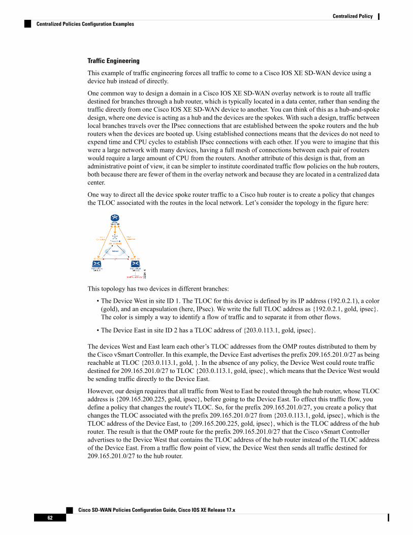
Traffic Engineering
This example of traffic engineering forces all traffic to come to a Cisco IOS XE SD-WAN device using adevice hub instead of directly.
One common way to design a domain in a Cisco IOS XE SD-WAN overlay network is to route all trafficdestined for branches through a hub router, which is typically located in a data center, rather than sending thetraffic directly from one Cisco IOS XE SD-WAN device to another. You can think of this as a hub-and-spokedesign, where one device is acting as a hub and the devices are the spokes. With such a design, traffic betweenlocal branches travels over the IPsec connections that are established between the spoke routers and the hubrouters when the devices are booted up. Using established connections means that the devices do not need toexpend time and CPU cycles to establish IPsec connections with each other. If you were to imagine that thiswere a large network with many devices, having a full mesh of connections between each pair of routerswould require a large amount of CPU from the routers. Another attribute of this design is that, from anadministrative point of view, it can be simpler to institute coordinated traffic flow policies on the hub routers,both because there are fewer of them in the overlay network and because they are located in a centralized datacenter.
One way to direct all the device spoke router traffic to a Cisco hub router is to create a policy that changesthe TLOC associated with the routes in the local network. Let’s consider the topology in the figure here:
This topology has two devices in different branches:
• The Device West in site ID 1. The TLOC for this device is defined by its IP address (192.0.2.1), a color(gold), and an encapsulation (here, IPsec). We write the full TLOC address as {192.0.2.1, gold, ipsec}.The color is simply a way to identify a flow of traffic and to separate it from other flows.
• The Device East in site ID 2 has a TLOC address of {203.0.113.1, gold, ipsec}.
The devices West and East learn each other’s TLOC addresses from the OMP routes distributed to them bythe Cisco vSmart Controller. In this example, the Device East advertises the prefix 209.165.201.0/27 as beingreachable at TLOC {203.0.113.1, gold, }. In the absence of any policy, the Device West could route trafficdestined for 209.165.201.0/27 to TLOC {203.0.113.1, gold, ipsec}, which means that the Device West wouldbe sending traffic directly to the Device East.
However, our design requires that all traffic fromWest to East be routed through the hub router, whose TLOCaddress is {209.165.200.225, gold, ipsec}, before going to the Device East. To effect this traffic flow, youdefine a policy that changes the route's TLOC. So, for the prefix 209.165.201.0/27, you create a policy thatchanges the TLOC associated with the prefix 209.165.201.0/27 from {203.0.113.1, gold, ipsec}, which is theTLOC address of the Device East, to {209.165.200.225, gold, ipsec}, which is the TLOC address of the hubrouter. The result is that the OMP route for the prefix 209.165.201.0/27 that the Cisco vSmart Controlleradvertises to the Device West that contains the TLOC address of the hub router instead of the TLOC addressof the Device East. From a traffic flow point of view, the Device West then sends all traffic destined for209.165.201.0/27 to the hub router.
Cisco SD-WAN Policies Configuration Guide, Cisco IOS XE Release 17.x62
Centralized PolicyCentralized Policies Configuration Examples

The device also learns the TLOC addresses of the West and East devices from the OMP routes advertised bythe Cisco vSmart Controller. Because, devices must use these two TLOC addresses, no policy is required tocontrol how the hub directs traffic to the devices.
Here is a policy configuration on the Cisco vSmart Controller that directs the Device West (and any otherdevices in the network domain) to send traffic destined to prefix 209.165.201.0/27 to TLOC 209.165.200.225,gold, which is the device:policylistsprefix-list east-prefixesip-prefix 209.165.201.0/27
site-list west-sitessite-id 1
control-policy change-tlocsequence 10match routeprefix-list east-prefixessite-id 2
action acceptset tloc 209.165.200.225 color gold encap ipsec
apply-policysite west-sites control-policy change-tloc out
A rough English translation of this policy is:Create a list named “east-prefixes” that contains the IP prefix “209.165.201.0/27”Create a list named “west-sites” that contains the site-id “1”Define a control policy named “change-tloc”Create a policy sequence element that:Matches a prefix from list “east-prefixes”, that is, matches “209.165.201.0/27”AND matches a route from site-id “2”
If a match occurs:Accept the routeAND change the route’s TLOC to “209.165.200.225” with a color of "gold" and an
encapsulation of "ipsec"Apply the control policy “change-tloc” to OMP routes sent by the vSmartcontroller to “west-sites”, that is, to site ID 1
This control policy is configured on the Cisco vSmart Controller as an outbound policy, as indicated by theout option in the apply-policy site command. This option means the Cisco vSmart Controller applies theTLOC change to the OMP route after it distributes the route from its route table. The OMP route for prefix209.165.201.0/27 that the Cisco vSmart Controller distributes to the DeviceWest associates 209.165.201.0/27with TLOC 209.165.200.225, gold. This is the OMP route that the Device West installs it in its route table.The end results are that when the Device West sends traffic to 209.165.201.0/27, the traffic is directed to thehub; and the Device West does not establish a DTLS tunnel directly with the Device East.
If the West side of the network had many sites instead of just one and each site had its own device, it wouldbe straightforward to apply this same policy to all the sites. To do this, you simply add the site IDs of all thesites in the site-list west-sites list. This is the only change you need to make in the policy to have all theWest-side sites send traffic bound for the prefix 209.165.201.0/27 through the device. For example:policylistsprefix-list east-prefixesip-prefix 209.165.201.0/27
site-list west-sitessite-id 1site-id 11site-id 12site-id 13
control-policy change-tloc
Cisco SD-WAN Policies Configuration Guide, Cisco IOS XE Release 17.x63
Centralized PolicyCentralized Policies Configuration Examples

sequence 10match routeprefix-list east-prefixessite-id 2
action acceptset tloc 209.165.200.225 color gold encap ipsec
apply-policysite west-sites control-policy change-tloc out
Creating Arbitrary Topologies
To provide redundancy in the hub-and-spoke-style topology discussed in the previous example, you can adda second Cisco hub to create a dual-homed hub site. The following figure shows that site ID 100 now has twoDevice hubs. We still want all inter-branch traffic to be routed through a device hub. However, because wenow have dual-homed hubs, we want to share the data traffic between the two hub routers.
• Device Hub West, with TLOC 209.165.200.225, gold. We want all data traffic from branches on theWest side of the overlay network to pass through and be processed by this device.
• Device Hub East, with TLOC 198.51.100.1, gold. Similarly, we all East-side data traffic to pass throughthe Device Hub East.
Here is a policy configuration on the Cisco vSmart Controller that would send West-side data traffic throughthe Cisco hub, and West and East-side traffic through the Device Hub East:policylistssite-list west-sitessite-id 1
site-list east-sitessite-id 2
tloc-list west-hub-tlocstloc-id 209.165.200.225 gold
tloc-list east-hub-tlocstloc-id 198.51.100.1 gold
control-policy prefer-west-hubsequence 10match tloctloc-list west-hub-tlocs
action acceptset preference 50
control-policy prefer-east-hubsequence 10match tloctloc-list east-hub-tlocs
action acceptset preference 50
apply-policysite west-sites control-policy prefer-west-hub outsite east-sites control-policy prefer-east-hub out
Cisco SD-WAN Policies Configuration Guide, Cisco IOS XE Release 17.x64
Centralized PolicyCentralized Policies Configuration Examples
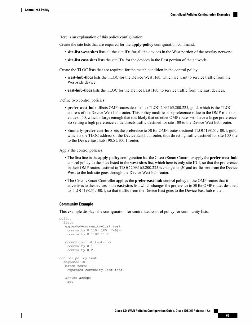
Here is an explanation of this policy configuration:
Create the site lists that are required for the apply-policy configuration command:
• site-list west-sites lists all the site IDs for all the devices in the West portion of the overlay network.
• site-list east-sites lists the site IDs for the devices in the East portion of the network.
Create the TLOC lists that are required for the match condition in the control policy:
• west-hub-tlocs lists the TLOC for the Device West Hub, which we want to service traffic from theWest-side device.
• east-hub-tlocs lists the TLOC for the Device East Hub, to service traffic from the East devices.
Define two control policies:
• prefer-west-hub affects OMP routes destined to TLOC 209.165.200.225, gold, which is the TLOCaddress of the Device West hub router. This policy modifies the preference value in the OMP route to avalue of 50, which is large enough that it is likely that no other OMP routes will have a larger preference.So setting a high preference value directs traffic destined for site 100 to the Device West hub router.
• Similarly, prefer-east-hub sets the preference to 50 for OMP routes destined TLOC 198.51.100.1, gold,which is the TLOC address of the Device East hub router, thus directing traffic destined for site 100 siteto the Device East hub 198.51.100.1 router.
Apply the control policies:
• The first line in the apply-policy configuration has the Cisco vSmart Controller apply the prefer-west-hubcontrol policy to the sites listed in the west-sites list, which here is only site ID 1, so that the preferencein their OMP routes destined to TLOC 209.165.200.225 is changed to 50 and traffic sent from the DeviceWest to the hub site goes through the Device West hub router.
• The Cisco vSmart Controller applies the prefer-east-hub control policy to the OMP routes that itadvertises to the devices in the east-sites list, which changes the preference to 50 for OMP routes destinedto TLOC 198.51.100.1, so that traffic from the Device East goes to the Device East hub router.
Community Example
This example displays the configuration for centralized control policy for community lists.policylistsexpanded-community-list testcommunity 0:110* 100:[7-9]+community 0:110* 11:*
community-list test-comcommunity 0:1community 0:2
control-policy testsequence 10match routeexpanded-community-list test
action acceptset
Cisco SD-WAN Policies Configuration Guide, Cisco IOS XE Release 17.x65
Centralized PolicyCentralized Policies Configuration Examples

community 100:2 100:3additive
This example displays the configuration for standard community lists.Standard Community list
route : 0:1234 0:11 0:12
community-listcommunity 0:100community 0:1234community 0:101
*MATCH*
route : 0:1234 0:11 0:12community-listcommunity 0:100community 0:5678community 0:101
*NO MATCH*
This example displays the configuration for expanded community lists. ORmatch compares each regex stringin the community list against the route’s community string.Expanded Community listroute - 0:1234 0:5678expanded-community-list:community 0:110* 11:community 0:110* 100:[7-9]+community 0:12[3-7]+
*MATCH*
route - 0:1234 0:5678expanded-community-list:
community 0:111*community 0:110* 11:*
*NO MATCH*
EXACTmatch input strings need to have communities in sorted order. Sorts it by byte value and add the metacharacters for start and end of string.route - 0:1234 0:5678expanded-community-list:community ^0:1234 0:5678$*MATCH*
AND match input strings need to have communities in sorted order. Add ‘.+’ to blindly match between thesorted communities.
route - 0:0 0:1234 0:5678 0:9789 0:9800 0:9900 0:9999 1:10expanded-community-list:
community 0:1234 .+ 0:9900 .+*MATCH*
Cisco SD-WAN Policies Configuration Guide, Cisco IOS XE Release 17.x66
Centralized PolicyCentralized Policies Configuration Examples
C H A P T E R 5Localized Policy
The topics in this section provide overview information about the different types of localized policies, thecomponents of localized policies, and how to configure localized policies using Cisco vManage or the CLI.
• Overview of Localized Policies, on page 67• Configure Localized Policy Using Cisco vManage , on page 68• Configure Localized Policy for IPv4 Using the CLI, on page 83• Configure Localized Policy for IPv6 Using the CLI, on page 85• Localized Data Policy Configuration Examples, on page 86
Overview of Localized PoliciesLocalized policy refers to a policy that is provisioned locally through the CLI on the Cisco IOS XE SD-WANdevices, or through a Cisco vManage device template.
Types of Localized Policies
Localized Control Policy
Control policy operates on the control plane traffic in the Cisco IOSXE SD-WAN overlay network, influencingthe determination of routing paths through the overlay network. Localized control policy is policy that isconfigured on a Cisco IOSXE SD-WAN device (hence, it is local) and affects BGP and OSPF routing decisionson the site-local network that the device is part of.
In addition to participating in the overlay network, a Cisco IOS XE SD-WAN device participates in thenetwork at its local site, where it appears to the other network devices to be simply a regular router. As such,you can provision routing protocols, such as BGP and OSPF, on the Cisco IOS XE SD-WAN device so thatit can exchange route information with the local-site routers. To control and modify the routing behavior onthe local network, you configure a type of control policy called route policy on the devices. Route policyapplies only to routing performed at the local branch, and it affects only the route table entries in the localdevice's route table.
Localized control policy, which you configure on the devices, lets you affect routing policy on the networkat the local site where the device is located. This type of control policy is called route policy. This policy issimilar to the routing policies that you configure on a regular driver, allowing you to modify the BGP andOSPF routing behavior on the site-local network. Whereas, centralized control policy affects the routingbehavior across the entire overlay network, route policy applies only to routing at the local branch.
Cisco SD-WAN Policies Configuration Guide, Cisco IOS XE Release 17.x67

Localized Data Policy
Data policy operates on the data plane in the Cisco IOS XE SD-WAN overlay network and affects how datatraffic is sent among the Cisco IOS XE SD-WAN devices in the network. The Cisco SD-WAN architecturedefines two types of data policy, centralized data policy, which controls the flow of data traffic based on theIP header fields in the data packets and based on network segmentation, and localized data policy, whichcontrols the flow of data traffic into and out of interfaces and interface queues on a Cisco IOS XE SD-WANdevice.
Localized data policy, so called because it is provisioned on the local Cisco IOS XE SD-WAN device, isapplied on a specific router interface and affects how a specific interface handles the data traffic that it istransmitting and receiving. Localized data policy is also referred to as access lists (ACLs). With access lists,you can provision class of service (CoS), classifying data packets and prioritizing the transmission propertiesfor different classes. You can configure policing and provision packet mirroring.
For IPv4, you can configure QoS actions.
You can apply IPv4 access lists in any VPN on the router, and you can create access lists that act on unicastand multicast traffic. You can apply IPv6 access lists only to tunnel interfaces in the transport VPN (VPN 0).
You can apply access lists either in the outbound or inbound direction on the interface. Applying an IPv4ACL in the outbound direction affects data packets traveling from the local service-side network into the IPsectunnel toward the remote service-side network. Applying an IPv4 ACL in the inbound direction affects datapackets exiting from the IPsec tunnel and being received by the local Cisco IOS XE SD-WAN device. ForIPv6, an outbound ACL is applied to traffic being transmitted by the router, and an inbound ACL is appliedto received traffic.
Explicit and Implicit Access Lists
Access lists that you configure using localized data policy are called explicit ACLs. You can apply explicitACLs in any VPN on the router.
Router tunnel interfaces also have implicit ACLs, which are also referred to as services. Some of these arepresent by default on the tunnel interface, and they are in effect unless you disable them. Through configuration,you can also enable other implicit ACLs. On Cisco IOS XE SD-WAN devices, the following services areenabled by default: DHCP (for DHCPv4 and DHCPv6), DNS, and ICMP. You can also enable services forBGP, Netconf, NTP, OSPF, SSHD, and STUN.
Perform QoS Actions
With access lists, you can provision quality of service (QoS) which allows you to classify data traffic byimportance, spread it across different interface queues, and control the rate at which different classes of trafficare transmitted. See Forwarding and QoS Overview.
Mirror Data Packets
Once packets are classified, you can configure access lists to send a copy of data packets seen on a CiscovEdge device to a specified destination on another network device. The Cisco IOS XE SD-WAN devicessupport 1:1 mirroring; that is, a copy of every packet is sent to the alternate destination.
Configure Localized Policy Using Cisco vManageTo configure localized policies, use the Cisco vManage policy configuration wizard. The wizard is a UI policybuilder that consists of five windows to configure and modify the following localized policy components:
Cisco SD-WAN Policies Configuration Guide, Cisco IOS XE Release 17.x68
Localized PolicyConfigure Localized Policy Using Cisco vManage
• Groups of interest, also called lists
• Forwarding classes to use for QoS
• Access control lists (ACLs)
• Route policies
• Policy settings
You configure some or all these components depending on the specific policy you are creating. To skip acomponent, click Next at the bottom of the window. To return to a component, click Back at the bottom ofthe window.
To configure localized policies using Cisco vManage, use the steps identified in the procedures that followthis section.
Start the Policy Configuration WizardTo start the policy configuration wizard:
1. From the Cisco vManage menu, choose Configuration > Policies.
2. Select Localized Policy.
3. Click Add Policy.
The Create Groups of Interest page is displayed.
Configure Groups of Interest for Localized PolicyIn Create Groups of Interest, create lists of groups to use in a localized policy:
In Create Groups of Interest, create new groups of list types as described in the following sections to use ina localized policy:
Configure As Path
1. In the group of interest list, click AS Path.
2. Click New AS Path List.
3. Enter a name for the list.
4. Enter the AS path, separating AS numbers with a comma.
5. Click Add.
AS Path list specifies one or more BGP AS paths. You can write each AS as a single number or as aregular expression. To specify more than one AS in a single path, include the list separated by commas.To configure multiple AS paths in a single list, include multiple as-path options, specifying one AS pathin each option.
Cisco SD-WAN Policies Configuration Guide, Cisco IOS XE Release 17.x69
Localized PolicyStart the Policy Configuration Wizard
Configure Community
A community list is used to create groups of communities to use in a match clause of a route map. A communitylist can be used to control which routes are accepted, preferred, distributed, or advertised. You can also usea community list to set, append, or modify the communities of a route.
1. In the group of interest list, click Community.
2. Click New Community List.
3. Enter a name for the community list.
4. In theAdd Community field, enter one or more data prefixes separated by commas in any of the followingformats:
• aa:nn: Autonomous System (AS) number and network number. Each number is a 2-byte value witha range from 1 to 65535.
• internet: Routes in this community are advertised to the Internet community. This communitycomprises all BGP-speaking networking devices.
• local-as: Routes in this community are not advertised outside the local AS number.
• no-advertise: Attaches the NO_ADVERTISE community to routes. Routes in this community arenot advertised to other BGP peers.
• no-export: Attaches the NO_EXPORT community to routes. Routes in this community are notadvertised outside the local AS or outside a BGP confederation boundary. To configure multipleBGP communities in a single list, include multiple community options, specifying one communityin each option.
5. Click Add.
Configure Data Prefix
1. In the Group of Interest list, click Data Prefix.
2. Click New Data Prefix List.
3. Enter a name for the list.
4. Enter one or more IP prefixes.
5. Click Add.
A data prefix list specifies one or more IP prefixes. You can specify both unicast and multicast addresses.To configure multiple prefixes in a single list, include multiple ip-prefix options, specifying one prefixin each option.
Configure Extended Community
1. In the group of interest list, click Extended Community.
2. Click New Extended Community List.
3. Enter a name for the list.
4. Enter the BGP extended community in the following formats:
Cisco SD-WAN Policies Configuration Guide, Cisco IOS XE Release 17.x70
Localized PolicyConfigure Groups of Interest for Localized Policy

• rt (aa:nn | ip-address): Route target community, which is one or more routers that can receive a setof routes carried by BGP. Specify this as the AS number and network number, where each numberis a 2-byte value with a range from 1 to 65535, or as an IP address.
• soo (aa:nn | ip-address): Route origin community, which is one or more routers that can inject a setof routes into BGP. Specify this as the AS number and network number, where each number is a2-byte value with a range from 1 to 65535, or as an IP address. To configure multiple extended BGPcommunities in a single list, include multiple community options, specifying one community ineach option.
5. Click Add.
Configure Class Map
1. In the group of interest list, click Class Map.
2. Click New Class List.
3. Enter a name for the class.
4. Select a required queue from the Queue drop-down list.
5. Click Save.
Configure Mirror
1. In the group of interest list, click Mirror.
2. Click New Mirror List. The Mirror List popup displays.
3. Enter a name for the list.
4. In theRemote Destination IP field, enter the IP address of the destination for which to mirror the packets.
5. In the Source IP field, enter the IP address of the source of the packets to mirror.
6. Click Add.
To configure mirroring parameters, define the remote destination to which to mirror the packets, anddefine the source of the packets. Mirroring applies to unicast traffic only. It does not apply to multicasttraffic.
Configure Policer
1. In the group of interest list, click Policer.
2. Click New Policer List.
3. Enter a name for the list.
4. In the Burst (bps) field, enter maximum traffic burst size. It can be a value from 15000 to 10000000bytes.
5. In the Exceed field, select the action to take when the burst size or traffic rate is exceeded. Select Drop(the default) to set the packet loss priority (PLP) to low. Select Remark to set the PLP to high.
Cisco SD-WAN Policies Configuration Guide, Cisco IOS XE Release 17.x71
Localized PolicyConfigure Groups of Interest for Localized Policy
6. In the Rate (bps) field, enter the maximum traffic rate. It can be value from 8 through 264 bps (8 through100000000000).
7. Click Add.
Configure Prefix
1. In the group of interest list, click Prefix.
2. Click New Prefix List.
3. Enter a name for the list.
4. In the Internet Protocol field, click either IPv4 or IPv6.
5. Under Add Prefix, enter the prefix for the list. (An example is displayed.) Optionally, click the greenImport link on the right-hand side to import a prefix list.
6. Click Add.
Click Next to move to Configure Forwarding Classes/QoS in the wizard.
Configure Forwarding Classes/QoSWhen you first open the Forwarding Classes/QoS page, QoS Map is selected by default:
QoS Map
To create a new QoS mapping:
1. In QoS, click the Add QoS Map drop-down.
2. Select Create New.
3. Enter a name and description for the QoS mapping.
4. Click Add Queue. The Add Queue popup appears.
5. Select the queue number from the Queue drop-down.
6. Select the maximum bandwidth and buffer percentages, and the scheduling and drop types.
7. Enter the Forwarding Class.
8. Click Save Queue.
To import an existing QoS mapping:
1. In QoS, click the Add QoS Map drop-down.
2. Select Import Existing. The Import Existing Application QoS Map Policy popup displays.
3. Select a QoS Map policy.
4. Click Import.
To view or copy a QoS mapping or to remove the mapping from the localized policy, click ... and select thedesired action.
Cisco SD-WAN Policies Configuration Guide, Cisco IOS XE Release 17.x72
Localized PolicyConfigure Forwarding Classes/QoS
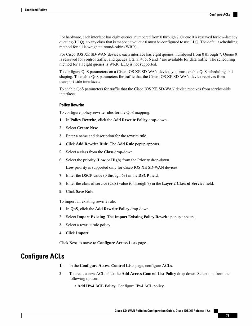
For hardware, each interface has eight queues, numbered from 0 through 7. Queue 0 is reserved for low-latencyqueuing (LLQ), so any class that is mapped to queue 0 must be configured to use LLQ. The default schedulingmethod for all is weighted round-robin (WRR).
For Cisco IOS XE SD-WAN devices, each interface has eight queues, numbered from 0 through 7. Queue 0is reserved for control traffic, and queues 1, 2, 3, 4, 5, 6 and 7 are available for data traffic. The schedulingmethod for all eight queues is WRR. LLQ is not supported.
To configure QoS parameters on a Cisco IOS XE SD-WAN device, you must enable QoS scheduling andshaping. To enable QoS parameters for traffic that the Cisco IOS XE SD-WAN device receives fromtransport-side interfaces:
To enable QoS parameters for traffic that the Cisco IOS XE SD-WAN device receives from service-sideinterfaces:
Policy Rewrite
To configure policy rewrite rules for the QoS mapping:
1. In Policy Rewrite, click the Add Rewrite Policy drop-down.
2. Select Create New.
3. Enter a name and description for the rewrite rule.
4. Click Add Rewrite Rule. The Add Rule popup appears.
5. Select a class from the Class drop-down.
6. Select the priority (Low or High) from the Priority drop-down.
Low priority is supported only for Cisco IOS XE SD-WAN devices.
7. Enter the DSCP value (0 through 63) in the DSCP field.
8. Enter the class of service (CoS) value (0 through 7) in the Layer 2 Class of Service field.
9. Click Save Rule.
To import an existing rewrite rule:
1. In QoS, click the Add Rewrite Policy drop-down..
2. Select Import Existing. The Import Existing Policy Rewrite popup appears.
3. Select a rewrite rule policy.
4. Click Import.
Click Next to move to Configure Access Lists page.
Configure ACLs1. In the Configure Access Control Lists page, configure ACLs.
2. To create a new ACL, click the Add Access Control List Policy drop-down. Select one from thefollowing options:
• Add IPv4 ACL Policy: Configure IPv4 ACL policy.
Cisco SD-WAN Policies Configuration Guide, Cisco IOS XE Release 17.x73
Localized PolicyConfigure ACLs

• Add IPv6 ACL Policy: Configure IPv6 ACL policy.
• Import Existing: Import existing ACL policy.
3. If you click Add IPv4 ACL Policy, the Add IPv4 ACL Policy page appears.
or
If you click Add IPv6 ACL Policy, the Add IPv6 ACL Policy page appears.
4. Enter a name and description for the ACL in the ACL Policy page.
5. In the left pane, click Add ACL Sequence. An Access Control List box is displayed in the left pane.
6. Double-click the Access Control List box, and type a name for the ACL.
7. In the right pane, click Add Sequence Rule to create a single sequence in the ACL. Match is selectedby default.
8. Click a match condition.
9. On the left, enter the values for the match condition.
a. On the right enter the action or actions to take if the policy matches.
10. Repeat Steps 6 through 8 to add match–action pairs to the ACL.
11. To rearrange match–action pairs in the ACL, in the right pane drag them to the desired position.
12. To remove a match–action pair from the ACL, click the X in the upper right of the condition.
13. Click Save Match and Actions to save a sequence rule.
14. To rearrange sequence rules in an ACL, in the left pane drag the rules to the desired position.
15. To copy, delete, or rename an ACL sequence rule, in the left pane, click ... next to the rule's name andselect the desired option.
Default Action
If a packet being evaluated does not match any of the match conditions in a access list, a default action isapplied to this packet. By default, the packet is dropped. To change the default action:
1. Click Default Action in the left pane.
2. Click the Pencil icon.
3. Change the default action to Accept.
4. Click Save Match and Actions.
5. Click Save Access Control List Policy.
To configure Device Access Policy, see Device Access Policy.
Click Next to move to Configure Route Policy page.
Cisco SD-WAN Policies Configuration Guide, Cisco IOS XE Release 17.x74
Localized PolicyConfigure ACLs

Explicit and Implicit Access ListsAccess lists that you configure through localized data policy using the policy access-list command are calledexplicit ACLs. You can apply explicit ACLs to any interface in any VPN on the device.
The device's tunnel interfaces in VPN 0 also have implicit ACLs, which are also referred to as services. Someservices are enabled by default on the tunnel interface, and are in effect unless you disable them. Throughconfiguration, you can also enable other services. You configure and modify implicit ACLs with theallow-service command:Device(config)# vpn 0Device(config-vpn)# interface interface-nameDevice(config-interface)# tunnel-interfaceDevice(config-tunnel-interface)# allow-service service-nameDevice(config-tunnel-interface)# no allow-service service-name
On Cisco IOS XE SD-WAN devices, the following services are enabled by default: DHCP (for DHCPv4 andDHCPv6), DNS, and ICMP. These three services allow the tunnel interface to accept DHCP, DNS, and ICMPpackets. You can also enable services for BGP, Netconf, NTP, OSPF, SSHD, and STUN.
If a connection is initiated from a device, and if NAT is enabled on the device (for example, Direct InternetAccess (DIA) is configured), return traffic is allowed by the NAT entry even if the implicit ACL has beenconfigured as no allow-service. You can still block this traffic with an explicit ACL.
Do not confuse an explicit ACL with a Cisco IOS XE ACL. A Cisco IOS XE ACL does not interact with aCisco SD-WAN explicit and an implicit ACL and cannot override an implicit ACL or explicit ACL. CiscoIOS XE ACLs are executed later in the order of traffic processing operations.
Note
When data traffic matches both an explicit ACL and an implicit ACL, how the packets are handled dependson the ACL configuration. Specifically, it depends on:
• Whether the implicit ACL is configured as allow (allow-service service-name) or deny (no allow-serviceservice-name). Allowing a service in an implicit ACL is the same as specifying the accept action in anexplicit ACL, and a service that is not allowed in an implicit ACL is the same as specifying the dropaction in an explicit ACL
• Whether, in an explicit ACL, the accept or deny action is configured in a policy sequence or in thedefault action.
The following table explains how traffic matching both an implicit and an explicit ACL is handled:
Table 14:
ResultExplicit ACL:Default
Explicit ACL:Sequence
Implicit ACL
Deny (drop)—Deny (drop)Allow(accept)
Allow(accept)
Deny (drop)—Allow(accept)
Allow(accept)
—Allow (accept)Deny (drop)
Cisco SD-WAN Policies Configuration Guide, Cisco IOS XE Release 17.x75
Localized PolicyExplicit and Implicit Access Lists
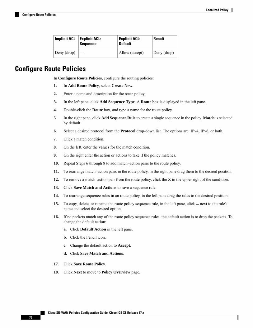
ResultExplicit ACL:Default
Explicit ACL:Sequence
Implicit ACL
Deny (drop)Allow (accept)—Deny (drop)
Configure Route PoliciesIn Configure Route Policies, configure the routing policies:
1. In Add Route Policy, select Create New.
2. Enter a name and description for the route policy.
3. In the left pane, click Add Sequence Type. A Route box is displayed in the left pane.
4. Double-click the Route box, and type a name for the route policy.
5. In the right pane, click Add Sequence Rule to create a single sequence in the policy. Match is selectedby default.
6. Select a desired protocol from the Protocol drop-down list. The options are: IPv4, IPv6, or both.
7. Click a match condition.
8. On the left, enter the values for the match condition.
9. On the right enter the action or actions to take if the policy matches.
10. Repeat Steps 6 through 8 to add match–action pairs to the route policy.
11. To rearrange match–action pairs in the route policy, in the right pane drag them to the desired position.
12. To remove a match–action pair from the route policy, click the X in the upper right of the condition.
13. Click Save Match and Actions to save a sequence rule.
14. To rearrange sequence rules in an route policy, in the left pane drag the rules to the desired position.
15. To copy, delete, or rename the route policy sequence rule, in the left pane, click ... next to the rule'sname and select the desired option.
16. If no packets match any of the route policy sequence rules, the default action is to drop the packets. Tochange the default action:
a. Click Default Action in the left pane.
b. Click the Pencil icon.
c. Change the default action to Accept.
d. Click Save Match and Actions.
17. Click Save Route Policy.
18. Click Next to move to Policy Overview page.
Cisco SD-WAN Policies Configuration Guide, Cisco IOS XE Release 17.x76
Localized PolicyConfigure Route Policies

Match Parameters
Access List Parameters
Access lists can match IP prefixes and fields in the IP headers.
In the CLI, you configure the match parameters with the policy access-list sequence match command.
Each sequence in an access-list must contain one match condition.
For access lists, you can match these parameters:
DescriptionMatch Condition
Name of a class defined with a policy class-map command.Class
Name of a data-prefix-list list.Destination Data Prefix
Specifies a single port number, a list of port numbers (with numbers separated by a space), ora range of port numbers (with the two numbers separated with a hyphen [-]). The range is 0through 65535.
Destination Port
Specifies the DSCP value. The range is 0 through 63.DSCP
Specifies the internet protocol number. The range is 0 through 255.Protocol
When you select a Protocol value as 1 the ICMP Message field displays where you can selectan ICMP message to apply to the data policy.
When you select a Next Header value as 58 the ICMP Message field displays where you canselect an ICMP message to apply to the data policy.
This field is available from Cisco IOS XE Release 17.4.1, Cisco vManage Release20.4.1.
Note
For icmp-msg and icmp6-msg message types, refer to the ICMP Message Types/Codesand Corresponding Enumeration Values table in the Centralized chapter.
ICMP Message
Specifies the length of the packet. The range can be from 0 through 65535. Specify a singlelength, a list of lengths (with numbers separated by a space), or a range of lengths (with thetwo numbers separated with a hyphen [-]).
Packet Length
Specifies the name of a data-prefix-list list.Source Data Prefix
Specifies the Packet Loss Priority (PLP) (high | low). By default, packets have a PLP valueof low. To set the PLP value to high, apply a policer that includes the exceed remark option.
PLP
Specifies a single port number, a list of port numbers (with numbers separated by a space), ora range of port numbers (with the two numbers separated with a hyphen [-]). The range is 0through 65535.
Source Port
synTCP
Cisco SD-WAN Policies Configuration Guide, Cisco IOS XE Release 17.x77
Localized PolicyMatch Parameters

Route Policy Parameters
For route policies, you can match these parameters:
DescriptionMatch Condition
Specifies the name of a Prefix-List list.Address
Specifies one or more BGP AS path lists. You can write each AS as a single number or asa regular expression. To specify more than one AS number in a single path, include the listin quotation marks (" "). To configure multiple AS numbers in a single list, include multipleAS Path options, specifying one AS path in each option.
AS Path List
List of one of more BGP communities. In Community List, you can specify:
• aa:nn: AS number and network number. Each number is a 2-byte value with a range from1 to 65535.
• internet: Routes in this community are advertised to the Internet community. Thiscommunity comprises all BGP-speaking networking devices.
• local-as: Routes in this community are not advertised outside the local AS.
• no-advertise: Attach the NO_ADVERTISE community to routes. Routes in thiscommunity are not advertised to other BGP peers.
• no-export: Attach the NO_EXPORT community to routes. Routes in this community arenot advertised outside the local AS or outside a BGP confederation boundary. To configuremultiple BGP communities in a single list, include multiple community options, specifyingone community in each option.
Community List
Specifies the list of one or more BGP extended communities. In community, you canspecify:
• rt (aa:nn | ip-address): Route target community, which is one or more routers that canreceive a set of routes carried by BGP. Specify this as the AS number and network number,where each number is a 2-byte value with a range from 1 to 65535, or as an IP address.
• soo (aa:nn | ip-address): Route origin community, which is one or more routers that caninject a set of routes into BGP. Specify this as the AS number and network number, whereeach number is a 2-byte value with a range from 1 to 65535, or as an IP address. Toconfigure multiple extended BGP communities in a single list, include multiple communityoptions, specifying one community in each option.
Extended Community List
Specifies the BGP local preference number. The range is 0 through 4294967295.BGP Local Preference
Specifies the route metric value. The range is 0 through 4294967295.Metric
Specifies the name of an IP prefix list.Next Hop
Specifies the OMP tag number. The range is 0 through 4294967295.OMP Tag
Specifies the BGP origin code. The optionss are: EGP (default), IGP, Incomplete.Origin
Specifies the OSPF tag number. The range is 0 through 4294967295.OSPF Tag
Specifies the peer IP address.Peer
Cisco SD-WAN Policies Configuration Guide, Cisco IOS XE Release 17.x78
Localized PolicyMatch Parameters

Action Parameters
Access List Parameters
When a packet matches the conditions in the match portion of an access list, the packet can be accepted ordropped, and it can be counted. Then, you can classify, mirror, or police accepted packets.
In the CLI, you configure the action parameters with the policy access-list sequence action command.
Each sequence in an access list can contain one action condition.
In the action, you first specify whether to accept or drop a matching data packet, and whether to count it:
DescriptionAction Condition
Accepts the packet. An accepted packet is eligible to be modified by the additional parametersconfigured in the action portion of the access list.
Accept
Name of a counter. To display counter information, use the show policy access-lists counters commandon the Cisco IOS XE SD-WAN device.
Counter
Discards the packet. This is the default action.Drop
Logs the packet headers into the messages and syslog system logging (syslog) files.
In addition to logging the packet headers, a syslog message is generated the first time a packet headeris logged and then every 5 minutes thereafter, as long as the flow is active.
To display logging information, use the show app log flow-all , show app log flows, and show logcommands on the Cisco IOS XE SD-WAN device.
Log
For a packet that is accepted, the following actions can be configured:
Value or RangeDescription
Specifies the name of a QoS class. It can also be defined with a policy class-map command.Class
Specifies the name of mirror . It is defined with a policy mirror command.Mirror List
Specifies the name of a policer defined with a policy policer command.Policer
Specifies the packet's DSCP value. The range is 0 through 63.DSCP
Specifies the IPv4 address. It sets the next hop IP address to which the packet should be forwarded.
Starting from Cisco vManage Release 20.5.1 and Cisco IOS XE Release 17.5.1a, UseDefault Route when Next Hop is not available field is available next to Next Hopaction parameter.
Note
Next Hop
Route Policy Parameters
Each sequence in a localized control policy can contain one action condition.
When a route matches the conditions in the match portion of a route policy, the route can be accepted orrejected:
Cisco SD-WAN Policies Configuration Guide, Cisco IOS XE Release 17.x79
Localized PolicyAction Parameters
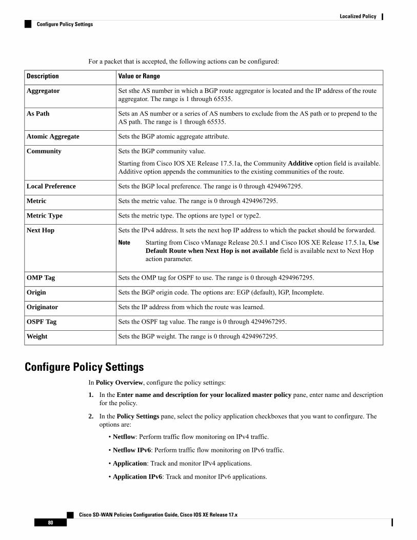
For a packet that is accepted, the following actions can be configured:
Value or RangeDescription
Set sthe AS number in which a BGP route aggregator is located and the IP address of the routeaggregator. The range is 1 through 65535.
Aggregator
Sets an AS number or a series of AS numbers to exclude from the AS path or to prepend to theAS path. The range is 1 through 65535.
As Path
Sets the BGP atomic aggregate attribute.Atomic Aggregate
Sets the BGP community value.
Starting from Cisco IOS XE Release 17.5.1a, the Community Additive option field is available.Additive option appends the communities to the existing communities of the route.
Community
Sets the BGP local preference. The range is 0 through 4294967295.Local Preference
Sets the metric value. The range is 0 through 4294967295.Metric
Sets the metric type. The options are type1 or type2.Metric Type
Sets the IPv4 address. It sets the next hop IP address to which the packet should be forwarded.
Starting from Cisco vManage Release 20.5.1 and Cisco IOS XE Release 17.5.1a, UseDefault Route when Next Hop is not available field is available next to Next Hopaction parameter.
Note
Next Hop
Sets the OMP tag for OSPF to use. The range is 0 through 4294967295.OMP Tag
Sets the BGP origin code. The options are: EGP (default), IGP, Incomplete.Origin
Sets the IP address from which the route was learned.Originator
Sets the OSPF tag value. The range is 0 through 4294967295.OSPF Tag
Sets the BGP weight. The range is 0 through 4294967295.Weight
Configure Policy SettingsIn Policy Overview, configure the policy settings:
1. In the Enter name and description for your localized master policy pane, enter name and descriptionfor the policy.
2. In the Policy Settings pane, select the policy application checkboxes that you want to confirgure. Theoptions are:
• Netflow: Perform traffic flow monitoring on IPv4 traffic.
• Netflow IPv6: Perform traffic flow monitoring on IPv6 traffic.
• Application: Track and monitor IPv4 applications.
• Application IPv6: Track and monitor IPv6 applications.
Cisco SD-WAN Policies Configuration Guide, Cisco IOS XE Release 17.x80
Localized PolicyConfigure Policy Settings

• Cloud QoS: Enable QoS scheduling.
• Cloud QoS Service Side: Enable QoS scheduling on the service side.
• Implicit ACL Logging: Log the headers of all the packets that are dropped because they do notmatch a service perform traffic flow monitoring.
3. To configure how often packets flows are logged, click Log Frequency.
Packet flows are those that match an access list (ACL), a cflowd flow, or an application-aware routingflow.
4. Click Preview to view the full policy in CLI format.
5. Click Save Policy.
Apply Localized Policy in a Device Template1. From the Cisco vManage menu, choose Configuration > Templates.
2. If you are creating a new device template:
a. Click Device, and from the Create Template drop-down, select From Feature Template.
b. From the Device Model drop-down, select one of the Cisco IOS XE SD-WAN devices.
c. In the Template Name field, enter a name for the device template. This field is mandatory and cancontain only uppercase and lowercase letters, the digits 0 through 9, hyphens (–), and underscores(_). It cannot contain spaces or any other characters.
d. In the Description field, enter a description for the device template. This field is mandatory, and itcan contain any characters and spaces.
e. Continue with Step 4.
3. If you are editing an existing device template:
a. Click Device, and for the desired template, click ... and select Edit.
b. Click Additional Templates. The screen scrolls to the Additional Templates section.
c. From the Policy drop-down, select the name of a policy that you have configured.
4. Click Additional Templates located directly beneath the Description field. The screen scrolls to theAdditional Templates section.
5. From the Policy drop-down, select the name of the policy you configured in the above procedure.
6. Click Create (for a new template) or Update (for an existing template).
Activate a Localized Policy1. Click Localized Policy, and select a policy.
2. For the desired policy, click ... and select Activate.
Cisco SD-WAN Policies Configuration Guide, Cisco IOS XE Release 17.x81
Localized PolicyApply Localized Policy in a Device Template

3. In the Activate Policy popup, click Activate to push the policy to all reachable Cisco vSmart Controllersin the network.
4. Click OK to confirm activation of the policy on all Cisco vSmart Controllers.
5. To deactivate the localized policy, select =, and then select a policy.
6. For the desired policy, click ... and select Deactivate.
7. In the Deactivate Policy popup, click Deactivate to confirm that you want to remove the policy from allreachable Cisco vSmart Controllers.
View Localized Policies
To view localized policies:
1. Click Localized Policy, and select a policy.
2. For a policy created using the UI policy builder or using the CLI, click ... and select View. The policycreated using the UI policy builder is displayed in graphical format while the policy created using the CLImethod is displayed in text format.
3. For a policy created using the Cisco vManage policy configuration wizard, click ... and select Preview.This policy is displayed in text format.
Copy, Edit, and Delete Policies
To copy a policy:
1. Click Localized Policy, and select a policy.
2. For the desired policy, click ... and select Copy.
3. In the Policy Copy popup window, enter the policy name and a description of the policy.
Starting with the Cisco IOS XE Release 17.2, 127 characters are supported for policy names forthe following policy types:
• Central route policy
• Local route policy
• Local Access Control lOst (ACL)
• Local IPv6 ACL
• Central data policy
• Central app route policy
• QoS map
• Rewrite rule
All other policy names support 32 characters.
Note
Cisco SD-WAN Policies Configuration Guide, Cisco IOS XE Release 17.x82
Localized PolicyActivate a Localized Policy

4. Click Copy.
To edit policies created using the Cisco vManage policy configuration wizard:
1. For the desired policy, click ... and select Edit.
2. Edit the policy as needed.
3. Click Save Policy Changes.
To edit polices created using the CLI method:
1. From the Custom Options drop-down, under Localized Policy, select CLI Policy.
2. For the desired policy, click ... and select Edit.
3. Edit the policy as needed.
4. Click Update.
To delete policies:
1. Click Localized Policy, and select a policy.
2. For the desired policy, click ... and select Delete.
3. Click OK to confirm deletion of the policy.
Configure Localized Policy for IPv4 Using the CLIFollowing are the high-level steps for configuring an access list using the CLI on Cisco IOS XE SD-WANdevices:
1. Create lists of IP prefixes as needed:Device(config)# policy lists data-prefix-list ipv4_prefix_listDevice(config-data-prefix-list-ipv4_prefix_list)# ip-prefix 192.168.0.3/24
2. For QoS, configure the class-map ios:Device(config)# class-map match-any class1Device(config)# match qos-group 1class-map match-any class6match qos-group 6class-map match-any class7match qos-group 7class-map match-any class4match qos-group 4class-map match-any class5match qos-group 5class-map match-any class2match qos-group 2class-map match-any class3match qos-group 3class-map match-any class1match qos-group 1end
Cisco SD-WAN Policies Configuration Guide, Cisco IOS XE Release 17.x83
Localized PolicyConfigure Localized Policy for IPv4 Using the CLI

queue2 is optional here since we are using class-default.Note
3. For QoS, define rewrite rules to overwrite the DSCP field of a packet's outer IP header, if desired:Device(config)# policy rewrite-rule rule1Device(config-rewrite-rule-rule1)# class class1 low dscp 3Device(config-rewrite-rule-rule1)# class class2 high dscp 4Will be a table to map class-id → QoS-Group, QID, DSCP, Discard-Class
4. For QoS, map each forwarding class to an output queue, configure a QoS scheduler for each forwardingclass, and group the QoS schedulers into a QoS map:Device(config)# policy class-map class class1 queue 1<0..7>[1]
5. For Qos map configuration, merge with interface shaping configuration, if shaping is configured.
If shaping is not configured, you can apply the policy-map generated for the qos-map.Device(config)# policy-map qos_map_for_data_policy<name:stringDevice(config-pmap)# class class1 name:stringDevice(config-pmap-c)# bandwidth percentageDevice(config-pmap-c)# random-detect
6. Configure a WAN interface without a shaping configuration:Device(config)# policy-map qos_map_for_data_policy name:stringDevice(config-pmap)# class class1 name:stringDevice(config-pmap-c)# bandwidth percentageDevice(config-pmap-c)# random-detect
7. Configure a WAN interface with a shaping configuration:Device(config)# policy-map shaping_interfaceDevice(config-pmap)# class class-defaultDevice(config-pmap-c)# shape average 100000000(rate-in-bps)Device(config-pmap-c)# service-policy qos_map_for_data_policy
8. Associate a service-policy to a Cisco IOS XE SD-WAN device:Device(config)# sdwan interface GigabitEthernet 1Device(config-if)# rewrite-rule rule1Device(config-if)# service-policy output qos_map_for_data_policy
9. Define policing parameters:Device(config)# policy policer policer_On_gigeDevice(config-policer-policer_On_gige)# rate ?Description: Bandwidth for 1g interfaces: <8..1000000000>bps; for 10g interfaces:<8..10000000000>bpsPossible completions:<0..2^64-1>Device(config-policer-policer_On_gige)# burstDescription: Burst rate, in bytesPossible completions:<15000..10000000>Device(config-policer-policer_On_gige)# exceed drop
10. Associate an access list set to policer:Device(config)# policy access-list ipv4_aclDevice(config-access-list-ipv4_acl)# sequence 100Device(config-sequence-100)# match dscp 10
Cisco SD-WAN Policies Configuration Guide, Cisco IOS XE Release 17.x84
Localized PolicyConfigure Localized Policy for IPv4 Using the CLI

Device(config-match)# exitDevice(config-sequence-100)# action acceptDevice(config-sequence-100)# action count dscp_10_countDevice(config-sequence-100)# policer policer_On_gigeDevice(config-sequence-100)# action dropvm5(config-action)#
11. Associate an access list to a LAN or a WAN interface:Device(config)# sdwan interface GigabitEthernet5Device(config-interface-GigabitEthernet5)# access-list ipv4_aclDevice(config-interface-GigabitEthernet5)# commit
Configure Localized Policy for IPv6 Using the CLIFollowing are the high-level steps for configuring an access list using the CLI:
1. Define policing parameters:Device(config)# policy policer policer_On_gigeDevice (config-policer-policer_On_gige)# rate ?Description: Bandwidth for 1g interfaces: <8..1000000000>bps;for 10g interfaces:<8..10000000000>bps Possible completions: <0..2^64-1>Device(config-policer-policer_On_gige)# burstDescription: Burst rate, in bytes Possible completions:<15000..10000000>Device(config-policer-policer_On_gige)# exceed drop
2. Create an access list instance:Device (config)# policy ipv6 access-list ipv6_access_list
3. Create a series of match–action pair sequences:Device(config-access-list-ipv6_access_list)# sequence 100
The match–action pairs are evaluated in order, by sequence number, starting with the lowest numberedpair and ending when the route matches the conditions in one of the pairs. Or if no match occurs, thedefault action is taken (either rejecting the route or accepting it as is).
4. Define match parameters for packets:Device(config-sequence-100)# match traffic-class 10Device(config-match)# exit
5. Define actions to take when a match occurs:Device(config-sequence-100)# action accept count traffic_class10_countDevice(config-sequence-100)# action dropDevice(config-sequence-100)# action accept class class1Device(config-sequence-100)# action accept policer policer_On_gige
6. Create additional numbered sequences of match–action pairs within the access list, as needed.
7. If a packet does not match any of the conditions in one of the sequences, it is rejected by default. If youwant nonmatching packets to be accepted, configure the default action for the access list:
8. Apply the access list to an interface:Device(config)# sdwan interface GigabitEthernet5Device(config-interface-GigabitEthernet5)# ipv6 access-list ipv6_access_list in
Cisco SD-WAN Policies Configuration Guide, Cisco IOS XE Release 17.x85
Localized PolicyConfigure Localized Policy for IPv6 Using the CLI

Device(config-interface-GigabitEthernet5)# commit
Applying the access list in the inbound direction (in) affects packets being received on the interface.Applying it in the outbound direction (out) affects packets being transmitted on the interface.
Localized Data Policy Configuration ExamplesThis topic provides some straightforward examples of configuring localized data policy to help you get anidea of how to use policy to influence traffic flow across the Cisco SD-WAN domain. Localized data policy,also known as access lists, is configured directly on the local Cisco vEdge devices.
QoS
You can configure quality of service (QoS) to classify data packets and control how traffic flows out of andin to the interfaces on a Cisco vEdge device and on the interface queues. For examples of how to configurea QoS policy, see Forwarding and QoS Configuration Examples.
ICMP Message Example
This example displays the configuration for localized data policy for ICMP messages.policyaccess-list acl_1sequence 100matchprotocol 1icmp-msg administratively-prohibited!action acceptcount administratively-prohibited!!
Cisco SD-WAN Policies Configuration Guide, Cisco IOS XE Release 17.x86
Localized PolicyLocalized Data Policy Configuration Examples

C H A P T E R 6Default AAR and QoS Policies
Table 15: Feature History
DescriptionRelease InformationFeature Name
This feature enables you to efficiently configure defaultapplication-aware routing (AAR), data, and quality ofservice (QoS) policies for Cisco IOS XE SD-WANdevices. The feature provides a step-by-step workflow forcategorizing the business relevance, path preference, andother parameters for network applications, and applyingthose preferences as traffic policy.
Cisco IOS XE Release17.7.1a
Cisco vManage Release20.7.1
Configure DefaultAAR and QoSPolicies
• Information About Default AAR and QoS Policies, on page 87• Prerequisites for Default AAR and QoS Policies, on page 88• Restrictions for Default AAR and QoS Policies, on page 89• Supported Devices for Default AAR and QoS Policies, on page 89• Use Cases for Default AAR and QoS Policies, on page 89• Configure Default AAR and QoS Policies Using Cisco vManage, on page 89• Monitor Default AAR and QoS Policies, on page 93
Information About Default AAR and QoS PoliciesIt is often helpful to create an AAR policy, a data policy, and a QoS policy for devices in a network. Thesepolicies route and prioritize traffic for best performance.When creating these policies, it is helpful to distinguishamong the applications producing network traffic, based on the likely business relevance of the applications,and to give higher priority to business-relevant applications.
Cisco vManage provides an efficient workflow to help you create a default set of AAR, data, and QoS policiesto apply to devices in the network. The workflow presents a set of more than 1000 applications that can beidentified by network-based application recognition (NBAR), an application recognition technology built intoCisco IOS XE SD-WAN devices. The workflow groups the applications into one of three business-relevancecategories:
• Business-relevant: Likely to be important for business operations, for example, Webex software.
• Business-irrelevant: Unlikely to be important for business operations, for example, gaming software.
Cisco SD-WAN Policies Configuration Guide, Cisco IOS XE Release 17.x87

• Default: No determination of relevance to business operations.
Within each of the business-relevance categories, the workflow groups the applications into application lists,such as broadcast video, multimedia conferencing, VoIP telephony, and so on.
Using the workflow, you can accept the predefined categorization of each application's business relevance oryou can customize the categorization of specific applications by moving them from one of thebusiness-relevance categories to another. For example, if, by default, the workflow predefines a specificapplication as business-irrelevant, but that application is important for your business operations, then you canrecategorize the application as Business-relevant.
The workflow provides a step-by-step procedure for configuring the business relevance, path preference, andservice level agreement (SLA) category.
After you complete the workflow, Cisco vManage produces a default set of the following:
• AAR policy
• QoS policy
• Data policy
After you attach these policies to a centralized policy, you can apply these default policies to Cisco IOS XESD-WAN devices in the network.
Background Information About NBAR
NBAR is an application recognition technology included in Cisco IOS XE SD-WAN devices. NBAR uses aset of application definitions called protocols to identify and categorize traffic. One of the categories that itassigns to traffic is the business-relevance attribute. The values of this attribute are Business-relevant,Business-irrelevant, and Default. In developing protocols to identify applications, Cisco estimates whetheran application is likely to be important for typical business operations, and assigns a business-relevance valueto the application. The default AAR andQoS policy feature uses the business-relevance categorization providedby NBAR.
Benefits of Default AAR and QoS Policies• Manage and customize bandwidth allocations.
• Prioritize applications based on their relevance to your business.
Prerequisites for Default AAR and QoS Policies• Knowledge about the relevant applications.
• Familiarity with the SLAs and QoS markings to prioritize traffic.
Cisco SD-WAN Policies Configuration Guide, Cisco IOS XE Release 17.x88
Default AAR and QoS PoliciesBenefits of Default AAR and QoS Policies

Restrictions for Default AAR and QoS Policies• When you customize a business-relevant application group, you cannot move all the applications fromthat group to another section. Application groups of business-relevant section need to have at least oneapplication in them.
• Default AAR and QoS policies do not support IPv6 addressing.
Supported Devices for Default AAR and QoS Policies• Cisco 1000 Series Integrated Services Routers (ISR1100-4G and ISR1100-6G)
• Cisco 4000 Series Integrated Services Routers (ISR44xx)
• Cisco Catalyst 8000V Edge Software
• Cisco Catalyst 8300 Series Edge Platforms
• Cisco Catalyst 8500 Series Edge Platforms
Use Cases for Default AAR and QoS PoliciesIf you are setting up a Cisco SD-WAN network and want to apply an AAR and a QoS policy to all the devicesin a network, use this feature to create and deploy these policies quickly.
Configure Default AAR and QoS Policies Using Cisco vManageFollow these steps to configure default AAR, data, and QoS policies using Cisco vManage:
1. From the Cisco vManage menu, choose Configuration > Policies.
2. Click Add Default AAR & QoS.
The Process Overview page is displayed.
3. Click Next.
The Recommended Settings based on your selection page is displayed.
4. Based on the requirements of your network, move the applications between the Business Relevant,Default, and Business Irrelevant groups.
When customizing the categorization of applications as Business-relevant, Business-irrelevant,or Default, you can only move individual applications from one category to another. You cannotmove an entire group from one category to another.
Note
5. Click Next.
Cisco SD-WAN Policies Configuration Guide, Cisco IOS XE Release 17.x89
Default AAR and QoS PoliciesRestrictions for Default AAR and QoS Policies
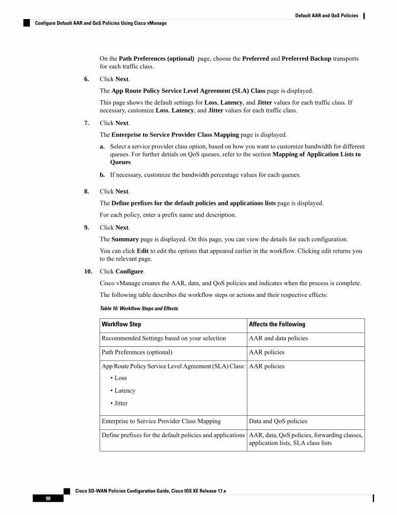
On the Path Preferences (optional) page, choose the Preferred and Preferred Backup transportsfor each traffic class.
6. Click Next.
The App Route Policy Service Level Agreement (SLA) Class page is displayed.
This page shows the default settings for Loss, Latency, and Jitter values for each traffic class. Ifnecessary, customize Loss, Latency, and Jitter values for each traffic class.
7. Click Next.
The Enterprise to Service Provider Class Mapping page is displayed.
a. Select a service provider class option, based on how you want to customize bandwidth for differentqueues. For further detials on QoS queues, refer to the section Mapping of Application Lists toQueues
b. If necessary, customize the bandwidth percentage values for each queues.
8. Click Next.
The Define prefixes for the default policies and applications lists page is displayed.
For each policy, enter a prefix name and description.
9. Click Next.
The Summary page is displayed. On this page, you can view the details for each configuration.
You can click Edit to edit the options that appeared earlier in the workflow. Clicking edit returns youto the relevant page.
10. Click Configure.
Cisco vManage creates the AAR, data, and QoS policies and indicates when the process is complete.
The following table describes the workflow steps or actions and their respective effects:
Table 16: Workflow Steps and Effects
Affects the FollowingWorkflow Step
AAR and data policiesRecommended Settings based on your selection
AAR policiesPath Preferences (optional)
AAR policiesAppRoute Policy Service Level Agreement (SLA)Class:
• Loss
• Latency
• Jitter
Data and QoS policiesEnterprise to Service Provider Class Mapping
AAR, data, QoS policies, forwarding classes,application lists, SLA class lists
Define prefixes for the default policies and applications
Cisco SD-WAN Policies Configuration Guide, Cisco IOS XE Release 17.x90
Default AAR and QoS PoliciesConfigure Default AAR and QoS Policies Using Cisco vManage

11. To view the policy, click View Your Created Policy.
To apply the default AAR and QoS policies to the devices in the network, create a centralizedpolicy that attaches the AAR and data policies to the required site lists. To apply the QoS policyto the Cisco IOS XE SD-WAN devices, attach it to a localized policy through device templates.
Note
Mapping of Application Lists to Queues
The following lists show each service provider class option, the queues in each option, and the applicationlists included in each queue. The application lists are named here as they appear on the Path Preferences pagein this workflow.
4 QoS class
• Voice
• Internetwork control
• VoIP telephony
• Mission critical
• Broadcast video
• Multimedia conferencing
• Real-Time interactive
• Multimedia streaming
• Business data
• Signaling
• Transactional data
• Network management
• Bulk data
• Default
• Best effort
• Scavenger
5 QoS class
• Voice
• Internetwork control
• VoIP telephony
• Mission critical
Cisco SD-WAN Policies Configuration Guide, Cisco IOS XE Release 17.x91
Default AAR and QoS PoliciesConfigure Default AAR and QoS Policies Using Cisco vManage

• Broadcast video
• Multimedia conferencing
• Real-Time interactive
• Multimedia streaming
• Business data
• Signaling
• Transactional data
• Network management
• Bulk data
• General data
• Scavenger
• Default
• Best effort
6 QoS class
• Voice
• Internetwork control
• VoIP telephony
• Video
• Broadcast video
• Multimedia conferencing
• Real-Time interactive
• Mission Critical
• Multimedia streaming
• Business data
• Signaling
• Transactional data
• Network management
• Bulk data
• General data
• Scavenger
Cisco SD-WAN Policies Configuration Guide, Cisco IOS XE Release 17.x92
Default AAR and QoS PoliciesConfigure Default AAR and QoS Policies Using Cisco vManage
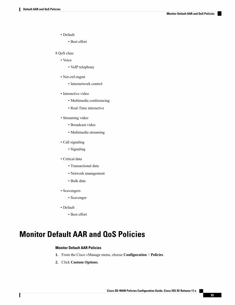
• Default
• Best effort
8 QoS class
• Voice
• VoIP telephony
• Net-ctrl-mgmt
• Internetwork control
• Interactive video
• Multimedia conferencing
• Real-Time interactive
• Streaming video
• Broadcast video
• Multimedia streaming
• Call signaling
• Signaling
• Critical data
• Transactional data
• Network management
• Bulk data
• Scavengers
• Scavenger
• Default
• Best effort
Monitor Default AAR and QoS PoliciesMonitor Default AAR Policies
1. From the Cisco vManage menu, choose Configuration > Policies.
2. Click Custom Options.
Cisco SD-WAN Policies Configuration Guide, Cisco IOS XE Release 17.x93
Default AAR and QoS PoliciesMonitor Default AAR and QoS Policies

3. Choose Traffic Policy from Centralized Policy.
4. Click Application Aware Routing.
A list of AAR policies is displayed.
5. Click Traffic Data.
A list of traffic data policies is displayed.
Monitor QoS Policies
1. From the Cisco vManage menu, choose Configuration > Policies.
2. Click Custom Options.
3. Choose Forwarding Class/QoS from Localized Policy.
4. Click QoS Map.
A list of QoS policies is displayed.
To verify QoS polices, refer to Verify QoS Policy.Note
Cisco SD-WAN Policies Configuration Guide, Cisco IOS XE Release 17.x94
Default AAR and QoS PoliciesMonitor Default AAR and QoS Policies

C H A P T E R 7Device Access Policy
Table 17: Feature History
DescriptionRelease InformationFeature Name
This feature defines the rules that traffic must meet topass through an interface. When you define rules forincoming traffic, they are applied to the traffic beforeany other policies are applied. The control plane of aCisco IOSXE SD-WAN device processes the data trafficfor local services (like SSH and SNMP) from a set ofsources. Routing packets are required to form the overlay.
Cisco IOS XE Release17.2.1r
DeviceAccess Policy onSNMP and SSH
• Device Access Policy Overview, on page 95• Configure Device Access Policy Using Cisco vManage, on page 96• Configure Device Access Policy Using the CLI, on page 97• Examples for ACL Statistics and Counters, on page 97• Verifying ACL Policy on an SNMP Server, on page 99• Verifying ACL Policy on SSH, on page 100
Device Access Policy OverviewStarting from Cisco IOS XE SD-WAN Release 17.2.1r, the Cisco vManage user interface is enhanced toconfigure device access policy on all the Cisco IOS XE SD-WAN devices.
The control plane of Cisco IOS XE SD-WAN devices process the data traffic for local services like, SSH andSNMP, from a set of sources. It is important to protect the CPU from device access traffic by applying thefilter to avoid malicious traffic.
Access policies define the rules that traffic must meet to pass through an interface. When you define rules forincoming traffic, they are applied to the traffic before any other policies are applied. You can use accesspolicies, in routed and transparent firewall mode to control IP traffic. An access rule permits or denies trafficbased on the protocol used, the source and destination IP address or network, and optionally, the users anduser groups. Each incoming packet at an interface is analyzed to determine if it must be forwarded or droppedbased on criteria you specify. If you define access rules for the outgoing traffic, packets are also analyzedbefore they are allowed to leave an interface. Access policies are applied in order. That is, when the devicecompares a packet to the rules, it searches from top to bottom in the access policies list, and applies the policy
Cisco SD-WAN Policies Configuration Guide, Cisco IOS XE Release 17.x95
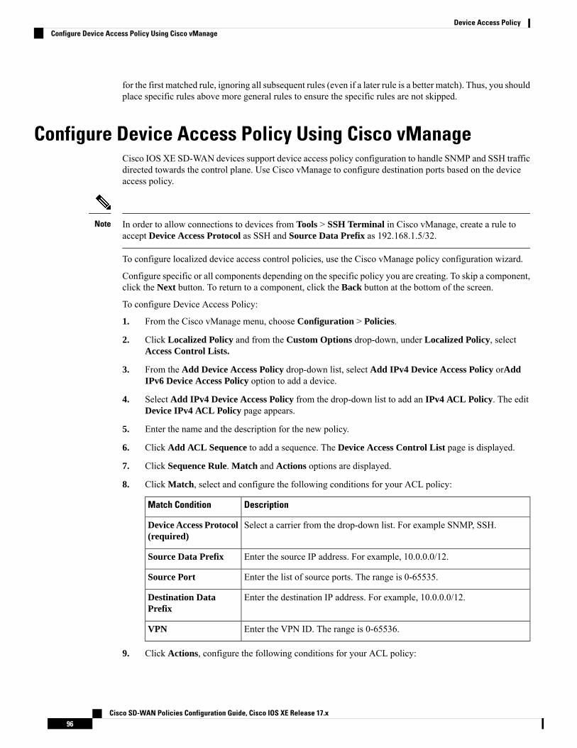
for the first matched rule, ignoring all subsequent rules (even if a later rule is a better match). Thus, you shouldplace specific rules above more general rules to ensure the specific rules are not skipped.
Configure Device Access Policy Using Cisco vManageCisco IOS XE SD-WAN devices support device access policy configuration to handle SNMP and SSH trafficdirected towards the control plane. Use Cisco vManage to configure destination ports based on the deviceaccess policy.
In order to allow connections to devices from Tools > SSH Terminal in Cisco vManage, create a rule toaccept Device Access Protocol as SSH and Source Data Prefix as 192.168.1.5/32.
Note
To configure localized device access control policies, use the Cisco vManage policy configuration wizard.
Configure specific or all components depending on the specific policy you are creating. To skip a component,click the Next button. To return to a component, click the Back button at the bottom of the screen.
To configure Device Access Policy:
1. From the Cisco vManage menu, choose Configuration > Policies.
2. Click Localized Policy and from the Custom Options drop-down, under Localized Policy, selectAccess Control Lists.
3. From the Add Device Access Policy drop-down list, select Add IPv4 Device Access Policy orAddIPv6 Device Access Policy option to add a device.
4. Select Add IPv4 Device Access Policy from the drop-down list to add an IPv4 ACL Policy. The editDevice IPv4 ACL Policy page appears.
5. Enter the name and the description for the new policy.
6. Click Add ACL Sequence to add a sequence. The Device Access Control List page is displayed.
7. Click Sequence Rule. Match and Actions options are displayed.
8. Click Match, select and configure the following conditions for your ACL policy:
DescriptionMatch Condition
Select a carrier from the drop-down list. For example SNMP, SSH.Device Access Protocol(required)
Enter the source IP address. For example, 10.0.0.0/12.Source Data Prefix
Enter the list of source ports. The range is 0-65535.Source Port
Enter the destination IP address. For example, 10.0.0.0/12.Destination DataPrefix
Enter the VPN ID. The range is 0-65536.VPN
9. Click Actions, configure the following conditions for your ACL policy:
Cisco SD-WAN Policies Configuration Guide, Cisco IOS XE Release 17.x96
Device Access PolicyConfigure Device Access Policy Using Cisco vManage

DescriptionAction Condition
Accept
Enter the counter name to be accepted. Themaximum length can be 20 characters.
Counter Name
Drop
Enter the counter name to drop. The maximumlength can be 20 characters.
Counter Name
10. Click Save Match And Actions to save all the conditions for the ACL policy.
11. Click Save Device Access Control List Policy to apply the selected match conditions to an action.
12. If no packets match, then any of the route policy sequence rules. The Default Action in the left paneis to drop the packets.
IPv6 prefix match is not supported on Cisco IOS XE SD-WAN devices. When you try to configure IPv6prefix matches on these devices, Cisco vManage fails to generate device configuration.
Note
Configure Device Access Policy Using the CLIConfiguration:ip access-list standard snmp-acl1 permit 10.0.1.12 255.255.255.011 deny any!
snmp-server community private view v2 ro snmp-acl
ip access-list extended ssh-acl1 permit tcp host 10.0.1.12 any eq 2211 deny tcp any any eq 22!
line vty 0 4access-class ssh-acl in vrf-also!
IPv6 prefix match is not supported on Cisco IOS XE SD-WAN devices.Note
Examples for ACL Statistics and CountersTo configure ACL statistics and counters using yang:Yang file: Cisco-IOS-XE-acl-oper.yang
Cisco SD-WAN Policies Configuration Guide, Cisco IOS XE Release 17.x97
Device Access PolicyConfigure Device Access Policy Using the CLI
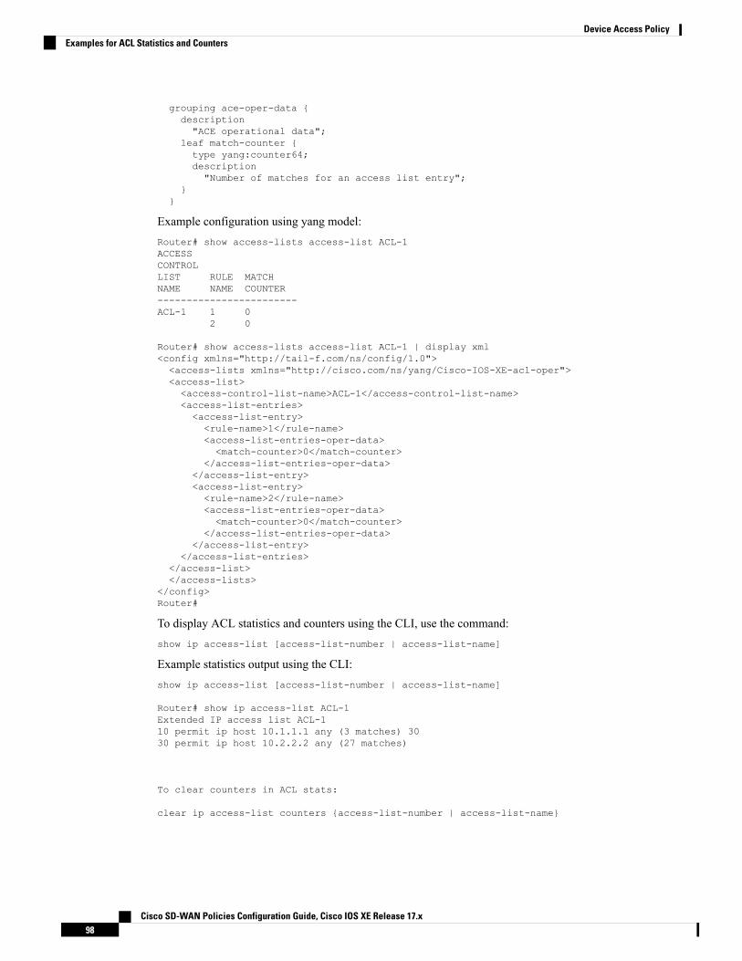
grouping ace-oper-data {description"ACE operational data";
leaf match-counter {type yang:counter64;description"Number of matches for an access list entry";
}}
Example configuration using yang model:Router# show access-lists access-list ACL-1ACCESSCONTROLLIST RULE MATCHNAME NAME COUNTER------------------------ACL-1 1 0
2 0
Router# show access-lists access-list ACL-1 | display xml<config xmlns="http://tail-f.com/ns/config/1.0"><access-lists xmlns="http://cisco.com/ns/yang/Cisco-IOS-XE-acl-oper"><access-list><access-control-list-name>ACL-1</access-control-list-name><access-list-entries><access-list-entry><rule-name>1</rule-name><access-list-entries-oper-data><match-counter>0</match-counter>
</access-list-entries-oper-data></access-list-entry><access-list-entry><rule-name>2</rule-name><access-list-entries-oper-data><match-counter>0</match-counter>
</access-list-entries-oper-data></access-list-entry>
</access-list-entries></access-list></access-lists>
</config>Router#
To display ACL statistics and counters using the CLI, use the command:show ip access-list [access-list-number | access-list-name]
Example statistics output using the CLI:show ip access-list [access-list-number | access-list-name]
Router# show ip access-list ACL-1Extended IP access list ACL-110 permit ip host 10.1.1.1 any (3 matches) 3030 permit ip host 10.2.2.2 any (27 matches)
To clear counters in ACL stats:
clear ip access-list counters {access-list-number | access-list-name}
Cisco SD-WAN Policies Configuration Guide, Cisco IOS XE Release 17.x98
Device Access PolicyExamples for ACL Statistics and Counters
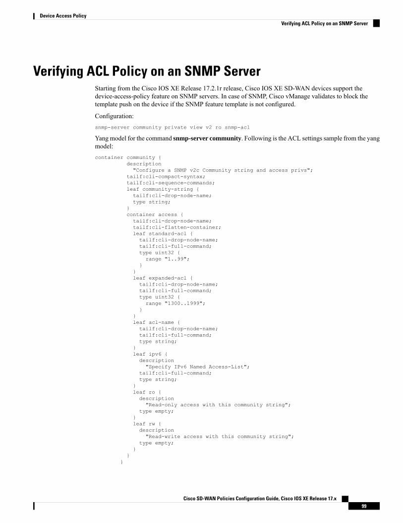
Verifying ACL Policy on an SNMP ServerStarting from the Cisco IOS XE Release 17.2.1r release, Cisco IOS XE SD-WAN devices support thedevice-access-policy feature on SNMP servers. In case of SNMP, Cisco vManage validates to block thetemplate push on the device if the SNMP feature template is not configured.
Configuration:snmp-server community private view v2 ro snmp-acl
Yang model for the command snmp-server community. Following is the ACL settings sample from the yangmodel:container community {
description"Configure a SNMP v2c Community string and access privs";
tailf:cli-compact-syntax;tailf:cli-sequence-commands;leaf community-string {tailf:cli-drop-node-name;type string;
}container access {tailf:cli-drop-node-name;tailf:cli-flatten-container;leaf standard-acl {tailf:cli-drop-node-name;tailf:cli-full-command;type uint32 {range "1..99";
}}leaf expanded-acl {tailf:cli-drop-node-name;tailf:cli-full-command;type uint32 {range "1300..1999";
}}leaf acl-name {tailf:cli-drop-node-name;tailf:cli-full-command;type string;
}leaf ipv6 {description"Specify IPv6 Named Access-List";
tailf:cli-full-command;type string;
}leaf ro {description"Read-only access with this community string";
type empty;}leaf rw {description"Read-write access with this community string";
type empty;}
}}
Cisco SD-WAN Policies Configuration Guide, Cisco IOS XE Release 17.x99
Device Access PolicyVerifying ACL Policy on an SNMP Server
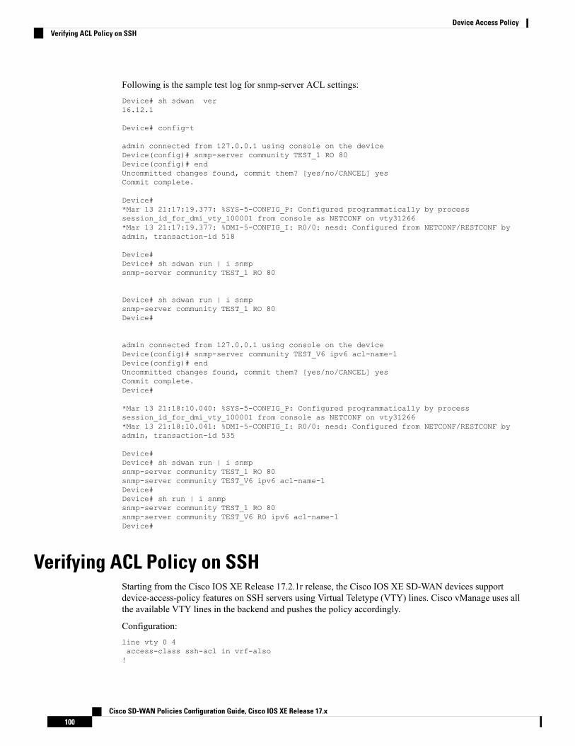
Following is the sample test log for snmp-server ACL settings:Device# sh sdwan ver16.12.1
Device# config-t
admin connected from 127.0.0.1 using console on the deviceDevice(config)# snmp-server community TEST_1 RO 80Device(config)# endUncommitted changes found, commit them? [yes/no/CANCEL] yesCommit complete.
Device#*Mar 13 21:17:19.377: %SYS-5-CONFIG_P: Configured programmatically by processsession_id_for_dmi_vty_100001 from console as NETCONF on vty31266*Mar 13 21:17:19.377: %DMI-5-CONFIG_I: R0/0: nesd: Configured from NETCONF/RESTCONF byadmin, transaction-id 518
Device#Device# sh sdwan run | i snmpsnmp-server community TEST_1 RO 80
Device# sh sdwan run | i snmpsnmp-server community TEST_1 RO 80Device#
admin connected from 127.0.0.1 using console on the deviceDevice(config)# snmp-server community TEST_V6 ipv6 acl-name-1Device(config)# endUncommitted changes found, commit them? [yes/no/CANCEL] yesCommit complete.Device#
*Mar 13 21:18:10.040: %SYS-5-CONFIG_P: Configured programmatically by processsession_id_for_dmi_vty_100001 from console as NETCONF on vty31266*Mar 13 21:18:10.041: %DMI-5-CONFIG_I: R0/0: nesd: Configured from NETCONF/RESTCONF byadmin, transaction-id 535
Device#Device# sh sdwan run | i snmpsnmp-server community TEST_1 RO 80snmp-server community TEST_V6 ipv6 acl-name-1Device#Device# sh run | i snmpsnmp-server community TEST_1 RO 80snmp-server community TEST_V6 RO ipv6 acl-name-1Device#
Verifying ACL Policy on SSHStarting from the Cisco IOS XE Release 17.2.1r release, the Cisco IOS XE SD-WAN devices supportdevice-access-policy features on SSH servers using Virtual Teletype (VTY) lines. Cisco vManage uses allthe available VTY lines in the backend and pushes the policy accordingly.
Configuration:line vty 0 4access-class ssh-acl in vrf-also!
Cisco SD-WAN Policies Configuration Guide, Cisco IOS XE Release 17.x100
Device Access PolicyVerifying ACL Policy on SSH

Following is the ACL settings sample from the yang model:// line * / access-class
container access-class {description"Filter connections based on an IP access list";
tailf:cli-compact-syntax;tailf:cli-sequence-commands;tailf:cli-reset-container;tailf:cli-flatten-container;list acccess-list {tailf:cli-drop-node-name;tailf:cli-compact-syntax;tailf:cli-reset-container;tailf:cli-suppress-mode;tailf:cli-delete-when-empty;key "direction";leaf direction {type enumeration {enum "in";enum "out";
}}leaf access-list {tailf:cli-drop-node-name;tailf:cli-prefix-key;type ios-types:exp-acl-type;mandatory true;
}leaf vrf-also {description"Same access list is applied for all VRFs";
type empty;}
}}
Following is the sample test log for line-server ACL settings:Device# config-transaction
admin connected from 127.0.0.1 using console on DeviceDevice(config)# line vty 0 4Device(config-line)# access-class acl_1 in vrf-alsoDevice(config-line)# transport input sshDevice(config-line)# endUncommitted changes found, commit them? [yes/no/CANCEL] yesCommit complete.Device#*May 24 20:51:02.994: %SYS-5-CONFIG_P: Configured programmatically by processiosp_vty_100001_dmi_nesd from console as NETCONF on vty31266*May 24 20:51:02.995: %DMI-5-CONFIG_I: R0/0: nesd: Configured from NETCONF/RESTCONF byadmin, transaction-id 227Device#Device#Device# sh sdwan run | sec vtyError: Licensing infrastructure is NOT initialized.Error: Licensing infrastructure is NOT initialized.line vty 0 4access-class acl_1 in vrf-alsologin localtransport input sshline vty 5 80login localtransport input ssh
Cisco SD-WAN Policies Configuration Guide, Cisco IOS XE Release 17.x101
Device Access PolicyVerifying ACL Policy on SSH

Device#Device# sh run | sec vtyError: Licensing infrastructure is NOT initialized.Error: Licensing infrastructure is NOT initialized.line vty 0 4access-class acl_1 in vrf-alsoexec-timeout 0 0password 7 11051807login localtransport preferred nonetransport input sshline vty 5 80login localtransport input ssh
Cisco SD-WAN Policies Configuration Guide, Cisco IOS XE Release 17.x102
Device Access PolicyVerifying ACL Policy on SSH

C H A P T E R 8Deep Packet Inspection
The topics in this section provide overview information about deep packet inspection (DPI), and how toconfigure DPI using Cisco vManage or the CLI.
• Deep Packet Inspection Overview, on page 103• Configure Deep Packet Inspection Using Cisco vManage, on page 103• Configure Deep Packet Inspection Using the CLI, on page 107
Deep Packet Inspection OverviewDeep packet inspection (DPI) provides the ability to look into the packet past the basic header information.DPI determines the contents of a particular packet, and then either records that information for statisticalpurposes or performs an action on the packet.
Benefits include increased visibility into the network traffic, which enables network operators to understandusage patterns and to correlate network performance information along with providing usage base billing oreven acceptable usage monitoring. DPI can also reduce the overall costs on the network.
You can configure DPI using a centralized data policy. You define the applications of interest in a CiscovManage policy list or with the policy lists app-list CLI command, and you call these lists in a policydata-policy command. You can control the path of the application traffic through the network by defining,in the action portion of the data policy, the local TLOC or the remote TLOC, or for strict control, you candefine both.
Configure Deep Packet Inspection Using Cisco vManageTo configure DPI feature, use the Cisco vManage policy configuration wizard. The wizard consists of thefollowing sequential screens that guide you through the process of creating and editing policy components:
• Create Applications or Groups of Interest—Create lists that group together related items and that youcall in the match or action components of a policy. For configuration details, see Configure Groups ofInterest.
• Configure Traffic Rules—Create the match and action conditions of a policy. For configuration details,see Configure Traffic Rules.
• Apply Policies to Sites and VPNs—Associate policy with sites and VPNs in the overlay network.
Cisco SD-WAN Policies Configuration Guide, Cisco IOS XE Release 17.x103

Apply Centralized Policy for Deep Packet InspectionFor a deep packet inspection centralized data policy to take effect, you apply it to a list of sites in the overlaynetwork.
To apply a centralized policy in Cisco vManage, see Configure Centralized Policy Using Cisco vManage.
To apply a centralized policy in the CLI:vSmart(config)# apply-policy site-list list-name data-policy policy-name (all | from-service| from-tunnel)
By default, data policy applies to all data traffic passing through the Cisco vSmart Controller: the policyevaluates all data traffic going from the local site (that is, from the service side of the router) into the tunnelinterface, and it evaluates all traffic entering to the local site through the tunnel interface. You can explicitlyconfigure this behavior by including the all option. To have the data policy apply only to policy exiting fromthe local site, include the from-service option. To have the policy apply only to incoming traffic, include thefrom-tunnel option.
You cannot apply the same type of policy to site lists that contain overlapping site IDs. That is, all data policiescannot have overlapping site lists among themselves. If you accidentally misconfigure overlapping site lists,the attempt to commit the configuration on the Cisco vSmart Controller fails.
Monitor Running ApplicationsTo enable the deep packet inspection infrastructure on Cisco vEdge devices, you must enable applicationvisibility on the devices:vEdge(config)# policy app-visibility
To display information about the running applications, use the show app dpi supported-applications, showapp dpi applications, and show app dpi flows commands on the device.
View DPI ApplicationsYou can view the list of all the application-aware applications supported by the Cisco SD-WAN software onthe router using the following steps:
1. From the Cisco vManage menu, choose Monitor > Devices.
Cisco vManage Release 20.6.x and earlier: From the Cisco vManage menu, choose Monitor > Network.
2. Click WAN-Edge, select the Device that supports DPI. The Cisco vManage Control Connections pageis displayed.
3. In the left pane, select Real Time to view the device details.
4. From the Device Options drop-down, choose DPI Applications to view the list of applications runningon the device.
5. From theDevice Options drop-down, chooseDPI Supported Applications to view the list of applicationsthat are supported on the device.
Cisco SD-WAN Policies Configuration Guide, Cisco IOS XE Release 17.x104
Deep Packet InspectionApply Centralized Policy for Deep Packet Inspection

Action Parameters for Configuring Deep Packet InspectionWhen data traffic matches the conditions in the match portion of a centralized data policy, the packet can beaccepted or dropped, and it can be counted. Then, you can associate parameters with accepted packets.
From the Cisco vManage menu, you can configure match parameters from:
• Configuration > Policies > Centralized Policy > Add Policy > Configure Traffic Rules >(Application-Aware Routing | Traffic Data | Cflowd) > Sequence Type > Sequence Rule > Action
• Configuration > Policies > Custom Options > Centralized Policy > Traffic Policy >(Application-Aware Routing | Traffic Data | Cflowd) > Sequence Type > Sequence Rule > Action.
In the CLI, you configure the action parameters under the policy data-policy vpn-list sequence actioncommand.
Each sequence in a centralized data policy can contain one action condition.
In the action, you first specify whether to accept or drop a matching data packet, and whether to count it:
Table 18:
Value or RangeCLI CommandCisco vManageDescription
—acceptClick Accept.Accept the packet. An accepted packet iseligible to be modified by the additionalparameters configured in the action portion ofthe policy configuration.
Name of a counter. Use theshow policy access-listscounters command on theCisco device.
count counter-nameAction Counter
Click Accept, then actionCounter
Count the accepted or dropped packets.
—dropClick DropDiscard the packet. This is the default action.
To view the packet logs, use the show app log flow and show log commands.
Then, for a packet that is accepted, the following parameters can be configured.
You cannot use deep packet inspection with either cflowd or NAT.Note
Table 19:
Value or RangeCLI CommandCisco vManageDescription
0 through 63set dscp valueClick Accept, thenaction DSCP.
DSCP value.
Name of forwarding classset forwarding-classvalue
Click Accept, thenaction ForwardingClass.
Forwarding class.
Cisco SD-WAN Policies Configuration Guide, Cisco IOS XE Release 17.x105
Deep Packet InspectionAction Parameters for Configuring Deep Packet Inspection
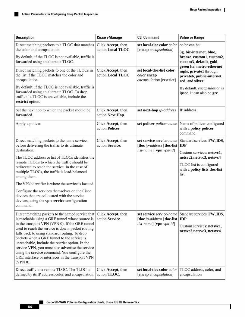
Value or RangeCLI CommandCisco vManageDescription
color can be:
3g, biz-internet, blue,bronze, custom1, custom2,custom3, default, gold,green lte, metro-ethernetmpls, private1 throughprivate6, public-internet,red, and silver.
By default, encapsulation isipsec. It can also be gre.
set local-tloc color color[encap encapsulation]
Click Accept, thenaction Local TLOC.
Direct matching packets to a TLOC that matchesthe color and encapsulation
By default, if the TLOC is not available, traffic isforwarded using an alternate TLOC.
set local-tloc-list colorcolor encapencapsulation [restrict]
Click Accept, thenaction Local TLOC
Direct matching packets to one of the TLOCs inthe list if the TLOC matches the color andencapsulation
By default, if the TLOC is not available, traffic isforwarded using an alternate TLOC. To droptraffic if a TLOC is unavailable, include therestrict option.
IP addressset next-hop ip-addressClick Accept, thenaction Next Hop.
Set the next hop to which the packet should beforwarded.
Name of policer configuredwith a policy policercommand.
set policer policer-nameClick Accept, thenaction Policer.
Apply a policer.
Standard services:FW, IDS,IDP
Custom services: netsvc1,netsvc2,netsvc3, netsvc4
TLOC list is configuredwith a policy lists tloc-listlist.
set service service-name[tloc ip-address | tloc-listlist-name] [vpn vpn-id]
Click Accept, thenaction Service.
Direct matching packets to the name service,before delivering the traffic to its ultimatedestination.
The TLOC address or list of TLOCs identifies theremote TLOCs to which the traffic should beredirected to reach the service. In the case ofmultiple TLOCs, the traffic is load-balancedamong them.
The VPN identifier is where the service is located.
Configure the services themselves on the Ciscodevices that are collocated with the servicedevices, using the vpn service configurationcommand.
Standard services:FW, IDS,IDP
Custom services: netsvc1,netsvc2,netsvc3, netsvc4
set service service-name[tloc ip-address | tloc-listlist-name] [vpn vpn-id]
Click Accept, thenaction Service.
Direct matching packets to the named service thatis reachable using a GRE tunnel whose source isin the transport VPN (VPN 0). If the GRE tunnelused to reach the service is down, packet routingfalls back to using standard routing. To droppackets when a GRE tunnel to the service isunreachable, include the restrict option. In theservice VPN, you must also advertise the serviceusing the service command. You configure theGRE interface or interfaces in the transport VPN(VPN 0).
TLOC address, color, andencapsulation
set local-tloc color color[encap encapsulation]
Click Accept, thenaction TLOC.
Direct traffic to a remote TLOC. The TLOC isdefined by its IP address, color, and encapsulation.
Cisco SD-WAN Policies Configuration Guide, Cisco IOS XE Release 17.x106
Deep Packet InspectionAction Parameters for Configuring Deep Packet Inspection

Value or RangeCLI CommandCisco vManageDescription
Name of a policy liststloc-list list
set tloc-list list-nameClick Accept, thenaction TLOC.
Direct traffic to one of the remote TLOCs in theTLOC list.
0 through 65530set vpn vpn-idClick Accept, thenaction VPN.
Set the VPN that the packet is part of.
Default Action
If a data packet being evaluated does not match any of the match conditions in a data policy, a default actionis applied to the packet. By default, the data packet is dropped.
From the Cisco vManage menu, you modify the default action from Configuration > Policies > CentralizedPolicy >Add Policy >Configure Traffic Rules >Application-Aware Routing > Sequence Type > SequenceRule > Default Action.
In the CLI, youmodify the default action with the policy data-policy vpn-list default-action accept command.
Configure Deep Packet Inspection Using the CLIFollowing are the high-level steps for configuring a centralized data policy for deep packet inspection:
1. Create a list of overlay network sites to which the data policy is to be applied using the apply-policycommand:vSmart(config)# policyvSmart(config-policy)# lists site-list list-namevSmart(config-lists-list-name)# site-id site-id
The list can contain as many site IDs as necessary. Include one site-id command for each site ID. Forcontiguous site IDs, you can specify a range of numbers separated with a dash (–).
Create additional site lists, as needed.
2. Create lists of applications and application families that are to be subject to the data policy. Each listcan contain one or more application names, or one or more application families. A single list cannotcontain both applications and application families.vSmart(config)# policy listsvSmart(config-lists)# app-list list-namevSmart(config-app-list)# app application-name
vSmart(config)# policy listsvSmart(config-lists)# app-list list-namevSmart(config-applist)# app-family family-name
3. Create lists of IP prefixes and VPNs, as needed:vSmart(config)# policy listsvSmart(config-lists)# data-prefix-list list-namevSmart(config-lists-list-name)# ip-prefix prefix/length
vSmart(config)# policy listsvSmart(config-lists)# vpn-list list-namevSmart(config-lists-list-name)# vpn vpn-id
4. Create lists of TLOCs, as needed:
Cisco SD-WAN Policies Configuration Guide, Cisco IOS XE Release 17.x107
Deep Packet InspectionConfigure Deep Packet Inspection Using the CLI

vSmart(config)# policyvSmart(config-policy)# lists tloc-list list-namevSmart(config-lists-list-name)# tloc ip-address color color encap encapsulation[preference number]
5. Define policing parameters, as needed:vSmart(config-policy)# policer policer-namevSmart(config-policer)# rate bandwidthvSmart(config-policer)# burst bytesvSmart(config-policer)# exceed action
6. Create a data policy instance and associate it with a list of VPNs:vSmart(config)# policy data-policy policy-namevSmart(config-data-policy-policy-name)# vpn-list list-name
7. Create a series of match–pair sequences:vSmart(config-vpn-list)# sequence numbervSmart(config-sequence-number)#
The match–action pairs are evaluated in order, by sequence number, starting with the lowest numberedpair and ending when the route matches the conditions in one of the pairs. Or if no match occurs, thedefault action is taken (either rejecting the route or accepting it as is).
8. Define match parameters based on applications:vSmart(config-sequence-number)# match app-list list-name
9. Define additional match parameters for data packets:vSmart(config-sequence-number)# match parameters
10. Define actions to take when a match occurs:vSmart(config-sequence-number)# action (accept | drop) [count]
11. For packets that are accepted, define the actions to take. To control the tunnel over which the packetstravels, define the remote or local TLOC, or for strict control over the tunnel path, set both:vSmart(config-action)# set tloc ip-address color color encap encapsulationvSmart(config-action)# set tloc-list list-namevSmart(config-action)# set local-tloc color color encap encapsulationvSmart(config-action)# set local-tloc-list color color encap encapsulation [restrict]
12. Define additional actions to take.
13. Create additional numbered sequences of match–action pairs within the data policy, as needed.
14. If a route does not match any of the conditions in one of the sequences, it is rejected by default. If youwant nonmatching prefixes to be accepted, configure the default action for the policy:vSmart(config-policy-name)# default-action accept
15. Apply the policy to one or more sites in the overlay network:vSmart(config)# apply-policy site-list list-name data-policy policy-name (all |from-service | from-tunnel)
Use the following show commands for visibility in to traffic classification:
• show app dpi flows
• show support dpi flows active detail
Cisco SD-WAN Policies Configuration Guide, Cisco IOS XE Release 17.x108
Deep Packet InspectionConfigure Deep Packet Inspection Using the CLI
• show app dpi application
• show support dpi flows expired detail
• show support dpi statistics
Cisco SD-WAN Policies Configuration Guide, Cisco IOS XE Release 17.x109
Deep Packet InspectionConfigure Deep Packet Inspection Using the CLI

Cisco SD-WAN Policies Configuration Guide, Cisco IOS XE Release 17.x110
Deep Packet InspectionConfigure Deep Packet Inspection Using the CLI

C H A P T E R 9Application-Aware Routing
• Application-Aware Routing Overview, on page 111• Application-Aware Routing Support for Multicast Protocols, on page 112• Restrictions for Multicast Protocols, on page 112• Components of Application-Aware Routing, on page 112• SLA Classes, on page 113• Classification of Tunnels into SLA Classes, on page 116• Per-Class Application-Aware Routing, on page 118• Configure Application-Aware Routing, on page 119• Configure Application-Aware Routing Using CLIs, on page 132• Configure Application Probe Class Using CLI, on page 134• Application-Aware Routing Policy Configuration Example, on page 135
Application-Aware Routing OverviewApplication-aware routing tracks network and path characteristics of the data plane tunnels between CiscoIOS XE SD-WAN devices and uses the collected information to compute optimal paths for data traffic. Thesecharacteristics include packet loss, latency, and jitter, and the load, cost and bandwidth of a link. The abilityto consider factors in path selection other than those used by standard routing protocols—such as route prefixes,metrics, link-state information, and route removal on the Cisco IOS XE SD-WAN device—offers a numberof advantages to an enterprise:
• In normal network operation, the path taken by application data traffic through the network can beoptimized, by directing it to WAN links that support the required levels of packet loss, latency, and jitterdefined in an application’s SLA.
• In the face of network brownouts or soft failures, performance degradation can beminimized. The trackingof network and path conditions by application-aware routing in real time can quickly reveal performanceissues, and it automatically activates strategies that redirect data traffic to the best available path. As thenetwork recovers from the soft failure conditions, application-aware routing automatically readjusts thedata traffic paths.
• Network costs can be reduced because data traffic can be more efficiently load-balanced.
• Application performance can be increased without the need for WAN upgrades.
Cisco SD-WAN Policies Configuration Guide, Cisco IOS XE Release 17.x111
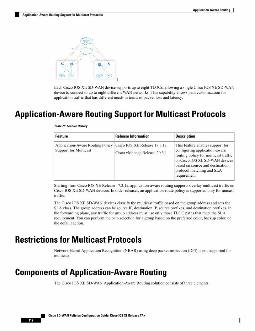
Each Cisco IOS XE SD-WAN device supports up to eight TLOCs, allowing a single Cisco IOS XE SD-WANdevice to connect to up to eight different WAN networks. This capability allows path customization forapplication traffic that has different needs in terms of packet loss and latency.
Application-Aware Routing Support for Multicast ProtocolsTable 20: Feature History
DescriptionRelease InformationFeature
This feature enables support forconfiguring application-awarerouting policy for multicast trafficon Cisco IOSXESD-WANdevicesbased on source and destination,protocol matching and SLArequirement.
Cisco IOS XE Release 17.3.1a
Cisco vManage Release 20.3.1
Application-Aware Routing PolicySupport for Multicast
Starting from Cisco IOS XE Release 17.3.1a, application-aware routing supports overlay multicast traffic onCisco IOS XE SD-WAN devices. In older releases, an application-route policy is supported only for unicasttraffic.
The Cisco IOS XE SD-WAN devices classify the multicast traffic based on the group address and sets theSLA class. The group address can be source IP, destination IP, source prefixes, and destination prefixes. Inthe forwarding plane, any traffic for group address must use only those TLOC paths that meet the SLArequirement. You can perform the path selection for a group based on the preferred color, backup color, orthe default action.
Restrictions for Multicast ProtocolsNetwork-Based Application Recognition (NBAR) using deep packet inspection (DPI) is not supported formulticast.
Components of Application-Aware RoutingThe Cisco IOS XE SD-WAN Application-Aware Routing solution consists of three elements:
Cisco SD-WAN Policies Configuration Guide, Cisco IOS XE Release 17.x112
Application-Aware RoutingApplication-Aware Routing Support for Multicast Protocols
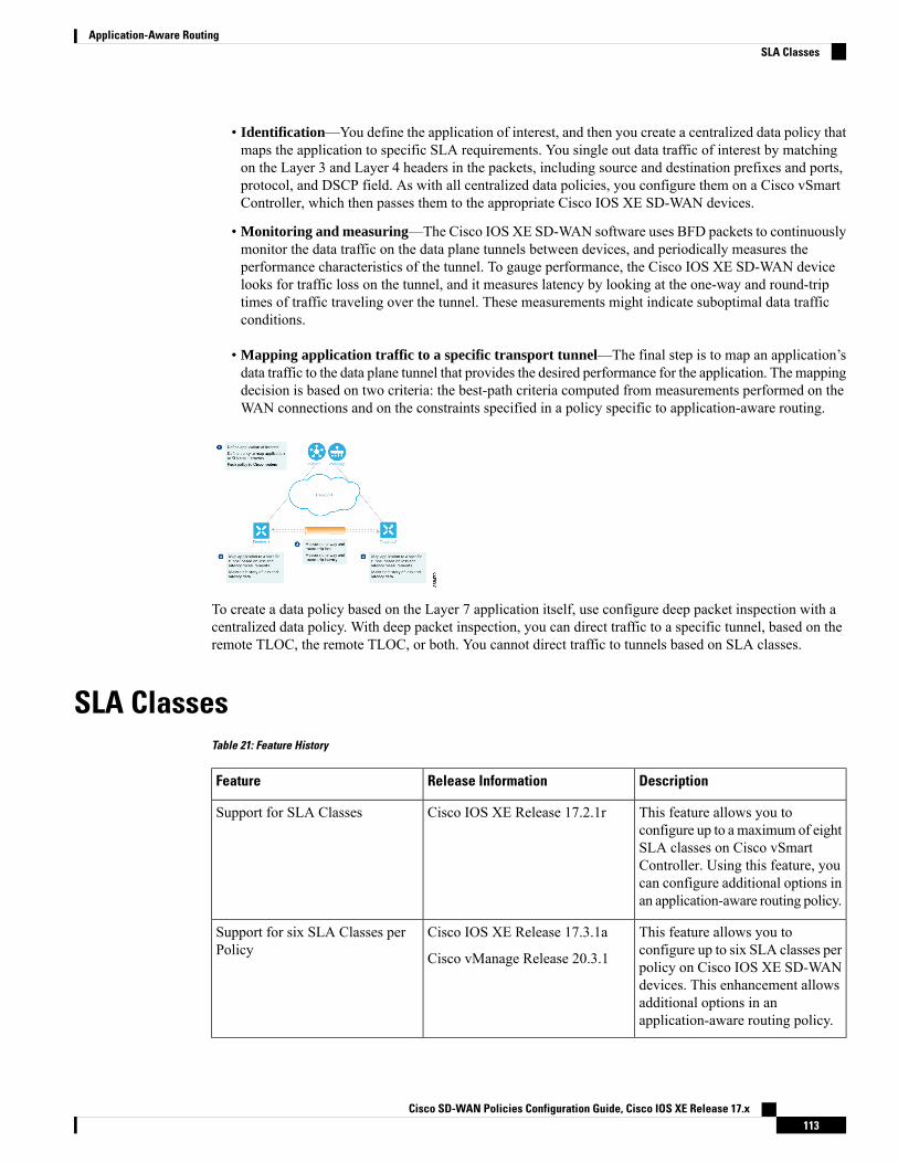
• Identification—You define the application of interest, and then you create a centralized data policy thatmaps the application to specific SLA requirements. You single out data traffic of interest by matchingon the Layer 3 and Layer 4 headers in the packets, including source and destination prefixes and ports,protocol, and DSCP field. As with all centralized data policies, you configure them on a Cisco vSmartController, which then passes them to the appropriate Cisco IOS XE SD-WAN devices.
• Monitoring and measuring—The Cisco IOS XE SD-WAN software uses BFD packets to continuouslymonitor the data traffic on the data plane tunnels between devices, and periodically measures theperformance characteristics of the tunnel. To gauge performance, the Cisco IOS XE SD-WAN devicelooks for traffic loss on the tunnel, and it measures latency by looking at the one-way and round-triptimes of traffic traveling over the tunnel. These measurements might indicate suboptimal data trafficconditions.
• Mapping application traffic to a specific transport tunnel—The final step is to map an application’sdata traffic to the data plane tunnel that provides the desired performance for the application. The mappingdecision is based on two criteria: the best-path criteria computed from measurements performed on theWAN connections and on the constraints specified in a policy specific to application-aware routing.
To create a data policy based on the Layer 7 application itself, use configure deep packet inspection with acentralized data policy. With deep packet inspection, you can direct traffic to a specific tunnel, based on theremote TLOC, the remote TLOC, or both. You cannot direct traffic to tunnels based on SLA classes.
SLA ClassesTable 21: Feature History
DescriptionRelease InformationFeature
This feature allows you toconfigure up to amaximum of eightSLA classes on Cisco vSmartController. Using this feature, youcan configure additional options inan application-aware routing policy.
Cisco IOS XE Release 17.2.1rSupport for SLA Classes
This feature allows you toconfigure up to six SLA classes perpolicy on Cisco IOS XE SD-WANdevices. This enhancement allowsadditional options in anapplication-aware routing policy.
Cisco IOS XE Release 17.3.1a
Cisco vManage Release 20.3.1
Support for six SLA Classes perPolicy
Cisco SD-WAN Policies Configuration Guide, Cisco IOS XE Release 17.x113
Application-Aware RoutingSLA Classes
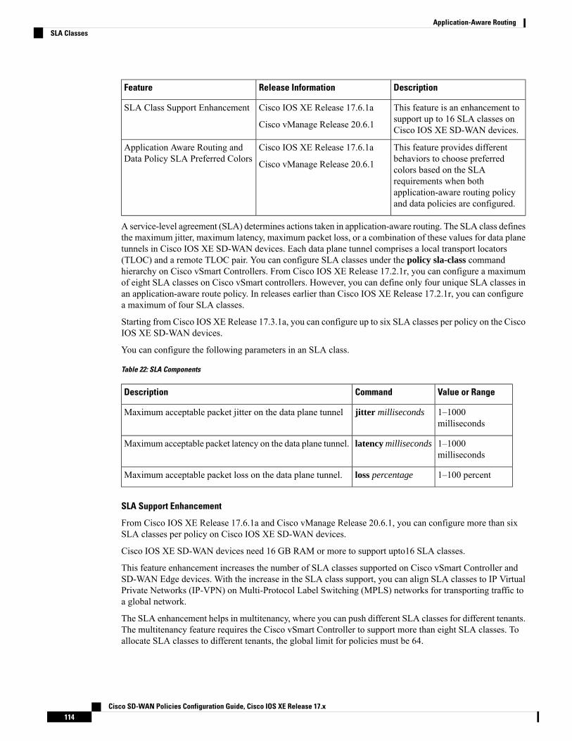
DescriptionRelease InformationFeature
This feature is an enhancement tosupport up to 16 SLA classes onCisco IOS XE SD-WAN devices.
Cisco IOS XE Release 17.6.1a
Cisco vManage Release 20.6.1
SLA Class Support Enhancement
This feature provides differentbehaviors to choose preferredcolors based on the SLArequirements when bothapplication-aware routing policyand data policies are configured.
Cisco IOS XE Release 17.6.1a
Cisco vManage Release 20.6.1
Application Aware Routing andData Policy SLA Preferred Colors
A service-level agreement (SLA) determines actions taken in application-aware routing. The SLA class definesthe maximum jitter, maximum latency, maximum packet loss, or a combination of these values for data planetunnels in Cisco IOS XE SD-WAN devices. Each data plane tunnel comprises a local transport locators(TLOC) and a remote TLOC pair. You can configure SLA classes under the policy sla-class commandhierarchy on Cisco vSmart Controllers. From Cisco IOS XE Release 17.2.1r, you can configure a maximumof eight SLA classes on Cisco vSmart controllers. However, you can define only four unique SLA classes inan application-aware route policy. In releases earlier than Cisco IOS XE Release 17.2.1r, you can configurea maximum of four SLA classes.
Starting from Cisco IOS XE Release 17.3.1a, you can configure up to six SLA classes per policy on the CiscoIOS XE SD-WAN devices.
You can configure the following parameters in an SLA class.
Table 22: SLA Components
Value or RangeCommandDescription
1–1000milliseconds
jitter millisecondsMaximum acceptable packet jitter on the data plane tunnel
1–1000milliseconds
latency millisecondsMaximum acceptable packet latency on the data plane tunnel.
1–100 percentloss percentageMaximum acceptable packet loss on the data plane tunnel.
SLA Support Enhancement
From Cisco IOS XE Release 17.6.1a and Cisco vManage Release 20.6.1, you can configure more than sixSLA classes per policy on Cisco IOS XE SD-WAN devices.
Cisco IOS XE SD-WAN devices need 16 GB RAM or more to support upto16 SLA classes.
This feature enhancement increases the number of SLA classes supported on Cisco vSmart Controller andSD-WAN Edge devices. With the increase in the SLA class support, you can align SLA classes to IP VirtualPrivate Networks (IP-VPN) on Multi-Protocol Label Switching (MPLS) networks for transporting traffic toa global network.
The SLA enhancement helps in multitenancy, where you can push different SLA classes for different tenants.The multitenancy feature requires the Cisco vSmart Controller to support more than eight SLA classes. Toallocate SLA classes to different tenants, the global limit for policies must be 64.
Cisco SD-WAN Policies Configuration Guide, Cisco IOS XE Release 17.x114
Application-Aware RoutingSLA Classes

Table 23: Maximum SLA Classes Supported on Cisco IOS XE SD-WAN Devices
SLA Class from Cisco IOS XERelease 17.6.1a (+1 Default SLAClass)
SLA Class prior to Cisco IOS XERelease 17.6.1a (+1 Default SLAClass)
Supported Platforms and Models
156ASR 1001 HX -16GB
• vedge-ASR-1001-HX
156ASR 1002 X -16GB
• vedge-ASR-1002-X
156ASR 1002 HX -16GB
• vedge-ASR-1002-HX
156ASR 1001 X -16GB
• vedge-ASR-1001-X
76ISR 4451 X
• vedge-ISR-4451-X
76ISR 4431
• vedge-ISR-4431
7NACatalyst 8300 Edge Platforms
• vedge-C8300-2N2S-6G
• vedge-C8300-2N2S-4G2X
• vedge-C8300-1N1S-6G
• vedge-C8300-1N1S-4G2X
• vedge-C8300-1N1S-6T
• vedge-C8300-1N1S-4T2X
• vedge-C8300-2N2S-6T
• vedge-C8300-2N2S-4T2X
15NACatalyst 8500 Edge platforms-16GB
• vedge-C8500L-8S4X
• vedge-C8500-12X4QC
• vedge-C8500-12X
Cisco SD-WAN Policies Configuration Guide, Cisco IOS XE Release 17.x115
Application-Aware RoutingSLA Classes

SLA Class from Cisco IOS XERelease 17.6.1a (+1 Default SLAClass)
SLA Class prior to Cisco IOS XERelease 17.6.1a (+1 Default SLAClass)
Supported Platforms and Models
66Any other Cisco IOSXE SD-WANdevices (C11xx, ISR1100, andCSR1000v)
SLA-Preferred Colors
From Cisco IOS XE Release 17.6.1a, when you configure both application-aware routing policy and datapolicy, and if data flow matches the app-route and data policy sequences, the following expected behaviorsoccur:
• If the preferred colors that you configure in application-aware routing meet the SLA requirements, andthese preferred colors have some colors that are common with data policy, the common preferred colorsare chosen over others for forwarding. (Prior to Cisco IOS XE Release 17.6.1a, the data policy-preferredcolors were forwarded and the application-aware routing policy preferences were ignored.)
• If preferred colors in application-aware routing do not meet the SLA, but there are colors that are commonwith the data policy, and these colors meet the SLA in application-aware routing, then these colors takeprecedence and are chosen for forwarding.
• If no tunnels or colors meet the SLA in application-aware routing, the data policy takes precedence andis chosen for forwarding. If the data policy has preferred colors, these colors are chosen. Otherwise, loadbalance occurs across all the colors in the data policy.
Classification of Tunnels into SLA ClassesThe process of classifying tunnels into one or more SLA classes for application-aware routing has three parts:
• Measure loss, latency, and jitter information for the tunnel.
• Calculate the average loss, latency, and jitter for the tunnel.
• Determine the SLA classification of the tunnel.
Measure Loss, Latency, and JitterWhen a data plane tunnel in the overlay network is established, a BFD session automatically starts on thetunnel. In the overlay network, each tunnel is identified with a color that identifies a specific link between alocal TLOC and a remote TLOC. The BFD session monitors the liveness of the tunnel by periodically sendingHello packets to detect whether the link is operational. Application-aware routing uses the BFDHello packetsto measure the loss, latency, and jitter on the links.
By default, the BFD Hello packet interval is 1 second. This interval is user-configurable (with the bfd colorinterval command). Note that the BFD Hello packet interval is configurable per tunnel.
Cisco SD-WAN Policies Configuration Guide, Cisco IOS XE Release 17.x116
Application-Aware RoutingClassification of Tunnels into SLA Classes
Calculate Average Loss, Latency, and JitterBFD periodically polls all the tunnels on the Cisco IOS XE SD-WAN devices to collect packet latency, loss,jitter, and other statistics for use by application-aware routing. At each poll interval, application-aware routingcalculates the average loss, latency, and jitter for each tunnel, and then calculates or recalculates each tunnel'sSLA. Each poll interval is also called a "bucket."
By default, the poll interval is 10 minutes. With the default BFD Hello packet interval at 1 second, this meansthat information from about 600 BFD Hello packets is used in one poll interval to calculate loss, latency, andjitter for the tunnel. The poll interval is user-configurable (with the bfd app-route poll-interval command).Note that the application-aware routing poll interval is configurable per Cisco IOS XE SD-WAN device; thatis, it applies to all tunnels originating on a device.
Reducing the poll interval without reducing the BFD Hello packet interval may affect the quality of the loss,latency, and jitter calculation. For example, setting the poll interval to 10 seconds when the BFD Hello packetinterval is 1 second means that only 10 Hello packets are used to calculate the loss, latency, and jitter for thetunnel.
The loss, latency, and jitter information from each poll interval is preserved for six poll intervals. At theseventh poll interval, the information from the earliest polling interval is discarded to make way for the latestinformation. In this way, application-aware routing maintains a sliding window of tunnel loss, latency, andjitter information.
The number of poll intervals (6) is not user-configurable. Each poll interval is identified by an index number(0 through 5) in the output of the show app-route statistics command.
Determine SLA ClassificationTo determine the SLA classification of a tunnel, application-aware routing uses the loss, latency, and jitterinformation from the latest poll intervals. The number of poll intervals used is determined by a multiplier. Bydefault, the multiplier is 6, so the information from all the poll intervals (specifically, from the last six pollintervals) is used to determine the classification. For the default poll interval of 10 minutes and the defaultmultiplier of 6, the loss, latency, and jitter information collected over the last hour is considered when classifyingthe SLA of each tunnel. These default values have to be chosen to provide damping of sorts, as a way toprevent frequent reclassification (flapping) of the tunnel.
The multiplier is user-configurable (with the bfd app-route multiplier command). Note that theapplication-aware routing multiplier is configurable per Cisco IOS XE SD-WAN device; that is, it applies toall tunnels originating on a device.
If there is a need to react quickly to changes in tunnel characteristics, you can reduce the multiplier all theway down to 1. With a multiplier of 1, only the latest poll interval loss and latency values are used to determinewhether this tunnel can satisfy one or more SLA criteria.
Based on the measurement and calculation of tunnel loss and latency, each tunnel may satisfy one or moreuser-configured SLA classes. For example, a tunnel with a mean loss of 0 packets and mean latency of 10milliseconds would satisfy a class that has been defined with a maximum packet loss of 5 and a minimumlatency of 20 milliseconds, and it would also satisfy a class that has been defined with a maximum packetloss of 0 and minimum latency of 15 milliseconds.
Regardless of how quickly a tunnel is reclassified, the loss, latency, and jitter information is measured andcalculated continuously. You can configure how quickly application-aware routing reacts to changes bymodifying the poll interval and multiplier.
Cisco SD-WAN Policies Configuration Guide, Cisco IOS XE Release 17.x117
Application-Aware RoutingCalculate Average Loss, Latency, and Jitter
Per-Class Application-Aware RoutingTable 24: Feature History
DescriptionRelease InformationFeature Name
This feature enhances the capabilities of directingtraffic to next-hop addresses based on the service levelagreement (SLA) definitions. These SLA definitionsalong with the policy to match and classify traffictypes can be used to direct traffic over specific CiscoSD-WAN tunnels. The SLA definition comprises ofvalues of loss, latency, and jitter, which are measuredusing the Bidirectional Forwarding Detection (BFD)channel that exists between two transport locators(TLOCs).
Cisco IOS XE Release17.4.1a
Cisco vManage Release20.4.1
Per-ClassApplication-AwareRouting
Per-Class Application-Aware Routing OverviewThe SLA definition comprises of values of loss, latency, and jitter, which are measured using the BFD channelthat exists between two TLOCs. These values collectively represent the status of the network and the BFDlink. The BFD control messages are sent with a high priority Differentiated Services Code Point (DSCP)marking of 48.
The SLA metrics based on the high priority packet does not reflect the priority that is received by the actualdata that flows through the edge device. The data, depending on the application class, can have different DSCPvalues in the network. Therefore, a more accurate representation of the loss, latency, and jitter for the trafficprofiles is required for the networks to use such measurements to direct traffic types to the right tunnels.
Application-aware routing uses policies that constrain paths that can be used for forwarding the application.These constraints are usually expressed in terms of SLA classes that contain loss, latency, and jitter requirementsthat must be met. This requires that these metrics be measured on all the paths to the destination of the trafficusing active probing or by passive monitoring.
Active probing methods include generation of synthetic traffic that is injected along with real traffic. Theexpectation is that the probes and the real traffic is forwarded in the same way. BFD probing, ICMP, periodicHTTP requests and IP SLA measurements are some examples of active probing mechanisms. The CiscoSD-WAN solution uses BFD based probes for active measurements. Passive monitoring methods rely on deeppacket inspection and monitoring actual traffic. For example, RTP/TCP traffic is monitored for loss, latency,and jitter.
Application Probe ClassAn application probe class (app-probe-class) comprises of a forwarding class, color, and DSCP. This definesthe marking per color of applications that are forwarded. The color or DSCP mapping is local to a CiscoSD-WAN network site. However, a few colors and the DSCP mapping for a color does not change per site.The forwarding class determines the QoS queue in which the BFD echo request is queued at the egress tunnelport. This is applicable only for BFD echo request packets. The packet-loss-priority for BFD packets is fixedto low.
Cisco SD-WAN Policies Configuration Guide, Cisco IOS XE Release 17.x118
Application-Aware RoutingPer-Class Application-Aware Routing
When the application route policy is applied at a site, only the colors relevant to the site are used. Since sixSLA classes are supported on Cisco IOS XE SD-WAN devices, the device correspondingly supports up tosix app-probe-classes.
Note
Default DSCP ValuesThe default DSCP value that is used in the DSCP control traffic is 48. However, there is a provision to changethe default value along with the option to configure on the edge devices. All the network service providersmay not necessarily use DSCP 48.
The BFD packet having the default DSCP can also be used for other features such as PMTU. A change in thedefault DSCP means that the other features are affected by the new default DSCP value. Therefore, werecommend that you configure the highest priority DSCP marking that the service provider provides (usually48, but can be different based on the SLA agreement of the service provider). The color level overrides theglobal level default DSCP marking.
Configure Application-Aware RoutingThis topic provides general procedures for configuring application-aware routing. Application-aware routingpolicy affects only traffic that is flowing from the service side (the local/WAN side) to the tunnel (WAN) sideof the Cisco IOS XE SD-WAN device.
An application-aware routing policy matches applications with an SLA, that is, with the data plane tunnelperformance characteristics that are necessary to transmit the applications' data traffic. The primary purposeof application-aware routing policy is to optimize the path for data traffic being transmitted by Cisco IOS XESD-WAN devices.
An application-aware routing policy is a type of centralized data policy: you configure it on the vSmartcontroller, and the controller automatically pushes it to the affected Cisco IOS XE SD-WAN devices. As withany policy, an application-aware routing policy consists of a series of numbered (ordered) sequences ofmatch-action pairs that are evaluated in order, from lowest sequence number to highest sequence number.When a data packet matches one of the match conditions, an SLA action is applied to the packet to determinethe data plane tunnel to use to transmit the packet. If a packet matches no parameters in any of the policysequences, and if no default SLA class is configured, the packet is accepted and forwardedwith no considerationof SLA. Because application-aware routing policy accepts nonmatching traffic by default, it is considered tobe a positive policy. Other types of policies in the Cisco IOS XE SD-WAN software are negative policies,because by default they drop nonmatching traffic.
Configure Application-Aware Routing Policies Using Cisco vManageTo configure application-aware routing policy, use the Cisco vManage policy configuration wizard. ForCentralized Policy configuration details, see Configure Centralized Policies Using Cisco vManage. The wizardconsists of four sequential windows that guide you through the process of creating and editing policycomponents:
• Create Applications or Groups of Interest: Create lists that group together related items and that you callin the match or action components of a policy. For configuration details, see Configure Groups of Interest.
Cisco SD-WAN Policies Configuration Guide, Cisco IOS XE Release 17.x119
Application-Aware RoutingDefault DSCP Values

• Configure Topology: Create the network structure to which the policy applies. For topology configurationdetails, see Configure Topology and VPN Membership.
• Configure Traffic Rules: Create the match and action conditions of a policy.
• Apply Policies to Sites and VPNs: Associate policy with sites and VPNs in the overlay network.
In the first three policy configuration wizard windows, you are creating policy components or blocks. In thelast window, you are applying policy blocks to sites and VPNs in the overlay network.
For an application-aware routing policy to take effect, you must activate the policy.
Configure Best Tunnel PathTable 25: Feature History
DescriptionRelease InformationFeature Name
This feature introduces a new policy actionfallback-to-best-path to pick the best path or colorout of the available colors.
When the data traffic does not meet any of the SLAclass requirements, this feature allows you to selectthe best tunnel path criteria sequence using theFallback Best Tunnel option under each SLA classto avoid packet loss.
Cisco IOS XE Release17.5.1a
Cisco vManage Release20.5.1
Best of the Worst TunnelSelection
Best Tunnel Path OverviewTo avoid data packet loss and to configure the best application-aware routing tunnel selection when a SLA isnot met, you can configure the following policy actions:
• backup-preferred-color
• fallback-to-best-path
Cisco SD-WAN Policies Configuration Guide, Cisco IOS XE Release 17.x120
Application-Aware RoutingConfigure Best Tunnel Path

Figure 12: Flow Chart for Application-Aware Routing Tunnel Selection
Recommendation for the Best Tunnel Path• Configure the fallback-to-best-path policy action in Cisco vManage when configuring a SLA class.
• Configure the backup-preferred-color policy action in Cisco vManage when configuring traffic rules.
Configure SLA Class1. From the Cisco vManage menu, select Configuration > Policies. Centralized Policy is selected and
displayed by default.
2. Click Add Policy.
3. In the create groups of interest page, from the left pane, click SLA Class, and then click New SLA ClassList.
4. In the SLA Class List Name field, enter a name for SLA class list.
5. Define the SLA class parameters:
a. In the Loss field, enter the maximum packet loss on the connection, a value from 0 through 100percent.
b. In the Latency field, enter the maximum packet latency on the connection, a value from 1 through1,000 milliseconds.
Cisco SD-WAN Policies Configuration Guide, Cisco IOS XE Release 17.x121
Application-Aware RoutingRecommendation for the Best Tunnel Path
c. In the Jitter field, enter the maximum jitter on the connection, a value from 1 through 1,000milliseconds.
d. Choose the required app probe class from the App Probe Class drop-down list.
6. (Optional) Check the Fallback Best Tunnel check box to enable the best tunnel criteria.
This optional field is available from Cisco IOS XE Release 17.5.1a to pick the best path or color from theavailable colors when a SLA is not met. When this option is selected, you can choose the required criteriafrom the drop-down. The criteria are a combination of one or more of loss, latency, and jitter values.
7. Select the Criteria from the drop-down. The available criteria are:
• None
• Latency
• Loss
• Jitter
• Latency, Loss
• Latency, Jitter
• Loss, Latency
• Loss, Jitter
• Jitter, Latency
• Jitter, Loss
• Latency, Loss, Jitter
• Latency, Jitter, Loss
• Loss, Latency, Jitter
• Loss, Jitter, Latency
• Jitter, Latency, Loss
• Jitter, Loss, Latency
8. (Optional) Enter the Loss Variance (%), Latency Variance (ms), and the Jitter Variance (ms) for theselected criteria.
9. Click Add.
Configure Traffic RulesTo configure traffic rules for application-aware routing policy:
1. Click Application-Aware Routing. From the Add Policy drop-down, select Create New.
2. Click Sequence Type. A policy sequence containing the text string App Route is added in the left pane.
Cisco SD-WAN Policies Configuration Guide, Cisco IOS XE Release 17.x122
Application-Aware RoutingConfigure Traffic Rules

3. Double-click the App Route text string and enter a name for the policy sequence. The name you typeis displayed both in the Sequence Type list in the left pane and in the right pane.
4. In the right pane, click Sequence Rule. The Match/Action box opens, and Match is selected by default.The available policy match conditions are listed below the box.
5. Click and select one or more Match conditions. Set the values as described in the following table:
Table 26:
ProcedureMatch Condition
Do not specify any match conditions.None (match all packets)
a. In the Match conditions, click Applications/Application FamilyList.
b. In the drop-down, select the application family.
c. To create an application list:
1. Click New Application List.
2. Enter a name for the list.
3. ClickApplication to create a list of individual applications. ClickApplication Family to create a list of related applications.
4. In the Select Application drop-down, select the desiredapplications or application families.
5. Click Save.
Applications/ApplicationFamily List
a. In the Match conditions, click Destination Data Prefix.
b. To match a list of destination prefixes, select the list from thedrop-down.
c. To match an individual destination prefix, type the prefix in theDestination box.
Destination Data Prefix
a. In the Match conditions, click Destination Port.
b. In the Destination field, enter the port number. Specify a single portnumber, a list of port numbers (with numbers separated by a space),or a range of port numbers (with the two numbers separated with ahyphen [-]).
Destination Port
a. In the Match conditions, click DNS Application List.
b. In the drop-down, select the application family.
DNS Application List (toenable split DNS)
Cisco SD-WAN Policies Configuration Guide, Cisco IOS XE Release 17.x123
Application-Aware RoutingConfigure Traffic Rules

a. In the Match conditions, click DNS.
b. In the drop-down, select Request to process DNS requests for theDNS applications, and select Response to process DNS responsesfor the applications.
DNS (to enable split DNS)
a. In the Match conditions, click DSCP.
b. In the DSCP field, type the DSCP value, a number from 0 through63.
DSCP
a. In the Match conditions, click PLP.
b. In the PLP drop-down, select Low or High. To set the PLP to high,apply a policer that includes the exceed remark option.
PLP
a. In the Match conditions, click Protocol.
b. In the Protocol field, type the Internet Protocol number, a numberfrom 0 through 255.
Protocol
For Protocol IPv4 and IPv6 when you select a Protocol value as 1 or 58,the ICMP Message field displays where you can select an ICMPmessageto apply to the data policy.
When Protocol is selected as Both, the ICMP Message or ICMPv6Message field displays.
ICMP Message
This field isavailable fromCisco IOS XERelease 17.4.1,Cisco vManageRelease 20.4.1.
Note
a. In the Match conditions, click Source Data Prefix.
b. To match a list of source prefixes, select the list from the drop-down.
c. To match an individual source prefix, type the prefix in the Sourcebox.
Source Data Prefix
a. In the Match conditions, click Source Port.
b. In the Source field, enter the port number. Specify a single portnumber, a list of port numbers (with numbers separated by a space),or a range of port numbers (with the two numbers separated with ahyphen [-]).
Source Port
6. To select actions to take on matching data traffic, click Actions. The available policy actions aredisplayed.
7. Set the policy action for a Backup SLA Preferred Color match condition. When no tunnel matchesthe SLA, direct the data traffic to a specific tunnel. Data traffic is sent out the configured tunnel if thattunnel interface is available. If that tunnel interface is not available, traffic is sent out another availabletunnel. You can specify one or more colors. The backup SLA preferred color is a loose matching, nota strict matching.
Cisco SD-WAN Policies Configuration Guide, Cisco IOS XE Release 17.x124
Application-Aware RoutingConfigure Traffic Rules

a. In the Action conditions, click Backup SLA Preferred Color.
b. In the drop-down, select one or more colors.
8. Set the policy action for a Counter match condition. Count matching data packets.
a. In the Action conditions, click Counter.
b. In the Counter Name field, enter the name of the file in which to store packet counters.
9. Set the policy action for a Log match condition. Place a sampled set of packets that match the SLAclass rule into system logging (syslog) files. In addition to logging the packet headers, a syslog messageis generated the first time a packet header is logged and then every 5 minutes thereafter, as long as theflow is active.
a. In the Action conditions, click Log to enable logging.
10. Set the policy action for a SLA Class List match condition. For the SLA class, all matching data trafficis directed to a tunnel whose performancematches the SLA parameters defined in the class. The softwarefirst tries to send the traffic through a tunnel that matches the SLA. If a single tunnel matches the SLA,data traffic is sent through that tunnel. If two or more tunnels match, traffic is distributed among them.If no tunnel matches the SLA, data traffic is sent through one of the available tunnels.
a. In the Action conditions, click SLA Class List.
b. In the SLA Class drop-down, select one or more SLA classes.
c. Optionally, in the Preferred Color drop-down, select the color of the data plane tunnel or tunnels toprefer. Traffic is load-balanced across all tunnels. If no tunnels match the SLA, data traffic is sentthrough any available tunnel. That is, color preference is a loose matching, not a strict matching.
d. Click Strict/Drop to perform strict matching of the SLA class. If no data plane tunnel is availablethat satisfies the SLA criteria, traffic is dropped.
Click Fallback to best path to select the best available tunnel to avoid a packet drop.
The Fallback to best path option is available from Cisco IOS XE Release 17.5.1a.Note
The Fallback to best path action can be selected only when Fallback Best Tunnel option is enabledwhile defining a SLA class. If the Fallback Best Tunnel option is not enabled, then the followingerror message displays in Cisco vManage:SLA Class selected, does not have Fallback Best Tunnel enabled.Please change the SLA class or change to Strict/Drop.
11. Click Save Match and Actions.
12. Create additional sequence rules as desired. Drag and drop to re-arrange them.
13. Create additional sequence types as desired. Drag and drop to re-arrange them.
14. Click Save Application-Aware Routing Policy.
15. Click Next to move to Apply Policies to Sites and VPNs.
Cisco SD-WAN Policies Configuration Guide, Cisco IOS XE Release 17.x125
Application-Aware RoutingConfigure Traffic Rules

Default Action of Application-Aware Routing PolicyThe default action of the policy defines how to handle packets that match none of the match conditions. Forapplication-aware routing policy, if you do not configure a default action, all data packets are accepted andtransmitted based on normal routing decisions, with no consideration of SLA.
Tomodify this behavior, include the default-action sla-class sla-class-name command in the policy, specifyingthe name of an SLA class you defined in the policy sla-class command.
When you apply an SLA class in a policy's default action, you cannot specify the strict option.
If no data plane tunnel satisfies the SLA class in the default action, the Cisco IOS XE SD-WAN device selectsone of the available tunnels by performing load-balancing across equal paths.
Expected behavior when data flow matches both AAR and data policies:
1. When data policy local TLOC action is configured, the App-route preferred-color andbackup-preferred-color actions are ignored.
2. The sla-class and sla-strict actions are retained from the application routing configuration.
3. The data policy TLOC takes precedence.
When there is a local-tloc-list action that has multiple options, choose the local-TLOC that meets SLA.
• If no local-tloc meets SLA, then choose equal-cost multi-path routing (ECMP) for the traffic over thelocal-tloc-list.
• If none of the local-tloc is up, then choose a TLOC that is up.
• If none of the local-tloc is up and the DP is configured in restrict mode, then drop the traffic.
Configure Application Probe Class through vManage1. From the Cisco vManage menu, choose Configuration > Policies.
2. In Centralized Policy, click Add Policy. The Create Groups of Interest page appears.
3. Choose the list type App Probe Class from the left navigation panel to create your groups of interest.
4. Click New App Probe Class.
5. Enter the probe class name in the Probe Class Name field.
6. Choose the required forwarding class from the Forwarding Class drop-down list.
If there are no forwarding classes, then create a class from the Class Map list page under the LocalizedPolicy Lists in the Custom Options menu.
To create a forwarding class:
a. In the Custom Options drop-down, choose Lists from the Localized Policy options.
b. In the Define Lists window, choose the list type Class Map from the left navigation panel.
c. Click New Class List to create a new list.
d. Enter Class and choose the Queue from the drop-down list.
Cisco SD-WAN Policies Configuration Guide, Cisco IOS XE Release 17.x126
Application-Aware RoutingDefault Action of Application-Aware Routing Policy

e. Click Save.
7. In the Entries pane, choose the appropriate color from the Color drop-down list and enter the DSCPvalue.
Click + sign, to add more entries as required.
8. Click Save.
Add App-Probe-Class to an SLA Class1. From the left pane, select SLA Class.
2. Click New SLA Class List.
3. In the SLA Class List Name field, enter a name for SLA class list.
4. Enter the required Loss (%), Latency (ms), and Jitter (ms).
5. Choose the required app probe class from the App Probe Class drop-down list.
6. Click Add.
The new SLA Class created with loss, latency, jitter, and app probe class is added to the table.
Configure Default DSCP on Cisco BFD Template1. From the Cisco vManage menu, select Configuration > Templates.
2. Click Feature.
3. Click Add Template.
4. Select a device from the device list in the left pane.
5. In the right pane, select the BFD template listed under Basic Information.
6. Enter Template Name and Description in the respective fields.
7. In the Basic Configuration pane, enter Multiplier and Poll Interval (milliseconds).
8. In the Default DSCP value for BFD Packets field, enter the required device specific value or choosethe default value for DSCP.
9. (Optional) In the Color pane, choose the required color from the drop-down list.
10. Enter the required Hello Interval (milliseconds) and Multiplier.
11. Choose the Path MTU Discovery value.
12. Enter the BFD Default DSCP value for tloc color.
13. Click Add.
The default DSCP and color values are configured on the BFD template.
Cisco SD-WAN Policies Configuration Guide, Cisco IOS XE Release 17.x127
Application-Aware RoutingAdd App-Probe-Class to an SLA Class
Apply Policies to Sites and VPNsIn the last window of the policy configuration wizard, you associate the policy blocks that you created on theprevious three windows with VPNs and with sites in the overlay network.
To apply a policy block to sites and VPNs in the overlay network:
1. From the Cisco vManage menu, choose Configuration > Policies. Centralized Policy is selected anddisplayed by default.
2. Click Add Policy. The Create Applications or Groups of Interest page is displayed.
3. Click Next. The Network Topology window opens, and in the Topology bar, Topology is selected bydefault.
4. Click Next. The Configure Traffic Rules window opens, and in the Application-Aware Routing bar,Application-Aware Routing is selected by default.
5. Click Next. The Apply Policies to Sites and VPNs window opens.
6. In the Policy Name field, enter a name for the policy. This field is mandatory and can contain onlyuppercase and lowercase letters, the digits 0 through 9, hyphens (–), and underscores (_). It cannotcontain spaces or any other characters.
7. In the Policy Description field, enter a description of the policy. It can contain up to 2048 characters.This field is mandatory, and it can contain any characters and spaces.
8. From the Topology bar, select the type of policy block. The table then lists policies that you have createdfor that type of policy block.
9. Click Add New Site List and VPN list. Select one or more site lists and select one or more VPN lists.Click Add.
10. Click Preview to view the configured policy. The policy is displayed in CLI format.
11. Click Save Policy. The Configuration > Policies page appears, and the policies table includes thenewly created policy.
For an application-aware route policy to take effect, you apply it to a list of sites in the overlay network:vSmart(config)# apply-policy site-list list-name app-route-policy policy-name
When you apply the policy, you do not specify a direction (either inbound or outbound). Application-awarerouting policy affects only the outbound traffic on the Cisco IOS XE SD-WAN devices.
For all app-route-policy policies that you apply with apply-policy commands, the site IDs across all the sitelists must be unique. That is, the site lists must not contain overlapping site IDs. An example of overlappingsite IDs are those in the two site lists site-list 1, site-id 1-100, and site-list 2 site-id 70-130. Here, sites 70through 100 are in both lists. If you were to apply these two site lists to two different app-route-policy policies,the attempt to commit the configuration on the Cisco vSmart Controller would fail.
The same type of restriction also applies to the following types of policies:
• Centralized control policy (control-policy)
• Centralized data policy (data-policy)
• Centralized data policy used for cflowd flow monitoring (data-policy that includes a cflowd action andapply-policy that includes a cflowd-template command)
Cisco SD-WAN Policies Configuration Guide, Cisco IOS XE Release 17.x128
Application-Aware RoutingApply Policies to Sites and VPNs

You can, however, have overlapping site IDs for site lists that you apply for different types of policy. Forexample, the sites lists for app-route-policy and data-policy policies can have overlapping site IDs. So forthe two example site lists above, site-list 1, site-id 1-100, and site-list 2 site-id 70-130, you could apply oneto a control policy and the other to a data policy.
As soon as you successfully activate the configuration on the Cisco vSmart Controller by issuing a commitcommand, the controller pushes the application-aware routing policy to the Cisco IOS XE SD-WAN devicesat the specified sites.
To view the policy configured on the Cisco vSmart Controller, use the show running-config command onthe controller.
To view the policy that the Cisco vSmart Controller has pushed to the device, issue the show policyfrom-vsmart command on the router.
To display flow information for the application-aware applications running on the device, issue the show appdpi flows command on the router.
How Application-Aware Routing Policy is Applied in Combination with Other Data PoliciesIf you configure a Cisco IOS XE SD-WAN device with application-aware routing policy and with otherpolicies, the policies are applied to data traffic sequentially.
On a Cisco IOS XE SD-WAN device, you can configure the following types of data policy:
• Centralized data policy. You configure this policy on the Cisco vSmart Controller, and the policy ispassed to the device. You define the configuration with the policy data-policy configuration command,and you apply it with the apply-policy site-list data-policy, or apply-policy site-list vpn-membershipcommand.
• Localized data policy, which is commonly called access lists. You configure access lists on the devicewith the policy access-list configuration command. You apply them, within a VPN, to an incominginterface with the vpn interface access-list in configuration command or to an outgoing interface withthe vpn interface access-list out command.
• Application-aware routing policy. Application-aware routing policy affects only traffic that is flowingfrom the service side (the local/LAN side) to the tunnel (WAN) side of the Cisco IOS XE SD-WANdevice. You configure application-aware routing policy on the Cisco vSmart Controller with the policyapp-route-policy configuration command, and you apply it with the apply-policy site-listapp-route-policy command.When you commit the configuration, the policy is passed to the appropriatedevices. Then, matching data traffic on the device is processed in accordance with the configured SLAconditions. Any data traffic that is not dropped as a result of this policy is passed to the data policy forevaluation. If the data traffic does not match and if no default action is configured, transmit it withoutSLA consideration.
You can apply only one data policy and one application-aware routing policy to a single site in the overlaynetwork. When you define and apply multiple site lists in a configuration, you must ensure that a single datapolicy or a single application-aware routing policy is not applied to more than one site. The CLI does notcheck for this circumstance, and the validate configuration command does not detect whether multiple policiesof the same type are applied to a single site.
For data traffic flowing from the service side of the router to the WAN side of the router, policy evaluationof the traffic evaluation occurs in the following order:
1. Apply the input access list on the LAN interface. Any data traffic that is not dropped as a result of thisaccess list is passed to the application-aware routing policy for evaluation.
Cisco SD-WAN Policies Configuration Guide, Cisco IOS XE Release 17.x129
Application-Aware RoutingHow Application-Aware Routing Policy is Applied in Combination with Other Data Policies

2. Apply the application-aware routing policy. Any data traffic that is not dropped as a result of this policyis passed to the data policy for evaluation. If the data traffic does not match and if no default action isconfigured, transmit it without SLA consideration.
3. Apply the centralized data policy. Any data traffic that is not dropped as a result of the input access listis passed to the output access list for evaluation.
4. Apply the output access list on the WAN interface. Any data traffic that is not dropped as a result of theoutput access list is transmitted out the WAN interface.
For data traffic coming from theWAN through the router and into the service-side LAN, the policy evaluationof the traffic occurs in the following order:
1. Apply the input access list on the WAN interface. Any data traffic that is not dropped as a result of theinput access list is passed to the data policy for evaluation.
2. Apply the data policy. Any data traffic that is not dropped as a result of the input access list is passed tothe output access list for evaluation.
3. Apply the output access list on the LAN interface. Any data traffic that is not dropped as a result of theoutput access list is transmitted out the LAN interface, towards its destination at the local site.
As mentioned above, application-aware routing policy affects only traffic that is flowing from the service side(the local/LAN side) to the tunnel (WAN) side of the Cisco IOS XE SD-WAN device, so data traffic inboundfrom the WAN is processed only by access lists and data policy.
Activate an Application-Aware Routing PolicyTo activate a policy:
1. From the Cisco vManage menu, choose Configuration > Policies. Centralized Policy is selected anddisplayed by default.
2. For the desired policy, click ... and select Activate. The Activate Policy popup opens. It lists the IPaddresses of the reachable Cisco vSmart Controllers to which the policy is to be applied.
3. Click Activate.
When you activate an application-aware routing policy, the policy is sent to all the connected Cisco vSmartControllers.
Monitor Data Plane Tunnel PerformanceThe Bidirectional Forwarding Detection (BFD) protocol runs over all data plane tunnels between Cisco IOSXE SD-WAN devices, monitoring the liveness, and network and path characteristics of the tunnels.Application-aware routing uses the information gathered by BFD to determine the transmission performanceof the tunnels. Performance is reported in terms of packet latency and packet loss on the tunnel.
BFD sends Hello packets periodically to test the liveness of a data plane tunnel and to check for faults on thetunnel. These Hello packets provide a measurement of packet loss and packet latency on the tunnel. The CiscoIOS XE SD-WAN device records the packet loss and latency statistics over a sliding window of time. BFDkeeps track of the six most recent sliding windows of statistics, placing each set of statistics in a separatebucket. If you configure an application-aware routing policy for the device, it is these statistics that the routeruses to determine whether a data plane tunnel's performance matches the requirements of the policy's SLA.
Cisco SD-WAN Policies Configuration Guide, Cisco IOS XE Release 17.x130
Application-Aware RoutingActivate an Application-Aware Routing Policy

The following parameters determine the size of the sliding window:
RangeConfiguration CommandDefaultParameters
1 through 65535seconds
bfd color color hello-intervalseconds
1 secondBFD Hello packet interval
1 through 4,294,967(232 – 1) milliseconds
bfd app-route poll-intervalmilliseconds
10 minutes(600,000milliseconds)
Polling interval forapplication-aware routing
1 through 6bfd app-route multipliernumber
6Multiplier forapplication-aware routing
Let us use the default values for these parameters to explain how application-aware routing works:
• For each sliding window time period, application-aware routing sees 600 BFDHello packets (BFDHellointerval x polling interval: 1 second x 600 seconds = 600 Hello packets). These packets providemeasurements of packet loss and latency on the data plane tunnels.
• Application-aware routing retains the statistics for 1 hour (polling interval x multiplier: 10 minutes x 6= 60 minutes).
• The statistics are placed in six separate buckets, indexed with the numbers 0 through 5. Bucket 0 containsthe latest statistics, and bucket 5 the oldest. Every 10 minutes, the newest statistics are placed in bucket0, the statistics in bucket 5 are discarded, and the remaining statistics move into the next bucket.
• Every 60 minutes (every hour), application-aware routing acts on the loss and latency statistics. Itcalculates the mean of the loss and latency of all the buckets in all the sliding windows and comparesthis value to the specified SLAs for the tunnel. If the calculated value satisfies the SLA, application-awarerouting does nothing. If the value does not satisfy the SLA, application-aware routing calculates a newtunnel.
• Application-aware routing uses the values in all six buckets to calculate the mean loss and latency for adata tunnel. This is because the multiplier is 6. While application-aware always retains six buckets ofdata, the multiplier determines how many it actually uses to calculate the loss and latency. For example,if the multiplier is 3, buckets 0, 1, and 2 are used.
Because these default values take action only every hour, they work well for a stable network. To capturenetwork failures more quickly so that application-aware routing can calculate new tunnels more often, adjustthe values of these three parameters. For example, if you change just the polling interval to 1 minute (60,000milliseconds), application-aware routing reviews the tunnel performance characteristics every minute, but itperforms its loss and latency calculations based on only 60 Hello packets. It may take more than 1 minute forapplication-aware routing to reset the tunnel if it calculates that a new tunnel is needed.
To display statistics for each data plane tunnel, use the show sdwan app-route stats command:Device# show sdwan app-route stats
TX RXSRC DST MEAN MEAN TOTAL AVERAGE AVERAGE DATA DATA
SRC IP DST IP PROTO PORT PORT LOSS LATENCY INDEX PACKETS LOSS LATENCY JITTER PKTS PKTS---------------------------------------------------------------------------------------------------------------------192.0.2.1 192.0.2.254 ipsec 12346 12346 0 22 0 596 0 21 2 0 0
1 596 0 21 2 0 02 596 0 21 2 0 03 597 1 21 2 0 04 596 0 21 2 0 05 596 0 29 4 0 0
Cisco SD-WAN Policies Configuration Guide, Cisco IOS XE Release 17.x131
Application-Aware RoutingMonitor Data Plane Tunnel Performance

192.0.2.1 192.0.2.254 ipsec 12346 12346 0 24 0 596 0 24 3 0 01 596 0 25 3 0 02 596 0 25 3 0 03 596 0 24 3 0 04 596 0 24 3 0 05 596 0 24 3 0 0
192.0.2.1 192.0.2.254 ipsec 12346 34083 0 21 0 596 0 21 3 0 01 596 0 22 3 0 02 596 0 22 3 0 03 596 0 21 3 0 04 596 0 21 3 0 05 596 0 21 3 0 0
192.0.2.1 192.0.2.254 ipsec 12346 36464 0 23 0 596 0 23 3 0 01 596 0 23 3 0 02 596 0 24 3 0 03 596 0 23 4 0 04 596 0 23 4 0 05 596 0 23 4 0 0
...
To display the next-hop information for an IP packet that a device sends out a service side interface, use theshow policy service-path command. To view the similar information for packets that the router sends out aWAN transport tunnel interface, use the show policy tunnel-path command.
Enable Application Visibility on Cisco IOS XE SD-WAN DevicesYou can enable application visibility directly on Cisco IOS XE SD-WAN devices, without configuringapplication-aware routing policy so that you can monitor all the applications running in all VPNs in the LAN.To do this, configure application visibility on the router:vEdge(config)# policy app-visibility
To monitor the applications, use the show app dpi applications and show app dpi supported-applicationscommands on the device.
Configure Application-Aware Routing Using CLIsFollowing are the high-level steps for configuring an application-aware routing policy:
1. Create a list of overlay network sties to which the application-aware routing policy is to be applied (inthe apply-policy command):vSmart(config)# policyvSmart(config-policy)# lists site-list list-namevSmart(config-site-list)# site-id site-id
The list can contain as many site IDs as necessary. Include one site-id command for each site ID. Forcontiguous site IDs, you can specify a range of numbers separated with a dash (–). Create additional sitelists, as needed.
2. Create SLA classes and traffic characteristics to apply to matching application data traffic:vSmart(config)# policy sla-class sla-class-namevSmart(config-sla-class)# jitter millisecondsvSmart(config-sla-class)# latency millisecondsvSmart(config-sla-class)# loss percentagevSmart(config-sla-class)# app-probe-class app-probe-classvSmart(config-sla-class)# fallback-best-tunnelcriterialatencylossjitter
3. Create lists of applications, IP prefixes, and VPNs to use in identifying application traffic of interest (inthe match section of the policy definition):
Cisco SD-WAN Policies Configuration Guide, Cisco IOS XE Release 17.x132
Application-Aware RoutingEnable Application Visibility on Cisco IOS XE SD-WAN Devices

vSmart(config)# policy listsvSmart(config-lists)# app-list list-namevSmart(config-app-list)# (app application-name | app-family family-name)
vSmart(config-lists)# prefix-list list-namevSmart(config-prefix-list)# ip-prefix prefix/length
vSmart(config-lists)# vpn-list list-namevSmart(config-vpn-list)# vpn vpn-id
4. Create an application-aware routing policy instance and associate it with a list of VPNs:vSmart(config)# policy app-route-policy policy-namevSmart(config-app-route-policy)# vpn-list list-name
5. Within the policy, create one or more numbered sequence of match–action pairs, where the matchparameters define the data traffic and applications of interest and the action parameters specify the SLAclass to apply if a match occurs.
a. Create a sequence:vSmart(config-app-route-policy)# sequence number
b. Define match parameters for data packets:vSmart(config-sequence)# match parameters
c. Define the action to take if a match occurs:vSmart(config-sequence)# action sla-class sla-class-name [strict]vSmart(config-sequence)# action sla-class sla-class-name [strict] preferred-colorcolorsvSmart(config-sequence)# <userinput>action backup-sla-preferred-color</userinput><varname>colors</varname>
The first two action options direct matching data traffic to a tunnel interface that meets the SLAcharacteristics in the specified SLA class:
• sla-class sla-class-name—When you specify an SLA class with no additional parameters, datatraffic that matches the SLA is forwarded as long as one tunnel interface is available. The softwarefirst tries to send the traffic through a tunnel that matches the SLA. If a single tunnel matchesthe SLA, data traffic is sent through that tunnel. If two or more tunnels match, traffic is distributedamong them. If no tunnel matches the SLA, data traffic is sent through one of the availabletunnels.
• sla-class sla-class-name preferred-color color—To set a specific tunnel to use when data trafficmatches an SLA class, include the preferred-color option, specifying the color of the preferredtunnel. If more than one tunnel matches the SLA, traffic is sent to the preferred tunnel. If a tunnelof the preferred color is not available, traffic is sent through any tunnel that matches the SLAclass. If no tunnel matches the SLA, data traffic is sent through any available tunnel. In this sense,color preference is considered to be a loose matching, not a strict matching, because data trafficis always forwarded, whether a tunnel of the preferred color is available or not.
• sla-class sla-class-name preferred-color colors—To set multiple tunnels to use when data trafficmatches an SLA class, include the preferred-color option, specifying two or more tunnel colors.Traffic is load-balanced across all tunnels.
If no tunnel matches the SLA, data traffic is sent through any available tunnel. In this sense, colorpreference is considered to be a loose matching, not a strict matching, because data traffic is always
Cisco SD-WAN Policies Configuration Guide, Cisco IOS XE Release 17.x133
Application-Aware RoutingConfigure Application-Aware Routing Using CLIs
forwarded, whether a tunnel of the preferred color is available or not. When no tunnel matches theSLA, you can choose how to handle the data traffic:
• strict—Drop the data traffic.
• backup-sla-preferred-color colors—Direct the data traffic to a specific tunnel. Data traffic issent out the configured tunnel if that tunnel interface is available; if that tunnel is unavailable,traffic is sent out another available tunnel. You can specify one or more colors. As with thepreferred-color option, the backup SLA preferred color is loose matching. In a single actionconfiguration, you cannot include both the strict and backup-sla-preferred-color options.
d. Count the packets or bytes that match the policy:vSmart(config-sequence)# action count counter-name
e. Place a sampled set of packets that match the SLA class rule into syslog files:vSmart(config-sequence)# action log
f. The match–action pairs within a policy are evaluated in numerical order, based on the sequencenumber, starting with the lowest number. If a match occurs, the corresponding action is taken andpolicy evaluation stops.
6. If a packet does not match any of the conditions in one of the sequences, a default action is taken. Forapplication-aware routing policy, the default action is to accept nonmatching traffic and forward it withno consideration of SLA. You can configure the default action so that SLA parameters are applied tononmatching packets:vSmart(config-policy-name)# default-action sla-class sla-class-name
7. Apply the policy to a site list:vSmart(config)# apply-policy site-list list-name app-route-policy policy-name
Configure Application Probe Class Using CLIConfigure app-probe-class, real-time-video and map them with the SLA class as shown in the followingexample:Device(config)# app-probe-class real-time-videoDevice(config)# forwarding-class videofcDevice(config)# color mpls dscp 34Device(config)# color biz-internet dscp 40Device(config)# color lte dscp 0
Device(config)# sla-class streamslaDevice(config)# latency 20Device(config)# loss 10Device(config)# app-probe-class real-time-video
Configure the default value for DSCP using BFD template as shown:Device(config)# bfd default-dscp 50Device(config)# bfd color mpls 15
Cisco SD-WAN Policies Configuration Guide, Cisco IOS XE Release 17.x134
Application-Aware RoutingConfigure Application Probe Class Using CLI
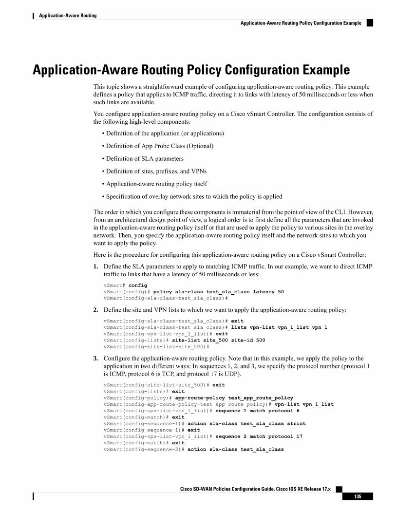
Application-Aware Routing Policy Configuration ExampleThis topic shows a straightforward example of configuring application-aware routing policy. This exampledefines a policy that applies to ICMP traffic, directing it to links with latency of 50 milliseconds or less whensuch links are available.
You configure application-aware routing policy on a Cisco vSmart Controller. The configuration consists ofthe following high-level components:
• Definition of the application (or applications)
• Definition of App Probe Class (Optional)
• Definition of SLA parameters
• Definition of sites, prefixes, and VPNs
• Application-aware routing policy itself
• Specification of overlay network sites to which the policy is applied
The order in which you configure these components is immaterial from the point of view of the CLI. However,from an architectural design point of view, a logical order is to first define all the parameters that are invokedin the application-aware routing policy itself or that are used to apply the policy to various sites in the overlaynetwork. Then, you specify the application-aware routing policy itself and the network sites to which youwant to apply the policy.
Here is the procedure for configuring this application-aware routing policy on a Cisco vSmart Controller:
1. Define the SLA parameters to apply to matching ICMP traffic. In our example, we want to direct ICMPtraffic to links that have a latency of 50 milliseconds or less:vSmart# configvSmart(config)# policy sla-class test_sla_class latency 50vSmart(config-sla-class-test_sla_class)#
2. Define the site and VPN lists to which we want to apply the application-aware routing policy:vSmart(config-sla-class-test_sla_class)# exitvSmart(config-sla-class-test_sla_class)# lists vpn-list vpn_1_list vpn 1vSmart(config-vpn-list-vpn_1_list)# exitvSmart(config-lists)# site-list site_500 site-id 500vSmart(config-site-list-site_500)#
3. Configure the application-aware routing policy. Note that in this example, we apply the policy to theapplication in two different ways: In sequences 1, 2, and 3, we specify the protocol number (protocol 1is ICMP, protocol 6 is TCP, and protocol 17 is UDP).vSmart(config-site-list-site_500)# exitvSmart(config-lists)# exitvSmart(config-policy)# app-route-policy test_app_route_policyvSmart(config-app-route-policy-test_app_route_policy)# vpn-list vpn_1_listvSmart(config-vpn-list-vpn_1_list)# sequence 1 match protocol 6vSmart(config-match)# exitvSmart(config-sequence-1)# action sla-class test_sla_class strictvSmart(config-sequence-1)# exitvSmart(config-vpn-list-vpn_1_list)# sequence 2 match protocol 17vSmart(config-match)# exitvSmart(config-sequence-2)# action sla-class test_sla_class
Cisco SD-WAN Policies Configuration Guide, Cisco IOS XE Release 17.x135
Application-Aware RoutingApplication-Aware Routing Policy Configuration Example
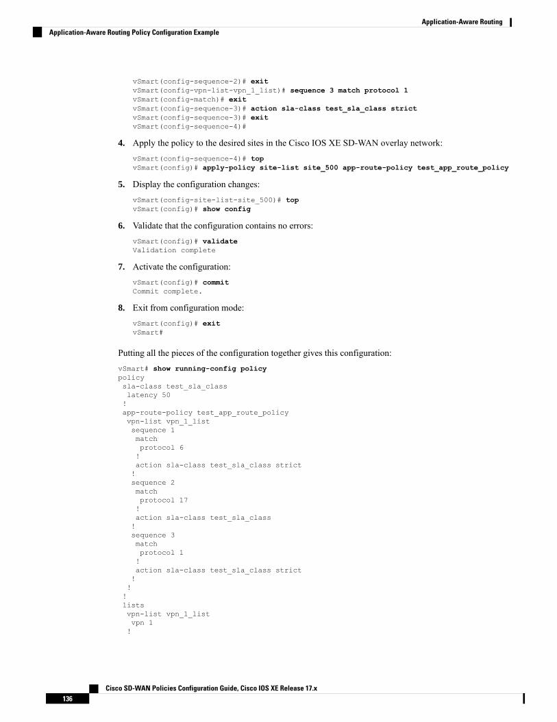
vSmart(config-sequence-2)# exitvSmart(config-vpn-list-vpn_1_list)# sequence 3 match protocol 1vSmart(config-match)# exitvSmart(config-sequence-3)# action sla-class test_sla_class strictvSmart(config-sequence-3)# exitvSmart(config-sequence-4)#
4. Apply the policy to the desired sites in the Cisco IOS XE SD-WAN overlay network:vSmart(config-sequence-4)# topvSmart(config)# apply-policy site-list site_500 app-route-policy test_app_route_policy
5. Display the configuration changes:vSmart(config-site-list-site_500)# topvSmart(config)# show config
6. Validate that the configuration contains no errors:vSmart(config)# validateValidation complete
7. Activate the configuration:vSmart(config)# commitCommit complete.
8. Exit from configuration mode:vSmart(config)# exitvSmart#
Putting all the pieces of the configuration together gives this configuration:vSmart# show running-config policypolicysla-class test_sla_classlatency 50!app-route-policy test_app_route_policyvpn-list vpn_1_listsequence 1matchprotocol 6!action sla-class test_sla_class strict!sequence 2matchprotocol 17!action sla-class test_sla_class!sequence 3matchprotocol 1!action sla-class test_sla_class strict!!!listsvpn-list vpn_1_listvpn 1!
Cisco SD-WAN Policies Configuration Guide, Cisco IOS XE Release 17.x136
Application-Aware RoutingApplication-Aware Routing Policy Configuration Example

site-list site_500site-id 500!site-list site_600site-id 600!!!apply-policysite-list site_500app-route-policy test_app_route_policy!!
The following example defines the multicast protocol:
policy!sla-class SLA_BEST_EFFORTjitter 900!sla-class SLA_BUSINESS_CRITICALloss 1latency 250jitter 300!sla-class SLA_BUSINESS_DATAloss 3latency 400jitter 500!sla-class SLA_REALTIMEloss 2latency 300jitter 60!app-route-policy policy_multicastvpn-list multicast-vpn-listsequence 10matchsource-ip 10.0.0.0/8destination-ip 10.255.255.254/8!actioncount mc-counter-10sla-class SLA_BUSINESS_CRITICAL!!sequence 15matchsource-ip 172.16.0.0/12destination-ip 172.31.255.254/12!actioncount mc-counter-15sla-class SLA_BEST_EFFORT!!sequence 20matchdestination-ip 192.168.0.1!actioncount mc-counter-20
Cisco SD-WAN Policies Configuration Guide, Cisco IOS XE Release 17.x137
Application-Aware RoutingApplication-Aware Routing Policy Configuration Example
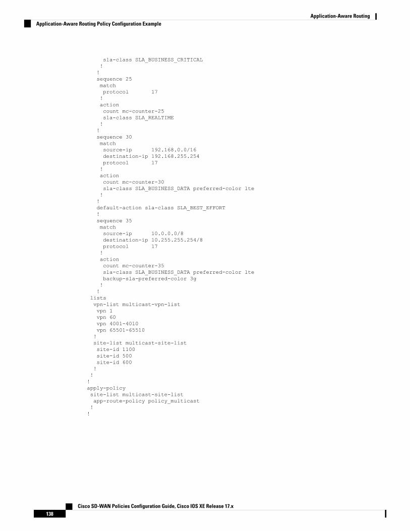
sla-class SLA_BUSINESS_CRITICAL!!sequence 25matchprotocol 17!actioncount mc-counter-25sla-class SLA_REALTIME!!sequence 30matchsource-ip 192.168.0.0/16destination-ip 192.168.255.254protocol 17!actioncount mc-counter-30sla-class SLA_BUSINESS_DATA preferred-color lte!!default-action sla-class SLA_BEST_EFFORT!sequence 35matchsource-ip 10.0.0.0/8destination-ip 10.255.255.254/8protocol 17!actioncount mc-counter-35sla-class SLA_BUSINESS_DATA preferred-color ltebackup-sla-preferred-color 3g!!
listsvpn-list multicast-vpn-listvpn 1vpn 60vpn 4001-4010vpn 65501-65510!site-list multicast-site-listsite-id 1100site-id 500site-id 600!!!apply-policysite-list multicast-site-listapp-route-policy policy_multicast!!
Cisco SD-WAN Policies Configuration Guide, Cisco IOS XE Release 17.x138
Application-Aware RoutingApplication-Aware Routing Policy Configuration Example

C H A P T E R 10Traffic Flow Monitoring with cFlowd
Table 27: Feature History
DescriptionRelease InformationFeature Name
This feature enables export of packet to externalcollector over IPv6 transport on Cisco IOS XESD-WAN devices and provides the visibility of IPv6network traffic. If you want to monitor IPv4 and IPv6traffic together, this feature enables you to modify thecache size on the data plane. Cisco Flexible NetFlow(FNF) is a technology that provides customizedvisibility into network traffic. In Cisco SD-WAN,FNF enables exporting data to Cisco vManage whichmakes it easy for the customers to monitor andimprove their network.
Cisco IOS XE Release17.4.1a
Cisco vManage Release20.4.1
Flexible NetFlow Supportfor IPv6 and Cache SizeModification
You can now enable or disable logging of droppedpackets in case of a link failure. You can alsoconfigure how often the packet flows are logged.
Cisco IOS XE Release17.5.1a
Cisco vManage Release20.5.1
Log Packets Dropped byImplicit ACL
This feature enhances Flexible NetFlow to collecttype of service (ToS), sampler ID and remarkedDSCPvalues in netflow records. This enhancement providesthe flexibility to define flow record fields to customizeflow records by defining flow record fields. The ToSand remarked DSCP fields are supported only on IPv4records. However, the sampler ID field is supportedfor both IPv4 and IPv6 records.
Cisco IOS XE Release17.6.1a
Cisco vManage Release20.6.1
Flexible NetFlowEnhancement
This feature supports NetFlow on VPN0 interfaces.
Flexible NetFlow acts as a security tool, enablesexport of data to Cisco vManage, detects attacks ondevices, and monitors traffic.
Cisco IOS XE Release17.7.1a
Cisco vManage Release20.7.1
Flexible NetFlow forVPN0 Interface
• Information about Traffic Flow Monitoring, on page 140• Configure Traffic Flow Monitoring on Cisco IOS XE SD-WAN Devices, on page 146
Cisco SD-WAN Policies Configuration Guide, Cisco IOS XE Release 17.x139

• Configure Cflowd Traffic Flow Monitoring Using the CLI, on page 150• Configure Flexible Netflow on VPN0 Interface, on page 151• Verify Flexible Netflow Configuration on VPN0 Interface , on page 152• Apply and Enable Cflowd Policy, on page 155• Cflowd Traffic Flow Monitoring Configuration Example, on page 156
Information about Traffic Flow Monitoring
Traffic Flow Monitoring with Cflowd OverviewCflowd is a flow analysis tool, used for analyzing Netflow traffic data. It monitors traffic flowing throughCisco IOS XE SD-WAN devices in the overlay network and exports flow information to a collector, whereit can be processed by an IP Flow Information Export (IPFIX) analyzer. For a traffic flow, Cflowd periodicallysends template reports to flow collector. These reports contain information about the flows and the data isextracted from the payload of these reports.
You can create a Cflowd template that defines the location of Cflowd collectors, how often sets of sampledflows are sent to the collectors, and how often the template is sent to the collectors (on Cisco vSmart Controllersand on Cisco vManage). You can configure amaximum of four Cflowd collectors per Cisco IOSXE SD-WANdevice. To have a Cflowd template take effect, apply it with the appropriate data policy.
You must configure at least one Cflowd template, but it need not contain any parameters. With no parameters,the data flow cache on the nodes is managed using default settings, and no flow export occurs.
Cflowd traffic flow monitoring is equivalent to Flexible Netflow (FNF).
The Cflowd software implements Cflowd version 10, as specified in RFC 7011 and RFC 7012. Cflowd version10 is also called the IP Flow Information Export (IPFIX) protocol.
Cflowd performs 1:1 sampling. Information about all flows is aggregated in the Cflowd records; flows arenot sampled. Cisco IOS XE SD-WAN devices do not cache any of the records that are exported to a collector.
Cisco IOSXE SD-WAN devices support only loopback interfaces as the source interface for external collectors.Note
Netflow on Secure Internet Gateway (SIG) tunnels is not supported on Cisco IOS XE SD-WAN devices.Note
Cflowd and SNMP Comparison
Cflowd monitors service side traffic. Cflowd mainly monitors traffic from LAN to WAN, WAN to LAN,LAN to LAN and DIA. If you use Cflowd and SNMP to monitor traffic of LAN interface (input or output),then packets and bytes should be similar. The difference of bytes in SNMP starts from L2 header, but Cflowdstarts from L3 header. However, if we use Cflowd and SNMP to monitor traffic of WAN interface (input or
Cisco SD-WAN Policies Configuration Guide, Cisco IOS XE Release 17.x140
Traffic Flow Monitoring with cFlowdInformation about Traffic Flow Monitoring

output), then packets or bytes are unlikely to be the same. All the traffic of WAN interfaces is not service sidetraffic. For example, Cflowd does not monitor BFD traffic, but SNMP does. The packets or bytes of Cflowdand SNMP traffic are not the same.
IPFIX Information Elements for Cisco IOS XE SD-WAN DevicesThe Cisco SD-WAN cflowd software exports the following IPFIX information elements to the cflowd collector.Fields vary depending on the release that you are on. Common fields are exported to Cisco vManage andexternal exporters. Feature fields are exported only to Cisco vManage.
Before Cisco IOS XE Release 17.2.1r, Flexible Netflow exports all fields to external collectors and CiscovManage. Starting from Cisco IOS XE Release 17.2.1r, FNF export the elements (that are marked yes) in thefollowing table to both external collectors and Cisco vManage. Other fields like “drop cause id” are for specificfeatures and these fields are exported only to Cisco vManage, but not to external collector.
Units orRange
Data TypeSemantics
Data TypeDescriptionExportedtoExternalCollector
ElementID
Information Element
—defaultipv4Address (4 bytes)IPv4 source address in the IP packetheader.
Yes8sourceIPv4Address
—defaultipv6Address (16bytes)
IPv6 source address in the IP packetheader.
Yes27sourceIPv6Address
—defaultIPv4Address (4 bytes)IPv4 destination address in the IPpacket header.
Yes12destinationIPv4Address
—defaultipv6Address (16bytes)
IPv6 destination address in the IPpacket header.
Yes28destinationIPv6Address
—identifierunsigned32 (4 bytes)Index of the IP interface where packetsof this flow are being received.
Yes10ingressInterface
0through63
identifierunsigned8 (1 byte)Value of a Differentiated Services CodePoint (DSCP) encoded in theDifferentiated Services field. This fieldspans the most significant 6 bits of theIPv4 TOS field.
Yes195ipDiffServCodePoint
—identifierunsigned8 (1 byte)Value of the protocol number in theProtocol field of the IP packet header.The protocol number identifies the IPpacket payload type. Protocol numbersare defined in the IANA ProtocolNumbers registry.
Yes4protocolIdentifier
Cisco SD-WAN Policies Configuration Guide, Cisco IOS XE Release 17.x141
Traffic Flow Monitoring with cFlowdIPFIX Information Elements for Cisco IOS XE SD-WAN Devices
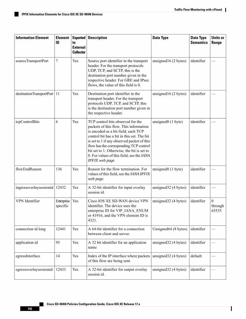
Units orRange
Data TypeSemantics
Data TypeDescriptionExportedtoExternalCollector
ElementID
Information Element
—identifierunsigned16 (2 bytes)Source port identifier in the transportheader. For the transport protocolsUDP, TCP, and SCTP, this is thedestination port number given in therespective header. For GRE and IPsecflows, the value of this field is 0.
Yes7sourceTransportPort
—identifierunsigned16 (2 bytes)Destination port identifier in thetransport header. For the transportprotocols UDP, TCP, and SCTP, thisis the destination port number given inthe respective header.
Yes11destinationTransportPort
—identifierunsigned8 (1 byte)TCP control bits observed for thepackets of this flow. This informationis encoded as a bit field; each TCPcontrol bit has a bit in this set. The bitis set to 1 if any observed packet of thisflow has the corresponding TCP controlbit set to 1. Otherwise, the bit is set to0. For values of this field, see the IANAIPFIX web page.
Yes6tcpControlBits
—identifierunsigned8 (1 byte)Reason for the flow termination. Forvalues of this field, see the IANA IPFIXweb page.
Yes136flowEndReason
—identifierunsigned32 (4 bytes)A 32-bit identifier for input overlaysession id.
Yes12432ingressoverlaysessionid
0through65535
identifierunsigned32 (4 bytes)Cisco IOS XE SD-WAN device VPNidentifier. The device uses theenterprise ID for VIP_IANA_ENUMor 41916, and the VPN element ID is4321.
YesEnterprisespecific
VPN Identifier
—identifierUnsigned64 (8 bytes)A 64-bit identifier for a connectionbetween client and server.
Yes12441connection id long
—identifierunsigned32 (4 bytes)A 32 bit identifier for an applicationname
Yes95application id
—defaultunsigned32 (4 bytes)Index of the IP interface where packetsof this flow are being sent.
Yes14egressInterface
—identifierunsigned32 (4 bytes)A 32-bit identifier for output overlaysession id.
Yes12433egressoverlaysessionid
Cisco SD-WAN Policies Configuration Guide, Cisco IOS XE Release 17.x142
Traffic Flow Monitoring with cFlowdIPFIX Information Elements for Cisco IOS XE SD-WAN Devices

Units orRange
Data TypeSemantics
Data TypeDescriptionExportedtoExternalCollector
ElementID
Information Element
—identifierunsigned8 (1 byte)Queue index for QoS.No12446sdwan qos-queue-id
—identifierunsigned16 (2 bytes)A 16-bit identifier for a drop causename.
No12442drop cause id
OctetstotalCounterunsigned64 (8 bytes)Total number of dropped octets inincoming packets for this flow at theobservation point since initialization orre-initialization of the metering processfor the observation point.
The count includes the IP heads and theIP payload.
No12443counter bytes sdwandropped long
—identifierunsigned8 (1 byte)A Boolean to indicate if required SLAis met or not.
No12444sdwan sla-not-met
—identifierunsigned8 (1 byte)A Boolean to indicate if preferred coloris met or not.
No12445sdwanpreferred-color-not-met
PacketstotalCounterunsigned64 (8 bytes)Total number of dropped packets inincoming packets for this flow at theobservation point since initialization orre-initialization of the metering processfor the observation point.
No42329counter packets sdwandropped long
OctetsdeltaCounterunsigned64 (8 bytes)Number of octets since the previousreport in incoming packets for this flowat the observation point. This numberincludes IP headers and IP payload.
Yes1octetDeltaCount
PacketsdeltaCounterunsigned64 (8 bytes)Number of incoming packets since theprevious report for this flow at thisobservation point.
Yes2packetDeltaCount
——dateTime-MilliSeconds(8 bytes)
Absolute timestamp of the first packetof this flow.
Yes152flowStartMilliseconds
——dateTime-MilliSeconds(8 bytes)
Absolute timestamp of the last packetof this flow.
Yes153flowEndMilliseconds
8 bitsidentifierunsigned8 (1 byte)The Type of Service field in the IPheader.
Yes5ip tos
0through63
identifierunsigned8 (1 byte)Value of a DSCP encoded in theDifferentiated Services field. This fieldspans the most significant 6 bits of theIPv4 TOS field.
Yes98dscp output
Cisco SD-WAN Policies Configuration Guide, Cisco IOS XE Release 17.x143
Traffic Flow Monitoring with cFlowdIPFIX Information Elements for Cisco IOS XE SD-WAN Devices

Units orRange
Data TypeSemantics
Data TypeDescriptionExportedtoExternalCollector
ElementID
Information Element
—identifierunsigned8 (1 byte)A set of properties that are defined in aNetflow sampler map that are appliedto at least one physical interface
Yes48flow sampler
Flexible Netflow for VPN0 InterfaceFromCisco IOSXERelease 17.7.1a, you can enable FNF for bidirectional traffic visibility on a VPN0 interfaceof a Cisco IOS XE SD-WAN device.
Netflow provides statistics on packets flowing through the device and helps to identify the tunnel or serviceVPNs. Flexible Netflow on VPN0 provides visibility for all the traffic (both ingress and egress) hitting VPN0on Cisco IOS XE SD-WAN devices.
A profile is a predefined set of traffic that you can enable or disable for a context. You can create an EasyPerformance Monitor (ezPM) profile that provides an express method of provisioning monitors. This newmechanism adds functionality and does not affect the existing methods for provisioning monitors. As part ofthis feature, you can create sdwan-fnf profile to monitor traffic passing through netflow VPN0 configuration.
A context represents a performance monitor policy map that is attached to an interface in ingress and egressdirections. A context contains the information about the traffic-monitor that has to be enabled.When a contextis attached to an interface, two policy-maps are created, one each in ingress and egress directions. Dependingon the direction specified in the traffic monitor, the policy-maps are attached in that direction and the trafficis monitored. You can modify the context to override pre-defined directions.
You can create multiple contexts based on a single profile with different traffic monitors, different exporters,and different parameters for every selected traffic monitor. An ezPM context can be attached to multipleinterfaces. Only one context can be attached to an interface.
Table 28: Flexible Netflow Components
Cisco SD-WAN Flexible NetflowVPN0 from Cisco vManage Release20.7.1
Cisco SD-WAN Flexible Netflow
Define Flexible Netflow VPN0monitor using commandperformance monitor context xxxprofile sdwan-fnf and attach onVPN0 interface.
Supported on CLI template andadd-on CLI feature template inCisco vManage.
Localized Policy: app-visibility orflow-visibility
Centralized policy: cflowd policy
Supported on both Cisco vManagefeature template and CLI template/
Configuration
VPN0 interface except CiscoSD-WAN tunnel andVPN interface
Cisco SD-WAN tunnel interfaceand service VPN interface
Interface
Cisco SD-WAN Policies Configuration Guide, Cisco IOS XE Release 17.x144
Traffic Flow Monitoring with cFlowdFlexible Netflow for VPN0 Interface

Cisco SD-WAN Flexible NetflowVPN0 from Cisco vManage Release20.7.1
Cisco SD-WAN Flexible Netflow
Fixed records. You cannot modifyor add new fields.
Fixed records by default.
Supports dynamic monitoring forrecords such as, FEC, packetduplication, SSL proxy and so on.Also supports collecting type ofservice (ToS), sampler ID andremarked DSCP values forcentralized policies.
Flow Records
Supports both ingress and egressby default.
Supports only ingress flowsFlow Direction
NBAR is enabled by default.Network-based Applicationrecognition (NBAR) is enabledonly when app-visibility isdefined.
NBAR for APP
Can’t export to Cisco vManage
IPFIX to external collectors
JSON file to Cisco vManage andIPFIX to external collector
Exporter
Limitations of Flexible Netflow on VPN0 Interface• Flexible Netflow on VPN0 is not supported on Cisco SD-WAN tunnel and Cisco SD-WAN VPNinterfaces.
• The FNF record for VPN0 traffic is a fixed record and cannot be modified.
• Cisco SD-WAN VPN0 flow entries are reported to external collectors defined in CLI configuration andnot to Cisco vManage.
• Cisco SD-WAN BFD and Cisco SD-WAN control connections such as OMP, Netconf, and SSH areencapsulated by Datagram Transport Layer Security (DTLS) or Transport Layer Security (TLS) tunnels.FNF reports on only the DTLS traffic and not the encapsulated protocol packets.
• When FNF is configured for a VPN0 WAN interface,
• For ingress flows (WAN > Cisco SD-WAN-tunnel > LAN) - the output interface is reported asNULL.
• For egress flows (LAN > Cisco SD-WAN-tunnel > WAN) - input interface is reported as WANinterface (Cisco SD-WAN underlay tunnels).
• VPN0 monitor supports only IPv4 and IPv6 protocols.
• For routing protocols, such as OSPF, BGP, only egress traffic is supported. Ingress OSPF and BGP trafficis treated as high priority packets.
Cisco SD-WAN Policies Configuration Guide, Cisco IOS XE Release 17.x145
Traffic Flow Monitoring with cFlowdLimitations of Flexible Netflow on VPN0 Interface
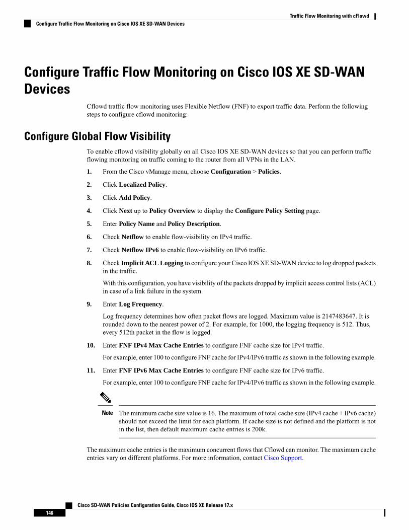
Configure Traffic Flow Monitoring on Cisco IOS XE SD-WANDevices
Cflowd traffic flow monitoring uses Flexible Netflow (FNF) to export traffic data. Perform the followingsteps to configure cflowd monitoring:
Configure Global Flow VisibilityTo enable cflowd visibility globally on all Cisco IOS XE SD-WAN devices so that you can perform trafficflowing monitoring on traffic coming to the router from all VPNs in the LAN.
1. From the Cisco vManage menu, choose Configuration > Policies.
2. Click Localized Policy.
3. Click Add Policy.
4. Click Next up to Policy Overview to display the Configure Policy Setting page.
5. Enter Policy Name and Policy Description.
6. Check Netflow to enable flow-visibility on IPv4 traffic.
7. Check Netflow IPv6 to enable flow-visibility on IPv6 traffic.
8. Check Implicit ACL Logging to configure your Cisco IOSXE SD-WAN device to log dropped packetsin the traffic.
With this configuration, you have visibility of the packets dropped by implicit access control lists (ACL)in case of a link failure in the system.
9. Enter Log Frequency.
Log frequency determines how often packet flows are logged. Maximum value is 2147483647. It isrounded down to the nearest power of 2. For example, for 1000, the logging frequency is 512. Thus,every 512th packet in the flow is logged.
10. Enter FNF IPv4 Max Cache Entries to configure FNF cache size for IPv4 traffic.
For example, enter 100 to configure FNF cache for IPv4/IPv6 traffic as shown in the following example.
11. Enter FNF IPv6 Max Cache Entries to configure FNF cache size for IPv6 traffic.
For example, enter 100 to configure FNF cache for IPv4/IPv6 traffic as shown in the following example.
The minimum cache size value is 16. The maximum of total cache size (IPv4 cache + IPv6 cache)should not exceed the limit for each platform. If cache size is not defined and the platform is notin the list, then default maximum cache entries is 200k.
Note
The maximum cache entries is the maximum concurrent flows that Cflowd can monitor. The maximum cacheentries vary on different platforms. For more information, contact Cisco Support.
Cisco SD-WAN Policies Configuration Guide, Cisco IOS XE Release 17.x146
Traffic Flow Monitoring with cFlowdConfigure Traffic Flow Monitoring on Cisco IOS XE SD-WAN Devices
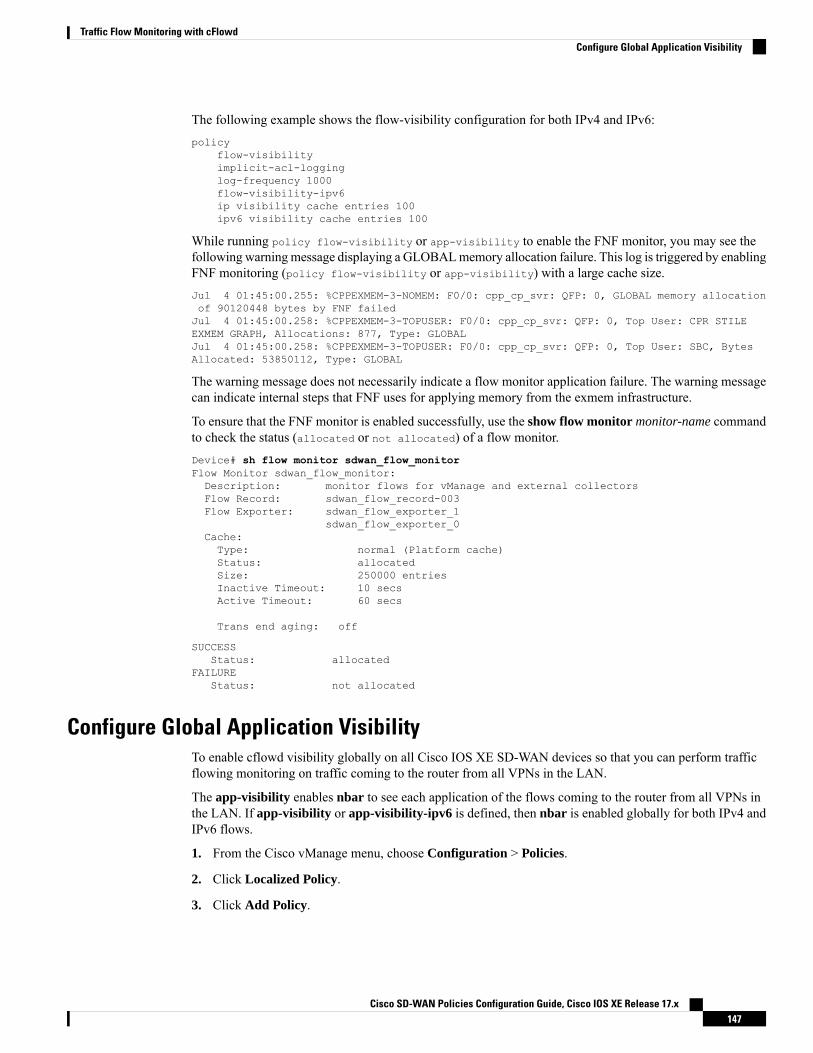
The following example shows the flow-visibility configuration for both IPv4 and IPv6:policy
flow-visibilityimplicit-acl-logginglog-frequency 1000flow-visibility-ipv6ip visibility cache entries 100ipv6 visibility cache entries 100
While running policy flow-visibility or app-visibility to enable the FNF monitor, you may see thefollowing warningmessage displaying a GLOBALmemory allocation failure. This log is triggered by enablingFNF monitoring (policy flow-visibility or app-visibility) with a large cache size.Jul 4 01:45:00.255: %CPPEXMEM-3-NOMEM: F0/0: cpp_cp_svr: QFP: 0, GLOBAL memory allocationof 90120448 bytes by FNF failedJul 4 01:45:00.258: %CPPEXMEM-3-TOPUSER: F0/0: cpp_cp_svr: QFP: 0, Top User: CPR STILEEXMEM GRAPH, Allocations: 877, Type: GLOBALJul 4 01:45:00.258: %CPPEXMEM-3-TOPUSER: F0/0: cpp_cp_svr: QFP: 0, Top User: SBC, BytesAllocated: 53850112, Type: GLOBAL
The warning message does not necessarily indicate a flow monitor application failure. The warning messagecan indicate internal steps that FNF uses for applying memory from the exmem infrastructure.
To ensure that the FNF monitor is enabled successfully, use the show flow monitor monitor-name commandto check the status (allocated or not allocated) of a flow monitor.Device# sh flow monitor sdwan_flow_monitorFlow Monitor sdwan_flow_monitor:Description: monitor flows for vManage and external collectorsFlow Record: sdwan_flow_record-003Flow Exporter: sdwan_flow_exporter_1
sdwan_flow_exporter_0Cache:Type: normal (Platform cache)Status: allocatedSize: 250000 entriesInactive Timeout: 10 secsActive Timeout: 60 secs
Trans end aging: off
SUCCESSStatus: allocated
FAILUREStatus: not allocated
Configure Global Application VisibilityTo enable cflowd visibility globally on all Cisco IOS XE SD-WAN devices so that you can perform trafficflowing monitoring on traffic coming to the router from all VPNs in the LAN.
The app-visibility enables nbar to see each application of the flows coming to the router from all VPNs inthe LAN. If app-visibility or app-visibility-ipv6 is defined, then nbar is enabled globally for both IPv4 andIPv6 flows.
1. From the Cisco vManage menu, choose Configuration > Policies.
2. Click Localized Policy.
3. Click Add Policy.
Cisco SD-WAN Policies Configuration Guide, Cisco IOS XE Release 17.x147
Traffic Flow Monitoring with cFlowdConfigure Global Application Visibility

4. Click Next up to Policy Overview to display the Configure Policy Setting page.
5. Enter Policy Name and Policy Description.
6. Select Application to enable app-visibility on IPv4 traffic.
7. Select Application IPv6 to enable app-visibility on IPv6 traffic.
8. Enter FNF IPv4 Max Cache Entries to configure FNF cache size for IPv4 traffic.
For example, enter 100 to configure FNF cache size for IPv4 traffic as shown in the following example.
9. Enter FNF IPv6 Max Cache Entries to configure FNF cache size for IPv6 traffic.
For example, enter 100 to configure FNF cache size for IPv6 traffic as shown in the following example.
The following example shows the app-visibility configuration for both IPv4 and IPv6:policyapp-visibility
app-visibility-ipv6ip visibility cache entries 100ipv6 visibility cache entries 100!
The policy app-visibility command also enables global flow visibility by enabling nbar to get theapplication name.
Note
Configure Cflowd Monitoring PolicyTo configure policy for cflowd traffic flow monitoring, use the Cisco vManage policy configuration wizard.The wizard consists of four sequential screens that guide you through the process of creating and editingpolicy components:
1. Create Applications or Groups of Interest: Create lists that group together related items and that you callin the match or action components of a policy.
2. Configure Topology: Create the network structure to which the policy applies.
3. Configure Traffic Rules: Create the match and action conditions of a policy.
4. Apply Policies to Sites and VPNs: Associate policy with sites and VPNs in the overlay network.
In the first three policy configuration wizard screens, create policy components or blocks. In the last screen,apply policy blocks to sites and VPNs in the overlay network. For the cflowd policy to take effect, activatethe policy.
1. From the Cisco vManage menu, choose Configuration > Policies.
2. Click Custom Options. Under Centralized Policy, click Traffic Policy.
3. Click Cflowd.
4. Click Add Policy and then Create New.
Cisco SD-WAN Policies Configuration Guide, Cisco IOS XE Release 17.x148
Traffic Flow Monitoring with cFlowdConfigure Cflowd Monitoring Policy
5. Enter the Name and Description for the policy.
6. In the Cflowd Template section, enter Active Flow Timeout. The range is 30 to 3600 seconds.
7. In the Inactive Flow Timeout, enter the timeout range. The range is 1 to 3600 seconds.
8. In the Flow Refresh, enter the range. The range is 60 to 86400 seconds.
9. In the Sampling Interval, enter the sample duration. The range is 1 out of N packets.
10. In the Protocol field, choose an option from the drop-down list.
The options are:
• IPv4
• IPv6
• Both
The default protocol is IPv4.Note
Starting fromCisco IOSXERelease 17.6.1a and Cisco vManage Release 20.6.1, theAdvanced Settingsfield displays when you choose IPv4 or Both from the options.
11. Under the Advanced Settings, do the following to collect additional IPv4 flow records:
• Check the TOS check box.
• Check the Re-marked DSCP check box.
12. Click Save Cflowd Policy.
View Cflowd InformationTo view cflowd information, use the following commands on the Cisco IOS XE SD-WAN device.
• show sdwan app-fwd cflowd collector
• show sdwan app-fwd cflowd flow-count
• show sdwan app-fwd cflowd flows [vpn vpn-id] format table
• show sdwan app-fwd cflowd statistics
• show sdwan app-fwd cflowd template [name template-name]
• show sdwan app-fwd cflowd flows format table
The following sample output displays the information cflowd:Device# show sdwan app-fwd cflowd flowsGenerating output, this might take time, please wait ...app-fwd cflowd flows vpn 1 src-ip 10.2.2.11 dest-ip 10.20.24.17 src-port 0 dest-port 2048dscp 63 ip-proto 1tcp-cntrl-bits 0
Cisco SD-WAN Policies Configuration Guide, Cisco IOS XE Release 17.x149
Traffic Flow Monitoring with cFlowdView Cflowd Information

icmp-opcode 2048total-pkts 6total-bytes 600start-time "Fri May 14 02:57:23 2021"egress-intf-name GigabitEthernet5ingress-intf-name GigabitEthernet1application unknownfamily network-servicedrop-cause "No Drop"drop-octets 0drop-packets 0sla-not-met 0color-not-met 0queue-id 2tos 255dscp-output 63sampler-id 3fec-d-pkts 0fec-r-pkts 0pkt-dup-d-pkts-orig 0pkt-dup-d-pkts-dup 0pkt-dup-r-pkts 0pkt-cxp-d-pkts 0traffic-category 0
For more information, see the show sdwan app-fwd cflowd flows command page.
Configure Cflowd Traffic Flow Monitoring Using the CLIFrom the CLI on the Cisco vSmart Controller that is controlling the Cisco IOS XE SD-WAN device:
1. Configure a Cflowd template to specify flow visibility and flow sampling parameters:vSmart(config)# policy cflowd-template template-namevSmart(config-cflowd-template)# flow-active-timeout secondsvSmart(config-cflowd-template)# flow-inactive-timeout secondsvSmart(config-cflowd-template)# flow-sampling-interval numbervSmart(config-cflowd-template)# template-refresh secondsvSmart(config-cflowd-template)# protocol ipv4|ipv6|Both
2. To collect TOS/DSCP output in flow monitor:
vSmart(config-cflowd-template)# customized-ipv4-record-fieldsvsmart(config-customized-ipv4-record-fields)# collect-tosvsmart(config-customized-ipv4-record-fields)# collect-dscp-output
3. Configure a flow collector:vSmart(config-cflowd-template)# collector vpn vpn-id addressip-address port port-number transport transport-typesource-interface interface-name
Cisco SD-WAN Policies Configuration Guide, Cisco IOS XE Release 17.x150
Traffic Flow Monitoring with cFlowdConfigure Cflowd Traffic Flow Monitoring Using the CLI

Cisco IOSXE SD-WAN devices only support UDP collector. Irrespective of the transport protocolthat is configured, UDP is the default collector for Cisco IOS XE SD-WAN devices.
Note
4. Configure a data policy that defines traffic match parameters and that includes the action cflowd:vSmart(config)# policy data-policy policy-namevSmart(config-data-policy)# sequence numbervSmart(config-sequence)# match match-parametersvSmart(config-sequence)# action cflowd
5. Create lists of sites in the overlay network that contain the Cisco IOS XE SD-WAN devices to which youwant to apply the traffic flow monitoring policy. To include multiple site in the list, configure multiplevpn vpn-id commands.vSmart(config)# policy listsvSmart(config-lists)# vpn-list list-namevSmart(config-vpn-list)# vpn vpn-id
6. Apply the data policy to the sites in the overlay network that contain the Cisco IOS XE SD-WAN devices:vSmart(config)# apply-policy site-list list-namevSmart(config-site-list)# data-policy policy-namevSmart(config-site-list)# cflowd-template template-name
Configure Flexible Netflow on VPN0 InterfaceYou can enable FNF on a VPN0 interface using a CLI template or the CLI add-on template. The ezPM profilehelps in creating a new profile to carry all the Netflow VPN0 monitor configuration. On selecting a profileand specifying a few parameters, ezPM provides the remaining provisioning information. A profile is apre-defined set of traffic monitors that can be enabled or disabled for a context. You can configure EasyPerformance Monitor (ezPM) and enable FNF as follows.Device# config-transactionDevice(config)# performance monitor context <monitor_name> profile <sdwan-fnf> traffic-monitor<all> [ipv4/ipv6]Device(config-perf-mon)# exporter destination <destination address> source <source interface>transport udp vrf <vrf-name> port <port-number> dscp <dscp>
The following example shows how to configure a performance monitor context using the sdwan-fnf profile.This configuration enables monitoring of traffic metrics. Here, 10.1.1.1 is the IP address of the third-partycollector, GigabitEthernet5 is the source interface, and 4739 is the listening port of the third-party collector.Device# config-transactionDevice(config)# performance monitor context <monitor_name> profile sdwan-fnf traffic-monitorall [ipv4/ipv6]Device(config-perf-mon)# exporter destination <10.1.1.1> source <GigabitEthernet5> transportudp vrf <vrf1> port <4739> dscp <1>
Cisco SD-WAN Policies Configuration Guide, Cisco IOS XE Release 17.x151
Traffic Flow Monitoring with cFlowdConfigure Flexible Netflow on VPN0 Interface
Verify Flexible Netflow Configuration on VPN0 InterfaceView Flexible Netflow Record Configuration Summary
You can verify FNF record configuration using the following command.Device# show flow record <monitor-context-name>
The monitor name is used as temp0 in the following examples.Note
The following sample output displays the information about IPv4 traffic flow records using ezPM profile.Device# show flow record temp0-sdwan-fnf-vpn0-monitor_ipv4flow record temp0-sdwan-fnf-vpn0-monitor_ipv4:Description: ezPM recordNo. of users: 1Total field space: 66 bytesFields:match ipv4 dscpmatch ipv4 protocolmatch ipv4 source addressmatch ipv4 destination addressmatch transport source-portmatch transport destination-portmatch flow directioncollect routing next-hop address ipv4collect transport tcp flagscollect interface inputcollect interface outputcollect flow samplercollect counter bytes longcollect counter packets longcollect timestamp absolute firstcollect timestamp absolute lastcollect application namecollect flow end-reason
The following sample output displays the information about IPv6 traffic flow records using ezPM profile.Device# show flow record temp0-sdwan-fnf-vpn0-monitor_ipv6
flow record temp0-sdwan-fnf-vpn0-monitor_ipv6:Description: ezPM recordNo. of users: 1Total field space: 102 bytesFields:match ipv6 dscpmatch ipv6 protocolmatch ipv6 source addressmatch ipv6 destination addressmatch transport source-portmatch transport destination-portmatch flow directioncollect routing next-hop address ipv6collect transport tcp flags
Cisco SD-WAN Policies Configuration Guide, Cisco IOS XE Release 17.x152
Traffic Flow Monitoring with cFlowdVerify Flexible Netflow Configuration on VPN0 Interface
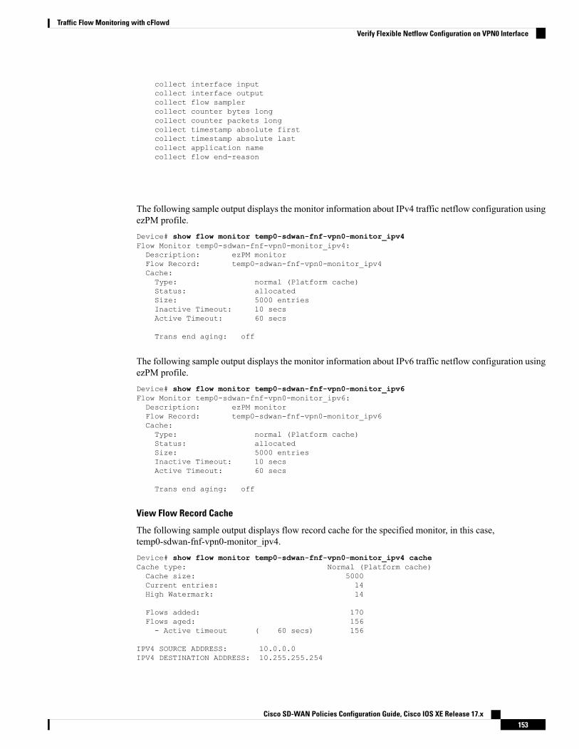
collect interface inputcollect interface outputcollect flow samplercollect counter bytes longcollect counter packets longcollect timestamp absolute firstcollect timestamp absolute lastcollect application namecollect flow end-reason
The following sample output displays the monitor information about IPv4 traffic netflow configuration usingezPM profile.Device# show flow monitor temp0-sdwan-fnf-vpn0-monitor_ipv4Flow Monitor temp0-sdwan-fnf-vpn0-monitor_ipv4:Description: ezPM monitorFlow Record: temp0-sdwan-fnf-vpn0-monitor_ipv4Cache:Type: normal (Platform cache)Status: allocatedSize: 5000 entriesInactive Timeout: 10 secsActive Timeout: 60 secs
Trans end aging: off
The following sample output displays the monitor information about IPv6 traffic netflow configuration usingezPM profile.Device# show flow monitor temp0-sdwan-fnf-vpn0-monitor_ipv6Flow Monitor temp0-sdwan-fnf-vpn0-monitor_ipv6:Description: ezPM monitorFlow Record: temp0-sdwan-fnf-vpn0-monitor_ipv6Cache:Type: normal (Platform cache)Status: allocatedSize: 5000 entriesInactive Timeout: 10 secsActive Timeout: 60 secs
Trans end aging: off
View Flow Record Cache
The following sample output displays flow record cache for the specified monitor, in this case,temp0-sdwan-fnf-vpn0-monitor_ipv4.Device# show flow monitor temp0-sdwan-fnf-vpn0-monitor_ipv4 cacheCache type: Normal (Platform cache)Cache size: 5000Current entries: 14High Watermark: 14
Flows added: 170Flows aged: 156- Active timeout ( 60 secs) 156
IPV4 SOURCE ADDRESS: 10.0.0.0IPV4 DESTINATION ADDRESS: 10.255.255.254
Cisco SD-WAN Policies Configuration Guide, Cisco IOS XE Release 17.x153
Traffic Flow Monitoring with cFlowdVerify Flexible Netflow Configuration on VPN0 Interface

TRNS SOURCE PORT: 0TRNS DESTINATION PORT: 0FLOW DIRECTION: InputIP DSCP: 0x00IP PROTOCOL: 1ipv4 next hop address: 10.0.0.1tcp flags: 0x00interface input: Gi1interface output: Gi2flow sampler id: 0counter bytes long: 840counter packets long: 10timestamp abs first: 02:55:24.359timestamp abs last: 02:55:33.446flow end reason: Not determinedapplication name: layer7 ping……
The following sample output displays flow record cache for the specified IPv6 monitor,temp0-sdwan-fnf-vpn0-monitor_ipv6.Device# show flow monitor temp0-sdwan-fnf-vpn0-monitor_ipv6 cacheCache type: Normal (Platform cache)Cache size: 5000Current entries: 6High Watermark: 6
Flows added: 10Flows aged: 4- Inactive timeout ( 10 secs) 4
IPV6 SOURCE ADDRESS: 2001:DB8::/32IPV6 DESTINATION ADDRESS: 2001:DB8::1TRNS SOURCE PORT: 0TRNS DESTINATION PORT: 32768FLOW DIRECTION: OutputIP DSCP: 0x00IP PROTOCOL: 58ipv6 next hop address: 2001:DB8:1::1tcp flags: 0x00interface input: Gi2interface output: Gi1flow sampler id: 0counter bytes long: 2912counter packets long: 28timestamp abs first: 02:57:06.025timestamp abs last: 02:57:33.378flow end reason: Not determinedapplication name: prot ipv6-icmp
The following sample output displays the flow exporter details.Device# show flow exporter temp0Flow Exporter temp0:Description: performance monitor context temp0 exporterExport protocol: IPFIX (Version 10)Transport Configuration:Destination type: IPDestination IP address: 10.0.0.1VRF label: 1Source IP address: 10.0.0.0Source Interface: GigabitEthernet5Transport Protocol: UDPDestination Port: 4739
Cisco SD-WAN Policies Configuration Guide, Cisco IOS XE Release 17.x154
Traffic Flow Monitoring with cFlowdVerify Flexible Netflow Configuration on VPN0 Interface
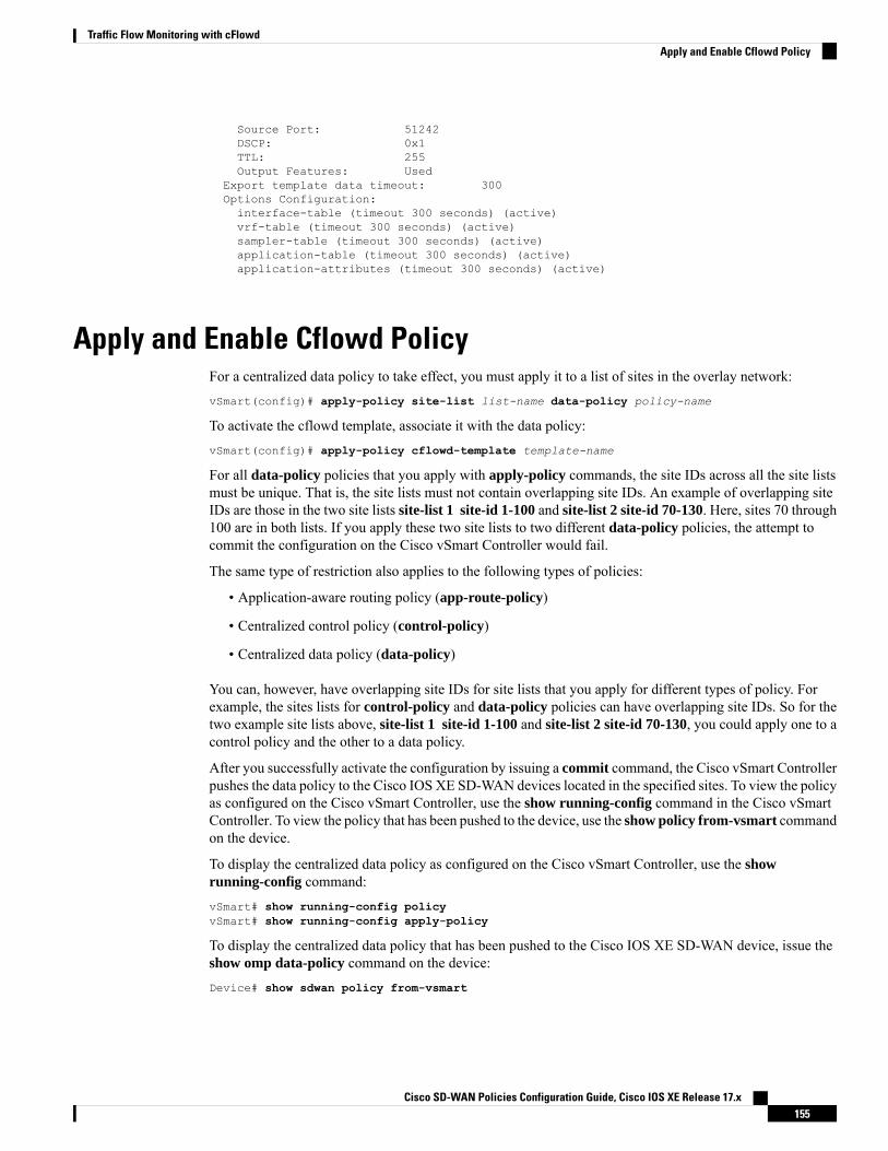
Source Port: 51242DSCP: 0x1TTL: 255Output Features: Used
Export template data timeout: 300Options Configuration:interface-table (timeout 300 seconds) (active)vrf-table (timeout 300 seconds) (active)sampler-table (timeout 300 seconds) (active)application-table (timeout 300 seconds) (active)application-attributes (timeout 300 seconds) (active)
Apply and Enable Cflowd PolicyFor a centralized data policy to take effect, you must apply it to a list of sites in the overlay network:vSmart(config)# apply-policy site-list list-name data-policy policy-name
To activate the cflowd template, associate it with the data policy:vSmart(config)# apply-policy cflowd-template template-name
For all data-policy policies that you apply with apply-policy commands, the site IDs across all the site listsmust be unique. That is, the site lists must not contain overlapping site IDs. An example of overlapping siteIDs are those in the two site lists site-list 1 site-id 1-100 and site-list 2 site-id 70-130. Here, sites 70 through100 are in both lists. If you apply these two site lists to two different data-policy policies, the attempt tocommit the configuration on the Cisco vSmart Controller would fail.
The same type of restriction also applies to the following types of policies:
• Application-aware routing policy (app-route-policy)
• Centralized control policy (control-policy)
• Centralized data policy (data-policy)
You can, however, have overlapping site IDs for site lists that you apply for different types of policy. Forexample, the sites lists for control-policy and data-policy policies can have overlapping site IDs. So for thetwo example site lists above, site-list 1 site-id 1-100 and site-list 2 site-id 70-130, you could apply one to acontrol policy and the other to a data policy.
After you successfully activate the configuration by issuing a commit command, the Cisco vSmart Controllerpushes the data policy to the Cisco IOS XE SD-WAN devices located in the specified sites. To view the policyas configured on the Cisco vSmart Controller, use the show running-config command in the Cisco vSmartController. To view the policy that has been pushed to the device, use the show policy from-vsmart commandon the device.
To display the centralized data policy as configured on the Cisco vSmart Controller, use the showrunning-config command:vSmart# show running-config policyvSmart# show running-config apply-policy
To display the centralized data policy that has been pushed to the Cisco IOS XE SD-WAN device, issue theshow omp data-policy command on the device:Device# show sdwan policy from-vsmart
Cisco SD-WAN Policies Configuration Guide, Cisco IOS XE Release 17.x155
Traffic Flow Monitoring with cFlowdApply and Enable Cflowd Policy

Enable Cflowd Visibility on Cisco IOS XE SD-WAN devices
You can enable cflowd visibility directly on Cisco IOS XE SD-WAN devices, without configuring a datapolicy, so that you can perform traffic flow monitoring on traffic coming to the router from all VPNs in theLAN. To do this, configure cflowd visiblity on the device:Device(config)# policy flow-visibility
To monitor the applications, use the show app cflowd flows and show app cflowd statistics commands onthe device.
Cflowd Traffic Flow Monitoring Configuration ExampleThis topic shows a straightforward example of configuring traffic flow monitoring.
Configuration Steps
You enable Cflowd traffic monitoring with a centralized data policy, so all configuration is done on a CiscovSmart Controller. The following example procedure monitors all TCP traffic, sending it to a single collector:
1. Create a Cflowd template to define the location of the collector and to modify Cflowd timers.vsmart(config)# policy cflowd-template test-cflowd-templatevsmart(config-cflowd-template-test-cflowd-template)# collector vpn 1 address 172.16.155.15port 13322 transport transport_udpvsmart(config-cflowd-template-test-cflowd-template)# flow-inactive-timeout 60vsmart(config-cflowd-template-test-cflowd-template)# template-refresh 90
2. Create a list of VPNs whose traffic you want to monitor.
vsmart(config)# policy lists vpn-list vpn_1 vpn 1
3. Create a list of sites to apply the data policy to.vsmart(config)# policy lists site-list cflowd-sites site-id 400,500,600
4. Configure the data policy.vsmart(config)# policy data-policy test-cflowd-policyvsmart(config-data-policy-test-cflowd-policy)# vpn-list vpn_1vsmart(config-vpn-list-vpn_1)# sequence 1vsmart(config-sequence-1)# match protocol 6vsmart(config-match)# exitvsmart(config-sequence-1)# action accept cflowdvsmart(config-action)# exitvsmart(config-sequence-1)# exitvsmart(config-vpn-list-vpn_1)# default-action accept
5. Apply the policy and the Cflowd template to sites in the overlay network.vsmart(config)# apply-policy site-list cflowd-sites data-policy test-cflowd-policyDevice(config-site-list-cflowd-sites)# cflowd-template test-cflowd-template
6. Activate the data policy.vsmart(config-site-list-cflowd-sites)# validateValidation completevsmart(config-site-list-cflowd-sites)# commitCommit complete.vsmart(config-site-list-cflowd-sites)# exit configuration-mode
Cisco SD-WAN Policies Configuration Guide, Cisco IOS XE Release 17.x156
Traffic Flow Monitoring with cFlowdCflowd Traffic Flow Monitoring Configuration Example

Full Example Configuration
Here is what the full example cflowd configuration looks like:vsmart(config)# show configurationapply-policysite-list cflowd-sitesdata-policy test-cflowd-policycflowd-template test-cflowd-template!!policydata-policy test-cflowd-policyvpn-list vpn_1sequence 1matchprotocol 6!action acceptcflowd!!default-action accept!!cflowd-template test-cflowd-templateflow-inactive-timeout 60template-refresh 90collector vpn 1 address 192.168.0.1 protocol ipv4 port 13322 transport transport_udp!listsvpn-list vpn_1vpn 1!site-list cflowd-sitessite-id 400,500,600!!!
Verify Cflowd Configuration
To verify the Cflowd configuration after activating it on the Cisco vSmart Controller, use the showrunning-config policy and show running-config apply-policy commands.
The following is a sample output from the show sdwan policy from-vsmart cflowd command:Device# show sdwan policy from-vsmart cflowd-templatefrom-vsmart cflowd-template test-cflowd-templateflow-active-timeout 30flow-inactive-timeout 60template-refresh 90flow-sampling-interval 1protocol ipv4/ipv6/bothcustomized-ipv4-record-fieldscollect-toscollect-dscp-output
collector vpn 1 address 192.0.2.1 protocol ipv4 port 13322 transport transport_udp
The following is a sample output from the show sdwan policy from-vsmart command:Device# show sdwan policy from-vsmartfrom-vsmart data-policy test-cflowd-policy
Cisco SD-WAN Policies Configuration Guide, Cisco IOS XE Release 17.x157
Traffic Flow Monitoring with cFlowdCflowd Traffic Flow Monitoring Configuration Example
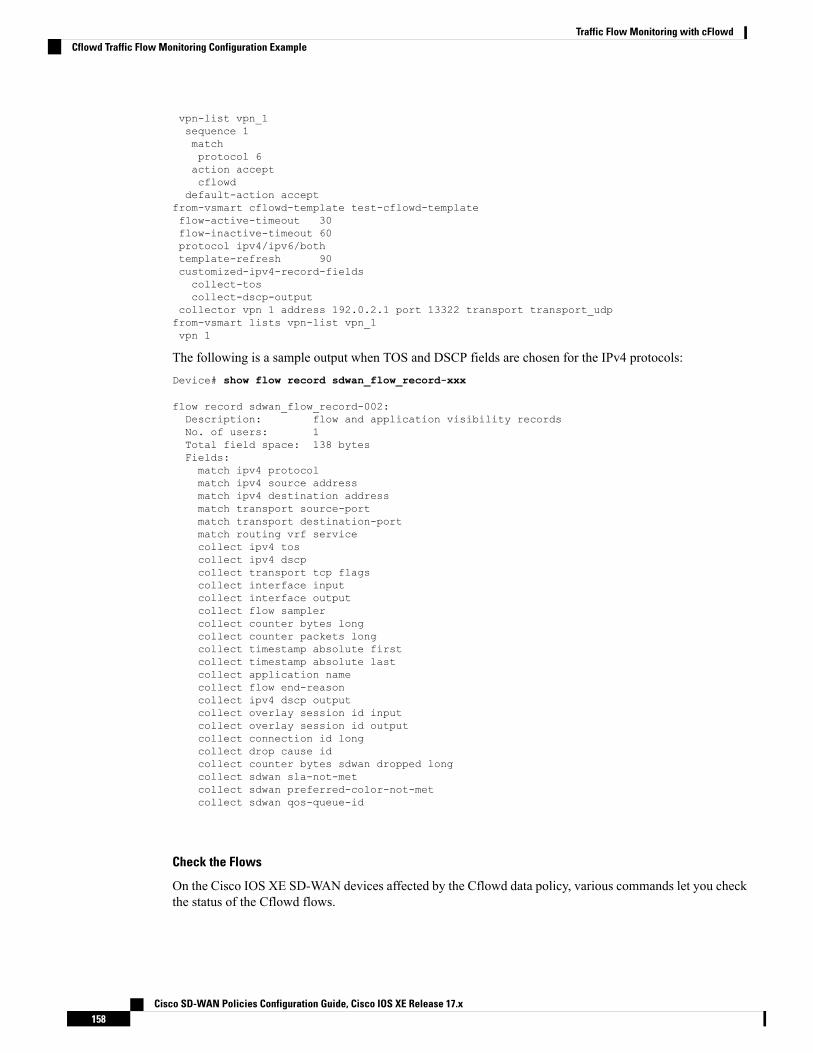
vpn-list vpn_1sequence 1matchprotocol 6action acceptcflowd
default-action acceptfrom-vsmart cflowd-template test-cflowd-templateflow-active-timeout 30flow-inactive-timeout 60protocol ipv4/ipv6/bothtemplate-refresh 90customized-ipv4-record-fieldscollect-toscollect-dscp-output
collector vpn 1 address 192.0.2.1 port 13322 transport transport_udpfrom-vsmart lists vpn-list vpn_1vpn 1
The following is a sample output when TOS and DSCP fields are chosen for the IPv4 protocols:Device# show flow record sdwan_flow_record-xxx
flow record sdwan_flow_record-002:Description: flow and application visibility recordsNo. of users: 1Total field space: 138 bytesFields:match ipv4 protocolmatch ipv4 source addressmatch ipv4 destination addressmatch transport source-portmatch transport destination-portmatch routing vrf servicecollect ipv4 toscollect ipv4 dscpcollect transport tcp flagscollect interface inputcollect interface outputcollect flow samplercollect counter bytes longcollect counter packets longcollect timestamp absolute firstcollect timestamp absolute lastcollect application namecollect flow end-reasoncollect ipv4 dscp outputcollect overlay session id inputcollect overlay session id outputcollect connection id longcollect drop cause idcollect counter bytes sdwan dropped longcollect sdwan sla-not-metcollect sdwan preferred-color-not-metcollect sdwan qos-queue-id
Check the Flows
On the Cisco IOS XE SD-WAN devices affected by the Cflowd data policy, various commands let you checkthe status of the Cflowd flows.
Cisco SD-WAN Policies Configuration Guide, Cisco IOS XE Release 17.x158
Traffic Flow Monitoring with cFlowdCflowd Traffic Flow Monitoring Configuration Example
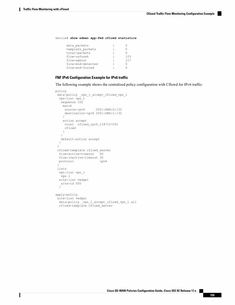
Device# show sdwan app-fwd cflowd statistics
data_packets : 0template_packets : 0total-packets : 0flow-refresh : 123flow-ageout : 117flow-end-detected : 0flow-end-forced : 0
FNF IPv6 Configuration Example for IPv6 traffic
The following example shows the centralized policy configuration with Cflowd for IPv6 traffic:policydata-policy _vpn_1_accept_cflowd_vpn_1vpn-list vpn_1sequence 102matchsource-ipv6 2001:DB8:0:/32destination-ipv6 2001:DB8:1:/32!action acceptcount cflowd_ipv6_1187157291cflowd!!default-action accept!!cflowd-template cflowd_serverflow-active-timeout 60flow-inactive-timeout 30protocol ipv6!listsvpn-list vpn_1vpn 1site-list vedge1site-id 500!
apply-policysite-list vedge1data-policy _vpn_1_accept_cflowd_vpn_1 allcflowd-template cflowd_server
Cisco SD-WAN Policies Configuration Guide, Cisco IOS XE Release 17.x159
Traffic Flow Monitoring with cFlowdCflowd Traffic Flow Monitoring Configuration Example

Cisco SD-WAN Policies Configuration Guide, Cisco IOS XE Release 17.x160
Traffic Flow Monitoring with cFlowdCflowd Traffic Flow Monitoring Configuration Example

C H A P T E R 11Application Performance Monitor
Table 29: Feature History
DescriptionRelease InformationFeature Name
This feature provides an express method forconfiguring an intent-based performance monitorwith the help of predefined monitoring profiles.
Configure this feature using the CLI Add-on featuretemplate in Cisco vManage.
Cisco IOSXERelease 17.5.1a
Cisco vManage Release20.5.1
ApplicationPerformance Monitor
• Overview of Application Performance Monitor, on page 161• Limitations and Restrictions, on page 163• Configure Application Performance Monitor, on page 164• Verify Performance Monitoring Configuration, on page 165
Overview of Application Performance MonitorThe Application Performance Monitor feature is a simplified framework that enables you to configureintent-based performance monitors. With this feature, you can view real-time, end-to-end applicationperformance filtered by client segments, network segments, and server segments. This information helps youoptimize application performance.
An application performance monitor is a predefined configuration that is used to collect performance metricsfor specific traffic.
Key Concepts in Application Performance Monitoring
Monitoring Profile: A profile is a predefined set of traffic monitors that can be enabled or disabled for acontext. As part of this feature, the sdwan-performance profile has been enhanced to include ApplicationResponse Time (ART) andmedia monitors to monitor traffic passing through Cisco SD-WAN tunnel interfaces.The sdwan-performance profile has a dedicated policy to filter traffic based on your intent.
When you choose the sdwan-performance profile, the related configuration is generated and appliedautomatically.
Context: A context represents a performance monitor policy map that is attached to an interface for ingressand egress traffic. A context contains information about a traffic monitor that has to be enabled. When a
Cisco SD-WAN Policies Configuration Guide, Cisco IOS XE Release 17.x161

context is attached to an interface, two policy-maps are created, one each for ingress and egress traffic.Depending on the direction specified in the traffic monitor, the policy maps are attached in that direction andthe traffic is monitored.
A context can be attached to multiple interfaces. Only one context can be attached to an interface. You canmodify the context only when it is not attached to an interface.
Note
Traffic Monitoring Specifications: You can choose to filter performance metrics using classification andsampler.
• Classification: Classification is a filter that defines the traffic that should be monitored for specifiedapplications. This filter reduces the load on the device and performance collectors because they onlyneed to monitor performance for specific applications.
• Sampler: A sampler monitors random traffic flows, based on the sampling rate specified, rather than allthe flows. Enabling the sampler reduces scaling and performance impact when the scale of traffic is large.
Features and Benefits
• ART can be monitored for TCP flows. Some of the parameters that can be monitored are—server networkdelay, client network delay, and application delay.
• Jitter can be monitored for Real-time Transport Protocol (RTP) audio and video traffic.
• Information about input and output interfaces and local and remote TLOCs can be collected for everyflow that matches the performance monitor.
• Performance monitor can be configured on all WAN tunnel interfaces or specific WAN tunnel interfacesusing CLI commands.
• Global performance sampler is supported. The sampler allows you to monitor random flows based onthe sampling rate configured, rather than the entire traffic, therefore, reducing performance and scalingoverhead.
Cisco SD-WAN Policies Configuration Guide, Cisco IOS XE Release 17.x162
Application Performance MonitorOverview of Application Performance Monitor

How Application Performance Monitor Works
Figure 13: Performance Monitoring Workflow
In this image, performance monitor has been applied globally (on all tunnel interfaces). You also have theoption to enable it on specific interfaces. Performance is monitored for traffic going out of, and coming intothe WAN tunnel interfaces. Based on the exporter parameters defined in the context that is initiated from themonitoring profile, the metrics that are collected are sent to the third-party collector that is defined. You canthen view details of the application or media that you are monitoring using various show commands.
Limitations and Restrictions• Performance monitoring is only supported on IPv4 traffic. IPv6 traffic is not supported.
• Once a performance monitor is applied to a device, the configuration cannot be modified and reappliedto the device. Follow these steps to make any modifications to performance monitor configuration:
1. Edit the CLI Add-on feature template or device CLI template to remove the performance monitorapply command from the template. Update the device CLI template or the device template to whichthe CLI Add-on feature template is attached.
2. Edit the performance monitor context in the CLI Add-on feature template, and apply theperformance monitor again using the performance monitor apply command. Update the devicetemplate to which the CLI Add-on feature template is attached.
Alternatively, configure a new context based on the same monitoring profile, and remove the previouscontext configuration.
• App visibility must be enabled in a policy to be able to set the connector initiator value appropriately.
Cisco SD-WAN Policies Configuration Guide, Cisco IOS XE Release 17.x163
Application Performance MonitorLimitations and Restrictions

Configure Application Performance MonitorYou can enable application performance monitor globally (on all WAN tunnel interfaces) or on specific WANtunnel interfaces. You can also enable performance monitoring for ART, or media monitors, or both.
To configure application performance monitoring using Cisco vManage, create a CLI add-on feature templateand attach it to the device template.
Enable Performance Monitor Globally
The following example shows how to configure a performance monitor context using the sdwan-performanceprofile. This configuration enables monitoring of traffic metrics for ART and media, and applies theconfiguration to all SD-WAN tunnel interfaces. Here, 10.0.1.128 is the IP address of the third-party collector,GigabitEthernet9 is the source interface, and 2055 is the listening port of the third-party collector.
performance monitor context CISCO-APP-MONITOR profile sdwan-performanceexporter destination 10.0.1.128 source GigabitEthernet9 port 2055traffic-monitor application-response-timetraffic-monitor media!performance monitor apply CISCO-APP-MONITOR sdwan-tunnel
Enable Performance Monitor on a Specific Interface
The following example shows how to configure a performance monitor context using the sdwan-performanceprofile. This configuration enables monitoring of traffic metrics for ART and media, and applies it to a specifictunel interface, in this case, Tunnel1. Here, 10.0.1.128 is the IP address of the third-party collector,GigabitEthernet9 is the source interface, and 2055 is the listening port of the third-party collector.
performance monitor context CISCO-APP-MONITOR profile sdwan-performanceexporter destination 10.0.1.128 source GigabitEthernet9 port 2055traffic-monitor application-response-timetraffic-monitor media!interface Tunnel1performance monitor context CISCO-APP-MONITOR
Specify Additional Monitoring Filters and Sampling Rate
The following example shows how to enable specific type of traffic to be monitored. In this case, the matchprotocol of rtp-audio is defined in the class map named match-audio. This class in then referenced intraffic-monitor media class-and match-audio so that rtp-audio traffic is specifically monitored. Alternatively,you can use the keyword class-and . In such a case, the customized class map replaces the default class map,which is automatically created when you enable the sdwan-performance profile.
In this example, performance monitor is applied globally, which means that it is applied on all SD-WANtunnel interfaces. The sampling rate of 10 indicates that one in 10 flows is monitored. Sampling rate 100indicates that one in 100 flows is monitored.
class-map match-any match-audiomatch protocol rtp-audio!performance monitor context CISCO-APP-MONITOR profile sdwan-performancekeywordexporter destination 10.75.212.84 source GigabitEthernet0/0/0 port 2055
Cisco SD-WAN Policies Configuration Guide, Cisco IOS XE Release 17.x164
Application Performance MonitorConfigure Application Performance Monitor

traffic-monitor application-response-timetraffic-monitor media class-and (or class-replace) match-audio!performance monitor apply CISCO-APP-MONITOR sdwan-tunnelperformance monitor sampling-rate 10
Verify Performance Monitoring ConfigurationView Performance Monitor Configuration Summary
The following sample out displays the information about traffic monitors that are enabled and the interfacesto which they are applied.Device# show performance monitor context CISCO-MONITOR summary
================================================================================
| CISCO-MONITOR |
================================================================================
Description: User defined
Based on profile: sdwan-performance
Coarse-grain NBAR based profile
Configured traffic monitors
===========================
application-response-time:
media: class-and match_audio
Attached to Interfaces
======================
Tunnel1
The following sample out displays operational information about the third-party exporters that are attachedto the specified context.Device# show performance monitor context CISCO-MONITOR exporter
================================================================================
| Exporters information of context CISCO-MONITOR |
================================================================================
Cisco SD-WAN Policies Configuration Guide, Cisco IOS XE Release 17.x165
Application Performance MonitorVerify Performance Monitoring Configuration

Flow Exporter 175_SDWAN-1:
Description: performance monitor context CISCO-MONITOR exporter
Export protocol: IPFIX (Version 10)
Transport Configuration:
Destination type: IP
Destination IP address: 10.75.212.84
Source IP address: 10.74.28.19
Source Interface: GigabitEthernet0/0/0
Transport Protocol: UDP
Destination Port: 2055
Source Port: 63494
DSCP: 0x0
TTL: 255
Output Features: Used
Options Configuration:
interface-table (timeout 600 seconds) (active)
sampler-table (timeout 600 seconds) (active)
application-table (timeout 600 seconds) (active)
sub-application-table (timeout 600 seconds) (active)
application-attributes (timeout 600 seconds) (active)
tunnel-tloc-table (timeout 600 seconds) (active)
Flow Exporter 175_SDWAN-1:
Packet send statistics (last cleared 04:13:19 ago):
Successfully sent: 10270 (13709142 bytes)
Client send statistics:
Client: Option options interface-table
Records added: 312
- sent: 312
Bytes added: 31824
- sent: 31824
Cisco SD-WAN Policies Configuration Guide, Cisco IOS XE Release 17.x166
Application Performance MonitorVerify Performance Monitoring Configuration

Client: Option options sampler-table
Records added: 28
- sent: 28
Bytes added: 1344
- sent: 1344
Client: Option options application-name
Records added: 38766
- sent: 38766
Bytes added: 3217578
- sent: 3217578
Client: Option sub-application-table
Records added: 858
- sent: 858
Bytes added: 144144
- sent: 144144
Client: Option options application-attributes
Records added: 38038
- sent: 38038
Bytes added: 9813804
- sent: 9813804
Client: Option options tunnel-tloc-table
Records added: 26
- sent: 26
Bytes added: 1352
- sent: 1352
Client: MMA EXPORTER GROUP MMA-EXP-1
Records added: 0
Cisco SD-WAN Policies Configuration Guide, Cisco IOS XE Release 17.x167
Application Performance MonitorVerify Performance Monitoring Configuration

Bytes added: 0
Client: Flow Monitor 175_SDWAN-art_ipv4
Records added: 0
Bytes added: 0
For more information, see the show performance monitor context command page.
View Flow Record Cache
The following sample output displays flow record cache for the specified monitor, in this case,CISCO-MONITOR-art_ipv4 .Device# show performance monitor cache
Monitor: CISCO-MONITOR
Data Collection Monitor:
Cache type: Synchronized (Platform cache)
Cache size: 4000
Current entries: 0
Flows added: 0
Flows aged: 0
Synchronized timeout (secs): 60
Monitor: CISCO-MONITOR-art_ipv4
Data Collection Monitor:
Cache type: Synchronized (Platform cache)
Cache size: 11250
Cisco SD-WAN Policies Configuration Guide, Cisco IOS XE Release 17.x168
Application Performance MonitorVerify Performance Monitoring Configuration

Current entries: 0
Flows added: 0
Flows aged: 0
Synchronized timeout (secs): 60
For more information, see the show performance monitor cache command page.
View Performance Monitor Templates
The following sample output displays flow exporter template information for the specified monitor.Device# show flow exporter CISCO-MONITOR templates
Flow Exporter CISCO-MONITOR:
Client: Option options sampler-table
Exporter Format: IPFIX (Version 10)
Template ID : 257
Source ID : 6
Record Size : 48
Template layout
_____________________________________________________________________________
| Field | ID | Ent.ID | Offset | Size |
-----------------------------------------------------------------------------
| FLOW SAMPLER | 48 | | 0 | 4 |
| flow sampler name | 84 | | 4 | 41 |
| flow sampler algorithm export | 49 | | 45 | 1 |
| flow sampler interval | 50 | | 46 | 2 |
-----------------------------------------------------------------------------
Client: Option options application-name
Exporter Format: IPFIX (Version 10)
Template ID : 258
Source ID : 6
Record Size : 83
Template layout
Cisco SD-WAN Policies Configuration Guide, Cisco IOS XE Release 17.x169
Application Performance MonitorVerify Performance Monitoring Configuration

_____________________________________________________________________________
| Field | ID | Ent.ID | Offset | Size |
-----------------------------------------------------------------------------| APPLICATION ID | 95 | | 0 | 4 |
| application name | 96 | | 4 | 24 |
| application description | 94 | | 28 | 55 |
-----------------------------------------------------------------------------
Client: Option sub-application-table
Exporter Format: IPFIX (Version 10)
Template ID : 259
Source ID : 6
Record Size : 168
Template layout
_____________________________________________________________________________
| Field | ID | Ent.ID | Offset | Size |
-----------------------------------------------------------------------------
| APPLICATION ID | 95 | | 0 | 4 |
| SUB APPLICATION TAG | 97 | | 4 | 4 |
| sub application name | 109 | | 8 | 80 |
| sub application description | 110 | | 88 | 80 |
-----------------------------------------------------------------------------
Client: Option options application-attributes
Exporter Format: IPFIX (Version 10)
Template ID : 260
Source ID : 6
Record Size : 258
Template layout
_____________________________________________________________________________
| Field | ID | Ent.ID | Offset | Size |
-----------------------------------------------------------------------------
Cisco SD-WAN Policies Configuration Guide, Cisco IOS XE Release 17.x170
Application Performance MonitorVerify Performance Monitoring Configuration

| APPLICATION ID | 95 | | 0 | 4 |
| application category name | 12232 | 9 | 4 | 32 |
| application sub category name | 12233 | 9 | 36 | 32 |
| application group name | 12234 | 9 | 68 | 32 |
| application traffic-class | 12243 | 9 | 100 | 32 |
| application business-relevance | 12244 | 9 | 132 | 32 |
| p2p technology | 288 | | 164 | 10 |
| tunnel technology | 289 | | 174 | 10 |
| encrypted technology | 290 | | 184 | 10 || application set name | 12231 | 9 | 194 | 32 |
| application family name | 12230 | 9 | 226 | 32 |
-----------------------------------------------------------------------------
Client: Option options tunnel-tloc-table
Exporter Format: IPFIX (Version 10)
Template ID : 261
Source ID : 6
Record Size : 52
Template layout
_____________________________________________________________________________
| Field | ID | Ent.ID | Offset | Size |
-----------------------------------------------------------------------------
| TLOC TABLE OVERLAY SESSION ID | 12435 | 9 | 0 | 4 |
| tloc local color | 12437 | 9 | 4 | 16 |
| tloc remote color | 12439 | 9 | 20 | 16 |
| tloc tunnel protocol | 12440 | 9 | 36 | 8 |
| tloc local system ip address | 12436 | 9 | 44 | 4 |
| tloc remote system ip address | 12438 | 9 | 48 | 4 |
-----------------------------------------------------------------------------
Client: Flow Monitor CISCO-MONITOR-art_ipv4
Exporter Format: IPFIX (Version 10)
Template ID : 0
Cisco SD-WAN Policies Configuration Guide, Cisco IOS XE Release 17.x171
Application Performance MonitorVerify Performance Monitoring Configuration

Source ID : 0
Record Size : 208
Template layout
_____________________________________________________________________________
| Field | ID | Ent.ID | Offset | Size |
-----------------------------------------------------------------------------
| interface input snmp | 10 | | 0 | 4 |
| connection client ipv4 address | 12236 | 9 | 4 | 4 |
| connection server ipv4 address | 12237 | 9 | 8 | 4 |
| ip dscp | 195 | | 12 | 1 |
| ip protocol | 4 | | 13 | 1 |
| ip ttl | 192 | | 14 | 1 |
| connection server transport port | 12241 | 9 | 15 | 2 |
| connection initiator | 239 | | 17 | 1 || timestamp absolute monitoring-interval | 359 | | 18 | 8 |
| flow observation point | 138 | | 26 | 8 |
| overlay session id input | 12432 | 9 | 34 | 4 |
| routing vrf service | 12434 | 9 | 38 | 4 |
| application id | 95 | | 42 | 4 |
| interface output snmp | 14 | | 46 | 4 |
| flow direction | 61 | | 50 | 1 |
| flow sampler | 48 | | 51 | 1 |
| overlay session id output | 12433 | 9 | 52 | 4 |
| timestamp absolute first | 152 | | 56 | 8 |
| timestamp absolute last | 153 | | 64 | 8 |
| connection new-connections | 278 | | 72 | 4 |
| connection sum-duration | 279 | | 76 | 8 |
| connection server counter bytes long | 232 | | 84 | 8 |
| connection server counter packets long | 299 | | 92 | 8 |
| connection client counter bytes long | 231 | | 100 | 8 |
| connection client counter packets long | 298 | | 108 | 8 |
| connection server counter bytes network | 8337 | 9 | 116 | 8 |
Cisco SD-WAN Policies Configuration Guide, Cisco IOS XE Release 17.x172
Application Performance MonitorVerify Performance Monitoring Configuration
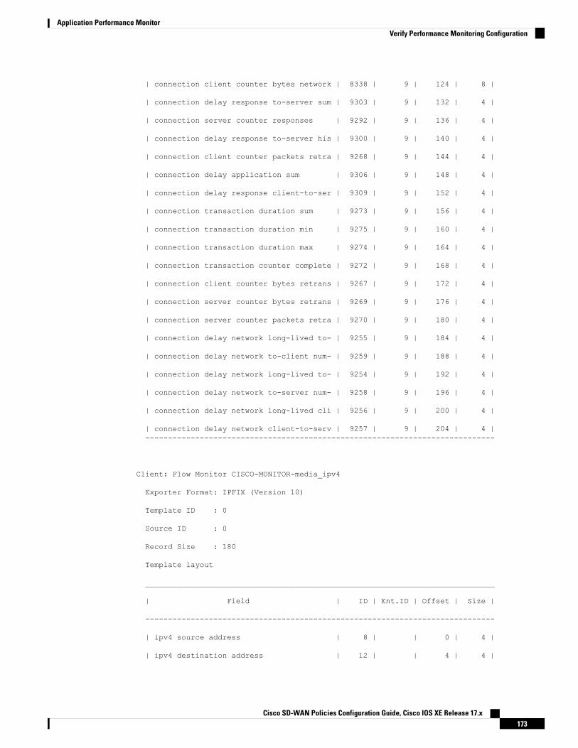
| connection client counter bytes network | 8338 | 9 | 124 | 8 |
| connection delay response to-server sum | 9303 | 9 | 132 | 4 |
| connection server counter responses | 9292 | 9 | 136 | 4 |
| connection delay response to-server his | 9300 | 9 | 140 | 4 |
| connection client counter packets retra | 9268 | 9 | 144 | 4 |
| connection delay application sum | 9306 | 9 | 148 | 4 |
| connection delay response client-to-ser | 9309 | 9 | 152 | 4 |
| connection transaction duration sum | 9273 | 9 | 156 | 4 |
| connection transaction duration min | 9275 | 9 | 160 | 4 |
| connection transaction duration max | 9274 | 9 | 164 | 4 |
| connection transaction counter complete | 9272 | 9 | 168 | 4 |
| connection client counter bytes retrans | 9267 | 9 | 172 | 4 |
| connection server counter bytes retrans | 9269 | 9 | 176 | 4 |
| connection server counter packets retra | 9270 | 9 | 180 | 4 |
| connection delay network long-lived to- | 9255 | 9 | 184 | 4 |
| connection delay network to-client num- | 9259 | 9 | 188 | 4 |
| connection delay network long-lived to- | 9254 | 9 | 192 | 4 |
| connection delay network to-server num- | 9258 | 9 | 196 | 4 |
| connection delay network long-lived cli | 9256 | 9 | 200 | 4 |
| connection delay network client-to-serv | 9257 | 9 | 204 | 4 |-----------------------------------------------------------------------------
Client: Flow Monitor CISCO-MONITOR-media_ipv4
Exporter Format: IPFIX (Version 10)
Template ID : 0
Source ID : 0
Record Size : 180
Template layout
_____________________________________________________________________________
| Field | ID | Ent.ID | Offset | Size |
-----------------------------------------------------------------------------
| ipv4 source address | 8 | | 0 | 4 |
| ipv4 destination address | 12 | | 4 | 4 |
Cisco SD-WAN Policies Configuration Guide, Cisco IOS XE Release 17.x173
Application Performance MonitorVerify Performance Monitoring Configuration
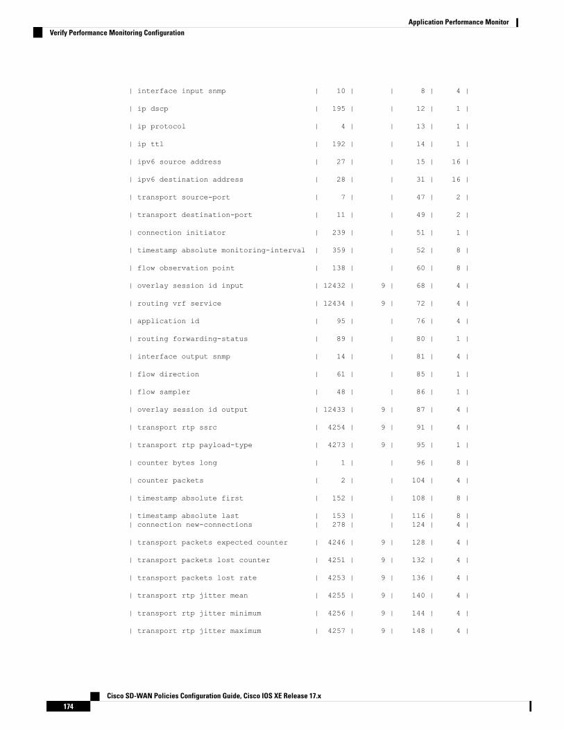
| interface input snmp | 10 | | 8 | 4 |
| ip dscp | 195 | | 12 | 1 |
| ip protocol | 4 | | 13 | 1 |
| ip ttl | 192 | | 14 | 1 |
| ipv6 source address | 27 | | 15 | 16 |
| ipv6 destination address | 28 | | 31 | 16 |
| transport source-port | 7 | | 47 | 2 |
| transport destination-port | 11 | | 49 | 2 |
| connection initiator | 239 | | 51 | 1 |
| timestamp absolute monitoring-interval | 359 | | 52 | 8 |
| flow observation point | 138 | | 60 | 8 |
| overlay session id input | 12432 | 9 | 68 | 4 |
| routing vrf service | 12434 | 9 | 72 | 4 |
| application id | 95 | | 76 | 4 |
| routing forwarding-status | 89 | | 80 | 1 |
| interface output snmp | 14 | | 81 | 4 |
| flow direction | 61 | | 85 | 1 |
| flow sampler | 48 | | 86 | 1 |
| overlay session id output | 12433 | 9 | 87 | 4 |
| transport rtp ssrc | 4254 | 9 | 91 | 4 |
| transport rtp payload-type | 4273 | 9 | 95 | 1 |
| counter bytes long | 1 | | 96 | 8 |
| counter packets | 2 | | 104 | 4 |
| timestamp absolute first | 152 | | 108 | 8 |
| timestamp absolute last | 153 | | 116 | 8 || connection new-connections | 278 | | 124 | 4 |
| transport packets expected counter | 4246 | 9 | 128 | 4 |
| transport packets lost counter | 4251 | 9 | 132 | 4 |
| transport packets lost rate | 4253 | 9 | 136 | 4 |
| transport rtp jitter mean | 4255 | 9 | 140 | 4 |
| transport rtp jitter minimum | 4256 | 9 | 144 | 4 |
| transport rtp jitter maximum | 4257 | 9 | 148 | 4 |
Cisco SD-WAN Policies Configuration Guide, Cisco IOS XE Release 17.x174
Application Performance MonitorVerify Performance Monitoring Configuration

| counter bytes rate | 4235 | 9 | 152 | 4 |
| application media bytes counter | 4236 | 9 | 156 | 4 |
| application media bytes rate | 4238 | 9 | 160 | 4 |
| application media packets counter | 4239 | 9 | 164 | 4 |
| application media packets rate | 4241 | 9 | 168 | 4 |
| transport rtp jitter mean sum | 4325 | 9 | 172 | 8 |
-----------------------------------------------------------------------------
For more information, see the show flow exporter command page.
Cisco SD-WAN Policies Configuration Guide, Cisco IOS XE Release 17.x175
Application Performance MonitorVerify Performance Monitoring Configuration

Cisco SD-WAN Policies Configuration Guide, Cisco IOS XE Release 17.x176
Application Performance MonitorVerify Performance Monitoring Configuration

C H A P T E R 12Enhanced Policy Based Routing
Table 30: Feature History
DescriptionRelease InformationFeature Name
This release extends Enhanced Policy Based Routing(ePBR) to Cisco SD-WAN. ePBR is aprotocol-independent traffic-steering mechanism thatroutes traffic based on flexible policies for trafficflows. You can create ePBR policies using CLI add-ontemplates in Cisco vManage.
Cisco IOS XE Release17.4.1a
Cisco vManage Release20.4.1
Enhanced Policy BasedRouting for CiscoSD-WAN
• Overview of ePBR, on page 177• Configure ePBR, on page 179• Monitor ePBR, on page 182
Overview of ePBREnhanced Policy Based Routing (ePBR) is an advanced version of Policy Based Routing (PBR). With thisfeature, traffic forwarding is based on policies rather than routing tables, and gives you more control overrouting. ePBR extends and complements the existing mechanisms provided by routing protocols. ePBR is anadvanced local data policy that routes traffic based on flexible match criteria such as IPv4 and IPv6 addresses,port numbers, protocols, or packet size.
ePBR matches traffic using flexible Cisco Common Classification Policy Language (C3PL language). Itsupports matching prefixes, applications, Differentiated Services Code Point (DSCP), Security Group Tags(SGT), and so on. With ePBR, based on match conditions, you can configure a single or multiple next hopsfor traffic forwarding. You also have the option to configure Internet Protocol Service Level Agreement (IPSLA) tracking. If a configured next hop is unavailable, traffic is routed to the next available hop throughdynamic probing enabled by the IP SLA tracker.
Features and Benefits
• Supports both IPv4 and IPv6.
• Supports multiple next hops; and if the next hop isn’t reachable, ePBR automatically switches to the nextavailable hop.
Cisco SD-WAN Policies Configuration Guide, Cisco IOS XE Release 17.x177

• You have the option to configure IP SLA tracking. If this is configured, the next hop is selected onlywhen the IP SLA probe is successful.
SLA probes can be configured in the same or a different VRF.
• If the current hop isn’t reachable, syslog messages are generated and the user is notified of the same.
How ePBR Works
• ePBR is applicable to unicast routing only and is based on traffic matching using C3PL.
• All packets received on an ePBR-enabled interface are passed through policy maps. The policy mapsused by ePBR dictate the policy, determining where to forward packets.
• ePBR policies are based on a classification criteria (match) and an action criteria (set) that are appliedto traffic flow.
• To enable ePBR, you must create a policy map that specifies the packet match criteria and desiredpolicy-route action. Then you associate the policy map on the required interface.
• The match criteria is specified in a class. The policy map then calls the class and takes action based onthe set statement.
• The set statements in ePBR policies define the route in terms of next hops, DSCP, VRFs, and so on.
Usage Example
Figure 14: Traffic Redirection with ePBR
This example shows that traffic is coming into VPN 1 interface. Based on the classification configured onVPN 1, the traffic overrides the regular route forwarding and is redirected to a next-hop in VPN 100, whereadditional network services are applied to the incoming traffic. Network services, such as WAN optimization,
Cisco SD-WAN Policies Configuration Guide, Cisco IOS XE Release 17.x178
Enhanced Policy Based RoutingOverview of ePBR
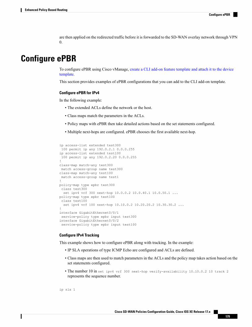
are then applied on the redirected traffic before it is forwarded to the SD-WAN overlay network through VPN0.
Configure ePBRTo configure ePBR using Cisco vManage, create a CLI add-on feature template and attach it to the devicetemplate.
This section provides examples of ePBR configurations that you can add to the CLI add-on template.
Configure ePBR for IPv4
In the following example:
• The extended ACLs define the network or the host.
• Class maps match the parameters in the ACLs.
• Policy maps with ePBR then take detailed actions based on the set statements configured.
• Multiple next-hops are configured. ePBR chooses the first available next-hop.
ip access-list extended test300100 permit ip any 192.0.2.1 0.0.0.255ip access-list extended test100100 permit ip any 192.0.2.20 0.0.0.255!class-map match-any test300match access-group name test300class-map match-any test100match access-group name test1!policy-map type epbr test300class test300set ipv4 vrf 300 next-hop 10.0.0.2 10.0.40.1 10.0.50.1 ...
policy-map type epbr test100class test100set ipv4 vrf 100 next-hop 10.10.0.2 10.20.20.2 10.30.30.2 ...
!interface GigabitEthernet0/0/1service-policy type epbr input test300interface GigabitEthernet0/0/2service-policy type epbr input test100
Configure IPv4 Tracking
This example shows how to configure ePBR along with tracking. In the example:
• IP SLA operations of type ICMP Echo are configured and ACLs are defined.
• Class maps are then used to match parameters in the ACLs and the policy map takes action based on theset statements configured.
• The number 10 in set ipv4 vrf 300 next-hop verify-availability 10.10.0.2 10 track 2
represents the sequence number.
ip sla 1
Cisco SD-WAN Policies Configuration Guide, Cisco IOS XE Release 17.x179
Enhanced Policy Based RoutingConfigure ePBR
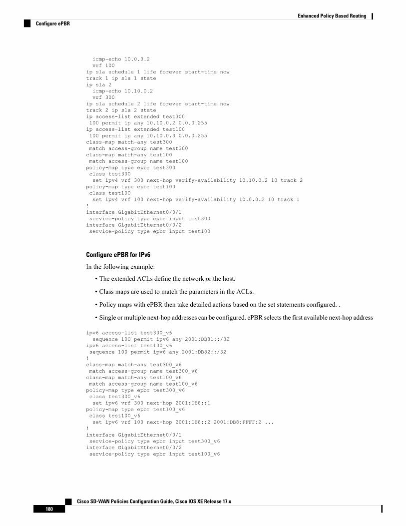
icmp-echo 10.0.0.2vrf 100
ip sla schedule 1 life forever start-time nowtrack 1 ip sla 1 stateip sla 2icmp-echo 10.10.0.2vrf 300
ip sla schedule 2 life forever start-time nowtrack 2 ip sla 2 stateip access-list extended test300100 permit ip any 10.10.0.2 0.0.0.255ip access-list extended test100100 permit ip any 10.10.0.3 0.0.0.255class-map match-any test300match access-group name test300class-map match-any test100match access-group name test100policy-map type epbr test300class test300set ipv4 vrf 300 next-hop verify-availability 10.10.0.2 10 track 2
policy-map type epbr test100class test100set ipv4 vrf 100 next-hop verify-availability 10.0.0.2 10 track 1
!interface GigabitEthernet0/0/1service-policy type epbr input test300interface GigabitEthernet0/0/2service-policy type epbr input test100
Configure ePBR for IPv6
In the following example:
• The extended ACLs define the network or the host.
• Class maps are used to match the parameters in the ACLs.
• Policy maps with ePBR then take detailed actions based on the set statements configured. .
• Single or multiple next-hop addresses can be configured. ePBR selects the first available next-hop address
ipv6 access-list test300_v6sequence 100 permit ipv6 any 2001:DB81::/32
ipv6 access-list test100_v6sequence 100 permit ipv6 any 2001:DB82::/32!class-map match-any test300_v6match access-group name test300_v6class-map match-any test100_v6match access-group name test100_v6policy-map type epbr test300_v6class test300_v6set ipv6 vrf 300 next-hop 2001:DB8::1
policy-map type epbr test100_v6class test100_v6set ipv6 vrf 100 next-hop 2001:DB8::2 2001:DB8:FFFF:2 ...
!interface GigabitEthernet0/0/1service-policy type epbr input test300_v6interface GigabitEthernet0/0/2service-policy type epbr input test100_v6
Cisco SD-WAN Policies Configuration Guide, Cisco IOS XE Release 17.x180
Enhanced Policy Based RoutingConfigure ePBR
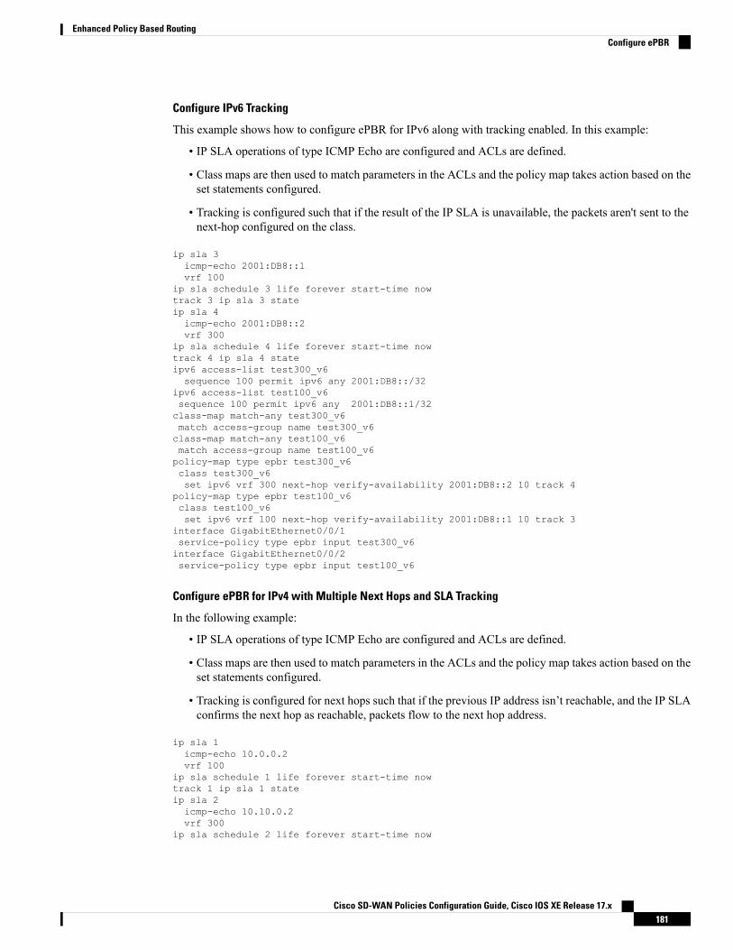
Configure IPv6 Tracking
This example shows how to configure ePBR for IPv6 along with tracking enabled. In this example:
• IP SLA operations of type ICMP Echo are configured and ACLs are defined.
• Class maps are then used to match parameters in the ACLs and the policy map takes action based on theset statements configured.
• Tracking is configured such that if the result of the IP SLA is unavailable, the packets aren't sent to thenext-hop configured on the class.
ip sla 3icmp-echo 2001:DB8::1vrf 100
ip sla schedule 3 life forever start-time nowtrack 3 ip sla 3 stateip sla 4icmp-echo 2001:DB8::2vrf 300
ip sla schedule 4 life forever start-time nowtrack 4 ip sla 4 stateipv6 access-list test300_v6sequence 100 permit ipv6 any 2001:DB8::/32
ipv6 access-list test100_v6sequence 100 permit ipv6 any 2001:DB8::1/32class-map match-any test300_v6match access-group name test300_v6class-map match-any test100_v6match access-group name test100_v6policy-map type epbr test300_v6class test300_v6set ipv6 vrf 300 next-hop verify-availability 2001:DB8::2 10 track 4
policy-map type epbr test100_v6class test100_v6set ipv6 vrf 100 next-hop verify-availability 2001:DB8::1 10 track 3
interface GigabitEthernet0/0/1service-policy type epbr input test300_v6interface GigabitEthernet0/0/2service-policy type epbr input test100_v6
Configure ePBR for IPv4 with Multiple Next Hops and SLA Tracking
In the following example:
• IP SLA operations of type ICMP Echo are configured and ACLs are defined.
• Class maps are then used to match parameters in the ACLs and the policy map takes action based on theset statements configured.
• Tracking is configured for next hops such that if the previous IP address isn’t reachable, and the IP SLAconfirms the next hop as reachable, packets flow to the next hop address.
ip sla 1icmp-echo 10.0.0.2vrf 100
ip sla schedule 1 life forever start-time nowtrack 1 ip sla 1 stateip sla 2icmp-echo 10.10.0.2vrf 300
ip sla schedule 2 life forever start-time now
Cisco SD-WAN Policies Configuration Guide, Cisco IOS XE Release 17.x181
Enhanced Policy Based RoutingConfigure ePBR

track 2 ip sla 2 stateip sla 3icmp-echo 10.20.0.2vrf 400
ip sla schedule 3 life forever start-time nowtrack 3 ip sla 3 stateip access-list extended test300100 permit ip any 192.0.2.1 255.255.255.0ip access-list extended test100100 permit ip any 192.0.2.10 255.255.255.0!class-map match-any test300match access-group name test300class-map match-any test100match access-group name test100!policy-map type epbr test300class test300set ipv4 vrf 300 next-hop verify-availability 10.10.0.2 10 track 2set ipv4 vrf 400 next-hop verify-availability 10.20.0.2 11 track 3
policy-map type epbr test100class test100set ipv4 vrf 100 next-hop verify-availability 10.0.0.2 10 track 1
!interface GigabitEthernet0/0/1service-policy type epbr input test300interface GigabitEthernet0/0/2service-policy type epbr input test100!
When next hops are configured along with the tracker, if the next hop is unreachable or if the IP SLA fails,the next available hop is selected. This means that when the tracker is configured, both next hop availabilityand IP SLA results are checked.
Note
Monitor ePBRePBR can't be monitored through Cisco vManage. To verify your configuration or monitor ePBR statistics,use the show commands described below.
Verify Availability of Next Hop
The following is sample output from the show platform software epbr track command.Device# show platform software epbr trackTrack Object:obj num:2:track:0x7F94B4376760seq:10, nhop:123.0.0.2, nhop_reachable:1, track_handle:0x7F94AFDAE240,global:0, vrf_name:300, track_reachable:1parent:0x7F94B4383778, oce:0x7F94B81193A8
obj num:1:track:0x7F94B8187810seq:10, nhop:100.0.0.2, nhop_reachable:1, track_handle:0x7F94AFDAE1D0,global:0, vrf_name:100, track_reachable:1parent:0x7F94B8187778, oce:0x7F94B81188B8
Cisco SD-WAN Policies Configuration Guide, Cisco IOS XE Release 17.x182
Enhanced Policy Based RoutingMonitor ePBR

In this example, nhop_reachable has the value 1, which indicates that the next hop is reachable.track_reachable represents the result of SLA probe and has the value 1, which indicates that the next hopis reachable. If the next hop isn’t reachable, the value would be 0 for these parameters.
View Next Hop Configuration
Use the show platform software epbr R0 feature-object redirect to view the next hop configuration.
To be able to view this output, you must have tracker configured.Note
Device# show platform software epbr r0 feature-object redirectFMAN EPBR Redirect Feature Objectep
Feature Object ID: 9876543211Flags: 0x3Table ID: 0x4Next-hop: 10.10.10.2P2P ADJ-ID: 0
Feature Object ID: 1234567890Flags: 0x3Table ID: 0x2Next-hop: 172.16.0.0P2P ADJ-ID: 0
Cisco SD-WAN Policies Configuration Guide, Cisco IOS XE Release 17.x183
Enhanced Policy Based RoutingMonitor ePBR
Cisco SD-WAN Policies Configuration Guide, Cisco IOS XE Release 17.x184
Enhanced Policy Based RoutingMonitor ePBR

C H A P T E R 13Forward Error Correction
Table 31: Feature History
DescriptionRelease InformationFeature Name
Feature introduced. FEC is a mechanism to recoverlost packets on a link by sending extra “parity” packetsfor every group (N) of packets.
Cisco IOS XE SD-WANRelease 16.11.x
Forward Error Correction
Forward Error Correction (FEC) is a mechanism to recover lost packets on a link by sending extra “parity”packets for every group (N) of packets. As long as the receiver receives a subset of packets in the group(at-least N-1) and the parity packet, up to a single lost packet in the group can be recovered. FEC is supportedon Cisco IOS XE SD-WAN devices.
• Configure Forward Error Correction for a Policy, on page 185• Monitor Forward Error Correction Tunnel Information, on page 186• Monitor Forward Error Application Family Information, on page 187
Configure Forward Error Correction for a Policy
Step 1 From the Cisco vManage menu, choose Configuration > Policies.Step 2 Click Centralized Policy and then click Add Policy.Step 3 Click Next.Step 4 Click Next again and then click Configure Traffic Rules.Step 5 Click Traffic Data, and from the Add Policy drop-down list, choose Create New.Step 6 Click Sequence Type.Step 7 From the Add Data Policy pop-up menu, choose QoS.Step 8 Click Sequence Rule.Step 9 In the Applications/Application Family List, choose one or more applications or lists.Step 10 Click Accept.Step 11 Click Actions and click Loss Correction.Step 12 In the Actions area, choose one of the following:
• FEC Adaptive: Only send FEC information when the loss detected by the system exceeds the packet loss threshold.
Cisco SD-WAN Policies Configuration Guide, Cisco IOS XE Release 17.x185

• FEC Always: Always send FEC information with every transmission.
• Packet Duplication check box: Duplicates packets through secondary links to reduce packet loss if one link goesdown.
Step 13 Click Save Match and Actions.Step 14 Click Save Data Policy.Step 15 Click Next and take these actions to create a centralized policy:
a) Enter a Name and a Description.b) Select Traffic Data Policy.c) Choose VPNs and a site list for the policy.d) Save the policy.
Monitor Forward Error Correction Tunnel Information
Step 1 From the Cisco vManage menu, choose Monitor > Devices.
Cisco vManage Release 20.6.x and earlier: From the Cisco vManage menu, choose Monitor > Network.
Step 2 Choose a device group.Step 3 In the left panel, click Tunnel, which displays under WAN.
The WAN tunnel information includes the following:
• A graph that shows the total tunnel loss for the selected tunnels.
• A table that provides the following information for each tunnel endpoint:
• Name of the tunnel endpoint
• Communications protocol that the endpoint uses
• State of the endpoint
• Jitter, in ms, on the endpoint
• Packet loss percentage for the endpoint
• Latency, in ms, on the endpoint
• Total bytes transmitted from the endpoint
• Total bytes received by the endpoint
• Application usage link
Cisco SD-WAN Policies Configuration Guide, Cisco IOS XE Release 17.x186
Forward Error CorrectionMonitor Forward Error Correction Tunnel Information

Monitor Forward Error Application Family Information
Step 1 From the Cisco vManage menu, choose Monitor > Devices.
Cisco vManage Release 20.6.x and earlier: From the Cisco vManage menu, choose Monitor > Network.
Step 2 Choose a device group.Step 3 In the left panel, click DPI Applications, which displays under Applications.
The FEC Recovery Rate application information includes the following:
• A graph for which you can choose the following perspective:
• Application Usage—Usage of various types of traffic for the selected application families, in KB.
• A table that provides the following for each application family:
• Name of the application family.
• Packet Delivery Performance for the application family.
If you need to see the packet delivery performance for the selected application family, ensure thatpacket duplication is enabled. Packet delivery performance is calculated based on the formula asdisplayed in the Cisco vManage tooltip for the Packet Delivery Performance column.
Note
• Traffic usage, in KB, MB, or GB for the selected application family.
Cisco SD-WAN Policies Configuration Guide, Cisco IOS XE Release 17.x187
Forward Error CorrectionMonitor Forward Error Application Family Information

Cisco SD-WAN Policies Configuration Guide, Cisco IOS XE Release 17.x188
Forward Error CorrectionMonitor Forward Error Application Family Information

C H A P T E R 14Packet Duplication for Noisy Channels
Table 32: Feature History
DescriptionRelease InformationFeature Name
This feature helps mitigate packet loss over noisychannels, thereby maintaining high application QoE forvoice and video.
Cisco IOSXESD-WANRelease 16.12.1b
Packet Duplication forNoisy Channels
• Information about Packet Duplication, on page 189• Configure Packet Duplication, on page 189• Monitor Packet Duplication Per Application, on page 190
Information about Packet DuplicationCisco IOS XE SD-WAN devices use packet duplication to overcome packet loss.
Packet duplication sends copies of packets on alternate available paths to reach Cisco IOS XE SD-WANdevices. If one of the packets is lost, a copy of the packet is forwarded to the server. Receiving Cisco IOS XESD-WAN devices discard copies of the packet and forward one packet to the server.
Packet duplication is suitable for edges with multiple access links. Once packet duplication is configured andpushed to your device, you can see the tunnel packet duplication statistics.
Packet duplication interop on Cisco IOSXE SD-WAN devices is not supported between Cisco IOSXERelease16.x and Cisco IOS XE Release 17.x versions.
Note
Configure Packet Duplication1. Select Configuration > Policies
2. Select Centralized Policy at the top of the page and then click Add Policy.
3. Click Next twice to select Configure Traffic Rules.
4. Select Traffic Data, and from the Add Policy drop-down, click Create New.
Cisco SD-WAN Policies Configuration Guide, Cisco IOS XE Release 17.x189

5. Click Sequence Type in the left pane.
6. From the Add Data Policy pop-up, select QoS.
7. Click Sequence Rule.
8. In the Applications/Application Family List/Data Prefix, Select one or more applications or lists.
9. Click Actions and select Loss Correction.
10. In the Actions area, select the Pack Duplication option to enable the packet duplication feature.
• FEC Adaptive—Only send Forward Error Correction (FEC) information when the system detectsa packet loss.
• FEC Always—Always send FEC information with every transmission.
• None—Use when no loss protection is needed.
• Packet Duplication—Enable when packets need to be duplicated and sent on the next availablelinks to reduce packet loss.
11. Click Save Match and Actions.
12. Click Save Data Policy.
13. Click Next and take these actions to create a Centralized Policy:
• Enter a Name and a Description.
• Select Traffic Data Policy.
• Choose VPNs/site list for the policy.
• Save the policy.
Monitor Packet Duplication Per Application1. Select Monitor > Network
2. Select a device group.
3. In the left pane, click Applications.
4. On the Application usage, select the application family of interest, and click on the Application familylisted.
5. If packet duplication is enabled for any application, vManage displays Packet Delivery Performance asGOOD, MODERATE, or POOR or the field displays as N/A.
6. GOOD and MODERATE performance is a clickable link. When clicking on the link, the status pops upa window.
7. On the pop-up window, you see Application, Packet Delivery Performance, Overall for the Application,Average Drop Rate, and Overall for the Application information. The time slot graph represents the packetstransmitted with different available link colors and the overall performance calculated when packetduplication is enabled.
Cisco SD-WAN Policies Configuration Guide, Cisco IOS XE Release 17.x190
Packet Duplication for Noisy ChannelsMonitor Packet Duplication Per Application

8. If you hover over the time slot, you can see the performance status and the average drop rate for eachlink.
Cisco SD-WAN Policies Configuration Guide, Cisco IOS XE Release 17.x191
Packet Duplication for Noisy ChannelsMonitor Packet Duplication Per Application

Cisco SD-WAN Policies Configuration Guide, Cisco IOS XE Release 17.x192
Packet Duplication for Noisy ChannelsMonitor Packet Duplication Per Application

C H A P T E R 15Integrate Cisco IOS XE SD-WAN Device withCisco ACI
Table 33: Feature History
DescriptionReleaseInformation
Feature Name
The Cisco IOS XE SD-WAN and Cisco ACI integration functionalitynow supports predefined SLA cloud beds. It also supports dynamicallygenerated mappings from a data prefix-list and includes a VPN list toan SLA class that is provided by Cisco ACI.
Cisco IOS XESD-WANRelease 16.12.1b
Integration withCisco ACI
Cisco ACI release 4.1(1) adds support for WAN SLA policies. This feature enables tenant administrators toapply preconfigured policies to specify the levels of packet loss, jitter, and latency for tenant traffic over theWAN. When a WAN SLA policy is applied to tenant traffic, the Cisco APIC sends the configured policiesto a Cisco vSmart Controller. The Cisco vSmart Controller, which is configured in Cisco ACI as an externaldevice manager that provides Cisco IOS XE SD-WAN capabilities, chooses the best possible WAN link thatmeets the loss, jitter, and latency parameters specified in the SLA policy.
The WAN SLA policies are applied to tenant traffic though contracts.
As an example of where this feature can be useful, consider a deployment in which branches connect to a datacenter over aWANusingmultiple transport technologies, such asMPLS, internet, and 4G. In such deployments,there can be multiple paths between the branches and data centers. This feature provides optimized pathselection in these situations based on application groups and SLA.
• Guidelines to Integrate with Cisco ACI, on page 194• Verify Cisco ACI Registration, on page 194• SLA Classes, on page 194• Data Prefixes, on page 195• VPNs, on page 195• Map Data Prefix and VPN to SLA, on page 195• Create an App-Route-Policy, on page 195• Map ACI Sites, on page 196• Unmap ACI Sites, on page 197• Delete a Controller, on page 197
Cisco SD-WAN Policies Configuration Guide, Cisco IOS XE Release 17.x193

Guidelines to Integrate with Cisco ACIThe general steps that you perform in Cisco vManage to configure the integration are:
1. Verify that Cisco ACI has registered the desired controller as a partner with a Cisco vSmart Controller,as described in the procedure, Verify Cisco ACI Registration, on page 194.
2. Attach devices to the Cisco vSmart Controller, as described in the Map ACI Sites section.
The following guidelines apply when integrating Cisco vManage with Cisco ACI:
• Only new Cisco IOS XE SD-WAN deployments support this integration.
• Make sure that any devices to which the Cisco APIC sends policies do not have any application-awarerouting policies configured for them.
• Make sure each device to which the Cisco APIC sends policies has an attached template.
• Before you begin the integration, use the CLI policy builder to create a centralized policy and activateit by using the Cisco vManage policy builder.
• Before you apply WAN SLA policies, establish a connection between the Cisco vSmart Controller andthe Cisco APIC. For instructions, see Cisco ACI and Cisco IOS XE SD-WAN Integration.
• Before you attach devices, configure Cisco ACI for this integration.
Verify Cisco ACI RegistrationAfter you configure Cisco ACI for integration with Cisco vManage, perform the following steps in the CiscovManage to verify that Cisco ACI has registered the desired controller as a Cisco vManage partner:
1. In Cisco vManage, select Administration > Integration Management.
The Integration Management page displays.
2. On the Integration Management page, verify that ACI Partner Registration appears in the Description forthe controller to which the Cisco APIC is to send policies.
SLA ClassesCisco vManage provides preconfigured SLA classes for use with the ACI integration. These SLA classes areavailable automatically and cannot be modified or deleted.
To view these SLA classes, follow these steps:
1. In Cisco vManage, select Configuration > Policies.
2. From the Custom Options drop-down menu, select Lists.
3. Select SLA Class from the type list on the left.
The following SLA classes are available:
Cisco SD-WAN Policies Configuration Guide, Cisco IOS XE Release 17.x194
Integrate Cisco IOS XE SD-WAN Device with Cisco ACIGuidelines to Integrate with Cisco ACI

• Business Normal—Designed for normal business operations
• Voice—Designed for voice operations
• Business Critical—Designed for critical business operations that require low packet loss and latency
• Business High—Designed for highly important business operations
Data PrefixesCisco ACI creates data prefix lists that are required for integration and updates these lists dynamically asrequired. You do not need to configure the data prefixes in Cisco vManage.
To view these data prefixes, follow these steps:
1. In Cisco vManage, select Configuration > Policies.
2. From the Custom Options drop-down menu, select Lists.
3. Select Data Prefix from the type list on the left.
Because Cisco ACI provides these data prefixes automatically, the information in this list can vary. To makesure you are viewing current information, refresh the page occasionally.
VPNsCisco ACI creates VPNs that are required for integration and sends them to Cisco vManage. These VPNsbecome available in Cisco vManage automatically. You do not need to configure the VPNs in Cisco vManage.
To view these VPNs, follow these steps:
1. In Cisco vManage, select Configuration > Policies.
2. From the Custom Options drop-down menu, select Lists.
3. Select VPN from the type list on the left.
Map Data Prefix and VPN to SLAAfter Cisco ACI establishes a mapping from a data prefix list and a VPN list to an SLA class, Cisco ACIsends the mapping to Cisco vManage. You can view these mappings in Cisco vManage on the page whereyou configure the app route policy.
Create an App-Route-PolicyAfter Cisco ACI maps a data prefix and a VPN to an SLA class list, you can create an app-rout-policy todefine sequence rules for the Cisco ACI integration.
To create an app-route-policy, follow these steps:
Cisco SD-WAN Policies Configuration Guide, Cisco IOS XE Release 17.x195
Integrate Cisco IOS XE SD-WAN Device with Cisco ACIData Prefixes

1. In Cisco vManage, select Configuration > Policies.
2. Click theMore Actions icon at the right of a row that contains a centralized policy, and then click Edit.
3. Select Traffic Rules.
4. Select Add Policy > Create New.
5. Click ACI Sequence Rules.
6. From the VPN drop-down, choose a VPN ID. Cisco vManage displays a list of data prefixes and SLAclasses that are mapped to this VPN. (These mappings were sent by Cisco ACI.)
7. Check the box to the left of the data prefix and SLA class that you want to include with the policy, andthen click Import.
8. Enter a name for the policy in the Name field and a description of the policy in the Description field,and then click Save Application Aware Routing Policy. Cisco vManage creates the policy.
9. To apply a site list and a VPN list to the policy, selectPolicy Application, then selectApplication-AwareRouting, and click New Site Lists and VPN List.
10. Select a site list and a VPN list for the policy.
11. Add sequence rules to the policy as needed.
12. Click Save Policy Changes.
Map ACI SitesMapping ACI sites designates the controller devices to which the policies from Cisco APIC apply.
Before you begin, review the guidelines in the Guidelines to Integrate with Cisco ACI section.
To attach devices to a controller, follow these steps:
1. In Cisco vManage, select Administration > Integration Management.
2. Click the More Actions icon to the right of the row for the applicable site and select Attach Devices.
3. In the Available Devices column on the left, select a group and search for one or more devices, select adevice from the list, or click Select All.
4. Click the arrow pointing right to move the device to the Selected Devices column on the right.
To remove devices from the Selected Devices column, in that column select a group and searchfor one or more devices, select a device from the list, or click Select All, and then click the arrowpointing left.
Note
5. Click Attach.
Cisco SD-WAN Policies Configuration Guide, Cisco IOS XE Release 17.x196
Integrate Cisco IOS XE SD-WAN Device with Cisco ACIMap ACI Sites
Unmap ACI SitesUnmapping ACI sites stops Cisco APIC policies from being applied to the unmapped devices.
To detach devices from a controller, follow these steps:
1. In Cisco vManage, select Administration > Integration Management.
The Integration Management page displays.
2. Click the More Actions icon to the right of the row for the applicable site and select Detach Devices.
3. In the Available Devices column on the left, select a group and search for one or more devices, select adevice from the list, or click Select All.
4. Click the arrow pointing right to move the device to the Selected Devices column on the right.
To remove devices from the Selected Devices column, in that column select a group and searchfor one or more devices, select a device from the list, or click Select All, and then click the arrowpointing left.
Note
5. Click Detach.
Delete a ControllerIf you want to remove a controller as a partner with Cisco ACI, we recommend that you remove its registrationby using Cisco ACI instead of deleting it in Cisco vManage. Deleting an ACI partner from Cisco vManageautomatically deletes the data prefixes and VPNs that Cisco ACI created for the partner.
Before you begin, remove from policy definitions and data prefix lists and VPN lists that ACI created andmake sure that these lists are not referenced from any policy.
1. In Cisco vManage, select Administration > Integration Management.
2. Detach all devices that are attached to the controller.
For instructions, see the Detach Devices from a Controller section.
3. Click the More Actions icon to the right of the row for the applicable site and select Delete Controller.
Cisco SD-WAN Policies Configuration Guide, Cisco IOS XE Release 17.x197
Integrate Cisco IOS XE SD-WAN Device with Cisco ACIUnmap ACI Sites

Cisco SD-WAN Policies Configuration Guide, Cisco IOS XE Release 17.x198
Integrate Cisco IOS XE SD-WAN Device with Cisco ACIDelete a Controller

C H A P T E R 16Define Custom Applications
Table 34: Feature History
DescriptionRelease InformationFeature Name
This feature adds support fordefining custom applications.
Cisco IOS XE Release 17.3.1a
Cisco vManage Release 20.3.1
Support for Defining CustomApplications
• Overview, on page 199• Define Custom Applications Using Cisco vManage, on page 201• View Custom Applications, on page 203
OverviewCisco Network-Based Application Recognition (NBAR) is a Cisco technology that performs deep packetinspection (DPI) on network traffic to identify network applications according to their traffic characteristics.
The specific traffic characteristics of a network application are called an application signatures. Cisco packagesthe signature for an application, together with other information, as a protocol. Cisco packages a large set ofprotocols, covering numerous commonly occurring network applications, as a Protocol Pack. Cisco updatesand distributes Protocol Packs regularly. They provide a database of network application signatures for NBARto use to identify network application traffic.
The term network applications is defined broadly, and may include all of the following, and more:
• Social media websites
• Voice over IP (VoIP) applications
• Streaming audio and video, such as Cisco Webex
• Cloud applications, such as for cloud storage
• SaaS applications
• Custom network applications specific to an organization
Identifying applications is useful for monitoring network traffic, configuring application-aware traffic policy,and more.
To summarize network application signatures, protocols, and Protocol Packs, and how NBAR uses them:
Cisco SD-WAN Policies Configuration Guide, Cisco IOS XE Release 17.x199

• The traffic of a network application has unique characteristics that can be used to identify the traffic asbelonging to that specific application. These characteristics are called application signatures.
• Cisco packages the signature for a specific network application as a protocol.
• Cisco packages a large set of protocols, covering commonly occurring internet applications, as ProtocolPacks.
• Cisco NBAR performs deep packet inspection on traffic to gather the information required to identifythe sources of the traffic, and uses protocols, such as those provided in Protocol Packs, to match thatinformation to specific network applications. The result is that NBAR identifies the network applicationsproducing traffic in the network.
Cisco Software-Defined Application Visibility and Control (SD-AVC) uses Cisco NBAR applicationidentification to provide information about application usage within a network.
Custom Applications
In addition to the standard protocols provided in a Protocol Pack, you can define protocols, called customapplications, to identify internet traffic, often for uncommon network applications that are of specific interestto their organization. Custom applications augment the protocols provided in a Protocol Pack.
You can use custom applications in the same way as any other protocol when configuring:
• Cisco SD-WAN policies
• ApplicationQuality of Experience (AppQoE) policies, such as application-aware routing, TCP acceleration,and Quality of Service (QoS)
The following terms are used in the documentation of related technologies, and are equivalent: customapplications, custom protocols, user-defined applications
Note
Custom Applications in Cisco SD-WAN
One function of Cisco SD-AVC, which is included as a component of Cisco SD-WAN, is to create andmanagecustom applications. Cisco SD-WAN uses this Cisco SD-AVC functionality, through SD-AVC REST APIs,to enable you to define custom applications within Cisco SD-WAN.
As a Cisco SD-WAN user, you can use Cisco vManage to define custom applications. Cisco SD-AVC thenpushes the custom applications to devices in the network. The devices in the network use the custom applicationsand other application protocols to analyze traffic traversing the devices.
The process of defining a custom protocol includes choosing criteria to identify network traffic as comingfrom a specific network application. The criteria can include characteristics of hosts originating the traffic,such as server names, IP addresses, and so on.
Priority of Protocols and Custom Applications
It is possible to define custom applications that match some of the same traffic as a protocol included in theProtocol Pack operating with Cisco NBAR. When matching traffic, custom applications have priority overProtocol Pack protocols.
Cisco SD-WAN Policies Configuration Guide, Cisco IOS XE Release 17.x200
Define Custom ApplicationsOverview

Define Custom Applications Using Cisco vManagePrerequisite: Install Cisco SD-AVC as a component of Cisco SD-WAN.
1. In Cisco vManage, select Configuration > Policies.
2. Select Centralized Policy.
3. Click Custom Options and select Centralized Policy > Lists.
4. Click Custom Applications, and then click New Custom Application.
5. To define the application, provide an application name and enter match criteria. The match criteria caninclude one or more of the attributes provided: server names, IP addresses, and so on. You do not needto enter match criteria for all fields.
The match logic follows these rules:
• Between all L3/L4 attributes, there is a logical AND. Traffic must match all conditions.
• Between L3/L4 and Server Names, there is a logical OR. Traffic must match either the server nameor the L3/L4 attributes.
DescriptionField
(mandatory)
Enter a name for the custom application.
Maximum length: 32 characters
Application Name
One or more server names, separated by commas.
You can include an asterisk wildcard match character (*) only at the beginningof the server name.
Examples:
*cisco.com, *.cisco.com (match www.cisco.com, developer.cisco.com, …)
See Notes and Limitations, on page 202.
Server Names
L3/L4 Attributes
Enter one or more IPv4 addresses, separated by commas.
Example:
10.0.1.1, 10.0.1.2
The subnet prefix range is 24 to 32.Note
IP Address
Enter one or more ports or port ranges, separated by commas.
Example:
30, 45-47
Ports
Cisco SD-WAN Policies Configuration Guide, Cisco IOS XE Release 17.x201
Define Custom ApplicationsDefine Custom Applications Using Cisco vManage

DescriptionField
Select one of the following:
TCP, UDP, TCP-UDP
L4 Protocol
6. Click Add. The new custom application appears in the table of custom applications.
To check the progress of creating the new custom application, click Tasks (clipboard icon). A panel opens,showing active and completed processes.
Note
Notes and Limitations
• Maximum number of custom applications: 1100
• Maximum number of L3/L4 rules: 20000
• Maximum number of server names: 50000
• For server names, maximum instances of wildcard followed by a period (.): 50000
Example: *.cisco.com matches www.cisco.com, developer.cisco.com
• For server names, maximum instances of prefix wildcard as part of server name: 256
Example: *ample.com matches www.example.com
• Mapping the same domain to two different custom applications is not supported.
• Activation of custom applications:
• When using Cisco vManage releases earlier than 20.5.1: For devices using releases earlier thanCisco IOS XE 17.5.1, the activation of custom applications is as follows:
• A custom application created in Cisco vManage is not activated for visibility functionality(monitoring traffic) or control functionality (traffic policy) until a policy that makes use of thecustom application is applied.
• When using Cisco vManage Release 20.5.1 or later: For devices using Cisco IOSXERelease 17.5.1aor later, the activation of custom applications is as follows:
• A custom application created in Cisco vManage is activated immediately for applicationvisibility functionality only (monitoring traffic), such as for protocol-discovery counters andFlexible NetFlow (FNF). When activated for visibility functionality only, custom applicationsdo not affect traffic policy.
• When the custom application is used by a policy, it becomes activated for control functionality(traffic policy) also.
Cisco SD-WAN Policies Configuration Guide, Cisco IOS XE Release 17.x202
Define Custom ApplicationsDefine Custom Applications Using Cisco vManage
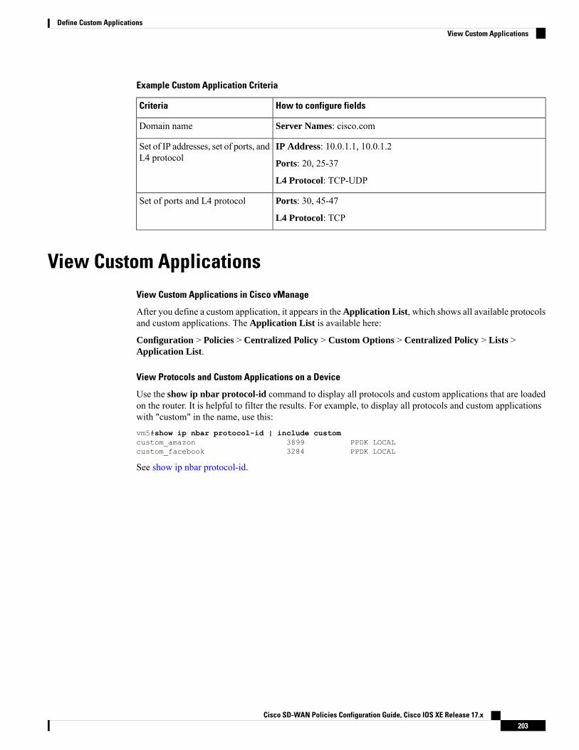
Example Custom Application Criteria
How to configure fieldsCriteria
Server Names: cisco.comDomain name
IP Address: 10.0.1.1, 10.0.1.2
Ports: 20, 25-37
L4 Protocol: TCP-UDP
Set of IP addresses, set of ports, andL4 protocol
Ports: 30, 45-47
L4 Protocol: TCP
Set of ports and L4 protocol
View Custom ApplicationsView Custom Applications in Cisco vManage
After you define a custom application, it appears in theApplication List, which shows all available protocolsand custom applications. The Application List is available here:
Configuration > Policies > Centralized Policy > Custom Options > Centralized Policy > Lists >Application List.
View Protocols and Custom Applications on a Device
Use the show ip nbar protocol-id command to display all protocols and custom applications that are loadedon the router. It is helpful to filter the results. For example, to display all protocols and custom applicationswith "custom" in the name, use this:vm5#show ip nbar protocol-id | include customcustom_amazon 3899 PPDK LOCALcustom_facebook 3284 PPDK LOCAL
See show ip nbar protocol-id.
Cisco SD-WAN Policies Configuration Guide, Cisco IOS XE Release 17.x203
Define Custom ApplicationsView Custom Applications

Cisco SD-WAN Policies Configuration Guide, Cisco IOS XE Release 17.x204
Define Custom ApplicationsView Custom Applications
C H A P T E R 17Service Chaining
Table 35: Feature History
DescriptionRelease InformationFeature Name
This feature extends support forservice chaining to Cisco IOS XESD-WAN devices. On Cisco IOSXE SD-WAN devices and CiscovEdge devices, it adds a trackingfeature that logs the availability ofa service.
Cisco IOS XE Release 17.3.1a
Cisco vManage Release 20.3.1
Service insertion tracker support
Service chaining allows data traffic to be rerouted through one or more services, such as firewall, load balancer,and intrusion detection and prevention (IDP) devices.
Services in the Network
Services such as firewall, load balancer, and intrusion detection and prevention (IDP) are often run within avirtualized environment, and they may physically be centralized in one location or in several locations forredundancy. Services may be internal, cloud based, or external subscriptions. Networks must be able to reroutetraffic from any location in the network through such services.
Customers want the ability to internally spawn or externally subscribe to new services on demand—forcapacity, redundancy, or simply to select best-of-breed technologies. For example, if a firewall site exceedsits capacity, a customer can spawn new firewall service at a new location. Supporting this new firewall wouldrequire the configuration of policy-based, weighted load distribution to multiple firewalls.
Following are some of the reasons to reroute a traffic flow through a service or chain of services:
• Traffic flow from a less secure region of a network must pass through a service, such as a firewall, orthrough a chain of services to ensure that it has not been tampered with.
• For a network that consists of multiple VPNs, each representing a function or an organization, trafficbetween VPNs must traverse through a service, such as a firewall, or through a chain of services. Forexample, in a campus, interdepartmental traffic might go through a firewall, while intradepartmentaltraffic might be routed directly.
• Certain traffic flows must traverse a service, such as a load balancer.
Cisco SD-WAN Policies Configuration Guide, Cisco IOS XE Release 17.x205

Today, the only way to reroute traffic flow is by provisioning every routing node—from the source to theservice node to the systems beyond the service node—with a policy route. This is done either by having anoperator manually configure each node or by using a provisioning tool that performs the configuration foreach node on behalf of the operator. Either way, the process is operationally complex to provision, maintain,and troubleshoot.
Provisioning Services in the Cisco SD-WAN Overlay Network
In the Cisco SD-WAN solution, the network operator can enable and orchestrate all service chaining from acentral controller, that is, from the Cisco vSmart Controller. No configuration or provisioning is required onany of the devices.
The general flow of service chaining in a Cisco SD-WAN network is as follows:
• Devices advertise the services available in their branch or campus—such as firewall, IDS, and IDP—tothe Cisco vSmart Controllers in their domain. Multiple devices can advertise the same services.
• Devices also advertise their OMP routes and TLOCs to the Cisco vSmart Controllers.
• For traffic that requires services, the policy on the Cisco vSmart Controller changes the next hop for theOMP routes to the service landing point. In this way, the traffic is first processed by the service beforebeing routed to its final destination.
The following figure illustrates how service chaining works in the Cisco SD-WAN solution. The networkshown has a centralized hub router that is connected to two branches, each with a device. The standard networkdesign implements a control policy such that all traffic from branch site 1 to branch site 2 travels through thehub router. Sitting behind the hub router is a firewall device. So now, assume we want all traffic from site 1to site 2 to first be processed by the firewall. Traffic from the device at site 1 still flows to the hub router, butinstead of sending it directly to site 2, the hub router redirects the traffic to the firewall device. When thefirewall completes its processing, it returns all cleared traffic to the hub, which then passes it along to thedevice at site 2.
Service Route SAFI
The hub and local branch devices advertise the services available in their networks to the Cisco vSmartControllers in its domain using service routes, which are sent by way of OMP using the service route SubsequentAddress Family Identifier (SAFI) bits of the OMP NLRI. The Cisco vSmart Controllers maintain the serviceroutes in their RIB, and they do not propagate these routes to the devices.
Each service route SAFI has the following attributes:
• VPN ID (vpn-id)—Identifies the VPN that the service belongs to.
• Service ID (svc-id)—Identifies the service being advertised by the service node. The Cisco SD-WANsoftware has the following predefined services:
• FW, for firewall (maps to svc-id 1)
Cisco SD-WAN Policies Configuration Guide, Cisco IOS XE Release 17.x206
Service Chaining
• IDS, for Intrusion Detection Systems (maps to svc-id 2)
• IDP, for Identity Providers (maps to svc-id 3)
• netsvc1, netsvc2, netsvc3, and netsvc4, which are reserved for custom services (they map to svc-id4, 5, 6, and 7, respectively)
• Label—For traffic that must traverse a service, the Cisco vSmart Controller replaces the label in theOMP route with the service label in order to direct the traffic to that service.
• Originator ID (originator-id)—The IP address of the service node that is advertising the service.
• TLOC—The transport location address of the device that is “hosting” the service.
• Path ID (path-id)—An identifier of the OMP path.
Service Chaining Policy
To route traffic through a service, you provision either a control policy or a data policy on the Cisco vSmartController. You use a control policy if the match criteria are based on a destination prefix or any of its attributes.You use a data policy if the match criteria include the source address, source port, DSCP value, or destinationport of the packet or traffic flow. You can provision the policy directly using the CLI, or it can be pushedfrom Cisco vManage.
The Cisco vSmart Controller maintains OMP routes, TLOC routes, and service routes in its route table. Agiven OMP route carries a TLOC and the label associated with it. On a Cisco vSmart Controller, a policy canbe applied that changes the TLOC and its associated label to be that of a service.
Tracking the Health of the Service Chain
Beginning with Cisco IOSXERelease 17.3.1a, Cisco SD-WAN periodically probes devices providing networkservices to test whether they are operational. Tracking the availability of devices in the service chain helps toprevent a null route, which can occur if a policy routes traffic to a service device which is not available. Bydefault, Cisco SD-WAN writes the tracking results to a service log, but this can be disabled.
Service insertion over tunnel interface is not supported on Cisco IOS XE SD-WAN devices.Note
• Configure Service Chaining, on page 208• Service Chaining Configuration Examples, on page 210• Monitor Service Chaining, on page 215
Cisco SD-WAN Policies Configuration Guide, Cisco IOS XE Release 17.x207
Service Chaining
Configure Service ChainingTable 36: Feature History
DescriptionRelease InformationFeature Name
This feature extends support forservice chaining to Cisco IOS XESD-WAN devices. On Cisco IOSXE SD-WAN devices and CiscovEdge devices, it adds a trackingfeature that logs the availability ofa service.
Cisco IOS XE Release 17.3.1a
Cisco vManage Release 20.3.1
Service insertion tracker support
Here is the workflow for configuring service chaining for a device managed by Cisco SD-WAN:
1. Service devices are accessed through a specific VRF. In the VPN template that corresponds to the VRFfor a service device, configure service chaining, specifying the service type and device addresses. Bydefault, the tracking feature adds each service device status update to the service log. You can disable thisin the VPN template.
2. Attach the VPN template to the device template for the device managed by Cisco SD-WAN.
3. Apply the device template to the device.
Configure Service Chaining Using Cisco vManage
To configure service chaining for a device.
1. In Cisco vManage, create a VPN template.
2. ClickService.
3. In the Service section, click New Service and configure the following:
• Service Type: Select the type of service that the service device is providing.
• IP Address: IP Address is the only working option.
• IPv4 Address: Enter between one and four addresses for the device.
• Tracking: Determines whether the periodic health updates of the service device are recorded in thesystem log. Default: On
Maximum number of services: 8Note
4. Click Add. The service appears in the table of configured services.
Cisco SD-WAN Policies Configuration Guide, Cisco IOS XE Release 17.x208
Service ChainingConfigure Service Chaining

CLI Equivalent for Cisco IOS XE SD-WAN Devices
The following table shows how configuration of service chaining by CLI corresponds to configuration inCisco vManage. CLI configuration differs between Cisco IOSXE SD-WAN devices and Cisco vEdge devices.The CLI example below is for a Cisco IOS XE SD-WAN device.
Cisco vManageCLI (Cisco IOS XE SD-WAN device)
In Cisco vManage, configure service insertion in the VPNtemplate for a specific VRF—VRF 10 in this example.
Select the service type from the drop-down —firewall in thisexample.
service firewall vrf 10
When adding a service in the VPN template Service, select Onor Off for Tracking.
no track-enable
Default: enabledNote
In the VRF template Service, enter one or more IP addresses forthe service device providing a specific service.
ipv4 address 10.0.2.1 10.0.2.2
CLI Example
sdwanservice firewall vrf 10ipv4 address 10.0.2.1 10.0.2.2
commit
CLI Equivalent for Cisco vEdge Devices
The following table shows how configuration of service chaining by CLI corresponds to configuration inCisco vManage. CLI configuration differs between Cisco IOSXE SD-WAN devices and Cisco vEdge devices.The CLI example below is for a Cisco vEdge device.
Cisco vManageCLI (Cisco vEdge device)
In Cisco vManage, configure service insertion in the VPNtemplate—VPN 10 in this example.
Select the service type from the drop-down—firewall in thisexample.
vpn 10
Select the service type from the drop-down—firewall in thisexample. Provide one or more addresses for the service device.
service FW address 10.0.2.1
When adding a service in the VPN template Service, select Onor Off for Tracking.
no track-enable
Default: enabledNote
CLI Example
vpn 10service FW address 10.0.2.1
commit
Cisco SD-WAN Policies Configuration Guide, Cisco IOS XE Release 17.x209
Service ChainingConfigure Service Chaining
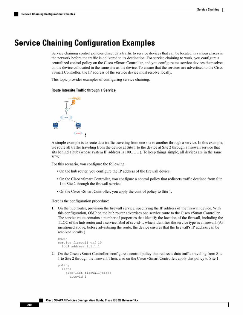
Service Chaining Configuration ExamplesService chaining control policies direct data traffic to service devices that can be located in various places inthe network before the traffic is delivered to its destination. For service chaining to work, you configure acentralized control policy on the Cisco vSmart Controller, and you configure the service devices themselveson the device collocated in the same site as the device. To ensure that the services are advertised to the CiscovSmart Controller, the IP address of the service device must resolve locally.
This topic provides examples of configuring service chaining.
Route Intersite Traffic through a Service
A simple example is to route data traffic traveling from one site to another through a service. In this example,we route all traffic traveling from the device at Site 1 to the device at Site 2 through a firewall service thatsits behind a hub (whose system IP address is 100.1.1.1). To keep things simple, all devices are in the sameVPN.
For this scenario, you configure the following:
• On the hub router, you configure the IP address of the firewall device.
• On the Cisco vSmart Controller, you configure a control policy that redirects traffic destined from Site1 to Site 2 through the firewall service.
• On the Cisco vSmart Controller, you apply the control policy to Site 1.
Here is the configuration procedure:
1. On the hub router, provision the firewall service, specifying the IP address of the firewall device. Withthis configuration, OMP on the hub router advertises one service route to the Cisco vSmart Controller.The service route contains a number of properties that identify the location of the firewall, including theTLOC of the hub router and a service label of svc-id-1, which identifies the service type as a firewall. (Asmentioned above, before advertising the route, the device ensures that the firewall's IP address can beresolved locally.)sdwanservice firewall vrf 10ipv4 address 1.1.1.1
2. On the Cisco vSmart Controller, configure a control policy that redirects data traffic traveling from Site1 to Site 2 through the firewall. Then, also on the Cisco vSmart Controller, apply this policy to Site 1.policylistssite-list firewall-sitessite-id 1
Cisco SD-WAN Policies Configuration Guide, Cisco IOS XE Release 17.x210
Service ChainingService Chaining Configuration Examples

control-policy firewall-servicesequence 10match routesite-id 2
action acceptset service FW vpn 10
default-action acceptapply-policysite-list firewall-sites control-policy firewall-service out
This policy configuration does the following:
• Create a site list called firewall-sites that is referenced in the apply-policy command and thatenumerates all the sites that this policy applies to. If you later want to scale this policy so that alltraffic destined to Site 2 from other sites should also first pass through the firewall, all you need todo is add the additional site IDs to the firewall-sites site list. You do not need to change anything inthe control-policy firewall-service portion of the configuration.
• Define a control policy named firewall-service. This policy has one sequence element and thefollowing conditions:
• Match routes destined for Site 2.
• If a match occurs, accept the route and redirect it to the firewall service provided by the Hubrouter, which is located in VPN 10.
• Accept all nonmatching traffic. That is, accept all traffic not destined for Site 2.
• Apply the policy to the sites listed in firewall-list, that is, to Site 1. The Cisco vSmart controllerapplies the policy in the outbound direction, that is, on routes that it redistributes to Site 1. In theseroutes:
• The TLOC is changed from Site 2’s TLOC to the hub router’s TLOC. This is the TLOC thatthe Cisco vSmart Controller learned from the service route received from the hub router. It isbecause of the change of TLOC that traffic destined for Site 2 is directed to the hub router
• The label is changed to svc-id-1, which identifies the firewall service. This label causes the hubrouter to direct the traffic to the firewall device.
When the hub router receives the traffic, it forwards it to the address 1.1.1.1, which is the system IP addressof the firewall. After the firewall has finished processing the traffic, the firewall returns the traffic to thehub router, and this router then forwards it to its final destination, which is Site 2.
Route Inter-VPN Traffic through a Service Chain with One Service per Node
Cisco SD-WAN Policies Configuration Guide, Cisco IOS XE Release 17.x211
Service ChainingService Chaining Configuration Examples
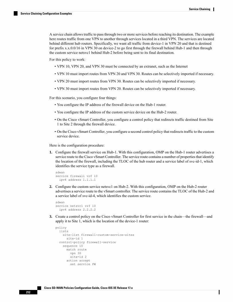
A service chain allows traffic to pass through two or more services before reaching its destination. The examplehere routes traffic from one VPN to another through services located in a third VPN. The services are locatedbehind different hub routers. Specifically, we want all traffic from device-1 in VPN 20 and that is destinedfor prefix x.x.0.0/16 in VPN 30 on device-2 to go first through the firewall behind Hub-1 and then throughthe custom service netsvc1 behind Hub-2 before being sent to its final destination.
For this policy to work:
• VPN 10, VPN 20, and VPN 30 must be connected by an extranet, such as the Internet
• VPN 10 must import routes from VPN 20 and VPN 30. Routes can be selectively imported if necessary.
• VPN 20 must import routes from VPN 30. Routes can be selectively imported if necessary.
• VPN 30 must import routes from VPN 20. Routes can be selectively imported if necessary.
For this scenario, you configure four things:
• You configure the IP address of the firewall device on the Hub-1 router.
• You configure the IP address of the custom service device on the Hub-2 router.
• On the Cisco vSmart Controller, you configure a control policy that redirects traffic destined from Site1 to Site 2 through the firewall device.
• On the Cisco vSmart Controller, you configure a second control policy that redirects traffic to the customservice device.
Here is the configuration procedure:
1. Configure the firewall service on Hub-1. With this configuration, OMP on the Hub-1 router advertises aservice route to the Cisco vSmart Controller. The service route contains a number of properties that identifythe location of the firewall, including the TLOC of the hub router and a service label of svc-id-1, whichidentifies the service type as a firewall.sdwanservice firewall vrf 10ipv4 address 1.1.1.1
2. Configure the custom service netsvc1 on Hub-2. With this configuration, OMP on the Hub-2 routeradvertises a service route to the vSmart controller. The service route contains the TLOC of the Hub-2 anda service label of svc-id-4, which identifies the custom service.sdwanservice netsvc1 vrf 10ipv4 address 2.2.2.2
3. Create a control policy on the Cisco vSmart Controller for first service in the chain—the firewall—andapply it to Site 1, which is the location of the device-1 router:policylistssite-list firewall-custom-service-sitessite-id 1
control-policy firewall-servicesequence 10match routevpn 30site-id 2
action acceptset service FW
Cisco SD-WAN Policies Configuration Guide, Cisco IOS XE Release 17.x212
Service ChainingService Chaining Configuration Examples

default-action acceptapply-policysite-list firewall-custom-service-sites control-policy firewall-service out
This policy configuration does the following:
• Create a site list called firewall-custom-service-sites that is referenced in the apply-policy commandand that enumerates all the sites that this policy applies to.
• Define a control policy named firewall-service that has one sequence element and the followingconditions:
• Match routes destined for both VPN 30 and Site 2.
• If a match occurs, accept the route and redirect it to a firewall service.
• If a match does not occur, accept the traffic.
• Apply the policy to the sites in the firewall-custom-service-sites site list, that is, to Site 1. The CiscovSmart controller applies this policy in the outbound direction, that is, on routes that it redistributesto Site 1. In these routes:
• The TLOC is changed from Site 2’s TLOC to the Hub-1 router’s TLOC. This is the TLOC thatthe Cisco vSmart Controller learned from the service route received from the hub. It is becauseof the change of TLOC that traffic destined for Site 2 is directed to the Hub-1 router.
• The label is changed to svc-id-1, which identifies the firewall service. This label causes theHub-1 router to direct the traffic to the firewall device.
When the Hub-1 router receives the traffic, it forwards it to the address 1.1.1.1, which is the system IPaddress of the firewall. After the firewall completes processing the traffic, it returns the traffic to the Hub-1router, which, because of the policy defined in the next step, forwards it to the Hub-2 router.
4. Create a control policy on the Cisco vSmart Controller for the second service in the chain, which is thecustom service, and apply it to the site of the Hub-1 router:policysite-list custom-servicesite-id 3
control-policy netsvc1-servicesequence 10match routevpn 30site-id 2
action acceptset service netsvc1
default-action acceptapply-policysite-list custom-service control-policy netsvc1-service out
This policy configuration does the following:
• Create a site list called custom-service that is referenced in the apply-policy command and thatenumerates all the sites that this policy applies to.
• Define a control policy named netsvc1-service that has one sequence element and the followingconditions:
• Match routes destined for both VPN 30 and Site 2.
• If a match occurs, accept the route and redirect it to the custom service.
Cisco SD-WAN Policies Configuration Guide, Cisco IOS XE Release 17.x213
Service ChainingService Chaining Configuration Examples
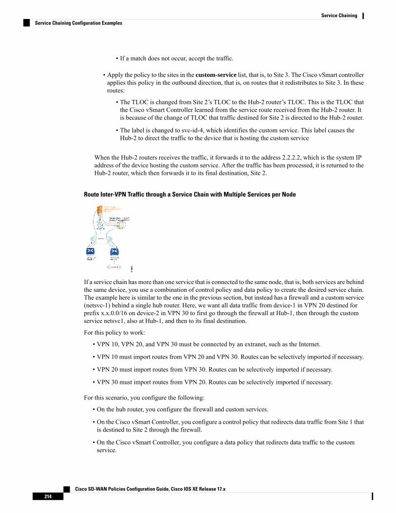
• If a match does not occur, accept the traffic.
• Apply the policy to the sites in the custom-service list, that is, to Site 3. The Cisco vSmart controllerapplies this policy in the outbound direction, that is, on routes that it redistributes to Site 3. In theseroutes:
• The TLOC is changed from Site 2’s TLOC to the Hub-2 router’s TLOC. This is the TLOC thatthe Cisco vSmart Controller learned from the service route received from the Hub-2 router. Itis because of the change of TLOC that traffic destined for Site 2 is directed to the Hub-2 router.
• The label is changed to svc-id-4, which identifies the custom service. This label causes theHub-2 to direct the traffic to the device that is hosting the custom service
When the Hub-2 routers receives the traffic, it forwards it to the address 2.2.2.2, which is the system IPaddress of the device hosting the custom service. After the traffic has been processed, it is returned to theHub-2 router, which then forwards it to its final destination, Site 2.
Route Inter-VPN Traffic through a Service Chain with Multiple Services per Node
If a service chain has more than one service that is connected to the same node, that is, both services are behindthe same device, you use a combination of control policy and data policy to create the desired service chain.The example here is similar to the one in the previous section, but instead has a firewall and a custom service(netsvc-1) behind a single hub router. Here, we want all data traffic from device-1 in VPN 20 destined forprefix x.x.0.0/16 on device-2 in VPN 30 to first go through the firewall at Hub-1, then through the customservice netsvc1, also at Hub-1, and then to its final destination.
For this policy to work:
• VPN 10, VPN 20, and VPN 30 must be connected by an extranet, such as the Internet.
• VPN 10 must import routes from VPN 20 and VPN 30. Routes can be selectively imported if necessary.
• VPN 20 must import routes from VPN 30. Routes can be selectively imported if necessary.
• VPN 30 must import routes from VPN 20. Routes can be selectively imported if necessary.
For this scenario, you configure the following:
• On the hub router, you configure the firewall and custom services.
• On the Cisco vSmart Controller, you configure a control policy that redirects data traffic from Site 1 thatis destined to Site 2 through the firewall.
• On the Cisco vSmart Controller, you configure a data policy that redirects data traffic to the customservice.
Cisco SD-WAN Policies Configuration Guide, Cisco IOS XE Release 17.x214
Service ChainingService Chaining Configuration Examples

Here is the configuration procedure:
1. On the hub router, configure the firewall and custom services:sdwanservice firewall vrf 10ipv4 address 1.1.1.1
service netsvc1 vrf 10ipv4 address 2.2.2.2
With this configuration, OMP on the hub router advertises two service routes to the Cisco vSmart Controller,one for the firewall and the second for the custom service netsvc1. Both service routes contain the TLOCof the Hub-1 router and a service label that identifies the type of service. For the firewall service, the labelis svc-id-1, and for the custom service, the label is svc-id-4.
2. On the Cisco vSmart Controller, configure a control policy controller to reroute traffic destined for VPN30 (at Site 2) to firewall service that is connected to Hub-1 (at Site 3), and apply this policy to Site 1:policylistssite-list device-1site-id 1
control-policy firewall-servicesequence 10match routevpn 30
action acceptset service FW
apply-policysite-list device-1 control-policy firewall-service out
3. On the Cisco vSmart Controller, configure a data policy that redirects, or chains, the data traffic receivedfrom the firewall device to the custom service netsvc1. Then apply this policy to Hub-1. This data policyroutes packets headed for destinations in the network x.x.0.0/16 to the IP address 2.2.2.2, which is thesystem IP address of the device hosting the custom service.policylistssite-list device-2site-id 2
site-list Hub-1site-id 3
prefix-list svc-chainip-prefix x.x.0.0/16
vpn-list vpn-10vpn 10
data-policy netsvc1-policyvpn-list vpn-10sequence 1matchip-destination x.x.0.0/16
action acceptset next-hop 2.2.2.2
apply-policysite-list Hub-1 data-policy netsvc1-policy from-service
Monitor Service ChainingYou can monitor different aspects of service chaining on hub and spoke devices.
Cisco SD-WAN Policies Configuration Guide, Cisco IOS XE Release 17.x215
Service ChainingMonitor Service Chaining

Configuring a service device to operate as part of the service chain is called service insertion.Note
• On a hub device, view the configured services.
• From the Cisco vManage menu:
View the configured services on the Real Time monitoring page (Monitor > Devices > hub-device> Real Time). For Device Options, select OMP Services.
Cisco vManage Release 20.6.x and earlier: View the configured services on theReal Timemonitoringpage (Monitor >Network > hub-device >Real Time). ForDevice Options, selectOMP Services.
• On a spoke device, view the details of the service chain path.
• Using Cisco vManage:
View the service chain path on the Traceroute page (Monitor > Devices > spoke-device >Troubleshooting > Connectivity > Trace Route). Enter the destination IP, VPN, and sourceinterface for the desired path.
Cisco vManage Release 20.6.x and earlier: View the service chain path on the Traceroute page(Monitor > Network > spoke-device > Troubleshooting > Connectivity > Trace Route). Enterthe destination IP, VPN, and source interface for the desired path.
• Using the CLI:
Use the traceroute command. For information, see the Cisco SD-WAN Command Reference.
Example: View a Service Chain Path Between Two Spoke Devices
The following example shows how to view the path between two spokes before and after adding a servicechain between them, using Cisco vManage or the CLI.
For clarity, the example presents a scenario of two spoke devices, a hub device, and a service device providinga firewall service, and shows how to configure the firewall service chain.
Here are the details for each device in the scenario:
AddressDevice
10.20.24.15Hub, through interface ge0/4
10.0.3.1Spoke 1
10.0.4.1Spoke 2
10.20.24.17Service device (firewall service)
Configuration of the three devices:Hub====vm5# show running-config vpn 1vpn 1name ospf_and_bgp_configsservice FW
Cisco SD-WAN Policies Configuration Guide, Cisco IOS XE Release 17.x216
Service ChainingMonitor Service Chaining

address 10.20.24.17exitrouterospfrouter-id 10.100.0.1timers spf 200 1000 10000redistribute staticredistribute omparea 0interface ge0/4exitexit!!interface ge0/4ip address 10.20.24.15/24no shutdown!interface ge0/5ip address 10.30.24.15/24no shutdown!!
Spoke 1=======vpn 1name ospf_and_bgp_configsinterface ge0/1ip address 10.0.3.1/24no shutdown!!
Spoke2======vpn 1interface ge0/1ip address 10.0.4.1/24no shutdown!!
1. Without Service Insertion:
At this point, no service insertion policy has been configured, so executing traceroute on Spoke 1 todisplay the path details to Spoke 2 (10.0.4.1) shows a simple path to Spoke 2:
→ Spoke 2 (10.0.4.1)
vm4# traceroute vpn 1 10.0.4.1Traceroute 10.0.4.1 in VPN 1traceroute to 10.0.4.1 (10.0.4.1), 30 hops max, 60 byte packets1 10.0.4.1 (10.0.4.1) 7.447 ms 8.097 ms 8.127 ms
Similarly, viewing the Traceroute page in Cisco vManage shows a simple path from Spoke 1 to Spoke 2.
2. With Service Insertion:
The following Cisco vSmart Controller policy configures service insertion for a firewall service, usingthe firewall service device described above.
Cisco SD-WAN Policies Configuration Guide, Cisco IOS XE Release 17.x217
Service ChainingMonitor Service Chaining
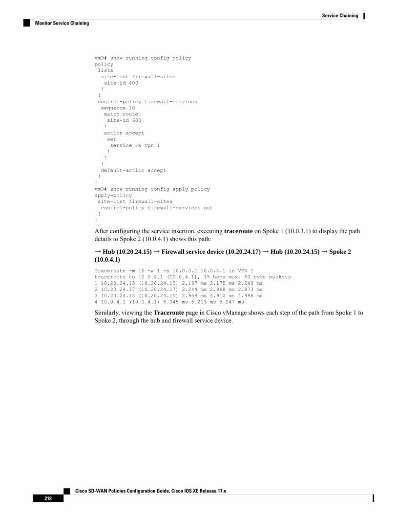
vm9# show running-config policypolicylistssite-list firewall-sitessite-id 400!!control-policy firewall-servicessequence 10match routesite-id 600!action acceptsetservice FW vpn 1!!!default-action accept!!vm9# show running-config apply-policyapply-policysite-list firewall-sitescontrol-policy firewall-services out!!
After configuring the service insertion, executing traceroute on Spoke 1 (10.0.3.1) to display the pathdetails to Spoke 2 (10.0.4.1) shows this path:
→ Hub (10.20.24.15)→ Firewall service device (10.20.24.17)→ Hub (10.20.24.15)→ Spoke 2(10.0.4.1)
Traceroute -m 15 -w 1 -s 10.0.3.1 10.0.4.1 in VPN 1traceroute to 10.0.4.1 (10.0.4.1), 15 hops max, 60 byte packets1 10.20.24.15 (10.20.24.15) 2.187 ms 2.175 ms 2.240 ms2 10.20.24.17 (10.20.24.17) 2.244 ms 2.868 ms 2.873 ms3 10.20.24.15 (10.20.24.15) 2.959 ms 4.910 ms 4.996 ms4 10.0.4.1 (10.0.4.1) 5.045 ms 5.213 ms 5.247 ms
Similarly, viewing the Traceroute page in Cisco vManage shows each step of the path from Spoke 1 toSpoke 2, through the hub and firewall service device.
Cisco SD-WAN Policies Configuration Guide, Cisco IOS XE Release 17.x218
Service ChainingMonitor Service Chaining

C H A P T E R 18Lawful Intercept
The Lawful Intercept (LI) feature supports service providers in meeting the requirements of law enforcementagencies (LEA) to provide electronic surveillance as authorized by a judicial or administrative order. Thesurveillance is performed using wiretaps to intercept Voice-over-Internet protocol (VoIP) or data traffic goingthrough the edge routers. The LEA delivers a request for a wiretap to the target's service provider, who isresponsible for intercepting data communication to and from the individual using IP sessions. A user sessionis tapped using either the Source and Destination IP addresses, or VRF name, which is translated to a vrf-tableidvalue within the router.
Table 37: Feature History
DescriptionReleaseInformation
Feature Name
This feature encrypts lawful intercept messages between a Cisco IOSXE SD-WAN device and amedia device using static tunnel information.
Cisco IOS XESD-WANRelease 16.12.1b
Encryption ofLawful InterceptMessages
• Information About Lawful Intercept, on page 219• Prerequisites for Lawful Intercept, on page 222• Install Lawful Intercept using vManage, on page 223• Lawful Intercept MIBs, on page 223• Restrict Access to Trusted Hosts (Without Encryption), on page 224• Restrict Trusted Mediation Device, on page 224• Configure Lawful Intercept, on page 225• Configure Lawful Intercept Using CLI, on page 225• Encrypt Lawful Intercept Traffic , on page 226• Verify Static Tunnel with Media Device Gateway, on page 228
Information About Lawful InterceptLawful intercept is a process that enables a Law Enforcement Agency (LEA) to perform electronic surveillanceon an individual (a target) as authorized by a judicial or administrative order. To facilitate the lawful interceptprocess, certain legislation and regulations require service providers (SPs) and Internet service providers(ISPs) to implement their networks to explicitly support authorized electronic surveillance.
Cisco SD-WAN Policies Configuration Guide, Cisco IOS XE Release 17.x219
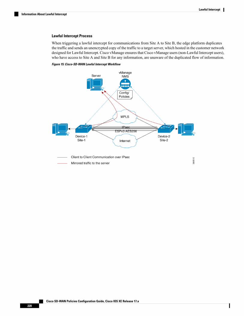
Lawful Intercept Process
When triggering a lawful intercept for communications from Site A to Site B, the edge platform duplicatesthe traffic and sends an unencrypted copy of the traffic to a target server, which hosted in the customer networkdesigned for Lawful Intercept. Cisco vManage ensures that Cisco vManage users (non-Lawful Intercept users),who have access to Site A and Site B for any information, are unaware of the duplicated flow of information.
Figure 15: Cisco-SD-WAN Lawful Intercept Workflow
Cisco SD-WAN Policies Configuration Guide, Cisco IOS XE Release 17.x220
Lawful InterceptInformation About Lawful Intercept
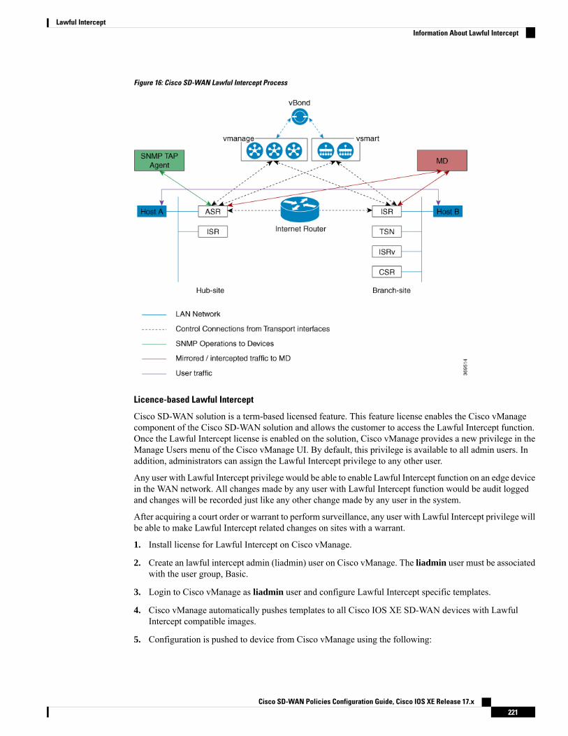
Figure 16: Cisco SD-WAN Lawful Intercept Process
Licence-based Lawful Intercept
Cisco SD-WAN solution is a term-based licensed feature. This feature license enables the Cisco vManagecomponent of the Cisco SD-WAN solution and allows the customer to access the Lawful Intercept function.Once the Lawful Intercept license is enabled on the solution, Cisco vManage provides a new privilege in theManage Users menu of the Cisco vManage UI. By default, this privilege is available to all admin users. Inaddition, administrators can assign the Lawful Intercept privilege to any other user.
Any user with Lawful Intercept privilege would be able to enable Lawful Intercept function on an edge devicein the WAN network. All changes made by any user with Lawful Intercept function would be audit loggedand changes will be recorded just like any other change made by any user in the system.
After acquiring a court order or warrant to perform surveillance, any user with Lawful Intercept privilege willbe able to make Lawful Intercept related changes on sites with a warrant.
1. Install license for Lawful Intercept on Cisco vManage.
2. Create an lawful intercept admin (liadmin) user on Cisco vManage. The liadmin user must be associatedwith the user group, Basic.
3. Login to Cisco vManage as liadmin user and configure Lawful Intercept specific templates.
4. Cisco vManage automatically pushes templates to all Cisco IOS XE SD-WAN devices with LawfulIntercept compatible images.
5. Configuration is pushed to device from Cisco vManage using the following:
Cisco SD-WAN Policies Configuration Guide, Cisco IOS XE Release 17.x221
Lawful InterceptInformation About Lawful Intercept

a. SNMP TAP MIB configuration
b. SNMP Access list (li-acl keyword)
c. MD List
6. SNMP SET is sent to device to achieve the following goals:
a. To setup and activate MD entry on Cisco IOS XE SD-WAN devices.
b. To setup and activate stream to be intercepted.
c. To activate or deactivate intercept
7. Mediation Device receives the intercepted or mirrored traffic.
VRF-Aware Lawful Intercept
VRF Aware Lawful Intercept is the ability to provision a Lawful Intercept wiretap on IPv4 data in a particularVPN. This feature allows a LEA to lawfully intercept targeted data within that VPN. Only IPv4 data withinthat VPN is subject to the VRF-based Lawful Intercept tap.
To provision a VPN-based IPv4 tap, the LI administrative function (running on the mediation device) usesthe CISCO-IP-TAP-MIB to identify the name of the VRF table that the targeted VPN uses. The VRF nameis used to select the VPN interfaces on which to enable LI in order to execute the tap. The device determineswhich traffic to intercept and which mediation device to send the intercepted packets based on the VRF name(along with the source and destination address, source and destination port, and protocol).
Prerequisites for Lawful InterceptAccess to the Cisco Lawful Intercept MIB view should be restricted to the mediation device and to systemadministrators who need to be aware of lawful intercepts on the router. To access the MIB, users must havelevel-15 access rights on the router.
For the router to communicate with the mediation device to execute a lawful intercept, the followingconfiguration requirements must be met:
• The domain name for both the router and the mediation device must be registered in the Domain NameSystem (DNS). In DNS, the router IP address is typically the address of the FastEthernet0/0/0 interfaceon the router.
• The mediation device must have an access function (AF) and an access function provisioning interface(AFPI).
• You must add the mediation device to the Simple Network Management Protocol (SNMP) user groupthat has access to the CISCO-TAP2-MIB view. Specify the username of the mediation device as the userto add to the group.
• When you add the mediation device as a CISCO-TAP2-MIB user, you can include the mediationdevice’s authorization password if you want. The password must be at least eight characters inlength.
• You must configure SNMP service in vManage using the VPN Interface Ethernet page of FeatureTemplate. See VPN Interface Ethernet section in Templates topic.
Cisco SD-WAN Policies Configuration Guide, Cisco IOS XE Release 17.x222
Lawful InterceptPrerequisites for Lawful Intercept
Install Lawful Intercept using vManage
The following process must be repeated for every Cisco vManage node.Note
1. Connect to a Cisco vManage device as administrator
2. Request tools licensevm12# tools license requestYour org-name is: XYZ IncYour license-request challenge is:Uwk3u4Vwkl8n632fKDIpKDEFkzfeJlhFQPOHopbvewmed0U83LQDgajO7GnmCIgA
3. Contact Cisco Support to generate the license using the output of Step 2.
4. Run the install file command and reboot:vm12# tools license install file license.licLicense installed. Please reboot to activate.vm12# rebootAre you sure you want to reboot? [yes,no] yes
Broadcast message from root@vm12 (somewhere) (Tue Jan 22 17:07:47 2019):Tue Jan 22 17:07:47 UTC 2019: The system is going down for reboot NOW!Connection to 10.0.1.32 closed.tester@vip-vmanage-dev-109:~$
5. Verify if the Lawful Intercept license is installed successfully, using the following command:vm12# show system statusLI License Enabled True
6. Create lawful intercept admin user using Cisco vManage.
7. Login to Cisco vManage using the lawful intercept admin credentials.
Use the tools license remove-all command to remove all licenses after reboot. You will not be able to re-installthe previous license.
Note
Lawful Intercept MIBsDue to its sensitive nature, the Cisco Lawful InterceptMIBs are only available in software images that supportthe Lawful Intercept feature.
These MIBs are not accessible through the Network Management Software MIBs Support page.
Restricting Access to the Lawful Intercept MIBs
Only the mediation device and users who need to know about lawful intercepts must be allowed to access theLawful Intercept MIBs. To restrict access to these MIBs, you must perform the following actions:
Cisco SD-WAN Policies Configuration Guide, Cisco IOS XE Release 17.x223
Lawful InterceptInstall Lawful Intercept using vManage

1. Create a view that includes the Cisco Lawful Intercept MIBs.
2. Create an SNMP user group that has read-and-write access to the view. Only users assigned to this usergroup can access information in the MIBs.
3. Add users to the Cisco LI user groups to define who can access the MIBs and any information related tolawful intercepts. Be sure to add the mediation device as a user in this group; otherwise, the router cannotperform lawful intercepts.
Detail MD5 authentication key generation algorithm is defined at https://tools.ietf.org/html/rfc3414#appendix-A.2.1
Note
Restrict Access to Trusted Hosts (Without Encryption)SNMPv3 provides support for both security models and security levels. A security model is an authenticationstrategy that is set up for a user and the group in which the user resides. A security level is the permitted levelof security within a security model. A combination of a security model and a security level will determine thesecurity mechanism employed when handling an SNMP packet.
Additionally, the SNMP support for the Named Access Lists feature adds support for standard named accesscontrol lists (ACLs) to several SNMP commands.
To configure a new SNMP group or a table that maps SNMP users to SNMP views, use the snmp-servercommand in global configuration mode.
In the following example, the access list named 99 allows SNMP traffic only from 10.1.1.1 to access CiscoIOS XE SD-WAN devices. This access list is then applied to the SNMP user, testuser.access-list 99 permit ip host 10.1.1.1snmp-server user testuser INTERCEPT_GROUP v3 encrypted auth shatestPassword1 priv aes testPassword2 access 99
SNMP traffic is only allowed from WAN interface (gigabitEthernet 1).control-plane hostmanagement-interface gigabitEthernet 1 allow snmp
Restrict Trusted Mediation DeviceIn the following example, the md-list command allows an SNMP request config MD in the subnet10.3.3.0/24.
When a Cisco IOS XE SD-WAN device receives an SNMP request to create a mediation device, it first checksthe Mediation Device List configuration information.
If the IP address of the mediation device is not in the configuredMediation Device List, the Mediation Deviceentry is not active.md-list 10.3.3.0 255.255.255.0
Cisco SD-WAN Policies Configuration Guide, Cisco IOS XE Release 17.x224
Lawful InterceptRestrict Access to Trusted Hosts (Without Encryption)
You can configure up to a maximum of eight Mediation Device List subnets.Note
Configure Lawful InterceptThe following are the two components for Lawful Intercept vManage configuration:
• Lawful Intercept SNMP template – This template provisions the configuration for the following:
• SNMPv3 group for lawful intercept – The group name is INTERCEPT_GROUP by default.
• SNMPv3 users for lawful intercept – All users are restricted by an access list by default.
• SNMPv3 view is configured by default. The view included Cisco TAP MIBs.
• The following TAP MIBs are configured:
• ciscoIpTapMIB
• ciscoTap2MIB
• ifIndex
• ifDescr
• Lawful intercept access list template – The access list template provides configuration for the following:
• Mediation Device-List configuration – Provides option to configure up to 8 subnets.
• SNMP access-list – provides option to configure up to 8 subnets or host addresses, and a wildcardmask.
Configure Lawful Intercept Using CLIcontrol-plane hostmanagement-interface GigabitEthernet0/0/0 allow ftp ssh snmpmanagement-interface GigabitEthernet0/0/1 allow ftp ssh snmp!!md-list 10.101.0.0 255.255.255.0md-list 10.102.0.10 255.255.255.255md-list 10.103.0.0 255.255.255.0md-list 10.104.0.4 255.255.255.255md-list 10.105.0.0 255.255.255.0md-list 10.106.0.0 255.255.255.0md-list 10.107.0.7 255.255.255.255md-list 10.108.0.0 255.255.0.0!ip access-list standard li-aclpermit 174.16.50.254
Cisco SD-WAN Policies Configuration Guide, Cisco IOS XE Release 17.x225
Lawful InterceptConfigure Lawful Intercept

Example: Enabling Mediation Device Access Lawful Intercept MIBs
The following example shows how to enable the mediation device to access the lawful intercept MIBs. Itcreates an SNMP view (tapV) that includes four LI MIBs (CISCO-TAP2-MIB, CISCO-IP-TAP-MIB,CISCO-802-TAP-MIB, and CISCO-USER-CONNECTION-TAP-MIB). It also creates a user group that hasread, write, and notify access to MIBs in the tapV view.snmp-server enable trapsnmp-server engineID local 766D616E6167652Dac10ff31snmp-server group INTERCEPT_GROUP v3 noauth read INTERCEPT_VIEW write INTERCEPT_VIEW notifySNG_VIEWsnmp-server user UItestuser1 INTERCEPT_GROUP v3 encrypted auth md5DA:B2:36:03:6A:5C:D0:6D:F6:D8:9C:5E:56:77:AD:43 priv aes 128DA:B2:36:03:6A:5C:D0:6D:F6:D8:9C:5E:56:77:AD:43 access li-aclsnmp-server user UItestuser2 INTERCEPT_GROUP v3 encrypted auth md5D2:01:1E:47:D8:9E:3E:B5:58:CD:90:0F:49:FC:36:56 priv aes 128CF:32:C4:3E:34:27:3F:4A:D8:18:A7:19:E5:04:A7:DF access li-acl!snmp-server engineID local 766D616E6167652DAC10FF31snmp-server group INTERCEPT_GROUP v3 noauth read INTERCEPT_VIEW write INTERCEPT_VIEW notifySNG_VIEWsnmp-server view INTERCEPT_VIEW ciscoIpTapMIB includedsnmp-server view INTERCEPT_VIEW ciscoTap2MIB includedsnmp-server view INTERCEPT_VIEW ifIndex includedsnmp-server view INTERCEPT_VIEW ifDescr included
Encrypt Lawful Intercept TrafficEncryption of intercepted traffic between the router (the content Intercept Access Point (IAP)) and theMediationDevice (MD) is recommended.
The following is the required configuration:
• Configuring encryption in the router, and either an encryption client in the MD or a router associatedwith the MD to decrypt the traffic.
• Restricting access to trusted hosts.
• Configuring the VPN client.
Configure Encryption in the DeviceTo configure encryption, configure Authentication, Authorization, and Accounting (AAA) parameters. Thefollowing example shows how to configure the parameters:aaa authentication login userauthen localusername <username> password 0 <password
In CISCO-TAP2-MIB, the source interface must be the tunnel interface of the Cisco IOSXE SD-WAN devicesand the destination address must be IP address of the mediation device.
Cisco SD-WAN Policies Configuration Guide, Cisco IOS XE Release 17.x226
Lawful InterceptEncrypt Lawful Intercept Traffic

Configure Lawful Intercept Encryption using CLIIn the following example, an IPSec tunnel is configured between Cisco IOS XE SD-WAN device and MediaDevice Gateway. Media Device Gateway terminates IPSec tunnel and adds a route to Media Device listthrough the IPSec Tunnel.
In CISCO-TAP2-MIB, source interface is the tunnel interface of the Cisco IOS XE SD-WAN devices;destination address is the IP address of the media device.crypto ikev2 diagnose error 1000crypto ikev2 keyring ikev2_keyringpeer mypeeraddress 0.0.0.0 0.0.0.0pre-shared-key cisco123 pre-shared key should bee same on mediadeviec gateway!crypto ikev2 profile ikev2_profileauthentication local pre-shareauthentication remote pre-sharedpd 10 3 on-demandlifetime 14400keyring local ikev2_keyringmatch identity remote address 0.0.0.0 0.0.0.0!crypto ikev2 proposal defaultencryption aes-cbc-256group 14 16 19 2 20 21integrity sha256 sha384 sha512!crypto ipsec profile ipsec_profileset ikev2-profile ikev2_profileset pfs group16set transform-set tfsset security-association lifetime seconds 7200set security-association replay window-size 256!crypto ipsec transform-set tfs esp-gcm 256mode tunnel!interface Tunnel100no shutdownip address 10.2.2.1 255.255.255.0 tunnel addresstunnel source GigabitEthernet1 Cisco XE SD-WAN WAN interfacetunnel destination 10.124.19.57 Media Device Gateway addresstunnel mode ipsec ipv4tunnel protection ipsec profile ipsec_profile
ip route 10.3.3.0 255.255.255.0 Tunnel100 route MD list traffic through IPSec Tunnel
Use the following configuration to configure media gateway to terminate IPSec tunnel:crypto ikev2 proposal defaultencryption aes-cbc-256integrity sha384 sha512 sha256group 20 16 19 14 21 2!crypto ikev2 keyring ikev2_keyringpeer mypeeraddress 0.0.0.0 0.0.0.0pre-shared-key cisco123 pre-shared key, should be same on cEdge!crypto ikev2 profile ikev2-profilematch identity remote address 0.0.0.0 0.0.0.0authentication remote pre-share
Cisco SD-WAN Policies Configuration Guide, Cisco IOS XE Release 17.x227
Lawful InterceptConfigure Lawful Intercept Encryption using CLI

authentication local pre-sharekeyring local ikev2_keyringlifetime 14400dpd 10 3 on-demandcrypto ipsec transform-set tfs esp-gcm 256mode tunnelcrypto ipsec profile ipsec_profileset security-association lifetime seconds 7200set security-association replay window-size 256set transform-set tfsset pfs group16set ikev2-profile ikev2_profile!interface Tunnel100ip address 10.2.2.2 255.255.255.0 Tunnel addresstunnel source GigabitEthernet1 MD GW phy interfacetunnel mode ipsec ipv4tunnel destination 10.74.5.213 cEdge wan interfacetunnel protection ipsec profile ipsec_profile!
Verify Static Tunnel with Media Device GatewayThe IPSec tunnel between the Cisco IOS XE SD-WAN device and the Media Device gateway is static and isalways in the UP state.
Use the following commands to verify static tunnel configuration with the Media Device gateway:
• show crypto session detail
• show crypto ipsec sa
Cisco SD-WAN Policies Configuration Guide, Cisco IOS XE Release 17.x228
Lawful InterceptVerify Static Tunnel with Media Device Gateway