Maintaining Your Cisco 7513, Cisco 7513-MX, and Cisco ...
20
CHAPTER 7-1 Cisco 7500 Series Installation and Configuration Guide OL-5008-03 B0 7 Maintaining Your Cisco 7513, Cisco 7513-MX, and Cisco 7576 Router Your Cisco 7513, Cisco 7513-MX, or Cisco 7576 router is configured to your order and is ready for installation and startup when it leaves the factory. After you install and configure your router, you might have to perform specific maintenance procedures and operations to ensure that the router is operating properly, to upgrade specific system components, or to replace components with spare parts or field-replaceable units (FRUs). This chapter describes procedures and maintenance operations required to maintain your Cisco 7513, Cisco 7513-MX, or Cisco 7576 router. Note Detailed, up-to-date instructions (called configuration notes) are available on Cisco.com. The Cisco 7513, Cisco 7513-MX, and Cisco 7576 allow you to remove and replace interface processors and RSPs while the system is powered on; however, you must shut down the system power before accessing the chassis interior for any other reason. Note If you intend to remove and replace an interface processor or RSP while the system is powered on, do so only when no operations are taking place that involve the RSP NVRAM or Flash memory. This includes operations involving system configuration changes and downloading microcode images. This chapter provides specific component replacement instructions for upgrading, removing, or replacing the following components: • Chassis cover panels • Blower module assembly • Card cage assembly • Chassis interface (CI) board • Power supply removal (power supply installation is discussed in the “Installing Cisco 7513, Cisco 7513-MX, and Cisco 7576 Power Supplies” section on page 3-27). Caution To help prevent problems, before performing any procedures in this chapter, review the “Safety Recommendations” section on page 2-2.
-
Upload
khangminh22 -
Category
Documents
-
view
6 -
download
0
Transcript of Maintaining Your Cisco 7513, Cisco 7513-MX, and Cisco ...

Cisco 7500 SerOL-5008-03 B0
C H A P T E R 7
orightrating
quired
ssorsre
on, dos.
Maintaining Your Cisco 7513, Cisco 7513-MX, andCisco 7576 Router
Your Cisco 7513, Cisco 7513-MX, or Cisco 7576 router is configured to your order and is ready finstallation and startup when it leaves the factory. After you install and configure your router, you mhave to perform specific maintenance procedures and operations to ensure that the router is opeproperly, to upgrade specific system components, or to replace components with spare parts orfield-replaceable units (FRUs). This chapter describes procedures and maintenance operations reto maintain your Cisco 7513, Cisco 7513-MX, or Cisco 7576 router.
Note Detailed, up-to-date instructions (calledconfiguration notes) are available on Cisco.com.
The Cisco 7513, Cisco 7513-MX, and Cisco 7576 allow you to remove and replace interface proceand RSPs while the system is powered on; however, you must shut down the system power befoaccessing the chassis interior for any other reason.
Note If you intend to remove and replace an interface processor or RSP while the system is powered so only when no operations are taking place that involve the RSP NVRAM or Flash memory. Thiincludes operations involving system configuration changes and downloading microcode images
This chapter provides specific component replacement instructions for upgrading, removing, orreplacing the following components:
• Chassis cover panels
• Blower module assembly
• Card cage assembly
• Chassis interface (CI) board
• Power supply removal (power supply installation is discussed in the“Installing Cisco 7513, Cisco7513-MX, and Cisco 7576 Power Supplies” section on page 3-27).
Caution To help prevent problems, before performing any procedures in this chapter, review the“SafetyRecommendations” section on page 2-2.
7-1ies Installation and Configuration Guide

Chapter 7 Maintaining Your Cisco 7513, Cisco 7513-MX, and Cisco 7576 Router Tools Required for Maintenance Procedures
oe
76
erplies
pe of
must, and
ecific to
are
bly,
age
Note Interface processor-specific configuration information is included in the companionInterface ProcessorInstallation and Configuration Guide, which shipped with your Cisco 7513, Cisco 7513-MX, or Cisc7576 router, as well as in the individual configuration notes that shipped with your spare interfacprocessors.
Tools Required for Maintenance ProceduresYou need the following tools to replace any one of the Cisco 7513, Cisco 7513-MX, and Cisco 75internal spares:
• 3/16-inch flat-blade screwdriver to loosen the captive screws on the processor modules, powsupplies, card cage assembly, and the DC-input terminal connections on DC-input power sup
• Number 1 Phillips screwdriver to loosen captive screws on processor modules that have this tyscrew
• Number 2 Phillips screwdriver to remove teh backplane cover screws
Maintenance Procedures for the Cisco7513, Cisco 7513-MX, andCisco7576
To replace internal spares, all of which are inside the noninterface processor end of the router, youremove the chassis cover panel and expose the chassis interior. The Cisco 7513, Cisco 7513-MXCisco 7576 are housed in the same chassis and use the same power supplies. If a procedure is spone model or the other, it is noted within that procedure.
Warning If the power is not shut down before removing chassis cover panels, high current can become ahazard. When the power harness cover is removed, the high current present in the wiring and on thebackplane also becomes a hazard. Removing metal cover panels when the system is operating alsocompromises the EMI integrity of the system. Therefore, always turn off the system power beforeremoving metal cover panels, and remove cover panels only when it is necessary to replace internalcomponents.
The specific maintenance procedures for your Cisco 7513, Cisco 7513-MX, or Cisco 7576 routerdescribed in the following sections:
• Removing Cisco 7513, Cisco 7513-MX, and Cisco 7576 Power Supplies, page 7-3
Note To install power supplies in the Cisco 7513, Cisco 7513-MX, and Cisco 7576, see the“Installing Cisco 7513, Cisco 7513-MX, and Cisco 7576 Power Supplies” section onpage 3-27.
• Removing and Replacing the Cisco 7513, Cisco 7513-MX, and Cisco 7576 Card Cage Assempage 7-5
• Removing and Replacing the Cisco 7513, Cisco 7513-MX, and Cisco 7576 Blower Module, p7-10
7-2Cisco 7500 Series Installation and Configuration Guide
OL-5008-03 B0

Chapter 7 Maintaining Your Cisco 7513, Cisco 7513-MX, and Cisco 7576 Router Maintenance Procedures for the Cisco 7513, Cisco 7513-MX, and Cisco 7576
anels,
ance
576,
-MX,
son
pply,pted
turnbay
ower
nd
etion
• Removing and Replacing the Cisco 7513, Cisco 7513-MX, and Cisco 7576 Chassis Cover Ppage 7-11
• Removing and Replacing the Cisco 7513, Cisco 7513-MX, and Cisco 7576 Backplane MaintenCover, page 7-13
• Removing and Replacing the Chassis Interface in the Cisco 7513, Cisco 7513-MX, and Cisco 7page 7-14
Warning Before working on a system that has an on/off switch, turn OFF the power and unplug the power cord.
Removing Cisco 7513, Cisco 7513-MX, and Cisco 7576 Power SuppliesThis section describes the procedure for removing a power supply from the Cisco 7513, Cisco 7513and Cisco 7576.
Note The procedure for installing power supplies in the Cisco 7513, Cisco 7513-MX, and Cisco 7576 idescribed in the“Installing Cisco 7513, Cisco 7513-MX, and Cisco 7576 Power Supplies” section page 3-27.
Redundant power supplies support online insertion and removal (OIR); if you remove one power suthe second supply immediately ramps up to supply full power to the system to maintain uninterruoperation.
If you have only one power supply in your Cisco 7513, Cisco 7513-MX, or Cisco 7576, you mustoff power before removing and replacing it. Always install a filler plate over an empty power supplyto protect the connectors from contamination.
Warning When stranded wiring is required, use approved wiring terminations, such as closed-loop orspade-type with upturned lugs. These terminations should be the appropriate size for the wires andshould clamp both the insulation and the conductor.
Warning Before performing any of the following procedures, ensure that power is removed from the DC circuit.To ensure that all power is OFF, locate the circuit breaker on the panel board that services the DCcircuit, switch the circuit breaker to the OFF position, and tape the switch handle of the circuitbreaker in the OFF position.
Use the following procedure to remove a power supply:
Step 1 If you have two power supplies installed and one power supply has failed, turn off (O) the system pswitch on the power supply you will remove.
Step 2 AC-input power supply: Using a screwdriver, loosen the cable-retention clip on the power cable aunplug the power cable from the AC receptacle.
DC-input power supply: Disconnect the power cable leads from a DC-input power supply. (See th“Connecting Power to Cisco 7513, Cisco 7513-MX, and Cisco 7576 DC-Input Power Supplies” secon page 3-29.) Then, with the power cable leads disconnected, proceed to Step 3.
7-3Cisco 7500 Series Installation and Configuration Guide
OL-5008-03 B0

Chapter 7 Maintaining Your Cisco 7513, Cisco 7513-MX, and Cisco 7576 Router Maintenance Procedures for the Cisco 7513, Cisco 7513-MX, and Cisco 7576
ssis
atelyay.
Ciscon the
Step 3 Use a flat-blade screwdriver to loosen the captive screw that secures the power supply to the chaframe.
Figure 7-1 Removing a Power Supply (Cisco 7513, Cisco 7513-MX, and Cisco 7576 AC-InputPower Supplies Shown)
Step 4 Grasp the power supply handle and pull the power supply about halfway out of the bay (approxim8 inches [20 cm]); then with your other hand under the power supply, pull it completely out of the b
Figure 7-2 Supporting the Power Supply (Cisco 7513, Cisco 7513-MX, and Cisco 7576 AC-InputPower Supply Shown)
Caution To maintain agency compliance requirements and meet EMI emissions standards in Cisco 7513,7513-MX, and Cisco 7576 chassis with a single power supply, a power supply blank must remain ipower supply bay adjacent to the power supply. Do not remove this blank from the chassis unless youdo so to install a redundant power supply.
Note To prevent system problems, do not mix AC-input and DC-input power supplies.
Warning High current levels on the power supply connections at the rear of the power supply bay are exposedwith the power supply or blank removed. Do not insert anything conductive into the open powersupply bay while power is ON.
H52
65
Captive screws
0
I
ACOK
FANOK
OUTPUTFAIL
0
I
ACOK
FANOK
OUTPUTFAIL
POWER
B
H52
67
0
I
ACOK
FANOK
OUTPUTFAIL
7-4Cisco 7500 Series Installation and Configuration Guide
OL-5008-03 B0

Chapter 7 Maintaining Your Cisco 7513, Cisco 7513-MX, and Cisco 7576 Router Maintenance Procedures for the Cisco 7513, Cisco 7513-MX, and Cisco 7576
, see7
ly slides
e; see
d with
the
ver, it
r
ocated
Figure 7-3 Power Supply Blank (Cisco 7513, Cisco 7513-MX, and Cisco 7576)
This completes the power supply removal procedure.
For the procedure for installing power supplies in the Cisco 7513, Cisco 7513-MX, and Cisco 7576the“Installing Cisco 7513, Cisco 7513-MX, and Cisco 7576 Power Supplies” section on page 3-2.
Removing and Replacing the Cisco 7513, Cisco 7513-MX, and Cisco 7576 CardCage Assembly
The card cage comprises one assembly that includes the card cage and backplane. The assembinto and out of the chassis and attaches to the chassis frame with four slotted captive screws.
The following procedure requires that you first remove the processor modules from the card cagthe procedure inFigure 3-14.
Removing the Card Cage Assembly
Use the following procedure to remove the card cage assembly. This procedure cannot be performepower supplies or power supply blanks installed.
Step 1 Remove all processor modules from the chassis card cage.
Make a note of the processor module slots as you remove the processor modules. Do not stack processor modules on top of one another.
It is possible to remove the card cage from the chassis with the processor modules installed; howeis not recommended. Thirteen processor modules add 32.5 lb (14.7 kg) to the system.
Step 2 Remove the power supplies. (See the“Removing Cisco 7513, Cisco 7513-MX, and Cisco 7576 PoweSupplies” section on page 7-3.)
Step 3 With the processor modules and power supplies removed, loosen the four large captive screws lon the card cage flanges, to the left and right of the card cage opening, as shown inFigure 7-4.
H35
39
Captive screw
7-5Cisco 7500 Series Installation and Configuration Guide
OL-5008-03 B0

Chapter 7 Maintaining Your Cisco 7513, Cisco 7513-MX, and Cisco 7576 Router Maintenance Procedures for the Cisco 7513, Cisco 7513-MX, and Cisco 7576
whenecondassis.
cageto pull
on an
ge andhe card
Figure 7-4 Removing the Cisco 7513, Cisco 7513-MX, and Cisco 7576 Card Cage Assembly
Caution Unless the chassis is mounted in a rack, or otherwise anchored, the chassis might move toward youyou pull the card cage and backplane assembly in the following step. To prevent injury, have a sperson hold the chassis in place while you pull the card cage and backplane assembly from the ch
Step 4 With the captive screws loosened, carefully grasp the intake grill with both hands and pull the cardassembly straight out of the chassis until there is enough clearance at the card cage side flangesthe entire assembly clear of the chassis sides, as shown inFigure 7-4. The assembly is heavier at thebackplane and might be awkward to handle.
Step 5 When the card cage and backplane assembly is completely free of the chassis, carefully place itantistatic mat or foam.
Caution The electronic components on the rear of the backplane are completely exposed when the card cabackplane assembly is removed from the chassis. To prevent damaging these components, place tcage and backplane assembly on an antistatic mat or foam, and place the assembly in the sameorientation as when it is mounted in the chassis.
H30
96
POWER
APOWER
B
Captive screw
Captive screw
Captive screw
Captive screw
Card cageside flange
Air intake grill
Card cageside flange
7-6Cisco 7500 Series Installation and Configuration Guide
OL-5008-03 B0

Chapter 7 Maintaining Your Cisco 7513, Cisco 7513-MX, and Cisco 7576 Router Maintenance Procedures for the Cisco 7513, Cisco 7513-MX, and Cisco 7576
install
cardvices
allyor the
h arequired
apply
yourone.
ROM 7513,
Cisco
terface
them
Note If you plan to replace your existing card cage assembly with a new one, youmust first perform theprocedure in the“Exchanging the EEPROM Devices” section on page 7-7 before you install your newcard cage assembly. However, if you simply plan to remove your card cage assembly and then reit, you donot need this procedure; instead, proceed to the“Installing the Card Cage Assembly” sectionon page 7-9.
Exchanging the EEPROM Devices
The following procedure requires you to first exchange the blank EEPROM devices on your new cage for the old EEPROM devices from your old card cage, and then place the blank EEPROM deon your old card cage for return to Cisco Systems.
Note You donot need to perform this procedure if you donot plan to install a new card cage assembly;however, if you do plan to install a new card cage assembly, you must exchange the new electricerasable programmable read-only memory (EEPROM) devices on the rear of the new card cage fold EEPROM devices on the rear of your old card cage.
The EEPROM devices on your old card cage have MAC addresses programmed into them, whicnecessary for your system to function properly, and these old EEPROM devices are therefore refor your system to operate properly with a new card cage assembly.
Note Do not perform these steps if you are upgrading a Cisco 7513 to a Cisco 7576. These instructionsonly to the replacement of an equivalent model card cage.
Caution To prevent system problems after installation, note that the new EEPROM devices that shipped onnew card cage are blank and must be replaced if you plan to replace your card cage with a new
For this procedure, you will need a small piece of masking or cellophane tape to mark the new EEPdevices as blank. (The old card cage is assumed to have already been removed from your CiscoCisco 7513-MX, or Cisco 7576 using the procedure in the“Removing the Card Cage Assembly” sectionon page 7-5.)
Use the following procedure to exchange the EEPROM devices:
Step 1 Attach an ESD preventive wrist strap between you and an unpainted surface of the Cisco 7513, 7513-MX, or Cisco 7576 chassis.
Step 2 Locate the blank EEPROM devices, located on the rear of the new card cage near the chassis inboard(s). (SeeFigure 7-5 for the Cisco 7513 and Cisco 7513-MX, andFigure 7-6 for the Cisco 7576.)
Step 3 Remove the blank EEPROM devices from the new card cage, place a piece of tape on them to markas blank EEPROM devices, and set them aside.
Step 4 Locate the old EEPROM devices, located on the rear of your old card cage. (SeeFigure 7-5for the Cisco7513 and Cisco 7513-MX, andFigure 7-6 for the Cisco 7576.)
7-7Cisco 7500 Series Installation and Configuration Guide
OL-5008-03 B0

Chapter 7 Maintaining Your Cisco 7513, Cisco 7513-MX, and Cisco 7576 Router Maintenance Procedures for the Cisco 7513, Cisco 7513-MX, and Cisco 7576
rencecard
tape)ROM
Figure 7-5 Location of the EEPROM Device on the Rear of the Card Cage (Cisco 7513 andCisco 7513-MX)
Figure 7-6 Location of the EEPROM Devices on the Rear of the Card Cage(Cisco 7576)
Step 5 Remove the old EEPROM devices from the old card cage. Note where pin 1 is and use it as a refeinsertion point. Immediately install the old EEPROM devices on the EEPROM sockets on your newcage. (SeeFigure 7-5 for the Cisco 7513 and Cisco 7513-MX, andFigure 7-6 for the Cisco 7576.)
Step 6 Install the blank EEPROM devices)(that you removed from your new card cage and marked withon the EEPROM sockets on your old card cage; remove the small piece of tape from the blank EEPdevices. Return the old card cage to Cisco Systems.
Step 7 Repeat Step 5 and Step 6 for the second EEPROM in the Cisco 7576.
This completes the procedure for exchanging the EEPROM devices, which is requiredonly if youexchange your existing card cage assembly for a new one.
H88
18
Pin 1
EEPROMdevice
Chassisinterfaceboard
1527
1
Pin 1
EEPROM B
EEPROM A
EEPROM device
Chassisinterfaceboard A
Chassisinterfaceboard B
7-8Cisco 7500 Series Installation and Configuration Guide
OL-5008-03 B0
Chapter 7 Maintaining Your Cisco 7513, Cisco 7513-MX, and Cisco 7576 Router Maintenance Procedures for the Cisco 7513, Cisco 7513-MX, and Cisco 7576
ge andly slide
to thes.
rtighten
Installing the Card Cage Assembly
Use the following procedure to install the card cage assembly.
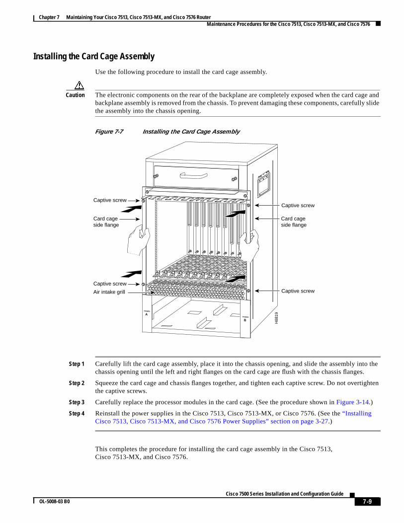
Caution The electronic components on the rear of the backplane are completely exposed when the card cabackplane assembly is removed from the chassis. To prevent damaging these components, carefulthe assembly into the chassis opening.
Figure 7-7 Installing the Card Cage Assembly
Step 1 Carefully lift the card cage assembly, place it into the chassis opening, and slide the assembly inchassis opening until the left and right flanges on the card cage are flush with the chassis flange
Step 2 Squeeze the card cage and chassis flanges together, and tighten each captive screw. Do not ovethe captive screws.
Step 3 Carefully replace the processor modules in the card cage. (See the procedure shown inFigure 3-14.)
Step 4 Reinstall the power supplies in the Cisco 7513, Cisco 7513-MX, or Cisco 7576. (See the“InstallingCisco 7513, Cisco 7513-MX, and Cisco 7576 Power Supplies” section on page 3-27.)
This completes the procedure for installing the card cage assembly in the Cisco 7513,Cisco 7513-MX, and Cisco 7576.
H88
19
POWER
APOWER
B
Captive screw
Captive screw
Captive screw
Captive screw
Card cageside flange
Air intake grill
Card cageside flange
7-9Cisco 7500 Series Installation and Configuration Guide
OL-5008-03 B0

Chapter 7 Maintaining Your Cisco 7513, Cisco 7513-MX, and Cisco 7576 Router Maintenance Procedures for the Cisco 7513, Cisco 7513-MX, and Cisco 7576
alodule
ne of
tem.ely 2
r. (See
n thethe
Removing and Replacing the Cisco 7513, Cisco 7513-MX, and Cisco 7576 BlowerModule
In the Cisco 7513, Cisco 7513-MX, and Cisco 7576, the blower provides cooling air to the internsystem components. When you view the chassis from the noninterface processor end, the blower mis located above the card cage. (SeeFigure 1-11.) Two slotted captive screws hold the blower module iplace. The front panel LEDs are located on a printed circuit board inside the blower module. If onthese LEDs fails, the blower module must be replaced. The LED board inside the blower moduleassembly is not separately replaceable.
Warning Although the system should not be operating when you remove the blower module, it is not necessaryto turn OFF system power before removing the blower module. However, with the system power ONand the blower module removed, high current is exposed on the blower module power connector atthe backplane; do not insert conductive items into the empty blower module opening. After anoperating blower module is removed, the blower impeller blades will continue to spin forapproximately two minutes; do not insert anything into the module’s vent holes while the impeller isspinning.
Caution With chassis power on and the blower module removed, no cooling air is circulating through the sysReplace the blower module before the system overheats. The system will shut down approximatminutes after reaching the shutdown temperature threshold.
Use the following procedure to remove and replace the blower module:
Step 1 Loosen the captive screws that fasten each end of the blower module using a flat-blade screwdriveFigure 7-8.)
Step 2 Grasp the handle on the front of the module and slowly pull it straight out of the chassis. (SeeFigure 7-8.)
Step 3 Replace the blower module. Using both hands to handle the module, and with the intake vents oblower module facing down and the “Insert This Side Up” label facing up, insert the module into chassis opening. Keep the module as straight as possible as you guide it into the chassis.
Figure 7-8 Removing the Cisco 7513, Cisco 7513-MX, and Cisco 7576 Blower Module
H30
38
Captive installation screws (2)
Blower module
7-10Cisco 7500 Series Installation and Configuration Guide
OL-5008-03 B0

Chapter 7 Maintaining Your Cisco 7513, Cisco 7513-MX, and Cisco 7576 Router Maintenance Procedures for the Cisco 7513, Cisco 7513-MX, and Cisco 7576
n the
re thefront
ward,
en, to
Step 4 When the blower is all the way into the chassis opening, tighten the captive installation screws ofront of the blower module.
This completes the blower module removal and replacement procedure.
Removing and Replacing the Cisco 7513, Cisco 7513-MX, and Cisco 7576Chassis Cover Panels
Each cover panel on the Cisco 7513, Cisco 7513-MX, and Cisco 7576 has four fasteners that secupanels to the front of the chassis. The following procedures describe how to remove and replace thecover panels.
Step 1 Use a 3/16-inch flat-blade screwdriver to gently loosen the top of each cover panel.
Step 2 Pull the top of the upper panel out about 2 inches (5.08 cm); grasp the sides and carefully pull it outaway from the chassis. Repeat this for the bottom panel.
Note See the appropriate sections depending on the replacement procedures you need to perform. Threplace the chassis cover panels, proceed to Step 3.
7-11Cisco 7500 Series Installation and Configuration Guide
OL-5008-03 B0

Chapter 7 Maintaining Your Cisco 7513, Cisco 7513-MX, and Cisco 7576 Router Maintenance Procedures for the Cisco 7513, Cisco 7513-MX, and Cisco 7576
anelanel.
Figure 7-9 Removing the Cisco 7513, Cisco 7513-MX, and Cisco 7576 Cover Panels
Step 3 Starting with the bottom cover panel, replace the cover panels by aligning the pins on the bottom pwith the holes in the chassis and pushing the panel against the chassis. Repeat this for the top p
H97
28
POWER A
POWER B
NORMAL
7-12Cisco 7500 Series Installation and Configuration Guide
OL-5008-03 B0

Chapter 7 Maintaining Your Cisco 7513, Cisco 7513-MX, and Cisco 7576 Router Maintenance Procedures for the Cisco 7513, Cisco 7513-MX, and Cisco 7576
ccessver to
edurechapter
Figure 7-10 Replacing the Cisco 7513, Cisco 7513-MX, and Cisco 7576 Cover Panels
Removing and Replacing the Cisco 7513, Cisco 7513-MX, and Cisco 7576Backplane Maintenance Cover
The backplane maintenance cover provides EMI and ground protection for the chassis interior. To athe chassis interior, you must remove the backplane cover. You need a number 2 Phillips screwdriremove the cover screws.
Following is the procedure for removing and replacing the backplane maintenance cover. This procassumes you have already removed the front panels. If not, see the appropriate procedures in thisto remove these items.
Step 1 Attach an ESD-preventive strap between you and an unpainted chassis surface.
Step 2 Loosen the ten Phillips screws that secure the cover.
H97
27
POWER A
POWER B
NORMAL
7-13Cisco 7500 Series Installation and Configuration Guide
OL-5008-03 B0

Chapter 7 Maintaining Your Cisco 7513, Cisco 7513-MX, and Cisco 7576 Router Maintenance Procedures for the Cisco 7513, Cisco 7513-MX, and Cisco 7576
en, to
one
Figure 7-11 Removing the Cisco 7513, Cisco 7513-MX, and Cisco 7576 Backplane MaintenanceCover
Step 3 Carefully guide the cover up and away from the chassis.
Note See the appropriate sections depending on the replacement procedures you need to perform. Threplace the maintenance cover, proceed to Step 4.
Step 4 Replace the maintenance cover by carefully guiding the cover over the ten screws.
Step 5 Align the cover; then tighten all ten screws that secure it to the chassis.
This completes the backplane maintenance cover removal and replacement procedure.
Removing and Replacing the Chassis Interface in the Cisco 7513, Cisco7513-MX, and Cisco 7576
In the Cisco 7513, Cisco 7513-MX, and Cisco 7576, the chassis interface (CI) (shown inFigure 7-12)provides environmental monitoring and logic functions. The Cisco 7513 and Cisco 7513-MX has chassis interface, and the Cisco 7576 has two chassis interfaces.
H30
97
Loosen thesescrews (10)
7-14Cisco 7500 Series Installation and Configuration Guide
OL-5008-03 B0

Chapter 7 Maintaining Your Cisco 7513, Cisco 7513-MX, and Cisco 7576 Router Maintenance Procedures for the Cisco 7513, Cisco 7513-MX, and Cisco 7576
nd thehassis
ector
Figure 7-12 Cisco 7500 Series Chassis Interface
The CI is a printed circuit board mounted to the noninterface processor side of the backplane, behibackplane maintenance cover. The Cisco 7513 and Cisco 7513-MX have one dual arbiter and one cinterface. The Cisco 7576 has two dual arbiters and two chassis interfaces. (SeeFigure 7-13.) On theback of the CI (backplane side) is a connector that plugs directly into the backplane. The edge connis for diagnostics at the factory and is not used.
Figure 7-13 Location of the CI with Maintenance Cover Removed (Cisco 7513 and Cisco 7513-MXShown)
H28
77
Chassis interface
Standoffscrew holes
Standoffscrew holes
H31
01
Dual arbiteror turbo arbiter
Chassisinterface
7-15Cisco 7500 Series Installation and Configuration Guide
OL-5008-03 B0

Chapter 7 Maintaining Your Cisco 7513, Cisco 7513-MX, and Cisco 7576 Router Maintenance Procedures for the Cisco 7513, Cisco 7513-MX, and Cisco 7576
e used
planeeplace
nce
ource
e a
ove
Figure 7-14 Location of the CIs with Maintenance Cover Removed (Cisco 7576 shown)
Note When you view the rear of the card cage, the dual arbiter and chassis interface on the right side arwith router A, and the dual arbiter and chassis interface on the left side are used with router B.
The following procedure assumes you have already removed the chassis cover panels and backmaintenance cover. If not, see the appropriate procedures in this chapter to remove these items. Rthe CIonly if it fails.
The following procedures apply to the Cisco 7513, Cisco 7513-MX, and Cisco 7576. The only differeis that the Cisco 7576 has two CIs on the backplane, as shown inFigure 7-14. If you have a CI problemwith a Cisco 7576, determine which CI has failed, and replace only the failed CI.
Use the following procedure to remove the CI:
Step 1 Turn off the power switch on each power supply and disconnect the power cable from each power sand power supply.
Step 2 Attach an ESD-preventive strap between you and an unpainted chassis surface.
Step 3 The CI is held in place by a connector, which is connected to the backplane, and four screws. Usnumber 1 Phillips screwdriver to remove the four screws.
Caution Access to the CI is partially blocked by a chassis panel. (SeeFigure 7-13for the Cisco 7513 and Cisco7513-MX andFigure 7-14for the Cisco 7576.) Two of the screws are below this panel, and two are abit. To avoid damaging CI components, do not hit the CI against the chassis panel.
1486
6
Dual arbiters
AB
ABChassis
interfaces
7-16Cisco 7500 Series Installation and Configuration Guide
OL-5008-03 B0

Chapter 7 Maintaining Your Cisco 7513, Cisco 7513-MX, and Cisco 7576 Router Maintenance Procedures for the Cisco 7513, Cisco 7513-MX, and Cisco 7576
ssis
Step 4 Grasp the edges of the CI (as shown inFigure 7-15 for the Cisco 7513 and Cisco 7513-MX, andFigure 7-16for the Cisco 7576) and pull it away from the backplane, up and out from behind the chapanel. If necessary, gently rock the CI from side to sidevery slightlyto dislodge its connector pins fromthe backplane connector.
Figure 7-15 Removing and Replacing the Cisco 7513 and Cisco 7513-MX CI (Cutaway View)
H30
99
Chassis interfacestandoffs (4)
7-17Cisco 7500 Series Installation and Configuration Guide
OL-5008-03 B0
Chapter 7 Maintaining Your Cisco 7513, Cisco 7513-MX, and Cisco 7576 Router Maintenance Procedures for the Cisco 7513, Cisco 7513-MX, and Cisco 7576
doff
w thise CI
d theently
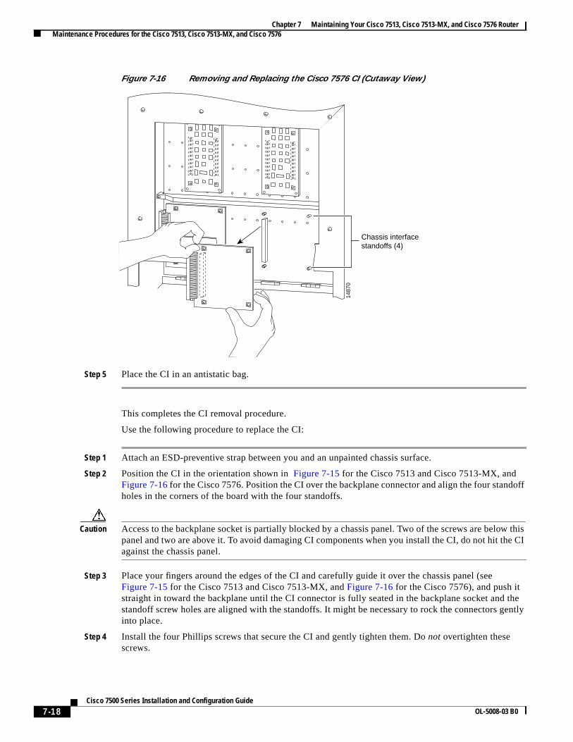
Figure 7-16 Removing and Replacing the Cisco 7576 CI (Cutaway View)
Step 5 Place the CI in an antistatic bag.
This completes the CI removal procedure.
Use the following procedure to replace the CI:
Step 1 Attach an ESD-preventive strap between you and an unpainted chassis surface.
Step 2 Position the CI in the orientation shown inFigure 7-15 for the Cisco 7513 and Cisco 7513-MX, andFigure 7-16for the Cisco 7576. Position the CI over the backplane connector and align the four stanholes in the corners of the board with the four standoffs.
Caution Access to the backplane socket is partially blocked by a chassis panel. Two of the screws are belopanel and two are above it. To avoid damaging CI components when you install the CI, do not hit thagainst the chassis panel.
Step 3 Place your fingers around the edges of the CI and carefully guide it over the chassis panel (seeFigure 7-15 for the Cisco 7513 and Cisco 7513-MX, andFigure 7-16 for the Cisco 7576), and push itstraight in toward the backplane until the CI connector is fully seated in the backplane socket anstandoff screw holes are aligned with the standoffs. It might be necessary to rock the connectors ginto place.
Step 4 Install the four Phillips screws that secure the CI and gently tighten them. Do not overtighten thesescrews.
1487
0
Chassis interfacestandoffs (4)
7-18Cisco 7500 Series Installation and Configuration Guide
OL-5008-03 B0

Chapter 7 Maintaining Your Cisco 7513, Cisco 7513-MX, and Cisco 7576 Router Maintenance Procedures for the Cisco 7513, Cisco 7513-MX, and Cisco 7576
7-13
o
6.
Step 5 Replace the backplane maintenance cover. (Follow Step 4 and Step 5 in the“Removing and Replacingthe Cisco 7513, Cisco 7513-MX, and Cisco 7576 Backplane Maintenance Cover” section on page.)
Step 6 Replace the chassis cover panels. (Follow Step 3 in the“Removing and Replacing the Cisco 7513, Cisc7513-MX, and Cisco 7576 Chassis Cover Panels” section on page 7-11.)
Step 7 Reconnect the power supplies and power sources.
This completes the CI replacement procedure in the Cisco 7513, Cisco 7513-MX, and Cisco 757
7-19Cisco 7500 Series Installation and Configuration Guide
OL-5008-03 B0
Chapter 7 Maintaining Your Cisco 7513, Cisco 7513-MX, and Cisco 7576 Router Maintenance Procedures for the Cisco 7513, Cisco 7513-MX, and Cisco 7576
7-20Cisco 7500 Series Installation and Configuration Guide
OL-5008-03 B0