WLAN Configuration Guide, Cisco IOS XE Release 3E ...
136
WLAN Configuration Guide, Cisco IOS XE Release 3E (Catalyst 3850 Switches) First Published: June 30, 2014 Last Modified: 0, Americas Headquarters Cisco Systems, Inc. 170 West Tasman Drive San Jose, CA 95134-1706 USA http://www.cisco.com Tel: 408 526-4000 800 553-NETS (6387) Fax: 408 527-0883 Text Part Number: OL-32352-01
-
Upload
khangminh22 -
Category
Documents
-
view
1 -
download
0
Transcript of WLAN Configuration Guide, Cisco IOS XE Release 3E ...

WLAN Configuration Guide, Cisco IOS XE Release 3E (Catalyst 3850Switches)First Published: June 30, 2014
Last Modified: 0,
Americas HeadquartersCisco Systems, Inc.170 West Tasman DriveSan Jose, CA 95134-1706USAhttp://www.cisco.comTel: 408 526-4000 800 553-NETS (6387)Fax: 408 527-0883
Text Part Number: OL-32352-01
THE SPECIFICATIONS AND INFORMATION REGARDING THE PRODUCTS IN THIS MANUAL ARE SUBJECT TO CHANGE WITHOUT NOTICE. ALL STATEMENTS,INFORMATION, AND RECOMMENDATIONS IN THIS MANUAL ARE BELIEVED TO BE ACCURATE BUT ARE PRESENTED WITHOUT WARRANTY OF ANY KIND,EXPRESS OR IMPLIED. USERS MUST TAKE FULL RESPONSIBILITY FOR THEIR APPLICATION OF ANY PRODUCTS.
THE SOFTWARE LICENSE AND LIMITEDWARRANTY FOR THE ACCOMPANYING PRODUCT ARE SET FORTH IN THE INFORMATION PACKET THAT SHIPPED WITHTHE PRODUCT AND ARE INCORPORATED HEREIN BY THIS REFERENCE. IF YOU ARE UNABLE TO LOCATE THE SOFTWARE LICENSE OR LIMITED WARRANTY,CONTACT YOUR CISCO REPRESENTATIVE FOR A COPY.
The Cisco implementation of TCP header compression is an adaptation of a program developed by the University of California, Berkeley (UCB) as part of UCB's public domain versionof the UNIX operating system. All rights reserved. Copyright © 1981, Regents of the University of California.
NOTWITHSTANDINGANYOTHERWARRANTYHEREIN, ALL DOCUMENT FILES AND SOFTWARE OF THESE SUPPLIERS ARE PROVIDED “AS IS"WITH ALL FAULTS.CISCO AND THE ABOVE-NAMED SUPPLIERS DISCLAIM ALL WARRANTIES, EXPRESSED OR IMPLIED, INCLUDING, WITHOUT LIMITATION, THOSE OFMERCHANTABILITY, FITNESS FORA PARTICULAR PURPOSEANDNONINFRINGEMENTORARISING FROMACOURSEOFDEALING, USAGE, OR TRADE PRACTICE.
IN NO EVENT SHALL CISCO OR ITS SUPPLIERS BE LIABLE FOR ANY INDIRECT, SPECIAL, CONSEQUENTIAL, OR INCIDENTAL DAMAGES, INCLUDING, WITHOUTLIMITATION, LOST PROFITS OR LOSS OR DAMAGE TO DATA ARISING OUT OF THE USE OR INABILITY TO USE THIS MANUAL, EVEN IF CISCO OR ITS SUPPLIERSHAVE BEEN ADVISED OF THE POSSIBILITY OF SUCH DAMAGES.
Any Internet Protocol (IP) addresses and phone numbers used in this document are not intended to be actual addresses and phone numbers. Any examples, command display output, networktopology diagrams, and other figures included in the document are shown for illustrative purposes only. Any use of actual IP addresses or phone numbers in illustrative content is unintentionaland coincidental.
Cisco and the Cisco logo are trademarks or registered trademarks of Cisco and/or its affiliates in the U.S. and other countries. To view a list of Cisco trademarks, go to this URL: http://www.cisco.com/go/trademarks. Third-party trademarks mentioned are the property of their respective owners. The use of the word partner does not imply a partnershiprelationship between Cisco and any other company. (1110R)
© 2014 Cisco Systems, Inc. All rights reserved.
C O N T E N T S
P r e f a c e Preface ix
Document Conventions ix
Related Documentation xi
Obtaining Documentation and Submitting a Service Request xi
C H A P T E R 1 Using the Command-Line Interface 1
Information About Using the Command-Line Interface 1
Command Modes 1
Using the Help System 3
Understanding Abbreviated Commands 4
No and Default Forms of Commands 5
CLI Error Messages 5
Configuration Logging 5
How to Use the CLI to Configure Features 6
Configuring the Command History 6
Changing the Command History Buffer Size 6
Recalling Commands 6
Disabling the Command History Feature 7
Enabling and Disabling Editing Features 7
Editing Commands Through Keystrokes 8
Editing Command Lines That Wrap 9
Searching and Filtering Output of show and more Commands 10
Accessing the CLI on a Switch Stack 11
Accessing the CLI Through a Console Connection or Through Telnet 11
C H A P T E R 2 Using the Web Graphical User Interface 13
Prerequisites for Using the Web GUI 13
WLAN Configuration Guide, Cisco IOS XE Release 3E (Catalyst 3850 Switches) OL-32352-01 iii
Information About Using The Web GUI 13
Web GUI Features 13
Connecting the Console Port of the Switch 15
Logging On to the Web GUI 15
Enabling Web and Secure Web Modes 15
Configuring the Switch Web GUI 16
C H A P T E R 3 Configuring WLANs 21
Finding Feature Information 21
Prerequisites for WLANs 21
Restrictions for WLANs 22
Information About WLANs 23
Band Selection 24
Off-Channel Scanning Defer 24
DTIM Period 25
Session Timeouts 25
Cisco Client Extensions 25
Peer-to-Peer Blocking 26
Diagnostic Channel 26
Per-WLAN Radius Source Support 26
How to Configure WLANs 27
Creating WLANs (CLI) 27
Creating WLANs (GUI) 28
Deleting WLANs 29
Deleting WLANs (GUI) 29
Searching WLANs 30
Searching WLANs (GUI) 30
Enabling WLANs (CLI) 31
Disabling WLANs (CLI) 32
Configuring General WLAN Properties (CLI) 32
Configuring General WLAN Properties (GUI) 35
Configuring Advanced WLAN Properties (CLI) 36
Configuring Advanced WLAN Properties (GUI) 39
Applying a QoS Policy on a WLAN (GUI) 43
Monitoring WLAN Properties (CLI) 44
WLAN Configuration Guide, Cisco IOS XE Release 3E (Catalyst 3850 Switches)iv OL-32352-01
Contents

Viewing WLAN Properties (GUI) 45
Where to Go Next 45
Additional References 45
Feature Information for WLANs 46
C H A P T E R 4 Configuring DHCP for WLANs 47
Finding Feature Information 47
Prerequisites for Configuring DHCP for WLANs 47
Restrictions for Configuring DHCP for WLANs 48
Information About the Dynamic Host Configuration Protocol 48
Internal DHCP Servers 49
External DHCP Servers 49
DHCP Assignments 50
Information About DHCP Option 82 51
Configuring DHCP Scopes 51
Information About DHCP Scopes 52
How to Configure DHCP for WLANs 52
Configuring DHCP for WLANs (CLI) 52
Configuring DHCP Scopes (CLI) 55
Additional References 56
Feature Information for DHCP for WLANs 57
C H A P T E R 5 Configuring WLAN Security 59
Finding Feature Information 59
Prerequisites for Layer 2 Security 59
Information About AAA Override 60
How to Configure WLAN Security 61
Configuring Static WEP + 802.1X Layer 2 Security Parameters (CLI) 61
Configuring Static WEP Layer 2 Security Parameters (CLI) 62
Configuring WPA + WPA2 Layer 2 Security Parameters (CLI) 63
Configuring 802.1X Layer 2 Security Parameters (CLI) 64
Configuring Layer 2 Parameters (GUI) 66
Additional References 69
Feature Information about WLAN Layer 2 Security 70
WLAN Configuration Guide, Cisco IOS XE Release 3E (Catalyst 3850 Switches) OL-32352-01 v
Contents
C H A P T E R 6 Setting Client Count Per WLAN 71
Finding Feature Information 71
Restrictions for Setting Client Count for WLANs 71
Information About Setting the Client Count per WLAN 72
How to Configure Client Count Per WLAN 72
Configuring Client Count per WLAN (CLI) 72
Configuring Client Count Per AP Per WLAN (CLI) 73
Configuring Client Count per AP Radio per WLAN (CLI) 74
Monitoring Client Connections (CLI) 75
Additional References for Client Connections 76
Feature Information about Client Connections Per WLAN 77
C H A P T E R 7 Configuring 802.11w 79
Finding Feature Information 79
Prerequisites for 802.11w 79
Restrictions for 802.11w 80
Information About 802.11w 80
How to Configure 802.11w 81
Configuring 802.11w (CLI) 81
Disabling 802.11w (CLI) 83
Monitoring 802.11w (CLI) 84
Additional References for 802.11w 85
Feature Information for 802.11w 86
C H A P T E R 8 Configuring Wi-Fi Direct Client Policy 89
Finding Feature Information 89
Restrictions for the Wi-Fi Direct Client Policy 89
Information About the Wi-Fi Direct Client Policy 89
How to Configure Wi-Fi Direct Client Policy 90
Configuring the Wi-Fi Direct Client Policy (CLI) 90
Disabling Wi-Fi Direct Client Policy (CLI) 91
Monitoring Wi-Fi Direct Client Policy (CLI) 92
Additional References for Wi-Fi Direct Client Policy 92
Feature Information about Wi-Fi Direct Client Policy 93
WLAN Configuration Guide, Cisco IOS XE Release 3E (Catalyst 3850 Switches)vi OL-32352-01
Contents
C H A P T E R 9 Configuring 802.11r BSS Fast Transition 95
Finding Feature Information 95
Restrictions for 802.11r Fast Transition 95
Information About 802.11r Fast Transition 96
How to Configure 802.11r Fast Transition 99
Configuring 802.11r Fast Transition in an Open WLAN (CLI) 99
Configuring 802.11r BSS Fast Transition on a Dot1x Security Enabled WLAN (CLI) 101
Configuring 802.11r Fast Transition on a PSK Security Enabled WLAN (CLI) 102
Configuring 802.11 Fast Transition (GUI) 104
Disabling 802.11r Fast Transition (CLI) 104
Monitoring 802.11r Fast Transition (GUI) 105
Monitoring 802.11r Fast Transition (CLI) 105
Additional References for 802.11r Fast Transition 107
Feature Information for 802.11r Fast Transition 108
C H A P T E R 1 0 Configuring Assisted Roaming 109
Finding Feature Information 109
Restrictions for Assisted Roaming 109
Information About Assisted Roaming 110
How to Configure Assisted Roaming 111
Configuring Assisted Roaming (CLI) 111
Monitoring Assisted Roaming 113
Configuration Examples for Assisted Roaming 113
Additional References for Assisted Roaming 114
Feature History and Information For Performing Assisted Roaming Configuration 115
C H A P T E R 1 1 Configuring Access Point Groups 117
Finding Feature Information 117
Prerequisites for Configuring AP Groups 117
Restrictions for Configuring Access Point Groups 118
Information About Access Point Groups 118
How to Configure Access Point Groups 119
Creating Access Point Groups 119
Assigning an Access Point to an AP Group 120
WLAN Configuration Guide, Cisco IOS XE Release 3E (Catalyst 3850 Switches) OL-32352-01 vii
Contents

Viewing Access Point Group 120
Additional References 121
Feature History and Information for Access Point Groups 122
WLAN Configuration Guide, Cisco IOS XE Release 3E (Catalyst 3850 Switches)viii OL-32352-01
Contents
Preface
• Document Conventions, page ix
• Related Documentation, page xi
• Obtaining Documentation and Submitting a Service Request, page xi
Document ConventionsThis document uses the following conventions:
DescriptionConvention
Both the ^ symbol and Ctrl represent the Control (Ctrl) key on a keyboard. Forexample, the key combination^D orCtrl-Dmeans that you hold down the Controlkey while you press the D key. (Keys are indicated in capital letters but are notcase sensitive.)
^ or Ctrl
Commands and keywords and user-entered text appear in bold font.bold font
Document titles, new or emphasized terms, and arguments for which you supplyvalues are in italic font.
Italic font
Terminal sessions and information the system displays appear in courier font.Courier font
Bold Courier font indicates text that the user must enter.Bold Courier font
Elements in square brackets are optional.[x]
An ellipsis (three consecutive nonbolded periods without spaces) after a syntaxelement indicates that the element can be repeated.
...
A vertical line, called a pipe, indicates a choice within a set of keywords orarguments.
|
Optional alternative keywords are grouped in brackets and separated by verticalbars.
[x | y]
WLAN Configuration Guide, Cisco IOS XE Release 3E (Catalyst 3850 Switches) OL-32352-01 ix

DescriptionConvention
Required alternative keywords are grouped in braces and separated by verticalbars.
{x | y}
Nested set of square brackets or braces indicate optional or required choiceswithin optional or required elements. Braces and a vertical bar within squarebrackets indicate a required choice within an optional element.
[x {y | z}]
A nonquoted set of characters. Do not use quotation marks around the string orthe string will include the quotation marks.
string
Nonprinting characters such as passwords are in angle brackets.< >
Default responses to system prompts are in square brackets.[ ]
An exclamation point (!) or a pound sign (#) at the beginning of a line of codeindicates a comment line.
!, #
Reader Alert Conventions
This document may use the following conventions for reader alerts:
Means reader take note. Notes contain helpful suggestions or references to material not covered in themanual.
Note
Means the following information will help you solve a problem.Tip
Means reader be careful. In this situation, you might do something that could result in equipment damageor loss of data.
Caution
Means the described action saves time. You can save time by performing the action described in theparagraph.
Timesaver
IMPORTANT SAFETY INSTRUCTIONS
This warning symbol means danger. You are in a situation that could cause bodily injury. Before youwork on any equipment, be aware of the hazards involved with electrical circuitry and be familiar withstandard practices for preventing accidents. Use the statement number provided at the end of each warningto locate its translation in the translated safety warnings that accompanied this device. Statement 1071
SAVE THESE INSTRUCTIONS
Warning
WLAN Configuration Guide, Cisco IOS XE Release 3E (Catalyst 3850 Switches)x OL-32352-01
PrefaceDocument Conventions

Related Documentation
Before installing or upgrading the switch, refer to the switch release notes.Note
• Cisco Catalyst 3850 Switch documentation, located at:http://www.cisco.com/go/cat3850_docs
• Cisco SFP and SFP+ modules documentation, including compatibility matrixes, located at:http://www.cisco.com/en/US/products/hw/modules/ps5455/tsd_products_support_series_home.html
• Cisco Validated Designs documents, located at:http://www.cisco.com/go/designzone
• Error Message Decoder, located at:
https://www.cisco.com/cgi-bin/Support/Errordecoder/index.cgi
Obtaining Documentation and Submitting a Service RequestFor information on obtaining documentation, submitting a service request, and gathering additional information,see the monthlyWhat's New in Cisco Product Documentation, which also lists all new and revised Ciscotechnical documentation, at:
http://www.cisco.com/c/en/us/td/docs/general/whatsnew/whatsnew.html
Subscribe to theWhat's New in Cisco Product Documentation as a Really Simple Syndication (RSS) feedand set content to be delivered directly to your desktop using a reader application. The RSS feeds are a freeservice and Cisco currently supports RSS version 2.0.
WLAN Configuration Guide, Cisco IOS XE Release 3E (Catalyst 3850 Switches) OL-32352-01 xi
PrefaceRelated Documentation

WLAN Configuration Guide, Cisco IOS XE Release 3E (Catalyst 3850 Switches)xii OL-32352-01
PrefaceObtaining Documentation and Submitting a Service Request
C H A P T E R 1Using the Command-Line Interface
• Information About Using the Command-Line Interface, page 1
• How to Use the CLI to Configure Features, page 6
Information About Using the Command-Line Interface
Command ModesThe Cisco IOS user interface is divided into many different modes. The commands available to you dependon whichmode you are currently in. Enter a questionmark (?) at the system prompt to obtain a list of commandsavailable for each command mode.
You can start a CLI session through a console connection, through Telnet, a SSH, or by using the browser.
When you start a session, you begin in user mode, often called user EXEC mode. Only a limited subset ofthe commands are available in user EXECmode. For example, most of the user EXEC commands are one-timecommands, such as show commands, which show the current configuration status, and clear commands,which clear counters or interfaces. The user EXEC commands are not saved when the switch reboots.
To have access to all commands, youmust enter privileged EXECmode. Normally, youmust enter a passwordto enter privileged EXEC mode. From this mode, you can enter any privileged EXEC command or enterglobal configuration mode.
Using the configurationmodes (global, interface, and line), you canmake changes to the running configuration.If you save the configuration, these commands are stored and used when the switch reboots. To access thevarious configuration modes, you must start at global configuration mode. From global configuration mode,you can enter interface configuration mode and line configuration mode.
This table describes the main command modes, how to access each one, the prompt you see in that mode, andhow to exit the mode.
WLAN Configuration Guide, Cisco IOS XE Release 3E (Catalyst 3850 Switches) OL-32352-01 1
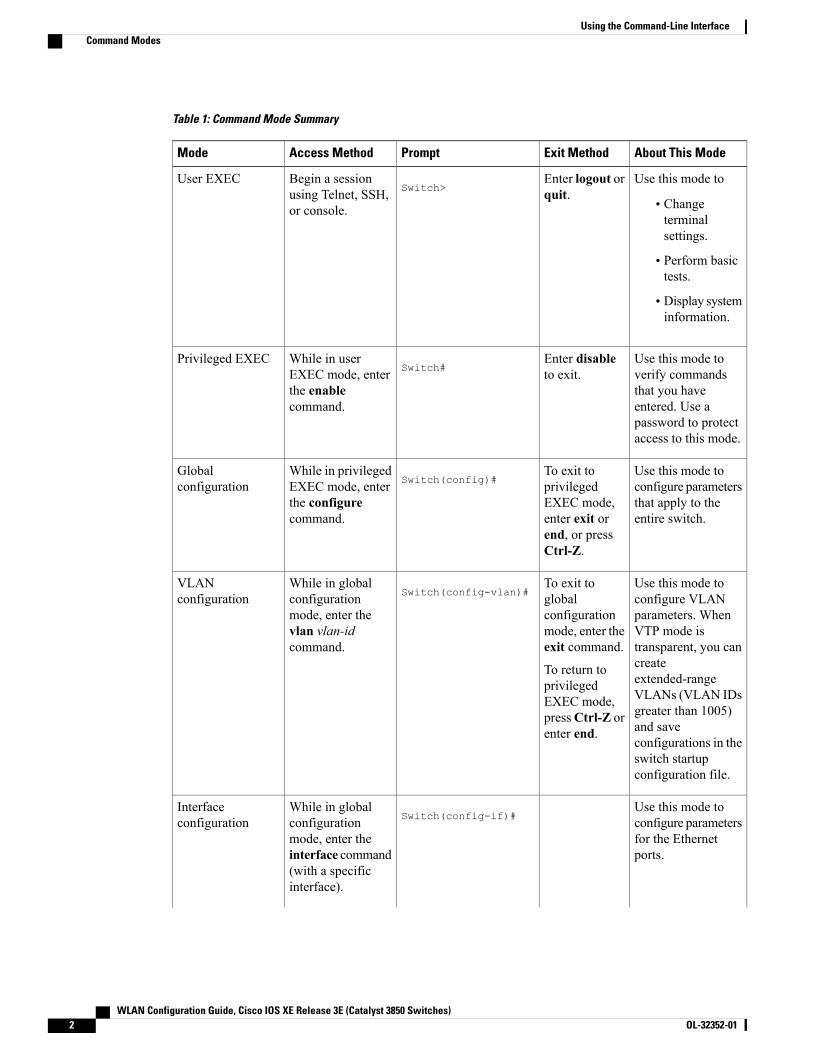
Table 1: Command Mode Summary
About This ModeExit MethodPromptAccess MethodMode
Use this mode to
• Changeterminalsettings.
• Perform basictests.
• Display systeminformation.
Enter logout orquit.Switch>
Begin a sessionusing Telnet, SSH,or console.
User EXEC
Use this mode toverify commandsthat you haveentered. Use apassword to protectaccess to this mode.
Enter disableto exit.Switch#
While in userEXEC mode, enterthe enablecommand.
Privileged EXEC
Use this mode toconfigure parametersthat apply to theentire switch.
To exit toprivilegedEXEC mode,enter exit orend, or pressCtrl-Z.
Switch(config)#While in privilegedEXEC mode, enterthe configurecommand.
Globalconfiguration
Use this mode toconfigure VLANparameters. WhenVTP mode istransparent, you cancreateextended-rangeVLANs (VLAN IDsgreater than 1005)and saveconfigurations in theswitch startupconfiguration file.
To exit toglobalconfigurationmode, enter theexit command.
To return toprivilegedEXEC mode,pressCtrl-Z orenter end.
Switch(config-vlan)#While in globalconfigurationmode, enter thevlan vlan-idcommand.
VLANconfiguration
Use this mode toconfigure parametersfor the Ethernetports.
Switch(config-if)#While in globalconfigurationmode, enter theinterface command(with a specificinterface).
Interfaceconfiguration
WLAN Configuration Guide, Cisco IOS XE Release 3E (Catalyst 3850 Switches)2 OL-32352-01
Using the Command-Line InterfaceCommand Modes
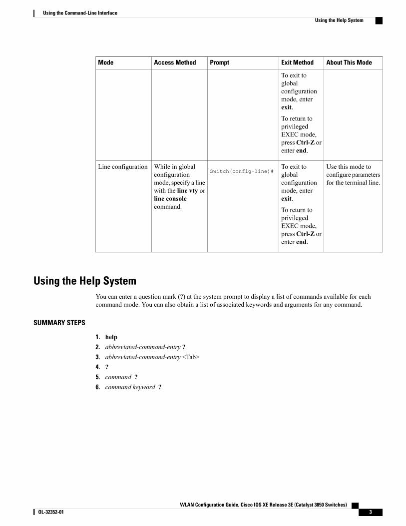
About This ModeExit MethodPromptAccess MethodMode
To exit toglobalconfigurationmode, enterexit.
To return toprivilegedEXEC mode,pressCtrl-Z orenter end.
Use this mode toconfigure parametersfor the terminal line.
To exit toglobalconfigurationmode, enterexit.
To return toprivilegedEXEC mode,pressCtrl-Z orenter end.
Switch(config-line)#While in globalconfigurationmode, specify a linewith the line vty orline consolecommand.
Line configuration
Using the Help SystemYou can enter a question mark (?) at the system prompt to display a list of commands available for eachcommand mode. You can also obtain a list of associated keywords and arguments for any command.
SUMMARY STEPS
1. help2. abbreviated-command-entry ?3. abbreviated-command-entry <Tab>4. ?5. command ?6. command keyword ?
WLAN Configuration Guide, Cisco IOS XE Release 3E (Catalyst 3850 Switches) OL-32352-01 3
Using the Command-Line InterfaceUsing the Help System
DETAILED STEPS
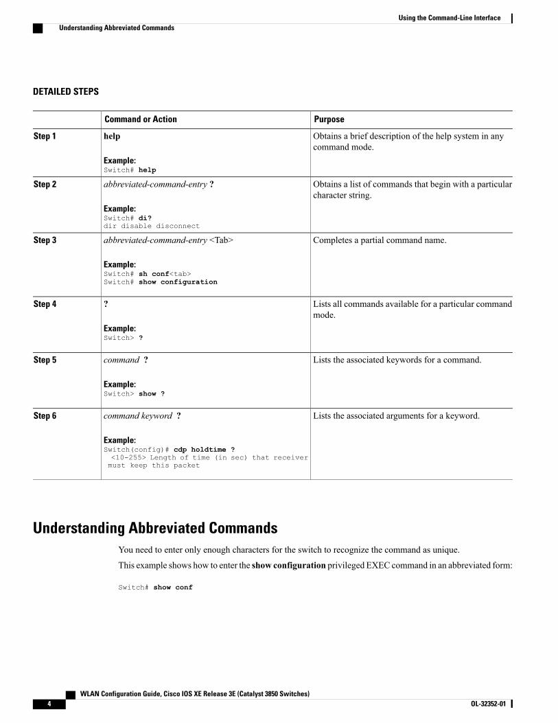
PurposeCommand or Action
Obtains a brief description of the help system in anycommand mode.
help
Example:Switch# help
Step 1
Obtains a list of commands that begin with a particularcharacter string.
abbreviated-command-entry ?
Example:Switch# di?dir disable disconnect
Step 2
Completes a partial command name.abbreviated-command-entry <Tab>
Example:Switch# sh conf<tab>Switch# show configuration
Step 3
Lists all commands available for a particular commandmode.
?
Example:Switch> ?
Step 4
Lists the associated keywords for a command.command ?
Example:Switch> show ?
Step 5
Lists the associated arguments for a keyword.command keyword ?
Example:Switch(config)# cdp holdtime ?<10-255> Length of time (in sec) that receiver
Step 6
must keep this packet
Understanding Abbreviated CommandsYou need to enter only enough characters for the switch to recognize the command as unique.
This example shows how to enter the show configuration privileged EXEC command in an abbreviated form:
Switch# show conf
WLAN Configuration Guide, Cisco IOS XE Release 3E (Catalyst 3850 Switches)4 OL-32352-01
Using the Command-Line InterfaceUnderstanding Abbreviated Commands
No and Default Forms of CommandsAlmost every configuration command also has a no form. In general, use the no form to disable a feature orfunction or reverse the action of a command. For example, the no shutdown interface configuration commandreverses the shutdown of an interface. Use the command without the keyword no to reenable a disabled featureor to enable a feature that is disabled by default.
Configuration commands can also have a default form. The default form of a command returns the commandsetting to its default. Most commands are disabled by default, so the default form is the same as the no form.However, some commands are enabled by default and have variables set to certain default values. In thesecases, the default command enables the command and sets variables to their default values.
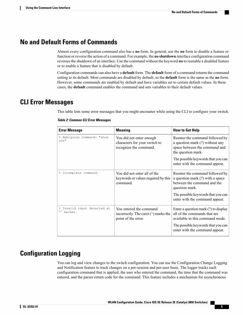
CLI Error MessagesThis table lists some error messages that you might encounter while using the CLI to configure your switch.
Table 2: Common CLI Error Messages
How to Get HelpMeaningError Message
Reenter the command followed bya question mark (?) without anyspace between the command andthe question mark.
The possible keywords that you canenter with the command appear.
You did not enter enoughcharacters for your switch torecognize the command.
% Ambiguous command: "showcon"
Reenter the command followed bya question mark (?) with a spacebetween the command and thequestion mark.
The possible keywords that you canenter with the command appear.
You did not enter all of thekeywords or values required by thiscommand.
% Incomplete command.
Enter a questionmark (?) to displayall of the commands that areavailable in this command mode.
The possible keywords that you canenter with the command appear.
You entered the commandincorrectly. The caret (^) marks thepoint of the error.
% Invalid input detected at‘^’ marker.
Configuration LoggingYou can log and view changes to the switch configuration. You can use the Configuration Change Loggingand Notification feature to track changes on a per-session and per-user basis. The logger tracks eachconfiguration command that is applied, the user who entered the command, the time that the command wasentered, and the parser return code for the command. This feature includes a mechanism for asynchronous
WLAN Configuration Guide, Cisco IOS XE Release 3E (Catalyst 3850 Switches) OL-32352-01 5
Using the Command-Line InterfaceNo and Default Forms of Commands
notification to registered applications whenever the configuration changes. You can choose to have thenotifications sent to the syslog.
Only CLI or HTTP changes are logged.Note
How to Use the CLI to Configure Features
Configuring the Command HistoryThe software provides a history or record of commands that you have entered. The command history featureis particularly useful for recalling long or complex commands or entries, including access lists. You cancustomize this feature to suit your needs.
Changing the Command History Buffer SizeBy default, the switch records ten command lines in its history buffer. You can alter this number for a currentterminal session or for all sessions on a particular line. This procedure is optional.
SUMMARY STEPS
1. terminal history [size number-of-lines]
DETAILED STEPS
PurposeCommand or Action
Changes the number of command lines that the switch records duringthe current terminal session in privileged EXEC mode. You canconfigure the size from 0 to 256.
terminal history [size number-of-lines]
Example:Switch# terminal history size 200
Step 1
Recalling CommandsTo recall commands from the history buffer, perform one of the actions listed in this table. These actions areoptional.
The arrow keys function only on ANSI-compatible terminals such as VT100s.Note
WLAN Configuration Guide, Cisco IOS XE Release 3E (Catalyst 3850 Switches)6 OL-32352-01
Using the Command-Line InterfaceHow to Use the CLI to Configure Features
SUMMARY STEPS
1. Ctrl-P or use the up arrow key2. Ctrl-N or use the down arrow key3. show history
DETAILED STEPS
PurposeCommand or Action
Recalls commands in the history buffer, beginningwith themost recent command.Repeat the key sequence to recall successively older commands.
Ctrl-P or use the up arrow keyStep 1
Returns to more recent commands in the history buffer after recalling commandswith Ctrl-P or the up arrow key. Repeat the key sequence to recall successivelymore recent commands.
Ctrl-N or use the down arrow keyStep 2
Lists the last several commands that you just entered in privileged EXEC mode.The number of commands that appear is controlled by the setting of the terminal
show history
Example:Switch# show history
Step 3
history global configuration command and the history line configurationcommand.
Disabling the Command History FeatureThe command history feature is automatically enabled. You can disable it for the current terminal session orfor the command line. This procedure is optional.
SUMMARY STEPS
1. terminal no history
DETAILED STEPS
PurposeCommand or Action
Disables the feature during the current terminal session inprivileged EXEC mode.
terminal no history
Example:Switch# terminal no history
Step 1
Enabling and Disabling Editing FeaturesAlthough enhanced editing mode is automatically enabled, you can disable it and reenable it.
WLAN Configuration Guide, Cisco IOS XE Release 3E (Catalyst 3850 Switches) OL-32352-01 7
Using the Command-Line InterfaceEnabling and Disabling Editing Features

SUMMARY STEPS
1. terminal editing2. terminal no editing
DETAILED STEPS
PurposeCommand or Action
Reenables the enhanced editing mode for the current terminalsession in privileged EXEC mode.
terminal editing
Example:Switch# terminal editing
Step 1
Disables the enhanced editing mode for the current terminalsession in privileged EXEC mode.
terminal no editing
Example:Switch# terminal no editing
Step 2
Editing Commands Through KeystrokesThe keystrokes help you to edit the command lines. These keystrokes are optional.
The arrow keys function only on ANSI-compatible terminals such as VT100s.Note
Table 3: Editing Commands
DescriptionEditing Commands
Moves the cursor back one character.Ctrl-B or use the left arrow key
Moves the cursor forward one character.Ctrl-F or use the right arrow key
Moves the cursor to the beginning of the commandline.
Ctrl-A
Moves the cursor to the end of the command line.Ctrl-E
Moves the cursor back one word.Esc B
Moves the cursor forward one word.Esc F
Transposes the character to the left of the cursor withthe character located at the cursor.
Ctrl-T
WLAN Configuration Guide, Cisco IOS XE Release 3E (Catalyst 3850 Switches)8 OL-32352-01
Using the Command-Line InterfaceEnabling and Disabling Editing Features

Erases the character to the left of the cursor.Delete or Backspace key
Deletes the character at the cursor.Ctrl-D
Deletes all characters from the cursor to the end ofthe command line.
Ctrl-K
Deletes all characters from the cursor to the beginningof the command line.
Ctrl-U or Ctrl-X
Deletes the word to the left of the cursor.Ctrl-W
Deletes from the cursor to the end of the word.Esc D
Capitalizes at the cursor.Esc C
Changes the word at the cursor to lowercase.Esc L
Capitalizes letters from the cursor to the end of theword.
Esc U
Designates a particular keystroke as an executablecommand, perhaps as a shortcut.
Ctrl-V or Esc Q
Scrolls down a line or screen on displays that arelonger than the terminal screen can display.
TheMore prompt is used for any output thathas more lines than can be displayed on theterminal screen, including show commandoutput. You can use the Return and Spacebar keystrokes whenever you see the Moreprompt.
Note
Return key
Scrolls down one screen.Space bar
Redisplays the current command line if the switchsuddenly sends a message to your screen.
Ctrl-L or Ctrl-R
Editing Command Lines That WrapYou can use a wraparound feature for commands that extend beyond a single line on the screen. When thecursor reaches the right margin, the command line shifts ten spaces to the left. You cannot see the first tencharacters of the line, but you can scroll back and check the syntax at the beginning of the command. Thekeystroke actions are optional.
To scroll back to the beginning of the command entry, press Ctrl-B or the left arrow key repeatedly. You canalso press Ctrl-A to immediately move to the beginning of the line.
WLAN Configuration Guide, Cisco IOS XE Release 3E (Catalyst 3850 Switches) OL-32352-01 9
Using the Command-Line InterfaceEnabling and Disabling Editing Features
The arrow keys function only on ANSI-compatible terminals such as VT100s.Note
The following example shows how to wrap a command line that extends beyond a single line on the screen.
SUMMARY STEPS
1. access-list2. Ctrl-A3. Return key
DETAILED STEPS
PurposeCommand or Action
Displays the global configuration command entry that extends beyondone line.
access-list
Example:
Switch(config)# access-list 101 permit tcp
Step 1
When the cursor first reaches the end of the line, the line is shifted tenspaces to the left and redisplayed. The dollar sign ($) shows that theline has been scrolled to the left. Each time the cursor reaches the endof the line, the line is again shifted ten spaces to the left.
10.15.22.25 255.255.255.0 10.15.22.35Switch(config)# $ 101 permit tcp10.15.22.25 255.255.255.0 10.15.22.35255.25Switch(config)# $t tcp 10.15.22.25255.255.255.0 131.108.1.20 255.255.255.0eqSwitch(config)# $15.22.25 255.255.255.010.15.22.35 255.255.255.0 eq 45
Checks the complete syntax.Ctrl-AStep 2
Example:Switch(config)# access-list 101 permit tcp10.15.22.25 255.255.255.0 10.15.2$
The dollar sign ($) appears at the end of the line to show that the linehas been scrolled to the right.
Execute the commands.Return keyStep 3
The software assumes that you have a terminal screen that is 80 columnswide. If you have a different width, use the terminal width privilegedEXEC command to set the width of your terminal.
Use line wrapping with the command history feature to recall andmodify previous complex command entries.
Searching and Filtering Output of show and more CommandsYou can search and filter the output for show andmore commands. This is useful when you need to sortthrough large amounts of output or if you want to exclude output that you do not need to see. Using thesecommands is optional.
WLAN Configuration Guide, Cisco IOS XE Release 3E (Catalyst 3850 Switches)10 OL-32352-01
Using the Command-Line InterfaceSearching and Filtering Output of show and more Commands

SUMMARY STEPS
1. {show |more} command | {begin | include | exclude} regular-expression
DETAILED STEPS
PurposeCommand or Action
Searches and filters the output.{show |more} command | {begin | include | exclude}regular-expression
Step 1
Expressions are case sensitive. For example, if you enter| exclude output, the lines that contain output are notdisplayed, but the lines that contain output appear.Example:
Switch# show interfaces | include protocolVlan1 is up, line protocol is upVlan10 is up, line protocol is downGigabitEthernet1/0/1 is up, line protocol is downGigabitEthernet1/0/2 is up, line protocol is up
Accessing the CLI on a Switch StackYou can access the CLI through a console connection, through Telnet, a SSH, or by using the browser.
Youmanage the switch stack and the stack member interfaces through the . You cannot manage stack memberson an individual switch basis. You can connect to the through the console port or the Ethernet managementport of one or more stack members. Be careful with using multiple CLI sessions on the . Commands that youenter in one session are not displayed in the other sessions. Therefore, it is possible to lose track of the sessionfrom which you entered commands.
We recommend using one CLI session when managing the switch stack.Note
If you want to configure a specific stack member port, you must include the stack member number in the CLIcommand interface notation.
Accessing the CLI Through a Console Connection or Through TelnetBefore you can access the CLI, you must connect a terminal or a PC to the switch console or connect a PC tothe Ethernet management port and then power on the switch, as described in the hardware installation guidethat shipped with your switch.
If your switch is already configured, you can access the CLI through a local console connection or through aremote Telnet session, but your switch must first be configured for this type of access.
You can use one of these methods to establish a connection with the switch:
• Connect the switch console port to a management station or dial-up modem, or connect the Ethernetmanagement port to a PC. For information about connecting to the console or Ethernet managementport, see the switch hardware installation guide.
WLAN Configuration Guide, Cisco IOS XE Release 3E (Catalyst 3850 Switches) OL-32352-01 11
Using the Command-Line InterfaceAccessing the CLI on a Switch Stack
• Use any Telnet TCP/IP or encrypted Secure Shell (SSH) package from a remote management station.The switch must have network connectivity with the Telnet or SSH client, and the switch must have anenable secret password configured.
• The switch supports up to 16 simultaneous Telnet sessions. Changes made by one Telnet user arereflected in all other Telnet sessions.
• The switch supports up to five simultaneous secure SSH sessions.
After you connect through the console port, through the Ethernet management port, through a Telnetsession or through an SSH session, the user EXEC prompt appears on the management station.
WLAN Configuration Guide, Cisco IOS XE Release 3E (Catalyst 3850 Switches)12 OL-32352-01
Using the Command-Line InterfaceAccessing the CLI Through a Console Connection or Through Telnet
C H A P T E R 2Using the Web Graphical User Interface
• Prerequisites for Using the Web GUI, page 13
• Information About Using The Web GUI, page 13
• Connecting the Console Port of the Switch , page 15
• Logging On to the Web GUI, page 15
• Enabling Web and Secure Web Modes , page 15
• Configuring the Switch Web GUI, page 16
Prerequisites for Using the Web GUI• The GUI must be used on a PC running Windows 7, Windows XP SP1 (or later releases), or Windows2000 SP4 (or later releases).
• The switch GUI is compatible with Microsoft Internet Explorer version 10.x, Mozilla Firefox 20.x, orGoogle Chrome 26.x.
Information About Using The Web GUIA web browser, or graphical user interface (GUI), is built into each switch.
You can use either the service port interface or the management interface to access the GUI. We recommendthat you use the service-port interface. Click Help at the top of any page in the GUI to display online help.You might need to disable your browser’s pop-up blocker to view the online help.
Web GUI FeaturesThe switch web GUI supports the following:
The Configuration Wizard—After initial configuration of the IP address and the local username/password orauth via the authentication server (privilege 15 needed), the wizard provides a method to complete the initial
WLAN Configuration Guide, Cisco IOS XE Release 3E (Catalyst 3850 Switches) OL-32352-01 13

wireless configuration. Start the wizard through Configuration -> Wizard and follow the nine-step process toconfigure the following:
• Admin Users
• SNMP System Summary
• Management Port
•Wireless Management
• RF Mobility and Country code
• Mobility configuration
•WLANs
• 802.11 Configuration
• Set Time
The Monitor tab:
• Displays summary details of switch, clients, and access points.
• Displays all radio and AP join statistics.
• Displays air quality on access points.
• Displays list of all Cisco Discovery Protocol (CDP) neighbors on all interfaces and the CDP trafficinformation.
• Displays all rogue access points based on their classification-friendly, malicious, ad hoc, classified, andunclassified.
The Configuration tab:
• Enables you to configure the switch for all initial operation using the web Configuration Wizard. Thewizard allows you to configure user details, management interface, and so on.
• Enables you to configure the system, internal DHCP server, management, and mobility managementparameters.
• Enables you to configure the switch, WLAN, and radios.
• Enables you to configure and set security policies on your switch.
• Enables you to access the switch operating system software management commands.
The Administration tab enables you to configure system logs.
WLAN Configuration Guide, Cisco IOS XE Release 3E (Catalyst 3850 Switches)14 OL-32352-01
Using the Web Graphical User InterfaceWeb GUI Features
Connecting the Console Port of the SwitchBefore You Begin
Before you can configure the switch for basic operations, you need to connect it to a PC that uses a VT-100terminal emulation program (such as HyperTerminal, ProComm, Minicom, or Tip).
Step 1 Connect one end of a null-modem serial cable to the switch's RJ-45 console port and the other end to your PC's serialport.
Step 2 Plug the AC power cord into the switch and a grounded 100 to 240 VAC, 50/60-Hz electrical outlet. Turn on the powersupply. The bootup script displays operating system software initialization (code download and power-on self-testverification) and basic configuration. If the switch passes the power-on self-test, the bootup script runs the configurationwizard, which prompts you for basic configuration input.
Step 3 Enter yes. Proceed with basic initial setup configuration parameters in the CLI setup wizard. Specify the IP address forthe service port which is the gigabitethernet 0/0 interface.After entering the configuration parameters in the configuration wizard, you can access the Web GUI. Now, the switchis configured with the IP address for service port.
Logging On to the Web GUI
Enter the switch IP address in your browser’s address bar. For a secure connection, enter https://ip-address. For a lesssecure connection, enter http://ip-address.
Enabling Web and Secure Web Modes
Step 1 Choose Configuration >Management > Protocol Management > HTTP-HTTPS.
The HTTP-HTTPS Configuration page appears.
Step 2 To enable web mode, which allows users to access the switch GUI using “http://ip-address,” choose Enabled from theHTTP Access drop-down list. Otherwise, choose Disabled. Web mode (HTTP) is not a secure connection.
WLAN Configuration Guide, Cisco IOS XE Release 3E (Catalyst 3850 Switches) OL-32352-01 15
Using the Web Graphical User InterfaceConnecting the Console Port of the Switch
Step 3 To enable secure web mode, which allows users to access the switch GUI using “https://ip-address,” choose Enabledfrom the HTTPSAccess drop-down list. Otherwise, choose Disabled. Secure webmode (HTTPS) is a secure connection.
Step 4 Choose to track the device in the IP Device Tracking check box.Step 5 Choose to enable the trust point in the Enable check box.Step 6 Choose the trustpoints from the Trustpoints drop-down list.Step 7 Enter the amount of time, in seconds, before the web session times out due to inactivity in the HTTP Timeout-policy (1
to 600 sec) text box.The valid range is from 1 to 600 seconds.
Step 8 Enter the server life time in the Server Life Time (1 to 86400 sec) text box.The valid range is from1 to 86400 seconds.
Step 9 Enter the maximum number of connection requests that the server can accept in the Maximum number of Requests (1to 86400) text box.The valid range is from 1 to 86400 connections.
Step 10 Click Apply.Step 11 Click Save Configuration.
Configuring the Switch Web GUIThe configuration wizard enables you to configure basic settings on the switch. You can run the wizard afteryou receive the switch from the factory or after the switch has been reset to factory defaults. The configurationwizard is available in both GUI and CLI formats.
Step 1 Connect your PC to the service port and configure an IPv4 address to use the same subnet as the switch. The switch isloaded with IOS XE image and the service port interface is configured as gigabitethernet 0/0.
Step 2 Start Internet Explorer 10 (or later), Firefox 2.0.0.11 (or later), or Google Chrome on your PC and enter the managementinterface IP address on the browser window. The management interface IP address is same as the gigabitethernet 0/0(also known as service port interface).When you log in for the first time, you need to enter HTTP username and password.By default, the username is admin and the password is cisco.You can use both HTTP and HTTPS when using the service port interface. HTTPS is enabled by default and HTTP canalso be enabled.
When you log in for the first time, the <Model Number> <Hostname> page appears.
Step 3 On the page, click theWireless Web GUI link to access switch web GUI Home page.Step 4 Choose Configuration >Wizard to perform all steps that you need to configure the switch initially.
The Admin Users page appears.
Step 5 On the Admin Users page, enter the administrative username to be assigned to this switch in the User Name text boxand the administrative password to be assigned to this switch in the Password and Confirm Password text boxes. ClickNext.The default username is admin and the default password is cisco. You can also create a new administrator user for theswitch. You can enter up to 24 ASCII characters for username and password.
WLAN Configuration Guide, Cisco IOS XE Release 3E (Catalyst 3850 Switches)16 OL-32352-01
Using the Web Graphical User InterfaceConfiguring the Switch Web GUI

The SNMP System Summary page appears.
Step 6 On the SNMP System Summary page, enter the following SNMP system parameters for the switch, and click Next:
• Customer-definable switch location in the Location text box.
• Customer-definable contact details such as phone number with names in the Contact text box.
• Choose enabled to send SNMP notifications for various SNMP traps or disabled not to send SNMP notificationsfor various SNMP traps from the SNMP Global Trap drop-down list.
• Choose enabled to send system log messages or disabled not to send system log messages from the SNMP Loggingdrop-down list.
The SNMP trap server, must be reachable through the distribution ports (and not through the gigabitethernet0/0service or management interface).
Note
TheManagement Port page appears.
Step 7 In theManagement Port page, enter the following parameters for the management port interface (gigabitethernet 0/0)and click Next.
• Interface IP address that you assigned for the service port in the IP Address text box.
• Network mask address of the management port interface in the Netmask text box.
• The IPv4 Dynamic Host Configuration Protocol (DHCP) address for the selected port in the IPv4 DHCP Servertext box.
TheWireless Management page appears.
Step 8 In theWireless Management page, enter the following wireless interface management details, and click Next.
• Choose the interface—VLAN, or Ten Gigabit Ethernet from the Select Interface drop-down list.
• VLAN tag identifier, or 0 for no VLAN tag in the VLAN id text box.
• IP address of wireless management interface where access points are connected in the IP Address text box.
• Network mask address of the wireless management interface in the Netmask text box.
• DHCP IPv4 IP address in the IPv4 DHCP Server text box.
When selecting VLAN as interface, you can specify the ports as –Trunk or Access ports from the selected list displayedin the Switch Port Configuration text box.
The RF Mobility and Country Code page appears.
Step 9 In the RF Mobility and Country Code page, enter the RF mobility domain name in the RF Mobility text box, choosecurrent country code from the Country Code drop-down list, and click Next. From the GUI, you can select only onecountry code.
Before configuring RF grouping parameters and mobility configuration, ensure that you refer to the relevantconceptual content and then proceed with the configuration.
Note
TheMobility Configuration page with mobility global configuration settings appears.
Step 10 In theMobility Configuration page, view and enter the following mobility global configuration settings, and clickNext.
• ChooseMobility Controller orMobility Agent from the Mobility Role drop-down list:
WLAN Configuration Guide, Cisco IOS XE Release 3E (Catalyst 3850 Switches) OL-32352-01 17
Using the Web Graphical User InterfaceConfiguring the Switch Web GUI
If Mobility Agent is chosen, enter the mobility controller IP address in the Mobility Controller IP Addresstext box and mobility controller IP address in the Mobility Controller Public IP Address text box.
•
• If Mobility Controller is chosen, then the mobility controller IP address and mobility controller public IPaddress are displayed in the respective text boxes.
• Displays mobility protocol port number in the Mobility Protocol Port text box.
• Displays the mobility switch peer group name in the Mobility Switch Peer Group Name text box.
• Displays whether DTLS is enabled in the DTLS Mode text box.
DTLS is a standards-track Internet Engineering Task Force (IETF) protocol based on TLS.
• Displays mobility domain identifier for 802.11 radios in the Mobility Domain ID for 802.11 radios text box.
• The amount of time (in seconds) between each ping request sent to an peer switch in theMobility Keepalive Interval(1-30)sec text box.
Valid range is from 1 to 30 seconds, and the default value is 10 seconds.
• Number of times a ping request is sent to an peer switch before the peer is considered to be unreachable in theMobility Keepalive Count (3-20) text box.
The valid range is from 3 to 20, and the default value is 3.
• The DSCP value that you can set for the mobility switch in the Mobility Control Message DSCP Value (0-63) textbox.
The valid range is 0 to 63, and the default value is 0.
• Displays the number of mobility switch peer group member configured in the Switch Peer Group MembersConfigured text box.
TheWLANs page appears.
Step 11 In theWLANs page, enter the following WLAN configuration parameters, and click Next.
•WLAN identifier in the WLAN ID text box.
• SSID of the WLAN that the client is associated with in the SSID text box.
• Name of the WLAN used by the client in the Profile Name text box.
The 802.11 Configuration page appears.
Step 12 In the 802.11 Configuration page, check either one or both 802.11a/n/ac and 802.11b/g/n check boxes to enable the802.11 radios, and click Next.The Set Time page appears.
Step 13 In the Set Time page, you can configure the time and date on the switch based on the following parameters, and clickNext.
• Displays current timestamp on the switch in the Current Time text box.
• Choose either Manual or NTP from the Mode drop-down list.
On using the NTP server, all access points connected to the switch, synchronizes its time based on the NTP serversettings available.
WLAN Configuration Guide, Cisco IOS XE Release 3E (Catalyst 3850 Switches)18 OL-32352-01
Using the Web Graphical User InterfaceConfiguring the Switch Web GUI
• Choose date on the switch from the Year, Month, and Day drop-down list.
• Choose time from the Hours, Minutes, and Seconds drop-down list.
• Enter the time zone in the Zone text box and select the off setting required when compared to the current timeconfigured on the switch from the Offset drop-down list.
The Save Wizard page appears.
Step 14 In the Save Wizard page, you can review the configuration settings performed on the switch using these steps, and ifyou wish to change any configuration value, click Previous and navigate to that page.You can save the switch configuration created using the wizard only if a success message is displayed for all the wizards.If the Save Wizard page displays errors, you must recreate the wizard for initial configuration of the switch.
WLAN Configuration Guide, Cisco IOS XE Release 3E (Catalyst 3850 Switches) OL-32352-01 19
Using the Web Graphical User InterfaceConfiguring the Switch Web GUI

WLAN Configuration Guide, Cisco IOS XE Release 3E (Catalyst 3850 Switches)20 OL-32352-01
Using the Web Graphical User InterfaceConfiguring the Switch Web GUI

C H A P T E R 3Configuring WLANs
• Finding Feature Information, page 21
• Prerequisites for WLANs, page 21
• Restrictions for WLANs, page 22
• Information About WLANs, page 23
• How to Configure WLANs, page 27
• Monitoring WLAN Properties (CLI), page 44
• Viewing WLAN Properties (GUI), page 45
• Where to Go Next, page 45
• Additional References, page 45
• Feature Information for WLANs, page 46
Finding Feature InformationYour software release may not support all the features documented in this module. For the latest featureinformation and caveats, see the release notes for your platform and software release. To find informationabout the features documented in this module, and to see a list of the releases in which each feature is supported,see the Feature Information Table at the end of this document.
Use Cisco Feature Navigator to find information about platform support and Cisco software image support.To access Cisco Feature Navigator, go to http://www.cisco.com/go/cfn. An account on Cisco.com is notrequired.
Prerequisites for WLANs• You can associate up to 16 WLANs with each access point group and assign specific access points toeach group. Each access point advertises only the enabledWLANs that belong to its access point group.The access point (AP) does not advertise disabled WLANs in its access point group or WLANs thatbelong to another group.
WLAN Configuration Guide, Cisco IOS XE Release 3E (Catalyst 3850 Switches) OL-32352-01 21
•We recommend that you assign one set of VLANs for WLANs and a different set of VLANs formanagement interfaces to ensure that switches properly route VLAN traffic.
• The switch uses different attributes to differentiate betweenWLANswith the same Service Set Identifier(SSID).
•WLANs with the same SSID and same Layer 2 policy cannot be created if the WLAN ID is lowerthan 17.
• Two WLANs with IDs that are greater than 17 and that have the same SSID and same Layer 2policy is allowed if WLANs are added in different AP groups.
This requirement ensures that clients never detect the SSID present on the same accesspoint radio.
Note
Related Topics
Creating WLANs (CLI), on page 27
Creating WLANs (GUI), on page 28
Configuring General WLAN Properties (CLI), on page 32
Configuring General WLAN Properties (GUI), on page 35
Deleting WLANs, on page 29
Configuring Advanced WLAN Properties (CLI), on page 36
Configuring Advanced WLAN Properties (GUI), on page 39
Band Selection, on page 24
Off-Channel Scanning DeferDTIM PeriodSession TimeoutCisco Client Extensions, on page 25
Peer-to-Peer Blocking, on page 26Diagnostic ChannelClient Count Per WLANEnabling WLANs (CLI), on page 31
Disabling WLANs (CLI), on page 32
Restrictions for WLANs• Peer-to-peer blocking does not apply to multicast traffic.
• You can configure a maximum up to of 2000 clients.
• The WLAN name and SSID can have up to 32 characters. Spaces are not allowed in the WLAN profilename and SSID.
• You cannot map a WLAN to VLAN0, and you cannot map VLANs 1002 to 1006.
WLAN Configuration Guide, Cisco IOS XE Release 3E (Catalyst 3850 Switches)22 OL-32352-01
Configuring WLANsRestrictions for WLANs
• Dual stack clients with a static-IPv4 address is not supported.
•When creating a WLAN with the same SSID, you must create a unique profile name for each WLAN.
•When multiple WLANs with the same SSID get assigned to the same AP radio, you must have a uniqueLayer 2 security policy so that clients can safely select between them.
Some clients might not be able to connect to WLANs properly if they detect the same SSID with multiplesecurity policies. Use this feature with care.
Caution
Related Topics
Creating WLANs (CLI), on page 27
Creating WLANs (GUI), on page 28
Configuring General WLAN Properties (CLI), on page 32
Configuring General WLAN Properties (GUI), on page 35
Deleting WLANs, on page 29
Configuring Advanced WLAN Properties (CLI), on page 36
Configuring Advanced WLAN Properties (GUI), on page 39
Band Selection, on page 24
Off-Channel Scanning DeferDTIM PeriodSession TimeoutCisco Client Extensions, on page 25
Peer-to-Peer Blocking, on page 26Diagnostic ChannelClient Count Per WLANEnabling WLANs (CLI), on page 31
Disabling WLANs (CLI), on page 32
Information About WLANsThis feature enables you to control up to 64WLANs for lightweight access points. EachWLAN has a separateWLAN ID, a separate profile name, and a WLAN SSID. All switches publish up to 16 WLANs to eachconnected access point, but you can create up to the maximum number of WLANs supported and thenselectively publish these WLANs (using access point groups) to different access points to better manage yourwireless network.
You can configure WLANs with different SSIDs or with the same SSID. An SSID identifies the specificwireless network that you want the switch to access.
WLAN Configuration Guide, Cisco IOS XE Release 3E (Catalyst 3850 Switches) OL-32352-01 23
Configuring WLANsInformation About WLANs
Band SelectionBand selection enables client radios that are capable of dual-band (2.4- and 5-GHz) operation to move to aless congested 5-GHz access point. The 2.4-GHz band is often congested. Clients on this band typicallyexperience interference from Bluetooth devices, microwave ovens, and cordless phones as well as co-channelinterference from other access points because of the 802.11b/g limit of three nonoverlapping channels. Toprevent these sources of interference and improve overall network performance, you can configure bandselection on the switch.
Band selection works by regulating probe responses to clients. It makes 5-GHz channels more attractive toclients by delaying probe responses to clients on 2.4-GHz channels.
Related Topics
Configuring Advanced WLAN Properties (CLI), on page 36
Configuring Advanced WLAN Properties (GUI), on page 39
Prerequisites for WLANs, on page 21
Restrictions for WLANs, on page 22
Off-Channel Scanning DeferIn deployments with certain power-save clients, you sometimes need to defer the Radio ResourceManagement's(RRM) normal off-channel scanning to avoid missing critical information from low-volume clients (forexample, medical devices that use power-save mode and periodically send telemetry information). This featureimproves the way that Quality of Service (QoS) interacts with the RRM scan defer feature.
You can use a client'sWi-FiMultimedia (WMM)UPmarking to configure the access point to defer off-channelscanning for a configurable period of time if it receives a packet marked UP.
Off-Channel Scanning Defer is essential to the operation of RRM, which gathers information about alternatechannel choices such as noise and interference. Additionally, Off-Channel Scanning Defer is responsible forrogue detection. Devices that need to defer Off-Channel Scanning Defer should use the sameWLAN as oftenas possible. If there are many of these devices (and the possibility exists that Off-Channel Defer scanningcould be completely disabled by the use of this feature), you should implement an alternative to local APOff-Channel Scanning Defer, such as monitoring access points, or other access points in the same locationthat do not have this WLAN assigned.
You can assign a QoS policy (bronze, silver, gold, and platinum) to aWLAN to affect how packets are markedon the downlink connection from the access point regardless of how they were received on the uplink fromthe client. UP=1,2 is the lowest priority, and UP=0,3 is the next higher priority. The marking results of eachQoS policy are as follows:
• Bronze marks all downlink traffic to UP= 1.
• Silver marks all downlink traffic to UP= 0.
• Gold marks all downlink traffic to UP=4.
• Platinum marks all downlink traffic to UP=6.
WLAN Configuration Guide, Cisco IOS XE Release 3E (Catalyst 3850 Switches)24 OL-32352-01
Configuring WLANsBand Selection
DTIM PeriodIn the 802.11 networks, lightweight access points broadcast a beacon at regular intervals, which coincideswith the Delivery Traffic Indication Map (DTIM). After the access point broadcasts the beacon, it transmitsany buffered broadcast and multicast frames based on the value set for the DTIM period. This feature allowspower-saving clients to wake up at the appropriate time if they are expecting broadcast or multicast data.
Typically, the DTIM value is set to 1 (to transmit broadcast and multicast frames after every beacon) or 2 (totransmit after every other beacon). For instance, if the beacon period of the 802.11 network is 100 ms and theDTIM value is set to 1, the access point transmits buffered broadcast and multicast frames 10 times per second.If the beacon period is 100 ms and the DTIM value is set to 2, the access point transmits buffered broadcastand multicast frames 5 times per second. Either of these settings are suitable for applications, including VoiceOver IP (VoIP), that expect frequent broadcast and multicast frames.
However, the DTIM value can be set as high as 255 (to transmit broadcast and multicast frames after every255th beacon) if all 802.11 clients have power save enabled. Because the clients have to listen only when theDTIM period is reached, they can be set to listen for broadcasts and multicasts less frequently which resultsin a longer battery life. For example, if the beacon period is 100 ms and you set the DTIM value to 100, theaccess point transmits buffered broadcast and multicast frames once every 10 seconds. This rate allows thepower-saving clients to sleep longer before they have to wake up and listen for broadcasts and multicasts,which results in a longer battery life.
A beacon period, which is specified in milliseconds on the switch, is converted internally by the softwareto 802.11 Time Units (TUs), where 1 TU = 1.024 milliseconds. On Cisco’s 802.11n access points, thisvalue is rounded to the nearest multiple of 17 TUs. For example, a configured beacon period of 100 msresults in an actual beacon period of 104 ms.
Note
Many applications cannot tolerate a long time between broadcast and multicast messages, which results inpoor protocol and application performance.We recommend that you set a lowDTIM value for 802.11 networksthat support such clients.
Session TimeoutsYou can configure a WLAN with a session timeout. The session timeout is the maximum time for a clientsession to remain active before requiring reauthorization.
Cisco Client ExtensionsThe Cisco Client Extensions (CCX) software is licensed to manufacturers and vendors of third-party clientdevices. The CCX code resident on these clients enables them to communicate wirelessly with Cisco accesspoints and to support Cisco features that other client devices do not, including those features that are relatedto increased security, enhanced performance, fast roaming, and power management.
• The software supports CCX versions 1 through 5, which enables switches and their access points tocommunicate wirelessly with third-party client devices that support CCX. CCX support is enabledautomatically for every WLAN on the switch and cannot be disabled. However, you can configureAironet information elements (IEs).
WLAN Configuration Guide, Cisco IOS XE Release 3E (Catalyst 3850 Switches) OL-32352-01 25
Configuring WLANsDTIM Period
• If Aironet IE support is enabled, the access point sends an Aironet IE 0x85 (which contains the accesspoint name, load, number of associated clients, and so on) in the beacon and probe responses of thisWLAN, and the switch sends Aironet IEs 0x85 and 0x95 (which contains the management IP addressof the switch and the IP address of the access point) in the reassociation response if it receives AironetIE 0x85 in the reassociation request.
Related Topics
Configuring Advanced WLAN Properties (CLI), on page 36
Configuring Advanced WLAN Properties (GUI), on page 39
Prerequisites for WLANs, on page 21
Restrictions for WLANs, on page 22
Peer-to-Peer BlockingPeer-to-peer blocking is applied to individual WLANs, and each client inherits the peer-to-peer blockingsetting of theWLAN to which it is associated. Peer-to-Peer enables you to have more control over how trafficis directed. For example, you can choose to have traffic bridged locally within the switch, dropped by theswitch, or forwarded to the upstream VLAN.
Peer-to-peer blocking is supported for clients that are associated with the local switching WLAN.
Related Topics
Configuring Advanced WLAN Properties (CLI), on page 36
Configuring Advanced WLAN Properties (GUI), on page 39
Prerequisites for WLANs, on page 21
Restrictions for WLANs, on page 22
Diagnostic ChannelYou can choose a diagnostic channel to troubleshoot why the client is having communication problems witha WLAN. You can test the client and access points to identify the difficulties that the client is experiencingand allow corrective measures to be taken to make the client operational on the network. You can use theswitch GUI or CLI to enable the diagnostic channel, and you can use the switch CLI to run the diagnostictests.
We recommend that you enable the diagnostic channel feature only for nonanchored SSIDs that use themanagement interface. CCX Diagnostic feature has been tested only with clients having Cisco ADU card
Note
Per-WLAN Radius Source SupportBy default, the switch sources all RADIUS traffic from the IP address on its management interface, whichmeans that even if a WLAN has specific RADIUS servers configured instead of the global list, the identityused is the management interface IP address.
WLAN Configuration Guide, Cisco IOS XE Release 3E (Catalyst 3850 Switches)26 OL-32352-01
Configuring WLANsPeer-to-Peer Blocking
If you want to filterWLANs, you can use the callStationID that is set by RFC 3580 to be in the APMAC:SSIDformat. You can also extend the filtering on the authentication server to be on a per-WLAN source interfaceby using the NAS-IP-Address attribute.
When you enable the per-WLAN RADIUS source support, the switch sources all RADIUS traffic for aparticular WLAN by using the dynamic interface that is configured. Also, RADIUS attributes are modifiedaccordingly to match the identity. This feature virtualizes the switch on the per-WLANRADIUS traffic, whereeach WLAN can have a separate layer 3 identity. This feature is useful in deployments that integrate withACS Network Access Restrictions and Network Access Profiles.
You can combine per-WLAN RADIUS source support with the normal RADIUS traffic source and someWLANs that use the management interface and others using the per-WLAN dynamic interface as the addresssource.
How to Configure WLANs
Creating WLANs (CLI)
SUMMARY STEPS
1. configure terminal2. wlan profile-name wlan-id [ssid]3. end
DETAILED STEPS
PurposeCommand or Action
Enters global configuration mode.configure terminal
Example:Switch# configure terminal
Step 1
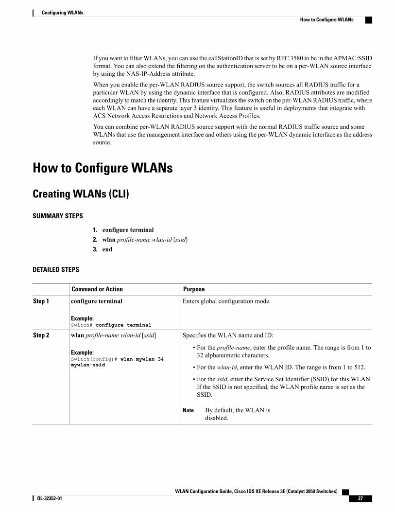
Specifies the WLAN name and ID:wlan profile-name wlan-id [ssid]Step 2
Example:Switch(config)# wlan mywlan 34mywlan-ssid
• For the profile-name, enter the profile name. The range is from 1 to32 alphanumeric characters.
• For the wlan-id, enter the WLAN ID. The range is from 1 to 512.
• For the ssid, enter the Service Set Identifier (SSID) for this WLAN.If the SSID is not specified, the WLAN profile name is set as theSSID.
By default, the WLAN isdisabled.
Note
WLAN Configuration Guide, Cisco IOS XE Release 3E (Catalyst 3850 Switches) OL-32352-01 27
Configuring WLANsHow to Configure WLANs
PurposeCommand or Action
Returns to privileged EXECmode. Alternatively, you can also pressCtrl-Zto exit global configuration mode.
end
Example:Switch(config)# end
Step 3
Related Topics
Prerequisites for WLANs, on page 21
Restrictions for WLANs, on page 22
Creating WLANs (GUI)
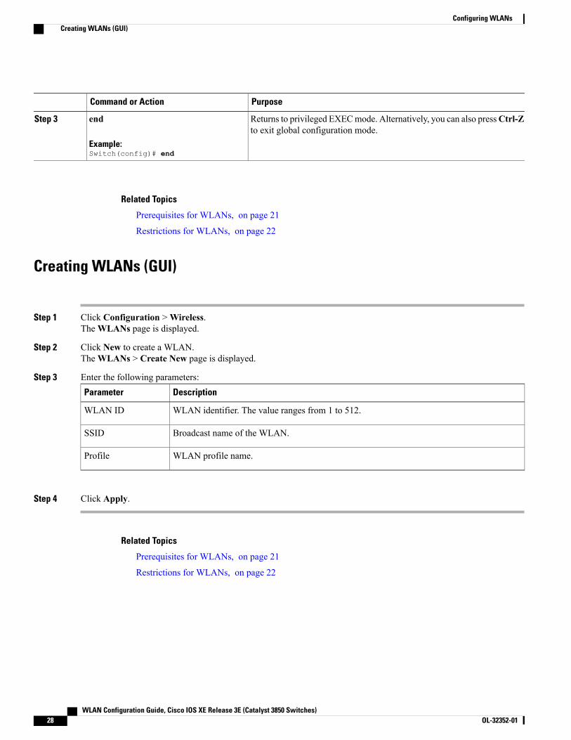
Step 1 Click Configuration >Wireless.TheWLANs page is displayed.
Step 2 Click New to create a WLAN.TheWLANs > Create New page is displayed.
Step 3 Enter the following parameters:DescriptionParameter
WLAN identifier. The value ranges from 1 to 512.WLAN ID
Broadcast name of the WLAN.SSID
WLAN profile name.Profile
Step 4 Click Apply.
Related Topics
Prerequisites for WLANs, on page 21
Restrictions for WLANs, on page 22
WLAN Configuration Guide, Cisco IOS XE Release 3E (Catalyst 3850 Switches)28 OL-32352-01
Configuring WLANsCreating WLANs (GUI)
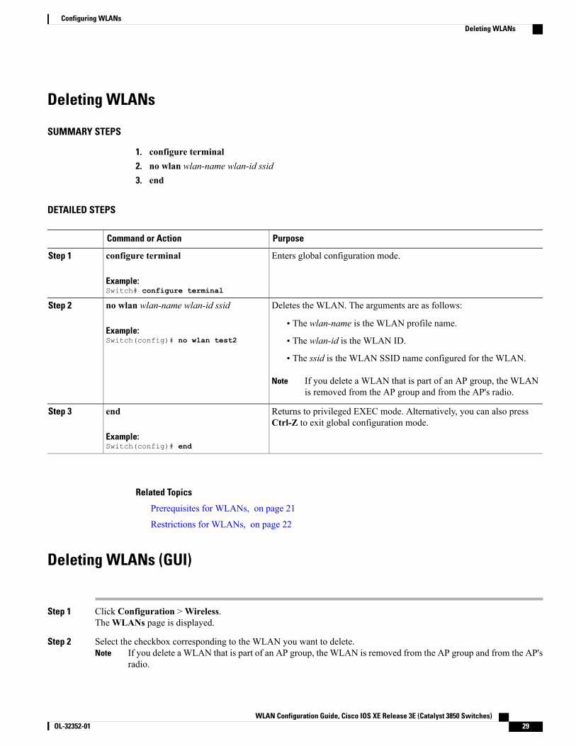
Deleting WLANs
SUMMARY STEPS
1. configure terminal2. no wlan wlan-name wlan-id ssid3. end
DETAILED STEPS
PurposeCommand or Action
Enters global configuration mode.configure terminal
Example:Switch# configure terminal
Step 1
Deletes the WLAN. The arguments are as follows:no wlan wlan-name wlan-id ssid
Example:Switch(config)# no wlan test2
Step 2
• The wlan-name is the WLAN profile name.
• The wlan-id is the WLAN ID.
• The ssid is the WLAN SSID name configured for the WLAN.
If you delete a WLAN that is part of an AP group, the WLANis removed from the AP group and from the AP's radio.
Note
Returns to privileged EXEC mode. Alternatively, you can also pressCtrl-Z to exit global configuration mode.
end
Example:Switch(config)# end
Step 3
Related Topics
Prerequisites for WLANs, on page 21
Restrictions for WLANs, on page 22
Deleting WLANs (GUI)
Step 1 Click Configuration >Wireless.TheWLANs page is displayed.
Step 2 Select the checkbox corresponding to the WLAN you want to delete.If you delete a WLAN that is part of an AP group, the WLAN is removed from the AP group and from the AP'sradio.
Note
WLAN Configuration Guide, Cisco IOS XE Release 3E (Catalyst 3850 Switches) OL-32352-01 29
Configuring WLANsDeleting WLANs

Step 3 Click Remove.
Searching WLANs
SUMMARY STEPS
1. show wlan summary
DETAILED STEPS
PurposeCommand or Action
Displays the list of all WLANs configured on the device. Youcan search for the WLAN in the output.
show wlan summary
Example:Switch# show wlan summary
Step 1
Switch# show wlan summaryNumber of WLANs: 4
WLAN Profile Name SSID VLAN Status--------------------------------------------------------------------------------1 test1 test1-ssid 137 UP3 test2 test2-ssid 136 UP2 test3 test3-ssid 1 UP45 test4 test4-ssid 1 DOWNYou can also use wild cards to search WLANs. For example show wlan summary include | variable. Wherevariable is any search string in the output.Switch# show wlan summary | include test-wlan-ssid1 test-wlan test-wlan-ssid 137 UP
Searching WLANs (GUI)
Step 1 Click Configuration >Wireless.TheWLANs page is displayed.
Step 2 Type the first few characters in the text box above the column you are searching. Fo For example, to search the WLANbased on the Profile, type the first few characters of the profile name.You can search a WLAN based on the following criteria:
• Profile
• ID
• SSID
WLAN Configuration Guide, Cisco IOS XE Release 3E (Catalyst 3850 Switches)30 OL-32352-01
Configuring WLANsSearching WLANs
• VLAN
• Status
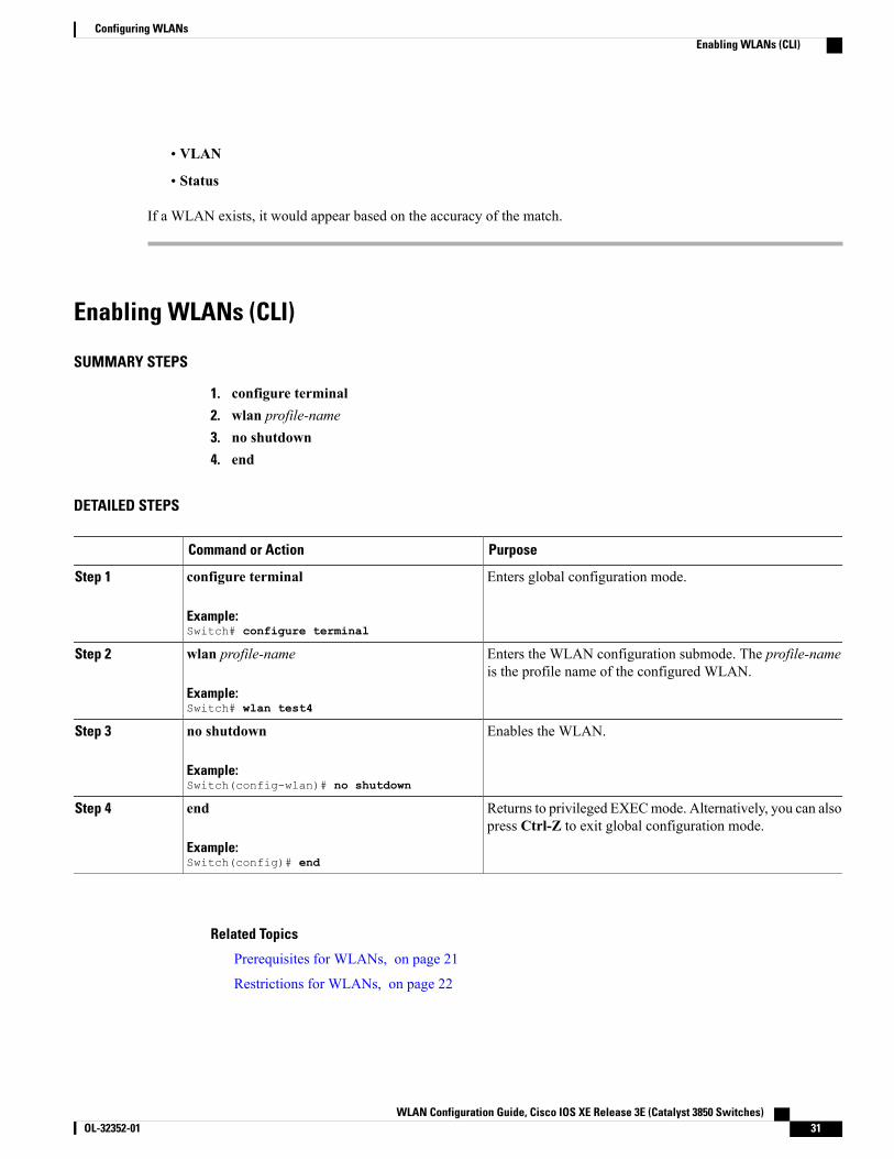
If a WLAN exists, it would appear based on the accuracy of the match.
Enabling WLANs (CLI)
SUMMARY STEPS
1. configure terminal2. wlan profile-name3. no shutdown4. end
DETAILED STEPS
PurposeCommand or Action
Enters global configuration mode.configure terminal
Example:Switch# configure terminal
Step 1
Enters the WLAN configuration submode. The profile-nameis the profile name of the configured WLAN.
wlan profile-name
Example:Switch# wlan test4
Step 2
Enables the WLAN.no shutdown
Example:Switch(config-wlan)# no shutdown
Step 3
Returns to privileged EXECmode. Alternatively, you can alsopress Ctrl-Z to exit global configuration mode.
end
Example:Switch(config)# end
Step 4
Related Topics
Prerequisites for WLANs, on page 21
Restrictions for WLANs, on page 22
WLAN Configuration Guide, Cisco IOS XE Release 3E (Catalyst 3850 Switches) OL-32352-01 31
Configuring WLANsEnabling WLANs (CLI)
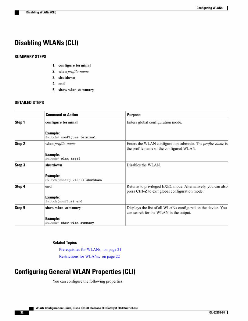
Disabling WLANs (CLI)
SUMMARY STEPS
1. configure terminal2. wlan profile-name3. shutdown4. end5. show wlan summary
DETAILED STEPS
PurposeCommand or Action
Enters global configuration mode.configure terminal
Example:Switch# configure terminal
Step 1
Enters the WLAN configuration submode. The profile-name isthe profile name of the configured WLAN.
wlan profile-name
Example:Switch# wlan test4
Step 2
Disables the WLAN.shutdown
Example:Switch(config-wlan)# shutdown
Step 3
Returns to privileged EXEC mode. Alternatively, you can alsopress Ctrl-Z to exit global configuration mode.
end
Example:Switch(config)# end
Step 4
Displays the list of all WLANs configured on the device. Youcan search for the WLAN in the output.
show wlan summary
Example:Switch# show wlan summary
Step 5
Related Topics
Prerequisites for WLANs, on page 21
Restrictions for WLANs, on page 22
Configuring General WLAN Properties (CLI)You can configure the following properties:
WLAN Configuration Guide, Cisco IOS XE Release 3E (Catalyst 3850 Switches)32 OL-32352-01
Configuring WLANsDisabling WLANs (CLI)
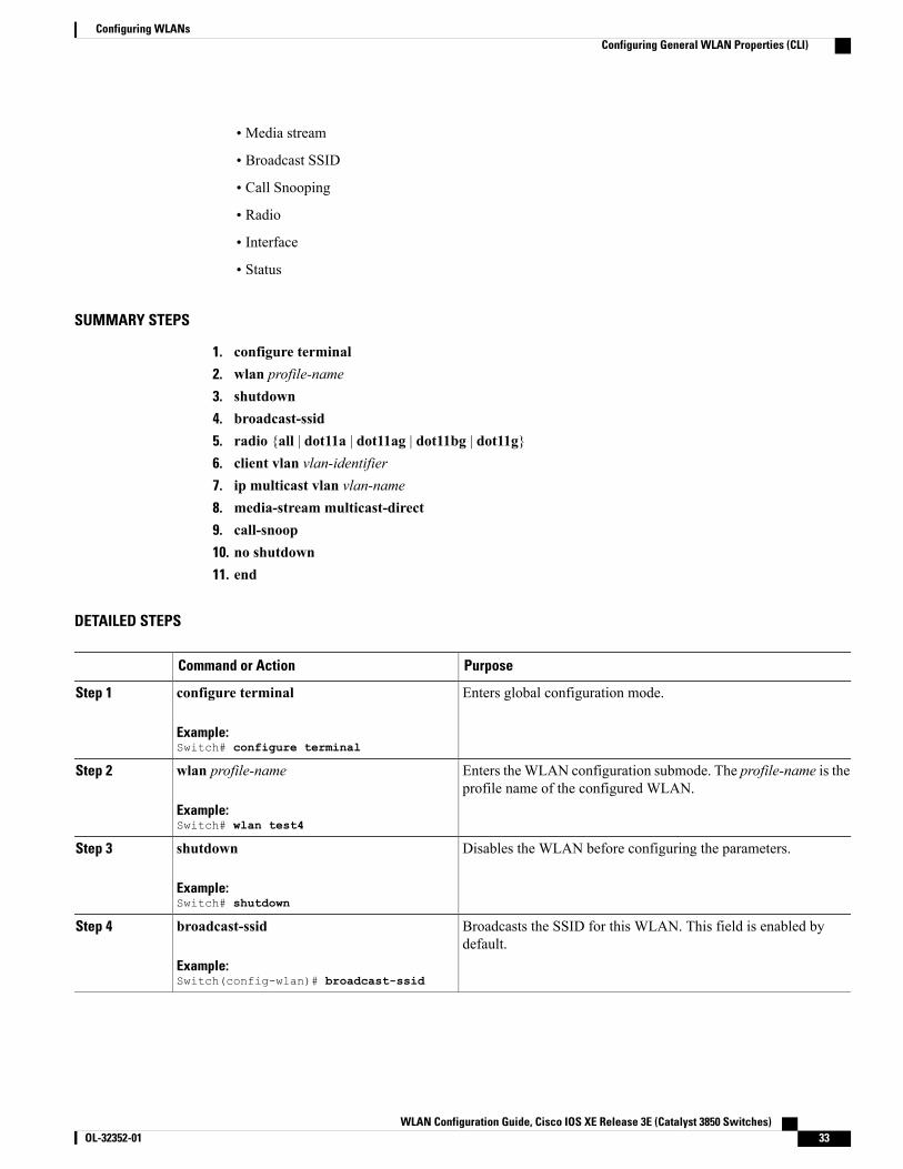
• Media stream
• Broadcast SSID
• Call Snooping
• Radio
• Interface
• Status
SUMMARY STEPS
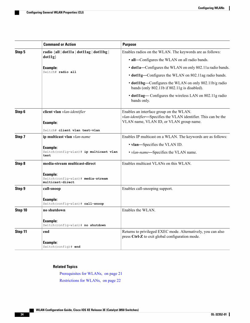
1. configure terminal2. wlan profile-name3. shutdown4. broadcast-ssid5. radio {all | dot11a | dot11ag | dot11bg | dot11g}6. client vlan vlan-identifier7. ip multicast vlan vlan-name8. media-stream multicast-direct9. call-snoop10. no shutdown11. end
DETAILED STEPS
PurposeCommand or Action
Enters global configuration mode.configure terminal
Example:Switch# configure terminal
Step 1
Enters theWLAN configuration submode. The profile-name is theprofile name of the configured WLAN.
wlan profile-name
Example:Switch# wlan test4
Step 2
Disables the WLAN before configuring the parameters.shutdown
Example:Switch# shutdown
Step 3
Broadcasts the SSID for this WLAN. This field is enabled bydefault.
broadcast-ssid
Example:Switch(config-wlan)# broadcast-ssid
Step 4
WLAN Configuration Guide, Cisco IOS XE Release 3E (Catalyst 3850 Switches) OL-32352-01 33
Configuring WLANsConfiguring General WLAN Properties (CLI)
PurposeCommand or Action
Enables radios on the WLAN. The keywords are as follows:radio {all | dot11a | dot11ag | dot11bg |dot11g}
Step 5
• all—Configures the WLAN on all radio bands.
Example:Switch# radio all
• dot1a—Configures theWLAN on only 802.11a radio bands.
• dot11g—Configures the WLAN on 802.11ag radio bands.
• dot11bg—Configures the WLAN on only 802.11b/g radiobands (only 802.11b if 802.11g is disabled).
• dot11ag— Configures the wireless LAN on 802.11g radiobands only.
Enables an interface group on the WLAN.vlan-identifier—Specifies the VLAN identifier. This can be theVLAN name, VLAN ID, or VLAN group name.
client vlan vlan-identifier
Example:
Switch# client vlan test-vlan
Step 6
Enables IP multicast on a WLAN. The keywords are as follows:ip multicast vlan vlan-name
Example:Switch(config-wlan)# ip multicast vlantest
Step 7
• vlan—Specifies the VLAN ID.
• vlan-name—Specifies the VLAN name.
Enables multicast VLANs on this WLAN.media-stream multicast-direct
Example:Switch(config-wlan)# media-streammulticast-direct
Step 8
Enables call-snooping support.call-snoop
Example:Switch(config-wlan)# call-snoop
Step 9
Enables the WLAN.no shutdown
Example:Switch(config-wlan)# no shutdown
Step 10
Returns to privileged EXEC mode. Alternatively, you can alsopress Ctrl-Z to exit global configuration mode.
end
Example:Switch(config)# end
Step 11
Related Topics
Prerequisites for WLANs, on page 21
Restrictions for WLANs, on page 22
WLAN Configuration Guide, Cisco IOS XE Release 3E (Catalyst 3850 Switches)34 OL-32352-01
Configuring WLANsConfiguring General WLAN Properties (CLI)
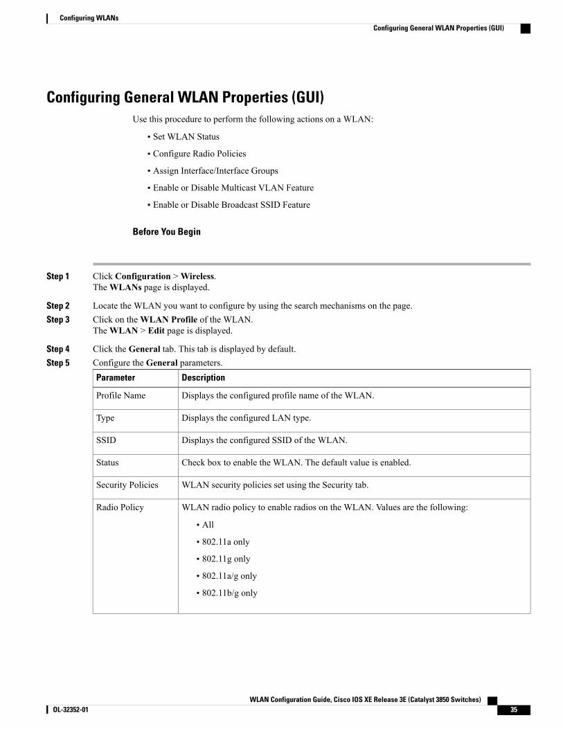
Configuring General WLAN Properties (GUI)Use this procedure to perform the following actions on a WLAN:
• Set WLAN Status
• Configure Radio Policies
• Assign Interface/Interface Groups
• Enable or Disable Multicast VLAN Feature
• Enable or Disable Broadcast SSID Feature
Before You Begin
Step 1 Click Configuration >Wireless.TheWLANs page is displayed.
Step 2 Locate the WLAN you want to configure by using the search mechanisms on the page.Step 3 Click on theWLAN Profile of the WLAN.
TheWLAN > Edit page is displayed.
Step 4 Click the General tab. This tab is displayed by default.Step 5 Configure the General parameters.
DescriptionParameter
Displays the configured profile name of the WLAN.Profile Name
Displays the configured LAN type.Type
Displays the configured SSID of the WLAN.SSID
Check box to enable the WLAN. The default value is enabled.Status
WLAN security policies set using the Security tab.Security Policies
WLAN radio policy to enable radios on the WLAN. Values are the following:
• All
• 802.11a only
• 802.11g only
• 802.11a/g only
• 802.11b/g only
Radio Policy
WLAN Configuration Guide, Cisco IOS XE Release 3E (Catalyst 3850 Switches) OL-32352-01 35
Configuring WLANsConfiguring General WLAN Properties (GUI)
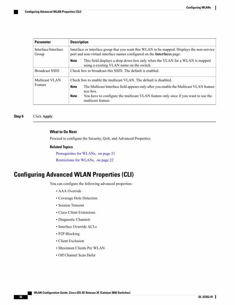
DescriptionParameter
Interface or interface group that you want this WLAN to be mapped. Displays the non-serviceport and non-virtual interface names configured on the Interfaces page.
This field displays a drop down box only when the VLAN for a WLAN is mappedusing a existing VLAN name on the switch.
Note
Interface/InterfaceGroup
Check box to broadcast this SSID. The default is enabled.Broadcast SSID
Check box to enable the multicast VLAN. The default is disabled.
TheMulticast Interface field appears only after you enable theMulticast VLAN featuretext box.
Note
You have to configure the multicast VLAN feature only once if you want to use themulticast feature.
Note
Multicast VLANFeature
Step 6 Click Apply.
What to Do Next
Proceed to configure the Security, QoS, and Advanced Properties.
Related Topics
Prerequisites for WLANs, on page 21
Restrictions for WLANs, on page 22
Configuring Advanced WLAN Properties (CLI)You can configure the following advanced properties:
• AAA Override
• Coverage Hole Detection
• Session Timeout
• Cisco Client Extensions
• Diagnostic Channels
• Interface Override ACLs
• P2P Blocking
• Client Exclusion
• Maximum Clients Per WLAN
• Off Channel Scan Defer
WLAN Configuration Guide, Cisco IOS XE Release 3E (Catalyst 3850 Switches)36 OL-32352-01
Configuring WLANsConfiguring Advanced WLAN Properties (CLI)

SUMMARY STEPS
1. configure terminal2. wlan profile-name3. aaa-override4. chd5. session-timeout time-in-seconds6. ccx aironet-iesupport7. diag-channel8. ip access-group [web] acl-name9. peer-blocking [drop | forward-upstream]10. exclusionlist time-in-seconds11. client association limit max-number-of-clients12. channel-scan defer-priority {defer-priority {0-7} | defer-time {0 - 6000}}13. end
DETAILED STEPS
PurposeCommand or Action
Enters global configuration mode.configure terminal
Example:Switch# configure terminal
Step 1
Enters the WLAN configuration submode. The profile-name is theprofile name of the configured WLAN.
wlan profile-name
Example:Switch# wlan test4
Step 2
Enables AAA override.aaa-override
Example:Switch(config-wlan)# aaa-override
Step 3
Enables coverage hole detection for thisWLAN. This field is enabledby default.
chd
Example:Switch(config-wlan)# chd
Step 4
Sets the session timeout in seconds. The range and default values varyaccording to the security configuration. If the WLAN security is
session-timeout time-in-seconds
Example:Switch(config-wlan)# session-timeout450
Step 5
configured to dot1x, the range is 300 to 86400 seconds and the defaultvalue is 1800 seconds. For all other WLAN security configurations,the range is 1 to 65535 seconds and the default value is 0 seconds. Avalue of 0 indicates no session timeout.
WLAN Configuration Guide, Cisco IOS XE Release 3E (Catalyst 3850 Switches) OL-32352-01 37
Configuring WLANsConfiguring Advanced WLAN Properties (CLI)
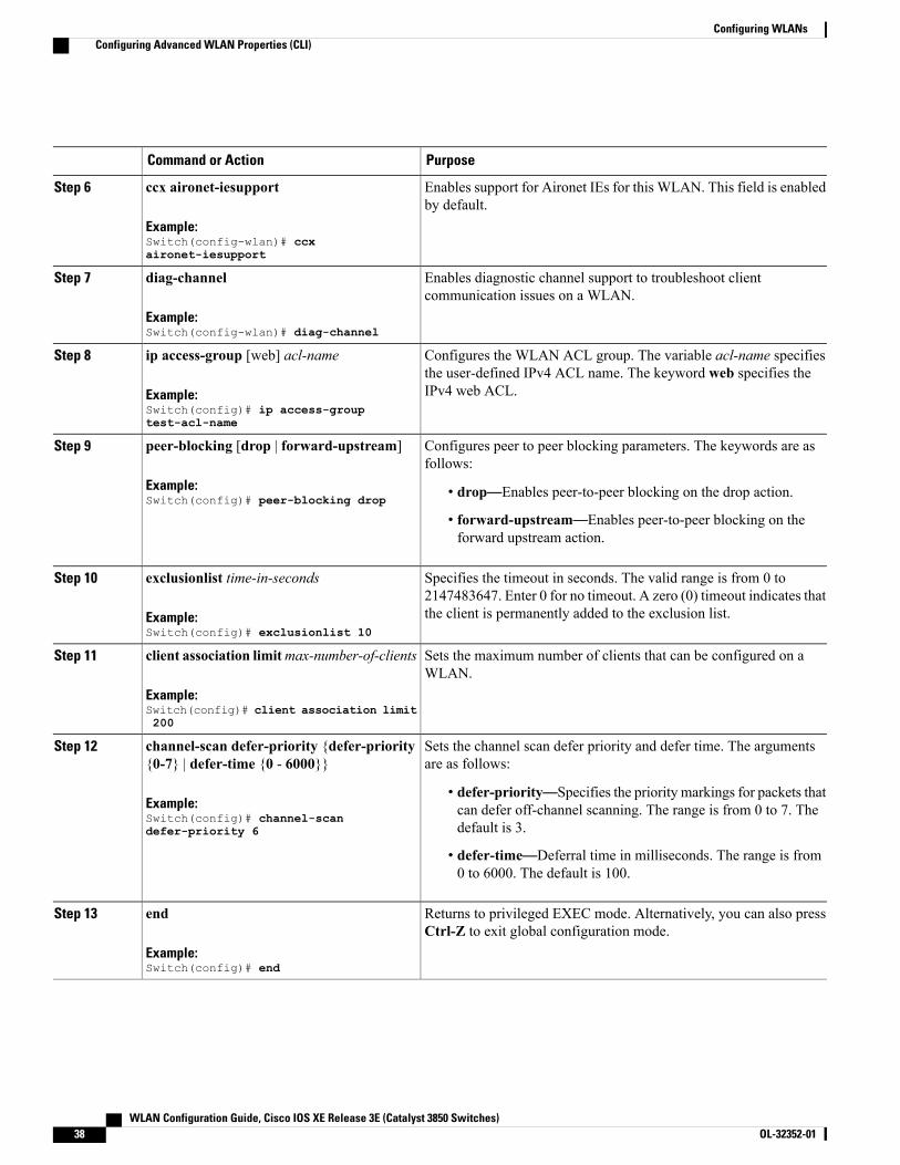
PurposeCommand or Action
Enables support for Aironet IEs for this WLAN. This field is enabledby default.
ccx aironet-iesupport
Example:Switch(config-wlan)# ccxaironet-iesupport
Step 6
Enables diagnostic channel support to troubleshoot clientcommunication issues on a WLAN.
diag-channel
Example:Switch(config-wlan)# diag-channel
Step 7
Configures the WLAN ACL group. The variable acl-name specifiesthe user-defined IPv4 ACL name. The keyword web specifies theIPv4 web ACL.
ip access-group [web] acl-name
Example:Switch(config)# ip access-grouptest-acl-name
Step 8
Configures peer to peer blocking parameters. The keywords are asfollows:
peer-blocking [drop | forward-upstream]
Example:Switch(config)# peer-blocking drop
Step 9
• drop—Enables peer-to-peer blocking on the drop action.
• forward-upstream—Enables peer-to-peer blocking on theforward upstream action.
Specifies the timeout in seconds. The valid range is from 0 to2147483647. Enter 0 for no timeout. A zero (0) timeout indicates thatthe client is permanently added to the exclusion list.
exclusionlist time-in-seconds
Example:Switch(config)# exclusionlist 10
Step 10
Sets the maximum number of clients that can be configured on aWLAN.
client association limitmax-number-of-clients
Example:Switch(config)# client association limit200
Step 11
Sets the channel scan defer priority and defer time. The argumentsare as follows:
channel-scan defer-priority {defer-priority{0-7} | defer-time {0 - 6000}}
Example:Switch(config)# channel-scandefer-priority 6
Step 12
• defer-priority—Specifies the priority markings for packets thatcan defer off-channel scanning. The range is from 0 to 7. Thedefault is 3.
• defer-time—Deferral time in milliseconds. The range is from0 to 6000. The default is 100.
Returns to privileged EXEC mode. Alternatively, you can also pressCtrl-Z to exit global configuration mode.
end
Example:Switch(config)# end
Step 13
WLAN Configuration Guide, Cisco IOS XE Release 3E (Catalyst 3850 Switches)38 OL-32352-01
Configuring WLANsConfiguring Advanced WLAN Properties (CLI)

Related Topics
Band Selection, on page 24
Off-Channel Scanning DeferDTIM PeriodSession TimeoutCisco Client Extensions, on page 25
Peer-to-Peer Blocking, on page 26Diagnostic ChannelClient Count Per WLANPrerequisites for WLANs, on page 21
Restrictions for WLANs, on page 22
Information About AAA Override, on page 60
Prerequisites for Layer 2 Security, on page 59
Configuring Advanced WLAN Properties (GUI)
Before You Begin
Step 1 Click Configuration >Wireless.TheWLANs page is displayed.
Step 2 Locate the WLAN you want to configure by using the search mechanisms on the page.Step 3 Click on theWLAN Profile of the WLAN.
TheWLAN > Edit page is displayed.
Step 4 Click on the Advanced Properties tab.Step 5 Configure the Advanced properties.
WLAN Configuration Guide, Cisco IOS XE Release 3E (Catalyst 3850 Switches) OL-32352-01 39
Configuring WLANsConfiguring Advanced WLAN Properties (GUI)

DescriptionParameter
AAA override for global WLAN parameters that you can enable or disable.
When AAA Override is enabled, and a client has conflicting AAA and switches WLANauthentication parameters, client authentication is performed by the AAA server. As part ofthis authentication, the operating systemmoves clients from the default CiscoWLAN SolutionWLANVLAN to a VLAN returned by the AAA server and predefined in the switches interfaceconfiguration. In all cases, the operating system also uses QoS, DSCP, 802.1p priority tagvalues, and ACLs provided by the AAA server, if they are predefined in the switches interfaceconfiguration. (This VLAN switching by AAA Override is also referred to as IdentityNetworking.)
If the Corporate WLAN primarily uses a Management Interface assigned to VLAN 2, and ifAAA Override returns a redirect to VLAN 100, the operating system redirects all clienttransmissions to VLAN 100, regardless of the physical port to which VLAN 100 is assigned.
When AAAOverride is disabled, all client authentication defaults to the switches authenticationparameter settings, and authentication is performed only by the AAA server if the switchesWLAN does not contain any client-specific authentication parameters.
The AAA override values might come from a RADIUS server, for example.
Allow AAA Override
Coverage hole detection (CHD) on this WLAN that you can enable or disable.
By default, CHD is enabled on all WLANs on the switches. You can disable CHD on aWLAN.
When you disable CHD on a WLAN, a coverage hole alert is still sent to the Switch, but noother processing is done to mitigate the coverage hole. This feature is useful for guest WLANswhere guests are connected to your network for short periods of time and are likely to be highlymobile.
Coverage HoleDetection
Configure a WLAN with a session timeout in seconds. The session timeout is the maximumtime for a client session to remain active before requiring reauthorization. The minimum sessiontimeout allowed is 1 second and the maximum timeout allowed is 65535 seconds.
Entering zero denotes the session will neverexpire.
Note
Session Timeout
Support of Aironet IEs per WLAN that you can enable or disable. The default is disabled.Aironet IE
Diagnostic channel support on theWLAN that you can enable or disable. The default is disabled.Diagnostic Channel
Peer-to-peer blocking settings that you can choose from the following:
• Disabled—(Default) Disables peer-to-peer blocking and bridges traffic locally within theswitch whenever possible.
• Drop—Causes the switches to discard the packets.
• Forward-UpStream—Causes the packets to be forwarded on the upstream VLAN. Thedevice above the switches decides what action to take regarding the packets.
P2P Blocking Action
WLAN Configuration Guide, Cisco IOS XE Release 3E (Catalyst 3850 Switches)40 OL-32352-01
Configuring WLANsConfiguring Advanced WLAN Properties (GUI)
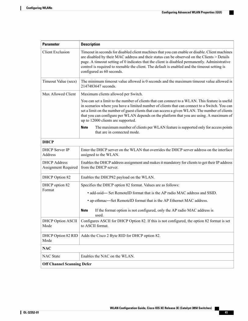
DescriptionParameter
Timeout in seconds for disabled client machines that you can enable or disable. Client machinesare disabled by their MAC address and their status can be observed on the Clients > Detailspage. A timeout setting of 0 indicates that the client is disabled permanently. Administrativecontrol is required to reenable the client. The default is enabled and the timeout setting isconfigured as 60 seconds.
Client Exclusion
The minimum timeout value allowed is 0 seconds and the maximum timeout value allowed is2147483647 seconds.
Timeout Value (secs)
Maximum clients allowed per Switch.
You can set a limit to the number of clients that can connect to a WLAN. This feature is usefulin scenarios where you have a limited number of clients that can connect to a Switch. You canset a limit on the number of guest clients that can access a givenWLAN. The number of clientsthat you can configure per WLAN depends on the platform that you are using. A maximum ofup to 12000 clients are supported.
Themaximum number of clients perWLAN feature is supported only for access pointsthat are in connected mode.
Note
Max Allowed Client
DHCP
Enter the DHCP server on the WLAN that overrides the DHCP server address on the interfaceassigned to the WLAN.
DHCP Server IPAddress
Enables the DHCP address assignment andmakes it mandatory for clients to get their IP addressfrom the DHCP server.
DHCP AddressAssignment Required
Enables the DHCP82 payload on the WLAN.DHCP Option 82
Specifies the DHCP option 82 format. Values are as follows:
• add-ssid— Set RemoteID format that is the AP radio MAC address and SSID.
• ap-ethmac—Set RemoteID format that is the AP Ethernet MAC address.
If the format option is not configured, only the AP radio MAC address isused.
Note
DHCP option 82Format
Configures ASCII for DHCP Option 82. If this is not configured, the option 82 format is setto ASCII format.
DHCP Option ASCIIMode
Adds the Cisco 2 Byte RID for DHCP option 82.DHCP Option 82 RIDMode
NAC
Enables the NAC on the WLAN.NAC State
Off Channel Scanning Defer
WLAN Configuration Guide, Cisco IOS XE Release 3E (Catalyst 3850 Switches) OL-32352-01 41
Configuring WLANsConfiguring Advanced WLAN Properties (GUI)
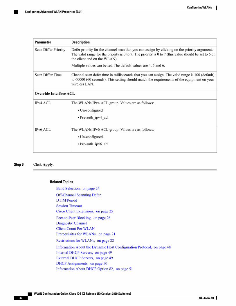
DescriptionParameter
Defer priority for the channel scan that you can assign by clicking on the priority argument.The valid range for the priority is 0 to 7. The priority is 0 to 7 (this value should be set to 6 onthe client and on the WLAN).
Multiple values can be set. The default values are 4, 5 and 6.
Scan Differ Priority
Channel scan defer time in milliseconds that you can assign. The valid range is 100 (default)to 60000 (60 seconds). This setting should match the requirements of the equipment on yourwireless LAN.
Scan Differ Time
Override Interface ACL
The WLANs IPv4 ACL group. Values are as follows:
• Un-configured
• Pre-auth_ipv4_acl
IPv4 ACL
The WLANs IPv6 ACL group. Values are as follows:
• Un-configured
• Pre-auth_ipv6_acl
IPv6 ACL
Step 6 Click Apply.
Related Topics
Band Selection, on page 24
Off-Channel Scanning DeferDTIM PeriodSession TimeoutCisco Client Extensions, on page 25
Peer-to-Peer Blocking, on page 26Diagnostic ChannelClient Count Per WLANPrerequisites for WLANs, on page 21
Restrictions for WLANs, on page 22
Information About the Dynamic Host Configuration Protocol, on page 48Internal DHCP Servers, on page 49External DHCP Servers, on page 49DHCP Assignments, on page 50Information About DHCP Option 82, on page 51
WLAN Configuration Guide, Cisco IOS XE Release 3E (Catalyst 3850 Switches)42 OL-32352-01
Configuring WLANsConfiguring Advanced WLAN Properties (GUI)
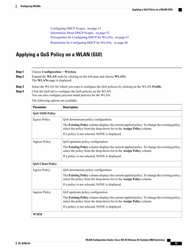
Configuring DHCP Scopes, on page 51Information About DHCP Scopes, on page 52Prerequisites for Configuring DHCP for WLANs, on page 47
Restrictions for Configuring DHCP for WLANs, on page 48
Applying a QoS Policy on a WLAN (GUI)
Step 1 Choose Configuration >Wireless.Step 2 Expand theWLAN node by clicking on the left pane and chooseWLANs.
TheWLANs page is displayed.
Step 3 Select the WLAN for which you want to configure the QoS policies by clicking on the WLAN Profile.Step 4 Click the QoS tab to configure the QoS policies on the WLAN.
You can also configure precious metal policies for the WLAN.
The following options are available:
DescriptionParameter
QoS SSID Policy
QoS downstream policy configuration.
The Existing Policy column displays the current applied policy. To change the existing policy,select the policy from the drop-down list in the Assign Policy column.
If a policy is not selected, NONE is displayed.
Egress Policy
QoS upstream policy configuration.
The Existing Policy column displays the current applied policy. To change the existing policy,select the policy from the drop-down list in the Assign Policy column.
If a policy is not selected, NONE is displayed.
Ingress Policy
QoS Client Policy
QoS downstream policy configuration.
The Existing Policy column displays the current applied policy. To change the existing policy,select the policy from the drop-down list in the Assign Policy column.
If a policy is not selected, NONE is displayed.
Egress Policy
QoS upstream policy configuration.
The Existing Policy column displays the current applied policy. To change the existing policy,select the policy from the drop-down list in the Assign Policy column.
If a policy is not selected, NONE is displayed.
Ingress Policy
WMM
WLAN Configuration Guide, Cisco IOS XE Release 3E (Catalyst 3850 Switches) OL-32352-01 43
Configuring WLANsApplying a QoS Policy on a WLAN (GUI)
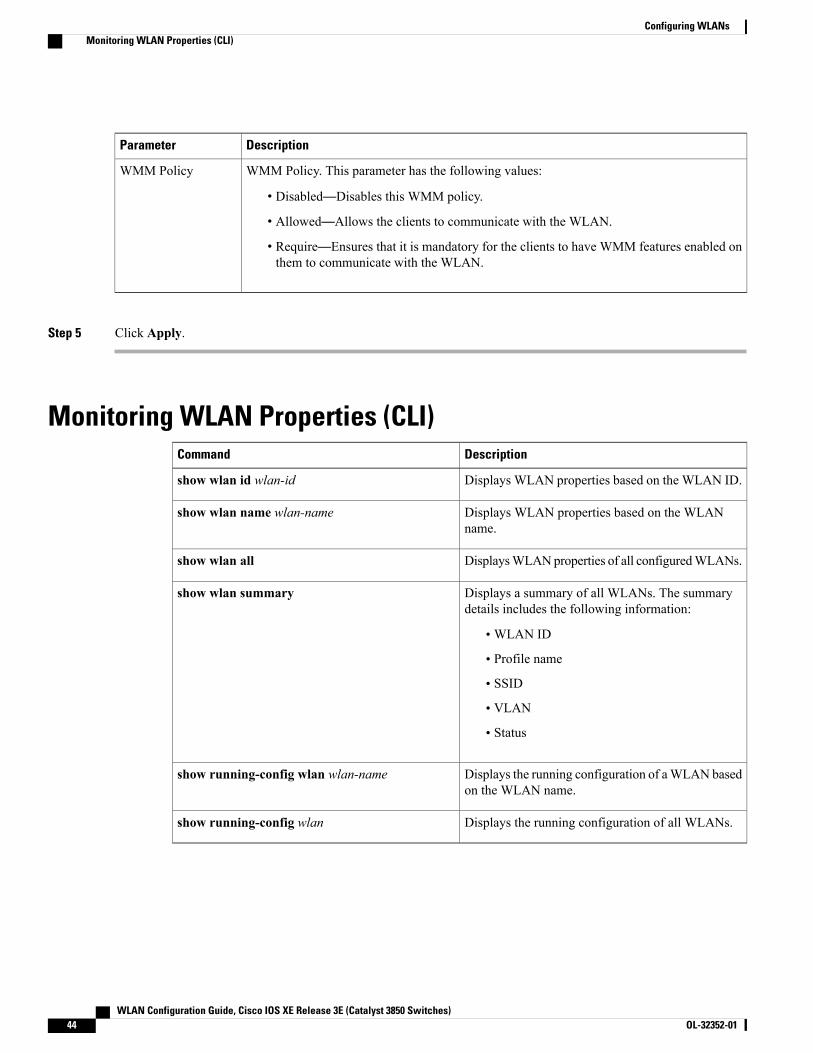
DescriptionParameter
WMM Policy. This parameter has the following values:
• Disabled—Disables this WMM policy.
• Allowed—Allows the clients to communicate with the WLAN.
• Require—Ensures that it is mandatory for the clients to have WMM features enabled onthem to communicate with the WLAN.
WMM Policy
Step 5 Click Apply.
Monitoring WLAN Properties (CLI)DescriptionCommand
Displays WLAN properties based on the WLAN ID.show wlan id wlan-id
Displays WLAN properties based on the WLANname.
show wlan name wlan-name
DisplaysWLANproperties of all configuredWLANs.show wlan all
Displays a summary of all WLANs. The summarydetails includes the following information:
•WLAN ID
• Profile name
• SSID
• VLAN
• Status
show wlan summary
Displays the running configuration of aWLAN basedon the WLAN name.
show running-config wlan wlan-name
Displays the running configuration of all WLANs.show running-config wlan
WLAN Configuration Guide, Cisco IOS XE Release 3E (Catalyst 3850 Switches)44 OL-32352-01
Configuring WLANsMonitoring WLAN Properties (CLI)

Viewing WLAN Properties (GUI)Before You Begin
• You must have administrator privileges.
Step 1 Select Configuration >WLANThe WLANs page is displayed.
Step 2 Click theWLAN Profile link.TheWLANs > Edit page is displayed. The WLANs page contains the following tabs:
• General : Displays the WLAN general properties.
• Security: Displays the security properties. The properties include Layer 2, Layer 3, and AAA properties.
• QoS: Displays the QoS configuration properties.
• Advanced: Displays the advanced properties.
Where to Go NextProceed to configure DHCP for WLANs.
Additional ReferencesRelated Documents
Document TitleRelated Topic
WLAN Command Reference, Cisco IOS XE Release3SE (Catalyst 3850 Switches)
WLAN command reference
Mobility Configuration Guide, Cisco IOS XE Release3SE (Catalyst 3850 Switches)
Mobility Anchor configuration
Security Configuration Guide (Catalyst 3850Switches)
WebAuth Configuration
WLAN Configuration Guide, Cisco IOS XE Release 3E (Catalyst 3850 Switches) OL-32352-01 45
Configuring WLANsViewing WLAN Properties (GUI)

Error Message Decoder
LinkDescription
https://www.cisco.com/cgi-bin/Support/Errordecoder/index.cgi
To help you research and resolve system errormessages in this release, use the Error MessageDecoder tool.
MIBs
MIBs LinkMIB
To locate and downloadMIBs for selected platforms,Cisco IOS releases, and feature sets, use Cisco MIBLocator found at the following URL:
http://www.cisco.com/go/mibs
All supported MIBs for this release.
Technical Assistance
LinkDescription
http://www.cisco.com/supportThe Cisco Support website provides extensive onlineresources, including documentation and tools fortroubleshooting and resolving technical issues withCisco products and technologies.
To receive security and technical information aboutyour products, you can subscribe to various services,such as the Product Alert Tool (accessed from FieldNotices), the Cisco Technical Services Newsletter,and Really Simple Syndication (RSS) Feeds.
Access to most tools on the Cisco Support websiterequires a Cisco.com user ID and password.
Feature Information for WLANsThis table lists the features in this module and provides links to specific configuration information:
ModificationReleaseFeature
This feature wasintroduced.
Cisco IOS XE 3.2SEWLAN Functionality
WLAN Configuration Guide, Cisco IOS XE Release 3E (Catalyst 3850 Switches)46 OL-32352-01
Configuring WLANsFeature Information for WLANs
C H A P T E R 4Configuring DHCP for WLANs
• Finding Feature Information, page 47
• Prerequisites for Configuring DHCP for WLANs, page 47
• Restrictions for Configuring DHCP for WLANs, page 48
• Information About the Dynamic Host Configuration Protocol, page 48
• How to Configure DHCP for WLANs, page 52
• Additional References, page 56
• Feature Information for DHCP for WLANs, page 57
Finding Feature InformationYour software release may not support all the features documented in this module. For the latest featureinformation and caveats, see the release notes for your platform and software release. To find informationabout the features documented in this module, and to see a list of the releases in which each feature is supported,see the Feature Information Table at the end of this document.
Use Cisco Feature Navigator to find information about platform support and Cisco software image support.To access Cisco Feature Navigator, go to http://www.cisco.com/go/cfn. An account on Cisco.com is notrequired.
Prerequisites for Configuring DHCP for WLANs• To be able to use the DHCP option 82, you must configure DHCP on Cisco IOS software. By default,DHCP option 82 is enabled for all clients. You can control the wireless client behavior using theWLANsuboptions.
• It is recommended to enable dhcp snooping on the Switches irrespective of the DHCP address requirementbeing checked or unchecked on the WLAN. This avoids any client connectivity issues when DHCPsnopping is not turned on.This example shows how to enable DHCP snooping on the Switches:Switch(config)# ip dhcp snooping 136, 139Switch(config)# ip dhcp snooping
WLAN Configuration Guide, Cisco IOS XE Release 3E (Catalyst 3850 Switches) OL-32352-01 47
Switch(config)# ip dhcp snooping trustSwitch(config)# ip dhcp snooping trust
Related Topics
Configuring DHCP for WLANs (CLI), on page 52
Configuring Advanced WLAN Properties (GUI), on page 39
Information About the Dynamic Host Configuration Protocol, on page 48Internal DHCP Servers, on page 49External DHCP Servers, on page 49DHCP Assignments, on page 50Information About DHCP Option 82, on page 51Configuring DHCP Scopes, on page 51Information About DHCP Scopes, on page 52
Restrictions for Configuring DHCP for WLANs• If you override the DHCP server in a WLAN, you must ensure that you configure the underlying CiscoIOS configuration to make sure that the DHCP server is reachable.
•WLAN DHCP override works only if DHCP service is enabled on the switch.
You can configure DHCP service in the following ways:
◦Configuring the DHCP pool on the switch.
◦Configuring a DHCP relay agent on the SVI. Note: the VLAN of the SVI must be mapped to theWLAN where DHCP override is configured.
Related Topics
Configuring DHCP for WLANs (CLI), on page 52
Configuring Advanced WLAN Properties (GUI), on page 39
Information About the Dynamic Host Configuration Protocol, on page 48Internal DHCP Servers, on page 49External DHCP Servers, on page 49DHCP Assignments, on page 50Information About DHCP Option 82, on page 51Configuring DHCP Scopes, on page 51Information About DHCP Scopes, on page 52
Information About the Dynamic Host Configuration ProtocolYou can configureWLANs to use the same or different Dynamic Host Configuration Protocol (DHCP) serversor no DHCP server. Two types of DHCP servers are available: internal and external.
WLAN Configuration Guide, Cisco IOS XE Release 3E (Catalyst 3850 Switches)48 OL-32352-01
Configuring DHCP for WLANsRestrictions for Configuring DHCP for WLANs
Related Topics
Configuring DHCP for WLANs (CLI), on page 52
Configuring Advanced WLAN Properties (GUI), on page 39
Prerequisites for Configuring DHCP for WLANs, on page 47
Restrictions for Configuring DHCP for WLANs, on page 48
Internal DHCP ServersThe switches contain an internal DHCP server. This server is typically used in branch offices that do notalready have a DHCP server. The wireless network generally contains a maximum of 10 access points orfewer, with the access points on the same IP subnet as the switch. The internal server provides DHCP addressesto wireless clients, direct-connect access points, and DHCP requests that are relayed from access points. Onlylightweight access points are supported. When you want to use the internal DHCP server, you must set themanagement interface IP address of the switch as the DHCP server IP address.
DHCP option 43 is not supported on the internal server. Therefore, the access point must use an alternativemethod to locate the management interface IP address of the switch, such as local subnet broadcast, DomainName System (DNS), or priming.
An internal DHCP server pool only serves the wireless clients of that switch, not clients of other switches.Also, an internal DHCP server can serve only wireless clients, not wired clients.
When clients use the internal DHCP server of the switch, IP addresses are not preserved across reboots. Asa result, multiple clients can be assigned with the same IP address. To resolve any IP address conflicts, clientsmust release their existing IP address and request a new one. Wired guest clients are always on a Layer 2network connected to a local or foreign switch.
DHCPv6 is not supported in the internal DHCP servers.Note
Related Topics
Configuring DHCP for WLANs (CLI), on page 52
Configuring Advanced WLAN Properties (GUI), on page 39
Prerequisites for Configuring DHCP for WLANs, on page 47
Restrictions for Configuring DHCP for WLANs, on page 48
External DHCP ServersThe operating system is designed to appear as a DHCP Relay to the network and as a DHCP server to clientswith industry-standard external DHCP servers that support DHCPRelay, whichmeans that each switch appearsas a DHCP Relay agent to the DHCP server and as a DHCP server at the virtual IP address to wireless clients.
Because the switch captures the client IP address that is obtained from a DHCP server, it maintains the sameIP address for that client during intra switch, inter switch, and inter-subnet client roaming.
WLAN Configuration Guide, Cisco IOS XE Release 3E (Catalyst 3850 Switches) OL-32352-01 49
Configuring DHCP for WLANsInternal DHCP Servers

External DHCP servers can support DHCPv6.Note
Related Topics
Configuring DHCP for WLANs (CLI), on page 52
Configuring Advanced WLAN Properties (GUI), on page 39
Prerequisites for Configuring DHCP for WLANs, on page 47
Restrictions for Configuring DHCP for WLANs, on page 48
DHCP AssignmentsYou can configure DHCP on a per-interface or per-WLAN basis. We recommend that you use the primaryDHCP server address that is assigned to a particular interface.
You can assign DHCP servers for individual interfaces. You can configure the management interface,AP-manager interface, and dynamic interface for a primary and secondary DHCP server, and you can configurethe service-port interface to enable or disable DHCP servers. You can also define a DHCP server on aWLAN.In this case, the server overrides the DHCP server address on the interface assigned to the WLAN.
Security Considerations
For enhanced security, we recommend that you require all clients to obtain their IP addresses from a DHCPserver. To enforce this requirement, you can configure all WLANs with a DHCP Addr. Assignment Requiredsetting, which disallows client static IP addresses. If DHCP Addr. Assignment Required is selected, clientsmust obtain an IP address via DHCP. Any client with a static IP address is not allowed on the network. Theswitch monitors DHCP traffic because it acts as a DHCP proxy for the clients.
WLANs that support management over wireless must allow management (device-servicing) clients toobtain an IP address from a DHCP server.
Note
If slightly less security is tolerable, you can create WLANs with DHCP Addr. Assignment Required disabled.Clients then have the option of using a static IP address or obtaining an IP address from a designated DHCPserver.
DHCP Addr. Assignment Required is not supported for wired guest LANs.Note
You can create separate WLANs with DHCP Addr. Assignment Required configured as disabled. This isapplicable only if DHCP proxy is enabled for the switch. You must not define the primary/secondaryconfiguration DHCP server you should disable the DHCP proxy. These WLANs drop all DHCP requests andforce clients to use a static IP address. These WLANs do not support management over wireless connections.
Related Topics
Configuring DHCP for WLANs (CLI), on page 52
Configuring Advanced WLAN Properties (GUI), on page 39
WLAN Configuration Guide, Cisco IOS XE Release 3E (Catalyst 3850 Switches)50 OL-32352-01
Configuring DHCP for WLANsDHCP Assignments
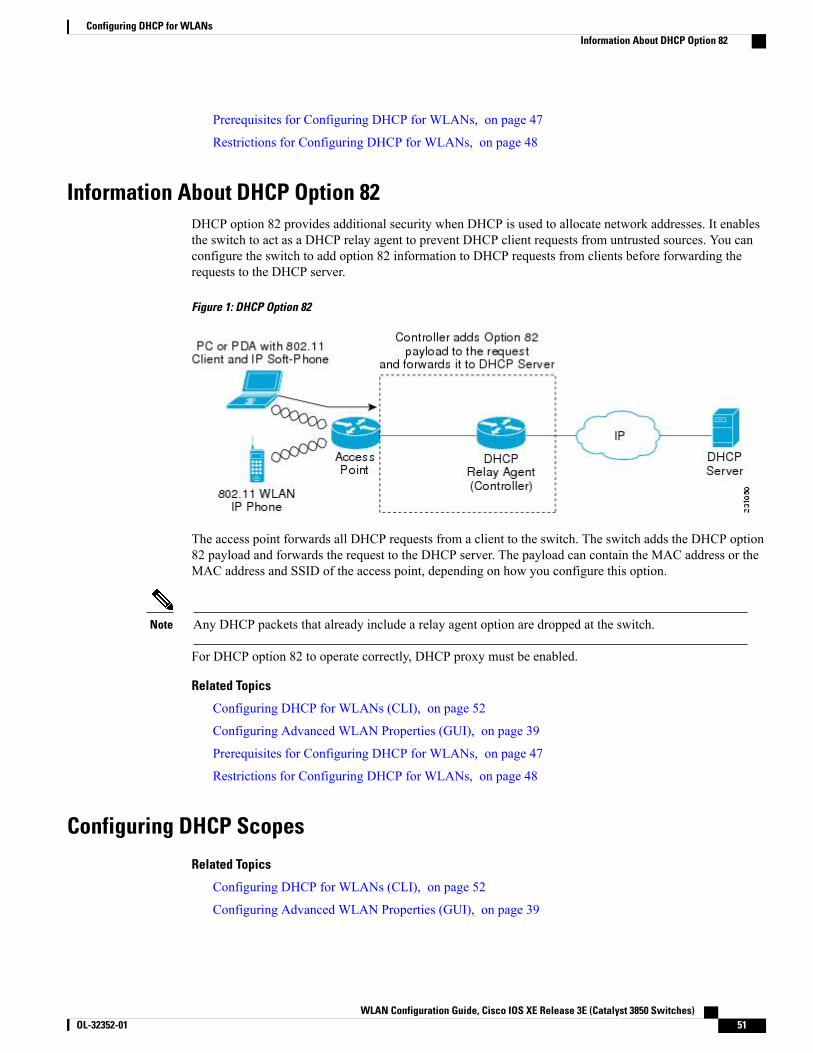
Prerequisites for Configuring DHCP for WLANs, on page 47
Restrictions for Configuring DHCP for WLANs, on page 48
Information About DHCP Option 82DHCP option 82 provides additional security when DHCP is used to allocate network addresses. It enablesthe switch to act as a DHCP relay agent to prevent DHCP client requests from untrusted sources. You canconfigure the switch to add option 82 information to DHCP requests from clients before forwarding therequests to the DHCP server.
Figure 1: DHCP Option 82
The access point forwards all DHCP requests from a client to the switch. The switch adds the DHCP option82 payload and forwards the request to the DHCP server. The payload can contain the MAC address or theMAC address and SSID of the access point, depending on how you configure this option.
Any DHCP packets that already include a relay agent option are dropped at the switch.Note
For DHCP option 82 to operate correctly, DHCP proxy must be enabled.
Related Topics
Configuring DHCP for WLANs (CLI), on page 52
Configuring Advanced WLAN Properties (GUI), on page 39
Prerequisites for Configuring DHCP for WLANs, on page 47
Restrictions for Configuring DHCP for WLANs, on page 48
Configuring DHCP Scopes
Related Topics
Configuring DHCP for WLANs (CLI), on page 52
Configuring Advanced WLAN Properties (GUI), on page 39
WLAN Configuration Guide, Cisco IOS XE Release 3E (Catalyst 3850 Switches) OL-32352-01 51
Configuring DHCP for WLANsInformation About DHCP Option 82

Prerequisites for Configuring DHCP for WLANs, on page 47
Restrictions for Configuring DHCP for WLANs, on page 48
Information About DHCP ScopesSwitches have built-in DHCP relay agents. However, when you desire network segments that do not have aseparate DHCP server, the switches can have built-in DHCP scopes that assign IP addresses and subnet masksto wireless clients. Typically, one switch can have one or more DHCP scopes that each provide a range of IPaddresses.
DHCP scopes are needed for internal DHCP to work. Once DHCP is defined on the switch, you can thenpoint the primary DHCP server IP address on the management, AP-manager, and dynamic interfaces to theswitch’s management interface.
Related Topics
Configuring DHCP for WLANs (CLI), on page 52
Configuring Advanced WLAN Properties (GUI), on page 39
Prerequisites for Configuring DHCP for WLANs, on page 47
Restrictions for Configuring DHCP for WLANs, on page 48
Configuring DHCP Scopes (CLI), on page 55
How to Configure DHCP for WLANs
Configuring DHCP for WLANs (CLI)Use this procedure to configure the following DHCP parameters on a WLAN:
• DHCP Option 82 Payload
• DHCP Required
• DHCP Override
Before You Begin
• You must have admin privileges for configuring the WLAN.
• To configure the DHCP override, you must have the IP address of the DHCP server.
WLAN Configuration Guide, Cisco IOS XE Release 3E (Catalyst 3850 Switches)52 OL-32352-01
Configuring DHCP for WLANsHow to Configure DHCP for WLANs
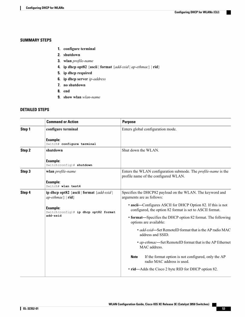
SUMMARY STEPS
1. configure terminal2. shutdown3. wlan profile-name4. ip dhcp opt82 {ascii | format {add-ssid | ap-ethmac} | rid}5. ip dhcp required6. ip dhcp server ip-address7. no shutdown8. end9. show wlan wlan-name
DETAILED STEPS
PurposeCommand or Action
Enters global configuration mode.configure terminal
Example:Switch# configure terminal
Step 1
Shut down the WLAN.shutdown
Example:Switch(config)# shutdown
Step 2
Enters the WLAN configuration submode. The profile-name is theprofile name of the configured WLAN.
wlan profile-name
Example:Switch# wlan test4
Step 3
Specifies the DHCP82 payload on the WLAN. The keyword andarguments are as follows:
ip dhcp opt82 {ascii | format {add-ssid |ap-ethmac} | rid}
Step 4
Example:Switch(config)# ip dhcp opt82 formatadd-ssid
• ascii—Configures ASCII for DHCP Option 82. If this is notconfigured, the option 82 format is set to ASCII format.
• format—Specifies the DHCP option 82 format. The followingoptions are available:
• add-ssid—Set RemoteID format that is the AP radioMACaddress and SSID.
• ap-ethmac—Set RemoteID format that is the AP EthernetMAC address.
If the format option is not configured, only the APradio MAC address is used.
Note
• rid—Adds the Cisco 2 byte RID for DHCP option 82.
WLAN Configuration Guide, Cisco IOS XE Release 3E (Catalyst 3850 Switches) OL-32352-01 53
Configuring DHCP for WLANsConfiguring DHCP for WLANs (CLI)
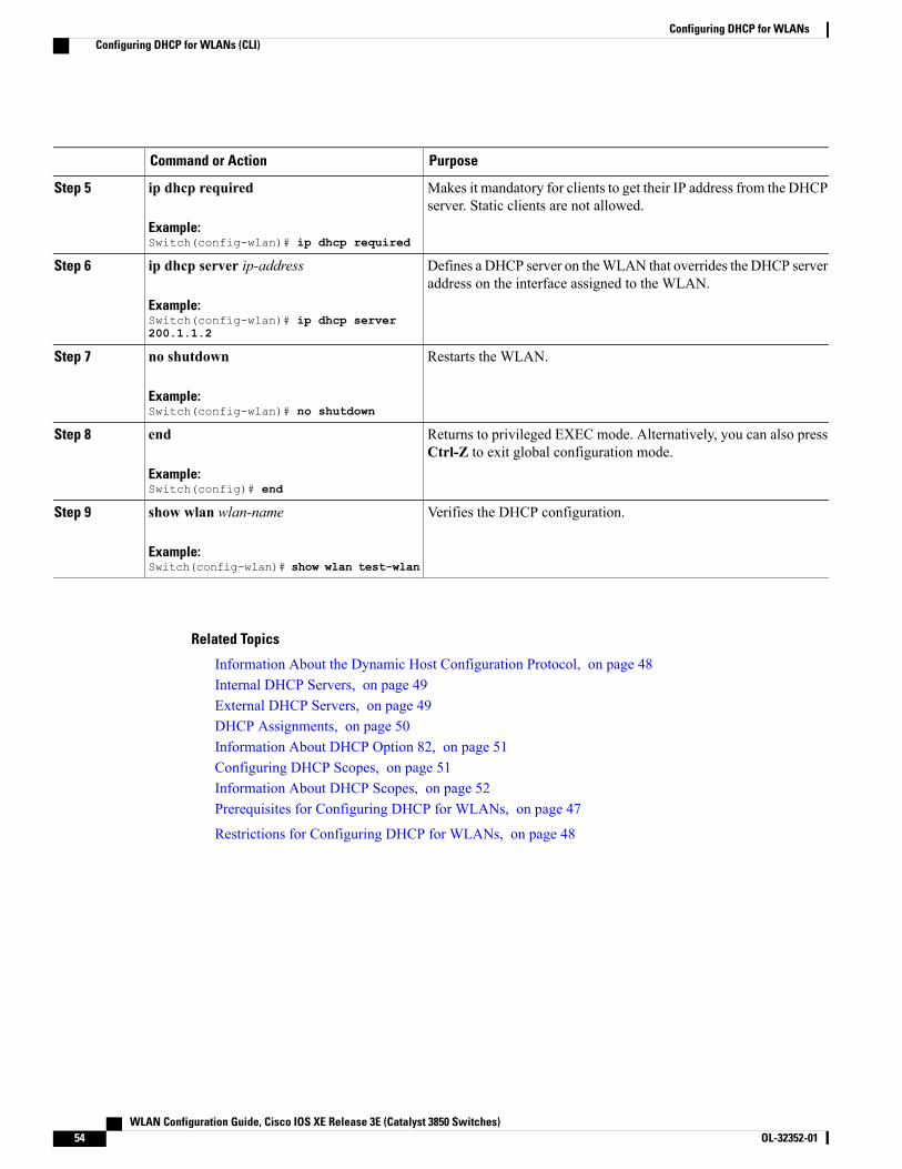
PurposeCommand or Action
Makes it mandatory for clients to get their IP address from the DHCPserver. Static clients are not allowed.
ip dhcp required
Example:Switch(config-wlan)# ip dhcp required
Step 5
Defines a DHCP server on theWLAN that overrides the DHCP serveraddress on the interface assigned to the WLAN.
ip dhcp server ip-address
Example:Switch(config-wlan)# ip dhcp server200.1.1.2
Step 6
Restarts the WLAN.no shutdown
Example:Switch(config-wlan)# no shutdown
Step 7
Returns to privileged EXEC mode. Alternatively, you can also pressCtrl-Z to exit global configuration mode.
end
Example:Switch(config)# end
Step 8
Verifies the DHCP configuration.show wlan wlan-name
Example:Switch(config-wlan)# show wlan test-wlan
Step 9
Related Topics
Information About the Dynamic Host Configuration Protocol, on page 48Internal DHCP Servers, on page 49External DHCP Servers, on page 49DHCP Assignments, on page 50Information About DHCP Option 82, on page 51Configuring DHCP Scopes, on page 51Information About DHCP Scopes, on page 52Prerequisites for Configuring DHCP for WLANs, on page 47
Restrictions for Configuring DHCP for WLANs, on page 48
WLAN Configuration Guide, Cisco IOS XE Release 3E (Catalyst 3850 Switches)54 OL-32352-01
Configuring DHCP for WLANsConfiguring DHCP for WLANs (CLI)
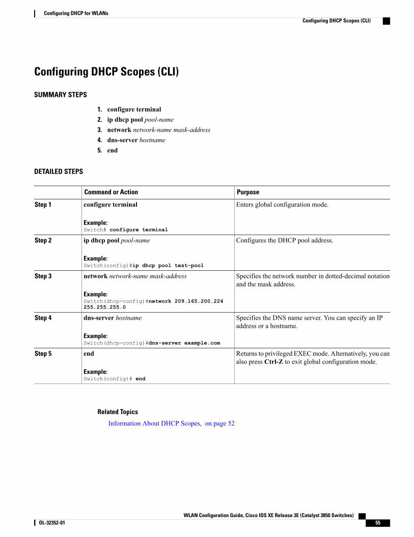
Configuring DHCP Scopes (CLI)
SUMMARY STEPS
1. configure terminal2. ip dhcp pool pool-name3. network network-name mask-address4. dns-server hostname5. end
DETAILED STEPS
PurposeCommand or Action
Enters global configuration mode.configure terminal
Example:Switch# configure terminal
Step 1
Configures the DHCP pool address.ip dhcp pool pool-name
Example:Switch(config)#ip dhcp pool test-pool
Step 2
Specifies the network number in dotted-decimal notationand the mask address.
network network-name mask-address
Example:Switch(dhcp-config)#network 209.165.200.224255.255.255.0
Step 3
Specifies the DNS name server. You can specify an IPaddress or a hostname.
dns-server hostname
Example:Switch(dhcp-config)#dns-server example.com
Step 4
Returns to privileged EXECmode. Alternatively, you canalso press Ctrl-Z to exit global configuration mode.
end
Example:Switch(config)# end
Step 5
Related Topics
Information About DHCP Scopes, on page 52
WLAN Configuration Guide, Cisco IOS XE Release 3E (Catalyst 3850 Switches) OL-32352-01 55
Configuring DHCP for WLANsConfiguring DHCP Scopes (CLI)
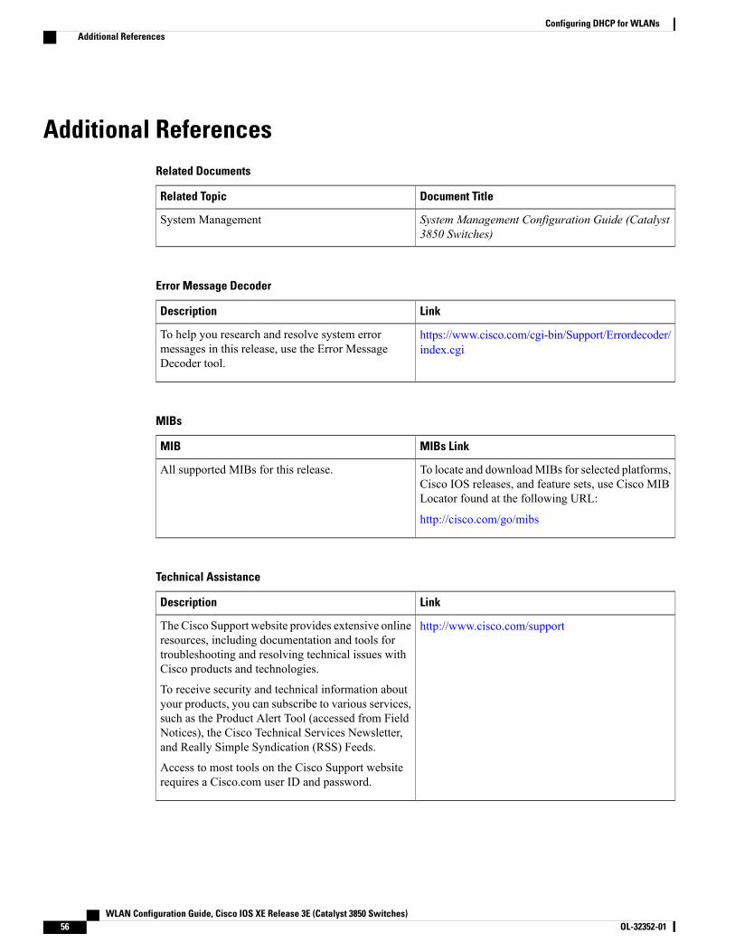
Additional ReferencesRelated Documents
Document TitleRelated Topic
System Management Configuration Guide (Catalyst3850 Switches)
System Management
Error Message Decoder
LinkDescription
https://www.cisco.com/cgi-bin/Support/Errordecoder/index.cgi
To help you research and resolve system errormessages in this release, use the Error MessageDecoder tool.
MIBs
MIBs LinkMIB
To locate and downloadMIBs for selected platforms,Cisco IOS releases, and feature sets, use Cisco MIBLocator found at the following URL:
http://cisco.com/go/mibs
All supported MIBs for this release.
Technical Assistance
LinkDescription
http://www.cisco.com/supportThe Cisco Support website provides extensive onlineresources, including documentation and tools fortroubleshooting and resolving technical issues withCisco products and technologies.
To receive security and technical information aboutyour products, you can subscribe to various services,such as the Product Alert Tool (accessed from FieldNotices), the Cisco Technical Services Newsletter,and Really Simple Syndication (RSS) Feeds.
Access to most tools on the Cisco Support websiterequires a Cisco.com user ID and password.
WLAN Configuration Guide, Cisco IOS XE Release 3E (Catalyst 3850 Switches)56 OL-32352-01
Configuring DHCP for WLANsAdditional References
Feature Information for DHCP for WLANsFeature InformationReleaseFeature Name
This feature was introduced.Cisco IOS XE 3.2SEDHCP functionality for WLAN
WLAN Configuration Guide, Cisco IOS XE Release 3E (Catalyst 3850 Switches) OL-32352-01 57
Configuring DHCP for WLANsFeature Information for DHCP for WLANs

WLAN Configuration Guide, Cisco IOS XE Release 3E (Catalyst 3850 Switches)58 OL-32352-01
Configuring DHCP for WLANsFeature Information for DHCP for WLANs
C H A P T E R 5Configuring WLAN Security
• Finding Feature Information, page 59
• Prerequisites for Layer 2 Security, page 59
• Information About AAA Override, page 60
• How to Configure WLAN Security, page 61
• Additional References, page 69
• Feature Information about WLAN Layer 2 Security, page 70
Finding Feature InformationYour software release may not support all the features documented in this module. For the latest featureinformation and caveats, see the release notes for your platform and software release. To find informationabout the features documented in this module, and to see a list of the releases in which each feature is supported,see the Feature Information Table at the end of this document.
Use Cisco Feature Navigator to find information about platform support and Cisco software image support.To access Cisco Feature Navigator, go to http://www.cisco.com/go/cfn. An account on Cisco.com is notrequired.
Prerequisites for Layer 2 SecurityWLANs with the same SSID must have unique Layer 2 security policies so that clients can make a WLANselection based on information advertised in beacon and probe responses. The available Layer 2 securitypolicies are as follows:
• None (open WLAN)
• Static WEP or 802.1X
WLAN Configuration Guide, Cisco IOS XE Release 3E (Catalyst 3850 Switches) OL-32352-01 59
Because staticWEP and 802.1X are both advertised by the same bit in beacon and proberesponses, they cannot be differentiated by clients. Therefore, they cannot both be usedby multiple WLANs with the same SSID.
Note
•WPA/WPA2
Although WPA and WPA2 cannot be used by multiple WLANs with the same SSID,you can configure two WLANs with the same SSID with WPA/TKIP with PSK andWi-Fi Protected Access (WPA )/Temporal Key Integrity Protocol (TKIP) with 802.1X,or with WPA/TKIP with 802.1X or WPA/AES with 802.1X.
Note
Related Topics
Configuring Static WEP + 802.1X Layer 2 Security Parameters (CLI), on page 61
Configuring Layer 2 Parameters (GUI), on page 66
Configuring Static WEP Layer 2 Security Parameters (CLI), on page 62
Configuring Layer 2 Parameters (GUI), on page 66
Configuring WPA + WPA2 Layer 2 Security Parameters (CLI), on page 63
Configuring Layer 2 Parameters (GUI), on page 66
Configuring 802.1X Layer 2 Security Parameters (CLI), on page 64
Configuring Layer 2 Parameters (GUI), on page 66
Configuring Advanced WLAN Properties (CLI), on page 36
Information About AAA Override, on page 60
Information About AAA OverrideThe AAAOverride option of aWLAN enables you to configure theWLAN for identity networking. It enablesyou to apply VLAN tagging, Quality of Service (QoS), and Access Control Lists (ACLs) to individual clientsbased on the returned RADIUS attributes from the AAA server.
Related Topics
Configuring Advanced WLAN Properties (CLI), on page 36
Prerequisites for Layer 2 Security, on page 59
WLAN Configuration Guide, Cisco IOS XE Release 3E (Catalyst 3850 Switches)60 OL-32352-01
Configuring WLAN SecurityInformation About AAA Override
How to Configure WLAN Security
Configuring Static WEP + 802.1X Layer 2 Security Parameters (CLI)
Before You Begin
You must have administrator privileges.
SUMMARY STEPS
1. configure terminal2. wlan profile-name3. security static-wep-key {authentication {open | sharedkey} | encryption {104 | 40} [ascii | hex] {0|8}}
wep-key wep-key-index1-44. end
DETAILED STEPS
PurposeCommand or Action
Enters global configuration mode.configure terminal
Example:Switch# configure terminal
Step 1
Enters theWLAN configuration submode. The profile-name is the profilename of the configured WLAN.
wlan profile-name
Example:Switch# wlan test4
Step 2
Configures static WEP security on a WLAN. The keywords andarguments are as follows:
security static-wep-key {authentication{open | sharedkey} | encryption {104 | 40}[ascii | hex] {0|8}}wep-key wep-key-index1-4
Step 3
• authentication—Configures 802.11 authentication.
Example:Switch(config-wlan)# securitystatic-wep-key encryption 40 hex 0 test2
• encryption—Sets the static WEP keys and indices.
• open—Configures open system authentication.
• sharedkey—Configures shared key authentication.
• 104, 40—Specifies the WEP key size.
• hex, ascii—Specifies the input format of the key.
• wep-key-index ,wep-key-index1-4—Type of password that follows.A value of 0 indicates that an unencrypted password follows. Avalue of 8 indicates that an AES encrypted follows.
WLAN Configuration Guide, Cisco IOS XE Release 3E (Catalyst 3850 Switches) OL-32352-01 61
Configuring WLAN SecurityHow to Configure WLAN Security
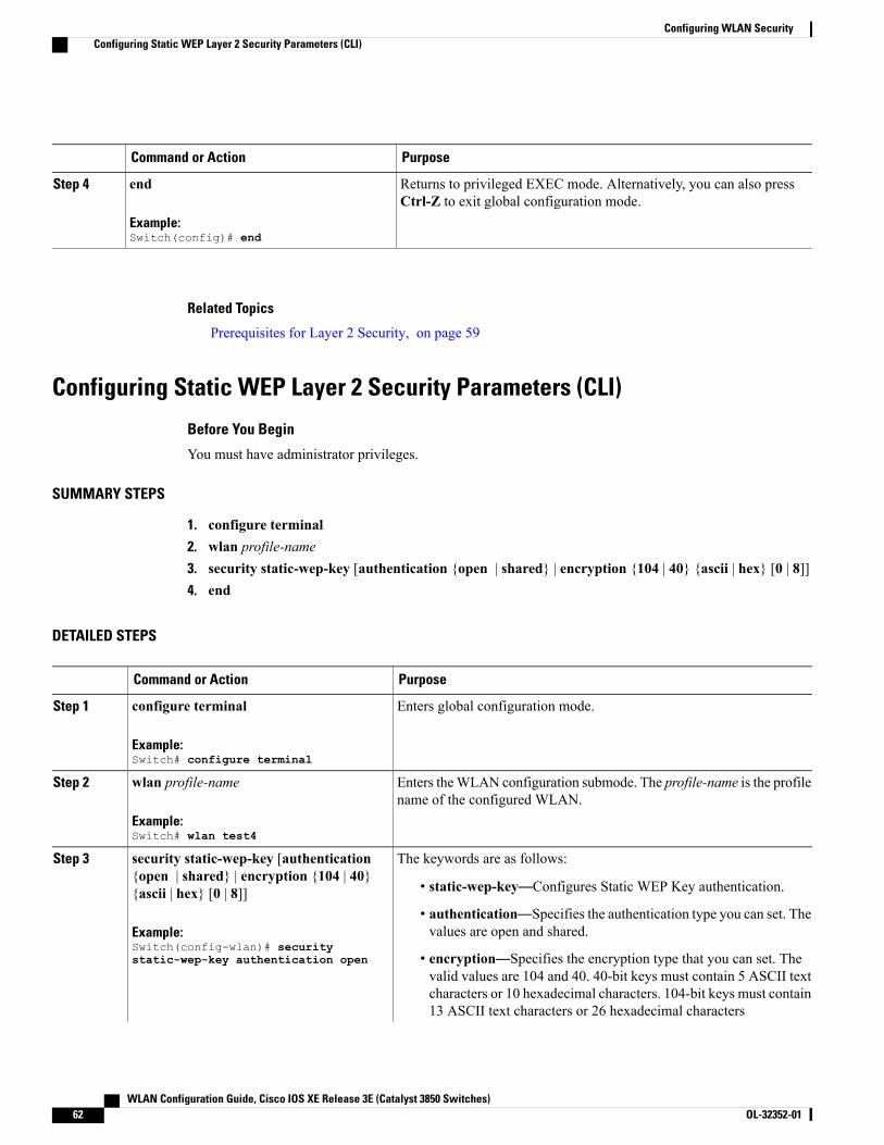
PurposeCommand or Action
Returns to privileged EXEC mode. Alternatively, you can also pressCtrl-Z to exit global configuration mode.
end
Example:Switch(config)# end
Step 4
Related Topics
Prerequisites for Layer 2 Security, on page 59
Configuring Static WEP Layer 2 Security Parameters (CLI)
Before You Begin
You must have administrator privileges.
SUMMARY STEPS
1. configure terminal2. wlan profile-name3. security static-wep-key [authentication {open | shared} | encryption {104 | 40} {ascii | hex} [0 | 8]]4. end
DETAILED STEPS
PurposeCommand or Action
Enters global configuration mode.configure terminal
Example:Switch# configure terminal
Step 1
Enters theWLAN configuration submode. The profile-name is the profilename of the configured WLAN.
wlan profile-name
Example:Switch# wlan test4
Step 2
The keywords are as follows:security static-wep-key [authentication{open | shared} | encryption {104 | 40}{ascii | hex} [0 | 8]]
Step 3
• static-wep-key—Configures Static WEP Key authentication.
Example:Switch(config-wlan)# securitystatic-wep-key authentication open
• authentication—Specifies the authentication type you can set. Thevalues are open and shared.
• encryption—Specifies the encryption type that you can set. Thevalid values are 104 and 40. 40-bit keys must contain 5 ASCII textcharacters or 10 hexadecimal characters. 104-bit keys must contain13 ASCII text characters or 26 hexadecimal characters
WLAN Configuration Guide, Cisco IOS XE Release 3E (Catalyst 3850 Switches)62 OL-32352-01
Configuring WLAN SecurityConfiguring Static WEP Layer 2 Security Parameters (CLI)
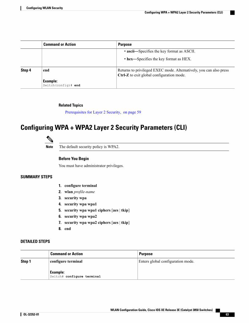
PurposeCommand or Action
• ascii—Specifies the key format as ASCII.
• hex—Specifies the key format as HEX.
Returns to privileged EXEC mode. Alternatively, you can also pressCtrl-Z to exit global configuration mode.
end
Example:Switch(config)# end
Step 4
Related Topics
Prerequisites for Layer 2 Security, on page 59
Configuring WPA + WPA2 Layer 2 Security Parameters (CLI)
The default security policy is WPA2.Note
Before You Begin
You must have administrator privileges.
SUMMARY STEPS
1. configure terminal2. wlan profile-name3. security wpa4. security wpa wpa15. security wpa wpa1 ciphers [aes | tkip]6. security wpa wpa27. security wpa wpa2 ciphers [aes | tkip]8. end
DETAILED STEPS
PurposeCommand or Action
Enters global configuration mode.configure terminal
Example:Switch# configure terminal
Step 1
WLAN Configuration Guide, Cisco IOS XE Release 3E (Catalyst 3850 Switches) OL-32352-01 63
Configuring WLAN SecurityConfiguring WPA + WPA2 Layer 2 Security Parameters (CLI)
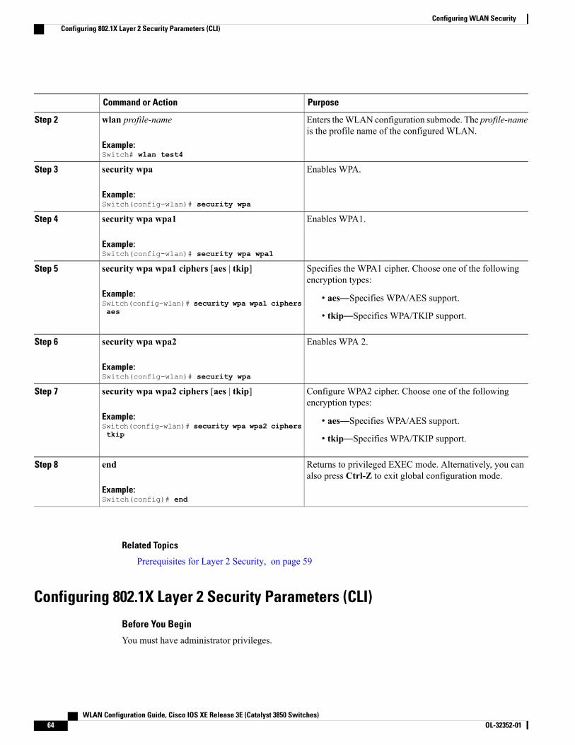
PurposeCommand or Action
Enters theWLAN configuration submode. The profile-nameis the profile name of the configured WLAN.
wlan profile-name
Example:Switch# wlan test4
Step 2
Enables WPA.security wpa
Example:Switch(config-wlan)# security wpa
Step 3
Enables WPA1.security wpa wpa1
Example:Switch(config-wlan)# security wpa wpa1
Step 4
Specifies the WPA1 cipher. Choose one of the followingencryption types:
security wpa wpa1 ciphers [aes | tkip]
Example:Switch(config-wlan)# security wpa wpa1 ciphersaes
Step 5
• aes—Specifies WPA/AES support.
• tkip—Specifies WPA/TKIP support.
Enables WPA 2.security wpa wpa2
Example:Switch(config-wlan)# security wpa
Step 6
Configure WPA2 cipher. Choose one of the followingencryption types:
security wpa wpa2 ciphers [aes | tkip]
Example:Switch(config-wlan)# security wpa wpa2 cipherstkip
Step 7
• aes—Specifies WPA/AES support.
• tkip—Specifies WPA/TKIP support.
Returns to privileged EXEC mode. Alternatively, you canalso press Ctrl-Z to exit global configuration mode.
end
Example:Switch(config)# end
Step 8
Related Topics
Prerequisites for Layer 2 Security, on page 59
Configuring 802.1X Layer 2 Security Parameters (CLI)
Before You Begin
You must have administrator privileges.
WLAN Configuration Guide, Cisco IOS XE Release 3E (Catalyst 3850 Switches)64 OL-32352-01
Configuring WLAN SecurityConfiguring 802.1X Layer 2 Security Parameters (CLI)
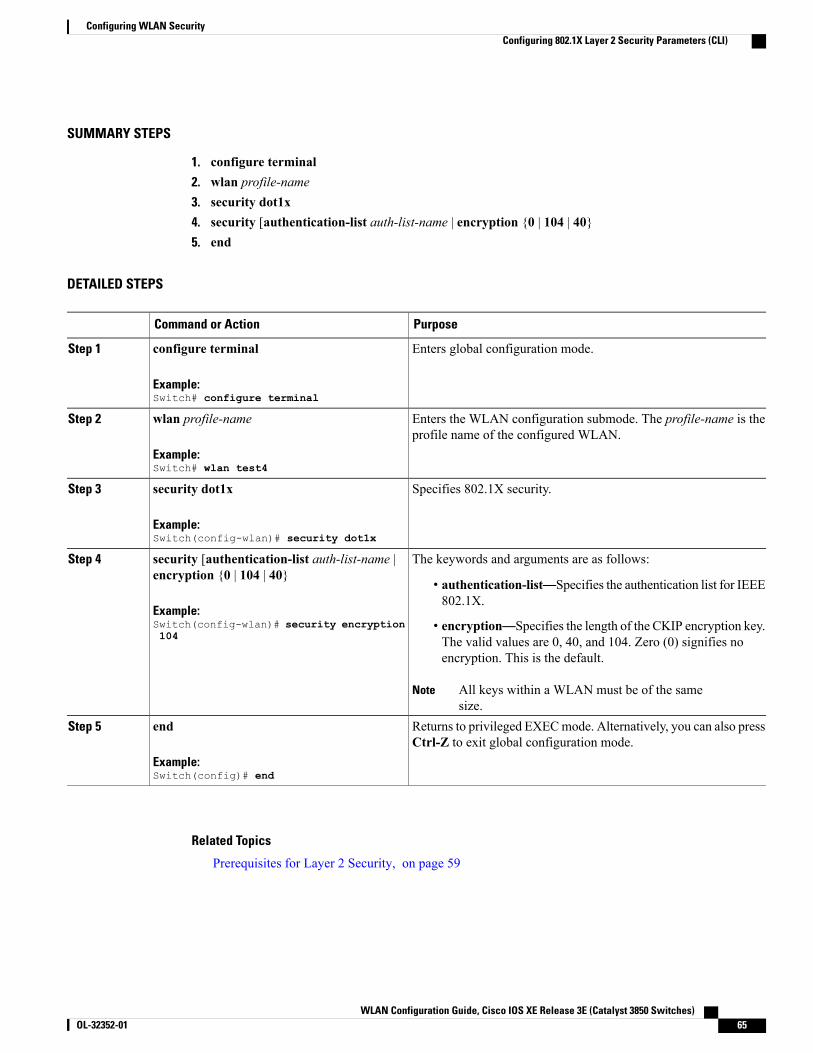
SUMMARY STEPS
1. configure terminal2. wlan profile-name3. security dot1x4. security [authentication-list auth-list-name | encryption {0 | 104 | 40}5. end
DETAILED STEPS
PurposeCommand or Action
Enters global configuration mode.configure terminal
Example:Switch# configure terminal
Step 1
Enters the WLAN configuration submode. The profile-name is theprofile name of the configured WLAN.
wlan profile-name
Example:Switch# wlan test4
Step 2
Specifies 802.1X security.security dot1x
Example:Switch(config-wlan)# security dot1x
Step 3
The keywords and arguments are as follows:security [authentication-list auth-list-name |encryption {0 | 104 | 40}
Step 4
• authentication-list—Specifies the authentication list for IEEE802.1X.
Example:Switch(config-wlan)# security encryption104
• encryption—Specifies the length of the CKIP encryption key.The valid values are 0, 40, and 104. Zero (0) signifies noencryption. This is the default.
All keys within a WLAN must be of the samesize.
Note
Returns to privileged EXECmode. Alternatively, you can also pressCtrl-Z to exit global configuration mode.
end
Example:Switch(config)# end
Step 5
Related Topics
Prerequisites for Layer 2 Security, on page 59
WLAN Configuration Guide, Cisco IOS XE Release 3E (Catalyst 3850 Switches) OL-32352-01 65
Configuring WLAN SecurityConfiguring 802.1X Layer 2 Security Parameters (CLI)

Configuring Layer 2 Parameters (GUI)
Before You Begin
• You must have administrator privileges.
Step 1 Click Configuration >WLAN > .TheWLANs page appears.
Step 2 Click the WLANs profile of the WLAN you want to configure.TheWLANs > Edit > page appears.
Step 3 Click the Security > Layer 2 > tab.DescriptionParameter
Layer 2 security for the selected WLAN. Values are the following:
• None—No Layer 2 security selected.
•WPA+WPA2—Wi-Fi Protected Access.
• 802.1X—WEP 802.1X data encryption type. For information on these settings, see theLayer 2 802.1X Parameters topic.
• Static WEP—Static WEP encryption parameters.
• Static WEP + 802.1x—Both Static WEP and 802.1X parameters.
Layer2 Security
MAC address filtering. You can locally configure clients by their MAC addresses in theMACFilters > New page . You can add a maximum of 12000 local net users. Otherwise, configurethe clients on a RADIUS server.
MACFiltering is also known asMACAuthenticationBy Pass (MAB).Note
MAC Filtering
Check box to enable or disable a fast transition between access points.Fast Transition
Check box to enable or disable a fast transition over a distributed system.Over the DS
Time in seconds after which a fast transition reassociation times out.Reassociation Timeout
To configure theWPA +WPA2 parameters, provide the following details:
DescriptionParameter
Check box to enable or disable WPA policy.WPA Policy
WPA2 encryption type: TKIP or AES. Available only if the WPA policy is enabled.WPA Encryption
Check box to enable or disable WPA2 policy.WPA2 Policy.
WLAN Configuration Guide, Cisco IOS XE Release 3E (Catalyst 3850 Switches)66 OL-32352-01
Configuring WLAN SecurityConfiguring Layer 2 Parameters (GUI)
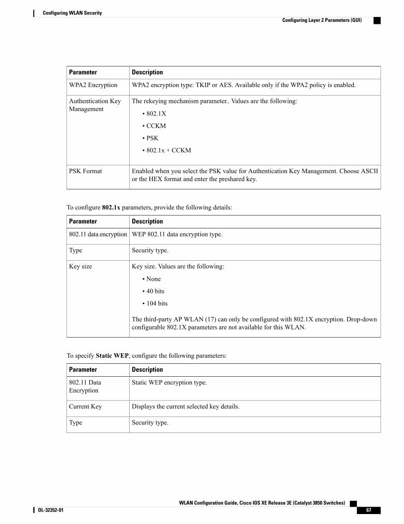
DescriptionParameter
WPA2 encryption type: TKIP or AES. Available only if the WPA2 policy is enabled.WPA2 Encryption
The rekeying mechanism parameter.. Values are the following:
• 802.1X
• CCKM
• PSK
• 802.1x + CCKM
Authentication KeyManagement
Enabled when you select the PSK value for Authentication Key Management. Choose ASCIIor the HEX format and enter the preshared key.
PSK Format
To configure 802.1x parameters, provide the following details:
DescriptionParameter
WEP 802.11 data encryption type.802.11 data encryption
Security type.Type
Key size. Values are the following:
• None
• 40 bits
• 104 bits
The third-party AP WLAN (17) can only be configured with 802.1X encryption. Drop-downconfigurable 802.1X parameters are not available for this WLAN.
Key size
To specify Static WEP, configure the following parameters:
DescriptionParameter
Static WEP encryption type.802.11 DataEncryption
Displays the current selected key details.Current Key
Security type.Type
WLAN Configuration Guide, Cisco IOS XE Release 3E (Catalyst 3850 Switches) OL-32352-01 67
Configuring WLAN SecurityConfiguring Layer 2 Parameters (GUI)
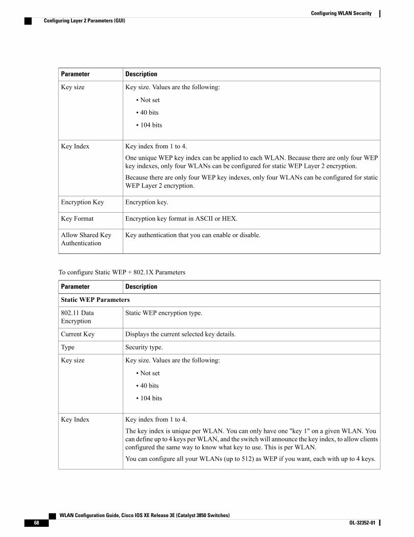
DescriptionParameter
Key size. Values are the following:
• Not set
• 40 bits
• 104 bits
Key size
Key index from 1 to 4.
One unique WEP key index can be applied to each WLAN. Because there are only four WEPkey indexes, only four WLANs can be configured for static WEP Layer 2 encryption.
Because there are only four WEP key indexes, only four WLANs can be configured for staticWEP Layer 2 encryption.
Key Index
Encryption key.Encryption Key
Encryption key format in ASCII or HEX.Key Format
Key authentication that you can enable or disable.Allow Shared KeyAuthentication
To configure Static WEP + 802.1X Parameters
DescriptionParameter
Static WEP Parameters
Static WEP encryption type.802.11 DataEncryption
Displays the current selected key details.Current Key
Security type.Type
Key size. Values are the following:
• Not set
• 40 bits
• 104 bits
Key size
Key index from 1 to 4.
The key index is unique per WLAN. You can only have one "key 1" on a given WLAN. Youcan define up to 4 keys perWLAN, and the switch will announce the key index, to allow clientsconfigured the same way to know what key to use. This is per WLAN.
You can configure all your WLANs (up to 512) as WEP if you want, each with up to 4 keys.
Key Index
WLAN Configuration Guide, Cisco IOS XE Release 3E (Catalyst 3850 Switches)68 OL-32352-01
Configuring WLAN SecurityConfiguring Layer 2 Parameters (GUI)
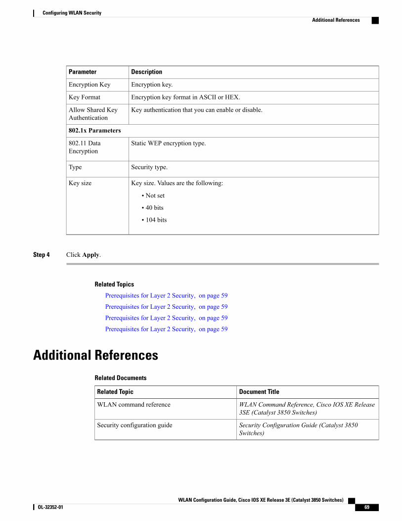
DescriptionParameter
Encryption key.Encryption Key
Encryption key format in ASCII or HEX.Key Format
Key authentication that you can enable or disable.Allow Shared KeyAuthentication
802.1x Parameters
Static WEP encryption type.802.11 DataEncryption
Security type.Type
Key size. Values are the following:
• Not set
• 40 bits
• 104 bits
Key size
Step 4 Click Apply.
Related Topics
Prerequisites for Layer 2 Security, on page 59
Prerequisites for Layer 2 Security, on page 59
Prerequisites for Layer 2 Security, on page 59
Prerequisites for Layer 2 Security, on page 59
Additional ReferencesRelated Documents
Document TitleRelated Topic
WLAN Command Reference, Cisco IOS XE Release3SE (Catalyst 3850 Switches)
WLAN command reference
Security Configuration Guide (Catalyst 3850Switches)
Security configuration guide
WLAN Configuration Guide, Cisco IOS XE Release 3E (Catalyst 3850 Switches) OL-32352-01 69
Configuring WLAN SecurityAdditional References
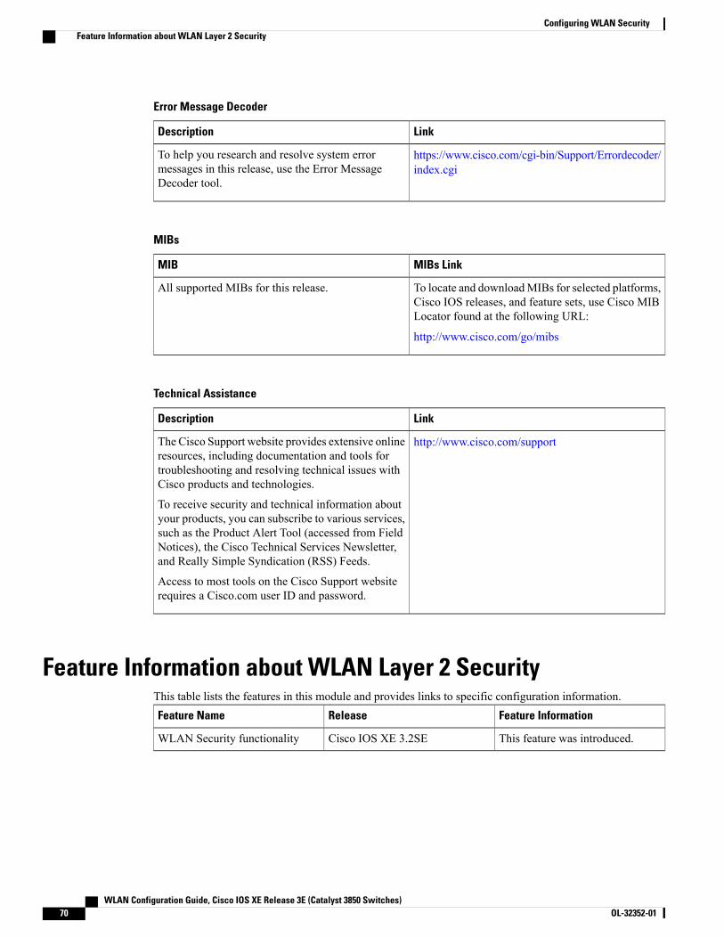
Error Message Decoder
LinkDescription
https://www.cisco.com/cgi-bin/Support/Errordecoder/index.cgi
To help you research and resolve system errormessages in this release, use the Error MessageDecoder tool.
MIBs
MIBs LinkMIB
To locate and downloadMIBs for selected platforms,Cisco IOS releases, and feature sets, use Cisco MIBLocator found at the following URL:
http://www.cisco.com/go/mibs
All supported MIBs for this release.
Technical Assistance
LinkDescription
http://www.cisco.com/supportThe Cisco Support website provides extensive onlineresources, including documentation and tools fortroubleshooting and resolving technical issues withCisco products and technologies.
To receive security and technical information aboutyour products, you can subscribe to various services,such as the Product Alert Tool (accessed from FieldNotices), the Cisco Technical Services Newsletter,and Really Simple Syndication (RSS) Feeds.
Access to most tools on the Cisco Support websiterequires a Cisco.com user ID and password.
Feature Information about WLAN Layer 2 SecurityThis table lists the features in this module and provides links to specific configuration information.
Feature InformationReleaseFeature Name
This feature was introduced.Cisco IOS XE 3.2SEWLAN Security functionality
WLAN Configuration Guide, Cisco IOS XE Release 3E (Catalyst 3850 Switches)70 OL-32352-01
Configuring WLAN SecurityFeature Information about WLAN Layer 2 Security

C H A P T E R 6Setting Client Count Per WLAN
• Finding Feature Information, page 71
• Restrictions for Setting Client Count for WLANs, page 71
• Information About Setting the Client Count per WLAN, page 72
• How to Configure Client Count Per WLAN, page 72
• Monitoring Client Connections (CLI), page 75
• Additional References for Client Connections, page 76
• Feature Information about Client Connections Per WLAN, page 77
Finding Feature InformationYour software release may not support all the features documented in this module. For the latest featureinformation and caveats, see the release notes for your platform and software release. To find informationabout the features documented in this module, and to see a list of the releases in which each feature is supported,see the Feature Information Table at the end of this document.
Use Cisco Feature Navigator to find information about platform support and Cisco software image support.To access Cisco Feature Navigator, go to http://www.cisco.com/go/cfn. An account on Cisco.com is notrequired.
Restrictions for Setting Client Count for WLANs•When a WLAN has reached the limit on the maximum number of clients connected to it or an AP radioand a new client tries to join the WLAN, the client cannot connect to the WLAN until an existing clientgets disconnected.
• Roaming clients are considered as new clients. The new client can connect to a WLAN, which hasreached the maximum limit on the number of connected clients, only when an existing client getsdisconnected.
WLAN Configuration Guide, Cisco IOS XE Release 3E (Catalyst 3850 Switches) OL-32352-01 71
For more information about the number of clients that are supported, see the product data sheet of yourswitch.
Note
Related Topics
Configuring Client Count per WLAN (CLI), on page 72
Configuring Client Count Per AP Per WLAN (CLI), on page 73
Configuring Client Count per AP Radio per WLAN (CLI), on page 74
Information About Setting the Client Count per WLAN, on page 72
Information About Setting the Client Count per WLANYou can set a limit to the number of clients that can connect to a WLAN, which is useful in scenarios whereyou have a limited number of clients that can connect to a switch. For example, consider a scenario where theswitch can serve up to 256 clients on a WLAN and these clients can be shared between enterprise users(employees) and guest users. You can set a limit on the number of guest clients that can access a givenWLAN.The number of clients that you can configure for each WLAN depends on the platform that you are using.
Related Topics
Configuring Client Count per WLAN (CLI), on page 72
Configuring Client Count Per AP Per WLAN (CLI), on page 73
Configuring Client Count per AP Radio per WLAN (CLI), on page 74
Restrictions for Setting Client Count for WLANs, on page 71
Monitoring Client Connections (CLI), on page 75
How to Configure Client Count Per WLAN
Configuring Client Count per WLAN (CLI)
SUMMARY STEPS
1. configure terminal2. wlan profile-name3. client association limit limit4. end
WLAN Configuration Guide, Cisco IOS XE Release 3E (Catalyst 3850 Switches)72 OL-32352-01
Setting Client Count Per WLANInformation About Setting the Client Count per WLAN
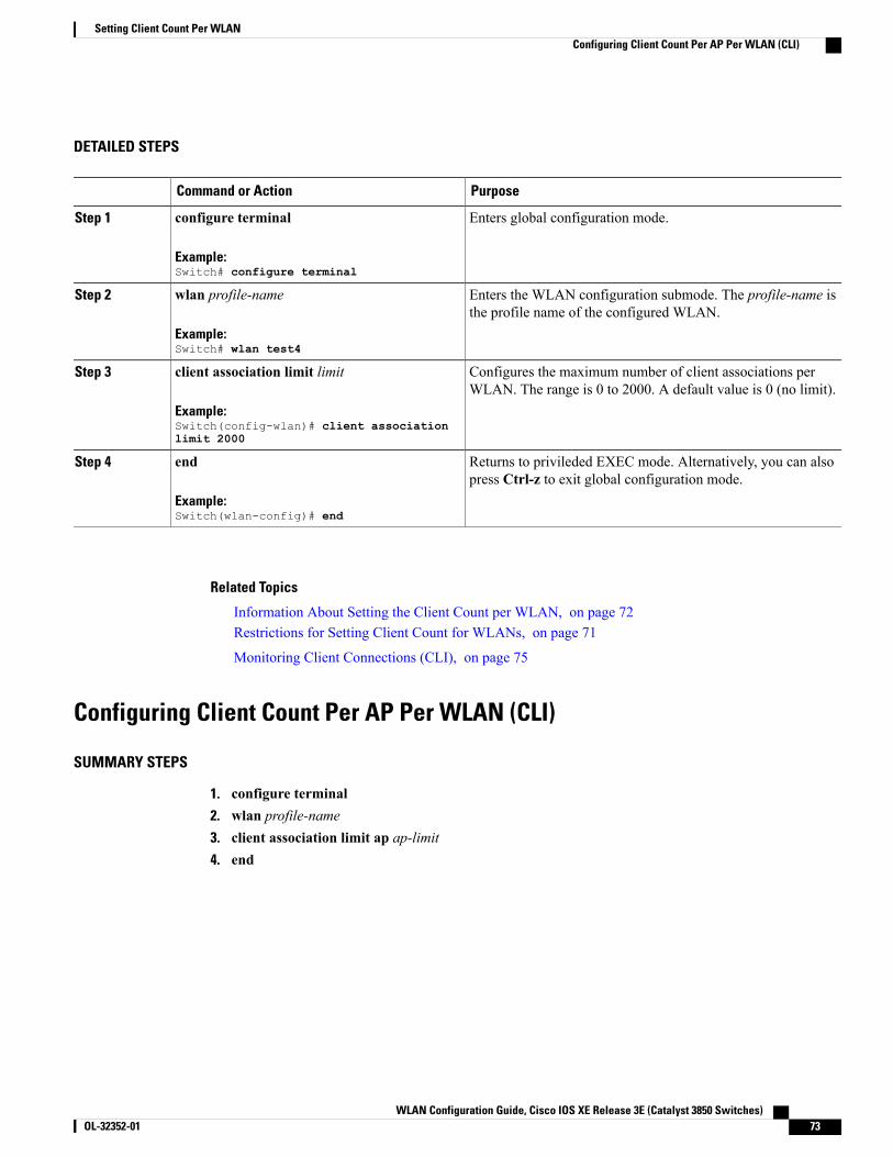
DETAILED STEPS
PurposeCommand or Action
Enters global configuration mode.configure terminal
Example:Switch# configure terminal
Step 1
Enters the WLAN configuration submode. The profile-name isthe profile name of the configured WLAN.
wlan profile-name
Example:Switch# wlan test4
Step 2
Configures the maximum number of client associations perWLAN. The range is 0 to 2000. A default value is 0 (no limit).
client association limit limit
Example:Switch(config-wlan)# client associationlimit 2000
Step 3
Returns to privileded EXEC mode. Alternatively, you can alsopress Ctrl-z to exit global configuration mode.
end
Example:Switch(wlan-config)# end
Step 4
Related Topics
Information About Setting the Client Count per WLAN, on page 72Restrictions for Setting Client Count for WLANs, on page 71
Monitoring Client Connections (CLI), on page 75
Configuring Client Count Per AP Per WLAN (CLI)
SUMMARY STEPS
1. configure terminal2. wlan profile-name3. client association limit ap ap-limit4. end
WLAN Configuration Guide, Cisco IOS XE Release 3E (Catalyst 3850 Switches) OL-32352-01 73
Setting Client Count Per WLANConfiguring Client Count Per AP Per WLAN (CLI)
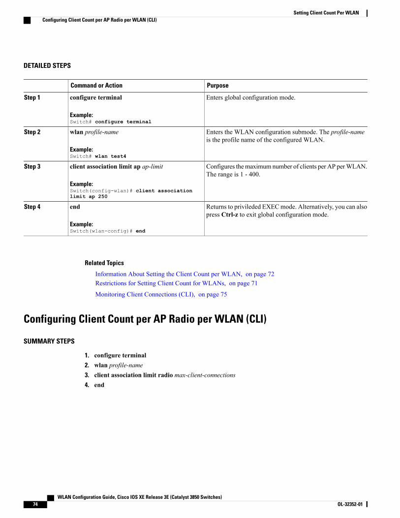
DETAILED STEPS
PurposeCommand or Action
Enters global configuration mode.configure terminal
Example:Switch# configure terminal
Step 1
Enters the WLAN configuration submode. The profile-nameis the profile name of the configured WLAN.
wlan profile-name
Example:Switch# wlan test4
Step 2
Configures themaximum number of clients per AP perWLAN.The range is 1 - 400.
client association limit ap ap-limit
Example:Switch(config-wlan)# client associationlimit ap 250
Step 3
Returns to privileded EXECmode. Alternatively, you can alsopress Ctrl-z to exit global configuration mode.
end
Example:Switch(wlan-config)# end
Step 4
Related Topics
Information About Setting the Client Count per WLAN, on page 72Restrictions for Setting Client Count for WLANs, on page 71
Monitoring Client Connections (CLI), on page 75
Configuring Client Count per AP Radio per WLAN (CLI)
SUMMARY STEPS
1. configure terminal2. wlan profile-name3. client association limit radio max-client-connections4. end
WLAN Configuration Guide, Cisco IOS XE Release 3E (Catalyst 3850 Switches)74 OL-32352-01
Setting Client Count Per WLANConfiguring Client Count per AP Radio per WLAN (CLI)

DETAILED STEPS
PurposeCommand or Action
Enters global configuration mode.configure terminal
Example:Switch# configure terminal
Step 1
Enters the WLAN configuration submode. The profile-name isthe profile name of the configured WLAN.
wlan profile-name
Example:Switch# wlan test4
Step 2
Configures the maximum number of client connections per APradio per WLAN. The range is 0 - 200 for the a, b, and g radios.
client association limit radiomax-client-connections
Example:Switch(config-wlan)# client associationlimit radio 180
Step 3
Returns to privileged EXEC mode. Alternatively, you can alsopress Ctrl-z to exit global configuration mode.
end
Example:Switch(config-wlan)# end
Step 4
Related Topics
Information About Setting the Client Count per WLAN, on page 72Restrictions for Setting Client Count for WLANs, on page 71
Monitoring Client Connections (CLI), on page 75
Monitoring Client Connections (CLI)The following commands can be used to monitor client connections on the switch:
DescriptionCommand
Displays the WLAN properties. Here is an example:
. . . .Max Associated Clients per WLAN :0Max Associated Clients per AP per WLAN :0Max Associated Clients per AP Radio per WLAN :0. . .. . .
show wlan name wlan-name
WLAN Configuration Guide, Cisco IOS XE Release 3E (Catalyst 3850 Switches) OL-32352-01 75
Setting Client Count Per WLANMonitoring Client Connections (CLI)
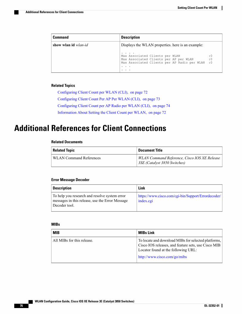
DescriptionCommand
Displays the WLAN properties. here is an example:
. . . .Max Associated Clients per WLAN :0Max Associated Clients per AP per WLAN :0Max Associated Clients per AP Radio per WLAN :0. . .. . .
show wlan id wlan-id
Related Topics
Configuring Client Count per WLAN (CLI), on page 72
Configuring Client Count Per AP Per WLAN (CLI), on page 73
Configuring Client Count per AP Radio per WLAN (CLI), on page 74
Information About Setting the Client Count per WLAN, on page 72
Additional References for Client ConnectionsRelated Documents
Document TitleRelated Topic
WLAN Command Reference, Cisco IOS XE Release3SE (Catalyst 3850 Switches)
WLAN Command References
Error Message Decoder
LinkDescription
https://www.cisco.com/cgi-bin/Support/Errordecoder/index.cgi
To help you research and resolve system errormessages in this release, use the Error MessageDecoder tool.
MIBs
MIBs LinkMIB
To locate and downloadMIBs for selected platforms,Cisco IOS releases, and feature sets, use Cisco MIBLocator found at the following URL:
http://www.cisco.com/go/mibs
All MIBs for this release.
WLAN Configuration Guide, Cisco IOS XE Release 3E (Catalyst 3850 Switches)76 OL-32352-01
Setting Client Count Per WLANAdditional References for Client Connections

Technical Assistance
LinkDescription
http://www.cisco.com/supportThe Cisco Support website provides extensive onlineresources, including documentation and tools fortroubleshooting and resolving technical issues withCisco products and technologies.
To receive security and technical information aboutyour products, you can subscribe to various services,such as the Product Alert Tool (accessed from FieldNotices), the Cisco Technical Services Newsletter,and Really Simple Syndication (RSS) Feeds.
Access to most tools on the Cisco Support websiterequires a Cisco.com user ID and password.
Feature Information about Client Connections Per WLANThis table lists the features in this module and provides links to specific configuration information:
Feature InformationReleaseFeature Name
This feature was introduced.Cisco IOS XE 3.3SEClient Connections Per WLAN,Per AP, and per AP Radio
WLAN Configuration Guide, Cisco IOS XE Release 3E (Catalyst 3850 Switches) OL-32352-01 77
Setting Client Count Per WLANFeature Information about Client Connections Per WLAN

WLAN Configuration Guide, Cisco IOS XE Release 3E (Catalyst 3850 Switches)78 OL-32352-01
Setting Client Count Per WLANFeature Information about Client Connections Per WLAN
C H A P T E R 7Configuring 802.11w
• Finding Feature Information, page 79
• Prerequisites for 802.11w, page 79
• Restrictions for 802.11w, page 80
• Information About 802.11w, page 80
• How to Configure 802.11w, page 81
• Disabling 802.11w (CLI), page 83
• Monitoring 802.11w (CLI), page 84
• Additional References for 802.11w, page 85
• Feature Information for 802.11w, page 86
Finding Feature InformationYour software release may not support all the features documented in this module. For the latest featureinformation and caveats, see the release notes for your platform and software release. To find informationabout the features documented in this module, and to see a list of the releases in which each feature is supported,see the Feature Information Table at the end of this document.
Use Cisco Feature Navigator to find information about platform support and Cisco software image support.To access Cisco Feature Navigator, go to http://www.cisco.com/go/cfn. An account on Cisco.com is notrequired.
Prerequisites for 802.11w• To configure 802.11w feature for optional and mandatory, you must have WPA and AKM configured.
The RNS (Robust Secure Network) IE must be enabled with an AES Cipher.Note
• To configure 802.11w as mandatory, you must enable PMF AKM in addition to WPA AKM.
WLAN Configuration Guide, Cisco IOS XE Release 3E (Catalyst 3850 Switches) OL-32352-01 79
Related Topics
Configuring 802.11w (CLI), on page 81
Disabling 802.11w (CLI), on page 83
Information About 802.11w, on page 80
Restrictions for 802.11w• 802.11w cannot be applied on an open WLAN, WEP-encrypted WLAN, or a TKIP-encrypted WLAN.
• The WLAN on which 802.11w is configured must have either WPA2-PSK or WPA2-802.1x securityconfigured.
Related Topics
Configuring 802.11w (CLI), on page 81
Disabling 802.11w (CLI), on page 83
Information About 802.11w, on page 80
Information About 802.11wWi-Fi is a broadcast medium that enables any device to eavesdrop and participate either as a legitimate orrogue device. Control and management frames such as authentication/deauthentication,association/disassociation, beacons, and probes are used by wireless clients to select an AP and to initiate asession for network services.
Unlike data traffic which can be encrypted to provide a level of confidentiality, these frames must be heardand understood by all clients and therefore must be transmitted as open or unencrypted. While these framescannot be encrypted, they must be protected from forgery to protect the wireless medium from attacks. Forexample, an attacker could spoof management frames from an AP to tear down a session between a client andAP.
The 802.11w protocol applies only to a set of robust management frames that are protected by theManagementFrame Protection (PMF) service. These include Disassociation, Deauthentication, and Robust Action frames.
Management frames that are considered as robust action and therefore protected are the following:
• Spectrum Management
• QoS
• Block Ack
• SA Query
• Vendor-specific Protected
When 802.11w is implemented in the wireless medium, the following occur:
• Client protection is added by the AP adding cryptographic protection (by including theMIC informationelement) to deauthentication and disassociation frames preventing them from being spoofed in a DOSattack.
WLAN Configuration Guide, Cisco IOS XE Release 3E (Catalyst 3850 Switches)80 OL-32352-01
Configuring 802.11wRestrictions for 802.11w
• Infrastructure protection is added by adding a Security Association (SA) teardown protection mechanismconsisting of an Association Comeback Time and an SA-Query procedure preventing spoofed associationrequest from disconnecting an already connected client.
Related Topics
Configuring 802.11w (CLI), on page 81
Disabling 802.11w (CLI), on page 83
Prerequisites for 802.11w, on page 79
Restrictions for 802.11w, on page 80
Monitoring 802.11w (CLI), on page 84
How to Configure 802.11w
Configuring 802.11w (CLI)
Before You Begin
WPA and AKM must be configured.
SUMMARY STEPS
1. configure terminal2. wlan profile-name3. shutdown4. security pmf {association-check association-comeback-time-in-seconds |mandatory | optional | saquery
saquery-time-in-milliseconds}5. no shutdown6. end
DETAILED STEPS
PurposeCommand or Action
Enters global configuration mode.configure terminal
Example:Switch# configure terminal
Step 1
Enters the WLAN configuration submode. The profile-name is theprofile name of the configured WLAN.
wlan profile-name
Example:Switch# wlan test4
Step 2
WLAN Configuration Guide, Cisco IOS XE Release 3E (Catalyst 3850 Switches) OL-32352-01 81
Configuring 802.11wHow to Configure 802.11w
PurposeCommand or Action
Shutdown the WLAN before configuring the PMF.shutdown
Example:Switch shutdown
Step 3
Configures the PMF parameters with the following options:security pmf {association-checkassociation-comeback-time-in-seconds |
Step 4
• association-comeback—Configures the 802.11w associationcomeback time.
mandatory | optional | saquerysaquery-time-in-milliseconds}
Example:Switch(config-wlan)# security pmfsaquery-retry-time 200
The range is from 1 to 20 seconds.
• mandatory—Requires clients to negotiate 802.11w PMFprotection on a WLAN.
• optional—Enables 802.11w PMF protection on a WLAN.
• saquery—Time interval identified in milliseconds before whichthe SA query response is expected. If the switch does not get aresponse, another SQ query is tried.
The range is from 100 to 500 ms. The value must be specified inmultiples of 100 milliseconds.
Restart the WLAN for the changes to take effect.no shutdown
Example:Switch no shutdown
Step 5
Returns to privileged EXEC mode. Alternatively, you can also pressCtrl-z to exit global configuration mode.
end
Example:Switch(config-wlan)# end
Step 6
Related Topics
Information About 802.11w, on page 80Prerequisites for 802.11w, on page 79
Restrictions for 802.11w, on page 80
Monitoring 802.11w (CLI), on page 84
WLAN Configuration Guide, Cisco IOS XE Release 3E (Catalyst 3850 Switches)82 OL-32352-01
Configuring 802.11wConfiguring 802.11w (CLI)
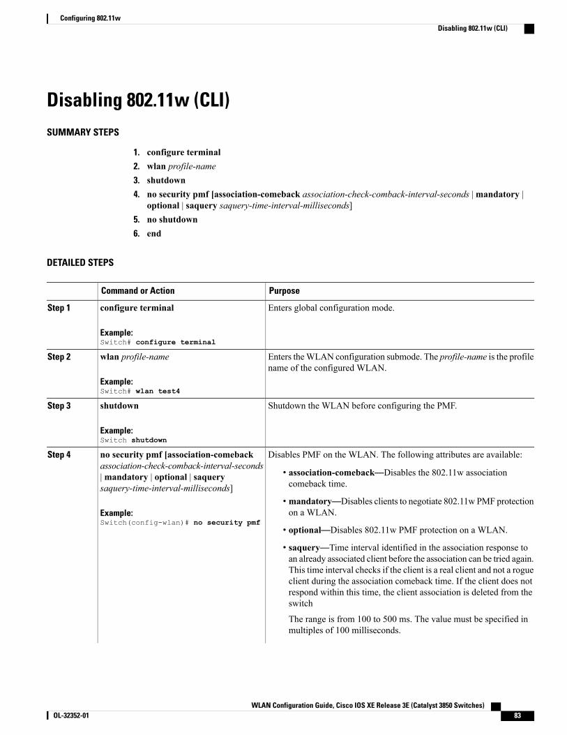
Disabling 802.11w (CLI)SUMMARY STEPS
1. configure terminal2. wlan profile-name3. shutdown4. no security pmf [association-comeback association-check-comback-interval-seconds |mandatory |
optional | saquery saquery-time-interval-milliseconds]5. no shutdown6. end
DETAILED STEPS
PurposeCommand or Action
Enters global configuration mode.configure terminal
Example:Switch# configure terminal
Step 1
Enters theWLAN configuration submode. The profile-name is the profilename of the configured WLAN.
wlan profile-name
Example:Switch# wlan test4
Step 2
Shutdown the WLAN before configuring the PMF.shutdown
Example:Switch shutdown
Step 3
Disables PMF on the WLAN. The following attributes are available:no security pmf [association-comebackassociation-check-comback-interval-seconds
Step 4
• association-comeback—Disables the 802.11w associationcomeback time.
|mandatory | optional | saquerysaquery-time-interval-milliseconds]
Example:Switch(config-wlan)# no security pmf
• mandatory—Disables clients to negotiate 802.11w PMF protectionon a WLAN.
• optional—Disables 802.11w PMF protection on a WLAN.
• saquery—Time interval identified in the association response toan already associated client before the association can be tried again.This time interval checks if the client is a real client and not a rogueclient during the association comeback time. If the client does notrespond within this time, the client association is deleted from theswitch
The range is from 100 to 500 ms. The value must be specified inmultiples of 100 milliseconds.
WLAN Configuration Guide, Cisco IOS XE Release 3E (Catalyst 3850 Switches) OL-32352-01 83
Configuring 802.11wDisabling 802.11w (CLI)
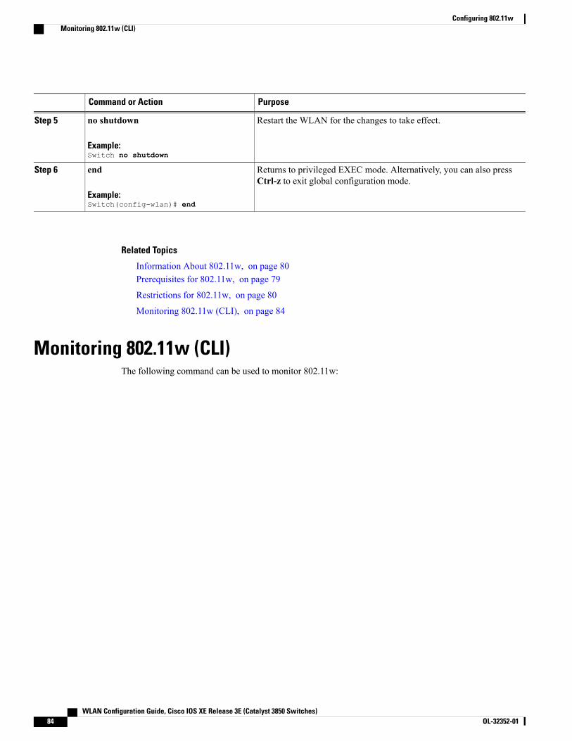
PurposeCommand or Action
Restart the WLAN for the changes to take effect.no shutdown
Example:Switch no shutdown
Step 5
Returns to privileged EXEC mode. Alternatively, you can also pressCtrl-z to exit global configuration mode.
end
Example:Switch(config-wlan)# end
Step 6
Related Topics
Information About 802.11w, on page 80Prerequisites for 802.11w, on page 79
Restrictions for 802.11w, on page 80
Monitoring 802.11w (CLI), on page 84
Monitoring 802.11w (CLI)The following command can be used to monitor 802.11w:
WLAN Configuration Guide, Cisco IOS XE Release 3E (Catalyst 3850 Switches)84 OL-32352-01
Configuring 802.11wMonitoring 802.11w (CLI)
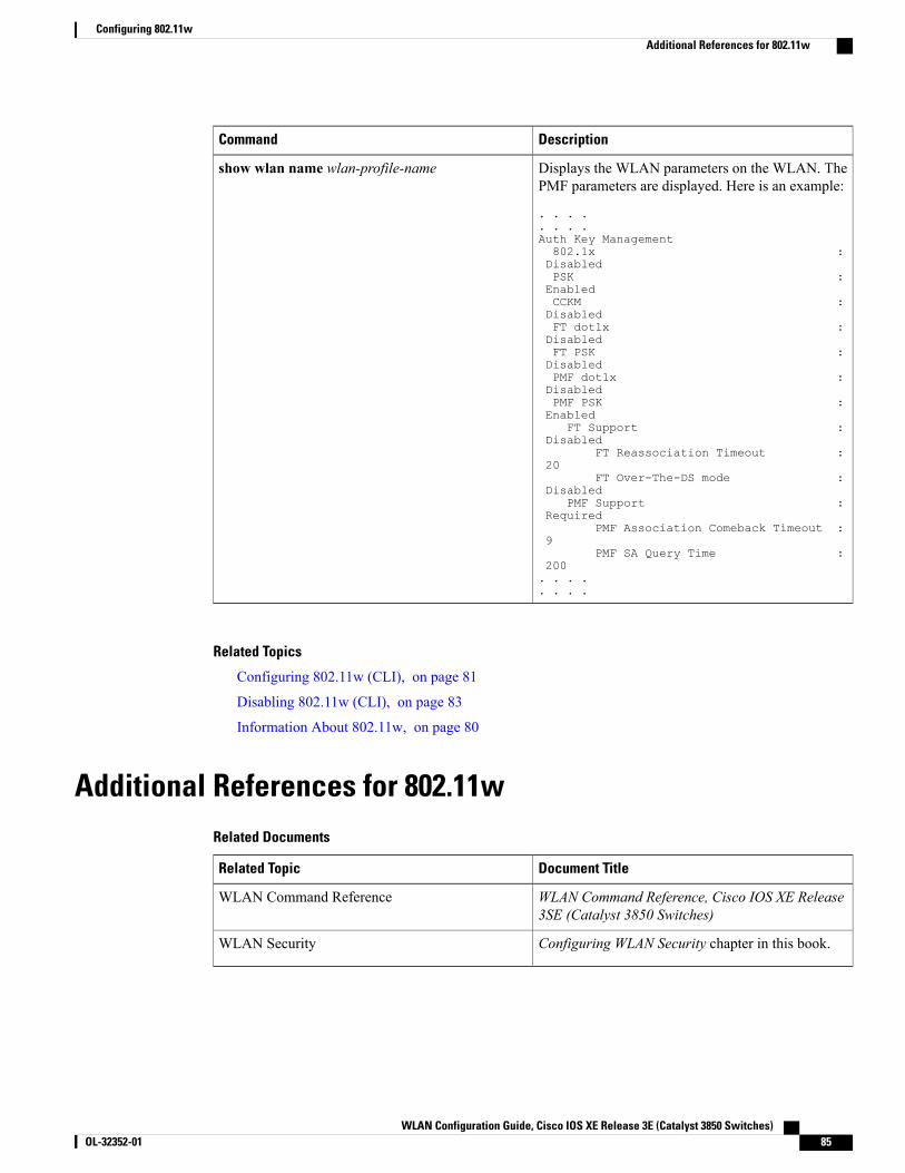
DescriptionCommand
Displays the WLAN parameters on the WLAN. ThePMF parameters are displayed. Here is an example:
. . . .
. . . .Auth Key Management802.1x :DisabledPSK :EnabledCCKM :DisabledFT dot1x :DisabledFT PSK :DisabledPMF dot1x :DisabledPMF PSK :Enabled
FT Support :Disabled
FT Reassociation Timeout :20
FT Over-The-DS mode :Disabled
PMF Support :Required
PMF Association Comeback Timeout :9
PMF SA Query Time :200. . . .. . . .
show wlan name wlan-profile-name
Related Topics
Configuring 802.11w (CLI), on page 81
Disabling 802.11w (CLI), on page 83
Information About 802.11w, on page 80
Additional References for 802.11wRelated Documents
Document TitleRelated Topic
WLAN Command Reference, Cisco IOS XE Release3SE (Catalyst 3850 Switches)
WLAN Command Reference
Configuring WLAN Security chapter in this book.WLAN Security
WLAN Configuration Guide, Cisco IOS XE Release 3E (Catalyst 3850 Switches) OL-32352-01 85
Configuring 802.11wAdditional References for 802.11w

Error Message Decoder
LinkDescription
https://www.cisco.com/cgi-bin/Support/Errordecoder/index.cgi
To help you research and resolve system errormessages in this release, use the Error MessageDecoder tool.
Standards and RFCs
TitleStandard/RFC
IEEE 802.11w Protected Management Frames802.11w
MIBs
MIBs LinkMIB
To locate and downloadMIBs for selected platforms,Cisco IOS releases, and feature sets, use Cisco MIBLocator found at the following URL:
http://www.cisco.com/go/mibs
All supported MIBs for this release.
Technical Assistance
LinkDescription
http://www.cisco.com/supportThe Cisco Support website provides extensive onlineresources, including documentation and tools fortroubleshooting and resolving technical issues withCisco products and technologies.
To receive security and technical information aboutyour products, you can subscribe to various services,such as the Product Alert Tool (accessed from FieldNotices), the Cisco Technical Services Newsletter,and Really Simple Syndication (RSS) Feeds.
Access to most tools on the Cisco Support websiterequires a Cisco.com user ID and password.
Feature Information for 802.11wThis table lists the features in this module and provides links to specific configuration information:
WLAN Configuration Guide, Cisco IOS XE Release 3E (Catalyst 3850 Switches)86 OL-32352-01
Configuring 802.11wFeature Information for 802.11w

Feature InformationReleaseFeature Name
This feature was introduced.Cisco IOS XE 3.3SE802.11w
WLAN Configuration Guide, Cisco IOS XE Release 3E (Catalyst 3850 Switches) OL-32352-01 87
Configuring 802.11wFeature Information for 802.11w

WLAN Configuration Guide, Cisco IOS XE Release 3E (Catalyst 3850 Switches)88 OL-32352-01
Configuring 802.11wFeature Information for 802.11w
C H A P T E R 8Configuring Wi-Fi Direct Client Policy
• Finding Feature Information, page 89
• Restrictions for the Wi-Fi Direct Client Policy, page 89
• Information About the Wi-Fi Direct Client Policy, page 89
• How to Configure Wi-Fi Direct Client Policy, page 90
• Additional References for Wi-Fi Direct Client Policy, page 92
• Feature Information about Wi-Fi Direct Client Policy, page 93
Finding Feature InformationYour software release may not support all the features documented in this module. For the latest featureinformation and caveats, see the release notes for your platform and software release. To find informationabout the features documented in this module, and to see a list of the releases in which each feature is supported,see the Feature Information Table at the end of this document.
Use Cisco Feature Navigator to find information about platform support and Cisco software image support.To access Cisco Feature Navigator, go to http://www.cisco.com/go/cfn. An account on Cisco.com is notrequired.
Restrictions for the Wi-Fi Direct Client PolicyWi-Fi Direct Client Policy is applicable to WLANs that have APs in local mode only.
Information About the Wi-Fi Direct Client PolicyDevices that are Wi-Fi Direct capable can connect directly to each other quickly and conveniently to do taskssuch as printing, synchronization, and sharing of data. Wi-Fi Direct devices may associate with multiplepeer-to-peer (P2P) devices and with infrastructure wireless LANs (WLANs) concurrently. You can use theswitch to configure the Wi-Fi Direct Client Policy, on a per WLAN basis, where you can allow or disallowassociation of Wi-Fi devices with infrastructure WLANs, or disable Wi-Fi Direct Client Policy altogether forWLANs.
WLAN Configuration Guide, Cisco IOS XE Release 3E (Catalyst 3850 Switches) OL-32352-01 89

Related Topics
Configuring the Wi-Fi Direct Client Policy (CLI), on page 90
Disabling Wi-Fi Direct Client Policy (CLI), on page 91
Monitoring Wi-Fi Direct Client Policy (CLI), on page 92
How to Configure Wi-Fi Direct Client Policy
Configuring the Wi-Fi Direct Client Policy (CLI)
SUMMARY STEPS
1. configure terminal2. wlan profile-name3. wifidirect policy {permit | deny }4. end
DETAILED STEPS
PurposeCommand or Action
Enters global configuration mode.configure terminal
Example:Switch# configure terminal
Step 1
Enters the WLAN configuration submode. The profile-name is the profile name ofthe configured WLAN.
wlan profile-name
Example:Switch# wlan test4
Step 2
Configures theWi-Fi Direct client policy on theWLAN using one of the following:wifidirect policy {permit | deny }
Example:Switch(config-wlan)#wifidirect policy permit
Step 3
• permit—Enables Wi-Fi Direct clients to associate with the WLAN.
• deny—When the Wi-Fi Direct policy is configured as "deny," the switchpermits or denies Wi-Fi Direct devices based on the device capabilities. AWi-Fi Direct device reports these capabilities in its association request to theswitch and these are based on the Wi-Fi capabilities of the device. Theseinclude:
• Concurrent operation
• Cross connection
The command no wifidirect policy ignores the client's Wi-Fi directstatus. Additionally, the access point also does not advertise anybeacons and probes. Effectively, the no form of the command disablesthe Wi-Fi direct feature on the WLAN.
Note
WLAN Configuration Guide, Cisco IOS XE Release 3E (Catalyst 3850 Switches)90 OL-32352-01
Configuring Wi-Fi Direct Client PolicyHow to Configure Wi-Fi Direct Client Policy
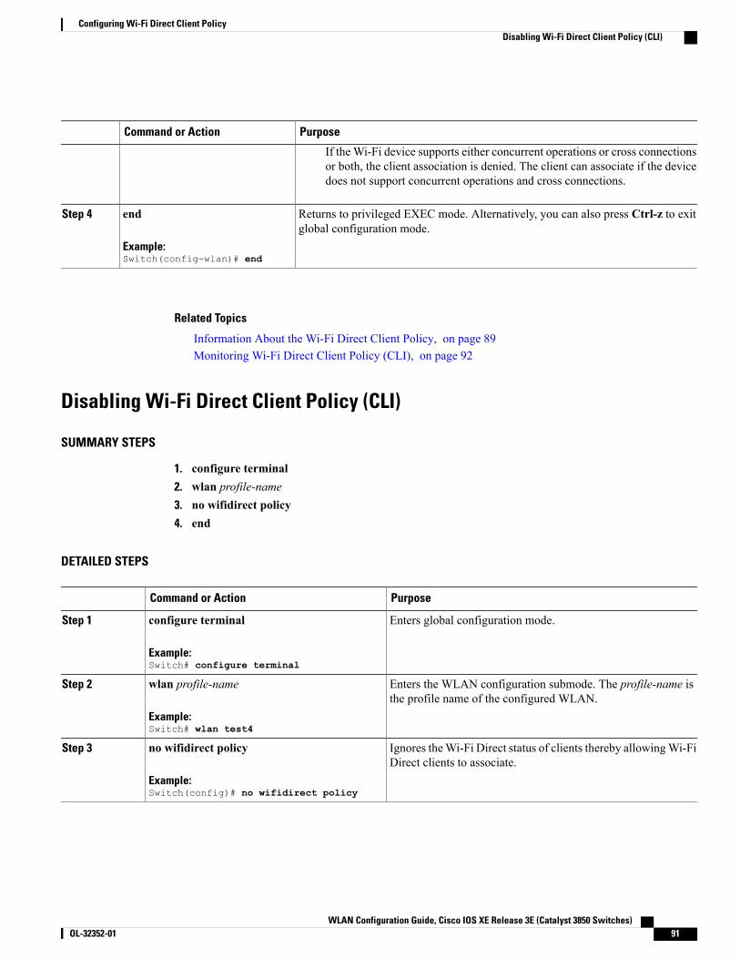
PurposeCommand or Action
If the Wi-Fi device supports either concurrent operations or cross connectionsor both, the client association is denied. The client can associate if the devicedoes not support concurrent operations and cross connections.
Returns to privileged EXEC mode. Alternatively, you can also press Ctrl-z to exitglobal configuration mode.
end
Example:Switch(config-wlan)# end
Step 4
Related Topics
Information About the Wi-Fi Direct Client Policy, on page 89Monitoring Wi-Fi Direct Client Policy (CLI), on page 92
Disabling Wi-Fi Direct Client Policy (CLI)
SUMMARY STEPS
1. configure terminal2. wlan profile-name3. no wifidirect policy4. end
DETAILED STEPS
PurposeCommand or Action
Enters global configuration mode.configure terminal
Example:Switch# configure terminal
Step 1
Enters the WLAN configuration submode. The profile-name isthe profile name of the configured WLAN.
wlan profile-name
Example:Switch# wlan test4
Step 2
Ignores theWi-Fi Direct status of clients thereby allowingWi-FiDirect clients to associate.
no wifidirect policy
Example:Switch(config)# no wifidirect policy
Step 3
WLAN Configuration Guide, Cisco IOS XE Release 3E (Catalyst 3850 Switches) OL-32352-01 91
Configuring Wi-Fi Direct Client PolicyDisabling Wi-Fi Direct Client Policy (CLI)
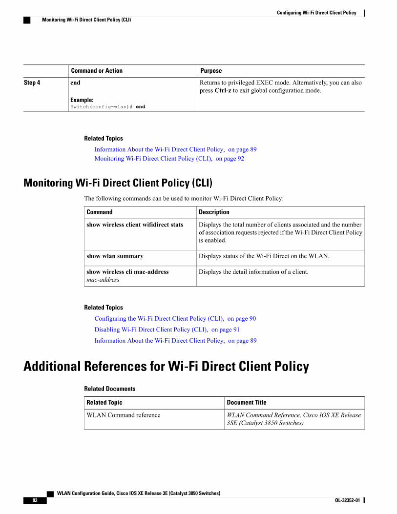
PurposeCommand or Action
Returns to privileged EXEC mode. Alternatively, you can alsopress Ctrl-z to exit global configuration mode.
end
Example:Switch(config-wlan)# end
Step 4
Related Topics
Information About the Wi-Fi Direct Client Policy, on page 89Monitoring Wi-Fi Direct Client Policy (CLI), on page 92
Monitoring Wi-Fi Direct Client Policy (CLI)The following commands can be used to monitor Wi-Fi Direct Client Policy:
DescriptionCommand
Displays the total number of clients associated and the numberof association requests rejected if theWi-Fi Direct Client Policyis enabled.
show wireless client wifidirect stats
Displays status of the Wi-Fi Direct on the WLAN.show wlan summary
Displays the detail information of a client.show wireless cli mac-addressmac-address
Related Topics
Configuring the Wi-Fi Direct Client Policy (CLI), on page 90
Disabling Wi-Fi Direct Client Policy (CLI), on page 91
Information About the Wi-Fi Direct Client Policy, on page 89
Additional References for Wi-Fi Direct Client PolicyRelated Documents
Document TitleRelated Topic
WLAN Command Reference, Cisco IOS XE Release3SE (Catalyst 3850 Switches)
WLAN Command reference
WLAN Configuration Guide, Cisco IOS XE Release 3E (Catalyst 3850 Switches)92 OL-32352-01
Configuring Wi-Fi Direct Client PolicyMonitoring Wi-Fi Direct Client Policy (CLI)
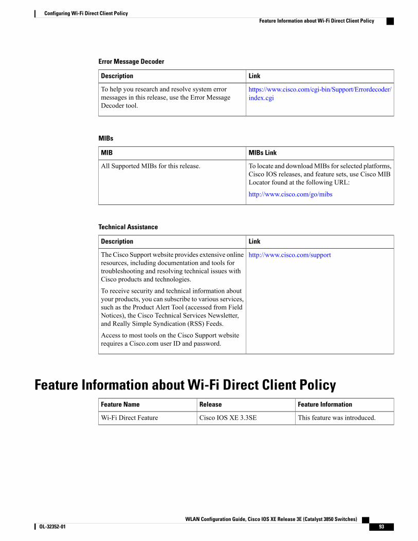
Error Message Decoder
LinkDescription
https://www.cisco.com/cgi-bin/Support/Errordecoder/index.cgi
To help you research and resolve system errormessages in this release, use the Error MessageDecoder tool.
MIBs
MIBs LinkMIB
To locate and downloadMIBs for selected platforms,Cisco IOS releases, and feature sets, use Cisco MIBLocator found at the following URL:
http://www.cisco.com/go/mibs
All Supported MIBs for this release.
Technical Assistance
LinkDescription
http://www.cisco.com/supportThe Cisco Support website provides extensive onlineresources, including documentation and tools fortroubleshooting and resolving technical issues withCisco products and technologies.
To receive security and technical information aboutyour products, you can subscribe to various services,such as the Product Alert Tool (accessed from FieldNotices), the Cisco Technical Services Newsletter,and Really Simple Syndication (RSS) Feeds.
Access to most tools on the Cisco Support websiterequires a Cisco.com user ID and password.
Feature Information about Wi-Fi Direct Client PolicyFeature InformationReleaseFeature Name
This feature was introduced.Cisco IOS XE 3.3SEWi-Fi Direct Feature
WLAN Configuration Guide, Cisco IOS XE Release 3E (Catalyst 3850 Switches) OL-32352-01 93
Configuring Wi-Fi Direct Client PolicyFeature Information about Wi-Fi Direct Client Policy

WLAN Configuration Guide, Cisco IOS XE Release 3E (Catalyst 3850 Switches)94 OL-32352-01
Configuring Wi-Fi Direct Client PolicyFeature Information about Wi-Fi Direct Client Policy
C H A P T E R 9Configuring 802.11r BSS Fast Transition
• Finding Feature Information, page 95
• Restrictions for 802.11r Fast Transition, page 95
• Information About 802.11r Fast Transition, page 96
• How to Configure 802.11r Fast Transition, page 99
• Additional References for 802.11r Fast Transition, page 107
• Feature Information for 802.11r Fast Transition, page 108
Finding Feature InformationYour software release may not support all the features documented in this module. For the latest featureinformation and caveats, see the release notes for your platform and software release. To find informationabout the features documented in this module, and to see a list of the releases in which each feature is supported,see the Feature Information Table at the end of this document.
Use Cisco Feature Navigator to find information about platform support and Cisco software image support.To access Cisco Feature Navigator, go to http://www.cisco.com/go/cfn. An account on Cisco.com is notrequired.
Restrictions for 802.11r Fast Transition• 802.11r client association is not supported on access points in standalone mode.
• 802.11r fast roaming is not supported on access points in standalone mode.
• 802.11r fast roaming between local authentication and central authentication WLAN is not supported.
• EAP LEAP method is not supported.
• TSpec is not supported for 802.11r fast roaming. Therefore, RIC IE handling is not supported.
• If WAN link latency exists, fast roaming is also delayed. Voice or data maximum latency should beverified. The switch handles 802.11r Fast Transition authentication request during roaming for bothOver-the-Air and Over-the-DS methods.
WLAN Configuration Guide, Cisco IOS XE Release 3E (Catalyst 3850 Switches) OL-32352-01 95
• This feature is supported only on open and WPA2 configured WLANs.
• Legacy clients cannot associate with a WLAN that has 802.11r enabled if the driver of the supplicantthat is responsible for parsing the Robust Security Network Information Exchange (RSN IE) is old andnot aware of the additional AKM suites in the IE. Due to this limitation, clients cannot send associationrequests to WLANs. These clients, however, can still associate with non-802.11r WLANs. Clients thatare 802.11r capable can associate as 802.11i clients on WLANs that have both 802.11i and 802.11rAuthentication Key Management Suites enabled.
The workaround is to enable or upgrade the driver of the legacy clients to work with the new 802.11rAKMs, after which the legacy clients can successfully associate with 802.11r enabled WLANs.
Another workaround is to have two SSIDs with the same name but with different security settings (FTand non-FT).
• Fast Transition resource request protocol is not supported because clients do not support this protocol.Also, the resource request protocol is an optional protocol.
• To avoid any Denial of Service (DoS) attack, each switch allows a maximum of three Fast Transitionhandshakes with different APs.
Related Topics
Configuring 802.11r Fast Transition in an Open WLAN (CLI), on page 99
Disabling 802.11r Fast Transition (CLI), on page 104
Configuring 802.11r BSS Fast Transition on a Dot1x Security Enabled WLAN (CLI), on page 101
Configuring 802.11r Fast Transition on a PSK Security Enabled WLAN (CLI), on page 102
Configuring 802.11 Fast Transition (GUI), on page 104Information About 802.11r Fast Transition, on page 96
Information About 802.11r Fast Transition802.11r, which is the IEEE standard for fast roaming, introduces a new concept of roaming where the initialhandshake with the newAP is done even before the client roams to the target AP, which is called Fast Transition(FT). The initial handshake allows the client and APs to do the Pairwise Transient Key (PTK) calculation inadvance. These PTK keys are applied to the client and AP after the client does the reassociation request orresponse exchange with new target AP.
802.11r provides two methods of roaming:
• Over-the-Air
• Over-the-DS (Distribution System)
The FT key hierarchy is designed to allow clients to make fast BSS transitions between APs without requiringreauthentication at every AP. WLAN configuration contains a new Authenticated Key Management (AKM)type called FT (Fast Transition).
From Release 3E, you can create an 802.11r WLAN that is also an WPAv2 WLAN. In earlier releases, youhad to create separate WLANs for 802.11r and for normal security. Non-802.11r clients can now join802.11r-enabledWLANs as the 802.11rWLANs can accept non-802.11r associations. If clients do not supportmixed mode or 802.11r join, they can join non-802.11r WLANS. When you configure FT PSK and laterdefine PSK, clients that can join only PSK can now join the WLAN in mixed mode.
WLAN Configuration Guide, Cisco IOS XE Release 3E (Catalyst 3850 Switches)96 OL-32352-01
Configuring 802.11r BSS Fast TransitionInformation About 802.11r Fast Transition
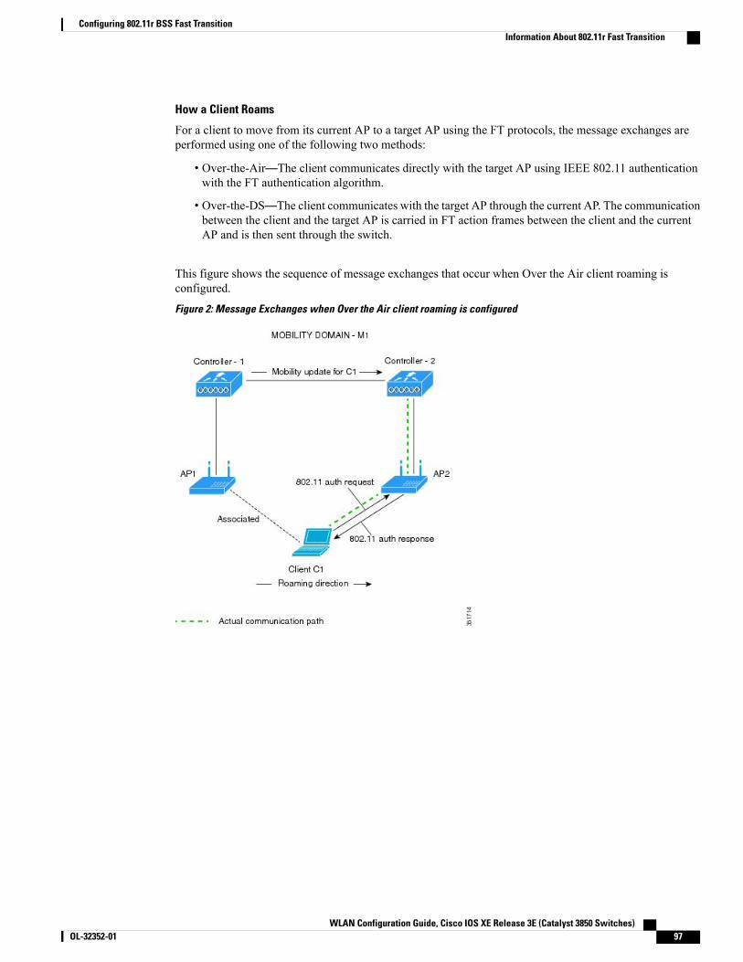
How a Client Roams
For a client to move from its current AP to a target AP using the FT protocols, the message exchanges areperformed using one of the following two methods:
• Over-the-Air—The client communicates directly with the target AP using IEEE 802.11 authenticationwith the FT authentication algorithm.
• Over-the-DS—The client communicates with the target AP through the current AP. The communicationbetween the client and the target AP is carried in FT action frames between the client and the currentAP and is then sent through the switch.
This figure shows the sequence of message exchanges that occur when Over the Air client roaming isconfigured.
Figure 2: Message Exchanges when Over the Air client roaming is configured
WLAN Configuration Guide, Cisco IOS XE Release 3E (Catalyst 3850 Switches) OL-32352-01 97
Configuring 802.11r BSS Fast TransitionInformation About 802.11r Fast Transition
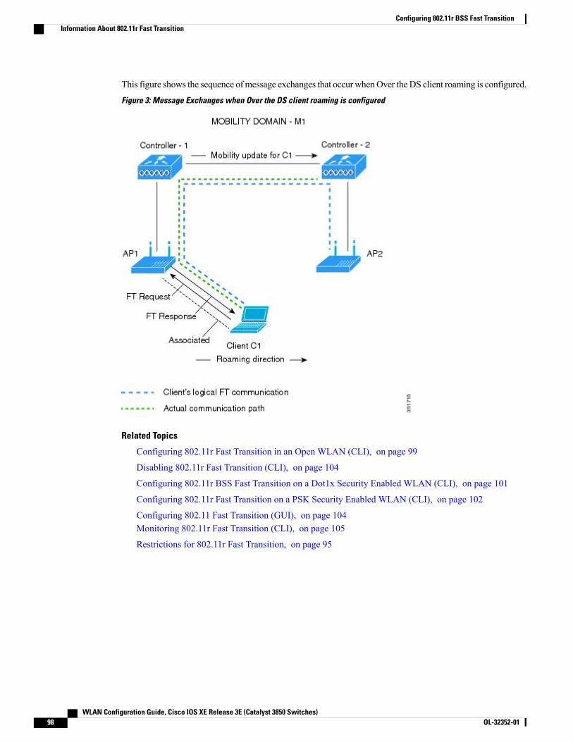
This figure shows the sequence ofmessage exchanges that occur whenOver the DS client roaming is configured.
Figure 3: Message Exchanges when Over the DS client roaming is configured
Related Topics
Configuring 802.11r Fast Transition in an Open WLAN (CLI), on page 99
Disabling 802.11r Fast Transition (CLI), on page 104
Configuring 802.11r BSS Fast Transition on a Dot1x Security Enabled WLAN (CLI), on page 101
Configuring 802.11r Fast Transition on a PSK Security Enabled WLAN (CLI), on page 102
Configuring 802.11 Fast Transition (GUI), on page 104Monitoring 802.11r Fast Transition (CLI), on page 105
Restrictions for 802.11r Fast Transition, on page 95
WLAN Configuration Guide, Cisco IOS XE Release 3E (Catalyst 3850 Switches)98 OL-32352-01
Configuring 802.11r BSS Fast TransitionInformation About 802.11r Fast Transition
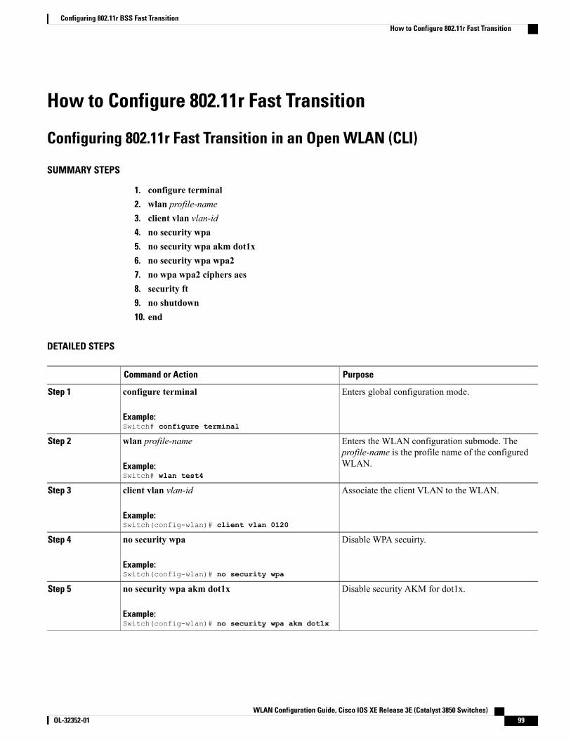
How to Configure 802.11r Fast Transition
Configuring 802.11r Fast Transition in an Open WLAN (CLI)
SUMMARY STEPS
1. configure terminal2. wlan profile-name3. client vlan vlan-id4. no security wpa5. no security wpa akm dot1x6. no security wpa wpa27. no wpa wpa2 ciphers aes8. security ft9. no shutdown10. end
DETAILED STEPS
PurposeCommand or Action
Enters global configuration mode.configure terminal
Example:Switch# configure terminal
Step 1
Enters the WLAN configuration submode. Theprofile-name is the profile name of the configuredWLAN.
wlan profile-name
Example:Switch# wlan test4
Step 2
Associate the client VLAN to the WLAN.client vlan vlan-id
Example:Switch(config-wlan)# client vlan 0120
Step 3
Disable WPA secuirty.no security wpa
Example:Switch(config-wlan)# no security wpa
Step 4
Disable security AKM for dot1x.no security wpa akm dot1x
Example:Switch(config-wlan)# no security wpa akm dot1x
Step 5
WLAN Configuration Guide, Cisco IOS XE Release 3E (Catalyst 3850 Switches) OL-32352-01 99
Configuring 802.11r BSS Fast TransitionHow to Configure 802.11r Fast Transition

PurposeCommand or Action
Disables WPA2 security.no security wpa wpa2
Example:Switch(config-wlan)# no security wpa wpa2
Step 6
Disables WPA2 ciphers for AES.no wpa wpa2 ciphers aes
Example:Switch(config-wlan)# no security wpa wpa2 ciphersaes
Step 7
Specifies the 802.11r fast transition parameters.security ft
Example:Switch(config-wlan)# security ft
Step 8
Shutdown the WLAN.no shutdown
Example:Switch(config-wlan)# shutdown
Step 9
Returns to privileged EXECmode. Alternatively, youcan also pressCtrl-z to exit global configurationmode
end
Example:Switch(config-wlan)# end
Step 10
Related Topics
Information About 802.11r Fast Transition, on page 96
Monitoring 802.11r Fast Transition (CLI), on page 105
Restrictions for 802.11r Fast Transition, on page 95
WLAN Configuration Guide, Cisco IOS XE Release 3E (Catalyst 3850 Switches)100 OL-32352-01
Configuring 802.11r BSS Fast TransitionConfiguring 802.11r Fast Transition in an Open WLAN (CLI)

Configuring 802.11r BSS Fast Transition on a Dot1x Security Enabled WLAN(CLI)
SUMMARY STEPS
1. configure terminal2. wlan profile-name3. client vlan vlan-name4. local-auth local-auth-profile-eap5. security dot1x authentication-list default6. security ft7. security wpa akm ft dot1x8. no shutdown9. end
DETAILED STEPS
PurposeCommand or Action
Enters global configuration mode.configure terminal
Example:Switch# configure terminal
Step 1
Enters the WLAN configuration submode. Theprofile-name is the profile name of the configuredWLAN.
wlan profile-name
Example:Switch# wlan test4
Step 2
Associate the client VLAN to this WLAN.client vlan vlan-name
Example:Switch(config-wlan)# client vlan 0120
Step 3
Enable the local auth EAP profile.local-auth local-auth-profile-eap
Example:Switch(config-wlan)# local-auth
Step 4
Enable security authentication list for dot1x security. Theconfiguration is similar for any dot1x security WLAN.
security dot1x authentication-list default
Example:Switch(config-wlan)# security dot1xauthentication-list default
Step 5
Enables 802.11r Fast Transition on this WLAN.security ft
Example:Switch(config-wlan)# security ft
Step 6
WLAN Configuration Guide, Cisco IOS XE Release 3E (Catalyst 3850 Switches) OL-32352-01 101
Configuring 802.11r BSS Fast TransitionConfiguring 802.11r BSS Fast Transition on a Dot1x Security Enabled WLAN (CLI)
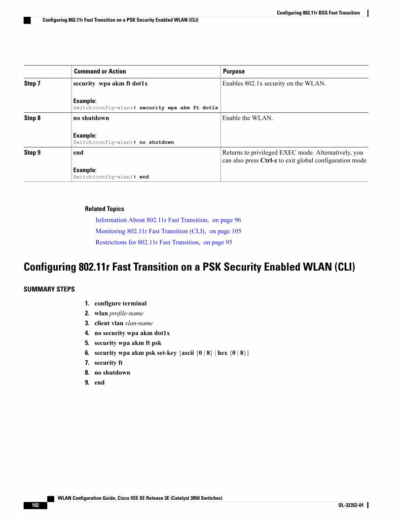
PurposeCommand or Action
Enables 802.1x security on the WLAN.security wpa akm ft dot1x
Example:Switch(config-wlan)# security wpa akm ft dot1x
Step 7
Enable the WLAN.no shutdown
Example:Switch(config-wlan)# no shutdown
Step 8
Returns to privileged EXEC mode. Alternatively, youcan also press Ctrl-z to exit global configuration mode
end
Example:Switch(config-wlan)# end
Step 9
Related Topics
Information About 802.11r Fast Transition, on page 96
Monitoring 802.11r Fast Transition (CLI), on page 105
Restrictions for 802.11r Fast Transition, on page 95
Configuring 802.11r Fast Transition on a PSK Security Enabled WLAN (CLI)
SUMMARY STEPS
1. configure terminal2. wlan profile-name3. client vlan vlan-name4. no security wpa akm dot1x5. security wpa akm ft psk6. security wpa akm psk set-key {ascii {0 | 8} | hex {0 | 8}}7. security ft8. no shutdown9. end
WLAN Configuration Guide, Cisco IOS XE Release 3E (Catalyst 3850 Switches)102 OL-32352-01
Configuring 802.11r BSS Fast TransitionConfiguring 802.11r Fast Transition on a PSK Security Enabled WLAN (CLI)

DETAILED STEPS
PurposeCommand or Action
Enters global configuration mode.configure terminal
Example:Switch# configure terminal
Step 1
Enters the WLAN configuration submode. Theprofile-name is the profile name of the configuredWLAN.
wlan profile-name
Example:Switch# wlan test4
Step 2
Associates the client VLAN to this WLAN.client vlan vlan-name
Example:Switch(config-wlan)# client vlan 0120
Step 3
Disables security AKM for dot1x.no security wpa akm dot1x
Example:Switch(config-wlan)# no security wpa akm dot1x
Step 4
Configures FT PSK support.security wpa akm ft psk
Example:Switch(config-wlan)# security wpa akm ft psk
Step 5
Configures PSK AKM shared key.security wpa akm psk set-key {ascii {0 | 8} | hex {0 | 8}}
Example:Switch(config-wlan)# security wpa akm psk set-keyascii 0 test
Step 6
Configures 802.11r Fast Transition.security ft
Example:Switch(config-wlan)# security ft
Step 7
Enables the WLAN.no shutdown
Example:Switch(config-wlan)# no shutdown
Step 8
Returns to privileged EXEC mode. Alternatively,you can also pressCtrl-z to exit global configurationmode
end
Example:Switch(config-wlan)# end
Step 9
Related Topics
Information About 802.11r Fast Transition, on page 96
Monitoring 802.11r Fast Transition (CLI), on page 105
WLAN Configuration Guide, Cisco IOS XE Release 3E (Catalyst 3850 Switches) OL-32352-01 103
Configuring 802.11r BSS Fast TransitionConfiguring 802.11r Fast Transition on a PSK Security Enabled WLAN (CLI)
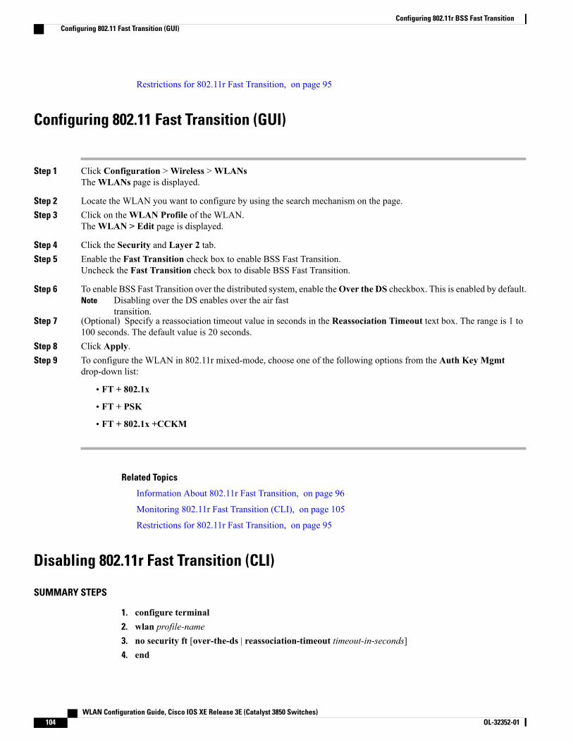
Restrictions for 802.11r Fast Transition, on page 95
Configuring 802.11 Fast Transition (GUI)
Step 1 Click Configuration >Wireless >WLANsTheWLANs page is displayed.
Step 2 Locate the WLAN you want to configure by using the search mechanism on the page.Step 3 Click on theWLAN Profile of the WLAN.
TheWLAN > Edit page is displayed.
Step 4 Click the Security and Layer 2 tab.Step 5 Enable the Fast Transition check box to enable BSS Fast Transition.
Uncheck the Fast Transition check box to disable BSS Fast Transition.
Step 6 To enable BSS Fast Transition over the distributed system, enable theOver the DS checkbox. This is enabled by default.Disabling over the DS enables over the air fasttransition.
Note
Step 7 (Optional) Specify a reassociation timeout value in seconds in the Reassociation Timeout text box. The range is 1 to100 seconds. The default value is 20 seconds.
Step 8 Click Apply.Step 9 To configure the WLAN in 802.11r mixed-mode, choose one of the following options from the Auth Key Mgmt
drop-down list:
• FT + 802.1x
• FT + PSK
• FT + 802.1x +CCKM
Related Topics
Information About 802.11r Fast Transition, on page 96
Monitoring 802.11r Fast Transition (CLI), on page 105
Restrictions for 802.11r Fast Transition, on page 95
Disabling 802.11r Fast Transition (CLI)
SUMMARY STEPS
1. configure terminal2. wlan profile-name3. no security ft [over-the-ds | reassociation-timeout timeout-in-seconds]4. end
WLAN Configuration Guide, Cisco IOS XE Release 3E (Catalyst 3850 Switches)104 OL-32352-01
Configuring 802.11r BSS Fast TransitionConfiguring 802.11 Fast Transition (GUI)

DETAILED STEPS
PurposeCommand or Action
Enters global configuration mode.configure terminal
Example:Switch# configure terminal
Step 1
Enters the WLAN configuration submode. The profile-name isthe profile name of the configured WLAN.
wlan profile-name
Example:Switch# wlan test4
Step 2
Disables 802.11r Fast Transition on the WLAN.no security ft [over-the-ds | reassociation-timeouttimeout-in-seconds]
Step 3
Disabling 802.11r Fast Transition for over the datasource enables over the air fast transition.
Note
Example:Switch(config-wlan)# no security ftover-the-ds
Returns to privileged EXEC mode. Alternatively, you can alsopress Ctrl-Z to exit global configuration mode.
end
Example:Switch(config)# end
Step 4
Related Topics
Information About 802.11r Fast Transition, on page 96
Monitoring 802.11r Fast Transition (CLI), on page 105
Restrictions for 802.11r Fast Transition, on page 95
Monitoring 802.11r Fast Transition (GUI)You can view the Authentication Key Management details of a client.
ChooseMonitor > Client. The Clients page appears. Click the corresponding client to view the client details.In theGeneral tab, you can view the Authentication KeyManagement for the client such as FT, PSK, 802.1x,CCKM, 802.1x + CCKM. If the AKM is for 802.11r mixed mode, then FT-802.1x, FT-802.1x-CCKM, orFT-PSK appears.
Monitoring 802.11r Fast Transition (CLI)The following command can be used to monitor 802.11r Fast Transition:
DescriptionCommand
Displays a summary of the configured parameters onthe WLAN.
show wlan name wlan-name
WLAN Configuration Guide, Cisco IOS XE Release 3E (Catalyst 3850 Switches) OL-32352-01 105
Configuring 802.11r BSS Fast TransitionMonitoring 802.11r Fast Transition (GUI)
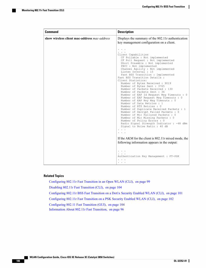
DescriptionCommand
Displays the summary of the 802.11r authenticationkey management configuration on a client.
. . .
. . .Client CapabilitiesCF Pollable : Not implementedCF Poll Request : Not implementedShort Preamble : Not implementedPBCC : Not implementedChannel Agility : Not implementedListen Interval : 15Fast BSS Transition : Implemented
Fast BSS Transition Details :Client Statistics:Number of Bytes Received : 9019Number of Bytes Sent : 3765Number of Packets Received : 130Number of Packets Sent : 36Number of EAP Id Request Msg Timeouts : 0Number of EAP Request Msg Timeouts : 0Number of EAP Key Msg Timeouts : 0Number of Data Retries : 1Number of RTS Retries : 0Number of Duplicate Received Packets : 1Number of Decrypt Failed Packets : 0Number of Mic Failured Packets : 0Number of Mic Missing Packets : 0Number of Policy Errors : 0Radio Signal Strength Indicator : -48 dBmSignal to Noise Ratio : 40 dB
. . .
. . .
If the AKM for the client is 802.11r mixed mode, thefollowing information appears in the output:
. . .
. . .Authentication Key Management : FT-PSK. . .. . .
show wireless client mac-address mac-address
Related Topics
Configuring 802.11r Fast Transition in an Open WLAN (CLI), on page 99
Disabling 802.11r Fast Transition (CLI), on page 104
Configuring 802.11r BSS Fast Transition on a Dot1x Security Enabled WLAN (CLI), on page 101
Configuring 802.11r Fast Transition on a PSK Security Enabled WLAN (CLI), on page 102
Configuring 802.11 Fast Transition (GUI), on page 104Information About 802.11r Fast Transition, on page 96
WLAN Configuration Guide, Cisco IOS XE Release 3E (Catalyst 3850 Switches)106 OL-32352-01
Configuring 802.11r BSS Fast TransitionMonitoring 802.11r Fast Transition (CLI)
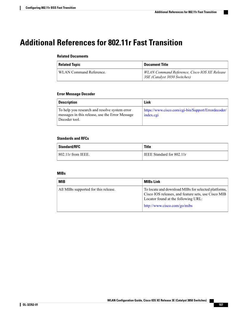
Additional References for 802.11r Fast TransitionRelated Documents
Document TitleRelated Topic
WLAN Command Reference, Cisco IOS XE Release3SE (Catalyst 3850 Switches)
WLAN Command Reference.
Error Message Decoder
LinkDescription
https://www.cisco.com/cgi-bin/Support/Errordecoder/index.cgi
To help you research and resolve system errormessages in this release, use the Error MessageDecoder tool.
Standards and RFCs
TitleStandard/RFC
IEEE Standard for 802.11r802.11r from IEEE.
MIBs
MIBs LinkMIB
To locate and downloadMIBs for selected platforms,Cisco IOS releases, and feature sets, use Cisco MIBLocator found at the following URL:
http://www.cisco.com/go/mibs
All MIBs supported for this release.
WLAN Configuration Guide, Cisco IOS XE Release 3E (Catalyst 3850 Switches) OL-32352-01 107
Configuring 802.11r BSS Fast TransitionAdditional References for 802.11r Fast Transition
Technical Assistance
LinkDescription
http://www.cisco.com/supportThe Cisco Support website provides extensive onlineresources, including documentation and tools fortroubleshooting and resolving technical issues withCisco products and technologies.
To receive security and technical information aboutyour products, you can subscribe to various services,such as the Product Alert Tool (accessed from FieldNotices), the Cisco Technical Services Newsletter,and Really Simple Syndication (RSS) Feeds.
Access to most tools on the Cisco Support websiterequires a Cisco.com user ID and password.
Feature Information for 802.11r Fast TransitionThis table lists the features in this module and provides links to specific configuration information:
Feature InformationReleaseFeature Name
This feature was introduced.Cisco IOS XE 3.3SE802.11r Fast Transition
WLAN Configuration Guide, Cisco IOS XE Release 3E (Catalyst 3850 Switches)108 OL-32352-01
Configuring 802.11r BSS Fast TransitionFeature Information for 802.11r Fast Transition

C H A P T E R 10Configuring Assisted Roaming
• Finding Feature Information, page 109
• Restrictions for Assisted Roaming, page 109
• Information About Assisted Roaming, page 110
• How to Configure Assisted Roaming, page 111
• Monitoring Assisted Roaming, page 113
• Configuration Examples for Assisted Roaming, page 113
• Additional References for Assisted Roaming, page 114
• Feature History and Information For Performing Assisted Roaming Configuration, page 115
Finding Feature InformationYour software release may not support all the features documented in this module. For the latest featureinformation and caveats, see the release notes for your platform and software release. To find informationabout the features documented in this module, and to see a list of the releases in which each feature is supported,see the Feature Information Table at the end of this document.
Use Cisco Feature Navigator to find information about platform support and Cisco software image support.To access Cisco Feature Navigator, go to http://www.cisco.com/go/cfn. An account on Cisco.com is notrequired.
Restrictions for Assisted Roaming• The assisted roaming feature is supported across multiple switches.
• This feature is supported only on 802.11n capable indoor access points. For a single band configuration,a maximum of 6 neighbors are visible in a neighbor list. For dual band configuration, a maximum of 12neighbors are visible.
• You can configure assisted roaming only using the switch CLI.
WLAN Configuration Guide, Cisco IOS XE Release 3E (Catalyst 3850 Switches) OL-32352-01 109
Related Topics
Information About Assisted Roaming, on page 110
Configuring Assisted Roaming (CLI), on page 111
Monitoring Assisted Roaming, on page 113
Configuration Examples for Assisted Roaming, on page 113
Information About Assisted RoamingThe 802.11k standard allows clients to request neighbor reports containing information about known neighboraccess points that are candidates for a service set transition. The use of the 802.11k neighbor list can limit theneed for active and passive scanning.
The assisted roaming feature is based on an intelligent and client optimized neighbor list.
Unlike the Cisco Client Extension (CCX) neighbor list, the 802.11k neighbor list is generated dynamicallyon-demand and is not maintained on the switch. The 802.11k neighbor list is based on the location of theclients without requiring the mobility services engine (MSE). Two clients on the same switch but differentAPs can have different neighbor lists delivered depending on their individual relationship with the surroundingAPs.
By default, the neighbor list contains only neighbors in the same band with which the client is associated.However, a switch exists that allows 802.11k to return neighbors in both bands.
Clients send requests for neighbor lists only after associating with the APs that advertize the RRM (RadioResource Management) capability information element (IE) in the beacon. The neighbor list includesinformation about BSSID, channel, and operation details of the neighboring radios.
Assembling and Optimizing the Neighbor List
When the switch receives a request for an 802.11k neighbor list, the following occurs:
1 The switch searches the RRM neighbor table for a list of neighbors on the same band as the AP with whichthe client is currently associated with.
2 The switch checks the neighbors according to the RSSI (Received Signal Strength Indication) betweenthe APs, the current location of the present AP, the floor information of the neighboring AP from CiscoPrime Infrastructure, and roaming history information on the switch to reduce the list of neighbors to sixper band. The list is optimized for APs on the same floor.
Assisted Roaming for Non-802.11k Clients
It is also possible to optimize roaming for non-802.11k clients. You can generate a prediction neighbor listfor each client without the client requiring to send an 802.11k neighbor list request. When this is enabled onaWLAN, after each successful client association/reassociation, the same neighbor list optimization is appliedon the non-802.11k client to generate the neighbor list and store the list in the mobile station software datastructure. Clients at different locations have different lists because the client probes are seen with differentRSSI values by different neighbors. Because clients usually probe before any association or reassociation,this list is constructed with the most updated probe data and predicts the next AP that the client is likely toroam to.
We discourage clients from roaming to those less desirable neighbors by denying association if the associationrequest to an AP does not match the entries on the stored prediction neighbor list.
WLAN Configuration Guide, Cisco IOS XE Release 3E (Catalyst 3850 Switches)110 OL-32352-01
Configuring Assisted RoamingInformation About Assisted Roaming

Similar to aggressive load balancing, there is a switch to turn on the assisted roaming feature both on aper-WLAN basis and globally. The following options are available:
• Denial count—Maximum number of times a client is refused association.
• Prediction threshold—Minimum number of entries required in the prediction list for the assisted roamingfeature to be activated.
Because both load balancing and assisted roaming are designed to influence the AP that a client associateswith, it is not possible to enable both the options at the same time on a WLAN.
Related Topics
Configuring Assisted Roaming (CLI), on page 111
Monitoring Assisted Roaming, on page 113
Configuration Examples for Assisted Roaming, on page 113
Restrictions for Assisted Roaming, on page 109
How to Configure Assisted Roaming
Configuring Assisted Roaming (CLI)
SUMMARY STEPS
1. configure terminal2. wireless assisted-roaming floor-bias dBm3. wlan wlan-id4. assisted-roaming neighbor-list5. assisted-roaming dual-list6. assisted-roaming prediction7. wireless assisted-roaming prediction-minimum count8. wireless assisted-roaming denial-maximum count9. end
DETAILED STEPS
PurposeCommand or Action
Enters global configuration mode.configure terminal
Example:Switch# configure terminal
Step 1
WLAN Configuration Guide, Cisco IOS XE Release 3E (Catalyst 3850 Switches) OL-32352-01 111
Configuring Assisted RoamingHow to Configure Assisted Roaming
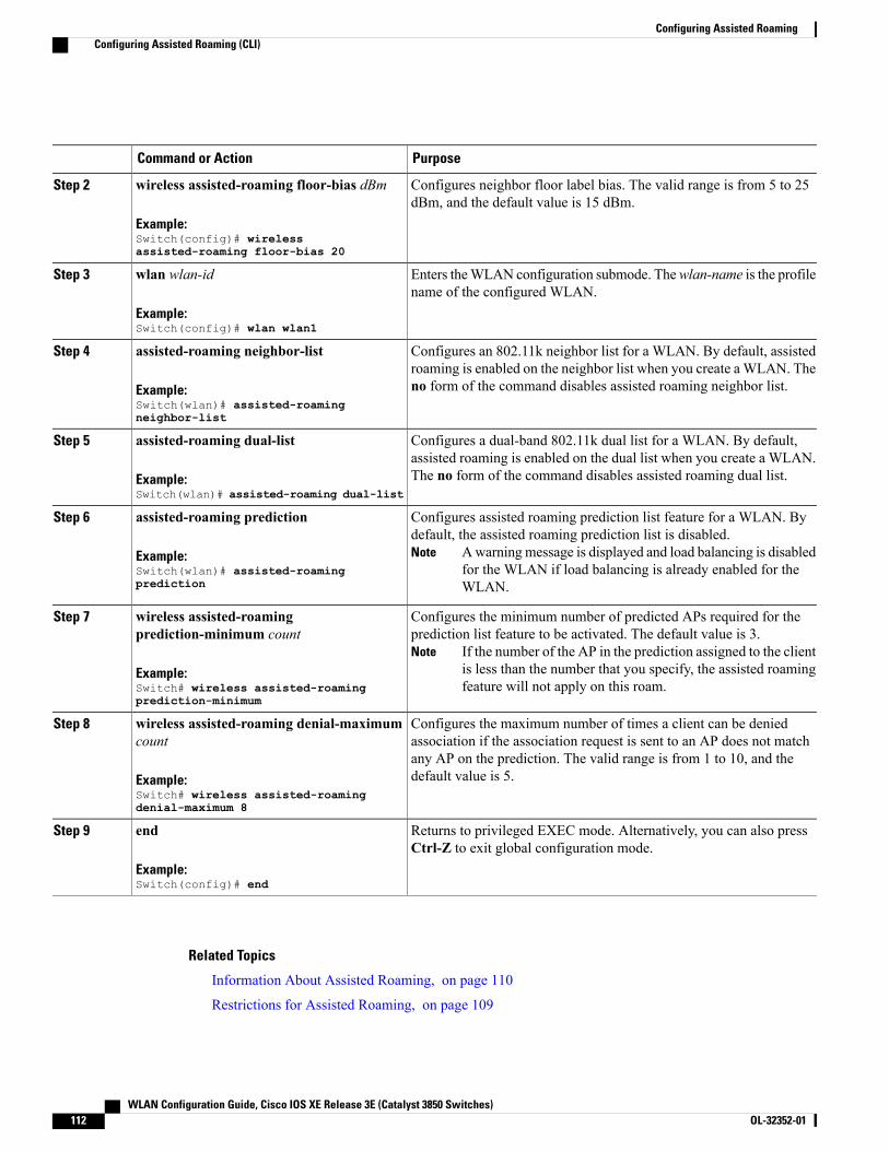
PurposeCommand or Action
Configures neighbor floor label bias. The valid range is from 5 to 25dBm, and the default value is 15 dBm.
wireless assisted-roaming floor-bias dBm
Example:Switch(config)# wirelessassisted-roaming floor-bias 20
Step 2
Enters theWLAN configuration submode. Thewlan-name is the profilename of the configured WLAN.
wlan wlan-id
Example:Switch(config)# wlan wlan1
Step 3
Configures an 802.11k neighbor list for a WLAN. By default, assistedroaming is enabled on the neighbor list when you create aWLAN. Theno form of the command disables assisted roaming neighbor list.
assisted-roaming neighbor-list
Example:Switch(wlan)# assisted-roamingneighbor-list
Step 4
Configures a dual-band 802.11k dual list for a WLAN. By default,assisted roaming is enabled on the dual list when you create a WLAN.The no form of the command disables assisted roaming dual list.
assisted-roaming dual-list
Example:Switch(wlan)# assisted-roaming dual-list
Step 5
Configures assisted roaming prediction list feature for a WLAN. Bydefault, the assisted roaming prediction list is disabled.
Awarningmessage is displayed and load balancing is disabledfor the WLAN if load balancing is already enabled for theWLAN.
Note
assisted-roaming prediction
Example:Switch(wlan)# assisted-roamingprediction
Step 6
Configures the minimum number of predicted APs required for theprediction list feature to be activated. The default value is 3.
If the number of the AP in the prediction assigned to the clientis less than the number that you specify, the assisted roamingfeature will not apply on this roam.
Note
wireless assisted-roamingprediction-minimum count
Example:Switch# wireless assisted-roamingprediction-minimum
Step 7
Configures the maximum number of times a client can be deniedassociation if the association request is sent to an AP does not match
wireless assisted-roaming denial-maximumcount
Step 8
any AP on the prediction. The valid range is from 1 to 10, and thedefault value is 5.Example:
Switch# wireless assisted-roamingdenial-maximum 8
Returns to privileged EXEC mode. Alternatively, you can also pressCtrl-Z to exit global configuration mode.
end
Example:Switch(config)# end
Step 9
Related Topics
Information About Assisted Roaming, on page 110
Restrictions for Assisted Roaming, on page 109
WLAN Configuration Guide, Cisco IOS XE Release 3E (Catalyst 3850 Switches)112 OL-32352-01
Configuring Assisted RoamingConfiguring Assisted Roaming (CLI)
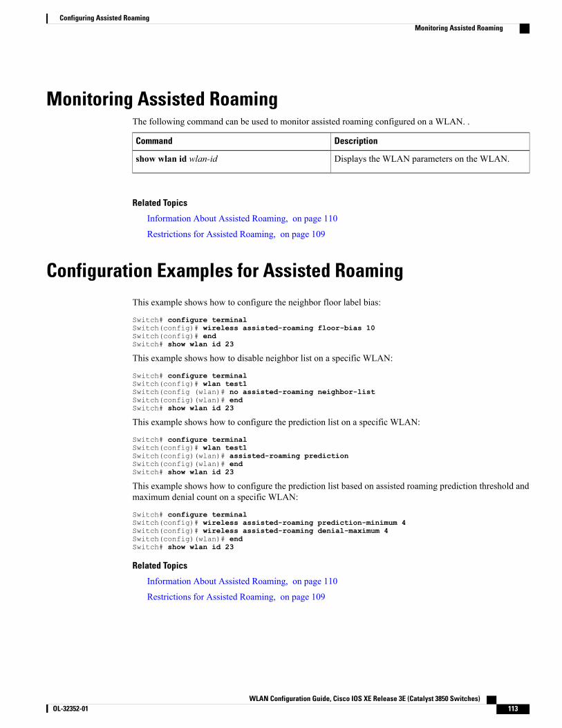
Monitoring Assisted RoamingThe following command can be used to monitor assisted roaming configured on a WLAN. .
DescriptionCommand
Displays the WLAN parameters on the WLAN.show wlan id wlan-id
Related Topics
Information About Assisted Roaming, on page 110
Restrictions for Assisted Roaming, on page 109
Configuration Examples for Assisted RoamingThis example shows how to configure the neighbor floor label bias:
Switch# configure terminalSwitch(config)# wireless assisted-roaming floor-bias 10Switch(config)# endSwitch# show wlan id 23
This example shows how to disable neighbor list on a specific WLAN:
Switch# configure terminalSwitch(config)# wlan test1Switch(config (wlan)# no assisted-roaming neighbor-listSwitch(config)(wlan)# endSwitch# show wlan id 23
This example shows how to configure the prediction list on a specific WLAN:
Switch# configure terminalSwitch(config)# wlan test1Switch(config)(wlan)# assisted-roaming predictionSwitch(config)(wlan)# endSwitch# show wlan id 23
This example shows how to configure the prediction list based on assisted roaming prediction threshold andmaximum denial count on a specific WLAN:
Switch# configure terminalSwitch(config)# wireless assisted-roaming prediction-minimum 4Switch(config)# wireless assisted-roaming denial-maximum 4Switch(config)(wlan)# endSwitch# show wlan id 23
Related Topics
Information About Assisted Roaming, on page 110
Restrictions for Assisted Roaming, on page 109
WLAN Configuration Guide, Cisco IOS XE Release 3E (Catalyst 3850 Switches) OL-32352-01 113
Configuring Assisted RoamingMonitoring Assisted Roaming

Additional References for Assisted RoamingRelated Documents
Document TitleRelated Topic
System Management Command Reference (Catalyst3850 Switches)
System management commands
Error Message Decoder
LinkDescription
https://www.cisco.com/cgi-bin/Support/Errordecoder/index.cgi
To help you research and resolve system errormessages in this release, use the Error MessageDecoder tool.
Standards and RFCs
TitleStandard/RFC
—802.11k
MIBs
MIBs LinkMIB
To locate and downloadMIBs for selected platforms,Cisco IOS releases, and feature sets, use Cisco MIBLocator found at the following URL:
http://www.cisco.com/go/mibs
All supported MIBs for this release.
WLAN Configuration Guide, Cisco IOS XE Release 3E (Catalyst 3850 Switches)114 OL-32352-01
Configuring Assisted RoamingAdditional References for Assisted Roaming
Technical Assistance
LinkDescription
http://www.cisco.com/supportThe Cisco Support website provides extensive onlineresources, including documentation and tools fortroubleshooting and resolving technical issues withCisco products and technologies.
To receive security and technical information aboutyour products, you can subscribe to various services,such as the Product Alert Tool (accessed from FieldNotices), the Cisco Technical Services Newsletter,and Really Simple Syndication (RSS) Feeds.
Access to most tools on the Cisco Support websiterequires a Cisco.com user ID and password.
Feature History and Information For Performing AssistedRoaming Configuration
Feature InformationReleaseFeature Name
This feature was introduced.Cisco IOS XE 3.2SEAssisted Roaming
WLAN Configuration Guide, Cisco IOS XE Release 3E (Catalyst 3850 Switches) OL-32352-01 115
Configuring Assisted RoamingFeature History and Information For Performing Assisted Roaming Configuration

WLAN Configuration Guide, Cisco IOS XE Release 3E (Catalyst 3850 Switches)116 OL-32352-01
Configuring Assisted RoamingFeature History and Information For Performing Assisted Roaming Configuration
C H A P T E R 11Configuring Access Point Groups
• Finding Feature Information, page 117
• Prerequisites for Configuring AP Groups, page 117
• Restrictions for Configuring Access Point Groups, page 118
• Information About Access Point Groups, page 118
• How to Configure Access Point Groups, page 119
• Additional References, page 121
• Feature History and Information for Access Point Groups, page 122
Finding Feature InformationYour software release may not support all the features documented in this module. For the latest featureinformation and caveats, see the release notes for your platform and software release. To find informationabout the features documented in this module, and to see a list of the releases in which each feature is supported,see the Feature Information Table at the end of this document.
Use Cisco Feature Navigator to find information about platform support and Cisco software image support.To access Cisco Feature Navigator, go to http://www.cisco.com/go/cfn. An account on Cisco.com is notrequired.
Prerequisites for Configuring AP GroupsThe following are the prerequisites for creating access point groups on a switch:
• The required access control list (ACL) must be defined on the router that serves the VLAN or subnet.
• Multicast traffic is supported with access point group VLANs. However, if the client roams from oneaccess point to another, the client might stop receivingmulticast traffic, unless IGMP snooping is enabled.
Related Topics
Information About Access Point Groups, on page 118
WLAN Configuration Guide, Cisco IOS XE Release 3E (Catalyst 3850 Switches) OL-32352-01 117
Restrictions for Configuring Access Point Groups, on page 118
Restrictions for Configuring Access Point Groups• Suppose that the interfacemapping for aWLAN in the AP group table is the same as theWLAN interface.If the WLAN interface is changed, the interface mapping for the WLAN in the AP group table alsochanges to the new WLAN interface.
Suppose that the interface mapping for a WLAN in the AP group table is different from the one definedfor the WLAN. If the WLAN interface is changed, then the interface mapping for the WLAN in the APgroup table does not change to the new WLAN interface.
• If you clear the configuration on the switch, all of the access point groups disappear except for the defaultaccess point group “default-group,” which is created automatically.
• The default access point group can have up to 16 WLANs associated with it. The WLAN IDs for thedefault access point group must be less than or equal to 16. If a WLAN with an ID greater than 16 iscreated in the default access point group, the WLAN SSID will not be broadcasted. All WLAN IDs inthe default access point group must have an ID that is less than or equal to 16. WLANs with IDs greaterthan 16 can be assigned to custom access point groups.
Related Topics
Information About Access Point Groups, on page 118Prerequisites for Configuring AP Groups, on page 117
Information About Access Point GroupsAfter you create up to 512WLANs on the switch, you can selectively publish them (using access point groups)to different access points to better manage your wireless network. In a typical deployment, all users on aWLAN aremapped to a single interface on the switch. Therefore, all users that are associated with thatWLANare on the same subnet or VLAN. However, you can choose to distribute the load among several interfacesor to a group of users based on specific criteria such as individual departments (such asMarketing) by creatingaccess point groups. Additionally, these access point groups can be configured in separate VLANs to simplifynetwork administration.
Related Topics
Creating Access Point Groups, on page 119
Viewing Access Point Group, on page 120
Assigning an Access Point to an AP Group, on page 120
Prerequisites for Configuring AP Groups, on page 117
Restrictions for Configuring Access Point Groups, on page 118
WLAN Configuration Guide, Cisco IOS XE Release 3E (Catalyst 3850 Switches)118 OL-32352-01
Configuring Access Point GroupsRestrictions for Configuring Access Point Groups
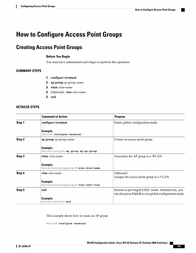
How to Configure Access Point Groups
Creating Access Point Groups
Before You Begin
You must have administrator privileges to perform this operation.
SUMMARY STEPS
1. configure terminal2. ap group ap-group-name3. wlan wlan-name4. (Optional) vlan vlan-name5. end
DETAILED STEPS
PurposeCommand or Action
Enters global configuration mode.configure terminal
Example:Switch# configure terminal
Step 1
Creates an access point group.ap group ap-group-name
Example:Switch(config)# ap group my-ap-group
Step 2
Associates the AP group to a WLAN.wlan wlan-name
Example:Switch(config-apgroup)# wlan wlan-name
Step 3
(Optional)Assigns the access point group to a VLAN.
vlan vlan-name
Example:Switch(config-apgroup)# vlan test-vlan
Step 4
Returns to privileged EXEC mode. Alternatively, youcan also pressCtrl-Z to exit global configurationmode.
end
Example:Switch(config)# end
Step 5
This example shows how to create an AP group:
Switch# configure terminal
WLAN Configuration Guide, Cisco IOS XE Release 3E (Catalyst 3850 Switches) OL-32352-01 119
Configuring Access Point GroupsHow to Configure Access Point Groups

Switch(config-apgroup)# ap group test-ap-group-16Switch(config-wlan-apgroup)# wlan test-ap-group-16Switch(config-wlan-apgroup)# vlan VLAN1300
Related Topics
Information About Access Point Groups, on page 118
Assigning an Access Point to an AP Group
Before You Begin
You must have administrator privileges to perform this operation.
SUMMARY STEPS
1. ap name ap-name ap-group-name ap-group
DETAILED STEPS
PurposeCommand or Action
Assigns the access point to the access point group. The keywords and argumentsare as follows:
ap name ap-name ap-group-nameap-group
Step 1
Example:Switch# ap name 1240-101ap-groupname apgroup_16
• name—Specifies that the argument following this keyword is the name ofan AP that is associated to the switch.
• ap-name—AP that you want to associate to the AP group.
• ap-group-name—Specifies that the argument following this keyword is thename of the AP group that is configured on the switch.
• ap-group—Name of the access point group that is configured on the switch.
Related Topics
Information About Access Point Groups, on page 118
Viewing Access Point Group
Before You Begin
You must have administrator privileges to perform this operation.
SUMMARY STEPS
1. show ap groups [extended ]
WLAN Configuration Guide, Cisco IOS XE Release 3E (Catalyst 3850 Switches)120 OL-32352-01
Configuring Access Point GroupsAssigning an Access Point to an AP Group
DETAILED STEPS
PurposeCommand or Action
Displays the AP groups configured on the switch. The extendedkeyword displays all AP Groups information defined in the systemin detail.
show ap groups [extended ]
Example:Switch# show ap groups
Step 1
Related Topics
Information About Access Point Groups, on page 118
Additional ReferencesRelated Documents
Document TitleRelated Topic
WLAN Command Reference, Cisco IOS XE Release3SE (Catalyst 3850 Switches)
WLAN commands
Lightweight Access Point Configuration Guide, CiscoIOS XE Release 3SE (Catalyst 3850 Switches)
Lightweight Access Point configuration
Lightweight Access Point Command Reference, CiscoIOS XE Release 3SE (Catalyst 3850 Switches)
Lightweight Access Point commands
Error Message Decoder
LinkDescription
https://www.cisco.com/cgi-bin/Support/Errordecoder/index.cgi
To help you research and resolve system errormessages in this release, use the Error MessageDecoder tool.
MIBs
MIBs LinkMIB
To locate and downloadMIBs for selected platforms,Cisco IOS releases, and feature sets, use Cisco MIBLocator found at the following URL:
http://www.cisco.com/go/mibs
All supported MIBs for this release.
WLAN Configuration Guide, Cisco IOS XE Release 3E (Catalyst 3850 Switches) OL-32352-01 121
Configuring Access Point GroupsAdditional References
Technical Assistance
LinkDescription
http://www.cisco.com/supportThe Cisco Support website provides extensive onlineresources, including documentation and tools fortroubleshooting and resolving technical issues withCisco products and technologies.
To receive security and technical information aboutyour products, you can subscribe to various services,such as the Product Alert Tool (accessed from FieldNotices), the Cisco Technical Services Newsletter,and Really Simple Syndication (RSS) Feeds.
Access to most tools on the Cisco Support websiterequires a Cisco.com user ID and password.
Feature History and Information for Access Point GroupsThis table lists the features in this modules and provides links to specific configuration information.
Feature InformationReleaseFeature Name
This feature was introduced.Cisco IOS XE 3.2SEAP Groups
WLAN Configuration Guide, Cisco IOS XE Release 3E (Catalyst 3850 Switches)122 OL-32352-01
Configuring Access Point GroupsFeature History and Information for Access Point Groups
I N D E X
802.11r 104configuring using GUI 104
C
CCX 25described 25
D
default-group access point group 118DHCP option 82 51
described 51example 51
DHCP servers 49internal 49
diagnostic channel 26described 26
DTIM 25
M
monitoring 105using GUI 105
P
peer-to-peer blocking 26described 26
Precious Metal Policies 43configuring using GUI 43
Q
QoS Policy, WLAN 43configuring using GUI 43
S
SSID 23described 23
W
WLAN broadcast ssid, Configure 33WLAN call snoop, Configure 33WLAN interface VLAN, Configure 33WLAN media stream multicast, Configure 33WLAN radio, Configure 33WLAN, enable, disable 33WLANs 25
session timeout 25described 25
WLAN Configuration Guide, Cisco IOS XE Release 3E (Catalyst 3850 Switches) OL-32352-01 IN-1

WLAN Configuration Guide, Cisco IOS XE Release 3E (Catalyst 3850 Switches)IN-2 OL-32352-01
Index