
High Availability Configuration Guide, Cisco IOS Release 12.2 ...
113
High Availability Configuration Guide, Cisco IOS Release 12.2SX Americas Headquarters Cisco Systems, Inc. 170 West Tasman Drive San Jose, CA 95134-1706 USA http://www.cisco.com Tel: 408 526-4000 800 553-NETS (6387) Fax: 408 527-0883
-
Upload
khangminh22 -
Category
Documents
-
view
6 -
download
0
Transcript of High Availability Configuration Guide, Cisco IOS Release 12.2 ...

High Availability Configuration Guide,Cisco IOS Release 12.2SX
Americas HeadquartersCisco Systems, Inc.170 West Tasman DriveSan Jose, CA 95134-1706USAhttp://www.cisco.comTel: 408 526-4000 800 553-NETS (6387)Fax: 408 527-0883

C O N T E N T S
Configuring Stateful Switchover 0
Finding Feature Information 1
Prerequisites for Stateful Switchover 1
General Prerequisites 2
Cisco 10000 Series Devices Prerequisites 2
Cisco 7500 Series Internet Router Platform Prerequisites 2
Restrictions for Stateful Switchover 2
General Restrictions for SSO 3
Configuration Mode Restrictions 3
Switchover Process Restrictions 3
ATM Restrictions 3
Frame Relay and Multilink Frame Relay Restrictions 4
PPP Restrictions 5
Cisco 12000 Series Internet Router Platform Restrictions 5
Cisco 10000 Series Internet Router Platform Restrictions 6
Cisco 7500 Series Internet Router Platform Restrictions 6
Cisco 7304 Router Platform Restrictions 8
Cisco ASR 1000 Series Routers Restrictions 8
Information About Stateful Switchover 9
SSO Overview 9
Redundancy Modes 11
High System Availability 11
Route Processor Redundancy Mode 11
Route Processor Redundancy Plus 12
Stateful Switchover Mode 12
Redundancy Modes by Platform and Software Release 12
Route Processor Synchronization 14
Bulk Synchronization During Initialization 14
Incremental Synchronization 15
Switchover Operation 16
Switchover Conditions 16
High Availability Configuration Guide, Cisco IOS Release 12.2SX ii

Switchover Time 16
Online Removal of the Active RP 17
Single Line Card Reload 17
Fast Software Upgrade 17
Core Dump Operation 18
Virtual Template Manager for SSO 18
SSO-Aware Protocols and Applications 18
Line Protocols 19
Supported Line protocols by Platform 19
ATM Stateful Switchover 21
Frame Relay and Multilink Frame Relay Stateful Switchover 22
PPP and Multilink PPP Stateful Switchover 23
HDLC Stateful Switchover 23
Quality of Service 24
IPv6 Support for Stateful Switchover 24
Line Card Drivers 24
APS 24
Routing Protocols and Nonstop Forwarding 25
Network Management 25
SSO for Circuit Emulation Services 25
How to Configure Stateful Switchover 25
Copying an Image onto an RP 26
Setting the Configuration Register and Boot Variable 27
Configuring SSO 28
Configuring Frame Relay and Multilink Frame Relay Autosynchronization LMI Sequence
Numbers 29
Verifying SSO Configuration 30
Performing a Fast Software Upgrade 31
Troubleshooting Stateful Switchover 33
Troubleshooting SSO 34
Configuration Examples for Stateful Switchover 36
Example Verifying that SSO Is Configured on Various Platforms 36
Example Verifying that SSO Is Operating on the Device 38
Example Verifying SSO Protocols and Applications 40
Additional References 42
Contents
High Availability Configuration Guide, Cisco IOS Release 12.2SX iii

Feature Information for Stateful Switchover 44
47
Configuring Nonstop Forwarding 0
Finding Feature Information 49
Prerequisites for Nonstop Forwarding 49
Restrictions for Nonstop Forwarding 50
General Restrictions 50
BGP NSF Restrictions 50
EIGRP NSF Restrictions 50
OSPF NSF Restrictions 51
Cisco7200SeriesRouterRestrictions 51
Information About Nonstop Forwarding 51
Nonstop Forwarding 51
Cisco NSF Routing and Forwarding 52
Routing Protocols and CEF Support in Cisco NSF 53
Cisco Express Forwarding and NSF 54
BGP NSF Operations 55
EIGRP NSF Operations 56
IPv6 support for NSF Operations 56
Nonstop Forwarding and Graceful Restart for MP-BGP IPv6 Address Family 56
Nonstop Forwarding for IPv6 RIP 57
Nonstop Forwarding for Static Routes 57
IS-IS NSF Operations 57
IETF IS-IS Configuration 57
Cisco IS-IS Configuration 58
OSPF NSF Operations 58
How to Configure Nonstop Forwarding 59
Configuring and Verifying BGP NSF 59
Configuring and Verifying EIGRP NSF 60
Configuring OSPF NSF 62
Configuring Cisco NSF for OSPF 62
Configuring IETF NSF for OSPF 63
Configuring and Verifying IS-IS NSF 65
Troubleshooting Nonstop Forwarding 66
Configuration Examples for Nonstop Forwarding 69
Contents
High Availability Configuration Guide, Cisco IOS Release 12.2SXiv

Example NSF-Capable CEF 69
Example BGP NSF 69
Example EIGRP NSF 70
Example OSPF and Cisco NSF 70
Example OSPF and IETF NSF 70
Example IS-ISNSF 71
Additional References 72
Feature Information for Nonstop Forwarding 74
77
Performing an In Service Software Upgrade 0
Finding Feature Information 79
Prerequisites for Performing an ISSU 79
Restrictions for Performing an ISSU 80
General Restrictions 80
Termination of Virtual Template Manager for ISSU Restrictions 80
Cisco 10000 Series Internet Router Platform Restrictions 80
Cisco Catalyst 4500 Restrictions 81
Information About Performing an ISSU 81
ISSU Process Overview 81
ISSU Rollback Timer 82
Fast Software Upgrade 82
Enhanced Fast Software Upgrade 82
Versioning Capability in Cisco Software to Support ISSU 83
Compatibility Matrix 83
SNMP Support for ISSU 84
Virtual Template Manager for ISSU 84
Compatibility Verification Using Cisco Feature Navigator 84
ISSU-Capable Protocols and Applications 84
How to Perform an ISSU 85
Displaying ISSU Compatibility Matrix Information 85
Loading Cisco IOS Software on the Standby RP 86
Switching to the Standby RP 87
Stopping the ISSU Rollback Timer 87
Verifying the ISSU Software Installation 88
Enabling the New Standby RP to Use New Software Version 88
Contents
High Availability Configuration Guide, Cisco IOS Release 12.2SX v

Aborting a Software Upgrade Using ISSU 89
Configuring the Rollback Timer to Safeguard Against Upgrades 90
Configuration Examples for Performing an ISSU 90
Example Verifying Redundancy Mode Before Beginning the ISSU Process 91
Example Verifying the ISSU State 91
Example Performing the ISSU Process 92
Example Aborting the ISSU Process 95
Example Verifying Rollback Timer Information 96
Additional References 96
Feature Information for Performing an ISSU 98
104
Contents
High Availability Configuration Guide, Cisco IOS Release 12.2SXvi

Contents
High Availability Configuration Guide, Cisco IOS Release 12.2SX vii

Configuring Stateful Switchover
The Stateful Switchover (SSO) feature works with Nonstop Forwarding (NSF) in Cisco software tominimize the amount of time a network is unavailable to its users following a switchover. The primaryobjective of SSO is to improve the availability of networks constructed with Cisco routers. SSO performsthe following functions:
• Maintains stateful protocol and application information to retain user session information during aswitchover.
• Enables line cards to continue to forward network traffic with no loss of sessions, providingimproved network availability.
• Provides a faster switchover relative to high system availability.
• Finding Feature Information, page 1• Prerequisites for Stateful Switchover, page 1• Restrictions for Stateful Switchover, page 2• Information About Stateful Switchover, page 9• How to Configure Stateful Switchover, page 25• Configuration Examples for Stateful Switchover, page 36• Additional References, page 42• Feature Information for Stateful Switchover, page 44• , page 47
Finding Feature InformationYour software release may not support all the features documented in this module. For the latest featureinformation and caveats, see the release notes for your platform and software release. To find informationabout the features documented in this module, and to see a list of the releases in which each feature issupported, see the Feature Information Table at the end of this document.
Use Cisco Feature Navigator to find information about platform support and Cisco software image support.To access Cisco Feature Navigator, go to http://www.cisco.com/go/cfn. An account on Cisco.com is notrequired.
Prerequisites for Stateful Switchover• General Prerequisites, page 2
• Cisco 10000 Series Devices Prerequisites, page 2
High Availability Configuration Guide, Cisco IOS Release 12.2SX 1
• Cisco 7500 Series Internet Router Platform Prerequisites, page 2
General Prerequisites• For hardware-redundant platforms, two Route Processors (RPs) must be installed in the chassis, each
running the same version or a compatible version of the Cisco software.• Before copying a file to flash memory, be sure that ample space is available in flash memory.
Compare the size of the file you are copying to the amount of available flash memory shown. If thespace available is less than the space required by the file you will copy, the copy process will notcontinue and an error message similar to the following will be displayed:
%Error copying tftp://image@server/tftpboot/filelocation/imagename (Not enough space on device).
• Distributed Cisco Express Forwarding must be enabled on any networking device configured to runSSO.
• For Nonstop Forwarding (NSF) support, neighbor routers must be running NSF-enabled images,though SSO need not be configured on the neighbor device.
Cisco 10000 Series Devices Prerequisites• On Cisco 10000 series devices only, to boot both Performance Routing Engines (PREs) from the
TFTP boot server, you must use the ip address negotiated command in interface configuration modeto enable DHCP on the PRE. Otherwise, you will get a duplicate IP address error because of thesynchronization of the IP address from the active to the standby Route Processor (RP).
Cisco 7500 Series Internet Router Platform Prerequisites• On the Cisco 7507 and Cisco 7513 routers, any combination of RSP8 and RSP16 devices, or any
combination of RSP2 and RSP4, are required.
Restrictions for Stateful Switchover• General Restrictions for SSO, page 3
• Configuration Mode Restrictions, page 3
• Switchover Process Restrictions, page 3
• ATM Restrictions, page 3
• Frame Relay and Multilink Frame Relay Restrictions, page 4
• PPP Restrictions, page 5
• Cisco 12000 Series Internet Router Platform Restrictions, page 5
• Cisco 10000 Series Internet Router Platform Restrictions, page 6
• Cisco 7500 Series Internet Router Platform Restrictions, page 6
• Cisco 7304 Router Platform Restrictions, page 8
• Cisco ASR 1000 Series Routers Restrictions, page 8
General Prerequisites Restrictions for Stateful Switchover
High Availability Configuration Guide, Cisco IOS Release 12.2SX2

General Restrictions for SSO• Both RPs must run the same Cisco software image. If the RPs are operating different Cisco software
images, the system reverts to RPR mode even if SSO is configured.• Configuration changes made through SNMP may not be automatically configured on the standby RP
after a switchover occurs.• Load sharing between dual processors is not supported.• The Hot Standby Routing Protocol (HSRP) is not supported with Cisco Nonstop Forwarding with
Stateful Switchover. Do not use HSRP with Cisco Nonstop Forwarding with Stateful Switchover.• Enhanced Object Tracking (EOT) is not stateful switchover-aware and cannot be used with HSRP,
Virtual Router Redundancy Protocol (VRRP), or Gateway Load Balancing Protocol (GLBP) in SSOmode.
• Multicast is not SSO-aware and restarts after switchover; therefore, multicast tables and data structuresare cleared upon switchover.
Configuration Mode Restrictions• The configuration registers on both RPs must be set the same for the networking device to behave the
same when either RP is rebooted.• During the startup (bulk) synchronization, configuration changes are not allowed. Before making any
configuration changes, wait for a message similar to the following:
%HA-5-MODE:Operating mode is sso, configured mode is sso.
• On the Cisco 7304 router, a message similar to the following appears (the actual slot number dependson which slot has the active processor):
%HA-6-STANDBY_READY: Standby RP in slot n is operational in SSO mode
Switchover Process Restrictions• If the router is configured for SSO mode, and the active RP fails before the standby is ready to switch
over, the router will recover through a full system reset.
ATM Restrictions• Label-controlled ATM (LC-ATM) functionality does not co-exist with SSO in this release.• The ATM line protocol does not support stateful switchover capability for the following features in
this release:
◦ SVCs◦ Switched virtual paths (SVPs)◦ Tagged virtual circuits (TVCs)◦ Point-to-multipoint SVC◦ Integrated Local Management Interface (ILMI)◦ Signaling and Service Specific Connection Oriented Protocol (SSCOP)
General Restrictions for SSORestrictions for Stateful Switchover
High Availability Configuration Guide, Cisco IOS Release 12.2SX 3

◦ ATM Connection Manager, permanent virtual circuit (PVC) discovery, ATM applications◦ Backward or version compatibility◦ Statistics and accounting◦ Zero ATM cell loss
Frame Relay and Multilink Frame Relay Restrictions• The following Frame Relay features are not synchronized between the active and standby RPs in this
release: Frame Relay statistics; enhanced LMI (ELMI); Link Access Procedure, Frame Relay (LAPF);SVCs; and subinterface line state.
Note The subinterface line state is determined by the PVC state, which follows the line card protocol state onDCE interfaces, and is learned from first LMI status exchange after switchover on DTE interfaces.
• Frame Relay SSO is supported with the following features:
◦ Serial interfaces◦ DTE and DCE LMI (or no keepalives)◦ PVCs (terminated and switched)◦ IP
• When no LMI type is explicitly configured on a DTE interface, the autosensed LMI type issynchronized.
• LMI sequence numbers are not synchronized between the active and standby RPs by default.
LMI keepalive messages contain sequence numbers so that each side (network and peer) of a PVC candetect errors. An incorrect sequence number counts as one error. By default, the switch declares the lineprotocol and all PVCs down after three consecutive errors. Although it seems that synchronizing LMIsequence numbers might prevent dropped PVCs, the use of resources required to synchronize LMIsequence numbers for potentially thousands of interfaces (channelized) on larger networking devices mightbe a problem in itself. The networking device can be configured to synchronize LMI sequence numbers.Synchronization of sequence numbers is not necessary for DCE interfaces.
• Changes to the line protocol state are synchronized between the active and standby RPs. The lineprotocol is assumed to be up on switchover, providing that the interface is up.
• PVC state changes are not synchronized between the active and standby RPs. The PVC is set to the upstate on switchover provided that the line protocol state is up. The true state is determined when thefirst full status message is received from the switch on DTE interfaces.
• Subinterface line state is not synchronized between the active and standby RPs. Subinterface line stateis controlled by the PVC state, by configuration settings, or by the hardware interface state when thePVC is up. On switchover, the subinterface state is set to up, providing that the subinterfaces are notshut down and the main interface is up and the line protocol state is up. On DTE devices, the correctstate is learned after the first LMI status exchange.
• Dynamic maps are not synchronized between the active and standby RPs. Adjacency changes as aresult of dynamic map change are relearned after switchover.
• Dynamically learned PVCs are synchronized between the active and standby RPs and are relearnedafter the first LMI status exchange.
• For Multilink Frame Relay bundle links, the state of the local bundle link and peer bundle ID issynchronized.
• For a Multilink Frame Relay bundle, the peer ID is synchronized.
Frame Relay and Multilink Frame Relay Restrictions Restrictions for Stateful Switchover
High Availability Configuration Guide, Cisco IOS Release 12.2SX4

PPP Restrictions• The following PPP features are not supported in this release: dialer; authentication, authorization, and
accounting (AAA), IPPOOL, Layer 2 (L2X), Point-to-Point Tunneling Protocol (PPTP), MicrosoftPoint-to-point Encryption (MPPE), Link Quality Monitoring (LQM), link or header compression,bridging, asynchronous PPP, and XXCP.
• We recommend that the keepalive value be set to 20 seconds on Cisco 7500 series routers for eachpeer in a PPP connection.
Cisco 12000 Series Internet Router Platform Restrictions• On Cisco 12000 series devices with three or more RPs in a chassis, after negotiation of active and
standby RP, the non-active (remaining) RPs do not participate in router operation.• On the Cisco 12000 and 7500 series routers, if any changes to the fabric configuration happen
simultaneously with an RP switchover, the chassis is reset and all line cards are reset.• On the Cisco 12000 series and 10000 series Internet routers, if a switchover occurs before the bulk
synchronization step is complete, the new active RP may be in inconsistent states. The router will bereloaded in this case.
• SSO does not support TFTP boot operation on the Cisco 12000 series Internet routers. The softwareimages must be downloaded to the flash memory cards on the router.
• Any line cards that are not online at the time of a switchover (line cards not in Cisco software runningstate) are reset and reloaded on a switchover.
• The following line cards support SSO and Cisco NSF:
◦ All Engine-0, Engine-2, and Engine-4 Packet over SONET (PoS) line cards◦ All Engine-0 ATM line cards◦ All nonchannelized DS3 and E3 line cards◦ All Engine-0 channelized line cards◦ 1XGE and 3XGE line cards
• The following Engine-0 line cards are supported:
◦ 4-port OC-3 PoS◦ 1-port OC-12 PoS◦ 1-port O-12 ATM◦ 4-port OC-3 ATM◦ 6-port DS3◦ 12-port DS3◦ 6-port E3◦ 12-port E3◦ 6-port CT3◦ 1-port CHOC-12->DS3◦ 6-port CT3->DS1◦ 1-port CHOC-12/STM4->OC-3/STM1 POS◦ 2-port CHOC-3/STM-1->DS1/E1
• The following Engine-1 line cards are supported:
◦ 2-Port OC-12/STM-4c DPT• The following Engine-2 line cards are supported:
PPP RestrictionsRestrictions for Stateful Switchover
High Availability Configuration Guide, Cisco IOS Release 12.2SX 5
◦ 1-port OC-48 POS◦ 1-port OC-48/STM-16c DPT◦ 4-port OC-12 POS◦ 8-port OC-3 POS◦ 8-port OC-3/STM-1c ATM◦ 16-port OC-3 POS
• The following Engine-4 line cards are supported:
◦ 1-port OC-192 POS◦ 4-port OC-48 POS
• The following IP Service Engine (ISE) line cards are supported:
◦ 4-port OC-3c/STM-1c POS/SDH ISE◦ 8-port OC-3c/STM-1c POS/SDH ISE◦ 16-port OC-3c/STM-1c POS/SDH ISE◦ 4-port OC-12c/STM-4c POS/SDH ISE◦ 1-port OC-48c/STM-16c POS/SDH ISE◦ 4-port channelized OC-12/STM-4 (DS3/E3, OC-3c/STM-1c) POS/SDH ISE◦ 1-port channelized OC-48/STM-16 (DS3/E3, OC-3c/STM-1c) POS/SDH ISE◦ 4-port OC-12c/STM-4c DPT ISE
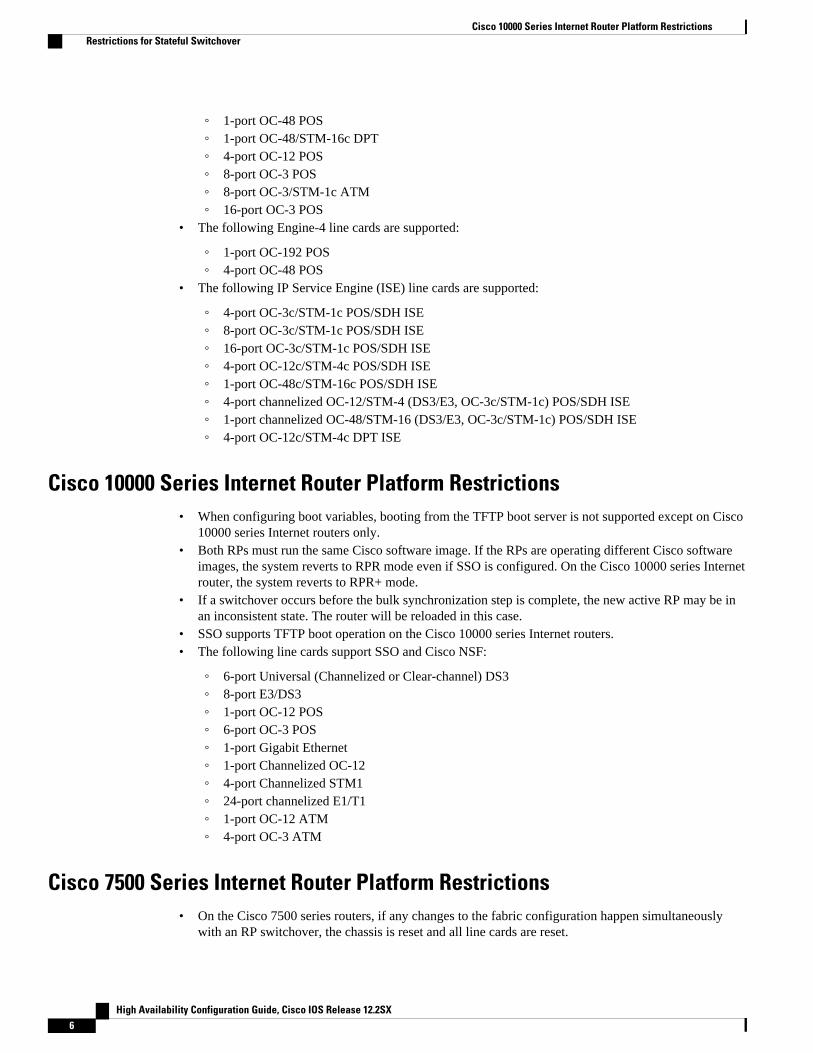
Cisco 10000 Series Internet Router Platform Restrictions• When configuring boot variables, booting from the TFTP boot server is not supported except on Cisco
10000 series Internet routers only.• Both RPs must run the same Cisco software image. If the RPs are operating different Cisco software
images, the system reverts to RPR mode even if SSO is configured. On the Cisco 10000 series Internetrouter, the system reverts to RPR+ mode.
• If a switchover occurs before the bulk synchronization step is complete, the new active RP may be inan inconsistent state. The router will be reloaded in this case.
• SSO supports TFTP boot operation on the Cisco 10000 series Internet routers.• The following line cards support SSO and Cisco NSF:
◦ 6-port Universal (Channelized or Clear-channel) DS3◦ 8-port E3/DS3◦ 1-port OC-12 POS◦ 6-port OC-3 POS◦ 1-port Gigabit Ethernet◦ 1-port Channelized OC-12◦ 4-port Channelized STM1◦ 24-port channelized E1/T1◦ 1-port OC-12 ATM◦ 4-port OC-3 ATM
Cisco 7500 Series Internet Router Platform Restrictions• On the Cisco 7500 series routers, if any changes to the fabric configuration happen simultaneously
with an RP switchover, the chassis is reset and all line cards are reset.
Cisco 10000 Series Internet Router Platform Restrictions Restrictions for Stateful Switchover
High Availability Configuration Guide, Cisco IOS Release 12.2SX6
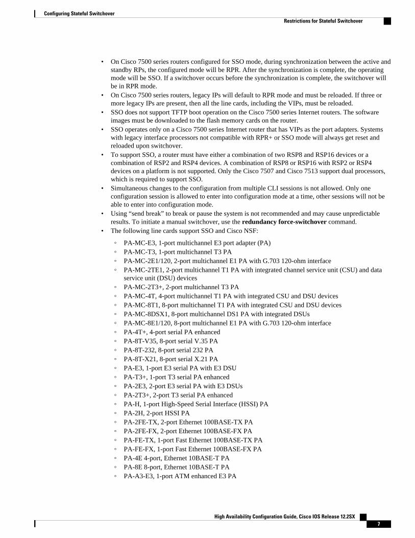
• On Cisco 7500 series routers configured for SSO mode, during synchronization between the active andstandby RPs, the configured mode will be RPR. After the synchronization is complete, the operatingmode will be SSO. If a switchover occurs before the synchronization is complete, the switchover willbe in RPR mode.
• On Cisco 7500 series routers, legacy IPs will default to RPR mode and must be reloaded. If three ormore legacy IPs are present, then all the line cards, including the VIPs, must be reloaded.
• SSO does not support TFTP boot operation on the Cisco 7500 series Internet routers. The softwareimages must be downloaded to the flash memory cards on the router.
• SSO operates only on a Cisco 7500 series Internet router that has VIPs as the port adapters. Systemswith legacy interface processors not compatible with RPR+ or SSO mode will always get reset andreloaded upon switchover.
• To support SSO, a router must have either a combination of two RSP8 and RSP16 devices or acombination of RSP2 and RSP4 devices. A combination of RSP8 or RSP16 with RSP2 or RSP4devices on a platform is not supported. Only the Cisco 7507 and Cisco 7513 support dual processors,which is required to support SSO.
• Simultaneous changes to the configuration from multiple CLI sessions is not allowed. Only oneconfiguration session is allowed to enter into configuration mode at a time, other sessions will not beable to enter into configuration mode.
• Using “send break” to break or pause the system is not recommended and may cause unpredictableresults. To initiate a manual switchover, use the redundancy force-switchover command.
• The following line cards support SSO and Cisco NSF:
◦ PA-MC-E3, 1-port multichannel E3 port adapter (PA)◦ PA-MC-T3, 1-port multichannel T3 PA◦ PA-MC-2E1/120, 2-port multichannel E1 PA with G.703 120-ohm interface◦ PA-MC-2TE1, 2-port multichannel T1 PA with integrated channel service unit (CSU) and data
service unit (DSU) devices◦ PA-MC-2T3+, 2-port multichannel T3 PA◦ PA-MC-4T, 4-port multichannel T1 PA with integrated CSU and DSU devices◦ PA-MC-8T1, 8-port multichannel T1 PA with integrated CSU and DSU devices◦ PA-MC-8DSX1, 8-port multichannel DS1 PA with integrated DSUs◦ PA-MC-8E1/120, 8-port multichannel E1 PA with G.703 120-ohm interface◦ PA-4T+, 4-port serial PA enhanced◦ PA-8T-V35, 8-port serial V.35 PA◦ PA-8T-232, 8-port serial 232 PA◦ PA-8T-X21, 8-port serial X.21 PA◦ PA-E3, 1-port E3 serial PA with E3 DSU◦ PA-T3+, 1-port T3 serial PA enhanced◦ PA-2E3, 2-port E3 serial PA with E3 DSUs◦ PA-2T3+, 2-port T3 serial PA enhanced◦ PA-H, 1-port High-Speed Serial Interface (HSSI) PA◦ PA-2H, 2-port HSSI PA◦ PA-2FE-TX, 2-port Ethernet 100BASE-TX PA◦ PA-2FE-FX, 2-port Ethernet 100BASE-FX PA◦ PA-FE-TX, 1-port Fast Ethernet 100BASE-TX PA◦ PA-FE-FX, 1-port Fast Ethernet 100BASE-FX PA◦ PA-4E 4-port, Ethernet 10BASE-T PA◦ PA-8E 8-port, Ethernet 10BASE-T PA◦ PA-A3-E3, 1-port ATM enhanced E3 PA
Configuring Stateful SwitchoverRestrictions for Stateful Switchover
High Availability Configuration Guide, Cisco IOS Release 12.2SX 7

◦ PA-A3-T3, 1-port ATM enhanced DS3 PA◦ PA-A3-OC3MM, 1-port ATM enhanced OC-3c/STM-1 multimode PA◦ PA-A3-OC3SMI, 1-port ATM enhanced OC-3c/STM-1 single-mode (IR) PA◦ PA-A3-OC3SML, 1-port ATM enhanced OC-3c/STM-1 single-model (LR) PA◦ PA-POS-OC3MM, 1-port PoS OC-3c/STM-1 multimode PA◦ PA-POS-OC3SMI, 1-port PoS OC-3c/STM-1 single-mode (IR) PA◦ PA-POS-OC3SML, 1-port PoS OC-3c/STM-1 single-mode (LR) PA◦ PA-A3-8E1IMA, 8-port ATM inverse multiplexer E1 (120-ohm) PA◦ PA-A3-8T1IMA, 8-port ATM inverse multiplexer T1 PA◦ PA-4E1G/75, 4-port E1 G.703 serial PA (75-ohm/unbalanced)◦ PA-4E1G/120, 4-port E1 G.703 serial PA (120-ohm/balanced)◦ PA-MCX-8TE1◦ PA-MCX-4TE1◦ PA-MCX-2TE1◦ All VIP2 and VIP4 line cards◦ PA/VIP Combinations: Gigabit-Ethernet IP (GEIP) and GEIP+
Cisco 7304 Router Platform Restrictions• Switchovers in SSO mode will not cause the reset of any line cards.• Interfaces on the RP itself are not stateful and will experience a reset across switchovers. The GE
interfaces on the RPs are reset across switchovers and do not support SSO.• SSO does not support TFTP boot operation on Cisco 7304 series routers. The software images must be
downloaded to the flash memory cards on the router.• On the Cisco 7304 routers, the two RPs must be the same type, either both NSE-100 or both NPE-
G100. Mixing the two types is not supported.• The presence of the PCI port adapter carrier card will force the system to fall back to the RPR
redundancy mode.• In Cisco IOS releases 12.2(20)S to 12.2(20)S2, the presence of the PA carrier card (7300-CC-PA) or
the SPA carrier card (MSC-100) forces the system to RPR mode.• In Cisco IOS Release 12.2(20)S3, both the PA carrier card and SPA carrier card support SSO mode.
The PA carrier card does not support RPR+ mode.• In Cisco IOS Release 12.2(20)S4 and later releases, all line cards support RPR+ and SSO modes.
Cisco ASR 1000 Series Routers Restrictions• Only RPR and SSO are supported on the Cisco ASR 1000 series routers.• RPR and SSO can be used on the Cisco ASR 1000 series router to enable a second Cisco software
process on a single RP. This configuration option is only available on Cisco ASR 1002 and Cisco ASR1004 routers. On all other Cisco ASR 1000 series routers, the second Cisco software process can runon the standby RP only.
• A second Cisco software process can only be enabled using RPR or SSO if the RP is using 4 GB ofDRAM. The show version command output shows the amount of DRAM configured on the router.
Cisco 7304 Router Platform Restrictions Restrictions for Stateful Switchover
High Availability Configuration Guide, Cisco IOS Release 12.2SX8

Information About Stateful Switchover• SSO Overview, page 9
• Redundancy Modes, page 11
• Route Processor Synchronization, page 14
• Switchover Operation, page 16
• Virtual Template Manager for SSO, page 18
• SSO-Aware Protocols and Applications, page 18
SSO OverviewSSO provides protection for network edge devices with dual RPs that represent a single point of failure inthe network design, and where an outage might result in loss of service for customers.
In Cisco networking devices that support dual RPs, SSO takes advantage of RP redundancy to increasenetwork availability. The feature establishes one of the RPs as the active processor while the other RP isdesignated as the standby processor, and then synchronizing critical state information between them.Following an initial synchronization between the two processors, SSO dynamically maintains RP stateinformation between them.
On Cisco ASR 1000 series routers, SSO can also be used to enable a second Cisco software process on thesame RP. This second Cisco IOS process acts as a standby process for the active Cisco software process,and also allows certain subpackages to be upgraded without experiencing any router downtime.
A switchover from the active to the standby processor occurs when the active RP fails, is removed from thenetworking device, or is manually taken down for maintenance.
SSO is used with the Cisco Nonstop Forwarding (NSF) feature. Cisco NSF allows for the forwarding ofdata packets to continue along known routes while the routing protocol information is being restoredfollowing a switchover. With Cisco NSF, peer networking devices do not experience routing flaps, therebyreducing loss of service outages for customers.
The figure below illustrates how SSO is typically deployed in service provider networks. In this example,Cisco NSF with SSO is primarily at the access layer (edge) of the service provider network. A fault at this
SSO OverviewInformation About Stateful Switchover
High Availability Configuration Guide, Cisco IOS Release 12.2SX 9

point could result in loss of service for enterprise customers requiring access to the service providernetwork.
Figure 1: Cisco NSF with SSO Network Deployment: Service Provider Networks
For Cisco NSF protocols that require neighboring devices to participate in Cisco NSF, Cisco NSF-awaresoftware images must be installed on those neighboring distribution layer devices. Additional networkavailability benefits might be achieved by applying Cisco NSF and SSO features at the core layer of yournetwork; however, consult your network design engineers to evaluate your specific site requirements.
Additional levels of availability may be gained by deploying Cisco NSF with SSO at other points in thenetwork where a single point of failure exists. The figure below illustrates an optional deployment strategythat applies Cisco NSF with SSO at the enterprise network access layer. In this example, each access pointin the enterprise network represents another single point of failure in the network design. In the event of a
Configuring Stateful Switchover Information About Stateful Switchover
High Availability Configuration Guide, Cisco IOS Release 12.2SX10

switchover or a planned software upgrade, enterprise customer sessions would continue uninterruptedthrough the network.
Figure 2: Cisco NSF with SSO Network Deployment: Enterprise Networks
Redundancy Modes• High System Availability, page 11• Route Processor Redundancy Mode, page 11• Route Processor Redundancy Plus, page 12• Stateful Switchover Mode, page 12• Redundancy Modes by Platform and Software Release, page 12
High System AvailabilityHSA mode allows you to install two RPs in a single router to improve system availability. This mode isavailable only on Cisco 7500 series routers. Supporting two RPs in a router provides the most basic level ofincreased system availability through a “cold restart” feature. A cold restart means that when one RP fails,the other RP reboots the router. Thus, the router is never in a failed state for very long, thereby increasingsystem availability.
Route Processor Redundancy ModeRouter Processor Redundancy (RPR) allows Cisco software to be booted on the standby processor prior toswitchover (a cold boot). In RPR, the standby RP loads a Cisco software image at boot time and initializes
Redundancy ModesHigh System Availability
High Availability Configuration Guide, Cisco IOS Release 12.2SX 11

itself in standby mode; however, although the startup configuration is synchronized to the standby RP,system changes are not. In the event of a fatal error on the active RP, the system switches to the standbyprocessor, which reinitializes itself as the active processor, reads and parses the startup configuration,reloads all of the line cards, and restarts the system.
Route Processor Redundancy PlusIn RPR+ mode, the standby RP is fully initialized. For RPR+ both the active RP and the standby RP mustbe running the same software image. The active RP dynamically synchronizes startup and the runningconfiguration changes to the standby RP, meaning that the standby RP need not be reloaded andreinitialized (a hot boot).
Additionally, on the Cisco 10000 and 12000 series Internet routers, the line cards are not reset in RPR+mode. This functionality provides a much faster switchover between the processors. Informationsynchronized to the standby RP includes running configuration information, startup information (Cisco7304, Cisco 7500, Cisco 10000, and Cisco 12000 series networking devices), and changes to the chassisstate such as online insertion and removal (OIR) of hardware. Line card, protocol, and application stateinformation is not synchronized to the standby RP.
Stateful Switchover ModeSSO mode provides all the functionality of RPR+ in that Cisco software is fully initialized on the standbyRP. In addition, SSO supports synchronization of line card, protocol, and application state informationbetween RPs for supported features and protocols (a hot standby).
Redundancy Modes by Platform and Software Release
Note During normal operation, SSO is the only supported mode for the Cisco 10000 series Internet routers.
The five tables below show redundancy modes by platform and release.
Table 1: Redundancy Modes by Platform in Cisco IOS Release 12.2S
Platform Mode 12.2 (18)S 12.2 (20)S 12.2 (25)S
7304 HSA No Yes Yes
RPR No Yes Yes
RPR+ No Yes Yes
SSO -- Yes Yes
7500 HSA Yes No Yes
RPR Yes No Yes
RPR+ Yes No Yes
SSO Yes No Yes
Configuring Stateful Switchover Route Processor Redundancy Plus
High Availability Configuration Guide, Cisco IOS Release 12.2SX12

Table 2: Redundancy Modes by Platform in Cisco IOS Release 12.2SB
Platform Mode 12.2(28)SB 12.2(31)SB2
7304 HSA No Yes
RPR No Yes
RPR+ No Yes
SSO No Yes
10000 HSA No No
RPR Yes Yes
RPR+ Yes Yes
SSO Yes Yes
Table 3: Redundancy Modes by Platform in Cisco IOS Release 12.2SR
Platform Mode 12.2 (33) SRA 12.2(33) SRB 12.2(33) SRC
7600 HSA No No No
RPR Yes Yes Yes
RPR+ Yes Yes Yes
SSO Yes Yes Yes
Table 4: Redundancy Modes by Platform in Cisco IOS Release 12.2SX
Platform Mode 12.2 (33)SXH
CAT6500 HSA No
RPR Yes
RPR+ Yes
SSO Yes
Table 5: Redundancy Modes by Platform in Cisco IOS Release 12.0S
Platform Mode RedundancyModeSupport inCisco IOSSoftwareReleases
12.0(22)S 12.0(23)S 12.0(24)S 12.0(26)S 12.0(28)S
Configuring Stateful SwitchoverRedundancy Modes by Platform and Software Release
High Availability Configuration Guide, Cisco IOS Release 12.2SX 13

Platform Mode RedundancyModeSupport inCisco IOSSoftwareReleases
7500 HSA Yes Yes Yes Yes Yes
RPR Yes Yes Yes Yes Yes
RPR+ Yes Yes Yes Yes Yes
SSO Yes Yes Yes Yes Yes
10000 HSA No No No No No
RPR No No No No No
RPR+ Yes Yes Yes Yes Yes
SSO Yes Yes Yes Yes Yes
12000 HSA No No No No No
RPR Yes Yes Yes Yes Yes
RPR+ Yes Yes Yes Yes Yes
SSO Yes Yes Yes Yes Yes
Route Processor SynchronizationIn networking devices running SSO, both RPs must be running the same configuration so that the standbyRP is always ready to assume control if the active RP fails.
To achieve the benefits of SSO, synchronize the configuration information from the active RP to thestandby RP at startup and whenever changes to the active RP configuration occur. This synchronizationoccurs in two separate phases:
• While the standby RP is booting, the configuration information is synchronized in bulk from the activeRP to the standby RP.
• When configuration or state changes occur, an incremental synchronization is conducted from theactive RP to the standby RP.
• Bulk Synchronization During Initialization, page 14
• Incremental Synchronization, page 15
Bulk Synchronization During InitializationWhen a system with SSO is initialized, the active RP performs a chassis discovery (discovery of thenumber and type of line cards and fabric cards, if available, in the system) and parses the startupconfiguration file.
Route Processor Synchronization Bulk Synchronization During Initialization
High Availability Configuration Guide, Cisco IOS Release 12.2SX14

The active RP then synchronizes this data to the standby RP and instructs the standby RP to complete itsinitialization. This method ensures that both RPs contain the same configuration information.
Even though the standby RP is fully initialized, it interacts only with the active RP to receive incrementalchanges to the configuration files as they occur. Executing CLI commands on the standby RP is notsupported.
During system startup, the startup configuration file is copied from the active RP to the standby RP. Anyexisting startup configuration file on the standby RP is overwritten. The startup configuration is a text filestored in the NVRAM of the RP. It is synchronized whenever you perform the following operations:
• The command copy system:running-config nvram:startup-config is used.• The command copy running-config startup-config is used.• The command write memory is used.• The command copy filename nvram:startup-config is used.• SNMP SET of MIB variable ccCopyEntry in CISCO_CONFIG_COPY MIB is used.• System configuration is saved using the reload command.• System configuration is saved following entry of a forced switchover command.
Incremental SynchronizationAfter both RPs are fully initialized, any further changes to the running configuration or active RP states aresynchronized to the standby RP as they occur. Active RP states are updated as a result of processingprotocol information, external events (such as the interface becoming up or down), or user configurationcommands (using Cisco IOS commands or Simple Network Management Protocol [SNMP]) or otherinternal events.
Changes to the running configuration are synchronized from the active RP to the standby RP. In effect, thecommand is run on both the active and the standby RP.
Configuration changes caused by an SNMP set operation are synchronized on a case-by-case basis. Onlytwo SNMP configuration set operations are supported:
• shut and no-shut (of an interface)• link up/down trap enable/disable
Routing and forwarding information is synchronized to the standby RP:
• State changes for SSO-aware protocols (ATM, Frame Relay, PPP, High-Level Data Link Control[HDLC]) or applications (SNMP) are synchronized to the standby RP.
• Cisco Express Forwarding (CEF) updates to the Forwarding Information Base (FIB) are synchronizedto the standby RP.
Chassis state changes are synchronized to the standby RP. Changes to the chassis state due to line cardinsertion or removal are synchronized to the standby RP.
Changes to the line card states are synchronized to the standby RP. Line card state information is initiallyobtained during bulk synchronization of the standby RP. Following bulk synchronization, line card events,such as whether the interface is up or down, received at the active processor are synchronized to thestandby RP.
The various counters and statistics maintained in the active RP are not synchronized because they maychange often and because the degree of synchronization they require is substantial. The volume ofinformation associated with statistics makes synchronizing them impractical.
Not synchronizing counters and statistics between RPs may create problems for external networkmanagement systems that monitor this information.
Configuring Stateful SwitchoverIncremental Synchronization
High Availability Configuration Guide, Cisco IOS Release 12.2SX 15

Switchover Operation• Switchover Conditions, page 16• Switchover Time, page 16• Online Removal of the Active RP, page 17• Single Line Card Reload, page 17• Fast Software Upgrade, page 17• Core Dump Operation, page 18
Switchover ConditionsAn automatic or manual switchover may occur under the following conditions:
• A fault condition that causes the active RP to crash or reboot--automatic switchover• The active RP is declared dead (not responding)--automatic switchover• The command is invoked--manual switchover
The user can force the switchover from the active RP to the standby RP by using a CLI command. Thismanual procedure allows for a graceful or controlled shutdown of the active RP and switchover to thestandby RP. This graceful shutdown allows critical cleanup to occur.
Note This procedure should not be confused with the graceful shutdown procedure for routing protocols in corerouters--they are separate mechanisms.
Caution The SSO feature introduces a number of new command and command changes, including commands tomanually cause a switchover. The reload command does not cause a switchover. The reload commandcauses a full reload of the box, removing all table entries, resetting all line cards, and interrupting nonstopforwarding.
Switchover TimeThe time required by the device to switch over from the active RP to the standby RP varies by platform:
• On the Cisco 7500 series devices, switchover time is approximately 30 seconds.• On the Cisco 7304 and Cisco 10000 series devices, switchover time is only a few seconds.• On the Cisco 12000 series devices, switchover time due to a manual switchover or due to automatic
switchover caused by an error is only a few seconds. If the switchover is caused by a fault on theactive RP, the standby RP will detect the problem following the switchover timeout period, which isset to three seconds by default.
• On the Cisco ASR 1000 series routers, switchover time is only a few seconds.
Although the newly active processor takes over almost immediately following a switchover, the timerequired for the device to begin operating again in full redundancy (SSO) mode can be several minutes,depending on the platform. The length of time can be due to a number of factors including the time neededfor the previously active processor to obtain crash information, load code and microcode, and synchronizeconfigurations between processors and line protocols and Cisco NSF-supported protocols.
Switchover Operation Switchover Conditions
High Availability Configuration Guide, Cisco IOS Release 12.2SX16

The impact of the switchover time on packet forwarding depends on the networking device:
• On the Cisco 7500 series devices, forwarding information is distributed, and packets forwarded fromthe same line card should have little to no forwarding delay; however, forwarding packets between linecards requires interaction with the RP, meaning that packet forwarding might have to wait for theswitchover time. The switchover time on Cisco 7500 series devices is also dependent on the type ofRSPs installed on the system.
• On the Cisco 10000 series devices, Cisco Express Forwarding information resides on the RP, sopacket forwarding can be impacted momentarily while the switchover occurs.
• On the Cisco 12000 series devices, complete forwarding information is distributed to the line cards, sopacket forwarding is not impacted as long as the line cards are working.
Online Removal of the Active RPFor Cisco 7500 series routers, online removal of the active RSP will automatically switch the redundancymode to RPR. Online removal of the active RSP causes all line cards to reset and reload, which isequivalent to an RPR switchover, and results in a longer switchover time. When it is necessary to removethe active RP from the system, first issue a switchover command to switch from the active RSP to thestandby RSP. When a switchover is forced to the standby RSP before the previously active RSP isremoved, the network operation benefits from the continuous forwarding capability of SSO.
For Cisco 7304, Cisco 10000, and Cisco 12000 series Internet routers that are configured to use SSO,online removal of the active RP automatically forces a stateful switchover to the standby RP.
Single Line Card ReloadIn Cisco 7500 series routers, a line card might fail to reach the quiescent state as a result of a hardware orsoftware fault. In such cases, the failing line card must be reset. We recommend using the Single Line CardReload (SLCR) feature to provide maximum assurance that SSO will continue forwarding packets onunaffected interfaces during switchover.
Note SLCR is not required on the Cisco 7304 router or on Cisco 10000 and 12000 series Internet routers.
The SLCR feature allows users to correct a line card fault on a Cisco 7500 series router by automaticallyreloading the microcode on a failed line card. During the SLCR process, all physical lines and routingprotocols on the other line cards of the network backplane remain active.
The SLCR feature is not enabled by default. When you enable SSO, RPR+, or RPR, it is important that youenable SLCR also. For information on how to load and configure SLCR, refer to the Cisco 7500 SingleLine Card Reload feature module.
Fast Software UpgradeYou can use Fast Software Upgrade (FSU) to reduce planned downtime. With FSU, you can configure thesystem to switch over to a standby RP that is preloaded with an upgraded Cisco software image. FSUreduces outage time during a software upgrade by transferring functions to the standby RP that has theupgraded Cisco software preinstalled. You can also use FSU to downgrade a system to an older version ofCisco software or have a backup system loaded for downgrading to a previous image immediately after anupgrade.
SSO must be configured on the networking device before performing FSU.
Configuring Stateful SwitchoverOnline Removal of the Active RP
High Availability Configuration Guide, Cisco IOS Release 12.2SX 17

Note During the upgrade process, different images will be loaded on the RPs for a short period of time. Duringthis time, the device will operate in RPR or RPR+ mode, depending on the networking device.
Core Dump OperationIn networking devices that support SSO, the newly active primary processor runs the core dump operationafter the switchover has taken place. Not having to wait for dump operations effectively decreases theswitchover time between processors.
Following the switchover, the newly active RP will wait for a period of time for the core dump to completebefore attempting to reload the formerly active RP. The time period is configurable. For example, on someplatforms an hour or more may be required for the formerly active RP to perform a coredump, and it mightnot be site policy to wait that much time before resetting and reloading the formerly active RP. In the eventthat the core dump does not complete within the time period provided, the standby is reset and reloadedregardless of whether it is still performing a core dump.
The core dump process adds the slot number to the core dump file to identify which processor generatedthe file content.
Note Core dumps are generally useful only to your technical support representative. The core dump file, which isa very large binary file, must be transferred using the TFTP, FTP, or remote copy protocol (rcp) server andsubsequently interpreted by a Cisco Technical Assistance Center (TAC) representative that has access tosource code and detailed memory maps.
Virtual Template Manager for SSOThe virtual template manager feature for SSO provides virtual access interfaces for sessions that are notHA-capable and are not synchronized to the standby router. The virtual template manager uses aredundancy facility (RF) client to allow the synchronization of the virtual interfaces in real time as they arecreated.
The virtual databases have instances of distributed FIB entries on line cards. Line cards requiresynchronization of content and timing in all interfaces to the standby processor to avoid incorrectforwarding. If the virtual access interface is not created on the standby processor, the interface indexes willbe corrupted on the standby router and line cards, which will cause problems with forwarding.
SSO-Aware Protocols and ApplicationsSSO-supported line protocols and applications must be SSO-aware. A feature or protocol is SSO-aware if itmaintains, either partially or completely, undisturbed operation through an RP switchover. Stateinformation for SSO-aware protocols and applications is synchronized from active to standby to achievestateful switchover for those protocols and applications.
The dynamically created state of SSO-unaware protocols and applications is lost on switchover and must bereinitialized and restarted on switchover.
SSO-aware applications are either platform-independent, such as in the case of line protocols or platform-dependent (such as line card drivers). Enhancements to the routing protocols (Cisco Express Forwarding,
Virtual Template Manager for SSO Core Dump Operation
High Availability Configuration Guide, Cisco IOS Release 12.2SX18

Open Shortest Path First, and Border Gateway Protocol [BGP]) have been made in the SSO feature toprevent loss of peer adjacency through a switchover; these enhancements are platform-independent.
• Line Protocols, page 19
• Quality of Service, page 24
• IPv6 Support for Stateful Switchover, page 24
• Line Card Drivers, page 24
• APS, page 24
• Routing Protocols and Nonstop Forwarding, page 25
• Network Management, page 25
• SSO for Circuit Emulation Services, page 25
Line ProtocolsSSO-aware line protocols synchronize session state information between the active and standby RPs tokeep session information current for a particular interface. In the event of a switchover, session informationneed not be renegotiated with the peer. During a switchover, SSO-aware protocols also check the line cardstate to learn if it matches the session state information. SSO-aware protocols use the line card interface toexchange messages with network peers in an effort to maintain network connectivity.
• Supported Line protocols by Platform, page 19
• ATM Stateful Switchover, page 21
• Frame Relay and Multilink Frame Relay Stateful Switchover, page 22
• PPP and Multilink PPP Stateful Switchover, page 23
• HDLC Stateful Switchover, page 23
Supported Line protocols by Platform
The five tables below indicate which line protocols are supported on various platforms and releases.
Table 6: Line Protocol Support in Cisco IOS Release 12.2S
Protocol Platform 12.2 (18)S 12.2 (20)S 12.2 (25)S
ATM Cisco 7304 No Yes Yes
Cisco 7500 Yes No Yes
Frame Relay andMultilink FrameRelay
Cisco 7304 No Yes Yes
Cisco 7500 Yes No Yes
PPP and MultilinkPPP
Cisco 7304 No Yes Yes
Cisco 7500 Yes No Yes
HDLC Cisco 7304 No Yes Yes
Cisco 7500 Yes No Yes
Configuring Stateful SwitchoverLine Protocols
High Availability Configuration Guide, Cisco IOS Release 12.2SX 19

Table 7: Line Protocol Support in Cisco IOS Release 12.2SB
Protocol Platform 12.2 (28)SB 12.2(31)SB2
ATM Cisco 7304 Yes Yes
Cisco 10000 Yes Yes
Frame Relay andMultilink Frame Relay
Cisco 7304 Yes Yes
Cisco 10000 Yes Yes
PPP and Multilink PPP Cisco 7304 Yes Yes
Cisco 10000 Yes Yes
HDLC Cisco 7304 Yes Yes
Cisco 10000 Yes Yes
Table 8: Line Protocol Support in Cisco IOS Release 12.2SR
Protocol Platform 12.2(33)SRA 12.2(33)SRB 12.2(33)SRC
ATM Cisco 7600 Yes Yes Yes
Frame Relay andMultilink Frame Relay
Cisco 7600 Yes Yes Yes
PPP and Multilink PPP Cisco 7600 Yes Yes Yes
HDLC Cisco 7600 Yes Yes Yes
Table 9: Line Protocol Support in Cisco IOS Release 12.2SX
Protocol Platform 12.2(33)SXH
ATM Cisco CAT6500 Yes
Cisco 7600 Yes
Frame Relay and Multilink FrameRelay
Cisco CAT6500 Yes1
Cisco 7600 Yes
PPP and Multilink PPP Cisco CAT6500 Yes
Cisco 7600 Yes
HDLC Cisco CAT6500 Yes
Cisco 7600 Yes
1 Frame Relay is supported, but Multilink Frame Relay is not.
Configuring Stateful Switchover Supported Line protocols by Platform
High Availability Configuration Guide, Cisco IOS Release 12.2SX20

Table 10: Line Protocol Support in Cisco IOS Release 12.0S
Protocol Platform 12.0 (22)S 12.0 (23)S 12.0 (24)S 12.0 (26)S 12.0(28)S
ATM Cisco 7500 Yes Yes Yes Yes Yes
Cisco 10000 Yes Yes Yes Yes Yes
Cisco 12000 Yes Yes Yes Yes Yes
Frame RelayandMultilinkFrame Relay
Cisco 7500 Yes Yes Yes Yes Yes
Cisco 10000 Yes Yes Yes Yes Yes
Cisco 12000 No No No No Yes
PPP andMultilinkPPP
Cisco 7500 Yes Yes Yes Yes Yes
Cisco 10000 Yes Yes Yes Yes Yes
Cisco 12000 Yes Yes Yes Yes Yes
HDLC Cisco 7500 Yes Yes Yes Yes Yes
Cisco 10000 Yes Yes Yes Yes Yes
Cisco 12000 Yes Yes Yes Yes Yes
ATM Stateful Switchover
With stateful switchover, ATM dynamic state information is synchronized between the active RP andstandby RP. Thus when the active RP fails, the standby RP can take over without spending excessive timerelearning the dynamic state information, and forwarding devices can continue to forward packets withonly a few seconds of interruption (less on some platforms).
Note ATM SSO is not configurable and runs by default on networking devices configured with ATM andRedundancy Mode SSO.
Permanent Virtual Circuits
For ATM to support forwarding during and after switchover, ATM permanent virtual circuits (PVCs) mustremain up not only within the networking device, but also within the ATM network.
In an ATM network, all traffic to or from an ATM interface is prefaced with a virtual path identifier (VPI)and virtual channel identifier (VCI). A VPI-VCI pair is considered a single virtual circuit. Each virtualcircuit is a private connection to another node on the ATM network. In ATM SSO, the VPI-VCI pair isassociated with a virtual circuit descriptor (VCD). ATM SSO uses VCD information in synchronizing VPI-VCI information to the standby RP.
Each virtual circuit is treated as a point-to-point or point-to-multipoint mechanism to another networkingdevice or host and can support bidirectional traffic. On point-to-point subinterfaces, or when staticmappings are configured, Inverse Address Resolution Protocol (ARP) need not run. In cases wheredynamic address mapping is used, an Inverse ARP protocol exchange determines the protocol address toVPI-VCI mapping for the PVC. This process occurs as soon as the PVC on a multipoint subinterface makes
Configuring Stateful SwitchoverATM Stateful Switchover
High Availability Configuration Guide, Cisco IOS Release 12.2SX 21

the transition to active. If that process fails for some reason, the remote networking device may drop theInverse ARP request if it has not yet seen the PVC transition to active. Inverse ARP runs every 60 secondsto relearn the dynamic address mapping information for the active RP.
ATM OAM Managed PVC or SVC Timeout
Operation, Administration, and Maintenance (OAM) F5 loopback cells must be echoed back on receipt bythe remote host, thus demonstrating connectivity on the PVC between the router and the remote host. WithATM SSO, OAM loopback cells received on an interface must be echoed within 15 seconds before a PVCor switched virtual circuit (SVC) is declared down. By default, the OAM timeout is set to 10 seconds,followed by at most five retries sent at 1-second intervals. In the worst case, a switchover will begin justbefore expiration of the 10-second period, meaning that the PVC will go down within 5 seconds on theremote networking device if switchover has not completed within 5 seconds.
Note Timers at remote ATM networking devices may be configurable, depending on the remote device owner.
Frame Relay and Multilink Frame Relay Stateful Switchover
With stateful switchover, Frame Relay and Multilink Frame Relay dynamic state information issynchronized between the active RP and standby RP. Thus when the active RP fails, the standby RP cantake over without spending excessive time relearning the dynamic state information, and forwardingdevices can continue to forward packets with only a few seconds of interruption (less on some platforms).
Permanent Virtual Circuits
For Frame Relay and Multilink Frame Relay to support forwarding during and after switchover, FrameRelay PVCs must remain up not only within the networking device, but also within the Frame Relaynetwork.
In many cases the networking devices are connected to a switch, rather than back-to-back to anothernetworking device, and that switch is not running Cisco software. The virtual circuit state is dependent online state. PVCs are down when the line protocol is down. PVCs are up when the line protocol is up and thePVC status reported by the adjacent switch is active.
On point-to-point subinterfaces, or when static mappings are configured, Inverse ARP need not run. Incases where dynamic address mapping is used, an Inverse ARP protocol exchange determines the protocoladdress to data-link connection identifier (DLCI) mapping for the PVC. This exchange occurs as soon asthe multipoint PVC makes the transition to active. If the exchange fails for some reason, for example, theremote networking device may drop the Inverse ARP request if it has not yet seen the PVC transition toactive--any outstanding requests are run off a timer, with a default of 60 seconds.
Keepalive Messages
A crucial factor in maintaining PVCs is the delivery of Local Management Interface (LMI) protocolmessages (keepalives) during switchover. This keepalive mechanism provides an exchange of informationbetween the network server and the switch to verify that data is flowing.
If a number of consecutive LMI keepalives messages are lost or in error, the adjacent Frame Relay devicedeclares the line protocol down and all PVCs on that interface are declared down within the Frame Relaynetwork and reported as such to the remote networking device. The speed with which a switchover occursis crucial to avoid the loss of keepalive messages.
The line protocol state depends on the Frame Relay keepalive configuration. With keepalives disabled, theline protocol is always up as long as the hardware interface is up. With keepalives enabled, LMI protocol
Configuring Stateful Switchover Frame Relay and Multilink Frame Relay Stateful Switchover
High Availability Configuration Guide, Cisco IOS Release 12.2SX22

messages are exchanged between the networking device and the adjacent Frame Relay switch. The lineprotocol is declared up after a number of consecutive successful LMI message exchanges.
The line protocol must be up according to both the networking device and the switch. The default numberof exchanges to bring up the line protocol is implementation-dependent: Three is suggested by thestandards; four is used on a Cisco Frame Relay switch, taking 40 seconds at the default interval of 10seconds; and two is used on a Cisco networking device acting as a switch or when connected back-to-back.This default number could be extended if the LMI “autosense” feature is being used while the LMI typeexpected on the switch is determined. The number of exchanges is configurable, although the switch androuter may not have the same owner.
The default number of lost messages or errors needed to bring down the line is three (two on a Ciscorouter). By default, if a loss of two messages is detected in 15 to 30 seconds, then a sequence number orLMI type error in the first message from the newly active RP takes the line down.
If a line goes down, consecutive successful LMI protocol exchanges (default of four over 40 seconds on aCisco Frame Relay switch; default of two over 20 seconds on a Cisco device) will bring the line back upagain.
PPP and Multilink PPP Stateful Switchover
With stateful switchover, specific PPP state information is synchronized between the active RP and standbyRP. Thus when the active RP fails, the standby RP can take over without spending excessive timerenegotiating the setup of a given link. As long as the physical link remains up, forwarding devices cancontinue to forward packets with only a few seconds of interruption (less on some platforms). Single-linkPPP and Multilink PPP (MLP) sessions are maintained during RP switchover for IP connections only.
PPP and MLP support many Layer 3 protocols such as IPX and IP. Only IP links are supported in SSO.Links supporting non IP traffic will momentarily renegotiate and resume forwarding following aswitchover. IP links will forward IP traffic without renegotiation.
A key factor in maintaining PPP session integrity during a switchover is the use of keepalive messages.This keepalive mechanism provides an exchange of information between peer interfaces to verify data andlink integrity. Depending on the platform and configuration, the time required for switchover to the standbyRP might exceed the keepalive timeout period. PPP keepalive messages are started when the physical linkis first brought up. By default, keepalive messages are sent at 10-second intervals from one PPP interface tothe other PPP peer.
If five consecutive keepalive replies are not received, the PPP link would be taken down on the newlyactive RP. Caution should be used when changing the keepalive interval duration to any value less than thedefault setting.
Only in extremely rare circumstances could the RP switchover time exceed the default 50-second keepaliveduration. In the unlikely event this time is exceeded, the PPP links would renegotiate with the peers andresume IP traffic forwarding.
Note PPP and MLP are not configurable and run by default on networking devices configured with SSO.
HDLC Stateful Switchover
With stateful switchover, High-Level Data Link Control (HDLC) synchronizes the line protocol stateinformation. Additionally, the periodic timer is restarted for interfaces that use keepalive messages to verifylink integrity. Link state information is synchronized between the active RP and standby RP. The line
Configuring Stateful SwitchoverPPP and Multilink PPP Stateful Switchover
High Availability Configuration Guide, Cisco IOS Release 12.2SX 23

protocols that were up before the switchover remain up afterward as long as the physical interface remainsup. Line protocols that were down remain down.
A key factor in maintaining HDLC link integrity during a switchover is the use of keepalive messages. Thiskeepalive mechanism provides an exchange of information between peer interfaces to verify data isflowing. HDLC keepalive messages are started when the physical link is first brought up. By default,keepalive messages are sent at 10-second intervals from one HDLC interface to the other.
HDLC waits at least three keepalive intervals without receiving keepalive messages, sequence numbererrors, or a combination of both before it declares a line protocol down. If the line protocol is down, SSOcannot support continuous forwarding of user session information in the event of a switchover.
Note HDLC is not configurable and runs by default on networking devices configured with SSO.
Quality of ServiceThe modular QoS CLI (MQS)-based QoS feature maintains a database of various objects created by theuser, such as those used to specify traffic classes, actions for those classes in traffic policies, andattachments of those policies to different traffic points such as interfaces. With SSO, QoS synchronizes thatdatabase between the primary and secondary RP.
IPv6 Support for Stateful SwitchoverIPv6 neighbor discovery supports SSO using Cisco Express Forwarding. When switchover occurs, theCisco Express Forwarding adjacency state, which is checkpointed, is used to reconstruct the neighbordiscovery cache.
Line Card DriversPlatform-specific line card device drivers are bundled with the Cisco software image for SSO and arecorrect for a specific image, meaning they are designed to be SSO-aware.
Line cards used with the SSO feature periodically generate status events that are forwarded to the activeRP. Information includes the line up or down status, and the alarm status. This information helps SSOsupport bulk synchronization after standby RP initialization and support state reconciliation andverification after a switchover.
Line cards used with the SSO feature also have the following requirements:
• Line cards must not reset during switchover.• Line cards must not be reconfigured.• Subscriber sessions may not be lost.
Note The standby RP communicates only with the active RP, never with the line cards. This function helps toensure that the active and standby RP always have the same information.
APS
Configuring Stateful Switchover Quality of Service
High Availability Configuration Guide, Cisco IOS Release 12.2SX24

RPR+ and SSO support allow the automatic protection switching (APS) state to be preserved in the eventof failover.
Routing Protocols and Nonstop ForwardingCisco nonstop forwarding (NSF) works with SSO to minimize the amount of time a network is unavailableto its users following a switchover. When a networking device restarts, all routing peers of that deviceusually detect that the device went down and then came back up. This down-to-up transition results in whatis called a “routing flap,” which could spread across multiple routing domains. Routing flaps caused byrouting restarts create routing instabilities, which are detrimental to the overall network performance. CiscoNSF helps to suppress routing flaps, thus improving network stability.
Cisco NSF allows for the forwarding of data packets to continue along known routes while the routingprotocol information is being restored following a switchover. With Cisco NSF, peer networking devicesdo not experience routing flaps. Data traffic is forwarded through intelligent line cards while the standbyRP assumes control from the failed active RP during a switchover. The ability of line cards to remain upthrough a switchover and to be kept current with the FIB on the active RP is key to Cisco NSF operation.
A key element of Cisco NSF is packet forwarding. In Cisco networking devices, packet forwarding isprovided by Cisco Express Forwarding. Cisco Express Forwarding maintains the FIB, and uses the FIBinformation that was current at the time of the switchover to continue forwarding packets during aswitchover. This feature eliminates downtime during the switchover.
Cisco NSF supports the BGP, IS-IS, and OSPF routing protocols. In general, these routing protocols mustbe SSO-aware to detect a switchover and recover state information (converge) from peer devices. Eachprotocol depends on Cisco Express Forwarding to continue forwarding packets during switchover while therouting protocols rebuild the Routing Information Base (RIB) tables.
Note Distributed Cisco Express Forwarding must be enabled in order to run NSF.
Network ManagementNetwork management support for SSO is provided through the synchronization of specific SNMP databetween the active and standby RPs. From a network management perspective, this functionality helps toprovide an uninterrupted management interface to the network administrator.
Note Synchronization of SNMP data between RPs is available only when the networking device is operating inSSO mode.
SSO for Circuit Emulation ServicesSSO for circuit emulation services (CES) for TDM pseudowires provides the ability to switch an incomingDS1/T1/E1 on one SPA to another SPA on same SIP or onto a different SIP.
How to Configure Stateful Switchover• Copying an Image onto an RP, page 26
Configuring Stateful SwitchoverRouting Protocols and Nonstop Forwarding
High Availability Configuration Guide, Cisco IOS Release 12.2SX 25

• Setting the Configuration Register and Boot Variable, page 27
• Configuring SSO, page 28
• Configuring Frame Relay and Multilink Frame Relay Autosynchronization LMI Sequence Numbers, page 29
• Verifying SSO Configuration, page 30
• Performing a Fast Software Upgrade, page 31
• Troubleshooting Stateful Switchover, page 33
Copying an Image onto an RP
Note To copy a consolidated package or subpackages onto active and standby RPs on the Cisco ASR 1000 SeriesRouter, see the Cisco ASR 1000 Series Aggregation Services Routers Software Configuration Guide.
SUMMARY STEPS
1. enable
2. copy tftp {slot | disk}device-number : filename
3. copy tftp {slave | stby-}{slot | disk}device-number : filename
4. exit
DETAILED STEPS
Command or Action Purpose
Step 1 enable
Example:
Router> enable
Enables privileged EXEC mode.
• Enter your password if prompted.
Step 2 copy tftp {slot | disk}device-number : filename
Example:
Router# copy tftp slot0:image1
Copies a Cisco software image onto the flash device of theactive RP.
Step 3 copy tftp {slave | stby-}{slot | disk}device-number : filename
Example:
Router# copy tftp stby-slot0:image1
Copies a Cisco software image onto the flash device of thestandby RP.
Step 4 exit
Example:
Router# exit
Exits to user EXEC mode.
Copying an Image onto an RP How to Configure Stateful Switchover
High Availability Configuration Guide, Cisco IOS Release 12.2SX26

Setting the Configuration Register and Boot Variable
Note Following the reload, each RP is in its default mode: The Cisco 7304 router boots in SSO mode; the Cisco7500 series router reboots in HSA mode; the Cisco 10000 series Internet router boots in SSO mode, and theCisco 12000 series Internet router reboots in RPR mode.
SUMMARY STEPS
1. enable
2. show version
3. configure terminal
4. no boot system {flash [flash-fs:][partition-number:][filename ] | ftpfilename [ip-address ]}
5. boot system {flash [flash-fs:][partition-number:][filename ] | tftpfilename [ip-address ]}
6. config-register value
7. exit
8. copy running-config startup-config
9. reload
DETAILED STEPS
Command or Action Purpose
Step 1 enable
Example:
Router> enable
Enables privileged EXEC mode.
• Enter your password if prompted.
Step 2 show version
Example:
Router# show version
Obtains the current configuration register setting.
Step 3 configure terminal
Example:
Router# configure terminal
Enters global configuration mode.
Step 4 no boot system {flash [flash-fs:][partition-number:][filename] | ftpfilename [ip-address ]}
Example:
Router(config)# no boot system flash
(Optional) Clears any existing system flash or TFTP bootimage specification.
Step 5 boot system {flash [flash-fs:][partition-number:][filename ] |tftpfilename [ip-address ]}
Specifies the filename of stored image in flash memory or,for Cisco 10000, on a TFTP server.
Setting the Configuration Register and Boot VariableHow to Configure Stateful Switchover
High Availability Configuration Guide, Cisco IOS Release 12.2SX 27

Command or Action Purpose
Example:
Example:
Router(config)# boot system flash
Step 6 config-register value
Example:
Router(config)# config-register 0x2102
Modifies the existing configuration register setting toreflect the way in which you want to load a system image.
Step 7 exit
Example:
Router(config)# exit
Exits global configuration mode and returns the router toprivileged EXEC mode.
Step 8 copy running-config startup-config
Example:
Router# copy running-config startup-config
Saves the configuration changes to the startup configurationfile.
Step 9 reload
Example:
Router# reload
Reboots both RPs on the device to ensure that changes tothe configuration take effect.
Configuring SSO
Note Cisco 7304 routers and Cisco 10000 series Internet routers operate in SSO mode by default after reloadingthe same version of SSO-aware images on the device. No configuration is necessary.
Image to be used by active or standby RP at initialization must be available on the local flash device.
SUMMARY STEPS
1. enable
2. configure terminal
3. hw-module slot slot-number image file-spec
4. redundancy
5. mode sso
6. end
7. copy running-config startup-config
Configuring SSO How to Configure Stateful Switchover
High Availability Configuration Guide, Cisco IOS Release 12.2SX28

DETAILED STEPS
Command or Action Purpose
Step 1 enable
Example:
Router> enable
Enables privileged EXEC mode.
• Enter your password if prompted.
Step 2 configure terminal
Example:
Router# configure terminal
Enters global configuration mode.
Step 3 hw-module slot slot-number image file-spec
Example:
Router(config)# hw-module slot 6 image slot0:rsp-pv-mz
(Optional) For Cisco 7500 series devices only. Specifies theimage to be used by an RP at initialization.
• Repeat this step for both the active and standby RPs.
Step 4 redundancy
Example:
Router(config)# redundancy
Enters redundancy configuration mode.
Step 5 mode sso
Example:
Router(config)# mode sso
Sets the redundancy configuration mode to SSO on both theactive and standby RP.
NoteAfter configuring SSO mode, the standby RP willautomatically reset.
Step 6 end
Example:
Router(config-red)# end
Exits redundancy configuration mode and returns the router toprivileged EXEC mode.
Step 7 copy running-config startup-config
Example:
Router# copy running-config startup-config
Saves the configuration changes to the startup configuration file.
Configuring Frame Relay and Multilink Frame Relay AutosynchronizationLMI Sequence Numbers
Configuring Frame Relay and Multilink Frame Relay Autosynchronization LMI Sequence NumbersHow to Configure Stateful Switchover
High Availability Configuration Guide, Cisco IOS Release 12.2SX 29

SUMMARY STEPS
1. enable
2. configure terminal
3. frame-relay redundancy auto-sync lmi-sequence-numbers
DETAILED STEPS
Command or Action Purpose
Step 1 enable
Example:
Router> enable
Enables privileged EXEC mode.
• Enter your password if prompted.
Step 2 configure terminal
Example:
Router# configure terminal
Enters global configuration mode.
Step 3 frame-relay redundancy auto-sync lmi-sequence-numbers
Example:
Router(config)# frame-relay redundancy auto-sync lmi-sequence-numbers
Configures automatic synchronization of Frame RelayLMI sequence numbers between the active RP and thestandby RP.
Verifying SSO Configuration
SUMMARY STEPS
1. enable
2. show redundancy [clients | counters | history | switchover history | states]
3. show redundancy states
DETAILED STEPS
Command or Action Purpose
Step 1 enable
Example:
Router> enable
Enables privileged EXEC mode.
• Enter your password if prompted.
Step 2 show redundancy [clients | counters | history | switchover history |states]
Displays SSO configuration information.
Verifying SSO Configuration How to Configure Stateful Switchover
High Availability Configuration Guide, Cisco IOS Release 12.2SX30

Command or Action Purpose
Example:
Router# show redundancy
Step 3 show redundancy states
Example:
Router# show redundancy states
Verifies that the device is running in SSO mode.
Performing a Fast Software Upgrade
Note During the upgrade process, different images will be loaded on the RPs for a very short period of time. If aswitchover occurs during this time, the device will recover in HSA, RPR or RPR+ mode, depending on thenetworking device.
SUMMARY STEPS
1. enable
2. copy tftp {slot | disk}device-number:filename
3. copy tftp {slave | stby-}{slot | disk } device-number : filename
4. configure terminal
5. no hw-module slot slot-number image file-spec
6. hw-module slot slot-number image file-spec
7. no boot system flash [flash-fs:][partition-number:][filename ]
8. boot system flash [flash-fs:][partition-number:][filename ]
9. config-register value
10. exit
11. copy running-config startup-config
12. hw-module standby-cpu reset
13. reload standby-cpu
14. redundancy force-switchover [main-cpu]
DETAILED STEPS
Command or Action Purpose
Step 1 enable
Example:
Router> enable
Enables privileged EXEC mode.
• Enter your password if prompted.
Performing a Fast Software UpgradeHow to Configure Stateful Switchover
High Availability Configuration Guide, Cisco IOS Release 12.2SX 31

Command or Action Purpose
Step 2 copy tftp {slot | disk}device-number:filename
Example:
Router# copy tftp slot0:image1
Copies a Cisco software image onto the flash device of the activeRP.
Step 3 copy tftp {slave | stby-}{slot | disk } device-number :filename
Example:
Router# copy tftp stby-slot0:image1
Example:
Copies a Cisco software image onto the flash device of thestandby RP.
Step 4 configure terminal
Example:
Router# configure terminal
Enters global configuration mode.
Step 5 no hw-module slot slot-number image file-spec
Example:
Router(config)# no hw-module slot 6 image slot0:rsp-pv-mz
For Cisco 7500 series routers only. Clears existing configurationentries for the specified image on an RSP. Configuration entriesare additive, and the networking device will use the first imagefound in the configuration file.
• Repeat this step for both the active and standby RSPs.
Step 6 hw-module slot slot-number image file-spec
Example:
Router(config)# hw-module slot 6 image slot0:image1
For Cisco 7500 series routers only. Specifies the image to be usedby the RSP at initialization. Configuration entries are additive,and the networking device will use the first image found in theconfiguration file.
• Repeat this step for both the active and standby RSPs.
Step 7 no boot system flash [flash-fs:][partition-number:][filename ]
Example:
Router(config)# no boot system flash
Clears the current boot image filename from the configurationfile.
Step 8 boot system flash [flash-fs:][partition-number:][filename ]
Example:
Router(config)# boot system flash
Specifies the filename of a boot image stored in flash memory.
Step 9 config-register value Modifies the existing configuration register setting to reflect theway in which you want to load a system image.
Configuring Stateful Switchover How to Configure Stateful Switchover
High Availability Configuration Guide, Cisco IOS Release 12.2SX32

Command or Action Purpose
Example:
Router(config)# config-register 0x2102
Step 10 exit
Example:
Router(config)# exit
Exits global configuration mode and returns the router toprivileged EXEC mode.
Step 11 copy running-config startup-config
Example:
Router# copy running-config startup-config
Saves the configuration changes to your startup configuration inNVRAM so that the router will boot with the configuration youhave entered.
Step 12 hw-module standby-cpu reset
Example:
Router# hw-module standby-cpu reset
Resets and reloads the standby processor with the specified Ciscosoftware image, and executes the image.
Step 13 reload standby-cpu
Example:
Router# reload standby-cpu
(Optional) For Cisco 12000 series Internet routers only. Resetsand reloads the standby processor with the specified Ciscosoftware image, and executes the image.
Step 14 redundancy force-switchover [main-cpu]
Example:
Router# redundancy force-switchover
Forces a switchover to the standby RP.
• For Cisco 10000 series Internet routers: The main-cpukeyword is required.
Troubleshooting Stateful Switchover• The standby RP was reset, but there are no messages describing what happened--To display a log of
SSO events and clues as to why a switchover or other event occurred, enter the show redundancyhistory command on the newly active RP.
• The show redundancy states command shows an operating mode that is different than what isconfigured on the networking device--On certain platforms the output of the show redundancy statescommand displays the actual operating redundancy mode running on the device, and not theconfigured mode as set by the platform. The operating mode of the system can change depending onsystem events. For example, SSO requires that both RPs on the networking device be running the samesoftware image; if the images are different, the device will not operate in SSO mode, regardless of itsconfiguration.
• Reloading the device disrupts SSO operation--The SSO feature introduces a number of commands,including commands to manually cause a switchover. The reload command is not an SSO command.This command causes a full reload of the box, removing all table entries, resetting all line cards, and
Troubleshooting Stateful SwitchoverHow to Configure Stateful Switchover
High Availability Configuration Guide, Cisco IOS Release 12.2SX 33

thereby interrupting network traffic forwarding. To avoid reloading the box unintentionally, use theredundancy force-switchover command.
• During a software upgrade, the networking device appears to be in a mode other than SSO--During thesoftware upgrade process, the show redundancy command indicates that the device is running in amode other than SSO.This is normal behavior. Until the FSU procedure is complete, each RP will be running a differentsoftware version. While the RPs are running different software versions, the mode will change toeither RPR or RPR+, depending on the device. The device will change to SSO mode once the upgradehas completed.
• On the Cisco 7500 series router, the previously active processor is being reset and reloaded before thecore dump completes--Use the crashdump-timeout command to set the maximum time that the newlyactive processor waits before resetting and reloading the previously active processor.
• You can enter ROM monitor mode by restarting the router and then pressing the Break key or issuinga send break command from a telnet session during the first 60 seconds of startup.The send breakfunction can be useful for experienced users or for users under the direction of a Cisco TechnicalAssistance Center (TAC) representative to recover from certain system problems or to evaluate thecause of system problems.
• On the Cisco 7500 series router, issuing a send break does not cause a system switchover--This isnormal operation on the Cisco 7500 series router. Using send break to break or pause the system isnot recommended and may cause unpredictable results. To initiate a manual switchover, use theredundancy force-switchover command.
• You can enter ROM monitor mode by restarting the router and then pressing the Break key or issuinga send break command from a telnet session during the first 60 seconds of startup.The send breakfunction can be useful for experienced users or for users under the direction of a Cisco TechnicalAssistance Center (TAC) representative to recover from certain system problems or to evaluate thecause of system problems.
• On Cisco 10000 and 12000 series Internet routers, if a standby RP is present, the system will detect thebreak and complete a switchover; however, this is not the recommended procedure for initiating aswitchover. To initiate a manual switchover, use the redundancy force-switchover command.
• Troubleshooting SSO, page 34
Troubleshooting SSO
SUMMARY STEPS
1. enable
2. crashdump-timeout [mm | hh : mm]
3. debug atm ha-error
4. debug atm ha-events
5. debug atm ha-state
6. debug frame-relay redundancy
7. debug ppp redundancy [detailed | event]
8. debug redundancy {all | ui | clk | hub}
9. show diag [ slot-number | chassis | subslot slot / subslot] [details | summary]
10. show redundancy [clients | counters | debug-log | handover | history | switchover history | states |inter-device]
11. show version
Configuring Stateful Switchover Troubleshooting SSO
High Availability Configuration Guide, Cisco IOS Release 12.2SX34

DETAILED STEPS
Command or Action Purpose
Step 1 enable
Example:
Router> enable
Enables privileged EXEC mode.
• Enter your password if prompted.
Step 2 crashdump-timeout [mm | hh : mm]
Example:
router(config-red)# crashdump-timeout
Set the longest time that the newly active RP willwait before reloading the formerly active RP.
Step 3 debug atm ha-error
Example:
Router# debug atm ha-error
Debugs ATM HA errors on the networking device.
Step 4 debug atm ha-events
Example:
Router# debug atm ha-events
Debugs ATM HA events on the networking device.
Step 5 debug atm ha-state
Example:
Router# debug atm ha-state
Debugs ATM high-availability state information onthe networking device.
Step 6 debug frame-relay redundancy
Example:
Router# debug frame-relay redundancy
Debugs Frame Relay redundancy on the networkingdevice.
Step 7 debug ppp redundancy [detailed | event]
Example:
Router# debug ppp redundancy
Debugs PPP redundancy on the networking device.
Step 8 debug redundancy {all | ui | clk | hub}
Example:
Router# debug redundancy all
Debugs redundancy on the networking device.
Step 9 show diag [ slot-number | chassis | subslot slot / subslot] [details |summary]
Displays hardware information for the router.
Configuring Stateful SwitchoverTroubleshooting SSO
High Availability Configuration Guide, Cisco IOS Release 12.2SX 35

Command or Action Purpose
Example:
Router# show diag
Step 10 show redundancy [clients | counters | debug-log | handover |history | switchover history | states | inter-device]
Example:
Router# show redundancy
Displays the redundancy configuration mode of theRP. Also displays information about the number ofswitchovers, system uptime, processor uptime, andredundancy state, and reasons for any switchovers.
Step 11 show version
Example:
Router# show version
Displays image information for each RP.
Configuration Examples for Stateful Switchover• Example Verifying that SSO Is Configured on Various Platforms, page 36• Example Verifying that SSO Is Operating on the Device, page 38• Example Verifying SSO Protocols and Applications, page 40
Example Verifying that SSO Is Configured on Various PlatformsIn the following several examples, the show redundancy command is used to verify that SSO isconfigured on the device. Sample output is provided for several platforms.
Cisco 7304 Router
Router# show redundancy Redundant System Information : Available system uptime = 2 minutes Switchovers system experienced = 0 Standby failures = 0 Last switchover reason = noneHardware Mode = Duplex Configured Redundancy Mode = SSO Operating Redundancy Mode = SSO Maintenance Mode = Disabled Communications = UpCurrent Processor Information : Active Location = slot 0 Current Software state = ACTIVE Uptime in current state = 2 minutes Image Version = Cisco Internetwork Operating System Software IOS (tm) 7300 Software (C7300-P-M), Version 12.2(20)S6, RELEASE SOFTWARE (fc4) Technical Support: http://www.cisco.com/techsupport Copyright (c) 1986-2004 by cisco Systems, Inc.
In the following several examples, the show redundancy command is used to verify that SSO isconfigured on the device. Sample output is provided for several platforms.
Example Verifying that SSO Is Configured on Various Platforms Configuration Examples for Stateful Switchover
High Availability Configuration Guide, Cisco IOS Release 12.2SX36

Cisco 7304 Router
Router# show redundancy Redundant System Information : Available system uptime = 2 minutes Switchovers system experienced = 0 Standby failures = 0 Last switchover reason = noneHardware Mode = Duplex Configured Redundancy Mode = SSO Operating Redundancy Mode = SSO Maintenance Mode = Disabled Communications = UpCurrent Processor Information : Active Location = slot 0 Current Software state = ACTIVE Uptime in current state = 2 minutes Image Version = Cisco Internetwork Operating System Software IOS (tm) 7300 Software (C7300-P-M), Version 12.2(20)S6, RELEASE SOFTWARE (fc4) Technical Support: http://www.cisco.com/techsupport Copyright (c) 1986-2004 by cisco Systems, Inc. Compiled Fri 29-Oct-04 14:39BOOT = CONFIG_FILE = BOOTLDR = bootdisk:c7300-boot-mz.121-13.EX1 Configuration register = 0x0Peer Processor Information : Standby Location = slot 2 Current Software state = STANDBY HOT Uptime in current state = 1 minute Image Version = Cisco Internetwork Operating System Software IOS (tm) 7300 Software (C7300-P-M), Version 12.2(20)S6, RELEASE SOFTWARE (fc4) Technical Support: http://www.cisco.com/techsupport Copyright (c) 1986-2004 by cisco Systems, Inc. Compiled Fri 29-Oct-04 14:39BOOT = CONFIG_FILE = BOOTLDR = bootdisk:c7300-boot-mz.121-13.EX1 Configuration register = 0x0
Cisco 7500 Series Router
Router# show redundancyOperating mode is ssoredundancy mode ssohw-module slot 6 image disk0:rsp-pv-mzhw-module slot 7 image disk0:rsp-pv-mzActive in slot 6Standby in slot 7The system total uptime since last reboot is 2 weeks, 23 hours 41 minutes.The system has experienced 4 switchovers.The system has been active (become master) for 21 hours 1 minute.Reason for last switchover: User forced.
Cisco 10000 Series Internet Router
Router# show redundancy PRE A (This PRE) : ActivePRE B : StandbyOperating mode : SSOUptime since this PRE switched to active : 13 hours, 51 minutesTotal system uptime from reload : 15 hours, 8 minutesSwitchovers this system has experienced : 2Standby failures since this PRE active : 0The standby PRE has been up for : 13 hours, 47 minutesStandby PRE information....Standby is up.Standby has 524288K bytes of memory.
Configuring Stateful SwitchoverConfiguration Examples for Stateful Switchover
High Availability Configuration Guide, Cisco IOS Release 12.2SX 37

Standby BOOT variable = disk0:c10k-p10-mzStandby CONFIG_FILE variable =Standby BOOTLDR variable =Standby Configuration register is 0x2102Standby version:Cisco Internetwork Operating System SoftwareIOS (tm) 10000 Software (C10K-P10-M), Version 12.0(20020221:082811) [REL-bowmore.ios-weekly 100]Copyright (c) 1986-2002 by cisco Systems, Inc.Compiled Thu 21-Feb-02 03:28Active version:Cisco Internetwork Operating System SoftwareIOS (am) 10000 Software (C10K-P10-M), Version 12.0(20020221:082811) [REL-bowmore.ios-weekly 100]Copyright (c) 1986-2002 by cisco Systems, Inc.Compiled Thu 21-Feb-02 03:28
Cisco 12000 Series Internet Router
Router# show redundancy Active GRP in slot 4:Standby GRP in slot 5:Preferred GRP: noneOperating Redundancy Mode: SSOAuto synch: startup-config running-configswitchover timer 3 seconds [default]
Cisco ASR 1000 Series Router
Router# show redundancy states my state = 13 -ACTIVE peer state = 4 -STANDBY COLD Mode = Duplex Unit ID = 48Redundancy Mode (Operational) = rprRedundancy Mode (Configured) = rprRedundancy State = rpr Maintenance Mode = Disabled Manual Swact = enabled Communications = Up client count = 66 client_notification_TMR = 30000 milliseconds RF debug mask = 0x0
Example Verifying that SSO Is Operating on the DeviceIn the following several examples, the show redundancy command with the states keyword is used toverify that SSO is configured on the device. Sample output is provided for several platforms.
Cisco 7304 Router
Router# show redundancy states my state = 13 -ACTIVE peer state = 8 -STANDBY HOT Mode = Duplex Unit ID = 0Redundancy Mode (Operational) = SSO Redundancy Mode (Configured) = SSO Split Mode = Disabled Manual Swact = Enabled Communications = Upclient count = 18 client_notification_TMR = 30000 milliseconds RF debug mask = 0x0
Example Verifying that SSO Is Operating on the Device Configuration Examples for Stateful Switchover
High Availability Configuration Guide, Cisco IOS Release 12.2SX38

Cisco 7500 Series Router
Router# show redundancy states my state = 13 -ACTIVEpeer state = 8 -STANDBY HOTMode = DuplexUnit ID = 7Redundancy Mode = ssoMaintenance Mode = DisabledManual Swact = EnabledCommunications = Upclient count = 12client_notification_TMR = 30000 millisecondsRF debug mask = 0x0
Cisco 10000 Series Internet Router
Router# show redundancy states my state = 13 -ACTIVEpeer state = 8 -STANDBY HOTMode = DuplexUnit = Preferred PrimaryUnit ID = 0Redundancy Mode = SSOMaintenance Mode = DisabledManual Swact = EnabledCommunications = Upclient count =14client_notification_TMR = 30000 millisecondsRF debug mask = 0x0
Cisco 12000 Series Internet Router
Router# show redundancy states my state = 13 -ACTIVEpeer state = 8 -STANDBY HOTMode = DuplexUnit ID = 4Redundancy Mode = SSOMaintenance Mode = DisabledManual Swact = EnabledCommunications = Upclient count = 14client_notification_TMR = 30000 millisecondsRF debug mask = 0x
Cisco ASR 1000 Series Router
Router# show redundancy states my state = 13 -ACTIVE peer state = 4 -STANDBY COLD Mode = Duplex Unit ID = 48Redundancy Mode (Operational) = rprRedundancy Mode (Configured) = rprRedundancy State = rpr Maintenance Mode = DisabledManual Swact = enabled Communications = Up client count = 66 client_notification_TMR = 30000 milliseconds RF debug mask = 0x0
Configuring Stateful SwitchoverConfiguration Examples for Stateful Switchover
High Availability Configuration Guide, Cisco IOS Release 12.2SX 39
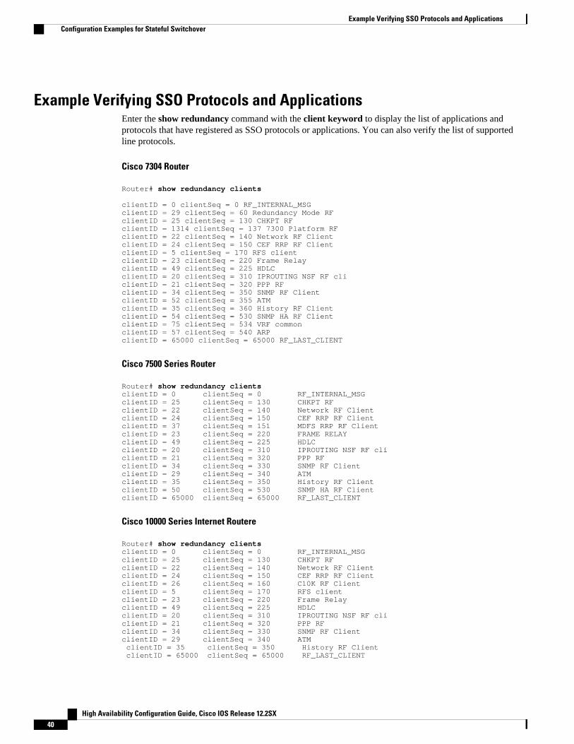
Example Verifying SSO Protocols and ApplicationsEnter the show redundancy command with the client keyword to display the list of applications andprotocols that have registered as SSO protocols or applications. You can also verify the list of supportedline protocols.
Cisco 7304 Router
Router# show redundancy clients clientID = 0 clientSeq = 0 RF_INTERNAL_MSG clientID = 29 clientSeq = 60 Redundancy Mode RF clientID = 25 clientSeq = 130 CHKPT RF clientID = 1314 clientSeq = 137 7300 Platform RF clientID = 22 clientSeq = 140 Network RF Client clientID = 24 clientSeq = 150 CEF RRP RF Client clientID = 5 clientSeq = 170 RFS client clientID = 23 clientSeq = 220 Frame Relay clientID = 49 clientSeq = 225 HDLC clientID = 20 clientSeq = 310 IPROUTING NSF RF cli clientID = 21 clientSeq = 320 PPP RF clientID = 34 clientSeq = 350 SNMP RF Client clientID = 52 clientSeq = 355 ATM clientID = 35 clientSeq = 360 History RF Client clientID = 54 clientSeq = 530 SNMP HA RF Client clientID = 75 clientSeq = 534 VRF common clientID = 57 clientSeq = 540 ARP clientID = 65000 clientSeq = 65000 RF_LAST_CLIENT
Cisco 7500 Series Router
Router# show redundancy clients clientID = 0 clientSeq = 0 RF_INTERNAL_MSG clientID = 25 clientSeq = 130 CHKPT RF clientID = 22 clientSeq = 140 Network RF Client clientID = 24 clientSeq = 150 CEF RRP RF Client clientID = 37 clientSeq = 151 MDFS RRP RF Client clientID = 23 clientSeq = 220 FRAME RELAYclientID = 49 clientSeq = 225 HDLC clientID = 20 clientSeq = 310 IPROUTING NSF RF cli clientID = 21 clientSeq = 320 PPP RF clientID = 34 clientSeq = 330 SNMP RF Client clientID = 29 clientSeq = 340 ATM clientID = 35 clientSeq = 350 History RF Client clientID = 50 clientSeq = 530 SNMP HA RF Client clientID = 65000 clientSeq = 65000 RF_LAST_CLIENT
Cisco 10000 Series Internet Routere
Router# show redundancy clients clientID = 0 clientSeq = 0 RF_INTERNAL_MSG clientID = 25 clientSeq = 130 CHKPT RF clientID = 22 clientSeq = 140 Network RF Client clientID = 24 clientSeq = 150 CEF RRP RF Client clientID = 26 clientSeq = 160 C10K RF Client clientID = 5 clientSeq = 170 RFS client clientID = 23 clientSeq = 220 Frame Relay clientID = 49 clientSeq = 225 HDLC clientID = 20 clientSeq = 310 IPROUTING NSF RF cli clientID = 21 clientSeq = 320 PPP RF clientID = 34 clientSeq = 330 SNMP RF Client clientID = 29 clientSeq = 340 ATM clientID = 35 clientSeq = 350 History RF Client clientID = 65000 clientSeq = 65000 RF_LAST_CLIENT
Example Verifying SSO Protocols and Applications Configuration Examples for Stateful Switchover
High Availability Configuration Guide, Cisco IOS Release 12.2SX40

Cisco 12000 Series Internet Router
Router# show redundancy clients clientID = 0 clientSeq = 0 RF_INTERNAL_MSGclientID = 25 clientSeq = 130 CHKPT RFclientID = 27 clientSeq = 132 C12K RF COMMON ClientclientID = 30 clientSeq = 135 Redundancy Mode RFclientID = 22 clientSeq = 140 Network RF ClientclientID = 24 clientSeq = 150 CEF RRP RF ClientclientID = 37 clientSeq = 151 MDFS RRP RF ClientclientID = 5 clientSeq = 170 RFS clientclientID = 23 clientSeq = 220 Frame RelayclientID = 49 clientSeq = 225 HDLCclientID = 20 clientSeq = 310 IPROUTING NSF RF cliclientID = 21 clientSeq = 320 PPP RFclientID = 34 clientSeq = 330 SNMP RF ClientclientID = 29 clientSeq = 340 ATMclientID = 35 clientSeq = 350 History RF ClientclientID = 50 clientSeq = 530 SNMP HA RF Client clientID = 65000 clientSeq = 65000 RF_LAST_CLIENT
Cisco ASR 1000 Series Router
Router# show redundancy clients clientID = 0 clientSeq = 0 RF_INTERNAL_MSG clientID = 29 clientSeq = 60 Redundancy Mode RF clientID = 139 clientSeq = 62 IfIndex clientID = 25 clientSeq = 69 CHKPT RF clientID = 1340 clientSeq = 90 ASR1000-RP Platform clientID = 1501 clientSeq = 91 Cat6k CWAN HA clientID = 78 clientSeq = 95 TSPTUN HA clientID = 305 clientSeq = 96 Multicast ISSU Conso clientID = 304 clientSeq = 97 IP multicast RF Clie clientID = 22 clientSeq = 98 Network RF Client clientID = 88 clientSeq = 99 HSRP clientID = 114 clientSeq = 100 GLBP clientID = 1341 clientSeq = 102 ASR1000 DPIDX clientID = 1505 clientSeq = 103 Cat6k SPA TSM clientID = 1344 clientSeq = 110 ASR1000-RP SBC RF clientID = 227 clientSeq = 111 SBC RF clientID = 71 clientSeq = 112 XDR RRP RF Client clientID = 24 clientSeq = 113 CEF RRP RF Client clientID = 146 clientSeq = 114 BFD RF Client clientID = 306 clientSeq = 120 MFIB RRP RF Client clientID = 1504 clientSeq = 128 Cat6k CWAN Interface clientID = 75 clientSeq = 130 Tableid HA clientID = 401 clientSeq = 131 NAT HA clientID = 402 clientSeq = 132 TPM RF client clientID = 5 clientSeq = 135 Config Sync RF clien clientID = 68 clientSeq = 149 Virtual Template RF clientID = 23 clientSeq = 152 Frame Relay clientID = 49 clientSeq = 153 HDLC clientID = 72 clientSeq = 154 LSD HA Proc clientID = 113 clientSeq = 155 MFI STATIC HA Proc clientID = 20 clientSeq = 171 IPROUTING NSF RF cli clientID = 100 clientSeq = 173 DHCPC clientID = 101 clientSeq = 174 DHCPD clientID = 74 clientSeq = 183 MPLS VPN HA Client clientID = 34 clientSeq = 185 SNMP RF Client clientID = 52 clientSeq = 186 ATM clientID = 69 clientSeq = 189 AAA clientID = 118 clientSeq = 190 L2TP clientID = 82 clientSeq = 191 CCM RF clientID = 35 clientSeq = 192 History RF Client clientID = 90 clientSeq = 204 RSVP HA Services clientID = 70 clientSeq = 215 FH COMMON RF CLIENT clientID = 54 clientSeq = 220 SNMP HA RF Client clientID = 73 clientSeq = 221 LDP HA clientID = 76 clientSeq = 222 IPRM clientID = 57 clientSeq = 223 ARP clientID = 50 clientSeq = 230 FH_RF_Event_Detector
Configuring Stateful SwitchoverConfiguration Examples for Stateful Switchover
High Availability Configuration Guide, Cisco IOS Release 12.2SX 41
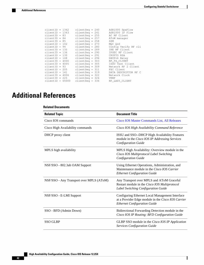
clientID = 1342 clientSeq = 240 ASR1000 SpaFlow clientID = 1343 clientSeq = 241 ASR1000 IF Flow clientID = 83 clientSeq = 255 AC RF Client clientID = 84 clientSeq = 257 AToM manager clientID = 85 clientSeq = 258 SSM clientID = 102 clientSeq = 273 MQC QoS clientID = 94 clientSeq = 280 Config Verify RF cli clientID = 135 clientSeq = 289 IKE RF Client clientID = 136 clientSeq = 290 IPSEC RF Client clientID = 130 clientSeq = 291 CRYPTO RSA clientID = 148 clientSeq = 296 DHCPv6 Relay clientID = 4000 clientSeq = 303 RF_TS_CLIENT clientID = 4005 clientSeq = 305 ISSU Test Client clientID = 93 clientSeq = 309 Network RF 2 Client clientID = 205 clientSeq = 311 FEC Client clientID = 141 clientSeq = 319 DATA DESCRIPTOR RF C clientID = 4006 clientSeq = 322 Network Clock clientID = 225 clientSeq = 326 VRRP clientID = 65000 clientSeq = 336 RF_LAST_CLIENT
Additional ReferencesRelated Documents
Related Topic Document Title
Cisco IOS commands Cisco IOS Master Commands List, All Releases
Cisco High Availability commands Cisco IOS High Availability Command Reference
DHCP proxy client ISSU and SSO--DHCP High Availability Featuresmodule in the Cisco IOS IP Addressing ServicesConfiguration Guide
MPLS high availability MPLS High Availability: Overview module in theCisco IOS Multiprotocol Label SwitchingConfiguration Guide
NSF/SSO - 802.3ah OAM Support Using Ethernet Operations, Administration, andMaintenance module in the Cisco IOS CarrierEthernet Configuration Guide
NSF/SSO - Any Transport over MPLS (AToM) Any Transport over MPLS and AToM GracefulRestart module in the Cisco IOS MultiprotocolLabel Switching Configuration Guide
NSF/SSO - E-LMI Support Configuring Ethernet Local Management Interfaceat a Provider Edge module in the Cisco IOS CarrierEthernet Configuration Guide
SSO - BFD (Admin Down) Bidirectional Forwarding Detection module in theCisco IOS IP Routing: BFD Configuration Guide
SSO GLBP GLBP SSO module in the Cisco IOS IP ApplicationServices Configuration Guide
Configuring Stateful Switchover Additional References
High Availability Configuration Guide, Cisco IOS Release 12.2SX42

Related Topic Document Title
SSO HSRP Configuring HSRP module in the Cisco IOS IPApplication Services Configuration Guide
• MFIB: IPv4 SSO/ISSU• NSF/SSO - IPv4 Multicast• SSO - IPv4 MFIB
Monitoring and Maintaining Multicast HAOperations (NSF/SSO and ISSU) module in theCisco IOS IP Multicast Configuration Guide
SSO and RPR on the Cisco ASR 1000 seriesrouters
Cisco ASR 1000 Series Aggregation ServicesRouters Software Configuration Guide
SSO VRRP Configuring VRRP module in the Cisco IOS IPApplication Services Configuration Guide
Basic IPv6 configuration Implementing IPv6 Addressing and BasicConnectivity module in the Cisco IOS IPv6Configuration Guide
Virtual Private LAN Services NSF/SSO/ISSU Support for VPLS module in theCisco IOS Multiprotocol Label SwitchingConfiguration Guide
Standards
Standard Title
No new or modified standards are supported by thisfeature, and support for existing standards has notbeen modified by this feature.
--
MIBs
MIB MIBs Link
No new or modified MIBs are supported, andsupport for existing MIBs has not been modified.
To locate and download MIBs for selectedplatforms, Cisco IOS releases, and feature sets, useCisco MIB Locator found at the following URL:
http://www.cisco.com/go/mibs
RFCs
RFC Title
No new or modified RFCs are supported by thisfeature.
--
Configuring Stateful SwitchoverAdditional References
High Availability Configuration Guide, Cisco IOS Release 12.2SX 43

Technical Assistance
Description Link
The Cisco Support and Documentation websiteprovides online resources to downloaddocumentation, software, and tools. Use theseresources to install and configure the software andto troubleshoot and resolve technical issues withCisco products and technologies. Access to mosttools on the Cisco Support and Documentationwebsite requires a Cisco.com user ID andpassword.
http://www.cisco.com/cisco/web/support/index.html
Feature Information for Stateful SwitchoverThe following table provides release information about the feature or features described in this module.This table lists only the software release that introduced support for a given feature in a given softwarerelease train. Unless noted otherwise, subsequent releases of that software release train also support thatfeature.
Use Cisco Feature Navigator to find information about platform support and Cisco software image support.To access Cisco Feature Navigator, go to http://www.cisco.com/go/cfn. An account on Cisco.com is notrequired.
Table 11: Feature Information for Cisco Stateful Switchover
Feature Name Releases Feature Information
Stateful Switchover (SSO) 12.0(22)S 12.0(23)S 12.0(24)S12.2(20)S 12.2(18)S12.2(33)SRA
This feature was introduced:
In 12.0(23)S, support was addedfor 1xGE and 3xGE line cards onthe
In 12.0(24)S, support was addedfor the following line cards on the
• Engine 1
◦ 2-port OC-12/STM-4cDPT
• Engine 2
◦ 1-port OC-48/STM-16cDPT
◦ 8-port OC-3/STM-1cATM
• IP Service Engine (ISE)
◦ 4-port OC-3c/STM-1cPOS/SDH ISE
Configuring Stateful Switchover Feature Information for Stateful Switchover
High Availability Configuration Guide, Cisco IOS Release 12.2SX44

Feature Name Releases Feature Information
◦ 8-port OC-3c/STM-1cPOS/SDH ISE
◦ 16-port OC-3c/STM-1cPOS/SDH ISE
◦ 4-port OC-12c/STM-4cPOS/SDH ISE
◦ 1-port OC-48c/STM-16c POS/SDHISE
◦ 4-port channelizedOC-12/STM-4 (DS3/E3, OC-3c/STM-1c)POS/SDH ISE
◦ 1-port channelizedOC-48/STM-16 (DS3/E3, OC-3c/STM-1c)POS/SDH ISE
In 12.0(26)S, support was addedfor the following line cards on the
• 4-port OC-12c/STM-4c DPTISE
In 12.2(20)S, support was addedfor the Cisco 7304 router.
CEM SSO/ISSU 12.2(33)SRC This feature was introduced.
Dynamic Host ConfigurationProtocol (DHCP) On DemandAddress Pool (ODAP) client/server
12.2(31)SB2 This feature was updated to beSSO-compliant.
MFIB: IPv4 SSO/ISSU 12.2(33)SRE This feature was introduced.
NSF/SSO - IPv4 Multicast 12.2(33)SRE This feature was introduced.
NSF/SSO - IPv6 Multicast 12.2(33)SRE This feature was introduced.
NSF/SSO--Virtual Private LANServices
12.2(33)SXI4 15.0(1)S This feature was introduced.
Route Processor RedundancyPlus (RPR+)
12.2(20)S This feature was introduced onthe Cisco 7304 router.
SSO- Automatic ProtectionSwitching (APS)
12.2(28)SB This feature was introduced.
SSO - BFD (Admin Down) 12.2(33)SB This feature was introduced.
Configuring Stateful SwitchoverFeature Information for Stateful Switchover
High Availability Configuration Guide, Cisco IOS Release 12.2SX 45
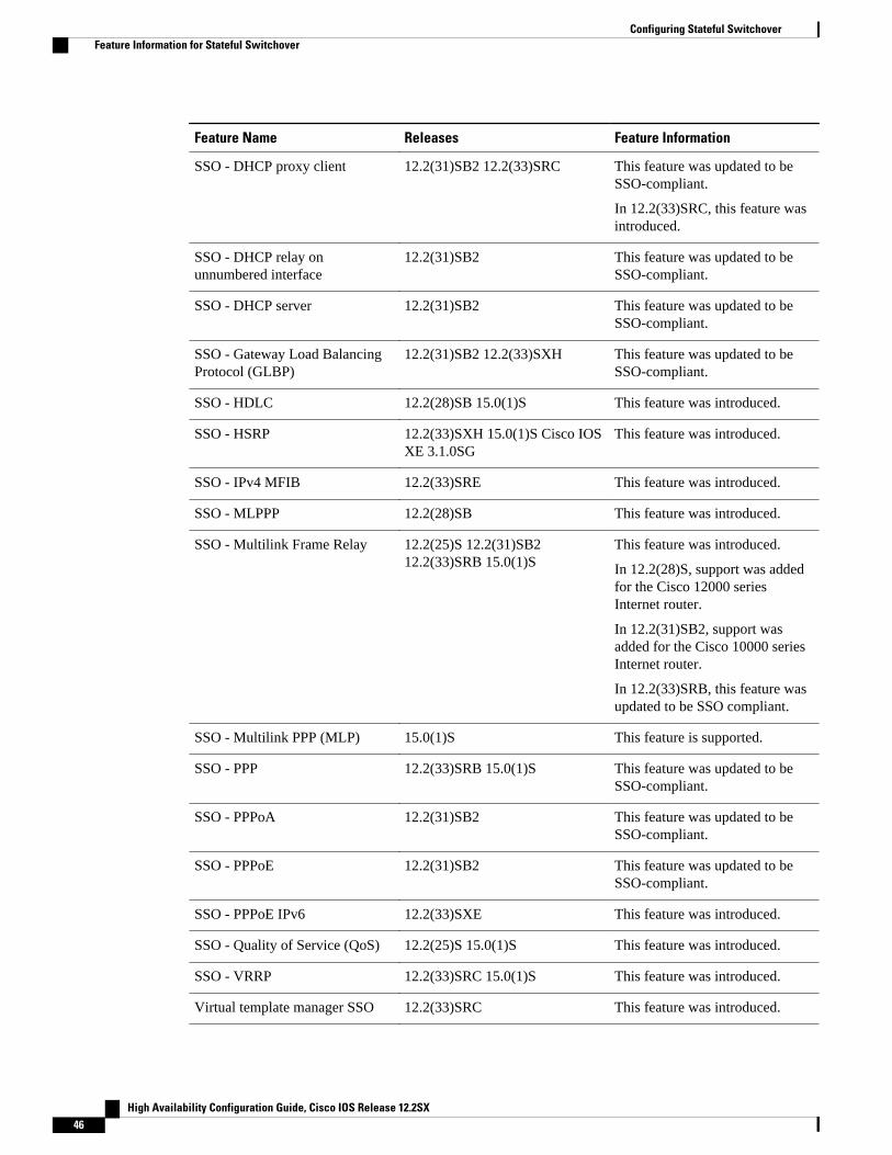
Feature Name Releases Feature Information
SSO - DHCP proxy client 12.2(31)SB2 12.2(33)SRC This feature was updated to beSSO-compliant.
In 12.2(33)SRC, this feature wasintroduced.
SSO - DHCP relay onunnumbered interface
12.2(31)SB2 This feature was updated to beSSO-compliant.
SSO - DHCP server 12.2(31)SB2 This feature was updated to beSSO-compliant.
SSO - Gateway Load BalancingProtocol (GLBP)
12.2(31)SB2 12.2(33)SXH This feature was updated to beSSO-compliant.
SSO - HDLC 12.2(28)SB 15.0(1)S This feature was introduced.
SSO - HSRP 12.2(33)SXH 15.0(1)S Cisco IOSXE 3.1.0SG
This feature was introduced.
SSO - IPv4 MFIB 12.2(33)SRE This feature was introduced.
SSO - MLPPP 12.2(28)SB This feature was introduced.
SSO - Multilink Frame Relay 12.2(25)S 12.2(31)SB212.2(33)SRB 15.0(1)S
This feature was introduced.
In 12.2(28)S, support was addedfor the Cisco 12000 seriesInternet router.
In 12.2(31)SB2, support wasadded for the Cisco 10000 seriesInternet router.
In 12.2(33)SRB, this feature wasupdated to be SSO compliant.
SSO - Multilink PPP (MLP) 15.0(1)S This feature is supported.
SSO - PPP 12.2(33)SRB 15.0(1)S This feature was updated to beSSO-compliant.
SSO - PPPoA 12.2(31)SB2 This feature was updated to beSSO-compliant.
SSO - PPPoE 12.2(31)SB2 This feature was updated to beSSO-compliant.
SSO - PPPoE IPv6 12.2(33)SXE This feature was introduced.
SSO - Quality of Service (QoS) 12.2(25)S 15.0(1)S This feature was introduced.
SSO - VRRP 12.2(33)SRC 15.0(1)S This feature was introduced.
Virtual template manager SSO 12.2(33)SRC This feature was introduced.
Configuring Stateful Switchover Feature Information for Stateful Switchover
High Availability Configuration Guide, Cisco IOS Release 12.2SX46

Cisco and the Cisco Logo are trademarks of Cisco Systems, Inc. and/or its affiliates in the U.S. and othercountries. A listing of Cisco's trademarks can be found at www.cisco.com/go/trademarks. Third partytrademarks mentioned are the property of their respective owners. The use of the word partner does notimply a partnership relationship between Cisco and any other company. (1005R)
Any Internet Protocol (IP) addresses and phone numbers used in this document are not intended to beactual addresses and phone numbers. Any examples, command display output, network topology diagrams,and other figures included in the document are shown for illustrative purposes only. Any use of actual IPaddresses or phone numbers in illustrative content is unintentional and coincidental.
Configuring Stateful Switchover
High Availability Configuration Guide, Cisco IOS Release 12.2SX 47

Example Verifying SSO Protocols and Applications
High Availability Configuration Guide, Cisco IOS Release 12.2SX48

Configuring Nonstop Forwarding
This module describes how to configure Nonstop Forwarding (NSF) in Cisco software to minimize theamount of time a network is unavailable to its users following a switchover. The main objective of NSF isto continue forwarding IP packets following a Route Processor (RP) switchover. NSF is supported by theBGP, EIGRP, IPv6, IS-IS, and OSPF protocols for routing and by CEF for forwarding.
The following terms are used throughout this document:
• NSF-aware device--A device that is running NSF-compatible software• NSF-capable device--A device that is configured to support NSF. NSF-capable devices can rebuild
routing information from either NSF-aware or NSF-capable neighboring devices.
• Finding Feature Information, page 49• Prerequisites for Nonstop Forwarding, page 49• Restrictions for Nonstop Forwarding, page 50• Information About Nonstop Forwarding, page 51• How to Configure Nonstop Forwarding, page 59• Configuration Examples for Nonstop Forwarding, page 69• Additional References, page 72• Feature Information for Nonstop Forwarding, page 74• , page 77
Finding Feature InformationYour software release may not support all the features documented in this module. For the latest featureinformation and caveats, see the release notes for your platform and software release. To find informationabout the features documented in this module, and to see a list of the releases in which each feature issupported, see the Feature Information Table at the end of this document.
Use Cisco Feature Navigator to find information about platform support and Cisco software image support.To access Cisco Feature Navigator, go to http://www.cisco.com/go/cfn. An account on Cisco.com is notrequired.
Prerequisites for Nonstop Forwarding• The networking device that is to be configured for NSF must first be configured for SSO. For
information, see the Configuring Stateful Switchover section.
High Availability Configuration Guide, Cisco IOS Release 12.2SX 49
• For Border Gateway Protocol (BGP) NSF, all neighboring devices must be NSF-aware and must beconfigured for BGP graceful restart.
• For Enhanced Interior Gateway Routing Protocol (EIGRP) NSF:
◦ All neighboring devices must be NSF-capable or NSF-aware.◦ An NSF-aware device must be completely converged with the network before it can assist an
NSF-capable device in an NSF restart operation.• For Internet Engineering Task Force (IETF) Intermediate System to Intermediate System (IS-IS), all
neighboring devices must be NSF-aware.• For Open Shortest Path First (OSPF) NSF, all networking devices on the same network segment must
be NSF-aware.• For IPv6 NSF, IPv6 must be enabled on your networking device.• On platforms supporting the Route Switch Processor (RSP), and where the Cisco Express Forwarding
(CEF) switching mode is configurable, configure distributed CEF (dCEF) switching mode using the ipcef distributed command.
Restrictions for Nonstop Forwarding• General Restrictions, page 50
• BGP NSF Restrictions, page 50
• EIGRP NSF Restrictions, page 50
• OSPF NSF Restrictions, page 51
• Cisco7200SeriesRouterRestrictions, page 51
General Restrictions• The Hot Standby Routing Protocol (HSRP) is not supported with Cisco NSF with SSO. Do not use
HSRP with Cisco NSF with SSO.• NSF capability is not enabled by default for OSPF, ISIS, or BGP. NSF capability is enabled by default
for EIGRP only.
BGP NSF Restrictions• BGP support in NSF requires that neighbor networking devices be NSF-aware. If an NSF-capable
device discovers that a particular BGP neighbor does not have graceful restart capability, it will notestablish an NSF-capable session with that neighbor. All other neighbors that have graceful restartcapability will continue to have NSF-capable sessions with this NSF-capable networking device.
• All devices must be configured with the same type of NSF helper mode, either IETF graceful restart orCisco NSF.
EIGRP NSF Restrictions• An NSF-aware device cannot support two NSF-capable peers performing an NSF restart operation at
the same time. However, both neighbors will reestablish peering sessions after the NSF restartoperation is complete.
General Restrictions Restrictions for Nonstop Forwarding
High Availability Configuration Guide, Cisco IOS Release 12.2SX50

• Distributed platforms that run a supporting version of Cisco software can support full NSFcapabilities. These devices can perform a restart operation and can support other NSF capable peers.
• Single processor platforms that run a supporting version of Cisco software support only NSFawareness. These devices maintain adjacency and hold known routes for the NSF-capable neighboruntil it signals that it is ready for the NSF-aware device to send its topology table or the route-holdtimer expires.
OSPF NSF Restrictions• OSPF NSF for virtual links is not supported.• OSPF NSF for sham links is not supported.• OSPF NSF supports NSF/SSO for IPv4 traffic only.• OSPFv3 is not supported with NSF/SSO. Only OSPFv2 is supported with NSF/SSO.• All neighbor networking devices must be NSF-aware. If an NSF-capable device discovers that it has
non-NSF-aware neighbors on a particular network segment, it will disable NSF capabilities for thatsegment. Other network segments composed entirely of NSF-capable or NSF-aware devices willcontinue to provide NSF capabilities.
• You can configure strict link state advertisement (LSA) checking on both NSF-aware and NSF-capable devices; however, it is effective only when the device is in helper mode.
Cisco7200SeriesRouterRestrictions• The Cisco 7200 series router has a single CPU and cannot support the stateful switchover in the event
of a network processor engine (NPE) fault.• The Cisco 7206 supports NSF and can operate in a peer role with a Cisco 7500, 10000, or 12000 series
router running Cisco IOS Release 12.0(23)S or a later release. With NSF enabled, an RP switchoveron the Cisco 7500, 10000, or 12000 series router peer should not cause a loss of PPP, ATM, high-leveldata link control (HDLC), or Frame Relay sessions, or a loss of any OSPF, BGP, or IS-IS adjacenciesestablished between the Cisco 7200 and the peer.
Information About Nonstop Forwarding• Nonstop Forwarding, page 51
• Cisco NSF Routing and Forwarding, page 52
• Cisco Express Forwarding and NSF, page 54
• BGP NSF Operations, page 55
• EIGRP NSF Operations, page 56
• IPv6 support for NSF Operations, page 56
• IS-IS NSF Operations, page 57
• OSPF NSF Operations, page 58
Nonstop Forwarding
OSPF NSF RestrictionsInformation About Nonstop Forwarding
High Availability Configuration Guide, Cisco IOS Release 12.2SX 51

Note Throughout this document, the term Route Processor (RP) is used to describe the route processing engineon all networking devices, regardless of the platform designation, unless otherwise noted.
NSF works with the SSO feature in Cisco software to minimize the amount of time a network isunavailable to its users following a switchover. The main objective of NSF is to continue forwarding IPpackets following an RP switchover.
Usually, when a networking device restarts, all routing peers of that device detect that the device wentdown and then came back up. This transition results in what is called a routing flap, which could spreadacross multiple routing domains. Routing flaps caused by routing restarts create routing instabilities, whichare detrimental to the overall network performance. NSF helps to suppress routing flaps in SSO-enableddevices, thus reducing network instability.
NSF allows for the forwarding of data packets to continue along known routes while the routing protocolinformation is being restored following a switchover. With NSF, peer networking devices do notexperience routing flaps. Data traffic is forwarded through intelligent line cards or dual forwardingprocessors (FPs) while the standby RP assumes control from the failed active RP during a switchover. Theability of line cards and FPs to remain up through a switchover and to be kept current with the ForwardingInformation Base (FIB) on the active RP is key to NSF operation.
The NSF feature provides the following benefits:
• Improved network availability--NSF continues forwarding network traffic and application stateinformation so that user session information is maintained after a switchover.
• Overall network stability--Network stability may be improved with the reduction in the number ofroute flaps that had been created when devices in the network failed and lost their routing tables.
• Neighboring devices do not detect link flapping--Because the interfaces remain up across aswitchover, neighboring devices do not detect a link flap (that is, the link does not go down and comeback up).
• Prevents routing flaps--Because SSO continues forwarding network traffic in the event of aswitchover, routing flaps are avoided.
• No loss of user sessions--User sessions established prior to the switchover are maintained.
NSF always runs together with SSO. SSO supported protocols and applications must be high-availability(HA)-aware. A feature or protocol is HA-aware if it maintains, either partially or completely, undisturbedoperation through an RP switchover. For some HA-aware protocols and applications, state information issynchronized from the active to the standby processor. For Cisco NSF, enhancements to the routingprotocols (CEF; OSPF; BGP; and IS-IS) have been made to support the HA features in SSO.
Cisco NSF Routing and ForwardingCisco NSF is supported by the BGP, EIGRP, IPv6, IS-IS, and OSPF protocols for routing and by CEF forforwarding. Of the routing protocols, BGP, EIGRP, IPv6, IS-IS, and OSPF have been enhanced with NSF-capability and awareness, which means that devices running these protocols can detect a switchover andtake the necessary actions to continue forwarding network traffic and to recover route information from thepeer devices. The IS-IS protocol can be configured to use state information that has been synchronizedbetween the active and the standby RP to recover route information following a switchover instead ofinformation received from peer devices.
Each protocol depends on CEF to continue forwarding packets during switchover while the routingprotocols rebuild the Routing Information Base (RIB) tables. Once the routing protocols have converged,CEF updates the FIB table and removes stale route entries. CEF, in turn, updates the line cards with thenew FIB information.
Cisco NSF Routing and Forwarding Information About Nonstop Forwarding
High Availability Configuration Guide, Cisco IOS Release 12.2SX52

• Routing Protocols and CEF Support in Cisco NSF, page 53
Routing Protocols and CEF Support in Cisco NSFThe table below lists the routing protocol and CEF support in Cisco NSF.
Table 12: Routing Protocol and CEF Support in Cisco NSF
Protocol Platform NSFSupport inCisco IOSSoftwareRelease
12.0(22)S 12.0(23)S 12.0(24)S 12.2(18)S 12.2(28)SB 12.2(33)SRA
BGP Cisco 7200 Yes2 Yes Yes No3 No No
Cisco 7304 No No No No Yes No
Cisco 7500 Yes Yes Yes Yes No No
Cisco 7600 No No No No No Yes
Cisco10000
Yes Yes Yes No Yes No
Cisco12000
Yes Yes Yes No No No
OSPF Cisco 7200 Yes Yes Yes No No No
Cisco 7304 No No No No Yes No
Cisco 7500 Yes Yes Yes Yes No No
Cisco 7600 No No No No No Yes
Cisco10000
Yes Yes Yes No No No
Cisco12000
Yes Yes Yes No No No
IS-IS Cisco 7200 Yes Yes Yes No No No
Cisco 7304 No No No No Yes No
Cisco 7500 Yes Yes Yes Yes No No
2 The Cisco 7200 is a single-route processor system and cannot maintain its forwarding table in the event of a route processor failure. It cannot performnonstop forwarding of packets. However, it supports the NSF protocol extensions for BGP, EIGRP, OSPF, and IS-IS. Therefore, it can peer with NSF-capable routers and facilitate the resynchronization of routing information with such routers.
3 The Cisco 7200 is NSF-aware in Cisco IOS Release 12.2(18)S.
Configuring Nonstop ForwardingRouting Protocols and CEF Support in Cisco NSF
High Availability Configuration Guide, Cisco IOS Release 12.2SX 53

Protocol Platform NSFSupport inCisco IOSSoftwareRelease
Cisco 7600 No No No No No Yes
Cisco10000
Yes Yes Yes No Yes No
Cisco12000
Yes Yes Yes No No No
CEF Cisco72004
-- -- -- -- -- --
Cisco 7304 No No No No Yes No
Cisco 7500 Yes Yes Yes Yes No No
Cisco 7600 No No No No No Yes
Cisco10000
Yes Yes Yes No No No
Cisco12000
Yes Yes Yes No No No
EIGRP Cisco 7200 No No No Yes No No
Cisco 7304 No No No No Yes No
Cisco 7500 No No No Yes No No
Cisco 7600 No No No No No Yes
Cisco10000
No No No No No No
Cisco12000
No No No No No No
Cisco Express Forwarding and NSFA key element of NSF is packet forwarding. In a Cisco networking device, packet forwarding is providedby CEF. CEF maintains the FIB, and uses the FIB information that was current at the time of theswitchover to continue forwarding packets during a switchover. This feature reduces traffic interruptionduring the switchover.
During normal NSF operation, CEF on the active RP synchronizes its current FIB and adjacency databaseswith the FIB and adjacency databases on the standby RP. Upon switchover of the active RP, the standbyRP initially has FIB and adjacency databases that are mirror images of those that were current on the active
4 The Cisco 7200 is a single-processor device and does not support SSO; therefore, CEF support for NSF does not apply.
Cisco Express Forwarding and NSF Routing Protocols and CEF Support in Cisco NSF
High Availability Configuration Guide, Cisco IOS Release 12.2SX54

RP. For platforms with intelligent line cards, the line cards will maintain the current forwardinginformation over a switchover; for platforms with forwarding engines, CEF will keep the forwardingengine on the standby RP current with changes that are sent to it by CEF on the active RP. In this way, theline cards or forwarding engines will be able to continue forwarding after a switchover as soon as theinterfaces and a data path are available.
As the routing protocols start to repopulate the RIB on a prefix-by-prefix basis, the updates in turn causeprefix-by-prefix updates to CEF, which it uses to update the FIB and adjacency databases. Existing andnew entries will receive the new version (“epoch”) number, indicating that they have been refreshed. Theforwarding information is updated on the line cards or forwarding engine during convergence. The RPsignals when the RIB has converged. The software removes all FIB and adjacency entries that have anepoch older than the current switchover epoch. The FIB now represents the newest routing protocolforwarding information.
The routing protocols run only on the active RP, and they receive routing updates from their neighbordevices. Routing protocols do not run on the standby RP. Following a switchover, the routing protocolsrequest that the NSF-aware neighbor devices send state information to help rebuild the routing tables.Alternately, the IS-IS protocol can be configured to synchronize state information from the active to thestandby RP to help rebuild the routing table on the NSF-capable device in environments where neighbordevices are not NSF-aware.
For NSF operation, the routing protocols depend on CEF to continue forwarding packets while the routingprotocols rebuild the routing information. The CEF NSF feature operates by default while the networkingdevice is running in SSO mode. No configuration is necessary.
BGP NSF OperationsWhen a NSF-capable device begins a BGP session with a BGP peer, it sends an OPEN message to the peer.Included in the message is a declaration that the NSF-capable device has “graceful restart capability.”Graceful restart is the mechanism by which BGP routing peers avoid a routing flap following a switchover.If the BGP peer has received this capability, it is aware that the device sending the message is NSF-capable. Both the NSF-capable device and its BGP peers need to exchange the graceful restart capability intheir OPEN messages, at the time of session establishment. If both the peers do not exchange the gracefulrestart capability, the session will not be graceful restart capable.
If the BGP session is lost during the RP switchover, the NSF-aware BGP peer marks all the routesassociated with the NSF-capable device as stale; however, it continues to use these routes to makeforwarding decisions for a set period of time. This functionality means that no packets are lost while thenewly active RP is waiting for convergence of the routing information with the BGP peers.
After an RP switchover occurs, the NSF-capable device reestablishes the session with the BGP peer. Inestablishing the new session, it sends a new graceful restart message that identifies the NSF-capable deviceas having restarted.
At this point, the routing information is exchanged between the two BGP peers. Once this exchange iscomplete, the NSF-capable device uses the routing information to update the RIB and the FIB with the newforwarding information. The NSF-aware device uses the network information to remove stale routes fromits BGP table. Following that, the BGP protocol is fully converged.
If a BGP peer does not support the graceful restart capability, it will ignore the graceful-restart capability inan OPEN message but will establish a BGP session with the NSF-capable device. This function will allowinteroperability with non-NSF-aware BGP peers (and without NSF functionality), but the BGP session withnon-NSF-aware BGP peers will not be graceful restart-capable.
BGP support in NSF requires that neighbor networking devices be NSF-aware; that is, the devices musthave the graceful restart capability and advertise that capability in their OPEN message during sessionestablishment. If an NSF-capable device discovers that a particular BGP neighbor does not have graceful
BGP NSF OperationsRouting Protocols and CEF Support in Cisco NSF
High Availability Configuration Guide, Cisco IOS Release 12.2SX 55

restart capability, it will not establish an NSF-capable session with that neighbor. All other neighbors thathave graceful restart capability will continue to have NSF-capable sessions with this NSF-capablenetworking device.
EIGRP NSF OperationsEIGRP NSF capabilities are exchanged by EIGRP peers in hello packets. The NSF-capable device notifiesits neighbors that an NSF restart operation has started by setting the restart (RS) bit in a hello packet. Whenan NSF-aware device receives notification from an NSF-capable neighbor that an NSF-restart operation isin progress, the NSF-capable and NSF-aware devices immediately exchange their topology tables. TheNSF-aware device sends an end-of-table (EOT) update packet when the transmission of its topology tableis complete. The NSF-aware device then performs the following actions to assist the NSF-capable device:
• The EIGRP hello hold timer is expired to reduce the time interval set for hello packet generation andtransmission. This allows the NSF-aware device to reply to the NSF-capable device more quicklyreducing the amount of time required for the NSF-capable device to rediscover neighbors and rebuildthe topology table.
• The route-hold timer is started. This timer is used to set the period of time that the NSF-aware devicewill hold known routes for the NSF-capable neighbor.
• The NSF-aware device notes in the peer list that the NSF-capable neighbor is restarting, maintainsadjacency, and holds known routes for the NSF-capable neighbor until the neighbor signals that it isready for the NSF-aware device to send its topology table or the route-hold timer expires. If the route-hold timer expires on the NSF-aware device, the NSF-aware device will discard held routes and treatthe NSF-capable device as a new device joining the network and reestablishing adjacency accordingly.
• The NSF-aware device will continue to send queries to the NSF-capable device that is still convergingafter switchover, effectively extending the time before a stuck-in-active (SIA) condition can occur.
When the switchover operation is complete, the NSF-capable device notifies its neighbors that it hasreconverged and has received all of their topology tables by sending an EOT update packet to the assistingdevices. The NSF-capable device then returns to normal operation. The NSF-aware device will look foralternate paths (go active) for any routes that are not refreshed by the NSF-capable (restarting device). TheNSF-aware device will then return to normal operation. If all paths are refreshed by the NSF-capabledevice, the NSF-aware device will immediately return to normal operation.
NSF-aware devices are completely compatible with non-NSF aware or -capable neighbors in an EIGRPnetwork. A non-NSF-aware neighbor will ignore NSF capabilities and reset adjacencies and otherwisemaintain the peering sessions normally.
IPv6 support for NSF Operations• Nonstop Forwarding and Graceful Restart for MP-BGP IPv6 Address Family, page 56• Nonstop Forwarding for IPv6 RIP, page 57• Nonstop Forwarding for Static Routes, page 57
Nonstop Forwarding and Graceful Restart for MP-BGP IPv6 Address FamilyThe graceful restart capability is supported for IPv6 BGP unicast, multicast, and VPNv6 address families,enabling Cisco NSF functionality for BGP IPv6. The BGP graceful restart capability allows the BGProuting table to be recovered from peers without keeping the TCP state.
NSF continues forwarding packets while routing protocols converge, therefore avoiding a route flap onswitchover. Forwarding is maintained by synchronizing the FIB between the active and standby RP. On
EIGRP NSF Operations Nonstop Forwarding and Graceful Restart for MP-BGP IPv6 Address Family
High Availability Configuration Guide, Cisco IOS Release 12.2SX56

switchover, forwarding is maintained using the FIB. The RIB is not kept synchronized; therefore, the RIBis empty on switchover. The RIB is repopulated by the routing protocols and subsequently informs the FIBabout RIB convergence by using the NSF_RIB_CONVERGED registry call. The FIB tables are updatedfrom the RIB, removing any stale entries. The RIB starts a fail-safe timer during RP switchover, in case therouting protocols fail to notify the RIB of convergence.
The Cisco BGP address family identifier (AFI) model is modular and scalable, and supports multiple AFIsand subsequent address family identifier (SAFI) configurations.
Nonstop Forwarding for IPv6 RIPRIP registers as an IPv6 NSF client. Doing so has the benefit of using RIP routes installed in the CiscoExpress Forwarding table until RIP has converged on the standby.
Nonstop Forwarding for Static RoutesCisco NSF supports IPv6 static routes.
IS-IS NSF OperationsWhen an IS-IS NSF-capable device performs an RP switchover, it must perform two tasks in order toresynchronize its Link State Database with its IS-IS neighbors. First, it must relearn the available IS-ISneighbors on the network without causing a reset of the neighbor relationship. Second, it must reacquire thecontents of the Link State Database for the network.
The IS-IS NSF feature offers two options when configuring NSF:
• IETF IS-IS• Cisco IS-IS
If neighbor devices on a network segment are NSF-aware, meaning that neighbor devices are running asoftware version that supports the IETF Internet draft for device restartability, they will assist an IETF NSFdevice that is restarting. With IETF, neighbor devices provide adjacency and link-state information to helprebuild the routing information following a switchover. A benefit of IETF IS-IS configuration is operationbetween peer devices based on a proposed standard.
If you configure IETF on the networking device, but neighbor devices are not IETF-compatible, NSF willabort following a switchover.
If the neighbor devices on a network segment are not NSF-aware, you must use the Cisco configurationoption. The Cisco IS-IS configuration transfers both protocol adjacency and link-state information from theactive to the standby RP. A benefit of Cisco configuration is that it does not rely on NSF-aware neighbors.
• IETF IS-IS Configuration, page 57
• Cisco IS-IS Configuration, page 58
IETF IS-IS ConfigurationWith the IETF IS-IS configuration, the NSF-capable device sends IS-IS NSF restart requests to neighboringNSF-aware devices as quickly as possible after an RP switchover. Neighbor networking devices recognizethis restart request as a cue that the neighbor relationship with this device should not be reset, but that theyshould initiate database resynchronization with the restarting device. As the restarting device receivesrestart request responses from devices on the network, it can begin to rebuild its neighbor list.
IS-IS NSF OperationsNonstop Forwarding for IPv6 RIP
High Availability Configuration Guide, Cisco IOS Release 12.2SX 57

Once this exchange is complete, the NSF-capable device uses the link-state information to remove staleroutes, update the RIB, and update the FIB with the new forwarding information. IS-IS is then fullyconverged.
The switchover from one RP to the other happens within seconds. IS-IS reestablishes its routing table andresynchronizes with the network within a few additional seconds. At this point, IS-IS waits for a specifiedinterval before it will attempt a second NSF restart. During this time, the new standby RP will boot up andsynchronize its configuration with the active RP. The IS-IS NSF operation waits for a specified interval toensure that connections are stable before attempting another restart of IS-IS NSF. This functionalityprevents IS-IS from attempting back-to-back NSF restarts with stale information.
Cisco IS-IS ConfigurationWith the Cisco configuration option, full adjacency and link-state packet (LSP) information is saved, or“checkpointed,” to the standby RP. Following a switchover, the newly active RP maintains its adjacenciesusing the checkpointed data, and can quickly rebuild its routing tables.
The switchover from one RP to the other happens within seconds. IS-IS reestablishes its routing table andresynchronizes with the network within a few additional seconds. At this point, IS-IS waits for a specifiedinterval before it will attempt a second NSF restart. During this time, the new standby RP will boot up andsynchronize its configuration with the active RP. Once this synchronization is completed, IS-IS adjacencyand LSP data is checkpointed to the standby RP; however, a new NSF restart will not be attempted by IS-ISuntil the interval time expires. This functionality prevents IS-IS from attempting back-to-back NSF restarts.IS-IS NSF provides a command to extend the wait time for interfaces that, for whatever reason, do notcome up in a timely fashion.
Following a switchover, Cisco IS-IS NSF has complete neighbor adjacency and LSP information; however,it must wait for all interfaces that had adjacencies prior to the switchover to come up. If an interface doesnot come up within the allocated interface wait time, the routes learned from these neighbor devices are notconsidered in routing table recalculation.
OSPF NSF OperationsBefore an OSPF NSF-capable device can perform an RP switchover, it must relearn the available OSPFneighbors on the network, without resetting the neighbor relationship, and it must reacquire the contents ofthe Link State Database for the network.
To do this, the NSF-capable device sends an OSPF NSF signal to neighboring NSF-aware devices to notifythe devices that the neighbor relationship with the sending device must not be reset. Then the NSF-capabledevice uses the signals it receives from other devices on the network to rebuild its neighbor list.
Next, the NSF-capable device resynchronizes its database with all of the NSF-aware neighbors on its list.After all of the neighbors exchange routing information, the NSF-capable device uses the routinginformation to remove stale routes, update the RIB, and update the FIB with the new forwardinginformation. The OSPF protocols are then fully converged.
Prior to RFC 3623, Cisco implemented the proprietary Cisco NSF. The RFC 3623 Graceful OSPF Restartfeature supports IETF NSF for OSPF processes in multivendor networks. The NSF device modes ofoperation common to the Cisco and IETF NSF implementations are as follows:
• Restarting mode--In this mode, the OSPF device is performing nonstop forwarding recovery becauseof an RP switchover.
• Helper mode--Also known as NSF-awareness. In this mode, the neighboring device is restarting andhelping in the NSF recovery.
The strict LSA checking feature allows a helper device to terminate the graceful restart process if it detectsa changed LSA that would cause flooding during the graceful restart process. Strict LSA checking is
OSPF NSF Operations Cisco IS-IS Configuration
High Availability Configuration Guide, Cisco IOS Release 12.2SX58

disabled by default. You can enable strict LSA checking when there is a change to an LSA that would beflooded to the restarting device.
How to Configure Nonstop Forwarding• Configuring and Verifying BGP NSF, page 59
• Configuring and Verifying EIGRP NSF, page 60
• Configuring OSPF NSF, page 62
• Configuring and Verifying IS-IS NSF, page 65
• Troubleshooting Nonstop Forwarding, page 66
Configuring and Verifying BGP NSFRepeat this procedure on each peer device.
SUMMARY STEPS
1. enable
2. configure terminal
3. router bgp autonomous-system-number
4. bgp graceful-restart [restart-time seconds | stalepath-time seconds]
5. end
6. show ip bgp neighbors [ip-address [advertised-routes | dampened-routes | flap-statistics | paths[reg-exp] | received prefix-filter | received-routes | routes | policy[detail]]]
DETAILED STEPS
Command or Action Purpose
Step 1 enable
Example:
Router> enable
Enables privileged EXEC mode.
• Enter your password if prompted.
Step 2 configure terminal
Example:
Router# configure terminal
Enters global configuration mode.
Step 3 router bgp autonomous-system-number
Example:
Router(config)# router bgp 120
Enables a BGP routing process, and entersrouter configuration mode.
Step 4 bgp graceful-restart [restart-time seconds | stalepath-time seconds] Enables the BGP graceful restart capability,which starts NSF for BGP.
Configuring and Verifying BGP NSFHow to Configure Nonstop Forwarding
High Availability Configuration Guide, Cisco IOS Release 12.2SX 59

Command or Action Purpose
Example:
Router(config-router)# bgp graceful-restart
Step 5 end
Example:
Router(config-router)# end
Exits to privileged EXEC mode.
Step 6 show ip bgp neighbors [ip-address [advertised-routes | dampened-routes | flap-statistics | paths [reg-exp] | received prefix-filter | received-routes | routes | policy[detail]]]
Example:
Router# show ip bgp neighbors
Displays information about BGP and TCPconnections to neighbors.
Configuring and Verifying EIGRP NSFRepeat this procedure on each peer device.
SUMMARY STEPS
1. enable
2. configure terminal
3. router eigrp as-number
4. nsf
5. timers nsf converge seconds
6. timers nsf signal seconds
7. timers nsf route-hold seconds
8. timers graceful-restart purge-time seconds
9. end
10. show ip protocols
DETAILED STEPS
Command or Action Purpose
Step 1 enable
Example:
Router> enable
Enables privileged EXEC mode.
• Enter your password if prompted.
Step 2 configure terminal Enters global configuration mode.
Configuring and Verifying EIGRP NSF How to Configure Nonstop Forwarding
High Availability Configuration Guide, Cisco IOS Release 12.2SX60

Command or Action Purpose
Example:
Router# configure terminal
Step 3 router eigrp as-number
Example:
Router(config)# router eigrp 109
Enables an EIGRP routing process, and enters router configurationmode.
Step 4 nsf
Example:
Router(config)# no nsf
(Optional) Enables NSF capabilities.
• This command is enabled by default.
Step 5 timers nsf converge seconds
Example:
Router(config-router)# timers nsf converge 120
(Optional) Adjusts the maximum time that the restarting device willwait for the EOT notification from an NSF-capable or NSF-awarepeer.
• Enter this command on NSF-capable devices only.
Step 6 timers nsf signal seconds
Example:
Router(config-router)# timers nsf signal 20
(Optional) Adjusts the maximum time for the initial restart period.
• Enter this command on NSF-capable devices only.
Step 7 timers nsf route-hold seconds
Example:
Router(config-router)# timers nsf route-hold 240
(Optional) Sets the route-hold timer to determine how long an NSF-aware EIGRP device will hold routes for an inactive peer.
• This command is suported in releases before Cisco IOS12.2(33)SRE.
Step 8 timers graceful-restart purge-time seconds
Example:
Router(config-router)# timers graceful-restart purge-time 240
(Optional) Sets the route-hold timer to determine how long an NSF-aware EIGRP device will hold routes for an inactive peer.
• This command is supported in Cisco IOS Release 12.2(33)SREand later releases.
Step 9 end
Example:
Router(config-router)# end
Exits to privileged EXEC mode.
Step 10 show ip protocols Displays the parameters and current state of the active routingprotocol process.
Configuring Nonstop ForwardingHow to Configure Nonstop Forwarding
High Availability Configuration Guide, Cisco IOS Release 12.2SX 61

Command or Action Purpose
Example:
Router# show ip protocols
Configuring OSPF NSFPerform only one of the following tasks:
• Configuring Cisco NSF for OSPF, page 62
• Configuring IETF NSF for OSPF, page 63
Configuring Cisco NSF for OSPF
SUMMARY STEPS
1. enable
2. configure terminal
3. router ospf process-id [vrf vpn-name]
4. nsf cisco [enforce global]
5. no nsf cisco helper disable
6. nsf ietf helper disable
7. end
8. show ip ospf nsf
DETAILED STEPS
Command or Action Purpose
Step 1 enable
Example:
Router> enable
Enables privileged EXEC mode.
• Enter your password if prompted.
Step 2 configure terminal
Example:
Router# configure terminal
Enters global configuration mode.
Step 3 router ospf process-id [vrf vpn-name]
Example:
Router(config)# router ospf 12
Enables OSPF and enters router configuration mode.
Step 4 nsf cisco [enforce global] Enables Cisco NSF restarting mode.
Configuring OSPF NSF Configuring Cisco NSF for OSPF
High Availability Configuration Guide, Cisco IOS Release 12.2SX62

Command or Action Purpose
Example:
Router(config-router)# nsf cisco
• This command is not required on devices that willoperate in NSF helper mode only.
Step 5 no nsf cisco helper disable
Example:
Router(config-router)# no nsf cisco helper disable
(Optional) Reeneables Cisco NFS helper support.
• This command is included here only to show how toreenable Cisco NSF helper mode if helper mode wasexplicitly disabled
Step 6 nsf ietf helper disable
Example:
Router(config-router)# nsf ietf helper disable
(Optional) Disables IETF NSF helper mode on an NSF-awaredevice.
Step 7 end
Example:
Router(config-router)# end
Exits to privileged EXEC mode.
Step 8 show ip ospf nsf
Example:
Router# show ip ospf nsf
Displays OSPF NSF state information
Configuring IETF NSF for OSPF
SUMMARY STEPS
1. enable
2. configure terminal
3. router ospf process-id [vrf vpn-name]
4. nsf ietf [restart-interval seconds]
5. nsf ietf [helper [disable | strict-lsa-checking]]
6. no nsf ietf helper disable
7. nsf cisco helper disable
8. end
9. show ip ospf nsf
DETAILED STEPS
Command or Action Purpose
Step 1 enable Enables privileged EXEC mode.
Configuring Nonstop ForwardingConfiguring IETF NSF for OSPF
High Availability Configuration Guide, Cisco IOS Release 12.2SX 63

Command or Action Purpose
Example:
Router> enable
• Enter your password if prompted.
Step 2 configure terminal
Example:
Router# configure terminal
Enters global configuration mode.
Step 3 router ospf process-id [vrf vpn-name]
Example:
Router(config)# router ospf 12
Enables OSPF and enters router configuration mode.
Step 4 nsf ietf [restart-interval seconds]
Example:
Router(config-router)# nsf ietf restart-interval 180
Enables IETF NSF restarting mode.
• This command is not required on devices that willoperate in helper mode only.
Step 5 nsf ietf [helper [disable | strict-lsa-checking]]
Example:
Router(config-router)# nsf ietf helper strict-lsa-checking
(Optional) Configures IETF NSF helper mode on neighbordevices that will operate in helper mode.
Step 6 no nsf ietf helper disable
Example:
Router(config-router)# no nsf ietf helper disable
(Optional) Reenables IETF NSF helper mode.
• This command is included here only to show how toreenable IETF NSF helper mode if helper mode wasexpliciltly disabled.
Step 7 nsf cisco helper disable
Example:
Router(config-router)# nsf cisco helper disable
(Optional) Disables Cisco NSF helper mode on an NSF-aware device.
Step 8 end
Example:
Router(config-router)# end
Exits to privileged EXEC mode.
Step 9 show ip ospf nsf
Example:
Router# show ip ospf nsf
Displays OSPF NSF state information
Configuring Nonstop Forwarding Configuring IETF NSF for OSPF
High Availability Configuration Guide, Cisco IOS Release 12.2SX64

Configuring and Verifying IS-IS NSF
SUMMARY STEPS
1. enable
2. configure terminal
3. router isis area-tag
4. nsf [cisco | ietf]
5. nsf interval minutes
6. nsf t3 {manual seconds | adjacency}
7. nsf interface wait seconds
8. end
9. show isis nsf
DETAILED STEPS
Command or Action Purpose
Step 1 enable
Example:
Router> enable
Enables privileged EXEC mode.
• Enter your password if prompted.
Step 2 configure terminal
Example:
Router# configure terminal
Enters global configuration mode.
Step 3 router isis area-tag
Example:
Router(config)# router isis cisco1
Enables the IS-IS routing protocol to specify an IS-IS process andenters router configuration mode.
Step 4 nsf [cisco | ietf]
Example:
Router(config-router)# nsf ietf
Enables IS-IS NSF operations.
Step 5 nsf interval minutes
Example:
Router(config-router)# nsf interval 2
(Optional) Configures the minimum time between NSF restartattempts.
Step 6 nsf t3 {manual seconds | adjacency} (Optional) Specifies the methodology used to determine how longIETF NSF will wait for the link-state packet (LSP) database tosynchronize before generating overloaded link-state information.
Configuring and Verifying IS-IS NSFConfiguring IETF NSF for OSPF
High Availability Configuration Guide, Cisco IOS Release 12.2SX 65

Command or Action Purpose
Example:
Router(config-router)# nsf t3 manual 40
• This command is supported for IETF NSF only.
Step 7 nsf interface wait seconds
Example:
Router(config-router)# nsf interface wait 15
(Optional) Specifies how long a Cisco NSF restart will wait for allinterfaces with IS-IS adjacencies to come up before completing therestart.
• This command is supported for Cisco NSF only.
Step 8 end
Example:
Router(config-router)# end
Exits to privileged EXEC mode.
Step 9 show isis nsf
Example:
Router# show isis nsf
Displays current state information regarding IS-IS NSF.
Troubleshooting Nonstop Forwarding
SUMMARY STEPS
1. enable
2. debug eigrp nsf
3. debug ip eigrp notifications
4. debug isis nsf [detail]
5. debug ospf nsf [detail]
6. show cef nsf
7. show cef state
8. show clns neighbors
9. show ip bgp
10. show ip bgp neighbor
11. show ip cef
12. show ip eigrp neighbors [interface-type | as-number | static | detail]
13. show ip ospf
14. show ip ospf neighbor [detail]
15. show ip protocols
16. show isis database [detail]
17. show isis nsf
Troubleshooting Nonstop Forwarding Configuring IETF NSF for OSPF
High Availability Configuration Guide, Cisco IOS Release 12.2SX66

DETAILED STEPS
Command or Action Purpose
Step 1 enable
Example:
Router> enable
Enables privileged EXEC mode.
• Enter your password if prompted.
Step 2 debug eigrp nsf
Example:
Router# debug eigrp nsf
Displays notifications and information about NSF events foran EIGRP routing process.
Step 3 debug ip eigrp notifications
Example:
Router# debug ip eigrp notifications
Displays information and notifications for an EIGRP routingprocess. This output includes NSF notifications and events.
Step 4 debug isis nsf [detail]
Example:
Router# debug isis nsf [detail]
Displays information about the IS-IS state during a CiscoNSF restart.
Step 5 debug ospf nsf [detail]
Example:
Router# debug ospf nsf [detail]
Displays debugging messages related to OSPF Cisco NSFcommands.
Step 6 show cef nsf
Example:
Router# show cef nsf
Displays the current NSF state of CEF on both the active andstandby RPs.
Step 7 show cef state
Example:
Router# show cef state
Displays the CEF state on a networking device.
Step 8 show clns neighbors
Example:
Router# show clns neighbors
Display both end system and intermediate system neighbors.
Step 9 show ip bgp Displays entries in the BGP routing table.
Configuring Nonstop ForwardingConfiguring IETF NSF for OSPF
High Availability Configuration Guide, Cisco IOS Release 12.2SX 67

Command or Action Purpose
Example:
Router# show ip bgp
Step 10 show ip bgp neighbor
Example:
Router# show ip bgp neighbor
Displays information about the TCP and BGP connections toneighbor devices.
Step 11 show ip cef
Example:
Router# show ip cef
Displays entries in the FIB that are unresolved, or displays aFIB summary.
Step 12 show ip eigrp neighbors [interface-type | as-number |static | detail]
Example:
Router# show ip eigrp neighbors detail
To display detailed information about neighbors discoveredby EIGRP.
Step 13 show ip ospf
Example:
Router# show ip ospf
Displays general information about OSPF routing processes.
Step 14 show ip ospf neighbor [detail]
Example:
Router# show ip ospf neighbor [detail]
Displays OSPF-neighbor information on a per-interface basis.
Step 15 show ip protocols
Example:
Router# show ip protocols
Displays the parameters and current state of the active routingprotocol process.
• The status of EIGRP NSF configuration and support isdisplayed in the output.
Step 16 show isis database [detail]
Example:
Router# show isis database [detail]
Displays the IS-IS link-state database.
Step 17 show isis nsf
Example:
Router# show isis nsf
Displays the current state information regarding IS-IS NSF.
Configuring Nonstop Forwarding Configuring IETF NSF for OSPF
High Availability Configuration Guide, Cisco IOS Release 12.2SX68

Configuration Examples for Nonstop Forwarding• Example NSF-Capable CEF, page 69• Example BGP NSF, page 69• Example EIGRP NSF, page 70• Example OSPF and Cisco NSF, page 70• Example OSPF and IETF NSF, page 70• Example IS-ISNSF, page 71
Example NSF-Capable CEFThe CEF NSF feature operates by default while the networking device is running in SSO mode. Noconfiguration is necessary. The following sample output shows that CEF is NSF capable:
Router# show cef stateCEF Status [RP]CEF enabled/runningdCEF enabled/runningCEF switching enabled/runningCEF default capabilities:Always FIB switching: yesDefault CEF switching: yesDefault dCEF switching: yesUpdate HWIDB counters: noDrop multicast packets: noCEF NSF capable: yesIPC delayed func on SSO: noRRP state: I am standby RRP: noMy logical slot: 0RF PeerComm: no
Example BGP NSFThe following partial output shows the BGP configuration on the SSO-enabled device:
Router# show running-configrouter bgp 120bgp graceful-restart neighbor 10.2.2.2 remote-as 300
The following sample output shows that the graceful restart function is both advertised and received andthat the address families have the graceful restart capability. If no address families were listed, then BGPNSF will not occur.
Router# show ip bgp neighbors 192.168.2.2BGP neighbor is 192.168.2.2, remote AS YY, external link BGP version 4, remote router ID 192.168.2.2 BGP state = Established, up for 00:01:18 Last read 00:00:17, hold time is 180, keepalive interval is 60 seconds Neighbor capabilities: Route refresh:advertised and received(new)Address family IPv4 Unicast:advertised and received Address family IPv4 Multicast:advertised and received Graceful Restart Capabilty:advertised and received Remote Restart timer is 120 seconds Address families preserved by peer: IPv4 Unicast, IPv4 Multicast
Example NSF-Capable CEFConfiguration Examples for Nonstop Forwarding
High Availability Configuration Guide, Cisco IOS Release 12.2SX 69

Received 1539 messages, 0 notifications, 0 in queue Sent 1544 messages, 0 notifications, 0 in queue Default minimum time between advertisement runs is 30 seconds
Example EIGRP NSFThe following sample output shows that EIGRP NSF support is present in the installed software image.
• “EIGRP NSF-aware route hold timer is...” is displayed in the output for either NSF-aware or NSF-capable devics, and displays the default or user-defined value for the route-hold timer.
• “EIGRP NSF enabled,” or “EIGRP NSF diasabled,” appears in the output only when the NSFcapability is supported by the device.
Router# show ip protocolsRouting Protocol is "eigrp 100" Outgoing update filter list for all interfaces is not set Incoming update filter list for all interfaces is not set Default networks flagged in outgoing updates Default networks accepted from incoming updates EIGRP metric weight K1=1, K2=0, K3=1, K4=0, K5=0 EIGRP maximum hopcount 100 EIGRP maximum metric variance 1 Redistributing: eigrp 100 EIGRP NSF-aware route hold timer is 240s EIGRP NSF enabled NSF signal timer is 20s NSF converge timer is 120s Automatic network summarization is in effect Maximum path: 4 Routing for Networks: 10.4.9.0/24 Routing Information Sources: Gateway Distance Last Update Distance: internal 90 external 170
Example OSPF and Cisco NSFThe following output from the show ip ospf nsf command shows that NSF is enabled for OSPF process400. NSF helper mode is enabled by default on routers running NSF-compatible software. Note that in thisconfiguration, IETF helper mode is disabled for process 400.
Router> show ip ospf nsf Routing Process "ospf 400" Non-Stop Forwarding enabled IETF NSF helper support disabled Cisco NSF helper support enabled OSPF restart state is NO_RESTART Handle 2162698, Router ID 192.0.2.155, checkpoint Router ID 0.0.0.0 Config wait timer interval 10, timer not running Dbase wait timer interval 120, timer not running
Example OSPF and IETF NSFThe following output from the show ip ospf nsf command shows that NSF is enabled for OSPF process500. NSF helper mode is enabled by default on routers running NSF-compatible software. Note that in thisconfiguration, Cisco helper mode is disabled.
Router> show ip ospf nsf Routing Process "ospf 500" Non-Stop Forwarding enabled
Example EIGRP NSF Configuration Examples for Nonstop Forwarding
High Availability Configuration Guide, Cisco IOS Release 12.2SX70

IETF NSF helper support enabled Cisco NSF helper support disabled OSPF restart state is NO_RESTART Handle 1786466333, Router ID 192.0.2.2, checkpoint Router ID 0.0.0.0 Config wait timer interval 10, timer not running Dbase wait timer interval 120, timer not running
Example IS-ISNSFThe following partial output shows that this device uses the Cisco implementation of IS-IS NSF. Thedisplay will show either Cisco IS-IS or IETF IS-IS configuration.
Router# show running-configrouter isis nsf cisco
In a Cisco NSF configuration, the display output is different on the active and the standby RPs.
The following sample output on the active RP shows that Cisco NSF is enabled on the device:
Router# show isis nsf NSF is ENABLED, mode 'cisco'RP is ACTIVE, standby ready, bulk sync completeNSF interval timer expired (NSF restart enabled)Checkpointing enabled, no errorsLocal state:ACTIVE, Peer state:STANDBY HOT, Mode:SSO
The following sample output on the standby RP shows that NSF is enabled on the device (NSF restartenabled):
Router# show isis nsf NSF enabled, mode 'cisco'RP is STANDBY, chkpt msg receive count:ADJ 2, LSP 7NSF interval timer notification received (NSF restart enabled)Checkpointing enabled, no errorsLocal state:STANDBY HOT, Peer state:ACTIVE, Mode:SSO
The following sample output shows that IETF NSF is configured for the IS-IS networking device:
Router# show isis nsf NSF is ENABLED, mode IETF NSF pdb state:InactiveNSF L1 active interfaces:0NSF L1 active LSPs:0NSF interfaces awaiting L1 CSNP:0Awaiting L1 LSPs:NSF L2 active interfaces:0NSF L2 active LSPs:0NSF interfaces awaiting L2 CSNP:0Awaiting L2 LSPs:Interface:Serial3/0/2 NSF L1 Restart state:Running NSF p2p Restart retransmissions:0 Maximum L1 NSF Restart retransmissions:3 L1 NSF ACK requested:FALSE L1 NSF CSNP requested:FALSE NSF L2 Restart state:Running NSF p2p Restart retransmissions:0 Maximum L2 NSF Restart retransmissions:3 L2 NSF ACK requested:FALSEInterface:GigabitEthernet2/0/0 NSF L1 Restart state:Running NSF L1 Restart retransmissions:0 Maximum L1 NSF Restart retransmissions:3 L1 NSF ACK requested:FALSE L1 NSF CSNP requested:FALSE NSF L2 Restart state:Running NSF L2 Restart retransmissions:0
Example IS-ISNSFConfiguration Examples for Nonstop Forwarding
High Availability Configuration Guide, Cisco IOS Release 12.2SX 71

Maximum L2 NSF Restart retransmissions:3 L2 NSF ACK requested:FALSE L2 NSF CSNP requested:FALSEInterface:Loopback1 NSF L1 Restart state:Running NSF L1 Restart retransmissions:0 Maximum L1 NSF Restart retransmissions:3 L1 NSF ACK requested:FALSE L1 NSF CSNP requested:FALSE NSF L2 Restart state:Running NSF L2 Restart retransmissions:0 Maximum L2 NSF Restart retransmissions:3 L2 NSF ACK requested:FALSE L2 NSF CSNP requested:FALSE
Additional ReferencesRelated Documents
Related Topic Document Title
Cisco IOS commands Cisco IOS Master Commands List, All Releases
Cisco debug commands Cisco IOS Debug Command Reference
Cisco IOS High Availability commands Cisco IOS High Availability Command Reference
BGP support for NSF BGP Support for Nonstop Routing (NSR) withStateful Switchover (SSO) module in the Cisco IOSIP Routing: BGP Configuration Guide
EIGRP NSF awareness EIGRP Nonstop Awareness module in the CiscoIOS IP Routing: EIGRP Configuration Guide
IPv6 BGP graceful restart Implementing Multiprotocol BGP for IPv6 modulein the Cisco IOS IPv6 Configuration Guide
IPv6 RIP Implementing RIP for IPv6 module in the CiscoIOS IPv6 Configuration Guide
IPv6 static routes Implementing Static Routes for IPv6 module in theCisco IOS IPv6 Configuration Guide
• MFIB: IPv4 SSO/ISSU• NSF/SSO--IPv4 Multicast
Monitoring and Maintaining Multicast HAOperations (NSF/SSO and ISSU) module in theCisco IOS IP Multicast Configuration Guide
NSF/SSO--802.3ah OAM Support Using Ethernet Operations, Administration, andMaintenance module in the Cisco IOS CarrierEthernet Configuration Guide
NSF/SSO--Any Transport over MPLS (AToM) Any Transport over MPLS and AToM GracefulRestart module in the Cisco IOS MultiprotocolLabel Switching Configuration Guide
Configuring Nonstop Forwarding Additional References
High Availability Configuration Guide, Cisco IOS Release 12.2SX72

Related Topic Document Title
NSF/SSO--E-LMI Support Configuring Ethernet Local Management Interfaceat a Provider Edge module in the Cisco IOS CarrierEthernet Configuration Guide
NSF/SSO--MPLS VPN Configuring NSF/SSO--MPLS VPN module in theMPLS Configuration Guide
Virtual Private LAN Services NSF/SSO/ISSU Support for VPLS module in theCisco IOS Multiprotocol Label SwitchingConfiguration Guide
Standards
Standard Title
No new or modified standards are supported by thisfeature, and support for existing standards has notbeen modified by this feature.
--
MIBs
MIB MIBs Link
No new or modified MIBs are supported, andsupport for existing MIBs has not been modified.
To locate and download MIBs for selectedplatforms, Cisco IOS releases, and feature sets, useCisco MIB Locator found at the following URL:
http://www.cisco.com/go/mibs
RFCs
RFC Title
RFC 3623 Graceful OSPF Restart
RFC 3847 Restart Signaling for Intermediate System toIntermediate System (IS-IS)
RFC 4781 Graceful Restart Mechanism for BGP
Technical Assistance
Description Link
The Cisco Support and Documentation websiteprovides online resources to downloaddocumentation, software, and tools. Use theseresources to install and configure the software andto troubleshoot and resolve technical issues withCisco products and technologies. Access to most
http://www.cisco.com/cisco/web/support/index.html
Configuring Nonstop ForwardingAdditional References
High Availability Configuration Guide, Cisco IOS Release 12.2SX 73

Description Link
tools on the Cisco Support and Documentationwebsite requires a Cisco.com user ID andpassword.
Feature Information for Nonstop ForwardingThe following table provides release information about the feature or features described in this module.This table lists only the software release that introduced support for a given feature in a given softwarerelease train. Unless noted otherwise, subsequent releases of that software release train also support thatfeature.
Use Cisco Feature Navigator to find information about platform support and Cisco software image support.To access Cisco Feature Navigator, go to http://www.cisco.com/go/cfn. An account on Cisco.com is notrequired.
Table 13: Feature Information for Nonstop Forwarding
Feature Name Releases Feature Information
EIGRP Nonstop Forwarding(NSF) Awareness
12.2(18)S NSF support for EIGRP allowsan NSF-aware device that isrunning EIGRP to forwardpackets along routes known to adevice performing a switchoveroperation or in a well-knownfailure condition.
The following commands wereintroduced or modified: debugeigrp nsf, debug ip eigrpnotifications, show ip eigrpneighbors, show ip protocols,timers graceful-restart purge-time, timers nsf route-hold.
MFIB: IPv4 SSO/ISSU 12.2(33)SRE This feature was introduced.
Nonstop Forwarding Support forEIGRP
12.2(18)S 12.2(28)SB NSF support for EIGRP allowsan NSF-aware device that isrunning EIGRP to forwardpackets along routes known to adevice performing a switchoveroperation or in a well-knownfailure condition.
The following commands wereintroduced or modified:nsf(EIGRP), router eigrp,
Configuring Nonstop Forwarding Feature Information for Nonstop Forwarding
High Availability Configuration Guide, Cisco IOS Release 12.2SX74
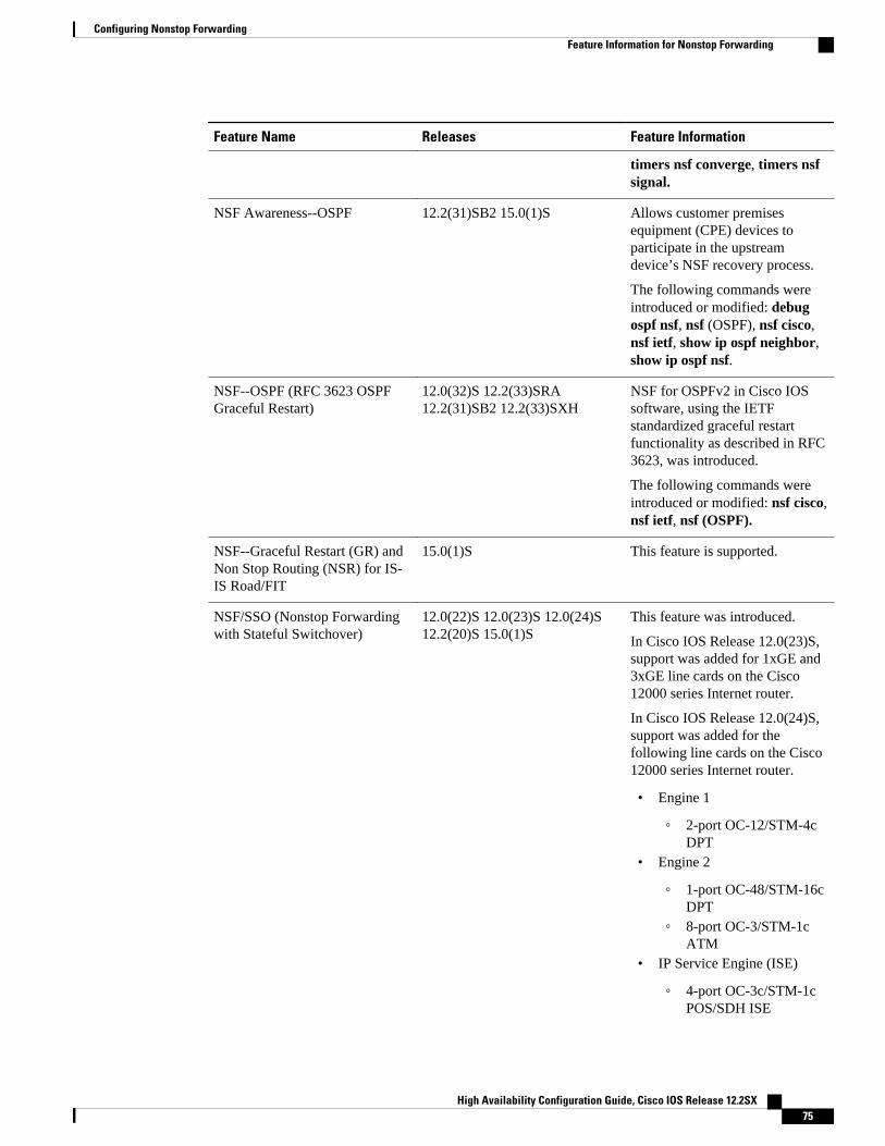
Feature Name Releases Feature Information
timers nsf converge, timers nsfsignal.
NSF Awareness--OSPF 12.2(31)SB2 15.0(1)S Allows customer premisesequipment (CPE) devices toparticipate in the upstreamdevice’s NSF recovery process.
The following commands wereintroduced or modified: debugospf nsf, nsf (OSPF), nsf cisco,nsf ietf, show ip ospf neighbor,show ip ospf nsf.
NSF--OSPF (RFC 3623 OSPFGraceful Restart)
12.0(32)S 12.2(33)SRA12.2(31)SB2 12.2(33)SXH
NSF for OSPFv2 in Cisco IOSsoftware, using the IETFstandardized graceful restartfunctionality as described in RFC3623, was introduced.
The following commands wereintroduced or modified: nsf cisco,nsf ietf, nsf (OSPF).
NSF--Graceful Restart (GR) andNon Stop Routing (NSR) for IS-IS Road/FIT
15.0(1)S This feature is supported.
NSF/SSO (Nonstop Forwardingwith Stateful Switchover)
12.0(22)S 12.0(23)S 12.0(24)S12.2(20)S 15.0(1)S
This feature was introduced.
In Cisco IOS Release 12.0(23)S,support was added for 1xGE and3xGE line cards on the Cisco12000 series Internet router.
In Cisco IOS Release 12.0(24)S,support was added for thefollowing line cards on the Cisco12000 series Internet router.
• Engine 1
◦ 2-port OC-12/STM-4cDPT
• Engine 2
◦ 1-port OC-48/STM-16cDPT
◦ 8-port OC-3/STM-1cATM
• IP Service Engine (ISE)
◦ 4-port OC-3c/STM-1cPOS/SDH ISE
Configuring Nonstop ForwardingFeature Information for Nonstop Forwarding
High Availability Configuration Guide, Cisco IOS Release 12.2SX 75

Feature Name Releases Feature Information
◦ 8-port OC-3c/STM-1cPOS/SDH ISE
◦ 16-port OC-3c/STM-1cPOS/SDH ISE
◦ 4-port OC-12c/STM-4cPOS/SDH ISE
◦ 1-port OC-48c/STM-16c POS/SDHISE
◦ 4-port channelizedOC-12/STM-4 (DS3/E3, OC-3c/STM-1c)POS/SDH ISE
◦ 1-port channelizedOC-48/STM-16 (DS3/E3, OC-3c/STM-1c)POS/SDH ISE
The following commands wereintroduced or modified: bgpgraceful-restart, debug isis nsf,ip cef distributed, nsf(IS-IS), nsfinterface wait, nsf interval, nsft3, router bgp, router isis,router ospf, show cef nsf, showcef state, show clns neighbors,show ip bgp, show ip bgpneighbors, show ip cef, show ipeigrp neighbors, show ipprotocols, show isis database,show isis nsf.
NSF/SSO--MPLS VPN 12.2(25)S 12.2(28)SB12.2(33)SRA 12.2(33)SXH
This feature allows a provideredge (PE) router or AutonomousSystem Border Router (ASBR)(with redundant RouteProcessors) to preserve dataforwarding information in aMultiprotocol Label Switching(MPLS) Virtual Private Network(VPN) when the primary RouteProcessor restarts.
In 12.2(25)S, this feature wasintroduced on the Cisco 7500series router.
In 12.2(28)SB, support was addedfor the Cisco 10000 seriesrouters.
Configuring Nonstop Forwarding Feature Information for Nonstop Forwarding
High Availability Configuration Guide, Cisco IOS Release 12.2SX76

Feature Name Releases Feature Information
In 12.2(33)SRA, support wasadded for the Cisco 7600 seriesrouters.
NSF/SSO--Virtual Private LANServices
12.2(33)SXI4 15.0(1)S This feature was introduced.
NSF/SSO--IPv4 Multicast 12.2(33)SRE 15.0(1)S This feature was introduced.
NSF/SSO--IPv6 Multicast 12.2(33)SRE This feature was introduced.
Cisco and the Cisco Logo are trademarks of Cisco Systems, Inc. and/or its affiliates in the U.S. and othercountries. A listing of Cisco's trademarks can be found at www.cisco.com/go/trademarks. Third partytrademarks mentioned are the property of their respective owners. The use of the word partner does notimply a partnership relationship between Cisco and any other company. (1005R)
Any Internet Protocol (IP) addresses and phone numbers used in this document are not intended to beactual addresses and phone numbers. Any examples, command display output, network topology diagrams,and other figures included in the document are shown for illustrative purposes only. Any use of actual IPaddresses or phone numbers in illustrative content is unintentional and coincidental.
Configuring Nonstop Forwarding
High Availability Configuration Guide, Cisco IOS Release 12.2SX 77

Example IS-ISNSF
High Availability Configuration Guide, Cisco IOS Release 12.2SX78

Performing an In Service Software Upgrade
This module describes how to perform an In Service Software Upgrade (ISSU) process.
• Finding Feature Information, page 79• Prerequisites for Performing an ISSU, page 79• Restrictions for Performing an ISSU, page 80• Information About Performing an ISSU, page 81• How to Perform an ISSU, page 85• Configuration Examples for Performing an ISSU, page 90• Additional References, page 96• Feature Information for Performing an ISSU, page 98• , page 104
Finding Feature InformationYour software release may not support all the features documented in this module. For the latest featureinformation and caveats, see the release notes for your platform and software release. To find informationabout the features documented in this module, and to see a list of the releases in which each feature issupported, see the Feature Information Table at the end of this document.
Use Cisco Feature Navigator to find information about platform support and Cisco software image support.To access Cisco Feature Navigator, go to http://www.cisco.com/go/cfn. An account on Cisco.com is notrequired.
Prerequisites for Performing an ISSU• Both the active and standby route processors (RPs) must be available in the system.• The new and old Cisco software images must be loaded into the file systems of both the active and
standby RPs before you begin the ISSU process.• Stateful switchover (SSO) must be configured and working properly.• Nonstop forwarding (NSF) must be configured and working properly.• Before you perform ISSU, the file system for both the active and standby RPs must contain the new
ISSU-compatible image. The current version running in the system must also support ISSU. You canissue various commands to determine RP versioning and compatibility, or you can use the ISSUapplication on Cisco Feature Navigator.
High Availability Configuration Guide, Cisco IOS Release 12.2SX 79

Restrictions for Performing an ISSU• General Restrictions, page 80• Termination of Virtual Template Manager for ISSU Restrictions, page 80• Cisco 10000 Series Internet Router Platform Restrictions, page 80• Cisco Catalyst 4500 Restrictions, page 81
General Restrictions• Do not make hardware changes while performing an ISSU process.• Perform upgrades only during a maintenance window. (Recommended)• Do not enable new features that require configuration changes during the ISSU process.• If a feature is not available in a downgrade of a Cisco software image, disable that feature before you
initiate the ISSU process.
Termination of Virtual Template Manager for ISSU RestrictionsThe Virtual Template Manager for ISSU is not supported in Cisco IOS Releases 12.2(31)SB and12.2(33)SB.
Cisco 10000 Series Internet Router Platform Restrictions• ISSU is available only in Cisco IOS 12.2(28)SB software released for theand later.• The following line cards support ISSU:
◦ 1-port channelized OC-12/STM-4◦ 1-port Gigabit Ethernet◦ 1-port half-height Gigabit Ethernet◦ 1-port OC-12 ATM◦ 1-port OC-12 Packet over SONET (PoS)◦ l-port OC-48 PoS◦ 4-port channelized OC-3/STM-1◦ 4-port OC-3 ATM IR◦ 4-port OC-3 ATM LR◦ 4-port half-height channelized T3◦ 6-port channelized T3◦ 6-port OC-3 PoS◦ 8-port ATM E3/DS3◦ 8-port E3/DS3◦ 8-port half-height Fast Ethernet◦ 24-port channelized E1/T1
• The following interface cards support ISSU:
◦ SPA Interface Processor (10000-SIP-600)◦ 2-port GE SPA◦ 5-port GE SPA
General Restrictions Restrictions for Performing an ISSU
High Availability Configuration Guide, Cisco IOS Release 12.2SX80

◦ 8-port GE SPA◦ 1-port 10GE SPA
Cisco Catalyst 4500 RestrictionsThe single-step complete upgrade process cycle is available on the Cisco Catalyst 4500 series switch inCisco IOS Release 12.2(47)SG.
Information About Performing an ISSU• ISSU Process Overview, page 81
• ISSU Rollback Timer, page 82
• Fast Software Upgrade, page 82
• Enhanced Fast Software Upgrade, page 82
• Versioning Capability in Cisco Software to Support ISSU, page 83
• SNMP Support for ISSU, page 84
• Virtual Template Manager for ISSU, page 84
• Compatibility Verification Using Cisco Feature Navigator, page 84
• ISSU-Capable Protocols and Applications, page 84
ISSU Process OverviewISSU allows Cisco software to be upgraded or downgraded, at a router level, while the system continues toforward packets. ISSU takes advantage of the Cisco high availability infrastructure--Cisco NSF with SSOand hardware redundancy--and eliminates downtime associated with software upgrades or version changesby allowing updates while the system remains in service. Cisco high availability features combine to lowerthe impact that planned maintenance activities have on network service availability, with the results of lessdowntime and better access to critical systems.
SSO mode supports configuration synchronization. When images on the active and standby RPs aredifferent, this feature allows the two Route Processors (RPs) to remain synchronized although they maysupport different sets of commands.
An ISSU-capable router consists of two RPs (active and standby) and one or more line cards. Beforeinitiating the ISSU process, you must copy the Cisco IOS software into the file systems of both RPs
After you have copied the Cisco IOS software to both file systems, load the new version of Cisco IOSsoftware onto the standby RP.
After switchover, the standby RP takes over as the new active RP.
Then, the former active RP, which is now the new standby RP, is loaded with the new software.
The two RPs in a system can be in one of three different states during ISSU:
• Active--One RP is actively forwarding packets with old software. After the ISSU process isperformed, the original active RP becomes the standby RP.
• Standby--Perform ISSU on the standby RP, loading it with new software. After the ISSU process isperformed, the original standby RP is the new active RP.
• Hot standby--After the original standby RP becomes the new active RP, load the new software imageinto the new standby RP. Doing so makes the standby RP a hot standby RP.
Cisco Catalyst 4500 RestrictionsInformation About Performing an ISSU
High Availability Configuration Guide, Cisco IOS Release 12.2SX 81

The figure below shows the ISSU states during the ISSU process.
Figure 3: ISSU States During the ISSU Process
ISSU Rollback TimerCisco IOS software maintains an ISSU rollback timer. The rollback timer provides a safeguard against anupgrade that may leave the new active RP in a state in which communication with the RP is severed.
Configuring the rollback timer to fewer than 45 minutes (the default) eliminates waiting in case the newsoftware is not committed or the connection to the router is lost while it is in runversion mode. Configurethe rollback timer to more than 45 minutes in order to have enough time to verify the operation of the newCisco IOS software before committing the new image.
Fast Software UpgradeWhen Cisco IOS software versions are not compatible and ISSU is not possible, the FSU procedure can beperformed within the ISSU command context. Through the use of optional parameters in ISSU commands,the system reverts to RPR mode rather than the SSO mode required for ISSU.
FSU using the ISSU command context works only with ISSU-aware Cisco software versions. If you wantto downgrade to a pre-ISSU version, you must use the manual FSU method.
Enhanced Fast Software UpgradeEnhanced Fast Software Upgrade (eFSU) is an improvement over FSU, reducing the downtime during aCisco software upgrade.
At the linecard level, an enhanced Fast Software Upgrade (eFSU) process minimizes linecard downtimeduring upgrades to between 30 and 90 seconds, by pre-loading the new linecard image before the ISSUswitchover occurs from the active to the standby Route Processor.
ISSU Rollback Timer Information About Performing an ISSU
High Availability Configuration Guide, Cisco IOS Release 12.2SX82

See the Enhanced Fast Software Upgrade on the Cisco 7600 Series Routers for more information.
Versioning Capability in Cisco Software to Support ISSUBefore the introduction of the ISSU capability, the SSO mode of operation required each RP to be runningthe same versions of Cisco software. The operating mode of the system in a redundant HA configuration isdetermined by exchanging version strings when the standby RP registers with the active RP.
The system entered SSO mode only if the versions running on both RPs were the same. If not, theredundancy mode was reduced to ensure compatibility. With ISSU capability, the implementation allowstwo different but compatible release levels of Cisco software images to interoperate in SSO mode andenables software upgrades while packet forwarding continues. Version checking done before ISSUcapability was introduced is no longer sufficient to allow the system to determine the operating mode.
ISSU requires additional information to determine compatibility between software versions. Therefore, acompatibility matrix is defined that contains information about other images with respect to the one inquestion. This compatibility matrix represents the compatibility of two software versions, one running onthe active and the other on the standby RP, and to allow the system to determine the highest operatingmode it can achieve. Incompatible versions will not be able to progress to SSO operational mode.
The Cisco software infrastructure has been internally modified and redesigned to accommodate subsystemversioning with ISSU. Cisco software subsystems correspond to feature sets and software componentgroupings. Features or subsystems that maintain state information across RPs are HA-aware or SSO clients.A mechanism called ISSU Framework, or ISSU protocol, allows subsystems within Cisco software tocommunicate RP to RP and to negotiate the message version for communication between RPs. Internally,all NSF- and SSO-compliant applications or subsystems that are HA-aware must follow this protocol toestablish communication with their peer across different versions of software.
• Compatibility Matrix, page 83
Compatibility MatrixYou can perform the ISSU process when the Cisco software on both the active and the standby RP iscapable of ISSU and the old and new images are compatible. The compatibility matrix information storesthe compatibility among releases as follows:
• Compatible--The base-level system infrastructure and all optional HA-aware subsystems arecompatible. An in-service upgrade or downgrade between these versions will succeed with minimalservice impact. The matrix entry designates the images to be compatible (C).
• Base-level compatible--One or more of the optional HA-aware subsystems is not compatible. An in-service upgrade or downgrade between these versions will succeed; however, some subsystems willnot be able to maintain state during the transition. The matrix entry designates the images to be base-level compatible (B).
• Incompatible--A core set of system infrastructure exists that must be able to interoperate in a statefulmanner for SSO to function correctly. If any of these required features or protocols is notinteroperable, then the two versions of the Cisco software images are declared to be incompatible. Anin-service upgrade or downgrade between these versions is not possible. The matrix entry designatesthe images to be incompatible (I).
If you attempt to perform ISSU with a peer that does not support ISSU, the system automatically uses FastSoftware Upgrade (FSU) instead.
The compatibility matrix represents the compatibility relationship a Cisco software image has with all ofthe other Cisco software versions within the designated support window (for example, all of those softwareversions the image “knows” about) and is populated and released with every image. The matrix stores
Versioning Capability in Cisco Software to Support ISSUCompatibility Matrix
High Availability Configuration Guide, Cisco IOS Release 12.2SX 83

compatibility information between its own release and prior releases. It is always the newest release thatcontains the latest information about compatibility with existing releases in the field. The compatibilitymatrix is available within the Cisco software image and on Cisco.com so that users can determine inadvance whether an upgrade can be done using the ISSU process.
SNMP Support for ISSUISSU - SNMP for SSO provides a mechanism for synchronizing the Simple Network Management Protocol(SNMP) configurations and the MIBs that support SSO from the active RP to the standby RP, assumingthat both RPs are running the same version of Cisco software. This assumption is not valid for ISSU.
ISSU - SNMP provides an SNMP client that can handle ISSU transformations for the MIBs. An SNMPclient (SIC) handles ISSU for all MIBs and handles the transmit and receive functions required for ISSU.During SNMP, a MIB is completely synchronized from the active RP to the standby RP only if the versionsof the MIB on both Cisco software releases are the same.
Virtual Template Manager for ISSUThe virtual template manager feature for ISSU provides virtual access interfaces for sessions that are notHA-capable and are not synchronized to the standby router. The virtual template manager uses aredundancy facility (RF) client to allow the synchronization of virtual access interfaces as they are created.
The virtual databases have instances of distributed FIB entries on line cards. Line cards requiresynchronization of content and timing in all interfaces to the standby processor to avoid incorrectforwarding. If the virtual access interface is not created on the standby processor, the interface indexes willbe corrupted on the standby router and line cards, which will cause problems with forwarding.
Compatibility Verification Using Cisco Feature NavigatorThe ISSU application on Cisco Feature Navigator allows you to:
• Select an ISSU-capable image• Identify which images are compatible with that image• Compare two images and understand the compatibility level of the images (that is, compatible, base-
level compatible, and incompatible)• Compare two images and see the client compatibility for each ISSU client• Provide links to release notes for the image
ISSU-Capable Protocols and ApplicationsThe following protocols and applications support ISSU:
• FHRP - HSRP Group Shutdown--FHRP - HSRP group shutdown is supported in ISSU.• ISSU - ARP--Address Resolution Protocol (ARP) is supported in ISSU.• ISSU - ATM--Asynchronous Transfer Mode (ATM) is supported in ISSU. The application
requirements for ISSU are as follows:
◦ Identify the ATM client as nonbase◦ Support message versioning of ATM HA event synchronous messages◦ Provide capability exchange between peers
• ISSU - Dynamic Host Configuration Protocol (DHCP) on-demand address pool (ODAP) client/server--This feature is supported in ISSU.
SNMP Support for ISSU Compatibility Matrix
High Availability Configuration Guide, Cisco IOS Release 12.2SX84

• ISSU - DHCP proxy client--The DHCP proxy client feature is supported in ISSU.• ISSU - DHCP relay on unnumbered interface--The DHCP relay on unnumbered interface feature is
supported in ISSU.• ISSU - DHCP server--The DHCP server feature is supported in ISSU.• ISSU - DHCP snooping--DHCP snooping is supported in ISSU.• ISSU - EtherChannel - Port Aggregation Protocol (PagP) and Link Aggregate Control Protocol
(LACP) support ISSU.• ISSU - First Hop Routing Protocol (FHRP) - Gateway Load Balancing Protocol (GLBP) is supported
in ISSU.• ISSU - FHRP/HSRP--The Hot Standby Router Protocol (HSRP) is supported in ISSU.• ISSU - Frame Relay--The Frame Relay protocol is supported in ISSU.• ISSU - HDLC--The High-Level Data Link Control (HDLC) protocol is supported in ISSU.• ISSU - IEEE 802.1x--The IEEE 802.1x protocol is supported in ISSU.• ISSU - IEEE 802.3af--IEEE 802.3af is supported in ISSU.• ISSU - Internet Group Management Protocol (IGMP) snooping--IGMP snooping is supported in ISSU.• ISSU - IP host--The IP host is supported in ISSU.• ISSU - IPv4 Multicast - IPv4 multicast is supported in ISSU.• ISSU - IS-IS--The Intermediate System-to-Intermediate System (IS-IS) protocol is supported in ISSU.• ISSU - MTR--Multitopology routing (MTR) is supported in ISSU.• ISSU - MPLS L3VPN--Multiprotocol Label Switching (MPLS) is supported in ISSU. For information
about upgrading ISSU MPLS-related applications through ISSUt.• ISSU - Port security--Port security is supported in ISSU.• ISSU - PPP/MLP--multilink PPP (MLP) support ISSU.• ISSU - PPP over ATM (PPPoA) and PPP over Ethernet (PPPoE) support ISSU.• ISSU - QoS support--The quality of service (QoS) feature is supported in ISSU.• ISSU - RIB/VRF - The RIB/VRF feature is supported in ISSU.• ISSU - SNMP--SNMP is supported in ISSU.• ISSU - Spanning-Tree Protocol (STP)--STP is supported in ISSU.
How to Perform an ISSU• Displaying ISSU Compatibility Matrix Information, page 85
• Loading Cisco IOS Software on the Standby RP, page 86
• Switching to the Standby RP, page 87
• Stopping the ISSU Rollback Timer, page 87
• Verifying the ISSU Software Installation, page 88
• Enabling the New Standby RP to Use New Software Version, page 88
• Aborting a Software Upgrade Using ISSU, page 89
• Configuring the Rollback Timer to Safeguard Against Upgrades, page 90
Displaying ISSU Compatibility Matrix Information
Displaying ISSU Compatibility Matrix InformationHow to Perform an ISSU
High Availability Configuration Guide, Cisco IOS Release 12.2SX 85

SUMMARY STEPS
1. enable
2. show issu comp-matrix {negotiated | stored}
DETAILED STEPS
Command or Action Purpose
Step 1 enable
Example:
Router> enable
Enables privileged EXEC mode.
• Enter your password if prompted.
Step 2 show issu comp-matrix {negotiated | stored}
Example:
Router# show issu comp-matrix negotiated
Displays information about the the compatibility of the two softwareversions, one running on the active and the other on the standby RP.
Loading Cisco IOS Software on the Standby RP
SUMMARY STEPS
1. enable
2. issu loadversion active-slot active-image standby-slot standby-image [force]
3. show issu state [detail]
DETAILED STEPS
Command or Action Purpose
Step 1 enable
Example:
Router> enable
Enables privileged EXEC mode.
• Enter your password if prompted.
Step 2 issu loadversion active-slot active-image standby-slotstandby-image [force]
Example:
Router# issu loadversion a disk0:c10k2-p11-mz.2.20040830 b stby-disk0:c10k2-p11-mz.2.20040830
Starts the ISSU process.
NoteIt may take several seconds after the issu loadversioncommand is entered for Cisco IOS software to load onto thestandby RP and for the standby RP to transition to SSO mode.
Step 3 show issu state [detail] Displays the state of the device during the ISSU process.
• Confirm that the standby RP is loaded and is in SSO mode.
Loading Cisco IOS Software on the Standby RP How to Perform an ISSU
High Availability Configuration Guide, Cisco IOS Release 12.2SX86

Command or Action Purpose
Example:
Router# show issu state
Switching to the Standby RP
SUMMARY STEPS
1. enable
2. issu runversion slot image
DETAILED STEPS
Command or Action Purpose
Step 1 enable
Example:
Router> enable
Enables privileged EXEC mode.
• Enter your password if prompted.
Step 2 issu runversion slot image
Example:
Router# issu runversion b stby-disk0:c10k2-p11-mz.2.20040830
Forces a switchover of the active to the standby processor andcauses the newly active processor to run the new image.
Stopping the ISSU Rollback Timer
SUMMARY STEPS
1. enable
2. show issu rollback-timer
3. issu acceptversion {active slot-number | active slot-name slot-name}
DETAILED STEPS
Command or Action Purpose
Step 1 enable
Example:
Router> enable
Enables privileged EXEC mode.
• Enter your password if prompted.
Step 2 show issu rollback-timer Displays amount of time left before an automatic rollback will occur.
Switching to the Standby RPHow to Perform an ISSU
High Availability Configuration Guide, Cisco IOS Release 12.2SX 87

Command or Action Purpose
Example:
Router# show issu rollback-timer
Step 3 issu acceptversion {active slot-number | active slot-name slot-name}
Example:
Router# issu acceptversion b disk0:c10k2-p11-mz.2.20040830
Halts the rollback timer and ensures the new Cisco IOS softwareimage is not automatically aborted during the ISSU process.
• You must enter this command within the time period specifiedby the rollback timer displayed in the previous step.
Verifying the ISSU Software Installation
SUMMARY STEPS
1. enable
2. show issu state [detail]
3. show redundancy [clients | counters | debug-log | handover | history | states | inter-device]
DETAILED STEPS
Command or Action Purpose
Step 1 enable
Example:
Router> enable
Enables privileged EXEC mode.
• Enter your password if prompted.
Step 2 show issu state [detail]
Example:
Router# show issu state
Displays the state of the RPs during the ISSU process.
Step 3 show redundancy [clients | counters | debug-log | handover |history | states | inter-device]
Example:
Router# show redundancy
Displays current or historical status, mode, and relatedredundancy information about the device.
Enabling the New Standby RP to Use New Software Version
Verifying the ISSU Software Installation How to Perform an ISSU
High Availability Configuration Guide, Cisco IOS Release 12.2SX88

SUMMARY STEPS
1. enable
2. issu commitversion slot active-image
DETAILED STEPS
Command or Action Purpose
Step 1 enable
Example:
Router> enable
Enables privileged EXEC mode.
• Enter your password if prompted.
Step 2 issu commitversion slot active-image
Example:
Router# issu commitversion a stby-disk0:c10k2-p11-mz.2.20040830
Allows the new Cisco IOS software image to be loaded intothe standby RP.
Aborting a Software Upgrade Using ISSUIf you abort the process after you load a new version on the standby RP and before switching to the standbyRP, the standby RP is reset and reloaded with the original software.
If you abort the process after switching to the standby RP or stopping an automatic rollback, a secondswitchover is performed to the new standby RP that is still running the original software version. The RPthat had been running the new software is reset and reloaded with the original software version.
SUMMARY STEPS
1. enable
2. issu abortversion slot image
DETAILED STEPS
Command or Action Purpose
Step 1 enable
Example:
Router> enable
Enables privileged EXEC mode.
• Enter your password if prompted.
Step 2 issu abortversion slot image
Example:
Router# issu abortversion b disk0:c10k2-p11-mz.2.20040830
Aborts the ISSU upgrade or downgrade process in progress andrestores the router to its state before the process had started.
Aborting a Software Upgrade Using ISSUHow to Perform an ISSU
High Availability Configuration Guide, Cisco IOS Release 12.2SX 89
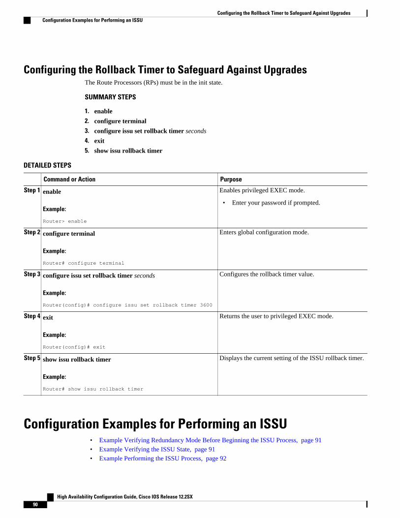
Configuring the Rollback Timer to Safeguard Against UpgradesThe Route Processors (RPs) must be in the init state.
SUMMARY STEPS
1. enable
2. configure terminal
3. configure issu set rollback timer seconds
4. exit
5. show issu rollback timer
DETAILED STEPS
Command or Action Purpose
Step 1 enable
Example:
Router> enable
Enables privileged EXEC mode.
• Enter your password if prompted.
Step 2 configure terminal
Example:
Router# configure terminal
Enters global configuration mode.
Step 3 configure issu set rollback timer seconds
Example:
Router(config)# configure issu set rollback timer 3600
Configures the rollback timer value.
Step 4 exit
Example:
Router(config)# exit
Returns the user to privileged EXEC mode.
Step 5 show issu rollback timer
Example:
Router# show issu rollback timer
Displays the current setting of the ISSU rollback timer.
Configuration Examples for Performing an ISSU• Example Verifying Redundancy Mode Before Beginning the ISSU Process, page 91• Example Verifying the ISSU State, page 91• Example Performing the ISSU Process, page 92
Configuring the Rollback Timer to Safeguard Against Upgrades Configuration Examples for Performing an ISSU
High Availability Configuration Guide, Cisco IOS Release 12.2SX90

• Example Aborting the ISSU Process, page 95• Example Verifying Rollback Timer Information, page 96
Example Verifying Redundancy Mode Before Beginning the ISSU ProcessBefore you begin the ISSU process, verify the redundancy mode for the system. NSF and SSO must beconfigured before attempting an ISSU. The following example displays verification that the system is inSSO mode and that slot A--RP A is the active R, and slot B--RP B is the standby RP. Both RPs are runningthe same Cisco software image.
Router# show redundancy states my state = 13 -ACTIVE peer state = 8 -STANDBY HOT Mode = Duplex Unit = Primary Unit ID = 0Redundancy Mode (Operational) = SSORedundancy Mode (Configured) = SSO Split Mode = Disabled Manual Swact = Enabled Communications = Up client count = 31 client_notification_TMR = 30000 milliseconds RF debug mask = 0x0 Router# show redundancyRedundant System Information :------------------------------ Available system uptime = 9 minutesSwitchovers system experienced = 0 Standby failures = 0 Last switchover reason = none Hardware Mode = Duplex Configured Redundancy Mode = SSO Operating Redundancy Mode = SSO Maintenance Mode = Disabled Communications = UpCurrent Processor Information :------------------------------- Active Location = slot A Current Software state = ACTIVE Uptime in current state = 9 minutesImage Version = Cisco IOS Software, 10000 Software (C10K2-P11-M), Experimental Version 12.2(20040825:224856) [wgrupp-c10k_bba_122s_work 102] Copyright (c) 1986-2004 by Cisco Systems, Inc. Compiled Mon 30-Aug-04 10:29 by wgrupp BOOT = disk0:c10k2-p11-mz.1.20040830,1; CONFIG_FILE = BOOTLDR = Configuration register = 0x102Peer Processor Information :---------------------------- Standby Location = slot B Current Software state = STANDBY HOT Uptime in current state = 8 minutes Image Version = Cisco IOS Software, 10000 Software (C10K2-P11-M), Experimental Version 12.2(20040825:224856) [wgrupp-c10k_bba_122s_work 102] Copyright (c) 1986-2004 by Cisco Systems, Inc. Compiled Mon 30-Aug-04 10:29 by wgrupp BOOT = disk0:c10k2-p11-mz.1.20040830,1; CONFIG_FILE = BOOTLDR = Configuration register = 0x102
Example Verifying the ISSU StateThe following sample output displays and verifies the ISSU state:
Router# show issu state detail
Example Verifying Redundancy Mode Before Beginning the ISSU ProcessConfiguration Examples for Performing an ISSU
High Availability Configuration Guide, Cisco IOS Release 12.2SX 91

Slot = A RP State = Active ISSU State = Init Boot Variable = N/A Operating Mode = SSO Primary Version = N/A Secondary Version = N/A Current Version = disk0:c10k2-p11-mz.1.20040830 Slot = B RP State = Standby ISSU State = Init Boot Variable = N/A Operating Mode = SSO Primary Version = N/A Secondary Version = N/A Current Version = disk0:c10k2-p11-mz.1.20040830
The new version of the Cisco IOS software must be present on both of the RPs. The directory informationdisplayed for each of the RPs shows that the new version is present.
Router# directory disk0:Directory of disk0:/ 1 -rw- 16864340 Jul 16 2004 01:59:42 -04:00 c10k2-p11-mz.122-16.BX1.bin 2 -rw- 2530912 Jul 16 2004 02:00:04 -04:00 c10k2-eboot-mz.122-16.BX1.bin 3 -rw- 20172208 Aug 30 2004 16:25:56 -04:00 c10k2-p11-mz.1.20040830 4 -rw- 20171492 Aug 31 2004 12:25:34 -04:00 c10k2-p11-mz.2.2004083064253952 bytes total (4509696 bytes free)Router# directory stby-disk0:Directory of stby-disk0:/
Example Performing the ISSU ProcessThe following examples show how to verify the ISSU software installation by entering show commandsthat provide information on the state of theduring the ISSU process.
Initiating the ISSU Process
To initiate the ISSU process, enter the issu loadversion command as shown in the following example:
Router# issu loadversion a disk0:c10k2-p11-mz.2.20040830 b stby-disk0:c10k2-p11-mz.2.20040830
The following two examples display the ISSU state and redundancy state after ISSU process initiation:
Router# show issu state Slot = A RP State = Active ISSU State = Load Version Boot Variable = disk0:c10k2-p11-mz.1.20040830,1; Slot = B RP State = Standby ISSU State = Load Version Boot Variable = disk0:c10k2-p11-mz.2.20040830,12;disk0:c10k2-p11-mz.1.20040830,1;Router# show redundancy state my state = 13 -ACTIVE peer state = 8 -STANDBY HOT Mode = Duplex Unit = Primary Unit ID = 0Redundancy Mode (Operational) = SSORedundancy Mode (Configured) = SSO Split Mode = Disabled Manual Swact = Enabled Communications = Up client count = 31
Example Performing the ISSU Process Configuration Examples for Performing an ISSU
High Availability Configuration Guide, Cisco IOS Release 12.2SX92
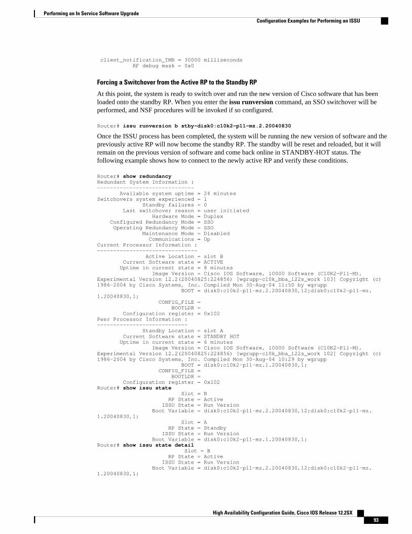
client_notification_TMR = 30000 milliseconds RF debug mask = 0x0
Forcing a Switchover from the Active RP to the Standby RP
At this point, the system is ready to switch over and run the new version of Cisco software that has beenloaded onto the standby RP. When you enter the issu runversion command, an SSO switchover will beperformed, and NSF procedures will be invoked if so configured.
Router# issu runversion b stby-disk0:c10k2-p11-mz.2.20040830
Once the ISSU process has been completed, the system will be running the new version of software and thepreviously active RP will now become the standby RP. The standby will be reset and reloaded, but it willremain on the previous version of software and come back online in STANDBY-HOT status. Thefollowing example shows how to connect to the newly active RP and verify these conditions.
Router# show redundancyRedundant System Information :------------------------------ Available system uptime = 24 minutesSwitchovers system experienced = 1 Standby failures = 0 Last switchover reason = user initiated Hardware Mode = Duplex Configured Redundancy Mode = SSO Operating Redundancy Mode = SSO Maintenance Mode = Disabled Communications = UpCurrent Processor Information :------------------------------- Active Location = slot B Current Software state = ACTIVE Uptime in current state = 8 minutes Image Version = Cisco IOS Software, 10000 Software (C10K2-P11-M), Experimental Version 12.2(20040825:224856) [wgrupp-c10k_bba_122s_work 103] Copyright (c) 1986-2004 by Cisco Systems, Inc. Compiled Mon 30-Aug-04 11:50 by wgrupp BOOT = disk0:c10k2-p11-mz.2.20040830,12;disk0:c10k2-p11-mz.1.20040830,1; CONFIG_FILE = BOOTLDR = Configuration register = 0x102Peer Processor Information :---------------------------- Standby Location = slot A Current Software state = STANDBY HOT Uptime in current state = 6 minutes Image Version = Cisco IOS Software, 10000 Software (C10K2-P11-M), Experimental Version 12.2(20040825:224856) [wgrupp-c10k_bba_122s_work 102] Copyright (c) 1986-2004 by Cisco Systems, Inc. Compiled Mon 30-Aug-04 10:29 by wgrupp BOOT = disk0:c10k2-p11-mz.1.20040830,1; CONFIG_FILE = BOOTLDR = Configuration register = 0x102Router# show issu state Slot = B RP State = Active ISSU State = Run Version Boot Variable = disk0:c10k2-p11-mz.2.20040830,12;disk0:c10k2-p11-mz.1.20040830,1; Slot = A RP State = Standby ISSU State = Run Version Boot Variable = disk0:c10k2-p11-mz.1.20040830,1;Router# show issu state detail Slot = B RP State = Active ISSU State = Run Version Boot Variable = disk0:c10k2-p11-mz.2.20040830,12;disk0:c10k2-p11-mz.1.20040830,1;
Performing an In Service Software UpgradeConfiguration Examples for Performing an ISSU
High Availability Configuration Guide, Cisco IOS Release 12.2SX 93

Operating Mode = SSO Primary Version = disk0:c10k2-p11-mz.2.20040830 Secondary Version = disk0:c10k2-p11-mz.1.20040830 Current Version = disk0:c10k2-p11-mz.2.20040830 Slot = A RP State = Standby ISSU State = Run Version Boot Variable = disk0:c10k2-p11-mz.1.20040830,1; Operating Mode = SSO Primary Version = disk0:c10k2-p11-mz.2.20040830 Secondary Version = disk0:c10k2-p11-mz.1.20040830 Current Version = disk0:c10k2-p11-mz.1.20040830
The new active RP is now running the new version of software, and the standby RP is running the oldversion of software and is in the STANDBY-HOT state.
Stopping the Rollback Process
In the following example, the “Automatic Rollback Time” information indicates the amount of time leftbefore an automatic rollback will occur. Enter the issu acceptversion command within the time periodspecified by the rollback timer to acknowledge that the RP has achieved connectivity to the outside world;otherwise, the ISSU process is terminated, and the system reverts to the previous version of Cisco softwareby switching to the standby RP.
Router# show issu rollback-timer Rollback Process State = In progressConfigured Rollback Time = 45:00Automatic Rollback Time = 29:03
Entering the issu acceptversion command stops the rollback timer:
Router# issu acceptversion b disk0:c10k2-p11-mz.2.20040830
Committing the New Software to the Standby RP
The following example shows how to commit the new Cisco software image in the file system of thestandby RP and ensure that both the active and the standby RPs are in the run version (RV) state. Thestandby RP is reset and reloaded with the new Cisco software and returned to STANDBY-HOT status.
Router# issu commitversion a stby-disk0:c10k2-p11-mz.2.20040830Router# show redundancy states my state = 13 -ACTIVE peer state = 8 -STANDBY HOT Mode = Duplex Unit = Secondary Unit ID = 1Redundancy Mode (Operational) = SSORedundancy Mode (Configured) = SSO Split Mode = Disabled Manual Swact = Enabled Communications = Up client count = 31 client_notification_TMR = 30000 milliseconds RF debug mask = 0x0 Router# show redundancyRedundant System Information :------------------------------ Available system uptime = 35 minutesSwitchovers system experienced = 1 Standby failures = 1 Last switchover reason = user initiated Hardware Mode = DuplexConfigured Redundancy Mode = SSO Operating Redundancy Mode = SSO Maintenance Mode = Disabled Communications = Up
Performing an In Service Software Upgrade Configuration Examples for Performing an ISSU
High Availability Configuration Guide, Cisco IOS Release 12.2SX94

Current Processor Information :------------------------------- Active Location = slot B Current Software state = ACTIVE Uptime in current state = 18 minutes Image Version = Cisco IOS Software, 10000 Software (C10K2-P11-M), Experimental Version 12.2(20040825:224856) [wgrupp-c10k_bba_122s_work 103] Copyright (c) 1986-2004 by Cisco Systems, Inc. Compiled Mon 30-Aug-04 11:50 by wgrupp BOOT = disk0:c10k2-p11-mz.2.20040830,12;disk0:c10k2-p11-mz.1.20040830,1; CONFIG_FILE = BOOTLDR = Configuration register = 0x102Peer Processor Information :---------------------------- Standby Location = slot A Current Software state = STANDBY HOT Uptime in current state = 4 minutes Image Version = Cisco IOS Software, 10000 Software (C10K2-P11-M), Experimental Version 12.2(20040825:224856) [wgrupp-c10k_bba_122s_work 103] Copyright (c) 1986-2004 by Cisco Systems, Inc. Compiled Mon 30-Aug-04 11:50 by wgrupp BOOT = disk0:c10k2-p11-mz.2.20040830,12;disk0:c10k2-p11-mz.1.20040830,1; CONFIG_FILE = BOOTLDR = Configuration register = 0x102Router# show issu state Slot = B RP State = Active ISSU State = Init Boot Variable = disk0:c10k2-p11-mz.2.20040830,12;disk0:c10k2-p11-mz.1.20040830,1; Slot = A RP State = Standby ISSU State = Init Boot Variable = disk0:c10k2-p11-mz.2.20040830,12;disk0:c10k2-p11-mz.1.20040830,1;Router# show issu state detail Slot = B RP State = Active ISSU State = Init Boot Variable = disk0:c10k2-p11-mz.2.20040830,12;disk0:c10k2-p11-mz.1.20040830,1; Operating Mode = SSO Primary Version = N/A Secondary Version = N/A Current Version = disk0:c10k2-p11-mz.2.20040830 Slot = A RP State = Standby ISSU State = Init Boot Variable = disk0:c10k2-p11-mz.2.20040830,12;disk0:c10k2-p11-mz.1.20040830,1; Operating Mode = SSO Primary Version = N/A Secondary Version = N/A Current Version = disk0:c10k2-p11-mz.2.20040830
The ISSU process has been completed. At this stage, any further Cisco software version upgrades ordowngrades will require that a new ISSU process be invoked.
Example Aborting the ISSU ProcessThe following example shows how to abort the ISSU process manually:
Router# issu abortversion b disk0:c10k2-p11-mz.2.20040830
If you abort the process after you have entered the issu loadversion command, the standby RP is reset andis reloaded with the original software version.
Example Aborting the ISSU ProcessConfiguration Examples for Performing an ISSU
High Availability Configuration Guide, Cisco IOS Release 12.2SX 95

Example Verifying Rollback Timer InformationTo display rollback timer information, enter the show issu rollback-timercommand:
Router# show issu rollback-timer Rollback Process State = In progress Configured Rollback Time = 45:00 Automatic Rollback Time = 29:03
Additional ReferencesRelated Documents
Related Topic Document Title
Cisco IOS master command list Cisco IOS Master Command List , All Releases
Cisco IOS High Availability commands Cisco IOS High Availability Command Reference
DHCP ODAP client/server ISSU - DHCP ODAP Client and Server module inthe Cisco IOS IP Addressing ServicesConfiguration Guide
DHCP proxy client ISSU - DHCP Proxy Client module in the CiscoIOS IP Addressing Services Configuration Guide
DHCP relay on unnumbered interface ISSU - DHCP Relay on Unnumbered Interfacemodule in the Cisco IOS IP Addressing ServicesConfiguration Guide
DHCP server ISSU - DHCP Server module in the Cisco IOS IPAddressing Services Configuration Guide
Enhanced Fast Software Upgrade (eFSU) Enhanced Fast Software Upgrade on the Cisco7600 Series Router
FHRP and HSRP group shutdown FHRP - HSRP Group Shutdown module in theCisco IOS IP Application Services ConfigurationGuide
ISSU - 802.3ah OAM Using Ethernet Operations, Administration, andMaintenance module in the Cisco IOS CarrierEthernet Configuration Guide
ISSU - AToM ATM Attachment Circuit Any Transport over MPLS and AToM GracefulRestart module in the Cisco IOS MultiprotocolLabel Switching Configuration Guide
Example Verifying Rollback Timer Information Additional References
High Availability Configuration Guide, Cisco IOS Release 12.2SX96

Related Topic Document Title
ISSU and eFSU on Cisco 7600 series routers ISSU and eFSU on Cisco 7600 Series Routersmodule in the Cisco 7600 Series Cisco IOSSoftware Configuration Guide
ISSU- E-LMI Support Configuring Ethernet Local Management Interfaceat a Provider Edge module in the Cisco IOS CarrierEthernet Configuration Guide
ISSU - IPv4 multicast Monitoring and Maintaining Multicast HAOperations (NSF/SSO and ISSU) module in theCisco IOS IP Multicast Configuration Guide
ISSU - PPoE Cisco IOS Broadband High Availability In ServiceSoftware Upgrade module in the Cisco IOSBroadband Access Aggregation and DSLConfiguration Guide
ISSU - VRRP Configuring VRRP module in the Cisco IOS IPApplication Services Configuration Guide
MPLS clients ISSU MPLS Clients module in the Cisco IOSMultiprotocol Label Switching ConfigurationGuide
MTR Cisco IOS Multi-Topology Routing ConfigurationGuide
Virtual Private LAN Services NSF/SSO/ISSU Support for VPLS module in theCisco IOS Multiprotocol Label SwitchingConfiguration Guide
Standards
Standard Title
No new or modified standards are supported, andsupport for existing standards has not beenmodified.
--
MIBs
MIB MIBs Link
No new or modified MIBs are supported, andsupport for existing MIBs has not been modified.
To locate and download MIBs for selectedplatforms, Cisco IOS releases, and feature sets, useCisco MIB Locator found at the following URL:
http://www.cisco.com/go/mibs
Performing an In Service Software UpgradeAdditional References
High Availability Configuration Guide, Cisco IOS Release 12.2SX 97

RFCs
RFC Title
No new or modified RFCs are supported, andsupport for existing RFCs has not been modified.
--
Technical Assistance
Description Link
The Cisco Support and Documentation websiteprovides online resources to downloaddocumentation, software, and tools. Use theseresources to install and configure the software andto troubleshoot and resolve technical issues withCisco products and technologies. Access to mosttools on the Cisco Support and Documentationwebsite requires a Cisco.com user ID andpassword.
http://www.cisco.com/cisco/web/support/index.html
Feature Information for Performing an ISSUThe following table provides release information about the feature or features described in this module.This table lists only the software release that introduced support for a given feature in a given softwarerelease train. Unless noted otherwise, subsequent releases of that software release train also support thatfeature.
Use Cisco Feature Navigator to find information about platform support and Cisco software image support.To access Cisco Feature Navigator, go to http://www.cisco.com/go/cfn. An account on Cisco.com is notrequired.
Table 14: Feature Information for Performing an In Service Software Upgrade Process
Feature Name Releases FeatureInformation
ISSU 12.2(28)SB12.2(31)SB212.2(31)SGA12.2(33)SB12.2(33)SRB112.2(33)SRC12.2(33)SRE12.3(11)TCisco IOS XE3.1.0SG
In ServiceSoftwareUpgrade(ISSU) allowsCisco IOSsoftware to beupdated orotherwisemodified whilepacketforwardingcontinues,increasing
ARP 12.2(33)SRB112.2(33)SXI
This feature issupported.
Performing an In Service Software Upgrade Feature Information for Performing an ISSU
High Availability Configuration Guide, Cisco IOS Release 12.2SX98

Feature Name Releases FeatureInformation
networkavailability andreducingdowntimecaused byplannedsoftwareupgrades.In12.2(31)SGA,ISSU wasintroduced onthe Cisco 7200router.In12.2(31)SGA,support forISSU wasintroduced onthe CiscoCatalyst 4500series switch.In 12.2(33)SB,support for thefollowinginterface cardswas added.• SPA
InterfaceProcessor(10000-SIP-600)
• 2-port GESPA
• 5-port GESPA
• 8-port GESPA
• 1-port10GE SPA
ATM 12.2(33)SRB112.2(33)SRE15.0(1)S
This feature issupported.
CircuitEmulationServices (CES)
12.2(33)SRC This feature issupported.
Performing an In Service Software UpgradeFeature Information for Performing an ISSU
High Availability Configuration Guide, Cisco IOS Release 12.2SX 99

Feature Name Releases FeatureInformation
for TDMpseudowires
DHCP ODAPclient/server
12.2(31)SB212.2(33)SRC15.0(1)S
This feature issupported.
DHCP proxyclient
12.2(31)SB212.2(33)SRC15.0(1)S
This feature issupported.
DHCP relay onunnumberedinterface
12.2(31)SB212.2(33)SRC15.0(1)S
This feature issupported.
DHCP server 12.2(31)SB212.2(33)SRC15.0(1)S
This feature issupported.
DHCPsnooping
12.2(31)SGA This featurewas introducedon the Cisco7200 router andsupport forISSU wasintroduced onthe CiscoCatalyst 4500series switch.
EtherChannel -PagP andLACP
12.2(31)SGA This featurewas introducedon the Cisco7200 router andsupport forISSU wasintroduced onthe CiscoCatalyst 4500series switch.
FHRP - HSRPgroup shutdown
12.2(33)SRC This feature issupported.
Frame Relay 12.2(33)SRB115.0(1)S
This feature issupported.
GLBP 12.2(31)SB212.2(33)SRB1
This feature issupported.
Performing an In Service Software Upgrade Feature Information for Performing an ISSU
High Availability Configuration Guide, Cisco IOS Release 12.2SX100
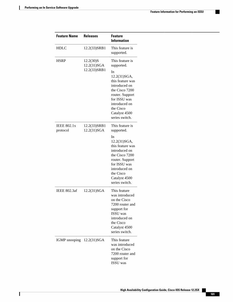
Feature Name Releases FeatureInformation
HDLC 12.2(33)SRB1 This feature issupported.
HSRP 12.2(30)S12.2(31)SGA12.2(33)SRB1
This feature issupported.
In12.2(31)SGA,this feature wasintroduced onthe Cisco 7200router. Supportfor ISSU wasintroduced onthe CiscoCatalyst 4500series switch.
IEEE 802.1xprotocol
12.2(33)SRB112.2(31)SGA
This feature issupported.
In12.2(31)SGA,this feature wasintroduced onthe Cisco 7200router. Supportfor ISSU wasintroduced onthe CiscoCatalyst 4500series switch.
IEEE 802.3af 12.2(31)SGA This featurewas introducedon the Cisco7200 router andsupport forISSU wasintroduced onthe CiscoCatalyst 4500series switch.
IGMP snooping 12.2(31)SGA This featurewas introducedon the Cisco7200 router andsupport forISSU was
Performing an In Service Software UpgradeFeature Information for Performing an ISSU
High Availability Configuration Guide, Cisco IOS Release 12.2SX 101

Feature Name Releases FeatureInformation
introduced onthe CiscoCatalyst 4500series switch.
IP host 12.2(31)SGA This feature issupported.
IPv4 Multicast 12.2(33)SRE15.0(1)S
This feature issupported.
IS-IS 12.2(31)SB212.2(31)SGA12.2(33)SRB115.0(1)S CiscoIOS XE3.1.0SG
This feature issupported.
In12.2(31)SGA,this feature wasintroduced onthe Cisco 7200router. Supportfor ISSU wasintroduced onthe CiscoCatalyst 4500series switch.
MPLS Clients 12.2(28)SB12.2(33)SRB1
MPLSapplications canbe upgradingusing the InServiceSoftwareUpgrade(ISSU) processand theenhanced FastSoftwareUpgrade(eFSU) process.Thus, MPLSapplications areconsideredISSU's MPLSclients. TheISSU processallows CiscoIOS software atthe router levelto be updated orotherwise
Performing an In Service Software Upgrade Feature Information for Performing an ISSU
High Availability Configuration Guide, Cisco IOS Release 12.2SX102

Feature Name Releases FeatureInformation
modified whilepacketforwardingcontinues. Atthe line-cardlevel, the eFSUprocessminimizes line-card downtimeduring suchupgrades tobetween 30 and90 seconds, byloading the newline-card imagebefore the ISSUswitchoveroccurs from theactive to thestandby RouteProcessor (RP).
In 12.2(28)SB,the ISSUfeature wasintroduced.
In12.2(33)SRB-1,the LSPV Pushand TE clientsand the eFSUfunctionalitywere added.
MPLS VPN6VPE and 6PEISSU support
12.2(33)SRE12.2(33)XNE
This feature issupported.
MTR 12.2(33)SRB1 This feature issupported.
NSF/SSO/ISSU- VirtualPrivate LANServices
12.2(33)SXI415.0(1)S
This feature issupported.
Port security 12.2(31)SGA This featurewas introducedon the Cisco
Performing an In Service Software UpgradeFeature Information for Performing an ISSU
High Availability Configuration Guide, Cisco IOS Release 12.2SX 103

Feature Name Releases FeatureInformation
7200 router andsupport forISSU wasintroduced onthe CiscoCatalyst 4500series switch.
PPP/MLP 12.2(33)SRB1 This feature issupported.
PPPoA 12.2(31)SB2 This feature issupported.
PPPoE 12.2(31)SB215.0(1)S
This feature issupported.
QoS 12.2(31)SB212.2(33)SRB1
This feature issupported.
RIB/VRF 12.2(33)SRB112.2(33)SRE
This feature issupported.
SNMP 12.2(33)SB12.2(33)SRB1
This feature issupported.
STP 12.2(31)SGA12.2(33)SRB1
This featurewas introducedon the Cisco7200 router andsupport forISSU wasintroduced onthe CiscoCatalyst 4500series switch.
Virtualtemplatemanager
12.2(33)SRC This feature issupported.
VRRP 15.0(1)S This feature issupported.
Cisco and the Cisco Logo are trademarks of Cisco Systems, Inc. and/or its affiliates in the U.S. and othercountries. A listing of Cisco's trademarks can be found at www.cisco.com/go/trademarks. Third party
Performing an In Service Software Upgrade
High Availability Configuration Guide, Cisco IOS Release 12.2SX104

trademarks mentioned are the property of their respective owners. The use of the word partner does notimply a partnership relationship between Cisco and any other company. (1005R)
Any Internet Protocol (IP) addresses and phone numbers used in this document are not intended to beactual addresses and phone numbers. Any examples, command display output, network topology diagrams,and other figures included in the document are shown for illustrative purposes only. Any use of actual IPaddresses or phone numbers in illustrative content is unintentional and coincidental.
Performing an In Service Software Upgrade
High Availability Configuration Guide, Cisco IOS Release 12.2SX 105

Example Verifying Rollback Timer Information
High Availability Configuration Guide, Cisco IOS Release 12.2SX106