
Cisco IOS XR Getting Started Guide for the Cisco XR 12000 ...
Upload
khangminh22Category
view
7download
0
Basic System Management Configuration Guide, Cisco IOS XE 17Americas HeadquartersCisco Systems, Inc.170 West Tasman DriveSan Jose, CA 95134-1706USAhttp://www.cisco.comTel: 408 526-4000
800 553-NETS (6387)Fax: 408 527-0883

THE SPECIFICATIONS AND INFORMATION REGARDING THE PRODUCTS IN THIS MANUAL ARE SUBJECT TO CHANGE WITHOUT NOTICE. ALL STATEMENTS,INFORMATION, AND RECOMMENDATIONS IN THIS MANUAL ARE BELIEVED TO BE ACCURATE BUT ARE PRESENTED WITHOUT WARRANTY OF ANY KIND,EXPRESS OR IMPLIED. USERS MUST TAKE FULL RESPONSIBILITY FOR THEIR APPLICATION OF ANY PRODUCTS.
THE SOFTWARE LICENSE AND LIMITED WARRANTY FOR THE ACCOMPANYING PRODUCT ARE SET FORTH IN THE INFORMATION PACKET THAT SHIPPED WITHTHE PRODUCT AND ARE INCORPORATED HEREIN BY THIS REFERENCE. IF YOU ARE UNABLE TO LOCATE THE SOFTWARE LICENSE OR LIMITED WARRANTY,CONTACT YOUR CISCO REPRESENTATIVE FOR A COPY.
The Cisco implementation of TCP header compression is an adaptation of a program developed by the University of California, Berkeley (UCB) as part of UCB's public domain version ofthe UNIX operating system. All rights reserved. Copyright © 1981, Regents of the University of California.
NOTWITHSTANDING ANY OTHERWARRANTY HEREIN, ALL DOCUMENT FILES AND SOFTWARE OF THESE SUPPLIERS ARE PROVIDED “AS IS" WITH ALL FAULTS.CISCO AND THE ABOVE-NAMED SUPPLIERS DISCLAIM ALL WARRANTIES, EXPRESSED OR IMPLIED, INCLUDING, WITHOUT LIMITATION, THOSE OFMERCHANTABILITY, FITNESS FOR A PARTICULAR PURPOSE AND NONINFRINGEMENT OR ARISING FROM A COURSE OF DEALING, USAGE, OR TRADE PRACTICE.
IN NO EVENT SHALL CISCO OR ITS SUPPLIERS BE LIABLE FOR ANY INDIRECT, SPECIAL, CONSEQUENTIAL, OR INCIDENTAL DAMAGES, INCLUDING, WITHOUTLIMITATION, LOST PROFITS OR LOSS OR DAMAGE TO DATA ARISING OUT OF THE USE OR INABILITY TO USE THIS MANUAL, EVEN IF CISCO OR ITS SUPPLIERSHAVE BEEN ADVISED OF THE POSSIBILITY OF SUCH DAMAGES.
Any Internet Protocol (IP) addresses and phone numbers used in this document are not intended to be actual addresses and phone numbers. Any examples, command display output, networktopology diagrams, and other figures included in the document are shown for illustrative purposes only. Any use of actual IP addresses or phone numbers in illustrative content is unintentionaland coincidental.
All printed copies and duplicate soft copies of this document are considered uncontrolled. See the current online version for the latest version.
Cisco has more than 200 offices worldwide. Addresses and phone numbers are listed on the Cisco website at www.cisco.com/go/offices.
Cisco and the Cisco logo are trademarks or registered trademarks of Cisco and/or its affiliates in the U.S. and other countries. To view a list of Cisco trademarks, go to this URL:https://www.cisco.com/c/en/us/about/legal/trademarks.html. Third-party trademarks mentioned are the property of their respective owners. The use of the word partner does not imply apartnership relationship between Cisco and any other company. (1721R)
© 2021 Cisco Systems, Inc. All rights reserved.
C O N T E N T S
Read Me First 1C H A P T E R 1
Performing Basic System Management 3C H A P T E R 2
Finding Feature Information 3
Information About Performing Basic System Management 3
System Name 3
Command Aliases 3
Minor Services 4
BOOTP Server 5
Finger Protocol 5
Hidden Telnet Addresses 5
EXEC Startup Delay 5
Idle Telnet Connections 5
Interval for Load Data 5
Number of TCP Transactions 6
Switching and Scheduling Priorities 6
System Buffer Size 6
How to Perform Basic System Management 6
Setting Basic System Parameters 6
Configuration Examples for Performing Basic System Management 12
Additional References 13
Feature Information for Performing Basic System Management 14
Memory Threshold Notifications 15C H A P T E R 3
Finding Feature Information 15
Information About Memory Threshold Notifications 15
Basic System Management Configuration Guide, Cisco IOS XE 17iii

Memory Threshold Notifications 15
Memory Reservation 16
How to Define Memory Threshold Notifications 16
Setting a Low Free Memory Threshold 16
Reserving Memory for Critical Notifications 16
Configuration Examples for Memory Threshold Notifications 17
Setting a Low Free Memory Threshold Examples 17
Reserving Memory for Critical Notifications Example 18
Additional References 18
Feature Information for Memory Threshold Notifications 19
NTPv4 MIB 21C H A P T E R 4
Finding Feature Information 21
Information About the NTPv4 MIB 21
NTPv4 MIB 21
How to Verify the NTPv4 MIB 22
Verifying NTPv4 MIB 22
Configuration Examples for NTPv4 MIB 23
Example: Verifying the NTP4 MIB 23
Additional References 24
Feature Information for the NTPv4 MIB 25
Network Time Protocol 27C H A P T E R 5
Finding Feature Information 27
Information About Network Time Protocol 27
Time and Calendar Services 27
Network Time Protocol 28
Poll-Based NTP Associations 29
Broadcast-Based NTP Associations 30
NTP Access Group 30
NTP Services on a Specific Interface 31
Source IP Address for NTP Packets 31
System as an Authoritative NTP Server 31
Orphan Mode 32
Basic System Management Configuration Guide, Cisco IOS XE 17iv
Contents

Simple Network Time Protocol 33
VINES Time Service 33
Hardware Clock 34
Time Ranges 34
How to Configure Network Time Protocol 35
Configuring NTP 35
Restrictions for Network Time Protocol 35
Configuring Poll-Based NTP Associations 36
Configuring Broadcast-Based NTP Associations 37
Configuring NTP Authentication 38
Configuring an External Reference Clock 40
Configuring Orphan Mode 41
Configuring VINES Time Service 42
Configuring the Time and Date 43
Setting the Hardware Clock 45
Configuring Time Ranges 47
Verifying Network Time Protocol 48
Configuration Examples for Network Time Protocol 49
Example: Configuring Network Time Protocol 49
Additional References for Network Time Protocol 50
Feature Information for Network Time Protocol 51
Simple Network Time Protocol 53C H A P T E R 6
Finding Feature Information 53
Restrictions for Simple Network Time Protocol 53
Information About Simple Network Time Protocol 54
Simple Network Time Protocol 54
How to Configure Simple Network Time Protocol 54
Configuring Simple Network Time Protocol (SNTP) Authentication 54
Verifying and Troubleshooting Simple Network Time Protocol 56
Configuration Examples for Simple Network Time Protocol 57
Example: Configuring Simple Network Time Protocol 57
Additional References for Simple Network Time Protocol 57
Feature Information for the SNTP 58
Basic System Management Configuration Guide, Cisco IOS XE 17v
Contents

Basic System Management Configuration Guide, Cisco IOS XE 17vi
Contents
C H A P T E R 1Read Me First
Important Information about Cisco IOS XE 16
Effective Cisco IOS XE Release 3.7.0E for Catalyst Switching and Cisco IOS XE Release 3.17S (for Accessand Edge Routing) the two releases evolve (merge) into a single version of converged release—the Cisco IOSXE 16—providing one release covering the extensive range of access and edge products in the Switching andRouting portfolio.
Feature Information
Use Cisco Feature Navigator to find information about feature support, platform support, and Cisco softwareimage support. An account on Cisco.com is not required.
Related References
• Cisco IOS Command References, All Releases
Obtaining Documentation and Submitting a Service Request
• To receive timely, relevant information from Cisco, sign up at Cisco Profile Manager.
• To get the business impact you’re looking for with the technologies that matter, visit Cisco Services.
• To submit a service request, visit Cisco Support.
• To discover and browse secure, validated enterprise-class apps, products, solutions and services, visitCisco Marketplace.
• To obtain general networking, training, and certification titles, visit Cisco Press.
• To find warranty information for a specific product or product family, access Cisco Warranty Finder.
Basic System Management Configuration Guide, Cisco IOS XE 171

Basic System Management Configuration Guide, Cisco IOS XE 172
Read Me First
C H A P T E R 2Performing Basic System Management
This module describes the basic tasks that you can perform to manage the general system features of the CiscoIOS software--those features that are generally not specific to a particular protocol.
• Finding Feature Information, on page 3• Information About Performing Basic System Management, on page 3• How to Perform Basic System Management, on page 6• Configuration Examples for Performing Basic System Management, on page 12• Additional References, on page 13• Feature Information for Performing Basic System Management, on page 14
Finding Feature InformationYour software release may not support all the features documented in this module. For the latest caveats andfeature information, see Bug Search Tool and the release notes for your platform and software release. Tofind information about the features documented in this module, and to see a list of the releases in which eachfeature is supported, see the feature information table.
Use Cisco Feature Navigator to find information about platform support and Cisco software image support.To access Cisco Feature Navigator, go to www.cisco.com/go/cfn. An account on Cisco.com is not required.
Information About Performing Basic System Management
System NameThe system name, also called the hostname, is used to uniquely identify the system in your network. Thesystem name is displayed at the CLI prompt. If no name is configured, the system default name is Router.
Command AliasesCommand aliases allow you to configure alternative syntax for commands. You may want to create aliasesfor commonly used or complex commands. For example, you could assign the alias save config to the copyrunning-config startup-config command to reduce the amount of typing you have to perform, or if your
Basic System Management Configuration Guide, Cisco IOS XE 173
users might find the save config command easier to remember. Use word substitutions or abbreviations totailor the command syntax for you and your user community.
Remember that any aliases you configure will be effective only on your system, and that the original commandsyntax will appear in the configuration file.
Minor ServicesMinor services are small servers that run on your routing device and are useful for basic system testing andfor providing basic network functions. Minor services are useful for testing connections from another host onthe network.
Cisco small servers are conceptually equivalent to daemons.
Small servers provided by Cisco IOS software-based devices include TCP, UDP, HTTP, Bootstrap Protocol(BOOTP), and Finger. For information about the HTTP server, see the “Using the Cisco Web Browser UserInterface” chapter in the Cisco IOS Configuration Fundamentals Configuration Guide.
The TCP small server provides the following minor services:
• Chargen--Generates a stream of ASCII data. To test this service, issue the telnet a.b.c.d chargencommandfrom a remote host.
• Daytime--Returns the system date and time if you have configured Network Time Protocol (NTP) or setthe date and time manually. To test this service, issue the telnet a.b.c.d daytimecommand from a remotehost.
• Discard--Discards whatever you type. To test this service, issue the telnet a.b.c.d discardcommand froma remote host.
• Echo--Echoes back whatever you type. To test this service, issue the telnet a.b.c.d echocommand froma remote host.
The UDP small server provides the following minor services:
• Chargen--Discards the datagram that you send and responds with a 72-character string of ASCII charactersterminated with a CR+LF (carriage return and line feed).
• Discard--Discards the datagram you send.
• Echo--Echoes the payload of the datagram that you send.
Minor services are disabled by default.
Enabling minor services creates the potential for certain types of denial-of-service (DoS) attacks, such as theUDP diagnostic port attack. Therefore, any network device that has UDP, TCP, BOOTP, or Finger servicesshould be protected by a firewall or have the minor services disabled. For information on preventing UDPdiagnostic port attacks, see the white paper titled Defining Strategies to Protect Against UDP Diagnostic PortDenial of Service Attacks a vailable on Cisco.com.
Caution
Basic System Management Configuration Guide, Cisco IOS XE 174
Performing Basic System ManagementMinor Services
BOOTP ServerYou can enable or disable an async line Bootstrap Protocol (BOOTP) service on your routing device. Thissmall server is enabled by default. Due to security considerations, this service should be disabled if you arenot using it.
Because DHCP is based on the BOOTP, both of these service share the well-known UDP server port 67 (perthe Internet standards and RFCs). For more information about DHCP configuration in the Cisco IOS software,see the Cisco IOS IP Addressing Configuration Guide. For more information about BOOTP, see RFC 951.Interoperation between BOOTP and DHCP is defined in RFC 1534. DHCP is defined in RFC 2131.
Finger ProtocolThe Finger protocol allows users throughout the network to get a list of the users currently using a particularrouting device. The information displayed includes the processes running on the system, the line number,connection name, idle time, and terminal location. This information is provided through the Cisco IOS softwareshow users EXEC command.
Hidden Telnet AddressesYou can hide addresses while attempting to establish a Telnet session. The hide feature suppresses the displayof the address and continues to display all other messages that normally would be displayed during a connectionattempt, such as detailed error messages if the connection fails.
EXEC Startup DelayTo delay the startup of the EXEC process on noisy lines until the line has been idle for 3 seconds, use theservice exec-wait command in global configuration mode.
This command is useful on noisy modem lines or when a modem attached to the line is configured to ignoreMicrocom Networking Protocol (MNP) or V.42 negotiations, and when MNP or V.42 modems are dialingin. In these cases, noise or MNP/V.42 packets might be interpreted as usernames and passwords, causingauthentication failure before the user can type a username or password. This command is not useful onnonmodem lines or lines without some kind of login configured.
Idle Telnet ConnectionsNormally, data sent to noncurrent Telnet connections is accepted and discarded. When the servicetelnet-zero-idle command is enabled and a session is suspended (that is, some other connection is madeactive), the TCP window is set to zero. This action prevents the remote host from sending any more data untilthe connection is resumed. Use this command when all messages sent by the host must be seen by the usersand the users are likely to use multiple sessions. Do not use this command if your host will eventually timeout and log out a TCP user whose window is zero.
Interval for Load DataYou can change the period of time over which a set of data is used for computing load statistics. Decisions,such as dial backup, depend on these statistics. If you decrease the load interval, the average statistics arecomputed over a shorter period of time and are more responsive to bursts of traffic.
Basic System Management Configuration Guide, Cisco IOS XE 175
Performing Basic System ManagementBOOTP Server

Number of TCP TransactionsWhen you are using a standard TCP implementation to send keystrokes between machines, TCP tends to sendone packet for each keystroke typed, which can use up the bandwidth and contribute to the congestion onlarger networks.
John Nagle’s algorithm (RFC 896) helps alleviate the small-packet problem in TCP. The first character typedafter the connection establishment is sent in a single packet, but TCP holds any additional characters that aretyped until the receiver acknowledges the previous packet. Then the second, larger packet is sent, and theadditional typed characters are saved until the acknowledgment comes back. The effect is to accumulatecharacters into larger chunks, and pace their transmission to the network at a rate matching the round-triptime of the given connection. This method is usually preferable for all TCP-based traffic.
By default, the Nagle algorithm is not enabled.
Switching and Scheduling PrioritiesThe normal operation of the network server allows the switching operations to use as much of the centralprocessor as required. If the network is running unusually heavy loads that do not allow the processor thetime to handle the routing protocols, you may need to give priority to the system process scheduler.
System Buffer SizeYou can adjust the initial buffer pool settings and limits at which temporary buffers are created and destroyed.
During normal system operation, there are two sets of buffer pools: public and interface. They behave asfollows:
• The buffers in the public pools grow and shrink based upon demand. Some public pools are temporaryand are created and destroyed as needed. Other public pools are permanently allocated and cannot bedestroyed. Public buffer pools are labeled as small, middle, big, very big, large, and huge.
• Interface pools are static--that is, they are all permanent. One interface pool exists for each interface. Forexample, a Cisco 4000 1E 4T configuration has one Ethernet buffer pool and four serial buffer pools.
The server has one pool of queueing elements and six public pools of packet buffers of different sizes. Foreach pool, the server keeps count of the number of outstanding buffers, the number of buffers in the free list,and the maximum number of buffers allowed in the free list.
How to Perform Basic System Management
Setting Basic System ParametersTo set basic system parameters perform the following steps. You can perform these steps based on thecustomization requirements of your system.
SUMMARY STEPS
1. hostname name
2. prompt string
Basic System Management Configuration Guide, Cisco IOS XE 176
Performing Basic System ManagementNumber of TCP Transactions
3. alias mode alias-name alias-command-line
4. service tcp-small-servers5. service udp-small-servers6. no ip bootp server7. ip finger8. ip finger rfc-compliant9. service hide-telnet-address10. line line-number
11. exit12. exit13. busy-message hostname message
14. service exec-wait15. service telnet-zero-idle16. load-interval seconds
17. service nagle18. scheduler interval milliseconds
19. scheduler allocate [network-microseconds process-microseconds]20. scheduler process-watchdog {hang | normal | reload | terminate}21. buffers {small |middle | big | verybig | large | huge | type number} {permanent |max-free |min-free
| initial} number
22. exit23. show aliases [mode]24. show buffers
DETAILED STEPS
Step 1 hostname name
Use the hostname name command to perform the basic system management task of assigning a name for your device.
Example:
Router(config)# hostname host1
Step 2 prompt string
or
no service prompt config
By default, the CLI prompt consists of the system name followed by an angle bracket (>) for user EXEC mode or apound sign (#) for privileged EXEC mode. Use the the prompt string or the no service prompt config command tocustomize the CLI prompt for your system.
Example:
Router(config)# prompt Router123
or
Example:
Basic System Management Configuration Guide, Cisco IOS XE 177
Performing Basic System ManagementSetting Basic System Parameters
Router(config)# no service prompt config
Step 3 alias mode alias-name alias-command-line
Use the alias mode alias-name alias-command-line command to create a command alias.
Example:
Router(config)# alias exec save config copy running-config startup-config
Step 4 service tcp-small-servers
Use the service tcp-small-servers command to enable minor TCP services such as chargen, daytime, discard, andecho.
The no form of the service tcp-small-servers command will appear in the configuration file when thesebasic services are disabled.
Note
Example:
Router(config)# service tcp-small-servers
Step 5 service udp-small-servers
Use the service udp-small-servers command to enable minor UDP services such as chargen, daytime, discard, andecho.
The no form of the service udp-small-servers command will appear in the configuration file when thesebasic services are disabled.
Note
Example:
Router(config)# service udp-small-servers
Step 6 no ip bootp server
Use the no ip bootp server command to disable the BOOTP server on your platform.
Example:
Router(config)# no ip bootp server
Step 7 ip finger
Use the ip finger command to enable a Cisco device to respond to Finger (port 79) requests. When the ip fingercommand is configured, the router will respond to a telnet a.b.c.d finger command from a remote host by immediatelydisplaying the output of the show userscommand and then closing the connection.
Example:
Router(config)# ip finger
Step 8 ip finger rfc-compliant
Use the ip finger rfc-compliant command to configure the finger protocol to be compliant with RFC 1288. The ipfinger rfc-compliant command should not be configured for devices with more than 20 simultaneous users. When theip finger rfc-compliantcommand is configured, the router will wait for input before displaying any information. The
Basic System Management Configuration Guide, Cisco IOS XE 178
Performing Basic System ManagementSetting Basic System Parameters
remote user can then press the Return key to display the output of the show users command, or enter /W to display theoutput of the show users wide command. After this information is displayed, the connection is closed.
Example:
Router(config)# ip finger rfc-compliant
Step 9 service hide-telnet-address
Use the service hide-telnet-address command to configure the router to suppress Telnet addresses.
Example:
Router(config)# service hide-telnet-address
Step 10 line line-number
Use the line command to enter line configuration mode.
Example:
Router(config)# line 1
Step 11 exit
Use the exit command to exit line configuration mode and return to global configuration mode.
Example:
Router(config-line)# exit
Step 12 exit
Use the exit command to exit line configuration mode and return to global configuration mode.
Example:
Router(config-line)# exit
Step 13 busy-message hostname message
Use the busy-message commandwith the service hide-telnet-addresscommand to customize the information displayedduring Telnet connection attempts. If the connection attempt fails, the router suppresses the address and displays themessage specified with the busy-message command.
Example:
Router(config)# busy-message host1 message1
Step 14 service exec-wait
Use the service exec-waitcommand to delay the startup of the EXEC process on noisy lines until the line has been idlefor 3 seconds.
Example:
Router(config)# service exec-wait
Step 15 service telnet-zero-idle
Basic System Management Configuration Guide, Cisco IOS XE 179
Performing Basic System ManagementSetting Basic System Parameters
Use the service telnet-zero-idle command to configure the Cisco IOS software to set the TCP window to zero (0) whenthe Telnet connection is idle.
Example:
Router(config)# service telnet-zero-idle
Step 16 load-interval seconds
Use the load-interval seconds command to change the length of time for which a set of data is used to compute loadstatistics.
Example:
Router(config)# load-interval 100
Step 17 service nagle
Use the service nagle command to enable the Nagle algorithm and thereby reduce the number of TCP transactions.
Example:
Router(config)# load-interval 100
Step 18 scheduler interval milliseconds
Use the scheduler interval milliseconds command to define the maximum amount of time that can elapse withoutrunning the lowest-priority system processes.
Example:
Router(config)# scheduler interval 100
Step 19 scheduler allocate [network-microseconds process-microseconds]
Use the scheduler allocate command to change the amount of time that the CPU spends on fast-switching andprocess-level operations on the Cisco 7200 series and Cisco 7500 series routers.
Cisco recommends that you do not change the default values of the scheduler allocate command.Caution
Example:
Router(config)# scheduler allocate 5000 200
Step 20 scheduler process-watchdog {hang | normal | reload | terminate}
Use the scheduler process-watchdog {hang | normal | reload | terminate} command to configure the characteristicsfor a looping process.
Example:
Router(config)# scheduler process-watchdog hang
Step 21 buffers {small | middle | big | verybig | large | huge | type number} {permanent | max-free | min-free | initial}number
Use the buffers {small | middle | big | verybig | large | huge | type number} {permanent | max-free | min-free |initial} number command to adjust the system buffer size.
Basic System Management Configuration Guide, Cisco IOS XE 1710
Performing Basic System ManagementSetting Basic System Parameters
Example:
Router(config)# buffers small permanent 10
Cisco does not recommend that you adjust these parameters. Improper settings can adversely impact thesystem performance.
Caution
Step 22 exit
Use the exit command to exit global configuration mode and return to privileged EXEC mode.
Example:
Router(config)# exit
Step 23 show aliases [mode]
Use the show aliases [mode] command to display a list of command aliases currently configured on your system, andthe original command syntax for those aliases.
Example:
Router# show aliases exec
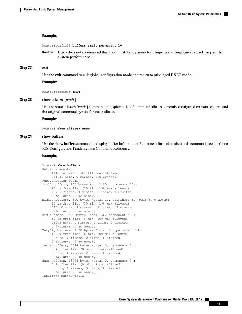
Step 24 show buffers
Use the show bufferscommand to display buffer information. For more information about this command, see the CiscoIOS Configuration Fundamentals Command Reference.
Example:
Router# show buffersBuffer elements:
1119 in free list (1119 max allowed)641606 hits, 0 misses, 619 created
Public buffer pools:Small buffers, 104 bytes (total 50, permanent 50):
48 in free list (20 min, 150 max allowed)2976557 hits, 0 misses, 0 trims, 0 created0 failures (0 no memory)
Middle buffers, 600 bytes (total 25, permanent 25, peak 37 @ 2w0d):25 in free list (10 min, 150 max allowed)445110 hits, 4 misses, 12 trims, 12 created0 failures (0 no memory)
Big buffers, 1536 bytes (total 50, permanent 50):50 in free list (5 min, 150 max allowed)58004 hits, 0 misses, 0 trims, 0 created0 failures (0 no memory)
VeryBig buffers, 4520 bytes (total 10, permanent 10):10 in free list (0 min, 100 max allowed)0 hits, 0 misses, 0 trims, 0 created0 failures (0 no memory)
Large buffers, 5024 bytes (total 0, permanent 0):0 in free list (0 min, 10 max allowed)0 hits, 0 misses, 0 trims, 0 created0 failures (0 no memory)
Huge buffers, 18024 bytes (total 0, permanent 0):0 in free list (0 min, 4 max allowed)0 hits, 0 misses, 0 trims, 0 created0 failures (0 no memory)
Interface buffer pools:
Basic System Management Configuration Guide, Cisco IOS XE 1711
Performing Basic System ManagementSetting Basic System Parameters
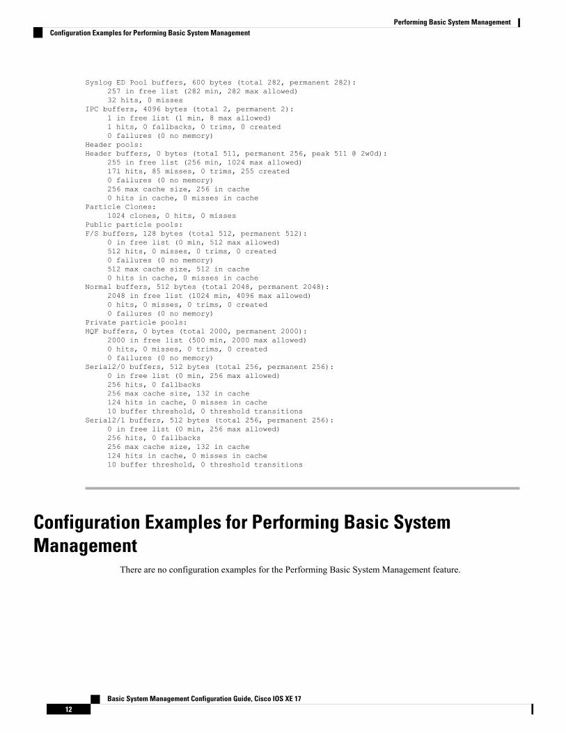
Syslog ED Pool buffers, 600 bytes (total 282, permanent 282):257 in free list (282 min, 282 max allowed)32 hits, 0 misses
IPC buffers, 4096 bytes (total 2, permanent 2):1 in free list (1 min, 8 max allowed)1 hits, 0 fallbacks, 0 trims, 0 created0 failures (0 no memory)
Header pools:Header buffers, 0 bytes (total 511, permanent 256, peak 511 @ 2w0d):
255 in free list (256 min, 1024 max allowed)171 hits, 85 misses, 0 trims, 255 created0 failures (0 no memory)256 max cache size, 256 in cache0 hits in cache, 0 misses in cache
Particle Clones:1024 clones, 0 hits, 0 misses
Public particle pools:F/S buffers, 128 bytes (total 512, permanent 512):
0 in free list (0 min, 512 max allowed)512 hits, 0 misses, 0 trims, 0 created0 failures (0 no memory)512 max cache size, 512 in cache0 hits in cache, 0 misses in cache
Normal buffers, 512 bytes (total 2048, permanent 2048):2048 in free list (1024 min, 4096 max allowed)0 hits, 0 misses, 0 trims, 0 created0 failures (0 no memory)
Private particle pools:HQF buffers, 0 bytes (total 2000, permanent 2000):
2000 in free list (500 min, 2000 max allowed)0 hits, 0 misses, 0 trims, 0 created0 failures (0 no memory)
Serial2/0 buffers, 512 bytes (total 256, permanent 256):0 in free list (0 min, 256 max allowed)256 hits, 0 fallbacks256 max cache size, 132 in cache124 hits in cache, 0 misses in cache10 buffer threshold, 0 threshold transitions
Serial2/1 buffers, 512 bytes (total 256, permanent 256):0 in free list (0 min, 256 max allowed)256 hits, 0 fallbacks256 max cache size, 132 in cache124 hits in cache, 0 misses in cache10 buffer threshold, 0 threshold transitions
Configuration Examples for Performing Basic SystemManagement
There are no configuration examples for the Performing Basic System Management feature.
Basic System Management Configuration Guide, Cisco IOS XE 1712
Performing Basic System ManagementConfiguration Examples for Performing Basic System Management
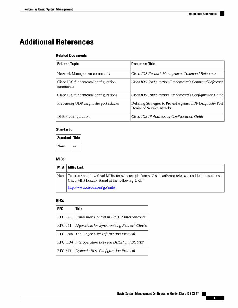
Additional ReferencesRelated Documents
Document TitleRelated Topic
Cisco IOS Network Management Command ReferenceNetwork Management commands
Cisco IOS Configuration Fundamentals Command ReferenceCisco IOS fundamental configurationcommands
Cisco IOS Configuration Fundamentals Configuration GuideCisco IOS fundamental configurations
Defining Strategies to Protect Against UDPDiagnostic PortDenial of Service Attacks
Preventing UDP diagnostic port attacks
Cisco IOS IP Addressing Configuration GuideDHCP configuration
Standards
TitleStandard
--None
MIBs
MIBs LinkMIB
To locate and download MIBs for selected platforms, Cisco software releases, and feature sets, useCisco MIB Locator found at the following URL:
http://www.cisco.com/go/mibs
None
RFCs
TitleRFC
Congestion Control in IP/TCP InternetworksRFC 896
Algorithms for Synchronizing Network ClocksRFC 951
The Finger User Information ProtocolRFC1288
Interoperation Between DHCP and BOOTPRFC1534
Dynamic Host Configuration ProtocolRFC2131
Basic System Management Configuration Guide, Cisco IOS XE 1713
Performing Basic System ManagementAdditional References
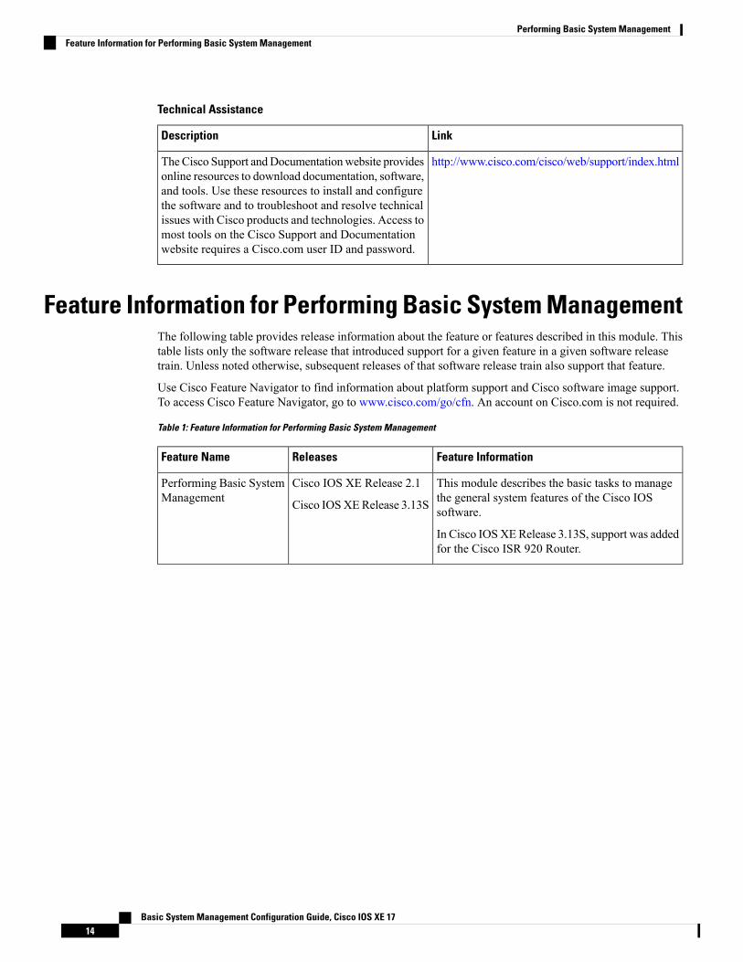
Technical Assistance
LinkDescription
http://www.cisco.com/cisco/web/support/index.htmlTheCisco Support andDocumentationwebsite providesonline resources to download documentation, software,and tools. Use these resources to install and configurethe software and to troubleshoot and resolve technicalissues with Cisco products and technologies. Access tomost tools on the Cisco Support and Documentationwebsite requires a Cisco.com user ID and password.
Feature Information for Performing Basic System ManagementThe following table provides release information about the feature or features described in this module. Thistable lists only the software release that introduced support for a given feature in a given software releasetrain. Unless noted otherwise, subsequent releases of that software release train also support that feature.
Use Cisco Feature Navigator to find information about platform support and Cisco software image support.To access Cisco Feature Navigator, go to www.cisco.com/go/cfn. An account on Cisco.com is not required.
Table 1: Feature Information for Performing Basic System Management
Feature InformationReleasesFeature Name
This module describes the basic tasks to managethe general system features of the Cisco IOSsoftware.
In Cisco IOSXERelease 3.13S, support was addedfor the Cisco ISR 920 Router.
Cisco IOS XE Release 2.1
Cisco IOSXERelease 3.13S
Performing Basic SystemManagement
Basic System Management Configuration Guide, Cisco IOS XE 1714
Performing Basic System ManagementFeature Information for Performing Basic System Management

C H A P T E R 3Memory Threshold Notifications
The Memory Threshold Notifications feature allows you to reserve memory for critical notifications and toconfigure a router to issue notifications when available memory falls below a specified threshold.
• Finding Feature Information, on page 15• Information About Memory Threshold Notifications, on page 15• How to Define Memory Threshold Notifications, on page 16• Configuration Examples for Memory Threshold Notifications, on page 17• Additional References, on page 18• Feature Information for Memory Threshold Notifications, on page 19
Finding Feature InformationYour software release may not support all the features documented in this module. For the latest caveats andfeature information, see Bug Search Tool and the release notes for your platform and software release. Tofind information about the features documented in this module, and to see a list of the releases in which eachfeature is supported, see the feature information table.
Use Cisco Feature Navigator to find information about platform support and Cisco software image support.To access Cisco Feature Navigator, go to www.cisco.com/go/cfn. An account on Cisco.com is not required.
Information About Memory Threshold NotificationsThe Memory Threshold Notifications feature provides two ways to mitigate low-memory conditions on arouter: notifications can be sent to indicate that free memory has fallen below a configured threshold, andmemory can be reserved to ensure that sufficient memory is available to issue critical notifications. Toimplement the Memory Threshold Notifications feature, you should understand the following concepts:
Memory Threshold NotificationsThe Memory Threshold Notifications feature allows you to reserve memory for critical notifications and toconfigure a router to issue notifications when available memory falls below a specified threshold.
Basic System Management Configuration Guide, Cisco IOS XE 1715
Memory ReservationMemory reservation for critical operations ensures that management processes, such as event logging, continueto function even when router memory is exhausted.
How to Define Memory Threshold Notifications
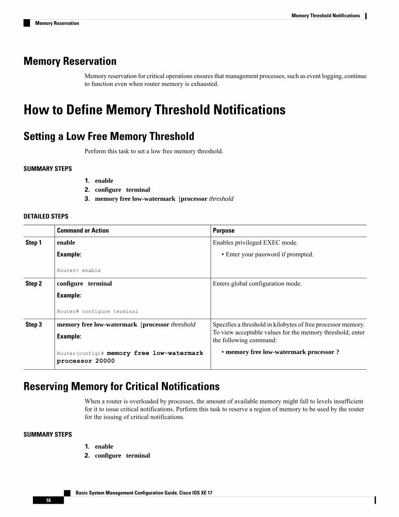
Setting a Low Free Memory ThresholdPerform this task to set a low free memory threshold.
SUMMARY STEPS
1. enable2. configure terminal3. memory free low-watermark [processor threshold
DETAILED STEPS
PurposeCommand or Action
Enables privileged EXEC mode.enableStep 1
Example: • Enter your password if prompted.
Router> enable
Enters global configuration mode.configure terminal
Example:
Step 2
Router# configure terminal
Specifies a threshold in kilobytes of free processor memory.To view acceptable values for the memory threshold, enterthe following command:
memory free low-watermark [processor threshold
Example:
Router(config)# memory free low-watermarkprocessor 20000
Step 3
• memory free low-watermark processor ?
Reserving Memory for Critical NotificationsWhen a router is overloaded by processes, the amount of available memory might fall to levels insufficientfor it to issue critical notifications. Perform this task to reserve a region of memory to be used by the routerfor the issuing of critical notifications.
SUMMARY STEPS
1. enable2. configure terminal
Basic System Management Configuration Guide, Cisco IOS XE 1716
Memory Threshold NotificationsMemory Reservation
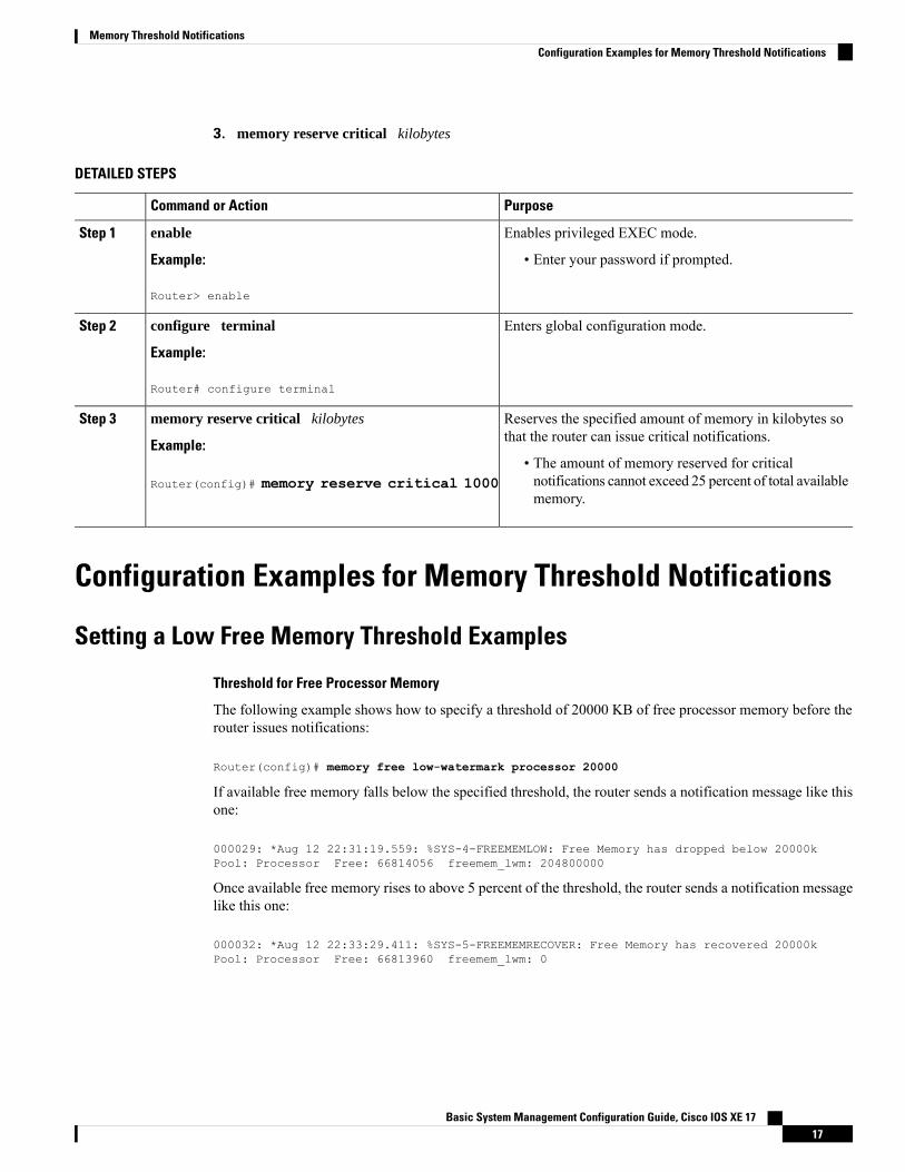
3. memory reserve critical kilobytes
DETAILED STEPS
PurposeCommand or Action
Enables privileged EXEC mode.enableStep 1
Example: • Enter your password if prompted.
Router> enable
Enters global configuration mode.configure terminal
Example:
Step 2
Router# configure terminal
Reserves the specified amount of memory in kilobytes sothat the router can issue critical notifications.
memory reserve critical kilobytes
Example:
Step 3
• The amount of memory reserved for criticalnotifications cannot exceed 25 percent of total availablememory.
Router(config)# memory reserve critical 1000
Configuration Examples for Memory Threshold Notifications
Setting a Low Free Memory Threshold Examples
Threshold for Free Processor Memory
The following example shows how to specify a threshold of 20000 KB of free processor memory before therouter issues notifications:
Router(config)# memory free low-watermark processor 20000
If available free memory falls below the specified threshold, the router sends a notification message like thisone:
000029: *Aug 12 22:31:19.559: %SYS-4-FREEMEMLOW: Free Memory has dropped below 20000kPool: Processor Free: 66814056 freemem_lwm: 204800000
Once available free memory rises to above 5 percent of the threshold, the router sends a notification messagelike this one:
000032: *Aug 12 22:33:29.411: %SYS-5-FREEMEMRECOVER: Free Memory has recovered 20000kPool: Processor Free: 66813960 freemem_lwm: 0
Basic System Management Configuration Guide, Cisco IOS XE 1717
Memory Threshold NotificationsConfiguration Examples for Memory Threshold Notifications
Reserving Memory for Critical Notifications ExampleThe following example shows how to reserve 1000 KB of memory for critical notifications:
Router# memory reserved critical 1000
The amount of memory reserved for critical notifications cannot exceed 25 percent of total available memory.Note
Additional ReferencesFor additional information related to the CPU Thresholding Notification feature, refer to the followingreferences:
Related Documents
Document TitleRelated Topic
Configuration Fundamentals Command ReferenceSNMP traps
Standards
TitleStandards
--No new or modified standards are supported by this feature and support for existing standards has notbeen modified by this feature.
MIBs
MIBs LinkMIBs
To locate and download MIBs for selected platforms, Cisco IOS releases, andfeature sets, use Cisco MIB Locator found at the following URL:
http://www.cisco.com/go/mibs
CISCO-PROCESS-MIB
RFCs
TitleRFCs
--No new or modified RFCs are supported by this feature and support for existing RFCs has not beenmodified by this feature.
Basic System Management Configuration Guide, Cisco IOS XE 1718
Memory Threshold NotificationsReserving Memory for Critical Notifications Example
Technical Assistance
LinkDescription
http://www.cisco.com/cisco/web/support/index.htmlTheCisco Support andDocumentationwebsite providesonline resources to download documentation, software,and tools. Use these resources to install and configurethe software and to troubleshoot and resolve technicalissues with Cisco products and technologies. Access tomost tools on the Cisco Support and Documentationwebsite requires a Cisco.com user ID and password.
Feature Information for Memory Threshold NotificationsThe following table provides release information about the feature or features described in this module. Thistable lists only the software release that introduced support for a given feature in a given software releasetrain. Unless noted otherwise, subsequent releases of that software release train also support that feature.
Use Cisco Feature Navigator to find information about platform support and Cisco software image support.To access Cisco Feature Navigator, go to www.cisco.com/go/cfn. An account on Cisco.com is not required.
Table 2: Feature Information for Memory Threshold Notifications
Feature InformationReleasesFeature Name
This feature was introduced onCiscoASR 1000Series Aggregation Services Routers.
Cisco IOS XE Release 2.1Memory ThresholdNotifications
Basic System Management Configuration Guide, Cisco IOS XE 1719
Memory Threshold NotificationsFeature Information for Memory Threshold Notifications

Basic System Management Configuration Guide, Cisco IOS XE 1720
Memory Threshold NotificationsFeature Information for Memory Threshold Notifications
C H A P T E R 4NTPv4 MIB
The NTPv4 MIB feature introduces the Network Time Protocol Version 4 (NTPv4) MIB in Cisco software.It defines data objects that represent the current status of NTP entities. These data objects are accessed usingthe Simple Network Management Protocol (SNMP) and are used to monitor and manage local NTP entities.
This module describes the NTPv4 MIB.
• Finding Feature Information, on page 21• Information About the NTPv4 MIB, on page 21• How to Verify the NTPv4 MIB, on page 22• Configuration Examples for NTPv4 MIB, on page 23• Additional References, on page 24• Feature Information for the NTPv4 MIB, on page 25
Finding Feature InformationYour software release may not support all the features documented in this module. For the latest caveats andfeature information, see Bug Search Tool and the release notes for your platform and software release. Tofind information about the features documented in this module, and to see a list of the releases in which eachfeature is supported, see the feature information table.
Use Cisco Feature Navigator to find information about platform support and Cisco software image support.To access Cisco Feature Navigator, go to www.cisco.com/go/cfn. An account on Cisco.com is not required.
Information About the NTPv4 MIB
NTPv4 MIBThe Network Time Protocol Version 4 (NTPv4) MIB feature, which is based on RFC 5907, defines dataobjects that represent the current status of NTP entities. These data objects are accessed using the SimpleNetwork Management Protocol (SNMP) and are used to monitor and manage local NTP entities.
The data objects contain the following information about the NTP entities:
• Connectivity to the upstream NTP servers and to hardware reference clocks.
• Product
Basic System Management Configuration Guide, Cisco IOS XE 1721

• Vendor
• Version
By using the information contained in the data objects, you can detect failures before the overall timesynchronization of the network is impacted.
The following object groups that are addressed in RFC 5907 are supported in the NTPv4 MIB:
• ntpAssociation
• ntpEntInfo
• ntpEntStatus
The following object groups that are addressed in RFC 5907 are not supported in the NTPv4 MIB:
• ntpEntControl
• ntpEntNotifObjects
How to Verify the NTPv4 MIBNo special configuration is needed for this feature. This feature is enabled by default.
Verifying NTPv4 MIBTo verify information about the NTPv4 MIB, perform any or all of the following optional commands in anyorder.
SUMMARY STEPS
1. show ntp associations [detail]2. show ntp status3. show ntp info4. show ntp packets
DETAILED STEPS
Step 1 show ntp associations [detail]
Example:Device> show ntp associations detail
(Optional) Displays detailed status of NTP associations.
Step 2 show ntp status
Example:Device> show ntp status
(Optional) Displays the status of NTP.
Basic System Management Configuration Guide, Cisco IOS XE 1722
NTPv4 MIBHow to Verify the NTPv4 MIB
Step 3 show ntp info
Example:Device> show ntp info
(Optional) Displays information about NTP entities.
Step 4 show ntp packets
Example:Device> show ntp packets
(Optional) Displays information about NTP packets.
Configuration Examples for NTPv4 MIB
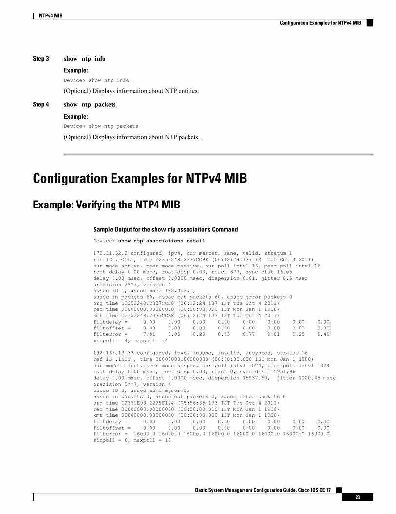
Example: Verifying the NTP4 MIB
Sample Output for the show ntp associations Command
Device> show ntp associations detail
172.31.32.2 configured, ipv4, our_master, sane, valid, stratum 1ref ID .LOCL., time D2352248.2337CCB8 (06:12:24.137 IST Tue Oct 4 2011)our mode active, peer mode passive, our poll intvl 16, peer poll intvl 16root delay 0.00 msec, root disp 0.00, reach 377, sync dist 16.05delay 0.00 msec, offset 0.0000 msec, dispersion 8.01, jitter 0.5 msecprecision 2**7, version 4assoc ID 1, assoc name 192.0.2.1,assoc in packets 60, assoc out packets 60, assoc error packets 0org time D2352248.2337CCB8 (06:12:24.137 IST Tue Oct 4 2011)rec time 00000000.00000000 (00:00:00.000 IST Mon Jan 1 1900)xmt time D2352248.2337CCB8 (06:12:24.137 IST Tue Oct 4 2011)filtdelay = 0.00 0.00 0.00 0.00 0.00 0.00 0.00 0.00filtoffset = 0.00 0.00 0.00 0.00 0.00 0.00 0.00 0.00filterror = 7.81 8.05 8.29 8.53 8.77 9.01 9.25 9.49minpoll = 4, maxpoll = 4
192.168.13.33 configured, ipv6, insane, invalid, unsynced, stratum 16ref ID .INIT., time 00000000.00000000 (00:00:00.000 IST Mon Jan 1 1900)our mode client, peer mode unspec, our poll intvl 1024, peer poll intvl 1024root delay 0.00 msec, root disp 0.00, reach 0, sync dist 15951.96delay 0.00 msec, offset 0.0000 msec, dispersion 15937.50, jitter 1000.45 msecprecision 2**7, version 4assoc ID 2, assoc name myserverassoc in packets 0, assoc out packets 0, assoc error packets 0org time D2351E93.2235F124 (05:56:35.133 IST Tue Oct 4 2011)rec time 00000000.00000000 (00:00:00.000 IST Mon Jan 1 1900)xmt time 00000000.00000000 (00:00:00.000 IST Mon Jan 1 1900)filtdelay = 0.00 0.00 0.00 0.00 0.00 0.00 0.00 0.00filtoffset = 0.00 0.00 0.00 0.00 0.00 0.00 0.00 0.00filterror = 16000.0 16000.0 16000.0 16000.0 16000.0 16000.0 16000.0 16000.0minpoll = 6, maxpoll = 10
Basic System Management Configuration Guide, Cisco IOS XE 1723
NTPv4 MIBConfiguration Examples for NTPv4 MIB
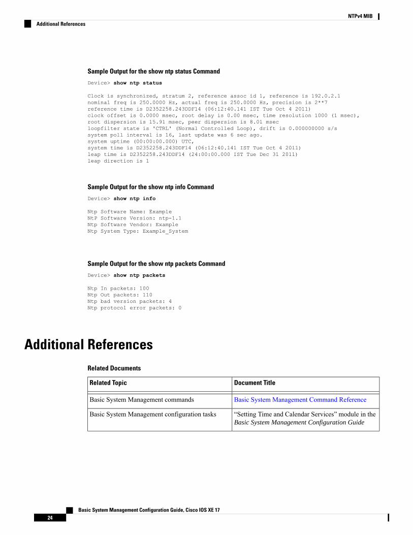
Sample Output for the show ntp status Command
Device> show ntp status
Clock is synchronized, stratum 2, reference assoc id 1, reference is 192.0.2.1nominal freq is 250.0000 Hz, actual freq is 250.0000 Hz, precision is 2**7reference time is D2352258.243DDF14 (06:12:40.141 IST Tue Oct 4 2011)clock offset is 0.0000 msec, root delay is 0.00 msec, time resolution 1000 (1 msec),root dispersion is 15.91 msec, peer dispersion is 8.01 msecloopfilter state is 'CTRL' (Normal Controlled Loop), drift is 0.000000000 s/ssystem poll interval is 16, last update was 6 sec ago.system uptime (00:00:00.000) UTC,system time is D2352258.243DDF14 (06:12:40.141 IST Tue Oct 4 2011)leap time is D2352258.243DDF14 (24:00:00.000 IST Tue Dec 31 2011)leap direction is 1
Sample Output for the show ntp info Command
Device> show ntp info
Ntp Software Name: ExampleNtP Software Version: ntp-1.1Ntp Software Vendor: ExampleNtp System Type: Example_System
Sample Output for the show ntp packets Command
Device> show ntp packets
Ntp In packets: 100Ntp Out packets: 110Ntp bad version packets: 4Ntp protocol error packets: 0
Additional ReferencesRelated Documents
Document TitleRelated Topic
Basic System Management Command ReferenceBasic System Management commands
“Setting Time and Calendar Services” module in theBasic System Management Configuration Guide
Basic System Management configuration tasks
Basic System Management Configuration Guide, Cisco IOS XE 1724
NTPv4 MIBAdditional References
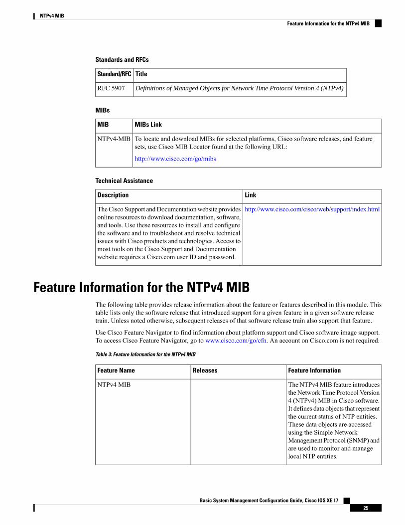
Standards and RFCs
TitleStandard/RFC
Definitions of Managed Objects for Network Time Protocol Version 4 (NTPv4)RFC 5907
MIBs
MIBs LinkMIB
To locate and download MIBs for selected platforms, Cisco software releases, and featuresets, use Cisco MIB Locator found at the following URL:
http://www.cisco.com/go/mibs
NTPv4-MIB
Technical Assistance
LinkDescription
http://www.cisco.com/cisco/web/support/index.htmlTheCisco Support andDocumentationwebsite providesonline resources to download documentation, software,and tools. Use these resources to install and configurethe software and to troubleshoot and resolve technicalissues with Cisco products and technologies. Access tomost tools on the Cisco Support and Documentationwebsite requires a Cisco.com user ID and password.
Feature Information for the NTPv4 MIBThe following table provides release information about the feature or features described in this module. Thistable lists only the software release that introduced support for a given feature in a given software releasetrain. Unless noted otherwise, subsequent releases of that software release train also support that feature.
Use Cisco Feature Navigator to find information about platform support and Cisco software image support.To access Cisco Feature Navigator, go to www.cisco.com/go/cfn. An account on Cisco.com is not required.
Table 3: Feature Information for the NTPv4 MIB
Feature InformationReleasesFeature Name
TheNTPv4MIB feature introducesthe Network Time Protocol Version4 (NTPv4) MIB in Cisco software.It defines data objects that representthe current status of NTP entities.These data objects are accessedusing the Simple NetworkManagement Protocol (SNMP) andare used to monitor and managelocal NTP entities.
NTPv4 MIB
Basic System Management Configuration Guide, Cisco IOS XE 1725
NTPv4 MIBFeature Information for the NTPv4 MIB

Basic System Management Configuration Guide, Cisco IOS XE 1726
NTPv4 MIBFeature Information for the NTPv4 MIB
C H A P T E R 5Network Time Protocol
Network Time Protocol (NTP) is a protocol designed to time-synchronize a network of machines. NTP runson User Datagram Protocol (UDP), which in turn runs on IP. NTP Version 3 is documented in RFC 1305.
This module describes how to configure Network Time Protocol on Cisco devices.
• Finding Feature Information, on page 27• Information About Network Time Protocol, on page 27• How to Configure Network Time Protocol, on page 35• Configuration Examples for Network Time Protocol, on page 49• Additional References for Network Time Protocol, on page 50• Feature Information for Network Time Protocol, on page 51
Finding Feature InformationYour software release may not support all the features documented in this module. For the latest caveats andfeature information, see Bug Search Tool and the release notes for your platform and software release. Tofind information about the features documented in this module, and to see a list of the releases in which eachfeature is supported, see the feature information table.
Use Cisco Feature Navigator to find information about platform support and Cisco software image support.To access Cisco Feature Navigator, go to www.cisco.com/go/cfn. An account on Cisco.com is not required.
Information About Network Time Protocol
Time and Calendar ServicesThe primary source for time data on your system is the software clock. This clock runs from the moment thesystem starts up and keeps track of the current date and time. The software clock can be set from a numberof sources and in turn can be used to distribute the current time through various mechanisms to other systems.When a device with a hardware clock is initialized or rebooted, the software clock is initially set based on thetime in the hardware clock. The software clock can then be updated from the following sources:
• Manual configuration (using the hardware clock)
• Network Time Protocol (NTP)
Basic System Management Configuration Guide, Cisco IOS XE 1727
• Simple Network Time Protocol (SNTP)
• Virtual Integrated Network Service (VINES) Time Service
Because the software clock can be dynamically updated, it has the potential to be more accurate than thehardware clock.
The software clock can provide time to the following services:
• Access lists
• Logging and debugging messages
• NTP
• The hardware clock
• User show commands
• VINES Time Service
The software clock cannot provide time to the NTP or VINES Time Service if the clock was set using SNTP.Note
The software clock keeps track of time internally based on the Coordinated Universal Time (UTC), also knownas Greenwich Mean Time (GMT). You can configure information about the local time zone and summer time(daylight saving time) so that time is displayed correctly relative to the local time zone.
The software clock keeps track of whether the time is authoritative (that is, whether it has been set by a timesource considered to be authoritative). If it is not authoritative, the time will be available only for displaypurposes and will not be redistributed.
Network Time ProtocolNetwork Time Protocol (NTP) is a protocol designed to time-synchronize a network of machines. NTP runson UDP, which in turn runs on IP. NTP Version 3 (NTPv3) is documented in RFC 1305.
An NTP network usually gets its time from an authoritative time source such as a radio clock or an atomicclock attached to a time server. NTP then distributes this time across the network. NTP is extremely efficient;no more than one packet per minute is necessary to synchronize two machines to the accuracy of within amillisecond of one another.
NTP uses the concept of a stratum to describe how many NTP hops away a machine is from an authoritativetime source. A stratum 1 time server typically has an authoritative time source (such as a radio or atomic clockor a Global Positioning System [GPS] time source) directly attached, a stratum 2 time server receives its timevia NTP from a stratum 1 time server, and so on.
NTP has two ways to avoid synchronizing to a machine whose time may not be accurate. NTP does notsynchronize to a machine that is not in turn synchronized with the NTP. NTP compares the time reported byseveral machines and does not synchronize to a machine whose time is significantly different from others,even if its stratum is lower. This strategy effectively builds a self-organizing tree of NTP servers.
Our implementation of NTP does not support stratum 1 service; that is, you cannot connect to a radio or atomicclock (for some specific platforms, however, you can connect to a GPS time-source device). We recommend
Basic System Management Configuration Guide, Cisco IOS XE 1728
Network Time ProtocolNetwork Time Protocol
that the time service you derive for your network from the public NTP servers that are available in the IPInternet.
If the network is isolated from the Internet, our implementation of NTP allows a machine to be configuredso that it acts as though it is synchronized via NTP, when in fact the network has determined the time by usingother means. Other machines can then synchronize to that machine via NTP.
A number of manufacturers include NTP software for their host systems and a publicly available version forsystems running UNIX. This software also allows UNIX-derivative servers to acquire the time directly froman atomic clock, which would subsequently propagate time information along to Cisco devices.
The communication betweenmachines running NTP (known as associations) are usually statically configured;each machine is given the IP address of all machines with which it should form associations. Accuratetimekeeping is made possible through exchange of NTP messages between each pair of machines with anassociation.
However, in a LAN environment, NTP can be configured to use IP broadcast messages instead. This alternativereduces configuration complexity because each machine can be configured to send or receive broadcastmessages. However, the accuracy of timekeeping is marginally reduced because the information flow is onlyone way.
The time kept on a machine is a critical resource, so we strongly recommend that you use the security featuresof NTP to avoid the accidental or malicious setting of incorrect time. Two security mechanisms are available:an access-list-based restriction scheme and an encrypted authentication mechanism.
When multiple sources of time (VINES, hardware clock, manual configuration) are available, NTP is alwaysconsidered to be more authoritative. NTP time overrides the time set by any other method.
NTP services are disabled on all interfaces by default.
For more information about NTP, see the following sections:
Poll-Based NTP AssociationsNetworking devices running NTP can be configured to operate in variety of association modes whensynchronizing time with reference time sources. A networking device can obtain time information on a networkin twoways—by polling host servers and by listening to NTP broadcasts. This section focuses on the poll-basedassociation modes. Broadcast-based NTP associations are discussed in the Broadcast-Based NTP Associationssection.
The following are the two most commonly used poll-based association modes:
• Client mode
• Symmetric active mode
The client and the symmetric active modes should be used when NTP is required to provide a high level oftime accuracy and reliability.
When a networking device is operating in the client mode, it polls its assigned time-serving hosts for thecurrent time. The networking device will then pick a host from among all the polled time servers to synchronizewith. Because the relationship that is established in this case is a client-host relationship, the host will notcapture or use any time information sent by the local client device. This mode is most suited for file-serverand workstation clients that are not required to provide any form of time synchronization to other local clients.Use the ntp server command to individually specify the time server that you want your networking deviceto consider synchronizing with and to set your networking device to operate in the client mode.
Basic System Management Configuration Guide, Cisco IOS XE 1729
Network Time ProtocolPoll-Based NTP Associations
When a networking device is operating in the symmetric active mode, it polls its assigned time-serving hostsfor the current time and it responds to polls by its hosts. Because this is a peer-to-peer relationship, the hostwill also retain time-related information of the local networking device that it is communicating with. Thismode should be used when a number of mutually redundant servers are interconnected via diverse networkpaths. Most stratum 1 and stratum 2 servers on the Internet adopt this form of network setup. Use the ntppeer command to individually specify the time serving hosts that you want your networking device to considersynchronizing with and to set your networking device to operate in the symmetric active mode.
The specific mode that you should set for each of your networking devices depends primarily on the role thatyou want them to assume as a timekeeping device (server or client) and the device’s proximity to a stratum1 timekeeping server.
A networking device engages in polling when it is operating as a client or a host in the client mode or whenit is acting as a peer in the symmetric active mode. Although polling does not usually place a burden onmemory and CPU resources such as bandwidth, an exceedingly large number of ongoing and simultaneouspolls on a system can seriously impact the performance of a system or slow the performance of a given network.To avoid having an excessive number of ongoing polls on a network, you should limit the number of direct,peer-to-peer or client-to-server associations. Instead, you should consider using NTP broadcasts to propagatetime information within a localized network.
Broadcast-Based NTP AssociationsBroadcast-based NTP associations should be used when time accuracy and reliability requirements are modestand if your network is localized and has more than 20 clients. Broadcast-based NTP associations are alsorecommended for use on networks that have limited bandwidth, system memory, or CPU resources.
A networking device operating in the broadcast client mode does not engage in any polling. Instead, it listensfor NTP broadcast packets that are transmitted by broadcast time servers. Consequently, time accuracy canbe marginally reduced because time information flows only one way.
Use the ntp broadcast client command to set your networking device to listen for NTP broadcast packetspropagated through a network. For broadcast client mode to work, the broadcast server and its clients mustbe located on the same subnet. You must enable the time server that transmits NTP broadcast packets on theinterface of the given device by using the ntp broadcast command.
NTP Access GroupThe access list-based restriction scheme allows you to grant or deny certain access privileges to an entirenetwork, a subnet within a network, or a host within a subnet. To define an NTP access group, use the ntpaccess-group command in global configuration mode.
The access group options are scanned in the following order, from least restrictive to the most restrictive:
1. ipv4—Configures IPv4 access lists.
2. ipv6—Configures IPv6 access lists.
3. peer—Allows time requests and NTP control queries, and allows the system to synchronize itself to asystem whose address passes the access list criteria.
4. serve—Allows time requests and NTP control queries, but does not allow the system to synchronize itselfto a system whose address passes the access list criteria.
5. serve-only—Allows only time requests from a system whose address passes the access list criteria.
6. query-only—Allows only NTP control queries from a systemwhose address passes the access list criteria.
Basic System Management Configuration Guide, Cisco IOS XE 1730
Network Time ProtocolBroadcast-Based NTP Associations
If the source IP address matches the access lists for more than one access type, the first type is granted access.If no access groups are specified, all access types are granted access to all systems. If any access groups arespecified, only the specified access types will be granted access.
For details on NTP control queries, see RFC 1305 (NTP Version 3).
The encrypted NTP authentication scheme should be used when a reliable form of access control is required.Unlike the access list-based restriction scheme that is based on IP addresses, the encrypted authenticationscheme uses authentication keys and an authentication process to determine if NTP synchronization packetssent by designated peers or servers on a local network are deemed as trusted before the time information thatthey carry along with them is accepted.
The authentication process begins from the moment an NTP packet is created. Cryptographic checksum keysare generated using the message digest algorithm 5 (MD5) and are embedded into the NTP synchronizationpacket that is sent to a receiving client. Once a packet is received by a client, its cryptographic checksum keyis decrypted and checked against a list of trusted keys. If the packet contains a matching authentication key,the time-stamp information that is contained within the packet is accepted by the receiving client. NTPsynchronization packets that do not contain a matching authenticator key are ignored.
In large networks, where many trusted keys must be configured, the Range of Trusted Key Configurationfeature enables configuring multiple keys simultaneously.
Note
It is important to note that the encryption and decryption processes used in NTP authentication can be veryCPU-intensive and can seriously degrade the accuracy of the time that is propagated within a network. If yournetwork setup permits a more comprehensive model of access control, you should consider the use of theaccess list-based form of control.
After NTP authentication is properly configured, your networking device will synchronize with and providesynchronization only to trusted time sources.
NTP Services on a Specific InterfaceNetwork Time Protocol (NTP) services are disabled on all interfaces by default. NTP is enabled globallywhen any NTP commands are entered. You can selectively prevent NTP packets from being received througha specific interface by using the ntp disable command in interface configuration mode.
Source IP Address for NTP PacketsWhen the system sends an NTP packet, the source IP address is normally set to the address of the interfacethrough which the NTP packet is sent. Use the ntp source interface command in global configuration modeto configure a specific interface from which the IP source address will be taken.
This interface will be used for the source address for all packets sent to all destinations. If a source address isto be used for a specific association, use the source keyword in the ntp peer or ntp server command.
System as an Authoritative NTP ServerUse the ntp command in global configuration mode if you want the system to be an authoritative NTP server,even if the system is not synchronized to an outside time source.
Basic System Management Configuration Guide, Cisco IOS XE 1731
Network Time ProtocolNTP Services on a Specific Interface
Use the ntp primary commandwith caution. It is very easy to override valid time sources using this command,especially if a low stratum number is configured. Configuring multiple machines in the same network withthe ntp primary command can cause instability in timekeeping if the machines do not agree on the time.
Note
Orphan ModeTheNTP subnet is sometimes isolated from local reference clocks or Internet clock servers. During this periodof isolation, the subnet servers and clients are synchronized to a common time scale. The local clock driversimulates a UTC source to provide a common time scale. A server connected to the driver directly or indirectlysynchronizes the other hosts in the subnet.
Using a local clock driver may sometimes result in irrecoverable failures of the subnet, and maintainingredundancy using multiple servers is not feasible. The Orphan Mode feature, which does not have any suchdisadvantages, eliminates the need for a local clock driver. The Orphan Mode feature provides a singlesimulated UTC source with multiple servers and a seamless switching mechanism as servers recover from afailure.
In private networks, one or multiple core servers operating at the lowest stratum is normally included. Youmust configure each of these servers as backups for other servers using symmetric or broadcast modes. Evenif one core server reaches a UTC source, the entire subnet synchronizes to the simulating server. If none ofthe servers reach a UTC source, one of the servers, which is known as the orphan parent, can simulate a UTCsource, and serve as the simulated UTC source for all the other hosts, known as orphan children, in the subnet.
Use the ntp orphan stratum command to enable a host for orphan mode, where stratum is a stratum valueless than 16 and greater than any stratum value that occurs in the configured Internet time servers. However,you must provide sufficient stratums so that every subnet host dependent on the orphan children has a stratumvalue less than 16. If no associations for other servers or reference clocks are configured, you must set theorphan stratum value to 1.
An orphan parent operating at stratum 1 with no sources displays the reference ID LOOP. An orphan parentnot operating at stratum 1 displays the UNIX loopback address 127.0.0.1. Ordinary NTP clients use a selectionmetric based on delay and dispersion, whereas orphan children use a metric computed from the IP address ofeach core server in the subnet. Each orphan child selects the orphan parent with the smallest metric as the rootserver.
A server that loses all sources, continuously synchronizes the local clock driver with other servers, thus backingup the server. Enable orphan mode only in core servers and orphan children.
The following figure illustrates how orphan mode is set up, and a peer network configuration, where twoprimary or secondary (stratum 2) servers are configured with reference clocks or public Internet primaryservers, with each using symmetric modes.
Basic System Management Configuration Guide, Cisco IOS XE 1732
Network Time ProtocolOrphan Mode
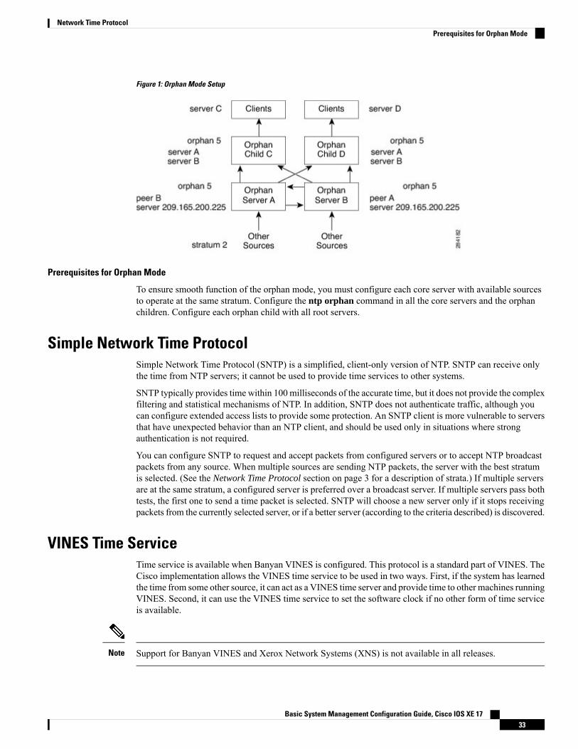
Figure 1: Orphan Mode Setup
Prerequisites for Orphan Mode
To ensure smooth function of the orphan mode, you must configure each core server with available sourcesto operate at the same stratum. Configure the ntp orphan command in all the core servers and the orphanchildren. Configure each orphan child with all root servers.
Simple Network Time ProtocolSimple Network Time Protocol (SNTP) is a simplified, client-only version of NTP. SNTP can receive onlythe time from NTP servers; it cannot be used to provide time services to other systems.
SNTP typically provides time within 100 milliseconds of the accurate time, but it does not provide the complexfiltering and statistical mechanisms of NTP. In addition, SNTP does not authenticate traffic, although youcan configure extended access lists to provide some protection. An SNTP client is more vulnerable to serversthat have unexpected behavior than an NTP client, and should be used only in situations where strongauthentication is not required.
You can configure SNTP to request and accept packets from configured servers or to accept NTP broadcastpackets from any source. When multiple sources are sending NTP packets, the server with the best stratumis selected. (See the Network Time Protocol section on page 3 for a description of strata.) If multiple serversare at the same stratum, a configured server is preferred over a broadcast server. If multiple servers pass bothtests, the first one to send a time packet is selected. SNTP will choose a new server only if it stops receivingpackets from the currently selected server, or if a better server (according to the criteria described) is discovered.
VINES Time ServiceTime service is available when Banyan VINES is configured. This protocol is a standard part of VINES. TheCisco implementation allows the VINES time service to be used in two ways. First, if the system has learnedthe time from some other source, it can act as a VINES time server and provide time to other machines runningVINES. Second, it can use the VINES time service to set the software clock if no other form of time serviceis available.
Support for Banyan VINES and Xerox Network Systems (XNS) is not available in all releases.Note
Basic System Management Configuration Guide, Cisco IOS XE 1733
Network Time ProtocolPrerequisites for Orphan Mode
Hardware ClockSome devices contain a battery-powered hardware clock that tracks the date and time across system restartsand power outages. The hardware clock is always used to initialize the software clock when the system isrestarted.
Within the CLI command syntax, the hardware clock is referred to as the system calendar.Note
If no other source is available, the hardware clock can be considered as an authoritative source of time andbe redistributed via NTP. If NTP is running, the hardware clock can be updated periodically from NTP,compensating for the inherent drift, which is the consistent gain or loss of time at a certain rate if the hardwareclock is left to run.
You can configure a hardware clock (system calendar) on any device to be periodically updated from thesoftware clock. We recommend that you use this configuration for any device using NTP, because the timeand date on the software clock (set using NTP) will be more accurate than the hardware clock, because thetime setting on the hardware clock has the potential to drift slightly over time.
Use the ntp update-calendar command in global configuration mode if a routing device is synchronized toan outside time source via NTP and you want the hardware clock to be synchronized to NTP time.
Time RangesThe Cisco software allows implementation of features based on the time of day. The time-range globalconfiguration command defines specific times of the day and week, which can then be referenced by a function,so that those time restrictions are imposed on the function itself.
Depending on your release, IP and Internetwork Packet Exchange (IPX) extended access lists are the onlyfunctions that can use time ranges. The time range allows the network administrator to define when the permitor deny statements in the access list are in effect. Prior to the introduction of this feature, access list statementswere always in effect once they were applied. Both named and numbered access lists can reference a timerange.
The time range relies on the system’s software clock. For the time range feature to work the way you intend,you need a reliable clock source. We recommend that you use NTP to synchronize the system’s softwareclock.
Note
Benefits of time ranges include the following:
• The network administrator has more control over permitting or denying a user access to resources. Theseresources could be an application (identified by an IP address/mask pair and a port number), policyrouting, or an on-demand link (identified as interesting traffic to the dialer).
• Network administrators can set a time-based security policy, including the following:
• Perimeter security using the Cisco Firewall feature set or access lists.• Data confidentiality with Cisco Encryption Technology or IP security.
• Policy-based routing and queueing functions are enhanced.
Basic System Management Configuration Guide, Cisco IOS XE 1734
Network Time ProtocolHardware Clock
• When provider access rates vary by time of day, traffic can be rerouted automatically and cost-effectively.
• Service providers can dynamically change a committed access rate (CAR) configuration to support thequality of service (QoS) service level agreements (SLAs) that are negotiated for certain times of the day.
Network administrators can control logging messages. Access list entries can log traffic at certain times ofthe day, but not constantly. Therefore, administrators can deny access without the need to analyze the manylogs generated during peak hours.
How to Configure Network Time Protocol
Configuring NTP
Restrictions for Network Time ProtocolThe Network Time Protocol (NTP) package contains a vulnerability that could allow an unauthenticated,remote attacker to cause a denial of service (DoS) condition. NTP versions 4.2.4p7 and earlier are vulnerable.
The vulnerability is due to an error in handling of certain malformed messages. An unauthenticated, remoteattacker could send a malicious NTP packet with a spoofed source IP address to a vulnerable host. The hostthat processes the packet sends a response packet back to the transmitter. This action could start a loop ofmessages between the two hosts that could cause both the hosts to consume excessive CPU resources, use upthe disk space by writing messages to log files, and consume the network bandwidth. All of these could causea DoS condition on the affected hosts.
For more information, see the Network Time Protocol Package Remote Message Loop Denial of ServiceVulnerability web page.
Cisco software releases that support NTPv4 are not affected. All other versions of Cisco software are affected.
To display whether a device is configured with NTP, use the show running-config | include ntp command.If the output returns any of the following commands, then that device is vulnerable to the attack:
• ntp broadcast client
• ntp primary
• ntp multicast client
• ntp peer
• ntp server
For more information on understanding Cisco software releases, see the White Paper: Cisco IOS and NX-OSSoftware Reference Guide.
There are no workarounds for this vulnerability other than disabling NTP on the device. Only packets destinedfor any configured IP address on the device can exploit this vulnerability. Transit traffic will not exploit thisvulnerability.
Depending on your release, your feature will process NTPmode 7 packets and will display themessage “NTP:Receive: dropping message: Received NTP private mode 7 packet ” if debugs for NTP are enabled. Configurethe ntp allow mode private command to process NTP mode 7 packets. This command is disabled by default.
Basic System Management Configuration Guide, Cisco IOS XE 1735
Network Time ProtocolHow to Configure Network Time Protocol
NTP peer authentication is not a workaround and is a vulnerable configuration.Note
NTP services are disabled on all interfaces by default.
Networking devices running NTP can be configured to operate in a variety of association modes whensynchronizing time with reference time sources. A networking device can obtain time information on a networkin two ways: by polling host servers and by listening to NTP broadcasts.
Line Aux 0 option is disabled by default.
When you configure both IP address and FQDN of the same NTP server in Cisco IOS XE, only the FQDNconfiguration is displayed in the show running-config command output after FQDN resolves to the same IPaddress.
Configuring Poll-Based NTP Associations
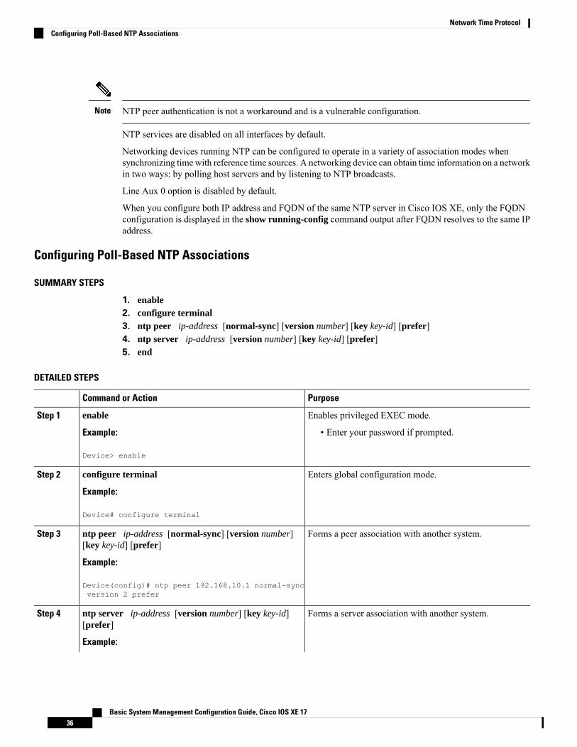
SUMMARY STEPS
1. enable2. configure terminal3. ntp peer ip-address [normal-sync] [version number] [key key-id] [prefer]4. ntp server ip-address [version number] [key key-id] [prefer]5. end
DETAILED STEPS
PurposeCommand or Action
Enables privileged EXEC mode.enableStep 1
Example: • Enter your password if prompted.
Device> enable
Enters global configuration mode.configure terminal
Example:
Step 2
Device# configure terminal
Forms a peer association with another system.ntp peer ip-address [normal-sync] [version number][key key-id] [prefer]
Step 3
Example:
Device(config)# ntp peer 192.168.10.1 normal-syncversion 2 prefer
Forms a server association with another system.ntp server ip-address [version number] [key key-id][prefer]
Step 4
Example:
Basic System Management Configuration Guide, Cisco IOS XE 1736
Network Time ProtocolConfiguring Poll-Based NTP Associations

PurposeCommand or Action
Device(config)# ntp server 192.168.10.1 version 2prefer
Exits global configuration mode and returns to privilegedEXEC mode.
end
Example:
Step 5
Device(config)# end
Configuring Broadcast-Based NTP Associations
SUMMARY STEPS
1. enable2. configure terminal3. interface type number
4. ntp broadcast version number
5. ntp broadcast client6. ntp broadcastdelay microseconds
7. end
DETAILED STEPS
PurposeCommand or Action
Enables privileged EXEC mode.enableStep 1
Example: • Enter your password if prompted.
Device> enable
Enters global configuration mode.configure terminal
Example:
Step 2
Device# configure terminal
Configures an interface and enters interface configurationmode.
interface type number
Example:
Step 3
Device(config)# interface GigabitEthernet 0/0
Configures the specified interface to send NTP broadcastpackets.
ntp broadcast version number
Example:
Step 4
Device(config-if)# ntp broadcast version 2
Configures the specified interface to receive NTP broadcastpackets.
ntp broadcast client
Example:
Step 5
Basic System Management Configuration Guide, Cisco IOS XE 1737
Network Time ProtocolConfiguring Broadcast-Based NTP Associations
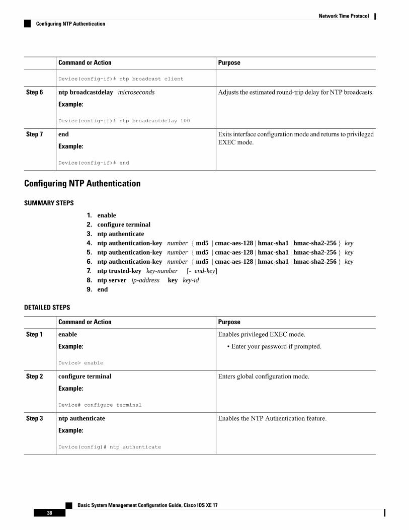
PurposeCommand or Action
Device(config-if)# ntp broadcast client
Adjusts the estimated round-trip delay for NTP broadcasts.ntp broadcastdelay microseconds
Example:
Step 6
Device(config-if)# ntp broadcastdelay 100
Exits interface configuration mode and returns to privilegedEXEC mode.
end
Example:
Step 7
Device(config-if)# end
Configuring NTP Authentication
SUMMARY STEPS
1. enable2. configure terminal3. ntp authenticate4. ntp authentication-key number { md5 | cmac-aes-128 | hmac-sha1 | hmac-sha2-256 } key
5. ntp authentication-key number { md5 | cmac-aes-128 | hmac-sha1 | hmac-sha2-256 } key
6. ntp authentication-key number { md5 | cmac-aes-128 | hmac-sha1 | hmac-sha2-256 } key
7. ntp trusted-key key-number [- end-key]8. ntp server ip-address key key-id
9. end
DETAILED STEPS
PurposeCommand or Action
Enables privileged EXEC mode.enableStep 1
Example: • Enter your password if prompted.
Device> enable
Enters global configuration mode.configure terminal
Example:
Step 2
Device# configure terminal
Enables the NTP Authentication feature.ntp authenticate
Example:
Step 3
Device(config)# ntp authenticate
Basic System Management Configuration Guide, Cisco IOS XE 1738
Network Time ProtocolConfiguring NTP Authentication
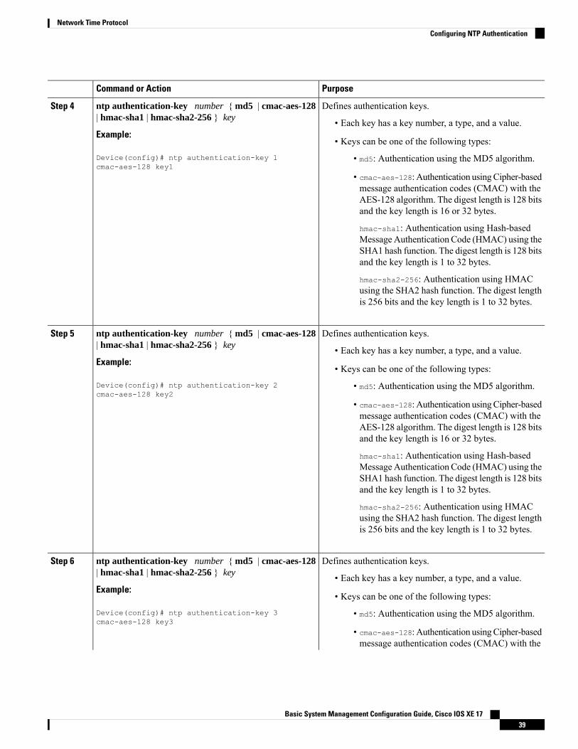
PurposeCommand or Action
Defines authentication keys.ntp authentication-key number { md5 | cmac-aes-128| hmac-sha1 | hmac-sha2-256 } key
Step 4
• Each key has a key number, a type, and a value.Example:
• Keys can be one of the following types:Device(config)# ntp authentication-key 1cmac-aes-128 key1
• md5: Authentication using the MD5 algorithm.
• cmac-aes-128: Authentication usingCipher-basedmessage authentication codes (CMAC) with theAES-128 algorithm. The digest length is 128 bitsand the key length is 16 or 32 bytes.
hmac-sha1: Authentication using Hash-basedMessage Authentication Code (HMAC) using theSHA1 hash function. The digest length is 128 bitsand the key length is 1 to 32 bytes.
hmac-sha2-256: Authentication using HMACusing the SHA2 hash function. The digest lengthis 256 bits and the key length is 1 to 32 bytes.
Defines authentication keys.ntp authentication-key number { md5 | cmac-aes-128| hmac-sha1 | hmac-sha2-256 } key
Step 5
• Each key has a key number, a type, and a value.Example:
• Keys can be one of the following types:Device(config)# ntp authentication-key 2cmac-aes-128 key2
• md5: Authentication using the MD5 algorithm.
• cmac-aes-128: Authentication usingCipher-basedmessage authentication codes (CMAC) with theAES-128 algorithm. The digest length is 128 bitsand the key length is 16 or 32 bytes.
hmac-sha1: Authentication using Hash-basedMessage Authentication Code (HMAC) using theSHA1 hash function. The digest length is 128 bitsand the key length is 1 to 32 bytes.
hmac-sha2-256: Authentication using HMACusing the SHA2 hash function. The digest lengthis 256 bits and the key length is 1 to 32 bytes.
Defines authentication keys.ntp authentication-key number { md5 | cmac-aes-128| hmac-sha1 | hmac-sha2-256 } key
Step 6
• Each key has a key number, a type, and a value.Example:
• Keys can be one of the following types:Device(config)# ntp authentication-key 3cmac-aes-128 key3
• md5: Authentication using the MD5 algorithm.
• cmac-aes-128: Authentication usingCipher-basedmessage authentication codes (CMAC) with the
Basic System Management Configuration Guide, Cisco IOS XE 1739
Network Time ProtocolConfiguring NTP Authentication
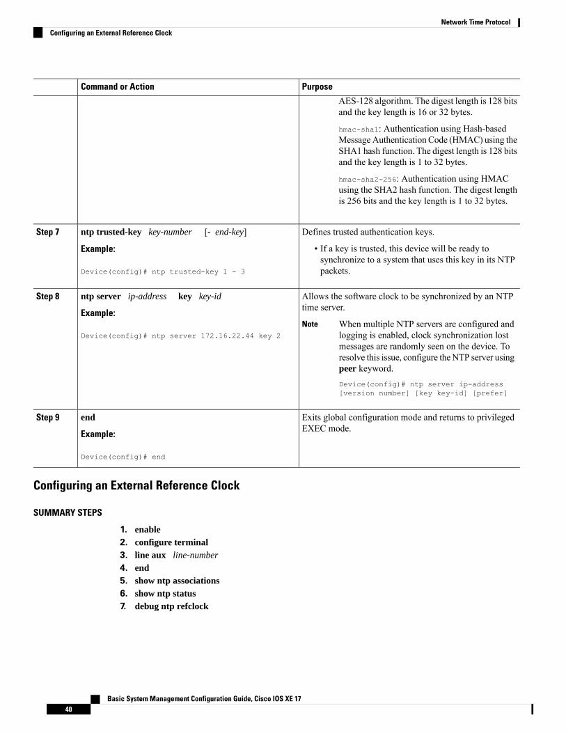
PurposeCommand or Action
AES-128 algorithm. The digest length is 128 bitsand the key length is 16 or 32 bytes.
hmac-sha1: Authentication using Hash-basedMessage Authentication Code (HMAC) using theSHA1 hash function. The digest length is 128 bitsand the key length is 1 to 32 bytes.
hmac-sha2-256: Authentication using HMACusing the SHA2 hash function. The digest lengthis 256 bits and the key length is 1 to 32 bytes.
Defines trusted authentication keys.ntp trusted-key key-number [- end-key]Step 7
Example: • If a key is trusted, this device will be ready tosynchronize to a system that uses this key in its NTPpackets.Device(config)# ntp trusted-key 1 - 3
Allows the software clock to be synchronized by an NTPtime server.
ntp server ip-address key key-id
Example:
Step 8
When multiple NTP servers are configured andlogging is enabled, clock synchronization lostmessages are randomly seen on the device. Toresolve this issue, configure the NTP server usingpeer keyword.Device(config)# ntp server ip-address[version number] [key key-id] [prefer]
NoteDevice(config)# ntp server 172.16.22.44 key 2
Exits global configuration mode and returns to privilegedEXEC mode.
end
Example:
Step 9
Device(config)# end
Configuring an External Reference Clock
SUMMARY STEPS
1. enable2. configure terminal3. line aux line-number
4. end5. show ntp associations6. show ntp status7. debug ntp refclock
Basic System Management Configuration Guide, Cisco IOS XE 1740
Network Time ProtocolConfiguring an External Reference Clock
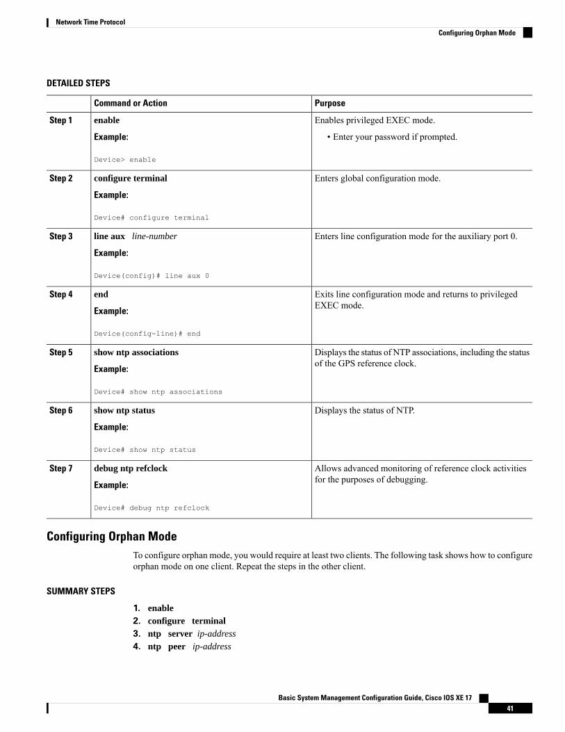
DETAILED STEPS
PurposeCommand or Action
Enables privileged EXEC mode.enableStep 1
Example: • Enter your password if prompted.
Device> enable
Enters global configuration mode.configure terminal
Example:
Step 2
Device# configure terminal
Enters line configuration mode for the auxiliary port 0.line aux line-number
Example:
Step 3
Device(config)# line aux 0
Exits line configuration mode and returns to privilegedEXEC mode.
end
Example:
Step 4
Device(config-line)# end
Displays the status of NTP associations, including the statusof the GPS reference clock.
show ntp associations
Example:
Step 5
Device# show ntp associations
Displays the status of NTP.show ntp status
Example:
Step 6
Device# show ntp status
Allows advanced monitoring of reference clock activitiesfor the purposes of debugging.
debug ntp refclock
Example:
Step 7
Device# debug ntp refclock
Configuring Orphan ModeTo configure orphan mode, you would require at least two clients. The following task shows how to configureorphan mode on one client. Repeat the steps in the other client.
SUMMARY STEPS
1. enable2. configure terminal3. ntp server ip-address
4. ntp peer ip-address
Basic System Management Configuration Guide, Cisco IOS XE 1741
Network Time ProtocolConfiguring Orphan Mode
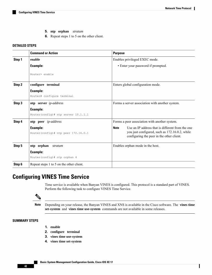
5. ntp orphan stratum
6. Repeat steps 1 to 5 on the other client.
DETAILED STEPS
PurposeCommand or Action
Enables privileged EXEC mode.enableStep 1
Example: • Enter your password if prompted.
Router> enable
Enters global configuration mode.configure terminal
Example:
Step 2
Router# configure terminal
Forms a server association with another system.ntp server ip-address
Example:
Step 3
Router(config)# ntp server 10.1.1.1
Forms a peer association with another system.ntp peer ip-addressStep 4
Example: Use an IP address that is different from the oneyou just configured, such as 172.16.0.2, whileconfiguring the peer in the other client.
Note
Router(config)# ntp peer 172.16.0.1
Enables orphan mode in the host.ntp orphan stratum
Example:
Step 5
Router(config)# ntp orphan 4
Repeat steps 1 to 5 on the other client.Step 6
Configuring VINES Time ServiceTime service is available when Banyan VINES is configured. This protocol is a standard part of VINES.Perform the following task to configure VINES Time Service.
Depending on your release, the Banyan VINES and XNS is available in the Cisco software. The vines timeset-system and vines time use-system commands are not available in some releases.
Note
SUMMARY STEPS
1. enable2. configure terminal3. vines time use-system4. vines time set-system
Basic System Management Configuration Guide, Cisco IOS XE 1742
Network Time ProtocolConfiguring VINES Time Service
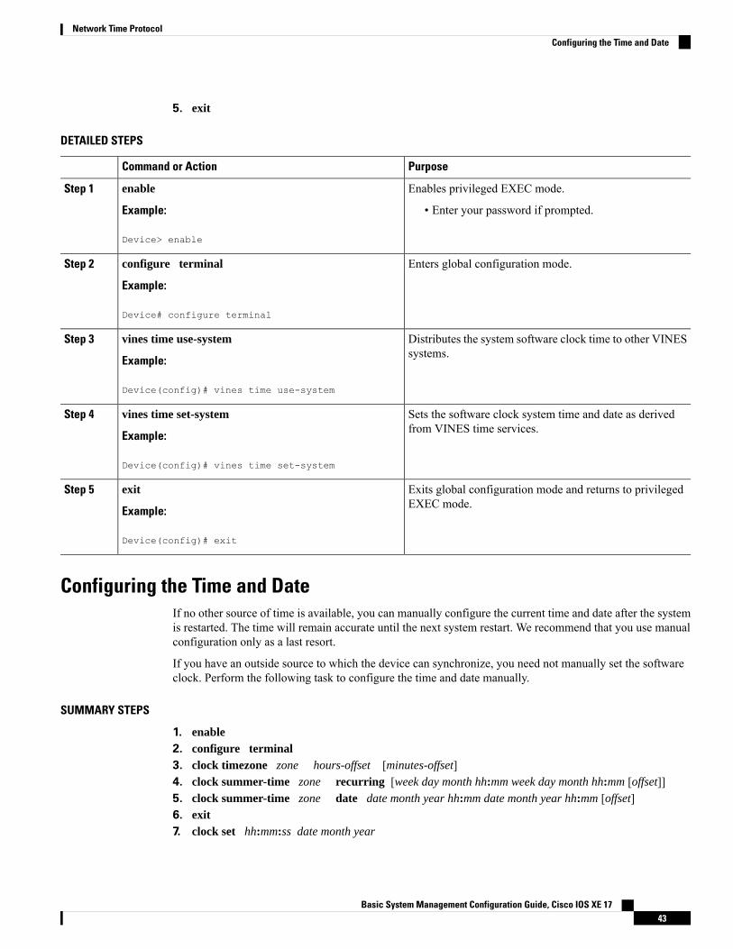
5. exit
DETAILED STEPS
PurposeCommand or Action
Enables privileged EXEC mode.enableStep 1
Example: • Enter your password if prompted.
Device> enable
Enters global configuration mode.configure terminal
Example:
Step 2
Device# configure terminal
Distributes the system software clock time to other VINESsystems.
vines time use-system
Example:
Step 3
Device(config)# vines time use-system
Sets the software clock system time and date as derivedfrom VINES time services.
vines time set-system
Example:
Step 4
Device(config)# vines time set-system
Exits global configuration mode and returns to privilegedEXEC mode.
exit
Example:
Step 5
Device(config)# exit
Configuring the Time and DateIf no other source of time is available, you can manually configure the current time and date after the systemis restarted. The time will remain accurate until the next system restart. We recommend that you use manualconfiguration only as a last resort.
If you have an outside source to which the device can synchronize, you need not manually set the softwareclock. Perform the following task to configure the time and date manually.
SUMMARY STEPS
1. enable2. configure terminal3. clock timezone zone hours-offset [minutes-offset]4. clock summer-time zone recurring [week day month hh:mm week day month hh:mm [offset]]5. clock summer-time zone date date month year hh:mm date month year hh:mm [offset]6. exit7. clock set hh:mm:ss date month year
Basic System Management Configuration Guide, Cisco IOS XE 1743
Network Time ProtocolConfiguring the Time and Date

DETAILED STEPS
PurposeCommand or Action
Enables privileged EXEC mode.enableStep 1
Example: • Enter your password if prompted.
Device> enable
Enters global configuration mode.configure terminal
Example:
Step 2
Device# configure terminal
Configures the time zone used by the Cisco software.clock timezone zone hours-offset [minutes-offset]Step 3
Example: The minutes-offset argument of the clocktimezone command is available for those caseswhere a local time zone is a percentage of anhour different from UTC/GMT. For example,the time zone for some sections of AtlanticCanada (AST) is UTC –3.5. In this case, thenecessary command would be clock timezoneAST –3 30.
Note
Device(config)# clock timezone PST 2 30
Configures summer time (daylight saving time) in areaswhere it starts and ends on a particular day of the week eachyear.
clock summer-time zone recurring [week day monthhh:mm week day month hh:mm [offset]]
Example:
Step 4
Device(config)# clock summer-time PST recurring 1monday january 12:12 4 Tuesday december 12:12 120
Configures a specific summer time start and end date.clock summer-time zone date date month year hh:mmdate month year hh:mm [offset]
Step 5
• The offset argument is used to indicate the number ofminutes to add to the clock during summer time.Example:
Device(config)# clock summer-time PST date 1january 1999 12:12 4 december 2001 12:12 120
Exits global configuration mode and returns to privilegedEXEC mode.
exit
Example:
Step 6
Device(config)# exit
Sets the software clock.clock set hh:mm:ss date month yearStep 7
Example: • Use this command if no other time sources areavailable. The time specified in this command isrelative to the configured time zone.Device# clock set 12:12:12 1 january 2011
Basic System Management Configuration Guide, Cisco IOS XE 1744
Network Time ProtocolConfiguring the Time and Date
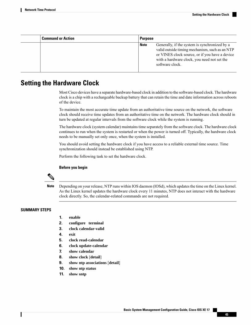
PurposeCommand or Action
Generally, if the system is synchronized by avalid outside timingmechanism, such as an NTPor VINES clock source, or if you have a devicewith a hardware clock, you need not set thesoftware clock.
Note
Setting the Hardware ClockMost Cisco devices have a separate hardware-based clock in addition to the software-based clock. The hardwareclock is a chip with a rechargeable backup battery that can retain the time and date information across rebootsof the device.
To maintain the most accurate time update from an authoritative time source on the network, the softwareclock should receive time updates from an authoritative time on the network. The hardware clock should inturn be updated at regular intervals from the software clock while the system is running.
The hardware clock (system calendar) maintains time separately from the software clock. The hardware clockcontinues to run when the system is restarted or when the power is turned off. Typically, the hardware clockneeds to be manually set only once, when the system is installed.
You should avoid setting the hardware clock if you have access to a reliable external time source. Timesynchronization should instead be established using NTP.
Perform the following task to set the hardware clock.
Before you begin
Depending on your release, NTP runs within IOS daemon (IOSd), which updates the time on the Linux kernel.As the Linux kernel updates the hardware clock every 11 minutes, NTP does not interact with the hardwareclock directly. So, the calendar-related commands are not required.
Note
SUMMARY STEPS
1. enable2. configure terminal3. clock calendar-valid4. exit5. clock read-calendar6. clock update-calendar7. show calendar8. show clock [detail]9. show ntp associations [detail]10. show ntp status11. show sntp
Basic System Management Configuration Guide, Cisco IOS XE 1745
Network Time ProtocolSetting the Hardware Clock
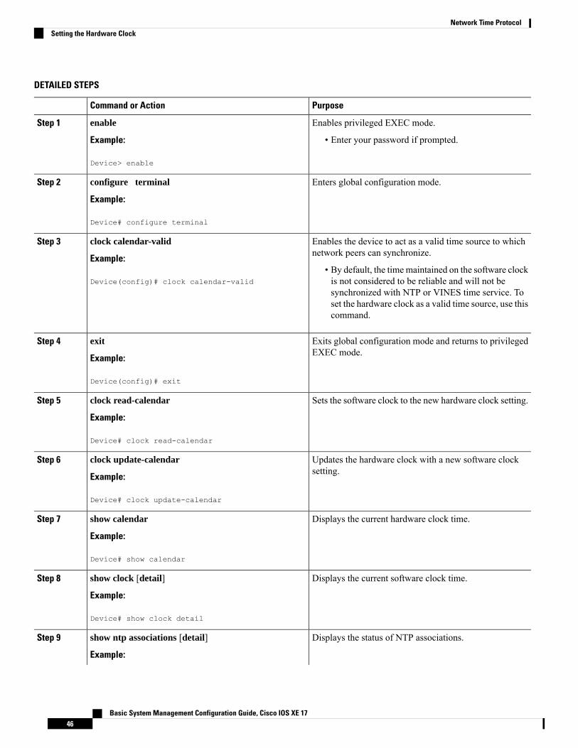
DETAILED STEPS
PurposeCommand or Action
Enables privileged EXEC mode.enableStep 1
Example: • Enter your password if prompted.
Device> enable
Enters global configuration mode.configure terminal
Example:
Step 2
Device# configure terminal
Enables the device to act as a valid time source to whichnetwork peers can synchronize.
clock calendar-valid
Example:
Step 3
• By default, the timemaintained on the software clockis not considered to be reliable and will not beDevice(config)# clock calendar-valid
synchronized with NTP or VINES time service. Toset the hardware clock as a valid time source, use thiscommand.
Exits global configuration mode and returns to privilegedEXEC mode.
exit
Example:
Step 4
Device(config)# exit
Sets the software clock to the new hardware clock setting.clock read-calendar
Example:
Step 5
Device# clock read-calendar
Updates the hardware clock with a new software clocksetting.
clock update-calendar
Example:
Step 6
Device# clock update-calendar
Displays the current hardware clock time.show calendar
Example:
Step 7
Device# show calendar
Displays the current software clock time.show clock [detail]
Example:
Step 8
Device# show clock detail
Displays the status of NTP associations.show ntp associations [detail]
Example:
Step 9
Basic System Management Configuration Guide, Cisco IOS XE 1746
Network Time ProtocolSetting the Hardware Clock
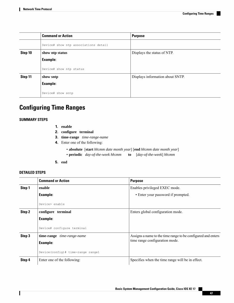
PurposeCommand or Action
Device# show ntp associations detail
Displays the status of NTP.show ntp status
Example:
Step 10
Device# show ntp status
Displays information about SNTP.show sntp
Example:
Step 11
Device# show sntp
Configuring Time Ranges
SUMMARY STEPS
1. enable2. configure terminal3. time-range time-range-name
4. Enter one of the following:
• absolute [start hh:mm date month year] [end hh:mm date month year]• periodic day-of-the-week hh:mm to [day-of-the-week] hh:mm
5. end
DETAILED STEPS
PurposeCommand or Action
Enables privileged EXEC mode.enableStep 1
Example: • Enter your password if prompted.
Device> enable
Enters global configuration mode.configure terminal
Example:
Step 2
Device# configure terminal
Assigns a name to the time range to be configured and enterstime range configuration mode.
time-range time-range-name
Example:
Step 3
Device(config)# time-range range1
Specifies when the time range will be in effect.Enter one of the following:Step 4
Basic System Management Configuration Guide, Cisco IOS XE 1747
Network Time ProtocolConfiguring Time Ranges
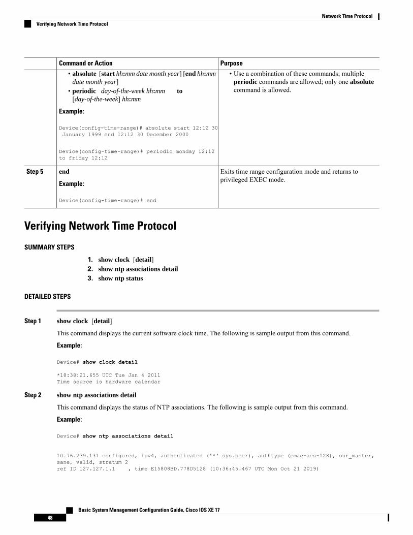
PurposeCommand or Action
• absolute [start hh:mm date month year] [end hh:mmdate month year]
• Use a combination of these commands; multipleperiodic commands are allowed; only one absolutecommand is allowed.• periodic day-of-the-week hh:mm to
[day-of-the-week] hh:mm
Example:
Device(config-time-range)# absolute start 12:12 30January 1999 end 12:12 30 December 2000
Device(config-time-range)# periodic monday 12:12to friday 12:12
Exits time range configuration mode and returns toprivileged EXEC mode.
end
Example:
Step 5
Device(config-time-range)# end
Verifying Network Time Protocol
SUMMARY STEPS
1. show clock [detail]2. show ntp associations detail3. show ntp status
DETAILED STEPS
Step 1 show clock [detail]
This command displays the current software clock time. The following is sample output from this command.
Example:
Device# show clock detail
*18:38:21.655 UTC Tue Jan 4 2011Time source is hardware calendar
Step 2 show ntp associations detail
This command displays the status of NTP associations. The following is sample output from this command.
Example:
Device# show ntp associations detail
10.76.239.131 configured, ipv4, authenticated ('*' sys.peer), authtype (cmac-aes-128), our_master,sane, valid, stratum 2ref ID 127.127.1.1 , time E15808BD.778D5128 (10:36:45.467 UTC Mon Oct 21 2019)
Basic System Management Configuration Guide, Cisco IOS XE 1748
Network Time ProtocolVerifying Network Time Protocol

our mode client, peer mode server, our poll intvl 64, peer poll intvl 64root delay 0.00 msec, root disp 2.34, reach 1, sync dist 443.84delay 2.00 msec, offset 0.0000 msec, dispersion 439.44, jitter 0.97 msecprecision 2**10, version 4assoc id 63678, assoc name 10.76.239.131assoc in packets 8, assoc out packets 8, assoc error packets 0org time 00000000.00000000 (00:00:00.000 UTC Mon Jan 1 1900)rec time E15808C9.80418A98 (10:36:57.501 UTC Mon Oct 21 2019)xmt time E15808C9.80418A98 (10:36:57.501 UTC Mon Oct 21 2019)filtdelay = 3.00 2.00 2.00 2.00 2.00 0.00 0.00 0.00filtoffset = -0.50 0.00 0.00 0.00 1.00 0.00 0.00 0.00filterror = 1.95 1.98 2.01 2.04 2.07 16000.0 16000.0 16000.0minpoll = 6, maxpoll = 10
Step 3 show ntp status
This command displays the status of NTP. The following is sample output from this command.
Example:
Device# show ntp status
Clock is synchronized, stratum 8, reference is 127.127.1.1nominal freq is 250.0000 Hz, actual freq is 250.0000 Hz, precision is 2**10reference time is D25AF07C.4B439650 (15:26:04.294 PDT Tue Oct 21 2011)clock offset is 0.0000 msec, root delay is 0.00 msecroot dispersion is 2.31 msec, peer dispersion is 1.20 msecloopfilter state is 'CTRL' (Normal Controlled Loop), drift is 0.000000000 s/ssystem poll interval is 16, last update was 10 sec ago.
Configuration Examples for Network Time Protocol
Example: Configuring Network Time ProtocolIn the following example, a device with a hardware clock that has server associations with two other systemssends broadcast NTP packets, periodically updates the hardware clock, and redistributes time into VINES:
clock timezone PST -8clock summer-time PDT recurring
ntp server 192.168.13.57ntp server 192.168.11.58interface GigabitEthernet 0/0ntp broadcastvines time use-system
In the following example, a device with a hardware clock has no outside time source, so it uses the hardwareclock as an authoritative time source and distributes the time via NTP broadcast packets:
clock timezone MET 2clock calendar-validntp masterinterface vlan 3ntp broadcast
Basic System Management Configuration Guide, Cisco IOS XE 1749
Network Time ProtocolConfiguration Examples for Network Time Protocol
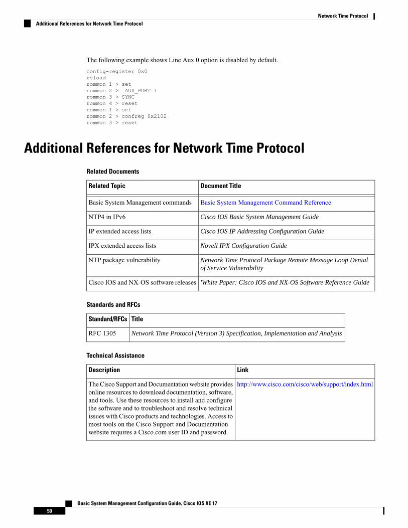
The following example shows Line Aux 0 option is disabled by default.config-register 0x0reloadrommon 1 > setrommon 2 > AUX_PORT=1rommon 3 > SYNCrommon 4 > resetrommon 1 > setrommon 2 > confreg 0x2102rommon 3 > reset
Additional References for Network Time ProtocolRelated Documents
Document TitleRelated Topic
Basic System Management Command ReferenceBasic System Management commands
Cisco IOS Basic System Management GuideNTP4 in IPv6
Cisco IOS IP Addressing Configuration GuideIP extended access lists
Novell IPX Configuration GuideIPX extended access lists
Network Time Protocol Package Remote Message Loop Denialof Service Vulnerability
NTP package vulnerability
'White Paper: Cisco IOS and NX-OS Software Reference GuideCisco IOS and NX-OS software releases
Standards and RFCs
TitleStandard/RFCs
Network Time Protocol (Version 3) Specification, Implementation and AnalysisRFC 1305
Technical Assistance
LinkDescription
http://www.cisco.com/cisco/web/support/index.htmlTheCisco Support andDocumentationwebsite providesonline resources to download documentation, software,and tools. Use these resources to install and configurethe software and to troubleshoot and resolve technicalissues with Cisco products and technologies. Access tomost tools on the Cisco Support and Documentationwebsite requires a Cisco.com user ID and password.
Basic System Management Configuration Guide, Cisco IOS XE 1750
Network Time ProtocolAdditional References for Network Time Protocol
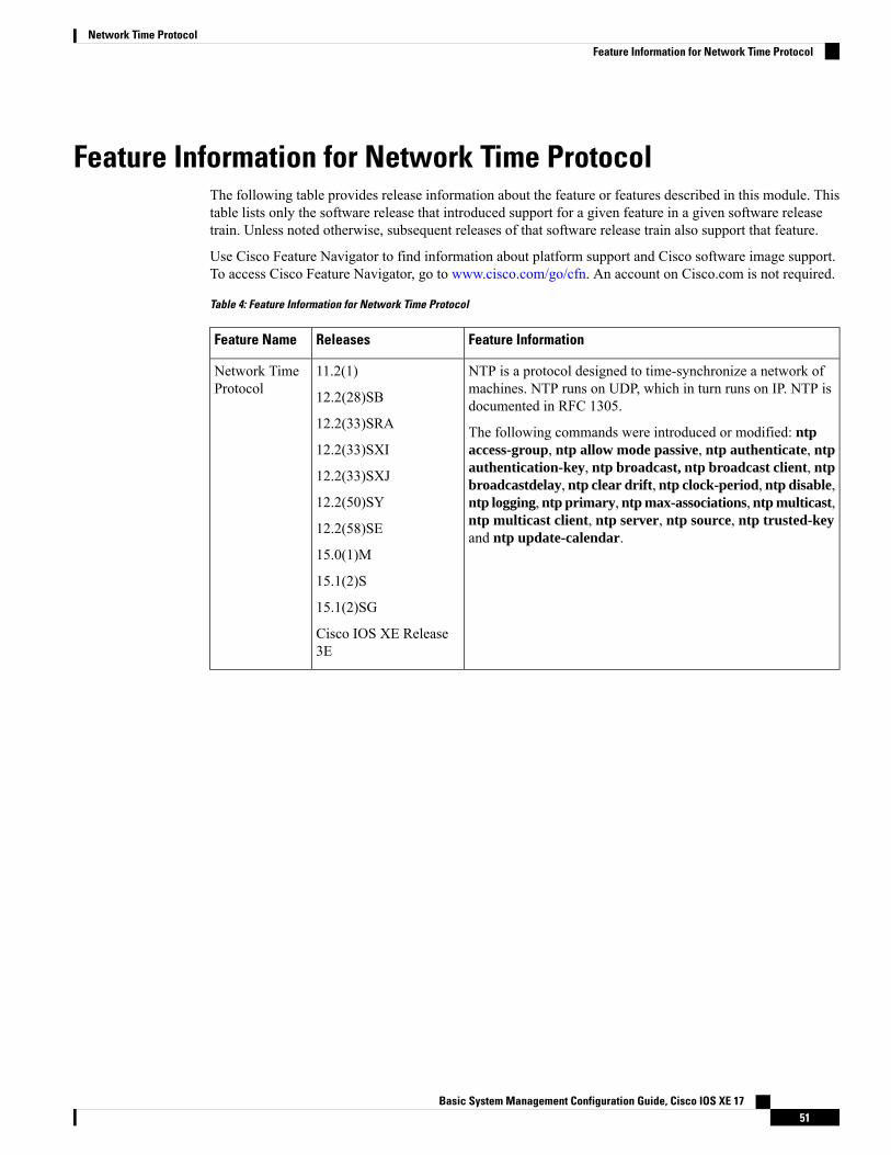
Feature Information for Network Time ProtocolThe following table provides release information about the feature or features described in this module. Thistable lists only the software release that introduced support for a given feature in a given software releasetrain. Unless noted otherwise, subsequent releases of that software release train also support that feature.
Use Cisco Feature Navigator to find information about platform support and Cisco software image support.To access Cisco Feature Navigator, go to www.cisco.com/go/cfn. An account on Cisco.com is not required.
Table 4: Feature Information for Network Time Protocol
Feature InformationReleasesFeature Name
NTP is a protocol designed to time-synchronize a network ofmachines. NTP runs on UDP, which in turn runs on IP. NTP isdocumented in RFC 1305.
The following commands were introduced or modified: ntpaccess-group, ntp allow mode passive, ntp authenticate, ntpauthentication-key, ntp broadcast, ntp broadcast client, ntpbroadcastdelay, ntp clear drift, ntp clock-period, ntp disable,ntp logging, ntp primary, ntp max-associations, ntp multicast,ntp multicast client, ntp server, ntp source, ntp trusted-keyand ntp update-calendar.
11.2(1)
12.2(28)SB
12.2(33)SRA
12.2(33)SXI
12.2(33)SXJ
12.2(50)SY
12.2(58)SE
15.0(1)M
15.1(2)S
15.1(2)SG
Cisco IOS XE Release3E
Network TimeProtocol
Basic System Management Configuration Guide, Cisco IOS XE 1751
Network Time ProtocolFeature Information for Network Time Protocol

Basic System Management Configuration Guide, Cisco IOS XE 1752
Network Time ProtocolFeature Information for Network Time Protocol
C H A P T E R 6Simple Network Time Protocol
Simple Network Time Protocol (SNTP) is a simplified version of Network Time Protocol(NTP). This moduledescribes how to configure Simple Network Time Protocol on Cisco devices.
• Finding Feature Information, on page 53• Restrictions for Simple Network Time Protocol, on page 53• Information About Simple Network Time Protocol, on page 54• How to Configure Simple Network Time Protocol, on page 54• Configuration Examples for Simple Network Time Protocol, on page 57• Additional References for Simple Network Time Protocol, on page 57• Feature Information for the SNTP, on page 58
Finding Feature InformationYour software release may not support all the features documented in this module. For the latest caveats andfeature information, see Bug Search Tool and the release notes for your platform and software release. Tofind information about the features documented in this module, and to see a list of the releases in which eachfeature is supported, see the feature information table.
Use Cisco Feature Navigator to find information about platform support and Cisco software image support.To access Cisco Feature Navigator, go to www.cisco.com/go/cfn. An account on Cisco.com is not required.
Restrictions for Simple Network Time Protocol• Simple Network Time Protocol (SNTP) and Network Time Protocol (NTP) cannot coexist on the samemachine as they use the same port. This means that these two services cannot be configured on the systemat the same time.
• Support for IPv6 addresses is available only if the image supports IPv6 addressing.
Basic System Management Configuration Guide, Cisco IOS XE 1753
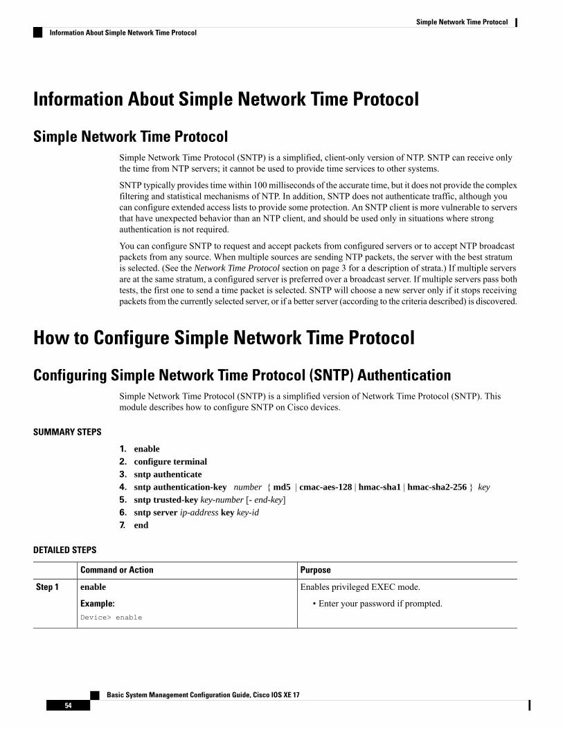
Information About Simple Network Time Protocol
Simple Network Time ProtocolSimple Network Time Protocol (SNTP) is a simplified, client-only version of NTP. SNTP can receive onlythe time from NTP servers; it cannot be used to provide time services to other systems.
SNTP typically provides time within 100 milliseconds of the accurate time, but it does not provide the complexfiltering and statistical mechanisms of NTP. In addition, SNTP does not authenticate traffic, although youcan configure extended access lists to provide some protection. An SNTP client is more vulnerable to serversthat have unexpected behavior than an NTP client, and should be used only in situations where strongauthentication is not required.
You can configure SNTP to request and accept packets from configured servers or to accept NTP broadcastpackets from any source. When multiple sources are sending NTP packets, the server with the best stratumis selected. (See the Network Time Protocol section on page 3 for a description of strata.) If multiple serversare at the same stratum, a configured server is preferred over a broadcast server. If multiple servers pass bothtests, the first one to send a time packet is selected. SNTP will choose a new server only if it stops receivingpackets from the currently selected server, or if a better server (according to the criteria described) is discovered.
How to Configure Simple Network Time Protocol
Configuring Simple Network Time Protocol (SNTP) AuthenticationSimple Network Time Protocol (SNTP) is a simplified version of Network Time Protocol (SNTP). Thismodule describes how to configure SNTP on Cisco devices.
SUMMARY STEPS
1. enable2. configure terminal3. sntp authenticate4. sntp authentication-key number { md5 | cmac-aes-128 | hmac-sha1 | hmac-sha2-256 } key
5. sntp trusted-key key-number [- end-key]6. sntp server ip-address key key-id
7. end
DETAILED STEPS
PurposeCommand or Action
Enables privileged EXEC mode.enableStep 1
Example: • Enter your password if prompted.Device> enable
Basic System Management Configuration Guide, Cisco IOS XE 1754
Simple Network Time ProtocolInformation About Simple Network Time Protocol

PurposeCommand or Action
Enters global configuration mode.configure terminal
Example:
Step 2
Device# configure terminal
Enables the SNTP Authentication feature.sntp authenticate
Example:
Step 3
Device(config)# sntp authenticate
Defines authentication keys.sntp authentication-key number { md5 | cmac-aes-128| hmac-sha1 | hmac-sha2-256 } key
Step 4
• Each key has a key number, a type, and a value.Example:
• Keys can be of the following types:Device(config)# sntp authentication-key 1cmac-aes-128 key1
• md5: Authentication using the MD5 algorithm.
• cmac-aes-128: Authentication usingCipher-basedmessage authentication codes (CMAC) with theAES-128 algorithm. The digest length is 128 bitsand the key length is 16 or 32 bytes.
hmac-sha1: Authentication using Hash-basedMessage Authentication Code (HMAC) using theSHA1 hash function. The digest length is 128 bitsand the key length is 1 to 32 bytes.
hmac-sha2-256: Authentication using HMACusing the SHA2 hash function. The digest lengthis 256 bits and the key length is 1 to 32 bytes.
• Repeat this step to define additional authenticationkeys.
Defines trusted authentication keys.sntp trusted-key key-number [- end-key]Step 5
Example: • If a key is trusted, this device will be ready tosynchronize to a system that uses this key in its SNTPpackets.
Device(config)# sntp trusted-key 1 - 3
Allows the software clock to be synchronized by an SNTPtime server.
sntp server ip-address key key-id
Example:
Step 6
Device(config)# sntp server 172.16.22.44 key 2
Exits global configuration mode and returns to privilegedEXEC mode.
end
Example:
Step 7
Device(config)# end
Basic System Management Configuration Guide, Cisco IOS XE 1755
Simple Network Time ProtocolConfiguring Simple Network Time Protocol (SNTP) Authentication
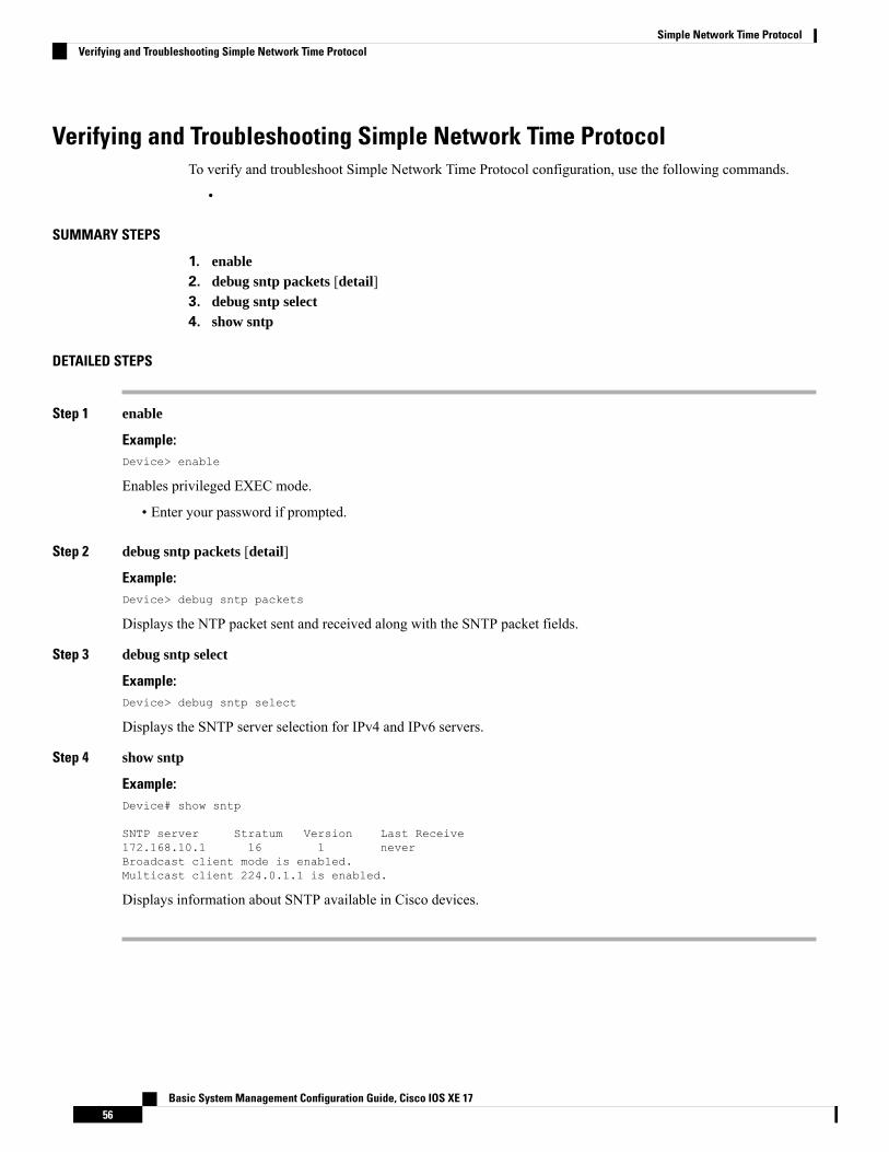
Verifying and Troubleshooting Simple Network Time ProtocolTo verify and troubleshoot Simple Network Time Protocol configuration, use the following commands.
•
SUMMARY STEPS
1. enable2. debug sntp packets [detail]3. debug sntp select4. show sntp
DETAILED STEPS
Step 1 enable
Example:Device> enable
Enables privileged EXEC mode.
• Enter your password if prompted.
Step 2 debug sntp packets [detail]
Example:Device> debug sntp packets
Displays the NTP packet sent and received along with the SNTP packet fields.
Step 3 debug sntp select
Example:Device> debug sntp select
Displays the SNTP server selection for IPv4 and IPv6 servers.
Step 4 show sntp
Example:Device# show sntp
SNTP server Stratum Version Last Receive172.168.10.1 16 1 neverBroadcast client mode is enabled.Multicast client 224.0.1.1 is enabled.
Displays information about SNTP available in Cisco devices.
Basic System Management Configuration Guide, Cisco IOS XE 1756
Simple Network Time ProtocolVerifying and Troubleshooting Simple Network Time Protocol
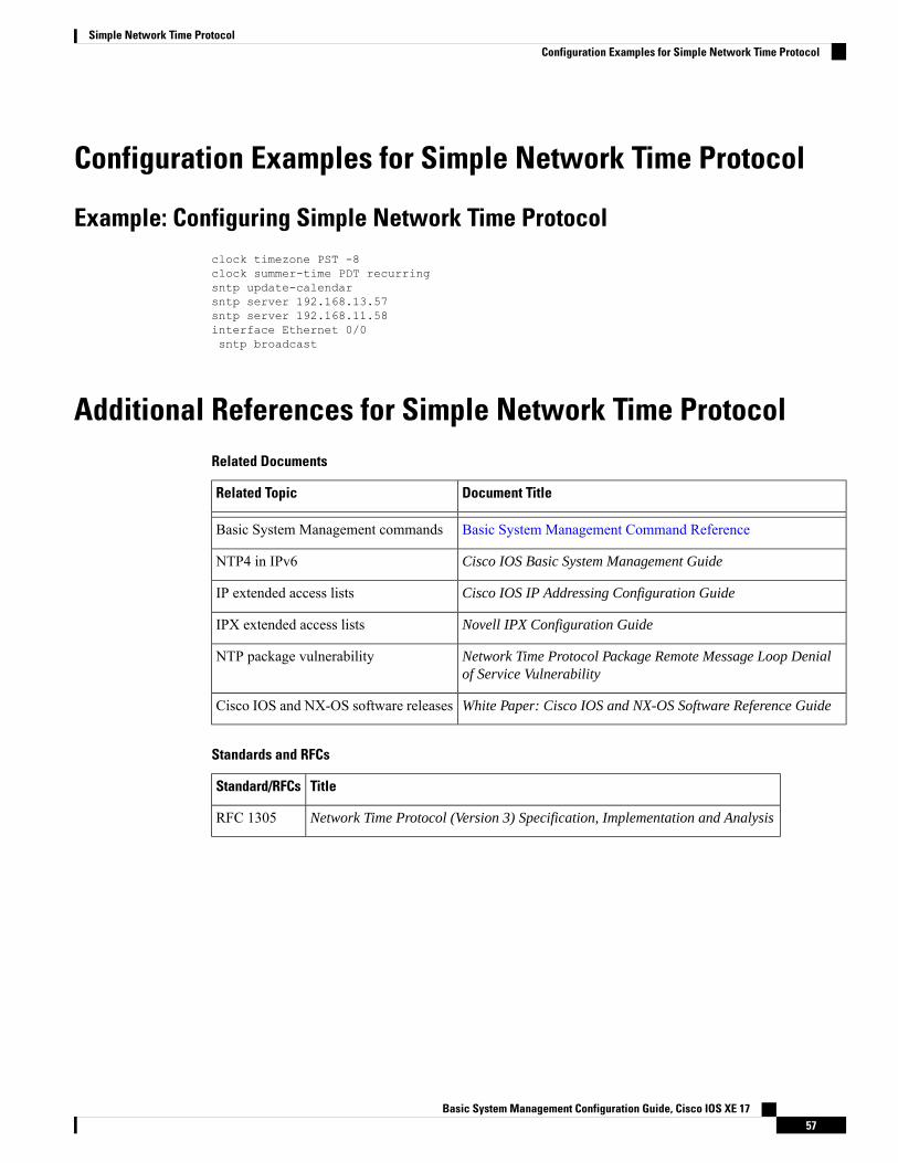
Configuration Examples for Simple Network Time Protocol
Example: Configuring Simple Network Time Protocolclock timezone PST -8clock summer-time PDT recurringsntp update-calendarsntp server 192.168.13.57sntp server 192.168.11.58interface Ethernet 0/0sntp broadcast
Additional References for Simple Network Time ProtocolRelated Documents
Document TitleRelated Topic
Basic System Management Command ReferenceBasic System Management commands
Cisco IOS Basic System Management GuideNTP4 in IPv6
Cisco IOS IP Addressing Configuration GuideIP extended access lists
Novell IPX Configuration GuideIPX extended access lists
Network Time Protocol Package Remote Message Loop Denialof Service Vulnerability
NTP package vulnerability
White Paper: Cisco IOS and NX-OS Software Reference GuideCisco IOS and NX-OS software releases
Standards and RFCs
TitleStandard/RFCs
Network Time Protocol (Version 3) Specification, Implementation and AnalysisRFC 1305
Basic System Management Configuration Guide, Cisco IOS XE 1757
Simple Network Time ProtocolConfiguration Examples for Simple Network Time Protocol
Technical Assistance
LinkDescription
http://www.cisco.com/cisco/web/support/index.htmlTheCisco Support andDocumentationwebsite providesonline resources to download documentation, software,and tools. Use these resources to install and configurethe software and to troubleshoot and resolve technicalissues with Cisco products and technologies. Access tomost tools on the Cisco Support and Documentationwebsite requires a Cisco.com user ID and password.
Feature Information for the SNTPThe following table provides release information about the feature or features described in this module. Thistable lists only the software release that introduced support for a given feature in a given software releasetrain. Unless noted otherwise, subsequent releases of that software release train also support that feature.
Use Cisco Feature Navigator to find information about platform support and Cisco software image support.To access Cisco Feature Navigator, go to www.cisco.com/go/cfn. An account on Cisco.com is not required.
Table 5: Feature Information for the SNTPv4
Feature InformationReleasesFeature Name
Simple Network Time Protocol(SNTP) is a simplified version ofNetwork Time Protocol(NTP). Thismodule describes how to configureSimple Network Time Protocol onCisco devices.
The following commands wereintroduced or modified: sntpserver, sntp authenticate, sntpauthentication-key, sntpmulticast, sntp trusted-key.
Simple Network Time Protocol
Basic System Management Configuration Guide, Cisco IOS XE 1758
Simple Network Time ProtocolFeature Information for the SNTP
Copyright © 2022 FDOKUMEN