Cisco IOS Broadband and DSL Configuration Guide - Audentia
518
Corporate Headquarters Cisco Systems, Inc. 170 West Tasman Drive San Jose, CA 95134-1706 USA http://www.cisco.com Tel: 408 526-4000 800 553-NETS (6387) Fax: 408 526-4100 Cisco IOS Broadband and DSL Configuration Guide Release 12.4 Customer Order Number: DOC-7817496= Text Part Number: 78-17496-01
-
Upload
khangminh22 -
Category
Documents
-
view
1 -
download
0
Transcript of Cisco IOS Broadband and DSL Configuration Guide - Audentia
Corporate HeadquartersCisco Systems, Inc.170 West Tasman DriveSan Jose, CA 95134-1706 USAhttp://www.cisco.comTel: 408 526-4000
800 553-NETS (6387)Fax: 408 526-4100
Cisco IOS Broadband and DSL Configuration GuideRelease 12.4
Customer Order Number: DOC-7817496=Text Part Number: 78-17496-01

THE SPECIFICATIONS AND INFORMATION REGARDING THE PRODUCTS IN THIS MANUAL ARE SUBJECT TO CHANGE WITHOUT NOTICE. ALL STATEMENTS, INFORMATION, AND RECOMMENDATIONS IN THIS MANUAL ARE BELIEVED TO BE ACCURATE BUT ARE PRESENTED WITHOUT WARRANTY OF ANY KIND, EXPRESS OR IMPLIED. USERS MUST TAKE FULL RESPONSIBILITY FOR THEIR APPLICATION OF ANY PRODUCTS.
THE SOFTWARE LICENSE AND LIMITED WARRANTY FOR THE ACCOMPANYING PRODUCT ARE SET FORTH IN THE INFORMATION PACKET THAT SHIPPED WITH THE PRODUCT AND ARE INCORPORATED HEREIN BY THIS REFERENCE. IF YOU ARE UNABLE TO LOCATE THE SOFTWARE LICENSE OR LIMITED WARRANTY, CONTACT YOUR CISCO REPRESENTATIVE FOR A COPY.
The Cisco implementation of TCP header compression is an adaptation of a program developed by the University of California, Berkeley (UCB) as part of UCB’s public domain version of the UNIX operating system. All rights reserved. Copyright © 1981, Regents of the University of California.
NOTWITHSTANDING ANY OTHER WARRANTY HEREIN, ALL DOCUMENT FILES AND SOFTWARE OF THESE SUPPLIERS ARE PROVIDED “AS IS” WITH ALL FAULTS. CISCO AND THE ABOVE-NAMED SUPPLIERS DISCLAIM ALL WARRANTIES, EXPRESSED OR IMPLIED, INCLUDING, WITHOUT LIMITATION, THOSE OF MERCHANTABILITY, FITNESS FOR A PARTICULAR PURPOSE AND NONINFRINGEMENT OR ARISING FROM A COURSE OF DEALING, USAGE, OR TRADE PRACTICE.
IN NO EVENT SHALL CISCO OR ITS SUPPLIERS BE LIABLE FOR ANY INDIRECT, SPECIAL, CONSEQUENTIAL, OR INCIDENTAL DAMAGES, INCLUDING, WITHOUT LIMITATION, LOST PROFITS OR LOSS OR DAMAGE TO DATA ARISING OUT OF THE USE OR INABILITY TO USE THIS MANUAL, EVEN IF CISCO OR ITS SUPPLIERS HAVE BEEN ADVISED OF THE POSSIBILITY OF SUCH DAMAGES.
Any Internet Protocol (IP) addresses used in this document are not intended to be actual addresses. Any examples, command display output, and figures included in the document are shown for illustrative purposes only. Any use of actual IP addresses in illustrative content is unintentional and coincidental.
Cisco IOS Broadband and DSL Configuration Guide© 2005–2006 Cisco Systems, Inc. All rights reserved.
CCSP, CCVP, the Cisco Square Bridge logo, Follow Me Browsing, and StackWise are trademarks of Cisco Systems, Inc.; Changing the Way We Work, Live, Play, and Learn, and iQuick Study are service marks of Cisco Systems, Inc.; and Access Registrar, Aironet, BPX, Catalyst, CCDA, CCDP, CCIE, CCIP, CCNA, CCNP, Cisco, the Cisco Certified Internetwork Expert logo, Cisco IOS, Cisco Press, Cisco Systems, Cisco Systems Capital, the Cisco Systems logo, Cisco Unity, Enterprise/Solver, EtherChannel, EtherFast, EtherSwitch, Fast Step, FormShare, GigaDrive, GigaStack, HomeLink, Internet Quotient, IOS, IP/TV, iQ Expertise, the iQ logo, iQ Net Readiness Scorecard, LightStream, Linksys, MeetingPlace, MGX, the Networkers logo, Networking Academy, Network Registrar, Packet, PIX, Post-Routing, Pre-Routing, ProConnect, RateMUX, ScriptShare, SlideCast, SMARTnet, The Fastest Way to Increase Your Internet Quotient, and TransPath are registered trademarks of Cisco Systems, Inc. and/or its affiliates in the United States and certain other countries.
All other trademarks mentioned in this document or Website are the property of their respective owners. The use of the word partner does not imply a partnership relationship between Cisco and any other company. (0601R)
iiiCisco IOS Broadband and DSL Configuration Guide
C O N T E N T S
About Cisco IOS Software Documentation for Release 12.4 xxv
Documentation Objectives xxv
Audience xxv
Documentation Organization for Cisco IOS Release 12.4 xxvi
Document Conventions xxxii
Obtaining Documentation xxxiii
Cisco.com xxxiii
Product Documentation DVD xxxiv
Ordering Documentation xxxiv
Documentation Feedback xxxiv
Cisco Product Security Overview xxxv
Reporting Security Problems in Cisco Products xxxv
Obtaining Technical Assistance xxxvi
Cisco Technical Support & Documentation Website xxxvi
Submitting a Service Request xxxvi
Definitions of Service Request Severity xxxvii
Obtaining Additional Publications and Information xxxvii
Using Cisco IOS Software for Release 12.4 xxxix
Understanding Command Modes xxxix
Getting Help xl
Example: How to Find Command Options xli
Using the no and default Forms of Commands xliv
Saving Configuration Changes xliv
Filtering Output from the show and more Commands xlv
Finding Additional Feature Support Information xlv
PART 1: BROADBAND ACCESS AGGREGATION OVERVIEW
Configuring Broadband Access Aggregation Features Roadmap 3
Understanding Broadband Access Aggregation 7
Contents 7
Information About Broadband Access Aggregation 7
Contents
ivCisco IOS Broadband and DSL Configuration Guide
Encapsulation Protocols 8
Layer 2 Tunneling Protocol 8
ATM Services 9
PPPoE 9
PPPoEoE/PPPoEo802.1q 10
PPPoA 10
Routed Bridge Encapsulation 10
Cisco Subscriber Service Switch 11
RADIUS Support in Cisco IOS 11
Additional References 12
Related Documents 12
Standards 12
MIBs 12
RFCs 12
Technical Assistance 13
Glossary 14
Preparing for Broadband Access Aggregation 17
Contents 17
Prerequisites for Preparing for Broadband Access Aggregation 18
Restrictions for Preparing for Broadband Access Aggregation 18
Information About Preparing for Broadband Access Aggregation 18
Virtual-Access Interfaces 18
Autosense for ATM PVCs 19
Virtual Access Interface Precloning 19
Configuration Enhancements for Broadband Scalability 19
Virtual Access Subinterfaces 19
Virtual Template Compatibility with Subinterfaces 20
Benefits of Using Broadband Scalability Features 20
How to Prepare for Broadband Access Aggregation 21
Configuring PVCs 21
Benefits of Configuring a PVC Range 21
Configuring an ATM PVC or PVC Range 21
Example 23
Configuring an Individual PVC Within a PVC Range 23
Configuring a Virtual Template 25
Precloning Virtual-Access Interfaces 26
Example 27
Configuring Enhancements for Broadband Scalability 27
Contents
vCisco IOS Broadband and DSL Configuration Guide
Verifying Virtual-Template Compatibility with Virtual-Access Subinterfaces 27
Example 28
Disabling Virtual-Access Subinterfaces 28
Configuration Examples for Preparing for Broadband Access Aggregation 29
ATM PVC Range on a Point-to-Point Subinterface: Example 29
ATM PVC Range on a Multipoint Subinterface: Example 29
Individual PVC Within a PVC Range Configuration: Example 30
Virtual-Access Subinterfaces Configuration: Examples 30
Virtual-Access Subinterface Configuration: Example 30
Testing a Virtual Template for Compatibility with Subinterfaces: Example 32
Where to Go Next 32
Additional References 33
Related Documents 33
Standards 33
MIBs 34
RFCs 34
Technical Assistance 34
Feature Information for Preparing for Broadband Access Aggregation 35
PART 2: PPPOA, PPPOE, PPPOX
Providing Protocol Support for Broadband Access Aggregation of PPP over ATM Sessions 39
Contents 39
Prerequisites for Providing Protocol Support for Broadband Access Aggregation of PPP over ATM Sessions 40
Restrictions for Providing Protocol Support for Broadband Access Aggregation of PPP over ATM Sessions 40
Information About Providing Protocol Support for Broadband Access Aggregation of PPP over ATM Sessions 40
PPP over ATM Configuration Scenario 40
Virtual Access Interface 41
Autosense for ATM PVCs 42
Benefits of Autosense for ATM PVCs 42
How to Provide Protocol Support for Broadband Access Aggregation of PPP over ATM Sessions 42
Configuring IETF-Compliant MUX Encapsulated PPP over ATM 42
Configuring IETF-Compliant LLC Encapsulated PPP over ATM 45
Configuring Cisco-Proprietary PPP over ATM PVCs 47
Configuring SVCs for NAPs and NSPs 49
Configuring PPPoA Autosense for a Single PVC 52
Contents
viCisco IOS Broadband and DSL Configuration Guide
Configuring PPPoA Autosense for a VC Class 54
Verifying PPPoA Autosense for ATM PVCs 56
Configuration Examples for Configuring PPP over ATM 57
IETF-Compliant MUX Encapsulated PPP over ATM Configuration: Examples 57
IETF-Compliant PPP over ATM with Different Traffic-Shaping Parameters: Example 57
ADSL Termination: Example 58
Two Routers with Back-to-Back PVCs: Example 60
Multiplexed Encapsulation Using VC Class: Example 61
IETF-Compliant LLC Encapsulated PPP over ATM Configuration: Examples 61
Configuring IETF-Compliant PPP over ATM LLC Encapsulation: Example 61
Overriding a Virtual Template for IETF-Compliant PPP over ATM: Example 62
Disabling IETF-Compliant PPP over ATM LLC Encapsulation on a Specific VC: Example 62
Cisco Proprietary-PPP-over-ATM: Example 62
PPP over an ATM SVC Configuration: Example 63
PPPoA/PPPoE Autosense on an ATM PVC: Example 63
PPPoA/PPPoE Autosense on a VC Class: Example 64
PPPoA/PPPoE Autosense on Multiple VC Classes and Virtual Templates: Example 64
Where to Go Next 65
Additional References 65
Related Documents 66
Standards 66
MIBs 66
RFCs 66
Technical Assistance 66
Feature Information for Providing Protocol Support for Broadband Access Aggregation of PPP over ATM Sessions 67
Providing Protocol Support for Broadband Access Aggregation of PPPoE Sessions 69
Contents 69
Prerequisites for Providing Protocol Support for Broadband Access Aggregation of PPPoE Sessions 70
Restrictions for Providing Protocol Support for Broadband Access Aggregation of PPPoE Sessions 70
Information About Providing Protocol Support for Broadband Access Aggregation for PPPoE Sessions 71
PPPoE Specification Definition 71
Benefits of PPPoE Profiles 71
PPPoE Connection Throttling 71
PPPoE Profile Assignment to a VLAN Without Subinterfaces 72
PPPoE over VLAN Configuration Without Using Subinterfaces 72
PPPoE over VLAN Support on ATM PVCs 72
Contents
viiCisco IOS Broadband and DSL Configuration Guide
Benefits of PPPoE over VLAN Scaling and ATM Support for PPPoE over VLANs 73
Autosense for ATM PVCs 73
Benefits of Autosense for ATM PVCs 73
How to Provide Protocol Support for Broadband Access Aggregation of PPPoE Sessions 74
Defining a PPPoE Profile 74
Assigning a PPPoE Profile to an Ethernet Interface 76
Assigning a PPPoE Profile to an ATM PVC 77
Assigning a PPPoE Profile to an ATM PVC Range and PVC Within a Range 78
Assigning a PPPoE Profile to an ATM VC Class 80
Assigning a PPPoE Profile to a VLAN Subinterface 81
Configuring PPPoE over 802.1Q VLAN Support on an Ethernet Interface 82
Configuring an ATM PVC to Support PPPoE over 802.1Q VLAN Traffic 84
Configuring a VC Class for PPPoE over 802.1Q VLAN Support 85
Configuring MAC Addresses for PPPoE 85
Prerequisites for Configurable MAC Address for PPPoE 86
MAC Address for PPPoEoA 86
Benefits of the Configurable MAC Address for PPPoE Feature 86
Example 88
Configuring PPPoE Session Recovery After Reload 88
Troubleshooting Tips 89
Monitoring and Maintaining PPPoE Profiles 89
Configuration Examples for Providing Protocol Support for Broadband Access Aggregation of PPPoE Sessions 90
PPPoE Profiles Configuration: Example 91
MAC Address of the PPPoEoA Session as the Burned-In MAC Address: Example 92
Address Autoselect Configured and MAC Address Not Configured: Example 93
PPPoE over 802.1Q VLAN Support on an Ethernet Interface: Example 94
PPPoE over 802.1Q VLAN Support on ATM PVCs: Example 94
MAC Address Configured on the ATM Interface: Example 94
MAC Address Configured on the BBA Group: Example 95
PPPoE Session Recovery After Reload: Example 96
Where to Go Next 96
Additional References 96
Related Documents 97
Standards 97
MIBs 97
RFCs 97
Technical Assistance 97
Feature Information for Providing Protocol Support for Broadband Access Aggregation of PPPoE Sessions 98
Contents
viiiCisco IOS Broadband and DSL Configuration Guide
PPP over Ethernet Client 101
Contents 101
Restrictions for PPPoE Client 101
Information About PPPoE Client 102
PPPoE Client Network Topology 102
PPPoE Client Support on ATM PVCs and Ethernet Interfaces 102
PPPoE Client Session Initiation 103
Benefits of the PPPoE Client Feature 103
How to Configure a PPPoE Client 103
Configuring a PPPoE Client in Releases Prior to Cisco IOS Release 12.2(13)T 103
Enabling PPPoE in a VPDN Group 104
Configuring a PPPoE Client on an ATM PVC 105
Configuring a PPPoE Client on an Ethernet Interface 106
Configuring the Dialer Interface 107
Clearing PPPoE Client Sessions 108
Verifying the PPPoE Client 109
Troubleshooting PPPoE Client Sessions 110
Configuring a PPPoE Client in Cisco IOS Release 12.2(13)T and Later Releases 110
Configuring a PPPoE Client on an ATM PVC 111
Configuring a PPPoE Client on an Ethernet Interface 112
Configuring the Dialer Interface 112
Clearing PPPoE Client Sessions 114
Verifying the PPPoE Client 114
Troubleshooting PPPoE Client Sessions 115
Configuration Examples for PPPoE Client 115
PPPoE Client in Releases Prior to Cisco IOS Release 12.2(13)T: Examples 116
PPPoE Client in Cisco IOS Release 12.2(13)T and Later Releases: Example 116
Additional References 117
Related Documents 117
Standards 117
MIBs 117
RFCs 117
Technical Assistance 117
PPPoE Circuit-Id Tag Processing 119
Contents 119
Prerequisites for the PPPoE Circuit-Id Tag Processing Feature 119
Information About the PPPoE Circuit-Id Tag Processing Feature 120
Differences Between ATM- and Ethernet-Based Broadband Access Networks 120

Contents
ixCisco IOS Broadband and DSL Configuration Guide
DSL Forum 2004-71 Solution 120
Approach for a Circuit-Id Tag in Ethernet-Based Broadband Access Networks 120
Benefits of the PPPoE Circuit-Id Tag Processing Feature 121
How to Configure the PPPoE Circuit-Id Tag Processing Feature 122
Configuring the PPPoE Circuit-Id Tag Processing Feature 122
Removing the PPPoE Circuit-Id Tag 123
Viewing the Session Activity Log 124
Configuration Examples for the PPPoE Circuit-Id Tag Processing Feature 126
Configuring PPPoE Circuit-Id Tag Processing: Example 126
Removing the PPPoE Circuit-Id Tag: Example 126
Additional References 126
Related Documents 126
Standards 127
MIBs 127
RFCs 127
Technical Assistance 127
PPPoE Client DDR Idle-Timer 129
Contents 130
Prerequisites for Using the PPPoE Client DDR Idle-Timer 130
Information About the PPPoE Client DDR Idle-Timer 130
DDR Functionality and the PPPoE Client 130
How to Configure the PPPoE Client DDR Idle-Timer 131
Configure the PPPoE Client DDR Idle-Timer on an ATM PVC Interface 131
What to Do Next 132
Configure the PPPoE Client DDR Idle-Timer on an Ethernet Interface 133
What to Do Next 134
Configure the Dialer Interface 134
Configuration Examples for PPPoE Client DDR Idle-Timer 135
PPPoEoA Client Configuration Example 135
PPPoEoE Client Configuration Example 136
Additional References 137
Related Documents 137
Standards 137
MIBs 137
RFCs 138
Technical Assistance 138
Command List 138
Contents
xCisco IOS Broadband and DSL Configuration Guide
Offering PPPoE Clients a Selection of Services During Call Setup 139
Contents 139
Prerequisites for Offering PPPoE Clients a Selection of Services During Call Setup 139
Information About Offering PPPoE Clients a Selection of Services During Call Setup 140
PPPoE Service Selection Through Service Tags 140
PPPoE Service Names 140
RADIUS Service Profiles for PPPoE Service Selection 141
Benefits of PPPoE Service Selection 141
How to Offer PPPoE Clients a Selection of Services During Call Setup 142
Configuring the Service Profile on the AAA Server for PPPoE Service Selection 142
Configuring the Subscriber Profile for PPPoE Service Selection 142
Configuring a Local Subscriber Profile for PPPoE Service Selection 143
Configuring a Subscriber Profile on the RADIUS Server for PPPoE Service Selection 144
Configuring the PPPoE Profile for PPPoE Service Selection 144
Troubleshooting Tips 145
What to Do Next 145
Verifying PPPoE Service Selection 146
Monitoring and Maintaining PPPoE Service Selection 147
Configuration Examples for PPPoE Service Selection 152
PPPoE Service Selection with ATM QoS and Tunneling Services: Example 152
PPPoE Service Selection with Tunneling Services: Example 153
Where to Go Next 154
Additional References 154
Related Documents 154
Standards 155
MIBs 155
RFCs 155
Technical Assistance 155
Feature Information for Offering PPPoE Clients a Selection of Services During Call Setup 156
Enabling PPPoE Relay Discovery and Service Selection Functionality 157
Contents 157
Prerequisites for Enabling PPPoE Relay Discovery and Service Selection Functionality 157
Information About Enabling PPPoE Relay Discovery and Service Selection Functionality 158
L2TP Active Discovery Relay for PPPoE 158
How to Enable PPPoE Relay Discovery and Service Selection Functionality 158
Configuring the LAC and Tunnel Switch for PPPoE Relay 158
RADIUS Subscriber Profile Entry for the LAC 159
What to Do Next 160
Contents
xiCisco IOS Broadband and DSL Configuration Guide
Configuring the LNS (or Multihop Node) to Respond to Relayed PAD Messages 160
RADIUS VPDN Group User Profile Entry for the LNS 161
Monitoring PPPoE Relay 162
Troubleshooting Tips 163
Configuration Examples for Enabling PPPoE Relay Discovery and Service Selection Functionality 163
PPPoE Relay on LAC Configuration: Example 163
Basic LNS Configured for PPPoE Relay: Example 164
Tunnel Switch (or Multihop Node) Configured to Respond to PAD Messages: Example 166
Tunnel Switch Configured to Relay PAD Messages: Example 167
RADIUS Subscriber Profile Entry for the LAC: Example 167
RADIUS VPDN Group User Profile Entry for the LNS: Example 168
Additional References 168
Related Documents 168
Standards 168
MIBs 169
RFCs 169
Technical Assistance 169
Feature Information for Enabling PPPoE Relay Discovery and Service Selection Functionality 170
Establishing PPPoE Session Limits per NAS Port 171
Contents 171
Prerequisites for Establishing PPPoE Session Limits per NAS Port 171
Restrictions for Establishing PPPoE Session Limits per NAS Port 172
Information About Establishing PPPoE Session Limits per NAS Port 172
How PPPoE per-NAS-Port Session Limits Work 172
Relationship Between the Per-NAS-Port Session Limit and Other Types of Session Limits 173
Benefits of PPPoE Session Limits per NAS Port 173
How to Establish PPPoE Session Limits per NAS Port 173
Enabling Subscriber Service Switch Preauthorization 174
Configuring the RADIUS User Profile for PPPoE Session Limits Per NAS Port 174
Verifying PPPoE Session Limit per NAS Port 175
Configuration Examples for Establishing PPPoE Session Limits per NAS Port 176
Configuring the LAC for per-NAS-Port Session Limits for PPPoE over ATM: Example 176
Configuring the LAC for per-NAS-Port Session Limits for PPPoE over VLAN: Example 178
Configuring the User Profile for PPPoE Session Limits per NAS Port: Example 179
Where to Go Next 179
Additional References 180
Related Documents 180
Standards 180
Contents
xiiCisco IOS Broadband and DSL Configuration Guide
MIBs 180
RFCs 180
Technical Assistance 181
Feature Information for Establishing PPPoE Session Limits per NAS Port 182
Providing Session Limit Support for Legacy Configurations 183
Contents 183
Prerequisites for Providing Session Limit Support for Legacy Configurations 184
Information About Providing Session Limit Support for Legacy Configurations 184
Benefits of Providing Session Limit Support for Legacy Configurations 184
How to Provide Session Limit Support for Legacy Configurations 184
Limiting the Number of PPPoE Sessions on the Router 185
Limiting the Number of PPPoE Sessions on a PVC 186
Limiting the Number of PPPoE Session on a VC Class 188
Limiting the Number of PPPoE Sessions in an ATM PVC Range 190
Limiting the Number of PPPoE Sessions on an Individual PVC Within a PVC Range 191
Verifying PPPoE Session Limits 193
Configuration Examples for Providing Session Limit Support for Legacy Configurations 193
Limiting the Number of PPPoE Sessions on the Router: Example 194
Limiting the Number of PPPoE Sessions on a PVC: Example 194
Limiting the Number of PPPoE Sessions in a VC Class: Example 194
Limiting the Number of PPPoE Sessions in an ATM PVC Range: Example 194
Limiting the Number of PPPoE Sessions on an Individual PVC Within a PVC Range: Example 194
Additional References 195
Related Documents 195
Standards 195
MIBs 195
RFCs 195
Technical Assistance 195
Feature Information for Supporting Session Limits on Legacy Configurations 196
Monitoring PPPoE Sessions with SNMP 197
Contents 197
Prerequisites for Monitoring PPPoE Sessions with SNMP 197
Restrictions for Monitoring PPPoE Sessions with SNMP 198
Information About Monitoring PPPoE Sessions with SNMP 198
Network Management Protocol 198
PPPoE Session Count MIB 198
Benefits of Monitoring PPPoE Sessions with SNMP 199
Contents
xiiiCisco IOS Broadband and DSL Configuration Guide
How to Configure SNMP Monitoring of PPPoE Sessions 199
Enabling PPPoE Session Count SNMP Traps 199
Configuring the PPPoE Session-Count Threshold for the Router 200
Configuring the PPPoE Session-Count Threshold for a PVC 201
Configuring the PPPoE Session-Count Threshold for a VC Class 202
Configuring the PPPoE Session-Count Threshold for an ATM PVC Range 203
Configuring the PPPoE Session-Count Threshold for an Individual PVC Within a Range 204
Verifying PPPoE Session-Count Thresholds 205
Monitoring and Maintaining PPPoE Session Counts and SNMP Notifications 206
Configuration Examples for Monitoring PPPoE Sessions with SNMP 208
Configuring PPPoE Session-Count SNMP Traps: Example 208
PPPoE Session-Count Threshold for the Router: Example 208
PPPoE Session-Count Threshold for a PVC: Example 208
PPPoE Session-Count Threshold for a VC Class: Example 209
PPPoE Session-Count Threshold for a PVC Range: Example 209
PPPoE Session-Count Threshold for an Individual PVC Within a PVC Range: Example 209
Where to Go Next 209
Additional References 210
Related Documents 210
Standards 210
MIBs 210
RFCs 210
Technical Assistance 211
Feature Information for Monitoring PPPoE Sessions with SNMP 212
Configuring Upstream Connection Speed Transfer 213
Contents 213
Prerequisites for Configuring Upstream Connection Speed Transfer 213
Restrictions for Configuring Upstream Connection Speed Transfer 214
Information About Configuring Upstream Connection Speed Transfer 214
Upstream PPPoX Connection Speed Transfer at LAC 214
Benefits of Upstream PPPoX Connection Speed Transfer at LAC 215
How to Configure Upstream Connection Speed Transfer 215
Configuring Upstream PPPoX Connection Speed Transfer at LAC 215
Configuring Upstream PPPoX Connection Speed Transfer at LAC on PVC 215
Configuring Upstream PPPoX Connection Speed Transfer at LAC on VC 216
Verifying Upstream PPPoX Connection Speed Transfer at LAC 217
Configuration Examples for Configuring Upstream Connection Speed Transfer 218
Configuring Upstream PPPoX Connection Speed Transfer at LAC: Example 218
Contents
xivCisco IOS Broadband and DSL Configuration Guide
Additional References 219
Related Documents 219
Standards 219
MIBs 220
RFCs 220
Technical Assistance 220
Feature Information for Configuring Upstream Connection Speed Transfer 221
PART 3: ATM RBE
Providing Connectivity Using ATM Routed Bridge Encapsulation 225
Contents 225
Prerequisites for Using ATM Routed Bridge Encapsulation 226
Restriction for Using ATM Routed Bridge Encapsulation 226
Information About Using ATM Routed Bridge Encapsulation 226
ATM RBE Subinterface Grouping by PVC Range 226
DHCP Option 82 Support for RBE 227
DHCP Lease Limit per ATM RBE Unnumbered Interface 228
Benefits of Using ATM Routed Bridge Encapsulation 228
How to Configure ATM Routed Bridge Encapsulation 229
Configuring ATM Routed Bridge Encapsulation Using PVCs 229
Example 231
Configuring DHCP Option 82 for RBE 232
Prerequisites for Configuring DHCP Option 82 for RBE 232
Configuring the DHCP Lease Limit 233
Troubleshooting the DHCP Lease Limit 233
Configuration Examples Using ATM Routed Bridge Encapsulation 234
ATM Routed Bridge Encapsulation: Example 234
ATM Routed Bridge Encapsulation on an Unnumbered Interface: Example 234
Concurrent Bridging and ATM Routed Bridge Encapsulation: Example 235
DHCP Option 82 for RBE Configuration: Example 235
DHCP Lease Limit: Example 236
Additional References 237
Related Documents 237
Standards 237
MIBs 237
RFCs 237
Technical Assistance 237
Feature Information for Providing Connectivity Using ATM Routed Bridge Encapsulation 238
Contents
xvCisco IOS Broadband and DSL Configuration Guide
PART 4: SUBSCRIBER SERVICE SWITCH
Configuring Cisco Subscriber Service Switch Policies 241
Contents 241
Prerequisites for Configuring a Subscriber Service Switch Policy 241
Restrictions for Configuring a Subscriber Service Switch Policy 242
Information About the Subscriber Service Switch 242
Benefits of the Subscriber Service Switch 242
Backward Compatibility 243
How to Configure a Subscriber Service Switch Policy 245
Enabling Domain Preauthorization on an LAC 245
Creating a RADIUS User Profile for Domain Preauthorization 246
Enabling a Subscriber Service Switch Preauthorization 247
Verifying the Subscriber Service Switch All Operation 248
Troubleshooting the Subscriber Service Switch 249
Debug Commands Available for Subscriber Service Switch 249
Configuration Examples for Configuring a Subscriber Service Switch Policy 252
LAC Domain Authorization: Example 252
Domain Preauthorization RADIUS User Profile: Example 252
Subscriber Service Switch Preauthorization: Example 252
Verify Subscriber Service Switch Call Operation: Example 253
Troubleshooting Subscriber Service Switch Examples 255
Troubleshooting the Subscriber Service Switch Operation: Example 255
Troubleshooting the Subscriber Service Switch on the LAC—Normal Operation: Example 257
Troubleshooting the Subscriber Service Switch on the LAC—Authorization Failure: Example 259
Troubleshooting the Subscriber Service Switch on the LAC—Authentication Failure: Example 261
Troubleshooting the Subscriber Service Switch at the LNS—Normal Operation: Example 265
Troubleshooting the Subscriber Service Switch at the LNS—Tunnel Failure: Example 266
Where to Go Next 268
Additional References 268
Related Documents 268
Standards 269
MIBs 269
RFCs 269
Technical Assistance 269
Feature Information for Configuring a Subscriber Service Switch Policy 270
Subscriber Profile Support 271
Contents 271
Contents
xviCisco IOS Broadband and DSL Configuration Guide
Prerequisites for Configuring Subscriber Profile Support 271
Information About Subscriber Profile Support 272
New Call Management Support for Subscriber Service Switch Architecture 272
How to Configure Subscriber Profile Support 272
Configuring VPDN Service for the Subscriber Service Switch Policy 272
What to Do Next 273
Configuring Local Termination Service for the Subscriber Service Switch Policy 273
What to Do Next 274
Configuring Denial of Service for the Subscriber Service Switch Policy 274
What to Do Next 275
RADIUS Subscriber Service Switch Services Configuration 276
Configuration Examples for Subscriber Profile Support 276
VPDN Service for the Subscriber Service Switch Policy: Examples 276
Local Termination for the Subscriber Service Switch Policy: Example 276
Denial of Service for the Subscriber Service Switch Policy: Example 277
RADIUS Subscriber Service Support Profiles: Examples 277
Additional References 278
Related Documents 278
Standards 278
MIBs 278
RFCs 279
Technical Assistance 279
Command List 279
PART 5: DYNAMIC SUBSCRIBER BANDWIDTH SELECTION
Controlling Subscriber Bandwidth 283
Contents 283
Restrictions for Controlling Subscriber Bandwidth 283
Information About Controlling Subscriber Bandwidth 284
Traffic-Shaping Parameters 284
Benefits of Controlling Subscriber Bandwidth 284
How to Control Subscriber Bandwidth 285
Configuring DBS Under a VC Class 285
Configuring DBS on a PVC 286
Configuring DBS on a Range of PVCs 287
Configuring DBS on a PVC Within a PVC Range 288
Configuring the RADIUS Attributes for DBS 289
Verifying DBS 290
Contents
xviiCisco IOS Broadband and DSL Configuration Guide
Monitoring DBS 293
Configuration Examples for Controlling Subscriber Bandwidth 294
Configuring DBS for a VC: Example 294
Configuring DBS for a PVC: Example 295
Configuring DBS for a Range of PVCs: Example 295
Configuring DBS for a PVC Within a PVC Range: Example 295
Configuring RADIUS Attributes: Examples 295
Additional References 296
Related Documents 296
Standards 296
MIBs 296
RFCs 296
Technical Assistance 297
Feature Information for Controlling Subscriber Bandwidth 298
PART 6: RADIUS NAS PORT ATTRIBUTES
Identifying the Physical Subscriber Line for RADIUS Access and Accounting 301
Contents 301
Prerequisites for Identifying the Physical Subscriber Line for RADIUS Access and Accounting 302
Information About Identifying the Physical Subscriber Line for RADIUS Access and Accounting 302
PPP over ATM and PPPoE over ATM NAS-Port Attribute Field Format 302
PPPoE over IEEE 802.1Q VLANs Format 303
How to Identify the Physical Subscriber Line for RADIUS Access and Accounting 303
Configuring the LAC for RADIUS Port Identification for PPP 304
Configuring the LNS for RADIUS Port Identification for PPP 304
Configuration Examples for Identifying the Physical Subscriber Line 305
RADIUS Port Identification for PPPoE over ATM: Example 305
RADIUS Port Identification for PPPoE over an 802.1Q VLAN: Example 306
LNS Configuration for RADIUS Port Identification for PPP: Example 307
Additional References 308
Related Documents 308
Standards 308
MIBs 308
RFCs 308
Technical Assistance 309
Feature Information for Identifying the Physical Subscriber Line for RADIUS Access and Accounting 310
Contents
xviiiCisco IOS Broadband and DSL Configuration Guide
PART 7: DSL
Virtual Auxiliary Port Feature and Configuration of DSL Settings 313
Contents 313
Information About the Virtual Auxiliary Port 314
How to Configure the Virtual Auxiliary Port and the DSL Settings 314
Configuring the Virtual Auxiliary Port 314
Configuring the DSL Settings 315
Configuration Example for Configuring the DSL Settings 317
Additional References 318
Related Documents 318
Standards 318
MIBs 319
RFCs 319
Technical Assistance 319
Command List 319
Monitoring and Retraining on Reception of Loss of Margin Messages 321
Contents 321
Information About Monitoring and Retraining on Reception of Loss of Margin Messages 322
ATM Technology 322
DSL Technology 322
How to Enable Monitoring and Retraining on Reception of Loss of Margin Messages 323
Enabling LOM Monitoring 323
Verifying LOM Monitoring 324
Configuration Examples for Monitoring and Retraining on Reception of Loss of Margin Messages 324
Enabling LoM Monitoring: Example 324
Additional References 324
Related Documents 325
Standards 325
MIBs 325
RFCs 325
Technical Assistance 325
Command List 325
1-Port ADSL WAN Interface Card 327
Feature Overview 327
Benefits 328
Restrictions 328

Contents
xixCisco IOS Broadband and DSL Configuration Guide
Related Documents 329
Supported Platforms 329
Configuring the Cisco ADSL WAN Interface Cards 330
Configuration Example 330
Additional References 331
Related Documents 331
Command List 331
1-Port ADSL WAN Interface Card for Cisco 2600 Series and Cisco 3600 Series Routers 333
Feature Overview 334
Benefits 334
Restrictions 335
Related Documents 335
Supported Platforms 336
Supported Standards, MIBs, and RFCs 336
Prerequisites 336
Configuration Tasks 337
Configuring the ADSL Port on the ADSL WAN Interface Card 337
Verifying ATM Configuration 338
Configuration Examples 339
VoATM over AAL2 on the ATM Interface Example 340
VoATM over AAL5 on the ATM Interface Example 342
Command List 344
Glossary 345
1-Port ADSL WAN Interface for the Cisco IAD2420 Series 347
Feature Overview 347
Benefits 349
Restrictions 349
Related Documents 349
Supported Platforms 349
Supported Standards, MIBs, and RFCs 350
Prerequisites 350
Configuration Tasks 351
Configuring the ADSL ATM Interface 351
Configuring ATM for AAL2 Voice 353
Configuring RSVP over an ATM Network 353
Verifying the ATM Interface Configuration 354
Troubleshooting Tips 355
Contents
xxCisco IOS Broadband and DSL Configuration Guide
Configuration Examples 357
Command List 360
Glossary 361
ATM Mode for Two-Wire or Four-Wire SHDSL 363
Contents 364
Prerequisites for ATM Mode for Two-Wire or Four-Wire SHDSL 364
Restrictions for ATM Mode for Two-Wire or Four-Wire SHDSL 365
Information About ATM Mode for Two-Wire or Four-Wire SHDSL 365
SHDSL Features 365
ATM Features 366
Interface and Controller Numbering on the Cisco 1721 Router 366
Interface Numbering on Cisco 2800 and Cisco 3800 Series Routers 367
How to Configure ATM Mode for Two-Wire or Four-Wire SHDSL 367
Configuring G.SHDSL Service 368
Prerequisites 368
Examples 374
What to Do Next 375
Verifying the ATM Configuration 375
Examples 376
What to Do Next 379
Verifying DSL Configuration 379
Examples 380
Troubleshooting Tasks 384
Configuration Examples for ATM Mode for Two-Wire or Four-Wire SHDSL 393
Router A: CPE Configuration Example 393
Router B: CO Configuration Example 394
Additional References 397
Related Documents 397
Standards 397
MIBs 397
RFCs 397
Technical Assistance 398
Command List 398
Glossary 399
T1/E1 Mode for SHDSL 401
Contents 402
Prerequisites for T1/E1 Mode for SHDSL 402

Contents
xxiCisco IOS Broadband and DSL Configuration Guide
Restrictions for T1/E1 Mode for SHDSL 402
Information About T1/E1 Mode for SHDSL 403
SHDSL Features 403
Interface and Controller Numbering on the Cisco 1721 Router 403
Interface Numbering on Cisco 2800 Series and Cisco 3800 Series Routers 404
How to Configure T1/E1 Mode for SHDSL 405
Configuring DSL 405
Prerequisites 405
Examples 407
What to Do Next 407
Configuring Two-Wire CPE T1/E1 Mode 408
Prerequisites 408
Restrictions 408
What to Do Next 409
Configuring the TDM Clock 410
Exporting Clock 410
Importing Clock 410
What to Do Next 410
Configuring a Channel Group and a TDM Group 410
Prerequisites 410
Restrictions 411
Configuring a Channel Group 412
Prerequisites 412
Restrictions 412
Example 413
Configuring a TDM Group 414
Prerequisites 414
Example 415
Verifying Two-Wire CPE T1/E1 Configuration Status 416
Examples 417
Troubleshooting Tasks 419
Configuration Examples for T1/E1 Mode for SHDSL 424
Router A: CPE Configuration Example 424
Router B: CO Configuration Example 424
PBX Voice TDM Traffic over SHDSL Example 425
Configuration Examples for the Cisco 1760 Router in E1 Mode with Voice 428
Configuration Examples for the Cisco 1760 Router in T1 Mode with Voice 435
Additional References 443
Related Documents 443
Contents
xxiiCisco IOS Broadband and DSL Configuration Guide
Standards 443
MIBs 443
RFCs 444
Technical Assistance 444
Command List 444
Glossary 445
G.SHDSL Symmetric DSL Support for Cisco IAD2420 Series IAD 447
Feature Overview 447
Benefits 448
Restrictions 448
Related Documents 448
Supported Platforms 448
Supported Standards, MIBs, and RFCs 449
Prerequisites 449
Configuration Tasks 449
Configuring G.SHDSL on Cisco IAD2420 Series IADs 449
Verifying ATM Configuration 451
Verifying Your Configuration 452
Configuration Example 453
Command List 455
Glossary 456
1-Port G.SHDSL WAN Interface Card for Cisco 2600 Series and Cisco 3600 Series Routers 457
Feature Overview 457
Benefits 458
Restrictions 458
Related Documents 458
Supported Platforms 459
Supported Standards, MIBs, and RFCs 460
Prerequisites 460
Configuration Tasks 460
Configuring G.SHDSL on a Cisco Router 460
Configuring ILMI on the DSLAM Connected to the G.SHDSL WIC 462
Verifying ATM Configuration 463
Configuration Examples 465
Configuration in CPE Mode Example 465
Configuration in CO Mode Example 467
Command List 470

Contents
xxiiiCisco IOS Broadband and DSL Configuration Guide
Glossary 471

Contents
xxivCisco IOS Broadband and DSL Configuration Guide
xxvCisco IOS Broadband and DSL Configuration Guide
About Cisco IOS Software Documentation for Release 12.4
This chapter describes the objectives, audience, organization, and conventions of Cisco IOS software documentation. It also provides sources for obtaining documentation, technical assistance, and additional publications and information from Cisco Systems. It contains the following sections:
• Documentation Objectives, page xxv
• Audience, page xxv
• Documentation Organization for Cisco IOS Release 12.4, page xxvi
• Document Conventions, page xxxii
• Obtaining Documentation, page xxxiii
• Documentation Feedback, page xxxiv
• Cisco Product Security Overview, page xxxv
• Obtaining Technical Assistance, page xxxvi
• Obtaining Additional Publications and Information, page xxxvii
Documentation ObjectivesCisco IOS software documentation describes the tasks and commands available to configure and maintain Cisco networking devices.
AudienceThe Cisco IOS software documentation set is intended primarily for users who configure and maintain Cisco networking devices (such as routers and switches) but who may not be familiar with the configuration and maintenance tasks, the relationship among tasks, or the Cisco IOS software commands necessary to perform particular tasks. The Cisco IOS software documentation set is also intended for those users experienced with Cisco IOS software who need to know about new features, new configuration options, and new software characteristics in the current Cisco IOS software release.
About Cisco IOS Software Documentation for Release 12.4Documentation Organization for Cisco IOS Release 12.4
xxviCisco IOS Broadband and DSL Configuration Guide
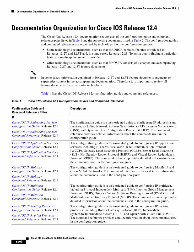
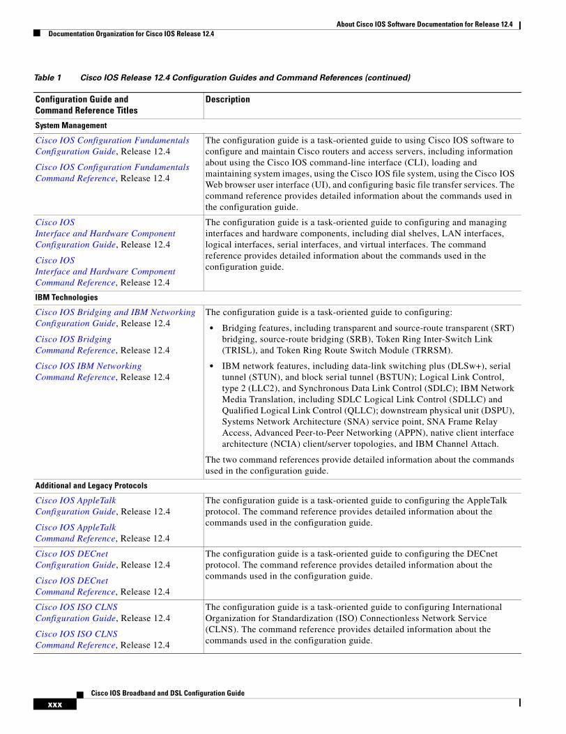
Documentation Organization for Cisco IOS Release 12.4The Cisco IOS Release 12.4 documentation set consists of the configuration guide and command reference pairs listed in Table 1 and the supporting documents listed in Table 2. The configuration guides and command references are organized by technology. For the configuration guides:
• Some technology documentation, such as that for DHCP, contains features introduced in Releases 12.2T and 12.3T and, in some cases, Release 12.2S. To assist you in finding a particular feature, a roadmap document is provided.
• Other technology documentation, such as that for OSPF, consists of a chapter and accompanying Release 12.2T and 12.3T feature documents.
Note In some cases, information contained in Release 12.2T and 12.3T feature documents augments or supersedes content in the accompanying documentation. Therefore it is important to review all feature documents for a particular technology.
Table 1 lists the Cisco IOS Release 12.4 configuration guides and command references.
Table 1 Cisco IOS Release 12.4 Configuration Guides and Command References
Configuration Guide and Command Reference Titles
Description
IP
Cisco IOS IP Addressing Services Configuration Guide, Release 12.4
Cisco IOS IP Addressing Services Command Reference, Release 12.4
The configuration guide is a task-oriented guide to configuring IP addressing and services, including Network Address Translation (NAT), Domain Name System (DNS), and Dynamic Host Configuration Protocol (DHCP). The command reference provides detailed information about the commands used in the configuration guide.
Cisco IOS IP Application Services Configuration Guide, Release 12.4
Cisco IOS IP Application ServicesCommand Reference, Release 12.4
The configuration guide is a task-oriented guide to configuring IP application services, including IP access lists, Web Cache Communication Protocol (WCCP), Gateway Load Balancing Protocol (GLBP), Server Load Balancing (SLB), Hot Standby Router Protocol (HSRP), and Virtual Router Redundancy Protocol (VRRP). The command reference provides detailed information about the commands used in the configuration guide.
Cisco IOS IP Mobility Configuration Guide, Release 12.4
Cisco IOS IP Mobility Command Reference, Release 12.4
The configuration guide is a task-oriented guide to configuring Mobile IP and Cisco Mobile Networks. The command reference provides detailed information about the commands used in the configuration guide.
Cisco IOS IP MulticastConfiguration Guide, Release 12.4
Cisco IOS IP Multicast Command Reference, Release 12.4
The configuration guide is a task-oriented guide to configuring IP multicast, including Protocol Independent Multicast (PIM), Internet Group Management Protocol (IGMP), Distance Vector Multicast Routing Protocol (DVMRP), and Multicast Source Discovery Protocol (MSDP). The command reference provides detailed information about the commands used in the configuration guide.
Cisco IOS IP Routing Protocols Configuration Guide, Release 12.4
Cisco IOS IP Routing Protocols Command Reference, Release 12.4
The configuration guide is a task-oriented guide to configuring IP routing protocols, including Border Gateway Protocol (BGP), Intermediate System-to-Intermediate System (IS-IS), and Open Shortest Path First (OSPF). The command reference provides detailed information about the commands used in the configuration guide.
About Cisco IOS Software Documentation for Release 12.4Documentation Organization for Cisco IOS Release 12.4
xxviiCisco IOS Broadband and DSL Configuration Guide
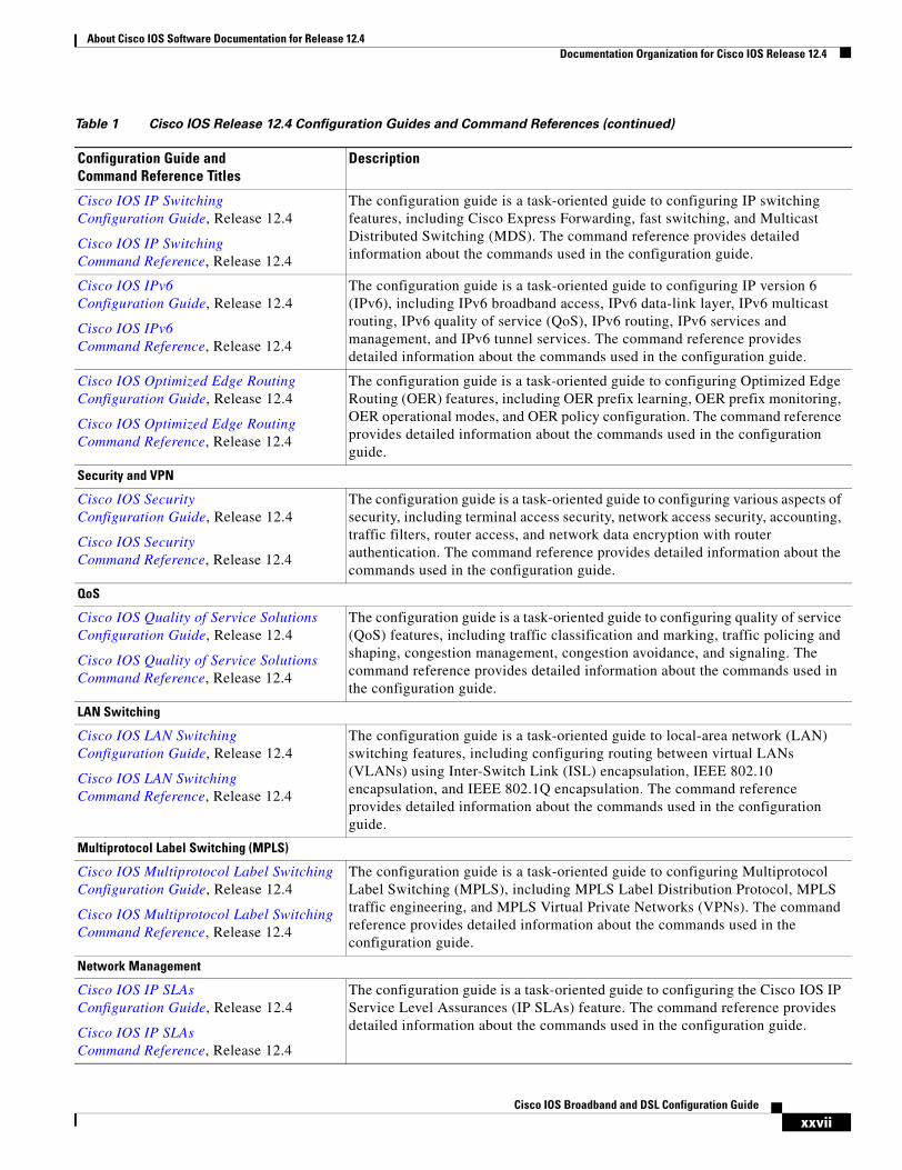
Cisco IOS IP Switching Configuration Guide, Release 12.4
Cisco IOS IP Switching Command Reference, Release 12.4
The configuration guide is a task-oriented guide to configuring IP switching features, including Cisco Express Forwarding, fast switching, and Multicast Distributed Switching (MDS). The command reference provides detailed information about the commands used in the configuration guide.
Cisco IOS IPv6 Configuration Guide, Release 12.4
Cisco IOS IPv6 Command Reference, Release 12.4
The configuration guide is a task-oriented guide to configuring IP version 6 (IPv6), including IPv6 broadband access, IPv6 data-link layer, IPv6 multicast routing, IPv6 quality of service (QoS), IPv6 routing, IPv6 services and management, and IPv6 tunnel services. The command reference provides detailed information about the commands used in the configuration guide.
Cisco IOS Optimized Edge Routing Configuration Guide, Release 12.4
Cisco IOS Optimized Edge Routing Command Reference, Release 12.4
The configuration guide is a task-oriented guide to configuring Optimized Edge Routing (OER) features, including OER prefix learning, OER prefix monitoring, OER operational modes, and OER policy configuration. The command reference provides detailed information about the commands used in the configuration guide.
Security and VPN
Cisco IOS Security Configuration Guide, Release 12.4
Cisco IOS Security Command Reference, Release 12.4
The configuration guide is a task-oriented guide to configuring various aspects of security, including terminal access security, network access security, accounting, traffic filters, router access, and network data encryption with router authentication. The command reference provides detailed information about the commands used in the configuration guide.
QoS
Cisco IOS Quality of Service Solutions Configuration Guide, Release 12.4
Cisco IOS Quality of Service Solutions Command Reference, Release 12.4
The configuration guide is a task-oriented guide to configuring quality of service (QoS) features, including traffic classification and marking, traffic policing and shaping, congestion management, congestion avoidance, and signaling. The command reference provides detailed information about the commands used in the configuration guide.
LAN Switching
Cisco IOS LAN Switching Configuration Guide, Release 12.4
Cisco IOS LAN Switching Command Reference, Release 12.4
The configuration guide is a task-oriented guide to local-area network (LAN) switching features, including configuring routing between virtual LANs (VLANs) using Inter-Switch Link (ISL) encapsulation, IEEE 802.10 encapsulation, and IEEE 802.1Q encapsulation. The command reference provides detailed information about the commands used in the configuration guide.
Multiprotocol Label Switching (MPLS)
Cisco IOS Multiprotocol Label Switching Configuration Guide, Release 12.4
Cisco IOS Multiprotocol Label Switching Command Reference, Release 12.4
The configuration guide is a task-oriented guide to configuring Multiprotocol Label Switching (MPLS), including MPLS Label Distribution Protocol, MPLS traffic engineering, and MPLS Virtual Private Networks (VPNs). The command reference provides detailed information about the commands used in the configuration guide.
Network Management
Cisco IOS IP SLAs Configuration Guide, Release 12.4
Cisco IOS IP SLAs Command Reference, Release 12.4
The configuration guide is a task-oriented guide to configuring the Cisco IOS IP Service Level Assurances (IP SLAs) feature. The command reference provides detailed information about the commands used in the configuration guide.
Table 1 Cisco IOS Release 12.4 Configuration Guides and Command References (continued)
Configuration Guide and Command Reference Titles
Description
About Cisco IOS Software Documentation for Release 12.4Documentation Organization for Cisco IOS Release 12.4
xxviiiCisco IOS Broadband and DSL Configuration Guide
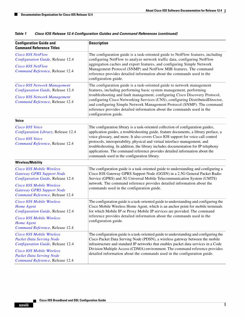
Cisco IOS NetFlow Configuration Guide, Release 12.4
Cisco IOS NetFlow Command Reference, Release 12.4
The configuration guide is a task-oriented guide to NetFlow features, including configuring NetFlow to analyze network traffic data, configuring NetFlow aggregation caches and export features, and configuring Simple Network Management Protocol (SNMP) and NetFlow MIB features. The command reference provides detailed information about the commands used in the configuration guide.
Cisco IOS Network Management Configuration Guide, Release 12.4
Cisco IOS Network Management Command Reference, Release 12.4
The configuration guide is a task-oriented guide to network management features, including performing basic system management, performing troubleshooting and fault management, configuring Cisco Discovery Protocol, configuring Cisco Networking Services (CNS), configuring DistributedDirector, and configuring Simple Network Management Protocol (SNMP). The command reference provides detailed information about the commands used in the configuration guide.
Voice
Cisco IOS Voice Configuration Library, Release 12.4
Cisco IOS Voice Command Reference, Release 12.4
The configuration library is a task-oriented collection of configuration guides, application guides, a troubleshooting guide, feature documents, a library preface, a voice glossary, and more. It also covers Cisco IOS support for voice call control protocols, interoperability, physical and virtual interface management, and troubleshooting. In addition, the library includes documentation for IP telephony applications. The command reference provides detailed information about the commands used in the configuration library.
Wireless/Mobility
Cisco IOS Mobile Wireless Gateway GPRS Support Node Configuration Guide, Release 12.4
Cisco IOS Mobile Wireless Gateway GPRS Support Node Command Reference, Release 12.4
The configuration guide is a task-oriented guide to understanding and configuring a Cisco IOS Gateway GPRS Support Node (GGSN) in a 2.5G General Packet Radio Service (GPRS) and 3G Universal Mobile Telecommunication System (UMTS) network. The command reference provides detailed information about the commands used in the configuration guide.
Cisco IOS Mobile Wireless Home Agent Configuration Guide, Release 12.4
Cisco IOS Mobile Wireless Home Agent Command Reference, Release 12.4
The configuration guide is a task-oriented guide to understanding and configuring the Cisco Mobile Wireless Home Agent, which is an anchor point for mobile terminals for which Mobile IP or Proxy Mobile IP services are provided. The command reference provides detailed information about the commands used in the configuration guide.
Cisco IOS Mobile Wireless Packet Data Serving Node Configuration Guide, Release 12.4
Cisco IOS Mobile Wireless Packet Data Serving Node Command Reference, Release 12.4
The configuration guide is a task-oriented guide to understanding and configuring the Cisco Packet Data Serving Node (PDSN), a wireless gateway between the mobile infrastructure and standard IP networks that enables packet data services in a Code Division Multiple Access (CDMA) environment. The command reference provides detailed information about the commands used in the configuration guide.
Table 1 Cisco IOS Release 12.4 Configuration Guides and Command References (continued)
Configuration Guide and Command Reference Titles
Description
http://lbj.cisco.com/push_targets1/ucdit/cc/td/doc/product/software/ios123/123cgcr/voice_c/index.htm
About Cisco IOS Software Documentation for Release 12.4Documentation Organization for Cisco IOS Release 12.4
xxixCisco IOS Broadband and DSL Configuration Guide
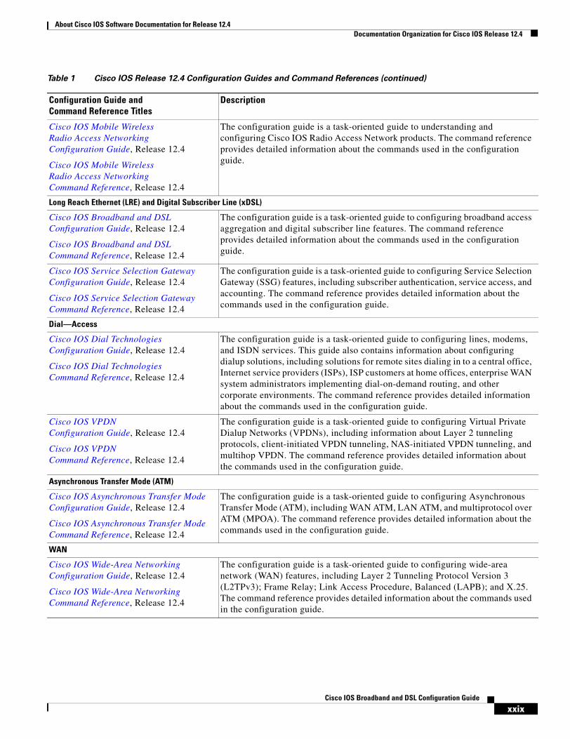
Cisco IOS Mobile Wireless Radio Access Networking Configuration Guide, Release 12.4
Cisco IOS Mobile Wireless Radio Access Networking Command Reference, Release 12.4
The configuration guide is a task-oriented guide to understanding and configuring Cisco IOS Radio Access Network products. The command reference provides detailed information about the commands used in the configuration guide.
Long Reach Ethernet (LRE) and Digital Subscriber Line (xDSL)
Cisco IOS Broadband and DSL Configuration Guide, Release 12.4
Cisco IOS Broadband and DSL Command Reference, Release 12.4
The configuration guide is a task-oriented guide to configuring broadband access aggregation and digital subscriber line features. The command reference provides detailed information about the commands used in the configuration guide.
Cisco IOS Service Selection GatewayConfiguration Guide, Release 12.4
Cisco IOS Service Selection Gateway Command Reference, Release 12.4
The configuration guide is a task-oriented guide to configuring Service Selection Gateway (SSG) features, including subscriber authentication, service access, and accounting. The command reference provides detailed information about the commands used in the configuration guide.
Dial—Access
Cisco IOS Dial Technologies Configuration Guide, Release 12.4
Cisco IOS Dial Technologies Command Reference, Release 12.4
The configuration guide is a task-oriented guide to configuring lines, modems, and ISDN services. This guide also contains information about configuring dialup solutions, including solutions for remote sites dialing in to a central office, Internet service providers (ISPs), ISP customers at home offices, enterprise WAN system administrators implementing dial-on-demand routing, and other corporate environments. The command reference provides detailed information about the commands used in the configuration guide.
Cisco IOS VPDN Configuration Guide, Release 12.4
Cisco IOS VPDN Command Reference, Release 12.4
The configuration guide is a task-oriented guide to configuring Virtual Private Dialup Networks (VPDNs), including information about Layer 2 tunneling protocols, client-initiated VPDN tunneling, NAS-initiated VPDN tunneling, and multihop VPDN. The command reference provides detailed information about the commands used in the configuration guide.
Asynchronous Transfer Mode (ATM)
Cisco IOS Asynchronous Transfer Mode Configuration Guide, Release 12.4
Cisco IOS Asynchronous Transfer Mode Command Reference, Release 12.4
The configuration guide is a task-oriented guide to configuring Asynchronous Transfer Mode (ATM), including WAN ATM, LAN ATM, and multiprotocol over ATM (MPOA). The command reference provides detailed information about the commands used in the configuration guide.
WAN
Cisco IOS Wide-Area Networking Configuration Guide, Release 12.4
Cisco IOS Wide-Area Networking Command Reference, Release 12.4
The configuration guide is a task-oriented guide to configuring wide-area network (WAN) features, including Layer 2 Tunneling Protocol Version 3 (L2TPv3); Frame Relay; Link Access Procedure, Balanced (LAPB); and X.25. The command reference provides detailed information about the commands used in the configuration guide.
Table 1 Cisco IOS Release 12.4 Configuration Guides and Command References (continued)
Configuration Guide and Command Reference Titles
Description
About Cisco IOS Software Documentation for Release 12.4Documentation Organization for Cisco IOS Release 12.4
xxxCisco IOS Broadband and DSL Configuration Guide
System Management
Cisco IOS Configuration Fundamentals Configuration Guide, Release 12.4
Cisco IOS Configuration Fundamentals Command Reference, Release 12.4
The configuration guide is a task-oriented guide to using Cisco IOS software to configure and maintain Cisco routers and access servers, including information about using the Cisco IOS command-line interface (CLI), loading and maintaining system images, using the Cisco IOS file system, using the Cisco IOS Web browser user interface (UI), and configuring basic file transfer services. The command reference provides detailed information about the commands used in the configuration guide.
Cisco IOS Interface and Hardware Component Configuration Guide, Release 12.4
Cisco IOS Interface and Hardware Component Command Reference, Release 12.4
The configuration guide is a task-oriented guide to configuring and managing interfaces and hardware components, including dial shelves, LAN interfaces, logical interfaces, serial interfaces, and virtual interfaces. The command reference provides detailed information about the commands used in the configuration guide.
IBM Technologies
Cisco IOS Bridging and IBM Networking Configuration Guide, Release 12.4
Cisco IOS Bridging Command Reference, Release 12.4
Cisco IOS IBM Networking Command Reference, Release 12.4
The configuration guide is a task-oriented guide to configuring:
• Bridging features, including transparent and source-route transparent (SRT) bridging, source-route bridging (SRB), Token Ring Inter-Switch Link (TRISL), and Token Ring Route Switch Module (TRRSM).
• IBM network features, including data-link switching plus (DLSw+), serial tunnel (STUN), and block serial tunnel (BSTUN); Logical Link Control, type 2 (LLC2), and Synchronous Data Link Control (SDLC); IBM Network Media Translation, including SDLC Logical Link Control (SDLLC) and Qualified Logical Link Control (QLLC); downstream physical unit (DSPU), Systems Network Architecture (SNA) service point, SNA Frame Relay Access, Advanced Peer-to-Peer Networking (APPN), native client interface architecture (NCIA) client/server topologies, and IBM Channel Attach.
The two command references provide detailed information about the commands used in the configuration guide.
Additional and Legacy Protocols
Cisco IOS AppleTalk Configuration Guide, Release 12.4
Cisco IOS AppleTalkCommand Reference, Release 12.4
The configuration guide is a task-oriented guide to configuring the AppleTalk protocol. The command reference provides detailed information about the commands used in the configuration guide.
Cisco IOS DECnet Configuration Guide, Release 12.4
Cisco IOS DECnet Command Reference, Release 12.4
The configuration guide is a task-oriented guide to configuring the DECnet protocol. The command reference provides detailed information about the commands used in the configuration guide.
Cisco IOS ISO CLNS Configuration Guide, Release 12.4
Cisco IOS ISO CLNS Command Reference, Release 12.4
The configuration guide is a task-oriented guide to configuring International Organization for Standardization (ISO) Connectionless Network Service (CLNS). The command reference provides detailed information about the commands used in the configuration guide.
Table 1 Cisco IOS Release 12.4 Configuration Guides and Command References (continued)
Configuration Guide and Command Reference Titles
Description
About Cisco IOS Software Documentation for Release 12.4Documentation Organization for Cisco IOS Release 12.4
xxxiCisco IOS Broadband and DSL Configuration Guide
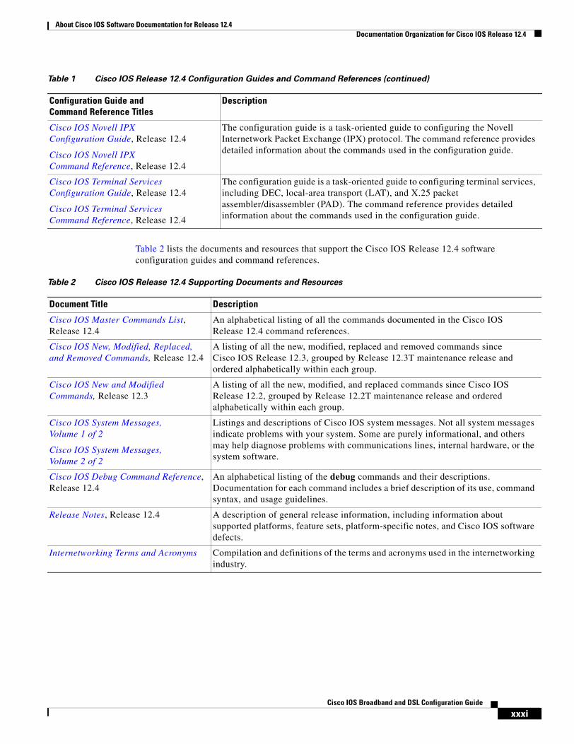
Table 2 lists the documents and resources that support the Cisco IOS Release 12.4 software configuration guides and command references.
Cisco IOS Novell IPX Configuration Guide, Release 12.4
Cisco IOS Novell IPX Command Reference, Release 12.4
The configuration guide is a task-oriented guide to configuring the Novell Internetwork Packet Exchange (IPX) protocol. The command reference provides detailed information about the commands used in the configuration guide.
Cisco IOS Terminal Services Configuration Guide, Release 12.4
Cisco IOS Terminal Services Command Reference, Release 12.4
The configuration guide is a task-oriented guide to configuring terminal services, including DEC, local-area transport (LAT), and X.25 packet assembler/disassembler (PAD). The command reference provides detailed information about the commands used in the configuration guide.
Table 1 Cisco IOS Release 12.4 Configuration Guides and Command References (continued)
Configuration Guide and Command Reference Titles
Description
Table 2 Cisco IOS Release 12.4 Supporting Documents and Resources
Document Title Description
Cisco IOS Master Commands List, Release 12.4
An alphabetical listing of all the commands documented in the Cisco IOS Release 12.4 command references.
Cisco IOS New, Modified, Replaced, and Removed Commands, Release 12.4
A listing of all the new, modified, replaced and removed commands since Cisco IOS Release 12.3, grouped by Release 12.3T maintenance release and ordered alphabetically within each group.
Cisco IOS New and Modified Commands, Release 12.3
A listing of all the new, modified, and replaced commands since Cisco IOS Release 12.2, grouped by Release 12.2T maintenance release and ordered alphabetically within each group.
Cisco IOS System Messages, Volume 1 of 2
Cisco IOS System Messages, Volume 2 of 2
Listings and descriptions of Cisco IOS system messages. Not all system messages indicate problems with your system. Some are purely informational, and others may help diagnose problems with communications lines, internal hardware, or the system software.
Cisco IOS Debug Command Reference, Release 12.4
An alphabetical listing of the debug commands and their descriptions. Documentation for each command includes a brief description of its use, command syntax, and usage guidelines.
Release Notes, Release 12.4 A description of general release information, including information about supported platforms, feature sets, platform-specific notes, and Cisco IOS software defects.
Internetworking Terms and Acronyms Compilation and definitions of the terms and acronyms used in the internetworking industry.
About Cisco IOS Software Documentation for Release 12.4Document Conventions
xxxiiCisco IOS Broadband and DSL Configuration Guide
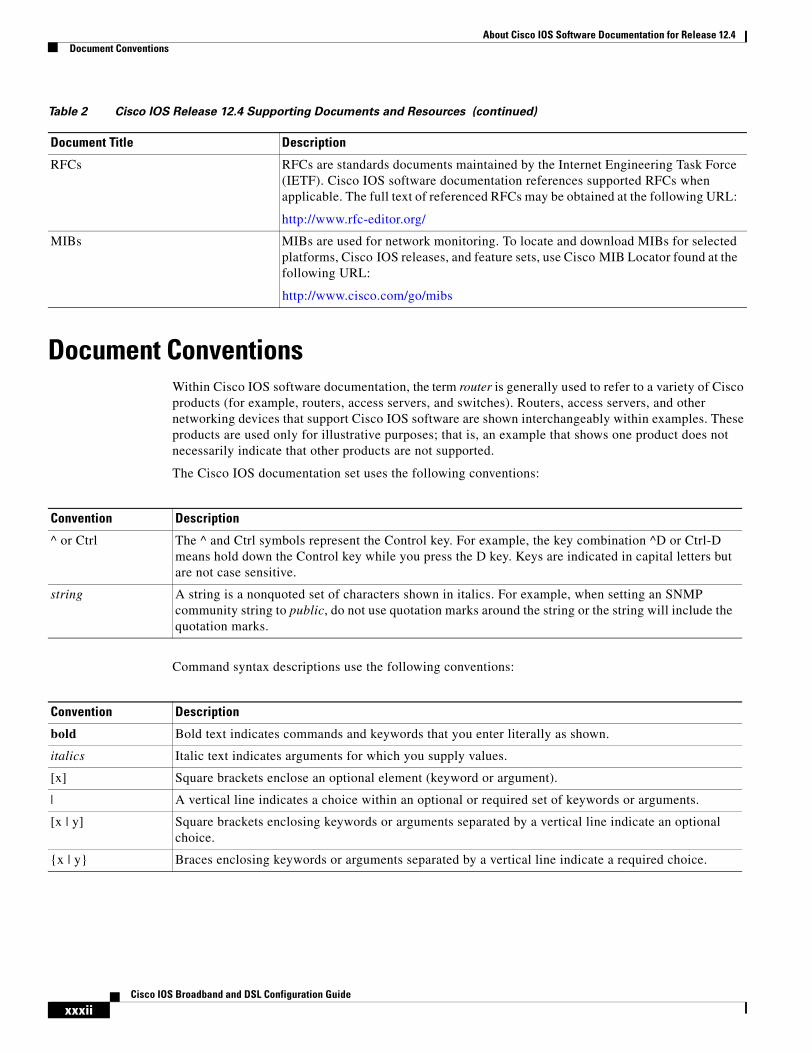
Document ConventionsWithin Cisco IOS software documentation, the term router is generally used to refer to a variety of Cisco products (for example, routers, access servers, and switches). Routers, access servers, and other networking devices that support Cisco IOS software are shown interchangeably within examples. These products are used only for illustrative purposes; that is, an example that shows one product does not necessarily indicate that other products are not supported.
The Cisco IOS documentation set uses the following conventions:
Command syntax descriptions use the following conventions:
RFCs RFCs are standards documents maintained by the Internet Engineering Task Force (IETF). Cisco IOS software documentation references supported RFCs when applicable. The full text of referenced RFCs may be obtained at the following URL:
http://www.rfc-editor.org/
MIBs MIBs are used for network monitoring. To locate and download MIBs for selected platforms, Cisco IOS releases, and feature sets, use Cisco MIB Locator found at the following URL:
http://www.cisco.com/go/mibs
Table 2 Cisco IOS Release 12.4 Supporting Documents and Resources (continued)
Document Title Description
Convention Description
^ or Ctrl The ^ and Ctrl symbols represent the Control key. For example, the key combination ^D or Ctrl-D means hold down the Control key while you press the D key. Keys are indicated in capital letters but are not case sensitive.
string A string is a nonquoted set of characters shown in italics. For example, when setting an SNMP community string to public, do not use quotation marks around the string or the string will include the quotation marks.
Convention Description
bold Bold text indicates commands and keywords that you enter literally as shown.
italics Italic text indicates arguments for which you supply values.
[x] Square brackets enclose an optional element (keyword or argument).
| A vertical line indicates a choice within an optional or required set of keywords or arguments.
[x | y] Square brackets enclosing keywords or arguments separated by a vertical line indicate an optional choice.
{x | y} Braces enclosing keywords or arguments separated by a vertical line indicate a required choice.
About Cisco IOS Software Documentation for Release 12.4Obtaining Documentation
xxxiiiCisco IOS Broadband and DSL Configuration Guide
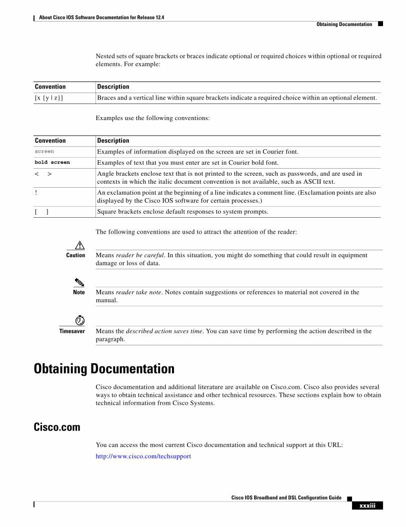
Nested sets of square brackets or braces indicate optional or required choices within optional or required elements. For example:
Examples use the following conventions:
The following conventions are used to attract the attention of the reader:
Caution Means reader be careful. In this situation, you might do something that could result in equipment damage or loss of data.
Note Means reader take note. Notes contain suggestions or references to material not covered in the manual.
Timesaver Means the described action saves time. You can save time by performing the action described in the paragraph.
Obtaining DocumentationCisco documentation and additional literature are available on Cisco.com. Cisco also provides several ways to obtain technical assistance and other technical resources. These sections explain how to obtain technical information from Cisco Systems.
Cisco.comYou can access the most current Cisco documentation and technical support at this URL:
http://www.cisco.com/techsupport
Convention Description
[x {y | z}] Braces and a vertical line within square brackets indicate a required choice within an optional element.
Convention Descriptionscreen Examples of information displayed on the screen are set in Courier font.
bold screen Examples of text that you must enter are set in Courier bold font.
< > Angle brackets enclose text that is not printed to the screen, such as passwords, and are used in contexts in which the italic document convention is not available, such as ASCII text.
! An exclamation point at the beginning of a line indicates a comment line. (Exclamation points are also displayed by the Cisco IOS software for certain processes.)
[ ] Square brackets enclose default responses to system prompts.
About Cisco IOS Software Documentation for Release 12.4Documentation Feedback
xxxivCisco IOS Broadband and DSL Configuration Guide
You can access the Cisco website at this URL:
http://www.cisco.com
You can access international Cisco websites at this URL:
http://www.cisco.com/public/countries_languages.shtml
Product Documentation DVDCisco documentation and additional literature are available in the Product Documentation DVD package, which may have shipped with your product. The Product Documentation DVD is updated regularly and may be more current than printed documentation.
The Product Documentation DVD is a comprehensive library of technical product documentation on portable media. The DVD enables you to access multiple versions of hardware and software installation, configuration, and command guides for Cisco products and to view technical documentation in HTML. With the DVD, you have access to the same documentation that is found on the Cisco website without being connected to the Internet. Certain products also have .pdf versions of the documentation available.
The Product Documentation DVD is available as a single unit or as a subscription. Registered Cisco.com users (Cisco direct customers) can order a Product Documentation DVD (product number DOC-DOCDVD=) from Cisco Marketplace at this URL:
http://www.cisco.com/go/marketplace/
Ordering DocumentationBeginning June 30, 2005, registered Cisco.com users may order Cisco documentation at the Product Documentation Store in the Cisco Marketplace at this URL:
http://www.cisco.com/go/marketplace/
Nonregistered Cisco.com users can order technical documentation from 8:00 a.m. to 5:00 p.m. (0800 to 1700) PDT by calling 1 866 463-3487 in the United States and Canada, or elsewhere by calling 011 408 519-5055. You can also order documentation by e-mail at [email protected] or by fax at 1 408 519-5001 in the United States and Canada, or elsewhere at 011 408 519-5001.
Documentation FeedbackYou can rate and provide feedback about Cisco technical documents by completing the online feedback form that appears with the technical documents on Cisco.com.
You can send comments about Cisco documentation to [email protected].
You can submit comments by using the response card (if present) behind the front cover of your document or by writing to the following address:
Cisco SystemsAttn: Customer Document Ordering170 West Tasman DriveSan Jose, CA 95134-9883
We appreciate your comments.
About Cisco IOS Software Documentation for Release 12.4Cisco Product Security Overview
xxxvCisco IOS Broadband and DSL Configuration Guide
Cisco Product Security OverviewCisco provides a free online Security Vulnerability Policy portal at this URL:
http://www.cisco.com/en/US/products/products_security_vulnerability_policy.html
From this site, you can perform these tasks:
• Report security vulnerabilities in Cisco products.
• Obtain assistance with security incidents that involve Cisco products.
• Register to receive security information from Cisco.
A current list of security advisories and notices for Cisco products is available at this URL:
http://www.cisco.com/go/psirt
If you prefer to see advisories and notices as they are updated in real time, you can access a Product Security Incident Response Team Really Simple Syndication (PSIRT RSS) feed from this URL:
http://www.cisco.com/en/US/products/products_psirt_rss_feed.html
Reporting Security Problems in Cisco ProductsCisco is committed to delivering secure products. We test our products internally before we release them, and we strive to correct all vulnerabilities quickly. If you think that you might have identified a vulnerability in a Cisco product, contact PSIRT:
• Emergencies— [email protected]
An emergency is either a condition in which a system is under active attack or a condition for which a severe and urgent security vulnerability should be reported. All other conditions are considered nonemergencies.
• Nonemergencies— [email protected]
In an emergency, you can also reach PSIRT by telephone:
• 1 877 228-7302
• 1 408 525-6532
Tip We encourage you to use Pretty Good Privacy (PGP) or a compatible product to encrypt any sensitive information that you send to Cisco. PSIRT can work from encrypted information that is compatible with PGP versions 2.x through 8.x.
Never use a revoked or an expired encryption key. The correct public key to use in your correspondence with PSIRT is the one linked in the Contact Summary section of the Security Vulnerability Policy page at this URL:
http://www.cisco.com/en/US/products/products_security_vulnerability_policy.html
The link on this page has the current PGP key ID in use.
About Cisco IOS Software Documentation for Release 12.4Obtaining Technical Assistance
xxxviCisco IOS Broadband and DSL Configuration Guide
Obtaining Technical AssistanceCisco Technical Support provides 24-hour-a-day award-winning technical assistance. The Cisco Technical Support & Documentation website on Cisco.com features extensive online support resources. In addition, if you have a valid Cisco service contract, Cisco Technical Assistance Center (TAC) engineers provide telephone support. If you do not have a valid Cisco service contract, contact your reseller.
Cisco Technical Support & Documentation WebsiteThe Cisco Technical Support & Documentation website provides online documents and tools for troubleshooting and resolving technical issues with Cisco products and technologies. The website is available 24 hours a day, at this URL:
http://www.cisco.com/techsupport
Access to all tools on the Cisco Technical Support & Documentation website requires a Cisco.com user ID and password. If you have a valid service contract but do not have a user ID or password, you can register at this URL:
http://tools.cisco.com/RPF/register/register.do
Note Use the Cisco Product Identification (CPI) tool to locate your product serial number before submitting a web or phone request for service. You can access the CPI tool from the Cisco Technical Support & Documentation website by clicking the Tools & Resources link. Choose Cisco Product Identification Tool from the Alphabetical Index drop-down list, or click the Cisco Product Identification Tool link under Alerts & RMAs. The CPI tool offers three search options: by product ID or model name; by tree view; or for certain products, by copying and pasting show command output. Search results show an illustration of your product with the serial number label location highlighted. Locate the serial number label on your product and record the information before placing a service call.
Submitting a Service RequestUsing the online TAC Service Request Tool is the fastest way to open S3 and S4 service requests. (S3 and S4 service requests are those in which your network is minimally impaired or for which you require product information.) After you describe your situation, the TAC Service Request Tool provides recommended solutions. If your issue is not resolved using the recommended resources, your service request is assigned to a Cisco engineer. The TAC Service Request Tool is located at this URL:
http://www.cisco.com/techsupport/servicerequest
For S1 or S2 service requests or if you do not have Internet access, contact the Cisco TAC by telephone. (S1 or S2 service requests are those in which your production network is down or severely degraded.) Cisco engineers are assigned immediately to S1 and S2 service requests to help keep your business operations running smoothly.
To open a service request by telephone, use one of the following numbers:
Asia-Pacific: +61 2 8446 7411 (Australia: 1 800 805 227)EMEA: +32 2 704 55 55USA: 1 800 553-2447
About Cisco IOS Software Documentation for Release 12.4Obtaining Additional Publications and Information
xxxviiCisco IOS Broadband and DSL Configuration Guide
For a complete list of Cisco TAC contacts, go to this URL:
http://www.cisco.com/techsupport/contacts
Definitions of Service Request SeverityTo ensure that all service requests are reported in a standard format, Cisco has established severity definitions.
Severity 1 (S1)—Your network is “down,” or there is a critical impact to your business operations. You and Cisco will commit all necessary resources around the clock to resolve the situation.
Severity 2 (S2)—Operation of an existing network is severely degraded, or significant aspects of your business operation are negatively affected by inadequate performance of Cisco products. You and Cisco will commit full-time resources during normal business hours to resolve the situation.
Severity 3 (S3)—Operational performance of your network is impaired, but most business operations remain functional. You and Cisco will commit resources during normal business hours to restore service to satisfactory levels.
Severity 4 (S4)—You require information or assistance with Cisco product capabilities, installation, or configuration. There is little or no effect on your business operations.
Obtaining Additional Publications and InformationInformation about Cisco products, technologies, and network solutions is available from various online and printed sources.
• Cisco Marketplace provides a variety of Cisco books, reference guides, documentation, and logo merchandise. Visit Cisco Marketplace, the company store, at this URL:
http://www.cisco.com/go/marketplace/
• Cisco Press publishes a wide range of general networking, training and certification titles. Both new and experienced users will benefit from these publications. For current Cisco Press titles and other information, go to Cisco Press at this URL:
http://www.ciscopress.com
• Packet magazine is the Cisco Systems technical user magazine for maximizing Internet and networking investments. Each quarter, Packet delivers coverage of the latest industry trends, technology breakthroughs, and Cisco products and solutions, as well as network deployment and troubleshooting tips, configuration examples, customer case studies, certification and training information, and links to scores of in-depth online resources. You can access Packet magazine at this URL:
http://www.cisco.com/packet
• iQ Magazine is the quarterly publication from Cisco Systems designed to help growing companies learn how they can use technology to increase revenue, streamline their business, and expand services. The publication identifies the challenges facing these companies and the technologies to help solve them, using real-world case studies and business strategies to help readers make sound technology investment decisions. You can access iQ Magazine at this URL:
http://www.cisco.com/go/iqmagazine
or view the digital edition at this URL:
http://ciscoiq.texterity.com/ciscoiq/sample/
About Cisco IOS Software Documentation for Release 12.4Obtaining Additional Publications and Information
xxxviiiCisco IOS Broadband and DSL Configuration Guide
• Internet Protocol Journal is a quarterly journal published by Cisco Systems for engineering professionals involved in designing, developing, and operating public and private internets and intranets. You can access the Internet Protocol Journal at this URL:
http://www.cisco.com/ipj
• Networking products offered by Cisco Systems, as well as customer support services, can be obtained at this URL:
http://www.cisco.com/en/US/products/index.html
• Networking Professionals Connection is an interactive website for networking professionals to share questions, suggestions, and information about networking products and technologies with Cisco experts and other networking professionals. Join a discussion at this URL:
http://www.cisco.com/discuss/networking
• World-class networking training is available from Cisco. You can view current offerings at this URL:
http://www.cisco.com/en/US/learning/index.html
xxxixCisco IOS Broadband and DSL Configuration Guide
Using Cisco IOS Software for Release 12.4
This chapter provides tips for understanding and configuring Cisco IOS software using the command-line interface (CLI). It contains the following sections:
• Understanding Command Modes, page xxxix
• Getting Help, page xl
• Using the no and default Forms of Commands, page xliv
• Saving Configuration Changes, page xliv
• Filtering Output from the show and more Commands, page xlv
• Finding Additional Feature Support Information, page xlv
For an overview of Cisco IOS software configuration, see the Cisco IOS Configuration Fundamentals Configuration Guide.
For information on the conventions used in the Cisco IOS software documentation set, see the “About Cisco IOS Software Documentation for Release 12.4” chapter.
Understanding Command ModesYou use the CLI to access Cisco IOS software. Because the CLI is divided into many different modes, the commands available to you at any given time depend on the mode that you are currently in. Entering a question mark (?) at the CLI prompt allows you to obtain a list of commands available for each command mode.
When you log in to a Cisco device, the device is initially in user EXEC mode. User EXEC mode contains only a limited subset of commands. To have access to all commands, you must enter privileged EXEC mode by entering the enable command and a password (when required). From privileged EXEC mode you have access to both user EXEC and privileged EXEC commands. Most EXEC commands are used independently to observe status or to perform a specific function. For example, show commands are used to display important status information, and clear commands allow you to reset counters or interfaces. The EXEC commands are not saved when the software reboots.
Configuration modes allow you to make changes to the running configuration. If you later save the running configuration to the startup configuration, these changed commands are stored when the software is rebooted. To enter specific configuration modes, you must start at global configuration mode. From global configuration mode, you can enter interface configuration mode and a variety of other modes, such as protocol-specific modes.
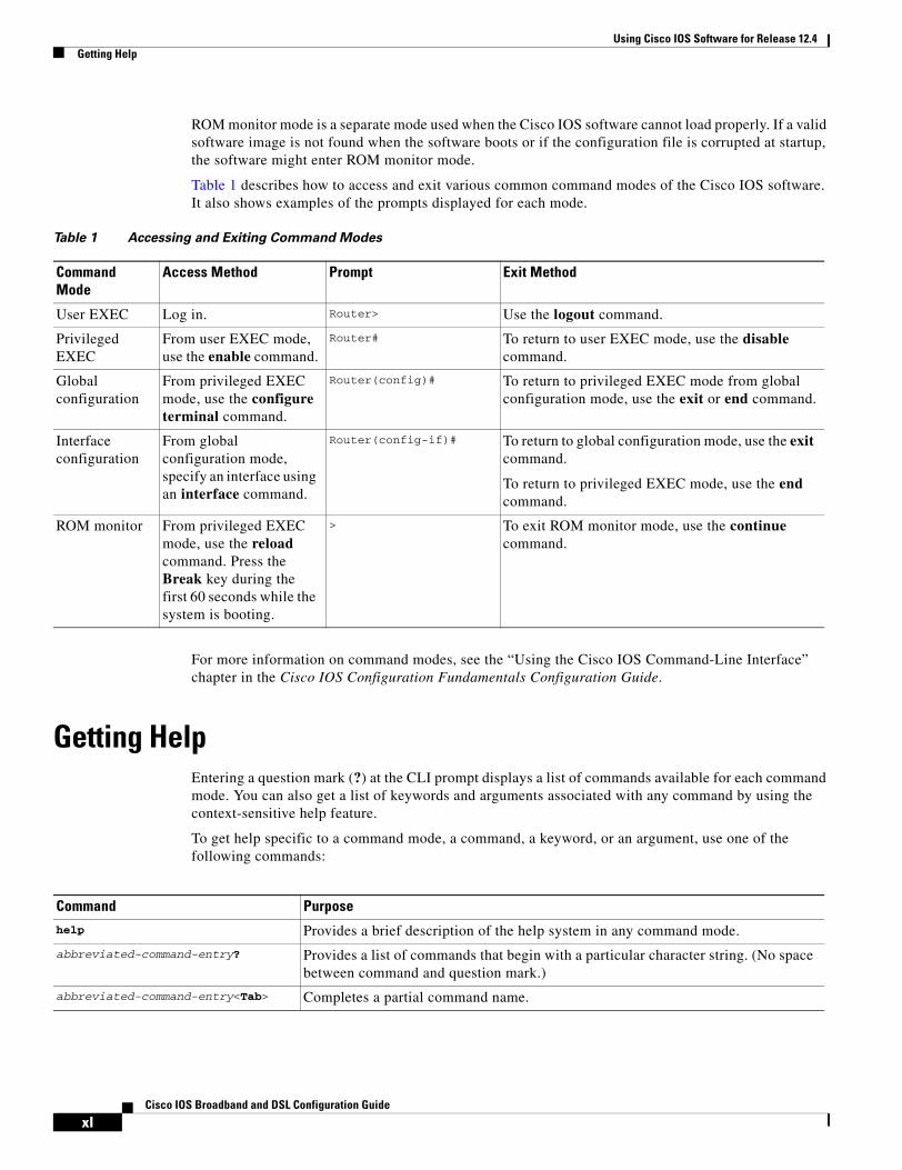
Using Cisco IOS Software for Release 12.4Getting Help
xlCisco IOS Broadband and DSL Configuration Guide
ROM monitor mode is a separate mode used when the Cisco IOS software cannot load properly. If a valid software image is not found when the software boots or if the configuration file is corrupted at startup, the software might enter ROM monitor mode.
Table 1 describes how to access and exit various common command modes of the Cisco IOS software. It also shows examples of the prompts displayed for each mode.
For more information on command modes, see the “Using the Cisco IOS Command-Line Interface” chapter in the Cisco IOS Configuration Fundamentals Configuration Guide.
Getting HelpEntering a question mark (?) at the CLI prompt displays a list of commands available for each command mode. You can also get a list of keywords and arguments associated with any command by using the context-sensitive help feature.
To get help specific to a command mode, a command, a keyword, or an argument, use one of the following commands:
Table 1 Accessing and Exiting Command Modes
Command Mode
Access Method Prompt Exit Method
User EXEC Log in. Router> Use the logout command.
Privileged EXEC
From user EXEC mode, use the enable command.
Router# To return to user EXEC mode, use the disable command.
Global configuration
From privileged EXEC mode, use the configure terminal command.
Router(config)# To return to privileged EXEC mode from global configuration mode, use the exit or end command.
Interface configuration
From global configuration mode, specify an interface using an interface command.
Router(config-if)# To return to global configuration mode, use the exit command.
To return to privileged EXEC mode, use the end command.
ROM monitor From privileged EXEC mode, use the reload command. Press the Break key during the first 60 seconds while the system is booting.
> To exit ROM monitor mode, use the continue command.
Command Purpose
help Provides a brief description of the help system in any command mode.
abbreviated-command-entry? Provides a list of commands that begin with a particular character string. (No space between command and question mark.)
abbreviated-command-entry<Tab> Completes a partial command name.
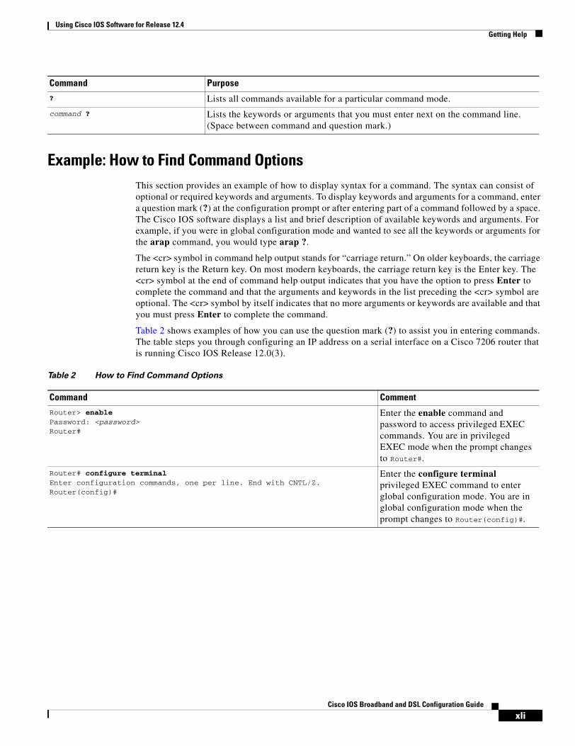
Using Cisco IOS Software for Release 12.4Getting Help
xliCisco IOS Broadband and DSL Configuration Guide
Example: How to Find Command OptionsThis section provides an example of how to display syntax for a command. The syntax can consist of optional or required keywords and arguments. To display keywords and arguments for a command, enter a question mark (?) at the configuration prompt or after entering part of a command followed by a space. The Cisco IOS software displays a list and brief description of available keywords and arguments. For example, if you were in global configuration mode and wanted to see all the keywords or arguments for the arap command, you would type arap ?.
The <cr> symbol in command help output stands for “carriage return.” On older keyboards, the carriage return key is the Return key. On most modern keyboards, the carriage return key is the Enter key. The <cr> symbol at the end of command help output indicates that you have the option to press Enter to complete the command and that the arguments and keywords in the list preceding the <cr> symbol are optional. The <cr> symbol by itself indicates that no more arguments or keywords are available and that you must press Enter to complete the command.
Table 2 shows examples of how you can use the question mark (?) to assist you in entering commands. The table steps you through configuring an IP address on a serial interface on a Cisco 7206 router that is running Cisco IOS Release 12.0(3).
? Lists all commands available for a particular command mode.
command ? Lists the keywords or arguments that you must enter next on the command line. (Space between command and question mark.)
Command Purpose
Table 2 How to Find Command Options
Command Comment
Router> enablePassword: <password>Router#
Enter the enable command and password to access privileged EXEC commands. You are in privileged EXEC mode when the prompt changes to Router#.
Router# configure terminalEnter configuration commands, one per line. End with CNTL/Z.Router(config)#
Enter the configure terminal privileged EXEC command to enter global configuration mode. You are in global configuration mode when the prompt changes to Router(config)#.
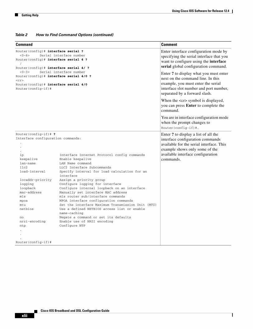
Using Cisco IOS Software for Release 12.4Getting Help
xliiCisco IOS Broadband and DSL Configuration Guide
Router(config)# interface serial ?<0-6> Serial interface number
Router(config)# interface serial 4 ?/
Router(config)# interface serial 4/ ?<0-3> Serial interface number
Router(config)# interface serial 4/0 ?<cr>Router(config)# interface serial 4/0Router(config-if)#
Enter interface configuration mode by specifying the serial interface that you want to configure using the interface serial global configuration command.
Enter ? to display what you must enter next on the command line. In this example, you must enter the serial interface slot number and port number, separated by a forward slash.
When the <cr> symbol is displayed, you can press Enter to complete the command.
You are in interface configuration mode when the prompt changes to Router(config-if)#.
Router(config-if)# ?Interface configuration commands:
.
.
.ip Interface Internet Protocol config commandskeepalive Enable keepalivelan-name LAN Name commandllc2 LLC2 Interface Subcommandsload-interval Specify interval for load calculation for an
interfacelocaddr-priority Assign a priority grouplogging Configure logging for interfaceloopback Configure internal loopback on an interfacemac-address Manually set interface MAC addressmls mls router sub/interface commandsmpoa MPOA interface configuration commandsmtu Set the interface Maximum Transmission Unit (MTU)netbios Use a defined NETBIOS access list or enable
name-cachingno Negate a command or set its defaultsnrzi-encoding Enable use of NRZI encodingntp Configure NTP...
Router(config-if)#
Enter ? to display a list of all the interface configuration commands available for the serial interface. This example shows only some of the available interface configuration commands.
Table 2 How to Find Command Options (continued)
Command Comment
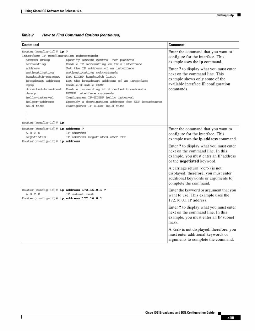
Using Cisco IOS Software for Release 12.4Getting Help
xliiiCisco IOS Broadband and DSL Configuration Guide
Router(config-if)# ip ?Interface IP configuration subcommands:
access-group Specify access control for packetsaccounting Enable IP accounting on this interfaceaddress Set the IP address of an interfaceauthentication authentication subcommandsbandwidth-percent Set EIGRP bandwidth limitbroadcast-address Set the broadcast address of an interfacecgmp Enable/disable CGMPdirected-broadcast Enable forwarding of directed broadcastsdvmrp DVMRP interface commandshello-interval Configures IP-EIGRP hello intervalhelper-address Specify a destination address for UDP broadcastshold-time Configures IP-EIGRP hold time...
Router(config-if)# ip
Enter the command that you want to configure for the interface. This example uses the ip command.
Enter ? to display what you must enter next on the command line. This example shows only some of the available interface IP configuration commands.
Router(config-if)# ip address ?A.B.C.D IP addressnegotiated IP Address negotiated over PPP
Router(config-if)# ip address
Enter the command that you want to configure for the interface. This example uses the ip address command.
Enter ? to display what you must enter next on the command line. In this example, you must enter an IP address or the negotiated keyword.
A carriage return (<cr>) is not displayed; therefore, you must enter additional keywords or arguments to complete the command.
Router(config-if)# ip address 172.16.0.1 ?A.B.C.D IP subnet mask
Router(config-if)# ip address 172.16.0.1
Enter the keyword or argument that you want to use. This example uses the 172.16.0.1 IP address.
Enter ? to display what you must enter next on the command line. In this example, you must enter an IP subnet mask.
A <cr> is not displayed; therefore, you must enter additional keywords or arguments to complete the command.
Table 2 How to Find Command Options (continued)
Command Comment
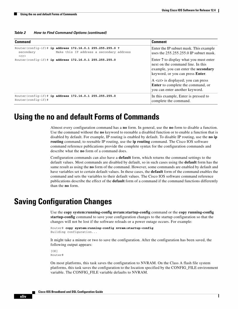
Using Cisco IOS Software for Release 12.4Using the no and default Forms of Commands
xlivCisco IOS Broadband and DSL Configuration Guide
Using the no and default Forms of CommandsAlmost every configuration command has a no form. In general, use the no form to disable a function. Use the command without the no keyword to reenable a disabled function or to enable a function that is disabled by default. For example, IP routing is enabled by default. To disable IP routing, use the no ip routing command; to reenable IP routing, use the ip routing command. The Cisco IOS software command reference publications provide the complete syntax for the configuration commands and describe what the no form of a command does.
Configuration commands can also have a default form, which returns the command settings to the default values. Most commands are disabled by default, so in such cases using the default form has the same result as using the no form of the command. However, some commands are enabled by default and have variables set to certain default values. In these cases, the default form of the command enables the command and sets the variables to their default values. The Cisco IOS software command reference publications describe the effect of the default form of a command if the command functions differently than the no form.
Saving Configuration ChangesUse the copy system:running-config nvram:startup-config command or the copy running-config startup-config command to save your configuration changes to the startup configuration so that the changes will not be lost if the software reloads or a power outage occurs. For example:
Router# copy system:running-config nvram:startup-configBuilding configuration...
It might take a minute or two to save the configuration. After the configuration has been saved, the following output appears:
[OK]Router#
On most platforms, this task saves the configuration to NVRAM. On the Class A flash file system platforms, this task saves the configuration to the location specified by the CONFIG_FILE environment variable. The CONFIG_FILE variable defaults to NVRAM.
Router(config-if)# ip address 172.16.0.1 255.255.255.0 ?secondary Make this IP address a secondary address<cr>
Router(config-if)# ip address 172.16.0.1 255.255.255.0
Enter the IP subnet mask. This example uses the 255.255.255.0 IP subnet mask.
Enter ? to display what you must enter next on the command line. In this example, you can enter the secondary keyword, or you can press Enter.
A <cr> is displayed; you can press Enter to complete the command, or you can enter another keyword.
Router(config-if)# ip address 172.16.0.1 255.255.255.0Router(config-if)#
In this example, Enter is pressed to complete the command.
Table 2 How to Find Command Options (continued)
Command Comment
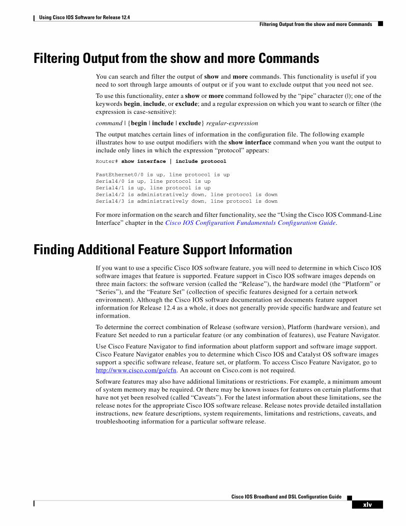
Using Cisco IOS Software for Release 12.4Filtering Output from the show and more Commands
xlvCisco IOS Broadband and DSL Configuration Guide
Filtering Output from the show and more CommandsYou can search and filter the output of show and more commands. This functionality is useful if you need to sort through large amounts of output or if you want to exclude output that you need not see.
To use this functionality, enter a show or more command followed by the “pipe” character (|); one of the keywords begin, include, or exclude; and a regular expression on which you want to search or filter (the expression is case-sensitive):
command | {begin | include | exclude} regular-expression
The output matches certain lines of information in the configuration file. The following example illustrates how to use output modifiers with the show interface command when you want the output to include only lines in which the expression “protocol” appears:
Router# show interface | include protocol
FastEthernet0/0 is up, line protocol is upSerial4/0 is up, line protocol is upSerial4/1 is up, line protocol is upSerial4/2 is administratively down, line protocol is downSerial4/3 is administratively down, line protocol is down
For more information on the search and filter functionality, see the “Using the Cisco IOS Command-Line Interface” chapter in the Cisco IOS Configuration Fundamentals Configuration Guide.
Finding Additional Feature Support InformationIf you want to use a specific Cisco IOS software feature, you will need to determine in which Cisco IOS software images that feature is supported. Feature support in Cisco IOS software images depends on three main factors: the software version (called the “Release”), the hardware model (the “Platform” or “Series”), and the “Feature Set” (collection of specific features designed for a certain network environment). Although the Cisco IOS software documentation set documents feature support information for Release 12.4 as a whole, it does not generally provide specific hardware and feature set information.
To determine the correct combination of Release (software version), Platform (hardware version), and Feature Set needed to run a particular feature (or any combination of features), use Feature Navigator.
Use Cisco Feature Navigator to find information about platform support and software image support. Cisco Feature Navigator enables you to determine which Cisco IOS and Catalyst OS software images support a specific software release, feature set, or platform. To access Cisco Feature Navigator, go to http://www.cisco.com/go/cfn. An account on Cisco.com is not required.
Software features may also have additional limitations or restrictions. For example, a minimum amount of system memory may be required. Or there may be known issues for features on certain platforms that have not yet been resolved (called “Caveats”). For the latest information about these limitations, see the release notes for the appropriate Cisco IOS software release. Release notes provide detailed installation instructions, new feature descriptions, system requirements, limitations and restrictions, caveats, and troubleshooting information for a particular software release.

Using Cisco IOS Software for Release 12.4Finding Additional Feature Support Information
xlviCisco IOS Broadband and DSL Configuration Guide

Part 1: Broadband Access Aggregation Overview

3Cisco IOS Broadband and DSL Configuration Guide
78-17496-01
Configuring Broadband Access Aggregation Features Roadmap
This roadmap lists the features documented in the Broadband Access Aggregation Configuration Guide and maps them to the modules in which they appear.
Roadmap History
This roadmap was first published on May 2, 2005, and was last updated on February 27, 2006.
Feature and Release Support
Table 3 lists the broadband access aggregation features supported in Cisco IOS Releases 12.2S, 12.2T, 12.3, 12.3T and 12.4T. Only features that were introduced or modified in Cisco IOS Releases 12.2(1) or 12.0(3)S or later releases appear in the table. Not all features may be supported in your Cisco IOS software release.
Table 3 lists broadband access aggregation feature support for the following Cisco IOS software release trains:
• Cisco IOS Releases 12.2T, 12.3, 12.3T and 12.4T
Note Table 3 lists only the Cisco IOS software release that introduced support for a given feature in a given Cisco IOS software release train. Unless noted otherwise, subsequent releases of that Cisco IOS software release train also support that feature.
Table 3 Supported Configuring Broadband Access Aggregation Features
Release Feature Name Feature Description Where Documented
Cisco IOS Releases 12.2T, 12.3, 12.3T and 12.4T
12.4(4)T PPPoE Circuit-Id Tag Processing
The PPPoE Circuit-Id Tag Processing feature provides a way to extract a Circuit-Id tag from the digital subscriber line (DSL) as an identifier for the authentication, authorization, and accounting (AAA) access request on an Ethernet interface, thereby simulating ATM-based broadband access, but using cost-effective Ethernet instead. The tag is useful for troubleshooting the network, and is also used in RADIUS authentication and accounting processes.
PPPoE Circuit-Id Tag Processing
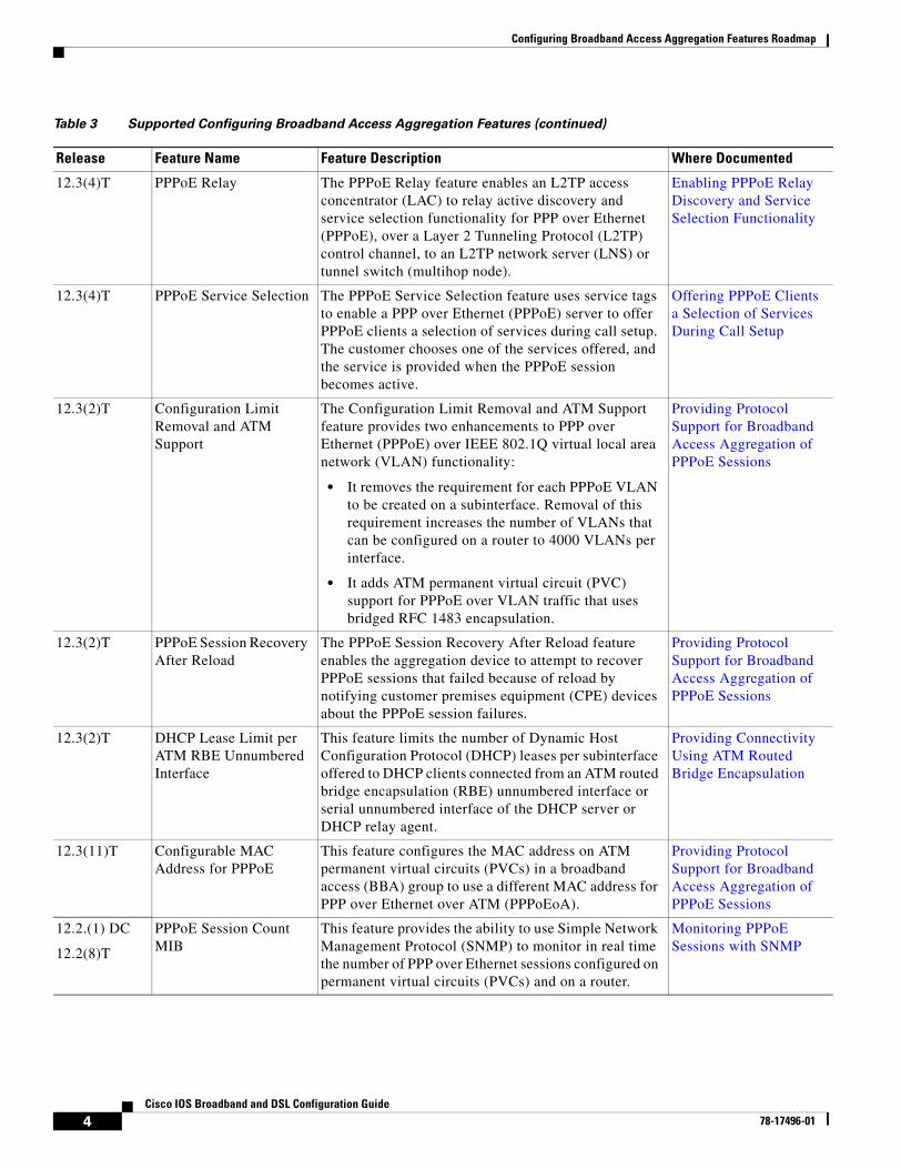
Configuring Broadband Access Aggregation Features Roadmap
4Cisco IOS Broadband and DSL Configuration Guide
78-17496-01
12.3(4)T PPPoE Relay The PPPoE Relay feature enables an L2TP access concentrator (LAC) to relay active discovery and service selection functionality for PPP over Ethernet (PPPoE), over a Layer 2 Tunneling Protocol (L2TP) control channel, to an L2TP network server (LNS) or tunnel switch (multihop node).
Enabling PPPoE Relay Discovery and Service Selection Functionality
12.3(4)T PPPoE Service Selection The PPPoE Service Selection feature uses service tags to enable a PPP over Ethernet (PPPoE) server to offer PPPoE clients a selection of services during call setup. The customer chooses one of the services offered, and the service is provided when the PPPoE session becomes active.
Offering PPPoE Clients a Selection of Services During Call Setup
12.3(2)T Configuration Limit Removal and ATM Support
The Configuration Limit Removal and ATM Support feature provides two enhancements to PPP over Ethernet (PPPoE) over IEEE 802.1Q virtual local area network (VLAN) functionality:
• It removes the requirement for each PPPoE VLAN to be created on a subinterface. Removal of this requirement increases the number of VLANs that can be configured on a router to 4000 VLANs per interface.
• It adds ATM permanent virtual circuit (PVC) support for PPPoE over VLAN traffic that uses bridged RFC 1483 encapsulation.
Providing Protocol Support for Broadband Access Aggregation of PPPoE Sessions
12.3(2)T PPPoE Session Recovery After Reload
The PPPoE Session Recovery After Reload feature enables the aggregation device to attempt to recover PPPoE sessions that failed because of reload by notifying customer premises equipment (CPE) devices about the PPPoE session failures.
Providing Protocol Support for Broadband Access Aggregation of PPPoE Sessions
12.3(2)T DHCP Lease Limit per ATM RBE Unnumbered Interface
This feature limits the number of Dynamic Host Configuration Protocol (DHCP) leases per subinterface offered to DHCP clients connected from an ATM routed bridge encapsulation (RBE) unnumbered interface or serial unnumbered interface of the DHCP server or DHCP relay agent.
Providing Connectivity Using ATM Routed Bridge Encapsulation
12.3(11)T Configurable MAC Address for PPPoE
This feature configures the MAC address on ATM permanent virtual circuits (PVCs) in a broadband access (BBA) group to use a different MAC address for PPP over Ethernet over ATM (PPPoEoA).
Providing Protocol Support for Broadband Access Aggregation of PPPoE Sessions
12.2.(1) DC
12.2(8)T
PPPoE Session Count MIB
This feature provides the ability to use Simple Network Management Protocol (SNMP) to monitor in real time the number of PPP over Ethernet sessions configured on permanent virtual circuits (PVCs) and on a router.
Monitoring PPPoE Sessions with SNMP
Table 3 Supported Configuring Broadband Access Aggregation Features (continued)
Release Feature Name Feature Description Where Documented
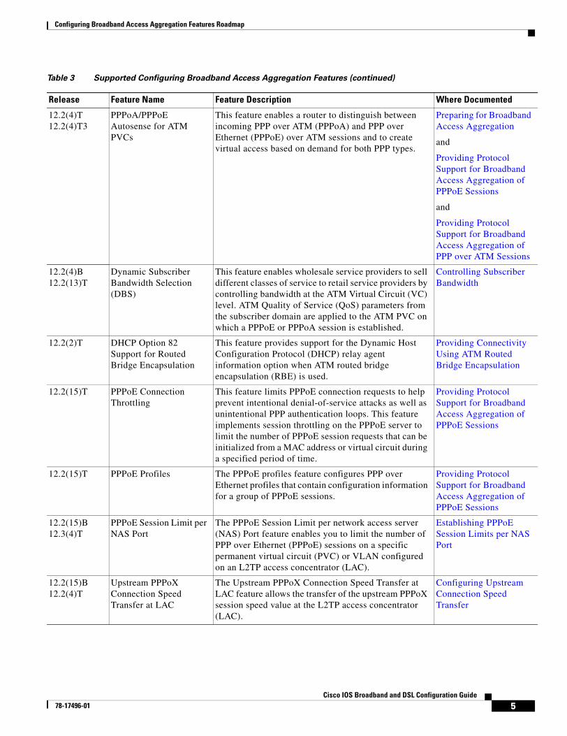
Configuring Broadband Access Aggregation Features Roadmap
5Cisco IOS Broadband and DSL Configuration Guide
78-17496-01
12.2(4)T12.2(4)T3
PPPoA/PPPoE Autosense for ATM PVCs
This feature enables a router to distinguish between incoming PPP over ATM (PPPoA) and PPP over Ethernet (PPPoE) over ATM sessions and to create virtual access based on demand for both PPP types.
Preparing for Broadband Access Aggregation
and
Providing Protocol Support for Broadband Access Aggregation of PPPoE Sessions
and
Providing Protocol Support for Broadband Access Aggregation of PPP over ATM Sessions
12.2(4)B12.2(13)T
Dynamic Subscriber Bandwidth Selection (DBS)
This feature enables wholesale service providers to sell different classes of service to retail service providers by controlling bandwidth at the ATM Virtual Circuit (VC) level. ATM Quality of Service (QoS) parameters from the subscriber domain are applied to the ATM PVC on which a PPPoE or PPPoA session is established.
Controlling Subscriber Bandwidth
12.2(2)T DHCP Option 82 Support for Routed Bridge Encapsulation
This feature provides support for the Dynamic Host Configuration Protocol (DHCP) relay agent information option when ATM routed bridge encapsulation (RBE) is used.
Providing Connectivity Using ATM Routed Bridge Encapsulation
12.2(15)T PPPoE Connection Throttling
This feature limits PPPoE connection requests to help prevent intentional denial-of-service attacks as well as unintentional PPP authentication loops. This feature implements session throttling on the PPPoE server to limit the number of PPPoE session requests that can be initialized from a MAC address or virtual circuit during a specified period of time.
Providing Protocol Support for Broadband Access Aggregation of PPPoE Sessions
12.2(15)T PPPoE Profiles The PPPoE profiles feature configures PPP over Ethernet profiles that contain configuration information for a group of PPPoE sessions.
Providing Protocol Support for Broadband Access Aggregation of PPPoE Sessions
12.2(15)B12.3(4)T
PPPoE Session Limit per NAS Port
The PPPoE Session Limit per network access server (NAS) Port feature enables you to limit the number of PPP over Ethernet (PPPoE) sessions on a specific permanent virtual circuit (PVC) or VLAN configured on an L2TP access concentrator (LAC).
Establishing PPPoE Session Limits per NAS Port
12.2(15)B12.2(4)T
Upstream PPPoX Connection Speed Transfer at LAC
The Upstream PPPoX Connection Speed Transfer at LAC feature allows the transfer of the upstream PPPoX session speed value at the L2TP access concentrator (LAC).
Configuring Upstream Connection Speed Transfer
Table 3 Supported Configuring Broadband Access Aggregation Features (continued)
Release Feature Name Feature Description Where Documented
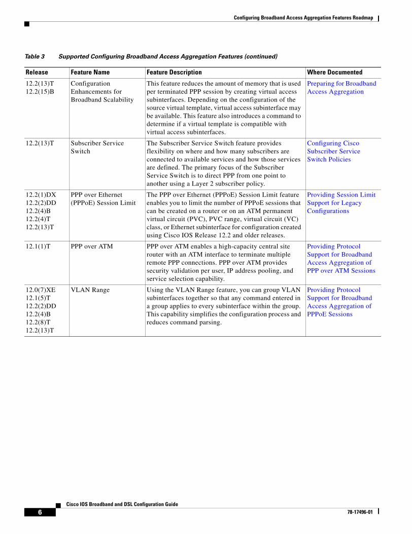
Configuring Broadband Access Aggregation Features Roadmap
6Cisco IOS Broadband and DSL Configuration Guide
78-17496-01
12.2(13)T12.2(15)B
Configuration Enhancements for Broadband Scalability
This feature reduces the amount of memory that is used per terminated PPP session by creating virtual access subinterfaces. Depending on the configuration of the source virtual template, virtual access subinterface may be available. This feature also introduces a command to determine if a virtual template is compatible with virtual access subinterfaces.
Preparing for Broadband Access Aggregation
12.2(13)T Subscriber Service Switch
The Subscriber Service Switch feature provides flexibility on where and how many subscribers are connected to available services and how those services are defined. The primary focus of the Subscriber Service Switch is to direct PPP from one point to another using a Layer 2 subscriber policy.
Configuring Cisco Subscriber Service Switch Policies
12.2(1)DX12.2(2)DD12.2(4)B12.2(4)T 12.2(13)T
PPP over Ethernet (PPPoE) Session Limit
The PPP over Ethernet (PPPoE) Session Limit feature enables you to limit the number of PPPoE sessions that can be created on a router or on an ATM permanent virtual circuit (PVC), PVC range, virtual circuit (VC) class, or Ethernet subinterface for configuration created using Cisco IOS Release 12.2 and older releases.
Providing Session Limit Support for Legacy Configurations
12.1(1)T PPP over ATM PPP over ATM enables a high-capacity central site router with an ATM interface to terminate multiple remote PPP connections. PPP over ATM provides security validation per user, IP address pooling, and service selection capability.
Providing Protocol Support for Broadband Access Aggregation of PPP over ATM Sessions
12.0(7)XE12.1(5)T12.2(2)DD12.2(4)B12.2(8)T12.2(13)T
VLAN Range Using the VLAN Range feature, you can group VLAN subinterfaces together so that any command entered in a group applies to every subinterface within the group. This capability simplifies the configuration process and reduces command parsing.
Providing Protocol Support for Broadband Access Aggregation of PPPoE Sessions
Table 3 Supported Configuring Broadband Access Aggregation Features (continued)
Release Feature Name Feature Description Where Documented
7Cisco IOS Broadband and DSL Configuration Guide
78-17496-01
Understanding Broadband Access Aggregation
Broadband access aggregation is the means by which connections are made among multiple technologies. These technologies include ISDN, DSL, cable, Ethernet, and wireless devices that are connected to corporate virtual private networks (VPNs), third-party applications, and the Internet. Subscriber demand for high-speed services, including multi-player gaming, video-on-demand, home security, digital audio, streaming video, and many other applications, require the delivery of IP services, regardless of the access medium.
Because so many different technologies are involved in broadband access aggregation, it is important that the service provider understand their network both in terms of the hardware that makes up the installation, which determines what type of sessions need to be established, but also in terms of what kinds of services their subscribers expect to receive. The demands placed on large service provider installations can often result in the need to contend with millions of sessions and provide flexible and reliable configurations for widely diverse consumer needs.
This module contains conceptual information about broadband access aggregation.
Module History
This module was first published on May 2, 2005, and was last updated on May 2, 2005.
Contents• Information About Broadband Access Aggregation, page 7
• Additional References, page 12
• Glossary, page 14
Information About Broadband Access AggregationTo perform the necessary tasks in providing broadband access aggregation, you should understand the following concepts:
• Encapsulation Protocols, page 8
• Layer 2 Tunneling Protocol, page 8
• ATM Services, page 9
• PPPoE, page 9
• PPPoEoE/PPPoEo802.1q, page 10
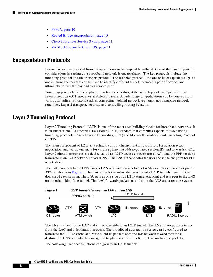
Understanding Broadband Access AggregationInformation About Broadband Access Aggregation
8Cisco IOS Broadband and DSL Configuration Guide
78-17496-01
• PPPoA, page 10
• Routed Bridge Encapsulation, page 10
• Cisco Subscriber Service Switch, page 11
• RADIUS Support in Cisco IOS, page 11
Encapsulation ProtocolsInternet access has evolved from dialup modems to high-speed broadband. One of the most important considerations in setting up a broadband network is encapsulation. The key protocols include the tunneling protocol and the transport protocol. The tunneled protocol (the one to be encapsulated) gains one or more headers that can be used to identify different tunnels between a pair of devices and ultimately deliver the payload to a remote peer.
Tunneling protocols can be applied to protocols operating at the same layer of the Open Systems Interconnection (OSI) model or at different layers. A wide range of applications can be derived from various tunneling protocols, such as connecting isolated network segments, nondisruptive network renumber, Layer 2 transport, security, and controlling routing behavior.
Layer 2 Tunneling ProtocolLayer 2 Tunneling Protocol (L2TP) is one of the most used building blocks for broadband networks. It is an International Engineering Task Force (IETF) standard that combines aspects of two existing tunneling protocols: Cisco Layer 2 Forwarding (L2F) and Microsoft Point-to-Point Tunneling Protocol (PPTP).
The main component of L2TP is a reliable control channel that is responsible for session setup, negotiation, and teardown, and a forwarding plane that adds negotiated session IDs and forwards traffic. Layer 2 circuits terminate in a device called an L2TP access concentrator (LAC), and the PPP sessions terminate in an L2TP network server (LNS). The LNS authenticates the user and is the endpoint for PPP negotiation.
The LAC connects to the LNS using a LAN or a wide-area network (WAN) switch as a public or private ATM as shown in Figure 1. The LAC directs the subscriber session into L2TP tunnels based on the domain of each session. The LAC acts as one side of an L2TP tunnel endpoint and is a peer to the LNS on the other side of the tunnel. The LAC forwards packets to and from the LNS and a remote system.
Figure 1 L2TP Tunnel Between an LAC and an LNS
The LNS is a peer to the LAC and sits on one side of an L2TP tunnel. The LNS routes packets to and from the LAC and a destination network. The broadband aggregation server can be configured to terminate the PPP sessions and route client IP packets onto the ISP network toward their final destination. LNSs can also be configured to place sessions in VRFs before routing the packets.
The following user encapsulations can go into an L2TP tunnel:
CE router ATM switch LAC LNS RADIUS server
EthernetEthernetATMATM
PPPoX session L2TP tunnel
1212
71
Understanding Broadband Access AggregationInformation About Broadband Access Aggregation
9Cisco IOS Broadband and DSL Configuration Guide
78-17496-01
• PPP sessions encapsulated in L2TP tunnels (LNS-side support only)
• PPPoE termination over ATM
• PPPoA termination
• PPPoEoE or PPPoEo802.1Q
Cisco’s broadband aggregation routers function as the service provider’s network access server when configured as the LAC. Subscribers can use a local or PPP connection to initiate a PPPoA or PPPoE session to the LAC. The LAC terminates the physical connection and forwards the PPP session to the provider’s LNS.
ATM ServicesATM networks provide the following ATM services, which provide delivery of the subscriber sessions to the service providers access concentrators:
• Permanent virtual circuits (PVC)
• Switched virtual circuits (SVC)
A PVC allows direct connectivity between sites. In this way a PVC is similar to a leased line. PVCs generally guarantee availability of a connection, and no call setup procedures are required between ATM switches. However, PVCs provide a static connectivity and require manual administration to set up.
An SVC is created and released dynamically and remains in use only as long as data is being transferred. In this way it is similar to a telephone call. Dynamic call control requires a signaling protocol between the ATM endpoint and the ATM switch. SVCs provide connection flexibility and call setup that can be automatically handled by a networking device. Setting up the connection requires extra time and overhead.
ATM supports two types of connections:
• Point-to-point
• Point-to-multipoint
A point-to-point ATM connection connects two ATM end systems and can be unidirectional (one-way communication) or bidirectional (two-way communication).
A point-to-multipoint ATM connection connects a single source end-system (known as the Root node) to multiple destination end-systems (known as leaves). Such connections are unidirectional only. Root nodes can transmit to leaves, but leaves cannot transmit to the root or to each other on the same connection.
PPPoEPPP over Ethernet (PPPoE) provides the ability to connect hosts on a network over a simple bridging device to a remote aggregation concentrator. PPPoE is the predominant access protocol in broadband networks worldwide. PPPoE typically is deployed with a software stack housed on the end-customer’s (subscriber’s) PC. This software allows the network service provider to “own” the customer as the PPP session runs from the customer PC to the service provider network.
Understanding Broadband Access AggregationInformation About Broadband Access Aggregation
10Cisco IOS Broadband and DSL Configuration Guide
78-17496-01
PPPoEoE/PPPoEo802.1qPPPoEoE is a variant of PPPoE where the Layer 2 transport protocol is now Ethernet or 802.1q VLAN instead of ATM. This encapsulation method is generally found in Metro Ethernet or Ethernet digital subscriber line access multiplexer (DSLAM) environments. The common deployment model is that this encapsulation method is typically found in multi-tenant buildings or hotels. By delivering Ethernet to the subscriber, the available bandwidth is much more abundant and the ease of further service delivery is increased.
PPPoAWith PPP over ATM (PPPoA), a customer premises equipment (CPE) device encapsulates the PPP session based on RFC 1483 for transport across the DSLAM. PPPoA is commonly used in SOHO and branch office type environments although it is not limited to them. It has greater flexibility for the home than the average PPPoE deployment because the customer LAN behind the CPE is under the complete control of the customer and the CPE acts as a router as opposed to a bridge for PPPoE.
When you configure PPP over ATM, a logical interface known as a virtual access interface associates each PPP connection with an ATM VC. You can create this logical interface by configuring an ATM PVC or SVC. This configuration encapsulates each PPP connection in a separate PVC or SVC, allowing each PPP connection to terminate at the router ATM interface as if received from a typical PPP serial interface.
The virtual access interface for each VC obtains its configuration from a virtual interface template (virtual template) when the VC is created. Before you create the ATM VC, it is recommended that you create and configure a virtual template as described in the “Preparing for Broadband Access Aggregation” module.
Once you have configured the router for PPP over ATM, the PPP subsystem starts and the router attempts to send a PPP configure request to the remote peer. If the peer does not respond, the router periodically goes into a “listen” state and waits for a configuration request from the peer. After a timeout (typically 45 seconds), the router again attempts to reach the remote router by sending configuration requests.
The virtual access interface remains associated with a VC as long as the VC is configured. If you remove the configuration of the VC, the virtual access interface is marked as deleted. If you shut down the associated ATM interface, you will also cause the virtual access interface to be marked as down (within 10 seconds), and you will bring the PPP connection down. If you set a keepalive timer of the virtual template on the interface, the virtual access interface uses the PPP echo mechanism to verify the existence of the remote peer.
The following three types of PPP over ATM connections are supported:
• IETF-compliant MUX encapsulated PPP over ATM
• IETF-compliant LLC encapsulated PPP over ATM
• Cisco-proprietary PPP over ATM
Routed Bridge EncapsulationATM routed bridge encapsulation (RBE) is used to route IP over bridged RFC 1483 Ethernet traffic from a stub-bridged LAN.
Understanding Broadband Access AggregationInformation About Broadband Access Aggregation
11Cisco IOS Broadband and DSL Configuration Guide
78-17496-01
The ATM subinterface on a head-end router is configured to function in ATM routed-bridge encapsulation mode. This configuration is useful when a remote bridged Ethernet network device needs connectivity to a routed network by way of a device bridging from an Ethernet LAN to an ATM RFC 1483 bridged encapsulation.
The bridged ATM interface supports ATM PVCs and ATM SVCs.
Because PVCs are statically configured along the entire path between the end systems, it would not be suitable to route bridged encapsulated traffic over them when the user wants to configure the VCs dynamically and tear down the VCs when there is no traffic.
The Subscriber Service Switch was developed in response to a need by Internet service providers for increased scalability and extensibility for remote access service selection and Layer 2 subscriber policy management. This Layer 2 subscriber policy is needed to manage tunneling of PPP in a policy-based bridging fashion.
Cisco Subscriber Service SwitchThe Cisco Subscriber Service Switch provides flexibility on where and how many subscribers are connected to available services and how those services are defined. In the past, remote access service selection was largely determined by the telephone number dialed or the PPP username and password entered during a PPP authentication cycle. However, emerging broadband, cable, virtual private network (VPN), and wireless access methods have created an environment where PPP sessions may be tunneled over a variety of protocols and media. The multitude of protocols, management domains, network infrastructure, and variety of services has created a complex environment for directing a subscriber to a given service or application. The problem is further complicated by the much greater density of total PPP sessions that can be transported over shared media versus traditional point-to-point links. The Subscriber Service Switch can provide a flexible and extensible decision point linking an incoming subscriber (typically a PPP session over some physical or virtual link) to another tunneled link or local termination for Layer 3 processing.
The Subscriber Service Switch is also scalable in situations where a subscriber’s Layer 2 service is switched across virtual links. Examples include switching between PPPoA, PPPoE, L2TP, Layer 2 Forwarding Protocol (L2F), Point-to-Point Tunneling Protocol (PPTP), generic routing encapsulation (GRE), and General Packet Radio Service (GPRS) Tunneling Protocol (GTP wireless data standard).
As networks grow beyond the campus, network security increases in importance and administration complexity. Customers need to protect networks and network resources from unauthorized access by remote users. Cisco Systems uses a strategy known as authentication, authorization, and accounting (AAA) for verifying the identity of, granting access to, and tracking the actions of remote users. In today’s networks, the TACACS+ and RADIUS protocols are commonly used to provide AAA solutions. Support for RADIUS along with TACACS+ enables Cisco to deliver tremendous flexibility and choice to organizations in AAA functionality.
RADIUS Support in Cisco IOS Cisco Systems introduced support for RADIUS in Cisco IOS Release 11.1 in its network access server (NAS) devices.
The RADIUS protocol is an access server authentication and accounting protocol. RADIUS has gained support among a wide customer base, including Internet service providers (ISPs).
The RADIUS protocol is based on a client/server model. An NAS operates as a client of RADIUS. The client is responsible for passing user information to a designated RADIUS server and then acting on the response that is returned.
Understanding Broadband Access AggregationAdditional References
12Cisco IOS Broadband and DSL Configuration Guide
78-17496-01
A RADIUS server (or daemon) can provide authentication and accounting services to one or more client NAS devices. RADIUS servers are responsible for receiving user connection requests, authenticating users, and then returning all configuration information necessary for the client to deliver service to the users. A RADIUS access server is generally a dedicated workstation connected to the network.
Additional ReferencesThe following sections provide references related to understanding broadband access aggregation.
Related Documents
Standards
MIBs
RFCs
Related Topic Document Title
Configuring a PVC range “Configuring PVCs” in the Cisco IOS Wide-Area Networking Configuration Guide
Creating a virtual template “Configuring Virtual Template Interfaces” chapter in the Cisco IOS Dial Technologies Configuration Guide
Standards Title
None —
MIBs MIBs Link
None To locate and download MIBs for selected platforms, Cisco IOS releases, and feature sets, use Cisco MIB Locator found at the following URL:
http://www.cisco.com/go/mibs
RFCs Title
1483 Multiprotocol Encapsulation over ATM Adaptation Layer 5

Understanding Broadband Access AggregationAdditional References
13Cisco IOS Broadband and DSL Configuration Guide
78-17496-01
Technical Assistance
Description Link
The Cisco Technical Support website contains thousands of pages of searchable technical content, including links to products, technologies, solutions, technical tips, and tools. Registered Cisco.com users can log in from this page to access even more content.
http://www.cisco.com/techsupport
Understanding Broadband Access AggregationGlossary
14Cisco IOS Broadband and DSL Configuration Guide
78-17496-01
GlossaryABR—available bit rate. QoS class defined by the ATM Forum for ATM networks. ABR is used for connections that do not require timing relationships between source and destination. ABR provides no guarantees in terms of cell loss or delay, providing only best-effort service. Traffic sources adjust their transmission rate in response to information they receive describing the status of the network and its capability to successfully deliver data.
ACR—allowed cell rate. A parameter defined by the ATM Forum for ATM traffic management. ACR varies between the MCR and the PCR, and is controlled dynamically using congestion control mechanisms.
CBR—constant bit rate. QoS class defined by the ATM Forum for ATM networks. CBR is used for connections that depend on precise clocking to ensure undistorted delivery.
MCR—minimum cell rate. Parameter defined by the ATM Forum for ATM traffic management. MCR is defined only for ABR transmissions, and specifies the minimum value for the ACR.
NAS—network access server. Cisco platform (or collection of platforms, such as an AccessPath system) that interfaces between the packet world (for example, the Internet) and the circuit world (for example, the PSTN).
PCR—peak cell rate. Parameter defined by the ATM Forum for ATM traffic management. In Constant Bit Rate (CBR) transmissions, PCR determines how often data samples are sent. In ABR transmissions, PCR determines the maximum value of the ACR.
PPP—Point-to-Point Protocol. PPP is the successor to Serial Line Internet Protocol (SLIP) that provides router-to-router and host-to-network connections over synchronous and asynchronous circuits. Whereas SLIP was designed to work with IP, PPP was designed to work with several network layer protocols, such as IP, IPX, and ARA. PPP also has built-in security mechanisms, such as CHAP and PAP. PPP relies on two protocols: Link Control Protocol (LCP) and Network Control Protocol (NCP).
PPPoA—Point-to-Point Protocol over ATM. The PPPoA feature enables a high-capacity central site router with an Asynchronous Transfer Mode (ATM) interface to terminate multiple remote Point-to-Point Protocol (PPP) connections.
PPPoE—Point-to-Point Protocol over Ethernet. PPPoE allows a PPP session to be initiated on a simple bridging Ethernet connected client.
PPPoX—Point-to-Point Protocol over Protocol. PPPoX indicates that the point-to-point protocol terminates on another protocol which could be ATM or Ethernet.
PVC—permanent virtual circuit. A virtual circuit that is permanently established. PVCs save bandwidth associated with circuit establishment and tear down in situations where certain virtual circuits must exist all the time. In ATM terminology, called a permanent virtual connection.
QoS—quality of service. Cisco IOS QoS technology lets complex networks control and predictably service a variety of networked applications and traffic types.
RADIUS—Remote Authentication Dial-in User Service
SCR—sustainable cell rate. Parameter defined by the ATM Forum for ATM traffic management. For VBR connections, SCR determines the long-term average cell rate that can be transmitted.
UBR—unspecified bit rate. QoS class defined by the ATM Forum for ATM networks. UBR allows any amount of data up to a specified maximum to be sent across the network but there are no guarantees in terms of cell loss rate and delay.
Understanding Broadband Access AggregationGlossary
15Cisco IOS Broadband and DSL Configuration Guide
78-17496-01
VBR—variable bit rate. QoS class defined by the ATM Forum for ATM networks. VBR is subdivided into a real time (rt) class and non-real time (nrt) class. VBR (rt) is used for connections in which there is a fixed timing relationship between samples. VBR (nrt) is used for connections in which there is no fixed timing relationship between samples but that still need a guaranteed QoS.
VPDN—virtual private dialup network. A VPDN is a network that extends remote access to a private network using a shared infrastructure. VPDNs use Layer 2 tunnel technologies (L2F, L2TP, and PPTP) to extend the Layer 2 and higher parts of the network connection from a remote user across an ISP network to a private network. VPDNs are a cost effective method of establishing a long distance, point-to-point connection between remote dial users and a private network.
VSA—vendor-specific attribute. An attribute that has been implemented by a particular vendor. It uses the attribute Vendor-Specific to encapsulate the resulting AV pair: essentially, Vendor-Specific = protocol:attribute = value.
Note See Internetworking Terms and Acronyms for terms not included in this glossary.

Understanding Broadband Access AggregationGlossary
16Cisco IOS Broadband and DSL Configuration Guide
78-17496-01
17Cisco IOS Broadband and DSL Configuration Guide
78-17496-01
Preparing for Broadband Access Aggregation
Before you begin to perform the tasks required to accomplish broadband access aggregation, there are several preparatory tasks that you can perform at your option to enable you to complete the aggregation task with more efficiency. This module presents three of those preparation tasks: configuring permanent virtual circuits (PVCs), configuring a virtual template interface, and configuring enhancements for broadband scalability.
In a digital subscriber line (DSL) environment, many applications require the configuration of a large number of PVCs. Configuring PVCs before you start broadband aggregation can save you time because configuring a range of PVCs is faster than configuring PVCs individually.
A virtual template interface saves time because all PPP parameters are managed within the virtual template configuration. Any configurations made in the virtual template are automatically propagated to the individual virtual access interfaces.
Using the enhancement for broadband scalability reduces the amount of memory that is used per terminated PPP session by creating virtual access subinterfaces. Determining if virtual access subinterfaces are available on your system and preconfiguring these enhancements can speed your aggregation process and improve system performance.
Module History
This module was first published on May 2, 2005, and last updated on May 2, 2005.
Finding Feature Information in This Module
Not all features may be supported in your Cisco IOS software release. Use the “Feature Information for Preparing for Broadband Access Aggregation” section on page 35 to find information about feature support and configuration.
Contents• Prerequisites for Preparing for Broadband Access Aggregation, page 18
• Restrictions for Preparing for Broadband Access Aggregation, page 18
• Information About Preparing for Broadband Access Aggregation, page 18
• How to Prepare for Broadband Access Aggregation, page 21
• Configuration Examples for Preparing for Broadband Access Aggregation, page 29
• Where to Go Next, page 32
• Additional References, page 33
Preparing for Broadband Access AggregationPrerequisites for Preparing for Broadband Access Aggregation
18Cisco IOS Broadband and DSL Configuration Guide
78-17496-01
• Feature Information for Preparing for Broadband Access Aggregation, page 35
Prerequisites for Preparing for Broadband Access AggregationBefore configuring broadband access aggregation, you will need to know the information that is presented in the “Understanding Broadband Access Aggregation” module.
Additional information can be found in these documents:
• Configuring a PVC range—For detailed information about configuring individual ATM PVCs, see “Configuring PVCs” in the Cisco IOS Wide-Area Networking Configuration Guide.
• Creating a virtual template—For detailed information see the “Configuring Virtual Template Interfaces” chapter in the Cisco IOS Dial Technologies Configuration Guide.
Restrictions for Preparing for Broadband Access AggregationBroadband scalability is not intended to improve the scalability of the following:
• Scaling for dial-out
• Scaling for PPP callback
• Scaling virtual profiles
• Scaling Multilink PPP (MLP)
• Various PPP (PPPoX) applications that terminate PPP on physical interfaces
Information About Preparing for Broadband Access AggregationTo prepare for broadband access aggregation, you should understand the following concepts:
• Virtual-Access Interfaces, page 18
• Autosense for ATM PVCs, page 19
• Configuration Enhancements for Broadband Scalability, page 19
Virtual-Access InterfacesA virtual-template interface is used to provide the configuration for dynamically created virtual-access interfaces. It is created by users and can be saved in NVRAM.
Once the virtual-template interface is created, it can be configured in the same way as a serial interface.
Virtual-template interfaces can be created and applied by various applications such as virtual profiles, virtual private dialup networks (VPDN), PPP over ATM, protocol translation, and Multichassis Multilink PPP (MMP).
All PPP parameters are managed within the virtual-template configuration. Configuration changes made to the virtual template are automatically propagated to the individual virtual access interfaces. Multiple virtual-access interfaces can originate from a single virtual template; therefore, multiple PVCs can use a single virtual template.
Preparing for Broadband Access AggregationInformation About Preparing for Broadband Access Aggregation
19Cisco IOS Broadband and DSL Configuration Guide
78-17496-01
Cisco IOS software supports up to 200 virtual-template configurations. If greater numbers of tailored configurations are required, an authentication, authorization, and accounting (AAA) server may be employed. Refer to the “Configuring Per-User Configuration” chapter in the Cisco IOS Dial Technologies Configuration Guide for additional information on configuring an AAA server.
If the parameters of the virtual template are not explicitly defined before the ATM PVC is configured, the PPP interface is brought up using default values from the virtual template. Some parameters (such as an IP address) take effect only if specified before the PPP interface comes up. Therefore, it is recommended that you explicitly create and configure the virtual template before configuring the ATM PVC to ensure that such parameters take effect. Alternatively, if parameters are specified after the ATM PVC has been configured, use the shutdown command followed by the no shutdown command on the ATM subinterface to restart the interface; this restart will cause the newly configured parameters (such as an IP address) to take effect.
Network addresses for the PPP-over-ATM connections are not configured on the main ATM interface or subinterface. Instead, they are configured on the appropriate virtual template or obtained via AAA.
The virtual templates support all standard PPP configuration commands; however, not all configurations are supported by the PPP-over-ATM virtual access interfaces. These restrictions are enforced at the time the virtual-template configuration is applied (cloned) to the virtual-access interface.
Autosense for ATM PVCsThe PPPoA/PPPoE Autosense for ATM PVCs feature enables a router to distinguish between incoming PPP over ATM (PPPoA) and PPP over Ethernet (PPPoE) over ATM sessions and to create virtual access based on demand for both PPP types.
Note The PPPoA/PPPoE Autosense for ATM PVCs feature is supported on SNAP-encapsulated ATM PVCs only. It is not supported on MUX-encapsulated PVCs.
Virtual Access Interface PrecloningPrecloning virtual-access interfaces for PPPoA at the NAS enables the virtual-access interface to be allocated at system start. This functionality significantly reduces the load on the system during call setup. When precloning is used, the virtual-access interface is attached to the session upon receipt of the first session-initiation packet from the client. The virtual-access interface is detached upon termination of the PPP session.
Configuration Enhancements for Broadband ScalabilityThe Configuration Enhancements for Broadband Scalability feature reduces the amount of memory that is used per terminated PPP session by creating virtual-access subinterfaces. Depending on the configuration of the source virtual template, virtual-access subinterfaces may be available. This feature also introduces a command to determine if a virtual template is compatible with virtual access subinterfaces.
Virtual Access Subinterfaces
The virtual-template command supports existing features, functions, and configurations. By default, the virtual-template subinterface command is enabled.
Preparing for Broadband Access AggregationInformation About Preparing for Broadband Access Aggregation
20Cisco IOS Broadband and DSL Configuration Guide
78-17496-01
The virtual template manager will determine if the set of options configured on the virtual template are all supported on a subinterface. Virtual-access subinterfaces will be created for all virtual templates that support subinterfaces. If the user has entered any commands that are not supported on a subinterface, a full virtual access interface will be created and cloned for all PPP sessions using that virtual template. If the virtual-template subinterface command is disabled, full virtual-access interfaces will always be created.
Different applications can use the same virtual template even if one application is subinterface-capable and another is not. The virtual-template manager will be notified whether the application supports virtual-access subinterfaces and creates the appropriate resource.
The ppp multilink and ppp callback accept commands will not necessarily prevent subinterfaces from being created. Often, these commands are present in a virtual-template configuration, but PPP does not negotiate them. If neither of these features is negotiated, virtual-access subinterfaces will be created. If one or both of these features is negotiated, subinterfaces will not be created. The router will automatically determine if subinterfaces will be created depending on how PPP is negotiated on a case-by-case basis.
Virtual Template Compatibility with Subinterfaces
The test virtual-template subinterface privileged EXEC command determines whether a virtual template can support the creation of a virtual-access subinterface. If the virtual template contains commands that prevent the creation of subinterfaces, the test virtual-template subinterface command identifies and displays these commands.
If the creation of virtual-access subinterfaces is disabled by the no virtual-template subinterface command, the test virtual-template subinterface command produces no output.
The debug vtemplate subinterface command displays debug messages that are generated if you enter configuration commands on the virtual template that are not valid on a subinterface. These messages are generated only if the debug vtemplate subinterface command is enabled, the virtual-template subinterface command is enabled, and a virtual template is configured that can support the creation of subinterfaces. If the creation of virtual-access subinterfaces is disabled by the no virtual-template subinterface command, the debug vtemplate subinterface command produces no output.
Benefits of Using Broadband Scalability FeaturesUsing broadband scalability reduces the amount of memory that is used per terminated PPP session by creating virtual-access subinterfaces. These virtual-access subinterfaces, along with improvements that are transparent to the user, speed up the cloning process.
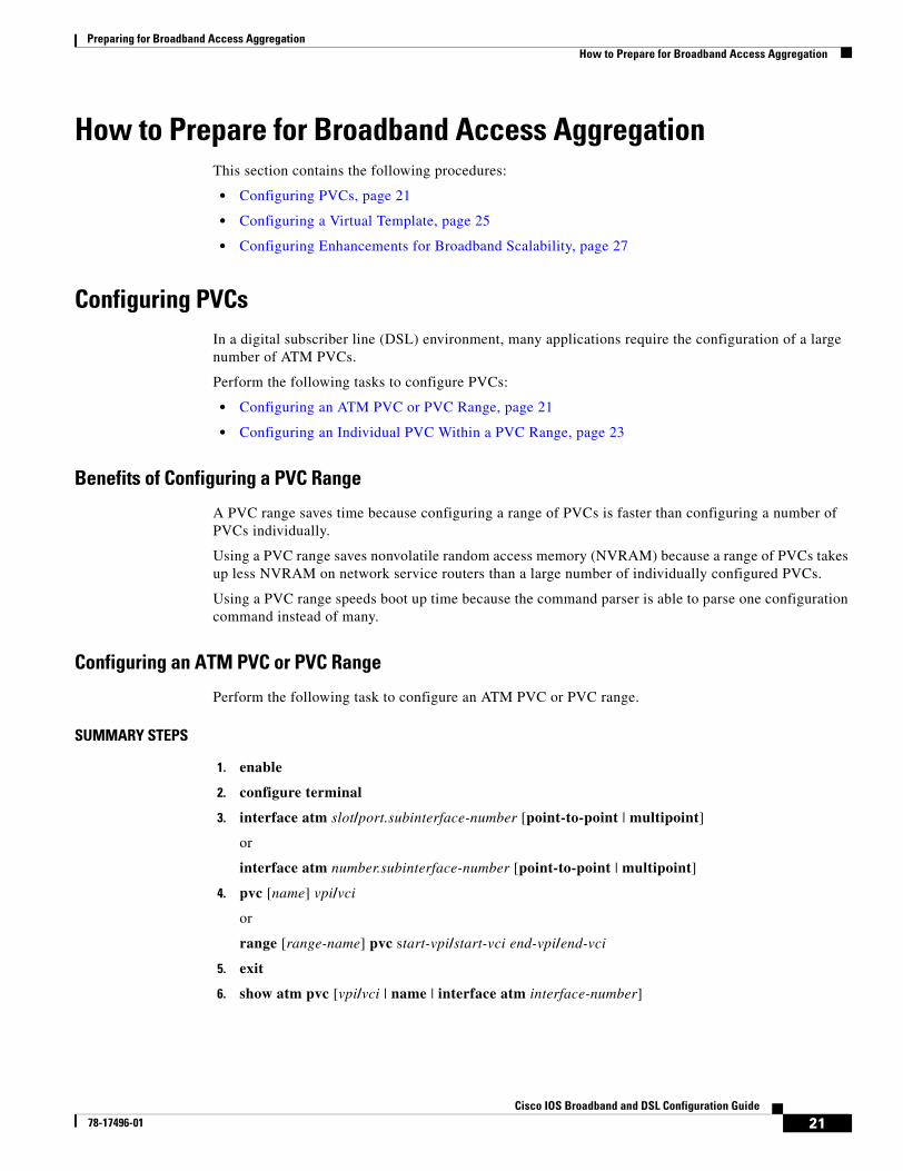
Preparing for Broadband Access AggregationHow to Prepare for Broadband Access Aggregation
21Cisco IOS Broadband and DSL Configuration Guide
78-17496-01
How to Prepare for Broadband Access AggregationThis section contains the following procedures:
• Configuring PVCs, page 21
• Configuring a Virtual Template, page 25
• Configuring Enhancements for Broadband Scalability, page 27
Configuring PVCsIn a digital subscriber line (DSL) environment, many applications require the configuration of a large number of ATM PVCs.
Perform the following tasks to configure PVCs:
• Configuring an ATM PVC or PVC Range, page 21
• Configuring an Individual PVC Within a PVC Range, page 23
Benefits of Configuring a PVC Range
A PVC range saves time because configuring a range of PVCs is faster than configuring a number of PVCs individually.
Using a PVC range saves nonvolatile random access memory (NVRAM) because a range of PVCs takes up less NVRAM on network service routers than a large number of individually configured PVCs.
Using a PVC range speeds boot up time because the command parser is able to parse one configuration command instead of many.
Configuring an ATM PVC or PVC Range
Perform the following task to configure an ATM PVC or PVC range.
SUMMARY STEPS
1. enable
2. configure terminal
3. interface atm slot/port.subinterface-number [point-to-point | multipoint]
or
interface atm number.subinterface-number [point-to-point | multipoint]
4. pvc [name] vpi/vci
or
range [range-name] pvc start-vpi/start-vci end-vpi/end-vci
5. exit
6. show atm pvc [vpi/vci | name | interface atm interface-number]
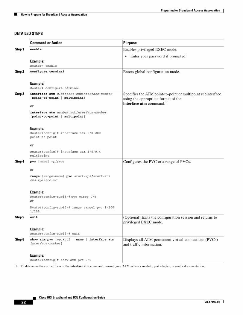
Preparing for Broadband Access AggregationHow to Prepare for Broadband Access Aggregation
22Cisco IOS Broadband and DSL Configuration Guide
78-17496-01
DETAILED STEPS
Command or Action Purpose
Step 1 enable
Example:Router> enable
Enables privileged EXEC mode.
• Enter your password if prompted.
Step 2 configure terminal
Example:Router# configure terminal
Enters global configuration mode.
Step 3 interface atm slot/port.subinterface-number [point-to-point | multipoint]
or
interface atm number.subinterface-number [point-to-point | multipoint]
Example:Router(config)# interface atm 6/0.200 point-to-point
or
Router(config)# interface atm 1/0/0.4 multipoint
Specifies the ATM point-to-point or multipoint subinterface using the appropriate format of theinterface atm command.1
1. To determine the correct form of the interface atm command, consult your ATM network module, port adapter, or router documentation.
Step 4 pvc [name] vpi/vci
or
range [range-name] pvc start-vpi/start-vci end-vpi/end-vci
Example:Router(config-subif)# pvc cisco 0/5or
Router(config-subif)# range range1 pvc 1/200 1/299
Configures the PVC or a range of PVCs.
Step 5 exit
Example:Router(config-subif)# exit
(Optional) Exits the configuration session and returns to privileged EXEC mode.
Step 6 show atm pvc [vpi/vci | name | interface atm interface-number]
Example:Router(config)# show atm pvc 0/5
Displays all ATM permanent virtual connections (PVCs) and traffic information.
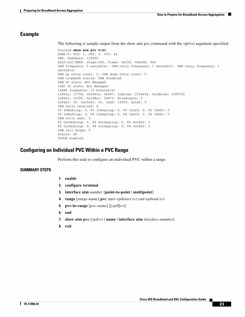
Preparing for Broadband Access AggregationHow to Prepare for Broadband Access Aggregation
23Cisco IOS Broadband and DSL Configuration Guide
78-17496-01
Example
The following is sample output from the show atm pvc command with the vpi/vci argument specified:
Router# show atm pvc 0/41ATM2/0: VCD: 3, VPI: 0, VCI: 41UBR, PeakRate: 155000AAL5-LLC/SNAP, etype:0x0, Flags: 0xC20, VCmode: 0x0OAM frequency: 0 second(s), OAM retry frequency: 1 second(s), OAM retry frequency: 1 second(s)OAM up retry count: 3, OAM down retry count: 5OAM Loopback status: OAM DisabledOAM VC state: Not ManagedILMI VC state: Not ManagedInARP frequency: 15 minutes(s)InPkts: 31759, OutPkts: 26497, InBytes: 2356434, OutBytes: 1589743InPRoc: 15785, OutPRoc: 26472, Broadcasts: 0InFast: 20, OutFast: 20, InAS: 15954, OutAS: 6OAM cells received: 0F5 InEndloop: 0, F5 InSegloop: 0, F5 InAIS: 0, F5 InRDI: 0F4 InEndloop: 0, F4 InSegloop: 0, F4 InAIS: 0, F4 InRDI: 0OAM cells sent: 0F5 OutEndloop: 0, F5 OutSegloop: 0, F5 OutRDI: 0F4 OutEndloop: 0, F4 OutSegloop: 0, F4 OutRDI: 0OAM cell drops: 0Status: UPPPPOE enabled.
Configuring an Individual PVC Within a PVC Range
Perform this task to configure an individual PVC within a range.
SUMMARY STEPS
1. enable
2. configure terminal
3. interface atm number [point-to-point | multipoint]
4. range [range-name] pvc start-vpi/start-vci end-vpi/end-vci
5. pvc-in-range [pvc-name] [[vpi/]vci]
6. end
7. show atm pvc [vpi/vci | name | interface atm interface-number]
8. exit
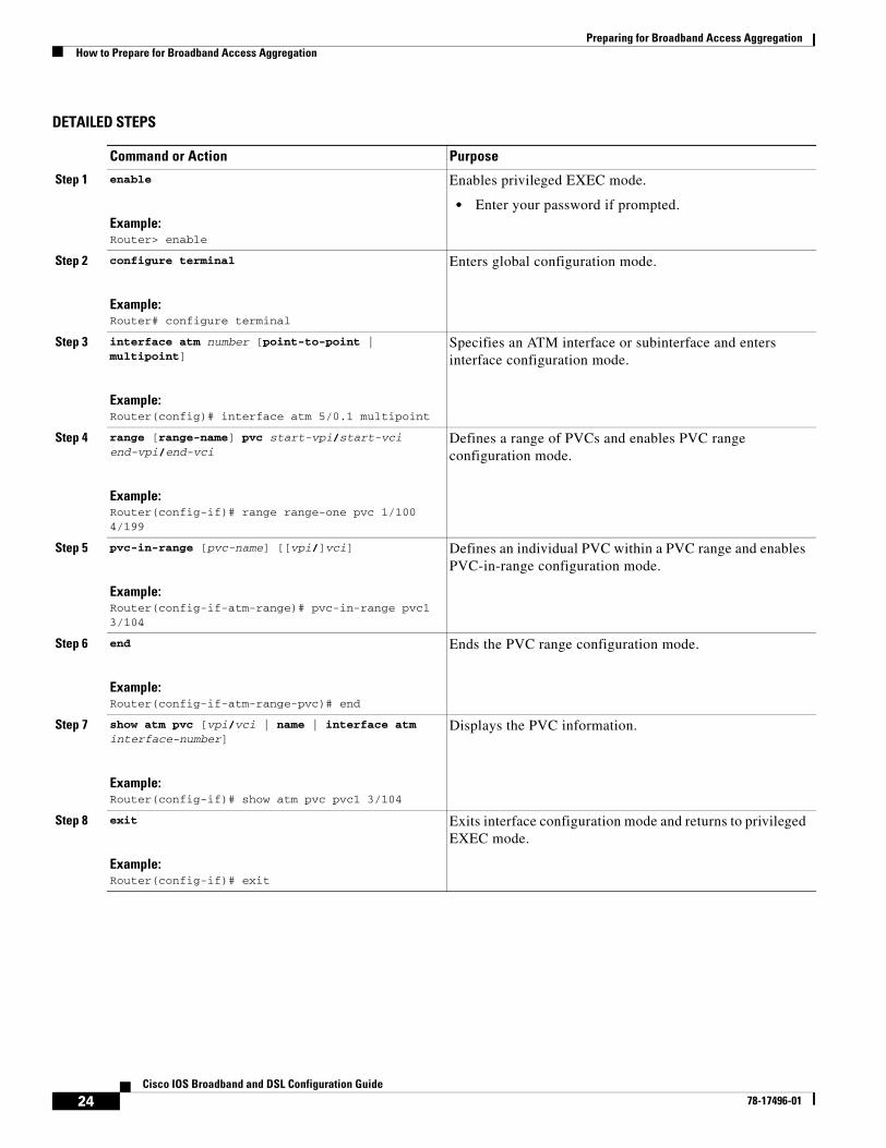
Preparing for Broadband Access AggregationHow to Prepare for Broadband Access Aggregation
24Cisco IOS Broadband and DSL Configuration Guide
78-17496-01
DETAILED STEPS
Command or Action Purpose
Step 1 enable
Example:Router> enable
Enables privileged EXEC mode.
• Enter your password if prompted.
Step 2 configure terminal
Example:Router# configure terminal
Enters global configuration mode.
Step 3 interface atm number [point-to-point | multipoint]
Example:Router(config)# interface atm 5/0.1 multipoint
Specifies an ATM interface or subinterface and enters interface configuration mode.
Step 4 range [range-name] pvc start-vpi/start-vci end-vpi/end-vci
Example:Router(config-if)# range range-one pvc 1/100 4/199
Defines a range of PVCs and enables PVC range configuration mode.
Step 5 pvc-in-range [pvc-name] [[vpi/]vci]
Example:Router(config-if-atm-range)# pvc-in-range pvc1 3/104
Defines an individual PVC within a PVC range and enables PVC-in-range configuration mode.
Step 6 end
Example:Router(config-if-atm-range-pvc)# end
Ends the PVC range configuration mode.
Step 7 show atm pvc [vpi/vci | name | interface atm interface-number]
Example:Router(config-if)# show atm pvc pvc1 3/104
Displays the PVC information.
Step 8 exit
Example:Router(config-if)# exit
Exits interface configuration mode and returns to privileged EXEC mode.
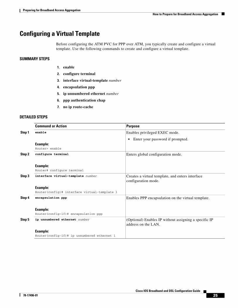
Preparing for Broadband Access AggregationHow to Prepare for Broadband Access Aggregation
25Cisco IOS Broadband and DSL Configuration Guide
78-17496-01
Configuring a Virtual TemplateBefore configuring the ATM PVC for PPP over ATM, you typically create and configure a virtual template. Use the following commands to create and configure a virtual template.
SUMMARY STEPS
1. enable
2. configure terminal
3. interface virtual-template number
4. encapsulation ppp
5. ip unnumbered ethernet number
6. ppp authentication chap
7. no ip route-cache
DETAILED STEPS
Command or Action Purpose
Step 1 enable
Example:Router> enable
Enables privileged EXEC mode.
• Enter your password if prompted.
Step 2 configure terminal
Example:Router# configure terminal
Enters global configuration mode.
Step 3 interface virtual-template number
Example:Router(config)# interface virtual-template 1
Creates a virtual template, and enters interface configuration mode.
Step 4 encapsulation ppp
Example:Router(config-if)# encapsulation ppp
Enables PPP encapsulation on the virtual template.
Step 5 ip unnumbered ethernet number
Example:Router(config-if)# ip unnumbered ethernet 1
(Optional) Enables IP without assigning a specific IP address on the LAN.
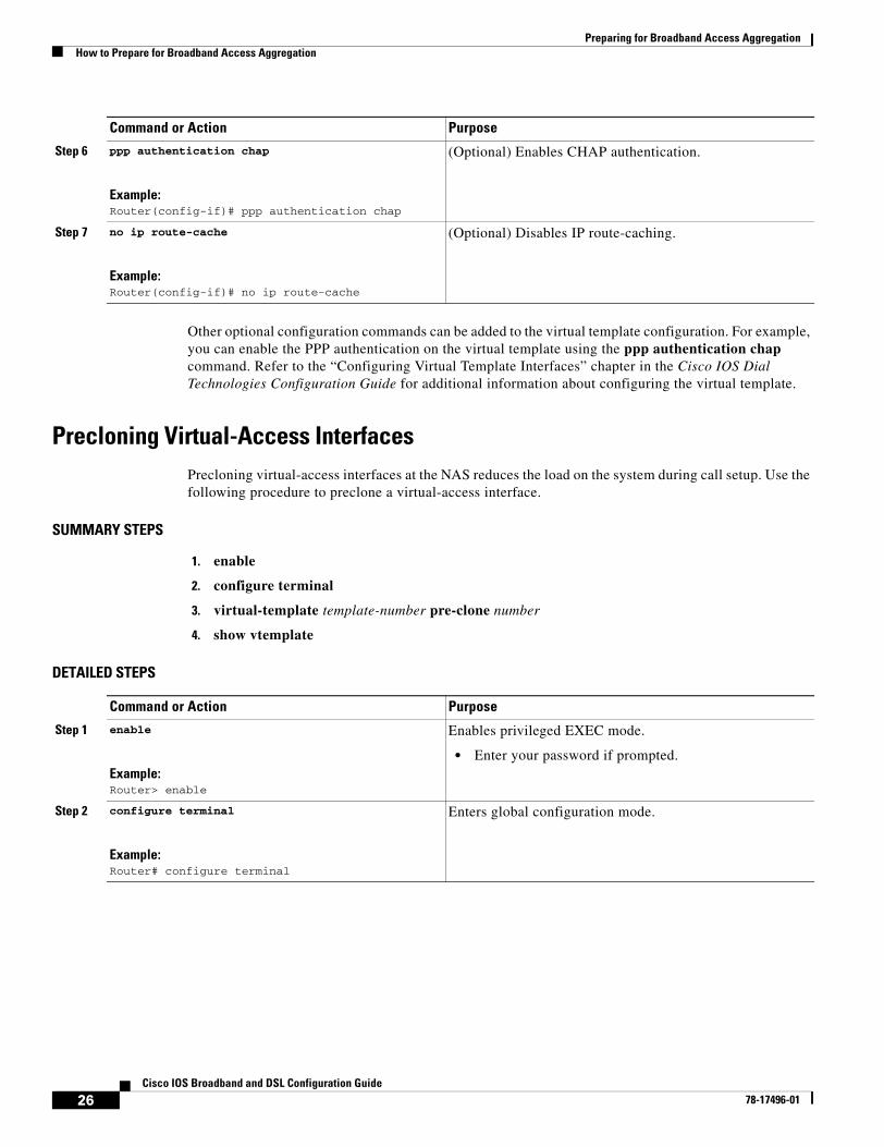
Preparing for Broadband Access AggregationHow to Prepare for Broadband Access Aggregation
26Cisco IOS Broadband and DSL Configuration Guide
78-17496-01
Other optional configuration commands can be added to the virtual template configuration. For example, you can enable the PPP authentication on the virtual template using the ppp authentication chap command. Refer to the “Configuring Virtual Template Interfaces” chapter in the Cisco IOS Dial Technologies Configuration Guide for additional information about configuring the virtual template.
Precloning Virtual-Access InterfacesPrecloning virtual-access interfaces at the NAS reduces the load on the system during call setup. Use the following procedure to preclone a virtual-access interface.
SUMMARY STEPS
1. enable
2. configure terminal
3. virtual-template template-number pre-clone number
4. show vtemplate
DETAILED STEPS
Step 6 ppp authentication chap
Example:Router(config-if)# ppp authentication chap
(Optional) Enables CHAP authentication.
Step 7 no ip route-cache
Example:Router(config-if)# no ip route-cache
(Optional) Disables IP route-caching.
Command or Action Purpose
Command or Action Purpose
Step 1 enable
Example:Router> enable
Enables privileged EXEC mode.
• Enter your password if prompted.
Step 2 configure terminal
Example:Router# configure terminal
Enters global configuration mode.
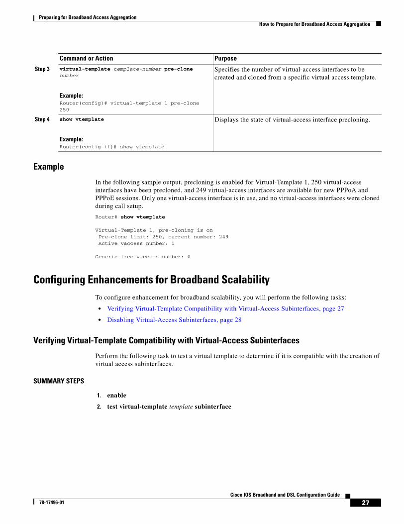
Preparing for Broadband Access AggregationHow to Prepare for Broadband Access Aggregation
27Cisco IOS Broadband and DSL Configuration Guide
78-17496-01
Example
In the following sample output, precloning is enabled for Virtual-Template 1, 250 virtual-access interfaces have been precloned, and 249 virtual-access interfaces are available for new PPPoA and PPPoE sessions. Only one virtual-access interface is in use, and no virtual-access interfaces were cloned during call setup.
Router# show vtemplate
Virtual-Template 1, pre-cloning is onPre-clone limit: 250, current number: 249Active vaccess number: 1
Generic free vaccess number: 0
Configuring Enhancements for Broadband ScalabilityTo configure enhancement for broadband scalability, you will perform the following tasks:
• Verifying Virtual-Template Compatibility with Virtual-Access Subinterfaces, page 27
• Disabling Virtual-Access Subinterfaces, page 28
Verifying Virtual-Template Compatibility with Virtual-Access Subinterfaces
Perform the following task to test a virtual template to determine if it is compatible with the creation of virtual access subinterfaces.
SUMMARY STEPS
1. enable
2. test virtual-template template subinterface
Step 3 virtual-template template-number pre-clone number
Example:Router(config)# virtual-template 1 pre-clone 250
Specifies the number of virtual-access interfaces to be created and cloned from a specific virtual access template.
Step 4 show vtemplate
Example:Router(config-if)# show vtemplate
Displays the state of virtual-access interface precloning.
Command or Action Purpose
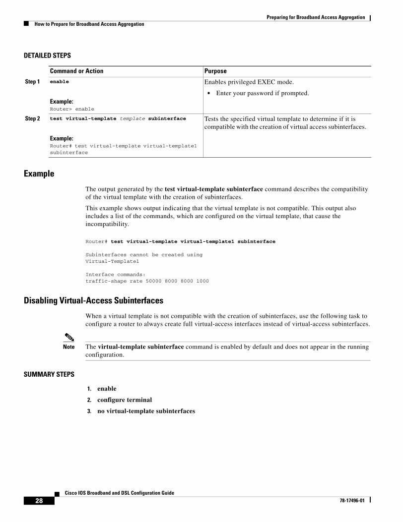
Preparing for Broadband Access AggregationHow to Prepare for Broadband Access Aggregation
28Cisco IOS Broadband and DSL Configuration Guide
78-17496-01
DETAILED STEPS
Example
The output generated by the test virtual-template subinterface command describes the compatibility of the virtual template with the creation of subinterfaces.
This example shows output indicating that the virtual template is not compatible. This output also includes a list of the commands, which are configured on the virtual template, that cause the incompatibility.
Router# test virtual-template virtual-template1 subinterface
Subinterfaces cannot be created using Virtual-Template1
Interface commands:traffic-shape rate 50000 8000 8000 1000
Disabling Virtual-Access Subinterfaces
When a virtual template is not compatible with the creation of subinterfaces, use the following task to configure a router to always create full virtual-access interfaces instead of virtual-access subinterfaces.
Note The virtual-template subinterface command is enabled by default and does not appear in the running configuration.
SUMMARY STEPS
1. enable
2. configure terminal
3. no virtual-template subinterfaces
Command or Action Purpose
Step 1 enable
Example:Router> enable
Enables privileged EXEC mode.
• Enter your password if prompted.
Step 2 test virtual-template template subinterface
Example:Router# test virtual-template virtual-template1 subinterface
Tests the specified virtual template to determine if it is compatible with the creation of virtual access subinterfaces.
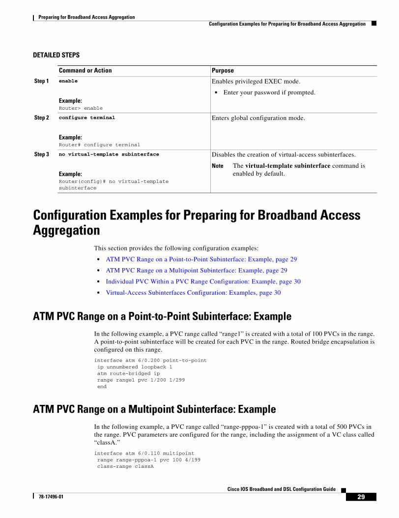
Preparing for Broadband Access AggregationConfiguration Examples for Preparing for Broadband Access Aggregation
29Cisco IOS Broadband and DSL Configuration Guide
78-17496-01
DETAILED STEPS
Configuration Examples for Preparing for Broadband Access Aggregation
This section provides the following configuration examples:
• ATM PVC Range on a Point-to-Point Subinterface: Example, page 29
• ATM PVC Range on a Multipoint Subinterface: Example, page 29
• Individual PVC Within a PVC Range Configuration: Example, page 30
• Virtual-Access Subinterfaces Configuration: Examples, page 30
ATM PVC Range on a Point-to-Point Subinterface: ExampleIn the following example, a PVC range called “range1” is created with a total of 100 PVCs in the range. A point-to-point subinterface will be created for each PVC in the range. Routed bridge encapsulation is configured on this range.
interface atm 6/0.200 point-to-point ip unnumbered loopback 1 atm route-bridged ip range range1 pvc 1/200 1/299 end
ATM PVC Range on a Multipoint Subinterface: ExampleIn the following example, a PVC range called “range-pppoa-1” is created with a total of 500 PVCs in the range. PVC parameters are configured for the range, including the assignment of a VC class called “classA.”
interface atm 6/0.110 multipoint range range-pppoa-1 pvc 100 4/199 class-range classA
Command or Action Purpose
Step 1 enable
Example:Router> enable
Enables privileged EXEC mode.
• Enter your password if prompted.
Step 2 configure terminal
Example:Router# configure terminal
Enters global configuration mode.
Step 3 no virtual-template subinterface
Example:Router(config)# no virtual-template subinterface
Disables the creation of virtual-access subinterfaces.
Note The virtual-template subinterface command is enabled by default.
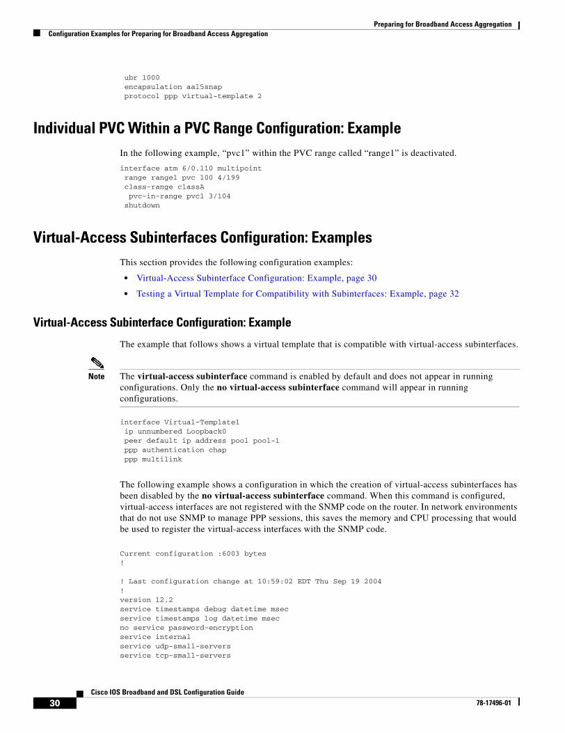
Preparing for Broadband Access AggregationConfiguration Examples for Preparing for Broadband Access Aggregation
30Cisco IOS Broadband and DSL Configuration Guide
78-17496-01
ubr 1000 encapsulation aal5snap protocol ppp virtual-template 2
Individual PVC Within a PVC Range Configuration: ExampleIn the following example, “pvc1” within the PVC range called “range1” is deactivated.
interface atm 6/0.110 multipoint range range1 pvc 100 4/199 class-range classA pvc-in-range pvc1 3/104 shutdown
Virtual-Access Subinterfaces Configuration: ExamplesThis section provides the following configuration examples:
• Virtual-Access Subinterface Configuration: Example, page 30
• Testing a Virtual Template for Compatibility with Subinterfaces: Example, page 32
Virtual-Access Subinterface Configuration: Example
The example that follows shows a virtual template that is compatible with virtual-access subinterfaces.
Note The virtual-access subinterface command is enabled by default and does not appear in running configurations. Only the no virtual-access subinterface command will appear in running configurations.
interface Virtual-Template1ip unnumbered Loopback0peer default ip address pool pool-1ppp authentication chapppp multilink
The following example shows a configuration in which the creation of virtual-access subinterfaces has been disabled by the no virtual-access subinterface command. When this command is configured, virtual-access interfaces are not registered with the SNMP code on the router. In network environments that do not use SNMP to manage PPP sessions, this saves the memory and CPU processing that would be used to register the virtual-access interfaces with the SNMP code.
Current configuration :6003 bytes!
! Last configuration change at 10:59:02 EDT Thu Sep 19 2004!version 12.2service timestamps debug datetime msecservice timestamps log datetime msecno service password-encryptionservice internalservice udp-small-serversservice tcp-small-servers
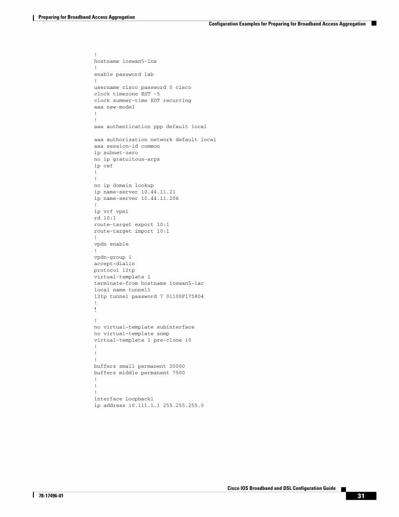
Preparing for Broadband Access AggregationConfiguration Examples for Preparing for Broadband Access Aggregation
31Cisco IOS Broadband and DSL Configuration Guide
78-17496-01
!hostname ioswan5-lns!enable password lab!username cisco password 0 ciscoclock timezone EST -5clock summer-time EDT recurringaaa new-model!!aaa authentication ppp default local
aaa authorization network default local aaa session-id commonip subnet-zerono ip gratuitous-arpsip cef!!no ip domain lookupip name-server 10.44.11.21ip name-server 10.44.11.206!ip vrf vpn1rd 10:1route-target export 10:1route-target import 10:1!vpdn enable!vpdn-group 1accept-dialinprotocol l2tpvirtual-template 1terminate-from hostname ioswan5-laclocal name tunnel1l2tp tunnel password 7 01100F175804!
!
!no virtual-template subinterfaceno virtual-template snmpvirtual-template 1 pre-clone 10! ! ! buffers small permanent 20000buffers middle permanent 7500! ! ! interface Loopback1ip address 10.111.1.1 255.255.255.0
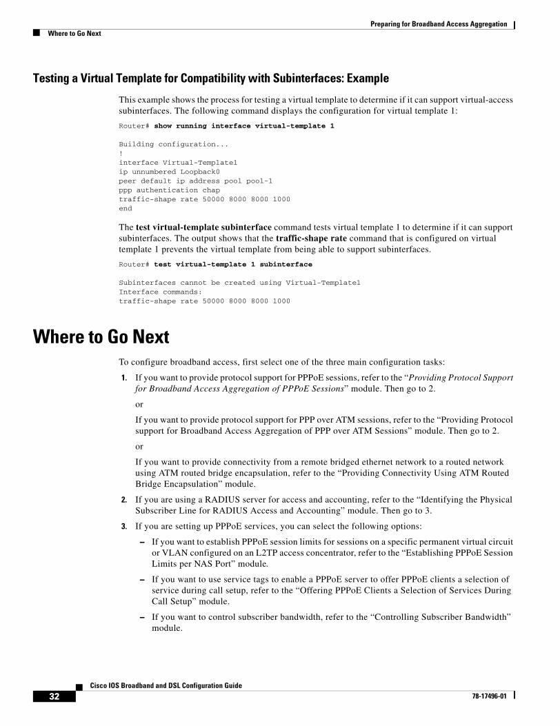
Preparing for Broadband Access AggregationWhere to Go Next
32Cisco IOS Broadband and DSL Configuration Guide
78-17496-01
Testing a Virtual Template for Compatibility with Subinterfaces: Example
This example shows the process for testing a virtual template to determine if it can support virtual-access subinterfaces. The following command displays the configuration for virtual template 1:
Router# show running interface virtual-template 1
Building configuration...!interface Virtual-Template1ip unnumbered Loopback0peer default ip address pool pool-1ppp authentication chaptraffic-shape rate 50000 8000 8000 1000end
The test virtual-template subinterface command tests virtual template 1 to determine if it can support subinterfaces. The output shows that the traffic-shape rate command that is configured on virtual template 1 prevents the virtual template from being able to support subinterfaces.
Router# test virtual-template 1 subinterface
Subinterfaces cannot be created using Virtual-Template1Interface commands:traffic-shape rate 50000 8000 8000 1000
Where to Go NextTo configure broadband access, first select one of the three main configuration tasks:
1. If you want to provide protocol support for PPPoE sessions, refer to the “Providing Protocol Support for Broadband Access Aggregation of PPPoE Sessions” module. Then go to 2.
or
If you want to provide protocol support for PPP over ATM sessions, refer to the “Providing Protocol support for Broadband Access Aggregation of PPP over ATM Sessions” module. Then go to 2.
or
If you want to provide connectivity from a remote bridged ethernet network to a routed network using ATM routed bridge encapsulation, refer to the “Providing Connectivity Using ATM Routed Bridge Encapsulation” module.
2. If you are using a RADIUS server for access and accounting, refer to the “Identifying the Physical Subscriber Line for RADIUS Access and Accounting” module. Then go to 3.
3. If you are setting up PPPoE services, you can select the following options:
– If you want to establish PPPoE session limits for sessions on a specific permanent virtual circuit or VLAN configured on an L2TP access concentrator, refer to the “Establishing PPPoE Session Limits per NAS Port” module.
– If you want to use service tags to enable a PPPoE server to offer PPPoE clients a selection of service during call setup, refer to the “Offering PPPoE Clients a Selection of Services During Call Setup” module.
– If you want to control subscriber bandwidth, refer to the “Controlling Subscriber Bandwidth” module.
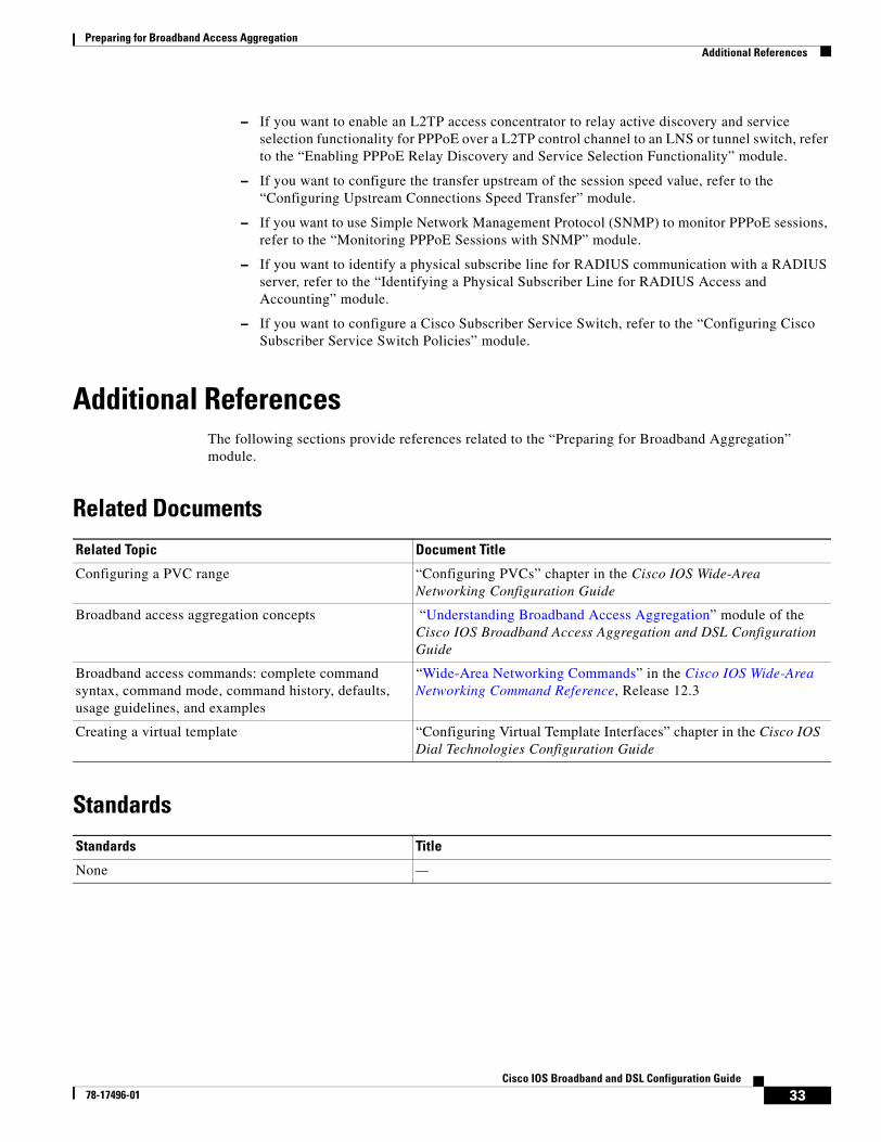
Preparing for Broadband Access AggregationAdditional References
33Cisco IOS Broadband and DSL Configuration Guide
78-17496-01
– If you want to enable an L2TP access concentrator to relay active discovery and service selection functionality for PPPoE over a L2TP control channel to an LNS or tunnel switch, refer to the “Enabling PPPoE Relay Discovery and Service Selection Functionality” module.
– If you want to configure the transfer upstream of the session speed value, refer to the “Configuring Upstream Connections Speed Transfer” module.
– If you want to use Simple Network Management Protocol (SNMP) to monitor PPPoE sessions, refer to the “Monitoring PPPoE Sessions with SNMP” module.
– If you want to identify a physical subscribe line for RADIUS communication with a RADIUS server, refer to the “Identifying a Physical Subscriber Line for RADIUS Access and Accounting” module.
– If you want to configure a Cisco Subscriber Service Switch, refer to the “Configuring Cisco Subscriber Service Switch Policies” module.
Additional ReferencesThe following sections provide references related to the “Preparing for Broadband Aggregation” module.
Related Documents
Standards
Related Topic Document Title
Configuring a PVC range “Configuring PVCs” chapter in the Cisco IOS Wide-Area Networking Configuration Guide
Broadband access aggregation concepts “Understanding Broadband Access Aggregation” module of the Cisco IOS Broadband Access Aggregation and DSL Configuration Guide
Broadband access commands: complete command syntax, command mode, command history, defaults, usage guidelines, and examples
“Wide-Area Networking Commands” in the Cisco IOS Wide-Area Networking Command Reference, Release 12.3
Creating a virtual template “Configuring Virtual Template Interfaces” chapter in the Cisco IOS Dial Technologies Configuration Guide
Standards Title
None —
http://www.cisco.com/univercd/cc/td/doc/product/software/ios123/123tcr/123twr/wan_a1gt.htm#wp1056981
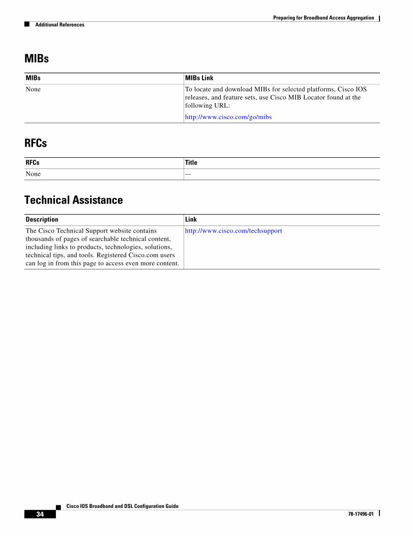
Preparing for Broadband Access AggregationAdditional References
34Cisco IOS Broadband and DSL Configuration Guide
78-17496-01
MIBs
RFCs
Technical Assistance
MIBs MIBs Link
None To locate and download MIBs for selected platforms, Cisco IOS releases, and feature sets, use Cisco MIB Locator found at the following URL:
http://www.cisco.com/go/mibs
RFCs Title
None —
Description Link
The Cisco Technical Support website contains thousands of pages of searchable technical content, including links to products, technologies, solutions, technical tips, and tools. Registered Cisco.com users can log in from this page to access even more content.
http://www.cisco.com/techsupport
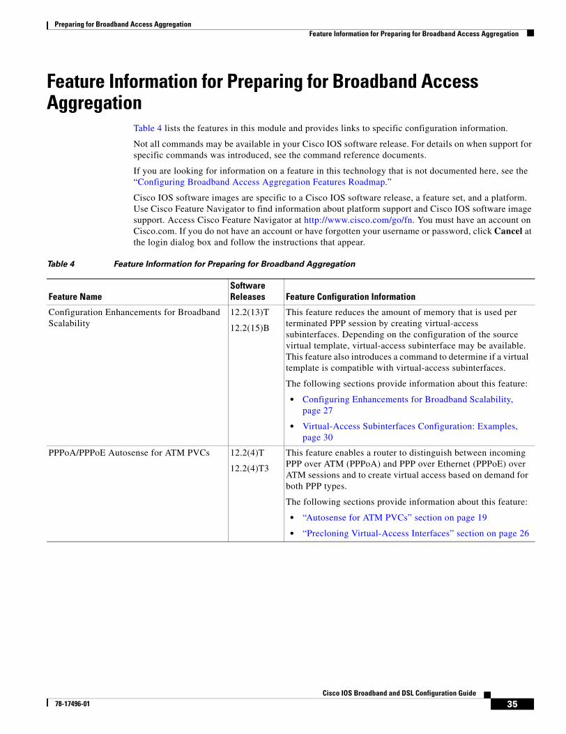
Preparing for Broadband Access AggregationFeature Information for Preparing for Broadband Access Aggregation
35Cisco IOS Broadband and DSL Configuration Guide
78-17496-01
Feature Information for Preparing for Broadband Access Aggregation
Table 4 lists the features in this module and provides links to specific configuration information.
Not all commands may be available in your Cisco IOS software release. For details on when support for specific commands was introduced, see the command reference documents.
If you are looking for information on a feature in this technology that is not documented here, see the “Configuring Broadband Access Aggregation Features Roadmap.”
Cisco IOS software images are specific to a Cisco IOS software release, a feature set, and a platform. Use Cisco Feature Navigator to find information about platform support and Cisco IOS software image support. Access Cisco Feature Navigator at http://www.cisco.com/go/fn. You must have an account on Cisco.com. If you do not have an account or have forgotten your username or password, click Cancel at the login dialog box and follow the instructions that appear.
Table 4 Feature Information for Preparing for Broadband Aggregation
Feature NameSoftware Releases Feature Configuration Information
Configuration Enhancements for Broadband Scalability
12.2(13)T
12.2(15)B
This feature reduces the amount of memory that is used per terminated PPP session by creating virtual-access subinterfaces. Depending on the configuration of the source virtual template, virtual-access subinterface may be available. This feature also introduces a command to determine if a virtual template is compatible with virtual-access subinterfaces.
The following sections provide information about this feature:
• Configuring Enhancements for Broadband Scalability, page 27
• Virtual-Access Subinterfaces Configuration: Examples, page 30
PPPoA/PPPoE Autosense for ATM PVCs 12.2(4)T
12.2(4)T3
This feature enables a router to distinguish between incoming PPP over ATM (PPPoA) and PPP over Ethernet (PPPoE) over ATM sessions and to create virtual access based on demand for both PPP types.
The following sections provide information about this feature:
• “Autosense for ATM PVCs” section on page 19
• “Precloning Virtual-Access Interfaces” section on page 26

Preparing for Broadband Access AggregationFeature Information for Preparing for Broadband Access Aggregation
36Cisco IOS Broadband and DSL Configuration Guide
78-17496-01

Part 2: PPPoA, PPPoE, PPPoX

39Cisco IOS Broadband and DSL Configuration Guide
78-17496-01
Providing Protocol Support for Broadband Access Aggregation of PPP over ATM Sessions
PPP over ATM enables a high-capacity central site router with an ATM interface to terminate multiple remote PPP connections. PPP over ATM provides security validation per user, IP address pooling, and service selection capability.
Module History
This module was first published on May 2, 2005, and last updated on May 2, 2005.
Finding Feature Information in This Module
Not all features may be supported in your Cisco IOS software release. Use the “Feature Information for Providing Protocol Support for Broadband Access Aggregation of PPP over ATM Sessions” section on page 67 to find information about feature support and configuration.
PPP over ATM can be configured on all platforms running Cisco IOS Release 12.1 or later.
Contents• Prerequisites for Providing Protocol Support for Broadband Access Aggregation of PPP over ATM
Sessions, page 40
• Restrictions for Providing Protocol Support for Broadband Access Aggregation of PPP over ATM Sessions, page 40
• Information About Providing Protocol Support for Broadband Access Aggregation of PPP over ATM Sessions, page 40
• How to Provide Protocol Support for Broadband Access Aggregation of PPP over ATM Sessions, page 42
• Configuration Examples for Configuring PPP over ATM, page 57
• Where to Go Next, page 65
• Additional References, page 65
• Feature Information for Providing Protocol Support for Broadband Access Aggregation of PPP over ATM Sessions, page 67
Providing Protocol Support for Broadband Access Aggregation of PPP over ATM SessionsPrerequisites for Providing Protocol Support for Broadband Access Aggregation of PPP over ATM Sessions
40Cisco IOS Broadband and DSL Configuration Guide
78-17496-01
Prerequisites for Providing Protocol Support for Broadband Access Aggregation of PPP over ATM Sessions
• You must understand the concepts described in the “Understanding Broadband Access Aggregation” module.
• Optionally you may perform the preparation tasks in the “Preparing for Broadband Access Aggregation” module
Restrictions for Providing Protocol Support for Broadband Access Aggregation of PPP over ATM Sessions
PPP over ATM cannot be configured on IETF-compliant Logical Link Control (LLC) encapsulated PPP over ATM.
Information About Providing Protocol Support for Broadband Access Aggregation of PPP over ATM Sessions
This section describes the following concepts:
• PPP over ATM Configuration Scenario, page 40
• Virtual Access Interface, page 41
• Autosense for ATM PVCs, page 42
PPP over ATM Configuration ScenarioPPP over ATM can be configured on all platforms running Cisco IOS Release 12.1 or later.
Note All forms of PPP over ATM are supported on the ATM port adapters, except for the PA-A1 ATM port adapter for Cisco IOS Release 12.1. All forms of PPP over ATM are now supported on the enhanced ATM port adapter for Cisco IOS Release 12.1 or later.
Figure 2 shows a typical scenario for using Cisco-proprietary PPP over ATM.
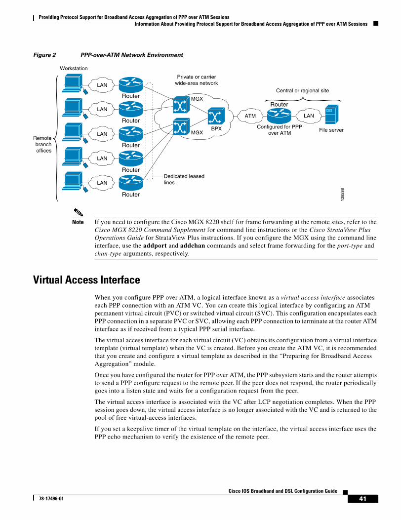
Providing Protocol Support for Broadband Access Aggregation of PPP over ATM SessionsInformation About Providing Protocol Support for Broadband Access Aggregation of PPP over ATM Sessions
41Cisco IOS Broadband and DSL Configuration Guide
78-17496-01
Figure 2 PPP-over-ATM Network Environment
Note If you need to configure the Cisco MGX 8220 shelf for frame forwarding at the remote sites, refer to the Cisco MGX 8220 Command Supplement for command line instructions or the Cisco StrataView Plus Operations Guide for StrataView Plus instructions. If you configure the MGX using the command line interface, use the addport and addchan commands and select frame forwarding for the port-type and chan-type arguments, respectively.
Virtual Access InterfaceWhen you configure PPP over ATM, a logical interface known as a virtual access interface associates each PPP connection with an ATM VC. You can create this logical interface by configuring an ATM permanent virtual circuit (PVC) or switched virtual circuit (SVC). This configuration encapsulates each PPP connection in a separate PVC or SVC, allowing each PPP connection to terminate at the router ATM interface as if received from a typical PPP serial interface.
The virtual access interface for each virtual circuit (VC) obtains its configuration from a virtual interface template (virtual template) when the VC is created. Before you create the ATM VC, it is recommended that you create and configure a virtual template as described in the “Preparing for Broadband Access Aggregation” module.
Once you have configured the router for PPP over ATM, the PPP subsystem starts and the router attempts to send a PPP configure request to the remote peer. If the peer does not respond, the router periodically goes into a listen state and waits for a configuration request from the peer.
The virtual access interface is associated with the VC after LCP negotiation completes. When the PPP session goes down, the virtual access interface is no longer associated with the VC and is returned to the pool of free virtual-access interfaces.
If you set a keepalive timer of the virtual template on the interface, the virtual access interface uses the PPP echo mechanism to verify the existence of the remote peer.
LAN
LAN
LAN
LAN
Router
Router
Router
Router
RouterRouter
LAN
Workstation
Remotebranchoffices
Central or regional site
Dedicated leasedlines
Private or carrierwide-area network
Configured for PPPover ATM
ATM
BPX
MGX
MGX File server
1292
88
LAN
Providing Protocol Support for Broadband Access Aggregation of PPP over ATM SessionsHow to Provide Protocol Support for Broadband Access Aggregation of PPP over ATM Sessions
42Cisco IOS Broadband and DSL Configuration Guide
78-17496-01
The following three types of PPP over ATM connections are supported:
• IETF-compliant MUX encapsulated PPP over ATM
• IETF-compliant LLC encapsulated PPP over ATM
• Cisco-proprietary PPP over ATM
Autosense for ATM PVCsThe PPPoA/PPPoE autosense for ATM PVCs feature enables a router to distinguish between incoming PPP over ATM (PPPoA) and PPP over Ethernet (PPPoE) over ATM sessions and to create virtual access based on demand for both PPP types.
Note The PPPoA/PPPoE autosense for ATM PVCs feature is supported on SNAP-encapsulated ATM PVCs only. It is not supported on MUX-encapsulated PVCs.
Benefits of Autosense for ATM PVCs
Autosense for ATM PVCs provides resource allocation on demand. For each permanent virtual circuit (PVC) configured for both PPPoA and PPPoE, certain resources (including one virtual-access interface) are allocated upon configuration, regardless of the existence of a PPPoA or PPPoE session on that PVC. With the autosense for ATM PVCs, resources are allocated for PPPoA and PPPoE sessions only when a client initiates a session, thus reducing overhead on the network access server (NAS).
How to Provide Protocol Support for Broadband Access Aggregation of PPP over ATM Sessions
• Configuring IETF-Compliant MUX Encapsulated PPP over ATM, page 42 (optional)
• Configuring IETF-Compliant LLC Encapsulated PPP over ATM, page 45 (optional)
• Configuring Cisco-Proprietary PPP over ATM PVCs, page 47 (optional)
• Configuring SVCs for NAPs and NSPs, page 49 (optional)
Configuring IETF-Compliant MUX Encapsulated PPP over ATM Internet Engineering Task Force (IETF)-compliant multiplexer (MUX) encapsulated PPP over ATM, also known as null encapsulation, allows you to configure PPP over ATM using a VC multiplexed encapsulation mode. This feature complies with IETF RFC 2364 entitled PPP over AAL5.
You can configure ATM PVCs for IETF-compliant MUX encapsulated PPP over ATM on either point-to-point or multipoint subinterfaces. Multiple PVCs on multipoint subinterfaces significantly increase the maximum number of PPP-over-ATM sessions running on a router. You can configure IETF-compliant MUX encapsulated PPP over ATM over a single ATM PVC or an ATM PVC range.
Perform this task to configure IETF-compliant MUX Encapsulated PPP over ATM.
Providing Protocol Support for Broadband Access Aggregation of PPP over ATM SessionsHow to Provide Protocol Support for Broadband Access Aggregation of PPP over ATM Sessions
43Cisco IOS Broadband and DSL Configuration Guide
78-17496-01
SUMMARY STEPS
1. enable
2. configure terminal
3. interface atm slot/port.subinterface-number point-to-point
or
interface atm number.subinterface-number point-to-point
or
interface atm slot/port.subinterface-number multipoint
or
interface atm number.subinterface-number multipoint
4. pvc [name] vpi/vci
or
range [range-name] pvc start-vpi/start-vci end-vpi/end-vci
5. encapsulation aal5mux ppp virtual-template number
DETAILED STEPS
Command or Action Purpose
Step 1 enable
Example:Router> enable
Enables privileged EXEC mode.
• Enter your password if prompted.
Step 2 configure terminal
Example:Router# configure terminal
Enters global configuration mode.
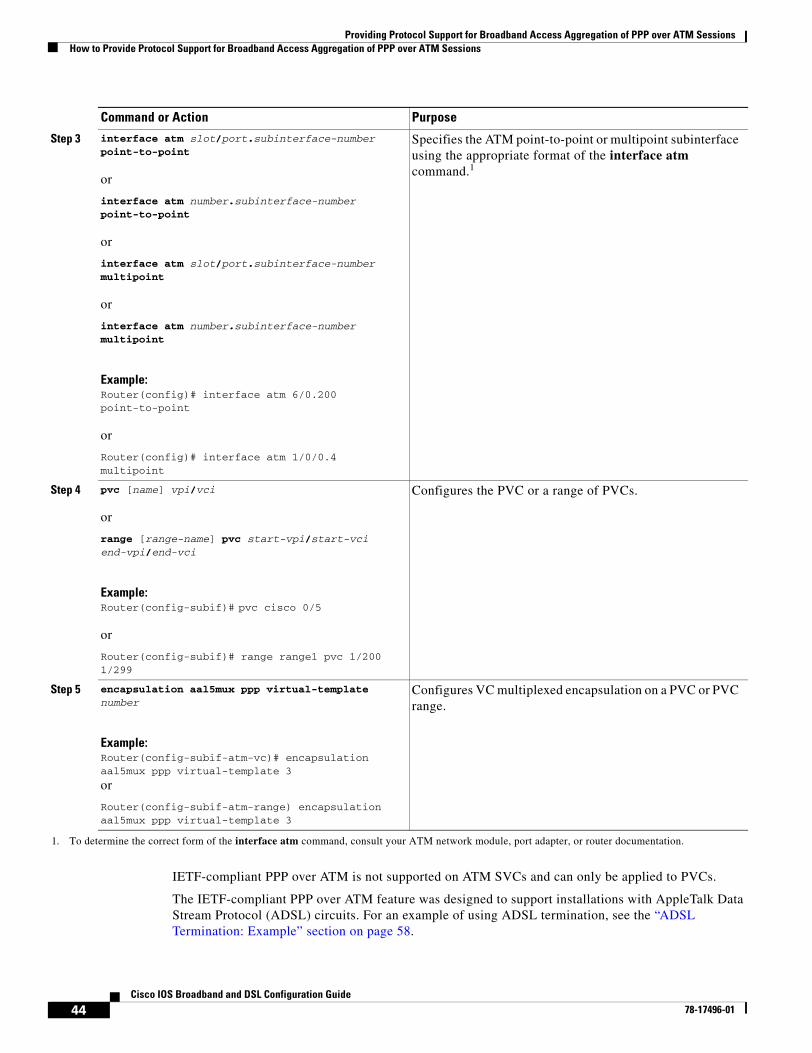
Providing Protocol Support for Broadband Access Aggregation of PPP over ATM SessionsHow to Provide Protocol Support for Broadband Access Aggregation of PPP over ATM Sessions
44Cisco IOS Broadband and DSL Configuration Guide
78-17496-01
IETF-compliant PPP over ATM is not supported on ATM SVCs and can only be applied to PVCs.
The IETF-compliant PPP over ATM feature was designed to support installations with AppleTalk Data Stream Protocol (ADSL) circuits. For an example of using ADSL termination, see the “ADSL Termination: Example” section on page 58.
Step 3 interface atm slot/port.subinterface-number point-to-point
or
interface atm number.subinterface-number point-to-point
or
interface atm slot/port.subinterface-number multipoint
or
interface atm number.subinterface-number multipoint
Example:Router(config)# interface atm 6/0.200 point-to-point
or
Router(config)# interface atm 1/0/0.4 multipoint
Specifies the ATM point-to-point or multipoint subinterface using the appropriate format of the interface atm command.1
Step 4 pvc [name] vpi/vci
or
range [range-name] pvc start-vpi/start-vci end-vpi/end-vci
Example:Router(config-subif)# pvc cisco 0/5
or
Router(config-subif)# range range1 pvc 1/200 1/299
Configures the PVC or a range of PVCs.
Step 5 encapsulation aal5mux ppp virtual-template number
Example:Router(config-subif-atm-vc)# encapsulation aal5mux ppp virtual-template 3
or
Router(config-subif-atm-range) encapsulation aal5mux ppp virtual-template 3
Configures VC multiplexed encapsulation on a PVC or PVC range.
1. To determine the correct form of the interface atm command, consult your ATM network module, port adapter, or router documentation.
Command or Action Purpose
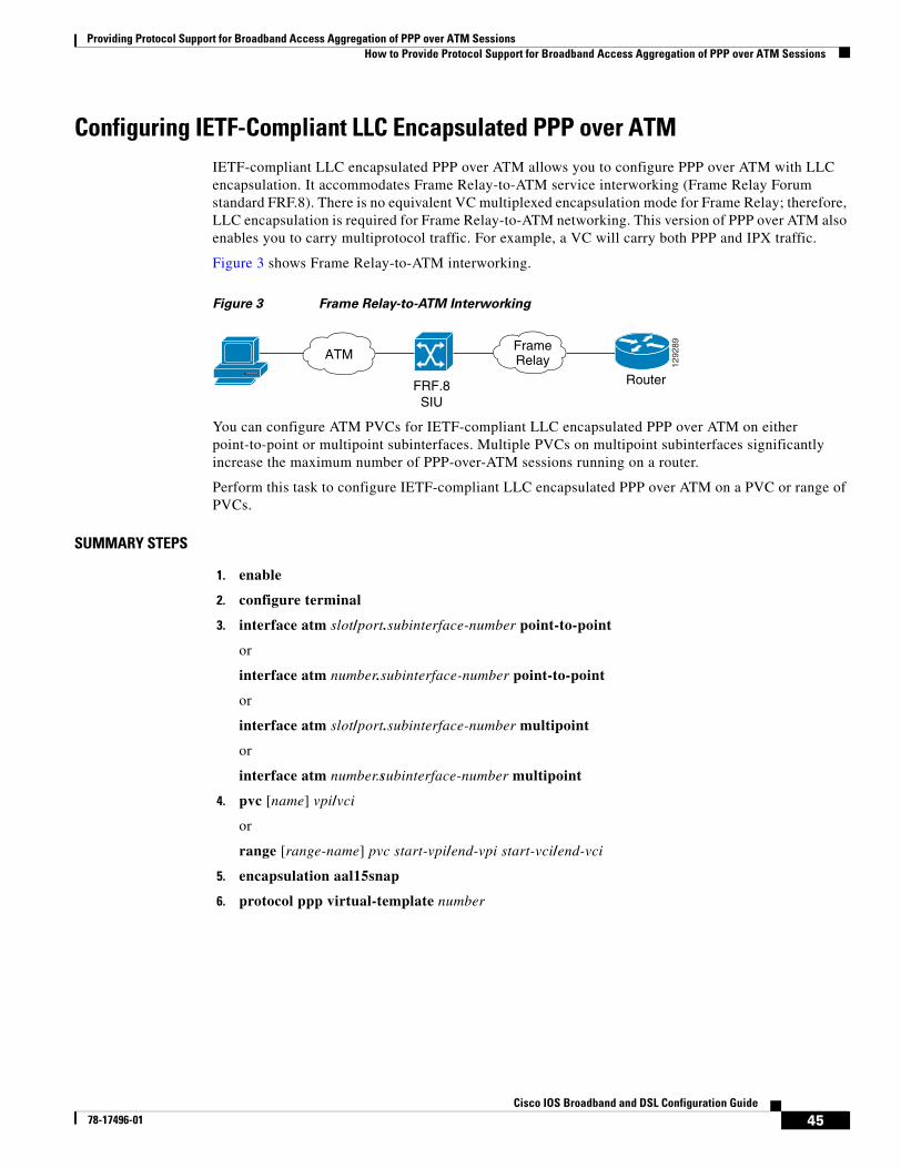
Providing Protocol Support for Broadband Access Aggregation of PPP over ATM SessionsHow to Provide Protocol Support for Broadband Access Aggregation of PPP over ATM Sessions
45Cisco IOS Broadband and DSL Configuration Guide
78-17496-01
Configuring IETF-Compliant LLC Encapsulated PPP over ATMIETF-compliant LLC encapsulated PPP over ATM allows you to configure PPP over ATM with LLC encapsulation. It accommodates Frame Relay-to-ATM service interworking (Frame Relay Forum standard FRF.8). There is no equivalent VC multiplexed encapsulation mode for Frame Relay; therefore, LLC encapsulation is required for Frame Relay-to-ATM networking. This version of PPP over ATM also enables you to carry multiprotocol traffic. For example, a VC will carry both PPP and IPX traffic.
Figure 3 shows Frame Relay-to-ATM interworking.
Figure 3 Frame Relay-to-ATM Interworking
You can configure ATM PVCs for IETF-compliant LLC encapsulated PPP over ATM on either point-to-point or multipoint subinterfaces. Multiple PVCs on multipoint subinterfaces significantly increase the maximum number of PPP-over-ATM sessions running on a router.
Perform this task to configure IETF-compliant LLC encapsulated PPP over ATM on a PVC or range of PVCs.
SUMMARY STEPS
1. enable
2. configure terminal
3. interface atm slot/port.subinterface-number point-to-point
or
interface atm number.subinterface-number point-to-point
or
interface atm slot/port.subinterface-number multipoint
or
interface atm number.subinterface-number multipoint
4. pvc [name] vpi/vci
or
range [range-name] pvc start-vpi/end-vpi start-vci/end-vci
5. encapsulation aal15snap
6. protocol ppp virtual-template number
FRF.8SIU
Router
ATMFrameRelay 12
9289
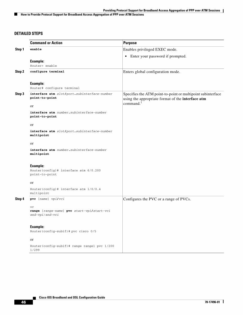
Providing Protocol Support for Broadband Access Aggregation of PPP over ATM SessionsHow to Provide Protocol Support for Broadband Access Aggregation of PPP over ATM Sessions
46Cisco IOS Broadband and DSL Configuration Guide
78-17496-01
DETAILED STEPS
Command or Action Purpose
Step 1 enable
Example:Router> enable
Enables privileged EXEC mode.
• Enter your password if prompted.
Step 2 configure terminal
Example:Router# configure terminal
Enters global configuration mode.
Step 3 interface atm slot/port.subinterface-number point-to-point
or
interface atm number.subinterface-number point-to-point
or
interface atm slot/port.subinterface-number multipoint
or
interface atm number.subinterface-number multipoint
Example:Router(config)# interface atm 6/0.200 point-to-point
or
Router(config)# interface atm 1/0/0.4 multipoint
Specifies the ATM point-to-point or multipoint subinterface using the appropriate format of the interface atm command.1
Step 4 pvc [name] vpi/vci
orrange [range-name] pvc start-vpi/start-vci end-vpi/end-vci
Example:Router(config-subif)# pvc cisco 0/5
or
Router(config-subif)# range range1 pvc 1/200 1/299
Configures the PVC or a range of PVCs.
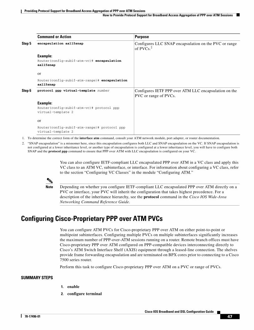
Providing Protocol Support for Broadband Access Aggregation of PPP over ATM SessionsHow to Provide Protocol Support for Broadband Access Aggregation of PPP over ATM Sessions
47Cisco IOS Broadband and DSL Configuration Guide
78-17496-01
You can also configure IETF-compliant LLC encapsulated PPP over ATM in a VC class and apply this VC class to an ATM VC, subinterface, or interface. For information about configuring a VC class, refer to the section “Configuring VC Classes” in the module “Configuring ATM.”
Note Depending on whether you configure IETF-compliant LLC encapsulated PPP over ATM directly on a PVC or interface, your PVC will inherit the configuration that takes highest precedence. For a description of the inheritance hierarchy, see the protocol command in the Cisco IOS Wide-Area Networking Command Reference Guide.
Configuring Cisco-Proprietary PPP over ATM PVCsYou can configure ATM PVCs for Cisco-proprietary PPP over ATM on either point-to-point or multipoint subinterfaces. Configuring multiple PVCs on multiple subinterfaces significantly increases the maximum number of PPP-over-ATM sessions running on a router. Remote branch offices must have Cisco-proprietary PPP over ATM configured on PPP-compatible devices interconnecting directly to Cisco’s ATM Switch Interface Shelf (AXIS) equipment through a leased-line connection. The shelves provide frame forwarding encapsulation and are terminated on BPX cores prior to connecting to a Cisco 7500 series router.
Perform this task to configure Cisco-proprietary PPP over ATM on a PVC or range of PVCs.
SUMMARY STEPS
1. enable
2. configure terminal
Step 5 encapsulation aal15snap
Example:Router(config-subif-atm-vc)# encapsulation aal15snap
or
Router(config-subif-atm-range)# encapsulation aal15snap
Configures LLC SNAP encapsulation on the PVC or range of PVCs.2
Step 6 protocol ppp virtual-template number
Example:Router(config-subif-atm-vc)# protocol ppp virtual-template 2
or
Router(config-subif-atm-range)# protocol ppp virtual-template 2
Configures IETF PPP over ATM LLC encapsulation on the PVC or range of PVCs.
1. To determine the correct form of the interface atm command, consult your ATM network module, port adapter, or router documentation.
2. “SNAP encapsulation” is a misnomer here, since this encapsulation configures both LLC and SNAP encapsulation on the VC. If SNAP encapsulation is not configured at a lower inheritance level, or another type of encapsulation is configured at a lower inheritance level, you will have to configure both SNAP and the protocol ppp command to ensure that PPP over ATM with LLC encapsulation is configured on your VC.
Command or Action Purpose
Providing Protocol Support for Broadband Access Aggregation of PPP over ATM SessionsHow to Provide Protocol Support for Broadband Access Aggregation of PPP over ATM Sessions
48Cisco IOS Broadband and DSL Configuration Guide
78-17496-01
3. interface atm slot/port.subinterface-number point-to-point
or
interface atm number.subinterface-number point-to-point
or
interface atm slot/port.subinterface-number multipoint
or
interface atm number.subinterface-number multipoint
4. pvc [name] vpi/vci
or
range [range-name] pvc start-vpi/start-vci end-vpi/end-vci
5. encapsulation aal5ciscoppp virtual-template number
DETAILED STEPS
Command or Action Purpose
Step 1 enable
Example:Router> enable
Enables privileged EXEC mode.
• Enter your password if prompted.
Step 2 configure terminal
Example:Router# configure terminal
Enters global configuration mode.
Step 3 interface atm slot/port.subinterface-number point-to-point
or
interface atm number.subinterface-number point-to-point
or
interface atm slot/port.subinterface-number multipoint
or
interface atm number.subinterface-number multipoint
Example:Router(config)# interface atm 6/0.200 point-to-point
or
Router(config)# interface atm 1/0/0.4 multipoint
Specifies the ATM point-to-point or multipoint subinterface using the appropriate format of the interface atm command.1
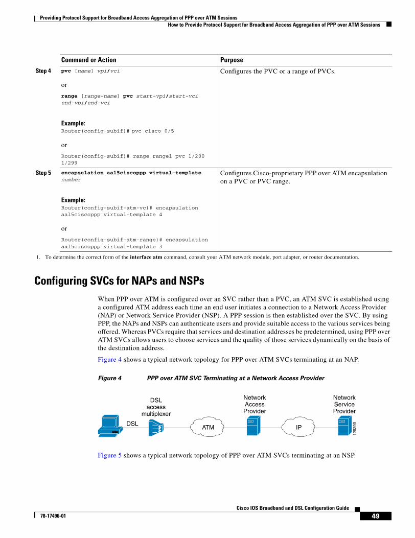
Providing Protocol Support for Broadband Access Aggregation of PPP over ATM SessionsHow to Provide Protocol Support for Broadband Access Aggregation of PPP over ATM Sessions
49Cisco IOS Broadband and DSL Configuration Guide
78-17496-01
Configuring SVCs for NAPs and NSPsWhen PPP over ATM is configured over an SVC rather than a PVC, an ATM SVC is established using a configured ATM address each time an end user initiates a connection to a Network Access Provider (NAP) or Network Service Provider (NSP). A PPP session is then established over the SVC. By using PPP, the NAPs and NSPs can authenticate users and provide suitable access to the various services being offered. Whereas PVCs require that services and destination addresses be predetermined, using PPP over ATM SVCs allows users to choose services and the quality of those services dynamically on the basis of the destination address.
Figure 4 shows a typical network topology for PPP over ATM SVCs terminating at an NAP.
Figure 4 PPP over ATM SVC Terminating at a Network Access Provider
Figure 5 shows a typical network topology of PPP over ATM SVCs terminating at an NSP.
Step 4 pvc [name] vpi/vci
or
range [range-name] pvc start-vpi/start-vci end-vpi/end-vci
Example:Router(config-subif)# pvc cisco 0/5
or
Router(config-subif)# range range1 pvc 1/200 1/299
Configures the PVC or a range of PVCs.
Step 5 encapsulation aal5ciscoppp virtual-template number
Example:Router(config-subif-atm-vc)# encapsulation aal5ciscoppp virtual-template 4
or
Router(config-subif-atm-range)# encapsulation aal5ciscoppp virtual-template 3
Configures Cisco-proprietary PPP over ATM encapsulation on a PVC or PVC range.
1. To determine the correct form of the interface atm command, consult your ATM network module, port adapter, or router documentation.
Command or Action Purpose
1292
90DSL
DSLaccess
multiplexer
NetworkAccessProvider
NetworkServiceProvider
ATM IP
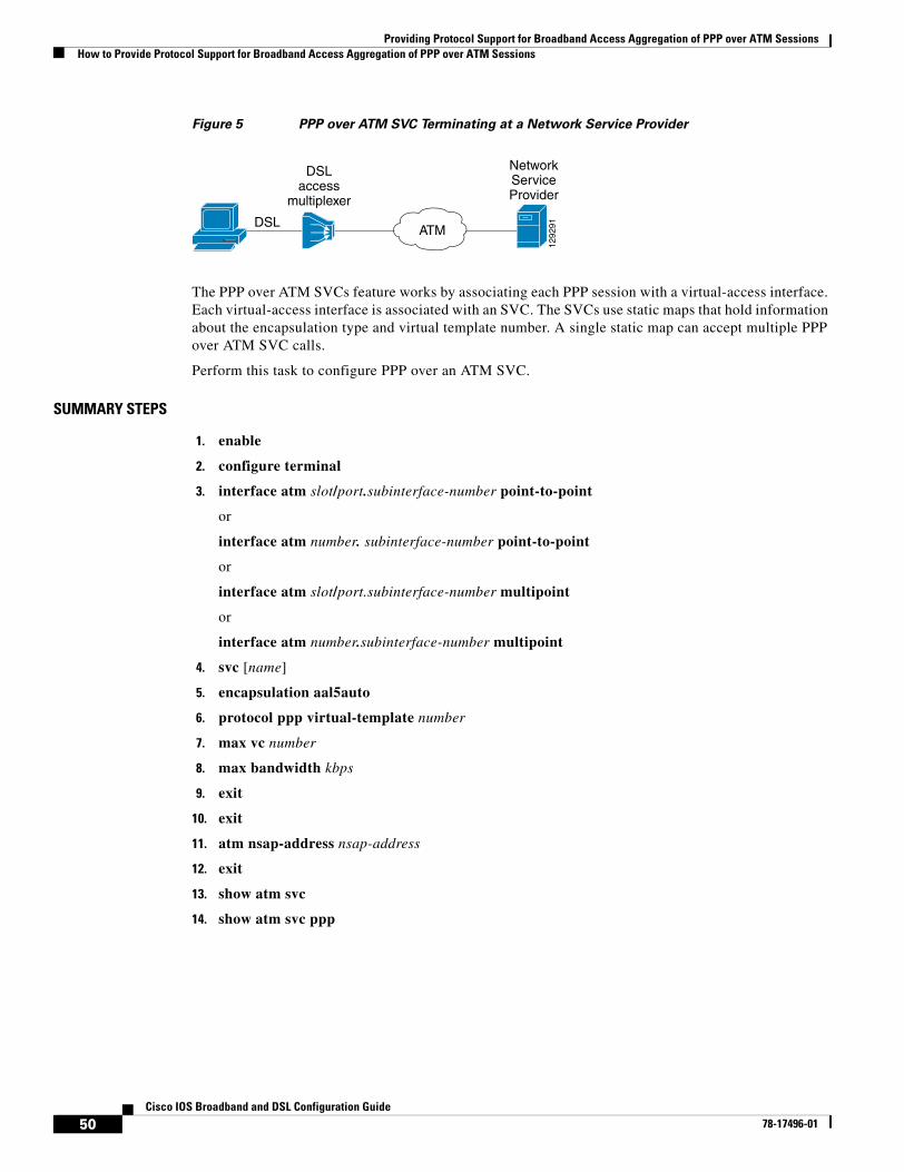
Providing Protocol Support for Broadband Access Aggregation of PPP over ATM SessionsHow to Provide Protocol Support for Broadband Access Aggregation of PPP over ATM Sessions
50Cisco IOS Broadband and DSL Configuration Guide
78-17496-01
Figure 5 PPP over ATM SVC Terminating at a Network Service Provider
The PPP over ATM SVCs feature works by associating each PPP session with a virtual-access interface. Each virtual-access interface is associated with an SVC. The SVCs use static maps that hold information about the encapsulation type and virtual template number. A single static map can accept multiple PPP over ATM SVC calls.
Perform this task to configure PPP over an ATM SVC.
SUMMARY STEPS
1. enable
2. configure terminal
3. interface atm slot/port.subinterface-number point-to-point
or
interface atm number. subinterface-number point-to-point
or
interface atm slot/port.subinterface-number multipoint
or
interface atm number.subinterface-number multipoint
4. svc [name]
5. encapsulation aal5auto
6. protocol ppp virtual-template number
7. max vc number
8. max bandwidth kbps
9. exit
10. exit
11. atm nsap-address nsap-address
12. exit
13. show atm svc
14. show atm svc ppp
1292
91DSL
DSLaccess
multiplexer
NetworkServiceProvider
ATM
Providing Protocol Support for Broadband Access Aggregation of PPP over ATM SessionsHow to Provide Protocol Support for Broadband Access Aggregation of PPP over ATM Sessions
51Cisco IOS Broadband and DSL Configuration Guide
78-17496-01
DETAILED STEPS
Command or Action Purpose
Step 1 enable
Example:Router> enable
Enables privileged EXEC mode.
• Enter your password if prompted.
Step 2 configure terminal
Example:Router# configure terminal
Enters global configuration mode.
Step 3 interface atm slot/port.subinterface-number point-to-point
or
interface atm number.subinterface-number point-to-point
or
interface atm slot/port.subinterface-number multipoint
or
interface atm number.subinterface-number multipoint
Example:Router(config)# interface atm 6/0.200 point-to-point
or
Router(config)# interface atm 1/0/0.4 multipoint
Specifies the ATM point-to-point or multipoint subinterface using the appropriate format of the interface atm command.1
Step 4 svc [name]
Example:Router(config-subif)# svc cisco
Configures the SVC.
Step 5 encapsulation aal5auto
Example:Router(config-subif-atm-vc)# encapsulation aal5auto
Specifies encapsulation auto, which allows the SVC to use either aal5snap or aal5mux encapsulation types.
Step 6 protocol ppp virtual-template number
Example:Router(config-subif-atm-vc)# protocol ppp virtual-template 6
Specifies that PPP is established over the ATM SVC using the configuration from the specified virtual template.
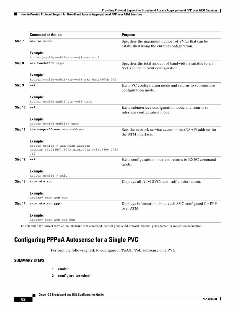
Providing Protocol Support for Broadband Access Aggregation of PPP over ATM SessionsHow to Provide Protocol Support for Broadband Access Aggregation of PPP over ATM Sessions
52Cisco IOS Broadband and DSL Configuration Guide
78-17496-01
Configuring PPPoA Autosense for a Single PVCPerform the following task to configure PPPoA/PPPoE autosense on a PVC.
SUMMARY STEPS
1. enable
2. configure terminal
Step 7 max vc number
Example:Router(config-subif-atm-vc)# max vc 5
Specifies the maximum number of SVCs that can be established using the current configuration.
Step 8 max bandwidth kbps
Example:Router(config-subif-atm-vc)# max bandwidth 564
Specifies the total amount of bandwidth available to all SVCs in the current configuration.
Step 9 exit
Example:Router(config-subif-atm-vc)# exit
Exits VC configuration mode and returns to subinterface configuration mode.
Step 10 exit
Example:Router(config-subif)# exit
Exits subinterface configuration mode and returns to interface configuration mode.
Step 11 atm nsap-address nsap-address
Example:Router(config)# atm nsap-address AB.CDEF.01.234567.890A.BCDE.F012.3456.7890.1234.12
Sets the network service access point (NSAP) address for the ATM interface.
Step 12 exit
Example:Router(config)# exit
Exits configuration mode and returns to EXEC command mode.
Step 13 show atm svc
Example:Router# show atm svc
Displays all ATM SVCs and traffic information.
Step 14 show atm svc ppp
Example:Router# show atm svc ppp
Displays information about each SVC configured for PPP over ATM.
1. To determine the correct form of the interface atm command, consult your ATM network module, port adapter, or router documentation.
Command or Action Purpose
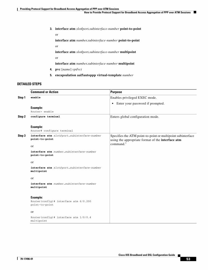
Providing Protocol Support for Broadband Access Aggregation of PPP over ATM SessionsHow to Provide Protocol Support for Broadband Access Aggregation of PPP over ATM Sessions
53Cisco IOS Broadband and DSL Configuration Guide
78-17496-01
3. interface atm slot/port.subinterface-number point-to-point
or
interface atm number.subinterface-number point-to-point
or
interface atm slot/port.subinterface-number multipoint
or
interface atm number.subinterface-number multipoint
4. pvc [name] vpi/vci
5. encapsulation aal5autoppp virtual-template number
DETAILED STEPS
Command or Action Purpose
Step 1 enable
Example:Router> enable
Enables privileged EXEC mode.
• Enter your password if prompted.
Step 2 configure terminal
Example:Router# configure terminal
Enters global configuration mode.
Step 3 interface atm slot/port.subinterface-number point-to-point
or
interface atm number.subinterface-number point-to-point
or
interface atm slot/port.subinterface-number multipoint
or
interface atm number.subinterface-number multipoint
Example:Router(config)# interface atm 6/0.200 point-to-point
or
Router(config)# interface atm 1/0/0.4 multipoint
Specifies the ATM point-to-point or multipoint subinterface using the appropriate format of the interface atm command.1
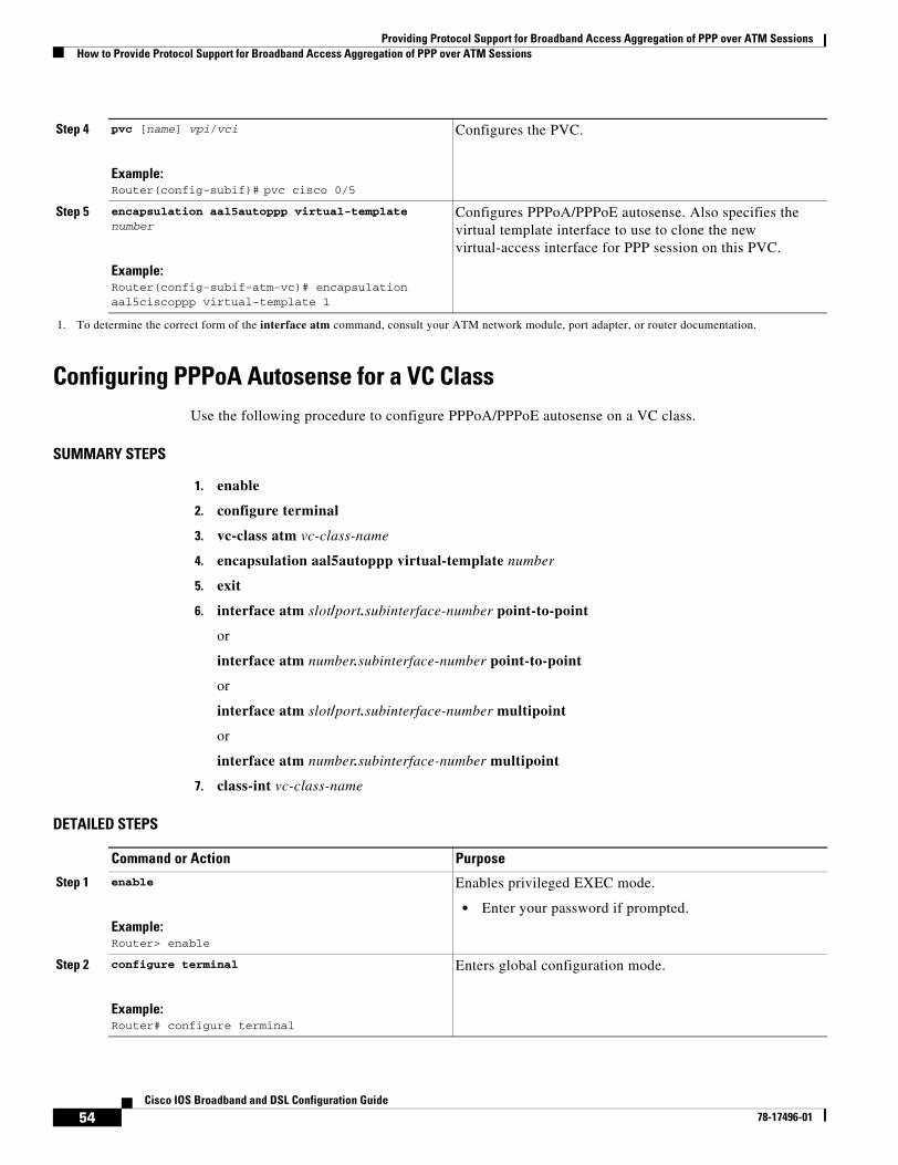
Providing Protocol Support for Broadband Access Aggregation of PPP over ATM SessionsHow to Provide Protocol Support for Broadband Access Aggregation of PPP over ATM Sessions
54Cisco IOS Broadband and DSL Configuration Guide
78-17496-01
Configuring PPPoA Autosense for a VC ClassUse the following procedure to configure PPPoA/PPPoE autosense on a VC class.
SUMMARY STEPS
1. enable
2. configure terminal
3. vc-class atm vc-class-name
4. encapsulation aal5autoppp virtual-template number
5. exit
6. interface atm slot/port.subinterface-number point-to-point
or
interface atm number.subinterface-number point-to-point
or
interface atm slot/port.subinterface-number multipoint
or
interface atm number.subinterface-number multipoint
7. class-int vc-class-name
DETAILED STEPS
Step 4 pvc [name] vpi/vci
Example:Router(config-subif)# pvc cisco 0/5
Configures the PVC.
Step 5 encapsulation aal5autoppp virtual-template number
Example:Router(config-subif-atm-vc)# encapsulation aal5ciscoppp virtual-template 1
Configures PPPoA/PPPoE autosense. Also specifies the virtual template interface to use to clone the new virtual-access interface for PPP session on this PVC.
1. To determine the correct form of the interface atm command, consult your ATM network module, port adapter, or router documentation.
Command or Action Purpose
Step 1 enable
Example:Router> enable
Enables privileged EXEC mode.
• Enter your password if prompted.
Step 2 configure terminal
Example:Router# configure terminal
Enters global configuration mode.
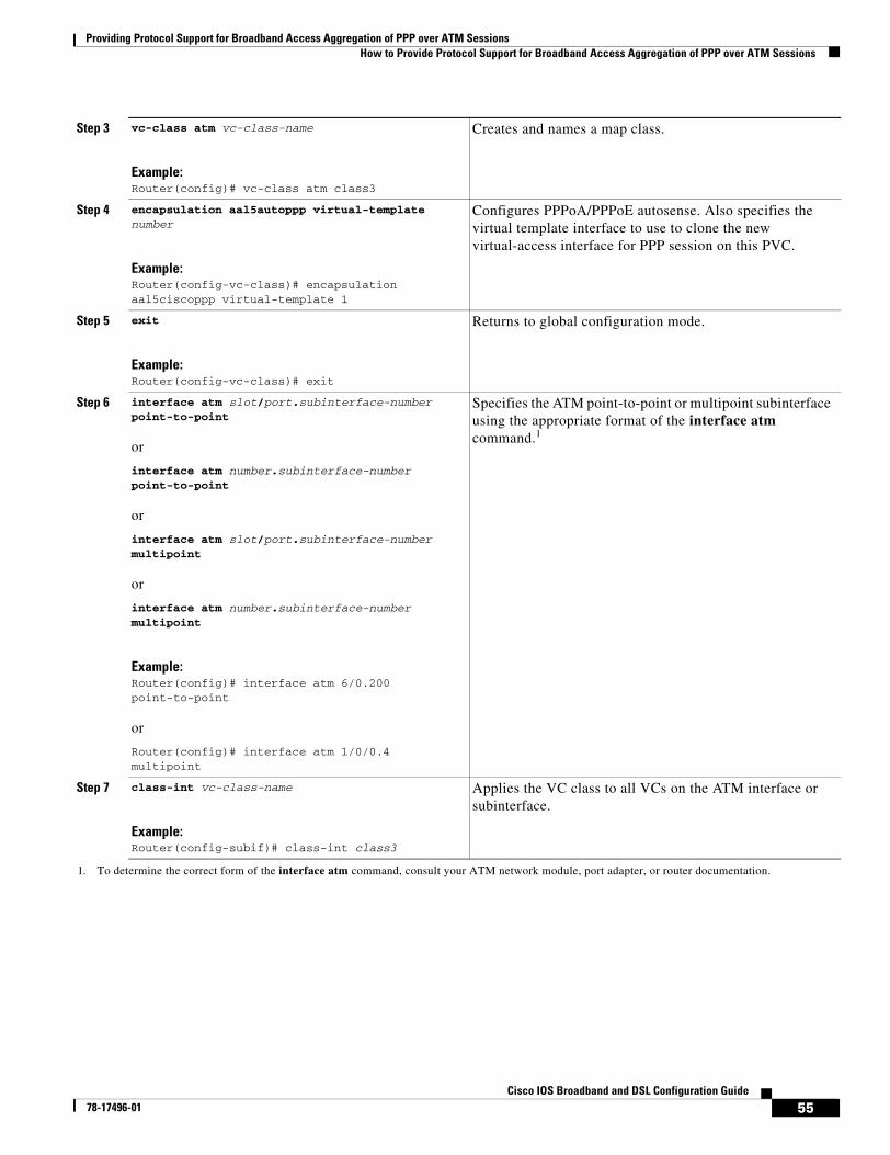
Providing Protocol Support for Broadband Access Aggregation of PPP over ATM SessionsHow to Provide Protocol Support for Broadband Access Aggregation of PPP over ATM Sessions
55Cisco IOS Broadband and DSL Configuration Guide
78-17496-01
Step 3 vc-class atm vc-class-name
Example:Router(config)# vc-class atm class3
Creates and names a map class.
Step 4 encapsulation aal5autoppp virtual-template number
Example:Router(config-vc-class)# encapsulation aal5ciscoppp virtual-template 1
Configures PPPoA/PPPoE autosense. Also specifies the virtual template interface to use to clone the new virtual-access interface for PPP session on this PVC.
Step 5 exit
Example:Router(config-vc-class)# exit
Returns to global configuration mode.
Step 6 interface atm slot/port.subinterface-number point-to-point
or
interface atm number.subinterface-number point-to-point
or
interface atm slot/port.subinterface-number multipoint
or
interface atm number.subinterface-number multipoint
Example:Router(config)# interface atm 6/0.200 point-to-point
or
Router(config)# interface atm 1/0/0.4 multipoint
Specifies the ATM point-to-point or multipoint subinterface using the appropriate format of the interface atm command.1
Step 7 class-int vc-class-name
Example:Router(config-subif)# class-int class3
Applies the VC class to all VCs on the ATM interface or subinterface.
1. To determine the correct form of the interface atm command, consult your ATM network module, port adapter, or router documentation.
Providing Protocol Support for Broadband Access Aggregation of PPP over ATM SessionsVerifying PPPoA Autosense for ATM PVCs
56Cisco IOS Broadband and DSL Configuration Guide
78-17496-01
Verifying PPPoA Autosense for ATM PVCsUse the following procedure to verify PPPoA/PPPoE autosense.
SUMMARY STEPS
1. show atm pvc [ppp]
2. show caller
3. show interface virtual access number
4. show user
5. show vpdn
DETAILED STEPS
Step 1 show atm pvc [ppp]
After the client at the other end of the PVC has initiated a PPPoA session, use this command to check that the PVC contains the PPPoA session.
Step 2 show caller
Use this command to:
• View individual users and consumed resources on the NAS.
• Inspect active call statistics for large pools of connections. (The debug commands produce too much output and tax the CPU too heavily.)
• Display the absolute and idle times for each user. The current values for both of these settings are displayed on the TTY line and the asynchronous interface. Users that have been idle for unacceptably long periods of time can be easily identified. By using this information, you can define time-out policies and multiple grades of services for different users.
Router# show callerLine User Service Active con 0 - TTY 00:08:21 BR0:1 hatteras PPP 00:00:14 Vi1 hatteras PPP Bundle 00:00:13
Step 3 show interface virtual access number
Displays information about the virtual-access interface, link control protocol (LCP), protocol states, and interface statistics:
Router# show interface virtual access Virtual-Access3Virtual-Access3 is up, line protocol is up
Step 4 show user
Displays information about the active lines on the router.
Router# show user
Line User Host(s) Idle Location * 2 vty 0 idle 00:00:00 bru-cse-058.cisco.com tty 2/01 ww Async interface 00:00:01 PPP: 12.12.12.3
Step 5 show vpdn
Displays information about active Level 2 Forwarding (L2F) Protocol tunnel and message identifiers in a virtual private dial-up network (VPDN).
Providing Protocol Support for Broadband Access Aggregation of PPP over ATM SessionsConfiguration Examples for Configuring PPP over ATM
57Cisco IOS Broadband and DSL Configuration Guide
78-17496-01
Router# show vpdn
Active L2F tunnels
NAS Name Gateway Name NAS CLID Gateway CLID State
nas gateway 4 2 open
L2F MIDs
Name NAS Name Interface MID State
[email protected] nas As7 1 open
[email protected] nas As8 2 open
Configuration Examples for Configuring PPP over ATMThis section provides the following configuration examples:
• IETF-Compliant MUX Encapsulated PPP over ATM Configuration: Examples, page 57
• IETF-Compliant LLC Encapsulated PPP over ATM Configuration: Examples, page 61
• Cisco Proprietary-PPP-over-ATM: Example, page 62
• PPP over an ATM SVC Configuration: Example, page 63
• PPPoA/PPPoE Autosense on an ATM PVC: Example, page 63
• PPPoA/PPPoE Autosense on a VC Class: Example, page 64
• PPPoA/PPPoE Autosense on Multiple VC Classes and Virtual Templates: Example, page 64
IETF-Compliant MUX Encapsulated PPP over ATM Configuration: Examples This section provides the following examples for configuring IETF-compliant PPP over ATM:
• IETF-Compliant PPP over ATM with Different Traffic-Shaping Parameters: Example, page 57
• ADSL Termination: Example, page 58
• Two Routers with Back-to-Back PVCs: Example, page 60
• Multiplexed Encapsulation Using VC Class: Example, page 61
IETF-Compliant PPP over ATM with Different Traffic-Shaping Parameters: Example
PVCs with different PPP-over-ATM traffic-shaping parameters can be configured on the same subinterface. In the following example, three PVCs are configured for PPP over ATM on subinterface ATM 2/0.1. PVC 0/60 is configured with IETF-compliant PPP over ATM encapsulation. Its traffic-shaping parameter is an unspecified bit rate with peak cell rate at 500 kbps. PVC 0/70 is also configured with IETF-compliant PPP over ATM encapsulation, but its traffic-shaping parameter is nonreal-time variable bit rate, with peak cell rate at 1 Mbps, sustainable cell rate at 500 kbps, and burst cell size of 64 cells. PVC 0/80 is configured with the Cisco-proprietary PPP over ATM encapsulation.
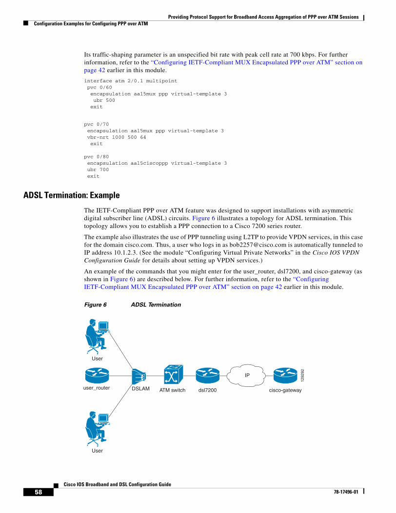
Providing Protocol Support for Broadband Access Aggregation of PPP over ATM SessionsConfiguration Examples for Configuring PPP over ATM
58Cisco IOS Broadband and DSL Configuration Guide
78-17496-01
Its traffic-shaping parameter is an unspecified bit rate with peak cell rate at 700 kbps. For further information, refer to the “Configuring IETF-Compliant MUX Encapsulated PPP over ATM” section on page 42 earlier in this module.
interface atm 2/0.1 multipoint pvc 0/60 encapsulation aal5mux ppp virtual-template 3 ubr 500 exit
pvc 0/70 encapsulation aal5mux ppp virtual-template 3 vbr-nrt 1000 500 64 exit
pvc 0/80 encapsulation aal5ciscoppp virtual-template 3 ubr 700 exit
ADSL Termination: Example
The IETF-Compliant PPP over ATM feature was designed to support installations with asymmetric digital subscriber line (ADSL) circuits. Figure 6 illustrates a topology for ADSL termination. This topology allows you to establish a PPP connection to a Cisco 7200 series router.
The example also illustrates the use of PPP tunneling using L2TP to provide VPDN services, in this case for the domain cisco.com. Thus, a user who logs in as [email protected] is automatically tunneled to IP address 10.1.2.3. (See the module “Configuring Virtual Private Networks” in the Cisco IOS VPDN Configuration Guide for details about setting up VPDN services.)
An example of the commands that you might enter for the user_router, dsl7200, and cisco-gateway (as shown in Figure 6) are described below. For further information, refer to the “Configuring IETF-Compliant MUX Encapsulated PPP over ATM” section on page 42 earlier in this module.
Figure 6 ADSL Termination
dsl7200 cisco-gatewayATM switchDSLAM
User
1292
92
user_router
User
IP
Providing Protocol Support for Broadband Access Aggregation of PPP over ATM SessionsConfiguration Examples for Configuring PPP over ATM
59Cisco IOS Broadband and DSL Configuration Guide
78-17496-01
user_router Configurationinterface virtual-template 1 ip address negotiated ppp chap hostname [email protected] ppp chap password 0 cisco exit
interface atm 0 pvc 0/40 encapsulation aal5mux ppp virtual-template 1 exit exit
dsl7200 Configurationusername [email protected] password 0 cisco username dsl7200 password 0 cisco
vpdn enable
vpdn-group 1 request dialin l2tp ip 10.2.1.1 domain cisco.com
interface virtual-template 1 ppp authentication chap exit
interface atm 2/0 pvc 0/40 encapsulation aal5mux ppp virtual-template 1 exit exit
cisco-gateway Configurationusername cisco_gateway password 0 cisco username [email protected] password 0 cisco
vpdn enable
vpdn-group 1 accept dialin l2tp virtual-template 1 remote dsl7200
interface loopback 0 ip address 10.0.1.1 255.255.255.0 exit
interface virtual-template 1 ip unnumbered loopback 0 peer default ip address pool pool-1 exit
ip local pool pool-1 10.1.2.1 10.1.2.254
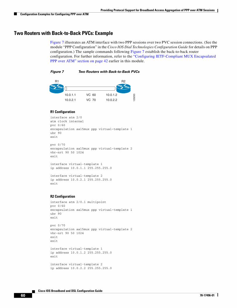
Providing Protocol Support for Broadband Access Aggregation of PPP over ATM SessionsConfiguration Examples for Configuring PPP over ATM
60Cisco IOS Broadband and DSL Configuration Guide
78-17496-01
Two Routers with Back-to-Back PVCs: Example
Figure 7 illustrates an ATM interface with two PPP sessions over two PVC session connections. (See the module “PPP Configuration” in the Cisco IOS Dial Technologies Configuration Guide for details on PPP configuration.) The sample commands following Figure 7 establish the back-to-back router configuration. For further information, refer to the “Configuring IETF-Compliant MUX Encapsulated PPP over ATM” section on page 42 earlier in this module.
Figure 7 Two Routers with Back-to-Back PVCs
R1 Configurationinterface atm 2/0 atm clock internal pvc 0/60 encapsulation aal5mux ppp virtual-template 1 ubr 90 exit
pvc 0/70 encapsulation aal5mux ppp virtual-template 2 vbr-nrt 90 50 1024 exit
interface virtual-template 1 ip address 10.0.1.1 255.255.255.0
interface virtual-template 2 ip address 10.0.2.1 255.255.255.0 exit
R2 Configurationinterface atm 2/0.1 multipoint pvc 0/60 encapsulation aal5mux ppp virtual-template 1 ubr 90 exit
pvc 0/70 encapsulation aal5mux ppp virtual-template 2 vbr-nrt 90 50 1024 exit exit
interface virtual-template 1 ip address 10.0.1.2 255.255.255.0 exit
interface virtual-template 2 ip address 10.0.2.2 255.255.255.0
R2R1
10.0.1.1
10.0.2.1
10.0.1.2
10.0.2.2
VC 60
VC 70 1292
93
Providing Protocol Support for Broadband Access Aggregation of PPP over ATM SessionsConfiguration Examples for Configuring PPP over ATM
61Cisco IOS Broadband and DSL Configuration Guide
78-17496-01
Multiplexed Encapsulation Using VC Class: Example
In the following example, PVC 0/60 is configured on subinterface ATM 2/0.1 with a VC class attached to it. For details on creating and applying a VC class, see the section “Configuring VC Classes” in the module “Configuring ATM.” By rule of inheritance, PVC 0/60 runs with IETF-compliant PPP over ATM encapsulation using the configuration from interface virtual-template 1. Its parameter is an unspecified bit rate with peak cell at 90 kbps.
interface atm 2/0.1 pvc 0/60 class-vc pvc-ppp exit exit
vc-class atm pvc-ppp encapsulation aal5mux ppp virtual-template 1 ubr 90 exit
IETF-Compliant LLC Encapsulated PPP over ATM Configuration: Examples This section provides the following examples for configuring IETF-compliant LLC encapsulated PPP over ATM:
• Configuring IETF-Compliant PPP over ATM LLC Encapsulation: Example, page 61
• Overriding a Virtual Template for IETF-Compliant PPP over ATM: Example, page 62
• Disabling IETF-Compliant PPP over ATM LLC Encapsulation on a Specific VC: Example, page 62
Configuring IETF-Compliant PPP over ATM LLC Encapsulation: Example
This example shows how to configure IETF PPP over ATM LLC encapsulation in the VC class called ppp-default. The VC class specifies virtual template 1 from which to spawn PPP interfaces, SNAP encapsulation (the default), and a UBR class traffic type at 256 kbps. When the VC class ppp-default is configured on interface 0.1, PVC 0/70 inherits these properties. PVC 0/80 overrides virtual template 1 in the VC class and uses virtual template 2 instead. PVC 0/90 also overrides virtual template 1 and uses virtual template 3 instead. In addition, PVC 0/90 uses a VC multiplexed encapsulation and a UBR class traffic type at 500 kbps. For further information, refer to the “IETF-Compliant LLC Encapsulated PPP over ATM Configuration: Examples” section on page 61.
interface atm 0.1 multipoint class-int ppp-default ! pvc 0/70 exit ! pvc 0/80 protocol ppp virtual-template 2 exit ! pvc 0/90 encapsulation aal5mux ppp virtual-template 3 ubr 500 exit exit !
Providing Protocol Support for Broadband Access Aggregation of PPP over ATM SessionsConfiguration Examples for Configuring PPP over ATM
62Cisco IOS Broadband and DSL Configuration Guide
78-17496-01
vc-class atm ppp-default protocol ppp virtual-template 1 ubr 256 exit
Overriding a Virtual Template for IETF-Compliant PPP over ATM: Example
This example illustrates how to use inheritance to override a virtual template configuration for muxppp or ciscoppp encapsulation options. For PVC 5/505, since the encapsulation option at that level is ciscoppp virtual template 1, as specified in the VC class called muxppp, the protocol ppp virtual-template 2 command overrides only the virtual-template configuration. For further information, refer to the “IETF-Compliant LLC Encapsulated PPP over ATM Configuration: Examples” section on page 61.
interface atm 2/0 class-int muxppp ! pvc 5/505 protocol ppp virtual-template 2 exit ! muxppp encapsulation aal5ciscoppp virtual-template 1 exit
Disabling IETF-Compliant PPP over ATM LLC Encapsulation on a Specific VC: Example
This example shows how to limit the configuration of a particular LLC encapsulated protocol to a particular VC. First, we see that the VC class called “ppp” is configured with IETF PPP over ATM with LLC encapsulation and virtual template 1. This VC class is then applied to ATM interface 1/0/0. By configuring SNAP encapsulation by itself on PVC 0/32, you disable IETF PPP over ATM with LLC encapsulation on this particular PVC; PVC 0/32 will only carry IP. For further information, refer to the “IETF-Compliant LLC Encapsulated PPP over ATM Configuration: Examples” section on page 61.
interface atm 1/0/0 class-int ppp exit ! interface atm 1/0/0.100 point-to-point description IP only VC ip address 10.1.1.1 255.255.255.0 pvc 0/32 encapsulation aal5snap exit exit ! vc-class atm ppp encapsulation aal5snap protocol ppp virtual-template 1 exit
Cisco Proprietary-PPP-over-ATM: ExampleThe following example shows how to configure Cisco-proprietary PPP over ATM to use PPP unnumbered link and Challenge Handshake Authentication Protocol (CHAP) authentication. For further information, refer to the “Configuring Cisco-Proprietary PPP over ATM PVCs” section on page 47.
Providing Protocol Support for Broadband Access Aggregation of PPP over ATM SessionsConfiguration Examples for Configuring PPP over ATM
63Cisco IOS Broadband and DSL Configuration Guide
78-17496-01
configure terminal ! interface virtual-template 2 encapsulation ppp ip unnumbered ethernet 0/0 ppp authentication chap ! interface atm 2/0.2 point-to-point pvc 0/34 encapsulation aal5ciscoppp virtual-template 2 exit
PPP over an ATM SVC Configuration: ExampleIn the following example, ATM interface 2/0/0 is configured to accept ATM SVC calls whose called party address is 47.00918100000000400B0A2501.0060837B4740.00. The same ATM NSAP address can be configured on other physical ATM interfaces as well. When a PPP session is established, a virtual-access interface is created and cloned with the configuration from virtual template 1. All PPP sessions established on this ATM interface will use the IP address of loopback interface 0. A maximum of 100 SVCs can be established using this configuration. SVCs established using this configuration cannot take up more than 50 Mbps in total bandwidth.
interface ATM 2/0/0 svc anna encapsulation aal5auto protocol ppp virtual-template 1 max vc 100 max bandwidth 50000 atm nsap 47.00918100000000400B0A2501.0060837B4740.00 ! interface virtual-template 1 ip unnumbered loopback 0 ! interface loopback 0 ip address 10.7.1.1 255.255.255.0
PPPoA/PPPoE Autosense on an ATM PVC: ExampleIn the following example, the NAS is configured with PPPoA/PPPoE autosense for ATM PVCs on PVC 30/33:
!! Configure PPP Autosense !interface ATM 0/0/0.33 multipointpvc 30/33 encapsulation aal5autoppp Virtual-Template1
!! Configure PPPoE!vpdn enablevpdn-group 1accept dialin protocol pppoe virtual-template 1
!ip cef
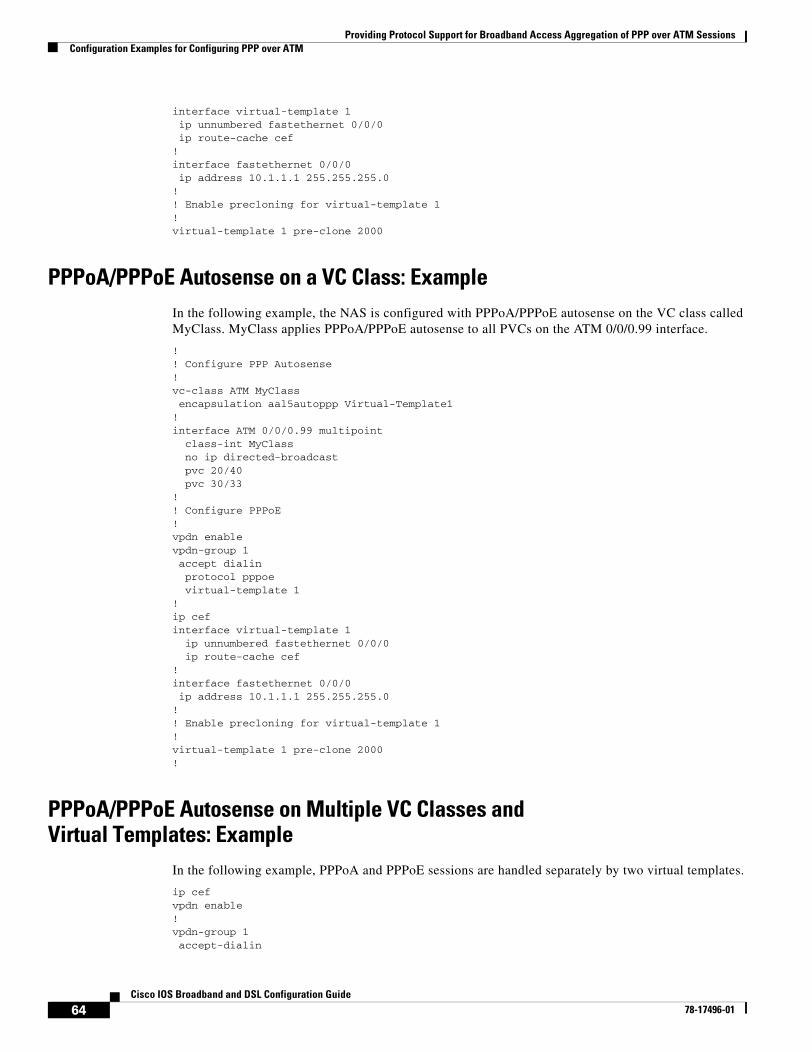
Providing Protocol Support for Broadband Access Aggregation of PPP over ATM SessionsConfiguration Examples for Configuring PPP over ATM
64Cisco IOS Broadband and DSL Configuration Guide
78-17496-01
interface virtual-template 1ip unnumbered fastethernet 0/0/0ip route-cache cef
!interface fastethernet 0/0/0ip address 10.1.1.1 255.255.255.0
!! Enable precloning for virtual-template 1!virtual-template 1 pre-clone 2000
PPPoA/PPPoE Autosense on a VC Class: ExampleIn the following example, the NAS is configured with PPPoA/PPPoE autosense on the VC class called MyClass. MyClass applies PPPoA/PPPoE autosense to all PVCs on the ATM 0/0/0.99 interface.
!! Configure PPP Autosense!vc-class ATM MyClassencapsulation aal5autoppp Virtual-Template1
!interface ATM 0/0/0.99 multipoint
class-int MyClassno ip directed-broadcastpvc 20/40
pvc 30/33 !! Configure PPPoE!vpdn enablevpdn-group 1accept dialin protocol pppoe virtual-template 1
!ip cefinterface virtual-template 1
ip unnumbered fastethernet 0/0/0ip route-cache cef
!interface fastethernet 0/0/0ip address 10.1.1.1 255.255.255.0
!! Enable precloning for virtual-template 1!virtual-template 1 pre-clone 2000!
PPPoA/PPPoE Autosense on Multiple VC Classes and Virtual Templates: Example
In the following example, PPPoA and PPPoE sessions are handled separately by two virtual templates.
ip cefvpdn enable!vpdn-group 1accept-dialin
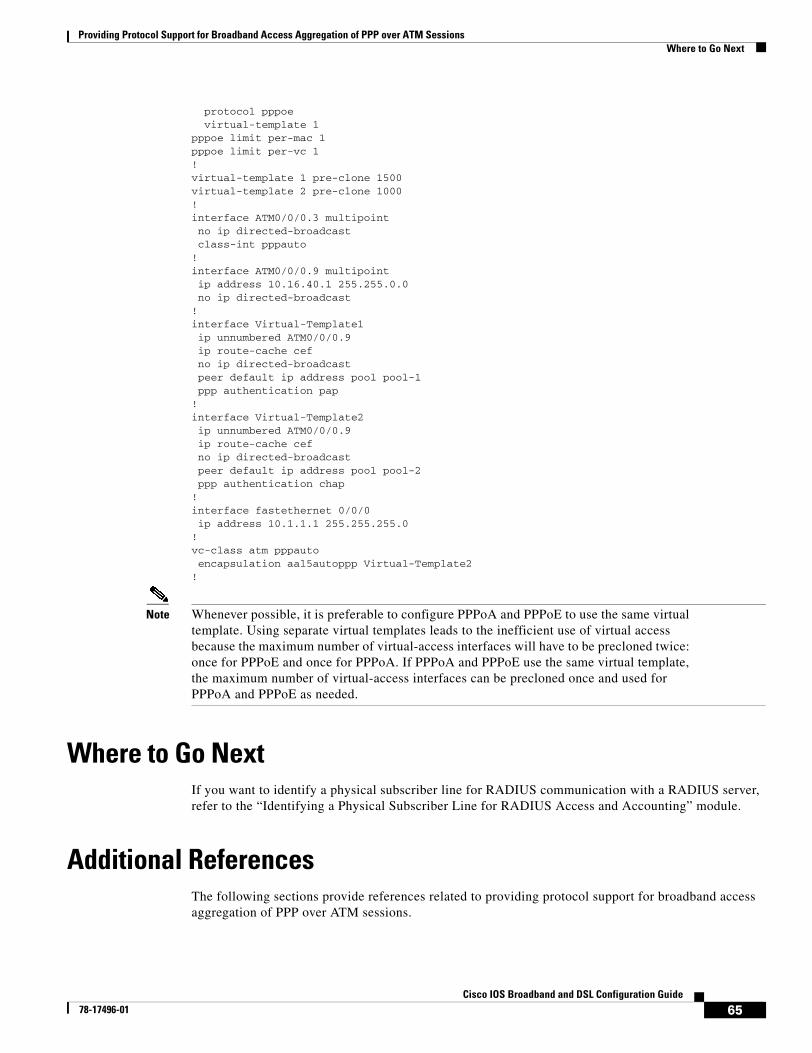
Providing Protocol Support for Broadband Access Aggregation of PPP over ATM SessionsWhere to Go Next
65Cisco IOS Broadband and DSL Configuration Guide
78-17496-01
protocol pppoevirtual-template 1
pppoe limit per-mac 1pppoe limit per-vc 1!virtual-template 1 pre-clone 1500virtual-template 2 pre-clone 1000!interface ATM0/0/0.3 multipointno ip directed-broadcastclass-int pppauto
!interface ATM0/0/0.9 multipointip address 10.16.40.1 255.255.0.0no ip directed-broadcast
!interface Virtual-Template1ip unnumbered ATM0/0/0.9ip route-cache cefno ip directed-broadcastpeer default ip address pool pool-1ppp authentication pap
!interface Virtual-Template2ip unnumbered ATM0/0/0.9ip route-cache cefno ip directed-broadcastpeer default ip address pool pool-2ppp authentication chap
!interface fastethernet 0/0/0ip address 10.1.1.1 255.255.255.0
!vc-class atm pppautoencapsulation aal5autoppp Virtual-Template2
!
Note Whenever possible, it is preferable to configure PPPoA and PPPoE to use the same virtual template. Using separate virtual templates leads to the inefficient use of virtual access because the maximum number of virtual-access interfaces will have to be precloned twice: once for PPPoE and once for PPPoA. If PPPoA and PPPoE use the same virtual template, the maximum number of virtual-access interfaces can be precloned once and used for PPPoA and PPPoE as needed.
Where to Go NextIf you want to identify a physical subscriber line for RADIUS communication with a RADIUS server, refer to the “Identifying a Physical Subscriber Line for RADIUS Access and Accounting” module.
Additional ReferencesThe following sections provide references related to providing protocol support for broadband access aggregation of PPP over ATM sessions.
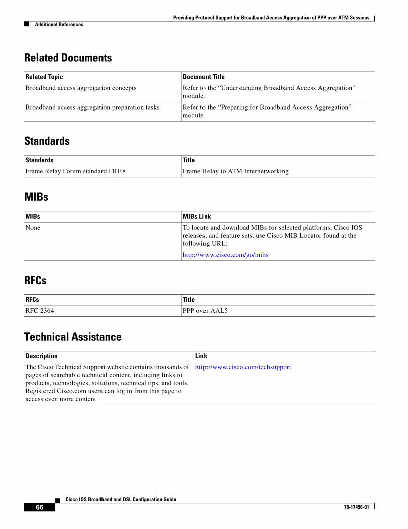
Providing Protocol Support for Broadband Access Aggregation of PPP over ATM SessionsAdditional References
66Cisco IOS Broadband and DSL Configuration Guide
78-17496-01
Related Documents
Standards
MIBs
RFCs
Technical Assistance
Related Topic Document Title
Broadband access aggregation concepts Refer to the “Understanding Broadband Access Aggregation” module.
Broadband access aggregation preparation tasks Refer to the “Preparing for Broadband Access Aggregation” module.
Standards Title
Frame Relay Forum standard FRF.8 Frame Relay to ATM Internetworking
MIBs MIBs Link
None To locate and download MIBs for selected platforms, Cisco IOS releases, and feature sets, use Cisco MIB Locator found at the following URL:
http://www.cisco.com/go/mibs
RFCs Title
RFC 2364 PPP over AAL5
Description Link
The Cisco Technical Support website contains thousands of pages of searchable technical content, including links to products, technologies, solutions, technical tips, and tools. Registered Cisco.com users can log in from this page to access even more content.
http://www.cisco.com/techsupport
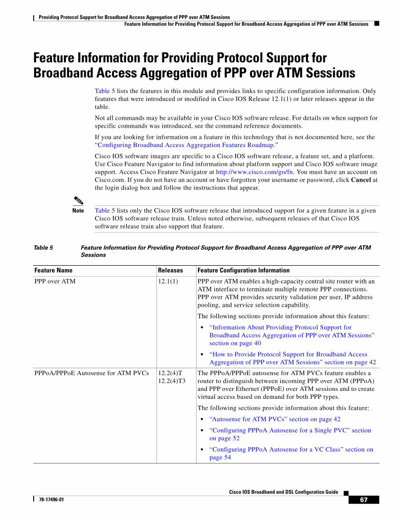
Providing Protocol Support for Broadband Access Aggregation of PPP over ATM SessionsFeature Information for Providing Protocol Support for Broadband Access Aggregation of PPP over ATM Sessions
67Cisco IOS Broadband and DSL Configuration Guide
78-17496-01
Feature Information for Providing Protocol Support for Broadband Access Aggregation of PPP over ATM Sessions
Table 5 lists the features in this module and provides links to specific configuration information. Only features that were introduced or modified in Cisco IOS Release 12.1(1) or later releases appear in the table.
Not all commands may be available in your Cisco IOS software release. For details on when support for specific commands was introduced, see the command reference documents.
If you are looking for information on a feature in this technology that is not documented here, see the “Configuring Broadband Access Aggregation Features Roadmap.”
Cisco IOS software images are specific to a Cisco IOS software release, a feature set, and a platform. Use Cisco Feature Navigator to find information about platform support and Cisco IOS software image support. Access Cisco Feature Navigator at http://www.cisco.com/go/fn. You must have an account on Cisco.com. If you do not have an account or have forgotten your username or password, click Cancel at the login dialog box and follow the instructions that appear.
Note Table 5 lists only the Cisco IOS software release that introduced support for a given feature in a given Cisco IOS software release train. Unless noted otherwise, subsequent releases of that Cisco IOS software release train also support that feature.
Table 5 Feature Information for Providing Protocol Support for Broadband Access Aggregation of PPP over ATM
Sessions
Feature Name Releases Feature Configuration Information
PPP over ATM 12.1(1) PPP over ATM enables a high-capacity central site router with an ATM interface to terminate multiple remote PPP connections. PPP over ATM provides security validation per user, IP address pooling, and service selection capability.
The following sections provide information about this feature:
• “Information About Providing Protocol Support for Broadband Access Aggregation of PPP over ATM Sessions” section on page 40
• “How to Provide Protocol Support for Broadband Access Aggregation of PPP over ATM Sessions” section on page 42
PPPoA/PPPoE Autosense for ATM PVCs 12.2(4)T12.2(4)T3
The PPPoA/PPPoE autosense for ATM PVCs feature enables a router to distinguish between incoming PPP over ATM (PPPoA) and PPP over Ethernet (PPPoE) over ATM sessions and to create virtual access based on demand for both PPP types.
The following sections provide information about this feature:
• “Autosense for ATM PVCs” section on page 42
• “Configuring PPPoA Autosense for a Single PVC” section on page 52
• “Configuring PPPoA Autosense for a VC Class” section on page 54

Providing Protocol Support for Broadband Access Aggregation of PPP over ATM SessionsFeature Information for Providing Protocol Support for Broadband Access Aggregation of PPP over ATM Sessions
68Cisco IOS Broadband and DSL Configuration Guide
78-17496-01
69Cisco IOS Broadband and DSL Configuration Guide
78-17496-01
Providing Protocol Support for Broadband Access Aggregation of PPPoE Sessions
PPP over Ethernet (PPPoE) profiles contain configuration information for a group of PPPoE sessions. Multiple PPPoE profiles can be defined for a device, allowing different virtual templates and other PPPoE configuration parameters to be assigned to different PPP interfaces, VLANs, and ATM PVCs that are used in supporting broadband access aggregation of PPPoE sessions.
Note This module describes the method for configuring PPPoE sessions using profiles. If you have configured your PPPoE sessions using a release of Cisco IOS software earlier than Cisco IOS Release 12.4, refer to the documentation that corresponds to that release. Although the configuration methods used in Cisco IOS software releases prior to Release 12.4 are supported in Release 12.4, it is recommended that you use the configuration methods described in this module for new configurations and when upgrading to Cisco IOS Release 12.4.
Module History
This module was first published on May 2, 2005, and last updated on May 2, 2005.
Finding Feature Information in This Module
Not all features may be supported in your Cisco IOS software release. Use the “Feature Information for Providing Protocol Support for Broadband Access Aggregation of PPPoE Sessions” section on page 98 to find information about feature support and configuration.
Contents• Prerequisites for Providing Protocol Support for Broadband Access Aggregation of PPPoE Sessions,
page 70
• Restrictions for Providing Protocol Support for Broadband Access Aggregation of PPPoE Sessions, page 70
• Information About Providing Protocol Support for Broadband Access Aggregation for PPPoE Sessions, page 71
• How to Provide Protocol Support for Broadband Access Aggregation of PPPoE Sessions, page 74
• Configuration Examples for Providing Protocol Support for Broadband Access Aggregation of PPPoE Sessions, page 90
• Where to Go Next, page 96
Providing Protocol Support for Broadband Access Aggregation of PPPoE SessionsPrerequisites for Providing Protocol Support for Broadband Access Aggregation of PPPoE Sessions
70Cisco IOS Broadband and DSL Configuration Guide
78-17496-01
• Additional References, page 96
• Feature Information for Providing Protocol Support for Broadband Access Aggregation of PPPoE Sessions, page 98
Prerequisites for Providing Protocol Support for Broadband Access Aggregation of PPPoE Sessions
• You must understand the concepts described in the “Understanding for Broadband Access Aggregation” module.
• You must perform the tasks contained in the “Preparing for Broadband Access Aggregation” module.
Restrictions for Providing Protocol Support for Broadband Access Aggregation of PPPoE Sessions
PPPoE profiles separate the configuration of PPPoE from the configuration of virtual private dial-up networks (VPDN). The legacy method of configuring PPPoE in VPDN groups is still permitted, but you cannot configure PPPoE profiles and PPPoE in VPDN groups simultaneously.
If a PPPoE profile is assigned to a PPPoE port (Ethernet interface, VLAN, or PVC), virtual circuit (VC) class, or ATM PVC range and the profile has not yet been defined, the port, VC class, or range will not have any PPPoE parameters configured and will not use parameters from the global group.
On the PPPoE server only, PPPoE over 802.1Q VLAN support can be configured without using subinterfaces.
ATM PVC support for PPPoE over 802.1Q VLANs can be configured only on the PPPoE server.
It is not possible to shut down traffic for individual VLANs that are configured on the main interface. Individual VLANs that are configured on subinterfaces can be shut down.
A VLAN range can be configured on a main interface at the same time that VLANs outside the range are configured on subinterfaces of the same main interface. However, you cannot configure a specific VLAN on the main interface and on a subinterface at the same time.
Providing Protocol Support for Broadband Access Aggregation of PPPoE SessionsInformation About Providing Protocol Support for Broadband Access Aggregation for PPPoE Sessions
71Cisco IOS Broadband and DSL Configuration Guide
78-17496-01
Information About Providing Protocol Support for Broadband Access Aggregation for PPPoE Sessions
This section contains information about the following:
• PPPoE Specification Definition, page 71
• Benefits of PPPoE Profiles, page 71
• PPPoE Connection Throttling, page 71
• PPPoE Profile Assignment to a VLAN Without Subinterfaces, page 72
PPPoE Specification DefinitionPPP over Ethernet (PPPoE) is a specification that defines how a host PC interacts with common broadband medium (for example, a digital subscriber line (DSL), wireless or cable modem) to achieve access to a high-speed data network. Relying on two widely accepted standards, Ethernet and PPP, the PPPoE implementation allows users over the Ethernet to share a common connection. The Ethernet principles supporting multiple users in a LAN, combined with the principles of PPP, which apply to serial connections, support this connection.
The base protocol is defined in RFC 2516.
Benefits of PPPoE ProfilesBefore the introduction of the use of PPPoE profiles, PPPoE parameters were configured within a VPDN group. Configuring PPPoE in a VPDN group limited PPPoE configuration options because only one PPPoE VPDN group with one virtual template is permitted on a device. The PPPoE Profiles feature provides simplicity and flexibility in PPPoE configuration by separating PPPoE from VPDN configuration. The PPPoE Profiles feature allows multiple PPPoE profiles, each with a different configuration, to be used on a single device.
Note This module describes the method for configuring PPPoE sessions using profiles. If you have configured your PPPoE sessions using a release of Cisco IOS software earlier than Cisco IOS Release 12.4, refer to the documentation that corresponds to that release. Although the configuration methods used in Cisco IOS software releases prior to Release 12.4 are supported in Release 12.4, it is recommended that you use the configuration methods described in this module for new configurations and when upgrading to Cisco IOS Release 12.4.
PPPoE Connection ThrottlingRepeated requests to initiate PPPoE sessions can adversely affect the performance of a router and RADIUS server. The PPPoE Connection Throttling feature limits PPPoE connection requests to help prevent intentional denial-of-service attacks as well as unintentional PPP authentication loops. This feature implements session throttling on the PPPoE server to limit the number of PPPoE session requests that can be initiated from a MAC address or virtual circuit (VC) during a specified period of time.
Providing Protocol Support for Broadband Access Aggregation of PPPoE SessionsInformation About Providing Protocol Support for Broadband Access Aggregation for PPPoE Sessions
72Cisco IOS Broadband and DSL Configuration Guide
78-17496-01
PPPoE Profile Assignment to a VLAN Without SubinterfacesUsing PPPoE profile assignment to a VLAN without subinterfaces provides two enhancements to PPP over Ethernet (PPPoE) over IEEE 802.1Q VLAN functionality:
• It removes the requirement for each PPPoE VLAN to be created on a subinterface. Removal of this requirement increases the number of VLANs that can be configured on a router to 4000 VLANs per interface.
• It adds ATM permanent virtual circuit (PVC) support for PPPoE over VLAN traffic that uses bridged RFC 1483 encapsulation.
To configure PPPoE over 802.1Q VLAN support on an interface rather than a subinterface, and to configure ATM support for PPPoE over 802.1Q VLANs, you should understand the following concepts:
• PPPoE over VLAN Configuration Without Using Subinterfaces, page 72
• PPPoE over VLAN Support on ATM PVCs, page 72
• Benefits of PPPoE over VLAN Scaling and ATM Support for PPPoE over VLANs, page 73
PPPoE over VLAN Configuration Without Using Subinterfaces
PPPoE profile assignment to a VLAN without subinterfaces removes the requirement for each PPPoE VLAN to be created on a subinterface. Allowing more than one PPPoE VLAN to be configured on a main interface increases the number of VLANs that can be configured on a router to 4000 VLANs per interface.
Individual VLANs or a range of VLANs can be configured on an interface. You can configure a VLAN range on a main interface and at the same time configure VLANs outside the range on subinterfaces of the same interface.
PPPoE over VLAN Support on ATM PVCs
PPPoE profile assignment to a VLAN without subinterfaces enables ATM PVCs to process PPPoE over VLAN packets that use bridged RFC 1483 encapsulation. This capability allows PPPoE traffic from different 802.1Q VLANs to be multiplexed over the same ATM PVC.
Figure 8 shows a sample network topology that implements PPPoE over VLAN on ATM PVCs. In this topology, a service provider is using an Ethernet switch to provide Ethernet service to home users and a single PVC to provide the switch with WAN access. The home users use PPPoE to access services on the network access server (NAS). Each port on the switch is assigned a separate VLAN, and the VLANs are trunked over a Fast Ethernet or Gigabit Ethernet interface that is connected to a digital subscriber line (DSL) modem acting as a bridge.
The 802.1Q VLAN-encapsulated traffic coming in from the Ethernet switch trunk is encapsulated in RFC 1483 bridged encapsulation by the DSL modem and sent across the ATM WAN to the NAS. The NAS, which is configured to support PPPoE over VLANs over ATM PVCs, will extract the PPPoE packet from the PPPoE over 802.1Q VLAN over RFC 1483 bridged encapsulation and provide PPPoE services to the user.
In the downlink, the NAS sends packets in PPPoE over 802.1Q VLAN over RFC 1483 bridged encapsulation. The DSL modem strips off the RFC 1483 encapsulation and forwards the 802.1Q VLAN packets across the trunk to the switch. The switch then sends the Ethernet packets to the port associated with the 802.1 VLAN ID.
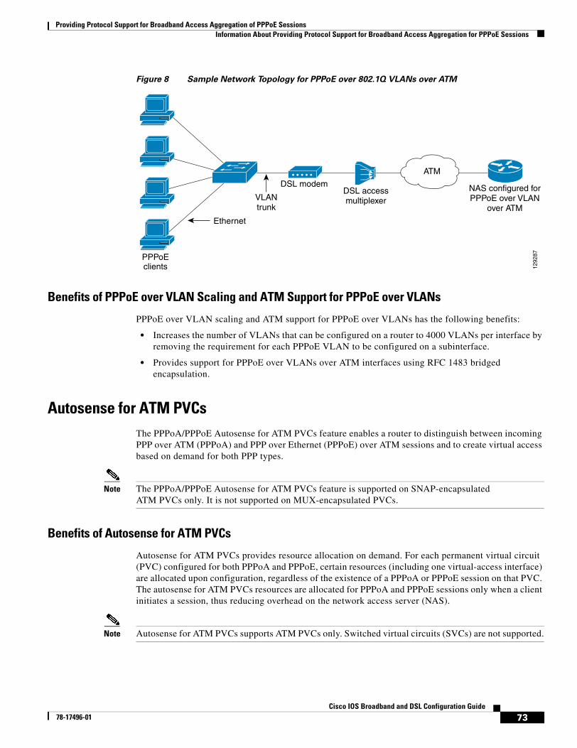
Providing Protocol Support for Broadband Access Aggregation of PPPoE SessionsInformation About Providing Protocol Support for Broadband Access Aggregation for PPPoE Sessions
73Cisco IOS Broadband and DSL Configuration Guide
78-17496-01
Figure 8 Sample Network Topology for PPPoE over 802.1Q VLANs over ATM
Benefits of PPPoE over VLAN Scaling and ATM Support for PPPoE over VLANs
PPPoE over VLAN scaling and ATM support for PPPoE over VLANs has the following benefits:
• Increases the number of VLANs that can be configured on a router to 4000 VLANs per interface by removing the requirement for each PPPoE VLAN to be configured on a subinterface.
• Provides support for PPPoE over VLANs over ATM interfaces using RFC 1483 bridged encapsulation.
Autosense for ATM PVCsThe PPPoA/PPPoE Autosense for ATM PVCs feature enables a router to distinguish between incoming PPP over ATM (PPPoA) and PPP over Ethernet (PPPoE) over ATM sessions and to create virtual access based on demand for both PPP types.
Note The PPPoA/PPPoE Autosense for ATM PVCs feature is supported on SNAP-encapsulated ATM PVCs only. It is not supported on MUX-encapsulated PVCs.
Benefits of Autosense for ATM PVCs
Autosense for ATM PVCs provides resource allocation on demand. For each permanent virtual circuit (PVC) configured for both PPPoA and PPPoE, certain resources (including one virtual-access interface) are allocated upon configuration, regardless of the existence of a PPPoA or PPPoE session on that PVC. The autosense for ATM PVCs resources are allocated for PPPoA and PPPoE sessions only when a client initiates a session, thus reducing overhead on the network access server (NAS).
Note Autosense for ATM PVCs supports ATM PVCs only. Switched virtual circuits (SVCs) are not supported.
1292
87PPPoEclients
Ethernet
VLANtrunk
DSL modemDSL accessmultiplexer
ATM
NAS configured forPPPoE over VLAN
over ATM
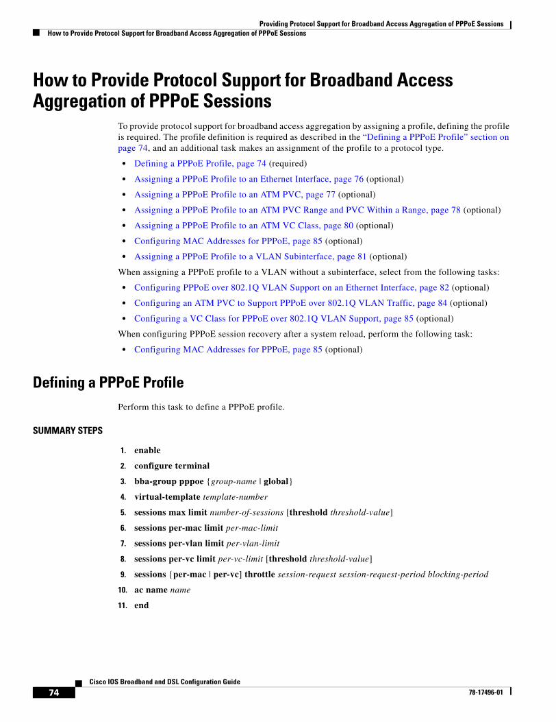
Providing Protocol Support for Broadband Access Aggregation of PPPoE SessionsHow to Provide Protocol Support for Broadband Access Aggregation of PPPoE Sessions
74Cisco IOS Broadband and DSL Configuration Guide
78-17496-01
How to Provide Protocol Support for Broadband Access Aggregation of PPPoE Sessions
To provide protocol support for broadband access aggregation by assigning a profile, defining the profile is required. The profile definition is required as described in the “Defining a PPPoE Profile” section on page 74, and an additional task makes an assignment of the profile to a protocol type.
• Defining a PPPoE Profile, page 74 (required)
• Assigning a PPPoE Profile to an Ethernet Interface, page 76 (optional)
• Assigning a PPPoE Profile to an ATM PVC, page 77 (optional)
• Assigning a PPPoE Profile to an ATM PVC Range and PVC Within a Range, page 78 (optional)
• Assigning a PPPoE Profile to an ATM VC Class, page 80 (optional)
• Configuring MAC Addresses for PPPoE, page 85 (optional)
• Assigning a PPPoE Profile to a VLAN Subinterface, page 81 (optional)
When assigning a PPPoE profile to a VLAN without a subinterface, select from the following tasks:
• Configuring PPPoE over 802.1Q VLAN Support on an Ethernet Interface, page 82 (optional)
• Configuring an ATM PVC to Support PPPoE over 802.1Q VLAN Traffic, page 84 (optional)
• Configuring a VC Class for PPPoE over 802.1Q VLAN Support, page 85 (optional)
When configuring PPPoE session recovery after a system reload, perform the following task:
• Configuring MAC Addresses for PPPoE, page 85 (optional)
Defining a PPPoE ProfilePerform this task to define a PPPoE profile.
SUMMARY STEPS
1. enable
2. configure terminal
3. bba-group pppoe {group-name | global}
4. virtual-template template-number
5. sessions max limit number-of-sessions [threshold threshold-value]
6. sessions per-mac limit per-mac-limit
7. sessions per-vlan limit per-vlan-limit
8. sessions per-vc limit per-vc-limit [threshold threshold-value]
9. sessions {per-mac | per-vc] throttle session-request session-request-period blocking-period
10. ac name name
11. end
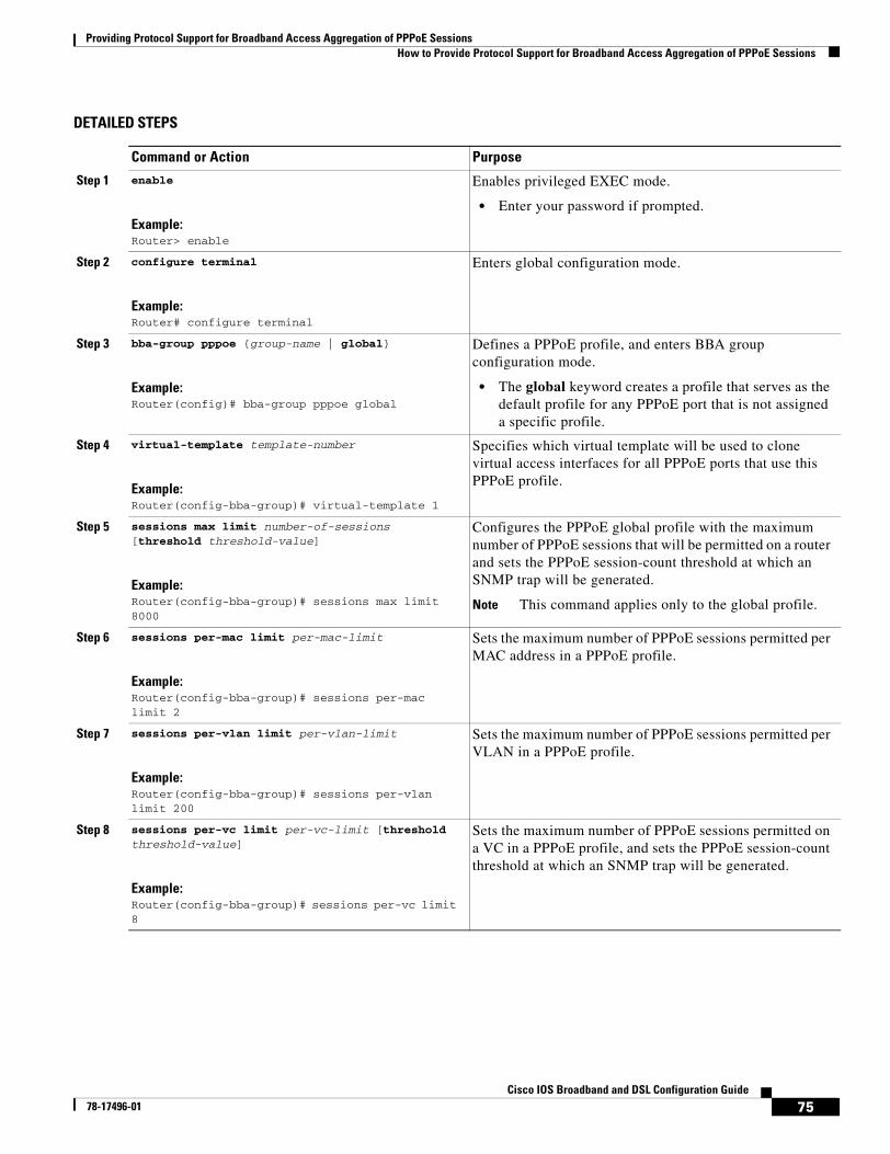
Providing Protocol Support for Broadband Access Aggregation of PPPoE SessionsHow to Provide Protocol Support for Broadband Access Aggregation of PPPoE Sessions
75Cisco IOS Broadband and DSL Configuration Guide
78-17496-01
DETAILED STEPS
Command or Action Purpose
Step 1 enable
Example:Router> enable
Enables privileged EXEC mode.
• Enter your password if prompted.
Step 2 configure terminal
Example:Router# configure terminal
Enters global configuration mode.
Step 3 bba-group pppoe {group-name | global}
Example:Router(config)# bba-group pppoe global
Defines a PPPoE profile, and enters BBA group configuration mode.
• The global keyword creates a profile that serves as the default profile for any PPPoE port that is not assigned a specific profile.
Step 4 virtual-template template-number
Example:Router(config-bba-group)# virtual-template 1
Specifies which virtual template will be used to clone virtual access interfaces for all PPPoE ports that use this PPPoE profile.
Step 5 sessions max limit number-of-sessions [threshold threshold-value]
Example:Router(config-bba-group)# sessions max limit 8000
Configures the PPPoE global profile with the maximum number of PPPoE sessions that will be permitted on a router and sets the PPPoE session-count threshold at which an SNMP trap will be generated.
Note This command applies only to the global profile.
Step 6 sessions per-mac limit per-mac-limit
Example:Router(config-bba-group)# sessions per-mac limit 2
Sets the maximum number of PPPoE sessions permitted per MAC address in a PPPoE profile.
Step 7 sessions per-vlan limit per-vlan-limit
Example:Router(config-bba-group)# sessions per-vlan limit 200
Sets the maximum number of PPPoE sessions permitted per VLAN in a PPPoE profile.
Step 8 sessions per-vc limit per-vc-limit [threshold threshold-value]
Example:Router(config-bba-group)# sessions per-vc limit 8
Sets the maximum number of PPPoE sessions permitted on a VC in a PPPoE profile, and sets the PPPoE session-count threshold at which an SNMP trap will be generated.
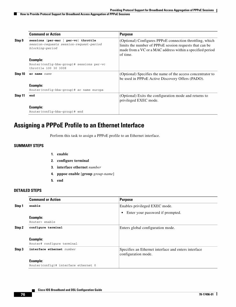
Providing Protocol Support for Broadband Access Aggregation of PPPoE SessionsHow to Provide Protocol Support for Broadband Access Aggregation of PPPoE Sessions
76Cisco IOS Broadband and DSL Configuration Guide
78-17496-01
Assigning a PPPoE Profile to an Ethernet InterfacePerform this task to assign a PPPoE profile to an Ethernet interface.
SUMMARY STEPS
1. enable
2. configure terminal
3. interface ethernet number
4. pppoe enable [group group-name]
5. end
DETAILED STEPS
Step 9 sessions {per-mac | per-vc} throttle session-requests session-request-period blocking-period
Example:Router(config-bba-group)# sessions per-vc throttle 100 30 3008
(Optional) Configures PPPoE connection throttling, which limits the number of PPPoE session requests that can be made from a VC or a MAC address within a specified period of time.
Step 10 ac name name
Example:Router(config-bba-group)# ac name europa
(Optional) Specifies the name of the access concentrator to be used in PPPoE Active Discovery Offers (PADO).
Step 11 end
Example:Router(config-bba-group)# end
(Optional) Exits the configuration mode and returns to privileged EXEC mode.
Command or Action Purpose
Command or Action Purpose
Step 1 enable
Example:Router> enable
Enables privileged EXEC mode.
• Enter your password if prompted.
Step 2 configure terminal
Example:Router# configure terminal
Enters global configuration mode.
Step 3 interface ethernet number
Example:Router(config)# interface ethernet 0
Specifies an Ethernet interface and enters interface configuration mode.
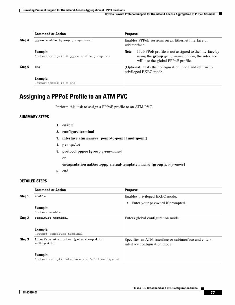
Providing Protocol Support for Broadband Access Aggregation of PPPoE SessionsHow to Provide Protocol Support for Broadband Access Aggregation of PPPoE Sessions
77Cisco IOS Broadband and DSL Configuration Guide
78-17496-01
Assigning a PPPoE Profile to an ATM PVCPerform this task to assign a PPPoE profile to an ATM PVC.
SUMMARY STEPS
1. enable
2. configure terminal
3. interface atm number [point-to-point | multipoint]
4. pvc vpi/vci
5. protocol pppoe [group group-name]
or
encapsulation aal5autoppp virtual-template number [group group-name]
6. end
DETAILED STEPS
Step 4 pppoe enable [group group-name]
Example:Router(config-if)# pppoe enable group one
Enables PPPoE sessions on an Ethernet interface or subinterface.
Note If a PPPoE profile is not assigned to the interface by using the group group-name option, the interface will use the global PPPoE profile.
Step 5 end
Example:Router(config-if)# end
(Optional) Exits the configuration mode and returns to privileged EXEC mode.
Command or Action Purpose
Command or Action Purpose
Step 1 enable
Example:Router> enable
Enables privileged EXEC mode.
• Enter your password if prompted.
Step 2 configure terminal
Example:Router# configure terminal
Enters global configuration mode.
Step 3 interface atm number [point-to-point | multipoint]
Example:Router(config)# interface atm 5/0.1 multipoint
Specifies an ATM interface or subinterface and enters interface configuration mode.
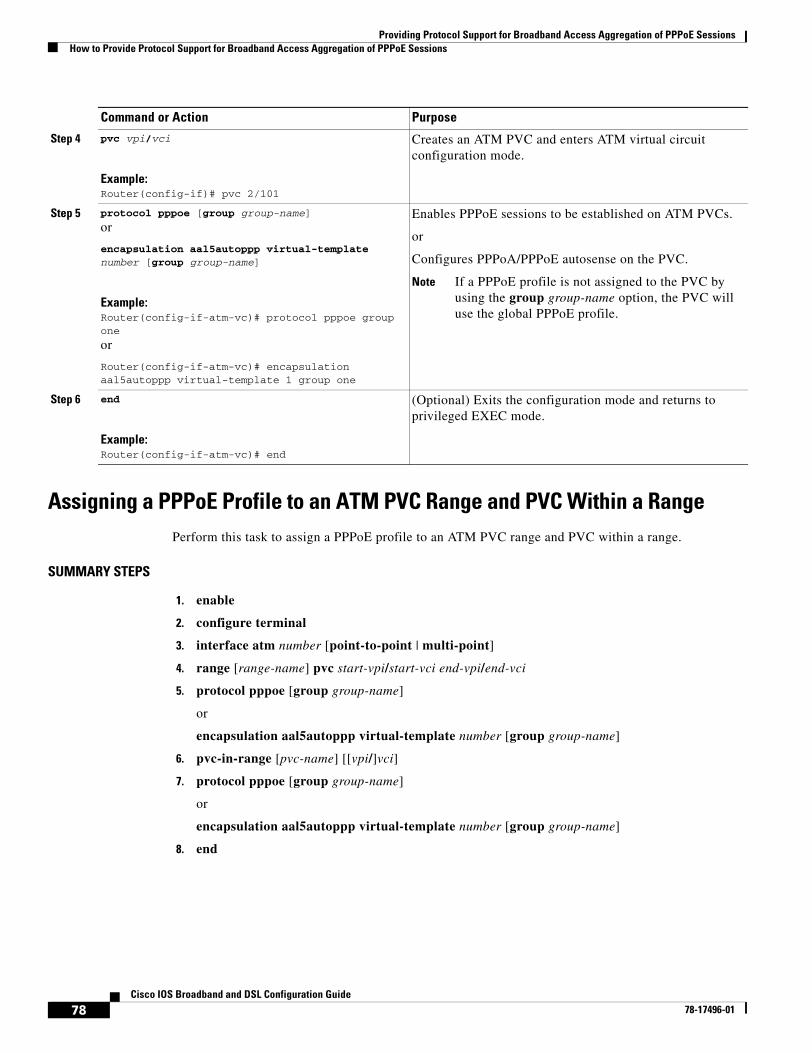
Providing Protocol Support for Broadband Access Aggregation of PPPoE SessionsHow to Provide Protocol Support for Broadband Access Aggregation of PPPoE Sessions
78Cisco IOS Broadband and DSL Configuration Guide
78-17496-01
Assigning a PPPoE Profile to an ATM PVC Range and PVC Within a Range Perform this task to assign a PPPoE profile to an ATM PVC range and PVC within a range.
SUMMARY STEPS
1. enable
2. configure terminal
3. interface atm number [point-to-point | multi-point]
4. range [range-name] pvc start-vpi/start-vci end-vpi/end-vci
5. protocol pppoe [group group-name]
or
encapsulation aal5autoppp virtual-template number [group group-name]
6. pvc-in-range [pvc-name] [[vpi/]vci]
7. protocol pppoe [group group-name]
or
encapsulation aal5autoppp virtual-template number [group group-name]
8. end
Step 4 pvc vpi/vci
Example:Router(config-if)# pvc 2/101
Creates an ATM PVC and enters ATM virtual circuit configuration mode.
Step 5 protocol pppoe [group group-name]
or
encapsulation aal5autoppp virtual-template number [group group-name]
Example:Router(config-if-atm-vc)# protocol pppoe group one
or
Router(config-if-atm-vc)# encapsulation aal5autoppp virtual-template 1 group one
Enables PPPoE sessions to be established on ATM PVCs.
or
Configures PPPoA/PPPoE autosense on the PVC.
Note If a PPPoE profile is not assigned to the PVC by using the group group-name option, the PVC will use the global PPPoE profile.
Step 6 end
Example:Router(config-if-atm-vc)# end
(Optional) Exits the configuration mode and returns to privileged EXEC mode.
Command or Action Purpose
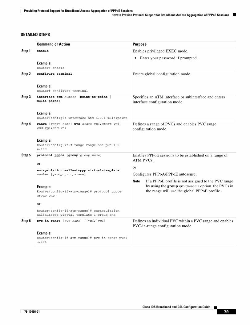
Providing Protocol Support for Broadband Access Aggregation of PPPoE SessionsHow to Provide Protocol Support for Broadband Access Aggregation of PPPoE Sessions
79Cisco IOS Broadband and DSL Configuration Guide
78-17496-01
DETAILED STEPS
Command or Action Purpose
Step 1 enable
Example:Router> enable
Enables privileged EXEC mode.
• Enter your password if prompted.
Step 2 configure terminal
Example:Router# configure terminal
Enters global configuration mode.
Step 3 interface atm number [point-to-point | multi-point]
Example:Router(config)# interface atm 5/0.1 multipoint
Specifies an ATM interface or subinterface and enters interface configuration mode.
Step 4 range [range-name] pvc start-vpi/start-vci end-vpi/end-vci
Example:Router(config-if)# range range-one pvc 100 4/199
Defines a range of PVCs and enables PVC range configuration mode.
Step 5 protocol pppoe [group group-name]
or
encapsulation aal5autoppp virtual-template number [group group-name]
Example:Router(config-if-atm-range)# protocol pppoe group one
or
Router(config-if-atm-range)# encapsulation aal5autoppp virtual-template 1 group one
Enables PPPoE sessions to be established on a range of ATM PVCs.
or
Configures PPPoA/PPPoE autosense.
Note If a PPPoE profile is not assigned to the PVC range by using the group group-name option, the PVCs in the range will use the global PPPoE profile.
Step 6 pvc-in-range [pvc-name] [[vpi/]vci]
Example:Router(config-if-atm-range)# pvc-in-range pvc1 3/104
Defines an individual PVC within a PVC range and enables PVC-in-range configuration mode.
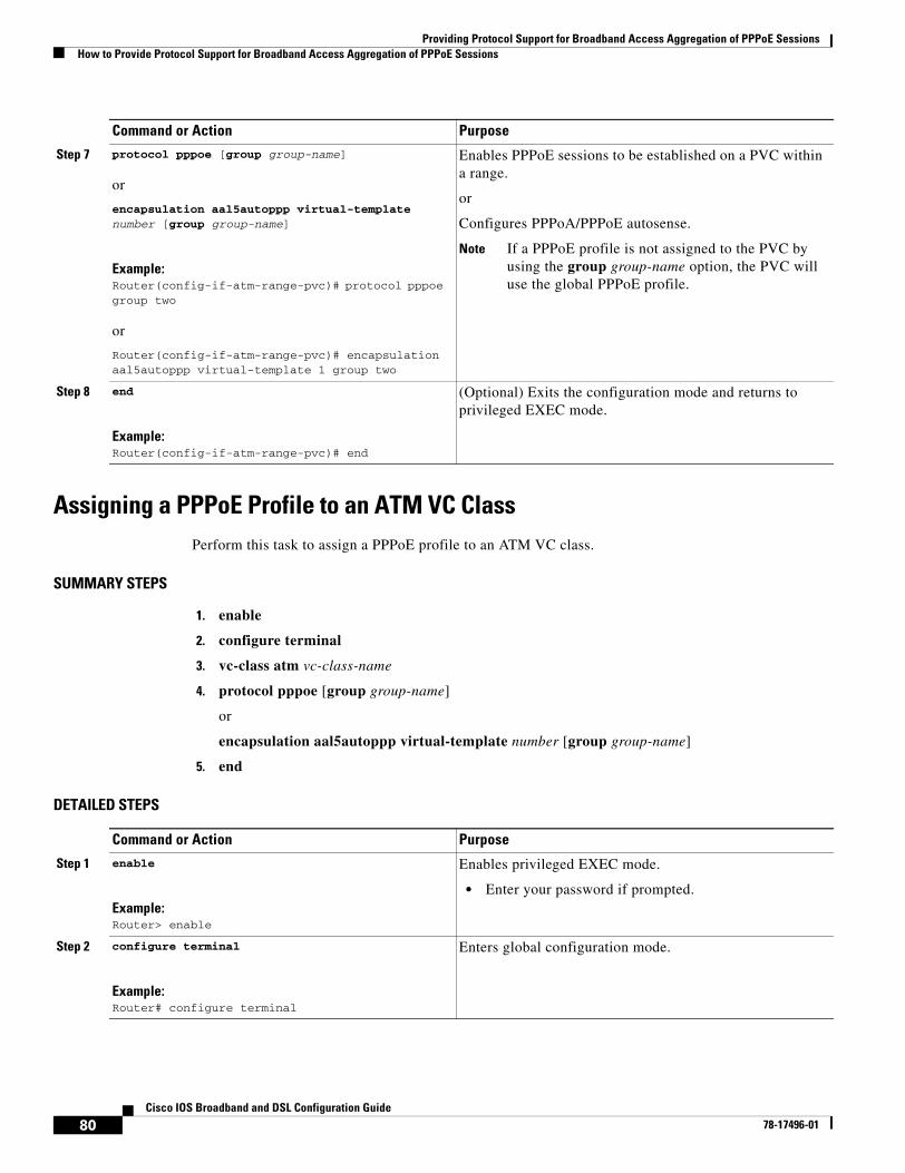
Providing Protocol Support for Broadband Access Aggregation of PPPoE SessionsHow to Provide Protocol Support for Broadband Access Aggregation of PPPoE Sessions
80Cisco IOS Broadband and DSL Configuration Guide
78-17496-01
Assigning a PPPoE Profile to an ATM VC Class Perform this task to assign a PPPoE profile to an ATM VC class.
SUMMARY STEPS
1. enable
2. configure terminal
3. vc-class atm vc-class-name
4. protocol pppoe [group group-name]
or
encapsulation aal5autoppp virtual-template number [group group-name]
5. end
DETAILED STEPS
Step 7 protocol pppoe [group group-name]
or
encapsulation aal5autoppp virtual-template number [group group-name]
Example:Router(config-if-atm-range-pvc)# protocol pppoe group two
or
Router(config-if-atm-range-pvc)# encapsulation aal5autoppp virtual-template 1 group two
Enables PPPoE sessions to be established on a PVC within a range.
or
Configures PPPoA/PPPoE autosense.
Note If a PPPoE profile is not assigned to the PVC by using the group group-name option, the PVC will use the global PPPoE profile.
Step 8 end
Example:Router(config-if-atm-range-pvc)# end
(Optional) Exits the configuration mode and returns to privileged EXEC mode.
Command or Action Purpose
Command or Action Purpose
Step 1 enable
Example:Router> enable
Enables privileged EXEC mode.
• Enter your password if prompted.
Step 2 configure terminal
Example:Router# configure terminal
Enters global configuration mode.
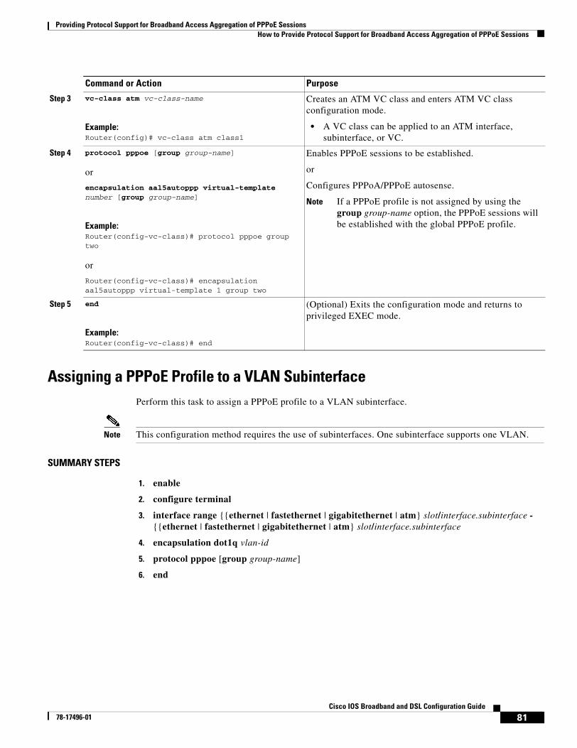
Providing Protocol Support for Broadband Access Aggregation of PPPoE SessionsHow to Provide Protocol Support for Broadband Access Aggregation of PPPoE Sessions
81Cisco IOS Broadband and DSL Configuration Guide
78-17496-01
Assigning a PPPoE Profile to a VLAN SubinterfacePerform this task to assign a PPPoE profile to a VLAN subinterface.
Note This configuration method requires the use of subinterfaces. One subinterface supports one VLAN.
SUMMARY STEPS
1. enable
2. configure terminal
3. interface range {{ethernet | fastethernet | gigabitethernet | atm} slot/interface.subinterface - {{ethernet | fastethernet | gigabitethernet | atm} slot/interface.subinterface
4. encapsulation dot1q vlan-id
5. protocol pppoe [group group-name]
6. end
Step 3 vc-class atm vc-class-name
Example:Router(config)# vc-class atm class1
Creates an ATM VC class and enters ATM VC class configuration mode.
• A VC class can be applied to an ATM interface, subinterface, or VC.
Step 4 protocol pppoe [group group-name]
or
encapsulation aal5autoppp virtual-template number [group group-name]
Example:Router(config-vc-class)# protocol pppoe group two
or
Router(config-vc-class)# encapsulation aal5autoppp virtual-template 1 group two
Enables PPPoE sessions to be established.
or
Configures PPPoA/PPPoE autosense.
Note If a PPPoE profile is not assigned by using the group group-name option, the PPPoE sessions will be established with the global PPPoE profile.
Step 5 end
Example:Router(config-vc-class)# end
(Optional) Exits the configuration mode and returns to privileged EXEC mode.
Command or Action Purpose
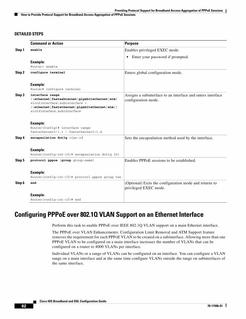
Providing Protocol Support for Broadband Access Aggregation of PPPoE SessionsHow to Provide Protocol Support for Broadband Access Aggregation of PPPoE Sessions
82Cisco IOS Broadband and DSL Configuration Guide
78-17496-01
DETAILED STEPS
Configuring PPPoE over 802.1Q VLAN Support on an Ethernet Interface Perform this task to enable PPPoE over IEEE 802.1Q VLAN support on a main Ethernet interface.
The PPPoE over VLAN Enhancements: Configuration Limit Removal and ATM Support feature removes the requirement for each PPPoE VLAN to be created on a subinterface. Allowing more than one PPPoE VLAN to be configured on a main interface increases the number of VLANs that can be configured on a router to 4000 VLANs per interface.
Individual VLANs or a range of VLANs can be configured on an interface. You can configure a VLAN range on a main interface and at the same time configure VLANs outside the range on subinterfaces of the same interface.
Command or Action Purpose
Step 1 enable
Example:Router> enable
Enables privileged EXEC mode.
• Enter your password if prompted.
Step 2 configure terminal
Example:Router# configure terminal
Enters global configuration mode.
Step 3 interface range {{ethernet|fasteahternet|gigabitethernet|atm} slot/interface.subinterface - {{ethernet|fastethernet|gigabitethernet|atm]} slot/inteface.subinterface
Example:Router(Config)# interface range fastethernet5/1.1 - fastethernet5/1.4
Assigns a subinterface to an interface and enters interface configuration mode.
Step 4 encapsulation dotlq vlan-id
Example:Router(config-int-if)# encapsulation dot1q 301
Sets the encapsulation method used by the interface.
Step 5 protocol pppoe [group group-name}
Example:Router(config-int-if)# protocol pppoe group two
Enables PPPoE sessions to be established.
Step 6 end
Example:Router(config-int-if)# end
(Optional) Exits the configuration mode and returns to privileged EXEC mode.
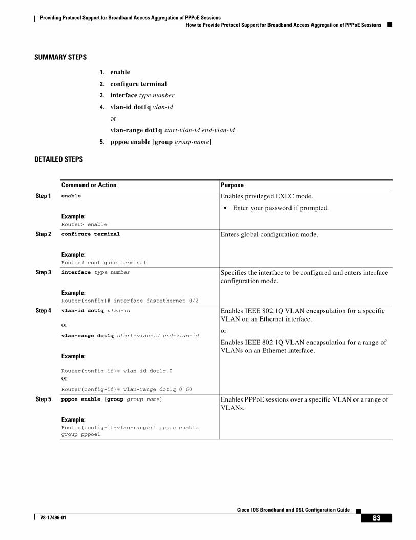
Providing Protocol Support for Broadband Access Aggregation of PPPoE SessionsHow to Provide Protocol Support for Broadband Access Aggregation of PPPoE Sessions
83Cisco IOS Broadband and DSL Configuration Guide
78-17496-01
SUMMARY STEPS
1. enable
2. configure terminal
3. interface type number
4. vlan-id dot1q vlan-id
or
vlan-range dot1q start-vlan-id end-vlan-id
5. pppoe enable [group group-name]
DETAILED STEPS
Command or Action Purpose
Step 1 enable
Example:Router> enable
Enables privileged EXEC mode.
• Enter your password if prompted.
Step 2 configure terminal
Example:Router# configure terminal
Enters global configuration mode.
Step 3 interface type number
Example:Router(config)# interface fastethernet 0/2
Specifies the interface to be configured and enters interface configuration mode.
Step 4 vlan-id dot1q vlan-id
or
vlan-range dot1q start-vlan-id end-vlan-id
Example:
Router(config-if)# vlan-id dot1q 0
or
Router(config-if)# vlan-range dot1q 0 60
Enables IEEE 802.1Q VLAN encapsulation for a specific VLAN on an Ethernet interface.
or
Enables IEEE 802.1Q VLAN encapsulation for a range of VLANs on an Ethernet interface.
Step 5 pppoe enable [group group-name]
Example:Router(config-if-vlan-range)# pppoe enable group pppoe1
Enables PPPoE sessions over a specific VLAN or a range of VLANs.
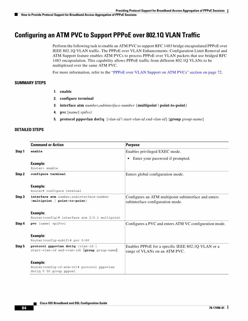
Providing Protocol Support for Broadband Access Aggregation of PPPoE SessionsHow to Provide Protocol Support for Broadband Access Aggregation of PPPoE Sessions
84Cisco IOS Broadband and DSL Configuration Guide
78-17496-01
Configuring an ATM PVC to Support PPPoE over 802.1Q VLAN TrafficPerform the following task to enable an ATM PVC to support RFC 1483 bridge encapsulated PPPoE over IEEE 802.1Q VLAN traffic. The PPPoE over VLAN Enhancements: Configuration Limit Removal and ATM Support feature enables ATM PVCs to process PPPoE over VLAN packets that use bridged RFC 1483 encapsulation. This capability allows PPPoE traffic from different 802.1Q VLANs to be multiplexed over the same ATM PVC.
For more information, refer to the “PPPoE over VLAN Support on ATM PVCs” section on page 72.
SUMMARY STEPS
1. enable
2. configure terminal
3. interface atm number.subinterface-number {multipoint | point-to-point}
4. pvc [name] vpi/vci
5. protocol pppovlan dot1q {vlan-id | start-vlan-id end-vlan-id} [group group-name]
DETAILED STEPS
Command or Action Purpose
Step 1 enable
Example:Router> enable
Enables privileged EXEC mode.
• Enter your password if prompted.
Step 2 configure terminal
Example:Router# configure terminal
Enters global configuration mode.
Step 3 interface atm number.subinterface-number {multipoint | point-to-point}
Example:Router(config)# interface atm 2/0.1 multipoint
Configures an ATM multipoint subinterface and enters subinterface configuration mode.
Step 4 pvc [name] vpi/vci
Example:Router(config-subif)# pvc 0/60
Configures a PVC and enters ATM VC configuration mode.
Step 5 protocol pppovlan dot1q {vlan-id | start-vlan-id end-vlan-id} [group group-name]
Example:Router(config-if-atm-vc)# protocol pppovlan dot1q 0 50 group pppoe1
Enables PPPoE for a specific IEEE 802.1Q VLAN or a range of VLANs on an ATM PVC.
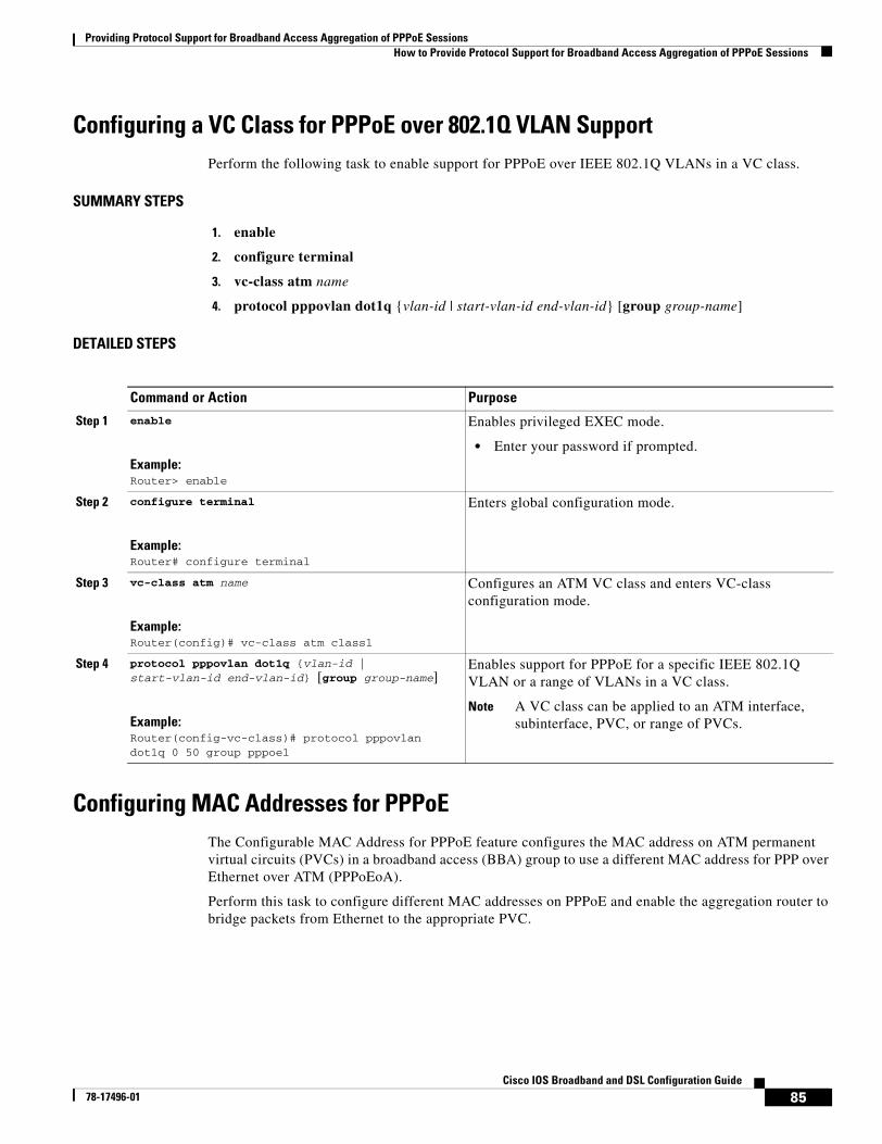
Providing Protocol Support for Broadband Access Aggregation of PPPoE SessionsHow to Provide Protocol Support for Broadband Access Aggregation of PPPoE Sessions
85Cisco IOS Broadband and DSL Configuration Guide
78-17496-01
Configuring a VC Class for PPPoE over 802.1Q VLAN Support Perform the following task to enable support for PPPoE over IEEE 802.1Q VLANs in a VC class.
SUMMARY STEPS
1. enable
2. configure terminal
3. vc-class atm name
4. protocol pppovlan dot1q {vlan-id | start-vlan-id end-vlan-id} [group group-name]
DETAILED STEPS
Configuring MAC Addresses for PPPoEThe Configurable MAC Address for PPPoE feature configures the MAC address on ATM permanent virtual circuits (PVCs) in a broadband access (BBA) group to use a different MAC address for PPP over Ethernet over ATM (PPPoEoA).
Perform this task to configure different MAC addresses on PPPoE and enable the aggregation router to bridge packets from Ethernet to the appropriate PVC.
Command or Action Purpose
Step 1 enable
Example:Router> enable
Enables privileged EXEC mode.
• Enter your password if prompted.
Step 2 configure terminal
Example:Router# configure terminal
Enters global configuration mode.
Step 3 vc-class atm name
Example:Router(config)# vc-class atm class1
Configures an ATM VC class and enters VC-class configuration mode.
Step 4 protocol pppovlan dot1q {vlan-id | start-vlan-id end-vlan-id} [group group-name]
Example:Router(config-vc-class)# protocol pppovlan dot1q 0 50 group pppoe1
Enables support for PPPoE for a specific IEEE 802.1Q VLAN or a range of VLANs in a VC class.
Note A VC class can be applied to an ATM interface, subinterface, PVC, or range of PVCs.
Providing Protocol Support for Broadband Access Aggregation of PPPoE SessionsHow to Provide Protocol Support for Broadband Access Aggregation of PPPoE Sessions
86Cisco IOS Broadband and DSL Configuration Guide
78-17496-01
Prerequisites for Configurable MAC Address for PPPoE
A BBA group profile should already exist. The BBA group commands are used to configure broadband access on aggregation and client devices that use PPP over ATM (PPPoA), PPP over Ethernet (PPPoE), and RBE.
Perform this task configure different MAC addresses on PPPoE and enable the aggregation router to bridge packets from Ethernet to the appropriate PVC.
To configure the configurable MAC Address for PPPoE feature, you should understand the following concepts:
• MAC Address for PPPoEoA, page 86
• Benefits of the Configurable MAC Address for PPPoE Feature, page 86
MAC Address for PPPoEoA
To prevent customers from experiencing unexpected behavior resulting from a system change, any change in the usage of MAC addresses will not happen unless it is explicitly configured.
Except for using a different MAC address, this feature does not change the way PPPoE works. This change is limited to ATM interfaces only—specifically, PPPoEoA—and will not be applied to other interfaces where PPPoE is operated on interfaces such as Ethernet, Ethernet VLAN, and Data-over-Cable Service Interface Specifications (DOCSIS). Changing the PPPoE MAC address on those interfaces, which are broadcast in nature, requires placing the interface in promiscuous mode, thereby affecting the performance of the router because the router software has to receive all Ethernet frames and then discard unneeded frames in the software driver.
This feature is disabled by default and applies to all PPPoE sessions on an ATM PVC interface configured in a BBA group.
When PPPoE and routed bridge encapsulation (RBE) are configured on two separate PVCs on the same digital subscriber line (DSL), the customer premises equipment (CPE) acts like a pure bridge, bridging from Ethernet to the two ATM PVCs on the DSL. Because the CPE acts as a bridge, and because the aggregation router uses the same MAC address for both PPPoE and RBE, the CPE will not be able to bridge packets to the correct PVC. The solution is to have a different MAC address for PPPoE only. The MAC address can be either configured or selected automatically.
The MAC address of the PPPoEoA session is either the value configured on the ATM interface using the mac-address command or the burned-in MAC address if a MAC address is not already configured on the ATM interface. This functionality is effective only when neither autoselect nor a MAC address is specified on a BBA group.
If the MAC address is specified on a BBA group, all PPPoEoA sessions use the MAC address specified on the BBA group, which is applied on the virtual circuit (VC).
If the MAC address is selected automatically, 7 is added to the MAC address of the ATM interface.
Benefits of the Configurable MAC Address for PPPoE Feature
Because the Cisco IOS aggregation routers use the interface MAC address as the source MAC address for all broadband aggregation protocols on that interface, this feature solves problems that may occur when both RBE and PPPoE are deployed on the same ATM interface.
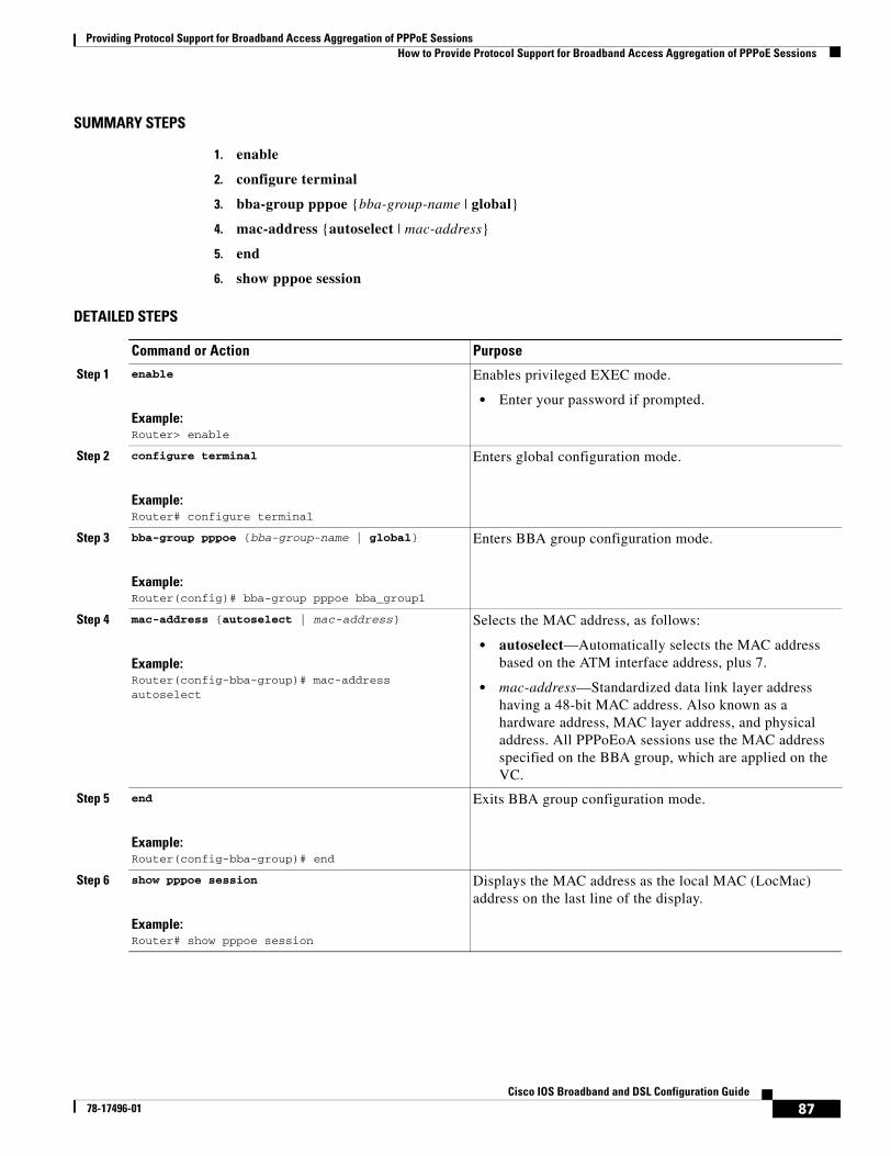
Providing Protocol Support for Broadband Access Aggregation of PPPoE SessionsHow to Provide Protocol Support for Broadband Access Aggregation of PPPoE Sessions
87Cisco IOS Broadband and DSL Configuration Guide
78-17496-01
SUMMARY STEPS
1. enable
2. configure terminal
3. bba-group pppoe {bba-group-name | global}
4. mac-address {autoselect | mac-address}
5. end
6. show pppoe session
DETAILED STEPS
Command or Action Purpose
Step 1 enable
Example:Router> enable
Enables privileged EXEC mode.
• Enter your password if prompted.
Step 2 configure terminal
Example:Router# configure terminal
Enters global configuration mode.
Step 3 bba-group pppoe {bba-group-name | global}
Example:Router(config)# bba-group pppoe bba_group1
Enters BBA group configuration mode.
Step 4 mac-address {autoselect | mac-address}
Example:Router(config-bba-group)# mac-address autoselect
Selects the MAC address, as follows:
• autoselect—Automatically selects the MAC address based on the ATM interface address, plus 7.
• mac-address—Standardized data link layer address having a 48-bit MAC address. Also known as a hardware address, MAC layer address, and physical address. All PPPoEoA sessions use the MAC address specified on the BBA group, which are applied on the VC.
Step 5 end
Example:Router(config-bba-group)# end
Exits BBA group configuration mode.
Step 6 show pppoe session
Example:Router# show pppoe session
Displays the MAC address as the local MAC (LocMac) address on the last line of the display.
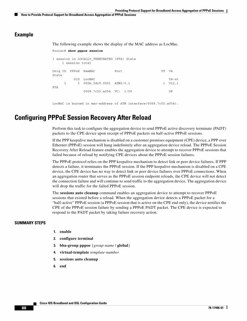
Providing Protocol Support for Broadband Access Aggregation of PPPoE SessionsHow to Provide Protocol Support for Broadband Access Aggregation of PPPoE Sessions
88Cisco IOS Broadband and DSL Configuration Guide
78-17496-01
Example
The following example shows the display of the MAC address as LocMac.
Router# show pppoe session
1 session in LOCALLY_TERMINATED (PTA) State 1 session total
Uniq ID PPPoE RemMAC Port VT VAState SID LocMAC VA-st 3 3 000b.fdc9.0001 ATM3/0.1 1 Vi2.1PTA 0008.7c55.a054 VC: 1/50 UP
LocMAC is burned in mac-address of ATM interface(0008.7c55.a054).
Configuring PPPoE Session Recovery After ReloadPerform this task to configure the aggregation device to send PPPoE active discovery terminate (PADT) packets to the CPE device upon receipt of PPPoE packets on half-active PPPoE sessions.
If the PPP keepalive mechanism is disabled on a customer premises equipment (CPE) device, a PPP over Ethernet (PPPoE) session will hang indefinitely after an aggregation device reload. The PPPoE Session Recovery After Reload feature enables the aggregation device to attempt to recover PPPoE sessions that failed because of reload by notifying CPE devices about the PPPoE session failures.
The PPPoE protocol relies on the PPP keepalive mechanism to detect link or peer device failures. If PPP detects a failure, it terminates the PPPoE session. If the PPP keepalive mechanism is disabled on a CPE device, the CPE device has no way to detect link or peer device failures over PPPoE connections. When an aggregation router that serves as the PPPoE session endpoint reloads, the CPE device will not detect the connection failure and will continue to send traffic to the aggregation device. The aggregation device will drop the traffic for the failed PPPoE session.
The sessions auto cleanup command enables an aggregation device to attempt to recover PPPoE sessions that existed before a reload. When the aggregation device detects a PPPoE packet for a “half-active” PPPoE session (a PPPoE session that is active on the CPE end only), the device notifies the CPE of the PPPoE session failure by sending a PPPoE PADT packet. The CPE device is expected to respond to the PADT packet by taking failure recovery action.
SUMMARY STEPS
1. enable
2. configure terminal
3. bba-group pppoe {group-name | global}
4. virtual-template template-number
5. sessions auto cleanup
6. end
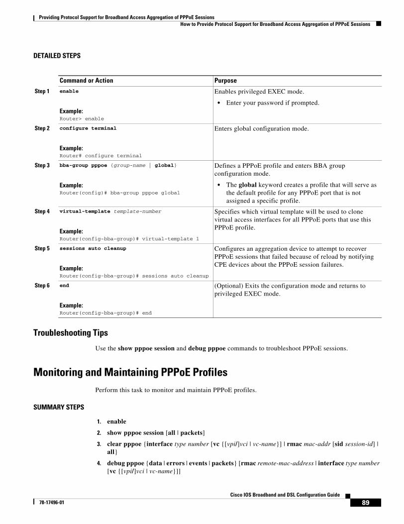
Providing Protocol Support for Broadband Access Aggregation of PPPoE SessionsHow to Provide Protocol Support for Broadband Access Aggregation of PPPoE Sessions
89Cisco IOS Broadband and DSL Configuration Guide
78-17496-01
DETAILED STEPS
Troubleshooting Tips
Use the show pppoe session and debug pppoe commands to troubleshoot PPPoE sessions.
Monitoring and Maintaining PPPoE Profiles Perform this task to monitor and maintain PPPoE profiles.
SUMMARY STEPS
1. enable
2. show pppoe session [all | packets]
3. clear pppoe {interface type number [vc {[vpi/]vci | vc-name}] | rmac mac-addr [sid session-id] | all}
4. debug pppoe {data | errors | events | packets} [rmac remote-mac-address | interface type number [vc {[vpi/]vci | vc-name}]]
Command or Action Purpose
Step 1 enable
Example:Router> enable
Enables privileged EXEC mode.
• Enter your password if prompted.
Step 2 configure terminal
Example:Router# configure terminal
Enters global configuration mode.
Step 3 bba-group pppoe {group-name | global}
Example:Router(config)# bba-group pppoe global
Defines a PPPoE profile and enters BBA group configuration mode.
• The global keyword creates a profile that will serve as the default profile for any PPPoE port that is not assigned a specific profile.
Step 4 virtual-template template-number
Example:Router(config-bba-group)# virtual-template 1
Specifies which virtual template will be used to clone virtual access interfaces for all PPPoE ports that use this PPPoE profile.
Step 5 sessions auto cleanup
Example:Router(config-bba-group)# sessions auto cleanup
Configures an aggregation device to attempt to recover PPPoE sessions that failed because of reload by notifying CPE devices about the PPPoE session failures.
Step 6 end
Example:Router(config-bba-group)# end
(Optional) Exits the configuration mode and returns to privileged EXEC mode.
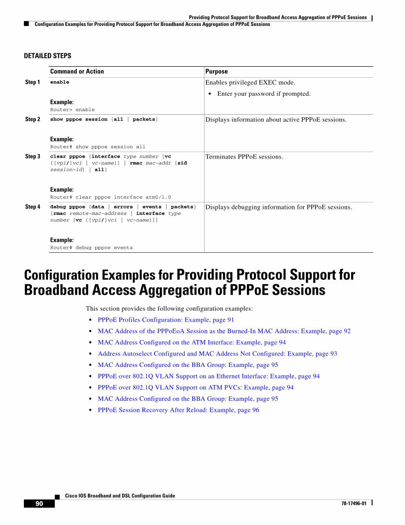
Providing Protocol Support for Broadband Access Aggregation of PPPoE SessionsConfiguration Examples for Providing Protocol Support for Broadband Access Aggregation of PPPoE Sessions
90Cisco IOS Broadband and DSL Configuration Guide
78-17496-01
DETAILED STEPS
Configuration Examples for Providing Protocol Support for Broadband Access Aggregation of PPPoE Sessions
This section provides the following configuration examples:
• PPPoE Profiles Configuration: Example, page 91
• MAC Address of the PPPoEoA Session as the Burned-In MAC Address: Example, page 92
• MAC Address Configured on the ATM Interface: Example, page 94
• Address Autoselect Configured and MAC Address Not Configured: Example, page 93
• MAC Address Configured on the BBA Group: Example, page 95
• PPPoE over 802.1Q VLAN Support on an Ethernet Interface: Example, page 94
• PPPoE over 802.1Q VLAN Support on ATM PVCs: Example, page 94
• MAC Address Configured on the BBA Group: Example, page 95
• PPPoE Session Recovery After Reload: Example, page 96
Command or Action Purpose
Step 1 enable
Example:Router> enable
Enables privileged EXEC mode.
• Enter your password if prompted.
Step 2 show pppoe session [all | packets]
Example:Router# show pppoe session all
Displays information about active PPPoE sessions.
Step 3 clear pppoe {interface type number [vc {[vpi/]vci | vc-name}] | rmac mac-addr [sid session-id] | all}
Example:Router# clear pppoe interface atm0/1.0
Terminates PPPoE sessions.
Step 4 debug pppoe {data | errors | events | packets} [rmac remote-mac-address | interface type number [vc {[vpi/]vci | vc-name}]]
Example:Router# debug pppoe events
Displays debugging information for PPPoE sessions.
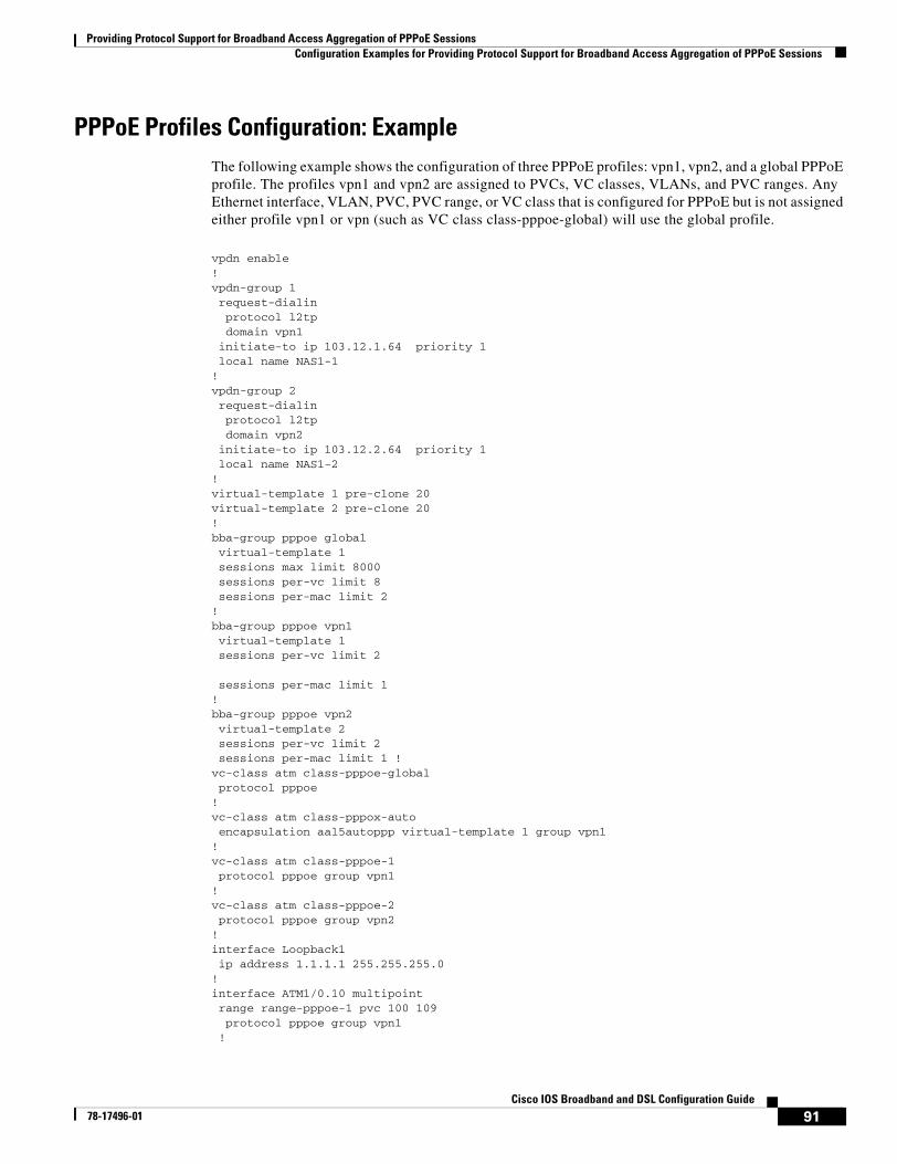
Providing Protocol Support for Broadband Access Aggregation of PPPoE SessionsConfiguration Examples for Providing Protocol Support for Broadband Access Aggregation of PPPoE Sessions
91Cisco IOS Broadband and DSL Configuration Guide
78-17496-01
PPPoE Profiles Configuration: Example The following example shows the configuration of three PPPoE profiles: vpn1, vpn2, and a global PPPoE profile. The profiles vpn1 and vpn2 are assigned to PVCs, VC classes, VLANs, and PVC ranges. Any Ethernet interface, VLAN, PVC, PVC range, or VC class that is configured for PPPoE but is not assigned either profile vpn1 or vpn (such as VC class class-pppoe-global) will use the global profile.
vpdn enable ! vpdn-group 1 request-dialin protocol l2tp domain vpn1 initiate-to ip 103.12.1.64 priority 1 local name NAS1-1 ! vpdn-group 2 request-dialin protocol l2tp domain vpn2 initiate-to ip 103.12.2.64 priority 1 local name NAS1-2 ! virtual-template 1 pre-clone 20 virtual-template 2 pre-clone 20 ! bba-group pppoe global virtual-template 1 sessions max limit 8000 sessions per-vc limit 8 sessions per-mac limit 2 ! bba-group pppoe vpn1 virtual-template 1 sessions per-vc limit 2
sessions per-mac limit 1 ! bba-group pppoe vpn2 virtual-template 2 sessions per-vc limit 2 sessions per-mac limit 1 ! vc-class atm class-pppoe-global protocol pppoe ! vc-class atm class-pppox-auto encapsulation aal5autoppp virtual-template 1 group vpn1 ! vc-class atm class-pppoe-1 protocol pppoe group vpn1 ! vc-class atm class-pppoe-2 protocol pppoe group vpn2 ! interface Loopback1 ip address 1.1.1.1 255.255.255.0 ! interface ATM1/0.10 multipoint range range-pppoe-1 pvc 100 109 protocol pppoe group vpn1 !
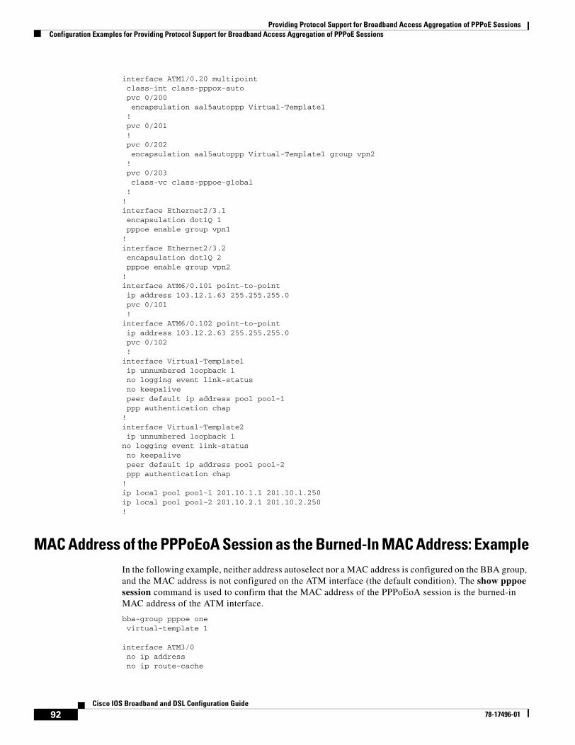
Providing Protocol Support for Broadband Access Aggregation of PPPoE SessionsConfiguration Examples for Providing Protocol Support for Broadband Access Aggregation of PPPoE Sessions
92Cisco IOS Broadband and DSL Configuration Guide
78-17496-01
interface ATM1/0.20 multipoint class-int class-pppox-auto pvc 0/200 encapsulation aal5autoppp Virtual-Template1 ! pvc 0/201 ! pvc 0/202 encapsulation aal5autoppp Virtual-Template1 group vpn2 ! pvc 0/203 class-vc class-pppoe-global ! ! interface Ethernet2/3.1 encapsulation dot1Q 1 pppoe enable group vpn1 ! interface Ethernet2/3.2 encapsulation dot1Q 2 pppoe enable group vpn2 ! interface ATM6/0.101 point-to-point ip address 103.12.1.63 255.255.255.0 pvc 0/101 ! interface ATM6/0.102 point-to-point ip address 103.12.2.63 255.255.255.0 pvc 0/102 ! interface Virtual-Template1 ip unnumbered loopback 1 no logging event link-status no keepalive peer default ip address pool pool-1 ppp authentication chap ! interface Virtual-Template2 ip unnumbered loopback 1 no logging event link-status no keepalive peer default ip address pool pool-2 ppp authentication chap ! ip local pool pool-1 201.10.1.1 201.10.1.250 ip local pool pool-2 201.10.2.1 201.10.2.250 !
MAC Address of the PPPoEoA Session as the Burned-In MAC Address: ExampleIn the following example, neither address autoselect nor a MAC address is configured on the BBA group, and the MAC address is not configured on the ATM interface (the default condition). The show pppoe session command is used to confirm that the MAC address of the PPPoEoA session is the burned-in MAC address of the ATM interface.
bba-group pppoe one virtual-template 1
interface ATM3/0 no ip address no ip route-cache
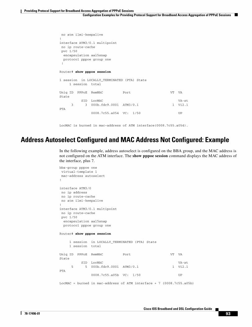
Providing Protocol Support for Broadband Access Aggregation of PPPoE SessionsConfiguration Examples for Providing Protocol Support for Broadband Access Aggregation of PPPoE Sessions
93Cisco IOS Broadband and DSL Configuration Guide
78-17496-01
no atm ilmi-keepalive!interface ATM3/0.1 multipoint no ip route-cache pvc 1/50 encapsulation aal5snap protocol pppoe group one !
Router# show pppoe session
1 session in LOCALLY_TERMINATED (PTA) State 1 session total
Uniq ID PPPoE RemMAC Port VT VAState SID LocMAC VA-st 3 3 000b.fdc9.0001 ATM3/0.1 1 Vi2.1PTA 0008.7c55.a054 VC: 1/50 UP
LocMAC is burned in mac-address of ATM interface(0008.7c55.a054).
Address Autoselect Configured and MAC Address Not Configured: ExampleIn the following example, address autoselect is configured on the BBA group, and the MAC address is not configured on the ATM interface. The show pppoe session command displays the MAC address of the interface, plus 7.
bba-group pppoe one virtual-template 1 mac-address autoselect!
interface ATM3/0 no ip address no ip route-cache no atm ilmi-keepalive!interface ATM3/0.1 multipoint no ip route-cache pvc 1/50 encapsulation aal5snap protocol pppoe group one
Router# show pppoe session
1 session in LOCALLY_TERMINATED (PTA) State 1 session total
Uniq ID PPPoE RemMAC Port VT VAState SID LocMAC VA-st 5 5 000b.fdc9.0001 ATM3/0.1 1 Vi2.1PTA 0008.7c55.a05b VC: 1/50 UP
LocMAC = burned in mac-address of ATM interface + 7 (0008.7c55.a05b)
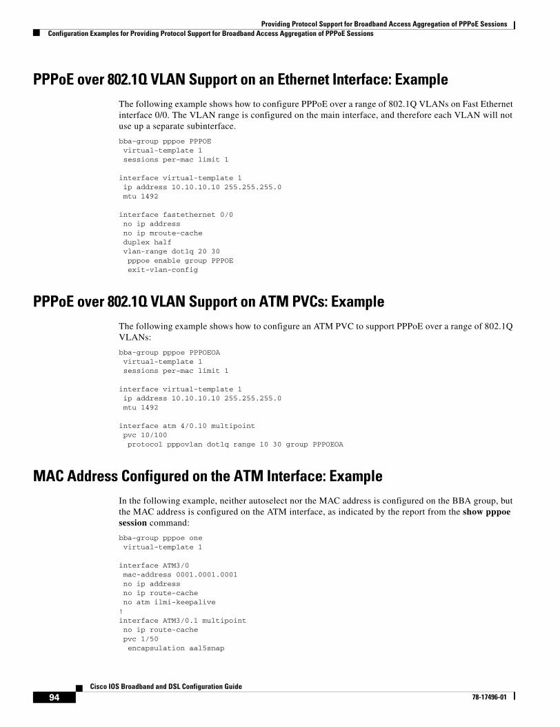
Providing Protocol Support for Broadband Access Aggregation of PPPoE SessionsConfiguration Examples for Providing Protocol Support for Broadband Access Aggregation of PPPoE Sessions
94Cisco IOS Broadband and DSL Configuration Guide
78-17496-01
PPPoE over 802.1Q VLAN Support on an Ethernet Interface: ExampleThe following example shows how to configure PPPoE over a range of 802.1Q VLANs on Fast Ethernet interface 0/0. The VLAN range is configured on the main interface, and therefore each VLAN will not use up a separate subinterface.
bba-group pppoe PPPOE virtual-template 1 sessions per-mac limit 1
interface virtual-template 1 ip address 10.10.10.10 255.255.255.0 mtu 1492
interface fastethernet 0/0no ip address no ip mroute-cache duplex half vlan-range dot1q 20 30 pppoe enable group PPPOE exit-vlan-config
PPPoE over 802.1Q VLAN Support on ATM PVCs: ExampleThe following example shows how to configure an ATM PVC to support PPPoE over a range of 802.1Q VLANs:
bba-group pppoe PPPOEOAvirtual-template 1 sessions per-mac limit 1
interface virtual-template 1 ip address 10.10.10.10 255.255.255.0 mtu 1492
interface atm 4/0.10 multipoint pvc 10/100 protocol pppovlan dot1q range 10 30 group PPPOEOA
MAC Address Configured on the ATM Interface: ExampleIn the following example, neither autoselect nor the MAC address is configured on the BBA group, but the MAC address is configured on the ATM interface, as indicated by the report from the show pppoe session command:
bba-group pppoe one virtual-template 1
interface ATM3/0 mac-address 0001.0001.0001 no ip address no ip route-cache no atm ilmi-keepalive!interface ATM3/0.1 multipoint no ip route-cache pvc 1/50 encapsulation aal5snap
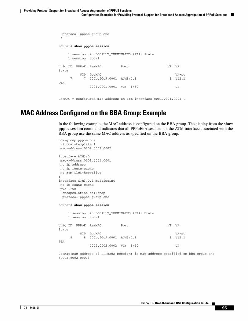
Providing Protocol Support for Broadband Access Aggregation of PPPoE SessionsConfiguration Examples for Providing Protocol Support for Broadband Access Aggregation of PPPoE Sessions
95Cisco IOS Broadband and DSL Configuration Guide
78-17496-01
protocol pppoe group one !
Router# show pppoe session
1 session in LOCALLY_TERMINATED (PTA) State 1 session total
Uniq ID PPPoE RemMAC Port VT VAState SID LocMAC VA-st 7 7 000b.fdc9.0001 ATM3/0.1 1 Vi2.1PTA 0001.0001.0001 VC: 1/50 UP
LocMAC = configured mac-address on atm interface(0001.0001.0001).
MAC Address Configured on the BBA Group: ExampleIn the following example, the MAC address is configured on the BBA group. The display from the show pppoe session command indicates that all PPPoEoA sessions on the ATM interface associated with the BBA group use the same MAC address as specified on the BBA group.
bba-group pppoe one virtual-template 1 mac-address 0002.0002.0002
interface ATM3/0 mac-address 0001.0001.0001 no ip address no ip route-cache no atm ilmi-keepalive!interface ATM3/0.1 multipoint no ip route-cache pvc 1/50 encapsulation aal5snap protocol pppoe group one
Router# show pppoe session
1 session in LOCALLY_TERMINATED (PTA) State 1 session total
Uniq ID PPPoE RemMAC Port VT VAState SID LocMAC VA-st 8 8 000b.fdc9.0001 ATM3/0.1 1 Vi2.1PTA 0002.0002.0002 VC: 1/50 UP
LocMac(Mac address of PPPoEoA session) is mac-address specified on bba-group one (0002.0002.0002)
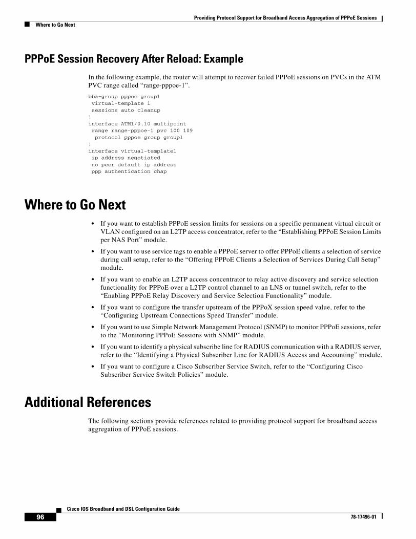
Providing Protocol Support for Broadband Access Aggregation of PPPoE SessionsWhere to Go Next
96Cisco IOS Broadband and DSL Configuration Guide
78-17496-01
PPPoE Session Recovery After Reload: ExampleIn the following example, the router will attempt to recover failed PPPoE sessions on PVCs in the ATM PVC range called “range-pppoe-1”.
bba-group pppoe group1 virtual-template 1 sessions auto cleanup
! interface ATM1/0.10 multipoint range range-pppoe-1 pvc 100 109 protocol pppoe group group1
! interface virtual-template1 ip address negotiated no peer default ip address ppp authentication chap
Where to Go Next• If you want to establish PPPoE session limits for sessions on a specific permanent virtual circuit or
VLAN configured on an L2TP access concentrator, refer to the “Establishing PPPoE Session Limits per NAS Port” module.
• If you want to use service tags to enable a PPPoE server to offer PPPoE clients a selection of service during call setup, refer to the “Offering PPPoE Clients a Selection of Services During Call Setup” module.
• If you want to enable an L2TP access concentrator to relay active discovery and service selection functionality for PPPoE over a L2TP control channel to an LNS or tunnel switch, refer to the “Enabling PPPoE Relay Discovery and Service Selection Functionality” module.
• If you want to configure the transfer upstream of the PPPoX session speed value, refer to the “Configuring Upstream Connections Speed Transfer” module.
• If you want to use Simple Network Management Protocol (SNMP) to monitor PPPoE sessions, refer to the “Monitoring PPPoE Sessions with SNMP” module.
• If you want to identify a physical subscribe line for RADIUS communication with a RADIUS server, refer to the “Identifying a Physical Subscriber Line for RADIUS Access and Accounting” module.
• If you want to configure a Cisco Subscriber Service Switch, refer to the “Configuring Cisco Subscriber Service Switch Policies” module.
Additional ReferencesThe following sections provide references related to providing protocol support for broadband access aggregation of PPPoE sessions.
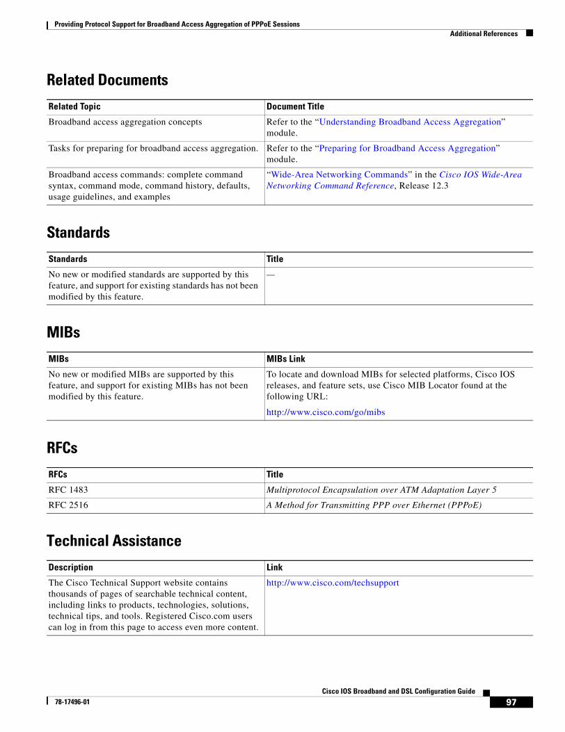
Providing Protocol Support for Broadband Access Aggregation of PPPoE SessionsAdditional References
97Cisco IOS Broadband and DSL Configuration Guide
78-17496-01
Related Documents
Standards
MIBs
RFCs
Technical Assistance
Related Topic Document Title
Broadband access aggregation concepts Refer to the “Understanding Broadband Access Aggregation” module.
Tasks for preparing for broadband access aggregation. Refer to the “Preparing for Broadband Access Aggregation” module.
Broadband access commands: complete command syntax, command mode, command history, defaults, usage guidelines, and examples
“Wide-Area Networking Commands” in the Cisco IOS Wide-Area Networking Command Reference, Release 12.3
Standards Title
No new or modified standards are supported by this feature, and support for existing standards has not been modified by this feature.
—
MIBs MIBs Link
No new or modified MIBs are supported by this feature, and support for existing MIBs has not been modified by this feature.
To locate and download MIBs for selected platforms, Cisco IOS releases, and feature sets, use Cisco MIB Locator found at the following URL:
http://www.cisco.com/go/mibs
RFCs Title
RFC 1483 Multiprotocol Encapsulation over ATM Adaptation Layer 5
RFC 2516 A Method for Transmitting PPP over Ethernet (PPPoE)
Description Link
The Cisco Technical Support website contains thousands of pages of searchable technical content, including links to products, technologies, solutions, technical tips, and tools. Registered Cisco.com users can log in from this page to access even more content.
http://www.cisco.com/techsupport
http://www.cisco.com/univercd/cc/td/doc/product/software/ios123/123tcr/123twr/wan_a1gt.htm#wp1056981
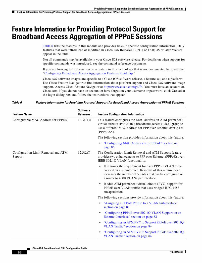
Providing Protocol Support for Broadband Access Aggregation of PPPoE SessionsFeature Information for Providing Protocol Support for Broadband Access Aggregation of PPPoE Sessions
98Cisco IOS Broadband and DSL Configuration Guide
78-17496-01
Feature Information for Providing Protocol Support for Broadband Access Aggregation of PPPoE Sessions
Table 6 lists the features in this module and provides links to specific configuration information. Only features that were introduced or modified in Cisco IOS Releases 12.2(1) or 12.0(3)S or later releases appear in the table.
Not all commands may be available in your Cisco IOS software release. For details on when support for specific commands was introduced, see the command reference documents.
If you are looking for information on a feature in this technology that is not documented here, see the “Configuring Broadband Access Aggregation Features Roadmap.”
Cisco IOS software images are specific to a Cisco IOS software release, a feature set, and a platform. Use Cisco Feature Navigator to find information about platform support and Cisco IOS software image support. Access Cisco Feature Navigator at http://www.cisco.com/go/fn. You must have an account on Cisco.com. If you do not have an account or have forgotten your username or password, click Cancel at the login dialog box and follow the instructions that appear.
Table 6 Feature Information for Providing Protocol Support for Broadband Access Aggregation of PPPoE Sessions
Feature NameSoftware Releases Feature Configuration Information
Configurable MAC Address for PPPoE 12.3(11)T This feature configures the MAC address on ATM permanent virtual circuits (PVCs) in a broadband access (BBA) group to use a different MAC address for PPP over Ethernet over ATM (PPPoEoA).
The following section provides information about this feature:
• “Configuring MAC Addresses for PPPoE” section on page 85
Configuration Limit Removal and ATM Support
12.3(2)T The Configuration Limit Removal and ATM Support feature provides two enhancements to PPP over Ethernet (PPPoE) over IEEE 802.1Q VLAN functionality:
• It removes the requirement for each PPPoE VLAN to be created on a subinterface. Removal of this requirement increases the number of VLANs that can be configured on a router to 4000 VLANs per interface.
• It adds ATM permanent virtual circuit (PVC) support for PPPoE over VLAN traffic that uses bridged RFC 1483 encapsulation.
The following sections provide information about this feature:
• “Assigning a PPPoE Profile to a VLAN Subinterface” section on page 81
• “Configuring PPPoE over 802.1Q VLAN Support on an Ethernet Interface” section on page 82
• “Configuring an ATM PVC to Support PPPoE over 802.1Q VLAN Traffic” section on page 84
• “Configuring an ATM PVC to Support PPPoE over 802.1Q VLAN Traffic” section on page 84
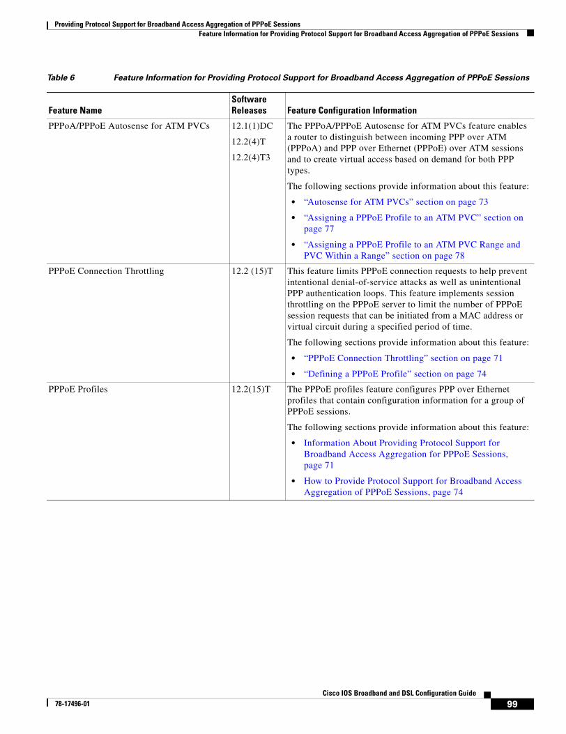
Providing Protocol Support for Broadband Access Aggregation of PPPoE SessionsFeature Information for Providing Protocol Support for Broadband Access Aggregation of PPPoE Sessions
99Cisco IOS Broadband and DSL Configuration Guide
78-17496-01
PPPoA/PPPoE Autosense for ATM PVCs 12.1(1)DC
12.2(4)T
12.2(4)T3
The PPPoA/PPPoE Autosense for ATM PVCs feature enables a router to distinguish between incoming PPP over ATM (PPPoA) and PPP over Ethernet (PPPoE) over ATM sessions and to create virtual access based on demand for both PPP types.
The following sections provide information about this feature:
• “Autosense for ATM PVCs” section on page 73
• “Assigning a PPPoE Profile to an ATM PVC” section on page 77
• “Assigning a PPPoE Profile to an ATM PVC Range and PVC Within a Range” section on page 78
PPPoE Connection Throttling 12.2 (15)T This feature limits PPPoE connection requests to help prevent intentional denial-of-service attacks as well as unintentional PPP authentication loops. This feature implements session throttling on the PPPoE server to limit the number of PPPoE session requests that can be initiated from a MAC address or virtual circuit during a specified period of time.
The following sections provide information about this feature:
• “PPPoE Connection Throttling” section on page 71
• “Defining a PPPoE Profile” section on page 74
PPPoE Profiles 12.2(15)T The PPPoE profiles feature configures PPP over Ethernet profiles that contain configuration information for a group of PPPoE sessions.
The following sections provide information about this feature:
• Information About Providing Protocol Support for Broadband Access Aggregation for PPPoE Sessions, page 71
• How to Provide Protocol Support for Broadband Access Aggregation of PPPoE Sessions, page 74
Table 6 Feature Information for Providing Protocol Support for Broadband Access Aggregation of PPPoE Sessions
Feature NameSoftware Releases Feature Configuration Information
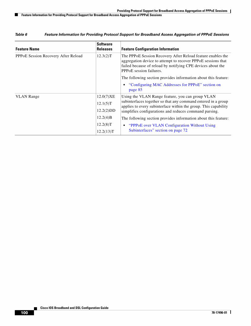
Providing Protocol Support for Broadband Access Aggregation of PPPoE SessionsFeature Information for Providing Protocol Support for Broadband Access Aggregation of PPPoE Sessions
100Cisco IOS Broadband and DSL Configuration Guide
78-17496-01
PPPoE Session Recovery After Reload 12.3(2)T The PPPoE Session Recovery After Reload feature enables the aggregation device to attempt to recover PPPoE sessions that failed because of reload by notifying CPE devices about the PPPoE session failures.
The following section provides information about this feature:
• “Configuring MAC Addresses for PPPoE” section on page 85
VLAN Range 12.0(7)XE
12.1(5)T
12.2(2)DD
12.2(4)B
12.2(8)T
12.2(13)T
Using the VLAN Range feature, you can group VLAN subinterfaces together so that any command entered in a group applies to every subinterface within the group. This capability simplifies configurations and reduces command parsing.
The following section provides information about this feature:
• “PPPoE over VLAN Configuration Without Using Subinterfaces” section on page 72
Table 6 Feature Information for Providing Protocol Support for Broadband Access Aggregation of PPPoE Sessions
Feature NameSoftware Releases Feature Configuration Information
101Cisco IOS Broadband and DSL Configuration Guide
78-17496-01
PPP over Ethernet Client
The PPP over Ethernet Client feature provides PPP over Ethernet (PPPoE) client support on routers on customer premises.
History for the PPP over Ethernet Client Feature
Finding Support Information for Platforms and Cisco IOS Software Images
Use Cisco Feature Navigator to find information about platform support and Cisco IOS software image support. Access Cisco Feature Navigator at http://www.cisco.com/go/fn. You must have an account on Cisco.com. If you do not have an account or have forgotten your username or password, click Cancel at the login dialog box and follow the instructions that appear.
Contents• Restrictions for PPPoE Client, page 101
• Information About PPPoE Client, page 102
• How to Configure a PPPoE Client, page 103
• Configuration Examples for PPPoE Client, page 115
• Additional References, page 117
Restrictions for PPPoE ClientFor PPPoE over ATM, one PVC will support only one PPPoE client. Multiple PPPoE clients can run concurrently on different PVCs, but each PPPoE client must use a separate dialer interface and a separate dialer pool.
Release Modification
12.2(2)T This feature was introduced.
12.2(13)T PPPoE client functionality was separated from VPDN functionality, resulting in changes to PPPoE client configuration.
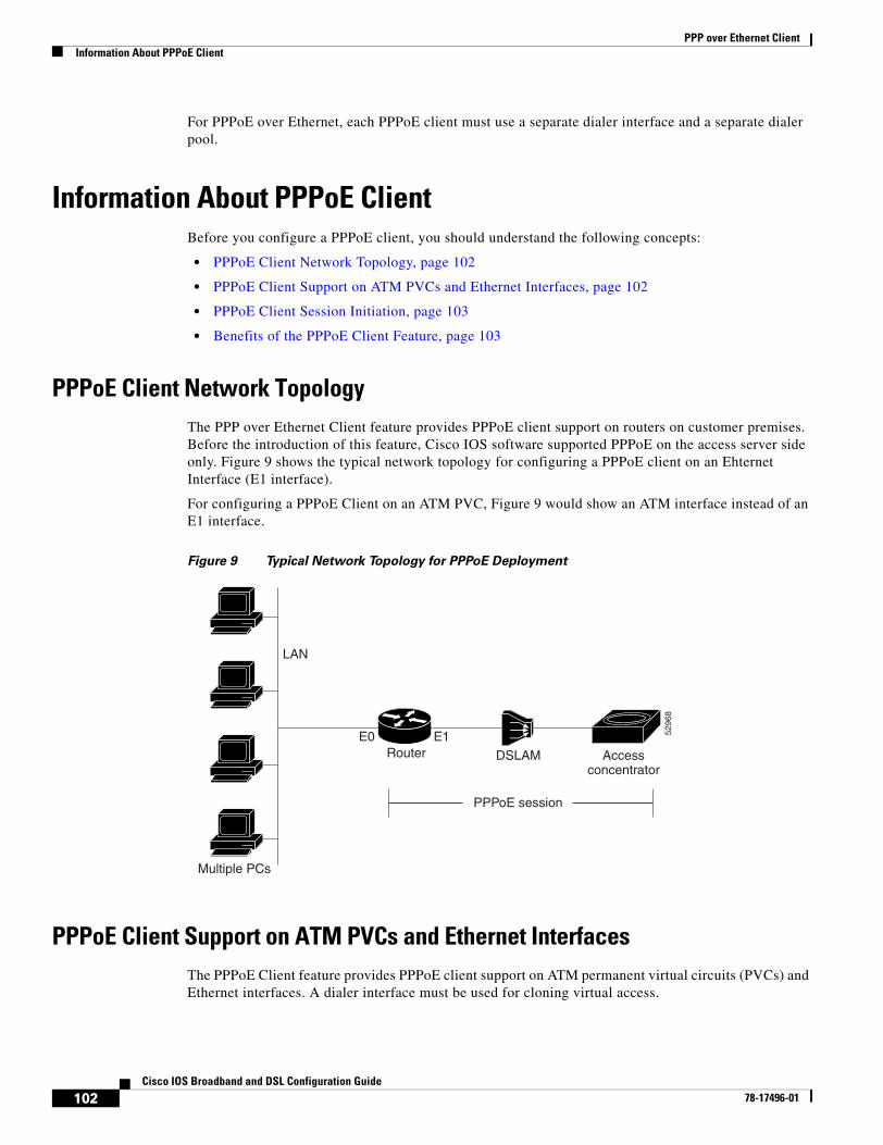
PPP over Ethernet ClientInformation About PPPoE Client
102Cisco IOS Broadband and DSL Configuration Guide
78-17496-01
For PPPoE over Ethernet, each PPPoE client must use a separate dialer interface and a separate dialer pool.
Information About PPPoE ClientBefore you configure a PPPoE client, you should understand the following concepts:
• PPPoE Client Network Topology, page 102
• PPPoE Client Support on ATM PVCs and Ethernet Interfaces, page 102
• PPPoE Client Session Initiation, page 103
• Benefits of the PPPoE Client Feature, page 103
PPPoE Client Network TopologyThe PPP over Ethernet Client feature provides PPPoE client support on routers on customer premises. Before the introduction of this feature, Cisco IOS software supported PPPoE on the access server side only. Figure 9 shows the typical network topology for configuring a PPPoE client on an Ehternet Interface (E1 interface).
For configuring a PPPoE Client on an ATM PVC, Figure 9 would show an ATM interface instead of an E1 interface.
Figure 9 Typical Network Topology for PPPoE Deployment
PPPoE Client Support on ATM PVCs and Ethernet InterfacesThe PPPoE Client feature provides PPPoE client support on ATM permanent virtual circuits (PVCs) and Ethernet interfaces. A dialer interface must be used for cloning virtual access.
DSLAM Accessconcentrator
LAN
Router
Multiple PCs
E0 E1
PPPoE session
5296
8
PPP over Ethernet ClientHow to Configure a PPPoE Client
103Cisco IOS Broadband and DSL Configuration Guide
78-17496-01
One ATM PVC will support one PPPoE client. Multiple PPPoE clients can run concurrently on different PVCs, but each PPPoE client must use a separate dialer interface and a separate dialer pool.
Multiple PPPoE client sessions can be configured on an Ethernet interface, but each session must use a separate dialer interface and a separate dialer pool.
PPPoE Client Session InitiationA PPPoE session is initiated by the PPPoE client. If the session has a timeout or is disconnected, the PPPoE client will immediately attempt to reestablish the session.
The following four steps describe the exchange of packets that occurs when a PPPoE client initiates a PPPoE session:
1. The client broadcasts a PPPoE Active Discovery Initiation (PADI) packet.
2. When the access concentrator receives a PADI that it can serve, it replies by sending a PPPoE Active Discovery Offer (PADO) packet to the client.
3. Because the PADI was broadcast, the host may receive more than one PADO packet. The host looks through the PADO packets it receives and chooses one. The choice can be based on the access concentrator name or on the services offered. The host then sends a single PPPoE Active Discovery Request (PADR) packet to the access concentrator that it has chosen.
4. The access concentrator responds to the PADR by sending a PPPoE Active Discovery Session-confirmation (PADS) packet. At this point a virtual access interface is created that will then negotiate PPP, and the PPPoE session will run on this virtual access.
If a client does not receive a PADO for a preceding PADI, the client sends out a PADI at predetermined intervals. That interval length is doubled for every successive PADI that does not evoke a response, until the interval reaches a configured maximum.
If PPP negotiation fails or the PPP line protocol is brought down for any reason, the PPPoE session and the virtual access will be brought down. When the PPPoE session is brought down, the client waits for a predetermined number of seconds before trying again to establish a PPPoE.
Benefits of the PPPoE Client FeaturePPPoE is a commonly used application in the deployment of digital subscriber lines (DSL). The PPP over Ethernet Client feature expands PPPoE functionality by providing support for PPPoE on the client as well as on the server.
How to Configure a PPPoE ClientThis section contains the following procedures:
• Configuring a PPPoE Client in Releases Prior to Cisco IOS Release 12.2(13)T, page 103
• Configuring a PPPoE Client in Cisco IOS Release 12.2(13)T and Later Releases, page 110
Configuring a PPPoE Client in Releases Prior to Cisco IOS Release 12.2(13)TPerform the following tasks to configure a PPPoE client in releases prior to Cisco IOS release 12.2(13)T:
PPP over Ethernet ClientHow to Configure a PPPoE Client
104Cisco IOS Broadband and DSL Configuration Guide
78-17496-01
• Enabling PPPoE in a VPDN Group, page 104
• Configuring a PPPoE Client on an ATM PVC, page 105
• Configuring a PPPoE Client on an Ethernet Interface, page 106
• Configuring the Dialer Interface, page 107
• Clearing PPPoE Client Sessions, page 108
• Verifying the PPPoE Client, page 109
• Troubleshooting PPPoE Client Sessions, page 110
Enabling PPPoE in a VPDN Group
Perform this task to enable PPPoE in a virtual private dial-up network (VPDN) group.
Restrictions
This task applies only to releases prior to Cisco IOS Release 12.2(13)T.
SUMMARY STEPS
1. enable
2. configure terminal
3. vpdn enable
4. vpdn-group name
5. request-dialin
6. protocol pppoe
DETAILED STEPS
Command or Action Purpose
Step 1 enable
Example:Router> enable
Enables privileged EXEC mode.
• Enter your password if prompted.
Step 2 configure terminal
Example:Router# configure terminal
Enters global configuration mode.
Step 3 vpdn enable
Example:Router(config)# vpdn enable
Enables virtual private dialup networking.
Step 4 vpdn-group name
Example:Router(config)# vpdn-group group1
Associates a VPDN group with a customer or VPDN profile.
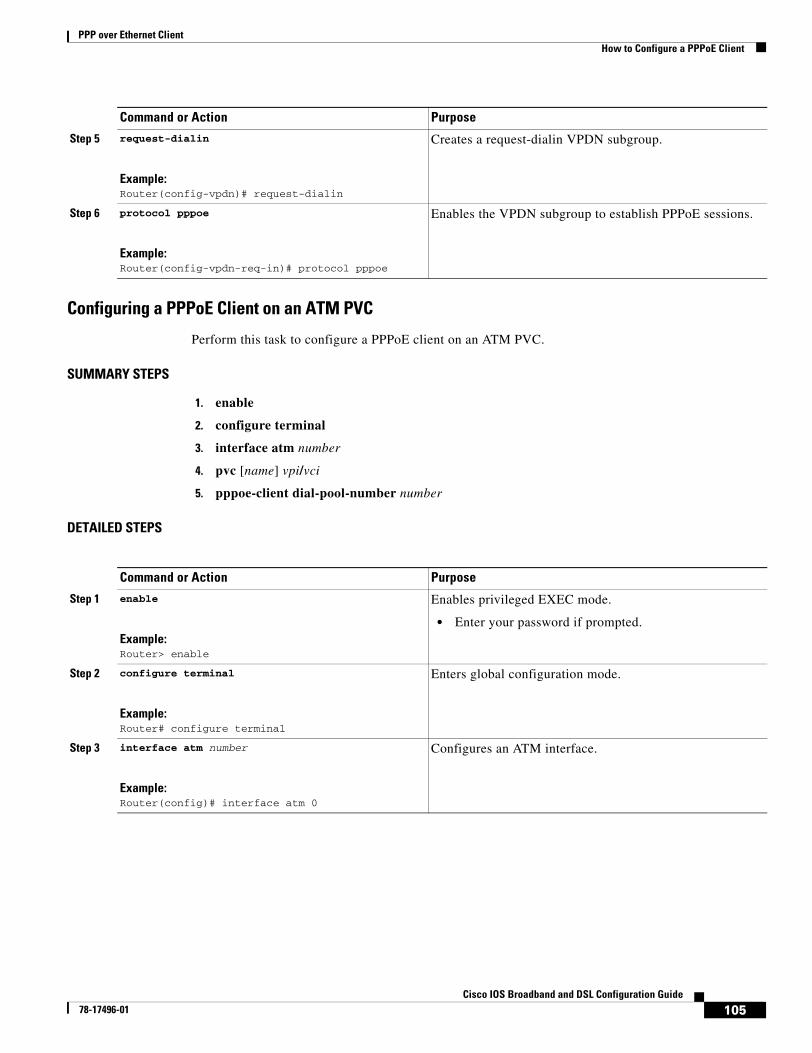
PPP over Ethernet ClientHow to Configure a PPPoE Client
105Cisco IOS Broadband and DSL Configuration Guide
78-17496-01
Configuring a PPPoE Client on an ATM PVC
Perform this task to configure a PPPoE client on an ATM PVC.
SUMMARY STEPS
1. enable
2. configure terminal
3. interface atm number
4. pvc [name] vpi/vci
5. pppoe-client dial-pool-number number
DETAILED STEPS
Step 5 request-dialin
Example:Router(config-vpdn)# request-dialin
Creates a request-dialin VPDN subgroup.
Step 6 protocol pppoe
Example:Router(config-vpdn-req-in)# protocol pppoe
Enables the VPDN subgroup to establish PPPoE sessions.
Command or Action Purpose
Command or Action Purpose
Step 1 enable
Example:Router> enable
Enables privileged EXEC mode.
• Enter your password if prompted.
Step 2 configure terminal
Example:Router# configure terminal
Enters global configuration mode.
Step 3 interface atm number
Example:Router(config)# interface atm 0
Configures an ATM interface.
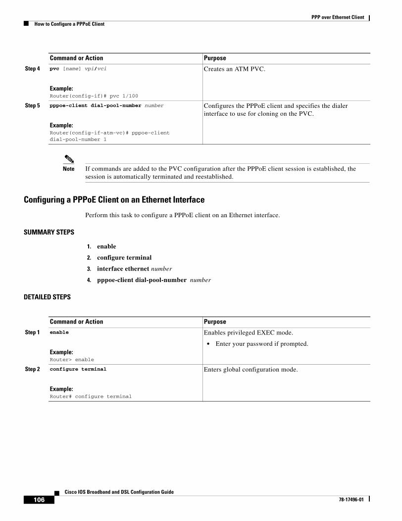
PPP over Ethernet ClientHow to Configure a PPPoE Client
106Cisco IOS Broadband and DSL Configuration Guide
78-17496-01
Note If commands are added to the PVC configuration after the PPPoE client session is established, the session is automatically terminated and reestablished.
Configuring a PPPoE Client on an Ethernet Interface
Perform this task to configure a PPPoE client on an Ethernet interface.
SUMMARY STEPS
1. enable
2. configure terminal
3. interface ethernet number
4. pppoe-client dial-pool-number number
DETAILED STEPS
Step 4 pvc [name] vpi/vci
Example:Router(config-if)# pvc 1/100
Creates an ATM PVC.
Step 5 pppoe-client dial-pool-number number
Example:Router(config-if-atm-vc)# pppoe-client dial-pool-number 1
Configures the PPPoE client and specifies the dialer interface to use for cloning on the PVC.
Command or Action Purpose
Command or Action Purpose
Step 1 enable
Example:Router> enable
Enables privileged EXEC mode.
• Enter your password if prompted.
Step 2 configure terminal
Example:Router# configure terminal
Enters global configuration mode.
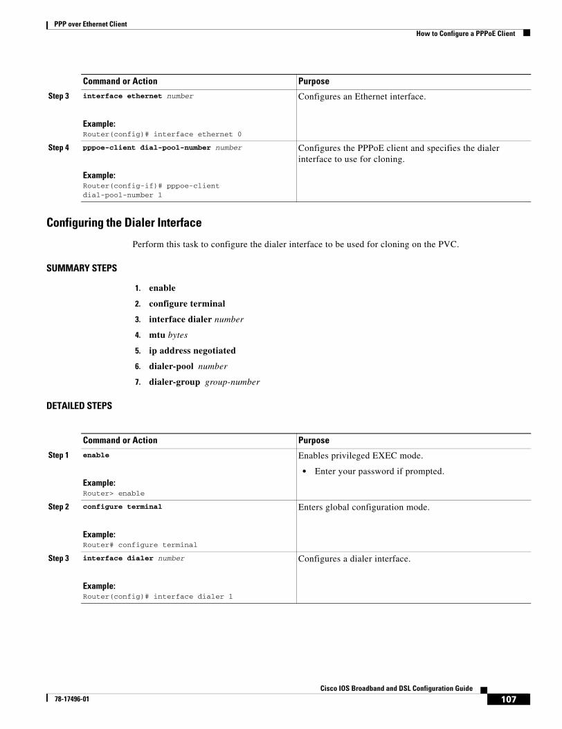
PPP over Ethernet ClientHow to Configure a PPPoE Client
107Cisco IOS Broadband and DSL Configuration Guide
78-17496-01
Configuring the Dialer Interface
Perform this task to configure the dialer interface to be used for cloning on the PVC.
SUMMARY STEPS
1. enable
2. configure terminal
3. interface dialer number
4. mtu bytes
5. ip address negotiated
6. dialer-pool number
7. dialer-group group-number
DETAILED STEPS
Step 3 interface ethernet number
Example:Router(config)# interface ethernet 0
Configures an Ethernet interface.
Step 4 pppoe-client dial-pool-number number
Example:Router(config-if)# pppoe-client dial-pool-number 1
Configures the PPPoE client and specifies the dialer interface to use for cloning.
Command or Action Purpose
Command or Action Purpose
Step 1 enable
Example:Router> enable
Enables privileged EXEC mode.
• Enter your password if prompted.
Step 2 configure terminal
Example:Router# configure terminal
Enters global configuration mode.
Step 3 interface dialer number
Example:Router(config)# interface dialer 1
Configures a dialer interface.
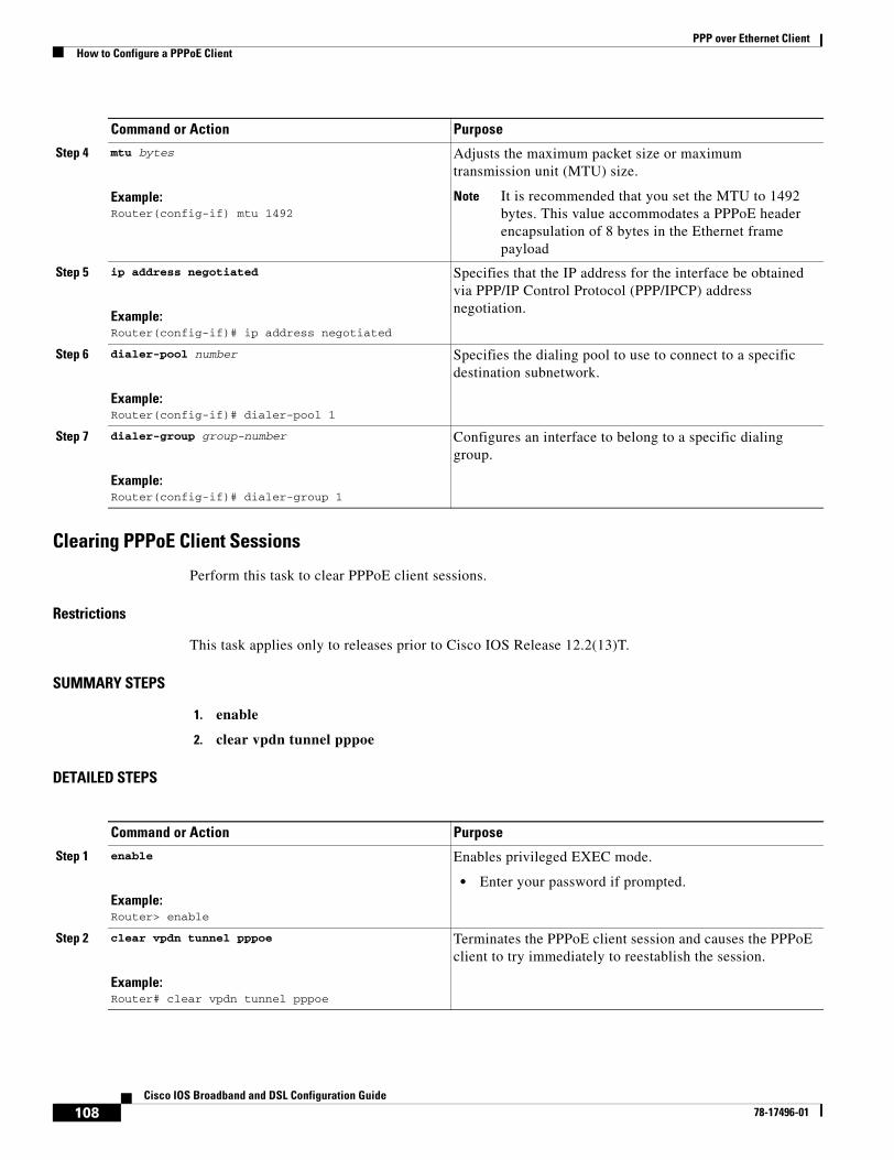
PPP over Ethernet ClientHow to Configure a PPPoE Client
108Cisco IOS Broadband and DSL Configuration Guide
78-17496-01
Clearing PPPoE Client Sessions
Perform this task to clear PPPoE client sessions.
Restrictions
This task applies only to releases prior to Cisco IOS Release 12.2(13)T.
SUMMARY STEPS
1. enable
2. clear vpdn tunnel pppoe
DETAILED STEPS
Step 4 mtu bytes
Example:Router(config-if) mtu 1492
Adjusts the maximum packet size or maximum transmission unit (MTU) size.
Note It is recommended that you set the MTU to 1492 bytes. This value accommodates a PPPoE header encapsulation of 8 bytes in the Ethernet frame payload
Step 5 ip address negotiated
Example:Router(config-if)# ip address negotiated
Specifies that the IP address for the interface be obtained via PPP/IP Control Protocol (PPP/IPCP) address negotiation.
Step 6 dialer-pool number
Example:Router(config-if)# dialer-pool 1
Specifies the dialing pool to use to connect to a specific destination subnetwork.
Step 7 dialer-group group-number
Example:Router(config-if)# dialer-group 1
Configures an interface to belong to a specific dialing group.
Command or Action Purpose
Command or Action Purpose
Step 1 enable
Example:Router> enable
Enables privileged EXEC mode.
• Enter your password if prompted.
Step 2 clear vpdn tunnel pppoe
Example:Router# clear vpdn tunnel pppoe
Terminates the PPPoE client session and causes the PPPoE client to try immediately to reestablish the session.
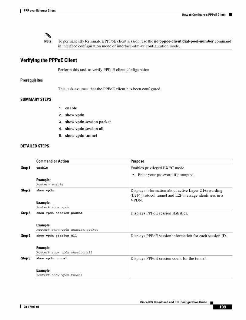
PPP over Ethernet ClientHow to Configure a PPPoE Client
109Cisco IOS Broadband and DSL Configuration Guide
78-17496-01
Note To permanently terminate a PPPoE client session, use the no pppoe-client dial-pool-number command in interface configuration mode or interface-atm-vc configuration mode.
Verifying the PPPoE Client
Perform this task to verify PPPoE client configuration.
Prerequisites
This task assumes that the PPPoE client has been configured.
SUMMARY STEPS
1. enable
2. show vpdn
3. show vpdn session packet
4. show vpdn session all
5. show vpdn tunnel
DETAILED STEPS
Command or Action Purpose
Step 1 enable
Example:Router> enable
Enables privileged EXEC mode.
• Enter your password if prompted.
Step 2 show vpdn
Example:Router# show vpdn
Displays information about active Layer 2 Forwarding (L2F) protocol tunnel and L2F message identifiers in a VPDN.
Step 3 show vpdn session packet
Example:Router# show vpdn session packet
Displays PPPoE session statistics.
Step 4 show vpdn session all
Example:Router# show vpdn session all
Displays PPPoE session information for each session ID.
Step 5 show vpdn tunnel
Example:Router# show vpdn tunnel
Displays PPPoE session count for the tunnel.
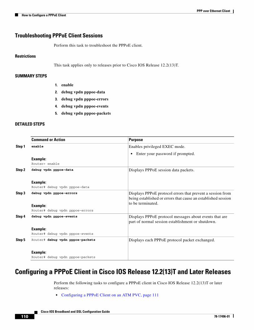
PPP over Ethernet ClientHow to Configure a PPPoE Client
110Cisco IOS Broadband and DSL Configuration Guide
78-17496-01
Troubleshooting PPPoE Client Sessions
Perform this task to troubleshoot the PPPoE client.
Restrictions
This task applies only to releases prior to Cisco IOS Release 12.2(13)T.
SUMMARY STEPS
1. enable
2. debug vpdn pppoe-data
3. debug vpdn pppoe-errors
4. debug vpdn pppoe-events
5. debug vpdn pppoe-packets
DETAILED STEPS
Configuring a PPPoE Client in Cisco IOS Release 12.2(13)T and Later ReleasesPerform the following tasks to configure a PPPoE client in Cisco IOS Release 12.2(13)T or later releases:
• Configuring a PPPoE Client on an ATM PVC, page 111
Command or Action Purpose
Step 1 enable
Example:Router> enable
Enables privileged EXEC mode.
• Enter your password if prompted.
Step 2 debug vpdn pppoe-data
Example:Router# debug vpdn pppoe-data
Displays PPPoE session data packets.
Step 3 debug vpdn pppoe-errors
Example:Router# debug vpdn pppoe-errors
Displays PPPoE protocol errors that prevent a session from being established or errors that cause an established session to be terminated.
Step 4 debug vpdn pppoe-events
Example:Router# debug vpdn pppoe-events
Displays PPPoE protocol messages about events that are part of normal session establishment or shutdown.
Step 5 Router# debug vpdn pppoe-packets
Example:Router# debug vpdn pppoe-packets
Displays each PPPoE protocol packet exchanged.
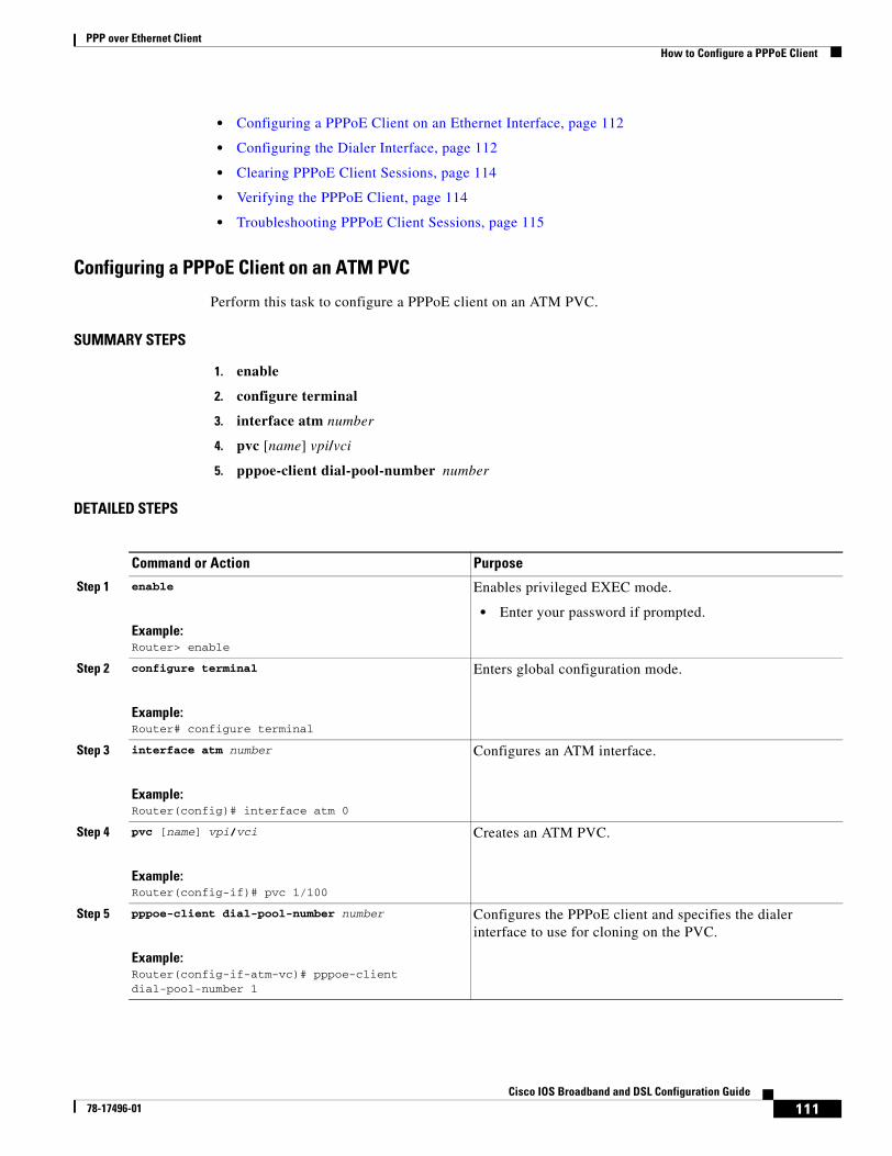
PPP over Ethernet ClientHow to Configure a PPPoE Client
111Cisco IOS Broadband and DSL Configuration Guide
78-17496-01
• Configuring a PPPoE Client on an Ethernet Interface, page 112
• Configuring the Dialer Interface, page 112
• Clearing PPPoE Client Sessions, page 114
• Verifying the PPPoE Client, page 114
• Troubleshooting PPPoE Client Sessions, page 115
Configuring a PPPoE Client on an ATM PVC
Perform this task to configure a PPPoE client on an ATM PVC.
SUMMARY STEPS
1. enable
2. configure terminal
3. interface atm number
4. pvc [name] vpi/vci
5. pppoe-client dial-pool-number number
DETAILED STEPS
Command or Action Purpose
Step 1 enable
Example:Router> enable
Enables privileged EXEC mode.
• Enter your password if prompted.
Step 2 configure terminal
Example:Router# configure terminal
Enters global configuration mode.
Step 3 interface atm number
Example:Router(config)# interface atm 0
Configures an ATM interface.
Step 4 pvc [name] vpi/vci
Example:Router(config-if)# pvc 1/100
Creates an ATM PVC.
Step 5 pppoe-client dial-pool-number number
Example:Router(config-if-atm-vc)# pppoe-client dial-pool-number 1
Configures the PPPoE client and specifies the dialer interface to use for cloning on the PVC.
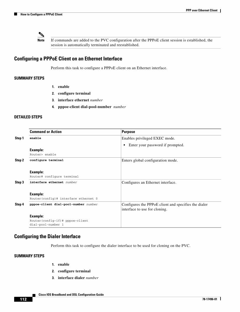
PPP over Ethernet ClientHow to Configure a PPPoE Client
112Cisco IOS Broadband and DSL Configuration Guide
78-17496-01
Note If commands are added to the PVC configuration after the PPPoE client session is established, the session is automatically terminated and reestablished.
Configuring a PPPoE Client on an Ethernet Interface
Perform this task to configure a PPPoE client on an Ethernet interface.
SUMMARY STEPS
1. enable
2. configure terminal
3. interface ethernet number
4. pppoe-client dial-pool-number number
DETAILED STEPS
Configuring the Dialer Interface
Perform this task to configure the dialer interface to be used for cloning on the PVC.
SUMMARY STEPS
1. enable
2. configure terminal
3. interface dialer number
Command or Action Purpose
Step 1 enable
Example:Router> enable
Enables privileged EXEC mode.
• Enter your password if prompted.
Step 2 configure terminal
Example:Router# configure terminal
Enters global configuration mode.
Step 3 interface ethernet number
Example:Router(config)# interface ethernet 0
Configures an Ethernet interface.
Step 4 pppoe-client dial-pool-number number
Example:Router(config-if)# pppoe-client dial-pool-number 1
Configures the PPPoE client and specifies the dialer interface to use for cloning.
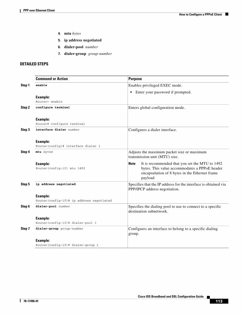
PPP over Ethernet ClientHow to Configure a PPPoE Client
113Cisco IOS Broadband and DSL Configuration Guide
78-17496-01
4. mtu bytes
5. ip address negotiated
6. dialer-pool number
7. dialer-group group-number
DETAILED STEPS
Command or Action Purpose
Step 1 enable
Example:Router> enable
Enables privileged EXEC mode.
• Enter your password if prompted.
Step 2 configure terminal
Example:Router# configure terminal
Enters global configuration mode.
Step 3 interface dialer number
Example:Router(config)# interface dialer 1
Configures a dialer interface.
Step 4 mtu bytes
Example:Router(config-if) mtu 1492
Adjusts the maximum packet size or maximum transmission unit (MTU) size.
Note It is recommended that you set the MTU to 1492 bytes. This value accommodates a PPPoE header encapsulation of 8 bytes in the Ethernet frame payload
Step 5 ip address negotiated
Example:Router(config-if)# ip address negotiated
Specifies that the IP address for the interface is obtained via PPP/IPCP address negotiation.
Step 6 dialer-pool number
Example:Router(config-if)# dialer-pool 1
Specifies the dialing pool to use to connect to a specific destination subnetwork.
Step 7 dialer-group group-number
Example:Router(config-if)# dialer-group 1
Configures an interface to belong to a specific dialing group.
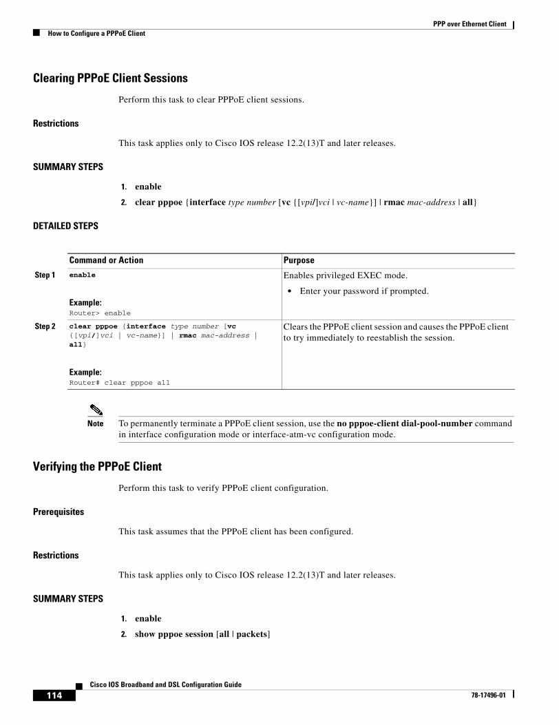
PPP over Ethernet ClientHow to Configure a PPPoE Client
114Cisco IOS Broadband and DSL Configuration Guide
78-17496-01
Clearing PPPoE Client Sessions
Perform this task to clear PPPoE client sessions.
Restrictions
This task applies only to Cisco IOS release 12.2(13)T and later releases.
SUMMARY STEPS
1. enable
2. clear pppoe {interface type number [vc {[vpi/]vci | vc-name}] | rmac mac-address | all}
DETAILED STEPS
Note To permanently terminate a PPPoE client session, use the no pppoe-client dial-pool-number command in interface configuration mode or interface-atm-vc configuration mode.
Verifying the PPPoE Client
Perform this task to verify PPPoE client configuration.
Prerequisites
This task assumes that the PPPoE client has been configured.
Restrictions
This task applies only to Cisco IOS release 12.2(13)T and later releases.
SUMMARY STEPS
1. enable
2. show pppoe session [all | packets]
Command or Action Purpose
Step 1 enable
Example:Router> enable
Enables privileged EXEC mode.
• Enter your password if prompted.
Step 2 clear pppoe {interface type number [vc {[vpi/]vci | vc-name}] | rmac mac-address | all}
Example:Router# clear pppoe all
Clears the PPPoE client session and causes the PPPoE client to try immediately to reestablish the session.
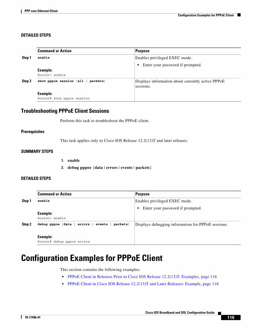
PPP over Ethernet ClientConfiguration Examples for PPPoE Client
115Cisco IOS Broadband and DSL Configuration Guide
78-17496-01
DETAILED STEPS
Troubleshooting PPPoE Client Sessions
Perform this task to troubleshoot the PPPoE client.
Prerequisites
This task applies only to Cisco IOS Release 12.2(13)T and later releases.
SUMMARY STEPS
1. enable
2. debug pppoe {data | errors | events | packets}
DETAILED STEPS
Configuration Examples for PPPoE ClientThis section contains the following examples:
• PPPoE Client in Releases Prior to Cisco IOS Release 12.2(13)T: Examples, page 116
• PPPoE Client in Cisco IOS Release 12.2(13)T and Later Releases: Example, page 116
Command or Action Purpose
Step 1 enable
Example:Router> enable
Enables privileged EXEC mode.
• Enter your password if prompted.
Step 2 show pppoe session [all | packets]
Example:Router# show pppoe session
Displays information about currently active PPPoE sessions.
Command or Action Purpose
Step 1 enable
Example:Router> enable
Enables privileged EXEC mode.
• Enter your password if prompted.
Step 2 debug pppoe {data | errors | events | packets}
Example:Router# debug pppoe errors
Displays debugging information for PPPoE sessions.
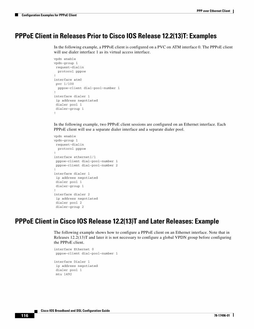
PPP over Ethernet ClientConfiguration Examples for PPPoE Client
116Cisco IOS Broadband and DSL Configuration Guide
78-17496-01
PPPoE Client in Releases Prior to Cisco IOS Release 12.2(13)T: ExamplesIn the following example, a PPPoE client is configured on a PVC on ATM interface 0. The PPPoE client will use dialer interface 1 as its virtual access interface.
vpdn enablevpdn-group 1request-dialinprotocol pppoe
! interface atm0pvc 1/100pppoe-client dial-pool-number 1
!interface dialer 1ip address negotiateddialer pool 1dialer-group 1
!
In the following example, two PPPoE client sessions are configured on an Ethernet interface. Each PPPoE client will use a separate dialer interface and a separate dialer pool.
vpdn enablevpdn-group 1request-dialinprotocol pppoe
! interface ethernet1/1pppoe-client dial-pool-number 1pppoe-client dial-pool-number 2
!interface dialer 1ip address negotiateddialer pool 1dialer-group 1
!interface dialer 2ip address negotiateddialer pool 2dialer-group 2
PPPoE Client in Cisco IOS Release 12.2(13)T and Later Releases: ExampleThe following example shows how to configure a PPPoE client on an Ethernet interface. Note that in Releases 12.2(13)T and later it is not necessary to configure a global VPDN group before configuring the PPPoE client.
interface Ethernet 0pppoe-client dial-pool-number 1
interface Dialer 1ip address negotiateddialer pool 1mtu 1492
PPP over Ethernet ClientAdditional References
117Cisco IOS Broadband and DSL Configuration Guide
78-17496-01
Additional ReferencesThe following sections provide references related to PPPoE client configuration.
Related Documents
Standards
MIBs
RFCs
Technical Assistance
Related Topic Document Title
VPDN configuration Cisco IOS Dial Technologies Configuration Guide, Release 12.2
VPDN commands Cisco IOS Dial Technologies Command Reference, Release 12.2
PPPoE configuration Cisco IOS Wide-Area Networking Configuration Guide, Release 12.2
PPPoE commands Cisco IOS Wide-Area Networking Command Reference, Release 12.2
Standard Title
No new or modified standards are supported by this feature.
—
MIB MIBs Link
No new or modified MIBs are supported by this feature.
To locate and download MIBs for selected platforms, Cisco IOS releases, and feature sets, use Cisco MIB Locator found at the following URL:
http://www.cisco.com/go/mibs
RFC Title
RFC 2516 A Method for Transmitting PPP over Ethernet (PPPoE)
Description Link
The Cisco Technical Support website contains thousands of pages of searchable technical content, including links to products, technologies, solutions, technical tips, and tools. Registered Cisco.com users can log in from this page to access even more content.
http://www.cisco.com/techsupport

PPP over Ethernet ClientAdditional References
118Cisco IOS Broadband and DSL Configuration Guide
78-17496-01
119Cisco IOS Broadband and DSL Configuration Guide
78-17496-01
PPPoE Circuit-Id Tag Processing
In an Ethernet access network, there is no unique mapping between the subscriber line identifier and the interface such as there is on a virtual circuit (VC) in an ATM-based network. The PPPoE Circuit-Id Tag Processing feature provides a way to extract a Circuit-Id tag from the digital subscriber line (DSL) as an identifier for the authentication, authorization, and accounting (AAA) access request on an Ethernet interface, thereby simulating ATM-based broadband access, but using cost-effective Ethernet instead. The tag is useful for troubleshooting the network, and is also used in RADIUS authentication and accounting processes.
History for the PPPoE Circuit-Id Tag Processing Feature
Finding Support Information for Platforms and Cisco IOS Software Images
Use Cisco Feature Navigator to find information about platform support and Cisco IOS software image support. Access Cisco Feature Navigator at http://www.cisco.com/go/fn. You must have an account on Cisco.com. If you do not have an account or have forgotten your username or password, click Cancel at the login dialog box and follow the instructions that appear.
Contents• Prerequisites for the PPPoE Circuit-Id Tag Processing Feature, page 119
• Information About the PPPoE Circuit-Id Tag Processing Feature, page 120
• How to Configure the PPPoE Circuit-Id Tag Processing Feature, page 122
• Configuration Examples for the PPPoE Circuit-Id Tag Processing Feature, page 126
• Additional References, page 126
Prerequisites for the PPPoE Circuit-Id Tag Processing FeatureIt is recommended that you be familiar with RFC 2516 before configuring this feature. See the “RFCs” section on page 127 for a pointer to this standard.
Release Modification
12.4(4)T This feature was introduced.
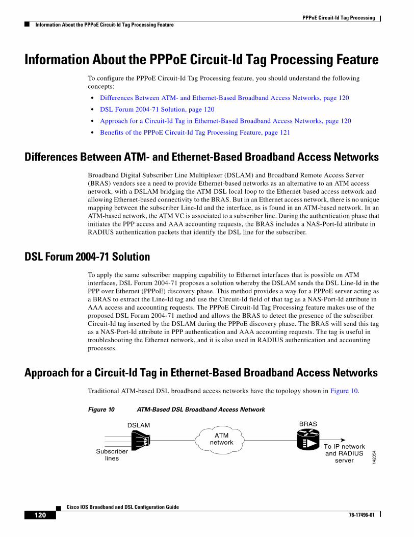
PPPoE Circuit-Id Tag ProcessingInformation About the PPPoE Circuit-Id Tag Processing Feature
120Cisco IOS Broadband and DSL Configuration Guide
78-17496-01
Information About the PPPoE Circuit-Id Tag Processing FeatureTo configure the PPPoE Circuit-Id Tag Processing feature, you should understand the following concepts:
• Differences Between ATM- and Ethernet-Based Broadband Access Networks, page 120
• DSL Forum 2004-71 Solution, page 120
• Approach for a Circuit-Id Tag in Ethernet-Based Broadband Access Networks, page 120
• Benefits of the PPPoE Circuit-Id Tag Processing Feature, page 121
Differences Between ATM- and Ethernet-Based Broadband Access NetworksBroadband Digital Subscriber Line Multiplexer (DSLAM) and Broadband Remote Access Server (BRAS) vendors see a need to provide Ethernet-based networks as an alternative to an ATM access network, with a DSLAM bridging the ATM-DSL local loop to the Ethernet-based access network and allowing Ethernet-based connectivity to the BRAS. But in an Ethernet access network, there is no unique mapping between the subscriber Line-Id and the interface, as is found in an ATM-based network. In an ATM-based network, the ATM VC is associated to a subscriber line. During the authentication phase that initiates the PPP access and AAA accounting requests, the BRAS includes a NAS-Port-Id attribute in RADIUS authentication packets that identify the DSL line for the subscriber.
DSL Forum 2004-71 SolutionTo apply the same subscriber mapping capability to Ethernet interfaces that is possible on ATM interfaces, DSL Forum 2004-71 proposes a solution whereby the DSLAM sends the DSL Line-Id in the PPP over Ethernet (PPPoE) discovery phase. This method provides a way for a PPPoE server acting as a BRAS to extract the Line-Id tag and use the Circuit-Id field of that tag as a NAS-Port-Id attribute in AAA access and accounting requests. The PPPoE Circuit-Id Tag Processing feature makes use of the proposed DSL Forum 2004-71 method and allows the BRAS to detect the presence of the subscriber Circuit-Id tag inserted by the DSLAM during the PPPoE discovery phase. The BRAS will send this tag as a NAS-Port-Id attribute in PPP authentication and AAA accounting requests. The tag is useful in troubleshooting the Ethernet network, and it is also used in RADIUS authentication and accounting processes.
Approach for a Circuit-Id Tag in Ethernet-Based Broadband Access NetworksTraditional ATM-based DSL broadband access networks have the topology shown in Figure 10.
Figure 10 ATM-Based DSL Broadband Access Network
DSLAM
Subscriberlines
ATMnetwork
BRAS
To IP networkand RADIUS
server 1423
54
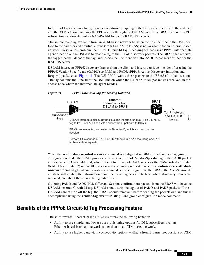
PPPoE Circuit-Id Tag ProcessingInformation About the PPPoE Circuit-Id Tag Processing Feature
121Cisco IOS Broadband and DSL Configuration Guide
78-17496-01
In terms of logical connectivity, there is a one-to-one mapping of the DSL subscriber line to the end user and the ATM VC used to carry the PPP session through the DSLAM and to the BRAS, where this VC information is converted into a NAS-Port-Id for use in RADIUS packets.
The simple mapping available from an ATM-based network between the physical line in the DSL local loop to the end user and a virtual circuit (from DSLAM to BRAS) is not available for an Ethernet-based network. To solve this problem, the PPPoE Circuit-Id Tag Processing feature uses a PPPoE intermediate agent function on the DSLAM to attach a tag to the PPPoE discovery packets. The BRAS then receives the tagged packet, decodes the tag, and inserts the line identifier into RADIUS packets destined for the RADIUS server.
DSLAM intercepts PPPoE discovery frames from the client and inserts a unique line identifier using the PPPoE Vendor-Specific tag (0x0105) to PADI and PADR (PPPoE Active Discovery Initiation and Request) packets; see Figure 11. The DSLAM forwards these packets to the BRAS after the insertion. The tag contains the Line-Id of the DSL line on which the PADI or PADR packet was received, in the access node where the intermediate agent resides.
Figure 11 PPPoE Circuit-Id Tag Processing Solution
When the vendor-tag circuit-id service command is configured in BBA (broadband access) group configuration mode, the BRAS processes the received PPPoE Vendor-Specific tag in the PADR packet and extracts the Circuit-Id field, which is sent to the remote AAA server as the NAS-Port-Id attribute (RADIUS attribute 87) in RADIUS access and accounting requests. When the radius-server attribute nas-port format d global configuration command is also configured on the BRAS, the Acct-Session-Id attribute will contain the information about the incoming access interface, where discovery frames are received, and about the session being established.
Outgoing PADO and PADS (PAD Offer and Session-confirmation) packets from the BRAS will have the DSLAM-inserted Circuit-Id tag. DSLAM should strip the tag out of PADO and PADS packets. If the DSLAM cannot strip off the tag, the BRAS should remove it before sending the packets out, and this is accomplished using the vendor-tag circuit-id strip BBA group configuration mode command.
Benefits of the PPPoE Circuit-Id Tag Processing FeatureThe shift towards Ethernet-based DSLAMs offers the following benefits:
• Ability to use simpler and lower cost provisioning options for DSL subscribers over an Ethernet-based backhaul network rather than on an ATM-based network.
• Ability to use higher bandwidth connectivity options available from Ethernet not possible on ATM.
DSLAM
Subscriberlines
Ethernetconnectivity fromDSLAM to BRAS
BRAS
To IP networkand RADIUS
server 1423
55
DSLAM intercepts discovery packets and inserts a unique PPPoE Line-ID tag to PADI or PADR packets and forwards upstream to BRAS.
BRAS processes tag and extracts Remote-ID, which is stored on the session.
Remote-ID is sent as a NAS-Port-ID attribute in AAA accounting and PPP authenticationrequests.
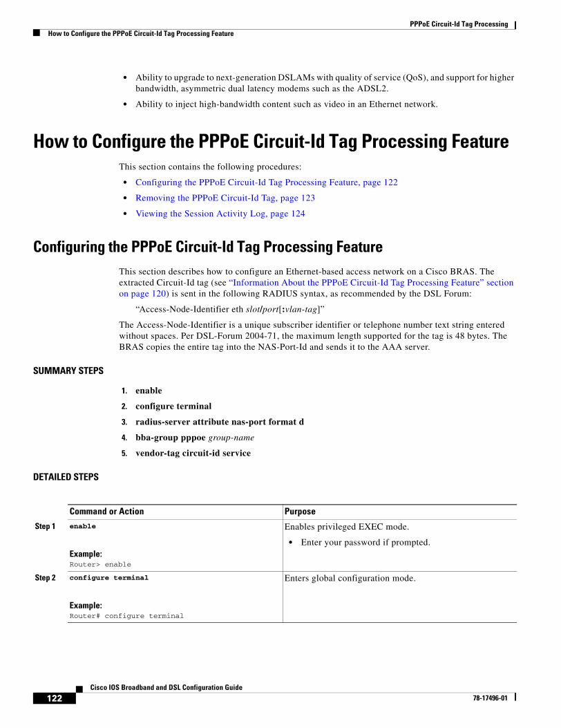
PPPoE Circuit-Id Tag ProcessingHow to Configure the PPPoE Circuit-Id Tag Processing Feature
122Cisco IOS Broadband and DSL Configuration Guide
78-17496-01
• Ability to upgrade to next-generation DSLAMs with quality of service (QoS), and support for higher bandwidth, asymmetric dual latency modems such as the ADSL2.
• Ability to inject high-bandwidth content such as video in an Ethernet network.
How to Configure the PPPoE Circuit-Id Tag Processing FeatureThis section contains the following procedures:
• Configuring the PPPoE Circuit-Id Tag Processing Feature, page 122
• Removing the PPPoE Circuit-Id Tag, page 123
• Viewing the Session Activity Log, page 124
Configuring the PPPoE Circuit-Id Tag Processing FeatureThis section describes how to configure an Ethernet-based access network on a Cisco BRAS. The extracted Circuit-Id tag (see “Information About the PPPoE Circuit-Id Tag Processing Feature” section on page 120) is sent in the following RADIUS syntax, as recommended by the DSL Forum:
“Access-Node-Identifier eth slot/port[:vlan-tag]”
The Access-Node-Identifier is a unique subscriber identifier or telephone number text string entered without spaces. Per DSL-Forum 2004-71, the maximum length supported for the tag is 48 bytes. The BRAS copies the entire tag into the NAS-Port-Id and sends it to the AAA server.
SUMMARY STEPS
1. enable
2. configure terminal
3. radius-server attribute nas-port format d
4. bba-group pppoe group-name
5. vendor-tag circuit-id service
DETAILED STEPS
Command or Action Purpose
Step 1 enable
Example:Router> enable
Enables privileged EXEC mode.
• Enter your password if prompted.
Step 2 configure terminal
Example:Router# configure terminal
Enters global configuration mode.
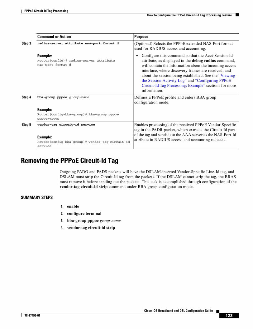
PPPoE Circuit-Id Tag ProcessingHow to Configure the PPPoE Circuit-Id Tag Processing Feature
123Cisco IOS Broadband and DSL Configuration Guide
78-17496-01
Removing the PPPoE Circuit-Id TagOutgoing PADO and PADS packets will have the DSLAM-inserted Vendor-Specific Line-Id tag, and DSLAM must strip the Circuit-Id tag from the packets. If the DSLAM cannot strip the tag, the BRAS must remove it before sending out the packets. This task is accomplished through configuration of the vendor-tag circuit-id strip command under BBA group configuration mode.
SUMMARY STEPS
1. enable
2. configure terminal
3. bba-group pppoe group-name
4. vendor-tag circuit-id strip
Step 3 radius-server attribute nas-port format d
Example:Router(config)# radius-server attribute nas-port format d
(Optional) Selects the PPPoE extended NAS-Port format used for RADIUS access and accounting.
• Configure this command so that the Acct-Session-Id attribute, as displayed in the debug radius command, will contain the information about the incoming access interface, where discovery frames are received, and about the session being established. See the “Viewing the Session Activity Log” and “Configuring PPPoE Circuit-Id Tag Processing: Example” sections for more information.
Step 4 bba-group pppoe group-name
Example:Router(config-bba-group)# bba-group pppoe pppoe-group
Defines a PPPoE profile and enters BBA group configuration mode.
Step 5 vendor-tag circuit-id service
Example:Router(config-bba-group)# vendor-tag circuit-id service
Enables processing of the received PPPoE Vendor-Specific tag in the PADR packet, which extracts the Circuit-Id part of the tag and sends it to the AAA server as the NAS-Port-Id attribute in RADIUS access and accounting requests.
Command or Action Purpose
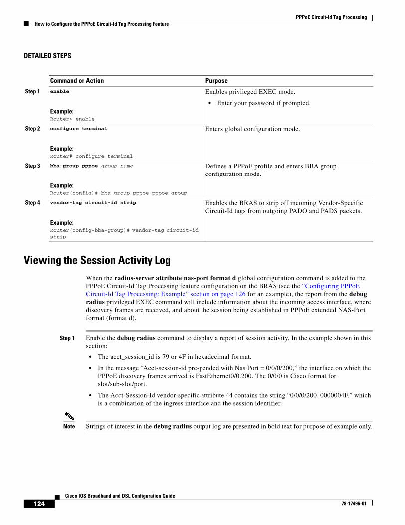
PPPoE Circuit-Id Tag ProcessingHow to Configure the PPPoE Circuit-Id Tag Processing Feature
124Cisco IOS Broadband and DSL Configuration Guide
78-17496-01
DETAILED STEPS
Viewing the Session Activity LogWhen the radius-server attribute nas-port format d global configuration command is added to the PPPoE Circuit-Id Tag Processing feature configuration on the BRAS (see the “Configuring PPPoE Circuit-Id Tag Processing: Example” section on page 126 for an example), the report from the debug radius privileged EXEC command will include information about the incoming access interface, where discovery frames are received, and about the session being established in PPPoE extended NAS-Port format (format d).
Step 1 Enable the debug radius command to display a report of session activity. In the example shown in this section:
• The acct_session_id is 79 or 4F in hexadecimal format.
• In the message “Acct-session-id pre-pended with Nas Port = 0/0/0/200,” the interface on which the PPPoE discovery frames arrived is FastEthernet0/0.200. The 0/0/0 is Cisco format for slot/sub-slot/port.
• The Acct-Session-Id vendor-specific attribute 44 contains the string “0/0/0/200_0000004F,” which is a combination of the ingress interface and the session identifier.
Note Strings of interest in the debug radius output log are presented in bold text for purpose of example only.
Command or Action Purpose
Step 1 enable
Example:Router> enable
Enables privileged EXEC mode.
• Enter your password if prompted.
Step 2 configure terminal
Example:Router# configure terminal
Enters global configuration mode.
Step 3 bba-group pppoe group-name
Example:Router(config)# bba-group pppoe pppoe-group
Defines a PPPoE profile and enters BBA group configuration mode.
Step 4 vendor-tag circuit-id strip
Example:Router(config-bba-group)# vendor-tag circuit-id strip
Enables the BRAS to strip off incoming Vendor-Specific Circuit-Id tags from outgoing PADO and PADS packets.
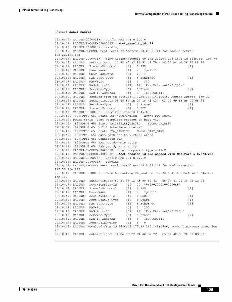
PPPoE Circuit-Id Tag ProcessingHow to Configure the PPPoE Circuit-Id Tag Processing Feature
125Cisco IOS Broadband and DSL Configuration Guide
78-17496-01
Router# debug radius
02:10:49: RADIUS(0000003F): Config NAS IP: 0.0.0.002:10:49: RADIUS/ENCODE(0000003F): acct_session_id: 7902:10:49: RADIUS(0000003F): sending02:10:49: RADIUS/ENCODE: Best Local IP-Address 10.0.58.141 for Radius-Server 172.20.164.14302:10:49: RADIUS(0000003F): Send Access-Request to 172.20.164.143:1645 id 1645/65, len 9802:10:49: RADIUS: authenticator 1C 9E B0 A2 82 51 C1 79 - FE 24 F4 D1 2F 84 F5 7902:10:49: RADIUS: Framed-Protocol [7] 6 PPP [1]02:10:49: RADIUS: User-Name [1] 7 "peer1"02:10:49: RADIUS: CHAP-Password [3] 19 *02:10:49: RADIUS: NAS-Port-Type [61] 6 Ethernet [15]02:10:49: RADIUS: NAS-Port [5] 6 20002:10:49: RADIUS: NAS-Port-Id [87] 22 "FastEthernet6/0.200:"02:10:49: RADIUS: Service-Type [6] 6 Framed [2]02:10:49: RADIUS: NAS-IP-Address [4] 6 10.0.58.14102:10:49: RADIUS: Received from id 1645/65 172.20.164.143:1645, Access-Accept, len 32 02:10:49: RADIUS: authenticator 06 45 84 1B 27 1F A5 C3 - C3 C9 69 6E B9 C0 6F 9402:10:49: RADIUS: Service-Type [6] 6 Framed [2]02:10:49: RADIUS: Framed-Protocol [7] 6 PPP [1]02:10:49: RADIUS(0000003F): Received from id 1645/6502:10:49: [62]PPPoE 65: State LCP_NEGOTIATION Event PPP_LOCAL02:10:49: PPPoE 65/SB: Sent vtemplate request on base Vi202:10:49: [62]PPPoE 65: State VACCESS_REQUESTED Event VA_RESP02:10:49: [62]PPPoE 65: Vi2.1 interface obtained02:10:49: [62]PPPoE 65: State PTA_BINDING Event STAT_BIND02:10:49: [62]PPPoE 65: data path set to Virtual Acess02:10:49: [62]PPPoE 65: Connected PTA02:10:49: [62]PPPoE 65: AAA get dynamic attrs02:10:49: [62]PPPoE 65: AAA get dynamic attrs02:10:49: RADIUS/ENCODE(0000003F):Orig. component type = PPoE02:10:49: RADIUS/ENCODE(0000003F): Acct-session-id pre-pended with Nas Port = 0/0/0/20002:10:49: RADIUS(0000003F): Config NAS IP: 0.0.0.002:10:49: RADIUS(0000003F): sending02:10:49: RADIUS/ENCODE: Best Local IP-Address 10.0.58.141 for Radius-Server 172.20.164.14302:10:49: RADIUS(0000003F): Send Accounting-Request to 172.20.164.143:1646 id 1 646/42, len 11702:10:49: RADIUS: authenticator 57 24 38 1A A3 09 62 42 - 55 2F 41 71 38 E1 CC 2402:10:49: RADIUS: Acct-Session-Id [44] 20 "0/0/0/200_0000004F"02:10:49: RADIUS: Framed-Protocol [7] 6 PPP [1]02:10:49: RADIUS: User-Name [1] 7 "peer1"02:10:49: RADIUS: Acct-Authentic [45] 6 RADIUS [1]02:10:49: RADIUS: Acct-Status-Type [40] 6 Start [1]02:10:49: RADIUS: NAS-Port-Type [61] 6 Ethernet [15]02:10:49: RADIUS: NAS-Port [5] 6 20002:10:49: RADIUS: NAS-Port-Id [87] 22 "FastEthernet6/0.200:"02:10:49: RADIUS: Service-Type [6] 6 Framed [2]02:10:49: RADIUS: NAS-IP-Address [4] 6 10.0.58.14102:10:49: RADIUS: Acct-Delay-Time [41] 6 002:10:49: RADIUS: Received from id 1646/42 172.20.164.143:1646, Accounting-resp onse, len 2002:10:49: RADIUS: authenticator 34 84 7E B2 F4 40 B2 7C - C5 B2 4E 98 78 03 8B C0
PPPoE Circuit-Id Tag ProcessingConfiguration Examples for the PPPoE Circuit-Id Tag Processing Feature
126Cisco IOS Broadband and DSL Configuration Guide
78-17496-01
Configuration Examples for the PPPoE Circuit-Id Tag Processing Feature
This section contains the following examples:
• Configuring PPPoE Circuit-Id Tag Processing: Example, page 126
• Removing the PPPoE Circuit-Id Tag: Example, page 126
Configuring PPPoE Circuit-Id Tag Processing: ExampleIn the following example, outgoing PADO and PADS packets will retain the incoming Vendor-Specific Circuit-Id tag:
radius-server attribute nas-port format d!bba-group pppoe pppoe-groupsessions per-mac limit 50vendor-tag circuit-id service
!interface FastEthernet0/0.1encapsulation dot1Q 120pppoe enable group pppoe-group
Removing the PPPoE Circuit-Id Tag: ExampleIn the following example, the BRAS will strip off incoming Vendor-Specific Circuit-Id tags from outgoing PADO and PADS packets:
bba-group pppoe pppoe-rm-tagsessions per-mac limit 50vendor-tag circuit-id servicevendor-tag circuit-id strip
interface FastEthernet0/0.1encapsulation dot1Q 120pppoe enable group pppoe-group
Additional ReferencesThe following sections provide references related to the PPPoE Circuit-Id Tag Processing feature.
Related Documents
Related Topic Document Title
Configuring broadband and DSL Cisco IOS Broadband and DSL Configuration Guide, Release 12.4
RADIUS attributes Cisco IOS Security Configuration Guide, Release 12.4
DSL Forum Line-Id tag solution DSL Forum 2004-71
PPPoE Circuit-Id Tag ProcessingAdditional References
127Cisco IOS Broadband and DSL Configuration Guide
78-17496-01
Standards
MIBs
RFCs
Technical Assistance
Standard Title
None —
MIB MIBs Link
None To locate and download MIBs for selected platforms, Cisco IOS releases, and feature sets, use Cisco MIB Locator found at the following URL:
http://www.cisco.com/go/mibs
RFC Title
RFC 2516 A Method for Transmitting PPP over Ethernet (PPPoE)
Description Link
The Cisco Technical Support website contains thousands of pages of searchable technical content, including links to products, technologies, solutions, technical tips, and tools. Registered Cisco.com users can log in from this page to access even more content.
http://www.cisco.com/techsupport

PPPoE Circuit-Id Tag ProcessingAdditional References
128Cisco IOS Broadband and DSL Configuration Guide
78-17496-01

129Cisco IOS Broadband and DSL Configuration Guide
78-17496-01
PPPoE Client DDR Idle-Timer
The PPPoE Client DDR Idle-Timer feature supports the dial-on-demand routing (DDR) interesting traffic control list functionality of the dialer interface with a PPP over Ethernet (PPPoE) client, but also keeps original functionality (PPPoE connection up and always on after configuration) for those PPPoE clients that require it.
Feature Specifications for the PPPoE Client DDR Idle-Timer Feature
Determining Platform Support Through Cisco Feature Navigator
Cisco IOS software is packaged in feature sets that are supported on specific platforms. To get updated information regarding platform support for this feature, access Cisco Feature Navigator. Cisco Feature Navigator dynamically updates the list of supported platforms as new platform support is added for the feature.
Cisco Feature Navigator is a web-based tool that enables you to quickly determine which Cisco IOS software images support a specific set of features and which features are supported in a specific Cisco IOS image. You can search by feature or release. Under the release section, you can compare releases side by side to display both the features unique to each software release and the features in common.
To access Cisco Feature Navigator, you must have an account on Cisco.com. If you have forgotten or lost your account information, send a blank e-mail to [email protected]. An automatic check will verify that your e-mail address is registered with Cisco.com. If the check is successful, account details with a new random password will be e-mailed to you. Qualified users can establish an account on Cisco.com by following the directions found at this URL:
http://www.cisco.com/register
Cisco Feature Navigator is updated regularly when major Cisco IOS software releases and technology releases occur. For the most current information, go to the Cisco Feature Navigator home page at the following URL:
http://www.cisco.com/go/fn
Feature HistoryRelease Modification
12.2(13)T This feature was introduced.
Supported Platforms
Cisco 806, Cisco 827, Cisco SOHO 70 series
PPPoE Client DDR Idle-TimerContents
130Cisco IOS Broadband and DSL Configuration Guide
78-17496-01
Availability of Cisco IOS Software Images
Platform support for particular Cisco IOS software releases is dependent on the availability of the software images for those platforms. Software images for some platforms may be deferred, delayed, or changed without prior notice. For updated information about platform support and availability of software images for each Cisco IOS software release, refer to the online release notes or Cisco Feature Navigator.
Contents• Prerequisites for Using the PPPoE Client DDR Idle-Timer, page 130
• Information About the PPPoE Client DDR Idle-Timer, page 130
• How to Configure the PPPoE Client DDR Idle-Timer, page 131
• Configuration Examples for PPPoE Client DDR Idle-Timer, page 135
• Additional References, page 137
• Command List, page 138
Prerequisites for Using the PPPoE Client DDR Idle-TimerBefore configuring the PPPoE Client DDR Idle-Timer feature, you must understand the concept of DDR interesting packets and access control lists and PPPoE Stage Protocols. See the “Additional References” section on page 137 for links to the documents describing these concepts.
Information About the PPPoE Client DDR Idle-TimerTo configure the PPPoE client DDR idle-timer, you need to understand the following concept:
• DDR Functionality and the PPPoE Client, page 130
DDR Functionality and the PPPoE ClientBefore Cisco IOS Release 12.2(13)T, the DDR interesting traffic control list functionality of the dialer interface was not supported for PPPoE. However, the PPPoE Client DDR Idle-Timer feature, available as part of Cisco IOS Release 12.2(13)T, now supports this DDR functionality for a PPPoE client.
Protocol access lists and dialer access lists are central to the operation of DDR. Access lists are used as the screening criteria for determining when to initiate DDR calls. All packets are tested against the dialer access list. Packets that match a permit entry are deemed interesting. Packets that do not match a permit entry or that do match a deny entry are deemed uninteresting. When a packet is found to be interesting, either the dialer idle timer is reset (if the line is active) or a connection is attempted (assuming the line is available but not active). If a tested packet is deemed uninteresting, it will be forwarded if it is intended for a destination known to be on a specific interface and the link is active. However, such a packet will not initiate a DDR call and will not reset the idle timer. If dialer idle timer expires, the dialer interface calls a PPPoE function to tear down the connection.
PPPoE Client DDR Idle-TimerHow to Configure the PPPoE Client DDR Idle-Timer
131Cisco IOS Broadband and DSL Configuration Guide
78-17496-01
A new command, pppoe-client dial-pool-number, allows configuring a DDR interesting traffic control list for PPPoE connections, but also keeps original connection functionality for those PPPoE clients that require it. If you do not require DDR, the PPPoE connection will be up and always on after configuration. If you do require DDR functionality, the connection will be brought up when interesting traffic comes in from the LAN interface and brought down after the dialer idle timer expires. Interesting traffic that comes from WAN interface will only reset the dialer idle timer.
Protocol access lists and dialer access lists have already been implemented in the dialer interface for the operation of DDR. For a PPPoE client, access lists are used as the screening criteria for determining if PPPoE Discovery initiation or a dialer idle timer reset is needed. But a protocol access list is not required for this feature; it depends on your network needs. An access-list can be configured and associated with dialer-list, or you can configure only the dialer list.
All packets destined to the dialer interface are tested against the dialer access list. Packets that match a permit entry are deemed interesting. Packets that do not match a permit entry or that do match a deny entry are deemed uninteresting. When a packet is found to be interesting, the dialer idle timer will be reset if the PPPoE session has already been set up, or a PPPoE Discovery will be attempted if there is no PPPoE session. If a tested packet is deemed uninteresting, it will not initiate PPPoE Discovery and will not reset the idle timer.
How to Configure the PPPoE Client DDR Idle-TimerThis section contains the following procedures. Each procedure is identified as either required or optional.
• Configure the PPPoE Client DDR Idle-Timer on an ATM PVC Interface, page 131 (required)
• Configure the PPPoE Client DDR Idle-Timer on an Ethernet Interface, page 133 (required)
• Configure the Dialer Interface, page 134 (required)
Configure the PPPoE Client DDR Idle-Timer on an ATM PVC InterfaceTo configure the PPPoE client DDR idle-timer in interface-ATM-VC configuration mode, use the following commands:
SUMMARY STEPS
1. enable
2. configure {terminal | memory | network}
3. interface atm atm-interface-number
4. pvc vpi/vci
5. pppoe-client dial-pool-number number [dial-on-demand]
6. exit
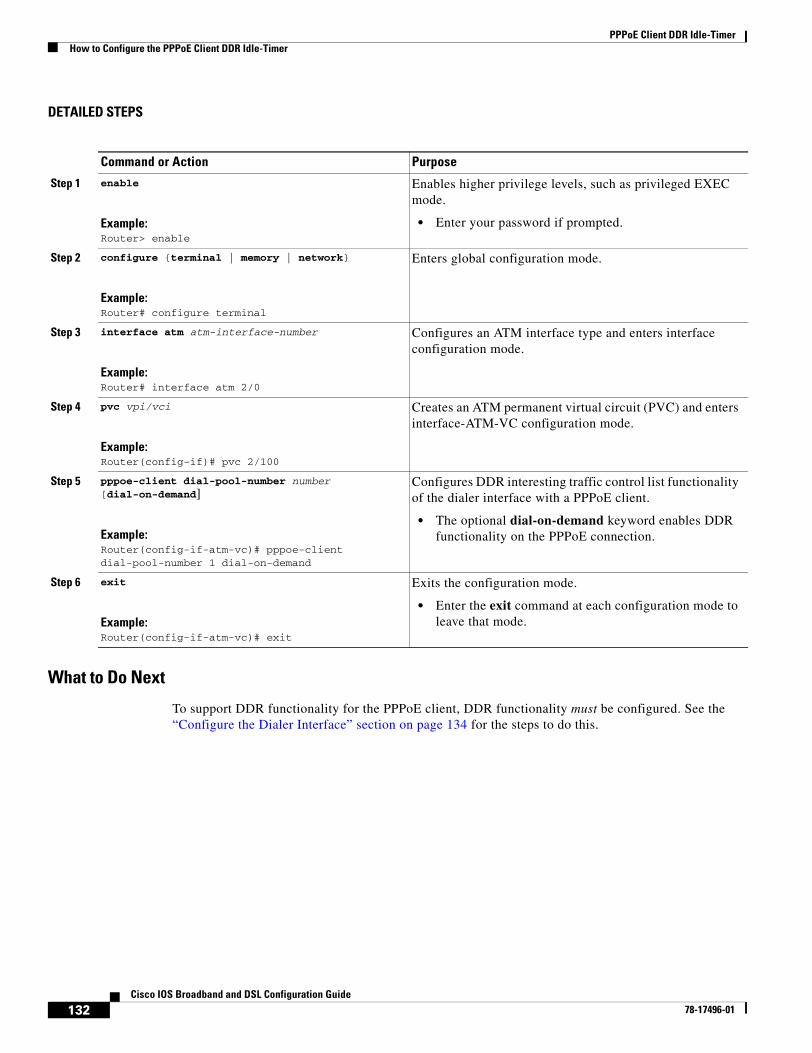
PPPoE Client DDR Idle-TimerHow to Configure the PPPoE Client DDR Idle-Timer
132Cisco IOS Broadband and DSL Configuration Guide
78-17496-01
DETAILED STEPS
What to Do Next
To support DDR functionality for the PPPoE client, DDR functionality must be configured. See the “Configure the Dialer Interface” section on page 134 for the steps to do this.
Command or Action Purpose
Step 1 enable
Example:Router> enable
Enables higher privilege levels, such as privileged EXEC mode.
• Enter your password if prompted.
Step 2 configure {terminal | memory | network}
Example:Router# configure terminal
Enters global configuration mode.
Step 3 interface atm atm-interface-number
Example:Router# interface atm 2/0
Configures an ATM interface type and enters interface configuration mode.
Step 4 pvc vpi/vci
Example:Router(config-if)# pvc 2/100
Creates an ATM permanent virtual circuit (PVC) and enters interface-ATM-VC configuration mode.
Step 5 pppoe-client dial-pool-number number [dial-on-demand]
Example:Router(config-if-atm-vc)# pppoe-client dial-pool-number 1 dial-on-demand
Configures DDR interesting traffic control list functionality of the dialer interface with a PPPoE client.
• The optional dial-on-demand keyword enables DDR functionality on the PPPoE connection.
Step 6 exit
Example:Router(config-if-atm-vc)# exit
Exits the configuration mode.
• Enter the exit command at each configuration mode to leave that mode.
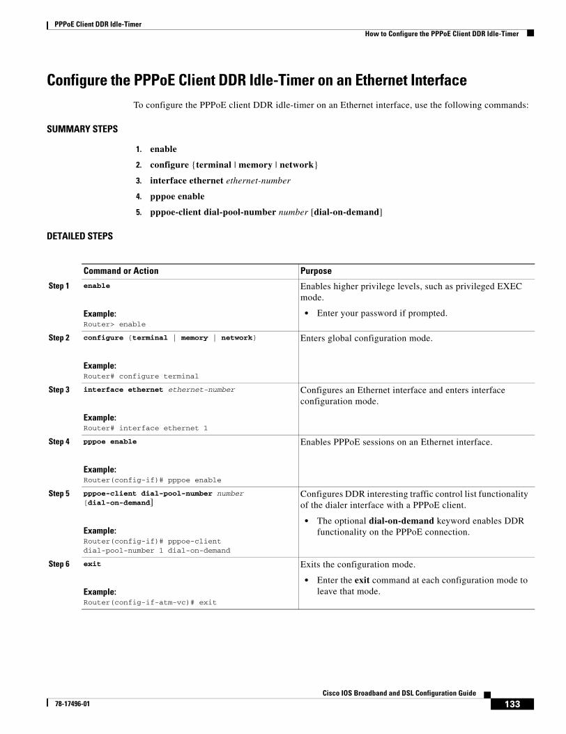
PPPoE Client DDR Idle-TimerHow to Configure the PPPoE Client DDR Idle-Timer
133Cisco IOS Broadband and DSL Configuration Guide
78-17496-01
Configure the PPPoE Client DDR Idle-Timer on an Ethernet InterfaceTo configure the PPPoE client DDR idle-timer on an Ethernet interface, use the following commands:
SUMMARY STEPS
1. enable
2. configure {terminal | memory | network}
3. interface ethernet ethernet-number
4. pppoe enable
5. pppoe-client dial-pool-number number [dial-on-demand]
DETAILED STEPS
Command or Action Purpose
Step 1 enable
Example:Router> enable
Enables higher privilege levels, such as privileged EXEC mode.
• Enter your password if prompted.
Step 2 configure {terminal | memory | network}
Example:Router# configure terminal
Enters global configuration mode.
Step 3 interface ethernet ethernet-number
Example:Router# interface ethernet 1
Configures an Ethernet interface and enters interface configuration mode.
Step 4 pppoe enable
Example:Router(config-if)# pppoe enable
Enables PPPoE sessions on an Ethernet interface.
Step 5 pppoe-client dial-pool-number number [dial-on-demand]
Example:Router(config-if)# pppoe-client dial-pool-number 1 dial-on-demand
Configures DDR interesting traffic control list functionality of the dialer interface with a PPPoE client.
• The optional dial-on-demand keyword enables DDR functionality on the PPPoE connection.
Step 6 exit
Example:Router(config-if-atm-vc)# exit
Exits the configuration mode.
• Enter the exit command at each configuration mode to leave that mode.
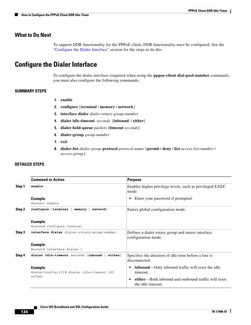
PPPoE Client DDR Idle-TimerHow to Configure the PPPoE Client DDR Idle-Timer
134Cisco IOS Broadband and DSL Configuration Guide
78-17496-01
What to Do Next
To support DDR functionality for the PPPoE client, DDR functionality must be configured. See the “Configure the Dialer Interface” section for the steps to do this.
Configure the Dialer InterfaceTo configure the dialer interface (required when using the pppoe-client dial-pool-number command), you must also configure the following commands:
SUMMARY STEPS
1. enable
2. configure {terminal | memory | network}
3. interface dialer dialer-rotary-group-number
4. dialer idle-timeout seconds [inbound | either]
5. dialer hold-queue packets [timeout seconds]
6. dialer-group group-number
7. exit
8. dialer-list dialer-group protocol protocol-name {permit | deny | list access-list-number | access-group}
DETAILED STEPS
Command or Action Purpose
Step 1 enable
Example:Router> enable
Enables higher privilege levels, such as privileged EXEC mode.
• Enter your password if prompted.
Step 2 configure {terminal | memory | network}
Example:Router# configure terminal
Enters global configuration mode.
Step 3 interface dialer dialer-rotary-group-number
Example:Router# interface dialer 1
Defines a dialer rotary group and enters interface configuration mode.
Step 4 dialer idle-timeout seconds [inbound | either]
Example:Router(config-if)# dialer idle-timeout 180 either
Specifies the duration of idle time before a line is disconnected.
• inbound—Only inbound traffic will reset the idle timeout.
• either—Both inbound and outbound traffic will reset the idle timeout.
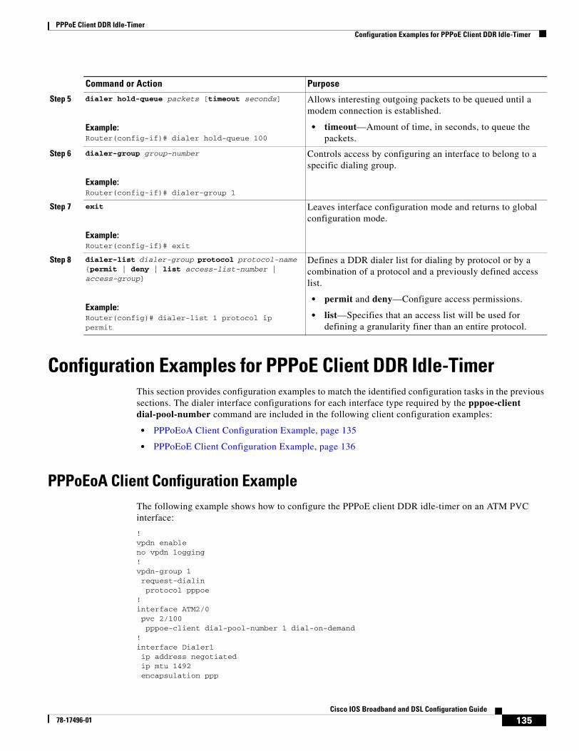
PPPoE Client DDR Idle-TimerConfiguration Examples for PPPoE Client DDR Idle-Timer
135Cisco IOS Broadband and DSL Configuration Guide
78-17496-01
Configuration Examples for PPPoE Client DDR Idle-TimerThis section provides configuration examples to match the identified configuration tasks in the previous sections. The dialer interface configurations for each interface type required by the pppoe-client dial-pool-number command are included in the following client configuration examples:
• PPPoEoA Client Configuration Example, page 135
• PPPoEoE Client Configuration Example, page 136
PPPoEoA Client Configuration ExampleThe following example shows how to configure the PPPoE client DDR idle-timer on an ATM PVC interface:
!vpdn enableno vpdn logging!vpdn-group 1 request-dialin protocol pppoe!interface ATM2/0 pvc 2/100 pppoe-client dial-pool-number 1 dial-on-demand!interface Dialer1 ip address negotiated ip mtu 1492 encapsulation ppp
Step 5 dialer hold-queue packets [timeout seconds]
Example:Router(config-if)# dialer hold-queue 100
Allows interesting outgoing packets to be queued until a modem connection is established.
• timeout—Amount of time, in seconds, to queue the packets.
Step 6 dialer-group group-number
Example:Router(config-if)# dialer-group 1
Controls access by configuring an interface to belong to a specific dialing group.
Step 7 exit
Example:Router(config-if)# exit
Leaves interface configuration mode and returns to global configuration mode.
Step 8 dialer-list dialer-group protocol protocol-name {permit | deny | list access-list-number | access-group}
Example:Router(config)# dialer-list 1 protocol ip permit
Defines a DDR dialer list for dialing by protocol or by a combination of a protocol and a previously defined access list.
• permit and deny—Configure access permissions.
• list—Specifies that an access list will be used for defining a granularity finer than an entire protocol.
Command or Action Purpose
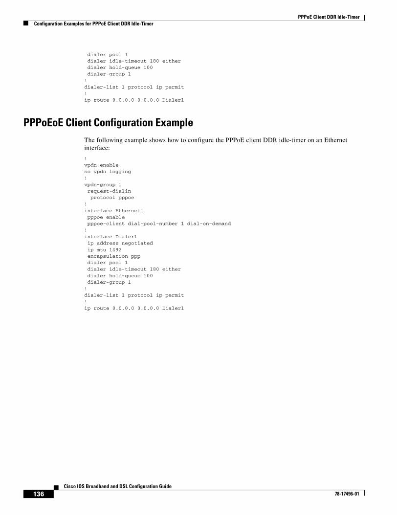
PPPoE Client DDR Idle-TimerConfiguration Examples for PPPoE Client DDR Idle-Timer
136Cisco IOS Broadband and DSL Configuration Guide
78-17496-01
dialer pool 1 dialer idle-timeout 180 either dialer hold-queue 100 dialer-group 1!dialer-list 1 protocol ip permit! ip route 0.0.0.0 0.0.0.0 Dialer1
PPPoEoE Client Configuration ExampleThe following example shows how to configure the PPPoE client DDR idle-timer on an Ethernet interface:
!vpdn enableno vpdn logging!vpdn-group 1 request-dialin protocol pppoe!interface Ethernet1 pppoe enable pppoe-client dial-pool-number 1 dial-on-demand!interface Dialer1 ip address negotiated ip mtu 1492 encapsulation ppp dialer pool 1 dialer idle-timeout 180 either dialer hold-queue 100 dialer-group 1!dialer-list 1 protocol ip permit! ip route 0.0.0.0 0.0.0.0 Dialer1
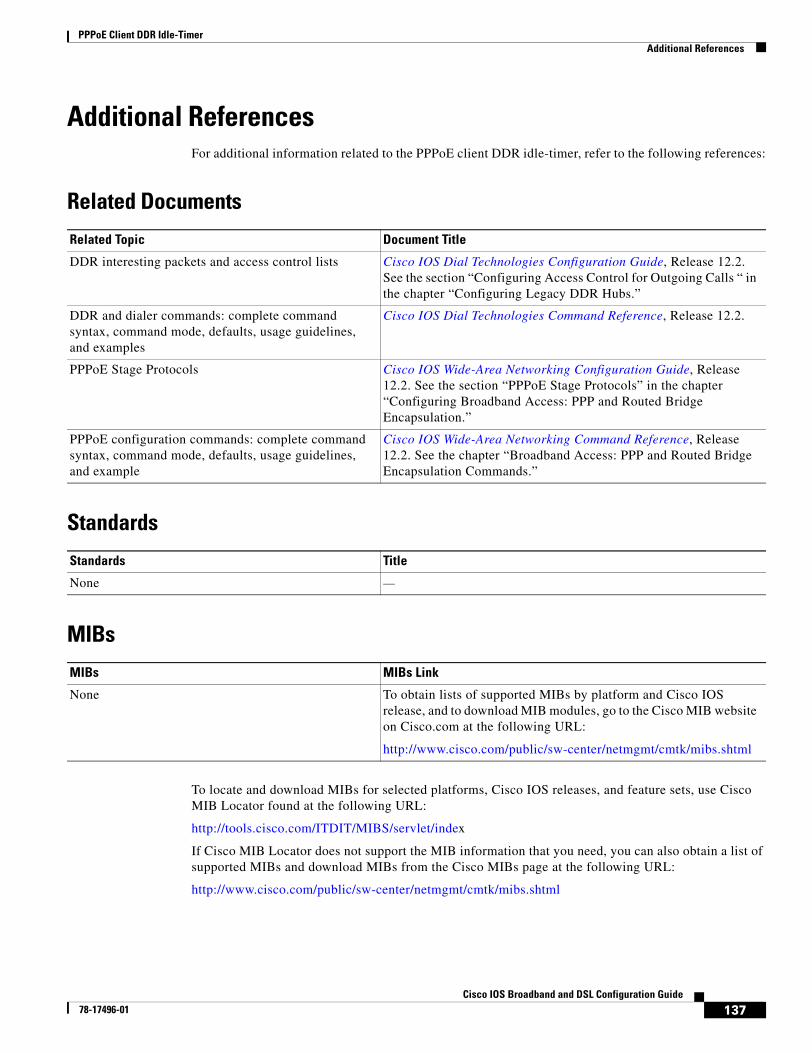
PPPoE Client DDR Idle-TimerAdditional References
137Cisco IOS Broadband and DSL Configuration Guide
78-17496-01
Additional ReferencesFor additional information related to the PPPoE client DDR idle-timer, refer to the following references:
Related Documents
Standards
MIBs
To locate and download MIBs for selected platforms, Cisco IOS releases, and feature sets, use Cisco MIB Locator found at the following URL:
http://tools.cisco.com/ITDIT/MIBS/servlet/index
If Cisco MIB Locator does not support the MIB information that you need, you can also obtain a list of supported MIBs and download MIBs from the Cisco MIBs page at the following URL:
http://www.cisco.com/public/sw-center/netmgmt/cmtk/mibs.shtml
Related Topic Document Title
DDR interesting packets and access control lists Cisco IOS Dial Technologies Configuration Guide, Release 12.2. See the section “Configuring Access Control for Outgoing Calls “ in the chapter “Configuring Legacy DDR Hubs.”
DDR and dialer commands: complete command syntax, command mode, defaults, usage guidelines, and examples
Cisco IOS Dial Technologies Command Reference, Release 12.2.
PPPoE Stage Protocols Cisco IOS Wide-Area Networking Configuration Guide, Release 12.2. See the section “PPPoE Stage Protocols” in the chapter “Configuring Broadband Access: PPP and Routed Bridge Encapsulation.”
PPPoE configuration commands: complete command syntax, command mode, defaults, usage guidelines, and example
Cisco IOS Wide-Area Networking Command Reference, Release 12.2. See the chapter “Broadband Access: PPP and Routed Bridge Encapsulation Commands.”
Standards Title
None —
MIBs MIBs Link
None To obtain lists of supported MIBs by platform and Cisco IOS release, and to download MIB modules, go to the Cisco MIB website on Cisco.com at the following URL:
http://www.cisco.com/public/sw-center/netmgmt/cmtk/mibs.shtml
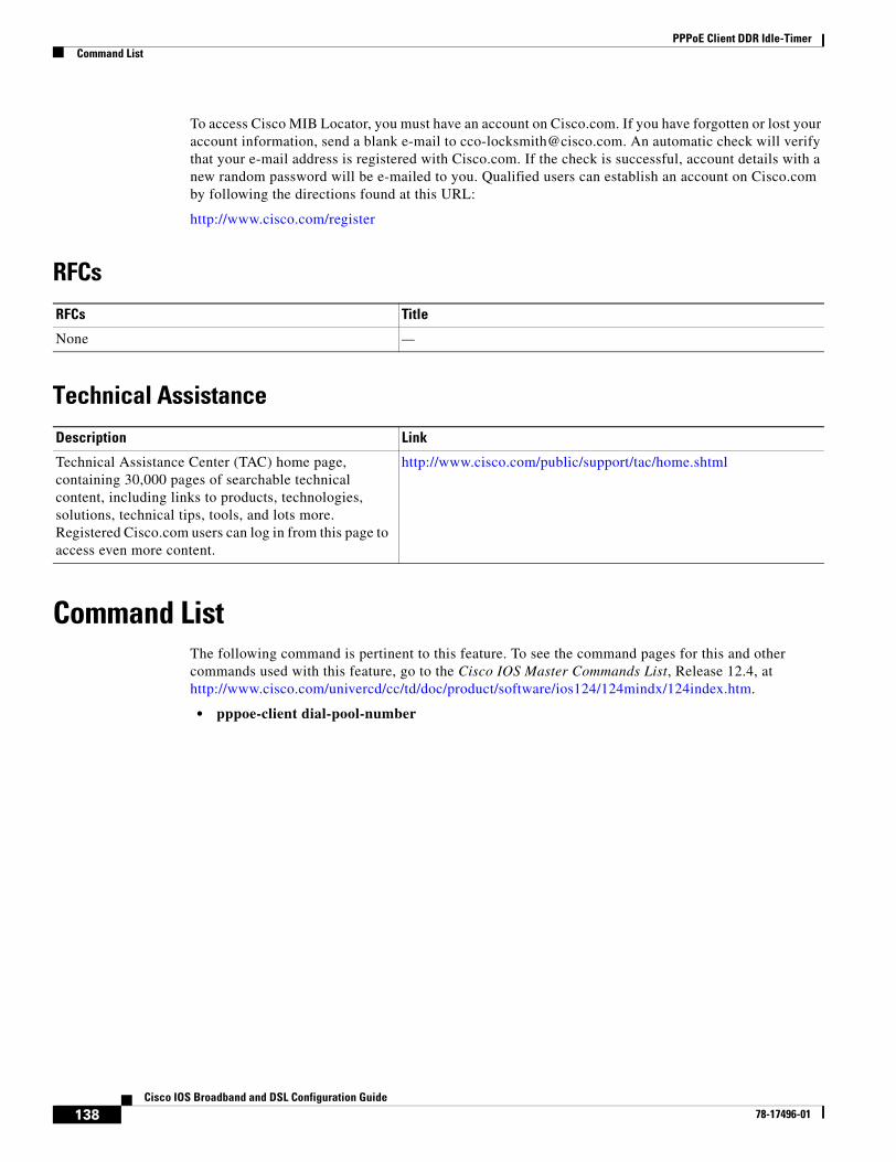
PPPoE Client DDR Idle-TimerCommand List
138Cisco IOS Broadband and DSL Configuration Guide
78-17496-01
To access Cisco MIB Locator, you must have an account on Cisco.com. If you have forgotten or lost your account information, send a blank e-mail to [email protected]. An automatic check will verify that your e-mail address is registered with Cisco.com. If the check is successful, account details with a new random password will be e-mailed to you. Qualified users can establish an account on Cisco.com by following the directions found at this URL:
http://www.cisco.com/register
RFCs
Technical Assistance
Command ListThe following command is pertinent to this feature. To see the command pages for this and other commands used with this feature, go to the Cisco IOS Master Commands List, Release 12.4, at http://www.cisco.com/univercd/cc/td/doc/product/software/ios124/124mindx/124index.htm.
• pppoe-client dial-pool-number
RFCs Title
None —
Description Link
Technical Assistance Center (TAC) home page, containing 30,000 pages of searchable technical content, including links to products, technologies, solutions, technical tips, tools, and lots more. Registered Cisco.com users can log in from this page to access even more content.
http://www.cisco.com/public/support/tac/home.shtml
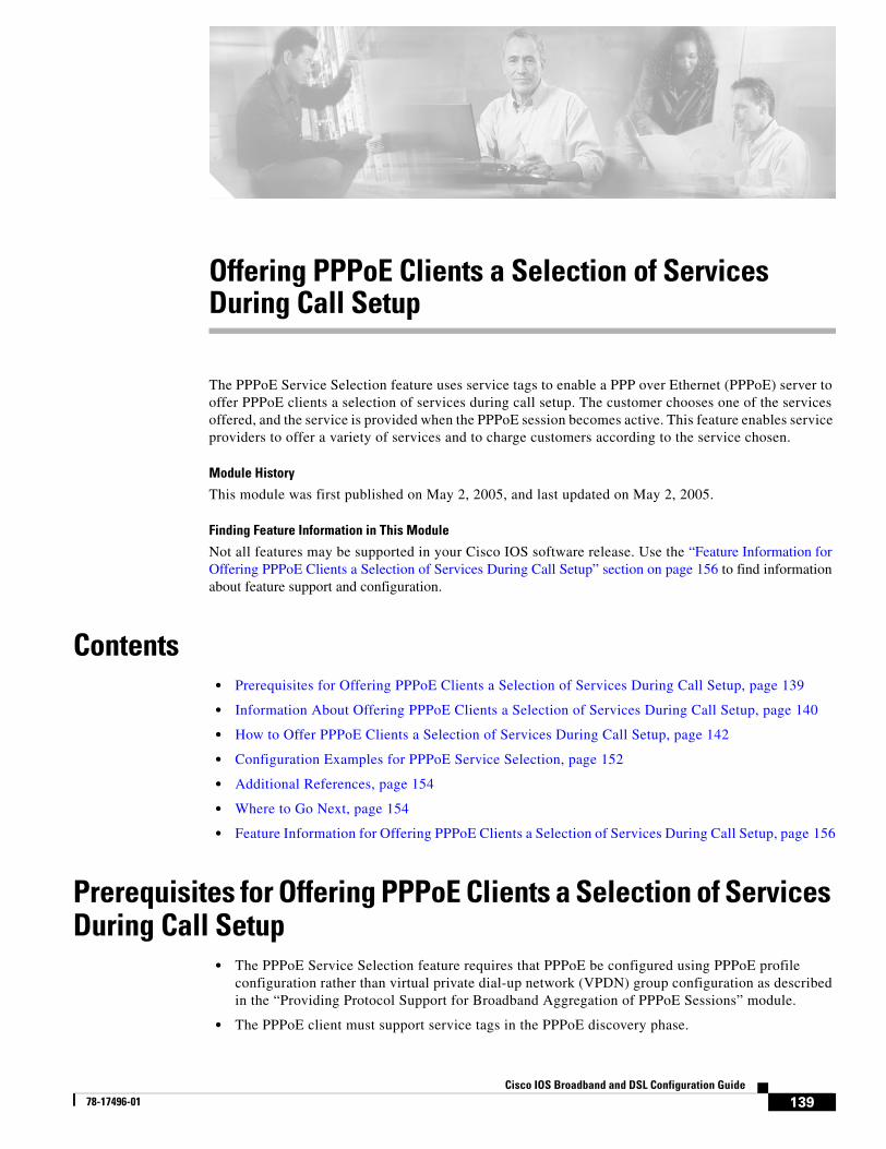
139Cisco IOS Broadband and DSL Configuration Guide
78-17496-01
Offering PPPoE Clients a Selection of Services During Call Setup
The PPPoE Service Selection feature uses service tags to enable a PPP over Ethernet (PPPoE) server to offer PPPoE clients a selection of services during call setup. The customer chooses one of the services offered, and the service is provided when the PPPoE session becomes active. This feature enables service providers to offer a variety of services and to charge customers according to the service chosen.
Module History
This module was first published on May 2, 2005, and last updated on May 2, 2005.
Finding Feature Information in This Module
Not all features may be supported in your Cisco IOS software release. Use the “Feature Information for Offering PPPoE Clients a Selection of Services During Call Setup” section on page 156 to find information about feature support and configuration.
Contents• Prerequisites for Offering PPPoE Clients a Selection of Services During Call Setup, page 139
• Information About Offering PPPoE Clients a Selection of Services During Call Setup, page 140
• How to Offer PPPoE Clients a Selection of Services During Call Setup, page 142
• Configuration Examples for PPPoE Service Selection, page 152
• Additional References, page 154
• Where to Go Next, page 154
• Feature Information for Offering PPPoE Clients a Selection of Services During Call Setup, page 156
Prerequisites for Offering PPPoE Clients a Selection of Services During Call Setup
• The PPPoE Service Selection feature requires that PPPoE be configured using PPPoE profile configuration rather than virtual private dial-up network (VPDN) group configuration as described in the “Providing Protocol Support for Broadband Aggregation of PPPoE Sessions” module.
• The PPPoE client must support service tags in the PPPoE discovery phase.
Offering PPPoE Clients a Selection of Services During Call SetupInformation About Offering PPPoE Clients a Selection of Services During Call Setup
140Cisco IOS Broadband and DSL Configuration Guide
78-17496-01
• The procedures in this document assume that RADIUS accounting and authentication and PPPoE are configured and working.
• If you are going to use PPPoE service selection to offer tunneling services, the procedures in this document assume that you already have tunneling configured and working.
Information About Offering PPPoE Clients a Selection of Services During Call Setup
To configure PPPoE service selection, you should understand the following concepts:
• PPPoE Service Selection Through Service Tags, page 140
• PPPoE Service Names, page 140
• RADIUS Service Profiles for PPPoE Service Selection, page 141
• Benefits of PPPoE Service Selection, page 141
PPPoE Service Selection Through Service TagsPPPoE service selection enables a PPPoE server to offer clients a selection of services during call setup. The PPPoE client chooses one of the services offered, and that service is provided when the PPPoE session becomes active.
PPPoE service selection works through the exchange of service tags during the PPPoE discovery phase. When a client initiates a call with a PPPoE Active Discovery Initiation (PADI) packet, the PPPoE server responds with a PPPoE Active Discovery Offer (PADO) packet that advertises a list of available services. The client selects a service and sends a PPPoE Active Discovery Request (PADR) packet that indicates the service name that was selected.
When the PPPoE server receives the PADR packet that indicates the chosen service, the PPPoE server handles the service name as it would a domain name. The service profile for the service name is retrieved from a RADIUS server, and the attributes within that service profile are applied to the call.
PPPoE Service NamesEach PPPoE service has a service name, which can be defined as a set of characteristics that are applied to a PPPoE connection when that service name is selected during call setup.
When you configure PPPoE service selection, you will define a RADIUS service profile for each service name, list in a subscriber profile the service names that you want to advertise, and then assign the subscriber profile to a PPPoE profile. The PPPoE server will advertise the service names that are listed in the subscriber profile to each PPPoE client connection that uses the configured PPPoE profile.
If a subscriber profile is not assigned to a PPPoE profile, the PPPoE connections that use that PPPoE profile will be established without the additional service tags in the discovery packets. If a port is configured with a static service name (using the vpn service command), the static service name takes precedence, and no services will be advertised to the client.
The Cisco RADIUS vendor-specific attribute (VSA) “service-name” will be used in RADIUS accounting records to log the service name that was selected by the client. This attribute is also used to download the service names from the subscriber profile when the subscriber profile is defined on the RADIUS server.
Offering PPPoE Clients a Selection of Services During Call SetupInformation About Offering PPPoE Clients a Selection of Services During Call Setup
141Cisco IOS Broadband and DSL Configuration Guide
78-17496-01
RADIUS Service Profiles for PPPoE Service SelectionA service profile must be created on the RADIUS server for each service name. The service profile contains attributes that define how the call will be handled. Currently, two sets of attributes are available for defining service profiles: attributes that define tunneling and attributes that define the quality of service (QoS) that will be applied to the permanent virtual circuit (PVC) on which the PPPoE call is coming in.
The “Configuring the Service Profile on the AAA Server for PPPoE Service Selection” section on page 142 lists some of the attributes that are supported in RADIUS service profiles for PPPoE service selection.
Benefits of PPPoE Service SelectionPPPoE service selection enables a service provider to use PPPoE to offer a selection of services to customers and to charge customers according to the service selected. For example, a wholesaler could offer different levels of service by defining multiple service profiles for the same tunnel but with different levels of QoS for the ATM PVC. The wholesaler would be able to charge customers according to the level of service provided.
PPPoE service selection could also be used by access providers to avoid link control protocol (LCP) negotiation at the Layer 2 Tunnel Protocol (L2TP) access concentrator (LAC) for sessions that are to be forwarded to tunnels. Avoiding LCP negotiation at the LAC can improve scalability of the LAC during call setup and help alleviate the load on the LAC while all the sessions on the LAC are reconnecting after an outage.
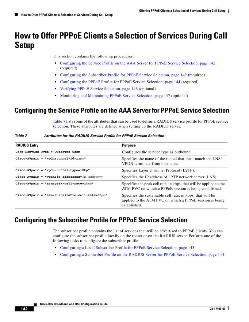
Offering PPPoE Clients a Selection of Services During Call SetupHow to Offer PPPoE Clients a Selection of Services During Call Setup
142Cisco IOS Broadband and DSL Configuration Guide
78-17496-01
How to Offer PPPoE Clients a Selection of Services During Call Setup
This section contains the following procedures:
• Configuring the Service Profile on the AAA Server for PPPoE Service Selection, page 142 (required)
• Configuring the Subscriber Profile for PPPoE Service Selection, page 142 (required)
• Configuring the PPPoE Profile for PPPoE Service Selection, page 144 (required)
• Verifying PPPoE Service Selection, page 146 (optional)
• Monitoring and Maintaining PPPoE Service Selection, page 147 (optional)
Configuring the Service Profile on the AAA Server for PPPoE Service SelectionTable 7 lists some of the attributes that can be used to define a RADIUS service profile for PPPoE service selection. These attributes are defined when setting up the RADIUS server.
Configuring the Subscriber Profile for PPPoE Service SelectionThe subscriber profile contains the list of services that will be advertised to PPPoE clients. You can configure the subscriber profile locally on the router or on the RADIUS server. Perform one of the following tasks to configure the subscriber profile:
• Configuring a Local Subscriber Profile for PPPoE Service Selection, page 143
• Configuring a Subscriber Profile on the RADIUS Server for PPPoE Service Selection, page 144
Table 7 Attributes for the RADIUS Service Profile for PPPoE Service Selection
RADIUS Entry Purpose
User-Service-Type = Outbound-User Configures the service type as outbound.
Cisco-AVpair = "vpdn:tunnel-id=name" Specifies the name of the tunnel that must match the LNS’s VPDN terminate-from hostname.
Cisco-AVpair = "vpdn:tunnel-type=l2tp" Specifies Layer 2 Tunnel Protocol (L2TP).
Cisco-AVpair = "vpdn:ip-addresses=ip-address" Specifies the IP address of L2TP network server (LNS).
Cisco-AVpair = "atm:peak-cell-rate=kbps" Specifies the peak cell rate, in kbps, that will be applied to the ATM PVC on which a PPPoE session is being established.
Cisco-AVpair = "atm:sustainable-cell-rate=kbps" Specifies the sustainable cell rate, in kbps, that will be applied to the ATM PVC on which a PPPoE session is being established.
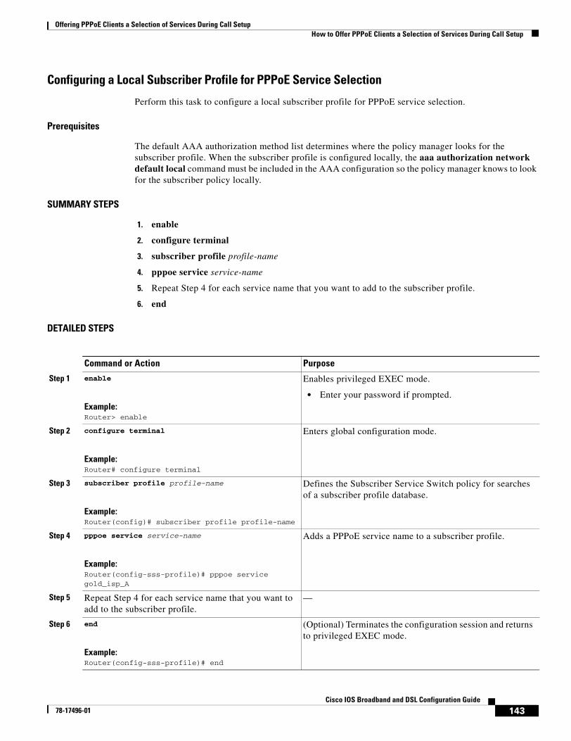
Offering PPPoE Clients a Selection of Services During Call SetupHow to Offer PPPoE Clients a Selection of Services During Call Setup
143Cisco IOS Broadband and DSL Configuration Guide
78-17496-01
Configuring a Local Subscriber Profile for PPPoE Service Selection
Perform this task to configure a local subscriber profile for PPPoE service selection.
Prerequisites
The default AAA authorization method list determines where the policy manager looks for the subscriber profile. When the subscriber profile is configured locally, the aaa authorization network default local command must be included in the AAA configuration so the policy manager knows to look for the subscriber policy locally.
SUMMARY STEPS
1. enable
2. configure terminal
3. subscriber profile profile-name
4. pppoe service service-name
5. Repeat Step 4 for each service name that you want to add to the subscriber profile.
6. end
DETAILED STEPS
Command or Action Purpose
Step 1 enable
Example:Router> enable
Enables privileged EXEC mode.
• Enter your password if prompted.
Step 2 configure terminal
Example:Router# configure terminal
Enters global configuration mode.
Step 3 subscriber profile profile-name
Example:Router(config)# subscriber profile profile-name
Defines the Subscriber Service Switch policy for searches of a subscriber profile database.
Step 4 pppoe service service-name
Example:Router(config-sss-profile)# pppoe service gold_isp_A
Adds a PPPoE service name to a subscriber profile.
Step 5 Repeat Step 4 for each service name that you want to add to the subscriber profile.
—
Step 6 end
Example:Router(config-sss-profile)# end
(Optional) Terminates the configuration session and returns to privileged EXEC mode.
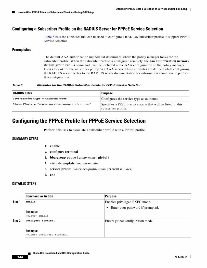
Offering PPPoE Clients a Selection of Services During Call SetupHow to Offer PPPoE Clients a Selection of Services During Call Setup
144Cisco IOS Broadband and DSL Configuration Guide
78-17496-01
Configuring a Subscriber Profile on the RADIUS Server for PPPoE Service Selection
Table 8 lists the attributes that can be used to configure a RADIUS subscriber profile to support PPPoE service selection.
Prerequisites
The default AAA authorization method list determines where the policy manager looks for the subscriber profile. When the subscriber profile is configured remotely, the aaa authorization network default group radius command must be included in the AAA configuration so the policy manager knows to look for the subscriber policy on a AAA server. These attributes are defined while configuring the RADIUS server. Refer to the RADIUS server documentation for information about how to perform this configuration.
Configuring the PPPoE Profile for PPPoE Service SelectionPerform this task to associate a subscriber profile with a PPPoE profile.
SUMMARY STEPS
1. enable
2. configure terminal
3. bba-group pppoe {group-name | global}
4. virtual-template template-number
5. service profile subscriber-profile-name [refresh minutes]
6. end
DETAILED STEPS
Table 8 Attributes for the RADIUS Subscriber Profile for PPPoE Service Selection
RADIUS Entry Purpose
User-Service-Type = Outbound-User Configures the service type as outbound.
Cisco-AVpair = "pppoe:service-name=service-name" Specifies a PPPoE service name that will be listed in this subscriber profile.
Command or Action Purpose
Step 1 enable
Example:Router> enable
Enables privileged EXEC mode.
• Enter your password if prompted.
Step 2 configure terminal
Example:Router# configure terminal
Enters global configuration mode.
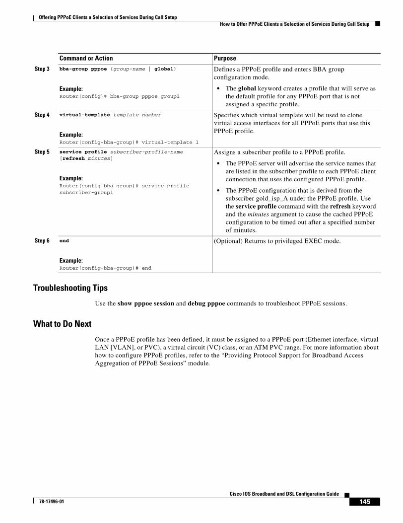
Offering PPPoE Clients a Selection of Services During Call SetupHow to Offer PPPoE Clients a Selection of Services During Call Setup
145Cisco IOS Broadband and DSL Configuration Guide
78-17496-01
Troubleshooting Tips
Use the show pppoe session and debug pppoe commands to troubleshoot PPPoE sessions.
What to Do Next
Once a PPPoE profile has been defined, it must be assigned to a PPPoE port (Ethernet interface, virtual LAN [VLAN], or PVC), a virtual circuit (VC) class, or an ATM PVC range. For more information about how to configure PPPoE profiles, refer to the “Providing Protocol Support for Broadband Access Aggregation of PPPoE Sessions” module.
Step 3 bba-group pppoe {group-name | global}
Example:Router(config)# bba-group pppoe group1
Defines a PPPoE profile and enters BBA group configuration mode.
• The global keyword creates a profile that will serve as the default profile for any PPPoE port that is not assigned a specific profile.
Step 4 virtual-template template-number
Example:Router(config-bba-group)# virtual-template 1
Specifies which virtual template will be used to clone virtual access interfaces for all PPPoE ports that use this PPPoE profile.
Step 5 service profile subscriber-profile-name [refresh minutes]
Example:Router(config-bba-group)# service profile subscriber-group1
Assigns a subscriber profile to a PPPoE profile.
• The PPPoE server will advertise the service names that are listed in the subscriber profile to each PPPoE client connection that uses the configured PPPoE profile.
• The PPPoE configuration that is derived from the subscriber gold_isp_A under the PPPoE profile. Use the service profile command with the refresh keyword and the minutes argument to cause the cached PPPoE configuration to be timed out after a specified number of minutes.
Step 6 end
Example:Router(config-bba-group)# end
(Optional) Returns to privileged EXEC mode.
Command or Action Purpose
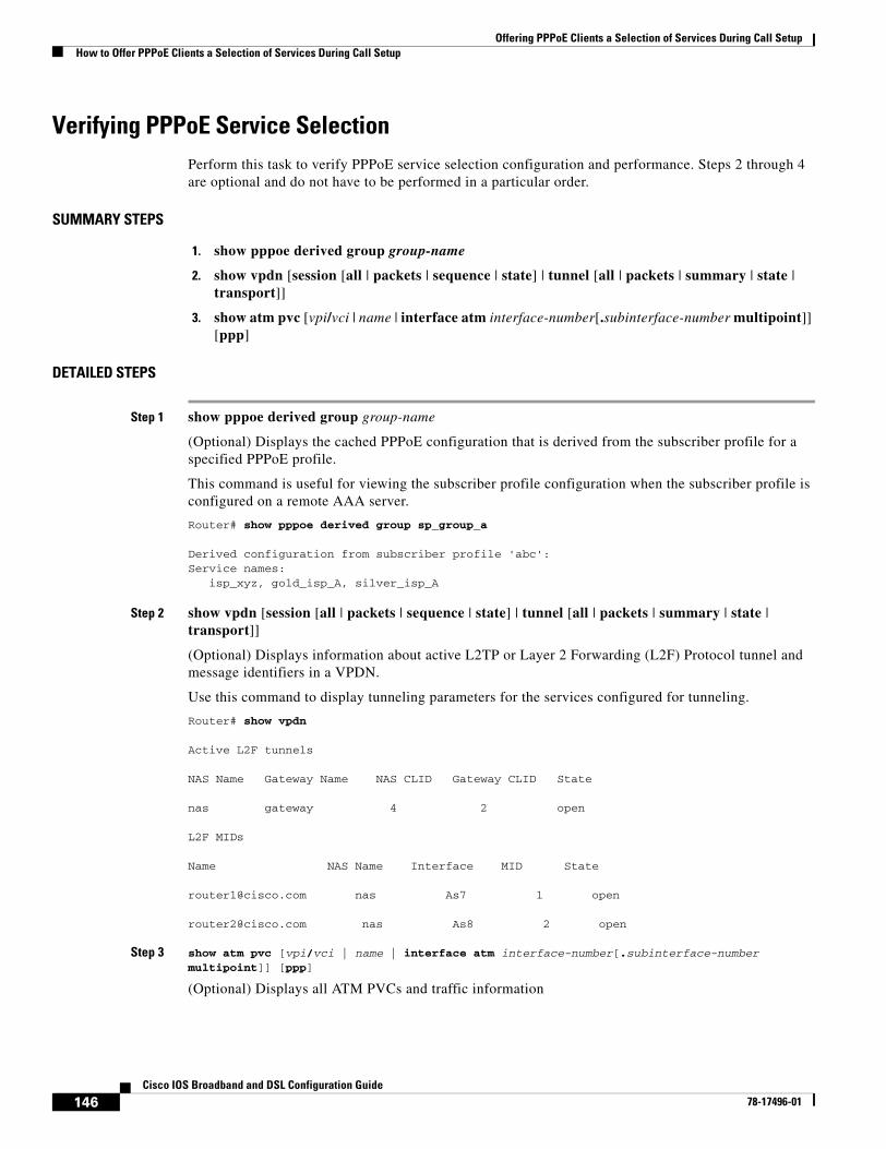
Offering PPPoE Clients a Selection of Services During Call SetupHow to Offer PPPoE Clients a Selection of Services During Call Setup
146Cisco IOS Broadband and DSL Configuration Guide
78-17496-01
Verifying PPPoE Service SelectionPerform this task to verify PPPoE service selection configuration and performance. Steps 2 through 4 are optional and do not have to be performed in a particular order.
SUMMARY STEPS
1. show pppoe derived group group-name
2. show vpdn [session [all | packets | sequence | state] | tunnel [all | packets | summary | state | transport]]
3. show atm pvc [vpi/vci | name | interface atm interface-number[.subinterface-number multipoint]] [ppp]
DETAILED STEPS
Step 1 show pppoe derived group group-name
(Optional) Displays the cached PPPoE configuration that is derived from the subscriber profile for a specified PPPoE profile.
This command is useful for viewing the subscriber profile configuration when the subscriber profile is configured on a remote AAA server.
Router# show pppoe derived group sp_group_a
Derived configuration from subscriber profile 'abc':Service names: isp_xyz, gold_isp_A, silver_isp_A
Step 2 show vpdn [session [all | packets | sequence | state] | tunnel [all | packets | summary | state | transport]]
(Optional) Displays information about active L2TP or Layer 2 Forwarding (L2F) Protocol tunnel and message identifiers in a VPDN.
Use this command to display tunneling parameters for the services configured for tunneling.
Router# show vpdn
Active L2F tunnels
NAS Name Gateway Name NAS CLID Gateway CLID State
nas gateway 4 2 open
L2F MIDs
Name NAS Name Interface MID State
[email protected] nas As7 1 open
[email protected] nas As8 2 open
Step 3 show atm pvc [vpi/vci | name | interface atm interface-number[.subinterface-number multipoint]] [ppp]
(Optional) Displays all ATM PVCs and traffic information
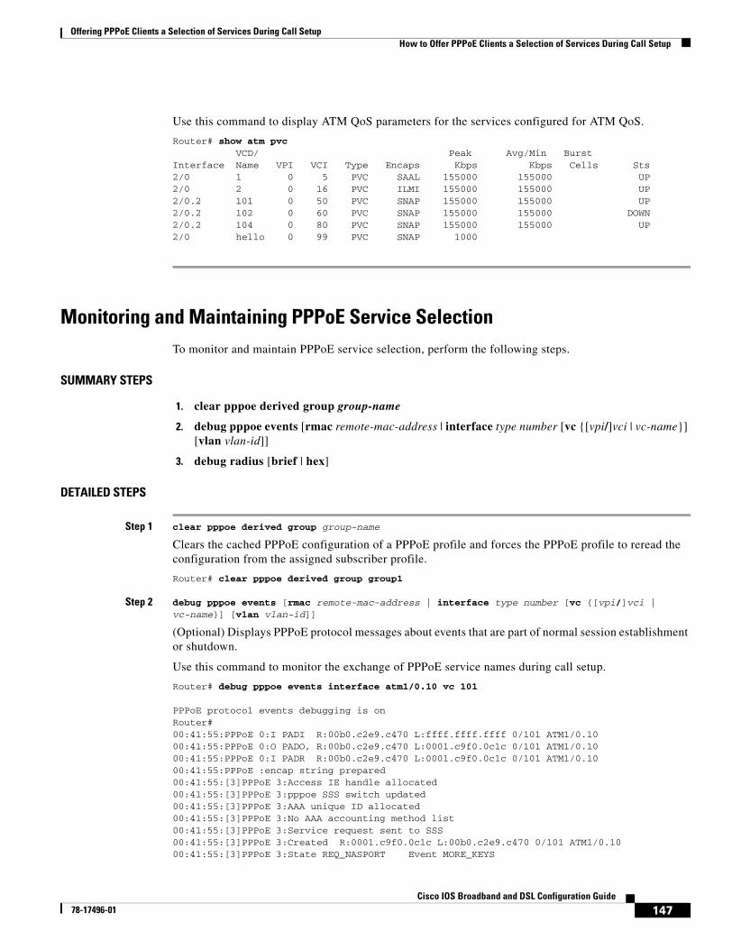
Offering PPPoE Clients a Selection of Services During Call SetupHow to Offer PPPoE Clients a Selection of Services During Call Setup
147Cisco IOS Broadband and DSL Configuration Guide
78-17496-01
Use this command to display ATM QoS parameters for the services configured for ATM QoS.
Router# show atm pvc VCD/ Peak Avg/Min BurstInterface Name VPI VCI Type Encaps Kbps Kbps Cells Sts2/0 1 0 5 PVC SAAL 155000 155000 UP2/0 2 0 16 PVC ILMI 155000 155000 UP2/0.2 101 0 50 PVC SNAP 155000 155000 UP2/0.2 102 0 60 PVC SNAP 155000 155000 DOWN2/0.2 104 0 80 PVC SNAP 155000 155000 UP2/0 hello 0 99 PVC SNAP 1000
Monitoring and Maintaining PPPoE Service SelectionTo monitor and maintain PPPoE service selection, perform the following steps.
SUMMARY STEPS
1. clear pppoe derived group group-name
2. debug pppoe events [rmac remote-mac-address | interface type number [vc {[vpi/]vci | vc-name}] [vlan vlan-id]]
3. debug radius [brief | hex]
DETAILED STEPS
Step 1 clear pppoe derived group group-name
Clears the cached PPPoE configuration of a PPPoE profile and forces the PPPoE profile to reread the configuration from the assigned subscriber profile.
Router# clear pppoe derived group group1
Step 2 debug pppoe events [rmac remote-mac-address | interface type number [vc {[vpi/]vci | vc-name}] [vlan vlan-id]]
(Optional) Displays PPPoE protocol messages about events that are part of normal session establishment or shutdown.
Use this command to monitor the exchange of PPPoE service names during call setup.
Router# debug pppoe events interface atm1/0.10 vc 101
PPPoE protocol events debugging is on Router# 00:41:55:PPPoE 0:I PADI R:00b0.c2e9.c470 L:ffff.ffff.ffff 0/101 ATM1/0.10 00:41:55:PPPoE 0:O PADO, R:00b0.c2e9.c470 L:0001.c9f0.0c1c 0/101 ATM1/0.10 00:41:55:PPPoE 0:I PADR R:00b0.c2e9.c470 L:0001.c9f0.0c1c 0/101 ATM1/0.10 00:41:55:PPPoE :encap string prepared 00:41:55:[3]PPPoE 3:Access IE handle allocated 00:41:55:[3]PPPoE 3:pppoe SSS switch updated 00:41:55:[3]PPPoE 3:AAA unique ID allocated 00:41:55:[3]PPPoE 3:No AAA accounting method list 00:41:55:[3]PPPoE 3:Service request sent to SSS 00:41:55:[3]PPPoE 3:Created R:0001.c9f0.0c1c L:00b0.c2e9.c470 0/101 ATM1/0.10 00:41:55:[3]PPPoE 3:State REQ_NASPORT Event MORE_KEYS
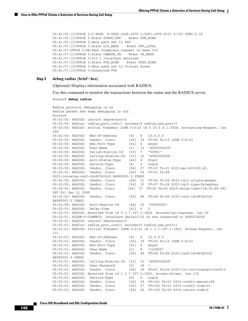
Offering PPPoE Clients a Selection of Services During Call SetupHow to Offer PPPoE Clients a Selection of Services During Call Setup
148Cisco IOS Broadband and DSL Configuration Guide
78-17496-01
00:41:55:[3]PPPoE 3:O PADS R:00b0.c2e9.c470 L:0001.c9f0.0c1c 0/101 ATM1/0.10 00:41:55:[3]PPPoE 3:State START_PPP Event DYN_BIND 00:41:55:[3]PPPoE 3:data path set to PPP 00:41:57:[3]PPPoE 3:State LCP_NEGO Event PPP_LOCAL 00:41:57:PPPoE 3/SB:Sent vtemplate request on base Vi2 00:41:57:[3]PPPoE 3:State CREATE_VA Event VA_RESP 00:41:57:[3]PPPoE 3:Vi2.1 interface obtained 00:41:57:[3]PPPoE 3:State PTA_BIND Event STAT_BIND 00:41:57:[3]PPPoE 3:data path set to Virtual Acess 00:41:57:[3]PPPoE 3:Connected PTA
Step 3 debug radius [brief | hex]
(Optional) Displays information associated with RADIUS.
Use this command to monitor the transactions between the router and the RADIUS server.
Router# debug radius
Radius protocol debugging is onRadius packet hex dump debugging is offRouter#00:02:50: RADIUS: ustruct sharecount=300:02:50: Radius: radius_port_info() success=0 radius_nas_port=100:02:50: RADIUS: Initial Transmit ISDN 0:D:23 id 0 10.0.0.1:1824, Accounting-Request, len 35800:02:50: RADIUS: NAS-IP-Address [4] 6 10.0.0.000:02:50: RADIUS: Vendor, Cisco [26] 19 VT=02 TL=13 ISDN 0:D:2300:02:50: RADIUS: NAS-Port-Type [61] 6 Async00:02:50: RADIUS: User-Name [1] 12 "4085554206"00:02:50: RADIUS: Called-Station-Id [30] 7 "52981"00:02:50: RADIUS: Calling-Station-Id [31] 12 "4085554206"00:02:50: RADIUS: Acct-Status-Type [40] 6 Start00:02:50: RADIUS: Service-Type [6] 6 Login00:02:50: RADIUS: Vendor, Cisco [26] 27 VT=33 TL=21 h323-gw-id=5300_43.00:02:50: RADIUS: Vendor, Cisco [26] 55 VT=01 TL=49 h323-incoming-conf-id=8F3A3163 B4980003 0 29BD000:02:50: RADIUS: Vendor, Cisco [26] 31 VT=26 TL=25 h323-call-origin=answer00:02:50: RADIUS: Vendor, Cisco [26] 32 VT=27 TL=26 h323-call-type=Telephony00:02:50: RADIUS: Vendor, Cisco [26] 57 VT=25 TL=51 h323-setup-time=*16:02:48.681 PST Fri Dec 31 199900:02:50: RADIUS: Vendor, Cisco [26] 46 VT=24 TL=40 h323-conf-id=8F3A3163 B4980003 0 29BD000:02:50: RADIUS: Acct-Session-Id [44] 10 "00000002"00:02:50: RADIUS: Delay-Time [41] 6 000:02:51: RADIUS: Received from id 0 1.7.157.1:1824, Accounting-response, len 2000:02:51: %ISDN-6-CONNECT: Interface Serial0:22 is now connected to 4085274206 00:03:01: RADIUS: ustruct sharecount=300:03:01: Radius: radius_port_info() success=0 radius_nas_port=100:03:01: RADIUS: Initial Transmit ISDN 0:D:23 id 1 1.7.157.1:1823, Access-Request, len 17100:03:01: RADIUS: NAS-IP-Address [4] 6 10.0.0.000:03:01: RADIUS: Vendor, Cisco [26] 19 VT=02 TL=13 ISDN 0:D:2300:03:01: RADIUS: NAS-Port-Type [61] 6 Async00:03:01: RADIUS: User-Name [1] 8 "123456"00:03:01: RADIUS: Vendor, Cisco [26] 46 VT=24 TL=40 h323-conf-id=8F3A3163 B4980003 0 29BD000:03:01: RADIUS: Calling-Station-Id [31] 12 "4085554206"00:03:01: RADIUS: User-Password [2] 18 *00:03:01: RADIUS: Vendor, Cisco [26] 36 VT=01 TL=30 h323-ivr-out=transactionID:000:03:01: RADIUS: Received from id 1 1.7.157.1:1823, Access-Accept, len 11500:03:01: RADIUS: Service-Type [6] 6 Login00:03:01: RADIUS: Vendor, Cisco [26] 29 VT=101 TL=23 h323-credit-amount=4500:03:01: RADIUS: Vendor, Cisco [26] 27 VT=102 TL=21 h323-credit-time=3300:03:01: RADIUS: Vendor, Cisco [26] 26 VT=103 TL=20 h323-return-code=0

Offering PPPoE Clients a Selection of Services During Call SetupHow to Offer PPPoE Clients a Selection of Services During Call Setup
149Cisco IOS Broadband and DSL Configuration Guide
78-17496-01
00:03:01: RADIUS: Class [25] 7 6C6F63616C00:03:01: RADIUS: saved authorization data for user 62321E14 at 6233D25800:03:13: %ISDN-6-DISCONNECT: Interface Serial0:22 disconnected from 4085274206, call lasted 22 seconds00:03:13: RADIUS: ustruct sharecount=200:03:13: Radius: radius_port_info() success=0 radius_nas_port=100:03:13: RADIUS: Sent class "local" at 6233D2C4 from user 62321E1400:03:13: RADIUS: Initial Transmit ISDN 0:D:23 id 2 1.7.157.1:1824, Accounting-Request, len 77500:03:13: RADIUS: NAS-IP-Address [4] 6 10.0.0.000:03:13: RADIUS: Vendor, Cisco [26] 19 VT=02 TL=13 ISDN 0:D:2300:03:13: RADIUS: NAS-Port-Type [61] 6 Async00:03:13: RADIUS: User-Name [1] 8 "123456"00:03:13: RADIUS: Called-Station-Id [30] 7 "52981"00:03:13: RADIUS: Calling-Station-Id [31] 12 "4085274206"00:03:13: RADIUS: Acct-Status-Type [40] 6 Stop00:03:13: RADIUS: Class [25] 7 6C6F63616C00:03:13: RADIUS: Undebuggable [45] 6 0000000100:03:13: RADIUS: Service-Type [6] 6 Login00:03:13: RADIUS: Vendor, Cisco [26] 27 VT=33 TL=21 h323-gw-id=5300_43.00:03:13: RADIUS: Vendor, Cisco [26] 55 VT=01 TL=49 h323-incoming-conf-id=8F3A3163 B4980003 0 29BD000:03:13: RADIUS: Vendor, Cisco [26] 31 VT=26 TL=25 h323-call-origin=answer00:03:13: RADIUS: Vendor, Cisco [26] 32 VT=27 TL=26 h323-call-type=Telephony00:03:13: RADIUS: Vendor, Cisco [26] 57 VT=25 TL=51 h323-setup-time=*16:02:48.681 PST Fri Dec 31 199900:03:13: RADIUS: Vendor, Cisco [26] 59 VT=28 TL=53 h323-connect-time=*16:02:48.946 PST Fri Dec 31 199900:03:13: RADIUS: Vendor, Cisco [26] 62 VT=29 TL=56in=000:03:13: RADIUS: Vendor, Cisco [26] 23 VT=01 TL=17 pre-bytes-out=000:03:13: RADIUS: Vendor, Cisco [26] 21 VT=01 TL=15 pre-paks-in=000:03:13: RADIUS: Vendor, Cisco [26] 22 VT=01 TL=16 pre-paks-out=000:03:13: RADIUS: Vendor, Cisco [26] 22 VT=01 TL=16 nas-rx-speed=000:03:13: RADIUS: Vendor, Cisco [26] 22 VT=01 TL=16 nas-tx-speed=000:03:13: RADIUS: Delay-Time [41] 6 000:03:13: RADIUS: Received from id 2 1.7.157.1:1824, Accounting-response, len 20h323-disconnect-time=*16:03:11.306 PST Fri Dec 31 199900:03:13: RADIUS: Vendor, Cisco [26] 32 VT=30 TL=26 h323-disconnect-cause=1000:03:13: RADIUS: Vendor, Cisco [26] 28 VT=31 TL=22 h323-voice-quality=000:03:13: RADIUS: Vendor, Cisco [26] 46 VT=24 TL=40 h323-conf-id=8F3A3163 B4980003 0 29BD000:03:13: RADIUS: Acct-Session-Id [44] 10 "00000002"00:03:13: RADIUS: Acct-Input-Octets [42] 6 000:03:13: RADIUS: Acct-Output-Octets [43] 6 8800000:03:13: RADIUS: Acct-Input-Packets [47] 6 000:03:13: RADIUS: Acct-Output-Packets [48] 6 55000:03:13: RADIUS: Acct-Session-Time [46] 6 2200:03:13: RADIUS: Vendor, Cisco [26] 30 VT=01 TL=24 subscriber=RegularLine00:03:13: RADIUS: Vendor, Cisco [26] 35 VT=01 TL=29 h323-ivr-out=Tariff:Unknown00:03:13: RADIUS: Vendor, Cisco [26] 22 VT=01 TL=16 pre-bytes-
The following is sample output from the debug radius brief command:
Router# debug radius brief
Radius protocol debugging is onRadius packet hex dump debugging is offRadius protocol in brief format debugging is on00:05:21: RADIUS: Initial Transmit ISDN 0:D:23 id 6 10.0.0.1:1824, Accounting-Request, len 35800:05:21: %ISDN-6-CONNECT: Interface Serial0:22 is now connected to 408527420600:05:26: RADIUS: Retransmit id 600:05:31: RADIUS: Tried all servers.00:05:31: RADIUS: No valid server found. Trying any viable server
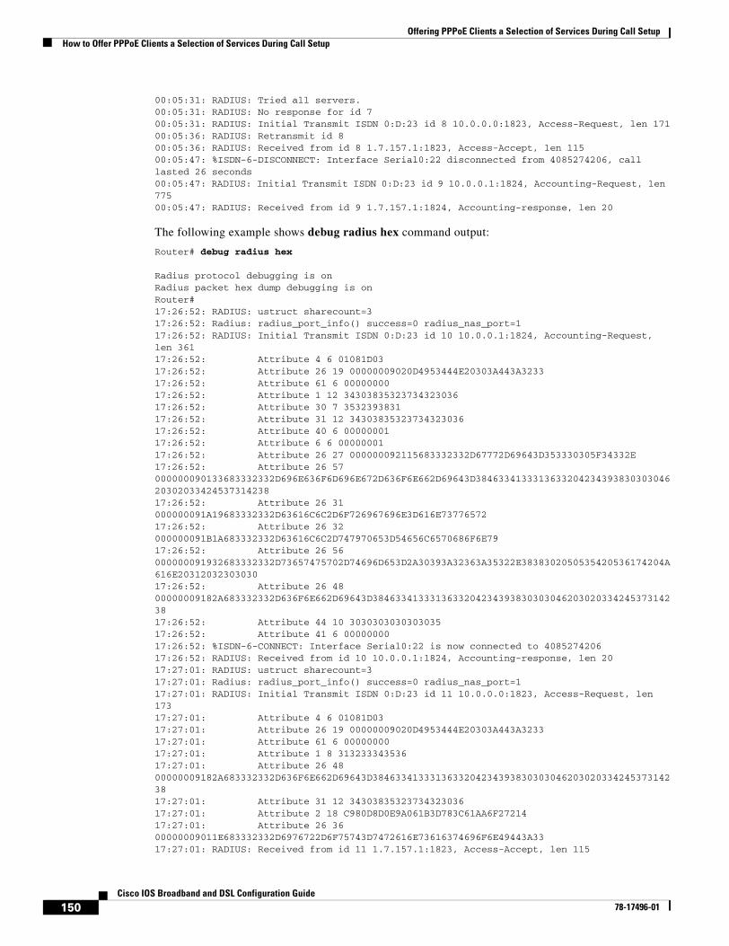
Offering PPPoE Clients a Selection of Services During Call SetupHow to Offer PPPoE Clients a Selection of Services During Call Setup
150Cisco IOS Broadband and DSL Configuration Guide
78-17496-01
00:05:31: RADIUS: Tried all servers.00:05:31: RADIUS: No response for id 700:05:31: RADIUS: Initial Transmit ISDN 0:D:23 id 8 10.0.0.0:1823, Access-Request, len 17100:05:36: RADIUS: Retransmit id 800:05:36: RADIUS: Received from id 8 1.7.157.1:1823, Access-Accept, len 11500:05:47: %ISDN-6-DISCONNECT: Interface Serial0:22 disconnected from 4085274206, call lasted 26 seconds00:05:47: RADIUS: Initial Transmit ISDN 0:D:23 id 9 10.0.0.1:1824, Accounting-Request, len 77500:05:47: RADIUS: Received from id 9 1.7.157.1:1824, Accounting-response, len 20
The following example shows debug radius hex command output:
Router# debug radius hex
Radius protocol debugging is onRadius packet hex dump debugging is onRouter#17:26:52: RADIUS: ustruct sharecount=317:26:52: Radius: radius_port_info() success=0 radius_nas_port=117:26:52: RADIUS: Initial Transmit ISDN 0:D:23 id 10 10.0.0.1:1824, Accounting-Request, len 36117:26:52: Attribute 4 6 01081D0317:26:52: Attribute 26 19 00000009020D4953444E20303A443A323317:26:52: Attribute 61 6 0000000017:26:52: Attribute 1 12 3430383532373432303617:26:52: Attribute 30 7 353239383117:26:52: Attribute 31 12 3430383532373432303617:26:52: Attribute 40 6 0000000117:26:52: Attribute 6 6 0000000117:26:52: Attribute 26 27 000000092115683332332D67772D69643D353330305F34332E17:26:52: Attribute 26 57 000000090133683332332D696E636F6D696E672D636F6E662D69643D38463341333136332042343938303030462030203342453731423817:26:52: Attribute 26 31 000000091A19683332332D63616C6C2D6F726967696E3D616E7377657217:26:52: Attribute 26 32 000000091B1A683332332D63616C6C2D747970653D54656C6570686F6E7917:26:52: Attribute 26 56 000000091932683332332D73657475702D74696D653D2A30393A32363A35322E3838302050535420536174204A616E2031203230303017:26:52: Attribute 26 48 00000009182A683332332D636F6E662D69643D38463341333136332042343938303030462030203342453731423817:26:52: Attribute 44 10 303030303030303517:26:52: Attribute 41 6 0000000017:26:52: %ISDN-6-CONNECT: Interface Serial0:22 is now connected to 408527420617:26:52: RADIUS: Received from id 10 10.0.0.1:1824, Accounting-response, len 2017:27:01: RADIUS: ustruct sharecount=317:27:01: Radius: radius_port_info() success=0 radius_nas_port=117:27:01: RADIUS: Initial Transmit ISDN 0:D:23 id 11 10.0.0.0:1823, Access-Request, len 17317:27:01: Attribute 4 6 01081D0317:27:01: Attribute 26 19 00000009020D4953444E20303A443A323317:27:01: Attribute 61 6 0000000017:27:01: Attribute 1 8 31323334353617:27:01: Attribute 26 48 00000009182A683332332D636F6E662D69643D38463341333136332042343938303030462030203342453731423817:27:01: Attribute 31 12 3430383532373432303617:27:01: Attribute 2 18 C980D8D0E9A061B3D783C61AA6F2721417:27:01: Attribute 26 36 00000009011E683332332D6976722D6F75743D7472616E73616374696F6E49443A3317:27:01: RADIUS: Received from id 11 1.7.157.1:1823, Access-Accept, len 115

Offering PPPoE Clients a Selection of Services During Call SetupHow to Offer PPPoE Clients a Selection of Services During Call Setup
151Cisco IOS Broadband and DSL Configuration Guide
78-17496-01
17:27:01: Attribute 6 6 0000000117:27:01: Attribute 26 29 000000096517683332332D6372656469742D616D6F756E743D343517:27:01: Attribute 26 27 000000096615683332332D6372656469742D74696D653D333317:27:01: Attribute 26 26 000000096714683332332D72657475726E2D636F64653D3017:27:01: Attribute 25 7 6C6F63616C17:27:01: RADIUS: saved authorization data for user 61AA0698 at 6215087C17:27:09: %ISDN-6-DISCONNECT: Interface Serial0:22 disconnected from 4085554206, call lasted 17 seconds17:27:09: RADIUS: ustruct sharecount=217:27:09: Radius: radius_port_info() success=0 radius_nas_port=117:27:09: RADIUS: Sent class "local" at 621508E8 from user 61AA069817:27:09: RADIUS: Initial Transmit ISDN 0:D:23 id 12 1.7.157.1:1824, Accounting-Request, len 77617:27:09: Attribute 4 6 01081D0317:27:09: Attribute 26 19 00000009020D4953444E20303A443A323317:27:09: Attribute 61 6 0000000017:27:09: Attribute 1 8 31323334353617:27:09: Attribute 30 7 353239383117:27:09: Attribute 31 12 3430383532373432303617:27:09: Attribute 40 6 0000000217:27:09: Attribute 25 7 6C6F63616C17:27:09: Attribute 45 6 0000000117:27:09: Attribute 6 6 0000000117:27:09: Attribute 26 27 000000092115683332332D67772D69643D353330305F34332E17:27:09: Attribute 26 57 000000090133683332332D696E636F6D696E672D636F6E662D69643D38463341333136332042343938303030462030203342453731423817:27:09: Attribute 26 31
000000091A19683332332D63616C6C2D6F726967696E3D616E7377657217:27:09: Attribute 26 32
000000091B1A683332332D63616C6C2D747970653D54656C6570686F6E7917:27:09: Attribute 26 56
000000091932683332332D73657475702D74696D653D2A30393A32363A35322E3838302050535420536174204A616E2031203230303017:27:09: Attribute 26 58
000000091C34683332332D636F6E6E6563742D74696D653D2A30393A32363A35322E3930372050535420536174204A616E2031203230303017:27:09: Attribute 26 61
000000091D37683332332D646973636F6E6E6563742D74696D653D2A30393A32373A31302E3133372050535420536174204A616E2031203230303017:27:09: Attribute 26 32
000000091E1A683332332D646973636F6E6E6563742D63617573653D313017:27:09: Attribute 26 28 000000091F16683332332D766F6963652D7175616C6974793D3017:27:09: Attribute 26 48
00000009182A683332332D636F6E662D69643D38463341333136332042343938303030462030203342453731423817:27:09: Attribute 44 10 303030303030303517:27:09: Attribute 42 6 0000000017:27:09: Attribute 43 6 00012CA017:27:09: Attribute 47 6 0000000017:27:09: Attribute 48 6 000001E117:27:09: Attribute 46 6 0000001117:27:09: Attribute 26 30 000000090118737562736372696265723D526567756C61724C696E6517:27:09: Attribute 26 35
00000009011D683332332D6976722D6F75743D5461726966663A556E6B6E6F776E17:27:09: Attribute 26 22 0000000901107072652D62797465732D696E3D30
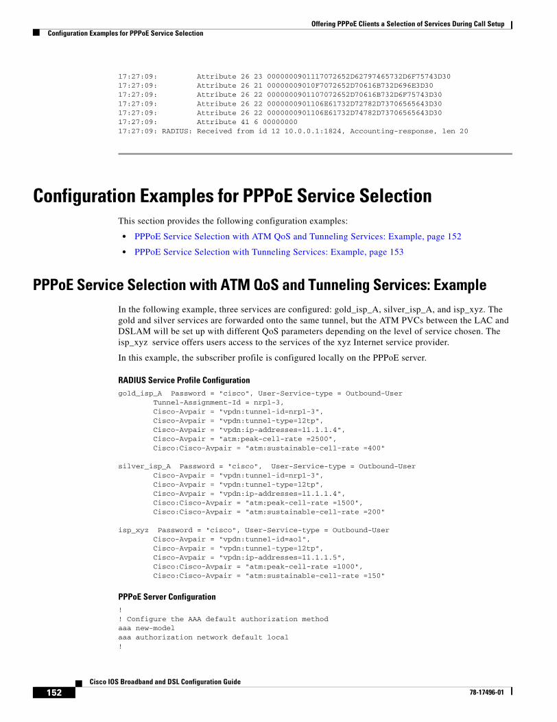
Offering PPPoE Clients a Selection of Services During Call SetupConfiguration Examples for PPPoE Service Selection
152Cisco IOS Broadband and DSL Configuration Guide
78-17496-01
17:27:09: Attribute 26 23 0000000901117072652D62797465732D6F75743D3017:27:09: Attribute 26 21 00000009010F7072652D70616B732D696E3D3017:27:09: Attribute 26 22 0000000901107072652D70616B732D6F75743D3017:27:09: Attribute 26 22 0000000901106E61732D72782D73706565643D3017:27:09: Attribute 26 22 0000000901106E61732D74782D73706565643D3017:27:09: Attribute 41 6 0000000017:27:09: RADIUS: Received from id 12 10.0.0.1:1824, Accounting-response, len 20
Configuration Examples for PPPoE Service SelectionThis section provides the following configuration examples:
• PPPoE Service Selection with ATM QoS and Tunneling Services: Example, page 152
• PPPoE Service Selection with Tunneling Services: Example, page 153
PPPoE Service Selection with ATM QoS and Tunneling Services: ExampleIn the following example, three services are configured: gold_isp_A, silver_isp_A, and isp_xyz. The gold and silver services are forwarded onto the same tunnel, but the ATM PVCs between the LAC and DSLAM will be set up with different QoS parameters depending on the level of service chosen. The isp_xyz service offers users access to the services of the xyz Internet service provider.
In this example, the subscriber profile is configured locally on the PPPoE server.
RADIUS Service Profile Configurationgold_isp_A Password = "cisco", User-Service-type = Outbound-User Tunnel-Assignment-Id = nrp1-3, Cisco-Avpair = "vpdn:tunnel-id=nrp1-3", Cisco-Avpair = "vpdn:tunnel-type=l2tp", Cisco-Avpair = "vpdn:ip-addresses=11.1.1.4", Cisco-Avpair = "atm:peak-cell-rate =2500", Cisco:Cisco-Avpair = "atm:sustainable-cell-rate =400"
silver_isp_A Password = "cisco", User-Service-type = Outbound-User Cisco-Avpair = "vpdn:tunnel-id=nrp1-3", Cisco-Avpair = "vpdn:tunnel-type=l2tp", Cisco-Avpair = "vpdn:ip-addresses=11.1.1.4", Cisco:Cisco-Avpair = "atm:peak-cell-rate =1500", Cisco:Cisco-Avpair = "atm:sustainable-cell-rate =200"
isp_xyz Password = "cisco", User-Service-type = Outbound-User Cisco-Avpair = "vpdn:tunnel-id=aol", Cisco-Avpair = "vpdn:tunnel-type=l2tp", Cisco-Avpair = "vpdn:ip-addresses=11.1.1.5", Cisco:Cisco-Avpair = "atm:peak-cell-rate =1000", Cisco:Cisco-Avpair = "atm:sustainable-cell-rate =150"
PPPoE Server Configuration ! ! Configure the AAA default authorization methodaaa new-modelaaa authorization network default local!
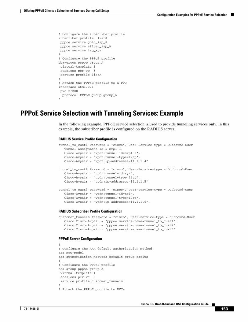
Offering PPPoE Clients a Selection of Services During Call SetupConfiguration Examples for PPPoE Service Selection
153Cisco IOS Broadband and DSL Configuration Guide
78-17496-01
! Configure the subscriber profilesubscriber profile listApppoe service gold_isp_Apppoe service silver_isp_Apppoe service isp_xyz
!! Configure the PPPoE profilebba-group pppoe group_A virtual-template 1sessions per-vc 5service profile listA
!! Attach the PPPoE profile to a PVCinterface atm1/0.1pvc 2/200protocol PPPoE group group_A
!
PPPoE Service Selection with Tunneling Services: ExampleIn the following example, PPPoE service selection is used to provide tunneling services only. In this example, the subscriber profile is configured on the RADIUS server.
RADIUS Service Profile Configurationtunnel_to_cust1 Password = "cisco", User-Service-type = Outbound-User
Tunnel-Assignment-Id = nrp1-3,Cisco-Avpair = "vpdn:tunnel-id=nrp1-3",Cisco-Avpair = "vpdn:tunnel-type=l2tp",Cisco-Avpair = "vpdn:ip-addresses=11.1.1.4",
tunnel_to_cust2 Password = "cisco", User-Service-type = Outbound-UserCisco-Avpair = "vpdn:tunnel-id=xyz",Cisco-Avpair = "vpdn:tunnel-type=l2tp",Cisco-Avpair = "vpdn:ip-addresses=11.1.1.5",
tunnel_to_cust3 Password = "cisco", User-Service-type = Outbound-User
Cisco-Avpair = "vpdn:tunnel-id=aol",Cisco-Avpair = "vpdn:tunnel-type=l2tp",Cisco-Avpair = "vpdn:ip-addresses=11.1.1.6",
RADIUS Subscriber Profile Configurationcustomer_tunnels Password = "cisco", User-Service-type = Outbound-User
Cisco:Cisco-Avpair = "pppoe:service-name=tunnel_to_cust1",Cisco:Cisco-Avpair = "pppoe:service-name=tunnel_to_cust2", Cisco:Cisco-Avpair = "pppoe:service-name=tunnel_to_cust3"
PPPoE Server Configuration !! Configure the AAA default authorization methodaaa new-modelaaa authorization network default group radius!! Configure the PPPoE profilebba-group pppoe group_A virtual-template 1sessions per-vc 5service profile customer_tunnels
!! Attach the PPPoE profile to PVCs
Offering PPPoE Clients a Selection of Services During Call SetupWhere to Go Next
154Cisco IOS Broadband and DSL Configuration Guide
78-17496-01
interface atm1/0.1pvc 2/200protocol PPPoE group pppoe_group_A
!interface atm1/0.2pvc 3/300protocol PPPoE group pppoe_group_A
Where to Go Next• If you want to establish PPPoE sessions limits for sessions on a specific permanent virtual circuit or
VLAN configured on an L2TP access concentrator, refer to the “Establishing PPPoE Session Limits per NAS Port” module.
• If you want to enable an L2TP access concentrator to relay active discovery and service selection functionality for PPPoE over an L2TP control channel to an LNS or tunnel switch, refer to the “Enabling PPPoE Relay Discovery and Service Selection Functionality” module.
• If you want to configure the transfer upstream of the PPPoX session speed value, refer to the “Configuring Upstream Connections Speed Transfer” module.
• If you want to use the Simple Network Management Protocol (SNMP) to monitor PPPoE sessions, refer to the “Monitoring PPPoE Sessions with SNMP.” module.
• If you want to identify a physical subscribe line for RADIUS communication with a RADIUS server, refer to the “Identifying a Physical Subscriber Line for RADIUS Access and Accounting” module.
• If you want to configure a Cisco Subscriber Service Switch, refer to the “Configuring Cisco Subscriber Service Switch Policies” module.
Additional ReferencesThe following sections provide references related to PPPoE service selection.
Related Documents
Related Topic Document Title
RADIUS configuration “Configuring RADIUS” chapter of the Cisco IOS Security Configuration Guide, Release 12.3
RADIUS attributes “RADIUS Attributes” appendix to the Cisco IOS Security Configuration Guide, Release 12.3
Tunneling configuration “Configuring Virtual Private Networks” chapter of the Cisco IOS Dial Technologies Configuration Guide, Release 12.3
Broadband access aggregation concepts Refer to the “Understanding Broadband Access Aggregation” module.
Task for preparing for broadband access aggregation. Refer to the “Preparing for Broadband Access Aggregation” module.
Offering PPPoE Clients a Selection of Services During Call SetupAdditional References
155Cisco IOS Broadband and DSL Configuration Guide
78-17496-01
Standards
MIBs
RFCs
Technical Assistance
Broadband access commands: complete command syntax, command mode, command history, defaults, usage guidelines, and examples
“Wide-Area Networking Commands” in the Cisco IOS Wide-Area Networking Command Reference, Release 12.3
Configuring PPPoE sessions Refer to the “Providing Protocol Support for Broadband Access Aggregation of PPPoE Sessions” module.
Standards Title
No new or modified standards are supported by this feature. Support for existing standards has not been modified by this feature.
—
MIBs MIBs Link
No new or modified MIBs are supported by this feature. Support for existing MIBs has not been modified by this feature.
To locate and download MIBs for selected platforms, Cisco IOS releases, and feature sets, use Cisco MIB Locator found at the following URL:
http://www.cisco.com/go/mibs
RFCs Title
RFC 2516 A Method for Transmitting PPP over Ethernet (PPPoE), February 1999
Description Link
The Cisco Technical Support website contains thousands of pages of searchable technical content, including links to products, technologies, solutions, technical tips, and tools. Registered Cisco.com users can log in from this page to access even more content.
http://www.cisco.com/techsupport
Related Topic Document Title
http://www.cisco.com/univercd/cc/td/doc/product/software/ios123/123tcr/123twr/wan_a1gt.htm#wp1056981
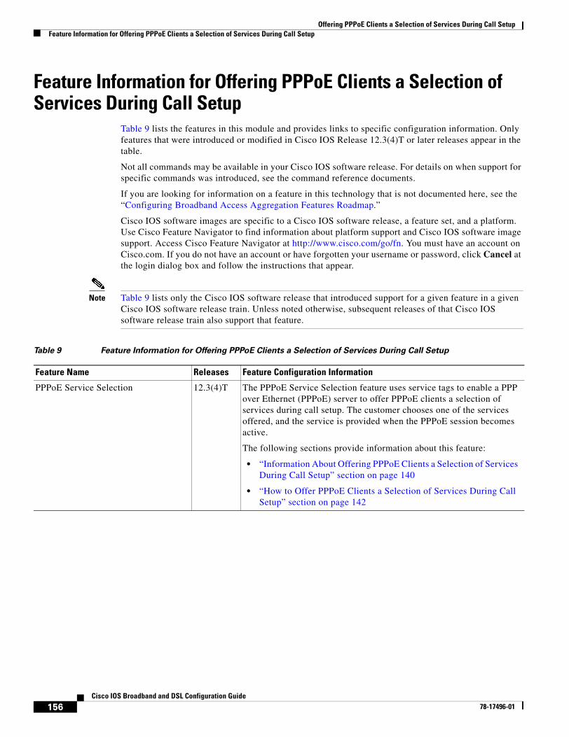
Offering PPPoE Clients a Selection of Services During Call SetupFeature Information for Offering PPPoE Clients a Selection of Services During Call Setup
156Cisco IOS Broadband and DSL Configuration Guide
78-17496-01
Feature Information for Offering PPPoE Clients a Selection of Services During Call Setup
Table 9 lists the features in this module and provides links to specific configuration information. Only features that were introduced or modified in Cisco IOS Release 12.3(4)T or later releases appear in the table.
Not all commands may be available in your Cisco IOS software release. For details on when support for specific commands was introduced, see the command reference documents.
If you are looking for information on a feature in this technology that is not documented here, see the “Configuring Broadband Access Aggregation Features Roadmap.”
Cisco IOS software images are specific to a Cisco IOS software release, a feature set, and a platform. Use Cisco Feature Navigator to find information about platform support and Cisco IOS software image support. Access Cisco Feature Navigator at http://www.cisco.com/go/fn. You must have an account on Cisco.com. If you do not have an account or have forgotten your username or password, click Cancel at the login dialog box and follow the instructions that appear.
Note Table 9 lists only the Cisco IOS software release that introduced support for a given feature in a given Cisco IOS software release train. Unless noted otherwise, subsequent releases of that Cisco IOS software release train also support that feature.
Table 9 Feature Information for Offering PPPoE Clients a Selection of Services During Call Setup
Feature Name Releases Feature Configuration Information
PPPoE Service Selection 12.3(4)T The PPPoE Service Selection feature uses service tags to enable a PPP over Ethernet (PPPoE) server to offer PPPoE clients a selection of services during call setup. The customer chooses one of the services offered, and the service is provided when the PPPoE session becomes active.
The following sections provide information about this feature:
• “Information About Offering PPPoE Clients a Selection of Services During Call Setup” section on page 140
• “How to Offer PPPoE Clients a Selection of Services During Call Setup” section on page 142
157Cisco IOS Broadband and DSL Configuration Guide
78-17496-01
Enabling PPPoE Relay Discovery and Service Selection Functionality
The PPPoE Relay feature enables an L2TP access concentrator (LAC) to relay active discovery and service selection functionality for PPP over Ethernet (PPPoE), over a Layer 2 Tunneling Protocol (L2TP) control channel, to an L2TP network server (LNS) or tunnel switch (multihop node). The relay functionality of this feature allows the LNS or tunnel switch to advertise the services it offers to the client, thereby providing end-to-end control of services between the LNS and a PPPoE client.
Module History
This module was first published on May 2, 2005, and last updated on May 2, 2005.
Finding Feature Information in This Module
Not all features may be supported in your Cisco IOS software release. Use the “Feature Information for Enabling PPPoE Relay Discovery and Service Selection Functionality” section on page 170 to find information about feature support and configuration.
Contents• Prerequisites for Enabling PPPoE Relay Discovery and Service Selection Functionality, page 157
• Information About Enabling PPPoE Relay Discovery and Service Selection Functionality, page 158
• How to Enable PPPoE Relay Discovery and Service Selection Functionality, page 158
• Configuration Examples for Enabling PPPoE Relay Discovery and Service Selection Functionality, page 163
• Additional References, page 168
• Feature Information for Enabling PPPoE Relay Discovery and Service Selection Functionality, page 170
Prerequisites for Enabling PPPoE Relay Discovery and Service Selection Functionality
• You must understand the concepts described in the “Preparing for Broadband Access Aggregation” module.
Enabling PPPoE Relay Discovery and Service Selection FunctionalityInformation About Enabling PPPoE Relay Discovery and Service Selection Functionality
158Cisco IOS Broadband and DSL Configuration Guide
78-17496-01
• PPPoE sessions must be established using the procedures in the “Providing Protocol Support for Broadband Access Aggregation of PPPoE Sessions” module.
• This document assumes you understand how to configure a virtual private dialup network (VPDN) tunnel and a tunnel switch. See the “Related Documents” section on page 168 for more information about these features.
Information About Enabling PPPoE Relay Discovery and Service Selection Functionality
To configure PPPoE relay, you need to understand the following concept:
• L2TP Active Discovery Relay for PPPoE, page 158
L2TP Active Discovery Relay for PPPoEThe PPPoE protocol described in RFC 2516 defines a method for active discovery and service selection of devices in the network by an LAC. A PPPoE client uses these methods to discover an access concentrator in the network, and the access concentrator uses these methods to advertise the services it offers.
The PPPoE Relay feature introduced in Cisco IOS Release 12.3(4)T allows the active discovery and service selection functionality to be offered by the LNS, rather than just by the LAC. The PPPoE Relay feature implements the Network Working Group Internet-Draft titled L2TP Active Discovery Relay for PPPoE. The Internet-Draft describes how to relay PPPoE Active Discovery (PAD) and Service Relay Request (SRRQ) messages over an L2TP control channel (the tunnel). (See the “RFCs” section on page 169 for information on how to access Network Working Group Internet-Drafts.)
The key benefit of the PPPoE Relay feature is end-to-end control of services between the LNS and a PPPoE client.
How to Enable PPPoE Relay Discovery and Service Selection Functionality
This section contains the following procedures:
• Configuring the LAC and Tunnel Switch for PPPoE Relay, page 158 (required)
• Configuring the LNS (or Multihop Node) to Respond to Relayed PAD Messages, page 160 (required)
• Additional References, page 168 (optional)
Configuring the LAC and Tunnel Switch for PPPoE RelayPerform this task to configure the LAC and tunnel switch for PPPoE Relay, which configures a subscriber profile that directs PAD messages to be relayed on an L2TP tunnel. The subscriber profile also will contain an authorization key for the outgoing L2TP tunnel.
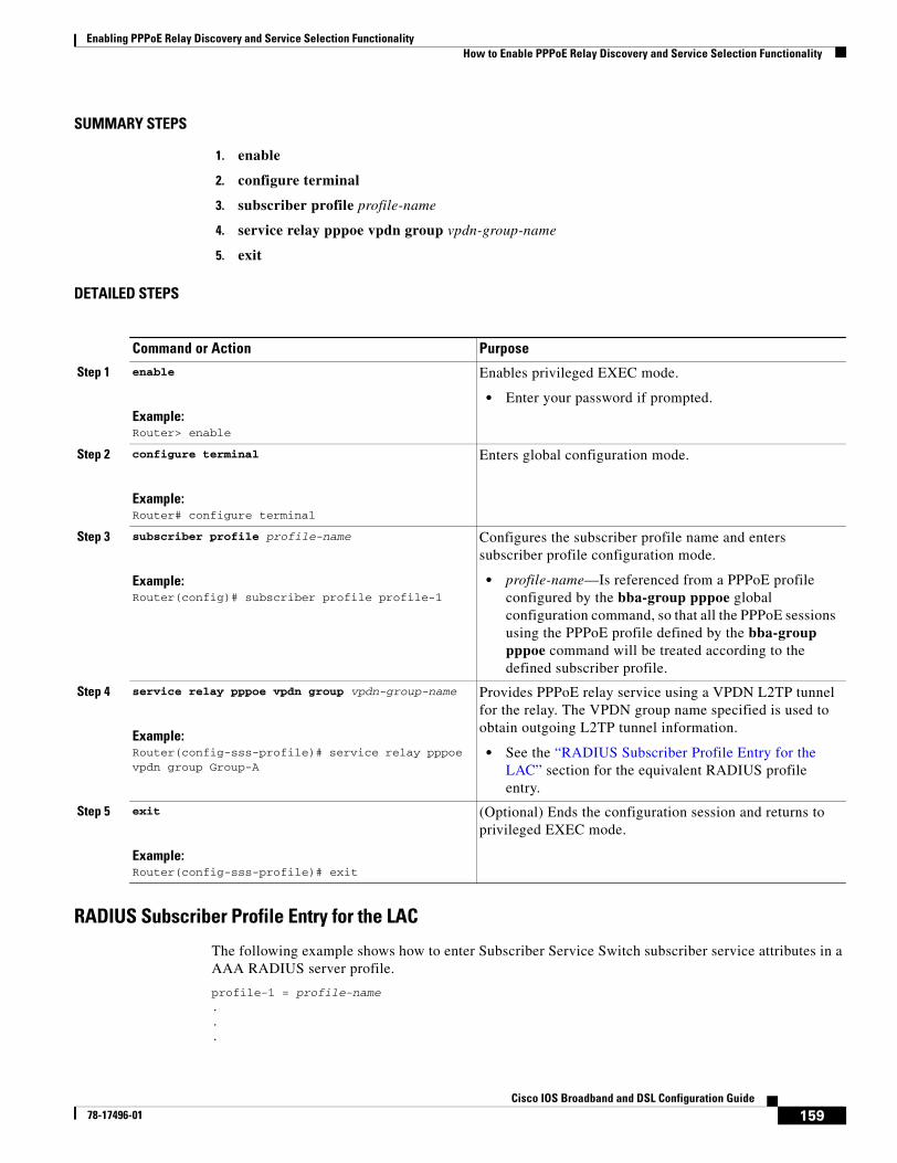
Enabling PPPoE Relay Discovery and Service Selection FunctionalityHow to Enable PPPoE Relay Discovery and Service Selection Functionality
159Cisco IOS Broadband and DSL Configuration Guide
78-17496-01
SUMMARY STEPS
1. enable
2. configure terminal
3. subscriber profile profile-name
4. service relay pppoe vpdn group vpdn-group-name
5. exit
DETAILED STEPS
RADIUS Subscriber Profile Entry for the LAC
The following example shows how to enter Subscriber Service Switch subscriber service attributes in a AAA RADIUS server profile.
profile-1 = profile-name...
Command or Action Purpose
Step 1 enable
Example:Router> enable
Enables privileged EXEC mode.
• Enter your password if prompted.
Step 2 configure terminal
Example:Router# configure terminal
Enters global configuration mode.
Step 3 subscriber profile profile-name
Example:Router(config)# subscriber profile profile-1
Configures the subscriber profile name and enters subscriber profile configuration mode.
• profile-name—Is referenced from a PPPoE profile configured by the bba-group pppoe global configuration command, so that all the PPPoE sessions using the PPPoE profile defined by the bba-group pppoe command will be treated according to the defined subscriber profile.
Step 4 service relay pppoe vpdn group vpdn-group-name
Example:Router(config-sss-profile)# service relay pppoe vpdn group Group-A
Provides PPPoE relay service using a VPDN L2TP tunnel for the relay. The VPDN group name specified is used to obtain outgoing L2TP tunnel information.
• See the “RADIUS Subscriber Profile Entry for the LAC” section for the equivalent RADIUS profile entry.
Step 5 exit
Example:Router(config-sss-profile)# exit
(Optional) Ends the configuration session and returns to privileged EXEC mode.
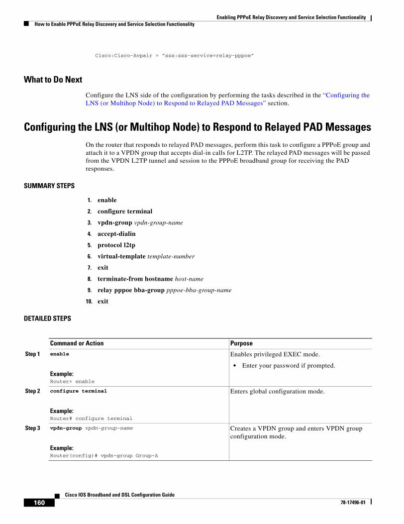
Enabling PPPoE Relay Discovery and Service Selection FunctionalityHow to Enable PPPoE Relay Discovery and Service Selection Functionality
160Cisco IOS Broadband and DSL Configuration Guide
78-17496-01
Cisco:Cisco-Avpair = ”sss:sss-service=relay-pppoe”
What to Do Next
Configure the LNS side of the configuration by performing the tasks described in the “Configuring the LNS (or Multihop Node) to Respond to Relayed PAD Messages” section.
Configuring the LNS (or Multihop Node) to Respond to Relayed PAD MessagesOn the router that responds to relayed PAD messages, perform this task to configure a PPPoE group and attach it to a VPDN group that accepts dial-in calls for L2TP. The relayed PAD messages will be passed from the VPDN L2TP tunnel and session to the PPPoE broadband group for receiving the PAD responses.
SUMMARY STEPS
1. enable
2. configure terminal
3. vpdn-group vpdn-group-name
4. accept-dialin
5. protocol l2tp
6. virtual-template template-number
7. exit
8. terminate-from hostname host-name
9. relay pppoe bba-group pppoe-bba-group-name
10. exit
DETAILED STEPS
Command or Action Purpose
Step 1 enable
Example:Router> enable
Enables privileged EXEC mode.
• Enter your password if prompted.
Step 2 configure terminal
Example:Router# configure terminal
Enters global configuration mode.
Step 3 vpdn-group vpdn-group-name
Example:Router(config)# vpdn-group Group-A
Creates a VPDN group and enters VPDN group configuration mode.
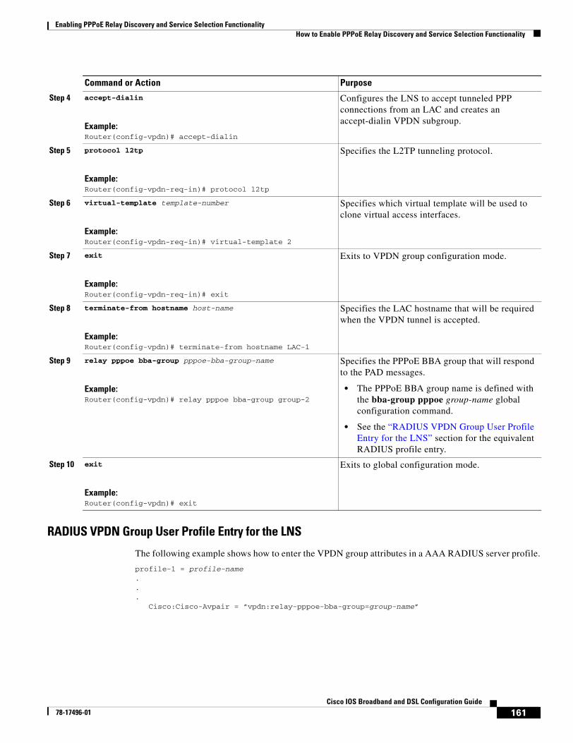
Enabling PPPoE Relay Discovery and Service Selection FunctionalityHow to Enable PPPoE Relay Discovery and Service Selection Functionality
161Cisco IOS Broadband and DSL Configuration Guide
78-17496-01
RADIUS VPDN Group User Profile Entry for the LNS
The following example shows how to enter the VPDN group attributes in a AAA RADIUS server profile.
profile-1 = profile-name...
Cisco:Cisco-Avpair = ”vpdn:relay-pppoe-bba-group=group-name”
Step 4 accept-dialin
Example:Router(config-vpdn)# accept-dialin
Configures the LNS to accept tunneled PPP connections from an LAC and creates an accept-dialin VPDN subgroup.
Step 5 protocol l2tp
Example:Router(config-vpdn-req-in)# protocol l2tp
Specifies the L2TP tunneling protocol.
Step 6 virtual-template template-number
Example:Router(config-vpdn-req-in)# virtual-template 2
Specifies which virtual template will be used to clone virtual access interfaces.
Step 7 exit
Example:Router(config-vpdn-req-in)# exit
Exits to VPDN group configuration mode.
Step 8 terminate-from hostname host-name
Example:Router(config-vpdn)# terminate-from hostname LAC-1
Specifies the LAC hostname that will be required when the VPDN tunnel is accepted.
Step 9 relay pppoe bba-group pppoe-bba-group-name
Example:Router(config-vpdn)# relay pppoe bba-group group-2
Specifies the PPPoE BBA group that will respond to the PAD messages.
• The PPPoE BBA group name is defined with the bba-group pppoe group-name global configuration command.
• See the “RADIUS VPDN Group User Profile Entry for the LNS” section for the equivalent RADIUS profile entry.
Step 10 exit
Example:Router(config-vpdn)# exit
Exits to global configuration mode.
Command or Action Purpose
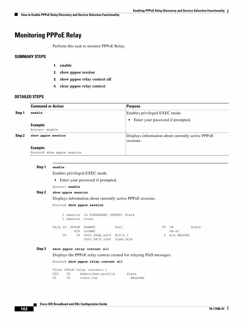
Enabling PPPoE Relay Discovery and Service Selection FunctionalityHow to Enable PPPoE Relay Discovery and Service Selection Functionality
162Cisco IOS Broadband and DSL Configuration Guide
78-17496-01
Monitoring PPPoE RelayPerform this task to monitor PPPoE Relay.
SUMMARY STEPS
1. enable
2. show pppoe session
3. show pppoe relay context all
4. clear pppoe relay context
DETAILED STEPS
Step 1 enable
Enables privileged EXEC mode.
• Enter your password if prompted.
Router> enable
Step 2 show pppoe session
Displays information about currently active PPPoE sessions.
Router# show pppoe session
1 session in FORWARDED (FWDED) State 1 session total
Uniq ID PPPoE RemMAC Port VT VA State SID LocMAC VA-st 26 19 0001.96da.a2c0 Et0/0.1 5 N/A RELFWD 000c.8670.1006 VLAN:3434
Step 3 show pppoe relay context all
Displays the PPPoE relay context created for relaying PAD messages.
Router# show pppoe relay context all
Total PPPoE relay contexts 1UID ID Subscriber-profile State25 18 cisco.com RELAYED
Command or Action Purpose
Step 1 enable
Example:Router> enable
Enables privileged EXEC mode.
• Enter your password if prompted.
Step 2 show pppoe session
Example:Router# show pppoe session
Displays information about currently active PPPoE sessions.
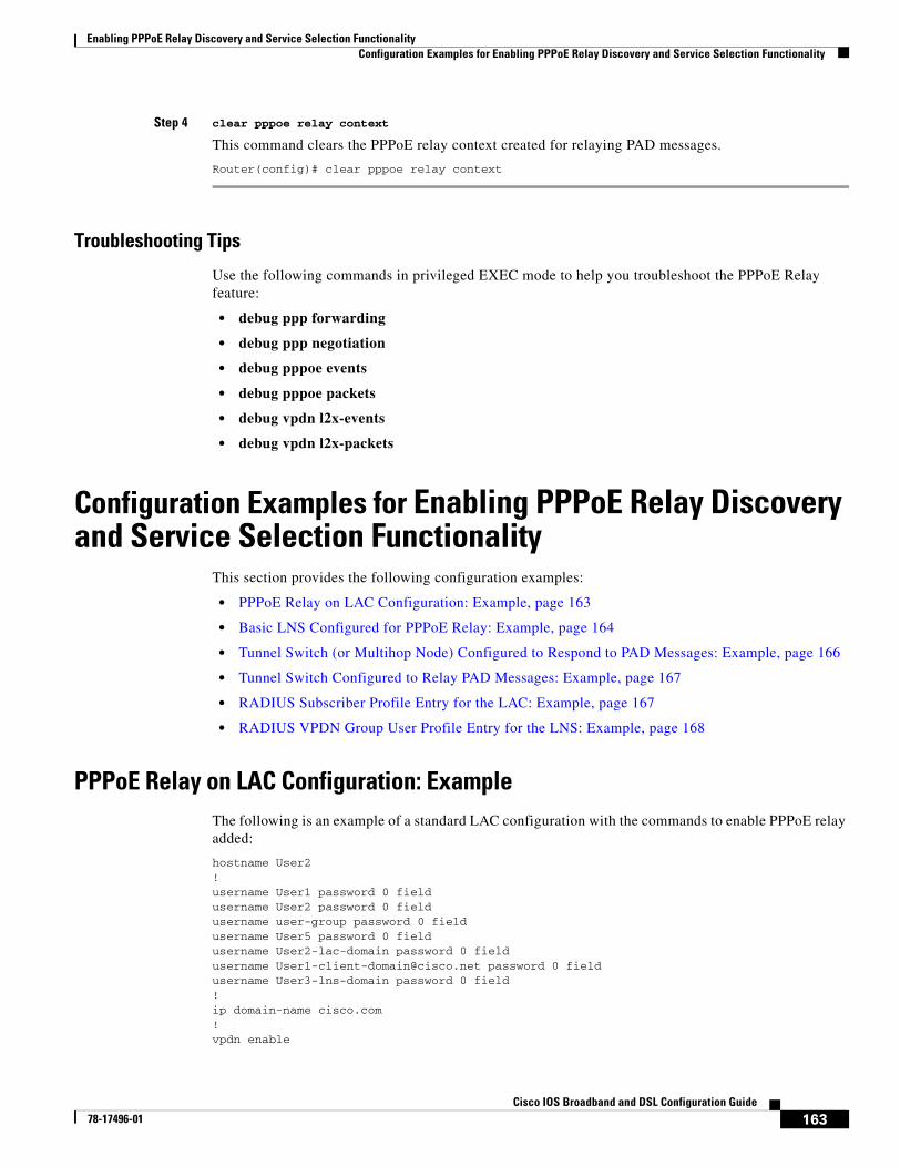
Enabling PPPoE Relay Discovery and Service Selection FunctionalityConfiguration Examples for Enabling PPPoE Relay Discovery and Service Selection Functionality
163Cisco IOS Broadband and DSL Configuration Guide
78-17496-01
Step 4 clear pppoe relay context
This command clears the PPPoE relay context created for relaying PAD messages.
Router(config)# clear pppoe relay context
Troubleshooting Tips
Use the following commands in privileged EXEC mode to help you troubleshoot the PPPoE Relay feature:
• debug ppp forwarding
• debug ppp negotiation
• debug pppoe events
• debug pppoe packets
• debug vpdn l2x-events
• debug vpdn l2x-packets
Configuration Examples for Enabling PPPoE Relay Discovery and Service Selection Functionality
This section provides the following configuration examples:
• PPPoE Relay on LAC Configuration: Example, page 163
• Basic LNS Configured for PPPoE Relay: Example, page 164
• Tunnel Switch (or Multihop Node) Configured to Respond to PAD Messages: Example, page 166
• Tunnel Switch Configured to Relay PAD Messages: Example, page 167
• RADIUS Subscriber Profile Entry for the LAC: Example, page 167
• RADIUS VPDN Group User Profile Entry for the LNS: Example, page 168
PPPoE Relay on LAC Configuration: ExampleThe following is an example of a standard LAC configuration with the commands to enable PPPoE relay added:
hostname User2!username User1 password 0 fieldusername User2 password 0 fieldusername user-group password 0 fieldusername User5 password 0 fieldusername User2-lac-domain password 0 fieldusername [email protected] password 0 fieldusername User3-lns-domain password 0 field!ip domain-name cisco.com!vpdn enable
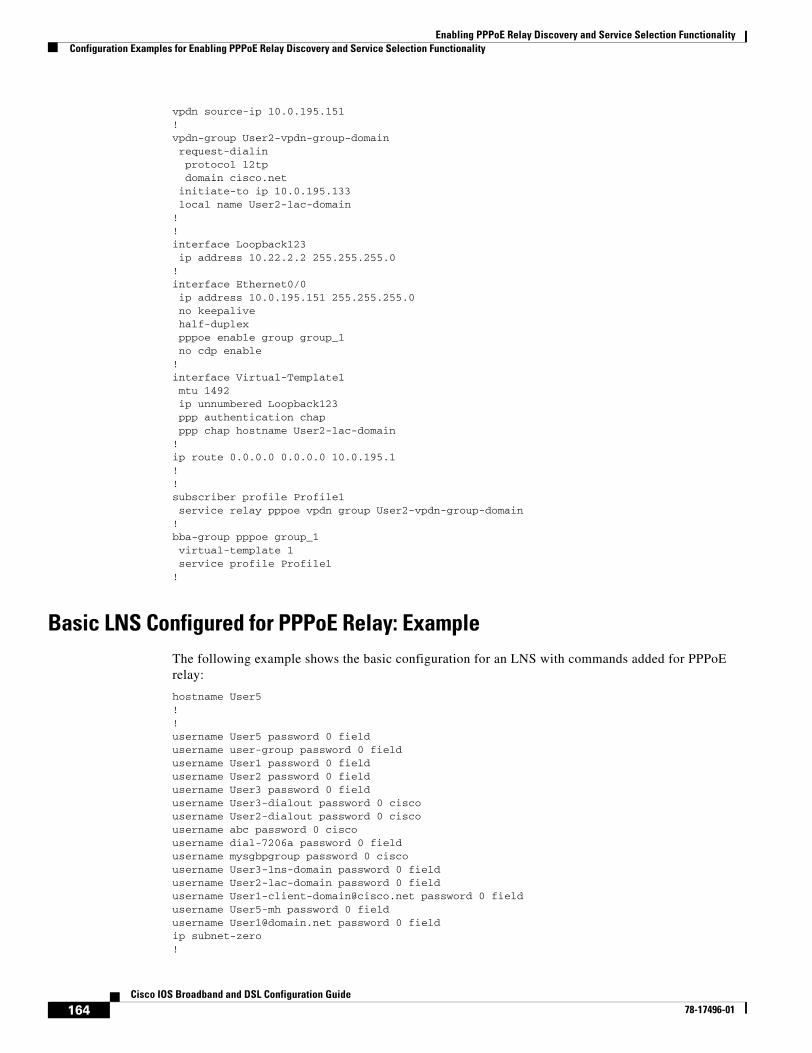
Enabling PPPoE Relay Discovery and Service Selection FunctionalityConfiguration Examples for Enabling PPPoE Relay Discovery and Service Selection Functionality
164Cisco IOS Broadband and DSL Configuration Guide
78-17496-01
vpdn source-ip 10.0.195.151!vpdn-group User2-vpdn-group-domainrequest-dialinprotocol l2tpdomain cisco.net
initiate-to ip 10.0.195.133local name User2-lac-domain
!!interface Loopback123ip address 10.22.2.2 255.255.255.0
!interface Ethernet0/0ip address 10.0.195.151 255.255.255.0no keepalivehalf-duplexpppoe enable group group_1no cdp enable
!interface Virtual-Template1mtu 1492ip unnumbered Loopback123ppp authentication chapppp chap hostname User2-lac-domain
!ip route 0.0.0.0 0.0.0.0 10.0.195.1!!subscriber profile Profile1service relay pppoe vpdn group User2-vpdn-group-domain
!bba-group pppoe group_1virtual-template 1service profile Profile1
!
Basic LNS Configured for PPPoE Relay: ExampleThe following example shows the basic configuration for an LNS with commands added for PPPoE relay:
hostname User5!!username User5 password 0 fieldusername user-group password 0 fieldusername User1 password 0 fieldusername User2 password 0 fieldusername User3 password 0 fieldusername User3-dialout password 0 ciscousername User2-dialout password 0 ciscousername abc password 0 ciscousername dial-7206a password 0 fieldusername mysgbpgroup password 0 ciscousername User3-lns-domain password 0 fieldusername User2-lac-domain password 0 fieldusername [email protected] password 0 fieldusername User5-mh password 0 fieldusername [email protected] password 0 fieldip subnet-zero!
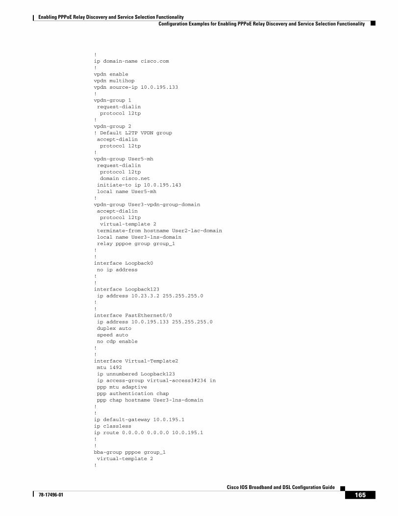
Enabling PPPoE Relay Discovery and Service Selection FunctionalityConfiguration Examples for Enabling PPPoE Relay Discovery and Service Selection Functionality
165Cisco IOS Broadband and DSL Configuration Guide
78-17496-01
!ip domain-name cisco.com!vpdn enablevpdn multihopvpdn source-ip 10.0.195.133!vpdn-group 1request-dialinprotocol l2tp
!vpdn-group 2! Default L2TP VPDN groupaccept-dialinprotocol l2tp
!vpdn-group User5-mhrequest-dialinprotocol l2tpdomain cisco.net
initiate-to ip 10.0.195.143local name User5-mh
!vpdn-group User3-vpdn-group-domainaccept-dialinprotocol l2tpvirtual-template 2
terminate-from hostname User2-lac-domainlocal name User3-lns-domainrelay pppoe group group_1
!!interface Loopback0no ip address
!!interface Loopback123ip address 10.23.3.2 255.255.255.0
!!interface FastEthernet0/0ip address 10.0.195.133 255.255.255.0duplex autospeed autono cdp enable
!!interface Virtual-Template2mtu 1492ip unnumbered Loopback123ip access-group virtual-access3#234 inppp mtu adaptiveppp authentication chapppp chap hostname User3-lns-domain
!!ip default-gateway 10.0.195.1ip classlessip route 0.0.0.0 0.0.0.0 10.0.195.1!!bba-group pppoe group_1virtual-template 2
!
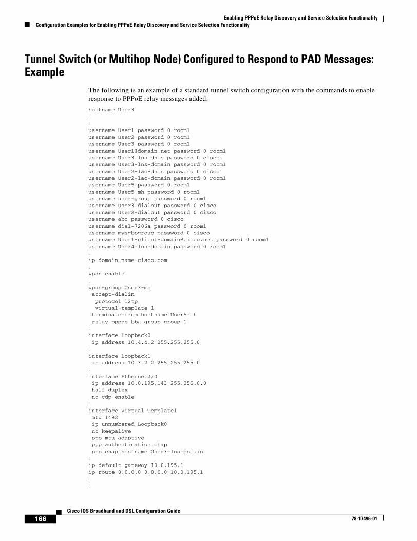
Enabling PPPoE Relay Discovery and Service Selection FunctionalityConfiguration Examples for Enabling PPPoE Relay Discovery and Service Selection Functionality
166Cisco IOS Broadband and DSL Configuration Guide
78-17496-01
Tunnel Switch (or Multihop Node) Configured to Respond to PAD Messages: Example
The following is an example of a standard tunnel switch configuration with the commands to enable response to PPPoE relay messages added:
hostname User3!!username User1 password 0 room1username User2 password 0 room1username User3 password 0 room1username [email protected] password 0 room1username User3-lns-dnis password 0 ciscousername User3-lns-domain password 0 room1username User2-lac-dnis password 0 ciscousername User2-lac-domain password 0 room1username User5 password 0 room1username User5-mh password 0 room1username user-group password 0 room1username User3-dialout password 0 ciscousername User2-dialout password 0 ciscousername abc password 0 ciscousername dial-7206a password 0 room1username mysgbpgroup password 0 ciscousername [email protected] password 0 room1username User4-lns-domain password 0 room1!ip domain-name cisco.com!vpdn enable!vpdn-group User3-mh accept-dialin protocol l2tp virtual-template 1 terminate-from hostname User5-mhrelay pppoe bba-group group_1
!interface Loopback0 ip address 10.4.4.2 255.255.255.0!interface Loopback1 ip address 10.3.2.2 255.255.255.0!interface Ethernet2/0 ip address 10.0.195.143 255.255.0.0 half-duplex no cdp enable!interface Virtual-Template1 mtu 1492 ip unnumbered Loopback0 no keepalive ppp mtu adaptive ppp authentication chap ppp chap hostname User3-lns-domain!ip default-gateway 10.0.195.1ip route 0.0.0.0 0.0.0.0 10.0.195.1!!
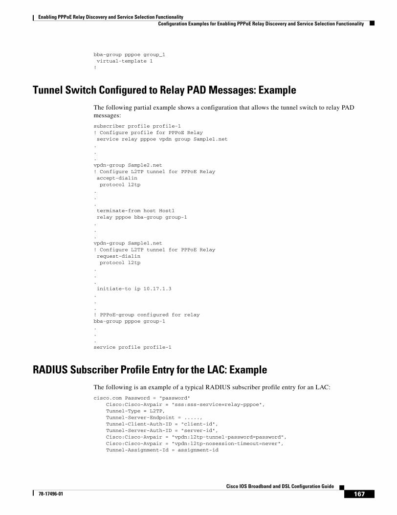
Enabling PPPoE Relay Discovery and Service Selection FunctionalityConfiguration Examples for Enabling PPPoE Relay Discovery and Service Selection Functionality
167Cisco IOS Broadband and DSL Configuration Guide
78-17496-01
bba-group pppoe group_1virtual-template 1
!
Tunnel Switch Configured to Relay PAD Messages: ExampleThe following partial example shows a configuration that allows the tunnel switch to relay PAD messages:
subscriber profile profile-1! Configure profile for PPPoE Relayservice relay pppoe vpdn group Sample1.net
.
.
.vpdn-group Sample2.net! Configure L2TP tunnel for PPPoE Relayaccept-dialinprotocol l2tp
.
.
.terminate-from host Host1relay pppoe bba-group group-1
.
.
.vpdn-group Sample1.net! Configure L2TP tunnel for PPPoE Relayrequest-dialinprotocol l2tp
.
.
.initiate-to ip 10.17.1.3
.
.
.! PPPoE-group configured for relaybba-group pppoe group-1...service profile profile-1
RADIUS Subscriber Profile Entry for the LAC: ExampleThe following is an example of a typical RADIUS subscriber profile entry for an LAC:
cisco.com Password = "password" Cisco:Cisco-Avpair = "sss:sss-service=relay-pppoe", Tunnel-Type = L2TP, Tunnel-Server-Endpoint = ....., Tunnel-Client-Auth-ID = "client-id", Tunnel-Server-Auth-ID = "server-id", Cisco:Cisco-Avpair = "vpdn:l2tp-tunnel-password=password", Cisco:Cisco-Avpair = "vpdn:l2tp-nosession-timeout=never", Tunnel-Assignment-Id = assignment-id
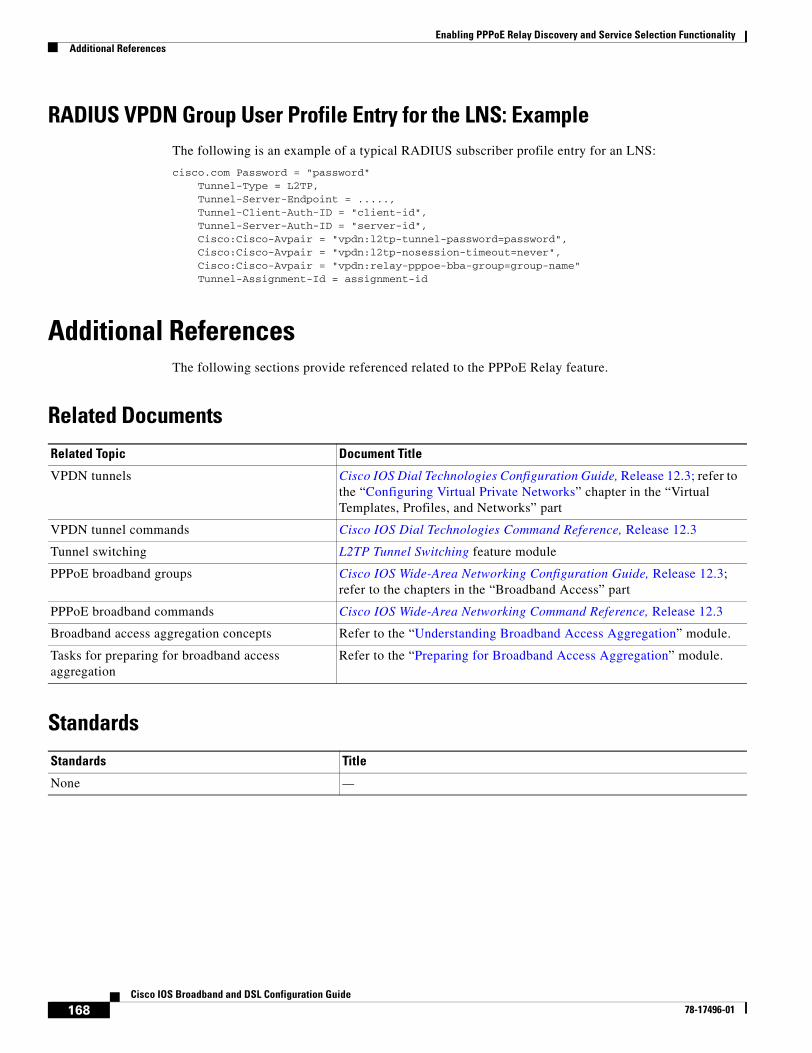
Enabling PPPoE Relay Discovery and Service Selection FunctionalityAdditional References
168Cisco IOS Broadband and DSL Configuration Guide
78-17496-01
RADIUS VPDN Group User Profile Entry for the LNS: ExampleThe following is an example of a typical RADIUS subscriber profile entry for an LNS:
cisco.com Password = "password"Tunnel-Type = L2TP,
Tunnel-Server-Endpoint = ....., Tunnel-Client-Auth-ID = "client-id", Tunnel-Server-Auth-ID = "server-id", Cisco:Cisco-Avpair = "vpdn:l2tp-tunnel-password=password", Cisco:Cisco-Avpair = "vpdn:l2tp-nosession-timeout=never",
Cisco:Cisco-Avpair = "vpdn:relay-pppoe-bba-group=group-name" Tunnel-Assignment-Id = assignment-id
Additional References The following sections provide referenced related to the PPPoE Relay feature.
Related Documents
Standards
Related Topic Document Title
VPDN tunnels Cisco IOS Dial Technologies Configuration Guide, Release 12.3; refer to the “Configuring Virtual Private Networks” chapter in the “Virtual Templates, Profiles, and Networks” part
VPDN tunnel commands Cisco IOS Dial Technologies Command Reference, Release 12.3
Tunnel switching L2TP Tunnel Switching feature module
PPPoE broadband groups Cisco IOS Wide-Area Networking Configuration Guide, Release 12.3; refer to the chapters in the “Broadband Access” part
PPPoE broadband commands Cisco IOS Wide-Area Networking Command Reference, Release 12.3
Broadband access aggregation concepts Refer to the “Understanding Broadband Access Aggregation” module.
Tasks for preparing for broadband access aggregation
Refer to the “Preparing for Broadband Access Aggregation” module.
Standards Title
None —
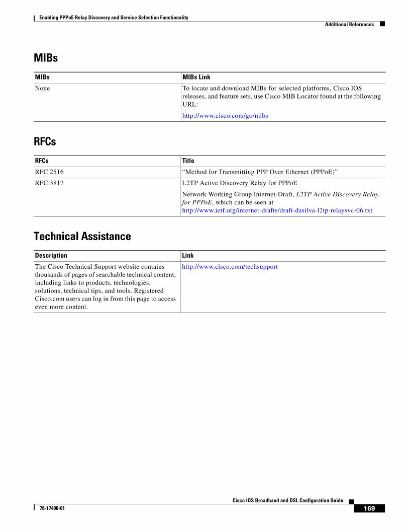
Enabling PPPoE Relay Discovery and Service Selection FunctionalityAdditional References
169Cisco IOS Broadband and DSL Configuration Guide
78-17496-01
MIBs
RFCs
Technical Assistance
MIBs MIBs Link
None To locate and download MIBs for selected platforms, Cisco IOS releases, and feature sets, use Cisco MIB Locator found at the following URL:
http://www.cisco.com/go/mibs
RFCs Title
RFC 2516 “Method for Transmitting PPP Over Ethernet (PPPoE)”
RFC 3817 L2TP Active Discovery Relay for PPPoE
Network Working Group Internet-Draft, L2TP Active Discovery Relay for PPPoE, which can be seen at http://www.ietf.org/internet-drafts/draft-dasilva-l2tp-relaysvc-06.txt
Description Link
The Cisco Technical Support website contains thousands of pages of searchable technical content, including links to products, technologies, solutions, technical tips, and tools. Registered Cisco.com users can log in from this page to access even more content.
http://www.cisco.com/techsupport
Enabling PPPoE Relay Discovery and Service Selection FunctionalityFeature Information for Enabling PPPoE Relay Discovery and Service Selection Functionality
170Cisco IOS Broadband and DSL Configuration Guide
78-17496-01
Feature Information for Enabling PPPoE Relay Discovery and Service Selection Functionality
Table 10 lists the features in this module and provides links to specific configuration information. Only features that were introduced or modified in Release 12.3(4)T or later releases appear in the table.
Not all commands may be available in your Cisco IOS software release. For details on when support for specific commands was introduced, see the command reference documents.
If you are looking for information on a feature in this technology that is not documented here, see the “Configuring Broadband Access Aggregation Features Roadmap.”
Cisco IOS software images are specific to a Cisco IOS software release, a feature set, and a platform. Use Cisco Feature Navigator to find information about platform support and Cisco IOS software image support. Access Cisco Feature Navigator at http://www.cisco.com/go/fn. You must have an account on Cisco.com. If you do not have an account or have forgotten your username or password, click Cancel at the login dialog box and follow the instructions that appear.
Note Table 10 lists only the Cisco IOS software release that introduced support for a given feature in a given Cisco IOS software release train. Unless noted otherwise, subsequent releases of that Cisco IOS software release train also support that feature.
Table 10 Feature Information for Enabling PPPoE Relay Discovery and Service Selection Functionality
Feature Name Releases Feature Configuration Information
PPPoE Relay 12.3(4)T The PPPoE Relay feature enables an L2TP access concentrator (LAC) to relay active discovery and service selection functionality for PPP over Ethernet (PPPoE), over a Layer 2 Tunneling Protocol (L2TP) control channel, to an L2TP network server (LNS) or tunnel switch (multihop node).
The following sections provide information about this feature:
• “Information About Enabling PPPoE Relay Discovery and Service Selection Functionality” section on page 158
• “How to Enable PPPoE Relay Discovery and Service Selection Functionality” section on page 158
171Cisco IOS Broadband and DSL Configuration Guide
78-17496-01
Establishing PPPoE Session Limits per NAS Port
The PPPoE Session Limits per NAS Port feature enables you to limit the number of PPP over Ethernet (PPPoE) sessions on a specific permanent virtual circuit (PVC) or VLAN configured on an L2TP access concentrator (LAC). The network access server (NAS) port is either an ATM PVC or a configured VLAN ID. PPPoE per-NAS-port session limits are maintained in a RADIUS server customer profile database and are downloaded during Subscriber Service Switch (SSS) preauthorization.
Module History
This module was first published on May 2, 2005, and last updated on May 2, 2005.
Finding Feature Information in This Module
Not all features may be supported in your Cisco IOS software release. Use the “Feature Information for Establishing PPPoE Session Limits per NAS Port” section on page 182 to find information about feature support and configuration.
Contents• Prerequisites for Establishing PPPoE Session Limits per NAS Port, page 171
• Restrictions for Establishing PPPoE Session Limits per NAS Port, page 172
• Information About Establishing PPPoE Session Limits per NAS Port, page 172
• How to Establish PPPoE Session Limits per NAS Port, page 173
• Configuration Examples for Establishing PPPoE Session Limits per NAS Port, page 176
• Additional References, page 180
• Where to Go Next, page 179
• Feature Information for Establishing PPPoE Session Limits per NAS Port, page 182
Prerequisites for Establishing PPPoE Session Limits per NAS Port
• You must understand the concepts described in the “Preparing for Broadband Access Aggregation” module.
• Both the LAC and the L2TP Network Server (LNS) must be running a Cisco IOS image that supports the PPPoE Session Limit Per NAS Port feature.
Establishing PPPoE Session Limits per NAS PortRestrictions for Establishing PPPoE Session Limits per NAS Port
172Cisco IOS Broadband and DSL Configuration Guide
78-17496-01
• Protocol support for broadband access aggregation must be established using the procedures in the “Providing Protocol Support for Broadband Access Aggregation of PPPoE Sessions” module.
Restrictions for Establishing PPPoE Session Limits per NAS Port• Do not configure the PPPoE per-NAS-port session limit to zero.
• PPPoE Session Limit per NAS Port does not support TACACS+.
• PPPoE Session Limit per NAS Port applies only to PVCs and VLANs.
Information About Establishing PPPoE Session Limits per NAS Port
To establish PPPoE session limits per NAS port, you should understand the following concepts:
• How PPPoE per-NAS-Port Session Limits Work, page 172
• Relationship Between the Per-NAS-Port Session Limit and Other Types of Session Limits, page 173
• Benefits of PPPoE Session Limits per NAS Port, page 173
How PPPoE per-NAS-Port Session Limits WorkThe PPPoE Session Limits Per NAS Port feature limits the number of PPPoE sessions on a specific PVC or VLAN configured on an LAC. The NAS port is either an ATM PVC or a configured VLAN ID.
The PPPoE per-NAS-port session limit is maintained in a RADIUS server customer profile database. This customer profile database is connected to an LAC and is separate from the RADIUS server that the LAC and LNS use for the authentication and authorization of incoming users. See Figure 12 for a sample network topology. When the customer profile database receives a preauthorization request from the LAC, it sends the PPPoE per-NAS-port session limit to the LAC.
The LAC sends a preauthorization request to the customer profile database when the LAC is configured for SSS preauthorization. When the LAC receives the PPPoE per-NAS-port session limit from the customer profile database, the LAC compares the PPPoE per-NAS-port session limit with the number of sessions currently on the NAS port. The LAC then decides whether to accept or reject the current call, depending upon the configured PPPoE per NAS port-session-limit and the number of calls currently on the NAS port.
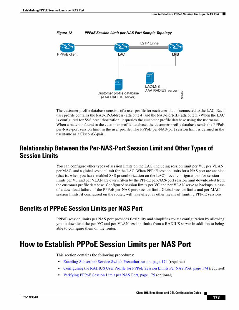
Establishing PPPoE Session Limits per NAS PortHow to Establish PPPoE Session Limits per NAS Port
173Cisco IOS Broadband and DSL Configuration Guide
78-17496-01
Figure 12 PPPoE Session Limit per NAS Port Sample Topology
The customer profile database consists of a user profile for each user that is connected to the LAC. Each user profile contains the NAS-IP-Address (attribute 4) and the NAS-Port-ID (attribute 5.) When the LAC is configured for SSS preauthorization, it queries the customer profile database using the username. When a match is found in the customer profile database, the customer profile database sends the PPPoE per-NAS-port session limit in the user profile. The PPPoE per-NAS-port session limit is defined in the username as a Cisco AV-pair.
Relationship Between the Per-NAS-Port Session Limit and Other Types of Session Limits
You can configure other types of session limits on the LAC, including session limit per VC, per VLAN, per MAC, and a global session limit for the LAC. When PPPoE session limits for a NAS port are enabled (that is, when you have enabled SSS preauthorization on the LAC), local configurations for session limits per VC and per VLAN are overwritten by the PPPoE per-NAS-port session limit downloaded from the customer profile database. Configured session limits per VC and per VLAN serve as backups in case of a download failure of the PPPoE per-NAS-port session limit. Global session limits and per-MAC session limits, if configured on the router, will take effect as other means of limiting PPPoE sessions.
Benefits of PPPoE Session Limits per NAS PortPPPoE session limits per NAS port provides flexibility and simplifies router configuration by allowing you to download the per-VC and per-VLAN session limits from a RADIUS server in addition to being able to configure them on the router.
How to Establish PPPoE Session Limits per NAS PortThis section contains the following procedures:
• Enabling Subscriber Service Switch Preauthorization, page 174 (required)
• Configuring the RADIUS User Profile for PPPoE Session Limits Per NAS Port, page 174 (required)
• Verifying PPPoE Session Limit per NAS Port, page 175 (optional)
L2TP tunnel
LNSLAC LNSLACPPPoE client
Customer profile database(AAA RADIUS server)
LAC/LNSAAA RADIUS server
1292
85
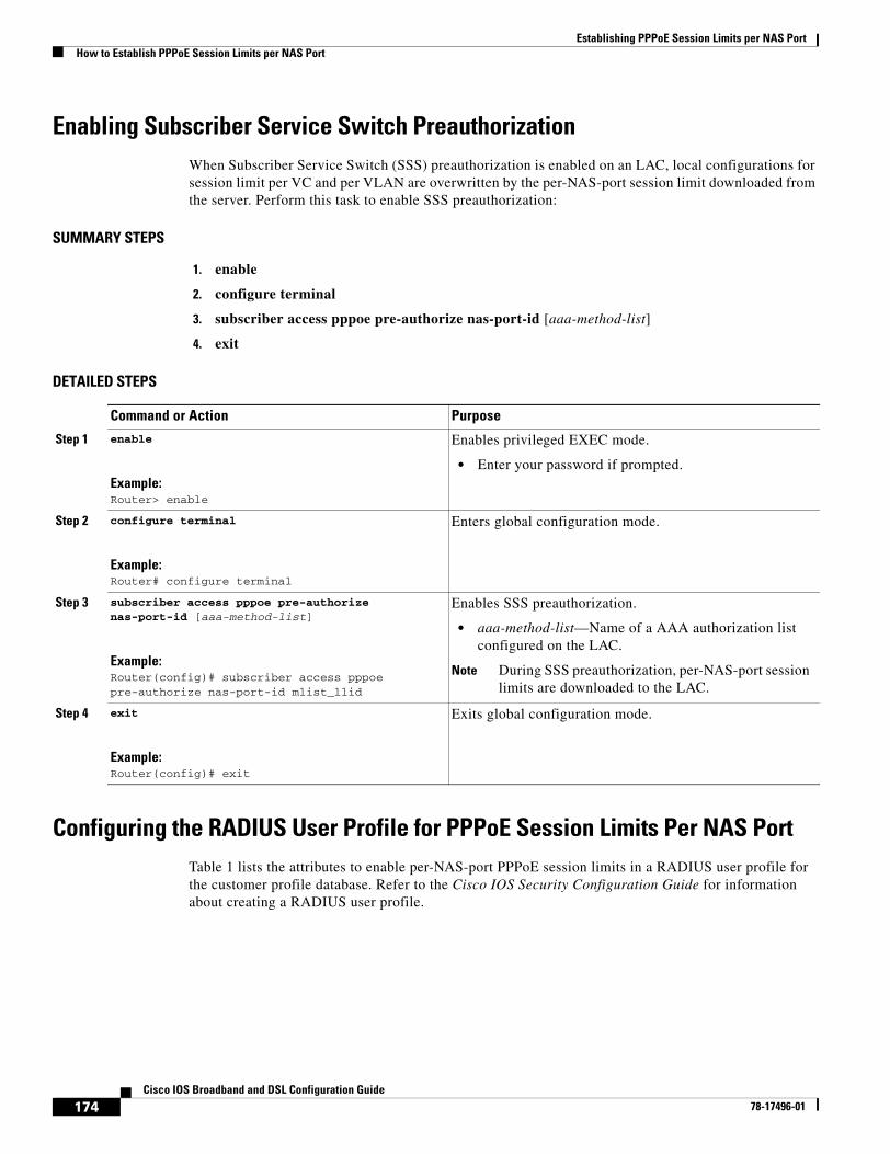
Establishing PPPoE Session Limits per NAS PortHow to Establish PPPoE Session Limits per NAS Port
174Cisco IOS Broadband and DSL Configuration Guide
78-17496-01
Enabling Subscriber Service Switch PreauthorizationWhen Subscriber Service Switch (SSS) preauthorization is enabled on an LAC, local configurations for session limit per VC and per VLAN are overwritten by the per-NAS-port session limit downloaded from the server. Perform this task to enable SSS preauthorization:
SUMMARY STEPS
1. enable
2. configure terminal
3. subscriber access pppoe pre-authorize nas-port-id [aaa-method-list]
4. exit
DETAILED STEPS
Configuring the RADIUS User Profile for PPPoE Session Limits Per NAS PortTable 1 lists the attributes to enable per-NAS-port PPPoE session limits in a RADIUS user profile for the customer profile database. Refer to the Cisco IOS Security Configuration Guide for information about creating a RADIUS user profile.
Command or Action Purpose
Step 1 enable
Example:Router> enable
Enables privileged EXEC mode.
• Enter your password if prompted.
Step 2 configure terminal
Example:Router# configure terminal
Enters global configuration mode.
Step 3 subscriber access pppoe pre-authorize nas-port-id [aaa-method-list]
Example:Router(config)# subscriber access pppoe pre-authorize nas-port-id mlist_llid
Enables SSS preauthorization.
• aaa-method-list—Name of a AAA authorization list configured on the LAC.
Note During SSS preauthorization, per-NAS-port session limits are downloaded to the LAC.
Step 4 exit
Example:Router(config)# exit
Exits global configuration mode.
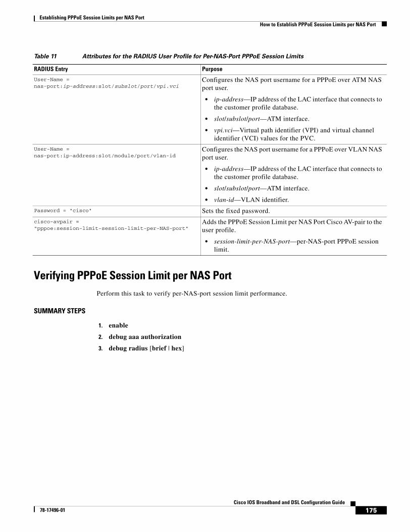
Establishing PPPoE Session Limits per NAS PortHow to Establish PPPoE Session Limits per NAS Port
175Cisco IOS Broadband and DSL Configuration Guide
78-17496-01
Table 11 Attributes for the RADIUS User Profile for Per-NAS-Port PPPoE Session Limits
Verifying PPPoE Session Limit per NAS PortPerform this task to verify per-NAS-port session limit performance.
SUMMARY STEPS
1. enable
2. debug aaa authorization
3. debug radius [brief | hex]
RADIUS Entry Purpose
User-Name = nas-port:ip-address:slot/subslot/port/vpi.vci
Configures the NAS port username for a PPPoE over ATM NAS port user.
• ip-address—IP address of the LAC interface that connects to the customer profile database.
• slot/subslot/port—ATM interface.
• vpi.vci—Virtual path identifier (VPI) and virtual channel identifier (VCI) values for the PVC.
User-Name = nas-port:ip-address:slot/module/port/vlan-id
Configures the NAS port username for a PPPoE over VLAN NAS port user.
• ip-address—IP address of the LAC interface that connects to the customer profile database.
• slot/subslot/port—ATM interface.
• vlan-id—VLAN identifier.
Password = "cisco" Sets the fixed password.
cisco-avpair = "pppoe:session-limit-session-limit-per-NAS-port"
Adds the PPPoE Session Limit per NAS Port Cisco AV-pair to the user profile.
• session-limit-per-NAS-port—per-NAS-port PPPoE session limit.
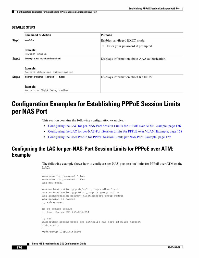
Establishing PPPoE Session Limits per NAS PortConfiguration Examples for Establishing PPPoE Session Limits per NAS Port
176Cisco IOS Broadband and DSL Configuration Guide
78-17496-01
DETAILED STEPS
Configuration Examples for Establishing PPPoE Session Limits per NAS Port
This section contains the following configuration examples:
• Configuring the LAC for per-NAS-Port Session Limits for PPPoE over ATM: Example, page 176
• Configuring the LAC for per-NAS-Port Session Limits for PPPoE over VLAN: Example, page 178
• Configuring the User Profile for PPPoE Session Limits per NAS Port: Example, page 179
Configuring the LAC for per-NAS-Port Session Limits for PPPoE over ATM: Example
The following example shows how to configure per-NAS-port session limits for PPPoE over ATM on the LAC:
! username lac password 0 lab username lns password 0 lab aaa new-model ! aaa authentication ppp default group radius local aaa authentication ppp mlist_nasport group radius aaa authorization network mlist_nasport group radius aaa session-id common ip subnet-zero ! no ip domain lookup ip host abrick 223.255.254.254 ! ip cef subscriber access pppoe pre-authorize nas-port-id mlist_nasport vpdn enable ! vpdn-group l2tp_initiator
Command or Action Purpose
Step 1 enable
Example:Router> enable
Enables privileged EXEC mode.
• Enter your password if prompted.
Step 2 debug aaa authorization
Example:Router# debug aaa authorization
Displays information about AAA authorization.
Step 3 debug radius [brief | hex]
Example:Router(config)# debug radius
Displays information about RADIUS.
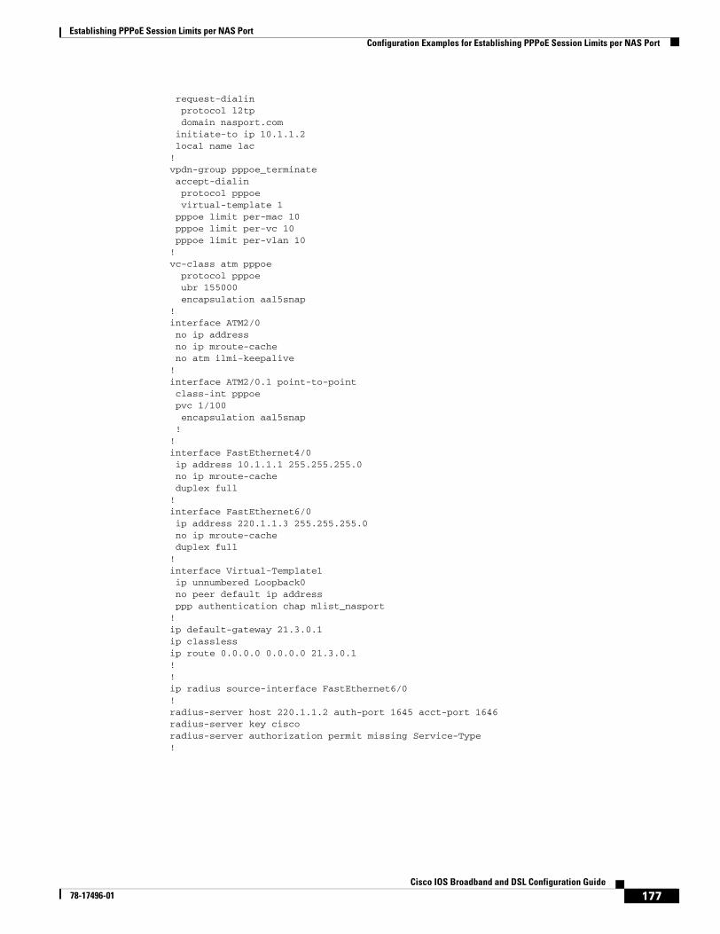
Establishing PPPoE Session Limits per NAS PortConfiguration Examples for Establishing PPPoE Session Limits per NAS Port
177Cisco IOS Broadband and DSL Configuration Guide
78-17496-01
request-dialin protocol l2tp domain nasport.com initiate-to ip 10.1.1.2 local name lac ! vpdn-group pppoe_terminate accept-dialin protocol pppoe virtual-template 1 pppoe limit per-mac 10 pppoe limit per-vc 10 pppoe limit per-vlan 10 ! vc-class atm pppoe protocol pppoe ubr 155000 encapsulation aal5snap ! interface ATM2/0 no ip address no ip mroute-cache no atm ilmi-keepalive ! interface ATM2/0.1 point-to-point class-int pppoe pvc 1/100 encapsulation aal5snap ! ! interface FastEthernet4/0 ip address 10.1.1.1 255.255.255.0 no ip mroute-cache duplex full ! interface FastEthernet6/0 ip address 220.1.1.3 255.255.255.0 no ip mroute-cache duplex full ! interface Virtual-Template1 ip unnumbered Loopback0 no peer default ip address ppp authentication chap mlist_nasport ! ip default-gateway 21.3.0.1 ip classless ip route 0.0.0.0 0.0.0.0 21.3.0.1 ! ! ip radius source-interface FastEthernet6/0 ! radius-server host 220.1.1.2 auth-port 1645 acct-port 1646 radius-server key cisco radius-server authorization permit missing Service-Type !
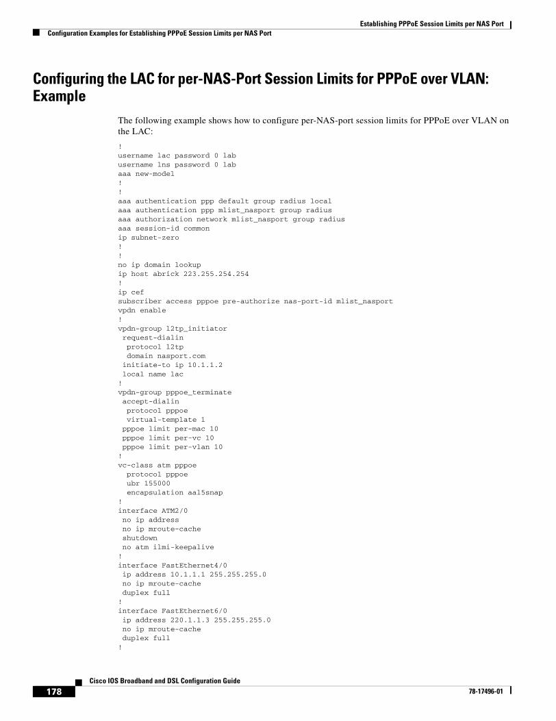
Establishing PPPoE Session Limits per NAS PortConfiguration Examples for Establishing PPPoE Session Limits per NAS Port
178Cisco IOS Broadband and DSL Configuration Guide
78-17496-01
Configuring the LAC for per-NAS-Port Session Limits for PPPoE over VLAN: Example
The following example shows how to configure per-NAS-port session limits for PPPoE over VLAN on the LAC:
! username lac password 0 lab username lns password 0 lab aaa new-model ! ! aaa authentication ppp default group radius local aaa authentication ppp mlist_nasport group radius aaa authorization network mlist_nasport group radius aaa session-id common ip subnet-zero ! ! no ip domain lookup ip host abrick 223.255.254.254 ! ip cef subscriber access pppoe pre-authorize nas-port-id mlist_nasport vpdn enable ! vpdn-group l2tp_initiator request-dialin protocol l2tp domain nasport.com initiate-to ip 10.1.1.2 local name lac ! vpdn-group pppoe_terminate accept-dialin protocol pppoe virtual-template 1 pppoe limit per-mac 10 pppoe limit per-vc 10 pppoe limit per-vlan 10 ! vc-class atm pppoe protocol pppoe ubr 155000 encapsulation aal5snap ! interface ATM2/0 no ip address no ip mroute-cache shutdown no atm ilmi-keepalive ! interface FastEthernet4/0 ip address 10.1.1.1 255.255.255.0 no ip mroute-cache duplex full ! interface FastEthernet6/0 ip address 220.1.1.3 255.255.255.0 no ip mroute-cache duplex full !
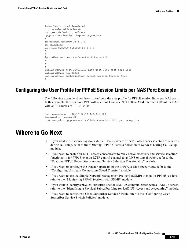
Establishing PPPoE Session Limits per NAS PortWhere to Go Next
179Cisco IOS Broadband and DSL Configuration Guide
78-17496-01
interface Virtual-Template1 ip unnumbered Loopback0 no peer default ip address ppp authentication chap mlist_nasport ! ip default-gateway 21.3.0.1 ip classless ip route 0.0.0.0 0.0.0.0 21.3.0.1 ! ! ip radius source-interface FastEthernet6/0 ! ! ! radius-server host 220.1.1.2 auth-port 1645 acct-port 1646 radius-server key cisco radius-server authorization permit missing Service-Type !
Configuring the User Profile for PPPoE Session Limits per NAS Port: ExampleThe following example shows how to configure the user profile for PPPoE session limits per NAS port. In this example, the user has a PVC with a VPI of 1 and a VCI of 100 on ATM interface 4/0/0 of the LAC with an IP address of 10.10.10.10:
Username=nas_port:10.10.10.10:4/0/0/1.100 Password = "password1" cisco-avpair= "pppoe:session-limit=<session limit per NAS-port>"
Where to Go Next• If you want to use service tags to enable a PPPoE server to offer PPPoE clients a selection of services
during call setup, refer to the “Offering PPPoE Clients a Selection of Services During Call Setup” module.
• If you want to enable an L2TP access concentrator to relay active discovery and service selection functionality for PPPoE over an L2TP control channel to an LNS or tunnel switch, refer to the “Enabling PPPoE Relay Discovery and Service Selection Functionality” module.
• If you want to configure the transfer upstream of the PPPoX session speed value, refer to the “Configuring Upstream Connections Speed Transfer” module.
• If you want to use the Simple Network Management Protocol (SNMP) to monitor PPPoE sessions, refer to the “Monitoring PPPoE Sessions with SNMP” module.
• If you want to identify a physical subscribe line for RADIUS communication with a RADIUS server, refer to the “Identifying a Physical Subscriber Line for RADIUS Access and Accounting” module.
• If you want to configure a Cisco Subscriber Service Switch, refer to the “Configuring Cisco Subscriber Service Switch Policies” module.
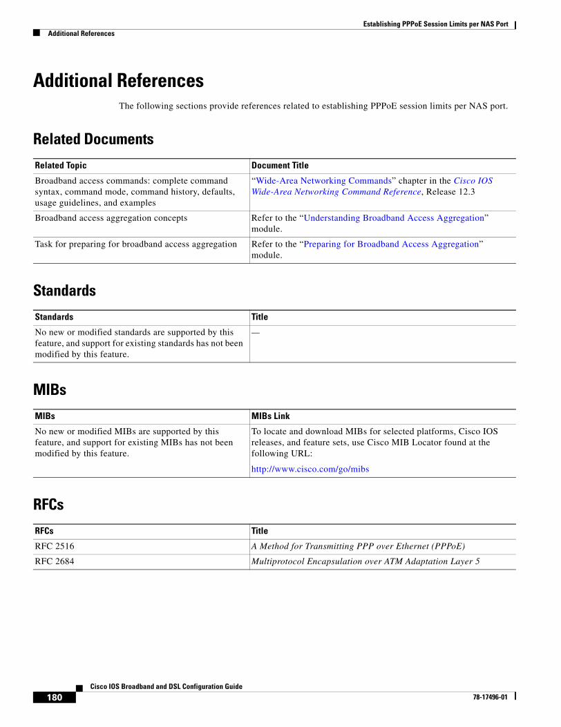
Establishing PPPoE Session Limits per NAS PortAdditional References
180Cisco IOS Broadband and DSL Configuration Guide
78-17496-01
Additional ReferencesThe following sections provide references related to establishing PPPoE session limits per NAS port.
Related Documents
Standards
MIBs
RFCs
Related Topic Document Title
Broadband access commands: complete command syntax, command mode, command history, defaults, usage guidelines, and examples
“Wide-Area Networking Commands” chapter in the Cisco IOS Wide-Area Networking Command Reference, Release 12.3
Broadband access aggregation concepts Refer to the “Understanding Broadband Access Aggregation” module.
Task for preparing for broadband access aggregation Refer to the “Preparing for Broadband Access Aggregation” module.
Standards Title
No new or modified standards are supported by this feature, and support for existing standards has not been modified by this feature.
—
MIBs MIBs Link
No new or modified MIBs are supported by this feature, and support for existing MIBs has not been modified by this feature.
To locate and download MIBs for selected platforms, Cisco IOS releases, and feature sets, use Cisco MIB Locator found at the following URL:
http://www.cisco.com/go/mibs
RFCs Title
RFC 2516 A Method for Transmitting PPP over Ethernet (PPPoE)
RFC 2684 Multiprotocol Encapsulation over ATM Adaptation Layer 5
http://www.cisco.com/univercd/cc/td/doc/product/software/ios123/123tcr/123twr/wan_a1gt.htm#wp1056981
Establishing PPPoE Session Limits per NAS PortAdditional References
181Cisco IOS Broadband and DSL Configuration Guide
78-17496-01
Technical Assistance
Description Link
The Cisco Technical Support website contains thousands of pages of searchable technical content, including links to products, technologies, solutions, technical tips, and tools. Registered Cisco.com users can log in from this page to access even more content.
http://www.cisco.com/techsupport
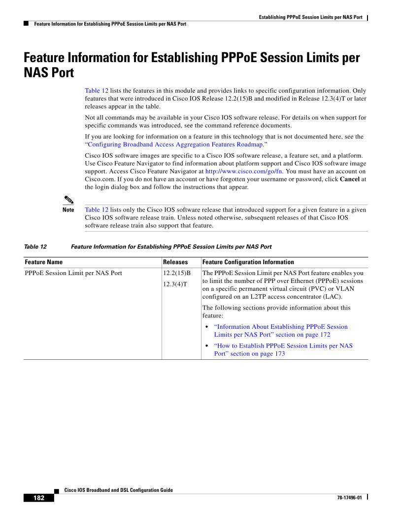
Establishing PPPoE Session Limits per NAS PortFeature Information for Establishing PPPoE Session Limits per NAS Port
182Cisco IOS Broadband and DSL Configuration Guide
78-17496-01
Feature Information for Establishing PPPoE Session Limits per NAS Port
Table 12 lists the features in this module and provides links to specific configuration information. Only features that were introduced in Cisco IOS Release 12.2(15)B and modified in Release 12.3(4)T or later releases appear in the table.
Not all commands may be available in your Cisco IOS software release. For details on when support for specific commands was introduced, see the command reference documents.
If you are looking for information on a feature in this technology that is not documented here, see the “Configuring Broadband Access Aggregation Features Roadmap.”
Cisco IOS software images are specific to a Cisco IOS software release, a feature set, and a platform. Use Cisco Feature Navigator to find information about platform support and Cisco IOS software image support. Access Cisco Feature Navigator at http://www.cisco.com/go/fn. You must have an account on Cisco.com. If you do not have an account or have forgotten your username or password, click Cancel at the login dialog box and follow the instructions that appear.
Note Table 12 lists only the Cisco IOS software release that introduced support for a given feature in a given Cisco IOS software release train. Unless noted otherwise, subsequent releases of that Cisco IOS software release train also support that feature.
Table 12 Feature Information for Establishing PPPoE Session Limits per NAS Port
Feature Name Releases Feature Configuration Information
PPPoE Session Limit per NAS Port 12.2(15)B
12.3(4)T
The PPPoE Session Limit per NAS Port feature enables you to limit the number of PPP over Ethernet (PPPoE) sessions on a specific permanent virtual circuit (PVC) or VLAN configured on an L2TP access concentrator (LAC).
The following sections provide information about this feature:
• “Information About Establishing PPPoE Session Limits per NAS Port” section on page 172
• “How to Establish PPPoE Session Limits per NAS Port” section on page 173
183Cisco IOS Broadband and DSL Configuration Guide
78-17496-01
Providing Session Limit Support for Legacy Configurations
This module provides information needed to provide session limit support for PPP over Ethernet configuration that were created using Cisco IOS software Release 12.2 or earlier releases. Users of Cisco IOS Release 12.3 and later should not use the procedures in this module as session limits are configured when creating profiles and provide for more flexible and scalable configuration options. See “Providing Protocol Support for PPPoE Sessions” for commands for establishing session limits using profiles.
The PPP over Ethernet (PPPoE) Session Limit feature enables you to limit the number of PPPoE sessions that can be created on a router or on an ATM permanent virtual circuit (PVC), PVC range, virtual circuit (VC) class, or Ethernet subinterface for configuration.
Not limiting the number of sessions makes it possible for the router to create so many PPPoE sessions that it could run out of memory.
To prevent the router from using too much memory for virtual access, the PPPoE Session Limit feature enables you to specify the maximum number of PPPoE sessions that can be created. The pppoe limit max-sessions command limits the number of PPPoE sessions that can be created on the router. The pppoe max-sessions command limits the number of PPPoE sessions that can be created on an ATM PVC, PVC range, VC class, or Ethernet subinterface.
In addition, this feature can be used when an administrator wants to restrict the number of PPPoE users per PVC for subscription purposes
Module History
This module was first published on May 2, 2005, and last updated on May 2, 2005.
Finding Feature Information in This Module
Not all features may be supported in your Cisco IOS software release. Use the “Feature Information for Supporting Session Limits on Legacy Configurations” section on page 196 to find information about feature support and configuration.
Contents• Prerequisites for Providing Session Limit Support for Legacy Configurations, page 184
• Information About Providing Session Limit Support for Legacy Configurations, page 184
• How to Provide Session Limit Support for Legacy Configurations, page 184
• Configuration Examples for Providing Session Limit Support for Legacy Configurations, page 193
Providing Session Limit Support for Legacy ConfigurationsPrerequisites for Providing Session Limit Support for Legacy Configurations
184Cisco IOS Broadband and DSL Configuration Guide
78-17496-01
• Additional References, page 195
• Feature Information for Supporting Session Limits on Legacy Configurations, page 196
Prerequisites for Providing Session Limit Support for Legacy Configurations
• You must understand the concepts described in the “Preparing for Broadband Access Aggregation” module.
Information About Providing Session Limit Support for Legacy Configurations
Information about limiting the number of PPPoE sessions on a port includes the following:
• Benefits of Providing Session Limit Support for Legacy Configurations, page 184
Benefits of Providing Session Limit Support for Legacy ConfigurationsThe PPPoE Session Limit feature prevents the router from using too much memory for virtual access by limiting the number of PPPoE sessions that can be created on a router or on an ATM PVC, PVC range, VC class or Ethernet subinterface.
Note The procedures provided in this section provide session limit support for configurations using Cisco IOS Release 12.2 or earlier releases. These configurations are supported in Cisco IOS Release 12.3 for backward compatibility only. New configurations should be defined using the procedures in Providing Protocol Support for Broadband Aggregation of PPPoE Sessions.
How to Provide Session Limit Support for Legacy ConfigurationsTo configure PPPoE session limits, complete one or more of the following tasks:
• Limiting the Number of PPPoE Sessions on the Router, page 185 (optional)
• Limiting the Number of PPPoE Sessions on a PVC, page 186 (optional)
• Limiting the Number of PPPoE Session on a VC Class, page 188 (optional)
• Limiting the Number of PPPoE Sessions in an ATM PVC Range, page 190 (optional)
• Limiting the Number of PPPoE Sessions on an Individual PVC Within a PVC Range, page 191 (optional)
To verify PPPoE session limits, use the following tasks:
• Verifying PPPoE Session Limits, page 193 (optional)
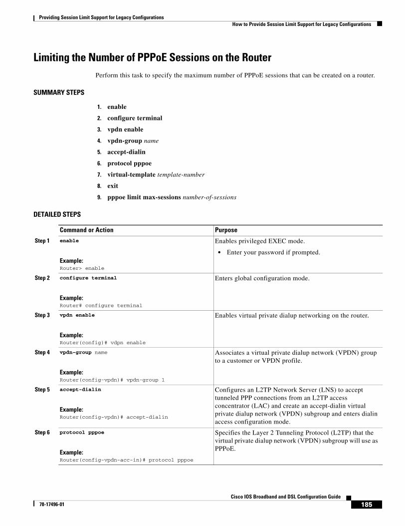
Providing Session Limit Support for Legacy ConfigurationsHow to Provide Session Limit Support for Legacy Configurations
185Cisco IOS Broadband and DSL Configuration Guide
78-17496-01
Limiting the Number of PPPoE Sessions on the RouterPerform this task to specify the maximum number of PPPoE sessions that can be created on a router.
SUMMARY STEPS
1. enable
2. configure terminal
3. vpdn enable
4. vpdn-group name
5. accept-dialin
6. protocol pppoe
7. virtual-template template-number
8. exit
9. pppoe limit max-sessions number-of-sessions
DETAILED STEPS
Command or Action Purpose
Step 1 enable
Example:Router> enable
Enables privileged EXEC mode.
• Enter your password if prompted.
Step 2 configure terminal
Example:Router# configure terminal
Enters global configuration mode.
Step 3 vpdn enable
Example:Router(config)# vdpn enable
Enables virtual private dialup networking on the router.
Step 4 vpdn-group name
Example:Router(config-vpdn)# vpdn-group 1
Associates a virtual private dialup network (VPDN) group to a customer or VPDN profile.
Step 5 accept-dialin
Example:Router(config-vpdn)# accept-dialin
Configures an L2TP Network Server (LNS) to accept tunneled PPP connections from an L2TP access concentrator (LAC) and create an accept-dialin virtual private dialup network (VPDN) subgroup and enters dialin access configuration mode.
Step 6 protocol pppoe
Example:Router(config-vpdn-acc-in)# protocol pppoe
Specifies the Layer 2 Tunneling Protocol (L2TP) that the virtual private dialup network (VPDN) subgroup will use as PPPoE.
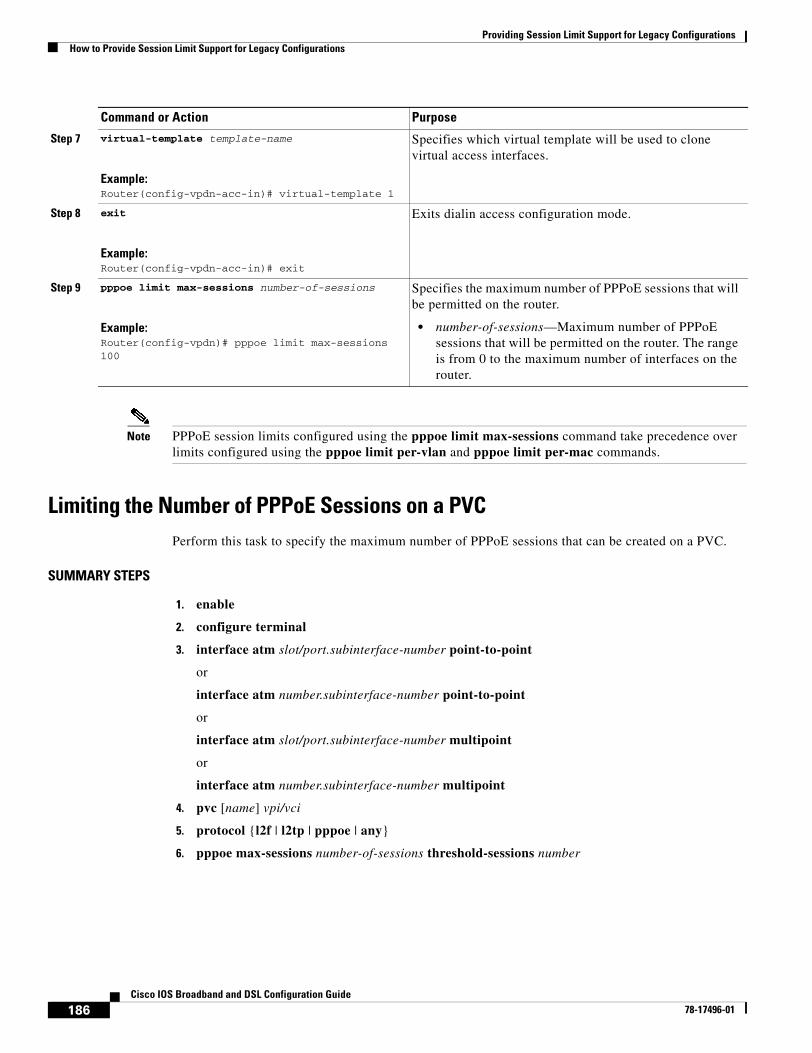
Providing Session Limit Support for Legacy ConfigurationsHow to Provide Session Limit Support for Legacy Configurations
186Cisco IOS Broadband and DSL Configuration Guide
78-17496-01
Note PPPoE session limits configured using the pppoe limit max-sessions command take precedence over limits configured using the pppoe limit per-vlan and pppoe limit per-mac commands.
Limiting the Number of PPPoE Sessions on a PVCPerform this task to specify the maximum number of PPPoE sessions that can be created on a PVC.
SUMMARY STEPS
1. enable
2. configure terminal
3. interface atm slot/port.subinterface-number point-to-point
or
interface atm number.subinterface-number point-to-point
or
interface atm slot/port.subinterface-number multipoint
or
interface atm number.subinterface-number multipoint
4. pvc [name] vpi/vci
5. protocol {l2f | l2tp | pppoe | any}
6. pppoe max-sessions number-of-sessions threshold-sessions number
Step 7 virtual-template template-name
Example:Router(config-vpdn-acc-in)# virtual-template 1
Specifies which virtual template will be used to clone virtual access interfaces.
Step 8 exit
Example:Router(config-vpdn-acc-in)# exit
Exits dialin access configuration mode.
Step 9 pppoe limit max-sessions number-of-sessions
Example:Router(config-vpdn)# pppoe limit max-sessions 100
Specifies the maximum number of PPPoE sessions that will be permitted on the router.
• number-of-sessions—Maximum number of PPPoE sessions that will be permitted on the router. The range is from 0 to the maximum number of interfaces on the router.
Command or Action Purpose
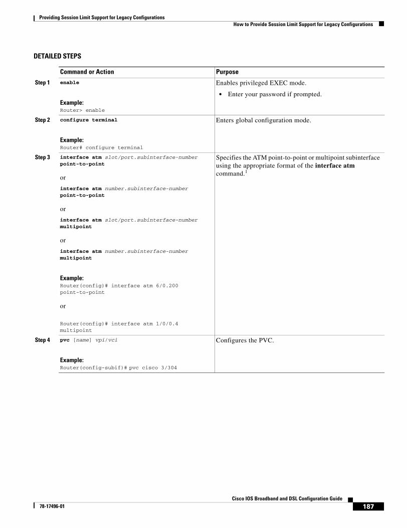
Providing Session Limit Support for Legacy ConfigurationsHow to Provide Session Limit Support for Legacy Configurations
187Cisco IOS Broadband and DSL Configuration Guide
78-17496-01
DETAILED STEPS
Command or Action Purpose
Step 1 enable
Example:Router> enable
Enables privileged EXEC mode.
• Enter your password if prompted.
Step 2 configure terminal
Example:Router# configure terminal
Enters global configuration mode.
Step 3 interface atm slot/port.subinterface-number point-to-point
or
interface atm number.subinterface-number point-to-point
or
interface atm slot/port.subinterface-number multipoint
or
interface atm number.subinterface-number multipoint
Example:Router(config)# interface atm 6/0.200 point-to-point
or
Router(config)# interface atm 1/0/0.4 multipoint
Specifies the ATM point-to-point or multipoint subinterface using the appropriate format of the interface atm command.1
Step 4 pvc [name] vpi/vci
Example:Router(config-subif)# pvc cisco 3/304
Configures the PVC.
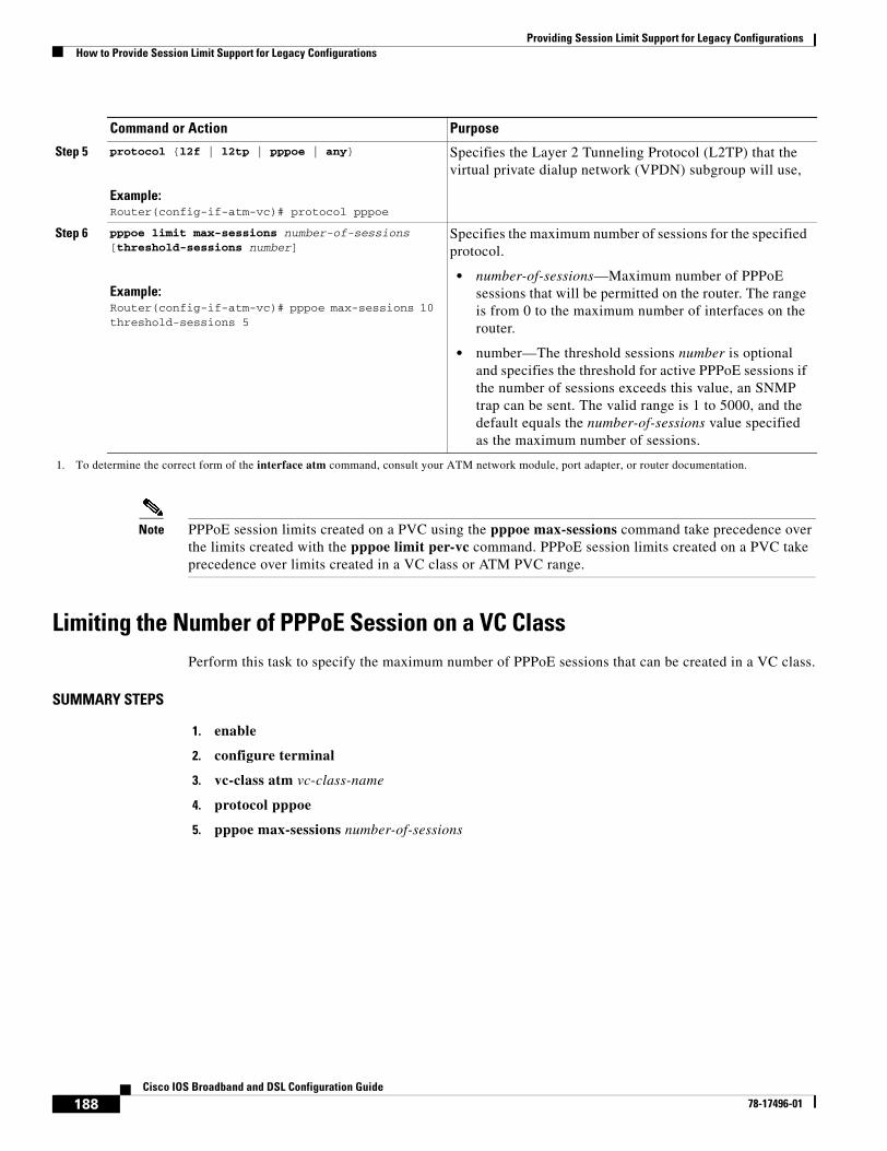
Providing Session Limit Support for Legacy ConfigurationsHow to Provide Session Limit Support for Legacy Configurations
188Cisco IOS Broadband and DSL Configuration Guide
78-17496-01
Note PPPoE session limits created on a PVC using the pppoe max-sessions command take precedence over the limits created with the pppoe limit per-vc command. PPPoE session limits created on a PVC take precedence over limits created in a VC class or ATM PVC range.
Limiting the Number of PPPoE Session on a VC ClassPerform this task to specify the maximum number of PPPoE sessions that can be created in a VC class.
SUMMARY STEPS
1. enable
2. configure terminal
3. vc-class atm vc-class-name
4. protocol pppoe
5. pppoe max-sessions number-of-sessions
Step 5 protocol {l2f | l2tp | pppoe | any}
Example:Router(config-if-atm-vc)# protocol pppoe
Specifies the Layer 2 Tunneling Protocol (L2TP) that the virtual private dialup network (VPDN) subgroup will use,
Step 6 pppoe limit max-sessions number-of-sessions [threshold-sessions number]
Example:Router(config-if-atm-vc)# pppoe max-sessions 10 threshold-sessions 5
Specifies the maximum number of sessions for the specified protocol.
• number-of-sessions—Maximum number of PPPoE sessions that will be permitted on the router. The range is from 0 to the maximum number of interfaces on the router.
• number—The threshold sessions number is optional and specifies the threshold for active PPPoE sessions if the number of sessions exceeds this value, an SNMP trap can be sent. The valid range is 1 to 5000, and the default equals the number-of-sessions value specified as the maximum number of sessions.
1. To determine the correct form of the interface atm command, consult your ATM network module, port adapter, or router documentation.
Command or Action Purpose
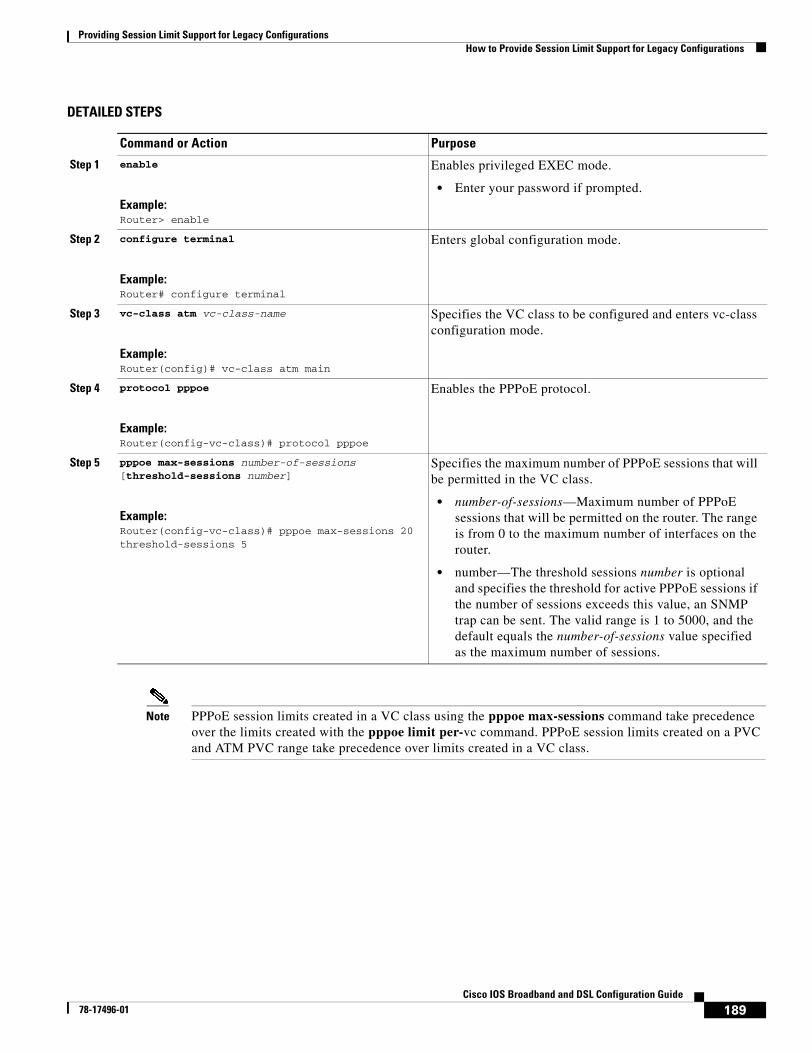
Providing Session Limit Support for Legacy ConfigurationsHow to Provide Session Limit Support for Legacy Configurations
189Cisco IOS Broadband and DSL Configuration Guide
78-17496-01
DETAILED STEPS
Note PPPoE session limits created in a VC class using the pppoe max-sessions command take precedence over the limits created with the pppoe limit per-vc command. PPPoE session limits created on a PVC and ATM PVC range take precedence over limits created in a VC class.
Command or Action Purpose
Step 1 enable
Example:Router> enable
Enables privileged EXEC mode.
• Enter your password if prompted.
Step 2 configure terminal
Example:Router# configure terminal
Enters global configuration mode.
Step 3 vc-class atm vc-class-name
Example:Router(config)# vc-class atm main
Specifies the VC class to be configured and enters vc-class configuration mode.
Step 4 protocol pppoe
Example:Router(config-vc-class)# protocol pppoe
Enables the PPPoE protocol.
Step 5 pppoe max-sessions number-of-sessions [threshold-sessions number]
Example:Router(config-vc-class)# pppoe max-sessions 20 threshold-sessions 5
Specifies the maximum number of PPPoE sessions that will be permitted in the VC class.
• number-of-sessions—Maximum number of PPPoE sessions that will be permitted on the router. The range is from 0 to the maximum number of interfaces on the router.
• number—The threshold sessions number is optional and specifies the threshold for active PPPoE sessions if the number of sessions exceeds this value, an SNMP trap can be sent. The valid range is 1 to 5000, and the default equals the number-of-sessions value specified as the maximum number of sessions.
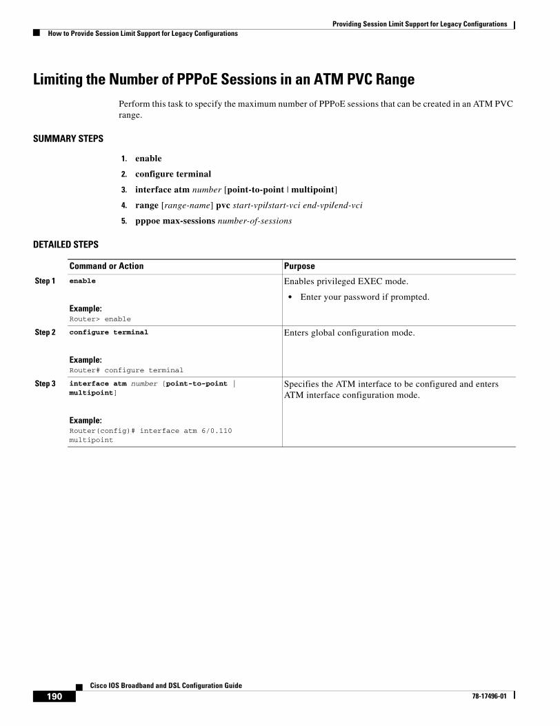
Providing Session Limit Support for Legacy ConfigurationsHow to Provide Session Limit Support for Legacy Configurations
190Cisco IOS Broadband and DSL Configuration Guide
78-17496-01
Limiting the Number of PPPoE Sessions in an ATM PVC RangePerform this task to specify the maximum number of PPPoE sessions that can be created in an ATM PVC range.
SUMMARY STEPS
1. enable
2. configure terminal
3. interface atm number [point-to-point | multipoint]
4. range [range-name] pvc start-vpi/start-vci end-vpi/end-vci
5. pppoe max-sessions number-of-sessions
DETAILED STEPS
Command or Action Purpose
Step 1 enable
Example:Router> enable
Enables privileged EXEC mode.
• Enter your password if prompted.
Step 2 configure terminal
Example:Router# configure terminal
Enters global configuration mode.
Step 3 interface atm number [point-to-point | multipoint]
Example:Router(config)# interface atm 6/0.110 multipoint
Specifies the ATM interface to be configured and enters ATM interface configuration mode.
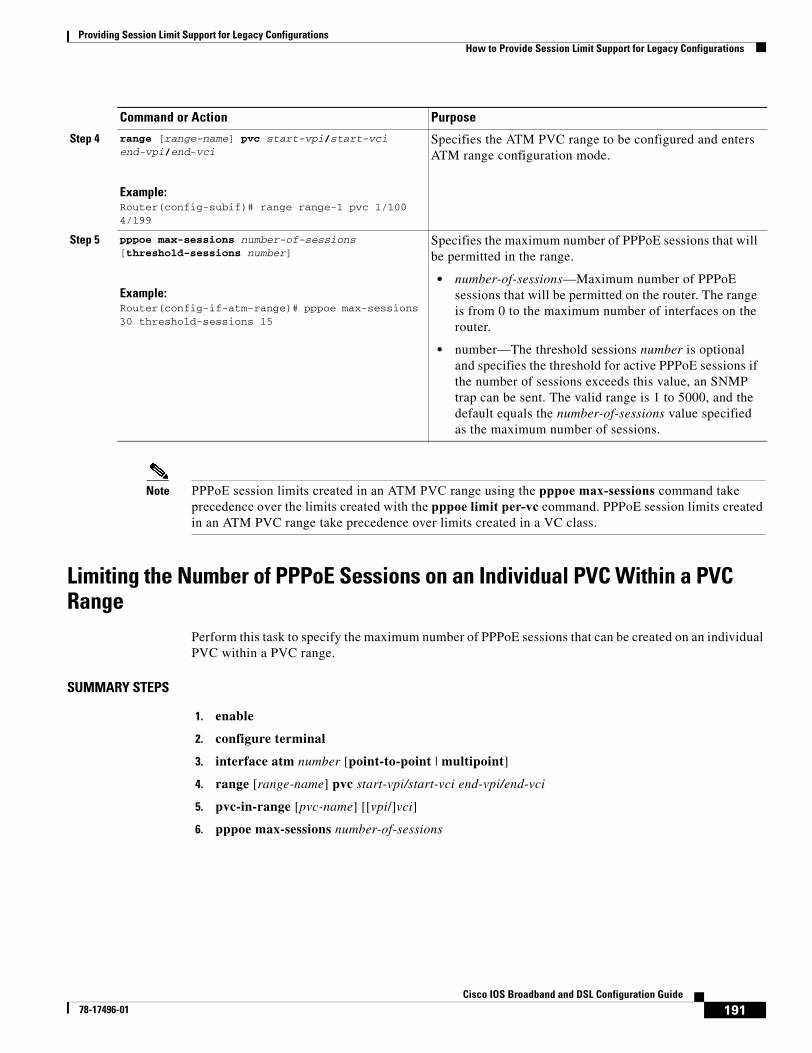
Providing Session Limit Support for Legacy ConfigurationsHow to Provide Session Limit Support for Legacy Configurations
191Cisco IOS Broadband and DSL Configuration Guide
78-17496-01
Note PPPoE session limits created in an ATM PVC range using the pppoe max-sessions command take precedence over the limits created with the pppoe limit per-vc command. PPPoE session limits created in an ATM PVC range take precedence over limits created in a VC class.
Limiting the Number of PPPoE Sessions on an Individual PVC Within a PVC Range
Perform this task to specify the maximum number of PPPoE sessions that can be created on an individual PVC within a PVC range.
SUMMARY STEPS
1. enable
2. configure terminal
3. interface atm number [point-to-point | multipoint]
4. range [range-name] pvc start-vpi/start-vci end-vpi/end-vci
5. pvc-in-range [pvc-name] [[vpi/]vci]
6. pppoe max-sessions number-of-sessions
Step 4 range [range-name] pvc start-vpi/start-vci end-vpi/end-vci
Example:Router(config-subif)# range range-1 pvc 1/100 4/199
Specifies the ATM PVC range to be configured and enters ATM range configuration mode.
Step 5 pppoe max-sessions number-of-sessions [threshold-sessions number]
Example:Router(config-if-atm-range)# pppoe max-sessions 30 threshold-sessions 15
Specifies the maximum number of PPPoE sessions that will be permitted in the range.
• number-of-sessions—Maximum number of PPPoE sessions that will be permitted on the router. The range is from 0 to the maximum number of interfaces on the router.
• number—The threshold sessions number is optional and specifies the threshold for active PPPoE sessions if the number of sessions exceeds this value, an SNMP trap can be sent. The valid range is 1 to 5000, and the default equals the number-of-sessions value specified as the maximum number of sessions.
Command or Action Purpose
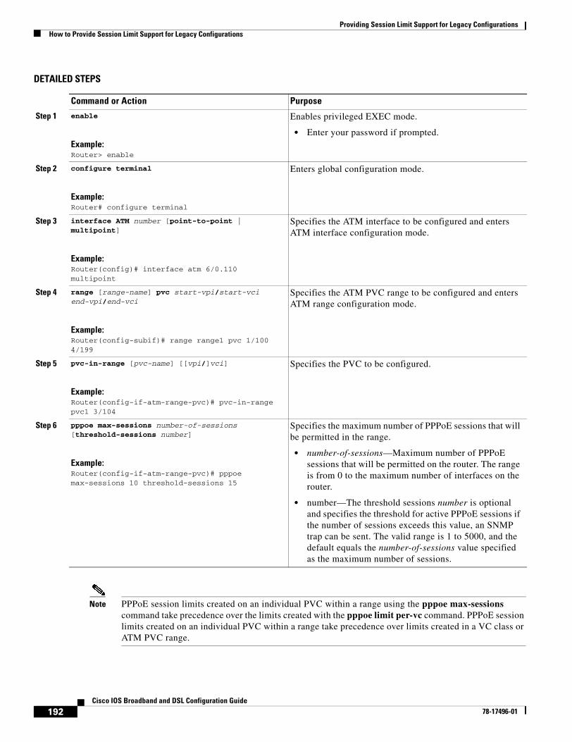
Providing Session Limit Support for Legacy ConfigurationsHow to Provide Session Limit Support for Legacy Configurations
192Cisco IOS Broadband and DSL Configuration Guide
78-17496-01
DETAILED STEPS
Note PPPoE session limits created on an individual PVC within a range using the pppoe max-sessions command take precedence over the limits created with the pppoe limit per-vc command. PPPoE session limits created on an individual PVC within a range take precedence over limits created in a VC class or ATM PVC range.
Command or Action Purpose
Step 1 enable
Example:Router> enable
Enables privileged EXEC mode.
• Enter your password if prompted.
Step 2 configure terminal
Example:Router# configure terminal
Enters global configuration mode.
Step 3 interface ATM number [point-to-point | multipoint]
Example:Router(config)# interface atm 6/0.110 multipoint
Specifies the ATM interface to be configured and enters ATM interface configuration mode.
Step 4 range [range-name] pvc start-vpi/start-vci end-vpi/end-vci
Example:Router(config-subif)# range range1 pvc 1/100 4/199
Specifies the ATM PVC range to be configured and enters ATM range configuration mode.
Step 5 pvc-in-range [pvc-name] [[vpi/]vci]
Example:Router(config-if-atm-range-pvc)# pvc-in-range pvc1 3/104
Specifies the PVC to be configured.
Step 6 pppoe max-sessions number-of-sessions [threshold-sessions number]
Example:Router(config-if-atm-range-pvc)# pppoe max-sessions 10 threshold-sessions 15
Specifies the maximum number of PPPoE sessions that will be permitted in the range.
• number-of-sessions—Maximum number of PPPoE sessions that will be permitted on the router. The range is from 0 to the maximum number of interfaces on the router.
• number—The threshold sessions number is optional and specifies the threshold for active PPPoE sessions if the number of sessions exceeds this value, an SNMP trap can be sent. The valid range is 1 to 5000, and the default equals the number-of-sessions value specified as the maximum number of sessions.
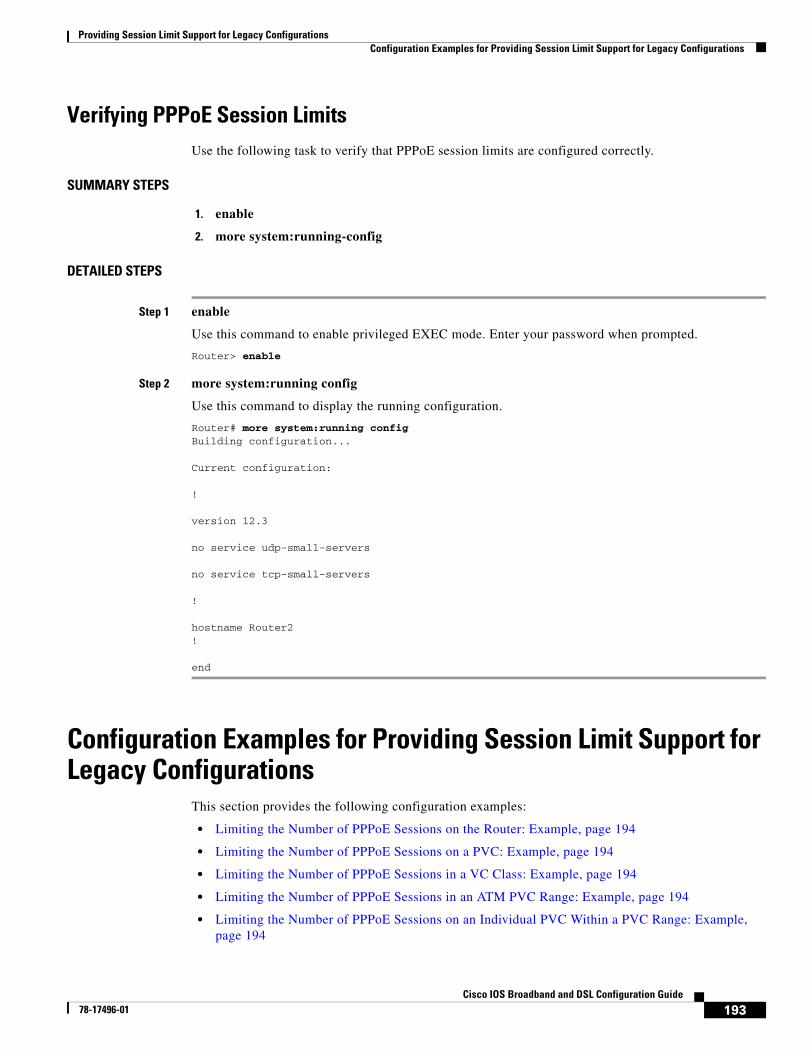
Providing Session Limit Support for Legacy ConfigurationsConfiguration Examples for Providing Session Limit Support for Legacy Configurations
193Cisco IOS Broadband and DSL Configuration Guide
78-17496-01
Verifying PPPoE Session LimitsUse the following task to verify that PPPoE session limits are configured correctly.
SUMMARY STEPS
1. enable
2. more system:running-config
DETAILED STEPS
Step 1 enable
Use this command to enable privileged EXEC mode. Enter your password when prompted.
Router> enable
Step 2 more system:running config
Use this command to display the running configuration.
Router# more system:running configBuilding configuration...
Current configuration:
!
version 12.3
no service udp-small-servers
no service tcp-small-servers
!
hostname Router2!
end
Configuration Examples for Providing Session Limit Support for Legacy Configurations
This section provides the following configuration examples:
• Limiting the Number of PPPoE Sessions on the Router: Example, page 194
• Limiting the Number of PPPoE Sessions on a PVC: Example, page 194
• Limiting the Number of PPPoE Sessions in a VC Class: Example, page 194
• Limiting the Number of PPPoE Sessions in an ATM PVC Range: Example, page 194
• Limiting the Number of PPPoE Sessions on an Individual PVC Within a PVC Range: Example, page 194

Providing Session Limit Support for Legacy ConfigurationsConfiguration Examples for Providing Session Limit Support for Legacy Configurations
194Cisco IOS Broadband and DSL Configuration Guide
78-17496-01
Limiting the Number of PPPoE Sessions on the Router: Example The following example shows a limit of 100 PPPoE sessions configured for the router:
vpdn enablevpdn-group 1accept dialinprotocol pppoevirtual-template 1exitpppoe limit max-sessions 100
Limiting the Number of PPPoE Sessions on a PVC: Example The following example shows a limit of 10 PPPoE sessions configured for the PVC:
interface ATM1/0.102 multipointpvc 3/304encapsulation aal5snapprotocol pppoepppoe max-sessions 10
Limiting the Number of PPPoE Sessions in a VC Class: Example The following example shows a limit of 20 PPPoE sessions configured for the VC class called main.
vc-class atm mainprotocol pppoepppoe max-sessions 20
Limiting the Number of PPPoE Sessions in an ATM PVC Range: Example The following example shows a limit of 30 PPPoE sessions configured for the ATM PVC range called “range-1.”
interface atm 6/0.110 multipointrange range-1 pvc 100 4/199encapsulation aal5snapprotocol ppp virtual-template 2 pppoe max-sessions 30
Limiting the Number of PPPoE Sessions on an Individual PVC Within a PVC Range: Example
The following example shows a limit of 10 PPPoE sessions configured for “pvc1,” which is part of the ATM PVC range called “range1.”
interface atm 6/0.110 multipointrange range1 pvc 100 4/199pvc-in-range pvc1 3/104pppoe max-sessions 10
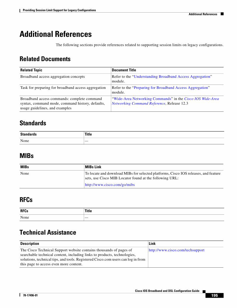
Providing Session Limit Support for Legacy ConfigurationsAdditional References
195Cisco IOS Broadband and DSL Configuration Guide
78-17496-01
Additional ReferencesThe following sections provide references related to supporting session limits on legacy configurations.
Related Documents
Standards
MIBs
RFCs
Technical Assistance
Related Topic Document Title
Broadband access aggregation concepts Refer to the “Understanding Broadband Access Aggregation” module.
Task for preparing for broadband access aggregation Refer to the “Preparing for Broadband Access Aggregation” module.
Broadband access commands: complete command syntax, command mode, command history, defaults, usage guidelines, and examples
“Wide-Area Networking Commands” in the Cisco IOS Wide-Area Networking Command Reference, Release 12.3
Standards Title
None —
MIBs MIBs Link
None To locate and download MIBs for selected platforms, Cisco IOS releases, and feature sets, use Cisco MIB Locator found at the following URL:
http://www.cisco.com/go/mibs
RFCs Title
None —
Description Link
The Cisco Technical Support website contains thousands of pages of searchable technical content, including links to products, technologies, solutions, technical tips, and tools. Registered Cisco.com users can log in from this page to access even more content.
http://www.cisco.com/techsupport
http://www.cisco.com/univercd/cc/td/doc/product/software/ios123/123tcr/123twr/wan_a1gt.htm#wp1056981
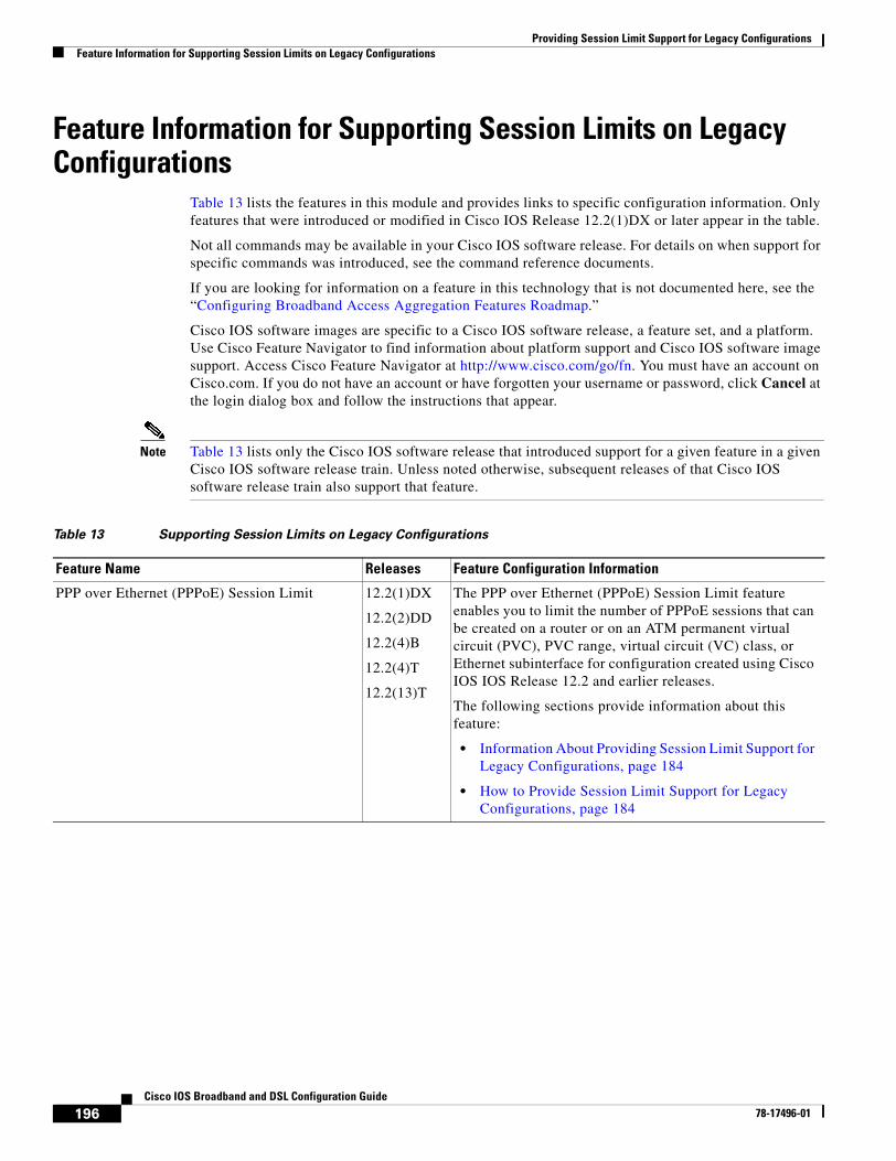
Providing Session Limit Support for Legacy ConfigurationsFeature Information for Supporting Session Limits on Legacy Configurations
196Cisco IOS Broadband and DSL Configuration Guide
78-17496-01
Feature Information for Supporting Session Limits on Legacy Configurations
Table 13 lists the features in this module and provides links to specific configuration information. Only features that were introduced or modified in Cisco IOS Release 12.2(1)DX or later appear in the table.
Not all commands may be available in your Cisco IOS software release. For details on when support for specific commands was introduced, see the command reference documents.
If you are looking for information on a feature in this technology that is not documented here, see the “Configuring Broadband Access Aggregation Features Roadmap.”
Cisco IOS software images are specific to a Cisco IOS software release, a feature set, and a platform. Use Cisco Feature Navigator to find information about platform support and Cisco IOS software image support. Access Cisco Feature Navigator at http://www.cisco.com/go/fn. You must have an account on Cisco.com. If you do not have an account or have forgotten your username or password, click Cancel at the login dialog box and follow the instructions that appear.
Note Table 13 lists only the Cisco IOS software release that introduced support for a given feature in a given Cisco IOS software release train. Unless noted otherwise, subsequent releases of that Cisco IOS software release train also support that feature.
Table 13 Supporting Session Limits on Legacy Configurations
Feature Name Releases Feature Configuration Information
PPP over Ethernet (PPPoE) Session Limit 12.2(1)DX
12.2(2)DD
12.2(4)B
12.2(4)T
12.2(13)T
The PPP over Ethernet (PPPoE) Session Limit feature enables you to limit the number of PPPoE sessions that can be created on a router or on an ATM permanent virtual circuit (PVC), PVC range, virtual circuit (VC) class, or Ethernet subinterface for configuration created using Cisco IOS IOS Release 12.2 and earlier releases.
The following sections provide information about this feature:
• Information About Providing Session Limit Support for Legacy Configurations, page 184
• How to Provide Session Limit Support for Legacy Configurations, page 184
197Cisco IOS Broadband and DSL Configuration Guide
78-17496-01
Monitoring PPPoE Sessions with SNMP
The PPPoE Session Count Management Information Base (MIB) feature provides the ability to use Simple Network Management Protocol (SNMP) to monitor in real time the number of PPP over Ethernet sessions configured on permanent virtual circuits (PVCs) and on a router.
This MIB also supports two SNMP traps that generate notification messages when a PPPoE session-count threshold is reached on any PVC or on the router. The PPPoE session-count thresholds can be configured using the pppoe limit max-sessions and pppoe max-sessions commands.
Module History
This module was first published on May 2, 2005, and was last updated on May 2, 2005.
Finding Feature Information in This Module
Not all features may be supported in your Cisco IOS software release. Use the “Feature Information for Monitoring PPPoE Sessions with SNMP” section on page 212 to find information about feature support and configuration.
Contents• Prerequisites for Monitoring PPPoE Sessions with SNMP, page 197
• Restrictions for Monitoring PPPoE Sessions with SNMP, page 198
• Information About Monitoring PPPoE Sessions with SNMP, page 198
• Configuration Examples for Monitoring PPPoE Sessions with SNMP, page 208
• Where to Go Next, page 209
• Additional References, page 210
• Feature Information for Monitoring PPPoE Sessions with SNMP, page 212
Prerequisites for Monitoring PPPoE Sessions with SNMP• You must understand the concepts described in the “Preparing for Broadband Access Aggregation”
module.
• PPPoE sessions must be established using the procedures in the “Providing Protocol Support for Broadband Access Aggregation of PPPoE Sessions” module.
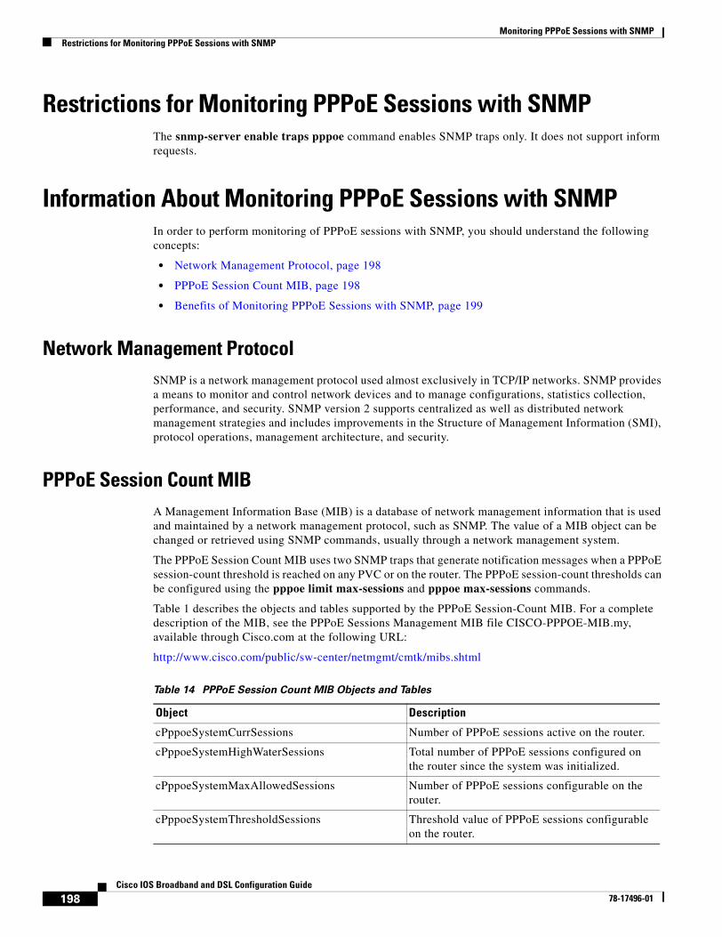
Monitoring PPPoE Sessions with SNMPRestrictions for Monitoring PPPoE Sessions with SNMP
198Cisco IOS Broadband and DSL Configuration Guide
78-17496-01
Restrictions for Monitoring PPPoE Sessions with SNMPThe snmp-server enable traps pppoe command enables SNMP traps only. It does not support inform requests.
Information About Monitoring PPPoE Sessions with SNMPIn order to perform monitoring of PPPoE sessions with SNMP, you should understand the following concepts:
• Network Management Protocol, page 198
• PPPoE Session Count MIB, page 198
• Benefits of Monitoring PPPoE Sessions with SNMP, page 199
Network Management ProtocolSNMP is a network management protocol used almost exclusively in TCP/IP networks. SNMP provides a means to monitor and control network devices and to manage configurations, statistics collection, performance, and security. SNMP version 2 supports centralized as well as distributed network management strategies and includes improvements in the Structure of Management Information (SMI), protocol operations, management architecture, and security.
PPPoE Session Count MIBA Management Information Base (MIB) is a database of network management information that is used and maintained by a network management protocol, such as SNMP. The value of a MIB object can be changed or retrieved using SNMP commands, usually through a network management system.
The PPPoE Session Count MIB uses two SNMP traps that generate notification messages when a PPPoE session-count threshold is reached on any PVC or on the router. The PPPoE session-count thresholds can be configured using the pppoe limit max-sessions and pppoe max-sessions commands.
Table 1 describes the objects and tables supported by the PPPoE Session-Count MIB. For a complete description of the MIB, see the PPPoE Sessions Management MIB file CISCO-PPPOE-MIB.my, available through Cisco.com at the following URL:
http://www.cisco.com/public/sw-center/netmgmt/cmtk/mibs.shtml
Table 14 PPPoE Session Count MIB Objects and Tables
Object Description
cPppoeSystemCurrSessions Number of PPPoE sessions active on the router.
cPppoeSystemHighWaterSessions Total number of PPPoE sessions configured on the router since the system was initialized.
cPppoeSystemMaxAllowedSessions Number of PPPoE sessions configurable on the router.
cPppoeSystemThresholdSessions Threshold value of PPPoE sessions configurable on the router.
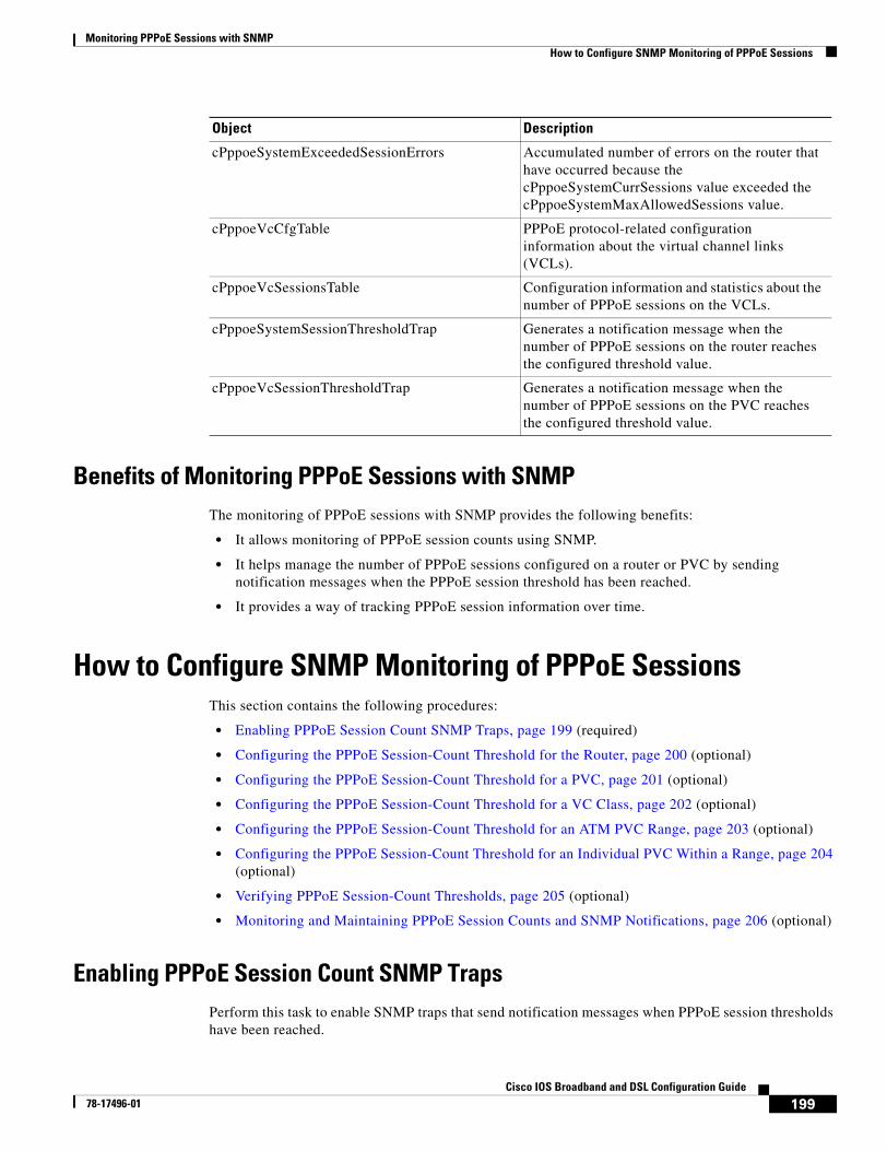
Monitoring PPPoE Sessions with SNMPHow to Configure SNMP Monitoring of PPPoE Sessions
199Cisco IOS Broadband and DSL Configuration Guide
78-17496-01
Benefits of Monitoring PPPoE Sessions with SNMPThe monitoring of PPPoE sessions with SNMP provides the following benefits:
• It allows monitoring of PPPoE session counts using SNMP.
• It helps manage the number of PPPoE sessions configured on a router or PVC by sending notification messages when the PPPoE session threshold has been reached.
• It provides a way of tracking PPPoE session information over time.
How to Configure SNMP Monitoring of PPPoE SessionsThis section contains the following procedures:
• Enabling PPPoE Session Count SNMP Traps, page 199 (required)
• Configuring the PPPoE Session-Count Threshold for the Router, page 200 (optional)
• Configuring the PPPoE Session-Count Threshold for a PVC, page 201 (optional)
• Configuring the PPPoE Session-Count Threshold for a VC Class, page 202 (optional)
• Configuring the PPPoE Session-Count Threshold for an ATM PVC Range, page 203 (optional)
• Configuring the PPPoE Session-Count Threshold for an Individual PVC Within a Range, page 204 (optional)
• Verifying PPPoE Session-Count Thresholds, page 205 (optional)
• Monitoring and Maintaining PPPoE Session Counts and SNMP Notifications, page 206 (optional)
Enabling PPPoE Session Count SNMP TrapsPerform this task to enable SNMP traps that send notification messages when PPPoE session thresholds have been reached.
cPppoeSystemExceededSessionErrors Accumulated number of errors on the router that have occurred because the cPppoeSystemCurrSessions value exceeded the cPppoeSystemMaxAllowedSessions value.
cPppoeVcCfgTable PPPoE protocol-related configuration information about the virtual channel links (VCLs).
cPppoeVcSessionsTable Configuration information and statistics about the number of PPPoE sessions on the VCLs.
cPppoeSystemSessionThresholdTrap Generates a notification message when the number of PPPoE sessions on the router reaches the configured threshold value.
cPppoeVcSessionThresholdTrap Generates a notification message when the number of PPPoE sessions on the PVC reaches the configured threshold value.
Object Description
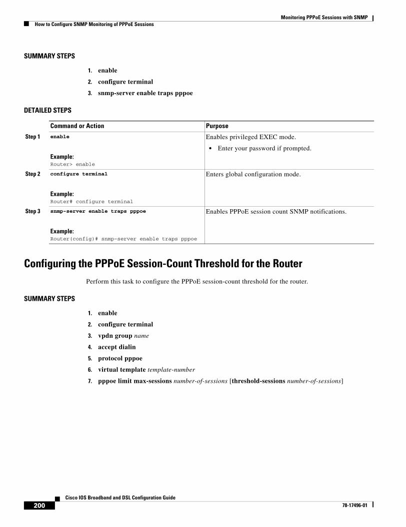
Monitoring PPPoE Sessions with SNMPHow to Configure SNMP Monitoring of PPPoE Sessions
200Cisco IOS Broadband and DSL Configuration Guide
78-17496-01
SUMMARY STEPS
1. enable
2. configure terminal
3. snmp-server enable traps pppoe
DETAILED STEPS
Configuring the PPPoE Session-Count Threshold for the RouterPerform this task to configure the PPPoE session-count threshold for the router.
SUMMARY STEPS
1. enable
2. configure terminal
3. vpdn group name
4. accept dialin
5. protocol pppoe
6. virtual template template-number
7. pppoe limit max-sessions number-of-sessions [threshold-sessions number-of-sessions]
Command or Action Purpose
Step 1 enable
Example:Router> enable
Enables privileged EXEC mode.
• Enter your password if prompted.
Step 2 configure terminal
Example:Router# configure terminal
Enters global configuration mode.
Step 3 snmp-server enable traps pppoe
Example:Router(config)# snmp-server enable traps pppoe
Enables PPPoE session count SNMP notifications.
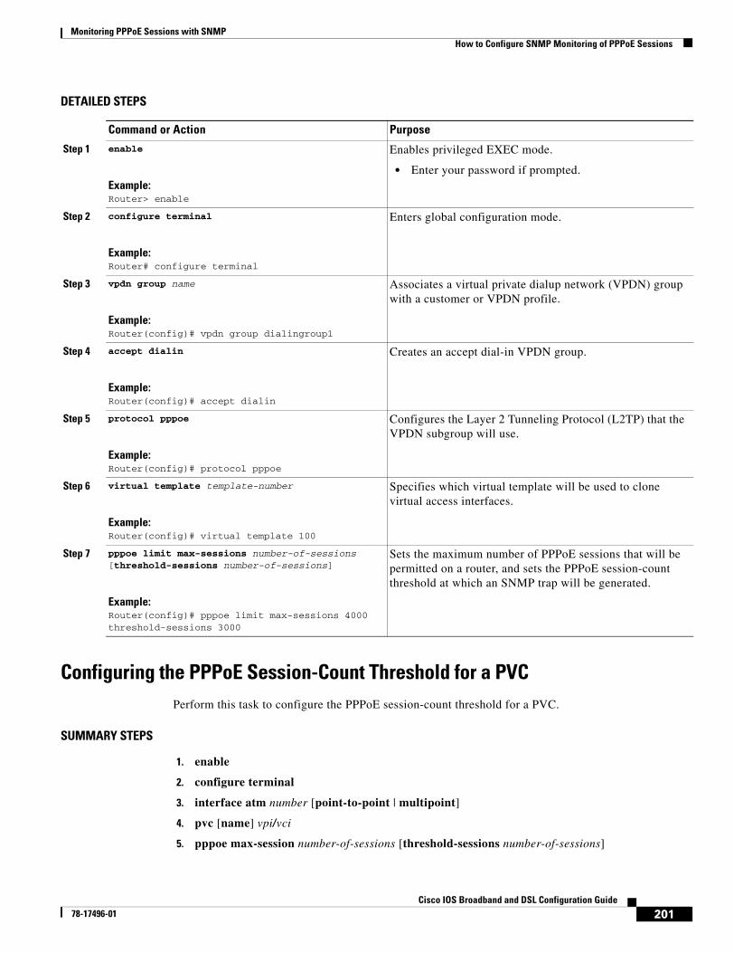
Monitoring PPPoE Sessions with SNMPHow to Configure SNMP Monitoring of PPPoE Sessions
201Cisco IOS Broadband and DSL Configuration Guide
78-17496-01
DETAILED STEPS
Configuring the PPPoE Session-Count Threshold for a PVCPerform this task to configure the PPPoE session-count threshold for a PVC.
SUMMARY STEPS
1. enable
2. configure terminal
3. interface atm number [point-to-point | multipoint]
4. pvc [name] vpi/vci
5. pppoe max-session number-of-sessions [threshold-sessions number-of-sessions]
Command or Action Purpose
Step 1 enable
Example:Router> enable
Enables privileged EXEC mode.
• Enter your password if prompted.
Step 2 configure terminal
Example:Router# configure terminal
Enters global configuration mode.
Step 3 vpdn group name
Example:Router(config)# vpdn group dialingroup1
Associates a virtual private dialup network (VPDN) group with a customer or VPDN profile.
Step 4 accept dialin
Example:Router(config)# accept dialin
Creates an accept dial-in VPDN group.
Step 5 protocol pppoe
Example:Router(config)# protocol pppoe
Configures the Layer 2 Tunneling Protocol (L2TP) that the VPDN subgroup will use.
Step 6 virtual template template-number
Example:Router(config)# virtual template 100
Specifies which virtual template will be used to clone virtual access interfaces.
Step 7 pppoe limit max-sessions number-of-sessions [threshold-sessions number-of-sessions]
Example:Router(config)# pppoe limit max-sessions 4000 threshold-sessions 3000
Sets the maximum number of PPPoE sessions that will be permitted on a router, and sets the PPPoE session-count threshold at which an SNMP trap will be generated.
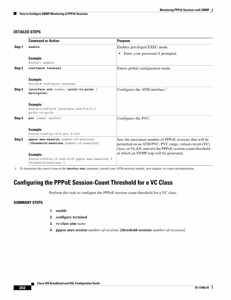
Monitoring PPPoE Sessions with SNMPHow to Configure SNMP Monitoring of PPPoE Sessions
202Cisco IOS Broadband and DSL Configuration Guide
78-17496-01
DETAILED STEPS
Configuring the PPPoE Session-Count Threshold for a VC ClassPerform this task to configure the PPPoE session-count threshold for a VC class.
SUMMARY STEPS
1. enable
2. configure terminal
3. vc-class atm name
4. pppoe max-session number-of-sessions [threshold-sessions number-of-sessions]
Command or Action Purpose
Step 1 enable
Example:Router> enable
Enables privileged EXEC mode.
• Enter your password if prompted.
Step 2 configure terminal
Example:Router# configure terminal
Enters global configuration mode.
Step 3 interface atm number [point-to-point | multipoint]
Example:Router(config)# interface atm/0/0/0.3 point-to-point
Configures the ATM interface.1
1. To determine the correct form of the interface atm command, consult your ATM network module, port adapter, or router documentation.
Step 4 pvc [name] vpi/vci
Example:Router(config-if)# pvc 5/120
Configures the PVC.
Step 5 pppoe max-session number-of-sessions [threshold-sessions number-of-sessions]
Example:Router(config-if-atm-vc)# pppoe max-sessions 5 threshold-sessions 3
Sets the maximum number of PPPoE sessions that will be permitted on an ATM PVC, PVC range, virtual circuit (VC) class, or VLAN, and sets the PPPoE session-count threshold at which an SNMP trap will be generated.
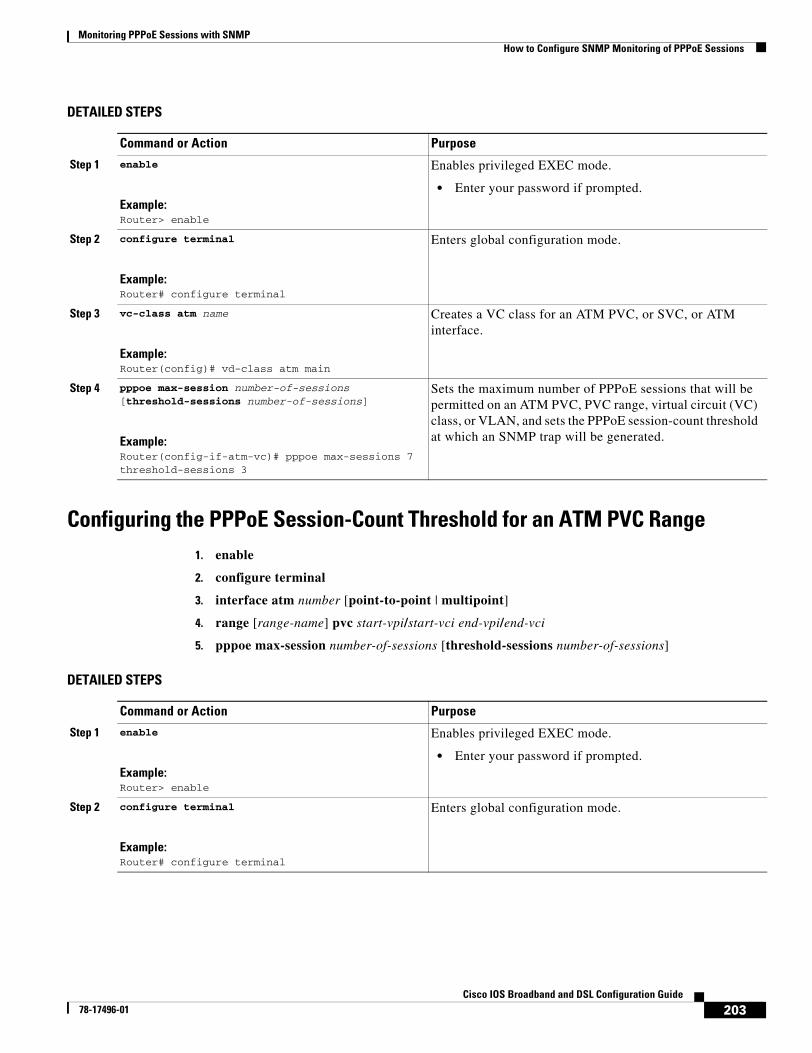
Monitoring PPPoE Sessions with SNMPHow to Configure SNMP Monitoring of PPPoE Sessions
203Cisco IOS Broadband and DSL Configuration Guide
78-17496-01
DETAILED STEPS
Configuring the PPPoE Session-Count Threshold for an ATM PVC Range1. enable
2. configure terminal
3. interface atm number [point-to-point | multipoint]
4. range [range-name] pvc start-vpi/start-vci end-vpi/end-vci
5. pppoe max-session number-of-sessions [threshold-sessions number-of-sessions]
DETAILED STEPS
Command or Action Purpose
Step 1 enable
Example:Router> enable
Enables privileged EXEC mode.
• Enter your password if prompted.
Step 2 configure terminal
Example:Router# configure terminal
Enters global configuration mode.
Step 3 vc-class atm name
Example:Router(config)# vd-class atm main
Creates a VC class for an ATM PVC, or SVC, or ATM interface.
Step 4 pppoe max-session number-of-sessions [threshold-sessions number-of-sessions]
Example:Router(config-if-atm-vc)# pppoe max-sessions 7 threshold-sessions 3
Sets the maximum number of PPPoE sessions that will be permitted on an ATM PVC, PVC range, virtual circuit (VC) class, or VLAN, and sets the PPPoE session-count threshold at which an SNMP trap will be generated.
Command or Action Purpose
Step 1 enable
Example:Router> enable
Enables privileged EXEC mode.
• Enter your password if prompted.
Step 2 configure terminal
Example:Router# configure terminal
Enters global configuration mode.
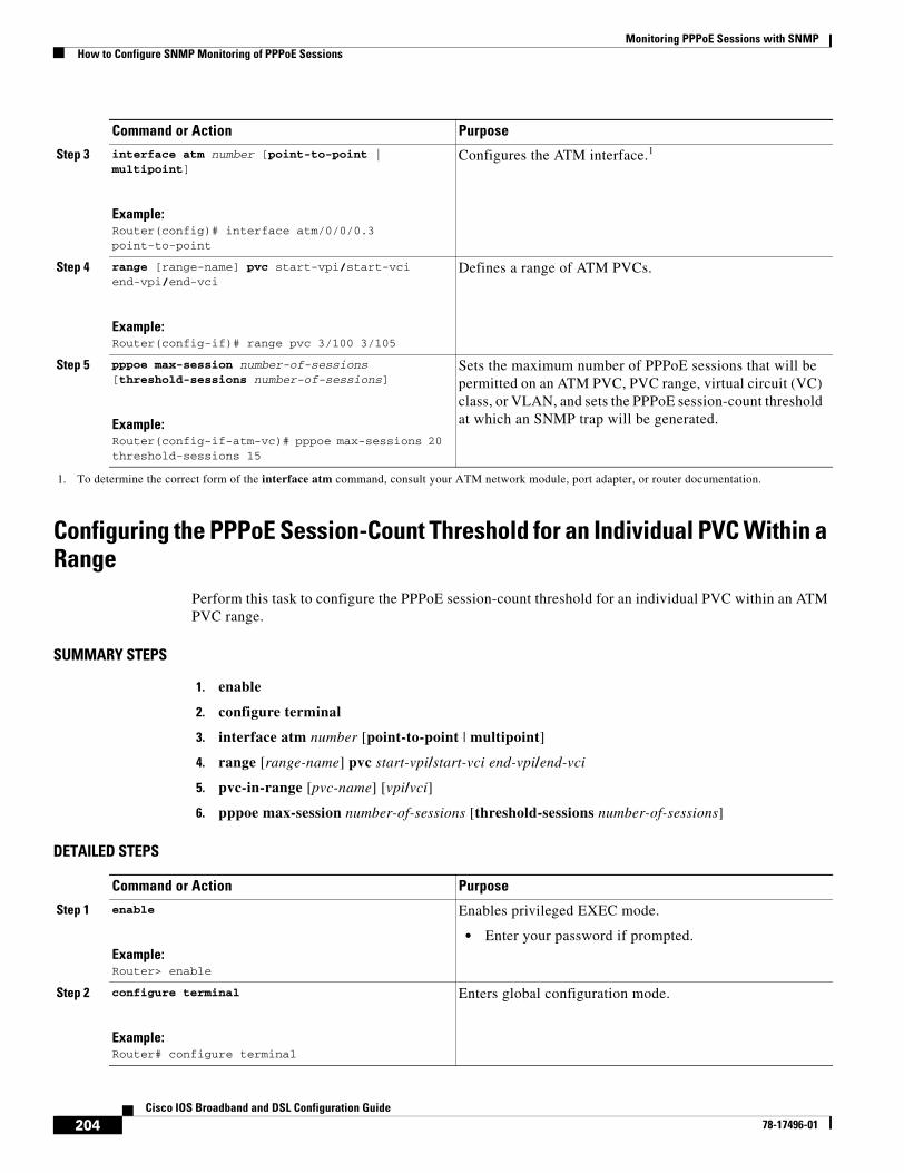
Monitoring PPPoE Sessions with SNMPHow to Configure SNMP Monitoring of PPPoE Sessions
204Cisco IOS Broadband and DSL Configuration Guide
78-17496-01
Configuring the PPPoE Session-Count Threshold for an Individual PVC Within a Range
Perform this task to configure the PPPoE session-count threshold for an individual PVC within an ATM PVC range.
SUMMARY STEPS
1. enable
2. configure terminal
3. interface atm number [point-to-point | multipoint]
4. range [range-name] pvc start-vpi/start-vci end-vpi/end-vci
5. pvc-in-range [pvc-name] [vpi/vci]
6. pppoe max-session number-of-sessions [threshold-sessions number-of-sessions]
DETAILED STEPS
Step 3 interface atm number [point-to-point | multipoint]
Example:Router(config)# interface atm/0/0/0.3 point-to-point
Configures the ATM interface.1
Step 4 range [range-name] pvc start-vpi/start-vci end-vpi/end-vci
Example:Router(config-if)# range pvc 3/100 3/105
Defines a range of ATM PVCs.
Step 5 pppoe max-session number-of-sessions [threshold-sessions number-of-sessions]
Example:Router(config-if-atm-vc)# pppoe max-sessions 20 threshold-sessions 15
Sets the maximum number of PPPoE sessions that will be permitted on an ATM PVC, PVC range, virtual circuit (VC) class, or VLAN, and sets the PPPoE session-count threshold at which an SNMP trap will be generated.
1. To determine the correct form of the interface atm command, consult your ATM network module, port adapter, or router documentation.
Command or Action Purpose
Command or Action Purpose
Step 1 enable
Example:Router> enable
Enables privileged EXEC mode.
• Enter your password if prompted.
Step 2 configure terminal
Example:Router# configure terminal
Enters global configuration mode.
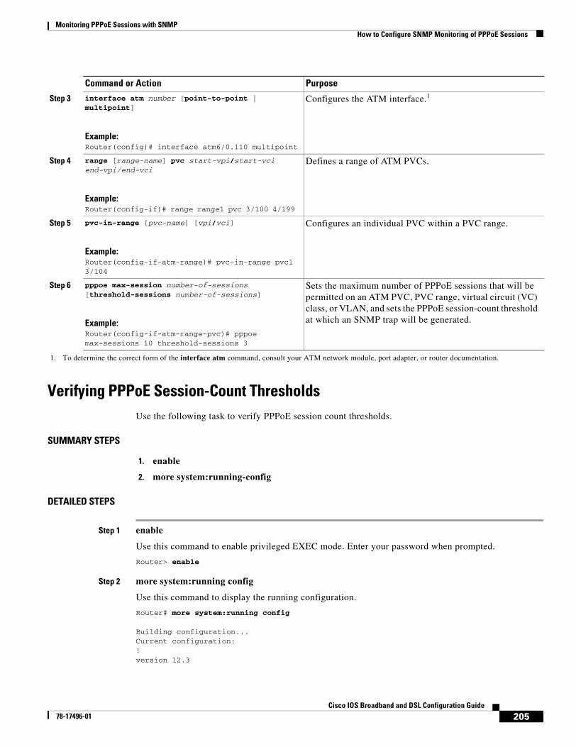
Monitoring PPPoE Sessions with SNMPHow to Configure SNMP Monitoring of PPPoE Sessions
205Cisco IOS Broadband and DSL Configuration Guide
78-17496-01
Verifying PPPoE Session-Count ThresholdsUse the following task to verify PPPoE session count thresholds.
SUMMARY STEPS
1. enable
2. more system:running-config
DETAILED STEPS
Step 1 enable
Use this command to enable privileged EXEC mode. Enter your password when prompted.
Router> enable
Step 2 more system:running config
Use this command to display the running configuration.
Router# more system:running config
Building configuration...Current configuration:!version 12.3
Step 3 interface atm number [point-to-point | multipoint]
Example:Router(config)# interface atm6/0.110 multipoint
Configures the ATM interface.1
Step 4 range [range-name] pvc start-vpi/start-vci end-vpi/end-vci
Example:Router(config-if)# range range1 pvc 3/100 4/199
Defines a range of ATM PVCs.
Step 5 pvc-in-range [pvc-name] [vpi/vci]
Example:Router(config-if-atm-range)# pvc-in-range pvc1 3/104
Configures an individual PVC within a PVC range.
Step 6 pppoe max-session number-of-sessions [threshold-sessions number-of-sessions]
Example:Router(config-if-atm-range-pvc)# pppoe max-sessions 10 threshold-sessions 3
Sets the maximum number of PPPoE sessions that will be permitted on an ATM PVC, PVC range, virtual circuit (VC) class, or VLAN, and sets the PPPoE session-count threshold at which an SNMP trap will be generated.
1. To determine the correct form of the interface atm command, consult your ATM network module, port adapter, or router documentation.
Command or Action Purpose
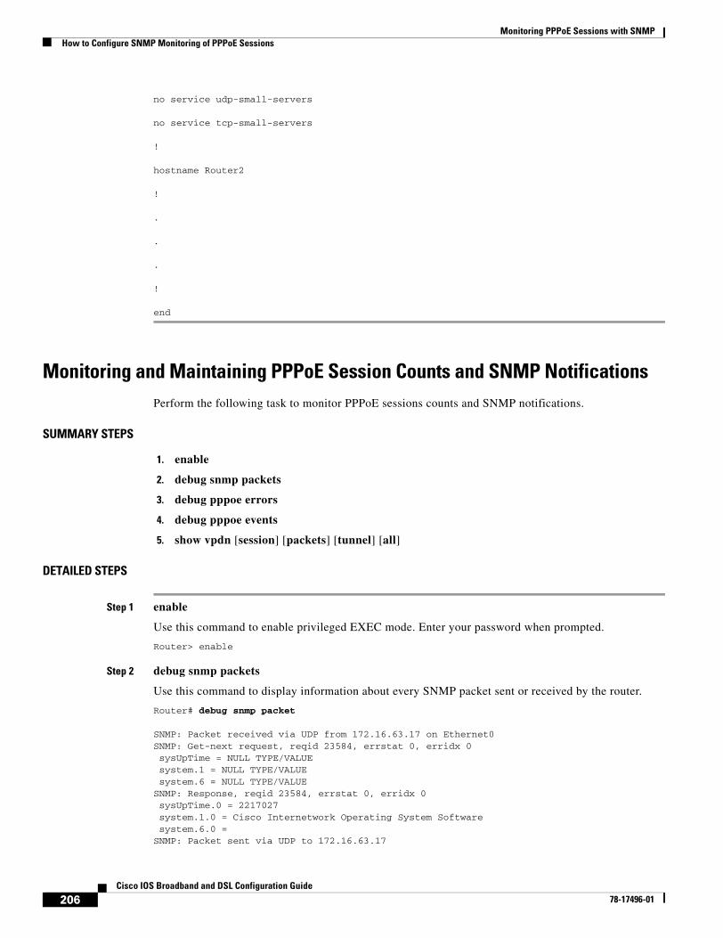
Monitoring PPPoE Sessions with SNMPHow to Configure SNMP Monitoring of PPPoE Sessions
206Cisco IOS Broadband and DSL Configuration Guide
78-17496-01
no service udp-small-servers
no service tcp-small-servers
!
hostname Router2
!
.
.
.
!
end
Monitoring and Maintaining PPPoE Session Counts and SNMP NotificationsPerform the following task to monitor PPPoE sessions counts and SNMP notifications.
SUMMARY STEPS
1. enable
2. debug snmp packets
3. debug pppoe errors
4. debug pppoe events
5. show vpdn [session] [packets] [tunnel] [all]
DETAILED STEPS
Step 1 enable
Use this command to enable privileged EXEC mode. Enter your password when prompted.
Router> enable
Step 2 debug snmp packets
Use this command to display information about every SNMP packet sent or received by the router.
Router# debug snmp packet
SNMP: Packet received via UDP from 172.16.63.17 on Ethernet0 SNMP: Get-next request, reqid 23584, errstat 0, erridx 0 sysUpTime = NULL TYPE/VALUE system.1 = NULL TYPE/VALUE system.6 = NULL TYPE/VALUESNMP: Response, reqid 23584, errstat 0, erridx 0 sysUpTime.0 = 2217027 system.1.0 = Cisco Internetwork Operating System Software system.6.0 = SNMP: Packet sent via UDP to 172.16.63.17
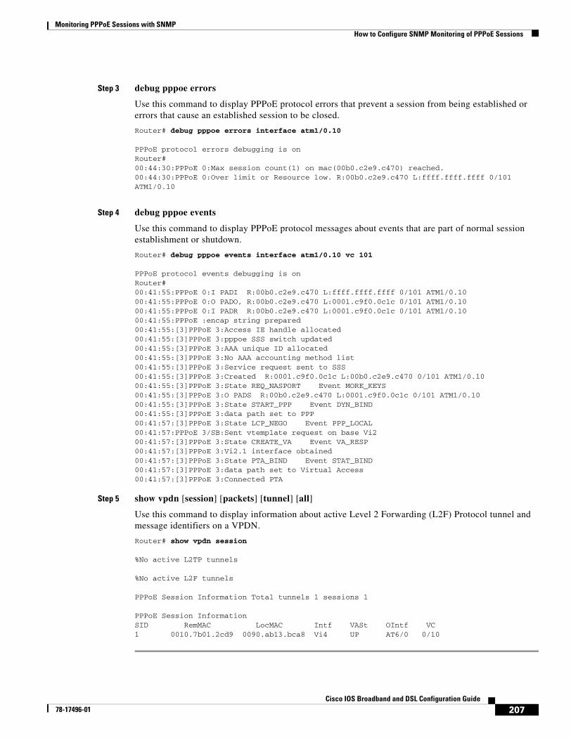
Monitoring PPPoE Sessions with SNMPHow to Configure SNMP Monitoring of PPPoE Sessions
207Cisco IOS Broadband and DSL Configuration Guide
78-17496-01
Step 3 debug pppoe errors
Use this command to display PPPoE protocol errors that prevent a session from being established or errors that cause an established session to be closed.
Router# debug pppoe errors interface atm1/0.10
PPPoE protocol errors debugging is on Router# 00:44:30:PPPoE 0:Max session count(1) on mac(00b0.c2e9.c470) reached. 00:44:30:PPPoE 0:Over limit or Resource low. R:00b0.c2e9.c470 L:ffff.ffff.ffff 0/101 ATM1/0.10
Step 4 debug pppoe events
Use this command to display PPPoE protocol messages about events that are part of normal session establishment or shutdown.
Router# debug pppoe events interface atm1/0.10 vc 101
PPPoE protocol events debugging is on Router# 00:41:55:PPPoE 0:I PADI R:00b0.c2e9.c470 L:ffff.ffff.ffff 0/101 ATM1/0.10 00:41:55:PPPoE 0:O PADO, R:00b0.c2e9.c470 L:0001.c9f0.0c1c 0/101 ATM1/0.10 00:41:55:PPPoE 0:I PADR R:00b0.c2e9.c470 L:0001.c9f0.0c1c 0/101 ATM1/0.10 00:41:55:PPPoE :encap string prepared 00:41:55:[3]PPPoE 3:Access IE handle allocated 00:41:55:[3]PPPoE 3:pppoe SSS switch updated 00:41:55:[3]PPPoE 3:AAA unique ID allocated 00:41:55:[3]PPPoE 3:No AAA accounting method list 00:41:55:[3]PPPoE 3:Service request sent to SSS 00:41:55:[3]PPPoE 3:Created R:0001.c9f0.0c1c L:00b0.c2e9.c470 0/101 ATM1/0.10 00:41:55:[3]PPPoE 3:State REQ_NASPORT Event MORE_KEYS 00:41:55:[3]PPPoE 3:O PADS R:00b0.c2e9.c470 L:0001.c9f0.0c1c 0/101 ATM1/0.10 00:41:55:[3]PPPoE 3:State START_PPP Event DYN_BIND 00:41:55:[3]PPPoE 3:data path set to PPP 00:41:57:[3]PPPoE 3:State LCP_NEGO Event PPP_LOCAL 00:41:57:PPPoE 3/SB:Sent vtemplate request on base Vi2 00:41:57:[3]PPPoE 3:State CREATE_VA Event VA_RESP 00:41:57:[3]PPPoE 3:Vi2.1 interface obtained 00:41:57:[3]PPPoE 3:State PTA_BIND Event STAT_BIND 00:41:57:[3]PPPoE 3:data path set to Virtual Access 00:41:57:[3]PPPoE 3:Connected PTA
Step 5 show vpdn [session] [packets] [tunnel] [all]
Use this command to display information about active Level 2 Forwarding (L2F) Protocol tunnel and message identifiers on a VPDN.
Router# show vpdn session
%No active L2TP tunnels
%No active L2F tunnels
PPPoE Session Information Total tunnels 1 sessions 1
PPPoE Session InformationSID RemMAC LocMAC Intf VASt OIntf VC1 0010.7b01.2cd9 0090.ab13.bca8 Vi4 UP AT6/0 0/10
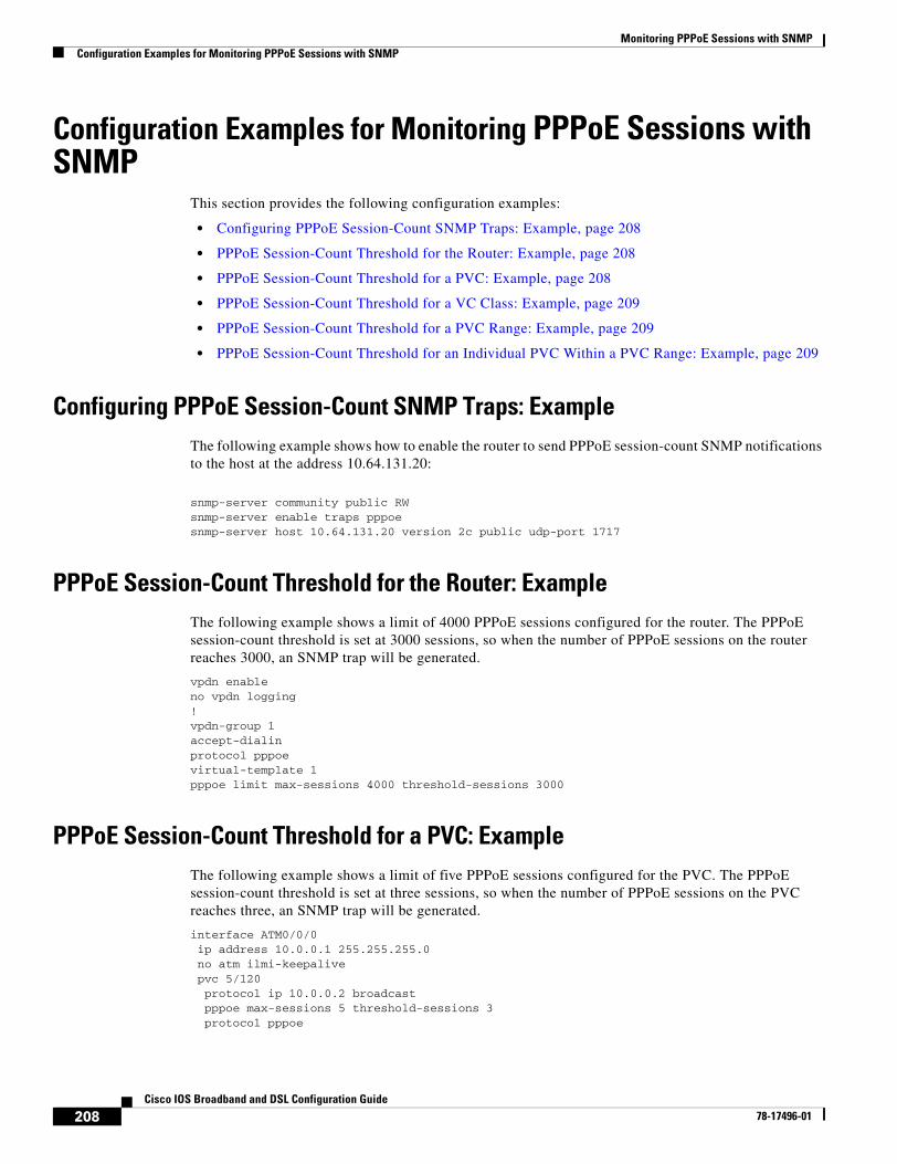
Monitoring PPPoE Sessions with SNMPConfiguration Examples for Monitoring PPPoE Sessions with SNMP
208Cisco IOS Broadband and DSL Configuration Guide
78-17496-01
Configuration Examples for Monitoring PPPoE Sessions with SNMP
This section provides the following configuration examples:
• Configuring PPPoE Session-Count SNMP Traps: Example, page 208
• PPPoE Session-Count Threshold for the Router: Example, page 208
• PPPoE Session-Count Threshold for a PVC: Example, page 208
• PPPoE Session-Count Threshold for a VC Class: Example, page 209
• PPPoE Session-Count Threshold for a PVC Range: Example, page 209
• PPPoE Session-Count Threshold for an Individual PVC Within a PVC Range: Example, page 209
Configuring PPPoE Session-Count SNMP Traps: ExampleThe following example shows how to enable the router to send PPPoE session-count SNMP notifications to the host at the address 10.64.131.20:
snmp-server community public RWsnmp-server enable traps pppoesnmp-server host 10.64.131.20 version 2c public udp-port 1717
PPPoE Session-Count Threshold for the Router: ExampleThe following example shows a limit of 4000 PPPoE sessions configured for the router. The PPPoE session-count threshold is set at 3000 sessions, so when the number of PPPoE sessions on the router reaches 3000, an SNMP trap will be generated.
vpdn enableno vpdn logging!vpdn-group 1accept-dialinprotocol pppoevirtual-template 1pppoe limit max-sessions 4000 threshold-sessions 3000
PPPoE Session-Count Threshold for a PVC: ExampleThe following example shows a limit of five PPPoE sessions configured for the PVC. The PPPoE session-count threshold is set at three sessions, so when the number of PPPoE sessions on the PVC reaches three, an SNMP trap will be generated.
interface ATM0/0/0 ip address 10.0.0.1 255.255.255.0 no atm ilmi-keepalive pvc 5/120 protocol ip 10.0.0.2 broadcast pppoe max-sessions 5 threshold-sessions 3 protocol pppoe
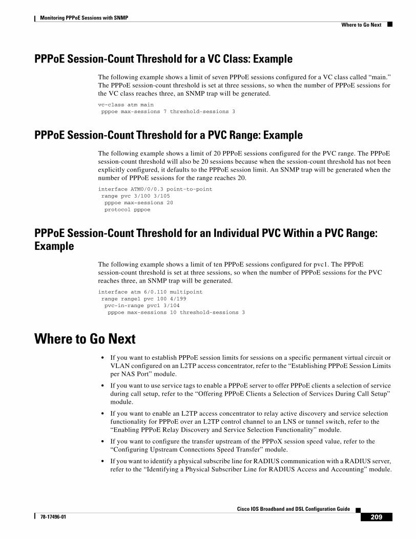
Monitoring PPPoE Sessions with SNMPWhere to Go Next
209Cisco IOS Broadband and DSL Configuration Guide
78-17496-01
PPPoE Session-Count Threshold for a VC Class: ExampleThe following example shows a limit of seven PPPoE sessions configured for a VC class called “main.” The PPPoE session-count threshold is set at three sessions, so when the number of PPPoE sessions for the VC class reaches three, an SNMP trap will be generated.
vc-class atm main pppoe max-sessions 7 threshold-sessions 3
PPPoE Session-Count Threshold for a PVC Range: ExampleThe following example shows a limit of 20 PPPoE sessions configured for the PVC range. The PPPoE session-count threshold will also be 20 sessions because when the session-count threshold has not been explicitly configured, it defaults to the PPPoE session limit. An SNMP trap will be generated when the number of PPPoE sessions for the range reaches 20.
interface ATM0/0/0.3 point-to-point range pvc 3/100 3/105 pppoe max-sessions 20 protocol pppoe
PPPoE Session-Count Threshold for an Individual PVC Within a PVC Range: Example
The following example shows a limit of ten PPPoE sessions configured for pvc1. The PPPoE session-count threshold is set at three sessions, so when the number of PPPoE sessions for the PVC reaches three, an SNMP trap will be generated.
interface atm 6/0.110 multipoint range range1 pvc 100 4/199 pvc-in-range pvc1 3/104 pppoe max-sessions 10 threshold-sessions 3
Where to Go Next• If you want to establish PPPoE session limits for sessions on a specific permanent virtual circuit or
VLAN configured on an L2TP access concentrator, refer to the “Establishing PPPoE Session Limits per NAS Port” module.
• If you want to use service tags to enable a PPPoE server to offer PPPoE clients a selection of service during call setup, refer to the “Offering PPPoE Clients a Selection of Services During Call Setup” module.
• If you want to enable an L2TP access concentrator to relay active discovery and service selection functionality for PPPoE over an L2TP control channel to an LNS or tunnel switch, refer to the “Enabling PPPoE Relay Discovery and Service Selection Functionality” module.
• If you want to configure the transfer upstream of the PPPoX session speed value, refer to the “Configuring Upstream Connections Speed Transfer” module.
• If you want to identify a physical subscribe line for RADIUS communication with a RADIUS server, refer to the “Identifying a Physical Subscriber Line for RADIUS Access and Accounting” module.
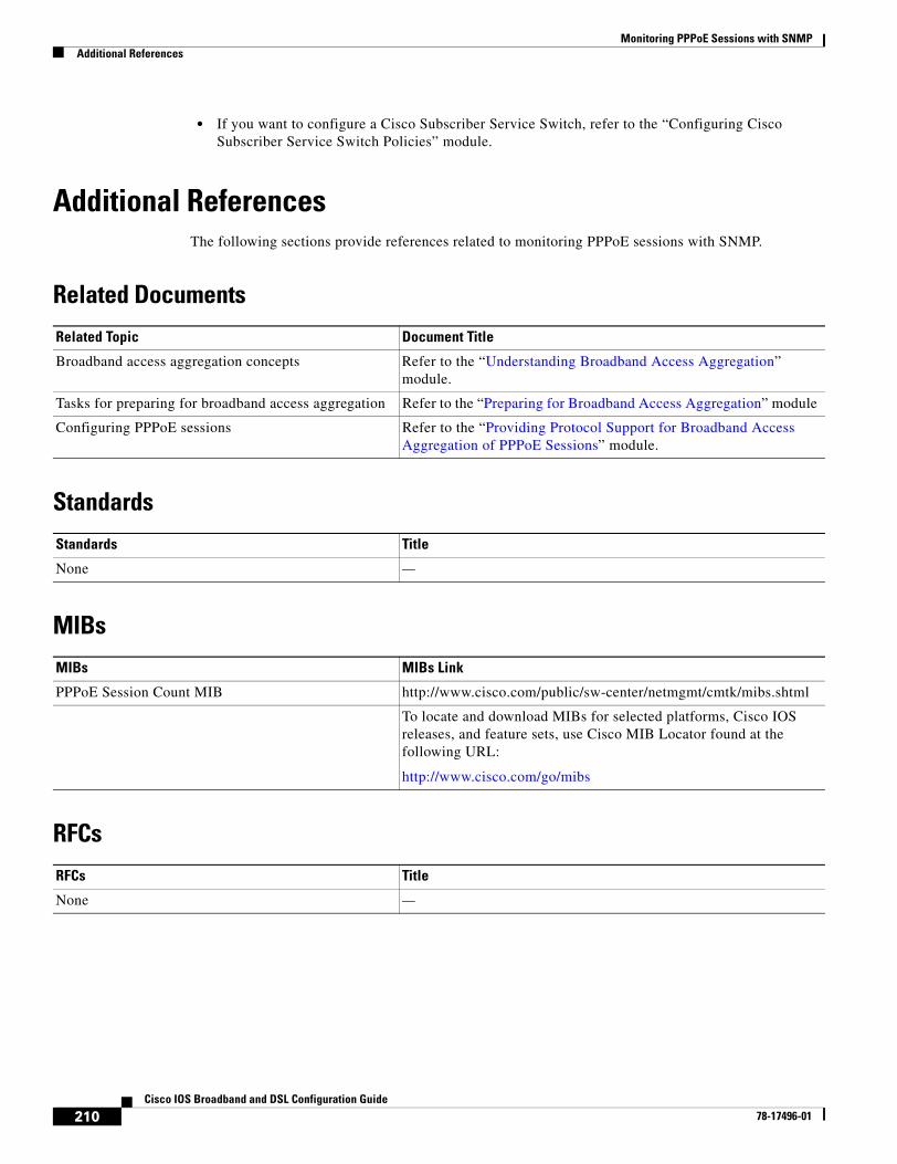
Monitoring PPPoE Sessions with SNMPAdditional References
210Cisco IOS Broadband and DSL Configuration Guide
78-17496-01
• If you want to configure a Cisco Subscriber Service Switch, refer to the “Configuring Cisco Subscriber Service Switch Policies” module.
Additional ReferencesThe following sections provide references related to monitoring PPPoE sessions with SNMP.
Related Documents
Standards
MIBs
RFCs
Related Topic Document Title
Broadband access aggregation concepts Refer to the “Understanding Broadband Access Aggregation” module.
Tasks for preparing for broadband access aggregation Refer to the “Preparing for Broadband Access Aggregation” module
Configuring PPPoE sessions Refer to the “Providing Protocol Support for Broadband Access Aggregation of PPPoE Sessions” module.
Standards Title
None —
MIBs MIBs Link
PPPoE Session Count MIB http://www.cisco.com/public/sw-center/netmgmt/cmtk/mibs.shtml
To locate and download MIBs for selected platforms, Cisco IOS releases, and feature sets, use Cisco MIB Locator found at the following URL:
http://www.cisco.com/go/mibs
RFCs Title
None —
Monitoring PPPoE Sessions with SNMPAdditional References
211Cisco IOS Broadband and DSL Configuration Guide
78-17496-01
Technical Assistance
Description Link
The Cisco Technical Support website contains thousands of pages of searchable technical content, including links to products, technologies, solutions, technical tips, and tools. Registered Cisco.com users can log in from this page to access even more content.
http://www.cisco.com/techsupport
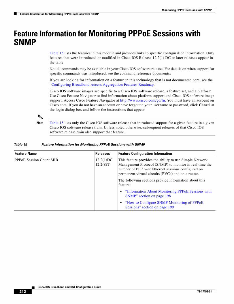
Monitoring PPPoE Sessions with SNMPFeature Information for Monitoring PPPoE Sessions with SNMP
212Cisco IOS Broadband and DSL Configuration Guide
78-17496-01
Feature Information for Monitoring PPPoE Sessions with SNMP
Table 15 lists the features in this module and provides links to specific configuration information. Only features that were introduced or modified in Cisco IOS Release 12.2(1) DC or later releases appear in the table.
Not all commands may be available in your Cisco IOS software release. For details on when support for specific commands was introduced, see the command reference documents.
If you are looking for information on a feature in this technology that is not documented here, see the “Configuring Broadband Access Aggregation Features Roadmap.”
Cisco IOS software images are specific to a Cisco IOS software release, a feature set, and a platform. Use Cisco Feature Navigator to find information about platform support and Cisco IOS software image support. Access Cisco Feature Navigator at http://www.cisco.com/go/fn. You must have an account on Cisco.com. If you do not have an account or have forgotten your username or password, click Cancel at the login dialog box and follow the instructions that appear.
Note Table 15 lists only the Cisco IOS software release that introduced support for a given feature in a given Cisco IOS software release train. Unless noted otherwise, subsequent releases of that Cisco IOS software release train also support that feature.
Table 15 Feature Information for Monitoring PPPoE Sessions with SNMP
Feature Name Releases Feature Configuration Information
PPPoE Session Count MIB 12.2(1)DC12.2(8)T
This feature provides the ability to use Simple Network Management Protocol (SNMP) to monitor in real time the number of PPP over Ethernet sessions configured on permanent virtual circuits (PVCs) and on a router.
The following sections provide information about this feature:
• “Information About Monitoring PPPoE Sessions with SNMP” section on page 198
• “How to Configure SNMP Monitoring of PPPoE Sessions” section on page 199
213Cisco IOS Broadband and DSL Configuration Guide
78-17496-01
Configuring Upstream Connection Speed Transfer
The Upstream PPPoX Connection Speed Transfer at LAC feature allows the transfer of the upstream PPPoX session speed value at the L2TP access concentrator (LAC). PPPoX is a term used to refer to PPPoE, PPPoA, and PPPoEoA. All are implementations of PPP over various delivery protocols such as Ethernet and ATM. This transfer will be accomplished by configuring the required speed on the ATM virtual circuit (VC) carrying the PPPoX session and then transferring this information into attribute-value (AV) pair 38 for transport from the LAC to the Layer 2 Tunnel Protocol (L2TP) network server (LNS).
Module History
This module was first published on May 2, 2005, and last updated on May 2, 2005.
Finding Feature Information in This Module
Not all features may be supported in your Cisco IOS software release. Use the “Feature Information for Configuring Upstream Connection Speed Transfer” section on page 221 to find information about feature support and configuration.
Contents• Prerequisites for Configuring Upstream Connection Speed Transfer, page 213
• Restrictions for Configuring Upstream Connection Speed Transfer, page 214
• Information About Configuring Upstream Connection Speed Transfer, page 214
• How to Configure Upstream Connection Speed Transfer, page 215
• Configuration Examples for Configuring Upstream Connection Speed Transfer, page 218
• Additional References, page 219
• Feature Information for Configuring Upstream Connection Speed Transfer, page 221
Prerequisites for Configuring Upstream Connection Speed Transfer
• You must understand the concepts described in the “Preparing for Broadband Access Aggregation” module.
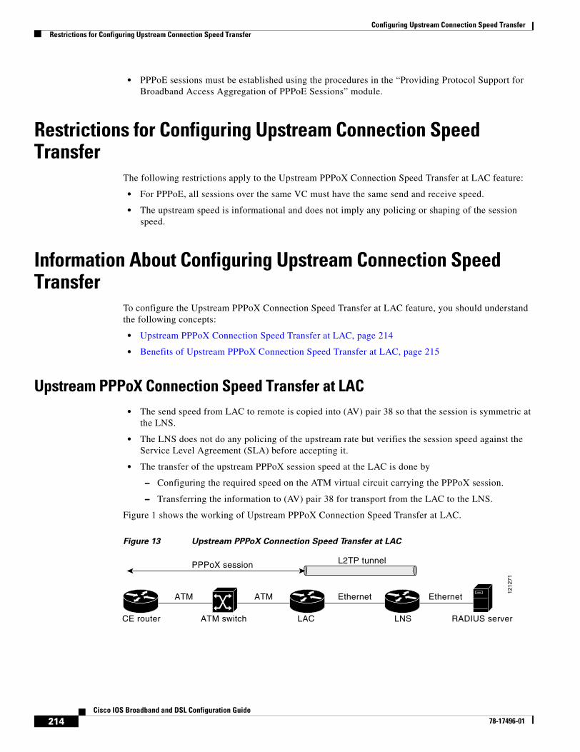
Configuring Upstream Connection Speed TransferRestrictions for Configuring Upstream Connection Speed Transfer
214Cisco IOS Broadband and DSL Configuration Guide
78-17496-01
• PPPoE sessions must be established using the procedures in the “Providing Protocol Support for Broadband Access Aggregation of PPPoE Sessions” module.
Restrictions for Configuring Upstream Connection Speed Transfer
The following restrictions apply to the Upstream PPPoX Connection Speed Transfer at LAC feature:
• For PPPoE, all sessions over the same VC must have the same send and receive speed.
• The upstream speed is informational and does not imply any policing or shaping of the session speed.
Information About Configuring Upstream Connection Speed Transfer
To configure the Upstream PPPoX Connection Speed Transfer at LAC feature, you should understand the following concepts:
• Upstream PPPoX Connection Speed Transfer at LAC, page 214
• Benefits of Upstream PPPoX Connection Speed Transfer at LAC, page 215
Upstream PPPoX Connection Speed Transfer at LAC• The send speed from LAC to remote is copied into (AV) pair 38 so that the session is symmetric at
the LNS.
• The LNS does not do any policing of the upstream rate but verifies the session speed against the Service Level Agreement (SLA) before accepting it.
• The transfer of the upstream PPPoX session speed at the LAC is done by
– Configuring the required speed on the ATM virtual circuit carrying the PPPoX session.
– Transferring the information to (AV) pair 38 for transport from the LAC to the LNS.
Figure 1 shows the working of Upstream PPPoX Connection Speed Transfer at LAC.
Figure 13 Upstream PPPoX Connection Speed Transfer at LAC
CE router ATM switch LAC LNS RADIUS server
EthernetEthernetATMATM
PPPoX session L2TP tunnel
1212
71
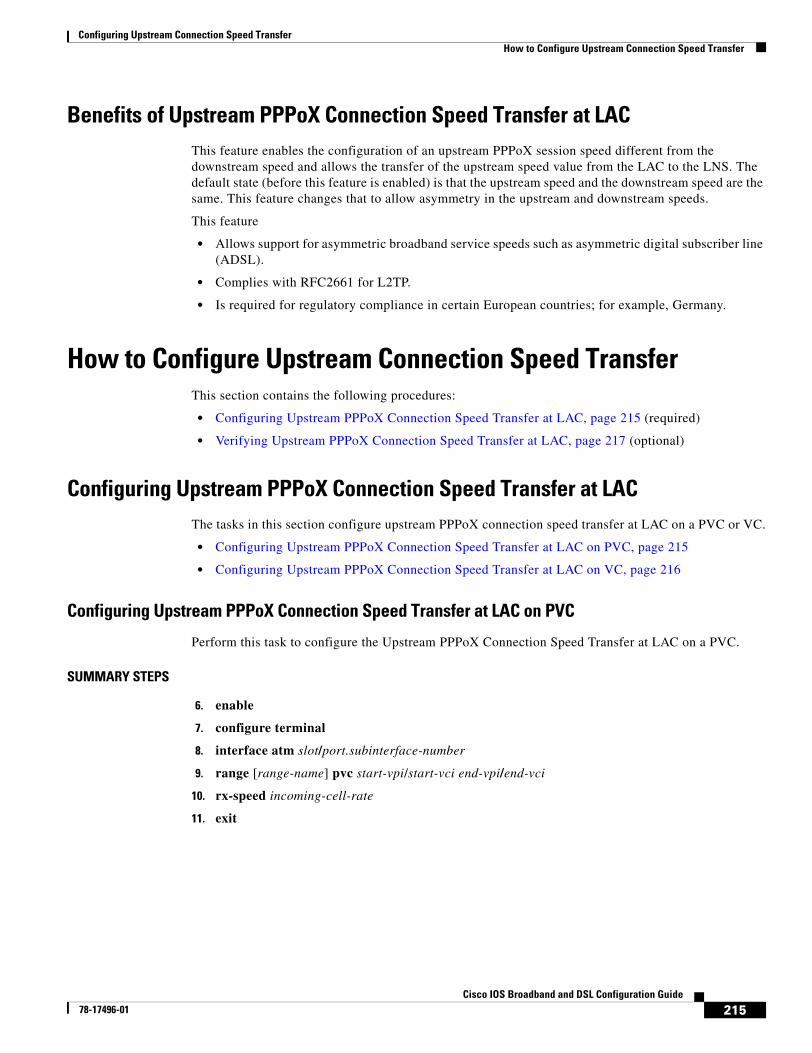
Configuring Upstream Connection Speed TransferHow to Configure Upstream Connection Speed Transfer
215Cisco IOS Broadband and DSL Configuration Guide
78-17496-01
Benefits of Upstream PPPoX Connection Speed Transfer at LACThis feature enables the configuration of an upstream PPPoX session speed different from the downstream speed and allows the transfer of the upstream speed value from the LAC to the LNS. The default state (before this feature is enabled) is that the upstream speed and the downstream speed are the same. This feature changes that to allow asymmetry in the upstream and downstream speeds.
This feature
• Allows support for asymmetric broadband service speeds such as asymmetric digital subscriber line (ADSL).
• Complies with RFC2661 for L2TP.
• Is required for regulatory compliance in certain European countries; for example, Germany.
How to Configure Upstream Connection Speed TransferThis section contains the following procedures:
• Configuring Upstream PPPoX Connection Speed Transfer at LAC, page 215 (required)
• Verifying Upstream PPPoX Connection Speed Transfer at LAC, page 217 (optional)
Configuring Upstream PPPoX Connection Speed Transfer at LACThe tasks in this section configure upstream PPPoX connection speed transfer at LAC on a PVC or VC.
• Configuring Upstream PPPoX Connection Speed Transfer at LAC on PVC, page 215
• Configuring Upstream PPPoX Connection Speed Transfer at LAC on VC, page 216
Configuring Upstream PPPoX Connection Speed Transfer at LAC on PVC
Perform this task to configure the Upstream PPPoX Connection Speed Transfer at LAC on a PVC.
SUMMARY STEPS
6. enable
7. configure terminal
8. interface atm slot/port.subinterface-number
9. range [range-name] pvc start-vpi/start-vci end-vpi/end-vci
10. rx-speed incoming-cell-rate
11. exit
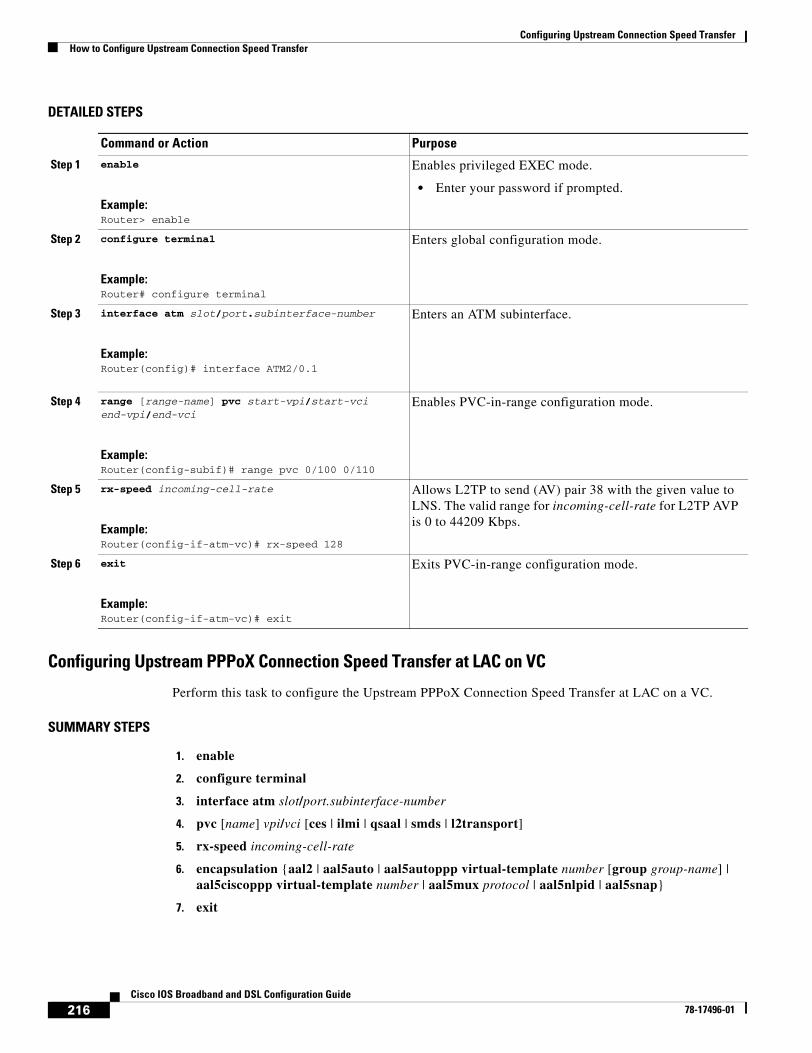
Configuring Upstream Connection Speed TransferHow to Configure Upstream Connection Speed Transfer
216Cisco IOS Broadband and DSL Configuration Guide
78-17496-01
DETAILED STEPS
Configuring Upstream PPPoX Connection Speed Transfer at LAC on VC
Perform this task to configure the Upstream PPPoX Connection Speed Transfer at LAC on a VC.
SUMMARY STEPS
1. enable
2. configure terminal
3. interface atm slot/port.subinterface-number
4. pvc [name] vpi/vci [ces | ilmi | qsaal | smds | l2transport]
5. rx-speed incoming-cell-rate
6. encapsulation {aal2 | aal5auto | aal5autoppp virtual-template number [group group-name] | aal5ciscoppp virtual-template number | aal5mux protocol | aal5nlpid | aal5snap}
7. exit
Command or Action Purpose
Step 1 enable
Example:Router> enable
Enables privileged EXEC mode.
• Enter your password if prompted.
Step 2 configure terminal
Example:Router# configure terminal
Enters global configuration mode.
Step 3 interface atm slot/port.subinterface-number
Example:Router(config)# interface ATM2/0.1
Enters an ATM subinterface.
Step 4 range [range-name] pvc start-vpi/start-vci end-vpi/end-vci
Example:Router(config-subif)# range pvc 0/100 0/110
Enables PVC-in-range configuration mode.
Step 5 rx-speed incoming-cell-rate
Example:Router(config-if-atm-vc)# rx-speed 128
Allows L2TP to send (AV) pair 38 with the given value to LNS. The valid range for incoming-cell-rate for L2TP AVP is 0 to 44209 Kbps.
Step 6 exit
Example:Router(config-if-atm-vc)# exit
Exits PVC-in-range configuration mode.
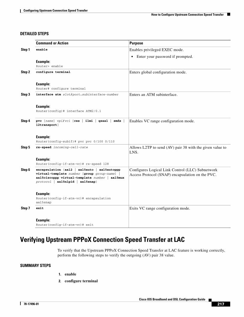
Configuring Upstream Connection Speed TransferHow to Configure Upstream Connection Speed Transfer
217Cisco IOS Broadband and DSL Configuration Guide
78-17496-01
DETAILED STEPS
Verifying Upstream PPPoX Connection Speed Transfer at LACTo verify that the Upstream PPPoX Connection Speed Transfer at LAC feature is working correctly, perform the following steps to verify the outgoing (AV) pair 38 value.
SUMMARY STEPS
1. enable
2. configure terminal
Command or Action Purpose
Step 1 enable
Example:Router> enable
Enables privileged EXEC mode.
• Enter your password if prompted.
Step 2 configure terminal
Example:Router# configure terminal
Enters global configuration mode.
Step 3 interface atm slot/port.subinterface-number
Example:Router(config)# interface ATM2/0.1
Enters an ATM subinterface.
Step 4 pvc [name] vpi/vci [ces | ilmi | qsaal | smds | l2transport]
Example:Router(config-subif)# pvc pvc 0/100 0/110
Enables VC range configuration mode.
Step 5 rx-speed incoming-cell-rate
Example:Router(config-if-atm-vc)# rx-speed 128
Allows L2TP to send (AV) pair 38 with the given value to LNS.
Step 6 encapsulation {aal2 | aal5auto | aal5autoppp virtual-template number [group group-name] | aal5ciscoppp virtual-template number | aal5mux protocol | aal5nlpid | aal5snap}
Example:Router(config-if-atm-vc)# encapsulation aal5snap
Configures Logical Link Control (LLC) Subnetwork Access Protocol (SNAP) encapsulation on the PVC.
Step 7 exit
Example:Router(config-if-atm-vc)# exit
Exits VC range configuration mode.
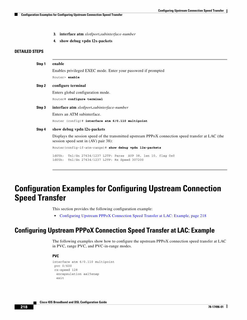
Configuring Upstream Connection Speed TransferConfiguration Examples for Configuring Upstream Connection Speed Transfer
218Cisco IOS Broadband and DSL Configuration Guide
78-17496-01
3. interface atm slot/port.subinterface-number
4. show debug vpdn l2x-packets
DETAILED STEPS
Step 1 enable
Enables privileged EXEC mode. Enter your password if prompted
Router> enable
Step 2 configure terminal
Enters global configuration mode.
Router# configure terminal
Step 3 interface atm slot/port.subinterface-number
Enters an ATM subinterface.
Router (config)# interface atm 6/0.110 multipoint
Step 4 show debug vpdn l2x-packets
Displays the session speed of the transmitted upstream PPPoX connection speed transfer at LAC (the session speed sent in (AV) pair 38):
Router(config-if-atm-range)# show debug vpdn l2x-packets
1d05h: Tnl/Sn 27634/1237 L2TP: Parse AVP 38, len 10, flag 0x0 1d05h: Tnl/Sn 27634/1237 L2TP: Rx Speed 307200
Configuration Examples for Configuring Upstream Connection Speed Transfer
This section provides the following configuration example:
• Configuring Upstream PPPoX Connection Speed Transfer at LAC: Example, page 218
Configuring Upstream PPPoX Connection Speed Transfer at LAC: ExampleThe following examples show how to configure the upstream PPPoX connection speed transfer at LAC in PVC, range PVC, and PVC-in-range modes.
PVCinterface atm 6/0.110 multipointpvc 0/600rx-speed 128 encapsulation aal5snap exit
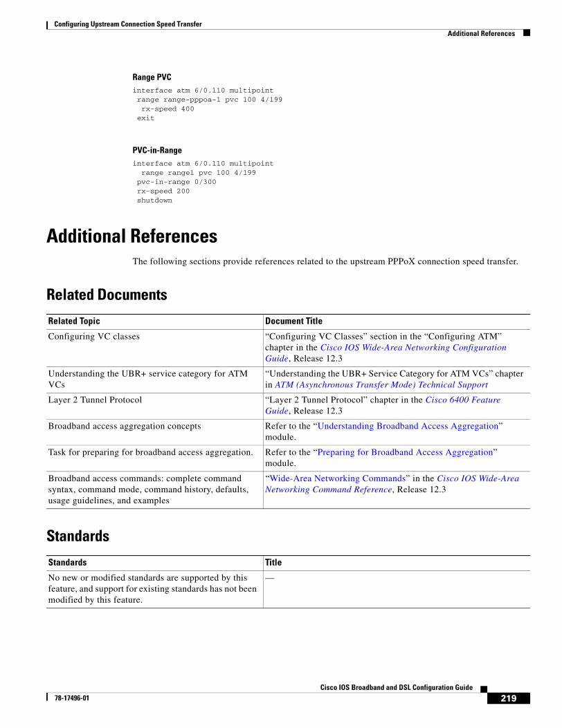
Configuring Upstream Connection Speed TransferAdditional References
219Cisco IOS Broadband and DSL Configuration Guide
78-17496-01
Range PVCinterface atm 6/0.110 multipointrange range-pppoa-1 pvc 100 4/199 rx-speed 400exit
PVC-in-Rangeinterface atm 6/0.110 multipoint range range1 pvc 100 4/199pvc-in-range 0/300rx-speed 200shutdown
Additional References The following sections provide references related to the upstream PPPoX connection speed transfer.
Related Documents
Standards
Related Topic Document Title
Configuring VC classes “Configuring VC Classes” section in the “Configuring ATM” chapter in the Cisco IOS Wide-Area Networking Configuration Guide, Release 12.3
Understanding the UBR+ service category for ATM VCs
“Understanding the UBR+ Service Category for ATM VCs” chapter in ATM (Asynchronous Transfer Mode) Technical Support
Layer 2 Tunnel Protocol “Layer 2 Tunnel Protocol” chapter in the Cisco 6400 Feature Guide, Release 12.3
Broadband access aggregation concepts Refer to the “Understanding Broadband Access Aggregation” module.
Task for preparing for broadband access aggregation. Refer to the “Preparing for Broadband Access Aggregation” module.
Broadband access commands: complete command syntax, command mode, command history, defaults, usage guidelines, and examples
“Wide-Area Networking Commands” in the Cisco IOS Wide-Area Networking Command Reference, Release 12.3
Standards Title
No new or modified standards are supported by this feature, and support for existing standards has not been modified by this feature.
—
http://www.cisco.com/univercd/cc/td/doc/product/software/ios123/123tcr/123twr/wan_a1gt.htm#wp1056981
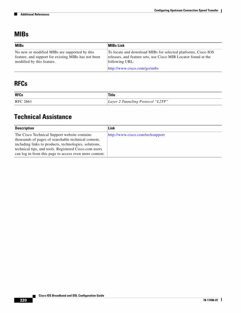
Configuring Upstream Connection Speed TransferAdditional References
220Cisco IOS Broadband and DSL Configuration Guide
78-17496-01
MIBs
RFCs
Technical Assistance
MIBs MIBs Link
No new or modified MIBs are supported by this feature, and support for existing MIBs has not been modified by this feature.
To locate and download MIBs for selected platforms, Cisco IOS releases, and feature sets, use Cisco MIB Locator found at the following URL:
http://www.cisco.com/go/mibs
RFCs Title
RFC 2661 Layer 2 Tunneling Protocol “L2TP”
Description Link
The Cisco Technical Support website contains thousands of pages of searchable technical content, including links to products, technologies, solutions, technical tips, and tools. Registered Cisco.com users can log in from this page to access even more content.
http://www.cisco.com/techsupport
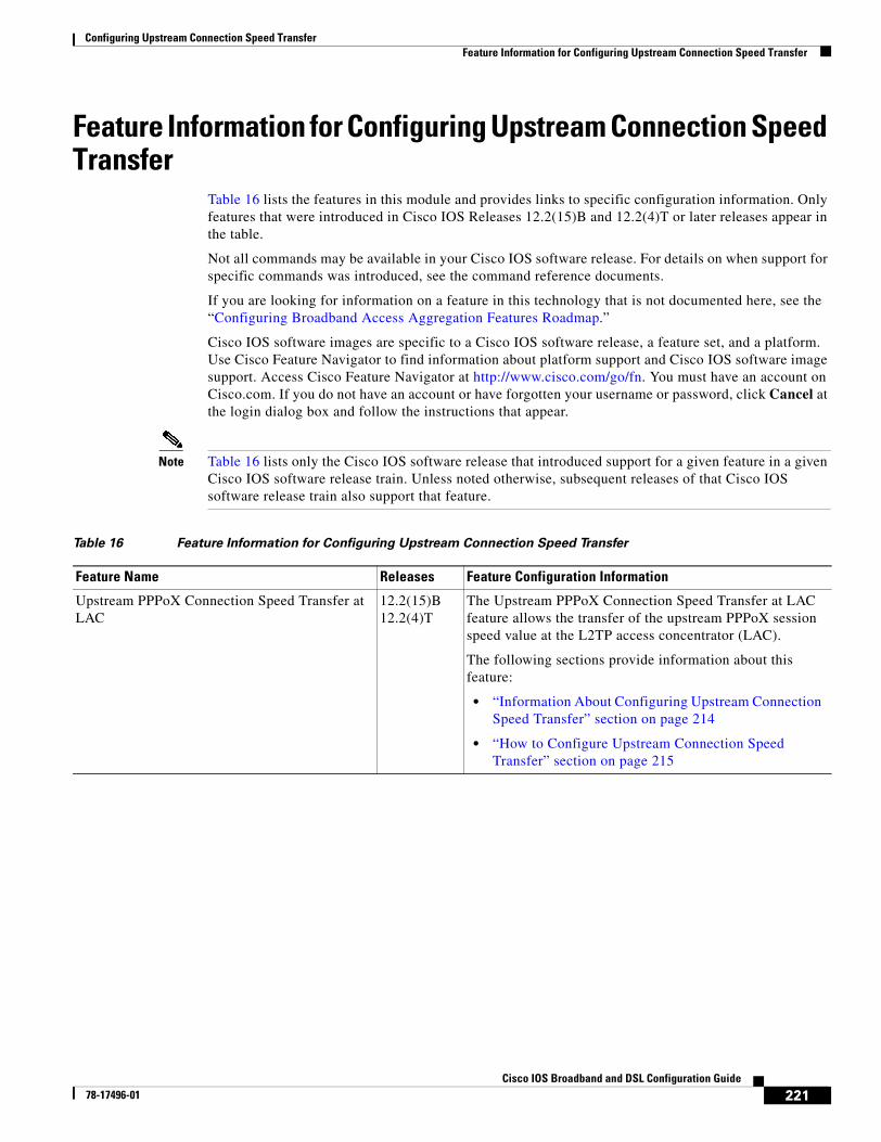
Configuring Upstream Connection Speed TransferFeature Information for Configuring Upstream Connection Speed Transfer
221Cisco IOS Broadband and DSL Configuration Guide
78-17496-01
Feature Information for Configuring Upstream Connection Speed Transfer
Table 16 lists the features in this module and provides links to specific configuration information. Only features that were introduced in Cisco IOS Releases 12.2(15)B and 12.2(4)T or later releases appear in the table.
Not all commands may be available in your Cisco IOS software release. For details on when support for specific commands was introduced, see the command reference documents.
If you are looking for information on a feature in this technology that is not documented here, see the “Configuring Broadband Access Aggregation Features Roadmap.”
Cisco IOS software images are specific to a Cisco IOS software release, a feature set, and a platform. Use Cisco Feature Navigator to find information about platform support and Cisco IOS software image support. Access Cisco Feature Navigator at http://www.cisco.com/go/fn. You must have an account on Cisco.com. If you do not have an account or have forgotten your username or password, click Cancel at the login dialog box and follow the instructions that appear.
Note Table 16 lists only the Cisco IOS software release that introduced support for a given feature in a given Cisco IOS software release train. Unless noted otherwise, subsequent releases of that Cisco IOS software release train also support that feature.
Table 16 Feature Information for Configuring Upstream Connection Speed Transfer
Feature Name Releases Feature Configuration Information
Upstream PPPoX Connection Speed Transfer at LAC
12.2(15)B12.2(4)T
The Upstream PPPoX Connection Speed Transfer at LAC feature allows the transfer of the upstream PPPoX session speed value at the L2TP access concentrator (LAC).
The following sections provide information about this feature:
• “Information About Configuring Upstream Connection Speed Transfer” section on page 214
• “How to Configure Upstream Connection Speed Transfer” section on page 215

Configuring Upstream Connection Speed TransferFeature Information for Configuring Upstream Connection Speed Transfer
222Cisco IOS Broadband and DSL Configuration Guide
78-17496-01

Part 3: ATM RBE

225Cisco IOS Broadband and DSL Configuration Guide
78-17496-01
Providing Connectivity Using ATM Routed Bridge Encapsulation
ATM routed bridge encapsulation (RBE) is used to route IP over bridged RFC 1483 Ethernet traffic from a stub-bridged LAN.
Module History
This module was first published on May 2, 2005, and last updated on May 2, 2005.
Finding Feature Information in This Module
Not all features may be supported in your Cisco IOS software release. Use the “Feature Information for Providing Connectivity Using ATM Routed Bridge Encapsulation” section on page 238 to find information about feature support and configuration.
Contents• Prerequisites for Using ATM Routed Bridge Encapsulation, page 226
• Restriction for Using ATM Routed Bridge Encapsulation, page 226
• Information About Using ATM Routed Bridge Encapsulation, page 226
• How to Configure ATM Routed Bridge Encapsulation, page 229
• Configuration Examples Using ATM Routed Bridge Encapsulation, page 234
• Additional References, page 237
• Feature Information for Providing Connectivity Using ATM Routed Bridge Encapsulation, page 238
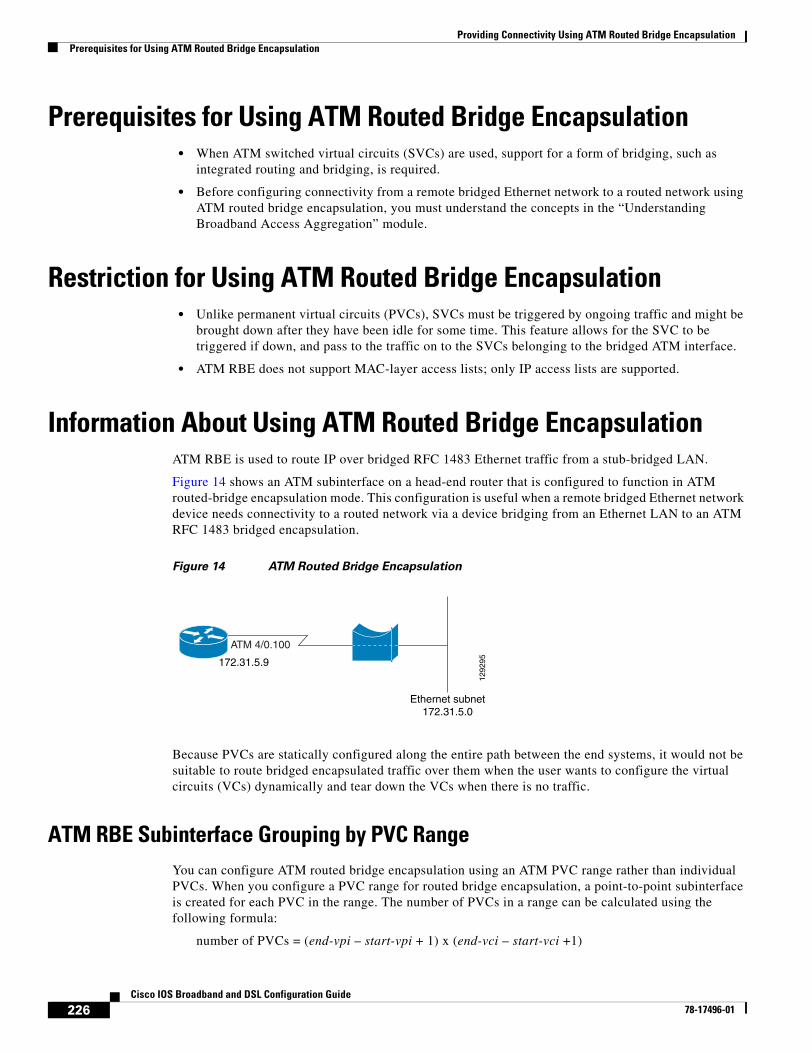
Providing Connectivity Using ATM Routed Bridge EncapsulationPrerequisites for Using ATM Routed Bridge Encapsulation
226Cisco IOS Broadband and DSL Configuration Guide
78-17496-01
Prerequisites for Using ATM Routed Bridge Encapsulation• When ATM switched virtual circuits (SVCs) are used, support for a form of bridging, such as
integrated routing and bridging, is required.
• Before configuring connectivity from a remote bridged Ethernet network to a routed network using ATM routed bridge encapsulation, you must understand the concepts in the “Understanding Broadband Access Aggregation” module.
Restriction for Using ATM Routed Bridge Encapsulation• Unlike permanent virtual circuits (PVCs), SVCs must be triggered by ongoing traffic and might be
brought down after they have been idle for some time. This feature allows for the SVC to be triggered if down, and pass to the traffic on to the SVCs belonging to the bridged ATM interface.
• ATM RBE does not support MAC-layer access lists; only IP access lists are supported.
Information About Using ATM Routed Bridge EncapsulationATM RBE is used to route IP over bridged RFC 1483 Ethernet traffic from a stub-bridged LAN.
Figure 14 shows an ATM subinterface on a head-end router that is configured to function in ATM routed-bridge encapsulation mode. This configuration is useful when a remote bridged Ethernet network device needs connectivity to a routed network via a device bridging from an Ethernet LAN to an ATM RFC 1483 bridged encapsulation.
Figure 14 ATM Routed Bridge Encapsulation
Because PVCs are statically configured along the entire path between the end systems, it would not be suitable to route bridged encapsulated traffic over them when the user wants to configure the virtual circuits (VCs) dynamically and tear down the VCs when there is no traffic.
ATM RBE Subinterface Grouping by PVC RangeYou can configure ATM routed bridge encapsulation using an ATM PVC range rather than individual PVCs. When you configure a PVC range for routed bridge encapsulation, a point-to-point subinterface is created for each PVC in the range. The number of PVCs in a range can be calculated using the following formula:
number of PVCs = (end-vpi – start-vpi + 1) x (end-vci – start-vci +1)
1292
95
ATM 4/0.100
172.31.5.9
Ethernet subnet172.31.5.0
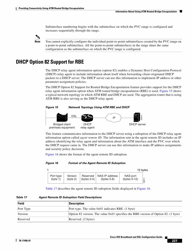
Providing Connectivity Using ATM Routed Bridge EncapsulationInformation About Using ATM Routed Bridge Encapsulation
227Cisco IOS Broadband and DSL Configuration Guide
78-17496-01
Subinterface numbering begins with the subinterface on which the PVC range is configured and increases sequentially through the range.
Note You cannot explicitly configure the individual point-to-point subinterfaces created by the PVC range on a point-to-point subinterface. All the point-to-point subinterfaces in the range share the same configuration as the subinterface on which the PVC range is configured.
DHCP Option 82 Support for RBEThe DHCP relay agent information option (option 82) enables a Dynamic Host Configuration Protocol (DHCP) relay agent to include information about itself when forwarding client-originated DHCP packets to a DHCP server. The DHCP server can use this information to implement IP address or other parameter-assignment policies.
The DHCP Option 82 Support for Routed Bridge Encapsulation feature provides support for the DHCP relay agent information option when ATM routed bridge encapsulation (RBE) is used. Figure 15 shows a typical network topology in which ATM RBE and DHCP are used. The aggregation router that is using ATM RBE is also serving as the DHCP relay agent.
Figure 15 Network Topology Using ATM RBE and DHCP
This feature communicates information to the DHCP server using a suboption of the DHCP relay agent information option called agent remote ID. The information sent in the agent remote ID includes an IP address identifying the relay agent and information about the ATM interface and the PVC over which the DHCP request came in. The DHCP server can use this information to make IP address assignments and security policy decisions.
Figure 16 shows the format of the agent remote ID suboption.
Figure 16 Format of the Agent Remote ID Suboption
Table 17 describes the agent remote ID suboption fields displayed in Figure 16.
Table 17 Agent Remote ID Suboption Field Descriptions
Bridged clientpremises equipment
DHCPrelay agent
DHCP server
DSLIP
5281
0
Port type(byte 1)
Version(byte 2)
Reserved(bytes 3-4)
NAS IP address(bytes 5-8)
NAS port(bytes 9-12)
5281
1
1 12 bytes
Field Description
Port Type Port type. The value 0x01 indicates RBE. (1 byte)
Version Option 82 version. The value 0x01 specifies the RBE version of Option 82. (1 byte)
Reserved Reserved. (2 bytes)
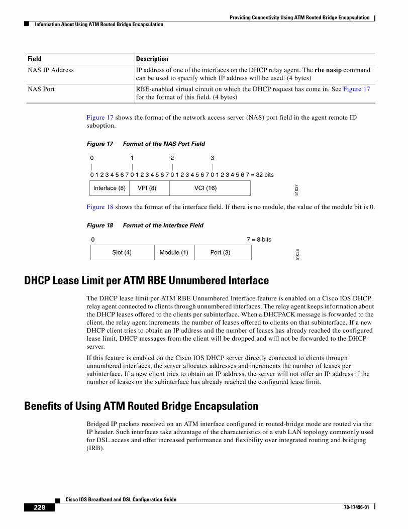
Providing Connectivity Using ATM Routed Bridge EncapsulationInformation About Using ATM Routed Bridge Encapsulation
228Cisco IOS Broadband and DSL Configuration Guide
78-17496-01
Figure 17 shows the format of the network access server (NAS) port field in the agent remote ID suboption.
Figure 17 Format of the NAS Port Field
Figure 18 shows the format of the interface field. If there is no module, the value of the module bit is 0.
Figure 18 Format of the Interface Field
DHCP Lease Limit per ATM RBE Unnumbered InterfaceThe DHCP lease limit per ATM RBE Unnumbered Interface feature is enabled on a Cisco IOS DHCP relay agent connected to clients through unnumbered interfaces. The relay agent keeps information about the DHCP leases offered to the clients per subinterface. When a DHCPACK message is forwarded to the client, the relay agent increments the number of leases offered to clients on that subinterface. If a new DHCP client tries to obtain an IP address and the number of leases has already reached the configured lease limit, DHCP messages from the client will be dropped and will not be forwarded to the DHCP server.
If this feature is enabled on the Cisco IOS DHCP server directly connected to clients through unnumbered interfaces, the server allocates addresses and increments the number of leases per subinterface. If a new client tries to obtain an IP address, the server will not offer an IP address if the number of leases on the subinterface has already reached the configured lease limit.
Benefits of Using ATM Routed Bridge EncapsulationBridged IP packets received on an ATM interface configured in routed-bridge mode are routed via the IP header. Such interfaces take advantage of the characteristics of a stub LAN topology commonly used for DSL access and offer increased performance and flexibility over integrated routing and bridging (IRB).
NAS IP Address IP address of one of the interfaces on the DHCP relay agent. The rbe nasip command can be used to specify which IP address will be used. (4 bytes)
NAS Port RBE-enabled virtual circuit on which the DHCP request has come in. See Figure 17 for the format of this field. (4 bytes)
Field Description
0 1 2 3 4 5 6 7 0 1 2 3 4 5 6 7 0 1 2 3 4 5 6 7 0 1 2 3 4 5 6 7 = 32 bits
0 1
Interface (8) VPI (8) VCI (16)
2 3
5103
7
0 7 = 8 bits
5103
8Slot (4) Port (3)Module (1)
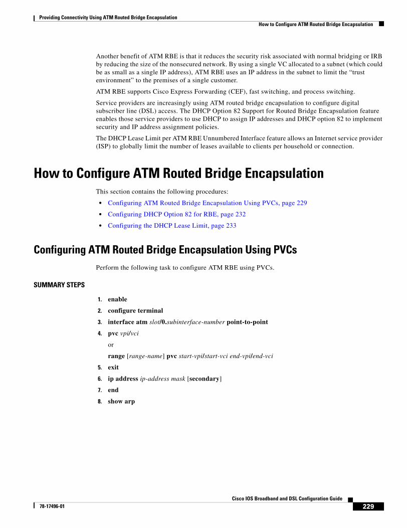
Providing Connectivity Using ATM Routed Bridge EncapsulationHow to Configure ATM Routed Bridge Encapsulation
229Cisco IOS Broadband and DSL Configuration Guide
78-17496-01
Another benefit of ATM RBE is that it reduces the security risk associated with normal bridging or IRB by reducing the size of the nonsecured network. By using a single VC allocated to a subnet (which could be as small as a single IP address), ATM RBE uses an IP address in the subnet to limit the “trust environment” to the premises of a single customer.
ATM RBE supports Cisco Express Forwarding (CEF), fast switching, and process switching.
Service providers are increasingly using ATM routed bridge encapsulation to configure digital subscriber line (DSL) access. The DHCP Option 82 Support for Routed Bridge Encapsulation feature enables those service providers to use DHCP to assign IP addresses and DHCP option 82 to implement security and IP address assignment policies.
The DHCP Lease Limit per ATM RBE Unnumbered Interface feature allows an Internet service provider (ISP) to globally limit the number of leases available to clients per household or connection.
How to Configure ATM Routed Bridge EncapsulationThis section contains the following procedures:
• Configuring ATM Routed Bridge Encapsulation Using PVCs, page 229
• Configuring DHCP Option 82 for RBE, page 232
• Configuring the DHCP Lease Limit, page 233
Configuring ATM Routed Bridge Encapsulation Using PVCsPerform the following task to configure ATM RBE using PVCs.
SUMMARY STEPS
1. enable
2. configure terminal
3. interface atm slot/0.subinterface-number point-to-point
4. pvc vpi/vci
or
range [range-name] pvc start-vpi/start-vci end-vpi/end-vci
5. exit
6. ip address ip-address mask [secondary]
7. end
8. show arp
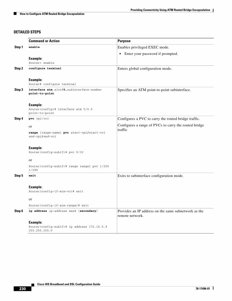
Providing Connectivity Using ATM Routed Bridge EncapsulationHow to Configure ATM Routed Bridge Encapsulation
230Cisco IOS Broadband and DSL Configuration Guide
78-17496-01
DETAILED STEPS
Command or Action Purpose
Step 1 enable
Example:Router> enable
Enables privileged EXEC mode.
• Enter your password if prompted.
Step 2 configure terminal
Example:Router# configure terminal
Enters global configuration mode.
Step 3 interface atm slot/0.subinterface-number point-to-point
Example:Router(config)# interface atm 5/0.5 point-to-point
Specifies an ATM point-to-point subinterface.
Step 4 pvc vpi/vci
or
range [range-name] pvc start-vpi/start-vci end-vpi/end-vci
Example:Router(config-subif)# pvc 0/32
or
Router(config-subif)# range range1 pvc 1/200 1/299
Configures a PVC to carry the routed bridge traffic.
Configures a range of PVCs to carry the routed bridge traffic
Step 5 exit
Example:Router(config-if-atm-vc)# exit
or
Router(config-if-atm-range)# exit
Exits to subinterface configuration mode.
Step 6 ip address ip-address mask [secondary]
Example:Router(config-subif)# ip address 172.16.5.9 255.255.255.0
Provides an IP address on the same subnetwork as the remote network.
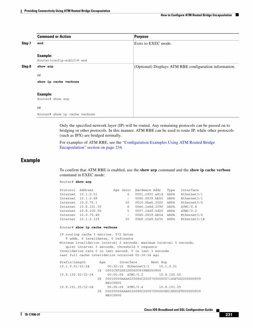
Providing Connectivity Using ATM Routed Bridge EncapsulationHow to Configure ATM Routed Bridge Encapsulation
231Cisco IOS Broadband and DSL Configuration Guide
78-17496-01
Only the specified network layer (IP) will be routed. Any remaining protocols can be passed on to bridging or other protocols. In this manner, ATM RBE can be used to route IP, while other protocols (such as IPX) are bridged normally.
For examples of ATM RBE, see the “Configuration Examples Using ATM Routed Bridge Encapsulation” section on page 234.
Example
To confirm that ATM RBE is enabled, use the show arp command and the show ip cache verbose command in EXEC mode:
Router# show arp
Protocol Address Age (min) Hardware Addr Type InterfaceInternet 10.1.0.51 6 0001.c9f2.a81d ARPA Ethernet3/1Internet 10.1.0.49 - 0060.0939.bb55 ARPA Ethernet3/1Internet 10.0.75.1 30 0010.0ba6.2020 ARPA Ethernet3/0Internet 10.8.101.35 6 00e0.1e8d.3f90 ARPA ATM1/0.4Internet 10.8.100.50 5 0007.144f.5d20 ARPA ATM1/0.2Internet 10.0.75.49 - 0060.0939.bb54 ARPA Ethernet3/0Internet 10.1.0.125 30 00b0.c2e9.bc55 ARPA Ethernet3/1#
Router# show ip cache verbose
IP routing cache 3 entries, 572 bytes 9 adds, 6 invalidates, 0 refcountsMinimum invalidation interval 2 seconds, maximum interval 5 seconds, quiet interval 3 seconds, threshold 0 requestsInvalidation rate 0 in last second, 0 in last 3 secondsLast full cache invalidation occurred 00:30:34 ago
Prefix/Length Age Interface Next Hop10.1.0.51/32-24 00:30:10 Ethernet3/1 10.1.0.51 14 0001C9F2A81D00600939BB55080010.8.100.50/32-24 00:00:04 ATM1/0.2 10.8.100.50 28 00010000AAAA030080C2000700000007144F5D2000600939 BB1C080010.8.101.35/32-24 00:06:09 ATM1/0.4 10.8.101.35 28 00020000AAAA030080C20007000000E01E8D3F9000600939 BB1C0800
Step 7 end
Example:Router(config-subif)# end
Exits to EXEC mode.
Step 8 show arp
or
show ip cache verbose
Example:Router# show arp
or
Router# show ip cache verbose
(Optional) Displays ATM RBE configuration information.
Command or Action Purpose
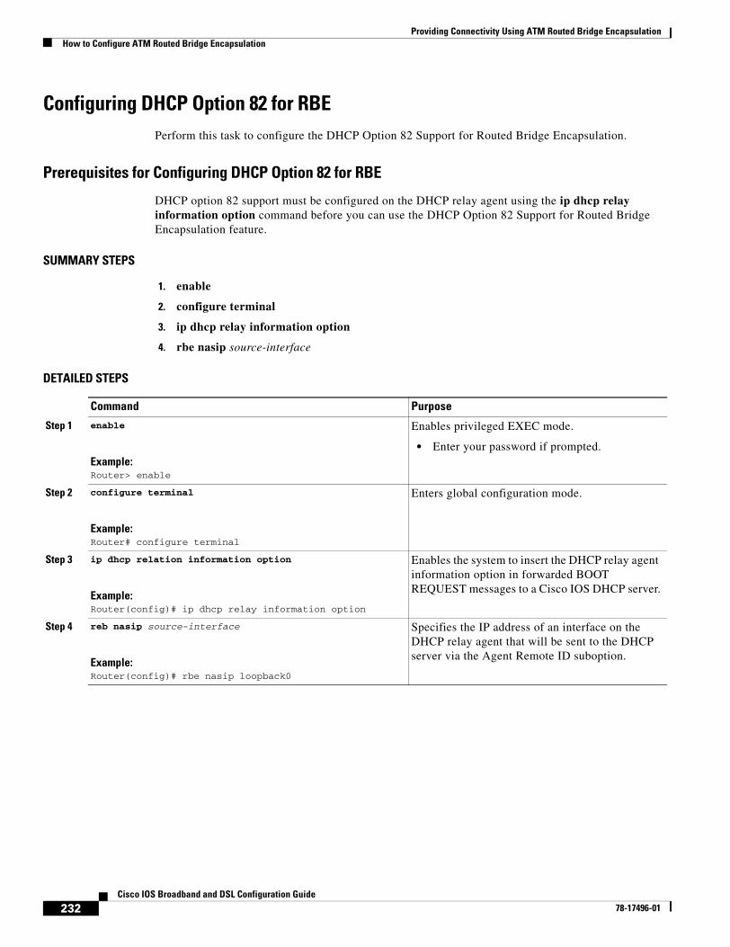
Providing Connectivity Using ATM Routed Bridge EncapsulationHow to Configure ATM Routed Bridge Encapsulation
232Cisco IOS Broadband and DSL Configuration Guide
78-17496-01
Configuring DHCP Option 82 for RBEPerform this task to configure the DHCP Option 82 Support for Routed Bridge Encapsulation.
Prerequisites for Configuring DHCP Option 82 for RBE
DHCP option 82 support must be configured on the DHCP relay agent using the ip dhcp relay information option command before you can use the DHCP Option 82 Support for Routed Bridge Encapsulation feature.
SUMMARY STEPS
1. enable
2. configure terminal
3. ip dhcp relay information option
4. rbe nasip source-interface
DETAILED STEPS
Command Purpose
Step 1 enable
Example:Router> enable
Enables privileged EXEC mode.
• Enter your password if prompted.
Step 2 configure terminal
Example:Router# configure terminal
Enters global configuration mode.
Step 3 ip dhcp relation information option
Example:Router(config)# ip dhcp relay information option
Enables the system to insert the DHCP relay agent information option in forwarded BOOT REQUEST messages to a Cisco IOS DHCP server.
Step 4 reb nasip source-interface
Example:Router(config)# rbe nasip loopback0
Specifies the IP address of an interface on the DHCP relay agent that will be sent to the DHCP server via the Agent Remote ID suboption.
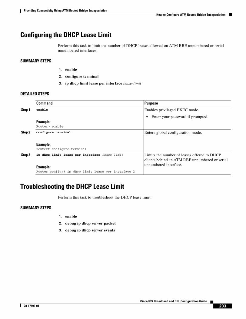
Providing Connectivity Using ATM Routed Bridge EncapsulationHow to Configure ATM Routed Bridge Encapsulation
233Cisco IOS Broadband and DSL Configuration Guide
78-17496-01
Configuring the DHCP Lease LimitPerform this task to limit the number of DHCP leases allowed on ATM RBE unnumbered or serial unnumbered interfaces.
SUMMARY STEPS
1. enable
2. configure terminal
3. ip dhcp limit lease per interface lease-limit
DETAILED STEPS
Troubleshooting the DHCP Lease LimitPerform this task to troubleshoot the DHCP lease limit.
SUMMARY STEPS
1. enable
2. debug ip dhcp server packet
3. debug ip dhcp server events
Command Purpose
Step 1 enable
Example:Router> enable
Enables privileged EXEC mode.
• Enter your password if prompted.
Step 2 configure terminal
Example:Router# configure terminal
Enters global configuration mode.
Step 3 ip dhcp limit lease per interface lease-limit
Example:Router(config)# ip dhcp limit lease per interface 2
Limits the number of leases offered to DHCP clients behind an ATM RBE unnumbered or serial unnumbered interface.
Providing Connectivity Using ATM Routed Bridge EncapsulationConfiguration Examples Using ATM Routed Bridge Encapsulation
234Cisco IOS Broadband and DSL Configuration Guide
78-17496-01
DETAILED STEPS
Configuration Examples Using ATM Routed Bridge Encapsulation
The following examples show various ways to provide connectivity from a remote bridged network to a routed network using ATM routed bridge encapsulation.
• ATM Routed Bridge Encapsulation: Example, page 234
• ATM Routed Bridge Encapsulation on an Unnumbered Interface: Example, page 234
• Concurrent Bridging and ATM Routed Bridge Encapsulation: Example, page 235
• DHCP Option 82 for RBE Configuration: Example, page 235
• DHCP Lease Limit: Example, page 236
ATM Routed Bridge Encapsulation: ExampleThe following example shows a typical ATM routed bridge encapsulation configuration:
interface atm 4/0.100 point-to-point ip address 172.16.5.9 255.255.255.0 pvc 0/32 atm route-bridge ip
ATM Routed Bridge Encapsulation on an Unnumbered Interface: ExampleThe following example uses a static route to point to an unnumbered interface:
interface loopback 0 ip address 172.16.5.1 255.255.255.0
interface atm 4/0.100 point-to-point ip unnumbered loopback 0 pvc 0/32 atm route-bridge ip
Command Purpose
Step 1 enable
Example:Router> enable
Enables privileged EXEC mode.
• Enter your password if prompted.
Step 2 debug ip dhcp server packet
Example:Router# debug ip dhcp server packet
(Optional) Decodes DHCP receptions and transmissions.
Step 3 debug ip dhcp server events
Example:Router(config)# debug ip dhcp server events
(Optional) Displays server events.
Providing Connectivity Using ATM Routed Bridge EncapsulationConfiguration Examples Using ATM Routed Bridge Encapsulation
235Cisco IOS Broadband and DSL Configuration Guide
78-17496-01
!ip route 172.16.5.2 255.255.255.255 atm 4/0.100
Concurrent Bridging and ATM Routed Bridge Encapsulation: ExampleThe following example shows concurrent use of ATM routed bridge encapsulation with normal bridging. IP datagrams are route-bridged, and other protocols (such as IPX or AppleTalk) are bridged.
bridge 1 protocol ieee
interface atm 4/0.100 point-to-point ip address 172.16.5.9 255.255.255.0 pvc 0/32 bridge-group 1 atm route-bridge ip
DHCP Option 82 for RBE Configuration: ExampleIn the following example, DHCP option 82 support is enabled on the DHCP relay agent using the ip dhcp relay agent information option command. The rbe nasip command configures the router to forward the IP address for Loopback0 to the DHCP server.
ip dhcp-server 170.16.1.2!ip dhcp relay information option!interface Loopback0ip address 11.1.1.129 255.255.255.192
!interface ATM4/0no ip address
!interface ATM4/0.1 point-to-pointip unnumbered Loopback0ip helper-address 170.16.1.2atm route-bridged ippvc 88/800encapsulation aal5snap
!!interface Ethernet5/1ip address 170.16.1.1 255.255.0.0
!router eigrp 100network 11.0.0.0network 170.16.0.0
!rbe nasip Loopback0
For the configuration example above, the value (in hexadecimal) of the agent remote ID suboption would be 010100000B01018140580320. Table 18 shows the value of each field within the agent remote ID suboption.
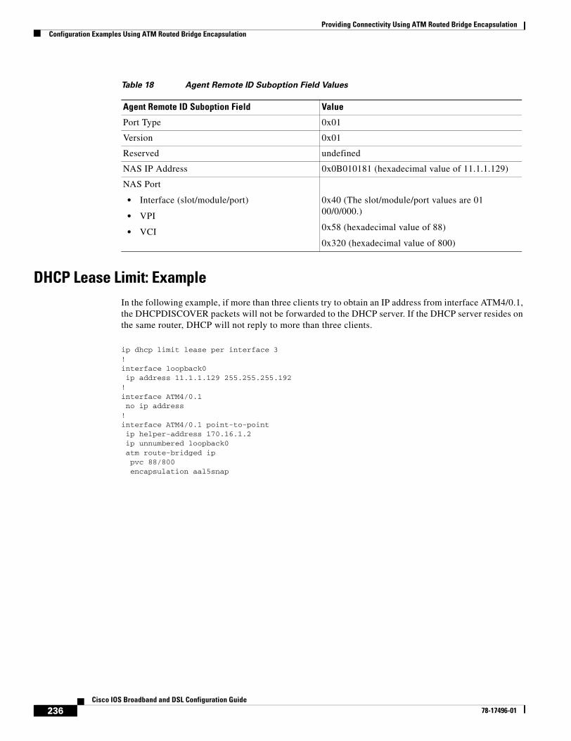
Providing Connectivity Using ATM Routed Bridge EncapsulationConfiguration Examples Using ATM Routed Bridge Encapsulation
236Cisco IOS Broadband and DSL Configuration Guide
78-17496-01
DHCP Lease Limit: ExampleIn the following example, if more than three clients try to obtain an IP address from interface ATM4/0.1, the DHCPDISCOVER packets will not be forwarded to the DHCP server. If the DHCP server resides on the same router, DHCP will not reply to more than three clients.
ip dhcp limit lease per interface 3!interface loopback0 ip address 11.1.1.129 255.255.255.192!interface ATM4/0.1 no ip address!interface ATM4/0.1 point-to-point ip helper-address 170.16.1.2 ip unnumbered loopback0 atm route-bridged ip pvc 88/800 encapsulation aal5snap
Table 18 Agent Remote ID Suboption Field Values
Agent Remote ID Suboption Field Value
Port Type 0x01
Version 0x01
Reserved undefined
NAS IP Address 0x0B010181 (hexadecimal value of 11.1.1.129)
NAS Port
• Interface (slot/module/port)
• VPI
• VCI
0x40 (The slot/module/port values are 01 00/0/000.)
0x58 (hexadecimal value of 88)
0x320 (hexadecimal value of 800)
Providing Connectivity Using ATM Routed Bridge EncapsulationAdditional References
237Cisco IOS Broadband and DSL Configuration Guide
78-17496-01
Additional ReferencesThe following sections provide references related to using ATM routed bridge encapsulation.
Related Documents
Standards
MIBs
RFCs
Technical Assistance
Related Topic Document Title
Broadband access aggregation concepts Refer to the “Understanding Broadband Access Aggregation” module.
Task for preparing for broadband access aggregation. Refer to the “Preparing for Broadband Access Aggregation” module.
DHCP commands Cisco IOS IP Command Reference, Volume 1 of 4: Addressing and Services, Release 12.3
DHCP configuration tasks Cisco IOS IP Configuration Guide, Release 12.3
Standards Title
None —
MIBs MIBs Link
None To locate and download MIBs for selected platforms, Cisco IOS releases, and feature sets, use Cisco MIB Locator found at the following URL:
http://www.cisco.com/go/mibs
RFCs Title
None —
Description Link
The Cisco Technical Support website contains thousands of pages of searchable technical content, including links to products, technologies, solutions, technical tips, and tools. Registered Cisco.com users can log in from this page to access even more content.
http://www.cisco.com/techsupport
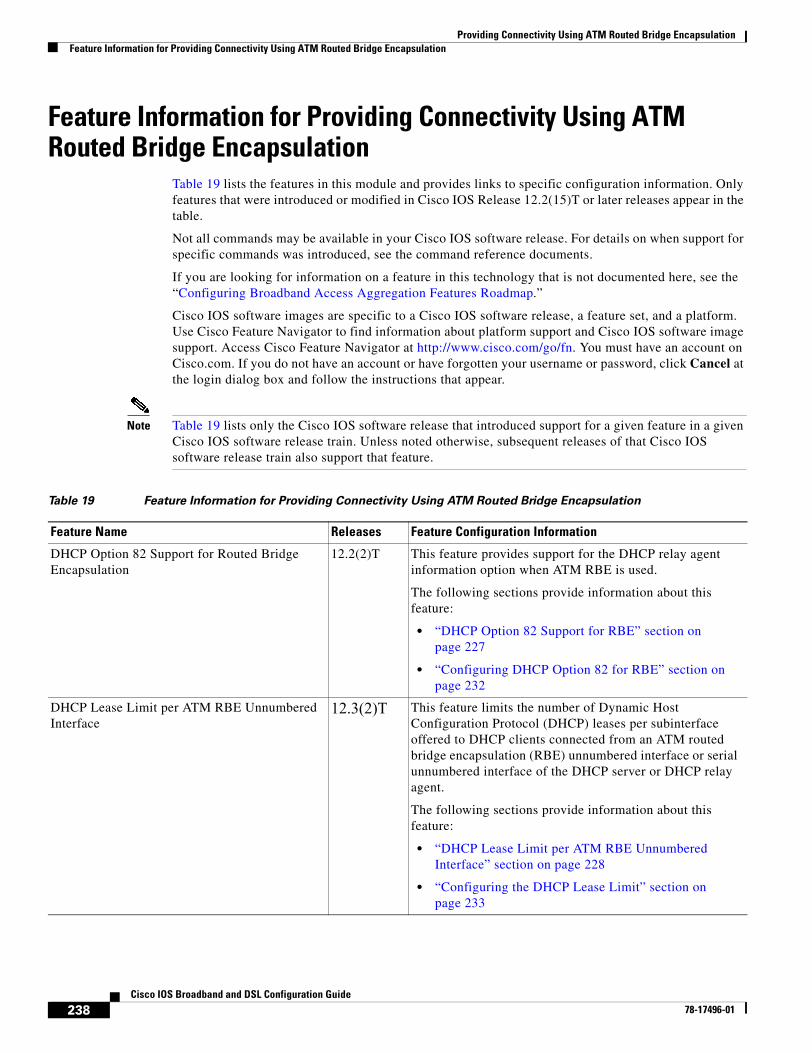
Providing Connectivity Using ATM Routed Bridge EncapsulationFeature Information for Providing Connectivity Using ATM Routed Bridge Encapsulation
238Cisco IOS Broadband and DSL Configuration Guide
78-17496-01
Feature Information for Providing Connectivity Using ATM Routed Bridge Encapsulation
Table 19 lists the features in this module and provides links to specific configuration information. Only features that were introduced or modified in Cisco IOS Release 12.2(15)T or later releases appear in the table.
Not all commands may be available in your Cisco IOS software release. For details on when support for specific commands was introduced, see the command reference documents.
If you are looking for information on a feature in this technology that is not documented here, see the “Configuring Broadband Access Aggregation Features Roadmap.”
Cisco IOS software images are specific to a Cisco IOS software release, a feature set, and a platform. Use Cisco Feature Navigator to find information about platform support and Cisco IOS software image support. Access Cisco Feature Navigator at http://www.cisco.com/go/fn. You must have an account on Cisco.com. If you do not have an account or have forgotten your username or password, click Cancel at the login dialog box and follow the instructions that appear.
Note Table 19 lists only the Cisco IOS software release that introduced support for a given feature in a given Cisco IOS software release train. Unless noted otherwise, subsequent releases of that Cisco IOS software release train also support that feature.
Table 19 Feature Information for Providing Connectivity Using ATM Routed Bridge Encapsulation
Feature Name Releases Feature Configuration Information
DHCP Option 82 Support for Routed Bridge Encapsulation
12.2(2)T This feature provides support for the DHCP relay agent information option when ATM RBE is used.
The following sections provide information about this feature:
• “DHCP Option 82 Support for RBE” section on page 227
• “Configuring DHCP Option 82 for RBE” section on page 232
DHCP Lease Limit per ATM RBE Unnumbered Interface
12.3(2)T This feature limits the number of Dynamic Host Configuration Protocol (DHCP) leases per subinterface offered to DHCP clients connected from an ATM routed bridge encapsulation (RBE) unnumbered interface or serial unnumbered interface of the DHCP server or DHCP relay agent.
The following sections provide information about this feature:
• “DHCP Lease Limit per ATM RBE Unnumbered Interface” section on page 228
• “Configuring the DHCP Lease Limit” section on page 233

Part 4: Subscriber Service Switch

241Cisco IOS Broadband and DSL Configuration Guide
78-17496-01
Configuring Cisco Subscriber Service Switch Policies
The Subscriber Service Switch provides flexibility in where subscribers are connected to available services, how many subscribers are connected, and how those services are defined. The primary focus of the Subscriber Service Switch is to direct PPP from one point to another using a Layer 2 subscriber policy. The policy manages tunneling of PPP in a policy-based bridging fashion.
Module History
This module was first published on May 2, 2005, and last updated on May 2, 2005.
Finding Feature Information in This Module
Not all features may be supported in your Cisco IOS software release. Use the “Feature Information for Configuring a Subscriber Service Switch Policy” section on page 270 to find information about feature support and configuration.
Contents• Prerequisites for Configuring a Subscriber Service Switch Policy, page 241
• Restrictions for Configuring a Subscriber Service Switch Policy, page 242
• Information About the Subscriber Service Switch, page 242
• How to Configure a Subscriber Service Switch Policy, page 245
• Configuration Examples for Configuring a Subscriber Service Switch Policy, page 252
• Troubleshooting Subscriber Service Switch Examples, page 255
• Where to Go Next, page 268
• Additional References, page 268
• Feature Information for Configuring a Subscriber Service Switch Policy, page 270
Prerequisites for Configuring a Subscriber Service Switch Policy
• Before configuring a Subscriber Service Switch policy, you must understand the concepts presented in the “Understanding Broadband Access Aggregation” module.
Configuring Cisco Subscriber Service Switch PoliciesRestrictions for Configuring a Subscriber Service Switch Policy
242Cisco IOS Broadband and DSL Configuration Guide
78-17496-01
• Before configuring a Subscriber Service Switch policy, you must perform the PPPoE configuration procedures in the “Providing Protocol Support for Broadband Access Aggregation of PPPoE Sessions” module or perform the PPP over ATM configuration procedures in the “Providing Protocol Support for Broadband Access Aggregation of PPP over ATM Sessions” module.
Restrictions for Configuring a Subscriber Service Switch PolicyThe Subscriber Service Switch provides the framework for the management and scalability of PPP sessions that are switched from one virtual PPP link to another. The Subscriber Server Switch provides the infrastructure for any protocol to plug into; however, the initial implementation provides switching PPP over Ethernet and PPP over ATM session to a Layer 2 Tunneling Protocol device such as an L2TP access concentrator (LAC) switch, and switching L2TP sessions to an L2TP tunnel switch only.
Information About the Subscriber Service SwitchThe Subscriber Service Switch was developed in response to a need by Internet service providers for increased scalability and extensibility for remote access service selection and Layer 2 subscriber policy management. This Layer 2 subscriber policy is needed to manage tunneling of PPP in a policy-based bridging fashion.
To configure the Cisco Subscriber Server Switch policy, you should understand the following concepts:
• Benefits of the Subscriber Service Switch, page 242
• Backward Compatibility, page 243
Benefits of the Subscriber Service SwitchThe Subscriber Service Switch provides flexibility in where subscribers are connected to available services, how many subscribers are connected, and how those services are defined. In the past, remote access service selection was largely determined by the telephone number dialed or the PPP username and password entered during a PPP authentication cycle. However, emerging broadband, cable, Virtual Private Network (VPN), and wireless access methods have created an environment where PPP sessions may be tunneled over a variety of protocols and media. The multitude of protocols, management domains, network infrastructure, and variety of services has created a complex environment for directing a subscriber to a given service or application. The problem is further complicated by the much greater density of total PPP sessions that can be transported over shared media versus traditional point-to-point links. The Subscriber Service Switch can provide a flexible and extensible decision point linking an incoming subscriber (typically a PPP session over some physical or virtual link) to another tunneled link or local termination for Layer 3 processing.
The Subscriber Service Switch is also scalable in situations where a subscriber’s Layer 2 service is switched across virtual links. Examples include switching among PPPoA, PPPoE, L2TP, Layer 2 Forwarding Protocol (L2F), Point-to-Point Tunneling Protocol (PPTP), generic routing encapsulation (GRE), and General Packet Radio Service (GPRS) Tunneling Protocol (GTP wireless data standard).
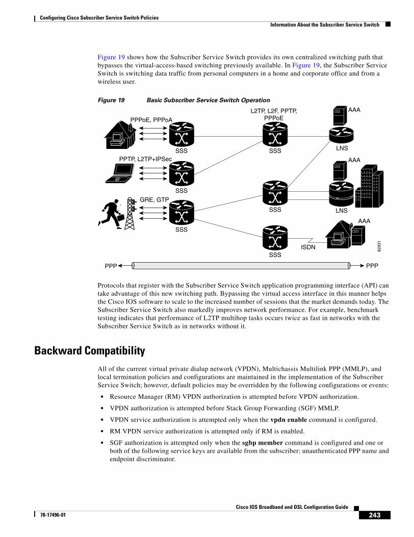
Configuring Cisco Subscriber Service Switch PoliciesInformation About the Subscriber Service Switch
243Cisco IOS Broadband and DSL Configuration Guide
78-17496-01
Figure 19 shows how the Subscriber Service Switch provides its own centralized switching path that bypasses the virtual-access-based switching previously available. In Figure 19, the Subscriber Service Switch is switching data traffic from personal computers in a home and corporate office and from a wireless user.
Figure 19 Basic Subscriber Service Switch Operation
Protocols that register with the Subscriber Service Switch application programming interface (API) can take advantage of this new switching path. Bypassing the virtual access interface in this manner helps the Cisco IOS software to scale to the increased number of sessions that the market demands today. The Subscriber Service Switch also markedly improves network performance. For example, benchmark testing indicates that performance of L2TP multihop tasks occurs twice as fast in networks with the Subscriber Service Switch as in networks without it.
Backward CompatibilityAll of the current virtual private dialup network (VPDN), Multichassis Multilink PPP (MMLP), and local termination policies and configurations are maintained in the implementation of the Subscriber Service Switch; however, default policies may be overridden by the following configurations or events:
• Resource Manager (RM) VPDN authorization is attempted before VPDN authorization.
• VPDN authorization is attempted before Stack Group Forwarding (SGF) MMLP.
• VPDN service authorization is attempted only when the vpdn enable command is configured.
• RM VPDN service authorization is attempted only if RM is enabled.
• SGF authorization is attempted only when the sgbp member command is configured and one or both of the following service keys are available from the subscriber: unauthenticated PPP name and endpoint discriminator.
8293
1
PPPoE, PPPoA
PPTP, L2TP+IPSec
GRE, GTP
SSS
PPP PPP
SSS
SSS SSS
SSS
SSSISDN
LNS
AAA
AAA
AAAL2TP, L2F, PPTP,PPPoE
LNS
Configuring Cisco Subscriber Service Switch PoliciesInformation About the Subscriber Service Switch
244Cisco IOS Broadband and DSL Configuration Guide
78-17496-01
• The dnis and domain service keys, in that order, are used to authorize VPDN service, provided that VPDN service is enabled. The order may be changed with the vpdn search-order global command, which may include multihop-hostname as a service key.
• An unauthenticated PPP name is always reduced to a domain name by taking all characters from the right of the PPP name up to a configurable delimiter character (default is the @ character). Only the domain portion is used to locate a service.
• If the vpdn authen-before-forward command is configured as a global configuration command, the authenticated PPP name is used to authorize VPDN service.
• The vpdn-group command can define four configurations:
1. Authorization for VPDN call termination (using the accept-dialin and accept-dialout keywords).
2. Authorization for VPDN subscriber service (using the request-dialin and request-dialout keywords).
3. A directive to collect further service keys and reauthorize (using the authen-before-forward keyword).
4. A tunnel configuration.
The Subscriber Service Switch adds a general configuration framework to replace the first three aspects of a VPDN group.
• If VPDN and SGF services either are not configured or cannot be authorized, local PPP termination service is selected. Further PPP authorization is still required to complete local termination.
• A two-phase authorization scheme is enabled by the vpn domain authorization command. An NAS-Port-ID (NAS port identifier) key is used to locate the first service record, which contains a restricted set of values for the domain substring of the unauthenticated PPP name. This filtered service key then locates the final service. Cisco refers to this scheme as domain preauthorization.
• Domain preauthorization will occur only when the NAS-Port-ID key is available.
• When domain preauthorization is enabled, both authenticated and unauthenticated domain names are checked for restrictions.
• It is possible to associate a fixed service with an ATM permanent virtual circuit (PVC), thus affecting any subscribers carried by the PVC. The vpn service command, in ATM VC or VC class configuration mode, and the associated key make up the generic service key.
• When the generic service key is available, it will be used for authorization instead of the unauthenticated domain name.
• If either the vpdn authen-before-forward or per vpdn-group authen-before-forward command is configured, the authenticated username is required and will be used to authorize VPDN service.
• To determine whether the authen-before-forward command is configured in a VPDN group (using the vpdn-group command), an unauthenticated username or the generic service key is required as the initial-want key set.
• When the global vpdn authen-before-forward command is not configured, the generic service key, if one is available, is used to determine whether the authen-before-forward function is configured in the VPDN group (using the vpdn-group command). If the generic service key is not available, the unauthenticated username will be used.
• If an accounting-enabled key is available, the unauthenticated username is required.
• VPDN multihop is allowed only when VPDN multihop is enabled.
• SGF on the L2TP network server (LNS) is allowed only when VPDN multihop is enabled on the LNS.
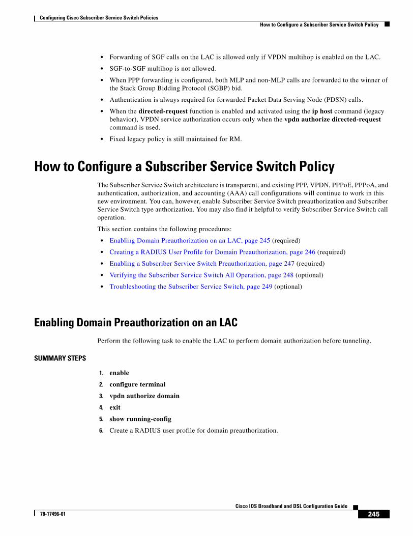
Configuring Cisco Subscriber Service Switch PoliciesHow to Configure a Subscriber Service Switch Policy
245Cisco IOS Broadband and DSL Configuration Guide
78-17496-01
• Forwarding of SGF calls on the LAC is allowed only if VPDN multihop is enabled on the LAC.
• SGF-to-SGF multihop is not allowed.
• When PPP forwarding is configured, both MLP and non-MLP calls are forwarded to the winner of the Stack Group Bidding Protocol (SGBP) bid.
• Authentication is always required for forwarded Packet Data Serving Node (PDSN) calls.
• When the directed-request function is enabled and activated using the ip host command (legacy behavior), VPDN service authorization occurs only when the vpdn authorize directed-request command is used.
• Fixed legacy policy is still maintained for RM.
How to Configure a Subscriber Service Switch PolicyThe Subscriber Service Switch architecture is transparent, and existing PPP, VPDN, PPPoE, PPPoA, and authentication, authorization, and accounting (AAA) call configurations will continue to work in this new environment. You can, however, enable Subscriber Service Switch preauthorization and Subscriber Service Switch type authorization. You may also find it helpful to verify Subscriber Service Switch call operation.
This section contains the following procedures:
• Enabling Domain Preauthorization on an LAC, page 245 (required)
• Creating a RADIUS User Profile for Domain Preauthorization, page 246 (required)
• Enabling a Subscriber Service Switch Preauthorization, page 247 (required)
• Verifying the Subscriber Service Switch All Operation, page 248 (optional)
• Troubleshooting the Subscriber Service Switch, page 249 (optional)
Enabling Domain Preauthorization on an LACPerform the following task to enable the LAC to perform domain authorization before tunneling.
SUMMARY STEPS
1. enable
2. configure terminal
3. vpdn authorize domain
4. exit
5. show running-config
6. Create a RADIUS user profile for domain preauthorization.
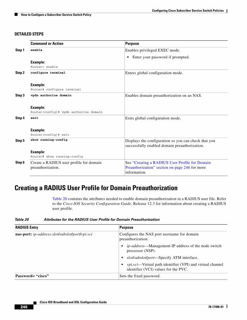
Configuring Cisco Subscriber Service Switch PoliciesHow to Configure a Subscriber Service Switch Policy
246Cisco IOS Broadband and DSL Configuration Guide
78-17496-01
DETAILED STEPS
Creating a RADIUS User Profile for Domain PreauthorizationTable 20 contains the attributes needed to enable domain preauthorization in a RADIUS user file. Refer to the Cisco IOS Security Configuration Guide, Release 12.3 for information about creating a RADIUS user profile.
Table 20 Attributes for the RADIUS User Profile for Domain Preauthorization
Command or Action Purpose
Step 1 enable
Example:Router> enable
Enables privileged EXEC mode.
• Enter your password if prompted.
Step 2 configure terminal
Example:Router# configure terminal
Enters global configuration mode.
Step 3 vpdn authorize domain
Example:Router(config)# vpdn authorize domain
Enables domain preauthorization on an NAS.
Step 4 exit
Example:Router(config)# exit
Exits global configuration mode.
Step 5 show running-config
Example:Router# show running-config
Displays the configuration so you can check that you successfully enabled domain preauthorization.
Step 6 Create a RADIUS user profile for domain preauthorization.
See “Creating a RADIUS User Profile for Domain Preauthorization” section on page 246 for more information.
RADIUS Entry Purpose
nas-port: ip-address:slot/subslot/port/vpi.vci Configures the NAS port username for domain preauthorization.
• ip-address—Management IP address of the node switch processor (NSP).
• slot/subslot/port—Specify ATM interface.
• vpi.vci—Virtual path identifier (VPI) and virtual channel identifier (VCI) values for the PVC.
Password= “cisco” Sets the fixed password.
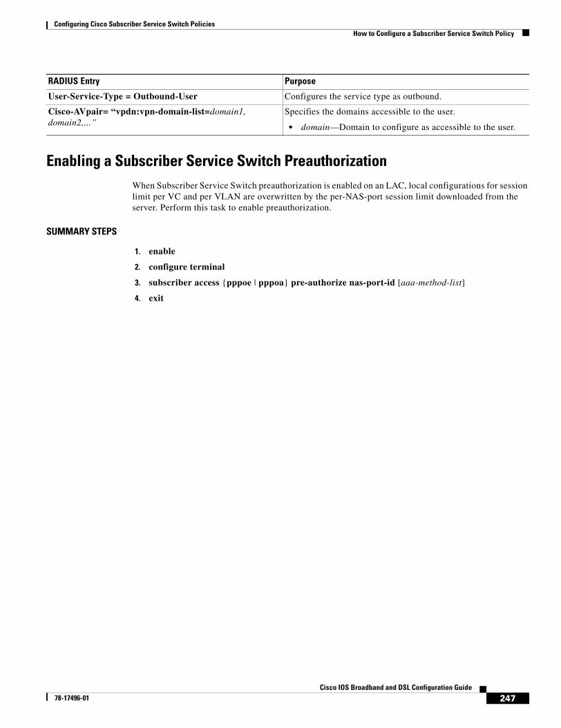
Configuring Cisco Subscriber Service Switch PoliciesHow to Configure a Subscriber Service Switch Policy
247Cisco IOS Broadband and DSL Configuration Guide
78-17496-01
Enabling a Subscriber Service Switch Preauthorization When Subscriber Service Switch preauthorization is enabled on an LAC, local configurations for session limit per VC and per VLAN are overwritten by the per-NAS-port session limit downloaded from the server. Perform this task to enable preauthorization.
SUMMARY STEPS
1. enable
2. configure terminal
3. subscriber access {pppoe | pppoa} pre-authorize nas-port-id [aaa-method-list]
4. exit
User-Service-Type = Outbound-User Configures the service type as outbound.
Cisco-AVpair= “vpdn:vpn-domain-list=domain1, domain2,...”
Specifies the domains accessible to the user.
• domain—Domain to configure as accessible to the user.
RADIUS Entry Purpose
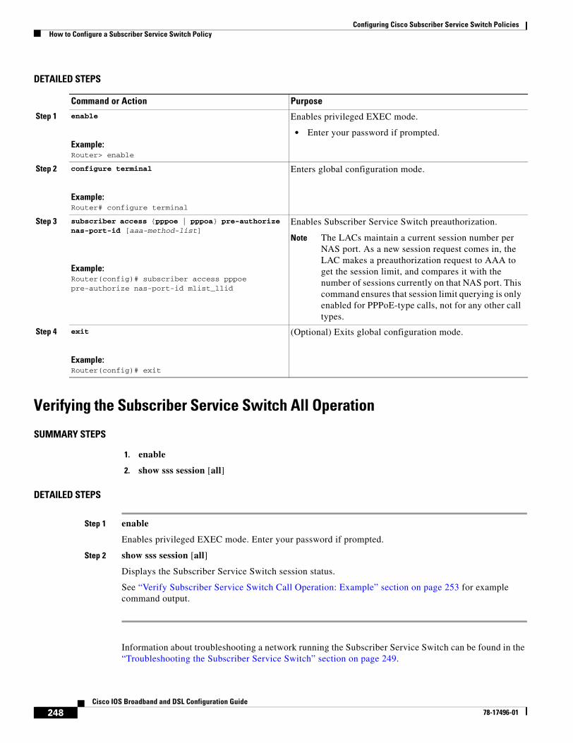
Configuring Cisco Subscriber Service Switch PoliciesHow to Configure a Subscriber Service Switch Policy
248Cisco IOS Broadband and DSL Configuration Guide
78-17496-01
DETAILED STEPS
Verifying the Subscriber Service Switch All Operation
SUMMARY STEPS
1. enable
2. show sss session [all]
DETAILED STEPS
Step 1 enable
Enables privileged EXEC mode. Enter your password if prompted.
Step 2 show sss session [all]
Displays the Subscriber Service Switch session status.
See “Verify Subscriber Service Switch Call Operation: Example” section on page 253 for example command output.
Information about troubleshooting a network running the Subscriber Service Switch can be found in the “Troubleshooting the Subscriber Service Switch” section on page 249.
Command or Action Purpose
Step 1 enable
Example:Router> enable
Enables privileged EXEC mode.
• Enter your password if prompted.
Step 2 configure terminal
Example:Router# configure terminal
Enters global configuration mode.
Step 3 subscriber access {pppoe | pppoa} pre-authorize nas-port-id [aaa-method-list]
Example:Router(config)# subscriber access pppoe pre-authorize nas-port-id mlist_llid
Enables Subscriber Service Switch preauthorization.
Note The LACs maintain a current session number per NAS port. As a new session request comes in, the LAC makes a preauthorization request to AAA to get the session limit, and compares it with the number of sessions currently on that NAS port. This command ensures that session limit querying is only enabled for PPPoE-type calls, not for any other call types.
Step 4 exit
Example:Router(config)# exit
(Optional) Exits global configuration mode.
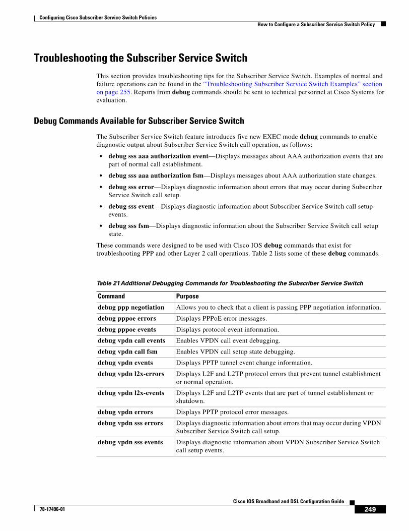
Configuring Cisco Subscriber Service Switch PoliciesHow to Configure a Subscriber Service Switch Policy
249Cisco IOS Broadband and DSL Configuration Guide
78-17496-01
Troubleshooting the Subscriber Service SwitchThis section provides troubleshooting tips for the Subscriber Service Switch. Examples of normal and failure operations can be found in the “Troubleshooting Subscriber Service Switch Examples” section on page 255. Reports from debug commands should be sent to technical personnel at Cisco Systems for evaluation.
Debug Commands Available for Subscriber Service Switch
The Subscriber Service Switch feature introduces five new EXEC mode debug commands to enable diagnostic output about Subscriber Service Switch call operation, as follows:
• debug sss aaa authorization event—Displays messages about AAA authorization events that are part of normal call establishment.
• debug sss aaa authorization fsm—Displays messages about AAA authorization state changes.
• debug sss error—Displays diagnostic information about errors that may occur during Subscriber Service Switch call setup.
• debug sss event—Displays diagnostic information about Subscriber Service Switch call setup events.
• debug sss fsm—Displays diagnostic information about the Subscriber Service Switch call setup state.
These commands were designed to be used with Cisco IOS debug commands that exist for troubleshooting PPP and other Layer 2 call operations. Table 2 lists some of these debug commands.
Table 21 Additional Debugging Commands for Troubleshooting the Subscriber Service Switch
Command Purpose
debug ppp negotiation Allows you to check that a client is passing PPP negotiation information.
debug pppoe errors Displays PPPoE error messages.
debug pppoe events Displays protocol event information.
debug vpdn call events Enables VPDN call event debugging.
debug vpdn call fsm Enables VPDN call setup state debugging.
debug vpdn events Displays PPTP tunnel event change information.
debug vpdn l2x-errors Displays L2F and L2TP protocol errors that prevent tunnel establishment or normal operation.
debug vpdn l2x-events Displays L2F and L2TP events that are part of tunnel establishment or shutdown.
debug vpdn errors Displays PPTP protocol error messages.
debug vpdn sss errors Displays diagnostic information about errors that may occur during VPDN Subscriber Service Switch call setup.
debug vpdn sss events Displays diagnostic information about VPDN Subscriber Service Switch call setup events.
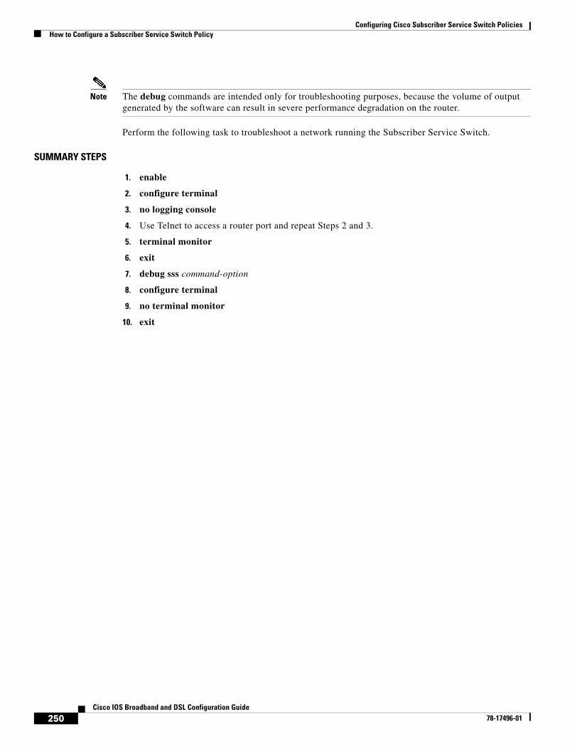
Configuring Cisco Subscriber Service Switch PoliciesHow to Configure a Subscriber Service Switch Policy
250Cisco IOS Broadband and DSL Configuration Guide
78-17496-01
Note The debug commands are intended only for troubleshooting purposes, because the volume of output generated by the software can result in severe performance degradation on the router.
Perform the following task to troubleshoot a network running the Subscriber Service Switch.
SUMMARY STEPS
1. enable
2. configure terminal
3. no logging console
4. Use Telnet to access a router port and repeat Steps 2 and 3.
5. terminal monitor
6. exit
7. debug sss command-option
8. configure terminal
9. no terminal monitor
10. exit
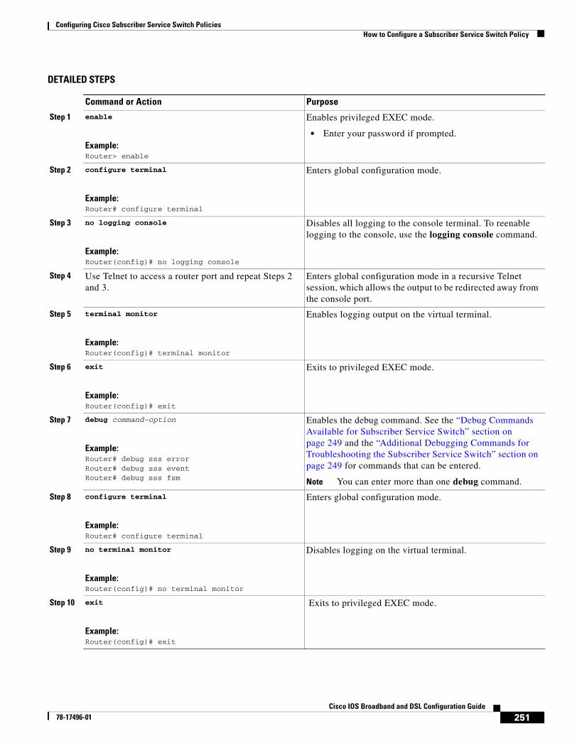
Configuring Cisco Subscriber Service Switch PoliciesHow to Configure a Subscriber Service Switch Policy
251Cisco IOS Broadband and DSL Configuration Guide
78-17496-01
DETAILED STEPS
Command or Action Purpose
Step 1 enable
Example:Router> enable
Enables privileged EXEC mode.
• Enter your password if prompted.
Step 2 configure terminal
Example:Router# configure terminal
Enters global configuration mode.
Step 3 no logging console
Example:Router(config)# no logging console
Disables all logging to the console terminal. To reenable logging to the console, use the logging console command.
Step 4 Use Telnet to access a router port and repeat Steps 2 and 3.
Enters global configuration mode in a recursive Telnet session, which allows the output to be redirected away from the console port.
Step 5 terminal monitor
Example:Router(config)# terminal monitor
Enables logging output on the virtual terminal.
Step 6 exit
Example:Router(config)# exit
Exits to privileged EXEC mode.
Step 7 debug command-option
Example:Router# debug sss error Router# debug sss event Router# debug sss fsm
Enables the debug command. See the “Debug Commands Available for Subscriber Service Switch” section on page 249 and the “Additional Debugging Commands for Troubleshooting the Subscriber Service Switch” section on page 249 for commands that can be entered.
Note You can enter more than one debug command.
Step 8 configure terminal
Example:Router# configure terminal
Enters global configuration mode.
Step 9 no terminal monitor
Example:Router(config)# no terminal monitor
Disables logging on the virtual terminal.
Step 10 exit
Example:Router(config)# exit
Exits to privileged EXEC mode.
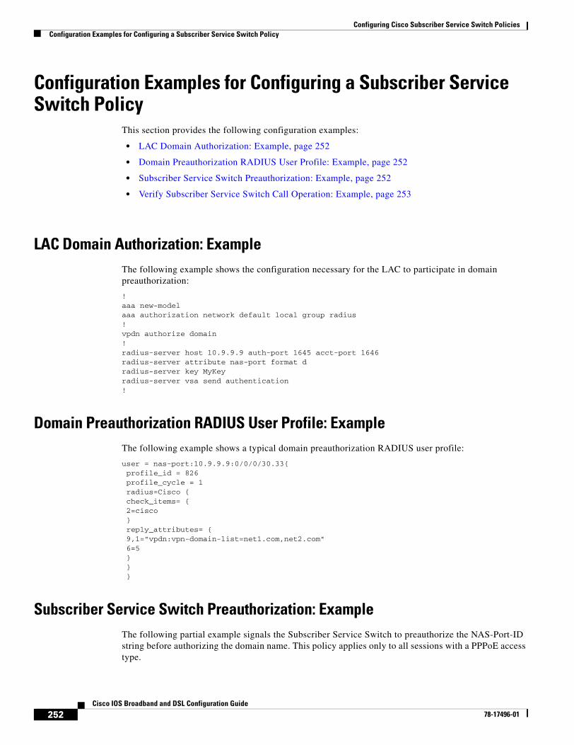
Configuring Cisco Subscriber Service Switch PoliciesConfiguration Examples for Configuring a Subscriber Service Switch Policy
252Cisco IOS Broadband and DSL Configuration Guide
78-17496-01
Configuration Examples for Configuring a Subscriber Service Switch Policy
This section provides the following configuration examples:
• LAC Domain Authorization: Example, page 252
• Domain Preauthorization RADIUS User Profile: Example, page 252
• Subscriber Service Switch Preauthorization: Example, page 252
• Verify Subscriber Service Switch Call Operation: Example, page 253
LAC Domain Authorization: Example The following example shows the configuration necessary for the LAC to participate in domain preauthorization:
!aaa new-modelaaa authorization network default local group radius!vpdn authorize domain!radius-server host 10.9.9.9 auth-port 1645 acct-port 1646radius-server attribute nas-port format dradius-server key MyKeyradius-server vsa send authentication!
Domain Preauthorization RADIUS User Profile: Example The following example shows a typical domain preauthorization RADIUS user profile:
user = nas-port:10.9.9.9:0/0/0/30.33{ profile_id = 826 profile_cycle = 1 radius=Cisco { check_items= { 2=cisco } reply_attributes= { 9,1="vpdn:vpn-domain-list=net1.com,net2.com" 6=5 } } }
Subscriber Service Switch Preauthorization: Example The following partial example signals the Subscriber Service Switch to preauthorize the NAS-Port-ID string before authorizing the domain name. This policy applies only to all sessions with a PPPoE access type.
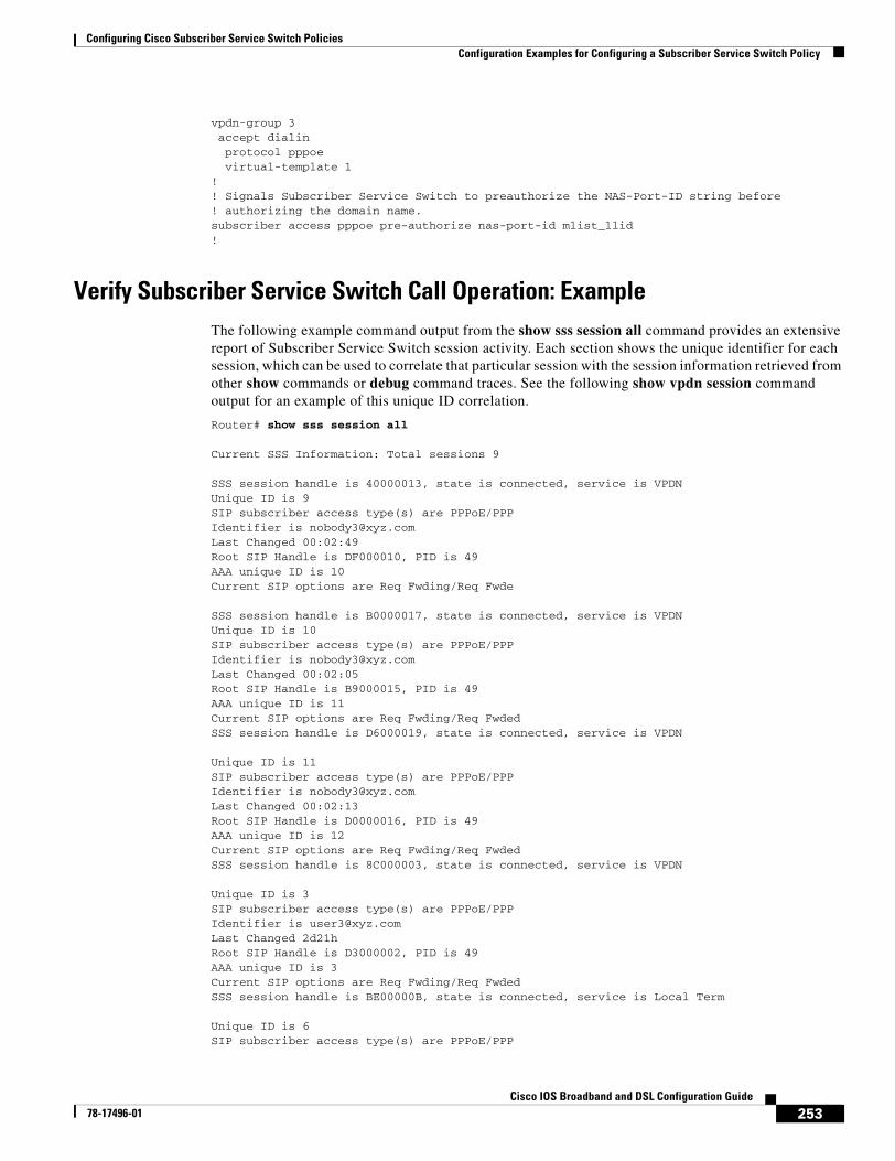
Configuring Cisco Subscriber Service Switch PoliciesConfiguration Examples for Configuring a Subscriber Service Switch Policy
253Cisco IOS Broadband and DSL Configuration Guide
78-17496-01
vpdn-group 3 accept dialin protocol pppoe virtual-template 1!! Signals Subscriber Service Switch to preauthorize the NAS-Port-ID string before! authorizing the domain name.subscriber access pppoe pre-authorize nas-port-id mlist_llid!
Verify Subscriber Service Switch Call Operation: Example The following example command output from the show sss session all command provides an extensive report of Subscriber Service Switch session activity. Each section shows the unique identifier for each session, which can be used to correlate that particular session with the session information retrieved from other show commands or debug command traces. See the following show vpdn session command output for an example of this unique ID correlation.
Router# show sss session all
Current SSS Information: Total sessions 9
SSS session handle is 40000013, state is connected, service is VPDNUnique ID is 9SIP subscriber access type(s) are PPPoE/PPPIdentifier is [email protected] Changed 00:02:49Root SIP Handle is DF000010, PID is 49AAA unique ID is 10Current SIP options are Req Fwding/Req Fwde
SSS session handle is B0000017, state is connected, service is VPDNUnique ID is 10SIP subscriber access type(s) are PPPoE/PPPIdentifier is [email protected] Changed 00:02:05Root SIP Handle is B9000015, PID is 49AAA unique ID is 11Current SIP options are Req Fwding/Req FwdedSSS session handle is D6000019, state is connected, service is VPDN
Unique ID is 11SIP subscriber access type(s) are PPPoE/PPPIdentifier is [email protected] Changed 00:02:13Root SIP Handle is D0000016, PID is 49AAA unique ID is 12Current SIP options are Req Fwding/Req FwdedSSS session handle is 8C000003, state is connected, service is VPDN
Unique ID is 3SIP subscriber access type(s) are PPPoE/PPPIdentifier is [email protected] Changed 2d21h Root SIP Handle is D3000002, PID is 49AAA unique ID is 3Current SIP options are Req Fwding/Req FwdedSSS session handle is BE00000B, state is connected, service is Local Term
Unique ID is 6SIP subscriber access type(s) are PPPoE/PPP
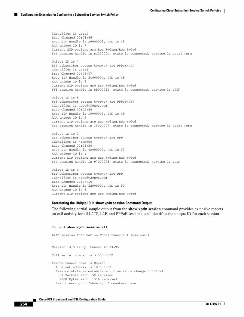
Configuring Cisco Subscriber Service Switch PoliciesConfiguration Examples for Configuring a Subscriber Service Switch Policy
254Cisco IOS Broadband and DSL Configuration Guide
78-17496-01
Identifier is user1Last Changed 00:03:56Root SIP Handle is A9000009, PID is 49AAA unique ID is 7Current SIP options are Req Fwding/Req FwdedSSS session handle is DC00000D, state is connected, service is Local Term
Unique ID is 7SIP subscriber access type(s) are PPPoE/PPPIdentifier is user2Last Changed 00:03:57Root SIP Handle is 2C00000A, PID is 49AAA unique ID is 8Current SIP options are Req Fwding/Req FwdedSSS session handle is DB000011, state is connected, service is VPDN
Unique ID is 8SIP subscriber access type(s) are PPPoE/PPPIdentifier is [email protected] Changed 00:02:58Root SIP Handle is 1000000F, PID is 49AAA unique ID is 9Current SIP options are Req Fwding/Req FwdedSSS session handle is 3F000007, state is connected, service is Local Term
Unique ID is 2SIP subscriber access type(s) are PPPIdentifier is johndoeLast Changed 00:05:30Root SIP Handle is 8A000009, PID is 92AAA unique ID is 1Current SIP options are Req Fwding/Req FwdedSSS session handle is 97000005, state is connected, service is VPDN
Unique ID is 4SIP subscriber access type(s) are PPPIdentifier is [email protected] Changed 00:07:16Root SIP Handle is 32000000, PID is 92AAA unique ID is 5Current SIP options are Req Fwding/Req Fwded
Correlating the Unique ID in show vpdn session Command Output
The following partial sample output from the show vpdn session command provides extensive reports on call activity for all L2TP, L2F, and PPPoE sessions, and identifies the unique ID for each session.
Router# show vpdn session all
L2TP Session Information Total tunnels 1 sessions 4
Session id 5 is up, tunnel id 13695
Call serial number is 3355500002
Remote tunnel name is User03 Internet address is 10.0.0.63 Session state is established, time since change 00:03:53 52 Packets sent, 52 received 2080 Bytes sent, 1316 received Last clearing of "show vpdn" counters never
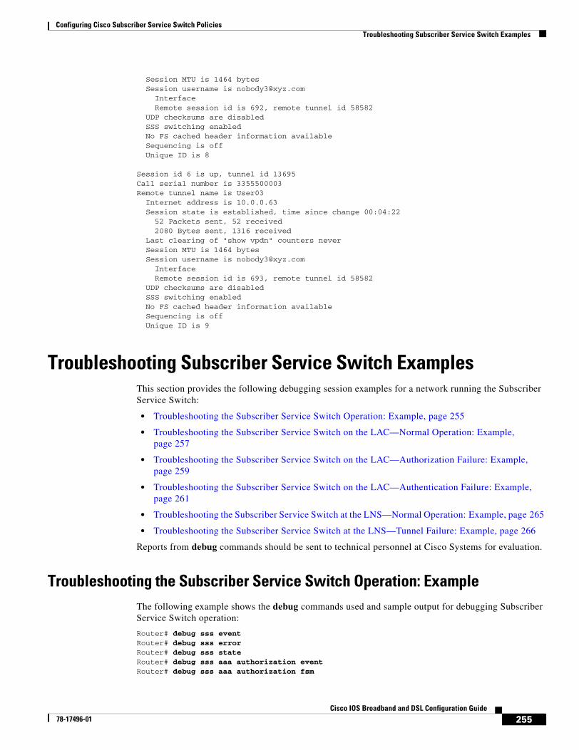
Configuring Cisco Subscriber Service Switch PoliciesTroubleshooting Subscriber Service Switch Examples
255Cisco IOS Broadband and DSL Configuration Guide
78-17496-01
Session MTU is 1464 bytes Session username is [email protected] Interface Remote session id is 692, remote tunnel id 58582 UDP checksums are disabled SSS switching enabled No FS cached header information available Sequencing is off Unique ID is 8
Session id 6 is up, tunnel id 13695Call serial number is 3355500003Remote tunnel name is User03 Internet address is 10.0.0.63 Session state is established, time since change 00:04:22 52 Packets sent, 52 received 2080 Bytes sent, 1316 received Last clearing of "show vpdn" counters never Session MTU is 1464 bytes Session username is [email protected] Interface Remote session id is 693, remote tunnel id 58582 UDP checksums are disabled SSS switching enabled No FS cached header information available Sequencing is off Unique ID is 9
Troubleshooting Subscriber Service Switch Examples This section provides the following debugging session examples for a network running the Subscriber Service Switch:
• Troubleshooting the Subscriber Service Switch Operation: Example, page 255
• Troubleshooting the Subscriber Service Switch on the LAC—Normal Operation: Example, page 257
• Troubleshooting the Subscriber Service Switch on the LAC—Authorization Failure: Example, page 259
• Troubleshooting the Subscriber Service Switch on the LAC—Authentication Failure: Example, page 261
• Troubleshooting the Subscriber Service Switch at the LNS—Normal Operation: Example, page 265
• Troubleshooting the Subscriber Service Switch at the LNS—Tunnel Failure: Example, page 266
Reports from debug commands should be sent to technical personnel at Cisco Systems for evaluation.
Troubleshooting the Subscriber Service Switch Operation: Example The following example shows the debug commands used and sample output for debugging Subscriber Service Switch operation:
Router# debug sss eventRouter# debug sss errorRouter# debug sss stateRouter# debug sss aaa authorization eventRouter# debug sss aaa authorization fsm
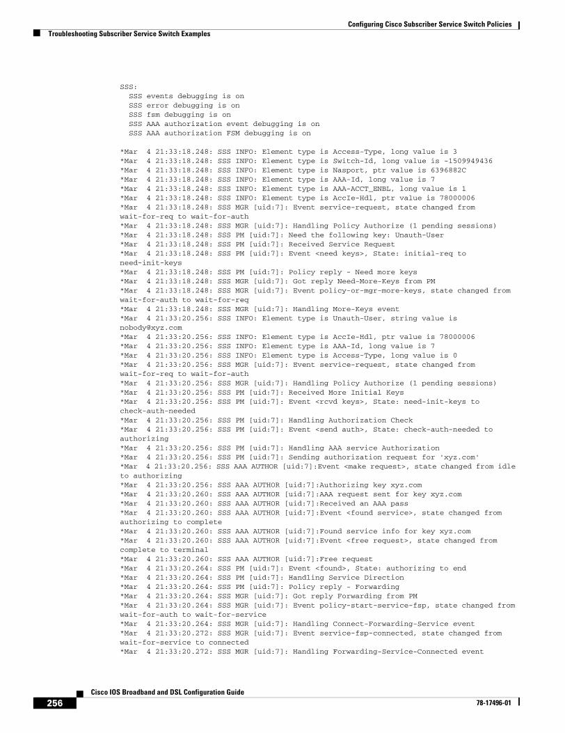
Configuring Cisco Subscriber Service Switch PoliciesTroubleshooting Subscriber Service Switch Examples
256Cisco IOS Broadband and DSL Configuration Guide
78-17496-01
SSS:SSS events debugging is onSSS error debugging is on
SSS fsm debugging is on SSS AAA authorization event debugging is on SSS AAA authorization FSM debugging is on
*Mar 4 21:33:18.248: SSS INFO: Element type is Access-Type, long value is 3*Mar 4 21:33:18.248: SSS INFO: Element type is Switch-Id, long value is -1509949436*Mar 4 21:33:18.248: SSS INFO: Element type is Nasport, ptr value is 6396882C*Mar 4 21:33:18.248: SSS INFO: Element type is AAA-Id, long value is 7*Mar 4 21:33:18.248: SSS INFO: Element type is AAA-ACCT_ENBL, long value is 1*Mar 4 21:33:18.248: SSS INFO: Element type is AccIe-Hdl, ptr value is 78000006*Mar 4 21:33:18.248: SSS MGR [uid:7]: Event service-request, state changed from wait-for-req to wait-for-auth*Mar 4 21:33:18.248: SSS MGR [uid:7]: Handling Policy Authorize (1 pending sessions)*Mar 4 21:33:18.248: SSS PM [uid:7]: Need the following key: Unauth-User*Mar 4 21:33:18.248: SSS PM [uid:7]: Received Service Request*Mar 4 21:33:18.248: SSS PM [uid:7]: Event <need keys>, State: initial-req to need-init-keys*Mar 4 21:33:18.248: SSS PM [uid:7]: Policy reply - Need more keys*Mar 4 21:33:18.248: SSS MGR [uid:7]: Got reply Need-More-Keys from PM*Mar 4 21:33:18.248: SSS MGR [uid:7]: Event policy-or-mgr-more-keys, state changed from wait-for-auth to wait-for-req*Mar 4 21:33:18.248: SSS MGR [uid:7]: Handling More-Keys event*Mar 4 21:33:20.256: SSS INFO: Element type is Unauth-User, string value is [email protected]*Mar 4 21:33:20.256: SSS INFO: Element type is AccIe-Hdl, ptr value is 78000006*Mar 4 21:33:20.256: SSS INFO: Element type is AAA-Id, long value is 7*Mar 4 21:33:20.256: SSS INFO: Element type is Access-Type, long value is 0*Mar 4 21:33:20.256: SSS MGR [uid:7]: Event service-request, state changed from wait-for-req to wait-for-auth*Mar 4 21:33:20.256: SSS MGR [uid:7]: Handling Policy Authorize (1 pending sessions)*Mar 4 21:33:20.256: SSS PM [uid:7]: Received More Initial Keys*Mar 4 21:33:20.256: SSS PM [uid:7]: Event <rcvd keys>, State: need-init-keys to check-auth-needed*Mar 4 21:33:20.256: SSS PM [uid:7]: Handling Authorization Check*Mar 4 21:33:20.256: SSS PM [uid:7]: Event <send auth>, State: check-auth-needed to authorizing*Mar 4 21:33:20.256: SSS PM [uid:7]: Handling AAA service Authorization*Mar 4 21:33:20.256: SSS PM [uid:7]: Sending authorization request for 'xyz.com'*Mar 4 21:33:20.256: SSS AAA AUTHOR [uid:7]:Event <make request>, state changed from idle to authorizing*Mar 4 21:33:20.256: SSS AAA AUTHOR [uid:7]:Authorizing key xyz.com*Mar 4 21:33:20.260: SSS AAA AUTHOR [uid:7]:AAA request sent for key xyz.com*Mar 4 21:33:20.260: SSS AAA AUTHOR [uid:7]:Received an AAA pass*Mar 4 21:33:20.260: SSS AAA AUTHOR [uid:7]:Event <found service>, state changed from authorizing to complete*Mar 4 21:33:20.260: SSS AAA AUTHOR [uid:7]:Found service info for key xyz.com*Mar 4 21:33:20.260: SSS AAA AUTHOR [uid:7]:Event <free request>, state changed from complete to terminal*Mar 4 21:33:20.260: SSS AAA AUTHOR [uid:7]:Free request*Mar 4 21:33:20.264: SSS PM [uid:7]: Event <found>, State: authorizing to end*Mar 4 21:33:20.264: SSS PM [uid:7]: Handling Service Direction*Mar 4 21:33:20.264: SSS PM [uid:7]: Policy reply - Forwarding*Mar 4 21:33:20.264: SSS MGR [uid:7]: Got reply Forwarding from PM*Mar 4 21:33:20.264: SSS MGR [uid:7]: Event policy-start-service-fsp, state changed from wait-for-auth to wait-for-service*Mar 4 21:33:20.264: SSS MGR [uid:7]: Handling Connect-Forwarding-Service event*Mar 4 21:33:20.272: SSS MGR [uid:7]: Event service-fsp-connected, state changed from wait-for-service to connected*Mar 4 21:33:20.272: SSS MGR [uid:7]: Handling Forwarding-Service-Connected event
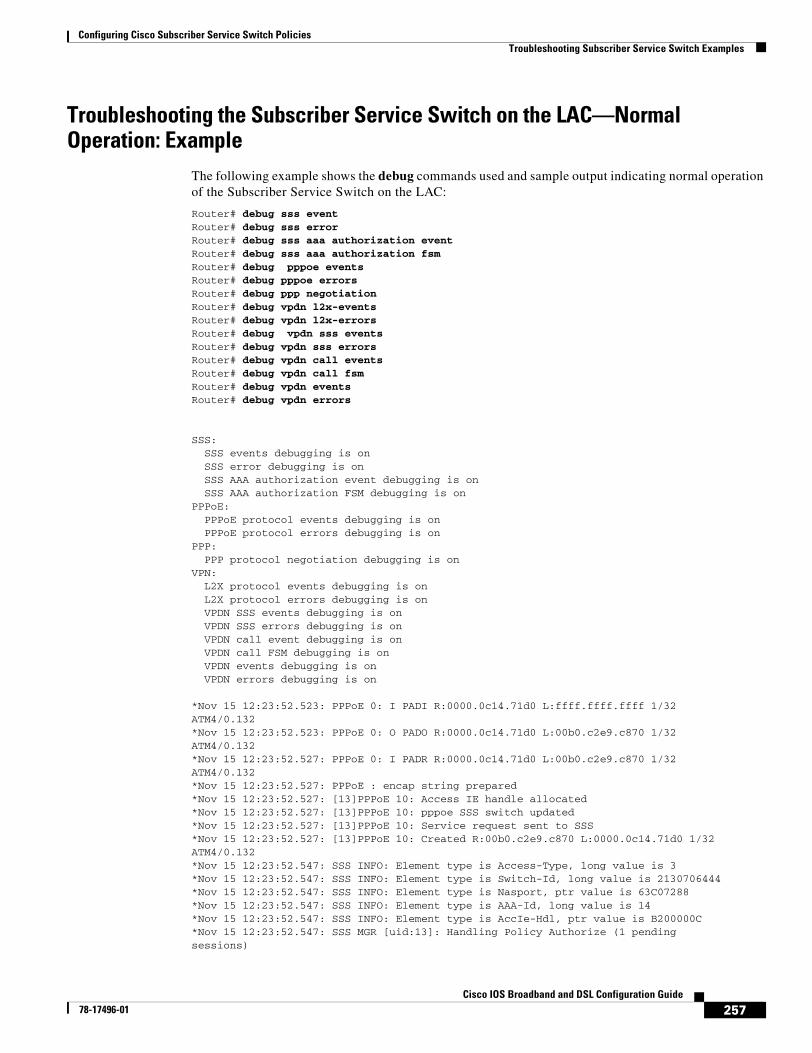
Configuring Cisco Subscriber Service Switch PoliciesTroubleshooting Subscriber Service Switch Examples
257Cisco IOS Broadband and DSL Configuration Guide
78-17496-01
Troubleshooting the Subscriber Service Switch on the LAC—Normal Operation: Example
The following example shows the debug commands used and sample output indicating normal operation of the Subscriber Service Switch on the LAC:
Router# debug sss eventRouter# debug sss errorRouter# debug sss aaa authorization eventRouter# debug sss aaa authorization fsmRouter# debug pppoe eventsRouter# debug pppoe errorsRouter# debug ppp negotiationRouter# debug vpdn l2x-eventsRouter# debug vpdn l2x-errorsRouter# debug vpdn sss eventsRouter# debug vpdn sss errorsRouter# debug vpdn call eventsRouter# debug vpdn call fsmRouter# debug vpdn eventsRouter# debug vpdn errors
SSS: SSS events debugging is on SSS error debugging is on SSS AAA authorization event debugging is on SSS AAA authorization FSM debugging is onPPPoE: PPPoE protocol events debugging is on PPPoE protocol errors debugging is onPPP: PPP protocol negotiation debugging is onVPN: L2X protocol events debugging is on L2X protocol errors debugging is on VPDN SSS events debugging is on VPDN SSS errors debugging is on VPDN call event debugging is on VPDN call FSM debugging is on VPDN events debugging is on VPDN errors debugging is on
*Nov 15 12:23:52.523: PPPoE 0: I PADI R:0000.0c14.71d0 L:ffff.ffff.ffff 1/32ATM4/0.132*Nov 15 12:23:52.523: PPPoE 0: O PADO R:0000.0c14.71d0 L:00b0.c2e9.c870 1/32ATM4/0.132*Nov 15 12:23:52.527: PPPoE 0: I PADR R:0000.0c14.71d0 L:00b0.c2e9.c870 1/32ATM4/0.132*Nov 15 12:23:52.527: PPPoE : encap string prepared*Nov 15 12:23:52.527: [13]PPPoE 10: Access IE handle allocated*Nov 15 12:23:52.527: [13]PPPoE 10: pppoe SSS switch updated*Nov 15 12:23:52.527: [13]PPPoE 10: Service request sent to SSS*Nov 15 12:23:52.527: [13]PPPoE 10: Created R:00b0.c2e9.c870 L:0000.0c14.71d0 1/32ATM4/0.132*Nov 15 12:23:52.547: SSS INFO: Element type is Access-Type, long value is 3*Nov 15 12:23:52.547: SSS INFO: Element type is Switch-Id, long value is 2130706444*Nov 15 12:23:52.547: SSS INFO: Element type is Nasport, ptr value is 63C07288*Nov 15 12:23:52.547: SSS INFO: Element type is AAA-Id, long value is 14*Nov 15 12:23:52.547: SSS INFO: Element type is AccIe-Hdl, ptr value is B200000C*Nov 15 12:23:52.547: SSS MGR [uid:13]: Handling Policy Authorize (1 pendingsessions)
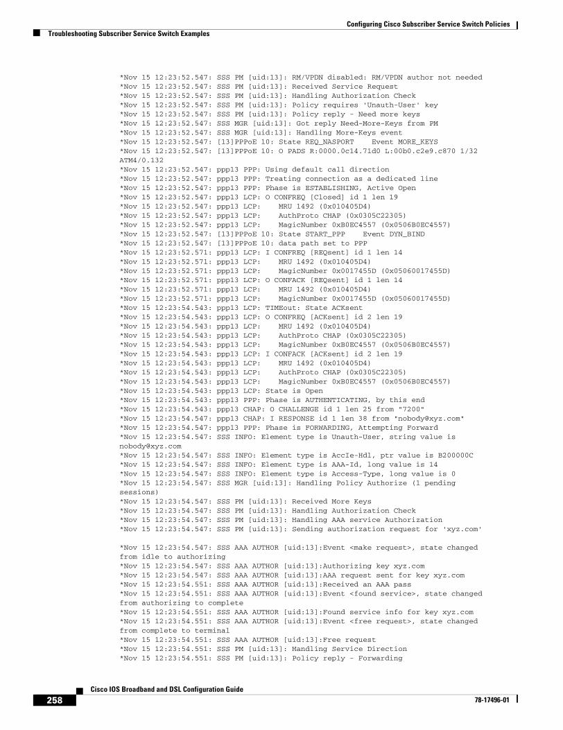
Configuring Cisco Subscriber Service Switch PoliciesTroubleshooting Subscriber Service Switch Examples
258Cisco IOS Broadband and DSL Configuration Guide
78-17496-01
*Nov 15 12:23:52.547: SSS PM [uid:13]: RM/VPDN disabled: RM/VPDN author not needed*Nov 15 12:23:52.547: SSS PM [uid:13]: Received Service Request*Nov 15 12:23:52.547: SSS PM [uid:13]: Handling Authorization Check*Nov 15 12:23:52.547: SSS PM [uid:13]: Policy requires 'Unauth-User' key*Nov 15 12:23:52.547: SSS PM [uid:13]: Policy reply - Need more keys*Nov 15 12:23:52.547: SSS MGR [uid:13]: Got reply Need-More-Keys from PM*Nov 15 12:23:52.547: SSS MGR [uid:13]: Handling More-Keys event*Nov 15 12:23:52.547: [13]PPPoE 10: State REQ_NASPORT Event MORE_KEYS*Nov 15 12:23:52.547: [13]PPPoE 10: O PADS R:0000.0c14.71d0 L:00b0.c2e9.c870 1/32ATM4/0.132*Nov 15 12:23:52.547: ppp13 PPP: Using default call direction*Nov 15 12:23:52.547: ppp13 PPP: Treating connection as a dedicated line*Nov 15 12:23:52.547: ppp13 PPP: Phase is ESTABLISHING, Active Open*Nov 15 12:23:52.547: ppp13 LCP: O CONFREQ [Closed] id 1 len 19*Nov 15 12:23:52.547: ppp13 LCP: MRU 1492 (0x010405D4)*Nov 15 12:23:52.547: ppp13 LCP: AuthProto CHAP (0x0305C22305)*Nov 15 12:23:52.547: ppp13 LCP: MagicNumber 0xB0EC4557 (0x0506B0EC4557)*Nov 15 12:23:52.547: [13]PPPoE 10: State START_PPP Event DYN_BIND*Nov 15 12:23:52.547: [13]PPPoE 10: data path set to PPP*Nov 15 12:23:52.571: ppp13 LCP: I CONFREQ [REQsent] id 1 len 14*Nov 15 12:23:52.571: ppp13 LCP: MRU 1492 (0x010405D4)*Nov 15 12:23:52.571: ppp13 LCP: MagicNumber 0x0017455D (0x05060017455D)*Nov 15 12:23:52.571: ppp13 LCP: O CONFACK [REQsent] id 1 len 14*Nov 15 12:23:52.571: ppp13 LCP: MRU 1492 (0x010405D4)*Nov 15 12:23:52.571: ppp13 LCP: MagicNumber 0x0017455D (0x05060017455D)*Nov 15 12:23:54.543: ppp13 LCP: TIMEout: State ACKsent*Nov 15 12:23:54.543: ppp13 LCP: O CONFREQ [ACKsent] id 2 len 19*Nov 15 12:23:54.543: ppp13 LCP: MRU 1492 (0x010405D4)*Nov 15 12:23:54.543: ppp13 LCP: AuthProto CHAP (0x0305C22305)*Nov 15 12:23:54.543: ppp13 LCP: MagicNumber 0xB0EC4557 (0x0506B0EC4557)*Nov 15 12:23:54.543: ppp13 LCP: I CONFACK [ACKsent] id 2 len 19*Nov 15 12:23:54.543: ppp13 LCP: MRU 1492 (0x010405D4)*Nov 15 12:23:54.543: ppp13 LCP: AuthProto CHAP (0x0305C22305)*Nov 15 12:23:54.543: ppp13 LCP: MagicNumber 0xB0EC4557 (0x0506B0EC4557)*Nov 15 12:23:54.543: ppp13 LCP: State is Open*Nov 15 12:23:54.543: ppp13 PPP: Phase is AUTHENTICATING, by this end*Nov 15 12:23:54.543: ppp13 CHAP: O CHALLENGE id 1 len 25 from "7200"*Nov 15 12:23:54.547: ppp13 CHAP: I RESPONSE id 1 len 38 from "[email protected]"*Nov 15 12:23:54.547: ppp13 PPP: Phase is FORWARDING, Attempting Forward*Nov 15 12:23:54.547: SSS INFO: Element type is Unauth-User, string value [email protected]*Nov 15 12:23:54.547: SSS INFO: Element type is AccIe-Hdl, ptr value is B200000C*Nov 15 12:23:54.547: SSS INFO: Element type is AAA-Id, long value is 14*Nov 15 12:23:54.547: SSS INFO: Element type is Access-Type, long value is 0*Nov 15 12:23:54.547: SSS MGR [uid:13]: Handling Policy Authorize (1 pendingsessions)*Nov 15 12:23:54.547: SSS PM [uid:13]: Received More Keys*Nov 15 12:23:54.547: SSS PM [uid:13]: Handling Authorization Check*Nov 15 12:23:54.547: SSS PM [uid:13]: Handling AAA service Authorization*Nov 15 12:23:54.547: SSS PM [uid:13]: Sending authorization request for 'xyz.com'
*Nov 15 12:23:54.547: SSS AAA AUTHOR [uid:13]:Event <make request>, state changedfrom idle to authorizing*Nov 15 12:23:54.547: SSS AAA AUTHOR [uid:13]:Authorizing key xyz.com*Nov 15 12:23:54.547: SSS AAA AUTHOR [uid:13]:AAA request sent for key xyz.com*Nov 15 12:23:54.551: SSS AAA AUTHOR [uid:13]:Received an AAA pass*Nov 15 12:23:54.551: SSS AAA AUTHOR [uid:13]:Event <found service>, state changedfrom authorizing to complete*Nov 15 12:23:54.551: SSS AAA AUTHOR [uid:13]:Found service info for key xyz.com*Nov 15 12:23:54.551: SSS AAA AUTHOR [uid:13]:Event <free request>, state changedfrom complete to terminal*Nov 15 12:23:54.551: SSS AAA AUTHOR [uid:13]:Free request*Nov 15 12:23:54.551: SSS PM [uid:13]: Handling Service Direction*Nov 15 12:23:54.551: SSS PM [uid:13]: Policy reply - Forwarding
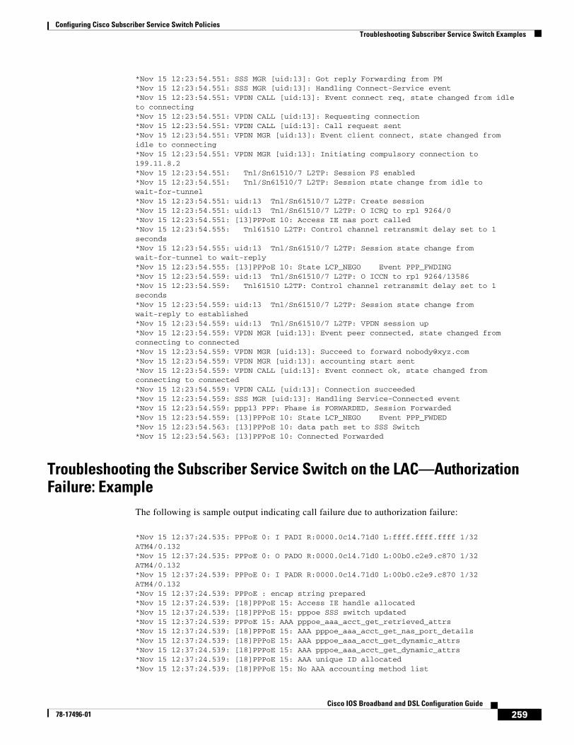
Configuring Cisco Subscriber Service Switch PoliciesTroubleshooting Subscriber Service Switch Examples
259Cisco IOS Broadband and DSL Configuration Guide
78-17496-01
*Nov 15 12:23:54.551: SSS MGR [uid:13]: Got reply Forwarding from PM*Nov 15 12:23:54.551: SSS MGR [uid:13]: Handling Connect-Service event*Nov 15 12:23:54.551: VPDN CALL [uid:13]: Event connect req, state changed from idleto connecting*Nov 15 12:23:54.551: VPDN CALL [uid:13]: Requesting connection*Nov 15 12:23:54.551: VPDN CALL [uid:13]: Call request sent*Nov 15 12:23:54.551: VPDN MGR [uid:13]: Event client connect, state changed fromidle to connecting*Nov 15 12:23:54.551: VPDN MGR [uid:13]: Initiating compulsory connection to199.11.8.2*Nov 15 12:23:54.551: Tnl/Sn61510/7 L2TP: Session FS enabled*Nov 15 12:23:54.551: Tnl/Sn61510/7 L2TP: Session state change from idle towait-for-tunnel*Nov 15 12:23:54.551: uid:13 Tnl/Sn61510/7 L2TP: Create session*Nov 15 12:23:54.551: uid:13 Tnl/Sn61510/7 L2TP: O ICRQ to rp1 9264/0*Nov 15 12:23:54.551: [13]PPPoE 10: Access IE nas port called*Nov 15 12:23:54.555: Tnl61510 L2TP: Control channel retransmit delay set to 1seconds*Nov 15 12:23:54.555: uid:13 Tnl/Sn61510/7 L2TP: Session state change fromwait-for-tunnel to wait-reply*Nov 15 12:23:54.555: [13]PPPoE 10: State LCP_NEGO Event PPP_FWDING*Nov 15 12:23:54.559: uid:13 Tnl/Sn61510/7 L2TP: O ICCN to rp1 9264/13586*Nov 15 12:23:54.559: Tnl61510 L2TP: Control channel retransmit delay set to 1seconds*Nov 15 12:23:54.559: uid:13 Tnl/Sn61510/7 L2TP: Session state change fromwait-reply to established*Nov 15 12:23:54.559: uid:13 Tnl/Sn61510/7 L2TP: VPDN session up*Nov 15 12:23:54.559: VPDN MGR [uid:13]: Event peer connected, state changed fromconnecting to connected*Nov 15 12:23:54.559: VPDN MGR [uid:13]: Succeed to forward [email protected]*Nov 15 12:23:54.559: VPDN MGR [uid:13]: accounting start sent*Nov 15 12:23:54.559: VPDN CALL [uid:13]: Event connect ok, state changed fromconnecting to connected*Nov 15 12:23:54.559: VPDN CALL [uid:13]: Connection succeeded*Nov 15 12:23:54.559: SSS MGR [uid:13]: Handling Service-Connected event*Nov 15 12:23:54.559: ppp13 PPP: Phase is FORWARDED, Session Forwarded*Nov 15 12:23:54.559: [13]PPPoE 10: State LCP_NEGO Event PPP_FWDED*Nov 15 12:23:54.563: [13]PPPoE 10: data path set to SSS Switch*Nov 15 12:23:54.563: [13]PPPoE 10: Connected Forwarded
Troubleshooting the Subscriber Service Switch on the LAC—Authorization Failure: Example
The following is sample output indicating call failure due to authorization failure:
*Nov 15 12:37:24.535: PPPoE 0: I PADI R:0000.0c14.71d0 L:ffff.ffff.ffff 1/32ATM4/0.132*Nov 15 12:37:24.535: PPPoE 0: O PADO R:0000.0c14.71d0 L:00b0.c2e9.c870 1/32ATM4/0.132*Nov 15 12:37:24.539: PPPoE 0: I PADR R:0000.0c14.71d0 L:00b0.c2e9.c870 1/32ATM4/0.132*Nov 15 12:37:24.539: PPPoE : encap string prepared*Nov 15 12:37:24.539: [18]PPPoE 15: Access IE handle allocated*Nov 15 12:37:24.539: [18]PPPoE 15: pppoe SSS switch updated*Nov 15 12:37:24.539: PPPoE 15: AAA pppoe_aaa_acct_get_retrieved_attrs*Nov 15 12:37:24.539: [18]PPPoE 15: AAA pppoe_aaa_acct_get_nas_port_details*Nov 15 12:37:24.539: [18]PPPoE 15: AAA pppoe_aaa_acct_get_dynamic_attrs*Nov 15 12:37:24.539: [18]PPPoE 15: AAA pppoe_aaa_acct_get_dynamic_attrs*Nov 15 12:37:24.539: [18]PPPoE 15: AAA unique ID allocated*Nov 15 12:37:24.539: [18]PPPoE 15: No AAA accounting method list
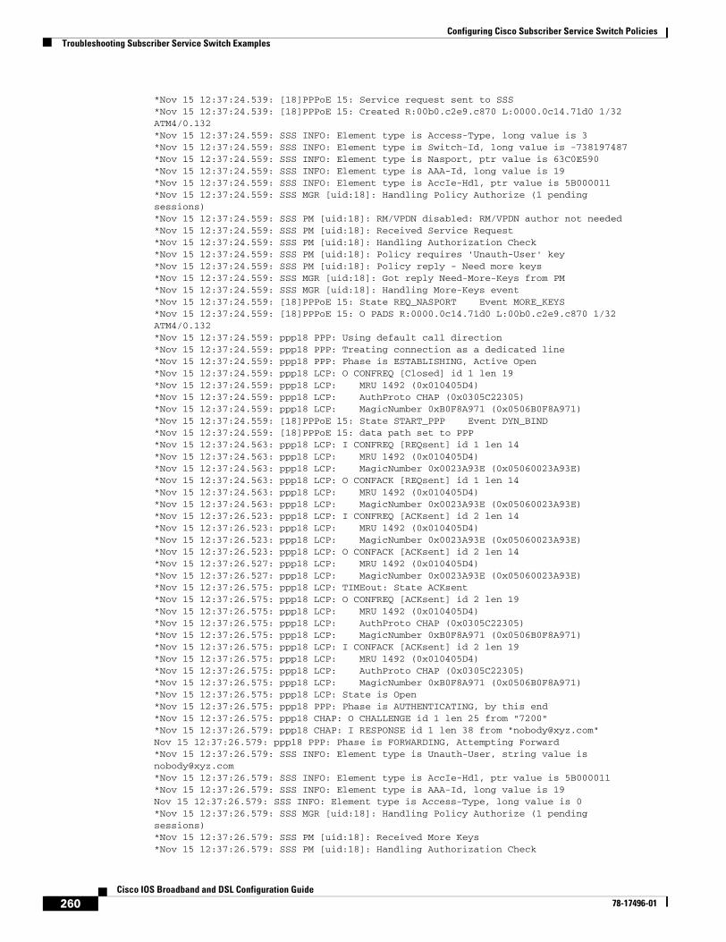
Configuring Cisco Subscriber Service Switch PoliciesTroubleshooting Subscriber Service Switch Examples
260Cisco IOS Broadband and DSL Configuration Guide
78-17496-01
*Nov 15 12:37:24.539: [18]PPPoE 15: Service request sent to SSS*Nov 15 12:37:24.539: [18]PPPoE 15: Created R:00b0.c2e9.c870 L:0000.0c14.71d0 1/32ATM4/0.132*Nov 15 12:37:24.559: SSS INFO: Element type is Access-Type, long value is 3*Nov 15 12:37:24.559: SSS INFO: Element type is Switch-Id, long value is -738197487*Nov 15 12:37:24.559: SSS INFO: Element type is Nasport, ptr value is 63C0E590*Nov 15 12:37:24.559: SSS INFO: Element type is AAA-Id, long value is 19*Nov 15 12:37:24.559: SSS INFO: Element type is AccIe-Hdl, ptr value is 5B000011*Nov 15 12:37:24.559: SSS MGR [uid:18]: Handling Policy Authorize (1 pendingsessions)*Nov 15 12:37:24.559: SSS PM [uid:18]: RM/VPDN disabled: RM/VPDN author not needed*Nov 15 12:37:24.559: SSS PM [uid:18]: Received Service Request*Nov 15 12:37:24.559: SSS PM [uid:18]: Handling Authorization Check*Nov 15 12:37:24.559: SSS PM [uid:18]: Policy requires 'Unauth-User' key*Nov 15 12:37:24.559: SSS PM [uid:18]: Policy reply - Need more keys*Nov 15 12:37:24.559: SSS MGR [uid:18]: Got reply Need-More-Keys from PM*Nov 15 12:37:24.559: SSS MGR [uid:18]: Handling More-Keys event*Nov 15 12:37:24.559: [18]PPPoE 15: State REQ_NASPORT Event MORE_KEYS*Nov 15 12:37:24.559: [18]PPPoE 15: O PADS R:0000.0c14.71d0 L:00b0.c2e9.c870 1/32ATM4/0.132*Nov 15 12:37:24.559: ppp18 PPP: Using default call direction*Nov 15 12:37:24.559: ppp18 PPP: Treating connection as a dedicated line*Nov 15 12:37:24.559: ppp18 PPP: Phase is ESTABLISHING, Active Open*Nov 15 12:37:24.559: ppp18 LCP: O CONFREQ [Closed] id 1 len 19*Nov 15 12:37:24.559: ppp18 LCP: MRU 1492 (0x010405D4)*Nov 15 12:37:24.559: ppp18 LCP: AuthProto CHAP (0x0305C22305)*Nov 15 12:37:24.559: ppp18 LCP: MagicNumber 0xB0F8A971 (0x0506B0F8A971)*Nov 15 12:37:24.559: [18]PPPoE 15: State START_PPP Event DYN_BIND*Nov 15 12:37:24.559: [18]PPPoE 15: data path set to PPP*Nov 15 12:37:24.563: ppp18 LCP: I CONFREQ [REQsent] id 1 len 14*Nov 15 12:37:24.563: ppp18 LCP: MRU 1492 (0x010405D4)*Nov 15 12:37:24.563: ppp18 LCP: MagicNumber 0x0023A93E (0x05060023A93E)*Nov 15 12:37:24.563: ppp18 LCP: O CONFACK [REQsent] id 1 len 14*Nov 15 12:37:24.563: ppp18 LCP: MRU 1492 (0x010405D4)*Nov 15 12:37:24.563: ppp18 LCP: MagicNumber 0x0023A93E (0x05060023A93E)*Nov 15 12:37:26.523: ppp18 LCP: I CONFREQ [ACKsent] id 2 len 14*Nov 15 12:37:26.523: ppp18 LCP: MRU 1492 (0x010405D4)*Nov 15 12:37:26.523: ppp18 LCP: MagicNumber 0x0023A93E (0x05060023A93E)*Nov 15 12:37:26.523: ppp18 LCP: O CONFACK [ACKsent] id 2 len 14*Nov 15 12:37:26.527: ppp18 LCP: MRU 1492 (0x010405D4)*Nov 15 12:37:26.527: ppp18 LCP: MagicNumber 0x0023A93E (0x05060023A93E)*Nov 15 12:37:26.575: ppp18 LCP: TIMEout: State ACKsent*Nov 15 12:37:26.575: ppp18 LCP: O CONFREQ [ACKsent] id 2 len 19*Nov 15 12:37:26.575: ppp18 LCP: MRU 1492 (0x010405D4)*Nov 15 12:37:26.575: ppp18 LCP: AuthProto CHAP (0x0305C22305)*Nov 15 12:37:26.575: ppp18 LCP: MagicNumber 0xB0F8A971 (0x0506B0F8A971)*Nov 15 12:37:26.575: ppp18 LCP: I CONFACK [ACKsent] id 2 len 19*Nov 15 12:37:26.575: ppp18 LCP: MRU 1492 (0x010405D4)*Nov 15 12:37:26.575: ppp18 LCP: AuthProto CHAP (0x0305C22305)*Nov 15 12:37:26.575: ppp18 LCP: MagicNumber 0xB0F8A971 (0x0506B0F8A971)*Nov 15 12:37:26.575: ppp18 LCP: State is Open*Nov 15 12:37:26.575: ppp18 PPP: Phase is AUTHENTICATING, by this end*Nov 15 12:37:26.575: ppp18 CHAP: O CHALLENGE id 1 len 25 from "7200"*Nov 15 12:37:26.579: ppp18 CHAP: I RESPONSE id 1 len 38 from "[email protected]"Nov 15 12:37:26.579: ppp18 PPP: Phase is FORWARDING, Attempting Forward*Nov 15 12:37:26.579: SSS INFO: Element type is Unauth-User, string value [email protected]*Nov 15 12:37:26.579: SSS INFO: Element type is AccIe-Hdl, ptr value is 5B000011*Nov 15 12:37:26.579: SSS INFO: Element type is AAA-Id, long value is 19Nov 15 12:37:26.579: SSS INFO: Element type is Access-Type, long value is 0*Nov 15 12:37:26.579: SSS MGR [uid:18]: Handling Policy Authorize (1 pendingsessions)*Nov 15 12:37:26.579: SSS PM [uid:18]: Received More Keys*Nov 15 12:37:26.579: SSS PM [uid:18]: Handling Authorization Check
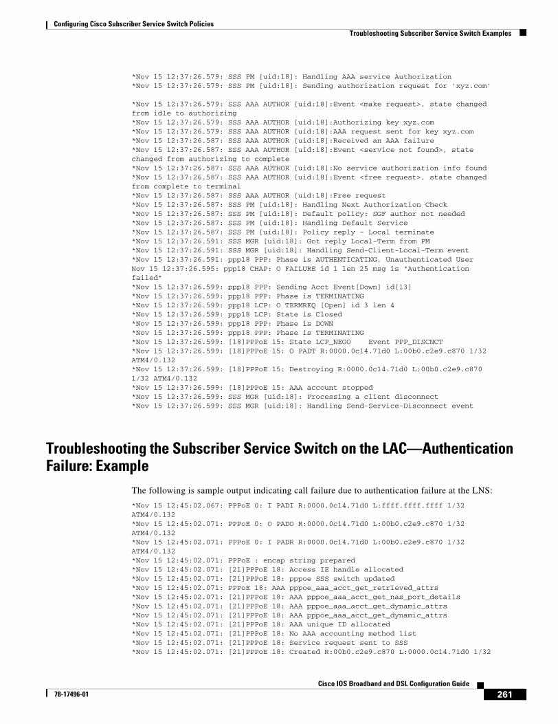
Configuring Cisco Subscriber Service Switch PoliciesTroubleshooting Subscriber Service Switch Examples
261Cisco IOS Broadband and DSL Configuration Guide
78-17496-01
*Nov 15 12:37:26.579: SSS PM [uid:18]: Handling AAA service Authorization*Nov 15 12:37:26.579: SSS PM [uid:18]: Sending authorization request for 'xyz.com'
*Nov 15 12:37:26.579: SSS AAA AUTHOR [uid:18]:Event <make request>, state changedfrom idle to authorizing*Nov 15 12:37:26.579: SSS AAA AUTHOR [uid:18]:Authorizing key xyz.com*Nov 15 12:37:26.579: SSS AAA AUTHOR [uid:18]:AAA request sent for key xyz.com*Nov 15 12:37:26.587: SSS AAA AUTHOR [uid:18]:Received an AAA failure*Nov 15 12:37:26.587: SSS AAA AUTHOR [uid:18]:Event <service not found>, statechanged from authorizing to complete*Nov 15 12:37:26.587: SSS AAA AUTHOR [uid:18]:No service authorization info found*Nov 15 12:37:26.587: SSS AAA AUTHOR [uid:18]:Event <free request>, state changedfrom complete to terminal*Nov 15 12:37:26.587: SSS AAA AUTHOR [uid:18]:Free request*Nov 15 12:37:26.587: SSS PM [uid:18]: Handling Next Authorization Check*Nov 15 12:37:26.587: SSS PM [uid:18]: Default policy: SGF author not needed*Nov 15 12:37:26.587: SSS PM [uid:18]: Handling Default Service*Nov 15 12:37:26.587: SSS PM [uid:18]: Policy reply - Local terminate*Nov 15 12:37:26.591: SSS MGR [uid:18]: Got reply Local-Term from PM*Nov 15 12:37:26.591: SSS MGR [uid:18]: Handling Send-Client-Local-Term event*Nov 15 12:37:26.591: ppp18 PPP: Phase is AUTHENTICATING, Unauthenticated UserNov 15 12:37:26.595: ppp18 CHAP: O FAILURE id 1 len 25 msg is "Authenticationfailed"*Nov 15 12:37:26.599: ppp18 PPP: Sending Acct Event[Down] id[13]*Nov 15 12:37:26.599: ppp18 PPP: Phase is TERMINATING*Nov 15 12:37:26.599: ppp18 LCP: O TERMREQ [Open] id 3 len 4*Nov 15 12:37:26.599: ppp18 LCP: State is Closed*Nov 15 12:37:26.599: ppp18 PPP: Phase is DOWN*Nov 15 12:37:26.599: ppp18 PPP: Phase is TERMINATING*Nov 15 12:37:26.599: [18]PPPoE 15: State LCP_NEGO Event PPP_DISCNCT*Nov 15 12:37:26.599: [18]PPPoE 15: O PADT R:0000.0c14.71d0 L:00b0.c2e9.c870 1/32ATM4/0.132*Nov 15 12:37:26.599: [18]PPPoE 15: Destroying R:0000.0c14.71d0 L:00b0.c2e9.c8701/32 ATM4/0.132*Nov 15 12:37:26.599: [18]PPPoE 15: AAA account stopped*Nov 15 12:37:26.599: SSS MGR [uid:18]: Processing a client disconnect*Nov 15 12:37:26.599: SSS MGR [uid:18]: Handling Send-Service-Disconnect event
Troubleshooting the Subscriber Service Switch on the LAC—Authentication Failure: Example
The following is sample output indicating call failure due to authentication failure at the LNS:
*Nov 15 12:45:02.067: PPPoE 0: I PADI R:0000.0c14.71d0 L:ffff.ffff.ffff 1/32ATM4/0.132*Nov 15 12:45:02.071: PPPoE 0: O PADO R:0000.0c14.71d0 L:00b0.c2e9.c870 1/32ATM4/0.132*Nov 15 12:45:02.071: PPPoE 0: I PADR R:0000.0c14.71d0 L:00b0.c2e9.c870 1/32ATM4/0.132*Nov 15 12:45:02.071: PPPoE : encap string prepared*Nov 15 12:45:02.071: [21]PPPoE 18: Access IE handle allocated*Nov 15 12:45:02.071: [21]PPPoE 18: pppoe SSS switch updated*Nov 15 12:45:02.071: PPPoE 18: AAA pppoe_aaa_acct_get_retrieved_attrs*Nov 15 12:45:02.071: [21]PPPoE 18: AAA pppoe_aaa_acct_get_nas_port_details*Nov 15 12:45:02.071: [21]PPPoE 18: AAA pppoe_aaa_acct_get_dynamic_attrs*Nov 15 12:45:02.071: [21]PPPoE 18: AAA pppoe_aaa_acct_get_dynamic_attrs*Nov 15 12:45:02.071: [21]PPPoE 18: AAA unique ID allocated*Nov 15 12:45:02.071: [21]PPPoE 18: No AAA accounting method list*Nov 15 12:45:02.071: [21]PPPoE 18: Service request sent to SSS*Nov 15 12:45:02.071: [21]PPPoE 18: Created R:00b0.c2e9.c870 L:0000.0c14.71d0 1/32
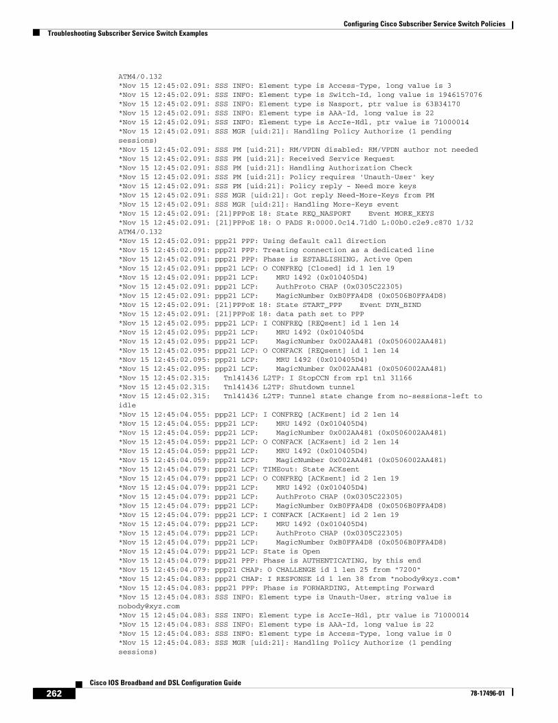
Configuring Cisco Subscriber Service Switch PoliciesTroubleshooting Subscriber Service Switch Examples
262Cisco IOS Broadband and DSL Configuration Guide
78-17496-01
ATM4/0.132*Nov 15 12:45:02.091: SSS INFO: Element type is Access-Type, long value is 3*Nov 15 12:45:02.091: SSS INFO: Element type is Switch-Id, long value is 1946157076*Nov 15 12:45:02.091: SSS INFO: Element type is Nasport, ptr value is 63B34170*Nov 15 12:45:02.091: SSS INFO: Element type is AAA-Id, long value is 22*Nov 15 12:45:02.091: SSS INFO: Element type is AccIe-Hdl, ptr value is 71000014*Nov 15 12:45:02.091: SSS MGR [uid:21]: Handling Policy Authorize (1 pendingsessions)*Nov 15 12:45:02.091: SSS PM [uid:21]: RM/VPDN disabled: RM/VPDN author not needed*Nov 15 12:45:02.091: SSS PM [uid:21]: Received Service Request*Nov 15 12:45:02.091: SSS PM [uid:21]: Handling Authorization Check*Nov 15 12:45:02.091: SSS PM [uid:21]: Policy requires 'Unauth-User' key*Nov 15 12:45:02.091: SSS PM [uid:21]: Policy reply - Need more keys*Nov 15 12:45:02.091: SSS MGR [uid:21]: Got reply Need-More-Keys from PM*Nov 15 12:45:02.091: SSS MGR [uid:21]: Handling More-Keys event*Nov 15 12:45:02.091: [21]PPPoE 18: State REQ_NASPORT Event MORE_KEYS*Nov 15 12:45:02.091: [21]PPPoE 18: O PADS R:0000.0c14.71d0 L:00b0.c2e9.c870 1/32ATM4/0.132*Nov 15 12:45:02.091: ppp21 PPP: Using default call direction*Nov 15 12:45:02.091: ppp21 PPP: Treating connection as a dedicated line*Nov 15 12:45:02.091: ppp21 PPP: Phase is ESTABLISHING, Active Open*Nov 15 12:45:02.091: ppp21 LCP: O CONFREQ [Closed] id 1 len 19*Nov 15 12:45:02.091: ppp21 LCP: MRU 1492 (0x010405D4)*Nov 15 12:45:02.091: ppp21 LCP: AuthProto CHAP (0x0305C22305)*Nov 15 12:45:02.091: ppp21 LCP: MagicNumber 0xB0FFA4D8 (0x0506B0FFA4D8)*Nov 15 12:45:02.091: [21]PPPoE 18: State START_PPP Event DYN_BIND*Nov 15 12:45:02.091: [21]PPPoE 18: data path set to PPP*Nov 15 12:45:02.095: ppp21 LCP: I CONFREQ [REQsent] id 1 len 14*Nov 15 12:45:02.095: ppp21 LCP: MRU 1492 (0x010405D4*Nov 15 12:45:02.095: ppp21 LCP: MagicNumber 0x002AA481 (0x0506002AA481)*Nov 15 12:45:02.095: ppp21 LCP: O CONFACK [REQsent] id 1 len 14*Nov 15 12:45:02.095: ppp21 LCP: MRU 1492 (0x010405D4)*Nov 15 12:45:02.095: ppp21 LCP: MagicNumber 0x002AA481 (0x0506002AA481)*Nov 15 12:45:02.315: Tnl41436 L2TP: I StopCCN from rp1 tnl 31166*Nov 15 12:45:02.315: Tnl41436 L2TP: Shutdown tunnel*Nov 15 12:45:02.315: Tnl41436 L2TP: Tunnel state change from no-sessions-left toidle*Nov 15 12:45:04.055: ppp21 LCP: I CONFREQ [ACKsent] id 2 len 14*Nov 15 12:45:04.055: ppp21 LCP: MRU 1492 (0x010405D4)*Nov 15 12:45:04.059: ppp21 LCP: MagicNumber 0x002AA481 (0x0506002AA481)*Nov 15 12:45:04.059: ppp21 LCP: O CONFACK [ACKsent] id 2 len 14*Nov 15 12:45:04.059: ppp21 LCP: MRU 1492 (0x010405D4)*Nov 15 12:45:04.059: ppp21 LCP: MagicNumber 0x002AA481 (0x0506002AA481)*Nov 15 12:45:04.079: ppp21 LCP: TIMEout: State ACKsent*Nov 15 12:45:04.079: ppp21 LCP: O CONFREQ [ACKsent] id 2 len 19*Nov 15 12:45:04.079: ppp21 LCP: MRU 1492 (0x010405D4)*Nov 15 12:45:04.079: ppp21 LCP: AuthProto CHAP (0x0305C22305)*Nov 15 12:45:04.079: ppp21 LCP: MagicNumber 0xB0FFA4D8 (0x0506B0FFA4D8)*Nov 15 12:45:04.079: ppp21 LCP: I CONFACK [ACKsent] id 2 len 19*Nov 15 12:45:04.079: ppp21 LCP: MRU 1492 (0x010405D4)*Nov 15 12:45:04.079: ppp21 LCP: AuthProto CHAP (0x0305C22305)*Nov 15 12:45:04.079: ppp21 LCP: MagicNumber 0xB0FFA4D8 (0x0506B0FFA4D8)*Nov 15 12:45:04.079: ppp21 LCP: State is Open*Nov 15 12:45:04.079: ppp21 PPP: Phase is AUTHENTICATING, by this end*Nov 15 12:45:04.079: ppp21 CHAP: O CHALLENGE id 1 len 25 from "7200"*Nov 15 12:45:04.083: ppp21 CHAP: I RESPONSE id 1 len 38 from "[email protected]"*Nov 15 12:45:04.083: ppp21 PPP: Phase is FORWARDING, Attempting Forward*Nov 15 12:45:04.083: SSS INFO: Element type is Unauth-User, string value [email protected]*Nov 15 12:45:04.083: SSS INFO: Element type is AccIe-Hdl, ptr value is 71000014*Nov 15 12:45:04.083: SSS INFO: Element type is AAA-Id, long value is 22*Nov 15 12:45:04.083: SSS INFO: Element type is Access-Type, long value is 0*Nov 15 12:45:04.083: SSS MGR [uid:21]: Handling Policy Authorize (1 pendingsessions)
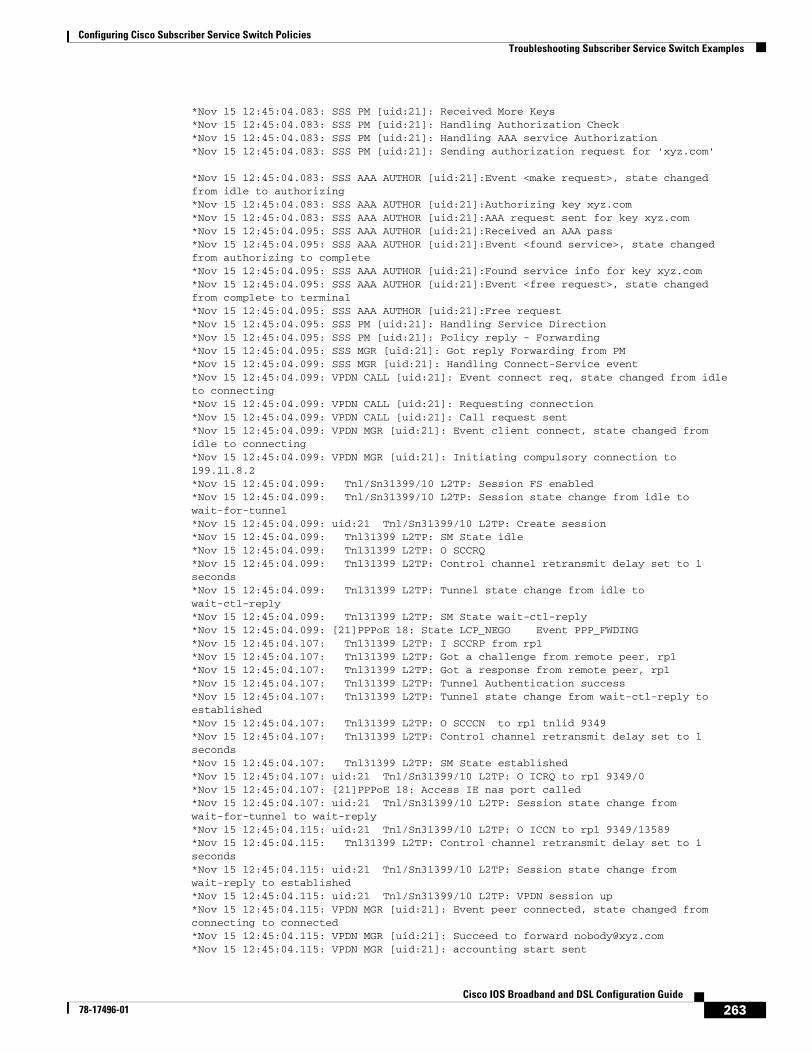
Configuring Cisco Subscriber Service Switch PoliciesTroubleshooting Subscriber Service Switch Examples
263Cisco IOS Broadband and DSL Configuration Guide
78-17496-01
*Nov 15 12:45:04.083: SSS PM [uid:21]: Received More Keys*Nov 15 12:45:04.083: SSS PM [uid:21]: Handling Authorization Check*Nov 15 12:45:04.083: SSS PM [uid:21]: Handling AAA service Authorization*Nov 15 12:45:04.083: SSS PM [uid:21]: Sending authorization request for 'xyz.com'
*Nov 15 12:45:04.083: SSS AAA AUTHOR [uid:21]:Event <make request>, state changedfrom idle to authorizing*Nov 15 12:45:04.083: SSS AAA AUTHOR [uid:21]:Authorizing key xyz.com*Nov 15 12:45:04.083: SSS AAA AUTHOR [uid:21]:AAA request sent for key xyz.com*Nov 15 12:45:04.095: SSS AAA AUTHOR [uid:21]:Received an AAA pass*Nov 15 12:45:04.095: SSS AAA AUTHOR [uid:21]:Event <found service>, state changedfrom authorizing to complete*Nov 15 12:45:04.095: SSS AAA AUTHOR [uid:21]:Found service info for key xyz.com*Nov 15 12:45:04.095: SSS AAA AUTHOR [uid:21]:Event <free request>, state changedfrom complete to terminal*Nov 15 12:45:04.095: SSS AAA AUTHOR [uid:21]:Free request*Nov 15 12:45:04.095: SSS PM [uid:21]: Handling Service Direction*Nov 15 12:45:04.095: SSS PM [uid:21]: Policy reply - Forwarding*Nov 15 12:45:04.095: SSS MGR [uid:21]: Got reply Forwarding from PM*Nov 15 12:45:04.099: SSS MGR [uid:21]: Handling Connect-Service event*Nov 15 12:45:04.099: VPDN CALL [uid:21]: Event connect req, state changed from idleto connecting*Nov 15 12:45:04.099: VPDN CALL [uid:21]: Requesting connection*Nov 15 12:45:04.099: VPDN CALL [uid:21]: Call request sent*Nov 15 12:45:04.099: VPDN MGR [uid:21]: Event client connect, state changed fromidle to connecting*Nov 15 12:45:04.099: VPDN MGR [uid:21]: Initiating compulsory connection to199.11.8.2*Nov 15 12:45:04.099: Tnl/Sn31399/10 L2TP: Session FS enabled*Nov 15 12:45:04.099: Tnl/Sn31399/10 L2TP: Session state change from idle towait-for-tunnel*Nov 15 12:45:04.099: uid:21 Tnl/Sn31399/10 L2TP: Create session*Nov 15 12:45:04.099: Tnl31399 L2TP: SM State idle*Nov 15 12:45:04.099: Tnl31399 L2TP: O SCCRQ*Nov 15 12:45:04.099: Tnl31399 L2TP: Control channel retransmit delay set to 1seconds*Nov 15 12:45:04.099: Tnl31399 L2TP: Tunnel state change from idle towait-ctl-reply*Nov 15 12:45:04.099: Tnl31399 L2TP: SM State wait-ctl-reply*Nov 15 12:45:04.099: [21]PPPoE 18: State LCP_NEGO Event PPP_FWDING*Nov 15 12:45:04.107: Tnl31399 L2TP: I SCCRP from rp1*Nov 15 12:45:04.107: Tnl31399 L2TP: Got a challenge from remote peer, rp1*Nov 15 12:45:04.107: Tnl31399 L2TP: Got a response from remote peer, rp1*Nov 15 12:45:04.107: Tnl31399 L2TP: Tunnel Authentication success*Nov 15 12:45:04.107: Tnl31399 L2TP: Tunnel state change from wait-ctl-reply toestablished*Nov 15 12:45:04.107: Tnl31399 L2TP: O SCCCN to rp1 tnlid 9349*Nov 15 12:45:04.107: Tnl31399 L2TP: Control channel retransmit delay set to 1seconds*Nov 15 12:45:04.107: Tnl31399 L2TP: SM State established*Nov 15 12:45:04.107: uid:21 Tnl/Sn31399/10 L2TP: O ICRQ to rp1 9349/0*Nov 15 12:45:04.107: [21]PPPoE 18: Access IE nas port called*Nov 15 12:45:04.107: uid:21 Tnl/Sn31399/10 L2TP: Session state change fromwait-for-tunnel to wait-reply*Nov 15 12:45:04.115: uid:21 Tnl/Sn31399/10 L2TP: O ICCN to rp1 9349/13589*Nov 15 12:45:04.115: Tnl31399 L2TP: Control channel retransmit delay set to 1seconds*Nov 15 12:45:04.115: uid:21 Tnl/Sn31399/10 L2TP: Session state change fromwait-reply to established*Nov 15 12:45:04.115: uid:21 Tnl/Sn31399/10 L2TP: VPDN session up*Nov 15 12:45:04.115: VPDN MGR [uid:21]: Event peer connected, state changed fromconnecting to connected*Nov 15 12:45:04.115: VPDN MGR [uid:21]: Succeed to forward [email protected]*Nov 15 12:45:04.115: VPDN MGR [uid:21]: accounting start sent
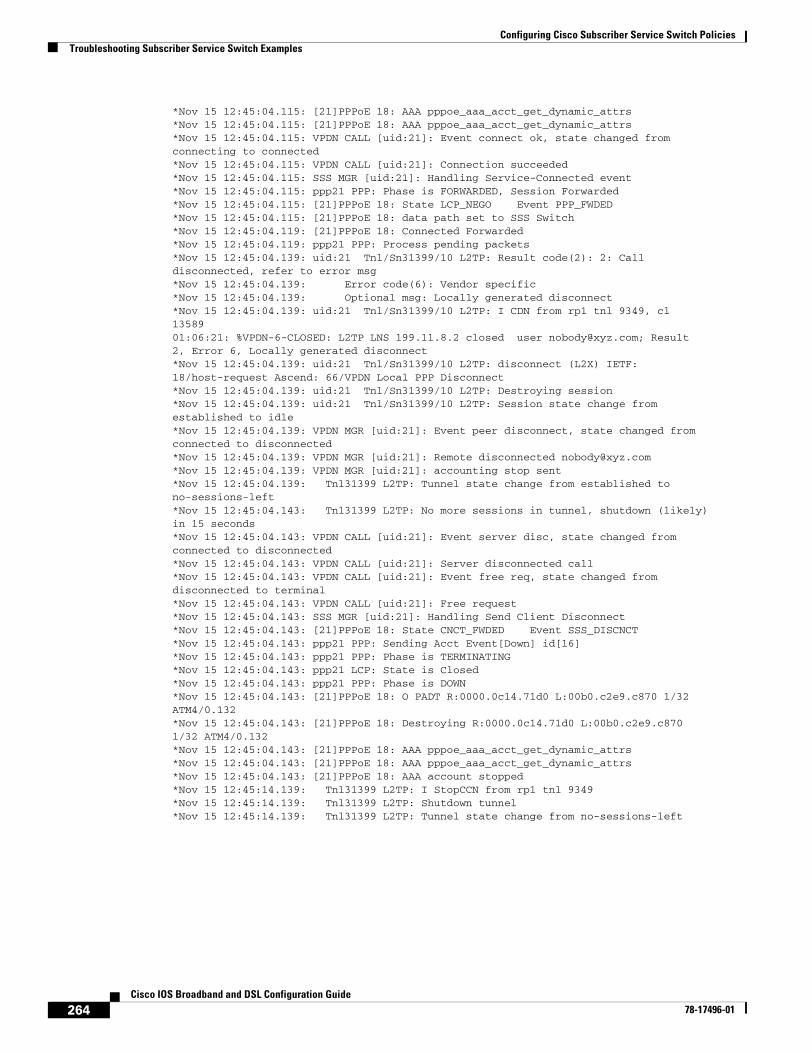
Configuring Cisco Subscriber Service Switch PoliciesTroubleshooting Subscriber Service Switch Examples
264Cisco IOS Broadband and DSL Configuration Guide
78-17496-01
*Nov 15 12:45:04.115: [21]PPPoE 18: AAA pppoe_aaa_acct_get_dynamic_attrs*Nov 15 12:45:04.115: [21]PPPoE 18: AAA pppoe_aaa_acct_get_dynamic_attrs*Nov 15 12:45:04.115: VPDN CALL [uid:21]: Event connect ok, state changed fromconnecting to connected*Nov 15 12:45:04.115: VPDN CALL [uid:21]: Connection succeeded*Nov 15 12:45:04.115: SSS MGR [uid:21]: Handling Service-Connected event*Nov 15 12:45:04.115: ppp21 PPP: Phase is FORWARDED, Session Forwarded*Nov 15 12:45:04.115: [21]PPPoE 18: State LCP_NEGO Event PPP_FWDED*Nov 15 12:45:04.115: [21]PPPoE 18: data path set to SSS Switch*Nov 15 12:45:04.119: [21]PPPoE 18: Connected Forwarded*Nov 15 12:45:04.119: ppp21 PPP: Process pending packets*Nov 15 12:45:04.139: uid:21 Tnl/Sn31399/10 L2TP: Result code(2): 2: Calldisconnected, refer to error msg*Nov 15 12:45:04.139: Error code(6): Vendor specific*Nov 15 12:45:04.139: Optional msg: Locally generated disconnect*Nov 15 12:45:04.139: uid:21 Tnl/Sn31399/10 L2TP: I CDN from rp1 tnl 9349, cl1358901:06:21: %VPDN-6-CLOSED: L2TP LNS 199.11.8.2 closed user [email protected]; Result2, Error 6, Locally generated disconnect*Nov 15 12:45:04.139: uid:21 Tnl/Sn31399/10 L2TP: disconnect (L2X) IETF:18/host-request Ascend: 66/VPDN Local PPP Disconnect*Nov 15 12:45:04.139: uid:21 Tnl/Sn31399/10 L2TP: Destroying session*Nov 15 12:45:04.139: uid:21 Tnl/Sn31399/10 L2TP: Session state change fromestablished to idle*Nov 15 12:45:04.139: VPDN MGR [uid:21]: Event peer disconnect, state changed fromconnected to disconnected*Nov 15 12:45:04.139: VPDN MGR [uid:21]: Remote disconnected [email protected]*Nov 15 12:45:04.139: VPDN MGR [uid:21]: accounting stop sent*Nov 15 12:45:04.139: Tnl31399 L2TP: Tunnel state change from established tono-sessions-left*Nov 15 12:45:04.143: Tnl31399 L2TP: No more sessions in tunnel, shutdown (likely)in 15 seconds*Nov 15 12:45:04.143: VPDN CALL [uid:21]: Event server disc, state changed fromconnected to disconnected*Nov 15 12:45:04.143: VPDN CALL [uid:21]: Server disconnected call*Nov 15 12:45:04.143: VPDN CALL [uid:21]: Event free req, state changed fromdisconnected to terminal*Nov 15 12:45:04.143: VPDN CALL [uid:21]: Free request*Nov 15 12:45:04.143: SSS MGR [uid:21]: Handling Send Client Disconnect*Nov 15 12:45:04.143: [21]PPPoE 18: State CNCT_FWDED Event SSS_DISCNCT*Nov 15 12:45:04.143: ppp21 PPP: Sending Acct Event[Down] id[16]*Nov 15 12:45:04.143: ppp21 PPP: Phase is TERMINATING*Nov 15 12:45:04.143: ppp21 LCP: State is Closed*Nov 15 12:45:04.143: ppp21 PPP: Phase is DOWN*Nov 15 12:45:04.143: [21]PPPoE 18: O PADT R:0000.0c14.71d0 L:00b0.c2e9.c870 1/32ATM4/0.132*Nov 15 12:45:04.143: [21]PPPoE 18: Destroying R:0000.0c14.71d0 L:00b0.c2e9.c8701/32 ATM4/0.132*Nov 15 12:45:04.143: [21]PPPoE 18: AAA pppoe_aaa_acct_get_dynamic_attrs*Nov 15 12:45:04.143: [21]PPPoE 18: AAA pppoe_aaa_acct_get_dynamic_attrs*Nov 15 12:45:04.143: [21]PPPoE 18: AAA account stopped*Nov 15 12:45:14.139: Tnl31399 L2TP: I StopCCN from rp1 tnl 9349*Nov 15 12:45:14.139: Tnl31399 L2TP: Shutdown tunnel*Nov 15 12:45:14.139: Tnl31399 L2TP: Tunnel state change from no-sessions-left
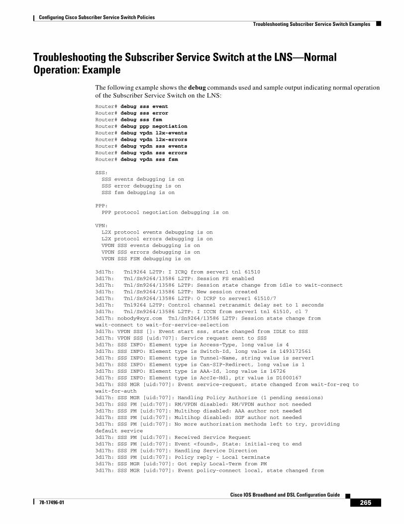
Configuring Cisco Subscriber Service Switch PoliciesTroubleshooting Subscriber Service Switch Examples
265Cisco IOS Broadband and DSL Configuration Guide
78-17496-01
Troubleshooting the Subscriber Service Switch at the LNS—Normal Operation: Example
The following example shows the debug commands used and sample output indicating normal operation of the Subscriber Service Switch on the LNS:
Router# debug sss eventRouter# debug sss errorRouter# debug sss fsmRouter# debug ppp negotiationRouter# debug vpdn l2x-eventsRouter# debug vpdn l2x-errorsRouter# debug vpdn sss eventsRouter# debug vpdn sss errorsRouter# debug vpdn sss fsm
SSS: SSS events debugging is on SSS error debugging is on SSS fsm debugging is on
PPP: PPP protocol negotiation debugging is on
VPN: L2X protocol events debugging is on L2X protocol errors debugging is on VPDN SSS events debugging is on VPDN SSS errors debugging is on VPDN SSS FSM debugging is on
3d17h: Tnl9264 L2TP: I ICRQ from server1 tnl 615103d17h: Tnl/Sn9264/13586 L2TP: Session FS enabled3d17h: Tnl/Sn9264/13586 L2TP: Session state change from idle to wait-connect3d17h: Tnl/Sn9264/13586 L2TP: New session created3d17h: Tnl/Sn9264/13586 L2TP: O ICRP to server1 61510/73d17h: Tnl9264 L2TP: Control channel retransmit delay set to 1 seconds3d17h: Tnl/Sn9264/13586 L2TP: I ICCN from server1 tnl 61510, cl 73d17h: [email protected] Tnl/Sn9264/13586 L2TP: Session state change fromwait-connect to wait-for-service-selection3d17h: VPDN SSS []: Event start sss, state changed from IDLE to SSS3d17h: VPDN SSS [uid:707]: Service request sent to SSS3d17h: SSS INFO: Element type is Access-Type, long value is 43d17h: SSS INFO: Element type is Switch-Id, long value is 14931725613d17h: SSS INFO: Element type is Tunnel-Name, string value is server13d17h: SSS INFO: Element type is Can-SIP-Redirect, long value is 13d17h: SSS INFO: Element type is AAA-Id, long value is 167263d17h: SSS INFO: Element type is AccIe-Hdl, ptr value is D10001673d17h: SSS MGR [uid:707]: Event service-request, state changed from wait-for-req towait-for-auth3d17h: SSS MGR [uid:707]: Handling Policy Authorize (1 pending sessions)3d17h: SSS PM [uid:707]: RM/VPDN disabled: RM/VPDN author not needed3d17h: SSS PM [uid:707]: Multihop disabled: AAA author not needed3d17h: SSS PM [uid:707]: Multihop disabled: SGF author not needed3d17h: SSS PM [uid:707]: No more authorization methods left to try, providingdefault service3d17h: SSS PM [uid:707]: Received Service Request3d17h: SSS PM [uid:707]: Event <found>, State: initial-req to end3d17h: SSS PM [uid:707]: Handling Service Direction3d17h: SSS PM [uid:707]: Policy reply - Local terminate3d17h: SSS MGR [uid:707]: Got reply Local-Term from PM3d17h: SSS MGR [uid:707]: Event policy-connect local, state changed from
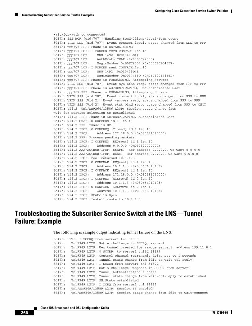
Configuring Cisco Subscriber Service Switch PoliciesTroubleshooting Subscriber Service Switch Examples
266Cisco IOS Broadband and DSL Configuration Guide
78-17496-01
wait-for-auth to connected3d17h: SSS MGR [uid:707]: Handling Send-Client-Local-Term event3d17h: VPDN SSS [uid:707]: Event connect local, state changed from SSS to PPP3d17h: ppp707 PPP: Phase is ESTABLISHING3d17h: ppp707 LCP: I FORCED rcvd CONFACK len 153d17h: ppp707 LCP: MRU 1492 (0x010405D4)3d17h: ppp707 LCP: AuthProto CHAP (0x0305C22305)3d17h: ppp707 LCP: MagicNumber 0xB0EC4557 (0x0506B0EC4557)3d17h: ppp707 LCP: I FORCED sent CONFACK len 103d17h: ppp707 LCP: MRU 1492 (0x010405D4)3d17h: ppp707 LCP: MagicNumber 0x0017455D (0x05060017455D)3d17h: ppp707 PPP: Phase is FORWARDING, Attempting Forward3d17h: VPDN SSS [uid:707]: Event dyn bind resp, state changed from PPP to PPP3d17h: ppp707 PPP: Phase is AUTHENTICATING, Unauthenticated User3d17h: ppp707 PPP: Phase is FORWARDING, Attempting Forward3d17h: VPDN SSS [uid:707]: Event connect local, state changed from PPP to PPP3d17h: VPDN SSS [Vi4.2]: Event vaccess resp, state changed from PPP to PPP3d17h: VPDN SSS [Vi4.2]: Event stat bind resp, state changed from PPP to CNCT3d17h: Vi4.2 Tnl/Sn9264/13586 L2TP: Session state change fromwait-for-service-selection to established3d17h: Vi4.2 PPP: Phase is AUTHENTICATING, Authenticated User3d17h: Vi4.2 CHAP: O SUCCESS id 1 len 43d17h: Vi4.2 PPP: Phase is UP3d17h: Vi4.2 IPCP: O CONFREQ [Closed] id 1 len 103d17h: Vi4.2 IPCP: Address 172.18.0.0 (0x030681010000)3d17h: Vi4.2 PPP: Process pending packets3d17h: Vi4.2 IPCP: I CONFREQ [REQsent] id 1 len 103d17h: Vi4.2 IPCP: Address 0.0.0.0 (0x030600000000)3d17h: Vi4.2 AAA/AUTHOR/IPCP: Start. Her address 0.0.0.0, we want 0.0.0.03d17h: Vi4.2 AAA/AUTHOR/IPCP: Done. Her address 0.0.0.0, we want 0.0.0.03d17h: Vi4.2 IPCP: Pool returned 10.1.1.33d17h: Vi4.2 IPCP: O CONFNAK [REQsent] id 1 len 103d17h: Vi4.2 IPCP: Address 10.1.1.3 (0x03065B010103)3d17h: Vi4.2 IPCP: I CONFACK [REQsent] id 1 len 103d17h: Vi4.2 IPCP: Address 172.18.0.0 (0x030681010000)3d17h: Vi4.2 IPCP: I CONFREQ [ACKrcvd] id 2 len 103d17h: Vi4.2 IPCP: Address 10.1.1.3 (0x03065B010103)3d17h: Vi4.2 IPCP: O CONFACK [ACKrcvd] id 2 len 103d17h: Vi4.2 IPCP: Address 10.1.1.3 (0x03065B010103)3d17h: Vi4.2 IPCP: State is Open3d17h: Vi4.2 IPCP: Install route to 10.1.1.3
Troubleshooting the Subscriber Service Switch at the LNS—Tunnel Failure: Example
The following is sample output indicating tunnel failure on the LNS:
3d17h: L2TP: I SCCRQ from server1 tnl 313993d17h: Tnl9349 L2TP: Got a challenge in SCCRQ, server13d17h: Tnl9349 L2TP: New tunnel created for remote server1, address 199.11.8.13d17h: Tnl9349 L2TP: O SCCRP to server1 tnlid 313993d17h: Tnl9349 L2TP: Control channel retransmit delay set to 1 seconds3d17h: Tnl9349 L2TP: Tunnel state change from idle to wait-ctl-reply3d17h: Tnl9349 L2TP: I SCCCN from server1 tnl 313993d17h: Tnl9349 L2TP: Got a Challenge Response in SCCCN from server13d17h: Tnl9349 L2TP: Tunnel Authentication success3d17h: Tnl9349 L2TP: Tunnel state change from wait-ctl-reply to established3d17h: Tnl9349 L2TP: SM State established3d17h: Tnl9349 L2TP: I ICRQ from server1 tnl 313993d17h: Tnl/Sn9349/13589 L2TP: Session FS enabled3d17h: Tnl/Sn9349/13589 L2TP: Session state change from idle to wait-connect
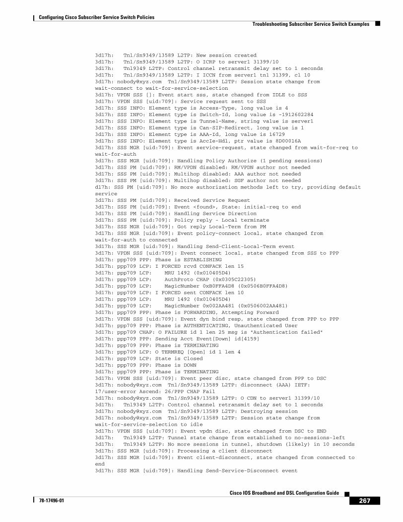
Configuring Cisco Subscriber Service Switch PoliciesTroubleshooting Subscriber Service Switch Examples
267Cisco IOS Broadband and DSL Configuration Guide
78-17496-01
3d17h: Tnl/Sn9349/13589 L2TP: New session created3d17h: Tnl/Sn9349/13589 L2TP: O ICRP to server1 31399/103d17h: Tnl9349 L2TP: Control channel retransmit delay set to 1 seconds3d17h: Tnl/Sn9349/13589 L2TP: I ICCN from server1 tnl 31399, cl 103d17h: [email protected] Tnl/Sn9349/13589 L2TP: Session state change fromwait-connect to wait-for-service-selection3d17h: VPDN SSS []: Event start sss, state changed from IDLE to SSS3d17h: VPDN SSS [uid:709]: Service request sent to SSS3d17h: SSS INFO: Element type is Access-Type, long value is 43d17h: SSS INFO: Element type is Switch-Id, long value is -19126022843d17h: SSS INFO: Element type is Tunnel-Name, string value is server13d17h: SSS INFO: Element type is Can-SIP-Redirect, long value is 13d17h: SSS INFO: Element type is AAA-Id, long value is 167293d17h: SSS INFO: Element type is AccIe-Hdl, ptr value is 8D00016A3d17h: SSS MGR [uid:709]: Event service-request, state changed from wait-for-req towait-for-auth3d17h: SSS MGR [uid:709]: Handling Policy Authorize (1 pending sessions)3d17h: SSS PM [uid:709]: RM/VPDN disabled: RM/VPDN author not needed3d17h: SSS PM [uid:709]: Multihop disabled: AAA author not needed3d17h: SSS PM [uid:709]: Multihop disabled: SGF author not neededd17h: SSS PM [uid:709]: No more authorization methods left to try, providing default service3d17h: SSS PM [uid:709]: Received Service Request3d17h: SSS PM [uid:709]: Event <found>, State: initial-req to end3d17h: SSS PM [uid:709]: Handling Service Direction3d17h: SSS PM [uid:709]: Policy reply - Local terminate3d17h: SSS MGR [uid:709]: Got reply Local-Term from PM3d17h: SSS MGR [uid:709]: Event policy-connect local, state changed fromwait-for-auth to connected3d17h: SSS MGR [uid:709]: Handling Send-Client-Local-Term event3d17h: VPDN SSS [uid:709]: Event connect local, state changed from SSS to PPP3d17h: ppp709 PPP: Phase is ESTABLISHING3d17h: ppp709 LCP: I FORCED rcvd CONFACK len 153d17h: ppp709 LCP: MRU 1492 (0x010405D4)3d17h: ppp709 LCP: AuthProto CHAP (0x0305C22305)3d17h: ppp709 LCP: MagicNumber 0xB0FFA4D8 (0x0506B0FFA4D8)3d17h: ppp709 LCP: I FORCED sent CONFACK len 103d17h: ppp709 LCP: MRU 1492 (0x010405D4)3d17h: ppp709 LCP: MagicNumber 0x002AA481 (0x0506002AA481)3d17h: ppp709 PPP: Phase is FORWARDING, Attempting Forward3d17h: VPDN SSS [uid:709]: Event dyn bind resp, state changed from PPP to PPP3d17h: ppp709 PPP: Phase is AUTHENTICATING, Unauthenticated User3d17h: ppp709 CHAP: O FAILURE id 1 len 25 msg is "Authentication failed"3d17h: ppp709 PPP: Sending Acct Event[Down] id[4159]3d17h: ppp709 PPP: Phase is TERMINATING3d17h: ppp709 LCP: O TERMREQ [Open] id 1 len 43d17h: ppp709 LCP: State is Closed3d17h: ppp709 PPP: Phase is DOWN3d17h: ppp709 PPP: Phase is TERMINATING3d17h: VPDN SSS [uid:709]: Event peer disc, state changed from PPP to DSC3d17h: [email protected] Tnl/Sn9349/13589 L2TP: disconnect (AAA) IETF:17/user-error Ascend: 26/PPP CHAP Fail3d17h: [email protected] Tnl/Sn9349/13589 L2TP: O CDN to server1 31399/103d17h: Tnl9349 L2TP: Control channel retransmit delay set to 1 seconds3d17h: [email protected] Tnl/Sn9349/13589 L2TP: Destroying session3d17h: [email protected] Tnl/Sn9349/13589 L2TP: Session state change fromwait-for-service-selection to idle3d17h: VPDN SSS [uid:709]: Event vpdn disc, state changed from DSC to END3d17h: Tnl9349 L2TP: Tunnel state change from established to no-sessions-left3d17h: Tnl9349 L2TP: No more sessions in tunnel, shutdown (likely) in 10 seconds3d17h: SSS MGR [uid:709]: Processing a client disconnect3d17h: SSS MGR [uid:709]: Event client-disconnect, state changed from connected toend3d17h: SSS MGR [uid:709]: Handling Send-Service-Disconnect event
Configuring Cisco Subscriber Service Switch PoliciesWhere to Go Next
268Cisco IOS Broadband and DSL Configuration Guide
78-17496-01
3d17h: Tnl9349 L2TP: O StopCCN to server1 tnlid 313993d17h: Tnl9349 L2TP: Control channel retransmit delay set to 1 seconds3d17h: Tnl9349 L2TP: Tunnel state change from no-sessions-left to shutting-down3d17h: Tnl9349 L2TP: Shutdown tunnel
Where to Go Next• If you want to establish PPPoE session limits for sessions on a specific permanent virtual circuit or
VLAN configured on an L2TP access concentrator, refer to the “Establishing PPPoE Session Limits per NAS Port” module.
• If you want to use service tags to enable a PPPoE server to offer PPPoE clients a selection of service during call setup, refer to the “Offering PPPoE Clients a Selection of Services During Call Setup” module.
• If you want to enable an L2TP access concentrator to relay active discovery and service selection functionality for PPPoE over a L2TP control channel to an LNS or tunnel switch, refer to the “Enabling PPPoE Relay Discovery and Service Selection Functionality” module.
• If you want to configure the transfer upstream of the PPPoX session speed value, refer to the “Configuring Upstream Connections Speed Transfer” module.
• If you want to use the Simple Network Management Protocol (SNMP) to monitor PPPoE sessions, refer to the “Monitoring PPPoE Sessions with SNMP” module.
• If you want to identify a physical subscribe line for RADIUS communication with a RADIUS server, refer to the “Identifying a Physical Subscriber Line for RADIUS Access and Accounting” module.
Additional ReferencesThe following sections provide references related to configuring Cisco Subscriber Service Switch policies.
Related Documents
Related Topic Document Title
Broadband access aggregation concepts Refer to the “Understanding Broadband Access Aggregation” module.
Tasks for preparing for broadband access aggregation. Refer to the “Preparing for Broadband Access Aggregation” module.
Broadband access commands: complete command syntax, command mode, command history, defaults, usage guidelines, and examples
“Wide-Area Networking Commands” in the Cisco IOS Wide-Area Networking Command Reference, Release 12.3
http://www.cisco.com/univercd/cc/td/doc/product/software/ios123/123tcr/123twr/wan_a1gt.htm#wp1056981
Configuring Cisco Subscriber Service Switch PoliciesAdditional References
269Cisco IOS Broadband and DSL Configuration Guide
78-17496-01
Standards
MIBs
RFCs
Technical Assistance
Standards Title
None —
MIBs MIBs Link
None To locate and download MIBs for selected platforms, Cisco IOS releases, and feature sets, use Cisco MIB Locator found at the following URL:
http://www.cisco.com/go/mibs
RFCs Title
RFC 2661 Layer Two Tunneling Protocol L2TP
RFC 2341 Cisco Layer Two Forwarding (Protocol) L2F
RFC 2516 A Method for Transmitting PPP Over Ethernet (PPPoE) (PPPoE Discovery)
Description Link
Technical Assistance Center (TAC) home page, containing 30,000 pages of searchable technical content, including links to products, technologies, solutions, technical tips, and tools. Registered Cisco.com users can log in from this page to access even more content.
http://www.cisco.com/public/support/tac/home.shtml
Configuring Cisco Subscriber Service Switch PoliciesFeature Information for Configuring a Subscriber Service Switch Policy
270Cisco IOS Broadband and DSL Configuration Guide
78-17496-01
Feature Information for Configuring a Subscriber Service Switch Policy
Table 22 lists the features in this module and provides links to specific configuration information. Only features that were introduced or modified in Cisco IOS Release 12.0(3)S or later releases appear in the table.
Not all commands may be available in your Cisco IOS software release. For details on when support for specific commands was introduced, see the command reference documents.
If you are looking for information on a feature in this technology that is not documented here, see the “Configuring Broadband Access Aggregation Features Roadmap.”
Cisco IOS software images are specific to a Cisco IOS software release, a feature set, and a platform. Use Cisco Feature Navigator to find information about platform support and Cisco IOS software image support. Access Cisco Feature Navigator at http://www.cisco.com/go/fn. You must have an account on Cisco.com. If you do not have an account or have forgotten your username or password, click Cancel at the login dialog box and follow the instructions that appear.
Note Table 22 lists only the Cisco IOS software release that introduced support for a given feature in a given Cisco IOS software release train. Unless noted otherwise, subsequent releases of that Cisco IOS software release train also support that feature.
Table 22 Feature Information for Configuring a Cisco Subscriber Service Switch Policy
Feature Name Releases Feature Configuration Information
Subscriber Service Switch 12.2(13)T The Subscriber Service Switch feature provides flexibility in where subscribers are connected to available services, how many subscribers are connected, and how those services are defined. The primary purpose of the Subscriber Service Switch is to direct PPP from one point to another using a Layer 2 subscriber policy.
The following sections provide information about this feature:
• “Information About the Subscriber Service Switch” section on page 242
• “How to Configure a Subscriber Service Switch Policy” section on page 245
271Cisco IOS Broadband and DSL Configuration Guide
78-17496-01
Subscriber Profile Support
The Subscriber Profile Support feature introduces new functionality for the Subscriber Service Switch architecture, a Cisco IOS subsystem that connects subscribers to network access services at Layer 2. This new functionality affects how the Subscriber Service Switch Manager determines a service for each subscriber with a combination of a policy and a service lookup model.
Feature Specifications for the Subscriber Profile Support Feature
Finding Support Information for Platforms and Cisco IOS Software Images
Use Cisco Feature Navigator to find information about platform support and Cisco IOS software image support. Access Cisco Feature Navigator at http://www.cisco.com/go/fn. You must have an account on Cisco.com. If you do not have an account or have forgotten your username or password, click Cancel at the login dialog box and follow the instructions that appear.
Contents• Prerequisites for Configuring Subscriber Profile Support, page 271
• Information About Subscriber Profile Support, page 272
• How to Configure Subscriber Profile Support, page 272
• Configuration Examples for Subscriber Profile Support, page 276
• Additional References, page 278
• Command List, page 279
Prerequisites for Configuring Subscriber Profile SupportBefore configuring the Subscriber Profile Support feature, you need to be familiar with concepts introduced in the Cisco Release 12.2(13)T feature module Subscriber Service Switch, and with the authentication, authorization, and accounting (AAA) and PPP access processes.
Feature HistoryRelease Modification
12.3(4)T This feature was introduced.
Subscriber Profile SupportInformation About Subscriber Profile Support
272Cisco IOS Broadband and DSL Configuration Guide
78-17496-01
Information About Subscriber Profile SupportTo configure subscriber profile support, you need to understand the following concept:
• New Call Management Support for Subscriber Service Switch Architecture, page 272
New Call Management Support for Subscriber Service Switch ArchitectureThe Subscriber Service Switch architecture in Cisco IOS Release 12.3(4)T offers a significant improvement in scalability by providing the ability to bypass PPP when forwarding a call. Instead, call service selection is decided entirely by a Subscriber Service Switch Manager. Client call processes that terminate subscriber lines or receive subscriber calls send their requests for service direction to the Subscriber Service Switch Manager, which determines service based on service keys collected by the Subscriber Service Switch client and a preestablished call service policy. Examples of service keys are a NAS Port ID (network access server port identifier) and an unauthenticated PPP name. Refer to the Subscriber Service Switch feature module for more information about service keys.
The Subscriber Profile Support feature introduces the subscriber profile command and its service subcommands, which support the Subscriber Service Switch policy for searching a subscriber profile database for authorization data and determining the services that will be granted to the requesting customer.
How to Configure Subscriber Profile SupportThis section contains the following tasks that may be performed to configure a Subscriber Service Switch policy:
• Configuring VPDN Service for the Subscriber Service Switch Policy, page 272 (as required)
• Configuring Denial of Service for the Subscriber Service Switch Policy, page 274 (as required)
• Configuring Local Termination Service for the Subscriber Service Switch Policy, page 273 (as required)
The tasks described in this section assume that an operational network running the Subscriber Service Switch architecture has been configured.
Configuring VPDN Service for the Subscriber Service Switch PolicyIn this task, you configure virtual private dial-up network (VPDN) service by directing the software to obtain the configuration from a predefined VPDN group.
SUMMARY STEPS
1. enable
2. configure terminal
3. subscriber profile profile-name
4. service vpdn group vpdn-group-name
5. exit
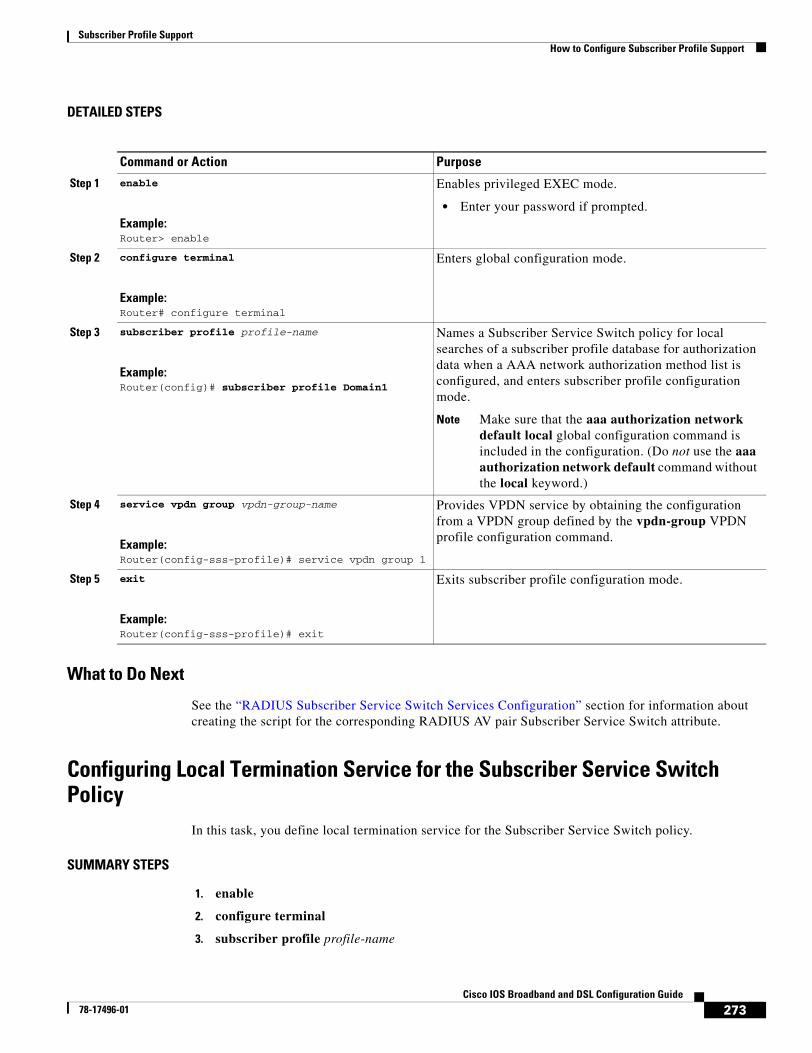
Subscriber Profile SupportHow to Configure Subscriber Profile Support
273Cisco IOS Broadband and DSL Configuration Guide
78-17496-01
DETAILED STEPS
What to Do Next
See the “RADIUS Subscriber Service Switch Services Configuration” section for information about creating the script for the corresponding RADIUS AV pair Subscriber Service Switch attribute.
Configuring Local Termination Service for the Subscriber Service Switch Policy
In this task, you define local termination service for the Subscriber Service Switch policy.
SUMMARY STEPS
1. enable
2. configure terminal
3. subscriber profile profile-name
Command or Action Purpose
Step 1 enable
Example:Router> enable
Enables privileged EXEC mode.
• Enter your password if prompted.
Step 2 configure terminal
Example:Router# configure terminal
Enters global configuration mode.
Step 3 subscriber profile profile-name
Example:Router(config)# subscriber profile Domain1
Names a Subscriber Service Switch policy for local searches of a subscriber profile database for authorization data when a AAA network authorization method list is configured, and enters subscriber profile configuration mode.
Note Make sure that the aaa authorization network default local global configuration command is included in the configuration. (Do not use the aaa authorization network default command without the local keyword.)
Step 4 service vpdn group vpdn-group-name
Example:Router(config-sss-profile)# service vpdn group 1
Provides VPDN service by obtaining the configuration from a VPDN group defined by the vpdn-group VPDN profile configuration command.
Step 5 exit
Example:Router(config-sss-profile)# exit
Exits subscriber profile configuration mode.
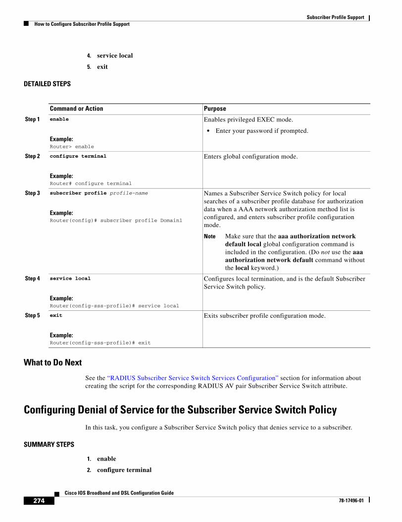
Subscriber Profile SupportHow to Configure Subscriber Profile Support
274Cisco IOS Broadband and DSL Configuration Guide
78-17496-01
4. service local
5. exit
DETAILED STEPS
What to Do Next
See the “RADIUS Subscriber Service Switch Services Configuration” section for information about creating the script for the corresponding RADIUS AV pair Subscriber Service Switch attribute.
Configuring Denial of Service for the Subscriber Service Switch PolicyIn this task, you configure a Subscriber Service Switch policy that denies service to a subscriber.
SUMMARY STEPS
1. enable
2. configure terminal
Command or Action Purpose
Step 1 enable
Example:Router> enable
Enables privileged EXEC mode.
• Enter your password if prompted.
Step 2 configure terminal
Example:Router# configure terminal
Enters global configuration mode.
Step 3 subscriber profile profile-name
Example:Router(config)# subscriber profile Domain1
Names a Subscriber Service Switch policy for local searches of a subscriber profile database for authorization data when a AAA network authorization method list is configured, and enters subscriber profile configuration mode.
Note Make sure that the aaa authorization network default local global configuration command is included in the configuration. (Do not use the aaa authorization network default command without the local keyword.)
Step 4 service local
Example:Router(config-sss-profile)# service local
Configures local termination, and is the default Subscriber Service Switch policy.
Step 5 exit
Example:Router(config-sss-profile)# exit
Exits subscriber profile configuration mode.
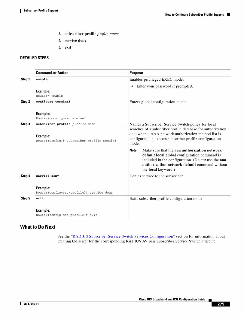
Subscriber Profile SupportHow to Configure Subscriber Profile Support
275Cisco IOS Broadband and DSL Configuration Guide
78-17496-01
3. subscriber profile profile-name
4. service deny
5. exit
DETAILED STEPS
What to Do Next
See the “RADIUS Subscriber Service Switch Services Configuration” section for information about creating the script for the corresponding RADIUS AV pair Subscriber Service Switch attribute.
Command or Action Purpose
Step 1 enable
Example:Router> enable
Enables privileged EXEC mode.
• Enter your password if prompted.
Step 2 configure terminal
Example:Router# configure terminal
Enters global configuration mode.
Step 3 subscriber profile profile-name
Example:Router(config)# subscriber profile Domain1
Names a Subscriber Service Switch policy for local searches of a subscriber profile database for authorization data when a AAA network authorization method list is configured, and enters subscriber profile configuration mode.
Note Make sure that the aaa authorization network default local global configuration command is included in the configuration. (Do not use the aaa authorization network default command without the local keyword.)
Step 4 service deny
Example:Router(config-sss-profile)# service deny
Denies service to the subscriber.
Step 5 exit
Example:Router(config-sss-profile)# exit
Exits subscriber profile configuration mode.
Subscriber Profile SupportConfiguration Examples for Subscriber Profile Support
276Cisco IOS Broadband and DSL Configuration Guide
78-17496-01
RADIUS Subscriber Service Switch Services ConfigurationThe Cisco AV pairs have been extended to include Subscriber Service Switch service configuration. Subscriber Service Switch values are prefixed with “sss:”, as follows:
cisco-avpair = “sss:sss-service=vpdn”cisco-avpair = “sss:sss-service=local”cisco-avpair = “sss:sss-service=deny”
Configuration Examples for Subscriber Profile SupportThis section contains the following configuration examples:
• VPDN Service for the Subscriber Service Switch Policy: Examples, page 276
• Local Termination for the Subscriber Service Switch Policy: Example, page 276
• Denial of Service for the Subscriber Service Switch Policy: Example, page 277
• RADIUS Subscriber Service Support Profiles: Examples, page 277
VPDN Service for the Subscriber Service Switch Policy: ExamplesThe following example provides VPDN service to users in the domain cisco.com, and uses VPDN group 1 to obtain VPDN configuration information:
!subscriber profile cisco.comservice vpdn group 1
The following example provides VPDN service to DNIS 1234567, and uses VPDN group 1 to obtain VPDN configuration information:
!subscriber profile dnis:1234567service vpdn group 1
The following example provides VPDN service using a remote tunnel (used on the multihop node), and uses VPDN group 1 to obtain VPDN configuration information:
!subscriber profile host:lacservice vpdn group 1
Local Termination for the Subscriber Service Switch Policy: ExampleThe following example provides local termination service to users in the domain cisco.com:
!subscriber profile cisco.comservice local
Subscriber Profile SupportConfiguration Examples for Subscriber Profile Support
277Cisco IOS Broadband and DSL Configuration Guide
78-17496-01
Denial of Service for the Subscriber Service Switch Policy: ExampleThe following example denies service to users in the domain cisco.com:
!subscriber profile cisco.comservice deny
RADIUS Subscriber Service Support Profiles: ExamplesThe following examples show typical RADIUS AV pair scripts to enable VPDN service and to define the service keys that are collected:
# # Domain "cisco.com" users get VPDN service with the enclosed configuration.# cisco.com Password = "cisco"User-Service-Type = Outbound-User,cisco-avpair = "sss:sss-service=vpdn",cisco-avpair = "vpdn:tunnel-id=nas-provider",cisco-avpair = "vpdn:ip-addresses=10.0.3.96",cisco-avpair = "vpdn:nas-password=secret1",cisco-avpair = "vpdn:gw-password=secret2"## Users with DNIS 1234567 get VPDN service with the enclosed configuration.#dnis:1234567 Password = "cisco"User-Service-Type = Outbound-User,cisco-avpair = "sss:sss-service=vpdn",cisco-avpair = "vpdn:tunnel-id=nas-provider",cisco-avpair = "vpdn:ip-addresses=10.0.3.96",cisco-avpair = "vpdn:nas-password=secret1",cisco-avpair = "vpdn:gw-password=secret2"## Users on the remote tunnel (LAC) get VPDN service with the enclosed configuration.#host:lac Password = "cisco"User-Service-Type = Outbound-User,cisco-avpair = "sss:sss-service=vpdn",cisco-avpair = "vpdn:tunnel-id=nas-provider",cisco-avpair = "vpdn:ip-addresses=10.0.3.96",cisco-avpair = "vpdn:nas-password=secret1",cisco-avpair = "vpdn:gw-password=secret2"
Subscriber Profile SupportAdditional References
278Cisco IOS Broadband and DSL Configuration Guide
78-17496-01
Additional ReferencesThe following sections provide references related to the Subscriber Service Support feature.
Related Documents
Standards
MIBs
Related Topic Document Title
AAA Cisco IOS Security Configuration Guide; refer to “Part 1: Authentication, Authorization, and Accounting (AAA)”
AAA commands: complete command syntax, command mode, defaults, usage guidelines, and examples
Cisco IOS Security Command Reference
Broadband access, PPPoE Cisco IOS Wide-Area Networking Configuration Guide; refer to “Part 2: Broadband Access”
Broadband access, PPPoE, commands: complete command syntax, command mode, defaults, usage guidelines, and examples
Cisco IOS Wide-Area Networking Command Reference
PPP Cisco IOS Dial Technologies Configuration Guide; refer to “Part 9: PPP Configuration”
VPDN Cisco IOS Dial Technologies Configuration Guide; refer to “Part 8: Virtual Templates, Profiles, and Networks”
PPP and VPDN commands: complete command syntax, command mode, defaults, usage guidelines, and examples
Cisco IOS Dial Technologies Command Reference
Subscriber Service Switch Subscriber Service Switch feature module
Standards Title
None —
MIBs MIBs Link
None To locate and download MIBs for selected platforms, Cisco IOS releases, and feature sets, use Cisco MIB Locator found at the following URL:
http://www.cisco.com/go/mibs
Subscriber Profile SupportCommand List
279Cisco IOS Broadband and DSL Configuration Guide
78-17496-01
RFCs
Technical Assistance
Command ListThe following commands are pertinent to this feature. To see the command pages for these and other commands used with this feature, go to the Cisco IOS Master Commands List, Release 12.4, at http://www.cisco.com/univercd/cc/td/doc/product/software/ios124/124mindx/124index.htm.
• service deny
• service local
• service vpdn group
• subscriber profile
RFCs Title
None —
Description Link
Technical Assistance Center (TAC) home page, containing 30,000 pages of searchable technical content, including links to products, technologies, solutions, technical tips, and tools. Registered Cisco.com users can log in from this page to access even more content.
http://www.cisco.com/public/support/tac/home.shtml

Subscriber Profile SupportCommand List
280Cisco IOS Broadband and DSL Configuration Guide
78-17496-01

Part 5: Dynamic Subscriber Bandwidth Selection

283Cisco IOS Broadband and DSL Configuration Guide
78-17496-01
Controlling Subscriber Bandwidth
The Dynamic Subscriber Bandwidth Selection (DBS) feature enables wholesale service providers to sell different classes of service to retail service providers by controlling bandwidth at the ATM virtual circuit (VC) level. ATM quality of service (QoS) parameters from the subscriber domain are applied to the ATM PVC on which a PPP over Ethernet (PPPoE) or PPP over ATM (PPPoA) session is established.
Module History
This module was first published on May 2, 2005, and last updated on May 2, 2005.
Finding Feature Information in This Module
Not all features may be supported in your Cisco IOS software release. Use the “Feature Information for Controlling Subscriber Bandwidth” section on page 298 to find information about feature support and configuration.
Contents• Restrictions for Controlling Subscriber Bandwidth, page 283
• Information About Controlling Subscriber Bandwidth, page 284
• How to Control Subscriber Bandwidth, page 285
• Configuration Examples for Controlling Subscriber Bandwidth, page 294
• Additional References, page 296
• Feature Information for Controlling Subscriber Bandwidth, page 298
Restrictions for Controlling Subscriber BandwidthThe DBS feature does not support the following:
• Switched virtual circuits (SVC)
• PA-A1 or PA-A2 port adapters installed in a Cisco 7200 series router
• When changing QoS values dynamically on a VC, there will be some duration (typically milliseconds) during which traffic on the VC is dropped.
Controlling Subscriber BandwidthInformation About Controlling Subscriber Bandwidth
284Cisco IOS Broadband and DSL Configuration Guide
78-17496-01
Information About Controlling Subscriber BandwidthInformation about controlling subscriber bandwidth includes the following:
• Traffic-Shaping Parameters, page 284
• Benefits of Controlling Subscriber Bandwidth, page 284
Traffic-Shaping ParametersUsing DBS you can set the ATM permanent virtual circuit (PVC) traffic-shaping parameters to be dynamically changed based on the RADIUS profile of a PPPoE or PPPoA user logging in on the PVC. If the user is the first user on a given PVC, the RADIUS profile values override the default values of the PVC. If users already exist on the PVC, the new value overrides the existing configuration only if it is higher than the existing value. If multiple PPPoE sessions are allowed on a subscriber VC, the highest peak cell rate (PCR) and sustainable cell rate (SCR) of all the sessions are selected as the PCR and SCR, respectively, of the VC.
You can apply DBS QoS parameters per user as well as per domain. If you apply DBS QoS parameters under a domain profile, all users in that profile are assigned the same DBS QoS parameters. These parameters are assigned to the RADIUS profile for that domain. You can also apply distinctive DBS QoS parameters via the RADIUS user profile.
Traffic-shaping parameters can be locally configured by Cisco IOS command-line interface (CLI) in VC-mode, VC-class, range mode, or PVC-in-range mode. These parameters have a lower priority and are overridden by the shaping parameters specified in the domain service profile. Traffic-shaping parameters that are CLI-configured at the VC class interface or subinterface level are treated as the default QoS parameters for the PVCs to which they apply. These parameters are overridden by the domain service profile QoS parameters of the domain the user is logged in to. If no VC class is configured, the default is the unspecified bit rate (UBR).
When a network access server (NAS) sends a domain authorization request and receives an affirmative response from the RADIUS server, this response may include a “QoS-management” string via vendor-specific attribute (VSA) 26 for QoS management in the NAS. The QoS management values are configured as part of the domain service profile attributes on the RADIUS server. These values contain PCR and SCR values for a particular user or domain. If the QoS specified for a domain or user cannot be applied on the PVC to which the session belongs, the session is not established.
Changing PVC traffic parameters because of new simultaneous PPPoE sessions on the PVC does not cause existing PPPoE sessions that are already established to disconnect. Changing domain service profile QoS parameters on the RADIUS server does not cause traffic parameters to automatically change for PVCs that have existing sessions.
When you enter the dbs enable or no dbs enable command to configure or unconfigure DBS, existing sessions are not disconnected. If you have a session that has been configured for DBS and you configure the no dbs enable command on a VC, additional sessions that are configured will display DBS-configured QoS values until the first new session is up. After the first session is brought up, the VC has default and locally configured values. If you configure the dbs enable command after multiple sessions are already up on the VC, all sessions on that VC have DBS QoS parameters.
Benefits of Controlling Subscriber BandwidthDBS provides the following benefits:
Controlling Subscriber BandwidthHow to Control Subscriber Bandwidth
285Cisco IOS Broadband and DSL Configuration Guide
78-17496-01
• Wholesale service providers can provide different bandwidth options to their retail service provider customers, such as ISPs and enterprises.
• Subscribers can choose between enhanced and basic service, with a fixed billing plan for each service.
How to Control Subscriber BandwidthSee the following sections for configuration tasks for the Dynamic Subscriber Bandwidth Selection feature. Each task in the list is identified as either required or optional.
• Configuring DBS Under a VC Class (optional)
• Configuring DBS on a PVC (optional)
• Configuring DBS on a Range of PVCs (optional)
• Configuring DBS on a PVC Within a PVC Range (optional)
• Configuring the RADIUS Attributes for DBS (optional)
• Monitoring DBS, page 293 (optional)
Configuring DBS Under a VC ClassPerform the following task to configure DBS under a VC class.
SUMMARY STEPS
1. enable
2. configure terminal
3. vc-class atm vc-class-name
4. dbs enable
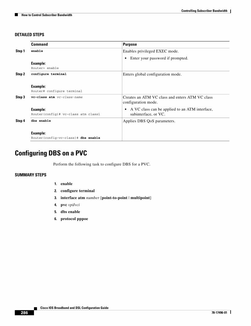
Controlling Subscriber BandwidthHow to Control Subscriber Bandwidth
286Cisco IOS Broadband and DSL Configuration Guide
78-17496-01
DETAILED STEPS
Configuring DBS on a PVCPerform the following task to configure DBS for a PVC.
SUMMARY STEPS
1. enable
2. configure terminal
3. interface atm number [point-to-point | multipoint]
4. pvc vpi/vci
5. dbs enable
6. protocol pppoe
Command Purpose
Step 1 enable
Example:Router> enable
Enables privileged EXEC mode.
• Enter your password if prompted.
Step 2 configure terminal
Example:Router# configure terminal
Enters global configuration mode.
Step 3 vc-class atm vc-class-name
Example:Router(config)# vc-class atm class1
Creates an ATM VC class and enters ATM VC class configuration mode.
• A VC class can be applied to an ATM interface, subinterface, or VC.
Step 4 dbs enable
Example:Router(config-vc-class)# dbs enable
Applies DBS QoS parameters.
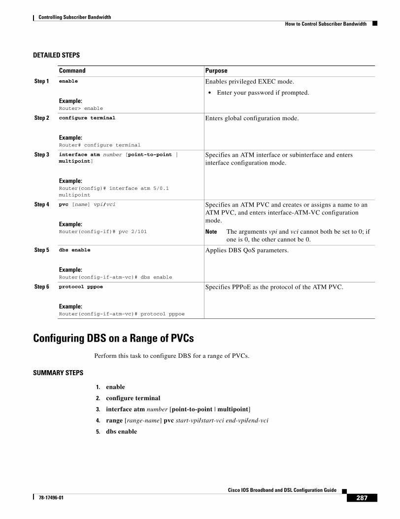
Controlling Subscriber BandwidthHow to Control Subscriber Bandwidth
287Cisco IOS Broadband and DSL Configuration Guide
78-17496-01
DETAILED STEPS
Configuring DBS on a Range of PVCsPerform this task to configure DBS for a range of PVCs.
SUMMARY STEPS
1. enable
2. configure terminal
3. interface atm number [point-to-point | multipoint]
4. range [range-name] pvc start-vpi/start-vci end-vpi/end-vci
5. dbs enable
Command Purpose
Step 1 enable
Example:Router> enable
Enables privileged EXEC mode.
• Enter your password if prompted.
Step 2 configure terminal
Example:Router# configure terminal
Enters global configuration mode.
Step 3 interface atm number [point-to-point | multipoint]
Example:Router(config)# interface atm 5/0.1 multipoint
Specifies an ATM interface or subinterface and enters interface configuration mode.
Step 4 pvc [name] vpi/vci
Example:Router(config-if)# pvc 2/101
Specifies an ATM PVC and creates or assigns a name to an ATM PVC, and enters interface-ATM-VC configuration mode.
Note The arguments vpi and vci cannot both be set to 0; if one is 0, the other cannot be 0.
Step 5 dbs enable
Example:Router(config-if-atm-vc)# dbs enable
Applies DBS QoS parameters.
Step 6 protocol pppoe
Example:Router(config-if-atm-vc)# protocol pppoe
Specifies PPPoE as the protocol of the ATM PVC.
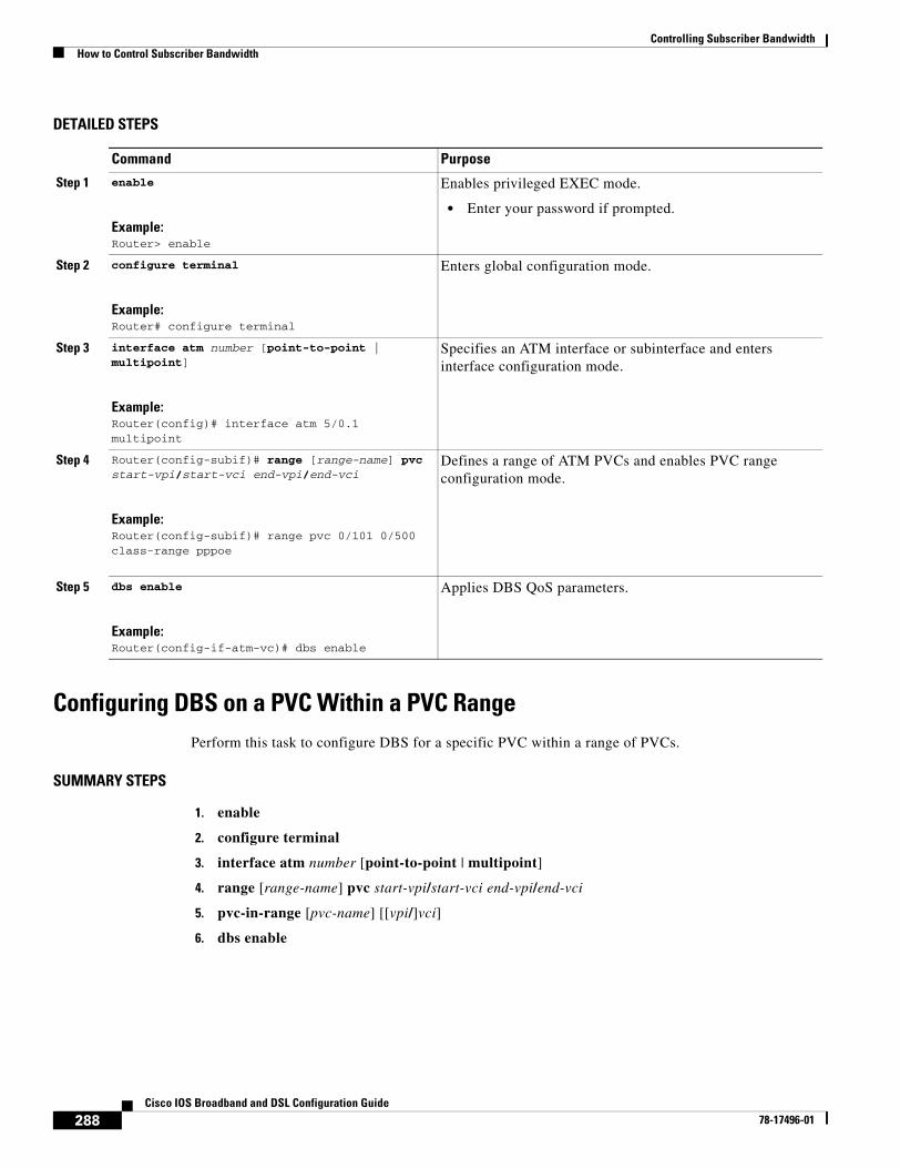
Controlling Subscriber BandwidthHow to Control Subscriber Bandwidth
288Cisco IOS Broadband and DSL Configuration Guide
78-17496-01
DETAILED STEPS
Configuring DBS on a PVC Within a PVC RangePerform this task to configure DBS for a specific PVC within a range of PVCs.
SUMMARY STEPS
1. enable
2. configure terminal
3. interface atm number [point-to-point | multipoint]
4. range [range-name] pvc start-vpi/start-vci end-vpi/end-vci
5. pvc-in-range [pvc-name] [[vpi/]vci]
6. dbs enable
Command Purpose
Step 1 enable
Example:Router> enable
Enables privileged EXEC mode.
• Enter your password if prompted.
Step 2 configure terminal
Example:Router# configure terminal
Enters global configuration mode.
Step 3 interface atm number [point-to-point | multipoint]
Example:Router(config)# interface atm 5/0.1 multipoint
Specifies an ATM interface or subinterface and enters interface configuration mode.
Step 4 Router(config-subif)# range [range-name] pvc start-vpi/start-vci end-vpi/end-vci
Example:Router(config-subif)# range pvc 0/101 0/500 class-range pppoe
Defines a range of ATM PVCs and enables PVC range configuration mode.
Step 5 dbs enable
Example:Router(config-if-atm-vc)# dbs enable
Applies DBS QoS parameters.
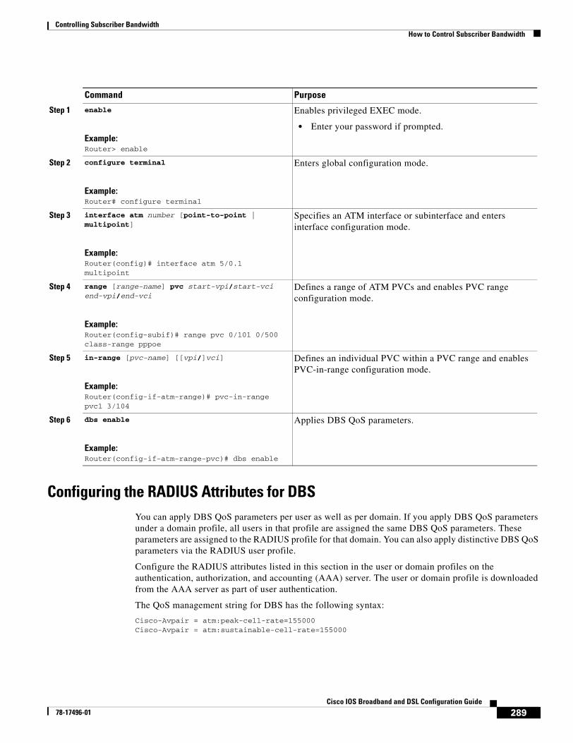
Controlling Subscriber BandwidthHow to Control Subscriber Bandwidth
289Cisco IOS Broadband and DSL Configuration Guide
78-17496-01
Configuring the RADIUS Attributes for DBSYou can apply DBS QoS parameters per user as well as per domain. If you apply DBS QoS parameters under a domain profile, all users in that profile are assigned the same DBS QoS parameters. These parameters are assigned to the RADIUS profile for that domain. You can also apply distinctive DBS QoS parameters via the RADIUS user profile.
Configure the RADIUS attributes listed in this section in the user or domain profiles on the authentication, authorization, and accounting (AAA) server. The user or domain profile is downloaded from the AAA server as part of user authentication.
The QoS management string for DBS has the following syntax:
Cisco-Avpair = atm:peak-cell-rate=155000Cisco-Avpair = atm:sustainable-cell-rate=155000
Command Purpose
Step 1 enable
Example:Router> enable
Enables privileged EXEC mode.
• Enter your password if prompted.
Step 2 configure terminal
Example:Router# configure terminal
Enters global configuration mode.
Step 3 interface atm number [point-to-point | multipoint]
Example:Router(config)# interface atm 5/0.1 multipoint
Specifies an ATM interface or subinterface and enters interface configuration mode.
Step 4 range [range-name] pvc start-vpi/start-vci end-vpi/end-vci
Example:Router(config-subif)# range pvc 0/101 0/500 class-range pppoe
Defines a range of ATM PVCs and enables PVC range configuration mode.
Step 5 in-range [pvc-name] [[vpi/]vci]
Example:Router(config-if-atm-range)# pvc-in-range pvc1 3/104
Defines an individual PVC within a PVC range and enables PVC-in-range configuration mode.
Step 6 dbs enable
Example:Router(config-if-atm-range-pvc)# dbs enable
Applies DBS QoS parameters.
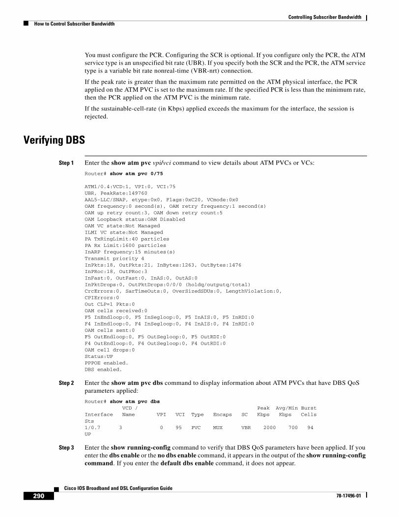
Controlling Subscriber BandwidthHow to Control Subscriber Bandwidth
290Cisco IOS Broadband and DSL Configuration Guide
78-17496-01
You must configure the PCR. Configuring the SCR is optional. If you configure only the PCR, the ATM service type is an unspecified bit rate (UBR). If you specify both the SCR and the PCR, the ATM service type is a variable bit rate nonreal-time (VBR-nrt) connection.
If the peak rate is greater than the maximum rate permitted on the ATM physical interface, the PCR applied on the ATM PVC is set to the maximum rate. If the specified PCR is less than the minimum rate, then the PCR applied on the ATM PVC is the minimum rate.
If the sustainable-cell-rate (in Kbps) applied exceeds the maximum for the interface, the session is rejected.
Verifying DBS
Step 1 Enter the show atm pvc vpi/vci command to view details about ATM PVCs or VCs:
Router# show atm pvc 0/75
ATM1/0.4:VCD:1, VPI:0, VCI:75UBR, PeakRate:149760AAL5-LLC/SNAP, etype:0x0, Flags:0xC20, VCmode:0x0OAM frequency:0 second(s), OAM retry frequency:1 second(s)OAM up retry count:3, OAM down retry count:5OAM Loopback status:OAM DisabledOAM VC state:Not ManagedILMI VC state:Not ManagedPA TxRingLimit:40 particlesPA Rx Limit:1600 particlesInARP frequency:15 minutes(s)Transmit priority 4InPkts:18, OutPkts:21, InBytes:1263, OutBytes:1476InPRoc:18, OutPRoc:3InFast:0, OutFast:0, InAS:0, OutAS:0InPktDrops:0, OutPktDrops:0/0/0 (holdq/outputq/total)CrcErrors:0, SarTimeOuts:0, OverSizedSDUs:0, LengthViolation:0,CPIErrors:0Out CLP=1 Pkts:0OAM cells received:0F5 InEndloop:0, F5 InSegloop:0, F5 InAIS:0, F5 InRDI:0F4 InEndloop:0, F4 InSegloop:0, F4 InAIS:0, F4 InRDI:0OAM cells sent:0F5 OutEndloop:0, F5 OutSegloop:0, F5 OutRDI:0F4 OutEndloop:0, F4 OutSegloop:0, F4 OutRDI:0OAM cell drops:0Status:UPPPPOE enabled.DBS enabled.
Step 2 Enter the show atm pvc dbs command to display information about ATM PVCs that have DBS QoS parameters applied:
Router# show atm pvc dbs VCD / Peak Avg/Min BurstInterface Name VPI VCI Type Encaps SC Kbps Kbps CellsSts1/0.7 3 0 95 PVC MUX VBR 2000 700 94UP
Step 3 Enter the show running-config command to verify that DBS QoS parameters have been applied. If you enter the dbs enable or the no dbs enable command, it appears in the output of the show running-config command. If you enter the default dbs enable command, it does not appear.
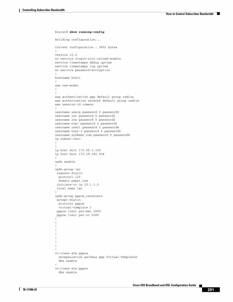
Controlling Subscriber BandwidthHow to Control Subscriber Bandwidth
291Cisco IOS Broadband and DSL Configuration Guide
78-17496-01
Router# show running-config
Building configuration...
Current configuration : 2902 bytes!version 12.2no service single-slot-reload-enableservice timestamps debug uptimeservice timestamps log uptimeno service password-encryption!hostname host1!aaa new-model!!aaa authentication ppp default group radiusaaa authorization network default group radius aaa session-id common!username usera password 0 password0username lac password 0 password1username lns password 0 password2username nrp1 password 0 password3username user1 password 0 password4username nrp1-3 password 0 password5username [email protected] password 0 password6ip subnet-zero!!ip host dirt 172.69.1.129ip host boot 172.19.192.254!vpdn enable!vpdn-group lac request-dialin protocol l2f domain pepsi.com initiate-to ip 10.1.1.5 local name lac!vpdn-group pppoe_terminate accept-dialin protocol pppoe virtual-template 1 pppoe limit per-mac 2000 pppoe limit per-vc 2000! !!!!!!!!vc-class atm pppoa encapsulation aal5mux ppp Virtual-Template2 dbs enable!vc-class atm pppoe dbs enable
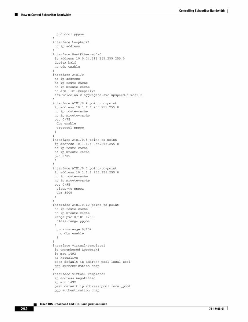
Controlling Subscriber BandwidthHow to Control Subscriber Bandwidth
292Cisco IOS Broadband and DSL Configuration Guide
78-17496-01
protocol pppoe!interface Loopback1 no ip address!interface FastEthernet0/0 ip address 10.0.74.211 255.255.255.0 duplex half no cdp enable!interface ATM1/0 no ip address no ip route-cache no ip mroute-cache no atm ilmi-keepalive atm voice aal2 aggregate-svc upspeed-number 0!interface ATM1/0.4 point-to-point ip address 10.1.1.6 255.255.255.0 no ip route-cache no ip mroute-cache pvc 0/75 dbs enable protocol pppoe !!interface ATM1/0.5 point-to-point ip address 10.1.1.6 255.255.255.0 no ip route-cache no ip mroute-cache pvc 0/85 !!interface ATM1/0.7 point-to-point ip address 10.1.1.6 255.255.255.0 no ip route-cache no ip mroute-cache pvc 0/95 class-vc pppoa ubr 5000 !!interface ATM1/0.10 point-to-point no ip route-cache no ip mroute-cache range pvc 0/101 0/500 class-range pppoe ! pvc-in-range 0/102 no dbs enable !!interface Virtual-Template1 ip unnumbered Loopback1 ip mtu 1492 no keepalive peer default ip address pool local_pool ppp authentication chap!interface Virtual-Template2 ip address negotiated ip mtu 1492 peer default ip address pool local_pool ppp authentication chap
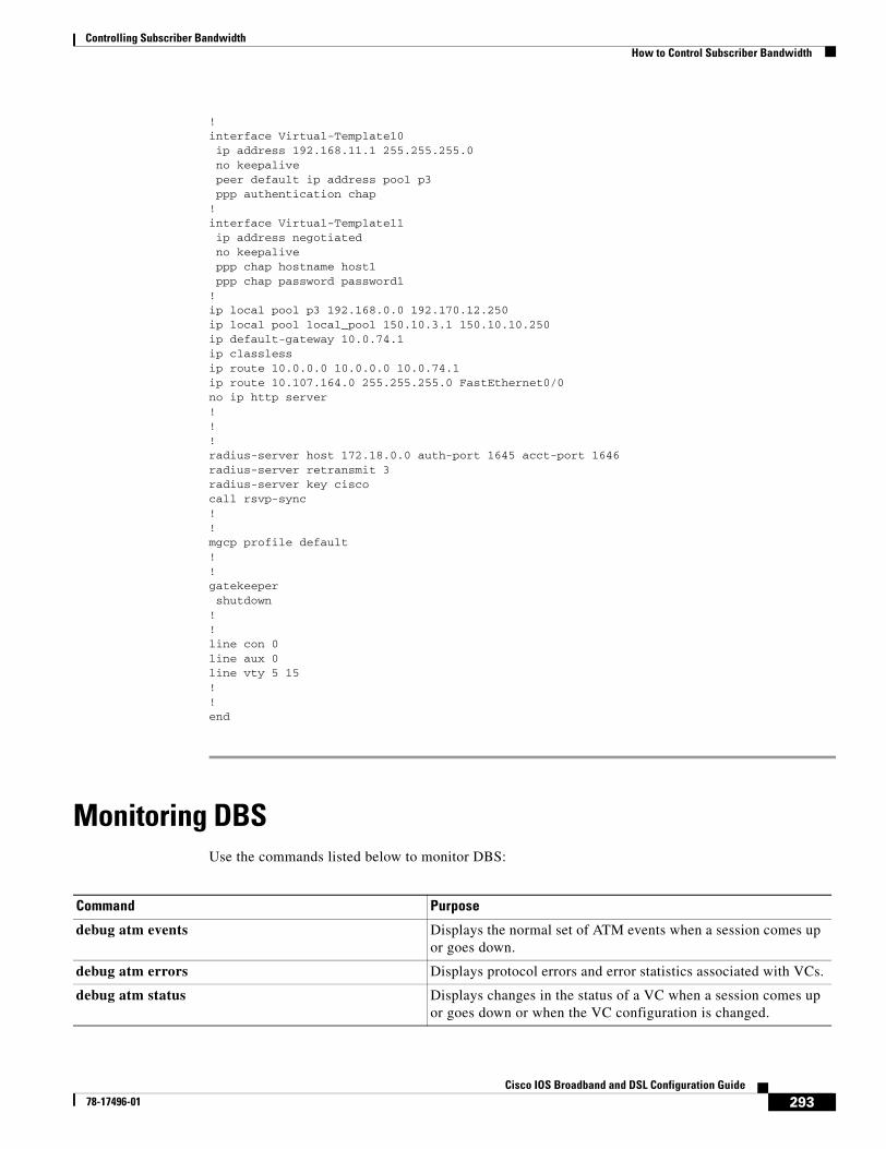
Controlling Subscriber BandwidthHow to Control Subscriber Bandwidth
293Cisco IOS Broadband and DSL Configuration Guide
78-17496-01
!interface Virtual-Template10 ip address 192.168.11.1 255.255.255.0 no keepalive peer default ip address pool p3 ppp authentication chap!interface Virtual-Template11 ip address negotiated no keepalive ppp chap hostname host1 ppp chap password password1!ip local pool p3 192.168.0.0 192.170.12.250ip local pool local_pool 150.10.3.1 150.10.10.250ip default-gateway 10.0.74.1ip classlessip route 10.0.0.0 10.0.0.0 10.0.74.1ip route 10.107.164.0 255.255.255.0 FastEthernet0/0no ip http server!!!radius-server host 172.18.0.0 auth-port 1645 acct-port 1646radius-server retransmit 3radius-server key ciscocall rsvp-sync!!mgcp profile default!!gatekeeper shutdown!!line con 0line aux 0line vty 5 15!!end
Monitoring DBSUse the commands listed below to monitor DBS:
Command Purpose
debug atm events Displays the normal set of ATM events when a session comes up or goes down.
debug atm errors Displays protocol errors and error statistics associated with VCs.
debug atm status Displays changes in the status of a VC when a session comes up or goes down or when the VC configuration is changed.
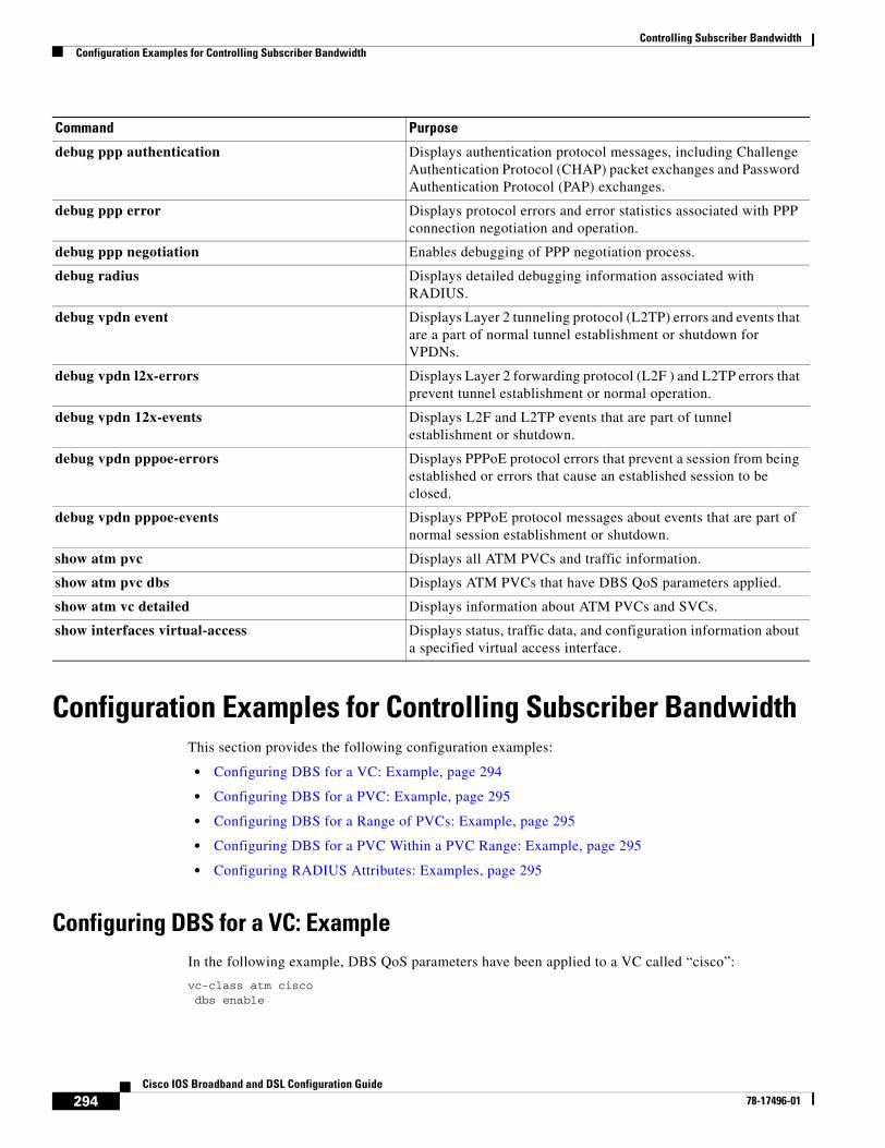
Controlling Subscriber BandwidthConfiguration Examples for Controlling Subscriber Bandwidth
294Cisco IOS Broadband and DSL Configuration Guide
78-17496-01
Configuration Examples for Controlling Subscriber BandwidthThis section provides the following configuration examples:
• Configuring DBS for a VC: Example, page 294
• Configuring DBS for a PVC: Example, page 295
• Configuring DBS for a Range of PVCs: Example, page 295
• Configuring DBS for a PVC Within a PVC Range: Example, page 295
• Configuring RADIUS Attributes: Examples, page 295
Configuring DBS for a VC: ExampleIn the following example, DBS QoS parameters have been applied to a VC called “cisco”:
vc-class atm ciscodbs enable
debug ppp authentication Displays authentication protocol messages, including Challenge Authentication Protocol (CHAP) packet exchanges and Password Authentication Protocol (PAP) exchanges.
debug ppp error Displays protocol errors and error statistics associated with PPP connection negotiation and operation.
debug ppp negotiation Enables debugging of PPP negotiation process.
debug radius Displays detailed debugging information associated with RADIUS.
debug vpdn event Displays Layer 2 tunneling protocol (L2TP) errors and events that are a part of normal tunnel establishment or shutdown for VPDNs.
debug vpdn l2x-errors Displays Layer 2 forwarding protocol (L2F ) and L2TP errors that prevent tunnel establishment or normal operation.
debug vpdn 12x-events Displays L2F and L2TP events that are part of tunnel establishment or shutdown.
debug vpdn pppoe-errors Displays PPPoE protocol errors that prevent a session from being established or errors that cause an established session to be closed.
debug vpdn pppoe-events Displays PPPoE protocol messages about events that are part of normal session establishment or shutdown.
show atm pvc Displays all ATM PVCs and traffic information.
show atm pvc dbs Displays ATM PVCs that have DBS QoS parameters applied.
show atm vc detailed Displays information about ATM PVCs and SVCs.
show interfaces virtual-access Displays status, traffic data, and configuration information about a specified virtual access interface.
Command Purpose
Controlling Subscriber BandwidthConfiguration Examples for Controlling Subscriber Bandwidth
295Cisco IOS Broadband and DSL Configuration Guide
78-17496-01
Configuring DBS for a PVC: ExampleIn the following example, DBS QoS parameters have been applied on a PVC called “cisco”:
interface atm0/0/0.5 point-to-pointip address 10.0.0.0 255.255.255.0pvc cisco 0/100dbs enableprotocol pppoe
Configuring DBS for a Range of PVCs: ExampleIn the following example, DBS QoS parameters have been applied on a range of PVCs. The range is named “cisco range” and has a start-vpi of 0, a start-vci of 50, an end-vpi of 0, and an end-vci of 70:
interface atm0/0/0.1 multipointip address 10.0.0.0 255.255.255.0range cisco pvc 0/50 0/70dbs enable
Configuring DBS for a PVC Within a PVC Range: ExampleIn the following example, DBS parameters have been applied on PVC 60, which is part of the PVC range called “cisco”:
interface atm0/0/0.1 multipointrange cisco pvc 0/50 0/70pvc-in-range 60dbs enable
Configuring RADIUS Attributes: ExamplesThe following example shows how to configure RADIUS attributes for a domain profile for DBS:
cisco.com Password = "cisco", Service-Type = OutboundService-Type = Outbound,Cisco-Avpair = "vpdn:tunnel-id=tunnel33",Cisco-Avpair = "vpdn:tunnel-type=l2tp",Cisco-Avpair = "vpdn:l2tp-tunnel-password=password2",Cisco-Avpair = "vpdn:ip-addresses=172.16.0.0",Cisco-Avpair = "atm:peak-cell-rate=155000",Cisco-Avpair = "atm:sustainable-cell-rate=155000"
The following example shows how to configure RADIUS attributes for a user profile for DBS:
[email protected] Password = "userpassword1", Service-Type = OutboundService-Type = Outbound,Cisco-Avpair = "vpdn:tunnel-id=tunnel33",Cisco-Avpair = "vpdn:tunnel-type=l2tp",Cisco-Avpair = "vpdn:l2tp-tunnel-password=password2",Cisco-Avpair = "vpdn:ip-addresses=172.16.0.0",Cisco-Avpair = "atm:peak-cell-rate=155000",Cisco-Avpair = "atm:sustainable-cell-rate=155000"
Controlling Subscriber BandwidthAdditional References
296Cisco IOS Broadband and DSL Configuration Guide
78-17496-01
Additional References
Related Documents
Standards
MIBs
RFCs
Related Topic Document Title
Cisco Subscriber Edge Services Manager Cisco Subscriber Edge Services Manager
HTTP Redirect-Login on 6400 series routers See the “Service Selection Gateway” chapter of the Cisco 6400 Feature Guide for Releases 12.1(5)DB and 12.1(5)DC
Cisco 6400 Series Routers Cisco 6400 Software Configuration Guide and Command Reference
Access Point Name Manager APN Manager Application Programming Guide
RADIUS configuration “Configuring RADIUS” chapter of the Cisco IOS Security Configuration Guide, Release 12.3
RADIUS attributes “RADIUS Attributes” appendix to the Cisco IOS Security Configuration Guide, Release 12.3
Broadband access aggregation concepts “Understanding Broadband Access Aggregation” module
Tasks for preparing for broadband access aggregation “Preparing for Broadband Access Aggregation” module
Broadband access commands: complete command syntax, command mode, command history, defaults, usage guidelines, and examples
“Wide-Area Networking Commands” in the Cisco IOS Wide-Area Networking Command Reference, Release 12.3
Standards Title
None —
MIBs MIBs Link
None To locate and download MIBs for selected platforms, Cisco IOS releases, and feature sets, use Cisco MIB Locator found at the following URL:
http://www.cisco.com/go/mibs
RFCs Title
None —
http://www.cisco.com/univercd/cc/td/doc/product/software/ios123/123tcr/123twr/wan_a1gt.htm#wp1056981
Controlling Subscriber BandwidthAdditional References
297Cisco IOS Broadband and DSL Configuration Guide
78-17496-01
Technical Assistance
Description Link
The Cisco Technical Support website contains thousands of pages of searchable technical content, including links to products, technologies, solutions, technical tips, and tools. Registered Cisco.com users can log in from this page to access even more content.
http://www.cisco.com/techsupport
Controlling Subscriber BandwidthFeature Information for Controlling Subscriber Bandwidth
298Cisco IOS Broadband and DSL Configuration Guide
78-17496-01
Feature Information for Controlling Subscriber BandwidthTable 23 lists the features in this module and provides links to specific configuration information. Only features that were introduced or modified in the Cisco IOS Release 12.2 or later releases appear in the table.
Not all commands may be available in your Cisco IOS Release. For details on when support for specific commands was introduced, see the command reference documents.
If you are looking for information on a feature in this technology that is not documented here, see the “Configuring Broadband Access Aggregation Features Roadmap.”
Cisco IOS software images are specific to a Cisco IOS software release, a feature set, and a platform. Use Cisco Feature Navigator to find information about platform support and Cisco IOS software image support. Access Cisco Feature Navigator at http://www.cisco.com/go/fn. You must have an account on Cisco.com. If you do not have an account or have forgotten your username or password, click Cancel at the login dialog box and follow the instructions that appear.
Note Table 23 lists only the Cisco IOS software release that introduced support for a given feature in a given Cisco IOS software release train. Unless noted otherwise, subsequent releases of that Cisco IOS software release train also support that feature.
Table 23 Feature Information for Controlling Subscriber Bandwidth
Feature Name Releases Feature Configuration Information
Dynamic Subscriber Bandwidth Selection (DBS) 12.2(4)B12.2(13)T
This feature enables wholesale service providers to sell different classes of service to retail service providers by controlling bandwidth at the ATM virtual circuit (VC) level. ATM quality of service (QoS) parameters from the subscriber domain are applied to the ATM PVC on which a PPPoE or PPPoA session is established.
The following sections provide information about this feature:
• “Information About Controlling Subscriber Bandwidth” section on page 284
• “How to Control Subscriber Bandwidth” section on page 285

Part 6: RADIUS NAS Port Attributes

301Cisco IOS Broadband and DSL Configuration Guide
78-17496-01
Identifying the Physical Subscriber Line for RADIUS Access and Accounting
Identifying a physical subscriber line for communication to a RADIUS server enables an L2TP access concentrator (LAC) and an L2TP network server (LNS) to identify and forward RADIUS NAS-Port and NAS-Port-Type attribute values for PPP over ATM, PPPoE over ATM, and PPPoE over IEEE 802.1Q virtual LANs (VLANs).
Module History
This module was first published on May 2, 2005, and last updated on May 2, 2005.
Finding Feature Information in This Module
Not all features may be supported in your Cisco IOS software release. Use the “Feature Information for Identifying the Physical Subscriber Line for RADIUS Access and Accounting” section on page 310 to find information about feature support and configuration.
Contents• Prerequisites for Identifying the Physical Subscriber Line for RADIUS Access and Accounting,
page 302
• Information About Identifying the Physical Subscriber Line for RADIUS Access and Accounting, page 302
• How to Identify the Physical Subscriber Line for RADIUS Access and Accounting, page 303
• Configuration Examples for Identifying the Physical Subscriber Line, page 305
• Additional References, page 308
• Feature Information for Identifying the Physical Subscriber Line for RADIUS Access and Accounting, page 310
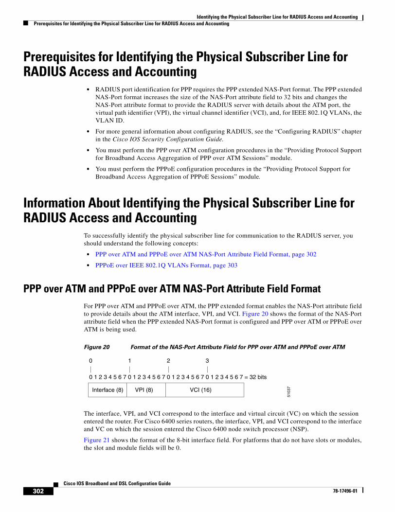
Identifying the Physical Subscriber Line for RADIUS Access and AccountingPrerequisites for Identifying the Physical Subscriber Line for RADIUS Access and Accounting
302Cisco IOS Broadband and DSL Configuration Guide
78-17496-01
Prerequisites for Identifying the Physical Subscriber Line for RADIUS Access and Accounting
• RADIUS port identification for PPP requires the PPP extended NAS-Port format. The PPP extended NAS-Port format increases the size of the NAS-Port attribute field to 32 bits and changes the NAS-Port attribute format to provide the RADIUS server with details about the ATM port, the virtual path identifier (VPI), the virtual channel identifier (VCI), and, for IEEE 802.1Q VLANs, the VLAN ID.
• For more general information about configuring RADIUS, see the “Configuring RADIUS” chapter in the Cisco IOS Security Configuration Guide.
• You must perform the PPP over ATM configuration procedures in the “Providing Protocol Support for Broadband Access Aggregation of PPP over ATM Sessions” module.
• You must perform the PPPoE configuration procedures in the “Providing Protocol Support for Broadband Access Aggregation of PPPoE Sessions” module.
Information About Identifying the Physical Subscriber Line for RADIUS Access and Accounting
To successfully identify the physical subscriber line for communication to the RADIUS server, you should understand the following concepts:
• PPP over ATM and PPPoE over ATM NAS-Port Attribute Field Format, page 302
• PPPoE over IEEE 802.1Q VLANs Format, page 303
PPP over ATM and PPPoE over ATM NAS-Port Attribute Field FormatFor PPP over ATM and PPPoE over ATM, the PPP extended format enables the NAS-Port attribute field to provide details about the ATM interface, VPI, and VCI. Figure 20 shows the format of the NAS-Port attribute field when the PPP extended NAS-Port format is configured and PPP over ATM or PPPoE over ATM is being used.
Figure 20 Format of the NAS-Port Attribute Field for PPP over ATM and PPPoE over ATM
The interface, VPI, and VCI correspond to the interface and virtual circuit (VC) on which the session entered the router. For Cisco 6400 series routers, the interface, VPI, and VCI correspond to the interface and VC on which the session entered the Cisco 6400 node switch processor (NSP).
Figure 21 shows the format of the 8-bit interface field. For platforms that do not have slots or modules, the slot and module fields will be 0.
0 1 2 3 4 5 6 7 0 1 2 3 4 5 6 7 0 1 2 3 4 5 6 7 0 1 2 3 4 5 6 7 = 32 bits
0 1
Interface (8) VPI (8) VCI (16)
2 3
5103
7
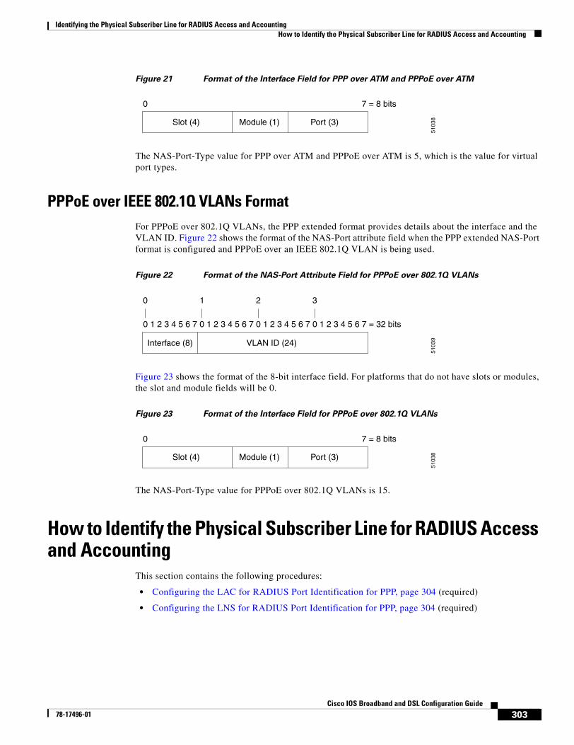
Identifying the Physical Subscriber Line for RADIUS Access and AccountingHow to Identify the Physical Subscriber Line for RADIUS Access and Accounting
303Cisco IOS Broadband and DSL Configuration Guide
78-17496-01
Figure 21 Format of the Interface Field for PPP over ATM and PPPoE over ATM
The NAS-Port-Type value for PPP over ATM and PPPoE over ATM is 5, which is the value for virtual port types.
PPPoE over IEEE 802.1Q VLANs FormatFor PPPoE over 802.1Q VLANs, the PPP extended format provides details about the interface and the VLAN ID. Figure 22 shows the format of the NAS-Port attribute field when the PPP extended NAS-Port format is configured and PPPoE over an IEEE 802.1Q VLAN is being used.
Figure 22 Format of the NAS-Port Attribute Field for PPPoE over 802.1Q VLANs
Figure 23 shows the format of the 8-bit interface field. For platforms that do not have slots or modules, the slot and module fields will be 0.
Figure 23 Format of the Interface Field for PPPoE over 802.1Q VLANs
The NAS-Port-Type value for PPPoE over 802.1Q VLANs is 15.
How to Identify the Physical Subscriber Line for RADIUS Access and Accounting
This section contains the following procedures:
• Configuring the LAC for RADIUS Port Identification for PPP, page 304 (required)
• Configuring the LNS for RADIUS Port Identification for PPP, page 304 (required)
0 7 = 8 bits
5103
8Slot (4) Port (3)Module (1)
0 1 2 3 4 5 6 7 0 1 2 3 4 5 6 7 0 1 2 3 4 5 6 7 0 1 2 3 4 5 6 7 = 32 bits
0 1
Interface (8) VLAN ID (24)
2 3
5103
90 7 = 8 bits
5103
8Slot (4) Port (3)Module (1)
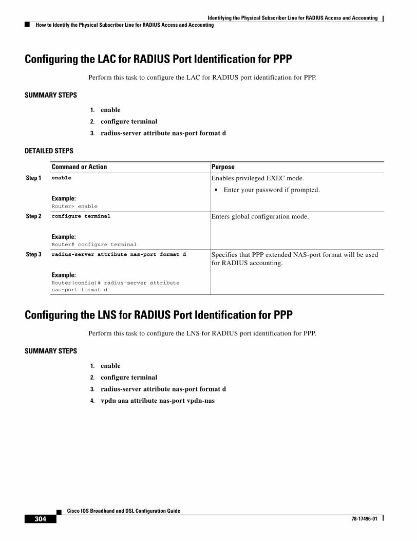
Identifying the Physical Subscriber Line for RADIUS Access and AccountingHow to Identify the Physical Subscriber Line for RADIUS Access and Accounting
304Cisco IOS Broadband and DSL Configuration Guide
78-17496-01
Configuring the LAC for RADIUS Port Identification for PPPPerform this task to configure the LAC for RADIUS port identification for PPP.
SUMMARY STEPS
1. enable
2. configure terminal
3. radius-server attribute nas-port format d
DETAILED STEPS
Configuring the LNS for RADIUS Port Identification for PPPPerform this task to configure the LNS for RADIUS port identification for PPP.
SUMMARY STEPS
1. enable
2. configure terminal
3. radius-server attribute nas-port format d
4. vpdn aaa attribute nas-port vpdn-nas
Command or Action Purpose
Step 1 enable
Example:Router> enable
Enables privileged EXEC mode.
• Enter your password if prompted.
Step 2 configure terminal
Example:Router# configure terminal
Enters global configuration mode.
Step 3 radius-server attribute nas-port format d
Example:Router(config)# radius-server attribute nas-port format d
Specifies that PPP extended NAS-port format will be used for RADIUS accounting.
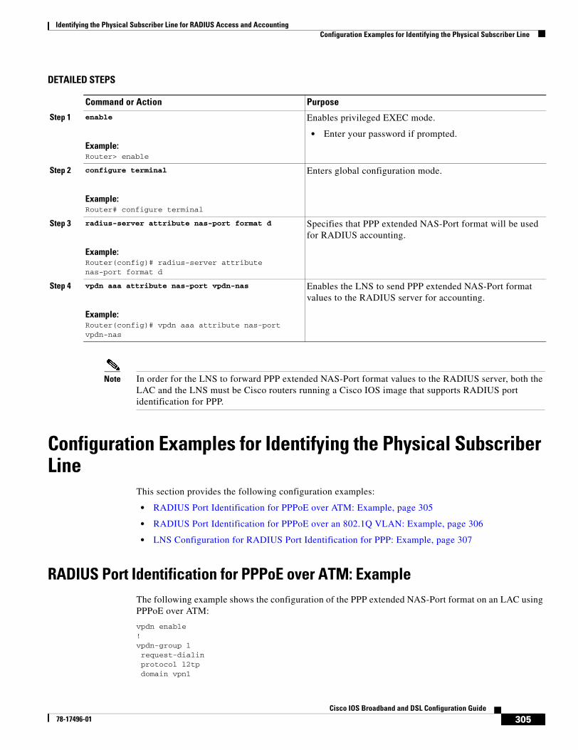
Identifying the Physical Subscriber Line for RADIUS Access and AccountingConfiguration Examples for Identifying the Physical Subscriber Line
305Cisco IOS Broadband and DSL Configuration Guide
78-17496-01
DETAILED STEPS
Note In order for the LNS to forward PPP extended NAS-Port format values to the RADIUS server, both the LAC and the LNS must be Cisco routers running a Cisco IOS image that supports RADIUS port identification for PPP.
Configuration Examples for Identifying the Physical Subscriber Line
This section provides the following configuration examples:
• RADIUS Port Identification for PPPoE over ATM: Example, page 305
• RADIUS Port Identification for PPPoE over an 802.1Q VLAN: Example, page 306
• LNS Configuration for RADIUS Port Identification for PPP: Example, page 307
RADIUS Port Identification for PPPoE over ATM: ExampleThe following example shows the configuration of the PPP extended NAS-Port format on an LAC using PPPoE over ATM:
vpdn enable ! vpdn-group 1 request-dialin protocol l2tp domain vpn1
Command or Action Purpose
Step 1 enable
Example:Router> enable
Enables privileged EXEC mode.
• Enter your password if prompted.
Step 2 configure terminal
Example:Router# configure terminal
Enters global configuration mode.
Step 3 radius-server attribute nas-port format d
Example:Router(config)# radius-server attribute nas-port format d
Specifies that PPP extended NAS-Port format will be used for RADIUS accounting.
Step 4 vpdn aaa attribute nas-port vpdn-nas
Example:Router(config)# vpdn aaa attribute nas-port vpdn-nas
Enables the LNS to send PPP extended NAS-Port format values to the RADIUS server for accounting.
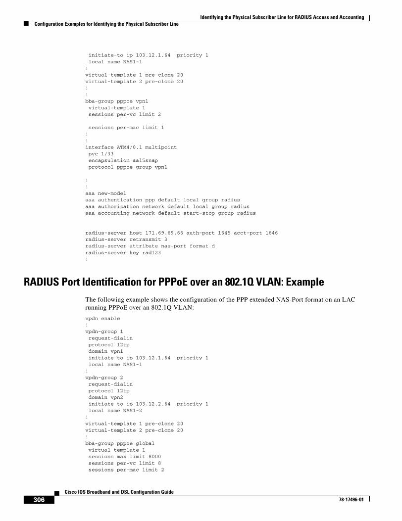
Identifying the Physical Subscriber Line for RADIUS Access and AccountingConfiguration Examples for Identifying the Physical Subscriber Line
306Cisco IOS Broadband and DSL Configuration Guide
78-17496-01
initiate-to ip 103.12.1.64 priority 1 local name NAS1-1 ! virtual-template 1 pre-clone 20 virtual-template 2 pre-clone 20 !! bba-group pppoe vpn1 virtual-template 1 sessions per-vc limit 2
sessions per-mac limit 1 ! !interface ATM4/0.1 multipoint pvc 1/33encapsulation aal5snapprotocol pppoe group vpn1
!!aaa new-modelaaa authentication ppp default local group radiusaaa authorization network default local group radiusaaa accounting network default start-stop group radius
radius-server host 171.69.69.66 auth-port 1645 acct-port 1646radius-server retransmit 3radius-server attribute nas-port format dradius-server key rad123!
RADIUS Port Identification for PPPoE over an 802.1Q VLAN: ExampleThe following example shows the configuration of the PPP extended NAS-Port format on an LAC running PPPoE over an 802.1Q VLAN:
vpdn enable ! vpdn-group 1 request-dialin protocol l2tp domain vpn1
initiate-to ip 103.12.1.64 priority 1 local name NAS1-1 ! vpdn-group 2 request-dialin protocol l2tp domain vpn2
initiate-to ip 103.12.2.64 priority 1 local name NAS1-2 ! virtual-template 1 pre-clone 20 virtual-template 2 pre-clone 20 ! bba-group pppoe global virtual-template 1 sessions max limit 8000 sessions per-vc limit 8 sessions per-mac limit 2
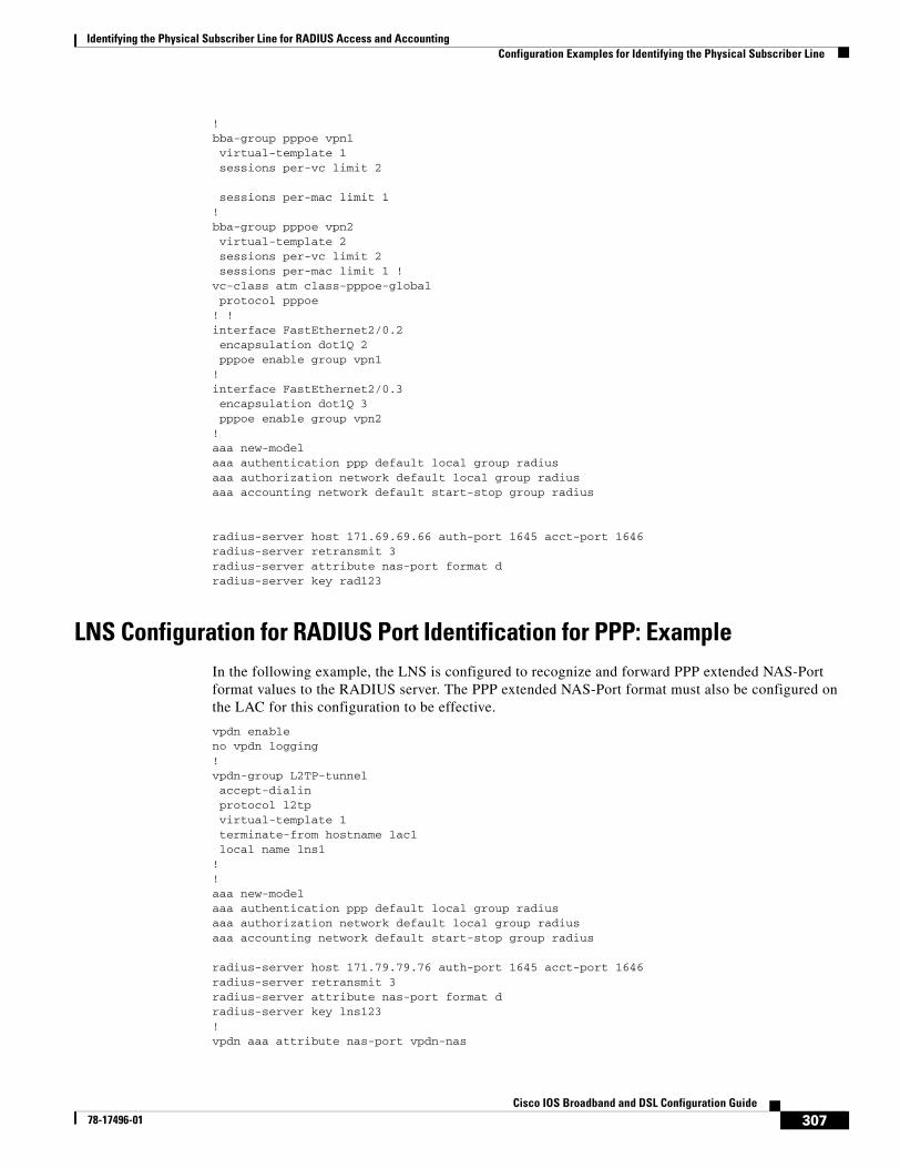
Identifying the Physical Subscriber Line for RADIUS Access and AccountingConfiguration Examples for Identifying the Physical Subscriber Line
307Cisco IOS Broadband and DSL Configuration Guide
78-17496-01
! bba-group pppoe vpn1 virtual-template 1 sessions per-vc limit 2
sessions per-mac limit 1 ! bba-group pppoe vpn2 virtual-template 2 sessions per-vc limit 2 sessions per-mac limit 1 ! vc-class atm class-pppoe-global protocol pppoe ! !interface FastEthernet2/0.2 encapsulation dot1Q 2 pppoe enable group vpn1!interface FastEthernet2/0.3 encapsulation dot1Q 3 pppoe enable group vpn2!aaa new-modelaaa authentication ppp default local group radiusaaa authorization network default local group radiusaaa accounting network default start-stop group radius
radius-server host 171.69.69.66 auth-port 1645 acct-port 1646radius-server retransmit 3radius-server attribute nas-port format dradius-server key rad123
LNS Configuration for RADIUS Port Identification for PPP: ExampleIn the following example, the LNS is configured to recognize and forward PPP extended NAS-Port format values to the RADIUS server. The PPP extended NAS-Port format must also be configured on the LAC for this configuration to be effective.
vpdn enableno vpdn logging!vpdn-group L2TP-tunnel accept-dialinprotocol l2tpvirtual-template 1
terminate-from hostname lac1 local name lns1! !aaa new-modelaaa authentication ppp default local group radiusaaa authorization network default local group radiusaaa accounting network default start-stop group radius
radius-server host 171.79.79.76 auth-port 1645 acct-port 1646radius-server retransmit 3radius-server attribute nas-port format dradius-server key lns123!vpdn aaa attribute nas-port vpdn-nas
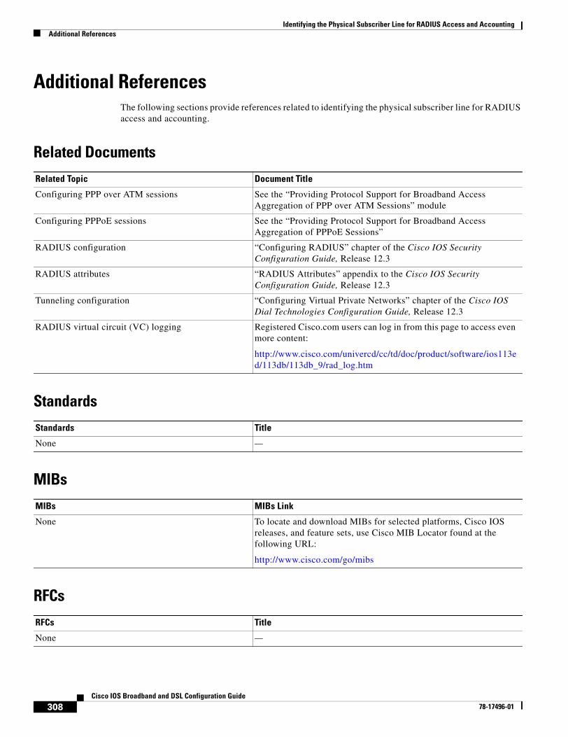
Identifying the Physical Subscriber Line for RADIUS Access and AccountingAdditional References
308Cisco IOS Broadband and DSL Configuration Guide
78-17496-01
Additional ReferencesThe following sections provide references related to identifying the physical subscriber line for RADIUS access and accounting.
Related Documents
Standards
MIBs
RFCs
Related Topic Document Title
Configuring PPP over ATM sessions See the “Providing Protocol Support for Broadband Access Aggregation of PPP over ATM Sessions” module
Configuring PPPoE sessions See the “Providing Protocol Support for Broadband Access Aggregation of PPPoE Sessions”
RADIUS configuration “Configuring RADIUS” chapter of the Cisco IOS Security Configuration Guide, Release 12.3
RADIUS attributes “RADIUS Attributes” appendix to the Cisco IOS Security Configuration Guide, Release 12.3
Tunneling configuration “Configuring Virtual Private Networks” chapter of the Cisco IOS Dial Technologies Configuration Guide, Release 12.3
RADIUS virtual circuit (VC) logging Registered Cisco.com users can log in from this page to access even more content:
http://www.cisco.com/univercd/cc/td/doc/product/software/ios113ed/113db/113db_9/rad_log.htm
Standards Title
None —
MIBs MIBs Link
None To locate and download MIBs for selected platforms, Cisco IOS releases, and feature sets, use Cisco MIB Locator found at the following URL:
http://www.cisco.com/go/mibs
RFCs Title
None —
Identifying the Physical Subscriber Line for RADIUS Access and AccountingAdditional References
309Cisco IOS Broadband and DSL Configuration Guide
78-17496-01
Technical Assistance
Description Link
The Cisco Technical Support website contains thousands of pages of searchable technical content, including links to products, technologies, solutions, technical tips, and tools. Registered Cisco.com users can log in from this page to access even more content.
http://www.cisco.com/techsupport
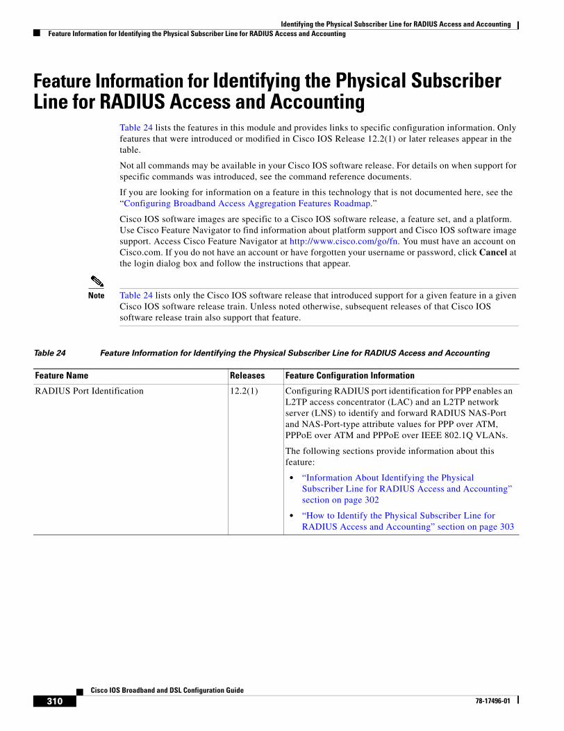
Identifying the Physical Subscriber Line for RADIUS Access and AccountingFeature Information for Identifying the Physical Subscriber Line for RADIUS Access and Accounting
310Cisco IOS Broadband and DSL Configuration Guide
78-17496-01
Feature Information for Identifying the Physical Subscriber Line for RADIUS Access and Accounting
Table 24 lists the features in this module and provides links to specific configuration information. Only features that were introduced or modified in Cisco IOS Release 12.2(1) or later releases appear in the table.
Not all commands may be available in your Cisco IOS software release. For details on when support for specific commands was introduced, see the command reference documents.
If you are looking for information on a feature in this technology that is not documented here, see the “Configuring Broadband Access Aggregation Features Roadmap.”
Cisco IOS software images are specific to a Cisco IOS software release, a feature set, and a platform. Use Cisco Feature Navigator to find information about platform support and Cisco IOS software image support. Access Cisco Feature Navigator at http://www.cisco.com/go/fn. You must have an account on Cisco.com. If you do not have an account or have forgotten your username or password, click Cancel at the login dialog box and follow the instructions that appear.
Note Table 24 lists only the Cisco IOS software release that introduced support for a given feature in a given Cisco IOS software release train. Unless noted otherwise, subsequent releases of that Cisco IOS software release train also support that feature.
Table 24 Feature Information for Identifying the Physical Subscriber Line for RADIUS Access and Accounting
Feature Name Releases Feature Configuration Information
RADIUS Port Identification 12.2(1) Configuring RADIUS port identification for PPP enables an L2TP access concentrator (LAC) and an L2TP network server (LNS) to identify and forward RADIUS NAS-Port and NAS-Port-type attribute values for PPP over ATM, PPPoE over ATM and PPPoE over IEEE 802.1Q VLANs.
The following sections provide information about this feature:
• “Information About Identifying the Physical Subscriber Line for RADIUS Access and Accounting” section on page 302
• “How to Identify the Physical Subscriber Line for RADIUS Access and Accounting” section on page 303

Part 7: DSL

313Cisco IOS Broadband and DSL Configuration Guide
78-17496-01
Virtual Auxiliary Port Feature and Configuration of DSL Settings
The virtual auxiliary port feature provides support for dial backup and out-of-band management on Cisco 837 and Cisco 831 routers, and provides support for out-of-band management on Cisco SOHO 97 and Cisco SOHO 91 routers. On these routers, the console port and the auxiliary port share the same physical RJ-45 port. The console port must be changed to act as a virtual auxiliary port, using the command-line interface (CLI) before the dial backup and out-of-band management capabilities can be enabled.
In addition, digital subscriber line (DSL) settings can now be configured on the Cisco 837, Cisco 831, Cisco SOHO 97, and Cisco SOHO 91 routers by using the DSL settings commands.
Feature Specifications for the Virtual Auxiliary Port Feature and the DSL Settings
Finding Support Information for Platforms and Cisco IOS Software Images
Use Cisco Feature Navigator to find information about platform support and Cisco IOS software image support. Access Cisco Feature Navigator at http://www.cisco.com/go/fn. You must have an account on Cisco.com. If you do not have an account or have forgotten your username or password, click Cancel at the login dialog box and follow the instructions that appear.
ContentsThis document contains the following sections:
• Information About the Virtual Auxiliary Port, page 314
• How to Configure the Virtual Auxiliary Port and the DSL Settings, page 314
• Configuration Example for Configuring the DSL Settings, page 317
• Additional References, page 318
• Command List, page 319
Feature HistoryRelease Modification
12.2(8)YN This feature was introduced.
12.3(2)T This feature was integrated into Cisco IOS Release 12.3(2)T.
Supported Platforms
Cisco 837, Cisco 831, Cisco SOHO 97, and Cisco SOHO 91.
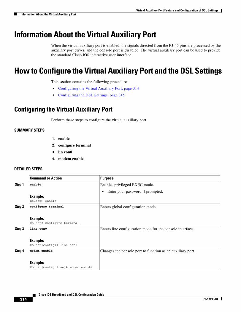
Virtual Auxiliary Port Feature and Configuration of DSL SettingsInformation About the Virtual Auxiliary Port
314Cisco IOS Broadband and DSL Configuration Guide
78-17496-01
Information About the Virtual Auxiliary PortWhen the virtual auxiliary port is enabled, the signals directed from the RJ-45 pins are processed by the auxiliary port driver, and the console port is disabled. The virtual auxiliary port can be used to provide the standard Cisco IOS interactive user interface.
How to Configure the Virtual Auxiliary Port and the DSL SettingsThis section contains the following procedures:
• Configuring the Virtual Auxiliary Port, page 314
• Configuring the DSL Settings, page 315
Configuring the Virtual Auxiliary PortPerform these steps to configure the virtual auxiliary port.
SUMMARY STEPS
1. enable
2. configure terminal
3. lin con0
4. modem enable
DETAILED STEPS
Command or Action Purpose
Step 1 enable
Example:Router> enable
Enables privileged EXEC mode.
• Enter your password if prompted.
Step 2 configure terminal
Example:Router# configure terminal
Enters global configuration mode.
Step 3 line con0
Example:Router(config)# line con0
Enters line configuration mode for the console interface.
Step 4 modem enable
Example:Router(config-line)# modem enable
Changes the console port to function as an auxiliary port.
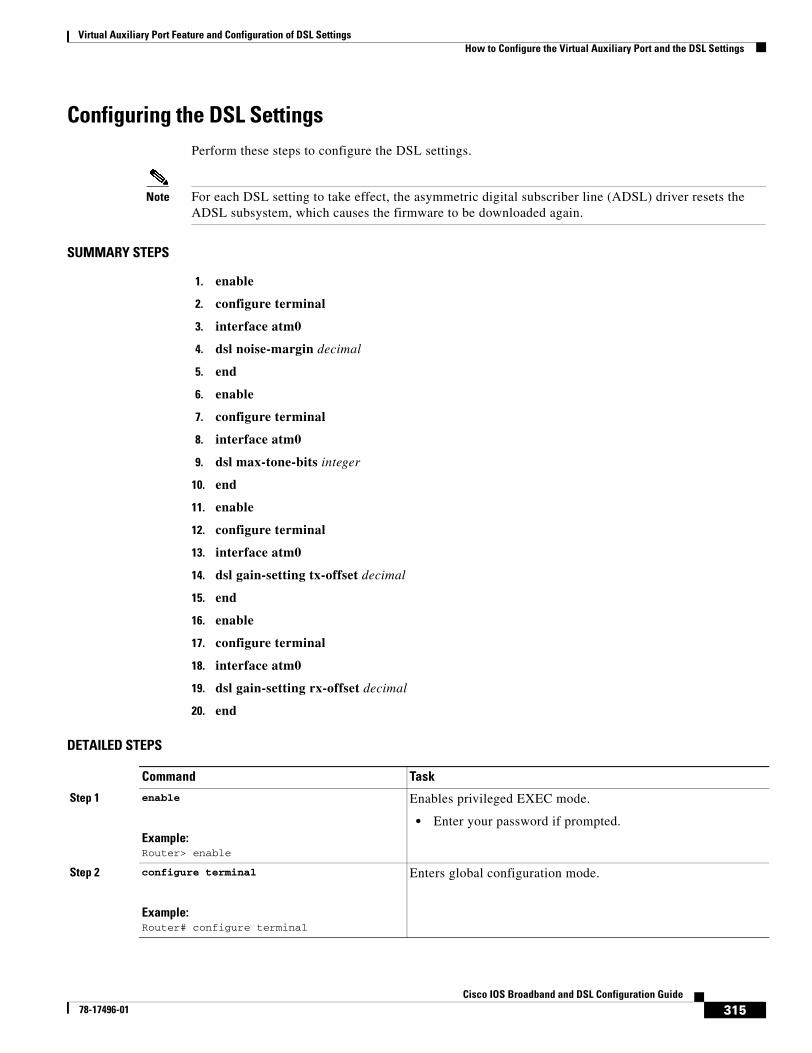
Virtual Auxiliary Port Feature and Configuration of DSL SettingsHow to Configure the Virtual Auxiliary Port and the DSL Settings
315Cisco IOS Broadband and DSL Configuration Guide
78-17496-01
Configuring the DSL SettingsPerform these steps to configure the DSL settings.
Note For each DSL setting to take effect, the asymmetric digital subscriber line (ADSL) driver resets the ADSL subsystem, which causes the firmware to be downloaded again.
SUMMARY STEPS
1. enable
2. configure terminal
3. interface atm0
4. dsl noise-margin decimal
5. end
6. enable
7. configure terminal
8. interface atm0
9. dsl max-tone-bits integer
10. end
11. enable
12. configure terminal
13. interface atm0
14. dsl gain-setting tx-offset decimal
15. end
16. enable
17. configure terminal
18. interface atm0
19. dsl gain-setting rx-offset decimal
20. end
DETAILED STEPS
Command Task
Step 1 enable
Example:Router> enable
Enables privileged EXEC mode.
• Enter your password if prompted.
Step 2 configure terminal
Example:Router# configure terminal
Enters global configuration mode.
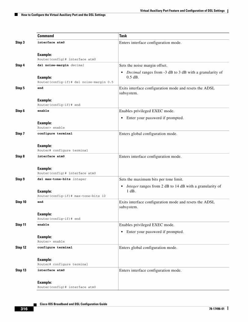
Virtual Auxiliary Port Feature and Configuration of DSL SettingsHow to Configure the Virtual Auxiliary Port and the DSL Settings
316Cisco IOS Broadband and DSL Configuration Guide
78-17496-01
Step 3 interface atm0
Example:Router(config)# interface atm0
Enters interface configuration mode.
Step 4 dsl noise-margin decimal
Example:Router(config-if)# dsl noise-margin 0.5
Sets the noise margin offset.
• Decimal ranges from -3 dB to 3 dB with a granularity of 0.5 dB.
Step 5 end
Example:Router(config-if)# end
Exits interface configuration mode and resets the ADSL subsystem.
Step 6 enable
Example:Router> enable
Enables privileged EXEC mode.
• Enter your password if prompted.
Step 7 configure terminal
Example:Router# configure terminal
Enters global configuration mode.
Step 8 interface atm0
Example:Router(config)# interface atm0
Enters interface configuration mode.
Step 9 dsl max-tone-bits integer
Example:Router(config-if)# max-tone-bits 10
Sets the maximum bits per tone limit.
• Integer ranges from 2 dB to 14 dB with a granularity of 1 dB.
Step 10 end
Example:Router(config-if)# end
Exits interface configuration mode and resets the ADSL subsystem.
Step 11 enable
Example:Router> enable
Enables privileged EXEC mode.
• Enter your password if prompted.
Step 12 configure terminal
Example:Router# configure terminal
Enters global configuration mode.
Step 13 interface atm0
Example:Router(config)# interface atm0
Enters interface configuration mode.
Command Task
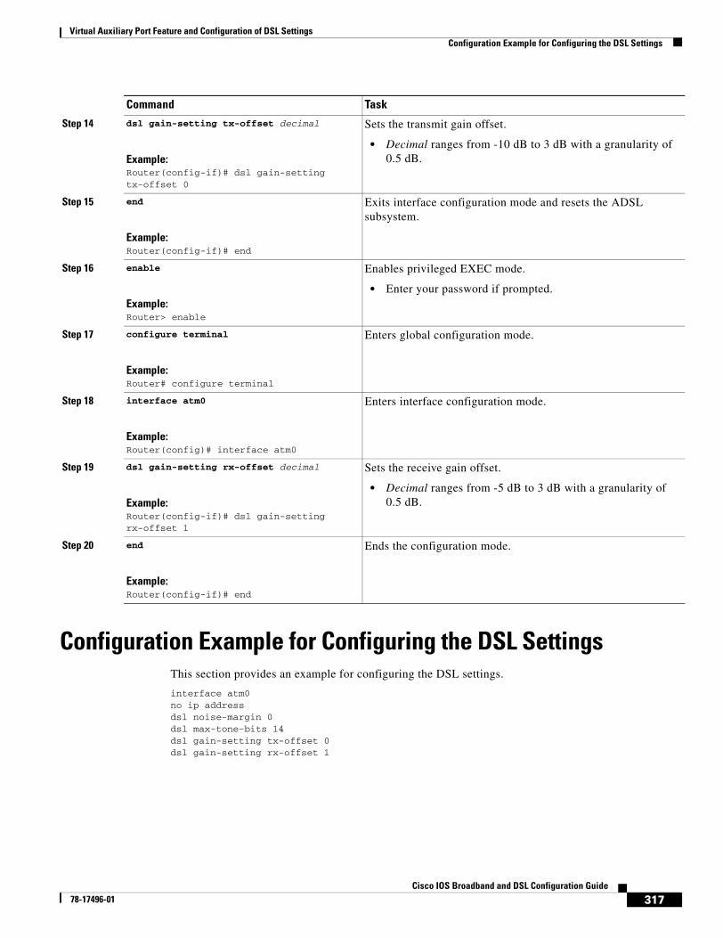
Virtual Auxiliary Port Feature and Configuration of DSL SettingsConfiguration Example for Configuring the DSL Settings
317Cisco IOS Broadband and DSL Configuration Guide
78-17496-01
Configuration Example for Configuring the DSL SettingsThis section provides an example for configuring the DSL settings.
interface atm0no ip addressdsl noise-margin 0dsl max-tone-bits 14dsl gain-setting tx-offset 0dsl gain-setting rx-offset 1
Step 14 dsl gain-setting tx-offset decimal
Example:Router(config-if)# dsl gain-setting tx-offset 0
Sets the transmit gain offset.
• Decimal ranges from -10 dB to 3 dB with a granularity of 0.5 dB.
Step 15 end
Example:Router(config-if)# end
Exits interface configuration mode and resets the ADSL subsystem.
Step 16 enable
Example:Router> enable
Enables privileged EXEC mode.
• Enter your password if prompted.
Step 17 configure terminal
Example:Router# configure terminal
Enters global configuration mode.
Step 18 interface atm0
Example:Router(config)# interface atm0
Enters interface configuration mode.
Step 19 dsl gain-setting rx-offset decimal
Example:Router(config-if)# dsl gain-setting rx-offset 1
Sets the receive gain offset.
• Decimal ranges from -5 dB to 3 dB with a granularity of 0.5 dB.
Step 20 end
Example:Router(config-if)# end
Ends the configuration mode.
Command Task
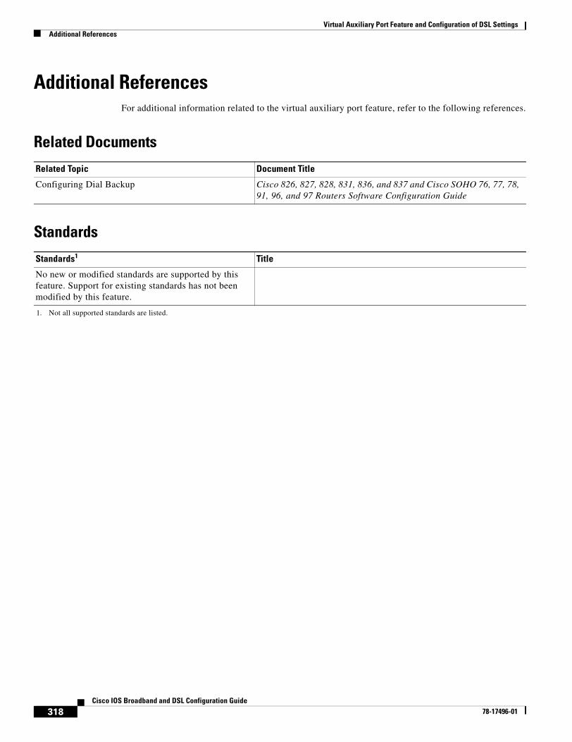
Virtual Auxiliary Port Feature and Configuration of DSL SettingsAdditional References
318Cisco IOS Broadband and DSL Configuration Guide
78-17496-01
Additional ReferencesFor additional information related to the virtual auxiliary port feature, refer to the following references.
Related Documents
Standards
Related Topic Document Title
Configuring Dial Backup Cisco 826, 827, 828, 831, 836, and 837 and Cisco SOHO 76, 77, 78, 91, 96, and 97 Routers Software Configuration Guide
Standards1
1. Not all supported standards are listed.
Title
No new or modified standards are supported by this feature. Support for existing standards has not been modified by this feature.
Virtual Auxiliary Port Feature and Configuration of DSL SettingsCommand List
319Cisco IOS Broadband and DSL Configuration Guide
78-17496-01
MIBs
RFCs
Technical Assistance
Command ListThe following commands are pertinent to this feature. To see the command pages for this and other commands used with this feature, go to the Cisco IOS Master Commands List, Release 12.4, at http://www.cisco.com/univercd/cc/td/doc/product/software/ios124/124mindx/124index.htm.
• modem enable
• dsl max-tone-bits
• dsl gain-setting rx-offset
• dsl gain-setting tx-offset
• dsl noise-margin
MIBs1
1. Not all supported MIBs are listed.
MIBs Link
No new or modified MIBs are supported by this feature. Support for existing MIBs has not been modified by this feature.
To locate and download MIBs for selected platforms, Cisco IOS releases, and feature sets, use Cisco MIB Locator available at the following URL:
http://www.cisco.com/go/mibs
RFCs1
1. Not all supported RFCs are listed.
Title
No new or modified RFCs are supported by this feature. Support for existing RFCs has not been modified by this feature.
Description Link
Technical Assistance Center (TAC) home page, containing 30,000 pages of searchable technical content, including links to products, technologies, solutions, technical tips, and tools. Registered Cisco.com users can log in from this page to access even more content.
http://www.cisco.com/public/support/tac/home.shtml

Virtual Auxiliary Port Feature and Configuration of DSL SettingsCommand List
320Cisco IOS Broadband and DSL Configuration Guide
78-17496-01
321Cisco IOS Broadband and DSL Configuration Guide
78-17496-01
Monitoring and Retraining on Reception of Loss of Margin Messages
Loss of Margin (LoM) monitoring allows the router to handle asymmetric digital subscriber line (ADSL) loss of margin messages received from the digital subscriber line access multiplexer (DSLAM). The dsl lom command is used to set digital subscriber line (DSL) LoM monitoring. The no dsl lom command disables LoM monitoring after the router has been configured to monitor LoM messages.
When set to monitor LoM, the router will retrain with the DSLAM when it receives LoM messages consecutively for the number of times specified in the number argument.
Feature History for the Monitoring and Retraining on Reception of Loss of Margin Messages Feature
Finding Support Information for Platforms and Cisco IOS Software Images
Use Cisco Feature Navigator to find information about platform support and Cisco IOS software image support. Access Cisco Feature Navigator at http://www.cisco.com/go/fn. You must have an account on Cisco.com. If you do not have an account or have forgotten your username or password, click Cancel at the login dialog box and follow the instructions that appear.
Contents• Information About Monitoring and Retraining on Reception of Loss of Margin Messages, page 322
• How to Enable Monitoring and Retraining on Reception of Loss of Margin Messages, page 323
• Configuration Examples for Monitoring and Retraining on Reception of Loss of Margin Messages, page 324
• Additional References, page 324
• Command List, page 325
Release Modification
12.3(2)T This feature was introduced.
Monitoring and Retraining on Reception of Loss of Margin MessagesInformation About Monitoring and Retraining on Reception of Loss of Margin Messages
322Cisco IOS Broadband and DSL Configuration Guide
78-17496-01
Information About Monitoring and Retraining on Reception of Loss of Margin Messages
To configure the Monitoring and Retraining on Reception of Loss of Margin Messages feature, you should understand the following concepts:
• ATM Technology, page 322
• DSL Technology, page 322
ATM TechnologyAsynchronous Transfer Mode (ATM) is a technology designed for the high-speed transfer of voice, video, and data through public and private networks using cell relay technology. ATM is an International Telecommunication Union Telecommunication Standardization Sector (ITU-T) standard. Ongoing work on ATM standards is being done primarily by the ATM Forum, which was jointly founded by Cisco Systems, NET/ADAPTIVE, Northern Telecom, and Sprint in 1991.
A cell switching and multiplexing technology, ATM combines the benefits of circuit switching (constant transmission delay, guaranteed capacity) with those of packet switching (flexibility, efficiency for intermittent traffic). To achieve these benefits, ATM uses the following features:
• Fixed-size cells, permitting more efficient switching in hardware than is possible with variable-length packets
• Connection-oriented service, permitting routing of cells through the ATM network over virtual connections, sometimes called virtual circuits, using simple connection identifiers
• Asynchronous multiplexing, permitting efficient use of bandwidth and interleaving of data of varying priority and size
The combination of these features allows ATM to provide different categories of service for different data requirements and to establish a service contract at the time a connection is set up. This means that a virtual connection of a given service category can be guaranteed a certain bandwidth, as well as other traffic parameters, for the life of the connection.
For more details on ATM Technology, refer to the following URL:
http://www.cisco.com/univercd/cc/td/doc/product/atm/c8540/12_1/pereg_1/atm_tech/index.htm
DSL TechnologyDigital Subscriber Line (DSL) is a public network technology that delivers high bandwidth over conventional copper wiring at limited distances. There are four types of DSL: Asymmetric DSL (ADSL), High-Data-Rate DSL (HDSL), Single-line DSL (SDSL), and Very-high-data-rate DSL (VDSL). All are provisioned via modem pairs, with one modem located at a central office and the other at the customer site. Because most DSL technologies do not use the whole bandwidth of the twisted pair, there is room remaining for a voice channel.
For more details on DSL Technology, refer to the following URL:
http://www.cisco.com/en/US/tech/tk175/tsd_technology_support_category_home.html
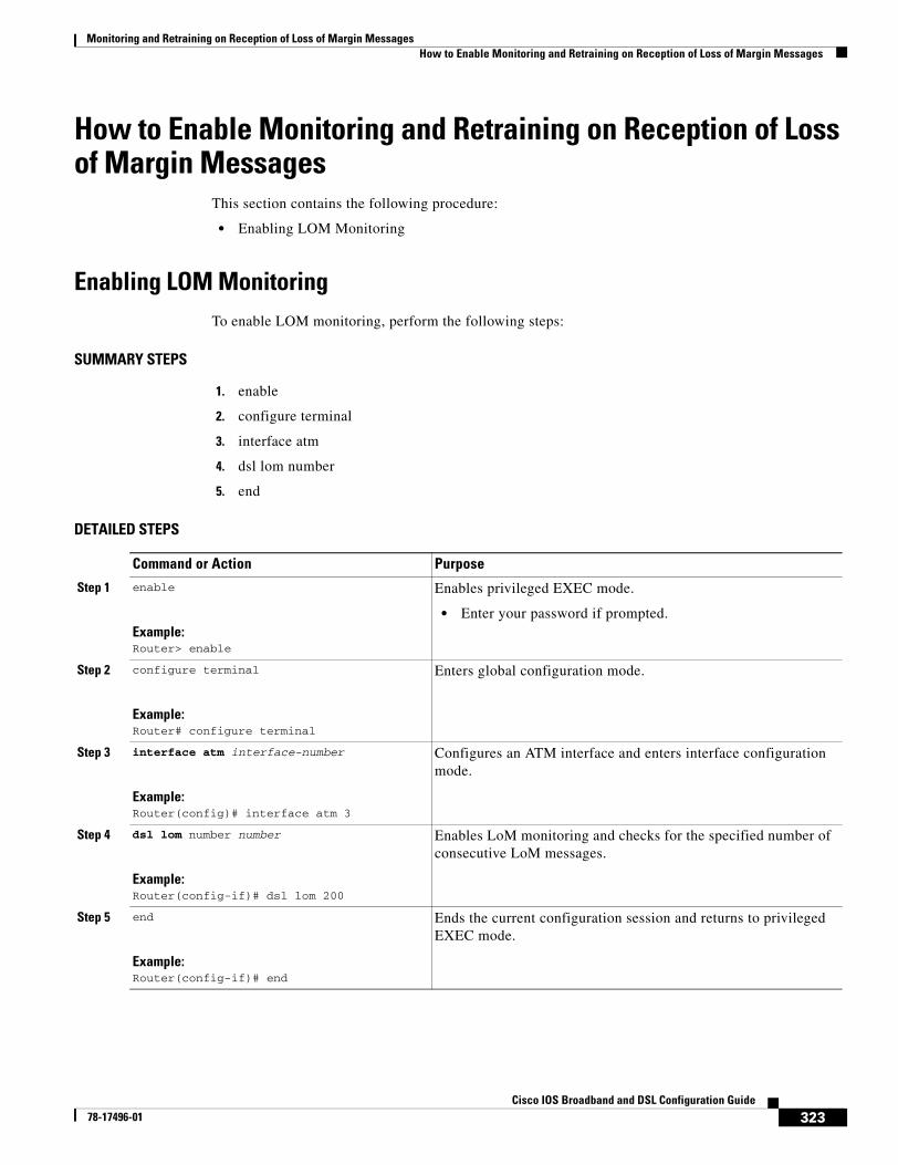
Monitoring and Retraining on Reception of Loss of Margin MessagesHow to Enable Monitoring and Retraining on Reception of Loss of Margin Messages
323Cisco IOS Broadband and DSL Configuration Guide
78-17496-01
How to Enable Monitoring and Retraining on Reception of Loss of Margin Messages
This section contains the following procedure:
• Enabling LOM Monitoring
Enabling LOM MonitoringTo enable LOM monitoring, perform the following steps:
SUMMARY STEPS
1. enable
2. configure terminal
3. interface atm
4. dsl lom number
5. end
DETAILED STEPS
Command or Action Purpose
Step 1 enable
Example:Router> enable
Enables privileged EXEC mode.
• Enter your password if prompted.
Step 2 configure terminal
Example:Router# configure terminal
Enters global configuration mode.
Step 3 interface atm interface-number
Example:Router(config)# interface atm 3
Configures an ATM interface and enters interface configuration mode.
Step 4 dsl lom number number
Example:Router(config-if)# dsl lom 200
Enables LoM monitoring and checks for the specified number of consecutive LoM messages.
Step 5 end
Example:Router(config-if)# end
Ends the current configuration session and returns to privileged EXEC mode.
Monitoring and Retraining on Reception of Loss of Margin MessagesConfiguration Examples for Monitoring and Retraining on Reception of Loss of Margin Messages
324Cisco IOS Broadband and DSL Configuration Guide
78-17496-01
Verifying LOM MonitoringTo verify the LOM monitoring configuration, enter the show dsl interface atm command in EXEC mode.
Configuration Examples for Monitoring and Retraining on Reception of Loss of Margin Messages
This section provides the following configuration example:
• Enabling LoM Monitoring: Example
Enabling LoM Monitoring: ExampleThe following example shows LoM monitoring enabled on an ATM interface with retraining configured for 200 counts:
configure terminalEnter configuration commands, one per line. End with CNTL/Z.interface atm0dsl lom 200end!show run interface atm000:16:46: %SYS-5-CONFIG_I: Configured from console by consoleint a0Building ConfigurationCurrent configuration: 209 bytes!interface atm0ip address 1.2.3.4 255.255.255.0no atm ilmi-keepalivepvc 1/40protocol ip 1.2.3.5 broadcastencapsulation aal5snap!dsl operating-mode autodsl lom 200dsl power-cutback 0end
Additional ReferencesThe following sections provide references related to Monitoring and Retraining on Reception of Loss of Margin Messages.
Monitoring and Retraining on Reception of Loss of Margin MessagesCommand List
325Cisco IOS Broadband and DSL Configuration Guide
78-17496-01
Related Documents
Standards
MIBs
RFCs
Technical Assistance
Command ListThe following command is pertinent to this feature. To see the command pages for this and other commands used with this feature, go to the Cisco IOS Master Commands List, Release 12.4, at http://www.cisco.com/univercd/cc/td/doc/product/software/ios124/124mindx/124index.htm.
• dsl lom
Related Topic Document Title
Cisco IOS Release 12.3 Configuration Guides and Command References
Cisco IOS Release 12.3 Configuration Guides and Command References
Standards Title
None —
MIBs MIBs Link
• None To locate and download MIBs for selected platforms, Cisco IOS releases, and feature sets, use Cisco MIB Locator found at the following URL:
http://www.cisco.com/go/mibs
RFCs Title
None —
Description Link
Technical Assistance Center (TAC) home page, containing 30,000 pages of searchable technical content, including links to products, technologies, solutions, technical tips, and tools. Registered Cisco.com users can log in from this page to access even more content.
http://www.cisco.com/public/support/tac/home.shtml

Monitoring and Retraining on Reception of Loss of Margin MessagesCommand List
326Cisco IOS Broadband and DSL Configuration Guide
78-17496-01
327Cisco IOS Broadband and DSL Configuration Guide
78-17496-01
1-Port ADSL WAN Interface Card
Feature History
This feature module describes the 1-port Asymmetric Digital Subscriber Line (ADSL) Wide Area Network (WAN) Interface Card (WIC) feature. It describes the benefits of the feature, supported platforms, configuration, related documents, and provides command reference information.
This document includes the following sections:
• Feature Overview, page 327
• Supported Platforms, page 329
• Configuring the Cisco ADSL WAN Interface Cards, page 330
• Configuration Example, page 330
• Additional References, page 331
• Command List, page 331
Feature OverviewThe Cisco ADSL WAN interface cards are 1-port WAN interface cards (WIC) for Cisco modular access routers. These cards provide high-speed ADSL digital data transfer between a single customer premises equipment (CPE) subscriber and a central office.
Release Modification
12.1(3)XJ This feature was introduced on the Cisco 1700 series routers.
12.2(2)T This feature was integrated into Cisco IOS Release 12.2(2)T.
12.2(13)ZH This feature was expanded to include the WIC-1ADSL-I-DG interface card on Cisco 1700 series modular access routers, to support ADSL over ISDN WAN. For specific platforms supported, see Table 25 on page 329.
12.2(15)ZJ This feature was expanded to include the WIC-1ADSL-I-DG interface card on Cisco 2600 series, Cisco 3600 series, and Cisco 3700 series modular access routers. For specific platforms supported, see Table 25 on page 329.
12.3(4)T Support was added for the WIC-1ADSL-I-DG interface card on Cisco 2600 series, Cisco 3600 series, and Cisco 3700 series modular access routers. For specific platforms supported, see Table 25 on page 329.
1-Port ADSL WAN Interface CardFeature Overview
328Cisco IOS Broadband and DSL Configuration Guide
78-17496-01
Note ADSL is a last-mile access technology that uses an asymmetrical data rate over a single copper wire pair.
The ADSL WICs are available in two variations: ADSL over POTS (WIC-1ADSL), and ADSL over ISDN WAN with Dying Gasp support (WIC-1ADSL-I-DG). The following bullets summarize the features of each card:
• Cisco WIC-1ADSL—Provides ADSL services over ordinary telephone lines. It is compatible with the Alcatel Digital Subscriber Loop Access Multiplexer (DSLAM), the Cisco 6260 DSLAM with Flexi-line cards, and the Cisco 6130 DSLAM with Flexi-line cards.
• Cisco WIC-1ADSL-I-DG—Provides ADSL services in areas of the world that have extensive ISDN backbones already in place. It is compatible with ECI, Siemens, Alcatel, and Cisco DSLAMs that support ISDN.
All Cisco ADSL WICs support Asynchronous Transfer Mode (ATM) Adaptation Layer 2 (AAL2) for the Cisco 2600, Cisco 3600, and Cisco 3700 series only, and AAL5 for the those models as well as for the Cisco 1700. The cards support various classes of Quality of Service (QoS) for both voice and data.
BenefitsBoth Cisco ADSL WAN interface cards provide the following benefits:
• Enable business-class broadband service with voice integration, scalable performance, flexibility, and security
• Aggregate both ADSL and other transport options into a single box
• Provide ADSL high-speed digital data transmissions between CPE and the central office (CO)
• Support ATM AAL5 services and applications, ATM class of service (constant bit rate [CBR], variable bit rate-nonreal time [VBR-NRT], variable bit rate–real time [VBR–rt], and unspecified bit rate [UBR]), as well as up to 23 virtual circuits on a WIC in Cisco routers
• Provide ATM traffic management and QoS features to enable service providers to manage their core ATM network infrastructure.
The following benefits are specific to each card:
• Cisco WIC-1ADSL—Supports and complies with ANSI T1.413 Issue 2, and ITU G.992.1, Annex A (G.DMT for full-rate ADSL over POTS)
• Cisco WIC-1ADSL-I-DG—Allows the coexistence of ADSL and ISDN on the same local loop; supports and complies with ITU G.992.1, Annex B (G.DMT for full-rate ADSL over ISDN), ETSI 101-388, and the Deutsche Telekom U-R2 specification
RestrictionsThe Cisco ADSL WAN interface cards do not support dual latency, ADSL2, or ADSL2plus. When the ADSL link is intended to support both voice and data traffic simultaneously, the link should be configured for either all fast-path data or all interleave data, with an interleave depth of zero to ensure that latency is minimized. In addition, the total supported data rate must be reduced to adjust for the reduced coding gain, which is usually present with high-latency traffic.
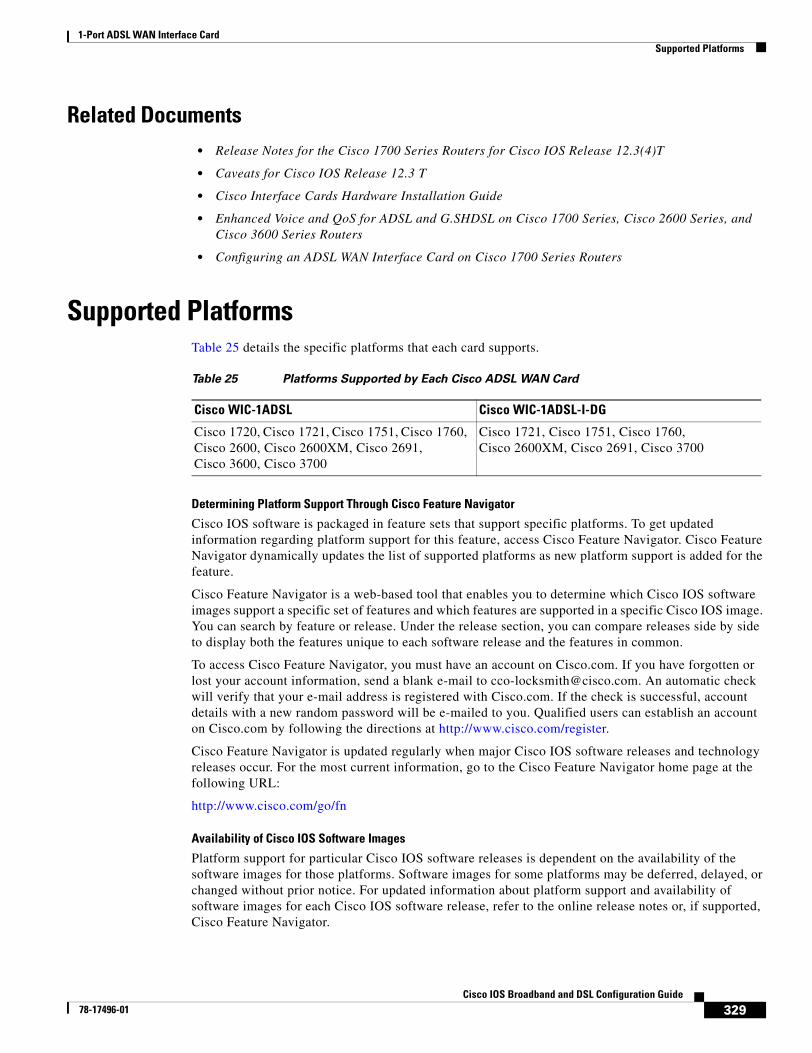
1-Port ADSL WAN Interface CardSupported Platforms
329Cisco IOS Broadband and DSL Configuration Guide
78-17496-01
Related Documents• Release Notes for the Cisco 1700 Series Routers for Cisco IOS Release 12.3(4)T
• Caveats for Cisco IOS Release 12.3 T
• Cisco Interface Cards Hardware Installation Guide
• Enhanced Voice and QoS for ADSL and G.SHDSL on Cisco 1700 Series, Cisco 2600 Series, and Cisco 3600 Series Routers
• Configuring an ADSL WAN Interface Card on Cisco 1700 Series Routers
Supported PlatformsTable 25 details the specific platforms that each card supports.
Determining Platform Support Through Cisco Feature Navigator
Cisco IOS software is packaged in feature sets that support specific platforms. To get updated information regarding platform support for this feature, access Cisco Feature Navigator. Cisco Feature Navigator dynamically updates the list of supported platforms as new platform support is added for the feature.
Cisco Feature Navigator is a web-based tool that enables you to determine which Cisco IOS software images support a specific set of features and which features are supported in a specific Cisco IOS image. You can search by feature or release. Under the release section, you can compare releases side by side to display both the features unique to each software release and the features in common.
To access Cisco Feature Navigator, you must have an account on Cisco.com. If you have forgotten or lost your account information, send a blank e-mail to [email protected]. An automatic check will verify that your e-mail address is registered with Cisco.com. If the check is successful, account details with a new random password will be e-mailed to you. Qualified users can establish an account on Cisco.com by following the directions at http://www.cisco.com/register.
Cisco Feature Navigator is updated regularly when major Cisco IOS software releases and technology releases occur. For the most current information, go to the Cisco Feature Navigator home page at the following URL:
http://www.cisco.com/go/fn
Availability of Cisco IOS Software Images
Platform support for particular Cisco IOS software releases is dependent on the availability of the software images for those platforms. Software images for some platforms may be deferred, delayed, or changed without prior notice. For updated information about platform support and availability of software images for each Cisco IOS software release, refer to the online release notes or, if supported, Cisco Feature Navigator.
Table 25 Platforms Supported by Each Cisco ADSL WAN Card
Cisco WIC-1ADSL Cisco WIC-1ADSL-I-DG
Cisco 1720, Cisco 1721, Cisco 1751, Cisco 1760, Cisco 2600, Cisco 2600XM, Cisco 2691, Cisco 3600, Cisco 3700
Cisco 1721, Cisco 1751, Cisco 1760, Cisco 2600XM, Cisco 2691, Cisco 3700
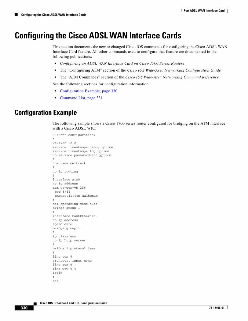
1-Port ADSL WAN Interface CardConfiguring the Cisco ADSL WAN Interface Cards
330Cisco IOS Broadband and DSL Configuration Guide
78-17496-01
Configuring the Cisco ADSL WAN Interface CardsThis section documents the new or changed Cisco IOS commands for configuring the Cisco ADSL WAN Interface Card feature. All other commands used to configure that feature are documented in the following publications:
• Configuring an ADSL WAN Interface Card on Cisco 1700 Series Routers
• The “Configuring ATM” section of the Cisco IOS Wide-Area Networking Configuration Guide
• The “ATM Commands” section of the Cisco IOS Wide-Area Networking Command Reference
See the following sections for configuration information:
• Configuration Example, page 330
• Command List, page 331
Configuration ExampleThe following sample shows a Cisco 1700 series router configured for bridging on the ATM interface with a Cisco ADSL WIC:
Current configuration:!version 12.2service timestamps debug uptimeservice timestamps log uptimeno service password-encryption!hostname meltrack!no ip routing!interface ATM0no ip addressatm vc-per-vp 256pvc 8/35 encapsulation aal5snap
!dsl operating-mode autobridge-group 1!interface FastEthernet0no ip addressspeed autobridge-group 1!ip classlessno ip http server!bridge 1 protocol ieee! line con 0transport input noneline aux 0line vty 0 4login!end
1-Port ADSL WAN Interface CardAdditional References
331Cisco IOS Broadband and DSL Configuration Guide
78-17496-01
Additional ReferencesThe following section provides a reference related to the ADSL WAN interface card.
Related Documents
Command ListThe following command is pertinent to this feature. To see the command pages for this and other commands used with this feature, go to the Cisco IOS Master Commands List, Release 12.4, at http://www.cisco.com/univercd/cc/td/doc/product/software/ios124/124mindx/124index.htm.
• dsl operating-mode
Related Topic Document Title
ADSL WAN interface card on Cisco 1700 series routers
Configuring an ADSL WAN Interface Card on Cisco 1700 Series Routers

1-Port ADSL WAN Interface CardCommand List
332Cisco IOS Broadband and DSL Configuration Guide
78-17496-01
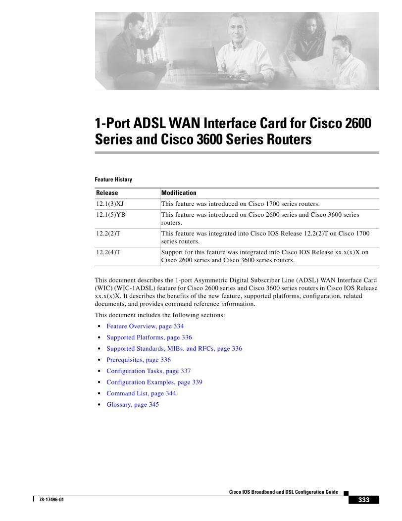
333Cisco IOS Broadband and DSL Configuration Guide
78-17496-01
1-Port ADSL WAN Interface Card for Cisco 2600 Series and Cisco 3600 Series Routers
Feature History
This document describes the 1-port Asymmetric Digital Subscriber Line (ADSL) WAN Interface Card (WIC) (WIC-1ADSL) feature for Cisco 2600 series and Cisco 3600 series routers in Cisco IOS Release xx.x(x)X. It describes the benefits of the new feature, supported platforms, configuration, related documents, and provides command reference information.
This document includes the following sections:
• Feature Overview, page 334
• Supported Platforms, page 336
• Supported Standards, MIBs, and RFCs, page 336
• Prerequisites, page 336
• Configuration Tasks, page 337
• Configuration Examples, page 339
• Command List, page 344
• Glossary, page 345
Release Modification
12.1(3)XJ This feature was introduced on Cisco 1700 series routers.
12.1(5)YB This feature was introduced on Cisco 2600 series and Cisco 3600 series routers.
12.2(2)T This feature was integrated into Cisco IOS Release 12.2(2)T on Cisco 1700 series routers.
12.2(4)T Support for this feature was integrated into Cisco IOS Release xx.x(x)X on Cisco 2600 series and Cisco 3600 series routers.
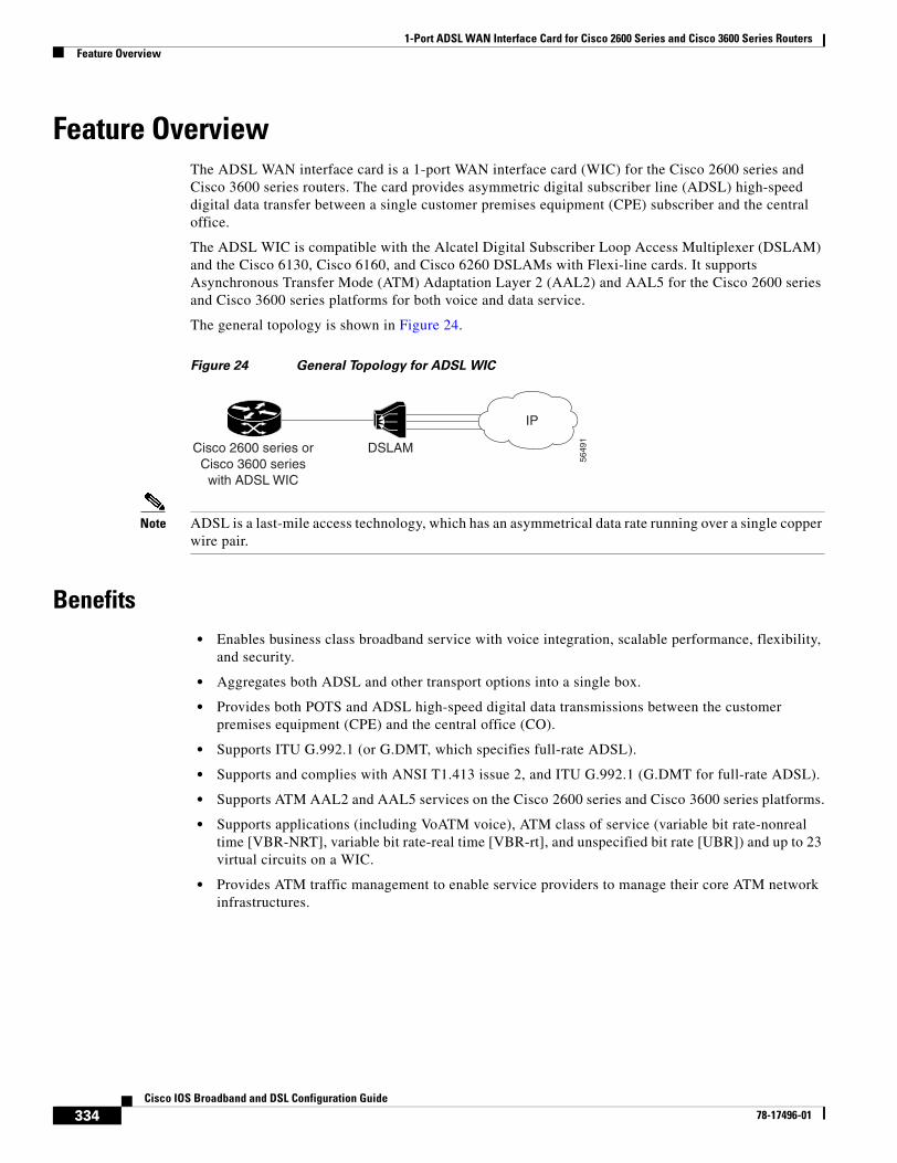
1-Port ADSL WAN Interface Card for Cisco 2600 Series and Cisco 3600 Series RoutersFeature Overview
334Cisco IOS Broadband and DSL Configuration Guide
78-17496-01
Feature OverviewThe ADSL WAN interface card is a 1-port WAN interface card (WIC) for the Cisco 2600 series and Cisco 3600 series routers. The card provides asymmetric digital subscriber line (ADSL) high-speed digital data transfer between a single customer premises equipment (CPE) subscriber and the central office.
The ADSL WIC is compatible with the Alcatel Digital Subscriber Loop Access Multiplexer (DSLAM) and the Cisco 6130, Cisco 6160, and Cisco 6260 DSLAMs with Flexi-line cards. It supports Asynchronous Transfer Mode (ATM) Adaptation Layer 2 (AAL2) and AAL5 for the Cisco 2600 series and Cisco 3600 series platforms for both voice and data service.
The general topology is shown in Figure 24.
Figure 24 General Topology for ADSL WIC
Note ADSL is a last-mile access technology, which has an asymmetrical data rate running over a single copper wire pair.
Benefits• Enables business class broadband service with voice integration, scalable performance, flexibility,
and security.
• Aggregates both ADSL and other transport options into a single box.
• Provides both POTS and ADSL high-speed digital data transmissions between the customer premises equipment (CPE) and the central office (CO).
• Supports ITU G.992.1 (or G.DMT, which specifies full-rate ADSL).
• Supports and complies with ANSI T1.413 issue 2, and ITU G.992.1 (G.DMT for full-rate ADSL).
• Supports ATM AAL2 and AAL5 services on the Cisco 2600 series and Cisco 3600 series platforms.
• Supports applications (including VoATM voice), ATM class of service (variable bit rate-nonreal time [VBR-NRT], variable bit rate-real time [VBR-rt], and unspecified bit rate [UBR]) and up to 23 virtual circuits on a WIC.
• Provides ATM traffic management to enable service providers to manage their core ATM network infrastructures.
IP
5649
1
DSLAMCisco 2600 series orCisco 3600 series
with ADSL WIC
1-Port ADSL WAN Interface Card for Cisco 2600 Series and Cisco 3600 Series RoutersFeature Overview
335Cisco IOS Broadband and DSL Configuration Guide
78-17496-01
Restrictions• The ADSL WAN interface card does not support dual latency. When the ADSL link is intended to
support both voice and data traffic simultaneously, the link should be configured for either all fast-path data or all interleave data with an interleave depth of zero to insure that latency is minimized. In addition, the total supported data rate must be reduced to adjust for the reduced coding gain, which is usually present with high-latency traffic.
• The ADSL WAN interface card does not support available bit rate (ABR) class of service (CoS).
• For the Cisco 2600 series routers, the ADSL WAN interface card should be inserted only into on-board WIC slots or 2W network modules. This card does not function properly in older network modules.
• For the Cisco 3600 series routers, the ADSL WAN interface card should be inserted only into on-board WIC slots or 2W, 1FE2W, 2FE2W, or 1FE1R2W network modules. This card does not function properly in older network modules.
• When using AAL2, analog voice is not supported. Voice calls should come through a digital voice card, such as the NM-HDV.
• VoATM is supported in both AAL2 and AAL5 modes on the Cisco 2600 series and Cisco 3600 series.
• VoATM AAL2 and AAL5 are supported only if voice and data use separate permanent virtual circuits (PVCs).
• VoATM AAL2 supports digital voice (T1/E1) only, while VoATM AAL5 supports both analog and digital voice.
• VoIP is not supported unless the ADSL WIC carries only voice traffic (with no data). The QoS features necessary for VoIP and data sharing the same PVC, or different PVCs on the same interface, are not supported yet. These features include LLQ, LFI, and tx-ring tuning.
Related DocumentsFor more information about voice configuration, see the following Cisco IOS Release 12.2 guides:
• Cisco IOS Voice, Video, and Fax Configuration Guide, Release 12.2
• Cisco IOS Voice, Video, and Fax Command Reference, Release 12.2
The following configuration guides describe the configuration of IP and ATM:
• For more information about configuring IP, see the Cisco IOS IP Configuration Guide, Release 12.2.
• For more information about configuring ATM, see “Configuring ATM” in the Wide-Area Networking Configuration Guide, Release 12.2.
The following online feature documentation and installation guides describe the configuration and installation of hardware components:
• For information about installing Cisco 2600 series hardware, see the documents listed at the following URL:
http://www.cisco.com/univercd/cc/td/doc/product/access/acs_mod/cis2600/index.htm
• For information about installing Cisco 3600 series hardware, see the documents listed at the following URL:
http://www.cisco.com/univercd/cc/td/doc/product/access/acs_mod/cis3600/index.htm
1-Port ADSL WAN Interface Card for Cisco 2600 Series and Cisco 3600 Series RoutersSupported Platforms
336Cisco IOS Broadband and DSL Configuration Guide
78-17496-01
Supported PlatformsThis feature is supported on the following platforms:
• Cisco 2600 series
• Cisco 3600 series
Determining Platform Support Through Feature Navigator
Cisco IOS software is packaged in feature sets that support specific platforms. To get updated information regarding platform support for this feature, access Feature Navigator. Feature Navigator dynamically updates the list of supported platforms as new platform support is added for the feature.
Feature Navigator is a web-based tool that enables you to quickly determine which Cisco IOS software images support a specific set of features and which features are supported in a specific Cisco IOS image.
To access Feature Navigator, you must have an account on Cisco.com. If you have forgotten or lost your account information, send a blank e-mail to [email protected]. An automatic check will verify that your e-mail address is registered with Cisco.com. If the check is successful, account details with a new random password will be e-mailed to you. Qualified users can establish an account on Cisco.com by following the directions at http://www.cisco.com/register.
Feature Navigator is updated regularly when major Cisco IOS software releases and technology releases occur. For the most current information, go to the Feature Navigator home page at the following URL:
http://www.cisco.com/go/fn
Supported Standards, MIBs, and RFCsStandards
• Supports ITU-T G.991.2 (SHDSL).
• Supports ADSL features ANSI T1.413 issue 2.
• Supports ITU 992.1 (G.DMT).
MIBs
• No new or modified MIBs are supported by this feature.
To obtain lists of supported MIBs by platform and Cisco IOS release, and to download MIB modules, go to the Cisco MIB website on Cisco.com at the following URL:
http://www.cisco.com/public/sw-center/netmgmt/cmtk/mibs.shtml
RFCs
• No new or modified RFCs are supported by this feature.
PrerequisitesA 1-Port ADSL WIC must be installed in the router to match the DSL service to be configured.
1-Port ADSL WAN Interface Card for Cisco 2600 Series and Cisco 3600 Series RoutersConfiguration Tasks
337Cisco IOS Broadband and DSL Configuration Guide
78-17496-01
Configuration TasksSee the following sections for configuration tasks for this feature. Each task in the list is identified as either required or optional:
• Configuring the ADSL Port on the ADSL WAN Interface Card (required)
• Verifying ATM Configuration (optional)
Features used on the ADSL WAN interface card must also be configured on the DSLAM. See the documentation for the specific DSLAM for information about configuring features.
Configuring the ADSL Port on the ADSL WAN Interface CardTo configure an ADSL port on the ADSL WAN interface card, complete the following steps:
Command Purpose
Step 1 Router> configure terminal Enters global configuration mode.
Step 2 Router(config)# interface atm slot/port Enters ATM configuration mode for the ATM interface in the specified slot and port.
Step 3 Router(config-if)# ip address IP-address Assigns an IP address to the ADSL ATM interface.
Step 4 Router(config-if)# pvc [name] vpi/vci Enters atm-virtual-circuit (interface-atm-vc) configuration mode, and configures a new ATM PVC by assigning a name (optional) and virtual path identifier (VPI)/virtual channel identifier (VCI) numbers.
The default traffic shaping is UBR; the default encapsulation is AAL5+LLC/SNAP.
Step 5 Router(config-if-vc)# protocol ip IP-address
(Optional) Enables IP connectivity and create a point-to-point IP address for the virtual circuit (VC).
Step 6 Router(config-if-vc)# vbr-rt peak-rate average-rate burst
(Optional) Configures the PVC for real-time variable bit rate (VBR) traffic shaping.
• Peak rate—Peak information rate (PIR)
• Average rate—Average information rate (AIR)
• Burst—Burst size in cells
Step 7 Router(config-if-vc)# encapsulation {aal2 | aal5ciscoppp | aal5mux | aal5nlpid | aal5snap}
(Optional) Configures the ATM adaptation layer (AAL) and encapsulation type.
• aal2—AAL2
• aal5ciscoppp—Cisco PPP over AAL5
• aal5mux—AAL5+MUX
• aal5nlpid—AAL5+NLPID
• aal5snap—AAL5+LLC/SNAP (the default)
Step 8 Router(config-if-vc)# exit Exits from interface-atm-vc configuration mode.
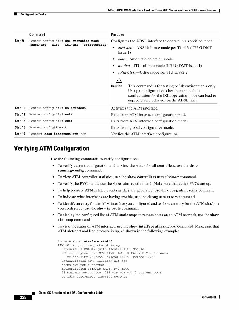
1-Port ADSL WAN Interface Card for Cisco 2600 Series and Cisco 3600 Series RoutersConfiguration Tasks
338Cisco IOS Broadband and DSL Configuration Guide
78-17496-01
Verifying ATM ConfigurationUse the following commands to verify configuration:
• To verify current configuration and to view the status for all controllers, use the show running-config command.
• To view ATM controller statistics, use the show controllers atm slot/port command.
• To verify the PVC status, use the show atm vc command. Make sure that active PVCs are up.
• To help identify ATM related events as they are generated, use the debug atm events command.
• To indicate what interfaces are having trouble, use the debug atm errors command.
• To identify an entry for the ATM interface you configured and to show an entry for the ATM slot/port you configured, use the show ip route command.
• To display the configured list of ATM static maps to remote hosts on an ATM network, use the show atm map command.
• To view the status of ATM interface, use the show interface atm slot/port command. Make sure that ATM slot/port and line protocol is up, as shown in the following example:
Router# show interface atm1/0ATM1/0 is up, line protocol is up Hardware is DSLSAR (with Alcatel ADSL Module) MTU 4470 bytes, sub MTU 4470, BW 800 Kbit, DLY 2560 usec, reliability 255/255, txload 1/255, rxload 1/255 Encapsulation ATM, loopback not set Keepalive not supported Encapsulation(s):AAL5 AAL2, PVC mode 24 maximum active VCs, 256 VCs per VP, 2 current VCCs VC idle disconnect time:300 seconds
Step 9 Router(config-if)# dsl operating-mode {ansi-dmt | auto | itu-dmt | splitterless}
Configures the ADSL interface to operate in a specified mode:
• ansi-dmt—ANSI full rate mode per T1.413 (ITU G.DMT Issue 1)
• auto—Automatic detection mode
• itu-dmt—ITU full rate mode (ITU G.DMT Issue 1)
• splitterless—G.lite mode per ITU G.992.2
Caution This command is for testing or lab environments only. Using a configuration other than the default configuration for the DSL operating mode can lead to unpredictable behavior on the ADSL line.
Step 10 Router(config-if)# no shutdown Activates the ATM interface.
Step 11 Router(config-if)# exit Exits from ATM interface configuration mode.
Step 12 Router(config-if)# exit Exits from ATM interface configuration mode.
Step 13 Router(config)# exit Exits from global configuration mode.
Step 14 Router# show interface atm 1/0 Verifies the ATM interface configuration.
Command Purpose
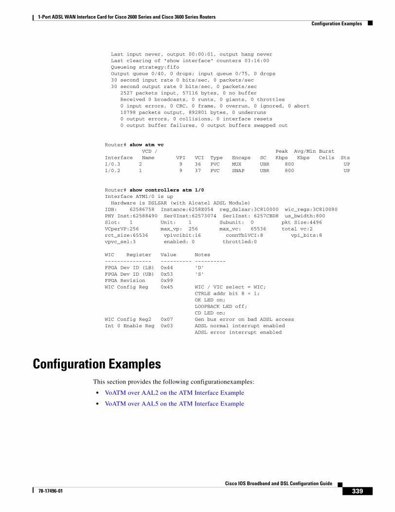
1-Port ADSL WAN Interface Card for Cisco 2600 Series and Cisco 3600 Series RoutersConfiguration Examples
339Cisco IOS Broadband and DSL Configuration Guide
78-17496-01
Last input never, output 00:00:01, output hang never Last clearing of "show interface" counters 03:16:00 Queueing strategy:fifo Output queue 0/40, 0 drops; input queue 0/75, 0 drops 30 second input rate 0 bits/sec, 0 packets/sec 30 second output rate 0 bits/sec, 0 packets/sec 2527 packets input, 57116 bytes, 0 no buffer Received 0 broadcasts, 0 runts, 0 giants, 0 throttles 0 input errors, 0 CRC, 0 frame, 0 overrun, 0 ignored, 0 abort 10798 packets output, 892801 bytes, 0 underruns 0 output errors, 0 collisions, 0 interface resets 0 output buffer failures, 0 output buffers swapped out
Router# show atm vc VCD / Peak Avg/Min BurstInterface Name VPI VCI Type Encaps SC Kbps Kbps Cells Sts1/0.3 2 9 36 PVC MUX UBR 800 UP1/0.2 1 9 37 PVC SNAP UBR 800 UP
Router# show controllers atm 1/0Interface ATM1/0 is up Hardware is DSLSAR (with Alcatel ADSL Module)IDB: 62586758 Instance:6258E054 reg_dslsar:3C810000 wic_regs:3C810080PHY Inst:62588490 Ser0Inst:62573074 Ser1Inst: 6257CBD8 us_bwidth:800 Slot: 1 Unit: 1 Subunit: 0 pkt Size:4496 VCperVP:256 max_vp: 256 max_vc: 65536 total vc:2 rct_size:65536 vpivcibit:16 connTblVCI:8 vpi_bits:8 vpvc_sel:3 enabled: 0 throttled:0
WIC Register Value Notes--------------- ---------- ----------FPGA Dev ID (LB) 0x44 'D'FPGA Dev ID (UB) 0x53 'S'FPGA Revision 0x99 WIC Config Reg 0x45 WIC / VIC select = WIC; CTRLE addr bit 8 = 1; OK LED on; LOOPBACK LED off; CD LED on; WIC Config Reg2 0x07 Gen bus error on bad ADSL accessInt 0 Enable Reg 0x03 ADSL normal interrupt enabled ADSL error interrupt enabled
Configuration ExamplesThis section provides the following configurationexamples:
• VoATM over AAL2 on the ATM Interface Example
• VoATM over AAL5 on the ATM Interface Example
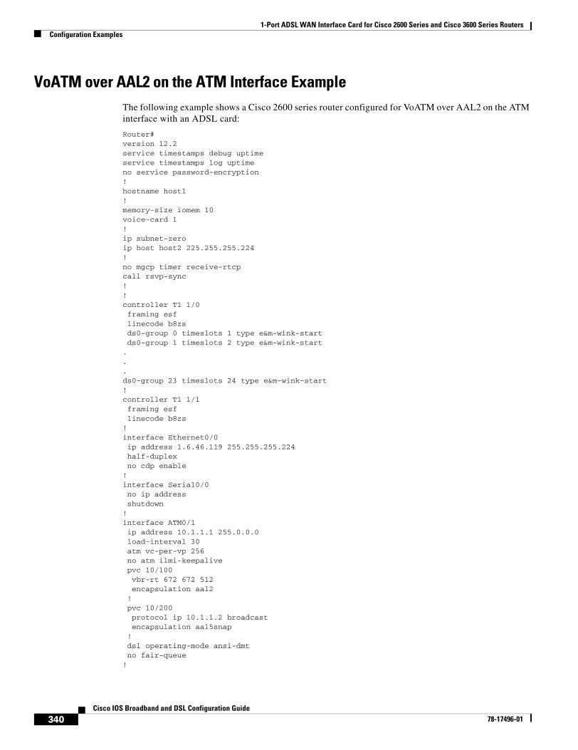
1-Port ADSL WAN Interface Card for Cisco 2600 Series and Cisco 3600 Series RoutersConfiguration Examples
340Cisco IOS Broadband and DSL Configuration Guide
78-17496-01
VoATM over AAL2 on the ATM Interface ExampleThe following example shows a Cisco 2600 series router configured for VoATM over AAL2 on the ATM interface with an ADSL card:
Router# version 12.2service timestamps debug uptimeservice timestamps log uptimeno service password-encryption!hostname host1!memory-size iomem 10voice-card 1!ip subnet-zeroip host host2 225.255.255.224!no mgcp timer receive-rtcpcall rsvp-sync!!controller T1 1/0 framing esf linecode b8zs ds0-group 0 timeslots 1 type e&m-wink-start ds0-group 1 timeslots 2 type e&m-wink-start...ds0-group 23 timeslots 24 type e&m-wink-start!controller T1 1/1 framing esf linecode b8zs!interface Ethernet0/0 ip address 1.6.46.119 255.255.255.224 half-duplex no cdp enable!interface Serial0/0 no ip address shutdown!interface ATM0/1 ip address 10.1.1.1 255.0.0.0 load-interval 30 atm vc-per-vp 256 no atm ilmi-keepalive pvc 10/100 vbr-rt 672 672 512 encapsulation aal2 ! pvc 10/200 protocol ip 10.1.1.2 broadcast encapsulation aal5snap ! dsl operating-mode ansi-dmt no fair-queue!
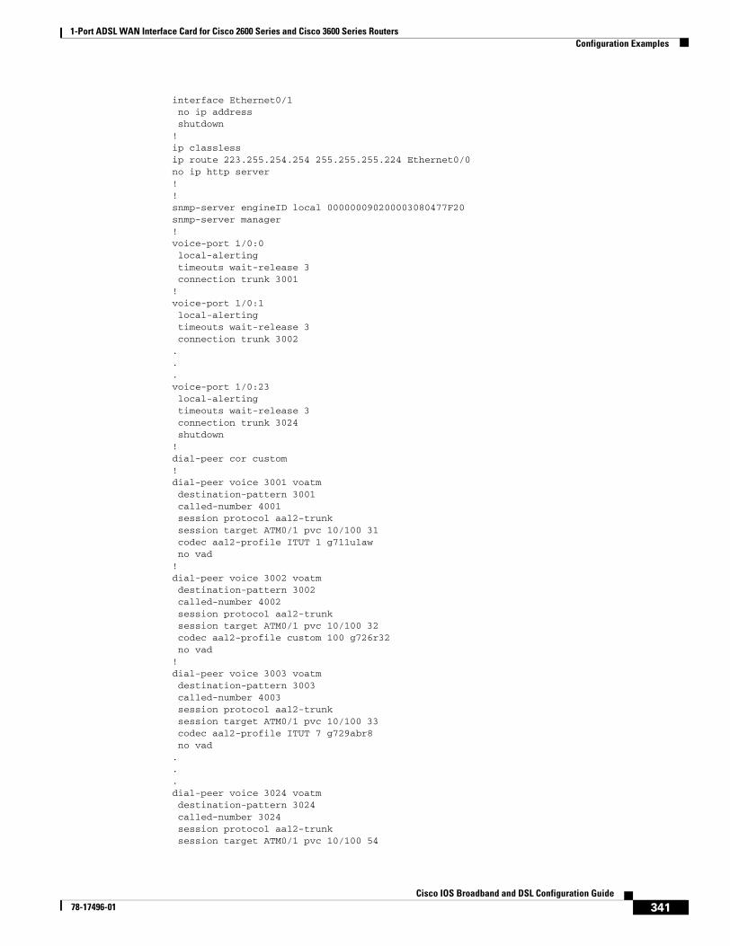
1-Port ADSL WAN Interface Card for Cisco 2600 Series and Cisco 3600 Series RoutersConfiguration Examples
341Cisco IOS Broadband and DSL Configuration Guide
78-17496-01
interface Ethernet0/1 no ip address shutdown!ip classlessip route 223.255.254.254 255.255.255.224 Ethernet0/0no ip http server!!snmp-server engineID local 000000090200003080477F20snmp-server manager!voice-port 1/0:0 local-alerting timeouts wait-release 3 connection trunk 3001 !voice-port 1/0:1 local-alerting timeouts wait-release 3 connection trunk 3002 ...voice-port 1/0:23 local-alerting timeouts wait-release 3 connection trunk 3024 shutdown!dial-peer cor custom!dial-peer voice 3001 voatm destination-pattern 3001 called-number 4001 session protocol aal2-trunk session target ATM0/1 pvc 10/100 31 codec aal2-profile ITUT 1 g711ulaw no vad!dial-peer voice 3002 voatm destination-pattern 3002 called-number 4002 session protocol aal2-trunk session target ATM0/1 pvc 10/100 32 codec aal2-profile custom 100 g726r32 no vad!dial-peer voice 3003 voatm destination-pattern 3003 called-number 4003 session protocol aal2-trunk session target ATM0/1 pvc 10/100 33 codec aal2-profile ITUT 7 g729abr8 no vad...dial-peer voice 3024 voatm destination-pattern 3024 called-number 3024 session protocol aal2-trunk session target ATM0/1 pvc 10/100 54
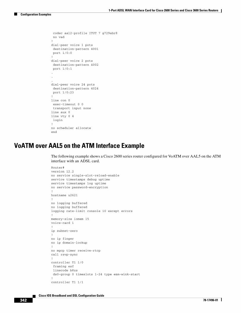
1-Port ADSL WAN Interface Card for Cisco 2600 Series and Cisco 3600 Series RoutersConfiguration Examples
342Cisco IOS Broadband and DSL Configuration Guide
78-17496-01
codec aal2-profile ITUT 7 g729abr8 no vad!dial-peer voice 1 pots destination-pattern 4001 port 1/0:0!dial-peer voice 2 pots destination-pattern 4002 port 1/0:1...dial-peer voice 24 pots destination-pattern 4024 port 1/0:23!line con 0 exec-timeout 0 0 transport input noneline aux 0line vty 0 4 login!no scheduler allocateend
VoATM over AAL5 on the ATM Interface ExampleThe following example shows a Cisco 2600 series router configured for VoATM over AAL5 on the ATM interface with an ADSL card.
Router#version 12.2no service single-slot-reload-enableservice timestamps debug uptimeservice timestamps log uptimeno service password-encryption!hostname u2621!no logging bufferedno logging bufferedlogging rate-limit console 10 except errors!memory-size iomem 15voice-card 1!ip subnet-zero!no ip fingerno ip domain-lookup!no mgcp timer receive-rtcpcall rsvp-sync!controller T1 1/0 framing esf linecode b8zs ds0-group 0 timeslots 1-24 type e&m-wink-start!controller T1 1/1
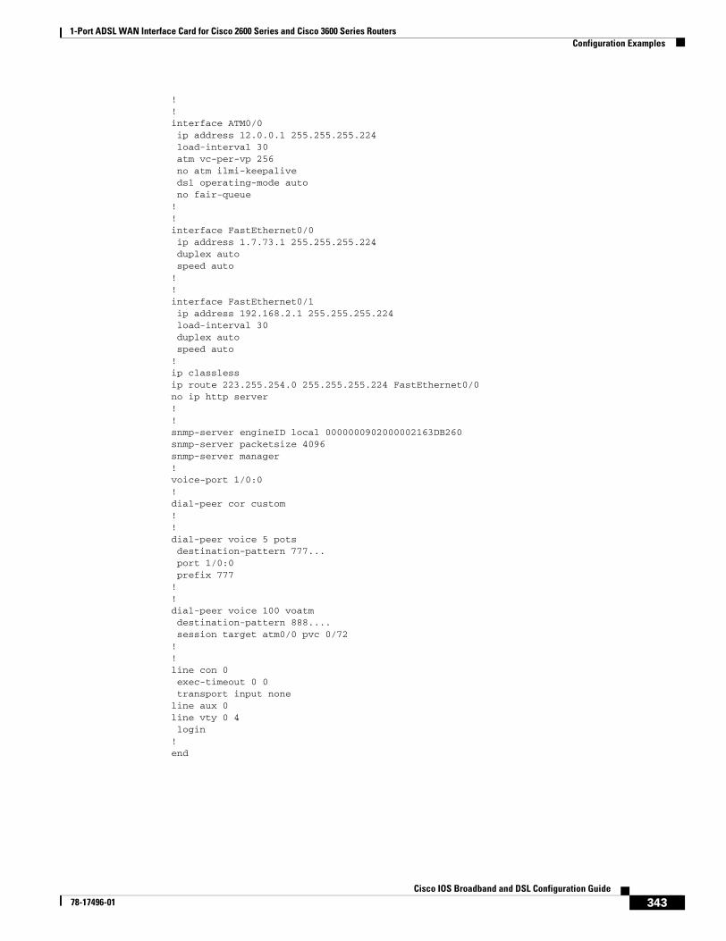
1-Port ADSL WAN Interface Card for Cisco 2600 Series and Cisco 3600 Series RoutersConfiguration Examples
343Cisco IOS Broadband and DSL Configuration Guide
78-17496-01
!!interface ATM0/0 ip address 12.0.0.1 255.255.255.224load-interval 30
atm vc-per-vp 256 no atm ilmi-keepalive dsl operating-mode auto no fair-queue!!interface FastEthernet0/0 ip address 1.7.73.1 255.255.255.224duplex auto
speed auto!!interface FastEthernet0/1 ip address 192.168.2.1 255.255.255.224load-interval 30
duplex auto speed auto!ip classlessip route 223.255.254.0 255.255.255.224 FastEthernet0/0no ip http server!!snmp-server engineID local 0000000902000002163DB260snmp-server packetsize 4096snmp-server manager!voice-port 1/0:0!dial-peer cor custom!!dial-peer voice 5 pots destination-pattern 777...port 1/0:0prefix 777
! ! dial-peer voice 100 voatmdestination-pattern 888....session target atm0/0 pvc 0/72
!!line con 0 exec-timeout 0 0 transport input noneline aux 0line vty 0 4 login!end

1-Port ADSL WAN Interface Card for Cisco 2600 Series and Cisco 3600 Series RoutersCommand List
344Cisco IOS Broadband and DSL Configuration Guide
78-17496-01
Command ListThe following commands are pertinent to this feature. To see the command pages for these and other commands used with this feature, go to the Cisco IOS Master Commands List, Release 12.4, at http://www.cisco.com/univercd/cc/td/doc/product/software/ios124/124mindx/124index.htm.
• dsl operating-mode (ADSL)
• show diag
• show dsl interface atm
1-Port ADSL WAN Interface Card for Cisco 2600 Series and Cisco 3600 Series RoutersGlossary
345Cisco IOS Broadband and DSL Configuration Guide
78-17496-01
GlossaryABR—available bit rate.
ADSL—asymmetric digital subscriber line (ADSL) available through several telecommunications carriers to accommodate the need for increased bandwidth for Internet access and telecommuting applications.
ATM—Asynchronous Transfer Mode. International standard for cell relay in which multiple service types (such as voice, video, or data) are conveyed in fixed-length (53-byte) cells. Fixed-length cells allow cell processing to occur in hardware, thereby reducing transit delays. ATM is designed to take advantage of high-speed transmission media such as E3, SONET, and T3.
CLI—command line interface.
CO—central office, or local exchange (local switch), which terminates individual local telephone subscriber lines for switching, and connects to the public network. Known as a class 5 switch office. For example, 5ESS by Lucent and DMS 100 by Nortel.
CPE—customer premise equipment, including devices such as channel service units (CSUs)/data service units (DSUs), modems, and ISDN terminal adapters, required to provide an electromagnetic termination for wide-area network circuits before connecting to the router or access server. This equipment was historically provided by the telephone company, but is now typically provided by the customer in North American markets.
DSL—digital subscriber line available through several telecommunications carriers to accommodate the need for increased bandwidth for Internet access and telecommuting applications.
FXO—foreign exchange office. A FXO interface connects to a central office.
FXS—foreign exchange station: A FXS interface connects directly to a standard telephone, supplying ring voltage, dial tone, etc.
G.SHDSL—multirate symmetrical high-speed digital subscriber line.
PVC—permanent virtual circuit.

1-Port ADSL WAN Interface Card for Cisco 2600 Series and Cisco 3600 Series RoutersGlossary
346Cisco IOS Broadband and DSL Configuration Guide
78-17496-01
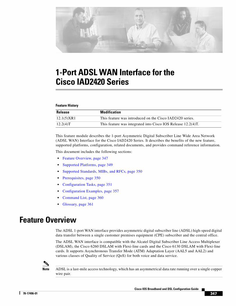
347Cisco IOS Broadband and DSL Configuration Guide
78-17496-01
1-Port ADSL WAN Interface for the Cisco IAD2420 Series
Feature History
This feature module describes the 1-port Asymmetric Digital Subscriber Line Wide Area Network (ADSL WAN) Interface for the Cisco IAD2420 Series. It describes the benefits of the new feature, supported platforms, configuration, related documents, and provides command reference information.
This document includes the following sections:
• Feature Overview, page 347
• Supported Platforms, page 349
• Supported Standards, MIBs, and RFCs, page 350
• Prerequisites, page 350
• Configuration Tasks, page 351
• Configuration Examples, page 357
• Command List, page 360
• Glossary, page 361
Feature OverviewThe ADSL 1-port WAN interface provides asymmetric digital subscriber line (ADSL) high-speed digital data transfer between a single customer premises equipment (CPE) subscriber and the central office.
The ADSL WAN interface is compatible with the Alcatel Digital Subscriber Line Access Multiplexer (DSLAM), the Cisco 6260 DSLAM with Flexi-line cards and the Cisco 6130 DSLAM with Flexi-line cards. It supports Asynchronous Transfer Mode (ATM) Adaptation Layer (AAL5 and AAL2) and various classes of Quality of Service (QoS) for both voice and data service.
Note ADSL is a last-mile access technology, which has an asymmetrical data rate running over a single copper wire pair.
Release Modification
12.1(5)XR1 This feature was introduced on the Cisco IAD2420 series.
12.2(4)T This feature was integrated into Cisco IOS Release 12.2(4)T.
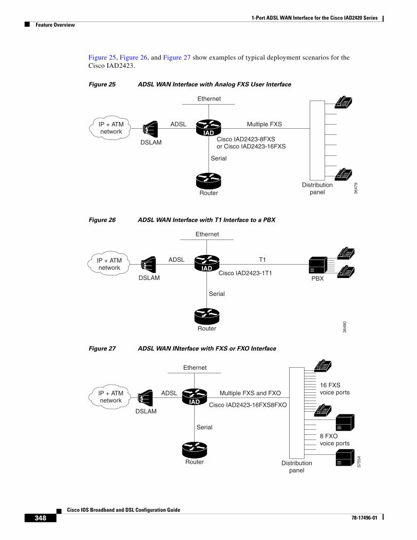
1-Port ADSL WAN Interface for the Cisco IAD2420 SeriesFeature Overview
348Cisco IOS Broadband and DSL Configuration Guide
78-17496-01
Figure 25, Figure 26, and Figure 27 show examples of typical deployment scenarios for the Cisco IAD2423.
Figure 25 ADSL WAN Interface with Analog FXS User Interface
Figure 26 ADSL WAN Interface with T1 Interface to a PBX
Figure 27 ADSL WAN INterface with FXS or FXO Interface
Cisco IAD2423-8FXSor Cisco IAD2423-16FXS
IP + ATMnetwork
ADSL Multiple FXS
Serial
Ethernet
RouterDistribution
panel 3647
9
DSLAM
IAD
3648
0
Cisco IAD2423-1T1
IP + ATMnetwork
ADSL
DSLAM
T1
Serial
Ethernet
PBX
Router
IAD
Cisco IAD2423-16FXS8FXO
IP + ATMnetwork
ADSL Multiple FXS and FXO
Serial
Ethernet
Router
3755
4
DSLAM
IAD
16 FXSvoice ports
8 FXOvoice ports
Distributionpanel
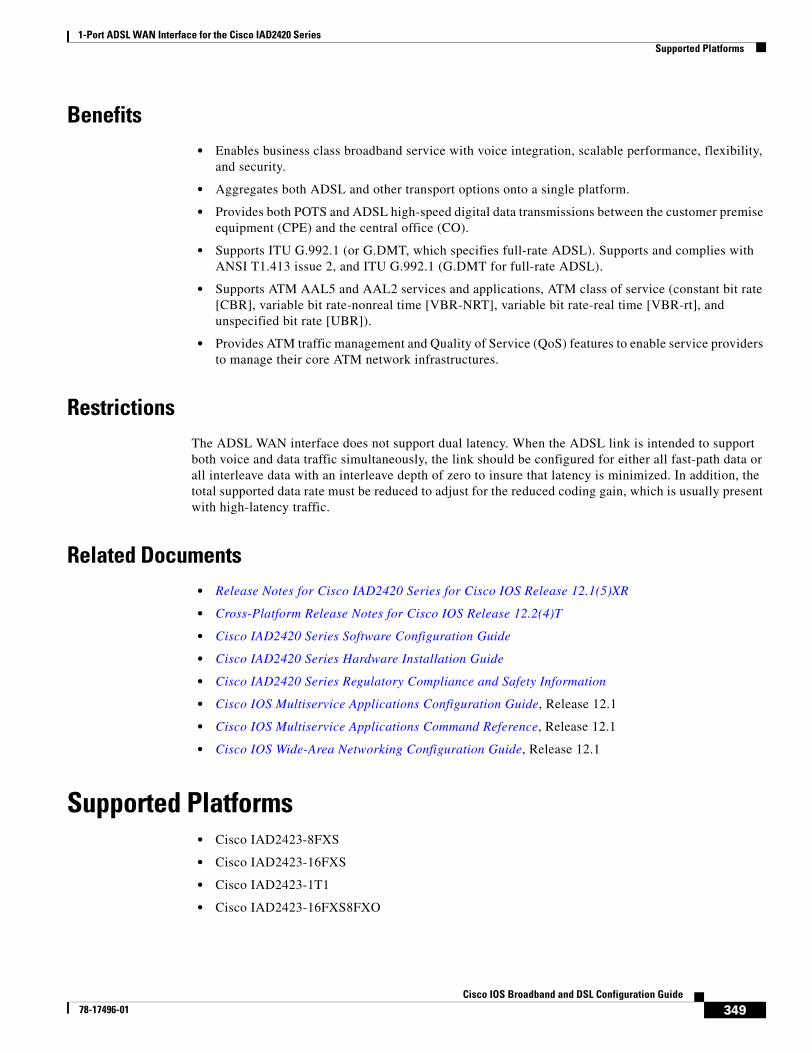
1-Port ADSL WAN Interface for the Cisco IAD2420 SeriesSupported Platforms
349Cisco IOS Broadband and DSL Configuration Guide
78-17496-01
Benefits• Enables business class broadband service with voice integration, scalable performance, flexibility,
and security.
• Aggregates both ADSL and other transport options onto a single platform.
• Provides both POTS and ADSL high-speed digital data transmissions between the customer premise equipment (CPE) and the central office (CO).
• Supports ITU G.992.1 (or G.DMT, which specifies full-rate ADSL). Supports and complies with ANSI T1.413 issue 2, and ITU G.992.1 (G.DMT for full-rate ADSL).
• Supports ATM AAL5 and AAL2 services and applications, ATM class of service (constant bit rate [CBR], variable bit rate-nonreal time [VBR-NRT], variable bit rate-real time [VBR-rt], and unspecified bit rate [UBR]).
• Provides ATM traffic management and Quality of Service (QoS) features to enable service providers to manage their core ATM network infrastructures.
RestrictionsThe ADSL WAN interface does not support dual latency. When the ADSL link is intended to support both voice and data traffic simultaneously, the link should be configured for either all fast-path data or all interleave data with an interleave depth of zero to insure that latency is minimized. In addition, the total supported data rate must be reduced to adjust for the reduced coding gain, which is usually present with high-latency traffic.
Related Documents• Release Notes for Cisco IAD2420 Series for Cisco IOS Release 12.1(5)XR
• Cross-Platform Release Notes for Cisco IOS Release 12.2(4)T
• Cisco IAD2420 Series Software Configuration Guide
• Cisco IAD2420 Series Hardware Installation Guide
• Cisco IAD2420 Series Regulatory Compliance and Safety Information
• Cisco IOS Multiservice Applications Configuration Guide, Release 12.1
• Cisco IOS Multiservice Applications Command Reference, Release 12.1
• Cisco IOS Wide-Area Networking Configuration Guide, Release 12.1
Supported Platforms• Cisco IAD2423-8FXS
• Cisco IAD2423-16FXS
• Cisco IAD2423-1T1
• Cisco IAD2423-16FXS8FXO
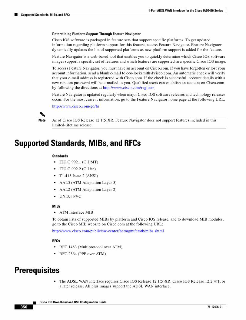
1-Port ADSL WAN Interface for the Cisco IAD2420 SeriesSupported Standards, MIBs, and RFCs
350Cisco IOS Broadband and DSL Configuration Guide
78-17496-01
Determining Platform Support Through Feature Navigator
Cisco IOS software is packaged in feature sets that support specific platforms. To get updated information regarding platform support for this feature, access Feature Navigator. Feature Navigator dynamically updates the list of supported platforms as new platform support is added for the feature.
Feature Navigator is a web-based tool that enables you to quickly determine which Cisco IOS software images support a specific set of features and which features are supported in a specific Cisco IOS image.
To access Feature Navigator, you must have an account on Cisco.com. If you have forgotten or lost your account information, send a blank e-mail to [email protected]. An automatic check will verify that your e-mail address is registered with Cisco.com. If the check is successful, account details with a new random password will be e-mailed to you. Qualified users can establish an account on Cisco.com by following the directions at http://www.cisco.com/register.
Feature Navigator is updated regularly when major Cisco IOS software releases and technology releases occur. For the most current information, go to the Feature Navigator home page at the following URL:
http://www.cisco.com/go/fn
Note As of Cisco IOS Release 12.1(5)XR, Feature Navigator does not support features included in this limited-lifetime release.
Supported Standards, MIBs, and RFCsStandards
• ITU G.992.1 (G.DMT)
• ITU G.992.2 (G.Lite)
• T1.413 Issue 2 (ANSI)
• AAL5 (ATM Adaptation Layer 5)
• AAL2 (ATM Adaptation Layer 2)
• UNI3.1 PVC
MIBs
• ATM Interface MIB
To obtain lists of supported MIBs by platform and Cisco IOS release, and to download MIB modules, go to the Cisco MIB website on Cisco.com at the following URL:
http://www.cisco.com/public/sw-center/netmgmt/cmtk/mibs.shtml
RFCs
• RFC 1483 (Multiprotocol over ATM)
• RFC 2364 (PPP over ATM)
Prerequisites• The ADSL WAN interface requires Cisco IOS Release 12.1(5)XR, Cisco IOS Release 12.2(4)T, or
a later release. All plus images support the ADSL WAN interface.
1-Port ADSL WAN Interface for the Cisco IAD2420 SeriesConfiguration Tasks
351Cisco IOS Broadband and DSL Configuration Guide
78-17496-01
Configuration TasksSee the following sections for configuration tasks for the ADSL WAN interface feature. Each task in the list is identified as either required or optional.
• Configuring the ADSL ATM Interface (required)
• Configuring ATM for AAL2 Voice (optional)
• Configuring RSVP over an ATM Network (optional)
Configuring the ADSL ATM InterfaceIf your Cisco IAD has an ADSL port, a default ATM configuration is automatically in effect when the Cisco IAD is first powered on. If your Cisco IAD has a T1-WAN port, a default ATM configuration takes effect when you enter the mode atm controller command. The default ATM configuration has the following operating parameters:
• ADSL port only.
– Operating mode is auto—The ADSL interface operates in the mode specified by the remote DSL access multiplexer (DSLAM).
• T1-WAN port and ADSL port.
– Maximum VPIs per VCI (atm vc-per-vc)—1024.
– No IP address.
– ATM UNI Version 4.0 is assigned.
– ATM ILMI keepalive is disabled.
– No ATM PVCs are configured
To configure the ADSL ATM interface, follow these steps:
Command Purpose
Step 1 Router> enablePassword:
Router#
Enters privileged EXEC mode by entering the enable command.
Step 2 Router# config terminal
Router(config)#
Enters configuration mode by entering the config terminal command.
Step 3 Router(config)# controller t1 0 Enter controller configuration mode and enter the controller number. The controller number for the T1-WAN port is 0.
Note This step is only necessary if you have a T1 interface.
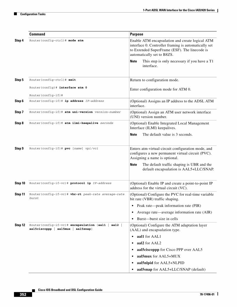
1-Port ADSL WAN Interface for the Cisco IAD2420 SeriesConfiguration Tasks
352Cisco IOS Broadband and DSL Configuration Guide
78-17496-01
Step 4 Router(config-ctrl)# mode atm Enable ATM encapsulation and create logical ATM interface 0. Controller framing is automatically set to Extended SuperFrame (ESF). The linecode is automatically set to B8ZS.
Note This step is only necessary if you have a T1 interface.
Step 5 Router(config-ctrl)# exit
Router(config)# interface atm 0
Router(config-if)#
Return to configuration mode.
Enter configuration mode for ATM 0.
Step 6 Router(config-if)# ip address IP-address (Optional) Assigns an IP address to the ADSL ATM interface.
Step 7 Router(config-if)# atm uni-version version-number (Optional) Assign an ATM user network interface (UNI) version number.
Step 8 Router(config-if)# atm ilmi-keepalive seconds (Optional) Enable Integrated Local Management Interface (ILMI) keepalives.
Note The default value is 3 seconds.
Step 9 Router(config-if)# pvc [name] vpi/vci Enters atm-virtual-circuit configuration mode, and configures a new permanent virtual circuit (PVC). Assigning a name is optional.
Note The default traffic shaping is UBR and the default encapsulation is AAL5+LLC/SNAP.
Step 10 Router(config-if-vc)# protocol ip IP-address (Optional) Enable IP and create a point-to-point IP address for the virtual circuit (VC).
Step 11 Router(config-if-vc)# vbr-rt peak-rate average-rate burst
(Optional) Configure the PVC for real-time variable bit rate (VBR) traffic shaping.
• Peak rate—peak information rate (PIR)
• Average rate—average information rate (AIR)
• Burst—burst size in cells
Step 12 Router(config-if-vc)# encapsulation {aal1 | aal2 | aal5ciscoppp | aal5mux | aal5snap}
(Optional) Configure the ATM adaptation layer (AAL) and encapsulation type.
• aal1 for AAL1
• aal2 for AAL2
• aal5ciscoppp for Cisco PPP over AAL5
• aal5mux for AAL5+MUX
• aal5nlpid for AAL5+NLPID
• aal5snap for AAL5+LLC/SNAP (default)
Command Purpose
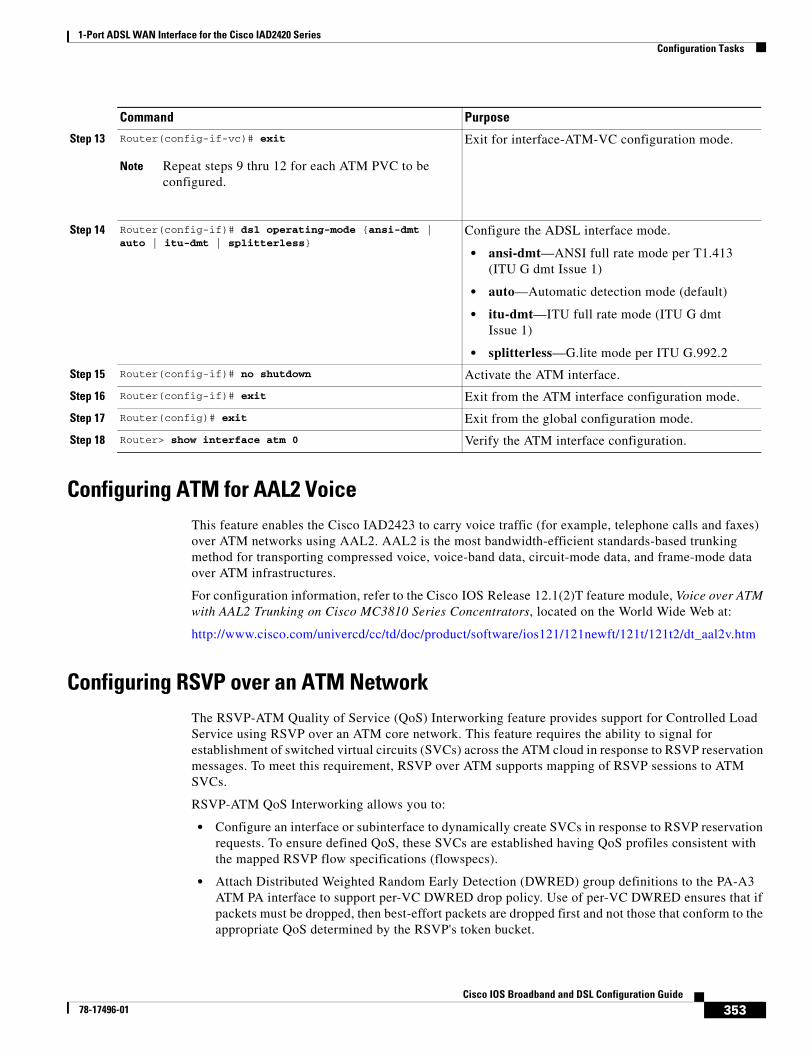
1-Port ADSL WAN Interface for the Cisco IAD2420 SeriesConfiguration Tasks
353Cisco IOS Broadband and DSL Configuration Guide
78-17496-01
Configuring ATM for AAL2 VoiceThis feature enables the Cisco IAD2423 to carry voice traffic (for example, telephone calls and faxes) over ATM networks using AAL2. AAL2 is the most bandwidth-efficient standards-based trunking method for transporting compressed voice, voice-band data, circuit-mode data, and frame-mode data over ATM infrastructures.
For configuration information, refer to the Cisco IOS Release 12.1(2)T feature module, Voice over ATM with AAL2 Trunking on Cisco MC3810 Series Concentrators, located on the World Wide Web at:
http://www.cisco.com/univercd/cc/td/doc/product/software/ios121/121newft/121t/121t2/dt_aal2v.htm
Configuring RSVP over an ATM NetworkThe RSVP-ATM Quality of Service (QoS) Interworking feature provides support for Controlled Load Service using RSVP over an ATM core network. This feature requires the ability to signal for establishment of switched virtual circuits (SVCs) across the ATM cloud in response to RSVP reservation messages. To meet this requirement, RSVP over ATM supports mapping of RSVP sessions to ATM SVCs.
RSVP-ATM QoS Interworking allows you to:
• Configure an interface or subinterface to dynamically create SVCs in response to RSVP reservation requests. To ensure defined QoS, these SVCs are established having QoS profiles consistent with the mapped RSVP flow specifications (flowspecs).
• Attach Distributed Weighted Random Early Detection (DWRED) group definitions to the PA-A3 ATM PA interface to support per-VC DWRED drop policy. Use of per-VC DWRED ensures that if packets must be dropped, then best-effort packets are dropped first and not those that conform to the appropriate QoS determined by the RSVP's token bucket.
Step 13 Router(config-if-vc)# exit
Note Repeat steps 9 thru 12 for each ATM PVC to be configured.
Exit for interface-ATM-VC configuration mode.
Step 14 Router(config-if)# dsl operating-mode {ansi-dmt | auto | itu-dmt | splitterless}
Configure the ADSL interface mode.
• ansi-dmt—ANSI full rate mode per T1.413 (ITU G dmt Issue 1)
• auto—Automatic detection mode (default)
• itu-dmt—ITU full rate mode (ITU G dmt Issue 1)
• splitterless—G.lite mode per ITU G.992.2
Step 15 Router(config-if)# no shutdown Activate the ATM interface.
Step 16 Router(config-if)# exit Exit from the ATM interface configuration mode.
Step 17 Router(config)# exit Exit from the global configuration mode.
Step 18 Router> show interface atm 0 Verify the ATM interface configuration.
Command Purpose
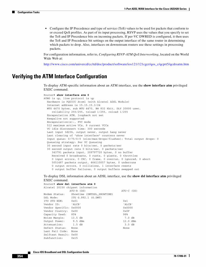
1-Port ADSL WAN Interface for the Cisco IAD2420 SeriesConfiguration Tasks
354Cisco IOS Broadband and DSL Configuration Guide
78-17496-01
• Configure the IP Precedence and type of service (ToS) values to be used for packets that conform to or exceed QoS profiles. As part of its input processing, RSVP uses the values that you specify to set the ToS and IP Precedence bits on incoming packets. If per-VC DWRED is configured, it then uses the ToS and IP Precedence bit settings on the output interface of the same router in determining which packets to drop. Also, interfaces on downstream routers use these settings in processing packets.
For configuration information, refer to, Configuring RSVP-ATM QoS Interworking, located on the World Wide Web at:
http://www.cisco.com/univercd/cc/td/doc/product/software/ios121/121cgcr/qos_c/qcprt5/qcdrsatm.htm
Verifying the ATM Interface ConfigurationTo display ATM-specific information about an ATM interface, use the show interface atm privileged EXEC command.
Router# show interface atm 0ATM0 is up, line protocol is up Hardware is PQUICC Atom1 (with Alcatel ADSL Module) Internet address is 15.15.15.3/24 MTU 4470 bytes, sub MTU 4470, BW 832 Kbit, DLY 20000 usec, reliability 255/255, txload 1/255, rxload 1/255 Encapsulation ATM, loopback not set Keepalive not supported Encapsulation(s):, PVC mode 512 maximum active VCs, 8 current VCCs VC idle disconnect time: 300 seconds Last input 3d23h, output never, output hang never Last clearing of "show interface" counters never Input queue: 0/75/0/0 (size/max/drops/flushes); Total output drops: 0 Queueing strategy: Per VC Queueing 30 second input rate 0 bits/sec, 0 packets/sec 30 second output rate 0 bits/sec, 0 packets/sec 343791 packets input, 209797720 bytes, 0 no buffer Received 0 broadcasts, 0 runts, 0 giants, 0 throttles 0 input errors, 0 CRC, 0 frame, 0 overrun, 0 ignored, 0 abort 5051487 packets output, 464110057 bytes, 0 underruns 0 output errors, 0 collisions, 1 interface resets 0 output buffer failures, 0 output buffers swapped out
To display DSL information about an ADSL interface, use the show dsl interface atm privileged EXEC command.Router# show dsl interface atm 0Alcatel 20150 chipset information ATU-R (DS) ATU-C (US)Modem Status: Showtime (DMTDSL_SHOWTIME)DSL Mode: ITU G.992.1 (G.DMT)ITU STD NUM: 0x01 0x1 Vendor ID: 'ALCB' 'ALCB'Vendor Specific: 0x0000 0x0000Vendor Country: 0x00 0x0FCapacity Used: 85% 98%Noise Margin: 13.5 dB 7.0 dBOutput Power: 9.5 dBm 12.0 dBmAttenuation: 1.5 dB 3.5 dBDefect Status: None None Last Fail Code: NoneSelftest Result: 0x00Subfunction: 0x15
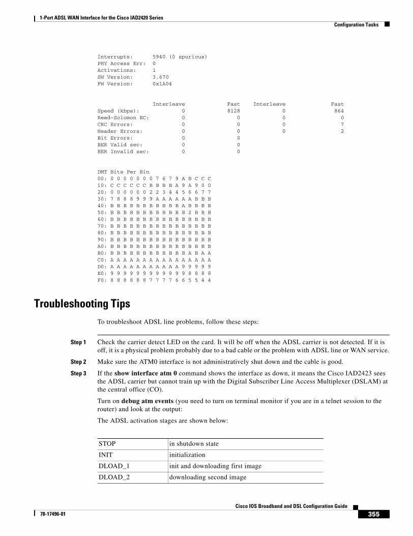
1-Port ADSL WAN Interface for the Cisco IAD2420 SeriesConfiguration Tasks
355Cisco IOS Broadband and DSL Configuration Guide
78-17496-01
Interrupts: 5940 (0 spurious)PHY Access Err: 0Activations: 1SW Version: 3.670FW Version: 0x1A04
Interleave Fast Interleave FastSpeed (kbps): 0 8128 0 864Reed-Solomon EC: 0 0 0 0CRC Errors: 0 0 0 7Header Errors: 0 0 0 2Bit Errors: 0 0BER Valid sec: 0 0BER Invalid sec: 0 0
DMT Bits Per Bin00: 0 0 0 0 0 0 0 7 6 7 9 A B C C C10: C C C C C C B B B B A 9 A 9 0 020: 0 0 0 0 0 0 2 2 3 4 4 5 6 6 7 730: 7 8 8 8 9 9 9 A A A A A A B B B40: B B B B B B B B B B B A B B B B50: B B B B B B B B B B B B 2 B B B60: B B B B B B B B B B B B B B B B70: B B B B B B B B B B B B B B B B80: B B B B B B B B B B B B B B B B90: B B B B B B B B B B B B B B B BA0: B B B B B B B B B B B B B B B BB0: B B B B B B B B B B B B A B A AC0: A A A A A A A A A A A A A A A AD0: A A A A A A A A A A A 9 9 9 9 9E0: 9 9 9 9 9 9 9 9 9 9 9 9 8 8 8 8F0: 8 8 8 8 8 8 7 7 7 7 6 6 5 5 4 4
Troubleshooting TipsTo troubleshoot ADSL line problems, follow these steps:
Step 1 Check the carrier detect LED on the card. It will be off when the ADSL carrier is not detected. If it is off, it is a physical problem probably due to a bad cable or the problem with ADSL line or WAN service.
Step 2 Make sure the ATM0 interface is not administratively shut down and the cable is good.
Step 3 If the show interface atm 0 command shows the interface as down, it means the Cisco IAD2423 sees the ADSL carrier but cannot train up with the Digital Subscriber Line Access Multiplexer (DSLAM) at the central office (CO).
Turn on debug atm events (you need to turn on terminal monitor if you are in a telnet session to the router) and look at the output:
The ADSL activation stages are shown below:
STOP in shutdown state
INIT initialization
DLOAD_1 init and downloading first image
DLOAD_2 downloading second image
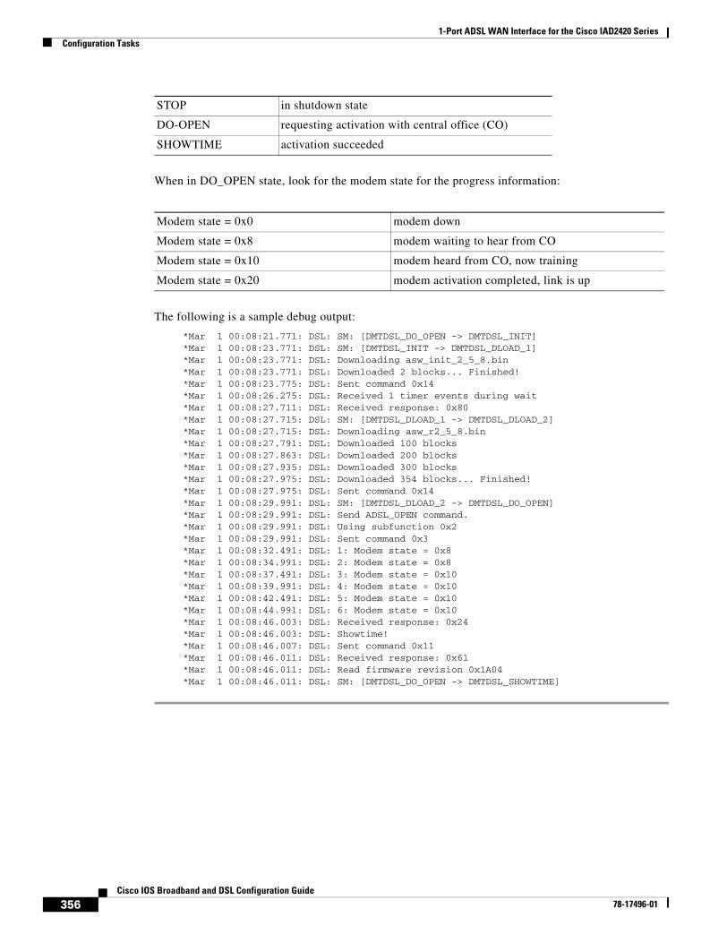
1-Port ADSL WAN Interface for the Cisco IAD2420 SeriesConfiguration Tasks
356Cisco IOS Broadband and DSL Configuration Guide
78-17496-01
When in DO_OPEN state, look for the modem state for the progress information:
The following is a sample debug output:
*Mar 1 00:08:21.771: DSL: SM: [DMTDSL_DO_OPEN -> DMTDSL_INIT] *Mar 1 00:08:23.771: DSL: SM: [DMTDSL_INIT -> DMTDSL_DLOAD_1] *Mar 1 00:08:23.771: DSL: Downloading asw_init_2_5_8.bin *Mar 1 00:08:23.771: DSL: Downloaded 2 blocks... Finished! *Mar 1 00:08:23.775: DSL: Sent command 0x14 *Mar 1 00:08:26.275: DSL: Received 1 timer events during wait *Mar 1 00:08:27.711: DSL: Received response: 0x80 *Mar 1 00:08:27.715: DSL: SM: [DMTDSL_DLOAD_1 -> DMTDSL_DLOAD_2] *Mar 1 00:08:27.715: DSL: Downloading asw_r2_5_8.bin *Mar 1 00:08:27.791: DSL: Downloaded 100 blocks *Mar 1 00:08:27.863: DSL: Downloaded 200 blocks *Mar 1 00:08:27.935: DSL: Downloaded 300 blocks *Mar 1 00:08:27.975: DSL: Downloaded 354 blocks... Finished! *Mar 1 00:08:27.975: DSL: Sent command 0x14 *Mar 1 00:08:29.991: DSL: SM: [DMTDSL_DLOAD_2 -> DMTDSL_DO_OPEN] *Mar 1 00:08:29.991: DSL: Send ADSL_OPEN command. *Mar 1 00:08:29.991: DSL: Using subfunction 0x2 *Mar 1 00:08:29.991: DSL: Sent command 0x3 *Mar 1 00:08:32.491: DSL: 1: Modem state = 0x8 *Mar 1 00:08:34.991: DSL: 2: Modem state = 0x8 *Mar 1 00:08:37.491: DSL: 3: Modem state = 0x10 *Mar 1 00:08:39.991: DSL: 4: Modem state = 0x10 *Mar 1 00:08:42.491: DSL: 5: Modem state = 0x10 *Mar 1 00:08:44.991: DSL: 6: Modem state = 0x10 *Mar 1 00:08:46.003: DSL: Received response: 0x24 *Mar 1 00:08:46.003: DSL: Showtime! *Mar 1 00:08:46.007: DSL: Sent command 0x11 *Mar 1 00:08:46.011: DSL: Received response: 0x61 *Mar 1 00:08:46.011: DSL: Read firmware revision 0x1A04 *Mar 1 00:08:46.011: DSL: SM: [DMTDSL_DO_OPEN -> DMTDSL_SHOWTIME]
DO-OPEN requesting activation with central office (CO)
SHOWTIME activation succeeded
STOP in shutdown state
Modem state = 0x0 modem down
Modem state = 0x8 modem waiting to hear from CO
Modem state = 0x10 modem heard from CO, now training
Modem state = 0x20 modem activation completed, link is up
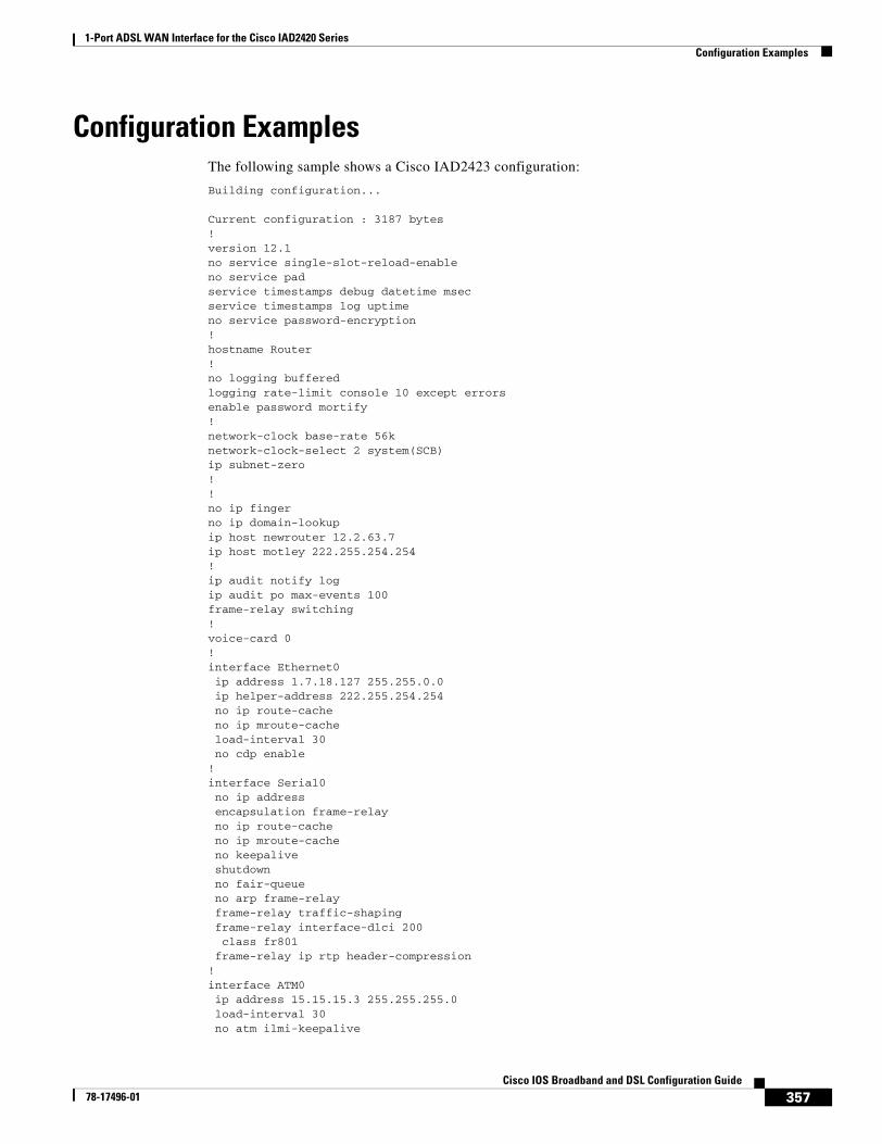
1-Port ADSL WAN Interface for the Cisco IAD2420 SeriesConfiguration Examples
357Cisco IOS Broadband and DSL Configuration Guide
78-17496-01
Configuration ExamplesThe following sample shows a Cisco IAD2423 configuration:
Building configuration...
Current configuration : 3187 bytes!version 12.1no service single-slot-reload-enableno service padservice timestamps debug datetime msecservice timestamps log uptimeno service password-encryption!hostname Router!no logging bufferedlogging rate-limit console 10 except errorsenable password mortify!network-clock base-rate 56knetwork-clock-select 2 system(SCB)ip subnet-zero!!no ip fingerno ip domain-lookupip host newrouter 12.2.63.7ip host motley 222.255.254.254!ip audit notify logip audit po max-events 100frame-relay switching!voice-card 0!interface Ethernet0 ip address 1.7.18.127 255.255.0.0 ip helper-address 222.255.254.254 no ip route-cache no ip mroute-cache load-interval 30 no cdp enable!interface Serial0 no ip address encapsulation frame-relay no ip route-cache no ip mroute-cache no keepalive shutdown no fair-queue no arp frame-relay frame-relay traffic-shaping frame-relay interface-dlci 200 class fr801 frame-relay ip rtp header-compression!interface ATM0 ip address 15.15.15.3 255.255.255.0 load-interval 30 no atm ilmi-keepalive
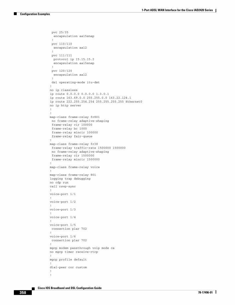
1-Port ADSL WAN Interface for the Cisco IAD2420 SeriesConfiguration Examples
358Cisco IOS Broadband and DSL Configuration Guide
78-17496-01
pvc 25/35 encapsulation aal5snap ! pvc 110/110 encapsulation aal2 ! pvc 111/111 protocol ip 15.15.15.2 encapsulation aal5snap ! pvc 120/120 encapsulation aal2 ! dsl operating-mode itu-dmt!no ip classlessip route 0.0.0.0 0.0.0.0 1.3.0.1ip route 163.69.0.0 255.255.0.0 163.22.124.1ip route 222.255.254.254 255.255.255.255 Ethernet0no ip http server!!map-class frame-relay fr801 no frame-relay adaptive-shaping frame-relay cir 100000 frame-relay bc 1000 frame-relay mincir 100000 frame-relay fair-queue!map-class frame-relay fr38 frame-relay traffic-rate 1500000 1500000 no frame-relay adaptive-shaping frame-relay cir 1500000 frame-relay mincir 1500000!map-class frame-relay voice!map-class frame-relay 801logging trap debuggingno cdp runcall rsvp-sync!voice-port 1/1!voice-port 1/2!voice-port 1/3!voice-port 1/4!voice-port 1/5 connection plar 702!voice-port 1/6 connection plar 702!mgcp modem passthrough voip mode cano mgcp timer receive-rtcp!mgcp profile default!dial-peer cor custom!!

1-Port ADSL WAN Interface for the Cisco IAD2420 SeriesConfiguration Examples
359Cisco IOS Broadband and DSL Configuration Guide
78-17496-01
!dial-peer voice 1001 pots destination-pattern 1001 port 1/1!dial-peer voice 2001 voatm destination-pattern 2001 session protocol aal2-trunk session target ATM0 pvc 110/110 101 signal-type trans codec aal2-profile custom 110 g711ulaw no vad!dial-peer voice 701 pots destination-pattern 701 port 1/1!dial-peer voice 702 pots destination-pattern 702 port 1/2!dial-peer voice 703 pots destination-pattern 703 port 1/3!dial-peer voice 704 pots destination-pattern 704 port 1/4!dial-peer voice 705 pots destination-pattern 705 port 1/5!dial-peer voice 706 pots destination-pattern 706 port 1/6!dial-peer voice 9999 voip destination-pattern 2222 session target ipv4:12.12.12.2 signal-type ext-signal!dial-peer voice 9998 voip destination-pattern 2223 session target ipv4:123.123.123.123 signal-type ext-signal!dial-peer voice 1000 voip signal-type ext-signal!!line con 0 exec-timeout 0 0 privilege level 15 transport input noneline aux 0line 2 3line vty 0 4 privilege level 15 no login!end

1-Port ADSL WAN Interface for the Cisco IAD2420 SeriesCommand List
360Cisco IOS Broadband and DSL Configuration Guide
78-17496-01
Command ListThe following commands are pertinent to this feature. To see the command pages for these and other commands used with this feature, go to the Cisco IOS Master Commands List, Release 12.4, at http://www.cisco.com/univercd/cc/td/doc/product/software/ios124/124mindx/124index.htm.
• debug atm events
• dsl operating-mode
• show dsl interface atm
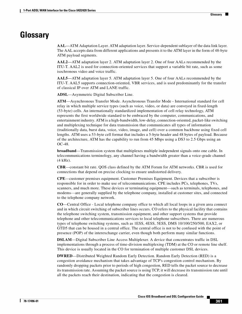
1-Port ADSL WAN Interface for the Cisco IAD2420 SeriesGlossary
361Cisco IOS Broadband and DSL Configuration Guide
78-17496-01
GlossaryAAL—ATM Adaptation Layer. ATM adaptation layer. Service-dependent sublayer of the data link layer. The AAL accepts data from different applications and presents it to the ATM layer in the form of 48-byte ATM payload segments.
AAL2—ATM adaptation layer 2. ATM adaptation layer 2. One of four AALs recommended by the ITU-T. AAL2 is used for connection-oriented services that support a variable bit rate, such as some isochronous video and voice traffic.
AAL5—ATM adaptation layer 5. ATM adaptation layer 5. One of four AALs recommended by the ITU-T. AAL5 supports connection-oriented, VBR services, and is used predominantly for the transfer of classical IP over ATM and LANE traffic.
ADSL—Asymmetric Digital Subscriber Line.
ATM—Asynchronous Transfer Mode. Asynchronous Transfer Mode - International standard for cell relay in which multiple service types (such as voice, video, or data) are conveyed in fixed-length (53-byte) cells. An internationally standardized implementation of cell relay technology, ATM represents the first worldwide standard to be embraced by the computer, communications, and entertainment industry. ATM is a high-bandwidth, low-delay, connection-oriented, packet-like switching and multiplexing technique for data transmission that communicates all types of information (traditionally data, burst data, voice, video, image, and cell) over a common backbone using fixed cell lengths. ATM uses a 53-byte cell format that includes a 5-byte header and 48 bytes of payload. Because of the architecture, ATM has the capability to run from 45 Mbps using a DS3 to 2.5 Gbps using an OC-48.
broadband—Transmission system that multiplexes multiple independent signals onto one cable. In telecommunications terminology, any channel having a bandwidth greater than a voice-grade channel (4 kHz).
CBR—constant bit rate. QOS class defined by the ATM Forum for ATM networks. CBR is used for connections that depend on precise clocking to ensure undistorted delivery.
CPE—customer premises equipment. Customer Premises Equipment. Devices that a subscriber is responsible for in order to make use of telecommunications. CPE includes PCs, telephones, TVs, scanners, and much more. These devices or terminating equipment---such as terminals, telephones, and modems---are generally supplied by the telephone company, installed at customer sites, and connected to the telephone company network.
CO—Central Office - Local telephone company office to which all local loops in a given area connect and in which circuit switching of subscriber lines occurs. CO refers to the physical facility that contains the telephone switching system, transmission equipment, and other support systems that provide telephone and other telecommunications services to local telephone subscribers. There are numerous types of telephone switching systems, such as 1ESS, 4ESS, 5ESS, DMS 10/100/250/500, EAX2, or GTD5 that can be housed in a central office. The central office is not to be confused with the point of presence (POP) of the interexchange carrier, even though both perform many similar functions.
DSLAM—Digital Subscriber Line Access Multiplexer. A device that concentrates traffic in DSL implementations through a process of time-division multiplexing (TDM) at the CO or remote line shelf. This device is usually located in the CO for termination of multiple customer DSL devices.
DWRED—Distributed Weighted Random Early Detection. Random Early Detection (RED) is a congestion avoidance mechanism that takes advantage of TCP's congestion control mechanism. By randomly dropping packets prior to periods of high congestion, RED tells the packet source to decrease its transmission rate. Assuming the packet source is using TCP, it will decrease its transmission rate until all the packets reach their destination, indicating that the congestion is cleared.
1-Port ADSL WAN Interface for the Cisco IAD2420 SeriesGlossary
362Cisco IOS Broadband and DSL Configuration Guide
78-17496-01
Weighted RED (WRED) generally drops packets selectively based on IP precedence. Packets with a higher IP precedence are less likely to be dropped than packets with a lower precedence. Thus, higher priority traffic is delivered with a higher probability than lower priority traffic. However, you can also configure WRED to ignore IP precedence when making drop decisions so that non-weighted RED behavior is achieved.
ILMI—Interim Local Management Interface. Specification developed by the ATM Forum for incorporating network-management capabilities into the ATM UNI.
POTS—plain old telephone service. Basic analog telephone service, usually associated with residential or business subscribers.
PPP over ATM—Point-to-Point Protocol. A successor to SLIP, PPP provides router-to-router and host-to-network connections over synchronous and asynchronous circuits.
PVC—permanent virtual circuit. Virtual circuit that is permanently established. PVCs save bandwidth associated with circuit establishment and tear down in situations where certain virtual circuits must exist all the time.
QoS—quality of service. Measure of performance for a transmission system that reflects its transmission quality and service availability.
RSVP—Resource Reservation Protocol. The Resource Reservation Protocol is a network-control protocol that enables Internet applications to obtain special qualities of service (QoSs) for their data flows.
SVC—switched virtual circuit. Virtual circuit that is dynamically established on demand and is torn down when transmission is complete. SVCs are used in situations where data transmission is sporadic. Called a switched virtual connection in ATM terminology.
ToS—type of service. See COS.
UBR—unspecified bit rate. QOS class defined by the ATM Forum for ATM networks. UBR allows any amount of data up to a specified maximum to be sent across the network, but there are no guarantees in terms of cell loss rate and delay.
UNI—User-Network Interface. ATM Forum specification that defines an interoperability standard for the interface between ATM-based products (a router or an ATM switch) located in a private network and the ATM switches located within the public carrier network.
VBR—variable bit rate. QOS class defined by the ATM Forum for ATM networks. VBR is subdivided into a real time (RT) class and non-real time (NRT) class.
VC—virtual circuit. Logical circuit created to ensure reliable communication between two network devices. A virtual circuit is defined by a virtual path identifier/virtual channel identifier (VPI/VCI) pair, and can be either a PVC or a SVC. Virtual circuits are used in Frame Relay and X.25. In ATM, a virtual circuit is called a virtual channel.
363Cisco IOS Broadband and DSL Configuration Guide
78-17496-01
ATM Mode for Two-Wire or Four-Wire SHDSL
This document describes the ATM Mode for Two-Wire or Four-Wire SHDSL feature on the Cisco 1700 series, Cisco 1800 series, Cisco 2600 series, Cisco 2800, Cisco 3631, Cisco 3700, and Cisco 3800 series routers.
The ATM Mode for Two-Wire or Four-Wire SHDSL feature adds four-wire support in fixed line-rate mode only on a WIC-1SHDSL-V2. Two-wire mode supports two-wire line-rate and auto line-rate. This feature builds on the existing features of the Multirate Symmetrical High-Speed Digital Subscriber Line (G.SHDSL) feature supported on the 1-port G.SHDSL WAN interface card (WIC-1SHDSL). The four-wire feature of G.991.2 doubles the bandwidth in ATM mode and increases usable distance over two pairs of wires.
The WIC-1SHDSL-V2 supports ATM on two-wire and four-wire line mode. Embedded Operation Channel (EOC) messages support for customer premise equipment (CPE) is provided for two-wire and four-wire modes.
Feature Specifications for the ATM Mode for SHDSL
Feature HistoryRelease Modification
12.3(4)XD This feature (WIC-1SHDSL-V2) was introduced on the Cisco 2600 series and Cisco 3700 series routers to add four-wire support. Two-wire support was previously available in 1-Port G.SHDSL WAN Interface Card for Cisco 2600 Series and Cisco 3600 Series Routers, Release 12.2(8)T.
12.3(4)XG This feature (WIC-1SHDSL-V2) was integrated into Cisco IOS Release 12.3(4)XG on the Cisco 1700 series routers.
12.3(7)T This feature (WIC-1SHDSL-V2) was integrated into the Cisco IOS Release 12.3(7)T on the Cisco 2600 series, Cisco 3631, and Cisco 3700 series routers. Cisco 1700 series routers do not support the WIC-1SHDSL-V2 in this release.
12.3(4)XG1 Support for the auto line-mode feature was added.
12.3(11)T Support for the following was added: additional annex parameters for Cisco 1700, Cisco 2600, Cisco 2800, Cisco 3631, Cisco 3700, and Cisco 3800 series routers; the HDSL2-SHDSL-LINE-MIB (RFC3276); and support for the ATM Mode for SHDSL feature was added for Cisco 2800 series, and Cisco 3800 series routers.
12.3(14)T Support was added for Cisco 1800 series routers and the Cisco 2801 Integrated Services router.
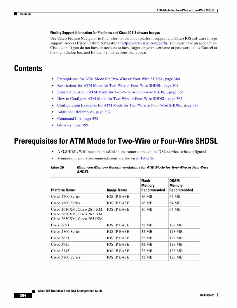
ATM Mode for Two-Wire or Four-Wire SHDSLContents
364Cisco IOS Broadband and DSL Configuration Guide
78-17496-01
Finding Support Information for Platforms and Cisco IOS Software Images
Use Cisco Feature Navigator to find information about platform support and Cisco IOS software image support. Access Cisco Feature Navigator at http://www.cisco.com/go/fn. You must have an account on Cisco.com. If you do not have an account or have forgotten your username or password, click Cancel at the login dialog box and follow the instructions that appear.
Contents• Prerequisites for ATM Mode for Two-Wire or Four-Wire SHDSL, page 364
• Restrictions for ATM Mode for Two-Wire or Four-Wire SHDSL, page 365
• Information About ATM Mode for Two-Wire or Four-Wire SHDSL, page 365
• How to Configure ATM Mode for Two-Wire or Four-Wire SHDSL, page 367
• Configuration Examples for ATM Mode for Two-Wire or Four-Wire SHDSL, page 393
• Additional References, page 397
• Command List, page 398
• Glossary, page 399
Prerequisites for ATM Mode for Two-Wire or Four-Wire SHDSL• A G.SHDSL WIC must be installed in the router to match the DSL service to be configured.
• Minimum memory recommendations are shown in Table 26.
Table 26 Minimum Memory Recommendations for ATM Mode for Two-Wire or Four-Wire
SHDSL
Platform Name Image Name
Flash MemoryRecommended
DRAM MemoryRecommended
Cisco 1700 Series IOS IP BASE 16 MB 64 MB
Cisco 1800 Series IOS IP BASE 16 MB 64 MB
Cisco 2610XM, Cisco 2611XM, Cisco 2620XM, Cisco 2621XM, Cisco 2650XM, Cisco 2651XM
IOS IP BASE 16 MB 64 MB
Cisco 2691 IOS IP BASE 32 MB 128 MB
Cisco 2800 Series IOS IP BASE 32 MB 128 MB
Cisco 3631 IOS IP BASE 32 MB 128 MB
Cisco 3725 IOS IP BASE 32 MB 128 MB
Cisco 3745 IOS IP BASE 32 MB 128 MB
Cisco 3800 Series IOS IP BASE 32 MB 128 MB
ATM Mode for Two-Wire or Four-Wire SHDSLRestrictions for ATM Mode for Two-Wire or Four-Wire SHDSL
365Cisco IOS Broadband and DSL Configuration Guide
78-17496-01
Restrictions for ATM Mode for Two-Wire or Four-Wire SHDSL• The auto parameter of the line-mode command on the WIC-1SHDSL-V2 is supported only in
Cisco IOS Release 12.3(4)XG1 and later releases.
• The WIC-1SHDSL-V2 ATM Mode for SHDSL does not support ATM adaption layer 1 (AAL1) and/or circuit emulation service.
• ATM adaption layer 2 (AAL2) is not supported on Cisco 1700 series, and Cisco 2801 routers.
• The ATM Mode for SHDSL does not interface with AIM-ATM.
• The ATM Mode for SHDSL does not support available bit rate (ABR) class of service (CoS).
• The ATM Mode for SHDSL does not support unspecified bit rate plus (UBR+).
• The ATM Mode for SHDSL only support 23 private virtual circuits (PVC) per WIC.
• The WIC-1SHDSL-V2 should be inserted only into onboard WIC slots or NM-2W, NM-1FE2W, NM-1FE1R2W, NM-2FE2W, NM-1FE2W-V2, or NM-2FE2W-V2 network modules. This WIC is not supported in NM-1E2W, NM-1E1R-2W, or NM-2E2W combination network modules.
• The WIC-1SHDSL-V2 does not support T1/E1 mode in four-wire mode.
• The WIC-1SHDSL does not support T1/E1 mode.
Information About ATM Mode for Two-Wire or Four-Wire SHDSL
This section provides information about the ATM Mode for SHDSL feature.
• SHDSL Features, page 365
• ATM Features, page 366
• Interface and Controller Numbering on the Cisco 1721 Router, page 366
• Interface Numbering on Cisco 2800 and Cisco 3800 Series Routers, page 367
SHDSL FeaturesSupported SHDSL features are listed as follows:
• ITU G.991.2 support (full support for Annex A & B)
– Dying Gasp (ITU G.991.2) is supported.
– Terminating wetting current is supported.
– Two-wire mode supports speeds from 192 kbps to 2.304 Mbps in increments of 64 kbps in both fixed and auto line rate.
– Four-wire mode supports speeds from 384 kbps to 4.608 Mbps in increments of 128 kbps in fixed line rate only and provides increased rate capability and greater reach.
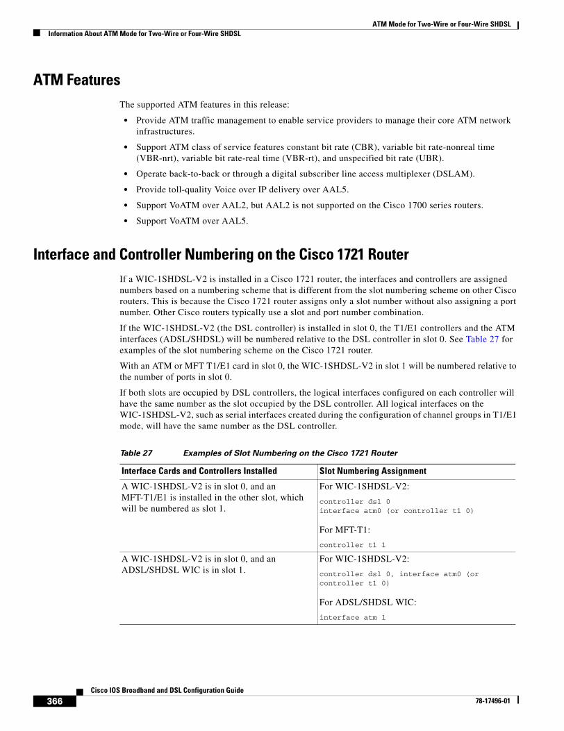
ATM Mode for Two-Wire or Four-Wire SHDSLInformation About ATM Mode for Two-Wire or Four-Wire SHDSL
366Cisco IOS Broadband and DSL Configuration Guide
78-17496-01
ATM FeaturesThe supported ATM features in this release:
• Provide ATM traffic management to enable service providers to manage their core ATM network infrastructures.
• Support ATM class of service features constant bit rate (CBR), variable bit rate-nonreal time (VBR-nrt), variable bit rate-real time (VBR-rt), and unspecified bit rate (UBR).
• Operate back-to-back or through a digital subscriber line access multiplexer (DSLAM).
• Provide toll-quality Voice over IP delivery over AAL5.
• Support VoATM over AAL2, but AAL2 is not supported on the Cisco 1700 series routers.
• Support VoATM over AAL5.
Interface and Controller Numbering on the Cisco 1721 RouterIf a WIC-1SHDSL-V2 is installed in a Cisco 1721 router, the interfaces and controllers are assigned numbers based on a numbering scheme that is different from the slot numbering scheme on other Cisco routers. This is because the Cisco 1721 router assigns only a slot number without also assigning a port number. Other Cisco routers typically use a slot and port number combination.
If the WIC-1SHDSL-V2 (the DSL controller) is installed in slot 0, the T1/E1 controllers and the ATM interfaces (ADSL/SHDSL) will be numbered relative to the DSL controller in slot 0. See Table 27 for examples of the slot numbering scheme on the Cisco 1721 router.
With an ATM or MFT T1/E1 card in slot 0, the WIC-1SHDSL-V2 in slot 1 will be numbered relative to the number of ports in slot 0.
If both slots are occupied by DSL controllers, the logical interfaces configured on each controller will have the same number as the slot occupied by the DSL controller. All logical interfaces on the WIC-1SHDSL-V2, such as serial interfaces created during the configuration of channel groups in T1/E1 mode, will have the same number as the DSL controller.
Table 27 Examples of Slot Numbering on the Cisco 1721 Router
Interface Cards and Controllers Installed Slot Numbering Assignment
A WIC-1SHDSL-V2 is in slot 0, and an MFT-T1/E1 is installed in the other slot, which will be numbered as slot 1.
For WIC-1SHDSL-V2:
controller dsl 0interface atm0 (or controller t1 0)
For MFT-T1:
controller t1 1
A WIC-1SHDSL-V2 is in slot 0, and an ADSL/SHDSL WIC is in slot 1.
For WIC-1SHDSL-V2:
controller dsl 0, interface atm0 (or controller t1 0)
For ADSL/SHDSL WIC:
interface atm 1
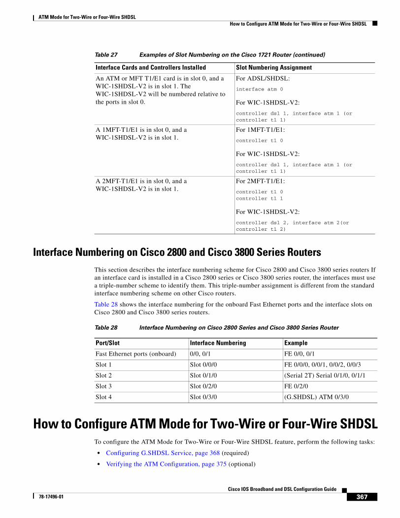
ATM Mode for Two-Wire or Four-Wire SHDSLHow to Configure ATM Mode for Two-Wire or Four-Wire SHDSL
367Cisco IOS Broadband and DSL Configuration Guide
78-17496-01
Interface Numbering on Cisco 2800 and Cisco 3800 Series RoutersThis section describes the interface numbering scheme for Cisco 2800 and Cisco 3800 series routers If an interface card is installed in a Cisco 2800 series or Cisco 3800 series router, the interfaces must use a triple-number scheme to identify them. This triple-number assignment is different from the standard interface numbering scheme on other Cisco routers.
Table 28 shows the interface numbering for the onboard Fast Ethernet ports and the interface slots on Cisco 2800 and Cisco 3800 series routers.
How to Configure ATM Mode for Two-Wire or Four-Wire SHDSLTo configure the ATM Mode for Two-Wire or Four-Wire SHDSL feature, perform the following tasks:
• Configuring G.SHDSL Service, page 368 (required)
• Verifying the ATM Configuration, page 375 (optional)
An ATM or MFT T1/E1 card is in slot 0, and a WIC-1SHDSL-V2 is in slot 1. The WIC-1SHDSL-V2 will be numbered relative to the ports in slot 0.
For ADSL/SHDSL:
interface atm 0
For WIC-1SHDSL-V2:
controller dsl 1, interface atm 1 (or controller t1 1)
A 1MFT-T1/E1 is in slot 0, and a WIC-1SHDSL-V2 is in slot 1.
For 1MFT-T1/E1:
controller t1 0
For WIC-1SHDSL-V2:
controller dsl 1, interface atm 1 (or controller t1 1)
A 2MFT-T1/E1 is in slot 0, and a WIC-1SHDSL-V2 is in slot 1.
For 2MFT-T1/E1:
controller t1 0controller t1 1
For WIC-1SHDSL-V2:
controller dsl 2, interface atm 2(or controller t1 2)
Table 27 Examples of Slot Numbering on the Cisco 1721 Router (continued)
Interface Cards and Controllers Installed Slot Numbering Assignment
Table 28 Interface Numbering on Cisco 2800 Series and Cisco 3800 Series Router
Port/Slot Interface Numbering Example
Fast Ethernet ports (onboard) 0/0, 0/1 FE 0/0, 0/1
Slot 1 Slot 0/0/0 FE 0/0/0, 0/0/1, 0/0/2, 0/0/3
Slot 2 Slot 0/1/0 (Serial 2T) Serial 0/1/0, 0/1/1
Slot 3 Slot 0/2/0 FE 0/2/0
Slot 4 Slot 0/3/0 (G.SHDSL) ATM 0/3/0

ATM Mode for Two-Wire or Four-Wire SHDSLHow to Configure ATM Mode for Two-Wire or Four-Wire SHDSL
368Cisco IOS Broadband and DSL Configuration Guide
78-17496-01
• Verifying DSL Configuration, page 379 (optional)
• Troubleshooting Tasks, page 384 (optional)
Configuring G.SHDSL ServiceThis section details how to configure the ATM Mode for Two-Wire or Four-Wire SHDSL feature for G.SHDSL service.
To configure G.SHDSL service in ATM mode on a Cisco router containing a G.SHDSL WIC, complete the steps in the Summary Steps or the Detailed Steps, beginning in global configuration mode.
Prerequisites
The following list of prerequisites should be followed for this configuration:
• A G.SHDSL WIC must be installed in the router to match the DSL service to be configured.
• Routers may be set up for back-to-back operation as shown in Figure 28 or they may be connected to a DSLAM.
Figure 28 Back-to-Back Setup
SUMMARY STEPS
1. enable
2. configure terminal
3. controller dsl slot/port
4. line-term {co | cpe]
5. dsl-mode shdsl symmetric annex mode
6. ignore-error-duration seconds
7. mode atm
8. line-mode [2-wire | 4-wire | auto]
9. line-rate [rate | auto]
10. exit
11. interface atm slot/port
12. ip address IP-address subnet-mask
13. atm ilmi-keepalive [seconds]
14. pvc [name] vpi/vci
15. protocol protocol [protocol-address]
16. vbr-rt peak-rate average-cell-rate burst
9525
3
Router A
CPE CO
Router BWIC-1SHDSL-V3WIC-1SHDSL-V3

ATM Mode for Two-Wire or Four-Wire SHDSLHow to Configure ATM Mode for Two-Wire or Four-Wire SHDSL
369Cisco IOS Broadband and DSL Configuration Guide
78-17496-01
17. encapsulation {aal2 | aal5ciscoppp | aal5mux | aal5nlpid | aal5snap | aal5autoppp}
18. exit
19. exit
20. exit
21. show interface atm slot/port
22. exit
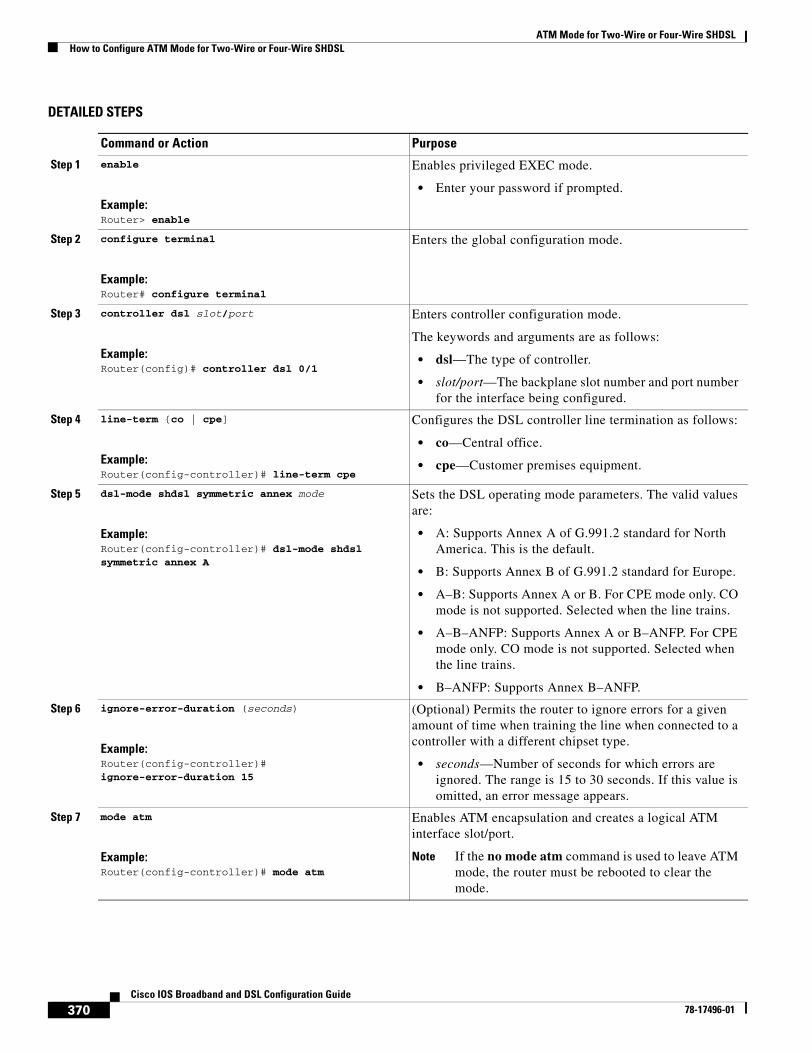
ATM Mode for Two-Wire or Four-Wire SHDSLHow to Configure ATM Mode for Two-Wire or Four-Wire SHDSL
370Cisco IOS Broadband and DSL Configuration Guide
78-17496-01
DETAILED STEPS
Command or Action Purpose
Step 1 enable
Example:Router> enable
Enables privileged EXEC mode.
• Enter your password if prompted.
Step 2 configure terminal
Example:Router# configure terminal
Enters the global configuration mode.
Step 3 controller dsl slot/port
Example:Router(config)# controller dsl 0/1
Enters controller configuration mode.
The keywords and arguments are as follows:
• dsl—The type of controller.
• slot/port—The backplane slot number and port number for the interface being configured.
Step 4 line-term {co | cpe]
Example:Router(config-controller)# line-term cpe
Configures the DSL controller line termination as follows:
• co—Central office.
• cpe—Customer premises equipment.
Step 5 dsl-mode shdsl symmetric annex mode
Example:Router(config-controller)# dsl-mode shdsl symmetric annex A
Sets the DSL operating mode parameters. The valid values are:
• A: Supports Annex A of G.991.2 standard for North America. This is the default.
• B: Supports Annex B of G.991.2 standard for Europe.
• A–B: Supports Annex A or B. For CPE mode only. CO mode is not supported. Selected when the line trains.
• A–B–ANFP: Supports Annex A or B–ANFP. For CPE mode only. CO mode is not supported. Selected when the line trains.
• B–ANFP: Supports Annex B–ANFP.
Step 6 ignore-error-duration (seconds)
Example:Router(config-controller)# ignore-error-duration 15
(Optional) Permits the router to ignore errors for a given amount of time when training the line when connected to a controller with a different chipset type.
• seconds—Number of seconds for which errors are ignored. The range is 15 to 30 seconds. If this value is omitted, an error message appears.
Step 7 mode atm
Example:Router(config-controller)# mode atm
Enables ATM encapsulation and creates a logical ATM interface slot/port.
Note If the no mode atm command is used to leave ATM mode, the router must be rebooted to clear the mode.
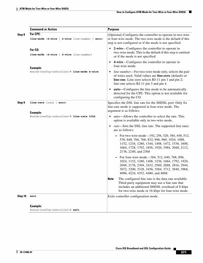
ATM Mode for Two-Wire or Four-Wire SHDSLHow to Configure ATM Mode for Two-Wire or Four-Wire SHDSL
371Cisco IOS Broadband and DSL Configuration Guide
78-17496-01
Step 8 For CPE:line-mode [4-wire | 2-wire line-number | auto}
For CO:line-mode {4-wire | 2-wire line-number}
Example:Router(config-controller)# line-mode 4-wire
(Optional) Configures the controller to operate in two-wire or four-wire mode. The two-wire mode is the default if this step is not configured or if the mode is not specified.
• 2-wire—Configures the controller to operate in two-wire mode. This is the default if this step is omitted or if the mode is not specified.
• 4-wire—Configures the controller to operate in four-wire mode.
• line-number—For two-wire mode only, selects the pair of wires used. Valid values are line-zero (default) or line-one. Line-zero selects RJ-11 pin 1 and pin 2; line-one selects RJ-11 pin 3 and pin 4.
• auto—Configures the line mode to be automatically detected for the CPE. This option is not available for configuring the CO.
Step 9 line-rate {rate | auto}
Example:Router(config-controller)# line-rate 1024
Specifies the DSL line rate for the SHDSL port. Only fix line-rate mode is supported in four-wire mode. The argument is as follows:
• auto—Allows the controller to select the rate. This option is available only in two-wire mode.
• rate—Sets the DSL line rate. The supported line rates are as follows:
– For two-wire mode—192, 256, 320, 384, 448, 512, 576, 640, 704, 768, 832, 896, 960, 1024, 1088, 1152, 1216, 1280, 1344, 1408, 1472, 1536, 1600, 1664, 1728, 1792, 1856, 1920, 1984, 2048, 2112, 2176, 2240, and 2304
– For four-wire mode—384, 512, 640, 768, 896, 1024, 1152, 1280, 1408, 1536, 1664, 1792, 1920, 2048, 2176, 2304, 2432, 2560, 2688, 2816, 2944, 3072, 3200, 3328, 3456, 3584, 3712, 3840, 3968, 4096, 4224, 4352, 4480, and 4608.
Note The configured line rate is the data rate available. Third-party equipment may use a line rate that includes an additional SHDSL overhead of 8 kbps for two-wire mode or 16 kbps for four-wire mode.
Step 10 exit
Example:Router(config-controller)# exit
Exits controller configuration mode.
Command or Action Purpose
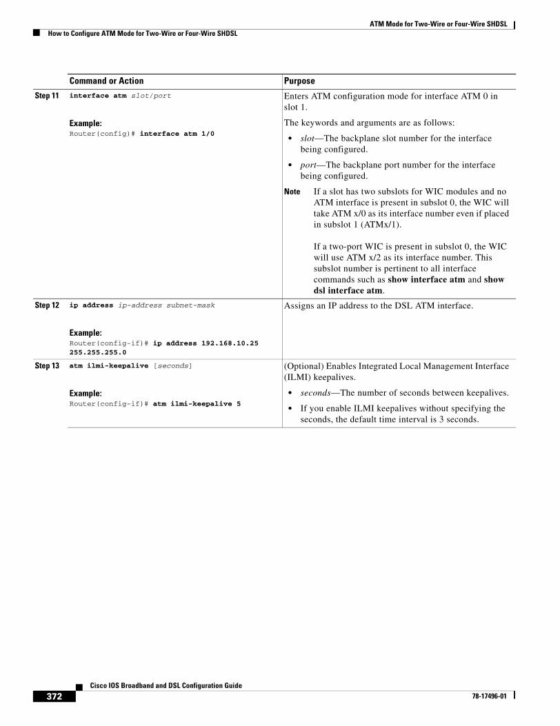
ATM Mode for Two-Wire or Four-Wire SHDSLHow to Configure ATM Mode for Two-Wire or Four-Wire SHDSL
372Cisco IOS Broadband and DSL Configuration Guide
78-17496-01
Step 11 interface atm slot/port
Example:Router(config)# interface atm 1/0
Enters ATM configuration mode for interface ATM 0 in slot 1.
The keywords and arguments are as follows:
• slot—The backplane slot number for the interface being configured.
• port—The backplane port number for the interface being configured.
Note If a slot has two subslots for WIC modules and no ATM interface is present in subslot 0, the WIC will take ATM x/0 as its interface number even if placed in subslot 1 (ATMx/1).
If a two-port WIC is present in subslot 0, the WIC will use ATM x/2 as its interface number. This subslot number is pertinent to all interface commands such as show interface atm and show dsl interface atm.
Step 12 ip address ip-address subnet-mask
Example:Router(config-if)# ip address 192.168.10.25 255.255.255.0
Assigns an IP address to the DSL ATM interface.
Step 13 atm ilmi-keepalive [seconds]
Example:Router(config-if)# atm ilmi-keepalive 5
(Optional) Enables Integrated Local Management Interface (ILMI) keepalives.
• seconds—The number of seconds between keepalives.
• If you enable ILMI keepalives without specifying the seconds, the default time interval is 3 seconds.
Command or Action Purpose
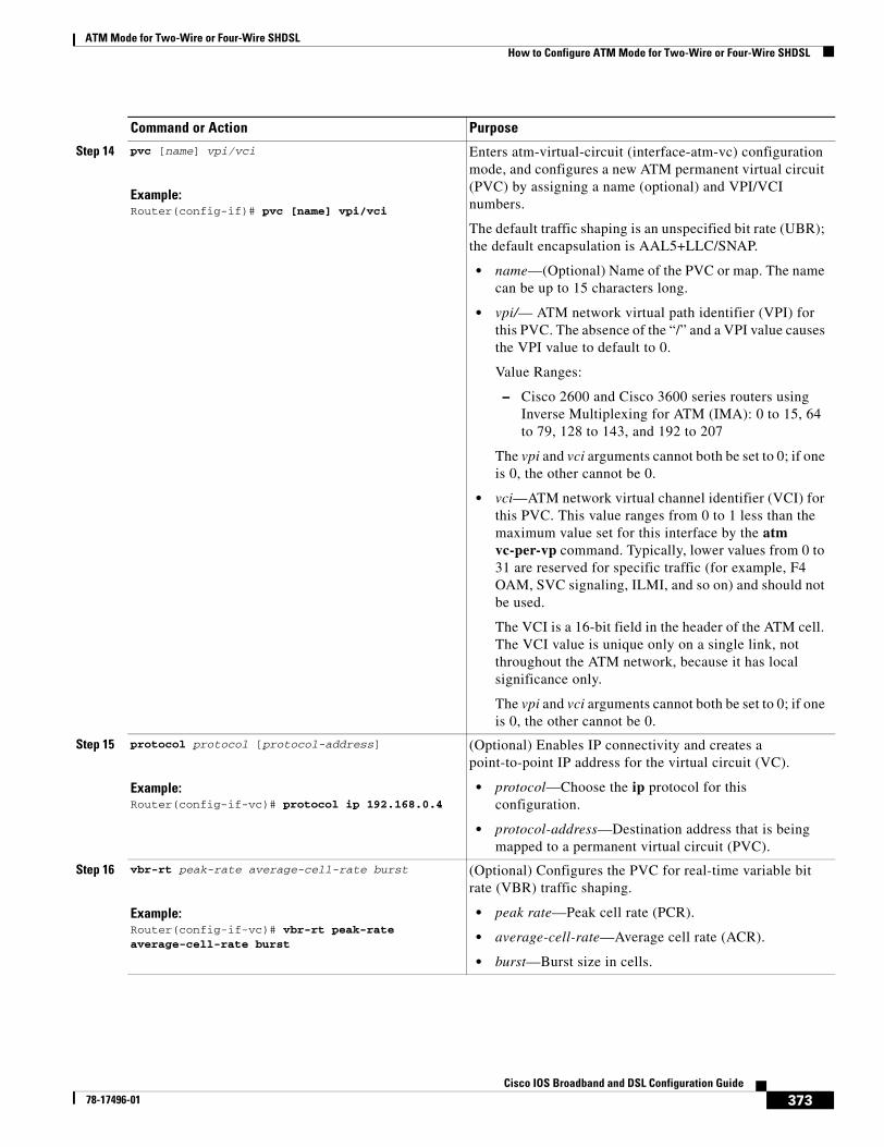
ATM Mode for Two-Wire or Four-Wire SHDSLHow to Configure ATM Mode for Two-Wire or Four-Wire SHDSL
373Cisco IOS Broadband and DSL Configuration Guide
78-17496-01
Step 14 pvc [name] vpi/vci
Example:Router(config-if)# pvc [name] vpi/vci
Enters atm-virtual-circuit (interface-atm-vc) configuration mode, and configures a new ATM permanent virtual circuit (PVC) by assigning a name (optional) and VPI/VCI numbers.
The default traffic shaping is an unspecified bit rate (UBR); the default encapsulation is AAL5+LLC/SNAP.
• name—(Optional) Name of the PVC or map. The name can be up to 15 characters long.
• vpi/— ATM network virtual path identifier (VPI) for this PVC. The absence of the “/” and a VPI value causes the VPI value to default to 0.
Value Ranges:
– Cisco 2600 and Cisco 3600 series routers using Inverse Multiplexing for ATM (IMA): 0 to 15, 64 to 79, 128 to 143, and 192 to 207
The vpi and vci arguments cannot both be set to 0; if one is 0, the other cannot be 0.
• vci—ATM network virtual channel identifier (VCI) for this PVC. This value ranges from 0 to 1 less than the maximum value set for this interface by the atm vc-per-vp command. Typically, lower values from 0 to 31 are reserved for specific traffic (for example, F4 OAM, SVC signaling, ILMI, and so on) and should not be used.
The VCI is a 16-bit field in the header of the ATM cell. The VCI value is unique only on a single link, not throughout the ATM network, because it has local significance only.
The vpi and vci arguments cannot both be set to 0; if one is 0, the other cannot be 0.
Step 15 protocol protocol [protocol-address]
Example:Router(config-if-vc)# protocol ip 192.168.0.4
(Optional) Enables IP connectivity and creates a point-to-point IP address for the virtual circuit (VC).
• protocol—Choose the ip protocol for this configuration.
• protocol-address—Destination address that is being mapped to a permanent virtual circuit (PVC).
Step 16 vbr-rt peak-rate average-cell-rate burst
Example:Router(config-if-vc)# vbr-rt peak-rate average-cell-rate burst
(Optional) Configures the PVC for real-time variable bit rate (VBR) traffic shaping.
• peak rate—Peak cell rate (PCR).
• average-cell-rate—Average cell rate (ACR).
• burst—Burst size in cells.
Command or Action Purpose
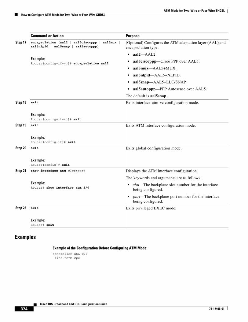
ATM Mode for Two-Wire or Four-Wire SHDSLHow to Configure ATM Mode for Two-Wire or Four-Wire SHDSL
374Cisco IOS Broadband and DSL Configuration Guide
78-17496-01
Examples
Example of the Configuration Before Configuring ATM Mode:controller DSL 0/0 line-term cpe
Step 17 encapsulation {aal2 | aal5ciscoppp | aal5mux | aal5nlpid | aal5snap | aal5autoppp}
Example:Router(config-if-vc)# encapsulation aal2
(Optional) Configures the ATM adaptation layer (AAL) and encapsulation type.
• aal2—AAL2.
• aal5ciscoppp—Cisco PPP over AAL5.
• aal5mux—AAL5+MUX.
• aal5nlpid—AAL5+NLPID.
• aal5snap—AAL5+LLC/SNAP.
• aal5autoppp—PPP Autosense over AAL5.
The default is aal5snap.
Step 18 exit
Example:Router(config-if-vc)# exit
Exits interface-atm-vc configuration mode.
Step 19 exit
Example:Router(config-if)# exit
Exits ATM interface configuration mode.
Step 20 exit
Example:Router(config)# exit
Exits global configuration mode.
Step 21 show interface atm slot/port
Example:Router# show interface atm 1/0
Displays the ATM interface configuration.
The keywords and arguments are as follows:
• slot—The backplane slot number for the interface being configured.
• port—The backplane port number for the interface being configured.
Step 22 exit
Example:Router# exit
Exits privileged EXEC mode.
Command or Action Purpose
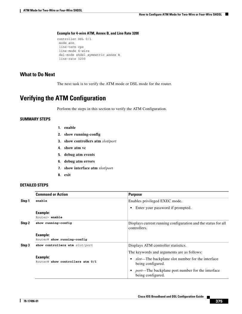
ATM Mode for Two-Wire or Four-Wire SHDSLHow to Configure ATM Mode for Two-Wire or Four-Wire SHDSL
375Cisco IOS Broadband and DSL Configuration Guide
78-17496-01
Example for 4-wire ATM, Annex B, and Line Rate 3200controller DSL 0/1 mode atm line-term cpe line-mode 4-wire dsl-mode shdsl symmetric annex B line-rate 3200
What to Do Next
The next task is to verify the ATM mode or DSL mode for the router.
Verifying the ATM ConfigurationPerform the steps in this section to verify the ATM Configuration.
SUMMARY STEPS
1. enable
2. show running-config
3. show controllers atm slot/port
4. show atm vc
5. debug atm events
6. debug atm errors
7. show interface atm slot/port
8. exit
DETAILED STEPS
Command or Action Purpose
Step 1 enable
Example:Router> enable
Enables privileged EXEC mode.
• Enter your password if prompted.
Step 2 show running-config
Example:Router# show running-config
Displays current running configuration and the status for all controllers.
Step 3 show controllers atm slot/port
Example:Router# show controllers atm 0/1
Displays ATM controller statistics.
The keywords and arguments are as follows:
• slot—The backplane slot number for the interface being configured.
• port—The backplane port number for the interface being configured.
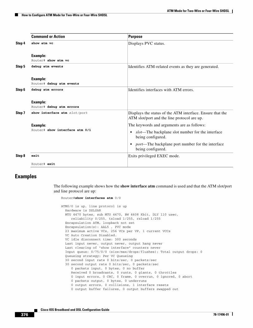
ATM Mode for Two-Wire or Four-Wire SHDSLHow to Configure ATM Mode for Two-Wire or Four-Wire SHDSL
376Cisco IOS Broadband and DSL Configuration Guide
78-17496-01
Examples
The following example shows how the show interface atm command is used and that the ATM slot/port and line protocol are up:
Router#show interfaces atm 0/0
ATM0/0 is up, line protocol is up Hardware is DSLSAR MTU 4470 bytes, sub MTU 4470, BW 4608 Kbit, DLY 110 usec, reliability 0/255, txload 1/255, rxload 1/255 Encapsulation ATM, loopback not set Encapsulation(s): AAL5 , PVC mode 23 maximum active VCs, 256 VCs per VP, 1 current VCCs VC Auto Creation Disabled. VC idle disconnect time: 300 seconds Last input never, output never, output hang never Last clearing of "show interface" counters never Input queue: 0/75/0/0 (size/max/drops/flushes); Total output drops: 0 Queueing strategy: Per VC Queueing 30 second input rate 0 bits/sec, 0 packets/sec 30 second output rate 0 bits/sec, 0 packets/sec 0 packets input, 0 bytes, 0 no buffer Received 0 broadcasts, 0 runts, 0 giants, 0 throttles 0 input errors, 0 CRC, 0 frame, 0 overrun, 0 ignored, 0 abort 0 packets output, 0 bytes, 0 underruns 0 output errors, 0 collisions, 1 interface resets 0 output buffer failures, 0 output buffers swapped out
Step 4 show atm vc
Example:Router# show atm vc
Displays PVC status.
Step 5 debug atm events
Example:Router# debug atm events
Identifies ATM-related events as they are generated.
Step 6 debug atm errors
Example:Router# debug atm errors
Identifies interfaces with ATM errors.
Step 7 show interface atm slot/port
Example:Router# show interface atm 0/1
Displays the status of the ATM interface. Ensure that the ATM slot/port and the line protocol are up.
The keywords and arguments are as follows:
• slot—The backplane slot number for the interface being configured.
• port—The backplane port number for the interface being configured.
Step 8 exit
Router# exit
Exits privileged EXEC mode.
Command or Action Purpose
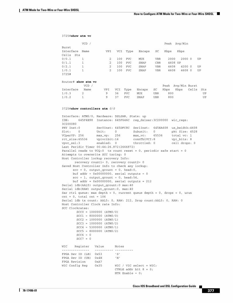
ATM Mode for Two-Wire or Four-Wire SHDSLHow to Configure ATM Mode for Two-Wire or Four-Wire SHDSL
377Cisco IOS Broadband and DSL Configuration Guide
78-17496-01
3725#show atm vc
VCD / Peak Avg/MinBurstInterface Name VPI VCI Type Encaps SC Kbps KbpsCells Sts0/0.1 1 2 100 PVC MUX VBR 2000 2000 0 UP0/1.1 1 2 100 PVC SNAP CBR 4608 UP0/2.1 1 2 100 PVC SNAP VBR 4608 4200 0 UP1/0.1 1 2 100 PVC SNAP VBR 4608 4608 0 UP3725#
Router# show atm vc VCD / Peak Avg/Min BurstInterface Name VPI VCI Type Encaps SC Kbps Kbps Cells Sts1/0.3 2 9 36 PVC MUX UBR 800 UP1/0.2 1 9 37 PVC SNAP UBR 800 UP
3725#show controllers atm 0/0
Interface: ATM0/0, Hardware: DSLSAR, State: upIDB: 645F4B98 Instance: 645F646C reg_dslsar:3C200000 wic_regs:3C200080PHY Inst:0 Ser0Inst: 645DFC8C Ser1Inst: 645EA608 us_bwidth:4608Slot: 0 Unit: 0 Subunit: 0 pkt Size: 4528VCperVP: 256 max_vp: 256 max_vc: 65536 total vc: 1rct_size:65536 vpivcibit:16 connTblVCI:8 vpi_bits: 8vpvc_sel:3 enabled: 0 throttled: 0 cell drops: 0Last Peridic Timer 00:44:26.872(2666872)Parallel reads to TCQ:0 tx count reset = 0, periodic safe start = 0Attempts to overwrite SCC txring: 0Host Controller lockup recovery Info: recovery count1= 0, recovery count2= 0Saved Host Controller Info to check any lockup: scc = 0, output_qcount = 0, head:0, buf addr = 0x00000000, serial outputs = 0 scc = 1, output_qcount = 0, head:54, buf addr = 0x00000000, serial outputs = 212Serial idb(AAL5) output_qcount:0 max:40Serial idb(RAW) output_qcount:0, max:40Sar ctrl queue: max depth = 0, current queue depth = 0, drops = 0, uruncnt = 0, total cnt = 106Serial idb tx count: AAL5: 0, RAW: 212, Drop count:AAL5: 0, RAW: 0Host Controller Clock rate Info:SCC Clockrates: SCC0 = 1000000 (ATM0/0) SCC1 = 8000000 (ATM0/0) SCC2 = 1000000 (ATM0/1) SCC3 = 1000000 (ATM0/2) SCC4 = 5300000 (ATM0/1) SCC5 = 8000000 (ATM0/2) SCC6 = 0 SCC7 = 0
WIC Register Value Notes--------------- ---------- ----------FPGA Dev ID (LB) 0x53 'S'FPGA Dev ID (UB) 0x4E 'N'FPGA Revision 0xA7WIC Config Reg 0x35 WIC / VIC select = WIC; CTRLE addr bit 8 = 0; NTR Enable = 0;

ATM Mode for Two-Wire or Four-Wire SHDSLHow to Configure ATM Mode for Two-Wire or Four-Wire SHDSL
378Cisco IOS Broadband and DSL Configuration Guide
78-17496-01
OK LED on; LOOPBACK LED off; CD LED on;WIC Config Reg2 0x07 Gen bus error on bad G.SHDSL ATM/T1/E1 accessInt 0 Enable Reg 0x01 G.SHDSL ATM/T1/E1 normal interrupt enabled G.SHDSL ATM/T1/E1 error interrupt disabled
DSLSAR Register Value Notes--------------- ---------- ----------sdram_refresh: 0x410FFFF Expected value: 0x428xxxxintr_event_reg: 0xC0 TMR.intr_enable_reg: 0x13C FIFOF.FBQE.RQAF.RPQAF.TSQAF.config: 0x660D0A20 UTOPIA.RXEN.RegulateXmit.RMCell.TXEN. Rx Buffer size: 8192. RCT: Large, VPI Bits:8.status: 0x0clkPerCell: 814121 (line rate: 4608 Kbps)Pre-timer Count: 461rcid_tableBase: 0x0rct_base: 0x10000tstBase1: 0x13C28 TST boot jump.rawCellBase: 0x14300 (0/128) slots used.rpq_base: 0x16000tsqb(Tx Stat Q): 0x17000fbq_base: 0x17880 (fbq_count: 128)txChanQueue: 0x18000rxBuffers: 0x30000txBuffers: 0x130000Lookup Error cnt: 0x0Invalid Cell cnt: 0x0SCCA Rx Errors: 0x0SCCB Rx Errors: 0x0Drop Pkt Count: 0x0Total Tx Count: 0x0Total Rx Count: 0x0Timer: 0x73A141DSLSAR Interrupts:0x0 Last Addr:0x12E14
Router# show controllers atm 1/0
Interface ATM1/0 is up Hardware is DSLSAR (with Globespan G.SHDSL Module)IDB: 62586758 Instance:6258E054 reg_dslsar:3C810000 wic_regs:3C810080PHY Inst:62588490 Ser0Inst:62573074 Ser1Inst: 6257CBD8 us_bwidth:800 Slot: 1 Unit: 1 Subunit: 0 pkt Size:4496 VCperVP:256 max_vp: 256 max_vc: 65536 total vc:2 rct_size:65536 vpivcibit:16 connTblVCI:8 vpi_bits:8 vpvc_sel:3 enabled: 0 throttled:0
WIC Register Value Notes--------------- ---------- ----------WIC Config Reg 0x45 WIC / VIC select = WIC; CTRLE addr bit 8 = 1; OK LED on; LOOPBACK LED off; CD LED on; WIC Config Reg2 0x07 Gen bus error on bad ADSL accessInt 0 Enable Reg 0x03 ADSL normal interrupt enabled ADSL error interrupt enabled
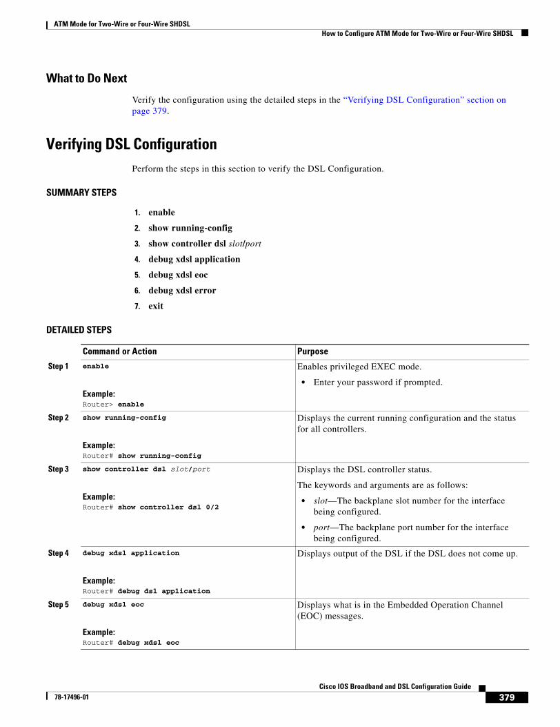
ATM Mode for Two-Wire or Four-Wire SHDSLHow to Configure ATM Mode for Two-Wire or Four-Wire SHDSL
379Cisco IOS Broadband and DSL Configuration Guide
78-17496-01
What to Do Next
Verify the configuration using the detailed steps in the “Verifying DSL Configuration” section on page 379.
Verifying DSL ConfigurationPerform the steps in this section to verify the DSL Configuration.
SUMMARY STEPS
1. enable
2. show running-config
3. show controller dsl slot/port
4. debug xdsl application
5. debug xdsl eoc
6. debug xdsl error
7. exit
DETAILED STEPS
Command or Action Purpose
Step 1 enable
Example:Router> enable
Enables privileged EXEC mode.
• Enter your password if prompted.
Step 2 show running-config
Example:Router# show running-config
Displays the current running configuration and the status for all controllers.
Step 3 show controller dsl slot/port
Example:Router# show controller dsl 0/2
Displays the DSL controller status.
The keywords and arguments are as follows:
• slot—The backplane slot number for the interface being configured.
• port—The backplane port number for the interface being configured.
Step 4 debug xdsl application
Example:Router# debug dsl application
Displays output of the DSL if the DSL does not come up.
Step 5 debug xdsl eoc
Example:Router# debug xdsl eoc
Displays what is in the Embedded Operation Channel (EOC) messages.
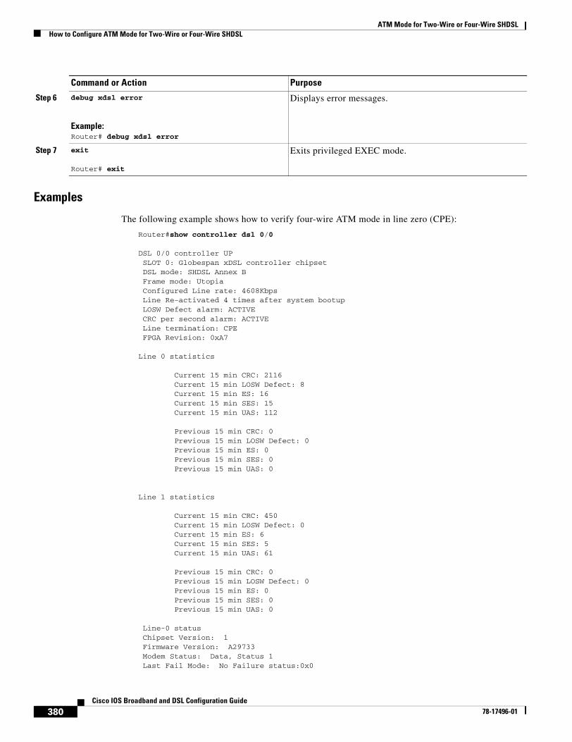
ATM Mode for Two-Wire or Four-Wire SHDSLHow to Configure ATM Mode for Two-Wire or Four-Wire SHDSL
380Cisco IOS Broadband and DSL Configuration Guide
78-17496-01
Examples
The following example shows how to verify four-wire ATM mode in line zero (CPE):
Router#show controller dsl 0/0
DSL 0/0 controller UP SLOT 0: Globespan xDSL controller chipset DSL mode: SHDSL Annex B Frame mode: Utopia Configured Line rate: 4608Kbps Line Re-activated 4 times after system bootup LOSW Defect alarm: ACTIVE CRC per second alarm: ACTIVE Line termination: CPE FPGA Revision: 0xA7
Line 0 statistics
Current 15 min CRC: 2116 Current 15 min LOSW Defect: 8 Current 15 min ES: 16 Current 15 min SES: 15 Current 15 min UAS: 112
Previous 15 min CRC: 0 Previous 15 min LOSW Defect: 0 Previous 15 min ES: 0 Previous 15 min SES: 0 Previous 15 min UAS: 0
Line 1 statistics
Current 15 min CRC: 450 Current 15 min LOSW Defect: 0 Current 15 min ES: 6 Current 15 min SES: 5 Current 15 min UAS: 61
Previous 15 min CRC: 0 Previous 15 min LOSW Defect: 0 Previous 15 min ES: 0 Previous 15 min SES: 0 Previous 15 min UAS: 0
Line-0 status Chipset Version: 1 Firmware Version: A29733 Modem Status: Data, Status 1 Last Fail Mode: No Failure status:0x0
Step 6 debug xdsl error
Example:Router# debug xdsl error
Displays error messages.
Step 7 exit
Router# exit
Exits privileged EXEC mode.
Command or Action Purpose
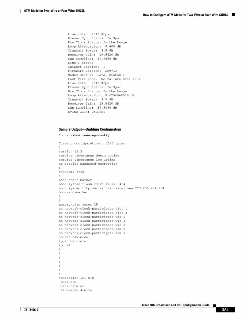
ATM Mode for Two-Wire or Four-Wire SHDSLHow to Configure ATM Mode for Two-Wire or Four-Wire SHDSL
381Cisco IOS Broadband and DSL Configuration Guide
78-17496-01
Line rate: 2312 Kbps Framer Sync Status: In Sync Rcv Clock Status: In the Range Loop Attenuation: 0.600 dB Transmit Power: 8.5 dB Receiver Gain: 19.5420 dB SNR Sampling: 37.9860 dB Line-1 status Chipset Version: 1 Firmware Version: A29733 Modem Status: Data, Status 1 Last Fail Mode: No Failure status:0x0 Line rate: 2312 Kbps Framer Sync Status: In Sync Rcv Clock Status: In the Range Loop Attenuation: 0.4294966516 dB Transmit Power: 8.5 dB Receiver Gain: 19.5420 dB SNR Sampling: 37.6080 dB Dying Gasp: Present
Sample Output—Building ConfigurationRouter>show running-config
Current configuration : 3183 bytes!version 12.3service timestamps debug uptimeservice timestamps log uptimeno service password-encryption!hostname 3725!boot-start-markerboot system flash c3725-is-mz.0424boot system tftp shriv/c3725-is-mz.new 223.255.254.254boot-end-marker!!memory-size iomem 25no network-clock-participate slot 1no network-clock-participate slot 2no network-clock-participate wic 0no network-clock-participate wic 1no network-clock-participate wic 2no network-clock-participate aim 0no network-clock-participate aim 1no aaa new-modelip subnet-zeroip cef!!!!!!!controller DSL 0/0 mode atm line-term co line-mode 4-wire
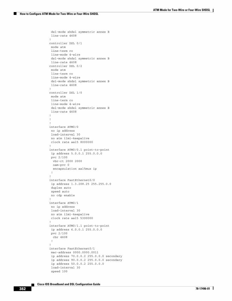
ATM Mode for Two-Wire or Four-Wire SHDSLHow to Configure ATM Mode for Two-Wire or Four-Wire SHDSL
382Cisco IOS Broadband and DSL Configuration Guide
78-17496-01
dsl-mode shdsl symmetric annex B line-rate 4608!controller DSL 0/1 mode atm line-term co line-mode 4-wire dsl-mode shdsl symmetric annex B line-rate 4608controller DSL 0/2 mode atm line-term co line-mode 4-wire dsl-mode shdsl symmetric annex B line-rate 4608!controller DSL 1/0 mode atm line-term co line-mode 4-wire dsl-mode shdsl symmetric annex B line-rate 4608!!!interface ATM0/0 no ip address load-interval 30 no atm ilmi-keepalive clock rate aal5 8000000!interface ATM0/0.1 point-to-point ip address 5.0.0.1 255.0.0.0 pvc 2/100 vbr-rt 2000 2000 oam-pvc 0 encapsulation aal5mux ip !!interface FastEthernet0/0 ip address 1.3.208.25 255.255.0.0 duplex auto speed auto no cdp enable!interface ATM0/1 no ip address load-interval 30 no atm ilmi-keepalive clock rate aal5 5300000!interface ATM0/1.1 point-to-point ip address 6.0.0.1 255.0.0.0 pvc 2/100 cbr 4608 !!interface FastEthernet0/1 mac-address 0000.0000.0011 ip address 70.0.0.2 255.0.0.0 secondary ip address 90.0.0.2 255.0.0.0 secondary ip address 50.0.0.2 255.0.0.0 load-interval 30 speed 100
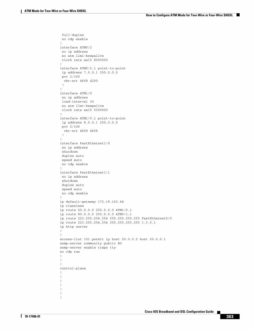
ATM Mode for Two-Wire or Four-Wire SHDSLHow to Configure ATM Mode for Two-Wire or Four-Wire SHDSL
383Cisco IOS Broadband and DSL Configuration Guide
78-17496-01
full-duplex no cdp enable!interface ATM0/2 no ip address no atm ilmi-keepalive clock rate aal5 8000000!interface ATM0/2.1 point-to-point ip address 7.0.0.1 255.0.0.0 pvc 2/100 vbr-nrt 4608 4200 !!interface ATM1/0 no ip address load-interval 30 no atm ilmi-keepalive clock rate aal5 5300000!interface ATM1/0.1 point-to-point ip address 8.0.0.1 255.0.0.0 pvc 2/100 vbr-nrt 4608 4608 !!interface FastEthernet1/0 no ip address shutdown duplex auto speed auto no cdp enable!interface FastEthernet1/1 no ip address shutdown duplex auto speed auto no cdp enable!ip default-gateway 172.19.163.44ip classlessip route 60.0.0.0 255.0.0.0 ATM1/0.1ip route 80.0.0.0 255.0.0.0 ATM0/1.1ip route 223.255.254.254 255.255.255.255 FastEthernet0/0ip route 223.255.254.254 255.255.255.255 1.3.0.1ip http server!!access-list 101 permit ip host 20.0.0.2 host 20.0.0.1snmp-server community public ROsnmp-server enable traps ttyno cdp run!!!control-plane!!!!!!!
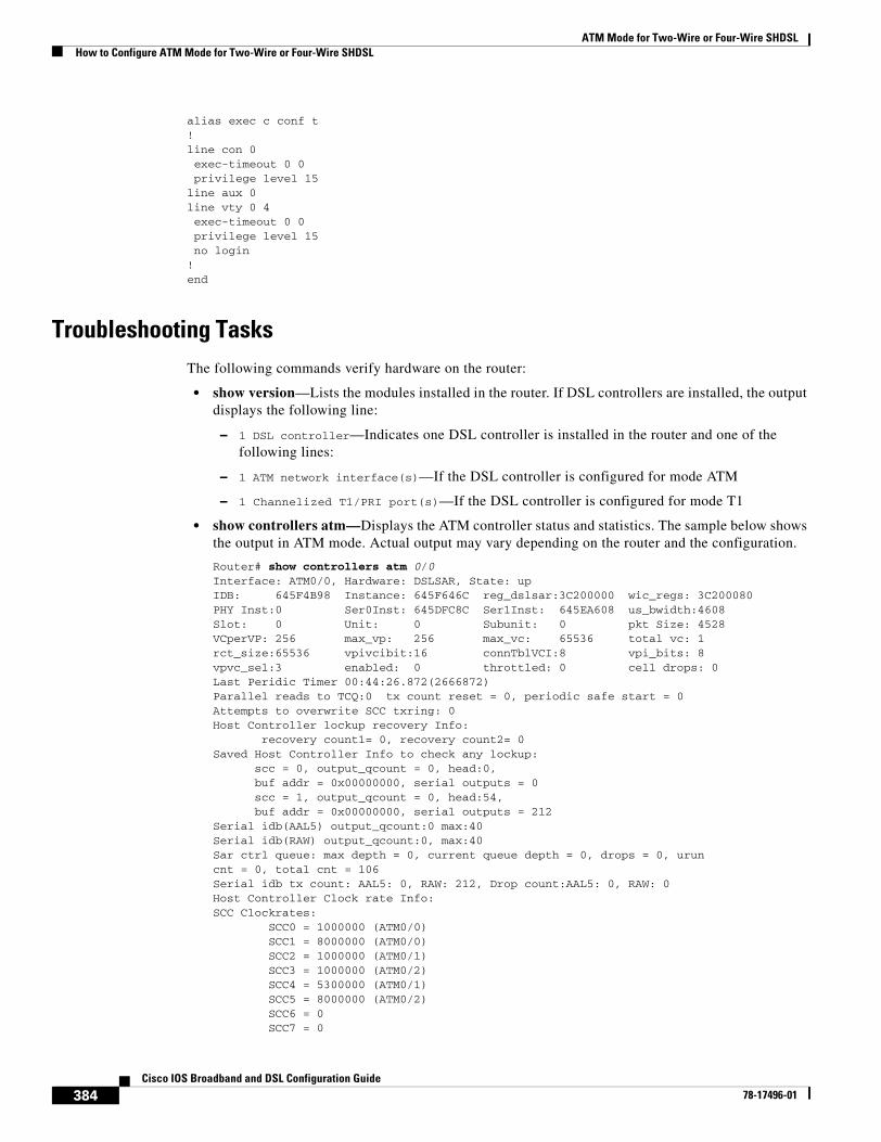
ATM Mode for Two-Wire or Four-Wire SHDSLHow to Configure ATM Mode for Two-Wire or Four-Wire SHDSL
384Cisco IOS Broadband and DSL Configuration Guide
78-17496-01
alias exec c conf t!line con 0 exec-timeout 0 0 privilege level 15line aux 0line vty 0 4 exec-timeout 0 0 privilege level 15 no login!end
Troubleshooting TasksThe following commands verify hardware on the router:
• show version—Lists the modules installed in the router. If DSL controllers are installed, the output displays the following line:
– 1 DSL controller—Indicates one DSL controller is installed in the router and one of the following lines:
– 1 ATM network interface(s)—If the DSL controller is configured for mode ATM
– 1 Channelized T1/PRI port(s)—If the DSL controller is configured for mode T1
• show controllers atm—Displays the ATM controller status and statistics. The sample below shows the output in ATM mode. Actual output may vary depending on the router and the configuration.
Router# show controllers atm 0/0Interface: ATM0/0, Hardware: DSLSAR, State: upIDB: 645F4B98 Instance: 645F646C reg_dslsar:3C200000 wic_regs: 3C200080PHY Inst:0 Ser0Inst: 645DFC8C Ser1Inst: 645EA608 us_bwidth:4608Slot: 0 Unit: 0 Subunit: 0 pkt Size: 4528VCperVP: 256 max_vp: 256 max_vc: 65536 total vc: 1rct_size:65536 vpivcibit:16 connTblVCI:8 vpi_bits: 8vpvc_sel:3 enabled: 0 throttled: 0 cell drops: 0Last Peridic Timer 00:44:26.872(2666872)Parallel reads to TCQ:0 tx count reset = 0, periodic safe start = 0Attempts to overwrite SCC txring: 0Host Controller lockup recovery Info: recovery count1= 0, recovery count2= 0Saved Host Controller Info to check any lockup: scc = 0, output_qcount = 0, head:0, buf addr = 0x00000000, serial outputs = 0 scc = 1, output_qcount = 0, head:54, buf addr = 0x00000000, serial outputs = 212Serial idb(AAL5) output_qcount:0 max:40Serial idb(RAW) output_qcount:0, max:40Sar ctrl queue: max depth = 0, current queue depth = 0, drops = 0, uruncnt = 0, total cnt = 106Serial idb tx count: AAL5: 0, RAW: 212, Drop count:AAL5: 0, RAW: 0Host Controller Clock rate Info:SCC Clockrates: SCC0 = 1000000 (ATM0/0) SCC1 = 8000000 (ATM0/0) SCC2 = 1000000 (ATM0/1) SCC3 = 1000000 (ATM0/2) SCC4 = 5300000 (ATM0/1) SCC5 = 8000000 (ATM0/2) SCC6 = 0 SCC7 = 0

ATM Mode for Two-Wire or Four-Wire SHDSLHow to Configure ATM Mode for Two-Wire or Four-Wire SHDSL
385Cisco IOS Broadband and DSL Configuration Guide
78-17496-01
WIC Register Value Notes--------------- ---------- ----------FPGA Dev ID (LB) 0x53 'S'FPGA Dev ID (UB) 0x4E 'N'FPGA Revision 0xA7WIC Config Reg 0x35 WIC / VIC select = WIC; CTRLE addr bit 8 = 0; NTR Enable = 0; OK LED on; LOOPBACK LED off; CD LED on;WIC Config Reg2 0x07 Gen bus error on bad G.SHDSL ATM/T1/E1 accessInt 0 Enable Reg 0x01 G.SHDSL ATM/T1/E1 normal interrupt enabled G.SHDSL ATM/T1/E1 error interrupt disabled
DSLSAR Register Value Notes--------------- ---------- ----------sdram_refresh: 0x410FFFF Expected value: 0x428xxxxintr_event_reg: 0xC0 TMR.intr_enable_reg: 0x13C FIFOF.FBQE.RQAF.RPQAF.TSQAF.config: 0x660D0A20 UTOPIA.RXEN.RegulateXmit.RMCell.TXEN. Rx Buffer size: 8192. RCT: Large, VPI Bits: 8.status: 0x0clkPerCell: 814121 (line rate: 4608 Kbps)Pre-timer Count: 461rcid_tableBase: 0x0rct_base: 0x10000tstBase1: 0x13C28 TST boot jump.rawCellBase: 0x14300 (0/128) slots used.rpq_base: 0x16000tsqb(Tx Stat Q): 0x17000fbq_base: 0x17880 (fbq_count: 128)txChanQueue: 0x18000rxBuffers: 0x30000txBuffers: 0x130000Lookup Error cnt: 0x0Invalid Cell cnt: 0x0SCCA Rx Errors: 0x0SCCB Rx Errors: 0x0Drop Pkt Count: 0x0Total Tx Count: 0x0Total Rx Count: 0x0Timer: 0x73A141DSLSAR Interrupts:0x0 Last Addr:0x12E14
• show controllers dsl—Displays the DSL controller status and statistics. The sample below shows the output in T1 mode. Actual output may vary depending on the router and the configuration.
Router# show controllers dsl 0/0
DSL 0/0 controller UP Globespan xDSL controller chipset DSL mode: SHDSL Annex B Frame mode: Utopia Configured Line rate: 4608Kbps Line Re-activated 5 times after system bootup LOSW Defect alarm: ACTIVE CRC per second alarm: ACTIVE Line termination: CO FPGA Revision: 0xA7

ATM Mode for Two-Wire or Four-Wire SHDSLHow to Configure ATM Mode for Two-Wire or Four-Wire SHDSL
386Cisco IOS Broadband and DSL Configuration Guide
78-17496-01
Line 0 statistics
Current 15 min CRC: 679 Current 15 min LOSW Defect: 8 Current 15 min ES: 5 Current 15 min SES: 5 Current 15 min UAS: 441
Previous 15 min CRC: 0 Previous 15 min LOSW Defect: 0 Previous 15 min ES: 0 Previous 15 min SES: 0 Previous 15 min UAS: 0
Line 1 statistics
Current 15 min CRC: 577 Current 15 min LOSW Defect: 8 Current 15 min ES: 7 Current 15 min SES: 4 Current 15 min UAS: 455
Previous 15 min CRC: 0 Previous 15 min LOSW Defect: 0 Previous 15 min ES: 0 Previous 15 min SES: 0 Previous 15 min UAS: 0
Line-0 status Chipset Version: 1 Firmware Version: A29733 Modem Status: Data, Status 1 Last Fail Mode: No Failure status:0x0 Line rate: 2312 Kbps Framer Sync Status: In Sync Rcv Clock Status: In the Range Loop Attenuation: 0.600 dB Transmit Power: 8.5 dB Receiver Gain: 21.420 dB SNR Sampling: 39.3690 dB Line-1 status Chipset Version: 1 Firmware Version: A29733 Modem Status: Data, Status 1 Last Fail Mode: No Failure status:0x0 Line rate: 2312 Kbps Framer Sync Status: In Sync Rcv Clock Status: In the Range Loop Attenuation: 0.4294966256 dB Transmit Power: 8.5 dB Receiver Gain: 21.420 dB SNR Sampling: 39.1570 dB Dying Gasp: Present
• debug xdsl application—Displays output from the xDSL to see what is happening if the DSL does not come up. When using the debug xdsl application command, resources and the buffer are used and will impact operation.
Router# debug xdsl application xDSL application debugging is onRouter#Apr 23 06:01:26.476: DSL 0/0 process_get_wakeupApr 23 06:01:27.476: DSL 0/0 process_get_wakeup
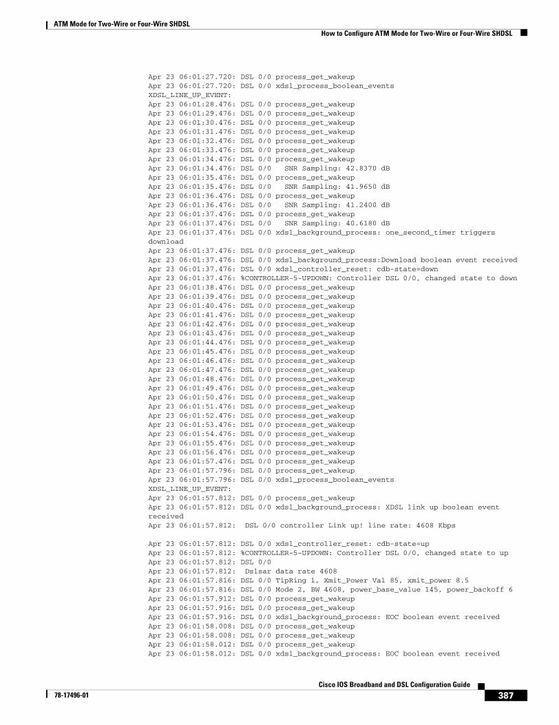
ATM Mode for Two-Wire or Four-Wire SHDSLHow to Configure ATM Mode for Two-Wire or Four-Wire SHDSL
387Cisco IOS Broadband and DSL Configuration Guide
78-17496-01
Apr 23 06:01:27.720: DSL 0/0 process_get_wakeupApr 23 06:01:27.720: DSL 0/0 xdsl_process_boolean_eventsXDSL_LINE_UP_EVENT:Apr 23 06:01:28.476: DSL 0/0 process_get_wakeupApr 23 06:01:29.476: DSL 0/0 process_get_wakeupApr 23 06:01:30.476: DSL 0/0 process_get_wakeupApr 23 06:01:31.476: DSL 0/0 process_get_wakeupApr 23 06:01:32.476: DSL 0/0 process_get_wakeupApr 23 06:01:33.476: DSL 0/0 process_get_wakeupApr 23 06:01:34.476: DSL 0/0 process_get_wakeupApr 23 06:01:34.476: DSL 0/0 SNR Sampling: 42.8370 dBApr 23 06:01:35.476: DSL 0/0 process_get_wakeupApr 23 06:01:35.476: DSL 0/0 SNR Sampling: 41.9650 dBApr 23 06:01:36.476: DSL 0/0 process_get_wakeupApr 23 06:01:36.476: DSL 0/0 SNR Sampling: 41.2400 dBApr 23 06:01:37.476: DSL 0/0 process_get_wakeupApr 23 06:01:37.476: DSL 0/0 SNR Sampling: 40.6180 dBApr 23 06:01:37.476: DSL 0/0 xdsl_background_process: one_second_timer triggers downloadApr 23 06:01:37.476: DSL 0/0 process_get_wakeupApr 23 06:01:37.476: DSL 0/0 xdsl_background_process:Download boolean event receivedApr 23 06:01:37.476: DSL 0/0 xdsl_controller_reset: cdb-state=downApr 23 06:01:37.476: %CONTROLLER-5-UPDOWN: Controller DSL 0/0, changed state to downApr 23 06:01:38.476: DSL 0/0 process_get_wakeupApr 23 06:01:39.476: DSL 0/0 process_get_wakeupApr 23 06:01:40.476: DSL 0/0 process_get_wakeupApr 23 06:01:41.476: DSL 0/0 process_get_wakeupApr 23 06:01:42.476: DSL 0/0 process_get_wakeupApr 23 06:01:43.476: DSL 0/0 process_get_wakeupApr 23 06:01:44.476: DSL 0/0 process_get_wakeupApr 23 06:01:45.476: DSL 0/0 process_get_wakeupApr 23 06:01:46.476: DSL 0/0 process_get_wakeupApr 23 06:01:47.476: DSL 0/0 process_get_wakeupApr 23 06:01:48.476: DSL 0/0 process_get_wakeupApr 23 06:01:49.476: DSL 0/0 process_get_wakeupApr 23 06:01:50.476: DSL 0/0 process_get_wakeupApr 23 06:01:51.476: DSL 0/0 process_get_wakeupApr 23 06:01:52.476: DSL 0/0 process_get_wakeupApr 23 06:01:53.476: DSL 0/0 process_get_wakeupApr 23 06:01:54.476: DSL 0/0 process_get_wakeupApr 23 06:01:55.476: DSL 0/0 process_get_wakeupApr 23 06:01:56.476: DSL 0/0 process_get_wakeupApr 23 06:01:57.476: DSL 0/0 process_get_wakeupApr 23 06:01:57.796: DSL 0/0 process_get_wakeupApr 23 06:01:57.796: DSL 0/0 xdsl_process_boolean_eventsXDSL_LINE_UP_EVENT:Apr 23 06:01:57.812: DSL 0/0 process_get_wakeupApr 23 06:01:57.812: DSL 0/0 xdsl_background_process: XDSL link up boolean event receivedApr 23 06:01:57.812: DSL 0/0 controller Link up! line rate: 4608 Kbps
Apr 23 06:01:57.812: DSL 0/0 xdsl_controller_reset: cdb-state=upApr 23 06:01:57.812: %CONTROLLER-5-UPDOWN: Controller DSL 0/0, changed state to upApr 23 06:01:57.812: DSL 0/0Apr 23 06:01:57.812: Dslsar data rate 4608Apr 23 06:01:57.816: DSL 0/0 TipRing 1, Xmit_Power Val 85, xmit_power 8.5Apr 23 06:01:57.816: DSL 0/0 Mode 2, BW 4608, power_base_value 145, power_backoff 6Apr 23 06:01:57.912: DSL 0/0 process_get_wakeupApr 23 06:01:57.916: DSL 0/0 process_get_wakeupApr 23 06:01:57.916: DSL 0/0 xdsl_background_process: EOC boolean event receivedApr 23 06:01:58.008: DSL 0/0 process_get_wakeupApr 23 06:01:58.008: DSL 0/0 process_get_wakeupApr 23 06:01:58.012: DSL 0/0 process_get_wakeupApr 23 06:01:58.012: DSL 0/0 xdsl_background_process: EOC boolean event received
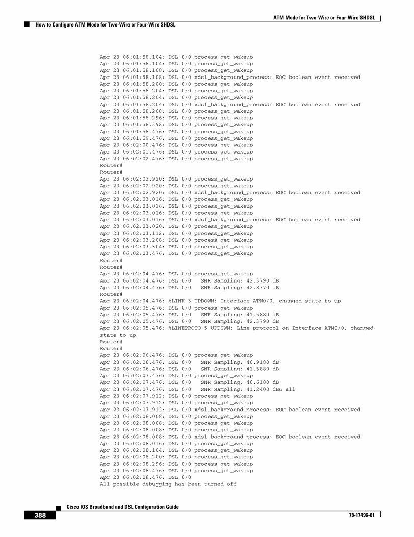
ATM Mode for Two-Wire or Four-Wire SHDSLHow to Configure ATM Mode for Two-Wire or Four-Wire SHDSL
388Cisco IOS Broadband and DSL Configuration Guide
78-17496-01
Apr 23 06:01:58.104: DSL 0/0 process_get_wakeupApr 23 06:01:58.104: DSL 0/0 process_get_wakeupApr 23 06:01:58.108: DSL 0/0 process_get_wakeupApr 23 06:01:58.108: DSL 0/0 xdsl_background_process: EOC boolean event receivedApr 23 06:01:58.200: DSL 0/0 process_get_wakeupApr 23 06:01:58.204: DSL 0/0 process_get_wakeupApr 23 06:01:58.204: DSL 0/0 process_get_wakeupApr 23 06:01:58.204: DSL 0/0 xdsl_background_process: EOC boolean event receivedApr 23 06:01:58.208: DSL 0/0 process_get_wakeupApr 23 06:01:58.296: DSL 0/0 process_get_wakeupApr 23 06:01:58.392: DSL 0/0 process_get_wakeupApr 23 06:01:58.476: DSL 0/0 process_get_wakeupApr 23 06:01:59.476: DSL 0/0 process_get_wakeupApr 23 06:02:00.476: DSL 0/0 process_get_wakeupApr 23 06:02:01.476: DSL 0/0 process_get_wakeupApr 23 06:02:02.476: DSL 0/0 process_get_wakeupRouter#Router#Apr 23 06:02:02.920: DSL 0/0 process_get_wakeupApr 23 06:02:02.920: DSL 0/0 process_get_wakeupApr 23 06:02:02.920: DSL 0/0 xdsl_background_process: EOC boolean event receivedApr 23 06:02:03.016: DSL 0/0 process_get_wakeupApr 23 06:02:03.016: DSL 0/0 process_get_wakeupApr 23 06:02:03.016: DSL 0/0 process_get_wakeupApr 23 06:02:03.016: DSL 0/0 xdsl_background_process: EOC boolean event receivedApr 23 06:02:03.020: DSL 0/0 process_get_wakeupApr 23 06:02:03.112: DSL 0/0 process_get_wakeupApr 23 06:02:03.208: DSL 0/0 process_get_wakeupApr 23 06:02:03.304: DSL 0/0 process_get_wakeupApr 23 06:02:03.476: DSL 0/0 process_get_wakeupRouter#Router#Apr 23 06:02:04.476: DSL 0/0 process_get_wakeupApr 23 06:02:04.476: DSL 0/0 SNR Sampling: 42.3790 dBApr 23 06:02:04.476: DSL 0/0 SNR Sampling: 42.8370 dBRouter#Apr 23 06:02:04.476: %LINK-3-UPDOWN: Interface ATM0/0, changed state to upApr 23 06:02:05.476: DSL 0/0 process_get_wakeupApr 23 06:02:05.476: DSL 0/0 SNR Sampling: 41.5880 dBApr 23 06:02:05.476: DSL 0/0 SNR Sampling: 42.3790 dBApr 23 06:02:05.476: %LINEPROTO-5-UPDOWN: Line protocol on Interface ATM0/0, changed state to upRouter#Router#Apr 23 06:02:06.476: DSL 0/0 process_get_wakeupApr 23 06:02:06.476: DSL 0/0 SNR Sampling: 40.9180 dBApr 23 06:02:06.476: DSL 0/0 SNR Sampling: 41.5880 dBApr 23 06:02:07.476: DSL 0/0 process_get_wakeupApr 23 06:02:07.476: DSL 0/0 SNR Sampling: 40.6180 dBApr 23 06:02:07.476: DSL 0/0 SNR Sampling: 41.2400 dBu allApr 23 06:02:07.912: DSL 0/0 process_get_wakeupApr 23 06:02:07.912: DSL 0/0 process_get_wakeupApr 23 06:02:07.912: DSL 0/0 xdsl_background_process: EOC boolean event receivedApr 23 06:02:08.008: DSL 0/0 process_get_wakeupApr 23 06:02:08.008: DSL 0/0 process_get_wakeupApr 23 06:02:08.008: DSL 0/0 process_get_wakeupApr 23 06:02:08.008: DSL 0/0 xdsl_background_process: EOC boolean event receivedApr 23 06:02:08.016: DSL 0/0 process_get_wakeupApr 23 06:02:08.104: DSL 0/0 process_get_wakeupApr 23 06:02:08.200: DSL 0/0 process_get_wakeupApr 23 06:02:08.296: DSL 0/0 process_get_wakeupApr 23 06:02:08.476: DSL 0/0 process_get_wakeupApr 23 06:02:08.476: DSL 0/0All possible debugging has been turned off
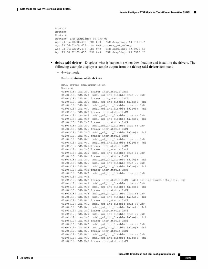
ATM Mode for Two-Wire or Four-Wire SHDSLHow to Configure ATM Mode for Two-Wire or Four-Wire SHDSL
389Cisco IOS Broadband and DSL Configuration Guide
78-17496-01
Router#Router#Router#Router# SNR Sampling: 40.750 dBApr 23 06:02:08.476: DSL 0/0 SNR Sampling: 40.6180 dBApr 23 06:02:09.476: DSL 0/0 process_get_wakeupApr 23 06:02:09.476: DSL 0/0 SNR Sampling: 39.5920 dBApr 23 06:02:09.476: DSL 0/0 SNR Sampling: 40.3380 dB
• debug xdsl driver—Displays what is happening when downloading and installing the drivers. The following example displays a sample output from the debug xdsl driver command:
– 4-wire mode:
Router# debug xdsl driver
xDSL driver debugging is onRouter#01:04:18: DSL 2/0 framer intr_status 0xC401:04:18: DSL 2/0 xdsl_gsi_int_disable(true):: 0x001:04:18: DSL 0/1 framer intr_status 0xC401:04:18: DSL 2/0 xdsl_gsi_int_disable(false):: 0x101:04:18: DSL 0/1 xdsl_gsi_int_disable(true):: 0x001:04:18: DSL 0/1 xdsl_gsi_int_disable(false):: 0x101:04:18: DSL 0/2 framer intr_status 0xC401:04:18: DSL 0/2 xdsl_gsi_int_disable(true):: 0x001:04:18: DSL 0/2 xdsl_gsi_int_disable(false):: 0x101:04:18: DSL 2/0 framer intr_status 0xC401:04:18: DSL 2/0 xdsl_gsi_int_disable(true):: 0x001:04:18: DSL 0/1 framer intr_status 0xC401:04:18: DSL 2/0 xdsl_gsi_int_disable(false):: 0x101:04:18: DSL 0/1 framer intr_status 0xC101:04:18: DSL 0/1 xdsl_gsi_int_disable(true):: 0x001:04:18: DSL 0/1 xdsl_gsi_int_disable(false):: 0x101:04:18: DSL 2/0 framer intr_status 0xC401:04:18: DSL 2/0 framer intr_status 0xC101:04:18: DSL 2/0 xdsl_gsi_int_disable(true):: 0x001:04:18: DSL 0/1 framer intr_status 0xC401:04:18: DSL 2/0 xdsl_gsi_int_disable(false):: 0x101:04:18: DSL 0/1 xdsl_gsi_int_disable(true):: 0x001:04:18: DSL 0/1 xdsl_gsi_int_disable(false):: 0x101:04:18: DSL 0/2 framer intr_status 0xC401:04:18: DSL 0/2 xdsl_gsi_int_disable(true):: 0x001:04:18: DSL 0/201:04:18: DSL 0/2 framer intr_status 0xC1 xdsl_gsi_int_disable(false):: 0x101:04:18: DSL 0/2 xdsl_gsi_int_disable(true):: 0x001:04:18: DSL 0/2 xdsl_gsi_int_disable(false):: 0x101:04:18: DSL 0/2 framer intr_status 0xC401:04:18: DSL 0/2 xdsl_gsi_int_disable(true):: 0x001:04:18: DSL 0/2 xdsl_gsi_int_disable(false):: 0x101:04:19: DSL 0/1 framer intr_status 0xC101:04:19: DSL 0/1 xdsl_gsi_int_disable(true):: 0x001:04:19: DSL 0/1 xdsl_gsi_int_disable(false):: 0x101:04:19: DSL 2/0 framer intr_status 0xC101:04:19: DSL 2/0 xdsl_gsi_int_disable(true):: 0x001:04:19: DSL 2/0 xdsl_gsi_int_disable(false):: 0x101:04:19: DSL 0/2 framer intr_status 0xC101:04:19: DSL 0/2 xdsl_gsi_int_disable(true):: 0x001:04:19: DSL 0/2 xdsl_gsi_int_disable(false):: 0x101:04:19: DSL 0/1 framer intr_status 0xC101:04:19: DSL 0/1 xdsl_gsi_int_disable(true):: 0x001:04:19: DSL 0/1 xdsl_gsi_int_disable(false):: 0x101:04:19: DSL 2/0 framer intr_status 0xC1
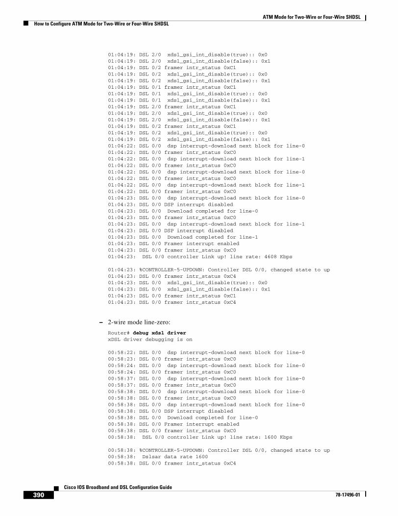
ATM Mode for Two-Wire or Four-Wire SHDSLHow to Configure ATM Mode for Two-Wire or Four-Wire SHDSL
390Cisco IOS Broadband and DSL Configuration Guide
78-17496-01
01:04:19: DSL 2/0 xdsl_gsi_int_disable(true):: 0x001:04:19: DSL 2/0 xdsl_gsi_int_disable(false):: 0x101:04:19: DSL 0/2 framer intr_status 0xC101:04:19: DSL 0/2 xdsl_gsi_int_disable(true):: 0x001:04:19: DSL 0/2 xdsl_gsi_int_disable(false):: 0x101:04:19: DSL 0/1 framer intr_status 0xC101:04:19: DSL 0/1 xdsl_gsi_int_disable(true):: 0x001:04:19: DSL 0/1 xdsl_gsi_int_disable(false):: 0x101:04:19: DSL 2/0 framer intr_status 0xC101:04:19: DSL 2/0 xdsl_gsi_int_disable(true):: 0x001:04:19: DSL 2/0 xdsl_gsi_int_disable(false):: 0x101:04:19: DSL 0/2 framer intr_status 0xC101:04:19: DSL 0/2 xdsl_gsi_int_disable(true):: 0x001:04:19: DSL 0/2 xdsl_gsi_int_disable(false):: 0x101:04:22: DSL 0/0 dsp interrupt-download next block for line-001:04:22: DSL 0/0 framer intr_status 0xC001:04:22: DSL 0/0 dsp interrupt-download next block for line-101:04:22: DSL 0/0 framer intr_status 0xC001:04:22: DSL 0/0 dsp interrupt-download next block for line-001:04:22: DSL 0/0 framer intr_status 0xC001:04:22: DSL 0/0 dsp interrupt-download next block for line-101:04:22: DSL 0/0 framer intr_status 0xC001:04:23: DSL 0/0 dsp interrupt-download next block for line-001:04:23: DSL 0/0 DSP interrupt disabled01:04:23: DSL 0/0 Download completed for line-001:04:23: DSL 0/0 framer intr_status 0xC001:04:23: DSL 0/0 dsp interrupt-download next block for line-101:04:23: DSL 0/0 DSP interrupt disabled01:04:23: DSL 0/0 Download completed for line-101:04:23: DSL 0/0 Framer interrupt enabled01:04:23: DSL 0/0 framer intr_status 0xC001:04:23: DSL 0/0 controller Link up! line rate: 4608 Kbps
01:04:23: %CONTROLLER-5-UPDOWN: Controller DSL 0/0, changed state to up01:04:23: DSL 0/0 framer intr_status 0xC401:04:23: DSL 0/0 xdsl_gsi_int_disable(true):: 0x001:04:23: DSL 0/0 xdsl_gsi_int_disable(false):: 0x101:04:23: DSL 0/0 framer intr_status 0xC101:04:23: DSL 0/0 framer intr_status 0xC4
– 2-wire mode line-zero:
Router# debug xdsl driverxDSL driver debugging is on
00:58:22: DSL 0/0 dsp interrupt-download next block for line-000:58:23: DSL 0/0 framer intr_status 0xC0 00:58:24: DSL 0/0 dsp interrupt-download next block for line-000:58:24: DSL 0/0 framer intr_status 0xC0 00:58:37: DSL 0/0 dsp interrupt-download next block for line-000:58:37: DSL 0/0 framer intr_status 0xC0 00:58:38: DSL 0/0 dsp interrupt-download next block for line-000:58:38: DSL 0/0 framer intr_status 0xC0 00:58:38: DSL 0/0 dsp interrupt-download next block for line-000:58:38: DSL 0/0 DSP interrupt disabled00:58:38: DSL 0/0 Download completed for line-000:58:38: DSL 0/0 Framer interrupt enabled00:58:38: DSL 0/0 framer intr_status 0xC0 00:58:38: DSL 0/0 controller Link up! line rate: 1600 Kbps
00:58:38: %CONTROLLER-5-UPDOWN: Controller DSL 0/0, changed state to up00:58:38: Dslsar data rate 160000:58:38: DSL 0/0 framer intr_status 0xC4
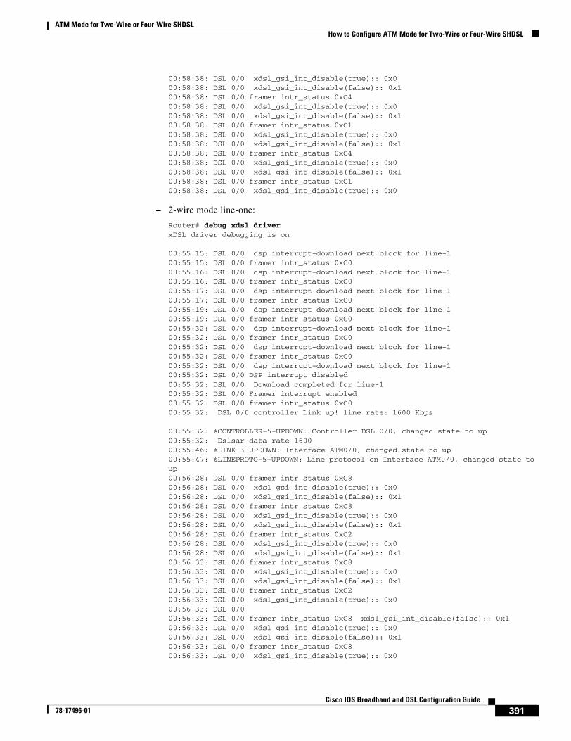
ATM Mode for Two-Wire or Four-Wire SHDSLHow to Configure ATM Mode for Two-Wire or Four-Wire SHDSL
391Cisco IOS Broadband and DSL Configuration Guide
78-17496-01
00:58:38: DSL 0/0 xdsl_gsi_int_disable(true):: 0x000:58:38: DSL 0/0 xdsl_gsi_int_disable(false):: 0x100:58:38: DSL 0/0 framer intr_status 0xC4 00:58:38: DSL 0/0 xdsl_gsi_int_disable(true):: 0x000:58:38: DSL 0/0 xdsl_gsi_int_disable(false):: 0x100:58:38: DSL 0/0 framer intr_status 0xC1 00:58:38: DSL 0/0 xdsl_gsi_int_disable(true):: 0x000:58:38: DSL 0/0 xdsl_gsi_int_disable(false):: 0x100:58:38: DSL 0/0 framer intr_status 0xC4 00:58:38: DSL 0/0 xdsl_gsi_int_disable(true):: 0x000:58:38: DSL 0/0 xdsl_gsi_int_disable(false):: 0x100:58:38: DSL 0/0 framer intr_status 0xC1 00:58:38: DSL 0/0 xdsl_gsi_int_disable(true):: 0x0
– 2-wire mode line-one:
Router# debug xdsl driverxDSL driver debugging is on
00:55:15: DSL 0/0 dsp interrupt-download next block for line-100:55:15: DSL 0/0 framer intr_status 0xC0 00:55:16: DSL 0/0 dsp interrupt-download next block for line-100:55:16: DSL 0/0 framer intr_status 0xC0 00:55:17: DSL 0/0 dsp interrupt-download next block for line-100:55:17: DSL 0/0 framer intr_status 0xC0 00:55:19: DSL 0/0 dsp interrupt-download next block for line-100:55:19: DSL 0/0 framer intr_status 0xC0 00:55:32: DSL 0/0 dsp interrupt-download next block for line-100:55:32: DSL 0/0 framer intr_status 0xC0 00:55:32: DSL 0/0 dsp interrupt-download next block for line-100:55:32: DSL 0/0 framer intr_status 0xC0 00:55:32: DSL 0/0 dsp interrupt-download next block for line-100:55:32: DSL 0/0 DSP interrupt disabled00:55:32: DSL 0/0 Download completed for line-100:55:32: DSL 0/0 Framer interrupt enabled00:55:32: DSL 0/0 framer intr_status 0xC0 00:55:32: DSL 0/0 controller Link up! line rate: 1600 Kbps
00:55:32: %CONTROLLER-5-UPDOWN: Controller DSL 0/0, changed state to up00:55:32: Dslsar data rate 160000:55:46: %LINK-3-UPDOWN: Interface ATM0/0, changed state to up00:55:47: %LINEPROTO-5-UPDOWN: Line protocol on Interface ATM0/0, changed state to up00:56:28: DSL 0/0 framer intr_status 0xC8 00:56:28: DSL 0/0 xdsl_gsi_int_disable(true):: 0x000:56:28: DSL 0/0 xdsl_gsi_int_disable(false):: 0x100:56:28: DSL 0/0 framer intr_status 0xC8 00:56:28: DSL 0/0 xdsl_gsi_int_disable(true):: 0x000:56:28: DSL 0/0 xdsl_gsi_int_disable(false):: 0x100:56:28: DSL 0/0 framer intr_status 0xC2 00:56:28: DSL 0/0 xdsl_gsi_int_disable(true):: 0x000:56:28: DSL 0/0 xdsl_gsi_int_disable(false):: 0x100:56:33: DSL 0/0 framer intr_status 0xC8 00:56:33: DSL 0/0 xdsl_gsi_int_disable(true):: 0x000:56:33: DSL 0/0 xdsl_gsi_int_disable(false):: 0x100:56:33: DSL 0/0 framer intr_status 0xC2 00:56:33: DSL 0/0 xdsl_gsi_int_disable(true):: 0x000:56:33: DSL 0/0 00:56:33: DSL 0/0 framer intr_status 0xC8 xdsl_gsi_int_disable(false):: 0x100:56:33: DSL 0/0 xdsl_gsi_int_disable(true):: 0x000:56:33: DSL 0/0 xdsl_gsi_int_disable(false):: 0x100:56:33: DSL 0/0 framer intr_status 0xC8 00:56:33: DSL 0/0 xdsl_gsi_int_disable(true):: 0x0

ATM Mode for Two-Wire or Four-Wire SHDSLHow to Configure ATM Mode for Two-Wire or Four-Wire SHDSL
392Cisco IOS Broadband and DSL Configuration Guide
78-17496-01
• debug xdsl eoc—Displays what is in the embedded operations channel messages. The following example shows the use of the debug xdsl eoc command, sample output, and use of the command to stop the display.
Router# debug xdsl eoc
xDSL EOC debugging is onRouter#Apr 23 07:31:26.945: DSL 0/0 controller Link up! line rate: 4608 Kbps
Apr 23 07:31:26.945: %CONTROLLER-5-UPDOWN: Controller DSL 0/0, changed state to upApr 23 07:31:27.057: DSL 0/0: line 0 EOC Rcv Intr :: 0x4Apr 23 07:31:27.057: DSL 0/0:Current length 40 GTI_OKApr 23 07:31:27.057: DSL 0/0:msg rcvd line 0Apr 23 07:31:27.057: DSL 0/0: GT_FAILApr 23 07:31:27.057: eoc_get_message for line::0Apr 23 07:31:27.057: Rx EOC remove transparency:: 1F 1 0 46 10Apr 23 07:31:27.057: data_transparency_remove: Done, eoc packet size = 5
Apr 23 07:31:27.057: Good eoc packet receivedApr 23 07:31:27.057: incoming request eocmsgid: 1 from line 0Apr 23 07:31:27.057: Tx Converted EOC message:: 21 81 1 43 43 49 53 434F 0 0 0 2 1 0 E9 61Apr 23 07:31:27.057: data_transparency_add: eoc packet size - before 17, after 17
Apr 23 07:31:27.153: DSL 0/0: line 0 EOC Rcv Intr :: 0x4Apr 23 07:31:27.153: DSL 0/0:Current length 40 GTI_OKApr 23 07:31:27.153: DSL 0/0:msg rcvd line 0Apr 23 07:31:27.153: DSL 0/0: GT_FAILApr 23 07:31:27.153: eoc_get_message for line::0Apr 23 07:31:27.153: Rx EOC remove transparency:: 12 2 74 8AApr 23 07:31:27.153: data_transparency_remove: Done, eoc packet size = 4
Apr 23 07:31:27.153: Good eoc packet receivedApr 23 07:31:27.153: incoming request eocmsgid: 2 from line 0Apr 23 07:31:27.153: Tx Converted EOC message:: 21 82 1 0 0 0 0 041 32 39 37 33 33 43 4E 53 38 44 44 30 41 41 41 43 43 49 53 43 4F 0 0 043 53 43 4F 2D 31 53 48 44 53 4C 0 46 4F 43 30 37 34 32 31 54 41 31 0 3132 2E 33 28 32 30 30 34 30 33 0 60 F0Apr 23 07:31:27.153: data_transparency_add: eoc packet size - before 71, after 71
Apr 23 07:31:27.249: DSL 0/0: line 0 EOC Rcv Intr :: 0x4Apr 23 07:31:27.249: DSL 0/0:Current length 40 GTI_OKApr 23 07:31:27.249: DSL 0/0:msg rcvd line 0Apr 23 07:31:27.249: DSL 0/0: GT_FAILApr 23 07:31:27.249: eoc_get_message for line::0Apr 23 07:31:27.249: Rx EOC remove transparency:: 12 3 0 0 6D E9Apr 23 07:31:27.249: data_transparency_remove: Done, eoc packet size = 6
Apr 23 07:31:27.249: Good eoc packet receivedApr 23 07:31:27.249: incoming request eocmsgid: 3 from line 0Apr 23 07:31:27.249: Tx Converted EOC message:: 21 83 0 0 0 1 ACApr 23 07:31:27.249: data_transparency_add: eoc packet size - before 7, after 7GSI Tx buffer yet to transmit
Apr 23 07:31:27.345: DSL 0/0: line 0 EOC Rcv Intr :: 0x4Apr 23 07:31:27.345: DSL 0/0:Current length 40 GTI_OKApr 23 07:31:27.345: DSL 0/0:msg rcvd line 0Apr 23 07:31:27.345: DSL 0/0: GT_FAILApr 23 07:31:27.345: eoc_get_message for line::0Apr 23 07:31:27.345: Rx EOC remove transparency:: 12 5 0 0 0 E9 0 00 0 0 0 0 0 0 0 0 0 0 0 0 0 32 42Apr 23 07:31:27.345: data_transparency_remove: Done, eoc packet size = 24
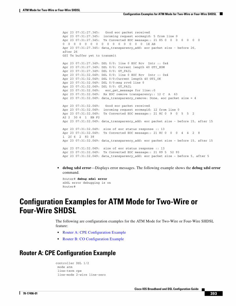
ATM Mode for Two-Wire or Four-Wire SHDSLConfiguration Examples for ATM Mode for Two-Wire or Four-Wire SHDSL
393Cisco IOS Broadband and DSL Configuration Guide
78-17496-01
Apr 23 07:31:27.345: Good eoc packet receivedApr 23 07:31:27.345: incoming request eocmsgid: 5 from line 0Apr 23 07:31:27.345: Tx Converted EOC message:: 21 85 0 0 0 0 0 0 00 0 0 0 0 0 0 0 0 0 0 0 0 0 0 1E ABApr 23 07:31:27.345: data_transparency_add: eoc packet size - before 26,after 26GSI Tx buffer yet to transmit
Apr 23 07:31:27.349: DSL 0/0: line 0 EOC Rcv Intr :: 0x4Apr 23 07:31:27.349: DSL 0/0: Current length 40 GTI_EOMApr 23 07:31:27.349: DSL 0/0: GT_FAILApr 23 07:31:32.049: DSL 0/0: line 0 EOC Rcv Intr :: 0x4Apr 23 07:31:32.049: DSL 0/0:Current length 40 GTI_OKApr 23 07:31:32.049: DSL 0/0:msg rcvd line 0Apr 23 07:31:32.049: DSL 0/0: GT_FAILApr 23 07:31:32.049: eoc_get_message for line::0Apr 23 07:31:32.049: Rx EOC remove transparency:: 12 C A 63Apr 23 07:31:32.049: data_transparency_remove: Done, eoc packet size = 4
Apr 23 07:31:32.049: Good eoc packet receivedApr 23 07:31:32.049: incoming request eocmsgid: 12 from line 0Apr 23 07:31:32.049: Tx Converted EOC message:: 21 8C 0 9 0 5 5 2A2 2 30 6 1 EB F2Apr 23 07:31:32.049: data_transparency_add: eoc packet size - before 15, after 15
Apr 23 07:31:32.049: size of eoc status response :: 13Apr 23 07:31:32.049: Tx Converted EOC message:: 21 8C 0 0 0 4 4 2 81 2C 6 2 83 38Apr 23 07:31:32.049: data_transparency_add: eoc packet size - before 15, after 15
Apr 23 07:31:32.049: size of eoc status response :: 13Apr 23 07:31:32.049: Tx Converted EOC message:: 21 89 5 52 93Apr 23 07:31:32.049: data_transparency_add: eoc packet size - before 5, after 5
• debug xdsl error—Displays error messages. The following example shows the debug xdsl error command.
Router# debug xdsl error xDSL error debugging is onRouter#
Configuration Examples for ATM Mode for Two-Wire or Four-Wire SHDSL
The following are configuration examples for the ATM Mode for Two-Wire or Four-Wire SHDSL feature:
• Router A: CPE Configuration Example
• Router B: CO Configuration Example
Router A: CPE Configuration Examplecontroller DSL 1/2 mode atm line-term cpe line-mode 2-wire line-zero
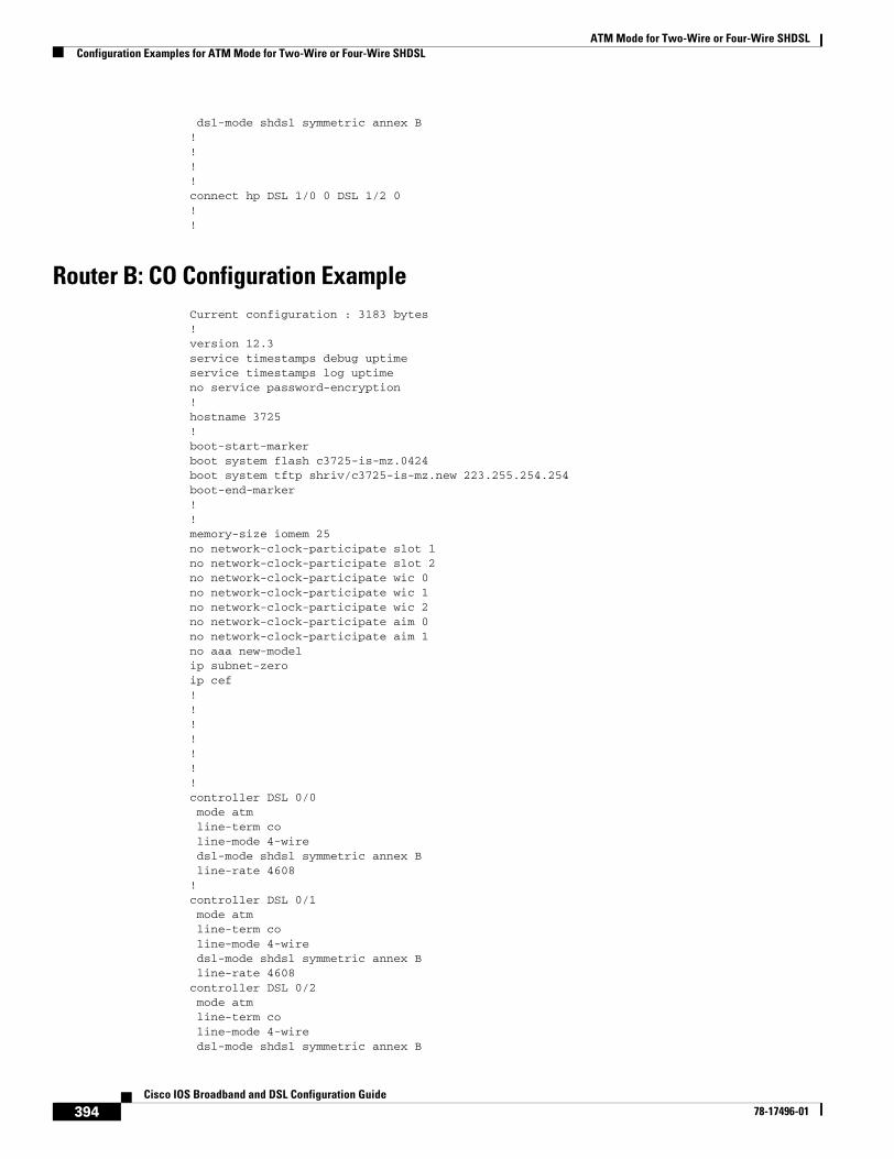
ATM Mode for Two-Wire or Four-Wire SHDSLConfiguration Examples for ATM Mode for Two-Wire or Four-Wire SHDSL
394Cisco IOS Broadband and DSL Configuration Guide
78-17496-01
dsl-mode shdsl symmetric annex B!!!!connect hp DSL 1/0 0 DSL 1/2 0!!
Router B: CO Configuration ExampleCurrent configuration : 3183 bytes!version 12.3service timestamps debug uptimeservice timestamps log uptimeno service password-encryption!hostname 3725!boot-start-markerboot system flash c3725-is-mz.0424boot system tftp shriv/c3725-is-mz.new 223.255.254.254boot-end-marker!!memory-size iomem 25no network-clock-participate slot 1no network-clock-participate slot 2no network-clock-participate wic 0no network-clock-participate wic 1no network-clock-participate wic 2no network-clock-participate aim 0no network-clock-participate aim 1no aaa new-modelip subnet-zeroip cef!!!!!!!controller DSL 0/0 mode atm line-term co line-mode 4-wire dsl-mode shdsl symmetric annex B line-rate 4608!controller DSL 0/1 mode atm line-term co line-mode 4-wire dsl-mode shdsl symmetric annex B line-rate 4608controller DSL 0/2 mode atm line-term co line-mode 4-wire dsl-mode shdsl symmetric annex B
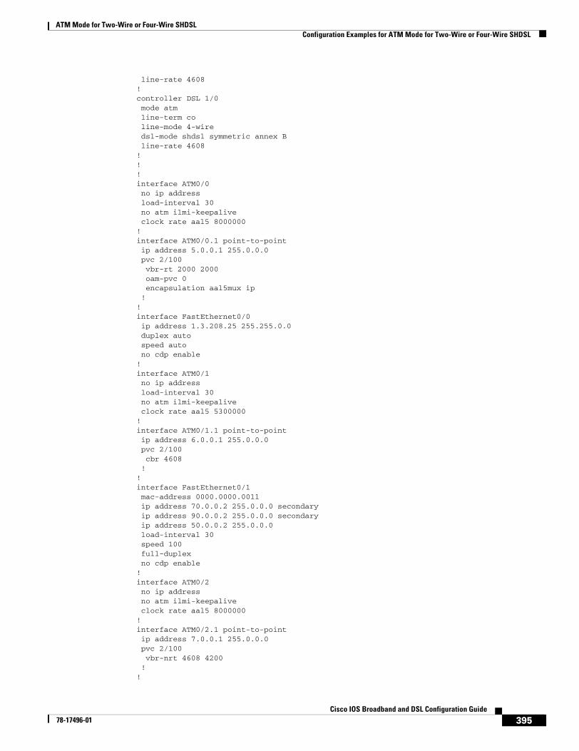
ATM Mode for Two-Wire or Four-Wire SHDSLConfiguration Examples for ATM Mode for Two-Wire or Four-Wire SHDSL
395Cisco IOS Broadband and DSL Configuration Guide
78-17496-01
line-rate 4608!controller DSL 1/0 mode atm line-term co line-mode 4-wire dsl-mode shdsl symmetric annex B line-rate 4608!!!interface ATM0/0 no ip address load-interval 30 no atm ilmi-keepalive clock rate aal5 8000000!interface ATM0/0.1 point-to-point ip address 5.0.0.1 255.0.0.0 pvc 2/100 vbr-rt 2000 2000 oam-pvc 0 encapsulation aal5mux ip !!interface FastEthernet0/0 ip address 1.3.208.25 255.255.0.0 duplex auto speed auto no cdp enable!interface ATM0/1 no ip address load-interval 30 no atm ilmi-keepalive clock rate aal5 5300000!interface ATM0/1.1 point-to-point ip address 6.0.0.1 255.0.0.0 pvc 2/100 cbr 4608 !!interface FastEthernet0/1 mac-address 0000.0000.0011 ip address 70.0.0.2 255.0.0.0 secondary ip address 90.0.0.2 255.0.0.0 secondary ip address 50.0.0.2 255.0.0.0 load-interval 30 speed 100 full-duplex no cdp enable!interface ATM0/2 no ip address no atm ilmi-keepalive clock rate aal5 8000000!interface ATM0/2.1 point-to-point ip address 7.0.0.1 255.0.0.0 pvc 2/100 vbr-nrt 4608 4200 !!
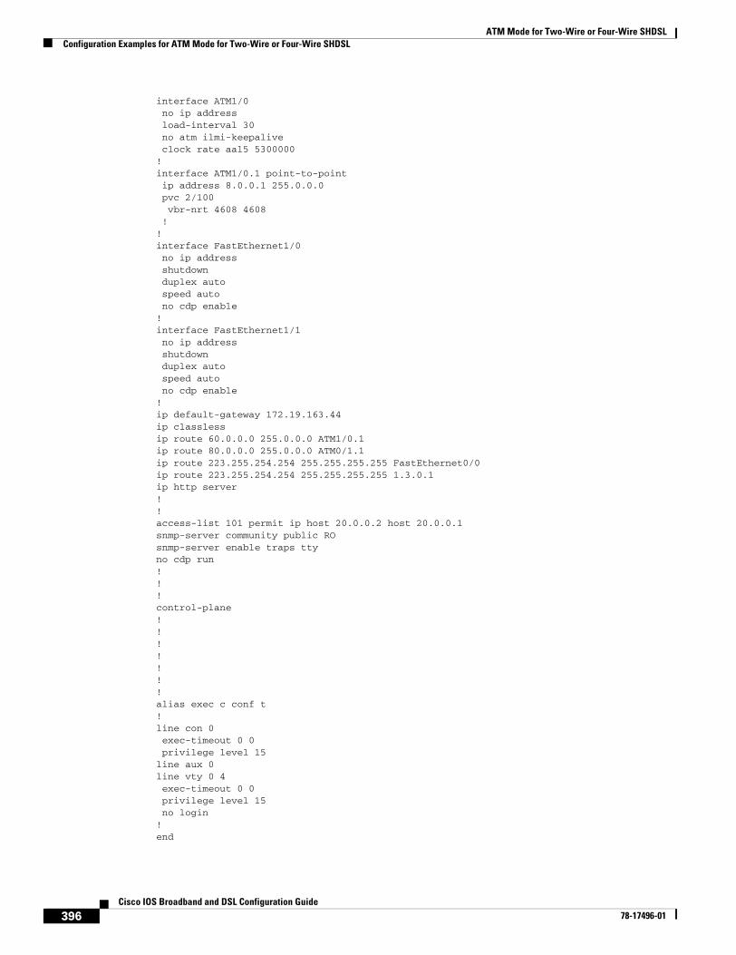
ATM Mode for Two-Wire or Four-Wire SHDSLConfiguration Examples for ATM Mode for Two-Wire or Four-Wire SHDSL
396Cisco IOS Broadband and DSL Configuration Guide
78-17496-01
interface ATM1/0 no ip address load-interval 30 no atm ilmi-keepalive clock rate aal5 5300000!interface ATM1/0.1 point-to-point ip address 8.0.0.1 255.0.0.0 pvc 2/100 vbr-nrt 4608 4608 !!interface FastEthernet1/0 no ip address shutdown duplex auto speed auto no cdp enable!interface FastEthernet1/1 no ip address shutdown duplex auto speed auto no cdp enable!ip default-gateway 172.19.163.44ip classlessip route 60.0.0.0 255.0.0.0 ATM1/0.1ip route 80.0.0.0 255.0.0.0 ATM0/1.1ip route 223.255.254.254 255.255.255.255 FastEthernet0/0ip route 223.255.254.254 255.255.255.255 1.3.0.1ip http server!!access-list 101 permit ip host 20.0.0.2 host 20.0.0.1snmp-server community public ROsnmp-server enable traps ttyno cdp run!!!control-plane!!!!!!!alias exec c conf t!line con 0 exec-timeout 0 0 privilege level 15line aux 0line vty 0 4 exec-timeout 0 0 privilege level 15 no login!end
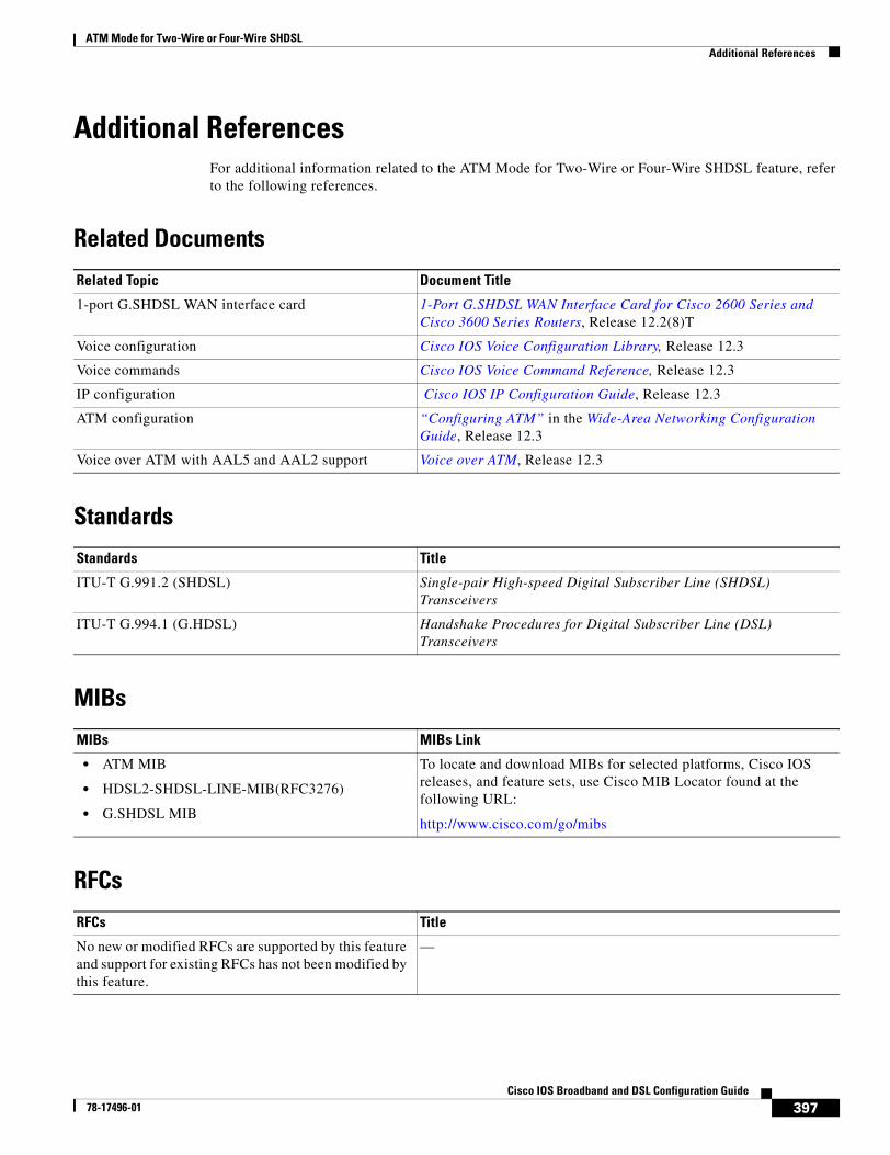
ATM Mode for Two-Wire or Four-Wire SHDSLAdditional References
397Cisco IOS Broadband and DSL Configuration Guide
78-17496-01
Additional ReferencesFor additional information related to the ATM Mode for Two-Wire or Four-Wire SHDSL feature, refer to the following references.
Related Documents
Standards
MIBs
RFCs
Related Topic Document Title
1-port G.SHDSL WAN interface card 1-Port G.SHDSL WAN Interface Card for Cisco 2600 Series and Cisco 3600 Series Routers, Release 12.2(8)T
Voice configuration Cisco IOS Voice Configuration Library, Release 12.3
Voice commands Cisco IOS Voice Command Reference, Release 12.3
IP configuration Cisco IOS IP Configuration Guide, Release 12.3
ATM configuration “Configuring ATM” in the Wide-Area Networking Configuration Guide, Release 12.3
Voice over ATM with AAL5 and AAL2 support Voice over ATM, Release 12.3
Standards Title
ITU-T G.991.2 (SHDSL) Single-pair High-speed Digital Subscriber Line (SHDSL) Transceivers
ITU-T G.994.1 (G.HDSL) Handshake Procedures for Digital Subscriber Line (DSL) Transceivers
MIBs MIBs Link
• ATM MIB
• HDSL2-SHDSL-LINE-MIB(RFC3276)
• G.SHDSL MIB
To locate and download MIBs for selected platforms, Cisco IOS releases, and feature sets, use Cisco MIB Locator found at the following URL:
http://www.cisco.com/go/mibs
RFCs Title
No new or modified RFCs are supported by this feature and support for existing RFCs has not been modified by this feature.
—
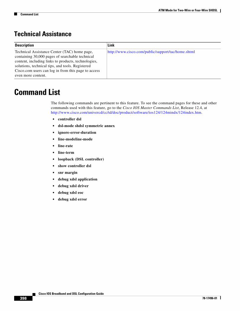
ATM Mode for Two-Wire or Four-Wire SHDSLCommand List
398Cisco IOS Broadband and DSL Configuration Guide
78-17496-01
Technical Assistance
Command ListThe following commands are pertinent to this feature. To see the command pages for these and other commands used with this feature, go to the Cisco IOS Master Commands List, Release 12.4, at http://www.cisco.com/univercd/cc/td/doc/product/software/ios124/124mindx/124index.htm.
• controller dsl
• dsl-mode shdsl symmetric annex
• ignore-error-duration
• line-modeline-mode
• line-rate
• line-term
• loopback (DSL controller)
• show controller dsl
• snr margin
• debug xdsl application
• debug xdsl driver
• debug xdsl eoc
• debug xdsl error
Description Link
Technical Assistance Center (TAC) home page, containing 30,000 pages of searchable technical content, including links to products, technologies, solutions, technical tips, and tools. Registered Cisco.com users can log in from this page to access even more content.
http://www.cisco.com/public/support/tac/home.shtml
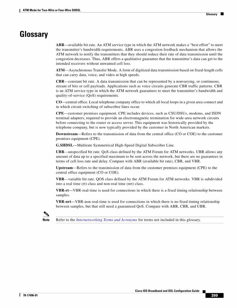
ATM Mode for Two-Wire or Four-Wire SHDSLGlossary
399Cisco IOS Broadband and DSL Configuration Guide
78-17496-01
GlossaryABR—available bit rate. An ATM service type in which the ATM network makes a “best effort” to meet the transmitter’s bandwidth requirements. ABR uses a congestion feedback mechanism that allows the ATM network to notify the transmitters that they should reduce their rate of data transmission until the congestion decreases. Thus, ABR offers a qualitative guarantee that the transmitter’s data can get to the intended receivers without unwanted cell loss.
ATM—Asynchronous Transfer Mode. A form of digitized data transmission based on fixed-length cells that can carry data, voice, and video at high speeds.
CBR—constant bit rate. A data transmission that can be represented by a nonvarying, or continuous, stream of bits or cell payloads. Applications such as voice circuits generate CBR traffic patterns. CBR is an ATM service type in which the ATM network guarantees to meet the transmitter’s bandwidth and quality-of-service (QoS) requirements.
CO—central office. Local telephone company office to which all local loops in a given area connect and in which circuit switching of subscriber lines occur.
CPE—customer premises equipment. CPE includes devices, such as CSU/DSUs, modems, and ISDN terminal adapters, required to provide an electromagnetic termination for wide-area network circuits before connecting to the router or access server. This equipment was historically provided by the telephone company, but is now typically provided by the customer in North American markets.
Downstream—Refers to the transmission of data from the central office (CO or COE) to the customer premises equipment (CPE).
G.SHDSL—Multirate Symmetrical High-Speed Digital Subscriber Line.
UBR—unspecified bit rate. QoS class defined by the ATM Forum for ATM networks. UBR allows any amount of data up to a specified maximum to be sent across the network, but there are no guarantees in terms of cell loss rate and delay. Compare with ABR (available bit rate), CBR, and VBR.
Upstream—Refers to the transmission of data from the customer premises equipment (CPE) to the central office equipment (CO or COE).
VBR—variable bit rate. QOS class defined by the ATM Forum for ATM networks. VBR is subdivided into a real time (rt) class and non-real time (nrt) class.
VBR-rt—VBR-real-time is used for connections in which there is a fixed timing relationship between samples.
VBR-nrt—VBR-non-real-time is used for connections in which there is no fixed timing relationship between samples, but that still need a guaranteed QoS. Compare with ABR, CBR, and UBR.
Note Refer to the Internetworking Terms and Acronyms for terms not included in this glossary.

ATM Mode for Two-Wire or Four-Wire SHDSLGlossary
400Cisco IOS Broadband and DSL Configuration Guide
78-17496-01
401Cisco IOS Broadband and DSL Configuration Guide
78-17496-01
T1/E1 Mode for SHDSL
This document describes the T1/E1 Mode for SHDSL feature for the Cisco 1700 series, Cisco 2600 series, Cisco 3631, Cisco 3700, and Cisco 3800 series routers.
The T1/E1 Mode for SHDSL feature adds T1 and E1 support on the new single-port multiline G.SHDSL WAN interface card (WIC), or WIC-1SHDSL-V2, to build on the existing features of the Multirate Symmetrical High- Digital Subscriber Line (G.SHDSL) feature supported on the 1-port G.SHDSL WAN interface card. Two-Wire Mode over SHDSL incorporates the 2.x firmware version and the latest hybrid circuit from Globespan.
The T1/E1 Mode for SHDSL feature supports T1 and E1 in two-wire mode. Embedded Operations Channel (EOC) message support for customer premises equipment (CPE) is provided for two-wire CPE mode. Some central office (CO) messages are also supported when in two-wire CO mode.
Feature Specifications for T1/E1 Mode for SHDSL
Finding Support Information for Platforms and Cisco IOS Software Images
Use Cisco Feature Navigator to find information about platform support and Cisco IOS software image support. Access Cisco Feature Navigator at http://www.cisco.com/go/fn. You must have an account on Cisco.com. If you do not have an account or have forgotten your username or password, click Cancel at the login dialog box and follow the instructions that appear.
Release Modification
12.3(4)XD This feature (WIC-1SHDSL-V2) was introduced on the Cisco 2600XM series routers to add support for T1/E1 two-wire mode.
12.3(4)XG This feature (WIC-1SHDSL-V2) was integrated into Cisco IOS Release 12.3(4)XG on the Cisco 1700 series routers.
12.3(7)T This feature (WIC-1SHDSL-V2) was integrated into Cisco IOS Release 12.3(7)T on the Cisco 2600XM series routers to add support for T1/E1 two-wire mode. Cisco 1700 series routers do not support the WIC-1SHDSL-V2 in this release.
12.3(11)T Support for the following was added: T1/E1 mode support for Cisco 2600 series, Cisco 3600 series, and Cisco 3700 series routers; and additional annex parameters for Cisco 2600, Cisco 3631, Cisco 3700, and Cisco 3800 series routers.
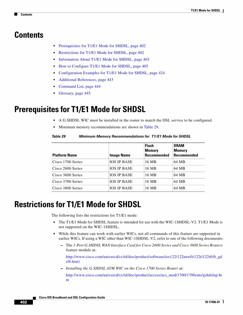
T1/E1 Mode for SHDSLContents
402Cisco IOS Broadband and DSL Configuration Guide
78-17496-01
Contents• Prerequisites for T1/E1 Mode for SHDSL, page 402
• Restrictions for T1/E1 Mode for SHDSL, page 402
• Information About T1/E1 Mode for SHDSL, page 403
• How to Configure T1/E1 Mode for SHDSL, page 405
• Configuration Examples for T1/E1 Mode for SHDSL, page 424
• Additional References, page 443
• Command List, page 444
• Glossary, page 445
Prerequisites for T1/E1 Mode for SHDSL• A G.SHDSL WIC must be installed in the router to match the DSL service to be configured.
• Minimum memory recommendations are shown in Table 29.
Restrictions for T1/E1 Mode for SHDSLThe following lists the restrictions for T1/E1 mode:
• The T1/E1 Mode for SHDSL feature is intended for use with the WIC-1SHDSL-V2. T1/E1 Mode is not supported on the WIC-1SHDSL.
• While this feature can work with earlier WICs, not all commands of this feature are supported in earlier WICs. If using a WIC other than WIC-1SHDSL-V2, refer to one of the following documents:
– The 1-Port G.SHDSL WAN Interface Card for Cisco 2600 Series and Cisco 3600 Series Routers feature module at:
http://www.cisco.com/univercd/cc/td/doc/product/software/ios122/122newft/122t/122t8/ft_gdsl8.htm)
– Installing the G.SHDSL ATM WIC on the Cisco 1700 Series Router at:
http://www.cisco.com/univercd/cc/td/doc/product/access/acs_mod/1700/1700cnts/gshdslup.htm
Table 29 Minimum Memory Recommendations for T1/E1 Mode for SHDSL
Platform Name Image Name
Flash MemoryRecommended
DRAM MemoryRecommended
Cisco 1700 Series IOS IP BASE 16 MB 64 MB
Cisco 2600 Series IOS IP BASE 16 MB 64 MB
Cisco 3600 Series IOS IP BASE 16 MB 64 MB
Cisco 3700 Series IOS IP BASE 16 MB 64 MB
Cisco 3800 Series IOS IP BASE 16 MB 64 MB
T1/E1 Mode for SHDSLInformation About T1/E1 Mode for SHDSL
403Cisco IOS Broadband and DSL Configuration Guide
78-17496-01
• The WIC-1SHDSL-V2 should be inserted only into onboard WIC slots or NM-2W network modules. This WIC is not supported in combination network modules (NM-xFE2W and NM-xFE2W-V2).
• The T1/E1 Mode for SHDSL feature is frame-based (Time Division Multiplexing (TDM)) and therefore does not support ATM features. For example, T1/E1 Mode for SHDSL feature does not support ATM adaption layer 1 (AAL1) and/or circuit emulation service.
• T1/E1 Mode for SHDSL feature is not supported in four-wire mode.
• TDM cross-connects are only supported between WIC slots on NM-2W network modules.
Information About T1/E1 Mode for SHDSLThis section provides information about the T1/E1 Mode for SHDSL feature.
• SHDSL Features, page 403
• Interface and Controller Numbering on the Cisco 1721 Router, page 403
• Interface Numbering on Cisco 2800 Series and Cisco 3800 Series Routers, page 404
SHDSL FeaturesSupported SHDSL features are listed as follows:
• ITU G.991.2 support (full support for Annex A & B)
– Dying Gasp (ITU G.991.2) is supported.
– Terminating wetting current is supported.
– T1/E1 mode when in two-wire configuration is supported.
• ITU G.991.2 support (partial support for Annex E)
– E.4—Aligned DS1/fractional DS1 support for T1.
– E.7—Aligned DS1/fractional DS1 support for E1.
– E.9—ATM transport.
Interface and Controller Numbering on the Cisco 1721 RouterIf a WIC-1SHDSL-V2 is installed in a Cisco 1721 router, the interfaces and controllers are assigned numbers based on a numbering scheme that is different from the slot numbering system on other Cisco routers. This is because the Cisco 1721 router assigns only a slot number without also assigning a port number. Other Cisco routers typically use a slot and port number combination.
If the WIC-1SHDSL-V2 is installed in slot 0, the T1/E1 controllers and the ATM interfaces (ADSL or SHDSL) will be numbered relative to the WIC-1SHDSL-V2 (as the DSL controller) in slot 0. See Table 30 for examples of the slot numbering scheme on the Cisco 1721.
With an ATM or MFT T1/E1 card in slot 0, the WIC-1SHDSL-V2 in slot 1 will be numbered relative to the number of ports in slot 0.
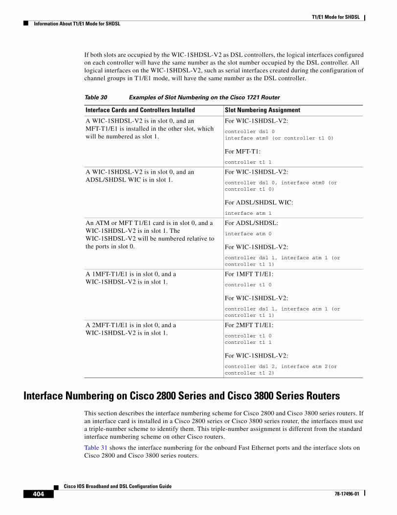
T1/E1 Mode for SHDSLInformation About T1/E1 Mode for SHDSL
404Cisco IOS Broadband and DSL Configuration Guide
78-17496-01
If both slots are occupied by the WIC-1SHDSL-V2 as DSL controllers, the logical interfaces configured on each controller will have the same number as the slot number occupied by the DSL controller. All logical interfaces on the WIC-1SHDSL-V2, such as serial interfaces created during the configuration of channel groups in T1/E1 mode, will have the same number as the DSL controller.
Interface Numbering on Cisco 2800 Series and Cisco 3800 Series RoutersThis section describes the interface numbering scheme for Cisco 2800 and Cisco 3800 series routers. If an interface card is installed in a Cisco 2800 series or Cisco 3800 series router, the interfaces must use a triple-number scheme to identify them. This triple-number assignment is different from the standard interface numbering scheme on other Cisco routers.
Table 31 shows the interface numbering for the onboard Fast Ethernet ports and the interface slots on Cisco 2800 and Cisco 3800 series routers.
Table 30 Examples of Slot Numbering on the Cisco 1721 Router
Interface Cards and Controllers Installed Slot Numbering Assignment
A WIC-1SHDSL-V2 is in slot 0, and an MFT-T1/E1 is installed in the other slot, which will be numbered as slot 1.
For WIC-1SHDSL-V2:
controller dsl 0interface atm0 (or controller t1 0)
For MFT-T1:
controller t1 1
A WIC-1SHDSL-V2 is in slot 0, and an ADSL/SHDSL WIC is in slot 1.
For WIC-1SHDSL-V2:
controller dsl 0, interface atm0 (or controller t1 0)
For ADSL/SHDSL WIC:
interface atm 1
An ATM or MFT T1/E1 card is in slot 0, and a WIC-1SHDSL-V2 is in slot 1. The WIC-1SHDSL-V2 will be numbered relative to the ports in slot 0.
For ADSL/SHDSL:
interface atm 0
For WIC-1SHDSL-V2:
controller dsl 1, interface atm 1 (or controller t1 1)
A 1MFT-T1/E1 is in slot 0, and a WIC-1SHDSL-V2 is in slot 1.
For 1MFT T1/E1:
controller t1 0
For WIC-1SHDSL-V2:
controller dsl 1, interface atm 1 (or controller t1 1)
A 2MFT-T1/E1 is in slot 0, and a WIC-1SHDSL-V2 is in slot 1.
For 2MFT T1/E1:
controller t1 0controller t1 1
For WIC-1SHDSL-V2:
controller dsl 2, interface atm 2(or controller t1 2)
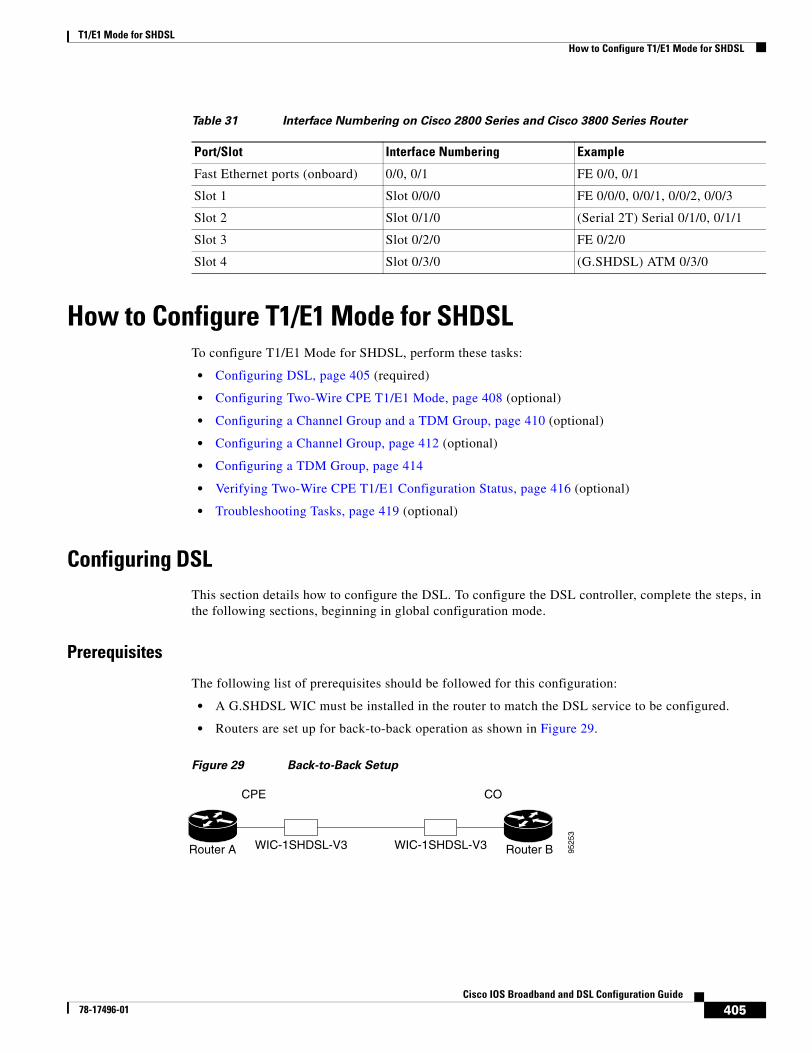
T1/E1 Mode for SHDSLHow to Configure T1/E1 Mode for SHDSL
405Cisco IOS Broadband and DSL Configuration Guide
78-17496-01
How to Configure T1/E1 Mode for SHDSLTo configure T1/E1 Mode for SHDSL, perform these tasks:
• Configuring DSL, page 405 (required)
• Configuring Two-Wire CPE T1/E1 Mode, page 408 (optional)
• Configuring a Channel Group and a TDM Group, page 410 (optional)
• Configuring a Channel Group, page 412 (optional)
• Configuring a TDM Group, page 414
• Verifying Two-Wire CPE T1/E1 Configuration Status, page 416 (optional)
• Troubleshooting Tasks, page 419 (optional)
Configuring DSLThis section details how to configure the DSL. To configure the DSL controller, complete the steps, in the following sections, beginning in global configuration mode.
Prerequisites
The following list of prerequisites should be followed for this configuration:
• A G.SHDSL WIC must be installed in the router to match the DSL service to be configured.
• Routers are set up for back-to-back operation as shown in Figure 29.
Figure 29 Back-to-Back Setup
Table 31 Interface Numbering on Cisco 2800 Series and Cisco 3800 Series Router
Port/Slot Interface Numbering Example
Fast Ethernet ports (onboard) 0/0, 0/1 FE 0/0, 0/1
Slot 1 Slot 0/0/0 FE 0/0/0, 0/0/1, 0/0/2, 0/0/3
Slot 2 Slot 0/1/0 (Serial 2T) Serial 0/1/0, 0/1/1
Slot 3 Slot 0/2/0 FE 0/2/0
Slot 4 Slot 0/3/0 (G.SHDSL) ATM 0/3/0
9525
3
Router A
CPE CO
Router BWIC-1SHDSL-V3WIC-1SHDSL-V3
T1/E1 Mode for SHDSLHow to Configure T1/E1 Mode for SHDSL
406Cisco IOS Broadband and DSL Configuration Guide
78-17496-01
SUMMARY STEPS
8. enable
9. configure terminal
10. controller dsl slot/port
11. dsl-mode shdsl symmetric annex mode
12. line-term {co | cpe}
13. ignore-error-duration seconds
14. snr margin {current [snr-value | disable] | snext [snr-value | disable]}
15. loopback {analog | digital}
DETAILED STEPS
Command or Action Purpose
Step 1 enable
Example:Router> enable
Enables privileged EXEC mode.
• Enter your password if prompted.
Step 2 configure terminal
Example:Router# configure terminal
Enters global configuration mode.
Step 3 controller dsl slot/port
Example:Router(config)# controller dsl 0/1
Enters controller configuration mode.
The keywords and arguments are as follows:
• dsl—The type of controller.
• slot/port—The backplane slot number and port number for the interface being configured.
Step 4 dsl-mode shdsl symmetric annex mode
Example:Router(config-controller)# dsl-mode shdsl symmetric annex A
Sets the DSL operating mode. The valid values are:
• A: Supports Annex A of G.991.2 standard for North America. This is the default.
• B: Supports Annex B of G.991.2 standard for Europe.
• A–B: Supports Annex A or B. For CPE mode only; not supported in CO mode. Selected when the line trains.
• A–B–ANFP: Supports Annex A or B–ANFP. For CPE mode only; not supported in CO mode. Selected when the line trains.
• B–ANFP: Supports Annex B–ANFP.
Step 5 line-term {co | cpe}
Example:Router(config-controller)# line-term cpe
(Optional) Configures the line termination as follows:
• co—Central office.
• cpe—Customer premises equipment.
T1/E1 Mode for SHDSLHow to Configure T1/E1 Mode for SHDSL
407Cisco IOS Broadband and DSL Configuration Guide
78-17496-01
Examples
Example of the Configuration Prior to Configuring T1/E1 modecontroller DSL 0/0line-term cpe
What to Do Next
Configure the router for two-wire T1/E1 mode using the steps shown in the “Configuring Two-Wire CPE T1/E1 Mode” section on page 408.
Step 6 ignore-error-duration seconds
Example:Router(config-controller)# ignore-error-duration 20
(Optional) Permits the router to ignore errors for a given amount of time when training the line when connected to a controller with a different chipset type.
• seconds—Sets the time for which errors will be ignored during training of the line. Range is from 15 to 30 seconds. If this value is omitted, an error message appears.
Step 7 snr margin {current [snr-value | disable] | snext [snr-value | disable]}
Example:Router(config-controller)# snr margin current 10
(Optional) Sets the margin of the signal-to-noise ratio on the line to improve the line stability.
• current—Sets the current signal-to-noise ratio (SNR) on the controller. To disable the current SNR, set current to disable.
• snext—Sets the Self Near End Cross Talk (SNEXT) signal-to-noise ratio. To disable the SNEXT, set snext to disable.
• snr-value—Value in decibels (dB) for the signal-to-noise ratio on the controller or the SNEXT. Range is from -10 dB to 10 dB. The default value is 0 dB.
• disable—Disables the snr margin command.
Step 8 loopback {analog | digital}
Example:Router(config-controller)# loopback analog
(Optional) Configures the core loopback.
• analog—Loops the circuit at the analog hybrid to verify the analog loopback hardware to the analog hybrid.
• digital—Loops the circuit at the framer to verify the hardware to the framer.
Command or Action Purpose
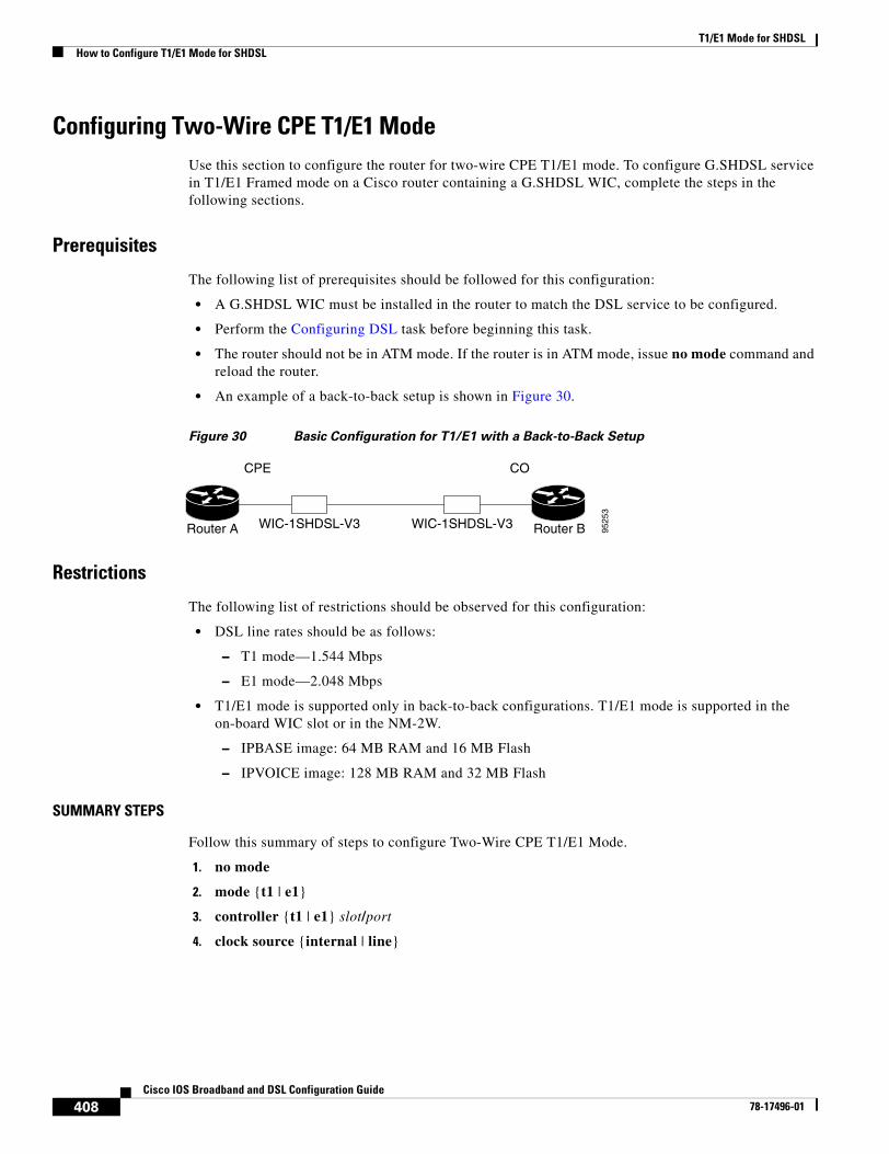
T1/E1 Mode for SHDSLHow to Configure T1/E1 Mode for SHDSL
408Cisco IOS Broadband and DSL Configuration Guide
78-17496-01
Configuring Two-Wire CPE T1/E1 ModeUse this section to configure the router for two-wire CPE T1/E1 mode. To configure G.SHDSL service in T1/E1 Framed mode on a Cisco router containing a G.SHDSL WIC, complete the steps in the following sections.
Prerequisites
The following list of prerequisites should be followed for this configuration:
• A G.SHDSL WIC must be installed in the router to match the DSL service to be configured.
• Perform the Configuring DSL task before beginning this task.
• The router should not be in ATM mode. If the router is in ATM mode, issue no mode command and reload the router.
• An example of a back-to-back setup is shown in Figure 30.
Figure 30 Basic Configuration for T1/E1 with a Back-to-Back Setup
Restrictions
The following list of restrictions should be observed for this configuration:
• DSL line rates should be as follows:
– T1 mode—1.544 Mbps
– E1 mode—2.048 Mbps
• T1/E1 mode is supported only in back-to-back configurations. T1/E1 mode is supported in the on-board WIC slot or in the NM-2W.
– IPBASE image: 64 MB RAM and 16 MB Flash
– IPVOICE image: 128 MB RAM and 32 MB Flash
SUMMARY STEPS
Follow this summary of steps to configure Two-Wire CPE T1/E1 Mode.
1. no mode
2. mode {t1 | e1}
3. controller {t1 | e1} slot/port
4. clock source {internal | line}
9525
3
Router A
CPE CO
Router BWIC-1SHDSL-V3WIC-1SHDSL-V3
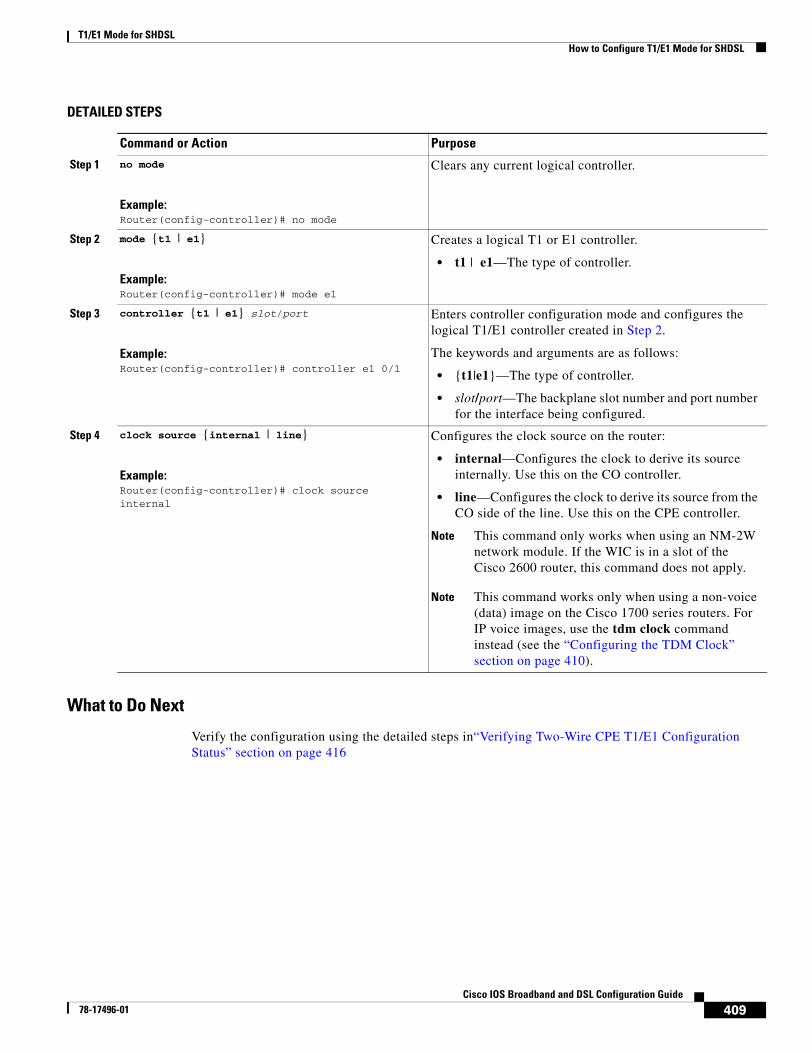
T1/E1 Mode for SHDSLHow to Configure T1/E1 Mode for SHDSL
409Cisco IOS Broadband and DSL Configuration Guide
78-17496-01
DETAILED STEPS
What to Do Next
Verify the configuration using the detailed steps in“Verifying Two-Wire CPE T1/E1 Configuration Status” section on page 416
Command or Action Purpose
Step 1 no mode
Example:Router(config-controller)# no mode
Clears any current logical controller.
Step 2 mode {t1 | e1}
Example:Router(config-controller)# mode e1
Creates a logical T1 or E1 controller.
• t1 | e1—The type of controller.
Step 3 controller {t1 | e1} slot/port
Example:Router(config-controller)# controller e1 0/1
Enters controller configuration mode and configures the logical T1/E1 controller created in Step 2.
The keywords and arguments are as follows:
• {t1|e1}—The type of controller.
• slot/port—The backplane slot number and port number for the interface being configured.
Step 4 clock source {internal | line}
Example:Router(config-controller)# clock source internal
Configures the clock source on the router:
• internal—Configures the clock to derive its source internally. Use this on the CO controller.
• line—Configures the clock to derive its source from the CO side of the line. Use this on the CPE controller.
Note This command only works when using an NM-2W network module. If the WIC is in a slot of the Cisco 2600 router, this command does not apply.
Note This command works only when using a non-voice (data) image on the Cisco 1700 series routers. For IP voice images, use the tdm clock command instead (see the “Configuring the TDM Clock” section on page 410).
T1/E1 Mode for SHDSLHow to Configure T1/E1 Mode for SHDSL
410Cisco IOS Broadband and DSL Configuration Guide
78-17496-01
Configuring the TDM Clock Use this section to configure the TDM clock source for voice images on the Cisco 1700 series routers. Configuring TDM clock is a prerequisite for configuring channel-groups in T1/E1 mode, but is an option for configuring ATM mode. The TDM clock configuration is not supported on data-only images.
The tdm clock global configuration command configures the clock source for the G.SHDSL WIC.
Exporting Clock
The following shows the command for exporting the clock.
tdm clock {T1 | E1} <slot/port> {voice | data | both} export linetdm clock {atm | bri} <slot/port> export
The following example shows how to use the external clock as the source.
Router(config) # tdm clock atm 1/0 export
Importing Clock
The following shows the command for importing the clock.
tdm clock {T1 | E1} <slot/port> {voice | data | both} import {T1 | E1 | atm | bri | onboard} <slot/port> {line | internal}
tdm clock {atm | bri} <slot/port> import {T1 | E1 | atm | bri | onboard} <slot/port>
The following example shows how to use the internal onboard system clock as the source.
Router(config) # tdm clock atm 1/0 import onboard
For more information about clock configuration for voice on the Cisco 1700 series routers, refer to the “Clock Configuration for Voice Images” in the Clock Configuration for Cisco 1751/1760 Routers document at the following location:
http://www.cisco.com/univercd/cc/td/doc/product/access/acs_mod/1700/1700cnts/tdmdesc.htm
What to Do Next
Verify the configuration. See the “Verifying Two-Wire CPE T1/E1 Configuration Status” section on page 416.
Configuring a Channel Group and a TDM GroupUse this section to configure a channel group and a TDM group. Complete the steps in the following sections.
Prerequisites
The following list of prerequisites should be followed for this configuration:
• A G.SHDSL WIC must be installed in the router to match the DSL service to be configured.
• Perform the Configuring DSL task before beginning this task.
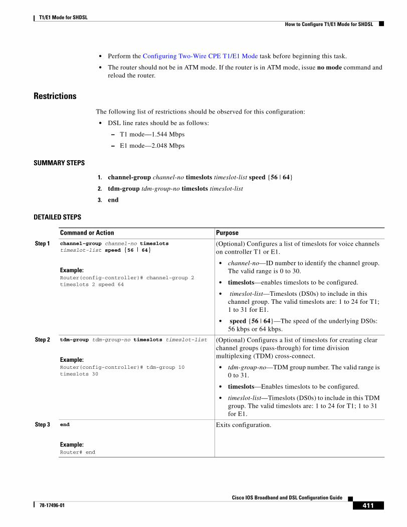
T1/E1 Mode for SHDSLHow to Configure T1/E1 Mode for SHDSL
411Cisco IOS Broadband and DSL Configuration Guide
78-17496-01
• Perform the Configuring Two-Wire CPE T1/E1 Mode task before beginning this task.
• The router should not be in ATM mode. If the router is in ATM mode, issue no mode command and reload the router.
Restrictions
The following list of restrictions should be observed for this configuration:
• DSL line rates should be as follows:
– T1 mode—1.544 Mbps
– E1 mode—2.048 Mbps
SUMMARY STEPS
1. channel-group channel-no timeslots timeslot-list speed {56 | 64}
2. tdm-group tdm-group-no timeslots timeslot-list
3. end
DETAILED STEPS
Command or Action Purpose
Step 1 channel-group channel-no timeslots timeslot-list speed {56 | 64}
Example:Router(config-controller)# channel-group 2 timeslots 2 speed 64
(Optional) Configures a list of timeslots for voice channels on controller T1 or E1.
• channel-no—ID number to identify the channel group. The valid range is 0 to 30.
• timeslots—enables timeslots to be configured.
• timeslot-list—Timeslots (DS0s) to include in this channel group. The valid timeslots are: 1 to 24 for T1; 1 to 31 for E1.
• speed {56 | 64}—The speed of the underlying DS0s: 56 kbps or 64 kbps.
Step 2 tdm-group tdm-group-no timeslots timeslot-list
Example:Router(config-controller)# tdm-group 10 timeslots 30
(Optional) Configures a list of timeslots for creating clear channel groups (pass-through) for time division multiplexing (TDM) cross-connect.
• tdm-group-no—TDM group number. The valid range is 0 to 31.
• timeslots—Enables timeslots to be configured.
• timeslot-list—Timeslots (DS0s) to include in this TDM group. The valid timeslots are: 1 to 24 for T1; 1 to 31 for E1.
Step 3 end
Example:Router# end
Exits configuration.
T1/E1 Mode for SHDSLHow to Configure T1/E1 Mode for SHDSL
412Cisco IOS Broadband and DSL Configuration Guide
78-17496-01
Configuring a Channel Group Use this section to configure a channel group. Complete the steps in the following sections.
Prerequisites
The following list of prerequisites should be followed for this configuration:
• A G.SHDSL WIC must be installed in the router to match the DSL service to be configured.
• Perform the Configuring DSL task before beginning this task.
• Perform the Configuring Two-Wire CPE T1/E1 Mode task before beginning this task.
• The router should not be in ATM mode. If the router is in ATM mode, issue no mode command and reload the router.
Restrictions
The following list of restrictions should be observed for this configuration:
• DSL line rates should be as follows:
– T1 mode—1.544 Mbps
– E1 mode— 2.048 Mbps
SUMMARY STEPS
1. channel-group channel-no timeslots timeslot-list speed {56 | 64}
2. tdm-group tdm-group-no timeslots timeslot-list
3. end
T1/E1 Mode for SHDSLHow to Configure T1/E1 Mode for SHDSL
413Cisco IOS Broadband and DSL Configuration Guide
78-17496-01
DETAILED STEPS
Example
CPE Configurationcontroller DSL 0/0 mode e1 line-term cpe line-mode 2-wire line-zero dsl-mode shdsl symmetric annex B ignore-error-duration 15 snr margin snext -10!!!controller E1 0/0 channel-group 0 timeslots 1-31!!!interface Serial0/0:0 ip address 10.0.0.2 255.0.0.0!
Command or Action Purpose
Step 1 channel-group channel-no timeslots timeslot-list speed {56 | 64}
Example:Router(config-controller)# channel-group 2 timeslots 2 speed 64
(Optional) Configures a list of timeslots for voice channels on controller T1 or E1.
• channel-no—ID number to identify the channel group. The valid range is 0 to 30.
• timeslots—enables timeslots to be configured.
• timeslot-list—Timeslots (DS0s) to include in this channel group. The valid timeslots are: 1 to 24 for T1; 1 to 31 for E1.
• speed {56 | 64}—The speed of the underlying DS0s: 56 kbps or 64 kbps.
Step 2 tdm-group tdm-group-no timeslots timeslot-list
Example:Router(config-controller)# tdm-group tdm-group-no timeslots timeslot-list
(Optional) Configures a list of timeslots for creating clear channel groups (pass-through) for time division multiplexing (TDM) cross-connect.
• tdm-group-no—TDM group number. The valid range is 0 to 31.
• timeslots—Enables timeslots to be configured.
• timeslot-list—Timeslots (DS0s) to include in this TDM group. The valid timeslots are: 1 to 24 for T1; 1 to 31 for E1.
Note TDM groups are not supported on the Cisco 1700 series routers.
Step 3 end
Example:Router# end
Exits configuration.
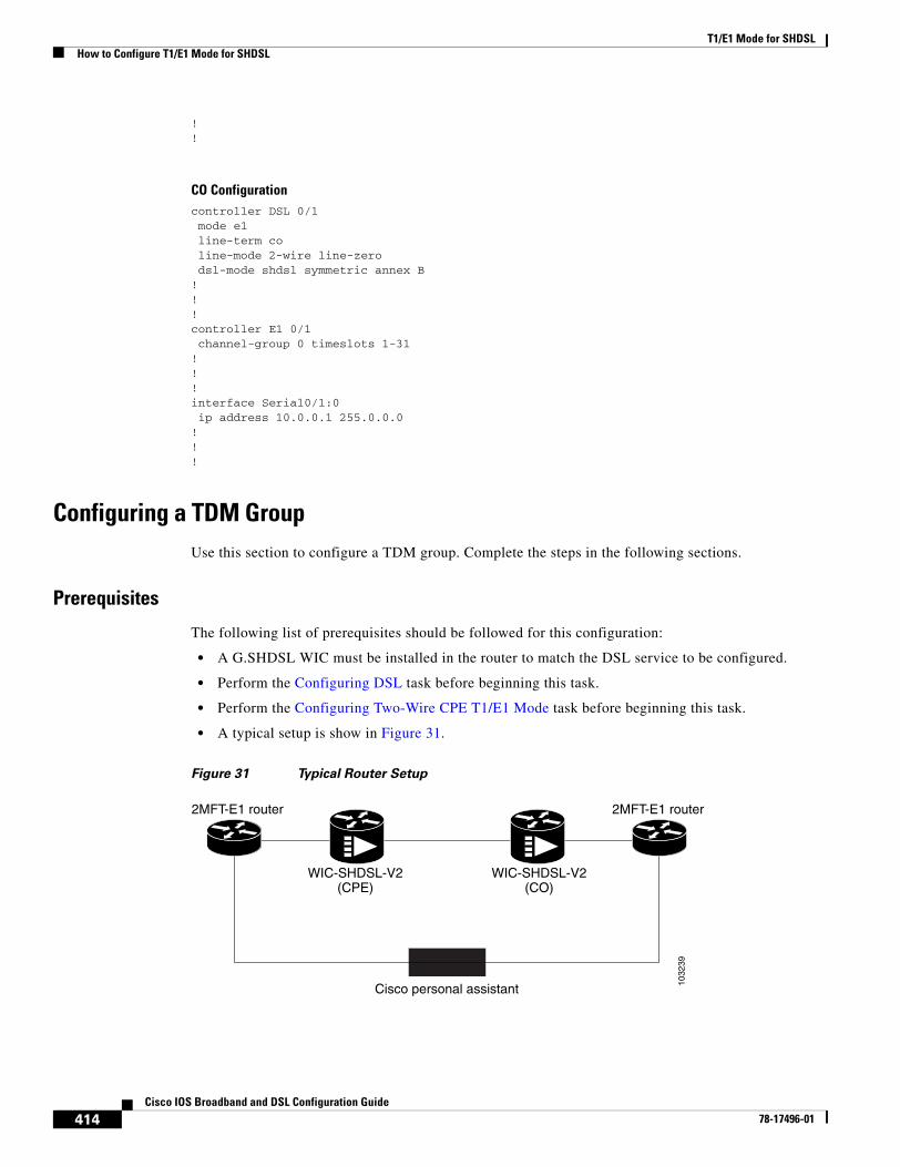
T1/E1 Mode for SHDSLHow to Configure T1/E1 Mode for SHDSL
414Cisco IOS Broadband and DSL Configuration Guide
78-17496-01
!!
CO Configurationcontroller DSL 0/1 mode e1 line-term co line-mode 2-wire line-zero dsl-mode shdsl symmetric annex B!!!controller E1 0/1 channel-group 0 timeslots 1-31!!!interface Serial0/1:0 ip address 10.0.0.1 255.0.0.0!!!
Configuring a TDM Group Use this section to configure a TDM group. Complete the steps in the following sections.
Prerequisites
The following list of prerequisites should be followed for this configuration:
• A G.SHDSL WIC must be installed in the router to match the DSL service to be configured.
• Perform the Configuring DSL task before beginning this task.
• Perform the Configuring Two-Wire CPE T1/E1 Mode task before beginning this task.
• A typical setup is show in Figure 31.
Figure 31 Typical Router Setup
1032
39
WIC-SHDSL-V2(CPE)
WIC-SHDSL-V2(CO)
2MFT-E1 router 2MFT-E1 router
Cisco personal assistant
T1/E1 Mode for SHDSLHow to Configure T1/E1 Mode for SHDSL
415Cisco IOS Broadband and DSL Configuration Guide
78-17496-01
SUMMARY STEPS
1. tdm-group tdm-group-no timeslots timeslot-list
2. end
DETAILED STEPS
Example
CPE Configurationcontroller E1 1/0 tdm-group 0 timeslots 1-15!!controller DSL 1/2 mode e1 line-term cpe line-mode 2-wire line-zero dsl-mode shdsl symmetric annex B!controller E1 1/2 tdm-group 0 timeslots 1-15!!!connect hp E1 1/0 0 E1 1/2 0!!
CO Configurationcontroller E1 1/0 tdm-group 0 timeslots 1-15!controller E1 1/1!controller DSL 1/2 mode e1 line-term co
Command or Action Purpose
Step 1 tdm-group tdm-group-no timeslots timeslot-list
Example:Router(config-controller)# tdm-group tdm-group-no timeslots timeslot-list
(Optional) Configures a list of timeslots for creating clear channel groups (pass-through) for Time Division Multiplexing (TDM) cross-connect.
• tdm-group-no—TDM group number. The valid range is 0 to 31.
• timeslots—enables timeslots to be configured.
• timeslot-list—Timeslots (DS0s) to include in this TDM group. The valid timeslots are: 1 to 24 for T1; 1 to 31 for E1.
Step 2 end
Example:Router# end
Exits configuration.
T1/E1 Mode for SHDSLHow to Configure T1/E1 Mode for SHDSL
416Cisco IOS Broadband and DSL Configuration Guide
78-17496-01
line-mode 2-wire line-zero dsl-mode shdsl symmetric annex B!controller E1 1/2 clock source internal tdm-group 0 timeslots 1-15!!!connect hp E1 1/0 0 E1 1/2 0!!!
Verifying Two-Wire CPE T1/E1 Configuration StatusUse the following commands to verify your configuration.
SUMMARY STEPS
1. enable
2. show running-config
3. show controllers dsl
4. exit
DETAILED STEPS
Command or Action Purpose
Step 1 enable
Example:Router> enable
Enables privileged EXEC mode.
• Enter your password if prompted.
Step 2 show running-config
Example:Router# show running-config
Displays the current running configuration and the status for all controllers.
Step 3 show controllers dsl
Example::Router# show controllers atm slot/port
Displays the status of the G.SHDSL modem.
Step 4 exit
Router# exit
Exits privileged EXEC mode.
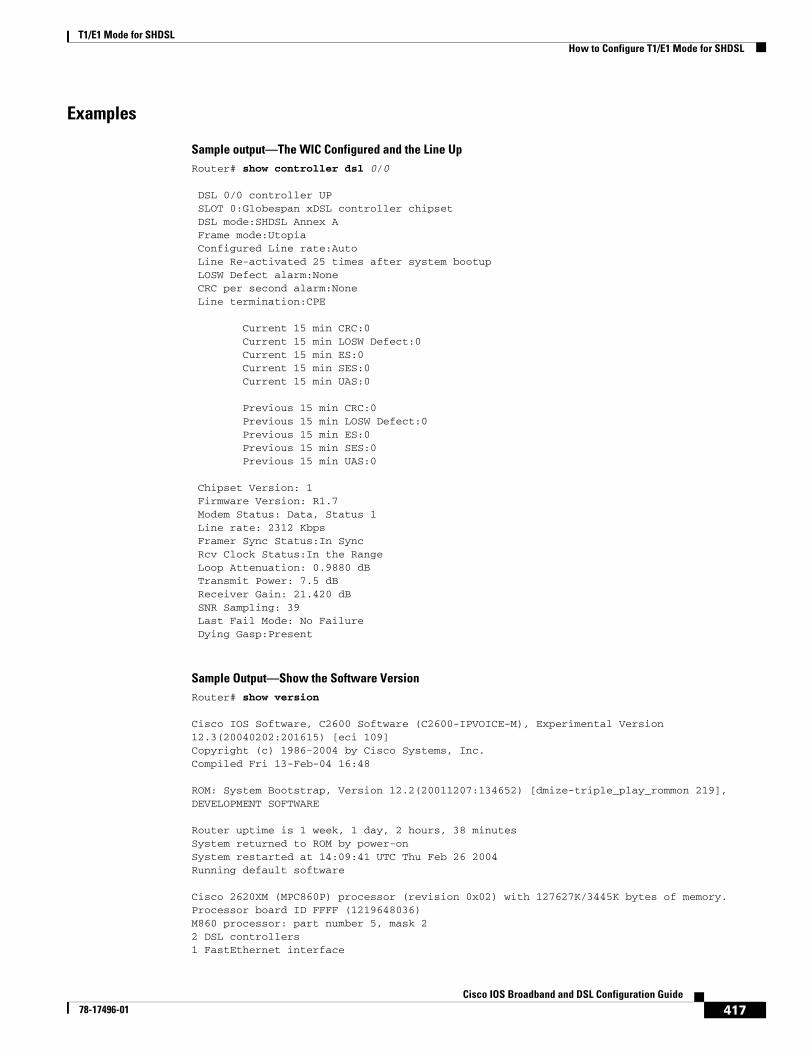
T1/E1 Mode for SHDSLHow to Configure T1/E1 Mode for SHDSL
417Cisco IOS Broadband and DSL Configuration Guide
78-17496-01
Examples
Sample output—The WIC Configured and the Line Up Router# show controller dsl 0/0
DSL 0/0 controller UP SLOT 0:Globespan xDSL controller chipset DSL mode:SHDSL Annex A Frame mode:Utopia Configured Line rate:Auto Line Re-activated 25 times after system bootup LOSW Defect alarm:None CRC per second alarm:None Line termination:CPE
Current 15 min CRC:0 Current 15 min LOSW Defect:0 Current 15 min ES:0 Current 15 min SES:0 Current 15 min UAS:0
Previous 15 min CRC:0 Previous 15 min LOSW Defect:0 Previous 15 min ES:0 Previous 15 min SES:0 Previous 15 min UAS:0 Chipset Version: 1 Firmware Version: R1.7 Modem Status: Data, Status 1 Line rate: 2312 Kbps Framer Sync Status:In Sync Rcv Clock Status:In the Range Loop Attenuation: 0.9880 dB Transmit Power: 7.5 dB Receiver Gain: 21.420 dB SNR Sampling: 39 Last Fail Mode: No Failure Dying Gasp:Present
Sample Output—Show the Software VersionRouter# show version
Cisco IOS Software, C2600 Software (C2600-IPVOICE-M), Experimental Version 12.3(20040202:201615) [eci 109]Copyright (c) 1986-2004 by Cisco Systems, Inc.Compiled Fri 13-Feb-04 16:48
ROM: System Bootstrap, Version 12.2(20011207:134652) [dmize-triple_play_rommon 219], DEVELOPMENT SOFTWARE
Router uptime is 1 week, 1 day, 2 hours, 38 minutesSystem returned to ROM by power-onSystem restarted at 14:09:41 UTC Thu Feb 26 2004Running default software
Cisco 2620XM (MPC860P) processor (revision 0x02) with 127627K/3445K bytes of memory.Processor board ID FFFF (1219648036)M860 processor: part number 5, mask 22 DSL controllers1 FastEthernet interface
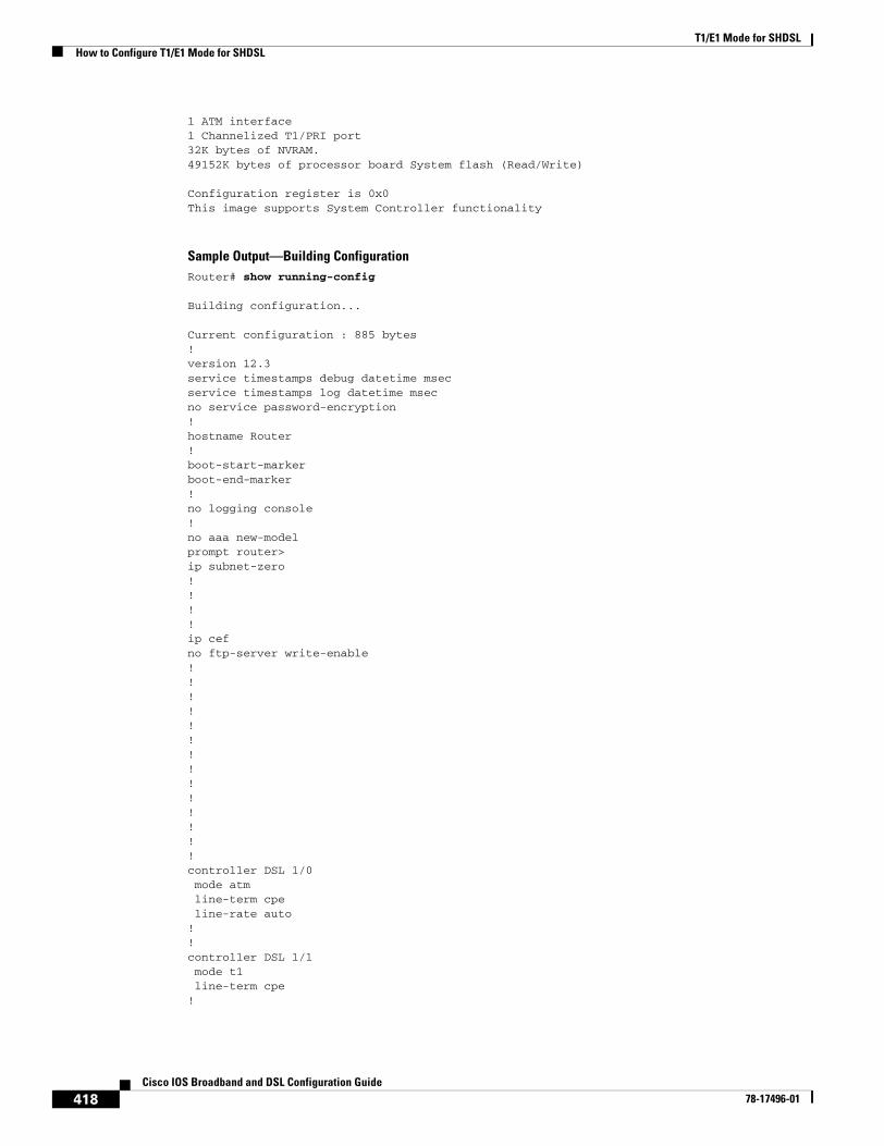
T1/E1 Mode for SHDSLHow to Configure T1/E1 Mode for SHDSL
418Cisco IOS Broadband and DSL Configuration Guide
78-17496-01
1 ATM interface1 Channelized T1/PRI port32K bytes of NVRAM.49152K bytes of processor board System flash (Read/Write) Configuration register is 0x0This image supports System Controller functionality
Sample Output—Building ConfigurationRouter# show running-config
Building configuration...
Current configuration : 885 bytes!version 12.3service timestamps debug datetime msecservice timestamps log datetime msecno service password-encryption!hostname Router!boot-start-markerboot-end-marker!no logging console!no aaa new-modelprompt router>ip subnet-zero!!!!ip cefno ftp-server write-enable!!!!!!!!!!!!!!controller DSL 1/0 mode atm line-term cpe line-rate auto!!controller DSL 1/1mode t1line-term cpe
!
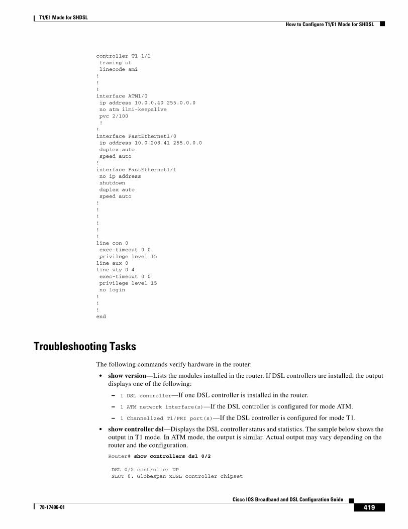
T1/E1 Mode for SHDSLHow to Configure T1/E1 Mode for SHDSL
419Cisco IOS Broadband and DSL Configuration Guide
78-17496-01
controller T1 1/1framing sflinecode ami
!!!interface ATM1/0 ip address 10.0.0.40 255.0.0.0 no atm ilmi-keepalive pvc 2/100 !!interface FastEthernet1/0 ip address 10.0.208.41 255.0.0.0 duplex auto speed auto! interface FastEthernet1/1 no ip address shutdown duplex auto speed auto!!!!!!line con 0 exec-timeout 0 0 privilege level 15line aux 0line vty 0 4 exec-timeout 0 0 privilege level 15 no login!!!end
Troubleshooting Tasks The following commands verify hardware in the router:
• show version—Lists the modules installed in the router. If DSL controllers are installed, the output displays one of the following:
– 1 DSL controller—If one DSL controller is installed in the router.
– 1 ATM network interface(s)—If the DSL controller is configured for mode ATM.
– 1 Channelized T1/PRI port(s)—If the DSL controller is configured for mode T1.
• show controller dsl—Displays the DSL controller status and statistics. The sample below shows the output in T1 mode. In ATM mode, the output is similar. Actual output may vary depending on the router and the configuration.
Router# show controllers dsl 0/2
DSL 0/2 controller UP SLOT 0: Globespan xDSL controller chipset
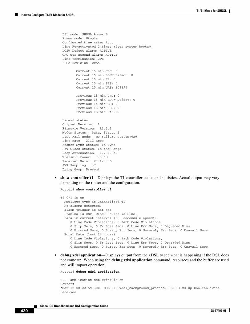
T1/E1 Mode for SHDSLHow to Configure T1/E1 Mode for SHDSL
420Cisco IOS Broadband and DSL Configuration Guide
78-17496-01
DSL mode: SHDSL Annex B Frame mode: Utopia Configured Line rate: Auto Line Re-activated 2 times after system bootup LOSW Defect alarm: ACTIVE CRC per second alarm: ACTIVE Line termination: CPE FPGA Revision: 0xA5
Current 15 min CRC: 0 Current 15 min LOSW Defect: 0 Current 15 min ES: 0 Current 15 min SES: 0 Current 15 min UAS: 203895
Previous 15 min CRC: 0 Previous 15 min LOSW Defect: 0 Previous 15 min ES: 0 Previous 15 min SES: 0 Previous 15 min UAS: 0 Line-0 status Chipset Version: 1 Firmware Version: R2.3.1 Modem Status: Data, Status 1 Last Fail Mode: No Failure status:0x0 Line rate: 2312 Kbps Framer Sync Status: In Sync Rcv Clock Status: In the Range Loop Attenuation: 0.7860 dB Transmit Power: 9.5 dB Receiver Gain: 21.420 dB SNR Sampling: 37 Dying Gasp: Present
• show controller t1—Displays the T1 controller status and statistics. Actual output may vary depending on the router and the configuration.
Router# show controller t1
T1 0/1 is up. Applique type is Channelized T1 No alarms detected. alarm-trigger is not set Framing is ESF, Clock Source is Line. Data in current interval (680 seconds elapsed): 0 Line Code Violations, 0 Path Code Violations 0 Slip Secs, 0 Fr Loss Secs, 0 Line Err Secs, 0 Degraded Mins 0 Errored Secs, 0 Bursty Err Secs, 0 Severely Err Secs, 0 Unavail Secs Total Data (last 24 hours) 0 Line Code Violations, 0 Path Code Violations, 0 Slip Secs, 0 Fr Loss Secs, 0 Line Err Secs, 0 Degraded Mins, 0 Errored Secs, 0 Bursty Err Secs, 0 Severely Err Secs, 0 Unavail Secs
• debug xdsl application—Displays output from the xDSL to see what is happening if the DSL does not come up. When using the debug xdsl application command, resources and the buffer are used and will impact operation.
Router# debug xdsl application
xDSL application debugging is onRouter#*Mar 12 08:22:59.300: DSL 0/2 xdsl_background_process: XDSL link up boolean event received
T1/E1 Mode for SHDSLHow to Configure T1/E1 Mode for SHDSL
421Cisco IOS Broadband and DSL Configuration Guide
78-17496-01
*Mar 12 08:22:59.300: DSL 0/2 controller Link up! line rate: 2304 Kbps
*Mar 12 08:22:59.300: DSL 0/2 xdsl_controller_reset: cdb-state=up*Mar 12 08:22:59.300: %CONTROLLER-5-UPDOWN: Controller DSL 0/2, changed state to up*Mar 12 08:22:59.300: Dslsar data rate 2304*Mar 12 08:22:59.300: DSL 0/2 TipRing 1, Xmit_Power Val 95, xmit_power 9.5*Mar 12 08:22:59.300: DSL 0/2 Mode 2, BW 2304, power_base_value 145, power_backoff 5*Mar 12 08:23:04.956: DSL 0/2 xdsl_background_process: EOC boolean event received*Mar 12 08:23:05.816: DSL 0/2 SNR Sampling: 43 dB*Mar 12 08:23:06.816: DSL 0/2 SNR Sampling: 42 dB*Mar 12 08:23:07.816: DSL 0/2 SNR Sampling: 41 dB*Mar 12 08:23:09.760: DSL 0/2 xdsl_background_process: EOC boolean event received*Mar 12 08:23:09.816: DSL 0/2 SNR Sampling: 40 dB*Mar 12 08:23:10.816: DSL 0/2 SNR Sampling: 40 dB
• debug xdsl driver—Displays what is happening when the drivers are downloaded and installed. The following example displays sample output from the debug xdsl driver command:
Router# debug xdsl driver
xDSL driver debugging is on*Mar 12 08:01:04.772: DSL 0/2 dsp interrupt-download next block for line-0*Mar 12 08:01:04.780: DSL 0/2 framer intr_status 0xC0 *Mar 12 08:01:05.072: DSL 0/2 dsp interrupt-download next block for line-0*Mar 12 08:01:05.080: DSL 0/2 framer intr_status 0xC0 *Mar 12 08:01:06.484: DSL 0/2 dsp interrupt-download next block for line-0*Mar 12 08:01:06.492: DSL 0/2 framer intr_status 0xC0 *Mar 12 08:01:08.092: DSL 0/2 dsp interrupt-download next block for line-0*Mar 12 08:01:08.096: DSL 0/2 framer intr_status 0xC0 *Mar 12 08:01:19.180: DSL 0/2 dsp interrupt-download next block for line-0*Mar 12 08:01:19.184: DSL 0/2 framer intr_status 0xC0 *Mar 12 08:01:19.480: DSL 0/2 dsp interrupt-download next block for line-0*Mar 12 08:01:19.484: DSL 0/2 framer intr_status 0xC0 *Mar 12 08:01:19.680: DSL 0/2 dsp interrupt-download next block for line-0*Mar 12 08:01:19.680: DSL 0/2 DSP interrupt disabled*Mar 12 08:01:19.680: DSL 0/2 Download completed for line-0*Mar 12 08:01:19.680: DSL 0/2 Framer interrupt enabled*Mar 12 08:01:19.680: DSL 0/2 framer intr_status 0xC0 *Mar 12 08:01:19.680: DSL 0/2 controller Link up! line rate: 2304 Kbps
*Mar 12 08:01:19.680: %CONTROLLER-5-UPDOWN: Controller DSL 0/2, changed state to up*Mar 12 08:01:19.680: Dslsar data rate 2304*Mar 12 08:01:22.528: %LINK-3-UPDOWN: Interface ATM0/2, changed state to up*Mar 12 08:01:23.528: %LINEPROTO-5-UPDOWN: Line protocol on Interface ATM0/2, changed state to up*Mar 12 08:01:23.812: DSL 0/2 framer intr_status 0xC4 *Mar 12 08:01:23.816: DSL 0/2 framer intr_status 0xC4 *Mar 12 08:01:23.904: DSL 0/2 framer intr_status 0xC1 *Mar 12 08:01:28.612: DSL 0/2 framer intr_status 0xC4 *Mar 12 08:01:28.616: DSL 0/2 framer intr_status 0xC4 *Mar 12 08:01:28.708: DSL 0/2 framer intr_status 0xC1 *Mar 12 08:01:28.804: DSL 0/2 framer intr_status 0xC1 *Mar 12 08:01:33.412: DSL 0/2 framer intr_status 0xC4 *Mar 12 08:01:33.420: DSL 0/2 framer intr_status 0xC4 *Mar 12 08:01:33.508: DSL 0/2 framer intr_status 0xC1 *Mar 12 08:01:33.604: DSL 0/2 framer intr_status 0xC1 *Mar 12 08:01:33.700: DSL 0/2 framer intr_status 0xC1 *Mar 12 08:01:38.212: DSL 0/2 framer intr_status 0xC4 *Mar 12 08:01:38.220: DSL 0/2 framer intr_status 0xC4 *Mar 12 08:01:38.308: DSL 0/2 framer intr_status 0xC1
• debug xdsl eoc—Displays what is in the embedded operations channel (EOC) messages. The following example displays sample output from the debug xdsl eoc command.
T1/E1 Mode for SHDSLHow to Configure T1/E1 Mode for SHDSL
422Cisco IOS Broadband and DSL Configuration Guide
78-17496-01
Router# debug xdsl eoc
xDSL EOC debugging is onRouter#*Mar 12 08:19:08.564: DSL 0/2 controller Link up! line rate: 2304 Kbps
*Mar 12 08:19:08.564: %CONTROLLER-5-UPDOWN: Controller DSL 0/2, changed state to up*Mar 12 08:19:08.564: Dslsar data rate 2304*Mar 12 08:19:12.528: %LINK-3-UPDOWN: Interface ATM0/2, changed state to up*Mar 12 08:19:13.528: %LINEPROTO-5-UPDOWN: Line protocol on Interface ATM0/2, changed state to up*Mar 12 08:19:14.500: DSL 0/2: line 0 EOC Rcv Intr :: 0xC4*Mar 12 08:19:14.500: DSL 0/2:Current length 40 GTI_OK*Mar 12 08:19:14.500: DSL 0/2: GT_FAIL *Mar 12 08:19:14.500: Rx EOC remove transparency:: 12 1 0 39 EF*Mar 12 08:19:14.500: data_transparency_remove: Done, eoc packet size = 5
*Mar 12 08:19:14.500: Good eoc packet received*Mar 12 08:19:14.500: incoming request eocmsgid: 1*Mar 12 08:19:14.500: Tx Converted EOC message:: 21 81 1 43 43 49 53 43 4F 0 0 0 2 1 0 E9 61*Mar 12 08:19:14.500: data_transparency_add: eoc packet size - before 17, after 17
*Mar 12 08:19:14.504: DSL 0/2: line 0 EOC Rcv Intr :: 0xC4*Mar 12 08:19:14.504: DSL 0/2: Current length 40 GTI_EOM*Mar 12 08:19:14.504: DSL 0/2: GT_FAIL *Mar 12 08:19:14.600: DSL 0/2: line 0 EOC TX Complete Intr :: 0xC1*Mar 12 08:19:19.300: DSL 0/2: line 0 EOC Rcv Intr :: 0xC4*Mar 12 08:19:19.300: DSL 0/2:Current length 40 GTI_OK*Mar 12 08:19:19.300: DSL 0/2: GT_FAIL *Mar 12 08:19:19.300: Rx EOC remove transparency:: 12 2 74 8A*Mar 12 08:19:19.300: data_transparency_remove: Done, eoc packet size = 4
*Mar 12 08:19:19.300: Good eoc packet received*Mar 12 08:19:19.300: incoming request eocmsgid: 2*Mar 12 08:19:19.300: Tx Converted EOC message:: 21 82 1 0 0 0 0 0 52 32 2E 33 2E 31 43 4E 53 38 44 44 30 41 41 41 43 43 49 53 43 4F 0 0 0 43 53 43 4F 2D 31 53 48 44 53 4C 0 46 48 48 30 37 31 39 30 31 4C 51 0 31 32 2E 33 28 32 30 30 33 30 36 0 A8 F3*Mar 12 08:19:19.300: data_transparency_add: eoc packet size - before 71, after 71
*Mar 12 08:19:19.308: DSL 0/2: line 0 EOC Rcv Intr :: 0xC4*Mar 12 08:19:19.308: DSL 0/2: Current length 40 GTI_EOM*Mar 12 08:19:19.308: DSL 0/2: GT_FAIL *Mar 12 08:19:19.400: DSL 0/2: line 0 EOC TX Complete Intr :: 0xC1*Mar 12 08:19:19.496: DSL 0/2: line 0 EOC TX Complete Intr :: 0xC1*Mar 12 08:19:24.100: DSL 0/2: line 0 EOC Rcv Intr :: 0xC4*Mar 12 08:19:24.100: DSL 0/2:Current length 40 GTI_OK*Mar 12 08:19:24.100: DSL 0/2: GT_FAIL *Mar 12 08:19:24.100: Rx EOC remove transparency:: 12 B B5 17*Mar 12 08:19:24.100: data_transparency_remove: Done, eoc packet size = 4
*Mar 12 08:19:24.100: Good eoc packet received*Mar 12 08:19:24.100: incoming request eocmsgid: 11*Mar 12 08:19:24.100: Tx Converted EOC message:: 21 8B 10 0 1 C5 DD*Mar 12 08:19:24.100: data_transparency_add: eoc packet size - before 7, after 7

T1/E1 Mode for SHDSLHow to Configure T1/E1 Mode for SHDSL
423Cisco IOS Broadband and DSL Configuration Guide
78-17496-01
*Mar 12 08:19:24.104: Tx Converted EOC message:: 21 8C 0 10 0 0 0 0 0 0 C 85 1 B0 4A*Mar 12 08:19:24.104: data_transparency_add: eoc packet size - before 15, after 15
*Mar 12 08:19:24.104: size of eoc status response :: 13*Mar 12 08:19:24.104: Tx Converted EOC message:: 21 89 5 52 93*Mar 12 08:19:24.104: data_transparency_add: eoc packet size - before 5, after 5
*Mar 12 08:19:24.104: size of eoc status response :: 3GSI Tx buffer yet to transmit
*Mar 12 08:19:24.108: DSL 0/2: line 0 EOC Rcv Intr :: 0xC4*Mar 12 08:19:24.108: DSL 0/2: Current length 40 GTI_EOM*Mar 12 08:19:24.108: DSL 0/2: GT_FAIL *Mar 12 08:19:24.204: DSL 0/2: line 0 EOC TX Complete Intr :: 0xC1*Mar 12 08:19:24.300: DSL 0/2: line 0 EOC TX Complete Intr :: 0xC1*Mar 12 08:19:24.396: DSL 0/2: line 0 EOC TX Complete Intr :: 0xC1*Mar 12 08:19:28.904: DSL 0/2: line 0 EOC Rcv Intr :: 0xC4*Mar 12 08:19:28.904: DSL 0/2:Current length 40 GTI_OK*Mar 12 08:19:28.904: DSL 0/2: GT_FAIL *Mar 12 08:19:28.904: Rx EOC remove transparency:: 12 11 6E A8*Mar 12 08:19:28.904: data_transparency_remove: Done, eoc packet size = 4
*Mar 12 08:19:28.904: Good eoc packet received*Mar 12 08:19:28.904: incoming request eocmsgid: 17*Mar 12 08:19:28.904: Tx Converted EOC message:: 21 91 0 0 0 D6 56*Mar 12 08:19:28.904: data_transparency_add: eoc packet size - before 7, after 7
*Mar 12 08:19:28.904: size of eoc status response :: 5*Mar 12 08:19:28.908: DSL 0/2: line 0 EOC Rcv Intr :: 0xC4*Mar 12 08:19:28.908: DSL 0/2: Current length 40 GTI_EOM*Mar 12 08:19:28.908: DSL 0/2: GT_FAIL *Mar 12 08:19:29.004: DSL 0/2: line 0 EOC TX Complete Intr :: 0xC1*Mar 12 08:19:33.704: DSL 0/2: line 0 EOC Rcv Intr :: 0xC4*Mar 12 08:19:33.704: DSL 0/2:Current length 40 GTI_OK*Mar 12 08:19:33.704: DSL 0/2: GT_FAIL *Mar 12 08:19:33.704: Rx EOC remove transparency:: 12 B B5 17*Mar 12 08:19:33.704: data_transparency_remove: Done, eoc packet size = 4
*Mar 12 08:19:33.704: Good eoc packet received*Mar 12 08:19:33.704: incoming request eocmsgid: 11*Mar 12 08:19:33.704: Tx Converted EOC message:: 21 8B E 0 1 4B 48*Mar 12 08:19:33.704: data_transparency_add: eoc packet size - before 7, after 7
*Mar 12 08:19:33.704: Tx Converted EOC message:: 21 8C 0 E 0 0 0 0 0 0 9 5 1 68 AC*Mar 12 08:19:33.704: data_transparency_add: eoc packet size - before 15, after 15
The following example displays a sample output using the undebug form of this command to turn off the monitoring:
Router# undebug xdsl eocxDSL EOC debugging is off
• debug xdsl error—Displays error messages. The following example shows use of the debug xdsl error command, sample output, and use of the command to stop the display.
Router# debug xdsl error xDSL error debugging is onRouter#
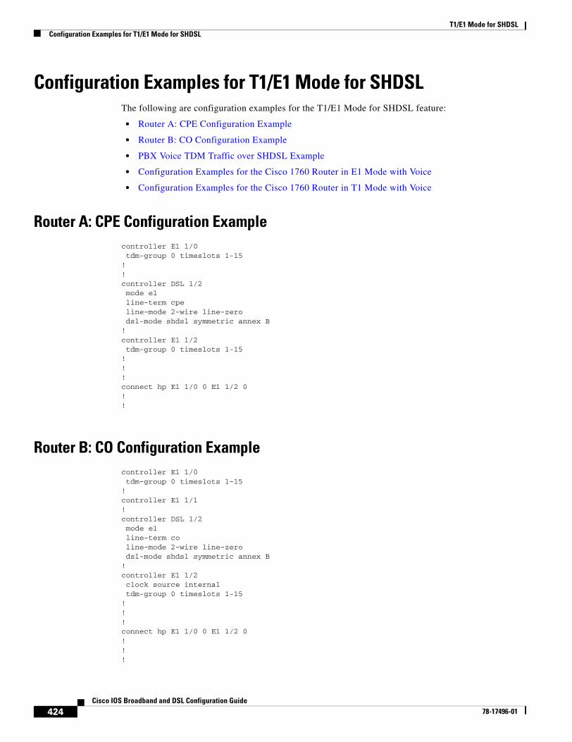
T1/E1 Mode for SHDSLConfiguration Examples for T1/E1 Mode for SHDSL
424Cisco IOS Broadband and DSL Configuration Guide
78-17496-01
Configuration Examples for T1/E1 Mode for SHDSLThe following are configuration examples for the T1/E1 Mode for SHDSL feature:
• Router A: CPE Configuration Example
• Router B: CO Configuration Example
• PBX Voice TDM Traffic over SHDSL Example
• Configuration Examples for the Cisco 1760 Router in E1 Mode with Voice
• Configuration Examples for the Cisco 1760 Router in T1 Mode with Voice
Router A: CPE Configuration Examplecontroller E1 1/0 tdm-group 0 timeslots 1-15!!controller DSL 1/2 mode e1 line-term cpe line-mode 2-wire line-zero dsl-mode shdsl symmetric annex B!controller E1 1/2 tdm-group 0 timeslots 1-15!!!connect hp E1 1/0 0 E1 1/2 0!!
Router B: CO Configuration Examplecontroller E1 1/0 tdm-group 0 timeslots 1-15!controller E1 1/1!controller DSL 1/2 mode e1 line-term co line-mode 2-wire line-zero dsl-mode shdsl symmetric annex B!controller E1 1/2 clock source internal tdm-group 0 timeslots 1-15!!!connect hp E1 1/0 0 E1 1/2 0!!!
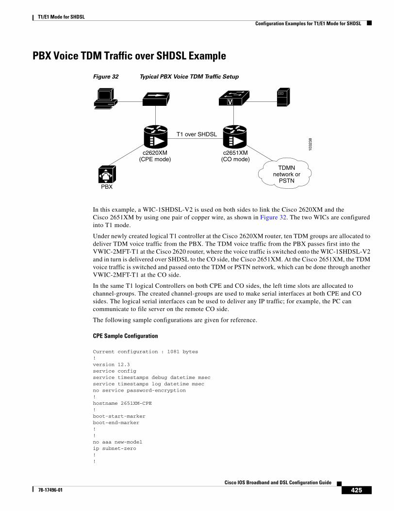
T1/E1 Mode for SHDSLConfiguration Examples for T1/E1 Mode for SHDSL
425Cisco IOS Broadband and DSL Configuration Guide
78-17496-01
PBX Voice TDM Traffic over SHDSL Example
Figure 32 Typical PBX Voice TDM Traffic Setup
In this example, a WIC-1SHDSL-V2 is used on both sides to link the Cisco 2620XM and the Cisco 2651XM by using one pair of copper wire, as shown in Figure 32. The two WICs are configured into T1 mode.
Under newly created logical T1 controller at the Cisco 2620XM router, ten TDM groups are allocated to deliver TDM voice traffic from the PBX. The TDM voice traffic from the PBX passes first into the VWIC-2MFT-T1 at the Cisco 2620 router, where the voice traffic is switched onto the WIC-1SHDSL-V2 and in turn is delivered over SHDSL to the CO side, the Cisco 2651XM. At the Cisco 2651XM, the TDM voice traffic is switched and passed onto the TDM or PSTN network, which can be done through another VWIC-2MFT-T1 at the CO side.
In the same T1 logical Controllers on both CPE and CO sides, the left time slots are allocated to channel-groups. The created channel-groups are used to make serial interfaces at both CPE and CO sides. The logical serial interfaces can be used to deliver any IP traffic; for example, the PC can communicate to file server on the remote CO side.
The following sample configurations are given for reference.
CPE Sample Configuration
Current configuration : 1081 bytes!version 12.3service configservice timestamps debug datetime msecservice timestamps log datetime msecno service password-encryption!hostname 2651XM-CPE!boot-start-markerboot-end-marker!!no aaa new-modelip subnet-zero!!
1032
38
T1 over SHDSL
c2620XM(CPE mode)
PBX
c2651XM(CO mode)
TDMNnetwork or
PSTN
V
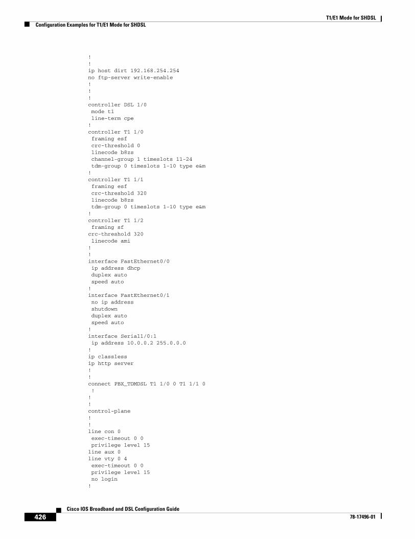
T1/E1 Mode for SHDSLConfiguration Examples for T1/E1 Mode for SHDSL
426Cisco IOS Broadband and DSL Configuration Guide
78-17496-01
!!ip host dirt 192.168.254.254no ftp-server write-enable!!!controller DSL 1/0 mode t1 line-term cpe!controller T1 1/0 framing esf crc-threshold 0 linecode b8zs channel-group 1 timeslots 11-24 tdm-group 0 timeslots 1-10 type e&m!controller T1 1/1 framing esf crc-threshold 320 linecode b8zs tdm-group 0 timeslots 1-10 type e&m!controller T1 1/2 framing sfcrc-threshold 320 linecode ami!!interface FastEthernet0/0 ip address dhcp duplex auto speed auto!interface FastEthernet0/1 no ip address shutdown duplex auto speed auto!interface Serial1/0:1 ip address 10.0.0.2 255.0.0.0!ip classlessip http server!!connect PBX_TDMDSL T1 1/0 0 T1 1/1 0 !!!control-plane!!line con 0 exec-timeout 0 0 privilege level 15line aux 0line vty 0 4 exec-timeout 0 0 privilege level 15 no login!
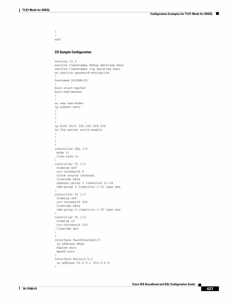
T1/E1 Mode for SHDSLConfiguration Examples for T1/E1 Mode for SHDSL
427Cisco IOS Broadband and DSL Configuration Guide
78-17496-01
!!end
CO Sample Configuration
version 12.3service timestamps debug datetime msecservice timestamps log datetime msecno service password-encryption!hostname 2620XM-CO!boot-start-markerboot-end-marker!!no aaa new-modelip subnet-zero!!!!ip host dirt 192.168.254.254no ftp-server write-enable!!!!controller DSL 1/0 mode t1 line-term co!controller T1 1/0 framing esf crc-threshold 0 clock source internal linecode b8zs channel-group 1 timeslots 11-24 tdm-group 0 timeslots 1-10 type e&m!controller T1 1/1 framing esf crc-threshold 320 linecode b8zs tdm-group 0 timeslots 1-10 type e&m!controller T1 1/2 framing sf crc-threshold 320 linecode ami!!interface FastEthernet0/0 ip address dhcp duplex auto speed auto!interface Serial1/0:1 ip address 10.0.0.1 255.0.0.0!
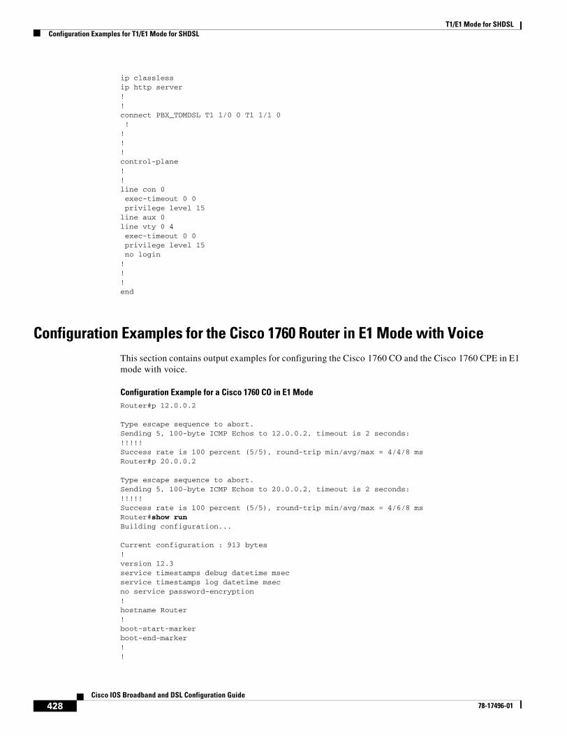
T1/E1 Mode for SHDSLConfiguration Examples for T1/E1 Mode for SHDSL
428Cisco IOS Broadband and DSL Configuration Guide
78-17496-01
ip classlessip http server!!connect PBX_TDMDSL T1 1/0 0 T1 1/1 0 !!!!control-plane!!line con 0 exec-timeout 0 0 privilege level 15line aux 0line vty 0 4 exec-timeout 0 0 privilege level 15 no login!!!end
Configuration Examples for the Cisco 1760 Router in E1 Mode with VoiceThis section contains output examples for configuring the Cisco 1760 CO and the Cisco 1760 CPE in E1 mode with voice.
Configuration Example for a Cisco 1760 CO in E1 ModeRouter#p 12.0.0.2
Type escape sequence to abort.Sending 5, 100-byte ICMP Echos to 12.0.0.2, timeout is 2 seconds:!!!!!Success rate is 100 percent (5/5), round-trip min/avg/max = 4/4/8 msRouter#p 20.0.0.2
Type escape sequence to abort.Sending 5, 100-byte ICMP Echos to 20.0.0.2, timeout is 2 seconds:!!!!!Success rate is 100 percent (5/5), round-trip min/avg/max = 4/6/8 msRouter#show runBuilding configuration...
Current configuration : 913 bytes!version 12.3service timestamps debug datetime msecservice timestamps log datetime msecno service password-encryption!hostname Router!boot-start-markerboot-end-marker!!
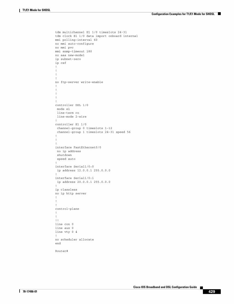
T1/E1 Mode for SHDSLConfiguration Examples for T1/E1 Mode for SHDSL
429Cisco IOS Broadband and DSL Configuration Guide
78-17496-01
tdm multichannel E1 1/0 timeslots 24-31tdm clock E1 1/0 data import onboard internalmmi polling-interval 60no mmi auto-configureno mmi pvcmmi snmp-timeout 180no aaa new-modelip subnet-zeroip cef! !!!no ftp-server write-enable!!!!!controller DSL 1/0 mode e1 line-term co line-mode 2-wire ! controller E1 1/0 channel-group 0 timeslots 1-12 channel-group 1 timeslots 24-31 speed 56!!!interface FastEthernet0/0 no ip address shutdown speed auto!interface Serial1/0:0 ip address 12.0.0.1 255.0.0.0!interface Serial1/0:1 ip address 20.0.0.1 255.0.0.0!ip classlessno ip http server!!!control-plane!!!!line con 0line aux 0line vty 0 4!no scheduler allocateend
Router#

T1/E1 Mode for SHDSLConfiguration Examples for T1/E1 Mode for SHDSL
430Cisco IOS Broadband and DSL Configuration Guide
78-17496-01
Router#show controller e1 1/0 E1 1/0 is up. Applique type is Channelized E1 - balanced Receiver has remote alarm. alarm-trigger is not set Framing is CRC4, Clock Source is Internal. Data in current interval (201 seconds elapsed): 0 Line Code Violations, 0 Path Code Violations 0 Slip Secs, 0 Fr Loss Secs, 0 Line Err Secs, 0 Degraded Mins 0 Errored Secs, 0 Bursty Err Secs, 0 Severely Err Secs, 0 Unavail Secs
Router#show controller dsl 1/0
DSL 1/0 controller UP Globespan xDSL controller chipset DSL mode: SHDSL Annex A Frame mode: E1 Slotted Line Re-activated 0 times after system bootup LOSW Defect alarm: ACTIVE CRC per second alarm: ACTIVE Line termination: CO FPGA Revision: 0xA9
Current 15 min CRC: 0 Current 15 min LOSW Defect: 0 Current 15 min ES: 0 Current 15 min SES: 0 Current 15 min UAS: 0
Previous 15 min CRC: 0 Previous 15 min LOSW Defect: 0 Previous 15 min ES: 0 Previous 15 min SES: 0 Previous 15 min UAS: 0
Line-0 status Chipset Version: 1 Firmware Version: A29733 Modem Status: Data, Status 1 Last Fail Mode: No Failure status:0x0 Line rate: 2056 Kbps Framer Sync Status: In Sync Rcv Clock Status: Out of Range Loop Attenuation: 0.9890 dB Transmit Power: 7.5 dB Receiver Gain: 19.5420 dB SNR Sampling: 39.1570 dB Dying Gasp: Present
Router#
Router#show versionCisco IOS Software, C1700 Software (C1700-IPVOICE-M), Experimental Version 12.3(20040114:170452) [gvsriks-crusher_pi5 101]Copyright (c) 1986-2004 by Cisco Systems, Inc.Compiled Thu 15-Jan-04 22:18 by gvsriks
ROM: System Bootstrap, Version 12.2(4r)XL, RELEASE SOFTWARE (fc1)
Router uptime is 34 minutes
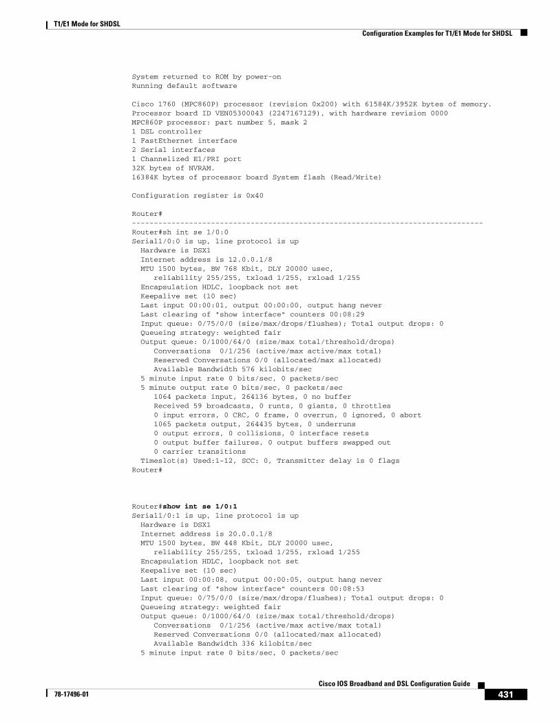
T1/E1 Mode for SHDSLConfiguration Examples for T1/E1 Mode for SHDSL
431Cisco IOS Broadband and DSL Configuration Guide
78-17496-01
System returned to ROM by power-onRunning default software
Cisco 1760 (MPC860P) processor (revision 0x200) with 61584K/3952K bytes of memory.Processor board ID VEN05300043 (2247167129), with hardware revision 0000MPC860P processor: part number 5, mask 21 DSL controller1 FastEthernet interface2 Serial interfaces1 Channelized E1/PRI port32K bytes of NVRAM.16384K bytes of processor board System flash (Read/Write)
Configuration register is 0x40 Router#--------------------------------------------------------------------------------Router#sh int se 1/0:0Serial1/0:0 is up, line protocol is up Hardware is DSX1 Internet address is 12.0.0.1/8 MTU 1500 bytes, BW 768 Kbit, DLY 20000 usec, reliability 255/255, txload 1/255, rxload 1/255 Encapsulation HDLC, loopback not set Keepalive set (10 sec) Last input 00:00:01, output 00:00:00, output hang never Last clearing of "show interface" counters 00:08:29 Input queue: 0/75/0/0 (size/max/drops/flushes); Total output drops: 0 Queueing strategy: weighted fair Output queue: 0/1000/64/0 (size/max total/threshold/drops) Conversations 0/1/256 (active/max active/max total) Reserved Conversations 0/0 (allocated/max allocated) Available Bandwidth 576 kilobits/sec 5 minute input rate 0 bits/sec, 0 packets/sec 5 minute output rate 0 bits/sec, 0 packets/sec 1064 packets input, 264136 bytes, 0 no buffer Received 59 broadcasts, 0 runts, 0 giants, 0 throttles 0 input errors, 0 CRC, 0 frame, 0 overrun, 0 ignored, 0 abort 1065 packets output, 264435 bytes, 0 underruns 0 output errors, 0 collisions, 0 interface resets 0 output buffer failures, 0 output buffers swapped out 0 carrier transitions Timeslot(s) Used:1-12, SCC: 0, Transmitter delay is 0 flagsRouter#
Router#show int se 1/0:1Serial1/0:1 is up, line protocol is up Hardware is DSX1 Internet address is 20.0.0.1/8 MTU 1500 bytes, BW 448 Kbit, DLY 20000 usec, reliability 255/255, txload 1/255, rxload 1/255 Encapsulation HDLC, loopback not set Keepalive set (10 sec) Last input 00:00:08, output 00:00:05, output hang never Last clearing of "show interface" counters 00:08:53 Input queue: 0/75/0/0 (size/max/drops/flushes); Total output drops: 0 Queueing strategy: weighted fair Output queue: 0/1000/64/0 (size/max total/threshold/drops) Conversations 0/1/256 (active/max active/max total) Reserved Conversations 0/0 (allocated/max allocated) Available Bandwidth 336 kilobits/sec 5 minute input rate 0 bits/sec, 0 packets/sec
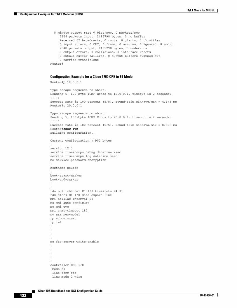
T1/E1 Mode for SHDSLConfiguration Examples for T1/E1 Mode for SHDSL
432Cisco IOS Broadband and DSL Configuration Guide
78-17496-01
5 minute output rate 0 bits/sec, 0 packets/sec 2648 packets input, 1485798 bytes, 0 no buffer Received 62 broadcasts, 0 runts, 0 giants, 0 throttles 0 input errors, 0 CRC, 0 frame, 0 overrun, 0 ignored, 0 abort 2648 packets output, 1485798 bytes, 0 underruns 0 output errors, 0 collisions, 0 interface resets 0 output buffer failures, 0 output buffers swapped out 0 carrier transitionsRouter#
Configuration Example for a Cisco 1760 CPE in E1 ModeRouter#p 12.0.0.1
Type escape sequence to abort.Sending 5, 100-byte ICMP Echos to 12.0.0.1, timeout is 2 seconds:!!!!!Success rate is 100 percent (5/5), round-trip min/avg/max = 4/5/8 msRouter#p 20.0.0.1
Type escape sequence to abort.Sending 5, 100-byte ICMP Echos to 20.0.0.1, timeout is 2 seconds:!!!!!Success rate is 100 percent (5/5), round-trip min/avg/max = 8/8/8 msRouter#show runBuilding configuration...
Current configuration : 902 bytes!version 12.3service timestamps debug datetime msecservice timestamps log datetime msecno service password-encryption!hostname Router!boot-start-markerboot-end-marker!!tdm multichannel E1 1/0 timeslots 24-31tdm clock E1 1/0 data export linemmi polling-interval 60no mmi auto-configureno mmi pvcmmi snmp-timeout 180no aaa new-modelip subnet-zeroip cef! !!!no ftp-server write-enable!!!!!controller DSL 1/0 mode e1 line-term cpe line-mode 2-wire
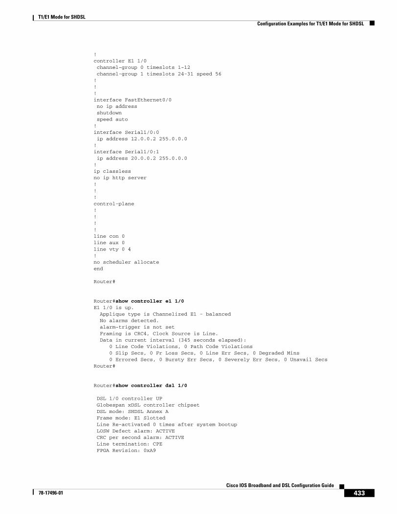
T1/E1 Mode for SHDSLConfiguration Examples for T1/E1 Mode for SHDSL
433Cisco IOS Broadband and DSL Configuration Guide
78-17496-01
! controller E1 1/0 channel-group 0 timeslots 1-12 channel-group 1 timeslots 24-31 speed 56!!!interface FastEthernet0/0 no ip address shutdown speed auto!interface Serial1/0:0 ip address 12.0.0.2 255.0.0.0!interface Serial1/0:1 ip address 20.0.0.2 255.0.0.0!ip classlessno ip http server!!!control-plane!!!!line con 0line aux 0line vty 0 4!no scheduler allocateend
Router#
Router#show controller e1 1/0E1 1/0 is up. Applique type is Channelized E1 - balanced No alarms detected. alarm-trigger is not set Framing is CRC4, Clock Source is Line. Data in current interval (345 seconds elapsed): 0 Line Code Violations, 0 Path Code Violations 0 Slip Secs, 0 Fr Loss Secs, 0 Line Err Secs, 0 Degraded Mins 0 Errored Secs, 0 Bursty Err Secs, 0 Severely Err Secs, 0 Unavail SecsRouter#
Router#show controller dsl 1/0
DSL 1/0 controller UP Globespan xDSL controller chipset DSL mode: SHDSL Annex A Frame mode: E1 Slotted Line Re-activated 0 times after system bootup LOSW Defect alarm: ACTIVE CRC per second alarm: ACTIVE Line termination: CPE FPGA Revision: 0xA9
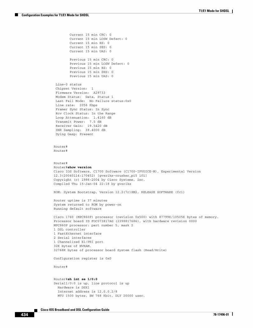
T1/E1 Mode for SHDSLConfiguration Examples for T1/E1 Mode for SHDSL
434Cisco IOS Broadband and DSL Configuration Guide
78-17496-01
Current 15 min CRC: 0 Current 15 min LOSW Defect: 0 Current 15 min ES: 0 Current 15 min SES: 0 Current 15 min UAS: 0
Previous 15 min CRC: 0 Previous 15 min LOSW Defect: 0 Previous 15 min ES: 0 Previous 15 min SES: 0 Previous 15 min UAS: 0
Line-0 status Chipset Version: 1 Firmware Version: A29733 Modem Status: Data, Status 1 Last Fail Mode: No Failure status:0x0 Line rate: 2056 Kbps Framer Sync Status: In Sync Rcv Clock Status: In the Range Loop Attenuation: 1.4160 dB Transmit Power: 7.5 dB Receiver Gain: 19.5420 dB SNR Sampling: 38.4000 dB Dying Gasp: Present
Router#Router#
Router#Router#show versionCisco IOS Software, C1700 Software (C1700-IPVOICE-M), Experimental Version 12.3(20040114:170452) [gvsriks-crusher_pi5 101]Copyright (c) 1986-2004 by Cisco Systems, Inc.Compiled Thu 15-Jan-04 22:18 by gvsriks
ROM: System Bootstrap, Version 12.2(7r)XM2, RELEASE SOFTWARE (fc1)
Router uptime is 37 minutesSystem returned to ROM by power-onRunning default software
Cisco 1760 (MPC860P) processor (revision 0x500) with 87799K/10505K bytes of memory.Processor board ID FOC073817AG (2398817686), with hardware revision 0000MPC860P processor: part number 5, mask 21 DSL controller1 FastEthernet interface2 Serial interfaces1 Channelized E1/PRI port32K bytes of NVRAM.32768K bytes of processor board System flash (Read/Write)
Configuration register is 0x0
Router#
Router#sh int se 1/0:0Serial1/0:0 is up, line protocol is up Hardware is DSX1 Internet address is 12.0.0.2/8 MTU 1500 bytes, BW 768 Kbit, DLY 20000 usec,
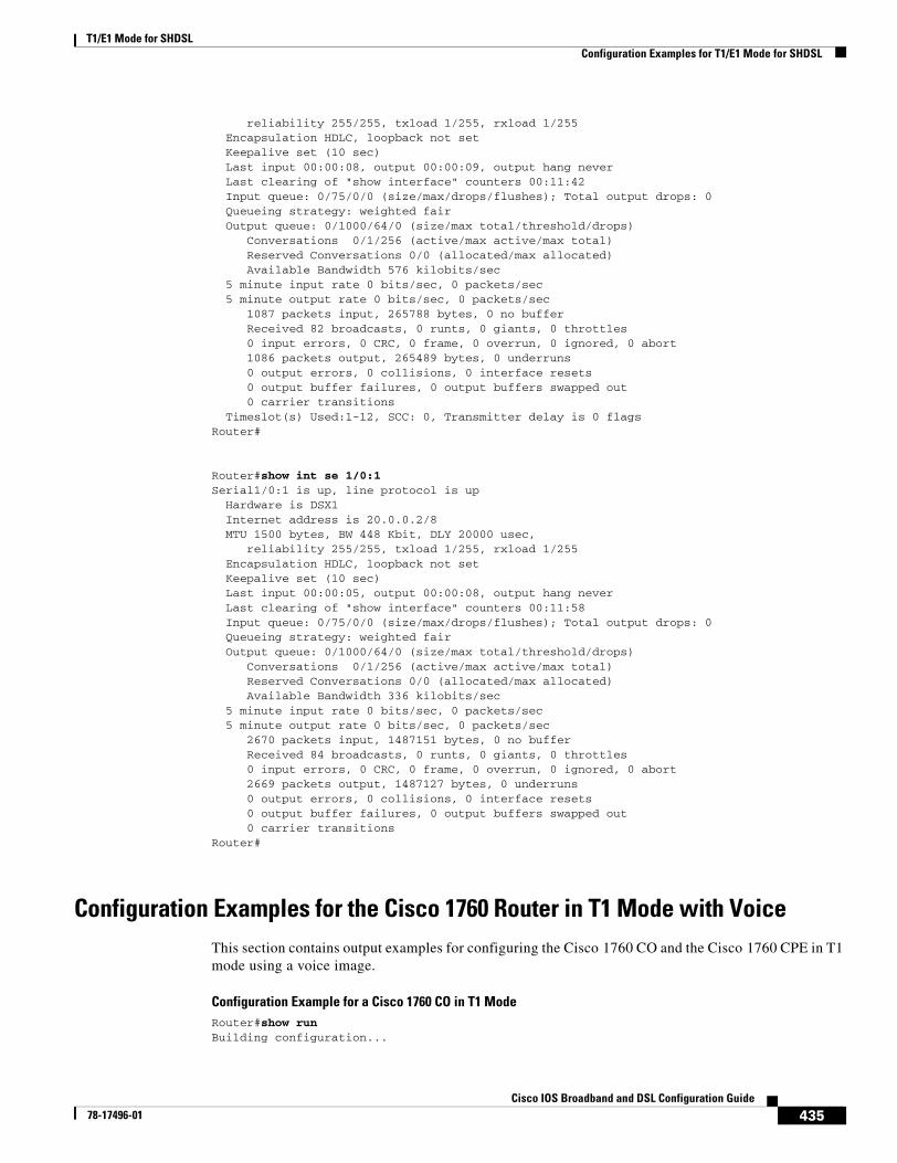
T1/E1 Mode for SHDSLConfiguration Examples for T1/E1 Mode for SHDSL
435Cisco IOS Broadband and DSL Configuration Guide
78-17496-01
reliability 255/255, txload 1/255, rxload 1/255 Encapsulation HDLC, loopback not set Keepalive set (10 sec) Last input 00:00:08, output 00:00:09, output hang never Last clearing of "show interface" counters 00:11:42 Input queue: 0/75/0/0 (size/max/drops/flushes); Total output drops: 0 Queueing strategy: weighted fair Output queue: 0/1000/64/0 (size/max total/threshold/drops) Conversations 0/1/256 (active/max active/max total) Reserved Conversations 0/0 (allocated/max allocated) Available Bandwidth 576 kilobits/sec 5 minute input rate 0 bits/sec, 0 packets/sec 5 minute output rate 0 bits/sec, 0 packets/sec 1087 packets input, 265788 bytes, 0 no buffer Received 82 broadcasts, 0 runts, 0 giants, 0 throttles 0 input errors, 0 CRC, 0 frame, 0 overrun, 0 ignored, 0 abort 1086 packets output, 265489 bytes, 0 underruns 0 output errors, 0 collisions, 0 interface resets 0 output buffer failures, 0 output buffers swapped out 0 carrier transitions Timeslot(s) Used:1-12, SCC: 0, Transmitter delay is 0 flagsRouter#
Router#show int se 1/0:1Serial1/0:1 is up, line protocol is up Hardware is DSX1 Internet address is 20.0.0.2/8 MTU 1500 bytes, BW 448 Kbit, DLY 20000 usec, reliability 255/255, txload 1/255, rxload 1/255 Encapsulation HDLC, loopback not set Keepalive set (10 sec) Last input 00:00:05, output 00:00:08, output hang never Last clearing of "show interface" counters 00:11:58 Input queue: 0/75/0/0 (size/max/drops/flushes); Total output drops: 0 Queueing strategy: weighted fair Output queue: 0/1000/64/0 (size/max total/threshold/drops) Conversations 0/1/256 (active/max active/max total) Reserved Conversations 0/0 (allocated/max allocated) Available Bandwidth 336 kilobits/sec 5 minute input rate 0 bits/sec, 0 packets/sec 5 minute output rate 0 bits/sec, 0 packets/sec 2670 packets input, 1487151 bytes, 0 no buffer Received 84 broadcasts, 0 runts, 0 giants, 0 throttles 0 input errors, 0 CRC, 0 frame, 0 overrun, 0 ignored, 0 abort 2669 packets output, 1487127 bytes, 0 underruns 0 output errors, 0 collisions, 0 interface resets 0 output buffer failures, 0 output buffers swapped out 0 carrier transitionsRouter#
Configuration Examples for the Cisco 1760 Router in T1 Mode with VoiceThis section contains output examples for configuring the Cisco 1760 CO and the Cisco 1760 CPE in T1 mode using a voice image.
Configuration Example for a Cisco 1760 CO in T1 ModeRouter#show runBuilding configuration...
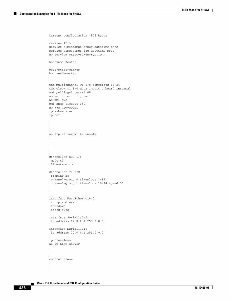
T1/E1 Mode for SHDSLConfiguration Examples for T1/E1 Mode for SHDSL
436Cisco IOS Broadband and DSL Configuration Guide
78-17496-01
Current configuration :906 bytes!version 12.3service timestamps debug datetime msecservice timestamps log datetime msecno service password-encryption!hostname Router!boot-start-markerboot-end-marker!!tdm multichannel T1 1/0 timeslots 16-24tdm clock T1 1/0 data import onboard internalmmi polling-interval 60no mmi auto-configureno mmi pvcmmi snmp-timeout 180no aaa new-modelip subnet-zeroip cef! !!!no ftp-server write-enable!!!!!controller DSL 1/0 mode t1 line-term co!controller T1 1/0 framing sf channel-group 0 timeslots 1-12 channel-group 1 timeslots 16-24 speed 56!!!interface FastEthernet0/0 no ip address shutdown speed auto!interface Serial1/0:0 ip address 12.0.0.1 255.0.0.0!interface Serial1/0:1 ip address 20.0.0.1 255.0.0.0!ip classlessno ip http server!!!control-plane!!!
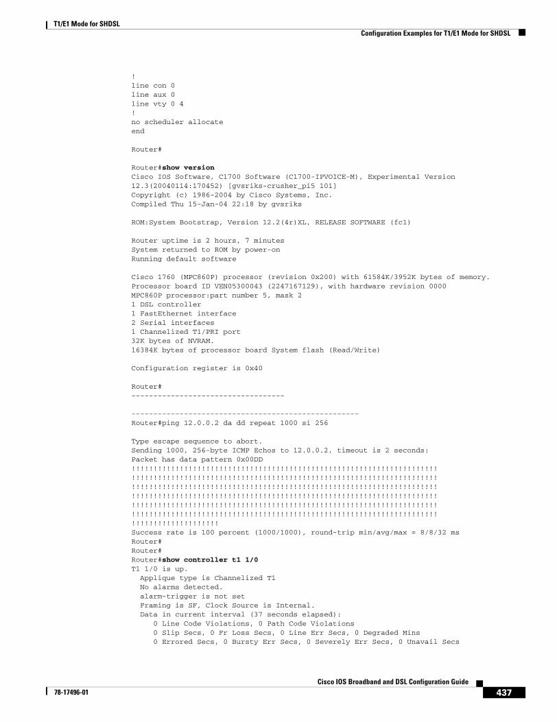
T1/E1 Mode for SHDSLConfiguration Examples for T1/E1 Mode for SHDSL
437Cisco IOS Broadband and DSL Configuration Guide
78-17496-01
!line con 0line aux 0line vty 0 4!no scheduler allocateend
Router#
Router#show versionCisco IOS Software, C1700 Software (C1700-IPVOICE-M), Experimental Version 12.3(20040114:170452) [gvsriks-crusher_pi5 101]Copyright (c) 1986-2004 by Cisco Systems, Inc.Compiled Thu 15-Jan-04 22:18 by gvsriks
ROM:System Bootstrap, Version 12.2(4r)XL, RELEASE SOFTWARE (fc1)
Router uptime is 2 hours, 7 minutesSystem returned to ROM by power-onRunning default software
Cisco 1760 (MPC860P) processor (revision 0x200) with 61584K/3952K bytes of memory.Processor board ID VEN05300043 (2247167129), with hardware revision 0000MPC860P processor:part number 5, mask 21 DSL controller1 FastEthernet interface2 Serial interfaces1 Channelized T1/PRI port32K bytes of NVRAM.16384K bytes of processor board System flash (Read/Write)
Configuration register is 0x40 Router#-----------------------------------
----------------------------------------------------Router#ping 12.0.0.2 da dd repeat 1000 si 256
Type escape sequence to abort.Sending 1000, 256-byte ICMP Echos to 12.0.0.2, timeout is 2 seconds:Packet has data pattern 0x00DD!!!!!!!!!!!!!!!!!!!!!!!!!!!!!!!!!!!!!!!!!!!!!!!!!!!!!!!!!!!!!!!!!!!!!!!!!!!!!!!!!!!!!!!!!!!!!!!!!!!!!!!!!!!!!!!!!!!!!!!!!!!!!!!!!!!!!!!!!!!!!!!!!!!!!!!!!!!!!!!!!!!!!!!!!!!!!!!!!!!!!!!!!!!!!!!!!!!!!!!!!!!!!!!!!!!!!!!!!!!!!!!!!!!!!!!!!!!!!!!!!!!!!!!!!!!!!!!!!!!!!!!!!!!!!!!!!!!!!!!!!!!!!!!!!!!!!!!!!!!!!!!!!!!!!!!!!!!!!!!!!!!!!!!!!!!!!!!!!!!!!!!!!!!!!!!!!!!!!!!!!!!!!!!!!!!!!!!!!!!!!!!!!!!!!!!!!!!!!!!!!!!!!!!!!!!!!!!!!!!!!!!!!!!!!!!!!!!!!!!!Success rate is 100 percent (1000/1000), round-trip min/avg/max = 8/8/32 msRouter#Router#Router#show controller t1 1/0T1 1/0 is up. Applique type is Channelized T1 No alarms detected. alarm-trigger is not set Framing is SF, Clock Source is Internal. Data in current interval (37 seconds elapsed): 0 Line Code Violations, 0 Path Code Violations 0 Slip Secs, 0 Fr Loss Secs, 0 Line Err Secs, 0 Degraded Mins 0 Errored Secs, 0 Bursty Err Secs, 0 Severely Err Secs, 0 Unavail Secs

T1/E1 Mode for SHDSLConfiguration Examples for T1/E1 Mode for SHDSL
438Cisco IOS Broadband and DSL Configuration Guide
78-17496-01
Router#show controller dsl 1/0
DSL 1/0 controller UP Globespan xDSL controller chipset DSL mode:SHDSL Annex A Frame mode:T1 Line Re-activated 0 times after system bootup LOSW Defect alarm:ACTIVE CRC per second alarm:ACTIVE Line termination:CO FPGA Revision:0xA9
Current 15 min CRC:0 Current 15 min LOSW Defect:0 Current 15 min ES:0 Current 15 min SES:0 Current 15 min UAS:0
Previous 15 min CRC:0 Previous 15 min LOSW Defect:0 Previous 15 min ES:0 Previous 15 min SES:0 Previous 15 min UAS:0
Line-0 status Chipset Version: 1 Firmware Version: A29733 Modem Status: Data, Status 1 Last Fail Mode: No Failure status:0x0 Line rate: 1552 Kbps Framer Sync Status:In Sync Rcv Clock Status:Out of Range Loop Attenuation: 0.4580 dB Transmit Power: 7.5 dB Receiver Gain: 22.5420 dB SNR Sampling: 36.6390 dB Dying Gasp:Present
Router#
Router#show int se 1/0:0 Serial1/0:0 is up, line protocol is up Hardware is DSX1 Internet address is 12.0.0.1/8 MTU 1500 bytes, BW 768 Kbit, DLY 20000 usec, reliability 255/255, txload 1/255, rxload 1/255 Encapsulation HDLC, loopback not set Keepalive set (10 sec) Last input 00:00:09, output 00:00:06, output hang never Last clearing of "show interface" counters 00:06:40 Input queue:0/75/0/0 (size/max/drops/flushes); Total output drops:0 Queueing strategy:weighted fair Output queue:0/1000/64/0 (size/max total/threshold/drops) Conversations 0/1/256 (active/max active/max total) Reserved Conversations 0/0 (allocated/max allocated) Available Bandwidth 576 kilobits/sec 5 minute input rate 0 bits/sec, 0 packets/sec 5 minute output rate 0 bits/sec, 0 packets/sec 1047 packets input, 263053 bytes, 0 no buffer Received 47 broadcasts, 0 runts, 0 giants, 0 throttles 0 input errors, 0 CRC, 0 frame, 0 overrun, 0 ignored, 0 abort 1047 packets output, 263053 bytes, 0 underruns 0 output errors, 0 collisions, 0 interface resets
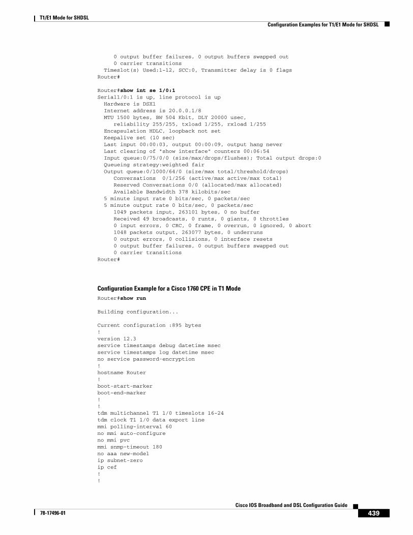
T1/E1 Mode for SHDSLConfiguration Examples for T1/E1 Mode for SHDSL
439Cisco IOS Broadband and DSL Configuration Guide
78-17496-01
0 output buffer failures, 0 output buffers swapped out 0 carrier transitions Timeslot(s) Used:1-12, SCC:0, Transmitter delay is 0 flagsRouter#
Router#show int se 1/0:1Serial1/0:1 is up, line protocol is up Hardware is DSX1 Internet address is 20.0.0.1/8 MTU 1500 bytes, BW 504 Kbit, DLY 20000 usec, reliability 255/255, txload 1/255, rxload 1/255 Encapsulation HDLC, loopback not set Keepalive set (10 sec) Last input 00:00:03, output 00:00:09, output hang never Last clearing of "show interface" counters 00:06:54 Input queue:0/75/0/0 (size/max/drops/flushes); Total output drops:0 Queueing strategy:weighted fair Output queue:0/1000/64/0 (size/max total/threshold/drops) Conversations 0/1/256 (active/max active/max total) Reserved Conversations 0/0 (allocated/max allocated) Available Bandwidth 378 kilobits/sec 5 minute input rate 0 bits/sec, 0 packets/sec 5 minute output rate 0 bits/sec, 0 packets/sec 1049 packets input, 263101 bytes, 0 no buffer Received 49 broadcasts, 0 runts, 0 giants, 0 throttles 0 input errors, 0 CRC, 0 frame, 0 overrun, 0 ignored, 0 abort 1048 packets output, 263077 bytes, 0 underruns 0 output errors, 0 collisions, 0 interface resets 0 output buffer failures, 0 output buffers swapped out 0 carrier transitionsRouter#
Configuration Example for a Cisco 1760 CPE in T1 ModeRouter#show run
Building configuration...
Current configuration :895 bytes!version 12.3service timestamps debug datetime msecservice timestamps log datetime msecno service password-encryption!hostname Router!boot-start-markerboot-end-marker!!tdm multichannel T1 1/0 timeslots 16-24tdm clock T1 1/0 data export linemmi polling-interval 60no mmi auto-configureno mmi pvcmmi snmp-timeout 180no aaa new-modelip subnet-zeroip cef!!
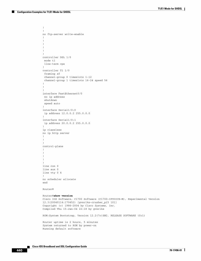
T1/E1 Mode for SHDSLConfiguration Examples for T1/E1 Mode for SHDSL
440Cisco IOS Broadband and DSL Configuration Guide
78-17496-01
!!no ftp-server write-enable!!!!!!controller DSL 1/0 mode t1 line-term cpe!controller T1 1/0 framing sf channel-group 0 timeslots 1-12 channel-group 1 timeslots 16-24 speed 56!!!interface FastEthernet0/0 no ip address shutdown speed auto!interface Serial1/0:0 ip address 12.0.0.2 255.0.0.0!interface Serial1/0:1 ip address 20.0.0.2 255.0.0.0!ip classlessno ip http server!!!control-plane!!!!!line con 0line aux 0line vty 0 4!no scheduler allocateend
Router#
Router#show versionCisco IOS Software, C1700 Software (C1700-IPVOICE-M), Experimental Version 12.3(20040114:170452) [gvsriks-crusher_pi5 101]Copyright (c) 1986-2004 by Cisco Systems, Inc.Compiled Thu 15-Jan-04 22:18 by gvsriks
ROM:System Bootstrap, Version 12.2(7r)XM2, RELEASE SOFTWARE (fc1)
Router uptime is 2 hours, 5 minutesSystem returned to ROM by power-onRunning default software
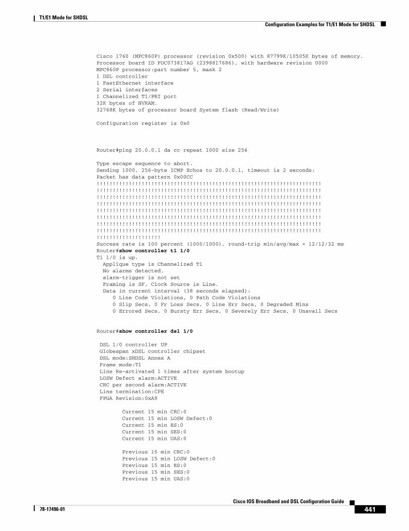
T1/E1 Mode for SHDSLConfiguration Examples for T1/E1 Mode for SHDSL
441Cisco IOS Broadband and DSL Configuration Guide
78-17496-01
Cisco 1760 (MPC860P) processor (revision 0x500) with 87799K/10505K bytes of memory.Processor board ID FOC073817AG (2398817686), with hardware revision 0000MPC860P processor:part number 5, mask 21 DSL controller1 FastEthernet interface2 Serial interfaces1 Channelized T1/PRI port32K bytes of NVRAM.32768K bytes of processor board System flash (Read/Write)
Configuration register is 0x0
Router#ping 20.0.0.1 da cc repeat 1000 size 256
Type escape sequence to abort.Sending 1000, 256-byte ICMP Echos to 20.0.0.1, timeout is 2 seconds:Packet has data pattern 0x00CC!!!!!!!!!!!!!!!!!!!!!!!!!!!!!!!!!!!!!!!!!!!!!!!!!!!!!!!!!!!!!!!!!!!!!!!!!!!!!!!!!!!!!!!!!!!!!!!!!!!!!!!!!!!!!!!!!!!!!!!!!!!!!!!!!!!!!!!!!!!!!!!!!!!!!!!!!!!!!!!!!!!!!!!!!!!!!!!!!!!!!!!!!!!!!!!!!!!!!!!!!!!!!!!!!!!!!!!!!!!!!!!!!!!!!!!!!!!!!!!!!!!!!!!!!!!!!!!!!!!!!!!!!!!!!!!!!!!!!!!!!!!!!!!!!!!!!!!!!!!!!!!!!!!!!!!!!!!!!!!!!!!!!!!!!!!!!!!!!!!!!!!!!!!!!!!!!!!!!!!!!!!!!!!!!!!!!!!!!!!!!!!!!!!!!!!!!!!!!!!!!!!!!!!!!!!!!!!!!!!!!!!!!!!!!!!!!!!!!!!!!!!!!!!!!!!!!!!!!!!!!!!!!!!!!!!!!!!!!!!!!!!!!!!!!!!!!!!!!!!!!!!!!!!!!!!!!!!!!!!!!!!!!!!!!!!!!!!!!!!!!!!!!!!!!!!!!!!!!!!!!!!!!!!!!!!!!!!!!!!!Success rate is 100 percent (1000/1000), round-trip min/avg/max = 12/12/32 msRouter#show controller t1 1/0 T1 1/0 is up. Applique type is Channelized T1 No alarms detected. alarm-trigger is not set Framing is SF, Clock Source is Line. Data in current interval (38 seconds elapsed): 0 Line Code Violations, 0 Path Code Violations 0 Slip Secs, 0 Fr Loss Secs, 0 Line Err Secs, 0 Degraded Mins 0 Errored Secs, 0 Bursty Err Secs, 0 Severely Err Secs, 0 Unavail Secs
Router#show controller dsl 1/0
DSL 1/0 controller UP Globespan xDSL controller chipset DSL mode:SHDSL Annex A Frame mode:T1 Line Re-activated 1 times after system bootup LOSW Defect alarm:ACTIVE CRC per second alarm:ACTIVE Line termination:CPE FPGA Revision:0xA9
Current 15 min CRC:0 Current 15 min LOSW Defect:0 Current 15 min ES:0 Current 15 min SES:0 Current 15 min UAS:0
Previous 15 min CRC:0 Previous 15 min LOSW Defect:0 Previous 15 min ES:0 Previous 15 min SES:0 Previous 15 min UAS:0
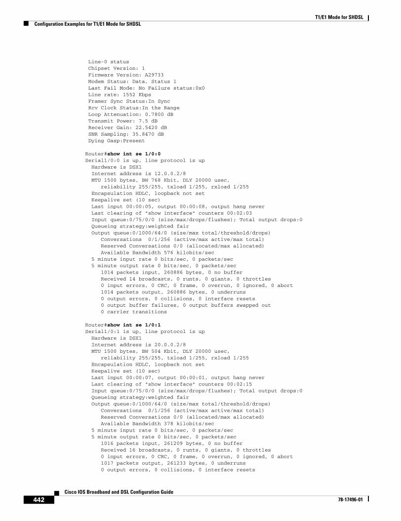
T1/E1 Mode for SHDSLConfiguration Examples for T1/E1 Mode for SHDSL
442Cisco IOS Broadband and DSL Configuration Guide
78-17496-01
Line-0 status Chipset Version: 1 Firmware Version: A29733 Modem Status: Data, Status 1 Last Fail Mode: No Failure status:0x0 Line rate: 1552 Kbps Framer Sync Status:In Sync Rcv Clock Status:In the Range Loop Attenuation: 0.7800 dB Transmit Power: 7.5 dB Receiver Gain: 22.5420 dB SNR Sampling: 35.8470 dB Dying Gasp:Present
Router#show int se 1/0:0Serial1/0:0 is up, line protocol is up Hardware is DSX1 Internet address is 12.0.0.2/8 MTU 1500 bytes, BW 768 Kbit, DLY 20000 usec, reliability 255/255, txload 1/255, rxload 1/255 Encapsulation HDLC, loopback not set Keepalive set (10 sec) Last input 00:00:05, output 00:00:08, output hang never Last clearing of "show interface" counters 00:02:03 Input queue:0/75/0/0 (size/max/drops/flushes); Total output drops:0 Queueing strategy:weighted fair Output queue:0/1000/64/0 (size/max total/threshold/drops) Conversations 0/1/256 (active/max active/max total) Reserved Conversations 0/0 (allocated/max allocated) Available Bandwidth 576 kilobits/sec 5 minute input rate 0 bits/sec, 0 packets/sec 5 minute output rate 0 bits/sec, 0 packets/sec 1014 packets input, 260886 bytes, 0 no buffer Received 14 broadcasts, 0 runts, 0 giants, 0 throttles 0 input errors, 0 CRC, 0 frame, 0 overrun, 0 ignored, 0 abort 1014 packets output, 260886 bytes, 0 underruns 0 output errors, 0 collisions, 0 interface resets 0 output buffer failures, 0 output buffers swapped out 0 carrier transitions
Router#show int se 1/0:1Serial1/0:1 is up, line protocol is up Hardware is DSX1 Internet address is 20.0.0.2/8 MTU 1500 bytes, BW 504 Kbit, DLY 20000 usec, reliability 255/255, txload 1/255, rxload 1/255 Encapsulation HDLC, loopback not set Keepalive set (10 sec) Last input 00:00:07, output 00:00:01, output hang never Last clearing of "show interface" counters 00:02:15 Input queue:0/75/0/0 (size/max/drops/flushes); Total output drops:0 Queueing strategy:weighted fair Output queue:0/1000/64/0 (size/max total/threshold/drops) Conversations 0/1/256 (active/max active/max total) Reserved Conversations 0/0 (allocated/max allocated) Available Bandwidth 378 kilobits/sec 5 minute input rate 0 bits/sec, 0 packets/sec 5 minute output rate 0 bits/sec, 0 packets/sec 1016 packets input, 261209 bytes, 0 no buffer Received 16 broadcasts, 0 runts, 0 giants, 0 throttles 0 input errors, 0 CRC, 0 frame, 0 overrun, 0 ignored, 0 abort 1017 packets output, 261233 bytes, 0 underruns 0 output errors, 0 collisions, 0 interface resets
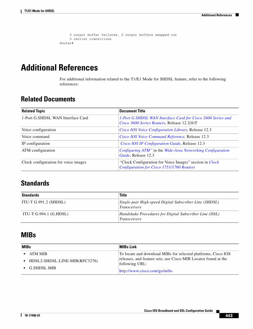
T1/E1 Mode for SHDSLAdditional References
443Cisco IOS Broadband and DSL Configuration Guide
78-17496-01
0 output buffer failures, 0 output buffers swapped out 0 carrier transitionsRouter#
Additional ReferencesFor additional information related to the T1/E1 Mode for SHDSL feature, refer to the following references:
Related Documents
Standards
MIBs
Related Topic Document Title
1-Port G.SHDSL WAN Interface Card 1-Port G.SHDSL WAN Interface Card for Cisco 2600 Series and Cisco 3600 Series Routers, Release 12.2(8)T
Voice configuration Cisco IOS Voice Configuration Library, Release 12.3
Voice command Cisco IOS Voice Command Reference, Release 12.3
IP configuration Cisco IOS IP Configuration Guide, Release 12.3
ATM configuration Configuring ATM” in the Wide-Area Networking Configuration Guide, Release 12.3
Clock configuration for voice images “Clock Configuration for Voice Images” section in Clock Configuration for Cisco 1751/1760 Routers
Standards Title
ITU-T G.991.2 (SHDSL) Single-pair High-speed Digital Subscriber Line (SHDSL) Transceivers
ITU-T G.994.1 (G.HDSL) Handshake Procedures for Digital Subscriber Line (DSL) Transceivers
MIBs MIBs Link
• ATM MIB
• HDSL2-SHDSL-LINE-MIB(RFC3276)
• G.SHDSL MIB
To locate and download MIBs for selected platforms, Cisco IOS releases, and feature sets, use Cisco MIB Locator found at the following URL:
http://www.cisco.com/go/mibs
T1/E1 Mode for SHDSLCommand List
444Cisco IOS Broadband and DSL Configuration Guide
78-17496-01
RFCs
Technical Assistance
Command ListThe following commands are pertinent to this feature. To see the command pages for these and other commands used with this feature, go to the Cisco IOS Master Commands List, Release 12.4, at http://www.cisco.com/univercd/cc/td/doc/product/software/ios124/124mindx/124index.htm.
• controller dsl
• dsl-mode shdsl symmetric annex
• ignore-error-duration
• line-rate
• line-term
• loopback (DSL controller)
• mode (ATM/T1/E1 controller)
• show controller dsl
• debug xdsl application
• debug xdsl driver
• debug xdsl eoc
• debug xdsl error
RFCs Title
No new or modified RFCs are supported by this feature and support for existing RFCs has not been modified by this feature.
—
Description Link
Technical Assistance Center (TAC) home page, containing 30,000 pages of searchable technical content, including links to products, technologies, solutions, technical tips, and tools. Registered Cisco.com users can log in from this page to access even more content.
http://www.cisco.com/public/support/tac/home.shtml
T1/E1 Mode for SHDSLGlossary
445Cisco IOS Broadband and DSL Configuration Guide
78-17496-01
GlossaryABR—available bit rate. An ATM service type in which the ATM network makes a “best effort” to meet the transmitter's bandwidth requirements. ABR uses a congestion feedback mechanism that allows the ATM network to notify the transmitters that they should reduce their rate of data transmission until the congestion decreases. Thus, ABR offers a qualitative guarantee that the transmitter's data can get to the intended receivers without unwanted cell loss.
CO—central office. Local telephone company office to which all local loops in a given area connect and in which circuit switching of subscriber lines occur.
CPE—customer premises equipment. CPE includes devices such as CSU/DSUs, modems, and ISDN terminal adapters, required to provide an electromagnetic termination for wide-area network circuits before connecting to the router or access server. This equipment was historically provided by the telephone company, but is now typically provided by the customer in North American markets.
DMT—Discrete Multi-Tone is the ANSI-specified modulation technique for G.SHDSL (ANSI-T1.413). DMT is theoretically capable of more speed than CAP. The key providers of DMT are Alcatel, Amati, Aware/ADI, and Orckit.
Downstream—Refers to the transmission of data from the central office (CO or COE) to the customer premises equipment (CPE).
G.SHDSL—Multirate Symmetrical High-Speed Digital Subscriber Line.
UBR—unspecified bit rate. QoS class defined by the ATM Forum for ATM networks. UBR allows any amount of data up to a specified maximum to be sent across the network, but there are no guarantees in terms of cell loss rate and delay. Compare with ABR (available bit rate), CBR, and VBR.
Upstream—Refers to the transmission of data from the customer premise equipment (CPE) to the central office equipment (CO or COE).
VBR—variable bit rate. QoS class defined by the ATM Forum for ATM networks. VBR is subdivided into a real time (rt) class and non-real time (nrt) class.
VBR-rt—VBR-real time is used for connections in which there is a fixed timing relationship between samples.
VBR-nrt—VBR-non-real time is used for connections in which there is no fixed timing relationship between samples, but that still need a guaranteed QoS. Compare with ABR (available bit rate), CBR, and UBR.
VDSL—very high-speed digital subscriber line. This is a high-speed asymmetrical service in the 10 to 25-Mbps range and is typically limited to less than 5000 feet. The targeted application for this technology is a hybrid fiber copper system (fiber to the neighborhood).
Note Refer to the Internetworking Terms and Acronyms for terms not included in this glossary.

T1/E1 Mode for SHDSLGlossary
446Cisco IOS Broadband and DSL Configuration Guide
78-17496-01
447Cisco IOS Broadband and DSL Configuration Guide
78-17496-01
G.SHDSL Symmetric DSL Support for Cisco IAD2420 Series IAD
Feature History
This document describes the Multirate Symmetrical High-Speed Digital Subscriber Line (G.SHDSL) feature supported on the Cisco IAD2420 series integrated access devices (IADs) in Cisco IOS Release 12.2(8)T.
This document includes the following sections:
• Feature Overview, page 447
• Supported Platforms, page 448
• Supported Standards, MIBs, and RFCs, page 449
• Prerequisites, page 449
• Configuration Tasks, page 449
• Configuration Example, page 453
• Command List, page 455
• Glossary, page 456
Feature OverviewG.SHDSL is ATM-based, multirate, high-speed (up to 2.3 MB), symmetrical digital subscriber line technology for data transfer between a single customer premises equipment (CPE) subscriber and a central office (CO). G.SHDSL refers to the approved standard officially designated in ITU-T G.991.2.
Release Modification
12.2(4)T3 The Multirate Symmetrical High-Speed Digital Subscriber Line (G.SHDSL) feature was supported on the G.SHDSL one-port WAN interface on the Cisco 2600 series and Cisco 3600 series routers.
12.2(8)T The Multirate Symmetrical High-Speed Digital Subscriber Line (G.SHDSL) feature was expanded to the Cisco IAD2420 series IADs.
G.SHDSL Symmetric DSL Support for Cisco IAD2420 Series IADSupported Platforms
448Cisco IOS Broadband and DSL Configuration Guide
78-17496-01
The Cisco IAD2420 series IADs support G.SHDSL in the following models: IAD2424-8FXS, IAD2424-16FXS, IAD2424-16FXS8FXO, and IAD2424-1T1. These models are compatible with the Cisco 6160 and Cisco 6260 Digital Subscriber Line Access Multiplexers (DSLAM). The DSLAM must be equipped with compatible G.SHDSL line cards.
The Cisco IAD2424 IAD supports ATM Adaption Layer 2 (AAL2), ATM Adaption Layer 5 (AAL5), and quality of service (QoS) features for both voice and data services.
Benefits• Enables business class broadband service with voice integration, scalable performance, flexibility,
and security.
• Aggregates G.SHDSL and other transport options into a single box.
• Provides G.SHDSL high-speed digital data transmissions between CPE and the CO.
• Supports AAL2 and AAL5 services and applications (including voice), ATM class of service (constant bit rate [CBR], variable bit rate-nonreal time [VBR-nrt], variable bit rate-real time [VBR-rt], and unspecified bit rate [UBR and UBR+]).
• Provides ATM traffic management and quality of service (QoS) features to enable service providers to manage their core ATM network infrastructures.
Restrictions• The wetting current function is not supported as part of G.SHDSL.
Related DocumentsFor more information about voice configuration, see the following documents:
• Cisco IOS Voice, Video, and Fax Configuration Guide, Release 12.2
• Cisco IOS Voice, Video, and Fax Command Reference, Release 12.2
For more information about configuring IP, see the Cisco IOS IP Configuration Guide, Release 12.2.
For more information about configuring ATM, see “Configuring ATM” in the Cisco IOS Wide-Area Networking Configuration Guide, Release 12.2.
For information about configuring a DSLAM, see the Configuration Guide for Cisco DSLAMs with NI-2.
For information about installing and configuring Cisco IAD2420 series IAD hardware and software, see the documents listed at the following URL:
http://www.cisco.com/univercd/cc/td/doc/product/access/iad/iad2420/index.htm
Supported Platforms• Cisco IAD2420 series IADs
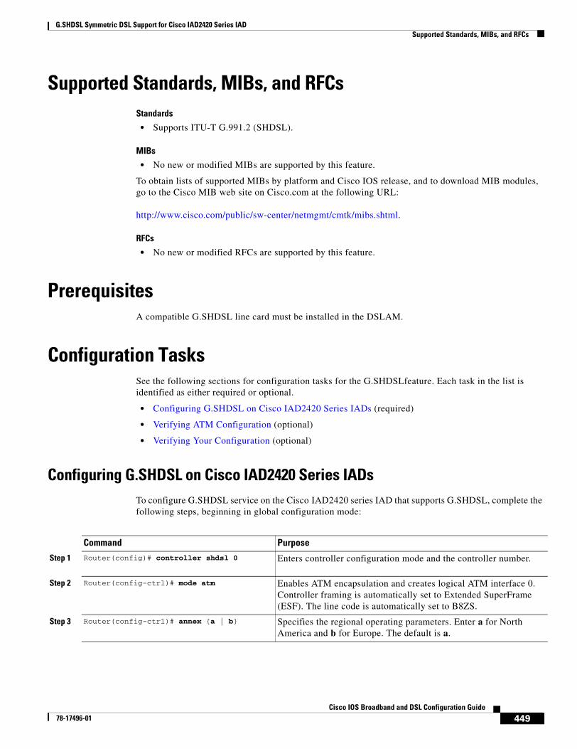
G.SHDSL Symmetric DSL Support for Cisco IAD2420 Series IADSupported Standards, MIBs, and RFCs
449Cisco IOS Broadband and DSL Configuration Guide
78-17496-01
Supported Standards, MIBs, and RFCsStandards
• Supports ITU-T G.991.2 (SHDSL).
MIBs
• No new or modified MIBs are supported by this feature.
To obtain lists of supported MIBs by platform and Cisco IOS release, and to download MIB modules, go to the Cisco MIB web site on Cisco.com at the following URL:
http://www.cisco.com/public/sw-center/netmgmt/cmtk/mibs.shtml.
RFCs
• No new or modified RFCs are supported by this feature.
PrerequisitesA compatible G.SHDSL line card must be installed in the DSLAM.
Configuration TasksSee the following sections for configuration tasks for the G.SHDSLfeature. Each task in the list is identified as either required or optional.
• Configuring G.SHDSL on Cisco IAD2420 Series IADs (required)
• Verifying ATM Configuration (optional)
• Verifying Your Configuration (optional)
Configuring G.SHDSL on Cisco IAD2420 Series IADsTo configure G.SHDSL service on the Cisco IAD2420 series IAD that supports G.SHDSL, complete the following steps, beginning in global configuration mode:
Command Purpose
Step 1 Router(config)# controller shdsl 0 Enters controller configuration mode and the controller number.
Step 2 Router(config-ctrl)# mode atm Enables ATM encapsulation and creates logical ATM interface 0. Controller framing is automatically set to Extended SuperFrame (ESF). The line code is automatically set to B8ZS.
Step 3 Router(config-ctrl)# annex {a | b} Specifies the regional operating parameters. Enter a for North America and b for Europe. The default is a.
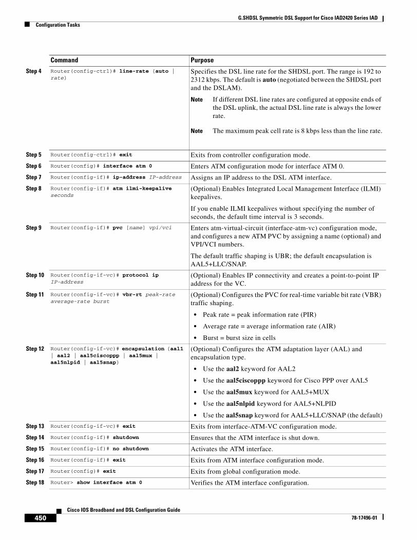
G.SHDSL Symmetric DSL Support for Cisco IAD2420 Series IADConfiguration Tasks
450Cisco IOS Broadband and DSL Configuration Guide
78-17496-01
Step 4 Router(config-ctrl)# line-rate {auto | rate}
Specifies the DSL line rate for the SHDSL port. The range is 192 to 2312 kbps. The default is auto (negotiated between the SHDSL port and the DSLAM).
Note If different DSL line rates are configured at opposite ends of the DSL uplink, the actual DSL line rate is always the lower rate.
Note The maximum peak cell rate is 8 kbps less than the line rate.
Step 5 Router(config-ctrl)# exit Exits from controller configuration mode.
Step 6 Router(config)# interface atm 0 Enters ATM configuration mode for interface ATM 0.
Step 7 Router(config-if)# ip-address IP-address Assigns an IP address to the DSL ATM interface.
Step 8 Router(config-if)# atm ilmi-keepalive seconds
(Optional) Enables Integrated Local Management Interface (ILMI) keepalives.
If you enable ILMI keepalives without specifying the number of seconds, the default time interval is 3 seconds.
Step 9 Router(config-if)# pvc [name] vpi/vci Enters atm-virtual-circuit (interface-atm-vc) configuration mode, and configures a new ATM PVC by assigning a name (optional) and VPI/VCI numbers.
The default traffic shaping is UBR; the default encapsulation is AAL5+LLC/SNAP.
Step 10 Router(config-if-vc)# protocol ip IP-address
(Optional) Enables IP connectivity and creates a point-to-point IP address for the VC.
Step 11 Router(config-if-vc)# vbr-rt peak-rate average-rate burst
(Optional) Configures the PVC for real-time variable bit rate (VBR) traffic shaping.
• Peak rate = peak information rate (PIR)
• Average rate = average information rate (AIR)
• Burst = burst size in cells
Step 12 Router(config-if-vc)# encapsulation {aal1 | aal2 | aal5ciscoppp | aal5mux | aal5nlpid | aal5snap}
(Optional) Configures the ATM adaptation layer (AAL) and encapsulation type.
• Use the aal2 keyword for AAL2
• Use the aal5ciscoppp keyword for Cisco PPP over AAL5
• Use the aal5mux keyword for AAL5+MUX
• Use the aal5nlpid keyword for AAL5+NLPID
• Use the aal5snap keyword for AAL5+LLC/SNAP (the default)
Step 13 Router(config-if-vc)# exit Exits from interface-ATM-VC configuration mode.
Step 14 Router(config-if)# shutdown Ensures that the ATM interface is shut down.
Step 15 Router(config-if)# no shutdown Activates the ATM interface.
Step 16 Router(config-if)# exit Exits from ATM interface configuration mode.
Step 17 Router(config)# exit Exits from global configuration mode.
Step 18 Router> show interface atm 0 Verifies the ATM interface configuration.
Command Purpose
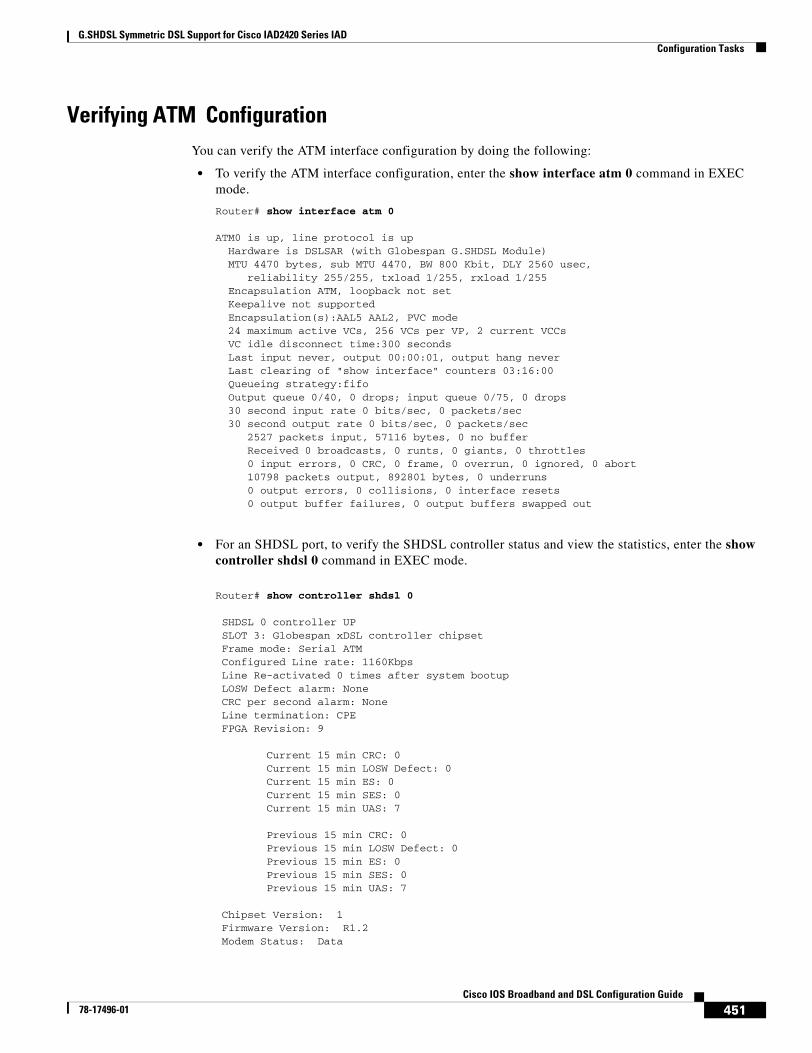
G.SHDSL Symmetric DSL Support for Cisco IAD2420 Series IADConfiguration Tasks
451Cisco IOS Broadband and DSL Configuration Guide
78-17496-01
Verifying ATM ConfigurationYou can verify the ATM interface configuration by doing the following:
• To verify the ATM interface configuration, enter the show interface atm 0 command in EXEC mode.
Router# show interface atm 0
ATM0 is up, line protocol is up Hardware is DSLSAR (with Globespan G.SHDSL Module) MTU 4470 bytes, sub MTU 4470, BW 800 Kbit, DLY 2560 usec, reliability 255/255, txload 1/255, rxload 1/255 Encapsulation ATM, loopback not set Keepalive not supported Encapsulation(s):AAL5 AAL2, PVC mode 24 maximum active VCs, 256 VCs per VP, 2 current VCCs VC idle disconnect time:300 seconds Last input never, output 00:00:01, output hang never Last clearing of "show interface" counters 03:16:00 Queueing strategy:fifo Output queue 0/40, 0 drops; input queue 0/75, 0 drops 30 second input rate 0 bits/sec, 0 packets/sec 30 second output rate 0 bits/sec, 0 packets/sec 2527 packets input, 57116 bytes, 0 no buffer Received 0 broadcasts, 0 runts, 0 giants, 0 throttles 0 input errors, 0 CRC, 0 frame, 0 overrun, 0 ignored, 0 abort 10798 packets output, 892801 bytes, 0 underruns 0 output errors, 0 collisions, 0 interface resets 0 output buffer failures, 0 output buffers swapped out
• For an SHDSL port, to verify the SHDSL controller status and view the statistics, enter the show controller shdsl 0 command in EXEC mode.
Router# show controller shdsl 0
SHDSL 0 controller UP SLOT 3: Globespan xDSL controller chipset Frame mode: Serial ATM Configured Line rate: 1160Kbps Line Re-activated 0 times after system bootup LOSW Defect alarm: None CRC per second alarm: None Line termination: CPE FPGA Revision: 9
Current 15 min CRC: 0 Current 15 min LOSW Defect: 0 Current 15 min ES: 0 Current 15 min SES: 0 Current 15 min UAS: 7
Previous 15 min CRC: 0 Previous 15 min LOSW Defect: 0 Previous 15 min ES: 0 Previous 15 min SES: 0 Previous 15 min UAS: 7
Chipset Version: 1 Firmware Version: R1.2 Modem Status: Data
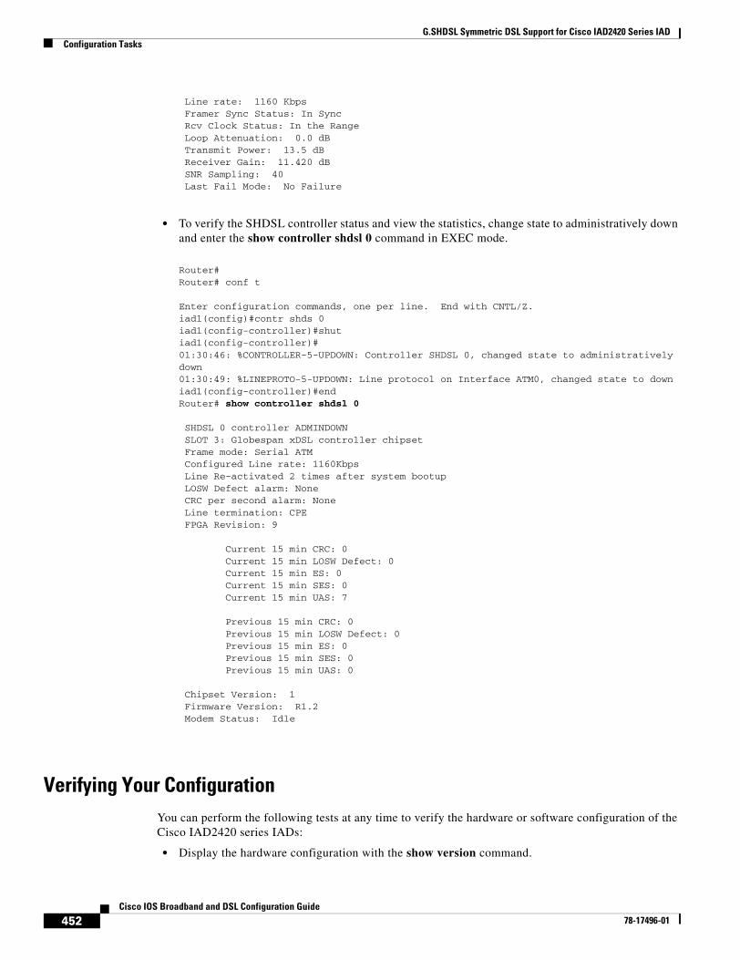
G.SHDSL Symmetric DSL Support for Cisco IAD2420 Series IADConfiguration Tasks
452Cisco IOS Broadband and DSL Configuration Guide
78-17496-01
Line rate: 1160 Kbps Framer Sync Status: In Sync Rcv Clock Status: In the Range Loop Attenuation: 0.0 dB Transmit Power: 13.5 dB Receiver Gain: 11.420 dB SNR Sampling: 40 Last Fail Mode: No Failure
• To verify the SHDSL controller status and view the statistics, change state to administratively down and enter the show controller shdsl 0 command in EXEC mode.
Router# Router# conf t
Enter configuration commands, one per line. End with CNTL/Z.iad1(config)#contr shds 0iad1(config-controller)#shutiad1(config-controller)#01:30:46: %CONTROLLER-5-UPDOWN: Controller SHDSL 0, changed state to administratively down01:30:49: %LINEPROTO-5-UPDOWN: Line protocol on Interface ATM0, changed state to downiad1(config-controller)#endRouter# show controller shdsl 0
SHDSL 0 controller ADMINDOWN SLOT 3: Globespan xDSL controller chipset Frame mode: Serial ATM Configured Line rate: 1160Kbps Line Re-activated 2 times after system bootup LOSW Defect alarm: None CRC per second alarm: None Line termination: CPE FPGA Revision: 9
Current 15 min CRC: 0 Current 15 min LOSW Defect: 0 Current 15 min ES: 0 Current 15 min SES: 0 Current 15 min UAS: 7
Previous 15 min CRC: 0 Previous 15 min LOSW Defect: 0 Previous 15 min ES: 0 Previous 15 min SES: 0 Previous 15 min UAS: 0
Chipset Version: 1 Firmware Version: R1.2 Modem Status: Idle
Verifying Your ConfigurationYou can perform the following tests at any time to verify the hardware or software configuration of the Cisco IAD2420 series IADs:
• Display the hardware configuration with the show version command.
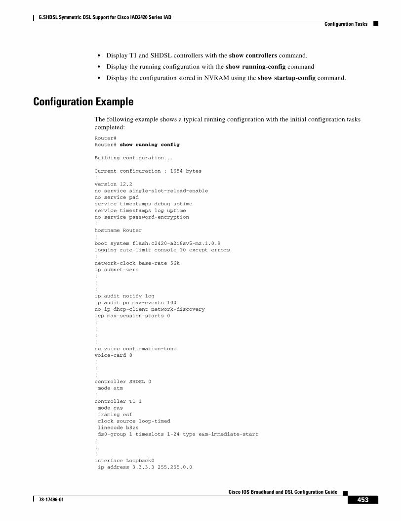
G.SHDSL Symmetric DSL Support for Cisco IAD2420 Series IADConfiguration Tasks
453Cisco IOS Broadband and DSL Configuration Guide
78-17496-01
• Display T1 and SHDSL controllers with the show controllers command.
• Display the running configuration with the show running-config command
• Display the configuration stored in NVRAM using the show startup-config command.
Configuration ExampleThe following example shows a typical running configuration with the initial configuration tasks completed:
Router#Router# show running config
Building configuration...
Current configuration : 1654 bytes!version 12.2no service single-slot-reload-enableno service padservice timestamps debug uptimeservice timestamps log uptimeno service password-encryption!hostname Router!boot system flash:c2420-a2i8sv5-mz.1.0.9logging rate-limit console 10 except errors!network-clock base-rate 56kip subnet-zero!!!ip audit notify logip audit po max-events 100no ip dhcp-client network-discoverylcp max-session-starts 0!!!!no voice confirmation-tonevoice-card 0!!!controller SHDSL 0 mode atm!controller T1 1 mode cas framing esf clock source loop-timed linecode b8zs ds0-group 1 timeslots 1-24 type e&m-immediate-start!!!interface Loopback0 ip address 3.3.3.3 255.255.0.0
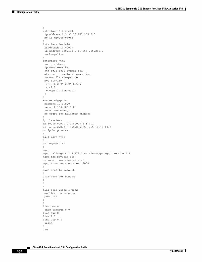
G.SHDSL Symmetric DSL Support for Cisco IAD2420 Series IADConfiguration Tasks
454Cisco IOS Broadband and DSL Configuration Guide
78-17496-01
!interface Ethernet0 ip address 1.3.95.50 255.255.0.0 no ip mroute-cache!interface Serial0 bandwidth 10000000 ip address 180.100.9.11 255.255.255.0 no keepalive!interface ATM0 no ip address ip mroute-cache atm idle-cell-format itu atm enable-payload-scrambling no atm ilmi-keepalive pvc 110/110 vbr-rt 2304 2304 65535 vcci 2 encapsulation aal2 !!router eigrp 10 network 10.0.0.0 network 180.100.0.0 no auto-summary no eigrp log-neighbor-changes!ip classlessip route 0.0.0.0 0.0.0.0 1.3.0.1ip route 2.2.2.2 255.255.255.255 10.10.10.2no ip http server!call rsvp-sync!voice-port 1:1!mgcpmgcp call-agent 1.4.173.1 service-type mgcp version 0.1mgcp tse payload 100no mgcp timer receive-rtcpmgcp timer net-cont-test 3000!mgcp profile default!dial-peer cor custom!!!dial-peer voice 1 pots application mgcpapp port 1:1!!line con 0 exec-timeout 0 0line aux 0line 2 3line vty 0 4 login!end
G.SHDSL Symmetric DSL Support for Cisco IAD2420 Series IADCommand List
455Cisco IOS Broadband and DSL Configuration Guide
78-17496-01
Command ListThe following commands are pertinent to this feature. To see the command pages for these and other commands used with this feature, go to the Cisco IOS Master Commands List, Release 12.4, at http://www.cisco.com/univercd/cc/td/doc/product/software/ios124/124mindx/124index.htm.
• controller shdsl 0
• mode atm
• show controller shdsl 0
G.SHDSL Symmetric DSL Support for Cisco IAD2420 Series IADGlossary
456Cisco IOS Broadband and DSL Configuration Guide
78-17496-01
GlossaryADSL—Asymmetric DSL (ADSL) available through several telecommunications carriers to accommodate the need for increased bandwidth for Internet access and telecommuting applications.
ATM—Asynchronous Transfer Mode. International standard for cell relay in which multiple service types (such as voice, video, or data) are conveyed in fixed-length (53-byte) cells. Fixed-length cells allow cell processing to occur in hardware, thereby reducing transit delays. ATM is designed to take advantage of high-speed transmission media such as E3, SONET, and T3.
CLI—command line interface.
CO—central office. Local exchange (local switch) that terminates individual local telephone subscriber lines for switching and connects to the public network. Known as a class 5 switch office. For example, 5ESS by Lucent and DMS 100 by Nortel.
CPE—customer premises equipment. Devices such as channel service units, data service units, modems, and ISDN terminal adapters, required to provide an electromagnetic termination for wide-area network circuits before connecting to the router or access server. This equipment was historically provided by the telephone company, but is now typically provided by the customer in North American markets.
DSL—Digital Subscriber Line available through several telecommunications carriers to accommodate the need for increased bandwidth for Internet access and telecommuting applications.
FXO—Foreign Exchange Office. An FXO interface connects to a central office.
FXS—Foreign Exchange Station: An FXS interface connects directly to a standard telephone, supplying ring voltage, dial tone, and so on.
G.SHDSL—Multirate Symmetrical High-Speed Digital Subscriber Line.
IAD—integrated access device. A CPE device used to combine services from various sources onto a common platform for transmission on a common transport span. Typically, an IAD combines various voice and data services such as circuit-based services like traditional telephone service and packet-switched services such as frame relay or ATM.
457Cisco IOS Broadband and DSL Configuration Guide
78-17496-01
1-Port G.SHDSL WAN Interface Card for Cisco 2600 Series and Cisco 3600 Series Routers
Feature History
This document describes the Multirate Symmetrical High-Speed Digital Subscriber Line (G.SHDSL) feature supported on the 1-port G.SHDSL WAN interface card (WIC) (WIC-1SHDSL) on Cisco 2600 series and Cisco 3600 series routers in Cisco IOS Release 12.2(8)T.
This document includes the following sections:
• Feature Overview, page 457
• Supported Platforms, page 459
• Supported Standards, MIBs, and RFCs, page 460
• Prerequisites, page 460
• Configuration Tasks, page 460
• Configuration Examples, page 465
• Command List, page 470
• Glossary, page 471
Feature OverviewG.SHDSL is an ATM-based, multirate, high-speed (up to 2.3 MB), symmetrical digital subscriber line technology for data transfer between a single customer premises equipment (CPE) subscriber and a central office.
G.SHDSL is supported on the G.SHDSL WAN interface card (WIC-1SHDSL), a 1-port WAN interface card (WIC) for Cisco 2600 series and Cisco 3600 series routers.
Release Modification
12.2(4)XL This feature was integrated into Cisco IOS Release 12.2(4)XL for Cisco 2600 series routers.
12.2(8)T This command was integrated into Cisco IOS Release 12.2(8)T on the G.SHDSL WIC on the Cisco 2600 series and Cisco 3600 series routers.
1-Port G.SHDSL WAN Interface Card for Cisco 2600 Series and Cisco 3600 Series RoutersFeature Overview
458Cisco IOS Broadband and DSL Configuration Guide
78-17496-01
The G.SHDSL WIC is compatible with the Cisco 6015, Cisco 6130, Cisco 6160, and Cisco 6260 Digital Subscriber Line Access Multiplexers (DSLAMs). The DSLAM must be equipped with G.SHDSL line cards that are compatible with the DSL service to be configured.
The G.SHDSL WIC supports ATM Adaptation Layer 2 (AAL2), ATM Adaptation Layer 5 (AAL5), and various classes of service for ATM.
Benefits• Enables business-class broadband service with voice integration, scalable performance, flexibility,
and security.
• Symmetrical WAN speeds (up to 2.3Mbps) over a single copper pair.
• Repeatable and has thirty percent longer reach than SDSL.
• Rate adaptive with G.HS “handshake” Protocol.
• Based on ITU Recommendation G.991.2 (Accepted Worldwide).
• Support for G.SHDSL Annex A (U.S. signaling) and Annex B (European signaling).
• Multiple G.SHDSL WAN Interface Cards configurable per Cisco 2600 series and Cisco 3600 series chassis.
• Toll-quality voice over IP delivery over AAL2 and AAL5.
• Provides ATM traffic management to enable service providers to manage their core ATM network infrastructures.
• Supports ATM class of service features constant bit rate (CBR), variable bit rate-nonreal time (VBR-nrt), variable bit rate-real time (VBR-rt), and unspecified bit rate (UBR and UBR+).
• Operates back-to-back or through a DSLAM.
• Sustains up to 23 virtual circuits per WAN on a WIC in Cisco 2600 series and Cisco 3600 series routers.
Restrictions• The G.SHDSL WIC does not support dual latency. When the DSL link is intended to support both
voice and data traffic simultaneously, the total supported data rate must be reduced to adjust for the reduced coding gain, which is usually present with high-latency traffic.
• The G.SHDSL WIC does not support Dying Gasp in ANSI T1.413 Issue 2.
• The G.SHDSL WIC does not support available bit rate (ABR) class of service (CoS).
• The G.SHDSL WIC should be inserted only into onboard WIC slots or 1FE2W, 2W, 1FE1R, 2FE2W network modules. This WIC is not supported in old combination network modules.
Related DocumentsFor more information about voice configuration, see the following Cisco IOS Release 12.2 guides:
• Cisco IOS Voice, Video, and Fax Configuration Guide, Release 12.2
• Cisco IOS Voice, Video, and Fax Command Reference, Release 12.2
The following configuration guides describe the configuration of IP and ATM:
1-Port G.SHDSL WAN Interface Card for Cisco 2600 Series and Cisco 3600 Series RoutersSupported Platforms
459Cisco IOS Broadband and DSL Configuration Guide
78-17496-01
• For more information about configuring IP, see the Cisco IOS IP Configuration Guide, Release 12.2.
• For more information about configuring ATM, see “Configuring ATM” in the Wide-Area Networking Configuration Guide, Release 12.2.
For information about configuring a DSLAM, see the Configuration Guide for Cisco DSLAMs with NI-2.
The following online feature documentation and installation guides describe the configuration and installation of hardware components:
• For information about installing Cisco 2600 series hardware, see the documents listed at the following URL:
http://www.cisco.com/univercd/cc/td/doc/product/access/acs_mod/cis2600/index.htm
• For information about installing Cisco 3600 series hardware, see the documents listed at the following URL:
http://www.cisco.com/univercd/cc/td/doc/product/access/acs_mod/cis3600/index.htm
Supported PlatformsThis feature is supported on the following router platforms:
• Cisco 2610
• Cisco 2611
• Cisco 2612
• Cisco 2613
• Cisco 2620
• Cisco 2621
• Cisco 2650
• Cisco 2651
• Cisco 3620
• Cisco 3631
• Cisco 3640
• Cisco 3661
• Cisco 3662
Determining Platform Support Through Feature Navigator
Cisco IOS software is packaged in feature sets that support specific platforms. To get updated information regarding platform support for this feature, access Feature Navigator. Feature Navigator dynamically updates the list of supported platforms as new platform support is added for the feature.
Feature Navigator is a web-based tool that enables you to quickly determine which Cisco IOS software images support a specific set of features and which features are supported in a specific Cisco IOS image.
To access Feature Navigator, you must have an account on Cisco.com. If you have forgotten or lost your account information, send a blank e-mail to [email protected]. An automatic check will verify that your e-mail address is registered with Cisco.com. If the check is successful, account details with a new random password will be e-mailed to you. Qualified users can establish an account on Cisco.com by following the directions at http://www.cisco.com/register.
1-Port G.SHDSL WAN Interface Card for Cisco 2600 Series and Cisco 3600 Series RoutersSupported Standards, MIBs, and RFCs
460Cisco IOS Broadband and DSL Configuration Guide
78-17496-01
Feature Navigator is updated regularly when major Cisco IOS software releases and technology releases occur. For the most current information, go to the Feature Navigator home page at the following URL:
http://www.cisco.com/go/fn
Supported Standards, MIBs, and RFCsStandards
• Supports ITU-T G.991.2 (SHDSL).
MIBs
• No new or modified MIBs are supported by this feature.
To obtain lists of supported MIBs by platform and Cisco IOS release, and to download MIB modules, go to the Cisco MIB website on Cisco.com at the following URL:
http://www.cisco.com/public/sw-center/netmgmt/cmtk/mibs.shtml
RFCs
• No new or modified RFCs are supported by this feature.
PrerequisitesA G.SHDSL WIC must be installed in the router to match the DSL service to be configured. A compatible G.SHDSL line card must be installed in the DSLAM.
Configuration TasksSee the following sections for configuration tasks for this feature. Each task in the list is identified as either required or optional:
• Configuring G.SHDSL on a Cisco Router (required)
• Configuring ILMI on the DSLAM Connected to the G.SHDSL WIC (optional)
• Verifying ATM Configuration (optional)
Configuring G.SHDSL on a Cisco RouterTo configure G.SHDSL service on a Cisco router containing a G.SHDSL WIC, complete the following steps, beginning in global configuration mode:
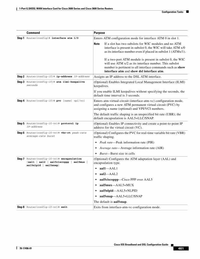
1-Port G.SHDSL WAN Interface Card for Cisco 2600 Series and Cisco 3600 Series RoutersConfiguration Tasks
461Cisco IOS Broadband and DSL Configuration Guide
78-17496-01
Command Purpose
Step 1 Router(config)# interface atm 1/0 Enters ATM configuration mode for interface ATM 0 in slot 1.
Note If a slot has two subslots for WIC modules and no ATM interface is present in subslot 0, the WIC will take ATM x/0 as its interface number even if placed in subslot 1 (ATMx/1).
If a two-port ATM module is present in subslot 0, the WIC will use ATM x/2 as its interface number. This subslot number is pertinent to all interface commands such as show interface atm and show dsl interface atm.
Step 2 Router(config-if)# ip-address IP-address Assigns an IP address to the DSL ATM interface.
Step 3 Router(config-if)# atm ilmi-keepalive seconds
(Optional) Enables Integrated Local Management Interface (ILMI) keepalives.
If you enable ILMI keepalives without specifying the seconds, the default time interval is 3 seconds.
Step 4 Router(config-if)# pvc [name] vpi/vci Enters atm-virtual-circuit (interface-atm-vc) configuration mode, and configures a new ATM permanent virtual circuit (PVC) by assigning a name (optional) and VPI/VCI numbers.
The default traffic shaping is an unspecified bit rate (UBR); the default encapsulation is AAL5+LLC/SNAP.
Step 5 Router(config-if-vc)# protocol ip IP-address
(Optional) Enables IP connectivity and create a point-to-point IP address for the virtual circuit (VC).
Step 6 Router(config-if-vc)# vbr-rt peak-rate average-rate burst
(Optional) Configures the PVC for real-time variable bit rate (VBR) traffic shaping.
• Peak rate—Peak information rate (PIR)
• Average rate—Average information rate (AIR)
• Burst—Burst size in cells
Step 7 Router(config-if-vc)# encapsulation {aal1 | aal2 | aal5ciscoppp | aal5mux | aal5nlpid | aal5snap}
(Optional) Configures the ATM adaptation layer (AAL) and encapsulation type.
• aal1—AAL1
• aal2—AAL2
• aal5ciscoppp—Cisco PPP over AAL5
• aal5mux—AAL5+MUX
• aal5nlpid—AAL5+NLPID
• aal5snap—AAL5+LLC/SNAP
The default is aal5snap.
Step 8 Router(config-if-vc)# exit Exits from interface-atm-vc configuration mode.
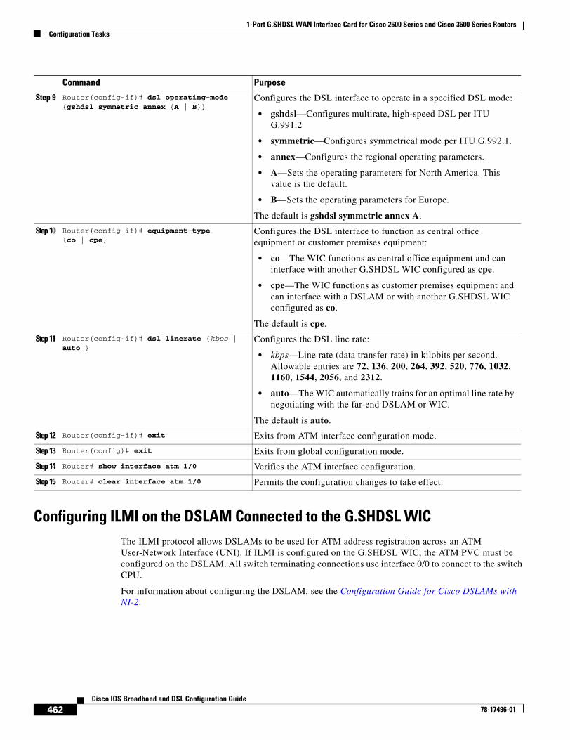
1-Port G.SHDSL WAN Interface Card for Cisco 2600 Series and Cisco 3600 Series RoutersConfiguration Tasks
462Cisco IOS Broadband and DSL Configuration Guide
78-17496-01
Configuring ILMI on the DSLAM Connected to the G.SHDSL WICThe ILMI protocol allows DSLAMs to be used for ATM address registration across an ATM User-Network Interface (UNI). If ILMI is configured on the G.SHDSL WIC, the ATM PVC must be configured on the DSLAM. All switch terminating connections use interface 0/0 to connect to the switch CPU.
For information about configuring the DSLAM, see the Configuration Guide for Cisco DSLAMs with NI-2.
Step 9 Router(config-if)# dsl operating-mode {gshdsl symmetric annex {A | B}}
Configures the DSL interface to operate in a specified DSL mode:
• gshdsl—Configures multirate, high-speed DSL per ITU G.991.2
• symmetric—Configures symmetrical mode per ITU G.992.1.
• annex—Configures the regional operating parameters.
• A—Sets the operating parameters for North America. This value is the default.
• B—Sets the operating parameters for Europe.
The default is gshdsl symmetric annex A.
Step 10 Router(config-if)# equipment-type {co | cpe}
Configures the DSL interface to function as central office equipment or customer premises equipment:
• co—The WIC functions as central office equipment and can interface with another G.SHDSL WIC configured as cpe.
• cpe—The WIC functions as customer premises equipment and can interface with a DSLAM or with another G.SHDSL WIC configured as co.
The default is cpe.
Step 11 Router(config-if)# dsl linerate {kbps | auto }
Configures the DSL line rate:
• kbps—Line rate (data transfer rate) in kilobits per second. Allowable entries are 72, 136, 200, 264, 392, 520, 776, 1032, 1160, 1544, 2056, and 2312.
• auto—The WIC automatically trains for an optimal line rate by negotiating with the far-end DSLAM or WIC.
The default is auto.
Step 12 Router(config-if)# exit Exits from ATM interface configuration mode.
Step 13 Router(config)# exit Exits from global configuration mode.
Step 14 Router# show interface atm 1/0 Verifies the ATM interface configuration.
Step 15 Router# clear interface atm 1/0 Permits the configuration changes to take effect.
Command Purpose
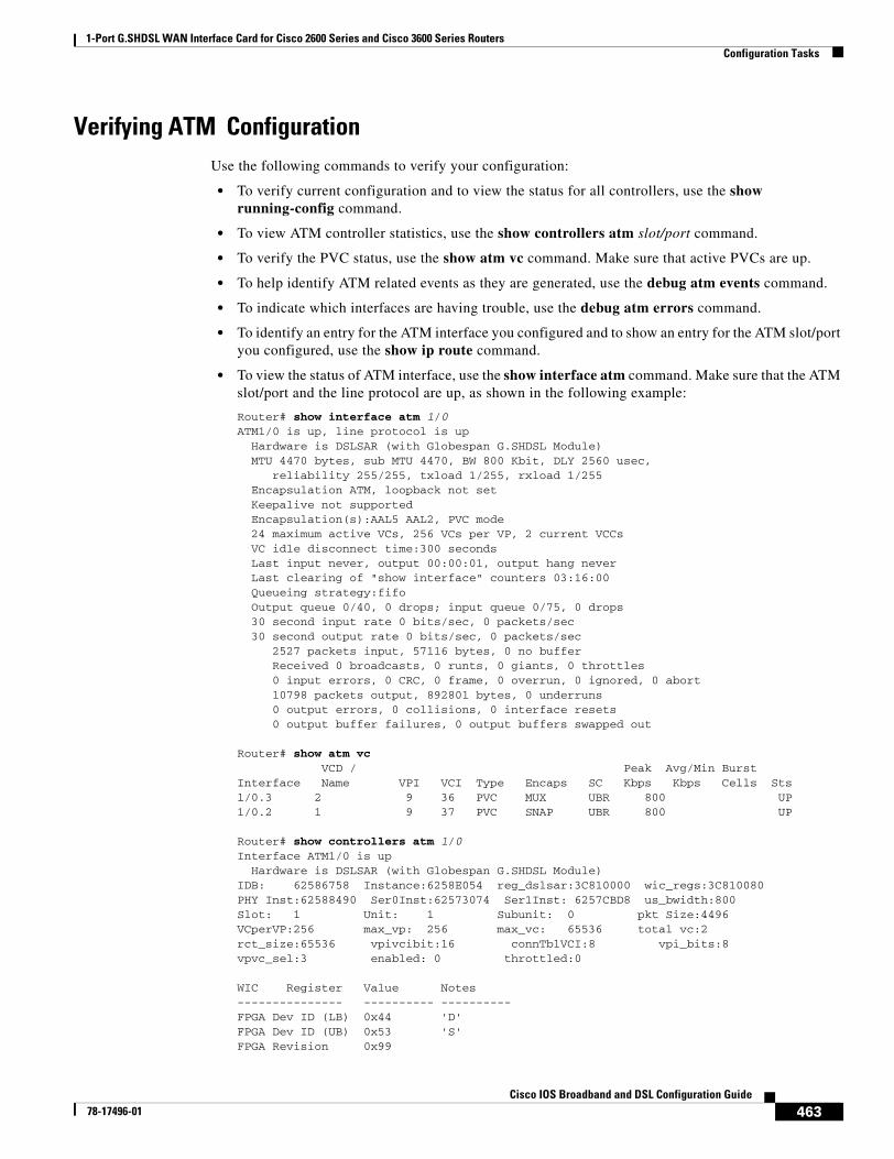
1-Port G.SHDSL WAN Interface Card for Cisco 2600 Series and Cisco 3600 Series RoutersConfiguration Tasks
463Cisco IOS Broadband and DSL Configuration Guide
78-17496-01
Verifying ATM ConfigurationUse the following commands to verify your configuration:
• To verify current configuration and to view the status for all controllers, use the show running-config command.
• To view ATM controller statistics, use the show controllers atm slot/port command.
• To verify the PVC status, use the show atm vc command. Make sure that active PVCs are up.
• To help identify ATM related events as they are generated, use the debug atm events command.
• To indicate which interfaces are having trouble, use the debug atm errors command.
• To identify an entry for the ATM interface you configured and to show an entry for the ATM slot/port you configured, use the show ip route command.
• To view the status of ATM interface, use the show interface atm command. Make sure that the ATM slot/port and the line protocol are up, as shown in the following example:
Router# show interface atm 1/0ATM1/0 is up, line protocol is up Hardware is DSLSAR (with Globespan G.SHDSL Module) MTU 4470 bytes, sub MTU 4470, BW 800 Kbit, DLY 2560 usec, reliability 255/255, txload 1/255, rxload 1/255 Encapsulation ATM, loopback not set Keepalive not supported Encapsulation(s):AAL5 AAL2, PVC mode 24 maximum active VCs, 256 VCs per VP, 2 current VCCs VC idle disconnect time:300 seconds Last input never, output 00:00:01, output hang never Last clearing of "show interface" counters 03:16:00 Queueing strategy:fifo Output queue 0/40, 0 drops; input queue 0/75, 0 drops 30 second input rate 0 bits/sec, 0 packets/sec 30 second output rate 0 bits/sec, 0 packets/sec 2527 packets input, 57116 bytes, 0 no buffer Received 0 broadcasts, 0 runts, 0 giants, 0 throttles 0 input errors, 0 CRC, 0 frame, 0 overrun, 0 ignored, 0 abort 10798 packets output, 892801 bytes, 0 underruns 0 output errors, 0 collisions, 0 interface resets 0 output buffer failures, 0 output buffers swapped out
Router# show atm vc VCD / Peak Avg/Min BurstInterface Name VPI VCI Type Encaps SC Kbps Kbps Cells Sts1/0.3 2 9 36 PVC MUX UBR 800 UP1/0.2 1 9 37 PVC SNAP UBR 800 UP
Router# show controllers atm 1/0Interface ATM1/0 is up Hardware is DSLSAR (with Globespan G.SHDSL Module)IDB: 62586758 Instance:6258E054 reg_dslsar:3C810000 wic_regs:3C810080PHY Inst:62588490 Ser0Inst:62573074 Ser1Inst: 6257CBD8 us_bwidth:800 Slot: 1 Unit: 1 Subunit: 0 pkt Size:4496 VCperVP:256 max_vp: 256 max_vc: 65536 total vc:2 rct_size:65536 vpivcibit:16 connTblVCI:8 vpi_bits:8 vpvc_sel:3 enabled: 0 throttled:0
WIC Register Value Notes--------------- ---------- ----------FPGA Dev ID (LB) 0x44 'D'FPGA Dev ID (UB) 0x53 'S'FPGA Revision 0x99
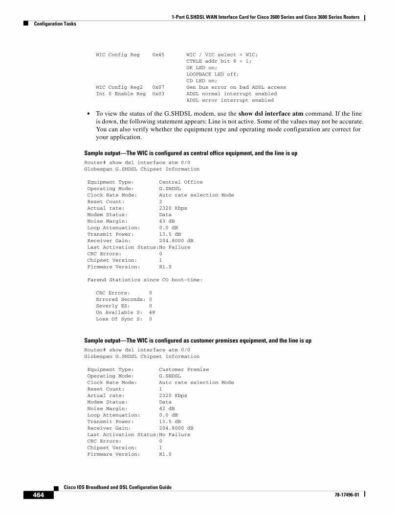
1-Port G.SHDSL WAN Interface Card for Cisco 2600 Series and Cisco 3600 Series RoutersConfiguration Tasks
464Cisco IOS Broadband and DSL Configuration Guide
78-17496-01
WIC Config Reg 0x45 WIC / VIC select = WIC; CTRLE addr bit 8 = 1; OK LED on; LOOPBACK LED off; CD LED on; WIC Config Reg2 0x07 Gen bus error on bad ADSL accessInt 0 Enable Reg 0x03 ADSL normal interrupt enabled ADSL error interrupt enabled
• To view the status of the G.SHDSL modem, use the show dsl interface atm command. If the line is down, the following statement appears: Line is not active. Some of the values may not be accurate. You can also verify whether the equipment type and operating mode configuration are correct for your application.
Sample output—The WIC is configured as central office equipment, and the line is upRouter# show dsl interface atm 0/0Globespan G.SHDSL Chipset Information
Equipment Type: Central Office Operating Mode: G.SHDSL Clock Rate Mode: Auto rate selection Mode Reset Count: 2 Actual rate: 2320 Kbps Modem Status: Data Noise Margin: 43 dB Loop Attenuation: 0.0 dB Transmit Power: 13.5 dB Receiver Gain: 204.8000 dB Last Activation Status:No Failure CRC Errors: 0 Chipset Version: 1 Firmware Version: R1.0
Farend Statistics since CO boot-time:
CRC Errors: 0Errored Seconds: 0Severly ES: 0Un Available S: 48Loss Of Sync S: 0
Sample output—The WIC is configured as customer premises equipment, and the line is upRouter# show dsl interface atm 0/0Globespan G.SHDSL Chipset Information
Equipment Type: Customer Premise Operating Mode: G.SHDSL Clock Rate Mode: Auto rate selection Mode Reset Count: 1 Actual rate: 2320 Kbps Modem Status: Data Noise Margin: 42 dB Loop Attenuation: 0.0 dB Transmit Power: 13.5 dB Receiver Gain: 204.8000 dB Last Activation Status:No Failure CRC Errors: 0 Chipset Version: 1 Firmware Version: R1.0
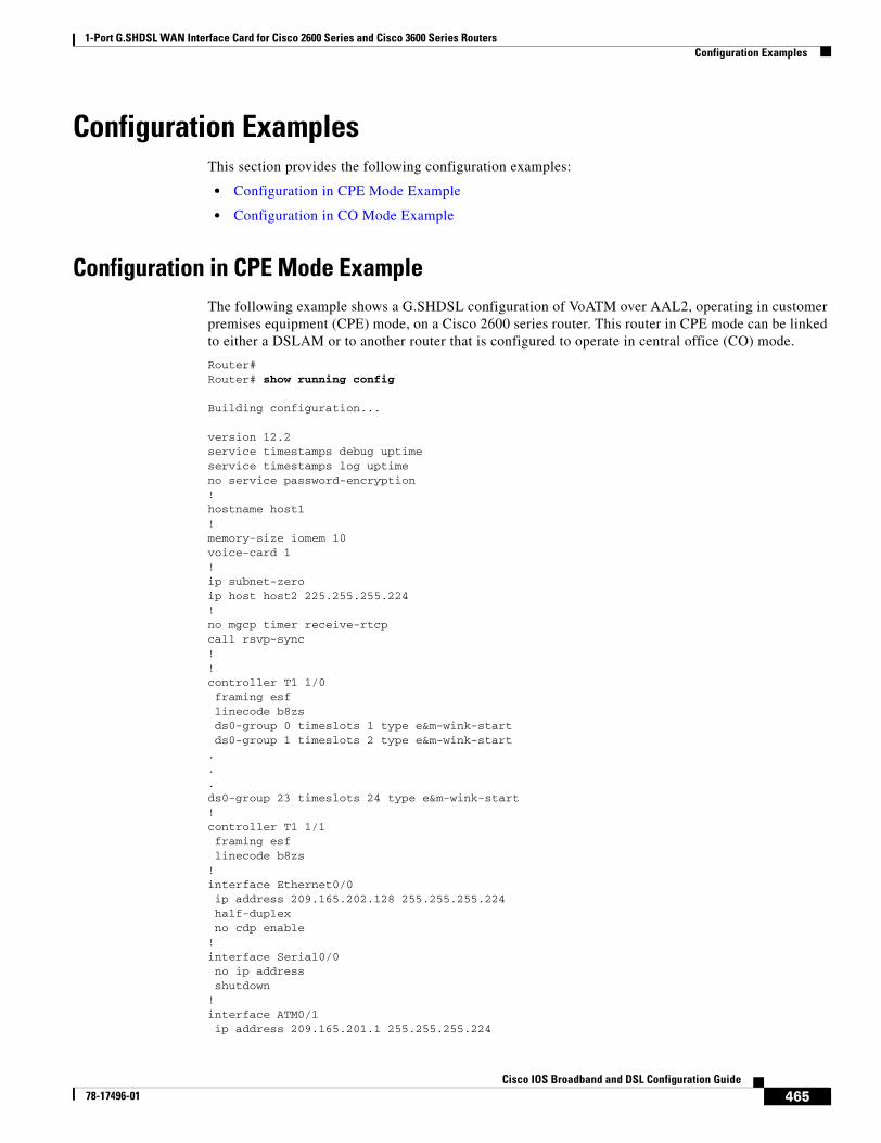
1-Port G.SHDSL WAN Interface Card for Cisco 2600 Series and Cisco 3600 Series RoutersConfiguration Examples
465Cisco IOS Broadband and DSL Configuration Guide
78-17496-01
Configuration ExamplesThis section provides the following configuration examples:
• Configuration in CPE Mode Example
• Configuration in CO Mode Example
Configuration in CPE Mode ExampleThe following example shows a G.SHDSL configuration of VoATM over AAL2, operating in customer premises equipment (CPE) mode, on a Cisco 2600 series router. This router in CPE mode can be linked to either a DSLAM or to another router that is configured to operate in central office (CO) mode.
Router#Router# show running config
Building configuration...
version 12.2service timestamps debug uptimeservice timestamps log uptimeno service password-encryption!hostname host1!memory-size iomem 10voice-card 1!ip subnet-zeroip host host2 225.255.255.224!no mgcp timer receive-rtcpcall rsvp-sync!!controller T1 1/0 framing esf linecode b8zs ds0-group 0 timeslots 1 type e&m-wink-start ds0-group 1 timeslots 2 type e&m-wink-start...ds0-group 23 timeslots 24 type e&m-wink-start!controller T1 1/1 framing esf linecode b8zs!interface Ethernet0/0 ip address 209.165.202.128 255.255.255.224 half-duplex no cdp enable!interface Serial0/0 no ip address shutdown!interface ATM0/1 ip address 209.165.201.1 255.255.255.224
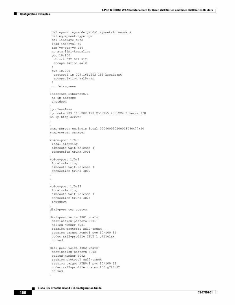
1-Port G.SHDSL WAN Interface Card for Cisco 2600 Series and Cisco 3600 Series RoutersConfiguration Examples
466Cisco IOS Broadband and DSL Configuration Guide
78-17496-01
dsl operating-mode gshdsl symmetric annex A dsl equipment-type cpe dsl linerate auto load-interval 30 atm vc-per-vp 256 no atm ilmi-keepalive pvc 10/100 vbr-rt 672 672 512 encapsulation aal2 ! pvc 10/200 protocol ip 209.165.202.159 broadcast encapsulation aal5snap ! no fair-queue!interface Ethernet0/1 no ip address shutdown!ip classlessip route 209.165.202.128 255.255.255.224 Ethernet0/0no ip http server!!snmp-server engineID local 000000090200003080477F20snmp-server manager!voice-port 1/0:0 local-alerting timeouts wait-release 3 connection trunk 3001 !voice-port 1/0:1 local-alerting timeouts wait-release 3 connection trunk 3002 ...voice-port 1/0:23 local-alerting timeouts wait-release 3 connection trunk 3024 shutdown!dial-peer cor custom!dial-peer voice 3001 voatm destination-pattern 3001 called-number 4001 session protocol aal2-trunk session target ATM0/1 pvc 10/100 31 codec aal2-profile ITUT 1 g711ulaw no vad!dial-peer voice 3002 voatm destination-pattern 3002 called-number 4002 session protocol aal2-trunk session target ATM0/1 pvc 10/100 32 codec aal2-profile custom 100 g726r32 no vad!
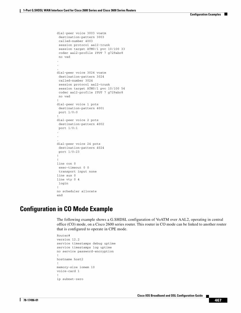
1-Port G.SHDSL WAN Interface Card for Cisco 2600 Series and Cisco 3600 Series RoutersConfiguration Examples
467Cisco IOS Broadband and DSL Configuration Guide
78-17496-01
dial-peer voice 3003 voatm destination-pattern 3003 called-number 4003 session protocol aal2-trunk session target ATM0/1 pvc 10/100 33 codec aal2-profile ITUT 7 g729abr8 no vad...dial-peer voice 3024 voatm destination-pattern 3024 called-number 3024 session protocol aal2-trunk session target ATM0/1 pvc 10/100 54 codec aal2-profile ITUT 7 g729abr8 no vad!dial-peer voice 1 pots destination-pattern 4001 port 1/0:0!dial-peer voice 2 pots destination-pattern 4002 port 1/0:1...dial-peer voice 24 pots destination-pattern 4024 port 1/0:23!!line con 0 exec-timeout 0 0 transport input noneline aux 0line vty 0 4 login!no scheduler allocateend
Configuration in CO Mode ExampleThe following example shows a G.SHDSL configuration of VoATM over AAL2, operating in central office (CO) mode, on a Cisco 2600 series router. This router in CO mode can be linked to another router that is configured to operate in CPE mode.
Router#version 12.2service timestamps debug uptimeservice timestamps log uptimeno service password-encryption!hostname host2!memory-size iomem 10voice-card 1!ip subnet-zero
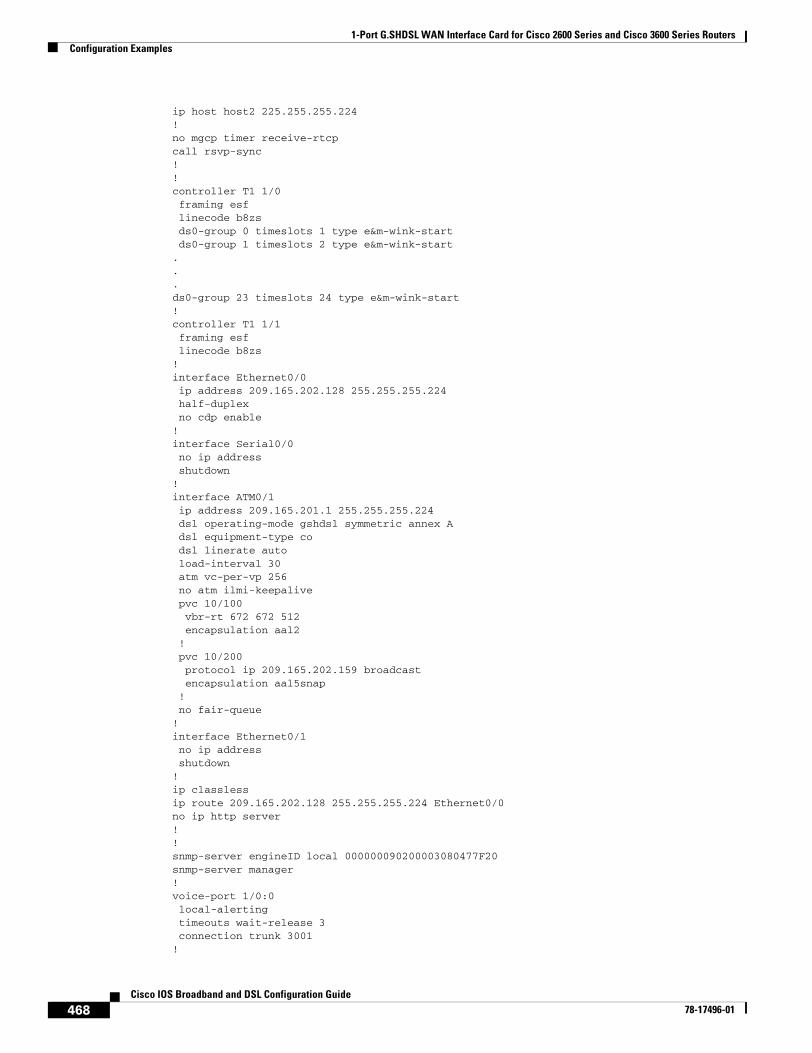
1-Port G.SHDSL WAN Interface Card for Cisco 2600 Series and Cisco 3600 Series RoutersConfiguration Examples
468Cisco IOS Broadband and DSL Configuration Guide
78-17496-01
ip host host2 225.255.255.224!no mgcp timer receive-rtcpcall rsvp-sync!!controller T1 1/0 framing esf linecode b8zs ds0-group 0 timeslots 1 type e&m-wink-start ds0-group 1 timeslots 2 type e&m-wink-start...ds0-group 23 timeslots 24 type e&m-wink-start!controller T1 1/1 framing esf linecode b8zs!interface Ethernet0/0 ip address 209.165.202.128 255.255.255.224 half-duplex no cdp enable!interface Serial0/0 no ip address shutdown!interface ATM0/1 ip address 209.165.201.1 255.255.255.224 dsl operating-mode gshdsl symmetric annex A dsl equipment-type co dsl linerate auto load-interval 30 atm vc-per-vp 256 no atm ilmi-keepalive pvc 10/100 vbr-rt 672 672 512 encapsulation aal2 ! pvc 10/200 protocol ip 209.165.202.159 broadcast encapsulation aal5snap ! no fair-queue!interface Ethernet0/1 no ip address shutdown!ip classlessip route 209.165.202.128 255.255.255.224 Ethernet0/0no ip http server!!snmp-server engineID local 000000090200003080477F20snmp-server manager!voice-port 1/0:0 local-alerting timeouts wait-release 3 connection trunk 3001 !
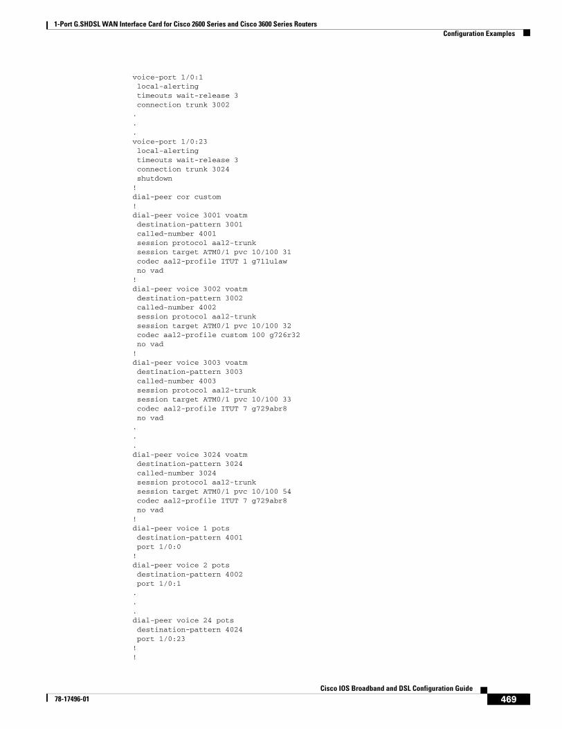
1-Port G.SHDSL WAN Interface Card for Cisco 2600 Series and Cisco 3600 Series RoutersConfiguration Examples
469Cisco IOS Broadband and DSL Configuration Guide
78-17496-01
voice-port 1/0:1 local-alerting timeouts wait-release 3 connection trunk 3002 ...voice-port 1/0:23 local-alerting timeouts wait-release 3 connection trunk 3024 shutdown!dial-peer cor custom!dial-peer voice 3001 voatm destination-pattern 3001 called-number 4001 session protocol aal2-trunk session target ATM0/1 pvc 10/100 31 codec aal2-profile ITUT 1 g711ulaw no vad!dial-peer voice 3002 voatm destination-pattern 3002 called-number 4002 session protocol aal2-trunk session target ATM0/1 pvc 10/100 32 codec aal2-profile custom 100 g726r32 no vad!dial-peer voice 3003 voatm destination-pattern 3003 called-number 4003 session protocol aal2-trunk session target ATM0/1 pvc 10/100 33 codec aal2-profile ITUT 7 g729abr8 no vad...dial-peer voice 3024 voatm destination-pattern 3024 called-number 3024 session protocol aal2-trunk session target ATM0/1 pvc 10/100 54 codec aal2-profile ITUT 7 g729abr8 no vad!dial-peer voice 1 pots destination-pattern 4001 port 1/0:0!dial-peer voice 2 pots destination-pattern 4002 port 1/0:1...dial-peer voice 24 pots destination-pattern 4024 port 1/0:23!!
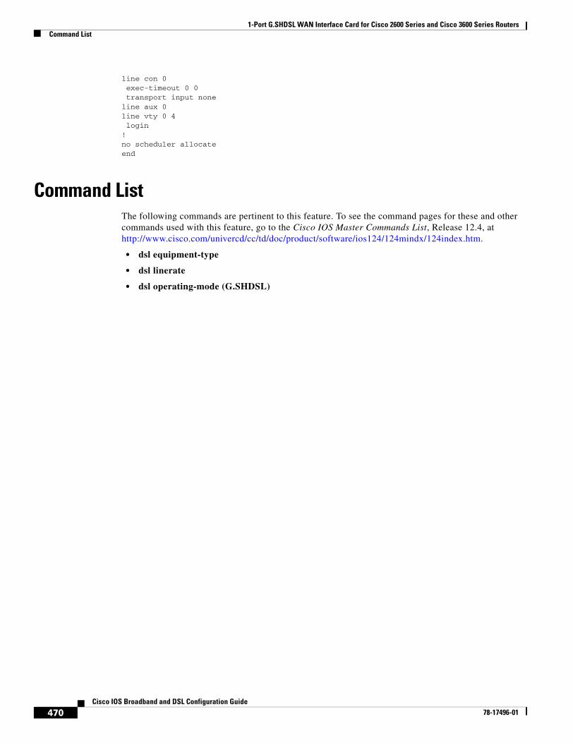
1-Port G.SHDSL WAN Interface Card for Cisco 2600 Series and Cisco 3600 Series RoutersCommand List
470Cisco IOS Broadband and DSL Configuration Guide
78-17496-01
line con 0 exec-timeout 0 0 transport input noneline aux 0line vty 0 4 login!no scheduler allocateend
Command ListThe following commands are pertinent to this feature. To see the command pages for these and other commands used with this feature, go to the Cisco IOS Master Commands List, Release 12.4, at http://www.cisco.com/univercd/cc/td/doc/product/software/ios124/124mindx/124index.htm.
• dsl equipment-type
• dsl linerate
• dsl operating-mode (G.SHDSL)
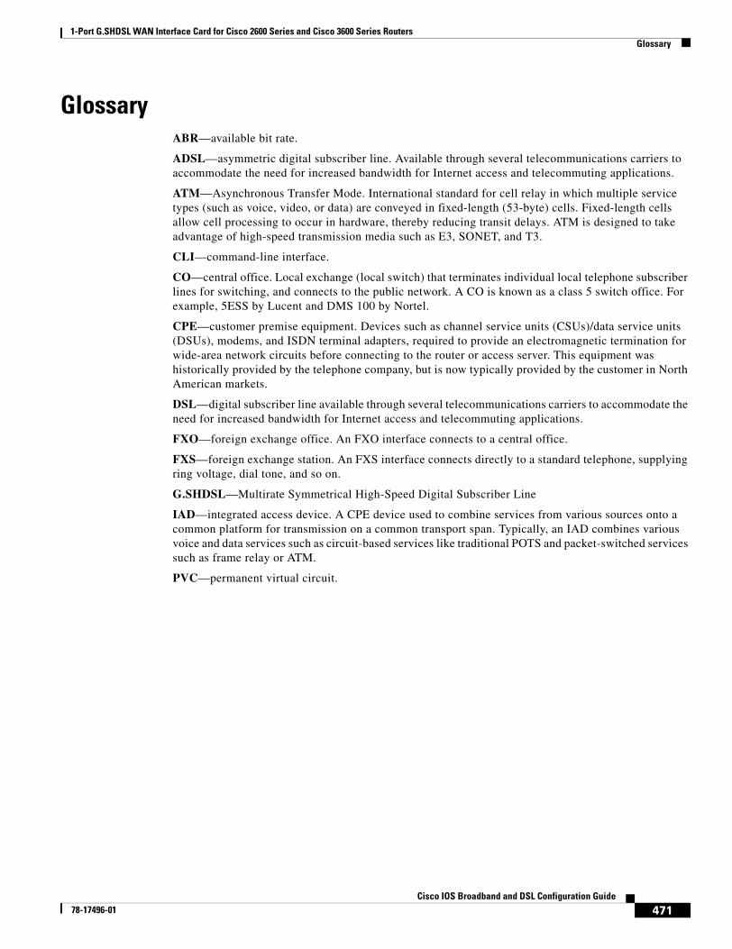
1-Port G.SHDSL WAN Interface Card for Cisco 2600 Series and Cisco 3600 Series RoutersGlossary
471Cisco IOS Broadband and DSL Configuration Guide
78-17496-01
GlossaryABR—available bit rate.
ADSL—asymmetric digital subscriber line. Available through several telecommunications carriers to accommodate the need for increased bandwidth for Internet access and telecommuting applications.
ATM—Asynchronous Transfer Mode. International standard for cell relay in which multiple service types (such as voice, video, or data) are conveyed in fixed-length (53-byte) cells. Fixed-length cells allow cell processing to occur in hardware, thereby reducing transit delays. ATM is designed to take advantage of high-speed transmission media such as E3, SONET, and T3.
CLI—command-line interface.
CO—central office. Local exchange (local switch) that terminates individual local telephone subscriber lines for switching, and connects to the public network. A CO is known as a class 5 switch office. For example, 5ESS by Lucent and DMS 100 by Nortel.
CPE—customer premise equipment. Devices such as channel service units (CSUs)/data service units (DSUs), modems, and ISDN terminal adapters, required to provide an electromagnetic termination for wide-area network circuits before connecting to the router or access server. This equipment was historically provided by the telephone company, but is now typically provided by the customer in North American markets.
DSL—digital subscriber line available through several telecommunications carriers to accommodate the need for increased bandwidth for Internet access and telecommuting applications.
FXO—foreign exchange office. An FXO interface connects to a central office.
FXS—foreign exchange station. An FXS interface connects directly to a standard telephone, supplying ring voltage, dial tone, and so on.
G.SHDSL—Multirate Symmetrical High-Speed Digital Subscriber Line
IAD—integrated access device. A CPE device used to combine services from various sources onto a common platform for transmission on a common transport span. Typically, an IAD combines various voice and data services such as circuit-based services like traditional POTS and packet-switched services such as frame relay or ATM.
PVC—permanent virtual circuit.

1-Port G.SHDSL WAN Interface Card for Cisco 2600 Series and Cisco 3600 Series RoutersGlossary
472Cisco IOS Broadband and DSL Configuration Guide
78-17496-01