
DS8000 Copy Services - Audentia
612
Redbooks Front cover DS8000 Copy Services Axel Westphal Bert Dufrasne Alcides Bertazi Cay-Uwe Kulzer Michael Frankenberg Lisa Gundy Lukasz Drózda Roland Wolf Warren Stanley
-
Upload
khangminh22 -
Category
Documents
-
view
0 -
download
0
Transcript of DS8000 Copy Services - Audentia

Redbooks
Front cover
DS8000 Copy Services
Axel Westphal
Bert Dufrasne
Alcides Bertazi
Cay-Uwe Kulzer
Michael Frankenberg
Lisa Gundy
Lukasz Drózda
Roland Wolf
Warren Stanley


International Technical Support Organization
DS8000 Copy Services
March 2017
SG24-8367-00

© Copyright International Business Machines Corporation 2017. All rights reserved.Note to U.S. Government Users Restricted Rights -- Use, duplication or disclosure restricted by GSA ADP ScheduleContract with IBM Corp.
First Edition (March 2017)
This edition applies to the IBM DS8000 series with DS8000 LMC 7.8.20.xxx (bundle version88.20.xxx.x).
Note: Before using this information and the product it supports, read the information in “Notices” on page xvii.

Contents
Notices . . . . . . . . . . . . . . . . . . . . . . . . . . . . . . . . . . . . . . . . . . . . . . . . . . . . . . . . . . . . . . . . xviiTrademarks . . . . . . . . . . . . . . . . . . . . . . . . . . . . . . . . . . . . . . . . . . . . . . . . . . . . . . . . . . . . xviii
Preface . . . . . . . . . . . . . . . . . . . . . . . . . . . . . . . . . . . . . . . . . . . . . . . . . . . . . . . . . . . . . . . . xixAuthors. . . . . . . . . . . . . . . . . . . . . . . . . . . . . . . . . . . . . . . . . . . . . . . . . . . . . . . . . . . . . . . . . xixNow you can become a published author, too! . . . . . . . . . . . . . . . . . . . . . . . . . . . . . . . . . . .xxComments welcome. . . . . . . . . . . . . . . . . . . . . . . . . . . . . . . . . . . . . . . . . . . . . . . . . . . . . . . xxiStay connected to IBM Redbooks . . . . . . . . . . . . . . . . . . . . . . . . . . . . . . . . . . . . . . . . . . . . xxi
Part 1. Overview . . . . . . . . . . . . . . . . . . . . . . . . . . . . . . . . . . . . . . . . . . . . . . . . . . . . . . . . . . . . . . . . . . . . . . 1
Chapter 1. Introduction. . . . . . . . . . . . . . . . . . . . . . . . . . . . . . . . . . . . . . . . . . . . . . . . . . . . 31.1 Point-in-time copy functions . . . . . . . . . . . . . . . . . . . . . . . . . . . . . . . . . . . . . . . . . . . . . . 4
1.1.1 FlashCopy. . . . . . . . . . . . . . . . . . . . . . . . . . . . . . . . . . . . . . . . . . . . . . . . . . . . . . . . 41.1.2 Remote Pair FlashCopy (Preserve Mirror) . . . . . . . . . . . . . . . . . . . . . . . . . . . . . . . 4
1.2 Business-continuity functions . . . . . . . . . . . . . . . . . . . . . . . . . . . . . . . . . . . . . . . . . . . . . 51.2.1 Metro Mirror . . . . . . . . . . . . . . . . . . . . . . . . . . . . . . . . . . . . . . . . . . . . . . . . . . . . . . 51.2.2 Global Copy . . . . . . . . . . . . . . . . . . . . . . . . . . . . . . . . . . . . . . . . . . . . . . . . . . . . . . 51.2.3 Global Mirror . . . . . . . . . . . . . . . . . . . . . . . . . . . . . . . . . . . . . . . . . . . . . . . . . . . . . . 51.2.4 Three-site Metro/Global Mirror with Incremental Resync . . . . . . . . . . . . . . . . . . . . 61.2.5 IBM Multiple Target Peer-to-Peer Remote Copy . . . . . . . . . . . . . . . . . . . . . . . . . . 6
1.3 Copy Services functions unique to z/OS. . . . . . . . . . . . . . . . . . . . . . . . . . . . . . . . . . . . . 71.3.1 z/OS Global Mirror and Metro Mirror across three sites . . . . . . . . . . . . . . . . . . . . . 71.3.2 IBM z/OS Metro/Global Mirror Incremental Resync (M/zGM Resync) . . . . . . . . . . 7
Chapter 2. Licensing . . . . . . . . . . . . . . . . . . . . . . . . . . . . . . . . . . . . . . . . . . . . . . . . . . . . . . 92.1 Licensed function . . . . . . . . . . . . . . . . . . . . . . . . . . . . . . . . . . . . . . . . . . . . . . . . . . . . . 102.2 License scope . . . . . . . . . . . . . . . . . . . . . . . . . . . . . . . . . . . . . . . . . . . . . . . . . . . . . . . . 112.3 Copy Services license functions and guidelines . . . . . . . . . . . . . . . . . . . . . . . . . . . . . . 12
2.3.1 Copy Services capacity examples . . . . . . . . . . . . . . . . . . . . . . . . . . . . . . . . . . . . 122.3.2 Managing use of Copy Services licensed functions . . . . . . . . . . . . . . . . . . . . . . . 13
Part 2. Interfaces . . . . . . . . . . . . . . . . . . . . . . . . . . . . . . . . . . . . . . . . . . . . . . . . . . . . . . . . . . . . . . . . . . . . . 15
Chapter 3. Copy Services interfaces overview. . . . . . . . . . . . . . . . . . . . . . . . . . . . . . . . 173.1 Summary tables . . . . . . . . . . . . . . . . . . . . . . . . . . . . . . . . . . . . . . . . . . . . . . . . . . . . . . 18
Chapter 4. DS command-line interface . . . . . . . . . . . . . . . . . . . . . . . . . . . . . . . . . . . . . . 234.1 User accounts . . . . . . . . . . . . . . . . . . . . . . . . . . . . . . . . . . . . . . . . . . . . . . . . . . . . . . . . 244.2 DS CLI profile . . . . . . . . . . . . . . . . . . . . . . . . . . . . . . . . . . . . . . . . . . . . . . . . . . . . . . . . 244.3 DS CLI command modes . . . . . . . . . . . . . . . . . . . . . . . . . . . . . . . . . . . . . . . . . . . . . . . 244.4 DS CLI Copy Services command structure. . . . . . . . . . . . . . . . . . . . . . . . . . . . . . . . . . 25
Chapter 5. z Systems interfaces . . . . . . . . . . . . . . . . . . . . . . . . . . . . . . . . . . . . . . . . . . . 275.1 z Systems command alternatives . . . . . . . . . . . . . . . . . . . . . . . . . . . . . . . . . . . . . . . . . 285.2 TSO commands for z/OS . . . . . . . . . . . . . . . . . . . . . . . . . . . . . . . . . . . . . . . . . . . . . . . 28
5.2.1 Protecting TSO Copy Services commands. . . . . . . . . . . . . . . . . . . . . . . . . . . . . . 285.3 ICKDSF commands for z/OS, z/VM, z/VSE . . . . . . . . . . . . . . . . . . . . . . . . . . . . . . . . . 30
5.3.1 Protecting ICKDSF Copy Services commands. . . . . . . . . . . . . . . . . . . . . . . . . . . 305.4 DFSMSdss copy commands with fast replication . . . . . . . . . . . . . . . . . . . . . . . . . . . . . 30
© Copyright IBM Corp. 2017. All rights reserved. iii

5.5 The ANTRQST API . . . . . . . . . . . . . . . . . . . . . . . . . . . . . . . . . . . . . . . . . . . . . . . . . . . . 315.5.1 Protecting ANTRQST API Functions . . . . . . . . . . . . . . . . . . . . . . . . . . . . . . . . . . 31
5.6 The ANTTREXX API and samples . . . . . . . . . . . . . . . . . . . . . . . . . . . . . . . . . . . . . . . . 315.6.1 Protecting ANTTREXX API Functions . . . . . . . . . . . . . . . . . . . . . . . . . . . . . . . . . 315.6.2 Sample REXX Programs in DGTCLIB . . . . . . . . . . . . . . . . . . . . . . . . . . . . . . . . . 32
5.7 Native z/VM commands for FlashCopy. . . . . . . . . . . . . . . . . . . . . . . . . . . . . . . . . . . . . 325.8 Native z/VSE commands for FlashCopy . . . . . . . . . . . . . . . . . . . . . . . . . . . . . . . . . . . . 325.9 Native z/TPF commands. . . . . . . . . . . . . . . . . . . . . . . . . . . . . . . . . . . . . . . . . . . . . . . . 33
Part 3. FlashCopy . . . . . . . . . . . . . . . . . . . . . . . . . . . . . . . . . . . . . . . . . . . . . . . . . . . . . . . . . . . . . . . . . . . . 35
Chapter 6. FlashCopy overview . . . . . . . . . . . . . . . . . . . . . . . . . . . . . . . . . . . . . . . . . . . . 376.1 FlashCopy operational environments . . . . . . . . . . . . . . . . . . . . . . . . . . . . . . . . . . . . . . 386.2 Terminology . . . . . . . . . . . . . . . . . . . . . . . . . . . . . . . . . . . . . . . . . . . . . . . . . . . . . . . . . 396.3 Basic concepts . . . . . . . . . . . . . . . . . . . . . . . . . . . . . . . . . . . . . . . . . . . . . . . . . . . . . . . 406.4 Source and target limitations. . . . . . . . . . . . . . . . . . . . . . . . . . . . . . . . . . . . . . . . . . . . . 42
Chapter 7. FlashCopy options . . . . . . . . . . . . . . . . . . . . . . . . . . . . . . . . . . . . . . . . . . . . . 457.1 Full volume Flashcopy . . . . . . . . . . . . . . . . . . . . . . . . . . . . . . . . . . . . . . . . . . . . . . . . . 467.2 FlashCopy for z/OS data sets . . . . . . . . . . . . . . . . . . . . . . . . . . . . . . . . . . . . . . . . . . . . 467.3 Copy option . . . . . . . . . . . . . . . . . . . . . . . . . . . . . . . . . . . . . . . . . . . . . . . . . . . . . . . . . . 477.4 NoCopy option . . . . . . . . . . . . . . . . . . . . . . . . . . . . . . . . . . . . . . . . . . . . . . . . . . . . . . . 477.5 Persistent FlashCopy . . . . . . . . . . . . . . . . . . . . . . . . . . . . . . . . . . . . . . . . . . . . . . . . . . 487.6 Incremental FlashCopy . . . . . . . . . . . . . . . . . . . . . . . . . . . . . . . . . . . . . . . . . . . . . . . . . 487.7 Reversing FlashCopy . . . . . . . . . . . . . . . . . . . . . . . . . . . . . . . . . . . . . . . . . . . . . . . . . . 497.8 Fast reverse restore . . . . . . . . . . . . . . . . . . . . . . . . . . . . . . . . . . . . . . . . . . . . . . . . . . . 507.9 Remote (in-band) FlashCopy . . . . . . . . . . . . . . . . . . . . . . . . . . . . . . . . . . . . . . . . . . . . 507.10 Consistent FlashCopy (FlashCopy consistency group). . . . . . . . . . . . . . . . . . . . . . . . 51
Chapter 8. FlashCopy interfaces . . . . . . . . . . . . . . . . . . . . . . . . . . . . . . . . . . . . . . . . . . . 538.1 FlashCopy management interfaces: Overview . . . . . . . . . . . . . . . . . . . . . . . . . . . . . . . 548.2 FlashCopy command interface reference . . . . . . . . . . . . . . . . . . . . . . . . . . . . . . . . . . . 558.3 FlashCopy control with the interfaces . . . . . . . . . . . . . . . . . . . . . . . . . . . . . . . . . . . . . . 558.4 FlashCopy in z/OS using DFSMSdss . . . . . . . . . . . . . . . . . . . . . . . . . . . . . . . . . . . . . . 56
8.4.1 DFSMSdss Full volume FlashCopy . . . . . . . . . . . . . . . . . . . . . . . . . . . . . . . . . . . 578.4.2 DFSMSdss data set FlashCopy . . . . . . . . . . . . . . . . . . . . . . . . . . . . . . . . . . . . . . 57
Chapter 9. Remote Pair FlashCopy . . . . . . . . . . . . . . . . . . . . . . . . . . . . . . . . . . . . . . . . . 599.1 FlashCopy in combination with other Copy Services . . . . . . . . . . . . . . . . . . . . . . . . . . 60
9.1.1 Terminology . . . . . . . . . . . . . . . . . . . . . . . . . . . . . . . . . . . . . . . . . . . . . . . . . . . . . 609.1.2 FlashCopy with Metro Mirror and Global Copy . . . . . . . . . . . . . . . . . . . . . . . . . . . 609.1.3 FlashCopy and Global Mirror . . . . . . . . . . . . . . . . . . . . . . . . . . . . . . . . . . . . . . . . 63
9.2 Remote Pair FlashCopy . . . . . . . . . . . . . . . . . . . . . . . . . . . . . . . . . . . . . . . . . . . . . . . . 649.2.1 Features of Remote Pair FlashCopy. . . . . . . . . . . . . . . . . . . . . . . . . . . . . . . . . . . 659.2.2 Considerations . . . . . . . . . . . . . . . . . . . . . . . . . . . . . . . . . . . . . . . . . . . . . . . . . . . 66
9.3 Remote Pair FlashCopy implementation and usage. . . . . . . . . . . . . . . . . . . . . . . . . . . 679.4 Remote Pair FlashCopy withdrawal . . . . . . . . . . . . . . . . . . . . . . . . . . . . . . . . . . . . . . . 68
9.4.1 Withdraw with Background Copy . . . . . . . . . . . . . . . . . . . . . . . . . . . . . . . . . . . . . 689.4.2 Forcing FlashCopy Withdraw . . . . . . . . . . . . . . . . . . . . . . . . . . . . . . . . . . . . . . . . 699.4.3 Withdrawing on the Metro Mirror secondary . . . . . . . . . . . . . . . . . . . . . . . . . . . . . 699.4.4 FlashCopy Withdraw interface differences . . . . . . . . . . . . . . . . . . . . . . . . . . . . . . 69
9.5 Remote Pair FlashCopy impact on Metro Mirror state . . . . . . . . . . . . . . . . . . . . . . . . . 709.6 Using Remote Pair FlashCopy in a z/OS environment . . . . . . . . . . . . . . . . . . . . . . . . . 70
9.6.1 Remote Pair FlashCopy and SMS volume selection . . . . . . . . . . . . . . . . . . . . . . 70
iv DS8000 Copy Services

9.7 FlashCopy considerations for Metro/Global Mirror and Multiple Target PPRC. . . . . . . 719.7.1 Remote Pair FlashCopy with Multiple Target PPRC. . . . . . . . . . . . . . . . . . . . . . . 72
Chapter 10. FlashCopy performance. . . . . . . . . . . . . . . . . . . . . . . . . . . . . . . . . . . . . . . . 7510.1 FlashCopy performance overview. . . . . . . . . . . . . . . . . . . . . . . . . . . . . . . . . . . . . . . . 76
10.1.1 Distribution of the workload: Location of source and target volumes . . . . . . . . . 7610.1.2 LSS/LCU versus rank: Considerations . . . . . . . . . . . . . . . . . . . . . . . . . . . . . . . . 7710.1.3 Rank characteristics . . . . . . . . . . . . . . . . . . . . . . . . . . . . . . . . . . . . . . . . . . . . . . 77
10.2 FlashCopy establish performance. . . . . . . . . . . . . . . . . . . . . . . . . . . . . . . . . . . . . . . . 7810.3 Background copy performance . . . . . . . . . . . . . . . . . . . . . . . . . . . . . . . . . . . . . . . . . . 7810.4 FlashCopy impact on applications . . . . . . . . . . . . . . . . . . . . . . . . . . . . . . . . . . . . . . . 79
10.4.1 FlashCopy nocopy . . . . . . . . . . . . . . . . . . . . . . . . . . . . . . . . . . . . . . . . . . . . . . . 8010.4.2 FlashCopy full copy. . . . . . . . . . . . . . . . . . . . . . . . . . . . . . . . . . . . . . . . . . . . . . . 8010.4.3 Incremental FlashCopy . . . . . . . . . . . . . . . . . . . . . . . . . . . . . . . . . . . . . . . . . . . . 80
10.5 FlashCopy scenarios. . . . . . . . . . . . . . . . . . . . . . . . . . . . . . . . . . . . . . . . . . . . . . . . . . 8110.5.1 Scenario #1: Backup to disk . . . . . . . . . . . . . . . . . . . . . . . . . . . . . . . . . . . . . . . . 8110.5.2 Scenario #2: Backup to tape. . . . . . . . . . . . . . . . . . . . . . . . . . . . . . . . . . . . . . . . 8110.5.3 Scenario #3: FlashCopy during peak application activity . . . . . . . . . . . . . . . . . . 8210.5.4 Scenario #4: Ranks reserved for FlashCopy . . . . . . . . . . . . . . . . . . . . . . . . . . . 83
Chapter 11. FlashCopy examples . . . . . . . . . . . . . . . . . . . . . . . . . . . . . . . . . . . . . . . . . . 8511.1 Creating a test system or integration system . . . . . . . . . . . . . . . . . . . . . . . . . . . . . . . 86
11.1.1 One-time test system . . . . . . . . . . . . . . . . . . . . . . . . . . . . . . . . . . . . . . . . . . . . . 8611.1.2 Multiple setup of a test system with the same contents . . . . . . . . . . . . . . . . . . . 86
11.2 Creating a backup . . . . . . . . . . . . . . . . . . . . . . . . . . . . . . . . . . . . . . . . . . . . . . . . . . . . 8711.2.1 Creating a FlashCopy for backup purposes without a volume copy . . . . . . . . . . 8711.2.2 Incremental FlashCopy for backup purposes . . . . . . . . . . . . . . . . . . . . . . . . . . . 8811.2.3 Using a target volume to restore its contents back to the source . . . . . . . . . . . . 88
11.3 Establishing a remote FlashCopy . . . . . . . . . . . . . . . . . . . . . . . . . . . . . . . . . . . . . . . . 8911.4 Establishing Remote Pair Flashcopy . . . . . . . . . . . . . . . . . . . . . . . . . . . . . . . . . . . . . 9011.5 TSO FlashCopy query commands . . . . . . . . . . . . . . . . . . . . . . . . . . . . . . . . . . . . . . . 9211.6 ICKDSF query command for FlashCopy. . . . . . . . . . . . . . . . . . . . . . . . . . . . . . . . . . . 93
Chapter 12. FlashCopy usage with z/OS products . . . . . . . . . . . . . . . . . . . . . . . . . . . . 9512.1 Using FlashCopy for COPY, DUMP, and RESTORE . . . . . . . . . . . . . . . . . . . . . . . . . 9612.2 Using FlashCopy for DEFRAG . . . . . . . . . . . . . . . . . . . . . . . . . . . . . . . . . . . . . . . . . . 9712.3 DFSMShsm Fast Replication . . . . . . . . . . . . . . . . . . . . . . . . . . . . . . . . . . . . . . . . . . . 9712.4 Using FlashCopy with DB2 for z/OS . . . . . . . . . . . . . . . . . . . . . . . . . . . . . . . . . . . . . . 99
Part 4. Metro Mirror and Global Copy . . . . . . . . . . . . . . . . . . . . . . . . . . . . . . . . . . . . . . . . . . . . . . . . . . . 101
Chapter 13. Metro Mirror overview . . . . . . . . . . . . . . . . . . . . . . . . . . . . . . . . . . . . . . . . 10313.1 Metro Mirror overview . . . . . . . . . . . . . . . . . . . . . . . . . . . . . . . . . . . . . . . . . . . . . . . . 10413.2 Metro Mirror positioning . . . . . . . . . . . . . . . . . . . . . . . . . . . . . . . . . . . . . . . . . . . . . . 105
Chapter 14. Global Copy overview . . . . . . . . . . . . . . . . . . . . . . . . . . . . . . . . . . . . . . . . 10714.1 Global Copy overview . . . . . . . . . . . . . . . . . . . . . . . . . . . . . . . . . . . . . . . . . . . . . . . . 10814.2 Global Copy positioning . . . . . . . . . . . . . . . . . . . . . . . . . . . . . . . . . . . . . . . . . . . . . . 109
Chapter 15. Metro Mirror and Global Copy paths. . . . . . . . . . . . . . . . . . . . . . . . . . . . . 11115.1 PPRC paths and links . . . . . . . . . . . . . . . . . . . . . . . . . . . . . . . . . . . . . . . . . . . . . . . . 11215.2 Fibre Channel physical links . . . . . . . . . . . . . . . . . . . . . . . . . . . . . . . . . . . . . . . . . . . 11215.3 Logical paths . . . . . . . . . . . . . . . . . . . . . . . . . . . . . . . . . . . . . . . . . . . . . . . . . . . . . . . 113
Chapter 16. Metro Mirror and Global Copy operations . . . . . . . . . . . . . . . . . . . . . . . . 115
Contents v

16.1 Metro Mirror and Global Copy pair states . . . . . . . . . . . . . . . . . . . . . . . . . . . . . . . . . 11616.2 Basic Metro Mirror and Global Copy operation . . . . . . . . . . . . . . . . . . . . . . . . . . . . . 116
16.2.1 Establishing PPRC paths . . . . . . . . . . . . . . . . . . . . . . . . . . . . . . . . . . . . . . . . . 11716.2.2 Removing PPRC paths . . . . . . . . . . . . . . . . . . . . . . . . . . . . . . . . . . . . . . . . . . . 11716.2.3 Establishing a pair. . . . . . . . . . . . . . . . . . . . . . . . . . . . . . . . . . . . . . . . . . . . . . . 11716.2.4 Suspending a pair . . . . . . . . . . . . . . . . . . . . . . . . . . . . . . . . . . . . . . . . . . . . . . . 12016.2.5 Resuming a pair . . . . . . . . . . . . . . . . . . . . . . . . . . . . . . . . . . . . . . . . . . . . . . . . 12016.2.6 Removing a pair . . . . . . . . . . . . . . . . . . . . . . . . . . . . . . . . . . . . . . . . . . . . . . . . 120
16.3 Suspension . . . . . . . . . . . . . . . . . . . . . . . . . . . . . . . . . . . . . . . . . . . . . . . . . . . . . . . . 12116.4 Freeze . . . . . . . . . . . . . . . . . . . . . . . . . . . . . . . . . . . . . . . . . . . . . . . . . . . . . . . . . . . . 121
16.4.1 Unfreeze (consistency group created) . . . . . . . . . . . . . . . . . . . . . . . . . . . . . . . 12116.5 PPRC failover and failback . . . . . . . . . . . . . . . . . . . . . . . . . . . . . . . . . . . . . . . . . . . . 121
16.5.1 Failover . . . . . . . . . . . . . . . . . . . . . . . . . . . . . . . . . . . . . . . . . . . . . . . . . . . . . . . 12216.5.2 PPRC Failback . . . . . . . . . . . . . . . . . . . . . . . . . . . . . . . . . . . . . . . . . . . . . . . . . 12216.5.3 Failover / Failback Scenario . . . . . . . . . . . . . . . . . . . . . . . . . . . . . . . . . . . . . . . 122
16.6 Metro Mirror Data consistency . . . . . . . . . . . . . . . . . . . . . . . . . . . . . . . . . . . . . . . . . 12516.7 Rolling disaster . . . . . . . . . . . . . . . . . . . . . . . . . . . . . . . . . . . . . . . . . . . . . . . . . . . . . 12616.8 Consistency group function. . . . . . . . . . . . . . . . . . . . . . . . . . . . . . . . . . . . . . . . . . . . 127
16.8.1 Data consistency and dependent writes . . . . . . . . . . . . . . . . . . . . . . . . . . . . . . 12716.8.2 Consistency group function: How it works . . . . . . . . . . . . . . . . . . . . . . . . . . . . 12816.8.3 Critical attribute (z Systems only) . . . . . . . . . . . . . . . . . . . . . . . . . . . . . . . . . . . 134
16.9 Creating a Global Copy consistent copy . . . . . . . . . . . . . . . . . . . . . . . . . . . . . . . . . . 13516.10 Automation and management . . . . . . . . . . . . . . . . . . . . . . . . . . . . . . . . . . . . . . . . . 137
Chapter 17. Metro Mirror and Global Copy implementation considerations . . . . . . . 13917.1 Bandwidth considerations . . . . . . . . . . . . . . . . . . . . . . . . . . . . . . . . . . . . . . . . . . . . . 140
17.1.1 Metro Mirror bandwidth considerations. . . . . . . . . . . . . . . . . . . . . . . . . . . . . . . 14017.1.2 Global Copy bandwidth considerations. . . . . . . . . . . . . . . . . . . . . . . . . . . . . . . 140
17.2 Performance considerations . . . . . . . . . . . . . . . . . . . . . . . . . . . . . . . . . . . . . . . . . . . 14117.2.1 Managing the load . . . . . . . . . . . . . . . . . . . . . . . . . . . . . . . . . . . . . . . . . . . . . . 14117.2.2 Initial synchronization . . . . . . . . . . . . . . . . . . . . . . . . . . . . . . . . . . . . . . . . . . . . 14117.2.3 Metro Mirror distance considerations . . . . . . . . . . . . . . . . . . . . . . . . . . . . . . . . 14217.2.4 z/OS Resource Management Facility . . . . . . . . . . . . . . . . . . . . . . . . . . . . . . . . 142
17.3 Symmetrical configuration. . . . . . . . . . . . . . . . . . . . . . . . . . . . . . . . . . . . . . . . . . . . . 14217.4 Volume selection. . . . . . . . . . . . . . . . . . . . . . . . . . . . . . . . . . . . . . . . . . . . . . . . . . . . 14317.5 Hardware requirements. . . . . . . . . . . . . . . . . . . . . . . . . . . . . . . . . . . . . . . . . . . . . . . 144
17.5.1 License . . . . . . . . . . . . . . . . . . . . . . . . . . . . . . . . . . . . . . . . . . . . . . . . . . . . . . . 14417.5.2 Interoperability . . . . . . . . . . . . . . . . . . . . . . . . . . . . . . . . . . . . . . . . . . . . . . . . . 14517.5.3 Connectivity: Ports, paths, and links . . . . . . . . . . . . . . . . . . . . . . . . . . . . . . . . . 14517.5.4 LSS and consistency group considerations . . . . . . . . . . . . . . . . . . . . . . . . . . . 146
17.6 Scalability . . . . . . . . . . . . . . . . . . . . . . . . . . . . . . . . . . . . . . . . . . . . . . . . . . . . . . . . . 14617.7 Distance considerations . . . . . . . . . . . . . . . . . . . . . . . . . . . . . . . . . . . . . . . . . . . . . . 147
17.7.1 Fibre Channel switches (FICON switches) . . . . . . . . . . . . . . . . . . . . . . . . . . . . 14717.7.2 Channel extender . . . . . . . . . . . . . . . . . . . . . . . . . . . . . . . . . . . . . . . . . . . . . . . 14717.7.3 Dense wavelength division multiplexing (DWDM). . . . . . . . . . . . . . . . . . . . . . . 147
17.8 z/OS multiple subchannel set support. . . . . . . . . . . . . . . . . . . . . . . . . . . . . . . . . . . . 14817.9 Global Copy point-in-time backup solution considerations . . . . . . . . . . . . . . . . . . . . 148
Chapter 18. Metro Mirror and Global Copy interfaces and examples . . . . . . . . . . . . 15118.1 Metro Mirror and Global Copy interfaces overview . . . . . . . . . . . . . . . . . . . . . . . . . . 152
18.1.1 Metro Mirror and Global Copy command reference . . . . . . . . . . . . . . . . . . . . . 15218.2 Metro Mirror and Global Copy DS CLI examples . . . . . . . . . . . . . . . . . . . . . . . . . . . 153
18.2.1 Setup, remove and manage of a Metro Mirror configuration. . . . . . . . . . . . . . . 154
vi DS8000 Copy Services

18.2.2 Switching over to a backup site . . . . . . . . . . . . . . . . . . . . . . . . . . . . . . . . . . . . 16418.2.3 Switching back to a primary site . . . . . . . . . . . . . . . . . . . . . . . . . . . . . . . . . . . . 17118.2.4 Metro Mirror freezepprc and unfreezepprc commands. . . . . . . . . . . . . . . . . . . 17318.2.5 Changing the copy mode from Metro Mirror to Global Copy. . . . . . . . . . . . . . . 17618.2.6 Changing the copy mode from Global Copy to Metro Mirror. . . . . . . . . . . . . . . 17718.2.7 Periodic offsite backup procedure. . . . . . . . . . . . . . . . . . . . . . . . . . . . . . . . . . . 17818.2.8 Managing data migration with Global Copy . . . . . . . . . . . . . . . . . . . . . . . . . . . 183
18.3 Metro Mirror and Global Copy TSO examples . . . . . . . . . . . . . . . . . . . . . . . . . . . . . 18618.3.1 Query an established path . . . . . . . . . . . . . . . . . . . . . . . . . . . . . . . . . . . . . . . . 18718.3.2 Query a Metro Mirror or Global Copy primary. . . . . . . . . . . . . . . . . . . . . . . . . . 18718.3.3 Querying a Metro Mirror Secondary . . . . . . . . . . . . . . . . . . . . . . . . . . . . . . . . . 188
18.4 Metro Mirror and Global Copy ICKDSF examples . . . . . . . . . . . . . . . . . . . . . . . . . . 18918.4.1 Displaying the Fibre Channel Connection Information Table . . . . . . . . . . . . . . 18918.4.2 Query device status . . . . . . . . . . . . . . . . . . . . . . . . . . . . . . . . . . . . . . . . . . . . . 19018.4.3 Defining and querying a Metro Mirror path . . . . . . . . . . . . . . . . . . . . . . . . . . . . 191
Part 5. Global Mirror . . . . . . . . . . . . . . . . . . . . . . . . . . . . . . . . . . . . . . . . . . . . . . . . . . . . . . . . . . . . . . . . . 197
Chapter 19. Global Mirror overview . . . . . . . . . . . . . . . . . . . . . . . . . . . . . . . . . . . . . . . . 19919.1 Global Mirror basic concepts. . . . . . . . . . . . . . . . . . . . . . . . . . . . . . . . . . . . . . . . . . . 200
19.1.1 Terminology in Global Mirror environments . . . . . . . . . . . . . . . . . . . . . . . . . . . 20019.1.2 Application I/O and Global Mirror . . . . . . . . . . . . . . . . . . . . . . . . . . . . . . . . . . . 20219.1.3 Asynchronous replication technique . . . . . . . . . . . . . . . . . . . . . . . . . . . . . . . . . 20319.1.4 Global Mirror Master Subordinate Relationship . . . . . . . . . . . . . . . . . . . . . . . . 204
19.2 Global Mirror consistency group processing . . . . . . . . . . . . . . . . . . . . . . . . . . . . . . . 20719.2.1 Properties of the Global Mirror journal . . . . . . . . . . . . . . . . . . . . . . . . . . . . . . . 20719.2.2 Consistency group formation . . . . . . . . . . . . . . . . . . . . . . . . . . . . . . . . . . . . . . 20819.2.3 Consistency group parameters . . . . . . . . . . . . . . . . . . . . . . . . . . . . . . . . . . . . . 209
Chapter 20. Global Mirror operations and recovery . . . . . . . . . . . . . . . . . . . . . . . . . . 21120.1 Modifying a Global Mirror session. . . . . . . . . . . . . . . . . . . . . . . . . . . . . . . . . . . . . . . 212
20.1.1 Adding volume pairs to or removing volume pairs from a Global Mirror session . . . . . . . . . . . . . . . . . . . . . . . . . . . . . . . . . . . . . . . . . . . . . 212
20.1.2 Adding or removing storage systems or LSSs . . . . . . . . . . . . . . . . . . . . . . . . . 21220.1.3 Modifying Global Mirror session parameters. . . . . . . . . . . . . . . . . . . . . . . . . . . 21320.1.4 Global Mirror environment topology changes . . . . . . . . . . . . . . . . . . . . . . . . . . 213
20.2 Global Mirror with multiple storage systems . . . . . . . . . . . . . . . . . . . . . . . . . . . . . . . 21420.3 Multiple Global Mirror sessions . . . . . . . . . . . . . . . . . . . . . . . . . . . . . . . . . . . . . . . . . 21620.4 Host connectivity at primary and secondary sites . . . . . . . . . . . . . . . . . . . . . . . . . . . 219
20.4.1 Multisite host connectivity . . . . . . . . . . . . . . . . . . . . . . . . . . . . . . . . . . . . . . . . . 21920.4.2 Single-site host connectivity . . . . . . . . . . . . . . . . . . . . . . . . . . . . . . . . . . . . . . . 220
20.5 Taking an additional copy for disaster recovery testing . . . . . . . . . . . . . . . . . . . . . . 22120.6 Global Mirror recovery. . . . . . . . . . . . . . . . . . . . . . . . . . . . . . . . . . . . . . . . . . . . . . . . 223
20.6.1 Autonomic behavior . . . . . . . . . . . . . . . . . . . . . . . . . . . . . . . . . . . . . . . . . . . . . 22320.6.2 General recovery principle . . . . . . . . . . . . . . . . . . . . . . . . . . . . . . . . . . . . . . . . 223
Chapter 21. Global Mirror interfaces and examples . . . . . . . . . . . . . . . . . . . . . . . . . . 22921.1 Global Mirror interface overview . . . . . . . . . . . . . . . . . . . . . . . . . . . . . . . . . . . . . . . . 230
21.1.1 Global Mirror command reference . . . . . . . . . . . . . . . . . . . . . . . . . . . . . . . . . . 23021.2 Establishing a Global Mirror environment by using the DS CLI . . . . . . . . . . . . . . . . 233
21.2.1 Creating Global Copy relationships: H1 to H2 volumes . . . . . . . . . . . . . . . . . . 23421.2.2 Creating FlashCopy relationships: H2 to J2 volumes . . . . . . . . . . . . . . . . . . . . 23521.2.3 Defining and Starting Global Mirror. . . . . . . . . . . . . . . . . . . . . . . . . . . . . . . . . . 236
21.3 Removing a Global Mirror environment with the DS CLI. . . . . . . . . . . . . . . . . . . . . . 242
Contents vii

21.3.1 Ending Global Mirror processing. . . . . . . . . . . . . . . . . . . . . . . . . . . . . . . . . . . . 24221.3.2 Removing the H1 volumes from the Global Mirror session. . . . . . . . . . . . . . . . 24321.3.3 Removing the Global Mirror session . . . . . . . . . . . . . . . . . . . . . . . . . . . . . . . . . 24421.3.4 Terminating FlashCopy pairs . . . . . . . . . . . . . . . . . . . . . . . . . . . . . . . . . . . . . . 24521.3.5 Terminating Global Copy pairs and removing the paths. . . . . . . . . . . . . . . . . . 245
21.4 Managing the Global Mirror environment with the DS CLI . . . . . . . . . . . . . . . . . . . . 24621.4.1 Pausing and resuming Global Mirror consistency group formation. . . . . . . . . . 24621.4.2 Changing the Global Mirror tuning parameters . . . . . . . . . . . . . . . . . . . . . . . . . 24821.4.3 Stopping and starting Global Mirror . . . . . . . . . . . . . . . . . . . . . . . . . . . . . . . . . 24921.4.4 Adding and removing volumes to the Global Mirror environment . . . . . . . . . . . 25021.4.5 Adding and removing an LSS to an existing Global Mirror environment. . . . . . 25221.4.6 Adding and removing a subordinate storage system . . . . . . . . . . . . . . . . . . . . 254
21.5 Recovery scenario after a local site failure by using the DS CLI . . . . . . . . . . . . . . . . . . . . . . . . . . . . . . . . . . . . . . . . . . . . . . . . . . . . . . . . . . . . 255
21.5.1 Summary of the recovery scenario . . . . . . . . . . . . . . . . . . . . . . . . . . . . . . . . . . 25521.5.2 Stopping Global Mirror processing . . . . . . . . . . . . . . . . . . . . . . . . . . . . . . . . . . 25521.5.3 Performing Global Copy failover from H2 to H1 . . . . . . . . . . . . . . . . . . . . . . . . 25621.5.4 Verifying a valid consistency group state . . . . . . . . . . . . . . . . . . . . . . . . . . . . . 25721.5.5 Reversing FlashCopy from H2 to J2 . . . . . . . . . . . . . . . . . . . . . . . . . . . . . . . . . 25921.5.6 Re-establishing the FlashCopy relationship from H2 to J2 . . . . . . . . . . . . . . . . 26221.5.7 Restarting the application at the remote site. . . . . . . . . . . . . . . . . . . . . . . . . . . 262
21.6 Returning to the local site . . . . . . . . . . . . . . . . . . . . . . . . . . . . . . . . . . . . . . . . . . . . . 26321.6.1 Creating paths from H2 to H1 . . . . . . . . . . . . . . . . . . . . . . . . . . . . . . . . . . . . . . 26321.6.2 Performing Global Copy failback from H2 to H1 . . . . . . . . . . . . . . . . . . . . . . . . 26421.6.3 Querying for the Global Copy first pass completion . . . . . . . . . . . . . . . . . . . . . 26621.6.4 Quiescing the application at the remote site . . . . . . . . . . . . . . . . . . . . . . . . . . . 26721.6.5 Querying the out-of-sync tracks until the result shows zero . . . . . . . . . . . . . . . 26721.6.6 Creating paths from H1 to H2 if they do not exist . . . . . . . . . . . . . . . . . . . . . . . 26721.6.7 Performing Global Copy failover from H1 to H2 . . . . . . . . . . . . . . . . . . . . . . . . 26821.6.8 Performing Global Copy failback from H1 to H2 . . . . . . . . . . . . . . . . . . . . . . . . 26921.6.9 Starting Global Mirror . . . . . . . . . . . . . . . . . . . . . . . . . . . . . . . . . . . . . . . . . . . . 270
21.7 Practicing disaster recovery readiness . . . . . . . . . . . . . . . . . . . . . . . . . . . . . . . . . . . 27121.7.1 Querying the Global Mirror environment . . . . . . . . . . . . . . . . . . . . . . . . . . . . . . 27221.7.2 Pausing Global Mirror and checking its completion . . . . . . . . . . . . . . . . . . . . . 27221.7.3 Pausing Global Copy pairs . . . . . . . . . . . . . . . . . . . . . . . . . . . . . . . . . . . . . . . . 27321.7.4 Performing Global Copy failover from H2 to H1 . . . . . . . . . . . . . . . . . . . . . . . . 27321.7.5 Creating consistent data on H2 volumes . . . . . . . . . . . . . . . . . . . . . . . . . . . . . 27421.7.6 Waiting for the FlashCopy background copy to complete. . . . . . . . . . . . . . . . . 27421.7.7 Re-establishing the FlashCopy relationships . . . . . . . . . . . . . . . . . . . . . . . . . . 27521.7.8 Taking a FlashCopy from H2 to I2 . . . . . . . . . . . . . . . . . . . . . . . . . . . . . . . . . . 27521.7.9 Performing disaster recovery testing by using the I2 volume . . . . . . . . . . . . . . 27621.7.10 Performing Global Copy failback from H1 to H2 . . . . . . . . . . . . . . . . . . . . . . . 27621.7.11 Waiting for the Global Copy first pass to complete . . . . . . . . . . . . . . . . . . . . . 27821.7.12 Resuming Global Mirror . . . . . . . . . . . . . . . . . . . . . . . . . . . . . . . . . . . . . . . . . 278
21.8 Query Global Mirror session information with z SystemsTSO or ICKDSF interfaces . . . . . . . . . . . . . . . . . . . . . . . . . . . . . . . . . . . . . . . . . . . . . 279
21.8.1 Querying Global Mirror session by using TSO . . . . . . . . . . . . . . . . . . . . . . . . . 27921.8.2 Querying the Global Mirror session by using ICKDSF . . . . . . . . . . . . . . . . . . . 282
Part 6. z/OS Global Mirror . . . . . . . . . . . . . . . . . . . . . . . . . . . . . . . . . . . . . . . . . . . . . . . . . . . . . . . . . . . . 287
Chapter 22. z/OS Global Mirror overview . . . . . . . . . . . . . . . . . . . . . . . . . . . . . . . . . . . 28922.1 z/OS Global Mirror introduction. . . . . . . . . . . . . . . . . . . . . . . . . . . . . . . . . . . . . . . . . 290
viii DS8000 Copy Services

22.2 z/OS Global Mirror terms and processes . . . . . . . . . . . . . . . . . . . . . . . . . . . . . . . . . 29122.2.1 Primary volume . . . . . . . . . . . . . . . . . . . . . . . . . . . . . . . . . . . . . . . . . . . . . . . . . 29122.2.2 Secondary volumes . . . . . . . . . . . . . . . . . . . . . . . . . . . . . . . . . . . . . . . . . . . . . 29122.2.3 Tertiary volumes . . . . . . . . . . . . . . . . . . . . . . . . . . . . . . . . . . . . . . . . . . . . . . . . 29222.2.4 Swap volumes. . . . . . . . . . . . . . . . . . . . . . . . . . . . . . . . . . . . . . . . . . . . . . . . . . 29222.2.5 Primary storage system . . . . . . . . . . . . . . . . . . . . . . . . . . . . . . . . . . . . . . . . . . 29222.2.6 Secondary storage system . . . . . . . . . . . . . . . . . . . . . . . . . . . . . . . . . . . . . . . . 29222.2.7 System data mover . . . . . . . . . . . . . . . . . . . . . . . . . . . . . . . . . . . . . . . . . . . . . . 29222.2.8 z/OS Global Mirror session . . . . . . . . . . . . . . . . . . . . . . . . . . . . . . . . . . . . . . . . 29222.2.9 Consistency group . . . . . . . . . . . . . . . . . . . . . . . . . . . . . . . . . . . . . . . . . . . . . . 29322.2.10 XRC or infrastructure data sets. . . . . . . . . . . . . . . . . . . . . . . . . . . . . . . . . . . . 29322.2.11 Utility devices . . . . . . . . . . . . . . . . . . . . . . . . . . . . . . . . . . . . . . . . . . . . . . . . . 294
22.3 z/OS Global Mirror operation: Data flow . . . . . . . . . . . . . . . . . . . . . . . . . . . . . . . . . . 294
Chapter 23. z/OS Global Mirror interfaces . . . . . . . . . . . . . . . . . . . . . . . . . . . . . . . . . . 29723.1 zGM commands summary . . . . . . . . . . . . . . . . . . . . . . . . . . . . . . . . . . . . . . . . . . . . 29823.2 ANTRQST and ANTTREXX API . . . . . . . . . . . . . . . . . . . . . . . . . . . . . . . . . . . . . . . . 298
Chapter 24. How z/OS Global Mirror maintains consistency . . . . . . . . . . . . . . . . . . . 29924.1 Consistency group . . . . . . . . . . . . . . . . . . . . . . . . . . . . . . . . . . . . . . . . . . . . . . . . . . 30024.2 Time stamping process . . . . . . . . . . . . . . . . . . . . . . . . . . . . . . . . . . . . . . . . . . . . . . . 30024.3 Common time reference . . . . . . . . . . . . . . . . . . . . . . . . . . . . . . . . . . . . . . . . . . . . . . 300
24.3.1 z/OS . . . . . . . . . . . . . . . . . . . . . . . . . . . . . . . . . . . . . . . . . . . . . . . . . . . . . . . . . 30024.3.2 z/VM . . . . . . . . . . . . . . . . . . . . . . . . . . . . . . . . . . . . . . . . . . . . . . . . . . . . . . . . . 30124.3.3 Linux on z Systems. . . . . . . . . . . . . . . . . . . . . . . . . . . . . . . . . . . . . . . . . . . . . . 301
24.4 z/OS Global Mirror consistency example . . . . . . . . . . . . . . . . . . . . . . . . . . . . . . . . . 30124.4.1 Gathering the data to be mirrored. . . . . . . . . . . . . . . . . . . . . . . . . . . . . . . . . . . 30224.4.2 Creating a consistency group . . . . . . . . . . . . . . . . . . . . . . . . . . . . . . . . . . . . . . 30324.4.3 Writing the consistency group. . . . . . . . . . . . . . . . . . . . . . . . . . . . . . . . . . . . . . 303
24.5 Time consistent recovery . . . . . . . . . . . . . . . . . . . . . . . . . . . . . . . . . . . . . . . . . . . . . 30424.6 z/OS Global Mirror recovery process . . . . . . . . . . . . . . . . . . . . . . . . . . . . . . . . . . . . 305
Chapter 25. z/OS Global Mirror scalability . . . . . . . . . . . . . . . . . . . . . . . . . . . . . . . . . . 30725.1 z/OS Global Mirror session organization. . . . . . . . . . . . . . . . . . . . . . . . . . . . . . . . . . 30825.2 Enhanced readers versus single reader . . . . . . . . . . . . . . . . . . . . . . . . . . . . . . . . . . 30825.3 Write pacing . . . . . . . . . . . . . . . . . . . . . . . . . . . . . . . . . . . . . . . . . . . . . . . . . . . . . . . 30925.4 Workload-based write pacing . . . . . . . . . . . . . . . . . . . . . . . . . . . . . . . . . . . . . . . . . . 311
Chapter 26. Managing z/OS Global Mirror . . . . . . . . . . . . . . . . . . . . . . . . . . . . . . . . . . 31526.1 GDPS and RCMF . . . . . . . . . . . . . . . . . . . . . . . . . . . . . . . . . . . . . . . . . . . . . . . . . . . 31626.2 Automation . . . . . . . . . . . . . . . . . . . . . . . . . . . . . . . . . . . . . . . . . . . . . . . . . . . . . . . . 31626.3 JCL or REXX generation. . . . . . . . . . . . . . . . . . . . . . . . . . . . . . . . . . . . . . . . . . . . . . 316
Part 7. Solutions . . . . . . . . . . . . . . . . . . . . . . . . . . . . . . . . . . . . . . . . . . . . . . . . . . . . . . . . . . . . . . . . . . . . 317
Chapter 27. IBM Geographically Dispersed Parallel Sysplex . . . . . . . . . . . . . . . . . . . 31927.1 GDPS solution offerings . . . . . . . . . . . . . . . . . . . . . . . . . . . . . . . . . . . . . . . . . . . . . . 32027.2 Components of a GDPS configuration . . . . . . . . . . . . . . . . . . . . . . . . . . . . . . . . . . . 321
27.2.1 GDPS/PPRC overview . . . . . . . . . . . . . . . . . . . . . . . . . . . . . . . . . . . . . . . . . . . 32227.2.2 PPRC and HyperSwap . . . . . . . . . . . . . . . . . . . . . . . . . . . . . . . . . . . . . . . . . . . 32227.2.3 GDPS Virtual Appliance overview. . . . . . . . . . . . . . . . . . . . . . . . . . . . . . . . . . . 32327.2.4 GDPS/PPRC Multiplatform Resiliency (xDR) for z Systems overview . . . . . . . 32327.2.5 GDPS/PPRC Distributed Cluster Management . . . . . . . . . . . . . . . . . . . . . . . . 32427.2.6 GDPS/XRC overview . . . . . . . . . . . . . . . . . . . . . . . . . . . . . . . . . . . . . . . . . . . . 324
Contents ix

27.2.7 GDPS/GM (Global Mirror) overview . . . . . . . . . . . . . . . . . . . . . . . . . . . . . . . . . 32427.2.8 GDPS 3-site solution overview . . . . . . . . . . . . . . . . . . . . . . . . . . . . . . . . . . . . . 32527.2.9 GDPS 4-site solution overview . . . . . . . . . . . . . . . . . . . . . . . . . . . . . . . . . . . . . 32627.2.10 IBM Global Services offerings for GDPS . . . . . . . . . . . . . . . . . . . . . . . . . . . . 327
Chapter 28. IBM Copy Services Manager . . . . . . . . . . . . . . . . . . . . . . . . . . . . . . . . . . . 32928.1 Copy Services Manager overview. . . . . . . . . . . . . . . . . . . . . . . . . . . . . . . . . . . . . . . 330
28.1.1 Why Copy Services Manager is needed. . . . . . . . . . . . . . . . . . . . . . . . . . . . . . 33028.1.2 What Copy Services Manager provides . . . . . . . . . . . . . . . . . . . . . . . . . . . . . . 33128.1.3 Copy Services Manager reliability, availability, and serviceability. . . . . . . . . . . 332
28.2 Copy Services Manager terminology . . . . . . . . . . . . . . . . . . . . . . . . . . . . . . . . . . . . 33428.2.1 Copy set . . . . . . . . . . . . . . . . . . . . . . . . . . . . . . . . . . . . . . . . . . . . . . . . . . . . . . 33428.2.2 Session . . . . . . . . . . . . . . . . . . . . . . . . . . . . . . . . . . . . . . . . . . . . . . . . . . . . . . . 33528.2.3 Location . . . . . . . . . . . . . . . . . . . . . . . . . . . . . . . . . . . . . . . . . . . . . . . . . . . . . . 33628.2.4 Volume types in a copy set . . . . . . . . . . . . . . . . . . . . . . . . . . . . . . . . . . . . . . . . 33728.2.5 Actions on sessions . . . . . . . . . . . . . . . . . . . . . . . . . . . . . . . . . . . . . . . . . . . . . 338
28.3 DS8000 specific information . . . . . . . . . . . . . . . . . . . . . . . . . . . . . . . . . . . . . . . . . . . 33828.3.1 PPRC paths . . . . . . . . . . . . . . . . . . . . . . . . . . . . . . . . . . . . . . . . . . . . . . . . . . . 33828.3.2 DS8000 connectivity . . . . . . . . . . . . . . . . . . . . . . . . . . . . . . . . . . . . . . . . . . . . . 33928.3.3 Metro Mirror heartbeat . . . . . . . . . . . . . . . . . . . . . . . . . . . . . . . . . . . . . . . . . . . 339
28.4 Copy Services Manager interfaces . . . . . . . . . . . . . . . . . . . . . . . . . . . . . . . . . . . . . . 34028.4.1 Copy Services Manager GUI . . . . . . . . . . . . . . . . . . . . . . . . . . . . . . . . . . . . . . 34028.4.2 Copy Services Manager CLI . . . . . . . . . . . . . . . . . . . . . . . . . . . . . . . . . . . . . . . 342
Chapter 29. z/OS Basic HyperSwap . . . . . . . . . . . . . . . . . . . . . . . . . . . . . . . . . . . . . . . 34329.1 z/OS Basic HyperSwap overview . . . . . . . . . . . . . . . . . . . . . . . . . . . . . . . . . . . . . . . 344
29.1.1 Benefits and positioning . . . . . . . . . . . . . . . . . . . . . . . . . . . . . . . . . . . . . . . . . . 34429.1.2 Sources of information . . . . . . . . . . . . . . . . . . . . . . . . . . . . . . . . . . . . . . . . . . . 34529.1.3 Setup. . . . . . . . . . . . . . . . . . . . . . . . . . . . . . . . . . . . . . . . . . . . . . . . . . . . . . . . . 345
29.2 z/OS Basic HyperSwap sequence . . . . . . . . . . . . . . . . . . . . . . . . . . . . . . . . . . . . . . 347
Chapter 30. VMware Site Recovery Manager . . . . . . . . . . . . . . . . . . . . . . . . . . . . . . . . 349
Part 8. MultiSite configurations . . . . . . . . . . . . . . . . . . . . . . . . . . . . . . . . . . . . . . . . . . . . . . . . . . . . . . . . 353
Chapter 31. Metro/Global Mirror overview . . . . . . . . . . . . . . . . . . . . . . . . . . . . . . . . . . 35531.1 Metro/Global Mirror overview . . . . . . . . . . . . . . . . . . . . . . . . . . . . . . . . . . . . . . . . . . 356
31.1.1 Metro Mirror and Global Mirror: Comparison . . . . . . . . . . . . . . . . . . . . . . . . . . 35631.1.2 Metro/Global Mirror design objectives. . . . . . . . . . . . . . . . . . . . . . . . . . . . . . . . 357
31.2 Metro/Global Mirror processes . . . . . . . . . . . . . . . . . . . . . . . . . . . . . . . . . . . . . . . . . 358
Chapter 32. Metro/Global Mirror configuration and setup . . . . . . . . . . . . . . . . . . . . . 36132.1 Metro/Global Mirror configuration . . . . . . . . . . . . . . . . . . . . . . . . . . . . . . . . . . . . . . . 362
32.1.1 Metro/Global Mirror with additional Global Mirror environments . . . . . . . . . . . . 36232.1.2 Metro/Global Mirror with multiple storage systems . . . . . . . . . . . . . . . . . . . . . . 363
32.2 Architectural Metro/Global Mirror example . . . . . . . . . . . . . . . . . . . . . . . . . . . . . . . . 36432.3 Initial setup of Metro/Global Mirror . . . . . . . . . . . . . . . . . . . . . . . . . . . . . . . . . . . . . . 365
32.3.1 Establish PPRC paths. . . . . . . . . . . . . . . . . . . . . . . . . . . . . . . . . . . . . . . . . . . . 36632.3.2 Establish Global Copy from H2 to H3 . . . . . . . . . . . . . . . . . . . . . . . . . . . . . . . . 36832.3.3 Establish Metro Mirror from H1 to H2 . . . . . . . . . . . . . . . . . . . . . . . . . . . . . . . . 36932.3.4 Establish FlashCopy at H3 . . . . . . . . . . . . . . . . . . . . . . . . . . . . . . . . . . . . . . . . 36932.3.5 Create the Global Mirror sessions and add volumes . . . . . . . . . . . . . . . . . . . . 37032.3.6 Start Global Mirror at H2 . . . . . . . . . . . . . . . . . . . . . . . . . . . . . . . . . . . . . . . . . . 371
32.4 Migrating from Metro Mirror to Metro/Global Mirror. . . . . . . . . . . . . . . . . . . . . . . . . . 373
x DS8000 Copy Services

32.5 Preferred practices for setting up Metro/Global Mirror . . . . . . . . . . . . . . . . . . . . . . . 374
Chapter 33. Metro/Global Mirror operations . . . . . . . . . . . . . . . . . . . . . . . . . . . . . . . . . 37533.1 Overview . . . . . . . . . . . . . . . . . . . . . . . . . . . . . . . . . . . . . . . . . . . . . . . . . . . . . . . . . . 37633.2 General considerations for storage failover . . . . . . . . . . . . . . . . . . . . . . . . . . . . . . . 37633.3 Freezing and unfreezing Metro Mirror volumes. . . . . . . . . . . . . . . . . . . . . . . . . . . . . 37833.4 Checking consistency at H3 . . . . . . . . . . . . . . . . . . . . . . . . . . . . . . . . . . . . . . . . . . . 37933.5 Setting up an additional Global Mirror from H3 . . . . . . . . . . . . . . . . . . . . . . . . . . . . . 380
33.5.1 Clean up the remaining Metro Mirror relationships . . . . . . . . . . . . . . . . . . . . . . 38033.5.2 Create Global Copy pairs from H3 to H2 . . . . . . . . . . . . . . . . . . . . . . . . . . . . . 38133.5.3 Create FlashCopy relationships at H2 . . . . . . . . . . . . . . . . . . . . . . . . . . . . . . . 38133.5.4 Create Global Mirror at H3 . . . . . . . . . . . . . . . . . . . . . . . . . . . . . . . . . . . . . . . . 381
Chapter 34. Metro/Global Mirror recovery scenarios. . . . . . . . . . . . . . . . . . . . . . . . . . 38334.1 Overview . . . . . . . . . . . . . . . . . . . . . . . . . . . . . . . . . . . . . . . . . . . . . . . . . . . . . . . . . . 38434.2 Recovery of the production environment at H2. . . . . . . . . . . . . . . . . . . . . . . . . . . . . 38434.3 Recovery of the production environment at H3. . . . . . . . . . . . . . . . . . . . . . . . . . . . . 384
34.3.1 Stop I/O at H1 . . . . . . . . . . . . . . . . . . . . . . . . . . . . . . . . . . . . . . . . . . . . . . . . . . 38534.3.2 Terminate Global Mirror . . . . . . . . . . . . . . . . . . . . . . . . . . . . . . . . . . . . . . . . . . 38534.3.3 Terminate Global Copy . . . . . . . . . . . . . . . . . . . . . . . . . . . . . . . . . . . . . . . . . . . 38634.3.4 Failover Metro Mirror to H2 . . . . . . . . . . . . . . . . . . . . . . . . . . . . . . . . . . . . . . . . 38634.3.5 Establish Global Copy from H3 to H2 . . . . . . . . . . . . . . . . . . . . . . . . . . . . . . . . 38734.3.6 Start I/O at H3 . . . . . . . . . . . . . . . . . . . . . . . . . . . . . . . . . . . . . . . . . . . . . . . . . . 387
34.4 Returning the production environment from H3 to H1. . . . . . . . . . . . . . . . . . . . . . . . 38734.4.1 Stop I/O at H3 . . . . . . . . . . . . . . . . . . . . . . . . . . . . . . . . . . . . . . . . . . . . . . . . . . 38834.4.2 Failback Metro Mirror from H2 to H1. . . . . . . . . . . . . . . . . . . . . . . . . . . . . . . . . 38934.4.3 Terminate Global Copy from H3 to H2 . . . . . . . . . . . . . . . . . . . . . . . . . . . . . . . 38934.4.4 Failover to H1 . . . . . . . . . . . . . . . . . . . . . . . . . . . . . . . . . . . . . . . . . . . . . . . . . . 39034.4.5 Failback Metro Mirror from H1 to H2. . . . . . . . . . . . . . . . . . . . . . . . . . . . . . . . . 39034.4.6 Create Global Copy from H2 to H3 . . . . . . . . . . . . . . . . . . . . . . . . . . . . . . . . . . 39134.4.7 Start I/O. . . . . . . . . . . . . . . . . . . . . . . . . . . . . . . . . . . . . . . . . . . . . . . . . . . . . . . 39134.4.8 Start Global Mirror or adding volumes to the session . . . . . . . . . . . . . . . . . . . . 391
Chapter 35. Metro/Global Mirror disaster recovery test scenarios . . . . . . . . . . . . . . 39335.1 Overview . . . . . . . . . . . . . . . . . . . . . . . . . . . . . . . . . . . . . . . . . . . . . . . . . . . . . . . . . . 39435.2 Providing consistency with Metro Mirror freeze. . . . . . . . . . . . . . . . . . . . . . . . . . . . . 394
35.2.1 Disaster recovery test at the intermediate H2 site . . . . . . . . . . . . . . . . . . . . . . 39435.2.2 Disaster recovery test at the remote H3 site . . . . . . . . . . . . . . . . . . . . . . . . . . . 398
35.3 Providing consistency with Global Mirror . . . . . . . . . . . . . . . . . . . . . . . . . . . . . . . . . 39935.3.1 Stop Global Mirror . . . . . . . . . . . . . . . . . . . . . . . . . . . . . . . . . . . . . . . . . . . . . . . 40035.3.2 Suspend Global Copy from H2 to H3 . . . . . . . . . . . . . . . . . . . . . . . . . . . . . . . . 40035.3.3 Failing over Global Copy to H3 . . . . . . . . . . . . . . . . . . . . . . . . . . . . . . . . . . . . . 40035.3.4 Fast reversal of FlashCopy from the J3 to H3 volumes . . . . . . . . . . . . . . . . . . 40035.3.5 Establish FlashCopy from the H3 volumes to the practice I3 volumes . . . . . . . 40135.3.6 Failback Global Copy from H2 to H3. . . . . . . . . . . . . . . . . . . . . . . . . . . . . . . . . 40135.3.7 Restart Global Mirror. . . . . . . . . . . . . . . . . . . . . . . . . . . . . . . . . . . . . . . . . . . . . 40235.3.8 Start I/O at the disaster recovery host. . . . . . . . . . . . . . . . . . . . . . . . . . . . . . . . 402
Chapter 36. Metro/Global Mirror incremental resynchronization . . . . . . . . . . . . . . . . 40336.1 Overview . . . . . . . . . . . . . . . . . . . . . . . . . . . . . . . . . . . . . . . . . . . . . . . . . . . . . . . . . . 404
36.1.1 Functional description . . . . . . . . . . . . . . . . . . . . . . . . . . . . . . . . . . . . . . . . . . . . 40536.1.2 Options for DS CLI . . . . . . . . . . . . . . . . . . . . . . . . . . . . . . . . . . . . . . . . . . . . . . 406
36.2 Setting up Metro/Global Mirror with Incremental Resync . . . . . . . . . . . . . . . . . . . . . 40636.3 Incremental Resync recovery scenarios . . . . . . . . . . . . . . . . . . . . . . . . . . . . . . . . . . 407
Contents xi

36.3.1 Failure at the local H1 site . . . . . . . . . . . . . . . . . . . . . . . . . . . . . . . . . . . . . . . . 40736.3.2 Failure at the intermediate H2 site . . . . . . . . . . . . . . . . . . . . . . . . . . . . . . . . . . 408
36.4 Restore original Metro/Global Mirror configuration . . . . . . . . . . . . . . . . . . . . . . . . . . 41236.4.1 Clean up the remaining components at H2. . . . . . . . . . . . . . . . . . . . . . . . . . . . 41336.4.2 Failback Global Copy from the H3 to H2. . . . . . . . . . . . . . . . . . . . . . . . . . . . . . 41536.4.3 Start Incremental Resync at H1 . . . . . . . . . . . . . . . . . . . . . . . . . . . . . . . . . . . . 41536.4.4 Stop Global Mirror at H1 and suspend Global Copy . . . . . . . . . . . . . . . . . . . . . 41636.4.5 Stop Global Copy from H1 to H3 at H3. . . . . . . . . . . . . . . . . . . . . . . . . . . . . . . 41636.4.6 Reverse Global Copy to run from H2 to H3 . . . . . . . . . . . . . . . . . . . . . . . . . . . 41736.4.7 Create Metro Mirror with Incremental Resync at H1 . . . . . . . . . . . . . . . . . . . . . 41736.4.8 Start Global Mirror at H2 . . . . . . . . . . . . . . . . . . . . . . . . . . . . . . . . . . . . . . . . . . 41836.4.9 Failure at remote H3 site. . . . . . . . . . . . . . . . . . . . . . . . . . . . . . . . . . . . . . . . . . 419
36.5 Convert Global Mirror to Metro/Global Mirror . . . . . . . . . . . . . . . . . . . . . . . . . . . . . . 41936.5.1 Establish PPRC paths. . . . . . . . . . . . . . . . . . . . . . . . . . . . . . . . . . . . . . . . . . . . 42136.5.2 Start Global Copy from H3 to H2 . . . . . . . . . . . . . . . . . . . . . . . . . . . . . . . . . . . 42136.5.3 Start incremental resynchronization at H1 . . . . . . . . . . . . . . . . . . . . . . . . . . . . 42236.5.4 Terminate Global Mirror and suspend Global Copy at H1 . . . . . . . . . . . . . . . . 42236.5.5 Terminate Global Copy at target H3 . . . . . . . . . . . . . . . . . . . . . . . . . . . . . . . . . 42336.5.6 Reverse Global Copy to run from H2 to H3 . . . . . . . . . . . . . . . . . . . . . . . . . . . 42336.5.7 Start Metro Mirror from H1 to H2. . . . . . . . . . . . . . . . . . . . . . . . . . . . . . . . . . . . 42436.5.8 Start Global Mirror at H2 . . . . . . . . . . . . . . . . . . . . . . . . . . . . . . . . . . . . . . . . . . 425
Chapter 37. Multiple Target PPRC overview . . . . . . . . . . . . . . . . . . . . . . . . . . . . . . . . . 42737.1 Multiple Target PPRC overview . . . . . . . . . . . . . . . . . . . . . . . . . . . . . . . . . . . . . . . . 42837.2 Positioning. . . . . . . . . . . . . . . . . . . . . . . . . . . . . . . . . . . . . . . . . . . . . . . . . . . . . . . . . 42937.3 Requirements and restrictions . . . . . . . . . . . . . . . . . . . . . . . . . . . . . . . . . . . . . . . . . 42937.4 Software considerations . . . . . . . . . . . . . . . . . . . . . . . . . . . . . . . . . . . . . . . . . . . . . . 42937.5 Licensing . . . . . . . . . . . . . . . . . . . . . . . . . . . . . . . . . . . . . . . . . . . . . . . . . . . . . . . . . . 43037.6 Terminology . . . . . . . . . . . . . . . . . . . . . . . . . . . . . . . . . . . . . . . . . . . . . . . . . . . . . . . 430
Chapter 38. Multiple Target PPRC topologies . . . . . . . . . . . . . . . . . . . . . . . . . . . . . . . 43338.1 Multiple Target PPRC topologies . . . . . . . . . . . . . . . . . . . . . . . . . . . . . . . . . . . . . . . 43438.2 Two Metro Mirror relationships . . . . . . . . . . . . . . . . . . . . . . . . . . . . . . . . . . . . . . . . . 43538.3 Metro Mirror and Global Mirror . . . . . . . . . . . . . . . . . . . . . . . . . . . . . . . . . . . . . . . . . 43538.4 Cascaded Metro Mirror/Global Mirror . . . . . . . . . . . . . . . . . . . . . . . . . . . . . . . . . . . . 43638.5 Metro Mirror and Global Copy. . . . . . . . . . . . . . . . . . . . . . . . . . . . . . . . . . . . . . . . . . 43738.6 Global Copy plus Global Mirror . . . . . . . . . . . . . . . . . . . . . . . . . . . . . . . . . . . . . . . . . 43838.7 Metro/Global Mirror plus Metro Mirror . . . . . . . . . . . . . . . . . . . . . . . . . . . . . . . . . . . . 43938.8 z/OS Global Mirror and two Metro Mirror pairs . . . . . . . . . . . . . . . . . . . . . . . . . . . . . 440
Chapter 39. Multiple Target PPRC architecture and design . . . . . . . . . . . . . . . . . . . . 44139.1 Multiple Target PPRC pairs. . . . . . . . . . . . . . . . . . . . . . . . . . . . . . . . . . . . . . . . . . . . 44239.2 Cascaded PPRC after Multiple Target PPRC failover. . . . . . . . . . . . . . . . . . . . . . . . 44339.3 Multiple Target Incremental Resynchronization . . . . . . . . . . . . . . . . . . . . . . . . . . . . 443
39.3.1 Multiple Target Incremental Resynchronization pairs . . . . . . . . . . . . . . . . . . . . 44439.3.2 Delayed creation of MTIR pairs. . . . . . . . . . . . . . . . . . . . . . . . . . . . . . . . . . . . . 44539.3.3 MTIR change recording . . . . . . . . . . . . . . . . . . . . . . . . . . . . . . . . . . . . . . . . . . 44539.3.4 Synchronizing MTIR pairs . . . . . . . . . . . . . . . . . . . . . . . . . . . . . . . . . . . . . . . . . 447
39.4 PPRC path states . . . . . . . . . . . . . . . . . . . . . . . . . . . . . . . . . . . . . . . . . . . . . . . . . . . 44939.4.1 Effects of freeze on path state . . . . . . . . . . . . . . . . . . . . . . . . . . . . . . . . . . . . . 44939.4.2 Effects of failover on path state. . . . . . . . . . . . . . . . . . . . . . . . . . . . . . . . . . . . . 450
Chapter 40. Implementing a two Metro Mirror topology . . . . . . . . . . . . . . . . . . . . . . . 45140.1 Overview of a two Metro Mirror topology . . . . . . . . . . . . . . . . . . . . . . . . . . . . . . . . . 452
xii DS8000 Copy Services

40.2 Creating a two Metro Mirror topology . . . . . . . . . . . . . . . . . . . . . . . . . . . . . . . . . . . . 45240.2.1 Terms used in examples. . . . . . . . . . . . . . . . . . . . . . . . . . . . . . . . . . . . . . . . . . 45240.2.2 Establish PPRC paths. . . . . . . . . . . . . . . . . . . . . . . . . . . . . . . . . . . . . . . . . . . . 45340.2.3 Create H1:H2 Metro Mirror pairs. . . . . . . . . . . . . . . . . . . . . . . . . . . . . . . . . . . . 45440.2.4 Establish H1:H3 pairs . . . . . . . . . . . . . . . . . . . . . . . . . . . . . . . . . . . . . . . . . . . . 454
40.3 Outage at H2 or H3 . . . . . . . . . . . . . . . . . . . . . . . . . . . . . . . . . . . . . . . . . . . . . . . . . . 45640.4 Outage at H1 site . . . . . . . . . . . . . . . . . . . . . . . . . . . . . . . . . . . . . . . . . . . . . . . . . . . 457
40.4.1 Recover at H2 . . . . . . . . . . . . . . . . . . . . . . . . . . . . . . . . . . . . . . . . . . . . . . . . . . 45840.4.2 Start replication H2:H3 . . . . . . . . . . . . . . . . . . . . . . . . . . . . . . . . . . . . . . . . . . . 46140.4.3 H1 recovered . . . . . . . . . . . . . . . . . . . . . . . . . . . . . . . . . . . . . . . . . . . . . . . . . . 462
40.5 Return production to H1 . . . . . . . . . . . . . . . . . . . . . . . . . . . . . . . . . . . . . . . . . . . . . . 46340.5.1 Move host systems to H1 . . . . . . . . . . . . . . . . . . . . . . . . . . . . . . . . . . . . . . . . . 46440.5.2 Start H1:H2 and H1:H3 replication . . . . . . . . . . . . . . . . . . . . . . . . . . . . . . . . . . 465
40.6 Copy Services Manager . . . . . . . . . . . . . . . . . . . . . . . . . . . . . . . . . . . . . . . . . . . . . . 467
Chapter 41. Implementing a Metro Mirror and Global Mirror topology . . . . . . . . . . . 47141.1 Overview of a Metro Mirror and Global Mirror topology . . . . . . . . . . . . . . . . . . . . . . 47241.2 Creating a Metro Mirror and Global Mirror topology . . . . . . . . . . . . . . . . . . . . . . . . . 473
41.2.1 Terms used in examples. . . . . . . . . . . . . . . . . . . . . . . . . . . . . . . . . . . . . . . . . . 47341.2.2 Establish PPRC Paths . . . . . . . . . . . . . . . . . . . . . . . . . . . . . . . . . . . . . . . . . . . 47341.2.3 Create H1:H2 Metro Mirror pairs. . . . . . . . . . . . . . . . . . . . . . . . . . . . . . . . . . . . 47341.2.4 Create H1:H3 Global Copy pairs. . . . . . . . . . . . . . . . . . . . . . . . . . . . . . . . . . . . 47441.2.5 Create FlashCopy H3:J3. . . . . . . . . . . . . . . . . . . . . . . . . . . . . . . . . . . . . . . . . . 47541.2.6 Create and start Global Mirror session . . . . . . . . . . . . . . . . . . . . . . . . . . . . . . . 475
41.3 Outage at H3. . . . . . . . . . . . . . . . . . . . . . . . . . . . . . . . . . . . . . . . . . . . . . . . . . . . . . . 47641.4 Outage at H2. . . . . . . . . . . . . . . . . . . . . . . . . . . . . . . . . . . . . . . . . . . . . . . . . . . . . . . 47641.5 Outage at H1. . . . . . . . . . . . . . . . . . . . . . . . . . . . . . . . . . . . . . . . . . . . . . . . . . . . . . . 477
41.5.1 Recover at H2 . . . . . . . . . . . . . . . . . . . . . . . . . . . . . . . . . . . . . . . . . . . . . . . . . . 47741.5.2 H1 recovered . . . . . . . . . . . . . . . . . . . . . . . . . . . . . . . . . . . . . . . . . . . . . . . . . . 481
41.6 Scripts for managing Metro Mirror/Global Mirror . . . . . . . . . . . . . . . . . . . . . . . . . . . . 483
Chapter 42. Implementing a Global Copy plus Global Mirror topology . . . . . . . . . . . 49142.1 Overview of Global Copy plus Global Mirror topology. . . . . . . . . . . . . . . . . . . . . . . . 49242.2 Creating a Global Copy plus Global Mirror topology. . . . . . . . . . . . . . . . . . . . . . . . . 492
42.2.1 Establish PPRC paths. . . . . . . . . . . . . . . . . . . . . . . . . . . . . . . . . . . . . . . . . . . . 49342.2.2 Create H1:H2 Global Copy pairs. . . . . . . . . . . . . . . . . . . . . . . . . . . . . . . . . . . . 49342.2.3 Create H1:H3 Global Mirror . . . . . . . . . . . . . . . . . . . . . . . . . . . . . . . . . . . . . . . 493
42.3 Outage at Global Copy secondary H2 . . . . . . . . . . . . . . . . . . . . . . . . . . . . . . . . . . . 49442.4 Outage at Global Mirror H3 . . . . . . . . . . . . . . . . . . . . . . . . . . . . . . . . . . . . . . . . . . . . 495
42.4.1 Start Global Mirror H1:H2 . . . . . . . . . . . . . . . . . . . . . . . . . . . . . . . . . . . . . . . . . 49542.4.2 H3 recovered . . . . . . . . . . . . . . . . . . . . . . . . . . . . . . . . . . . . . . . . . . . . . . . . . . 495
42.5 Outage at H1. . . . . . . . . . . . . . . . . . . . . . . . . . . . . . . . . . . . . . . . . . . . . . . . . . . . . . . 49642.5.1 Recover at Global Mirror remote H3 site. . . . . . . . . . . . . . . . . . . . . . . . . . . . . . 49742.5.2 Restore Global Mirror disaster recovery capability . . . . . . . . . . . . . . . . . . . . . . 49742.5.3 Start Global Mirror H3:H2 . . . . . . . . . . . . . . . . . . . . . . . . . . . . . . . . . . . . . . . . . 49742.5.4 H1 recovered . . . . . . . . . . . . . . . . . . . . . . . . . . . . . . . . . . . . . . . . . . . . . . . . . . 498
Chapter 43. Implementing a Metro/Global Mirror and Metro Mirror topology . . . . . . 49943.1 Overview of Metro/Global Mirror and Metro Mirror topology . . . . . . . . . . . . . . . . . . . 50043.2 Scenario: Outage at primary site H1 . . . . . . . . . . . . . . . . . . . . . . . . . . . . . . . . . . . . . 500
43.2.1 Freeze H1:H2 and H1:H3 . . . . . . . . . . . . . . . . . . . . . . . . . . . . . . . . . . . . . . . . . 50043.2.2 Failover H3:H1 . . . . . . . . . . . . . . . . . . . . . . . . . . . . . . . . . . . . . . . . . . . . . . . . . 50143.2.3 Start Metro Mirror H3:H2. . . . . . . . . . . . . . . . . . . . . . . . . . . . . . . . . . . . . . . . . . 50143.2.4 H1 recovered . . . . . . . . . . . . . . . . . . . . . . . . . . . . . . . . . . . . . . . . . . . . . . . . . . 502
Contents xiii

Chapter 44. MultiTarget PPRC with cascaded Metro/Global Mirror . . . . . . . . . . . . . . 50544.1 Cascaded Metro/Global Mirror topology . . . . . . . . . . . . . . . . . . . . . . . . . . . . . . . . . . 50644.2 Outage at H3. . . . . . . . . . . . . . . . . . . . . . . . . . . . . . . . . . . . . . . . . . . . . . . . . . . . . . . 50644.3 Outage at H2. . . . . . . . . . . . . . . . . . . . . . . . . . . . . . . . . . . . . . . . . . . . . . . . . . . . . . . 50744.4 Outage at H1. . . . . . . . . . . . . . . . . . . . . . . . . . . . . . . . . . . . . . . . . . . . . . . . . . . . . . . 507
44.4.1 Terms used in this example . . . . . . . . . . . . . . . . . . . . . . . . . . . . . . . . . . . . . . . 50744.4.2 Recover at H2 . . . . . . . . . . . . . . . . . . . . . . . . . . . . . . . . . . . . . . . . . . . . . . . . . . 50844.4.3 H1 recovered . . . . . . . . . . . . . . . . . . . . . . . . . . . . . . . . . . . . . . . . . . . . . . . . . . 51144.4.4 Return production to H1 . . . . . . . . . . . . . . . . . . . . . . . . . . . . . . . . . . . . . . . . . . 51244.4.5 Start replication H1:H2 . . . . . . . . . . . . . . . . . . . . . . . . . . . . . . . . . . . . . . . . . . . 512
44.5 Cascaded Metro/Global Mirror and Multiple Target PPRC Metro/Global Mirror . . . . 513
Chapter 45. Using Multiple Target PPRC for migration . . . . . . . . . . . . . . . . . . . . . . . . 51545.1 General considerations . . . . . . . . . . . . . . . . . . . . . . . . . . . . . . . . . . . . . . . . . . . . . . . 51645.2 Replacement of Metro Mirror secondary . . . . . . . . . . . . . . . . . . . . . . . . . . . . . . . . . . 516
45.2.1 Requirements . . . . . . . . . . . . . . . . . . . . . . . . . . . . . . . . . . . . . . . . . . . . . . . . . . 51645.2.2 Terms used in examples. . . . . . . . . . . . . . . . . . . . . . . . . . . . . . . . . . . . . . . . . . 51645.2.3 Initial configuration . . . . . . . . . . . . . . . . . . . . . . . . . . . . . . . . . . . . . . . . . . . . . . 51745.2.4 Installation of new DS8000 at H2’ . . . . . . . . . . . . . . . . . . . . . . . . . . . . . . . . . . . 51745.2.5 PPRC paths H1:H2’ . . . . . . . . . . . . . . . . . . . . . . . . . . . . . . . . . . . . . . . . . . . . . 51845.2.6 Create H1:H2’ Metro Mirror pairs . . . . . . . . . . . . . . . . . . . . . . . . . . . . . . . . . . . 51845.2.7 Monitor for H1:H2’ full duplex . . . . . . . . . . . . . . . . . . . . . . . . . . . . . . . . . . . . . . 51945.2.8 Remove H1:H2 . . . . . . . . . . . . . . . . . . . . . . . . . . . . . . . . . . . . . . . . . . . . . . . . . 519
45.3 Replacement of Metro Mirror primary . . . . . . . . . . . . . . . . . . . . . . . . . . . . . . . . . . . . 52145.3.1 Requirements . . . . . . . . . . . . . . . . . . . . . . . . . . . . . . . . . . . . . . . . . . . . . . . . . . 52145.3.2 Terms used in examples. . . . . . . . . . . . . . . . . . . . . . . . . . . . . . . . . . . . . . . . . . 52145.3.3 Initial configuration . . . . . . . . . . . . . . . . . . . . . . . . . . . . . . . . . . . . . . . . . . . . . . 52245.3.4 Installation of new DS8000 at H1’ . . . . . . . . . . . . . . . . . . . . . . . . . . . . . . . . . . . 52245.3.5 Start Metro Mirror H1:H1’ . . . . . . . . . . . . . . . . . . . . . . . . . . . . . . . . . . . . . . . . . 52245.3.6 Monitor for H1:H1’ full duplex . . . . . . . . . . . . . . . . . . . . . . . . . . . . . . . . . . . . . . 52545.3.7 Monitor out of sync tracks for H1’:H2 and H2:H1’ . . . . . . . . . . . . . . . . . . . . . . . 52545.3.8 Move production to H1’ . . . . . . . . . . . . . . . . . . . . . . . . . . . . . . . . . . . . . . . . . . . 52645.3.9 Start replication H1’:H2 . . . . . . . . . . . . . . . . . . . . . . . . . . . . . . . . . . . . . . . . . . . 52845.3.10 Remove Metro Mirror pairs for H1. . . . . . . . . . . . . . . . . . . . . . . . . . . . . . . . . . 52945.3.11 Remove PPRC paths for H1 . . . . . . . . . . . . . . . . . . . . . . . . . . . . . . . . . . . . . . 532
45.4 Replacement of Metro Mirror primary, alternative method . . . . . . . . . . . . . . . . . . . . 53345.4.1 Initial configuration . . . . . . . . . . . . . . . . . . . . . . . . . . . . . . . . . . . . . . . . . . . . . . 53345.4.2 Move production to H2 . . . . . . . . . . . . . . . . . . . . . . . . . . . . . . . . . . . . . . . . . . . 53345.4.3 Installation of new DS8000 at H1’ . . . . . . . . . . . . . . . . . . . . . . . . . . . . . . . . . . . 53445.4.4 Start Metro Mirror H2:H1’ . . . . . . . . . . . . . . . . . . . . . . . . . . . . . . . . . . . . . . . . . 53445.4.5 Remove H2:H1 . . . . . . . . . . . . . . . . . . . . . . . . . . . . . . . . . . . . . . . . . . . . . . . . . 53545.4.6 Move production back to H1’ . . . . . . . . . . . . . . . . . . . . . . . . . . . . . . . . . . . . . . 535
Chapter 46. Multi-site replication scenario examples . . . . . . . . . . . . . . . . . . . . . . . . . 53746.1 Data migration with double cascading . . . . . . . . . . . . . . . . . . . . . . . . . . . . . . . . . . . 53846.2 A 4-site scenario with Metro/Global Mirror and Global Copy . . . . . . . . . . . . . . . . . . 539
Chapter 47. z/OS Metro/Global Mirror . . . . . . . . . . . . . . . . . . . . . . . . . . . . . . . . . . . . . . 54147.1 z/OS Metro/Global Mirror overview . . . . . . . . . . . . . . . . . . . . . . . . . . . . . . . . . . . . . . 54247.2 z/OS Metro/Global Mirror operation: Data Flow . . . . . . . . . . . . . . . . . . . . . . . . . . . . 54347.3 MzGM recovery. . . . . . . . . . . . . . . . . . . . . . . . . . . . . . . . . . . . . . . . . . . . . . . . . . . . . 54447.4 z/OS Metro/Global Mirror Incremental Resync . . . . . . . . . . . . . . . . . . . . . . . . . . . . . 545
Appendix A. z/OS concurrent copy function . . . . . . . . . . . . . . . . . . . . . . . . . . . . . . . . 547
xiv DS8000 Copy Services

Concurrent copy function characteristics and usage . . . . . . . . . . . . . . . . . . . . . . . . . . . . . 548Concurrent copy function terminology. . . . . . . . . . . . . . . . . . . . . . . . . . . . . . . . . . . . . . 548Benefits of using the concurrent copy function . . . . . . . . . . . . . . . . . . . . . . . . . . . . . . . 549
Overview of the concurrent copy function features . . . . . . . . . . . . . . . . . . . . . . . . . . . . . . 550Concurrent copy operation . . . . . . . . . . . . . . . . . . . . . . . . . . . . . . . . . . . . . . . . . . . . . . 551Starting the concurrent copy function . . . . . . . . . . . . . . . . . . . . . . . . . . . . . . . . . . . . . . 551Cache-based concurrent copy on the DS8000 . . . . . . . . . . . . . . . . . . . . . . . . . . . . . . . 552Virtual concurrent copy on the DS8000 . . . . . . . . . . . . . . . . . . . . . . . . . . . . . . . . . . . . 552Cache-based concurrent copy sizing and requirements . . . . . . . . . . . . . . . . . . . . . . . . 553Virtual concurrent copy sizing and requirements . . . . . . . . . . . . . . . . . . . . . . . . . . . . . 554Production and performance considerations. . . . . . . . . . . . . . . . . . . . . . . . . . . . . . . . . 555SMF information . . . . . . . . . . . . . . . . . . . . . . . . . . . . . . . . . . . . . . . . . . . . . . . . . . . . . . 557Examples of concurrent copy invocation. . . . . . . . . . . . . . . . . . . . . . . . . . . . . . . . . . . . 557
Appendix B. SNMP notifications . . . . . . . . . . . . . . . . . . . . . . . . . . . . . . . . . . . . . . . . . . 561SNMP overview . . . . . . . . . . . . . . . . . . . . . . . . . . . . . . . . . . . . . . . . . . . . . . . . . . . . . . . . . 562Physical connection events . . . . . . . . . . . . . . . . . . . . . . . . . . . . . . . . . . . . . . . . . . . . . . . . 562Remote Mirror and Copy events . . . . . . . . . . . . . . . . . . . . . . . . . . . . . . . . . . . . . . . . . . . . 564
Global Mirror related SNMP traps. . . . . . . . . . . . . . . . . . . . . . . . . . . . . . . . . . . . . . . . . 564Copy Services Manager related SNMP traps . . . . . . . . . . . . . . . . . . . . . . . . . . . . . . . . 567Correlating remote copy traps and possible actions . . . . . . . . . . . . . . . . . . . . . . . . . . . 569
Appendix C. Resource Groups . . . . . . . . . . . . . . . . . . . . . . . . . . . . . . . . . . . . . . . . . . . 573Overview of Resource Groups . . . . . . . . . . . . . . . . . . . . . . . . . . . . . . . . . . . . . . . . . . . . . . 574Functional description . . . . . . . . . . . . . . . . . . . . . . . . . . . . . . . . . . . . . . . . . . . . . . . . . . . . 575
Basic attributes and relationships . . . . . . . . . . . . . . . . . . . . . . . . . . . . . . . . . . . . . . . . . 575Remote relationships . . . . . . . . . . . . . . . . . . . . . . . . . . . . . . . . . . . . . . . . . . . . . . . . . . 576Default behavior . . . . . . . . . . . . . . . . . . . . . . . . . . . . . . . . . . . . . . . . . . . . . . . . . . . . . . 577Special attributes . . . . . . . . . . . . . . . . . . . . . . . . . . . . . . . . . . . . . . . . . . . . . . . . . . . . . 578
Implementation example . . . . . . . . . . . . . . . . . . . . . . . . . . . . . . . . . . . . . . . . . . . . . . . . . . 578Metro Mirror and DS CLI example . . . . . . . . . . . . . . . . . . . . . . . . . . . . . . . . . . . . . . . . 578Remote configuration . . . . . . . . . . . . . . . . . . . . . . . . . . . . . . . . . . . . . . . . . . . . . . . . . . 580
Related publications . . . . . . . . . . . . . . . . . . . . . . . . . . . . . . . . . . . . . . . . . . . . . . . . . . . . 583IBM Redbooks . . . . . . . . . . . . . . . . . . . . . . . . . . . . . . . . . . . . . . . . . . . . . . . . . . . . . . . . . . 583Online resources . . . . . . . . . . . . . . . . . . . . . . . . . . . . . . . . . . . . . . . . . . . . . . . . . . . . . . . . 583Help from IBM . . . . . . . . . . . . . . . . . . . . . . . . . . . . . . . . . . . . . . . . . . . . . . . . . . . . . . . . . . 584
Contents xv

xvi DS8000 Copy Services

Notices
This information was developed for products and services offered in the US. This material might be available from IBM in other languages. However, you may be required to own a copy of the product or product version in that language in order to access it.
IBM may not offer the products, services, or features discussed in this document in other countries. Consult your local IBM representative for information on the products and services currently available in your area. Any reference to an IBM product, program, or service is not intended to state or imply that only that IBM product, program, or service may be used. Any functionally equivalent product, program, or service that does not infringe any IBM intellectual property right may be used instead. However, it is the user's responsibility to evaluate and verify the operation of any non-IBM product, program, or service.
IBM may have patents or pending patent applications covering subject matter described in this document. The furnishing of this document does not grant you any license to these patents. You can send license inquiries, in writing, to:IBM Director of Licensing, IBM Corporation, North Castle Drive, MD-NC119, Armonk, NY 10504-1785, US
INTERNATIONAL BUSINESS MACHINES CORPORATION PROVIDES THIS PUBLICATION “AS IS” WITHOUT WARRANTY OF ANY KIND, EITHER EXPRESS OR IMPLIED, INCLUDING, BUT NOT LIMITED TO, THE IMPLIED WARRANTIES OF NON-INFRINGEMENT, MERCHANTABILITY OR FITNESS FOR A PARTICULAR PURPOSE. Some jurisdictions do not allow disclaimer of express or implied warranties in certain transactions, therefore, this statement may not apply to you.
This information could include technical inaccuracies or typographical errors. Changes are periodically made to the information herein; these changes will be incorporated in new editions of the publication. IBM may make improvements and/or changes in the product(s) and/or the program(s) described in this publication at any time without notice.
Any references in this information to non-IBM websites are provided for convenience only and do not in any manner serve as an endorsement of those websites. The materials at those websites are not part of the materials for this IBM product and use of those websites is at your own risk.
IBM may use or distribute any of the information you provide in any way it believes appropriate without incurring any obligation to you.
The performance data and client examples cited are presented for illustrative purposes only. Actual performance results may vary depending on specific configurations and operating conditions.
Information concerning non-IBM products was obtained from the suppliers of those products, their published announcements or other publicly available sources. IBM has not tested those products and cannot confirm the accuracy of performance, compatibility or any other claims related to non-IBM products. Questions on the capabilities of non-IBM products should be addressed to the suppliers of those products.
Statements regarding IBM's future direction or intent are subject to change or withdrawal without notice, and represent goals and objectives only.
This information contains examples of data and reports used in daily business operations. To illustrate them as completely as possible, the examples include the names of individuals, companies, brands, and products. All of these names are fictitious and any similarity to actual people or business enterprises is entirely coincidental.
COPYRIGHT LICENSE:
This information contains sample application programs in source language, which illustrate programming techniques on various operating platforms. You may copy, modify, and distribute these sample programs in any form without payment to IBM, for the purposes of developing, using, marketing or distributing application programs conforming to the application programming interface for the operating platform for which the sample programs are written. These examples have not been thoroughly tested under all conditions. IBM, therefore, cannot guarantee or imply reliability, serviceability, or function of these programs. The sample programs are provided “AS IS”, without warranty of any kind. IBM shall not be liable for any damages arising out of your use of the sample programs.
© Copyright IBM Corp. 2017. All rights reserved. xvii

Trademarks
IBM, the IBM logo, and ibm.com are trademarks or registered trademarks of International Business Machines Corporation, registered in many jurisdictions worldwide. Other product and service names might be trademarks of IBM or other companies. A current list of IBM trademarks is available on the web at “Copyright and trademark information” at http://www.ibm.com/legal/copytrade.shtml
The following terms are trademarks or registered trademarks of International Business Machines Corporation, and might also be trademarks or registered trademarks in other countries.
AIX®CICS®DB2®DS8000®Easy Tier®Enterprise Storage Server®eServer™FICON®FlashCopy®GDPS®Geographically Dispersed Parallel
Sysplex™HyperSwap®
IBM®IBM Spectrum™IBM Spectrum Control™IBM Spectrum Protect™IBM z®IBM z Systems®IMS™MVS™Parallel Sysplex®RACF®Redbooks®Redbooks (logo) ®Resource Measurement Facility™
RMF™Storwize®System Storage®System Storage DS®System z®Tivoli®XIV®z Systems®z/OS®z/VM®z/VSE®
The following terms are trademarks of other companies:
TWC, and Wundersearch are trademarks or registered trademarks of TWC Product and Technology LLC, an IBM Company.
Linux is a trademark of Linus Torvalds in the United States, other countries, or both.
Windows, and the Windows logo are trademarks of Microsoft Corporation in the United States, other countries, or both.
Java, and all Java-based trademarks and logos are trademarks or registered trademarks of Oracle and/or its affiliates.
Other company, product, or service names may be trademarks or service marks of others.
xviii DS8000 Copy Services

Preface
This IBM® Redbooks® publication helps you plan, install, tailor, configure, and manage Copy Services on the IBM DS8000® operating in an IBM z Systems® or Open Systems environment.
This book helps you design and implement a new Copy Services installation or migrate from an existing installation. It includes hints and tips to maximize the effectiveness of your installation, and information about tools and products to automate Copy Services functions. It is intended for anyone who needs a detailed and practical understanding of the DS8000 Copy Services.
Authors
This book was produced by a team of specialists from around the world working at the International Technical Support Organization, at the EMEA Storage Competence Center (ESCC) in Kelsterbach, Germany.
Axel Westphal is an IBM Certified IT Specialist at the IBM EMEA Storage Competence Center (ESCC) in San Jose, Germany. He joined IBM in 1996, working for IBM Global Services as a Systems Engineer. His areas of expertise include setup and demonstration of IBM System Storage® products and solutions in various environments. He wrote several storage white papers and co-authored several IBM Redbooks publications.
Bert Dufrasne is an IBM Certified Consulting IT Specialist and Project Leader for IBM System Storage disk products at the International Technical Support Organization, San Jose Center. He has worked at IBM in various IT areas. Bertrand has written many IBM Redbooks publications and has also developed and taught technical workshops. Before he joined the ITSO, he worked for IBM Global Services as an Application Architect in the retail, banking, telecommunication, and healthcare industries. He holds a Master’s degree in Electrical Engineering.
Alcides Bertazi has joined IBM Brazil in 1979 as a Technical Specialist working in IBM Hardware Support Center. In 1993 he moved to the Customer Support Center to provide mainframe customers with technical support on IBM z/OS®, IBM MVS™ in that time, Operational System and IBM DB2® product. In 1999 he moved to IBM System Technology Group under Americas Storage Advanced Technical Support department covering storage products around Latin America region. Since then, he has been providing pre sales technical support, initially fro the IBM Enterprise Storage Server® product and, later on, for the IBM DS8000 Storage family. Currently, he is supporting the storage systems sales team in Brazil focusing in complex storage deals and technical support for critical situation resolution.
Cay-Uwe Kulzer has joined IBM 1985 after getting a master in electronic engineering. He started as a customer engineer specialist at a big german bank and was responsible for the disk subsystems. 1988 he moved to the IBM EMEA CE Education Center and was responsible for the education and development of CEs training, mainly for disk subsystems. 1999 he started at the EBC in Mainz and where he worked on the launch of the Enterprise Storage Server (ESS). During his stay in the EBC Mainz, he conducted many proof of concept for several big European Banks and clients. Since 2010 he works in the ESCC and is responsible for business partner education and other Lab Services. He previously
© Copyright IBM Corp. 2017. All rights reserved. xix

participated also in several IBM Redbooks publications, like ESS and two DS8000 Copy Services.
Michael Frankenberg is a Certified IT Specialist in Germany and joined IBM in 1995. With more than eighteen years of experience in high-end storage he works in Technical Sales Support at the EMEA Storage Competence Center. His area of expertise includes performance analysis, establishing high availability and disaster recovery solutions and implementation of storage systems. He supports the introduction of new products and provides advice for business partners, Technical Sales and customers. He holds a degree in Electrical Engineering / Information Technology from University of Applied Sciences Bochum, Germany.
Lisa Gundy is a Senior Technical Staff Member with more than 35 years of experience with IBM, with 30 of those years spent in IBM z/OS software architecture, design and development. She is currently the lead architect for DFSMS Copy Services support for the DS8000 storage family. Lisa is a member of the IBM GDPS® Customer Design Council and the z/OS China Customer Council (zCCC).
Lukasz Drózda is a Managing IT Consultant with more than16 years experience with IBM Mainframe technology supporting complex IBM z Systems environment. He specializes in high availability and disaster recovery solutions which he consults, teaches and implements worldwide. Multiple time he was assign for GDPS test and development team in Montpelier, France. He holds degree in Management of IT Systems from Warsaw School of Information Technology under auspices of Polish Academy of Science.
Roland Wolf is a is a Senior Systems Engineer with IBM Business Partner SVA System Vertrieb Alexander GmbH in Germany. He has worked at IBM for 28 years, with the last 23 years in storage with a background of mainframe high-end storage and covering all disk storage products. For the last two years, he has worked for an IBM Business Partner in Germany. Roland has been co-author of many Redbooks publications covering ESS, IBM DS8000, IBM XIV®, and Copy Services Redbooks publications. Roland holds a PhD in Physics.
Warren Stanley is a Senior Technical Staff Member and Master Inventor in the IBM DS8000 Copy Services microcode development organization. He is the microcode architect for Multiple Target PPRC, in addition to being a Copy Services architect and developer for PPRC replication and IBM z/OS Global Mirror (XRC). Warren holds a degree in Electrical and Computer Engineering from California State Polytechnic University in Pomona, California. He joined IBM in 1982.
Many thanks to the authors of the previous editions of this book:
Thorsten Altmannsberger, Charlie Burger, Doug Acuff, Pat Atkinson, Werner Bauer, Urban Biel, Hans-Paul Drumm, Michael Frankenberg, Wilhelm Gardt, Jean Iyabi, Jana Jamsek, Peter Kimmel, Peter Klee, Flavio Morais, Luiz Moreira, Jukka Myyrylainen, Lu Nguyen, Markus Oscheka, Gerhard Pieper, Gero Schmidt, Shin Takata, Ying Thia, Robert Tondini, Paulus Usong, Anthony Vandewerdt, Bjoern Wesselbaum, Stephen West, Axel Westphal, Roland Wolf
Now you can become a published author, too!
Here’s an opportunity to spotlight your skills, grow your career, and become a published author—all at the same time! Join an ITSO residency project and help write a book in your area of expertise, while honing your experience using leading-edge technologies. Your efforts will help to increase product acceptance and customer satisfaction, as you expand your
xx DS8000 Copy Services

network of technical contacts and relationships. Residencies run from two to six weeks in length, and you can participate either in person or as a remote resident working from your home base.
Find out more about the residency program, browse the residency index, and apply online at:
ibm.com/redbooks/residencies.html
Comments welcome
Your comments are important to us!
We want our books to be as helpful as possible. Send us your comments about this book or other IBM Redbooks publications in one of the following ways:
� Use the online Contact us review Redbooks form found at:
ibm.com/redbooks
� Send your comments in an email to:
� Mail your comments to:
IBM Corporation, International Technical Support OrganizationDept. HYTD Mail Station P0992455 South RoadPoughkeepsie, NY 12601-5400
Stay connected to IBM Redbooks
� Find us on Facebook:
http://www.facebook.com/IBMRedbooks
� Follow us on Twitter:
http://twitter.com/ibmredbooks
� Look for us on LinkedIn:
http://www.linkedin.com/groups?home=&gid=2130806
� Explore new Redbooks publications, residencies, and workshops with the IBM Redbooks weekly newsletter:
https://www.redbooks.ibm.com/Redbooks.nsf/subscribe?OpenForm
� Stay current on recent Redbooks publications with RSS Feeds:
http://www.redbooks.ibm.com/rss.html
Preface xxi

xxii DS8000 Copy Services

Part 1 Overview
This part of the book provides a general introduction to the various Copy Services offerings for the DS8000 series. It describes their overall architecture and reviews some of the licensing requirements.
The Copy Services configuration is done by using either the IBM System Storage DS8000 Command-Line Interface (DS CLI) or the IBM DS Graphical User Interface (DS GUI). Copy Services can also be managed by using the IBM Copy Services Manager (CSM).
In z Systems environments, Copy Services can also be managed by using various operating system-specific interfaces, such as TSO, ICKDSF, or DFSMSdss on z/OS.
Note the following requirements and considerations:
� The DS CLI provides a consistent interface for current and planned IBM System Storage products.
� The DS CLI starts Copy Services functions directly and DS CLI commands can be saved in reusable scripts.
� IBM Copy Services Manager is an automated application to manage Copy Services functions. It is easy to use and customizable through different existing scenarios.
Part 1
© Copyright IBM Corp. 2017. All rights reserved. 1

2 DS8000 Copy Services

Chapter 1. Introduction
Copy Services are a collection of functions that provide disaster recovery, data migration, and data duplication solutions integration. Copy Services provide the following primary functions:
� Point-in-time copy, generally used for data duplication� Remote Mirror and Copy, typically used for data migration and disaster recovery
With the Copy Services functions, for example, you can create backup data with little or no disruption to your application, and you can backup your application data to the remote site for disaster recovery.
Copy Services functions are licensed and consist of the following components:
� IBM FlashCopy®, which is a point-in-time copy function
� Remote Mirror and Remote Copy functions, which include:
– Metro Mirror– Global Copy– Global Mirror– 3-site Metro/Global Mirror with Incremental Resync
� z/OS Global Mirror, previously known as extended remote copy (XRC)
� z/OS Metro/Global Mirror across three sites
IBM z/OS Metro/Global Mirror Incremental Resync (RMZ Resync)
The Copy Services functions are optional licensed functions of the DS8000. You can find additional licensing information for Copy Services functions in Chapter 2, “Licensing” on page 9.
You can manage the Copy Services functions through a command-line interface (DS CLI), through the open application programming interface (DS Open API), and by using IBM Copy Services Manager. When you manage the Copy Services through these interfaces, these interfaces start Copy Services functions through the Ethernet network. These interfaces can be used to manage Copy Services on both fixed-block architecture (FB) and count key data (CKD) volumes.
In z Systems environments, you can start Copy Services functions by using various operating system-specific software packages. In z/OS, the options include TSO, ICKDSF, and
1
© Copyright IBM Corp. 2017. All rights reserved. 3

DFSMSdss. For these interfaces, an Ethernet connection to the storage unit is not required. The commands are sent to the DS8000 inband through host channels.
We explain these interfaces in Part 2, “Interfaces” on page 15.
This chapter covers the following topics:
� Point-in-time copy functions� Business-continuity functions� Copy Services functions unique to z/OS
1.1 Point-in-time copy functions
You can use the DS8000 point-in-time copy function FlashCopy, to create volume copies of data in a storage system. In z Systems environments, data set level copies are also supported by FlashCopy. To use FlashCopy functions, you must purchase the Copy Services bundle license.
1.1.1 FlashCopy
FlashCopy enables the creation of a point in time copy of a volume, or a set of data (a subset of a volume) in a DS8000 storage system. With FlashCopy, both copies are immediately available for read and write operations. FlashCopy is also known as a point-in-time copy, fast replication, or time-zero copy (t0 copy).
When you set up a FlashCopy operation, a relationship is established between the source and target volumes, and a bitmap of the source volume is created. After this relationship and bitmap are created, the target volume can be accessed as though all the data was physically copied.
In case the FlashCopy is established with the background copy option real data are copied from the source to the target volumes. If you access the source or the target volumes during the background copy, FlashCopy manages these I/O requests, and facilitates both reading from and writing to both the source and target copies. When all the data is copied to the target, the FlashCopy relationship ends, unless it is set up as a persistent relationship (used for incremental copies, for example). The user can withdraw a FlashCopy relationship at any time before all data is copied to the target.
1.1.2 Remote Pair FlashCopy (Preserve Mirror)
Remote Pair FlashCopy or Preserve Mirror overcomes the shortcomings of the previous solution to FlashCopy onto a Metro Mirror source volume. This configuration can reduce the recovery point objective (RPO) that exists when a FlashCopy background copy and Metro Mirror Resync are in progress. The Remote Pair FlashCopy provides a solution for data replication, data migration, Remote Copy, and disaster recovery tasks. As the name implies, Preserve Mirror preserves the existing Metro Mirror status of FULL DUPLEX.
Important: This book describes Copy Services as available on DS8880 systems with Release 8.1. This DS8000 Release introduced small extents and thin provisioning for FB and CKD environments.
FlashCopy operations can be performed between any type of volume, full or thin provisioned, with large or small extents.
4 DS8000 Copy Services

1.2 Business-continuity functions
The DS8000 provides a set of flexible data mirroring techniques that allow replication between volumes on two or more storage systems. You can use the functions for such purposes as data backup and disaster recovery. Remote Mirror and Copy functions are optional features of the DS8000. To use these functions, you must purchase the Copy Services bundle license.
The DS8000 supports the mirroring functions described in this section.
1.2.1 Metro Mirror
Metro Mirror is a synchronous replication solution between two DS8000s where write operations are completed on both the local and remote volumes before the I/O is considered to be complete. Metro Mirror is used in environments that requires no data loss in the event of a storage system failure.
Because data is synchronously transferred to the secondary storage system before considering the write to be complete, the distance between primary and secondary storage systems affects the application response time for writes. The supported distance for Metro Mirror is 300 km.
1.2.2 Global Copy
Global Copy is an asynchronous remote copy function that is used for longer distances than are possible with Metro Mirror. Global Copy is appropriate for remote data migration, offsite backups, and transmission of inactive database logs over virtually unlimited distances.
Global Copy is also used as the data transfer mechanism for Global Mirror.
With Global Copy, write operations complete on the primary storage system before the data is copied to the secondary storage system, thus preventing the primary system’s performance from being affected by the time that is required to write to the secondary storage system. This method allows the sites to be separated by a large distance.
All data that is written to the primary DS8000 is transferred to the secondary DS8000 but not necessarily in the same order that it was written to the primary. This method means that data on the secondary is not time-consistent. Making use the data on the secondary volume requires using some technique to ensure consistency.
1.2.3 Global Mirror
Global Mirror provides a long-distance Remote Copy feature across two sites by using asynchronous technology. This solution is based on the existing Global Copy and FlashCopy functions. With Global Mirror, the data that the host writes to the storage system at the primary site is asynchronously shadowed to the storage system at the secondary site. A consistent copy of the data is automatically maintained on the storage system at the remote site.
Global Mirror operations provide the benefit of supporting operations over unlimited distances between the local and remote sites, which are restricted only by the capabilities of the network and the channel extension technology. It can also provide a consistent and restartable copy of the data at the remote site, created with minimal impact to applications at the local site.
Chapter 1. Introduction 5

The ability to maintain an efficient synchronization of the local and remote sites with support for failover and failback modes helps to reduce the time that is required to switch back to the local site after a planned or unplanned outage.
1.2.4 Three-site Metro/Global Mirror with Incremental Resync
Metro/Global Mirror combines a Metro Mirror and a Global Mirror together to provide the possibility to implement a 3-site disaster recovery solution. The production system is using the storage at the local site, which is replicated synchronously using Metro Mirror to an intermediate site. The secondary volumes of the Metro Mirror relationships are used further on as the primary volumes to the cascaded Global Mirror relationships, which replicate the data to the remote disaster recovery site.
This configuration provides a resilient and flexible solution for recovery in various disaster situations. The user also benefits from a synchronous replication of the data to a close location that acts as the intermediate site. It also enables the possibility to copy the data across almost unlimited distance, where data consistency can be provided in any time in each location.
With Incremental Resync, it is possible to change the copy target destination of a copy relation without requiring a full copy of the data. This function can be used, for example, when an intermediate site fails because of a disaster. In this case, a Global Mirror is established from the local to the remote site, which bypasses the intermediate site. When the intermediate site becomes available again, the Incremental Resync is used to bring it back into the Metro/Global Mirror setup.
1.2.5 IBM Multiple Target Peer-to-Peer Remote Copy
Multiple Target Peer-to-Peer Remote Copy (PPRC) enhances a multi-site disaster recovery environment by providing the capability to have two PPRC relationships on a single primary volume, with another remote site for additional data protection.
6 DS8000 Copy Services

Multiple Target PPRC provides the following enhancements:
� Mirrors data from a single primary (local) site to two secondary (remote) sites
� Provides an increased capability and flexibility in the following disaster recovery solutions:
– Synchronous replication– Asynchronous replication– Combination of synchronous replication and asynchronous replication configurations
� Improves a cascaded Metro/Global Mirror configuration and simplifies some procedures
Before Multiple Target PPRC, it was possible for a primary volume to mirror data to only one secondary volume. With Multiple Target PPRC, the same primary volume can have more than one target, allowing data to be mirrored from a single primary site to two target sites.
1.3 Copy Services functions unique to z/OS
z/OS Global Mirror is a disaster recovery solution that uses a combination of hardware and software functions. DFSMSdfp provides a system data mover (SDM) that manages the formation of consistency groups. DS8000 storage systems hardware support z/OS Global Mirror on z Systems hosts. The z/OS Global Mirror function mirrors data on the DS8000 storage system to a remote location for disaster recovery. It protects data consistency across all volumes that you define for mirroring. The volumes can be on several different storage systems. The z/OS Global Mirror function can mirror the volumes over several thousand kilometers from the source site to the secondary remote site.
With z/OS Global Mirror, you can suspend or resume service during an outage. You do not have to terminate your current data-copy session. You can suspend the session, then restart it. Only data that changed during the outage must be resynchronized between the copies. The z/OS Global Mirror function is an optional function.
1.3.1 z/OS Global Mirror and Metro Mirror across three sites
This mirroring capability uses z/OS Global Mirror to mirror primary site data to a location that is a long distance away and also uses Metro Mirror to mirror primary site data to a location within the metropolitan area. This configuration enables a z/OS 3-site high availability and disaster recovery solution for even greater protection from unplanned outages.
1.3.2 IBM z/OS Metro/Global Mirror Incremental Resync (M/zGM Resync)
The IBM DS8000 Series supports z/OS Metro/Global Mirror Incremental Resync, which can eliminate the need for a full copy after an IBM HyperSwap® situation in 3-site z/OS Metro/Global Mirror configurations. The M/zGM Resync capability is intended to enhance the 3-site mirroring solution by enabling resynchronization of data between sites by using only the changed data from the Metro Mirror secondary to the z/OS Global Mirror secondary after an IBM GDPS HyperSwap.
Chapter 1. Introduction 7

8 DS8000 Copy Services

Chapter 2. Licensing
Licensed functions are functions of the operating system and of the storage system. There are both required and optional features. This chapter describes how the Copy Services licensing works for the DS8000 Series.
This chapter covers the following topics:
� Licensed function� License scope� Copy Services license functions and guidelines
2
© Copyright IBM Corp. 2017. All rights reserved. 9

2.1 Licensed function
All DS8000 Series machines must have an Operating Environment License (OEL) for the total storage that is installed, as defined in gross decimal TB. With the current DS8000 licensing schema, the OEL is part of the Base Function license bundle.
Licensed functions are available in the following bundles:
� Base Function License
The Base Function license is required for each DS8880 storage system. The license needs to be equal to or greater than the total physical capacity of the storage system. Select the full raw capacity and order the number of TBs to support the total physical capacity of your storage system.
The licensed functions include:
– Operating Environment License (OEL)– Logical Configuration support for fixed-block architecture (FB) (Open Systems)– Thin provisioning– IBM Easy Tier®– I/O Priority Manager– Encryption Authorization
� z-synergy Services License
The z-synergy Services include z/OS functions that are supported on the storage system such as:
– Fibre Channel connection (IBM FICON®) attachment– Parallel access volume (PAV)– HyperPAV– High Performance FICON for z Systems (zHPF)– IBM z/OS Distributed Data Backup
The license can be equal to or less than the total physical capacity of the storage system, but order less only if you have a mixed machine FB/Open Systems and count key data (CKD)/mainframe systems. You need to license the full CKD/z Systems raw capacity for z/OS (that is, the physical capacity of all ranks that will be formatted as CKD ranks).
� Copy Services License
Copy Services features help you implement storage solutions to keep your business running 24 hours a day, 7 days a week by providing data duplication, data migration, and disaster recovery functions. The Copy Services bundle includes functions such as:
– FlashCopy and Point in Time Copy– Metro Mirror– Global Mirror– Metro/Global Mirror– z/Global Mirror– z/Global Metro/Global Mirror– Multi-Target Peer-to-Peer Remote Copy
The license can be equal to, less than, or more than the total physical capacity of the storage system. You need to license the TBs that you actually use in copy relationships.
Note: If you use z/OS Distributed Data Backup on a system with no CKD ranks, you must order a 10 TB z-synergy Services license to enable the FICON attachment functionality.
10 DS8000 Copy Services

� IBM Copy Services Manager Basic Edition on Hardware Management Console
The IBM Copy Services Manager on Hardware Management Console license enables IBM Copy Services Manager Basic Edition to run on the Hardware Management Console, which eliminates the need to maintain a separate server for Copy Services function.
2.2 License scope
The DS8000 license scope is detailed in Table 2-1.
Table 2-1 License scope
An increase in license capacity is concurrent. A deactivation (or decrease in license capacity) takes place only after one additional machine IML. Similar considerations apply to the license scopes:
� The Base Function license and Copy Services license are available with several license scopes, such as ALL, FB, and CKD.
� An increase in license scope, for example, changing FB or CKD to ALL, is a concurrent activity (nondisruptive) and takes effect immediately.
� A lateral change, such as changing FB to CKD or changing CKD to FB, is a concurrent activity, but will not take effect until the next IML, making the impact of the change disruptive.
� A reduction of the license scope, such as changing ALL to FB or ALL to CKD, is also a concurrent activity, but considered disruptive because it requires an IML to activate the change.
If you plan to practice regular site swap operations or deploy an Active/Active or Active/Standby type of configuration, the licensing and scope are required at local and remote storage systems.
License function for DS8000
Scope Comments
Base Function ALL
Copy Services CKD, FB, or ALL Specifying CKD prevents Copy Services ability on FB devices and vice versa. So if both FB an CKD devices are configured and use Copy Services, the scope must be set to ALL.
z-synergy Services CKD z-synergy Services applies only to z Systems attached CKD devices.
Tip: Because the Base Function license must be ordered for the full physical capacity anyway, and because the Copy Services license can be ordered for only those volumes that are in Copy Services relationships, consider the following tip: For Base Function and Copy Services, configure these bundles with scope “ALL” from the beginning.
Chapter 2. Licensing 11

2.3 Copy Services license functions and guidelines
In most cases, the total capacity that is installed must be licensed. This capacity is the total capacity in decimal TB equal to or greater than the actual capacity installed, including all RAID parity disks and hot spares.
An exception might be where a mix of both z Systems and Open Systems hosts are using the same storage system. In this case, it is possible to acquire Copy Services Bundle license for just the capacity that is formatted for CKD, or just the capacity that is formatted for FB storage. This situation implies that the licensed Copy Services function is required only for Open Systems hosts, or only for z Systems hosts. If, however, a Copy Services function is required for both CKD and FB, that Copy Services license must match the total configured capacity of the machine. For example, when a DS8000 where the actual capacity is 15 TB used for both CKD and FB, the scope for the Base Function license is ALL.
If the client splits storage allocation with 8 TB for CKD and only CKD storage is using Copy Services, the scope type for the Copy Services license can be set to CKD. This situation means that no Open Systems hosts can use the FlashCopy function. Now the Copy Services license can be purchased at the CKD level of 8 TB. Refer to Table 2-2 for information about license function for the DS8000.
Table 2-2 License function for the DS8000
You can order the Copy Services license to support the total usable capacity of all volumes that are involved in one or more copy services functions. However, this sort of subcapacity licensing (less than the total physical raw capacity) requires capacity monitoring and a steady remote connection on the client side.
By using a remote connection for call home, the Copy Services license can be based on the usable capacity of the volumes that will potentially be in Copy Services relationships. This amount typically is less than the total physical capacity.
For example, with overprovisioning, if the total rank usable capacity of a DS8880 is 100 TB but 200 TB of thin-provisioning volumes are in Metro Mirror, only a 100 TB of Copy Services license is needed.For FlashCopy volumes, you need to count the source plus target volumes as usable capacity.
2.3.1 Copy Services capacity examples
The Copy Services license goes by the usable capacity of all volumes that are involved in at least one Copy Services relationship. If overprovisioning is used on the DS8880 with a
License function for DS8000 Scope
Base Function ALL
Copy Services CKD
z-synergy Services CKD
Note: The Copy Services license goes by the usable capacity of all volumes that are involved in at least one Copy Services relationship. If overprovisioning is used on the DS8880 with a significant amount of Copy Services functionality, the Copy Services license needs to be equal to the total rank usable capacity only. This is true even if the logical volume capacity of volumes in Copy Services is greater.
12 DS8000 Copy Services

significant amount of Copy Services functionality, the Copy Services license needs to be equal to the total rank usable capacity only. This is true even if the logical volume capacity of volumes in Copy Services is greater.
The following examples are provided to illustrate your Copy Services licensing requirements using TB as the capacity measurement:
� Scenario 1: For FlashCopy of a 10 TB source, the purchase of 20 TBs of capacity of Copy Services license is required.
� Scenario 2: To use Metro Mirror on a source of 10 TB and then a single FlashCopy on the target of 10 TB, the purchase of 10 TBs of Copy Services license on the source and the purchase of 20 TBs of Copy Services on the target DS8000 is required.
� Scenario 3: To use Global Mirror on a source of 10 TB and then a single FlashCopy on the target DS8000 of 10 TB, the purchase of 10 TBs of Copy Services license on the source and the purchase of 20 TBs of Copy Services on the target DS8000 is required.
� Scenario 4: To use Metro/Global Mirror on a source of 10 TB and then a single FlashCopy on the target of 10 TB, the purchase of 10 TB of Copy Services license on the source and secondary, and the purchase of 20 TB of Copy Services on the target is required.
However, consider that with Metro/Global Mirror, certain scenarios can require more FlashCopy targets on the local machines, larger Copy Services capacity is necessary.
� Scenario 5: A client wants to perform Global Mirror for 10 TB and perform a FlashCopy on the target for practicing disaster recovery, but not affect the normal Global Mirror. This situation requires a Global Mirror secondary, Global Mirror Journal, and FlashCopy volume on the secondary system. The local DS8880 requires 10 TB and the remote DS8880 requires a 30 TB Copy Services license.
� Scenario 6: For zGM, previously known as extended remote copy (XRC), 10 TB, the purchase of 10 TB and 10 TB of capacity for the Copy Services license on both the primary and the secondary is required. An additional 10 TB for FlashCopy is needed during recovery processing at the remote site and is required for most management software.
� Scenario 7: To perform 4-site replications, the purchase of the correct capacity license requirement for each storage system is required.
2.3.2 Managing use of Copy Services licensed functions
Because of the new licensing bundle, it is more important that all copy services functions are properly protected to prevent unexpected copy services capacity usage.
Previously, when each individual capability or function came with an individual license, the management of what functions could not be used was simple if you did not have the license. With the new bundle, the recommendation is to ensure proper controls are put in place to ensure there is no unexpected use of copy services where none was expected (for example, some software will use FlashCopy by default if it is available).
Note: With the Copy Services license bundle, only order sub capacity licensing, which is less than the total physical raw capacity, when a steady remote connection for the DS8000 is available.
Chapter 2. Licensing 13

Controls are available in several forms such as:
� IBM RACF® facility classes for TSO commands� RACF facility classes for DSS commands� Placing commands in system authorized libraries� Utilizing DS8000 Resource Groups functions
Some of these control mechanisms are outlined in Chapter 5, “z Systems interfaces” on page 27.
14 DS8000 Copy Services

Part 2 Interfaces
This part describes the interfaces available to manage the Copy Services features of the DS8000 storage system. It provides an overview of the interfaces, describes the options available, describes configuration considerations, and provides interface usage examples.
Part 2
© Copyright IBM Corp. 2017. All rights reserved. 15

16 DS8000 Copy Services

Chapter 3. Copy Services interfaces overview
This chapter provides a reference between the Copy Services functionality (for example, FlashCopy Establish) and the actual command for each interface to perform that function. It also includes references to the publications for each interface, which contain full command syntax details. Each interface and command set identifies the operating systems where they are supported.
3
© Copyright IBM Corp. 2017. All rights reserved. 17

3.1 Summary tables
Table 3-1 summarizes the command interfaces that are supported by various operating systems.
Table 3-1 Copy Services command interfaces listed by operating systems environment
Table 3-2 Copy Services command interfaces reference
DFSMSdss TSO ANTTREXX Command
ANTRQST API
ICKDSF IBM z/VM® CP Nativea
a. When operating as a guest under VM, the VM guest directory must include the ‘STDEVOPT DATAMOVER=YES’ statement.
IBM z/VSE® Native
z/TPF Native
DSCLIb
b. DSCLI commands are directed to the device independent of the operating system. DSCLI supports both fixed-block architecture (FB) and count key data (CKD) devices.
z/OS X X X X X - - - X
z/VM X - - - X X - - X
z/VSE - - - - X - Xc
c. z/VSE has one native command (ZXCPY) for all copy services.
- X
z/TPF - - - - X - - Xd
d. The z/TPF native command (ZXCPY) is used for FlashCopy and Peer-to-Peer Remote Copy (PPRC).
X
OPEN Systems - Xe
e. TSO, ANTTREXX, and ANTRQST support FB devices via a CKD access device in the same cluster.
Table 3-2 lists the Copy Services commands for the various interfaces.
X X - - - - X
Function DFSMSdss Command
TSO Command
ANTTREXX Command or APIa
ANTRQST API ICKDSF Command
z/VM CP Command b
DSCLI Command
FlashCopy
FlashCopy Establish - full volume relationship
COPY FULL FCESTABL (ANTFREXX) FCESTABLISH
ILK=ESSRVCS REQUEST= FCESTABLISH
FLASHCPY ESTABLISH
FLASHCOPY ESTABLISH with cylinders 0-END specified
mkflash
FlashCopy Establish - data set
COPY DATASET FCESTABL with extent ranges specified
- ILK=ESSRVCS REQUEST= FCESTABLISH with extent ranges specified
- FLASHCOPY ESTABLISH with cylinder ranges specified
-
FlashCopy Withdraw (Remove FlashCopy relationship)
DUMP with FCWITHDRAW parameter
FCWITHDR - ILK=ESSRVCS REQUEST= FCWITHDRAW
FLASHCPY WITHDRAW
FLASHCOPY WITHDRAW
rmflash
Non-persistent relationships are automatically removed as soon as background copy completes (all data copied to target)
-
FlashCopy Query (Display a current summary of FlashCopy activity for a device)
- FCQUERY FCQUERYc ILK=ESSRVCS REQUEST= FCQUERY
FLASHCPY QUERY QUERY FLASHCOPY Virtual FlashCopy
lsflash
18 DS8000 Copy Services

FlashCopy Query (Display current detailed data for FlashCopy activity for a device
- FCQUERY with SHOWRELS
FCQUERY ILK=ESSRVCS REQUEST= FCQUERY
FLASHCPY QUERY RELATIONS
QUERY FLASHCOPY
lsflash -l
Relocate data set extents on a DASD volume.
DEFRAG - - - - - -
Metro Mirror / Global Copy
Display available I/O ports for remote copy
- CQUERY LNK (ANTPREXX) PQUERY LNK
ILK=PPRC REQUEST=PQUERY with LNK parameter
ANALYZE NODRIVE NOSCAN
- lsavailpprcport
Establish Paths - CESTPATH (ANTPREXX) PESTPATH
ILK=PPRC REQUEST= PESTPATH
PPRCOPY ESTPATHd
- mkpprcpath
Establish Pair - CESTPAIR (ANTPREXX) PESTPAIR
ILK=PPRC REQUEST= PESTPAIR
PPRCOPY ESTPAIRd
- mkpprc
Suspend Pair - CSUSPAIR (ANTPREXX) PSUSPAIR
ILK=PPRC REQUEST=PSUSPAIR
PPRCOPY SUSPENDd
- pausepprc
Resume or Resync Pair
- CESTPAIR (ANTPREXX) PESTPAIR
ILK=PPRC REQUEST=PESTPAIR
PPRCOPY ESTPAIRd
- resumepprc
Remove Pair - CDELPAIR (ANTPREXX) PDELPAIR
ILK=PPRC REQUEST= PDELPAIR
PPRCOPY DELPAIRd
- rmpprc
Remove Paths - CDELPATH (ANTPREXX) PDELPATH
ILK=PPRC REQUEST= PDELPATH
PPRCOPY DELPATHd
- rmpprcpath
Freeze all pairs between two LSSes or LCUs
- CGROUP FREEZE (ANTPREXX) PFREEZE
ILK=PPRC REQUEST= PFREEZE
PPRCOPY FREEZEd - freezepprc
Remove Extended Long Busy from devices in an LSS/LCU (UnFreeze)
- CGROUP RUN (ANTPREXX) PRUN ILK=PPRC REQUEST= PRUN
PPRCOPY RUNd - unfreezepprc
Set pair characteristics
- PSETCHAR (ANTPREXX) PSETCHAR
ILK=PPRC REQUEST= PSETCHAR
PPRCOPY SETCHARACTERISTICSd
- chpprc-
Query or display PPRC path status
- CQUERY PATHS (ANTPREXX) PQUERY FORMAT(PQMAP)
ILK=PPRC REQUEST= PQUERY
PPRCOPY QUERY PATHSd
- lspprcpath
Query or display PPRC pair status
- CQUERY (ANTPREXX) PQUERY FORMAT(PQMAP)
ILK=PPRC REQUEST= PQUERY
PPRCOPY QUERYd QUERY DASD DETAILS
lspprc
Soft Fence - - (ANTPREXX) REQUEST=FENCE
ILK=PPRC REQUEST=FENCE
CONTROL CLEARFENCE (to remove soft fence)
- manageckdvol - sfdisable (to remove soft fence)
SPID Fence - - (ANTPREXX) REQUEST=FENCE
LK=PPRC REQUEST=FENCE
- - -
Query Storage Controller status / health
- - (ANTPREXX) ANTPQSCSTAT
ILK=PPRC REQUEST=PQSCSTAT
- - -
Function DFSMSdss Command
TSO Command
ANTTREXX Command or APIa
ANTRQST API ICKDSF Command
z/VM CP Command b
DSCLI Command
Chapter 3. Copy Services interfaces overview 19

Global Mirror
Define a session to an LSS
- RSESSION DEFINE
(ANTRREXX) RSESSION DEFINE
ILK=ESSRVCS REQUEST= RSESSION with DEFINE
PPRCOPY DEFINESESSION OPENd
- mksession
Remove session definition from an LSS
- RSESSION UNDEFINE
(ANTRREXX) RSESSION UNDEFINE
ILK=ESSRVCS REQUEST= RSESSION with UNDEFINE
PPRCOPY DEFINESESSION CLOSEd
- rmsession
Join list of devices in an LSS to a session
- RVOLUME JOIN with VOLLIST
(ANTRREXX) RVOLUME JOIN with VOLLIST
ILK=ESSRVCS REQUEST= RVOLUME with JOIN and VOLLIST
PPRCOPY POPULATESESSION JOIN IVOLLISTd
- chsession
Join a range of devices in an LSS to a session
- RVOLUME JOIN with VOLRANGE
(ANTRREXX) RVOLUME JOIN with VOLRANGE
ILK=ESSRVCS REQUEST= RVOLUME with JOIN and VOLRANGE
PPRCOPY POPULATESESSION JOIN RVOLLISTd
- chsession
Remove a list of devices in an LSS from a session
- RVOLUME REMOVE with VOLLIST
(ANTRREXX) RVOLUME REMOVE with VOLLIST
ILK=ESSRVCS REQUEST= RVOLUME with REMOVE and VOLLIST
PPRCOPY POPULATESESSION REMOVE IVOLLISTd
- chsession
Remove a range of devices in an LSS from a session
- RVOLUME REMOVE with VOLRANGE
(ANTRREXX) RVOLUME REMOVE with VOLRANGE
ILK=ESSRVCS REQUEST= RVOLUME with REMOVE and VOLRANGE
PPRCOPY POPULATESESSION REMOVE RVOLLISTd
- chsession
Start a Global Mirror session
- RSESSION START
(ANTRREXX) RSESSION
ILK=ESSRVCS REQUEST= RSESSION with START
PPRCOPY STARTASYNCCOPY STARTd
- mkgmir
Pause a Global Mirror session
- RSESSION PAUSE
(ANTRREXX) RSESSION PAUSE
ILK=ESSRVCS REQUEST= RSESSION with PAUSE
PPRCOPY TERMASYNCCOPY PAUSEd
- pausegmir
Pause a Global Mirror session with secondary consistency
- RSESSION CGPAUSE
(ANTRREXX) RSESSION CGPAUSE
ILK=ESSRVCS REQUEST= RSESSION with CGPAUSE
PPRCOPY TERMASYNCCOPY PAUSEd
- pausegmir
Resume a Global Mirror session
- RSESSION RESUME
(ANTRREXX) RSESSION RESUME
ILK=ESSRVCS REQUEST= RSESSION with RESUME
PPRCOPY STARTASYNCCOPY MODIFYd
- resumegmir
Stop a Global Mirror session
- RSESSION STOP (ANTRREXX) RSESSION STOP
ILK=ESSRVCS REQUEST= RSESSION with STOP
PPRCOPY TERMASYNCCOPY TERMINATEd
- rmgmir
Obtain / display information about Global Mirror session
- RQUERY GMLSTAT
(ANTRREXX) Formatted: RQUERY GMLSTATUnformatted: RQUERY RQMAP
ILK=ESSRVCS REQUEST=RQUERY
PPRCOPY QUERY ASYNCCOPYd
- showgmir
Obtain / display out of sync information in a Global Mirror session
- RQUERY GMPSTAT
(ANTRREXX) Formatted: RQUERY GMPSTATUnformatted: RQUERY RQMAP
ILK=ESSRVCS REQUEST=RQUERY
PPRCOPY QUERY OUTOFSYNCSTATEd
- showgmir
Function DFSMSdss Command
TSO Command
ANTTREXX Command or APIa
ANTRQST API ICKDSF Command
z/VM CP Command b
DSCLI Command
20 DS8000 Copy Services

Obtain / display information about devices in an LSS that belong to the current Global Mirror session
- RQUERY DVCSTAT
(ANTRREXX) Formatted: RQUERY DVCSTATUnformatted: RQUERY RQMAP
ILK=ESSRVCS REQUEST=RQUERY
PRCOPY QUERY SESSIONSDEVICESd
- lssession
z/OS Global Mirror (XRC)
Add a volume pair or a utility volume to a session
- XADDPAIR (ANTXREXX) XADD ILK=XRC REQUEST= XADD
- - -
Update secondary volumes
- XADVANCE (ANTXREXX) XADVANCE
ILK=XRC REQUEST= XADVANCE
- - -
Couple XRC sessions
- XCOUPLE (ANTXREXX) XCOUPLE
ILK=XRC REQUEST= XCOUPLE
- - -
Remove a volume pair or a utility volume from a session
- XDELPAIR (ANTXREXX) XDEL ILK=XRC REQUEST= XDEL
- - -
Stop an XRC session
- XEND (ANTXREXX) XEND ILK=XRC REQUEST= XEND
- - -
Query or display XRC session summary
- XQUERY (ANTXREXX) XQUERY
ILK=XRC REQUEST= XQUERY
- - -
Recover data on the recovery system (disaster recovery site)
- XRECOVER (ANTXREXX) XRECOVER
ILK=XRC REQUEST= XRECOVER
- - -
Modify session parameters
- XSET (ANTXREXX) XSET ILK=XRC REQUEST=XSET
- - -
Start an XRC session
- XSTART (ANTXREXX)XSTART
ILK=XRC REQUEST=XSTART
- - -
Query XRC session status
- XSTATUS (ANTXREXX) XSTATUS
ILK=XRC REQUEST=XSTATUS
- - -
Suspend a volume pair or a session
- XSUSPEND (ANTXREXX) XSUSPEND
ILK=XRC REQUEST=XSUSPEND
- - -
Obtain the current XRC consistency time
- - (ANTXREXX) XCONTIME
ILK=XRC REQUEST=XCONTIME
- - -
Obtain storage control statistics for the data mover sessions known to the z/OS image
- - (ANTXREXX) XSCSTATS
ILK=XRC REQUEST=XSCSTATS
- - -
a. ANTTREXX is the REXX callable service, however samples are also shipped with DFSMS in DGTCLIB so that they can be invoked like TSO commands. The sample programs are ANTFREXX for FlashCopy, ANTPREXX for PPRC, ANTRREXX for Global Mirror, and ANTXREXX for zGM, previously known as extended remote copy (XRC).
b. Native z/VM commands are listed, however, ICKDSF commands are also supported on z/VM.c. Using the REXX samples provided, FCQUERY information will be displayed in dump format.d. On a VM system or when operating as an MVS guest under VM, PRCOPY commands (via ICKDSF) can be issued only to dedicated volumes
or volumes defined as fullpack minidisks (including DEVNO-defined minidisks).
Function DFSMSdss Command
TSO Command
ANTTREXX Command or APIa
ANTRQST API ICKDSF Command
z/VM CP Command b
DSCLI Command
Chapter 3. Copy Services interfaces overview 21

For more information about the commands in this chapter, see the following publications:
� DFSMSdss Storage Administration, SC23-6868
� z/OS DFSMS Advanced Copy Services, SC23-6847
� ICKDSF User’s Guide and Reference, GC35-0033
� z/VM CP Commands and Utilities Reference, SC24-6175
� z/VSE V5R2.0 System Control Statements, SC34-2637
� IBM DS8000 Series Command-Line Interface Users Guide, GC27-4212
� IBM System Storage DS® Open Application Programming Interface Reference, GC35-0516
� IBM DS8880 Architecture and Implementation, SG24-8323.
For a more detailed description of the available commands for a specific Copy Services discipline (for example, FlashCopy), see the respective parts of this book.
Automation layer: In addition to the interfaces described in this section, there are also automation layers, such as IBM Copy Services Manager and IBM Geographically Dispersed Parallel Sysplex™ (IBM GDPS). For more information, refer to Part 7, “Solutions” on page 317.
Use of independent command interface: When using automation software, using independent command interfaces might disrupt the automation. Refer to documentation that comes with your automation software to determine recommendations for your environment.
22 DS8000 Copy Services

Chapter 4. DS command-line interface
The DS command-line interface (CLI) provides a full-function command set that you can use to configure and manage the DS8000 storage system. The DS CLI communicates with the DS8000 storage system through the Hardware Management Console (HMC). Either the primary or secondary HMC console can be used. For detailed information about the DS CLI use and set up, see IBM DS8000 Series Command-Line Interface Users Guide, SC27-8526.
You can access the DS CLI locally at the HMC. You can install it on any administration workstation, and it supports various operating systems. For the most recent information about currently supported operating systems, see IBM System Storage DS8880 IBM Knowledge Center at:
https://www.ibm.com/support/knowledgecenter/ST5GLJ_8.1.1/com.ibm.storage.ssic.help.doc/f2c_ichomepage_v8.11.html
In the Table of Contents, navigate to Reference → Command-line interface → Supported operating systems for the DS CLI.
This chapter provides a brief overview of the DS command-line interface (DS CLI), which you can use to configure and to administer the DS8000 storage system. It includes information that is important to know for managing Copy Services with the DS CLI.
This chapter includes the following topics:
� User accounts� DS CLI profile� DS CLI command modes� DS CLI Copy Services command structure
4
More information: If you are not familiar with the usage of the DS CLI, you can find information about the DS CLI in the IBM DS8000 Series Command-Line Interface Users Guide, SC27-8526.
© Copyright IBM Corp. 2017. All rights reserved. 23

4.1 User accounts
The DS CLI access is authenticated by using HMC user accounts. To manage Copy Services with the DS CLI, you need a user ID with the correct user role assigned.
A user ID can be assigned to more than one user role. The following user roles are able to manage DS8000 Copy Services:
� Administrator (admin)� Physical operator (op_storage)� The Copy Services operator (op_copy_services)
The password of your user ID must be changed before it can be used. You can use the DS CLI to log in, but you cannot run any other command until you change the password.
4.2 DS CLI profile
To manage Copy Services with the DS CLI, it is useful to create a profile for each DS8000 system. With this profile, you can avoid specifying information like the DS8000 IP address each time you start the DS CLI. When you start the DS CLI, all you need to do is to specify a profile name on the DS CLI command by using the parameter -cfg <profile_name>.
Before you set up a Copy Services environment, set up the following DS CLI environment to simplify the command syntax.
To avoid having to type -dev storage_image_ID and -remotedev storage_image_ID in each command, you can add these values into the DS CLI profile. The default and target Storage Image ID devid and remotedevid are equivalent to the -dev storage_image_ID and -remotedev storage_image_ID command options. Create another DS CLI profile that works in the opposite direction. To get information of all possible values in the profile see, IBM DS8000 Series Command-Line Interface Users Guide, SC27-8526.
4.3 DS CLI command modes
To manage your Copy Services environment, use the following modes for the DS CLI you can use to run commands:
� Single-shot command mode
Use the DS CLI single-shot command mode if you want to run an occasional command but do not want to keep a history of the commands that you ran.
Single Point of Authentication: The DS8880 supports the Single Point of Authentication function for the GUI and CLI through a centralized LDAP server. For detailed information about LDAP-based authentication, see IBM DS8880 Integrated Copy Services Manager and LDAP Client on the HMC, REDP-5356.
Attention: The default profile file that is created when you install the DS CLI is potentially replaced every time that you install a new version of the DS CLI. It is a preferred practice to open the default profile and then save it as a new file. You can then create multiple profiles and reference the relevant profile file by using the -cfg parameter.
24 DS8000 Copy Services

� Interactive command mode
Use the DS CLI interactive command mode when you have multiple transactions to process that cannot be incorporated into a script. The interactive command mode provides a history function that makes repeating or checking prior command usage easy to do.
� Script command mode
If you want to run a script that contains only DS CLI commands, you can start the DS CLI in script mode.
Whenever you complete a transaction using the DS CLI single-shot mode or the script mode, an exit code is generated. However, no exit codes are generated when you use the DS CLI interactive mode, because you never leave the DS CLI session. If a DS CLI command fails (for example, because of a syntax error or the usage of an incorrect password), then a failure reason and a return code is presented.
The DS CLI is designed to include several forms of user assistance. If you are interested in more details about a specific command, run the command followed by -help.
For more information about the command modes, return codes, and user assistance, see IBM System Storage DS8880 IBM Knowledge Center at:
https://www.ibm.com/support/knowledgecenter/ST5GLJ_8.1.1/com.ibm.storage.ssic.help.doc/f2c_ichomepage_v8.11.html
Using the Table of Contents, navigate to Reference → Command-line interface → Supported operating systems for the DS CLI.
4.4 DS CLI Copy Services command structure
The following type of commands are available with the DS CLI:
� ls commands
Provide brief information about all or a subset of the Copy Services states (for example, the lspprc command returns a list of all defined Metro Mirror relationships).
� show commands
Provide detailed information about an individual Copy Services state (for example, the showgmir command returns the status of a specific Global Mirror relationship).
� mk commands
Used to create relationships (for example, the mkpprcpath command creates logical paths across physical links to be used by mirroring relationships).
� rm commands
Used to remove relationships (for example, the rmflash command removes a relationship between FlashCopy pairs).
DS CLI script: The DS CLI script can contain only DS CLI commands. Using shell commands results in a process failure. You can add comments in the scripts, which are prefixed by the hash symbol (#). It must be the first non-blank character on the line. Empty lines are allowed in the script file. Only one single authentication process is needed to run all the script commands.
Chapter 4. DS command-line interface 25

� ch commands
Used to change the attributes of existing objects (for example, the chsession command modifies a Global Mirror session).
� Other commands that are specific to a Copy Services type
For example, the freezepprc command initiates a set of actions to preserve data consistency on a group of secondary volumes.
For a description of the available commands for a specific Copy Services discipline (for example, FlashCopy), see the respective parts of this book.
26 DS8000 Copy Services

Chapter 5. z Systems interfaces
Although the DS CLI can be used for devices attached to a z Systems operating system, there are also operating system specific interfaces available. This chapter describes the z Systems interfaces available to manage DS8000 Copy Services functions. It includes the following topics:
� z Systems command alternatives� TSO commands for z/OS� ICKDSF commands for z/OS, z/VM, z/VSE� DFSMSdss copy commands with fast replication� The ANTRQST API� The ANTTREXX API and samples� Native z/VM commands for FlashCopy� Native z/VSE commands for FlashCopy� Native z/TPF commands
All of these interfaces have the advantage that you do not have to run their commands in the DS8000 Hardware Management Console (HMC). You can instead directly send these commands directly over a Fibre Channel connection (FICON) channel between the DS8000 and the z Systems operating system. Sending channel commands directly allows for a quick command transfer that does not depend on any additional software stacks.
5
Attention: With the DS8000 licensing scheme change to simplify copy services into a single license, it is recommended that RACF facility classes, where available, are created to protect these copy services commands, even in environments where there is no intention to use the commands. RACF facility classes provide protection only if they are defined. If the facility class does not exist (that is, was not created), there is nothing in the operating system to prevent usage of commands by unauthorized users. On pre-DS8880 control units, if you have a FlashCopy license but not a Peer-to-Peer Remote Copy (PPRC) license, you can use FlashCopy only because there is no ability to use PPRC without a license. Therefore, there is no need to create the RACF facility class to protect the PPRC commands. However, with the DS8880 license simplification, to a single copy services license, all commands become eligible for use.
© Copyright IBM Corp. 2017. All rights reserved. 27

5.1 z Systems command alternatives
From an operating system point of view, these interfaces break out as follows:
� z/OS
– TSO commands– ICKDSF commands– DFSMSdss copy commands with fast replication– ANTRQST application programming interface (API)
� z/VM:
– ICKDSF commands– Native CP FLASHCopy command.
� z/VSE
– ICKDSF commands– Native IXFP SNAP used to start FlashCopy
� z/TPF
– ICKDSF commands– Native ZXCPY command to start FlashCopy, Global Copy, or Metro Mirror
5.2 TSO commands for z/OS
TSO commands are used in z/OS environments to manage many operations. TSO commands might be generated by REXX or CLIST procedures. They might also be generated out of other software tools. Then, you can run the TSO commands from procedures that are similar to the scripting approach in Open Systems environments.
Often, TSO commands are the quickest and simplest mechanism to correct a problem, clean up after a job or script fails, or to collect query data. For true management of a copy services environment, the ANTRQST API or the ANTTREXX API typically would prove to be more useful.
For more information about TSO commands to manage Copy Services, see z/OS DFSMS Advanced Copy Services, SC23-6847.
5.2.1 Protecting TSO Copy Services commands
You can protect copy services commands using one of the following methods:
� Define resource profiles in the RACF facility class and restrict access to those profiles.� Put the commands in a library that is protected by RACF.
TSO commands RACF protectionTSO commands can be protected using RACF facility classes. There are two facility classes each for FlashCopy, the PPRC family (Metro Mirror, Global Copy, Global Mirror), and z/OS Global Mirror, previously known as extended remote copy (XRC).
For each set of commands, there is a facility class for the query commands and a second facility class for the active commands (commands that change a status or result in data movement). A user with access to the active commands automatically inherits access to the query commands.
28 DS8000 Copy Services

A good practice is to define all of the facility classes for Copy Services interfaces, even if you are not planning on using them in the installation. Example 5-1 shows a sample procedure to create the RACF Facility Classes to protect TSO, ANTRQST, and ANTTREXX invocations.
Example 5-1 Creating RACF Facility Class to Protect Copy Services Commands
Examples: The following RACF command examples activate the RACF FACILITYclass, define the profile for the FlashCopy commands, and give user STGADMINauthority to use this profile:1. Activate the RACF FACILITY class:
a. SETROPTS CLASSACT(FACILITY)2. Define the profile for FlashCopy commands, and authorize user STGADMIN to use
this profile:a. RDEFINE FACILITY STGADMIN.ANT.ESFC.COMMANDS UACC(NONE) b. PERMIT STGADMIN.ANT.ESFC.COMMANDS CLASS(FACILITY) ID(STGADMIN) ACCESS(READ)
TSO Commands authorized library protectionAs an alternative to, or in addition to the RACF Facility classes, you can protect your TSO copy services commands from unauthorized use by placing them in an authorized TSO command library.
Use the following procedure:
1. Issue the following RDEFINE command for each PPRC command and for each command abbreviation that you want defined to RACF:
RDEFINE PROGRAM cmdname ADDMEM('SYS1.CMDLIB')/volser/NOPADCHK) UACC(NONE)
The following terms apply to this example:
cmdname Defines the PPRC TSO command name or an abbreviation of a command. Issue a separate RDEFINE command for each command and any command abbreviations you plan to use. RACF can perform checking only on commands and abbreviations that are defined to it.
volser Defines the name of the volume that contains the SYS1.CMDLIB data set.
2. Issue the PERMIT command for all commands and authorized PPRC TSO command users as follows:
PERMIT cmdname CLASS(PROGRAM) ID(name) ACCESS(READ)
The following terms apply to this example:
cmdname Defines the PPRC TSO command name or an abbreviation of a command.
name Defines the user ID that will receive RACF access authority for that command name.
3. Issue the SETROPTS command from a user ID that has the appropriate authority:
SETROPTS CLASSACT(PROGRAM) WHEN(PROGRAM) REFRESH
An alternative to this procedure with the same result is to add the commands that you want to protect by adding the command names to the AUTHCMD PARM parameter of the IKJTSOxx member of PARMLIB. After they are added, issue the PARMLIB(UPDATE(xx) TSO command to activate the new IKJTSOxx member.
Chapter 5. z Systems interfaces 29

5.3 ICKDSF commands for z/OS, z/VM, z/VSE
The z Systems ICKDSF utility offers a means of control for Copy Services functions. You can use the ICKDSF utility to start Copy Services in all z Systems environments, including z/OS, z/VM, z/VSE, and z/TPF.
The ICKDSF utility typically runs as a batch program, and so can be automatically run from batch scheduling products (for example, IBM Tivoli® Workload Scheduler).
5.3.1 Protecting ICKDSF Copy Services commands
Like the TSO commands, ICKDSF commands can also be protected using RACF FACILITY classes. The RACF FACILITY classes are listed in Table 5-1.
You can protect certain ICKDSF commands by defining FACILITY class resource profiles and restricting access to those profiles. Table 5-1 shows these commands and their associated RACF class profiles. Protection of an ICKDSF command occurs when the following conditions are met:
� The RACF FACILITY class is active.� The FACILITY class profile is defined.
When a FACILITY class is active and one of the profiles shown in Table 5-1 is defined, you need read access authority to that profile in order to use the associated command. If the facility class is not defined, the command is not protected (that is, can be issued by any user).
Table 5-1 ICKDSF FACF FACILITY classes
For more information about the ICKDSF utility, see Device Support Facilities User’s Guide and Reference, GC35-0033.
5.4 DFSMSdss copy commands with fast replication
You can use the DFSMSdss commands to manage Copy Services relationships. For more information, see DFSMSdss Storage Administration, SC23-6868.
Defining FACILITY classes: Note that you should define all the FACILITY classes for Copy Services interfaces, even if you are not planning on using them in the installation.
ICKDSF command RACF FACILITY class profile name
ANALYZE STGADMIN.ICK.ANALYZE
CONTROL STGADMIN.ICK.CONTROL
CPVOLUME STGADMIN.ICK.CPVOLUME
FLASHCPY STGADMIN.ICK.FLASHCPY
PPRCOPY STGADMIN.ICK.PPRCOPY
30 DS8000 Copy Services

5.5 The ANTRQST API
The ANTRQST executable macro provides an application program call to the z/OS system data mover (SDM) component AP). This is one of two APIs offered by DFSMS in support of Copy Services. ANTRQST is in the form of an executable assembler macro. The other API, ANTTREXX, is described in 5.6, “The ANTTREXX API and samples” on page 31.
You can use this interface to manage the following Copy Services environments:
� Metro Mirror� Global Mirror� Global Copy� Metro/Global Copy� z/OS Global Mirror� Metro/Global Mirror� Multi-Target PPRC� Concurrent copy function� FlashCopy
5.5.1 Protecting ANTRQST API Functions
ANTRQST functions are protected using the same RACF facility classes and the TSO commands. So, there are two facility classes each for FlashCopy, the PPRC family (Metro Mirror, Global Copy, and Global Mirror), and z/OS Global Mirror (XRC).
For each set of commands, there is a facility class for the query commands and a second facility class for the active commands (commands that change a status or result in data movement). A user with access to the active commands automatically inherits access to the query commands. It is recommended that the facility classes be defined, even if the commands are not going to be used by your installation.
For more information, see z/OS DFSMS Advanced Copy Services, SC23-6847.
5.6 The ANTTREXX API and samples
The ANTTREXX is a REXX programming layer on top of the ANTRQST assembler API. You can use this interface to perform the same functions available via the ANTRQST API; however, the REXX version is more user friendly than using assembler, in many cases.
5.6.1 Protecting ANTTREXX API Functions
Because ANTTREXX is a layer on top of ANTRQST, the ANTTREXX functions are protected using the same RACF FACILITY classes as the ANTRQST functions. So, there are two FACILITY classes each for FlashCopy, the PPRC family (Metro Mirror, Global Copy, Global Mirror), and z/OS Global Mirror (XRC).
For each set of commands, there is a FACILITY class for the query commands and a second FACILITY class for the active commands (commands that change a status or result in data movement). A user with access to the active commands automatically inherits access to the query commands. Define the FACILITY classes, even if the commands are not going to be used by the installation.
Chapter 5. z Systems interfaces 31

5.6.2 Sample REXX Programs in DGTCLIB
For users who chose to write their own software management procedures, ANTTREXX provides the simplest approach using REXX. The parameters passed into ANTTREXX closely resemble the keywords used by the ANTRQST API.
For users who want to use REXX rather than TSO but who do not want to start from scratch, sample programs are provided in hlq.DGTCLIB, which is in most users’ log on library concatenation. These sample programs can be invoked via TSO command line or TSO batch. Refer to Table 5-2.
Table 5-2 ANTTREXX sample programs
When using the REXX examples, unformatted query data is returned in dump format, which can be mapped by their associated DSECT macros, as shown in Table 5-3.
Table 5-3 Query DSECT mapping
5.7 Native z/VM commands for FlashCopy
You can start a FlashCopy by using the native z/VM CP FLASHCopy command. Additionally, you can use the ICKDSF Copy Services commands to manage z/VM CP volumes.
5.8 Native z/VSE commands for FlashCopy
You can start FlashCopy by using native IXFP SNAP commands. Additionally, you can use the ICKDSF Copy Services commands to manage a z/VSE replication environment.
Sample program Copy Services function
ANTFREXX FlashCopy
ANTPREXX PPRC (Metro Mirror, Global Copy)
ANTRREXX Global Mirror
ANTXREXX zGM (XRC)
Query command Mapping DSECT
FCQUERY ANTFQMAP
PQUERY ANTPQMAP
RQUERY ANTRQMAP
STAT4ALSSSTAT4AESSSTAT4ACGRP
ANTRQMAP TYPE=STAT4A
STAT4BLSSSTAT4BESS
ANTRQMAP TYPE=STAT4B
STAT4C ANTRQMAP TYPE=STAT4C
STAT51 ANTRQMAP TYPE=STAT51
32 DS8000 Copy Services

5.9 Native z/TPF commands
You can run Copy Services commands by using native z/TPF commands. You can use the ZXCPY command to initiate a FlashCopy, Global Copy (XD), or Metro Mirror (SYNC). You can find information about using z/TPF to control Copy Services in IBM Knowledge Center:
https://www.ibm.com/support/knowledgecenter/SSB23S
Chapter 5. z Systems interfaces 33

34 DS8000 Copy Services

Part 3 FlashCopy
This part describes IBM System Storage FlashCopy for the DS8000 in z Systems and Open Systems environments. It describes the FlashCopy features and the options for setup. It also shows which management interfaces can be used and the important aspects to consider when establishing FlashCopy relationships.
Part 3
© Copyright IBM Corp. 2017. All rights reserved. 35

36 DS8000 Copy Services

Chapter 6. FlashCopy overview
FlashCopy enables the creation of a point in time copy of a volume, or a set of data (a subset of a volume) in a DS8000. With FlashCopy, both copies are immediately available for read and write operations. FlashCopy is also known as a point-in-time copy, fast replication, or time-zero copy (t0 copy).
This chapter explains the basic characteristics of FlashCopy when used in either z Systems or Open Systems environments with the DS8000. It includes the following topics:
� FlashCopy operational environments� Terminology� Basic concepts� Source and target limitations
6
© Copyright IBM Corp. 2017. All rights reserved. 37

6.1 FlashCopy operational environments
In a 24x7 production environment, you can use the speed of the FlashCopy operation to take multiple FlashCopy copies of data for use with different applications or operations. Some of the different uses of FlashCopy are shown in Figure 6-1.
Figure 6-1 FlashCopy uses
FlashCopy is suitable for the following operational environments:
� Production backup system
A FlashCopy of the production data allows the client to create backups with the shortest possible application outage. An additional reason for data backup is to provide protection in case there is source data loss because of a disaster, hardware failure, or software failure.
A periodic FlashCopy of the production data allows recovery from an earlier version of data. This action might be necessary because of a user error or a logical application error. This can be performed at the volume level or at the data set level.
Assume that a user accidentally deletes a client record. The production backup system can work with one of the periodic FlashCopy copies of the data. If background copy has completed, FlashCopy can be used to copy the original version back to the production environment. Optionally, the necessary part of the client data can be exported from the backup system and imported back to the production environment. Thus, production continues while a specific problem is being fixed, and most users continue to work without any knowledge of this issue.
With the capability to reverse a FlashCopy, a previously created FlashCopy can be used to bring production back to the point-in-time when the FlashCopy was taken.
Full system backup FlashCopy data can also be used by another operating system to re-establish production if necessary.
� Data mining system
A FlashCopy of the data can be used for data analysis, thus avoiding performance impacts for the production system because of long running data mining tasks.
TestSystem
Production System
IntegrationSystem
Productiondata
FlashCopy
Reverse
BusinessIntegration
Development
Production Backup System
SystemOperation
Data Mining System
ApplicationHelp desk
orSystem
Operation
othersystems
AnalysisTeam
Data movement / Migration
38 DS8000 Copy Services

� Test system
Test environments that are created with FlashCopy can be used by the development team to test new application functions with real production data, which provides testing that is more customized to the real operating environment.
� Integration system
New application releases (for example, SAP releases) are likely to be tested before you implement them onto a production server. By using FlashCopy, a copy of the production data can be established and used for integration tests.
� Data movement / migration
FlashCopy can be used to migrate data within a storage system to consolidate data or migrate to larger volumes. FlashCopy is also used by default, where possible, by most DFSMS copy operations.
FlashCopy can also be used to create a temporary copy of data that needs to be off-loaded (for example, dumped to tape). The off load is then performed using the FlashCopy target, allowing the source to be available to production even while it is being dumped or off-loaded.
6.2 Terminology
In a discussion about copy services, the following terms are frequently used interchangeably:
� The terms local, production, application, primary, or source denote the site where the production applications run while in normal operation. These applications create, modify, and read the application data. The meaning is extended to the storage system that holds the data and to its components, that is, volumes and LSS.
� The terms remote, recovery, backup, secondary, or target denote the site to where the data is replicated (the copy of the application data). The meaning is extended to the storage system that holds the data and to its components (volumes and LSS).
� The terms LUN and volume are also used interchangeably in our descriptions.
� The terms blocks and tracks are used interchangeably. For a FlashCopy relationship, data is copied in blocks or tracks. A block is the unit of measure for a piece of data on fixed-block architecture (FB) volumes and a track is the unit of measure for a piece of data on count key data (CKD) volumes.
When we describe FlashCopy, the following terms are used:
� Source refers to the original data that is to be copied.
� Target refers to the volume or set of tracks where the data is to be copied.
� Point-in-time copy describes the result of a Flashcopy establish operation. The target of the establish will contain a copy of the source as of the point in time that the establish was performed.
� Time-zero (T0) copy refers to the first point in time that a copy is taken. A subsequent version would be t1, then t2, and so on.
� background copy refers to the physical copy operation that is performed by the DS8000 in the background, asynchronously from the FlashCopy establish.
Chapter 6. FlashCopy overview 39

6.3 Basic concepts
Issuing a FlashCopy Establish results in a relationship being created between the specified source volume or tracks and the specified target volume or tracks. This is what is referred to as a FlashCopy relationship.
As a result of the FlashCopy, all physical blocks (FB) or tracks (CKD) from the source volume are copied to the target volume if background copy was requested, otherwise (if no copy was specified), data is copied to the target only when the source is updated (to preserve the time zero point in time). The FlashCopy target must be the same size or larger than the FlashCopy source and must be in the same storage facility image.
The following characteristics are basic to the FlashCopy operation:
� Establishing a FlashCopy relationship
When a FlashCopy establish is issued, a relationship between source and target is created and both copies are immediately available for use.
The DS8000 keeps a record of which data has been copied to the target using bitmaps, so it is able to ensure the point in time is preserved on the target until the relationship is withdrawn or all data has been copied.
The target bitmap monitors out of sync tracks or blocks on the target. When the target bitmap is empty, all tracks or blocks have been copied and the relationship is no longer needed, so will go away along with the bitmap. At this first step, the bitmap and the data look as illustrated in Figure 6-2.
Figure 6-2 FlashCopy at time t0
The target volume, as depicted in various figures in this section, is a logically identical view of the source volume at the time of the FlashCopy Establish.
When the relationship is established, both source and target are available for read and write activity. Figure 6-3 on page 41 illustrates how reads to the target ensure the t0 version of data is returned (assuming no writes to the target).
1 1 1 111
bitmap
t t t ttt
source
data
0 0 0
target
data
0 0 0
timet
0
FlashCopy established at time t0 (time-zero)
40 DS8000 Copy Services

Figure 6-3 Reads from source and target volumes and writes to source volume
� Reading from the source
The data is read immediately from the source volume.
� Writing to the source
Whenever data is written to the source volume while the FlashCopy relationship exists, the storage system makes sure that the t0 data is copied to the target volume before the update is hardened on the source volume. See Figure 6-3.
� Reading from the target
Whenever a read-request goes to the target while the FlashCopy relationship exists, the bitmap is used to identify if the data must be retrieved from the source or from the target. If the bitmap states that the t0 data is not yet copied to the target, then the physical read is directed to the source. If the t0 data is copied to the target, then the read is performed at the target.
Figure 6-4 on page 42 illustrates how writes to the target ensure that if the t0 version of the data has not yet been copied, that it is removed from the OOS tracking so that the updated data is not overlaid.
time
Writing to the source and reading from the source and the target
t0
1 0 1 110
bitmap
t t t ttt
data
0 0 z t t
target
data
x 0 0 0 0
write x write y
tx t
y
read
read 1 read 2
before physical write to the source:copy time-zero data from the source to the target
time-zero data not yet available in target :read it from source.
source
write z
tz
Chapter 6. FlashCopy overview 41

Figure 6-4 Writes to the target volume
� Writing to the target
Whenever data is written to the target volume while the FlashCopy relationship exists, the storage system ensures that the bitmap is updated to indicate that t0 data does not need to be copied to the target. This way, the t0 data from the source volume never overwrites updates that are done directly to the target volume.
� Terminating the FlashCopy relationship
After all blocks or tracks have been copied from the source to the target, the FlashCopy relationship has served its purpose and will be automatically removed by the DS8000, unless the relationship is persistent.
If the relationship was established as persistent, the FlashCopy relationship remains, even after background copy is complete, until the relationship is explicitly withdrawn.
FlashCopy relationships can also be explicitly withdrawn by issuing the appropriate FlashCopy withdraw command.
6.4 Source and target limitations
It is possible to establish up to 12 FlashCopy relationships that use the same source, meaning a source track or block or can have up to 12 targets tracks or blocks. However, a target track or block can still have only one source.
Here is a summary of the considerations that apply:
� A FlashCopy source track or block can have up to 12 FlashCopy targets.
� A FlashCopy target track or block can have only one FlashCopy source.
� With data set FlashCopy, a volume can have extents with a data set in a relationship as a source and different extents in a relationship as a target for a different data set FlashCopy.
� A FlashCopy target cannot be a FlashCopy source.
timet
0
0 0 1 110
bitmap
t t t ttt
source
data
0 0 y t t t
data
x 0 0 0 b
ta t
b
write a write b
a
Writing to the target
target
42 DS8000 Copy Services

Figure 6-5 illustrates what is possible and what is not with multiple relationship FlashCopy.
Figure 6-5 Multiple relationship FlashCopy possibilities
Source or target: At any time, a volume, data set, or track can be only a source or a target of a FlashCopy relationship.
source target
FlashCopy
maximum is 12...
...
source target
FlashCopy
not allowed
a source can have up to 12 targets
a target can have only one source
source target
FlashCopy
not allowed
a volume or dataset can be only a source or target at any given time
source andtarget
Chapter 6. FlashCopy overview 43

44 DS8000 Copy Services

Chapter 7. FlashCopy options
This chapter describes the options that available for FlashCopy when you work with the IBM System Storage DS8000 series in a z Systems and Open system environment. It includes the following topics:
� Full volume Flashcopy� FlashCopy for z/OS data sets� Copy option� NoCopy option� Persistent FlashCopy� Incremental FlashCopy� Reversing FlashCopy� Fast reverse restore� Remote (in-band) FlashCopy� Consistent FlashCopy (FlashCopy consistency group)
7
© Copyright IBM Corp. 2017. All rights reserved. 45

7.1 Full volume Flashcopy
A full volume FlashCopy can be accomplished by specifying only a source volume and a target volume, without any indication of a subset (range of tracks in z/OS) specified. This option tells the DS8000 to establish a relationship between the source volume and the target volume. As long as the target volume is the same size or larger than the source and the two volumes are compatible, the relationship will be established.
A full volume FlashCopy can also be accomplished by specifying a source volume and a target volume and a range of tracks in z/OS that span all of the source volume (00000000 - xxxxxxxx, where xxxxxxxx is the last address on the source volume). Again, as long as the target volume is the same size or larger than the source and the two volumes are compatible, the relationship will be established.
7.2 FlashCopy for z/OS data sets
Data set FlashCopy is supported by z/OS volumes only. The following rules apply when you use FlashCopy for z/OS data sets (see Figure 7-1):
� All types of z/OS data sets are supported (sequential, partitioned, and VSAM data sets).
� The data set source and target volumes do not have to be the same size. (Target must be large enough to contain the source track range.)
� The location within the target volume does not have to match the location within the source.
� The source data set and the target data set can be on the same or on different volumes.
– Data sets can be copied to a different location on the same source volume. (The volume would have the properties of both source and target, depending on the relations, but they must not overlap.)
– If the source and target data sets are on the same volume, the source data set and the target data set MUST have different relative locations on the volume.
Figure 7-1 Source data set and target data set can be in the same volume
FlashCopy
volume
source dataset
target dataset
46 DS8000 Copy Services

Not all interfaces support relationships at the data set level. Figure 7-2 on page 49 shows that the DS Storage Manager and the DS CLI do not support multiple relationships at the data set level. The following interfaces support data set FlashCopy on z Systems:
� DFSMSdss� IBM DB2� IBM IMS™� DFSMShsm� TSO� The ANTRQST API� z/VSE with IXFP SNAP
ConsiderationsUsing FlashCopy with TSO or API does not provide any data management services, such as allocation or cataloging. Data sets that are copied by using these functions are not accessible from the target volume without the user manually performing these data management services as part of the copy process, such as DFSMSdss.
If a data set is deleted from a source of a relationship, the Direct Access Device Space Management (DADSM) component of z/OS starts a background copy before it deletes a source data set.
If a data set is deleted from a target of a relationship, the DADSM component of z/OS issues a withdraw for the tracks occupied by the data set on the target to avoid unnecessarily copying the tracks for that data set because it is no longer needed at the target. If the data set is in the middle of a larger relationship, removing these tracks in the middle splits the large relationship into two separate relationships (with a gap between for the withdrawn tracks). This is referred to as a split relationship, which refers to a count key data (CKD) FlashCopy relationship that has had some portion of the tracks in the middle of the relationship withdrawn, resulting in multiple smaller relationships remaining.
7.3 Copy option
When the copy option is invoked and the establish process completes, a background process is started that copies all data from the source to the target. When the background copy is complete, if not explicitly established as a persistent relationship (or incremental), the FlashCopy relationship ends as soon as all the data is copied.
7.4 NoCopy option
If FlashCopy is established with no background copy requested, the background copy task is not automatically started when the relationship is established. The only time data is transferred from the source to the target is when an update occurs to the t0 version of the data on the source. That t0 version will be copied to the target before it is hardened on the source. The relationship lasts until it is explicitly withdrawn or until every block or track of data on the source volume is modified.
Note: Incremental FlashCopy is a full volume operation only. An incremental relationship cannot be split into multiple relationships.
Chapter 7. FlashCopy options 47

This option is used in z/OS by DFSMSdss when performing tasks, such as DUMP Conditioning, where a volume needs to be dumped to tape for backup or migration purposes, but to keep that volume consistent throughout the dump process, no updates would be allowed to the source or production volume. In this case, DFSMSdss uses no background copy to create a FlashCopy of the volume or data set, then it performs the dump to tape from the Flashcopy target volume. This frees up the production volume for continued use and backup / dump to tape can occur simultaneously with batch processing that could be updating the production volume.
For more details about DFSMSdss FlashCopy usage, refer to DFSMSdss Storage Administration, SC23-6868.
7.5 Persistent FlashCopy
With this option, the FlashCopy relationship continues until explicitly removed (until the user terminates the relationship by using one of the interface methods). If this option is not selected, the FlashCopy relationship exists only until all the data is copied from the source volume to the target.
For z systems, the only interface that supports persistent without incremental is through the ICKDSF interface. For other z/OS interfaces, you can get a persistent relationship by using the incremental option.
7.6 Incremental FlashCopy
Incremental FlashCopy provides the capability to create a persistent FlashCopy relationship between two volumes with a change recording attribute. The change recording capability allows you to ‘refresh’ the target of the FlashCopy relationship by issuing another FlashCopy Establish command with the appropriate keywords. When a new increment is created, only the tracks or blocks that changed since the last increment are copied to the target (instead of all of the volume’s tracks or blocks), and those tracks or blocks on the target that changed are re-copied from the source to put the two volumes back in sync, as shown in Figure 7-2 on page 49.
The Incremental FlashCopy function is meant to be used with background copy. In z/OS, TSO, ANTRQST, and ANTTREXX do not allow no copy with the incremental option.
DS8000 FlashCopy has two types of change recording mechanisms for incremental FlashCopy. Type 1 incremental is required in the Global Mirror environment and only one target from a source can be type 1 incremental. Type 2 incremental allows any number of the targets from a source (up to the architectural limit) to be incremental.
For the type 1 incremental relationships, two bitmaps are created (source and target), which is required for the revertible properties of the Global Mirror journal relationship. With standard FlashCopy, you needed twice the capacity at the secondary site, as compared to the primary site. With extent space-efficient (ESE) or thin provisioned volumes as the FlashCopy targets, you need twice the logical capacity as on the primary site. However, the physical storage available in the extent pool need only be the same physical capacity as on the primary site with additional physical capacity for the ESE target volumes to capture the current consistency group’s changes. The physical capacity of the journal volumes is less than using fully provisioned C volumes. The physical capacity that you need is determined by how long you can tolerate an inactive Global Mirror session. If Global Mirror does not initiate FlashCopy
48 DS8000 Copy Services

copies by forming consistency groups, which releases space consumed by the target (journal) at the start of establish processing, the extent pool could fill up with data as tracks are updated with updates from the primary site. For type 2 relationships, one bitmap is created (target). This method conserves bitmap resources yet still provides the full Incremental FlashCopy function.
When available, type 2 incremental FlashCopy is created in z Systems environments by default unless disabled by setting MULTINCRFLC=NO in the DEVSUPxx member PARMLIB.
Figure 7-2 Updates to the target volume that are caused by a refresh target FlashCopy
7.7 Reversing FlashCopy
To reverse a FlashCopy relationship, you must wait for the background copy to complete, and then the relationship can be reversed. Tracks or blocks that were changed on what was the target (now the source after the reversal) must be copied, and tracks or blocks that have changed on what was the source (now the target after the reversal) must be restored by the new source’s tracks or blocks to put the two volumes back into sync.
When the background copy completes after the reversal, you can reverse the relationship back again, so that you have the point in time from the last increment before the first reversal, but back to your original source and target relationship, as shown in Figure 7-3 on page 50.
no updates in source
no updates in source
updates took place in source volume
updates took place in source volume
no updates in target
updates took place in target volume
no updates in target volume
updates took place in target volume
nothing to be done as data was already copied from
source to target and is identical on both sides
current source data will be copied to target
source volume target volume
Chapter 7. FlashCopy options 49

Figure 7-3 Reverse restore
7.8 Fast reverse restore
Fast reverse restore performs the same operation as a FlashCopy reversal except it bypasses the check to ensure that the background copy completed before the reversal can happen. This means that the source volume (original target) cannot be relied upon for valid data.
This option is used during Global Mirror recovery processes, but it is also used by solutions such as DFSMShsm Copy Pool function in z/OS. If data needs to be recovered from a copy pool, we don’t want to have to wait until background copy completes in order to do the restore. So, DFSMShsm will use fast reverse restore to recover as quickly as possible, then it will initialize the unreliable target so that it can be used again on z/OS.
7.9 Remote (in-band) FlashCopy
Remote Flashcopy provides the ability to manage FlashCopy for Peer-to-Peer Remote Copy (PPRC) secondary devices at their remote site using their associated PPRC primary devices at the production site as an access device. The commands can be issued from the local site to a Metro Mirror or Global Copy primary and they are then transmitted over the Metro Mirror or Global Copy links to the secondary.
This configuration allows management of FlashCopy from Metro Mirror or Global Copy secondary volumes while eliminating the necessity for a network connection to the remote site (solely for the management of FlashCopy). This function is also referred to as In-band FlashCopy.
no updates in source
no updates in source
updates took place in source volume
updates took place in source volume
no updates in target
updates took place in target volume
no updates in target volume
updates took place in target volume
nothing to be done as data was already copied from source
to target and is identical on both
sides
data of previous target (now source) will be copied to previous source (now target)
source volumewill become
target volume
target volumewill become
source volume
Consideration: Remote Pair FlashCopy does not support Fast Reverse Restore.
50 DS8000 Copy Services

The FlashCopy command I/O must be issued to a PPRC primary volume, and the FlashCopy source volume specified in the command must be the PPRC secondary volume at the remote site of the Metro Mirror or Global Copy pair or the command fails.
Figure 7-4 illustrates Remote FlashCopy. In this figure, the Metro Mirror (or Global Copy) secondary and the FlashCopy source are the same volume. They are displayed as two separate volumes for ease of understanding.
Figure 7-4 Remote FlashCopy
7.10 Consistent FlashCopy (FlashCopy consistency group)
Applications typically have their data spread over multiple volumes. So, if FlashCopy must be used for multiple volumes, they all must be at a consistent level. FlashCopy consistency groups can be used to help create a consistent point-in-time copy across multiple volumes, and even across multiple DS8000 storage systems, thus maintaining the order of dependent writes.
If the start of one write operation depends upon the completion of a previous write, the writes are dependent. Application examples for dependent writes include:
� Databases with their associated logging files, where a transaction is not complete until both:
– The update to the database is complete.– The transaction is recorded in the database log data set.
� In z/OS with its associated catalogs, volume table of contents (VTOC), and so on that require:
– When a data set is created, it is not complete until the data set is created, the VTOC is updated, and the data set is catalogued.
– When a data set is updated or extended, it is not complete until the update is complete and the VTOC or catalog is updated if necessary.
– VSAM data sets have separate components (VSAM indexes and VSAM data components) that rely on dependent writes.
So, often writing or updating of data is not a single lone write but requires a set of dependent writes to complete the transaction.
The chronological order of dependent writes to the FlashCopy source volumes is the basis for providing consistent data to the FlashCopy target volumes. For a more detailed understanding of dependent writes and how extended long busy conditions enable the
Global Copy
primary secondary
GlobalCopy
source target
FlashCopy
MetroMirror
MetroMirror
Remote siteLocal site
same volume
Chapter 7. FlashCopy options 51

creation of consistency groups, thus ensuring data integrity on the target volumes, see 16.8.1, “Data consistency and dependent writes” on page 127.
With the FlashCopy consistency group option, the DS8000 holds off I/O activity to a volume by putting the source volume in extended long busy (ELB) state. Thus, a condition is created during which the dependent write updates do not occur, and FlashCopy uses that time to obtain a consistent point-in-time copy of the related volumes. I/O activity resumes when the DS8000 is told that the FlashCopy consistency group is completed. If the consistency group is not completed before the ELB timer expires, with a default of 120 seconds for CKD LCUs and 60 seconds for fixed-block architecture (FB) LSSs, it is reset automatically by the DS8000. Thus, the script or job needs to include some verification that creates a FlashCopy consistency group to ensure the ELB timer did not expire before completion to ensure the data is write dependent consistent.
For FlashCopy, the FlashCopy Establish with the consistency group option results in an ELB for the source volume. However, the consistency group complete option is at the LSS level. Therefore, if you have multiple consistency groups to capture that might share an LSS, you must either ensure that the tasks are not run concurrently, or you must take care that all of the tasks complete their FlashCopy Establish commands before the consistency group completion is done, releasing the ELB for all volumes in the LSS.
52 DS8000 Copy Services

Chapter 8. FlashCopy interfaces
The setup of FlashCopy in a z Systems and Open System environments can be done by using various interfaces. This chapter provides a high level view of the interfaces available for FlashCopy. Details regarding command syntax for individual interfaces can be located in the appropriate book for the interface you are interested in using for FlashCopy management on the IBM System Storage DS8000.
This chapter include the following topics:
� FlashCopy management interfaces: Overview� FlashCopy command interface reference� FlashCopy control with the interfaces� FlashCopy in z/OS using DFSMSdss
8
© Copyright IBM Corp. 2017. All rights reserved. 53

8.1 FlashCopy management interfaces: Overview
There are various interfaces available for the configuration and management of FlashCopy when used in a z Systems or an Open Systems environment with the DS8000. The following interfaces support both z Systems and Open Systems:
� DS CLI
You can download the DS CLI from the IBM website and then install it on a workstation. It communicates with the DS8000 Hardware Management Console (HMC).
For more information about the DS CLI command for FlashCopy, see IBBM DS8000 Series Command-Line Interface User’s Guide, SC27-8526.
� IBM Copy Services Manager
For more information about IBM Copy Services Manager, see Chapter 28, “IBM Copy Services Manager” on page 329.
For more information about the DS open API, see IBM System Storage DS Open Application Programming Interface Reference, GC35-0516.
� DS Open Application Programming Interface (DS Open API)
For more information about DS Open API, see IBM System Storage DS Open Application Programming Interface Reference, GC35-0516.
The following interfaces are specific to z Systems and can be used for FlashCopy management:
� TSO
For more information about TSO commands for FlashCopy see, z/OS DFSMS Advanced Copy Services, SC23-6847.
� ICKDSF
For more information about ICKDSF commands for FlashCopy, see ICKDSF User’s Guide, GC35-0033.
� DFSMSdss
For more information about DFSMSdss and FlashCopy usage, see DFSMSdss Storage Administration, SC23-6868.
� The ANTRQST API
For more information about the ANTRQST API usage for FlashCopy, see z/OS DFSMS Advanced Copy Services, SC23-6847.
� ANTTREXX API
For more information about the ANTTREXX API usage for FlashCopy see z/OS DFSMS Advanced Copy Services, SC23-6847
� Native z/VM command
For more information about z/VM native commands for FlashCopy, see CP Commands and Utilities Reference, SC24-6175.
� Native z/VSE IXFP SNAP command
For more information about native z/VSE commands for FlashCopy, see z/VSE V5R1.0 System Control Statements, SC34-2637.
� Native TPF commands (for z/TPF only)
54 DS8000 Copy Services

8.2 FlashCopy command interface reference
Table 8-1 list the command interface reference for FlashCopy.
Table 8-1 FlashCopy command interface reference
8.3 FlashCopy control with the interfaces
Independently of the interface that is used, when you manage FlashCopy, the following basic sequence takes place:
1. FlashCopy is initiated through an interface.
The initialization process of a FlashCopy relationship is fast. At the end of this process, FlashCopy is established based on the parameters. All of the necessary meta structures are established. No data is physically copied yet.
2. FlashCopy runs in the background.
Any tracks physically copied from the source to the target volume are done in the background (background copy). Whether FlashCopy physically copies all of the tracks or
Function DFSMSdss Command
TSO Command
ANTTREXX Command or APIa
a. ANTTREXX is the REXX callable service; however, samples are also shipped with DFSMS in DGTCLIB so that they can be invoked similar to TSO commands. The sample programs are ANTFREXX for FlashCopy, ANTPREXX for Peer-to-Peer Remote Copy (PPRC), ANTRREXX for Global Mirror, and ANTXREXX for zGM, previously known as extended remote copy (XRC).
ANTRQST API ICKDSF Command
z/VM CP Command b
b. Native z/VM commands are listed; however, ICKDSF commands are also supported on z/VM.
DSCLI Command
FlashCopy
FlashCopy Establish: full volume relationship
COPY FULL FCESTABL (ANTFREXX) FCESTABLISH
ILK=ESSRVCS REQUEST= FCESTABLISH
FLASHCPY ESTABLISH
FLASHCOPY ESTABLISH with cylinders 0-END specified
mkflash
FlashCopy Establish: data set
COPY DATASET FCESTABL with extent ranges specified
- ILK=ESSRVCS REQUEST= FCESTABLISH with extent ranges specified
- FLASHCOPY ESTABLISH with cylinder ranges specified
-
FlashCopy Withdraw (Remove FlashCopy relationship)
DUMP with FCWITHDRAW parameter
FCWITHDR - ILK=ESSRVCS REQUEST= FCWITHDRAW
FLASHCPY WITHDRAW
FLASHCOPY WITHDRAW
rmflash
Non-persistent relationships are automatically removed as soon as background copy completes (all data copied to target)
-
FlashCopy Query (Display a current summary of FlashCopy activity for a device)
- FCQUERY FCQUERYc
c. Using the REXX samples provided, FCQUERY information is displayed in dump format.
ILK=ESSRVCS REQUEST= FCQUERY
FLASHCPY QUERY QUERY FLASHCOPY Virtual FlashCopy
lsflash
FlashCopy Query (Display current detailed data for FlashCopy activity for a device
- FCQUERY with SHOWRELS
FCQUERY ILK=ESSRVCS REQUEST= FCQUERY
FLASHCPY QUERY RELATIONS
QUERY FLASHCOPY
lsflash -l
Relocate data set extents on a DASD volume.
DEFRAG - - - - - -
Chapter 8. FlashCopy interfaces 55

only those tracks required to maintain the T0 copy is determined by keywords that are specified at initialization time.
3. FlashCopy completes.
FlashCopy relationships will either be automatically removed if all tracks are copied, or removed explicitly through a FlashCopy Withdraw command (persistent relationships must be explicitly withdrawn).
8.4 FlashCopy in z/OS using DFSMSdss
On z/OS, DFSMSdss and DFSMShsm provide some unique application solution support and some general default options with Flashcopy that can be modified to fit your environment. For instance, DFSMShsm calls DFSMSdss to perform data movement. So, the defaults set for DSS will reflect on HSM as well, unless overridden by the HSM parameters on invocation. FlashCopy if possible for volume copies and data set copies. Detailed information can be found in the following IBM publications:
� DFSMSdss Storage Administration, SC23-6868� DFSMSdfp Storage Administration, SC23-6860� DFSMShsm Storage Administration, SC23-6871
For the best performance during copy operations with DFSMSdss, specify the parameters in Table 8-2, as applicable to your task.
Table 8-2 Parameters that can improve the performance
FlashCopy is the preferred copy method for DFSMSdss. The FASTREPLICATION setting can be used to determine whether or not DS8000 FlashCopy should be used. See Table 8-3 for how this setting is used during DSS copy operations.
Table 8-3 Fast Replication Management for DFSMSdss
DFSMSdss COPY command parameters
Performance improvements
ADMINISTRATOR Allows a DFSMSdss authorized administrator to bypass access checking to data sets and catalogs.
ALLDATA(*) Copies all allocated space (for organization types PS, PSU, PO, POU, or null).
ALLEXCP Copies all allocated space (for organization types PS, PSU, PO, POU, or null), even if data sets are empty.
PURGE Unexpired data sets on the target volume can be overlaid for a full or track copy operation.
Parameter Description
FASTREPLICATION(PREFERRED) This value is the default. For DFSMSdss, DS8000 FlashCopy is the preferred method for data copy. If FlashCopy cannot be used, the CONCURRENT parameter ensures that concurrent copy is used. If CONCURRENT is not used or the concurrent copy function fails, traditional data copy methods are used.
FASTREPLICATION(REQUIRED) For DFSMSdss, the DS8000 FlashCopy is the required method to copy the volume. If FlashCopy cannot be used, DFSMSdss fails the operation with error message ADR938E.
56 DS8000 Copy Services

8.4.1 DFSMSdss Full volume FlashCopy
DFSMSdss can implicitly use the hardware function of the DS8000 to perform a full volume FlashCopy if the following conditions are met:
� The source and target volumes must have the same track format.� The source volumes and target volumes are in the same DS8000.� The source and target volumes must be online.� The FASTREPLICATION(NONE) keyword must not be specified.
Not all tracks on the volume are copied when DFSMSdss starts FlashCopy for a full volume copy. DFSMSdss requests FlashCopy for allocated extents only.
To achieve balance between excluding free space and saving the number of FlashCopy relationships, up to 255 relations are created for each full volume copy. If there are more than 255 extents on the volume, extents are merged (to reduce the number of extents), resulting in some free space being copied.
8.4.2 DFSMSdss data set FlashCopy
DFSMSdss can implicitly use the hardware function of the DS8000 to perform a FlashCopy if the following conditions are met with the COPY DATASET command:
� The source and target types are the same.� The source devices and target devices are in the same DS8000.� The source and target volumes must be online.
The COPY DATASET command can be used with the parameters listed in Table 8-4.
Table 8-4 Parameters with COPY DATASET
Depending on the type of data set, the DFSMSdss does not always start the FlashCopy hardware function to perform the copy. DFSMSdss Storage Administration, SC23-6868
FASTREPLICATION(NONE) DFSMSdss does not try to use the DS8000 FlashCopy.
Keyword usage: Do not use the FASTREPLICATION(NONE) parameter, as it prevents the usage of FlashCopy.
Parameter Description
Parameters with COPY DATASET
Performance improvements
NOPACKING If COPY DATASET is used for a partitioned data set, the nopacking option specifies that the data set is not to be compressed during copy. This action allows DFSMSdss to start FlashCopy for the copy operation.
FCNOCOPY If FlashCopy is used to perform the copy operation, do not perform a full background copy of the data.
ALLEXCP Copy all allocated space (for organization types PS, PSU, PO, POU, or null), even if the data sets are empty.
PURGE Unexpired data sets on the target volume can be overlaid for a full or track copy operation.
Chapter 8. FlashCopy interfaces 57

provides detailed information regarding which functions are started by DFSMSdss depending on the type of data set.
58 DS8000 Copy Services
Chapter 9. Remote Pair FlashCopy
This chapter covers the following topics:
� FlashCopy in combination with other Copy Services� Remote Pair FlashCopy� Remote Pair FlashCopy implementation and usage� Remote Pair FlashCopy withdrawal� Remote Pair FlashCopy impact on Metro Mirror state� Using Remote Pair FlashCopy in a z/OS environment� FlashCopy considerations for Metro/Global Mirror and Multiple Target PPRC
9
© Copyright IBM Corp. 2017. All rights reserved. 59

9.1 FlashCopy in combination with other Copy Services
FlashCopy can be used in various combinations with other Copy Services functions, and the most suitable option depends on the characteristics of the environment and the requirements.
9.1.1 Terminology
The following terms describe the configuration details and terms used in this chapter:
Local A The device at the local site that is the source of the FlashCopy relationship that is being requested.
Local B The device at the local site that is the intended target of the FlashCopy relationship that is being requested. Local A and Local B can be the same device for a data set level operation.
Remote A When Local A is a Metro Mirror primary device, Remote A is the Metro Mirror secondary associated with Local A.
Remote B When Local B is a Metro Mirror primary device, Remote B is the Metro Mirror secondary associated with Local B. Remote A and Remote B can be the same device for a data set level operation.
Mirrored FlashCopy relationship or Mirrored relationship This is a FlashCopy relationship that is established as a Remote Pair FlashCopy operation.
Preserve Mirror The interface terminology that is used to describe the hardware Remote Pair FlashCopy function.
Local Relationship The FlashCopy relationship that is established between Local A and Local B as part of a Remote Pair FlashCopy operation.
Remote Relationship The FlashCopy relationship that is established between Remote A and Remote B as part of a Remote Pair FlashCopy operation.
9.1.2 FlashCopy with Metro Mirror and Global Copy
A FlashCopy target volume can also be a primary volume for a Metro Mirror or Global Copy relationship. This capability creates a Local and a Remote Copy production data. Figure 9-1 on page 61 illustrates the FlashCopy target and the Metro Mirror (or Global Copy) primary are the same volume. They are displayed as two separate volumes for ease of understanding.
Terminology: The terms Remote Pair FlashCopy and Preserve Mirror are used interchangeably in this chapter.
60 DS8000 Copy Services

Figure 9-1 FlashCopy target is Metro Mirror (or Global Copy) primary
Options are provided on FlashCopy Establish to allow a FlashCopy to a Metro Mirror or Global Copy primary device. The option that you use in your installation depends on the task that you want to accomplish and the type of remote mirroring that you are using.
As illustrated in Figure 9-2, this can be expanded to show not just FlashCopy capability but also Remote Pair FlashCopy (Preserve Mirror) capability and the combinations supported:
� A FlashCopy source volume can become a Metro Mirror primary volume and vice versa. The order of creation is optional.
� A FlashCopy target volume can become a Metro Mirror primary volume and vice versa.
� On the remote site of the Metro Mirror, a FlashCopy source volume can be the Metro Mirror secondary volume and vice versa. There are no restrictions on which relationship should be defined first.
Figure 9-2 Remote Pair FlashCopy and Metro Mirror
Global Copy
primary secondary
GlobalCopy
source target
FlashCopy
MetroMirror
MetroMirror
Remote siteLocal site
same volume
Chapter 9. Remote Pair FlashCopy 61

FlashCopy to Metro Mirror and Global Copy without Preserve MirrorFigure 9-3 displays the following sequence of events that occur during a FlashCopy to a Metro Mirror (or Global Copy) primary device:
� Step 1: Note that two Metro Mirror pairs are full duplex and that there is data that resides on Local A and Remote A (because they are identical). You want to FlashCopy that data set from Local A to Local B.
� Step 2: The FlashCopy Establish command is issued to copy the data to Local B, including keywords that allow the target to be a Metro Mirror or Global Copy primary device but without preserve mirror keywords.
� Step 3: The Local B - Remote B pair transitions to duplex pending state, while the data is transmitted over the Peer-to-Peer Remote Copy (PPRC) links to Remote B.
� Step 4: The copy to Remote B completes and Local B - Remote B pair transitions back to Full Duplex state.
Figure 9-3 The system as vulnerable during the COPY PENDING state
The issue with this approach is when the user initiates a FlashCopy onto a Metro Mirror primary volume that is in a FULL DUPLEX mode, the pair transitions to DUPLEX PENDING
62 DS8000 Copy Services
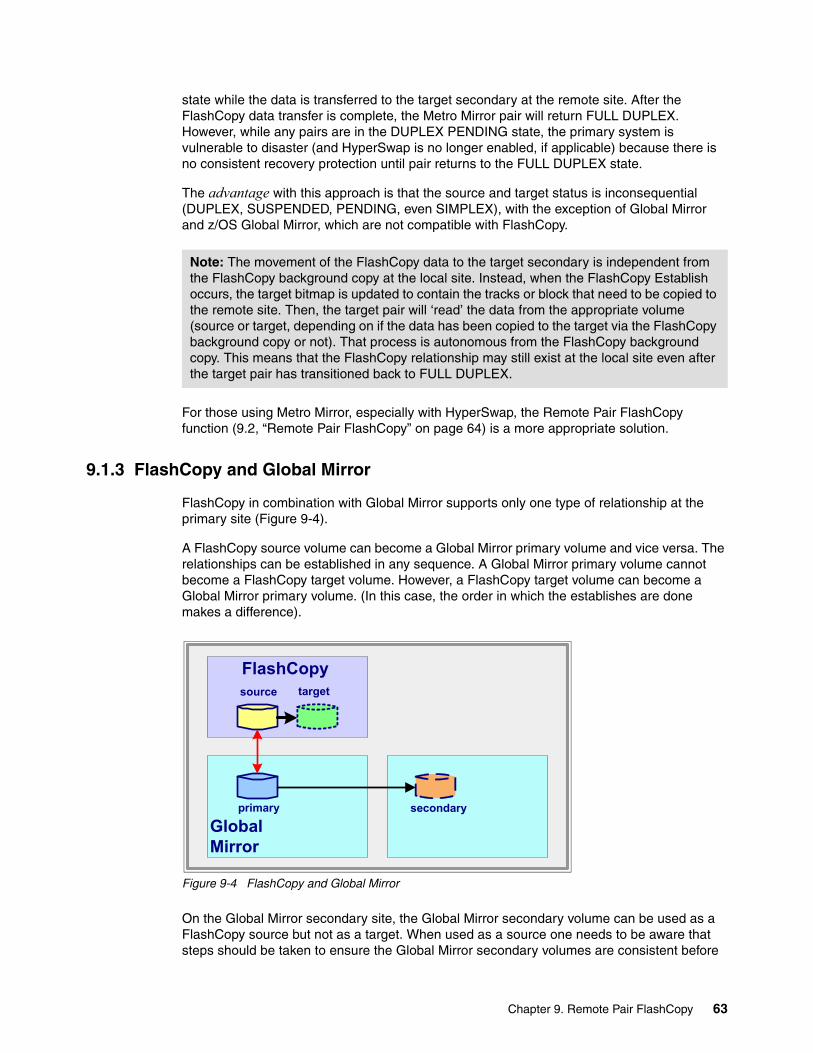
state while the data is transferred to the target secondary at the remote site. After the FlashCopy data transfer is complete, the Metro Mirror pair will return FULL DUPLEX. However, while any pairs are in the DUPLEX PENDING state, the primary system is vulnerable to disaster (and HyperSwap is no longer enabled, if applicable) because there is no consistent recovery protection until pair returns to the FULL DUPLEX state.
The advantage with this approach is that the source and target status is inconsequential (DUPLEX, SUSPENDED, PENDING, even SIMPLEX), with the exception of Global Mirror and z/OS Global Mirror, which are not compatible with FlashCopy.
For those using Metro Mirror, especially with HyperSwap, the Remote Pair FlashCopy function (9.2, “Remote Pair FlashCopy” on page 64) is a more appropriate solution.
9.1.3 FlashCopy and Global Mirror
FlashCopy in combination with Global Mirror supports only one type of relationship at the primary site (Figure 9-4).
A FlashCopy source volume can become a Global Mirror primary volume and vice versa. The relationships can be established in any sequence. A Global Mirror primary volume cannot become a FlashCopy target volume. However, a FlashCopy target volume can become a Global Mirror primary volume. (In this case, the order in which the establishes are done makes a difference).
Figure 9-4 FlashCopy and Global Mirror
On the Global Mirror secondary site, the Global Mirror secondary volume can be used as a FlashCopy source but not as a target. When used as a source one needs to be aware that steps should be taken to ensure the Global Mirror secondary volumes are consistent before
Note: The movement of the FlashCopy data to the target secondary is independent from the FlashCopy background copy at the local site. Instead, when the FlashCopy Establish occurs, the target bitmap is updated to contain the tracks or block that need to be copied to the remote site. Then, the target pair will ‘read’ the data from the appropriate volume (source or target, depending on if the data has been copied to the target via the FlashCopy background copy or not). That process is autonomous from the FlashCopy background copy. This means that the FlashCopy relationship may still exist at the local site even after the target pair has transitioned back to FULL DUPLEX.
source target
FlashCopy
GlobalMirror
primary secondary
Chapter 9. Remote Pair FlashCopy 63

performing Flashcopy (such as using the Global Mirror pause with consistency function). Otherwise, the FlashCopy target volumes might not be consistent.
9.2 Remote Pair FlashCopy
Remote Pair FlashCopy allows a Metro Mirror pair that is a FlashCopy target to remain FULL DUPLEX, and it also reduces the overhead of transferring all of the data to be copied via the PPRC links. With Remote Pair FlashCopy, only the FlashCopy command itself is sent from the local site to the secondary at the remote site, and the FlashCopy is performed, independently but consistently at both the local and remote sites. Preserving the FULL DUPLEX state of the mirror ensures that there is no loss of disaster recovery protection.
The following conditions are required to establish Remote Pair FlashCopy:
� Both the Local A / Remote A and the Local B / Remote B Metro Mirror pairs are in the FULL DUPLEX state.
� Local B / Remote B pair is SIMPLEX, SUSPENDED, or PENDING, Local A / Remote A pair can be in any state (SIMPLEX, PENDING, or SUSPENDED.
� The Remote A and Remote B volumes are in the same DS8000 Storage Facility Image (SFI).
� The required microcode level must be installed on both the local and remote storage systems.
Figure 9-5 on page 65 illustrates the following sequence of events that occur during a FlashCopy with Preserve Mirror Required (Remote Pair FlashCopy) to a Metro Mirror (or Global Copy) primary device:
� Step 1: Notice that two Metro Mirror pairs are full duplex and that there is data that resides on Local A and Remote A (because they are identical). You want to FlashCopy that data from Local A to Local B. This is the same starting point you have for non-Preserve Mirror FlashCopy invocations, but you won’t have the state transitions.
� Step 2: The FlashCopy Establish command is issued to copy the data to Local B, including keywords that allow the target to be a Metro Mirror or Global Copy primary device and with the preserve mirror required keywords.
� Step 3: The FlashCopy command is sent from Local A to Remote A. Independent of each other, the local storage system and the remote storage system then run the FlashCopy operation. The local storage system coordinates the FlashCopy activities and if the FlashCopy does not succeed at the remote site, the local storage system will suspend the target pair.
� Step 4: The FlashCopy is applied to Local A / Local B, and it is applied to Remote A / Remote B. The target pair remains full duplex the entire time.
Note: This status is reflected in PPRC query command output as a specific suspend reason (suspended due to FlashCopy failure). Remote Pair FlashCopy supports both full volume and data set FlashCopy.
Note: Remote Pair FlashCopy will not impact HyperSwap ennoblement status for the configuration because the mirror is not impacted (unless an unforeseen error occurs) and FlashCopy operations can be freely used within the storage system configuration with confidence that your data is protected.
64 DS8000 Copy Services

Figure 9-5 Remote Pair FlashCopy preserves Metro Mirror FULL DUPLEX state
9.2.1 Features of Remote Pair FlashCopy
Remote Pair FlashCopy provides the following features:
� Remote Pair FlashCopy operations are supported on both count key data (CKD) and fixed block architecture (FB) volumes.
� Remote Pair FlashCopy maintains Metro Mirror Full Duplex to preserve HyperSwap enabled state and for disaster recovery scenarios.
� No additional link bandwidth is needed because only the FlashCopy commands are sent to the remote site, not the data to be copied.
� Remote Pair FlashCopy can be used in combination with the following features:
– Incremental FlashCopy (if the initial established FlashCopy used Remote Pair FlashCopy)
– FlashCopy options: copy, nocopy, or nocopy-to-copy– FlashCopy consistency groups– Data set level FlashCopy in z/OS
Chapter 9. Remote Pair FlashCopy 65

9.2.2 Considerations
The following options are not supported by Remote Pair FlashCopy:
� Certain FlashCopy options are not supported by Remote Pair FlashCopy:
– Commit is not supported.– Revert is not supported.– Fast Reverse Restore is not supported.
� Remote Pair FlashCopy onto a Global Mirror primary is not supported.
� Remote Pair FlashCopy onto a Global Copy primary is not supported.
� Remote Pair FlashCopy with cascading configurations has the following limitations:
– Metro/Global Copy
Remote Pair FlashCopy can be used by this configuration if the configuration requirements for the devices that are involved in the Metro Mirror relationships are met. The FlashCopy command is run from Local A to Local B, and an inband FlashCopy command is run to do the FlashCopy copy from Remote A to Remote B. The tracks or blocks in the relationship are copied from Remote B to its corresponding PPRC secondary device through the Global Copy resync mechanism.
– Metro/Global Mirror
Because the ability to perform a FlashCopy to a primary device that is participating in a Global Mirror session is not allowed, any attempt to perform a Remote Pair FlashCopy (Preserve Mirror) Required operation fails because the inband FlashCopy operation attempts to perform a FlashCopy from Remote A to Remote B, and Remote B is the Global Mirror primary, which is not supported.
In this case, you cannot use Preserve Mirror unless you remove the Global Mirror pairs, that are to become FlashCopy targets, from the Global Mirror session before invoking the FlashCopy Establish commands.
Alternatively, FlashCopy to a PPRC primary without Preserve Mirror can be used at the local site between the Metro Mirror primaries, resulting in the target Metro Mirror pair going duplex pending rather than attempting an in-band FlashCopy Establish to the Global Mirror primary.
Existing Copy Services restrictions still apply. (A remote target cannot be a source, and so forth).
Remote Pair FlashCopy with Multiple Target PPRCThere are additional considerations to account for when using Remote Pair FlashCopy in a Multiple Target PPRC environment.
In a Multiple Target PPRC configuration with two Metro Mirror pairs, the Remote Pair FlashCopy operation may be performed for only one of the Metro Mirror pairs. The chpprc command is used to specify which of the Metro Mirror pairs is used for the Remote Pair FlashCopy command. The other Metro Mirror pair reverts to the duplex pending state and performs a physical copy of the data. For a detailed description of Multiple Target PPRC and the use of Remote Pair FlashCopy, see 9.7, “FlashCopy considerations for Metro/Global Mirror and Multiple Target PPRC” on page 71 or IBM DS8870 Multiple Target Peer-to-Peer Remote Copy, REDP-5151.
66 DS8000 Copy Services

9.3 Remote Pair FlashCopy implementation and usage
Before Remote Pair FlashCopy can be established, the Metro Mirror relationship between the Local A and Remote A pair and the Metro Mirror relationship between Local B and Remote B pair must be established and in Full Duplex. For more information about how to create Metro Mirror relationships, see Chapter 13, “Metro Mirror overview” on page 103.
If the Remote Pair FlashCopy establish command completes successfully at the local site but fails to mirror the command at the remote site, the Metro Mirror pair is no longer considered duplex. This results in the suspension of the Local B / Remote B Metro Mirror pair.
Table 9-1 summarizes the behavior of Remote Pair FlashCopy for different combinations of the Local and Remote Mirror pair states.
Table 9-1 Remote Pair FlashCopy behavior
Keyword: The FlashCopy to a Metro Mirror or Global Copy Primary OK keyword must be specified when the Remote Pair FlashCopy required options are used. The keyword differs depending on the interface that is used to establish FlashCopy.
Source Target Situation PM Required No PM
Duplex Duplex Normal Remote Pair FlashCopy is performed.
Target device duplex pending.
Duplex Duplex Problem with Remote FlashCopy detected early
FlashCopy failed. Target device duplex pending.
Duplex Duplex Problem with remote FlashCopy detected late
Target device suspended. Target device duplex pending.
Suspended Suspended Any Perform a local FlashCopy and set the Metro Mirror OOS bitmap.
Set the target device OOS bitmap.
Pending Pending Any Perform a local FlashCopy and set the Metro Mirror OOS bitmap.
Set the target device OOS bitmap.
Duplex Suspended / Pending
Any Perform a local FlashCopy and set the Metro Mirror OOS bitmap
Set the target device OOS bitmap.
Suspended / Pending
Duplex Any FlashCopy fails. Target device duplex pending.
Any Simplex Any FlashCopy issued locally. FlashCopy issued locally.
Simplex Duplex Any FlashCopy failed. Target device duplex pending.
Simplex Suspended / Pending
Any Perform a local FlashCopy and set the Metro Mirror OOS bitmap.
Set the target device OOS bitmap.
Chapter 9. Remote Pair FlashCopy 67

9.4 Remote Pair FlashCopy withdrawal
When a Remote Pair FlashCopy operation begins, there is no guarantee that the local and remote DS8000s perform the background copy for their respective relationships at the same pace. Therefore, a withdrawal of the FlashCopy relationship, which might be issued by the host, introduces a situation where Local B and Remote B are not identical, even though the Metro Mirror pair is in the Full Duplex state.
There are two methods to withdraw Remote Pair FlashCopy relationships. The relationships can be withdrawn after a background copy completes that maintains the Metro Mirror Full Duplex state, or the relationships can be forced to withdraw immediately, which also maintains Metro Mirror Full Duplex state, but it sets an indicator in the Metro Mirror target relationship that they are logically identical if not physically identical.
9.4.1 Withdraw with Background Copy
To ensure identical Local B and Remote B data, the local and remote relationships should be terminated only after all source data is copied (destaged) to the target volumes. This task can be achieved by performing a FlashCopy Withdraw with Background Copy operation on both local and remote relationships. After the background copy completes, the Metro Mirror primary and secondary volumes are physically identical.
The following rules apply to Withdraw with Background Copy:
� FlashCopy Withdraw of a mirrored relationship that is established with Remote Pair FlashCopy Required, without the force indicator, issued to either Local A or Local B, results in a background copy being initiated for both the local and the remote relationships. If the relationship is persistent, the relationship is withdrawn after the background copy completes.
� A start background copy that is issued to Local A starts a background copy for both the local and the remote relationships.
� A start background copy that is issued to Remote A starts a background copy for the remote relationship only.
� FlashCopy Withdraw without start Background Copy or Terminate All (also known as the Deleted Data Space Withdraw (DDSW) option - z/OS only) issued to Remote A is rejected if the background copy is not complete.
� FlashCopy Withdraw with Terminate All issued to Remote B is rejected if the background copy is not complete.
� FlashCopy Withdraw with Terminate All, issued to the remote FlashCopy source (Remote A), starts a background copy for the remote relationship only.
Resynchronizing: If Remote Pair FlashCopy is used in combination with Incremental FlashCopy, the FlashCopy relationship must be created after the Metro Mirror relationship, or subsequent increment restores will fail. This is because if the relationship is established without Remote Pair FlashCopy, there will not be a corresponding relationship at the remote. A restore issued with Remote Pair FlashCopy Required will fail when it attempts to mirror that restore to a relationship that does not exist at the remote location and will suspend the target Metro Mirror pair.
68 DS8000 Copy Services

9.4.2 Forcing FlashCopy Withdraw
Withdraw with Background Copy might not be suitable for all situations. For example, if another FlashCopy Establish is issued before the previously established relationships finish the background copy, the new FlashCopy operation fails. This could happen if you are doing many FlashCopy operations to take a backup before running batch, for instance, but before the job completes, one of the FlashCopy establish commands fails. In order to restart the job, you need to withdraw all relationships that were successful and then re-establish. In this case, there is no purpose in waiting for background copy to complete so that the same copies can be taken again. The delay could impact batch window processing and it is a lot of unnecessary overhead to copy the volumes more than one time to get a consistent copy.
In that scenario, a force option can be used on the FlashCopy Withdraw that causes a mirrored relationship to be withdrawn immediately at both the local and the remote sites without initiating background copy first.
When the force option is used, an indicator is set for the target Metro Mirror pair, stating that there might be tracks that are not physically identical even though the pair is Full Duplex and logically identical. The data on those tracks is not considered valid by the host, so the Metro Mirror pair is still considered Full Duplex.
9.4.3 Withdrawing on the Metro Mirror secondary
Normally, removing the FlashCopy relationship on the Metro Mirror Primary volumes automatically removes the remote FlashCopy relationship on the secondary Metro Mirror volume. If there are communications problems, the remote FlashCopy relationship on the secondary Metro Mirror volumes cannot be removed.
In this case, it will be necessary to withdraw the remote relationship manually to prevent errors when attempting to mirror a new relationship from the local when a relationship already exists on the remote. This can be done via inband (if the PPRC links are in tact and the pair is not suspended), or by issuing the command directly to the remote device, if the host system has access to the remote devices.
9.4.4 FlashCopy Withdraw interface differences
The default handling behavior for FlashCopy Withdraw is different depending on the interface that is used:
� ICKDSF:
– The default initiates Background Copy on withdraw. – The FORCE keyword exists and is optional.
� TSO / DFSMSdss / ANTRQST:
Force is the default with no other option.
Mirrored relationships: If FlashCopy relationship is established as a mirrored relationship, and the Local B to Remote B Metro Mirror relationship is deleted before a FlashCopy Withdraw request, then the relationship is no longer treated as a mirrored relation, so normal withdraw processing applies.
Chapter 9. Remote Pair FlashCopy 69

� DS CLI:
– There is no force option.– The default behavior fails the withdraw. – It requires the -cprm option to initiate Background Copy.
9.5 Remote Pair FlashCopy impact on Metro Mirror state
Remote Pair FlashCopy operations can impact the state of the Metro Mirror pair:
� If a force withdraw is issued against a Remote Pair FlashCopy pair, the Metro Mirror pair still shows as Full Duplex, but there is also an indication that the pair was the target of a Remote Pair FlashCopy Withdraw.
� If a Remote Pair FlashCopy Establish Required fails at the remote system, the Metro Mirror pair suspends. The Metro Mirror query indicates that the reason for the suspension is Remote Pair FlashCopy.
9.6 Using Remote Pair FlashCopy in a z/OS environment
In a z/OS environment, specifically for SMS managed volumes or data sets, there is a process called volume selection when looking for space to allocate a data set to copy into or to select volumes that are eligible to become Flashcopy targets for full volume operations.
9.6.1 Remote Pair FlashCopy and SMS volume selection
When doing volume selection, it is known, if the copy is going to be logical (FlashCopy) or physical (standard I/O). It is also known, if FlashCopy will be used and which type of FlashCopy operation it will be. These values are taken into consideration so that the correct volume and/or tracks are chosen.
DFSMS takes several things into consideration, two of them are key:
� Is FAST REPLICATION (use of FlashCopy) required or preferred?� Is Remote Pair FlashCopy required?
70 DS8000 Copy Services

The following situations are handled in the following ways:
� If the volume is not FlashCopy eligible or capable and if FAST REPLICATION was REQUIRED, this volume is rejected.
� If the volume is FlashCopy capable:
– PRESERVE MIRROR is either not specified or specified as NO.
• If the potential target is not a PPRC primary, the volume is eligible for volume selection and is ranked higher than a similar non-FR capable volumes.
• If the potential target is a PPRC primary and FlashCopy to PPRC OK is specified, the volume is eligible for volume selection and is ranked higher than a similar non-FR capable volumes.
• If the potential target is a PPRC primary and FlashCopy to PPRC OK is not specified, the volume is rejected.
– PRESERVE MIRROR is specified as REQUIRED. This volume is considered eligible for volume selection if any one of the following conditions is met:
• The volume is PRESERVE MIRROR capable.
• The volume is NOT PRESERVE MIRROR capable because it is not a PPRC volume. But this means there is no mirror to impact.
9.7 FlashCopy considerations for Metro/Global Mirror and Multiple Target PPRC
In a multigrade PPRC environment with Metro Mirror on one leg and Global Mirror on the other leg, FlashCopy target volumes cannot be part of a Global Mirror Session. Many customers want to mirror all data or volumes, even the FlashCopy target volumes. However, FlashCopy cannot be used if a target volume is part of a Global Mirror session.
The FlashCopy target volume can be mirrored with Global Copy, but it cannot be part of a consistency group that a Global Mirror session represents, because consistency group formation would have to wait until the FlashCopy background copy process has finished, which would significantly impact your RPO. Refer to Figure 9-6 on page 72.
Chapter 9. Remote Pair FlashCopy 71

Figure 9-6 FlashCopy in a Metro Mirror / Global Mirror multigrade environment
You can identify and isolate a range of volumes that will act as FlashCopy target volumes. You can replicate this range of volumes with Global Copy, but they cannot be part of the Global Mirror session. DFSMS volume selection will honor policies set up to isolate these volumes and select appropriate FlashCopy target volumes accordingly.
9.7.1 Remote Pair FlashCopy with Multiple Target PPRC
With Multiple Target PPRC, the Local source and target volumes can now have two Metro Mirror relationships on them, as shown in Figure 9-7 on page 73. A Remote Pair FlashCopy command can be performed for only one of the Metro Mirror pairs. The other pair will transition back to duplex pending and mirror the copied data to the remote volume.
H1
H2
H3Metro Mirror(synchronous)
Global Copy (asynchronous)
Global Mirror session controls FlashCopy at H3FlashCopy
FlashCopyworkswithpmir
Preserve mirror FlashCopy
Background copy process
Background copyprocess
…sends data to H3
H1
H2
H3Metro Mirror(synchronous)
Global Copy (asynchronous)
Global Mirror session controls FlashCopy at H3FlashCopy
FlashCopydoesnotwork
Preserve mirrordoes not work
Background copy process
Background copyprocess
…sends data to H3
72 DS8000 Copy Services

Figure 9-7 Remote Pair FlashCopy with Multiple Target PPRC
In a configuration with two Metro Mirror pairs, the user must identify which of the pairs to use for the Remote Pair FlashCopy operation. The Set PPRC Characteristics command is used to set or reset Use Remote Pair FlashCopy for a Metro Mirror pair to indicate whether Remote Pair FlashCopy is to be used for that pair. In the case of a failure or suspension of the pair that is enabled for Remote Pair FlashCopy, the Use Remote Pair FlashCopy command can be used to enable the function on the surviving Metro Mirror pairs. The interfaces for the set PPRC Characteristics command are:
� DS CLI chpprc � TSO PSETCHAR � ANTRQST PSETCHAR � ANTTREXX PSETCHAR � ICKDSF PPRCOPY SETCHARACTERISTICS
When a Remote Pair FlashCopy command is issued to a Multiple Target PPRC primary volume and the conditions allow such an operation, the Metro Mirror pair that is enabled for Remote Pair FlashCopy will mirror the FlashCopy command, and the other pair will transition back to duplex pending and copy the data to the remote site using Metro Mirror.
If neither pair or if both pairs are enabled for Remote Pair FlashCopy and a Remote Pair FlashCopy command is received, the command will be rejected because the storage system cannot determine which of the Metro Mirror pairs to use for the command. (Fails due to ambiguous configuration).
Chapter 9. Remote Pair FlashCopy 73

74 DS8000 Copy Services

Chapter 10. FlashCopy performance
This chapter describes the preferred practices when you configure FlashCopy for specific environments or scenarios. It includes the following topics:
� FlashCopy performance overview� FlashCopy establish performance� Background copy performance� FlashCopy impact on applications� FlashCopy scenarios
10
© Copyright IBM Corp. 2017. All rights reserved. 75

10.1 FlashCopy performance overview
Many parameters can affect the performance of FlashCopy operations. It is important to review the data processing requirements and select the correct FlashCopy options.
This chapter examines when to use copy versus nocopy mode and where to place the FlashCopy source and target volumes/LUNs. This chapter also describes when and how to use Incremental FlashCopy, which should definitely be evaluated for use in most applications.
TerminologyBefore you read the description of FlashCopy preferred practices, review the following basic terminology that is used in this chapter:
� Server
The current DS8000 models have one pair of servers (server 0 and server 1, one on each processor complex), both integrated in a single Storage Facility Image (SFI). You can run lsserver to see the available servers.
� Device adapter (DA)
A physical component of the DS8000 that provides communications between the servers and the storage devices. The lsda command lists the available device adapters.
� Rank
An array site that is made into an array, which is then made into a rank. For the DS8000, a rank is a collection of eight disk drive modules (DDMs). The lsrank command displays detailed information about the ranks.
10.1.1 Distribution of the workload: Location of source and target volumes
In general, you can achieve the best performance by distributing the load across all of the resources of the DS8000. You should carefully plan your usage so that the load is:
� Spread evenly across the storage system� Within each storage system, spread evenly across servers� Within each server, spread evenly across device adapters� Within each device adapter, spread evenly across ranks
Use Storage Pool Striping in the extent pools to spread the activity across DAs and ranks.
Storage Pool Striping is an allocation method for volumes where the extents for a volume are allocated on the ranks by using a round-robin algorithm. This allocation method can improve the throughput for a single volume.
Since Storage Pool Striping and Easy Tier, the preferred practice for logical configuration is to have as few extent pools as possible. Extent pools should have multiple ranks from different DAs and use Storage Pool Striping. This configuration spreads the FlashCopy activity across DAs and ranks. Therefore, the only consideration that is left is to have the source and targets in the same server.
Terminology: The information in this chapter is equally valid for z Systems count key data (CKD) volumes and Open Systems fixed block architecture (FB) volumes. The following sections use only the terms volume or volumes, but the text is equally valid if the terms LUN and LUNs are used, unless otherwise noted.
76 DS8000 Copy Services

Table 10-1 lists a summary of the volume placement considerations.
Table 10-1 FlashCopy source and target volume location
10.1.2 LSS/LCU versus rank: Considerations
With the DS8000, it is more meaningful to describe volume location in terms of ranks and not in terms of a logical subsystems (LSS) or logical control unit (LCU).
The LSS/LCU in a DS8000 storage system are logical constructs that are not tied to predetermined ranks. Within the DS8000, the LSS/LCU can be configured to span one or more ranks but is not limited to specific ranks. There can be individual ranks that contain volumes from more than a single LSS/LCU, which was not possible before the introduction of the DS8000.
However, the LSS/LCU is associated with one server of the DS8000. An even-numbered LSS/LCU is managed by server 0, and an odd-numbered LSS/LCU is managed by server 1. Remember, the first two numbers xx of a volume’s address xxnn denote the LSS/LCU. To select an ideal (from a performance standpoint) target volume yymm for source volume xxnn, xx and yy should be both even or both odd.
In z/OS DFSMSdss and DFSMShsm, when using FlashCopy, goes through a volume selection process when the user does not specifically identify the target volume for the Establish. During volume selection processing DFSMS will prefer eligible targets in the same server as the source, over potential targets that are in a different server.
10.1.3 Rank characteristics
Normal performance planning also includes the task to select disk drives (capacity and RPM) and RAID configurations to match the performance needs of the applications.
With FlashCopy nocopy relationships, the DS8000 does copy on writes for each first change to a source volume track. If the disks of the target volume are slower than the disks of the source volume, production I/O might be affected. A full volume background copy causes read
Server Device adapter Rank
FlashCopy establish performance
Same server Unimportant Different ranks
Background copy performance
Same server Different device adapter Different ranks
FlashCopy impact to applications
Same server Unimportant Different ranks
Tip: To find the relative location of volumes, use the following procedure:
1. Run the lsckdvol command to discover which extent pool contains the relevant volumes.
2. Run the lsrank command to display both the device adapter and the rank for each extent pool.
3. To determine which server contains volumes, look at the extent pool name. Even-numbered extent pools are always from server 0, and odd-numbered extent pools are always from server 1.
Chapter 10. FlashCopy performance 77

activity on the source volumes and write activity on the target volumes. This situation should be considered when you choose when full volume copies should be done and whether nocopy or copy should be used. Keep in mind that a nocopy relationship can be converted to a copy relationship. Therefore, it is a preferred practice to use target volumes on ranks with the same characteristics as the source volumes.
Finally, you can achieve a small performance improvement by using identical rank geometries for both the source and target volumes. If the source volumes are on a rank with a 7+p/RAID 5 configuration, then the target volumes should also be on a rank that is configured as 7+p/RAID 5.
10.2 FlashCopy establish performance
The FlashCopy of a volume has the following distinct phases:
� The initial logical FlashCopy (also called establish)� The physical FlashCopy (also called background copy)
The FlashCopy establish phase, or logical FlashCopy, is the period when the microcode is preparing things, such as the bitmaps, necessary to create the FlashCopy relationship so the microcode can properly process subsequent reads and writes to the related volumes. During this logical FlashCopy period, the DS8000 holds off I/O activity to the source and target volume. However, this period is short. After the logical relationship is established, normal I/O activity resumes to both source and target volumes according to the options selected.
When there are many volumes, the method that is used to start the FlashCopy commands can influence the time that it takes to complete the logical FlashCopy for all FlashCopy pairs. An inband invocation, as it is used by z/OS, sources the commands to the microcode faster than an out-of-band method, as used by the DS CLI.
Finally, the placement of the FlashCopy source and target volumes affects the establish performance. For a description of this topic, see 10.1.1, “Distribution of the workload: Location of source and target volumes” on page 76, and see Table 10-1 on page 77 for a summary of the recommendations.
10.3 Background copy performance
The background copy phase, or physical FlashCopy, is the movement of the data from the source volume to the target volume. If the FlashCopy relationship is established with the nocopy option, then only write updates to the source volume force a copy from the source to the target. This forced copy is also called copy-on-write.
If the copy option is used, upon completion of the logical FlashCopy establish phase, the source is copied to the target in an expedient manner.
Copy-on-write: The term copy-on-write describes a forced copy from the source to the target because a write to the source occurs. This situation occurs on the first write to a track. Because the DS8000 writes to a non-volatile cache, there is typically no direct response time delay on host writes. The forced copy occurs only when the write is destaged onto disk.
78 DS8000 Copy Services

If many FlashCopy relationships are established, then not all pairs are actively copying data when their logical FlashCopy relationship is complete. The DS8000 microcode has the intelligence to limit the number of active pairs that are copying data at one time. This algorithm balances active copy pairs across the DS8000 device adapter resources. Additionally, the algorithm limits the number of active pairs so that there is bandwidth for host or server I/Os.
The preferred placement of the FlashCopy source and target volumes regarding the physical FlashCopy phase is described in 10.1.1, “Distribution of the workload: Location of source and target volumes” on page 76. For a summary of the conclusions, see Table 10-1 on page 77. For good background copy performance, the implementation should always place the source and target volumes in different ranks. There are more criteria to consider if the FlashCopy is a full box copy that involves all ranks.
For full box copies, you should still place the source and target volumes in different ranks. When all ranks are participating in the FlashCopy, it is still possible to accomplish this configuration by doing a FlashCopy of volumes on rank R0 onto rank R1, and volumes on rank R1 onto rank R0 (for example). Additionally, if there is heavy application activity in the source rank, performance is less affected if the background copy target is in some other rank that can be expected to have lighter application activity.
If background copy performance is of high importance in your environment, you should use Incremental FlashCopy as much as possible. Incremental FlashCopy greatly reduces the amount of data that must be copied, and therefore greatly reduces the background copy time.
10.4 FlashCopy impact on applications
One of the most important considerations when you implement FlashCopy is to achieve an implementation that has minimal impact on the users’ applications performance.
Note: The DS8000 gives higher priority to application performance than background copy performance. The DS8000 throttles the background copy if necessary so that applications are not unduly impacted.
Full box copy: The term full box copy implies that all rank resources are involved in the copy process. Either all or nearly all ranks have both source and target volumes, or half the ranks have source volumes and half the ranks have target volumes.
Tip: If you use Storage Pool Striping when you allocate your volumes, all ranks are more or less equally busy, so you are not concerned about the placement of your data.
FlashCopy performance: As already mentioned, the preferred practices that are described in this chapter consider only the performance aspects of a FlashCopy implementation. But FlashCopy performance is only one aspect of an effective system design. You must consider all business requirements when you design a complete solution. These additional requirements, together with the performance considerations, can guide you when you choose FlashCopy options, such as the copy, nocopy, and incremental options, and when you make choices about the source and target volumes’ location.
Chapter 10. FlashCopy performance 79

The relative placement of the source and target volumes has a significant impact on the applications performance, as described in 10.1.1, “Distribution of the workload: Location of source and target volumes” on page 76.
In addition to the relative placement of volumes, the selection of copy or nocopy is also an important consideration regarding the impact on application performance. Typically, the choice of copy or nocopy depends primarily on how the FlashCopy is used and for what interval of time the FlashCopy relationship exists. From a pure performance point of view, the choice of whether to use copy or nocopy depends a great deal on the type of workload. The general answer is to use nocopy, but this option is not always the best choice. For most workloads, including online transaction processing (OLTP) workloads, nocopy typically is the preferred option. However, some workloads that contain many random writes and are not cache friendly might benefit from using the copy option.
10.4.1 FlashCopy nocopy
In a FlashCopy nocopy relationship, a copy-on-demand is done whenever a write to a source track occurs for the first time after the FlashCopy is established. This type of FlashCopy is ideal when the target volumes are needed for a short time only, for example, to run the backup jobs. The FlashCopy nocopy option puts only a minimum additional workload on the back-end adapters and disk drives. However, it affects most of the writes to the source volumes while the relationship exists. When you plan to keep your target volumes for a long time, this might not be the best solution.
10.4.2 FlashCopy full copy
When you plan to use the target volumes for a longer time or you plan to use them for production and you do not plan to repeat the FlashCopy often, then the full copy FlashCopy is the preferred choice. A full copy FlashCopy puts a high additional workload on the back-end device adapters and disk drives, but this load lasts only for a few minutes or hours depending on the capacity, and then there is no additional impact.
10.4.3 Incremental FlashCopy
Another important performance consideration is whether to use Incremental FlashCopy. You should use Incremental FlashCopy when you do FlashCopy copies always to the same target volumes at regular intervals. The first FlashCopy is a full copy, but subsequent FlashCopy operations copy only the tracks of the source volume that are modified since the last FlashCopy.
Incremental FlashCopy has the least impact on applications. During normal operation, no copy-on-write is done (as in a nocopy relationship), and during a resync, the load on the back end is much lower compared to a full copy. There is only a small impact for the maintenance of the target change recording bitmap.
Incremental FlashCopy is only supported at the volume level. Incremental FlashCopy does not support data set level FlashCopy.
The resyncflash command: The Incremental FlashCopy resyncflash command does not have a nocopy option. Running resyncflash automatically uses the copy option, regardless of whether the original FlashCopy was copy or nocopy.
80 DS8000 Copy Services

10.5 FlashCopy scenarios
This section describes four scenarios. These scenario descriptions assume that the primary concern is to minimize the FlashCopy impact to application performance.
10.5.1 Scenario #1: Backup to disk
In environments where recovery time objective (RTO) (how quickly you can return to production after a failure) is of most importance, a FlashCopy backup to disk can help achieve a fast restore time. When the logical FlashCopy is complete, it is possible to perform a reverse FlashCopy and restore your production data in seconds, instead of the several hours it normally takes to retrieve the data from tape.
When you back up to disk, it is important to take the necessary steps to protect your data. Remember, until the background copy is complete, you still have only one physical copy of the data, and that copy is vulnerable. Therefore, it is important to always establish the FlashCopy with the copy option and have the target volumes on other ranks as the source volumes. Otherwise, in the unlikely event that you have a failure of your production volumes, you also lose your backup.
One method for protecting against failure is to use multiple FlashCopy targets. FlashCopy supports up to 12 targets per source volume. With this feature, it is possible to keep up to 12 versions of your production data (for example, a FlashCopy backup every two hours for one day). Another method is to use Incremental FlashCopy. Incremental FlashCopy copies only the data that changed since the last FlashCopy, so the background copy completes faster.
10.5.2 Scenario #2: Backup to tape
If you want to create a copy of the data only to later back up that data to tape, then FlashCopy with the nocopy option is the preferred approach. There are still some implementations where the copy option is employed.
The backup to tape is normally done shortly after the logical FlashCopy relationships are established for all the volumes that are going to be backed up to tape.
If you choose the nocopy option, that is probably because the data that is being backed up to tape is mostly coming from the FlashCopy source volumes. If so, then the location of the target volumes is less critical and might be decided by considerations other than performance.
If you choose the copy option, that is probably because the data that is being backed up is coming from the target volumes (assuming that the backup to tape does not start until the background copy completes). If the backup starts sooner, the data might be coming from a mixture of source volumes and target volumes. As the backup continues, more of the data comes from the target volumes as the background copy moves more of the data to the target volumes.
To have the least impact on the application and to have a fast backup to tape, spread the source volumes evenly across the available storage system resources. After the backup to tape is complete, withdraw the FlashCopy relationship.
Tip: Withdraw the pairs as soon as the backup to tape is finished. This action eliminates any unnecessary copying from the source volume.
Chapter 10. FlashCopy performance 81
These recommendations are equally valid for a copy or nocopy environment.
10.5.3 Scenario #3: FlashCopy during peak application activity
The choice of whether to use copy or nocopy depends mostly on business requirements, but with regards to performance, it also depends a great deal on the type of workload. This topic is described in 10.4, “FlashCopy impact on applications” on page 79.
In general, nocopy is the preferred method, but you should also think about the following considerations when you choose either copy or nocopy:
� Using nocopy: The argument here is that the impact caused by the I/O resulting from the copy option is more significant than the impact of the nocopy option, where less I/O activity results from copy-on-demand occurs. Still, because the background copy occurs only when the writes are destaged from non-volatile cache, there is typically a negligible impact. If the workload is cache-friendly, then potentially all of the operations are served from cache, and there is no impact from copy-on-write at all.
� Using copy: The goal of using copy is to complete quickly the background copy so that the overlapping situations between FlashCopy and application processing ends sooner. If copy is used, then all I/Os experience some degradation as they compete for resources with the background copy activity. However, this impact might be less than the impact to the individual writes that a copy-on-demand causes.
If FlashCopy nocopy is active during a period of application high activity, there might be a high rate of collisions, that is, destages being delayed so that the track image can be read and then written to the FlashCopy target track to preserve the point-in-time copy. The destage delay might cause degradation of the performance for all writes that occur during the delay destage periods. It is only the first write to a track that causes a collision, and only when that write is destaged. The reads do not suffer collision degradation.
If you use the copy option, also consider these tips:
� Examine the application environment for the highest activity volumes and the most performance sensitive volumes.
� Consider arranging the FlashCopy order such that the highest activity and most performance sensitive volumes are copied early and the least active and least performance sensitive volumes are copied last.
If a background copy is the wanted result and FlashCopy is started just before or during a high activity period, consider the possibility of starting with nocopy and converting to copy after the high activity period completes.
Tip: You should fully explore alternatives that reduce FlashCopy activity with other peak application activity. If such alternatives are not viable for whatever operative reasons, then consider the topics that are described in this section.
Tip: One approach to achieve a specified FlashCopy order is to partition the volumes into priority groups. Run the appropriate FlashCopy commands for all volumes, but use copy on only the highest priority group and nocopy on all other groups. After a specified period or after some observable event, issue FlashCopy commands to the next highest priority group from nocopy to copy. Continue in this manner until all volumes are fully copied.
82 DS8000 Copy Services

10.5.4 Scenario #4: Ranks reserved for FlashCopy
Another configuration worth considering is the one where 50% of the ranks (capacity) are all FlashCopy source volumes (where the applications write I/Os take place) and the remaining 50% of the ranks (capacity) are all FlashCopy target volumes.
Such an approach does have pros and cons. The disadvantage is the loss of 50% of the ranks for normal application processing. The advantage is that FlashCopy writes to target volumes do not compete against applications that are writing to the target volumes, which means that the background copy completes faster, which reduces the interference with application I/Os.
There is a trade-off that must be decided upon:
� Use all ranks for your application:
– This action maximizes normal application performance.– FlashCopy performance is reduced.
� Use only half of the ranks for your applications:
– This action maximizes FlashCopy performance.– Normal performance is reduced.
If you plan for a FlashCopy implementation at the disaster recovery site, you must consider the following distinct environments:
� Disaster recovery mirroring performance with and without FlashCopy active� Application performance if disaster recovery failover occurs
The solution should provide acceptable performance for both environments.
For the z/OS Global Mirror secondary configuration, use the configuration where 50% of the ranks are for FlashCopy source volumes and the other 50% for FlashCopy target volumes. In such a configuration, the z/OS Global Mirror journal volumes are placed on the FlashCopy target volume ranks. The FlashCopy target volumes for these journal volumes are placed on the z/OS Global Mirror secondary volume ranks.
Because all of the update data is first written to the journal volumes and then written to the secondary volumes, such an arrangement does split the non- FlashCopy secondary workload in half and can be implemented to use all ranks. During FlashCopy, the copy of the journal volumes from source to target is less stressful because there are relatively few journal volumes relative to the many z/OS Global Mirror secondary volumes.
Chapter 10. FlashCopy performance 83

84 DS8000 Copy Services

Chapter 11. FlashCopy examples
This chapter presents examples of the usage of FlashCopy on the IBM System Storage DS8000 in a z Systems and Open Systems environment. It focuses on the following scenarios:
� Creating a test system or integration system� Creating a backup� Establishing a remote FlashCopy� Establishing Remote Pair Flashcopy� TSO FlashCopy query commands� ICKDSF query command for FlashCopy
For each of these scenarios the DS CLI is used. For z Systems environments, it shows examples of query commands for FlashCopy.
11
© Copyright IBM Corp. 2017. All rights reserved. 85

11.1 Creating a test system or integration system
Test systems or integration systems are used to perform application tests or system integration tests. Because many write operations probably occur over the period that is involved in the tests, perform a copy in the background environment.
11.1.1 One-time test system
Assume that there is an application using one volume, and you must create a test system to allow application tests or integration tests, which are based on the contents of the production data. You set up FlashCopy to copy the data once, see Example 11-1.
Example 11-1 Create a one-time test system by using TSO FlashCopy commands
#--- remove existing FlashCopy relationships for volume 6100rmflash -quiet 6100:6300
#--- establish FlashCopy relationships for source volume 6100mkflash -seqnum 01 6100:6300
#--- list FlashCopy relationships for volume 6100lsflash -l 6100
Example 11-1 first removes existing FlashCopy relationships and then establishes a new FlashCopy with the optional -seqnum parameter. You can use this sequence number as an identifier for a relationship.
The application typically should be quiesced or briefly suspended before you start the FlashCopy. Also, some applications cache their data. So you might have to flush this data to disk by using application methods before you run the FlashCopy (this action is not covered in our example).
11.1.2 Multiple setup of a test system with the same contents
Assume that an application test is required multiple times with the same setup of data. The production volume is 6100; the test volume is 6300. You choose volume 6101 as an intermediate volume that gets its data once, copying it from the production volume by using FlashCopy. Then, you use it as a base for refresh of the test volume 6300.
Running Part 1 and Part 2 as one job or script (see Example 11-2) does not work. The script fails because volume 6101 cannot be the target for one FlashCopy relationship and the source for another FlashCopy relationship at the same time. You must wait until the background copy (indicated by the -cp parameter) for 6100 and 6101 finishes successfully before you start Part 2.
Example 11-2 Create a multiple setup of a test system
#=== Part 1: establish FlashCopy relationship #--- remove, establish, list FlashCopy relationships rmflash -quiet 6100:6101rmflash -quiet 6101:6300mkflash -seqnum 01 -cp 6100:6101 lsflash -l 6100-6400#=== Part 2: establish FlashCopy 2 relationship 03:00 pm 6100 → 6300
86 DS8000 Copy Services

#--- after the full volume copy of 6100 → 6101 finished#--- establish relationship from 6101:6300 mkflash -seqnum 02 -cp 6101:6300lsflash -l 6100-6300
Alternatively, you can also run rmflash with the -cp and -wait parameters. These parameters cause the command to wait until the background copy is complete before you continue with the next step.
Whenever the test environment must be reset to the original data, run Part 2 of the script to perform a FlashCopy.
11.2 Creating a backup
Using FlashCopy for backup purposes can be implemented in several ways, as described in the following sections.
11.2.1 Creating a FlashCopy for backup purposes without a volume copy
Volumes that are the result of a FlashCopy can be used by a backup server to back up the data to tape. Because the backup process merely reads the data, one of your options can be to perform a FlashCopy without physically copying all data to the target. When the backup of the data finishes, you can remove the FlashCopy relationship explicitly.
To start this procedure, complete the following steps:
1. Establish FlashCopy from volume A to volume B with the nocopy option (see Example 11-3).
Example 11-3 Create a backup copy by using TSO FlashCopy commands
#=== Part 1: establish FlashCopy relationship
mkflash -nocp -seqnum 01 6100:6300
#--- list FlashCopy relationships for volume 6100lsflash -l 6100
2. Run the backup.
3. Remove the FlashCopy relationship after the volume backup completes (see Example 11-4).
Example 11-4 Withdraw the FlashCopy relationship
#=== Part 2: remove FlashCopy relationshipsrmflash -quiet 6100:6300
After you take the backup, remove the FlashCopy relationship if you do not intend to use it for other purposes. Thus, you can avoid unnecessary writes (see Example 11-4).
In complex application environments (for example, SAP), FlashCopy is often used as part of the backup solutions. A good example for such solution in a open system environment is IBM Spectrum™ Protect Snapshot, which integrates into the IBM Spectrum Protect™ backup infrastructure.
Chapter 11. FlashCopy examples 87

11.2.2 Incremental FlashCopy for backup purposes
You can have the safety of a real physical copy without always copying the full volume by taking an Incremental FlashCopy. An initial full volume FlashCopy is followed by subsequent Incremental FlashCopy copies, which copy only the updates that took place on the source volume (see Example 11-5). To create a FlashCopy relationship that persists after the full copy is done, which is necessary for a incremental FlashCopy, you need to specify -persist and -record parameter.
Create an initial FlashCopy ready for subsequent incremental FlashCopy copies.
Example 11-5 FlashCopy updates that took place on the source volume
#=== Part 1: establish FlashCopy relationship
mkflash -record -persist -seqnum 01 6100:6300
#--- list FlashCopy relationships for volume 6100lsflash -l 6100
After the initial full volume copy, the script that is shown in Example 11-6 supports the incremental copy of the FlashCopy relationship by using the command resyncflash.
Example 11-6 Create an Incremental FlashCopy
=== Part 2: resynch FlashCopy relationshipresyncflash -record -persist -seqnum 01 6100:6300lsflash -l 6100
11.2.3 Using a target volume to restore its contents back to the source
You might have to apply logs to the FlashCopy target volume and then reverse the target volume to the source volume.
To reverse the relationship, you must copy the data to the target before you reverse it back to the source. To avoid a situation where the full volume must be copied with each FlashCopy, you should use Incremental FlashCopy. As you might have to apply logs to the target volume before you reverse it, you should vary the target volume online (z Systems) or in an open system environment the target volume should be write-enabled.
This example consists of the following steps:
1. Establish initial FlashCopy (see Example 11-7).
2. Establish Incremental FlashCopy (see Example 11-8 on page 89).
3. Reverse the relationship (see Example 11-9 on page 89).
Consider applying application or DB logs as well.
Example 11-7 Run the initial FlashCopy to support the refresh of the source volume
#=== Part 1: Establish Incremental FlashCopy mkflash -persist -record -tgtinhibit -seqnum 01 6100:6101 lsflash -l 6100
The -tgtinhibit parameter is used to prevent host system to do write operations to the target volume while the FlashCopy relationship exists.
88 DS8000 Copy Services

After the initial FlashCopy, the incremental copies can be done (see Example 11-8).
Example 11-8 Create an Incremental FlashCopy
#=== Part 2: Resynch FlashCopy relationshipresyncflash -record -persist -tgtinhibit -seqnum 01 6100:6101lsflash -l 6100
The reverse of the FlashCopy is done by running reverseflash (see Example 11-9).
Example 11-9 Reverse the volumes
#=== Part 3: Reverse FlashCopy relationshipreverseflash -persist -record -tgtinhibit -seqnum 01 6100:6101 lsflash -l 6100
11.3 Establishing a remote FlashCopy
You can use commands to manage a FlashCopy relationship at a remote site. The commands can be issued from the local site, and then they are transmitted over the Metro Mirror or Global Copy links. This configuration eliminates the need for an Ethernet network connection to the remote site solely for the management of FlashCopy. This functionality is also known as in-band FlashCopy. For more information see 7.9, “Remote (in-band) FlashCopy” on page 50.
To shorten our example we assume that the Metro Mirror or Global Copy relationships already exist, see 18.2.1, “Setup, remove and manage of a Metro Mirror configuration” on page 154 to get more information about how to establish a Global Copy and Metro Mirror relationship.
Figure 11-1 illustrates the volume pairs for which we establish the FlashCopy pair at the remote site H2.
Figure 11-1 Remote FlashCopy environment
Because we use the in-band functions of FlashCopy, we must specify the LSS of the H1 volume with the -conduit parameter and the Storage Image ID at the remote site for the -dev parameter (see Example 11-10). You must issue this command to the DS HMC connected to the local DS8000 H1.
Example 11-10 Create FlashCopy relationships: Source to target volumes
dscli> mkremoteflash -nocp -conduit IBM.2107-7520781/10 -dev IBM.2107-75ABTV1 2000-2001:2002-2003CMUC00173I mkremoteflash: Remote FlashCopy volume pair 2000:2200 successfully created. Use the lsremoteflash command to determine copy completion.
2 1 0 0
2 1 0 1
2 1 0 2
L S S 1 0
1 0 0 0
1 0 0 1
L S S 11
11 0 0
11 0 1
L S S 2 0
2 0 0 0
2 0 0 1
L S S 2 1
D S 8 0 0 0 H 1 D S 8 0 0 0 H 2
G C /M M P r im a r yG C /M M S e c o n d a r y
a n d F C S o u rc e
2 0 0 2
2 0 0 3
2 1 0 3
F C Ta rg e t
F la s h C o p y
F la s h C o p yF C P l in k s
P P R C p a ir s
P P R C p a ir s
Chapter 11. FlashCopy examples 89

CMUC00173I mkremoteflash: Remote FlashCopy volume pair 2001:2201 successfully created. Use the lsremoteflash command to determine copy completion.
dscli> mkremoteflash -nocp -conduit IBM.2107-7520781/11 -dev IBM.2107-75ABTV1 2100-2101:2102-2103CMUC00173I mkremoteflash: Remote FlashCopy volume pair 2100:2300 successfully created. Use the lsremoteflash command to determine copy completion.CMUC00173I mkremoteflash: Remote FlashCopy volume pair 2101:2301 successfully created. Use the lsremoteflash command to determine copy completion.
dscli> lsremoteflash -l -conduit IBM.2107-7520781/20 -dev IBM.2107-75ABTV1 2000-2001ID SrcLSS SequenceNum ActiveCopy Recording Persistent Revertible SourceWriteEnabled TargetWriteEnabled BackgroundCopy OutOfSyncTracks ==========================================================================================================================================2000:2002 20 0 Disabled Enabled Enabled Disabled Enabled Disabled Disabled 61036 2001:2003 20 0 Disabled Enabled Enabled Disabled Enabled Disabled Disabled 61036 dscli>
dscli> lsremoteflash -l -conduit IBM.2107-7520781/21 -dev IBM.2107-75ABTV1 2100-2101ID SrcLSS SequenceNum ActiveCopy Recording Persistent Revertible SourceWriteEnabled TargetWriteEnabled BackgroundCopy OutOfSyncTracks ==========================================================================================================================================2100:2102 21 0 Disabled Enabled Enabled Disabled Enabled Disabled Disabled 61036 2101:2103 21 0 Disabled Enabled Enabled Disabled Enabled Disabled Disabled 61036 dscli>
Because the -nocp parameter is specified and the initial copy (first pass) completed, no FlashCopy background copy occurs.
11.4 Establishing Remote Pair Flashcopy
Remote Pair FlashCopy or Preserve Mirror improves the Remote FlashCopy solution where a FlashCopy operation copies data onto a Metro Mirror primary volume.
When Remote Pair FlashCopy is established (see Figure 11-2 on page 91), data is copied by FlashCopy from S1 to T1 volumes. An equivalent operation is also performed at the remote site from S2 to T2 volume. Only the command (through Metro Mirror links), not the actual data, is sent from the local to the remote site, so that the Metro Mirror relationship remains in the Full Duplex state. This situation is important for HyperSwap environments, as all volumes must stay in the DUPLEX status to retain HyperSwap capability.
FlashCopy relationship: You can create this FlashCopy relationship before the initial copy of Global Copy occurs. However, because it leads to unnecessary FlashCopy background I/Os, it is not a preferred practice.
90 DS8000 Copy Services

Figure 11-2 Metro Mirror environment using Remote Pair FlashCopy
To establish Remote Pair FlashCopy using DS CLI, run mkflash -tgtpprc with the -pmir parameter. The -tgtpprc parameter must be included (Example 11-11).
Example 11-11 Establish Remote Pair FlashCopy with DS CLI
dscli> mkflash -tgtpprc -pmir required c000:c040CMUC00137I mkflash: FlashCopy pair C000:C040 successfully created.
The -pmir parameter has the following options:
[-pmir no|required]
A detailed description of each option is described in Chapter 9, “Remote Pair FlashCopy” on page 59.
Querying Remote Pair FlashCopy using DS CLIWith the lsflash and the lsremoteflash commands, you can query the status of a Remote Pair FlashCopy operation. The lsflash command shows the status of the local pair. This output is updated with an additional column that shows the type (Pmir) of Remote Pair FlashCopy (Preserve Mirror) established on the pair (Example 11-12).
Example 11-12 DS CLI lsflash showing Remote Pair FlashCopy (Preserve Mirror) status on local pair
dscli> lsflash -fmt delim -l c000:c040ID,SrcLSS,SequenceNum,Timeout,ActiveCopy,Recording,Persistent,Revertible,SourceWriteEnabled,TargetWriteEnabled,BackgroundCopy,Pmir==================================================================================================================================C000:C040,C0,0,120,Enabled,Disabled,Disabled,Disabled,Enabled,Enabled,Enabled,Required
The lsremoteflash command shows the status of the remote pair. This output is also updated with the Pmir column (Example 11-13).
Example 11-13 DS CLI lsremoteflash showing Remote Pair FlashCopy status on a remote pair
dscli> lsremoteflash -fmt delim -l -conduit IBM.2107-1301411/c0 IBM.2107-75HT431/c000:IBM.2107-75HT431/c040ID,SrcLSS,SequenceNum,ActiveCopy,Recording,Persistent,Revertible,SourceWriteEnabled,TargetWriteEnabled,BackgroundCopy,OutOfSyncTracks,State,isTgtSE,Pmir==========================================================================================================c000:c040,c0,0,Disabled,Disabled,Disabled,Disabled,Enabled,Enabled,Disabled,163840,Valid,No,Remote
Chapter 11. FlashCopy examples 91

11.5 TSO FlashCopy query commands
For z/OS, the TSO FlashCopy commands offer a powerful interface to control your FlashCopy relationships. TSO commands can be integrated into REXX programs for automation purposes.
The TSO FCQUERY command is used to display available information about FlashCopy and other Copy Services relationships active on the device. If the device is not in a source or target FlashCopy relationship, the FCQUERY report shows the number of active FlashCopy relationships as 0.
As shown in Example 11-14, the FCQUERY output report indicates that volume D600 has two active FlashCopy relationships (ACT=2) and it is in a Remote Mirror session as a primary volume (PC=P). The same volume is not in a z/OS Global Mirror session (XC=N), or in a concurrent copy function (CC=N), it has a non-revertible status (RV=N), and source and target are not space efficient (SE=NN).
Example 11-14 FlashCopy report: FCQUERY
FCQUERY DEVN(D600)************************************************************************* FCQUERY Formatted -3 DEVN SSID LSS CCA CU SERIAL ACT MAX XC PC CC RV SE SEQNUM D600 D601 D6 00 2107 0000000ACA91 2 65534 N P N N NN 00000000
With the SHOWRELS parameter (see Example 11-15) you get detailed information about each of the FlashCopy relationships.
Example 11-15 TSO FCQUERY with the SHOWRELS option
FCQUERY DEVN(D600) SHOWRELS(ALL)*****************************************************************************FCQUERY Relationship 1 DEVN SSID LSS CCA CU SERIAL ACT MAX XC PC CC RV SE SEQNUM D600 D601 D6 00 2107 0000000ACA91 2 65534 N P N N NN 00000000 *** RELATIONSHIP DETAIL STARTING TRACK: 00000000 DEVICE LONG BUSY FOR CG: NO WRITE INHIBITED: NO --------------------------------------------------- PARTNER SOURCE TARGET S F C C P C T S F P LSS CCA SSID START START O V O A R R W E S M --- --- ---- -------- -------- - - - - - - - - - - D6 01 D601 00000000 00000000 Y Y N N N N Y N N N NO. OF TRACKS: 00004137 TRACKS TO COPY: 00004137 ESTABL: 2016/10/25 16:51:04 LAST INCR: 2016/10/25 16:51:04 D6 02 D601 00000000 00000000 Y Y Y N Y Y Y N N N NO. OF TRACKS: 00004137 TRACKS TO COPY: 00000000 ESTABL: 2016/10/26 08:46:16 LAST INCR: 2016/10/26 08:52:43 FCQUERY COMMAND COMPLETED FOR DEVICE D600, COMPLETION CODE: 00 ***
The Example 11-15 shows two relationships for volume D600. It is the source (SO=Y) for volume D601 and volume D602. D600 is a full volume (FV=Y), it has at the same time a copy and a nocopy (CO=N) relationship, a persistent (PR=Y) and a none persistent relationship,
92 DS8000 Copy Services
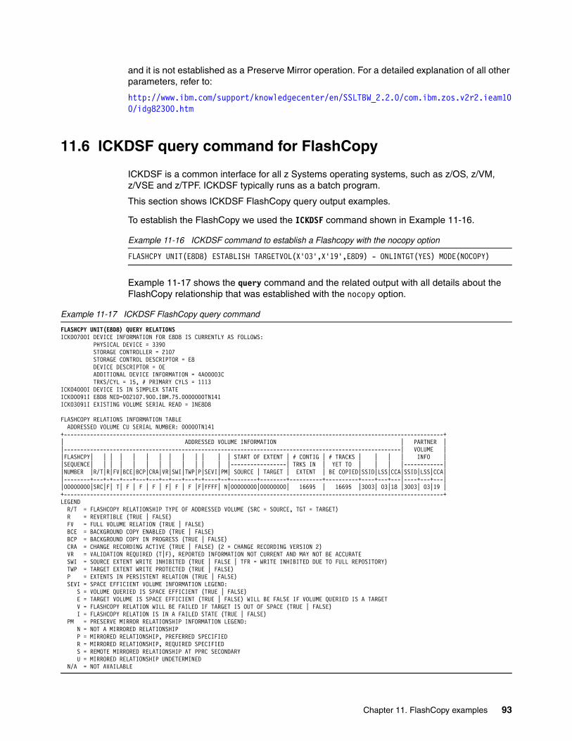
and it is not established as a Preserve Mirror operation. For a detailed explanation of all other parameters, refer to:
http://www.ibm.com/support/knowledgecenter/en/SSLTBW_2.2.0/com.ibm.zos.v2r2.ieam100/idg82300.htm
11.6 ICKDSF query command for FlashCopy
ICKDSF is a common interface for all z Systems operating systems, such as z/OS, z/VM, z/VSE and z/TPF. ICKDSF typically runs as a batch program.
This section shows ICKDSF FlashCopy query output examples.
To establish the FlashCopy we used the ICKDSF command shown in Example 11-16.
Example 11-16 ICKDSF command to establish a Flashcopy with the nocopy option
FLASHCPY UNIT(E8D8) ESTABLISH TARGETVOL(X'03',X'19',E8D9) - ONLINTGT(YES) MODE(NOCOPY)
Example 11-17 shows the query command and the related output with all details about the FlashCopy relationship that was established with the nocopy option.
Example 11-17 ICKDSF FlashCopy query command
FLASHCPY UNIT(E8D8) QUERY RELATIONS ICK00700I DEVICE INFORMATION FOR E8D8 IS CURRENTLY AS FOLLOWS: PHYSICAL DEVICE = 3390 STORAGE CONTROLLER = 2107 STORAGE CONTROL DESCRIPTOR = E8 DEVICE DESCRIPTOR = 0E ADDITIONAL DEVICE INFORMATION = 4A00003C TRKS/CYL = 15, # PRIMARY CYLS = 1113 ICK04000I DEVICE IS IN SIMPLEX STATE ICK00091I E8D8 NED=002107.900.IBM.75.0000000TN141 ICK03091I EXISTING VOLUME SERIAL READ = INE8D8 FLASHCOPY RELATIONS INFORMATION TABLE ADDRESSED VOLUME CU SERIAL NUMBER: 00000TN141 +--------------------------------------------------------------------------------------------------------------------+| ADDRESSED VOLUME INFORMATION | PARTNER ||-------------------------------------------------------------------------------------------------------| VOLUME ||FLASHCPY| | | | | | | | | | | | | START OF EXTENT | # CONTIG | # TRACKS | | | | INFO ||SEQUENCE| | | | | | | | | | | | |-----------------| TRKS IN | YET TO | | | |------------||NUMBER |R/T|R|FV|BCE|BCP|CRA|VR|SWI|TWP|P|SEVI|PM| SOURCE | TARGET | EXTENT | BE COPIED|SSID|LSS|CCA|SSID|LSS|CCA||--------+---+-+--+---+---+---+--+---+---+-+----+--+--------+--------+----------+----------+----+---+---|----+---+---||00000000|SRC|F| T| F | F | F | F| F | F |F|FFFF| N|00000000|00000000| 16695 | 16695 |3003| 03|18 |3003| 03|19 |+--------------------------------------------------------------------------------------------------------------------+LEGEND R/T = FLASHCOPY RELATIONSHIP TYPE OF ADDRESSED VOLUME (SRC = SOURCE, TGT = TARGET) R = REVERTIBLE (TRUE | FALSE) FV = FULL VOLUME RELATION (TRUE | FALSE) BCE = BACKGROUND COPY ENABLED (TRUE | FALSE) BCP = BACKGROUND COPY IN PROGRESS (TRUE | FALSE) CRA = CHANGE RECORDING ACTIVE (TRUE | FALSE) (2 = CHANGE RECORDING VERSION 2) VR = VALIDATION REQUIRED (T|F), REPORTED INFORMATION NOT CURRENT AND MAY NOT BE ACCURATE SWI = SOURCE EXTENT WRITE INHIBITED (TRUE | FALSE | TFR = WRITE INHIBITED DUE TO FULL REPOSITORY) TWP = TARGET EXTENT WRITE PROTECTED (TRUE | FALSE) P = EXTENTS IN PERSISTENT RELATION (TRUE | FALSE) SEVI = SPACE EFFICIENT VOLUME INFORMATION LEGEND: S = VOLUME QUERIED IS SPACE EFFICIENT (TRUE | FALSE) E = TARGET VOLUME IS SPACE EFFICIENT (TRUE | FALSE) WILL BE FALSE IF VOLUME QUERIED IS A TARGET V = FLASHCOPY RELATION WILL BE FAILED IF TARGET IS OUT OF SPACE (TRUE | FALSE) I = FLASHCOPY RELATION IS IN A FAILED STATE (TRUE | FALSE) PM = PRESERVE MIRROR RELATIONSHIP INFORMATION LEGEND: N = NOT A MIRRORED RELATIONSHIP P = MIRRORED RELATIONSHIP, PREFERRED SPECIFIED R = MIRRORED RELATIONSHIP, REQUIRED SPECIFIED S = REMOTE MIRRORED RELATIONSHIP AT PPRC SECONDARY U = MIRRORED RELATIONSHIP UNDETERMINED N/A = NOT AVAILABLE
Chapter 11. FlashCopy examples 93

Example 11-18 demonstrates the FlashCopy establish command and the query command for a relationship that has background copy enabled, the change recording is active, and the target volume is online. The legend in the query command output explains each field.
Example 11-18 ICKDSF FlashCopy establish and query command
FLASHCPY UNIT(E8D8) ESTABLISH TARGETVOL(X'03',X'19',E8D9) - ONLINTGT(YES) MODE(COPY) CHANGERECORDING(YES) ICK00700I DEVICE INFORMATION FOR E8D8 IS CURRENTLY AS FOLLOWS: PHYSICAL DEVICE = 3390 STORAGE CONTROLLER = 2107 STORAGE CONTROL DESCRIPTOR = E8 DEVICE DESCRIPTOR = 0E ADDITIONAL DEVICE INFORMATION = 4A00003C TRKS/CYL = 15, # PRIMARY CYLS = 1113 ICK04000I DEVICE IS IN SIMPLEX STATE ICK00091I E8D8 NED=002107.900.IBM.75.0000000TN141 ICK03091I EXISTING VOLUME SERIAL READ = INE8D8 ICK00001I FUNCTION COMPLETED, HIGHEST CONDITION CODE WAS 0 07:44:16 10/26/16 FLASHCPY UNIT(E8D8) QUERY RELATIONS ICK00700I DEVICE INFORMATION FOR E8D8 IS CURRENTLY AS FOLLOWS: PHYSICAL DEVICE = 3390 STORAGE CONTROLLER = 2107 STORAGE CONTROL DESCRIPTOR = E8 DEVICE DESCRIPTOR = 0E ADDITIONAL DEVICE INFORMATION = 4A00003C TRKS/CYL = 15, # PRIMARY CYLS = 1113 ICK04000I DEVICE IS IN SIMPLEX STATE ICK00091I E8D8 NED=002107.900.IBM.75.0000000TN141 ICK03091I EXISTING VOLUME SERIAL READ = INE8D8
FLASHCOPY RELATIONS INFORMATION TABLE ADDRESSED VOLUME CU SERIAL NUMBER: 00000TN141 +--------------------------------------------------------------------------------------------------------------------+ | ADDRESSED VOLUME INFORMATION | PARTNER | |-------------------------------------------------------------------------------------------------------| VOLUME | |FLASHCPY| | | | | | | | | | | | | START OF EXTENT | # CONTIG | # TRACKS | | | | INFO | |SEQUENCE| | | | | | | | | | | | |-----------------| TRKS IN | YET TO | | | |------------| |NUMBER |R/T|R|FV|BCE|BCP|CRA|VR|SWI|TWP|P|SEVI|PM| SOURCE | TARGET | EXTENT | BE COPIED|SSID|LSS|CCA|SSID|LSS|CCA| |--------+---+-+--+---+---+---+--+---+---+-+----+--+--------+--------+----------+----------+----+---+---|----+---+---| |00000000|SRC|F| T| T | F | T | F| F | F |T|FFFF| N|00000000|00000000| 16695 | 16695 |3003| 03|18 |3003| 03|19 | +--------------------------------------------------------------------------------------------------------------------+ LEGEND R/T = FLASHCOPY RELATIONSHIP TYPE OF ADDRESSED VOLUME (SRC = SOURCE, TGT = TARGET) R = REVERTIBLE (TRUE | FALSE) FV = FULL VOLUME RELATION (TRUE | FALSE) BCE = BACKGROUND COPY ENABLED (TRUE | FALSE) BCP = BACKGROUND COPY IN PROGRESS (TRUE | FALSE) CRA = CHANGE RECORDING ACTIVE (TRUE | FALSE) (2 = CHANGE RECORDING VERSION 2) VR = VALIDATION REQUIRED (T|F), REPORTED INFORMATION NOT CURRENT AND MAY NOT BE ACCURATE SWI = SOURCE EXTENT WRITE INHIBITED (TRUE | FALSE | TFR = WRITE INHIBITED DUE TO FULL REPOSITORY) TWP = TARGET EXTENT WRITE PROTECTED (TRUE | FALSE) P = EXTENTS IN PERSISTENT RELATION (TRUE | FALSE) SEVI = SPACE EFFICIENT VOLUME INFORMATION LEGEND: S = VOLUME QUERIED IS SPACE EFFICIENT (TRUE | FALSE) E = TARGET VOLUME IS SPACE EFFICIENT (TRUE | FALSE) WILL BE FALSE IF VOLUME QUERIED IS A TARGET V = FLASHCOPY RELATION WILL BE FAILED IF TARGET IS OUT OF SPACE (TRUE | FALSE) I = FLASHCOPY RELATION IS IN A FAILED STATE (TRUE | FALSE) PM = PRESERVE MIRROR RELATIONSHIP INFORMATION LEGEND: N = NOT A MIRRORED RELATIONSHIP P = MIRRORED RELATIONSHIP, PREFERRED SPECIFIED R = MIRRORED RELATIONSHIP, REQUIRED SPECIFIED S = REMOTE MIRRORED RELATIONSHIP AT PPRC SECONDARY U = MIRRORED RELATIONSHIP UNDETERMINED N/A = NOT AVAILABLE
94 DS8000 Copy Services

Chapter 12. FlashCopy usage with z/OS products
This chapter presents some examples of the usage of FlashCopy with some z/OS tools and products. It includes the following topics:
� Using FlashCopy for COPY, DUMP, and RESTORE� Using FlashCopy for DEFRAG� DFSMShsm Fast Replication� Using FlashCopy with DB2 for z/OS
12
© Copyright IBM Corp. 2017. All rights reserved. 95

12.1 Using FlashCopy for COPY, DUMP, and RESTORE
We already described the usage of FlashCopy for disk-to-disk copy operations with DFSMSdss. The FASTREPLICATION(REQUIRED | PREFERRED | NONE) keyword tells DFSMSdss how you want to use Fast Replication methods such as FlashCopy. The default is FASTREPLICATION(PREFERRED).
If you copy one volume onto another with FlashCopy, both volumes are identical or differ only in the VOLSER (volume serial in the volume label) depending on whether you specified the COPYVOLID keyword or not in the COPY FULL DFSMSdss command. If you copied the VOLSER, both volumes are identical and both volumes cannot be online to the same z/OS image at the same time. Therefore, the target volume goes offline. If you did not copy the VOLSER, the target volume keeps its original VOLSER and its volume table of contents (VTOC) index.
However, when you want to dump the volume to tape, there is another parameter with the COPY FULL command that you can use: DUMPCONDITIONING.
The DUMPCONDITIONING parameter of the DFSMSdss COPY FULL command allows both the source and target volumes to remain online after a full volume copy operation, thus creating an interim copy for a subsequent dump to tape (or DASD) that can be done by using the same z/OS system (see Example 12-1 and Figure 12-1).
Example 12-1 Copy a volume with DUMPCONDITIONING
COPY FULL INDY(source volume) OUTDY(target volume) ALLDATA(*) ALLEXCPDUMPCONDITIONING FASTREPLICATION(REQUIRED) PURGE
Figure 12-1 Usage of the DUMPCONDITIONING parameter
When DUMPCONDITIONING is specified, the volume serial (VOLSER) of the target volume does not change. However, the volume label is updated to save the original volume serial in a reserved location for the DUMP processing to follow. The VVDS and VTOC index names on the target volume do not change to match the target volume serial. Instead, they continue to match the source volume. This volume is a conditioned volume. A conditioned volume is not usable in its current state, except for the DFSMSdss DUMP operation, because the volume serial, the VTOC index, and VVDS names are not consistent.
A full volume dump of the conditioned volume results in a dump data set that looks as though it was created by dumping the source volume. This action allows the dump data set to be
DumpTape
Level0DASD
Vol. A
VTOC.AVVDS.A
Vol. BVTOC.AVVDS.A
COPY FULL with parameterDUMPCONDITIONINGoptional NOCOPY
DUMPFULLFCWITHDRAWRESTORE
COPYVOLIDvolume
Vol. AVTOC.AVVDS.A
orRESTOREDATASET
„ConditionedVolume“
DFSMSdss
96 DS8000 Copy Services

restored (with the RESTORE command) and used without having to restore the VOLSER (volume serial on the label).
Additionally, you can specify the FCWITHDRAW parameter for the DUMP FULL command. If the volume that is dumped is the target volume of a FlashCopy relationship, the relationship is withdrawn when the dump successfully completes. For more information about DFSMSdss and FlashCopy, see DFSMSdss Storage Administration, SC23-6868.
12.2 Using FlashCopy for DEFRAG
The DEFRAG command is another DFSMSdss command. When you run DEFRAG, DFSMSdss relocates data set extents on a DASD volume to reduce or eliminate free space fragmentation. When the storage system has the FlashCopy feature, DEFRAG uses FlashCopy when possible to relocate the tracks.
To use FlashCopy to defragment a volume, you must specify FASTREPlication(REQuired) or FASTREPlication(PREFerred) with the DEFRAG command. FASTREP(PREF) is the default.
If the volume you are defragmenting is mirrored with Metro Mirror or Global Mirror, you must also specify the FCTOPPRCPrimary parameter. If the volume is a Metro Mirror primary, you can request that the Remote Pair FlashCopy function is used by specifying FCTOPPRCP(PRESMIRREQ). If the volume is a Global Copy primary, you must specify FCTOPPRCP, which defaults to FCTOPPRCP(PRESMIRNONE).
12.3 DFSMShsm Fast Replication
DFSMShsm takes advantage of FlashCopy. DFSMShsm starts DFSMSdss to perform the Fast Replication function for backup and recover.
DFSMShsm calls DFSMSdss without the COPYVOLID keyword but with the DUMPCONDITIONING keyword, so both the source and the target volumes stay online all the time. Thus, the target volumes are not usable by any user to allocate data sets, or even for the DFSMShsm BACKVOL nor AUTODUMP functions.
Four DFSMShsm commands are available for DFSMShsm Fast Replication function:
FRBACKUP Creates a Fast Replication backup version for each volume in a specified copy pool.
FRRECOV Uses Fast Replication to recover a single volume or a pool of volumes from the managed backup versions.
FRDELETE Deletes one or more unneeded Fast Replication backup versions.
LIST and QUERY These commands are modified to aid monitoring of the Fast Replication backup versions.
Chapter 12. FlashCopy usage with z/OS products 97

DFSMShsm Fast Replication function uses a construct that is named Copy Pool and a Copy Pool Backup storage group type (see Figure 12-2).
Figure 12-2 Copy pools in SMS
You can use the FRBACKUP command to create a Fast Replication backup version for sets of storage groups followed by a dump of each Fast Replication target volume. A set of storage groups is defined through the SMS construct copy pool. Storage groups are defined to a copy pool and all of the volumes in those storage groups are backed up or dumped by the Fast Replication function.
Example 12-2 shows how to create a backup with the DFSMShsm FRBACKUP command. DUMP is an optional parameter that first causes DFSMShsm to establish a Fast Replication relationship (FlashCopy for a DS8000) between the source and target volumes. When all relationships are successfully established, DFSMShsm starts dumping the target DASD copies to tape.
Example 12-2 FRBACKUP
FRBACKUP COPYPOOL(cpname) EXECUTE DUMP
DFSMShsm supports the Incremental FlashCopy function for Fast Replication Copy Pools. A Copy Pool can be designated to have a single incremental backup version by using the FCINCREMENTAL keyword on the FRBACKUP command.
A FlashCopy relationship between a source volume and a target volume that is established through an FRBACKUP command should never be withdrawn outside of DFSMShsm control. Doing so invalidates the backup version, but DFSMShsm still manages the version as though it is valid. This situation might result in a data integrity exposure. When it is necessary to withdraw one or more relationships that are established by an FRBACKUP command, you can use the command that is shown in Example 12-3.
Example 12-3 Withdrawal of a FlashCopy relationship
FRBACKUP COPYPOOL(cpname) WITHDRAW
SG1 SG2 SG3
SMS Group Type: Copy Pool Backup
SMS Group Type: Pool
Upto 256 SG‘sper copy pool
Used to specify candidate target backup volumes for DFSMShsmfast replication requests
Backup Pool: CPB1 Backup Pool: CPB2
98 DS8000 Copy Services

The FRRECOV command can be used to recover a pool of volumes, individual volumes, or individual data sets from the managed copy pool copies. The usage of FlashCopy in the recovery is controlled by the optional FASTREPLICATION and ALLOWPPRCP parameters of FRRECOV.
� FASTREPLICATION indicates whether the usage of fast replication for data set recovery is required, preferred, or not wanted. FASTREPLICATION is valid only for recovery from disk. If the recovery is from tape, the parameter is ignored.
� ALLOWPPRCP specifies whether a Metro Mirror primary volume can become a target of a FlashCopy operation, and whether a preserve mirror operation is required, preferred, or not wanted. ALLOWPPRCP is ignored when you recover from a tape.
For more information about the DFSMShsm Fast Replication function, see DFSMShsm Storage Administration, SC23-6871 or DFSMShsm Fast Replication Technical Guide, SG24-7069.
12.4 Using FlashCopy with DB2 for z/OS
DB2 for z/OS is enhanced to provide more backup and recover capabilities at the DB2 subsystem or data sharing group level. These enhancements provide an easier and less disruptive way to make fast volume level backups of an entire DB2 subsystem or data sharing group and to recover a subsystem or data sharing group to any point-in-time, regardless of whether uncommitted units of work are involved. SAP uses these new recovery functions.
DB2 provides a fast, easy, and minimally disruptive way to create volume-level backups and a fast and reliable way to recover to a specific point-in-time with the BACKUP SYSTEM and RESTORE SYSTEM utilities:
� The BACKUP SYSTEM utility provides fast volume-level copies of DB2 databases and logs.
� The RESTORE SYSTEM utility recovers a DB2 system to a designated point-in-time. RESTORE SYSTEM automatically handles any creates, drops, and LOG NO events that might occur between the backup and the recovery point-in-time.
The BACKUP SYSTEM and RESTORE SYSTEM utilities perform all the tasks in a statement that previously required a separate command for each task. The utilities call DFSMShsm to create FlashCopy copies and dump data to tape if the DUMP option is used on the BACKUP SYSTEM command (see Example 12-4). Incremental FlashCopy is also supported. In this case, the ESTABLISH FCINCREMENTAL parameter must be added.
Example 12-4 BACKUP SYSTEM
//STEP1 EXEC DSNUPROC,SYSTEM=DB8B,UID=DIAG//* UTSTATS=''//SYSIN DD *BACKUP SYSTEM FULL DUMP
The utilities enable DFSMShsm to know which volumes, target, and source should be processed for Fast Replication functions, and how to manage them. Recovery can be performed with the RECOVER SYSTEM utility at the volume level, copy pool level, or for individual table spaces. This utility reduces the need for image copies.
Chapter 12. FlashCopy usage with z/OS products 99

100 DS8000 Copy Services

Part 4 Metro Mirror and Global Copy
Metro Mirror and Global Copy are remote copy functions that replicate updates from one volume to another. Metro Mirror is a synchronous form of replication that mirrors data to the secondary volume before considering the host I/O to be complete. Global Copy is an asynchronous form of replication that copies data to the secondary volume at some time after the host I/O has completed.
Metro Mirror and Global Copy have many common characteristics. For those features that area common to both Metro Mirror and Global Copy, the more general term Peer-to-Peer Remote Copy (PPRC) is used.
The chapters in this part of the book provide an overview of Metro Mirror and Global Copy and describes these remote copy functions.
Part 4
© Copyright IBM Corp. 2017. All rights reserved. 101

102 DS8000 Copy Services

Chapter 13. Metro Mirror overview
This chapter explains the basic characteristics of the DS8000 Metro Mirror function and includes the following topics:
� Metro Mirror overview� Metro Mirror positioning
13
© Copyright IBM Corp. 2017. All rights reserved. 103

13.1 Metro Mirror overview
Metro Mirror is a synchronous replication solution between two DS8000s where write operations are completed on both the local and remote volumes before the I/O is considered to be complete. Metro Mirror is used in environments that require no data loss in the event of a storage system failure.
The volume written to by the host server is referred to as the primary or source volume. The remote volume to which the data is mirrored is called the secondary or target volume. The terms primary/secondary and source/target are used interchangeably.
Figure 13-1 illustrates the sequence of operations for a write operation to a Metro Mirror primary volume.
Figure 13-1 Metro Mirror
When the application performs a write update operation to a Metro Mirror primary volume, the following actions occur:
1. The host server writes to the Metro Mirror primary volume. The data is written into the DS8000 cache and non-volatile storage (NVS).
2. The primary DS8000 mirrors the data to the secondary DS8000.
3. The secondary storage system acknowledges to the primary storage system that the write has completed.
4. The primary storage system then acknowledges to the host server that the write is complete.
During normal operation with Metro Mirror, all data written to the primary volume is mirrored to the secondary volume, keeping the contents of the two volumes identical.
Serverwrite
Write to secondary
Write acknowledgement toserver
Write acknowledgmentto primary
Primary(source)
Secondary(target)
3
2
1
4
H1 H2
104 DS8000 Copy Services

Because data is synchronously transferred to the secondary storage system before considering the write to be complete, the distance between primary and secondary storage systems affects the application response time for writes. The maximum supported distance for Metro Mirror is 300 km.
Read operations access only the primary storage system and are not affected by the mirroring.
13.2 Metro Mirror positioning
Metro Mirror is generally used for disaster recovery purposes to avoid data loss in the event of a failure. Because Metro Mirror transmits data to the secondary synchronously with the application I/O, the data on the secondary is the same as on the primary. In the event of a failure at the primary production site, applications can be continued using the data from the secondary storage system. When combined with management software, such as IBM Copy Services Manager or IBM Geographically Dispersed Parallel Sysplex (IBM GDPS), Metro Mirror provides a high availability function for the transparent failover of host I/O operations.
Metro Mirror can also be used for migrating data from one storage system to another.
Chapter 13. Metro Mirror overview 105

106 DS8000 Copy Services

Chapter 14. Global Copy overview
This chapter explains the basic characteristics of the DS8000 Global Copy function and it includes the following topics:
� Global Copy overview� Global Copy positioning
14
© Copyright IBM Corp. 2017. All rights reserved. 107

14.1 Global Copy overview
Global Copy is an asynchronous remote copy function that is used for longer distances than are possible with Metro Mirror. Global Copy is appropriate for remote data migration, offsite backups, and transmission of inactive database logs over virtually unlimited distances.
Global Copy is also used as the data transfer mechanism for Global Mirror. See Part 5, “Global Mirror” on page 197 for a description of Global Mirror.
With Global Copy, write operations complete on the primary storage system before the data is copied to the secondary storage system, thus preventing the primary system’s performance from being affected by the time required to write to the secondary storage system. This process allows the sites to be separated by a large distance.
Figure 14-1illustrates the sequence of operations for a write update to a Global Copy primary volume.
Figure 14-1 Global Copy
When the application performs a write update operation to a Global Copy primary volume, the following actions occur:
1. The host server writes to the Global Copy primary volume. The data is written into the DS8000 cache and non-volatile storage (NVS).
2. The primary DS8000 records that the data needs to be copied to the secondary volume in a Global Copy change recording structure and then acknowledges to the host server that the write is complete.
3. Some moments later, that is, in an asynchronous manner, the primary DS8000 copies the data to the secondary DS8000. Multiple updates can be grouped in batches for efficient transmission.
4. The secondary DS8000 acknowledges to the primary that the write has completed to the primary. The primary DS8000 then resets its Global Copy change recording information to indicate that the data has been copied.
Serverwrite
Write to secondary
Write acknowledgement toserver
Write acknowledgmentto primary
Primary(source)
Secondary(target)
4
3
1
2
H1 H2
108 DS8000 Copy Services

All data that is written to the primary DS8000 is transferred to the secondary DS8000, but not necessarily in the same order that it was written to the primary. This means that data on the secondary is not time-consistent. Making use the data on the secondary volume requires using some technique to ensure consistency.
14.2 Global Copy positioning
Global Copy is a solution for remote data copy, data migration, offsite backup, and transmission of inactive database logs without impacting application performance, even over continental distances. Here some reasons why you might want to consider using Global Copy:
� It can be used for application recovery implementations if application I/O activity can be quiesced and nonzero data loss is admissible.
� It can be used over long distances without impacting application performance. The distances are limited only by the network and channel extenders capabilities.
� There might be a fuzzy copy of data at the recovery site (the sequence of dependent writes might not be respected at the recovery site).
� Recovery data can become a consistent point-in-time copy of the primary data, if appropriate application checkpoints are set to perform global catch-ups. Pairs are synchronized with application group consistency.
� Synchronization can be performed more frequently because of short catch-ups. The recovery point objective (RPO) is still not zero, but improves substantially.
Chapter 14. Global Copy overview 109

110 DS8000 Copy Services

Chapter 15. Metro Mirror and Global Copy paths
This chapter describes the connections, physical links, and logical paths that are required to transfer data for Metro Mirror and Global Copy. The creation and management of these paths is the same for both Metro Mirror and Global Copy. This chapter uses the more general term Peer-to-Peer Remote Copy (PPRC) when describing features and uses that are common between Metro Mirror and Global Mirror.
This chapter includes the following topics:
� PPRC paths and links� Fibre Channel physical links� Logical paths
15
Terminology: The following pairs of terms are used interchangeably in this chapter:
� Primary and source � Secondary and target � Logical subsystem (LSS) and logical control unit (LCU)
© Copyright IBM Corp. 2017. All rights reserved. 111

15.1 PPRC paths and links
Before a PPRC pair can be created, logical paths between the primary and secondary LSSs must be defined.
A logical PPRC path is defined between a primary LSS and a secondary LSS using a physical link between the storage systems. Establishing the PPRC logical paths creates an LSS to LSS relationship.
15.2 Fibre Channel physical links
The physical link includes the host adapter in the primary DS8000, the cabling, switches, or directors, any wide-band or long-distance transport devices (WDM, channel extenders, and WAN), and the host adapters in the secondary DS8000 storage system. Physical links are bidirectional and can be shared by both Metro Mirror and Global Copy.
A DS8000 Fibre Channel port can simultaneously be:
� A sender for a PPRC primary� A receiver for a PPRC secondary� A target for Fibre Channel Protocol (FCP) hosts I/O from Open Systems and Linux on
z Systems
Each PPRC port provides connectivity for all LSSs within the DS8000 and can carry multiple logical PPRC paths. Although one FCP link can have sufficient bandwidth for many environments, the preferred practices are to:
� Configure at least two Fibre Channel links between each primary and secondary storage systems to:
– Provide redundancy for continuous availability if there is a physical path failure
– Provide multiple logical paths between the LSSs
� Dedicate Fibre Channel ports for PPRC usage, to ensure that there is no interference from host I/O activity. This action is especially essential with Metro Mirror, which is time critical and should not be impacted by host I/O activity.
See Chapter 17, “Metro Mirror and Global Copy implementation considerations” on page 139 for further information. IBM Support is available to assist you with determining the number of
Note: An LSS is a grouping of up to 256 logical volumes. You can define up to 255 LSSs in a DS8000. LSSs are either count key data (CKD) or fixed-block architecture (FB) and have affinity with one storage facility image server. Up to 128 LSSs can be managed by Server 0, and up to 127 LSSs can be managed by Server 1 (one LSS address is reserved).
Fibre Channel support: For PPRC, the DS8000 supports Fibre Channel links only; you cannot use FICON links.
Metro Mirror paths: Consider defining all Metro Mirror paths that are used by one application environment on the same set of physical links if you intend to keep the data consistent. With this approach, the paths between multiple Metro Mirror volume relationships cannot fail at a different time. For more information, see 16.8.2, “Consistency group function: How it works” on page 128.
112 DS8000 Copy Services

links that are used by a bandwidth analysis to ensure that the environment is able to effectively handle the workload.
PPRC links can be directly connected, or connected via switches.
15.3 Logical paths
A PPRC logical path is a connecting path between the primary LSS and the secondary LSS. Physical links can carry multiple PPRC logical paths, as shown in Figure 15-1.
Figure 15-1 Logical paths
Logical PPRC paths are unidirectional, that is, they operate in only one direction. An LSS can be both a primary and a secondary for sets of PPRC logical paths. Also, logical paths in opposite directions can be defined on the same Fibre Channel physical link.
For bandwidth and redundancy, up to eight logical paths can be established between a primary LSS and a secondary LSS. Metro Mirror and Global Copy balance the workload across the available physical paths.
Figure 15-2 on page 114 shows an example of PPRC logical paths from primary H1 to secondary H2. With a 1:1 mapping of primary to secondary LSSs there are the following logical paths:
� LSS 1 in H1 to LSS 1 in H2� LSS 2 in H1 to LSS 2 in H2� LSS 3 in H1 to LSS 3 in H2
Alternatively, if the volumes in each of the LSSs of H1 map to volumes in all three target LSSs in H2, then there are nine logical paths over the physical link.
Whenever possible, you should use a 1:1 LSS mapping to simplify the management of the configuration.
Sharing links: In general, you should not share the FCP links used for Metro Mirror with Global Mirror.
Channel extension: If you use channel extension technology devices for PPRC links, you should verify with the product’s vendor what environment (directly connected or connected with a SAN switch) is supported by the vendor and what SAN switch is supported.
LSS 0
LSS 3
LSS 1LSS 2
LSS 08
LSS nn
:
:
Physical Fibre Channel link
Up to 256 logical pathsper FCP link
LSS 0
LSS 3
LSS 1LSS 2
LSS 08
LSS nn
:
:
Chapter 15. Metro Mirror and Global Copy paths 113

Figure 15-2 Logical paths over a physical link for Metro Mirror
Metro Mirror FCP paths have certain architectural limits, which include:
� A primary LSS can maintain paths up to a maximum of 16 secondary LSSs. Each secondary LSS can be in a different DS8000.
� You can define up to eight physical port pairs per LSS-LSS relationship.
� An FCP port can host up to 1280 logical paths. These paths are the logical and directional paths that are made from LSS to LSS.
� An FCP physical link (the physical connection from one port to another port) can host up to 256 logical paths.
� An FCP port can accommodate up to 126 different physical links (DS8000 port to DS8000 port through the SAN).
H1
Port
1 logical path
LSS 2
LSS 3
LSS 1
1 logical path
1 logical path
Port
1 logical path
LSS 2
LSS 3
LSS 1
1 logical path
1 logical path
1 Link
Metro Mirror paths
H2
switch
3 to 9 logical paths
114 DS8000 Copy Services

Chapter 16. Metro Mirror and Global Copy operations
This chapter describes the operation of Metro Mirror and Global Copy and includes the following topics:
� Metro Mirror and Global Copy pair states� Basic Metro Mirror and Global Copy operation� Suspension� Freeze� PPRC failover and failback� Metro Mirror Data consistency� Rolling disaster� Consistency group function� Creating a Global Copy consistent copy� Automation and management
16
Terminology:
Metro Mirror and Global Copy have many common characteristics. For those features that area common to both Metro Mirror and Global Copy, the more general term Peer-to-Peer Remote Copy (PPRC) is used.
The following pairs of terms are used interchangeably in this chapter:
� Primary and source � Secondary and target � Logical subsystem (LSS) and logical control unit (LCU)
© Copyright IBM Corp. 2017. All rights reserved. 115

16.1 Metro Mirror and Global Copy pair states
A volume can be in one or several PPRC pair states. These states represent the current status of the replication for the volume. Each primary and secondary volume maintains its own pair state.
Table 16-1 shows the possible PPRC pair states:
Table 16-1 PPRC pair states
16.2 Basic Metro Mirror and Global Copy operation
The basic operations for Metro Mirror and Global Copy consist of:
� Establishing logical paths� Removing logical paths� Establishing a pair� Suspending a pair� Resuming a pair� Terminating a pair
In addition, there are more specialized commands and operations for:
� Failover and failback� Freeze� Consistency groups
Pair State Description
Simplex The volume is not in a PPRC relationship
Copy Pending The primary volume is being asynchronously mirrored to the secondary volume.
Metro Mirror volumes are in this state while being synchronized or re-synchronized after a suspension.
This is the normal state for Global Copy volumes.
Full Duplex Updates to the primary volume are being synchronously mirrored to the secondary volume.
This is the normal state for Metro Mirror volumes after they have been synchronized.
This state does not apply to Global Copy volumes.
Suspended Updates to the primary volume are not being synchronized to the secondary. The changed data is recorded on the primary DS8000. When the pair is resumed, this information is used to determine which data to copy to the secondary.
Note: A volume can be in more than one PPRC relationship at a time. It can be a primary to more than one secondary volume. It can also be the secondary of one relationship and the primary of another. Each of these PPRC relationships one the volume are independent and has its own pair state.
116 DS8000 Copy Services

16.2.1 Establishing PPRC paths
PPRC logical paths must be established between the primary and secondary LSSs before a PPRC pair can be created. As described in Chapter 15, “Metro Mirror and Global Copy paths” on page 111, establishing the paths creates an LSS to LSS relationship between the primary and secondary storage systems. There is a maximum of eight logical paths possible for each specific LSS to LSS relationship.
A primary LSS can have sets of PPRC logical paths to up to 16 different secondary LSSs. There is no limit on the number of primary LSSs that are associated with a secondary LSS. However, to simplify the management of the relationships, it is a preferred practice to have a one to one relationship between the primary and secondary LSSs.
The logical paths for an LSS to LSS relationship can be modified while Metro Mirror or Global Copy is using them. The establish PPRC path command (DS CLI command mkpprcpath) replaces the existing paths with the paths specified in the new command.
For example, say there are currently logical paths established for ports P1:Q1 and P2:Q2. If a new establish path command is issued for ports P1:Q1 and P3:Q3, then the logical path for P1:Q1 will remain and the logical path for P2:Q2 will be replaced by P3:Q3. When replacing logical paths, a new path is added before removing an existing path so that there is never any period of time where no paths exist. This process allows Metro Mirror or Global Copy to continue running while the logical paths are being changed.
A logical path can be removed by merely issuing a new establish path command which excludes the path to be removed.
16.2.2 Removing PPRC paths
When a set of logical PPRC paths are no longer required, they can be removed. The remove PPRC paths command (DS CLI rmpprcpath) is used to remove the entire LSS to LSS relationship.
PPRC paths for an LSS to LSS relationship cannot normally be removed while there are PPRC pairs established that are using those paths, although there is a -force option to allow this, if necessary in special circumstances.
16.2.3 Establishing a pair
Establishing a PPRC pair creates a copy relationship between a primary and a secondary volume. The command specifies whether to create a Metro Mirror or a Global Copy relationship.
When a pair is first established, it typically goes into the Copy Pending state to indicate that data is in the process of being copied to the secondary volume. This initial copy of the volume copies all of the data from the primary volume to the secondary volume.
Note: The primary and secondary volumes are typically in different storage systems for disaster recovery purposes. However, it is possible to have the primary and secondary in the same storage system. This can be useful for initial testing purposes when hardware availability is limited.
Chapter 16. Metro Mirror and Global Copy operations 117

If the pair is established as Metro Mirror, then after the entire volume has been copied, the state changes to Full Duplex indicating that the two volumes are synchronized. Global Copy transfers data asynchronously from the host I/O and the pairs remains in the Copy Pending state.
When establishing a Metro Mirror or Global Copy pair, the following options are available:
� No copy
This option causes the DS8000 to bypass the initial copy of data from the primary to the secondary. This option presumes that the volumes are already synchronized. The data synchronization is the users responsibility and the DS8000 does not check its validity.
� Suspend after data synchronization (Metro Mirror only)
This option suspends the volume pairs after the data is synchronized. This parameter cannot be used with the no copy option. This can be useful in automation processes when the secondary volume is to be used after synchronization for additional steps, such as creating a FlashCopy from the Metro Mirror secondary volume to preserve the data as a consistency point.
� Incremental resynchronization
Used in 3-site Metro/Global Mirror environments only.
� Disable autoresync (Global Copy only)
See the next section, “Synchronization and resynchronization”.
� Wait (Metro Mirror only)
This option delays the command response until the volume pairs are in one of the final states: Simplex, Full Duplex, Suspended, Target Full Duplex, Target Suspended (until the pair is not in the Copy Pending state). This parameter cannot be used with Global Copy or pairs that are established with the no copy mode.
Synchronization and resynchronizationWhen a pair is first established, an initial copy of the volume is normally performed. This is done for both Metro Mirror and Global Copy.
Each primary volume has a change recording structure for each relationship which describes what data on the primary is out of synchronization with the secondary. The internal DS8000 synchronization process uses this information to determine what data needs to be copied.
When a pair is first established, this change recording structure is normally set to indicate that all data is different between the primary and the secondary. This cause the synchronization process to perform a full initial copy of all data.
In certain specialized situations, this initial copy can be bypassed by using the no copy option. When this option is used, the change recording information is set to indicate that no data differs between the primary and the secondary. This should be done only if there when it is assured that the primary and secondary volumes are already identical.
When a pair is suspended, writes to the primary volume are marked in the change recording structure so that when the pair is resumed, only the changed data is resynchronized to the secondary volume.
Extent space-efficient volumesDS8000 Microcode Release 8.2 introduces the ability to establish a PPRC relationship between full provisioned and extent space efficient (ESE) volumes. When the primary volume is ESE, only the allocated extents are transferred to the secondary volume.
118 DS8000 Copy Services

Establishing PPRC from a standard volume to an ESE volume is one way of migrating data to an ESE volume. Keep in mind however, that the initial copy of the pair causes all tracks from from the primary to be transferred to the secondary, allocating the extents on the secondary volume. If the secondary volume is later made host accessible, by either terminating the pair or through a PPRC failover process, it can be possible to then release the unused space on the ESE volume.
Space release functionality at the extent level for count key data (CKD) volumes is supported for Metro Mirror primary volumes that are in the full duplex state, however, the space is released only on the primary volume.
MultiSite configurationsA volume can be the primary to more than one secondary volume, creating a Multiple Target PPRC configuration. It is also possible for a volume to be both a secondary of one volume and the primary of another, creating a cascading configuration. Cascading can be used to perform remote copy from a local primary volume through an intermediate volume to a remote volume.
The two volume pairs in a cascaded relationship can be either Global Copy or Metro Mirror pairs with the exception that the first pair (primary to intermediate) cannot be Global Copy if the second pair (intermediate to remote) is Metro Mirror.
If both pairs are Metro Mirror, then the second pair is suspended when any write I/O is directed to the intermediate volume. This action prevents potential performance impacts that a cascading Metro Mirror to Metro Mirror remote copy relationship might have on application write I/Os. A cascading Metro Mirror to Metro Mirror setup is intended for temporary use only. It is used to allow the remote volume to be synchronized with the intermediate volume while the applications are quiesced (possibly followed by suspending of the first Metro Mirror pair) so that there is no write I/O activity on the second Metro Mirror pair.
Cascading is not limited to two copy pairs. You can create a chain of cascaded copy pairs. The first pair can be Metro Mirror, and the other pairs are normally Global Copy.
The two pairs can be established in any order: First and second here do not refer to the order of establishment. To minimize the amount of data to be copied on the second pairing, it is preferable to establish the primary-to-intermediate pair first.
Cascading can be used for migrating data from one storage system to another compatible system. If the volumes to be migrated are already mirrored between two storage systems, you can set up a cascaded Global Copy from the secondary of the current relationship to the intended secondary system. This way, you can migrate without having to remove the existing remote copy relationships.
Part 8, “MultiSite configurations” on page 353 contains an extensive description of different multiple site topologies and uses.
Converting Global Copy to Metro MirrorThis operation is known as the Go-to-sync operation. The following common situations occur when you convert a pair from Global Copy mode to Metro Mirror mode:
� Situation 1: You use Global Copy to complete the bulk transfer of data when you create many copy pairs, and you now want to convert some or all of those pairs to Metro Mirror mode.
� Situation 2: You have Global Copy pairs for which you want to make FlashCopy backups on the recovery site. You convert the pairs temporarily to Metro Mirror mode to obtain point-in-time consistent copies.
Chapter 16. Metro Mirror and Global Copy operations 119

The transition of a volume pair from Global Copy to Metro Mirror is also referred to as the catch-up transition.
Copy pending catch-up is the name of the transition for a Global Copy pair that goes from its normal out-of-sync condition to a fully synchronous condition, that is, a full duplex Metro Mirror pair. The pair goes from the pending state to the full duplex state. At the end of this transition, primary and secondary volumes are fully synchronized, with all their respective tracks identical.
As a result of the catch-up, the Global Copy pair becomes a Metro Mirror pair. This pair has an impact on application response times because write I/Os in a Metro Mirror pair are written to both primary and secondary volumes before the host application is acknowledged. For this reason, a Global Copy pair is normally synchronized only for short periods, typically to make a FlashCopy, and host application updates are quiesced for the duration. For a more detailed description about this topic, see 16.9, “Creating a Global Copy consistent copy” on page 135.
For an example about how to convert a Global Copy pair to a Metro Mirror pair, see 18.2.6, “Changing the copy mode from Global Copy to Metro Mirror” on page 177.
16.2.4 Suspending a pair
Suspending a pair pauses the transfer of data from the primary to the secondary. The DS8000 keeps track of what data has been changed on the primary volume. When the pair is resumed, only this changed data is transferred to the secondary.
16.2.5 Resuming a pair
This operation resumes a PPRC relationship for a volume pair that was suspended, and restarts the transfer of data. The DS8000 records which data tracks have been changed on the primary volume so that only this changed data is transferred to the secondary when the pair is resumed.
When a Metro Mirror pair is suspended, the secondary volumes will be in a consistent state if the appropriate techniques are used as described in 16.8, “Consistency group function” on page 127. However, when a pair is resumed, the data is not necessarily copied to the secondary in the same order that it was written to the primary, so the data on the secondary volumes will no longer be consistent until the pairs reach the full duplex state again. If a disaster were to occur during while this resynchronization is in process, there might not be a usable consistent copy of data from which to recover. Performing a FlashCopy of the secondary volumes before resuming the pairs preserves a consistent copy of data at the remote location to protect from this situation.
16.2.6 Removing a pair
This operation ends the PPRC relationship between the primary and secondary volumes. The contents of the secondary volume are not changed when the PPRC relationship is removed. If the secondary volume is consistent at the time of the termination, it can be accessed and used by a host server.
120 DS8000 Copy Services

16.3 Suspension
A Metro Mirror or Global Copy pair can become suspended due to a command or due to a condition the prevents the further copying of data, such as the loss of connectivity between the primary and secondary storage systems, or a condition at the secondary storage system that prevents the acceptance of write data.
When the condition has been corrected, a resume command can be issued to resume the copying of data. As described in “Synchronization and resynchronization” on page 118, only the changed data is copied to the secondary.
Depending upon the reason for the suspension, a Global Copy can automatically resume without further user input by the autoresync process. For example, a loss of connectivity to the secondary will cause pairs to suspend because data can no longer be transferred. When the connectivity is restored, Global Copy can internally resume the pair and transition back to the copy pending state. Some suspensions, such as a one resulting from a suspend command, are not eligible for autoresync.
Metro Mirror pairs are never eligible for autoresync, and a resume command is required to resume the pair, because during the time that Metro Mirror pairs are resynchronizing the secondary site is not in a consistent state. The user might want to save a copy of the secondary state before resuming mirroring.
16.4 Freeze
Unlike most other PPRC commands, the freeze command operates on a LSS to LSS relationship instead of a specific pair. A freeze command does two things:
1. Removes the PPRC logical paths between the primary and secondary LSS. Removing the paths prevents any further data from being transferred to the secondary and helps to preserve data consistency at the secondary site.
2. Suspends all pairs between the primary and secondary LSS.
If consistency groups are used, the primary volumes are placed into the extended long busy (for CKD volumes) or queue full (for Open Systems volumes) state. This is used to preserve data consistency at the remote site, as described in 16.8, “Consistency group function” on page 127.
16.4.1 Unfreeze (consistency group created)
The unfreeze or consistency group created command removes the extended long busy state for all volumes in the LSS to LSS relationship. It is used as part of the consistency creation as explained in 16.8, “Consistency group function” on page 127.
16.5 PPRC failover and failback
The failover and failback commands are used to switch the direction of a PPRC relationship. The two commands are usually used together and are described separately in the sections that follow.
Chapter 16. Metro Mirror and Global Copy operations 121

16.5.1 Failover
A PPRC failover command converts a secondary volume into a primary volume so that it can be used for host I/O. A failover is usually used as part of the process of moving production to the secondary site. As an example, consider an H1:H2 pair. The H2 volumes are PPRC secondaries and do not accept host write I/O. If there is a failure at the primary H1 site, then it is often desired to switch to the secondary site to continue operations. A failover H2:H1 command causes the secondary H2 volumes to become suspended primary volumes so that they can accept host I/O. In addition, they start the PPRC change recording process to track which data has been updated. See 16.5.3, “Failover / Failback Scenario” for a more detailed description.
16.5.2 PPRC Failback
A PPRC failback command is typically used to resume active mirroring after a failover command. In an H1:H2 relationship, after a failover to H2 causes H2 to become a suspended primary volume to H1, and the failback command can be used to resume mirroring without doing a full copy from H2 back to H1, that is, in the opposite direction.
The failback command combines the change recording information of the secondary volume with its own change recording information to determine the entire set of data that has been changed on either volume since the time of the suspension. It uses this information to determine what data to resynchronize, so that the primary and secondary volumes will contain the same data, even in cases where either one or both of the volumes has been updated.
The next section describes a typical scenario to demonstrate the use of the freeze, failover and failback command.
16.5.3 Failover / Failback Scenario
A scenario showing the use of the freeze, failover and failback command is described here to give a better understanding of their typical usage.
Figure 16-1 on page 123 shows a typical PPRC topology where the volumes labeled H1 are being copied to the volumes labeled H2.
122 DS8000 Copy Services

Figure 16-1 PPRC basic topology
To move the production I/O to the remote H2 volumes and then to reverse the direction of the copy:
1. Freeze the paths from H1 to H2. As described in 16.4, “Freeze” on page 121, this removes the PPRC logical paths between H1 and H2 and suspends all of the PPRC pairs.
Depending upon the state of the H1 storage system, volumes and connectivity, these freeze commands might not succeed. For example, if there has been a failure at the H1 site, it might not be possible to successfully send and complete the commands.
If the freeze to H1 is not successfully completed, then H1 can remain an active primary to H2. If a write to this volume is received, it will be accepted on H1 but the copy of the data to H2 will fail because H2 is no longer a secondary of H1. This will cause the H1:H2 pair to suspend at this time. The H1 storage system will also use the PPRC change recording mechanism to record that the data has been updated and is out of synchronization with H2.
2. Failover command to H2 for the H2:H1 pair.
This process causes the H2 volumes to become a suspended PPRC primary volumes whose secondaries are H1. The H1 volumes remain PPRC primary volumes to H2.
Now that the H2 volumes are PPRC primaries, they can accept host I/O and the application processing can be moved to access the H2 volumes. All updates made to the H2 volumes are tracked by the DS8000 change recording mechanism.
Figure 16-2 on page 124 shows the volume pair states at this point where both H1 and H2 are suspended primary volumes and the host I/O is now being directed to the H2 volumes.
H2H1
Host I/O
Chapter 16. Metro Mirror and Global Copy operations 123

Figure 16-2 After PPRC failover to H2
3. Failback command for H2:H1.
When the H1 site has been recovered and is available to accept I/O, a failback of H2:H1 is be done to resume the copy or mirror of data from H2 to H1. The application I/O continues to run to H2.
The failback operation causes the H2:H1 pairs to transition to the copy pending state and resynchronize all of the changed data from H2 to H1.
The H2 storage system requests the change recording information from H1 so that the resynchronization includes any tracks that were updated on H1 after the suspension of H1:H2. During the failback, H2 will then copy those tracks from H2 to H1, thus restoring H1 to the current data residing on H2. As each volume is resynchronized, Metro Mirror pairs transition to full duplex. Global Copy pairs remain in the copy pending state.
After this sequence of steps, the direction of the copy or mirror is reversed, as shown in Figure 16-3 on page 125. If it is desired to restore the original configuration where H1 is the primary, repeat these steps at H1 to reverse the direction of the copy again.
H2H1
SuspendedSuspended
Host I/O
124 DS8000 Copy Services

Figure 16-3 After failback H2:H1
It is also possible to perform a failback H1:H2 after the H2:H1 failover shown in Figure 16-2, however there are some important considerations that must be understood before doing so. As described earlier, a suspended primary volume performs change recording to track all updates that have been made to it but not copied to its secondary volume. The failback command combines this changed track information from both the primary and the secondary volumes to determine which data to copy.
Consider the following scenario:
1. Failover H2:H12. Data written to H23. Failback H1:H2
The failback H1:H2 determines which tracks were written to either H1 or H2, creating the set of tracks to be copied from H1 to H2. This means that the failback H1:H2 will copy the data currently residing on H1 to H2, replacing the newer data that had been written to H2. There can be circumstances where this is desired, but this is not the typical use of failover and failback.
16.6 Metro Mirror Data consistency
To successfully restart applications at the remote site after a PPRC failover, the remote site volumes must have consistent data. In normal operation, PPRC keeps data consistency at the remote site. However, if there is a rolling disaster type of situation, a certain mechanism is necessary to keep data consistency at the remote site.
For Metro Mirror, consistency requirements are managed through the consistency group option. You can specify this option when you are defining Metro Mirror paths between pairs of LSSs or when you change the default LSS settings. Volumes that are paired between two
H2H1
Host I/O
Chapter 16. Metro Mirror and Global Copy operations 125

LSSs whose paths are defined with the consistency group option can be considered as part of a consistency group.
Consistency is provided with the extended long busy or queue full conditions. These conditions are triggered when the DS8000 detects a condition where it cannot update the Metro Mirror secondary volume. The volume pair that first detects the error goes into the extended long busy or queue full state and does not accept any further writes. This prevents dependent writes from being initiated and consistency is created at the secondary site. An SNMP trap is generated. In addition, for z Systems, a system message is issued (IEA494I state change message). The SNMP trap or z Systems message can be used as a trigger for automation purposes that provide data consistency.
The term extended long busy (ELB) is used internally in the DS8000 and for CKD volumes. With Open Systems type hosts that communicate through SCSI protocol with the DS8000, the ELB translates into a SCSI queue full condition. This situation means a SCSI write operation that is issued by the server receives a SCSI status code of queue full by the storage system, allowing the server to try the command again, usually after a short wait time. Depending on the implementation on the server, this situation might result in several sequences of write/queue full exchanges until the ELB times out and the write operation finally succeeds. The terms ELB and queue full are used interchangeably throughout the document.
The default extended long busy setting for CKD volumes is 120 seconds. The default queue full condition for fixed-block architecture (FB) volumes is 60 seconds. The value is defined in DS CLI as Xtndlbztimout in both cases (for example, showlcu and showlss).
Data consistency, dependent writes, and extended long busy are described in 16.8, “Consistency group function” on page 127
16.7 Rolling disaster
In disaster situations, it is unlikely that the entire complex fails at the same moment. Failures tend to be intermittent and gradual, and a disaster can occur over many seconds, even minutes. Because some data might be processed and other data might be lost in this transition, data integrity on the secondary volumes is exposed. This situation is called a rolling disaster. The mirrored data at the recovery site must be managed so that cross-volume or LSS data consistency is preserved during the intermittent or gradual failure.
Metro Mirror by itself does not offer the means of controlling such a scenario. It offers the consistency group attribute which, along with appropriate automation solutions, can manage data consistency and integrity at the remote site. The Metro Mirror volume pairs are always consistent because of the synchronous nature of Metro Mirror.
Mirrored data: During normal Metro Mirror processing, the data at the secondary site is an exact mirror of the data at the primary site. During or after an error situation, this data’s contents depend on the options that are specified for the pair and the path.
Remember, any data that is still on the host buffers or processor memory has not been transmitted to the primary storage system and is not mirrored to the secondary site.
If you lose the primary site for any reason, you can perform a database restart (versus a database recovery) from the volumes at the secondary site, as they are data consistent.
126 DS8000 Copy Services

However, cross-system or cross-LSS data consistency must have an external management method. IBM offers solutions such as IBM Copy Services Manager and IBM Geographically Dispersed Parallel System (IBM GDPS) to deliver such solutions. See Part 7, “Solutions” on page 317 for more information.
16.8 Consistency group functionTo restart applications at the remote site successfully, the remote site must have consistent data. For example, for databases, consistent data provides the capability to perform a database restart rather than a database recovery. A restart can be measured in minutes, and a recovery might be hours or even days. To achieve consistency at a Remote Mirror location, you must maintain the order of dependent writes.
In normal operation, data is consistent on the remote site, as Metro Mirror acknowledges writes after they are completed on the remote site. However, as mentioned in 16.6, “Metro Mirror Data consistency”, if there is a rolling disaster, a certain procedure is necessary to keep data consistent even in a synchronous Remote Copy environment.
This section describes data consistency and explains how the Metro Mirror consistency group function keeps data consistent at the remote site if there is a rolling disaster.
16.8.1 Data consistency and dependent writesMany applications, such as databases, process a repository of data that is generated over a period. Many of these applications require that the repository is in a consistent state to begin or continue processing. In general, consistency implies that the order of dependent writes is preserved in the data copy. In the Metro Mirror environment, keeping data consistent means that the order of dependent writes is preserved in all the Metro Mirror target volumes. For example, the following sequence might occur for a database operation that involves a log volume and a data volume:
1. Write to log volume: Data Record #2 is being updated.2. Update Data Record #2 on data volume.3. Write to log volume: Data Record #2 update complete.
If the copy of the data contains any of these combinations, the data is consistent:
� Operation 1, 2, and 3� Operation 1 and 2� Operation 1
If the copy of data contains any of those combinations, then the data is inconsistent (the order of dependent writes is not preserved):
� Operation 2 and 3� Operation 1 and 3� Operation 2� Operation 3
Regarding the consistency group function, data consistency means that this sequence is always kept in the copied data. The order of non-dependent writes does not necessarily have to be preserved. For example, consider the following two sequences:
1. Deposit paycheck in checking account A.2. Withdraw cash from checking account A.3. Deposit paycheck in checking account B.4. Withdraw cash from checking account B.
Chapter 16. Metro Mirror and Global Copy operations 127

In order for the data to be consistent, the deposit of the paycheck must be applied before the withdrawal of cash for each of the checking accounts. However, it does not matter whether the deposit to checking account A or checking account B occurs first if the associated withdrawals are in the correct order. So, for example, the data copy is consistent if the following sequence occurred at the copy.
1. Deposit paycheck in checking account B.2. Deposit paycheck in checking account A.3. Withdraw cash from checking account B.4. WIthdraw cash from checking account A.
The order of updates is not the same as it is for the primary volume’s data, but the order of dependent writes is still preserved.
16.8.2 Consistency group function: How it works
In the operation of the consistency group function of Metro Mirror, we distinguish two parts. One is invoking the consistency group option and the other one is the freeze/unfreeze operation. Together, they make it possible for the storage system to freeze/hold I/O activity and then to unfreeze/run the held I/O activities. The freeze operation serves two purposes:
1. Preserve a set of volumes at the Metro Mirror target site in a consistent state.
2. Start the Extended Long Busy or queue full timer to hold I/O activity at the primary site. The timer is required so that an operator or an automation solution can perform some specific actions.
In general, there are two different scenarios:
1. After an unfreeze the primary volumes: A suspended mirror condition where the systems continue to run at the primary site (for example, the loss of the mirroring links between two or more mirrored systems).
2. An unplanned swap to the secondary site and systems continue to operate with the secondary volumes (for example, the failure of a common switch, which results in the loss of both the mirroring paths and all host paths to a primary volume).
Consistency group optionThis option causes the storage system to hold I/O activity to a volume for a period by putting the primary volume into an Extended Long Busy (for CKD devices) or queue full (for Open Systems volumes) condition when the DS8000 detects a situation where it cannot update the Metro Mirror secondary volume. The default extended long busy timeout value for CKD LCUs is 120 seconds and the default queue full timeout value for open system LSSs is 60 seconds.
After this period, I/O activity is allowed again to the volume, but changes are not copied to the secondary storage system. You can specify this option in the following ways:
� When you are defining Metro Mirror paths
In this option, you do not see consistency group enabled on the LSS level. Only volume pairs that use this path are protected. You can also change the path definition later to enable or disable the Consistency group option.
Note: The term extended long busy (ELB) is used internally in the DS8000. For simplicity, this term is used throughout the remainder of this section. Keep in mind however, that for Open Systems this results in a SCSI status of queue full.
128 DS8000 Copy Services

� When you are defining LSS or LCU options
All paths that are defined with this LSS as a primary LSS have the consistency group option enabled. After this option is specified at the LSS level, you cannot change the path definition to disable the Consistency group option. You can change the LSS definition later to enable or disable the Consistency group option. If you want to change the default extended long busy or queue full timeout to extend the freeze window, you must change it at the LSS level.
Which method to use depends on your requirements. In a symmetrical environment where you always have a 1:1 relationship between LSSs, you probably prefer to enable it at the LSS level to set the consistency group option on for all volumes in the LSS. If more volume pairs are added to the LSS, they automatically become members of the consistency group.
Setting the consistency group option at the path level might be preferable if you have a 1:N relationship of LSSs. For example, if the primary LSS has multiple secondary LSS associations, the user might or might not want to set consistency group on for all of the path associations. You can use this configuration to manage volumes that belong to one application by using paths between two LSSs (00:00) with the consistency group option enabled, and you can also manage volumes that belong to another application by using different paths between LSSs (00:22) without the consistency group option.
Operation principlesWhether writes are dependent or not depends on the application architecture. Typically, you want your database file system, database log file system, and application file system to be consistent. To balance your workload across both DS8000 internal storage servers, your data is usually placed in at least two LSSs.
Figure 16-4 shows a file system that is placed on four volumes in two different LSSs, one even and one odd. There are two logical Metro Mirror paths between LSS 11 on the primary storage system and LSS 11 on the target storage system. There are another two different logical Metro Mirror paths between LSS 12 on the primary storage system and LSS 12 on the secondary storage system. The logical paths between LSSs 11:11 and LSSs 12:12 might fail at different times.
Figure 16-4 Typical Metro Mirror environment
LSS11LSS11
Logical paths
LSS12 LSS12
H1 H2
1201
1202
1103
1102 1102
1201
1202
Logical paths
I/O #1
I/O #2
I/O #3
I/O #4
Application
CG aware management
DS HMC
1101 1101
Chapter 16. Metro Mirror and Global Copy operations 129

An application is going to issue four dependent writes in the order #1, #2, #3, and #4. The application does not issue write #N until write #(N–1) is confirmed. Each write in our scenario goes to a different volume. There is also a volume with no Remote Copy relationship.
Assume that, before write #1 is issued, both logical paths between LSSs 11:11 fail as shown in Figure 16-5. Failure for write #1 causes volume 1101 to be put into the Extended Long Busy (ELB) state for the ELB timeout period, which is 120 seconds by default. Because the application does not get a write acknowledgment for that time period, it does not issue any of the dependent writes #2, #3, or #4.
Figure 16-5 Metro Mirror path failure with consistency group enabled
At the time that the first copy operation fails, the management software can react to that event within the ELB timeout. The consistency group aware management application (for example, IBM GDPS or IBM Copy Services Manager) must ensure data consistency on the secondary storage system within the ELB timeout window by issuing a freeze to all volumes that belong to a group that requires consistency. To do this task, the application must have information about where the application (or applications that are related and dependent) has its data that must be consistent.
In this example, these volumes are volumes 1101, 1102, 1201, and 1202 on LSSs 11 and 12. Within the ELB timeout, the management software creates a consistency group by freezing paths for all volumes that are mirrored, in this example, for paths 11:11 and 12:12. All volumes in these LSSs that are mirrored are put in Extended Long Busy for the ELB timeout, and logical paths from 11:11 and 12:12 are removed (see Figure 16-6 on page 131). The paths are still visible on the storage system in a failed state with the Failed Reason set to System Reserved Path and with no physical ports defined. Now the data consistency at the secondary storage system is preserved.
LSS11LSS11
Logical paths
LSS12 LSS12
H1 H2
1201
1202
1103
1101
1102
1101
1102
1201
1202
Logical paths
Application
SNMP trap
I/O #1
I/O #2
I/O #3
I/O #4
DS HMCCG aware management
130 DS8000 Copy Services

Figure 16-6 Freeze of Metro Mirror
An unfreeze of LSSs 11 and 12 resets the ELB on all volumes in these LSSs, even before the ELB timeout expires. Write operation #1 finishes and the application can issue the next dependent operation. All writes are performed only at the primary storage system, and no data is copied to the secondary storage system for volume pairs in the primary LSS 11 and the secondary LSS 11 and also for volume pairs in the primary LSS 12 and the secondary LSS 12 (see Figure 16-7).
Figure 16-7 Unfreeze Metro Mirror
If no manual or automated actions are taken during the ELB timeout, write #1 is written locally only, and the logical path between the LSS 11:11 pair is put in to the suspended mode. The
LSS11LSS11
LSS12 LSS12
H1 H2
1201
1202
1103
1101
1102
1101
1102
1201
1202
Application
I/O #1
I/O #2
I/O #3
I/O #4
Consistentdata
FREEZE 11:11,12:12
extendedlong busy
DS HMC
Pairssuspended
CG aware management
LSS11LSS11
LSS12 LSS12
H1 H2
1201
1202
1103
1101
1102
1101
1102
1201
1202
DS HMC
Application
I/O #1
I/O #2
I/O #3
I/O #4
Consistentdata
UNFREEZE 11:11,12:12
Pairssuspended
CG aware management
Chapter 16. Metro Mirror and Global Copy operations 131

application gets write #1 commitment and issues write #2. This action does not cause another Extended Long Busy on volume 1102. Write #2 is written locally only and write OK is sent to the application. Because the logical paths are still available for the LSS 12:12 pair, write #3 is written locally and also copied to the second storage system, as shown in Figure 16-8. Data is not consistent at the remote site anymore. The same situation applies to write #4.
Figure 16-8 Inconsistent data
Freeze and unfreeze operations and ELB timeout considerationsThe consistency group option by itself can keep data consistent at the remote site if all paths for all Metro Mirror pairs (that you want to keep consistent) fail at the same time. To achieve this consistency, all logical paths must be defined by using the same physical paths, which might not always be the case. For that reason, you need a command that you can use to freeze the related Metro Mirror relationships and then release the held I/O without having to wait for the ELB timeout to minimize the impact on the applications. The DS CLI commands for this are freezepprc and unfreezepprc.
Figure 16-9 shows a more real-world scenario together with timing. There are the same volumes, 1101, 1102, 1201, 1202, as in “Operation principles” on page 129. The additional volume 1103 is not in a Metro Mirror relationship. When the DS8000 detects a condition where it cannot update the Metro Mirror secondary volume, the Metro Mirror primary volume within the LSS that has the consistency group option set becomes suspended and enters the ELB condition. At this time there is an SNMP trap and for z Systems, there is also a system message.
LSS11LSS11
Logical paths
LSS12 LSS12
H1 H2
1201
1202
1103
1101
1102
1101
1102
1201
1202
DS HMC
Application
I/O #1
I/O #2
I/O #3
I/O #4
Inconsistentdata
beingupdated
CG aware management
132 DS8000 Copy Services
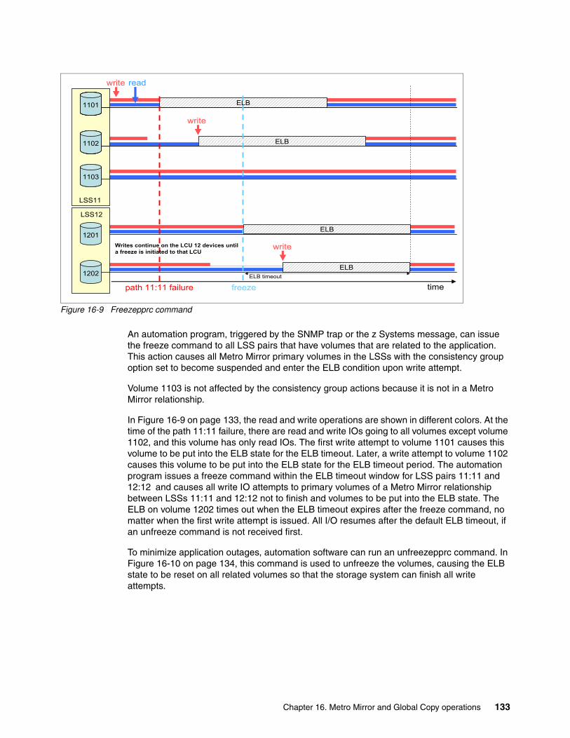
Figure 16-9 Freezepprc command
An automation program, triggered by the SNMP trap or the z Systems message, can issue the freeze command to all LSS pairs that have volumes that are related to the application. This action causes all Metro Mirror primary volumes in the LSSs with the consistency group option set to become suspended and enter the ELB condition upon write attempt.
Volume 1103 is not affected by the consistency group actions because it is not in a Metro Mirror relationship.
In Figure 16-9 on page 133, the read and write operations are shown in different colors. At the time of the path 11:11 failure, there are read and write IOs going to all volumes except volume 1102, and this volume has only read IOs. The first write attempt to volume 1101 causes this volume to be put into the ELB state for the ELB timeout. Later, a write attempt to volume 1102 causes this volume to be put into the ELB state for the ELB timeout period. The automation program issues a freeze command within the ELB timeout window for LSS pairs 11:11 and 12:12 and causes all write IO attempts to primary volumes of a Metro Mirror relationship between LSSs 11:11 and 12:12 not to finish and volumes to be put into the ELB state. The ELB on volume 1202 times out when the ELB timeout expires after the freeze command, no matter when the first write attempt is issued. All I/O resumes after the default ELB timeout, if an unfreeze command is not received first.
To minimize application outages, automation software can run an unfreezepprc command. In Figure 16-10 on page 134, this command is used to unfreeze the volumes, causing the ELB state to be reset on all related volumes so that the storage system can finish all write attempts.
write read
ELB
ELB
ELB
ELBELB timeout
path 11:11 failure freeze time
1100
1101
1102
LSS11
1100
1101
1102
1100
1101
1103
1100
1101
1101
1102
1201
1202
LSS12
Writes continue on the LCU 12 devices until a freeze is initiated to that LCU
write
write
Chapter 16. Metro Mirror and Global Copy operations 133

Figure 16-10 Unfreezepprc command
16.8.3 Critical attribute (z Systems only)For z Systems, the critical mode option can be used to alter the DS8000’s behavior when the primary storage system is unsuccessful in mirroring data to the secondary. In this case, the primary volume is placed into a write inhibited state, so that no further host writes to the volume are allowed.
Automated management solutions such as IBM Geographically Dispersed Parallel Sysplex (IBM GDPS) service and IBM Copy Services Manager include policy options to control the host I/O behavior in different error scenarios. Specifying the desired policy with one of these management solutions ensures that the business objectives related to your RPO requirements are met. It is a preferred practice to use these policy options instead of the critical mode option.
For more information about the z Systems critical mode option, see z/OS DFSMS Advanced Copy Services, SC23-6847.
unfreeze
write read
ELB
ELB
ELB
ELBELB timeout
path 11:11 failure freeze time
1100
1101
1102
LSS11
1100
1101
1102
1100
1101
1103
1100
1101
1101
1102
1201
1202
LSS12
Writes continue on the LCU 12 devices until a freeze is initiated to that LCU
write
write
Important: The Extended Long Busy (or queue full condition) is presented only for the primary volume that is affected by the error (in the case of path failures, multiple volumes are often affected). Still, the freeze operation is performed at the Metro Mirror path level, causing all Metro Mirror volumes that use those paths to go into a suspended state with an Extended Long Busy condition and terminating all associated paths. Therefore, when you plan your implementation, you should consider not intermixing volumes from different applications in an LSS pair that is part of a consistency group. Otherwise, the not-in-error volumes that belong to other applications are frozen as well.
134 DS8000 Copy Services

16.9 Creating a Global Copy consistent copy
While the copy pair volumes are in the Copy Pending state, the secondary volumes maintain a fuzzy copy of the data for the following reasons:
� Because of the non-synchronous data transfer characteristics, at any time there is a certain amount of updated data that is not reflected at the secondary volume. This data corresponds to the sectors that were updated since the last volume bitmap scan was done. These sectors are the out-of-sync sectors.
� Because of the bitmap scan method, writes are not ensured to be applied to the secondary volume in the same sequence as they are written to the primary volume.
When you terminate the Global Copy relationship to establish host access to secondary volumes, you can have the following problems:
� Transactions loss because there is a certain amount of updated data that is not reflected to the secondary volume
� Inconsistent volumes because the consistency of a file system or database depends on the correct order of writes
Therefore, for host systems to use secondary volumes, you must make them point-in-time consistent:
� The application must be quiesced and the volume pairs temporarily suspended. This action is necessary to ensure consistency not only at the volume level, but also at the application level.
� The secondary volumes must catch up to their primary counterparts. Global Copy catch-up is the name of the transition that occurs to a Global Copy pair when it goes from its normal out-of-sync condition until it reaches a full sync condition. At the end of this transition, the primary and secondary volumes are fully synchronized.
� You should now perform a FlashCopy of the secondary volumes onto tertiary volumes, and then resume the Global Copy pairs. These tertiary volumes are then a consistent point-in-time copy of the primary volumes.
Figure 16-11 on page 136 illustrates a procedure to get a consistent point-in-time copy at the secondary site.
Chapter 16. Metro Mirror and Global Copy operations 135

Figure 16-11 Create a Global Copy consistent copy
Here is a more detailed description of the steps in the procedure that is shown in Figure 16-11:
1. Quiesce the application updates.
2. Synchronize the volume pairs by using one of these methods:
– Perform the catch-up by doing a go-to-sync operation, as described in “Converting Global Copy to Metro Mirror” on page 119. The volume pair changes from the Copy Pending state to the Full Duplex state. From this moment, primary write updates are synchronously transmitted to the secondary volumes, if the application updates were not quiesced.
– Perform the catch-up by waiting until all application updates are transmitted to the secondary site.
You can monitor the number of out-of-sync tracks with the DS CLI.
3. Suspend the Global Copy pairs after they reach the Full Duplex state. If you use consistency groups, you can do a freeze operation.
Now, you have a set of consistent secondary volumes.
4. You can resume the application. Updates are not transmitted to the secondary volumes because the pairs are suspended. The secondary volumes remain consistent, and the application do not experience any response time impact.
5. Perform a FlashCopy on the secondary volumes.
6. Resume Global Copy mode for the copy pair.
Global Copy
fuzzy copy of data
Consistent copy of data
Primary Site Secondary Site
FlashCopy
1. Quiesce application updates
2. Catch-up (synchronize volumes)go-to-sync & suspendorwait for application writes to quiesce
3. Freeze (or Suspend) Global Copy
4. Resume application writes when freezes complete
6. Resynchronize Global Copy
volume pairs synchronize
data is consistent across all secondary volumes
5. FlashCopy to preserve consistent copy of data
Channel ExtenderChannel Extender
H2H1
I2
136 DS8000 Copy Services

For applications recovery based on point-in-time copies, you must plan for appropriate checkpoints to briefly quiesce the application and synchronize the volumes pairs. When the recovery of the application is done, you must remember, while in an active Global Copy relationship, the secondary volumes always have a current fuzzy copy of the primary volumes. So, you must keep the tertiary volumes where you did a FlashCopy of the last globally consistent catch-up. This tertiary copy does not reflect the current updates; it reflects any updates up until the last global catch-up operation.
It is not always possible to quiesce an application when the systems and applications must be always online and available to the user. If so, consider the following approaches:
� The quiesce is planned when the quiesce has the least possible impact to the user. For example, if possible, the quiesce of the application can be performed on the second or third shift.
� You can use a different approach than quiescing the application by completing the following steps:
a. Perform a consistency group FlashCopy of all volumes that are used by this application. This action causes I/O operations to the frozen volume to return Extended Long Busy (ELB) or I/O queue full messages for a short period to maintain the order of dependent writes, which in turn keeps the copied data at a consistency level. For many users, this action is preferred instead of quiescing the application. For a complete description of this function, see 7.10, “Consistent FlashCopy (FlashCopy consistency group)” on page 51.
b. Now you have a consistent FlashCopy of the application data at the primary site, and you are able to perform a Global Copy copy of this data to the secondary site.
c. Consider using Incremental FlashCopy with the FlashCopy consistency group option to reduce the amount of data that is transmitted to the secondary site when you perform the procedure. For more information about this function, see 7.6, “Incremental FlashCopy” on page 48.
d. You can perform a FlashCopy of the secondary volumes to tertiary volumes at the secondary site. These volumes can be used if there is a disaster or a problem at the primary site.
e. Perform a Consistent Group FlashCopy with Incremental FlashCopy again.
16.10 Automation and management
Metro Mirror is a storage system mirroring solution. Each volume on the primary system is paired with at least one volume on a secondary storage system. In a some multi-site configurations there are even more relationships. As the size of the environment grows, so does the complexity of managing it. You must have a means for managing the pairs, ensuring that they are in duplex status, adding volume pairs as required, monitoring for error conditions, and more importantly, for managing data consistency across LSS and across all of the storage systems.
When you plan a Metro Mirror environment, you should give careful consideration to the following topics:
� Design of the automation solution� Design and capacity of the replication network� Maintenance and management of the solution� Failover and disaster recovery testing� Copy services environment support
Chapter 16. Metro Mirror and Global Copy operations 137

You do not want to be in a situation where you are relying on your mirroring implementation for data to be consistent in a disaster situation, only to find that it has not worked. Or, even worse, you might not even be aware that your data is inconsistent.
IBM offers services and solutions for the automation and management of the Metro Mirror environment. These services include IBM Copy Services Manager and IBM Geographically Dispersed Parallel System (IBM GDPS) as described in Part 7, “Solutions” on page 317.
138 DS8000 Copy Services

Chapter 17. Metro Mirror and Global Copy implementation considerations
This chapter contains topics to consider when planning to establish a Global Copy or Metro Mirror environment with DS8000, and it includes the following topics:
� Bandwidth considerations� Performance considerations� Symmetrical configuration� Volume selection� Hardware requirements� Scalability� Distance considerations� z/OS multiple subchannel set support� Global Copy point-in-time backup solution considerations
17
Terminology: This chapter uses Peer-to-Peer Remote Copy (PPRC) as a common term if the topic belongs to both functions Global Copy and Metro Mirror.
© Copyright IBM Corp. 2017. All rights reserved. 139

17.1 Bandwidth considerationsFor Metro Mirror and Global Copy, the bandwidth considerations are slightly different. For Metro Mirror it is important to know the peak write throughput, and for Global Copy you need to know the amount of data that must transferred to the remote site and the available window.
17.1.1 Metro Mirror bandwidth considerations
Before you establish your Metro Mirror solution, determine the bandwidth requirements for connecting the primary and secondary storage systems. This step is a critical one in designing the Metro Mirror environment.
Bandwidth analysis and capacity planning helps to define how many links you require initially and, when you need to add more, to ensure continuous optimal performance.
To assist you with this analysis, IBM Spectrum Control™ or IBM z/OS Resource Measurement Facility™ (RMF™) can provide precise information about read/write ratios, data throughput, and input/output operations per second (IOPS) for a specific storage system. Another method, but much less exact one, is to collect historical traffic data from the Fibre Channel (FC) switches by using FC switch tools.
Peak bandwidth requirementsTo avoid any response time issues, determine the peak sustained write rate for your systems and ensure that you have adequate bandwidth to manage this load and to allow for growth. Remember, only writes are mirrored across to the secondary volumes. For a typical system, this peak is usually during batch processing, when many updates are occurring. It might be higher still during month-end or year-end processing.
You must make allowances for this peak period when you perform your bandwidth calculations.
17.1.2 Global Copy bandwidth considerations
To determine the bandwidth requirement for your Global Copy environment, consider both the amount of data you must transfer to the remote site and the available window.
You can estimate the amount of data to be sent to the target by calculating the amount of write data to the source. RMF or Spectrum Control can assist you to get the necessary data. Another method, but not so exact, is to monitor the traffic over the FC/FICON switches by using FC switch tools and other management tools, but remember, only writes are mirrored by Global Copy.
For a conservative estimation of your daily offsite backup window, you can estimate and tally up the time of each operation, such as Global Copy data transmission, application quiesce, FlashCopy establishment, application restart, FlashCopy background copy operation, and backing up the FlashCopy target.
Finally, you can estimate how much network bandwidth is necessary for your Global Copy solution by dividing the amount of data you must transfer by the duration of the backup window.
Be aware, that a FlashCopy relationship at the remote site can influence the performance of the Global Copy operation. If you use the FlashCopy with the nocopy option at the remote site, when the Global Copy secondary volume receives an update, the track on the FlashCopy
140 DS8000 Copy Services

source, which is also the Global Copy secondary, must be copied to the FlashCopy target before the data transfer operation completes. This copy operation to the FlashCopy target can complete by using the DS8000 cache and NVS without waiting for a physical write to the FlashCopy target. However, this data movement can influence the Global Copy activity. So, when you consider the network bandwidth, consider that the FlashCopy effect on the Global Copy activity might in fact decrease the bandwidth utilization during some intervals.
If you are not using the nocopy option, but are resuming Global Copy before the FlashCopy background copy finishes at the remote site, this background data movement might also influence the Global Copy performance.
17.2 Performance considerations
As opposed to Metro Mirror, Global Copy is an asynchronous replication and has no application impact. Thus, we discuss only Metro Mirror considerations in this section.
Because Metro Mirror is a synchronous mirroring technology, it has a performance impact for write operations on the storage system greater than a similar environment that has no remote mirroring. It does not use any host processor resources, unlike host-based or operating system mirroring. Consider this aspect as part of the planning process for Metro Mirror.
17.2.1 Managing the loadAs part of your implementation project, you might be able to identify and redistribute hot spots across your configuration, or take other actions to manage and balance the workload.
Here are some basic considerations:
� Is your bandwidth sufficient? If not, do you see an increase in the response time of your applications during peak workloads?
� When possible, do not share the Metro Mirror link I/O ports with host attachment ports. One result can be unpredictable performance of Metro Mirror and a much more complicated search in the case of performance analysis.
� Sometimes the problem is not Metro Mirror, but rather hot spots on the disks. Be sure that these problems are resolved before you start with Metro Mirror.
17.2.2 Initial synchronizationWhen you perform the initial synchronization of your Metro Mirror pairs, the DS8000 uses an internal algorithm to balance work across all available resources to prevent the Metro Mirror process from using too many storage system resources. This algorithm might prolong the synchronization process if your DS8000 is busy at the time. You might choose to stagger your synchronization tasks, or to run them at a time of low utilization, to make this process more efficient.
As an alternative, you might also choose to do the initial synchronization in Global Copy mode, and then after the majority of the data has been copied, switch to Metro Mirror mode. You can use this mode to bring all volumes to a Copy Pending state, which has little or no application impact, and then switch to a Full Duplex state. You can do so through the DS CLI, or one of the other interfaces.
Chapter 17. Metro Mirror and Global Copy implementation considerations 141

17.2.3 Metro Mirror distance considerationsDistance is an important topic. The distance between your local and remote DS8000 systems affects the response time impact of the Metro Mirror implementation. The maximum supported distance for Metro Mirror is 300 km.
Light speed is less than 300,000 km/s, that is, less than 300 km/ms on Fibre Channel. The data must go to the other site, and then an acknowledgment must come back. Add possible latency times of any active components in the configuration (for example, Fibre Channel directors), and you get approximately a 1-ms impact per 100 km for write I/Os.
17.2.4 z/OS Resource Management Facility
z/OS Resource Management Facility (RMF) can collect and report on Metro Mirror link performance statistics for a DS8000 storage system, and is used for capacity planning and trending reports. You can track the utilization of the Metro Mirror links over time and introduce new links in a planned manner.
You can also produce reports on extent pool and rank performance statistics by using the RMF Post Processor, if you enabled the collection of this data through the RMF PARMLIB member.
17.3 Symmetrical configurationWhen you plan your Metro Mirror or Global Copy configuration, consider the possibility of a symmetrical configuration, in terms of both physical and logical elements. This configuration has the following benefits:
� Simplified management. It is easier to see where volumes are mirrored, and processes can be easily automated.
� Reduced administrator overhead. Because of automation, and the simpler nature of the solution, overhead can be reduced.
� Simplifies the addition of new capacity into the environment. New arrays can be added in a modular fashion.
� Ease problem diagnosis. The simple structure of the solution aids in identifying where any problems might exist.
142 DS8000 Copy Services

Figure 17-1 shows this idea in a graphical form.
Figure 17-1 Symmetrical Metro Mirror configuration
DS8000 H1 has Metro Mirror/Global Copy paths that are defined to DS8000 H2, which is in a remote location. On DS8000 H1, volumes that are defined in LSS 00 are mirrored to volumes in LCU 00 on DS8000 H2 (volume 0001 from DS8000 H1 is paired with volume 0001 from DS8000 H2, and so on). Volumes in LCU 01 on DS8000 H1 are mirrored to volumes in LCU 01 on DS8000 H2, and so on.
Requirements for additional capacity can be added in a symmetrical way by adding volumes into existing LCUs, and by adding new LCUs when needed.
17.4 Volume selectionYou must consider which volumes should be mirrored to the remote site. One option is to mirror all volumes. This configuration has the following advantages:
� You do not have to consider whether any required data is missed.
� Users do not have to remember which logical pool of volumes is mirrored and which is not.
� You do not require a potentially complex volume pooling scheme (DFSMS Storage Groups)
� Adding volumes to the environment is simplified. You do not require two processes for the addition of disks (one for mirrored volumes, and another for non-mirrored volumes).
� You can move data around your disk environment easily without being concerned about whether the target volume is a mirrored volume.
You might choose not to mirror all volumes. In this case, you need careful control over what data is placed on the mirrored volumes (to avoid any capacity issues) and what data you place on the non-mirrored volumes (to avoid missing any required data). One method of doing this task is to place all mirrored volumes in a particular set of LSSs, in which all volumes are Metro Mirror-enabled, and direct all data that requires mirroring to these volumes.
DS8000 H1
LSS000001 0002 0003 0004
LSS010101 0102 0103 0104
LSS101001 1002 1003 1004
LSS111101 1102 1103 1104
LSS212101 2102 2103 2104
DS8000 H2
LSS000001 0002 0003 0004
LSS010101 0102 0103 0104
LSS101001 1002 1003 1004
LSS111101 1102 1103 1104
LSS212101 2102 2103 2104
Chapter 17. Metro Mirror and Global Copy implementation considerations 143

In some environments it is actually necessary to exclude volumes from mirroring. For example in a z/OS Basic HyperSwap or z/OS Geographically Dispersed Parallel Sysplex (GDPS) managed environment you should not mirror some of the Couple Data Sets volumes. Refer to your Copy Services Management Software to get more information regarding which volumes should excluded from mirroring.
Volume type selectionAnother aspect to consider is the volume type you use for your primary and secondary volumes. Prior to DS8000 Microcode Rel 8.1.1, PPRC supports only the same volume types for primary and secondary volumes, meaning that they must be either both fully provisioned or both extent space-efficient (ESE) volumes. DS8000 Microcode Rel. 8.2 introduces the ability to establish a PPRC relationship between fully provisioned and ESE volumes. This functionality can be used to migrate from full to thin provisioned volumes.
With ESE volumes, users no longer need to worry about volume expansion with PPRC. Today, in order to accomplish that, PPRC relationships must be terminated, the volumes expanded, and then the relationships reestablished. With ESE volumes, volumes can be defined as much larger than needed at that time, but large enough for planned future usage. As physical storage is consumed, more physical storage can be added to the configuration without having to redefine or expand the virtual volumes with PPRC active.
17.5 Hardware requirementsThis section describes the hardware requirements to establish a Global Copy or Metro Mirror.
17.5.1 LicenseGlobal Copy and Metro Mirror require the optional Copy Services license. You must purchase the corresponding licensed function for the primary and secondary DS8000 systems. For detailed information about DS8000 licenses, see 2.1, “Licensed function” on page 10.
Tip: Although mirroring all volumes might be the simpler solution to manage, it might also require more network bandwidth. Because network bandwidth is a cost, minimizing the bandwidth might well be worth the added management complexity.
Note: DS8000 Microcode Rel. 8.1 introduced thin provisioning support for z Systems count key data (CKD) volumes.
Note: The DS8880 Release 8.0 introduced new license bundles. The Copy Services license includes the following features:
� Global Mirror� Metro Mirror� Metro/Global Mirror� Point-in-time copy/FlashCopy� z/OS Global Mirror� z/OS Metro/Global Mirror Incremental Resync (RMZ)
144 DS8000 Copy Services

17.5.2 InteroperabilityMetro Mirror/Global Copy pairs can be established only between storage systems of the same (or similar) type and features. For example, a DS8300 can have a Global Copy relationship with a DS8880. All storage systems must have the appropriate licensed feature installed.
17.5.3 Connectivity: Ports, paths, and linksThe DS8000 employs up to 128 ports. Each port can be independently configured to support Fibre Channel or FICON.
For Metro Mirror or Global Copy paths, you must have at least one Fibre Channel connection between the two DS8000 systems for which you want to set up a relationship. For higher availability, use at least two Fibre Channel connections between the two systems on different host adapters on the DS8000.
The Fibre Channel ports that are used to establish the PPRC paths can be shared with between PPRC and Fibre Channel data traffic.
Global Copy or Metro Mirror pairs are set up between volumes in LSSs, usually in different storage systems, which are normally in separate locations. A path (or group of paths) must be defined between the primary LSS and the secondary LSS. These logical paths are defined over physical links between the storage systems.
The physical link includes the host adapter in the primary DS8000, the cabling, switches or directors, any wideband or long-distance transport devices (DWDM, channel extenders, WAN), and the host adapters in the remote storage system. Physical links can carry multiple logical paths.
For more detailed information about logical and physical paths, see Chapter 15, “Metro Mirror and Global Copy paths” on page 111.
Logical paths are unidirectional, that is, they are defined to operate in either one direction or the other. Global Copy/Metro Mirror is bidirectional, which means that any particular pair of LSSs can have paths that are defined among them that have opposite directions; each LSS holds both primary and secondary volumes from the other particular LSS. Furthermore, opposite direction paths are allowed to be defined on the same Fibre Channel physical link.
Fibre Channel ports: Although it is possible to share a Fibre Channel port for PPRC and host data traffic, use different Fibre Channel ports and adapters in the DS8000 systems to avoid contentions and potential host performance degradation.
Physical Links: If you want to use coarse wavelength division multiplexing (CWDM) to connect two DS8000 systems directly make sure that the CWDM Fibre optic has the same speed as the DS8000 Fibre Channel port. For example if you have a 16 Gbps DS8000 HBA you must use in the CWDM an SFP with the same speed, because auto-negotiation does not work.
Links: For a PPRC, the DS8000 supports Fibre Channel links only (no FICON links). To facilitate ease of testing, the DS8000 supports Metro Mirror/Global Copy primary and secondary volumes on the same DS8000.
Chapter 17. Metro Mirror and Global Copy implementation considerations 145

For bandwidth and redundancy, more than one path can be created between an LSS pair. The DS8000 balances the workload across the available paths between the primary and secondary LSSs.
Physical links are bidirectional and can be shared by other remote mirror and copy functions, such as Global Mirror.
17.5.4 LSS and consistency group considerationsThe LSS and consistency group considerations applies to Metro Mirror and Global Copy. For more information, see 13.2, “Metro Mirror positioning” on page 105.
The DS CLI freezepprc and unfreezepprc commands are used in the Metro Mirror environment or after you convert from Global Copy mode to Metro Mirror mode. However, if you set the consistency group option on an LSS, even when the volumes in the LSS are Global Copy primaries, the freeze operation that is triggered by the freezepprc command, or a failure of a secondary update, causes the queue full condition. Therefore, you should pay attention to the LSS design if you use the consistency group option.
17.6 ScalabilityThe DS8000 PPRC environment can be scaled up or down as required. If new volumes are added to the DS8000 that require mirroring, they can be dynamically added. If additional PPRC paths are required, they also can be dynamically added.
The logical nature of the LSS makes a Metro Mirror implementation on the DS8000 easier to plan, implement, and manage. However, if you must add more LSSs to your PPRC environment, your management and automation solutions should be set up to handle this task.
IBM Copy Services Manager and the IBM Geographically Dispersed Parallel Sysplex (IBM GDPS) service offering are designed to provide this function.
Adding capacity to the same DS8000 systemIf you are adding capacity to an existing DS8000, you might have to add only volume pairs into your configuration, providing your Metro Mirror/Global Copy link bandwidth is not close to or over its capacity limit. If you are adding more LSSs, then you must define new logical PPRC paths over the existing physical links before you add the new volume pairs.
Adding capacity in new DS8000 systemsIf you are adding new DS8000s to your configuration, you must add physical Fibre Channel links before you define your PPRC paths and volume pairs. A minimum of two PPRC paths per DS8000 pair is a preferred practice for redundancy reasons. Your bandwidth analysis indicates whether you require more than two paths.
LSSs: Remember, the LSS is not a physical construct in the DS8000; it is a logical construct. Volumes in an LSS can come from multiple disk arrays.
FCP links: In general, you should not share the FCP links for synchronous and asynchronous remote copy functions.
146 DS8000 Copy Services

17.7 Distance considerationsThe maximum distance for a direct DS8000 Fibre Channel connection is 10 km. If you want to use PPRC over longer distances, you can use the following connectivity technologies to extend this distance:
� Fibre Channel switches� Channel extenders over wide area network (WAN) lines� Dense wavelength division multiplexing (DWDM) on dark fibre
17.7.1 Fibre Channel switches (FICON switches)Fibre Channel/FICON switches allow FC Links or FICON channels to be connected to storage systems, tape systems, and other peripheral devices. For Fibre Channel Switches multiple hops are allowed. FICON Cascading allows you to connect two FICON Switches with each other, it is possible, either over small distances or long distances through WAN connectivity (DWDM, ATM, E3/DS3, and T1/E1).
With FICON Switches, a DS8000 can be connected to another DS8000 over a large distance by the DS8000-FCP-FICON Switch-WAN-FICON Switch-FCP-DS8000 connection.
17.7.2 Channel extenderChannel extenders connect DS8000 systems through various wide area network (WAN) connections, including Fibre Channel, Ethernet/IP, ATM-OC3, and T1/T3 or E1/E3 connection links.
Basically, a Channel Extender works in a pair (you can also have three or more channel extenders connected), where the network links connect those machines over long distances, and also the channel extender has FICON, FCP, or SCSI connections to a host server. DS8000 connected to DS8000 over large distances with channel extenders is an FCP-WAN-FCP protocol encapsulation. Channel extenders usually emulate a local connection and they have software running, which allows many facilities.
The channel extender vendor should be contacted so that you can learn their distance capability, line quality requirements, and WAN attachment capabilities when you use PPRC between the primary and secondary DS8000 systems.
The channel extender vendor should be contacted regarding hardware and software prerequisites when you use their products in a DS8000 PPRC configuration. Evaluation, qualification, approval, and support of PPRC configurations that use channel extender products is the sole responsibility of the channel extender vendor.
17.7.3 Dense wavelength division multiplexing (DWDM)Wavelength wavelength division multiplexing (WDM) and dense wavelength division multiplexing (DWDM) is the basic technology of fiber optical networking. It is a technique for carrying many separate and independent optical channels on a single dark fiber.
A simple way to envision DWDM is to consider that at the primary end, multiple fiber optic input channels, such as Fibre Channel, FICON, or Gbit Ethernet, are combined by DWDM into a single fiber optic cable. Each channel is encoded as light of a different wavelength.
You might think of each individual channel as an individual color: The DWDM system is transmitting a rainbow. At the receiving end, the DWDM fans out the different optical channels. DWDM provides the full bandwidth capability of the individual channel. As the
Chapter 17. Metro Mirror and Global Copy implementation considerations 147

wavelength of light is, from a practical perspective, infinitely divisible, DWDM technology is only limited by the sensitivity of its receptors, as the total aggregate bandwidth possible.
You should contact your DWDM vendor regarding hardware and software prerequisites whenever you are using DWDM products in a DS8000 PPRC configuration.
A complete and current list of Global Copy supported environments, configurations, networks, and products is available at:
http://www.ibm.com/systems/support/storage/ssic/interoperability.wss
17.8 z/OS multiple subchannel set supportIn larger z/OS environments you need to address a lot of devices. To avoid address constraints, z/OS supports up to four multiple subchannel sets (MSS).
PPRC secondaries in alternative subchannel sets are supported on all current releases of z/OS and DFSMS. This support enables greater scalability for the Metro Mirror environment by reducing the number of devices that are required to be addressed in the base subchannel set.
For planning considerations refer to your Copy Services Management Software guides to get information about which Subchannel Set is supported in your specific environment.
The support for subchannel sets for PPRC secondary devices includes SUBCHSET parameters for several TSO commands (for example, CESTPAIR and CESTPATH) and in the ANTRQST macro. The output of the CQUERY and RQUERY requests changed to show the subchannel for the device number where the query was issued. For more information about these commands, see z/OS DFSMS Advanced Copy Services, SC23-6847.
17.9 Global Copy point-in-time backup solution considerationsWhen you plan to use Global Copy for point-in-time backup solutions, such as the one illustrated in Figure 17-2 on page 149, you must also consider the following requirements:
� If you are going to have tertiary copies, then within the secondary storage system you should have an available set of volumes ready to become the FlashCopy target.
� If your next step is to dump the tertiary volumes onto tapes, then you must ensure that the tape resources can handle these dump operations in between the point-in-time checkpoints. This situation is necessary unless you have more sets of volumes ready to become alternative FlashCopy targets.
Note: PPRC secondary devices located in an alternate subchannel set must:
� Have the same 4-digit device number as the associated PPRC primary device in subchannel set 0
� Be defined as 3390D devices in the I/O configuration using HCD
148 DS8000 Copy Services

Figure 17-2 Global Copy environment
Global Copy
fuzzy copy of data
Consistent copyof data
Primary Site Secondary Site
FlashCopyChannel ExtenderChannel Extender
H2H1
I2
Chapter 17. Metro Mirror and Global Copy implementation considerations 149

150 DS8000 Copy Services

Chapter 18. Metro Mirror and Global Copy interfaces and examples
You can set up Metro Mirror and Global Copy through various interfaces. This chapter provides a brief comparison of the possible commands for each of these interfaces and shows some examples of their usage for Metro Mirror and Global Copy management on the IBM System Storage DS8000 in a z Systems and Open Systems environment.
It includes the following high-level topics:
� Metro Mirror and Global Copy interfaces overview� Metro Mirror and Global Copy DS CLI examples� Metro Mirror and Global Copy TSO examples� Metro Mirror and Global Copy ICKDSF examples
18
© Copyright IBM Corp. 2017. All rights reserved. 151

18.1 Metro Mirror and Global Copy interfaces overviewThe following interfaces are available for the setup and management of Metro Mirror and Global Copy environments.
� For Open Systems:
– DS CLI
� For z/OS:
– TSO commands– ICKDSF utility– ANTTREXX– ANTRQST API– DS CLI
� For z/VM:
– ICKDSF utility– DS CLI
� For z/VSE:
– ICKDSF utility– DS CLI
� For z/TPF:
– ICKDSF utility– z/TPF itself– DS CLI
In addition to these specific interfaces, the following DS8000 interfaces can also be used for management and automation:
� IBM Copy Services Manager is a business continuity solution, including FlashCopy, Metro Mirror, and Global Mirror. An overview of IBM Copy Services Manager is included in Chapter 28, “IBM Copy Services Manager” on page 329.
� DS Open Application Programming Interface (DS Open API): The DS Open API is a set of application programming interfaces that are available to be integrated in programs. The DS Open API is not covered in this book. For information about the DS Open API, see IBM System Storage DS Open Application Programming Interface Reference, GC35-0516.
18.1.1 Metro Mirror and Global Copy command reference
Table 18-1 provides an overview of the available commands for the various interfaces.
Table 18-1 Metro Mirror and Global Copy command reference
Function TSO command ANTTREXX command or API
ANTRQST API ICKDSF command
DSCLI command
Display available I/O ports for remote copy
CQUERY LNK (ANTPREXX) PQUERY LNK
ILK=PPRC REQUEST=PQUERY with LNK parameter
- lsavailpprcport
Establish paths CESTPATH (ANTPREXX) PESTPATH
ILK=PPRC REQUEST= PESTPATH
PPRCOPY ESTPATH mkpprcpath
Establish pair CESTPAIR (ANTPREXX) PESTPAIR
ILK=PPRC REQUEST= PESTPAIR
PPRCOPY ESTPAIR mkpprc
152 DS8000 Copy Services

For more information about the various interfaces and commands in this chapter, see Chapter 3, “Copy Services interfaces overview” on page 17 and the following publications:
� DFSMSdss Storage Administration, SC23-6868� z/OS DFSMS Advanced Copy Services, SC23-6847� ICKDSF User’s Guide, GC35-0033� z/VM CP Commands and Utilities Reference, SC24-6175� z/VSE V5R1.0 System Control Statements, SC34-2637� IBM DS8000 Series Command-Line Interface User’s Guide, SC27-8526
18.2 Metro Mirror and Global Copy DS CLI examples
To establish a Metro Mirror or Global Copy pair, the LAN connection between the primary and secondary DS8000 systems is not needed. However, Copy Services DS CLI commands must be issued to the DS8000 Hardware Management Console (HMC) that contains the primary
Suspend pair CSUSPAIR (ANTPREXX) PSUSPAIR
ILK=PPRC REQUEST=PSUSPAIR
PPRCOPY SUSPEND pausepprc
Resume or resync pair
CESTPAIR (ANTPREXX) PESTPAIR
ILK=PPRC REQUEST=PESTPAIR
PPRCOPY ESTPAIR resumepprc
Remove pair CDELPAIR (ANTPREXX) PDELPAIR
ILK=PPRC REQUEST= PDELPAIR
PPRCOPY DELPAIR rmpprc
Remove paths CDELPATH (ANTPREXX) PDELPATH
ILK=PPRC REQUEST= PDELPATH
PPRCOPY DELPATH rmpprcpath
Freeze all pairs between two LSSes or LCUs
CGROUP FREEZE (ANTPREXX) PFREEZE
ILK=PPRC REQUEST= PFREEZE
PPRCOPY FREEZE freezepprc
Remove extended long busy from devices in an LSS/LCU (unfreeze)
CGROUP RUN (ANTPREXX) PRUN ILK=PPRC REQUEST= PRUN
PPRCOPY RUN unfreezepprc
Set pair characteristics
PSETCHAR (ANTPREXX) PSETCHAR
ILK=PPRC REQUEST= PSETCHAR
PPRCOPY SETCHARACTERISTICS
chpprc
Query or display PPRC path status
CQUERY PATHS (ANTPREXX) PQUERY FORMAT(PQMAP)
ILK=PPRC REQUEST= PQUERY
PPRCOPY QUERY PATHS
lspprcpath
Query or display PPRC pair status
CQUERY (ANTPREXX) PQUERY FORMAT(PQMAP)
ILK=PPRC REQUEST= PQUERY
PPRCOPY QUERY lspprc
Soft fence - (ANTPREXX) REQUEST=FENCE
ILK=PPRC REQUEST=FENCE
CONTROL CLEARFENCE (to remove soft fence)
manageckdvol - sfdisable (to remove soft fence)
SPID fence - (ANTPREXX) REQUEST=FENCE
LK=PPRC REQUEST=FENCE
- -
Query storage controller status / health
- (ANTPREXX) ANTPQSCSTAT
ILK=PPRC REQUEST=PQSCSTAT
- -
Function TSO command ANTTREXX command or API
ANTRQST API ICKDSF command
DSCLI command
Chapter 18. Metro Mirror and Global Copy interfaces and examples 153

volume or will contain the primary volume. That means, you need a LAN connection from your DS CLI client machine to both DS8000 systems or DS HMCs.
When you establish or remove Metro Mirror or Global Copy paths and volume pairs, you must give the DS CLI commands to the DS HMC that is connected to the primary DS8000. Also, when you check the status information at the primary and secondary site, you must run DS CLI list type commands, such as the lspprc, to each DS8000, primary, and secondary.
This section covers the following DS CLI examples:
� Set up, manage, and remove a Metro Mirror environment� Perform Metro Mirror failover and failback operations (site switch)
– Switching over to a backup site – Switching back to a primary site
� Run Metro Mirror freezepprc and unfreezepprc commands� Changing the copy mode from Metro Mirror to Global Copy� Changing the copy mode from Global Copy to Metro Mirror� Global Copy: Periodic offsite backup procedure� Global Copy Cascading� Managing data migration with Global Copy
18.2.1 Setup, remove and manage of a Metro Mirror configurationFigure 18-1 on page 155 shows the configuration we set up for this example. The configuration has four Metro Mirror pairs that are in two LSSs. Two paths are defined between each source and target LSS.
This example uses different LSS and volume numbers for the Metro Mirror source and target elements so that you can more clearly understand which one is being specified when you read through the example.
Note: This chapter does not demonstrate setting up, managing, and removing a Global Copy environment, because the DS CLI commands that are used for Metro Mirror and Global Copy are similar. However, for some commands you need to specify what kind of relationship you want to establish. To create a Global Copy relationship, you must specify the -type gcp parameter, and for a Metro Mirror relationship you must specify the -type mmir parameter. The commands to establish paths between a primary and secondary storage system are identical for Global Copy and Metro Mirror.
Real-world environment: In a real environment (and different from this example), to simplify the management of your environment, maintain a symmetrical configuration in terms of both physical and logical elements.
154 DS8000 Copy Services

Figure 18-1 Metro Mirror environment to be set up
To configure the Metro Mirror environment, complete the following steps:
1. Determine the available Fibre Channel links for paths definition.2. Define the paths that Metro Mirror uses.3. Create Metro Mirror pairs.
Determining the available Fibre Channel linksFirst, you must look at the available Fibre Channel links. You can accomplish this task by running lsavailpprcport (see Example 18-1). You see all available port combinations between the source and the target LSSs. You must issue this command to the DS HMC connected to DS8000 H1, which is the Metro Mirror source.
Example 18-1 List available Fibre Channel links
dscli> lsavailpprcport -l -remotewwnn 5005076303FFD18E 40:50Local Port Attached Port Type Switch ID Switch Port===================================================I0102 I0137 FCP NA NAI0201 I0237 FCP NA NA
FCP port ID with the lsavailpprcport command has four hexadecimal characters in the format 0xEEAP, where EE is a port enclosure number (00–3F), A is the adapter number (0–F), and P is the port number (0–7). The FCP port ID number is prefixed with the letter I.
You can use the -fullid parameter to display the DS8000 Storage Image ID in the command output (see Example 18-2).
Example 18-2 List available Fibre Channel links with DS8000 Storage Image ID
dscli> lsavailpprcport -l -fullid -remotewwnn 5005076303FFD18E 40:50Local Port Attached Port Type Switch ID Switch Port========================================================================IBM.2107-75TV181/I0102 IBM.2107-75TV181/I0137 FCP NA NAIBM.2107-75TV181/I0201 IBM.2107-75TV181/I0237 FCP NA NA
Physical Fibre path
LSS10
4000
4001
LSS41
LSS50
LSS51
DS8000 H1 DS8000 H2
5000
5001
4100
4101
5100
5101
LSS40
Metro Mirror Pairs
Primary Secondary
Metro Mirror Pairs
Metro Mirror paths
Chapter 18. Metro Mirror and Global Copy interfaces and examples 155

You need the worldwide node name (WWNN) of your target DS8000 to issue the lsavailpprcport command. You can get the WWNN by running lssi (see Example 18-3). You must issue this command to the DS HMC connected to DS8000 H2, which is the Metro Mirror target.
Example 18-3 Get WWNN of target DS8000
dscli> lssiName ID Storage Unit Model WWNN State ESSNet====================================================================================DS8k05_3Tier IBM.2107-75ACV21 IBM.2107-75ACV20 951 5005076303FFD18E Online Enabled
Creating Metro Mirror pathsNow you can run mkpprcpath to create paths between the source and target LSSs and then verify the result by running lspprcpath. You must run mkpprcpath for each LSS pair (see Example 18-4). The consistency group attribute is here only used as an example for LSS 40/50, as there is no external automation solution that takes note of consistency. The -l option of the lspprcpath command displays the consistency group information.
Example 18-4 Create Metro Mirror paths and list them
dscli> mkpprcpath -remotewwnn 5005076303FFD18E -srclss 40 -tgtlss 50 -consistgrp i0102:i0137 i0201:i0237CMUC00149I mkpprcpath: Remote Mirror and Copy path 40:50 successfully established.dscli> mkpprcpath -remotewwnn 5005076303FFD18E -srclss 41 -tgtlss 51 i0102:i0137 i0201:i0237CMUC00149I mkpprcpath: Remote Mirror and Copy path 41:51 successfully established.
dscli> lspprcpath -l 40-41Src Tgt State SS Port Attached Port Tgt WWNN Failed Reason PPRC CG================================================================================40 50 Success FF50 I0102 I0137 5005076303FFD18E - Enabled40 50 Success FF50 I0201 I0237 5005076303FFD18E - Enabled41 51 Success FF51 I0102 I0137 5005076303FFD18E - Disabled41 51 Success FF51 I0201 I0237 5005076303FFD18E - Disabled
With the lspprcpath command, you can use the -fullid command flag to display the fully qualified DS8000 Storage Image ID in the command output (see Example 18-5).
Example 18-5 List paths with DS8000 Storage Image ID
dscli> lspprcpath -fullid 40-41Src Tgt State SS Port Attached Port Tgt WWNN==================================================================================IBM.2107-75TV181/40 IBM.2107-75ACV21/50 Success FF50 IBM.2107-75TV181/I0102 IBM.2107-75ACV21/I0137 5005076303FFD18EIBM.2107-75TV181/40 IBM.2107-75ACV21/50 Success FF50 IBM.2107-75TV181/I0201 IBM.2107-75ACV21/I0237 5005076303FFD18EIBM.2107-75TV181/41 IBM.2107-75ACV21/51 Success FF51 IBM.2107-75TV181/I0102 IBM.2107-75ACV21/I0137 5005076303FFD18EIBM.2107-75TV181/41 IBM.2107-75ACV21/51 Success FF51 IBM.2107-75TV181/I0201 IBM.2107-75ACV21/I0237 5005076303FFD18E
156 DS8000 Copy Services

When you want to add an additional path you need to specify the new and the existing paths in mkpprcpath command. If you want to remove one path you can run mkpprcpath command only without this path.
Creating Metro Mirror pairsAfter you create the paths, you can establish Metro Mirror volume pairs. You accomplish this task by running mkpprc and verifying the result by running lspprc (see Example 18-6). When you create a Metro Mirror pair, you must specify the -type mmir parameter with the mkpprc command. For mkpprc, the -remotedev parameter must be specified even if it is provided in the DS CLI profile.
Example 18-6 Create Metro Mirror pairs and verify the result
dscli> mkpprc -remotedev IBM.2107-75ACV21 -type mmir 4000-4001:5000-5001 4100-4101:5100-5101CMUC00153I mkpprc: Remote Mirror and Copy volume pair relationship 4000:5000 successfully created.CMUC00153I mkpprc: Remote Mirror and Copy volume pair relationship 4001:5001 successfully created.CMUC00153I mkpprc: Remote Mirror and Copy volume pair relationship 4100:5100 successfully created.CMUC00153I mkpprc: Remote Mirror and Copy volume pair relationship 4101:5101 successfully created.
dscli> lspprc 4000-4001 4100-4101ID State Reason Type SourceLSS Timeout (secs) Critical Mode First Pass Status===========================================================================================4000:5000 Copy Pending - Metro Mirror 40 60 Disabled Invalid4001:5001 Copy Pending - Metro Mirror 40 60 Disabled Invalid4100:5100 Copy Pending - Metro Mirror 41 60 Disabled Invalid4101:5101 Copy Pending - Metro Mirror 41 60 Disabled Invalid
After the Metro Mirror source and target volumes are synchronized, the volume state changes to Full Duplex from Copy Pending (see Example 18-7).
Example 18-7 List Metro Mirror status after Metro Mirror initial copy completes
dscli> lspprc 4000-4001 4100-4101ID State Reason Type SourceLSS Timeout (secs) Critical Mode First Pass Status===========================================================================================4000:5000 Full Duplex - Metro Mirror 40 60 Disabled Invalid4001:5001 Full Duplex - Metro Mirror 40 60 Disabled Invalid4100:5100 Full Duplex - Metro Mirror 41 60 Disabled Invalid4101:5101 Full Duplex - Metro Mirror 41 60 Disabled Invalid
The states of Full Duplex and Copy Pending indicate the Metro Mirror source state. In the case of the target state, the states are Target Full Duplex and Target Copy Pending (see Example 18-8). You must issue this command to the DS HMC connected to DS8000 H2, which is the Metro Mirror target.
Example 18-8 lspprc for Metro Mirror target volumes
dscli> lspprc 5000-5001 5100-5101ID State Reason Type SourceLSS Timeout (secs) Critical Mode First Pass Status======================================================================================================4000:5000 Target Copy Pending - Metro Mirror 40 unknown Disabled Invalid4001:5001 Target Copy Pending - Metro Mirror 40 unknown Disabled Invalid4100:5100 Target Copy Pending - Metro Mirror 41 unknown Disabled Invalid4101:5101 Target Copy Pending - Metro Mirror 41 unknown Disabled Invalid
Mirroring direction: Remember, logical paths are unidirectional. To reverse the mirroring direction (as it is required for failover/failback scenarios), you must establish logical paths from the remote to the local LSSs, for example, 50:40 and 51:41.
Chapter 18. Metro Mirror and Global Copy interfaces and examples 157

dscli> lspprc 5000-5001 5100-5101ID State Reason Type SourceLSS Timeout (secs) Critical Mode First Pass Status======================================================================================================4000:5000 Target Full Duplex - Metro Mirror 40 unknown Disabled Invalid4001:5001 Target Full Duplex - Metro Mirror 40 unknown Disabled Invalid4100:5100 Target Full Duplex - Metro Mirror 41 unknown Disabled Invalid4101:5101 Target Full Duplex - Metro Mirror 41 unknown Disabled Invalid
In the Copy Pending state, you can check the data transfer status of the Metro Mirror initial copy by running lspprc -l. Out Of Sync Tracks shows the remaining tracks to be sent to the target volume. The lspprc -l command output is wide; you might use stanza output format to break it into a more readable format. See Example 18-9 for stanza output.
Example 18-9 Long lspprc -l output formatted to stanzas
dscli> lspprc -l -fmt stanza 5000-5001 5100-5101ID 4000:5000State Copy PendingReason -Type Metro MirrorOut Of Sync Tracks 297216Tgt Read DisabledSrc Cascade DisabledTgt Cascade InvalidDate Suspended -SourceLSS 40Timeout (secs) 60Critical Mode DisabledFirst Pass Status InvalidIncremental Resync DisabledTgt Write DisabledGMIR CG N/APPRC CG EnabledisTgtSE UnknownDisableAutoResync -
ID 4001:5001State Copy PendingReason -Type Metro MirrorOut Of Sync Tracks 295234Tgt Read DisabledSrc Cascade DisabledTgt Cascade InvalidDate Suspended -SourceLSS 40Timeout (secs) 60Critical Mode DisabledFirst Pass Status InvalidIncremental Resync DisabledTgt Write DisabledGMIR CG N/APPRC CG EnabledisTgtSE UnknownDisableAutoResync -
158 DS8000 Copy Services

ID 4100:5100State Copy PendingReason -Type Metro MirrorOut Of Sync Tracks 304637Tgt Read DisabledSrc Cascade DisabledTgt Cascade InvalidDate Suspended -SourceLSS 41Timeout (secs) 60Critical Mode DisabledFirst Pass Status InvalidIncremental Resync DisabledTgt Write DisabledGMIR CG N/APPRC CG EnabledisTgtSE UnknownDisableAutoResync -
ID 4101:5101State Copy PendingReason -Type Metro MirrorOut Of Sync Tracks 301122Tgt Read DisabledSrc Cascade DisabledTgt Cascade InvalidDate Suspended -SourceLSS 41Timeout (secs) 60Critical Mode DisabledFirst Pass Status InvalidIncremental Resync DisabledTgt Write DisabledGMIR CG N/APPRC CG EnabledisTgtSE UnknownDisableAutoResync -
Removing the Metro Mirror environmentThis section shows how to terminate the Metro Mirror environment that was set up in the previous sections. Complete the following steps:
1. Remove Metro Mirror pairs.2. Remove logical paths.
Removing Metro Mirror pairsThe rmpprc command removes the volume pairs relationships (see Example 18-10 on page 160). You can use the -quiet parameter to turn off the confirmation prompt for this command.
Chapter 18. Metro Mirror and Global Copy interfaces and examples 159

Example 18-10 Removing Metro Mirror pairs
dscli> lspprc 4000-4001 4100-4101ID State Reason Type SourceLSS Timeout (secs) Critical Mode First Pass Status==================================================================================================4000:5000 Full Duplex - Metro Mirror 40 60 Disabled Invalid4001:5001 Full Duplex - Metro Mirror 40 60 Disabled Invalid4100:5100 Full Duplex - Metro Mirror 41 60 Disabled Invalid4101:5101 Full Duplex - Metro Mirror 41 60 Disabled Invalid
dscli> rmpprc -remotedev IBM.2107-75ACV21 4000-4001:5000-5001 4100-4101:5100-5101CMUC00160W rmpprc: Are you sure you want to delete the Remote Mirror and Copy volume pair relationship 4000-4001:5000-5001:? [y/n]:yCMUC00155I rmpprc: Remote Mirror and Copy volume pair 4000:5000 relationship successfully withdrawn.CMUC00155I rmpprc: Remote Mirror and Copy volume pair 4001:5001 relationship successfully withdrawn.CMUC00160W rmpprc: Are you sure you want to delete the Remote Mirror and Copy volume pair relationship 4100-4101:5100-5101:? [y/n]:yCMUC00155I rmpprc: Remote Mirror and Copy volume pair 4100:5100 relationship successfully withdrawn.CMUC00155I rmpprc: Remote Mirror and Copy volume pair 4101:5101 relationship successfully withdrawn.
You can add the -at tgt parameter to the rmpprc command to remove only the Metro Mirror target volume (see Example 18-11). The commands are given to the DS HMC connected to DS8000 H2, which is the Metro Mirror target.
Example 18-11 Results of rmpprc with -at tgt
dscli> lspprc 5000ID State Reason Type SourceLSS Timeout (secs) Critical Mode First Pass Status====================================================================================================4000:5000 Target Full Duplex - Metro Mirror 40 unknown Disabled Invalid
dscli> rmpprc -quiet -remotedev IBM.2107-75ACV21 -at tgt 4000:5000CMUC00155I rmpprc: Remote Mirror and Copy volume pair 4000:5000 relationship successfully withdrawn.
dscli> lspprc 5000CMUC00234I lspprc: No Remote Mirror and Copy found.
Example 18-12 shows the Metro Mirror source volume status after the rmpprc -at tgt command completes. The source status changed to Suspended with a reason of Simplex Target as a result of the rmpprc -at tgt command. If there are no available paths, the state of the Metro Mirror source volume is preserved. To remove the relationship on the source, you must run rmpprc. You must issue the command to the DS HMC connected to DS8000 H1, which is the Metro Mirror source.
Example 18-12 Metro Mirror source volume status after rmpprc with -at tgt and rmpprc with -at src
dscli> lspprc 4000-4001 4100-4101ID State Reason Type SourceLSS Timeout (secs) Critical Mode First Pass Status==========================================================================================================4000:5000 Suspended Simplex Target Metro Mirror 40 60 Disabled Invalid
dscli> rmpprc -quiet -remotedev IBM.2107-75ACV21 4000:5000CMUC00155I rmpprc: Remote Mirror and Copy volume pair 4000:5000 relationship successfully withdrawn.
dscli> lspprc 4000CMUC00234I lspprc: No Remote Mirror and Copy found.
160 DS8000 Copy Services

Removing pathsThe rmpprcpath command removes paths. Before you remove the paths, you must remove all Remote Mirror pairs that are using the paths or you must use the -force parameter with the rmpprcpath command (see Example 18-13, Example 18-14, and Example 18-15).
Example 18-13 Remove paths
dscli> lspprc 4000-4001CMUC00234I lspprc: No Remote Mirror and Copy found.
dscli> rmpprcpath -remotedev IBM.2107-75ACV21 40:50CMUC00152W rmpprcpath: Are you sure you want to remove the Remote Mirror and Copy path 40:50:? [y/n]:yCMUC00150I rmpprcpath: Remote Mirror and Copy path 40:50 successfully removed.
If you do not remove the Metro Mirror pairs that are using the paths, the rmpprcpath command fails (see Example 18-14).
Example 18-14 Removed paths that still have Metro Mirror pairs
dscli> lspprc 4100ID State Reason Type SourceLSS Timeout (secs) Critical Mode First Pass Status==================================================================================================4100:5100 Full Duplex - Metro Mirror 41 60 Disabled Invalid
dscli> rmpprcpath -remotedev IBM.2107-75ACV21 41:51CMUC00152W rmpprcpath: Are you sure you want to remove the Remote Mirror and Copy path 41:51:? [y/n]:yCMUN03070E rmpprcpath: 41:51: Copy Services operation failure: pairs remain
If you want to remove logical paths while still having Metro Mirror pairs, you can use the -force parameter (see Example 18-15). After the path is removed, the Metro Mirror pair is still in a Full Duplex state until the Metro Mirror source receives I/O from the servers. When I/O arrives to the Metro Mirror source, the source volume becomes Suspended. If you set the consistency group option for the LSS in which the Metro Mirror volumes are, I/Os from the servers are held with queue-full status for the specified timeout value.
Example 18-15 Removing paths while still having Metro Mirror pairs with the -force parameter
dscli> lspprc 4100ID State Reason Type SourceLSS Timeout (secs) Critical Mode First Pass Status==================================================================================================4100:5100 Full Duplex - Metro Mirror 41 60 Disabled Invalid
dscli> rmpprcpath -remotedev IBM.2107-75ACV21 -quiet -force 41:51CMUC00150I rmpprcpath: Remote Mirror and Copy path 41:51 successfully removed.
dscli> lspprc 4100ID State Reason Type SourceLSS Timeout (secs) Critical Mode First Pass Status==================================================================================================4100:5100 Full Duplex - Metro Mirror 41 60 Disabled Invalid
<< After I/O goes to the source volume >>
dscli> lspprc 4100ID State Reason Type SourceLSS Timeout (secs) Critical Mode First Pass Status====================================================================================================================4100:5100 Suspended Internal Conditions Target Metro Mirror 41 60 Disabled Invalid
Chapter 18. Metro Mirror and Global Copy interfaces and examples 161

Managing the Metro Mirror environment with the DS CLIThis section shows how we can manage the Metro Mirror environment, such as suspending and resuming Metro Mirror pairs and changing logical paths.
Suspending and resuming Metro Mirror data transferThe pausepprc command stops Metro Mirror from transferring data to the target volumes. After this command completes, the Metro Mirror pair becomes Suspended. I/Os from the servers complete at the Metro Mirror source volumes without sending those updates to their target volumes (see Example 18-16).
Example 18-16 Suspending Metro Mirror data transfer
dscli> lspprc 4000-4001 4100-4101ID State Reason Type SourceLSS Timeout (secs) Critical Mode First Pass Status==================================================================================================4000:5000 Full Duplex - Metro Mirror 40 60 Disabled Invalid4001:5001 Full Duplex - Metro Mirror 40 60 Disabled Invalid4100:5100 Full Duplex - Metro Mirror 41 60 Disabled Invalid4101:5101 Full Duplex - Metro Mirror 41 60 Disabled Invalid
dscli> pausepprc -remotedev IBM.2107-75ACV21 4000-4001:5000-5001CMUC00157I pausepprc: Remote Mirror and Copy volume pair 4000:5000 relationship successfully paused.CMUC00157I pausepprc: Remote Mirror and Copy volume pair 4001:5001 relationship successfully paused.
dscli> lspprc 4000-4001 4100-4101ID State Reason Type SourceLSS Timeout (secs) Critical Mode First Pass Status=======================================================================================================4000:5000 Suspended Host Source Metro Mirror 40 60 Disabled Invalid4001:5001 Suspended Host Source Metro Mirror 40 60 Disabled Invalid4100:5100 Full Duplex - Metro Mirror 41 60 Disabled Invalid4101:5101 Full Duplex - Metro Mirror 41 60 Disabled Invalid
Because the source DS8000 tracks all changed data on the source volume, you can resume Metro Mirror operations later. The resumepprc command resumes a Metro Mirror relationship for a volume pair and restarts transferring data. You must specify the Remote Mirror and Copy type, such as Metro Mirror or Global Copy, with the -type parameter (see Example 18-17).
Example 18-17 Resuming Metro Mirror pairs
dscli> lspprc 4000-4001 4100-4101ID State Reason Type SourceLSS Timeout (secs) Critical Mode First Pass Status======================================================================================================4000:5000 Suspended Host Source Metro Mirror 40 60 Disabled Invalid4001:5001 Suspended Host Source Metro Mirror 40 60 Disabled Invalid4100:5100 Full Duplex - Metro Mirror 41 60 Disabled Invalid4101:5101 Full Duplex - Metro Mirror 41 60 Disabled Invalid
dscli> resumepprc -remotedev IBM.2107-75ACV21 -type mmir 4000-4001:5000-5001CMUC00158I resumepprc: Remote Mirror and Copy volume pair 4000:5000 relationship successfully resumed. This message is being returned before the copy completes.CMUC00158I resumepprc: Remote Mirror and Copy volume pair 4001:5001 relationship successfully resumed. This message is being returned before the copy completes.
dscli> lspprc 4000-4001 4100-4101ID State Reason Type SourceLSS Timeout (secs) Critical Mode First Pass Status==================================================================================================4000:5000 Full Duplex - Metro Mirror 40 60 Disabled Invalid4001:5001 Full Duplex - Metro Mirror 40 60 Disabled Invalid
162 DS8000 Copy Services

4100:5100 Full Duplex - Metro Mirror 41 60 Disabled Invalid4101:5101 Full Duplex - Metro Mirror 41 60 Disabled Invalid
When you resume the Metro Mirror pairs, the state of the pairs is Copy Pending, and because of the way the copy is done, data consistency at the target volumes is not kept. Therefore, you must act to keep data consistency at the recovery site while you resume the Metro Mirror pairs. Taking an initial FlashCopy at the recovery site is one of the ways to keep data consistency.
Adding and removing pathsYou can use the mkpprcpath command to add and reduce the number of paths between LSS pairs.
In Example 18-18, for each LSS pair (40:50 and 41:51), we add one more path (I0331:I0337) to the existing two paths (I0102:I0137 and I0201:I0237).
Example 18-18 Adding paths
dscli> lspprcpath 40-41Src Tgt State SS Port Attached Port Tgt WWNN=========================================================40 50 Success FF50 I0102 I0137 5005076303FFD18E40 50 Success FF50 I0201 I0237 5005076303FFD18E41 51 Success FF51 I0102 I0137 5005076303FFD18E41 51 Success FF51 I0201 I0237 5005076303FFD18E
dscli> lsavailpprcport -l -remotewwnn 5005076303FFD18E 40:50Local Port Attached Port Type Switch ID Switch Port===================================================I0102 I0137 FCP NA NAI0201 I0237 FCP NA NAI0331 I0337 FCP NA NA
dscli> lsavailpprcport -l -remotewwnn 5005076303FFD18E 41:51Local Port Attached Port Type Switch ID Switch Port===================================================I0102 I0137 FCP NA NAI0201 I0237 FCP NA NAI0331 I0337 FCP NA NA
dscli> mkpprcpath -remotewwnn 5005076303FFD18E -srclss 40 -tgtlss 50 -consistgrp i0102:i0137 i0201:i0237 i0331:i0337CMUC00149I mkpprcpath: Remote Mirror and Copy path 40:50 successfully established.
dscli> mkpprcpath -remotewwnn 5005076303FFD18E -srclss 41 -tgtlss 51 -consistgrp i0102:i0137 i0201:i0237 i0331:i0337CMUC00149I mkpprcpath: Remote Mirror and Copy path 41:51 successfully established.
dscli> lspprcpath 40-41Src Tgt State SS Port Attached Port Tgt WWNN=========================================================40 50 Success FF50 I0102 I0137 5005076303FFD18E40 50 Success FF50 I0201 I0237 5005076303FFD18E40 50 Success FF50 I0331 I0337 5005076303FFD18E41 51 Success FF51 I0102 I0137 5005076303FFD18E41 51 Success FF51 I0201 I0237 5005076303FFD18E41 51 Success FF51 I0331 I0337 5005076303FFD18E
Chapter 18. Metro Mirror and Global Copy interfaces and examples 163

To reduce the number of paths, you can also use the mkpprcpath command. In Example 18-19, for each LSS pair (40:50 and 41:51), we remove one path (I0331:I0337) from the existing three paths (I0102:I0137, I0201:I0237, and I0331:I0337).
Example 18-19 Removing paths
dscli> lspprcpath 40-41Src Tgt State SS Port Attached Port Tgt WWNN=========================================================40 50 Success FF50 I0102 I0137 5005076303FFD18E40 50 Success FF50 I0201 I0237 5005076303FFD18E40 50 Success FF50 I0331 I0337 5005076303FFD18E41 51 Success FF51 I0102 I0137 5005076303FFD18E41 51 Success FF51 I0201 I0237 5005076303FFD18E41 51 Success FF51 I0331 I0337 5005076303FFD18E
dscli> mkpprcpath -remotewwnn 5005076303FFD18E -srclss 40 -tgtlss 50 -consistgrp i0102:i0137 i0201:i0237CMUC00149I mkpprcpath: Remote Mirror and Copy path 40:50 successfully established.
dscli> mkpprcpath -remotewwnn 5005076303FFD18E -srclss 41 -tgtlss 51 -consistgrp i0102:i0137 i0201:i0237CMUC00149I mkpprcpath: Remote Mirror and Copy path 41:51 successfully established.
dscli> lspprcpath 40-41Src Tgt State SS Port Attached Port Tgt WWNN=========================================================40 50 Success FF50 I0102 I0137 5005076303FFD18E40 50 Success FF50 I0201 I0237 5005076303FFD18E41 51 Success FF51 I0102 I0137 5005076303FFD18E41 51 Success FF51 I0201 I0237 5005076303FFD18E
18.2.2 Switching over to a backup siteThis section and 18.2.3, “Switching back to a primary site” on page 171 describe the usage of the Metro Mirror failover and failback functions in planned and unplanned outage scenarios.
Planned outagesThe planned outage procedures rely on the following facts:
� The Metro Mirror source and target volumes are in a consistent and current state.� Both DS8000s are functional and reachable.
You can swap sites without any full copy operation by combining Metro Mirror initialization modes.
Important: When you add paths with the mkpprcpath command, you must specify all of the paths that you want to use, which includes the existing paths. Otherwise, you lose those definitions that were already there.
Important: Pay attention to whether the path is created with the -consistgrp option. Otherwise, you change the consistency group behavior when you re-create the path.
164 DS8000 Copy Services

Unplanned outagesIn contrast to the assumptions for planned outages, the situation in a disaster is more difficult:
� In an unplanned outage situation, only the DS8000 at the recovery site is functioning. The production site DS8000 might be lost or unreachable.
� In an unplanned situation, volumes at the production and recovery site might be in different states.
� As opposed to a planned situation, where you can stop all I/Os at the production site to make all volumes across the recovery site reach a consistent status, this action cannot be done in an unplanned situation. If you are not using consistency groups, in the case of, for example, a power failure, you can assume consistency only at the level of a single volume pair, not at the application level.
In either case (planned or unplanned), you typically perform four major steps to switch production to the recovery site and back to the original production site after the problem is repaired:
1. Perform a failover to make the secondary volumes on the recovery site available to the host to continue operation or restart the host.
2. Perform a failback to reestablish the mirroring back in the opposite direction from the recovery site to the original production site after it is repaired. This action is typically done for the following reasons:
– To reestablish mirroring as a data protection and business continuity measure– As a preparation to switch back to production in a controlled manner
3. Perform a failover again to make the volumes on the original production site available to the host, so that the host can restart operations.
4. Perform a failback again to complete the site switch by turning around the mirroring direction and start synchronizing the data.
Metro Mirror failover functionIn our example, we used the Metro Mirror environment that is shown in Figure 18-2. We have four Metro Mirror primary volumes in DS8000 H1 at the production site and four Metro Mirror secondary volumes in DS8000 H2 at the recovery site. We call the volumes at the production site H1 volumes, which initially are Metro Mirror primary volumes. We call the volumes at the recovery site H2 volumes, which initially are Metro Mirror secondary volumes. During site switch operations, H1 and H2 volumes alternate between primary and secondary. Therefore, we add the H1 and H2 terminology for easier understanding.
Figure 18-2 Metro Mirror environment for sites switch example
Physical Fibre path
LSS10
4000
4001
LSS41
LSS50
LSS51
DS8000 H1 DS8000 H2
5000
5001
4100
4101
5100
5101
LSS40
Metro Mirror Pairs
Primary Secondary
Metro Mirror Pairs
Metro Mirror paths
Chapter 18. Metro Mirror and Global Copy interfaces and examples 165

A planned site switch that uses the Metro Mirror failover function involves the following steps. If the site switch is because of an unplanned outage, the procedure starts from step 4 on page 167:
1. When the planned outage window is reached, the applications at the production site (H1) must be quiesced to cease all write I/O activity, so that there are no more updates to the source volumes. Depending on the host operating system, it might be necessary to unmount the source volumes.
2. Ensure that all Metro Mirror pairs are in the Full Duplex state. It is better to check on both sites, on DS8000 H1 and on DS8000 H2. To do this task, you must run lspprc to each DS HMC (see Example 18-20).
Example 18-20 Check the Metro Mirror state at the production site and the recovery site
<< DS8000#1 >>dscli> lspprc 4000-4001 4100-4101ID State Reason Type SourceLSS Timeout (secs) Critical Mode First Pass Status==================================================================================================4000:5000 Full Duplex - Metro Mirror 40 60 Disabled Invalid4001:5001 Full Duplex - Metro Mirror 40 60 Disabled Invalid4100:5100 Full Duplex - Metro Mirror 41 60 Disabled Invalid4101:5101 Full Duplex - Metro Mirror 41 60 Disabled Invalid
<< DS8000#2 >>dscli> lspprc 5000-5101ID State Reason Type SourceLSS Timeout (secs) Critical Mode First Pass Status=========================================================================================================4000:5000 Target Full Duplex - Metro Mirror 40 unknown Disabled Invalid4001:5001 Target Full Duplex - Metro Mirror 40 unknown Disabled Invalid4100:5100 Target Full Duplex - Metro Mirror 41 unknown Disabled Invalid4101:5101 Target Full Duplex - Metro Mirror 41 unknown Disabled Invalid
3. You can submit the freezepprc command to ensure that no data can possibly be transferred to the secondary volumes (H2 volumes). You can then submit the unfreezepprc command to release the source volumes again and allow I/O from the host, but because the volume state is Suspended, no data is sent to the target volumes anymore (see Example 18-21).
Example 18-21 freezepprc and unfreezepprc
dscli> freezepprc -remotedev IBM.2107-75ACV21 40:50 41:51CMUC00161I freezepprc: Remote Mirror and Copy consistency group 40:50 successfully created.CMUC00161I freezepprc: Remote Mirror and Copy consistency group 41:51 successfully created.
dscli> lspprc 4000-4001 4100-4101ID State Reason Type SourceLSS Timeout (secs) Critical Mode First Pass Status================================================================================================4000:5000 Suspended Freeze Metro Mirror 40 60 Disabled Invalid4001:5001 Suspended Freeze Metro Mirror 40 60 Disabled Invalid4100:5100 Suspended Freeze Metro Mirror 41 60 Disabled Invalid4101:5101 Suspended Freeze Metro Mirror 41 60 Disabled Invalid
dscli> lspprcpath 40-41Src Tgt State SS Port Attached Port Tgt WWNN=======================================================40 50 Failed FF50 - - 5005076303FFD18E41 51 Failed FF51 - - 5005076303FFD18E
dscli> unfreezepprc -remotedev IBM.2107-75ACV21 40:50 41:51CMUC00198I unfreezepprc: Remote Mirror and Copy pair 40:50 successfully thawed.
LSS level command: The freezepprc command is an LSS level command, which means that all Remote Mirror and Copy pairs, Metro Mirror and Global Copy, in the particular LSS are affected by this command. This command also removes the logical paths between the LSS pair.
166 DS8000 Copy Services

CMUC00198I unfreezepprc: Remote Mirror and Copy pair 41:51 successfully thawed.
dscli> lspprc 4000-4001 4100-4101ID State Reason Type SourceLSS Timeout (secs) Critical Mode First Pass Status================================================================================================4000:5000 Suspended Freeze Metro Mirror 40 60 Disabled Invalid4001:5001 Suspended Freeze Metro Mirror 40 60 Disabled Invalid4100:5100 Suspended Freeze Metro Mirror 41 60 Disabled Invalid4101:5101 Suspended Freeze Metro Mirror 41 60 Disabled Invalid
4. Submit a failoverpprc command to the HMC connected to DS8000 H2.
You must run failoverpprc command according to the roles the volumes have after the command is complete. In our example, you must specify the H2 volumes as the primary volumes. After the failoverpprc command runs successfully, the H2 volumes become new primary volumes in the Suspended state (Example 18-22). The state of the A volumes is preserved.
Example 18-22 failoverpprc command
dscli> lspprc 5000-5101ID State Reason Type SourceLSS Timeout (secs) Critical Mode First Pass Status=========================================================================================================4000:5000 Target Full Duplex - Metro Mirror 40 unknown Disabled Invalid4001:5001 Target Full Duplex - Metro Mirror 40 unknown Disabled Invalid4100:5100 Target Full Duplex - Metro Mirror 41 unknown Disabled Invalid4101:5101 Target Full Duplex - Metro Mirror 41 unknown Disabled Invalid
dscli> failoverpprc -remotedev IBM.2107-75TV181 -type mmir 5000-5001:4000-4001 5100-5101:4100-4101CMUC00196I failoverpprc: Remote Mirror and Copy pair 5000:4000 successfully reversed.CMUC00196I failoverpprc: Remote Mirror and Copy pair 5001:4001 successfully reversed.CMUC00196I failoverpprc: Remote Mirror and Copy pair 5100:4100 successfully reversed.CMUC00196I failoverpprc: Remote Mirror and Copy pair 5101:4101 successfully reversed.
dscli> lspprc 5000-5101ID State Reason Type SourceLSS Timeout (secs) Critical Mode First Pass Status=====================================================================================================5000:4000 Suspended Host Source Metro Mirror 50 60 Disabled Invalid5001:4001 Suspended Host Source Metro Mirror 50 60 Disabled Invalid5100:4100 Suspended Host Source Metro Mirror 51 60 Disabled Invalid5101:4101 Suspended Host Source Metro Mirror 51 60 Disabled Invalid
5. Create paths in the direction recovery site to production site (H2:H1) (see Example 18-23). You must issue the mkpprcpath command to the DS HMC connected to DS8000 H2.
Although it is not strictly necessary to reverse the paths, do it so that you have a well-defined situation at the end of the procedure. Additionally, you need the paths to transfer the updates back to the production site.
Example 18-23 Create paths from H2 to H1
dscli> mkpprcpath -remotewwnn 500507630AFFC29F -srclss 50 -tgtlss 40 i0137:i0102 i0237:i0201CMUC00149I mkpprcpath: Remote Mirror and Copy path 50:40 successfully established.
dscli> mkpprcpath -remotewwnn 500507630AFFC29F -srclss 51 -tgtlss 41 i0137:i0102 i0237:i0201CMUC00149I mkpprcpath: Remote Mirror and Copy path 51:41 successfully established.
Disconnecting the physical links: If there is an unplanned outage, before you run failoverpprc, you might consider disconnecting the physical links between the production and the recovery sites, which ensures that no unexpected data transfer to the recovery site occurs at all.
State column: The lspprc command shows Target in the State column only for a target volume. In the case of a source volume, there is no indication.
Chapter 18. Metro Mirror and Global Copy interfaces and examples 167

dscli> lspprcpath 50-51Src Tgt State SS Port Attached Port Tgt WWNN=========================================================50 40 Success FF40 I0137 I0102 500507630AFFC29F50 40 Success FF40 I0237 I0201 500507630AFFC29F51 41 Success FF41 I0137 I0102 500507630AFFC29F51 41 Success FF41 I0237 I0201 500507630AFFC29F
6. Depending on your operating system, it might be necessary to rescan Fibre Channel devices (to remove device objects and recognize the new sources) and mount the new primary volumes (H2 volumes). Start all applications at the recovery site (H2).
Now that the applications have started, Metro Mirror starts tracking the updated data on the new primary volumes at H2.
Summary of the failover procedureHere is the procedure to switch to the recovery site:
1. Stop applications at the production site.2. Verify the Metro Mirror volume pairs.3. Run freezepprc and unfreezepprc (optional).4. Run failoverpprc for H2 to H1.5. Run mkpprcpath for H2 to H1.6. Start applications at the recovery site.
Metro Mirror failback functionAfter the production site is restored, you must move your application back. Here is what the current situation should be:
� Applications are updating the primary volumes (H2 volumes) at the recovery site.
� During operation at the recovery site, data is replicated from H2 to H1.
� Both DS8000s are functional and reachable.
� Paths are established from the recovery to the production site.
� Volumes at the recovery site are in the Suspended state (source). Volumes at the production site are also in the Suspended state (source), if you ran the optional step 3 on page 168 in the previous procedure.
To perform a switchback by using the Metro Mirror failback function, complete the following steps:
1. Using the lspprcpath command, verify that the paths from the recovery site to the production site are available. Issue this command to the DS HMC connected to DS8000 H2 (see Example 18-24). You can check whether you have paths between the correct DS8000s by using the -fullid parameter.
Example 18-24 Verify the paths between the recovery and production sites
dscli> lspprcpath -fullid 50-51Src Tgt State SS Port Attached Port Tgt WWNN===============================================================================IBM.2107-75ACV21/50 IBM.2107-75TV181/40 Success FF40 IBM.2107-75ACV21/I0137 IBM.2107-75TV181/I0102 500507630AFFC29FIBM.2107-75ACV21/50 IBM.2107-75TV181/40 Success FF40 IBM.2107-75ACV21/I0237 IBM.2107-75TV181/I0201 500507630AFFC29FIBM.2107-75ACV21/51 IBM.2107-75TV181/41 Success FF41 IBM.2107-75ACV21/I0137 IBM.2107-75TV181/I0102 500507630AFFC29F
168 DS8000 Copy Services
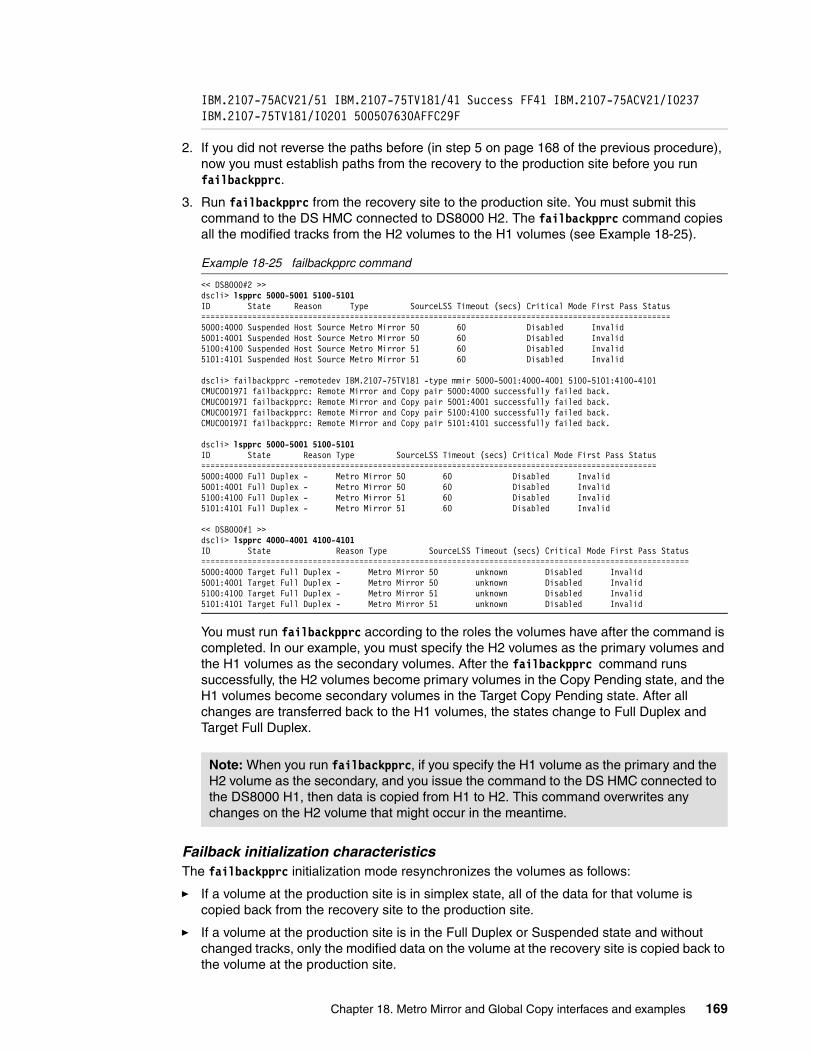
IBM.2107-75ACV21/51 IBM.2107-75TV181/41 Success FF41 IBM.2107-75ACV21/I0237 IBM.2107-75TV181/I0201 500507630AFFC29F
2. If you did not reverse the paths before (in step 5 on page 168 of the previous procedure), now you must establish paths from the recovery to the production site before you run failbackpprc.
3. Run failbackpprc from the recovery site to the production site. You must submit this command to the DS HMC connected to DS8000 H2. The failbackpprc command copies all the modified tracks from the H2 volumes to the H1 volumes (see Example 18-25).
Example 18-25 failbackpprc command
<< DS8000#2 >>dscli> lspprc 5000-5001 5100-5101ID State Reason Type SourceLSS Timeout (secs) Critical Mode First Pass Status=====================================================================================================5000:4000 Suspended Host Source Metro Mirror 50 60 Disabled Invalid5001:4001 Suspended Host Source Metro Mirror 50 60 Disabled Invalid5100:4100 Suspended Host Source Metro Mirror 51 60 Disabled Invalid5101:4101 Suspended Host Source Metro Mirror 51 60 Disabled Invalid
dscli> failbackpprc -remotedev IBM.2107-75TV181 -type mmir 5000-5001:4000-4001 5100-5101:4100-4101CMUC00197I failbackpprc: Remote Mirror and Copy pair 5000:4000 successfully failed back.CMUC00197I failbackpprc: Remote Mirror and Copy pair 5001:4001 successfully failed back.CMUC00197I failbackpprc: Remote Mirror and Copy pair 5100:4100 successfully failed back.CMUC00197I failbackpprc: Remote Mirror and Copy pair 5101:4101 successfully failed back.
dscli> lspprc 5000-5001 5100-5101ID State Reason Type SourceLSS Timeout (secs) Critical Mode First Pass Status==================================================================================================5000:4000 Full Duplex - Metro Mirror 50 60 Disabled Invalid5001:4001 Full Duplex - Metro Mirror 50 60 Disabled Invalid5100:4100 Full Duplex - Metro Mirror 51 60 Disabled Invalid5101:4101 Full Duplex - Metro Mirror 51 60 Disabled Invalid
<< DS8000#1 >>dscli> lspprc 4000-4001 4100-4101ID State Reason Type SourceLSS Timeout (secs) Critical Mode First Pass Status=========================================================================================================5000:4000 Target Full Duplex - Metro Mirror 50 unknown Disabled Invalid5001:4001 Target Full Duplex - Metro Mirror 50 unknown Disabled Invalid5100:4100 Target Full Duplex - Metro Mirror 51 unknown Disabled Invalid5101:4101 Target Full Duplex - Metro Mirror 51 unknown Disabled Invalid
You must run failbackpprc according to the roles the volumes have after the command is completed. In our example, you must specify the H2 volumes as the primary volumes and the H1 volumes as the secondary volumes. After the failbackpprc command runs successfully, the H2 volumes become primary volumes in the Copy Pending state, and the H1 volumes become secondary volumes in the Target Copy Pending state. After all changes are transferred back to the H1 volumes, the states change to Full Duplex and Target Full Duplex.
Failback initialization characteristicsThe failbackpprc initialization mode resynchronizes the volumes as follows:
� If a volume at the production site is in simplex state, all of the data for that volume is copied back from the recovery site to the production site.
� If a volume at the production site is in the Full Duplex or Suspended state and without changed tracks, only the modified data on the volume at the recovery site is copied back to the volume at the production site.
Note: When you run failbackpprc, if you specify the H1 volume as the primary and the H2 volume as the secondary, and you issue the command to the DS HMC connected to the DS8000 H1, then data is copied from H1 to H2. This command overwrites any changes on the H2 volume that might occur in the meantime.
Chapter 18. Metro Mirror and Global Copy interfaces and examples 169

� If a volume at the production site is in a suspended state and has tracks on which data is written, then both the tracks that are changed on the production site and the tracks that are marked at the recovery site are copied back.
� Finally, the volume at the production site becomes a write-inhibited target volume. This action is performed on an individual volume basis.
The failbackpprc commandDepending on the host operating system, if the server at the production site is still online and accessing the disk, or a crash happens, and the SCSI persistent reserve is still set on the primary disk (H1), the failbackpprc command fails (see Example 18-26). In this case, the server at the production site locks the target with a SCSI persistent reserve. This situation can be reset from the server by running the appropriate command, for example, varyoffvg for IBM AIX®. Then, the failbackpprc command completes successfully.
Example 18-26 The failbackpprc command fails when H1 volumes are online
dscli> failbackpprc -remotedev IBM.2107-75TV181 -type mmir 5000-5001:4000-4001 5100-5101:4100-4101CMUN03103E failbackpprc: 5000:4000: Copy Services operation failure: The volume is in a long busy state, not yet configured, not yet formatted, or the source and target volumes are of different types.CMUN03103E failbackpprc: 5001:4001: Copy Services operation failure: The volume is in a long busy state, not yet configured, not yet formatted, or the source and target volumes are of different types.CMUN03103E failbackpprc: 5100:4100: Copy Services operation failure: The volume is in a long busy state, not yet configured, not yet formatted, or the source and target volumes are of different types.CMUN03103E failbackpprc: 5101:4101: Copy Services operation failure: The volume is in a long busy state, not yet configured, not yet formatted, or the source and target volumes are of different types.
<< After performing varyoffvg H1 volumes from the AIX servers at the production site >>
dscli> failbackpprc -remotedev IBM.2107-75TV181 -type mmir 5000-5001:4000-4001 5100-5101:4100-4101CMUC00197I failbackpprc: Remote Mirror and Copy pair 5000:4000 successfully failed back.CMUC00197I failbackpprc: Remote Mirror and Copy pair 5001:4001 successfully failed back.CMUC00197I failbackpprc: Remote Mirror and Copy pair 5100:4100 successfully failed back.CMUC00197I failbackpprc: Remote Mirror and Copy pair 5101:4101 successfully failed back.
However, if the server that set the SCSI persistent reserve on the H1volumes is not up anymore for whatever reason, there is a -resetreserve parameter for the failbackpprc command. This parameter resets the reserved status so the operation can complete. In a situation after a planned site switch, you must not use this parameter because the server at the production site still owns the H1 volume, and might be using it, and the failback operation suddenly changes the contents of the volume. This situation might cause corruption on the server’s file system.
170 DS8000 Copy Services

18.2.3 Switching back to a primary siteTo accomplish the switchback task, complete the following steps:
1. Wait until the Metro Mirror pairs become synchronized. When the pairs are synchronized, the state of the source is Full Duplex and the state of the targets is Target Full Duplex (see Example 18-27).
Example 18-27 Confirm that synchronization is complete
<< DS8000#2 >>dscli> lspprc 5000-5001 5100-5101ID State Reason Type SourceLSS Timeout (secs) Critical Mode First Pass Status==================================================================================================5000:4000 Full Duplex - Metro Mirror 50 60 Disabled Invalid5001:4001 Full Duplex - Metro Mirror 50 60 Disabled Invalid5100:4100 Full Duplex - Metro Mirror 51 60 Disabled Invalid5101:4101 Full Duplex - Metro Mirror 51 60 Disabled Invalid
<< DS8000#1 >>dscli> lspprc 4000-4001 4100-4101ID State Reason Type SourceLSS Timeout (secs) Critical Mode First Pass Status=========================================================================================================5000:4000 Target Full Duplex - Metro Mirror 50 unknown Disabled Invalid5001:4001 Target Full Duplex - Metro Mirror 50 unknown Disabled Invalid5100:4100 Target Full Duplex - Metro Mirror 51 unknown Disabled Invalid5101:4101 Target Full Duplex - Metro Mirror 51 unknown Disabled Invalid
2. Before you return to normal operation, the applications, still updating H2 volumes at the recovery site, must be quiesced to cease all write I/O from updating the H2 volumes. Depending on the host operating system, it might be necessary to unmount the H2 volumes.
3. You should now run one more failoverpprc command. Now, you must specify the H1 volumes as the primary volumes and the H2 volumes as the secondary volumes. You must submit this command to the DS HMC connected to the DS8000#1.
This operation changes the state of the H1 volumes from Target Full Duplex to (source) Suspended. The state of the H2 volumes is preserved (see Example 18-28).
Example 18-28 Running failoverpprc to convert H1 volumes to source Suspended
<< DS8000#1 >>dscli> failoverpprc -remotedev IBM.2107-75ACV21 -type mmir 4000-4001:5000-5001 4100-4101:5100-5101CMUC00196I failoverpprc: Remote Mirror and Copy pair 4000:5000 successfully reversed.CMUC00196I failoverpprc: Remote Mirror and Copy pair 4001:5001 successfully reversed.CMUC00196I failoverpprc: Remote Mirror and Copy pair 4100:5100 successfully reversed.CMUC00196I failoverpprc: Remote Mirror and Copy pair 4101:5101 successfully reversed.
dscli> lspprc 4000-4001 4100-4101ID State Reason Type SourceLSS Timeout (secs) Critical Mode First Pass Status=====================================================================================================4000:5000 Suspended Host Source Metro Mirror 40 60 Disabled Invalid4001:5001 Suspended Host Source Metro Mirror 40 60 Disabled Invalid4100:5100 Suspended Host Source Metro Mirror 41 60 Disabled Invalid4101:5101 Suspended Host Source Metro Mirror 41 60 Disabled Invalid
<< DS8000#2 >>dscli> lspprc 5000-5001 5100-5101ID State Reason Type SourceLSS Timeout (secs) Critical Mode First Pass Status==================================================================================================5000:4000 Full Duplex - Metro Mirror 50 60 Disabled Invalid5001:4001 Full Duplex - Metro Mirror 50 60 Disabled Invalid5100:4100 Full Duplex - Metro Mirror 51 60 Disabled Invalid5101:4101 Full Duplex - Metro Mirror 51 60 Disabled Invalid
Chapter 18. Metro Mirror and Global Copy interfaces and examples 171

4. Define paths in the direction of production site to recovery site H1:H2 (see Example 18-29). You must create paths if you run the freezepprc command in the optional step 3 on page 168 of the production to recovery site switchover procedure (freezepprc removed the paths).
Example 18-29 Create Metro Mirror paths from H1 to H2
dscli> lspprcpath 40-41Src Tgt State SS Port Attached Port Tgt WWNN=======================================================40 50 Failed FF50 - - 5005076303FFD18E41 51 Failed FF51 - - 5005076303FFD18E
dscli> mkpprcpath -remotewwnn 5005076303FFD18E -srclss 40 -tgtlss 50 -consistgrp i0102:i0137 i0201:i0237CMUC00149I mkpprcpath: Remote Mirror and Copy path 40:50 successfully established.
dscli> mkpprcpath -remotewwnn 5005076303FFD18E -srclss 41 -tgtlss 51 -consistgrp i0102:i0137 i0201:i0237CMUC00149I mkpprcpath: Remote Mirror and Copy path 41:51 successfully established.
dscli> lspprcpath 40-41Src Tgt State SS Port Attached Port Tgt WWNN=========================================================40 50 Success FF50 I0102 I0137 5005076303FFD18E40 50 Success FF50 I0201 I0237 5005076303FFD18E41 51 Success FF51 I0102 I0137 5005076303FFD18E41 51 Success FF51 I0201 I0237 5005076303FFD18E
5. Run another failbackpprc command. Now, you must specify the H1 volumes as the primary volumes and the H2 volumes as the secondary volumes. You must submit this command to the DS HMC connected to the DS8000 H1. After you run the failbackpprc command successfully, the H1 volumes become primary volumes in the Copy Pending state and the H2 volumes become secondary volumes in Target Copy Pending state (see Example 18-30).
Example 18-30 Running failbackpprc to restart the H1 to H2 Metro Mirror operation
dscli> failbackpprc -remotedev IBM.2107-75ACV21 -type mmir 4000-4001:5000-5001 4100-4101:5100-5101CMUC00197I failbackpprc: Remote Mirror and Copy pair 4000:5000 successfully failed back.CMUC00197I failbackpprc: Remote Mirror and Copy pair 4001:5001 successfully failed back.CMUC00197I failbackpprc: Remote Mirror and Copy pair 4100:5100 successfully failed back.CMUC00197I failbackpprc: Remote Mirror and Copy pair 4101:5101 successfully failed back.
6. Wait until the Metro Mirror pairs are synchronized. Normally, this operation does not take much time because no data transfer is necessary. After the Metro Mirror pairs are synchronized, the state of the primary volumes (H1) becomes Full Duplex and the state of the secondary volumes (H2) becomes Target Full Duplex (see Example 18-31).
Example 18-31 After the Metro Mirror pairs are synchronized
<< DS8000#1 >>dscli> lspprc 4000-4001 4100-4101ID State Reason Type SourceLSS Timeout (secs) Critical Mode First Pass Status==================================================================================================4000:5000 Full Duplex - Metro Mirror 40 60 Disabled Invalid4001:5001 Full Duplex - Metro Mirror 40 60 Disabled Invalid
172 DS8000 Copy Services

4100:5100 Full Duplex - Metro Mirror 41 60 Disabled Invalid4101:5101 Full Duplex - Metro Mirror 41 60 Disabled Invalid
<< DS8000#2 >>dscli> lspprc 5000-5001 5100-5101ID State Reason Type SourceLSS Timeout (secs) Critical Mode First Pass Status=========================================================================================================4000:5000 Target Full Duplex - Metro Mirror 40 unknown Disabled Invalid4001:5001 Target Full Duplex - Metro Mirror 40 unknown Disabled Invalid4100:5100 Target Full Duplex - Metro Mirror 41 unknown Disabled Invalid4101:5101 Target Full Duplex - Metro Mirror 41 unknown Disabled Invalid
7. Depending on your operating system, it might be necessary to rescan Fibre Channel devices and mount the new primary volumes (H1) at the production site. Start all applications at the production site and check for consistency.
Now that the applications are started, all the write I/Os to the primary volumes (H1) are tracked by Metro Mirror. You should verify the application’s integrity.
8. Eventually, you can terminate the paths from the recovery to the production LSSs, depending on your requirements.
Summary of the failback procedureHere is the procedure to switch back to the production site:
1. Verify the paths status of H2 to H1.2. Run mkpprcpath for H2 to H1.3. Run failbackpprc for H2 to H1.4. Wait for the volume pairs to synchronize.5. Quiesce the applications at the recovery site (H2).6. Run failoverpprc for H1 to H2.7. Run mkpprcpath for H1 to H2.8. Run failbackpprc for H1 to H2.9. Wait for the volume pairs to synchronize.10.Start applications at the production site (H1).11.Run rmpprcpath for H2 to H1.
18.2.4 Metro Mirror freezepprc and unfreezepprc commandsAs mentioned in 16.8, “Consistency group function” on page 127, you must implement a procedure to keep data consistency at the recovery site. One such procedure is to use the freezepprc and unfreezepprc commands with the consistency group option. This section illustrates how to set the consistency group option and describes how the freezepprc and unfreezepprc commands work.
Example 18-32 shows how to enable the consistency group option by running the chlss command. The setting of the option can be verified by running the showlss command.
Example 18-32 Change the default consistency group setting by running the chlss command
dscli> showlss 40ID 40Group 0addrgrp 4stgtype fbconfgvols 2subsys 0xFF40pprcconsistgrp Disabledxtndlbztimout 60 secsresgrp RG0
Chapter 18. Metro Mirror and Global Copy interfaces and examples 173

dscli> showlss 41ID 41Group 1addrgrp 4stgtype fbconfgvols 2subsys 0xFF41pprcconsistgrp Disabledxtndlbztimout 60 secsresgrp RG0
dscli> chlss -pprcconsistgrp enable 40-41CMUC00029I chlss: LSS 41 successfully modified.CMUC00029I chlss: LSS 40 successfully modified.
dscli> showlss 40ID 40Group 0addrgrp 4stgtype fbconfgvols 2subsys 0xFF40pprcconsistgrp Enabledxtndlbztimout 60 secsresgrp RG0
dscli> showlss 41ID 41Group 1addrgrp 4stgtype fbconfgvols 2subsys 0xFF41pprcconsistgrp Enabledxtndlbztimout 60 secsresgrp RG0
When the DS8000 detects a condition where it cannot update a Metro Mirror target volume, it sends an SNMP alert. At that moment, if an automation procedure is in place, the SNMP alert triggers the automation procedure, which runs a freezepprc command (see Example 18-33).
Example 18-33 The results of the freezepprc command
dscli> freezepprc -remotedev IBM.2107-75ACV21 40:50 41:51CMUC00161I freezepprc: Remote Mirror and Copy consistency group 40:50 successfully created.CMUC00161I freezepprc: Remote Mirror and Copy consistency group 41:51 successfully created.
dscli> lspprc 4000-4001 4100-4101ID State Reason Type SourceLSS Timeout (secs) Critical Mode First Pass Status================================================================================================4000:5000 Suspended Freeze Metro Mirror 40 60 Disabled Invalid4001:5001 Suspended Freeze Metro Mirror 40 60 Disabled Invalid4100:5100 Suspended Freeze Metro Mirror 41 60 Disabled Invalid4101:5101 Suspended Freeze Metro Mirror 41 60 Disabled Invalid
dscli> lspprcpath 40-41
174 DS8000 Copy Services

Src Tgt State SS Port Attached Port Tgt WWNN=======================================================40 50 Failed FF50 - - 5005076303FFD18E41 51 Failed FF51 - - 5005076303FFD18E
With the freezepprc command, the DS8000 holds the I/O activity to the addressed LSSs by putting the source volumes depending on the host operating system in a queue full state or a extended long busy state for a time period.
After the freezepprc command completes for all related LSSs pairs, you have consistent data at the recovery site. Therefore, the automation procedure can run the unfreezepprc command to release (thaw) the I/O that was on hold (frozen) on the affected source LSSs.
Example 18-34 shows the unfreezepprc command that thaws the frozen I/O queue on the LSS pairs 40:50 and 41:51.
Example 18-34 The unfreezepprc command
dscli> unfreezepprc -remotedev IBM.2107-75ACV21 40:50 41:51CMUC00198I unfreezepprc: Remote Mirror and Copy pair 40:50 successfully thawed.CMUC00198I unfreezepprc: Remote Mirror and Copy pair 41:51 successfully thawed.
In a situation where the data cannot be replicated because of a links failure circumstance, that is, the production site kept running, then Metro Mirror processing can resume after the links are recovered. Still, if the automation is triggered and the freezepprc is run, then the Metro Mirror paths must be defined again because the freezepprc command removes the paths between the affected LSSs.
After the paths are re-established, run resumepprc to resynchronize the Metro Mirror pairs. Example 18-35 shows this scenario.
Example 18-35 Resume the Metro Mirror environment
dscli> mkpprcpath -remotewwnn 5005076303FFD18E -srclss 40 -tgtlss 50 -consistgrp i0102:i0137 i0201:i0237CMUC00149I mkpprcpath: Remote Mirror and Copy path 40:50 successfully established.
dscli> mkpprcpath -remotewwnn 5005076303FFD18E -srclss 41 -tgtlss 51 -consistgrp i0102:i0137 i0201:i0237CMUC00149I mkpprcpath: Remote Mirror and Copy path 41:51 successfully established.
dscli> resumepprc -remotedev IBM.2107-75ACV21 -type mmir 4000-4001:5000-5001 4100-4101:5100-5101CMUC00158I resumepprc: Remote Mirror and Copy volume pair 4000:5000 relationship successfully resumed. This message is being returned before the copy completes.CMUC00158I resumepprc: Remote Mirror and Copy volume pair 4001:5001 relationship successfully resumed. This message is being returned before the copy completes.CMUC00158I resumepprc: Remote Mirror and Copy volume pair 4100:5100 relationship successfully resumed. This message is being returned before the copy completes.CMUC00158I resumepprc: Remote Mirror and Copy volume pair 4101:5101 relationship successfully resumed. This message is being returned before the copy completes.
dscli> lspprc 4000-4001 4100-4101ID State Reason Type SourceLSS Timeout (secs) Critical Mode First Pass Status==================================================================================================4000:5000 Full Duplex - Metro Mirror 40 60 Disabled Invalid4001:5001 Full Duplex - Metro Mirror 40 60 Disabled Invalid
The freezepprc command: In addition to holding (freezing) the I/O activity, the freezepprc command also removes the paths between the affected LSSs.
Chapter 18. Metro Mirror and Global Copy interfaces and examples 175

4100:5100 Full Duplex - Metro Mirror 41 60 Disabled Invalid4101:5101 Full Duplex - Metro Mirror 41 60 Disabled Invalid
18.2.5 Changing the copy mode from Metro Mirror to Global Copy
In case you want to change the copy mode from the Metro Mirror to Global Copy directly you must run pausepprc to suspend the Metro Mirror pair first, and then resume the pair in Global Copy mode by running resumepprc -type gcp (see Example 18-36).
Example 18-36 Change the copy mode from Metro Mirror to Global Copy
dscli> lspprc 1000-1001 1100-1101ID State Reason Type SourceLSS Timeout (secs) Critical Mode First Pass Status==================================================================================================1000:2000 Full Duplex - Metro Mirror 10 unknown Disabled Invalid1001:2001 Full Duplex - Metro Mirror 10 unknown Disabled Invalid1100:2100 Full Duplex - Metro Mirror 11 unknown Disabled Invalid1101:2101 Full Duplex - Metro Mirror 11 unknown Disabled Invaliddscli> mkpprc -remotedev IBM.2107-75ABTV1 -type gcp 1000-1001:2000-2001 1100-1101:2100-2101CMUN03053E mkpprc: 1000:2000: Copy Services operation failure: invalid transitionCMUN03053E mkpprc: 1001:2001: Copy Services operation failure: invalid transitionCMUN03053E mkpprc: 1100:2100: Copy Services operation failure: invalid transitionCMUN03053E mkpprc: 1101:2101: Copy Services operation failure: invalid transitiondscli> pausepprc -remotedev IBM.2107-75ABTV1 1000-1001:2000-2001 1100-1101:2100-2101CMUC00157I pausepprc: Remote Mirror and Copy volume pair 1000:2000 relationship successfully paused.CMUC00157I pausepprc: Remote Mirror and Copy volume pair 1001:2001 relationship successfully paused.CMUC00157I pausepprc: Remote Mirror and Copy volume pair 1100:2100 relationship successfully paused.CMUC00157I pausepprc: Remote Mirror and Copy volume pair 1101:2101 relationship successfully paused.dscli> lspprc 1000-1001 1100-1101ID State Reason Type SourceLSS Timeout (secs) Critical Mode First Pass Status=====================================================================================================1000:2000 Suspended Host Source Metro Mirror 10 unknown Disabled Invalid1001:2001 Suspended Host Source Metro Mirror 10 unknown Disabled Invalid1100:2100 Suspended Host Source Metro Mirror 11 unknown Disabled Invalid1101:2101 Suspended Host Source Metro Mirror 11 unknown Disabled Invaliddscli> resumepprc -remotedev IBM.2107-75ABTV1 -type gcp 1000-1001:2000-2001 1100-1101:2100-2101CMUC00158I resumepprc: Remote Mirror and Copy volume pair 1000:2000 relationship successfully resumed. This message is being returned before the copy completes.CMUC00158I resumepprc: Remote Mirror and Copy volume pair 1001:2001 relationship successfully resumed. This message is being returned before the copy completes.CMUC00158I resumepprc: Remote Mirror and Copy volume pair 1100:2100 relationship successfully resumed. This message is being returned before the copy completes.CMUC00158I resumepprc: Remote Mirror and Copy volume pair 1101:2101 relationship successfully resumed. This message is being returned before the copy completes.dscli> lspprc 1000-1001 1100-1101ID State Reason Type SourceLSS Timeout (secs) Critical Mode First Pass Status==================================================================================================1000:2000 Copy Pending - Global Copy 10 unknown Disabled True1001:2001 Copy Pending - Global Copy 10 unknown Disabled True1100:2100 Copy Pending - Global Copy 11 unknown Disabled True1101:2101 Copy Pending - Global Copy 11 unknown Disabled True
Data consistency: While you do the resynchronization, the volume pairs are in a Copy Pending state. During this time, there is no data consistency in the target volumes. Therefore, you might want to take specific action to keep data consistency at the recovery site while you resume the Metro Mirror pairs. Completing a FlashCopy at the recovery site first is one way to accomplish this task.
176 DS8000 Copy Services

18.2.6 Changing the copy mode from Global Copy to Metro Mirror
You can change the copy mode from Global Copy to Metro Mirror by running mkpprc (see Example 18-37). This operation is called go-to-sync. Depending on the amount of data to be sent to the secondary, it takes time until the pairs become full duplex.
Example 18-37 Change the copy mode from Global Copy to Metro Mirror
dscli> lspprc 1000-1001 1100-1101ID State Reason Type SourceLSS Timeout (secs) Critical Mode First Pass Status==================================================================================================1000:2000 Copy Pending - Global Copy 10 unknown Disabled True1001:2001 Copy Pending - Global Copy 10 unknown Disabled True1100:2100 Copy Pending - Global Copy 11 unknown Disabled True1101:2101 Copy Pending - Global Copy 11 unknown Disabled Truedscli> mkpprc -remotedev IBM.2107-75ABTV1 -type mmir 1000-1001:2000-2001 1100-1101:2100-2101CMUC00153I mkpprc: Remote Mirror and Copy volume pair relationship 1000:2000 successfully created.CMUC00153I mkpprc: Remote Mirror and Copy volume pair relationship 1001:2001 successfully created.CMUC00153I mkpprc: Remote Mirror and Copy volume pair relationship 1100:2100 successfully created.CMUC00153I mkpprc: Remote Mirror and Copy volume pair relationship 1101:2101 successfully created.dscli> lspprc 1000-1001 1100-1101ID State Reason Type SourceLSS Timeout (secs) Critical Mode First Pass Status==================================================================================================1000:2000 Full Duplex - Metro Mirror 10 unknown Disabled Invalid1001:2001 Full Duplex - Metro Mirror 10 unknown Disabled Invalid1100:2100 Full Duplex - Metro Mirror 11 unknown Disabled Invalid1101:2101 Full Duplex - Metro Mirror 11 unknown Disabled Invalid
You can use the -suspend parameter with the mkpprc -type mmir command. If you use this parameter, the state of the pairs becomes suspended when the data synchronization is complete (see Example 18-38). You can use this option for your offsite backup scenario with the Global Copy function.
Example 18-38 The mkpprc -type mmir command with -suspend
dscli> lspprc 1000-1001 1100-1101ID State Reason Type SourceLSS Timeout (secs) Critical Mode First Pass Status==================================================================================================1000:2000 Copy Pending - Global Copy 10 unknown Disabled True1001:2001 Copy Pending - Global Copy 10 unknown Disabled True1100:2100 Copy Pending - Global Copy 11 unknown Disabled True1101:2101 Copy Pending - Global Copy 11 unknown Disabled Truedscli> mkpprc -remotedev IBM.2107-75ABTV1 -type mmir -suspend 1000-1001:2000-2001 1100-1101:2100-2101CMUC00153I mkpprc: Remote Mirror and Copy volume pair relationship 1000:2000 successfully created.CMUC00153I mkpprc: Remote Mirror and Copy volume pair relationship 1001:2001 successfully created.CMUC00153I mkpprc: Remote Mirror and Copy volume pair relationship 1100:2100 successfully created.CMUC00153I mkpprc: Remote Mirror and Copy volume pair relationship 1101:2101 successfully created.dscli> lspprc 1000-1001 1100-1101ID State Reason Type SourceLSS Timeout (secs) Critical Mode First Pass Status=====================================================================================================1000:2000 Suspended Host Source Metro Mirror 10 unknown Disabled Invalid1001:2001 Suspended Host Source Metro Mirror 10 unknown Disabled Invalid1100:2100 Suspended Host Source Metro Mirror 11 unknown Disabled Invalid1101:2101 Suspended Host Source Metro Mirror 11 unknown Disabled Invalid
Chapter 18. Metro Mirror and Global Copy interfaces and examples 177

You can add the -wait parameter with the mkpprc command. With the -wait parameter, the mkpprc -type mmir -suspend command does not return to the command prompt until the pairs complete data synchronization and reach the suspended state (see Example 18-39).
Example 18-39 mkpprc -type mmir -suspend with -wait
dscli> lspprc 1000-1001 1100-1101ID State Reason Type SourceLSS Timeout (secs) Critical Mode First Pass Status==================================================================================================1000:2000 Copy Pending - Global Copy 10 unknown Disabled True1001:2001 Copy Pending - Global Copy 10 unknown Disabled True1100:2100 Copy Pending - Global Copy 11 unknown Disabled True1101:2101 Copy Pending - Global Copy 11 unknown Disabled Truedscli> mkpprc -remotedev IBM.2107-75ABTV1 -type mmir -suspend -wait 1000-1001:2000-2001 1100-1101:2100-2101CMUC00153I mkpprc: Remote Mirror and Copy volume pair relationship 1000:2000 successfully created.CMUC00153I mkpprc: Remote Mirror and Copy volume pair relationship 1001:2001 successfully created.CMUC00153I mkpprc: Remote Mirror and Copy volume pair relationship 1100:2100 successfully created.CMUC00153I mkpprc: Remote Mirror and Copy volume pair relationship 1101:2101 successfully created.1/4 pair 1001:2001 state: Suspended2/4 pair 1000:2000 state: Suspended3/4 pair 1101:2101 state: Suspended4/4 pair 1100:2100 state: Suspendeddscli> lspprc 1000-1001 1100-1101ID State Reason Type SourceLSS Timeout (secs) Critical Mode First Pass Status=====================================================================================================1000:2000 Suspended Host Source Metro Mirror 10 unknown Disabled Invalid1001:2001 Suspended Host Source Metro Mirror 10 unknown Disabled Invalid1100:2100 Suspended Host Source Metro Mirror 11 unknown Disabled Invalid1101:2101 Suspended Host Source Metro Mirror 11 unknown Disabled Invalid
18.2.7 Periodic offsite backup procedure
This section describes to use Global Copy for periodical offsite backup. Figure 18-3 on page 179 shows a diagram of the DS8000 Global Copy environment for this example. We use the Remote Incremental FlashCopy function for the FlashCopy at the recovery site DS8000 H2. We use 1000, 1001, 1100, and 1101 in DS8000 H1 for Global Copy primary, 2000, 2001, 2100, and 2101 in DS8000 H2 for Global Copy secondary and FlashCopy sources, and 2002, 2003, 2102, and 2103 in the DS8000 H2 for FlashCopy targets.
Data synchronization: If you do not specify the -wait parameter with the mkpprc -type mmir -suspend command, the mkpprc command does not wait for the data synchronization. If you do not use the -wait parameter, you must check the completion of the synchronization by running lspprc.
178 DS8000 Copy Services

Figure 18-3 The DS8000 environment for Global Copy offsite backup
Initial setup for this environmentTo set up the Global Copy and FlashCopy environment, complete the following steps:
1. Create paths, create pairs, and wait for the completion of the Global Copy initial copy.
2. Create the Remote Incremental FlashCopy relationship at the recovery site and wait for the completion of the FlashCopy background copy.
Step 1: Creating paths and pairsAn example of this step is shown in Example 18-40.
Example 18-40 Create paths and pairs
dscli> mkpprcpath -remotedev IBM.2107-75ABTV1 -remotewwnn 5005076303FFC663 -srclss 10 -tgtlss 20 i0143:i0010 i0213:i0140CMUC00149I mkpprcpath: Remote Mirror and Copy path 10:20 successfully established.dscli> mkpprcpath -remotedev IBM.2107-75ABTV1 -remotewwnn 5005076303FFC663 -srclss 11 -tgtlss 21 i0143:i0010 i0213:i0140CMUC00149I mkpprcpath: Remote Mirror and Copy path 11:21 successfully established.dscli> mkpprc -remotedev IBM.2107-75ABTV1 -type gcp 1000-1001:2000-2001 1100-1101:2100-2101CMUC00153I mkpprc: Remote Mirror and Copy volume pair relationship 1000:2000 successfully created.CMUC00153I mkpprc: Remote Mirror and Copy volume pair relationship 1001:2001 successfully created.CMUC00153I mkpprc: Remote Mirror and Copy volume pair relationship 1100:2100 successfully created.CMUC00153I mkpprc: Remote Mirror and Copy volume pair relationship 1101:2101 successfully created.dscli> lspprc -l 1000-1001 1100-1101ID State Reason Type Out Of Sync Tracks Tgt Read Src Cascade Tgt Cascade Date Suspended SourceLSS Timeout (secs) Critical Mode First Pass Status==========================================================================================================================================1000:2000 Copy Pending - Global Copy 0 Disabled Disabled invalid - 10 unknown Disabled True1001:2001 Copy Pending - Global Copy 0 Disabled Disabled invalid - 10 unknown Disabled True1100:2100 Copy Pending - Global Copy 0 Disabled Disabled invalid - 11 unknown Disabled True1101:2101 Copy Pending - Global Copy 0 Disabled Disabled invalid - 11 unknown Disabled True
2100
2101
2102
LSS10
1000
1001
LSS11
1100
1101
LSS20
2000
2001
LSS21
DS8000 H1 DS8000 H2
GC Primary
GC Secondaryand
FC source
2002
2003
2103
FC Target
FlashCopy
FlashCopyFCP links
PPRC Paths
Global Copy pairs
Global Copy pairs
Chapter 18. Metro Mirror and Global Copy interfaces and examples 179

Step 2: Creating a FlashCopy relationshipAn example of this step is shown in Example 18-41. The command is still issued at the primary storage IBM.2107-7520781, and the -dev parameter points to the storage, where you want to create a remote FlashCopy volume pair. The -conduit parameter must be a fully qualified LSS identifier. The lspprcpath command can help you identify available paths.
Example 18-41 Create a FlashCopy relationship
dscli> lspprcpath -fullid 10 11Src Tgt State SS Port Attached Port Tgt WWNN===========================================================================================================IBM.2107-7520781/10 IBM.2107-75ABTV1/10 Success FF10 IBM.2107-7520781/I0143 IBM.2107-75ABTV1/I0010 5005076303FFC663IBM.2107-7520781/10 IBM.2107-75ABTV1/10 Success FF10 IBM.2107-7520781/I0213 IBM.2107-75ABTV1/I0140 5005076303FFC663IBM.2107-7520781/11 IBM.2107-75ABTV1/11 Success FF11 IBM.2107-7520781/I0143 IBM.2107-75ABTV1/I0010 5005076303FFC663IBM.2107-7520781/11 IBM.2107-75ABTV1/11 Success FF11 IBM.2107-7520781/I0213 IBM.2107-75ABTV1/I0140 5005076303FFC663dscli> mkremoteflash -record -persist -conduit IBM.2107-7520781/10 -dev IBM.2107-75ABTV1 2000-2001:2002-2003CMUC00173I mkremoteflash: Remote FlashCopy volume pair 2000:2002 successfully created. Use the lsremoteflash command to determine copy completion.CMUC00173I mkremoteflash: Remote FlashCopy volume pair 2001:2003 successfully created. Use the lsremoteflash command to determine copy completion.dscli> mkremoteflash -record -persist -conduit IBM.2107-7520781/11 -dev IBM.2107-75ABTV1 2100-2101:2102-2103CMUC00173I mkremoteflash: Remote FlashCopy volume pair 2100:2102 successfully created. Use the lsremoteflash command to determine copy completion.CMUC00173I mkremoteflash: Remote FlashCopy volume pair 2101:2103 successfully created. Use the lsremoteflash command to determine copy completion.
Verify that the FlashCopy background copy completes by running the command that is shown in Example 18-42 and reviewing the output.
Example 18-42 lsremoteflash to check the FlashCopy background copy completion
dscli> lsremoteflash -l -conduit IBM.2107-7520781/10 -dev IBM.2107-75ABTV1 2000-2001ID SrcLSS SequenceNum ActiveCopy Recording Persistent Revertible SourceWriteEnabled TargetWriteEnabled BackgroundCopy OutOfSyncTracks ==========================================================================================================================================2000:2002 20 0 Enabled Enabled Enabled Disabled Enabled Enabled Enabled 44626 2001:2003 20 0 Enabled Enabled Enabled Disabled Enabled Enabled Enabled 11153 dscli> lsremoteflash -l -conduit IBM.2107-7520781/11 -dev IBM.2107-75ABTV1 2100-2101ID SrcLSS SequenceNum ActiveCopy Recording Persistent Revertible SourceWriteEnabled TargetWriteEnabled BackgroundCopy OutOfSyncTracks ==========================================================================================================================================2100:2102 21 0 Enabled Enabled Enabled Disabled Enabled Enabled Enabled 46289 2101:2103 21 0 Enabled Enabled Enabled Disabled Enabled Enabled Enabled 14695 dscli> lsremoteflash -l -conduit IBM.2107-7520781/10 -dev IBM.2107-75ABTV1 2000-2001ID SrcLSS SequenceNum ActiveCopy Recording Persistent Revertible SourceWriteEnabled TargetWriteEnabled BackgroundCopy OutOfSyncTracks=========================================================================================================================================2000:2002 20 0 Disabled Enabled Enabled Disabled Enabled Enabled Enabled 02001:2003 20 0 Disabled Enabled Enabled Disabled Enabled Enabled Enabled 0dscli> lsremoteflash -l -conduit IBM.2107-7520781/11 -dev IBM.2107-75ABTV1 2100-2101ID SrcLSS SequenceNum ActiveCopy Recording Persistent Revertible SourceWriteEnabled TargetWriteEnabled BackgroundCopy OutOfSyncTracks==========================================================================================================================================2100:2102 21 0 Disabled Enabled Enabled Disabled Enabled Enabled Enabled 02101:2103 21 0 Disabled Enabled Enabled Disabled Enabled Enabled Enabled 0
180 DS8000 Copy Services

Periodical backup operationDepending on your backup requirement and application acceptance, schedule the following scenario periodically, such as daily. We show examples of the DS CLI commands to control this procedure, which is based on the scenario that is illustrated in Figure 18-4.
Figure 18-4 Create a Global Copy consistent copy
For a more detailed description of each of the steps shown in Figure 18-4, refer to 16.9, “Creating a Global Copy consistent copy” on page 135.
Step 1: Normal Global Copy mode operationIn this step, you are operating in the normal Global Copy mode. The lspprc and lsremoteflash commands show the status of the DS8000, as shown in Example 18-43.
Example 18-43 Normal Global Copy mode operation
dscli> lspprc 1000-1001 1100-1101ID State Reason Type SourceLSS Timeout (secs) Critical Mode First Pass Status==================================================================================================1000:2000 Copy Pending - Global Copy 10 unknown Disabled True1001:2001 Copy Pending - Global Copy 10 unknown Disabled True1100:2100 Copy Pending - Global Copy 11 unknown Disabled True1101:2101 Copy Pending - Global Copy 11 unknown Disabled Truedscli> lsremoteflash -conduit IBM.2107-7520781/10 -dev IBM.2107-75ABTV1 2000-2001 2100-2101ID SrcLSS SequenceNum ActiveCopy Recording Persistent Revertible SourceWriteEnabled TargetWriteEnabled BackgroundCopy============================================================================================================================2000:2002 20 0 Disabled Enabled Enabled Disabled Enabled Enabled Enabled2001:2003 20 0 Disabled Enabled Enabled Disabled Enabled Enabled Enabled2100:2102 21 0 Disabled Enabled Enabled Disabled Enabled Enabled Enabled2101:2103 21 0 Disabled Enabled Enabled Disabled Enabled Enabled Enabled
Step 2: Stopping or quiescing the application at the production siteDepending on your application and platform, you should take the necessary actions to briefly stop updates to the primary volumes by quiescing the application.
Global Copy
fuzzy copy of data
Consistent copy of data
Primary Site Secondary Site
FlashCopy
1. Quiesce application updates
2. Catch-up (synchronize volumes)go-to-sync & suspendorwait for application writes to quiesce
3. Freeze (or Suspend) Global Copy
4. Resume application writes when freezes complete
6. Resynchronize Global Copy
volume pairs synchronize
data is consistent across all secondary volumes
5. FlashCopy to preserve consistent copy of data
Channel ExtenderChannel Extender
H2H1
I2
Chapter 18. Metro Mirror and Global Copy interfaces and examples 181

Step 3: Run a go-to-sync and suspend the Global Copy pairsThe DS CLI command examples for this step are shown in Example 18-44.
Example 18-44 The mkpprc -type mmir -wait -suspend
dscli> lspprc 1000-1001 1100-1101ID State Reason Type SourceLSS Timeout (secs) Critical Mode First Pass Status==================================================================================================1000:2000 Copy Pending - Global Copy 10 unknown Disabled True1001:2001 Copy Pending - Global Copy 10 unknown Disabled True1100:2100 Copy Pending - Global Copy 11 unknown Disabled True1101:2101 Copy Pending - Global Copy 11 unknown Disabled Truedscli> mkpprc -remotedev IBM.2107-75ABTV1 -type mmir -suspend -wait 1000-1001:2000-2001 1100-1101:2100-2101CMUC00153I mkpprc: Remote Mirror and Copy volume pair relationship 1000:2000 successfully created.CMUC00153I mkpprc: Remote Mirror and Copy volume pair relationship 1001:2001 successfully created.CMUC00153I mkpprc: Remote Mirror and Copy volume pair relationship 1100:2100 successfully created.CMUC00153I mkpprc: Remote Mirror and Copy volume pair relationship 1101:2101 successfully created.<< It may take time to show bellow messages depending on the amount of the Out Of Sync Tracks remained. >>1/4 pair 1000:2000 state: Suspended2/4 pair 1001:2001 state: Suspended3/4 pair 1100:2100 state: Suspended4/4 pair 1101:2101 state: Suspendeddscli> lspprc 1000-1001 1100-1101ID State Reason Type SourceLSS Timeout (secs) Critical Mode First Pass Status=====================================================================================================1000:2000 Suspended Host Source Metro Mirror 10 unknown Disabled Invalid1001:2001 Suspended Host Source Metro Mirror 10 unknown Disabled Invalid1100:2100 Suspended Host Source Metro Mirror 11 unknown Disabled Invalid1101:2101 Suspended Host Source Metro Mirror 11 unknown Disabled Invaliddscli> lspprc -l 1000-1001 1100-1101ID State Reason Type Out Of Sync Tracks Tgt Read Src Cascade Tgt Cascade Date Suspended SourceLSS ========================================================================================================================1000:2000 Suspended Host Source Metro Mirror 0 Disabled Disabled invalid - 101001:2001 Suspended Host Source Metro Mirror 0 Disabled Disabled invalid - 10 1100:2100 Suspended Host Source Metro Mirror 0 Disabled Disabled invalid - 11 1101:2101 Suspended Host Source Metro Mirror 0 Disabled Disabled invalid - 11
Step 4: Resuming or restarting the application at the production siteDepending on your application and platform, you should take the necessary actions to restart your application and resume I/O activity to the primary volumes.
Step 5: Taking a FlashCopy from the secondary to tertiary volumesThe DS CLI command examples for this step are shown in Example 18-45. We use the resyncremoteflash command to perform the Incremental FlashCopy from the production site. We add the -seqnum parameter with mkremoteflash to add the FlashCopy sequence number to identify this FlashCopy set.
Step 6: Resume Global Copy mode for the copy pair.We specify the -type gcp parameter with the resumepprc command to restart the normal Global Copy mode, as shown in Example 18-46 on page 183.
Example 18-45 Take a FlashCopy from the secondary to tertiary volumes
dscli> resyncremoteflash -record -persist -seqnum 20051103 -conduit IBM.2107-7520781/10 -dev IBM.2107-75ABTV1 2000-2001:2002-2003CMUC00175I resyncremoteflash: Remote FlashCopy volume pair 2000:2002 successfully resynchronized. Use the lsremoteflash command to determine copy completion.CMUC00175I resyncremoteflash: Remote FlashCopy volume pair 2001:2003 successfully resynchronized. Use the lsremoteflash command to determine copy completion.dscli> resyncremoteflash -record -persist -seqnum 20051103 -conduit IBM.2107-7520781/11 -dev IBM.2107-75ABTV1 2100-2101:2102-2103
182 DS8000 Copy Services

CMUC00175I resyncremoteflash: Remote FlashCopy volume pair 2100:2102 successfully resynchronized. Use the lsremoteflash command to determine copy completion.CMUC00175I resyncremoteflash: Remote FlashCopy volume pair 2101:2103 successfully resynchronized. Use the lsremoteflash command to determine copy completion.dscli> lsremoteflash -conduit IBM.2107-7520781/10 -dev IBM.2107-75ABTV1 2000-2001 2100-2101ID SrcLSS SequenceNum ActiveCopy Recording Persistent Revertible SourceWriteEnabled TargetWriteEnabled Background========================================================================================================================2000:2002 20 20051103 Disabled Enabled Enabled Disabled Enabled Enabled Enabled2001:2003 20 20051103 Disabled Enabled Enabled Disabled Enabled Enabled Enabled2100:2102 21 20051103 Disabled Enabled Enabled Disabled Enabled Enabled Enabled2101:2103 21 20051103 Disabled Enabled Enabled Disabled Enabled Enabled Enabled
Example 18-46 Resume normal Global Copy mode
dscli> lspprc 1000-1001 1100-1101ID State Reason Type SourceLSS Timeout (secs) Critical Mode First Pass Status=====================================================================================================1000:2000 Suspended Host Source Metro Mirror 10 unknown Disabled Invalid1001:2001 Suspended Host Source Metro Mirror 10 unknown Disabled Invalid1100:2100 Suspended Host Source Metro Mirror 11 unknown Disabled Invalid1101:2101 Suspended Host Source Metro Mirror 11 unknown Disabled Invaliddscli> resumepprc -remotedev IBM.2107-75ABTV1 -type gcp 1000-1001:2000-2001 1100-1101:2100-2101CMUC00158I resumepprc: Remote Mirror and Copy volume pair 1000:2000 relationship successfully resumed. This message is being returned before the copy completes.CMUC00158I resumepprc: Remote Mirror and Copy volume pair 1001:2001 relationship successfully resumed. This message is being returned before the copy completes.CMUC00158I resumepprc: Remote Mirror and Copy volume pair 1100:2100 relationship successfully resumed. This message is being returned before the copy completes.CMUC00158I resumepprc: Remote Mirror and Copy volume pair 1101:2101 relationship successfully resumed. This message is being returned before the copy completes.dscli> lspprc 1000-1001 1100-1101ID State Reason Type SourceLSS Timeout (secs) Critical Mode First Pass Status==================================================================================================1000:2000 Copy Pending - Global Copy 10 unknown Disabled True1001:2001 Copy Pending - Global Copy 10 unknown Disabled True1100:2100 Copy Pending - Global Copy 11 unknown Disabled True1101:2101 Copy Pending - Global Copy 11 unknown Disabled True
18.2.8 Managing data migration with Global Copy
In this example, we show how to use DS CLI commands to migrate volumes from an older DS8000 to a new DS8000 with Global Copy. For more information of various data migration options see DS8870 Data Migration Techniques, SG24-8257.
In the example, we have only two volumes. In reality, you perform the steps for many volumes. DS CLI scripts are useful for performing remote copy operations for many volumes. You can code and test the commands with a few volumes and then modify the scripts for the rest of the volumes. DS CLI is also flexible as it allows multiple volume pairs to be managed with a single command.
The setup in the example is as follows:
� The old volumes are 050A and 050B on LSS 05 of DS8000 IBM.2107-7522391.
� The corresponding new volumes are 031A and 031B on LSS 03 of DS8000 IBM.2107-7503461.
Chapter 18. Metro Mirror and Global Copy interfaces and examples 183

Migration from simplex volumesThe following steps describe the DS CLI commands and scripts that we used to migrate non-mirrored (simplex) volumes from an older DS8000 to a new DS8000 with Global Copy.
1. Check the WWNN of the new DS8000 system. In our example, we use the DS CLI lssi command (see Example 18-47).
Example 18-47 Check the WWNN of the new DS8000
C:\IBM\DSCLI> lssiName ID Storage Unit Model WWNN State ESSNet============================================================================- IBM.2107-7503461 IBM.2107-7503460 951 5005076303FFC08F Online Enabled
2. Check what FCP ports are available for establishing paths between LSS 05 on the old DS8000 and LSS 03 on the new DS8000. In our example, we use the DS CLI lsavailpprcport command (see Example 18-48).
Example 18-48 Check the ports
C:\IBM\DSCLI> lsavailpprcport -dev ibm.2107-7522391 -remotedev ibm.2107-7503461 -remotewwnn 5005076303ffc08f 05:03Local Port Attached Port Type=============================I0002 I0002 FCPI0003 I0003 FCP
3. Establish logical paths from LSS 05 to LSS 03. The DS CLI command to do this task is shown in Example 18-49.
Example 18-49 Establish the paths
C:\IBM\DSCLI >mkpprcpath -dev ibm.2107-7522391 -remotedev ibm.2107-7503461 -srclss 05 -tgtlss 03 -remotewwnn 5005076303ffc08f I0003:I0003 I0002:I0002CMUC00149I mkpprcpath: Remote Mirror and Copy path 05:03 successfully established.C:\IBM\DSCLI> lspprcpath -dev ibm.2107-7522391 05Src Tgt State SS Port Attached Port Tgt WWNN=========================================================05 03 Success 7B00 I0003 I0003 5005076303FFC08F05 03 Success 7B00 I0002 I0002 5005076303FFC08F
4. Establish the Global Copy pairs. The DS CLI commands to do this task are shown in Example 18-50.
Example 18-50 Establish the pairs
C:\IBM\DSCLI> mkpprc -dev ibm.2107-7522391 -remotedev ibm.2107-7503461 -type gcp -mode full 050a:031aCMUC00153I mkpprc: Remote Mirror and Copy volume pair relationship 050A:031A successfully created.C:\IBM\DSCLI> mkpprc -dev ibm.2107-7522391 -remotedev ibm.2107-7503461 -type gcp -mode full 050b:031bCMUC00153I mkpprc: Remote Mirror and Copy volume pair relationship 050B:031B successfully created.C:\IBM\DSCLI> lspprc -dev ibm.2107-7522391 -l 050a-050bID State Reason Type Out Of Sync Tracks Tgt Read Src Cascade Tgt Casca===========================================================================================050A:031A Copy Pending - Global Copy 0 Disabled Unknown Unknown 050B:031B Copy Pending - Global Copy 0 Disabled Unknown Unknown
184 DS8000 Copy Services

5. Shut down the host systems that are using the volumes that are being migrated. This task should not be done until the number of out-of-sync tracks for most of the Global Copy volume pairs is zero or close to zero so that synchronization in the next step does not take long. This action reduces application downtime.
6. Display the number of out-of-sync tracks by using the DS CLI command lspprc -l shown in Example 18-51. In this example we see that there are 71030 out-of-sync tracks.
Example 18-51 View out-of-sync tracks
dscli> lspprc -dev ibm.2107-7522391 -remotedev ibm.2107-7503461 -l 050AID State Reason Type Out Of Sync Tracks Tgt Read Src Cascade Tgt Casca===========================================================================================050A:031A Copy Pending - Global Copy 71030 Disabled Disabled invalid
7. Change the Global Copy pairs to Metro Mirror pairs or wait until the out-of-sync tracks reach zero so that the target volumes are consistent. The DS CLI commands to synchronize the pairs are shown in Example 18-52.
Example 18-52 Synchronize the pairs
C:\IBM\DSCLI> mkpprc -dev ibm.2107-7522391 -remotedev ibm.2107-7503461 -type mmir 050a:031aCMUC00153I mkpprc: Remote Mirror and Copy volume pair relationship 050A:031A successfully created.C:\IBM\DSCLI> mkpprc -dev ibm.2107-7522391 -remotedev ibm.2107-7503461 -type mmir 050b:031bCMUC00153I mkpprc: Remote Mirror and Copy volume pair relationship 050B:031B successfully created.C:\IBM\DSCLI> lspprc -dev ibm.2107-7522391 050a-050bID State Reason Type SourceLSS Timeout (secs) Critical Mode First Pass ===========================================================================================050A:031A Full Duplex - Metro Mirror 05 unknown Disabled Invalid050B:031B Full Duplex - Metro Mirror 05 unknown Disabled Invalid
8. You can now stop mirroring and change the secondary volumes to the simplex status, as shown in Example 18-53.
Example 18-53 Terminate the Metro Mirror pairs
C:\IBM\DSCLI> rmpprc -dev ibm.2107-7522391 -remotedev ibm.2107-7503461 -quiet 050a:031aCMUC00155I rmpprc: Remote Mirror and Copy volume pair 050A:031A relationship successfully withdrawn.C:\IBM\DSCLI> rmpprc -dev ibm.2107-7522391 -remotedev ibm.2107-7503461 -quiet 050b:031bCMUC00155I rmpprc: Remote Mirror and Copy volume pair 050B:031B relationship successfully withdrawn.C:\IBM\DSCLI> lspprc -dev ibm.2107-7522391 050a-050bCMUC00234I lspprc: No Remote Mirror and Copy found.
9. After the volume pairs are deleted, you can restart the host systems from the volumes on the new DS8000 and start the applications again.
10.Remove the paths between the old DS8000 and the new DS8000 by running the DS CLI rmpprcpath command (see Example 18-54).
Example 18-54 Delete the paths
C:\IBM\DSCLI> rmpprcpath -dev ibm.2107-7522391 -remotedev ibm.2107-7503461 -quiet 05:03CMUC00150I rmpprcpath: Remote Mirror and Copy path 05:03 successfully removed.
Chapter 18. Metro Mirror and Global Copy interfaces and examples 185

Migration from the secondary volumesThe procedure in , “Migration from simplex volumes” on page 184 assumes that the source volumes on the old DS8000 are simplex. However, migration is also possible from secondary volumes of existing Global Copy or Metro Mirror pairs. In this case, you set up a cascading Global Copy relationship by specifying the -cascade parameter with the mkpprc command in step 4 on page 184. (The -cascade parameter is not needed with Release 7.4).The modified command is shown in Example 18-55.
Example 18-55 Establish the cascaded pairs
C:\IBM\DSCLI> mkpprc -dev ibm.2107-7522391 -remotedev ibm.2107-7503461 -type gcp -mode full -cascade 050a:031aCMUC00153I mkpprc: Remote Mirror and Copy volume pair relationship 050A:031A successfully created.C:\IBM\DSCLI> mkpprc -dev ibm.2107-7522391 -remotedev ibm.2107-7503461 -type gcp -mode full -cascade 050b:031bCMUC00153I mkpprc: Remote Mirror and Copy volume pair relationship 050B:031B successfully created.C:\IBM\DSCLI> lspprc -dev ibm.2107-7522391 -l 050aID State Reason Type Out Of Sync Tracks Tgt Read Src Cascade Tgt CascaID State Reason Type SourceLSS Timeout (secs) Critical Mode ===========================================================================================011A:050A Target Copy Pending - Global Copy 01 unknown Disabled 050A:031A Copy Pending - Global Copy 05 unknown Disabled
Here, 011A is the source volume, 050A is the intermediate volume, and 031A is the target volume. The lspprc command shows the status of both volume pairs where the intermediate volume 050A belongs. 011A:050A is the first pair, where 050A is the secondary, and 050A:031A is the second pair, where 050A is the cascading primary.
If the existing pairs are in a Global Copy relationship, you must change them to Metro Mirror pairs before you perform the synchronization in step 7 on page 185 because the first pair of a cascading relationship cannot be Global Copy if the second pair is Metro Mirror.
18.3 Metro Mirror and Global Copy TSO examples
For z/OS, the TSO Metro Mirror commands offer a powerful and flexible interface to control your Metro Mirror environment. The TSO commands communicate with the DS8000 through a device number that is specified on the command. IP connectivity is not required.
TSO commands can be integrated into REXX programs for automation purposes.
This section covers the following TSO examples:
� Query an establish path� Query a Metro Mirror or Global Copy primary� Query a Metro Mirror secondary
186 DS8000 Copy Services

18.3.1 Query an established path
Verify that the paths are established by running CQUERY. The command output is shown in Example 18-56. Path status 13 indicates success.
Example 18-56 Verify the path status
ANTP8802I CQUERY DEVN(X'400A') PATHS ANTP0095I CQUERY FORMATTED LVL 3 817 PATHS REPORT *************** PPRC REMOTE COPY CQUERY - PATHS ********************* PRIMARY UNIT: SERIAL#= 0000000ABTV1 SSID= 4000 SS= 2107 LSS= 00 ** FIRST SECOND THIRD FOURTH ** SECONDARY SECONDARY SECONDARY SECONDARY **SERIAL NO: 000000020781 ............ ............ ............ ** SSID LSS: 8000 80 ....... ....... ....... ** PATHS: 2 0 0 0 ** PFCA SFCA S* SAID DEST S* SAID DEST S* SAID DEST S* ** --------- -- --------- -- --------- -- --------- -- ** 1: 0010 0143 13 ---- ---- 00 ---- ---- 00 ---- ---- 00 ** 2: 0031 0102 13 ---- ---- 00 ---- ---- 00 ---- ---- 00 ** 3: ---- ---- 00 ---- ---- 00 ---- ---- 00 ---- ---- 00 ** 4: ---- ---- 00 ---- ---- 00 ---- ---- 00 ---- ---- 00 ** SUBSYSTEM WWNN LIC LEVEL ** ----------- ---------------- ----------- ** PRIMARY.... 5005076303FFC663 5.1.00.0212 ** SECONDARY.1 5005076303FFC1A5 ** ** S* = PATH STATUS: ** 00=NO PATH 01=ESTABLISHED ESCON 02=INIT FAILED ** 03=TIME OUT 04=NO RESOURCES AT PRI 05=NO RESOURCES AT SEC** 06=SERIAL# MISMATCH 07=SEC SSID MISMATCH 08=ESCON LINK OFFLINE ** 09=ESTABLISH RETRY 0A=PATH ACTIVE TO HOST 0B=PATH TO SAME CLUSTR** 10=CONFIG ERROR FF=UNABLE TO DETERMINE ** 13=ESTABL FIBRE PTH 14=FIBRE PATH DOWN 15=FIBRE RETRY EXCEED ** 16=SEC ADPTR INCPBL 17=SEC ADPTR UNAVAIL 18=FIBRE LOGIN EXCEED *********************************************************************
18.3.2 Query a Metro Mirror or Global Copy primary
To verify the status of a device that is (or will be) a Metro Mirror primary, run the CQUERY DEVN(xxxx) command. This command provides more information, such as serial numbers, WWNNs, and CCA and LCU numbers that are useful for other Metro Mirror command input (for example, CSUSPEND and CESTPAIR).
In Example 18-57 on page 188, we can see from the output of the CQUERY command that device number 7000 is a primary volume, and is in the DUPLEX state. The SSID, CCA, LCU, and serial number information is shown on the right side of the display for both the primary (7001, 00, 70, and TV181) and secondary (2801, 00, 28, and ACV21). The path information is also provided. Two logical paths are currently defined, from primary Fibre Channel adapter 0201 to secondary Fibre Channel adapter 0337, and from primary Fibre Channel adapter 0331 to secondary Fibre Channel adapter 0207. Note the inclusion of the SCH(0) identifier below the device number, indicating which subchannel set the CQUERY command found by default.
Chapter 18. Metro Mirror and Global Copy interfaces and examples 187

Example 18-57 CQUERY of a Metro Mirror primary volume
ANTP8802I CQUERY devn(7000) ANTP0090I CQUERY FORMATTED LVL 5 040 VOLUME REPORT ************** PPRC REMOTE COPY CQUERY - VOLUME ******************** * (PRIMARY) (SECONDARY) * * SSID CCA LSS SSID CCA LSS* *DEVICE LEVEL STATE PATH STATUS SERIAL# SERIAL# * *------ --------- ---------- ----------- --------- --------- * * 7000 PRIMARY.. DUPLEX.... ACTIVE.. 7001 00 70 2801 00 28 * * SCH(0) CRIT(NO)....... CGRPLB(YES) 0000000TV181 0000000ACV21* * INCRES(NO). AUTORESYNC(NO). * * PATHS PFCA SFCA STATUS: DESCRIPTION * * ----- --------- ------ ------------------- * * 2 0201 0337 13 PATH ESTABLISHED... * * 0331 0207 13 PATH ESTABLISHED... * * ---- ---- 00 NO PATH............ * * ---- ---- 00 NO PATH............ * * SUBSYSTEM WWNN LIC LEVEL * * ----------- ---------------- ----------- * * PRIMARY.... 500507630AFFC29F 7.6.30.160 * * SECONDARY.1 5005076303FFD18E * ********************************************************************
ANTP0001I CQUERY COMMAND COMPLETED FOR DEVICE 7000. COMPLETION CODE: 00
18.3.3 Querying a Metro Mirror SecondaryTo verify the status of a device that is (or will be) a Metro Mirror Secondary, run the CQUERY DEVN(xxxx) command. This command also provides other information, such as serial numbers, WWNNs, CCAs, and LCU numbers, which is useful for other command input (for example, CESTPAIR).
In Example 18-58, you can see in the output of the CQUERY command that device number 2800 is a secondary volume, and is in the DUPLEX state. The SSID, CCA, LCU, and serial number information is shown on the right side of the display for both the primary (7001, 00, 70, and TV181) and the secondary devices (2801, 00, 28, and ACV21).
The path information is not consistent with the information received from the CQUERY command that is run on the primary volume, because the logical paths are currently defined from the secondary system (ACV21) LCU 28 to the primary system (TV181) LCU 70. The storage control has an association that is recorded between the indicated primary and secondary subsystems but 0 paths are identified. Thus, the CQUERY command could not determine the SAID and DEST. A path and a status of FF is displayed. This can occur after a freeze is issued. To clean up the XXXX XXXX values, you must issue an establish path.
Example 18-58 CQUERY of a Metro Mirror secondary volume
ANTP8802I CQUERY devn(2800) ANTP0090I CQUERY FORMATTED LVL 5 044 VOLUME REPORT ************** PPRC REMOTE COPY CQUERY - VOLUME ******************** * (PRIMARY) (SECONDARY) * * SSID CCA LSS SSID CCA LSS* *DEVICE LEVEL STATE PATH STATUS SERIAL# SERIAL# *
188 DS8000 Copy Services
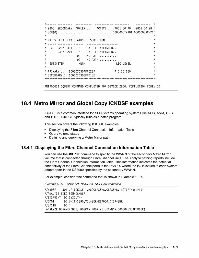
*------ --------- ---------- ----------- --------- --------- * * 2800 SECONDARY DUPLEX.... ACTIVE.. 7001 00 70 2801 00 28 * * SCH(0) ............... ........... 0000000TV181 0000000ACV21* * ........... ............... * * PATHS PFCA SFCA STATUS: DESCRIPTION * * ----- --------- ------ ------------------- * * 2 0207 0331 13 PATH ESTABLISHED... * * 0337 0201 13 PATH ESTABLISHED... * * ---- ---- 00 NO PATH............ * * ---- ---- 00 NO PATH............ * * SUBSYSTEM WWNN LIC LEVEL * * ----------- ---------------- ----------- * * PRIMARY.... 500507630AFFC29F 7.6.30.160 * * SECONDARY.1 5005076303FFD18E * ********************************************************************
ANTP0001I CQUERY COMMAND COMPLETED FOR DEVICE 2800. COMPLETION CODE: 00
18.4 Metro Mirror and Global Copy ICKDSF examples
ICKDSF is a common interface for all z Systems operating systems like z/OS, z/VM, z/VSE and z/TPF. ICKDSF typically runs as a batch program.
This section covers the following ICKDSF examples:
� Displaying the Fibre Channel Connection Information Table� Query volume status� Defining and querying a Metro Mirror path
18.4.1 Displaying the Fibre Channel Connection Information TableYou can use the ANALYZE command to specify the WWNN of the secondary Metro Mirror volume that is connected through Fibre Channel links. The Analyze pathing reports include the Fibre Channel Connection Information Table. This information indicates the potential connectivity of the Fibre Channel ports in the DS8000 where the I/O is issued to each system adapter port in the DS8000 specified by the secondary WWNN.
For example, consider the command that is shown in Example 18-59.
Example 18-59 ANALYZE NODRIVE NOSCAN command
//WBDSF JOB ,' ICKDSF ',MSGCLASS=A,CLASS=B, NOTIFY=userid //ANALYZE EXEC PGM=ICKDSF //SYSPRINT DD SYSOUT=* //DD01 DD UNIT=3390,VOL=SER=RE7000,DISP=SHR //SYSIN DD * ANALYZE DDNAME(DD01) NOSCAN NODRIVE SECWWNN(5005076303FFD18E)
Chapter 18. Metro Mirror and Global Copy interfaces and examples 189
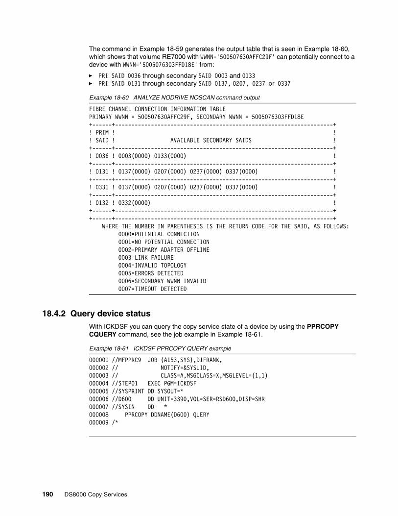
The command in Example 18-59 generates the output table that is seen in Example 18-60, which shows that volume RE7000 with WWNN='500507630AFFC29F' can potentially connect to a device with WWNN='5005076303FFD18E' from:
� PRI SAID 0036 through secondary SAID 0003 and 0133� PRI SAID 0131 through secondary SAID 0137, 0207, 0237 or 0337
Example 18-60 ANALYZE NODRIVE NOSCAN command output
FIBRE CHANNEL CONNECTION INFORMATION TABLE PRIMARY WWNN = 500507630AFFC29F, SECONDARY WWNN = 5005076303FFD18E +------+-------------------------------------------------------------------+ ! PRIM ! ! ! SAID ! AVAILABLE SECONDARY SAIDS ! +------+-------------------------------------------------------------------+ ! 0036 ! 0003(0000) 0133(0000) ! +------+-------------------------------------------------------------------+ ! 0131 ! 0137(0000) 0207(0000) 0237(0000) 0337(0000) ! +------+-------------------------------------------------------------------+ ! 0331 ! 0137(0000) 0207(0000) 0237(0000) 0337(0000) ! +------+-------------------------------------------------------------------+ ! 0132 ! 0332(0000) ! +------+-------------------------------------------------------------------+ +------+-------------------------------------------------------------------+
WHERE THE NUMBER IN PARENTHESIS IS THE RETURN CODE FOR THE SAID, AS FOLLOWS: 0000=POTENTIAL CONNECTION 0001=NO POTENTIAL CONNECTION 0002=PRIMARY ADAPTER OFFLINE 0003=LINK FAILURE 0004=INVALID TOPOLOGY 0005=ERRORS DETECTED 0006=SECONDARY WWNN INVALID 0007=TIMEOUT DETECTED
18.4.2 Query device statusWith ICKDSF you can query the copy service state of a device by using the PPRCOPY CQUERY command, see the job example in Example 18-61.
Example 18-61 ICKDSF PPRCOPY QUERY example
000001 //MFPPRC9 JOB (A153,SYS),D1FRANK, 000002 // NOTIFY=&SYSUID, 000003 // CLASS=A,MSGCLASS=X,MSGLEVEL=(1,1) 000004 //STEP01 EXEC PGM=ICKDSF 000005 //SYSPRINT DD SYSOUT=* 000006 //D600 DD UNIT=3390,VOL=SER=RSD600,DISP=SHR 000007 //SYSIN DD * 000008 PPRCOPY DDNAME(D600) QUERY 000009 /*
190 DS8000 Copy Services

In Example 18-62, the device D600 is a PERIMARY device in a DUPLEX state.
Example 18-62 Query a volume status output
PPRCOPY DDNAME(D600) QUERY ICK00700I DEVICE INFORMATION FOR D600 IS CURRENTLY AS FOLLOWS: PHYSICAL DEVICE = 3390 STORAGE CONTROLLER = 2107 STORAGE CONTROL DESCRIPTOR = E8 DEVICE DESCRIPTOR = 0A ADDITIONAL DEVICE INFORMATION = 4A00003C TRKS/CYL = 15, # PRIMARY CYLS = 1113 ICK04030I DEVICE IS A PEER TO PEER REMOTE COPY VOLUME ICK03091I EXISTING VOLUME SERIAL READ = RSD600 QUERY REMOTE COPY - VOLUME (PRIMARY) (SECONDARY) SSID CCA SSID CCA DEVICE LEVEL STATE PATH STATUS SER # LSS SER # LSS AUTORE------ --------- -------------- ----------- ----------- ----------- ------D600 PRIMARY DUPLEX ACTIVE D601 00 C002 00 DISABL ACA91 D6 FAW81 C0 PATHS SAID/DEST STATUS DESCRIPTION ----- --------- ------ ---------------- 1 0210 0200 13 ESTABLISHED FIBRE CHANNEL PATH ICKDSF - MVS/ESA DEVICE SUPPORT FACILITIES 17.0 TIME: 13:25:52ICK02206I PPRCOPY QUERY FUNCTION COMPLETED SUCCESSFULLY ICK00001I FUNCTION COMPLETED, HIGHEST CONDITION CODE WAS 0
If you need more information about the established paths between devices you need to specify the PATHS parameter in our job, for an example see Example 18-64 on page 192.
18.4.3 Defining and querying a Metro Mirror pathExample 18-63 shows an ICKDSF job that is defining a Metro Mirror path. We run a QUERY command for the path status before and after we establish the paths.
Example 18-63 ICKDSF PPRCOPY ESTPATH example
000010 //WBIPATH JOB ,'ICKDSF PPRC',MSGCLASS=T,CLASS=B, 000020 // MSGLEVEL=(1,1),NOTIFY=&SYSUID,REGION=0M,USER=&SYSUID 000021 //*JOBPARM S=VSL1 000030 //* -------------------------------------------------------------- *** 000100 //STEP01 EXEC PGM=ICKDSF 000200 //SYSPRINT DD SYSOUT=* 000210 //DD01 DD UNIT=3390,VOL=SER=RE7000,DISP=SHR 000300 //SYSIN DD * 000315 000320 PPRCOPY DDNAME(DD01) QUERY PATHS 000330 000400 PPRCOPY DDNAME(DD01) ESTPATH - 000401 PRI(X'7001' TV181) -
Chapter 18. Metro Mirror and Global Copy interfaces and examples 191

000402 SEC(X'2801' ACV21) - 000403 LSS(X'70' X'28') - 000404 FCPPATHS(X'02010337' - 000405 X'03310207') - 000500 WWNN(500507630AFFC29F - 000600 5005076303FFD18E) 000650 000651 PPRCOPY DDNAME(DD01) QUERY PATHS 000661 /* 000670 //* ------------------------- JOB END ---------------------------- ***
The PPRCOPY ESTPATH command replaces any path definitions that currently exist. Example 18-64 shows the output from the ESTPATH and QUERY PATH commands.
Example 18-64 ICKDSF PPRCOPY ESTPATH output
ICKDSF - MVS/ESA DEVICE SUPPORT FACILITIES 17.0 TIME: 12:39:41 00031502 PPRCOPY DDNAME(DD01) QUERY PATHS 00032012ICK00700I DEVICE INFORMATION FOR 7000 IS CURRENTLY AS FOLLOWS: PHYSICAL DEVICE = 3390 STORAGE CONTROLLER = 2107 STORAGE CONTROL DESCRIPTOR = E8 DEVICE DESCRIPTOR = 0C ADDITIONAL DEVICE INFORMATION = 4A00003C TRKS/CYL = 15, # PRIMARY CYLS = 10017 ICK04000I DEVICE IS IN SIMPLEX STATE ICK03091I EXISTING VOLUME SERIAL READ = RE7000 QUERY REMOTE COPY - PATHS PRIMARY (OR SIMPLEX) CONTROL UNIT INFORMATION SERIAL WORLD WIDE NUMBER SSID LSS NODE NAME ------- ---- --- ---------------- TV181 7001 70 500507630AFFC29F ICKDSF - MVS/ESA DEVICE SUPPORT FACILITIES 17.0 TIME: 12:39:41 SECONDARY CONTROL UNIT INFORMATION SERIAL WORLD WIDE NUMBER SSID LSS NODE NAME ------- ---- --- ---------------- ....... .... ... ................
PATHS: SERIAL WORLD WIDE NUMBER SSID LSS NODE NAME PATH SAID DEST S* ------- ---- --- ---------------- ---- ---- ---- -- 1ST: ....... .... ... ................ .... .... .... 00 2ND: ....... .... ... ................ .... .... .... 00 3RD: ....... .... ... ................ .... .... .... 00
192 DS8000 Copy Services
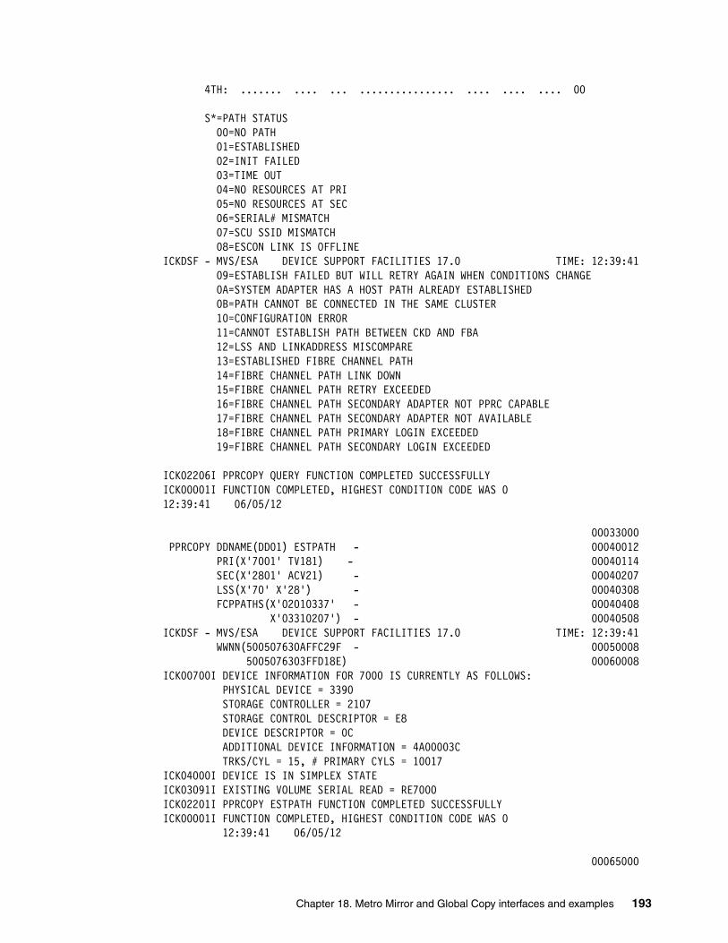
4TH: ....... .... ... ................ .... .... .... 00 S*=PATH STATUS 00=NO PATH 01=ESTABLISHED 02=INIT FAILED 03=TIME OUT 04=NO RESOURCES AT PRI 05=NO RESOURCES AT SEC 06=SERIAL# MISMATCH 07=SCU SSID MISMATCH 08=ESCON LINK IS OFFLINE ICKDSF - MVS/ESA DEVICE SUPPORT FACILITIES 17.0 TIME: 12:39:41 09=ESTABLISH FAILED BUT WILL RETRY AGAIN WHEN CONDITIONS CHANGE 0A=SYSTEM ADAPTER HAS A HOST PATH ALREADY ESTABLISHED 0B=PATH CANNOT BE CONNECTED IN THE SAME CLUSTER 10=CONFIGURATION ERROR 11=CANNOT ESTABLISH PATH BETWEEN CKD AND FBA 12=LSS AND LINKADDRESS MISCOMPARE 13=ESTABLISHED FIBRE CHANNEL PATH 14=FIBRE CHANNEL PATH LINK DOWN 15=FIBRE CHANNEL PATH RETRY EXCEEDED 16=FIBRE CHANNEL PATH SECONDARY ADAPTER NOT PPRC CAPABLE 17=FIBRE CHANNEL PATH SECONDARY ADAPTER NOT AVAILABLE 18=FIBRE CHANNEL PATH PRIMARY LOGIN EXCEEDED 19=FIBRE CHANNEL PATH SECONDARY LOGIN EXCEEDED ICK02206I PPRCOPY QUERY FUNCTION COMPLETED SUCCESSFULLY ICK00001I FUNCTION COMPLETED, HIGHEST CONDITION CODE WAS 0 12:39:41 06/05/12 00033000 PPRCOPY DDNAME(DD01) ESTPATH - 00040012 PRI(X'7001' TV181) - 00040114 SEC(X'2801' ACV21) - 00040207 LSS(X'70' X'28') - 00040308 FCPPATHS(X'02010337' - 00040408 X'03310207') - 00040508ICKDSF - MVS/ESA DEVICE SUPPORT FACILITIES 17.0 TIME: 12:39:41 WWNN(500507630AFFC29F - 00050008 5005076303FFD18E) 00060008ICK00700I DEVICE INFORMATION FOR 7000 IS CURRENTLY AS FOLLOWS: PHYSICAL DEVICE = 3390 STORAGE CONTROLLER = 2107 STORAGE CONTROL DESCRIPTOR = E8 DEVICE DESCRIPTOR = 0C ADDITIONAL DEVICE INFORMATION = 4A00003C TRKS/CYL = 15, # PRIMARY CYLS = 10017 ICK04000I DEVICE IS IN SIMPLEX STATE ICK03091I EXISTING VOLUME SERIAL READ = RE7000 ICK02201I PPRCOPY ESTPATH FUNCTION COMPLETED SUCCESSFULLY ICK00001I FUNCTION COMPLETED, HIGHEST CONDITION CODE WAS 0 12:39:41 06/05/12 00065000
Chapter 18. Metro Mirror and Global Copy interfaces and examples 193

PPRCOPY DDNAME(DD01) QUERY PATHS 00065112ICK00700I DEVICE INFORMATION FOR 7000 IS CURRENTLY AS FOLLOWS: PHYSICAL DEVICE = 3390 ICKDSF - MVS/ESA DEVICE SUPPORT FACILITIES 17.0 TIME: 12:39:41 STORAGE CONTROLLER = 2107 STORAGE CONTROL DESCRIPTOR = E8 DEVICE DESCRIPTOR = 0C ADDITIONAL DEVICE INFORMATION = 4A00003C TRKS/CYL = 15, # PRIMARY CYLS = 10017 ICK04000I DEVICE IS IN SIMPLEX STATE ICK03091I EXISTING VOLUME SERIAL READ = RE7000
QUERY REMOTE COPY - PATHS PRIMARY (OR SIMPLEX) CONTROL UNIT INFORMATION SERIAL WORLD WIDE NUMBER SSID LSS NODE NAME ------- ---- --- ---------------- TV181 7001 70 500507630AFFC29F SECONDARY CONTROL UNIT INFORMATION SERIAL WORLD WIDE NUMBER SSID LSS NODE NAME ------- ---- --- ---------------- ....... .... ... ................ ICKDSF - MVS/ESA DEVICE SUPPORT FACILITIES 17.0 TIME: 12:39:41 PATHS: SERIAL WORLD WIDE NUMBER SSID LSS NODE NAME PATH SAID DEST S* ------- ---- --- ---------------- ---- ---- ---- -- 1ST: ACV21 2801 28 5005076303FFD18E 1 0201 0337 13 2 0331 0207 13 2ND: ....... .... ... ................ .... .... .... 00 3RD: ....... .... ... ................ .... .... .... 00 4TH: ....... .... ... ................ .... .... .... 00 S*=PATH STATUS 00=NO PATH 01=ESTABLISHED 02=INIT FAILED 03=TIME OUT 04=NO RESOURCES AT PRI 05=NO RESOURCES AT SEC 06=SERIAL# MISMATCH 07=SCU SSID MISMATCH 08=ESCON LINK IS OFFLINE 09=ESTABLISH FAILED BUT WILL RETRY AGAIN WHEN CONDITIONS CHANGE 0A=SYSTEM ADAPTER HAS A HOST PATH ALREADY ESTABLISHED 0B=PATH CANNOT BE CONNECTED IN THE SAME CLUSTER 10=CONFIGURATION ERROR
194 DS8000 Copy Services

11=CANNOT ESTABLISH PATH BETWEEN CKD AND FBA 12=LSS AND LINKADDRESS MISCOMPARE ICKDSF - MVS/ESA DEVICE SUPPORT FACILITIES 17.0 TIME: 12:39:41 13=ESTABLISHED FIBRE CHANNEL PATH 14=FIBRE CHANNEL PATH LINK DOWN 15=FIBRE CHANNEL PATH RETRY EXCEEDED 16=FIBRE CHANNEL PATH SECONDARY ADAPTER NOT PPRC CAPABLE 17=FIBRE CHANNEL PATH SECONDARY ADAPTER NOT AVAILABLE 18=FIBRE CHANNEL PATH PRIMARY LOGIN EXCEEDED 19=FIBRE CHANNEL PATH SECONDARY LOGIN EXCEEDED ICK02206I PPRCOPY QUERY FUNCTION COMPLETED SUCCESSFULLY ICK00001I FUNCTION COMPLETED, HIGHEST CONDITION CODE WAS 0 12:39:41 06/05/12 ICK00002I ICKDSF PROCESSING COMPLETE. MAXIMUM CONDITION CODE WAS 0
Chapter 18. Metro Mirror and Global Copy interfaces and examples 195

196 DS8000 Copy Services

Part 5 Global Mirror
This part of the book describes the asynchronous copy service function Global Mirror for DS8000. It describes the characteristics of Global Mirror and explains the options for its setup. It also shows which management interfaces you can use, and the important aspects to consider when you establish a Global Mirror environment. It concludes with examples of Global Mirror management and setup.
Part 5
© Copyright IBM Corp. 2017. All rights reserved. 197

198 DS8000 Copy Services

Chapter 19. Global Mirror overview
This chapter provides an overview of Global Mirror. It describes the necessity for data consistency over unlimited distances when synchronous data replication such as Metro Mirror is not practical or possible. It explains how Global Mirror works in a manner similar to a distributed application, that is in a client/server relationship. It includes the following topics:
� Global Mirror basic concepts� Global Mirror consistency group processing
19
© Copyright IBM Corp. 2017. All rights reserved. 199

19.1 Global Mirror basic concepts
When you replicate data over long distances, that is, beyond the 300 km Metro Mirror non-RPQ limit, asynchronous data replication is the preferred approach. The reason this approach is the preferred one is because, with asynchronous techniques, the application I/O processing on the primary storage system remains independent of the process of data transmission to the secondary storage system.
With asynchronous data replication techniques, you must provide additional means to ensure data consistency at the secondary location. Such a scenario requires a solution that ensures data consistency within a single primary-secondary pair of storage systems and across multiple primary and secondary storage systems.
Global Mirror, is based on an efficient combination of Global Copy and FlashCopy functions. It is the storage system microcode that provides, from the user perspective, a transparent and autonomic mechanism to intelligently use Global Copy with certain FlashCopy operations to attain consistent data at the secondary site.
In normal operations for asynchronous data replication, data consistency for dependent writes is preserved depending on the technique that is used to replicate the data. Dependent writes and data consistency are explained in detail in 16.8, “Consistency group function” on page 127. Global Mirror uses a different technique than z/OS Global Mirror, which is explained in Chapter 24, “How z/OS Global Mirror maintains consistency” on page 299.
The trade-off of providing consistency in an asynchronous replication is that not all the most recent data can be saved in a consistency group. The reason is that data consistency can only be provided in distinct periods of time. When an incident occurs, only the data from the previous point of consistency creation can be restored. The measurement of the amount of data which is lost in such a case is named recovery point objective (RPO) and it is given in units of time, usually seconds or minutes. The RPO is not a fixed number, it is in fact highly dependant on the available bandwidth and the quality of the physical data link and of the current workload at the local site.
19.1.1 Terminology in Global Mirror environments
The following terms and elements are commonly used when working in a Global Mirror context:
� Bitmaps
– Out of sync (OOS)
This bitmap, in the Global Mirror environment, is created by the DS8000 at Global Copy pair establish time and keeps all tracks of data that are modified on the Primary storage system and not yet copied to the secondary storage system.
– Change recording (CR)
This bitmap, in the Global Mirror environment, is used during consistency group processing to track any changes that come in to the primary storage system while the OOS bitmap is being drained to the secondary storage system in preparation for a consistency group.
� Consistency
The consistency of data is ensured if the order of dependent writes to disks or disk groups is maintained. With Copy Services solutions, the data consistency at the secondary site is
200 DS8000 Copy Services

important for the ability to restart a database. You can use consistent data to perform a database restart rather than a database recovery that might take hours or days.
Data consistency across all secondary volumes that are spread across multiple storage disk systems is essential for logical data integrity.
Consistency is ensured to be equivalent to a power off of a production storage system, where everything that was written right up to the point of losing power is consistent. Thus, without a quiesce of all production activity, there is always some data in flight. So you might need to rerun some tasks to completion at the secondary after recovery.
� Consistency group
A group of volumes in one or more secondary storage systems whose data contains a consistent point in time for disaster recovery.
� Data currency
This term describes the difference of time since the last data was written at the primary site, versus the time the same data was written to the secondary site. It determines the amount of data you must recover at the remote site after a disaster. This concept is also called the recovery point objective (RPO). Only synchronous copy solutions, such as Metro Mirror, have an RPO equal to zero. All asynchronous copy solutions have a data currency greater than zero.
With Global Mirror, a data currency of a few seconds can be achieved, and data consistency is always maintained by the consistency group process within Global Mirror.
Here are some examples of different asynchronous replication methods:
– Global Copy is an asynchronous method that does not ensure consistent data at the secondary site.
– z/OS Global Mirror is an asynchronous replication method that ensures consistent data at the secondary site.
• It is a hardware and software solution, that is a system data mover (SDM) in DFSMSdfp.
• It supports only z Systems count key data (CKD) volumes.
– Global Mirror is also an asynchronous replication method that provides consistent data at the secondary site. For more information, see 19.1.4, “Global Mirror Master Subordinate Relationship” on page 204.
• It is a hardware solution.• It supports all platforms (z Systems and Open Systems).
� Dependent writes
If the start of one write operation depends upon the completion of a previous write, the writes are dependent. An example of an application with dependent writes is databases with their associated logging files.
Maintaining the order of dependent writes is the basis for having data consistency at the secondary (remote) site.
Dependent writes are described in detail with examples in 16.8.1, “Data consistency and dependent writes” on page 127.
� Journal
Asynchronous mirroring requires a mechanism to contain consistent recoverable data. The Global Mirror function uses FlashCopy to create the Global Mirror journals. These relationships are created during the Global Mirror setup process and are refreshed with each consistency group that is created.
Chapter 19. Global Mirror overview 201

� Master
The master is a function inside a primary storage system that communicates with other primary storage systems (subordinates), and coordinates the creation of consistency groups while you manage the Global Mirror session. The master is defined when the start command for a session is issued to any LSS in a primary storage system. This command determines which DS8000 becomes the master storage system and which LSS becomes the master LSS.
The master requires communication paths over Fibre Channel links to any one of the LSSs in each subordinate storage system.
� Session
A Global Mirror session is a collection of Global Copy pairs that are managed together when you create consistent copies of data volumes. This set of volumes can be in one or more LSSs and one or more storage disk systems at the primary site. Open Systems volumes and z/OS volumes can both be members of the same session.
When you start or resume a session, consistency group processing occurs, with the master storage system coordinating the session by communicating with the subordinate storage systems.
For a Global Copy pair to be part of a Global Mirror session, the session must be defined to the LSS where the volume resides. All LSSs with a specific session defined are combined and grouped within that Global Mirror session at the time the session is started.
� Subordinate
The subordinate is a function inside a primary storage system that communicates with the master and is coordinated by the master. At least one of the LSSs of each subordinate primary storage systems requires Fibre Channel communication paths to the master. These paths enable the communication between the master and the subordinate, and are required to create consistency groups of volumes that spread across more than one storage system.
If all the volumes of a Global Mirror session are in one primary storage disk system, no subordinate is required because the master can communicate to all LSSs inside the primary storage system.
19.1.2 Application I/O and Global Mirror
In an asynchronous data replication environment, an application write I/O has the following steps (see Figure 14-1 on page 108):
1. Write application data to the primary storage system cache.
2. Acknowledge a successful I/O to the application so that the next I/O can be immediately scheduled. The application can then immediately schedule the next I/O.
3. Replicate the data from the primary storage system cache to the auxiliary storage system cache and NVS.
4. Acknowledge to the primary storage system that data successfully arrived at the auxiliary storage system.
Note how in an asynchronous type technique that the data transmission and the I/O completion acknowledge are independent processes, which result in virtually no application I/O impact, or at most a minimal degree of I/O. This technique is convenient when you must replicate over long distances.
202 DS8000 Copy Services

19.1.3 Asynchronous replication technique
An asynchronous data replication technique provides the following features:
� Data replication to the secondary site is independent from application write I/O processing at the primary site, which results in no impact, or at least only minimal impact, to the application write I/O response time.
� The order of dependent writes is maintained at the primary site, so data consistency can be maintained at the secondary site.
� Data currency at the secondary site lags behind the primary site. How much it lags depends upon network bandwidth and storage system configuration. In periods of peak write workloads, this difference increases.
� The bandwidth requirement between the primary and secondary sites does not have to be configured for peak write workload; link bandwidth utilization is improved over synchronous solutions.
� Journal copies are required at the secondary site to preserve data consistency.
� Data loss in disaster recovery situations is limited to the data in transit plus the data that might still be in the queue at the primary site that is waiting to be replicated to the secondary site.
To accomplish the necessary activities with a minimal impact on the application write I/O, Global Mirror architecture uses Global Copy, FlashCopy and a bitmap approach. Global Mirror uses two different types of bitmaps, the OOS bitmaps used by the Global Copy function and the CR bitmap allocated during the process of consistency formation. Figure 19-1 on page 204 identifies the following essential components of the DS8000 Global Mirror architecture:
� Global Copy is used to transmit the data asynchronously from the primary volumes to the secondary volumes.
� FlashCopy relationship from the Global Copy secondary volumes to the journal volumes.
� A CR bitmap which is maintained by the Global Mirror running on the primary storage system while consistency group is created at the primary site.
When the Global Mirror Process at the primary site creates a consistency group, I/O is held at the primary volumes for the time it takes to coordinate all subordinates that a consistency group is to be formed and to create the CR bitmap in the primary storage memory (maximum coordination interval default = 50 ms). All new data sent from the hosts will be marked for each corresponding track in the CR bitmap.
In Global Mirror, the latest consistency group is represented by the journal volumes (FlashCopy targets) at the secondary site.
Chapter 19. Global Mirror overview 203

Figure 19-1 General architecture of Global Mirror
19.1.4 Global Mirror Master Subordinate Relationship
Global Mirror works like a distributed application. A distributed application is usually built on a server to client relationship. The server functions as a supervisor and instructs the client. The client is able to do some work in an autonomic fashion but relies on the coordination efforts from the server, as shown in Figure 19-2.
Figure 19-2 Distributed application
The server distributes the work to its clients. The server also coordinates all individual feedback from the clients and decides further actions. Looking at this diagram, the communication paths between the server and all its clients are key. Without communication paths between these four components, the functions eventually come to a complete stop. Matters get more complicated when the communication fails unexpectedly in the middle of information exchange between the server and its clients or to some of its clients.
Remote siteLocal site
Server
Task1
Client Client
Client
Network
Task1Task2
Task2Task3
Task3
204 DS8000 Copy Services

Usually, a two-phase commit process provides a consistent state for certain functions and determines whether they complete successfully at the client site. After a function completes successfully and is acknowledged to the server, the server progresses to the next function task. Concurrently, the server tries to parallelize operations (for example, I/O requests and coordinate communication) to minimize the impact on throughput because of serialization and checkpoints.
When certain activities depend on each other, the server must coordinate these activities to ensure a correct sequence. The server and client can be also referred as master and subordinate.
Figure 19-3 shows the basic Global Mirror structure in relation to a distributed application. A master coordinates all efforts within a Global Mirror environment. After the master is started and manages a Global Mirror environment, the master issues all related commands over Peer-to-Peer Remote Copy (PPRC) links to its attached subordinates at the primary site. These subordinates can include a subordinate within the master itself. This communication between the master and an internal subordinate is transparent and does not require any extra attention from the user. The subordinates use inband communication to communicate with their related auxiliary storage systems at the remote site. The master also receives all acknowledgements from the subordinates and coordinates and serializes all the activities in the session.
Figure 19-3 Global Mirror as a distributed application
Now, if we look at this structure in a more detail view, you see that we have primary volumes in the master and subordinate storage system, secondary volumes in the secondary storage systems, and the secondary volumes are also FlashCopy source volumes in the secondary storage systems. Pull them all together into a coordinated entity and you have a Global Mirror session. A Session is a Global Mirror master session that manages a Global Mirror processing, as shown in Figure 19-4 on page 206. A Global Mirror session is identified by a Global Mirror session ID, which is the number 20 in the figure. This session ID is defined in all the involved LSSs at the primary site, which contain Global Copy primary volumes that belong to session 20. The Global Mirror master manages the subordinate through PPRC logical paths between both DS8000 storage systems. Consistency is provided across all primary storage systems.
Remote siteLocal site
Master
Subordinate Secondary
Secondary
Network
Subord Flash Sec
FlashCopy2
Primary
Primary
Chapter 19. Global Mirror overview 205

Figure 19-4 Global Mirror session
When the master and subordinate are in a single storage system, the subordinate is internally managed by the master. With two or more storage systems at the primary site, which participate in a Global Mirror session, the subordinate is external and requires separate attention when you create and manage a Global Mirror session or environment (Figure 19-5).
Figure 19-5 Global Mirror master and subordinate configuration
Primary
PENDINGSAN
Secondary SitePrimary Site
Global Copy
Primary
PENDING
DS8700/ DS8800DS8700/DS8800
20Session
GM master
Subordinate
20
20
20
20
20
20
Secondary
PENDIN G
Secondary
PENDIN G
S econdary
PEN DING
Secondary
PENDIN G
Secondary
PENDIN G
S econdary
PEN DING
206 DS8000 Copy Services

19.2 Global Mirror consistency group processing
In a Global Mirror environment, as mentioned previously, the consistent set of data is represented by the journal volumes at the secondary site. This is accomplished using specific steps and coordination within the storage systems and between storage systems as described in this section.
19.2.1 Properties of the Global Mirror journal
To create a set of volumes at a secondary site that contains consistent data, asynchronous data replication alone is not enough. It must be complemented with either a journal or a tertiary copy of the secondary volume. With Global Mirror, this third copy is created by using FlashCopy.
Figure 19-6 shows a FlashCopy relationship with a Global Copy secondary volume as the FlashCopy source volume. Volume H2 is now both, at the same time, a Global Copy secondary volume and a FlashCopy source volume. In the same storage server is the corresponding FlashCopy target volume.
Figure 19-6 Volume relationships in a Global Mirror configuration
This FlashCopy relationship has certain attributes that are typical and required when you create a Global Mirror session:
� Inhibit target write
Protect the FlashCopy target volume from being modified by anything other than Global Mirror related actions.
� Start change recording
Apply changes only from the source volume to the target volume that occur to the source volume in between FlashCopy establish operations, except for the first time when FlashCopy is initially established.
� Persist
Keep the FlashCopy relationship until explicitly or implicitly terminated. This parameter is automatic because of the change recording property.
� Nocopy
Do not start background copy from source to target, but keep the set of FlashCopy bitmaps required for tracking the source and target volumes. These bitmaps are established when a FlashCopy relationship is created. Before a track in the source volume B is modified, between consistency group creations, the track is copied to the target
Chapter 19. Global Mirror overview 207

volume C to preserve the previous point-in-time copy. This copy includes updates to the corresponding bitmaps to reflect the new location of the track that belongs to the point-in-time copy. The first Global Copy write to its secondary volume track with the window of two adjacent consistency groups causes FlashCopy to perform copy on write operations.
Some interfaces to trigger this particular FlashCopy relationship combine these attributes into a single parameter such as MODE(ASYNC) with the TSO command for z/OS.
With standard FlashCopy, you needed twice the capacity at the secondary site, as compared to the primary site. With extent space-efficient (ESE) or thin provisioned volumes as the FlashCopy targets, you need twice the logical capacity as on the primary site. However, the physical storage available in the extent pool need only be the same physical capacity as on the primary site with additional physical capacity for the ESE target volumes to capture the current consistency group’s changes. The physical capacity of the journal volumes is less than using fully provisioned C volumes. The physical capacity that you need is determined by how long you can tolerate an inactive Global Mirror session. If Global Mirror does not initiate FlashCopy copies by forming consistency groups, which releases space consumed by the target (journal) at the start of establish processing, the extent pool could fill up with data as tracks are updated with updates from the primary site.
For detailed information about ESE volumes (thin provisioning), see IBM DS8880 Thin Provisioning, REDP-5343.
19.2.2 Consistency group formation
The microcode automatically triggers a sequence of autonomic events to create a set of consistent data volumes at the secondary site. This set of consistent data volumes is a consistency group. The following sections describe the sequence of events that create a consistency group.
The creation of a consistency group requires three steps that are internally processed and controlled by the microcode. These steps are fully transparent and do not require any other external code invocation or user action.
The numbers in Figure 19-7 illustrate the sequence of the events that are involved in the creation of a consistency group. This illustration provides only a high-level view to aid in understanding how this process works.
Figure 19-7 Formation of a consistent set of volumes at the secondary site
J2
Tertiary
J2Tertiary
2
Primary
Serialize allGlobal Copy
primary volumes
Drain data from primary to secondary site
PerformFlashCopy
StartDone
StartDone
StartDone
Secondary
1 3
OOS
OOS
CR
CR
DrainCoordination
time not drawn to scale
H1Primary
H1Primary
H2Secondary
H2Secondary
208 DS8000 Copy Services

Note that before step 1 and after step 3, Global Copy constantly scans through the OOS bitmaps and replicates data from H1 volumes to H2 volumes.
When the creation of a consistency group is triggered by the Global Mirror master, the following steps occur:
1. Coordination includes serializing all of the Global Copy primary volumes in the Global Mirror session. This serialization imposes a brief hold on all incoming write I/Os to all involved Global Copy primary volumes. After all primary volumes are serialized across all involved primary DS8000s, the pause on the incoming write I/O is released and all further write I/Os are now noted in the CR bitmap. They are not replicated until step 3 on page 209 is done, but application write I/Os can immediately continue. This serialization phase takes only a few milliseconds and the default coordination time is set to 50 ms.
2. Drain includes the process to replicate all remaining data that is indicated in the OOS bitmap and still not replicated. After all out-of-sync bitmaps are empty, step 3 is triggered by the microcode from the primary site.
3. Now the H2 volumes contain all data at a point-in-time copy, and are consistent because of the serialization process in step 1 and the completed replication or drain process in step 2. Step 3 is now a FlashCopy that is triggered by the primary system’s microcode as an inband FlashCopy command to volume H2, as FlashCopy source, and the journal volume J2, as a FlashCopy target volume. This FlashCopy is a two-phase process. First, the FlashCopy command is issued to all involved FlashCopy pairs in the Global Mirror session. Then, the master collects the feedback and all incoming FlashCopy completion messages. When all FlashCopy operations are successfully completed, the master concludes that a new consistency group is created successfully and performs commit operations to each of the FlashCopy relationships.
FlashCopy applies here only to changed data since the last FlashCopy operation because the start change recording property was set at the time when the FlashCopy relationship was established. The FlashCopy relationship does not end because the relationship is persistent. Because of the nocopy attribute, only copy on write operations cause physical tracks to be copied from the source to the target.
When step 3 is complete, a consistent set of volumes is created at the secondary site. This set of volumes, the H2 and J volumes, represents the consistency group.
For this brief moment only, the H2 volumes and the J2 volumes are equal in their content. Immediately after the FlashCopy process is logically complete, the primary storage systems are notified to continue with the Global Copy process from H1 to H2. To replicate the changes to the H1 volumes that occurred during the step 1 to step 3 window, the change recording bitmap is merged into the empty out-of-sync bitmap, and from now on, all arriving write I/Os end up again in the out-of-sync bitmap. Then, the conventional Global Copy process, as outlined in 14.1, “Global Copy overview” on page 108, continues until the next consistency group creation process is started.
19.2.3 Consistency group parameters
There are three externalized parameters that can be specified by a user (see Figure 19-8 on page 210). Their default values can be overridden.
Note: If any error occurs preventing the successful completion of the FlashCopy commands, the relationships that were established are reverted to the previous consistency group. So, there is always a consistent set of data at the remote site.
Chapter 19. Global Mirror overview 209

Figure 19-8 Consistency group tuning parameters
The following parameters are available:
� Maximum coordination time
In the first step, the serialization step, Global Mirror serializes all related Global Mirror primary volumes across all participating primary storage systems. This parameter dictates, for all of the Global Copy primary volumes that belong to this session and consistency group, the maximum time that is allowed when you form the change recording bitmaps for each volume. This time is measured in milliseconds (ms). The default is 50 ms.
� Maximum drain time
This time is the maximum time that is allowed for draining the out-of-sync bitmap after the process to form a consistency group is started and step 1 of Figure 19-8 completes successfully. The maximum drain time is specified in seconds. The default is 30 seconds. You might want to increase this time window when you replicate over a longer distance and with limited bandwidth.
If the maximum drain time is exceeded, Global Mirror fails to form the consistency group and evaluates the current throughput of the environment. If the evaluation indicates that another drain failure is likely, Global Mirror stays in Global Copy mode while regularly re-evaluating the situation to determine when to form the next consistency group. If this situation persists for a significant period, then Global Mirror eventually forces the formation of a new consistency group. In this way, Global Mirror ensures that during periods when the bandwidth is insufficient, production performance is protected, and data is transmitted to the secondary site in the most efficient manner possible. When the peak activity passed, consistency group formation resumes in a timely fashion.
� Consistency group interval time
After a consistency group (CG) is created, the consistency group interval time (CGI) determines how long to wait before starting the formation of the next consistency group. This formation is specified in seconds, and the default is zero seconds. Zero seconds means that consistency group formation happens constantly. When a consistency group is created successfully, the process to create a consistency group starts again immediately.
2Serialize allGlobal Copy
primary volumes
Drain data from primary to secondary site
PerformFlashCopy
1 3
1 2 3
Maximum
coordinationtime
time
CG interval
draintime
Maximum
1 2 3
time line not drawn to scale
210 DS8000 Copy Services

Chapter 20. Global Mirror operations and recovery
This chapter provides a detailed description of Global Mirror options, including how to create a Global Mirror environment and how to remove it. It describes how to change Global Mirror tuning parameters and how to modify an active Global Mirror session. Finally, this chapter describes basic recovery steps for Global Mirror.
Global Mirror is intended for long-distance data replication, so it relies on the network infrastructure and components that are used between the remote sites. This chapter does not cover network configuration options, but describes the importance of adequate bandwidth in a Global Mirror environment.
This chapter includes the following topics:
� Modifying a Global Mirror session� Global Mirror with multiple storage systems� Multiple Global Mirror sessions� Host connectivity at primary and secondary sites� Taking an additional copy for disaster recovery testing� Global Mirror recovery
20
© Copyright IBM Corp. 2017. All rights reserved. 211

20.1 Modifying a Global Mirror session
When a session is active and running, you can alter the Global Mirror environment to add or remove volumes. You also can add storage systems to a Global Mirror session or you can change the interval between the formation of consistency groups.
20.1.1 Adding volume pairs to or removing volume pairs from a Global Mirror session
Volumes can be added to the session at any time after the session number is defined to the LSS where the volumes are. When the session is started, volumes can be added to the session or can be removed from the session also at any time.
Volumes can be added to a session in any state, for example, simplex or pending. Volumes that have not completed their initial copy phase, or volume pairs that do not have a FlashCopy relationship established for the journal, stay in a join pending state until the pair is in the proper state (first pass copy complete, not suspended, FlashCopy with appropriate settings established). If a volume in a session is suspended, it causes consistency group formation to fail. This ensures consistency at all times across all volumes that are being mirrored in that session.
As a preferred practice, add only Global Copy pairs that have completed their first pass copy. Also, wait until the first initial copy is complete before you create the FlashCopy relationship between the B and the C volumes.
Suspending a Global Copy pair that belongs to an active Global Mirror session will cause consistency group formation to fail. This is because after a volume pair participates in a consistency group, the master assumes it is required for true consistency. So Global Mirror will fail CGs that cannot include all volume pairs that are still joined to the session and previously participated in a consistency group (CG), but for some reason one or more volume pairs are unable to participate in the current CG.
20.1.2 Adding or removing storage systems or LSSs
When you add a subordinate storage system to an active session, you must stop the session first. Then, add the subordinate storage system and start the session again with the updated configuration, or topology. The next consistency group will include volumes in that new storage system, as long as the volume pairs are in the proper state for inclusion.
Adding primary volumes: You cannot add a Metro Mirror primary volume to a Global Mirror session. Global Mirror supports only Global Copy pairs. When Global Mirror detects a volume that, for example, is converted from Global Copy to Metro Mirror, the formation of a consistency group fails.
Consistency group failure: When you see a consistency group failure (for example, after suspension of one of the pairs in the session), this error does not mean that you lost your consistent copy at the secondary site. Global Mirror does not take the FlashCopy (B to C) for the failed consistency group data. Global Mirror will stop consistency group processing when it encounters an error, and it will start the sequence again.
212 DS8000 Copy Services

The same procedure applies when you remove a storage system from a Global Mirror session. You can only remove a subordinate (you cannot remove the master storage system) and only while the session is stopped.
When you add an LSS to an active session and this LSS belongs to a storage system that already has another LSS that belongs to this Global Mirror session, you can add the LSS to the session without stopping and starting the session again. This situation is true for either the master or for a subordinate storage system.
20.1.3 Modifying Global Mirror session parameters
You can modify the parameters that are used for tuning a Global Mirror session by pausing the session and then resuming the session with the new values. Here are the parameters that you can modify:
� Consistency group interval time� Maximum coordination interval time� Maximum consistency drain time
When you issue a start/resume command after a pause command, as opposed to a resume command, any value for the consistency group interval time, maximum coordination interval time, or maximum consistency group drain time in the start command is ignored. If these parameters must be altered, you must run a resume command to the paused session with the parameters specified. If you resume a paused session without specifying these parameters, they are set to their default values (for more information, see 19.2.3, “Consistency group parameters” on page 209).
20.1.4 Global Mirror environment topology changes
The topology of a Global Mirror session, for example, the master SSID, subordinate SSIDs, and subordinate serial numbers, cannot be altered through a pause and resume command sequence. When you resume the session after a pause and the Global Mirror topology is not the same as it was at the pause, resuming the session fails.
If you must change the topology of your Global Mirror session, you must stop the session and start the session again with the new topology structure information in the start command.
Important: When you set values for the tuning parameters, check for errors in the consistency group formation and in draining the out-of-sync bitmaps. A few failed CGs are not significant and do not jeopardize the consistency of your Global Mirror. However, if failures repeatedly occur, for example, and CG formation is not meeting your required RPO, then you should revise and change the values that are set for the tuning parameters.
Attention: If you use extent space-efficient (ESE) or thin provisioned FlashCopy target volumes and if a Global Mirror Session is paused or terminates for some other reason, the extent pool where the journal volumes reside will start to consume more physical storage. Restart the Global Mirror session as soon as possible.
Chapter 20. Global Mirror operations and recovery 213

20.2 Global Mirror with multiple storage systems
When you create a Global Mirror environment that spans multiple storage systems at the primary site, then you must establish communication paths between the involved primary storage systems.
Figure 20-1 shows a symmetrical configuration with a one-to-one mapping. You must define the corresponding session, with its number, to all potentially involved LSSs at the primary site. As illustrated in Figure 20-1, there is still no connection between both primary storage systems, so you must define the corresponding Global Mirror paths, as shown in Figure 20-2.
Figure 20-1 Define Global Mirror session to all potentially involved storage systems
Figure 20-2 Define for Master storage server and start Global Mirror session
Through the start command, you decide which LSS becomes the master LSS and consequently which primary storage system becomes the master storage system. This master acts like a server in a client/server environment.
The required communication between the master storage system and the subordinate storage systems is inband, over the defined Global Mirror paths. This communication is efficient, and minimizes any potential application write I/O impact during the coordination
PrimaryPrimary
PrimaryPrimaryA
H2
J2
PrimaryPrimary
PrimaryPrimaryA
H2
J2
Network
Network01
01
Define Global Mirror session
Define Global Mirror session
Primary site
Secondary site
Primary
H1
Primary
H1
Global Copy
Start Global Mirror session
PrimaryPrimaryA
H1 Primary
PENDING
PrimaryPrimaryA
H1 Primary
PENDING
PrimaryPrimary
PrimaryPrimaryA
H2 Secondary
J2 Tertiary
PENDING
PrimaryPrimary
PrimaryPrimaryA
H2 Secondary
J2Tertiary
PENDING
Network
Network01
01
Subordinate
Master
Global Copy
paths
Primary site Secondary site
214 DS8000 Copy Services

phase to about a few milliseconds. For more information, see 19.2.2, “Consistency group formation” on page 208.
This communication is performed over FCP links. At least one FCP link is required between the master storage system and the subordinate storage system. Figure 20-3 uses dashed lines to show the Global Mirror paths that are defined over FCP links, between the master storage system and its associated subordinate storage systems. These FCP ports are dedicated for Global Mirror communication between master and subordinates.
Figure 20-3 Global Mirror paths over FCP links between primary storage systems
Also shown in Figure 20-3 is a shared port on the Master storage system, and dedicated ports at the subordinates.
When you configure links over a SAN network, the same FCP ports of the storage system can be used for the Global Mirror session communication, and for the Global Copy communication and for host connectivity. However, for performance reasons, and to prevent host errors from disrupting your Global Mirror environment, you should use separate FCP ports.
The recommended configuration is the one shown in Figure 20-4 on page 216. From a performance and throughput viewpoint, you do not require two Global Mirror logical paths between the master and its subordinate storage systems. Still, dedicated ports for Global Mirror control communication between a master and subordinate provides a maximum of responsiveness and availability.
PrimaryPrimaryA
H1Primary
PENDING
01
Master
PrimaryPrimaryA
H1Primary
PENDING
01
Subordinate
PrimaryPrimaryA
H1Primary
PENDING
Network
01
Subordinate
Global Copy links
GM links
Global Copy links
Global Copy links
Primary site
PrimaryPrimary
PrimaryPrimaryA
H2 Secondary
J2 Tertiary
PENDING
PrimaryPrimary
PrimaryPrimaryA
H2 Secondary
J2 Tertiary
PENDING
PrimaryPrimary
PrimaryPrimaryA
H2 Secondary
J2 Tertiary
PENDING
Secondary site
Chapter 20. Global Mirror operations and recovery 215

Figure 20-4 Dedicated Global Mirror links and dedicated Global Copy links
20.3 Multiple Global Mirror sessions
Up to 32 dedicated and individual master Global Mirror sessions within each primary storage system is supported.
Figure 20-5 on page 217 depicts a configuration with a single Global Mirror session across two storage systems (master and subordinate).
Potential impacts with such a single Global Mirror session are shown in Figure 20-6. Assume that a storage environment is commonly used by various application servers. To provide good performance, all volumes should be spread across primary and secondary storage systems. For disaster recovery purposes, a secondary site exists with a corresponding storage system and the data volumes are replicated through a Global Mirror session with the Global Mirror master function in a storage system.
PrimaryPrimaryA
H1 Primary
PENDING
PrimaryPrimary
PrimaryPrimaryA
H2 Secondary
J2 Tertiary
PENDING
01
Master
PrimaryPrimaryA
H1 Primary
PENDING
PrimaryPrimary
PrimaryPrimaryA
H2 Secondary
J2 Tertiary
PENDING
01
Subordinate
PrimaryPrimaryA
H1 Primary
PENDING
PrimaryPrimary
PrimaryPrimaryA
H2 Secondary
J2 Tertiary
PENDING
Network
01
Subordinate
Global Copy links
GM links
Global Copy links
Global Copy links
Primary site Secondary site
216 DS8000 Copy Services

Figure 20-5 Multiple applications - single Global Mirror session
When Application 2 fails and there is no access from the secondary site servers to the primary site servers, then the entire Global Mirror session 20 must fail over to the secondary site. Figure 20-6 on page 218 shows the impact on the other two applications, Application 1 and Application 3. When there is only a single Global Mirror session, the entire session must be failed over to the secondary site to restart Application 2 on the backup server. In this case, even the other two servers, Application 1 and Application 3, also must swap sites when you perform a failover.
SAN
Secondary SitePrimary
Site
Global Copy
20Session
Application 1
Application 2
Application 3
Subordinate
GM master
Chapter 20. Global Mirror operations and recovery 217
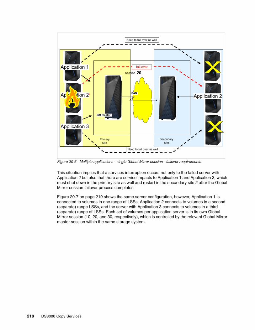
Figure 20-6 Multiple applications - single Global Mirror session - failover requirements
This situation implies that a services interruption occurs not only to the failed server with Application 2 but also that there are service impacts to Application 1 and Application 3, which must shut down in the primary site as well and restart in the secondary site 2 after the Global Mirror session failover process completes.
Figure 20-7 on page 219 shows the same server configuration, however, Application 1 is connected to volumes in one range of LSSs, Application 2 connects to volumes in a second (separate) range LSSs, and the server with Application 3 connects to volumes in a third (separate) range of LSSs. Each set of volumes per application server is in its own Global Mirror session (10, 20, and 30, respectively), which is controlled by the relevant Global Mirror master session within the same storage system.
SAN
Secondary Site
Primary Site
20Session
Need to fail over as well
Need to fail over as well
fail over
GM master
Application 2
Application 1
Application 3
Application 2
218 DS8000 Copy Services

Figure 20-7 DS8000 supports multiple Global Mirror master sessions
In this case, if there is a failure involving the volumes for Application 2, only Global Mirror session 20 is failed over to the secondary site, and then the corresponding server in Site 2 can start Application 2 after the failover process completes. This failover processing for Application 2 has no impact on Application 1 or Application 3, which continue to run at the primary site with Global Mirror mirroring to the secondary site. After Application 2 and session 20 are started, application processing will be at the secondary site with Global Mirror mirroring to the primary site.
This is also helpful for situations where different applications might have different RPO requirements. Separating the volumes for applications between LSSs in a storage system into separate Global Mirror sessions allows you to manage the sessions with separate RPO requirements. Also, a burst of activity on one application and a potentially longer drain time will not impact the application in the other Global Mirror session.
20.4 Host connectivity at primary and secondary sites
The choice of which interface to use for Global Mirror management depends on how the 2-site configuration is designed. You can use a multihost configuration to configure and manage the secondary site by using the host systems at the secondary site because this alternative does not require the usage of inband commands. Alternatively, in a single site host configuration, you can access the secondary site by using the primary site host, when the distance does not exceed a standard Fibre Channel distance.
20.4.1 Multisite host connectivity
Figure 20-8 on page 220 shows a configuration with hosts connected to their primary storage systems only. In this example, there is no connection between the hosts of one site to the storage systems of the other site. This example shows a typical 2-site disaster recovery
Secondary SitePrimary Site
20Session
10Session
30Session
Application 1
Application 2
Application 3
GM master
GM master
GM master Application 2
Chapter 20. Global Mirror operations and recovery 219

solution with the active application host Host1 at the primary site. The host at the secondary site might be a stand-by host configuration, or a system that hosts non-critical applications.
Figure 20-8 Host connectivity at both sites
If there is a failure at the primary site, the host at the secondary site can recover from the Global Mirror configuration. The host at the secondary site requires a disk environment that is independent from the Global Mirror environment.
All Global Mirror related management commands can be run at the respective site. The primary site host can run all commands that address the primary volumes. The secondary site host can run all the commands that are targeted at the secondary or tertiary volumes. However, this approach might not be the preferable one to manage a Global Mirror environment.
20.4.2 Single-site host connectivity
Figure 20-9 on page 221 shows a single host configuration example, with or without Fibre Channel connectivity.
PrimaryA
H2Secondary PrimaryPrimary
J2
Tertiary
PENDING
PrimaryA
H2 Secondary PrimaryPrimary
J2
Tertiary
PENDING
PrimaryA
H2 Secondary
J2
Tertiary
PENDING
PrimaryPrimaryA
H1 Primary
PENDING
01
PrimaryPrimaryA
H1
Primary
PENDING
01
PrimaryPrimaryA
H1 Primary
PENDING
01
Host ISL
Host channelsHost channels
Global Mirror
session links
Host
Global Copy links
FCPFC/FICON FCP FC/FICON
Global Mirrorsession links
Primary site Secondary site
220 DS8000 Copy Services

Figure 20-9 Single-site host connectivity with or without Fibre Channel connectivity between sites
Again, this solution is a 2-site disaster recovery solution, although there are no hosts in the recovery site. Recovery is provided at the storage system level (data recovery).
Depending on how far apart both sites are from each other, you can manage such a configuration using one of the following basic approaches:
� Both sites are at Fibre Channel distance.
You can use this configuration to connect the host to both sites and manage either site from the host through conventional Global Mirror inband commands. Such a configuration can use cascaded Fibre Channel directors to interconnect both sites by using fibre channels. If there is a primary site failure, limited to storage systems, the failover can be managed from the primary host.
If a primary site outage is not limited to the storage servers (that is, you lose your system or system components), a new host would need to be activated to perform recovery, or the DSCLI commands can be used to perform recovery (but you still need to start a system to restart applications, and so on.)
� Both sites are not interconnected because of extended distances, or the required network technology is not available.
Global Mirror management of the auxiliary storage systems can be done through inband commands from the primary site, which is limited to FlashCopy operations only.
20.5 Taking an additional copy for disaster recovery testing
It is common for businesses to have a requirement to practice disaster recovery testing at the remote site while production data is still being replicated to the disaster recovery site. With the Global Mirror, it is accomplished by taking an additional FlashCopy at the remote site. In fact, it is not uncommon for businesses to have multiple ‘extra’ copies at their secondary site for other purposes, such as data mining, or a safety copy during disaster recovery processing.
PrimaryPrimaryA
H2
Secondary PrimaryPrimary
J2
Tertiary
PENDING
PrimaryPrimaryA
H2
Secondary PrimaryPrimary
J2
Tertiary
PENDING
PrimaryPrimaryA
H2
Secondary PrimaryPrimary
J2Tertiary
PENDING
PrimaryPrimaryA
H1
Primary
PENDING
01
PrimaryPrimaryA
H1
Primary
PENDING
01
PrimaryPrimaryA
H1
Primary
PENDING
01
Host
FC/FICONFC/FICON FCPFCP
FICON/FCP director(s) FICON/FCP director(s)
Hostchannels
Global Mirrorsession links
FICON/FC Channels
Global Copylinks
ISLs Global Mirrorsession links
Hostchannels
Primary site Secondary site
Chapter 20. Global Mirror operations and recovery 221

Figure 20-10 illustrates the entire process.
Figure 20-10 Process to take an additional copy for disaster recovery testing
To take a consistent copy of data at the disaster recovery site, the Global Mirror session has to be paused. There is an option on the Global Mirror pause function that ensures that, when the Global Mirror is paused, that it is on a consistency group boundary and the Global Copy pairs are suspended so that the I2 volumes remain consistent while performing FlashCopy to obtain the extra copy.
The Global Mirror pause with consistency function provides a simple method for obtaining a consistent copy of data at disaster recovery site. As soon as the Global Mirror pause command is issued, the new consistency group is created. As soon as the consistency group is created, the Global Copy pairs are immediately suspended in order to stop any further updates coming from the primary (production) to the secondary volumes. After the consistency group is created, the session state changes to paused. The primary Global Copy volumes change to suspended state meaning all further updates to these volumes will be recorded into the bitmap.
Now, that the Global Mirror session is paused with consistent copy of data, the FlashCopy for disaster recovery test can be taken.
As soon as the FlashCopy relationship is established, you can resume the Global Mirror session. The Global Mirror Resume function will automatically start resynchronizing Global Copy pairs and create a new consistency group.
H 1 I2
H 2 J 2
1 . P a u se G M :• C re a t e C o n siste n c y G ro u p• S u sp e n d G C
I2
H 2 J2
2 . T a k e F la sh C o p y
H 1 I2
H 2 J 2
3 . R e su m e G M :• R e sy n c• C re a te C o n sist e n c y G ro u p
H 1
I/ O
I/ O
I/ O D R te s t
G lo b a l M irro r
S u sp e n d e d
222 DS8000 Copy Services

20.6 Global Mirror recovery
This section discusses Global Mirror recovery functions and operations.
20.6.1 Autonomic behavior
Global Mirror is designed to be able to handle certain conditions such as a loss of connectivity automatically without requiring user intervention.
PPRC pathsIf Peer-to-Peer Remote Copy (PPRC) paths are removed unexpectedly for some reason then the disk system will automatically re-establish these paths when the error situation is resolved.
PPRC pairsIf Global Copy pairs suspend for some reason other than a user command then the disk system will automatically attempt to restart the mirroring for these pairs. As the consistent set of disks is the FlashCopy secondary devices, this will not compromise the integrity at the secondary site. This is different from Metro Mirror, where the resynchronisation is always via command, because the Metro Mirror secondaries are the consistent devices.
20.6.2 General recovery principle
The Global Mirror general recovery scenario can be subdivided into the following general operations:
1. First the underlaying Global Copy fails over from the remote site to local site.
2. The journal volumes are checked to see whether any steps are needed to harden the FlashCopy target volumes.
3. The FlashCopy relationship is reversed from the FlashCopy target volumes to the FlashCopy source volumes.
The sections that following explain how to perform the different operations for a complete Global Mirror recovery scenario. As reference for the content that follows, Figure 20-11 on page 224 uses the terms H1 for the local or primary volumes, H2 for the remote or secondary volumes, and Jx for the journal or FlashCopy target volumes.
Chapter 20. Global Mirror operations and recovery 223

Figure 20-11 Global Mirror layout
Planned recovery scenarioPossible reasons for planned recovery scenarios might be to test the Global Mirror consistency or when the safety of the production is jeopardized because of physical maintenance operations in primary data center. In those cases, the production is failed over to the remote site.
The first step in a planned recovery scenario is to stop the Global Mirror right before the recovery will be performed. The goal is to preserve data consistency at the remote site.
Next, the underlaying Global Copy will be turned around from H2 to H1 using a FAILOVER command. The H2 volumes are are now ready for host access, but they still contain inconsistent data.
In order to provide consistent data to the H2 volumes, the FlashCopy must be reversed from the J2 volumes back to the H2 volumes. The host can now access the data from H2.
Unplanned recovery scenarioUnplanned recovery scenarios must be performed when disaster strikes at the primary site or a serious outage of the data center infrastructure impacts the production in a way that the production cannot be continued at the primary site.
Checking consistency at H2In an unplanned recovery scenario, it is required to check the status of the last saved consistency group. The status can be obtained by querying the FlashCopy relations and inspect the status of the revertible bit and the sequence number for each FlashCopy relation.
The Global Mirror process runs at H1 and uses FlashCopy at H2 to preserve consistency groups. When more than one storage system is used at H1, one of these systems is the master and the other storage systems are the subordinates. The Global Mirror environment coordinates the consistency formation for all volumes of the master and the subordinates, which are joined into a Global Mirror session.
224 DS8000 Copy Services

For a detailed description of consistency formation in a Global Mirror environment, see 19.2, “Global Mirror consistency group processing” on page 207.
The consistency of the data is provided in each phase of the consistency group formation process, as shown in Figure 20-12.
Figure 20-12 Phases of consistency group formation
The following phases are included:
� When the failure occurs during the coordination time or the draining of the data to H2, consistency is still available on the FlashCopy volumes because the new FlashCopy has not started.
� When the failure happens while the FlashCopy command is running, a manual intervention is required to either roll revert or commit the consistency group before you continue with the recovery or restarting Global Mirror. The action that is needed depends on the status of the FlashCopy, where the sequence numbers and the revertible flag are of special interest:
– When the sequence numbers of the FlashCopy are different, the copy process has not started for all the volumes. In this case, the recent FlashCopy is inconsistent and cannot be used. You must roll back by issuing FlashCopy REVERT, which removes all uncommitted sequences from the FlashCopy target.
– When the sequence numbers are all equal and there is a mix of revertible and unrevertible volumes, the copy to the FlashCopy targets has taken place but the process is not finished for some volumes. In this case, the recent FlashCopy targets are usable and the process must be committed manually by issuing FlashCopy COMMIT.
So, depending on when the failure occurs, there are some combinations of revertible states and FlashCopy sequence numbers that require different corrective actions. Use Table 20-1 on page 226 as a guide. This table is a decision table. When column 2 and column 3 are true, take the action in column 4. Column 5 contains additional comments. Do this task for each of the four cases.
Create consistency group by holding application writes while creating bitmap containing updates for this consistency group on all volumes - design point is 2-3ms.Maximum coordination time eg 10ms
FlashCopy issued with revertible option
Transmit updates in Global Copy mode while between consistency groupsConsistency group interval - 0s to 18hrs
Drain consistency group and send to remote DS8000 using Global CopyApplication writes for next consistency group are recorded in change recording bitmapMaximum drain time - eg 1 min
FlashCopy committed once all revertible flashcopies have successfully completed
Start next consistency group
Chapter 20. Global Mirror operations and recovery 225

Table 20-1 Consistency group and FlashCopy validation decision table
Case 1: FlashCopy copies are still committedThis case indicates the situation where all FlashCopy operations completed their tasks (and the next FlashCopy operations are not started). In this situation, you do not need to correct the FlashCopy status because you have consistent data in all journal volumes. This state is also reached after the FlashCopy copies are complete, and Global Mirror is waiting to create the next consistency group.
Case 2: FlashCopy copies are partially issuedIn this case, there is a group of FlashCopy pairs that are all revertible and another group of FlashCopy pairs that are all non-revertible. Consistency can be restored if these two criteria are true:
� The FlashCopy sequence number for all revertible pairs is equal.� The FlashCopy sequence number for all non-revertible pairs is equal too.
This case indicates that the FlashCopy operations were interrupted. Some FlashCopy operations for the new consistency group started, but not all of them.
Case Are all FC relationships revertible?
Are all FlashCopy sequence numbers equal?
Action to take Comments
Case 1 No Yes No action is required. All C volumes are consistent.
CG formation has ended.
Case 2 Some: Some FlashCopy pairs are revertible and others are not revertible.
The revertible FlashCopy pairs’ sequence numbers are equal. Non-revertible FlashCopy pairs sequence numbers are equal, but do not match the revertible FlashCopy copies sequence number.
Revert the FC relationships.
Some FlashCopy pairs are running in a consistency group process and some have not started their incremental process.
Case 3 Yes Yes Revert all FC relationships.
All FlashCopy pairs are in a new consistency group process and none have finished their incremental process.
Case 4 Some: Some FlashCopy pairs are revertible and others are not revertible.
Yes Commit the FC relationships.
Some FlashCopy pairs are running in a consistency group process and some have finished their incremental process.
Important: If you see a situation other than these four cases, the Global Mirror mechanism is corrupted.
226 DS8000 Copy Services

The FlashCopy relationships that are not started are in a non-revertible state and all of them have the same FlashCopy sequence number. Other FlashCopy relationships, which already started, are in a revertible state and all of them have the same FlashCopy sequence number, but the number is different from the sequence number of the non-revertible FlashCopy relationships.
These indications suggest that you must return the revertible FlashCopy relationships to the previous consistency group by running a FlashCopy command with the REVERT action to restore the FlashCopy relations to their prior state. You can run this command against all volumes. As stated before, this command does nothing to the non-revertible FlashCopy pairs, but returns an error message. The command restores the consistency group to the prior state, and resets the revertible state to NO. After this command, the FlashCopy relationship is not removed.
Case 3: FlashCopy copies are all revertibleWhen all of the pairs are revertible and all FlashCopy sequence numbers are equal, all FlashCopy operations are running and none of them have completed their task for consistency group formation because all relationships are still in a revertible state and nothing is finished and committed. Also, all the relationships were involved in the same consistency group set with identical FlashCopy sequence numbers. You should return to the previous consistency group.
Case 4: FlashCopy copies are partially committedIf at the failure point some of the FlashCopy operations complete their task to create a consistent copy and commit this process, they are no longer revertible. Other FlashCopy relationships might have not completed their corresponding part of the new consistency group, so they are still in a revertible state, but all have the same FlashCopy sequence number and are involved in the same consistency group. In this situation, you can commit the revertible FlashCopy relationships. To make the task easier, you can issue the COMMIT command to all FlashCopy pairs. Non-revertible FlashCopy relations return an error message.
This commits the FlashCopy relationship to its current state and resets the revertible state. When you issue this command to FlashCopy pairs that are not revertible, you see an error message and no action is performed.
After the Global Copy pairs are restarted and have re-synchronized, Global Mirror resumes the formation of consistency groups.
Chapter 20. Global Mirror operations and recovery 227

228 DS8000 Copy Services
Chapter 21. Global Mirror interfaces and examples
You can set up Global Mirror through various interfaces. This chapter provides a brief comparison of the possible commands for each of these interfaces and provides examples that describe how to set up and manage a Global Mirror environment on the IBM System Storage DS8000 in a z Systems and Open Systems environment.
For the z Systems environment, it shows examples of query commands for Global Mirror.
This chapter includes the following topics:
� Global Mirror interface overview� Establishing a Global Mirror environment by using the DS CLI� Removing a Global Mirror environment with the DS CLI� Managing the Global Mirror environment with the DS CLI� Recovery scenario after a local site failure by using the DS CLI� Returning to the local site� Practicing disaster recovery readiness� Query Global Mirror session information with z Systems TSO or ICKDSF interfaces
The information that is described in this chapter is complemented by the following IBM publications:
� z/OS DFSMS Advanced Copy Services, SC23-6847� IBM System Storage DS: Command-Line Interface User's Guide, SC27-8526
21
© Copyright IBM Corp. 2017. All rights reserved. 229

21.1 Global Mirror interface overview
The following interfaces are available for the setup and management of Global Mirror environments:
� For Open Systems:
– DS CLI
� For z/OS:
– TSO commands– ICKDSF utility– ANTTREXX– ANTRQST API– DS CLI
� For z/VM:
– ICKDSF utility– DS CLI
� For z/VSE:
– ICKDSF utility– DS CLI
� For z/TPF:
– ICKDSF utility– z/TPF itself– DS CLI
In addition to these specific interfaces, you can also use the following DS8000 interfaces for management and automation:
� IBM Copy Services Manager is a business continuity solution, including FlashCopy, Metro Mirror, and Global Mirror. An overview of IBM Copy Services Manager is included in Chapter 28, “IBM Copy Services Manager” on page 329.
� DS Open Application Programming Interface (DS Open API): The DS Open API is a set of application programming interfaces that are available to be integrated in programs. The DS Open API is not covered in this book. For information about the DS Open API, see IBM System Storage DS Open Application Programming Interface Reference, GC35-0516.
21.1.1 Global Mirror command reference
Table 21-1 provides an overview of the available commands for the various interfaces.
Table 21-1 Global Mirror command referenceFunction TSO
CommandANTTREXX Command or APIa
ANTRQST API ICKDSF Command
DSCLI Command
Metro Mirror / Global Copy.
Display available I/O ports for remote copy
CQUERY LNK (ANTPREXX) PQUERY LNK
ILK=PPRC REQUEST=PQUERY with LNK parameter
ANALYZE NODRIVE NOSCAN
lsavailpprcport
Establish Paths CESTPATH (ANTPREXX) PESTPATH
ILK=PPRC REQUEST= PESTPATH
PPRCOPY ESTPATHb
mkpprcpath
230 DS8000 Copy Services

Establish Pair CESTPAIR (ANTPREXX) PESTPAIR
ILK=PPRC REQUEST= PESTPAIR
PPRCOPY ESTPAIRb
mkpprc
Suspend Pair CSUSPAIR (ANTPREXX) PSUSPAIR
ILK=PPRC REQUEST=PSUSPAIR
PPRCOPY SUSPENDb
pausepprc
Resume or Resync Pair
CESTPAIR (ANTPREXX) PESTPAIR
ILK=PPRC REQUEST=PESTPAIR
PPRCOPY ESTPAIRb
resumepprc
Remove Pair CDELPAIR (ANTPREXX) PDELPAIR
ILK=PPRC REQUEST= PDELPAIR
PPRCOPY DELPAIRb
rmpprc
Remove Paths CDELPATH (ANTPREXX) PDELPATH
ILK=PPRC REQUEST= PDELPATH
PPRCOPY DELPATHb
rmpprcpath
Freeze all pairs between two LSSes or LCUs
CGROUP FREEZE (ANTPREXX) PFREEZE
ILK=PPRC REQUEST= PFREEZE
PPRCOPY FREEZEb freezepprc
Remove Extended Long Busy from devices in an LSS/LCU (UnFreeze)
CGROUP RUN (ANTPREXX) PRUN ILK=PPRC REQUEST= PRUN
PPRCOPY RUNb unfreezepprc
Set pair characteristics
PSETCHAR (ANTPREXX) PSETCHAR
ILK=PPRC REQUEST= PSETCHAR
PPRCOPY SETCHARACTERISTICSb
chpprc-
Query or display PPRC path status
CQUERY PATHS (ANTPREXX) PQUERY FORMAT(PQMAP)
ILK=PPRC REQUEST= PQUERY
PPRCOPY QUERY PATHSb
lspprcpath
Query or display PPRC pair status
CQUERY (ANTPREXX) PQUERY FORMAT(PQMAP)
ILK=PPRC REQUEST= PQUERY
PPRCOPY QUERYb lspprc
Soft Fence - (ANTPREXX) REQUEST=FENCE
ILK=PPRC REQUEST=FENCE
CONTROL CLEARFENCE (to remove soft fence)
manageckdvol - sfdisable (to remove soft fence)
SPID Fence - (ANTPREXX) REQUEST=FENCE
LK=PPRC REQUEST=FENCE
- -
Query Storage Controller status / health
- (ANTPREXX) ANTPQSCSTAT
ILK=PPRC REQUEST=PQSCSTAT
- -
Global Mirror
Define a session to an LSS
RSESSION DEFINE
(ANTRREXX) RSESSION DEFINE
ILK=ESSRVCS REQUEST= RSESSION with DEFINE
PPRCOPY DEFINESESSION OPENb
mksession
Remove session definition from an LSS
RSESSION UNDEFINE
(ANTRREXX) RSESSION UNDEFINE
ILK=ESSRVCS REQUEST= RSESSION with UNDEFINE
PPRCOPY DEFINESESSION CLOSEb
rmsession
Join list of devices in an LSS to a session
RVOLUME JOIN with VOLLIST
(ANTRREXX) RVOLUME JOIN with VOLLIST
ILK=ESSRVCS REQUEST= RVOLUME with JOIN and VOLLIST
PPRCOPY POPULATESESSION JOIN IVOLLISTb
chsession
Join a range of devices in an LSS to a session
RVOLUME JOIN with VOLRANGE
(ANTRREXX) RVOLUME JOIN with VOLRANGE
ILK=ESSRVCS REQUEST= RVOLUME with JOIN and VOLRANGE
PPRCOPY POPULATESESSION JOIN RVOLLISTb
chsession
Function TSO Command
ANTTREXX Command or APIa
ANTRQST API ICKDSF Command
DSCLI Command
Chapter 21. Global Mirror interfaces and examples 231

For more information about the various interfaces and commands in this chapter, see Chapter 3, “Copy Services interfaces overview” on page 17 and the following publications:
� DFSMSdss Storage Administration, SC23-6868� z/OS DFSMS Advanced Copy Services, SC23-6847� ICKDSF User’s Guide, GC35-0033� z/VSE V5R1.0 System Control Statements, SC34-2637� IBM DS8000 Series Command-Line Interface User’s Guide, SC27-8526
Remove a list of devices in an LSS from a session
RVOLUME REMOVE with VOLLIST
(ANTRREXX) RVOLUME REMOVE with VOLLIST
ILK=ESSRVCS REQUEST= RVOLUME with REMOVE and VOLLIST
PPRCOPY POPULATESESSION REMOVE IVOLLISTb
chsession
Remove a range of devices in an LSS from a session
RVOLUME REMOVE with VOLRANGE
(ANTRREXX) RVOLUME REMOVE with VOLRANGE
ILK=ESSRVCS REQUEST= RVOLUME with REMOVE and VOLRANGE
PPRCOPY POPULATESESSION REMOVE RVOLLISTb
chsession
Start a Global Mirror session
RSESSION START
(ANTRREXX) RSESSION
ILK=ESSRVCS REQUEST= RSESSION with START
PPRCOPY STARTASYNCCOPY STARTb
mkgmir
Pause a Global Mirror session
RSESSION PAUSE
(ANTRREXX) RSESSION PAUSE
ILK=ESSRVCS REQUEST= RSESSION with PAUSE
PPRCOPY TERMASYNCCOPY PAUSEb
pausegmir
Pause a Global Mirror session with secondary consistency
RSESSION CGPAUSE
(ANTRREXX) RSESSION CGPAUSE
ILK=ESSRVCS REQUEST= RSESSION with CGPAUSE
PPRCOPY TERMASYNCCOPY PAUSEb
pausegmir
Resume a Global Mirror session
RSESSION RESUME
(ANTRREXX) RSESSION RESUME
ILK=ESSRVCS REQUEST= RSESSION with RESUME
PPRCOPY STARTASYNCCOPY MODIFYb
resumegmir
Stop a Global Mirror session
RSESSION STOP (ANTRREXX) RSESSION STOP
ILK=ESSRVCS REQUEST= RSESSION with STOP
PPRCOPY TERMASYNCCOPY TERMINATEb
rmgmir
Obtain / display information about Global Mirror session
RQUERY GMLSTAT
(ANTRREXX) Formatted: RQUERY GMLSTATUnformatted: RQUERY RQMAP
ILK=ESSRVCS REQUEST=RQUERY
PPRCOPY QUERY ASYNCCOPYb
showgmir
Obtain / display out of sync information in a Global Mirror session
RQUERY GMPSTAT
(ANTRREXX) Formatted: RQUERY GMPSTATUnformatted: RQUERY RQMAP
ILK=ESSRVCS REQUEST=RQUERY
PPRCOPY QUERY OUTOFSYNCSTATEb
showgmir
Obtain / display information about devices in an LSS that belong to the current Global Mirror session
RQUERY DVCSTAT
(ANTRREXX) Formatted: RQUERY DVCSTATUnformatted: RQUERY RQMAP
ILK=ESSRVCS REQUEST=RQUERY
PRCOPY QUERY SESSIONSDEVICESb
lssession
a. ANTTREXX is the REXX callable service, however samples are also shipped with DFSMS in DGTCLIB so that they can be invoked like TSO commands. The sample programs are ANTFREXX for FlashCopy, ANTPREXX for Peer-to-Peer Remote Copy (PPRC), ANTRREXX for Global Mirror, and ANTXREXX for zGM, previously known as extended remote copy (XRC).
b. On a VM system or when operating as an MVS guest under VM, PRCOPY commands (via ICKDSF) can only be issued to dedicated volumes, or volumes defined as fullpack minidisks (including DEVNO-defined minidisks.
Function TSO Command
ANTTREXX Command or APIa
ANTRQST API ICKDSF Command
DSCLI Command
232 DS8000 Copy Services

21.2 Establishing a Global Mirror environment by using the DS CLI
This section presents an example about how to set up a Global Mirror environment by using the DS CLI. Before you use DS CLI to configure Global Mirror, prepare your DS CLI environment, so that you can reach all involved DS8000 storage systems.
Figure 21-1 shows the configuration that is used for this example. The configuration has four H1 volumes in two LSSs on DS8000#1, four H2 volumes in two LSSs on DS8000 #2, and four J2 volumes in two other LSSs that are also on DS8000#2. Two paths are defined for each Global Copy primary and secondary LSS pair (LSS10:LSS20 and LSS11:LSS21). We start the Global Mirror master in LSS10.
Figure 21-1 DS8000 configuration in the Global Mirror example
In this configuration, different LSS and LUN numbers are used across the components, so that you can easily identify every element when they are referenced.
The sequence of steps for the creation of a Global Mirror environment is not fixed, and allows for some variation. For our example, though, complete the following procedure:
1. Create Global Copy relationships (H1 to H2 volumes).2. Create FlashCopy relationships (H2 to J2 volumes).3. Define and start a Global Mirror session.
2100
2101
2300
Physical Fibre path
LSS10
1000
1001
LSS11
1100
1101
LSS20
2000
2001
LSS21
DS8000 H1-
DS8000 H2
PPRC path
Global Copy Pair
H1
2200
2201
2301
FlashCopy
FlashCopy
LSS22
LSS23
H2 J2
FlashCopy
Global Copy
GM Master
Chapter 21. Global Mirror interfaces and examples 233

21.2.1 Creating Global Copy relationships: H1 to H2 volumes
Create the Global Copy relationships between the H1 and the H2 volumes by completing the following steps:
1. Determine the available FCP links between the local and the remote disk systems.2. Create the Global Copy paths between the local and the remote LSSs.3. Create the Global Copy volume pairs.4. Wait until the initial copies of the Global Copy pairs are completed.
This procedure is outlined in Example 21-1, where the sequence of commands and the corresponding results are shown.
Example 21-1 Create Global Copy pairs relationships (H1 to H2)
<< Determine the available fibre links >>dscli> lsavailpprcport -l -remotedev IBM.2107-75ABTV1 -remotewwnn 5005076303FFC663 10:20Local Port Attached Port Type Switch ID Switch Port===================================================I0143 I0010 FCP NA NAI0213 I0140 FCP NA NAdscli>dscli> lsavailpprcport -l -remotedev IBM.2107-75ABTV1 -remotewwnn 5005076303FFC663 11:21Local Port Attached Port Type Switch ID Switch Port===================================================I0143 I0010 FCP NA NAI0213 I0140 FCP NA NAdscli>
<< Create paths >>dscli> mkpprcpath -remotedev IBM.2107-75ABTV1 -remotewwnn 5005076303FFC663 -srclss 10 -tgtlss 20 I0143:I0010 I0213:I0140CMUC00149I mkpprcpath: Remote Mirror and Copy path 10:20 successfully established.dscli>dscli> mkpprcpath -remotedev IBM.2107-75ABTV1 -remotewwnn 5005076303FFC663 -srclss 11 -tgtlss 21 I0143:I0010 I0213:I0140CMUC00149I mkpprcpath: Remote Mirror and Copy path 11:21 successfully established.dscli>dscli> lspprcpath 10-11Src Tgt State SS Port Attached Port Tgt WWNN=========================================================10 20 Success FF20 I0143 I0010 5005076303FFC66310 20 Success FF20 I0213 I0140 5005076303FFC66311 21 Success FF21 I0143 I0010 5005076303FFC66311 21 Success FF21 I0213 I0140 5005076303FFC663dscli>
<< Create Global Copy pairs >>dscli> mkpprc -remotedev IBM.2107-75ABTV1 -type gcp 1000-1001:2000-2001 1100-1101:2100-2101CMUC00153I mkpprc: Remote Mirror and Copy volume pair relationship 1000:2000 successfully created.CMUC00153I mkpprc: Remote Mirror and Copy volume pair relationship 1001:2001 successfully created.CMUC00153I mkpprc: Remote Mirror and Copy volume pair relationship 1100:2100 successfully created.CMUC00153I mkpprc: Remote Mirror and Copy volume pair relationship 1101:2101 successfully created.
dscli> lspprc -l 1000-1001 1100-1101ID State Reason Type Out Of Sync Tracks Tgt Read Src Cascade Tgt Cascade Date Suspended SourceLSS
====================================================================================================================
1000:2000 Copy Pending - Global Copy 44383 Disabled Disabled invalid - 10 1001:2001 Copy Pending - Global Copy 44374 Disabled Disabled invalid - 10 1100:2100 Copy Pending - Global Copy 52920 Disabled Disabled invalid - 11 1101:2101 Copy Pending - Global Copy 52886 Disabled Disabled invalid - 11 dscli>
234 DS8000 Copy Services

<< some columns were suppressed in lspprc output to fit the screen >>
<< wait to see that the Out Of Sync Tracks shows 0 >>
dscli> lspprc -l 1000-1001 1100-1101ID State Reason Type Out Of Sync Tracks Tgt Read Src Cascade Tgt Cascade Date Suspended SourceLSS
=====================================================================================================================
1000:2000 Copy Pending - Global Copy 0 Disabled Disabled invalid - 101001:2001 Copy Pending - Global Copy 0 Disabled Disabled invalid - 101100:2100 Copy Pending - Global Copy 0 Disabled Disabled invalid - 111101:2101 Copy Pending - Global Copy 0 Disabled Disabled invalid - 11dscli>
<< some columns were suppressed in lspprc output to fit the screen >>
The tasks that you must perform to create the Global Copy relationships in a Global Mirror environment are similar to the tasks shown in 18.2.1, “Setup, remove and manage of a Metro Mirror configuration” on page 154.
21.2.2 Creating FlashCopy relationships: H2 to J2 volumes
To create the FlashCopy relationships between the H2 and H1 volumes, run mkflash or mkremoteflash with the -tgtinhibit, -record, and -nocp parameters. The -persist parameter is automatically selected when the -record parameter is selected. Therefore, you do not have to specify the -persist parameter explicitly.
Here is a brief explanation for each parameter:
� -tgtinhibit
Prevents host system writes to the target while the FlashCopy relationship exists.
� -record
Keeps a record of the tracks that were modified on both volumes within a FlashCopy pair. Select this parameter when you create an initial FlashCopy volume pair that you intend to use with the resyncflash command.
� -nocp
Inhibits background copy. Data is copied from the source volume to the target volume only if a track on the source volume is modified.
� -persist
Keeps the FlashCopy relationship until it is explicitly or implicitly terminated.
Depending on your network environment, you can issue the FlashCopy command to the local DS8000#1 through its inband transmission to the remote DS8000#2. In this case, you use the mkremoteflash command. Alternatively, if you have connectivity to the remote DS8000#2, then you can perform the mkflash command directly to the DS8000#2.
In our example, we use the inband functions of FlashCopy, in which case we must specify the LSS of the H1 volume for the -conduit parameter and the Storage Image ID at the remote site for the -dev parameter (see Example 21-2 on page 236). You must issue this command to the DS HMC connected to the local DS8000#1.
Chapter 21. Global Mirror interfaces and examples 235

Example 21-2 Create FlashCopy relationships - H2 to J2 volumes
dscli> mkremoteflash -tgtinhibit -nocp -record -conduit IBM.2107-7520781/10 -dev IBM.2107-75ABTV1 2000-2001:2200-2201CMUC00173I mkremoteflash: Remote FlashCopy volume pair 2000:2200 successfully created. Use the lsremoteflash command to determine copy completion.CMUC00173I mkremoteflash: Remote FlashCopy volume pair 2001:2201 successfully created. Use the lsremoteflash command to determine copy completion.
dscli> mkremoteflash -tgtinhibit -nocp -record -conduit IBM.2107-7520781/11 -dev IBM.2107-75ABTV1 2100-2101:2300-2301CMUC00173I mkremoteflash: Remote FlashCopy volume pair 2100:2300 successfully created. Use the lsremoteflash command to determine copy completion.CMUC00173I mkremoteflash: Remote FlashCopy volume pair 2101:2301 successfully created. Use the lsremoteflash command to determine copy completion.
dscli> lsremoteflash -l -conduit IBM.2107-7520781/10 -dev IBM.2107-75ABTV1 2000-2001ID SrcLSS SequenceNum ActiveCopy Recording Persistent Revertible SourceWriteEnabled TargetWriteEnabled BackgroundCopy OutOfSyncTracks ==========================================================================================================================================2000:2200 20 0 Disabled Enabled Enabled Disabled Enabled Disabled Disabled 61036 2001:2201 20 0 Disabled Enabled Enabled Disabled Enabled Disabled Disabled 61036 dscli>
dscli> lsremoteflash -l -conduit IBM.2107-7520781/11 -dev IBM.2107-75ABTV1 2100-2101ID SrcLSS SequenceNum ActiveCopy Recording Persistent Revertible SourceWriteEnabled TargetWriteEnabled BackgroundCopy OutOfSyncTracks ==========================================================================================================================================2100:2300 21 0 Disabled Enabled Enabled Disabled Enabled Disabled Disabled 61036 2101:2301 21 0 Disabled Enabled Enabled Disabled Enabled Disabled Disabled 61036 dscli>
Because the -nocp parameter is specified and the Global Copy initial copy (first pass) completed, no FlashCopy background copy occurs.
21.2.3 Defining and Starting Global Mirror
To start Global Mirror operation, complete the following steps:
1. Define the Global Mirror session on the involved LSSs (master and subordinates).2. Add the volumes to the session.3. Start the Global Mirror session.
Defining the Global Mirror session on the involved LSSsThe mksession command defines the Global Mirror session to the specified LSSs. You perform this task for all the LSSs that are involved in the Global Mirror session, both master and subordinates. You can verify the results by running lssession.
In our example, we have two LSSs, LSS10 and LSS11, in the local DS8000#1 that participate in the Global Mirror environment. Therefore, we run mksession twice and use the -lss parameter to specify the selected LSS. You also specify the Global Mirror session ID with this command. This session ID is used to start Global Mirror at a later step. In our example, we specify 02 for the Global Mirror session ID. Example 21-3 shows the mksession and lssession commands that are used in our example.
Example 21-3 Open the Global Mirror session on each LSS
dscli> mksession -dev IBM.2107-7520781 -lss IBM.2107-7520781/10 02CMUC00145I mksession: Session 02 opened successfully.dscli> mksession -dev IBM.2107-7520781 -lss IBM.2107-7520781/11 02
FlashCopy relationship: You can create this FlashCopy relationship before the initial copy of Global Copy occurs. However, because it leads to unnecessary FlashCopy background I/Os, it is not a preferred practice.
236 DS8000 Copy Services

CMUC00145I mksession: Session 02 opened successfully.
dscli> lssession -l IBM.2107-7520781/10LSS ID Session Status Volume VolumeStatus PrimaryStatus SecondaryStatus FirstPassComplete AllowCascading================================================================================================10 02 - - - - - - -
dscli> lssession -l IBM.2107-7520781/11LSS ID Session Status Volume VolumeStatus PrimaryStatus SecondaryStatus FirstPassComplete AllowCascading========================================================================================================11 02 - - - - - - -
Adding the volumes to the sessionAdd the volumes to the session that was defined in “Defining the Global Mirror session on the involved LSSs” on page 236. For our example, we run chsession -action add -volpair and verify the results by running lssession, as shown in Example 21-4.
Example 21-4 Add the volumes to the session on each LSS
dscli> chsession -dev IBM.2107-7520781 -lss IBM.2107-7520781/10 -action add -volpair 1000-1001:2000-2001 02CMUC00147I chsession: Session 02 successfully modified.
dscli> chsession -dev IBM.2107-7520781 -lss IBM.2107-7520781/11 -action add -volpair 1100-1101:2100-2101 02CMUC00147I chsession: Session 02 successfully modified.
dscli> lssession -l IBM.2107-7520781/10LSS ID Session Status Volume VolumeStatus PrimaryStatus SecondaryStatus FirstPassComplete AllowCascading=================================================================================================================10 02 Normal 1000 Join Pending Primary Copy Pending Secondary Simplex True Disable10 02 Normal 1001 Join Pending Primary Copy Pending Secondary Simplex True Disable
dscli> lssession -l IBM.2107-7520781/11LSS ID Session Status Volume VolumeStatus PrimaryStatus SecondaryStatus FirstPassComplete AllowCascading=================================================================================================================11 02 Normal 1100 Join Pending Primary Copy Pending Secondary Simplex True Disable11 02 Normal 1101 Join Pending Primary Copy Pending Secondary Simplex True Disable
With the chsession command, you specify the Global Mirror session ID (02 in our example) and the volumes to be part of the Global Mirror environment. After you add the volumes to the session, running lssession shows the volume IDs with their states in the LSS. The volumes’ state is join pending. The session is not started and the volumes are not yet connected in the Global Mirror relationship.
Adding volumes: At this step, we used the new -volpair parameter instead of the -volume parameter, because in case you want to establish later a Multi-Target environment the secondary volume ID is required. You do not have to do anything to add the J2 volumes to the Global Mirror session. They are automatically recognized by the Global Mirror mechanism through the FlashCopy relationships.
Chapter 21. Global Mirror interfaces and examples 237

As an alternative to the chsession command, you can also add the volumes by running mksession when you define the Global Mirror session on an LSS (see Example 21-5).
Example 21-5 Add the volumes when you create a Global Mirror session
dscli> mksession -dev IBM.2107-7520781 -lss IBM.2107-7520781/10 -volpair 1100-1101:2100-2101 02CMUC00145I mksession: Session 02 opened successfully.
dscli> mksession -dev IBM.2107-7520781 -lss IBM.2107-7520781/11 -volpair 1100-1101:2100-2101 02CMUC00145I mksession: Session 02 opened successfully.
dscli> lssession -l IBM.2107-7520781/10LSS ID Session Status Volume VolumeStatus PrimaryStatus SecondaryStatus FirstPassComplete AllowCascading=================================================================================================================10 02 Normal 1000 Join Pending Primary Copy Pending Secondary Simplex True Disable10 02 Normal 1001 Join Pending Primary Copy Pending Secondary Simplex True Disable
dscli> lssession -l IBM.2107-7520781/11LSS ID Session Status Volume VolumeStatus PrimaryStatus SecondaryStatus FirstPassComplete AllowCascading=================================================================================================================11 02 Normal 1100 Join Pending Primary Copy Pending Secondary Simplex True Disable11 02 Normal 1101 Join Pending Primary Copy Pending Secondary Simplex True Disable
Starting the Global Mirror session when there are no subordinatesNow, you can start the Global Mirror session so that consistency group formation begins. For this task, run mkgmir. The results can be verified by running showgmir (see Example 21-6).
Example 21-6 Start Global Mirror session 02
dscli> mkgmir -dev IBM.2107-7520781 -lss IBM.2107-7520781/10 -session 02CMUC00162I mkgmir: Global Mirror for session 02 successfully started.
dscli> showgmir -dev IBM.2107-7520781 -session 02 IBM.2107-7520781/10ID IBM.2107-7520781/10Master Count 1Master Session ID 0x02Copy State RunningFatal Reason Not FatalCG Interval Time (seconds) 0Coord. Time (milliseconds) 50Max CG Drain Time (seconds) 30Current Time 06/15/2012 10:39:04 BRTCG Time 06/15/2012 10:39:04 BRTSuccessful CG Percentage 100FlashCopy Sequence Number 0x43723196Master ID IBM.2107-7520781Subordinate Count 0Master/Subordinate Assoc -
In the mkgmir command, the LSS specified with the -lss parameter becomes the master. In our example, this master is LSS10. With this command, we also specify the Global Mirror session ID of the session we are starting.
238 DS8000 Copy Services

When you start the Global Mirror session, you can change the Global Mirror tuning parameters of the session by running mkgmir. Here are some of the parameters you can change:
� -cginterval
Specifies how long to wait between the formation of consistency groups. If this number is not specified or is set to zero, consistency groups are formed continuously.
� -coordinate
Indicates the maximum time that Global Mirror processing can hold host I/Os in the source disk system to start forming a consistency group.
� -drain
Specifies the maximum amount of time in seconds allowed for the data to drain to the remote site before the current consistency group fails.
For more information about these tuning parameters, see Chapter 20, “Global Mirror operations and recovery” on page 211.
This showgmir command shows the current Global Mirror status. The Copy State field indicates Running, which means that Global Mirror is satisfactorily operating. A Fatal state indicates that Global Mirror failed, and the Fatal Reason field show the reason for the failure.
The showgmir command also shows the current time in the Current Time field, which is the time when the DS8000 received this command. The time when the last successful consistency group (CG) formed is shown in the CG Time field. You can calculate the current recovery point objective (RPO) for this Global Mirror session from the difference between the Current Time and the CG Time.
In the output of the lssession command in Example 21-7, you can see that after you start the Global Mirror session, the VolumeStatus of the A volumes changes from Join Pending to Active.
Example 21-7 The A volumes status after you start the Global Mirror session
dscli> lssession 10-11LSS ID Session Status Volume VolumeStatus PrimaryStatus SecondaryStatus FirstPassComplete AllowCascadin========================================================================================================================10 02 CG In Progress 1000 Active Primary Copy Pending Secondary Simplex True Disable10 02 CG In Progress 1001 Active Primary Copy Pending Secondary Simplex True Disable11 02 CG In Progress 1100 Active Primary Copy Pending Secondary Simplex True Disable11 02 CG In Progress 1101 Active Primary Copy Pending Secondary Simplex True Disable
If you use the -metrics parameter with the showgmir command, you can obtain more detailed metrics for Global Mirror after you start the session (see Example 21-8).
Example 21-8 The showgmir command with the -metrics parameter
dscli> showgmir -metrics -dev IBM.2107-7520781 -session 02 IBM.2107-7520781/10ID IBM.2107-7520781/10Total Failed CG Count 0Total Successful CG Count 83947Successful CG Percentage 100Failed CG after Last Success 0Last Successful CG Form Time 06/15/2012 10:57:32 BRTCoord. Time (milliseconds) 50CG Interval Time (seconds) 0Max CG Drain Time (seconds) 30
Chapter 21. Global Mirror interfaces and examples 239

First Failure Control Unit -First Failure LSS -First Failure Status No ErrorFirst Failure Reason -First Failure Master State -Last Failure Control Unit -Last Failure LSS -Last Failure Status No ErrorLast Failure Reason -Last Failure Master State -Previous Failure Control Unit -Previous Failure LSS -Previous Failure Status No ErrorPrevious Failure Reason -Previous Failure Master State -
In Example 21-8 on page 239 the Total Failed CG Count field indicates the number of attempts to form a consistency group that did not complete successfully after you started the Global Mirror. The Total Successful CG Count indicates the total number of consistency groups that completed successfully. First Failure indicates the first failure after you started this session. Last Failure indicates the latest failure, and Previous Failure indicates the failure before the latest one. All this failure information is cleared after we stop the Global Mirror and start it again. Pausing and resuming the Global Mirror operation does not reset this information.
There is another command that is related to Global Mirror, which is the showgmiroos command. This command reports the number of Out-Of-Sync Tracks at a moment that Global Mirror must transmit to the remote site. With the -scope parameter, you select either the Storage Image scope or the LSS scope for the information to be reported (see Example 21-9).
Example 21-9 The showgmiroos command
dscli> showgmiroos -dev IBM.2107-7520781 -lss IBM.2107-7520781/10 -scope si 02Scope IBM.2107-7520781Session 02OutOfSyncTracks 1138
dscli> showgmiroos -dev IBM.2107-7520781 -lss IBM.2107-7520781/10 -scope lss 02Scope IBM.2107-7520781/10Session 02OutOfSyncTracks 303
dscli> showgmiroos -dev IBM.2107-7520781 -lss IBM.2107-7520781/11 -scope lss 02Scope IBM.2107-7520781/11Session 02OutOfSyncTracks 0
Starting the Global Mirror session with a subordinateIf you start a Global Mirror configuration where there is more than one storage disk system at the local site, then the Global Mirror control path information between the master LSS and the LSSs in the subordinate storage system must be indicated. Before this operation, you must create the Global Mirror control paths between the master LSS and the LSSs in the subordinates.
240 DS8000 Copy Services

Figure 21-2 shows the example DS8000 configuration where you have a total of eight H1 volumes (four on DS8000#1 and four on DS8000#3) at the local site that participate in the Global Mirror session. You have one DS8000 (DS8000#2) at the remote site with the corresponding H2 and the J2 volumes.
Figure 21-2 Start Global Mirror session with a subordinate (DS8000 #3)
Example 21-10 shows how to start a Global Mirror configuration with a subordinate. The example does not show how to set up the Global Copy and FlashCopy relationships because these steps are the same as in a non-subordinate situation.
Example 21-10 Start a Global Mirror session when there is a subordinate
<< Create Global Mirror control path between DS8000#1 and DS8000#3 >>dscli> lsavailpprcport -l -remotedev IBM.2107-7503461 -remotewwnn 5005076303FFC08F 10:90Local Port Attached Port Type Switch ID Switch Port===================================================I0001 I0031 FCP NA NAI0101 I0101 FCP NA NA
dscli> mkpprcpath -remotedev IBM.2107-7503461 -remotewwnn 5005076303FFC08F -srclss 10 -tgtlss 90 i0001:i0031 i0101:i0101CMUC00149I mkpprcpath: Remote Mirror and Copy path 10:90 successfully established.
dscli> lspprcpath -fullid 10Src Tgt State SS Port Attached Port Tgt WWNN===================================================================================================================IBM.2107-7520781/10 IBM.2107-75ABTV1/20 Success FF20 IBM.2107-7520781/I0143 IBM.2107-75ABTV1/I0010 5005076303FFC663IBM.2107-7520781/10 IBM.2107-75ABTV1/20 Success FF20 IBM.2107-7520781/I0213 IBM.2107-75ABTV1/I0140 5005076303FFC663IBM.2107-7520781/10 IBM.2107-7503461/90 Success FF90 IBM.2107-7520781/I0001 IBM.2107-7503461/I0031 5005076303FFC08FIBM.2107-7520781/10 IBM.2107-7503461/90 Success FF90 IBM.2107-7520781/I0101 IBM.2107-7503461/I0101 5005076303FFC08F
<< Setup Global Mirror environment bewteen DS8000#3 and DS8000#2 (These steps are NOT shown here) >>
2100
2101
2300
Physical Fibre path
LSS10
1000
1001
LSS11
1100
1101
LSS20
2000
2001
LSS21
DS8000#3 DS8000#2
PPRC path
Global Copy Pair
H1
2200
2201
2301
FlashCopy
FlashCopy
LSS22
LSS23
H2 J2FlashCopyGlobal Copy
GM Master
2500
2501
2700
Physical Fibre path
LSS90
9000
9001
LSS91
9100
9101
LSS24
2400
2401
LSS25
PPRC path
Global Copy Pair2600
2601
2701
FlashCopy
FlashCopy
DS8000#1
LSS26
LSS27
Global Mirror Control Path
Chapter 21. Global Mirror interfaces and examples 241

<< Start Global Mirror with a Subordinate (DS8000#3) >>dscli> mkgmir -dev IBM.2107-7520781 -lss IBM.2107-7520781/10 -session 02 IBM.2107-7520781/10:IBM.2107-7503461/90CMUC00162I mkgmir: Global Mirror for session 02 successfully started.
dscli> showgmir -dev IBM.2107-7520781 -session 02 IBM.2107-7520781/10ID IBM.2107-7520781/10Master Count 1Master Session ID 0x02Copy State RunningFatal Reason Not FatalCG Interval Time (seconds) 0Coord. Time (milliseconds) 50Max CG Drain Time (seconds) 30Current Time 06/15/2012 10:39:04 BRTCG Time 06/15/2012 10:39:04 BRTSuccessful CG Percentage 100FlashCopy Sequence Number 0x4373384AMaster ID IBM.2107-7520781Subordinate Count 1Master/Subordinate Assoc IBM.2107-7520781/10:IBM.2107-7503461/90
When you plan more than one primary storage system in a Global Mirror session you must specify the Global Mirror associations by using fully qualified LSS IDs with the mkgmir command. In the output of the showgmir command you see the number of subordinates.
21.3 Removing a Global Mirror environment with the DS CLI
This section provides an example about how to remove a Global Mirror environment by using the DS CLI.
The Global Mirror environment removal process has the following steps:
1. End Global Mirror processing.2. Remove volumes from the session.3. Remove the Global Mirror session.4. Terminate the FlashCopy pairs.5. Terminate the Global Copy pairs.6. Remove paths:
– Between the local site to the remote site– Between the master LSS and the subordinate LSSs
21.3.1 Ending Global Mirror processing
You terminate Global Mirror processing by running rmgmir. You must specify the master LSS and the Global Mirror session ID of the session you terminate (see Example 21-11 on page 243). Before you end Global Mirror processing, first display the session information by running showgmir.
242 DS8000 Copy Services

Example 21-11 shows how to end Global Mirror session 02 processing. Although this command might interrupt the formation of a consistency group, every attempt is made to preserve the previous consistent copy of the data on the FlashCopy target volumes. If, because of failures, this command cannot complete without compromising the consistent copy, the command stops processing and an error code is issued. If this error occurs, rerun rmgmir with the -force parameter to force the command to stop the Global Mirror process.
Example 21-11 Terminate Global Mirror
dscli> showgmir -dev IBM.2107-7520781 -session 02 IBM.2107-7520781/10ID IBM.2107-7520781/10Master Count 1Master Session ID 0x02Copy State RunningFatal Reason Not FatalCG Interval Time (seconds) 0Coord. Time (milliseconds) 50Max CG Drain Time (seconds) 30Current Time 06/15/2012 10:39:04 BRTCG Time 06/15/2012 10:39:04 BRTSuccessful CG Percentage 100FlashCopy Sequence Number 0x4373481AMaster ID IBM.2107-7520781Subordinate Count 0Master/Subordinate Assoc -
dscli> rmgmir -dev IBM.2107-7520781 -lss IBM.2107-7520781/10 -session 02CMUC00166W rmgmir: Are you sure you want to stop the Global Mirror session 02:? [y/n]:yCMUC00165I rmgmir: Global Mirror for session 02 successfully stopped.
If the Global Mirror configuration had subordinates, then to end Global Mirror, you also must specify the Global Mirror control path information when running rmgmir. Otherwise, the command fails, as shown in Example 21-12.
Example 21-12 Terminate Global Mirror when there is a subordinate
dscli> rmgmir -dev IBM.2107-7520781 -lss IBM.2107-7520781/10 -session 02CMUC00166W rmgmir: Are you sure you want to stop the Global Mirror session 02:? [y/n]:yCMUN03067E rmgmir: Copy Services operation failure: configuration does not exist
dscli> rmgmir -dev IBM.2107-7520781 -lss IBM.2107-7520781/10 -session 02 IBM.2107-7520781/10:IBM.2107-7503461/90CMUC00166W rmgmir: Are you sure you want to stop the Global Mirror session 02:? [y/n]:yCMUC00165I rmgmir: Global Mirror for session 02 successfully stopped.
21.3.2 Removing the H1 volumes from the Global Mirror session
With the chsession command and the -action remove -volume parameters, you can remove the A volumes from the Global Mirror session for an LSS, as shown in Example 21-13. Run lssession to get Global Mirror session volumes information for the required LSSs.
Example 21-13 Remove the A volumes from the Global Mirror session
dscli> lssession 10-11LSS ID Session Status Volume VolumeStatus PrimaryStatus SecondaryStatus FirstPassComplete AllowCas
Chapter 21. Global Mirror interfaces and examples 243

================================================================================================10 02 Normal 1000 Join Pending Primary Copy Pending Secondary Simplex True Disable10 02 Normal 1001 Join Pending Primary Copy Pending Secondary Simplex True Disable11 02 Normal 1100 Join Pending Primary Copy Pending Secondary Simplex True Disable11 02 Normal 1101 Join Pending Primary Copy Pending Secondary Simplex True Disable
dscli> chsession -dev IBM.2107-7520781 -lss IBM.2107-7520781/10 -action remove -volume 1000-1001 02CMUC00147I chsession: Session 02 successfully modified.
dscli> chsession -dev IBM.2107-7520781 -lss IBM.2107-7520781/11 -action remove -volume 1100-1101 02CMUC00147I chsession: Session 02 successfully modified.
dscli> lssession 10-11LSS ID Session Status Volume VolumeStatus PrimaryStatus SecondaryStatus FirstPassComplete AllowCascading================================================================================================10 02 - - - - - - -11 02 - - - - - - -
21.3.3 Removing the Global Mirror session
With the rmsession command, you undefine the Global Mirror session from an LSS, as shown in Example 21-14. Use this command for all the source LSSs where the Global Mirror session is defined. Then, run lssession to verify that the Global Mirror session is removed.
Example 21-14 Remove the Global Mirror session from the LSSs
dscli> lssession 10-11LSS ID Session Status Volume VolumeStatus PrimaryStatus SecondaryStatus FirstPassComplete AllowCascading================================================================================================10 02 - - - - - - -11 02 - - - - - - -
dscli> rmsession -dev IBM.2107-7520781 -lss IBM.2107-7520781/10 02CMUC00146I rmsession: Session 02 closed successfully.
dscli> rmsession -dev IBM.2107-7520781 -lss IBM.2107-7520781/11 02CMUC00146I rmsession: Session 02 closed successfully.
dscli> lssession 10-11CMUC00234I lssession: No Session found.
Before you delete the Global Mirror session on the LSS, remove all the H1 volumes from the Global Mirror session on that LSS, or the rmsession command fails.
244 DS8000 Copy Services

21.3.4 Terminating FlashCopy pairs
Depending on your network environment, you can perform the FlashCopy commands to the local storage system through its inband transmission to the remote storage system. In this case, run rmremoteflash. Alternatively, if you have connectivity to the remote system, then you can perform the rmflash command directly to the remote system.
In our example, we use the inband function of FlashCopy, in which case we must specify the LSS with the H1 volume for the -conduit parameter and the Storage Image ID at the remote site for the -dev parameter, as shown in Example 21-15. You must perform this command at the DS HMC connected to the local DS8000 #1.
Before you terminate the pairs, gather information by running lsremoteflash.
Example 21-15 Remove all FlashCopy relationships between the H2 and J2 volumes
dscli> lsremoteflash -conduit IBM.2107-7520781/10 -dev IBM.2107-75ABTV1 2000-2001ID SrcLSS SequenceNum ActiveCopy Recording Persistent Revertible SourceWriteEnabled TargetWriteEnabled Background========================================================================================================================2000:2200 20 43734829 Disabled Enabled Enabled Disabled Enabled Disabled Disabled2001:2201 20 43734829 Disabled Enabled Enabled Disabled Enabled Disabled Disabled
dscli> lsremoteflash -conduit IBM.2107-7520781/11 -dev IBM.2107-75ABTV1 2100-2101ID SrcLSS SequenceNum ActiveCopy Recording Persistent Revertible SourceWriteEnabled TargetWriteEnabled Background========================================================================================================================2100:2300 21 43734829 Disabled Enabled Enabled Disabled Enabled Disabled Disabled2101:2301 21 43734829 Disabled Enabled Enabled Disabled Enabled Disabled Disabled
dscli> rmremoteflash -quiet -conduit IBM.2107-7520781/10 -dev IBM.2107-75ABTV1 2000-2001:2200-2201CMUC00180I rmremoteflash: Removal of the remote FlashCopy volume pair 2000:2200 has been initiated successfully. Use the lsremoteflash command to determine when the relationship is deleted.CMUC00180I rmremoteflash: Removal of the remote FlashCopy volume pair 2001:2201 has been initiated successfully. Use the lsremoteflash command to determine when the relationship is deleted.
dscli> rmremoteflash -quiet -conduit IBM.2107-7520781/11 -dev IBM.2107-75ABTV1 2100-2101:2300-2301CMUC00180I rmremoteflash: Removal of the remote FlashCopy volume pair 2100:2300 has been initiated successfully. Use the lsremoteflash command to determine when the relationship is deleted.CMUC00180I rmremoteflash: Removal of the remote FlashCopy volume pair 2101:2301 has been initiated successfully. Use the lsremoteflash command to determine when the relationship is deleted.
dscli> lsremoteflash -conduit IBM.2107-7520781/10 -dev IBM.2107-75ABTV1 2000-2001CMUC00234I lsremoteflash: No Remote FlashCopy found.
dscli> lsremoteflash -conduit IBM.2107-7520781/11 -dev IBM.2107-75ABTV1 2100-2101CMUC00234I lsremoteflash: No Remote FlashCopy found.
21.3.5 Terminating Global Copy pairs and removing the paths
To terminate the Global Copy pairs, run rmpprc command, and to delete the paths, run rmpprcpath, as shown in Example 21-16. Before you terminate the pairs and delete the paths, gather information by running lspprc and lspprcpath.
Example 21-16 Remove all Global Copy pairs and remove the paths
dscli> lspprc 1000-1001 1100-1101ID State Reason Type SourceLSS Timeout (secs) Critical Mode First Pass Status===============================================================================================1000:2000 Copy Pending - Global Copy 10 unknown Disabled True1001:2001 Copy Pending - Global Copy 10 unknown Disabled True1100:2100 Copy Pending - Global Copy 11 unknown Disabled True1101:2101 Copy Pending - Global Copy 11 unknown Disabled True
dscli> rmpprc -remotedev IBM.2107-75ABTV1 -quiet 1000-1001:2000-2001 1100-1101:2100-2101
Chapter 21. Global Mirror interfaces and examples 245

CMUC00155I rmpprc: Remote Mirror and Copy volume pair 1000:2000 relationship successfully withdrawn.CMUC00155I rmpprc: Remote Mirror and Copy volume pair 1001:2001 relationship successfully withdrawn.CMUC00155I rmpprc: Remote Mirror and Copy volume pair 1100:2100 relationship successfully withdrawn.CMUC00155I rmpprc: Remote Mirror and Copy volume pair 1101:2101 relationship successfully withdrawn.
dscli> lspprcpath 10-11Src Tgt State SS Port Attached Port Tgt WWNN=========================================================10 20 Success FF20 I0143 I0010 5005076303FFC66310 20 Success FF20 I0213 I0140 5005076303FFC66311 21 Success FF21 I0143 I0010 5005076303FFC66311 21 Success FF21 I0213 I0140 5005076303FFC663
dscli> rmpprcpath -quiet -remotedev IBM.2107-75ABTV1 10:20 11:21CMUC00150I rmpprcpath: Remote Mirror and Copy path 10:20 successfully removed.CMUC00150I rmpprcpath: Remote Mirror and Copy path 11:21 successfully removed.
21.4 Managing the Global Mirror environment with the DS CLI
This section describes and provides examples of how to perform common Global Mirror control tasks by using the DS CLI. The following management activities are presented:
� Pause and resume the Global Mirror consistency group formation. � Change the Global Mirror tuning parameters.� Stop and start Global Mirror.� Add and remove volumes to the Global Mirror environment.� Add and remove an LSS to an existing Global Mirror environment.� Add and remove a subordinate disk system to an existing Global Mirror environment.
21.4.1 Pausing and resuming Global Mirror consistency group formation
The pausegmir command pauses Global Mirror consistency group formation. You must specify the Global Mirror master LSS ID and session ID. You can verify the result by running showgmir, which shows a Paused state in the Copy State field (see Example 21-17).
Example 21-17 Pause Global Mirror CG formation
dscli> showgmir -dev IBM.2107-7520781 IBM.2107-7520781/10ID IBM.2107-7520781/10Master Count 1Master Session ID 0x02Copy State RunningFatal Reason Not FatalCG Interval Time (seconds) 0Coord. Time (milliseconds) 50Max CG Drain Time (seconds) 30Current Time 06/15/2012 10:39:04 BRTCG Time 06/15/2012 10:39:04 BRTSuccessful CG Percentage 100
246 DS8000 Copy Services

FlashCopy Sequence Number 0x437364CDMaster ID IBM.2107-7520781Subordinate Count 0Master/Subordinate Assoc -
dscli> lssession 10-11LSS ID Session Status Volume VolumeStatus PrimaryStatus SecondaryStatus FirstPassComplete AllowCasca=====================================================================================================================10 02 CG In Progress 1000 Active Primary Copy Pending Secondary Simplex True Disable10 02 CG In Progress 1001 Active Primary Copy Pending Secondary Simplex True Disable11 02 CG In Progress 1100 Active Primary Copy Pending Secondary Simplex True Disable11 02 CG In Progress 1101 Active Primary Copy Pending Secondary Simplex True Disable
dscli> pausegmir -dev IBM.2107-7520781 -lss IBM.2107-7520781/10 -session 02CMUC00163I pausegmir: Global Mirror for session 02 successfully paused.
dscli> showgmir -dev IBM.2107-7520781 -session 02 IBM.2107-7520781/10ID IBM.2107-7520781/10Master Count 1Master Session ID 0x02Copy State PausedFatal Reason Not FatalCG Interval Time (seconds) 0Coord. Time (milliseconds) 50Max CG Drain Time (seconds) 30Current Time 06/15/2012 10:39:04 BRTCG Time 06/15/2012 10:39:04 BRTSuccessful CG Percentage 100FlashCopy Sequence Number 0x43736656Master ID IBM.2107-7520781Subordinate Count 0Master/Subordinate Assoc -
dscli> lssession 10-11LSS ID Session Status Volume VolumeStatus PrimaryStatus SecondaryStatus FirstPassComplete AllowCascading=================================================================================================================10 02 Normal 1000 Active Primary Copy Pending Secondary Simplex True Disable10 02 Normal 1001 Active Primary Copy Pending Secondary Simplex True Disable11 02 Normal 1100 Active Primary Copy Pending Secondary Simplex True Disable11 02 Normal 1101 Active Primary Copy Pending Secondary Simplex True Disable
When you pause a Global Mirror session by running pausegmir, the command completes the consistency group formation in progress before it pauses the session. This action is slightly different from the usage of the rmgmir command that is described in 21.4.3, “Stopping and starting Global Mirror” on page 249.
The Status that is shown by the lssession command changes from CG In Progress, which means that the consistency group of the session is in progress, to Normal, which means that the session is in a normal Global Copy state. In fact, you see this state (Normal) between the time when a FlashCopy is taken and the next Global Copy consistency group formation time.
The resumegmir command resumes Global Mirror processing for a specified session (see Example 21-18 on page 248). Consistency group formation is resumed.
Data transfer: The pausegmir command does not influence the Global Copy data transfer.
Chapter 21. Global Mirror interfaces and examples 247

Example 21-18 Resume Global Mirror processing
dscli> resumegmir -dev IBM.2107-7520781 -lss IBM.2107-7520781/10 -session 02CMUC00164I resumegmir: Global Mirror for session 02 successfully resumed.
dscli> showgmir -dev IBM.2107-7520781 -session 02 IBM.2107-7520781/10ID IBM.2107-7520781/10Master Count 1Master Session ID 0x02Copy State RunningFatal Reason Not FatalCG Interval Time (seconds) 0Coord. Time (milliseconds) 50Max CG Drain Time (seconds) 30Current Time 06/15/2012 10:39:04 BRTCG Time 06/15/2012 10:39:04 BRTSuccessful CG Percentage 100FlashCopy Sequence Number 0x43737359Master ID IBM.2107-7520781Subordinate Count 0Master/Subordinate Assoc -
21.4.2 Changing the Global Mirror tuning parameters
You can change the three Global Mirror tuning parameters by pausing and resuming Global Mirror. Example 21-19 changes the consistency group interval time parameter from zero to 60 seconds.
Example 21-19 Change the Consistent Group interval (CG Interval) time parameter
dscli> showgmir -dev IBM.2107-7520781 -session 02 IBM.2107-7520781/10ID IBM.2107-7520781/10Master Count 1Master Session ID 0x02Copy State RunningFatal Reason Not FatalCG Interval Time (seconds) 0Coord. Time (milliseconds) 50Max CG Drain Time (seconds) 30Current Time 06/15/2012 10:39:04 BRTCG Time 06/15/2012 10:39:04 BRTSuccessful CG Percentage 100FlashCopy Sequence Number 0x43737359Master ID IBM.2107-7520781Subordinate Count 0Master/Subordinate Assoc -
dscli> pausegmir -dev IBM.2107-7520781 -lss IBM.2107-7520781/10 -session 02CMUC00163I pausegmir: Global Mirror for session 02 successfully paused.
dscli> resumegmir -dev IBM.2107-7520781 -lss IBM.2107-7520781/10 -session 02 -cginterval 60CMUC00164I resumegmir: Global Mirror for session 02 successfully resumed.
dscli> showgmir -dev IBM.2107-7520781 -session 02 IBM.2107-7520781/10ID IBM.2107-7520781/10
248 DS8000 Copy Services

Master Count 1Master Session ID 0x02Copy State RunningFatal Reason Not FatalCG Interval Time (seconds) 60Coord. Time (milliseconds) 50Max CG Drain Time (seconds) 30Current Time 06/15/2012 10:39:04 BRTCG Time 06/15/2012 10:39:04 BRTSuccessful CG Percentage 100FlashCopy Sequence Number 0x43737529Master ID IBM.2107-7520781Subordinate Count 0Master/Subordinate Assoc -
21.4.3 Stopping and starting Global Mirror
Stopping Global Mirror means stopping the Global Mirror master on an LSS by running rmgmir, as shown in Example 21-20. You stop Global Mirror when, for example, you want to start by using a different topology.
You do not need to remove the Global Copy and FlashCopy relationships to stop the Global Mirror master. After you stop the Global Mirror master, the consistency group formation does not continue, which means that the FlashCopy sequence number at the remote site doesnot increment.
Although the operation to stop Global Mirror with the rmgmir command might interrupt the formation of a consistency group, every attempt is made to preserve the previous consistent copy of the data on the FlashCopy target volumes. If, because of failures, the rmgmir command cannot complete without compromising the consistent copy, the command stops processing and an error code is issued. If this situation occurs, rerun rmgmir with the -force parameter to force the command to stop the Global Mirror process.
The mkgmir command restarts the Global Mirror master. You can specify another LSS on which you start the Global Mirror master. In Example 21-20, we stop the Global Mirror master that runs on LSS10 and then start it again on LSS11.
Example 21-20 Stop and start Global Mirror
dscli> lssession 10-12LSS ID Session Status Volume VolumeStatus PrimaryStatus SecondaryStatus FirstPassComplete AllowCascading========================================================================================================================10 02 CG In Progress 1000 Active Primary Copy Pending Secondary Simplex True Disable10 02 CG In Progress 1001 Active Primary Copy Pending Secondary Simplex True Disable11 02 CG In Progress 1100 Active Primary Copy Pending Secondary Simplex True Disable11 02 CG In Progress 1101 Active Primary Copy Pending Secondary Simplex True Disable
dscli> rmgmir -quiet -dev IBM.2107-7520781 -lss IBM.2107-7520781/10 -session 02CMUC00165I rmgmir: Global Mirror for session 02 successfully stopped.
dscli> showgmir -dev IBM.2107-7520781 -session 02 IBM.2107-7520781/10ID IBM.2107-7520781/10Master Count -Master Session ID -Copy State -Fatal Reason -CG Interval (seconds) -XDC Interval(milliseconds) -
Chapter 21. Global Mirror interfaces and examples 249

CG Drain Time (seconds) -Current Time -CG Time -Successful CG Percentage -FlashCopy Sequence Number -Master ID -Subordinate Count -Master/Subordinate Assoc -
dscli> lssession 10-12LSS ID Session Status Volume VolumeStatus PrimaryStatus SecondaryStatus FirstPassComplete AllowCascading=================================================================================================================10 02 Normal 1000 Active Primary Copy Pending Secondary Simplex True Disable10 02 Normal 1001 Active Primary Copy Pending Secondary Simplex True Disable11 02 Normal 1100 Active Primary Copy Pending Secondary Simplex True Disable11 02 Normal 1101 Active Primary Copy Pending Secondary Simplex True Disable
dscli> mkgmir -dev IBM.2107-7520781 -lss IBM.2107-7520781/11 -session 02CMUC00162I mkgmir: Global Mirror for session 02 successfully started.
dscli> lssession 10-12LSS ID Session Status Volume VolumeStatus PrimaryStatus SecondaryStatus FirstPassComplete AllowCascading========================================================================================================================10 02 CG In Progress 1000 Active Primary Copy Pending Secondary Simplex True Disable10 02 CG In Progress 1001 Active Primary Copy Pending Secondary Simplex True Disable11 02 CG In Progress 1100 Active Primary Copy Pending Secondary Simplex True Disable11 02 CG In Progress 1101 Active Primary Copy Pending Secondary Simplex True Disable
dscli> showgmir -dev IBM.2107-7520781 IBM.2107-7520781/11ID IBM.2107-7520781/11Master Count 1Master Session ID 0x02Copy State RunningFatal Reason Not FatalCG Interval Time (seconds) 0Coord. Time (milliseconds) 50Max CG Drain Time (seconds) 30Current Time 06/15/2012 10:39:04 BRTCG Time 06/15/2012 10:39:04 BRTSuccessful CG Percentage 100FlashCopy Sequence Number 0x43749344Master ID IBM.2107-7520781Subordinate Count 0Master/Subordinate Assoc -
21.4.4 Adding and removing volumes to the Global Mirror environment
First, create the Global Copy (H1 to H2) and FlashCopy (H2 to J2) relationships for the H1 volume that you want to add to the Global Mirror environment. Then, add the volumes to the Global Mirror session by running chsession -action add -volpair. In Example 21-21, we add volume pair 1002:2002, which is associated with J2 volume 2202.
Example 21-21 Add volumes to the Global Mirror environment
<< Preparing volumes >>dscli> mkpprc -remotedev IBM.2107-75ABTV1 -type gcp 1002:2002CMUC00153I mkpprc: Remote Mirror and Copy volume pair relationship 1002:2002 successfully created.
dscli> lspprc -l 1002ID State Reason Type Out Of Sync Tracks Tgt Read Src Cascade Tgt Cascade Date Suspended SourceLSS
250 DS8000 Copy Services

===========================================================================================================1002:2002 Copy Pending - Global Copy 36222 Disabled Disabled invalid - 10
<< some columns were suppressed in lspprc output to fit the screen >>
dscli> lspprc -l 1002ID State Reason Type Out Of Sync Tracks Tgt Read Src Cascade Tgt Cascade Date Suspended SourceLSS ===========================================================================================================1002:2002 Copy Pending - Global Copy 0 Disabled Disabled invalid - 10
<< some columns were suppressed in lspprc output to fit the screen >>
dscli> mkremoteflash -tgtinhibit -nocp -record -conduit IBM.2107-7520781/10 -dev IBM.2107-75ABTV1 2002:2202CMUC00173I mkremoteflash: Remote FlashCopy volume pair 2002:2202 successfully created. Use the lsremoteflash command to determine copy completion
dscli> lsremoteflash -conduit IBM.2107-7520781/10 -dev IBM.2107-75ABTV1 2002:2202ID SrcLSS SequenceNum ActiveCopy Recording Persistent Revertible SourceWriteEnabled TargetWriteEnabl===========================================================================================================2002:2202 20 0 Disabled Enabled Enabled Disabled Enabled Disabled
<< Add the volume pairs to Global Mirror >>dscli> lssession 10LSS ID Session Status Volume VolumeStatus PrimaryStatus SecondaryStatus FirstPassComplete AllowCas===========================================================================================================10 02 Normal 1000 Active Primary Copy Pending Secondary Simplex True Disable10 02 Normal 1001 Active Primary Copy Pending Secondary Simplex True Disable
dscli> chsession -dev IBM.2107-7520781 -lss IBM.2107-7520781/10 -action add -volpair 1002:2002 02CMUC00147I chsession: Session 02 successfully modified.
dscli> lssession 10LSS ID Session Status Volume VolumeStatus PrimaryStatus SecondaryStatus FirstPassComplete AllowCas===========================================================================================================10 02 Normal 1000 Active Primary Copy Pending Secondary Simplex True Disable10 02 Normal 1001 Active Primary Copy Pending Secondary Simplex True Disable10 02 Normal 1002 Join Pending Primary Copy Pending Secondary Simplex True Disable
dscli> lssession 10LSS ID Session Status Volume VolumeStatus PrimaryStatus SecondaryStatus FirstPassComplete AllowCas==========================================================================================================10 02 Normal 1000 Active Primary Copy Pending Secondary Simplex True Disable10 02 Normal 1001 Active Primary Copy Pending Secondary Simplex True Disable10 02 Normal 1002 Active Primary Copy Pending Secondary Simplex True Disable
You can check the first pass status by running lspprc -l, as shown in Example 21-22. The First Pass Status field reports this information, where True means that the Global Copy first pass is complete.
Example 21-22 Check the first pass completion for the Global Copy initial copy
dscli> lspprc -l -fmt stanza 1002
Attention: To be added to a Global Mirror session, the volumes can be in any state, such as simplex (no relationship), Copy Pending, or suspended. Volumes that have not completed their initial copy phase (also called first pass) stay in a join pending state until the first pass is complete.
Chapter 21. Global Mirror interfaces and examples 251

ID 1002:2002State Copy PendingReason -Type Global CopyOut Of Sync Tracks 0Tgt Read EnabledSrc Cascade DisabledTgt Cascade InvalidDate Suspended -SourceLSS B1Timeout (secs) 60Critical Mode DisabledFirst Pass Status TrueIncremental Resync DisabledTgt Write DisabledGMIR CG N/APPRC CG DisabledisTgtSE UnknownDisableAutoResync False
To remove an H1 volume from the Global Mirror environment, run chsession -action remove -volume. First, remove the H1 volume from the Global Mirror session and then remove its Global Copy and FlashCopy relationships (see Example 21-23).
Example 21-23 Remove an H1 volume from the Global Mirror environment
dscli> lssession 10-11LSS ID Session Status Volume VolumeStatus PrimaryStatus SecondaryStatus FirstPassComplete AllowCascadin========================================================================================================================10 02 CG In Progress 1000 Active Primary Copy Pending Secondary Simplex True Disable10 02 CG In Progress 1001 Active Primary Copy Pending Secondary Simplex True Disable10 02 CG In Progress 1002 Active Primary Copy Pending Secondary Simplex True Disable11 02 CG In Progress 1100 Active Primary Copy Pending Secondary Simplex True Disable11 02 CG In Progress 1101 Active Primary Copy Pending Secondary Simplex True Disable
dscli> chsession -dev IBM.2107-7520781 -lss IBM.2107-7520781/10 -action remove -volume 1002 02CMUC00147I chsession: Session 02 successfully modified.dscli>dscli> lssession 10-11LSS ID Session Status Volume VolumeStatus PrimaryStatus SecondaryStatus FirstPassComplete AllowCascadin========================================================================================================================10 02 CG In Progress 1000 Active Primary Copy Pending Secondary Simplex True Disable10 02 CG In Progress 1001 Active Primary Copy Pending Secondary Simplex True Disable11 02 CG In Progress 1100 Active Primary Copy Pending Secondary Simplex True Disable11 02 CG In Progress 1101 Active Primary Copy Pending Secondary Simplex True Disable
21.4.5 Adding and removing an LSS to an existing Global Mirror environment
First, create the Global Copy (H1 to H2) and FlashCopy (H2 to J2) relationships for the LSS that you want to add to the Global Mirror environment.
Attention: Suspending or removing even one Global Copy pair that belongs to an active Global Mirror session impacts the formation of consistency groups. If you suspend or remove the Global Copy relationship from the H1 volume without removing the volume from the Global Mirror session, consistency group formation fails, and periodical SNMP alerts are issued.
252 DS8000 Copy Services

Then, add the LSS by running mksession, and then add the volume pair. You can also run mksession to add the LSS and the volumes at the same time (see Example 21-24).
Example 21-24 Add an LSS to the Global Mirror session
<< Prepare the volumes >>dscli> mkpprcpath -remotedev IBM.2107-75ABTV1 -remotewwnn 5005076303FFC663 -srclss 12 -tgtlss 24 i0143:i0010 i0213:i0140CMUC00149I mkpprcpath: Remote Mirror and Copy path 12:24 successfully established.
dscli> lspprcpath -fullid 12Src Tgt State SS Port Attached Port Tgt WWNN===================================================================================================================IBM.2107-7520781/12 IBM.2107-75ABTV1/24 Success FF24 IBM.2107-7520781/I0143 IBM.2107-75ABTV1/I0010 5005076303FFC663IBM.2107-7520781/12 IBM.2107-75ABTV1/24 Success FF24 IBM.2107-7520781/I0213 IBM.2107-75ABTV1/I0140 5005076303FFC663
dscli> mkpprc -remotedev IBM.2107-75ABTV1 -type gcp 1200:2400CMUC00153I mkpprc: Remote Mirror and Copy volume pair relationship 1200:2400 successfully created.
dscli> lspprc -l 1200ID State Reason Type Out Of Sync Tracks Tgt Read Src Cascade Tgt Cascade Date Suspended SourceLSS ========================================================================================================================1200:2400 Copy Pending - Global Copy 37844 Disabled Disabled invalid - 12
<< some columns were suppressed in lspprc output to fit the screen >>
dscli> lspprc -l 1200ID State Reason Type Out Of Sync Tracks Tgt Read Src Cascade Tgt Cascade Date Suspended SourceLSS ========================================================================================================================1200:2400 Copy Pending - Global Copy 0 Disabled Disabled invalid - 12
<< some columns were suppressed in lspprc output to fit the screen >>
dscli> mkremoteflash -tgtinhibit -nocp -record -conduit IBM.2107-7520781/10 -dev IBM.2107-75ABTV1 2400:2600CMUN03044E mkremoteflash: 2400:2600: Copy Services operation failure: path not available
dscli> mkremoteflash -tgtinhibit -nocp -record -conduit IBM.2107-7520781/12 -dev IBM.2107-75ABTV1 2400:2600CMUC00173I mkremoteflash: Remote FlashCopy volume pair 2400:2600 successfully created. Use the lsremoteflash command to determine copy completion.
dscli> lsremoteflash -l -conduit IBM.2107-7520781/10 -dev IBM.2107-75ABTV1 2400CMUC00234I lsremoteflash: No Remote FlashCopy found.
dscli> lsremoteflash -l -conduit IBM.2107-7520781/12 -dev IBM.2107-75ABTV1 2400ID SrcLSS SequenceNum ActiveCopy Recording Persistent Revertible SourceWriteEnabled TargetWriteEnabled BackgroundCopy OutOfSyncTracks ==========================================================================================================================================2400:2600 24 0 Disabled Enabled Enabled Disabled Enabled Disabled Disabled 61036 << Add an LSS and an A volume to the Global Mirror >>dscli> lssession 12CMUC00234I lssession: No Session found.
dscli> mksession -dev IBM.2107-7520781 -lss IBM.2107-7520781/12 -volpair 1200:2400 02CMUC00145I mksession: Session 02 opened successfully.
dscli> lssession 12LSS ID Session Status Volume VolumeStatus PrimaryStatus SecondaryStatus FirstPassComplete AllowCascading=================================================================================================================12 02 Normal 1200 Join Pending Primary Copy Pending Secondary Simplex True Disable
dscli> lssession 10-12LSS ID Session Status Volume VolumeStatus PrimaryStatus SecondaryStatus FirstPassComplete AllowCascading
Chapter 21. Global Mirror interfaces and examples 253

=================================================================================================================10 02 Normal 1000 Active Primary Copy Pending Secondary Simplex True Disable10 02 Normal 1001 Active Primary Copy Pending Secondary Simplex True Disable11 02 Normal 1100 Active Primary Copy Pending Secondary Simplex True Disable11 02 Normal 1101 Active Primary Copy Pending Secondary Simplex True Disable12 02 Normal 1200 Active Primary Copy Pending Secondary Simplex True Disable
When you remove an LSS from a Global Mirror environment, you must first remove all the H1 volumes on the LSS by running chsession and then remove the LSS by running rmsession (see Example 21-25).
Example 21-25 Remove an LSS from a Global Mirror session
dscli> lssession 10-12LSS ID Session Status Volume VolumeStatus PrimaryStatus SecondaryStatus FirstPassComplete AllowCascadin========================================================================================================================10 02 CG In Progress 1000 Active Primary Copy Pending Secondary Simplex True Disable10 02 CG In Progress 1001 Active Primary Copy Pending Secondary Simplex True Disable11 02 CG In Progress 1100 Active Primary Copy Pending Secondary Simplex True Disable11 02 CG In Progress 1101 Active Primary Copy Pending Secondary Simplex True Disable12 02 CG In Progress 1200 Active Primary Copy Pending Secondary Simplex True Disable
dscli> chsession -dev IBM.2107-7520781 -lss IBM.2107-7520781/12 -action remove -volume 1200 02CMUC00147I chsession: Session 02 successfully modified.
dscli> lssession 10-12LSS ID Session Status Volume VolumeStatus PrimaryStatus SecondaryStatus FirstPassComplete AllowCascadin========================================================================================================================10 02 Normal 1000 Active Primary Copy Pending Secondary Simplex True Disable10 02 Normal 1001 Active Primary Copy Pending Secondary Simplex True Disable11 02 CG In Progress 1100 Active Primary Copy Pending Secondary Simplex True Disable11 02 CG In Progress 1101 Active Primary Copy Pending Secondary Simplex True Disable12 02 - - - - - - -
dscli> rmsession -dev IBM.2107-7520781 -lss IBM.2107-7520781/12 02CMUC00148W rmsession: Are you sure you want to close session 02? [y/n]:yCMUC00146I rmsession: Session 02 closed successfully.
dscli> lssession 10-12LSS ID Session Status Volume VolumeStatus PrimaryStatus SecondaryStatus FirstPassComplete AllowCascading========================================================================================================================10 02 CG In Progress 1000 Active Primary Copy Pending Secondary Simplex True Disable10 02 CG In Progress 1001 Active Primary Copy Pending Secondary Simplex True Disable11 02 CG In Progress 1100 Active Primary Copy Pending Secondary Simplex True Disable11 02 CG In Progress 1101 Active Primary Copy Pending Secondary Simplex True Disable
21.4.6 Adding and removing a subordinate storage system
To add or remove a subordinate storage system from an existing Global Mirror environment, stop the Global Mirror session and start it again with or without the subordinate specification.
This task is in fact a topology change of the Global Mirror configuration, which requires that you stop Global Mirror first to restart it again with the new configuration.
For examples of Global Mirror stop and start tasks, see 21.4.3, “Stopping and starting Global Mirror” on page 249.
254 DS8000 Copy Services

21.5 Recovery scenario after a local site failure by using the DS CLI
The example that is presented in this section illustrates how to perform the required steps to recover from a production site failure by using DS CLI commands. This example uses the configuration that was set up in 21.2, “Establishing a Global Mirror environment by using the DS CLI” on page 233.
Figure 21-3 shows the configuration during normal operations.
Figure 21-3 Global Mirror example before an unplanned production site failure
21.5.1 Summary of the recovery scenario
The typical recovery scenario after the production site failure has the following steps:
1. Stop Global Mirror processing.2. Perform a Global Copy failover from H2 to H1.3. Verify that there is a valid consistency group state.4. Create consistent data on H2 volumes (perform a Reverse FlashCopy from H2 to J2).5. Re-establish the FlashCopy relationship from H2 to J2. 6. Restart the application at the remote site.
21.5.2 Stopping Global Mirror processing
Depending on the state of the Global Mirror local storage system where the master is running, you might be able to stop the Global Mirror session. The rmgmir command stops Global Mirror processing. You run this command at the DS HMC connected to the local DS8000 (DS8000#1), as shown in Example 21-26 on page 256.
2100
2101
2300
LSS10
1000
1001
LSS11
1100
1101
LSS20
2000
2001
LSS21
DS8000#1 DS8000#2
Global Copy Pair
H1
2200
2201
2301
LSS22
LSS23
H2 J2
Global Copy Pair
Application server and DS CLI client
Application Backup server and DS CLI client
GC: PrimaryCopy Pending
GC: SecondaryCopy PendingFC: Source
FC: Target
FlashCopy
FlashCopy
GM Master
Chapter 21. Global Mirror interfaces and examples 255

Example 21-26 Terminate Global Mirror
dscli> rmgmir -dev IBM.2107-7520781 -lss IBM.2107-7520781/10 -session 02CMUC00166W rmgmir: Are you sure you want to stop the Global Mirror session 02:? [y/n]:yCMUC00165I rmgmir: Global Mirror for session 02 successfully stopped.
21.5.3 Performing Global Copy failover from H2 to H1
A failover operation (Copy Services failover function) on the Global Copy target H2 volumes turns these volumes into source volumes and also suspends them immediately. You can use the failoverpprc command to accomplish this task.
This failover operation sets the stage for change recording when application updates start changing the H2 volumes. Change recording in turn allows you to resynchronize just the changes from the H2 to the H1 volumes before returning to the local site. But currently the H2 volumes do not contain consistent data and are still useless. You changed their Global Copy state from secondary to primary and suspended. Figure 21-4 shows the DS8000 environment after the failover operation.
Figure 21-4 Site swap scenario after failoverpprc
Example 21-27 shows the command for this operation. You can check the result with the lspprc command.
Example 21-27 failoverpprc command example
dscli> lspprc 2000-2001 2100-2101ID State Reason Type SourceLSS Timeout (secs) Critical Mode First Pass Status================================================================================================1000:2000 Target Copy Pending - Global Copy 10 unknown Disabled Invalid1001:2001 Target Copy Pending - Global Copy 10 unknown Disabled Invalid1100:2100 Target Copy Pending - Global Copy 11 unknown Disabled Invalid1101:2101 Target Copy Pending - Global Copy 11 unknown Disabled Invalid
2100
2101
2300
LSS10
1000
1001
LSS11
1100
1101
LSS20
2000
2001
LSS21
DS8000#1 DS8000#2
Global Copy Pair
H1
2200
2201
2301
FlashCopy
FlashCopy
LSS22
LSS23
H2 J2
Global Copy Pair
Application server and DS CLI client
Application Backup server and DS CLI client
GC: Source Copy Pending
GC: Primary SuspendedFC: Source
FC: Target
failoverpprc H2 to H1
256 DS8000 Copy Services

dscli> failoverpprc -remotedev IBM.2107-7520781 -type gcp 2000-2001:1000-1001 2100-2101:1100-1101CMUC00196I failoverpprc: Remote Mirror and Copy pair 2000:1000 successfully reversed.CMUC00196I failoverpprc: Remote Mirror and Copy pair 2001:1001 successfully reversed.CMUC00196I failoverpprc: Remote Mirror and Copy pair 2100:1100 successfully reversed.CMUC00196I failoverpprc: Remote Mirror and Copy pair 2101:1101 successfully reversed.
dscli> lspprc 2000-2001 2100-2101ID State Reason Type SourceLSS Timeout (secs) Critical Mode First Pass Status================================================================================================2000:1000 Suspended Host Source Global Copy 20 unknown Disabled True2001:1001 Suspended Host Source Global Copy 20 unknown Disabled True2100:1100 Suspended Host Source Global Copy 21 unknown Disabled True2101:1101 Suspended Host Source Global Copy 21 unknown Disabled True
21.5.4 Verifying a valid consistency group state
Now, you must investigate whether all FlashCopy relationships are in a consistent state, which means that you must query all FlashCopy relationships between H2and J2, which are part of the consistency group, to determine the state of the FlashCopy relationship. Global Mirror might have been in the middle of forming a consistency group and FlashCopy might have not completed the creation of a complete set of consistent J2 volumes.
Each FlashCopy pair needs a FlashCopy query to identify its state. Run lsflash to check the SequenceNum and the Revertible field statuses. Example 21-28 shows that the Revertible status of all of the FlashCopy pairs is Disabled (that is, non-revertible) and the Sequence numbers of all relationships are equal. Therefore, you do not need to act in this case.
You can find a detailed description of this verification process in Chapter 20, “Global Mirror operations and recovery” on page 211.
Example 21-28 Verify the FlashCopy state
dscli> lsflash 2000-2001 2100-2101ID SrcLSS SequenceNum Timeout ActiveCopy Recording Persistent Revertible SourceWriteEnabled TargetWriteEnabled BackgroundCopy====================================================================================================================================2000:2200 20 4374ABB7 300 Disabled Enabled Enabled Disabled Enabled Disabled Disabled2001:2201 20 4374ABB7 300 Disabled Enabled Enabled Disabled Enabled Disabled Disabled2100:2300 21 4374ABB7 300 Disabled Enabled Enabled Disabled Enabled Disabled Disabled2101:2301 21 4374ABB7 300 Disabled Enabled Enabled Disabled Enabled Disabled Disabled
Example 21-29 shows a hypothetical situation where all FlashCopy relationships are in the revertible state and have the same sequence number. In this case, run revertflash for all the FlashCopy relationships.
Example 21-29 If all revertible and SeqNum are equal, then perform a revertflash
dscli> lsflash 2000-2001 2100-2101ID SrcLSS SequenceNum Timeout ActiveCopy Recording Persistent Revertible SourceWriteEnabled TargetWriteEnabled BackgroundCopy====================================================================================================================================2000:2200 20 437895B2 300 Disabled Enabled Enabled Enabled Disabled Disabled Disabled2001:2201 20 437895B2 300 Disabled Enabled Enabled Enabled Disabled Disabled Disabled2100:2300 21 437895B2 300 Disabled Enabled Enabled Enabled Disabled Disabled Disabled2101:2301 21 437895B2 300 Disabled Enabled Enabled Enabled Disabled Disabled Disabled
dscli> revertflash 2000-2001 2100-2101CMUC00171I revertflash: FlashCopy volume pair 2000:2000 successfully reverted.CMUC00171I revertflash: FlashCopy volume pair 2001:2001 successfully reverted.CMUC00171I revertflash: FlashCopy volume pair 2100:2100 successfully reverted.
Chapter 21. Global Mirror interfaces and examples 257

CMUC00171I revertflash: FlashCopy volume pair 2101:2101 successfully reverted.
dscli> lsflash 2000-2001 2100-2101ID SrcLSS SequenceNum Timeout ActiveCopy Recording Persistent Revertible SourceWriteEnabled TargetWriteEnabled BackgroundCopy====================================================================================================================================2000:2200 20 437895B2 300 Disabled Enabled Enabled Disabled Enabled Disabled Disabled2001:2201 20 437895B2 300 Disabled Enabled Enabled Disabled Enabled Disabled Disabled2100:2300 21 437895B2 300 Disabled Enabled Enabled Disabled Enabled Disabled Disabled2101:2301 21 437895B2 300 Disabled Enabled Enabled Disabled Enabled Disabled Disabled
If some FlashCopy pairs are revertible and others are not revertible while their sequence numbers are equal, you should run commitflash for the FlashCopy relationships that have the revertible status (see Example 21-30).
When the FlashCopy relationship is not in a revertible state, the commit operation is not possible. When you issue this command to FlashCopy pairs that are non-revertible, you see only an error message; no action is performed. To speed up this process, you can issue a commitflash command to all FlashCopy pairs. In Example 21-30, 2000 and 2001 are not in the revertible state, so we see error messages.
Example 21-30 If some pairs are revertible and the SeqNum are equal, then perform a commitflash
dscli> lsflash 2000-2001 2100-2101ID SrcLSS SequenceNum Timeout ActiveCopy Recording Persistent Revertible SourceWriteEnabled TargetWriteEnabled BackgroundCopy====================================================================================================================================2000:2200 20 437895B2 300 Disabled Enabled Enabled Disabled Enabled Disabled Disabled2001:2201 20 437895B2 300 Disabled Enabled Enabled Disabled Enabled Disabled Disabled2100:2300 21 437895B2 300 Disabled Enabled Enabled Enabled Disabled Disabled Disabled2101:2301 21 437895B2 300 Disabled Enabled Enabled Enabled Disabled Disabled Disabled
dscli> commitflash 2000-2001 2100-2101CMUN03054E commitflash: 2000:2000: Copy Services operation failure: invalid revertible specificationCMUN03054E commitflash: 2001:2001: Copy Services operation failure: invalid revertible specificationCMUC00170I commitflash: FlashCopy volume pair 2100:2100 successfully committed.CMUC00170I commitflash: FlashCopy volume pair 2101:2101 successfully committed.
dscli> lsflash 2000-2001 2100-2101ID SrcLSS SequenceNum Timeout ActiveCopy Recording Persistent Revertible SourceWriteEnabled TargetWriteEnabled BackgroundCopy====================================================================================================================================2000:2200 20 437895B2 300 Disabled Enabled Enabled Disabled Enabled Disabled Disabled2001:2201 20 437895B2 300 Disabled Enabled Enabled Disabled Enabled Disabled Disabled2100:2300 21 437895B2 300 Disabled Enabled Enabled Disabled Enabled Disabled Disabled2101:2301 21 437895B2 300 Disabled Enabled Enabled Disabled Enabled Disabled Disabled
Example 21-31 shows a hypothetical situation where some FlashCopy pairs are revertible and others are non-revertible. The revertible FlashCopy pairs' sequence numbers are equal. The non-revertible FlashCopy pairs’ sequence numbers are also equal, but do not match the revertible FlashCopies sequence number. In this case, you should issue a revertflash command to the FlashCopy relationships that have the revertible status.
When the FlashCopy relationship is non-revertible, the revert operation is not possible. When you issue this command against FlashCopy pairs that are non-revertible, you see only an error message; no action is performed. To speed up this process, you can issue a revertflash command to all FlashCopy pairs. In Example 21-31, 2000 and 2001 are not in the revertible state, so you see error messages.
Example 21-31 If some are revertible and the SeqNum are not equal, then perform a revertflash
dscli> lsflash 2000-2001 2100-2101ID SrcLSS SequenceNum Timeout ActiveCopy Recording Persistent Revertible SourceWriteEnabled TargetWriteEnabled BackgroundCopy====================================================================================================================================2000:2200 20 437895B2 300 Disabled Enabled Enabled Disabled Enabled Disabled Disabled2001:2201 20 437895B2 300 Disabled Enabled Enabled Disabled Enabled Disabled Disabled2100:2300 21 437895B3 300 Disabled Enabled Enabled Enabled Disabled Disabled Disabled2101:2301 21 437895B3 300 Disabled Enabled Enabled Enabled Disabled Disabled Disabled
258 DS8000 Copy Services

dscli> revertflash 2000-2001:2200-2201 2100-2101:2300-2301CMUC00083E revertflash: Invalid volume 2000-2001:2200-2201.
dscli> revertflash 2000-2001 2100-2101CMUN03054E revertflash: 2000:2000: Copy Services operation failure: invalid revertible specificationCMUN03054E revertflash: 2001:2001: Copy Services operation failure: invalid revertible specificationCMUC00171I revertflash: FlashCopy volume pair 2100:2100 successfully reverted.CMUC00171I revertflash: FlashCopy volume pair 2101:2101 successfully reverted.
dscli> lsflash 2000-2001 2100-2101ID SrcLSS SequenceNum Timeout ActiveCopy Recording Persistent Revertible SourceWriteEnabled TargetWriteEnabled BackgroundCopy====================================================================================================================================2000:2200 20 437895B2 300 Disabled Enabled Enabled Disabled Enabled Disabled Disabled2001:2201 20 437895B2 300 Disabled Enabled Enabled Disabled Enabled Disabled Disabled2100:2300 21 437895B2 300 Disabled Enabled Enabled Disabled Enabled Disabled Disabled2101:2301 21 437895B2 300 Disabled Enabled Enabled Disabled Enabled Disabled Disabled
After these actions complete, all FlashCopy pairs are non-revertible and all sequence numbers are equal, so you can proceed to the next step.
21.5.5 Reversing FlashCopy from H2 to J2
Now, only the J2 volumes (logical data) comprise a set of consistent data volumes, although the data of the J2 volumes might be spread over the physical H2 and J2 volumes. The H2 volumes (logical data) do not provide consistent data volumes because Global Copy does not contain data consistency.
You want to maintain two good copies of the data at the recovery site. The aim is to have a consistent set of volumes to work with, and still keep a good copy that you can use if needed. The next step is to create the same consistency on the H2 volumes as we have on the J2 volumes, as shown in Figure 21-5 on page 260. This consistency can be achieved by running reverseflash -fast. This operation is called Fast Reverse Restore (FRR). You must use the -tgtpprc parameter with the reverseflash -fast command because the H2 volume is also a Global Copy primary at this step.
Figure 21-5 on page 260 shows the remote DS8000 environment after reverseflash is run. After you run this command and before the J2 to H2background copy is completed, the J2 volumes become the FlashCopy source and the H2 volumes become the FlashCopy target.
Fast Reverse Restore: Although the FRR operation starts a background copy from the J2 to the H2 volumes, in the reverseflash command you must specify the H2 volumes as the FlashCopy sources and the J2 volumes as the FlashCopy targets.
Chapter 21. Global Mirror interfaces and examples 259

Figure 21-5 Site swap scenario after the reverseflash command is run
Example 21-32 shows the results of the reverseflash command. The lsflash command shows volume 2200 (J2 volume) as the FlashCopy source.
Example 21-32 The reverseflash from H2 to J2
dscli> reverseflash -fast -tgtpprc 2000-2001:2200-2201 2100-2101:2300-2301CMUC00169I reverseflash: FlashCopy volume pair 2000:2200 successfully reversed.CMUC00169I reverseflash: FlashCopy volume pair 2001:2201 successfully reversed.CMUC00169I reverseflash: FlashCopy volume pair 2100:2300 successfully reversed.CMUC00169I reverseflash: FlashCopy volume pair 2101:2301 successfully reversed.
dscli> lsflash 2000-2001 2100-2101ID SrcLSS SequenceNum Timeout ActiveCopy Recording Persistent Revertible SourceWriteEnabled TargetWriteEnabled BackgroundCopy====================================================================================================================================2200:2000 22 4374ABB7 300 Enabled Disabled Disabled Disabled Enabled Enabled Enabled2201:2001 22 4374ABB7 300 Enabled Disabled Disabled Disabled Enabled Enabled Enabled2300:2100 23 4374ABB7 300 Enabled Disabled Disabled Disabled Enabled Enabled Enabled2301:2101 23 4374ABB7 300 Enabled Disabled Disabled Disabled Enabled Enabled Enableddscli>
The FRR operation does a background copy of all tracks that changed on the H2 volumes since the last CG formation, which results in the H2 volumes becoming equal to the image that was present on the J2 volumes. This view is the logical one. From the physical data placement point of view, the J2 volumes do not have meaningful data after the FlashCopy relationship ends.
Because you do not specify the -persist parameter, the FlashCopy relationship ends after the background copy from J2 to H2 completes, as shown in Figure 21-6 on page 261.
2100
2101
2300
LSS10
1000
1001
LSS11
1100
1101
LSS20
2000
2001
LSS21
DS8000#1 DS8000#2
Global Copy Pair
H1
2200
2201
2301
LSS22
LSS23
H2 J2
Global Copy Pair
Application server and DS CLI client
Application Backup server andDS CLI client
GC: Primary Copy Pending
GC: Primary SuspendedFC: Target
FC: Source
Background Copy
Background Copy
reverseflash H2 to J2
260 DS8000 Copy Services

Figure 21-6 After the completion of the background copy
You must wait until all FRR operations and their background copy complete successfully before you proceed with the next step. When the background copy completes, the FlashCopy relationship ends. Therefore, you should check whether any FlashCopy relationships remain to determine when all FRR operations are complete, as shown in Example 21-33. This example shows the result of the lsflash command after the reverseflash background copy completes.
Example 21-33 The lsflash command to confirm the completion of the background copy
dscli> lsflash 2000-2001 2100-2101CMUC00234I lsflash: No FlashCopy found.
2100
2101
2300
LSS10
1000
1001
LSS11
1100
1101
LSS20
2000
2001
LSS21
DS8000#1 DS8000#2
Global Copy Pair
H1
2200
2201
2301
LSS22
LSS23
H2 J2
Global Copy Pair
Application server and DS CLI client
Application Backup server and DS CLI client
GC: Primary Copy Pending
GC: Primary SuspendedFC: None
FC: None
Chapter 21. Global Mirror interfaces and examples 261

21.5.6 Re-establishing the FlashCopy relationship from H2 to J2
Create the former FlashCopy relationship between the H2 and J2 volumes, as they were at the beginning when you set up the Global Mirror environment (see Figure 21-7).
Figure 21-7 After you issue mkflash for H2 to J2
This step is in preparation for returning production to the local site. The mkflash command that is used in this step is illustrated in Example 21-34, and is the same FlashCopy command that you might have used when you initially created the Global Mirror environment in 21.2.2, “Creating FlashCopy relationships: H2 to J2 volumes” on page 235.
In a disaster situation, you might not want to use the -nocp option for the FlashCopy from H2 to J2. This option removes the FlashCopy I/O processing impact when the application starts.
Example 21-34 Re-establish the FlashCopy relationships from H2 to J2
dscli> mkflash -tgtinhibit -nocp -record 2000-2001:2200-2201 2100-2101:2300-2301CMUC00137I mkflash: FlashCopy pair 2000:2200 successfully created.CMUC00137I mkflash: FlashCopy pair 2001:2201 successfully created.CMUC00137I mkflash: FlashCopy pair 2100:2300 successfully created.CMUC00137I mkflash: FlashCopy pair 2101:2301 successfully created.
dscli> lsflash 2000-2001 2100-2101ID SrcLSS SequenceNum Timeout ActiveCopy Recording Persistent Revertible SourceWriteEnabled TargetWriteEnabled BackgroundCopy====================================================================================================================================2000:2200 20 0 300 Disabled Enabled Enabled Disabled Enabled Disabled Disabled2001:2201 20 0 300 Disabled Enabled Enabled Disabled Enabled Disabled Disabled2100:2300 21 0 300 Disabled Enabled Enabled Disabled Enabled Disabled Disabled2101:2301 21 0 300 Disabled Enabled Enabled Disabled Enabled Disabled Disabled
21.5.7 Restarting the application at the remote site
Do the appropriate action to access the volumes at the remote site depending on your operating system. Now that the application is started at the remote site, all the write I/Os to
2100
2101
2300
LSS10
1000
1001
LSS11
1100
1101
LSS20
2000
2001
LSS21
DS8000#1 DS8000#2
Global Copy Pair
H1
2200
2201
2301
LSS22
LSS23
H2 J2
Global Copy Pair
Application server and DS CLI client
Application Backup server and DS CLI client
GC: Primary Copy Pending
GC: Primary SuspendedFC: Source
FC: Target
FlashCopy
FlashCopy
mkflash H2 to J2
262 DS8000 Copy Services

the new primary volumes (that is, the H2 volumes) are tracked in the bitmaps by the failover function. Figure 21-8 shows this environment.
Figure 21-8 After the application start
21.6 Returning to the local site
The return to the normal production site typically follows this scenario:
1. Create paths from H2 to H1.2. Perform Global Copy failback from H2 to H1.3. Query for the Global Copy first pass completion.4. Quiesce the application at the remote site.5. Query the Out-of-Sync Tracks until it shows zero.6. Create paths from H1 to H2 if they do not exist.7. Perform Global Copy failover from H1 to H2.8. Perform Global Copy failback from H1 to H2.9. Start Global Mirror and the application at the local site.
21.6.1 Creating paths from H2 to H1
The local site is operational again. If the local site did not lose the data at the time when the swap to the remote site occurred, then it is possible to resynchronize the changed data from H2 to H1 in preparation for returning to the local site.
Before you perform this failback process, you must define paths from H2 to H1. For this task, you run the lsavailpprcport, mkpprcpath, and lspprcpath commands, as shown in Example 21-35. You perform these commands at the DS HMC connected to the remote DS8000 #2.
Example 21-35 Create paths from H2 to H1
dscli> lsavailpprcport -l -remotedev IBM.2107-7520781 -remotewwnn 5005076303FFC1A5 20:10
2100
2101
2300
LSS10
1000
1001
LSS11
1100
1101
LSS20
2000
2001
LSS21
DS8000#1 DS8000#2
Global Copy Pair
H1
2200
2201
2301
LSS22
LSS23
H2 J2
Global Copy Pair
Application server and DS CLI client
Application Backup server and DS CLI client
GC: Primary Copy Pending
GC: Primary SuspendedFC: Source
FC: Target
FlashCopy
FlashCopy
Start application
I/O
Chapter 21. Global Mirror interfaces and examples 263

Local Port Attached Port Type Switch ID Switch Port===================================================I0010 I0143 FCP NA NAI0140 I0213 FCP NA NA
dscli> lsavailpprcport -l -remotedev IBM.2107-7520781 -remotewwnn 5005076303FFC1A5 21:11Local Port Attached Port Type Switch ID Switch Port===================================================I0010 I0143 FCP NA NAI0140 I0213 FCP NA NA
dscli> mkpprcpath -remotedev IBM.2107-7520781 -remotewwnn 5005076303FFC1A5 -srclss 20 -tgtlss 10 I0010:I0143 I0140:I0213CMUC00149I mkpprcpath: Remote Mirror and Copy path 20:10 successfully established.
dscli> mkpprcpath -remotedev IBM.2107-7520781 -remotewwnn 5005076303FFC1A5 -srclss 21 -tgtlss 11 I0010:I0143 I0140:I0213CMUC00149I mkpprcpath: Remote Mirror and Copy path 21:11 successfully established.
dscli> lspprcpath -fullid 20-21Src Tgt State SS Port Attached Port Tgt WWNN===================================================================================================================IBM.2107-75ABTV1/20 IBM.2107-7520781/10 Success FF10 IBM.2107-75ABTV1/I0010 IBM.2107-7520781/I0143 5005076303FFC1A5IBM.2107-75ABTV1/20 IBM.2107-7520781/10 Success FF10 IBM.2107-75ABTV1/I0140 IBM.2107-7520781/I0213 5005076303FFC1A5IBM.2107-75ABTV1/21 IBM.2107-7520781/11 Success FF11 IBM.2107-75ABTV1/I0010 IBM.2107-7520781/I0143 5005076303FFC1A5IBM.2107-75ABTV1/21 IBM.2107-7520781/11 Success FF11 IBM.2107-75ABTV1/I0140 IBM.2107-7520781/I0213 5005076303FFC1A5
21.6.2 Performing Global Copy failback from H2 to H1
After you define the paths from H2 to H1, run failbackpprc to resynchronize the changed data from H2 to H1. The failbackpprc command is issued to the H1 volume as the primary and the H1 volume as the secondary, as shown in Example 21-36 on page 265.
This process changes the H1volume from its previous state (source) Copy Pending to target Copy Pending (see Figure 21-9 on page 265). You must use the -type gcp parameter with the failbackpprc command to request Global Copy mode.
264 DS8000 Copy Services

Figure 21-9 Site swap scenario after Global Copy failback from H2 to H1
The failbackpprc initialization mode resynchronizes the volumes in this manner:
� If a volume at the production site is in simplex state (no relationship), all of the data for that volume is sent from the recovery site to the production site.
� If a volume at the production site is in the Copy Pending or suspended state and without changed tracks, only the modified data on the volume at the recovery site is sent to the volume at the production site.
� If a volume at the production site is in a suspended state and has tracks on which data is written, the volume at the recovery site discovers which tracks were modified on any site and sends both the tracks that are changed on the production site and the tracks that are marked at the recovery site.
The volume at the production site becomes a write-inhibited target volume. This action is performed on an individual volume basis.
Example 21-36 shows the commands that are performed in our example. We list the status of the H2 volumes and then perform the Global Copy failback operation on the DS HMC connected to the remote DS8000#2.
Example 21-36 Perform Global Copy failback from H2 to H1
<< Before the failbackpprc H2 to H1 >><< H2 volume status >>dscli> lspprc 2000-2001 2100-2101ID State Reason Type SourceLSS Timeout (secs) Critical Mode First Pass Status================================================================================================2000:1000 Suspended Host Source Global Copy 20 unknown Disabled True2001:1001 Suspended Host Source Global Copy 20 unknown Disabled True2100:1100 Suspended Host Source Global Copy 21 unknown Disabled True2101:1101 Suspended Host Source Global Copy 21 unknown Disabled True
<< The failbackpprc H2 to H1 >>
2100
2101
2300
LSS10
1000
1001
LSS11
1100
1101
LSS20
2000
2001
LSS21
DS8000#1 DS8000#2
Global Copy Pair
H1
2200
2201
2301
LSS22
LSS23
H2 J2
Global Copy Pair
Application server and DS CLI client
Application Backup server and DS CLI client
GC: SecondaryCopy Pending
GC: Primary Copy PendingFC: Source
FC: Target
FlashCopy
FlashCopy
failbackpprc H2 to H1 Application running
Changed data sent from H2 to H1
Chapter 21. Global Mirror interfaces and examples 265

dscli> failbackpprc -remotedev IBM.2107-7520781 -type gcp 2000-2001:1000-1001 2100-2101:1100-1101CMUC00197I failbackpprc: Remote Mirror and Copy pair 2000:1000 successfully failed back.CMUC00197I failbackpprc: Remote Mirror and Copy pair 2001:1001 successfully failed back.CMUC00197I failbackpprc: Remote Mirror and Copy pair 2100:1100 successfully failed back.CMUC00197I failbackpprc: Remote Mirror and Copy pair 2101:1101 successfully failed back.
<< H2 volume status >>dscli> lspprc 2000-2001 2100-2101ID State Reason Type SourceLSS Timeout (secs) Critical Mode First Pass Status================================================================================================2000:1000 Copy Pending - Global Copy 20 unknown Disabled False2001:1001 Copy Pending - Global Copy 20 unknown Disabled False2100:1100 Copy Pending - Global Copy 21 unknown Disabled False2101:1101 Copy Pending - Global Copy 21 unknown Disabled False
<< H1 volume status >>dscli> lspprc 1000-1001 1100-1101ID State Reason Type SourceLSS Timeout (secs) Critical Mode First Pass Status================================================================================================2000:1000 Target Copy Pending - Global Copy 20 unknown Disabled Invalid2001:1001 Target Copy Pending - Global Copy 20 unknown Disabled Invalid2100:1100 Target Copy Pending - Global Copy 21 unknown Disabled Invalid2101:1101 Target Copy Pending - Global Copy 21 unknown Disabled Invalid
21.6.3 Querying for the Global Copy first pass completion
The first pass of Global Copy is the first phase of the resynchronization process, when all the data that changed while the H2 volumes were suspended is copied to the H1 volumes. While the first pass copy process continues, the Out-Of-Sync Tracks does not show zero. Therefore, depending on your failback scenario, you can continue to run the application at the remote site until the Global Copy first pass process completes.
You can query this status by running lspprc -l, as shown in Example 21-37. The First Pass Status field indicates the status of the first pass, where True means that the first pass completed.
Example 21-37 Query for the Global Copy first pass completion
dscli> lspprc -l 2000-2001 2100-2101ID State Reason Type Out Of Sync Tracks Tgt Read Src Cascade Tgt Cascade Date Suspended SourceLSS Timeout (secs) Critical Mode First Pass Status==========================================================================================================================================2000:1000 Copy Pending - Global Copy 0 Disabled Disabled invalid - 20 unknown Disabled True2001:1001 Copy Pending - Global Copy 0 Disabled Disabled invalid - 20 unknown Disabled True2100:1100 Copy Pending - Global Copy 0 Disabled Disabled invalid - 21 unknown Disabled True2101:1101 Copy Pending - Global Copy 0 Disabled Disabled invalid - 21 unknown Disabled True
<< some columns were suppressed in lspprc output to fit the screen >>
266 DS8000 Copy Services

21.6.4 Quiescing the application at the remote site
Before you return to normal operation at the local site, the application (still updating H2 volumes in the recovery site) must be quiesced to cease all write I/O from updating the H2 volumes.
Depending on the host operating system, it might be necessary to remove the H2 volumes from the operating system configuration.
21.6.5 Querying the out-of-sync tracks until the result shows zero
After you quiesce the application, to ensure that all the data is written to the H2 volumes, you wait until the out-of-sync tracks for the Global Copy pairs shows zero. You can check this status by running lspprc -l, as shown in Example 21-38. You run this command at the DS HMC connected to the remote DS8000 (DS8000 #2).
Example 21-38 Query the Global Copy out-of-sync tracks until the result shows zero
dscli> lspprc -l 2000-2001 2100-2101ID State Reason Type OutOfSyncTracks Tgt Read Src Cascade Tgt Cascade Date Suspended SourceLSS Timeout (secs) Critical Mode First Pass ==========================================================================================================================================2000:1000 Copy Pending - Global Copy 0 Disabled Disabled invalid - 20 unknown Disabled True2001:1001 Copy Pending - Global Copy 0 Disabled Disabled invalid - 20 unknown Disabled True2100:1100 Copy Pending - Global Copy 0 Disabled Disabled invalid - 21 unknown Disabled True2101:1101 Copy Pending - Global Copy 0 Disabled Disabled invalid - 21 unknown Disabled True
<< some columns were suppressed in lspprc output to fit the screen >>
21.6.6 Creating paths from H1 to H2 if they do not exist
Most likely, there are no paths from H1 to H2. You can check the current paths status by running lspprcpath. As a preferred practice, run this command with the -fullid flag so that you get fully qualified IDs in the output report. The fully qualified ID information helps when you try to identify whether you have paths between the correct DS8000s (DS8000 #1 to DS8000 #2 in this example). You run this command on the DS HMC connected to the local DS8000 (DS8000 #1).
In our example, the paths are still available (see Example 21-39). If there are no available paths, you must define them now by running mkpprcpath. Example 21-1 on page 234 shows the commands to accomplish this task.
Example 21-39 Check the available paths from A to B
dscli> lspprcpath -fullid 10-11Src Tgt State SS Port Attached Port Tgt WWNN===================================================================================================================IBM.2107-7520781/10 IBM.2107-75ABTV1/20 Success FF20 IBM.2107-7520781/I0143 IBM.2107-75ABTV1/I0010 5005076303FFC663IBM.2107-7520781/10 IBM.2107-75ABTV1/20 Success FF20 IBM.2107-7520781/I0213 IBM.2107-75ABTV1/I0140 5005076303FFC663IBM.2107-7520781/11 IBM.2107-75ABTV1/21 Success FF21 IBM.2107-7520781/I0143 IBM.2107-75ABTV1/I0010 5005076303FFC663IBM.2107-7520781/11 IBM.2107-75ABTV1/21 Success FF21 IBM.2107-7520781/I0213 IBM.2107-75ABTV1/I0140 5005076303FFC663
Chapter 21. Global Mirror interfaces and examples 267

21.6.7 Performing Global Copy failover from H1 to H2
To return to the original configuration, you must return the H1 volumes to their original Global Copy (source) Copy Pending volume state.
First, running failoverpprc converts the state of the H1 volumes from target Copy Pending to (source) suspended. The state of the H2 volumes is preserved, see Figure 21-10.
Figure 21-10 Site swap scenario after Global Copy failover from H1 to H2
Example 21-40 shows the result of the failoverpprc command that we used in our example, and the volume state after this command is ran. You must perform this command on the DS HMC connected to the local DS8000 (DS8000 #1).
Example 21-40 Global Copy failover from H1 to H2
<< DS8000#1 >>dscli> failoverpprc -remotedev IBM.2107-75ABTV1 -type gcp 1000-1001:2000-2001 1100-1101:2100-2101CMUC00196I failoverpprc: Remote Mirror and Copy pair 1000:2000 successfully reversed.CMUC00196I failoverpprc: Remote Mirror and Copy pair 1001:2001 successfully reversed.CMUC00196I failoverpprc: Remote Mirror and Copy pair 1100:2100 successfully reversed.CMUC00196I failoverpprc: Remote Mirror and Copy pair 1101:2101 successfully reversed.
dscli> lspprc 1000-1001 1100-1101ID State Reason Type SourceLSS Timeout (secs) Critical Mode First Pass Status================================================================================================1000:2000 Suspended Host Source Global Copy 10 unknown Disabled True1001:2001 Suspended Host Source Global Copy 10 unknown Disabled True1100:2100 Suspended Host Source Global Copy 11 unknown Disabled True1101:2101 Suspended Host Source Global Copy 11 unknown Disabled True
<< DS8000#2 >>dscli> lspprc 2000-2001 2100-2101
2100
2101
2300
LSS10
1000
1001
LSS11
1100
1101
LSS20
2000
2001
LSS21
DS8000#1 DS8000#2
Global Copy Pair
H1
2200
2201
2301
LSS22
LSS23
H2 J2
Global Copy Pair
Application server and DS CLI client
Application Backup server and DS CLI client
GC: SecondarySuspended
GC: Primary Copy PendingFC: Source
FC: Target
FlashCopy
FlashCopy
failoverpprc H1 to H2 Application running
268 DS8000 Copy Services

ID State Reason Type SourceLSS Timeout (secs) Critical Mode First Pass Status================================================================================================2000:1000 Copy Pending - Global Copy 20 unknown Disabled True2001:1001 Copy Pending - Global Copy 20 unknown Disabled True2100:1100 Copy Pending - Global Copy 21 unknown Disabled True2101:1101 Copy Pending - Global Copy 21 unknown Disabled True
21.6.8 Performing Global Copy failback from H1 to H2
Next, we return the Global Copy pairs to the original configuration by running failbackpprc. Figure 21-11 shows the configuration after this command is run.
Figure 21-11 Site swap scenario after you run failbackpprc for H1 to H2
Example 21-41 shows the result of the failbackpprc command that is used in our example, and the volume state after this command is ran. You must run this command on the DS HMC connected to the local DS8000 (DS8000 #1).
Example 21-41 Global Copy failback from H1 to H2
<< DS8000#1 >>dscli> failbackpprc -remotedev IBM.2107-75ABTV1 -type gcp 1000-1001:2000-2001 1100-1101:2100-2101CMUC00197I failbackpprc: Remote Mirror and Copy pair 1000:2000 successfully failed back.CMUC00197I failbackpprc: Remote Mirror and Copy pair 1001:2001 successfully failed back.CMUC00197I failbackpprc: Remote Mirror and Copy pair 1100:2100 successfully failed back.CMUC00197I failbackpprc: Remote Mirror and Copy pair 1101:2101 successfully failed back.
dscli> lspprc 1000-1001 1100-1101ID State Reason Type SourceLSS Timeout (secs) Critical Mode First Pass Status================================================================================================1000:2000 Copy Pending - Global Copy 10 unknown Disabled True
2100
2101
2300
LSS10
1000
1001
LSS11
1100
1101
LSS20
2000
2001
LSS21
DS8000#1 DS8000#2
Global Copy Pair
H1
2200
2201
2301
LSS22
LSS23
H2 J2
Global Copy Pair
Application server and DS CLI client
Application Backup server and DS CLI client
GC: SecondarySuspended
GC: Primary Copy PendingFC: Source
FC: Target
FlashCopy
FlashCopy
failoverpprc H1 to H2 Application running
Chapter 21. Global Mirror interfaces and examples 269

1001:2001 Copy Pending - Global Copy 10 unknown Disabled True1100:2100 Copy Pending - Global Copy 11 unknown Disabled True1101:2101 Copy Pending - Global Copy 11 unknown Disabled True
<< DS8000#2 >>dscli> lspprc 2000-2001 2100-2101ID State Reason Type SourceLSS Timeout (secs) Critical Mode First Pass Status================================================================================================1000:2000 Target Copy Pending - Global Copy 10 unknown Disabled Invalid1001:2001 Target Copy Pending - Global Copy 10 unknown Disabled Invalid1100:2100 Target Copy Pending - Global Copy 11 unknown Disabled Invalid1101:2101 Target Copy Pending - Global Copy 11 unknown Disabled Invalid
21.6.9 Starting Global Mirror
Figure 21-12 shows the process for starting the Global Mirror session.
Figure 21-12 Start Global Mirror
The last step before you start the application at the production site is to start the Global Mirror session again, as shown in Figure 21-12. Before you start the Global Mirror, create the FlashCopy relationships from H2 to J2 volumes.
To start the Global Mirror session, run mkgmir. Before you start Global Mirror, you can check the status of the Global Mirror session on each LSS by running lssession. After you start Global Mirror, you can run showgmir to check the LSS’s status.
Example 21-42 on page 271 shows the commands that we used in our example and the corresponding results. We run this command on the DS HMC connected to the local DS8000 (DS8000 #1).
2100
2101
2300
LSS10
1000
1001
LSS11
1100
1101
LSS20
2000
2001
LSS21
DS8000#1 DS8000#2
Global Copy Pair
H1
2200
2201
2301
LSS22
LSS23
H2 J2
Global Copy Pair
Application server and DS CLI client
Application Backup server and DS CLI client
GC: PrimaryCopy Pending
GC: SecondaryCopy PendingFC: Source
FC: Target
FlashCopy
FlashCopy
mkgmirApplication running
GM MasterStarted
270 DS8000 Copy Services

Example 21-42 Start Global Mirror
dscli> lssession 10-11LSS ID Session Status Volume VolumeStatus PrimaryStatus SecondaryStatus FirstPassComplete AllowCas================================================================================================10 02 Normal 1000 Active Primary Copy Pending Secondary Simplex True Disable10 02 Normal 1001 Active Primary Copy Pending Secondary Simplex True Disable11 02 Normal 1100 Active Primary Copy Pending Secondary Simplex True Disable11 02 Normal 1101 Active Primary Copy Pending Secondary Simplex True Disable
dscli> mkgmir -dev IBM.2107-7520781 -lss IBM.2107-7520781/10 -session 02CMUC00162I mkgmir: Global Mirror for session 02 successfully started.
dscli> showgmir -dev IBM.2107-7520781 -session 02 IBM.2107-7520781/10ID IBM.2107-7520781/10Master Count 1Master Session ID 0x02Copy State RunningFatal Reason Not FatalCG Interval Time (seconds) 0Coord. Time (milliseconds) 50Max CG Drain Time (seconds) 30Current Time 06/15/2012 10:39:04 BRTCG Time 06/15/2012 10:39:04 BRTSuccessful CG Percentage 91FlashCopy Sequence Number 0x4374B72BMaster ID IBM.2107-7520781Subordinate Count 0Master/Subordinate Assoc -
Now you have an environment on which to start the application at the original local site. Do the appropriate action to access the H1 volumes at the local site depending on your operating system. Start all applications and check for consistency. Depending on your path design, delete the paths from the recovery to the production LSSs.
21.7 Practicing disaster recovery readiness
This section describes how to practice your disaster recovery readiness without stopping the application at the production site. You can use the same procedure to make a test or make a regular backup copy at the remote site.
The typical scenario for this activity is the following one:
1. Query the Global Mirror environment to see its status.2. Pause Global Mirror and check its completion.3. Pause Global Copy pairs.4. Perform Global Copy failover from H2 to H1.5. Create consistent data on H2 volumes (Perform reverse FlashCopy from H2 to J2).6. Wait for the FlashCopy background copy to complete.
Chapter 21. Global Mirror interfaces and examples 271

7. Re-establish FlashCopy pairs (H2 to J2 with original Global Mirror options).8. Take a FlashCopy copy from H2 to (newly created) I2.9. Perform the disaster recovery testing by using the I2 volume.10.Perform Global Copy failback from A to B.11.Resume Global Mirror.
Many of the steps in this scenario are also described in 21.5, “Recovery scenario after a local site failure by using the DS CLI” on page 255 and 21.6, “Returning to the local site” on page 263. For those steps that are similar, we provide their pointers here.
21.7.1 Querying the Global Mirror environment
Next, we describe several commands that you can use to look at the Global Mirror status:
� Query the Global Copy status.
To accomplish this task, run lspprcpath and lspprc, as described in 21.2.1, “Creating Global Copy relationships: H1 to H2 volumes” on page 234.
� Query the FlashCopy status,
To accomplish this task, run lsremoteflash (or lsflash), as described in 21.2.2, “Creating FlashCopy relationships: H2 to J2 volumes” on page 235.
� Query the Global Mirror status.
To accomplish this task, run lssession, showgmir, showgmir -metrics, and showgmiroos, as described in 21.2.3, “Defining and Starting Global Mirror” on page 236.
21.7.2 Pausing Global Mirror and checking its completion
Example 21-43 shows how to perform this task. For a detailed description and considerations, see Figure 21.4.1 on page 246. Run the command that is shown in Example 21-43 on the DS HMC connected to the local storage system.
Example 21-43 Pause Global Mirror
dscli> pausegmir -dev IBM.2107-7520781 -lss IBM.2107-7520781/10 -session 02CMUC00163I pausegmir: Global Mirror for session 02 successfully paused.
dscli> showgmir -dev IBM.2107-7520781 -session 02 IBM.2107-7520781/10ID IBM.2107-7520781/10Master Count 1Master Session ID 0x02Copy State PausedFatal Reason Not FatalCG Interval Time (seconds) 0Coord. Time (milliseconds) 50Max CG Drain Time (seconds) 30Current Time 06/15/2012 10:39:04 BRTCG Time 06/15/2012 10:39:04 BRTSuccessful CG Percentage 100FlashCopy Sequence Number 0x43785DC7Master ID IBM.2107-7520781Subordinate Count 0Master/Subordinate Assoc -dscli>
272 DS8000 Copy Services

21.7.3 Pausing Global Copy pairs
The pausepprc command suspends the Global Copy pairs (see Example 21-44). Perform this command on the DS HMC connected to the local disk system.
Example 21-44 Pause Global Copy pairs
<< DS8000#1 >>dscli> pausepprc -remotedev IBM.2107-75ABTV1 1000-1001:2000-2001 1100-1101:2100-2101CMUC00157I pausepprc: Remote Mirror and Copy volume pair 1000:2000 relationship successfully paused.CMUC00157I pausepprc: Remote Mirror and Copy volume pair 1001:2001 relationship successfully paused.CMUC00157I pausepprc: Remote Mirror and Copy volume pair 1100:2100 relationship successfully paused.CMUC00157I pausepprc: Remote Mirror and Copy volume pair 1101:2101 relationship successfully paused.
dscli> lspprc 1000-1001 1100-1101ID State Reason Type SourceLSS Timeout (secs) Critical Mode First Pass Status================================================================================================1000:2000 Suspended Host Source Global Copy 10 unknown Disabled True1001:2001 Suspended Host Source Global Copy 10 unknown Disabled True1100:2100 Suspended Host Source Global Copy 11 unknown Disabled True1101:2101 Suspended Host Source Global Copy 11 unknown Disabled True
<< DS8000#2 >>dscli> lspprc 2000-2001 2100-2101ID State Reason Type SourceLSS Timeout (secs) Critical Mode First Pass Stat================================================================================================1000:2000 Target Suspended Update Target Global Copy 10 unknown Disabled Invalid1001:2001 Target Suspended Update Target Global Copy 10 unknown Disabled Invalid1100:2100 Target Suspended Update Target Global Copy 11 unknown Disabled Invalid1101:2101 Target Suspended Update Target Global Copy 11 unknown Disabled Invalid
21.7.4 Performing Global Copy failover from H2 to H1
Example 21-45 shows how to perform Global Copy failover from H2 to H1. For a detailed description and considerations, see 21.5.3, “Performing Global Copy failover from H2 to H1” on page 256. Run the commands that are shown in Example 21-45 on the DS HMC connected to the remote storage system.
Example 21-45 Perform Global Copy failover from H2 to H1
<< DS8000#2 >>dscli> lspprc 2000-2001 2100-2101ID State Reason Type SourceLSS Timeout (secs) Critical Mode First Pass Stat
Chapter 21. Global Mirror interfaces and examples 273

================================================================================================1000:2000 Target Suspended Update Target Global Copy 10 unknown Disabled Invalid1001:2001 Target Suspended Update Target Global Copy 10 unknown Disabled Invalid1100:2100 Target Suspended Update Target Global Copy 11 unknown Disabled Invalid1101:2101 Target Suspended Update Target Global Copy 11 unknown Disabled Invalid
dscli> failoverpprc -remotedev IBM.2107-7520781 -type gcp 2000-2001:1000-1001 2100-2101:1100-1101CMUC00196I failoverpprc: Remote Mirror and Copy pair 2000:1000 successfully reversed.CMUC00196I failoverpprc: Remote Mirror and Copy pair 2001:1001 successfully reversed.CMUC00196I failoverpprc: Remote Mirror and Copy pair 2100:1100 successfully reversed.CMUC00196I failoverpprc: Remote Mirror and Copy pair 2101:1101 successfully reversed.
dscli> lspprc 2000-2001 2100-2101ID State Reason Type SourceLSS Timeout (secs) Critical Mode First Pass Status================================================================================================2000:1000 Suspended Host Source Global Copy 20 unknown Disabled True2001:1001 Suspended Host Source Global Copy 20 unknown Disabled True2100:1100 Suspended Host Source Global Copy 21 unknown Disabled True2101:1101 Suspended Host Source Global Copy 21 unknown Disabled Truedscli>
21.7.5 Creating consistent data on H2 volumes
Example 21-46 shows how to create consistent data on H2 volumes. For a detailed description and considerations, see 21.5.5, “Reversing FlashCopy from H2 to J2” on page 259. Run reverseflash on the DS HMC connected to the remote disk system.
Example 21-46 Reverse FlashCopy from H2 to J2
dscli> reverseflash -fast -tgtpprc 2000-2001:2200-2201 2100-2101:2300-2301CMUC00169I reverseflash: FlashCopy volume pair 2000:2200 successfully reversed.CMUC00169I reverseflash: FlashCopy volume pair 2001:2201 successfully reversed.CMUC00169I reverseflash: FlashCopy volume pair 2100:2300 successfully reversed.CMUC00169I reverseflash: FlashCopy volume pair 2101:2301 successfully reversed.
21.7.6 Waiting for the FlashCopy background copy to complete
After the FlashCopy background copy completes, the FlashCopy relationship ends. You can check this status of the copy by running lsflash (see Example 21-47).
Example 21-47 Check the FlashCopy background copy completion
dscli> lsflash 2000-2001 2100-2101CMUC00234I lsflash: No FlashCopy found.
274 DS8000 Copy Services

21.7.7 Re-establishing the FlashCopy relationships
To resume the Global Mirror environment quickly, re-establish the FlashCopy relationships from H2 to J2 with the original options for the Global Mirror environment, as shown in Example 21-48. For a detailed description and considerations about this topic, see 21.5.6, “Re-establishing the FlashCopy relationship from H2 to J2” on page 262.
Example 21-48 Reestablish the FlashCopy relationships
dscli> mkflash -tgtinhibit -nocp -record 2000-2001:2200-2201 2100-2101:2300-2301CMUC00137I mkflash: FlashCopy pair 2000:2200 successfully created.CMUC00137I mkflash: FlashCopy pair 2001:2201 successfully created.CMUC00137I mkflash: FlashCopy pair 2100:2300 successfully created.CMUC00137I mkflash: FlashCopy pair 2101:2301 successfully created.
dscli> lsflash 2000-2001 2100-2101ID SrcLSS SequenceNum Timeout ActiveCopy Recording Persistent Revertible SourceWriteEnabled TargetWriteEnabled BackgroundCopy====================================================================================================================================2000:2200 20 0 300 Disabled Enabled Enabled Disabled Enabled Disabled Disabled2001:2201 20 0 300 Disabled Enabled Enabled Disabled Enabled Disabled Disabled2100:2300 21 0 300 Disabled Enabled Enabled Disabled Enabled Disabled Disabled2101:2301 21 0 300 Disabled Enabled Enabled Disabled Enabled Disabled Disabled
21.7.8 Taking a FlashCopy from H2 to I2
In 21.7.5, “Creating consistent data on H2 volumes” on page 274, you created a consistent copy of the data on the H2 volumes. Now, you make another copy of the H2 volumes for the disaster recovery testing. These FlashCopy targets are the I2 volumes or Practical Volume (see Figure 21-13).
Figure 21-13 After you run mkflash from I2 to H2
2100
2101
2300
LSS10
1000
1001
LSS11
1100
1101
LSS20
2000
2001
LSS21
DS8000#1 DS8000#2
Global Copy Pair
H1
2200
2201
2301
LSS22
LSS23
I2 J2
Global Copy Pair
Application server and DS CLI client
Application Backup server and DS CLI client
GC: Primary Copy Pending
GC: Secondary SuspendedFC: Source
FC: Target
FlashCopy
FlashCopy
2500
2400
2401
2501
H2FC: Target
LSS24
LSS26
mkflash I2 to H2
Chapter 21. Global Mirror interfaces and examples 275

Example 21-49 shows the DS CLI log for this operation. It uses the -nocp option for the FlashCopy. You can also use the copy option.
Example 21-49 Take FlashCopy from H2 to I2
dscli> lsflash 2000-2001 2100-2101ID SrcLSS SequenceNum Timeout ActiveCopy Recording Persistent Revertible SourceWriteEnabled TargetWriteEnabled BackgroundCopy====================================================================================================================================2000:2200 20 0 300 Disabled Enabled Enabled Disabled Enabled Disabled Disabled2001:2201 20 0 300 Disabled Enabled Enabled Disabled Enabled Disabled Disabled2100:2300 21 0 300 Disabled Enabled Enabled Disabled Enabled Disabled Disabled2101:2301 21 0 300 Disabled Enabled Enabled Disabled Enabled Disabled Disabled
dscli> mkflash -nocp 2000-2001:2400-2401 2100-2101:2500-2501CMUC00137I mkflash: FlashCopy pair 2000:2400 successfully created.CMUC00137I mkflash: FlashCopy pair 2001:2401 successfully created.CMUC00137I mkflash: FlashCopy pair 2100:2500 successfully created.CMUC00137I mkflash: FlashCopy pair 2101:2501 successfully created.
dscli> lsflash 2000-2001 2100-2101ID SrcLSS SequenceNum Timeout ActiveCopy Recording Persistent Revertible SourceWriteEnabled TargetWriteEnabled BackgroundCopy====================================================================================================================================2000:2200 20 0 300 Disabled Enabled Enabled Disabled Enabled Disabled Disabled2000:2400 20 0 300 Disabled Disabled Disabled Disabled Enabled Enabled Disabled2001:2201 20 0 300 Disabled Enabled Enabled Disabled Enabled Disabled Disabled2001:2401 20 0 300 Disabled Disabled Disabled Disabled Enabled Enabled Disabled2100:2300 21 0 300 Disabled Enabled Enabled Disabled Enabled Disabled Disabled2100:2500 21 0 300 Disabled Disabled Disabled Disabled Enabled Enabled Disabled2101:2301 21 0 300 Disabled Enabled Enabled Disabled Enabled Disabled Disabled2101:2501 21 0 300 Disabled Disabled Disabled Disabled Enabled Enabled Disabled
21.7.9 Performing disaster recovery testing by using the I2 volume
Do the appropriate action to access the H1 volumes at the remote site depending on your operating system. After this task completes, you can perform your disaster recovery testing by using the I2 volumes. You can also use the I2 volumes for backup or to make a tape backup.
21.7.10 Performing Global Copy failback from H1 to H2
To return to the normal Global Mirror environment, you must resume the Global Copy pairs that were suspended in 21.7.3, “Pausing Global Copy pairs” on page 273. Because the application at the production site keeps running and you must not lose these updates, you must resynchronize the H1 and the H2 volumes with the H1 volumes as the source and the H2 volumes as the target.
Run failbackpprc on the DS HMC connected to the local DS8000 (DS8000#1) (see Figure 21-14 on page 277 and Example 21-50 on page 277).
276 DS8000 Copy Services

Figure 21-14 Perform Global Copy failback H1 to H2- test scenario
Example 21-50 Perform Global Copy failback from H1 to H2- test scenario
<< Before failbackpprc >><< DS8000#1 >>dscli> lspprc 1000-1001 1100-1101ID State Reason Type SourceLSS Timeout (secs) Critical Mode First Pass Status====================================================================================================1000:2000 Suspended Host Source Global Copy 10 unknown Disabled True1001:2001 Suspended Host Source Global Copy 10 unknown Disabled True1100:2100 Suspended Host Source Global Copy 11 unknown Disabled True1101:2101 Suspended Host Source Global Copy 11 unknown Disabled True
<< DS8000#2 >>dscli> lspprc 2000-2001 2100-2101ID State Reason Type SourceLSS Timeout (secs) Critical Mode First Pass Status====================================================================================================2000:1000 Suspended Host Source Global Copy 20 unknown Disabled True2001:1001 Suspended Host Source Global Copy 20 unknown Disabled True2100:1100 Suspended Host Source Global Copy 21 unknown Disabled True2101:1101 Suspended Host Source Global Copy 21 unknown Disabled True
<< DS8000#1 >>dscli> failbackpprc -remotedev IBM.2107-75ABTV1 -type gcp 1000-1001:2000-2001 1100-1101:2100-2101CMUC00197I failbackpprc: Remote Mirror and Copy pair 1001:2001 successfully failed back.CMUC00197I failbackpprc: Remote Mirror and Copy pair 1100:2100 successfully failed back.CMUC00197I failbackpprc: Remote Mirror and Copy pair 1101:2101 successfully failed back.
dscli> lspprc 1000-1001 1100-1101ID State Reason Type SourceLSS Timeout (secs) Critical Mode First Pass Status==================================================================================================1000:2000 Copy Pending - Global Copy 10 unknown Disabled True1001:2001 Copy Pending - Global Copy 10 unknown Disabled True1100:2100 Copy Pending - Global Copy 11 unknown Disabled True1101:2101 Copy Pending - Global Copy 11 unknown Disabled True
2100
2101
2300
LSS10
1000
1001
LSS11
1100
1101
LSS20
2000
2001
LSS21
DS8000#1 DS8000#2
Global Copy Pair
H1
2200
2201
2301
LSS22
LSS23
H2 J2
Global Copy Pair
Application server and DS CLI client
Application Backup server and DS CLI client
GC: PrimaryCopy Pending
GC: Secondary Copy PendingFC: Source
FC: Target
FlashCopy
FlashCopy
2500
2400
2401
2501
I2FC: Target
LSS24
LSS26
failbackpprc H1 to H2
Chapter 21. Global Mirror interfaces and examples 277

21.7.11 Waiting for the Global Copy first pass to complete
The Global Copy first pass does not have to complete to resume Global Mirror. However, the consistency group formation does not start until this completion. You can check the status with the lspprc command as you see in Example 21-51. The First Pass Status field indicates the status of the first pass, where True means that the first pass is complete. You can also use the lssession command output field FirstPassComplete to verify the status of the first pass.
Example 21-51 Check the Global Copy first pass completion
dscli> lspprc 1000-1001 1100-1101ID State Reason Type SourceLSS Timeout (secs) Critical Mode First Pass Status==================================================================================================1000:2000 Copy Pending - Global Copy 10 unknown Disabled True1001:2001 Copy Pending - Global Copy 10 unknown Disabled True1100:2100 Copy Pending - Global Copy 11 unknown Disabled True1101:2101 Copy Pending - Global Copy 11 unknown Disabled True
dscli> lspprc -l 1000-1001 1100-1101ID State Reason Type Out Of Sync Tracks Tgt Read Src Cascade Tgt Cascade Date Suspended SourceLSS Timeout (secs) Critical Mode First Pass==========================================================================================================================================1000:2000 Copy Pending - Global Copy 0 Disabled Disabled invalid - 10 unknown Disabled True1001:2001 Copy Pending - Global Copy 0 Disabled Disabled invalid - 10 unknown Disabled True1100:2100 Copy Pending - Global Copy 0 Disabled Disabled invalid - 11 unknown Disabled True1101:2101 Copy Pending - Global Copy 0 Disabled Disabled invalid - 11 unknown Disabled True
dscli> lssession 10-11LSS ID Session Status Volume VolumeStatus PrimaryStatus SecondaryStatus FirstPassComplete AllowCascading=================================================================================================================10 02 Normal 1000 Active Primary Copy Pending Secondary Simplex True Disable10 02 Normal 1001 Active Primary Copy Pending Secondary Simplex True Disable11 02 Normal 1100 Active Primary Copy Pending Secondary Simplex True Disable11 02 Normal 1101 Active Primary Copy Pending Secondary Simplex True Disable
21.7.12 Resuming Global Mirror
Now you can resume Global Mirror by running resumegmir. You can verify the result by running showgmir (see Example 21-52). For a detailed description and considerations, see 21.4.1, “Pausing and resuming Global Mirror consistency group formation” on page 246.
In our example, the first showgmir output shows Running in the Copy State field, but the consistency group formation is not done, as shown in the Current Time and the CG Time fields. The next showgmir command that you run shows that at least one consistency group formation is done.
Example 21-52 Resume Global Mirror
dscli> resumegmir -dev IBM.2107-7520781 -lss IBM.2107-7520781/10 -session 02CMUC00164I resumegmir: Global Mirror for session 02 successfully resumed.dscli>dscli> showgmir -dev IBM.2107-7520781 IBM.2107-7520781/10ID IBM.2107-7520781/10Master Count 1
Important: Do not specify the H2 volume as a primary when you run failbackpprc (to the DS8000#2), or data on the H2 volume is copied to the H1 volume. If the H1 volume does not have reserve status, data on the H1 volume might be overwritten.
278 DS8000 Copy Services

Master Session ID 0x02Copy State RunningFatal Reason Not FatalCG Interval Time (seconds) 0Coord. Time (milliseconds) 50Max CG Drain Time (seconds) 30Current Time 06/15/2012 10:39:04 BRTCG Time 06/15/2012 10:39:04 BRTSuccessful CG Percentage 99FlashCopy Sequence Number 0x43785DC7Master ID IBM.2107-7520781Subordinate Count 0Master/Subordinate Assoc -
dscli> showgmir -dev IBM.2107-7520781 IBM.2107-7520781/10ID IBM.2107-7520781/10Master Count 1Master Session ID 0x02Copy State RunningFatal Reason Not FatalCG Interval Time (seconds) 0Coord. Time (milliseconds) 50Max CG Drain Time (seconds) 30Current Time 06/15/2012 10:39:04 BRTCG Time 06/15/2012 10:39:04 BRTSuccessful CG Percentage 99FlashCopy Sequence Number 0x437883A2Master ID IBM.2107-7520781Subordinate Count 0Master/Subordinate Assoc -
21.8 Query Global Mirror session information with z SystemsTSO or ICKDSF interfaces
For z/OS, TSO and ICKDSF offer interfaces to control the Global Mirror environment. The TSO and ICKDSF commands communicate with the DS8000 through a device number/volume that is specified on the command. IP connectivity is not required.
TSO commands can be integrated into REXX programs for automation purposes.
ICKDSF is a common interface for all z Systems operating systems, such as z/OS, z/VM, z/VSE, and z/TPF. ICKDSF typically runs as a batch program.
21.8.1 Querying Global Mirror session by using TSO
To obtain status information about the Global Mirror session, run RQUERY command. RQUERY has the following options:
� DVCSTAT
Provides an overview of all involved devices in a Global Mirror session for the LSS addressed in the VOLSER parameter.
Chapter 21. Global Mirror interfaces and examples 279

� GMLSTAT
Provides summary information that pertains to the Global Mirror session, which includes information about the master storage system, the subordinate storage system, and the number of successfully created consistency groups and how often consistency group creation fails. It also includes the parameter values for the session.
� GMPSTAT
Provides Global Mirror summary status information of the LSS addressed in the VOLSER parameter. Key information from this query is the number of tracks that are still in the out-of-sync bitmap at the primary LSS, and are waiting to be replicated to the corresponding secondary LSS. This query also details the total number of Global Mirror volumes within this LSS, and how many volumes out of the total contain out-of-sync tracks.
Querying Global Mirror volume status: the DVCSTAT optionThe DVCSTAT option returns information that pertains to the volumes in the LSS where VOLSER points to. The specified VOLSER itself does not have to be a Global Mirror volume. You direct this command to an LSS that is part of a Global Mirror session.
Example 21-53 shows two TSO RQUERY commands with the ACTION(DVCSTAT) parameter. One command is addressed to LSS 0C and the other one to LSS 0D. They both show, for the corresponding LSS, individual information for the Global Copy primary volumes that are in the Global Mirror session. These devices are a device with CCA x’00’ in LSS x’0C’, and devices with CCA x’00’ and x’01’ in LSS x’0D.
Example 21-53 RQUERY Global Copy primary volumes in a premature status
READY RQUERY SNBR(01) VOLSER(XX2C00) ACTION(DVCSTAT) RQUERY Output Volser(XX2C00) Action(DVCSTAT) Version(001) SNbr LSS Dvc VolStat PriPPRCStat SecCascStat -- -- -- -------------------- ---------- ---------- 01 0C 00 NIn+JoinP+1st DplxPendng Simplex READY
RQUERY SNBR(01) VOLSER(XX2D00) ACTION(DVCSTAT) RQUERY Output Volser(XX2D00) Action(DVCSTAT) Version(001) SNbr LSS Dvc VolStat PriPPRCStat SecCascStat -- -- -- -------------------- ---------- ---------- 01 0D 00 NIn+JoinP+1st DplxPendng Simplex 0D 01 NIn+JoinP+1st DplxPendng Simplex READY
Example 21-53 shows that the volumes in both LSSs are still not in session, are in their initial copy phase, and have not completed their first pass.
Example 21-54 shows the same TSO RQUERY commands as in the previous example, but this time the initial copy phase is complete and all volumes are in session, which means they participate in the consistency groups formation at the remote site.
Example 21-54 TSO RQUERY command with DVCSTAT option and formatted output
READY RQUERY SNBR(01) VOLSER(XX2C00) ACTION(DVCSTAT) RQUERY Output Volser(XX2C00) Action(DVCSTAT) Version(001) SNbr LSS Dvc VolStat PriPPRCStat SecCascStat
280 DS8000 Copy Services

-- -- -- -------------------- ---------- ---------- 01 0C 00 InSession DplxPendng Simplex READY
RQUERY SNBR(01) VOLSER(XX2D00) ACTION(DVCSTAT) RQUERY Output Volser(XX2D00) Action(DVCSTAT) Version(001) SNbr LSS Dvc VolStat PriPPRCStat SecCascStat -- -- -- -------------------- ---------- ---------- 01 0D 00 InSession DplxPendng Simplex 0D 01 InSession DplxPendng Simplex READY
All three volumes are in Global Mirror session number 01. It is possible to omit the session number parameter SNBR. If this action is done, RQUERY returns whatever session is active in the addressed LSS and its Global Mirror volumes.
Querying Global Mirror session summary: GMLSTAT optionWhen used with the GMLSTAT parameter, the RQUERY command, pointing through the VOLSER parameter to the Global Mirror Master LSS, provides summary information about the volumes that are involved in the session.
Example 21-55 shows an RQUERY command with the ACTION(GMLSTAT) parameter. The example shows the formatted line output information for the LSS that has VOLSER(XX2C00) in it.
Example 21-55 Session summary as the Master LSS reports
RQUERY SNBR(01) VOLSER(XX2C00) ACTION(GMLSTAT)
RQUERY Output Volser(XX2C00) Action(GMLSTAT) Version(001) SNbr GMLStat GoodCg Pct CrnBadCG TotBadCG LastGoodCGSCntlClock-- ---------- -------- --- -------- -------- --------------------01 Running 0000D0C1 99 00000005 19 May 2005 19:08:00. Master: Serial SSID LSS CGInt CGDrn CrdInt ------------ ---- -- ----- ----- ----- 000107527131 2C00 0C 0 600 5 . BadCGrpFormation: When Serial SSID LSS Reason Activity ----- ------------ ---- --- ---------- ---------- Last 000107527131 2C00 0C CmdRej FCC StrtIncr Prev 000107527131 2C00 0C CmdRej FCC StrtIncr First 000107527131 2C00 0C CmdRej FCC StrtIncr
Example 21-55 shows a second RQUERY command. The command was issued to the master LSS of the Global Mirror session. When you address an LSS that is not the Global Mirror master LSS, the GMLSTAT option does not return Global Mirror session information.
In the output information, besides the information that is related to the master LSS, there is also information about the number of consistency groups that are created, the number of failed attempts, and the last successfully created consistency group with the internal time stamp from the storage system. The status of the Global Mirror session is also important. Example 21-55 shows the status Running. For a description of different status indications, see z/OS DFSMS Advanced Copy Services, SC23-6847.
Chapter 21. Global Mirror interfaces and examples 281

Global Mirror session status for each LSS: GMPSTAT optionThe ACTION(GMPSTAT) option returns Global Mirror session information with volume counts, and out-of-sync tracks information, which is related to the addressed LSS.
Example 21-56 shows the formatted output with the session status details for LSS 0C and 0D.
Example 21-56 RQUERY TSO command example with ACTION(GMPSTAT) for LSS 0C/0D
RQUERY SNBR(01) VOLSER(XX2C00) ACTION(GMPSTAT)
RQUERY Output Volser(XX2C00) Action(GMPSTAT) Version(001) SNbr LSS GMPStatus TotVol OOSVol OOSTrks -- -- ---------- ------ ------ --------01 0C CGInPrgrs 1 0 00000000
RQUERY SNBR(01) VOLSER(XX2D00) ACTION(GMPSTAT) RQUERY Output Volser(XX2D00) Action(GMPSTAT) Version(001) SNbr LSS GMPStatus TotVol OOSVol OOSTrks -- -- ---------- ------ ------ -------- 01 0D CGInPrgrs 2 2 00003E02
The formatted output provides the following information:
� LSS number 0C contains one volume in the session number 01 and LSS number 0D contains two volumes in this session. (SNbr, LSS, and TotVol).
� The volume in LSS 0D contains tracks that are not yet replicated by Global Copy to their corresponding secondary volumes (OOSVol).
� The number of out-of-sync tracks is indicated in hexadecimal (OOSTrks).
� Consistency group formation is in process for this LSS (GMPStatus).
21.8.2 Querying the Global Mirror session by using ICKDSF
Figure 21-15 on page 283 shows an ICKDSF command to query the devices and their session status. At the moment when the query was done, consistency group formation was occurring.
282 DS8000 Copy Services

Figure 21-15 ICKDSF: Query devices in Global Mirror session
The query also shows four volumes within the LSS (indicated by DDNAME), which are also part of the Global Mirror session. The first two volumes are in session (IS). The next two volumes are defined to the session, but they are in a join pending (JP) state, and they are not Global Copy primary volumes (simplex, SX). This situation means that the volumes are added to the session with the POPULATESESSION command, although these volumes are not Global Copy primary volumes, as indicated by the SX code.
Figure 21-16 on page 284 shows an ICKDSF query command of a Global Mirror session and its edited output. The master LSS is pointed at through the DDNAME volume serial.
EXTENDED DISTANCE CONSISTENCY SESSIONS AND DEVICES TABLE +- - - - - - - - - - - - - - - - - - - - - - - - - - - - - - - - - - - - - - - - - - - - - - - - - - - - - - - - - - - - - - - - - - - - - - - - - - - - - +! SESS ! SESS ! !! NO ! STAT ! VOLUMES I N SESSI ON !! - - - - - - +- - - - - - +- - - - - - - - - - - - - - - - - - - - - - - - - - - - - - - - - - - - - - - - - - - - - - - - - - - - - - - - - - - - - - - !! 1 ! CGI P ! 05. 00( I S, DP) 05. 01( I S, DP) 05. 02( JP, SX) 05. 03( JP, SX) !+- - - - - - - - - - - - - - - - - - - - - - - - - - - - - - - - - - - - - - - - - - - - - - - - - - - - - - - - - - - - - - - - - - - - - - - - - - - - - +
LEGEND SESSION STATUSCGIP = CONSISTENCY GROUP IN PROGRESS INAC = NO INFORMATION, DATA STRUCTURES INACCESSIBLE IP = INCREMENT PENDING NAV = NO ACTIVE VOLUMES IN SESSION N = NORMAL NSES = NO SESSIONS DEFINED ON ESS
VOLUME STATUS (1ST ENTRY IN PARENTHESES)IS = IN EXTENDED DISTANCE CONSISTENCY GROUP SESSIONJP = EXTENDED DISTANCE CONSISTENCY VOLUME IS JOIN PENDING RP = EXTENDED DISTANCE CONSISTENCY VOLUME IS REMOVE PENDING1P = PPRC PAIR IS IN FIRST PASS OF INTIAL COPY
VOLUME STATE (2ND ENTRY IN PARENTHESES)SX = PAIR IS SIMPLEX DP = PAIR IS DUPLEX PENDING FD = PAIR IS FULL DUPLEX SP = PAIR IS SUSPENDED
/ / * - - - - - - - - - - - - - - - - - - - - - - - - - - - - - - - - - - - - - - - - - - - - - - - - - - - - - - - - - - - - - - * * */ / STEP01 EXEC PGM=I CKDSF / / SYSPRI NT DD SYSOUT=* / / DD01 DD UNI T=3390, VOL=SER=RSED00, DI SP=SHR/ / SYSI N DD *
PPRCOPY DDNAME( DD01) QUERY SESSDEV
/ *
Chapter 21. Global Mirror interfaces and examples 283

Figure 21-16 ICKDSF: Query session information and CG failure report
This query command provides the following reports:
� Under Session Information, you can find details about forming consistency groups. In the table, you can also find the Global Mirror session tunable variables that are active.
� The consistency group FAILURE REPORT provides information about why consistency groups that were forming failed. Example 21-57 provides the corresponding legend to understand the codes that are shown in this report.
Example 21-57 Legend to address ICKDSF consistency group FAILURE REPORT
LEGEND SESS NO UA : UNABLE TO RETRIEVE INFORMATION, DATA STRUCTURES UNAVAILABLE. WAIT A FEW MINUTES AND RETRY.
WHICH FAILURE FIRST : FIRST Consistency Group FAILURE PREV : PREVIOUS Consistency Group FAILURE M RCNT: MOST RECENT Consistency Group FAILURE
LSS, ERROR REASON, OR MASTER STATE CODE FO/IM: INFORMATION UNAVAILABLE DUE TO FAILOVER OR IML N/A : NOT AVAILABLE, PERHAPS DUE TO FAILOVER OR IML, OR NOT APPLICABLE
ERROR REASON 01 : ASYNCHRONOUS PPRC STRUCTURES CANNNOT BE ACCESSED 02 : ASYNCHRONOUS PPRC COMMUNICATION PATH FAILURE 03 : EXTENDED DISTANCE CONSISTENCY SESSION MEMBERS NOT IN CORRECT STATE 04 : MAXIMUM Consistency Group DRAIN TIME EXCEEDED 400 : INVALID PARAMETER
/ / * - - - - - - - - - - - - - - - - - - - - - - - - - - - - - - - - - - - - - - - - - - - - - - - - - - - - - - - - - - - - - - * * */ / STEP01 EXEC PGM=I CKDSF / / SYSPRI NT DD SYSOUT=* / / DD01 DD UNI T=3390, VOL=SER=RSED00, DI SP=SHR PPRC XD Pr i mar y / / SYSI N DD *
PPRCOPY DDNAME( DD01) QUERY ASYNCCOPY/ *
SESSI ON I NFORMATI ONCURRENT TI ME = 2004. 05. 20. 16: 49: 54+- - - - - - - - - - - - - - - - - - - - - - - - - - - - - - - - - - - - - - - - - - - - - - - - - - - - - - - - - - - - - - - - - - - - - - - - - - - - - - - - - - - - - - - - - - - - - - - - - - - - - - - - - - - - - - - - - - +! ! ! ! ! ! ! TOTAL # ! ! ! TOTAL # ! !! ! ! ! ! ! ! GOOD CGS ! ! # FAI LED ! UNSUCCFL ! !! ! ! ! MAX ! MAX ! ! FORMED ! ! TRI ES TO ! TRI ES TO ! THI S MASTER TO OTHER !! ! ! CG ! COORD ! CG ! TI ME ! SI NCE ! %AGE ! FORM CG ! FORM CG ! SUBORDI NATES DATA !! ! ! I NTVL ! I NTVL ! DRAI N ! LAST ! LAST I ML ! GOOD ! SI NCE ! SI NCE ! - - - - - - - - - - - - - - - - - - - - - - - - - - - !! SESS! ! TI ME ! TI ME ! TI ME ! GOOD CG ! OR ! CG ! LAST GOOD ! LAST I ML ! MSTR/ LSS! SUB/ LSS! SUBORD !! NO ! STATE! ( SEC) ! ( MSEC) ! ( SEC) ! FORMED ! FAI LOVER ! FRMD ! CG FORMED ! OR FAI LOVR! SSI D ! SSI D ! CUSN !! - - - - +- - - - - +- - - - - - - +- - - - - - - +- - - - - - - +- - - - - - - - - - +- - - - - - - - - - +- - - - - - +- - - - - - - - - - - +- - - - - - - - - - +- - - - - - - - +- - - - - - - +- - - - - - - - - - !! 1 ! RUN ! 0 ! 3 ! 30 ! 05/ 20/ 04 ! 3143 ! 98 ! 00 ! 46 ! NO SUBORDI NATES DEFI NED !! ! ! ! ! ! 16: 49: 52 ! ! ! ! ! !+- - - - - - - - - - - - - - - - - - - - - - - - - - - - - - - - - - - - - - - - - - - - - - - - - - - - - - - - - - - - - - - - - - - - - - - - - - - - - - - - - - - - - - - - - - - - - - - - - - - - - - - - - - - - - - - - - - +
CONSI STENCY GROUP FAI LURES REPORT+- - - - - - - - - - - - - - - - - - - - - - - - - - - - - - - - - - - - - - - - - - - - - - - - - - - - - +! ! ! ! ! ! MASTER !! SESS ! WHI CH ! ! ! ERROR ! STATE !! NO ! FAI LURE ! CUSN ! LSS ! REASON ! CODE !! - - - - - - +- - - - - - - - - +- - - - - - - - - - - - +- - - - - +- - - - - - - - +- - - - - - - - !! 1 ! FI RST ! 27310 ! 05 ! FCC ! 04 !! ! - - - - - - - - - +- - - - - - - - - - - - +- - - - - +- - - - - - - - +- - - - - - - - !! ! PREV ! 27310 ! 05 ! FC4 ! 05 !! ! - - - - - - - - - +- - - - - - - - - - - - +- - - - - +- - - - - - - - +- - - - - - - - !! ! M RCNT ! 27310 ! 05 ! FC4 ! 05 !+- - - - - - - - - - - - - - - - - - - - - - - - - - - - - - - - - - - - - - - - - - - - - - - - - - - - - +
Partial output
284 DS8000 Copy Services

FYY : FORMAT 0X0F ERROR, WHERE YY IS THE REASON CODE 7ZZZ: MICROCODE LOGIC ERROR - ZZZ DESCRIBES ERROR F005: TEMPORARILY UNAVAILABLE F01D: LONG BUSY
MASTER STATE 01: PAUSE/TERMINATE ASYNCHRONOUS PPRC IN PROGRESS 02: START/RESUME ASYNCHRONOUS PPRC IN PROGRESS 03: ASYNCHRONOUS PPRC IS BETWEEN Consistency Group FORMATIONS 04: XDC START INCREMENT IN PROGRESS 05: XDC RUN IN PROGRESS 06: DRAIN IN PROGRESS 07: FLASHCOPY ESTABLISH WITH REVERTIBLE IN PROGRESS 08: FLASHCOPY WITHDRAW WITH COMMIT IN PROGRESS 09: XDC INCREMENT COMPLETE IN PROGRESS 0A: FLASHCOPY WITHDRAW WITH REVERT IN PROGRESS 0B: ASYNCHRONOUS PPRC IS PAUSED 0C: ASYNCHRONOUS PPRC IS PERFORMING POST-Consistency Group TASKS 0D: ASYNCHRONOUS PPRC IS FATAL 0E: ASYNCHRONOUS PPRC IS COMPLETING ERROR RECOVERY
For more information, see the ICKDSF User’s Guide and Reference, SC35-0033.
Querying device information with ICKDSFExample 21-58 shows an ICKDSF example that queries all hardware-related device information, including all connected channel paths and their status.
Example 21-58 ICKDSF queries all device attributes
//* -------------------------------------------------------------- *** //* ICKDSF ANALYZE *** //* -------------------------------------------------------------- *** //ANALYZE EXEC PGM=ICKDSF //* UNIT(XXXX) - OFFLINE / OTHERWISE DDNAME(...) WHEN ONLINE //DD01 DD UNIT=3390,VOL=SER=AA6000,DISP=SHR //SYSPRINT DD SYSOUT=* //SYSIN DD * ANALYZE DDNAME(DD01) NODRIVE NOSCAN /*
This command is useful, especially when you are collecting detailed information in case of errors and problem reporting.
Chapter 21. Global Mirror interfaces and examples 285

286 DS8000 Copy Services

Part 6 z/OS Global Mirror
This part introduces the characteristics of z/OS Global Mirror. It provides an overview, and describes the benefits and the most important features. It also includes references to product documentation and other sources of information if you need more details.
Part 6
© Copyright IBM Corp. 2017. All rights reserved. 287

288 DS8000 Copy Services

Chapter 22. z/OS Global Mirror overview
This chapter describes the characteristics and operation of z/OS Global Mirror (zGM), previously known and commonly referred to as extended remote copy (XRC). It provides long-distance remote mirror solution across two sites for z Systems data using asynchronous technology. It includes the following topics:
� z/OS Global Mirror introduction� z/OS Global Mirror terms and processes� z/OS Global Mirror operation: Data flow
22
© Copyright IBM Corp. 2017. All rights reserved. 289

22.1 z/OS Global Mirror introduction
zGM is a remote mirroring function that is available for count key data (CKD) devices on z Systems architectures (z/OS, z/VM, and z/VSE). zGM asynchronously maintains a consistent copy of the data at a remote location and can be implemented over unlimited distances. It is a solution that consists of cooperative functions between DS8000 firmware and z/OS DFSMS software that offers accurate and rapid disaster recovery with data integrity.
zGM is designed for environments that match the following criteria:
� Must maintain the highest levels of performance on their primary system.
� Support extended distances between volume copies.
� Can support a recovery point objective (RPO) time of a few seconds.
� Provides support for a mixed vendor environment.
You are allowed to mix and match primary and secondary volumes for any storage vendor that supports zGM architecture. Primary volumes must have zGM firmware installed, but secondary volumes need not have zGM firmware installed unless there is a requirement to be able to perform site swaps (requirement to run zGM from either site).
Protecting your enterprise’s data requires that dependent updates are applied to the secondary volumes in the same order as they were applied on the primary volumes. Maintaining data integrity becomes especially critical when a volume is updated by multiple applications, or when a data set exists on multiple volumes spread across multiple storage controls. XRC design strategy ensures that secondary updates are applied on a consistent basis across multiple storage controls. This update sequencing is necessary to avoid data integrity problems and potential data loss. For more information, see Chapter 24, “How z/OS Global Mirror maintains consistency” on page 299.
zGM can be used as part of business continuance solutions, for disaster recovery, workload movement, or for data migration. The zGM function is a part of the DS8000 Copy Services license bundle.
290 DS8000 Copy Services

Figure 22-1 illustrates a basic zGM environment.
Figure 22-1 Basic zGM environment
22.2 z/OS Global Mirror terms and processes
Some definitions of the primary components include terms described in the following sections, which are illustrated in Figure 22-1.
22.2.1 Primary volume
A zGM primary volume is a production host-defined volume that is used for normal daily read/write activity that zGM mirrors to a remote location. This volume must be part of a primary storage system that is zGM capable, such as the DS8000 with the optional Copy Services license bundle enabled. The primary volumes are attached to one or more host applications that run on one or more z/OS systems, z/VM systems, or Linux on z Systems guest system images.
22.2.2 Secondary volumes
The zGM secondary volumes are duplicates of the zGM primary volumes and maintain that status by receiving all updated write activity that occurs on the primary volumes through the system data mover (SDM). These volumes can be part of any storage system that is supported by the z/OS system where the SDM is running. Each zGM primary volume has a corresponding secondary volume.
Chapter 22. z/OS Global Mirror overview 291

22.2.3 Tertiary volumes
The tertiary volumes are those volumes that are typically used in a recovery process. These volumes are point-in-time copies of the zGM secondary volumes and are in the same secondary storage system as the zGM secondary volumes. These point-in-time copies can be made without interrupting the zGM process, and can be used to enable disaster recovery process testing.
22.2.4 Swap volumes
Swap volumes are used in a 3-site environment that simultaneously includes Metro Mirror for synchronous data mirroring and zGM for asynchronous data mirroring. This environment is called a MzGM environment. The swap volumes are the Metro Mirror copies, or secondaries, that are not being used as zGM primary volumes. These volumes are on separate storage systems from the zGM primary or secondary volumes and might become zGM primary volumes at any time if there is a need to swap the production workload to these storage systems.
22.2.5 Primary storage system
A primary storage system is the physical storage unit where a collection of primary volumes that is designated to be mirrored to a secondary site is. This collection of volumes can be all the volumes at the primary site, or a subset of them.
22.2.6 Secondary storage system
The secondary site storage system is the physical storage unit where a collection of secondary volumes resides. This collection of volumes can be mirrors of all the volumes at the primary site, or a subset of them. The secondary storage systems contain the devices that are used to rebuild and run the production environment at the disaster recovery center if there is a loss of production processing capabilities.
22.2.7 System data mover
The SDM is part of the DFSMSdfp software and must have connectivity to the primary volumes and to the secondary volumes. When primary systems write to the primary volumes, the SDM manages the process of mirroring those updates to the secondary volumes in a consistent manner.
22.2.8 z/OS Global Mirror session
A zGM session is a single instance of an SDM tasked with managing the replication and consistency of a particular set of zGM primary volumes. Each SDM has one zGM session that is responsible for a group of volumes. The SDM maintains the consistency for the volumes that participate in the zGM session, across LCUs in the DS8000 and across multiple DS8000s (or with other storage systems that support zGM).
Multiple zGM sessions can be in effect per z/OS system (up to 20). Multiple instances of the SDM on separate z/OS images are also possible.
zGM provides a highly scalable architecture with the ability to manage thousands of volumes with coupled extended remote copy (CXRC) and clustering. CXRC allows up to 14 zGM
292 DS8000 Copy Services

sessions to be coupled together to ensure that all volumes are consistent to the same point across all coupled zGM sessions. You can use clustering to link up to 13 zGM coupled sessions within a single logical partition, thus allowing up to 182 (14 x 13) zGM sessions to be coupled to a single master session.
22.2.9 Consistency group
Within the SDM, the update writes, read from multiple primary disk storage systems, are processed into consistency groups (CGs) by the SDM. A CG contains records that have their order of updates preserved across one to many disk storage subsystems that participate in the same zGM session. This preservation of order is vital for dependent write I/Os, such as ensuring database updates and their logs are in sync. The creation of CGs ensures that zGM applies the updates to the secondary volumes with consistency for any type of data.
22.2.10 XRC or infrastructure data sets
The cluster data set, cluster state data set, control data set, journal data set, master data set, and state data set are used by the SDM to harden, on disk, time-consistent groups of updated records that are received from the primary volumes, and to control the process of applying them to the secondary volumes, thus maintaining consistency. The SDM creates consistency groups and writes them to the journal data sets, and then applies them to the secondary volumes.
� Cluster data set
The cluster data set is used to restart a cluster session.
� Cluster state data set
The cluster state data set contains performance information that is consolidated from all coupled sessions in the cluster.
� Control data set
The control data set contains consistent group information about the secondary volumes and the journal data set. It contains information necessary for recovery operations.
� Journal data set
The journal data set contains consistent temporary user data that has been read from the primary volumes due to a change or update to a primary volume. The data in the journal data set has been formed into a consistency group from the data mover buffers. The journal data set will wrap when full, as long as the data being overwritten has been hardened on the secondary volumes.
� Master data set
The master data set records information that is used to ensure recoverable consistency among all XRC systems that are contained within the Coupled XRC system. It is required only for a coupled zGM (CXRC) environment.
� State data set
The state data set acts as the table of contents for the session and contains the status of the XRC session and the associated volumes that XRC is managing. Session performance information is also recorded in this data set.
Chapter 22. z/OS Global Mirror overview 293

22.2.11 Utility devices
When the SDM issues channel commands to read updates from the primary storage control unit cache, it must specify a device address even though the data in the cache belongs to several different devices. This device address that is used by the SDM to offload updates from the primary storage system cache is referred to as the utility device.
Depending on the workload in an LCU, you might require more than a single utility device to offload the update write activity. Readers can work either independently or in parallel to offload updates for an LCU.
It is important that the utility device is not heavily used by the primary system because this situation can prevent the SDM from getting access to the device, and the offload process slows down. A preferred practice is to use dedicated volumes for the utility devices. These volumes are required for the enhanced readers that are described in “Enhanced readers versus single reader” on page 308.
22.3 z/OS Global Mirror operation: Data flow
Figure 22-2 illustrates a simplified view of the zGM components and the data flow logic.
Figure 22-2 zGM data flow
Readers: Utility devices are often referred to as readers, as they are used by the SDM to read the updates from the primary storage system.
294 DS8000 Copy Services

The logic for the zGM data flow is as follows:
1. The primary system writes to the primary volumes.
2. The application I/O operation is complete when the data is written to the primary DS8000 cache and NVS (this point is when channel end and device end are returned to the primary system). Thus, the application write I/O operation is complete, and the updated data will be mirrored asynchronously.
3. The DS8000 groups the updates into record sets that are buffered in a cache structure called sidefiles. These record sets are then asynchronously offloaded from the cache sidefiles to the SDM system buffers. As zGM uses this asynchronous copy technique, there is no performance impact on the primary applications’ I/O operations.
4. The record sets from the primary storage systems in the XRC session, are processed into consistency groups (CGs) by the SDM. A CG contains records that have their order of updates preserved across multiple LCUs within a DS8000, across multiple DS8000s, and across other storage systems that participate in the same zGM session. This preservation of order is vital for dependent write I/Os, such as databases and their logs. The creation of CGs ensures that zGM mirrors data to the secondary site with point-in-time cross-volume consistent integrity.
5. When a CG forms, it is written from SDM real storage buffers to the journal data sets.
6. Immediately after the CG is hardened on the journal data sets, the records are written to their corresponding secondary volumes. Those records are also written from the SDM real storage buffers. Because of the data in transit between the primary and secondary sites, the currency of the data on secondary volumes lags slightly behind the currency of the data at the primary site.
7. The control data set is updated to reflect that the records in the CG are written to the secondary volumes.
Chapter 22. z/OS Global Mirror overview 295

296 DS8000 Copy Services

Chapter 23. z/OS Global Mirror interfaces
This chapter introduces the commands and API options that are used to set up and manage z/OS Global Mirror (zGM). An overview of all copy services commands are introduced in Chapter 3, “Copy Services interfaces overview” on page 17.
For zGM, the only interfaces supported are TSO commands, ANTRQST API, and ANTTREXX. So only those interfaces are summarized in this chapter. This chapter includes the following topics:
� zGM commands summary� ANTRQST and ANTTREXX API
23
© Copyright IBM Corp. 2017. All rights reserved. 297
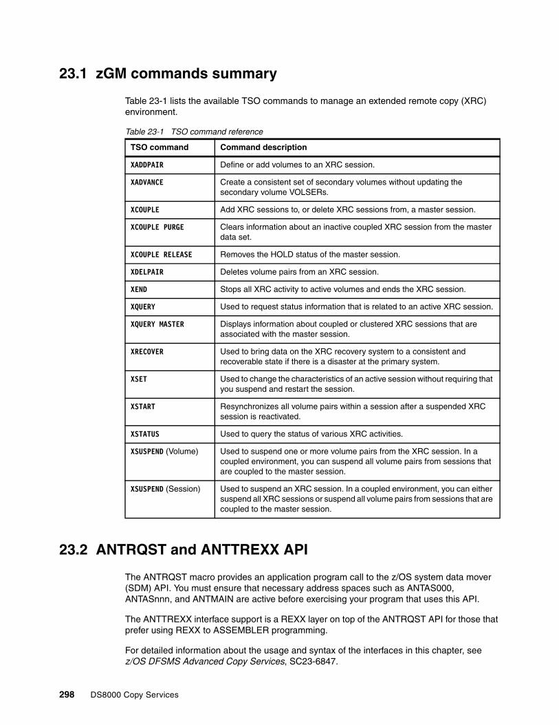
23.1 zGM commands summary
Table 23-1 lists the available TSO commands to manage an extended remote copy (XRC) environment.
Table 23-1 TSO command reference
23.2 ANTRQST and ANTTREXX API
The ANTRQST macro provides an application program call to the z/OS system data mover (SDM) API. You must ensure that necessary address spaces such as ANTAS000, ANTASnnn, and ANTMAIN are active before exercising your program that uses this API.
The ANTTREXX interface support is a REXX layer on top of the ANTRQST API for those that prefer using REXX to ASSEMBLER programming.
For detailed information about the usage and syntax of the interfaces in this chapter, see z/OS DFSMS Advanced Copy Services, SC23-6847.
TSO command Command description
XADDPAIR Define or add volumes to an XRC session.
XADVANCE Create a consistent set of secondary volumes without updating the secondary volume VOLSERs.
XCOUPLE Add XRC sessions to, or delete XRC sessions from, a master session.
XCOUPLE PURGE Clears information about an inactive coupled XRC session from the master data set.
XCOUPLE RELEASE Removes the HOLD status of the master session.
XDELPAIR Deletes volume pairs from an XRC session.
XEND Stops all XRC activity to active volumes and ends the XRC session.
XQUERY Used to request status information that is related to an active XRC session.
XQUERY MASTER Displays information about coupled or clustered XRC sessions that are associated with the master session.
XRECOVER Used to bring data on the XRC recovery system to a consistent and recoverable state if there is a disaster at the primary system.
XSET Used to change the characteristics of an active session without requiring that you suspend and restart the session.
XSTART Resynchronizes all volume pairs within a session after a suspended XRC session is reactivated.
XSTATUS Used to query the status of various XRC activities.
XSUSPEND (Volume) Used to suspend one or more volume pairs from the XRC session. In a coupled environment, you can suspend all volume pairs from sessions that are coupled to the master session.
XSUSPEND (Session) Used to suspend an XRC session. In a coupled environment, you can either suspend all XRC sessions or suspend all volume pairs from sessions that are coupled to the master session.
298 DS8000 Copy Services

Chapter 24. How z/OS Global Mirror maintains consistency
This chapter describes the characteristics of time stamping and z/OS Global Mirror (zGM) consistency group formation processing. It includes the following topics:
� Consistency group� Time stamping process� Common time reference� z/OS Global Mirror consistency example� Time consistent recovery� z/OS Global Mirror recovery process
24
© Copyright IBM Corp. 2017. All rights reserved. 299

24.1 Consistency group
Within the system data mover (SDM), the update writes, read from multiple primary disk systems, are processed into consistency groups by the SDM. A consistency group (CG) contains records that have their order of updates preserved across (potentially many) storage systems that participate in the same zGM session. This preservation of order is vital for dependent write I/Os, such as databases and logs. The creation of CGs ensures that zGM applies the updates to the secondary volumes with consistency for any type of data.
24.2 Time stamping process
Maintaining the update sequence for application data that is being copied in real time is a critical requirement for applications that process dependent write I/Os. If data is copied out of sequence, it can create serious integrity errors rendering the recovery procedures useless. zGM provides consistency for all data. The starting point for maintaining update sequence integrity is when a record is first written by an application system to a primary volume of a zGM managed pair. When the record is written, the storage system maintains the data (including the time stamp information) and transfers it to the SDM along with other updated records. This process is shown in Figure 24-1 on page 302. Time stamped writes are used by zGM to ensure data consistency.
The time stamping code is an extension of the IOS Start Subchannel (SSCH) code, so it applies to all data. Deferred writes that are held in main storage buffers for database applications are processed in SSCH order. This order ensures that the time stamping process delivers update sequence integrity support accurately and efficiently.
24.3 Common time reference
This section describes the management of time references in different operating systems for z Systems.
24.3.1 z/OS
When a zGM pair is established, a signal is sent to the primary system and the host system DFSMSdfp (system data mover) software starts to time stamp all write I/Os to the primary volumes. This action is necessary to provide consistency across multiple LCUs. If those primary volumes are shared by systems that run on different z Systems processors, the sysplex timer (or IBM Server Time Protocol (STP) feature) is required to provide a common time reference. If all the primary systems are running in different LPARs on the same z Systems processor, you can use the system time-of-day clock.
300 DS8000 Copy Services

24.3.2 z/VM
z/VM (5.4 or above with SPE maintenance) can use STP to time stamp guest and system disk write I/O operations. The data for z/VM and its guests can be copied by an extended remote copy (XRC), and consistency can be provided across z/VM (and guest) data and z/OS (or other z/VM) data. There are a number of requirements that must all be met before this support can be used:
� All system LPARs for this type of an environment (where the data for multiple system images is copied by XRC in a single consistency group) must be running on centralized processing complexes (CPCs) in the same Coordinated Timing Network (CTN) to have a common time source.
� The CTN configuration must meet the requirements that are specified by VM.
� The STP time stamping feature in VM must be enabled in the VM SYSTEM CONFIG file.
For more information about z/VM time stamping support, see z/VM CP Planning and Administration, SC24-6178.
24.3.3 Linux on z Systems
The IBM eServer™ zSeries DASD driver for Linux supports time stamping of writes and also contains changes to support write pacing. With this support, GDPS (or other management software) can manage the copying of Linux data by XRC. If there is a primary site disaster (or for a planned site switch), recovery of Linux data that is copied by XRC can be automated and Linux systems can be restarted in the recovery site by booting them from of the recovered XRC data.
Ask your Linux distributor whether the required changes for XRC are included in the DASD drivers for your distribution.
When Linux is running under VM in an STP environment where z/VM time stamping for guests is enabled, the Linux guest does not need to support time stamping because z/VM can do this task on behalf of the Linux guest.
24.4 z/OS Global Mirror consistency example
The example that is shown in Figure 24-1 on page 302 illustrates how a consistency group (CG) is created. You can see a configuration with six primary volumes that are spread across three LCUs (A, B, C) at the primary site, and six secondary volumes that are spread across three LCUs (A’, B’, C’) at the remote site. The system where SDM is running has connectivity to the LCUs at both the primary site and the secondary site.In the example GRPn refers to a group of record sets that are read by the data mover in one collection cycle (time group).
Chapter 24. How z/OS Global Mirror maintains consistency 301

Figure 24-1 Creating consistency group CG1
24.4.1 Gathering the data to be mirrored
As applications running on the primary system site perform updates, each write has a time stamp associated with it. All of these time stamps come from a common time reference. In Figure 24-1, the time stamps on the LCUs indicate the time when the SDM last read updates from that LCU.
The DS8000 saves the updates as record sets in the cache sidefile. Asynchronously, the SDM reads these record sets from the primary sidefiles into real storage buffers in preparation for CG processing.
After the SDM has read from all primary LCUs that have volumes in the zGM session, the next phase is to perform the update sequence integrity check for all of the current updated records.
10:26 10:3310:29
10:0910:1210:1910:2210:25
writeto journal data setSDM
system
10:1910:2210:25
LCULCULCULCULCULCU
10:2910:3010:33
10:1910:2210:25
10:0910:12
A B C B' C'
Primary site Secondary site
GRP1
10:2910:3010:33
10:2910:3010:33
GRP3
A'
CG1
10:0910:12 10:28
10:1910:2210:25
10:27
10:0910:1210:28
10:28
GRP2
write tosecondary
Note: There are two time stamped updates on two volumes in the figure that are highlighted (10:27 and 10:28 respectively). These will represent dependent writes and this example will show how consistency group processing ensures that they are not applied out of order.
Keep in Mind: Referencing the times that the last cycle of reads were done for each LCU, you will see that our dependent write updates were not both read. Because the read from LCU A was done at 10:26, the 10:27 update had not yet occurred. But then the read from LCU B was at 10:29, so it includes the 10:28 update (that is dependent upon the 10:27 update).
302 DS8000 Copy Services

24.4.2 Creating a consistency group
The SDM uses all of the record set groups that are read from the LCUs as input for the creation of a consistency group. This example has three record set groups that the SDM uses.
The SDM compares the maximum time stamp for each individual record set group:
� GRP1 = 10:25� GRP2 = 10:28� GRP3 = 10:33
The SDM selects the earliest value out of all the maximum time stamps per record set group (10:25) to calculate which records should be included in the CG. All records written at or before this smallest value time can be written together to the remote site journals as a CG because we know that all of the other LCUs have updates later than the selected time value.
In our example, five records (before and including 10:25) qualify for inclusion in the consistency group.
In Figure 24-1 on page 302, you will see the updates that were not included in CG1 listed beneath their respective original record set groups.
24.4.3 Writing the consistency group
Having created a group of records that can be safely written together, the SDM writes the group to the journal data sets at the secondary site. Thus, the SDM can perform the updates as quickly as possible in one I/O to a single data set.
After the CG is written to the journal data set, the SDM immediately writes out the individual records to their appropriate secondary volumes. Every update will be applied in the order they were received (not just the latest update to a track).
Note: The database update at 10:28 is not included in the CG. This situation is vital because the log update that was done at 10:27 is not yet read into the SDM real storage buffers for inclusion in the consistency group creation algorithm.
Chapter 24. How z/OS Global Mirror maintains consistency 303

Figure 24-2 concludes the example on consistency by showing how the dependent write updates are copied to the secondary site in the next CG (CG2).
Figure 24-2 Creating consistency group CG2
When the SDM writes the records to the secondary volumes, the relationship between the contents of the log and the database, which is vital for recovery, is protected.
This cycle repeats until the zGM session is ended or suspended.
24.5 Time consistent recovery
One of the most valuable features of zGM is its ability to do a time consistent recovery. After a disaster that affects the primary site, the secondary site must be made ready for takeover. This situation involves getting the secondary volumes to a state where their contents are usable in anticipation of an application restart. The XRECOVER command provides a single-step process to recover individual zGM sessions. With automation such as GDPS, it is reduced to nearly a one button approach for large-scale zGM environment recovery.
The XRECOVER command commits the last available consistency groups to the secondary volumes for each XRC session, reports the consistency time for the secondary volumes, and then clips the volume serial number of each secondary device to that of its matching primary device.
You can also run the XRECOVER command to recover a group of interlocked coupled sessions to the same consistency time. For a more detailed description of interlocked sessions, see z/OS DFSMS Advanced Copy Services, SC23-6847.
10:35 NULL10:36
10:2710:2810:2910:29
writeto journal data set
write tosecondary
SDMsystem
LCULCULCULCULCULCU
10:2910:3010:33
10:3010:33
Primary site Secondary site
GRP1 GRP2 GRP3CG2
10:0910:1210:1910:2210:25
CG1
Done!
10:29
A B C B' C'A'
10:1910:2210:25
10:2710:3110:35
10:1910:2210:25
10:2710:0910:12
10:2810:29
10:0910:12
10:2810:29
10:2910:3010:33
10:2710:3110:35
10:3110:35
10:2810:29
304 DS8000 Copy Services

24.6 z/OS Global Mirror recovery process
Your normal operational requirements already include procedures for restarting online applications if there is a short-term outage (a power failure or processor failure, for example).
For zGM disaster recovery, the same procedure should be used at the secondary site. The same checks for ensuring data consistency and restarting your applications must be done at your secondary site, just as they are done today at your application site.
zGM provides data currency across all volumes in the zGM session. If there is a disaster at the primary site, updates in flight are lost. However, recovery can be achieved to an identified consistent point-in-time. The recovery technique does not require a database restore followed by forward recovery. Recovery can follow the procedure that is used at the primary site for a system outage, consistent with the point-in-time. Any transaction that is completed after this point-in-time might require investigation and be re-created against the secondary disks after recovery -or accounted for in your business process.
Chapter 24. How z/OS Global Mirror maintains consistency 305

306 DS8000 Copy Services

Chapter 25. z/OS Global Mirror scalability
This chapter describes some of the areas to consider when setting up z/OS Global Mirror (zGM) configuration to ensure that extended remote copy (XRC) scales appropriately for the environment. You need to address these areas when you modify the scope of the solution.
This chapter includes the following topics:
� z/OS Global Mirror session organization� Enhanced readers versus single reader� Write pacing� Workload-based write pacing
25
© Copyright IBM Corp. 2017. All rights reserved. 307

25.1 z/OS Global Mirror session organization
When you start a zGM session and establish the first volume pair, a z/OS Global Mirror storage control session (zGM SC session) is created within the DS8000 LCU to which the primary volume belongs. This zGM storage control session in the LCU has a counterpart in the system data mover (SDM). It is possible to have multiple zGM storage control sessions within an LCU, where a specific set of primary volumes is defined for each storage control session that is created for that LCU. The SDM uses a separate utility device and runs a separate read task (reader task) per zGM storage control session, making it possible to transfer data in parallel between one LCU and one SDM.
Figure 25-1 shows an overview of an LCU enhanced reader example.
Figure 25-1 LCU enhanced reader overview example
25.2 Enhanced readers versus single reader
The zGM enhanced multiple reader capability improves copy bandwidth for high write activity volumes by allowing multiple SDM readers to process updates to a single volume if necessary. With the primary volume fixed to single reader relationship, there are periods when the production workload demand, and write updates to a specific primary volume, occur at a rate greater than a single zGM storage control session (reader task) can sustain. Enhanced readers remove the fixed association of primary volume to a single reader task and instead allows all readers in the LCU, to equally share in transferring the data to the SDM.
The key difference between the single reader and the enhanced reader approaches is shown in Figure 25-1. The single reader approach defines one or more readers within an LCU, where each reader is associated with a fixed set of primary volumes. This configuration implies that each of these readers in the LCU can process updates only to the volumes associated with that specific reader. A single reader does have a maximum data transfer rate
multiple reader
sidefiles
single reader
sidefiles
empty
sidefiles
Single reader capacity per read group
Primary System SDM System
Some readers are at full capacity and require multiple read cycles and other readers are nearly
empty and contribute very little to the data transfer
All readers share equally in the transfer of data
These writes wait for next SDM read cycle
These writes wait for second following SDM read cycle
Exa
mp
le L
CU
Example LCU is shown
All LCUs can operate in similar manner
Write updates to the example LCU
Parallel SDM reads to drain available sidefile updates
NOTE:
The Multiple Reader domain is the LCU
308 DS8000 Copy Services

and a single primary volume or a few primary volumes can sustain a write update rate that exceeds the single reader bandwidth/capacity.
The enhanced reader approach defines a pool of readers within an LCU to share equally in the reading and draining of the updates to the zGM volumes in the specified LCU. If a single primary volume has a high burst of update activity that exceeds the single reader capacity, the enhanced reader function spreads these updates across the LCU’s multiple readers to achieve a much higher drain rate.
In addition to the increase in the single volume update rate that can be supported by zGM Multiple Enhanced Readers, the equal sharing of the updates across the LCU readers also implies a notable improvement in the associated distance latency costs. During high demand periods, fewer SDM read cycles are necessary to transfer the same capacity. This situation results in fewer SDM read cycles for the same capacity that is transferred and less time is wasted or used in distance latency.
25.3 Write pacing
There might be situations where record sets are created at a higher rate than they can be read by the SDM. In such cases, the number of record sets in the sidefiles on the primary DS8000 storage system increases, which in turn causes the recovery point objective (RPO) time to increase. If this situation doesn’t clear before the sidefiles are full, suspensions will occur. You can use write pacing to reduce gradually the application update rate to balance it against the SDM off load rate to maintain an RPO within the wanted range.
You can think of write pacing as “tapping on the brakes” so that you can avoid “slamming into a wall.” Write pacing works by injecting a small delay as each record set is created in the DS8000 cache sidefile for a host write. As the number of record sets for a volume increases, the magnitude of the pacing increases. Similarly, as the number of record sets for a volume decreases, the magnitude of the pacing decreases.
A maximum pacing value and a target residual count are specified for each volume. The target residual count is the number of record sets at which the maximum pacing value is applied.
There are 15 different levels of maximum pacing, which are identified by the hexadecimal digits 1 - F. These digits are specified in commands through the DVCBLOCK keyword values WP1 - WPF. Each volume in the session can be assigned its own value, or a session-level value can be applied to a group of volumes.
The amount of delay that is injected at each pacing level is shown in table Table 25-1.
Table 25-1 Pacing delay
Pacing level Delay Pacing level Delay
WP0 None WP8 5 ms
WP1 0.02 ms WP9 10 ms
WP2 0.04 ms WPA 25 ms
WP3 0.1 ms WPB 50 ms
WP4 0.2 ms WPC 100 ms
WP5 0.5 ms WPD 250 ms
Chapter 25. z/OS Global Mirror scalability 309

The minimum amount of delay that is injected on any one write is 1 ms. Values less than 1 ms are an average delay that is created by delaying 1 out of “n” writes by 1 ms. For example, a 0.1 ms average delay is created by delaying every 10th write by 1 ms.
The calculation for determining the amount of delay any specific write is a step function that takes as inputs the following values:
� Target residual count� Maximum pacing level� Volume’s current record set count
Record set values up to the specified target residual count are divided into “maximum pacing level” intervals such that the maximum pacing delay is reached when the volume’s record set count reaches the target residual count.
For example, if the target residual count is 1000 and the maximum pacing level is set to 5, then five pacing levels are used and each step is 1000 / 5 = 200 record sets wide. For record set counts 0 - 199, no pacing is applied. For record set counts of 200 - 399, pacing level 1 is applied, and so on.
This situation is illustrated in Figure 25-2 on page 311 for a target residual count of 1000 with several different maximum pacing levels.
WP6 1 ms WPE 500 ms
WP7 2 ms WPF 1000 ms
Pacing level Delay Pacing level Delay
310 DS8000 Copy Services

Figure 25-2 Write Pacing Step Function
The target residual count is specified at the session level with the XRC PARMLIB value WrtPacingResidualCnt. This value is multiplied by 64 to determine the residual count at which the maximum level of pacing is in effect for write-paced volumes.
For applications that require the highest level of performance, specific volumes can be excluded from write pacing by adding the DONOTBLOCK parameter in the XADDPAIR command.
You must be careful when selecting the write pacing levels and residual count. Insufficient pacing can result in extended long busy conditions and volume suspension, and excessive pacing can result in unacceptable application throughput and response time.
For more information about using write-pacing values, see z/OS DFSMS Advanced Copy Services, SC23-6847.
25.4 Workload-based write pacing
zGM workload-based write pacing works with IBM Workload Manager for z/OS (WLM) to automatically tailor write pacing to the application requirements.
Chapter 25. z/OS Global Mirror scalability 311

Different applications have different response time requirements. Without workload-based write pacing, these requirements can be managed by assigning different maximum pacing levels and target residual counts to different volumes and then placing data on volumes that have the appropriate settings. This configuration requires significant planning for data placement. As requirements change, data must be moved or volume pacing values changed. If applications cannot be segregated by volume, then this approach cannot be used.
Workload-based write pacing reduces the need for this continual planning.
You can use WLM to set performance goals. Applications that have similar goals are grouped into service classes, and then WLM assigns resources to maximize goal achievement. One part of the resource management is that I/O has an importance value. There are six importance values:
� 1 = Highest� 2 = High� 3 = Medium� 4 = Low� 5 = Lowest� 6 = Discretionary (or default when not part of a service class)
Workload-base write pacing takes this importance value into account when determining the amount of write pacing. Each importance value is mapped to a maximum pacing level so that higher importance I/O is paced less than lower importance I/O. In this manner, the amount of delay that is injected depends upon the importance of the I/O instead of which volume to which the I/O is directed.
As an example, consider a case with the following values:
� Volume maximum pacing level = 10� Volume target residual count = 1200� Current record set count = 950
Using these values and referring to Figure 25-2 on page 311, volume-based write pacing results in pacing at level 7, or 2 ms for each write.
312 DS8000 Copy Services

Now, further assume a mapping between I/O importance and maximum pacing levels, as shown in Table 25-2.
Table 25-2 Pacing level mapping example
Using the information in Figure 25-2 on page 311, the amount of pacing for volume-level pacing and for the different importance levels that use workload-based write pacing is shown in Table 25-3.
Table 25-3 Pacing delay with volume and workload-based pacing
As shown in this example, the delay that is injected by volume pacing is the same regardless of the I/O importance. However, with workload-based write pacing, high-importance I/O is paced less than low importance I/O. The pacing levels can be set so that there is little impact to high-importance I/O, and low-importance I/O can be heavily paced to maintain the wanted RPO.
The pacing values that are used for this example are for illustrative purposes only and do not represent recommended values.
I/O Importance Maximum pacing level
1 4
2 6
3 8
4 10
5 12
6 (Discretionary) 8
Importance level
Volumepacing level
Volumepacing delay
Workload-basedpacing level
Workload-basedpacing delay
1 (high) 7 2 ms 3 0.1 ms
2 7 2 ms 4 0.2 ms
3 7 2 ms 6 1 ms
4 7 2 ms 7 2 ms
5 (low) 7 2 ms 9 10 ms
Chapter 25. z/OS Global Mirror scalability 313

314 DS8000 Copy Services

Chapter 26. Managing z/OS Global Mirror
This chapter provides information about some preferred practices, tools, and procedures for the management of z/OS Global Mirror (zGM). It includes the following topics:
� GDPS and RCMF� Automation� JCL or REXX generation
26
© Copyright IBM Corp. 2017. All rights reserved. 315

26.1 GDPS and RCMF
IBM Geographically Dispersed Parallel Sysplex (IBM GDPS), an industry-leading availability solution that is available through IBM Global Services, is a multi-site solution that is designed to manage the remote copy configuration and storage systems, to automate Parallel Sysplex operational tasks, and to perform failure recovery from a single point of control. This solution can help to improve application availability. GDPS supports both synchronous Metro Mirror and the asynchronous zGM forms of remote copy.
GDPS is an integrated solution offering that manages all aspects of switching computer operations, whether they are planned or unplanned, from one site to another site. The SDM is placed outside the production sysplex. This support of z/OS Global Mirror as a remote copy technology can accommodate the following types of installations:
� Installations that cannot tolerate the performance impact of the synchronous remote copy technology.
� Installations that require a 3-site replication solution, by using synchronous replication for continuous or high availability and asynchronous replication for disaster recovery.
� Installations that require a four-site replication solution (two geographical regions), by using synchronous replication at both geographies for continuous or high availability with asynchronous replication between the geographies for disaster recovery.
One subset of the GDPS solution is the Remote Copy Management Facility (RCMF) offering. RCMF is an automated disk system and management facility, with a high-level user interface. This interface has the form of ISPF-like displays, and virtually eliminates the tedious and time consuming work that is associated with TSO commands.
Managing zGM with RCMF can be the first step of a full GDPS implementation.
IBM offers the GDPS service offering to deliver solutions in this area. For more information, go to:
http://www.ibm.com/systems/z/advantages/gdps/offerings/index.html
26.2 Automation
A zGM environment can involve hundreds or even thousands of volumes. You should keep the configuration as simple and symmetric as possible, for example, with a one-to-one correspondence between primary and secondary LCUs. However, you should also implement some form of automation. Automation for z/OS Global Mirror can range from simple JCL or REXX code to fully automated management software that includes monitoring and recovery actions.
26.3 JCL or REXX generation
Using JCL or REXX generation is a preferred practice for minimizing errors when you perform z/OS Global Mirror operations. Code can be automatically generated to, for example, the XADDPAIR and XSUSPEND commands. This automation ensures that all eligible volumes are included in all lists. Even if major operations such as migration and recovery are under manual control, errors can be minimized by automatic generation of the jobs that are run.
316 DS8000 Copy Services

Part 7 Solutions
This part introduces the following solutions that are available from IBM that can assist you with the exploitation, management, and automation of the DS8000 Copy Services functions:
� IBM Globally Dispersed Parallel Sysplex (IBM GDPS)� IBM Copy Services Manager� z/OS Basic HyperSwap� VMware Site Recovery Manager
For each solution, this part provides an overview and describes the benefits and the most important features. It also include references to product documentation and other sources of information if you need more information.
Part 7
© Copyright IBM Corp. 2017. All rights reserved. 317

318 DS8000 Copy Services

Chapter 27. IBM Geographically Dispersed Parallel Sysplex
Today’s data centers must be resilient to handle planned and unplanned system outages without impacting the business of the enterprise.
Most solutions that provide continuous IT services availability are based on cluster server software, mirrored storage, and redundant networks. When a failure occurs, an integrated disaster recovery solution runs, in a pre-determined fashion, a set of tasks to restart the operating system, recover storage servers and networks, and restart applications on a different set of servers and storage in another location. This level of functionality is also defined as IT continuous availability.
IBM Geographically Dispersed Parallel Sysplex (IBM GDPS) is an automated solution that provides various levels of IT continuous availability through different implementation levels. GDPS, as a continuous availability and near-transparent disaster recovery solution, is based on Parallel Sysplex server functions and disk mirroring that uses Metro Mirror, Global Mirror. Some scenarios includes even software mirroring to enhance transparency of action to achieve IT goal set by business.
This chapter provides an overview of the various features that GDPS offers. For more information about GDPS, see GDPS Family: An Introduction to Concepts and Capabilities, SG24-6374, IBM System Storage Business Continuity: Part 1 Planning Guide, SG24-6547, and the following websites:
http://www.ibm.com/systems/z/gdps/http://www.ibm.com/storage
This chapter includes the following topics:
� GDPS solution offerings� Components of a GDPS configuration
27
Important: GDPS is a set of continuous availability solutions for z Systems environments. The various IBM GDPS offerings are not products. They are delivered as IBM Global Service offerings.
© Copyright IBM Corp. 2017. All rights reserved. 319

27.1 GDPS solution offerings
GDPS is a family of offerings, for a single site or a multi-site application availability solution, with the capability to manage the remote copy configuration of storage systems, automate z Systems operational tasks, manage and automate planned reconfigurations, and do failure recovery from a single point of control.
GDPS is an integrated end-to-end solution that is composed of software automation, software, servers and storage, networking, and IBM Global Services to configure and deploy the solution, as shown in Figure 27-1. The GDPS solution has components in the areas that are denoted by dark shading.
Figure 27-1 Positioning of GDPS solution offerings
The benefits of GDPS are a highly reliable and highly automated IT infrastructure solution with a z Systems-based control point, which can provide robust application availability.
GDPS is enabled through key IBM technologies and architectures.
GDPS supports both the synchronous (Metro Mirror) and the asynchronous (z/OS Global Mirror or Global Mirror) forms of remote copy. GDPS V3.11 is the last release that supports Peer-to-Peer Virtual Tape Server (PtP VTS) for Remote Copying tape data. IBM Virtualization Engine TS7700 retains support for remote copying of tape data based on grid configuration. The GDPS solution is a non-proprietary solution, working with IBM and other vendors’ storage systems, if the vendor meets the specific functions of the Metro Mirror, Global Mirror, and z/OS Global Mirror architectures that are required to support GDPS functions.
GDPS automation manages and protects IT services by handling planned and unplanned exception conditions. Depending on the GDPS configuration that is selected, availability can be storage resiliency only, or can provide near-continuous application and data availability. Regardless of the specific configuration variation, GDPS provides a z Systems-based business continuity automation and integration solution to manage both planned and unplanned exception conditions.
To attain high-levels of continuous availability and near-transparent disaster recovery, the GDPS solution is based on geographical clusters and disk mirroring.
7 6 5 4 3 2 1
Recovery Time
disk tape
Bu
sin
ess
va
lue
+
- +
Software Automation for SAP, DB2,Siebel,MS SQL Server, Exchange etc.4
Ser
vic
es
Automation for server z/OS, UNIX, Linux, Windows and heterogeneous environments.3
Point in Time Copy, Metro Mirror, Global Mirror, TotalStorage Software Family, DFSMS for z/OS, TSM.2
Hardware Infrastructure: ESS, DS family, SAN Switches, VTS, 3584, 3592, LTO 1
Aut
onom
ic
320 DS8000 Copy Services

27.2 Components of a GDPS configuration
Figure 27-2 shows some of the many possible components that are supported in a GDPS configuration. GDPS is configured to meet specific client requirements. Not all of the components that are shown are necessary in all GDPS offerings or GDPS solutions.
Figure 27-2 GDPS integrates many components
The GDPS family of z Systems business continuity solutions consists of three major offering categories, and each category has several subofferings. Each GDPS solution is delivered through IBM Global Services, and is tailored to fit a specific set of client recovery requirements, budgetary requirements, physical distance and infrastructure, and other factors.
The following major categories of GDPS solutions are built on DS8000 Copy Services:
� GDPS/PPRC solutions that are based on Metro Mirror. Metro Mirror was formerly known as Peer-to-Peer Remote Copy (PPRC). GDPS PPRC comes in several versions:
– GDPS/PPRC, a Tier 7 solution– GDPS/PPRC HyperSwap Manager, a Tier 6 solution– GDPS/PPRC Multiplatform Resiliency for z Systems (also known as xDR)– GDPS/PPRC Distributed Cluster management (DCM)
� GDPS/MTMM solutions that are based on IBM Multi-Target Metro Mirror. It is similar to GDPS/PPRC except that instead one, two synchronous copies are managed.
� GDPS/XRC solutions that are based on z/OS Global Mirror. z/OS Global Mirror was formerly known as extended remote copy (XRC).
� GDPS/GM (Global Mirror) solutions that are based on Global Mirror.
These GDPS offerings also can be combined into 3-site and 4-site GDPS solutions, providing Tier 7 recoverability in multi-site environments:
� GDPS/MzGM, based on z/OS Metro/Global Mirror� GDPS/MGM, based on Metro/Global Mirror
Remote Copy Management Facility: Remote Copy Management Facility (RCMF), an offering that includes only the storage interface management functions of GDPS, is not available anymore. Therefore, there are no details and references to it in this chapter.
High bandwidth connections
Site A Site B
Copy Servcices
SecondaryFlashCopy
Tier 7, Tier 6 integrated solutions
Automation via GDPS
zSeries zSeries
VTSVTS
PrimaryPeer to Peer VTS
FlashCopyTape
Chapter 27. IBM Geographically Dispersed Parallel Sysplex 321
IBM GDPS active/active continuous availability is a solution for an environment that consists of two sites, which are separated by unlimited distances, running the same applications and having the same data with cross-site workload monitoring, data replication, and balancing. Based on asynchronous software replication, planned switches can be accomplished with no data loss (RPO 0), and when sufficient replication bandwidth is provided, the RPO can be as low as a few seconds if there is an unplanned workload switch.
Because IBM GDPS active/active continuous availability does not use storage system-based data replication, this chapter does not describe it in detail. For more information about this solution, see the documentation that is listed at the beginning of this chapter.
27.2.1 GDPS/PPRC overview
GDPS/PPRC is designed to manage and protect IT services by handling planned and unplanned exception conditions, and maintain data integrity across multiple volumes and storage systems. By managing both planned and unplanned exception conditions, GDPS/PPRC can maximize application availability and provide business continuity.
GDPS/PPRC provides the following attributes:
� A near continuous availability solution� A near transparent disaster recovery solution� A recovery time objective (RTO) of less than an hour� A recovery point objective (RPO) of zero (optional)� Protection against localized area disasters with a typical distance between sites that is
limited to a 100-km fiber distance
The GDPS/PPRC solution offering combines z Systems Parallel Sysplex capability, IBM System Storage DS8000 Metro Mirror disk mirroring technology to provide a Business Continuity solution for IT infrastructures that have z Systems at the core. GDPS/PPRC offers efficient workload management, system resource management, and business continuity or disaster recovery for z/OS servers and Open System data, and provides data consistency across all platforms that use the Metro Mirror consistency group function.
The GDPS solution uses automation technology to provide end-to-end management of z Systems servers, disk mirroring, tape mirroring, and workload shutdown and start. GDPS manages the infrastructure to minimize or eliminate the outage during a planned or unplanned site failure. Critical data is disk mirrored, and processing is automatically restarted at an alternative site if a primary planned site shutdown or site failure occurs.
GDPS/PPRC automation provides scalability to ensure data integrity at many volumes across hundreds or thousands of Metro Mirror pairs.
27.2.2 PPRC and HyperSwap
The HyperSwap function is designed to broaden the near continuous availability attributes of GDPS/PPRC by extending the Parallel Sysplex redundancy to storage systems. HyperSwap can transparently switch primary Metro Mirror storage systems with the secondary disk systems for a planned or unplanned reconfiguration. The HyperSwap function can reduce the time that is required to switch to the secondary set of disks while it keeps the z/OS systems active together with their applications.
322 DS8000 Copy Services

HyperSwap can be implemented as part of the full GDPS/PPRC offering, or through the GDPS/PPRC HyperSwap Manager offering, which provides HyperSwap functions without the host system management capabilities of the full GDPS/PPRC offering.
Since GDPS/PPRC V3.2, the HyperSwap function uses the Metro Mirror failover/failback function.
For planned reconfigurations, failover/failback might reduce the overall elapsed time to switch the storage systems, thus reducing the time that applications might be unavailable to users.
For unplanned reconfigurations, failover/failback allows the secondary disks to be configured in the suspended state after the switch and record any updates that are made to the data. When the failure condition is repaired, resynchronizing back to the original primary disks requires only the copying of the changed data, thus eliminating the necessity of performing a full copy of the data. The window during which critical data is left without Metro Mirror protection after an unplanned reconfiguration is therefore minimized.
27.2.3 GDPS Virtual Appliance overview
Not all customers run z Systems platforms with z/OS. GDPS Virtual Appliance provides the required levels of automation for planned and unplanned outages for those who run just Linux on z Systems or z/VM.
GDPS Virtual Appliance is a self-contained system that runs in a separate logical partition (LPAR) that has GDPS/PPRC code, which provides PPRC monitoring and management of replication. Additionally, the GDPS Virtual Appliance can manage z/VM systems that use production disks. For this purpose, the GDPS Virtual Appliance is working together with GDPS/PPRC xDR.
27.2.4 GDPS/PPRC Multiplatform Resiliency (xDR) for z Systems overview
With a multitiered architecture, there is a need to provide a coordinated near-continuous availability and disaster recovery solution for both z/OS and Linux on z Systems. The GDPS/PPRC function that provides this capability is called multiplatform resiliency for z Systems, and it can be implemented if the disks used by z/VM and Linux are count key data (CKD) disks. To provide these capabilities, GDPS/PPRC communicates and coordinates with System Automation for Multiplatforms (SA MP) that is running on Linux on z Systems.
Linux can run either of the following ways:
� As a guest under z/VM� Native in a z Systems partition
GDPS/PPRC coordinates planned and unplanned HyperSwap for both z/OS and z/VM disks, providing continuous data availability spanning the multitiered application. It does not matter whether the first disk failure is detected for a z/VM disk or a z/OS disk; all are swapped together. For site failures, GDPS/PPRC provides a coordinated freeze for data consistency across z/VM and z/OS. Again, it does not matter whether the first freeze trigger is captured on a z/OS disk or a z/VM disk; all are frozen together.
GDPS 3.11 is last release that will support disk subsystem which is not failover/failback capable.
Chapter 27. IBM Geographically Dispersed Parallel Sysplex 323

27.2.5 GDPS/PPRC Distributed Cluster Management
GDPS Distributed Cluster Management (DCM) is a capability that allows the management and coordination of disaster recovery across clustered distributed servers and the z Systems workload (or workloads) for which GDPS is responsible.
DCM support is provided in GDPS/PPRC for both Symantec Veritas Cluster Server (VCS) clusters and IBM Tivoli System Automation Application Manager (SA AppMan). GDPS/PPRC can support both VCS and SA AppMan concurrently. DCM provides advisory and coordination functions between GDPS and one or more VCS or SA AppMan managed clusters.
DCM allows the management and coordination of planned and unplanned outages across non- z Systems distributed clusters in coordination with the z Systems workloads for which GDPS is responsible.
27.2.6 GDPS/XRC overview
z/OS Global Mirror, previously known as extended remote copy (XRC), is a combined hardware and z/OS software asynchronous Remote Copy solution for z Systems data. z/OS Global Mirror is designed to provide premium levels of scalability, reaching into the tens of thousands of z Systems volumes. Consistency of the data is maintained through the consistency group function within the system data mover (SDM). For more information about z/OS Global Mirror, see Chapter 22, “z/OS Global Mirror overview” on page 289.
GDPS/XRC includes automation to manage z/OS Global Mirror Remote Copy pairs and automates the process of recovering the production environment with limited manual intervention, including invocation of Capacity Backup (CBU), thus providing significant value in reducing the duration of the recovery window and requiring less operator interaction.
GDPS/XRC provides the following attributes:
� A disaster recovery solution� An RTO of 1 - 2 hours � An RPO of less than 2 minutes, and typically 3 - 5 seconds� Protection against localized and regional disasters with unlimited distance between sites� Minimal Remote Copy performance impact
27.2.7 GDPS/GM (Global Mirror) overview
GDPS/GM is similar to GDPS/XRC in that it supports virtually any distance; GDPS/PPRC is limited to 100 km. However, because of the differing characteristics of the underlying remote copy technology (Global Mirror), GDPS/GM extends the remote copy support to fixed-block architecture (FB) data.
GDPS/GM can be viewed as a mixture of GDPS/PPRC and GDPS/XRC. Just as GDPS/PPRC is a storage system-based remote copy technology, GDPS/GM is also disk-based, meaning that it supports the same mix of CKD and FB data that is supported by GDPS/PPRC. Also, being disk-based, there is no requirement for an SDM system to drive the Remote Copy process. And, like Metro Mirror, Global Mirror requires that the primary and auxiliary storage systems are from the same vendor; however, Global Mirror is only supported by IBM storage systems.
GDPS/GM resembles GDPS/XRC in that it supports unlimited distances between the application and recovery sites. Also, GDPS/GM does not provide any automation or
324 DS8000 Copy Services

management of the production systems; its focus is on managing the Global Mirror Remote Copy environment and automating and managing recovery of data and systems if there is a disaster. Also, like GDPS/XRC, GDPS/GM supports the ability to make Remote Copy copies of data from multiple sysplexes; each GDPS/PPRC license supports Remote Copy for a single sysplex.
In addition to its disaster recovery capabilities, GDPS/GM also provides an interface for monitoring and managing the Remote Copy configuration. This management includes the initialization and monitoring of the Global Mirror volume pairs that are based on policy, and performing routine operations on installed storage systems.
For more information about GDPS/GM, see GDPS Family: An Introduction to Concepts and Capabilities, SG24-6374.
27.2.8 GDPS 3-site solution overview
GPDS also supports 3-site configuration solutions by using a combination of the previous GDPS solutions. A 3-site solution can combine the advantages of metropolitan distance business continuity and regional or long-distance disaster recovery.
GDPS z/OS Metro/Global MirrorGDPS/PPRC and GDPS/XRC are supported configurations for the 3-site configuration that is shown in Figure 27-3.
Figure 27-3 GDPS 3-site configuration with GDPS/PPRC and GDPS/XRC
The same primary volume for Metro Mirror and z/OS Global Mirror can be supported by two different GDPSs, a GDPS/PPRC for metropolitan distance and Business Continuity, and a GDPS/XRC for regional distance and disaster recovery. The two mirroring technologies and GDPS implementations work independently of each other, yet provide the synergy of a common management scheme and common skills.
You can obtain more information about GDPS 3-site configurations from your IBM GDPS representative.
TotalStorage TotalStorage
Primary Secondary
TotalStorage
Metro Mirror Tertiary
1 4
56
3
2
SDM
Recovery system
System zApplication
systems
System z
Chapter 27. IBM Geographically Dispersed Parallel Sysplex 325

GDPS Metro/Global MirrorYou can use GDPS/PPRC with GDPS/Global Mirror (GDPS Metro/Global Mirror) to manage the configuration across all formats of data, as Global Mirror is not limited to z Systems formatted data.
GDPS Metro/Global Mirror combines the benefits of GDPS/PPRC that uses Metro Mirror with GDPS/Global Mirror that uses Global Mirror. A typical configuration has the secondary disk from a Metro Mirror Remote Copy configuration in turn becomes the primary disk for a Global Mirror Remote Copy pair. Data is replicated in a “cascading” fashion.
Combining the benefits of PPRC and Global Mirror, GDPS Metro/Global Mirror enables the following features:
� A HyperSwap capability for near-continuous availability for a disk control unit failure� An option for no data loss� Maintenance of a disaster recovery capability after a HyperSwap� Data consistency to allow restart, not recovery, at either site 2 or site 3� A long-distance disaster recovery site for protection against a regional disaster� Minimal application impact� GDPS automation to manage Remote Copy pairs, manage a Parallel Sysplex
configuration, and perform planned and unplanned reconfigurations
In addition, GDPS Metro/Global Mirror can be used for both z Systems and open data, and provide consistency between them.
For more information about Metro/Global Mirror configuration, see Chapter 32, “Metro/Global Mirror configuration and setup” on page 361.
27.2.9 GDPS 4-site solution overview
There is two options covering 4-site solutions:
� MGM� MzGM
The MGM 4-site configuration is managed by a combination of GDPS/PPRC and GDPS/GM in both the application and the recovery regions. It also supports the use of the incremental resynchronization function of Metro/Global Mirror that is extended to a new PPRC-XD relationship between the C-disk and the D-disk.
In MGM 4-site configurations, the application region is Region A and the primary disks are in Site1, that is, there is an ABCD configuration from Region A to Region B.
From a disk point of view, MGM 4-site is basically two MGM-IR 3-site configurations (ABC and CDA) plus a cascaded leg of PPRC-XD from the C-disks to the D-disks in the recovery region. It is a 4-site symmetrical mirroring configuration providing the same high availability and disaster recovery protection no matter which region is the application region.
The MGM 4-site configuration can manage incremental resync operations between the two sites in one of the regions or between the two regions. This capability is important in
z Systems data support: GDPS/XRC supports z Systems data for z/OS, Linux on z/VM, z/VM, and z/VSE. GDPS/XRC and GDPS/PPRC on the same volume is a z Systems solution only.
326 DS8000 Copy Services

managing a 4-site replication solution when planning for the possibility of the loss of the intermediate site or even an entire region.
From a GDPS point of view, GDPS/PPRC manages PPRC between the two sites in the application region, and GDPS/GM manages the cross-region GM session. In MGM 4-site, another GDPS/PPRC is added into the recovery region. This GDPS/PPRC is used to manage the PPRC-XD leg from Site1 to Site2 in the recovery region, which can be converted to synchronous PPRC (for example, after a disaster or as the result of a region switch).
The MzGM 4-site configuration is a combination of GDPS/PPRC and GDPS/XRC. In first region, GDPS uses PPRC. Hyperswap technology is also implemented for high availability functions. PPRC is also used for the second region. Also in this situation Hyperswap is available. Between regions XRC is used. Incremental resychronization is available also between region 1 secondary disks and region 2, so in case of need to re-establish XRC session there is no need of full copy.
MzGM, similar to the MGM 4-site configuration, is somewhat two separate three sites MzGM configuration. The key advantages of using MzGM is nearly identical operation procedures when running in either region and most relevant copy when you want to perform scheduled disaster recovery tests.
27.2.10 IBM Global Services offerings for GDPS
The various GDPS offerings are not products. They are delivered as IBM Global Service offerings. GDPS is an end to end solution in which IBM Global Services tailors and installs the specific combination of components, integrated within the client’s environment. GDPS integration work, including education, is done by using IBM Global Services, in addition to the planning and installation of the code. This work ensures that the GDPS solution provides the intended value to all parts of the business and IT processes.
The following GDPS services and offerings are provided by IBM Global Services.
GDPS Technical Consulting WorkshopA Technical Consulting Workshop (TWC®) is a two-day workshop where IBM Global Services specialists work with your representatives to understand your business objectives, service requirements, technological directions, business applications, recovery processes, and cross-site and I/O requirements. High-level education on GDPS is provided along with the service and implementation process. Various remote and local data protection options are evaluated.
IBM Global Services specialists present a number of planned and unplanned GDPS reconfiguration scenarios with recommendations about how GDPS can assist you in achieving your objectives. At the conclusion of the workshop, the following items are developed:
� Acceptance criteria for both the test and production phases� A high-level task list� A services list� A project summary
GDPS/PPRC HyperSwap ManagerIBM Implementation Services for GDPS/PPRC HyperSwap Manager helps simplify implementation by working with you to get GDPS/PPRC HyperSwap Manager and its prerequisites running with limited disruption to your business. Onsite planning, configuration, implementation, testing, and education help make your IBM Implementation Services for
Chapter 27. IBM Geographically Dispersed Parallel Sysplex 327

GDPS/PPRC HyperSwap Manager solution accessible in the most efficient manner. Because GDPS/PPRC HyperSwap Manager is a subset of the GDPS/PPRC offering it is good practice to review comparison between both of them.
GDPS/PPRC and GDPS/XRCIBM Implementation Services for GDPS/PPRC or GDPS/XRC assists you with planning, configuration, automation code customization, testing, onsite implementation assistance, and training in the IBM GDPS solution. Either GDPS has capability to manage TS7700 grid configuration.
328 DS8000 Copy Services

Chapter 28. IBM Copy Services Manager
IBM Copy Services Manager is a Copy Services automation solution. It has the following key functions:
� Maintains data consistency of the recovery data across multiple resources.� Automates complex Copy Services procedures.� Provides situation-based decision support.� Provides reliable user interfaces to set up large Copy Services scenarios.
This chapter introduces Copy Services Manager, with a focus on the integration of DS8000 Copy Services functions. It includes the following topics:
� Copy Services Manager overview� Copy Services Manager terminology� DS8000 specific information� Copy Services Manager interfaces
28
© Copyright IBM Corp. 2017. All rights reserved. 329

28.1 Copy Services Manager overview
This chapter provides an overview of the Copy Services Manager functions and describes how it integrates with the DS8000 Copy Services. For more information, see IBM Copy Services Manager Knowledge Center at:
http://www.ibm.com/support/knowledgecenter/SSESK4_6.1.0/com.ibm.storage.csm.help.doc/csm_kc_homepage_6.1.html
This website is the main entry point to all Copy Services Manager related documentation.
The IBM Copy Services Manager product family consists of the following products:
� Copy Services Manager � Copy Services Manager for z Systems � Copy Services Manager Basic Edition for z Systems
Which product you need depends on your requirements. Copy Services Manager and Copy Services Manager for z Systems are solutions that provide high availability and disaster recovery for multiple sites. The Copy Services Manager Basic Edition for z Systems is a free of charge version that provides high availability in a z/OS environment for a single site if a disk storage system failure occurs. This Basic Edition is mainly used to establish z/OS Basic HyperSwap environments, for more information about z/OS Basic HyperSwap, see Chapter 29, “z/OS Basic HyperSwap” on page 343.
You can install Copy Services Manager on various operating systems, such as Linux, AIX, Windows or z/OS (for the z Systems products only). For more detail, refer to IBM Knowledge Center.
28.1.1 Why Copy Services Manager is needed
Copy Services Manager provides a single point of control and automation for the hardware-based data replication features (Copy Services) of most IBM storage systems. The most important reason for Copy Services automation is data consistency. Without s solution such as Copy Services Manager, the scope of consistency is often the storage system itself or an even smaller entity, such as the LSS in a DS8000. If the production data is spread over more than one storage system or LSS, maintaining consistency of the recovery data becomes more difficult and probably impossible by using only the onboard features of the storage system.
Copy Services Manager provides mechanisms to expand the scope of consistency across LSSs or even storage systems. For more information about recovery data consistency, see 16.8.1, “Data consistency and dependent writes” on page 127 and 16.8, “Consistency group function” on page 127.
Note: With DS8000 Microcode Rel. 8.1 and higher, Copy Services Manager is pre installed on the DS8000 Hardware Management Console (HMC). For more information about Copy Services Manager on HMC, refer to IBM DS8880 Integrated Copy Services Manager and LDAP Client on the HMC, REDP-5356.
330 DS8000 Copy Services

The other aspects of Copy Services Manager, Copy Services management and automation, provide necessary functions:
� Configuration and management
Copy Services configurations can become complex, with thousands of relationships, several sites, practice and test copies, and numerous recovery scenarios. Managing all of these aspects through the storage system’s GUI or CLI requires a large amount of effort and is prone to errors. With Copy Services Manager, you can set up and manage complex and large scenarios with a few mouse clicks.
� Automation
Failover and failback scenarios, especially in asynchronous long-distance mirroring or multi-site scenarios, require an exact understanding of the state of the recovery data. Numerous commands must be run to check this state and to make the correct data available to the correct host systems. Copy Services Manager automation minimizes the time that is needed by reducing multiple steps to a few mouse clicks or commands, and it also reduces the risk of human error because all the checks and scenarios are coded.
� Decision support
If there is a disaster, mistakes are easily made because decisions might have to be taken by people who are not familiar with the disaster recovery procedures. Copy Services Manager provides options that are specific to a situation.
28.1.2 What Copy Services Manager provides
Copy Services Manager can automate and simplify Copy Services management for IBM storage systems, such as DS8000, IBM SAN Volume Controller, IBM Storwize® V7000, and IBM XIV Storage System.
Copy Services Manager keeps data on multiple related volumes, and keeps that data consistent across storage systems. It monitors the states of the remote copy relationships and instantly reacts to changes. It maintains consistency by using the consistency group and freeze features of the storage systems.
Copy Services Manager provides easy configuration and management for many different Copy Services scenarios. These scenarios range from basic FlashCopy for backup or test purposes to complete 3-site Metro/Global Mirror setups. You can use wizards, which automatically line up the candidate volumes, to set up the Copy Services relationships or import configuration files that describe it.
Copy Services Manager uses a session concept to define a Copy Services scenario. The scope and purpose of a scenario is defined by the session type.
Here are the available session types for the DS8000 storage system:
� FlashCopy1
� Basic HyperSwap1
� Metro Mirror single direction� Metro Mirror failover/failback1
DS8000 DSCLI: Using the DS8000 DSCLI, you need 8 to 24 commands to set up a single Metro/Global Mirror relationship. With Copy Services Manager, you need only one command.
1 Also with HyperSwap for z/OS environments.
Chapter 28. IBM Copy Services Manager 331

� Metro Mirror failover/failback with a practice volume� Global Mirror failover/failback� Global Mirror single direction� Global Mirror failover/failback with a practice volume� Global Mirror in either direction with a 2-site practice volume� Metro/Global Mirror1
� Metro/Global Mirror with a practice volume1
� Multiple Target Peer-to-Peer Remote Copy (PPRC) – Metro Mirror - Metro Mirror1 – Metro Mirror - Global Mirror1 – Metro Mirror - Global Mirror with Practice1
– Metro Mirror - Global Mirror with Site 3 Global Mirror
Different session types are available for the other storage systems, depending on their Copy Services capabilities.
You can exercise all allowed recovery, failover, and failback scenarios with a few clicks. Copy Services Manager supports the decision-making process by offering only those activities that make sense in a situation. It also requires extra confirmation for critical decisions that affect host data access or might cause data to be overwritten. The scenarios are illustrated with images that visualize the effect of each action you take.
There are no limits to the size of the configuration Copy Services Manager can manage. You can have multiple scenarios (sessions) with thousands of relationships that are distributed over multiple storage systems.
28.1.3 Copy Services Manager reliability, availability, and serviceability
This section describes some features of Copy Services Manager that are not related to the core functions, but required for any application that performs important management functions in an enterprise environment.
High availabilityYou can create a high availability environment by setting up a standby Copy Services Manager server. This server is a second instance of Copy Services Manager that runs on a different physical system. It is continuously synchronized with the primary (or active) Copy Services Manager server.
Note: For certain IBM host platforms (AIX and z/OS), Copy Services Manager provides support for HyperSwap functions. HyperSwap is a high availability feature that allows transparent failover of host I/O operations from a Metro Mirror primary to secondary volumes. Copy Services Manager for z Systems and Copy Services Manager Basic Edition for z Systems provides an additional session type called Basic HyperSwap. For more information, see Chapter 29, “z/OS Basic HyperSwap” on page 343.
Copy Services Manager on DS8000 HMC: With DS8000 Microcode Rel. 8.1and higher Copy Services Manager is pre installed on each DS8000 HMC. Copy Services Manager installed on a HMC is restricted to manage up to four DS8000 systems.
332 DS8000 Copy Services

The active server issues commands and processes events, and the standby server records the changes to the active one. As a result, the standby server keeps all configuration information that is identical to the active one and can take over and run the environment without any loss of data.
Copy Services Manager does not automatically fail over to the standby system if there is an incident. You must initiate the take over manually. This behavior is reasonable for a disaster recovery solution because the decision about which management server is still operating correctly can be ambiguous and might require human judgment.
The Copy Services Manager consoleCopy Services Manager does a detailed logging of all activities and incidents. You can use the console to view, interpret, and analyze logged events. Copy Services Manager provides detailed information, and if necessary, links for each reported message.
System dumpYou can use Copy Services Manager to generate a system dump package (PE Package) if you observe unexpected behavior (it is a dump of the Copy Services Manager logs).
SNMPCopy Services Manager can be configured to send SNMP alerts to registered SNMP managers. A management information database (MIB) is available to provide textual interpretation of the alerts.
User managementFor authentication and authorization, Copy Services Manager uses users and groups that are defined in the user registry of the management server. This registry can either be local (managed by the operating system) or a Lightweight Directory Access Protocol (LDAP) server. Copy Services Manager cannot create, update, or delete users or groups in this user registry. To manage users or groups, you must use the appropriate tool that is associated with the user registry in which the users and groups are stored.
In Copy Services Manager, you can assign users from the management server’s user registry that need access to Copy Services Manager to one of the following roles:
� Administrator: Unrestricted access� Operator: Can perform operations to specific sessions� Monitor: View only access
The standby server: The standby server does not have to run on the same platform as the active one. For example, an active Copy Services Manager on z Systems can have a Copy Services Manager on Linux as the standby server, and vice versa.
Be aware that Copy Services Manager Basic Edition for z Systems does not support a standby server.
Tip: It is a preferred practice to run the active instance of Copy Services Manager at the remote site because the remote site’s main goal is to recover the environment after an incident at the local or primary site.
Chapter 28. IBM Copy Services Manager 333

28.2 Copy Services Manager terminology
Copy Services Manager manages and integrates most IBM storage systems, not just the DS8000 family. It also approaches Copy Services not from a product features point of view, but from a more holistic and scenario focused point of view. Therefore, it uses terminology that is different from the one you know from the DS8000 Copy Services features and most other parts of this book. It covers the following terms and subjects:
� Copy set� Session� Location� Volume types in a copy set� Actions on sessions
28.2.1 Copy set
A Copy Services Manager copy set is a set of volumes that all contain a copy of the same data. In Metro Mirror terms, a copy set is a set of a Metro Mirror primary and secondary volume. In more complicated scenarios, a copy set consists of more than two volumes.
Figure 28-1 on page 335 shows how the Copy Services Manager diagram for a Metro/Global Mirror with practice volume session illustrates the corresponding Copy Set. The labels (H1, H2, and so on) below the volume symbols are explained in 28.2.4, “Volume types in a copy set” on page 337.
Attention: The Copy Services Manager user management configuration is not replicated to the standby server. This configuration is for the local server only and must be configured separately on each Copy Services Manager server.
RACF: Copy Services Manager running on z/OS can integrate with Resource Access Control Facility (RACF) or System Authorization Facility (SAF) for user management.
Important: In session types that include asynchronous replication (for example, Global Mirror) or point-in-time copies (for example, FlashCopy) the term “a copy of the same data” does not mean an exact copy. The copy can be shifted in time.
334 DS8000 Copy Services

Figure 28-1 Copy Services Manager Metro/Global Mirror with practice volume Copy Set
28.2.2 Session
A session is a logical construct that holds multiple copy sets, representing a group of volumes that depend on each other and are expected to contain data that is consistent across all affected volumes. Actions that are performed on a session, such as start, stop, and recover, are always run against all copy sets of a session so that data consistency is ensured.
There are predefined session types that cover all scenarios that are supported by Copy Services Manager. They range from simple FlashCopy to complex 3-site configurations. A session can contain an unlimited number of copy sets, which can span multiple storage systems. A Copy Services Manager instance can maintain multiple active and inactive sessions at the same time.
Figure 28-2 on page 336 illustrates the session concept with an example of two storage systems at the local site H1 and two corresponding systems at the remote site H2, and two Metro Mirror sessions.
Important: Do not manipulate Copy Services relationships that are managed with Copy Services Manager with other tools, such as the DS CLI. Doing so might result in an inconsistent Copy Services Manager configuration. Also, you should not delete volumes that are still part of a Copy Services Manager copy set.
Attention: Under some circumstances, Copy Services Manager allows a copy set (or volume within a copy set) to be part of more than one session. It issues a warning when it detects such a situation. This scenario must be treated with care.
Chapter 28. IBM Copy Services Manager 335

Figure 28-2 Copy Services Manager session concept
The common extent of a session is a group of applications that depend on each other. All volumes that contain data of this group must belong to the same session to ensure consistent recovery data for the whole group.
28.2.3 Location
You can associate a location with each storage system and each site in a session. Locations can be at different geographical sites or represent places within the same campus or building. When you define a session, you can assign one of the existing locations to each site. Copy Services Manager displays these locations in the pictogram that illustrates the Session state.
The example shown in Figure 28-1 on page 335 uses the default locations “Site 1,” “Site 2,” and “Site 3.”
When you add a copy set to a session, Copy Services Manager allows you to choose volumes only from the storage systems that have the same location as the site you select the volumes for.
Important: The DS8000 Metro Mirror CG function works on an LSS pair scope. This scope is based on the freeze function, which suspends all PPRC paths between the frozen LSS pair. Therefore, Metro Mirror volumes from the same LSS pair should not be part of more than one session with active Metro Mirror role-pairs in a copy set.
PrimaryPrimary
A
PrimaryH1
Secondary
H2 PPRC path Copy Set 2
PPRC pathPrimaryPrimaryA
PrimaryH1
PrimaryPrimaryPrimaryA
Secondary
H2 Copy Set 4
PPRC pathPrimaryPrimary
A
Primary
H1 Secondary
H2 Copy Set 1
Remote site H2Local site H1
PPRC pathPrimaryPrimaryA
PrimaryH1
PrimaryPrimaryPrimary
A
Secondary
H2 Copy Set 5
PPRC pathPrimaryPrimaryA
PrimaryH1
PrimaryPrimaryPrimaryA
Secondary
H2 Copy Set 3
Session 2
Session 1
DS8000DS8000
DS8000DS8000
336 DS8000 Copy Services

Copy Services Manager does not perform automatic discovery of locations. You define a location when you add a storage system to the Copy Services Manager configuration. You can set or change the location that is associated with a storage system at any time. Copy Services Manager deletes a location when there is no longer a storage system that is associated to it.
28.2.4 Volume types in a copy set
Copy Services Manager also uses its own terms for the roles of the volumes within a copy set. These terms describe the part that a volume plays in a recovery scenario more generically, independent of the Copy Services function and the storage system that provides it. Additionally, some session types are a combination of more than one Copy Services function and therefore the original volume roles, such as source and target or primary and secondary, become ambiguous.
The following volume types are used:
� Host volume� Journal volume� Intermediate volume� Target volume
Host volumeA host (H) volume is a volume that can be connected to a host and serve host I/O operations. In all recovery session types, there are several H volume types, one in each site, which is designated by a number. If a session is in its normal state (prepared, with everything running normally in Site 1), H1 volumes are the ones that hold the production copy of the data and serve the production I/O.
In a Metro Mirror session, the Metro Mirror secondaries in Site 2 are the H2 volumes. If there is an outage in Site 1, Copy Services Manager performs the Metro Mirror failover operations and the H2 volumes are used to serve the production I/O. Likewise, there are H3 volumes in the 3-site session types, such as Metro/Global Mirror, as shown in Figure 28-1 on page 335.
For a description of all volume role symbols, see Copy Services Manager Knowledge Center:
http://www.ibm.com/support/knowledgecenter/SSESK4_6.1.3/com.ibm.storage.csm.help.doc/frg_r_session_images.html
Journal volumeA journal (J) volume is the FlashCopy target volume in a Copy Set containing a Global Mirror relationship. It acts as a journal and is never accessed by a host directly. It is used to re-create a consistency group at the disaster recovery site, if required. Depending on the session type, there can be more than one J volume.
Location awareness: Copy Services Manager has no real location awareness. The Location definitions save two purposes:
� Help you avoid mistakes during the creation of sessions and copy sets. Copy Services Manager does not audit existing copy sets for location mismatches.
� Better visualization of a session and its current state.
Chapter 28. IBM Copy Services Manager 337

Intermediate volumeIntermediate (I) volumes are used in certain Metro Mirror and Global Mirror sessions that support an additional volume on the recovery site to test (practice) the recovery procedures on the host volumes of the disaster recovery site while replication continues to the intermediate volumes.
Another benefit of having Intermediate volumes is to have an additional set of consistent data on the recovery site in real disaster recovery situations. This additional set provides redundancy if the application recovery corrupts the data on the H2 volumes for any reason. If so, Copy Services Manager can perform another FlashCopy copy of the consistent data from the I2 to the H2 volumes to allow another application restart.
Target volumeA target (T) volume is used only in the basic FlashCopy session type. It is the FlashCopy target that can be used for test or backup purposes.
28.2.5 Actions on sessions
After you define a session and add its copy sets, you can act on this session. Copy Services Manager provides only a subset of all possible actions, depending on whether they make sense in the current situation (Session State). For detailed information about possible actions for each session type, see IBM Copy Services Manager Knowledge Center:
http://www.ibm.com/support/knowledgecenter/SSESK4_6.1.3/com.ibm.storage.csm.help.doc/frg_r_ct_cmds.html
28.3 DS8000 specific information
This section describes how Copy Services Manager integrates into the DS8000 storage system. It includes the following topics:
� PPRC paths� DS8000 connectivity� Metro Mirror heartbeat
28.3.1 PPRC paths
DS8000 remote replication solutions require the definition of logical paths between the source and target LSSs. These logical paths are backed by one or more physical port pairs that can establish a Fibre Channel connection between them. For details about PPRC paths, see 15.1, “PPRC paths and links” on page 112. You can create and manage these paths with Copy Services Manager in the following ways:
� Automatic: If no path for an LSS (source - target) pair exists, Copy Services Manager establishes the logical path with one physical port pair, if it can detect any connection.
� Manual: You can use GUI windows and CLI commands to establish paths with one or more port pairs. The GUI assists you with finding the available port pairs.
� Port pairing definition file: You can specify a file in a CSV format that is called portpairings.csv that defines the port pairs that Copy Services Manager uses for all
Tip: The test procedure is the same as for a real disaster recovery situation. With Copy Services Manager, you practice the same way that you recover.
338 DS8000 Copy Services

PPRC paths between two DS8000 systems. Copy Services Manager uses this definition to create a path whenever it needs one.
28.3.2 DS8000 connectivity
Copy Services Manager connects to the DS8000 storage system through TCP/IP through the DS8000 Hardware Management Console. Therefore, network connectivity is required from all Copy Services Manager servers to all DS8000 HMCs in a disaster recovery configuration.
28.3.3 Metro Mirror heartbeat
There can be situations where Copy Services Manager loses communication with a connected DS8000 system:
� A network connection failure� An HMC failure� A DS8000 failure
If so, two issues can occur:
� Copy Services Manager does not notice if a Metro Mirror replication problem occurs on the affected DS8000 system.
� Copy Services Manager is not able to notify the affected DS8000 system of a Metro Mirror replication problem on another DS8000 system.
However, the consistency of the recovery data that is contained in the Metro Mirror secondary volumes depends on the ability of Copy Services Manager to immediately react to any Metro Mirror incidents.
The Copy Services Manager Metro Mirror heartbeat monitors the connection between the Copy Services Manager server and all DS8000 HMCs. It is active on both the Copy Services Manager server and the DS8000 and immediately freezes and suspends all Metro Mirror relationships if a communication problem occurs. Thus, it ensures that the recovery data is consistent.
PPRC paths: When a freeze happens in a DS8000 remote replication relationship, all PPRC paths are set to the suspended state. They must be re-established to resume the replication. Without a port pairing definition file, Copy Services Manager automatically establishes the paths again, but with only one port pair. The same is valid, if, in a recovery situation, paths in the reverse direction are required, but not yet defined.
Using a port pairing definition file is the preferred method because Copy Services Manager always uses all defined port pairs to establish the required PPRC paths. When you use a port pairing definition file, it must be maintained on each Copy Services Manager server, as this file is not replicated automatically.
FICON channels: Copy Services Manager on z/OS can also connect to the DS8000 through the FICON channels that are defined in the system to connect the DS8000 volumes.
Chapter 28. IBM Copy Services Manager 339

28.4 Copy Services Manager interfaces
The following interfaces are available to interact with Copy Services Manager:
� A web-based Copy Services Manager GUI� A CLI called Copy Services Manager CLI
This section provides a short introduction to both interfaces.
28.4.1 Copy Services Manager GUI
Copy Services Manager provides a GUI to manage and monitor all Copy Services configurations and operations, and to manage the Copy Services Manager configuration itself. This GUI is web browser-based and does not rely on any other third-party product for connection.
You can connect to the GUI directly from a web browser. Enter the Copy Services Manager server address and the TCP/IP port, as shown in Example 28-1. This example shows the stand-alone Copy Services Manager product web-link syntax.
Example 28-1 Call the Copy Services Manager GUI through a web browser
https://xxx.xxx.xxx.xxx:9559/CSM/
Heartbeat: Metro Mirror heartbeat is not mandatory. It can be turned on or off on the active Copy Services Manager server and is controlled only by the active Copy Services Manager server. When Metro Mirror relationships are frozen because of a heartbeat lost event, there is no automatic unfreeze of the relationships because Copy Services Manager communication and coordination of the unfreeze might be broken. If so, there is an extended long busy (ELB) condition (or SCSI Queue full condition) on the PPRC primaries for the defined ELB timeout.
IP port number: The IP port number (the four-digit number after the colon) can be different in your environment. The value that is given in Example 28-1 is the default.
With DS8000 Microcode Rel. 8.1 and higher Copy Services Manager is preinstalled on each DS8000 HMC. In case you use Copy Services Manager on the HMC and want to connect to the GUI, you have to enter https://<IP>/CSM/, which means a port number must not be specified, unlike the case for the Copy Services Manager stand-alone product.
For more information about Copy Services Manager on the HMC, refer to IBM DS8880 Integrated Copy Services Manager and LDAP Client on the HMC, REDP-5356.
340 DS8000 Copy Services

After you connect to the GUI, you see the Copy Services Manager login window, as shown in Figure 28-3.
Figure 28-3 Copy Services Manager login window
Apart from the login fields, this window shows the Copy Services Manager version information and the server name.
After a successful login, you see the main window, called Health Overview, as shown in Figure 28-4. It provides a status overview of the Copy Services Manager system and the configured Copy Services sessions.
Figure 28-4 Copy Services Manager overview
By selecting the links on either the main view or menu bar, you can switch to specific windows to view more detailed data or perform activities.
Chapter 28. IBM Copy Services Manager 341

28.4.2 Copy Services Manager CLI
Besides the GUI, you can also manage Copy Services Manager through a CLI. The command structure is similar to that of the DS8000 DS CLI, providing commands like mk* for make, ch* for change, and rm* for delete. This section explains how to start the CLI and shows some examples of Copy Services Manager CLI commands.
You can run Copy Services Manager CLI in the same fashion as the DS CLI for the DS8000 products. It provides the following different modes:
� Singe-shot mode� Interactive mode� Script mode
Copy Services Manager CLI uses a standard configuration file that is called repcli.properties that is in the same directory as the csmcli command itself. The file is mandatory. It contains the IP address or host name and the Copy Services Manager CLI communication port.
The Copy Services Manager CLI provides a built-in help function. If you run help, the Copy Services Manager CLI prints a list of all available commands. If you run help with another command, you get detailed usage information. More information about the Copy Services Manager CLI commands are described in IBM Copy Services Manager Knowledge Center:
http://www.ibm.com/support/knowledgecenter/SSESK4_6.1.3/com.ibm.storage.csm.help.doc/frg_r_commands.html
Tip: The GUI has automatic refresh capabilities, which means all states are refreshed automatically without manual intervention. The default refresh interval is set to 30 seconds, but can be lowered to 5 seconds in the Advanced Tools window under Settings (only data in the GUI is refreshed, but data such as the state of devices might not be queried, and thus refreshed, at the same frequency). The latest refresh time stamp is visible in the upper right of each window.
Copy Services Manager CLI: The Copy Services Manager CLI is an application that you must install on all systems that you want to run Copy Services Manager CLI commands from. You can find the installation code on the Copy Services Manager server, along with the repcli.properties file. It cannot be downloaded from the Internet. The Copy Services Manager CLI is a platform-independent Java program.
342 DS8000 Copy Services
Chapter 29. z/OS Basic HyperSwap
Basic HyperSwap is a z/OS high availability feature that is available with the DS8000 storage system. It provides the capability to switch host I/O operations transparently without application outage, between Metro Mirror primary and secondary volumes. The switch can be either planned (for maintenance) or unplanned (as a result of a primary storage system failure, for example).
This chapter describes the z/OS Basic HyperSwap functions. It provides a short overview and describes some of the sequences of HyperSwap operations.
This chapter includes the following topics:
� z/OS Basic HyperSwap overview� z/OS Basic HyperSwap sequence
29
© Copyright IBM Corp. 2017. All rights reserved. 343

29.1 z/OS Basic HyperSwap overview
Basic HyperSwap is a high availability function that cooperates with DS8000 Metro Mirror and IBM Copy Services Manager for z Systems former known as Tivoli Productivity Center for Replication (TPC-R) for z Systems. For this purpose, a limited version that is designated as the Copy Services Manager Basic Edition for z Systems is available for the z/OS operating system at no additional cost, apart from a small maintenance fee.
This section provides an overview of Basic HyperSwap, explains how it works, what its benefits and requirements are, and where you can find more information about it.
Basic HyperSwap relies on Copy Services Manager for its configuration and management. Support for Basic HyperSwap is now available with Copy Services Manager running on any of the supported platforms.
29.1.1 Benefits and positioning
Basic HyperSwap for z/OS is enabled by Copy Services Manager for z Systems and can provide a low-cost, high availability disk solution that allows the configuration of disk replication services by using an intuitive GUI from z/OS. It extends Parallel Sysplex availability to the disk systems.
Unplanned Basic HyperSwap masks primary disk storage system failures by transparently switching to the secondary disks. Planned Basic HyperSwap can be performed to complete disk maintenance without quiescing applications.
HyperSwap support: Copy Services Manager Basic Edition supports only the session types Basic HyperSwap and FlashCopy. You need the fully licensed version of Copy Services Manager for z Systems to use its disaster recovery capabilities. The following Copy Services Manager session types support Basic HyperSwap:
� Basic HyperSwap� Metro Mirror with Failover/Failback� Metro-Mirror Metro-Mirror� Metro/Global Mirror� Metro/Global Mirror with Practice
TPC-R, Copy Services Manager, and high availability: You can run Copy Services Manager in a high availability configuration, with the active Copy Services Manager server running on z/OS and the standby server on another platform, as with Linux, AIX, or Windows. If there is an outage of the active instance, the standby server can take over. In this situation, you cannot change the HyperSwap configuration because Copy Services Manager for example on Linux cannot communicate the changes to z/OS. The HyperSwap capability itself does not depend on Copy Services Manager; it is a pure z/OS function and is not affected.
The minimum version for non z/OS platform support is Tivoli Storage Productivity Center for Replication V5.2 plus APAR OA40866 with R13 and later. Both instances of Tivoli Storage Productivity Center for Replication or Copy Services Manager must be at the same service level.
344 DS8000 Copy Services

The Basic HyperSwap session type is not a disaster recovery solution. Copy Services Manager Basic Edition for z Systems does not include the capability to maintain recovery data consistency and is a single site solution only. It is not designed to handle Metro Mirror link failures that can occur in cross site configurations.
However, Metro Mirror with Failover/Failback and HyperSwap session, which is managed by Copy Services Manager or Copy Services Manager for z Systems platforms, provides both high availability and disaster recovery automation.
There is some overlap between z/OS Basic HyperSwap and GDPS/PPRC HyperSwap Manager. The following list contains the most significant advantages of the GDPS solution:
� Support for other vendors’ storage systems
� Support for z/VM and Linux on z Systems
� Support for open—fixed-block architecture (FB)—and mainframe—count key data (CKD)—disks in the same consistency group
� Seamless upgrade path to full-featured GDPS/PPRC and beyond
For more information about the available GDPS offerings, see Chapter 27, “IBM Geographically Dispersed Parallel Sysplex” on page 319.
29.1.2 Sources of information
You find more information about z/OS Basic HyperSwap in the following publications:
� IBM DS8000 and z/OS Basic HyperSwap, REDP-4441
� IBM Tivoli Storage Productivity Center for Replication for System z, SG24-7563
� Securing IBM HyperSwap and IBM Tivoli Storage Productivity Center for Replication Communication Using AT-TLS, REDP-5061
Complete documentation of Basic HyperSwap related commands and messages are available in the MVS section of z/OS IBM Knowledge Center:
http://www.ibm.com/support/knowledgecenter/SSLTBW_2.2.0/com.ibm.zos.v2r2/en/homepage.html
29.1.3 Setup
Basic HyperSwap consists of a set of functions that interact with the z/OS I/O Supervisor (IOS) to perform swaps of devices on a mass scale. HyperSwap functions are performed in parallel for each logical subsystem (LSS) in the Metro Mirror configuration.
z/OS provides two address spaces, the Basic HyperSwap Management address space (HSIB) and the HyperSwap API Services address space (HSIBAPI), which perform all HyperSwap related activities, such as:
� Monitoring the device and Metro Mirror states� Enabling or disabling HyperSwap based on these states� Listening for HyperSwap triggers� Performing the swap itself, including the necessary Metro Mirror operations
These address spaces are started as started tasks, for more information about the address spaces, see IBM Copy Services Manager Installation and Configuration Guide, SC27-8543.
Chapter 29. z/OS Basic HyperSwap 345

You define and enable a Metro Mirror session with HyperSwap support through Copy Services Manager. When all Metro Mirror volume pairs reach the FULL DUPLEX state, Copy Services Manager passes the Copy Services configuration over to HyperSwap management address space, which then distributes the configuration to all participating z/OS images within the same Parallel Sysplex.
After the configuration load process finishes successfully, IOS with the HyperSwap address spaces is responsible for HyperSwap events. Copy Services Manager or TPC-R is not required any longer for HyperSwap operations, but can be used to initiate a planned HyperSwap. The HyperSwap address spaces issue all the required Metro Mirror commands to handle and manage a HyperSwap if there is an unplanned disk systems outage.
A HyperSwap configuration always involves the whole Parallel Sysplex. Therefore, the HyperSwap address spaces must be running in all images. They communicate with each other through the cross-system coupling facility (XCF).
Figure 29-1 illustrates the system structure of a Basic HyperSwap configuration.
Figure 29-1 Copy Services Manager on z/OS system overview
A HyperSwap can be performed only on a Metro Mirror configuration that is in the DUPLEX state. The primary volumes and Metro Mirror are continuously monitored for events that might trigger a HyperSwap, such as:
� A permanent I/O error on a primary volume triggers a HyperSwap for all devices in the configuration file.
� A planned HyperSwap, started through a Copy Services Manager or a z/OS system command for maintenance.
� A Metro Mirror status change causes Basic HyperSwap to be disabled. Basic HyperSwap is re-enabled when the Peer-to-Peer Remote Copy (PPRC) devices are back in the FULL DUPLEX state.
CSM and HyperSwap function – system overview
112
2
3
45
678
9
10
11
HSIB
HSIBAPI
HSIB
HSIBAPI
z/OSLPAR1 LPAR2
Production Plex
XCF
WebSphere
CSM/TPC-R
z/OS
FICONDIRDIR
PRIMARY DUPLEX SECONDARY DUPLEX
FCP
PPRC links
Site 2 / H2Site 1 / H1
Appl I/O
HS enabled
HS enabled
346 DS8000 Copy Services

29.2 z/OS Basic HyperSwap sequence
This section explains how HyperSwap works by describing the sequence of events that comprise a HyperSwap event.
A HyperSwap is a staged process that happens in phases. When a z/OS image detects a HyperSwap trigger, it propagates a HyperSwap start request to all participating z/OS images within the Parallel Sysplex. Each z/OS image then performs the HyperSwap operation. One of the z/OS images in the Sysplex has the role of a master system, which verifies that all participating systems successfully finish the swap process.
A planned HyperSwap is triggered by Copy Services Manager or a z/OS system command. Copy Services Manager does not play an active role after you issue the trigger event to IOS. IOS handles and manages all further activities:
1. Validates I/O connectivity (can the secondary devices be accessed?).
2. Freezes and quiesces the DASD I/O.
3. Fails over Metro Mirror.
4. Swaps Unit Control Blocks (UCBs).
5. Resumes DASD I/O.
6. Soft Fences the former primary devices to prevent accidental online activation if the z/OS system has an IPL or unexpected accesses by systems outside of the current sysplex.
7. Unfreezes.
The freeze (step 2) ensures an I/O quiesce to all the involved primary devices. Then, IOS performs the actual swap operation and exchanges the primary with the secondary device addresses in the UCBs.
If there is an unplanned HyperSwap, Copy Services Manager is not involved. z/OS, or more precisely IOS with the help of the HSIB address spaces, handles the unplanned HyperSwap. When IOS detects a permanent I/O error on a primary volume, it stops all application I/Os and performs the swap.
After the swap is complete, IOS reissues any failed operation and resumes normal I/O. Transparent to the application, I/O is now performed against the former Metro Mirror secondary volumes. Their new Metro Mirror state is Primary Suspended.
Figure 29-2 on page 348 shows the status after a successful HyperSwap operation. The volumes in Site 2 are in the Primary Suspended state and are now the active or host volumes. HyperSwap is disabled because Metro Mirror is suspended.
Note: The Soft Fence function requires DS8000 Microcode Rel. 7.1 and later plus APAR OA41388. The TPC-R or Copy Services Manager version is not relevant.
Chapter 29. z/OS Basic HyperSwap 347

Figure 29-2 After a successful HyperSwap
You can re-enable Metro Mirror in the reverse direction (Metro Mirror failback) by using Copy Services Manager or TPC-R (Start_H2_H1 operation). HyperSwap is automatically enabled after the resynchronization is complete and all Metro Mirror relationships are in the Full Duplex state. In this phase, the volumes in Site 2 are in the Primary Duplex state, and the volumes in Site 1 are in the Secondary Duplex state.
If you want to return to the original replication configuration, you can perform another planned HyperSwap.
Hyperswap
112
2
3
45
678
9
10
11
HSIB
HSIBAPI
HSIB
HSIBAPI
z/OSLPAR1 LPAR2
Production Plex
XCF
WebSphere
CSM/TPC-R
z/OS
FICONDIRDIR
PRIMARY DUPLEX PRIMARY SUSPENDED
FCP
PPRC links
Site 2 / H2Site 1 / H1
Appl I/O
HS disabled
HS disabled
348 DS8000 Copy Services

Chapter 30. VMware Site Recovery Manager
This chapter describes the VMware Site Recovery Manager solution and the minimum setup for the solution.
The VMware Site Recovery Manager is a continuity and disaster recovery solution that provides automation for the following tasks:
� Tests a recovery plan of protected virtual machines from one site to another site.
� Runs a recovery plan of protected virtual machines from one site to another site. The solution can be used for a planned or unplanned outage.
� Runs an automatic failback when the protected site is available after a disaster.
The VMware Site Recovery Manager enables administrators of virtualized environments to automatically fail over the whole environment or parts of it to a backup site. It uses the mirroring capabilities of the underlying storage to create a copy of the data on a second location (for example, a disaster recovery data center). This solution ensures that two copies of the data are always available and production can run on either of them.
During normal production, the virtual machines (VMs) are running on ESXi hosts and storage devices in the primary data center (the production site). Additional ESXi servers and storage devices are standing by in the backup data center (recovery site). Mirroring functions of the storage systems create a copy of the data on the storage device at the backup location. In a failover case, all VMs are shut down on the primary site (if this action is still possible or required) and are restarted on the ESXi hosts of the backup data center, accessing the data on the backup storage system.
This solution requires many steps, for example, stopping any running VMs on the primary side, stopping the mirroring, making the copy accessible for the backup ESXi servers, and registering and restarting the VMs on the backup ESXi servers.
VMware Site Recovery Manager can automatically perform all these steps and fail over complete virtual environments with “one click.” This solution saves time, eliminates user errors, and provides a detailed documentation of the disaster recovery plan. VMware Site Recovery Manager can also perform a test of the recovery plan by creating an additional copy of the data on the backup side and start the virtual machines from this copy without
30
© Copyright IBM Corp. 2017. All rights reserved. 349

connecting them to any network. This situation enables administrators to test recovery plans without interfering with the running production.
To use VMware Site Recovery Manager with an IBM System Storage DS8000 system, you need the storage replication adapter (SRA) software. With VMware and the SRA for DS8000 Version 1.30.11907 or later, the following Copy Services are supported:
� Metro Mirror� Global Mirror (including Multi-Global Mirror Session support)� Metro/Global Mirror
A minimum setup for VMware Site Recovery Manager contains the following items:
� Two ESXi servers (one on each site)� A vCenter installed at each site� Ethernet connectivity between the two data centers� VMware Site Recovery Manager software installed on each site� Two storage systems (one on each site) that are in a copy-services relationship� The SRA software on each site to communicate with the storage systems
350 DS8000 Copy Services

Figure 30-1 shows an overview of the necessary VMware Site Recovery Manager components with a DS8000.
Figure 30-1 Components of a VMware Site Recovery Manager solution with a DS8000
You can find more detailed information about concepts, and installing, configuring, and using VMware Site Recovery Manager at:
http://www.vmware.com/support/pubs/srm_pubs.html
You can download the latest DS8000 storage replication adapter (SRA) software from the following IBM Fix Central website:
https://www.ibm.com/support/fixcentral
Additional information about how to install and configure the SRA software is described in the IBM DS8000 SRA Installation and User’s Guide, which is included with the SRA software package.
If the environment mandates the use of VMware Site Recovery Manager with IBM Copy Services Manager, then the SRA should be configured for a pre-configured environment. For more information about this configuration, see the IBM DS8000 SRA Installation and Users Guide, SC27-4232.
For further information about VMware Site Recovery Manager, refer to IBM DS8870 and VMware Synergy, REDP-4915.
Site 1 (production site)
vCenter Server 1
SRM Server 1
SRM 1 DB
Metro Mirror / Global Mirror or Metro/Global Mirror
Site 2 (recovery site)
SRM Server 2
SRM 2 DB
DS8000 # 1 DS8000 # 2
vCenter Server 2
StorageReplicationAdapter for DS8000
StorageReplicationAdapter for DS8000
ESXi Server 2
ESXi Server 1 Metro Mirror / Global Mirror
or Metro/Global Mirror
Chapter 30. VMware Site Recovery Manager 351

352 DS8000 Copy Services
Part 8 MultiSite configurations
This part of the book describes multi-site configurations, including Metro/Global Mirror, which is a 3-site disaster recovery solution, Multiple Target Peer-to-Peer Remote Copy (PPRC) and z/OS Metro/Global Mirror.
Many companies and businesses require their applications to be continuously available and cannot tolerate any service interruption. A loss of a disaster recovery site is often considered to be a severe impact on their business. If their local production site fails, swapping to a Metro Mirror target allows applications to continue running. However, without another site to act as a backup for disaster protection, business applications are left unprotected from a subsequent failure or from a disaster that affects both of the local sites.
Part 8
© Copyright IBM Corp. 2017. All rights reserved. 353

354 DS8000 Copy Services

Chapter 31. Metro/Global Mirror overview
This chapter provides an overview of the characteristics and operation of Metro/Global Mirror, which a 3-site and high availability (HA) disaster recovery implementation. This chapter describes implementation considerations on the IBM DS8000 storage system. It includes the following topics:
� Metro/Global Mirror overview� Metro/Global Mirror processes
31
© Copyright IBM Corp. 2017. All rights reserved. 355

31.1 Metro/Global Mirror overview
Metro/Global Mirror is a 3-site high availability and disaster recovery solution for both z Systems and Open Systems data. As shown in Figure 31-1, Metro Mirror provides a high availability replication from a local site (Site H1) to an intermediate site (Site H2), and Global Mirror provides a long-distance disaster recovery replication from an intermediate site (Site H2) to a remote site (Site H3).
Figure 31-1 Metro/Global Mirror elements
31.1.1 Metro Mirror and Global Mirror: Comparison
Metro/Global Mirror combines Metro Mirror and Global Mirror to incorporate the best features of the two solutions:
� Metro Mirror:
– A synchronous operation supports zero data loss.
– Placing the intermediate H2 site near the local H1 site allows it to be used as a high availability configuration. In this case, high availability means that if there is any problem with the local site, you can go to the intermediate site and get the same DS8000 data (zero data loss) without needing to perform an IPL of the system or restart the application. This solution is known as a continuous availability solution.
Local Site (H1) Intermediate Site (H2) Remote Site (H3)
Global Mirror
Host Server I/O
Metro Mirror
H2H1 H3
J3
Global Mirror• asynchronous• long distance
Global Mirror FlashCopy• incremental• NOCOPY
Metro Mirror• synchronous• short distance
Metro/Global Mirror distances: Metro Mirror is supported to a distance of 300 km, but when in a Metro/Global Mirror implementation, a shorter distance might be more appropriate to support the high availability function.
356 DS8000 Copy Services

� Global Mirror:
– An asynchronous operation supports long-distance replication for disaster recovery.
– The Global Mirror methodology has no impact on applications at the local site.
– It provides a recoverable, restartable, and consistent image at the remote site with a typical recovery point objective (RPO) of 3 to 5 seconds.
– If there is a disaster and the local and intermediate sites are unavailable, a consistent copy of the data is available on the remote site.
31.1.2 Metro/Global Mirror design objectives
Metro/Global Mirror takes advantage of a short distance Metro Mirror. When there is a disaster or a problem at the local H1 site, the applications and systems can be recovered immediately at the intermediate H2 site. The solution also uses Global Mirror so that when there is a disaster at both H1 and H2, the applications can be restarted at the remote H3 site. Metro/Global Mirror thus uses the features and characteristics of both Metro Mirror and Global Mirror by combining them in a cascaded configuration.
Cascading is a capability of DS8000 storage systems where the secondary (target) volume of a Global Copy or Metro Mirror relationship is at the same time the primary (source) volume of another Global Copy or Metro Mirror relationship.
Metro/Global Mirror has the following characteristics:
� It can be used for both z Systems data and Open Systems data. Metro Mirror and Global Mirror are replication technologies that support both z Systems data and Open Systems data separately or intermixed on the same storage system.
� It creates consistent, recoverable data.
– Metro Mirror: Is a synchronous copy which can create a consistent copy of data with no data loss at the secondary site.
– Global Mirror: Is a asynchronous copy with creates frequent consistency groups at a remote site over long distances.
� High availability
– Mirrored data is immediately available and accessible by local hosts from the Metro Mirror remote copy.
– The Metro Mirror image is a zero data loss image. When the Metro Mirror secondary site is near the local site it can be quickly made available to the local site applications.
� Disaster recovery
– The long distance Global Mirror remote site can be at long distances to use for recovery after a regional disaster at the primary production site.
– Metro Mirror is also a disaster recovery solution when there is a disaster at only H1, which means you can use the H2 site to recover.
� Recovery point objective (RPO) in single digit seconds– Metro Mirror RPO = zero– Global Mirror RPO = typically 3 - 5 seconds
� Scalable solution accommodates growth across many storage systems
Content note: This chapter provides a high-level overview of Metro/Global Mirror. It does not go into the details of the individual processes and elements of the solution, as they are already described in great detail in the other parts of this book.
Chapter 31. Metro/Global Mirror overview 357

31.2 Metro/Global Mirror processes
The Metro/Global Mirror process can be best understood when the individual processes are understood. One notable point to keep in mind is that the intermediate site volumes (H2) act as both a primary of a Global Mirror relationship and a secondary of a Metro Mirror relationship at the same time.
The local H1 to intermediate H2 relationships are Metro Mirror and the intermediate H2 to H3 relationships are Global Mirror.
Figure 31-2 show the overall Metro/Global Mirror process.
Figure 31-2 Metro/Global Mirror overview
In most aspects, the Metro Mirror and Global Mirror parts of the solution operate independently. Application I/O is synchronously mirrored from the primary H1 DS8000 to the intermediate H2 DS8000. These mirrored writes are in turn, asynchronously copied to the remote h3 DS8000. Global Mirror continually forms consistency groups and hardens them with a FlashCopy to the J3 journal volumes.
The Global Mirror processes are described in much greater detail in Chapter 19, “Global Mirror overview” on page 199.
IBM offers services and solutions for the automation and management of the Metro/Global Mirror environment, which include GDPS for z Systems (see Chapter 27, “IBM Geographically Dispersed Parallel Sysplex” on page 319) and IBM Copy Services Manager (see Chapter 28, “IBM Copy Services Manager” on page 329).
Global MirrorMetro Mirror• synchronous• short distance
Global Mirror• asynchronous• long distance
Global Mirror FlashCopy• incremental• NOCOPYHost Server I/O
Metro Mirror
H2H1 H3
J3
Metro Mirror Write: 1. Application I/O to H1 volume2. Copy data from H1 to H23. Aknowledge to H14. Write complete to application
Global Mirror Consistency Group formation:a. Write updates to H2 volumes paused to create CGb. CG updates to H2 volumes drained to H3 volumesc. After all updated drained, FlashCopy changed data from
H3 to J3 volumes
1
2
3
4
ab
c
358 DS8000 Copy Services

The use of one of these automation and management systems is highly advised for the following reasons:
� The scenarios, either planned or unplanned, are complex. Using individual commands to recover from a disaster or other problem is difficult and could be error prone.
� A problem can happen any time. Sometimes the necessary human resources are not available to run the correct commands to recover from a problem.
� GDPS or IBM Copy Services Manager are easy-to-use interfaces to perform the needed functions.
Chapter 31. Metro/Global Mirror overview 359

360 DS8000 Copy Services

Chapter 32. Metro/Global Mirror configuration and setup
This chapter provides an overview of possible setups of Metro/Global Mirror and explains how it can be used in either an Open Systems or z Systems environment. This chapter also provides sample instructions about how to set up a simple Metro/Global Mirror environment.
It includes the following topics:
� Metro/Global Mirror configuration� Architectural Metro/Global Mirror example� Initial setup of Metro/Global Mirror� Migrating from Metro Mirror to Metro/Global Mirror� Preferred practices for setting up Metro/Global Mirror
32
© Copyright IBM Corp. 2017. All rights reserved. 361

32.1 Metro/Global Mirror configuration
As described in Chapter 31, “Metro/Global Mirror overview” on page 355, Metro/Global Mirror is a cascade of Metro Mirror and a Global Mirror. Metro Mirror covers data replication between a local site and an intermediate site. The Global Mirror is cascaded from the secondary volumes of the Metro Mirror environment and continues to copy the data from the intermediate site to the remote site. This chapter describes a few options and configuration examples that are applicable for Metro/Global Mirror.
32.1.1 Metro/Global Mirror with additional Global Mirror environments
A recovery of storage at H3 might be initiated for various reasons, such as a disaster situation at H1 or a planned failover where you want to avoid impacting production when during maintenance operations at H1. After recovering and starting production at H3, it is possible that production will remain at remote site for production for some significant period of time. During this time, there is no disaster recovery protection against a situation that might occur at H3.
One common method of creating a disaster recovery capability at H3 is to use the storage at H2 as an additional secondary copy. The Global Mirror that normally runs from H2 to H3 is reversed to run from H3 to H2, instead.
To set up Global Mirror between the remote and intermediate sites, you must have an additional set of FlashCopy volumes at the intermediate H2 site. Figure 32-1 illustrates the volume setup for Metro/Global Mirror with these addition J2 FlashCopy journal volumes at the intermediate H2 site.
Figure 32-1 Metro/Global Mirror with an additional J2 volumes
After recovering at the remote H3 site, the direction of the H2 to H3 Global Copy pairs is reversed. These pairs can then be added into a Global Mirror session running from H3 to H2, as shown in Figure 32-2 on page 363. In this way, if there is a disaster situation at the H3 site, a recovery can be done at the intermediate H2 site. Refer to 33.5, “Setting up an additional Global Mirror from H3” on page 380 for detailed steps about how to set up this Global Mirror relationship.
H1
Intermediate (H2) Remote (H3)Local (H1)
Global MirrorMetro Mirror
H2 H3
J3J2
362 DS8000 Copy Services

Figure 32-2 Global Mirror from H3 to H2
32.1.2 Metro/Global Mirror with multiple storage systems
Using on the capabilities of Global Mirror, it is possible to span Metro/Global Mirror across multiple storage systems. At the intermediate site, one of the storage systems is the Global Mirror master and the other ones are the subordinates. The Global Mirror master controls the formation of the consistency group that is provided at the remote site. Peer-to-Peer Remote Copy (PPRC) paths between the master and each subordinate are required, as shown in Figure 32-3.
Figure 32-3 Setup of Metro/Global Mirror with multiple storage systems
The Metro Mirror is set up from multiple storage systems at H1 to the Global Mirror primary systems at the intermediate site. The paths of the Metro Mirror relationships must be established with consistency group enabled. The data consistency at the intermediate site can be provided in two steps.
(Suspended) Global Mirror
Intermediate (H2) Remote (H3)Local (H1)
J3
H1 H2
J2
H3
Intermediate RemoteLocal
Global MirrorMetro Mirror
Global MirrorMetro Mirror
Global MirrorMetro Mirror
Global MirrorMaster
Subordinate
Subordinate
Chapter 32. Metro/Global Mirror configuration and setup 363

A failure at H2 will cause the primary H1 volumes to enter the extended long busy state. An automation mechanism is required to detects the extended long busy state and initiate a freeze and run for all of related LSSs to cause a consistent state to be created at the intermediate H2 site. This function is provided either with IBM Copy Services Manager or IBM Geographically Dispersed Parallel Sysplex (IBM GDPS). It is a preferred practice to use one of these automation solutions.
32.2 Architectural Metro/Global Mirror example
Figure 32-4 shows a possible configuration of a Metro/Global Mirror environment. It is divided into a primary production site, a secondary production site, and a remote site. Between the primary and secondary production sites, Metro Mirror relationships can be configured in either direction. In both production sites, a Global Mirror is configured to the remote site. All connections are set up with redundant inter-switch links between fiber directors or switches.
Figure 32-4 Metro/Global Mirror configuration example
When an application uses a Metro Mirror from the primary production site to the secondary production site, the primary production site is the Metro/Global Mirror local site and the
Site connections: Figure 32-4 shows only one Fibre Channel director per site. In a real implementation, the connections between the sites should be realized by two redundant fabrics across all locations.
Primarysingle Host
Primaryproduction site Remote site
Secondaryproduction site
HACMP stretched clusters
Secondarysingle Host
switch
switch
switch
DS8000DS8000DS8000
Remoteproduction forstretched clusters
Metro Mirror
Metro Mirror
Global Mirror
Global Mirror
364 DS8000 Copy Services

secondary site is the intermediate site and vice versa for applications that run in the other direction.
Using this setup, you can configure clustered systems that span across both production sites, which offers more flexibility for high availability setups. A failure of a clustered server at the production site can be taken over automatically at the other production site by using the automatic takeover feature of the cluster software while the primary storage is still being used. Otherwise, if a single host system, as shown in Figure 32-4 on page 364, fails at the primary production site, the only way to start the production site again is through a failover of the storage and a recovery of the secondary server at the remote site.
A failure of the storage can be seen as a failure of an infrastructure component, and this situation can be categorized as a partial disaster. In this case, recovery of storage at the intermediate or remote site must be performed. The storage at the intermediate site can be accessed by the server at the local site, if the bandwidth between both production sites does not compromise performance. This situation means that a takeover of the servers is not necessarily required, which offers you more flexibility about how to start the applications.
For cost effectiveness, it is possible to consolidate the needed storage capacity at the remote site. Because of the distance, a stretched cluster environment might not be possible, so single host systems or local clustered systems are implemented at the remote site. A large-scale server that can provide multiple logical partitions to run the multiple applications from the production sites can be used. It is also possible to equip the storage system at the remote site with disk drive modules of higher capacity to reduce the number of installed storage systems.
32.3 Initial setup of Metro/Global Mirror
This section describes how to set up a Metro/Global Mirror environment, as illustrated in Figure 32-5. Each step has sample commands and output using the DS CLI.
Figure 32-5 Set up Metro/Global Mirror
Figure 32-5 shows describes the high-level steps required for setting up an Metro/Global Mirror configuration. Details and examples are described in the following sections.
1. Establish the Metro Mirror and Global Mirror paths from H1 to H2 and from H2 to H3.
2. Establish Global Copy with nocopy from H2 site to H3.
H1
Intermediate (H2) Remote (H3)Local (H1)
Global MirrorMetro Mirror
H3
J3
1 15
3 24
6
H2
75-ABTV1 75-03461 75-TV181
Chapter 32. Metro/Global Mirror configuration and setup 365

Because the data on H2 is going to be replaced by the data on H1 there is no need to copy the existing data that resides on H2 to the H3 site.
3. Establish Metro Mirror from H1 to H2. Wait for the initial Metro Mirror copy complete before you proceed to the next step.
To minimize the impact on a running production system, the Metro Mirror pairs can be initially established as Global Copy pairs. After the first pass of the data copy has completed, they can be converted into Metro Mirror pairs.
4. Establish FlashCopy H3 to the J3 volumes at the remote site.
5. Create a Global Mirror session and add volumes to the session at H2.
6. Start Global Mirror at H2.
32.3.1 Establish PPRC paths
Establishing the PPRC paths requires that you first identify the ports to be used on both the primary and secondary storage systems.
For performance reasons, it is important that the links between the sites be used only for the PPRC paths. While it is possible to mix ports for PPRC with host connections, the high link utilization for PPRC can impact host I/Os. The reverse is also true; if there is a high host path usage, then PPRC performance might be negatively impacted.
To simplify the PPRC management, it is a preferred practice to use a 1:1 mapping between primary and secondary LSSs and volumes.
The following sections show some preferred practices for defining paths for a Metro/Global Mirror environment.
Create a connection table To get a clear idea about how the primary, secondary, and tertiary DS8000 storage systems are connected, create a table where the ports and the LSSs of the Metro/Global Mirror environment are listed. Figure 32-6 on page 367 shows an example of such a table.
Tip: For all operations on PPRC paths, using the -fullid option with the lsavailpprcport and lspprcpath commands produces information about the fully qualified path, including the deviceID of the storage systems for each path port entity. This information helps identify the correct ports or paths.
366 DS8000 Copy Services

Figure 32-6 List of PPRC ports and LSSs to define PPRC paths
Figure 32-6 shows that for the PPRC paths for each LSS from H1 to H2, the port relationships I0240:I0320 and I0032:I0001 must be used. The other ports from H2 have a relationship to the ports on H3. On each site, the same LSS IDs are assigned. At H2, use different ports for the communication to the local and to H3.
Identify the usable PPRC port IDsRun lsavailpprcport to obtain all the possible routes for mirror links by displaying local and remote ports that have a physical connection. These links can be either point-to-point links or a zoned connection through a storage area network (SAN).
Example 32-1 shows that there are two PPRC links (physical paths) available. These connections can be used to create the PPRC paths according to your installation plan.
Example 32-1 Display available PPRC ports
dscli> lsavailpprcport -fullid -remotedev IBM.2107-7503461 -remotewwnn 5005076303FFC08F 64:42Local Port Attached Port Type==================================================IBM.2107-75ABTV1/I0011 IBM.2107-7503461/I0142 FCPIBM.2107-75ABTV1/I0012 IBM.2107-7503461/I0141 FCP
This command uses the -fullid option, which shows the corresponding device ID of the storage systems for each LSSID in the output. This information helps you identify on which storage systems the PPRC ports are seen. If this output does not show the correct port ID as defined in the connection table defined (see “Create a connection table” on page 366), then the zoning should be verified and corrected.
The following sections give detailed information about the steps outlines in Figure 32-5 on page 365.
Establish the Metro Mirror and Global Mirror pathsBased on the PPRC links that are discovered, the paths must be created for each LSS pair in the Metro/Global Mirror configuration.
Port ID LSS Port ID LSS Port ID LSS
I0240 10 I0320 10 10I0032 11 I0001 11 11
12 I0332 12 I0000 1213 I0232 13 I0330 1322 22 2223 23 2324 24 2425 25 2526 26 26
Local Site Intermediate Site Remote Site
Chapter 32. Metro/Global Mirror configuration and setup 367

The following prerequisites must be fulfilled to create PPRC paths successfully:
� The physical connection must be available, either through an appropriate zone in a SAN or through point-to-point links.
� The LSSs must exist in both storage devices. The LSSs are generated when at least one volume is created on each of the designated LSSs.
It is a preferred practice to create the PPRC paths for both directions beforehand. If there is a disaster, all paths in all directions are available and do not have to be created during the disaster recovery time.
Example 32-2 shows the setup of Metro Mirror paths between H1 and H2. The mkpprcpath command is always run at the DS8000 where the primary volumes go in each direction, which means that for the H1 to H2 direction, mkpprcpath is run at H1 and vice versa for the opposite direction.
Example 32-2 Establish PPRC paths from H1 to H2
## At H1:dscli> mkpprcpath -remotedev IBM.2107-7503461 -remotewwnn 5005076303FFC08F -srclss 42 -tgtlss 64 -consistgrp I0011:I0142 I0012:I0141CMUC00149I mkpprcpath: Remote Mirror and Copy path 42:64 successfully established.dscli>##At H2:
dscli> mkpprcpath -remotedev IBM.2107-75ABTV1 -remotewwnn 5005076303FFC663 -srclss 64 -tgtlss 42 -consistgrp I0233:I0033 I0301:I0102CMUC00149I mkpprcpath: Remote Mirror and Copy path 64:42 successfully established.
32.3.2 Establish Global Copy from H2 to H3
The Global Copy relationships are cascaded from the Metro Mirror relationships.
Example 32-3 shows the complete command. In step 3, 32.3.3, “Establish Metro Mirror from H1 to H2” on page 369, the Metro Mirror pairs are created and copy all data from the H1 volumes to the H2 volumes. The data is then copied by Global Copy to the H3 volumes. To avoid copying the data twice, initiate the setup of the Global Copy with NOCOPY mode, which is provided with the -mode nocp option.
Example 32-3 Establish Global Copy from intermediate to remote sites
dscli> mkpprc -remotedev IBM.2107-75TV181 -mode nocp -type gcp 6400-6403:e400-e403CMUC00153I mkpprc: Remote Mirror and Copy volume pair relationship 6400:E400 successfully created.CMUC00153I mkpprc: Remote Mirror and Copy volume pair relationship 6401:E401 successfully created.CMUC00153I mkpprc: Remote Mirror and Copy volume pair relationship 6402:E402 successfully created.
Note: Prior to DS8000 LMC Release 7.4, establishing a cascaded PPRC configuration required the use of the -cascade option for the remote pair. This is no longer needed.
368 DS8000 Copy Services

CMUC00153I mkpprc: Remote Mirror and Copy volume pair relationship 6403:E403 successfully created.
32.3.3 Establish Metro Mirror from H1 to H2
To create the Metro Mirror pairs, run mkpprc with the -type mmir option, to indicate Metro Mirror. For the initial setup, the pairs are created in full copy mode. Example 32-4 shows the mkpprc command, which is run at the local H1 site.
Example 32-4 Establish Metro Mirror from H1 to H2
dscli> mkpprc -remotedev IBM.2107-7503461 -type mmir 4200-4203:6400-6403CMUC00153I mkpprc: Remote Mirror and Copy volume pair relationship 4200:6400 successfully created.CMUC00153I mkpprc: Remote Mirror and Copy volume pair relationship 4201:6401 successfully created.CMUC00153I mkpprc: Remote Mirror and Copy volume pair relationship 4202:6402 successfully created.CMUC00153I mkpprc: Remote Mirror and Copy volume pair relationship 4203:6403 successfully created.
The volumes at H2 are secondary volumes for Metro Mirror and primary volumes for Global Copy at the same time. When the lspprc command is run against these volumes, it shows the pair status of both the Metro Mirror and Global Copy relationships (see Example 32-5).
Example 32-5 Query the PPRC relationship at H2
dscli> lspprc -remotedev IBM.2107-75TV181 6400-6403ID State Reason Type SourceLSS Timeout (secs) Critical Mode First Pass Status==========================================================================================================4200:6400 Target Copy Pending - Metro Mirror 42 unknown Disabled Invalid4201:6401 Target Copy Pending - Metro Mirror 42 unknown Disabled Invalid4202:6402 Target Copy Pending - Metro Mirror 42 unknown Disabled Invalid4203:6403 Target Copy Pending - Metro Mirror 42 unknown Disabled Invalid6400:E400 Copy Pending - Global Copy 64 unknown Disabled True6401:E401 Copy Pending - Global Copy 64 unknown Disabled True6402:E402 Copy Pending - Global Copy 64 unknown Disabled True6403:E403 Copy Pending - Global Copy 64 unknown Disabled True
The Metro Mirror pairs are established as a full copy and the Global Copy pairs are established in nocopy mode. The Metro Mirror starts its initial copy, and each track that is copied from the local to H2 is copied to H3 as well. Usually, the distance between the H2 and H3 sites is larger and the bandwidth is lower than for the Metro Mirror pairs from H1 to H2. The out-of-sync track count of the Global Copy increases as the Metro Mirror pairs perform their initial copy. After the Metro Mirror pairs complete the initial copy, the Global Copy out-of-sync track count will decrease.
32.3.4 Establish FlashCopy at H3
When the Metro Mirror relationships have reached the Full Duplex state and the Global Copy pairs have finished the initial copy phase, then establish the FlashCopy relationships at H3. Waiting until this time to establish the FlashCopy prevents unnecessary copy-on-writes to the
Chapter 32. Metro/Global Mirror configuration and setup 369

FlashCopy target volume during the initial copy phase. If ESE volumes are used for the FlashCopy target volumes, establishing the FlashCopy relationships earlier would also cause unnecessary storage allocation.
This FlashCopy relationship has certain attributes that are typical and required when you create a Global Mirror. These attributes are:
� Inhibit target write: Protects the FlashCopy target volume from being modified by anyone other than Global Mirror related actions.
� Enable change recording: Applies changes only from the source volume to the target volume that occurred on the source volume between FlashCopy establish operations, except for the first time when FlashCopy is initially established.
� Make relationship persistent: Keeps the FlashCopy relationship until it is explicitly or implicitly terminated. This parameter is automatic because of the nocopy property.
� Nocopy: Does not initiate a background copy from source to target, but keeps the set of FlashCopy bitmaps that are required for tracking the source and target volumes. These bitmaps are established the first time a FlashCopy relationship is created with the nocopy attribute. Before a track in the source volume H2 is modified, between consistency group creations, the track is copied to the target volume H3 to preserve the previous point-in-time copy. This action includes updates to the corresponding bitmaps to reflect the new location of the track that belongs to the point-in-time copy. Each Global Copy write to its target volume within the window of two adjacent consistency groups can cause FlashCopy I/O operations.
The FlashCopy target volumes J3 can be fully provisioned or thin provisioned extent space-efficient (ESE) volumes. Because the FlashCopy relationships do not perform a background copy, this is an excellent use case for ESE volumes. It is advised that ESE volumes be used for the Global Mirror FlashCopy target volumes.
Example 32-6 shows how to create a standard FlashCopy copy for the Global Mirror at H3.
Example 32-6 Create the FlashCopy for the Global Mirror at H3
dscli> mkflash -tgtinhibit -record -persist -nocp e400-e403:d400-d403CMUC00137I mkflash: FlashCopy pair E400:D400 successfully created.CMUC00137I mkflash: FlashCopy pair E401:D401 successfully created.CMUC00137I mkflash: FlashCopy pair E402:D402 successfully created.CMUC00137I mkflash: FlashCopy pair E403:D403 successfully created.
32.3.5 Create the Global Mirror sessions and add volumes
This action is done at the intermediate H2 site. The session is created with the mksession command. For each LSS, a session must be created. The session is denoted by a session number.
Example 32-7 shows a series of commands. The first command creates an empty session. The second command populates the session with the primary volumes of the Global Copy. If Global Mirror is not started and no consistency group is formed, the status of the volumes is Join Pending.
Example 32-7 Create the sessions and add the volumes
dscli> mksession -lss 64 2CMUC00145I mksession: Session 2 opened successfully.dscli>dscli>chsession -lss 64 -action add -volpair 6400-6403:e400-e403CMUC00147I chsession: Session 2 successfully modified.
370 DS8000 Copy Services
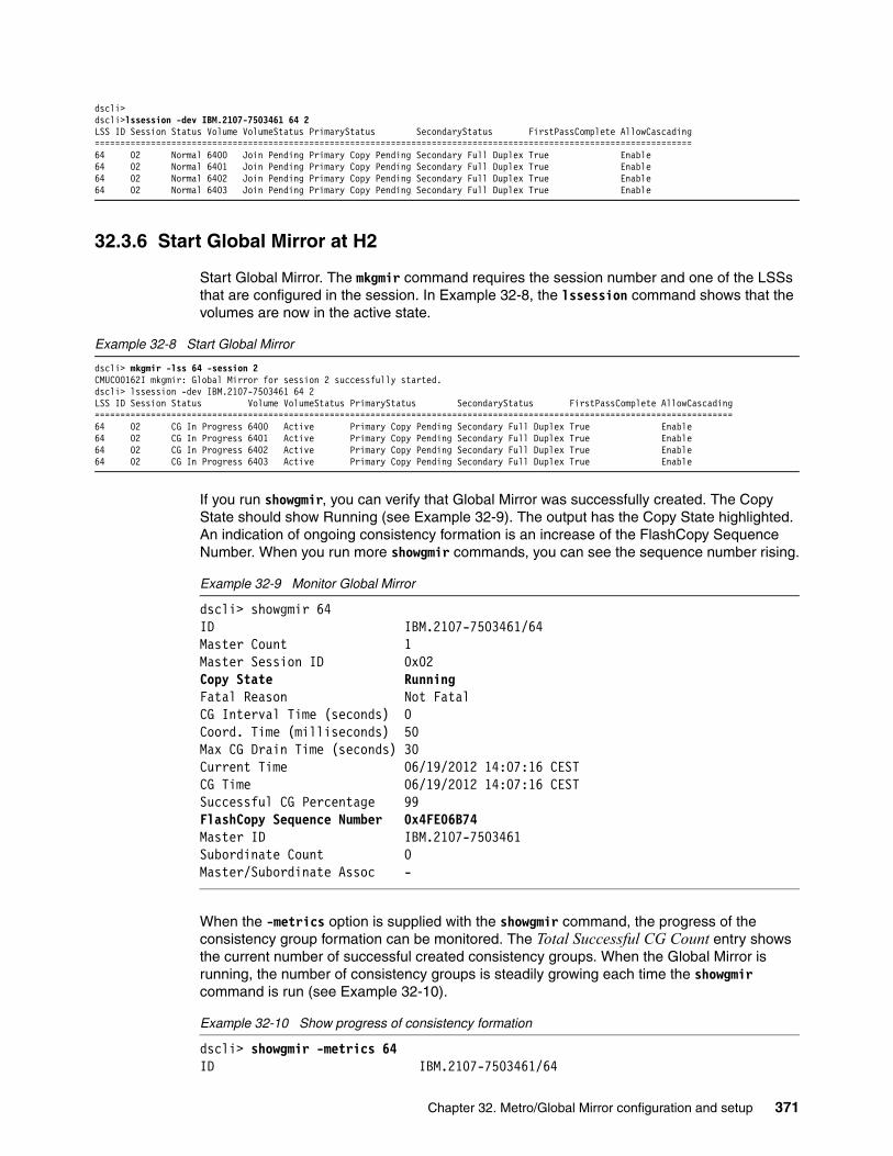
dscli>dscli>lssession -dev IBM.2107-7503461 64 2LSS ID Session Status Volume VolumeStatus PrimaryStatus SecondaryStatus FirstPassComplete AllowCascading=====================================================================================================================64 02 Normal 6400 Join Pending Primary Copy Pending Secondary Full Duplex True Enable64 02 Normal 6401 Join Pending Primary Copy Pending Secondary Full Duplex True Enable64 02 Normal 6402 Join Pending Primary Copy Pending Secondary Full Duplex True Enable64 02 Normal 6403 Join Pending Primary Copy Pending Secondary Full Duplex True Enable
32.3.6 Start Global Mirror at H2
Start Global Mirror. The mkgmir command requires the session number and one of the LSSs that are configured in the session. In Example 32-8, the lssession command shows that the volumes are now in the active state.
Example 32-8 Start Global Mirror
dscli> mkgmir -lss 64 -session 2CMUC00162I mkgmir: Global Mirror for session 2 successfully started.dscli> lssession -dev IBM.2107-7503461 64 2LSS ID Session Status Volume VolumeStatus PrimaryStatus SecondaryStatus FirstPassComplete AllowCascading=============================================================================================================================64 02 CG In Progress 6400 Active Primary Copy Pending Secondary Full Duplex True Enable64 02 CG In Progress 6401 Active Primary Copy Pending Secondary Full Duplex True Enable64 02 CG In Progress 6402 Active Primary Copy Pending Secondary Full Duplex True Enable64 02 CG In Progress 6403 Active Primary Copy Pending Secondary Full Duplex True Enable
If you run showgmir, you can verify that Global Mirror was successfully created. The Copy State should show Running (see Example 32-9). The output has the Copy State highlighted. An indication of ongoing consistency formation is an increase of the FlashCopy Sequence Number. When you run more showgmir commands, you can see the sequence number rising.
Example 32-9 Monitor Global Mirror
dscli> showgmir 64ID IBM.2107-7503461/64Master Count 1Master Session ID 0x02Copy State RunningFatal Reason Not FatalCG Interval Time (seconds) 0Coord. Time (milliseconds) 50Max CG Drain Time (seconds) 30Current Time 06/19/2012 14:07:16 CESTCG Time 06/19/2012 14:07:16 CESTSuccessful CG Percentage 99FlashCopy Sequence Number 0x4FE06B74Master ID IBM.2107-7503461Subordinate Count 0Master/Subordinate Assoc -
When the -metrics option is supplied with the showgmir command, the progress of the consistency group formation can be monitored. The Total Successful CG Count entry shows the current number of successful created consistency groups. When the Global Mirror is running, the number of consistency groups is steadily growing each time the showgmir command is run (see Example 32-10).
Example 32-10 Show progress of consistency formation
dscli> showgmir -metrics 64ID IBM.2107-7503461/64
Chapter 32. Metro/Global Mirror configuration and setup 371

Total Failed CG Count 0Total Successful CG Count 4Successful CG Percentage 100Failed CG after Last Success 0Last Successful CG Form Time 06/19/2012 14:10:47 CESTCoord. Time (milliseconds) 50CG Interval Time (seconds) 0Max CG Drain Time (seconds) 30First Failure Control Unit -First Failure LSS -First Failure Status No ErrorFirst Failure Reason -First Failure Master State -Last Failure Control Unit -Last Failure LSS -Last Failure Status No ErrorLast Failure Reason -Last Failure Master State -Previous Failure Control Unit -Previous Failure LSS -Previous Failure Status No ErrorPrevious Failure Reason -Previous Failure Master State -dscli>dscli> showgmir -metrics 65ID IBM.2107-7503461/65Total Failed CG Count 0Total Successful CG Count 77Successful CG Percentage 100Failed CG after Last Success 0Last Successful CG Form Time 06/19/2012 14:12:00 CESTCoord. Time (milliseconds) 50CG Interval Time (seconds) 0Max CG Drain Time (seconds) 30First Failure Control Unit -First Failure LSS -First Failure Status No ErrorFirst Failure Reason -First Failure Master State -Last Failure Control Unit -Last Failure LSS -Last Failure Status No ErrorLast Failure Reason -Last Failure Master State -Previous Failure Control Unit -Previous Failure LSS -Previous Failure Status No ErrorPrevious Failure Reason -Previous Failure Master State -
372 DS8000 Copy Services
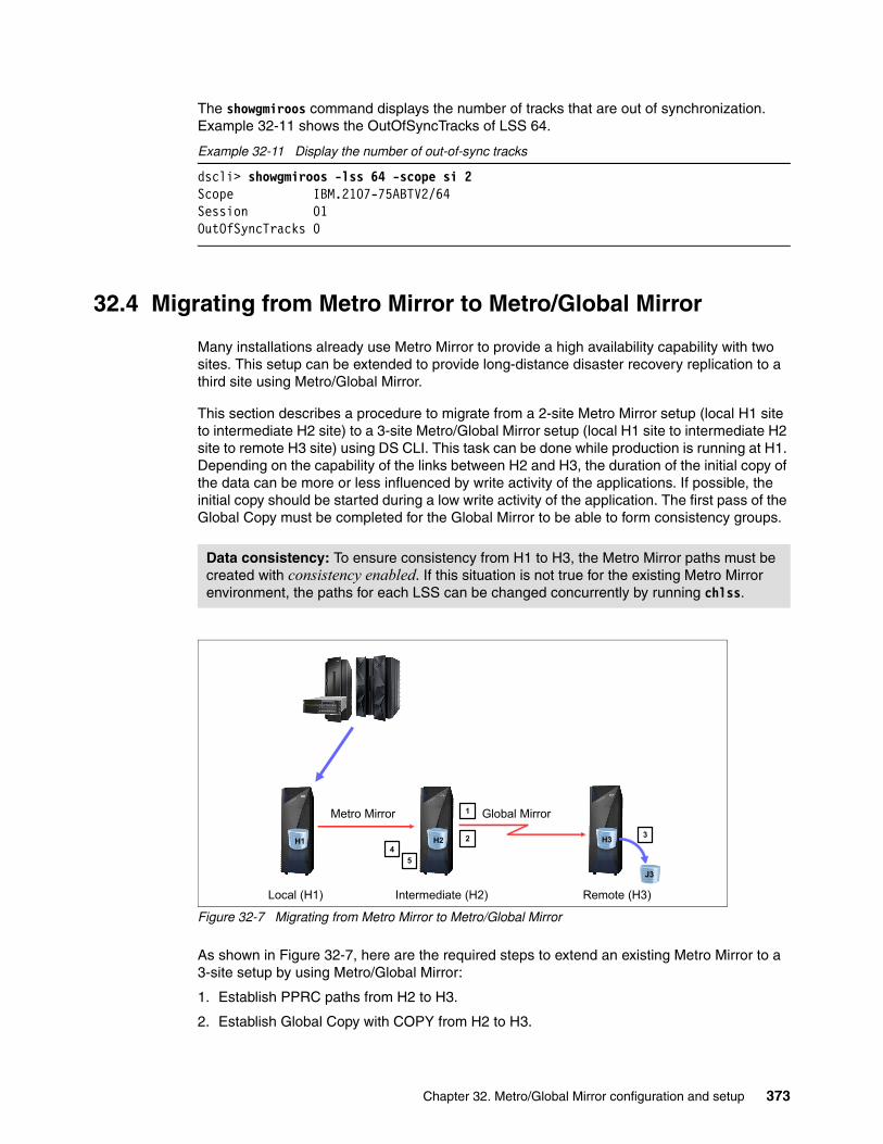
The showgmiroos command displays the number of tracks that are out of synchronization. Example 32-11 shows the OutOfSyncTracks of LSS 64.
Example 32-11 Display the number of out-of-sync tracks
dscli> showgmiroos -lss 64 -scope si 2Scope IBM.2107-75ABTV2/64Session 01OutOfSyncTracks 0
32.4 Migrating from Metro Mirror to Metro/Global Mirror
Many installations already use Metro Mirror to provide a high availability capability with two sites. This setup can be extended to provide long-distance disaster recovery replication to a third site using Metro/Global Mirror.
This section describes a procedure to migrate from a 2-site Metro Mirror setup (local H1 site to intermediate H2 site) to a 3-site Metro/Global Mirror setup (local H1 site to intermediate H2 site to remote H3 site) using DS CLI. This task can be done while production is running at H1. Depending on the capability of the links between H2 and H3, the duration of the initial copy of the data can be more or less influenced by write activity of the applications. If possible, the initial copy should be started during a low write activity of the application. The first pass of the Global Copy must be completed for the Global Mirror to be able to form consistency groups.
Figure 32-7 Migrating from Metro Mirror to Metro/Global Mirror
As shown in Figure 32-7, here are the required steps to extend an existing Metro Mirror to a 3-site setup by using Metro/Global Mirror:
1. Establish PPRC paths from H2 to H3.
2. Establish Global Copy with COPY from H2 to H3.
Data consistency: To ensure consistency from H1 to H3, the Metro Mirror paths must be created with consistency enabled. If this situation is not true for the existing Metro Mirror environment, the paths for each LSS can be changed concurrently by running chlss.
H1
Intermediate (H2)Local (H1)
Global MirrorMetro Mirror
H2 2
1
3
4
5
Remote (H3)
H3
J3
Chapter 32. Metro/Global Mirror configuration and setup 373

In contrast to the initial Metro/Global Mirror setup, the Global Copy is established with copy mode to ensure that all data is copied from H2 to H3.
3. Establish FlashCopy at H3.
4. Create a Global Mirror session and add the volume pairs to the session at H2.
5. Start Global Mirror at H2.
The steps are described in detail in 32.3, “Initial setup of Metro/Global Mirror” on page 365.
32.5 Preferred practices for setting up Metro/Global Mirror
This section gives some brief preferred practices for planning the setup of Metro/Global Mirror:
� Use LSSs to group volumes logically to applications.
Because some Copy Services functions manage LSSs, you should dedicate LSSs to applications for easier management. For example, a freezepprc command freezes all volumes of the specified LSS. To manage applications independently, each application should use dedicated LSSs.
� Use at least two PPRC links.
You should implement at least two independent PPRC links each for Metro Mirror and Global Mirror for redundancy. Capacity planning for Metro Mirror might yield a requirement for more than two links because the synchronous relationship requires a higher bandwidth. With Global Copy, only the last modified version of a track is transmitted to the secondary volumes, so the bandwidth requirement is not as high as it is for Metro Mirror. However, to provide redundancy, at least two independent links should be deployed for the Global Copy.
� Volume placement for FlashCopy at H3.
FlashCopy target volumes should use LSSs that are processed by the same server as the FlashCopy source volumes. Otherwise, the data must be passed to the other server, which consumes needless processing power and bandwidth of the internal busses.
� Use the same number of FCP ports at the local and remote sites.
Make sure that the number of FCP ports at the local and remote site are balanced. If there are two ports at H1, there should be two ports at H3.
FCP links: In general, you should not share the FCP links used for synchronous and asynchronous remote copy functions. For more configuration information, see Figure 15-2 on page 114.
374 DS8000 Copy Services

Chapter 33. Metro/Global Mirror operations
This chapter describes some general considerations for Metro Mirror and Global Mirror, when used within the context of Metro/Global Mirror. It provides hints and tips that are related to specific operations of Metro/Global Mirror. It includes the following topics:
� Overview� General considerations for storage failover� Freezing and unfreezing Metro Mirror volumes� Checking consistency at H3� Setting up an additional Global Mirror from H3
33
© Copyright IBM Corp. 2017. All rights reserved. 375

33.1 Overview
This chapter includes some general operations that are preferred practices for a Metro/Global Mirror environment. Metro/Global Mirror has characteristics beyond a simple combination of Metro Mirror and Global Mirror. Some of the topics described here are preferred practices that ensure that you take special care because of the complexity of Metro/Global Mirror.
Figure 33-1 shows a general Metro/Global Mirror configuration. Host I/O is directed to the local site labeled H1. Metro Mirror is used to synchronously mirror data to the intermediate site labeled H2 and then Global Mirror asynchronous mirrors data to the remote recovery site labeled H3.
Figure 33-1 Metro/Global Mirror configuration
33.2 General considerations for storage failover
A storage failover changes the access point of the data from the local to the remote storage system. The application is started by using the remote storage system. This has an a serious impact on a production site. This failover results in downtime for the applications because they must be started on the storage system of the secondary site. Depending on the configuration of the storage environment, access to the remote storage must be configured after the failover and before the applications can be restarted.
A storage failover is activated only for situations such as:
� Conditions that result from a disaster where the required infrastructure components are now inaccessible
� Maintenance operations at the local H1 site� Migration of applications
Disaster recovery tests can be performed without performing a failover of the applications. Chapter 35, “Metro/Global Mirror disaster recovery test scenarios” on page 393 describes how to perform these tests.
Before you perform a failover of the Metro Mirror or the Global Copy relationship, you must verify the state of the pair relationships. For a planned failover, the status of the Metro Mirror between H1 and H2 must be Full Duplex mode. when the status is still Copy Pending, the data has not been completely copied to the secondary volumes.
H1
Intermediate (H2) Remote (H3)Local (H1)
Global MirrorMetro Mirror
H2 H3
J3J2
376 DS8000 Copy Services

It is important to understand the status of the entire Metro/Global Mirror environment before you act. Otherwise, your actions could result in a situation where either the Metro Mirror or the Global Copy environments cannot be recovered to their original state. In this case, the relationships might need to be completely re-created, requiring a full copy of the data.
The following examples show the status of the Metro/Global Mirror environment during normal operations.
In Example 33-1, all volumes of the Metro Mirror are in Full Duplex mode.
Example 33-1 Metro Mirror Full Duplex for H1 to H2
dscli>lspprc -remotedev IBM.2107-75ABTV1 6000-6003ID State Reason Type SourceLSS Timeout (secs) Critical Mode First Pass Status==========================================================================================================6000:6200 Full Duplex - Metro Mirror IBM.2107-7520781/60 unknown Disabled Invalid6001:6201 Full Duplex - Metro Mirror IBM.2107-7520781/60 unknown Disabled Invalid6002:6202 Full Duplex - Metro Mirror IBM.2107-7520781/60 unknown Disabled Invalid6003:6203 Full Duplex - Metro Mirror IBM.2107-7520781/60 unknown Disabled Invalid
The Global Copy pairs are always Copy Pending. To determine that all tracks are copied to the secondary site, you must inspect the Out of Sync Tracks value. The Global Copy environment is synchronized when the Out of Sync Tracks value is zero for all volumes, as shown in Example 33-2.
Example 33-2 Synchronized Global Copy relationship
dscli> lspprc -remotedev IBM.2107-75ABTV1 -l 6400-6403ID State Reason Type Out Of Sync Tracks ... Critical Mode First Pass Status=================================================================================================6400:6200 Copy Pending - Global Copy 0 ... Disabled True6401:6201 Copy Pending - Global Copy 0 ... Disabled True6402:6202 Copy Pending - Global Copy 0 ... Disabled True6403:6203 Copy Pending - Global Copy 0 ... Disabled True
In a Metro/Global Mirror environment, the volumes at H2 are in a different state than in a conventional Metro Mirror or Global Mirror environment. Because the Global Mirror environment is cascaded to the Metro Mirror environment, the volumes at H2 are both a secondary and primary at the same time. Thus, the lspprc command that is run at H2 shows both the Metro Mirror and the Global Mirror environments, as shown in Example 33-3 on page 378.
Note: The output data from the lspprc command is lengthy, so parts have been edited to better show the fields of interest.
Chapter 33. Metro/Global Mirror operations 377

Example 33-3 Status of the H2 volumes in a Metro/Global Mirror
dscli> lspprc -remotedev IBM.2107-7520781 6200-6203ID State Reason Type SourceLSS Timeout (secs) Critical Mode First Pass Status==========================================================================================================6000:6200 Target Full Duplex - Metro Mirror 60 unknown Disabled Invalid6001:6201 Target Full Duplex - Metro Mirror 60 unknown Disabled Invalid6002:6202 Target Full Duplex - Metro Mirror 60 unknown Disabled Invalid6003:6203 Target Full Duplex - Metro Mirror 60 unknown Disabled Invalid6200:6400 Copy Pending - Global Copy 62 unknown Disabled True6201:6401 Copy Pending - Global Copy 62 unknown Disabled True6202:6402 Copy Pending - Global Copy 62 unknown Disabled True6203:6403 Copy Pending - Global Copy 62 unknown Disabled True
33.3 Freezing and unfreezing Metro Mirror volumes
The freezepprc and unfreezepprc commands work in a Metro Mirror environment when the Peer-to-Peer Remote Copy (PPRC) paths are created with the -consistencygrp option. A freezepprc command does two things:
� It sets the extended long busy condition on all the primary volumes of the LSS. This condition blocks the I/O to these volumes. All I/O from the hosts waits until the long busy condition is removed by running unfreezepprc or when the long busy timeout value is exceeded. The default timeout value is 60 seconds for fixed-block architecture (FB) volumes and 120 seconds for count key data (CKD) volumes. Because the long busy timeout value is a value that is related to the LSS, you can change this value with either the chlss -extlongbusy command, for FB volumes, or the chlcu -extlongbusy command, for count key data (CKD) volumes.
� It fails the paths between the primary site and the secondary site.
For a detailed description about how consistency is provided in a Metro Mirror environment, see 16.6, “Metro Mirror Data consistency” on page 125.
As shown in Example 33-4, the pair status at the primary site after freezepprc runs is Suspended with the reason Freeze (for all volumes in the LSS). At the secondary site, the pair status is still in Target Full Duplex mode.
Example 33-4 Example of a freezepprc and the pair status at the primary site
# At H1:#
dscli> freezepprc -remotedev IBM.2107-75ABTV1 68:62CMUC00161W freezepprc: Remote Mirror and Copy consistency group 68:62 successfully created.dscli> lspprc -remotedev IBM.2107-75ABTV1 6800-6803ID State Reason Type SourceLSS Timeout (secs) Critical Mode First Pass Status================================================================================================6800:6200 Suspended Freeze Metro Mirror 68 unknown Disabled Invalid6801:6201 Suspended Freeze Metro Mirror 68 unknown Disabled Invalid6802:6202 Suspended Freeze Metro Mirror 68 unknown Disabled Invalid6803:6203 Suspended Freeze Metro Mirror 68 unknown Disabled Invalid
# At H2:#
378 DS8000 Copy Services

dscli> lspprc -remotedev IBM.2107-7503461 6200-6203ID State Reason Type SourceLSS Timeout (secs) Critical Mode First Pass Status==========================================================================================================6800:6200 Target Full Duplex - Metro Mirror 68 unknown Disabled Invalid6801:6201 Target Full Duplex - Metro Mirror 68 unknown Disabled Invalid6802:6202 Target Full Duplex - Metro Mirror 68 unknown Disabled Invalid6803:6203 Target Full Duplex - Metro Mirror 68 unknown Disabled Invalid
The unfreezepprc command removes the long busy status from the primary volumes and I/O continues. The pair status of the primary volumes is still Suspended, as shown in Example 33-5.
Example 33-5 unfreezepprc after the freezepprc
dscli> unfreezepprc -remotedev IBM.2107-75ABTV1 68:62CMUC00198I unfreezepprc: Remote Mirror and Copy pair 68:62 successfully thawed.dscli> lspprc -remotedev IBM.2107-75ABTV1 6800-6803ID State Reason Type SourceLSS Timeout (secs) Critical Mode First Pass Status================================================================================================6800:6200 Suspended Freeze Metro Mirror 68 unknown Disabled Invalid6801:6201 Suspended Freeze Metro Mirror 68 unknown Disabled Invalid6802:6202 Suspended Freeze Metro Mirror 68 unknown Disabled Invalid6803:6203 Suspended Freeze Metro Mirror 68 unknown Disabled Invalid
A freezepprc command can be issued against the volumes of a running application, although it has an impact on the application: after the freezepprc command runs, the applications wait to continue with the I/O because the freeze command puts the volumes into the extended long busy state. This freeze is ended by the unfreezepprc command or after the consistency group timeout value is exceeded. This method is used to provide a consistent copy of the data at the secondary site when the applications at the primary site are not stopped.
33.4 Checking consistency at H3
The Metro Mirror paths from H1 to H2 ensure consistency through the use of the freeze and unfreeze functions. The paths must be created with the -consistgrp option. Consistency is provided to the Metro Mirror environment by an extended long busy condition (set at the primary volumes) when the last Metro Mirror physical link fails and no logical path is available. When I/O to the primary volumes can resume, an unfreezepprc command is issued to the H1 LSS’s to remove the extended long busy condition.
The Global Mirror process runs at H2 and uses FlashCopy at H3 to preserve consistency groups. When more than one storage system is used at H2, one of these systems is the master, where the Global Mirror environment is (see 32.1.2, “Metro/Global Mirror with multiple storage systems” on page 363). The other storage systems are the subordinates. The Global Mirror environment coordinates the consistency formation for all volumes of the master and the subordinates, which are joined into a Global Mirror session. The consistency is formed in the following steps:
1. The master coordinates with all the subordinates to stop I/O for 3 - 5 ms to all primary volumes that form a consistency group.
2. The consistency group is transmitted to the secondary volumes.
3. FlashCopy copies all the tracks that changed since the last write operation to the secondary volumes.
Chapter 33. Metro/Global Mirror operations 379

For a detailed description of consistency formation in a Global Mirror environment, see 19.2.2, “Consistency group formation” on page 208.
Section 21.2.2, “Creating FlashCopy relationships: H2 to J2 volumes” on page 235 describes how to verify the FlashCopy status and gives examples on how to perform the revertflash and reverseflash operations to return the H3 volumes to the last successful consistency group.
33.5 Setting up an additional Global Mirror from H3
When a planned failover of the production to H3 is done, depending on the reason for the failover, it might be that the production environment remains at H3 for an extended period. During this period, H3 volumes are not protected against a disaster. If the H2 site is still available, it is possible to create an additional Global Mirror session from H3 to H2 to protect the data against a possible disaster at H3.
To accomplish this task, more volumes are required at H2 for setting up the a FlashCopy relationships as a new Global Mirror secondary. In addition, H2 must be prepared for these Global Copy relationships from H3. This task is necessary because the H2 volumes are still secondaries for the Metro Mirror environment and a volume cannot be a secondary of two different relandscapes at the same time. Finally, a session with the related volumes must be created and the Global Mirror must be started at H3.
Figure 33-2 shows the steps to create the additional Global Mirror relationship.
Figure 33-2 Create an additional Global Mirror from H3
The creation of the additional Global Mirror relationship consists of the following steps:
1. Clean up Metro Mirror relationships2. Create or failback from H3 to H23. Establish a FlashCopy path to the additional volumes at H24. Create a session and start the Global Mirror environment
33.5.1 Clean up the remaining Metro Mirror relationships
To reverse the Global Copy direction from H3 to H2, the remaining parts of the Metro Mirror environment at H2 must be removed. If the local storage device is still available, the Metro Mirror environment can be removed by running rmpprc. But when H1 is gone, you failover the
(Suspended) Global Mirror
Intermediate (H2) Remote (H3)Local (H1)
J3
H1 H2
J2
H31
2
34
380 DS8000 Copy Services

Metro Mirror environment at H2 before the Metro Mirror can be removed in the opposite direction.
33.5.2 Create Global Copy pairs from H3 to H2
The volumes at H3 (see Figure 33-2 on page 380) are a primary for the Global Mirror environment, which is established from H3 to H2. The first step is to establish the Global Copy pairs from the remote H3 volumes to the intermediate H2 volumes.
Example 33-6 shows how to set up the Global Copy environment. Because the data at H3 is the same as it is at H2, the Global Copy environment can be established with the -mode nocp option to avoid background copy.
Example 33-6 Establish Global Copy from H2 to H3
dscli> mkpprc -remotedev IBM.2107-75ABTV1 -type gcp -mode nocp 6400-6403:6200-6203CMUC00153I mkpprc: Remote Mirror and Copy volume pair relationship 6400:6200 successfully created.CMUC00153I mkpprc: Remote Mirror and Copy volume pair relationship 6401:6201 successfully created.CMUC00153I mkpprc: Remote Mirror and Copy volume pair relationship 6402:6202 successfully created.CMUC00153I mkpprc: Remote Mirror and Copy volume pair relationship 6403:6203 successfully created.dscli>dscli>dscli>dscli> lspprc -remotedev IBM.2107-75ABTV1 -l 6400-6403ID State Reason Type Out Of Sync Tracks Tgt Read Src Cascade SourceLSS Critical Mode First Pass Status================================================================================= =========== ================================6400:6200 Copy Pending - Global Copy 0 Disabled Enabled 64 Disabled True6401:6201 Copy Pending - Global Copy 0 Disabled Enabled 64 Disabled True6402:6202 Copy Pending - Global Copy 0 Disabled Enabled 64 Disabled True6403:6203 Copy Pending - Global Copy 0 Disabled Enabled 64 Disabled True
33.5.3 Create FlashCopy relationships at H2
The Global Mirror environment at H3 requires FlashCopy relationships at the intermediate site from the H2 volumes to a new set of volumes named J2 (see Figure 33-2 on page 380).
Example 33-7 shows how to set establish the FlashCopy relationships.
Example 33-7 Establish FlashCopy at H2
dscli> mkflash -tgtinhibit -record -persist -nocp 6200-6203:6300-6303CMUC00137I mkflash: FlashCopy pair 6200:6300 successfully created.CMUC00137I mkflash: FlashCopy pair 6201:6301 successfully created.CMUC00137I mkflash: FlashCopy pair 6202:6302 successfully created.CMUC00137I mkflash: FlashCopy pair 6203:6303 successfully created.
33.5.4 Create Global Mirror at H3
To complete the setup of the Global Mirror, create a session at H3 and add the Global Copy primary volumes in to the session. Finally, start the Global Mirror environment.
Example 33-8 shows the setup of the session and the Global Mirror environment and how to check whether the Global Mirror environment is running properly.
Example 33-8 Create Global Mirror at H3
dscli> mksession -lss 64 1dscli> chsession -lss 64 -action add -volpair 6400-6403:6200-6203 1CMUC00145I mksession: Session 1 opened successfully.CMUC00147I chsession: Session 1 successfully modified.dscli> lssession 64LSS ID Session Status Volume VolumeStatus PrimaryStatus SecondaryStatus FirstPassComplete AllowCascading
Chapter 33. Metro/Global Mirror operations 381

=========================================================================================================================64 01 CG In Progress 6400 Active Primary Copy Pending Secondary Simplex True Enable64 01 CG In Progress 6401 Active Primary Copy Pending Secondary Simplex True Enable64 01 CG In Progress 6402 Active Primary Copy Pending Secondary Simplex True Enable64 01 CG In Progress 6403 Active Primary Copy Pending Secondary Simplex True Enabledscli> mkgmir -lss 64 -session 1CMUC00162I mkgmir: Global Mirror for session 1 successfully started.dscli> showgmir 64ID IBM.2107-75ABTV2/64Master Count 1Master Session ID 0x01Copy State RunningFatal Reason Not FatalCG Interval (seconds) 0XDC Interval(milliseconds) 50CG Drain Time (seconds) 30Current Time 11/14/20nn 10:38:21 CETCG Time 11/14/20nn 10:38:21 CETSuccessful CG Percentage 10FlashCopy Sequence Number 0x43785B0DMaster ID IBM.2107-75ABTV2Subordinate Count 0Master/Subordinate Assoc -
382 DS8000 Copy Services

Chapter 34. Metro/Global Mirror recovery scenarios
This chapter describes recovery scenarios. For each scenario, this chapter explains in detail all the operations in a step-by-step approach. You can use this chapter as a guide for Metro/Global Mirror operations. It includes the following topics:
� Overview� Recovery of the production environment at H2� Recovery of the production environment at H3� Returning the production environment from H3 to H1
34
© Copyright IBM Corp. 2017. All rights reserved. 383

34.1 Overview
Recovery scenarios are a series of operations that are initiated by you that are based on the failover/failback functions. A storage failover always impacts the production environment. For this reason, all failover operations must be planned carefully by you in terms of the integrity of procedures, the time schedule, and the availability of the applications.
In a planned failover, the application must be stopped before recovery at H2 or H3 can occur. The host is then given access to the volumes and the application is started by using these volumes. A reason for a planned recovery at H2 might be because there are planned maintenance activities at H1, which might impact the production environment. See 33.2, “General considerations for storage failover” on page 376. A recovery at H2 minimizes the impact to the production environment which normally runs at the H1 site.
In a large data center, many applications that run on different servers can participate in the Metro/Global Mirror environment. In this case, it is most likely that failover operations are not accomplished against the complete environment, but rather to specific applications. In this case, the failover operations must be applied in a way that does not affect the copy relationships for the remaining applications. This situation is accounted for in all the scenarios that are presented in this chapter.
All the scenarios that are presented in this chapter were tested and represent the preferred practice for the situations they address. However, additional or alternative scenarios are possible, depending on the particular circumstances within your data center.
The scenarios in a Metro/Global Mirror are complex and sometimes difficult to handle with DS CLI commands. A certain level of automation, where the steps are processed in the correct sequence is needed. This automation can be provided by IBM Copy Services Manager or IBM Geographically Dispersed Parallel Sysplex (IBM GDPS). See Part 7, “Solutions” on page 317 for information about these solutions.
34.2 Recovery of the production environment at H2
A recovery at the intermediate H2 site can make use of Multiple Target Peer-to-Peer Remote Copy (PPRC) to simplify the return back to the local H1 site. Chapter 39, “Multiple Target PPRC architecture and design” on page 441 gives a description of Multiple Target PPRC and Chapter 44, “MultiTarget PPRC with cascaded Metro/Global Mirror” on page 505 contains a scenario where the application is moved to the intermediate H2 site and back again.
34.3 Recovery of the production environment at H3
One possible reason for a recovery of the production environment is to minimize the impact to the production environment at H1, for example, when there is maintenance at H1. The recovery of the production environment at H3 is indicated when no servers are available at H2.
Other scenarios: If you require other scenarios, test them extensively before you implement them in your production environment.
384 DS8000 Copy Services

Figure 34-1 illustrates the steps that it takes to perform a recovery at H3.
Figure 34-1 Recovery of the production environment at H3
An additional option for this scenario is to create a Global Mirror session from H3 to H2 to provide disaster protection for the production environment while it is at H3. This setup requires more volumes as FlashCopy targets at H2. For more information, see 33.5, “Setting up an additional Global Mirror from H3” on page 380.
Here are the steps to perform the recovery of the production environment at H3 (Figure 34-1):
1. Stop I/O at H12. Terminate Global Mirror3. Terminate Global Copy4. Failover Metro Mirror to H25. Establish Global Copy from H3 to H26. Start I/O at H3
34.3.1 Stop I/O at H1
Before any failover can happen, you must stop the I/O to the primary volumes. The data must be identical at the local, intermediate, and remote sites. During the whole scenario, make sure that the data is not changed by any server access. The volumes must also be released by the host to enable the failbackpprc command on Metro Mirror when the production environment returns to H1 (see 34.4.1, “Stop I/O at H3” on page 388).
34.3.2 Terminate Global Mirror
You must terminate Global Mirror now, as shown in Example 34-1 on page 386. For applications that are in the same Global Mirror consistency group but do not fail over to H2, no more consistency groups are formed unless the Global Mirror is restarted in 34.3.5, “Establish Global Copy from H3 to H2” on page 387.
Important: In this scenario, Global Copy between the intermediate and remote site is terminated and re-created in the opposite direction as a nocopy relationship. To avoid data corruption during the whole scenario, do not allow any I/O to any host volume.
(Suspended) Global Mirror
Intermediate (H2) Remote (H3)Local (H1)
J3
H1 H2
J2
H35
1
2
34
6
Chapter 34. Metro/Global Mirror recovery scenarios 385

Example 34-1 Terminate Global Mirror
dscli> rmgmir -quiet -lss 64 -session 2CMUC00165I rmgmir: Global Mirror for session 2 successfully stopped.
34.3.3 Terminate Global Copy
As preparation for a later return of the production environment to H1, the Global Copy is reversed from H3 to H2. Because of the cascading status of the intermediate volumes, a reversal of Global Copy by using the failover and failback commands result in the H2 volumes being secondaries of both H1 and H3 at the same time, which is not allowed. Therefore, you must terminate the Global Copy pairs. Later in this scenario (see 34.3.5, “Establish Global Copy from H3 to H2” on page 387), the Global Copy is re-created in nocopy mode between H3 and H2.
Example 34-2 shows how to remove Global Copy.
Example 34-2 Remove Global Copy
dscli> rmpprc -remotedev IBM.2107-75TV181 6400-6403:e400-e403CMUC00155I rmpprc: Remote Mirror and Copy volume pair 6400:E400 relationship successfully withdrawn.CMUC00155I rmpprc: Remote Mirror and Copy volume pair 6401:E401 relationship successfully withdrawn.CMUC00155I rmpprc: Remote Mirror and Copy volume pair 6402:E402 relationship successfully withdrawn.CMUC00155I rmpprc: Remote Mirror and Copy volume pair 6403:E403 relationship successfully withdrawn.
34.3.4 Failover Metro Mirror to H2
The volumes at H2 become secondary volumes for Global Copy, which is then established from H3 to H2. Therefore, Metro Mirror must be failed over to H2.
The Metro Mirror failover can also be seen as preparation for the failback to H1. The reversed Metro Mirror acts as a cascade from the reversed Global Copy between the remote and intermediate sites.
Example 34-3 on page 387 shows the failover of Metro Mirror H2 to H1.
Attention: Between steps 3 - 6, make sure that all I/O from the servers to the volumes is stopped. If not, data can become inconsistent and a full copy will be required in 34.3.5, “Establish Global Copy from H3 to H2” on page 387.
Important: Before you remove Global Copy, check that all tracks are copied to the secondary site. Run the lspprc -l command to determine the number of out-of-sync tracks.
Note: Prior to DS8000 LMC Release 7.4, establishing a cascaded PPRC configuration required the use of the -cascade option for the remote pair. This is no longer needed.
Specifying volumes: To fail over to H2, you must specify the intermediate volumes as the source and the local volumes as targets in the failoverpprc command.
386 DS8000 Copy Services

Example 34-3 Failover of Metro Mirror at H2
dscli> failoverpprc -remotedev IBM.2107-75ABTV1 -type mmir 6400-6403:4200-4203CMUC00196I failoverpprc: Remote Mirror and Copy pair 6400:4200 successfully reversed.CMUC00196I failoverpprc: Remote Mirror and Copy pair 6401:4201 successfully reversed.CMUC00196I failoverpprc: Remote Mirror and Copy pair 6402:4202 successfully reversed.CMUC00196I failoverpprc: Remote Mirror and Copy pair 6403:4203 successfully reversed.dscli> dscli> lspprc -remotedev IBM.2107-75ABTV1 6400-6403ID State Reason Type SourceLSS Timeout (secs) Critical Mode First Pass Status====================================================================================================6400:4200 Suspended Host Source Metro Mirror 64 120 Disabled Invalid6401:4201 Suspended Host Source Metro Mirror 64 120 Disabled Invalid6402:4202 Suspended Host Source Metro Mirror 64 120 Disabled Invalid6403:4203 Suspended Host Source Metro Mirror 64 120 Disabled Invalid
If you run the lspprc command at H2, you can see that the type of the volume pairs changed from Metro Mirror to Global Copy.
34.3.5 Establish Global Copy from H3 to H2
In anticipation of returning the production environment to H1, and if the volumes at H2 and the links are still available, it is now possible to establish Global Copy from H3 to H2.
If, at H2, more volumes can be provided for a new FlashCopy relationship to the intermediate volumes, it is possible to set up an additional Global Mirror from H3 to H2. Assuming that the production environment might remain for a long period at H3, this approach provides consistent data at H2, and protects the production environment against a possible disaster at H3. For more details about this topic, see 33.5, “Setting up an additional Global Mirror from H3” on page 380.
Example 34-4 shows how to establish Global Copy. Because the data on the volumes at the remote and intermediate sites contain are identical, use the -mode nocp option to avoid needing to make a full copy.
Example 34-4 Establish Global Copy from H3 to H2
dscli> mkpprc -remotedev IBM.2107-7503461 -mode nocp -type gcp e400-e403:6400-6403CMUC00153I mkpprc: Remote Mirror and Copy volume pair relationship E400:6400 successfully created.CMUC00153I mkpprc: Remote Mirror and Copy volume pair relationship E401:6401 successfully created.CMUC00153I mkpprc: Remote Mirror and Copy volume pair relationship E402:6402 successfully created.CMUC00153I mkpprc: Remote Mirror and Copy volume pair relationship E403:6403 successfully created.
34.3.6 Start I/O at H3
Now, you completed all necessary actions to recover the production environment from H1 to H3. You can now start the host I/O against the volumes at H3 (see Figure 34-1 on page 385).
34.4 Returning the production environment from H3 to H1
The scenario that is described in this section includes the return of the production environment from H3 after a planned recovery, which is described in 34.3, “Recovery of the production environment at H3” on page 384. This scenario also applies after a recovery at H3 takes place because of a failure at H1. If the recovery at H3 was accomplished because of a
Chapter 34. Metro/Global Mirror recovery scenarios 387

failure at H1, the return of the production environment to H1 can be done only when all required resources are available again.
As part of the recovery at H3 scenario, a Global Copy is established from H3 to H2. If this step was omitted, it must be done now. Ensure that all the data is drained to H2 and then to H1 before the applications are started again at H1.
If an additional Global Mirror is set up as described in 33.5, “Setting up an additional Global Mirror from H3” on page 380, then it must be removed before you return the production environment to H1.
Figure 34-2 illustrates the steps to return the production environment to H1.
Figure 34-2 Return of the production environment from H3 to H1
Here are the steps to return the production environment from H3 to H1:
1. Stop I/O at H3.2. Failback Metro Mirror from H2 to H1 and wait until the pairs are in the Full Duplex state.3. Terminate Global Copy from H3 to H2.4. Failover to H1.5. Failback Metro Mirror from H1 to H2.6. Establish Global Copy from H2 to H3.7. Start I/O at H1.8. Start Global Mirror or add volumes to a session.
34.4.1 Stop I/O at H3
To return the production environment to H1, the applications must be stopped at a certain point-in-time. You should stop the I/O to the remote volumes now. This action ensures that the data remains identical in each location while you perform this scenario.
Important: In this scenario, the Global Copy between the intermediate and remote sites is terminated and re-created in the opposite direction as a nocopy relationship. To avoid data corruption, no I/O to any host volume can occur during the whole scenario.
H1
Intermediate (H2) Remote (H3)Local (H1)
36
1
8
2
7
54
Global MirrorMetro Mirror
H3
J3
H2
J275-ABTV1 75-03461 75-TV181
388 DS8000 Copy Services

34.4.2 Failback Metro Mirror from H2 to H1
The running application’s data at H3 is replicated to H2 because a Global Copy was established during the failover procedure (see 34.3.5, “Establish Global Copy from H3 to H2” on page 387). When H1 becomes available again, Metro Mirror can be failed back to transfer the changed data back to H1.
Example 34-5 shows the failbackpprc command at H2. Before you take any further action, make sure that all data is replicated to H1 by running lspprc.
Example 34-5 failback Metro Mirror at H2
dscli> failbackpprc -remotedev IBM.2107-75ABTV1 -type gcp 6400-6403:4200-4203CMUC00197I failbackpprc: Remote Mirror and Copy pair 6400:4200 successfully failed back.CMUC00197I failbackpprc: Remote Mirror and Copy pair 6401:4201 successfully failed back.CMUC00197I failbackpprc: Remote Mirror and Copy pair 6402:4202 successfully failed back.CMUC00197I failbackpprc: Remote Mirror and Copy pair 6403:4203 successfully failed back.dscli>dscli> lspprc -remotedev IBM.2107-75ABTV1 6400-6403ID State Reason Type SourceLSS Timeout (secs) Critical Mode First Pass Status=========================================================================================================6400:4200 Copy Pending - Global Copy 64 unknown Disabled True6401:4201 Copy Pending - Global Copy 64 unknown Disabled True6402:4202 Copy Pending - Global Copy 64 unknown Disabled True6403:4203 Copy Pending - Global Copy 64 unknown Disabled TrueE400:6400 Target Copy Pending - Global Copy E4 unknown Disabled InvalidE401:6401 Target Copy Pending - Global Copy E4 unknown Disabled InvalidE402:6402 Target Copy Pending - Global Copy E4 unknown Disabled InvalidE403:6403 Target Copy Pending - Global Copy E4 unknown Disabled Invalid
34.4.3 Terminate Global Copy from H3 to H2
Reversing the Global Copy by using failover and failback functions results in the intermediate volumes becoming sources for the reversed Metro Mirror and the Global Copy, which is not permitted. (If all the involved DS8870 systems are at Release 7.4 then multiple PPRC relationships are possible; see IBM DS8870 Multiple Target Peer-to-Peer Remote Copy, REDP-5151). For this reason, you must terminate Global Copy now. In a later step (see 34.4.6, “Create Global Copy from H2 to H3” on page 391), Global Copy is re-created from H2 to H3 in nocopy mode.
Example 34-6 shows the DS CLI command to remove Global Copy.
Example 34-6 Remove the Global Copy from H3 to H2
dscli> rmpprc -quiet -remotedev IBM.2107-7503461 e400-e403:6400-6403CMUC00155I rmpprc: Remote Mirror and Copy volume pair E400:6400 relationship successfully withdrawn.
Attention: Make sure that between this step and step 6 that no I/O to the volumes occurs. Otherwise, data can become inconsistent because of the nocopy option, which means that you must perform a full copy.
Important: Before you remove Global Copy, check that all the tracks are copied to H2. Run lspprc to inspect the out-of-sync tracks.
Chapter 34. Metro/Global Mirror recovery scenarios 389

CMUC00155I rmpprc: Remote Mirror and Copy volume pair E401:6401 relationship successfully withdrawn.CMUC00155I rmpprc: Remote Mirror and Copy volume pair E402:6402 relationship successfully withdrawn.CMUC00155I rmpprc: Remote Mirror and Copy volume pair E403:6403 relationship successfully withdrawn.
34.4.4 Failover to H1
Before you perform the failover to H1, ensure that all tracks are transmitted to H1. Run the lspprc command at H2, and its output should show that there are no more out-of-sync tracks.
Example 34-7 shows how to fail over to H1. The command in the example is run at H1.
Example 34-7 Failover at H1
dscli> failoverpprc -remotedev IBM.2107-7503461 -type mmir 4200-4203:6400-6403CMUC00196I failoverpprc: Remote Mirror and Copy pair 4200:6400 successfully reversed.CMUC00196I failoverpprc: Remote Mirror and Copy pair 4201:6401 successfully reversed.CMUC00196I failoverpprc: Remote Mirror and Copy pair 4202:6402 successfully reversed.CMUC00196I failoverpprc: Remote Mirror and Copy pair 4203:6403 successfully reversed.
34.4.5 Failback Metro Mirror from H1 to H2
The failback enables tracks to be copied from H1 to H2. The Metro Mirror is no longer in a cascaded relationship and the copy type is now mmir again. Because the applications are not started, the contents of the volumes at the local and H2 are the same. The status of the Metro Mirror volumes is Full Duplex.
Example 34-8 shows the failback to H2 at H1.
Example 34-8 Failback Metro Mirror from H1 to H2
dscli> failbackpprc -remotedev IBM.2107-7503461 -type mmir 4200-4203:6400-6403CMUC00197I failbackpprc: Remote Mirror and Copy pair 4200:6400 successfully failed back.CMUC00197I failbackpprc: Remote Mirror and Copy pair 4201:6401 successfully failed back.CMUC00197I failbackpprc: Remote Mirror and Copy pair 4202:6402 successfully failed back.CMUC00197I failbackpprc: Remote Mirror and Copy pair 4203:6403 successfully failed back.dscli>dscli> lspprc -remotedev IBM.2107-7503461 4200-4203ID State Reason Type SourceLSS Timeout (secs) Critical Mode First Pass Status==================================================================================================4200:6400 Full Duplex - Metro Mirror 42 60 Disabled Invalid4201:6401 Full Duplex - Metro Mirror 42 60 Disabled Invalid4202:6402 Full Duplex - Metro Mirror 42 60 Disabled Invalid4203:6403 Full Duplex - Metro Mirror 42 60 Disabled Invalid
Specifying volumes: To fail over to H1, you must specify the local volumes as the source and the intermediate volumes as the targets with the failoverpprc command.
390 DS8000 Copy Services

34.4.6 Create Global Copy from H2 to H3
Create Global Copy from H2 to H3. Because the volumes at the remote and intermediate sites are identical, the Global Copy should be established with the -mode nocp option (NO COPY).
Example 34-9 shows the DS CLI command to create the Global Copy.
Example 34-9 Create Global Copy from H2 to H3
dscli> mkpprc -remotedev IBM.2107-75TV181 -mode nocp -type gcp 6400-6403:e400-e403CMUC00153I mkpprc: Remote Mirror and Copy volume pair relationship 6400:E400 successfully created.CMUC00153I mkpprc: Remote Mirror and Copy volume pair relationship 6401:E401 successfully created.CMUC00153I mkpprc: Remote Mirror and Copy volume pair relationship 6402:E402 successfully created.CMUC00153I mkpprc: Remote Mirror and Copy volume pair relationship 6403:E403 successfully created.
34.4.7 Start I/O
Now that Metro Mirror and Global Copy are fully re-established from H1 to H2 to H3, the application can be started at H1.
34.4.8 Start Global Mirror or adding volumes to the session
Start the Global Mirror if it is stopped, as shown in Example 34-10 and as described in 34.3.2, “Terminate Global Mirror” on page 385.
Example 34-10 Add volumes to the session and check them
dscli> mkgmir -lss 64-session 2CMUC00162I mkgmir: Global Mirror for session 2 successfully started.
Note: Prior to DS8000 LMC Release 7.4, establishing a cascaded PPRC configuration required the use of the -cascade option for the remote pair. This is no longer needed.
Important: Be sure that there is no active I/O to the volumes between steps 3 - 7. Otherwise, data can become inconsistent because of the nocopy option and you must run a full copy.
Chapter 34. Metro/Global Mirror recovery scenarios 391

392 DS8000 Copy Services

Chapter 35. Metro/Global Mirror disaster recovery test scenarios
This chapter describes several disaster recovery test scenarios. For each scenario, this chapter describes all operations in detail using a step-by-step approach. It includes the following topics:
� Overview� Providing consistency with Metro Mirror freeze� Providing consistency with Global Mirror
35
© Copyright IBM Corp. 2017. All rights reserved. 393

35.1 Overview
Disaster recovery test scenarios are used to test readiness for a disaster. While testing, the production environment must not be affected. Also, the replication of the production data to the disaster sites should be affected as little as possible.
The general goal for enabling disaster recovery testing at the intermediate or the remote site is to provide consistent data according to the required level of consistency of the applications that must be tested. The requirements for a disaster recovery test scenario are summarized in the following list:
� All volumes belonging to the application subject to the test must be considered.
� Data consistency for all volumes must be provided at the testing site.
� Replication must be resumed as quickly as possible to keep the recovery point objective (RPO) for the production environment at H1 low.
It is a preferred practice to use extra FlashCopy volumes for the disaster recovery tests. In this chapter, all the scenarios use these volumes. The secondary volumes of Metro Mirror or Global Mirror should not be used during the tests for the following reasons:
� When a target volume is used for the test, no replication of the production is possible, which means that the RPO increases continually during the whole disaster recovery test.
� The scenarios are more complicated, especially when replication is re-established to the original direction after the test.
� There is a potential risk of data corruption because of user errors.
The scenarios that are presented in this chapter have a minimal impact on the existing Metro/Global Mirror and no impact on the production environment at the local H1 site. We describe two disaster recovery test scenarios: one at the intermediate H2 site and one at the remote H3 site.
Both scenarios were tested and represent the preferred practices for the situations they address. However, additional or alternative scenarios remain possible depending on the particular circumstances within your data center.
35.2 Providing consistency with Metro Mirror freeze
This section describes the following disaster recovery tests:
� A disaster recovery test at the intermediate H2 site� A disaster recovery test at the remote H3 site
35.2.1 Disaster recovery test at the intermediate H2 site
This section describes the sequence of steps that are required to perform a disaster recovery test at H2 while the production site keeps running at H1. Assume that the storage at H2 is accessible to a host that starts the application for the disaster recovery test.
Tip: IBM Copy Services Manager has an automation solution that provides practice scenarios to reflect real disaster scenarios. For more information, see Chapter 28, “IBM Copy Services Manager” on page 329.
394 DS8000 Copy Services

Figure 35-1 illustrates the steps that are required to perform a failover to the intermediate H2 site while the production environment remains at the local H1 site.
Figure 35-1 Disaster recovery test at the intermediate H2 site
Here are the steps to fail over to H2 for a disaster recovery test with Metro Mirror:
1. Prepare the failover by issuing a freeze and unfreeze of the Metro Mirror.
2. Establish FlashCopy to the additional volumes at H2.
3. Re-establish Peer-to-Peer Remote Copy (PPRC) paths from H1 to H2.
4. Resume Metro Mirror.
5. Start I/O at the disaster recovery host.
Preparing the failover for the disaster recovery testBecause the applications continue after the failover, you must ensure that the data is consistent at H2. To provide consistency at H2, before the failover, issue a freeze and an unfreeze of the Metro Mirror pairs (see 33.3, “Freezing and unfreezing Metro Mirror volumes” on page 378). The freeze of the Metro Mirror sets the extended long busy state on the primary volumes and the paths between the local and H2 are set to Failed. The unfreeze that follows immediately removes the extended long busy state from the volume so that I/O to the volumes is enabled again.
Example 35-1 on page 396 shows the usage of the freezepprc and the unfreezepprc commands for Metro Mirror. These commands are issued at H1. A subsequent lspprc command at the local storage system shows that the primary volumes went to a suspended state as a result of the Metro Mirror freeze. An lspprc command that is issued at H2 shows the status of the secondary volumes, which are still in the Target Full Duplex mode.
Copying data: During the freeze/unfreeze interval, no data is copied to H3.
Application I/O: During the extended long busy state, the I/O from the application is blocked and waits until the volumes are accessible again. There is an interruption of the application I/O during the time it takes to fail the Metro Mirror paths. The application does not have to be stopped.
H1
Intermediate (H2) Remote (H3)Local (H1)
Metro Mirror
H3
J3I2
Disaster RecoveryTest Host
ProductionHost
1
H2
I2
234
5
75-ABTV1 75-03461 75-TV181Test Data
Global Mirror
Chapter 35. Metro/Global Mirror disaster recovery test scenarios 395

Example 35-1 Freeze and unfreeze before the failover
## At H1:
dscli> freezepprc -remotedev IBM.2107-7503461 42:64CMUC00161I freezepprc: Remote Mirror and Copy consistency group 42:64 successfully created.dscli>dscli> lspprc -remotedev IBM.2107-7503461 4200-4203ID State Reason Type SourceLSS Timeout (secs) Critical Mode First Pass Status================================================================================================4200:6400 Suspended Freeze Metro Mirror 42 60 Disabled Invalid4201:6401 Suspended Freeze Metro Mirror 42 60 Disabled Invalid4202:6402 Suspended Freeze Metro Mirror 42 60 Disabled Invalid4203:6403 Suspended Freeze Metro Mirror 42 60 Disabled Invalid
##At H2:
dscli> lspprc -remotedev IBM.2107-75ABTV1 6400-6403ID State Reason Type SourceLSS Timeout (secs) Critical Mode First Pass Status=========================================================================================================4200:6400 Target Full Duplex - Metro Mirror 42 unknown Disabled Invalid4201:6401 Target Full Duplex - Metro Mirror 42 unknown Disabled Invalid4202:6402 Target Full Duplex - Metro Mirror 42 unknown Disabled Invalid4203:6403 Target Full Duplex - Metro Mirror 42 unknown Disabled Invalid6400:E400 Copy Pending - Global Copy 64 unknown Disabled True6401:E401 Copy Pending - Global Copy 64 unknown Disabled True6402:E402 Copy Pending - Global Copy 64 unknown Disabled True6403:E403 Copy Pending - Global Copy 64 unknown Disabled Truedscli>
To quickly re-enable I/O to the primary volumes, run unfreezepprc immediately after you run freezepprc. Example 35-2 illustrates the unfreezepprc command.
Example 35-2 Unfreeze the primary volumes and re-create the PPRC paths
dscli> unfreezepprc -remotedev IBM.2107-7503461 42:64CMUC00198I unfreezepprc: Remote Mirror and Copy pair 42:64 successfully thawed.dscli>
Establish FlashCopyThe freezepprc command failed the PPRC paths and suspended the primary volumes. The volumes at H2 are now ready for a FlashCopy. To perform the FlashCopy, run mkflash at H2 (Example 35-3).
Example 35-3 Set up FlashCopy on H2
dscli> mkflash - 6400-6403:7000-7003CMUC00137I mkflash: FlashCopy pair 6400:7000 successfully created.CMUC00137I mkflash: FlashCopy pair 6401:7001 successfully created.CMUC00137I mkflash: FlashCopy pair 6402:7002 successfully created.CMUC00137I mkflash: FlashCopy pair 6403:7003 successfully created.dscli>dscli> lsflash 6400-6403 ID SrcLSS SequenceNum Timeout ActiveCopy Recording Persistent Revertible SourceWriteEnabled TargetWriteEnabled BackgroundCopy====================================================================================================================================6400:7000 64 0 120 Disabled Disabled Disabled Disabled Enabled Enabled Enabled6401:7001 64 0 120 Disabled Disabled Disabled Disabled Enabled Enabled Enabled6402:7002 64 0 120 Enabled Disabled Disabled Disabled Enabled Enabled Enabled6403:7003 64 0 120 Enabled Disabled Disabled Disabled Enabled Enabled Enabled
396 DS8000 Copy Services

For two volumes, the ActiveCopy flag is enabled, as indicated by the fact that the background copy for these volumes is still ongoing.
Re-establish the PPRC paths from H1 to H2After the FlashCopy for the practice scenario is created, re-establish the PPRC paths by running mkpprcpath (Example 35-4).
Example 35-4 Set up PPRC paths from H1 to H2 and check the paths
dscli> lspprcpath -fullid 42IBM.2107-75ABTV1/42 IBM.2107-7503461/64 Failed FF64 - - 5005076303FFC08Fdscli>dscli> mkpprcpath -remotedev IBM.2107-7503461 -remotewwnn 5005076303FFC08F -srclss 42 -tgtlss 64 -consistgrp I0011:I0142 I0012:I0141 MUC00149I mkpprcpath: Remote Mirror and Copy path 42:64 successfully established.dscli>dscli> lspprcpath -fmt default -fullid -dev IBM.2107-75ABTV1 -hdr off 42IBM.2107-75ABTV1/42 IBM.2107-7503461/64 Success FF64 IBM.2107-75ABTV1/I0011 IBM.2107-7503461/I0142 5005076303FFC08FIBM.2107-75ABTV1/42 IBM.2107-7503461/64 Success FF64 IBM.2107-75ABTV1/I0012 IBM.2107-7503461/I0141 5005076303FFC08Fdscli>
Resume Metro MirrorResume Metro Mirror, which was suspended by the freezepprc command in “Preparing the failover for the disaster recovery test” on page 395. After Metro Mirror resumes, Metro/Global Mirror is active again.
Example 35-5 shows the resumepprc and lspprc commands that are used to resume Metro Mirror.
Example 35-5 Resume the PPRC pairs and check the state
#At H1:#
dscli> resumepprc -remotedev IBM.2107-7503461 -type mmir 4200-4203:6400-6403CMUC00158I resumepprc: Remote Mirror and Copy volume pair 4200:6400 relationship successfully resumed. This message is being returned before the copy completes.CMUC00158I resumepprc: Remote Mirror and Copy volume pair 4201:6401 relationship successfully resumed. This message is being returned before the copy completes.CMUC00158I resumepprc: Remote Mirror and Copy volume pair 4202:6402 relationship successfully resumed. This message is being returned before the copy completes.CMUC00158I resumepprc: Remote Mirror and Copy volume pair 4203:6403 relationship successfully resumed. This message is being returned before the copy completes.dscli>dscli> lspprc -remotedev IBM.2107-7503461 4200-4203ID State Reason Type SourceLSS Timeout (secs) Critical Mode First Pass Status==================================================================================================4200:6400 Full Duplex - Metro Mirror 42 60 Disabled Invalid4201:6401 Full Duplex - Metro Mirror 42 60 Disabled Invalid4202:6402 Full Duplex - Metro Mirror 42 60 Disabled Invalid4203:6403 Full Duplex - Metro Mirror 42 60 Disabled Invalid
#At H2:#
dscli> lspprc -remotedev IBM.2107-75ABTV1 6400-6403ID State Reason Type SourceLSS Timeout (secs) Critical Mode First Pass Status=========================================================================================================4200:6400 Target Full Duplex - Metro Mirror 42 unknown Disabled Invalid4201:6401 Target Full Duplex - Metro Mirror 42 unknown Disabled Invalid4202:6402 Target Full Duplex - Metro Mirror 42 unknown Disabled Invalid4203:6403 Target Full Duplex - Metro Mirror 42 unknown Disabled Invalid
Chapter 35. Metro/Global Mirror disaster recovery test scenarios 397
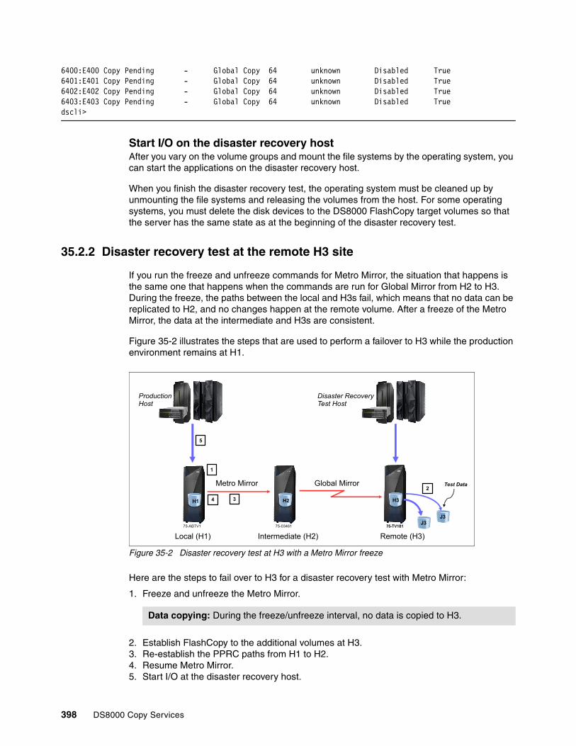
6400:E400 Copy Pending - Global Copy 64 unknown Disabled True6401:E401 Copy Pending - Global Copy 64 unknown Disabled True6402:E402 Copy Pending - Global Copy 64 unknown Disabled True6403:E403 Copy Pending - Global Copy 64 unknown Disabled Truedscli>
Start I/O on the disaster recovery hostAfter you vary on the volume groups and mount the file systems by the operating system, you can start the applications on the disaster recovery host.
When you finish the disaster recovery test, the operating system must be cleaned up by unmounting the file systems and releasing the volumes from the host. For some operating systems, you must delete the disk devices to the DS8000 FlashCopy target volumes so that the server has the same state as at the beginning of the disaster recovery test.
35.2.2 Disaster recovery test at the remote H3 site
If you run the freeze and unfreeze commands for Metro Mirror, the situation that happens is the same one that happens when the commands are run for Global Mirror from H2 to H3. During the freeze, the paths between the local and H3s fail, which means that no data can be replicated to H2, and no changes happen at the remote volume. After a freeze of the Metro Mirror, the data at the intermediate and H3s are consistent.
Figure 35-2 illustrates the steps that are used to perform a failover to H3 while the production environment remains at H1.
Figure 35-2 Disaster recovery test at H3 with a Metro Mirror freeze
Here are the steps to fail over to H3 for a disaster recovery test with Metro Mirror:
1. Freeze and unfreeze the Metro Mirror.
2. Establish FlashCopy to the additional volumes at H3.3. Re-establish the PPRC paths from H1 to H2.4. Resume Metro Mirror.5. Start I/O at the disaster recovery host.
Data copying: During the freeze/unfreeze interval, no data is copied to H3.
H1
Intermediate (H2) Remote (H3)Local (H1)
Metro Mirror
Disaster RecoveryTest Host
ProductionHost
1
2
34
5
75-ABTV1 75-03461 75-TV181
Test Data
H2
Global Mirror
75-TV181J3
H3
J3J3
398 DS8000 Copy Services

For this scenario, assume that an additional host is available to start the application from the additional volumes that were copied with FlashCopy at H3.
These steps are explained in detail in 35.2.1, “Disaster recovery test at the intermediate H2 site” on page 394. The only difference is that steps 2 and 5 are performed on H3.
35.3 Providing consistency with Global Mirror
In some client environments, the synchronous replication with Metro Mirror is as critical as the production environment. In this case, the Metro Mirror must not be stopped at all during testing, so a disaster recovery test must be done at H3, where consistent data for the test is provided by Global Mirror.
This scenario requires a few more steps than when you use Metro Mirror, but it is fairly easy task to achieve, as shown in Figure 35-3.
Figure 35-3 Disaster recovery test at H3 with Global Mirror
Here are the steps to fail over to H3 for a disaster recovery test with Global Mirror:
1. Stop Global Mirror.2. Pause Global Copy from H2 to H3.3. Failover Global Copy to H3.4. Fast reverse FlashCopy from the J3 to the H3 volumes.5. Establish FlashCopy from the H3 to the I3 volumes.6. Failback Global Copy from H2 to H3.7. Restart Global Mirror.8. Start I/O at the disaster recovery host.
RPO: Between step 1 and step 7, Global Mirror is stopped and cannot provide consistency at H3. During this time, the RPO increases.
H1
Intermediate (H2) Remote (H3)Local (H1)
Metro Mirror
Disaster RecoveryTest Host
ProductionHost
1
2 3
75-ABTV1 75-03461 75-TV181
Test Data
H2
Global Mirror
75-TV181
H34
5
6
7
8
J3J3
Chapter 35. Metro/Global Mirror disaster recovery test scenarios 399

35.3.1 Stop Global Mirror
When Global Mirror stops, no more consistency groups are formed and saved on the FlashCopy target volumes. The moment when Global Mirror stops represents the time stamp of the data for the disaster recover test.
Example 35-6 shows the command to stop Global Mirror.
Example 35-6 Stop Global Mirror
dscli> rmgmir -quiet -lss 64 -session 2 CMUC00165I rmgmir: Global Mirror for session 2 successfully stopped.dscli>
35.3.2 Suspend Global Copy from H2 to H3
Suspend the Global Copy from the intermediate to H3 to prepare for the failback in 35.3.6, “Failback Global Copy from H2 to H3” on page 401. In that step, the failbackpprc command is issued to the original direction, and the command requires that the Global Copy primary volume is in the suspended state.
Example 35-7 shows the command that is used to suspend Global Copy from H2 to H3.
Example 35-7 Suspend Global Copy from H2 to H3
dscli> pausepprc -remotedev IBM.2107-75TV181 6400-6403:e400-e403CMUC00157I pausepprc: Remote Mirror and Copy volume pair 6400:E400 relationship successfully paused.CMUC00157I pausepprc: Remote Mirror and Copy volume pair 6401:E401 relationship successfully paused.CMUC00157I pausepprc: Remote Mirror and Copy volume pair 6402:E402 relationship successfully paused.CMUC00157I pausepprc: Remote Mirror and Copy volume pair 6403:E403 relationship successfully paused.dscli>
35.3.3 Failing over Global Copy to H3
Now the Global Copy must be failed over to H3. Issue the failoverpprc command that is shown in Example 35-8 at H3. Remember, the C volumes are not consistent because the Metro Mirror constantly sends data from the running production site while this command is running.
Example 35-8 Failover Global Copy to H3
dscli> failoverpprc -remotedev IBM.2107-7503461 -type gcp e400-e403:6400-6403CMUC00196I failoverpprc: Remote Mirror and Copy pair E400:6400 successfully reversed.CMUC00196I failoverpprc: Remote Mirror and Copy pair E401:6401 successfully reversed.CMUC00196I failoverpprc: Remote Mirror and Copy pair E402:6402 successfully reversed.CMUC00196I failoverpprc: Remote Mirror and Copy pair E403:6403 successfully reversed.dscli>
35.3.4 Fast reversal of FlashCopy from the J3 to H3 volumes
The remote volumes at C are now ready to catch the most recent consistency group from the FlashCopy target volumes of the Global Mirror (Example 35-9 on page 401). This action is necessary because the production environment is running at H1 and the Metro Mirror has constantly copied data to H2 while the failoverpprc command was running.
400 DS8000 Copy Services

Example 35-9 Fast reverse restore of the Global Mirror FlashCopy
dscli> reverseflash -fast -tgtpprc e400-e403:d400-d403CMUC00169I reverseflash: FlashCopy volume pair E400:D400 successfully reversed.CMUC00169I reverseflash: FlashCopy volume pair E401:D401 successfully reversed.CMUC00169I reverseflash: FlashCopy volume pair E402:D402 successfully reversed.CMUC00169I reverseflash: FlashCopy volume pair E403:D403 successfully reversed.dscli>
The FlashCopy must be re-created to start Global Mirror in 35.3.7, “Restart Global Mirror” on page 402. You can re-create the FlashCopy by running the command that is shown in Example 35-10.
Example 35-10 Re-create the Global Mirror FlashCopy pairs
dscli> mkflash -tgtinhibit -record -persist -nocp e400-e403:d400-d403CMUC00137I mkflash: FlashCopy pair E400:D400 successfully created.CMUC00137I mkflash: FlashCopy pair E401:D401 successfully created.CMUC00137I mkflash: FlashCopy pair E402:D402 successfully created.CMUC00137I mkflash: FlashCopy pair E403:D403 successfully created.scli>
35.3.5 Establish FlashCopy from the H3 volumes to the practice I3 volumes
As consistent data is now present on the H3 volumes, you can create a background FlashCopy to the final practice I3 volumes, where the I/O is started later. To accomplish this task, run the command that is shown in Example 35-11.
Example 35-11 Create FlashCopy to the practice volumes
dscli> mkflash e400-e403:d410-d413CMUC00137I mkflash: FlashCopy pair E400:D410 successfully created.CMUC00137I mkflash: FlashCopy pair E401:D411 successfully created.CMUC00137I mkflash: FlashCopy pair E402:D412 successfully created.CMUC00137I mkflash: FlashCopy pair E403:D413 successfully created.dscli>
While the background copy continues, the data can be accessed by the test servers at H3. However, you should finish the scenario before you start testing to bring the Global Mirror back into production as fast as possible.
35.3.6 Failback Global Copy from H2 to H3
Global Copy must be failed back to the original direction. To accomplish this task, run failbackpprc command at H2 (Example 35-12).
Example 35-12 Failbackpprc from H2 to H3
dscli> failbackpprc -remotedev IBM.2107-75TV181 -type gcp 6400-6403:e400-e403CMUC00197I failbackpprc: Remote Mirror and Copy pair 6400:E400 successfully failed back.CMUC00197I failbackpprc: Remote Mirror and Copy pair 6401:E401 successfully failed back.
Note: Prior to DS8000 LMC Release 7.4, establishing a cascaded PPRC configuration required the use of the -cascade option for the remote pair. This is no longer needed.
Chapter 35. Metro/Global Mirror disaster recovery test scenarios 401

CMUC00197I failbackpprc: Remote Mirror and Copy pair 6402:E402 successfully failed back.CMUC00197I failbackpprc: Remote Mirror and Copy pair 6403:E403 successfully failed back.dscli>
35.3.7 Restart Global Mirror
Restart the Global Mirror by running the commands that are shown in Example 35-13. This action brings Global Mirror back into production. New consistency groups are formed at H3. The RPO catches up immediately.
Example 35-13 Restart Global Mirror
dscli> mkgmir -lss 64 -session 2CMUC00162I mkgmir: Global Mirror for session 2 successfully started.
Run showgmir to verify that the Global Mirror continues with consistency formation.
35.3.8 Start I/O at the disaster recovery host
The disaster recovery test can begin at H3. After you vary on the volume groups and mount the file systems of the operating system, you can start the applications on the disaster recovery host.
When you finish the disaster recovery test, the operating system must be cleaned up by unmounting the file systems and releasing the volumes by the host. For some operating systems, the disk devices of the DS800 FlashCopy target volumes must be deleted so that the server has the same state as it had at the beginning of the disaster recovery test.
402 DS8000 Copy Services

Chapter 36. Metro/Global Mirror incremental resynchronization
This chapter explains and illustrates the incremental resynchronization feature that is available in a cascaded Metro/Global Mirror environment. It includes the following topics:
� Overview� Setting up Metro/Global Mirror with Incremental Resync� Incremental Resync recovery scenarios� Restore original Metro/Global Mirror configuration� Convert Global Mirror to Metro/Global Mirror
36
© Copyright IBM Corp. 2017. All rights reserved. 403

36.1 Overview
In a Metro/Global Mirror environment, data is copied from the local H1 site to the intermediate H2 site and then cascaded from H2 to the remote H3 site. If there is a failure at H2, or a loss of connectivity between H1 and H2, data cannot be replicated to H3. However, when there is connectivity between H1 and H3, Global Mirror can be established from H1 to H3 to resume the disaster recovery protection.
Incremental Resync offers the capability to establish the Global Mirror relationship between H1 and H3 without needing to replicate all the data again. In other words, the resynchronization between H1 and H3 is an incremental copy, instead of a full copy.
Figure 36-1 shows how to start Global Mirror from the H1 directly to H3 in the case where there has been a failure at H2.
Figure 36-1 Incremental Resync overview
With Metro/Global Mirror and incremental resynchronization, the following recovery actions possible:
� Recovery after a failure at the intermediate H2 site
Start a Global Mirror from the local H1 site directly to the remote H3 site, where only the changes at H2 must be resynchronized. The production environment continues to run at H1. When the intermediate side is recovered, it can be synchronized from H3. When this synchronization is finished, the original replicating direction from H1 through H2 to H3 can be restored.
� Recovery after a failure at the local H1 site
Move the production environment to run at the intermediate H2 site while Global Mirror continues to run from H2 to H3. When the local H1 site is back, it is resynchronized from H3. When this resynchronization has completed, Metro/Global Mirror Incremental Resync can be used to establish Metro Mirror from H2 to H1. The Metro/Global Mirror configuration can be restored by establishing Global Mirror from H1 to H3, resulting in an Metro/Global Mirror H2:H1:H3 configuration.
� Swap the production environment between the local H1 and intermediate H2 sites
The copy direction can be swapped between H1:H2:H3 to H2:H1:H3 without requiring a full copy of data.
H1
Intermediate RemoteLocal
Global Mirror
Metro Mirror
H3
J3
H2
J2
Global Mirror
404 DS8000 Copy Services

36.1.1 Functional description
To enable the Incremental Resync capability, use the -incrementalresync option when you initially establish the Metro Mirror relationship between the local H1 and intermediate H2 sites. If the Metro Mirror pairs are already established and in the Full Duplex state, you can enable Incremental Resync by running mkpprc against the existing Metro Mirror relationships with the -incrementalresync option to enable Incremental Resync. For information about mkpprc, see 36.1.2, “Options for DS CLI” on page 406.
This start Incremental Resync at H1. Two change recording bitmaps, N and N-1, are created for each volume. The N bitmap records all host writes that occur to the volume.
An internal DS8000 process is started on the local H1 storage system which periodically queries the consistency status of the Global Mirror at H2. If the query reports that a consistency group to the remote H3 site has formed successfully at least three times, then the current N bitmap is saved as the N-1 bitmap and a new all zero N-1 bitmap is created. Then, this process starts over again. Figure 36-2 shows this whole process. As a result, the combination of the N and N-1 bitmaps represent all data that has been written to H1, but potentially not yet mirrored to H3.
Figure 36-2 Incremental Resynchronization process
If there is a failure at H2, the Metro Mirror H1:H2 pairs will suspend and the out-of-sync bitmaps at H1 will record all writes that have occurred at H1, but not mirrored to H2.
To bypass H2 after a site failure, a new Global Copy relationship is established from H1 to H3. This new Global Copy must be established with the Incremental Resync option. When this is done, only the tracks that are recorded in the change recording bitmap and in the out-of-sync recording are copied to H3. When all out-of-sync tracks are sent from the local to H3, a Global Mirror can be started at H1 by using the remote volumes as the Global Mirror target volumes.
H1
Intermediate RemoteLocal
Global MirrorMetro Mirror
H3
J3
H2
J2
Global Mirror
H1 query ofGlobal Mirror at H2
CR N
CR N-1
Chapter 36. Metro/Global Mirror incremental resynchronization 405

36.1.2 Options for DS CLI
You can enable Incremental Resync by specifying the -incrementalresync option on the mkpprc command. (The other interfaces for establishing a Metro Mirror pair have similar options.) This option uses the following values to specify the actions of Incremental Resync:
enable Enables the Incremental Resync function. It creates initialized change recording bitmaps. (Bitmaps consist initially of all ones. As consistency groups are formed in Global Mirror, the bitmaps change to reflect only the changed data.)
enablenoinit Enables the Incremental Resync function and creates change recording bitmaps. The bitmaps are not initialized (they are all zeros). This option should be used only in certain cases as part of the return scenario for Incremental Resync.
disable Stops the Incremental Resync mechanism.
recover Brings in relationships of local to remote volumes as new pairs. The devices that are specified in the command are checked to ensure that they currently have a target device in common. This value verifies that the devices are part of an existing Metro/Global Mirror relationship.
override Is the same as with the recover value, but the volumes cannot be part of a Metro/Global Mirror. Unlike the recover option, the relationship validation is not performed.
36.2 Setting up Metro/Global Mirror with Incremental Resync
This section describes how to set up Metro/Global Mirror with incremental resynchronization. This description assumes that no existing Metro Mirror or Global Copy relationships exist. A description of converting a Global Mirror configuration to a Metro/Global Mirror with incremental resynchronization is given in 36.5, “Convert Global Mirror to Metro/Global Mirror” on page 419.
Before using Incremental Resync, you must establish paths from H1 to H3. These paths are required for the Global Mirror relationship, which is created when the failing H2 site is bypassed.
When this topology is set up, the size of the link between H1 and H3 should be similar to or have the same bandwidth and latency characteristics of the intermediate to remote Global Mirror link. The Global Mirror between H1 and H3 then has a similar recovery point objective (RPO) behavior to the existing Global Mirror from H2 to H3.
To set up Metro/Global Mirror with Incremental Resync, complete the steps in 32.3, “Initial setup of Metro/Global Mirror” on page 365.
Note: With the -incrementalresync option enabled, the N-bitmaps are initialized with ones and at least two toggles must happen before the data is copied incrementally. Before this action occurs, a full copy takes place. Before an incremental resynchronization can be initiated, it must run at least for 10 - 15 minutes; otherwise, a full copy takes place.
Prior to DS8000 LMC Release 7.4, establishing a cascaded Peer-to-Peer Remote Copy (PPRC) configuration required the use of the -cascade option for the remote pair. This is no longer needed.
406 DS8000 Copy Services

The steps must be completed in the same order. However, the steps listed in 32.3.3, “Establish Metro Mirror from H1 to H2” on page 369 are modified as follows to implement Metro/Global Mirror with Incremental Resync:
� Specify the -incrementalresync enable option with the -type mmir option when you run mkpprc at H1 to create the Metro Mirror relationship. This action enables the Incremental Resync function and creates change record bitmaps for the Metro Mirror primary volumes that are running at H1.
� When the Metro Mirror is established without Incremental Resync enabled, the -mode nocp option (to avoid a full copy) is required to enable Incremental Resync with an existing Metro Mirror.
Example 36-1 shows how to set up incremental resynchronization for Metro/Global Mirror. The output data from the lspprc -l command is lengthy. So parts are edited out in this example to better show the fields of interest.
Example 36-1 Setup of Metro/Global Mirror with Incremental Resync
dscli> mkpprc -dev IBM.2107-1301651 -remotedev IBM.2107-1301261 -type mmir -mode nocp -incrementalresync enable 2000-2007:2000-2007CMUC00153I mkpprc: Remote Mirror and Copy volume pair relationship 2000:2000 successfully created.CMUC00153I mkpprc: Remote Mirror and Copy volume pair relationship 2001:2001 successfully created.CMUC00153I mkpprc: Remote Mirror and Copy volume pair relationship 2002:2002 successfully created.CMUC00153I mkpprc: Remote Mirror and Copy volume pair relationship 2003:2003 successfully created.CMUC00153I mkpprc: Remote Mirror and Copy volume pair relationship 2004:2004 successfully created.CMUC00153I mkpprc: Remote Mirror and Copy volume pair relationship 2005:2005 successfully created.CMUC00153I mkpprc: Remote Mirror and Copy volume pair relationship 2006:2006 successfully created.CMUC00153I mkpprc: Remote Mirror and Copy volume pair relationship 2007:2007 successfully created.dscli>dsclI> lspprc -dev IBM.2107-1301651 -l 2000-2007ID State Reason Type Out Of Sync Tracks Tgt Read Src Cascade Tgt Cascade ... First Pass Status Incremental Resync============================================================================================== ... ====================================2000:2000 Full Duplex - Metro Mirror 0 Disabled Disabled Invalid ... Invalid Enabled2001:2001 Full Duplex - Metro Mirror 0 Disabled Disabled Invalid ... Invalid Enabled2002:2002 Full Duplex - Metro Mirror 0 Disabled Disabled Invalid ... Invalid Enabled2003:2003 Full Duplex - Metro Mirror 0 Disabled Disabled Invalid ... Invalid Enabled2004:2004 Full Duplex - Metro Mirror 0 Disabled Disabled Invalid ... Invalid Enabled2005:2005 Full Duplex - Metro Mirror 0 Disabled Disabled Invalid ... Invalid Enabled2006:2006 Full Duplex - Metro Mirror 0 Disabled Disabled Invalid ... Invalid Enabled2007:2007 Full Duplex - Metro Mirror 0 Disabled Disabled Invalid ... Invalid Enabled
Complete the remaining steps in 32.3, “Initial setup of Metro/Global Mirror” on page 365 to complete the setup for Metro/Global Mirror with Incremental Resync.
36.3 Incremental Resync recovery scenarios
In a 3-site Metro/Global Mirror configuration, a failure can occur at any one of the sites. This section provides descriptions for handling failures at the three sites in a cascaded Metro/Global Mirror configuration.
36.3.1 Failure at the local H1 site
This scenario starts with Metro/Global Mirror with Incremental Resync running from H1 to H2 to H3.
A failure of the local H1 site can be handled by using the capabilities of Multiple Target PPRC. The high-level steps for this process are as follows:
1. Swap to the intermediate H2 site
– Failover H2:H1, which results in a Multiple Target PPRC configuration where H2 is a primary to both H1 and H3.
Chapter 36. Metro/Global Mirror incremental resynchronization 407
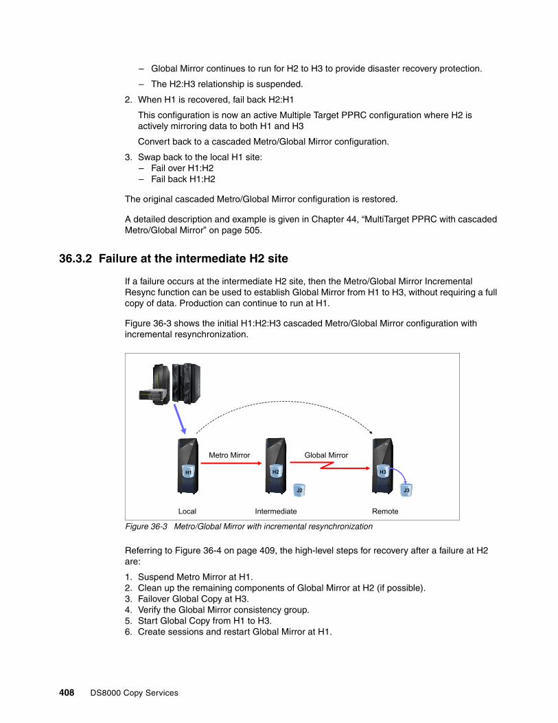
– Global Mirror continues to run for H2 to H3 to provide disaster recovery protection.
– The H2:H3 relationship is suspended.
2. When H1 is recovered, fail back H2:H1
This configuration is now an active Multiple Target PPRC configuration where H2 is actively mirroring data to both H1 and H3
Convert back to a cascaded Metro/Global Mirror configuration.
3. Swap back to the local H1 site:– Fail over H1:H2– Fail back H1:H2
The original cascaded Metro/Global Mirror configuration is restored.
A detailed description and example is given in Chapter 44, “MultiTarget PPRC with cascaded Metro/Global Mirror” on page 505.
36.3.2 Failure at the intermediate H2 site
If a failure occurs at the intermediate H2 site, then the Metro/Global Mirror Incremental Resync function can be used to establish Global Mirror from H1 to H3, without requiring a full copy of data. Production can continue to run at H1.
Figure 36-3 shows the initial H1:H2:H3 cascaded Metro/Global Mirror configuration with incremental resynchronization.
Figure 36-3 Metro/Global Mirror with incremental resynchronization
Referring to Figure 36-4 on page 409, the high-level steps for recovery after a failure at H2 are:
1. Suspend Metro Mirror at H1.2. Clean up the remaining components of Global Mirror at H2 (if possible).3. Failover Global Copy at H3.4. Verify the Global Mirror consistency group.5. Start Global Copy from H1 to H3.6. Create sessions and restart Global Mirror at H1.
H1
Intermediate RemoteLocal
Metro Mirror
H3
J3
H2
J2
Global Mirror
408 DS8000 Copy Services

Figure 36-4 Global Mirror H1:H3 after failure at H2
The following sections give detailed descriptions of these steps. The examples use the DS CLI. The equivalent commands for other interfaces are listed in Chapter 3, “Copy Services interfaces overview” on page 17.
The examples use the following address ranges.
� H1: 4200-4203� H2: 6400-6403� H3: E400-E403
The volume ranges for each site is different only to help distinguish them in the examples. It is not a requirement that they be different.
Suspend Metro Mirror H1:H2The Metro Mirror H1:H2 pairs might already be suspended because of the failure at H2. However, depending on the type of failure and the workload distribution, it is possible that not all pairs will suspend. You run pausepprc to suspend all the volume pairs.
Example 36-2 shows the command to suspend Metro Mirror at H1.
Example 36-2 Suspend Metro Mirror at H1
dscli> pausepprc -remotedev IBM.2107-7503461 4200-4203:6400-6403CMUC00157I pausepprc: Remote Mirror and Copy volume pair 4200: relationship successfully paused.CMUC00157I pausepprc: Remote Mirror and Copy volume pair 4201: relationship successfully paused.CMUC00157I pausepprc: Remote Mirror and Copy volume pair 4202: relationship successfully paused.CMUC00157I pausepprc: Remote Mirror and Copy volume pair 4203: relationship successfully paused.
Clean up the remaining components of Global MirrorDepending on the type of failure at H2, there might be some components of Global Mirror that can be cleaned up. If the H2 site is still partially accessible, you can attempt a termination of Global Mirror by running rmgmir. If the command fails, it might mean that the subordinates are orphaned because the master at H2 does not have access to them. In this case, the rmgmir
Note: Depending on the type of failure at H2, communication to it might not be possible. In this case, the pausepprc command might return an error message, but the volumes at H1 will still be suspended.
H1
Intermediate RemoteLocal
H3
J3
H2
J2
1
2
Global Mirror
5 6
3 4
Chapter 36. Metro/Global Mirror incremental resynchronization 409

command can be attempted at any of the subordinates. If none of these actions are successful and Global Mirror or any of its components cannot be cleaned up, you can perform the cleanup after the intermediate is accessible again (for more information, see 36.4, “Restore original Metro/Global Mirror configuration” on page 412).
Failover Global Copy H3A Global Copy failover at H3 changes the state of the volumes at the H3 from secondary duplex pending (or suspended) to Suspended Host Source. PPRC out-of-sync bitmaps are created for use during the resynchronization to H2 in 36.4.2, “Failback Global Copy from the H3 to H2” on page 415 and in 36.4.3, “Start Incremental Resync at H1” on page 415.
The command that is issued at H3 is failoverpprc, as shown in Example 36-3.
Example 36-3 Failover Global Copy H3:H2
dscli> failoverpprc -remotedev IBM.2107-7503461 -type gcp e400-e403:6400-6403CMUC00196I failoverpprc: Remote Mirror and Copy pair E400:6400 successfully reversed.CMUC00196I failoverpprc: Remote Mirror and Copy pair E401:6401 successfully reversed.CMUC00196I failoverpprc: Remote Mirror and Copy pair E402:6402 successfully reversed.CMUC00196I failoverpprc: Remote Mirror and Copy pair E403:6403 successfully reversed.dscli>dscli> lspprc e400-e403 ID State Reason Type SourceLSS Timeout (secs) Critical Mode First Pass Status====================================================================================================E400:6400 Suspended Host Source Global Copy E4 60 Disabled TrueE401:6401 Suspended Host Source Global Copy E4 60 Disabled TrueE402:6402 Suspended Host Source Global Copy E4 60 Disabled TrueE403:6403 Suspended Host Source Global Copy E4 60 Disabled True
Verify the Global Mirror consistency groupYou must check the Global Mirror consistency at H3. This step is necessary in case H2 fails in the middle of consistency group formation, which means that the FlashCopy of the Global Mirror must be reverted or committed.
To verify the Global Mirror consistency, see 33.4, “Checking consistency at H3” on page 379, which describes how to verify the consistency group and determine whether any action must be taken.
Start Global Copy from H1 to H3Establish Global Copy from H1 to H3 using incremental resynchronization by running mkpprc with the -incrementalresync recover option. The recover parameter causes the DS8000 to verify that the H2 volumes are in common between H1 and H2.
Verifying consistency groups: Depending on the extent of the failure at H2, Global Mirror might no longer be running and might show “FATAL” or failing consistency groups. If Global Mirror was in the middle of a FlashCopy, then the consistency group might need to be verified at some point. To check the status of the Global Mirror and see whether consistency groups are failing, run showgmir -metrics to display the status.
Tip: The lsflash -l command shows a query of the FlashCopy status. This query is helpful when verifying the Global Mirror consistency group.
410 DS8000 Copy Services

When Global Copy is established from H1 to H3, the incremental resynchronization function running at H1 is stopped. The change recording bitmaps at H1 are merged with the out-of-sync bitmaps to determine which data tracks require synchronization from H1 to H3.I
In Example 36-4, the lspprc command that is issued at H1 shows the relationship of the Metro Mirror from H1 to H2. After you run mkpprc with the -incrementalresync recover option, the pair relation changes to Global Copy relationship from H1 to H3.
Example 36-4 Start Global Copy from H1 to H3 with incremental resynchronization
dsclI> mkpprc -remotedev IBM.2107-75TV181 -type gcp -mode full -incrementalresync recover 4200-4203:e400-e403CMUC00153I mkpprc: Remote Mirror and Copy volume pair relationship 4200:E400 successfully created.CMUC00153I mkpprc: Remote Mirror and Copy volume pair relationship 4201:E401 successfully created.CMUC00153I mkpprc: Remote Mirror and Copy volume pair relationship 4202:E402 successfully created.CMUC00153I mkpprc: Remote Mirror and Copy volume pair relationship 4203:E403 successfully created.dsclI> lspprc -l 4200-4203ID State Reason Type Out Of Sync Tracks Tgt Read Src Cascade Tgt Cascade ...============================================================================================== ...4200:E400 Copy Pending - Global Copy 5 Disabled Enabled Invalid ...4201:E401 Copy Pending - Global Copy 8 Disabled Enabled Invalid ...4202:E402 Copy Pending - Global Copy 18 Disabled Enabled Invalid ...4203:E403 Copy Pending - Global Copy 2 Disabled Enabled Invalid ...
Create and start Global Mirror session at H1For the H1:H3 Global Copy relationships, create a session and add the volumes to the session before you start the Global Mirror at H1. Create the session with the mksession command and add the pairs to the session by running chsession with the -action add option at H1.
Start the Global Mirror session by running mkgmir command at H1. This configuration remains unchanged until the H2 site is available again for Metro/Global Mirror. Production continues to run at H1 without interruption while the Global Mirror configuration is being changed. Example 36-5 shows the steps to make the Global Mirror session, add volumes into the session and start Global Mirror.
Example 36-5 Create a session and start Global Mirror at H1
dscli> mksession -lss 42 2CMUC00145I mksession: Session 2 opened successfully.dscli>dscli> chsession -lss 42 -action add -volpair 4200-4203:e400-e403 2CMUC00147I chsession: Session 2 successfully modified.dscli>dscli> lssession -dev IBM.2107-75ABTV1 42 2LSS ID Session Status Volume VolumeStatus PrimaryStatus SecondaryStatus FirstPassComplete AllowCascading=================================================================================================================42 02 Normal 4200 Active Primary Copy Pending Secondary Simplex True Enable42 02 Normal 4201 Active Primary Copy Pending Secondary Simplex True Enable42 02 Normal 4202 Active Primary Copy Pending Secondary Simplex True Enable42 02 Normal 4203 Active Primary Copy Pending Secondary Simplex True Enabledscli>dscli> mkgmir -dev IBM.2107-75ABTV1 -lss 42 -session 2 CMUC00162I mkgmir: Global Mirror for session 2 successfully started.
Important: All writes are transferred from the local H1 site to the remote H3 site and all the out-of-sync tracks must be drained before you continue with “Create and start Global Mirror session at H1”. To query out-of-sync tracks, run the lspprc -l command at H1.
Chapter 36. Metro/Global Mirror incremental resynchronization 411

At this point, the protection of Global Mirror is restored. Application I/O continues to run against the H1 volumes and Global Mirror replicates the data to the remote H3 disaster recovery site.
36.4 Restore original Metro/Global Mirror configuration
This section describes the process of restoring the original H1:H2:H3 Metro/Global Mirror configuration after the H2 site has been recovered.
Figure 36-5 shows the starting configuration when Global Mirror has been established from H1 to H3 following a failure at H2.
Figure 36-5 After H2 site failure
After the H2 site is available again, it might still have Global Mirror relationships left over from before the failure event. These must be removed before proceeding. However, the underlaying Global Copy relationship must not be removed because this relationship corresponds to the failed over status at H3, which happened in “Failover Global Copy H3” on page 410. Later in this scenario, a failback from H3 to H2 incrementally resynchronizes data to H2, instead of performing a full copy.
H1
Intermediate RemoteLocal
H3
J3
H2
J2
Global Mirror
412 DS8000 Copy Services

Figure 36-6 illustrates the steps to clean up the intermediate H2 site after it has been recovered.
Figure 36-6 Steps to clean up H2 after recovery
Here are the steps to clean up H2 after it is fully recovered:
1. Remove the remaining components.2. Failback Global Copy from H3 to H2.3. Start Incremental Resync at H1.4. Stop Global Mirror and suspend Global Copy from H1 to H3.5. Remove Global Copy from H1 to H3 at H3.6. Reverse Global Copy to run from H2 to H3.7. Create Metro Mirror from H1 to H2.8. Start Global Mirror.
36.4.1 Clean up the remaining components at H2
To clean up the surviving components, complete the following steps:
� Remove Metro Mirror.� Finish Global Mirror.� Suspend the Global Copy relationships from H2 to H3.
Remove Metro MirrorMetro Mirror, which was running from H1 to H2, must be terminated at H2. When the intermediate H2 site becomes available, the volumes might still show as Target Full Duplex from the former Metro Mirror relationship. Removing the Metro Mirror allows you to do the failback from H1 to H2 in a later step.
To remove Metro Mirror, run rmpprc with the options -unconditional -at tgt at H2.
H1
Intermediate RemoteLocal
Metro Mirror
H3
J3
H2
J2
Global Mirror2
3
1
45
6
8
7
Tip: To remove the Metro Mirror pairs, the communication between H1 and H2 must be operational. Check the PPRC paths in both directions when the H2 site becomes available again.
Chapter 36. Metro/Global Mirror incremental resynchronization 413

In Example 36-6, the paths between H1 and H2 checked first. You can view the Global Copy status between H1 and H3 by running the lssprc command at H1.
Example 36-6 Remove the Metro Mirror target relationship at H2
dcsli> lspprc 6400-6403ID State Reason Type SourceLSS Timeout (secs) Critical Mode First Pass Status==============================================================================================================ID State Reason Type SourceLSS Timeout (secs) Critical Mode First Pass Status==============================================================================================================4200:6400 Target Suspended Update Target Metro Mirror 42 unknown Disabled Invalid4201:6401 Target Suspended Update Target Metro Mirror 42 unknown Disabled Invalid4202:6402 Target Suspended Update Target Metro Mirror 42 unknown Disabled Invalid4203:6403 Target Suspended Update Target Metro Mirror 42 unknown Disabled Invalid6400:E400 Suspended Host Source Global Copy 64 unknown Disabled True6401:E401 Suspended Host Source Global Copy 64 unknown Disabled True6402:E402 Suspended Host Source Global Copy 64 unknown Disabled True6403:E403 Suspended Host Source Global Copy 64 unknown Disabled True
dscli>dscli> rmpprc -quiet -unconditional -at tgt 6400-6403 5700-5703CMUC00155I rmpprc: Remote Mirror and Copy volume pair :6400 relationship successfully withdrawn.CMUC00155I rmpprc: Remote Mirror and Copy volume pair :6401 relationship successfully withdrawn.CMUC00155I rmpprc: Remote Mirror and Copy volume pair :6402 relationship successfully withdrawn.CMUC00155I rmpprc: Remote Mirror and Copy volume pair :6403 relationship successfully withdrawn.dscli>dscli> lspprc 6400-6403ID State Reason Type SourceLSS Timeout (secs) Critical Mode First Pass Status==================================================================================================6400:E400 Suspended Host Source Global Copy 64 unknown Disabled True6401:E401 Suspended Host Source Global Copy 64 unknown Disabled True6402:E402 Suspended Host Source Global Copy 64 unknown Disabled True6403:E403 Suspended Host Source Global Copy 64 unknown Disabled True
Finishing Global MirrorThe former Global Mirror session must be terminated at H2. Run rmgmir at H2 to terminate Global Mirror. However, if this operation was already done in “Clean up the remaining components of Global Mirror” on page 409, the current attempt fails because the Global Mirror session is already terminated.
If the session was not terminated before and fails again now, the failure might be caused by orphaned subordinates. In this case, Global Mirror must be terminated at the orphaned subordinate by running the rmgmir command.
Suspend Global Copy relationships from the H2 or H3The volumes at H2 still have Global Copy relationships with H3. These relationships were not removed because they still correspond to the failover status at H3. In the next step, the Global Copy is failed back from H3, for which these relationships are still required.
It is likely that after the storage at the intermediate is back, that Global Copy relationships are already in a suspended state. If not, you must suspend the Global Copy now by running the pausepprc command with the -unconditional -at src options. Then, the Global Copy relationships at H2 must be in the host suspended state (Example 36-6).
Failover state: The failover state at H3 prevents any previous Global Mirror configuration from operating.
414 DS8000 Copy Services

36.4.2 Failback Global Copy from the H3 to H2
Now that you have cleared the intermediate site H2 storage, you can run failbackpprc at H3 to begin copying data from H3 to H2.
Example 36-7 shows the command to fail back the Global Copy.
Example 36-7 Failback Global Copy from H3 to H2
dscli> failbackpprc -remotedev IBM.2107-7503461 -type gcp e400-e403:6400-6403CMUC00197I failbackpprc: Remote Mirror and Copy pair E400:6400 successfully failed back.CMUC00197I failbackpprc: Remote Mirror and Copy pair E401:6401 successfully failed back.CMUC00197I failbackpprc: Remote Mirror and Copy pair E402:6402 successfully failed back.CMUC00197I failbackpprc: Remote Mirror and Copy pair E403:6403 successfully failed back.dscli>dscli>lspprc -l e400-e403ID State Reason Type Out Of Sync Tracks ... First Pass Status Incremental Resync ...==================================================================== ... ==================================== ...4200:E400 Target Copy Pending - Global Copy 0 ... Invalid Disabled ...4201:E401 Target Copy Pending - Global Copy 0 ... Invalid Disabled ...4202:E402 Target Copy Pending - Global Copy 0 ... Invalid Disabled ...4203:E403 Target Copy Pending - Global Copy 0 ... Invalid Disabled ...E400:6400 Copy Pending - Global Copy 0 ... True Disabled ...E401:6401 Copy Pending - Global Copy 9076 ... False Disabled ...E402:6402 Copy Pending - Global Copy 5331 ... False Disabled ...E403:6403 Copy Pending - Global Copy 0 ... True Disabled ...
36.4.3 Start Incremental Resync at H1
You can now start incremental resynchronization at H1 with the no initialization option.
Running mkpprc with the -incrementalresync enablenoinit option successfully starts Incremental Resync at H1 without enabling the bitmaps, as shown in Example 36-8.
Example 36-8 Start Incremental Resync at H1
dscli> mkpprc -remotedev IBM.2107-75TV181 -type gcp -mode nocp -incrementalresync enablenoinit 4200-4203:e400-e403 CMUC00153I mkpprc: Remote Mirror and Copy volume pair relationship 4200:E400 successfully created.CMUC00153I mkpprc: Remote Mirror and Copy volume pair relationship 4201:E401 successfully created.CMUC00153I mkpprc: Remote Mirror and Copy volume pair relationship 4202:E402 successfully created.CMUC00153I mkpprc: Remote Mirror and Copy volume pair relationship 4203:E403 successfully created.dscli>dscli>lspprc -l 4200-4203 5300-5303ID State Reason Type Out Of Sync Tracks Tgt Read Src Cascade Tgt Cascade Date Suspended SourceLSS Timeout (secs) Critical Mode First Pass Status Incremental Resync Tgt Write GMIR CG PPRC CG isTgtSE DisableAutoResync==========================================================================================================================================4200:E400 Copy Pending - Global Copy 0 Disabled Enabled Invalid - 42 60 Disabled True Enabled Disabled N/A Disabled Unknown False4201:E401 Copy Pending - Global Copy 0 Disabled Enabled Invalid - 42 60 Disabled True Enabled Disabled N/A Disabled Unknown False4202:E402 Copy Pending - Global Copy 0 Disabled Enabled Invalid - 42 60 Disabled True Enabled Disabled N/A Disabled Unknown False4203:E403 Copy Pending - Global Copy 0 Disabled Enabled Invalid - 42 60 Disabled True Enabled Disabled N/A Disabled Unknown False
Incremental resynchronization: Waiting for the initial pass of the resynchronization before you restart incremental resynchronization is the preferred practice to reduce the number of updates that are sent later when Metro Mirror is started with incremental resynchronization and the -force option at H1. To query the out-of-sync status, run the lspprc -l command at H2.
Note: This step is necessary so that the Metro Mirror relationship at H1 can be restored in a later step by using the -incrementalresync override option.
Chapter 36. Metro/Global Mirror incremental resynchronization 415

36.4.4 Stop Global Mirror at H1 and suspend Global Copy
Global Mirror was running from H1 to H3 while H2 was being recovered. Before you restore the original configuration, terminate the Global Mirror with Incremental Resync from H1 to H3 by running the rmgmir command at H1. The remote FlashCopy target begins to age while the transition back to the original configuration is in progress.
To stop data from being copied to H3 and to allow the resynchronization to complete between H3 and H2, suspend Global Copy at H1 by running pausepprc command at H1. This command puts the H1 and H3 sites in to the primary suspend mode.
Example 36-9 shows the DS CLI command to suspend the Global Copy.
Example 36-9 Suspend Global Copy from H1 to H3
dscli> pausepprc -remotedev IBM.2107-75TV181 4200-4203:e400-e403CMUC00157I pausepprc: Remote Mirror and Copy volume pair 4200:E400 relationship successfully paused.CMUC00157I pausepprc: Remote Mirror and Copy volume pair 4201:E401 relationship successfully paused.CMUC00157I pausepprc: Remote Mirror and Copy volume pair 4202:E402 relationship successfully paused.CMUC00157I pausepprc: Remote Mirror and Copy volume pair 4203:E403 relationship successfully paused.
36.4.5 Stop Global Copy from H1 to H3 at H3
The Global Copy is terminated only at H3. This action is necessary because the pair relationships at H1 are required later. However, the pair relationships must be removed at H3 to proceed to 36.4.6, “Reverse Global Copy to run from H2 to H3” on page 417.
Run the rmpprc command with the -unconditional -at tgt option at H3. This termination does not affect H1’s state, so the out-of-sync bitmaps can remain in operation at H1. The state of H1 remains primary suspended, and H3 no longer shows as suspended target.
This step is necessary so that the failback from H2 to H3 described in 36.4.6, “Reverse Global Copy to run from H2 to H3” on page 417 can proceed.
Example 36-10 shows the command to remove the Global Copy at h3. The lspprc command, which is run at H1, shows that the relationship at H1 is still there. It is required for the incremental resynchronization in 36.4.7, “Create Metro Mirror with Incremental Resync at H1” on page 417.
Example 36-10 Stop Global Copy from H1 to H3 at H3
dscli> rmpprc -quiet -unconditional -at tgt e400-e403 e500-e503CMUC00155I rmpprc: Remote Mirror and Copy volume pair :E400 relationship successfully withdrawn.CMUC00155I rmpprc: Remote Mirror and Copy volume pair :E401 relationship successfully withdrawn.CMUC00155I rmpprc: Remote Mirror and Copy volume pair :E402 relationship successfully withdrawn.
Note: The swap back to the intermediate H2 site can be done at any time, but ideally should be done at a planned time.
Important: Out-of-sync tracks must be drained to H3 before you continue with 36.4.5, “Stop Global Copy from H1 to H3 at H3” on page 416. To query the out-of-sync tracks, run the lspprc -l command at H3.
Site updates: The local H1 site has updates for the H2 and H3 sites that are being recorded in the Incremental Resync change recording and out-of-sync bitmaps.
416 DS8000 Copy Services

CMUC00155I rmpprc: Remote Mirror and Copy volume pair :E403 relationship successfully withdrawn.dscli>dscli>lspprc -l e400-e403 e500-e503ID State Reason Type Out Of Sync Tracks Tgt Read Src Cascade Tgt Cascade Date Suspended SourceLSS Timeout (secs) Critical Mode First Pass Status Incremental Resync Tgt Write GMIR CG PPRC CG isTgtSE DisableAutoResync==========================================================================================================================================E400:6400 Copy Pending - Global Copy 0 Disabled Enabled Invalid - E4 60 Disabled True Disabled Disabled N/A Enabled Unknown FalseE401:6401 Copy Pending - Global Copy 0 Disabled Enabled Invalid - E4 60 Disabled True Disabled Disabled N/A Enabled Unknown FalseE402:6402 Copy Pending - Global Copy 0 Disabled Enabled Invalid - E4 60 Disabled True Disabled Disabled N/A Enabled Unknown FalseE403:6403 Copy Pending - Global Copy 0 Disabled Enabled Invalid - E4 60 Disabled True Disabled Disabled N/A Enabled Unknown False
36.4.6 Reverse Global Copy to run from H2 to H3
In this step, you reverse the Global Copy between H3 and H2 to the original H2:H3 direction.
Run failoverpprc and failbackpprc at H2. This action places the volumes at H2 into the primary suspended state.
Example 36-11 shows the required commands.
Example 36-11 Reverse Global Copy from H3 to H2
dscli> failoverpprc -remotedev IBM.2107-75TV181 -type gcp 6400-6403:e400-e403CMUC00196I failoverpprc: Remote Mirror and Copy pair 6400:E400 successfully reversed.CMUC00196I failoverpprc: Remote Mirror and Copy pair 6401:E401 successfully reversed.CMUC00196I failoverpprc: Remote Mirror and Copy pair 6402:E402 successfully reversed.CMUC00196I failoverpprc: Remote Mirror and Copy pair 6403:E403 successfully reversed.dscli>dscli> failbackpprc -remotedev IBM.2107-75TV181 -type gcp 6400-6403:e400-e403CMUC00197I failbackpprc: Remote Mirror and Copy pair 6400:E400 successfully failed back.CMUC00197I failbackpprc: Remote Mirror and Copy pair 6401:E401 successfully failed back.CMUC00197I failbackpprc: Remote Mirror and Copy pair 6402:E402 successfully failed back.CMUC00197I failbackpprc: Remote Mirror and Copy pair 6403:E403 successfully failed back.
36.4.7 Create Metro Mirror with Incremental Resync at H1
In this step, the command to create Metro Mirror with the Incremental Resync option is run twice with two different parameters. First, to stop Incremental Resync from H1 to H3 and to move it to H2, set Metro Mirror with Incremental Resync by running the mkpprc command with the -incrementalresync override option. By using the override parameter for -incrementalresync, you establish Metro Mirror with Incremental Resync without checking H2 (the Metro Mirror secondary). The change recording bitmaps are also merged with the out-of-sync bitmaps at H1 during this step.
Example 36-12 on page 418 shows the DS CLI command to create the Metro Mirror with the -incremental override option. During this phase, all tracks that are marked in the incremental resynchronization are not enabled. When all tracks are drained to H2, the incremental resynchronization is enabled.
Querying Metro Mirror and Global Copy: Both Metro Mirror and Global Copy might still be in the first pass. To query the status of Global Mirror or Metro Mirror, run the lspprc -l command at H1 to query Metro Mirror and at H2 to query Global Copy.
Chapter 36. Metro/Global Mirror incremental resynchronization 417

Example 36-12 Create Metro Mirror with Incremental Resync at H1
dscli> mkpprc -remotedev IBM.2107-7503461 -type mmir -mode nocp -incrementalresync override 4200-4203:6400-6403 CMUC00153I mkpprc: Remote Mirror and Copy volume pair relationship 4200:6400 successfully created.CMUC00153I mkpprc: Remote Mirror and Copy volume pair relationship 4201:6401 successfully created.CMUC00153I mkpprc: Remote Mirror and Copy volume pair relationship 4202:6402 successfully created.CMUC00153I mkpprc: Remote Mirror and Copy volume pair relationship 4203:6403 successfully created.dscli>dscli> lspprc 4200-4203ID State Reason Type SourceLSS Timeout (secs) Critical Mode First Pass Status==================================================================================================4200:6400 Full Duplex - Metro Mirror 42 60 Disabled Invalid4201:6401 Full Duplex - Metro Mirror 42 60 Disabled Invalid4202:6402 Full Duplex - Metro Mirror 42 60 Disabled Invalid4203:6403 Full Duplex - Metro Mirror 42 60 Disabled Invaliddscli>
## At intermediate H2 site#
dscli>lspprc -l 6400-6403 ID State Reason Type Out Of Sync Tracks Tgt Read Src Cascade Tgt Cascade Date Suspended SourceLSS Timeout (secs) Critical Mode First Pass Status Incremental Resync Tgt Write GMIR CG PPRC CG isTgtSE DisableAutoResync==========================================================================================================================================4200:6400 Target Full Duplex - Metro Mirror 0 Disabled Invalid Enabled - 42 unknown Disabled Invalid Disabled Disabled N/A N/A Unknown -4201:6401 Target Full Duplex - Metro Mirror 0 Disabled Invalid Enabled - 42 unknown Disabled Invalid Disabled Disabled N/A N/A Unknown -4202:6402 Target Full Duplex - Metro Mirror 0 Disabled Invalid Enabled - 42 unknown Disabled Invalid Disabled Disabled N/A N/A Unknown -4203:6403 Target Full Duplex - Metro Mirror 0 Disabled Invalid Enabled - 42 unknown 6400:E400 Copy Pending - Global Copy 0 Disabled Enabled Invalid - 64 unknown Disabled True Disabled Disabled N/A Disabled Unknown False6401:E401 Copy Pending - Global Copy 0 Disabled Enabled Invalid - 64 unknown Disabled True Disabled Disabled N/A Disabled Unknown False6402:E402 Copy Pending - Global Copy 0 Disabled Enabled Invalid - 64 unknown Disabled True Disabled Disabled N/A Disabled Unknown False6403:E403 Copy Pending - Global Copy 0 Disabled Enabled Invalid - 64 unknown Disabled True Disabled Disabled N/A Disabled Unknown False
Next, to monitor and track data as it is written on the primary volumes at H1, create a Metro Mirror relationship with Incremental Resync from H1 to H2 by running the mkpprc command with the -incrementalresync enable option.
Using the enable parameter for -incrementalresync initializes Incremental Resync by creating a change recording bitmap on H1.
36.4.8 Start Global Mirror at H2
When the original configuration is restored and Metro Mirror is in the Full Duplex state, then you can start Global Mirror, and it starts forming consistency groups successfully. Start Global Mirror by running mkgmir at H2. Depending on the Global Mirror configuration that is shown after H2 becomes available again, it is possible that these sessions must be created.
Example 36-13 shows the command to start the Global Mirror and the sessions at H2.
Example 36-13 Start Global Mirror at H2
dscli> mkgmir -dev IBM.2107-1301261 -lss 20 -session 2CMUC00162I mkgmir: Global Mirror for session 2 successfully started.
Important: Verify that the out-of-sync tracks completed for Metro Mirror before you start Global Mirror. Otherwise, the consistency groups fail when Global Mirror is started by running mkgmir.
418 DS8000 Copy Services

36.4.9 Failure at remote H3 site
If a failure occurs at the remote H3 site, then Metro Mirror from H1 to H2 continues to run and provides protection in case of a subsequent error at the production H1 site.
The failure at H3 will cause the Global Mirror from H2 to H3 will suspend. The H2 volumes l keep track of all write updates that are copied from H1 to H2. When the H3 site is recovered, Global Mirror can be restarted and only the changed data will be transferred from H2 to H3.
36.5 Convert Global Mirror to Metro/Global Mirror
Metro/Global Mirror with Incremental Resync can be initialized even if production is already running in a Global Mirror environment. The transition from the Global Mirror environment to an Metro/Global Mirror with Incremental Resync environment is performed by doing a full copy from the remote H3 site to the new intermediate H2 site.
Figure 36-7 shows an initial configuration where Global Mirror is running from H1 to H3. A new H2 storage system is brought in to be added as a new intermediate site.
Figure 36-7 Move from Global Mirror to Metro/Global Mirror with Incremental Resync
The general approach to this scenario is to synchronize the new H2 site from the existing H3 site using Global Copy. When the initial copy phase of this relationship passes, Incremental Resync is enabled at H1. Then, the original Global Mirror is terminated, the new Global Copy is reversed, and finally Metro Mirror is established by using the contents of the change recording bitmap of Incremental Resync.
Figure 36-8 on page 420 shows the steps for setting up and initializing Metro/Global Mirror with Incremental Resync if Global Mirror is already running.
H3
J3
H2
Remote
Local
Global Mirror
H1
Intermediate
Chapter 36. Metro/Global Mirror incremental resynchronization 419

Figure 36-8 Establish Global Copy for H3:H2
Referring to Figure 36-8:
1. Set up all PPRC paths to the new H2 from both H1 and H3.
2. Start Global Copy from H3 to H2.
The data from H3 will start to be copied to the new H2 storage system. Wait until all of the H2:H3 volumes have completed the first pass of copy.
3. Start incremental resynchronization from H1.
At this point, the incremental resync bitmaps at H1 are recording the data that is potentially out of sync between H1 and H3, as shown in Figure 36-9.
Figure 36-9 Use incremental resync to create H1:H2:H3
H3
J3
H2
Remote
Local
Global Mirror
Global Copy
H1
Intermediate
1
1 2
3
CR N
CR N-1
H3
J3
H2
Remote
Local Global Mirror
H1
Metro Mirror
Intermediate
4
5
67
8
420 DS8000 Copy Services

At this point, the configuration can be changed to H1:H2:H3, using incremental resync to prevent a full copy of data:
1. Terminate Global Mirror H1:H3 and suspend the H1:H3 Global Copy at H1.2. Terminate the H1:H3 Global Copy pairs at H3.3. Reverse Global Copy to run from the new intermediate H2 site to H3.4. Set up Metro Mirror from H1 to H2.5. Set up Global Mirror at H2.
36.5.1 Establish PPRC paths
Before you set up Metro/Global Mirror with a new intermediate site, establish all paths. To determine which PPRC ports are available and can be used as links for the Metro/Global Mirror environment, see 32.3.1, “Establish PPRC paths” on page 366.
After identifying the PPRC ports, you can then create PPRC paths from H1 to H2 and also from H2 to H3. It is a preferred practice to also create the PPRC paths in the opposite directions, that is, for H2 to H1 and for H3 to H2. The prerequisites for creating a successful PPRC path and the reasons for creating PPRC in both directions are explained in “Establish the Metro Mirror and Global Mirror paths” on page 367.
To create the PPRC paths, run the mkpprcpath command from each of the sites.
36.5.2 Start Global Copy from H3 to H2
To copy the data from H3 to H2, establish new H3:H2 Global Copy relationships. These Global Copy pairs transmit data from H3 to the new H2 site without impacting the current production environment or the current Global Mirror configuration.
The mkpprc command with the -type gcp option is run for H3:H2 to create the H3:H2 Global Copy pairs.
Example 36-14 shows the DS CLI command that is run to create the Global Copy pairs. The subsequent lspprc command shows the cascaded H1:H3:h2 pairs. The First Pass column shows False. Wait until all volumes complete the first pass, which is indicated by the entry True.
Example 36-14 Start Global Copy from H3 to H2
dscli> mkpprc -dev IBM.2107-75DNXC1 -remotedev IBM.2107-7520781 -type gcp -mode full 6000-6003:6600-6603CMUC00153I mkpprc: Remote Mirror and Copy volume pair relationship 6000:6600 successfully created.CMUC00153I mkpprc: Remote Mirror and Copy volume pair relationship 6001:6601 successfully created.CMUC00153I mkpprc: Remote Mirror and Copy volume pair relationship 6002:6602 successfully created.CMUC00153I mkpprc: Remote Mirror and Copy volume pair relationship 6003:6603 successfully created.dscli>dscli> lspprc -dev IBM.2107-75DNXC1 -fullid 6000-6003ID State Reason Type SourceLSS Critical Mode First Pass Status======================================================================================================== ===============================IBM.2107-7503461/6200:IBM.2107-75DNXC1/6000 Target Copy Pending - Global Copy IBM.2107-7503461/62 Disabled InvalidIBM.2107-7503461/6201:IBM.2107-75DNXC1/6001 Target Copy Pending - Global Copy IBM.2107-7503461/62 Disabled InvalidIBM.2107-7503461/6202:IBM.2107-75DNXC1/6002 Target Copy Pending - Global Copy IBM.2107-7503461/62 Disabled InvalidIBM.2107-7503461/6203:IBM.2107-75DNXC1/6003 Target Copy Pending - Global Copy IBM.2107-7503461/62 Disabled InvalidIBM.2107-75DNXC1/6000:IBM.2107-7520781/6600 Copy Pending - Global Copy IBM.2107-75DNXC1/60 Disabled FalseIBM.2107-75DNXC1/6001:IBM.2107-7520781/6601 Copy Pending - Global Copy IBM.2107-75DNXC1/60 Disabled FalseIBM.2107-75DNXC1/6002:IBM.2107-7520781/6602 Copy Pending - Global Copy IBM.2107-75DNXC1/60 Disabled FalseIBM.2107-75DNXC1/6003:IBM.2107-7520781/6603 Copy Pending - Global Copy IBM.2107-75DNXC1/60 Disabled False
Chapter 36. Metro/Global Mirror incremental resynchronization 421

36.5.3 Start incremental resynchronization at H1
Before you terminate the original Global Mirror that is running from H1 to H3, start Incremental Resync at H1. This creates change recording bitmaps at H1 to track all the updates that occur in the production environment at H1. The updates at H1 are needed when Metro Mirror with Incremental Resync is established later in 36.5.7, “Start Metro Mirror from H1 to H2” on page 424.
The mkpprc command with the -incrementalresync enablenoinit option is run from the local H1 site by using the current H1:H3 Global Mirror relationship, as shown in Example 36-15.
Example 36-15 Start incremental resynchronization from H1
dscli> mkpprc -dev IBM.2107-7503461 -remotedev IBM.2107-75DNXC1 -type gcp -mode nocp -incrementalresync enablenoinit 6200-6203:6000-6003CMUC00153I mkpprc: Remote Mirror and Copy volume pair relationship 6200:6000 successfully created.CMUC00153I mkpprc: Remote Mirror and Copy volume pair relationship 6201:6001 successfully created.CMUC00153I mkpprc: Remote Mirror and Copy volume pair relationship 6202:6002 successfully created.CMUC00153I mkpprc: Remote Mirror and Copy volume pair relationship 6203:6003 successfully created.dscli>dscli> lspprc -dev IBM.2107-7503461 -l 6200-6203ID State Reason Type Out Of Sync Tracks Tgt Read Src Cascade Tgt Cascade Date First Pass Status Incremental Resync============================================================================================== ... ====================================6200:6000 Copy Pending - Global Copy 0 Disabled Enabled Invalid - True Enabled 6201:6001 Copy Pending - Global Copy 0 Disabled Enabled Invalid - True Enabled 6202:6002 Copy Pending - Global Copy 0 Disabled Enabled Invalid - True Enabled 6203:6003 Copy Pending - Global Copy 0 Disabled Enabled Invalid - True Enabled
36.5.4 Terminate Global Mirror and suspend Global Copy at H1
Now that the current active volumes are being updated according to the change recording bitmaps on H1, Global Mirror can be terminated at H1. This action causes the FlashCopy targets on H3 to age. Run the rmgmir command at H1 to terminate the Global Mirror from H1 to H3.
Run pausepprc to suspend the Global Copy relationship from H1 to H3. By suspending Global Copy for H1:H3, data at H2 is no longer in sync with data at H1. Therefore, the data at H2 begins to age as production continues running at H1. However, the change recording bitmaps and the out-of-sync bitmaps at H1 track all the updates from the production environment.
In Example 36-16, the Global Mirror and the sessions are removed from H1. Finally, the Global Copy from H1 to H3 is suspended.
Example 36-16 Terminate Global Mirror and suspend Global Copy at H1
dscli> rmgmir -dev IBM.2107-7503461 -quiet -lss 62 -session 2CMUC00165I rmgmir: Global Mirror for session 2 successfully stopped.dscli> chsession -dev IBM.2107-7503461 -lss 62 -action remove -volume 6200-6203 2CMUC00147I chsession: Session 10 successfully modified.dscli> rmsession -dev IBM.2107-7503461 -quiet -lss 62 2CMUC00146I rmsession: Session 2 closed successfully.dscli>dscli> pausepprc -dev IBM.2107-7503461 -remotedev IBM.2107-75DNXC1 6200-6203:6000-6003CMUC00157I pausepprc: Remote Mirror and Copy volume pair 6200:6000 relationship successfully paused.CMUC00157I pausepprc: Remote Mirror and Copy volume pair 6201:6001 relationship successfully paused.CMUC00157I pausepprc: Remote Mirror and Copy volume pair 6202:6002 relationship successfully paused.CMUC00157I pausepprc: Remote Mirror and Copy volume pair 6203:6003 relationship successfully paused.
422 DS8000 Copy Services
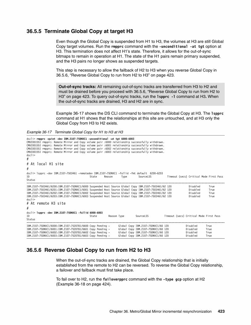
36.5.5 Terminate Global Copy at target H3
Even though the Global Copy is suspended from H1 to H3, the volumes at H3 are still Global Copy target volumes. Run the rmpprc command with the -unconditional -at tgt option at H3. This termination does not affect H1’s state. Therefore, it allows for the out-of-sync bitmaps to remain in operation at H1. The state of the H1 pairs remain primary suspended, and the H3 pairs no longer shows as suspended targets.
This step is necessary to allow the failback of H2 to H3 when you reverse Global Copy in 36.5.6, “Reverse Global Copy to run from H2 to H3” on page 423.
Example 36-17 shows the DS CLI command to terminate the Global Copy at H3. The lspprc command at H1 shows that the relationships at this site are untouched, and at H3 only the Global Copy from H3 to H2 exists.
Example 36-17 Terminate Global Copy for H1 to H3 at H3
dscli> rmpprc -quiet -dev IBM.2107-75DNXC1 -unconditional -at tgt 6000-6003CMUC00155I rmpprc: Remote Mirror and Copy volume pair :6000 relationship successfully withdrawn.CMUC00155I rmpprc: Remote Mirror and Copy volume pair :6001 relationship successfully withdrawn.CMUC00155I rmpprc: Remote Mirror and Copy volume pair :6002 relationship successfully withdrawn.CMUC00155I rmpprc: Remote Mirror and Copy volume pair :6003 relationship successfully withdrawn.dscli>## At local H1 site#dscli> lspprc -dev IBM.2107-7503461 -remotedev IBM.2107-75DNXC1 -fullid -fmt default 6200-6203ID State Reason Type SourceLSS Timeout (secs) Critical Mode First Pass Status==========================================================================================================================================IBM.2107-7503461/6200:IBM.2107-75DNXC1/6000 Suspended Host Source Global Copy IBM.2107-7503461/62 120 Disabled TrueIBM.2107-7503461/6201:IBM.2107-75DNXC1/6001 Suspended Host Source Global Copy IBM.2107-7503461/62 120 Disabled TrueIBM.2107-7503461/6202:IBM.2107-75DNXC1/6002 Suspended Host Source Global Copy IBM.2107-7503461/62 120 Disabled TrueIBM.2107-7503461/6203:IBM.2107-75DNXC1/6003 Suspended Host Source Global Copy IBM.2107-7503461/62 120 Disabled Truedscli># At remote H3 site#dscli> lspprc -dev IBM.2107-75DNXC1 -fullid 6000-6003ID State Reason Type SourceLSS Timeout (secs) Critical Mode First Pass Status==========================================================================================================================================IBM.2107-75DNXC1/6000:IBM.2107-7520781/6600 Copy Pending - Global Copy IBM.2107-75DNXC1/60 120 Disabled TrueIBM.2107-75DNXC1/6001:IBM.2107-7520781/6601 Copy Pending - Global Copy IBM.2107-75DNXC1/60 120 Disabled TrueIBM.2107-75DNXC1/6002:IBM.2107-7520781/6602 Copy Pending - Global Copy IBM.2107-75DNXC1/60 120 Disabled TrueIBM.2107-75DNXC1/6003:IBM.2107-7520781/6603 Copy Pending - Global Copy IBM.2107-75DNXC1/60 120 Disabled True
36.5.6 Reverse Global Copy to run from H2 to H3
When the out-of-sync tracks are drained, the Global Copy relationship that is initially established from the remote to H2 can be reversed. To reverse the Global Copy relationship, a failover and failback must first take place.
To fail over to H2, run the failoverpprc command with the -type gcp option at H2 (Example 36-18 on page 424).
Out-of-sync tracks: All remaining out-of-sync tracks are transferred from H3 to H2 and must be drained before you proceed with 36.5.6, “Reverse Global Copy to run from H2 to H3” on page 423. To query out-of-sync tracks, run the lspprc -l command at H3. When the out-of-sync tracks are drained, H3 and H2 are in sync.
Chapter 36. Metro/Global Mirror incremental resynchronization 423

Example 36-18 Failover Global Copy at H2
dscli> failoverpprc -remotedev IBM.2107-7520781 -type gcp 6600-6603:6000-6003CMUC00196I failoverpprc: Remote Mirror and Copy pair 6600:6000 successfully reversed.CMUC00196I failoverpprc: Remote Mirror and Copy pair 6601:6001 successfully reversed.CMUC00196I failoverpprc: Remote Mirror and Copy pair 6602:6002 successfully reversed.CMUC00196I failoverpprc: Remote Mirror and Copy pair 6603:6003 successfully reversed.
Next, failback Global Copy from H2 to H3 by running the failbackpprc command with the -type gcp option at H2 (Example 36-19).
Example 36-19 Failback Global Copy at H2
dscli> failbackpprc -remotedev IBM.2107-1300561 -type gcp 6600-6603:6000-6003CMUC00197I failbackpprc: Remote Mirror and Copy pair 6600:6000 successfully failed back.CMUC00197I failbackpprc: Remote Mirror and Copy pair 6601:6001 successfully failed back.CMUC00197I failbackpprc: Remote Mirror and Copy pair 6602:6002 successfully failed back.CMUC00197I failbackpprc: Remote Mirror and Copy pair 6603:6003 successfully failed back.
36.5.7 Start Metro Mirror from H1 to H2
To start Metro Mirror from H1 to H2, run the mkpprc command with the -type mmir option at H1. In 36.5.3, “Start incremental resynchronization at H1” on page 422, change recording bitmaps were created to track all the updates from the production environment. To recover and restore these updates, run the mkpprc command with the -incrementalresync recover option. The recover parameter of the -incrementalresync option establishes the Metro Mirror relationship after you perform a check at H2 (the Metro Mirror secondary) for a relationship. The change recording bitmaps that are created in 36.5.3, “Start incremental resynchronization at H1” on page 422 are then merged with the out-of-sync bitmaps at H1.
Example 36-20 creates the Metro Mirror in the first step by using the -incrementalresync recover option, which initiates copying all tracks that are marked in the change recording bitmap at H1. When all the tracks are drained to H2, the incremental resynchronization is restarted.
Example 36-20 Set up Metro Mirror from H1 to H2
dscli> mkpprc -dev IBM.2107-7503461 -remotedev IBM.2107-7520781 -type mmir -mode full -incrementalresync recover 6200-6203:6600-6603CMUC00153I mkpprc: Remote Mirror and Copy volume pair relationship 6200:6600 successfully created.CMUC00153I mkpprc: Remote Mirror and Copy volume pair relationship 6201:6601 successfully created.CMUC00153I mkpprc: Remote Mirror and Copy volume pair relationship 6202:6602 successfully created.CMUC00153I mkpprc: Remote Mirror and Copy volume pair relationship 6203:6603 successfully created.dscli>dscli> lspprc -dev IBM.2107-7503461 -l -fullid 6200-6203ID State Reason Type Out Of Sync Tracks Tgt Read Src Cascade Tgt Cascade Date Suspended SourceLSS Timeout (secs) Critical Mode First Pass Status Incremental Resync Tgt Write GMIR CG PPRC CG================================================================================================================================================================================================================================================================
Enabling Incremental Resync: To be prepared for a disaster, start Metro Mirror with Incremental Resync enabled. Run the mkpprc command with the -type mmir and -incrementalresync enable options at H1. This action creates new change recording bitmaps for all the Metro Mirror primary volumes.
Metro Mirror and Global Copy states: Metro Mirror must be in the Full Duplex state and Global Copy must complete the first pass before you continue 36.5.8, “Start Global Mirror at H2” on page 425. To query the status of Global Mirror and Metro Mirror, run the lspprc -l command at H1 to query Metro Mirror and at H2 to query Global Copy.
424 DS8000 Copy Services

IBM.2107-7503461/6200:IBM.2107-7520781/6600 Full Duplex - Metro Mirror 0 Disabled Enabled Invalid - IBM.2107-7503461/62 120 Disabled Invalid Disabled Disabled Disabled DisabledIBM.2107-7503461/6201:IBM.2107-7520781/6601 Full Duplex - Metro Mirror 0 Disabled Enabled Invalid - IBM.2107-7503461/62 120 Disabled Invalid Disabled Disabled Disabled DisabledIBM.2107-7503461/6202:IBM.2107-7520781/6602 Full Duplex - Metro Mirror 0 Disabled Enabled Invalid - IBM.2107-7503461/62 120 Disabled Invalid Disabled Disabled Disabled DisabledIBM.2107-7503461/6203:IBM.2107-7520781/6603 Full Duplex - Metro Mirror 0 Disabled Enabled Invalid - IBM.2107-7503461/62 120 Disabled Invalid Disabled Disabled Disabled Disableddscli>dscli> mkpprc -dev IBM.2107-7503461 -remotedev IBM.2107-7520781 -type mmir -mode nocp -incrementalresync enable 6200-6203:6600-6603CMUC00153I mkpprc: Remote Mirror and Copy volume pair relationship 6200:6600 successfully created.CMUC00153I mkpprc: Remote Mirror and Copy volume pair relationship 6201:6601 successfully created.CMUC00153I mkpprc: Remote Mirror and Copy volume pair relationship 6202:6602 successfully created.CMUC00153I mkpprc: Remote Mirror and Copy volume pair relationship 6203:6603 successfully created.dscli>dscli>lspprc -dev IBM.2107-7503461 -l 6200-6203ID State Reason Type Out Of Sync Tracks Tgt Read Src Cascade Tgt Cascade Date Suspended SourceLSS Timeout (secs) Critical Mode First Pass Status Incremental Resync Tgt Write GMIR CG PPRC CG====================================================================================================================================================================================================================6200:6600 Full Duplex - Metro Mirror 0 Disabled Enabled Invalid - 62 120 Disabled Invalid Enabled Disabled Disabled Disabled6201:6601 Full Duplex - Metro Mirror 0 Disabled Enabled Invalid - 62 120 Disabled Invalid Enabled Disabled Disabled Disabled6202:6602 Full Duplex - Metro Mirror 0 Disabled Enabled Invalid - 62 120 Disabled Invalid Enabled Disabled Disabled Disabled6203:6603 Full Duplex - Metro Mirror 0 Disabled Enabled Invalid - 62 120 Disabled Invalid Enabled Disabled Disabled Disabled
36.5.8 Start Global Mirror at H2
When Metro Mirror for H1:H2 reaches the Full Duplex state, then Global Mirror can be started by running the mkgmir command at H2.
Example 36-21 shows the commands that are used to set up the Global Mirror. The showgmir commands at the end verify that the Global Mirror is forming consistency groups.
Example 36-21 Set up Global Mirror at H2
dscli> mksession -dev IBM.2107-7520781 -lss 66 2CMUC00145I mksession: Session 2 opened successfully.dscli>dscli> chsession -dev IBM.2107-7520781 -lss 66 -action add -volpair 6600-6603:6000-6003 2CMUC00147I chsession: Session 2 successfully modified.dscli>dscli> mkgmir -dev IBM.2107-7520781 -lss 66 -session 2CMUC00162I mkgmir: Global Mirror for session 2 successfully started.dscli>dscli> lssession -dev IBM.2107-7520781 66 2LSS ID Session Status Volume VolumeStatus PrimaryStatus SecondaryStatus FirstPassComplete AllowCascading=============================================================================================================================66 02 CG In Progress 6600 Active Primary Copy Pending Secondary Full Duplex True Enable66 02 CG In Progress 6601 Active Primary Copy Pending Secondary Full Duplex True Enable66 02 CG In Progress 6602 Active Primary Copy Pending Secondary Full Duplex True Enable66 02 CG In Progress 6603 Active Primary Copy Pending Secondary Full Duplex True Enabledscli> dscli> showgmir -metrics 66ID IBM.2107-7520781/66Total Failed CG Count 0Total Successful CG Count 56Successful CG Percentage 100Failed CG after Last Success 0Last Successful CG Form Time 11/17/20nn 23:20:06 CETCoord. Time (seconds) 50Interval Time (seconds) 0Max Drain Time (seconds) 30First Failure Control Unit -First Failure LSS -First Failure Status No ErrorFirst Failure Reason -
Important: Verify that the out-of-sync tracks are complete for Metro Mirror before you start Global Mirror. Otherwise, the consistency groups start to fail when Global Mirror is started by running the mkgmir command.
Chapter 36. Metro/Global Mirror incremental resynchronization 425

First Failure Master State -Last Failure Control Unit -Last Failure LSS -Last Failure Status No ErrorLast Failure Reason -Last Failure Master State -Previous Failure Control Unit -Previous Failure LSS -Previous Failure Status No ErrorPrevious Failure Reason -Previous Failure Master State -dscli>dscli> showgmir -metrics 66ID IBM.2107-7520781/66Total Failed CG Count 0Total Successful CG Count 69Successful CG Percentage 100Failed CG after Last Success 0Last Successful CG Form Time 11/17/20nn 23:20:19 CETCoord. Time (seconds) 50Interval Time (seconds) 0Max Drain Time (seconds) 30First Failure Control Unit -First Failure LSS -First Failure Status No ErrorFirst Failure Reason -First Failure Master State -Last Failure Control Unit -Last Failure LSS -Last Failure Status No ErrorLast Failure Reason -Last Failure Master State -Previous Failure Control Unit -Previous Failure LSS -Previous Failure Status No ErrorPrevious Failure Reason -Previous Failure Master State -
At this point, you have the desired H1:H2:H3 Metro/Global Mirror configuration.
426 DS8000 Copy Services

Chapter 37. Multiple Target PPRC overview
This chapter provides an introduction to Multiple Target Peer-to-Peer Remote Copy (Multiple Target PPRC). It covers these topics:
� Multiple Target PPRC overview� Positioning� Requirements and restrictions� Requirements and restrictions� Software considerations� Licensing� Terminology
37
© Copyright IBM Corp. 2017. All rights reserved. 427

37.1 Multiple Target PPRC overview
Multiple Target PPRC extends the basic Metro Mirror, Global Copy, and Global Mirror solutions by providing the capability to have two PPRC relationships on a single primary volume. The primary volume can ave more than one secondary, enabling data to be mirrored to two different sites.
With two PPRC relationships on a volume, additional topologies and flexibility are possible, providing additional data protection. Multiple Target PPRC complements the use of cascaded 3-site mirroring topologies, such as Metro/Global Mirror, by adding flexibility and simplifying certain recovery scenarios.
Multiple Target PPRC provides the following enhancements:
� Mirrors data from a single local primary site to two remote secondary sites
� Increases capability and flexibility for disaster recovery solutions by using:
– Synchronous replication– Asynchronous replication– Combination of synchronous replication and asynchronous replication configurations
� Improves a cascaded Metro/Global Mirror configuration and simplifies recovery procedures
Multiple target PPRC is available for DS8000 storage systems with the appropriate license (see 37.5, “Licensing” on page 430).
Figure 37-1 shows a general Multiple Target PPRC topology where a single primary site is replicated to two secondary sites. Host I/O is directed to the primary site labeled H1, and Multiple Target PPRC mirrors the updated data to the two secondary sites, which are labeled H2 and H3.
Figure 37-1 Multiple Target PPRC
Note: Multiple Target PPRC is available in both Open Systems and IBM System z® environments.
428 DS8000 Copy Services

When both relationships are synchronous Metro Mirror, the transfers of updated data to the two remote sites are performed in parallel to minimize the impact on host response time in comparison to one Metro Mirror relationship.
37.2 Positioning
Many companies and businesses require their applications to be continuously available and cannot tolerate any service interruption. A loss of a disaster recovery site is often considered to be a severe impact on their business. If their local production site fails, swapping to a Metro Mirror target allows applications to continue running. However, without another target to act as a backup for disaster protection, business applications are left unprotected from a subsequent failure. MultipleTarget PPRC addresses these needs by allowing an additional replication target.
Multiple Target PPRC also complements the use of cascaded 3-site mirroring topologies, such as Metro/Global Mirror, by adding flexibility and simplifying certain recovery scenarios.
37.3 Requirements and restrictions
All DS8000 storage systems in a Multiple Target PPRC environment are required to have a Licensed Machine Code level which supports it in addition to the appropriate licenses.
37.4 Software considerations
A Multiple Target PPRC environment includes, but is not limited to, the following software requirements:
� Activate Multiple Target PPRC support on the DS8000 storage system by using the appropriate Copy Services license. DFSMS software verifies that both the storage system and appropriate software is installed and enabled prior to exploiting the Multiple Target PPRC function.
� A keyword (PPRCMT) in the DEVSUPxx member of PARMLIB is provided to enable the new function. If it is not set, software support for Multiple Target PPRC will not be enabled and will run in toleration mode for any Multiple Target PPRC relationships that exist.
� GDPS and Copy Services Manager management software requires that all systems be upgraded to support the function. Otherwise, the function is in single-target mode. After systems are upgraded, update your DEVSUPxx member of PARMLIB to enable the function.
Note: A primary volume can have any combination of two Metro Mirror, Global Copy, or Global Mirror relationships, with a restriction that a primary volume can belong to only one Global Mirror session at a time.
Note: A Storage Customer Opportunity Request (SCORE) can be requested to allow the use of Multiple Target PPRC when the secondary storage systems are at previous code levels that do not support it. This can be useful in certain migration situations.
Chapter 37. Multiple Target PPRC overview 429

37.5 Licensing
To use the Multiple Target PPRC function, the appropriate licensed features must be applied to all DS8000 storage systems that are part of the Multiple Target PPRC configuration.
37.6 Terminology
The term site is used to designate the data that is to be replicated. A site is a specific set of volumes. This can be a group of volumes within a single storage system or several volumes across multiple storage systems that are being replicated.
These sites are labeled as H1, H2, H3, and so on. To simplify the procedures, the descriptions often refer to the sites as though they are a single volume, but it is important to remember that they are actually groups of volumes.
For example, Figure 37-2 shows a sample configuration where the different sites are labeled.
Figure 37-2 Sample configuration for describing terminology
The local site is labeled H1. Site H1 can be a single volume, a subset of volumes within a storage system, all volumes within a storage system, or a group of volumes across multiple storage systems. All volumes referred to by “site H1” are related and are used in a similar manner.
Site H2 in Figure 37-2 is a different set of volumes, which can be within a single storage system or spread across multiple storage systems. This H2 site is often at a different physical location from H1, but it is not required to be. In some situations, such as initial testing when
Note: A Storage Customer Opportunity Request (SCORE) can be requested to allow the use of Multiple Target PPRC when the secondary storage systems are at previous levels that do not support it. This can be useful in certain migration situations.
430 DS8000 Copy Services

limited hardware is available, it is even possible that H1 and H2 are different sets of volumes within a single storage system.
Using this terminology, it is possible to refer to operations such as “establish H1:H2” as a type of shorthand. Because H1 and H2 refer to groups of related volumes, this means to establish a pair from each volume at site H1 to its corresponding volume at H2.
PPRC paths are created at the LSS level rather than the volume level, so an operation such as “establish paths H1:H2” means to establish paths from each LSS at site H1 to its corresponding LSS at site H2.
The PPRC failover command deserves some special consideration in the terminology used. Consider a configuration of Metro Mirror from H1 to H2 as shown in Figure 37-3:
� Site H1 contains PPRC primary volumes that are being mirrored to PPRC secondary volumes at H2.
� A PPRC failover command is used to change the H2 volumes to become primary volumes whose corresponding secondary volumes are then H1. This is described by the term “failover H2:H1,” which indicates that the command is issued to the H2 and H1are the secondary volumes specified in the command.
� Global Mirror journal volumes are designated as J1, J2, and so on.
Figure 37-3 Sample Metro Mirror
Chapter 37. Multiple Target PPRC overview 431

432 DS8000 Copy Services

Chapter 38. Multiple Target PPRC topologies
This chapter describes the different topologies that are possible using Multiple Target Peer-to-Peer Remote Copy (PPRC). Multiple Target PPRC allows for many different combinations of Metro Mirror, Global Copy, and Global Mirror. It is also possible to use Multiple Target PPRC in combination with IBM z/OS Global Mirror.
This chapter includes the following topics:
� Multiple Target PPRC topologies� Two Metro Mirror relationships� Metro Mirror and Global Mirror� Cascaded Metro Mirror/Global Mirror� Metro Mirror and Global Copy� Global Copy plus Global Mirror� Metro/Global Mirror plus Metro Mirror� z/OS Global Mirror and two Metro Mirror pairs
38
© Copyright IBM Corp. 2017. All rights reserved. 433

38.1 Multiple Target PPRC topologies
Figure 38-1 shows a typical diagram that is used for describing the different topologies and configurations throughout this book.
Figure 38-1 Sample figure showing Multiple Target PPRC topology
In Figure 38-1, the different locations are identified by the labels H1, H2, and H3. Each of these refers to a site that typically has many volumes. Each site can also contain multiple DS8000 storage systems. The Global Mirror journal volumes on the Global Mirror recovery sites are indicated by J3 in this example.
The double thin lines between each of the sites represent PPRC paths. PPRC paths are normally established in both directions so that they are available when needed. The path direction is not usually indicated in the figures in the interest of keeping the diagrams simple.
The Host I/O is shown with an arrow going to the primary production site.
The type of mirror or copy (Metro Mirror, Global Mirror, or Global Copy) is shown for each relationship. Active relationships are shown by an arrow from the primary to the secondary. Suspended relationships are indicated by a short arrow from the primary site.
Figure 38-1 represents a Multiple Target PPRC configuration with Metro Mirror H1:H2 and Global Mirror H1:H3. The short arrow for the Global Mirror H1:H3 indicates that the relationship is suspended. The Global Mirror journal volumes are indicated by J3. There are PPRC paths established among all three sites.
Figure 38-1 also shows suspended pairs between H2 and H3. These are internally created pairs, as described in 39.3, “Multiple Target Incremental Resynchronization” on page 443.
434 DS8000 Copy Services

38.2 Two Metro Mirror relationships
In a two Metro Mirror pair topology, data is synchronously mirrored to both secondary sites at the same time.
One possible configuration is to have H1 and H2 at the same location, perhaps even within the same data center. H3 can be at a different location, although still within Metro Mirror distance. In this configuration, H2 provides a high-availability copy in case of a failure of H1. In addition, the Incremental Resynchronization capability described in 39.3, “Multiple Target Incremental Resynchronization” on page 443, provides the capability of establishing Metro Mirror H2:H3 so that even after a failure there is a capability to quickly resume the protection of another Metro Mirror copy.
H3 provides a remote copy of data in case of a more widespread failure that affects both H1 and H2.
Figure 38-2 shows a topology with two Metro Mirror pairs.
Figure 38-2 Two Metro Mirror pairs
The specifics of using this topology, including several scenarios for recovering after failures at the different sites, are described in detail in Chapter 40, “Implementing a two Metro Mirror topology” on page 451.
38.3 Metro Mirror and Global Mirror
A topology with Metro Mirror and Global Mirror provides a local high availability capability and a long-distance disaster recovery capability at the same time. In such a configuration, data is synchronously mirrored with Metro Mirror to one secondary site while being asynchronously mirrored by Global Mirror to a separate disaster recovery site.
Chapter 38. Multiple Target PPRC topologies 435
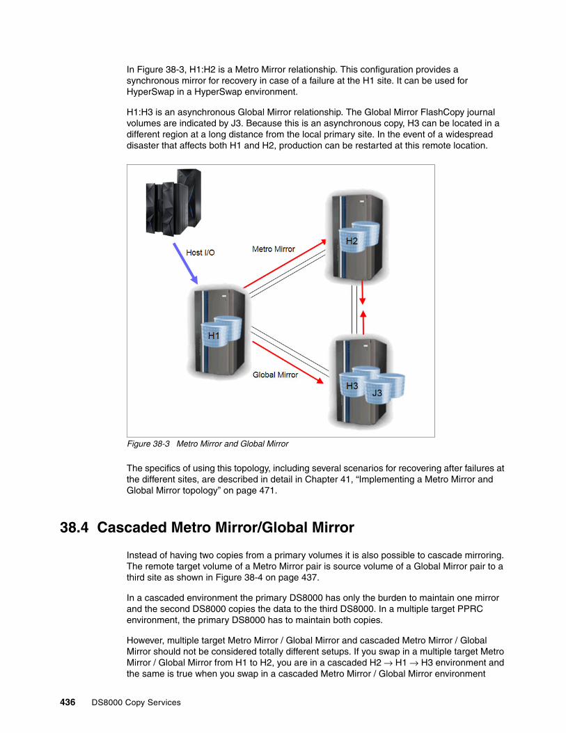
In Figure 38-3, H1:H2 is a Metro Mirror relationship. This configuration provides a synchronous mirror for recovery in case of a failure at the H1 site. It can be used for HyperSwap in a HyperSwap environment.
H1:H3 is an asynchronous Global Mirror relationship. The Global Mirror FlashCopy journal volumes are indicated by J3. Because this is an asynchronous copy, H3 can be located in a different region at a long distance from the local primary site. In the event of a widespread disaster that affects both H1 and H2, production can be restarted at this remote location.
Figure 38-3 Metro Mirror and Global Mirror
The specifics of using this topology, including several scenarios for recovering after failures at the different sites, are described in detail in Chapter 41, “Implementing a Metro Mirror and Global Mirror topology” on page 471.
38.4 Cascaded Metro Mirror/Global Mirror
Instead of having two copies from a primary volumes it is also possible to cascade mirroring. The remote target volume of a Metro Mirror pair is source volume of a Global Mirror pair to a third site as shown in Figure 38-4 on page 437.
In a cascaded environment the primary DS8000 has only the burden to maintain one mirror and the second DS8000 copies the data to the third DS8000. In a multiple target PPRC environment, the primary DS8000 has to maintain both copies.
However, multiple target Metro Mirror / Global Mirror and cascaded Metro Mirror / Global Mirror should not be considered totally different setups. If you swap in a multiple target Metro Mirror / Global Mirror from H1 to H2, you are in a cascaded H2 → H1 → H3 environment and the same is true when you swap in a cascaded Metro Mirror / Global Mirror environment
436 DS8000 Copy Services

(H1 → H2 → H3) the H1 and H2 sites, you are in a multiple target PPRC environment with H2 being the primary to H1 and H3.
Cascaded Metro/Global Mirror is covered in detail in Chapter 31, “Metro/Global Mirror overview” on page 355.
Figure 38-4 Cascaded Metro Mirror / Global Mirror configuration
38.5 Metro Mirror and Global Copy
Like the topology with Metro Mirror and Global Mirror, a topology with Metro Mirror and Global Copy provides both a local synchronous copy and a long-distance asynchronous copy. Unlike Global Mirror, however, Global Copy does not create a dependent write-consistent copy for disaster recovery purposes. However, this topology has several uses:
� Intermediate configuration for two Metro Mirror pairs
In a two Metro Mirror pair configuration, the Metro Mirror pairs can be initially established as Global Copy. After all of the pairs have completed copying the majority of their data, they can be converted to Metro Mirror. This is a common technique when establishing Metro Mirror pairs to minimize the host impact when synchronizing or resynchronizing volumes where there is a large amount of data to copy. By keeping the pairs in a Global Copy asynchronous relationship, there is little or no host response time impact while the initial pass of data copy is being performed.
� Periodic copies
Various techniques can be used to make data consistent at the secondary, such as converting the relationship to Metro Mirror and then suspending the pair. The resultant copy will be consistent until the time of the suspension and can be used as a practice copy, for data mining, as a backup, or for other purposes.
� Migration
Global Copy can be used to asynchronously copy data over a long distance without affecting the host response time. After the completion of the initial data copy, various techniques can be used to make the data consistent, such as converting the relationship to Metro Mirror or using the Multiple Target PPRC Incremental Resynchronization feature to establish a relationship between the two remote sites. The Incremental
Host I/O
PPRC
PPRC
Cascaded configuration
Chapter 38. Multiple Target PPRC topologies 437

Resynchronization feature is described in section 39.3, “Multiple Target Incremental Resynchronization” on page 443.
As with a two Metro Mirror topology, the Incremental Resynchronization capability allows for quickly resuming Metro Mirror from H2 to H3 in the event of an outage at site H1.
Figure 38-5 shows Metro Mirror H1:H2 and Global Copy H1:H3.
Figure 38-5 Metro Mirror and Global Copy
38.6 Global Copy plus Global Mirror
Multiple Target PPRC supports a topology with two asynchronous copies. Although Global Mirror does not allow for a primary volume to be in two different Global Mirror sessions at the same time, Multiple Target PPRC does allow for a Global Copy and a Global Mirror relationship on the same volume.
With this topology, there is mirroring among three sites in different regions at a long distance from each other. In the event of a failure at any one of the three sites, Global Mirror can be established between the two remaining sites by using the Incremental Resynchronization function described in 39.3, “Multiple Target Incremental Resynchronization” on page 443.
In Figure 38-6 on page 439, there are Global Copy relationships, H1:H2, and Global Mirror relationships, H1:H3, with the Global Mirror journal volumes at J3. Global Mirror journal volumes J1 and J2 are also shown at the H1 and H2 sites. This is so they are available for situations where the Global Mirror sessions are moved between different sites. If a site will never be used as a Global Mirror secondary site, these journal volumes are not required.
438 DS8000 Copy Services

Figure 38-6 Global Copy plus Global Mirror
The specifics of using this topology are described in detail in Chapter 42, “Implementing a Global Copy plus Global Mirror topology” on page 491.
38.7 Metro/Global Mirror plus Metro Mirror
A cascaded Metro/Global Mirror configuration consists of Global Mirror relationship cascaded from a Metro Mirror. Multiple Target PPRC allows for an additional Metro Mirror pair to be added, as shown in Figure 38-7 on page 440. The Metro Mirror H1:H2 and Global Mirror H2:H4 create an Metro/Global Mirror configuration. The additional Metro Mirror pair H1:H3 can be added to create an Metro/Global Mirror plus Metro Mirror configuration.
In the event of a failure at site H1, the production applications can be moved to run at H3, and the Incremental Resynchronization capabilities of Multiple Target PPRC can be used to establish an active Metro Mirror relationship H3:H2. This situation results in a Metro/Global Mirror configuration where there is Metro Mirror H3:H2 and Global Mirror H2:H4. Even after a failure of the primary production site, there is still the full protection of a Metro/Global Mirror environment where Metro Mirror H3:H2 provides a high availability capability and the Global Mirror H2:H4 provides for long-distance disaster recovery.
Chapter 38. Multiple Target PPRC topologies 439

Figure 38-7 Metro/Global Mirror plus Metro Mirror
38.8 z/OS Global Mirror and two Metro Mirror pairs
A topology with z/OS Global Mirror and one Metro Mirror pair is referred to as Mz/GM. With Multiple Target PPC, it is possible to add a second Metro Mirror pair to an Mz/GM configuration. Figure 38-8 shows such a configuration. There is Metro Mirror H1:H2 and z/OS Global Mirror H1:H3. These H1, H2, and H3 sites make up an Mz/GM configuration. With Multiple Target PPRC, a second Metro Mirror pair H1:H4 can be added.
Figure 38-8 z/OS Global Mirror and two Metro Mirror pairs
440 DS8000 Copy Services

Chapter 39. Multiple Target PPRC architecture and design
This chapter provides information about the architecture and design of Multiple Target and cascaded Peer-to-Peer Remote Copy (PPRC). Knowing the design details helps the users understand the reasons for the various steps and procedures that are detailed in other sections of this book. With this background, it is possible to modify the scenarios and sequences to fit the users' specific needs.
This chapter includes the following topics:
� Multiple Target PPRC pairs� Cascaded PPRC after Multiple Target PPRC failover� Multiple Target Incremental Resynchronization� PPRC path states
39
© Copyright IBM Corp. 2017. All rights reserved. 441

39.1 Multiple Target PPRC pairs
In the Multiple Target PPRC design, each PPRC pair operates independently. As an example, in Figure 39-1, suspending, resuming, or terminating the H1:H3 pair does not change the state of or otherwise affect the H1:H2 pair. Similarly, if there is an existing H1:H2 pair, establishing an H1:H3 pair does not affect the previously existing H1:H2 pair.
Figure 39-1 Example of a Multiple Target PPRC configuration
Example 39-1 shows the message displayed by the DS CLI when attempting to create a third PPRC relationship on a volume.
Example 39-1 Attempt to establish three pairs on a volume
dscli> mkpprc -dev IBM.2107-75CZM21 -remotedev IBM.2107-75CYM31 -type mmir 5000:6000CMUC00153I mkpprc: Remote Mirror and Copy volume pair relationship IBM.2107-75CZM21/5000:IBM.2107-75CYM31/6000 successfully created.
dscli> mkpprc -dev IBM.2107-75CZM21 -remotedev IBM.2107-75CYK71 -type mmir 5000:7000CMUC00153I mkpprc: Remote Mirror and Copy volume pair relationship IBM.2107-75CZM21/5000:IBM.2107-75CYK71/7000 successfully created.
dscli> mkpprc -dev IBM.2107-75CZM21 -remotedev IBM.2107-75CYM31 -type mmir 5000:6100CMUN80520E mkpprc: IBM.2107-75CZM21/5000:IBM.2107-75CYM31/6100: The Peer-to-Peer Remote Copy (PPRC) multitarget relationship could not be established because more than two secondary relationships arealready active for the primary.
Note: Attempting to establish a third pair on H1 is not allowed and will result in an error.
442 DS8000 Copy Services

39.2 Cascaded PPRC after Multiple Target PPRC failover
When we swap the Metro Mirror direction from H1:H2 to H2:H1 with a failover H2:H1 and a failback H2:H1, we have another topology: a cascaded PPRC environment (see Figure 39-2).
In the past, a cascaded Metro Mirror / Global Mirror configuration was the only supported three site solution. To set up a cascaded environment, the -cascade parameter had to be used with the mkpprc command.
The remote mirrors between H1 and H2 and H2 and H3 are set up independently from each other. However, there are some restrictions about what combinations are allowed.
Allowed configurations:
� Metro Mirror/Global Copy� Metro Mirror/Metro Mirror� Metro Mirror/Global Mirror� Global Copy/Global Copy
Not allowed are asynchronous to synchronous configurations like Global Copy / Metro Mirror. Also not allowed is a Global Mirror / Global Mirror environment.
Figure 39-2 Cascaded PPRC
39.3 Multiple Target Incremental Resynchronization
An essential feature of Multiple Target PPRC is the ability to establish active PPRC relationships between the two secondary sites, H2 and H3, without requiring a full copy of the data. This capability is called Multiple Target Incremental Resynchronization.
Note: Prior to DS8000 LMC Release 7.4, establishing a cascaded PPRC configuration required the use of the -cascade option for the remote pair. This is no longer needed.
Host I/O
PPRC
PPRC
Cascaded configuration
Chapter 39. Multiple Target PPRC architecture and design 443
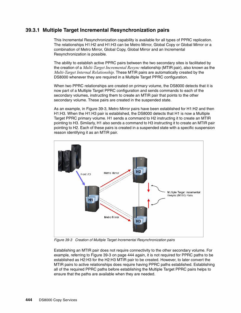
39.3.1 Multiple Target Incremental Resynchronization pairs
This Incremental Resynchronization capability is available for all types of PPRC replication. The relationships H1:H2 and H1:H3 can be Metro Mirror, Global Copy or Global Mirror or a combination of Metro Mirror, Global Copy, Global Mirror and an Incremental Resynchronization is possible.
The ability to establish active PPRC pairs between the two secondary sites is facilitated by the creation of a Multi-Target Incremental Resync relationship (MTIR pair), also known as the Multi-Target Internal Relationship. These MTIR pairs are automatically created by the DS8000 whenever they are required in a Multiple Target PPRC configuration.
When two PPRC relationships are created on primary volume, the DS8000 detects that it is now part of a Multiple Target PPRC configuration and sends commands to each of the secondary volumes, instructing them to create an MTIR pair that points to the other secondary volume. These pairs are created in the suspended state.
As an example, in Figure 39-3, Metro Mirror pairs have been established for H1:H2 and then H1:H3. When the H1:H3 pair is established, the DS8000 detects that H1 is now a Multiple Target PPRC primary volume. H1 sends a command to H2 instructing it to create an MTIR pointing to H3. Similarly, H1 also sends a command to H3 instructing it to create an MTIR pair pointing to H2. Each of these pairs is created in a suspended state with a specific suspension reason identifying it as an MTIR pair.
Figure 39-3 Creation of Multiple Target Incremental Resynchronization pairs
Establishing an MTIR pair does not require connectivity to the other secondary volume. For example, referring to Figure 39-3 on page 444 again, it is not required for PPRC paths to be established as H2:H3 for the H2:H3 MTIR pair to be created. However, to later convert the MTIR pairs to active relationships does require having PPRC paths established. Establishing all of the required PPRC paths before establishing the Multiple Target PPRC pairs helps to ensure that the paths are available when they are needed.
444 DS8000 Copy Services

The MTIR pairs serve the following main purposes:
� They enable an active relationship to be quickly established between the two secondary volumes by converting the existing pair rather than establishing a new pair.
� They provide a change recording mechanism to track which data is potentially different between the two secondary volumes. This is what allows for the resynchronization to be an incremental copy rather than a full copy.
39.3.2 Delayed creation of MTIR pairs
If there is no connectivity between H1 and H2 at the time that H1:H3 is created, the MTIR pairs H2:H3 will not be created. These MTIR pairs will be created later after the connectivity has been restored.
As an example, consider the following sequence:
1. Establish pairs H1:H2.
2. Connectivity between H1 and H2 is lost.
When data is attempted to be transferred from H1 to H2, it will not succeed and the H1:H2 pairs will suspend.
3. Establish pairs H1:H3.
4. H1 sends a command to H3 instructing it to create the H3:H2 MTIR pair.
5. H3 creates the H3:H2 MTIR pair.
6. H1 sends a command to H2 instructing it to create the H2:H3 MTIR pair. Because the connectivity to H2 is lost, the command cannot be sent and the H2:H3 MTIR pair is not created.
At this point, there are MTIR pairs H3:H2 but no MTIR pairs H2:H3.
7. Connectivity for H1:H2 is restored and the H1:H2 pairs are resumed.
8. The MTIR pairs H2:H3 are created as part of the PPRC resume processing.
39.3.3 MTIR change recording
Each of the MTIR pairs contains structures that enable a change recording mechanism to keep track of data that is potentially out of synchronization between the two secondary volumes. This change recording mechanism is implemented by bitmaps in which each bit represents a track.
Note: When setting up a Multiple Target PPRC configuration, it is advisable to establish the PPRC paths H2:H3 and H3:H2 before establishing the PPRC pairs H1:H2 and H1:H3.
Chapter 39. Multiple Target PPRC architecture and design 445

Figure 39-4 shows an MTIR pair H2:H3, including the change recording bitmap structure.
Figure 39-4 MTIR change recording
As writes are received at H2 from the primary H1 volume, the modified tracks are recorded in the change recording bitmap file to indicate that the data has been updated on H2 and is, therefore, potentially out of synchronization with the other secondary volume, H3.
The DS8000 firmware uses an internal algorithm to determine when a track has been successfully written to both H2 and H3 secondary volumes and resets the track in the bitmap. The resetting of bits in the bitmap is not done continuously. Instead, groups of tracks are collected and reset at one time. This is done to reduce the frequency of commands sent between the storage controllers. If a track is subsequently written again after a previous write had been successfully written to both secondaries, it will not be reset until the new write has also been written to both secondaries.
The same tracking is also performed on the H3 volume. Each of the secondary volumes thus contains a record of data that it has received and for which it has not yet received a notification that the data has also been written and hardened on the other secondary volume.
When an MTIR pair is created, the change recording structure indicates that the entire volume is out of synchronization with the other secondary volume. After the initial copy of the volume’s data has been completed, the change recording mechanism starts the process of recording new updates and resetting the indications for the previous updates. It requires a few minutes before the out-of-synchronization indications are reset. Until this time, the change recording structures continue to show that the entire volume is out of synchronization.
Each MTIR pair can be queried to see how many tracks are out of synchronization between the two secondary volumes.
Notes: This description explains the effect of the change recording algorithm, although not necessarily its actual internal implementation.
The Incremental Resynchronization capability does not depend upon the type of mirror or copy. Regardless of the pair types, Metro Mirror, Global Copy, or Global Mirror, an Incremental Resynchronization between the secondary volumes is possible.
446 DS8000 Copy Services

Example 39-2 shows an example query about the out of synchronization count for an MTIR pair, using the DS CLI. The first lspprc command shows that the out-of-sync track count is 81920 tracks for all volumes, which is the size of these particular volumes. A later query shows that the counts have dropped to a value lower than the full volume. As long as I/O is running to a volume, the counts will remain non-zero. However, if the host I/O is quiesced, the counts will eventually drop to zero.
Example 39-2 Query MTIR out of sync tracks
dscli> lspprc -l -dev IBM.2107-75CYM31 -remotedev IBM.2107-75CYK71 -multtgt 6000-600f:7000-700fID State Reason Type Out Of Sync Tracks ===========================================================================================================IBM.2107-75CYM31/6000:IBM.2107-75CYK71/7000 Suspended Multi-target Internal Global Copy 81920 ...IBM.2107-75CYM31/6001:IBM.2107-75CYK71/7001 Suspended Multi-target Internal Global Copy 81920 ...IBM.2107-75CYM31/6002:IBM.2107-75CYK71/7002 Suspended Multi-target Internal Global Copy 81920 ...
dscli> lspprc -l -dev IBM.2107-75CYM31 -remotedev IBM.2107-75CYK71 -multtgt 6000-600f:7000-700fID State Reason Type Out Of Sync Tracks ===========================================================================================================IBM.2107-75CYM31/6000:IBM.2107-75CYK71/7000 Suspended Multi-target Internal Global Copy 259 ...IBM.2107-75CYM31/6001:IBM.2107-75CYK71/7001 Suspended Multi-target Internal Global Copy 136 ...IBM.2107-75CYM31/6002:IBM.2107-75CYK71/7002 Suspended Multi-target Internal Global Copy 536 ...
39.3.4 Synchronizing MTIR pairs
Multiple Target Incremental Resynchronization pairs are synchronized by using a PPRC failback command. This is the same failback command that is used to reverse a PPRC relationship after a PPRC failover. It is possible to use the standard failback command because Multiple Target PPRC creates the MTIR pairs in such a manner that they are in the correct state for this operation.
Note: By default, the DS CLI does not display the internal MTIR pairs in the lspprc output. The -multtgt option must be used for lspprc to show the MTIR pairs.
Chapter 39. Multiple Target PPRC architecture and design 447

In Figure 39-5, the PPRC failback command for H2:H3 converts the MTIR pairs to an active pair.
Figure 39-5 Synchronize MTIR pairs
The PPRC failback command for H2:H3 performs the following steps:
1. H2 sends a command to H3 to convert it to a secondary volume of H2 and place it in the duplex pending state.
2. H2 reads the change recording information from H3.
3. H2 merges the change recording information from H3 into its own change recording information.
H2 now has a complete list of all changes that are potentially out of synchronization with H3.
4. H2 transfers the data indicated in the change recording structure to synchronize the pair.
If Metro Mirror is specified on the failback pair, the pair transitions to the full-duplex state. If Global Copy is specified, the pair completes the first pass of the initial copy.
If a synchronization of the MTIR pairs is performed before the initial copy of the volume’s data has been completed, the change recording structures still indicate that all tracks on the volume are out of synchronization and a full copy of data is performed.
As shown previously in Example 39-2 on page 447, the MTIR pairs can be queried to see how many tracks are recorded as being out of synchronization, which indicates the amount of data that will be copied if a synchronization is performed.
448 DS8000 Copy Services

39.4 PPRC path states
To keep the diagrams in this chapter clear, the majority of them do not show the state and direction of the PPRC paths. For Multiple Target PPRC it is advisable to establish active paths in both directions among the H1, H2, and H3 sites. However, in some migration cases, not all of these sets of paths are required because the intermediate configurations are temporary and there is no requirement to establish active mirroring in all possible directions.
39.4.1 Effects of freeze on path state
A freeze command changes the state of a set of PPRC paths to Failed but does not totally remove their existence.
For example, Example 39-3 uses a DS CLI command to show how the state of a set of paths is changed by a freeze command. Before the freeze, there are two logical paths established from IBM.2107-75CZM21/50 to IBM.2107-75CYM31/60. The freeze command removes the logical path connections. However, the relationship between the two storage systems remains, as shown in the second lspprcpath query in the example.
Example 39-3 Path state before and after a freeze
dscli> lspprcpath -dev IBM.2107-75CZM21 50Src Tgt State SS Port Attached Port Tgt WWNN===================================================================================================================IBM.2107-75CZM21/50 IBM.2107-75CYM31/60 Success FF60 IBM.2107-75CZM21/I0201 IBM.2107-75CYM31/I0232 5005076305FFD71EIBM.2107-75CZM21/50 IBM.2107-75CYM31/60 Success FF60 IBM.2107-75CZM21/I0234 IBM.2107-75CYM31/I0332 5005076305FFD71E
dscli> freezepprc -dev IBM.2107-75CZM21 -remotedev IBM.2107-75CYM31 50:60CMUC00161I freezepprc: Remote Mirror and Copy consistency group IBM.2107-75CZM21/50:IBM.2107-75CYM31/60 successfully created.
dscli> lspprcpath -dev IBM.2107-75CZM21 50Src Tgt State SS Port Attached Port Tgt WWNN===================================================================================================================IBM.2107-75CZM21/50 IBM.2107-75CYM31/60 Failed FF60 - - 5005076305FFD71E
A command to remove the paths, such as the DS CLI rmpprcpath command, will completely delete the relationship, as demonstrated in Example 39-4.
Example 39-4 Remote PPRC paths
dscli> rmpprcpath -dev IBM.2107-75CZM21 -remotedev IBM.2107-75CYM31 -remotewwnn 5005076305FFD71E -quiet 50:60CMUC00150I rmpprcpath: Remote Mirror and Copy path IBM.2107-75CZM21/50:IBM.2107-75CYM31/60 successfully removed.
dscli> lspprcpath 50CMUC00234I lspprcpath: No Remote Mirror and Copy Path found.
Important: If a synchronization is performed before the change recording structures have reset their change indications, a full copy of the data occurs.
Note: A knowledge of the following PPRC design points is required to understand the state of the PPRC paths after different types of operations.
Note: All PPRC pairs using the paths must be removed before removing the paths.
Chapter 39. Multiple Target PPRC architecture and design 449

39.4.2 Effects of failover on path state
PPRC paths are not required to be established before performing a failover operation, although, in most cases, it is best that the paths be established beforehand. A failover when there are no paths established causes the storage controller to internally create a path structure that can later be replaced with the actual paths that are to be used.
As an example, consider a pair H1:H2, where paths are established in the H1:H2 direction but not in the opposite H2:H1 direction. The example uses the DS8000 identifications shown in Table 39-1.
Table 39-1 Identifications used in DS CLI examples
Even though there are no paths established for H2:H1, a failover of H2:H1 is still allowed. The DS8000 storage system will create a placeholder for the paths and mark the paths as failed, as shown in Example 39-5.
Example 39-5 Failover creates failed paths is required
dscli> lspprcpath 60CMUC00234I lspprcpath: No Remote Mirror and Copy Path found.
dscli> failoverpprc -dev IBM.2107-75CYM31 -remotedev IBM.2107-75CZM21 -type mmir 6000-600f:5000-500fCMUC00196I failoverpprc: Remote Mirror and Copy pair IBM.2107-75CYM31/6000:IBM.2107-75CZM21/5000 successfully reversed....CMUC00196I failoverpprc: Remote Mirror and Copy pair IBM.2107-75CYM31/600F:IBM.2107-75CZM21/500F successfully reversed.
dscli> lspprcpath 60Src Tgt State SS Port Attached Port Tgt WWNN=======================================================================================IBM.2107-75CYM31/60 IBM.2107-75CZM21/50 Failed FFFF - - 5005076305FFD75A
Before performing a PPRC failback command to create active pairs, the PPRC paths must be successfully established. If no failback is planned, it is not required to establish the paths.
This creation of failed PPRC paths is noted here because there are some migration scenarios where these paths are created. Having an awareness of these paths is required to understand why they appear and when they can be removed. These paths can be removed in the same manner other established paths.
Site Role Dev WWNN Volume range
H1 Metro Mirror primary IBM.2107-75CZM21 5005076305FFD75A 5000 - 500F
H2 Metro Mirror secondary
IBM.2107-75CYM31 5005076305FFD71E 6000 - 600F
450 DS8000 Copy Services

Chapter 40. Implementing a two Metro Mirror topology
This chapter describes the creation of a two Metro Mirror configuration and explains recovery scenarios for failures at the remote or local site. It includes the following topics:
� Overview of a two Metro Mirror topology� Creating a two Metro Mirror topology� Outage at H2 or H3� Outage at H1 site� Return production to H1� Copy Services Manager
40
© Copyright IBM Corp. 2017. All rights reserved. 451

40.1 Overview of a two Metro Mirror topology
In a two Metro Mirror configuration, there are two Metro Mirror pairs with the same source volume. They mirror data synchronously to both secondary sites.
These are basic steps of creating a Metro Mirror topology of H1:H2 and H1:H3:
1. Establish Peer-to-Peer Remote Copy (PPRC) paths between all sites.2. Establish the H1:H2 pairs.3. Establish the H1:H3 pairs.
The terms H1, H2, and H3 refer to the different sites. Each site can contain many volumes and many volume pairs. Each site can also contain more than one storage system. There is no required order for establishing the pairs. “H1:H2” and “H1:H3” refer to the relationships between the sites and are independent of the order in which they are established.
To simplify the descriptions, these sites are often referred to as though they were a single volume, but it must be understood that the terms refer to the entire set of volumes being mirrored by PPRC. For example, “Failover H2:H1” means to fail over all of the H2 volumes to their corresponding H1 volumes.
40.2 Creating a two Metro Mirror topology
This section describes the detailed steps to create a two Metro Mirror topology.
40.2.1 Terms used in examples
For the examples in this section, the following terms are used:
� H1 is the current primary site, where the production applications are running.� H2 is the first Metro Mirror secondary site, to which H1 is mirroring data.� H3 is the second Metro Mirror secondary site, to which H1 is mirroring data.
Table 40-1 identifies the DS8000 storage controllers used in the examples in this chapter.
Table 40-1 Identifications used in DS CLI examples
Note: The scenarios in this chapter refer to an outage at one of the sites. This can be either a failure condition or a planned event for testing or maintenance.
Note: The volume range on each DS8000 is different in the following examples only to help clarify the different sites used. It is not a requirement that they be different.
Site Role Dev WWNN Volume range
H1 Current primary IBM.2107-75CZM21 5005076305FFD75A 5000 - 500F
H2 Metro Mirror secondary
IBM.2107-75CYM31 5005076305FFD71E 6000 - 600F
H3 Metro Mirror secondary
IBM.2107-75CYK71 5005076305FFD71A 7000 - 700F
452 DS8000 Copy Services

40.2.2 Establish PPRC paths
PPRC paths are required before the PPRC pairs can be established. It is best to establish all paths that might be needed so that they are available when they are required.
For example, as shown in Figure 40-1, a two Metro Mirror topology has Metro Mirror relationships H1:H2 and H1:H3. There are also Multi-Target Incremental Resync relationships (MTIR pair), also known as Multi-Target Internal Relationships, H2:H3 and H3:H2. In most cases, after a move or HyperSwap to H2, a failback H2:H1 is done after the H1 site is recovered, so paths for H2:H1 are needed. Similarly, in the event of a move or HyperSwap to H3, a failback of H3:H1 requires paths for H3:H1.
Therefore, it is advisable to establish the PPRC paths in all possible directions among the H1, H2, and H3 sites. For simplicity, the direction of the PPRC paths is not indicated in these diagrams.
Figure 40-1 Establish PPRC paths
Create the following PPRC paths:
� Establish PPRC Paths H1:H2� Establish PPRC Paths H1:H3
� Establish PPRC Paths H2:H1� Establish PPRC Paths H2:H3
� Establish PPRC Paths H3:H1� Establish PPRC Paths H3:H2
Chapter 40. Implementing a two Metro Mirror topology 453
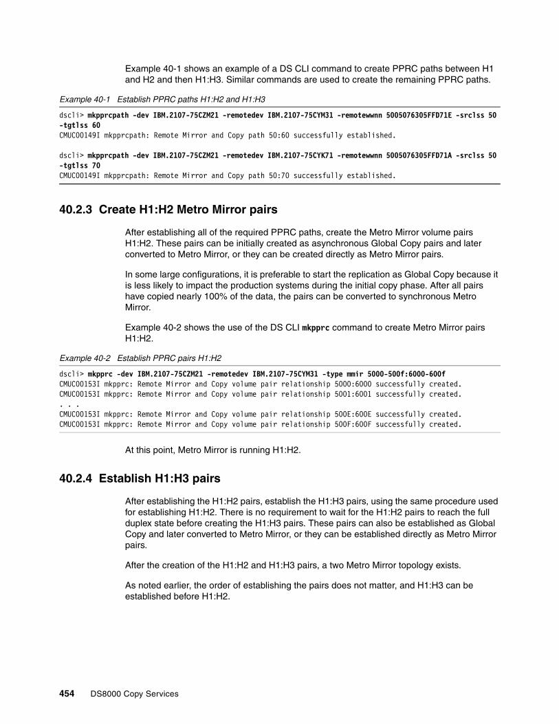
Example 40-1 shows an example of a DS CLI command to create PPRC paths between H1 and H2 and then H1:H3. Similar commands are used to create the remaining PPRC paths.
Example 40-1 Establish PPRC paths H1:H2 and H1:H3
dscli> mkpprcpath -dev IBM.2107-75CZM21 -remotedev IBM.2107-75CYM31 -remotewwnn 5005076305FFD71E -srclss 50 -tgtlss 60 CMUC00149I mkpprcpath: Remote Mirror and Copy path 50:60 successfully established.
dscli> mkpprcpath -dev IBM.2107-75CZM21 -remotedev IBM.2107-75CYK71 -remotewwnn 5005076305FFD71A -srclss 50 -tgtlss 70 CMUC00149I mkpprcpath: Remote Mirror and Copy path 50:70 successfully established.
40.2.3 Create H1:H2 Metro Mirror pairs
After establishing all of the required PPRC paths, create the Metro Mirror volume pairs H1:H2. These pairs can be initially created as asynchronous Global Copy pairs and later converted to Metro Mirror, or they can be created directly as Metro Mirror pairs.
In some large configurations, it is preferable to start the replication as Global Copy because it is less likely to impact the production systems during the initial copy phase. After all pairs have copied nearly 100% of the data, the pairs can be converted to synchronous Metro Mirror.
Example 40-2 shows the use of the DS CLI mkpprc command to create Metro Mirror pairs H1:H2.
Example 40-2 Establish PPRC pairs H1:H2
dscli> mkpprc -dev IBM.2107-75CZM21 -remotedev IBM.2107-75CYM31 -type mmir 5000-500f:6000-600fCMUC00153I mkpprc: Remote Mirror and Copy volume pair relationship 5000:6000 successfully created.CMUC00153I mkpprc: Remote Mirror and Copy volume pair relationship 5001:6001 successfully created.. . .CMUC00153I mkpprc: Remote Mirror and Copy volume pair relationship 500E:600E successfully created.CMUC00153I mkpprc: Remote Mirror and Copy volume pair relationship 500F:600F successfully created.
At this point, Metro Mirror is running H1:H2.
40.2.4 Establish H1:H3 pairs
After establishing the H1:H2 pairs, establish the H1:H3 pairs, using the same procedure used for establishing H1:H2. There is no requirement to wait for the H1:H2 pairs to reach the full duplex state before creating the H1:H3 pairs. These pairs can also be established as Global Copy and later converted to Metro Mirror, or they can be established directly as Metro Mirror pairs.
After the creation of the H1:H2 and H1:H3 pairs, a two Metro Mirror topology exists.
As noted earlier, the order of establishing the pairs does not matter, and H1:H3 can be established before H1:H2.
454 DS8000 Copy Services

Creation of MTIR pairsAs described in 39.2, “Cascaded PPRC after Multiple Target PPRC failover” on page 443, when the DS8000 detects that a Multiple Target PPRC configuration exists, it creates MTIR pairs between H2 and H3.
The creation of these MTIR pairs is initiated by the DS8000 at the primary H1 site by sending commands to the secondary H2 and H3 storage systems.
After establishing the PPRC paths and creating the pairs, the two Metro Mirror topology appears, as shown in Figure 40-2.
Figure 40-2 Two Metro Mirror pairs
Example 40-3 is an lspprc query to a volume, with the primary H1 showing that it has two Metro Mirror relationships, one to H2 and the other to H3. (The output has been truncated on the right in the example output for better readability.)
Example 40-3 lspprc for H1 showing two Metro Mirror pairs on each primary volume
dscli> lspprc -dev IBM.2107-75CZM21 5000-500fID State Reason Type SourceLSS ...===========================================================================================================IBM.2107-75CZM21/5000:IBM.2107-75CYK71/7000 Full Duplex - Metro Mirror IBM.2107-75CZM21/50 ...IBM.2107-75CZM21/5000:IBM.2107-75CYM31/6000 Full Duplex - Metro Mirror IBM.2107-75CZM21/50 ......IBM.2107-75CZM21/500F:IBM.2107-75CYK71/700F Full Duplex - Metro Mirror IBM.2107-75CZM21/50 ...IBM.2107-75CZM21/500F:IBM.2107-75CYM31/600F Full Duplex - Metro Mirror IBM.2107-75CZM21/50 ...
Chapter 40. Implementing a two Metro Mirror topology 455

Example 40-4 shows an lspprc query to the secondary H2, first without the -multtgt option and again with the -multtgt option to list the MTIR pairs. Notice that the MTIR pairs are shown as Global Copy suspended pairs in addition to being marked as Multi-target Internal.
Example 40-4 lspprc query to the secondary H2
dscli> lspprc -dev IBM.2107-75CYM31 6000-600fID State Reason Type SourceLSS===========================================================================================================IBM.2107-75CZM21/5000:IBM.2107-75CYM31/6000 Target Full Duplex - Metro Mirror IBM.2107-75CZM21/50......IBM.2107-75CZM21/500F:IBM.2107-75CYM31/600F Target Full Duplex - Metro Mirror IBM.2107-75CZM21/50...
dscli> lspprc -dev IBM.2107-75CYM31 -multtgt 6000-600fID State Reason Type SourceLSS Timeout (secs) Critical Mode First Pass Status========================================================================================================================IBM.2107-75CYM31/6000:IBM.2107-75CYK71/7000 Suspended Multi-target Internal Global Copy IBM.2107-75CYM31/60...IBM.2107-75CYM31/600F:IBM.2107-75CYK71/700F Suspended Multi-target Internal Global Copy IBM.2107-75CYM31/60...IBM.2107-75CZM21/5000:IBM.2107-75CYM31/6000 Target Full Duplex - Metro Mirror IBM.2107-75CZM21/50...IBM.2107-75CZM21/500F:IBM.2107-75CYM31/600F Target Full Duplex - Metro Mirror IBM.2107-75CZM21/50...
If there is no connectivity between H1 and H2 at the time that H1:H3 is created, the creation of the MTIR pairs from H2:H3 will be delayed, as explained in 39.3.2, “Delayed creation of MTIR pairs” on page 445.
As a further step you might want to enable Preserve Mirror on one of the two Metro Mirror legs as described in Chapter 9, “Remote Pair FlashCopy” on page 59.
40.3 Outage at H2 or H3
An outage at one of the secondary sites, either H2 or H3, can cause the PPRC pairs to that site to suspend. Because of the design, a suspension of one relationship on a volume does not affect other relationships on the volume, so the second Metro Mirror pairs will remain active.
For example, Figure 40-3 on page 457 shows a two Metro Mirror configuration where there has been an error at the H3 site, causing the H1:H3 pairs to suspend.
456 DS8000 Copy Services
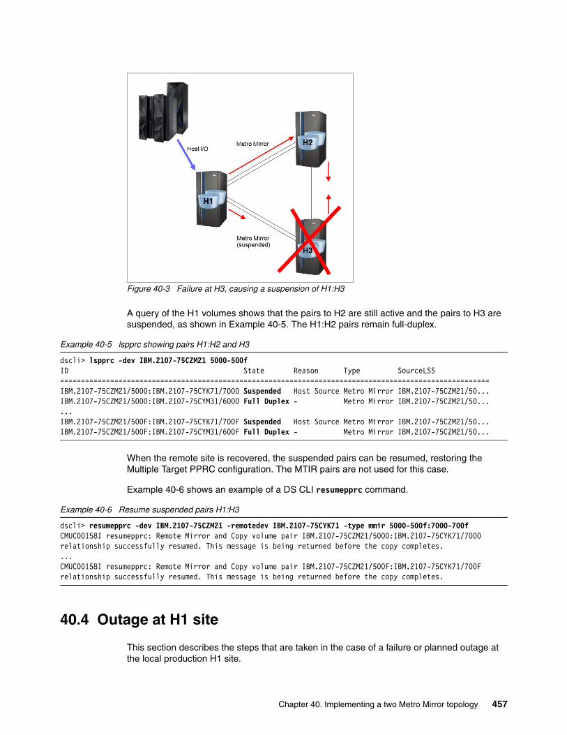
Figure 40-3 Failure at H3, causing a suspension of H1:H3
A query of the H1 volumes shows that the pairs to H2 are still active and the pairs to H3 are suspended, as shown in Example 40-5. The H1:H2 pairs remain full-duplex.
Example 40-5 lspprc showing pairs H1:H2 and H3
dscli> lspprc -dev IBM.2107-75CZM21 5000-500fID State Reason Type SourceLSS =======================================================================================================IBM.2107-75CZM21/5000:IBM.2107-75CYK71/7000 Suspended Host Source Metro Mirror IBM.2107-75CZM21/50...IBM.2107-75CZM21/5000:IBM.2107-75CYM31/6000 Full Duplex - Metro Mirror IBM.2107-75CZM21/50......IBM.2107-75CZM21/500F:IBM.2107-75CYK71/700F Suspended Host Source Metro Mirror IBM.2107-75CZM21/50...IBM.2107-75CZM21/500F:IBM.2107-75CYM31/600F Full Duplex - Metro Mirror IBM.2107-75CZM21/50...
When the remote site is recovered, the suspended pairs can be resumed, restoring the Multiple Target PPRC configuration. The MTIR pairs are not used for this case.
Example 40-6 shows an example of a DS CLI resumepprc command.
Example 40-6 Resume suspended pairs H1:H3
dscli> resumepprc -dev IBM.2107-75CZM21 -remotedev IBM.2107-75CYK71 -type mmir 5000-500f:7000-700fCMUC00158I resumepprc: Remote Mirror and Copy volume pair IBM.2107-75CZM21/5000:IBM.2107-75CYK71/7000 relationship successfully resumed. This message is being returned before the copy completes....CMUC00158I resumepprc: Remote Mirror and Copy volume pair IBM.2107-75CZM21/500F:IBM.2107-75CYK71/700F relationship successfully resumed. This message is being returned before the copy completes.
40.4 Outage at H1 site
This section describes the steps that are taken in the case of a failure or planned outage at the local production H1 site.
Chapter 40. Implementing a two Metro Mirror topology 457

In a two Metro Mirror configuration, a swap can be performed to either H2 or H3. It is the user’s choice to decide which of the sites is the preferred site for the swap. In this example, the swap is being performed to H2.
40.4.1 Recover at H2
The first step in the process is to move production to H2 so that the host application I/O can continue. Either HyperSwap or a traditional restart can be used.
The steps involved in this process follow.
Freeze H1:H2 and H1:H3Freeze commands for H1:H2 and H1:H3 remove the PPRC paths and suspend all PPRC pairs for H1:H2 and H1:H3, as shown in Example 40-7. A separate freeze command is required for each LSS to LSS PPRC relationship. With the use of consistency groups, the freeze command creates consistent data at the remote H2 and H3 sites by using extended long busy or queue full to temporarily queue dependent writes.
Depending on the type of failure at H1, the freeze commands might not complete successfully, and some or all H1 pairs can remain full duplex. If the H1 site has completely failed, these commands might not have even been issued or executed.
Example 40-7 Freeze PPRC Group H1:H2 and H1:H3
dscli> freezepprc -dev IBM.2107-75CZM21 -remotedev IBM.2107-75CYM31 50:60CMUC00161I freezepprc: Remote Mirror and Copy consistency group IBM.2107-75CZM21/50:IBM.2107-75CYM31/60 successfully created.
dscli> freezepprc -dev IBM.2107-75CZM21 -remotedev IBM.2107-75CYK71 50:70CMUC00161I freezepprc: Remote Mirror and Copy consistency group IBM.2107-75CZM21/50:IBM.2107-75CYK71/70 successfully created.
Unfreeze and run H1:H2 and H1:H3.When all freeze commands have completed, the secondary H2 and H3 sites contain a consistent copy of data. The unfreeze or run command (also known as a consistency group created command) removes the extended long busy or queue full condition at the local H1 site. An unfreeze command is required for each LSS to LSS PPRC relationship.
As with the freeze command, depending on the type of failure at H1, the unfreeze commands might not complete successfully.
Example 40-8 shows an example of a DS CLI unfreeze command.
Example 40-8 Consistency group created, H1:H2 and H1:H3
dscli> unfreezepprc -dev IBM.2107-75CZM21 -remotedev IBM.2107-75CYM31 50:60CMUC00198I unfreezepprc: Remote Mirror and Copy pair IBM.2107-75CZM21/50:IBM.2107-75CYM31/60 successfully thawed.dscli> unfreezepprc -dev IBM.2107-75CZM21 -remotedev IBM.2107-75CYK71 50:70CMUC00198I unfreezepprc: Remote Mirror and Copy pair IBM.2107-75CZM21/50:IBM.2107-75CYK71/70 successfully thawed.
458 DS8000 Copy Services

Failover H2:H1 and H3:H1The failover command for H2:H1 coverts the H2 volumes to suspended Metro Mirror primary volumes whose secondary volumes are H1. Similarly, the failover H3:H1 converts the H3 volumes to suspended primary volumes where secondary volumes are H1.
Example 40-9 and Example 40-10 show DS CLI examples of the failover commands for H2:H1 and H3:H1, respectively.
Example 40-9 Failover H2:H1
dscli> failoverpprc -dev IBM.2107-75CYM31 -remotedev IBM.2107-75CZM21 -type mmir 6000-600f:5000-500fCMUC00196I failoverpprc: Remote Mirror and Copy pair IBM.2107-75CYM31/6000:IBM.2107-75CZM21/5000 successfully reversed....CMUC00196I failoverpprc: Remote Mirror and Copy pair IBM.2107-75CYM31/600F:IBM.2107-75CZM21/500F successfully reversed.
Example 40-10 Failover H3:H1
dscli> failoverpprc -dev IBM.2107-75CYK71 -remotedev IBM.2107-75CZM21 -type mmir 7000-700f:5000-500fCMUC00196I failoverpprc: Remote Mirror and Copy pair IBM.2107-75CYK71/7000:IBM.2107-75CZM21/5000 successfully reversed....CMUC00196I failoverpprc: Remote Mirror and Copy pair IBM.2107-75CYK71/700F:IBM.2107-75CZM21/500F successfully reversed.
At this point, each volume on H1, H2, and H3 is a suspended primary volume pointing to the other two sites, as shown in Figure 40-4 on page 460. In other words:
� H1 is a suspended primary to H2� H1 is a suspended primary to H3
� H2 is a suspended primary to H1� H2 is a suspended primary to H3 (internally created MTIR pair)
� H3 is a suspended primary to H1� H3 is a suspended primary to H2 (internally created MTIR pair)
Example 40-11 shows that the H1:H2 and H1:H3 pairs are suspended due to the freeze commands. If H1 is inaccessible due to the failure, the freeze commands might not be possible and a query might not be possible.
Example 40-11 lspprc for H1 pairs
dscli> lspprc -dev IBM.2107-75CZM21 5000-500fID State Reason Type SourceLSS ==============================================================================================IBM.2107-75CZM21/5000:IBM.2107-75CYK71/7000 Suspended Freeze Metro Mirror IBM.2107-75CZM21/50 ...IBM.2107-75CZM21/5000:IBM.2107-75CYM31/6000 Suspended Freeze Metro Mirror IBM.2107-75CZM21/50 ......IBM.2107-75CZM21/500F:IBM.2107-75CYK71/700F Suspended Freeze Metro Mirror IBM.2107-75CZM21/50 ...IBM.2107-75CZM21/500F:IBM.2107-75CYM31/600F Suspended Freeze Metro Mirror IBM.2107-75CZM21/50 ...
Example 40-12 on page 460 shows that the H2:H1 pairs are suspended from the failover H2:H1 command. The -multtgt option is used to also include the H2:H3 MTIR pairs in the output. As previously noted, the example shows that the suspended states H2:H3 and H3:H2 are created internally, not as the result of a user command.
Chapter 40. Implementing a two Metro Mirror topology 459

Example 40-12 lspprc for H2 pairs
dscli> lspprc -dev IBM.2107-75CYM31 -multtgt 6000-600fID State Reason Type SourceLSS ============================================================================================================IBM.2107-75CYM31/6000:IBM.2107-75CYK71/7000 Suspended Multi-target Internal Global Copy IBM.2107-75CYM31/60 ...IBM.2107-75CYM31/6000:IBM.2107-75CZM21/5000 Suspended Host Source Metro Mirror IBM.2107-75CYM31/60 ......IBM.2107-75CYM31/600F:IBM.2107-75CYK71/700F Suspended Multi-target Internal Global Copy IBM.2107-75CYM31/60 ...IBM.2107-75CYM31/600F:IBM.2107-75CZM21/500F Suspended Host Source Metro Mirror IBM.2107-75CYM31/60 ...
Example 40-13 shows that the H3:H1 pairs are suspended from the failover H3:H1 command. The -multtgt option is used to include the H3:H2 MTIR pairs in the output.
Example 40-13 lspprc for H3 pairs
dscli> lspprc -dev IBM.2107-75CYK71 -multtgt 7000-700fID State Reason Type SourceLSS ============================================================================================================IBM.2107-75CYK71/7000:IBM.2107-75CYM31/6000 Suspended Multi-target Internal Global Copy IBM.2107-75CYK71/70 ...IBM.2107-75CYK71/7000:IBM.2107-75CZM21/5000 Suspended Host Source Metro Mirror IBM.2107-75CYK71/70 ......IBM.2107-75CYK71/700F:IBM.2107-75CYM31/600F Suspended Multi-target Internal Global Copy IBM.2107-75CYK71/70 ...IBM.2107-75CYK71/700F:IBM.2107-75CZM21/500F Suspended Host Source Metro Mirror IBM.2107-75CYK71/70 ...
Resume host systems at H2Host systems can be restarted at H2. If HyperSwap is used, the host I/O is directed to H2.
At this point, the host systems are running at H2, and the configuration appears as in Figure 40-4.
Figure 40-4 After recovery at H2
460 DS8000 Copy Services
40.4.2 Start replication H2:H3
The Incremental Resynchronization capability is used to start replication H2:H3. With the change recording function of Multiple Target PPRC, only the tracks that are potentially out of synchronization between H2 and H3 are transferred and a full copy of data is not required.
Failback H2:H3A failback command for H2:H3 merges the change recording bitmap files for H2 and H3 and initiates the transfer of the out-of-synchronization data.
Example 40-14 shows a sample DS CLI for the failback command.
Example 40-14 Failback H2:H3
dscli> failbackpprc -dev IBM.2107-75CYM31 -remotedev IBM.2107-75CYK71 -type mmir 6000-600f:7000-700fCMUC00197I failbackpprc: Remote Mirror and Copy pair IBM.2107-75CYM31/6000:IBM.2107-75CYK71/7000 successfully failed back....CMUC00197I failbackpprc: Remote Mirror and Copy pair IBM.2107-75CYM31/600F:IBM.2107-75CYK71/700F successfully failed back.
By transferring only the out-of-synchronization data, the pairs reach the full duplex state, as shown in Example 40-15.
Example 40-15 lspprc showing full duplex after incremental resync
dscli> lspprc -dev IBM.2107-75CYM31 -remotedev IBM.2107-75CYK71 6000-600f:7000-700fID State Reason Type SourceLSS Timeout (secs) Critical Mode First Pass Status===========================================================================================================IBM.2107-75CYM31/6000:IBM.2107-75CYK71/7000 Full Duplex - Metro Mirror IBM.2107-75CYM31/60 ......IBM.2107-75CYM31/600F:IBM.2107-75CYK71/700F Full Duplex - Metro Mirror IBM.2107-75CYM31/60 ...
At this point in the process, the H2:H3 pairs have been resumed. The state of the configuration is that shown in Figure 40-5 on page 462.
Chapter 40. Implementing a two Metro Mirror topology 461

Figure 40-5 After failback H2:H3 with Incremental Resynchronization
The data protection of Metro Mirror has now been restored after a failure of the primary site. Without Multiple Target PPRC, host access could have been restored at site H2, but there would have been no mirroring protection until the H1 site was recovered and the H2:H1 pairs resumed.
40.4.3 H1 recovered
When site H1 is recovered, mirroring can be resumed to H2 to restore the Multiple Target PPRC configuration.
Establish paths H1:H2 and H1:H3The paths for H1:H2 and H1:H3 were removed by the freeze commands. After H1 is recovered, these paths need to be reestablished. The paths are not required until the time when mirroring is later resumed for H1:H2 and H1:H3, but establishing them as soon as H1 is recovered helps to ensure that they are available when needed.
The paths are reestablished by using the same command used to originally create the paths, as shown again in Example 40-16.
Example 40-16 Reestablish paths H1:H2 and H1:H3
dscli> mkpprcpath -dev IBM.2107-75CZM21 -remotedev IBM.2107-75CYM31 -remotewwnn 5005076305FFD71E -srclss 50 -tgtlss 60 -consistgrp I0201:I0232 I0234:I0332CMUC00149I mkpprcpath: Remote Mirror and Copy path 50:60 successfully established.
dscli> mkpprcpath -dev IBM.2107-75CZM21 -remotedev IBM.2107-75CYK71 -remotewwnn 5005076305FFD71A -srclss 50 -tgtlss 70 -consistgrp I0201:I0032 I0234:I0306CMUC00149I mkpprcpath: Remote Mirror and Copy path 50:70 successfully established.
462 DS8000 Copy Services

Failback H2:H1A failback command for H2:H1 resumes the H2:H1 Metro Mirror pairs, as shown in Example 40-17.
Example 40-17 Failback H2:H1
dscli> failbackpprc -dev IBM.2107-75CYM31 -remotedev IBM.2107-75CZM21 -type mmir 6000-600f:5000-500fCMUC00197I failbackpprc: Remote Mirror and Copy pair IBM.2107-75CYM31/6000:IBM.2107-75CZM21/5000 successfully failed back....CMUC00197I failbackpprc: Remote Mirror and Copy pair IBM.2107-75CYM31/600F:IBM.2107-75CZM21/500F successfully failed back.
When these pairs reach full duplex, the Multiple Target PPRC configuration has been restored, as shown in Figure 40-6.
Figure 40-6 Multiple Target PPRC topology restored
The suspended pairs between H1 and H3 are automatically converted by the DS8000 storage system to become MTIR pairs. The change recording mechanism is started to track the out-of-synchronization data between H1 and H3. This is now the same topology as the initial state, with two Metro Mirror pairs. However, the host systems are now running at H2 rather than H1.
Depending upon the specific circumstances, for example if H1 and H2 are local to each other, there might be no preference for running at one site versus the other. In other situations, there might be reasons to prefer that the host systems run at site H1. Section 40.5, “Return production to H1” on page 463 describes a method to return to the original H1 site.
40.5 Return production to H1
Returning to site H1 is similar to a move to H2 previously described in 40.4, “Outage at H1 site” on page 457. The main difference is that this is a planned move and the original move to H2 might have been the result of an error event at H1.
Chapter 40. Implementing a two Metro Mirror topology 463
40.5.1 Move host systems to H1
The first step in the process is to move production back to H1. As with the move to H2, either HyperSwap or a traditional restart can be used. The steps involved in this process follow.
Query out of-synchronization tracksQuery the out-of-synchronization tracks from H1:H3 and H3:H1. As described in 39.3.3, “MTIR change recording” on page 445, after the H2:H1 pair reaches the full-duplex state, there can be a period of time before the out-of-sync tracks counts is reduced from the full volume amount. It is important to verify that these counts have dropped from the full volume amount to ensure that failback H1:H3 for the MTIR pairs does not perform a full copy of data.
Freeze H2:H1 and H2:H3Freeze commands for H2:H1 and H2:H3 remove the PPRC paths and suspend the H1:H2 and H1:H3 PPRC pairs. A separate freeze command is required for each LSS to LSS PPRC relationship. The use of consistency groups ensures consistent data at H1 and H2.
Unfreeze and run H2:H1 and H2:H3When all freeze commands have completed, the secondary H1 and H3 sites contain a consistent copy of data. The unfreeze or run command (also known as a consistency group created command) removes the extended long busy or queue-full condition at the primary H2 site. An unfreeze command is required for each LSS to LSS PPRC relationship.
Example 40-18 shows an example of the DS CLI commands.
Example 40-18 Freeze and unfreeze H2:H1 and H2:H3
dscli> freezepprc -dev IBM.2107-75CYM31 -remotedev IBM.2107-75CZM21 60:50CMUC00161I freezepprc: Remote Mirror and Copy consistency group IBM.2107-75CYM31/60:IBM.2107-75CZM21/50 successfully created.
dscli> freezepprc -dev IBM.2107-75CYM31 -remotedev IBM.2107-75CYK71 60:70CMUC00161I freezepprc: Remote Mirror and Copy consistency group IBM.2107-75CYM31/60:IBM.2107-75CYK71/70 successfully created.
dscli> unfreezepprc -dev IBM.2107-75CYM31 -remotedev IBM.2107-75CZM21 60:50CMUC00198I unfreezepprc: Remote Mirror and Copy pair IBM.2107-75CYM31/60:IBM.2107-75CZM21/50 successfully thawed.
dscli> unfreezepprc -dev IBM.2107-75CYM31 -remotedev IBM.2107-75CYK71 60:70CMUC00198I unfreezepprc: Remote Mirror and Copy pair IBM.2107-75CYM31/60:IBM.2107-75CYK71/70 successfully thawed.
Failover H1:H2 and H3:H2The failover command for H1:H2 coverts the H1 volumes to suspended Metro Mirror primary volumes whose secondary volumes are H2. Similarly, the failover H3:H2 converts the H3 volumes to suspended primary volumes whose secondary volumes are H2.
Example 40-19 shows a DS CLI example of these failover commands.
Example 40-19 Failover H1:H2 and H1:H3
dscli> failoverpprc -dev IBM.2107-75CZM21 -remotedev IBM.2107-75CYM31 -type mmir 5000-500f:6000-600fCMUC00196I failoverpprc: Remote Mirror and Copy pair IBM.2107-75CZM21/5000:IBM.2107-75CYM31/6000 successfully reversed....
464 DS8000 Copy Services

CMUC00196I failoverpprc: Remote Mirror and Copy pair IBM.2107-75CZM21/500F:IBM.2107-75CYM31/600F successfully reversed.
dscli> failoverpprc -dev IBM.2107-75CYK71 -remotedev IBM.2107-75CYM31 -type mmir 7000-700f:6000-600fCMUC00196I failoverpprc: Remote Mirror and Copy pair IBM.2107-75CYK71/7000:IBM.2107-75CYM31/6000 successfully reversed....CMUC00196I failoverpprc: Remote Mirror and Copy pair IBM.2107-75CYK71/700F:IBM.2107-75CYM31/600F successfully reversed.
Resume host systems at H1The host systems can now be restarted at H1. If HyperSwap is used, the host systems are switched to H1.
At this point, the host systems are running at H1. The configuration appears as in Figure 40-7.
Figure 40-7 Move production back to H1
Each volume on H1, H2, and H3 is a suspended primary volume pointing to the other two sites.
40.5.2 Start H1:H2 and H1:H3 replication
Because this is a planned swap, there is no need to wait for the secondary system to be recovered. The replication H1:H2 and H1:H3 can be immediately resumed.
Establish H2:H1 and H2:H3 pathsThe paths from H2:H1 and H2:H3 were removed by the previous freeze commands. reestablishing these paths as soon as possible helps to ensure that they are available when needed.
Example 40-20 on page 466 shows sample DS CLI commands to establish the paths for H2:H1 and H2:H3.
Chapter 40. Implementing a two Metro Mirror topology 465

Example 40-20 Reestablish paths for H2:H1 and H2:H3
dscli> mkpprcpath -dev IBM.2107-75CYM31 -remotedev IBM.2107-75CZM21 -remotewwnn 5005076305FFD75A -srclss 60 -tgtlss 50 -consistgrp I0232:I0201 I0332:I0234CMUC00149I mkpprcpath: Remote Mirror and Copy path 60:50 successfully established.
dscli> mkpprcpath -dev IBM.2107-75CYM31 -remotedev IBM.2107-75CYK71 -remotewwnn 5005076305FFD71A -srclss 60 -tgtlss 70 -consistgrp I0300:I0300 I0330:I0330CMUC00149I mkpprcpath: Remote Mirror and Copy path 60:70 successfully established.
Failback H1:H2 and H1:H3A failback command for H1:H2 and H1:H3 starts replication for all pairs. Example 40-21 shows sample commands for the failback.
Example 40-21 Failback H1:H2 and H1:H3
dscli> failbackpprc -dev IBM.2107-75CZM21 -remotedev IBM.2107-75CYM31 -type mmir 5000-500f:6000-600fCMUC00197I failbackpprc: Remote Mirror and Copy pair IBM.2107-75CZM21/5000:IBM.2107-75CYM31/6000 successfully failed back....CMUC00197I failbackpprc: Remote Mirror and Copy pair IBM.2107-75CZM21/500F:IBM.2107-75CYM31/600F successfully failed back.
dscli> failbackpprc -dev IBM.2107-75CZM21 -remotedev IBM.2107-75CYK71 -type mmir 5000-500f:7000-700fCMUC00197I failbackpprc: Remote Mirror and Copy pair IBM.2107-75CZM21/5000:IBM.2107-75CYK71/7000 successfully failed back....CMUC00197I failbackpprc: Remote Mirror and Copy pair IBM.2107-75CZM21/500F:IBM.2107-75CYK71/700F successfully failed back.
The suspended pairs between H2 and H3 are changed to MTIR pairs.
The original configuration is now restored, as show in Figure 40-8.
Figure 40-8 Return to original configuration
466 DS8000 Copy Services

A query of the H1 volumes shows that all pairs have returned to the full-duplex state, as shown in Example 40-22.
Example 40-22 lspprc showing H1:H2 and H1:H3 in full duplex state
dscli> lspprc -dev IBM.2107-75CZM21 5000-500fID State Reason Type SourceLSS ================================================================================================IBM.2107-75CZM21/5000:IBM.2107-75CYK71/7000 Full Duplex - Metro Mirror IBM.2107-75CZM21/50 ...IBM.2107-75CZM21/5000:IBM.2107-75CYM31/6000 Full Duplex - Metro Mirror IBM.2107-75CZM21/50 ......IBM.2107-75CZM21/500F:IBM.2107-75CYK71/700F Full Duplex - Metro Mirror IBM.2107-75CZM21/50 ...IBM.2107-75CZM21/500F:IBM.2107-75CYM31/600F Full Duplex - Metro Mirror IBM.2107-75CZM21/50 ...
40.6 Copy Services Manager
The IBM Copy Services Manager provides an easy and reliable user interface to manage large copy service configurations, including a Multiple Target PPRC configuration with two Metro Mirror pairs. It simplifies and automates the tasks for recovery after both planned and unplanned outages.
On a DS8000, the Copy Services Manager can now be ordered pre installed on the DS8000 HMCs. This makes it very easy to use the Copy Services Manager. If you want a graphical user interface you should use Copy Services Manager. The DS8000 GUI no longer supports copy services. However, you can still access the old GUI to do some basic copy services functions.
Copy Services Manager is licensed for the primary usable capacity.
This book does not attempt to describe the operation or use of Copy Services Manager but gives a few examples to show the power and simplicity of this product in a Multiple Target PPRC configuration.
Figure 40-9 on page 468 is a sample of the GUI interface showing Metro Mirror pairs H1:H2 and H1:H3, including icons indicating that both relationships are HyperSwap-capable.
The role pairs displayed at the bottom of the window show the internal MTIR pairs that are created between the H2 and H3 secondary volumes.
Chapter 40. Implementing a two Metro Mirror topology 467

Figure 40-9 Copy Services Manager
Complex actions can be performed in a simple and intuitive manner. For example, a planned HyperSwap can be initiated by selecting Commands and then HyperSwap, as shown in Figure 40-10.
Figure 40-10 Selecting HyperSwap
With just a few simple and intuitive actions, Copy Services Manager can HyperSwap the activity to either of the remote sites. After moving production to one of the secondary sites, replication can be started to either or both of the other sites.
468 DS8000 Copy Services

As an example, Figure 40-11 shows the results after a HyperSwap to H2 and restarting replication for both H2:H1 and H2:H3.
Figure 40-11 After HyperSwap to H2 and restarting H2:H1, H2:H3
Chapter 40. Implementing a two Metro Mirror topology 469

470 DS8000 Copy Services

Chapter 41. Implementing a Metro Mirror and Global Mirror topology
This chapter describes the creation of a Multiple Target Peer-to-Peer Remote Copy (PPRC) topology with Metro Mirror and Global Mirror. It includes the following topics:
� Overview of a Metro Mirror and Global Mirror topology� Creating a Metro Mirror and Global Mirror topology� Outage at H3� Outage at H2� Outage at H1� Scripts for managing Metro Mirror/Global Mirror
41
© Copyright IBM Corp. 2017. All rights reserved. 471

41.1 Overview of a Metro Mirror and Global Mirror topology
A topology with Metro Mirror and Global Mirror provides both a local high availability capability and, at the same time, a long-distance disaster recovery capability. In such a configuration, data is synchronously mirrored to one secondary site and is asynchronously mirrored to a separate disaster recovery site.
Figure 41-1 shows Metro Mirror H1:H2 and Global Mirror H1:H3.
Figure 41-1 Metro Mirror and Global Mirror
These are the basic steps of creating a Metro Mirror H1:H2 and Global Mirror H1:H3 topology:
1. Establish all required paths.2. Establish the H1:H2 Metro Mirror pairs.3. Establish Global Mirror H1:H3:
a. Establish H1:H3 Global Copy pairs.b. Create FlashCopy H3:J3.c. Create and start the Global Mirror session for H1:H3.
The scenarios in this chapter describe recovery actions after an outage at one of the sites. This can be either a failure condition or a planned event for testing or maintenance.
To simplify the descriptions, these sites are often referred to as though they were a single volume, but it must be understood that the terms refer to the entire set of volumes being mirrored by PPRC. For example, “Failover H2:H1” means to fail over all of the H2 volumes to their corresponding H1 volumes.
472 DS8000 Copy Services

41.2 Creating a Metro Mirror and Global Mirror topology
This section describes the steps in creating a Multiple Target PPRC configuration with one Metro Mirror and one Global Mirror relationship on each primary volume.
41.2.1 Terms used in examples
For the examples in this section, the following terms are used:
� H1 is the current primary site where the production applications are running.� H2 is the Metro Mirror secondary site to which H1 is mirroring data.� H3 is the Global Mirror secondary site to which H1 is mirroring data asynchronously.
Table 41-1 identifies the DS8000 storage controllers used in the examples in this chapter.
Table 41-1 Identifications used in DS CLI examples
41.2.2 Establish PPRC Paths
PPRC paths are required before the PPRC pairs can be established. It is best to establish all paths that might be needed so that they are available at the time when they are required.
The procedure for establishing these paths is similar to that for the two Metro Mirror topology that is described in 40.2.2, “Establish PPRC paths” on page 453, so it is not repeated here.
41.2.3 Create H1:H2 Metro Mirror pairs
After establishing all of the required PPRC paths, create the Metro Mirror volume pairs H1:H2. These pairs can be initially created as asynchronous Global Copy pairs and later converted to Metro Mirror, or they can be created directly as Metro Mirror pairs. The procedure for establishing the Metro Mirror pairs is the same as that described in 40.2.3, “Create H1:H2 Metro Mirror pairs” on page 454, for the two Metro Mirror topology.
Note: The volume range on each DS8000 is different in these examples only to help clarify the different sites used. It is not a requirement that they be different.
Site Role Dev WWNN Volume range
H1 Current primary IBM.2107-75CZM21 5005076305FFD75A 5000 - 500F
H2 Metro Mirror secondary
IBM.2107-75CYM31 5005076305FFD71E 6000 - 600F
H3 Global Mirror secondary
IBM.2107-75CYK71 5005076305FFD71A 7000 - 700F
J3 Global Mirror FlashCopy targets
IBM.2107-75CYK71 5005076305FFD71A 7200 - 720F
Chapter 41. Implementing a Metro Mirror and Global Mirror topology 473
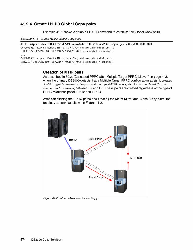
41.2.4 Create H1:H3 Global Copy pairs
Example 41-1 shows a sample DS CLI command to establish the Global Copy pairs.
Example 41-1 Create H1:H3 Global Copy pairs
dscli> mkpprc -dev IBM.2107-75CZM21 -remotedev IBM.2107-75CYK71 -type gcp 5000-500f:7000-700fCMUC00153I mkpprc: Remote Mirror and Copy volume pair relationship IBM.2107-75CZM21/5000:IBM.2107-75CYK71/7000 successfully created....CMUC00153I mkpprc: Remote Mirror and Copy volume pair relationship IBM.2107-75CZM21/500F:IBM.2107-75CYK71/700F successfully created.
Creation of MTIR pairsAs described in 39.2, “Cascaded PPRC after Multiple Target PPRC failover” on page 443, when the primary DS8000 detects that a Multiple Target PPRC configuration exists, it creates Multi-Target Incremental Resync relationships (MTIR pairs), also known as Multi-Target Internal Relationships, between H2 and H3. These pairs are created regardless of the type of PPRC relationships for H1:H2 and H1:H3.
After establishing the PPRC paths and creating the Metro Mirror and Global Copy pairs, the topology appears as shown in Figure 41-2.
Figure 41-2 Metro Mirror and Global Copy
474 DS8000 Copy Services

41.2.5 Create FlashCopy H3:J3
The next step is to establish the FlashCopy relationships from the Global Copy secondary volumes to create the journal volumes used by Global Mirror. These FlashCopy relationships are created with the following attributes:
Inhibit target writes Protects the FlashCopy target volume from being modified by host writes. Only the Global Copy primary can write to the target volume.
Start change recording Starts recording which tracks have changed on either volume in the FlashCopy pair.
Persistent Keeps the FlashCopy relationship until it is explicitly or implicitly terminated.
No copy Does not perform a background copy of the data from the FlashCopy source volume to the target.
Example 41-2 shows a sample DS CLI command to create FlashCopy relationships for Global Mirror to use.
Example 41-2 Create FlashCopy H3:J3
dscli> mkflash -dev IBM.2107-75CYK71 -tgtinhibit -record -persist -nocp 7000-700f:7200-720fCMUC00137I mkflash: FlashCopy pair IBM.2107-75CYK71/7000:IBM.2107-75CYK71/7200 successfully created....CMUC00137I mkflash: FlashCopy pair IBM.2107-75CYK71/700F:IBM.2107-75CYK71/720F successfully created.
The creation of the FlashCopy relationships can be verified as shown in Example 41-3.
Example 41-3 List FlashCopy relationships
dscli> lsflash -dev IBM.2107-75CYK71 7000-700fID SrcLSS SequenceNum Timeout ActiveCopy Recording Persistent Revertible SourceWriteEnabled TargetWriteEnabled BackgroundCopy===========================================================================================================IBM.2107-75CYK71/7000:IBM.2107-75CYK71/7200 IBM.2107-75CYK71/70 0 60 Disabled Enabled Enabled Disabled Enabled Disabled Disabled...IBM.2107-75CYK71/700F:IBM.2107-75CYK71/720F IBM.2107-75CYK71/70 0 60 Disabled Enabled Enabled Disabled Enabled Disabled Disabled
41.2.6 Create and start Global Mirror session
The Global Mirror session is created. Example 41-4 shows sample DS CLI commands to create a session, start the session, and then query to show the session status. In this simple example, there are no external subordinates.
Note, that the -volpair option is used for the mksession command. There is also a -volume option that was used in the past to specify the primary volume, but for a multiple target PPRC environment, you have to use the -volpair option to specify the primary volume and the target volume.
Example 41-4 Create Global Mirror session
dscli> mksession -volpair 5000-500f:7000-700f -dev IBM.2107-75CZM21 -remotedev IBM.2107-75CYK71 -lss 50 01CMUC00145I mksession: Session 01 opened successfully.
Chapter 41. Implementing a Metro Mirror and Global Mirror topology 475

dscli> mkgmir -dev IBM.2107-75CZM21 -lss 50 -session 01CMUC00162I mkgmir: Global Mirror for session 01 successfully started.
dscli> lsgmir -dev IBM.2107-75CZM21 -session 01 50SessionID MasterID ID State %Success CGtime
0x01 IBM.2107-75CZM21 50 Running 100 11/17/20nn 23:24:42 CET
At this point, there is a Metro Mirror and Global Mirror Multiple Target PPRC configuration, which is illustrated in Figure 41-3.
Figure 41-3 Metro Mirror and Global Mirror
41.3 Outage at H3
A failure or planned outage at the Global Mirror remote site H3 can cause the Global Copy pairs to suspend and the Global Mirror session to stop forming consistency groups. The Metro Mirror pairs to H2 continue to run and provide protection in case of a outage at H1. When site H3 is recovered, Global Mirror H1:H3 can be resumed to restore the Global Mirror protection.
41.4 Outage at H2
A failure or planned outage at the secondary site H2 can cause the Metro Mirror pairs H1:H2 to suspend. Global Mirror to H3 continues to provide disaster recovery protection in case of a failure at H1. When site H2 is recovered, Metro Mirror H1:H2 can be resumed to restore the Metro Mirror protection.
476 DS8000 Copy Services

41.5 Outage at H1
The sections that follow describe the steps that are taken in the case of a failure or planned outage at the local production H1 site. In a Metro Mirror and Global Mirror configuration, a swap to the Metro Mirror secondary site H2 can be performed.
41.5.1 Recover at H2
First, use HyperSwap or a traditional restart to move production to H2 without interrupting host I/O.
Freeze H1:H2 and H1:H3Freeze commands for H1:H2 and H1:H3 remove the PPRC paths and suspend all PPRC pairs for H1:H2 and H1:H3. A separate freeze command is required for each LSS-to-LSS PPRC relationship.
With the use of consistency groups, the freeze command creates consistent data at the remote H2 site by using extended long busy or queue full to temporarily queue dependent writes.
Depending on the type of failure at H1, the freeze commands might not complete successfully and some or all H1 pairs can remain full-duplex.
Example 41-5 Freeze PPRC Group H1:H2 and H1:H3
dscli> freezepprc -dev IBM.2107-75CZM21 -remotedev IBM.2107-75CYM31 50:60CMUC00161I freezepprc: Remote Mirror and Copy consistency group IBM.2107-75CZM21/50:IBM.2107-75CYM31/60 successfully created.
dscli> freezepprc -dev IBM.2107-75CZM21 -remotedev IBM.2107-75CYK71 50:70CMUC00161I freezepprc: Remote Mirror and Copy consistency group IBM.2107-75CZM21/50:IBM.2107-75CYK71/70 successfully created.
Unfreeze and run H1:H2 and H1:H3When all freeze commands have completed, the secondary H2 and H3 sites contain a consistent copy of data. The unfreeze or run command (also known as a consistency group created command) removes the extended long busy or queue-full condition at the local H1 site. An unfreeze command is required for each LSS-to-LSS PPRC relationship.
As with the freeze command, depending on the type of failure at H1, the unfreeze commands might not complete successfully. Example 41-6 shows an example of a DS CLI unfreeze command.
Example 41-6 Consistency group created, H1:H2 and H1:H3
dscli> unfreezepprc -dev IBM.2107-75CZM21 -remotedev IBM.2107-75CYM31 50:60CMUC00198I unfreezepprc: Remote Mirror and Copy pair IBM.2107-75CZM21/50:IBM.2107-75CYM31/60 successfully thawed.
dscli> unfreezepprc -dev IBM.2107-75CZM21 -remotedev IBM.2107-75CYK71 50:70CMUC00198I unfreezepprc: Remote Mirror and Copy pair IBM.2107-75CZM21/50:IBM.2107-75CYK71/70 successfully thawed.
Chapter 41. Implementing a Metro Mirror and Global Mirror topology 477

Failover H2:H1 and H3:H1The failover command for H2:H1 converts the H2 volumes to suspended Metro Mirror primary volumes whose secondary volumes are H1. Similarly, the failover H3:H1 converts the H3 volumes to suspended primary Global Copy volumes whose secondary volumes are H1.
Example 41-7 and Example 41-8 show DS CLI examples of the failover commands for H2:H1 and H3:H1, respectively.
Example 41-7 Failover H2:H1
dscli> failoverpprc -dev IBM.2107-75CYM31 -remotedev IBM.2107-75CZM21 -type mmir 6000-600f:5000-500fCMUC00196I failoverpprc: Remote Mirror and Copy pair IBM.2107-75CYM31/6000:IBM.2107-75CZM21/5000 successfully reversed....CMUC00196I failoverpprc: Remote Mirror and Copy pair IBM.2107-75CYM31/600F:IBM.2107-75CZM21/500F successfully reversed.
Example 41-8 Failover H3:H1
dscli> failoverpprc -dev IBM.2107-75CYK71 -remotedev IBM.2107-75CZM21 -type gcp 7000-700f:5000-500fCMUC00196I failoverpprc: Remote Mirror and Copy pair IBM.2107-75CYK71/7000:IBM.2107-75CZM21/5000 successfully reversed....CMUC00196I failoverpprc: Remote Mirror and Copy pair IBM.2107-75CYK71/700F:IBM.2107-75CZM21/500F successfully reversed.
At this point, each volume on H1, H2, and H3 is a suspended primary volume pointing to the other two sites as shown in Figure 41-4 on page 479. Specifically, the pair states are as follows:
� H1 suspended primary to H2� H1 suspended primary to H3
� H2 suspended primary to H1� H2 suspended primary to H3
� H3 suspended primary to H1� H3 suspended primary to H2
Example 41-9 shows that the H1:H2 and H1:H3 pairs are suspended due to the freeze commands. If H1 is inaccessible due to a failure, the freeze commands might not be possible and a query might not be possible, either.
Example 41-9 lspprc for H1 pairs
dscli> lspprc -dev IBM.2107-75CZM21 5000-500fID State Reason Type SourceLSS=============================================================================================IBM.2107-75CZM21/5000:IBM.2107-75CYK71/7000 Suspended Freeze Global Copy IBM.2107-75CZM21/50 ...IBM.2107-75CZM21/5000:IBM.2107-75CYM31/6000 Suspended Freeze Metro Mirror IBM.2107-75CZM21/50 ......IBM.2107-75CZM21/500F:IBM.2107-75CYK71/700F Suspended Freeze Global Copy IBM.2107-75CZM21/50 ...IBM.2107-75CZM21/500F:IBM.2107-75CYM31/600F Suspended Freeze Metro Mirror IBM.2107-75CZM21/50 ...
478 DS8000 Copy Services

Example 41-10 shows that the H2:H1 pairs are suspended from the failover H2:H1 command. The -multtgt option is used to include the H2:H3 MTIR pairs in the output.
Example 41-10 lspprc for H2 pairs
dscli> lspprc -dev IBM.2107-75CYM31 -multtgt 6000-600fID State Reason Type SourceLSS============================================================================================================IBM.2107-75CYM31/6000:IBM.2107-75CYK71/7000 Suspended Multi-target Internal Global Copy IBM.2107-75CYM31/60 ...IBM.2107-75CYM31/6000:IBM.2107-75CZM21/5000 Suspended Host Source Metro Mirror IBM.2107-75CYM31/60 ......IBM.2107-75CYM31/600F:IBM.2107-75CYK71/700F Suspended Multi-target Internal Global Copy IBM.2107-75CYM31/60 ...IBM.2107-75CYM31/600F:IBM.2107-75CZM21/500F Suspended Host Source Metro Mirror IBM.2107-75CYM31/60 ...
Example 41-11 shows that the H3:H1 pairs are suspended from the failover H3:H1 command. The -multtgt option is used to also include the H3:H2 MTIR pairs in the output.
Example 41-11 lspprc for H3 pairs
dscli> lspprc -dev IBM.2107-75CYK71 -multtgt 7000-700fID State Reason Type SourceLSS ===========================================================================================================IBM.2107-75CYK71/7000:IBM.2107-75CYM31/6000 Suspended Multi-target Internal Global Copy IBM.2107-75CYK71/70 ...IBM.2107-75CYK71/7000:IBM.2107-75CZM21/5000 Suspended Host Source Global Copy IBM.2107-75CYK71/70 ......IBM.2107-75CYK71/700F:IBM.2107-75CYM31/600F Suspended Multi-target Internal Global Copy IBM.2107-75CYK71/70 ...IBM.2107-75CYK71/700F:IBM.2107-75CZM21/500F Suspended Host Source Global Copy IBM.2107-75CYK71/70 ...
Resume host systems at H2Host systems can be restarted at H2. If HyperSwap is used, the host I/O is switched to H2. At this point, the host systems are running at H2, and the configuration appears as in Figure 41-4.
Figure 41-4 After recovery at H2
Chapter 41. Implementing a Metro Mirror and Global Mirror topology 479

Start replication H2:H3The Incremental Resynchronization capability is used to start replication H2:H3. With the change recording function of Multiple Target PPRC, only the tracks that are potentially out of synchronization between H2 and H3 are transferred, and a full copy of data is not required.
This Incremental Resynchronization capability operates the same for Global Copy and Global Mirror pairs as it does for Metro Mirror. Even though H2 was a Metro Mirror secondary and H3 was a Global Mirror scenario, the Incremental Resynchronization is still possible.
Failback H2:H3A failback command for H2:H3 merges the change recording bitmap files from H2 and H3 and initiates the transfer of the out-of-synchronization data. Example 41-12 shows a sample DS CLI for the failback command.
Example 41-12 Failback H2:H3
dscli> failbackpprc -dev IBM.2107-75CYM31 -remotedev IBM.2107-75CYK71 -type gcp 6000-600f:7000-700fCMUC00197I failbackpprc: Remote Mirror and Copy pair IBM.2107-75CYM31/6000:IBM.2107-75CYK71/7000 successfully failed back....CMUC00197I failbackpprc: Remote Mirror and Copy pair IBM.2107-75CYM31/600F:IBM.2107-75CYK71/700F successfully failed back.
At this point in the process, the H2:H3 pairs have been resumed. The state of the configuration is as shown in Figure 41-5, with Global Copy now active from H2 to H3.
Figure 41-5 After failback H2:H3 with Incremental Resynchronization
Start Global Mirror H2:H3Global Copy is running for H2:H3 and transferring data. The FlashCopy journal volumes at J3 contain the last consistency group that was formed before the failure at H1. Example 41-13 on page 481 shows the next step, which is to start Global Mirror from H2:H3 and resume the formation of Global Mirror consistency groups.
480 DS8000 Copy Services

Example 41-13 Start Global Mirror H2:H3
dscli> mksession -volpair 6000-600f:7000-700f -dev IBM.2107-75CYM31 -remotedev IBM.2107-75CYK71 -lss 60 01CMUC00145I mksession: Session 01 opened successfully.
dscli> mkgmir -dev IBM.2107-75CYM31 -lss 60 -session 01CMUC00162I mkgmir: Global Mirror for session 01 successfully started.
Global Mirror is started for H2:H3 by using the same FlashCopy volumes on H3, and consistency group formation is resumed, as shown in Example 41-14.
Example 41-14 Query showing consistency group formation
dscli> lsgmir -dev IBM.2107-75CYM31 -session 01 60SessionID MasterID ID State %Success CGtime======================================================================0x01 IBM.2107-75CYM31 60 Running 100 mm/dd/yyyy hh:mm:ss TZ
41.5.2 H1 recovered
When site H1 is recovered, mirroring can be resumed to H2 to restore the Multiple Target PPRC configuration.
Pause or remove Global Mirror H1:H3H1 has Global Mirror running for H1:H3. Because the Global Copy pairs H1:H3 are suspended, Global Mirror is unable to form consistency groups. The Global Mirror session can be either paused or removed.
Example 41-15 shows a DS CLI command to pause the Global Mirror session, followed by a query showing that the state is now paused.
Example 41-15 Pause Global Mirror H1:H3
dscli> pausegmir -dev IBM.2107-75CZM21 -lss 50 -session 01CMUC00163I pausegmir: Global Mirror for session 01 successfully paused....dscli> lsgmir -dev IBM.2107-75CZM21 -session 01 50SessionID MasterID ID State %Success CGtime=====================================================================0x01 IBM.2107-75CZM21 50 Paused 95 11/18/20nn 10:11:31 CET
Alternatively, the Global Mirror H1:H3 session can be ended by removing the Global Copy pairs from the session and then removing the session, as shown in Example 41-16.
Example 41-16 Stop Global Mirror H1:H3
dscli> chsession -volpair 5000-500f:7000-700f -dev IBM.2107-75CZM21 -remotedev IBM.2107-75CYK71 -lss 50 -action remove 01CMUC00147I chsession: Session 01 successfully modified.
dscli> rmsession -dev IBM.2107-75CZM21 -lss 50 -quiet 01CMUC00146I rmsession: Session 01 closed successfully.
Establish paths H1:H2 and H1:H3The paths H1:H2 and H1:H3 were removed by the freeze commands issued in 41.5.1, “Recover at H2” on page 477. After H1 is recovered, these paths need to be reestablished. The paths are not required until the time when mirroring is later resumed from H1:H2 and
Chapter 41. Implementing a Metro Mirror and Global Mirror topology 481

H1:H3, but establishing them as soon as H1 is recovered helps to ensure that they are available when needed.
The paths are re-established by using the same commands that were used to create the paths.
Failback H2:H1A failback command for H2:H1 resumes the H2:H1 Metro Mirror pairs, as shown in Example 41-17.
Example 41-17 Failback H2:H1
dscli> failbackpprc -dev IBM.2107-75CYM31 -remotedev IBM.2107-75CZM21 -type mmir 6000-600f:5000-500fCMUC00197I failbackpprc: Remote Mirror and Copy pair IBM.2107-75CYM31/6000:IBM.2107-75CZM21/5000 successfully failed back....CMUC00197I failbackpprc: Remote Mirror and Copy pair IBM.2107-75CYM31/600F:IBM.2107-75CZM21/500F successfully failed back.
Site H2 is now a Multiple Target PPRC primary with Metro Mirror H2:H1 and Global Mirror H2:H3. The suspended pairs that existed between the two secondary sites H1 and H3 are automatically converted by the DS8000 to MTIR pairs. Example 41-18 shows an lspprc command issued at H1, showing that it is now a Metro Mirror target of H2 and also has MTIR pairs to H3. Compare this to the query of H1 shown in Example 41-9 on page 478, which was issued before the failback H2:H1, to see how the DS8000 has created the MTIR pair relationships.
Example 41-18 lspprc at H1 showing H1:H3 MTIR pairs
dscli> lspprc -dev IBM.2107-75CZM21 -multtgt 5000-500fID State Reason Type SourceLSS=====================================================================================================================IBM.2107-75CYM31/6000:IBM.2107-75CZM21/5000 Target Full Duplex - Metro Mirror IBM.2107-75CYM31/60......IBM.2107-75CYM31/600F:IBM.2107-75CZM21/500F Target Full Duplex - Metro Mirror IBM.2107-75CYM31/60...IBM.2107-75CZM21/5000:IBM.2107-75CYK71/7000 Suspended Multi-target Internal Global Copy IBM.2107-75CZM21/50......IBM.2107-75CZM21/500F:IBM.2107-75CYK71/700F Suspended Multi-target Internal Global Copy IBM.2107-75CZM21/50...
After the H2:H3 pairs reach full-duplex, the Multiple Target PPRC configuration has been restored, as shown in Figure 41-6. This is now the same topology as the initial state with Metro Mirror and Global Mirror.
482 DS8000 Copy Services

Figure 41-6 Metro Mirror and Global Mirror topology restored
You can compare Figure 41-3 on page 476 with Figure 41-6 to see that it is the same general topology, but now the host systems are now running at H2 rather than H1. Depending upon the specific circumstances, for example if H1 and H2 are local to each other, there might be no preference for running at one site versus the other.
In other situations, there might be reasons to prefer that the host systems run at site H1. Returning to H1 involves the same sequence of steps as the move from H1 to H2. This move back will be a planned move, although the original move from H1 to H2 might have been performed due to a failure event at H1.
41.6 Scripts for managing Metro Mirror/Global Mirror
The best solution is to use a management software like Copy Services Manager or GDPS for z/OS environments. If you do not have either, prepare scripts to manage your environment.
You can prepare DS CLI scripts with all the commands, but DS CLI scripts have the disadvantage that execution stops when there is an error in one line of the script, which can be caused by a volume that is not in the expected state, for example. With many thousand volume-pairs, it is more practical to let the script run for all volumes and treat the exceptions later instead of stopping the script. Therefore, we use Windows batch files.
Because in most commands you have to deal with the same pairs, this example creates input files with the Metro Mirror pairs, the Global Mirror pairs, and the FlashCopy pairs for Global Mirror as shown in Example 41-19.
Example 41-19 Input files with pair definitions
Input file: all-h1h2-mm-pairs.txtA000-A07F:B000-B07FA100-A17F:B100-B17FA200-A27F:B200-B27FA300:B300
Chapter 41. Implementing a Metro Mirror and Global Mirror topology 483
Input file: all-h1h3-gm-pairs.txtA000-A07F:C000-C07FA100-A17F:C100-C17FA200-A27F:C200-C27FA300:C300
Input file: all-h3-fc-pairs.txtC000-C07F:D000-D07FC100-C17F:D100-D17FC200-C27F:D200-D27FC300:C300
The sample scripts provided here are only a suggestion and are in no way complete. For some tasks like establishing paths or freeze/unfreeze, we prepare separate scripts.
To make the scripts more flexible, we use a .ini file and call it pprcconfig.ini to define the environment, access to the DS8000 systems and set variables for the input files, as shown in Example 41-20.
Example 41-20 The pprcconfig.ini file
all-mm-ps-pairs=..\input\all-h1h2-mm-pairs.txtmm-mkpprcpath-P2S=..\input\mkpprcpath-h1-h2.txtmm-mkpprcpath-S2P=..\input\mkpprcpath-h2-h1.txtmm-freezeunfreeze-P2S=..\input\freezeunfreeze-h1-h2.txtall-gm-ps-pairs=..\input\all-h1h3-gm-pairs.txtgm-mkpprcpath-P2S=..\input\mkpprcpath-h1-h3.txtgm-mkpprcpath-S2P=..\input\mkpprcpath-h3-h1.txtall-gm-mksession=..\input\mksession-h1.txtall-gm-fc-pairs=..\input\all-h3-fc-pairs.txtpname=D86pdev=IBM.2107-75FAW81pdsclicmd="C:\Program Files (x86)\IBM\dscli\dscli.exe" -hmc1 p.p.p.p -user p -passwd pwsname=D84sdev=IBM.2107-75ACA91sdsclicmd="C:\Program Files (x86)\IBM\dscli\dscli.exe" -hmc1 s.s.s.s -user s -passwd swgname=D70gdev=IBM.2107-75ZA181gdsclicmd="C:\Program Files (x86)\IBM\dscli\dscli.exe" -hmc1 g.g.g.g -user g -passwd gwgm-session-nr=01gm-master-lss=A0
Example 41-21 shows the scripts to establish the paths or define the sessions.
Example 41-21 Scripts to establish paths, freeze/unfreeze and define sessions
mkpprcpath-h1-h2.txt:mkpprcpath -dev IBM.2107-75FAW81 -remotedev IBM.2107-75ACA91 -remotewwnn
5005076303FFD13E -srclss A0 -tgtlss B0 I0332:I0330 I0200:I0210mkpprcpath -dev IBM.2107-75FAW81 -remotedev IBM.2107-75ACA91 -remotewwnn
5005076303FFD13E -srclss A1 -tgtlss B1 I0332:I0330 I0200:I0210:freezeunfreeze-h1-h2.txtfreezepprc -dev IBM.2107-75FAW81 -remotedev IBM.2107-75ACA91 A0:B0 A1:B1 A2:B2..unfreezepprc -dev IBM.2107-75FAW81 -remotedev IBM.2107-75ACA91 A0:B0 A1:B1 A2:B2..
484 DS8000 Copy Services

mksession-h1.txtmksession -dev IBM.2107-75FAW81 -lss A0 01mksession -dev IBM.2107-75FAW81 -lss A1 01mksession -dev IBM.2107-75FAW81 -lss A2 01mksession -dev IBM.2107-75FAW81 -lss A3 01
Now we can use our first script to set up a Metro Mirror environment as shown in Example 41-22.
Example 41-22 Script: 1-create-all-MM-pairs.bat
ECHO offfor /F "tokens=*" %%K in (..\input\pprcconfig.ini) do set %%KremECHO Create new MM pairs Prim to Sec. To continue press ENTERpausesetlocal enabledelayedexpansionremset outfile="..\output\"%DATE%-1-all-create-MM-pairs-P2S.txtdel %outfile% 2>nul remrem Establish Paths Prim to Secrem%pdsclicmd% -script %mm-mkpprcpath-P2S% >> %outfile%remrem Establish pairsremFOR /F "tokens=*" %%i IN ( %all-mm-ps-pairs% ) DO ( %pdsclicmd% mkpprc -dev %pdev% -remotedev %sdev% -type mmir -mode full
-tgtonline %%i >> %outfile%)ECHO Output in: %outfile%pause
We first parse the pprcconfig.ini file and set the variables. We define an output file and put the date in front of the file name. We establish the paths and then take the input file with all the pair definitions for the Metro Mirror relationship and establish the pairs.
In a similar way, Example 41-23 establishes the Global Mirror environment.
Example 41-23 1-create-gm-h1-to-h3.bat
ECHO offfor /F "tokens=*" %%K in (..\input\pprcconfig.ini) do set %%KremECHO Establish Global Mirror from %pname% to %gname%. To continue press ENTERpausesetlocal enabledelayedexpansionset outfile="..\output\"%DATE%-1-all-create-GM-%pname%-2-%gname%.txtdel %outfile% 2>nulremrem Establish Paths
Important: Some DS CLI commands are shown here in two lines for better reading, but they must be entered on one line.
Chapter 41. Implementing a Metro Mirror and Global Mirror topology 485

rem%pdsclicmd% -script %gm-mkpprcpath-P2S% >> %outfile%remrem Establish pairsremFOR /F "tokens=*" %%i IN ( %all-gm-ps-pairs% ) DO ( %pdsclicmd% mkpprc -dev %pdev% -remotedev %gdev% -type gcp -mode full
-tgtonline %%i >> %outfile%)remrem Establish FlashCopies on h3remFOR /F "tokens=*" %%i IN ( %all-gm-fc-pairs% ) DO ( %gdsclicmd% mkflash -dev %gdev% -tgtinhibit -record -nocp -persist %%i >>
%outfile%)rem Define Global Mirror Sessions on h1rem%pdsclicmd% -script %all-gm-mksession% >> %outfile%remrem Add volumes to Global Mirror SessionremFOR /F "tokens=*" %%i IN ( %all-gm-ps-pairs% ) DO ( set paar=%%i set lss=!paar:~0,2! %pdsclicmd% chsession -dev %pdev% -remotedev %gdev% -lss !lss! -action add
-volpair %%i %gm-session-nr% >> %outfile%)remrem Start Global Mirror Sessionrem%pdsclicmd% mkgmir -dev %pdev% -lss %gm-master-lss% -cginterval 0 -coordinate 50
-drain 300 -session %gm-session-nr% >> %outfile%remECHO Output in: %outfile%pause
Example 41-24 shows a failover to H2 that reverses the pairs of the input file.
Example 41-24 2-failover-mm-to-h2.bat
ECHO offfor /F "tokens=*" %%K in (..\input\pprcconfig.ini) do set %%KremECHO Switch to %sname% with freeze and unfreeze of all %pname%-volumes. ECHO To continue press ENTERpausesetlocal enabledelayedexpansionset outfile="..\output\"%DATE%-2-all-MM-failover-to-%sname%-with-freeze.txtdel %outfile% 2>nulremrem Freeze and unfreeze of all pairs
Examine the output: These scripts are only a suggestion. They do not perform any error checking. At the least, you have to examine the output.
486 DS8000 Copy Services

rem%pdsclicmd% -script %mm-freezeunfreeze-P2S% >> %outfile%remrem Failover: remFOR /F "tokens=*" %%i IN ( %all-mm-ps-pairs% ) DO ( set paar=%%i set pvol=!paar:~0,9! IF "!paar:~4,1!"==":" set pvol=!paar:~0,4! set svol=!paar:~10,9! IF "!paar:~4,1!"==":" set svol=!paar:~5,4! %sdsclicmd% failoverpprc -dev %sdev% -remotedev %pdev% -type mmir -tgtonline
!svol!:!pvol! >> %outfile%)ECHO Output in: %outfile%pause
You can now perform a failback from H1 to H2 as shown in Example 41-25 or a failback from H2 to H1.
Example 41-25 3-mm-failback-h1-to-h2.bat
ECHO offsetlocal enabledelayedexpansionfor /F "tokens=*" %%K in (..\input\pprcconfig.ini) do set %%KremECHO MM failback (resync) %pname% to %sname%. Volumes at %sname% should be
offline!!! To continue press ENTERpauseremset outfile="..\output\"%DATE%-3-all-failback-MM-%pname%-to-%sname%.txtdel %outfile% 2>nul remremrem Establish pathsrem%pdsclicmd% -script %mm-mkpprcpath-P2S% >> %outfile%remrem Failback (resync) H1 to H2remFOR /F "tokens=*" %%i IN ( %all-mm-ps-pairs% ) DO ( %pdsclicmd% failbackpprc -dev %pdev% -remotedev %sdev% -type mmir -tgtonline
%%i >> %outfile%)ECHO Output in: %outfile%pause
Example 41-26 4-mm-failback-h2-to-h1.bat
ECHO offsetlocal enabledelayedexpansionfor /F "tokens=*" %%K in (..\input\pprcconfig.ini) do set %%KremECHO MM failback %sname% to %pname%. Attention!! Reverse direction. All %pname%
volumes should be offline!!. To continue press ENTERpause
Chapter 41. Implementing a Metro Mirror and Global Mirror topology 487
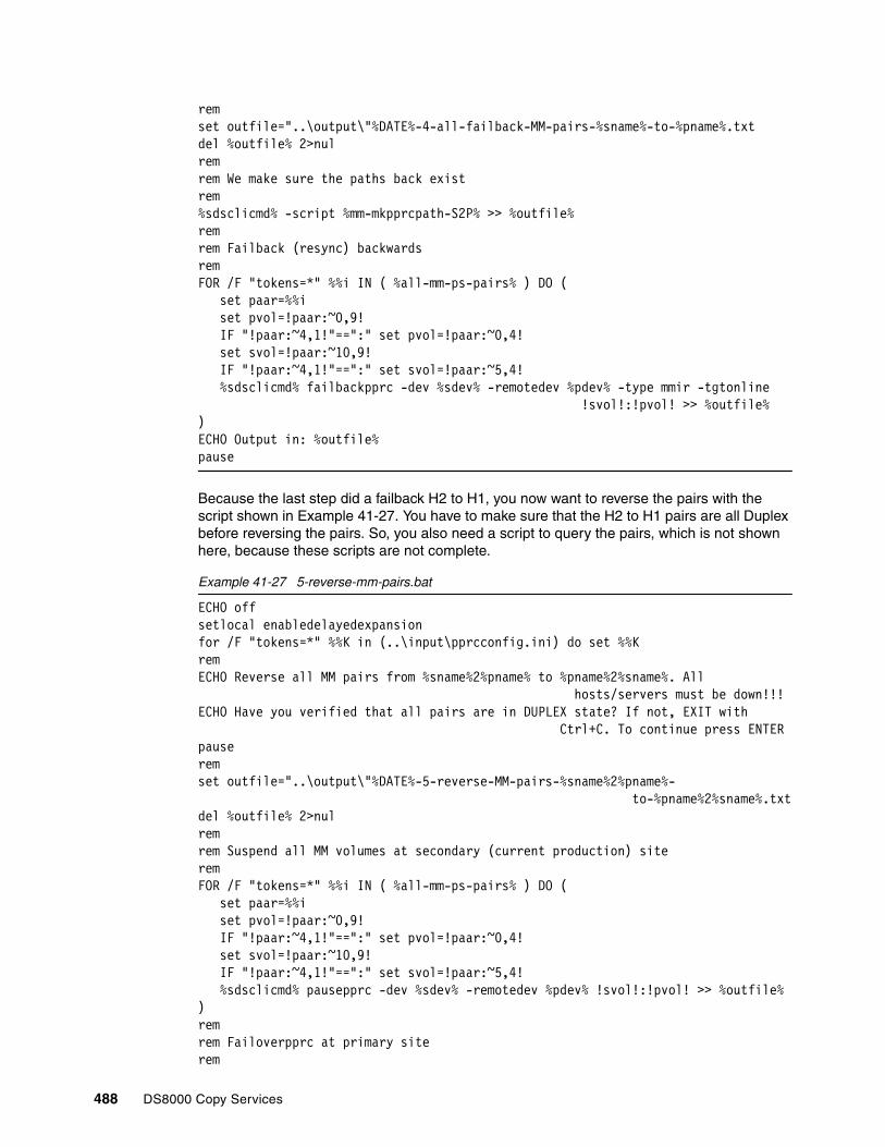
remset outfile="..\output\"%DATE%-4-all-failback-MM-pairs-%sname%-to-%pname%.txtdel %outfile% 2>nul remrem We make sure the paths back existrem%sdsclicmd% -script %mm-mkpprcpath-S2P% >> %outfile%remrem Failback (resync) backwardsremFOR /F "tokens=*" %%i IN ( %all-mm-ps-pairs% ) DO ( set paar=%%i set pvol=!paar:~0,9! IF "!paar:~4,1!"==":" set pvol=!paar:~0,4! set svol=!paar:~10,9! IF "!paar:~4,1!"==":" set svol=!paar:~5,4! %sdsclicmd% failbackpprc -dev %sdev% -remotedev %pdev% -type mmir -tgtonline
!svol!:!pvol! >> %outfile%)ECHO Output in: %outfile%pause
Because the last step did a failback H2 to H1, you now want to reverse the pairs with the script shown in Example 41-27. You have to make sure that the H2 to H1 pairs are all Duplex before reversing the pairs. So, you also need a script to query the pairs, which is not shown here, because these scripts are not complete.
Example 41-27 5-reverse-mm-pairs.bat
ECHO offsetlocal enabledelayedexpansionfor /F "tokens=*" %%K in (..\input\pprcconfig.ini) do set %%KremECHO Reverse all MM pairs from %sname%2%pname% to %pname%2%sname%. All
hosts/servers must be down!!! ECHO Have you verified that all pairs are in DUPLEX state? If not, EXIT with
Ctrl+C. To continue press ENTERpauseremset outfile="..\output\"%DATE%-5-reverse-MM-pairs-%sname%2%pname%-
to-%pname%2%sname%.txtdel %outfile% 2>nul remrem Suspend all MM volumes at secondary (current production) siteremFOR /F "tokens=*" %%i IN ( %all-mm-ps-pairs% ) DO ( set paar=%%i set pvol=!paar:~0,9! IF "!paar:~4,1!"==":" set pvol=!paar:~0,4! set svol=!paar:~10,9! IF "!paar:~4,1!"==":" set svol=!paar:~5,4! %sdsclicmd% pausepprc -dev %sdev% -remotedev %pdev% !svol!:!pvol! >> %outfile%)remrem Failoverpprc at primary siterem
488 DS8000 Copy Services

FOR /F "tokens=*" %%i IN ( %all-mm-ps-pairs% ) DO ( %pdsclicmd% failoverpprc -dev %pdev% -remotedev %sdev% -type mmir -multtgt
-tgtonline %%i >> %outfile%)remrem Make sure paths existrem%pdsclicmd% -script %mm-mkpprcpath-P2S% >> %outfile%remrem Failbackpprc H1 to H2remFOR /F "tokens=*" %%i IN ( %all-mm-ps-pairs% ) DO ( %pdsclicmd% failbackpprc -dev %pdev% -remotedev %sdev% -type mmir -tgtonline
%%i >> %outfile%)ECHO Output in: %outfile%pause
There is one parameter worth mentioning here. On the failoverpprc command H1 to H2, you need to specify the -multtgt parameter because H1 is a multiple target source. Without this parameter, the following failbackpprc H1 to H2 fails.
Many more scripts are needed to manage the environment. This chapter shows only a few examples. Similar scripts can be created for the Global Mirror part.
Chapter 41. Implementing a Metro Mirror and Global Mirror topology 489

490 DS8000 Copy Services

Chapter 42. Implementing a Global Copy plus Global Mirror topology
This chapter describes the Global Copy plus Global Mirror topology and its use in providing a disaster recovery solution with three sites in three different regions separated by long distances. It includes the following topics:
� Overview of Global Copy plus Global Mirror topology� Creating a Global Copy plus Global Mirror topology� Outage at Global Copy secondary H2� Outage at Global Mirror H3� Outage at H1
42
© Copyright IBM Corp. 2017. All rights reserved. 491

42.1 Overview of Global Copy plus Global Mirror topology
A topology consisting of a Global Copy and a Global Mirror relationship provides a disaster recovery solution with three sites in three different regions that are separated by long distances. Figure 42-1 shows an example of this topology, where H1:H2 is Global Copy and H1:H3 is Global Mirror. The J3 volumes are the Global Mirror FlashCopy journal volumes.
In the case of a failure at H3, the Global Copy H1:H2 pairs can be put into a Global Mirror session for H1:H2. Therefore, FlashCopy journal volumes at J2 are also required. With support for thin provisioning also for count key data (CKD) environments, the additional capacity needed for the journal volumes is not very large.
As with all types of Multiple Target Peer-to-Peer Remote Copy (PPRC) topologies, there are Multi-Target Incremental Resync relationships (MTIR pairs), also known as Multi-Target Internal Relationships, between the two secondary sites, H2 and H3, as shown in Figure 42-1.
Figure 42-1 Global Copy plus Global Mirror topology
With this topology, a long-distance disaster recovery configuration remains available after an outage at any one of the three sites.
42.2 Creating a Global Copy plus Global Mirror topology
The sections that follow explain the following steps for creating a Global Copy H1:H2 and a Global Mirror H1:H3 topology:
1. Establish PPRC paths between all sites.
2. Establish the H1:H2 Global Copy pairs.
Create FlashCopy H2:J2. (These are required to run Global Mirror H1:H2.)
492 DS8000 Copy Services
3. Establish Global Mirror H1:H3:
a. Establish H1:H3 Global Copy pairs.b. Create FlashCopy H3:J3. c. Create and start the Global Mirror session for H1:H3.
The details of creating these relationships are similar to creating the Metro Mirror and Global Mirror topology described in 41.2, “Creating a Metro Mirror and Global Mirror topology” on page 473. The one difference is that the H1:H2 relationships are Global Copy rather than Metro Mirror.
The scenarios in this section describe an outage at each of the three sites. Each of these could be either a failure condition or a planned event for testing or maintenance.
To simplify the descriptions, these sites are often referred to as though they were a single volume, but it must be understood that the terms refer to the entire set of volumes being mirrored by PPRC. For example, “Failover H2:H1” means to fail over all of the H2 volumes to their corresponding H1 volumes.
42.2.1 Establish PPRC paths
PPRC paths are required before the PPRC pairs can be established. It is best that paths among all three sites be established so that they are available when they are required.
The procedure for establishing these paths is similar to that for the two Metro Mirror topology that is described in 40.2.2, “Establish PPRC paths” on page 453.
42.2.2 Create H1:H2 Global Copy pairs
After establishing all of the required PPRC paths, create the Global Copy volume pairs H1:H2.
To provide for the possibility of starting Global Mirror H1:H2 in the event of an outage at the Global Mirror remote H3 site, Global Mirror FlashCopy journal volumes J2 are required. These FlashCopy relationships from H2:J2 are created with “inhibit target writes,” “start change recording,” “persistent,” and “no copy” options.
42.2.3 Create H1:H3 Global Mirror
Global Mirror H1:H3 is established in the same manner as described in 41.2, “Creating a Metro Mirror and Global Mirror topology” on page 473.
After both the H1:H2 and H1:H3 relationships have been created, the DS8000 storage system creates the MTIR pairs between H2 and H3, as described in 39.2, “Cascaded PPRC after Multiple Target PPRC failover” on page 443. At this point, there is Global Copy running from H1 to H2, and Global Mirror is running from H1 to H3.
The topology is now as shown in Figure 42-2 on page 494.
Chapter 42. Implementing a Global Copy plus Global Mirror topology 493

Figure 42-2 Global Copy and Global Mirror, including MTIR pairs
42.3 Outage at Global Copy secondary H2
An outage at the Global Copy secondary H2 site can cause the Global Copy H1:H2 pairs to suspend. Because of the design, a suspension of one relationship on a volume does not affect other relationships on the volume, so Global Mirror H1:H3 continues to run and provide a disaster recovery capability, as shown in Figure 42-3.
Figure 42-3 Outage at Global Copy secondary H2
When site H2 is recovered, the Global Copy H1:H2 pairs are resumed and data is copied from H1 to H2 again.
494 DS8000 Copy Services

42.4 Outage at Global Mirror H3
An outage at the Global Mirror remote site H3 causes the loss of the Global Mirror disaster recovery capability.
The Global Copy H1:H2 pairs can be placed into a Global Mirror session to restore the disaster recovery capability.
42.4.1 Start Global Mirror H1:H2
Global Copy for H1:H2 remains active. The disaster recovery capability can be restored by converting the Global Copy H1:H2 to Global Mirror. This conversion requires removing the H1:H3 Global Copy pairs from the H1:H3 Global Mirror session, removing the GM H1:H3 session, and adding the Global Copy pairs into a new H1:H2 Global Mirror session.
Because the H1:H2 Global Copy pairs have already been running and transferring data from H1 to H2, there is no additional data transfer required. The H1:H2 pairs are already past the first round of copy, so they will be immediately joined to the session, and consistency groups will begin to be formed at the H2 site.
The resulting configuration is shown in Figure 42-4.
Figure 42-4 Global Mirror H1:H2 after outage at H3
42.4.2 H3 recovered
When the H3 site is recovered, the Global Copy H1:H3 pairs are resumed, resulting in the configuration shown in Figure 42-5 on page 496.
This is the same topology as in the initial starting case with Global Copy plus Global Mirror. However, Global Mirror is now running from H1 to H2 rather than from H1 to H3. If desired, the Global Mirror can be moved back to H1:H3 with a steps similar to those described previously.
Chapter 42. Implementing a Global Copy plus Global Mirror topology 495

Figure 42-5 Resume Global Copy H1:H3
42.5 Outage at H1
In the case of an outage at the H1 site, a recovery at the remote Global Mirror H3 site is required. This requires a Global Mirror recovery and restart of production at the disaster recovery site, H3.
With Multiple Target PPRC, the MTIR pairs between H2 and H3 are used to perform an Incremental Resynchronization between the two sites.
The initial configuration is shown in Figure 42-6, where there has been a failure at the H1 site.
Figure 42-6 Global Copy plus Global Mirror topology
496 DS8000 Copy Services

42.5.1 Recover at Global Mirror remote H3 site
The Global Mirror recovery at the H3 site is the same as in a non-Multiple Target PPRC environment. Further information about the process for this is described in Part 5, “Global Mirror” on page 197.
42.5.2 Restore Global Mirror disaster recovery capability
After recovering at the remote Global Mirror location, the disaster recovery protection of Global Mirror can be restored.
Failover H2:H1A PPRC failover H2:H1 causes H2 to be converted from a secondary of H1 to become a suspended primary to H1. This is required so that H2 can become a secondary of H3.
Incremental Resynchronization for H3:H2The Multiple Target PPRC configuration created MTIR pairs between H2 and H3. As with the previously described Multiple Target PPRC configurations, the MTIR pairs can be changed to active pairs with a PPRC failback command. In this case, the recovery is performed at the H3 site, and Global Copy is restored with a failback H3:H2 command that specifies Global Copy.
42.5.3 Start Global Mirror H3:H2
A Global Mirror session is started for H3:H2, and then the H3:H2 Global Copy pairs are added to this Global Mirror session. This results in the configuration shown in Figure 42-7.
Figure 42-7 Restore Global Mirror capability
At this point, the disaster recovery protection of Global Mirror as been restored, with H2 acting as the remote recovery site.
Chapter 42. Implementing a Global Copy plus Global Mirror topology 497

42.5.4 H1 recovered
When the H1 site has been recovered, Global Copy H3:H1 can be resumed with a PPRC failback H3:H1. This results in the configuration shown in Figure 42-8.
Figure 42-8 Failback H3:H1, Global Copy
The original topology of Global Copy plus Global Mirror has now been restored. The host I/O is running at the H3 site rather than the original H1 site. If you want to return to the H1 site, you can follow a similar sequence of steps to do a planned move back to the H1 site location.
498 DS8000 Copy Services

Chapter 43. Implementing a Metro/Global Mirror and Metro Mirror topology
This chapter describes a Metro/Global Mirror topology with an additional Metro Mirror relationship at the primary site. It includes the following topics:
� Overview of Metro/Global Mirror and Metro Mirror topology� Scenario: Outage at primary site H1
43
© Copyright IBM Corp. 2017. All rights reserved. 499

43.1 Overview of Metro/Global Mirror and Metro Mirror topology
A topology of Metro/Global Mirror and Metro Mirror adds an additional synchronous Metro Mirror secondary site to an Metro/Global Mirror topology, as shown in Figure 43-1.
Figure 43-1 Metro/Global Mirror and Metro Mirror topology
The relationships across the top of the diagram show a Metro/Global Mirror configuration of Metro Mirror H1:H2 and Global Mirror H2:H4. Metro Mirror H1:H3 was added to this configuration. An alternative but equivalent way to view this topology is to consider it as a Multiple Target Peer-to-Peer Remote Copy (PPRC) topology with Metro Mirror H1:H2 and H1:H3 to which a Global Mirror H2:H4 has been added.
An outage at one of the secondary sites is handled in a similar manner as in a non-Multiple Target PPRC configuration.
43.2 Scenario: Outage at primary site H1
In the case of an outage at the primary site H1, a decision can be made to move host production I/O to site H3. You can use either IBM HyperSwap or a traditional restart. The sections that following describe the steps for this process.
43.2.1 Freeze H1:H2 and H1:H3
A freeze is issued for both the H1:H2 and H1:H3 relationships. A separate freeze command is required for each relationship. The production systems are stopped or quiesced. Depending upon the type of failure at H1, the freeze commands might not be able to be issued or they might fail. If the freeze commands are not successful, the pairs can remain duplex.
500 DS8000 Copy Services

43.2.2 Failover H3:H1
A PPRC failover for H3:H1 converts H3 to become a suspended primary to H1. The production systems can then be restarted on H3. All writes that are received on H3 are tracked for later resynchronization. At this point, the configuration is as shown in Figure 43-2.
Figure 43-2 Failover H3:H1 and move host I/O
43.2.3 Start Metro Mirror H3:H2
The Multi-Target Incremental Resync relationships (MTIR pairs), also known as Multi-Target Internal Relationship pairs, between H2 and H3 are used to restore the Metro Mirror replication. The steps involved follow.
Failover H2:H1A PPRC failover H2:H1 causes H2 to be converted from a secondary of H1 to become a suspended primary to H1. This is required so that it is available to become a secondary of H3.
After this step H1, H2, and H3 are all suspended primary volumes to each of the other sites.
Failback H3:H2A failback H3:H2 uses the Multiple Target PPRC Incremental Resynchronization capability to resume the H3:H2 pairs, restoring Metro Mirror replication and creating the configuration shown in Figure 43-3 on page 502.
At this point, there is the full protection of a cascaded Metro/Global Mirror configuration. The Metro Mirror from H3:H2 provides local synchronous data protection and the Global Mirror H2:H4 provides long-distance, asynchronous disaster recovery protection.
Chapter 43. Implementing a Metro/Global Mirror and Metro Mirror topology 501

Figure 43-3 Failback H2:H3 to restore Metro/Global Mirror configuration
43.2.4 H1 recovered
When site H1 is recovered, mirroring can be resumed to H2 to restore the full Metro/Global Mirror plus Metro Mirror topology.
Establish paths H1:H2 and H1:H3The paths H1:H2 and H1:H3 were removed by the freeze commands issued in 43.2.1, “Freeze H1:H2 and H1:H3” on page 500. After H1 is recovered, these paths can be reestablished so that they are available when needed. The paths are not required until the time when mirroring is later resumed from H1:H2 and H1:H3, but establishing them as soon as H1 is recovered helps to ensure that they are available when needed.
Failback H3:H1A failback command for H3:H1 resumes the H3:H1 Metro Mirror pairs, as shown in Figure 43-4.
Figure 43-4 Failback H3:H1, restoring Metro/Global Mirror + Metro Mirror
502 DS8000 Copy Services

This is now the same topology as the initial starting state. There is Metro Mirror H3:H1 and Metro/Global Mirror H3:H2:H4. The host I/O is now running to H3 rather than H1. Depending upon the specific circumstances, for example if H1 and H3 are local to each other, there might be no advantage to running at one site versus the other. In other situations, there might be reasons to prefer that the host systems run at site H1. If wanted, production I/O can be returned to site H1 using the same sequence of steps as used for the move to H3.
Chapter 43. Implementing a Metro/Global Mirror and Metro Mirror topology 503

504 DS8000 Copy Services

Chapter 44. MultiTarget PPRC with cascaded Metro/Global Mirror
This chapter describes how Multiple Target Peer-to-Peer Remote Copy (PPRC) simplifies the use of a cascaded Metro/Global Mirror environment and provides added flexibility. It includes the following topics:
� Cascaded Metro/Global Mirror topology� Outage at H3� Outage at H2� Outage at H1� Cascaded Metro/Global Mirror and Multiple Target PPRC Metro/Global Mirror
44
© Copyright IBM Corp. 2017. All rights reserved. 505

44.1 Cascaded Metro/Global Mirror topology
Multiple Target PPRC provides several benefits and simplifications in a cascaded Metro/Global Mirror topology. Figure 44-1 shows a cascaded Metro/Global Mirror topology where there is Metro Mirror H1:H2 and Global Mirror H2:H3.
Figure 44-1 Cascaded Metro/Global Mirror configuration
Similar to Multiple Target PPRC with Metro Mirror and Global Mirror, this topology provides both a local high availability capability and a long-distance disaster recovery capability at the same time. Data is synchronously mirrored from H1 to H2 and asynchronously mirrored from H2:H3. Because H2:H3 is an asynchronous copy, H3 can be located in a different region at a long distance from the local primary site. In the event of a widespread disaster that affects both H1 and H2, production can be restarted at the H3 remote location.
The scenarios in this chapter describe outages at one of the sites. These can be either a failure condition or a planned event for testing or maintenance purposes.
To simplify the descriptions, these sites are often referred to as though they were a single volume, but it must be understood that the terms refer to the entire set of volumes being mirrored by PPRC. For example, “Failover H2:H1” means to fail over all of the H2 volumes to their corresponding H1 volumes.
44.2 Outage at H3
A failure or outage at the Global Mirror remote site H3 can cause the Global Copy pairs to suspend and the Global Mirror session to stop forming consistency groups. The Metro Mirror pairs H1 continue to run and provide protection in case of a failure at H1. When site H3 is recovered, Global Mirror H2:H3 can be resumed to restore the Global Mirror protection.
506 DS8000 Copy Services

44.3 Outage at H2
A failure or outage at the secondary site H2 can cause the Metro Mirror pairs H1:H2 to suspend.
Global Mirror with Incremental Resynchronization from H1 to H3 can be used to start Global Mirror H1:H3 and continue to provide disaster recovery protection. See Chapter 36, “Metro/Global Mirror incremental resynchronization” on page 403 for the use of Metro/Global Mirror Incremental Resynchronization.
44.4 Outage at H1
Multiple Target PPRC can be used to simplify the recovery procedures in the case of a failure or outage at site H1 in a cascaded Metro/Global Mirror configuration.
After a failure at the local site H1, production can be moved to the H2 Metro Mirror secondary site. The following sections describe the steps that are taken in the case of a failure or planned outage at the local production H1 site, including the use of the Multiple Target PPRC capabilities.
44.4.1 Terms used in this example
For the examples in this section, the following terms are used:
� H1 is the current primary site where the production applications are running.
� H2 is the intermediate site which is a Metro Mirror secondary site from H1 and a Global Mirror primary to H3.
� H3 is the remote Global Mirror secondary site.
Table 44-1 identifies the DS8000 storage controllers used in the examples.
Table 44-1 Identifications used in DS CLI examples
Note: The volume range on each DS8000 is different in these examples only to help clarify the different sites used. It is not a requirement that they be different.
Site Role Dev WWNN Volume range
H1 Local primary IBM.2107-75CZM21 5005076305FFD75A 5000-500F
H2 Intermediated cascaded site
IBM.2107-75CYM31 5005076305FFD71E 6000-600F
H3 Remote Global Mirror site
IBM.2107-75CYK71 5005076305FFD71A 7000-700F
Chapter 44. MultiTarget PPRC with cascaded Metro/Global Mirror 507

44.4.2 Recover at H2
The first step in the process is to move production to H2 so that the host application I/O can continue. Either HyperSwap or a traditional restart can be used. After performing the freeze and unfreeze operations for H1:H2, a failover H2:H1 is performed to prepare the H2 site for receiving application host I/O.
Freeze H1:H2Freeze commands for H1:H2 remove the PPRC paths and suspend all PPRC pairs for H1:H2. A separate freeze command is required for each LSS-to-LSS PPRC relationship. With the use of consistency groups, the freeze command creates consistent data at the H2 site by using extended long busy or queue full to temporarily queue dependent writes.
Depending on the type of failure at H1, the freeze commands might not complete successfully and some or all H1 pairs can remain full duplex. If the H1 site has completely failed, these commands might not have even been issued or executed.
Failover H2:H1 without Multiple Target PPRCWithout Multiple Target PPRC in a cascaded configuration, a failover H2:H1 cannot cause H2 to become a suspended primary to H1 because it is already a primary to H3, and a PPRC primary volume can be a source to only one secondary. In this case, H2 detects that it is a cascaded volume, and the processing is different than for a conventional failover in a noncascaded configuration. In a cascaded failover, the H2 volumes remain as secondaries of H1 and their secondary pair state is changed to target suspended. The H2 volumes remain as active primary volumes to H3. The states of the H2 volumes are changed to allow host I/O to be received.
Example 44-1 shows a failover H2:H1 without the -multtgt option. This prevents the failover command from creating a Multiple Target PPRC configuration. As this example shows, H2 is left as a target of H1.
Example 44-1 Failover H2:H2 without -multtgt
dscli> failoverpprc -dev IBM.2107-75CYM31 -remotedev IBM.2107-75CZM21 -type mmir 6000-600f:5000-500fCMUC00196I failoverpprc: Remote Mirror and Copy pair IBM.2107-75CYM31/6000:IBM.2107-75CZM21/5000 successfully reversed....
dscli> lspprc -dev IBM.2107-75CYM31 6000-600fID State Reason Type SourceLSS=========================================================================================================IBM.2107-75CYM31/6000:IBM.2107-75CYK71/7000 Copy Pending - Global Copy IBM.2107-75CYM31/60 ......IBM.2107-75CYM31/600F:IBM.2107-75CYK71/700F Copy Pending - Global Copy IBM.2107-75CYM31/60 ...IBM.2107-75CZM21/5000:IBM.2107-75CYM31/6000 Target Suspended Host Target Metro Mirror IBM.2107-75CZM21/50 ......IBM.2107-75CZM21/500F:IBM.2107-75CYM31/600F Target Suspended Host Target Metro Mirror IBM.2107-75CZM21/50 ...
508 DS8000 Copy Services
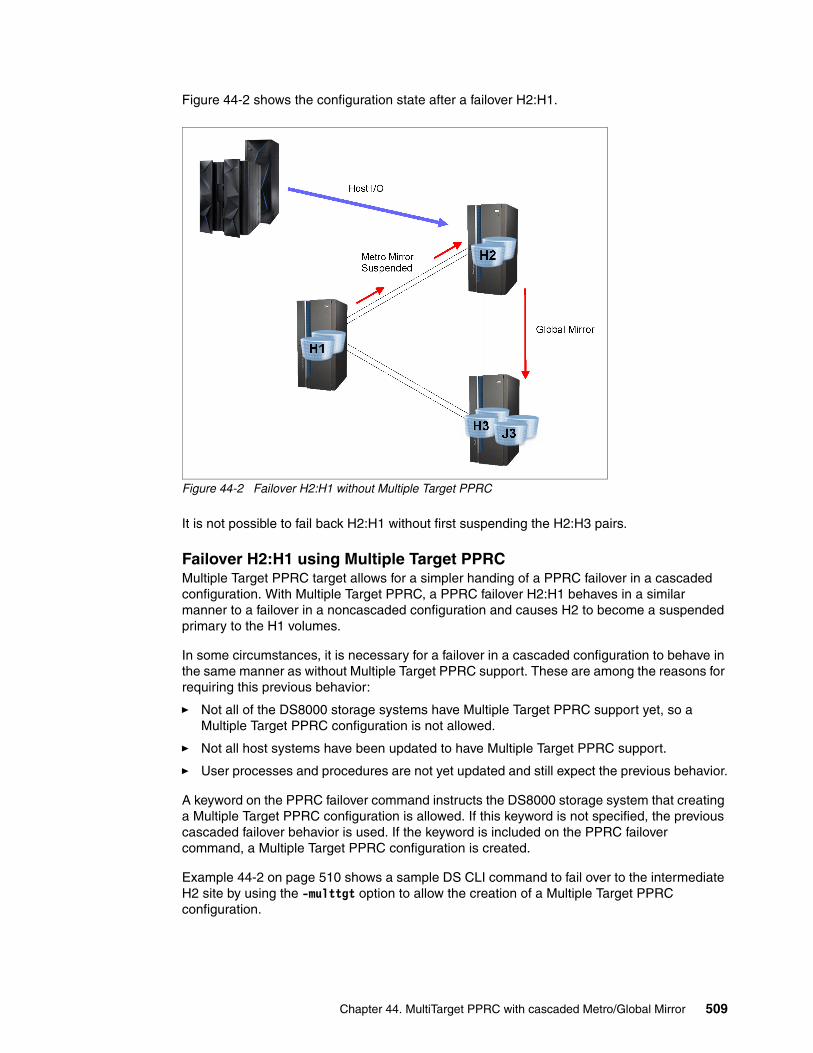
Figure 44-2 shows the configuration state after a failover H2:H1.
Figure 44-2 Failover H2:H1 without Multiple Target PPRC
It is not possible to fail back H2:H1 without first suspending the H2:H3 pairs.
Failover H2:H1 using Multiple Target PPRCMultiple Target PPRC target allows for a simpler handing of a PPRC failover in a cascaded configuration. With Multiple Target PPRC, a PPRC failover H2:H1 behaves in a similar manner to a failover in a noncascaded configuration and causes H2 to become a suspended primary to the H1 volumes.
In some circumstances, it is necessary for a failover in a cascaded configuration to behave in the same manner as without Multiple Target PPRC support. These are among the reasons for requiring this previous behavior:
� Not all of the DS8000 storage systems have Multiple Target PPRC support yet, so a Multiple Target PPRC configuration is not allowed.
� Not all host systems have been updated to have Multiple Target PPRC support.
� User processes and procedures are not yet updated and still expect the previous behavior.
A keyword on the PPRC failover command instructs the DS8000 storage system that creating a Multiple Target PPRC configuration is allowed. If this keyword is not specified, the previous cascaded failover behavior is used. If the keyword is included on the PPRC failover command, a Multiple Target PPRC configuration is created.
Example 44-2 on page 510 shows a sample DS CLI command to fail over to the intermediate H2 site by using the -multtgt option to allow the creation of a Multiple Target PPRC configuration.
Chapter 44. MultiTarget PPRC with cascaded Metro/Global Mirror 509

Example 44-2 Failover H2:H1 with -multtgt
dscli> failoverpprc -dev IBM.2107-75CYM31 -remotedev IBM.2107-75CZM21 -type mmir -multtgt 6000-600f:5000-500fCMUC00196I failoverpprc: Remote Mirror and Copy pair IBM.2107-75CYM31/6000:IBM.2107-75CZM21/5000 successfully reversed....CMUC00196I failoverpprc: Remote Mirror and Copy pair IBM.2107-75CYM31/600F:IBM.2107-75CZM21/500F successfully reversed.
As Example 44-3 shows, the failover H2:H1 caused H2 to become a Multiple Target PPRC primary to both H1 and H3. Compare this to the results shown in Example 44-1 on page 508 when the -multtgt option was not used.
Example 44-3 Query after failover H2:H1 with -multtgt
dscli> lspprc -dev IBM.2107-75CYM31 6000-600fID State Reason Type SourceLSS=====================================================================================================IBM.2107-75CYM31/6000:IBM.2107-75CYK71/7000 Copy Pending - Global Copy IBM.2107-75CYM31/60 ...IBM.2107-75CYM31/6000:IBM.2107-75CZM21/5000 Suspended Host Source Metro Mirror IBM.2107-75CYM31/60 ......IBM.2107-75CYM31/600F:IBM.2107-75CYK71/700F Copy Pending - Global Copy IBM.2107-75CYM31/60 ...IBM.2107-75CYM31/600F:IBM.2107-75CZM21/500F Suspended Host Source Metro Mirror IBM.2107-75CYM31/60 ...
The host applications can then run at the H2 site by using either HyperSwap or a traditional restart method.
The configuration at this point in the process is shown in Figure 44-3.
Figure 44-3 Multiple Target PPRC failover H2:H1
510 DS8000 Copy Services

44.4.3 H1 recovered
This scenario is for the case where Multiple Target PPRC was used for the failover H2:H1 after the outage at H1.
When site H1 is recovered, mirroring can be resumed to H2 to create a Multiple Target PPRC Metro/Global Mirror configuration.
Establish paths H1:H2The paths for H1:H2 were removed by the freeze commands. After H1 is recovered, these paths can be reestablished so that they are available when needed. The paths are not required until the time when mirroring is later resumed for H1:H2, but establishing them as soon as H1 is recovered helps to ensure that they are available when needed. The paths are reestablished using the same command that was used to originally create the paths.
Failback H2:H1 When the local H1 site is recovered, a failback H2:H1 resumes Metro Mirror from H2:H1 and copies all the data that was updated since the time of the failover to H2. Example 44-4 shows an example DS CLI command to fail back H2:H1.
Example 44-4 Failback H2:H1
dscli> failbackpprc -dev IBM.2107-75CYM31 -remotedev IBM.2107-75CZM21 -type mmir 6000-600f:5000-500fCMUC00197I failbackpprc: Remote Mirror and Copy pair IBM.2107-75CYM31/6000:IBM.2107-75CZM21/5000 successfully failed back....CMUC00197I failbackpprc: Remote Mirror and Copy pair IBM.2107-75CYM31/600F:IBM.2107-75CZM21/500F successfully failed back.
The cascaded Metro/Global Mirror configuration is now a Multiple Target PPRC Metro/Global Mirror configuration with Metro Mirror H2:H1 and Global Mirror H2:H3. Because H2 is now a Multiple Target PPRC primary, MTIR pairs are created between the secondary H1 and H3 sites. The resulting configuration is shown in Figure 44-4.
Figure 44-4 Failback H2:H1 creating Multiple Target PPRC Metro/Global Mirror configuration
Chapter 44. MultiTarget PPRC with cascaded Metro/Global Mirror 511

44.4.4 Return production to H1
After the H1 site has been recovered, the original cascaded configuration of Metro Mirror H1:H2 and Global Mirror H2:H3 can be restored easily. The first step in the process is to move production back to H1. The process and commands are similar to those described for the two Metro Mirror case in 40.5, “Return production to H1” on page 463, which contains examples of the DS CLI commands.
As with the move to H2, either HyperSwap or a traditional restart can be used. The steps involved in this process is described in the sections that follow.
Freeze H2:H1A freeze command for H2:H1 removes the PPRC paths for H2:H1 and suspends the PPRC H2:H1 pairs. A separate freeze command is required for each LSS-to-LSS PPRC relationship. With the use of consistency groups, this creates consistent data at the H1 site.
Unfreeze and run H2:H1When all freeze commands have completed, the secondary H1 site contains a consistent copy of data. The unfreeze or run command (also known as a consistency group created command) removes the extended long busy or queue full condition at the primary H2 site. A separate unfreeze command is required for each LSS-to-LSS PPRC relationship.
Failover H1:H2The failover command for H1:H2 coverts the H1 volumes to suspended Metro Mirror primary volumes whose secondary volumes are H2.
Resume host systems at H1The host systems can now be restarted at H1. If HyperSwap is used, the host systems are switched to H1.
44.4.5 Start replication H1:H2
Because this is a planned swap, there is no need to wait for a secondary system to be recovered. The replication of H1:H2 can be immediately resumed.
Failback H1:H2A failback command for H1:H2 resumes replication for the H1:H2 pairs.
Establish paths H2:H1The paths from H2:H1 were removed by the freeze commands that were performed before the failover H2:H1. Reestablishing these paths as soon as possible helps to ensure that they are available when needed.
The configuration is now restored to the original configuration, as shown in Figure 44-1 on page 506.
512 DS8000 Copy Services

44.5 Cascaded Metro/Global Mirror and Multiple Target PPRC Metro/Global Mirror
This scenario described in 44.1, “Cascaded Metro/Global Mirror topology” on page 506 started with a cascaded Metro/Global Mirror configuration, converted it to a Multiple Target PPRC Metro/Global Mirror configuration and then went back to the original cascaded configuration again. This demonstrates how cascaded and Multiple Target PPRC Metro/Global Mirror configurations complement each other.
In the course of operations, a configuration can change from a cascaded configuration to Multiple Target PPRC and back again. The ability to move between cascaded and Multiple Target Metro/Global Mirror configurations as needed gives additional flexibility and options to manage different requirements and circumstances.
Chapter 44. MultiTarget PPRC with cascaded Metro/Global Mirror 513

514 DS8000 Copy Services

Chapter 45. Using Multiple Target PPRC for migration
This chapter demonstrates how to use Multiple Target Peer-to-Peer Remote Copy (PPRC) for data migration between DS8000 storage systems within an existing PPRC environment. It presents scenarios to give a detailed description for replacing a Metro Mirror secondary or a Metro Mirror primary volume without the loss of replication protection.
This chapter includes the following topics:
� General considerations� Replacement of Metro Mirror secondary� Replacement of Metro Mirror primary� Replacement of Metro Mirror primary, alternative method
45
© Copyright IBM Corp. 2017. All rights reserved. 515

45.1 General considerations
You can use Multiple Target PPRC to migrate data from a primary or secondary DS8000 storage system in a PPRC configuration. The use of Multiple Target PPRC allows for migration procedures with either few or no periods of time where the system is not protected by mirroring.
In a Multiple Target PPRC configuration, all DS8000 storage systems must have Multiple Target PPRC support and the correct license features.
45.2 Replacement of Metro Mirror secondary
The general method of this migration is to use the Multiple Target PPRC capabilities to start Metro Mirror from the existing H1 primary site to the new H2’ secondary site. After all of the volume pairs H1:H2’ have reached full duplex, the original H2 site can be removed.
The new H2’ storage system can be at the same location as the existing H2 system, as for a hardware replacement. Alternatively, the new H2’ system can be at a different location, as for a data center move.
Metro Mirror H1:H2 remains active until Metro Mirror H1:H2’ is fully operational, so there is no loss of recovery capability during this process.
45.2.1 Requirements
The appropriate license function is required for all DS8000 storage systems at the H1 primary site, the current H2 secondary site, and the new H2’ secondary site.
Fibre Channel connectivity is required from the H1 site to the new H2’ site.
45.2.2 Terms used in examples
For the examples in this section, the following terms are used:
� H1 is the current primary site where the production applications are running.� H2 is the current Metro Mirror secondary site to which H1 is mirroring data.� H2’ is the new Metro Mirror secondary site which is replacing the current H2.
Table 45-1 on page 517 identifies the DS8000 storage controllers used in the examples in this chapter.
Note: All DS8000 storage systems must support Multiple Target PPRC to use these techniques. This means that these methods cannot be used to migrate from previous code levels. But after all systems have Multiple Target PPRC support, the technique can be used for future migrations.
A Storage Customer Opportunity Request (SCORE) can be requested to allow the use of Multiple Target PPRC when the secondary storage systems are at prior levels that do not support it. This can be useful in certain migration situations.
516 DS8000 Copy Services

Table 45-1 Identifications used in DS CLI examples
45.2.3 Initial configuration
The examples use DS CLI commands. Equivalent TSO and ICKDSF commands are listed in section Chapter 3, “Copy Services interfaces overview” on page 17. The initial configuration consists of Metro Mirror pairs H1:H2, as shown in Figure 45-1.
Figure 45-1 Initial configuration for migration of Metro Mirror secondary
Site H1 contains the Metro Mirror primary volumes, and site H2 contains the Metro Mirror secondary volumes that are to be migrated to a different DS8000 system. H2 can be only some of the volumes on a DS8000, all volumes on a DS8000, or volumes across multiple DS8000 systems.
The H1:H2 pairs are in the full-duplex state at the beginning of this scenario.
45.2.4 Installation of new DS8000 at H2’
Install, configure, and physically connect the new H2’ storage system, including any host system requirements and the Fibre Channel connections to H1 to be used for Metro Mirror.
Note: The volume range on each DS8000 is different in these examples only to help clarify the different sites used. It is not a requirement that they be different.
Site Role Dev WWNN Volume range
H1 Current primary IBM.2107-75CZM21 5005076305FFD75A 5000 - 500F
H2 Current secondary IBM.2107-75CYM31 5005076305FFD71E 6000 - 600F
H2’ New secondary (to replace H2)
IBM.2107-75CYK71 5005076305FFD71A 7000 - 700F
Chapter 45. Using Multiple Target PPRC for migration 517

45.2.5 PPRC paths H1:H2’
PPRC paths from H1 to the new H2’ are required before the PPRC pairs can be established. Example 45-1 on page 518 shows a DS CLI command used to create PPRC paths from H1 to H2’. Separate mkpprcpath commands are required for each primary-to-secondary LSS relationship.
Example 45-1 Establish paths H1:H2’
dscli> mkpprcpath -dev IBM.2107-75CZM21 -remotedev IBM.2107-75CYK71 -remotewwnn 5005076305FFD71A -srclss 50 -tgtlss 70 -consistgrp I0201:I0032 I0234:I0306CMUC00149I mkpprcpath: Remote Mirror and Copy path 50:70 successfully established.
45.2.6 Create H1:H2’ Metro Mirror pairs
After establishing all of the required PPRC paths, create the H1:H2’ Metro Mirror volume pairs. These pairs can be initially created as asynchronous Global Copy pairs and later converted to Metro Mirror, or they can be created directly as Metro Mirror pairs.
In some large configurations, it is preferable to start the replication as Global Copy because it is less likely to affect the production systems during the initial copy phase. After all pairs have copied nearly 100% of the data, the pairs can be converted to synchronous Metro Mirror.
Example 45-2 shows a sample mkpprc command to create the H1:H2’ Metro Mirror pairs.
Example 45-2 Create H1:H2’ Metro Mirror pairs
dscli> mkpprc -dev IBM.2107-75CZM21 -remotedev IBM.2107-75CYK71 -type mmir 5000-500f:7000-700fCMUC00153I mkpprc: Remote Mirror and Copy volume pair relationship IBM.2107-75CZM21/5000:IBM.2107-75CYK71/7000 successfully created....CMUC00153I mkpprc: Remote Mirror and Copy volume pair relationship IBM.2107-75CZM21/500F:IBM.2107-75CYK71/700F successfully created.
Figure 45-2 on page 519 shows the configuration after establishing Metro Mirror H1:H2’. Notice that MTIR pairs are established between H2 and H2’ even though they are not required for this migration scenario. It is not required to establish PPRC paths between H2 and H2’ for these MTIR pairs because there is no intent to create active pairs between the two sites.
518 DS8000 Copy Services

Figure 45-2 Metro Mirror established to H2’
After the Metro Mirror pairs H1:H2’ have been established, the data at site H1 will be replicated to the new H2’ site. During this time, the original H1:H2 pairs remain active and H2 is still available as a recovery site in case of an error at H1.
45.2.7 Monitor for H1:H2’ full duplex
The H1:H2’ pairs copy all data from H1 to the new H2’ site. During this time, the progress of the copy can be monitored. Example 45-3 is a sample DS CLI command that shows the pair state and the number of out-of-sync tracks left to copy for each pair. When the number of out-of-sync tracks for a pair drops to zero, the pair state changes from Copy Pending to Full Duplex. The output of the lspprc command can be long, especially when the -l (long) option is specified, so the output in this example is truncated on the right side to better show the fields of interest.
Example 45-3 Monitoring for full duplex
dscli> lspprc -l -dev IBM.2107-75CZM21 -remotedev IBM.2107-75CYK71 5000-500f:7000-700fID State Reason Type Out Of Sync Tracks Tgt Read========================================================================================================IBM.2107-75CZM21/5000:IBM.2107-75CYK71/7000 Full Duplex - Metro Mirror 0 Disabled...IBM.2107-75CZM21/5001:IBM.2107-75CYK71/7001 Copy Pending - Metro Mirror 38750 Disabled...IBM.2107-75CZM21/5002:IBM.2107-75CYK71/7002 Copy Pending - Metro Mirror 81920 Disabled......
After all H1:H2’ pairs reach full duplex, the migration procedure can proceed.
45.2.8 Remove H1:H2
After all of the H1:H2’ pairs have reached full duplex, the H1:H2 pairs can be removed, because the H1:H2’ pairs are now available to provide the Metro Mirror protection. Example 45-4 on page 520 shows a DS CLI command to remove the H1:H2 pairs.
Chapter 45. Using Multiple Target PPRC for migration 519

Example 45-4 Remote H1:H2 Metro Mirror pairs
dscli> rmpprc -dev IBM.2107-75CZM21 -remotedev IBM.2107-75CYM31 -quiet 5000-500f:6000-600fCMUC00155I rmpprc: Remote Mirror and Copy volume pair IBM.2107-75CZM21/5000:IBM.2107-75CYM31/6000 relationship successfully withdrawn....CMUC00155I rmpprc: Remote Mirror and Copy volume pair IBM.2107-75CZM21/500F:IBM.2107-75CYM31/600F relationship successfully withdrawn.
After removing the H1:H2 pairs, there is no longer a Multiple Target PPRC configuration, and the DS8000 storage systems automatically remove the MTIR pairs that were created between H2 and H2’. The PPRC paths between H1 and the original H2 are no longer needed and should be removed. In most instances, the PPRC paths will be established in both directions between H1 and H2.
Example 45-5 shows a sample DS CLI command for removing these paths.
Example 45-5 Remove PPRC paths between H1 and H2
dscli> rmpprcpath -dev IBM.2107-75CZM21 -remotedev IBM.2107-75CYM31 -remotewwnn 5005076305FFD71E -quiet 50:60CMUC00150I rmpprcpath: Remote Mirror and Copy path IBM.2107-75CZM21/50:IBM.2107-75CYM31/60 successfully removed.
dscli> rmpprcpath -dev IBM.2107-75CYM31 -remotedev IBM.2107-75CZM21 -remotewwnn 5005076305FFD75A -quiet 60:50CMUC00150I rmpprcpath: Remote Mirror and Copy path IBM.2107-75CYM31/60:IBM.2107-75CZM21/50 successfully removed.
The resulting configuration is shown in Figure 45-3.
Figure 45-3 Metro Mirror H1:H2’ after migration
The migration is now complete.
520 DS8000 Copy Services
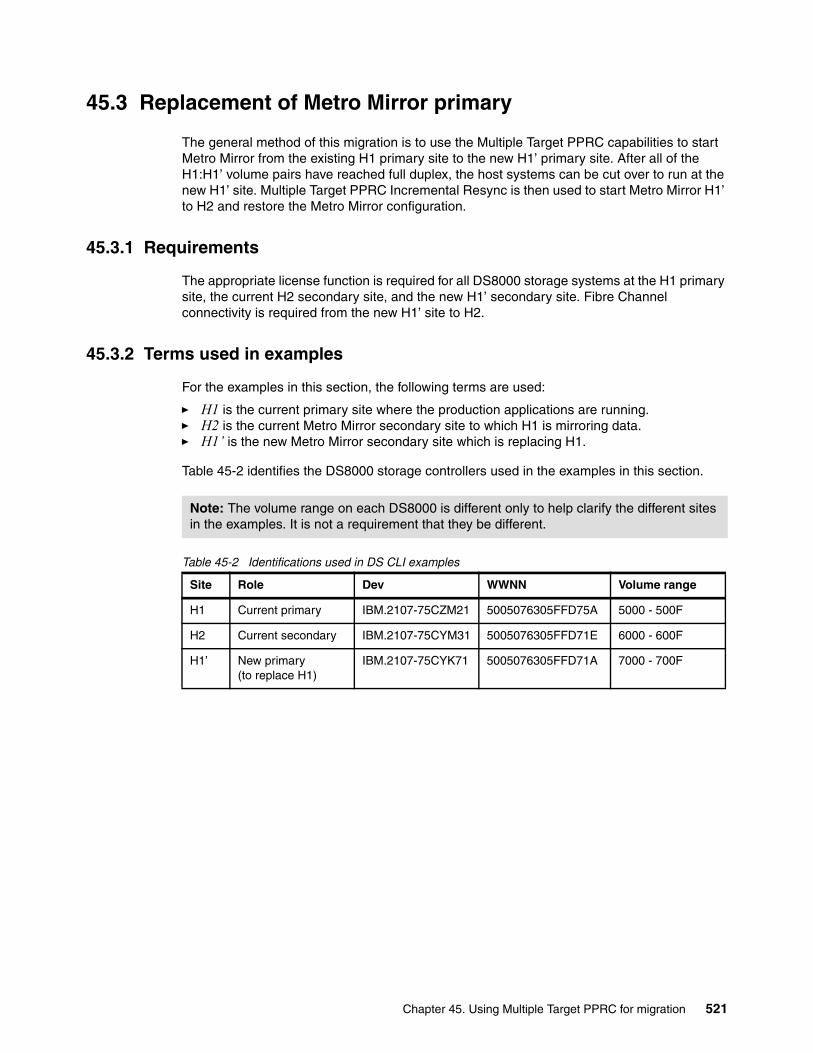
45.3 Replacement of Metro Mirror primary
The general method of this migration is to use the Multiple Target PPRC capabilities to start Metro Mirror from the existing H1 primary site to the new H1’ primary site. After all of the H1:H1’ volume pairs have reached full duplex, the host systems can be cut over to run at the new H1’ site. Multiple Target PPRC Incremental Resync is then used to start Metro Mirror H1’ to H2 and restore the Metro Mirror configuration.
45.3.1 Requirements
The appropriate license function is required for all DS8000 storage systems at the H1 primary site, the current H2 secondary site, and the new H1’ secondary site. Fibre Channel connectivity is required from the new H1’ site to H2.
45.3.2 Terms used in examples
For the examples in this section, the following terms are used:
� H1 is the current primary site where the production applications are running.� H2 is the current Metro Mirror secondary site to which H1 is mirroring data.� H1’ is the new Metro Mirror secondary site which is replacing H1.
Table 45-2 identifies the DS8000 storage controllers used in the examples in this section.
Table 45-2 Identifications used in DS CLI examples
Note: The volume range on each DS8000 is different only to help clarify the different sites in the examples. It is not a requirement that they be different.
Site Role Dev WWNN Volume range
H1 Current primary IBM.2107-75CZM21 5005076305FFD75A 5000 - 500F
H2 Current secondary IBM.2107-75CYM31 5005076305FFD71E 6000 - 600F
H1’ New primary (to replace H1)
IBM.2107-75CYK71 5005076305FFD71A 7000 - 700F
Chapter 45. Using Multiple Target PPRC for migration 521

45.3.3 Initial configuration
The initial configuration consists of a Metro Mirror pair H1:H2, as shown in Figure 45-4.
Figure 45-4 Initial configuration for migration of Metro Mirror primary
Site H1 contains the Metro Mirror primary volumes that are to be migrated to a different DS8000 storage system, and site H2 contains the Metro Mirror secondary volumes. H1 can be only some of the volumes on a DS8000 storage system or it can be volumes across multiple DS8000 storage systems.
The H1:H2 pairs are in the full-duplex state at the beginning of this scenario.
45.3.4 Installation of new DS8000 at H1’
Install, configure, and physically connect the new H1’ storage system, including any host system requirements and the Fibre Channel connections to H2 to be used for the Metro Mirror PPRC paths.
45.3.5 Start Metro Mirror H1:H1’
PPRC H1:H1’ paths are required for the replication of data from the original H1 to the new H1’ system. In addition, the new Metro Mirror configuration will be H1’ to H2, so PPRC paths are required for H1’ to H2. Finally, in the event of a swap to H2, paths H2:H1’ are required to be able to mirror back to H1’.
The following commands are required:
� Establish PPRC paths H1:H1’� Establish PPRC paths H1’:H2� Establish PPRC paths H2:H1’
Example 45-6 on page 523 shows a sample DS CLI command to establish paths from H1 to the new H1’.
522 DS8000 Copy Services

Example 45-6 Establish PPRC paths H1:H1’
dscli> mkpprcpath -dev IBM.2107-75CZM21 -remotedev IBM.2107-75CYK71 -remotewwnn 5005076305FFD71A -srclss 50 -tgtlss 70 -consistgrp I0201:I0032 I0234:I0306CMUC00149I mkpprcpath: Remote Mirror and Copy path 50:70 successfully established.
Example 45-7 shows sample DS CLI commands to establish PPRC paths from H1’ to H2 and then in the opposite direction, from H2 to H1’.
Example 45-7 Establish PPRC paths H1’:H2 and H2:H1’
dscli> mkpprcpath -dev IBM.2107-75CYK71 -remotedev IBM.2107-75CYM31 -remotewwnn 5005076305FFD71E -srclss 70 -tgtlss 60 -consistgrp I0300:I0300 I0330:I0330CMUC00149I mkpprcpath: Remote Mirror and Copy path 70:60 successfully established.
dscli> mkpprcpath -dev IBM.2107-75CYM31 -remotedev IBM.2107-75CYK71 -remotewwnn 5005076305FFD71A -srclss 60 -tgtlss 70 -consistgrp I0300:I0300 I0330:I0330CMUC00149I mkpprcpath: Remote Mirror and Copy path 60:70 successfully established.
Create Metro Mirror H1:H1’After required PPRC paths are established, the H1:H1’ pairs can be created. Example 45-8 shows a sample DS CLI command to create the H1:H1’ Metro Mirror pairs.
Example 45-8 Create Metro Mirror H1:H1’
dscli> mkpprc -dev IBM.2107-75CZM21 -remotedev IBM.2107-75CYK71 -type mmir 5000-500f:7000-700fCMUC00153I mkpprc: Remote Mirror and Copy volume pair relationship IBM.2107-75CZM21/5000:IBM.2107-75CYK71/7000 successfully created....CMUC00153I mkpprc: Remote Mirror and Copy volume pair relationship IBM.2107-75CZM21/500F:IBM.2107-75CYK71/700F successfully created.
This is now a Multiple Target PPRC configuration, so MTIR pairs are automatically created by the DS8000 storage system for H1’:H2 and H2:H1’.
This is also now a Multiple Target PPRC configuration, so MTIR pairs will be automatically created for H1’:H2 and H2:H1’.
Figure 45-5 on page 524 shows the configuration after creating the Metro Mirror pairs H1:H1’.
Chapter 45. Using Multiple Target PPRC for migration 523

Figure 45-5 Metro Mirror established to H1’
Notice that MTIR pairs are established between H1’ and H2. These MTIR pairs are used for the Incremental Resync H1’:H2, which allows for mirroring to be resumed after moving the host systems to run on the new H1’ without requiring a full copy of data.
The correct configuration can be verified by querying the volumes within the Multiple Target PPRC configuration. Example 45-9 shows a query to volumes at H1 to verify that they are Multiple Target Metro Mirror volumes that are being mirrored to both H2 and H1’. While the initial copy of data is being performed, some of the H1:H1’ pairs will be Copy Pending, while others are Full Duplex.
Example 45-9 Query to primary H1 volumes
dscli> lspprc -dev IBM.2107-75CZM21 5000-500fID State Reason Type SourceLSS================================================================================================IBM.2107-75CZM21/5000:IBM.2107-75CYK71/7000 Full Duplex - Metro Mirror IBM.2107-75CZM21/50 ...IBM.2107-75CZM21/5000:IBM.2107-75CYM31/6000 Full Duplex - Metro Mirror IBM.2107-75CZM21/50 ...IBM.2107-75CZM21/5001:IBM.2107-75CYK71/7001 Copy Pending - Metro Mirror IBM.2107-75CZM21/50 ...IBM.2107-75CZM21/5001:IBM.2107-75CYM31/6001 Full Duplex - Metro Mirror IBM.2107-75CZM21/50 ......IBM.2107-75CZM21/500F:IBM.2107-75CYK71/700F Copy Pending - Metro Mirror IBM.2107-75CZM21/50 ...IBM.2107-75CZM21/500F:IBM.2107-75CYM31/600F Full Duplex - Metro Mirror IBM.2107-75CZM21/50 ...
A query of the secondary volumes can be performed to verify that they are in the expected state.
524 DS8000 Copy Services

A sample DS CLI query of the H1’ volumes is shown in Example 45-10. This query shows that there are MTIR pairs H1’:H2 and also that H1’ is the target of the original H1.
Example 45-10 Query of new H1’ volumes
dscli> lspprc -dev IBM.2107-75CYK71 -multtgt 7000-700fID State Reason Type SourceLSS =====================================================================================================================IBM.2107-75CYK71/7000:IBM.2107-75CYM31/6000 Suspended Multi-target Internal Global Copy IBM.2107-75CYK71/70......IBM.2107-75CYK71/700F:IBM.2107-75CYM31/600F Suspended Multi-target Internal Global Copy IBM.2107-75CYK71/70...IBM.2107-75CZM21/5000:IBM.2107-75CYK71/7000 Target Full Duplex - Metro Mirror IBM.2107-75CZM21/50......IBM.2107-75CZM21/500F:IBM.2107-75CYK71/700F Target Full Duplex - Metro Mirror IBM.2107-75CZM21/50...
During this time, the original H1:H2 pairs remain active and H2 remains available as a recovery site in case of an outage at H1.
45.3.6 Monitor for H1:H1’ full duplex
The H1:H1’ pairs will copy all data from H1 to the new H1’ box. During this time, the progress of the copy can be monitored. Example 45-11 is a sample DS CLI command that shows the pair state and the number of out-of-sync tracks left to copy for each pair. When the number of out-of-sync tracks for a pair goes to zero, the pair state changes from Copy Pending to Full Duplex. The output of the lspprc command can be long, especially when the -l (long) option is specified, so the output has been truncated on the right side to better show the fields of interest.
Example 45-11 Monitoring for full duplex
dscli> lspprc -l -dev IBM.2107-75CZM21 -remotedev IBM.2107-75CYK71 5000-500f:7000-700fID State Reason Type Out Of Sync Tracks Tgt Read=========================================================================================================IBM.2107-75CZM21/5000:IBM.2107-75CYK71/7000 Full Duplex - Metro Mirror 0 Disabled...IBM.2107-75CZM21/5001:IBM.2107-75CYK71/7001 Copy Pending - Metro Mirror 41662 Disabled...IBM.2107-75CZM21/5002:IBM.2107-75CYK71/7002 Copy Pending - Metro Mirror 486 Disabled......
45.3.7 Monitor out of sync tracks for H1’:H2 and H2:H1’
As each H1:H1’ pair goes full duplex, the MTIR change recording mechanism will start as described in 39.3.3, “MTIR change recording” on page 445. It typically takes several minutes after reaching full duplex for the number of out-of-sync tracks for the MTIR pairs to drop from the total number of tracks on the volume to only the most recently updated tracks.
Example 45-12 on page 526 shows a query of the MTIR pairs H1’:H2 and H2:H1’ displaying the full volume counts, followed by a later query of the same relationships after the counts have been dropped to represent only the most recently updated tracks.
Because the different pairs reach full duplex at different times, the out-of-synchronization track counts also change at different times.
Note: If the move to H1’ is performed while the MTIR out-of-synchronization track count is still at the full volume level, then the replication for H1’:H2 will require a full copy of the volumes and the benefit of the Multiple Target PPRC Incremental Resynchronization will not be realized.
Chapter 45. Using Multiple Target PPRC for migration 525

Example 45-12 Query MTIR pair out-of-synchronization track counts
dscli> lspprc -l -dev IBM.2107-75CYM31 -remotedev IBM.2107-75CYK71 -multtgt 6000-600f:7000-700fID State Reason Type Out Of Sync Tracks===========================================================================================================IBM.2107-75CYM31/6000:IBM.2107-75CYK71/7000 Suspended Multi-target Internal Global Copy 96 ...IBM.2107-75CYM31/6001:IBM.2107-75CYK71/7001 Suspended Multi-target Internal Global Copy 81920 ...IBM.2107-75CYM31/6002:IBM.2107-75CYK71/7002 Suspended Multi-target Internal Global Copy 81920 ......
dscli> lspprc -l -dev IBM.2107-75CYK71 -remotedev IBM.2107-75CYM31 -multtgt 7000-700f:6000-600fID State Reason Type Out Of Sync Tracks===========================================================================================================IBM.2107-75CYK71/7000:IBM.2107-75CYM31/6000 Suspended Multi-target Internal Global Copy 81920 ...IBM.2107-75CYK71/7001:IBM.2107-75CYM31/6001 Suspended Multi-target Internal Global Copy 81920 ...IBM.2107-75CYK71/7002:IBM.2107-75CYM31/6002 Suspended Multi-target Internal Global Copy 81920 ......
dscli> lspprc -l -dev IBM.2107-75CYM31 -remotedev IBM.2107-75CYK71 -multtgt 6000-600f:7000-700fID State Reason Type Out Of Sync Tracks===========================================================================================================IBM.2107-75CYM31/6000:IBM.2107-75CYK71/7000 Suspended Multi-target Internal Global Copy 112 ...IBM.2107-75CYM31/6001:IBM.2107-75CYK71/7001 Suspended Multi-target Internal Global Copy 111 ...IBM.2107-75CYM31/6002:IBM.2107-75CYK71/7002 Suspended Multi-target Internal Global Copy 111 ......
dscli> lspprc -l -dev IBM.2107-75CYK71 -remotedev IBM.2107-75CYM31 -multtgt 7000-700f:6000-600fID State Reason Type Out Of Sync Tracks===========================================================================================================IBM.2107-75CYK71/7000:IBM.2107-75CYM31/6000 Suspended Multi-target Internal Global Copy 137 ...IBM.2107-75CYK71/7001:IBM.2107-75CYM31/6001 Suspended Multi-target Internal Global Copy 136 ...IBM.2107-75CYK71/7002:IBM.2107-75CYM31/6002 Suspended Multi-target Internal Global Copy 136 ......
45.3.8 Move production to H1’
Either HyperSwap or a traditional restart can be used. The steps in this process are described in the sections that follow.
Freeze H1:H1’ and H1:H2Freeze commands for H1:H1’ and H1:H2 remove the PPRC paths, and suspend all H1:H1’ and H1:H2 Metro Mirror pairs. A separate freeze command is required for each LSS-to-LSS PPRC relationship. The use of consistency groups creates consistent data at the new H1’ site by using extended long busy or queue full to temporarily queue dependent writes. Alternatively, all application I/Os to the set of volumes being migrated can be quiesced.
Example 45-13 Freeze H1:H1’ and H1:H2
dscli> freezepprc -dev IBM.2107-75CZM21 -remotedev IBM.2107-75CYM31 50:60CMUC00161I freezepprc: Remote Mirror and Copy consistency group IBM.2107-75CZM21/50:IBM.2107-75CYM31/60 successfully created.
dscli> freezepprc -dev IBM.2107-75CZM21 -remotedev IBM.2107-75CYK71 50:70CMUC00161I freezepprc: Remote Mirror and Copy consistency group IBM.2107-75CZM21/50:IBM.2107-75CYK71/70 successfully created.
526 DS8000 Copy Services

Unfreeze and run H1:H1’ and H1:H2When all freeze commands have completed, the secondary H1’ and H2 sites contain consistent copies of data. The unfreeze or run command (also known as a consistency group created command) removes the extended long busy or queue-full condition at the local H1 site. An unfreeze command is required for each LSS-to-LSS PPRC relationship. A sample DS CLI unfreeze command is shown in Example 45-14.
Example 45-14 Unfreeze H1:H1’ and H1:H2
dscli> unfreezepprc -dev IBM.2107-75CZM21 -remotedev IBM.2107-75CYM31 50:60CMUC00198I unfreezepprc: Remote Mirror and Copy pair IBM.2107-75CZM21/50:IBM.2107-75CYM31/60 successfully thawed.
dscli> unfreezepprc -dev IBM.2107-75CZM21 -remotedev IBM.2107-75CYK71 50:70CMUC00198I unfreezepprc: Remote Mirror and Copy pair IBM.2107-75CZM21/50:IBM.2107-75CYK71/70 successfully thawed.
Failover H1’:H1 and H2:H1The failover command for H1’:H1 coverts the H1’ volumes to suspended Metro Mirror primary volumes whose secondary volumes are H1. Similarly, the failover H2:H1 converts the H2 volumes to suspended primary volumes whose secondary volumes are H1.
Example 45-15 Failover H1’:H1 and H2:H1
dscli> failoverpprc -dev IBM.2107-75CYK71 -remotedev IBM.2107-75CZM21 -type mmir 7000-700f:5000-500fCMUC00196I failoverpprc: Remote Mirror and Copy pair IBM.2107-75CYK71/7000:IBM.2107-75CZM21/5000 successfully reversed....CMUC00196I failoverpprc: Remote Mirror and Copy pair IBM.2107-75CYK71/700F:IBM.2107-75CZM21/500F successfully reversed.
dscli> failoverpprc -dev IBM.2107-75CYM31 -remotedev IBM.2107-75CZM21 -type mmir 6000-600f:5000-500fCMUC00196I failoverpprc: Remote Mirror and Copy pair IBM.2107-75CYM31/6000:IBM.2107-75CZM21/5000 successfully reversed....CMUC00196I failoverpprc: Remote Mirror and Copy pair IBM.2107-75CYM31/600F:IBM.2107-75CZM21/500F successfully reversed.
Resume host systems at H1’Host systems can now be restarted at H1’. If HyperSwap is used, the host systems are switched to H1’. At this point, the host systems are running at H2 and the configuration appears as shown in Figure 45-6 on page 528.
Note: The H1’ site becomes the new production site, and the H1:H2 pairs are no longer used. If you wonder why a failover of H2:H1 is performed rather than terminating the H1:H2 pair, the reason for performing a failover H2:H1 is that a termination of H1:H2 would result in ending the Multiple Target PPRC configuration. This, in turn, would cause the MTIR pairs between H1’ and H2 to be removed. These pairs are required to perform the Incremental Resynchronization from H1’:H2.
Chapter 45. Using Multiple Target PPRC for migration 527

Figure 45-6 Move production to H1’
The H1, H2, and H3 sites are all suspended primary volumes to each of the other sites.
45.3.9 Start replication H1’:H2
The Incremental Resynchronization capability is used to start replication for H1’:H2. With the change recording function of Multiple Target PPRC, only the out-of-synchronization tracks between H1’ and H2 are transferred, and a full copy of data is not required.
Failback H1’:H2The failback command for H1’:H2 merges the change recording bitmap files from H1’ and H2 and initiates the transfer of the out-of-sync data. A sample DS CLI command for this failback is shown in Example 45-16.
Example 45-16 Failback H1’:H2
dscli> failbackpprc -dev IBM.2107-75CYK71 -remotedev IBM.2107-75CYM31 -type mmir 7000-700f:6000-600fCMUC00197I failbackpprc: Remote Mirror and Copy pair IBM.2107-75CYK71/7000:IBM.2107-75CYM31/6000 successfully failed back....CMUC00197I failbackpprc: Remote Mirror and Copy pair IBM.2107-75CYK71/700F:IBM.2107-75CYM31/600F successfully failed back.
The pairs reach the full duplex state, as shown in the DS CLI lspprc command of Example 45-17.
Example 45-17 Query showing H1’:H2 pairs full duplex
dscli> lspprc -dev IBM.2107-75CYK71 -remotedev IBM.2107-75CYM31 -multtgt 7000-700f:6000-600fID State Reason Type SourceLSS ========================================================================================================IBM.2107-75CYK71/7000:IBM.2107-75CYM31/6000 Full Duplex - Metro Mirror IBM.2107-75CYK71/70 ......IBM.2107-75CYK71/700F:IBM.2107-75CYM31/600F Full Duplex - Metro Mirror IBM.2107-75CYK71/70 ...
528 DS8000 Copy Services

The state of the configuration at this point is shown in Figure 45-7.
Figure 45-7 After failback H1’ to H2
Metro Mirror is active from the new H1’ site to the secondary H2 site.
45.3.10 Remove Metro Mirror pairs for H1
In the case of a storage system replacement, the original H1 is no longer being used and can be removed. In some instances, a migration might be performed to move only some data from the storage system, in which case other volumes at the H1site might still be in use.
For the LSSs that are no longer used for PPRC replication, the pairs and paths should be removed.
In Figure 45-7, remove the unused pairs between H1 and H1’ and also between H1 and H2.
� Remove H1:H1’ Metro Mirror pairs� Remove H1’:H1 Metro Mirror pairs� Remove H1:H2 Metro Mirror pairs� Remove H2:H1 Metro Mirror pairs
To keep the diagrams in this chapter clear, the majority of diagrams do not indicate the state and direction of the PPRC paths. For most Multiple Target PPRC uses, it is best to establish active paths in both directions between the different sites involved in the replication. In some migration cases, however, not all of these paths are required. The intermediate configurations are temporary, and there is no requirement to establish active mirroring in all possible directions.
Figure 45-8 on page 530 shows the existing PPRC path relationships at this point in the migration scenario. It is important to understand which sets of paths exists so that a complete removal can be performed.
Note: The PPRC paths do not exist between all of the storage systems. Removing PPRC when the paths do not exist results in warning messages. In this scenario, these messages are expected.
Chapter 45. Using Multiple Target PPRC for migration 529

Refer to 39.4, “PPRC path states” on page 449 for a detailed description of how the PPRC path states are affected by freeze and PPRC failover commands.
Figure 45-8 Path and pair relationships between H1, H2 and H1’
Notice that H1’ is a Multiple Target PPRC primary to H1 and H2. Because it is a Multiple Target PPRC primary, it sends commands to create the MTIR pairs H1:H2 and H2:H1. However, as explained in 39.3.2, “Delayed creation of MTIR pairs” on page 445, because there is no communication from H1’ to H1, the command cannot be sent to H1 and the suspended H1:H2 pairs remain suspended because of the freeze.
Example 45-18 shows the DS CLI lspprc output. The H1:H2 pairs are suspended because of the freeze, and the H2:H1 pairs are converted to MTIR pairs.
Example 45-18 Query H1:H2 and H2:H1 pairs
dscli> lspprc -dev IBM.2107-75CZM21 -remotedev IBM.2107-75CYM31 -multtgt 5000-500f:6000-600fID State Reason Type SourceLSS==============================================================================================IBM.2107-75CZM21/5000:IBM.2107-75CYM31/6000 Suspended Freeze Metro Mirror IBM.2107-75CZM21/50 ......IBM.2107-75CZM21/500F:IBM.2107-75CYM31/600F Suspended Freeze Metro Mirror IBM.2107-75CZM21/50 ...
dscli> lspprc -dev IBM.2107-75CYM31 -remotedev IBM.2107-75CZM21 -multtgt 6000-600f:5000-500fID State Reason Type SourceLSS===========================================================================================================IBM.2107-75CYM31/6000:IBM.2107-75CZM21/5000 Suspended Multi-target Internal Global Copy IBM.2107-75CYM31/60 ...IBM.2107-75CYM31/600F:IBM.2107-75CZM21/500F Suspended Multi-target Internal Global Copy IBM.2107-75CYM31/60
530 DS8000 Copy Services

Remove pairs H1’:H1The H1’:H1 pairs were created by the failover H1’:H1 and can be removed, as shown in Example 45-19.
Example 45-19 Remove pairs H1’:H1
dscli> rmpprc -dev IBM.2107-75CYK71 -remotedev IBM.2107-75CZM21 -quiet 7000-700f:5000-500fCMUN03012E rmpprc: IBM.2107-75CYK71/7000:IBM.2107-75CZM21/5000: An error occurred for a Remote Mirror and Copy (RMC) operation or its channel extender path which can result in the failure of a command or the incomplete removal of a relationship pair....CMUN03012E rmpprc: IBM.2107-75CYK71/700F:IBM.2107-75CZM21/500F: An error occurred for a Remote Mirror and Copy (RMC) operation or its channel extender path which can result in the failure of a command or the incomplete removal of a relationship pair.
The error messages are to inform the user that there is no communication from H1’ to H1 so the pair was removed only at the local H1’ site. This is expected in this case because it is only the H1’:H1 relationship at H1’ that is being removed.
The removal of the H1’:H1 pair causes H1 to no longer be a Multiple Target PPRC primary, so it will remove the MTIR pairs between the two secondary sites, H1 and H2. There is active communication for H1’:H2, and the MTIR pairs from H2:H1 are removed.
Remove H1:H1’ and H1:H2 pairsExample 45-20 shows sample DS CLI commands to remove the H1:H1’ and H1:H2 pairs. As with the removal of H1’:H1 pairs, because there are no active PPRC paths between the storage systems, the error messages are expected.
Example 45-20 Remove pairs H1:H1’
dscli> rmpprc -dev IBM.2107-75CZM21 -remotedev IBM.2107-75CYK71 -quiet 5000-500f:7000-700fCMUN03012E rmpprc: IBM.2107-75CZM21/5000:IBM.2107-75CYK71/7000: An error occurred for a Remote Mirror and Copy (RMC) operation or its channel extender path which can result in the failure of a command or the incomplete removal of a relationship pair....CMUN03012E rmpprc: IBM.2107-75CZM21/500F:IBM.2107-75CYK71/700F: An error occurred for a Remote Mirror and Copy (RMC) operation or its channel extender path which can result in the failure of a command or the incomplete removal of a relationship pair.
dscli> rmpprc -dev IBM.2107-75CZM21 -remotedev IBM.2107-75CYM31 -quiet 5000-500f:6000-600fCMUN03012E rmpprc: IBM.2107-75CZM21/5000:IBM.2107-75CYM31/6000: An error occurred for a Remote Mirror and Copy (RMC) operation or its channel extender path which can result in the failure of a command or the incomplete removal of a relationship pair. ...CMUN03012E rmpprc: IBM.2107-75CZM21/500F:IBM.2107-75CYM31/600F: An error occurred for a Remote Mirror and Copy (RMC) operation or its channel extender path which can result in the failure of a command or the incomplete removal of a relationship pair.
At this point, all of the pairs associated with the original H1 site have been removed.
Chapter 45. Using Multiple Target PPRC for migration 531

45.3.11 Remove PPRC paths for H1
If all Metro Mirror volumes have been migrated off of H1, the PPRC paths between H1 and H1’ and between H1 and H2 can be removed. If some volumes on H1 are still in Metro Mirror relationships to H2, the paths could still be required. These are the commands:
� Remove PPRC paths for H1:H2� Remove PPRC paths for H1:H1’� Remove PPRC paths for H2:H1� Remove PPRC paths for H1’:H1
Example 45-21 Remove unused paths
dscli> rmpprcpath -dev IBM.2107-75CZM21 -remotedev IBM.2107-75CYM31 -remotewwnn 5005076305FFD71E -quiet 50:60CMUC00150I rmpprcpath: Remote Mirror and Copy path IBM.2107-75CZM21/50:IBM.2107-75CYM31/60 successfully removed.
dscli> rmpprcpath -dev IBM.2107-75CZM21 -remotedev IBM.2107-75CYK71 -remotewwnn 5005076305FFD71A -quiet 50:70CMUC00150I rmpprcpath: Remote Mirror and Copy path IBM.2107-75CZM21/50:IBM.2107-75CYK71/70 successfully removed.
dscli> rmpprcpath -dev IBM.2107-75CYM31 -remotedev IBM.2107-75CZM21 -remotewwnn 5005076305FFD75A -quiet 60:50CMUC00150I rmpprcpath: Remote Mirror and Copy path IBM.2107-75CYM31/60:IBM.2107-75CZM21/50 successfully removed.
dscli> rmpprcpath -dev IBM.2107-75CYK71 -remotedev IBM.2107-75CZM21 -remotewwnn 5005076305FFD75A -quiet 70:50CMUC00150I rmpprcpath: Remote Mirror and Copy path IBM.2107-75CYK71/70:IBM.2107-75CZM21/50 successfully removed.
At this point, only the H1’: H2 relationships exist, and H1 can be removed from the Metro Mirror configuration, as shown in Figure 45-9.
Figure 45-9 Migration from H1 to H1’ is complete
532 DS8000 Copy Services

45.4 Replacement of Metro Mirror primary, alternative method
An alternative method for replacing a Metro Mirror primary is to first switch the direction of the replication, and then follow the process for replacing a Metro Mirror secondary, as described in 45.2, “Replacement of Metro Mirror secondary” on page 516.
45.4.1 Initial configuration
The initial configuration consists of a Metro Mirror pair H1:H2, as shown in Figure 45-10.
Figure 45-10 Initial configuration for migration of Metro Mirror primary
Site H1 contains the Metro Mirror primary volumes that are to be migrated to a different DS8000 storage system, and site H2 contains the Metro Mirror secondary volumes. H1 can be only some of the volumes on a DS8000 storage system or it can be volumes across multiple DS8000 storage systems.
The H1:H2 pairs are in the full-duplex state at the beginning of this scenario.
45.4.2 Move production to H2
Either HyperSwap or a traditional restart can be used to move the production workload to the H2 site. After the move to H2, a failback command H2:H1 restores active replication. Metro Mirror replication is now active in the reverse direction, as shown in Figure 45-11 on page 534.
Chapter 45. Using Multiple Target PPRC for migration 533

Figure 45-11 Direction of Metro Mirror is reversed
45.4.3 Installation of new DS8000 at H1’
Install, configure, and physically connect the new H1’ storage system, including any host system requirements and the Fibre Channel connections to H2 to be used for the Metro Mirror paths.
45.4.4 Start Metro Mirror H2:H1’
PPRC paths are required H2:H1’ for the replication of data from H2 to the new H1’ system. The new Metro Mirror configuration will be H1’ to H2, so PPRC paths are also required in the H1’ to H2 direction.
Establish new Metro Mirror pairs H2:H1’, and wait for the pairs to reach the full-duplex state. At the completion of this step, there is a Multiple Target PPRC topology of H2:H1 and H2:H1’, as shown in Figure 45-12 on page 535.
Because this is now a Multiple Target PPRC topology, the storage systems automatically create MTIR pairs between the secondary volumes, H1’ and H2. Because this migration scenario does not require an active relationship between H1’ and H2, it is not necessary to establish PPRC paths between the two sites. This is one possible advantage over the method described in 45.3, “Replacement of Metro Mirror primary” on page 521.
534 DS8000 Copy Services

Figure 45-12 Multiple Target Metro Mirror H2:H1 and H2:H1’
45.4.5 Remove H2:H1
After all of the H2:H1’ pairs have reached full duplex, the H2:H1 pairs can be removed because H2:H1’ is now available to provide the Metro Mirror protection. When the H2:H1 pairs are removed, the storage system detects that there is no longer a Multiple Target PPRC topology and automatically removes the MTIR pairs between H1 and H1’. After all pairs have been removed, the PPRC paths between H1 and H2 can be removed.
45.4.6 Move production back to H1’
Either HyperSwap or a traditional restart can be used to move the production workload to the new H1’ site. After the move to H1’, a failback command H1’:H2 restores active replication. The migration to H1’ is now complete, as shown in Figure 45-13 on page 536.
Chapter 45. Using Multiple Target PPRC for migration 535

Figure 45-13 Migration to H1’ is complete
536 DS8000 Copy Services

Chapter 46. Multi-site replication scenario examples
This chapter describes the following multi-site replication scenarios that are also well suited for data migration:
� The first scenario is a data migration solution that can be used to migrate data from one DS8000 pair to another pair, while maintaining the existing data replication and data consistency.
� The second solution describes a 4-site replication scenario that can be use if the equivalent availability functions are needed at the disaster recovery site.
This chapter includes the following topics:
� Data migration with double cascading� A 4-site scenario with Metro/Global Mirror and Global Copy
For more information about additional scenarios and techniques, see DS8870 Data Migration Techniques, SG24-8257.
46
© Copyright IBM Corp. 2017. All rights reserved. 537

46.1 Data migration with double cascading
Combining the Copy Services functions Metro Mirror and Global Copy into a double cascading setup means that you can migrate data over long distances while you maintain local disaster recovery capabilities. Numerous configurations and methods are possible. This section explains the concept with a single example.
Figure 46-1 shows a double cascading configuration with a Metro Mirror relationship from volume H1 to volume H2 and Global Copy relationships from volume H2 to volume H3 and from H3 to H4. There is a cascading relationship at both volume H2 and H3, which are both primary and secondary volumes simultaneously.
Figure 46-1 Double cascading example
The migration can be completed when all Global Copy relationships finish their initial copy. You shut down all applications at the volume H1 location and wait until both cascaded Global Copy relationships have no out-of-sync tracks left. Now all four copies are identical and consistent, and the migration is done.
To prepare for starting the applications in the volume H3 location, terminate the Global Copy between H2 and H3 and change the H3 to H4 relationship to synchronous mode (Metro Mirror). If your production runs at the H4 location, you also must reverse the H3 to H4 replication by using Metro Mirror failover and failback.
Terminating relationships: Instead of terminating the H2 to H3 relationships, you can also suspend them and perform a Metro Mirror failover at H3. You retain the relationships and have change recording enabled. You can resynchronize either H2 to H3 or H3 to H2 without full copy, if required.
Application I/O: No application I/O should be running at any of the locations before you finish the reversal of the remote copy relationships to avoid inconsistent data.
Metro Mirror Global Copy
DS8000 DS8000 DS8000 DS8000
H4H3H2H1Channel ExtenderChannel Extender
Global Copy
538 DS8000 Copy Services

If you want to test, during the migration and without interrupting production, whether the data at the new site (volume H3 / H4 location) is usable, complete the following steps:
1. Issue a freeze to the Metro Mirror relationship between H1 and H2. This relationship is already synchronous. Therefore, the H2 volumes are consistent with the H1 volumes at any time. All H1 volumes are suspended by the freeze.
2. Unfreeze the H1 volumes and allow production I/O to continue.
3. Wait until the number of out-of-sync tracks reaches zero for both Global Copy relationships so that you have consistent data at the H3 and H4 volume locations, which is a snapshot of H1 at the time of the freeze operation.
4. Suspend the Global Copy relationship from H2 to H3.
5. Resume the Metro Mirror relationship from H1 to H2. First, you must re-establish the Peer-to-Peer Remote Copy (PPRC) paths between H1 and H2. They were set to the Failed state with the freeze operation.
6. Now you can check whether the migrated data is usable by making the volumes at either the H3 or H4 location read / writable and starting a test application.
46.2 A 4-site scenario with Metro/Global Mirror and Global Copy
This scenario combines DS8000 synchronous and asynchronous replication techniques to provide 4-site replication by using Metro/Global Mirror together with Global Copy at the disaster recovery site. It can be used in Open Systems and z Systems environments.
As shown in Figure 46-2 on page 540, you establish Metro Mirror relationships between both production data centers (local site). From the Metro Mirror secondary volumes, you establish Global Mirror to replicate the production data asynchronously to the disaster recovery (remote) site. At the recovery site, you establish Global Copy between the Global Mirror secondary volumes and the second data center at the remote site.
Timing: Steps 2 must be completed within the application I/O timeout. Otherwise, the applications receive I/O errors.
Chapter 46. Multi-site replication scenario examples 539

Figure 46-2 A 4-site replication solution that combines Metro/Global Mirror and Global Copy
With this 4-site solution, you avoid the situation where you do not have a synchronous copy while you run production at the remote site. If there is a disaster at the production site, you convert the Global Copy relationships at the remote site to Metro Mirror. Thus, you can restart the production environment with the same high availability and disaster recovery features you had available at the local site.
To enable planned site switches between the production and the disaster recovery sites, prepare a Global Mirror relationship (represented by the dotted arrow in Figure 46-2) between the remote site secondary volumes and the local site primary volumes.
To do a planned site switch from the local site to the remote site, complete the following steps:
1. Shut down production systems and wait until all updates are transferred to all four data centers.
2. Terminate Global Mirror and delete the Global Copy relationships between the local and remote sites (volumes H2 and H3).
3. Suspend Metro Mirror and resume Global Copy at the local site.
4. Establish Global Copy relationships with NOCOPY and start Global Mirror between the remote and local sites (volumes H4 and H1). You need Journal Volumes at H1 to do this.
5. Convert Global Copy to Metro Mirror at the remote site.
6. Restart the production systems at the remote site.
In this scenario, the Global Mirror Incremental Resync function is useful. If there is an outage in the “local data center II”, you can re-establish the Global Mirror between the “local data center I” and the remote site by using Incremental Resync without copying all the data.
SCORE: You need an approved Storage Customer Opportunity Request (SCORE) for this solution. Contact IBM Support to obtain the best approach for your environment. Your IBM marketing representative assists you with obtaining the correct resources to develop the solution.
MetroMirror
Global Copy
Local Datacenter 1
Local Datacenter 2
Remote Datacenter 1
Remote Datacenter 2
Production (local) Site Disaster recovery (remote) Site
H4H2
H1 H3
J3
540 DS8000 Copy Services

Chapter 47. z/OS Metro/Global Mirror
This chapter describes the following z/OS Global Mirror (zGM) multi-site scenarios:
� z/OS Metro/Global Mirror overview� z/OS Metro/Global Mirror operation: Data Flow� MzGM recovery� z/OS Metro/Global Mirror Incremental Resync
47
© Copyright IBM Corp. 2017. All rights reserved. 541

47.1 z/OS Metro/Global Mirror overview
z/OS Metro/Global Mirror (MzGM) uses Metro Mirror to replicate primary site data to a location within Metro Mirror distance limits and uses zGM to mirror primary site data to a remote location. This solution provides a 3-site high availability and disaster recovery solution.
Figure 47-1 shows an example of a z/OS Metro/Global Mirror implementation.
Figure 47-1 A 3-site configuration with z/OS Metro/Global Mirror
The following definitions provide the labels on the volume shown in Figure 47-1 on page 542:
� Primary site
The local production system and devices and their Metro Mirror secondary devices are at one geography but are physically separated by short distance for high availability, which is also referred to as two geographies, three sites.
� Secondary site
The secondary site is the data mover site where the system data mover (SDM) code is pulling updates from the primary site and applying to the journal and the extended remote copy (XRC) secondaries at the secondary site.
� P1..Pn
These devices are both Metro Mirror primary devices and a zGM primary device.
542 DS8000 Copy Services

� S1...Sn
These devices are the Metro Mirror secondary devices at the secondary site.
� XS1...XSn
These devices are the XRC (zGM) secondary volumes that belong to the session.
� FC1
This is the “extra” FlashCopy target that is used for practice recovery, data mining, temporary space for DUMP processing, and so on.
47.2 z/OS Metro/Global Mirror operation: Data Flow
Figure 47-2 illustrates a simplified view of the MzGM data flow logic.
Figure 47-2 MzGM data flow logic
The logic for the MzGM data flow is as follows:
1. The primary system writes to the primary volumes.
At this point, the operation splits into two paths. One path is for the synchronous write on the Metro Mirror personality of the primary volume. The second path is for the asynchronous write on the z/OS Global Mirror personality of the primary volume.
2. The synchronous write is no different than any normal write to a Metro Mirror primary device. The write occurs at the primary, is replicated to the secondary.
3. The synchronous write is completed at the secondary and signalled back to the primary.
4. When completed, the channel end or device end is returned to the host.
Chapter 47. z/OS Metro/Global Mirror 543

The zGM portion of the mirroring process is performed asynchronously:
1. The application I/O operation is complete when the data is written to the primary DS8000 cache, NVS, and mirrored to the synchronous Metro Mirror secondary device. (This point is when channel end and device end are returned to the primary system.)
2. The DS8000 groups the updates into record sets that are buffered in a cache structure called sidefile.
3. These record sets are then asynchronously read from the cache sidefiles by the SDM into the SDM system buffers. As zGM uses this asynchronous copy technique, there is no performance impact on the primary applications’ I/O operations.
4. The record sets from the primary storage systems in the XRC session, are processed into consistency groups (CGs) by the SDM. A CG contains records that have their order of updates preserved across multiple LCUs within a DS8000, across multiple DS8000s, and across other storage systems that participate in the same zGM session. This preservation of order is vital for dependent write I/Os, such as databases and their logs. The creation of CGs ensures that zGM mirrors data to the secondary site with point-in-time cross-volume consistent integrity.
5. When a CG forms, it is written from SDM real storage buffers to the journal data sets.
6. Immediately after the CG is hardened on the journal data sets, the records are written to their corresponding secondary volumes. Those records are also written from the SDM real storage buffers. Because of the data in transit between the primary and secondary sites, the currency of the data on secondary volumes lags slightly behind the currency of the data at the primary site.
7. The control data set is updated to reflect that the records in the CG are written to the secondary volumes.
47.3 MzGM recovery
Recovery operations depend on the nature and location of the disaster, per the following list:
� Primary site, production volume (P1...Pn) disaster
Production can be switched to the Metro Mirror secondaries running at the primary site. This switch can occur in seconds to minutes with GDPS type automation. Mirroring to the remote site is suspended. If operation with the Metro Mirror secondary devices is expected to be long term, The new Metro Mirror primaries (previously Metro Mirror primaries) can be mirrored to the remote site with the appropriate communications connectivity.
Without MzGM with Incremental Resync, this requires a full copy to restart XRC from the Primary site S1.....Sn devices to the Secondary site S1....Sn devices.
� Metro Mirror secondary (primary site S1....Sn devices - high availability) site disaster
The Primary and Secondary sites continue to operate normally. When the devices return to normal operation, they can be resynchronized quickly from the Metro Mirror primary devices (P1...Pn).
During this time, the sites are still protected from disaster; however, they will not be HyperSwap enabled.
� Primary site (P1...Pn + Primary site S1.....Sn devices) disaster
The remote site can be brought up to the most recent consistent image with some loss of in-flight updates. A FlashCopy copy of the consistent image disks (FC1) should be taken to preserve the original recovery point. Production can be started at the remote site by using either set of local disks (Pn or FC1), depending on your configuration.
544 DS8000 Copy Services

� Secondary Site (disaster recovery) site disaster
The Primary site with Metro Mirror continues to operate normally. During this time, the Metro Mirror pair acts as both high availability and disaster recovery.
47.4 z/OS Metro/Global Mirror Incremental Resync
In the 3-site configuration that is shown in Figure 47-1 on page 542, you can implement automatic failover (by using HyperSwap) from the primary storage (Primary site P1...Pn) to the Metro Mirror secondary (Primary Site S1...Sn). If such a failover occurs, and after the production is running on the (Primary site S1....Sn) volumes, there are updates to these volumes that are not transferred to the z/GM target (Secondary site S1...Sn). Therefore, your recovery point objective (RPO) is aging.
To obtain up-to-date disaster recovery data on (Secondary site S1...Sn), you must reconfigure the z/GM part of the solution to replicate from Primary Site S1...Sn to Secondary site S1...Sn. This replication requires a full z/GM copy from Primary Site S1...Sn to Secondary site S1...Sn to resync the XRC, unless you are using MzGM Incremental Resync. The full copy results in much traffic on the long-distance links and a long time without a recent D/R copy. Only the old copy from before the primary site swap is available during this time, if it was backed up by the FlashCopy FC1.
When zGM Incremental Resync is enabled, the Incremental Resync change recording monitors updates that happen to Primary site S1...Sn devices after the P1...Pn to S1....Sn site switch. Thus, it is possible to transfer only the updated data from P1...Pn to the Secondary site S1...Sn devices upon the restart of z/GM.
With the GDPS/MzGM Incremental Resync feature, installation can avoid a full zGM initial copy to build up the zGM relationship between Primary site S1...Sn and the Secondary site S1...Sn devices. The MzGM Incremental Resync feature on the Metro Mirror storage systems replicates the zGM hardware bitmaps to the DS8000 Metro Mirror secondary storage systems. After HyperSwap, the Metro Mirror secondary storage systems keep track of the updates to the zGM hardware bitmaps on it. With these pieces of information, it is possible to transfer only the updated data during zGM resync, instead of a full initial copy by zGM.
MzGM Incremental Resync can only be supported in conjunction with GDPS/MzGM, and is then called GDPS/MzGM Incremental Resync. It provides a special setting on the Primary site Metro Mirror pair so that the XRC session that is on the Metro Mirror primary device is also known at the Metro Mirror secondary device. This setting allows a susp[ended zGM session to be created on the Metro Mirror secondary device that receives the zGM bitmaps from the Metro Mirror primary device. It permits automatic failover/failback management between Ds8000 Metro Mirror primary storage systems and auxiliary storage systems, without affecting the primary systems’ I/O. It is capable of a restart at the zGM recovery site when primary sites completely fail.
Chapter 47. z/OS Metro/Global Mirror 545

546 DS8000 Copy Services

Appendix A. z/OS concurrent copy function
This appendix describes the concurrent copy function of the DS8000 series and includes the following topics:
� Concurrent copy function characteristics and usage� Overview of the concurrent copy function features
A
© Copyright IBM Corp. 2017. All rights reserved. 547

Concurrent copy function characteristics and usage
This section describes the characteristics and operation of the concurrent copy function. It also describes the considerations that are involved when you use this function.
You can find more information about the concurrent copy function in the following IBM publications:
� z/OS DFSMS Advanced Copy Services, SC23-6847� DFSMSdss Storage Administration, SC23-6868� DFSMS Installation Exits, SC23-6850� DFSMS: Implementing System Managed Storage, SC23-6849� DFSMShsm Storage Administration, SC23-6871� DFSMS Managing Catalogs, SC23-6853
Concurrent copy function terminology
This section lists the definitions of the terms that are used with the concurrent copy function. These terms are described in detail in the following sections.
SessionA session is a logical concept that represents a single invocation of the concurrent copy function (a single DFSMSdss DUMP/COPY command). A session can include one or more data sets or volumes on the same DS8000 or across different DS8000 storage systems. An individual DS8000 can support up to 16 simultaneous concurrent copy sessions per volume, with a maximum of 64 simultaneous sessions per LSS.
Session IDThe system assigns a unique session ID to each concurrent copy session. The system uses the session ID to identify and coordinate all host and DS8000 resources that are associated with a particular concurrent copy session.
Concurrent copy domainThe set of devices and tracks that are identified during the initialization of a concurrent copy session is called the concurrent copy domain. It represents the set of data that concurrent copy copies.
Intercepted writesWhen an application tries to update information that is included in a concurrent copy domain, the DS8000 intercepts those writes, thus maintaining a copy of the data as it was at the time when the concurrent copy was requested.
Cache-based concurrent copy functionA cache-based concurrent copy function is a point-in-time copy function that is provided by hardware and software. It uses cache sidefiles in the storage system and host sidefiles in processor main storage. DFSMSdss provides JCL and an API for the invocation of the concurrent copy function. The copy is complete when the concurrent copy environment is initialized.
548 DS8000 Copy Services

SidefileA sidefile is a temporary repository for concurrent copy domain tracks that are not copied by the system data mover (SDM) and are about to receive an update. During the processing of an intercepted write, the DS8000 copies a before-image of the track that is being updated into a sidefile for later processing. Together, the DS8000 and the SDM maintain two sidefiles, one in the DS8000 cache and another one in the processor storage.
TerminateThe concurrent copy function terminates when DFSMSdss copies the concurrent copy domain and when both sidefiles are empty. In error situations, either the DS8000 or the SDM can terminate the concurrent copy session before the entire domain is copied.
Virtual concurrent copy functionA virtual concurrent copy function uses point-in-time copy technology (for example, FlashCopy) to provide a concurrent copy-like function. DFSMSdss provides JCL and API for the invocation of virtual concurrent copy. The copy is logically complete when data is flashed from the source location to a working set data set (WSDS) intermediate location. There is no background copy. This operation was introduced with z/OS V1R10.
Fuzzy copyWithout a tool such as the concurrent copy function, if you make a copy of the data while the data is being updated, the copy does not reflect a point-in-time version of the original data. In this case, the copy is fuzzy because it does not represent any particular point-in-time status. A fuzzy copy is a set of data with no logical consistency from the application perspective.
Consistent copyA consistent copy is a set of data with logical consistency from the application perspective. The logical consistency of the source data is ensure by the application itself. The logical consistency of the copied data must be ensured by a mechanism such as the concurrent copy function. With the application ensuring that the original data is consistent, you can, with the concurrent copy function, produce a point-in-time copy of the complete set of data. The copy holds the same logical consistency status as the original data at that certain point-in-time.
Benefits of using the concurrent copy function
The concurrent copy function can reduce the amount of time that is required to back up your application data, therefore increasing the application’s availability time. When you use the concurrent copy function, application processing is interrupted for only a minimum time while the system initializes the concurrent copy session. When the concurrent copy function is active, your applications continue to process the data while it is being backed up using the concurrent copy function.
The concurrent copy function provides point-in-time data consistency. The system serializes access to the data that is being dumped or copied long enough for the concurrent copy session to be initialized. This serialization takes a short time to complete, and this process ensures that the point-in-time copy is consistent while the copy is being done with your applications running.
Appendix A. z/OS concurrent copy function 549

Overview of the concurrent copy function features
Concurrent copy is a copy function that helps you keep your high data availability objectives by allowing point-in-time copies of your data that are concurrent with normal application processing. The concurrent copy function works with the DS8000 and the DFSMS SDM. The concurrent copy function is available for the z/OS operating systems and requires software support that is provided in DFSMS.
The concurrent copy function works on a full-volume basis and also at a data set level. The target is not restricted only to DASD volumes in the same DS8000 but can also be a DASD volume on another DS8000 or a tape cartridge. Figure A-1 shows the operations that are performed when you use a cache-based concurrent copy function.
Figure A-1 Concurrent copy function characteristics
Using the concurrent copy function versus FlashCopy: Many of the benefits of using the concurrent copy function also apply to using FlashCopy, with the added benefits of not using host resources (channel bandwidth, and memory). However, you should allow for FlashCopy space in your disk storage systems. The use of extent space-efficient (ESE) volumes provides a full volume point-in-time copy alternative.
In z/OS HyperSwap environments, if a HyperSwap occurs when a concurrent copy job is running, this job will be terminated, and will have to be restarted after the HyperSwap operation completes. Refer to your Copy Services Management Software to get more information regarding usage of the concurrent copy function.
In general, you must decide which technique offers the best return for your business requirements.
• Cache-based concurrent copy– z/OS function
– Existing T0 point-in-time copy function provided by software and hardware
• Backups of data at time T0 while source can be modified
– Cache sidefile in storage subsystem
– Host sidefile in processor central storage
– DFSMSdss provides JCL invocation and API• DFSMS/MVS System Data Mover is used to move
the data
– Copy is logically complete when the concurrent copy environment has been initialized
– Up to 64 Concurrent Copy sessions (plus z/OS
Global Mirror sessions) at a time
DataMover
Sidefile
550 DS8000 Copy Services

If you use virtual concurrent copy, Figure A-2 shows how the operation is performed.
Figure A-2 Virtual concurrent copy with FlashCopy
Concurrent copy operation
For more information about the operations of the concurrent copy function, see z/OS DFSMS Advanced Copy Services SC23-6847.
Starting the concurrent copy function
The concurrent copy function can be started by either the DFSMSdss or the DFSMShsm functions by using DFSMSdss. IBM IMS, IBM CICS®, DFSMSrmm, and DB2 can use CC for their backups.
DFSMSdss has the option of using the concurrent copy function when data sets are copied or dumped. To start the concurrent copy function, specify the CONCURRENT keyword with the DFSMSdss COPY or DUMP commands.
To set whether a cache-based or virtual concurrent copy function is used by DFSMSdss, the following parameters are available with the CONCURRENT keyword of the COPY and DUMP commands:
� PREFERRED | ANYPREF� CACHEpreferred I CPref� VIRTUALpreferred | VPref� REQUIRED | ANYREQ� CACHEREQuired | CReq� VIRTUALREQuired | VReq� NOne | STANDARD | STD
PREFERRED | ANYPREF is the default if you specify the CONCURRENT keyword without a subkeyword. This parameter specifies that data is processed with the concurrent copy function. Virtual concurrent copy is attempted first if the storage system on which the data is can use it and working-space data sets are defined. Otherwise, cache-based concurrent copy is attempted if the storage system is capable of it. If neither type of the concurrent copy function is possible or both fail, the data is processed with standard I/O. For descriptions of these new parameters, see DFSMSdss Storage Administration, SC23-6868.
With DFSMShsm, system-managed data can be backed up automatically with the concurrent copy function by using management class parameters. DFSMShsm also allows the concurrent copy function to be used when copying data by using Aggregate Backup and Recovery Support (ABARS).
Appendix A. z/OS concurrent copy function 551

The Management Class SMS construct has a backup copy technique attribute that determines whether or not DFSMShsm uses the concurrent copy function, and, if it does use the concurrent copy function, whether it uses a cache-based or virtual concurrent copy function. ABARS uses the backup copy technique attribute.
The following attributes are available:
P CONCURRENT PREFERREDR CONCURRENT REQUIREDS STANDARDVP VIRTUAL PREFERREDVR VIRTUAL REQUIREDCP CACHE PREFERREDCR CACHE REQUIRED
Standard (S) is the default when you define a management class and specifies that the concurrent copy facility should not be used, even if it is available for the data sets. Normal DFSMSdss logical dump backup processing is used without the concurrent copy function. For descriptions about the various options, see DFSMShsm Storage Administration, SC23-6871.
Using the CONCURRENT control statement of the DB2 COPY utility, you can start the concurrent copy function to make a full image copy. During recovery, DB2 can automatically use the most recent image copy and then apply records from the log.
The concurrent copy function requires the software support that is provided in DFSMS. For details about using the concurrent copy function with these products, see the appropriate product manual.
Cache-based concurrent copy on the DS8000
Cache-based concurrent copy is initiated with the CONCURRENT keyword and its parameters in DFSMSdss or in applications that internally call DFSMSdss as the copy program, for example, the DB2 COPY utility.
The SDM establishes a concurrent copy session with the DS8000. There can be up to 64 sessions active at a time (including sessions for z/OS Global Mirror) per DS8000 logical subsystem (LSS).
Virtual concurrent copy on the DS8000
Virtual concurrent copy (VCC) is initiated with the CONCURRENT keyword and its parameters in DFSMSdss or in applications that internally call DFSMSdss as the copy program, for example, DFSMShsm.
A FlashCopy NOCOPY relationship is established between the source data set and an intermediate location, the WSDS (which are described in “Working space data sets” on page 554). FlashCopy rules apply to virtual concurrent copy usage of FlashCopy.
An extent is limited to 12 FlashCopy targets. The source data set or volume can be in up to 12 VCC operations.
A FlashCopy target extent cannot become a FlashCopy source. VCC cannot be used when one or more extents of the source data set or volume are the target of FlashCopy relationships.
552 DS8000 Copy Services

The concurrent copy function and FlashCopyThe concurrent copy function and FlashCopy can coexist in the same DS8000.
If DFSMSdss is instructed to do a concurrent copy by specifying the CONCurrent (CC) keyword, DFSMSdss uses FlashCopy instead of the concurrent copy function to quickly move data when the following requirements exist:
� The source and target device types must be the same.
� The source devices and the target devices must be in the same storage image.
� The FlashCopy feature is installed on the DS8000.
� The FASTREPLICATION(NONE) keyword is not specified.
� The data does not require manipulation, such as reblocking, PDS compression, changing stripe counts, or PDS/PDSE conversion.
The FASTREPLICATION parameter of the COPY command does not affect the concurrent copy function; it applies only for FlashCopy and SnapShot invocation. The FASTREPLICATION(REQuired) and CONCURRENT parameters cannot be used together in the same COPY command.
DFSMSdss full volume copy does not use the concurrent copy function or traditional I/O data movement methods to copy data if the output volume is a space-efficient volume. Do not specify the FASTREPLICATION(NONE) parameter if the target is a space-efficient volume.
Cache-based concurrent copy sizing and requirements
The concurrent copy function requirements and information about sizing the storage requirements can be found in z/OS DFSMS Advanced Copy Services, SC23-6847.
Central and expanded storageRunning many concurrent copy jobs simultaneously can cause auxiliary (AUX) storage shortages. PTF OW50284 introduced methods to limit the amount of auxiliary storage that is used and either terminates existing CC jobs or fails to copy data sets that use the concurrent copy function. The SDM can modify the concurrent copy AUX values that are used in evaluating the AUX storage that is used by the concurrent copy function.
Example A-1 shows the system command to modify the concurrent copy AUX delta to determine at what percentage value new concurrent copy data sets are not copied by using the concurrent copy function. The SDM subtracts this delta value from the lower MVS percentage. The newly computed SDM percentage is then compared to the total current system AUX storage percentage that is being used. The default value is -1, indicating that SDM does not perform a percentage check for AUX storage usage by the concurrent copy function. The nnnn value can be any non-negative value (including zero).
Example A-1 Modify auxiliary storage delta for a new concurrent copy data set
F ANTMAIN,P .CMTUN+3A X’FFFF’ X’nnnn’
Example A-2 on page 554 shows the system command to modify the concurrent copy AUX delta to determine at what percentage value that the existing concurrent copy data sets are terminated. The SDM subtracts this delta value from the upper MVS percentage. The newly computed SDM percentage is then compared to the total current system AUX storage percentage that is being used. The default value is -1, indicating that SDM does not perform a percentage check for AUX storage usage by the concurrent copy function. The nnnn value can be any non-negative value (including zero).
Appendix A. z/OS concurrent copy function 553

Example A-2 Modify auxiliary storage delta for an existing concurrent copy data set
F ANTMAIN,P .CMTUN+3C X’FFFF’ X’nnnn’
Virtual concurrent copy sizing and requirements
Virtual concurrent copy requirements and information about sizing can be found in DFSMSdss Storage Administration, SC23-6868.
Working space data setsVirtual concurrent copy requires available working space data sets. To satisfy this requirement, you can allocate working space data sets on one or more volumes in the same storage system with FlashCopy enabled in which data sets are copied. Here is the naming convention for these data sets:
hlq.ANTMAIN.FCWKnnnn
The hlq variable is set in the SDM parmlib member and nnnn is a decimal number value 0000 - 9999. The nnnn must be unique across both VSAM and physical sequential data sets if you allocate data set by using both types of DSORGs.
The working space data sets must be cataloged, single volume, and be non-indexed, such as LSDS, ESDS, or non-extended format sequential data sets. Non-indexed VSAM data sets can be in an extended format and can be SMS-managed.
A working space data set is not extended by SDM. To extend the data set, you can fill the WSDS with data before DFSMSdss starts processing, or you can delete and reallocate the WSDS.
More working space data sets can be added after ANTMAIN completes its initialization process. If SDM encounters an out-of-space condition, it uses these added data sets.
The LRECL and block size can be any valid combination. The VSAM CI size can be any value. SDM uses the tracks within the WSDS as the target of FlashCopy operations, and you should not try to access them using normal data access methods.
WSDS considerationsThe following list points out considerations that you should be aware of when you implement virtual concurrent copy working space data sets:
� The working space data sets should be protected by a security product such as RACF.
� Data sets must be allocated in each storage system in which virtual concurrent copy is used.
� A working space data set is required for each device type that is defined in that storage system.
� If simultaneous concurrent copy operations are run from different systems, you need a WSDS for each system. A WSDS is also required for each device type.
� The total size of all of the working space data sets allocated should be equal to or exceed the largest total amount of data to be processed in a single DFSMSdss COPY or DUMP operation on that storage system.
� Insufficient space causes the concurrent copy initialization to fail.
554 DS8000 Copy Services

Production and performance considerations
When you plan to use the concurrent copy function, pay attention to system performance considerations, such as:
� Application response time� Storage system usage � System throughput� Concurrent copy throughput
Your workload flow and your hardware configuration determine how these factors affect your ability to use the concurrent copy function.
Also, when you plan for production use of the concurrent copy function, here are some other things that you should address:
� When to schedule the concurrent copy function operations� Where to use the concurrent copy function� The number of simultaneous sessions (z/OS Global Mirror and the concurrent copy
function) that you can run
When to schedule the concurrent copy functionMany factors influence when you can schedule the concurrent copy function operations. For example, the structure of your overnight batch processing determines at what stages in the processing you can use the concurrent copy function. Similarly, factors such as availability of tape drives might restrict the intervals during which running a concurrent copy operation is feasible.
If other considerations are not a factor, you can use the concurrent copy function at times of lowest activity, especially lowest update activity. It might, however, be beneficial to use the concurrent copy function to back up data even during periods of higher I/O activity. In some cases, ensuring data availability might be more important than preserving levels of application performance.
Where to use the concurrent copy functionYou can use the concurrent copy function to back up any data that can be backed up using DFSMSdss because DFSMSdss is the external interface to the concurrent copy function. The general-purpose design of the concurrent copy function simplifies the use of the concurrent copy function because it builds on existing experience with DFSMSdss.
For example, IMS databases can be backed up using DFSMSdss. During the recovery process, IMS database recovery control (DBRC) coordinates recovery of the DFSMSdss dump and the application of updates from the IMS log. This feature is also available for DB2. Data sets that are consistently in use, such as DFSMShsm control data sets, databases, and libraries, require specialized facilities to ensure that data set backups are not destructive and preserve data set integrity.
You can use management class attributes to choose how DFSMShsm and DFSMSdss should process data sets that are in use during availability management. Point-in-time capabilities that use the concurrent copy function on the DS8000 allow you to do the following tasks:
� Use DFSMSdss to create a point of consistency backup of CICS, IMS, or DB2 databases without having to quiesce them during the entire backup process.
� Use DFSMSdss to create backups of data sets without requiring serialization during the entire backup process. DFSMSdss serializes the data during the concurrent copy
Appendix A. z/OS concurrent copy function 555

initialization period (the time between the start of DFSMSdss and the issuing of the ADR734I message).
� Create and maintain multiple backup versions of DFSMShsm control data sets while you increase the availability of DFSMShsm functions, such as recall.
� Use the backup-while-open capability for CICS VSAM data sets with DFSMSdss in batch mode or with automated DFSMShsm to provide backups with data integrity even when the data sets are being updated. Data integrity is ensured for VSAM KSDSs even when CICS access results in control interval or control area splits, or a data set obtaining another extent.
Concurrent copy coexistence with z/OS Global Mirrorz/OS Global Mirror is designed to work together with the DS8000, thus efficiently managing the available resources. The SDM issues I/Os to efficiently drain from the cache records that are designated to be copied by z/OS Global Mirror. Also, with the z/OS Global Mirror SDM sessions, separate storage control sessions (SC sessions) can be defined to more effectively manage the remote copy environment.
The concurrent copy function and z/OS Global Mirror both use the DS8000 cache and the SDM. If you run z/OS Global Mirror and start heavy concurrent copy activity, the cache might become rapidly consumed. In this case, the concurrent copy function activity might become canceled, and z/OS Global Mirror might start to pace primary updates. You might instead want to run the concurrent copy function during low z/OS Global Mirror update activity periods, or else run the concurrent copy function against the secondary volumes of the z/OS Global Mirror pair.
Equip all the storage system with adequate cache and channel connections to handle the work that is associated with the z/OS Global Mirror sessions and the coexisting concurrent copy sessions. If adequate resources are not provided, the data mover might not be able to empty cache rapidly enough, and the cache might become overcommitted.
Number of allowed SDM sessions In addition to the server and storage resources that are required for running multiple SDM sessions, you must consider the following design maximums:
� 16 data mover sessions per device (a combined total of the concurrent copy function and z/OS Global Mirror operations)
� 64 data mover sessions per DS8000 logical subsystem (a combined total of the concurrent copy function and z/OS Global Mirror operations)
� 16320 data mover sessions per DS8000 (255 LSSs x 64)
If you attempt to use more than 16 data mover sessions per device, or more than 64 data mover sessions per LSS at the same time, you receive an error message, and the copy continues to use the traditional DFSMSdss copy.
Simultaneous the concurrent copy function sessionsEach the concurrent copy function session generates more channel load and increases the usage of the storage paths within the DS8000. If you are running multiple simultaneous the concurrent copy function sessions, it is possible you might generate contention for these resources, resulting in greater than normal queuing and extended response times.
Sessions for aggregate groupIf you relate the concurrent copy function processing to the ABACKUP command for an aggregate group that includes numerous data sets that are on multiple devices and LSS, a
556 DS8000 Copy Services

separate concurrent copy session is created for each LSS that has volumes that contain data that is defined by the aggregate.
SMF information
This section describes the different statistics that are written by the system management facility (SMF) for cache-based concurrent copy and virtual concurrent copy.
Cache-based concurrent copyThe SDM writes a system management facility (SMF) type 42 subtype 4 record that contains session statistics for each concurrent copy session when the session ends. The concurrent copy function records contain the identifier CC. Among other things, you can use the information in this record to determine the following statistics:
� Session initialization time� Maximum size of host cached storage subsystem sidefiles� Number of intercepted writes
Virtual concurrent copyThe SDM writes a system management facility (SMF) type 42 subtype 4 record that contains session statistics for each virtual-concurrent copy session when the session ends. Virtual concurrent copy records contain the identifier VCC.
In the virtual concurrent copy SMF type 42 subtype 4 records, the following information is included:
� The size of the data that is used on CC and VCC. The following fields show the sizes:
– Total tracks– CC tracks– VCC tracks
� The numbers of CC tracks that are read from disk and cache
� The maximum cache size for CC at an SSID boundary
� The total data space size for CC at a job name boundary
� The available WSDS space for VCC at a controller serial number boundary
The SMF type 42 subtype 4 record is described in detail in z/OS DFSMS Advanced Copy Services, SC23-6847.
Examples of concurrent copy invocation
This section illustrates some examples about how the concurrent copy function can be started for the following operations:
� Full volume dump� Logical data set dump� Logical data set copy� Full volume copy that starts FlashCopy
This section also describes the invocation of the concurrent copy function from an application program.
Appendix A. z/OS concurrent copy function 557

DFSMSdss: Full volume dump and copy examplesExample A-3 shows a DFSMSdss full volume dump that uses the concurrent copy function and specifying that it is required. VCC is first attempted. If VCC fails, Cache-based CC is attempted. If Cache-based CC fails, the operation fails. No special action is required to perform a restore operation afterward.
Example A-3 DFSMSdss full volume dump with the concurrent copy function
//DSSJOB JOB ... //DUMPSTEP EXEC PGM=ADRDSSU //SYSPRINT DD SYSOUT=* //DASD DD UNIT=SYSDA,VOL=SER=(SSDASD),DISP=OLD //TAPE DD UNIT=TAPE,VOL=SER=(TAPE01,TAPE02,TAPE03),LABEL=(1,SL), // DISP=(NEW,KEEP),DSN=USER.BACKUP //SYSIN DD * DUMP FULL INDDNAME(DASD) OUTDDNAME(TAPE) - COMPRESS CONCURRENT(ANYREQ) /*
Example A-4 shows a DFSMSdss logical data set dump of three fully qualified data sets that uses the concurrent copy function and that it is preferred. ANYPREFERRED is the default. VCC is first attempted. If VCC fails, Cache-based CC is attempted. If Cache-based CC fails, standard I/O is attempted. No special action is required to perform a restore operation after a the concurrent copy function dump operation.
Example A-4 Logical data set dump operation with CONCURRENT
//JOB6 JOB ... //DUMPSTEP EXEC PGM=ADRDSSU //SYSPRINT DD SYSOUT=* //TAPE DD UNIT=TAPE,VOL=SER=(TAPE01,TAPE02,TAPE03),LABEL=(1,SL), // DISP=(NEW,KEEP),DSN=USER.BACKUP //SYSIN DD * DUMP DATASET(INCLUDE(USER.LOG,USER.TABLE,USER.XREF)) - OUTDDNAME(TAPE) OPTIMIZE(4) CONCURRENT(ANYPREF) /*
Example A-5 shows a DFSMSdss logical data set copy that uses the concurrent copy function.
Example A-5 Data set copy with CONCURRENT
//DSSJOB JOB ... //COPYSTEP EXEC PGM=ADRDSSU //SYSPRINT DD SYSOUT=* //SYSIN DD * COPY DATASET(INCLUDE(USER.LOG,USER.TABLE,USER.XREF)) - OUTDYNAM(OVOL01,OVOL02,OVOL03,OVOL08) - ALLDATA(*) ALLEXCP -
CONCURRENT - STORCLAS(BACKUP) RENAMEUNCONDITIONAL(USERX) /*
558 DS8000 Copy Services

DFSMSdss: FlashCopy exampleExample A-6 shows an example of the usage of FlashCopy and the concurrent copy function together. It is a full volume copy between two volumes in the same storage image. As such, the volumes are eligible for FlashCopy, and FlashCopy is used, as shown by the message ADR806I. Concurrently, the CC keyword is specified so you get both ADR806I and ADR734I the concurrent copy function initialization successful messages.
Example A-6 Use FlashCopy and the concurrent copy function together
//STEPT40 EXEC PGM=ADRDSSU //SYSPRINT DD SYSOUT=* //SYSUDUMP DD SYSOUT=V,OUTLIM=3000 //SYSIN DD * //*
COPY FULL - INDYNAM ((CP11S3)) - OUTDYNAM ((TP11S3)) - COPYVOLID - CC ADR101I (R/I)-RI01 (01), TASKID 001 HAS BEEN ASSIGNED TO COMMAND 'COPY ' ADR109I (R/I)-RI01 (01), 2000.107 16:09:59 INITIAL SCAN OF USER CONTROL STATEMENTS
COMPLETED. ADR016I (001)-RI01 (01), RACF LOGGING OPTION IN EFFECT FOR THIS TASK ADR006I (001)-STEND(01), 2000.107 16:10:00 EXECUTION BEGINS ADR241I (001)-DDTFP(01), TARGET VTOC BEGINNING AT 000550:0000 AND ENDING AT 000550:0014 IS OVERLAID ADR806I (001)-T0MI (02), VOLUME COPIED USING A FAST REPLICATION FUNCTION.ADR734I (001)-T0MI (03), 2000.107 16:10:12 CONCURRENT COPY INITIALIZATION SUCCESSFUL FOR VOLUME CP11S3. SERIALIZATION FOR THIS DATA IS RELEASED IF DFSMSDSS HELD IT. THE INTERMEDIATE RETURN CODE IS 0000.ADR320I (001)-SBRTN(01), VOLUME SERIAL TP11S3 ON UNIT D70C IS CHANGED TO CP11S3 ADR344I (001)-SBRTN(01), VOLSER ON UCB D70C IS A DUPLICATE. VOLUME MADE UNAVAILABLE. ADR006I (001)-STEND(02), 2000.107 16:10:35 EXECUTION ENDS ADR013I (001)-CLTSK(01), 2000.107 16:10:35 TASK COMPLETED WITH RETURN CODE 0000 ADR012I (SCH)-DSSU (01), 2000.107 16:10:35 DFSMSDSS PROCESSING COMPLETE. HIGHEST RETURN CODE IS 0000
Invocation from an application programWhen DFSMSdss is started from an application program, you can use the user interaction module (UIM) to interact with DFSMSdss. For user interactions to take place, the application must start DFSMSdss and must provide a pointer to a user interaction module (UIM) list. DFSMSdss can be started by any of the following system macros:
ATTACH EP=ADRDSSU,PARAM=(OPTPTR,DDPTR,PAGEPTR,UIMPTR,UAPTR),VL=1LINK EP=ADRDSSU,PARAM=(OPTPTR,DDPTR,PAGEPTR,UIMPTR,UAPTR),VL=1CALL (15),(OPTPTR,DDPTR,PAGEPTR,UIMPTR,UAPTR),VL
When a UIM exit routine is specified, DFSMSdss processes normally, then at each point in the process (DFSMSdss exit points), the UIM exit routine is called conditionally to allow some types of user operations. The exit identification block is passed to the UIM every time DFSMSdss gives control to it.
Among the exit points available with DFSMSdss (EIOPTION 1 - 26), DFSMSdss calls the UIM with option code 24 (EIOPTION 24) to inform it that the initialization of the concurrent copy
Appendix A. z/OS concurrent copy function 559

session for a data set or volume is complete. For full volume or tracks operation, there is only one call (because there is only one input volume). For a physical data set operation, there is one call for each input volume. For a logical data set operation, there is one call for every data set.
DFSMSdss does not call the UIM with this option code if the CONCURRENT keyword is not specified. DFSMSdss provides the UIM with information through the EIREC24 structure within the exit identification block, ADREIB (in the ADREID0 macro).
For a detailed description of the DFSMSdss interaction with the user interface module (UIM) when you start from an application program, see DFSMSdss Storage Administration Reference, SC23-6868.
Installation options exitUsing the concurrent copy function can also be controlled through the installation options exit, a product-sensitive programming interface that is intended for users. For more information, see the Options Installation Exit Routine (ADRUIXIT) description in z/OS DFSMS Installation Exits, SC26-7396.
560 DS8000 Copy Services

Appendix B. SNMP notifications
This appendix describes SNMP traps that are sent out in a remote copy and mirror environments. This appendix repeats some of the SNMP trap information that is available in IBM DS8880 Architecture and Implementation (Release 8.2.1), SG24-8323. It includes the following topics:
� SNMP overview� Physical connection events� Remote Mirror and Copy events
B
© Copyright IBM Corp. 2017. All rights reserved. 561

SNMP overview
The DS8000 sends out SNMP traps when a state change in a remote Copy Services environment occurs. Thirteen traps are implemented. The traps 1xx are sent out for a state change of a physical link connection. The 2xx traps are sent out for state changes in the logical Copy Services setup.
The DS HMC can be set up to send SNMP traps to up to two defined IP addresses. Copy Services Manager (see Chapter 28, “IBM Copy Services Manager” on page 329) is listening to the SNMP traps of the DS8000. In addition, Network Management programs can be used to catch and process the SNMP traps.
Physical connection events
With the trap 1xx range, a state change of the physical links is reported. The trap is sent if the physical remote copy link is interrupted. The Link trap is sent from the primary system. The PLink and SLink columns are used only by one of our former products the 2105 Enterprise Storage Server (ESS). If one or several links (but not all links) are interrupted, a trap 100, as shown in Example B-1, is posted and indicates that the redundancy is degraded. The RC column in the trap represents the return code for the interruption of the link; return codes are listed in Table B-1 on page 563.
Example B-1 Trap 100 - the Remote Mirror and Copy links are degraded
PPRC Links DegradedUNIT: Mnf Type-Mod SerialNm LSPRI: IBM 2107-922 75-20781 12SEC: IBM 2107-9A2 75-ABTV1 24Path: Type PP PLink SP SLink RC1: FIBRE 0143 XXXXXX 0010 XXXXXX 152: FIBRE 0213 XXXXXX 0140 XXXXXX OK
If all links all interrupted, a trap 101, as shown in Example B-2, is posted. This event indicates that no communication between the primary and the secondary system is possible any more.
Example B-2 Trap 101 - the Remote Mirror and Copy links are inoperable
PPRC Links DownUNIT: Mnf Type-Mod SerialNm LSPRI: IBM 2107-922 75-20781 10SEC: IBM 2107-9A2 75-ABTV1 20Path: Type PP PLink SP SLink RC1: FIBRE 0143 XXXXXX 0010 XXXXXX 172: FIBRE 0213 XXXXXX 0140 XXXXXX 17
When the DS8000 can communicate again by using any of the links, trap 102, as shown in Example B-3, is sent when one or more of the interrupted links are available again.
Example B-3 Trap 102 - Remote Mirror and Copy links are operational
PPRC Links UpUNIT: Mnf Type-Mod SerialNm LSPRI: IBM 2107-9A2 75-ABTV1 21SEC: IBM 2107-922 75-20781 11
562 DS8000 Copy Services

Path: Type PP PLink SP SLink RC1: FIBRE 0010 XXXXXX 0143 XXXXXX OK2: FIBRE 0140 XXXXXX 0213 XXXXXX OK
Table B-1 shows the Remote Mirror and Copy return codes.
Table B-1 Remote Mirror and Copy return codes
Return code Description
02 The initialization failed. The ESCON link reject threshold is exceeded when you attempt to send ELP or RID frames.
03 There is a timeout. No reason is available.
04 There are no resources available in the primary storage unit for establishing logical paths because the maximum number of logical paths are already established.
05 There are no resources available in the auxiliary storage unit for establishing logical paths because the maximum number of logical paths are already established.
06 There is an auxiliary storage unit sequence number, or logical subsystem number, mismatch.
07 There is a secondary LSS subsystem identifier (SSID) mismatch, or failure of the I/O that collects the secondary information for validation.
08 The ESCON link is offline. This situation is caused by the lack of light detection that is coming from a host, peer, or switch.
09 The establish failed. It is tried again until the command succeeds or a remove paths command is run for the path. The attempt-to-establish state persists until the establish path operation succeeds or the remove Remote Mirror and Copy paths command is run for the path.
0A The primary storage unit port or link cannot be converted to channel mode if a logical path is already established on the port or link. The establish paths operation is not tried within the storage unit.
10 Configuration error. The source of the error is one of the following conditions:� The specification of the SA ID does not match the installed ESCON adapters in the
primary controller.� For ESCON paths, the auxiliary storage unit destination address is zero and an ESCON Director
(switch) was found in the path.� For ESCON paths, the auxiliary storage unit destination address is not zero and an ESCON
director does not exist in the path. The path is a direct connection.
14 The Fibre Channel path link is down.
15 The maximum number of Fibre Channel path retry operations is exceeded.
16 The Fibre Channel path secondary adapter is not Remote Mirror and Copy capable. This situation might be caused by one of the following conditions:� The secondary adapter is not configured correctly or does not have the current firmware installed. � The secondary adapter is already a target of 32 different logical subsystems (LSSs).
17 The secondary adapter Fibre Channel path is not available.
18 The maximum number of Fibre Channel path primary login attempts is exceeded.
19 The maximum number of Fibre Channel path secondary login attempts is exceeded.
1A The primary Fibre Channel adapter is not configured correctly or does not have the correct firmware level installed.
1B The Fibre Channel path is established but is degraded because of a high failure rate.
1C The Fibre Channel path was removed because of a high failure rate.
Appendix B. SNMP notifications 563

Remote Mirror and Copy events
If you configured consistency groups and a volume within this consistency group is suspended because of a write error to the secondary volume, trap 200, as shown in Example B-4, is sent. One trap per LSS, which is configured with the consistency group option, is sent. This trap can be handled by automation software such as Copy Services Manager to freeze this consistency group. The SR column in the trap represents the suspension reason code, which explains the cause of the error that suspended the Remote Mirror and Copy group. Suspension reason codes are listed in Table B-2 on page 567.
Example B-4 Trap 200: LSS-Pair consistency group Remote Mirror and Copy pair error
LSS-Pair Consistency Group PPRC-Pair ErrorUNIT: Mnf Type-Mod SerialNm LS LD SRPRI: IBM 2107-922 75-03461 56 84 08SEC: IBM 2107-9A2 75-ABTV1 54 84
Trap 202, as shown in Example B-5, is sent if a remote Copy Pair goes into a suspended state. The trap contains the serial number (SerialNm) of the primary and secondary system, the logical subsystem or LSS (LS), and the logical device (LD). To avoid SNMP trap flooding, the number of SNMP traps for the LSS is throttled. The complete suspended pair information is represented in the summary. The last row of the trap represents the Suspended state for all pairs in the reporting LSS. The suspended pair information contains a hexadecimal string of a length of 64 characters. By converting this hex string into binary, each bit represents a single device. If the bit is 1, then the device is suspended; otherwise, the device is still in the Full Duplex mode.
Example B-5 Trap 202: Primary Remote Mirror and Copy devices on the LSS suspended due to error
Primary PPRC Devices on LSS Suspended Due to ErrorUNIT: Mnf Type-Mod SerialNm LS LD SRPRI: IBM 2107-922 75-20781 11 00 03SEC: IBM 2107-9A2 75-ABTV1 21 00Start: 20xx/11/14 09:48:05 CSTPRI Dev Flags (1 bit/Dev, 1=Suspended):C000000000000000000000000000000000000000000000000000000000000000
Global Mirror related SNMP traps
Trap 210, as shown in Example B-6, is sent when a consistency group in a Global Mirror environment is successfully formed.
Example B-6 Trap 210 - Global Mirror initial consistency group successfully formed
Asynchronous PPRC Initial Consistency Group Successfully FormedUNIT: Mnf Type-Mod SerialNm
IBM 2107-922 75-20781Session ID: 4002
Triggering this alert: This alert can also be triggered depending on your actions. For example, the alert is triggered if you manually suspend the replication.
564 DS8000 Copy Services

Trap 211, as shown in Example B-7, is sent if the Global Mirror setup goes into a severe error state where no attempts are made to form a consistency group.
Example B-7 Trap 211: The Global Mirror session is in a fatal state
Asynchronous PPRC Session is in a Fatal StateUNIT: Mnf Type-Mod SerialNm
IBM 2107-922 75-20781Session ID: 4002
Trap 212, as shown in Example B-8, is sent when a consistency group cannot be created in a Global Mirror relationship. Some of the reasons might be:
� Volumes are taken out of a copy session.� The remote copy link bandwidth might not be sufficient.� The FC link between the primary and secondary system is not available.
Example B-8 Trap 212: Global Mirror consistency group failure - a retry is attempted
Asynchronous PPRC Consistency Group Failure - Retry will be attemptedUNIT: Mnf Type-Mod SerialNm
IBM 2107-922 75-20781Session ID: 4002
Trap 213, as shown in Example B-9, is sent when a consistency group in a Global Mirror environment can be formed after a previous consistency group formation failure.
Example B-9 Trap 213: Global Mirror consistency group successful recovery
Asynchronous PPRC Consistency Group Successful RecoveryUNIT: Mnf Type-Mod SerialNm
IBM 2107-9A2 75-ABTV1Session ID: 4002
Trap 214, as shown in Example B-10, is sent if a Global Mirror Session is terminated by running the DS CLI rmgmir command.
Example B-10 Trap 214: Global Mirror Master terminated
Asynchronous PPRC Master TerminatedUNIT: Mnf Type-Mod SerialNmIBM 2107-922 75-20781Session ID: 4002
Trap 215, as shown in Example B-11, is sent if, in the Global Mirror environment, the master detects a failure to complete the FlashCopy commit. The trap is sent after a number of commit retries fail.
Example B-11 Trap 215: Global Mirror FlashCopy at the remote site is unsuccessful
Asynchronous PPRC FlashCopy at Remote Site UnsuccessfulA UNIT: Mnf Type-Mod SerialNm
IBM 2107-9A2 75-ABTV1Session ID: 4002
Appendix B. SNMP notifications 565

Trap 216, as shown in Example B-12, is sent if a Global Mirror master cannot terminate the Global Copy relationship at one of its subordinates. This situation might occur if the master is terminated by running rmgmir but the master cannot terminate the copy relationship on the subordinate. You might need to run rmgmir against the subordinate to prevent any interference with other Global Mirror sessions.
Example B-12 Trap 216: Global Mirror subordinate termination unsuccessful
Asynchronous PPRC Slave Termination UnsuccessfulUNIT: Mnf Type-Mod SerialNmMaster: IBM 2107-922 75-20781Slave: IBM 2107-921 75-03641Session ID: 4002
Trap 217, as shown in Example B-13, is sent if a Global Mirror environment is suspended by the DS CLI command pausegmir.
Example B-13 Trap 217: Global Mirror paused
Asynchronous PPRC PausedUNIT: Mnf Type-Mod SerialNm
IBM 2107-9A2 75-ABTV1Session ID: 4002
Trap 218, as shown in Example B-14, is sent if a Global Mirror exceeds the allowed threshold for failed consistency group formation attempts.
Example B-14 Trap 218: Global Mirror number of consistency group failures exceed threshold
Global Mirror number of consistency group failures exceed thresholdUNIT: Mnf Type-Mod SerialNm
IBM 2107-9A2 75-ABTV1Session ID: 4002
Trap 219, as shown in Example B-15, is sent if a Global Mirror successfully forms a consistency group after one or more formations attempts previously failed.
Example B-15 Trap 219: Global Mirror first successful consistency group after prior failures
Global Mirror first successful consistency group after prior failuresUNIT: Mnf Type-Mod SerialNm
IBM 2107-9A2 75-ABTV1Session ID: 4002
Trap 220, as shown in Example B-16, is sent if a Global Mirror exceeds the threshold of failed FlashCopy commit attempts.
Example B-16 Trap 220: Global Mirror number of FlashCopy commit failures exceed threshold
Global Mirror number of FlashCopy commit failures exceed thresholdUNIT: Mnf Type-Mod SerialNm
IBM 2107-9A2 75-ABTV1Session ID: 4002
566 DS8000 Copy Services

Table B-2 shows the Copy Services suspension reason codes.
Table B-2 Copy Services suspension reason codes
Copy Services Manager related SNMP traps
As described in Chapter 28, “IBM Copy Services Manager” on page 329, Copy Services Manager is a software that manages and monitors Copy Services. It can handle FlashCopy, Metro Mirror, Global Copy, Global Mirror, and Metro/Global Mirror. It is also important to monitor Copy Services Manager, as it produces messages about all the created sessions.
Other networking management software can receive traps and act after they are notified. Such software usually helps many companies to monitor and take support actions that are based on the reported problems.
The traps can be classified as the following general events:
� Session state change� Configuration change� Suspending-event notification
Suspension reason code (SRC)
Description
03 The host system sent a command to the primary volume of a Remote Mirror and Copy volume pair to suspend copy operations. The host system might have specified either an immediate suspension or a suspension after the copy completed and the volume pair reached a Full Duplex state.
04 The host system sent a command to suspend the copy operations on the secondary volume. During the suspension, the primary volume of the volume pair can still accept updates but updates are not copied to the secondary volume. The out-of-sync tracks that are created between the volume pair are recorded in the change recording feature of the primary volume.
05 Copy operations between the Remote Mirror and Copy volume pair were suspended by a primary storage unit secondary device status command. This system resource code can be returned only by the secondary volume.
06 Copy operations between the Remote Mirror and Copy volume pair were suspended because of internal conditions in the storage unit. This system resource code can be returned by the control unit of either the primary volume or the secondary volume.
07 Copy operations between the Remote Mirror and Copy volume pair were suspended when the auxiliary storage unit notified the primary storage unit of a state change transition to the simplex state. The specified volume pair between the storage units is no longer in a copy relationship.
08 Copy operations were suspended because the secondary volume was suspended as a result of internal conditions or errors. This system resource code can be returned only by the primary storage unit.
09 The Remote Mirror and Copy volume pair was suspended when the primary or auxiliary storage unit was rebooted or when the power was restored.The paths to the auxiliary storage unit might not be disabled if the primary storage unit was turned off. If the auxiliary storage unit was turned off, the paths between the storage units are restored automatically, if possible. After the paths are restored, run mkpprc to resynchronize the specified volume pairs. Depending on the state of the volume pairs, you might have to run rmpprc to delete the volume pairs and run mkpprc to reestablish the volume pairs.
0A The Remote Mirror and Copy pair was suspended because the host issued a command to freeze the Remote Mirror and Copy group. This system resource code can be returned only if a primary volume was queried.
Appendix B. SNMP notifications 567

� Communication failure� Management Server state change
Table B-3 describes the traps alerts that Copy Services Manager can produce along with a short description of the change that is made to a session.
Table B-3 Session State traps: These traps are sent only by an active server
Table B-4 describes the Configuration change traps.
Table B-4 Configuration change traps: These traps are sent only by an active server
Table B-5 describes a suspending-event trap.
Table B-5 Suspending-event traps are sent by both the active and standby servers
Object ID (OID) Description
1.3.6.1.4.1.2.6.208.0.1 The state of session X has transitioned to Defined.
1.3.6.1.4.1.2.6.208.0.2 The state of session X has transitioned to Preparing.
1.3.6.1.4.1.2.6.208.0.3 The state of session X has transitioned to Prepared.
1.3.6.1.4.1.2.6.208.0.4 The state of session X has transitioned to Suspended.
1.3.6.1.4.1.2.6.208.0.5 The state of session X has transitioned to Recovering.
1.3.6.1.4.1.2.6.208.0.6 The state of session X has transitioned to Target Available.
1.3.6.1.4.1.2.6.208.0.19 The state of session X has transitioned to Suspending.
1.3.6.1.4.1.2.6.208.0.20 The state of session X has transitioned to SuspendedH2H3.
1.3.6.1.4.1.2.6.208.0.21 The state of session X has transitioned to SuspendedH1H3.
1.3.6.1.4.1.2.6.208.0.22 The state of session X has transitioned to Flashing.
1.3.6.1.4.1.2.6.208.0.23 The state of session X has transitioned to Terminating.
1.3.6.1.4.1.2.6.208.0.26 The recovery point objective (RPO) for the role pair of X in session Y has passed the warning threshold of Z seconds.
1.3.6.1.4.1.2.6.208.0.27 The RPO for the role pair of X in session Y has passed the severe threshold of Z seconds.
Object ID (OID) Description
1.3.6.1.4.1.2.6.208.0.7 One or more copy sets have been added or deleted from this session.An event is sent for each session at least every 15 minutes.
1.3.6.1.4.1.2.6.208.0.8 Peer-to-Peer Remote Copy (PPRC) path definitions has been changed. An event is sent for each path configuration change.
Object ID (OID) Description
1.3.6.1.4.1.2.6.208.0.9 The session is in a severe state due to an unexpected error.
568 DS8000 Copy Services

Table B-6 describes the Communication-failure traps.
Table B-6 Communication-failure traps: These traps are sent by both the active and standby servers
Table B-7 describes the management servers traps.
Table B-7 Management servers traps: These traps are sent by both active and standby servers
Correlating remote copy traps and possible actions
When you work with Metro Mirror, Global Copy, Global Mirror, or Metro/Global Mirror, you can face multiple interpretations of the results on SNMP messages. Table B-8 on page 570 describes the principals traps and the possible actions to take or check to identify the root cause of your problem.
Object ID (OID) Description
1.3.6.1.4.1.2.6.208.0.10 Server X has timed out attemptong to communicate with storage system Y.
1.3.6.1.4.1.2.6.208.0.11 Server X has encountered errors attempting to communicate with storage system Y.
1.3.6.1.4.1.2.6.208.0.12 Active server X has terminated communication with standby server Y as a result of communication errors.
1.3.6.1.4.1.2.6.208.0.13 Standby server X has encountered communication errors with active server Y.
Important: For Communication-failure traps, after an SNMP trap for a failure is sent, it is not resent unless communication is reestablished and failed again.
Object ID (OID) Description
1.3.6.1.4.1.2.6.208.0.14 The copy services management server HA connection X → Y has changed state to Unknown (previously Offline).
1.3.6.1.4.1.2.6.208.0.15 The copy services management server HA connection X →Y has changed state to Synchronized.
1.3.6.1.4.1.2.6.208.0.16 The copy services management server HA connection X →Y has changed state to Disconnected Consistent (previously Consistent Offline).
1.3.6.1.4.1.2.6.208.0.17 The copy services management server HA connection X →Y has changed state to Synchronization Pending.
1.3.6.1.4.1.2.6.208.0.18 The copy services management server HA connection X →Y has changed state to Disconnected.
Terminology note: Due to space constraints, Table B-8 on page 570 uses the terms MM for Metro Mirror, GM for Global Mirror, and MGM for Metro/Global Mirror.
Appendix B. SNMP notifications 569

Table B-8 Remote copy traps and possible actions
Error trap code Remote Copy type
Source error message
Target error message
Possible actions
Trap 100 MM/GM/MGM PPRC Links Degraded
PPRC Links Degraded
Check connectivity on both sides. The message describes which IOPORT failed. Check whether connectivity is still available for the mentioned ports. At least one path is still available.
Trap 101 MM/GM/MGM PPRC Links Down
PPRC Links Down
Check connectivity on both sides. The message describes which IOPORT failed. Check whether connectivity is still available for the mentioned ports. All paths are down.
Trap 202 MM/GM/MGM Primary PPRC Devices on LSS Suspended Due to Error
PPRC Links Down. This error can come first on any of the available systems that are reporting the message.
This error message can be reported after a Trap 102. In this case, it means that the copy was suspended on the primary because of connectivity problems. Recheck the connectivity and resume the PPRC copy.
Trap 202 MM/GM/MGM Primary PPRC Devices on LSS Suspended Due to Error
None The PPRC relationship was manually paused or an error with the volume on primary system caused the error. Check the volume status and connectivity and resume operations after you correct the issues. If the volume status depends on the DDM status, call IBM for a complete health check before you continue. This message can also be issued after you remove a PPRC relationship. In this case, no further action is needed.
Trap 218 GM/MGM Global Mirror Number of consistency group failures exceed threshold
None Check the connectivity and bandwidth capacities. Recheck your session’s configurations on GM/MGM. Also, this error can appear when the secondary site has issues with the LUNs.
Trap 219 GM/MGM Global Mirror First successful Consistency Group after prior failures
None There is no needed action for this trap. It means only that it can successfully restore after a previous failure.
Trap 210 GM/MGM Global Mirror Master Terminated
None The session was manually terminated. Reestablish a new session between the primary / secondary or tertiary site.
570 DS8000 Copy Services

Trap 221 GM/MGM Primary PPRC Devices on LSS Suspended Due to Error
Space-Efficient Repository or Over-provisioned Volume has reached a warning watermark
Check for your TSE or ESE repositories sizes. Resume PPRC operations after you correct the problem.
Trap 223 MM/GM/MGM Extent Pool Capacity Threshold Reached
None or Extent Pool Capacity Threshold Reached
Check for your TSE or ESE repositories sizes. Resume PPRC operations after you correct the problem.
Error trap code Remote Copy type
Source error message
Target error message
Possible actions
Appendix B. SNMP notifications 571

572 DS8000 Copy Services

Appendix C. Resource Groups
There is a trend to consolidate multiple separate storage systems to fewer and larger ones. Company acquisitions, mergers, or outsourcing contracts create the need to accommodate different organizations (in this context, they are called tenants) on the same storage system. This multi-tenancy often mandates a clear separation of administrative access to certain resources and functions.
This appendix describes how the DS8000 family can handle multi-tenant Copy Services configurations by using a feature that is called Resource Groups. This appendix describes the ideas and concepts behind this feature and explain its usage with two simple examples.
For more information about Resource Groups, see IBM System Storage DS8000 Copy Services Scope Management and Resource Groups, REDP-4758.
This appendix includes the following topics:
� Overview of Resource Groups� Functional description� Implementation example
C
© Copyright IBM Corp. 2017. All rights reserved. 573

Overview of Resource Groups
You can use Resource Groups to specify policy-based limitations on Copy Services requests. This function is sometimes referred to as Copy Services Scope Management. In combination with the DS8000 inherent volume addressing limitations, it is possible to control which volumes can be in Copy Services relationships and who can issue Copy Services requests to which resources. You can use this function to separate and protect your Copy Services relationships and your volumes from being affected by Copy Services activities that are initiated by other users.
In the “traditional” (single tenant) world, where all configuration work is done by one person or organization, the Copy Services environment can be controlled by being careful and thorough. With multiple tenants who work independently of each other, this simple approach is not sufficient. It is, for example, possible that a tenant establishes a FlashCopy relationship with a secondary volume that is being used by another tenant, thus overwriting their data.
To limit the scope of access for certain tenants, the storage administrator can define a configuration object that is called a Resource Group for each of them and then add all resources to this object the respective tenant should have under their control. These resources are either volumes or complete LSSs.
If the Copy Services are managed through the DS CLI, as is usually the case in Open Systems environments, you should define one or more DS8000 user IDs for each tenant, which you associate with the respective Resource Groups.
Figure C-1 illustrates the relationship between the different configuration objects in an HMC managed environment.
Figure C-1 Relationships of objects in Resource Groups with HMC management
Important: Many Copy Services operations affect a complete LSS (for example, a Metro Mirror freeze). Therefore, it is better to use only one Resource Group per LSS.
RG1
RG2
TenantB
TenantA
HMC DS8000
User 1
User 1
User 3
RG1
RG2
TenantB
TenantA
HMC DS8000
User 1
User 1
User 3
574 DS8000 Copy Services
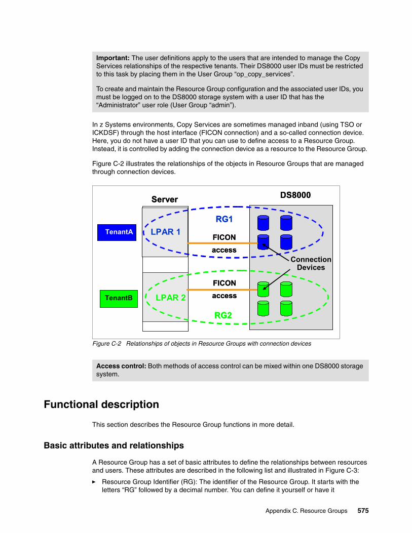
In z Systems environments, Copy Services are sometimes managed inband (using TSO or ICKDSF) through the host interface (FICON connection) and a so-called connection device. Here, you do not have a user ID that you can use to define access to a Resource Group. Instead, it is controlled by adding the connection device as a resource to the Resource Group.
Figure C-2 illustrates the relationships of the objects in Resource Groups that are managed through connection devices.
Figure C-2 Relationships of objects in Resource Groups with connection devices
Functional description
This section describes the Resource Group functions in more detail.
Basic attributes and relationships
A Resource Group has a set of basic attributes to define the relationships between resources and users. These attributes are described in the following list and illustrated in Figure C-3:
� Resource Group Identifier (RG): The identifier of the Resource Group. It starts with the letters “RG” followed by a decimal number. You can define it yourself or have it
Important: The user definitions apply to the users that are intended to manage the Copy Services relationships of the respective tenants. Their DS8000 user IDs must be restricted to this task by placing them in the User Group “op_copy_services”.
To create and maintain the Resource Group configuration and the associated user IDs, you must be logged on to the DS8000 storage system with a user ID that has the “Administrator” user role (User Group “admin”).
Access control: Both methods of access control can be mixed within one DS8000 storage system.
RG1
RG2
TenantB
TenantA
FICON
access
DS8000
LPAR 2
LPAR 1
Server
Connection Devices
FICON
access
RG1
RG2
TenantB
TenantA
FICON
access
DS8000
LPAR 2
LPAR 1
Server
Connection Devices
FICON
access
Appendix C. Resource Groups 575

automatically assigned upon creation. Resources belong to a Resource Group if they have this Resource Group Identifier assigned to them.
� Resource Group Label (RGL): A text string that is used to match the Resource Group to the User Resource Scope (URS) of a user. It must be unique within a storage system and is 1 - 32 characters in length.
Apart from the exact match of a URS and the RGL, there are special User Resource Scopes:
– “*” matches any RGL.– null (empty) matches no RGL.
� Name: A nickname for the Resource Group. It has no functional relevance.
Figure C-3 Basic Resource Group attributes and the relationships to users and resources
Remote relationships
The Resource Groups feature is intended to manage the scope of Copy Services, which in many cases affect more than one storage system (with all remote copy functions). Therefore, Resource Group definitions and scopes are also observed on the target storage systems that are involved in the Copy Services operations.
To manage remote relationships, use the Copy Services Global Resource Scope attribute (CS_GRS). A Copy Services relationship is allowed if the primary (local) Resource Group’s RGL matches the secondary (remote) Resource Group’s CS_GRS and vice versa, as illustrated in Figure C-4 on page 577.
Maximum number of Resource Groups: A maximum of 64 Resource Groups is supported for a DS8000 storage system.
RG: RG1
RGL: TenantA
HMC DS8000
User 1
URS: TenantA RG1
RG1
RG1
RG1
User 3
URS: TenantA
Resources
RG: RG1
RGL: TenantA
HMC DS8000
User 1
URS: TenantA RG1
RG1
RG1
RG1
User 3
URS: TenantA
Resources
576 DS8000 Copy Services

Figure C-4 Resource Groups remote relationships
Default behavior
Resource Groups is not a licensed feature. It is available automatically when you have a DS8000 microcode level installed that supports Resource Groups. When the feature becomes available through a microcode update, all available and newly created resources are assigned to a Default Resource Group (RG0). All users are associated with Resource Group Scope “*” and therefore have access to all resources.
A system administrator does not have to configure Resource Groups functions when upgrading to a microcode level that supports Resource Groups. By default, the behavior of the storage system is unchanged. There is no change to the behavior of commands and scripts.
Tip: In the example in Figure C-4, the RGL and CS_GRS are different. We chose them to be this way to clarify how remote relations work. They do not have to be different. You can use an identical string for RGL and CS_GRS. The RG identifiers also do not have to be different.
Tip: You can also use an RGL - CS_GRS relationship to allow Copy Services between the resources of two different RGs within a single DS8000 storage system.
RG: RG1
RGL:TenantA
CS_GRS:RemoteA
HMC
DS8000
local
User 1
URS: TenantA RG1
RG1
RG1
RG1
User 3
URS: TenantA
Resources
DS8000
remote
RG2
RG2
RG2
RG2
Resources
RG: RG2
RGL:RemoteA
CS_GRS:TenantA
RG: RG1
RGL:TenantA
CS_GRS:RemoteA
HMC
DS8000
local
User 1
URS: TenantA RG1
RG1
RG1
RG1
User 3
URS: TenantA
Resources
DS8000
remote
RG2
RG2
RG2
RG2
Resources
RG: RG2
RGL:RemoteA
CS_GRS:TenantA
Tip: Resources that you do not explicitly assign to a resource group belong to RG0 and therefore are not restricted by the Resource Groups feature. You might consider putting them into their own Resource Group that no tenant has access to. Thus, you can avoid having tenants, whether accidentally or on purpose, by using resources that are not assigned to them.
Deleting a Resource Group: Before you can delete a Resource Group, you must assign its resources to a remaining Resource Group. This Resource Group can also be RG0.
Appendix C. Resource Groups 577

Special attributes
Resource Groups can have a number of additional attributes for special purposes. The following list explains which attributes are available and what effects they have:
� Pass-through Global Resource Scope (P_GRS): Using pass-through mode, you allow a connection device to manage Copy Services relationships in LSSs other than its own. P_GRS is a resource scope that is used to validate whether a connection volume can pass through to a destination volume.
� GM Sessions Allowed: A bit mask of those Global Mirror session numbers (1 - 255) that can be assigned to an LSS associated with the RG. This attribute allows the assignment of GM session numbers to tenants.
� GM Masters Allowed: A bit mask of those GM session numbers (1 - 255) that can be used to manage a Global Mirror Master through an LSS associated with the RG. This attribute limits which Storage Facility Image a GM Master can run on.
For more information about these special attributes, see IBM System Storage DS8000 Copy Services Scope Management and Resource Groups, REDP-4758.
Implementation example
This section explains how you can implement Resource Groups with the help of an example.
Metro Mirror and DS CLI example
In the second example, we set up a Resource Group environment to manage a remote copy relation with DS CLI commands. Figure C-5 illustrates the wanted configuration.
Figure C-5 Metro Mirror example configuration
Fixed-block architecture (FB) versus count key data (CKD) resources: We describe the example by using FB resources. They are not fixed block specific, though. You can apply these examples one to one for CKD resources.
RG: RG3
RGL:venus
CS_GRS:venus_sec
HMC
DS8000
Local
S/N 75TV181
User itso_rg_venus
URS: venus
4A02
4A00
4A03
4A01
Volumes
DS8000
Remote
S/N 75ACV21
RG: RG1
RGL:venus_sec
CS_GRS:venus
4A02
4A00
4A03
4A01
MetroMirror
VolumesRG: RG3
RGL:venus
CS_GRS:venus_sec
HMC
DS8000
Local
S/N 75TV181
User itso_rg_venus
URS: venus
4A02
4A00
4A03
4A01
Volumes
DS8000
Remote
S/N 75ACV21
RG: RG1
RGL:venus_sec
CS_GRS:venus
4A02
4A00
4A03
4A01
MetroMirror
Volumes
578 DS8000 Copy Services

Local configurationStart on the local site by creating the Resource Group and defining the CS_GRS, as shown in Example C-1.
Example C-1 Create and modify a Resource Group on the primary system
dscli> mkresgrp -label venus -name "Resources_Client_Venus" CMUC00432I mkresgrp: Resource group RG3 successfully created.
dscli> manageresgrp -ctrl copyglobal -action set -scope venus_sec rg3CMUC00436I manageresgrp: Resource group rg3 successfully modified
In Example C-2, you create the user ID with the URS needed to access your Resource Group.
Example C-2 Create a user with the required URS
dscli> mkuser -group op_copy_services -scope venus -pw test123 itso_rg_venusCMUC00133I mkuser: User itso_rg_venus successfully created.
Finally, assign the volumes that you want to use as Metro Mirror primaries to the Resource Group you created, as shown in Example C-3.
Example C-3 Assign the primary volumes to the Resource Group
dscli> chfbvol -resgrp rg3 4a00-4a03CMUC00026I chfbvol: FB volume 4A00 successfully modified.CMUC00026I chfbvol: FB volume 4A01 successfully modified.CMUC00026I chfbvol: FB volume 4A02 successfully modified.CMUC00026I chfbvol: FB volume 4A03 successfully modified.
In Example C-4, you run some DS CLI commands that allow you to check whether you did the configuration correctly.
Example C-4 Check the local configuration
dscli> showresgrp rg3ID RG3Name Resources_Client_VenusState NormalLabel venusCS_Global_RS venus_secPassthru_Global_RS PUBLICGM_Masters_Allowed 01-FFGM_Sessions_Allowed 01-FF
dscli> showuser itso_rg_venusName itso_rg_venusGroup op_copy_servicesState activeFailedLogin 0DaysToExpire 9999Scope venus
dscli> lsfbvol -resgrp rg3Name ID accstate datastate configstate deviceMTM datatype extpool cap (2^30B) cap (10^9B) cap (blocks)
Specific command usage: With the mkresgrp commands, you can specify only the basic RG attributes, such as label, RG, and name. All other attributes are set by running manageresgrp for an existing RG.
Appendix C. Resource Groups 579

====================================================================================================================RGvenus_pri_4A00 4A00 Online Normal Normal 2107-900 FB 512 P8 10.0 - 20971520RGvenus_pri_4A01 4A01 Online Normal Normal 2107-900 FB 512 P8 10.0 - 20971520RGvenus_pri_4A02 4A02 Online Normal Normal 2107-900 FB 512 P8 10.0 - 20971520RGvenus_pri_4A03 4A03 Online Normal Normal 2107-900 FB 512 P8 10.0 - 20971520
Remote configuration
Now, we provide an example of configuring the remote site and the auxiliary storage system. Again, the first step is to create a Resource Group with matching RG and CS_GRS, as shown in Example C-5.
Example C-5 Create and modify a Resource Group on a secondary system
dscli> mkresgrp -label venus_sec -name Targets_for_Client_Venus CMUC00432I mkresgrp: Resource group RG1 successfully created.
dscli> manageresgrp -ctrl copyglobal -action set -scope venus rg1CMUC00436I manageresgrp: Resource group rg1 successfully modified.
A user scope definition is not necessary because all user interaction (create Metro Mirror relationships) is performed on the primary storage system only.
In the next step, illustrated in Example C-6, assign the secondary volumes to your new Resource Group.
Example C-6 Assign secondary volumes to the Resource Group
dscli> chfbvol -resgrp RG1 4a00-4a03 CMUC00026I chfbvol: FB volume 4A00 successfully modified.CMUC00026I chfbvol: FB volume 4A01 successfully modified.CMUC00026I chfbvol: FB volume 4A02 successfully modified.CMUC00026I chfbvol: FB volume 4A03 successfully modified.
Example C-7 shows the commands that you can use to check whether the configuration is correct.
Example C-7 Check the secondary configuration
dscli> showresgrp rg1ID RG1Name Targets_for_Client_VenusState NormalLabel venus_secCS_Global_RS venusPassthru_Global_RS PUBLICGM_Masters_Allowed 01-FFGM_Sessions_Allowed 01-FF
dscli> lsfbvol -resgrp rg1Name ID accstate datastate configstate deviceMTM datatype extpool cap (2^30B) cap (10^9B) cap (blocks)====================================================================================================================RGvenus_sec_4A00 4A00 Online Normal Normal 2107-900 FB 512 P4 10.0 - 20971520RGvenus_sec_4A01 4A01 Online Normal Normal 2107-900 FB 512 P4 10.0 - 20971520
Real-world configuration: In a real-world configuration, you will probably need a user with a matching URS on the remote system. In a disaster case or test, it must be possible to modify Copy Services relationships from there.
580 DS8000 Copy Services

RGvenus_sec_4A02 4A02 Online Normal Normal 2107-900 FB 512 P4 10.0 - 20971520RGvenus_sec_4A03 4A03 Online Normal Normal 2107-900 FB 512 P4 10.0 - 20971520
Testing the Resource Group configuration with Metro MirrorTo test your Resource Group definitions, establish Metro Mirror relationships between the primary and secondary volumes. Example C-8 shows the positive test for which you log on to the DS CLI on the primary system with the itso_rg_venus user ID that has the correct URS.
Example C-8 Test a Resource Group configuration with the correct user ID
dscli> whoamiName Group Policy Scope==================================================itso_rg_venus op_copy_services initialPolicy venus
dscli> mkpprc -remotedev IBM.2107-75ACV21 -type mmir 4a00-4a03:4a00-4a03 CMUC00153I mkpprc: Remote Mirror and Copy volume pair relationship 4A00:4A00 successfully created.CMUC00153I mkpprc: Remote Mirror and Copy volume pair relationship 4A01:4A01 successfully created.CMUC00153I mkpprc: Remote Mirror and Copy volume pair relationship 4A02:4A02 successfully created.CMUC00153I mkpprc: Remote Mirror and Copy volume pair relationship 4A03:4A03 successfully created.
In Example C-9 shows the counter-test, where you try to establish the same Metro Mirror relationships, but you are logged on to the primary system by using a user ID with the wrong URS.
Example C-9 Test a Resource Group configuration with an incorrect user ID
dscli> whoamiName Group Policy Scope==================================================itso_rg_earth op_copy_services initialPolicy earth
dscli> mkpprc -remotedev IBM.2107-75ACV21 -type mmir 4a00-4a03:4a00-4a03CMUN03176E mkpprc: 4A00:4A00: The task cannot be initiated because a user resource scope policy violation has occurred ...CMUN03176E mkpprc: 4A01:4A01: The task cannot be initiated because a user resource scope policy violation has occurred .. CMUN03176E mkpprc: 4A02:4A02: The task cannot be initiated because a user resource scope policy violation has occurred ...CMUN03176E mkpprc: 4A03:4A03: The task cannot be initiated because a user resource scope policy violation has occurred ...
Note: In this example, we chose different strings for RGL and CS_GRS to illustrate how the systems resolve the relationship between local and remote Resource Groups. As already stated in “Remote relationships” on page 576, you can also use the same string for both labels.
Shortened output: The full wording of the error messages in Example C-9 is CMUN03176E mkpprc: 4A00:4A00: The task cannot be initiated because a user resource scope policy violation has occurred on the destination logical volume.
Appendix C. Resource Groups 581

582 DS8000 Copy Services

Related publications
The publications listed in this section are considered particularly suitable for a more detailed discussion of the topics covered in this book.
IBM Redbooks
The following IBM Redbooks publications provide additional information about the topic in this document. Note that some publications referenced in this list might be available in softcopy only.
� IBM DS8880 Architecture and Implementation, SG24-8323� IBM DS8870 Multiple Target Peer-to-Peer Remote Copy, REDP-5151� IBM System Storage DS8000: Remote Pair FlashCopy (Preserve Mirror), REDP-4504
You can search for, view, download or order these documents and other Redbooks, Redpapers, Web Docs, draft and additional materials, at the following website:
ibm.com/redbooks
Online resources
These websites are also relevant as further information sources:
� Documentation for the DS8000, found at:
https://www.ibm.com/support/knowledgecenter/en/ST5GLJ/ds8000_kcwelcome.html
� IBM Disk Storage Feature Activation (DSFA), found at:
http://www.ibm.com/storage/dsfa
� IBM SAN information, found at:
http://www.ibm.com/systems/storage/san
� IBM System Storage Interoperation Center (SSIC), found at:
http://www.ibm.com/systems/support/storage/config/ssic/index.jsp
� IBM Techdocs Library - The IBM Technical Sales Library, found at:
http://www.ibm.com/support/techdocs/atsmastr.nsf/Web/Techdocs
� PSP information can be found at:
http://www.ibm.com/servers/resourcelink/svc03100.nsf?OpenDatabase
© Copyright IBM Corp. 2017. All rights reserved. 583

Help from IBM
IBM Support and downloads
ibm.com/support
IBM Global Services
ibm.com/services
584 DS8000 Copy Services
ISB
N 0738442372
SG
24-8367-00
(1.0” spine)0.875”<
->1.498”
460 <->
788 pages
DS8000 Copy Services


ibm.com/redbooks
Printed in U.S.A.
Back cover
ISBN 0738442372
SG24-8367-00
®