Cisco Unified SCCP and SIP SRST System ... - Audentia
382
Cisco Systems, Inc. www.cisco.com Cisco has more than 200 offices worldwide. Addresses, phone numbers, and fax numbers are listed on the Cisco website at www.cisco.com/go/offices. Cisco Unified SCCP and SIP SRST System Administrator Guide (All Versions) November 23, 2017
-
Upload
khangminh22 -
Category
Documents
-
view
6 -
download
0
Transcript of Cisco Unified SCCP and SIP SRST System ... - Audentia
Cisco Unified SCCP and SIP SRST System Administrator Guide (All Versions)
November 23, 2017
Cisco Systems, Inc.www.cisco.com
Cisco has more than 200 offices worldwide. Addresses, phone numbers, and fax numbers are listed on the Cisco website at www.cisco.com/go/offices.
THE SPECIFITIONS AND INFORMATION REGARDING THE PRODUCTS IN THIS MANUAL ARE SUBJECT TO CHANGE WITHOUT NOTICE. ALL STATEMENTS, INFORMATION, AND RECOMMENDATIONS IN THIS MANUAL ARE BELIEVED TO BE ACCURATE BUT ARE PRESENTED WITHOUT WARRANTY OF ANY KIND, EXPRESS OR IMPLIED. USERS MUST TAKE FULL RESPONSIBILITY FOR THEIR APPLITION OF ANY PRODUCTS.
THE SOFTWARE LICENSE AND LIMITED WARRANTY FOR THE ACCOMPANYING PRODUCT ARE SET FORTH IN THE INFORMATION PACKET THAT SHIPPED WITH THE PRODUCT AND ARE INCORPORATED HEREIN BY THIS REFERENCE. IF YOU ARE UNABLE TO LOTE THE SOFTWARE LICENSE OR LIMITED WARRANTY, CONTACT YOUR CISCO REPRESENTATIVE FOR A COPY.
The Cisco implementation of TCP header compression is an adaptation of a program developed by the University of California, Berkeley (UCB) as part of UCB’s public domain version of the UNIX operating system. All rights reserved. Copyright © 1981, Regents of the University of California.
NOTWITHSTANDING ANY OTHER WARRANTY HEREIN, ALL DOCUMENT FILES AND SOFTWARE OF THESE SUPPLIERS ARE PROVIDED “AS IS” WITH ALL FAULTS. CISCO AND THE ABOVE-NAMED SUPPLIERS DISCLAIM ALL WARRANTIES, EXPRESSED OR IMPLIED, INCLUDING, WITHOUT LIMITATION, THOSE OF MERCHANTABILITY, FITNESS FOR A PARTICULAR PURPOSE AND NONINFRINGEMENT OR ARISING FROM A COURSE OF DEALING, USAGE, OR TRADE PRACTICE.
IN NO EVENT SHALL CISCO OR ITS SUPPLIERS BE LIABLE FOR ANY INDIRECT, SPECIAL, CONSEQUENTIAL, OR INCIDENTAL DAMAGES, INCLUDING, WITHOUT LIMITATION, LOST PROFITS OR LOSS OR DAMAGE TO DATA ARISING OUT OF THE USE OR INABILITY TO USE THIS MANUAL, EVEN IF CISCO OR ITS SUPPLIERS HAVE BEEN ADVISED OF THE POSSIBILITY OF SUCH DAMAGES.
Cisco and the Cisco logo are trademarks or registered trademarks of Cisco and/or its affiliates in the U.S. and other countries. To view a list of Cisco trademarks, go to thisURL: www.cisco.com/go/trademarks. Third-party trademarks mentioned are the property of their respective owners. The use of the word partner does not imply a partnershiprelationship between Cisco and any other company. (1721R)
Any Internet Protocol (IP) addresses used in this document are not intended to be actual addresses. Any examples, command display output, and figures included in the document are shown for illustrative purposes only. Any use of actual IP addresses in illustrative content is unintentional and coincidental.
Cisco Unified SCCP and SIP SRST System Administrator Guide (All Versions)© 2017 Cisco Systems, Inc. All rights reserved.
.
C O N T E N T S
Preface i
Audience ii-i
Conventions ii-i
Obtain Documentation and Submit a Service Request ii-ii
Cisco Unified Survivable Remote Site Telephony Feature Roadmap iii-iii
Contents iii-iii
Documentation Organization iii-iv
Feature Roadmap iii-v
Information About New Features in Cisco Unified SRST iii-x
New Features for Unified SRST Version 12.1 iii-x
New Feature for Unified SRST Version 12.0 iii-x
New Features for Cisco Unified SRST Version 11.0 iii-xi
New Features for Cisco Unified SRST Version 10.5 iii-xi
Support for Cisco Unified DX650 SIP IP Phones iii-xi
Support for Cisco Unified 78xx SIP IP Phones iii-xi
New Features in Cisco Unified SRST Version 10.0 iii-xi
Cisco Jabber for Windows iii-xii
Version Negotiation for Cisco Unified SIP IP Phones iii-xii
New Features in Cisco Unified SRST Version 9.5 iii-xii
After-hour Pattern Blocking Support for Regular Expressions iii-xiii
Call Park Recall Enhancement iii-xiii
Park Monitor iii-xiv
Display Support for Name of Called Voice Hunt Groups iii-xiv
Preventing Local-Call Forwarding to Final Agent in Voice Hunt Groups iii-xv
Trunk-to-Trunk Transfer Blocking for Toll Fraud Prevention on Cisco Unified SIP IP Phones iii-xvi
conference-pattern blocked iii-xviii
Configuring the Maximum Number of Digits for a Conference Call iii-xix
Prerequisites iii-xix
DETAILED STEPS iii-xx
Configuring Conference Blocking Options for Phones iii-xx
Prerequisites iii-xxi
transfer-pattern blocked iii-xxii
iCisco Unified SIP SRST System Administrator Guide
Contents
New Features in Cisco Unified SRST Version 9.1 iii-xxiii
KEM Support for Cisco Unified SIP IP Phones iii-xxiv
Enhancement in Speed-Dial Support iii-xxiv
Voice Hunt Group Support iii-xxiv
New Features in Cisco Unified SRST Version 9.0 iii-xxv
Support for Cisco Unified 6901 and 6911 SIP IP Phones iii-xxv
Support for Cisco Unified 6921, 6941, 6945, and 6961 SIP IP Phones iii-xxvi
Support for Cisco Unified 8941 and 8945 SIP IP Phones iii-xxvi
Multiple Calls Per Line iii-xxvi
Voice and Fax Support on Cisco ATA-187 iii-xxvii
New Features in Cisco Unified SRST Version 8.8 iii-xxvii
Support for Cisco Unified 6945, 8941, and 8945 SCCP IP Phones iii-xxvii
New Features in Cisco Unified SRST Version 8.0 iii-xxvii
New Features in Cisco Unified SRST Version 7.0/4.3 iii-xxvii
New Features in Cisco Unified SRST Version 4.2(1) iii-xxviii
New Features in Cisco Unified SRST Version 4.1 iii-xxviii
New Features in Cisco Unified SRST Version 4.0 iii-xxviii
Additional Cisco Unified IP Phone Support iii-xxviii
Cisco IP Communicator Support iii-xxix
Fax Pass-through using SCCP and ATAs Support iii-xxix
H.323 VoIP Call Preservation Enhancements for WAN Link Failures for SCCP Phones iii-xxix
Video Support iii-xxix
New Features in Cisco Unified SRST Version 3.4 iii-xxix
Cisco SIP SRST 3.4 iii-xxx
New Features in Cisco SRST Version 3.3 iii-xxx
Secure SRST iii-xxx
Cisco Unified IP Phone 7970G and Cisco Unified 7971G-GE Support iii-xxxi
Enhancement to the show ephone Command iii-xxxi
New Features in Cisco SRST Version 3.2 iii-xxxi
Enhancement to the alias Command iii-xxxii
Enhancement to the cor Command iii-xxxii
Enhancement to the pickup Command iii-xxxii
Enhancement to the user-locale Command iii-xxxii
Increased the Number of Cisco Unified IP Phones Supported on the Cisco 3845 iii-xxxii
MOH Live-Feed Support iii-xxxii
No Timeout for Call Preservation iii-xxxiii
RFC 2833 DTMF Relay Support iii-xxxiii
iiCisco Unified SIP SRST System Administrator Guide
Contents
Translation Profile Support iii-xxxiii
New Features in Cisco SRST Version 3.1 iii-xxxiii
Cisco Unified IP Phone 7920 Support iii-xxxiv
Cisco Unified IP Phone 7936 Support iii-xxxiv
New Features in Cisco SRST Version 3.0 iii-xxxiv
Additional Language Options for IP Phone Display iii-xxxiv
Consultative Call Transfer and Forward Using H.450.2 and H.450.3 for SCCP Phones iii-xxxvi
Customized System Message for Cisco Unified IP Phones iii-xxxvi
Dual-Line Mode iii-xxxvi
E1 R2 Signaling Support iii-xxxvii
European Date Formats iii-xxxviii
Huntstop for Dual-Line Mode iii-xxxviii
Music-on-Hold for Multicast from Flash Files iii-xxxviii
Ringing Timeout Default iii-xxxviii
Secondary Dial Tone iii-xxxviii
Enhancement to the show ephone Command iii-xxxix
System Log Messages for Phone Registrations iii-xxxix
Three-Party G.711 Ad Hoc Conferencing iii-xxxix
Support for Cisco VG248 Analog Phone Gateway 1.2(1) and Higher Versions iii-xxxix
New Features in Cisco SRST Version 2.1 iii-xxxix
Additional Language Options for IP Phone Display iii-xl
Cisco SRST Aggregation iii-xl
Cisco ATA 186 and ATA 188 Support iii-xl
Cisco Unified IP Phone 7902G Support iii-xli
Cisco Unified IP Phone 7905G Support iii-xli
Cisco Unified IP Phone 7912G Support iii-xli
Cisco Unified IP Phone Expansion Module 7914 Support iii-xli
Enhancement to the dialplan-pattern Command iii-xli
New Features in Cisco SRST Version 2.02 iii-xlii
Cisco Unified IP Phone Conference Station 7935 Support iii-xlii
Increase in Directory Numbers iii-xlii
Cisco Unity Voicemail Integration Using In-Band DTMF Signaling Across the PSTN and BRI/PRI iii-xlii
Where to Go Next iii-xliii
Cisco Unified SRST Feature Overview 1-1
Contents 1-1
Cisco Unified SCCP SRST 1-1
iiiCisco Unified SIP SRST System Administrator Guide
Contents
Information About SCCP SRST 1-2
Prerequisites for Configuring Cisco Unified SCCP SRST 1-4
Installing Cisco Unified Communications Manager 1-4
Installing Cisco Unified SCCP SRST 1-5
Integrating Cisco Unified SCCP SRST with Cisco Unified Communications Manager 1-5
Restrictions for Configuring Cisco Unified SCCP SRST 1-7
Cisco Unified SIP SRST 1-9
Information About SIP SRST 1-9
Prerequisites for Configuring Cisco Unified SIP SRST 1-9
Restrictions for Configuring Cisco Unified SIP SRST 1-9
Cisco Unified SRST Licenses 1-12
Cisco Unified SRST Permanent License 1-13
Collaboration Professional Suite License 1-13
Cisco Smart License 1-14
Configure Call Home 1-15
Licensing Modes 1-16
Restrictions 1-16
Interface Support for Unified CME and Unified SRST 1-17
MGCP Gateways and SRST 1-17
IPv6 Support for Unified SRST SIP IP Phones 1-17
Feature Support for IPv6 in Unified SRST SIP IP Phones 1-18
Restrictions 1-18
Configure IPv6 Pools for SIP IP Phones 1-18
Examples for Configuring IPv6 Pools for SIP IP Phones 1-23
Support for Cisco Unified IP Phones and Platforms 1-24
Finding Cisco IOS Software Releases That Support Cisco Unified SRST 1-24
Cisco Unified IP Phone Support 1-25
Platform and Memory Support 1-25
Determining Platform Support Through Cisco Feature Navigator 1-25
Availability of Cisco IOS Software Images 1-25
Cisco Unified Communications Manager Compatibility 1-25
Signal Support 1-25
Language Support 1-25
Switch Support 1-26
Where to Go Next 1-26
Additional References 1-27
Related Documents 1-28
Standards 1-30
ivCisco Unified SIP SRST System Administrator Guide
Contents
MIBs 1-30
RFCs 1-30
Technical Assistance 1-30
Obtaining Documentation, Obtaining Support, and Security Guidelines 1-30
Cisco Unified Enhanced Survivable Remote Site Telephony 2-31
Overview of Enhanced SRST Feature 2-31
Contents 2-31
SIP: Configuring Enhanced SRST 2-31
Restrictions 2-32
Enabling the E-SRST Mode 2-32
Configuring SIP shared-line 2-33
Configuring BLF 2-34
Enabling a Directory Number to be Watched 2-34
Enabling BLF on a voice register pool: 2-34
Configuring Digest Credentials On CUCM 2-35
SCCP: Configuring Enhanced SRST 2-36
Prerequisites 2-36
Enhanced SRST Scale Support 2-37
Where to Go Next 2-38
Setting Up the Network 3-39
Contents 3-39
Information About Setting Up the Network 3-40
How to Set Up the Network 3-40
Enabling IP Routing 3-40
Enabling Cisco Unified SRST on an MGCP Gateway 3-40
Configuring Cisco Unified SRST on an MGCP Gateway Prior to Cisco IOS Release 12.3(14)T 3-41
Configuring SRST on an MGCP Gateway Using Cisco IOS Release 12.3(14)T or Later Releases 3-42
Restrictions 3-42
Configuration Example of Enabling SRST on a MGCP Gateway using Cisco IOS Release 12.3(14)T 3-44
Configuring DHCP for Cisco Unified SRST Phones 3-46
Defining a Single DHCP IP Address Pool 3-46
Defining a Separate DHCP IP Address Pool for Each Cisco Unified IP Phone 3-47
Defining the DHCP Relay Server 3-48
Specifying Keepalive Intervals 3-49
Examples 3-50
vCisco Unified SIP SRST System Administrator Guide
Contents
Where to Go Next 3-50
Cisco Unified SIP SRST 4.1 4-51
Contents 4-51
Prerequisites for Cisco Unified SIP SRST 4.1 4-51
Restrictions for Cisco Unified SIP SRST 4.1 4-52
Information About Cisco Unified SIP SRST 4.1 4-52
Out-of-Dialog REFER 4-52
Digit Collection on SIP Phones 4-53
KPML Digit Collection 4-53
SIP Dial Plans 4-53
Caller ID Display 4-54
Disabling SIP Supplementary Services for Call Forward and Call Transfer 4-54
Idle Prompt Status 4-54
Enhanced 911 Services 4-54
How to Configure Cisco Unified SIP SRST 4.1 Features 4-55
Enabling KPML for SIP Phones 4-55
Restrictions 4-55
What to Do Next 4-56
Disabling SIP Supplementary Services for Call Forward and Call Transfer 4-57
Configuring Idle Prompt Status for SIP Phones 4-58
Prerequisites 4-58
Where to Go Next 4-59
Setting Up Cisco Unified IP Phones using SCCP 5-61
Contents 5-61
Information About Setting Up Cisco Unified IP Phones 5-61
How to Set Up Cisco Unified IP Phones 5-62
Configuring Cisco Unified SRST to Support Phone Functions 5-62
Configuring Cisco Unified 8941 and 8945 SCCP IP Phones 5-64
Verifying That Cisco Unified SRST Is Enabled 5-65
Configuring IP Phone Clock, Date, and Time Formats 5-66
Example 5-67
Configuring IP Phone Language Display 5-68
Examples 5-69
Configuring Customized System Messages for Cisco Unified IP Phones 5-70
Examples 5-71
Configuring a Secondary Dial Tone 5-71
Examples 5-71
Configuring Dual-Line Phones 5-72
viCisco Unified SIP SRST System Administrator Guide
Contents
Examples 5-73
Configuring Eight Calls per Button (Octo-Line) 5-74
Prerequisites 5-74
Restrictions 5-74
Examples 5-76
Configuring the Maximum Number of Calls 5-76
Prerequisites 5-76
Troubleshooting 5-78
How to Set Up Cisco IP Communicator for Cisco Unified SRST 5-78
Prerequisites 5-78
Verifying Cisco IP Communicator 5-79
Troubleshooting Cisco IP Communicator 5-79
Where to Go Next 5-79
Setting Up Cisco Unified IP Phones using SIP 6-81
Contents 6-81
Prerequisites for Configuring the SIP Registrar 6-81
Restrictions for Configuring the SIP Registrar 6-81
Information About Configuring the SIP Registrar 6-81
How to Configure the SIP Registrar 6-82
Configuring the SIP Registrar 6-82
What to Do Next 6-84
Configuring Backup Registrar Service to SIP Phones 6-84
Prerequisites 6-85
Restrictions 6-85
What to Do Next 6-87
Configuring Backup Registrar Service to SIP Phones (Using Optional Commands) 6-88
Prerequisites 6-88
Examples 6-91
Verifying SIP Registrar Configuration 6-91
Verifying Proxy Dial-Peer Configuration 6-93
Where to Go Next 6-96
Configuring Call Handling 7-99
Contents 7-99
Prerequisites for Configuring SIP SRST Features Using Back-to-Back User Agent Mode 7-100
Restrictions for Configuring SIP SRST Features Using Back-to-Back User Agent Mode 7-100
Information About Configuring SCCP SRST Call Handling 7-100
viiCisco Unified SIP SRST System Administrator Guide
Contents
H.323 VoIP Call Preservation Enhancements for WAN Link Failures 7-100
Toll Fraud Prevention 7-101
Information About Configuring SIP SRST Features Using Back-to-Back User Agent Mode 7-101
Cisco Unified SIP SRST and Cisco SIP Communications Manager Express Feature Crossover 7-101
How to Configure Cisco Unified SCCP SRST 7-103
Configuring Incoming Calls 7-104
Configuring Call Forwarding During a Busy Signal or No Answer 7-104
Examples 7-105
Configuring Call Rerouting 7-106
Examples 7-109
Configuring Call Pickup 7-109
Examples 7-110
Configuring Consultative Transfer 7-111
Conference Calls 7-112
Configuring Transfer Digit Collection Method 7-112
Examples 7-113
Configuring Global Prefixes 7-113
Examples 7-115
Enabling Digit Translation Rules 7-115
Examples 7-116
Enabling Translation Profiles 7-116
Examples 7-119
Verifying Translation Profiles 7-119
Configuring Dial-Peer and Channel Hunting 7-120
Examples 7-121
Configuring Busy Timeout 7-121
Examples 7-122
Configuring the Ringing Timeout Default 7-122
Examples 7-123
Configuring Outgoing Calls 7-123
Configuring Local and Remote Call Transfer 7-123
Examples 7-124
Enabling Consultative Call Transfer and Forward Using H.450.2 and H.450.3 with Cisco SRST 3.0 7-124
Examples 7-127
Enabling Analog Transfer Using Hookflash and the H.450.2 Standard with Cisco SRST 3.0 or Earlier 7-128
Examples 7-132
viiiCisco Unified SIP SRST System Administrator Guide
Contents
Configuring Trunk Access Codes 7-132
Examples 7-133
Configuring Interdigit Timeout Values 7-133
Examples 7-134
Configuring Class of Restriction 7-134
Examples 7-136
Call Blocking (Toll Bar) Based on Time of Day and Day of Week or Date 7-138
Examples 7-139
How to Configure Cisco Unified SIP SRST 7-140
Configuring SIP Phone Features 7-140
Configuring SIP-to-SIP Call Forwarding 7-142
Configuring Call Blocking Based on Time of Day, Day of Week, or Date 7-144
Examples 7-147
Verification 7-147
SIP Call Hold and Resume 7-148
Examples 7-148
How to Configure Optional Features 7-150
Enabling Three-Party G.711 Ad Hoc Conferencing 7-150
Examples 7-151
Defining XML API Schema 7-152
Configuration Examples for Call Handling 7-152
Example: Monitoring the Status of Key Expansion Modules 7-152
Example: Configuring Voice Hunt Groups in Cisco Unified SIP SRST 7-153
Where to Go Next 7-153
Configuring Secure SRST for SCCP and SIP 8-155
Contents 8-155
Prerequisites for Configuring Secure SRST 8-155
Restrictions for Configuring Secure SRST 8-156
Information About Configuring Secure SRST 8-157
Benefits of Secure SRST 8-157
Secure SRST Support on Cisco 4000 Series Integrated Services Router 8-158
Secure Music on Hold 8-158
Cisco IP Phones Clear-Text Fallback During Non-Secure SRST 8-158
Signaling Security on Unify SRST - TLS 8-158
SRST Routers and the TLS Protocol 8-159
Certificates Operation on Secure SRST 8-159
Certificates Transport from CUCM to Secure SRST 8-161
Media Security on Unify SRST - SRTP 8-161
ixCisco Unified SIP SRST System Administrator Guide
Contents
Establishment of Secure Cisco Unified SRST to the Cisco Unified IP Phone 8-161
Secure SRST Authentication and Encryption 8-163
How to Configure Secure Unified SRST 8-164
8-164
Preparing the Cisco Unified SRST Router for Secure Communication 8-165
Configuring a Certificate Authority Server on a Cisco IOS Certificate Server 8-165
Autoenrolling and Authenticating the Secure Cisco Unified SRST Router to the CA Server 8-167
Disabling Automatic Certificate Enrollment 8-171
What to Do Next 8-171
Verifying Certificate Enrollment 8-172
Enabling Credentials Service on the Secure Cisco Unified SRST Router 8-174
Troubleshooting Credential Settings 8-176
Importing Phone Certificate Files in PEM Format to the Secure SRST Router 8-176
Cisco Unified Communications Manager 4.X.X and Earlier Versions 8-177
Cisco Unified Communications Manager 5.0 and Later Versions 8-177
Cisco Unified Communications Manager 6.0 and Later Versions 8-178
Authenticating the Imported Certificates on the Cisco Unified SRST Router 8-178
What to Do Next 8-179
Examples 8-179
Configuring Cisco Unified Communications Manager to the Secure Cisco Unified SRST Router 8-184
Adding an SRST Reference to Cisco Unified Communications Manager 8-184
Configuring SRST Fallback on Cisco Unified Communications Manager 8-185
Configuring CAPF on Cisco Unified Communications Manager 8-187
Enabling SRST Mode on the Secure Cisco Unified SRST Router 8-187
Examples 8-189
Configuring Secure SCCP SRST 8-189
Prerequisites for Configuring Secure SCCP SRST 8-189
Restrictions for Configuring Secure SCCP SRST 8-189
Verifying Phone Status and Registrations 8-190
Configuration Examples for Secure SCCP SRST 8-197
Configuring Secure SIP Call Signaling and SRTP Media with Cisco SRST 8-203
Prerequisites for Configuring Secure SIP Call Signaling and SRTP Media with Cisco SRST 8-203
Restrictions for Configuring Secure SIP Call Signaling and SRTP Media with Cisco SRST 8-203
Information About Cisco Unified SIP SRST Support of Secure SIP Signaling and SRTP Media 8-204
Configuring Cisco Unified Communications Manager 8-204
8-204
xCisco Unified SIP SRST System Administrator Guide
Contents
8-204
Configuring Phones 8-205
Configuring SIP options for Secure SIP SRST 8-206
Configuring SIP SRST Security Policy 8-207
Configuring SIP User Agent for Secure SIP SRST 8-208
Configuration Example for Cisco Unified SIP SRST 8-212
Additional References 8-218
Related Documents 8-219
Standards 8-219
MIBs 8-219
RFCs 8-219
Technical Assistance 8-220
Command Reference 8-220
Feature Information for Secure SCCP and SIP SRST 8-221
Where to Go Next 8-221
Configuring SIP Trunking on Unified SRST 9-223
Contents 9-223
Unified SRST and Unified Border Element Co-location 9-223
Configuration Recommendations for Unified SRST and Unified Border Element Co-location 9-225
Restrictions 9-227
Examples 9-227
Feature Information for Configuring SIP Trunking on Unified SRST 9-238
Integrating Voicemail with Cisco Unified SRST 10-239
Contents 10-239
Information About Integrating Voicemail with Cisco Unified SRST 10-239
How to Integrate Voicemail with Cisco Unified SCCP and SIP SRST 10-241
Configuring Direct Access to Voicemail 10-241
Examples 10-244
Configuring Message Buttons 10-244
Examples 10-246
Redirecting to Cisco Unified Communications Manager Gateway 10-247
Configuring Call Forwarding to Voicemail 10-247
Call Routing Instructions Using DTMF Digit Patterns 10-247
Prerequisites 10-249
Examples 10-251
Configuring Message Waiting Indication (Cisco Unified SRST Routers) 10-251
xiCisco Unified SIP SRST System Administrator Guide
Contents
Configuring Message Waiting Indication (SIP Phones in SRST Mode) 10-253
Configuration Examples for Unified SRST 10-255
Configuring Local Voicemail System (FXO and FXS): Example 10-255
Configuring Central Location Voicemail System (FXO and FXS): Example 10-256
Configuring Voicemail Access over FXO and FXS: Example 10-256
Configuring Voicemail Access over BRI and PRI: Example 10-257
Message Waiting Indication for SIP SRST: Example 10-258
How to Configure DTMF Relay for SIP Applications and Voicemail 10-258
DTMF Relay Using SIP RFC 2833 10-258
Troubleshooting Tips 10-260
DTMF Relay Using SIP Notify (Nonstandard) 10-260
Troubleshooting Tips 10-261
Where to Go Next 10-262
Setting Video Parameters 11-263
Contents 11-263
Prerequisites for Setting Video Parameters 11-263
Restrictions for Setting Video Parameters 11-264
Information About Setting Video Parameters 11-264
Matching Endpoint Capabilities 11-265
Retrieving Video Codec Information 11-265
Call Fallback to Audio-Only 11-265
Call Setup for Video Endpoints 11-265
Call Setup Between Two Local SCCP Endpoints 11-266
Call Setup Between SCCP and H.323 Endpoints 11-266
Call Setup Between Two SCCP Endpoints Across an H.323 Network 11-266
Flow of the RTP Video Stream 11-266
How to Set Video Parameters for Cisco Unified SRST 11-267
Configuring Slow Connect Procedures 11-267
Verifying Cisco Unified SRST 11-268
Examples 11-269
Setting Video Parameters for Cisco Unified SRST 11-274
Examples 11-275
Troubleshooting Video for Cisco Unified SRST 11-276
Where to Go Next 11-276
Monitoring and Maintaining Cisco Unified SRST 12-277
Configuring Cisco Unified SIP SRST Features Using Redirect Mode A-1
Contents A-1
xiiCisco Unified SIP SRST System Administrator Guide
Contents
Prerequisites for Cisco Unified SIP SRST Features Using Redirect Mode A-1
Restrictions for Cisco Unified SIP SRST Features Using Redirect Mode A-1
Information About Cisco Unified SIP SRST Features Using Redirect Mode A-2
How to Configure Cisco Unified SIP SRST Features Using Redirect Mode A-2
Configuring Call Redirect Enhancements to Support Calls Between SIP IP Phones for Cisco Unified SIP SRST A-2
Configuring Call Redirect Enhancements to Support Calls Globally A-3
Configuring Call Redirect Enhancements to Support Calls on a Specific VoIP Dial Peer A-4
Configuring Sending 300 Multiple Choice Support A-5
Configuration Examples for Cisco Unified SIP SRST Features Using Redirect Mode A-6
Cisco Unified SIP SRST: Example A-7
Where to Go Next A-8
Integrating Cisco Unified Communications Manager and Cisco Unified SRST to Use Cisco Unified SRST as a Multicast MOH Resource B-11
Contents B-11
Prerequisites for Using Cisco Unified SRST Gateways as a Multicast MOH Resource B-12
Restrictions for Using Cisco Unified SRST Gateways as a Multicast MOH Resource B-12
Information About Using Cisco Unified SRST Gateways as a Multicast MOH Resource B-13
Cisco Unified SRST Gateways and Cisco Unified Communications Manager B-13
Codecs, Port Numbers, and IP Addresses B-14
Multicast MOH Transmission B-16
MOH from a Live Feed B-16
MOH from Flash Files B-17
How to Use Cisco Unified SRST Gateways as a Multicast MOH Resource B-18
Configuring Cisco Unified Communications Manager for Cisco Unified SRST Multicast MOH B-18
Configuring the MOH Audio Source to Enable Multicasting B-19
Enabling Multicast on the Cisco Unified Communications Manager MOH Server and Configuring Port Numbers and IP Addresses B-20
Creating an MRG and an MRGL, Enabling MOH Multicast, and Configuring Gateways B-23
Creating a Region for the MOH Server B-25
Verifying Cisco Unified Communications Manager Multicast MOH B-26
Configuring Cisco Unified SRST for Multicast MOH from an Audio File B-26
Prerequisites B-27
Enabling Multicast MOH on the Cisco Unified SRST Gateway B-27
Verifying Basic Cisco Unified SRST Multicast MOH Streaming B-31
Verifying Cisco Unified SRST MOH to PSTN B-32
xiiiCisco Unified SIP SRST System Administrator Guide
Contents
Verifying Cisco Unified SRST Multicast MOH to IP Phones B-36
Troubleshooting Tips B-36
Configuring Cisco Unified SRST for MOH from a Live Feed B-36
Prerequisites B-37
Restrictions B-37
Setting Up the Voice Port on the Cisco Unified SRST Gateway B-37
Setting Up the Directory Numbers on the Cisco Unified SRST Gateway B-39
Establishing the MOH Feed B-39
Verifying Cisco Unified SRST MOH Live Feed B-41
Configurations Examples for Cisco Unified SRST Gateways B-41
MOH Routed to Two IP Addresses: Example B-41
MOH Live Feed: Example B-42
Feature Information for Cisco Unified SRST as a Multicast MOH Resource B-42
Where to Go Next B-43
xivCisco Unified SIP SRST System Administrator Guide
Preface
This preface describes the audience and conventions of the Cisco Unified SCCP and SIP SRST System Administration Guide. It also describes the available product documentation and provides information on how to obtain documentation and technical assistance.
• Audience, page i
• Conventions, page i
• Obtain Documentation and Submit a Service Request, page ii
AudienceThis guide is intended primarily for network administrators and channel partners.
ConventionsThis guide uses the following conventions:
Item Convention
Commands and keywords. boldface font
Variables for which you supply values. italic font
Optional command keywords. You do not have to select any options.
[enclosed in brackets]
Required command keyword to be selected from a set of options. You must choose one option.
{options enclosed in braces | separated by vertical bar}
Displayed session and system information. screen font
Information you enter. boldface screen font
Variables you enter. italic screen font
Menu items and button names. boldface font
Choosing a menu item. Option > Network Preferences
iCisco Unified SCCP and SIP SRST System Administrator Guide
Obtain Documentation and Submit a Service Request
Note Means reader take note.
Tip Means the following information will help you solve a problem.
Caution Means reader be careful. In this situation, you might perform an action that could result in equipment damage or loss of data.
Timesaver Means the described action saves time. You can save time by performing the action described in the paragraph.
Warning Means reader be warned. In this situation, you might perform an action that could result in bodily injury.
Obtain Documentation and Submit a Service RequestFor information on obtaining documentation, using the Cisco Bug Search Tool (BST), submitting a service request, and gathering additional information, see What’s New in Cisco Product Documentation.
To receive new and revised Cisco technical content directly to your desktop, you can subscribe to the What’s New in Cisco Product Documentation RSS feed. The RSS feeds are a free service.
iiCisco Unified SCCP and SIP SRST System Administrator Guide
Cisco Unified SC
C H A P T E R iii
Cisco Unified Survivable Remote Site Telephony Feature RoadmapThis chapter contains a list of Cisco Unified Survivable Remote Site Telephony (Cisco Unified SRST) features and the location of feature documentation.
Use Cisco Feature Navigator to find information about platform support and Cisco IOS software image support. Access Cisco Feature Navigator at http://www.cisco.com/go/fn. You must have an account on Cisco.com. If you do not have an account or have forgotten your username or password, click Cancel at the login dialog box and follow the instructions that appear.
Contents• Documentation Organization, page iv
• Feature Roadmap, page v
• Information About New Features in Cisco Unified SRST, page xi
• Where to Go Next, page xliv
iii-iiiCP and SIP SRST System Administrator Guide
Chapter iii Cisco Unified Su rvivable Remote Site Telephony Feature RoadmapDocumentation Organization
Documentation OrganizationThis document consists of the following chapters or appendixes as shown in Table iii-1.
Table iii-1 Cisco Unified SRST Configuration Sequence
Chapter or Appendix Description
Cisco Unified SRST Feature Overview, page 1
Gives a brief description of Cisco Unified SRST and provides information on the supported platforms and Cisco Unified IP Phones. In addition, it describes any prerequisites or restrictions that should be addressed before Cisco Unified SIP SRST is configured.
Setting Up the Network, page 39 Describes how to set up a Cisco Unified SRST system to communicate with your network.
Cisco Unified Enhanced Survivable Remote Site Telephony, page 31
Describes how to configure the Cisco Unified Enhanced SRST feature in your network.
Cisco Unified SIP SRST 4.1, page 51
Describes the features for Cisco Unified SIP SRST Version 4.1 and provides the associated configuration procedures.
Setting Up Cisco Unified IP Phones using SCCP, page 61
Describes how to set up the basic Cisco Unified SRST phone configuration.
Setting Up Cisco Unified IP Phones using SIP, page 81
Describes features available in Version 3.0 that are also necessary for Version 3.4. Features include instructions on how to provide a backup to an external SIP proxy server by providing basic registrar services. These services are used by a SIP IP phone in the event of a WAN connection outage when the SIP phone is unable to communicate with its primary SIP proxy.
Configuring Call Handling, page 99 Describes how to configure incoming and outgoing calls.
Configuring Secure SRST for SCCP and SIP, page 155
Describes the Secure SRST security functionality to the Cisco Unified SRST.
Integrating Voicemail with Cisco Unified SRST, page 239
Describes how to set up voicemail.
Setting Video Parameters, page 263 Describes how to set up video parameters.
Monitoring and Maintaining Cisco Unified SRST, page 277
Provides a list of useful show commands for monitoring and maintaining Cisco Unified SRST.
Configuring Cisco Unified SIP SRST Features Using Redirect Mode, page 1
Describes features using redirect mode, which applies to version 3.0 only.
Integrating Cisco Unified Communications Manager and Cisco Unified SRST to Use Cisco Unified SRST as a Multicast MOH Resource, page 11
Describes how to configure Cisco Unified CM and Cisco Unified SRST to enable multicast music-on-hold (MOH).
iii-ivCisco Unified SCCP and SIP SRST System Administrator Guide
Chapter iii Cisco Unified Su rvivable Remote Site Telephony Feature RoadmapFeature Roadmap
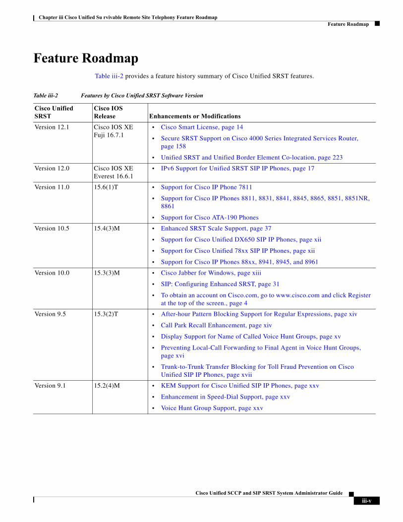
Feature RoadmapTable iii-2 provides a feature history summary of Cisco Unified SRST features.
Table iii-2 Features by Cisco Unified SRST Software Version
Cisco Unified SRST
Cisco IOS Release Enhancements or Modifications
Version 12.1 Cisco IOS XE Fuji 16.7.1
• Cisco Smart License, page 14
• Secure SRST Support on Cisco 4000 Series Integrated Services Router, page 158
• Unified SRST and Unified Border Element Co-location, page 223
Version 12.0 Cisco IOS XE Everest 16.6.1
• IPv6 Support for Unified SRST SIP IP Phones, page 17
Version 11.0 15.6(1)T • Support for Cisco IP Phone 7811
• Support for Cisco IP Phones 8811, 8831, 8841, 8845, 8865, 8851, 8851NR, 8861
• Support for Cisco ATA-190 Phones
Version 10.5 15.4(3)M • Enhanced SRST Scale Support, page 37
• Support for Cisco Unified DX650 SIP IP Phones, page xii
• Support for Cisco Unified 78xx SIP IP Phones, page xii
• Support for Cisco IP Phones 88xx, 8941, 8945, and 8961
Version 10.0 15.3(3)M • Cisco Jabber for Windows, page xiii
• SIP: Configuring Enhanced SRST, page 31
• To obtain an account on Cisco.com, go to www.cisco.com and click Register at the top of the screen., page 4
Version 9.5 15.3(2)T • After-hour Pattern Blocking Support for Regular Expressions, page xiv
• Call Park Recall Enhancement, page xiv
• Display Support for Name of Called Voice Hunt Groups, page xv
• Preventing Local-Call Forwarding to Final Agent in Voice Hunt Groups, page xvi
• Trunk-to-Trunk Transfer Blocking for Toll Fraud Prevention on Cisco Unified SIP IP Phones, page xvii
Version 9.1 15.2(4)M • KEM Support for Cisco Unified SIP IP Phones, page xxv
• Enhancement in Speed-Dial Support, page xxv
• Voice Hunt Group Support, page xxv
iii-vCisco Unified SCCP and SIP SRST System Administrator Guide
Chapter iii Cisco Unified Su rvivable Remote Site Telephony Feature RoadmapFeature Roadmap
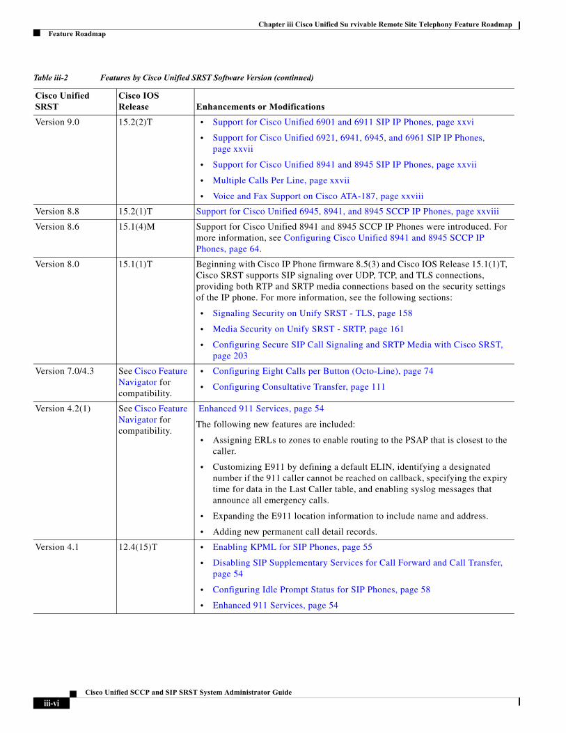
Version 9.0 15.2(2)T • Support for Cisco Unified 6901 and 6911 SIP IP Phones, page xxvi
• Support for Cisco Unified 6921, 6941, 6945, and 6961 SIP IP Phones, page xxvii
• Support for Cisco Unified 8941 and 8945 SIP IP Phones, page xxvii
• Multiple Calls Per Line, page xxvii
• Voice and Fax Support on Cisco ATA-187, page xxviii
Version 8.8 15.2(1)T Support for Cisco Unified 6945, 8941, and 8945 SCCP IP Phones, page xxviii
Version 8.6 15.1(4)M Support for Cisco Unified 8941 and 8945 SCCP IP Phones were introduced. For more information, see Configuring Cisco Unified 8941 and 8945 SCCP IP Phones, page 64.
Version 8.0 15.1(1)T Beginning with Cisco IP Phone firmware 8.5(3) and Cisco IOS Release 15.1(1)T, Cisco SRST supports SIP signaling over UDP, TCP, and TLS connections, providing both RTP and SRTP media connections based on the security settings of the IP phone. For more information, see the following sections:
• Signaling Security on Unify SRST - TLS, page 158
• Media Security on Unify SRST - SRTP, page 161
• Configuring Secure SIP Call Signaling and SRTP Media with Cisco SRST, page 203
Version 7.0/4.3 See Cisco Feature Navigator for compatibility.
• Configuring Eight Calls per Button (Octo-Line), page 74
• Configuring Consultative Transfer, page 111
Version 4.2(1) See Cisco Feature Navigator for compatibility.
Enhanced 911 Services, page 54
The following new features are included:
• Assigning ERLs to zones to enable routing to the PSAP that is closest to the caller.
• Customizing E911 by defining a default ELIN, identifying a designated number if the 911 caller cannot be reached on callback, specifying the expiry time for data in the Last Caller table, and enabling syslog messages that announce all emergency calls.
• Expanding the E911 location information to include name and address.
• Adding new permanent call detail records.
Version 4.1 12.4(15)T • Enabling KPML for SIP Phones, page 55
• Disabling SIP Supplementary Services for Call Forward and Call Transfer, page 54
• Configuring Idle Prompt Status for SIP Phones, page 58
• Enhanced 911 Services, page 54
Table iii-2 Features by Cisco Unified SRST Software Version (continued)
Cisco Unified SRST
Cisco IOS Release Enhancements or Modifications
iii-viCisco Unified SCCP and SIP SRST System Administrator Guide
Chapter iii Cisco Unified Su rvivable Remote Site Telephony Feature RoadmapFeature Roadmap
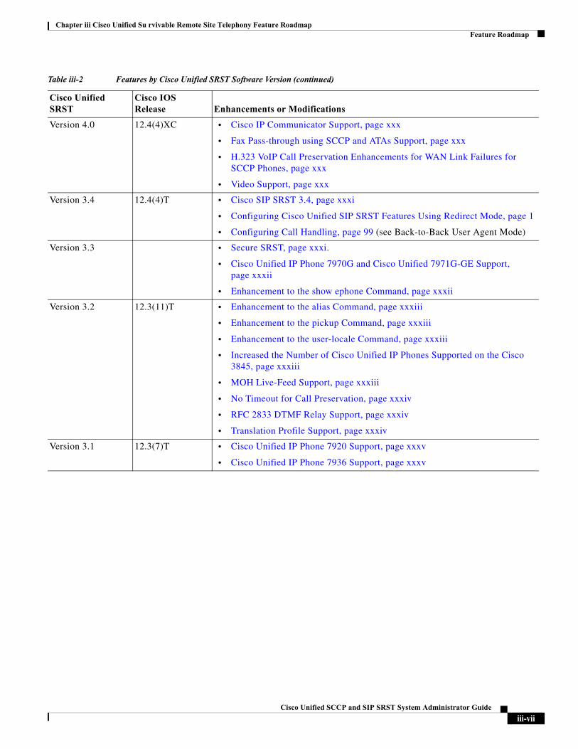
Version 4.0 12.4(4)XC • Cisco IP Communicator Support, page xxx
• Fax Pass-through using SCCP and ATAs Support, page xxx
• H.323 VoIP Call Preservation Enhancements for WAN Link Failures for SCCP Phones, page xxx
• Video Support, page xxx
Version 3.4 12.4(4)T • Cisco SIP SRST 3.4, page xxxi
• Configuring Cisco Unified SIP SRST Features Using Redirect Mode, page 1
• Configuring Call Handling, page 99 (see Back-to-Back User Agent Mode)
Version 3.3 • Secure SRST, page xxxi.
• Cisco Unified IP Phone 7970G and Cisco Unified 7971G-GE Support, page xxxii
• Enhancement to the show ephone Command, page xxxii
Version 3.2 12.3(11)T • Enhancement to the alias Command, page xxxiii
• Enhancement to the pickup Command, page xxxiii
• Enhancement to the user-locale Command, page xxxiii
• Increased the Number of Cisco Unified IP Phones Supported on the Cisco 3845, page xxxiii
• MOH Live-Feed Support, page xxxiii
• No Timeout for Call Preservation, page xxxiv
• RFC 2833 DTMF Relay Support, page xxxiv
• Translation Profile Support, page xxxiv
Version 3.1 12.3(7)T • Cisco Unified IP Phone 7920 Support, page xxxv
• Cisco Unified IP Phone 7936 Support, page xxxv
Table iii-2 Features by Cisco Unified SRST Software Version (continued)
Cisco Unified SRST
Cisco IOS Release Enhancements or Modifications
iii-viiCisco Unified SCCP and SIP SRST System Administrator Guide
Chapter iii Cisco Unified Su rvivable Remote Site Telephony Feature RoadmapFeature Roadmap
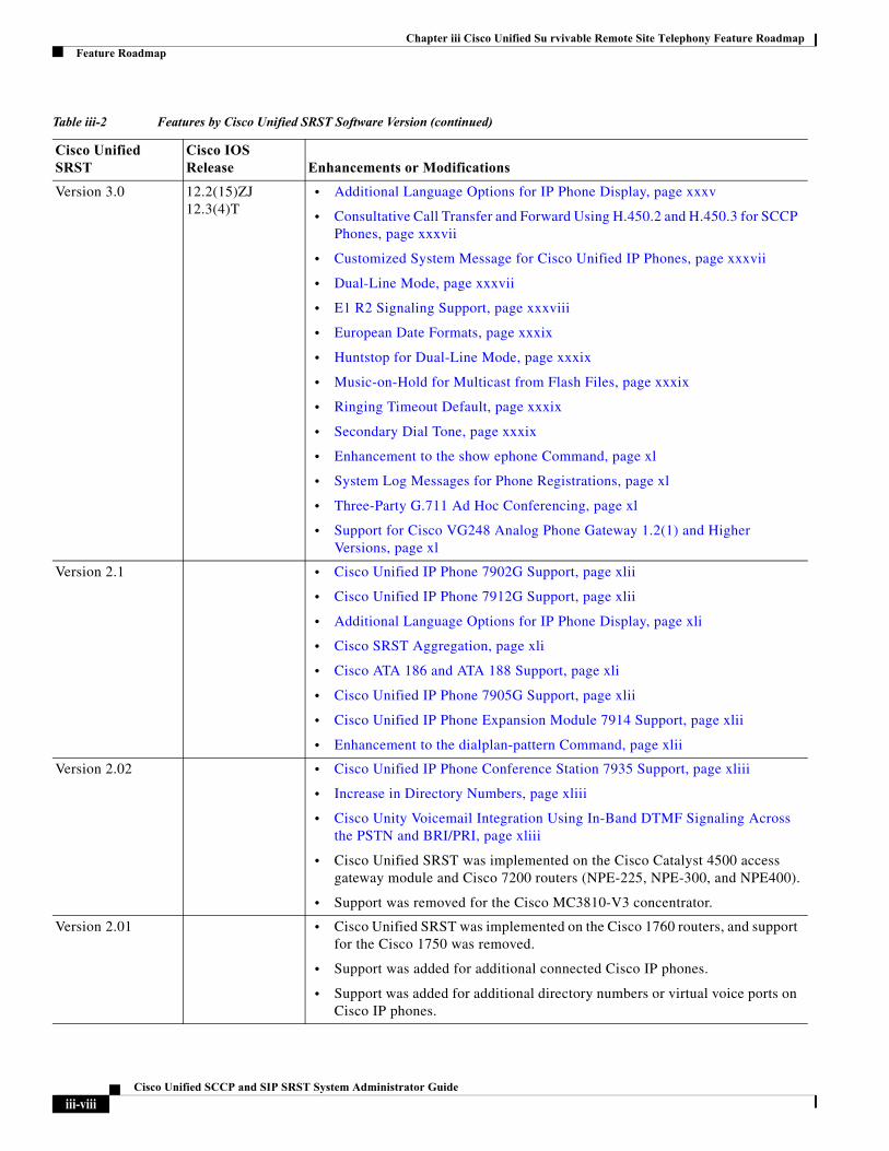
Version 3.0 12.2(15)ZJ 12.3(4)T
• Additional Language Options for IP Phone Display, page xxxv
• Consultative Call Transfer and Forward Using H.450.2 and H.450.3 for SCCP Phones, page xxxvii
• Customized System Message for Cisco Unified IP Phones, page xxxvii
• Dual-Line Mode, page xxxvii
• E1 R2 Signaling Support, page xxxviii
• European Date Formats, page xxxix
• Huntstop for Dual-Line Mode, page xxxix
• Music-on-Hold for Multicast from Flash Files, page xxxix
• Ringing Timeout Default, page xxxix
• Secondary Dial Tone, page xxxix
• Enhancement to the show ephone Command, page xl
• System Log Messages for Phone Registrations, page xl
• Three-Party G.711 Ad Hoc Conferencing, page xl
• Support for Cisco VG248 Analog Phone Gateway 1.2(1) and Higher Versions, page xl
Version 2.1 • Cisco Unified IP Phone 7902G Support, page xlii
• Cisco Unified IP Phone 7912G Support, page xlii
• Additional Language Options for IP Phone Display, page xli
• Cisco SRST Aggregation, page xli
• Cisco ATA 186 and ATA 188 Support, page xli
• Cisco Unified IP Phone 7905G Support, page xlii
• Cisco Unified IP Phone Expansion Module 7914 Support, page xlii
• Enhancement to the dialplan-pattern Command, page xlii
Version 2.02 • Cisco Unified IP Phone Conference Station 7935 Support, page xliii
• Increase in Directory Numbers, page xliii
• Cisco Unity Voicemail Integration Using In-Band DTMF Signaling Across the PSTN and BRI/PRI, page xliii
• Cisco Unified SRST was implemented on the Cisco Catalyst 4500 access gateway module and Cisco 7200 routers (NPE-225, NPE-300, and NPE400).
• Support was removed for the Cisco MC3810-V3 concentrator.
Version 2.01 • Cisco Unified SRST was implemented on the Cisco 1760 routers, and support for the Cisco 1750 was removed.
• Support was added for additional connected Cisco IP phones.
• Support was added for additional directory numbers or virtual voice ports on Cisco IP phones.
Table iii-2 Features by Cisco Unified SRST Software Version (continued)
Cisco Unified SRST
Cisco IOS Release Enhancements or Modifications
iii-viiiCisco Unified SCCP and SIP SRST System Administrator Guide
Chapter iii Cisco Unified Su rvivable Remote Site Telephony Feature RoadmapFeature Roadmap
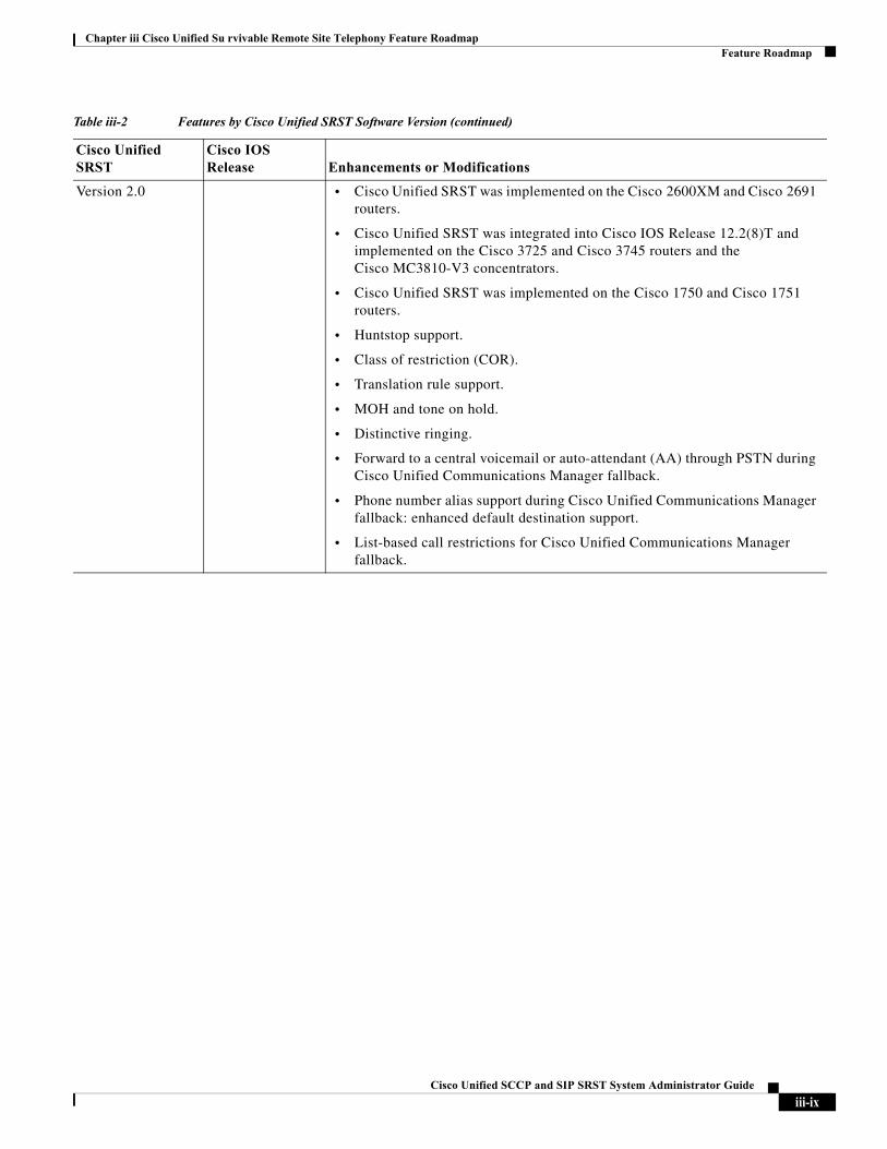
Version 2.0 • Cisco Unified SRST was implemented on the Cisco 2600XM and Cisco 2691 routers.
• Cisco Unified SRST was integrated into Cisco IOS Release 12.2(8)T and implemented on the Cisco 3725 and Cisco 3745 routers and the Cisco MC3810-V3 concentrators.
• Cisco Unified SRST was implemented on the Cisco 1750 and Cisco 1751 routers.
• Huntstop support.
• Class of restriction (COR).
• Translation rule support.
• MOH and tone on hold.
• Distinctive ringing.
• Forward to a central voicemail or auto-attendant (AA) through PSTN during Cisco Unified Communications Manager fallback.
• Phone number alias support during Cisco Unified Communications Manager fallback: enhanced default destination support.
• List-based call restrictions for Cisco Unified Communications Manager fallback.
Table iii-2 Features by Cisco Unified SRST Software Version (continued)
Cisco Unified SRST
Cisco IOS Release Enhancements or Modifications
iii-ixCisco Unified SCCP and SIP SRST System Administrator Guide
Chapter iii Cisco Unified Su rvivable Remote Site Telephony Feature RoadmapFeature Roadmap
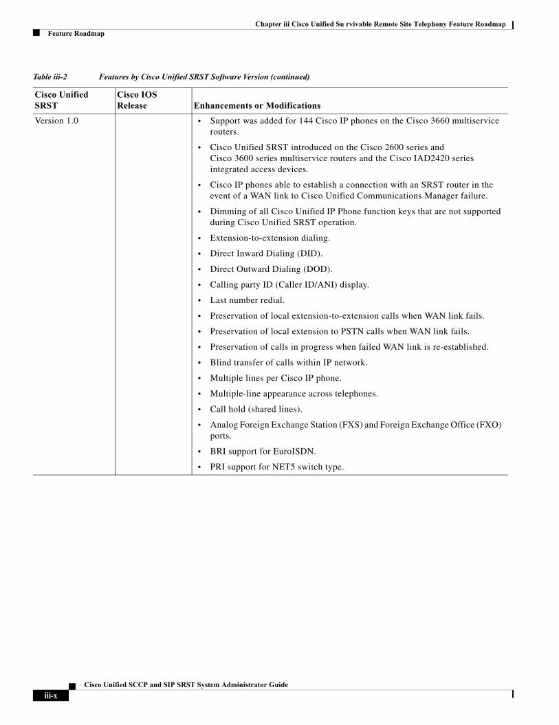
Version 1.0 • Support was added for 144 Cisco IP phones on the Cisco 3660 multiservice routers.
• Cisco Unified SRST introduced on the Cisco 2600 series and Cisco 3600 series multiservice routers and the Cisco IAD2420 series integrated access devices.
• Cisco IP phones able to establish a connection with an SRST router in the event of a WAN link to Cisco Unified Communications Manager failure.
• Dimming of all Cisco Unified IP Phone function keys that are not supported during Cisco Unified SRST operation.
• Extension-to-extension dialing.
• Direct Inward Dialing (DID).
• Direct Outward Dialing (DOD).
• Calling party ID (Caller ID/ANI) display.
• Last number redial.
• Preservation of local extension-to-extension calls when WAN link fails.
• Preservation of local extension to PSTN calls when WAN link fails.
• Preservation of calls in progress when failed WAN link is re-established.
• Blind transfer of calls within IP network.
• Multiple lines per Cisco IP phone.
• Multiple-line appearance across telephones.
• Call hold (shared lines).
• Analog Foreign Exchange Station (FXS) and Foreign Exchange Office (FXO) ports.
• BRI support for EuroISDN.
• PRI support for NET5 switch type.
Table iii-2 Features by Cisco Unified SRST Software Version (continued)
Cisco Unified SRST
Cisco IOS Release Enhancements or Modifications
iii-xCisco Unified SCCP and SIP SRST System Administrator Guide
Chapter iii Cisco Unified Su rvivable Remote Site Telephony Feature RoadmapInformation About New Features in Cisco Unified SRST
Information About New Features in Cisco Unified SRSTThis section contains the following topics:
• New Features for Unified SRST Version 12.1, page xi
• New Feature for Unified SRST Version 12.0, page xi
• New Features for Cisco Unified SRST Version 11.0, page xii
• New Features for Cisco Unified SRST Version 10.5, page xii
• New Features in Cisco Unified SRST Version 10.0, page xii
• New Features in Cisco Unified SRST Version 9.5, page xiii
• New Features in Cisco Unified SRST Version 9.1, page xxiv
• New Features in Cisco Unified SRST Version 9.0, page xxvi
• New Features in Cisco Unified SRST Version 8.8, page xxviii
• New Features in Cisco Unified SRST Version 8.0, page xxviii
• New Features in Cisco Unified SRST Version 7.0/4.3, page xxviii
• New Features in Cisco Unified SRST Version 4.2(1), page xxix
• New Features in Cisco Unified SRST Version 4.1, page xxix
• New Features in Cisco Unified SRST Version 4.0, page xxix
• New Features in Cisco Unified SRST Version 3.4, page xxx
• New Features in Cisco SRST Version 3.3, page xxxi
• New Features in Cisco SRST Version 3.2, page xxxii
• New Features in Cisco SRST Version 3.1, page xxxiv
• New Features in Cisco SRST Version 3.0, page xxxv
• New Features in Cisco SRST Version 2.1, page xl
• New Features in Cisco SRST Version 2.02, page xliii
New Features for Unified SRST Version 12.1Unified SRST 12.1 introduces support for the following new features:
• Cisco Smart License, page 14
• Secure SRST Support on Cisco 4000 Series Integrated Services Router, page 158
• Unified SRST and Unified Border Element Co-location, page 223
New Feature for Unified SRST Version 12.0Cisco Unified SRST 12.0 introduces support for IPv6 protocols on SIP IP Phones. For more information on IPv6 Support introduced for Unified SRST, see IPv6 Support for Unified SRST SIP IP Phones, page 17.
iii-xiCisco Unified SCCP and SIP SRST System Administrator Guide
Chapter iii Cisco Unified Su rvivable Remote Site Telephony Feature RoadmapNew Features for Cisco Unified SRST Version 11.0
New Features for Cisco Unified SRST Version 11.0Cisco Unified SRST 11.0 supports the following new Cisco IP phones and adapters:
• Support for Cisco IP Phone 7811
• Support for Cisco IP Phones 8811, 8831, 841, 8851, 8851NR, 8861
• Support for Cisco ATA-190
For information on the phones supported in Cisco Unified SRST 11.0, see Phone Feature Support Guide for Unified CME, Unified SRST, Unified E-SRST, and Unified Secure SRST.
New Features for Cisco Unified SRST Version 10.5Cisco Unified SRST 10.5 supports the following features:
• Enhanced SRST Scale Support, page 37
For more information on the Cisco Unified SRST 10.5 supported feature, see the “SCCP: Configuring Enhanced SRST” section on page 36.
Cisco Unified SRST 10.5 supports the following new Cisco Unified SIP IP phones:
• Support for Cisco Unified DX650 SIP IP Phones, page xii
• Support for Cisco Unified 78xx SIP IP Phones, page xii
Support for Cisco Unified DX650 SIP IP Phones
For information on feature support for the Cisco Unified DX650 SIP IP Phones in Cisco Unified SRST 10.5, see Phone Feature Support Guide for Unified CME, Unified SRST, Unified E-SRST, and Unified Secure SRST.
Support for Cisco Unified 78xx SIP IP Phones
For information on feature support for the Cisco Unified 78xx SIP IP Phones in Cisco Unified SRST 10.5, see Phone Feature Support Guide for Unified CME, Unified SRST, Unified E-SRST, and Unified Secure SRST.
New Features in Cisco Unified SRST Version 10.0Cisco Unified SRST 10.0 supports the following new features:
• Cisco Jabber for Windows, page xiii
• SIP: Configuring Enhanced SRST, page 31
• To obtain an account on Cisco.com, go to www.cisco.com and click Register at the top of the screen.
iii-xiiCisco Unified SCCP and SIP SRST System Administrator Guide
Chapter iii Cisco Unified Su rvivable Remote Site Telephony Feature RoadmapNew Features in Cisco Unified SRST Version 9.5
Cisco Jabber for Windows
Cisco Jabber for Windows client is supported from Cisco Unified CME Release 10 onwards.Cisco Jabber for Windows supports the visual voicemail functionality integrated with the Cisco Unity connection. Cisco Jabber for Windows is a SIP-based soft client with integrated Instant Messaging and presence functionality, and uses the new Client Services Framework 2nd Generation (CSF2G) architecture.
CSF is a unified communications engine that is reused by multiple Cisco PC-based clients. The Cisco Jabber client has to be registered with a presence server such as cloud-based Cisco Webex server, or Cisco Unified Presence server to avail the standard XMPP-based instant messaging functionalities. The client is identified by a device ID name that can be configured under the voice register pool in Cisco Unified CME. You should configure the username and password under voice register pool to identify the user logging into Cisco Unified CME through Cisco Jabber for Windows client. The device discovery process uses HTTPS connection. Therefore, you should configure the secure HTTP on Cisco Unified CME. A new phone type, Jabber-Win has been added to configure the voice register pool for Cisco Jabber for Windows client.
Restrictions
• The Cisco Jabber for Windows client version should be version 9.1.0 and later version.
• The Cisco Jabber for Windows client should register with a presence server such as cloud-based Webex server, or a Cisco Unified Presence server to enable the telephony features on the Jabber client.
• The Cisco Jabber for Windows client supports only the visual voicemail functionality using Internet Message Access Protocol (IMAP) on the Cisco Unity Connection.
• The Cisco Jabber for Windows client does not support software-based conferencing and supports only the softphone mode with Cisco Unified CME.
• Desk phone models are not supported.
For configuration information, see the “Cisco Jabber for Windows” section of Cisco Unified Communications Manager Administration Guide.
Version Negotiation for Cisco Unified SIP IP Phones
The version negotiation for Cisco Unified SIP IP Phones was introduced in Cisco Unified SRST 10.0 release. For more information on the Cisco Unified SRST 10.0 supported features, see the “SIP: Configuring Enhanced SRST” section on page 31.
New Features in Cisco Unified SRST Version 9.5Cisco Unified SRST 9.5 supports the following new features:
• After-hour Pattern Blocking Support for Regular Expressions, page xiv
• Call Park Recall Enhancement, page xiv
• Display Support for Name of Called Voice Hunt Groups, page xv
• Preventing Local-Call Forwarding to Final Agent in Voice Hunt Groups, page xvi
• Trunk-to-Trunk Transfer Blocking for Toll Fraud Prevention on Cisco Unified SIP IP Phones, page xvii
iii-xiiiCisco Unified SCCP and SIP SRST System Administrator Guide
Chapter iii Cisco Unified Su rvivable Remote Site Telephony Feature RoadmapNew Features in Cisco Unified SRST Version 9.5
After-hour Pattern Blocking Support for Regular Expressions
In Cisco Unified SRST 9.5, support for afterhours pattern blocking is extended to regular expression patterns for dial plans on Cisco Unified SIP and Cisco Unified SCCP IP phones. With this support, users can add a combination of fixed dial plans and regular expression-based dial plans.
When a call is initiated after hours, the dialed number is matched against a combination of dial plans. If a match is found, the call is blocked.
To enable regular expression patterns to be included when configuring afterhours pattern blocking, the after-hours block pattern command is modified to include regular expressions as a value for the pattern argument in the following command syntax:
after-hours block pattern pattern-tag pattern
This command is available in the following configuration modes:
• telephony-service—For both SCCP and SIP Phones.
• ephone-template—For SCCP phones only.
Note The maximum length of a regular expression pattern is 32 for both Cisco Unified SIP and Cisco Unified SCCP IP phones.
If calls to the following numbers are to be blocked after hours:
• numbers beginning with ‘0’ and ‘00’
• numbers beginning with 1800, followed by four digits
• numbers 9876512340 to 9876512345
then the following configurations can be used:
• after-hours block pattern 1 0*
• after-hours block pattern 2 00*
• after-hours block pattern 3 1800….
• after-hours block pattern 4 987651234[0-5]
Note There is no change in the number of afterhours patterns that can be added. The maximum number is still 100.
For more information on configuration examples, see the “Configuring Afterhours Block Patterns of Regular Expressions: Example” section of Cisco Unified Communications Manager Administration Guide.
For a summary of the basic Cisco IOS regular expression characters and their functions, see the “Cisco Regular Expression Pattern Matching Characters“ section of Terminal Services Configuration Guide.
Call Park Recall Enhancement
Before Cisco Unified CME 9.5, a parked call could not be recalled by or transferred to the phone that put the call in park or the original phone that transferred the call when the destination phone was offhook or ringing.
iii-xivCisco Unified SCCP and SIP SRST System Administrator Guide
Chapter iii Cisco Unified Su rvivable Remote Site Telephony Feature RoadmapNew Features in Cisco Unified SRST Version 9.5
In Cisco Unified CME 9.5, the recall force keyword is added to the call-park system command in telephony-service configuration mode to allow a user to force the recall or transfer of a parked call to the phone that put the call in park or the phone with the reserved-for number as its primary DN when the destination phone is available to answer the call.
In Cisco Unified CME 10.5, a new ring tone is introduced for park recall to assist the phone user to distinctly identify the type of call.
This feature is supported on all phone families for SCCP endpoints and on 89XX and 99XX phone families for SIP endpoints. No configurations are required to activate this feature.
Examples
The following example configures the Call Park Recall:
Router# configure terminal Router(config)# telephony-service Router(config)# srst mode auto-provision all Router(config-telephony)# call-park system ? recall Configure parameters for recall Router(config-telephony)# call-park system recall ? force Force recall for busy call park
initiator Router(config-telephony)# call-park system recall force
Park Monitor
In Cisco Unified CME 8.5 and later versions, the park monitor feature allows you to park a call and monitor the status of the parked call until the parked call is retrieved or abandoned. When a Cisco Unified SIP IP Phone 8961, 9951, or 9971 parks a call using the park soft key, the park monitoring feature monitors the status of the parked call. The park monitoring call bubble is not cleared until the parked call gets retrieved or is abandoned by the parkee. This parked call can be retrieved using the same call bubble on the parker’s phone to monitor the status of the parked call.
Once a call is parked, Cisco Unified CME sends a SIP NOTIFY message to the parker phone indicating the “parked” event along with the park slot number so that the parker phone can display the park slot number as long as the call remains parked.
When a parked call is retrieved, Cisco Unified CME sends another SIP NOTIFY message to the parker phone indicating the “retrieved” event so that the phone can clear the call bubble. When a parked call is disconnected by the parkee, Cisco Unified CME sends a SIP NOTIFY message to the parker phone indicating the “abandoned” event and the parker phone clears the call bubble upon cancellation of the parked call.
When a parked call is recalled or transferred, Cisco Unified CME sends a SIP NOTIFY message to the parker phone indicating the “forwarded” event so that parker phone can clear the call bubble during park, recall, and transfer. You can also retrieve a parked call from the parker phone by directly selecting the call bubble or pressing the resume soft key on the phone.
Display Support for Name of Called Voice Hunt Groups
A voice hunt group is associated with a pilot number. But because there is no association with the name of the voice hunt group when calls are forwarded from the voice hunt group to the final number, the forwarding number is sent without the name of the forwarding party. The final number can be in the form of a voicemail, a Basic Automatic Call Distribution (BACD) script, or another extension.
In Cisco Unified SRST 9.5, the display of the name of the called voice-hunt-group pilot is supported by configuring the following command in voice hunt-group or ephone-hunt configuration mode:
iii-xvCisco Unified SCCP and SIP SRST System Administrator Guide
Chapter iii Cisco Unified Su rvivable Remote Site Telephony Feature RoadmapNew Features in Cisco Unified SRST Version 9.5
[no] name “primary pilot name” [secondary “secondary pilot name”]
The secondary name is optional and when the secondary pilot name is not explicitly configured, the primary pilot name is applicable to both pilot numbers.
For configuration information, see the “Associating a Name with a Called Voice Hunt Group” section
Examples
The following example configures the primary pilot name for both the primary and secondary pilot numbers:
name SALES
The following example configures different names for the primary and secondary pilot numbers:
name SALES secondary SALES-SECONDARY
Note Use quotes (") when input strings have spaces in between as shown in the next three examples.
The following example associates a two-word name for the primary pilot number and a one-word name for the secondary pilot number:
name “CUSTOMER SERVICE” secondary CS
The following example associates a one-word name for the primary pilot number and a two-word name for the secondary pilot number:
name FINANCE secondary “INTERNAL ACCOUNTING”
The following example associates two-word names for the primary and secondary pilot numbers:
name “INTERNAL LLER” secondary “EXTERNAL LLER”
For configuration information, see the “Associating a Name with a Called Voice Hunt Group” section of Cisco Unified Communications Manager Administration Guide.
For configuration examples, see the “Example: Associating a Name with a Called Voice Hunt Group” section of Cisco Unified Communications Manager Administration Guide.
Restrictions
• Display support applies to Cisco Unified SCCP IP phones in voice hunt-group and ephone-hunt configuration modes but are not supported in Cisco Unified SIP IP phones.
• Called name and called number information displayed on the caller’s phone follows existing behavior, where the called names and called numbers are updated so that a sequential hunt reflects the name and number of the ringing phone.
Preventing Local-Call Forwarding to Final Agent in Voice Hunt Groups
Local or internal calls are calls originating from a Cisco Unified SIP or Cisco Unified SCCP IP phone in the same Cisco Unified CME system.
iii-xviCisco Unified SCCP and SIP SRST System Administrator Guide
Chapter iii Cisco Unified Su rvivable Remote Site Telephony Feature RoadmapNew Features in Cisco Unified SRST Version 9.5
Before Cisco Unified CME 9.5, the no forward local-calls command was configured in ephone-hunt group to prevent a local call from being forwarded to the next agent.
In Cisco Unified CME 9.5, local calls are prevented from being forwarded to the final destination using the no forward local-calls to-final command in parallel or sequential voice hunt-group configuration mode.
When the no forward local-calls to-final command is configured in sequential voice hunt-group configuration mode, local calls to the hunt-group pilot number are sent sequentially only to the list of members of the group using the rotary-hunt technique. In case all the group members of the voice hunt group are busy, the caller hears a busy tone. If any of the group members are available but do not answer, the caller hears a ringback tone and is eventually disconnected after the specified timeout. The call is not forwarded to the final number.
When the no forward local-calls to-final command is configured in parallel voice hunt-group configuration mode, local calls to the hunt-group pilot number are sent simultaneously to the list of members of the group using the blast technique. In case all the group members of the voice hunt group are busy, the caller hears a busy tone. If any of the group members are available but do not answer, the caller hears a ringback tone and is eventually disconnected after the specified timeout.The call is not forwarded to the final number. or configuration examples, see the “Preventing Local-Call Forwarding to Final Agent in Voice Hunt Groups” section of” section of Cisco Unified Communications Manager Administration Guide.
Trunk-to-Trunk Transfer Blocking for Toll Fraud Prevention on Cisco Unified SIP IP Phones
In Cisco Unified Survivable Remote Site Telephony (SRST) 4.0, trunk-to-trunk transfer blocking for toll bypass fraud prevention is supported on Cisco Unified Skinny Client Control Protocol (SCCP) IP phones.
Table iii-3 lists the transfer-blocking commands and the appropriate configuration modes for Cisco Unified CME and Cisco Unified SRST.
Note The call transfer and conference restrictions apply when transfers or conferences are initiated toward external parties, like a PSTN trunk, a SIP trunk, or an H.323 trunk. The restrictions do not apply to transfers and conferences to local extensions.
Table iii-3 Configuration Modes for Transfer-Blocking Commands
Commands Cisco Unified SRST
transfer-pattern call-manager-fallback
transfer max-length voice register pool
transfer-pattern blocked voice register pool
conference transfer-pattern call-manager-fallback
conference max-length voice register pool or voice register template
conference-pattern blocked voice register pool or voice register template
iii-xviiCisco Unified SCCP and SIP SRST System Administrator Guide
Chapter iii Cisco Unified Su rvivable Remote Site Telephony Feature RoadmapNew Features in Cisco Unified SRST Version 9.5
transfer-pattern
The transfer-pattern command for Cisco Unified SIP IP phones functions like the transfer-pattern command for Cisco Unified SCCP IP phones by allowing all, not just local, transfers to take place.
The transfer-pattern command specifies the directory numbers for call transfer. The command can be configured up to 32 times using the following command syntax: transfer-pattern transfer-pattern [blind].
Note The blind keyword in the transfer-pattern command applies only to Cisco Unified SCCP IP phones and does not apply to Cisco Unified SIP IP phones.
With the transfer-pattern command configured, only call transfers to numbers that match the configured transfer pattern are allowed to take place. With the transfer pattern configured, all or a subset of transfer numbers can be dialed and the transfer to a remote party can be initiated.
The following are examples of configurable transfer patterns:
• .T—This configuration allows call transfers to any destinations with one or more digits, like 123, 877656, or 76548765.
• 919........—This configuration only allows call transfers to remote numbers beginning with “919” and followed by eight digits, like 91912345678. However, call transfers to 9191234 or 919123456789 are not allowed.
Backward Compatibility
To maintain backward compatibility, all call transfers from Cisco Unified SIP IP phones to any number (local or over trunk) are allowed when no transfer patterns are configured through the transfer-pattern, transfer-pattern blocked, or transfer max-length commands.
For Cisco Unified SCCP IP phones, call transfers over trunk continue to be blocked when no transfer patterns are configured.
Dial Plans
Whatever dial plan is used for external calls, the same numbers should be configured as specific numbers using the transfer-pattern command.
If a dial plan requires “9” to be dialed before an external call is made, then “9” should be a prefix of the transfer-pattern number. For example, if 12345678 is an external number that requires “9” to be dialed before the external call can be made, then the transfer-pattern number should be 912345678.
transfer max-length
The transfer max-length command is used to indicate the maximum length of the number being dialed for a call transfer. When only a specific number of digits are to be allowed during a call transfer, a value between 3 and 16 is configured.When the number dialed exceeds the maximum length configured, then the call transfer is blocked.
For example, if the maximum length is configured as 5, then only call transfers from Cisco Unified SIP IP phones up to a five-digit directory number are allowed. All call transfers to directory numbers with more than five digits are blocked.
iii-xviiiCisco Unified SCCP and SIP SRST System Administrator Guide
Chapter iii Cisco Unified Su rvivable Remote Site Telephony Feature RoadmapNew Features in Cisco Unified SRST Version 9.5
Note If only transfer max length is configured and conference max-length is not configured, then transfer max-length takes effect for transfers and conferences.
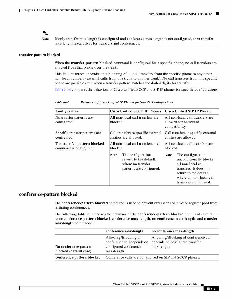
transfer-pattern blocked
When the transfer-pattern blocked command is configured for a specific phone, no call transfers are allowed from that phone over the trunk.
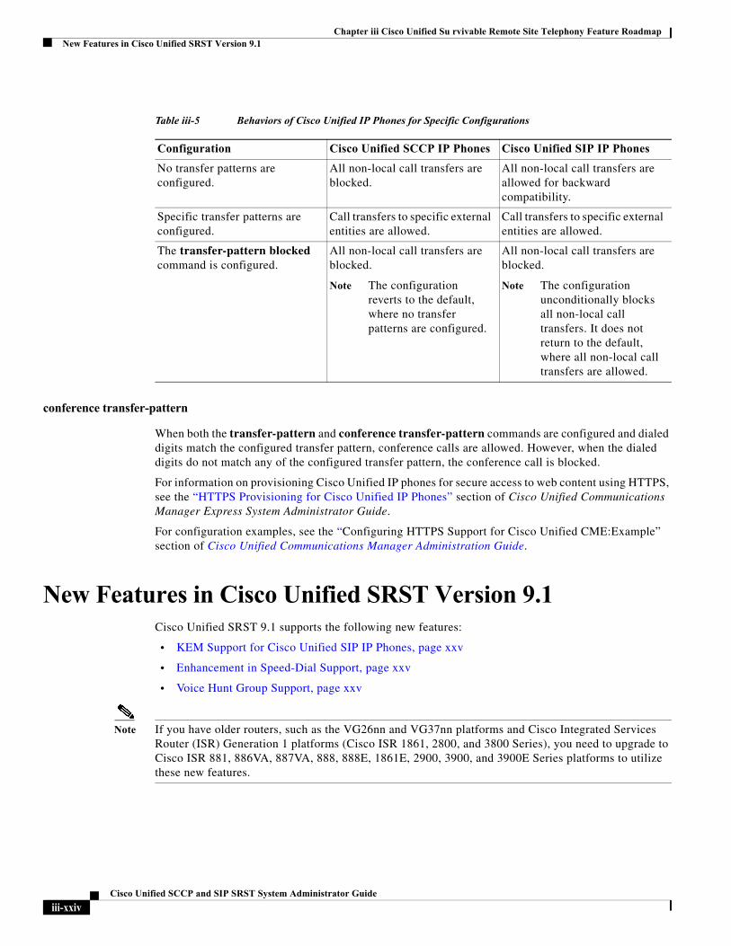
This feature forces unconditional blocking of all call transfers from the specific phone to any other non-local numbers (external calls from one trunk to another trunk). No call transfers from this specific phone are possible even when a transfer pattern matches the dialed digits for transfer.
Table iii-4 compares the behaviors of Cisco Unified SCCP and SIP IP phones for specific configurations.
conference-pattern blocked
The conference-pattern blocked command is used to prevent extensions on a voice register pool from initiating conferences.
The following table summarizes the behavior of the conference-pattern blocked command in relation to no conference-pattern blocked, conference max-length, no conference max-length, and transfer max-length commands.
Table iii-4 Behaviors of Cisco Unified IP Phones for Specific Configurations
Configuration Cisco Unified SCCP IP Phones Cisco Unified SIP IP Phones
No transfer patterns are configured.
All non-local call transfers are blocked.
All non-local call transfers are allowed for backward compatibility.
Specific transfer patterns are configured.
Call transfers to specific external entities are allowed.
Call transfers to specific external entities are allowed.
The transfer-pattern blocked command is configured.
All non-local call transfers are blocked.
Note The configuration reverts to the default, where no transfer patterns are configured.
All non-local call transfers are blocked.
Note The configuration unconditionally blocks all non-local call transfers. It does not return to the default, where all non-local call transfers are allowed.
conference max-length no conference max-length
No conference-pattern blocked (default case)
Allowing/Blocking of conference call depends on configured conference max-length
Allowing/Blocking of conference call depends on configured transfer max-length
conference-pattern blocked Conference calls are not allowed on SIP and SCCP phones.
iii-xixCisco Unified SCCP and SIP SRST System Administrator Guide
Chapter iii Cisco Unified Su rvivable Remote Site Telephony Feature RoadmapNew Features in Cisco Unified SRST Version 9.5
Configuring the Maximum Number of Digits for a Conference Call
This feature enables you to specify the maximum number of digits while making a conference call.
Prerequisites
• Cisco Unified SRST 10.5 or a later version.
SUMMARY STEPS
1. enable
2. configure terminal
3. voice register pool pool-tag
4. conference max-length value
5. end
Max-length <= allowed max-length
Max-length > allowed max-length
Transfer Conference Transfer Conference
Transfer max-length +
No Conference max-length (use transfer max-length for conference cases too, as conference max-length not configured)
Y Y N N
No transfer max-length + Conference max-length (conference max-length has precedence over transfer max-length for conference)
Y Y Y N
No transfer max-length + Conference max-length (conference max-length has precedence over transfer max-length for conference)
Y Y N N
No transfer max-length + No conference max-length
All transfer and conference calls are allowed
iii-xxCisco Unified SCCP and SIP SRST System Administrator Guide
Chapter iii Cisco Unified Su rvivable Remote Site Telephony Feature RoadmapNew Features in Cisco Unified SRST Version 9.5
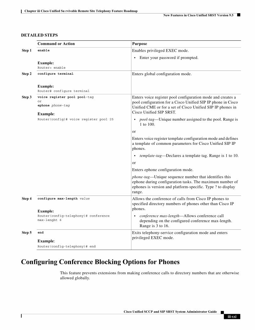
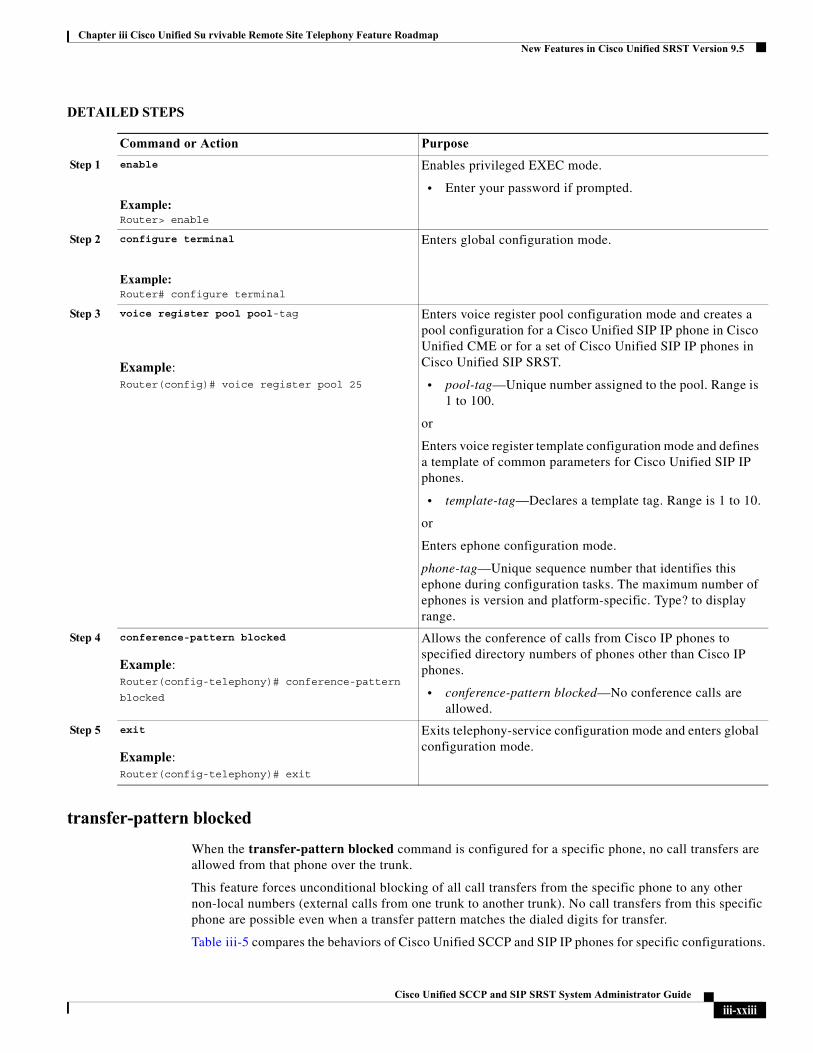
DETAILED STEPS
Configuring Conference Blocking Options for Phones
This feature prevents extensions from making conference calls to directory numbers that are otherwise allowed globally.
Command or Action Purpose
Step 1 enable
Example:Router> enable
Enables privileged EXEC mode.
• Enter your password if prompted.
Step 2 configure terminal
Example:Router# configure terminal
Enters global configuration mode.
Step 3 voice register pool pool-tagorephone phone-tag
Example:Router(config)# voice register pool 25
Enters voice register pool configuration mode and creates a pool configuration for a Cisco Unified SIP IP phone in Cisco Unified CME or for a set of Cisco Unified SIP IP phones in Cisco Unified SIP SRST.
• pool-tag—Unique number assigned to the pool. Range is 1 to 100.
or
Enters voice register template configuration mode and defines a template of common parameters for Cisco Unified SIP IP phones.
• template-tag—Declares a template tag. Range is 1 to 10.
or
Enters ephone configuration mode.
phone-tag—Unique sequence number that identifies this ephone during configuration tasks. The maximum number of ephones is version and platform-specific. Type ? to display range.
Step 4 configure max-length value
Example:Router(config-telephony)# conference max-lenght 6
Allows the conference of calls from Cisco IP phones to specified directory numbers of phones other than Cisco IP phones.
• conference max-length—Allows conference call depending on the configured conference max-length. Range is 3 to 16.
Step 5 end
Example:Router(config-telephony)# end
Exits telephony-service configuration mode and enters privileged EXEC mode.
iii-xxiCisco Unified SCCP and SIP SRST System Administrator Guide
Chapter iii Cisco Unified Su rvivable Remote Site Telephony Feature RoadmapNew Features in Cisco Unified SRST Version 9.5
Prerequisites
• Cisco Unified SRST 10.5 or a later version.
• The transfer-pattern command must be configured.
• The conference transfer-pattern command must be configured.
SUMMARY STEPS
1. enable
2. configure terminal
3. voice register pool pool-tag
4. conference-pattern blocked
5. end
iii-xxiiCisco Unified SCCP and SIP SRST System Administrator Guide
Chapter iii Cisco Unified Su rvivable Remote Site Telephony Feature RoadmapNew Features in Cisco Unified SRST Version 9.5
DETAILED STEPS
transfer-pattern blocked
When the transfer-pattern blocked command is configured for a specific phone, no call transfers are allowed from that phone over the trunk.
This feature forces unconditional blocking of all call transfers from the specific phone to any other non-local numbers (external calls from one trunk to another trunk). No call transfers from this specific phone are possible even when a transfer pattern matches the dialed digits for transfer.
Table iii-5 compares the behaviors of Cisco Unified SCCP and SIP IP phones for specific configurations.
Command or Action Purpose
Step 1 enable
Example:Router> enable
Enables privileged EXEC mode.
• Enter your password if prompted.
Step 2 configure terminal
Example:Router# configure terminal
Enters global configuration mode.
Step 3 voice register pool pool-tag
Example:Router(config)# voice register pool 25
Enters voice register pool configuration mode and creates a pool configuration for a Cisco Unified SIP IP phone in Cisco Unified CME or for a set of Cisco Unified SIP IP phones in Cisco Unified SIP SRST.
• pool-tag—Unique number assigned to the pool. Range is 1 to 100.
or
Enters voice register template configuration mode and defines a template of common parameters for Cisco Unified SIP IP phones.
• template-tag—Declares a template tag. Range is 1 to 10.
or
Enters ephone configuration mode.
phone-tag—Unique sequence number that identifies this ephone during configuration tasks. The maximum number of ephones is version and platform-specific. Type? to display range.
Step 4 conference-pattern blocked
Example:Router(config-telephony)# conference-pattern
blocked
Allows the conference of calls from Cisco IP phones to specified directory numbers of phones other than Cisco IP phones.
• conference-pattern blocked—No conference calls are allowed.
Step 5 exit
Example:Router(config-telephony)# exit
Exits telephony-service configuration mode and enters global configuration mode.
iii-xxiiiCisco Unified SCCP and SIP SRST System Administrator Guide
Chapter iii Cisco Unified Su rvivable Remote Site Telephony Feature RoadmapNew Features in Cisco Unified SRST Version 9.1
conference transfer-pattern
When both the transfer-pattern and conference transfer-pattern commands are configured and dialed digits match the configured transfer pattern, conference calls are allowed. However, when the dialed digits do not match any of the configured transfer pattern, the conference call is blocked.
For information on provisioning Cisco Unified IP phones for secure access to web content using HTTPS, see the “HTTPS Provisioning for Cisco Unified IP Phones” section of Cisco Unified Communications Manager Express System Administrator Guide.
For configuration examples, see the “Configuring HTTPS Support for Cisco Unified CME:Example” section of Cisco Unified Communications Manager Administration Guide.
New Features in Cisco Unified SRST Version 9.1Cisco Unified SRST 9.1 supports the following new features:
• KEM Support for Cisco Unified SIP IP Phones, page xxv
• Enhancement in Speed-Dial Support, page xxv
• Voice Hunt Group Support, page xxv
Note If you have older routers, such as the VG26nn and VG37nn platforms and Cisco Integrated Services Router (ISR) Generation 1 platforms (Cisco ISR 1861, 2800, and 3800 Series), you need to upgrade to Cisco ISR 881, 886VA, 887VA, 888, 888E, 1861E, 2900, 3900, and 3900E Series platforms to utilize these new features.
Table iii-5 Behaviors of Cisco Unified IP Phones for Specific Configurations
Configuration Cisco Unified SCCP IP Phones Cisco Unified SIP IP Phones
No transfer patterns are configured.
All non-local call transfers are blocked.
All non-local call transfers are allowed for backward compatibility.
Specific transfer patterns are configured.
Call transfers to specific external entities are allowed.
Call transfers to specific external entities are allowed.
The transfer-pattern blocked command is configured.
All non-local call transfers are blocked.
Note The configuration reverts to the default, where no transfer patterns are configured.
All non-local call transfers are blocked.
Note The configuration unconditionally blocks all non-local call transfers. It does not return to the default, where all non-local call transfers are allowed.
iii-xxivCisco Unified SCCP and SIP SRST System Administrator Guide
Chapter iii Cisco Unified Su rvivable Remote Site Telephony Feature RoadmapNew Features in Cisco Unified SRST Version 9.1
KEM Support for Cisco Unified SIP IP Phones
Cisco Unified IP Key Expansion Modules (KEMs) are supported on Cisco Unified 8851/51NR, 8861, 8961, 9951, and 9971 SIP IP phones from Cisco Unified SIP SRST 9.1.
For information on KEM support for Cisco Unified 8851/51NR, 8861, 8961, 9951, and 971 SIP IP phones, see Phone Feature Support Guide for Unified CME, Unified SRST, Unified E-SRST, and Unified Secure SRST.
Restrictions
• Bulk registration is not supported for KEMs in Cisco Unified SRST. Phones do not send bulk registration requests but always use the User Datagram Protocol (UDP) port for registration.
• KEM is not supported for Cisco Unified SCCP IP Phones and Cisco Unified SIP IP Phones other than the Cisco Unified 8851/51NR, 8861, 8961, 9951, and 9971 SIP IP phones.
• Features configured on keys are disabled when supported Cisco Unified SIP IP phones are in Cisco Unified SIP SRST.
• All Cisco Unified 8851/51NR, 8861,8961, 9951, and 9971 SIP IP phone restrictions and limitations apply to KEMs.
• All Cisco Unified SIP SRST feature restrictions and limitations apply to KEMs.
For more information on how the blf-speed-dial, number, and speed-dial commands, in voice register pool configuration mode, have been modified, see Cisco Unified Communications Manager Express Command Reference.
For information on installing KEMs on Cisco Unified IP Phone, see the “Installing a Key Expansion Module on the Cisco Unified IP Phone” section of Cisco Unified IP Phone 8961, 9951, and 9971 Administration Guide for Cisco Unified Communications Manager 7.1 (3) (SIP).
For information on installing KEMs on Cisco Unified 8811, 8841, 8851, 8851NR, and 8861 Phones, see the Cisco IP Phone Key Expansion Module section of Cisco IP Phone 8811, 8841, 8851, 8851NR, and 8861 Administration Guide for Cisco Unified Communications Manager.
Enhancement in Speed-Dial Support
In Cisco Unified SRST 9.1, the “,” or comma (pause indicator) is ignored to avoid a break in speed-dial support.
Because the pause speed-dial feature (supported in Cisco Unified Communications Manager or Cisco Unified CM) is not supported in Cisco Unified SRST, Cisco Unified CM and phones (Cisco Unified SCCP IP phones and Cisco Unified SIP IP phones) registered in Cisco Unified SRST maintain backward compatibility in Cisco Unified SRST mode. When phones failover to the Cisco Unified SRST router during WAN outages and Cisco Unified CM failure, the phones only send the speed-dial numbers when the pause speed-dial buttons are pressed. The comma pause indicator is ignored and the preconfigured FAC, PIN, and DTMF are not sent.
For information on configuring speed-dial in Cisco Unified Communications Manager, see the “Device setup” chapter of Cisco Unified Communications Manager Administration Guide.
Voice Hunt Group Support
Cisco Unified SIP SRST 9.1 supports voice hunt groups. Voice hunt groups allow a call placed to a single (pilot) number to contact multiple destinations.
iii-xxvCisco Unified SCCP and SIP SRST System Administrator Guide
Chapter iii Cisco Unified Su rvivable Remote Site Telephony Feature RoadmapNew Features in Cisco Unified SRST Version 9.0
There are three different types of voice hunt groups. Each type uses a different strategy to determine the first number that rings for successive calls to the pilot number until a number answers.
• Parallel Hunt Groups—Allows an incoming call to simultaneously ring all the numbers in the hunt group member list.
• Sequential Hunt Groups—Allows an incoming call to ring all the numbers in the left-to-right order in which they were listed when the hunt group was defined. The first number in the list is always the first number tried when the pilot number is called. Maximum number of hops is not a configurable parameter for sequential hunt groups.
• Longest-Idle Hunt Groups—Allows an incoming call to first go to the number that has been idle the longest for the number of hops specified when the hunt group was defined. The longest-idle time is determined from the last time that a phone registered, re-registered, or went on-hook.
While ephone hunt groups only support Cisco Unified SCCP IP phones, a voice hunt group supports Cisco Unified SCCP IP phones, Cisco Unified SIP IP phones, or a mixture of Cisco Unified SCCP IP phones and Cisco Unified SIP IP phones.
With the voice hunt group feature preconfigured in the Cisco Unified SIP SRST router, voice hunt groups continue to be supported after phones fallback from Cisco Unified CM to the Cisco Unified SIP SRST router.
Restrictions
• Hunt group statistics is not supported for voice hunt groups in Cisco Unified SRST.
• Hunt group nesting or setting the final number of one hunt group as the pilot of another hunt group is not supported.
New Features in Cisco Unified SRST Version 9.0Cisco Unified SRST 9.0 supports the following new Cisco Unified SIP IP phones:
• Cisco Unified 6901 and 6911 SIP IP Phones
• Cisco Unified 6921, 6941, 6945, and 6961 SIP IP Phones
• Cisco Unified 8941 and 8945 SIP IP Phones
Cisco Unified SRST 9.0 supports the following new features:
• Multiple Calls Per Line, page xxvii
• Voice and Fax Support on Cisco ATA-187, page xxviii
Support for Cisco Unified 6901 and 6911 SIP IP Phones
For information on feature support for the Cisco Unified 6901 and 6911SIP IP Phones in Cisco Unified SRST, see Phone Feature Support Guide for Unified CME, Unified SRST, Unified E-SRST, and Unified Secure SRST.
iii-xxviCisco Unified SCCP and SIP SRST System Administrator Guide
Chapter iii Cisco Unified Su rvivable Remote Site Telephony Feature RoadmapNew Features in Cisco Unified SRST Version 9.0
Support for Cisco Unified 6921, 6941, 6945, and 6961 SIP IP Phones
For information on feature support for the Cisco Unified 6921, 6941, 6945, and 6961 SIP IP Phones in Cisco Unified SRST, see Phone Feature Support Guide for Unified CME, Unified SRST, Unified E-SRST, and Unified Secure SRST.
Support for Cisco Unified 8941 and 8945 SIP IP Phones
For information on feature support for the Cisco Unified 8941 and 8945 SIP IP Phones in Cisco Unified SRST, see Phone Feature Support Guide for Unified CME, Unified SRST, Unified E-SRST, and Unified Secure SRST.
Multiple Calls Per Line
Cisco Unified SRST 9.0 provides support for the Multiple Calls Per Line (MCPL) feature on Cisco Unified 6921, 6941, 6945, and 6961 SIP IP phones and Cisco Unified 8941 and 8945 SCCP and SIP IP phones.
Before Cisco Unified SRST 9.0, the maximum number of calls supported for every directory number (DN) on Cisco Unified 8941 and 8945 SCCP IP phones was restricted to two.
With Cisco Unified SRST 9.0, the MCPL feature overcomes the limitation on the maximum number of calls per line.
In Cisco Unified SRST 9.0, the MCPL feature is not supported on Cisco Unified 6921, 6941, 6945, and 6961 SCCP IP phones. The maximum number of calls allowed on these phones is two and the maximum number of calls allowed on octo-line directory numbers on these phones before activating Call Forward Busy or a busy tone is one.
Cisco Unified 8941 and 8945 SCCP IP Phones
Before Cisco Unified SRST 9.0, the values for the max-dn and timeouts busy commands were hardcoded for Cisco Unified 8941 and 8945 SCCP IP phones.
In Cisco Unified SRST 9.0, you can configure the max-dn and timeouts busy commands in call-manager-fallback configuration mode. Use the max-dn command to set the maximum number of DNs that can be supported by the router and enable dual-line mode, octo-line mode, or both modes. Use the timeouts busy command to set the timeout value for call transfers to busy destinations.
For configuration information, see the “Configuring the Maximum Number of Calls” section on page 76.
Cisco Unified 6921, 6941, 6945, 6961, 8941, and 8945 SIP IP Phones
In Cisco Unified SRST 9.0, the maximum number of calls for Cisco Unified 6921, 6941, 6945, 6961, 8941, and 8945 SIP IP phones is controlled by the phones.
Prerequisites
• Cisco Unified SRST 9.0 and later versions.
• Correct firmware is installed:
– 9.2(1) or a later version for Cisco Unified 6921, 6941, 6945 and 6961 SIP IP phones.
– 9.2(2) or a later version for Cisco Unified 8941 and 8945 SIP IP phones.
iii-xxviiCisco Unified SCCP and SIP SRST System Administrator Guide
Chapter iii Cisco Unified Su rvivable Remote Site Telephony Feature RoadmapNew Features in Cisco Unified SRST Version 8.8
Voice and Fax Support on Cisco ATA-187
Cisco ATA-187 is a SIP-based analog telephone adaptor that turns traditional telephone devices into IP devices. Cisco ATA-187 can connect with a regular analog FXS phone or fax machine on one end, while the other end is an IP side that uses SIP for signaling and registers as a Cisco Unified SIP IP phone.
Cisco ATA-187 functions as a Cisco Unified SIP IP phone that supports T.38 fax relay and fax pass-through, enabling the real-time transmission of fax over IP networks. The fax rate is from 7.2 to 14.4 kbps.
For information on feature support for the Cisco ATA-187 in Cisco Unified SRST, see Phone Feature Support Guide for Unified CME, Unified SRST, Unified E-SRST, and Unified Secure SRST.
For more information on Cisco ATA-187, see Cisco ATA 187 Analog Telephone Adaptor Administration Guide for SIP.
New Features in Cisco Unified SRST Version 8.8Cisco Unified SRST 8.8 supports the following new Cisco Unified SCCP IP phones:
• Cisco Unified 6945 SCCP IP Phones
• Cisco Unified 8941 SCCP IP Phones
• Cisco Unified 8945 SCCP IP Phones
Support for Cisco Unified 6945, 8941, and 8945 SCCP IP Phones
For information on feature support for the Cisco Unified 6945, 8941, and 8945 SCCP IP Phones in Cisco Unified SRST, see Phone Feature Support Guide for Unified CME, Unified SRST, Unified E-SRST, and Unified Secure SRST.
For information on the Cisco Unified 6945 SCCP IP Phone, see Cisco Unified IP Phone 6945 User Guide for Cisco Unified Communications Manager Express Version 8.8 (SCCP).
For information on the Cisco Unified 8941 and 8945 SCCP IP Phones, see Cisco Unified IP Phone 8941 and 8945 User Guide for Cisco Unified Communications Manager Express Version 8.8 (SCCP).
New Features in Cisco Unified SRST Version 8.0Beginning with Cisco IP Phone firmware 8.5(3) and Cisco IOS Release 15.1(1)T, Cisco SRST supports SIP signaling over UDP, TCP, and TLS connections, providing both RTP and SRTP media connections based on the security settings of the IP phone.
New Features in Cisco Unified SRST Version 7.0/4.3Cisco Unified SRST 7.0/4.3 supports the following new features:
• Configuring Eight Calls per Button (Octo-Line), page 74
• Configuring Consultative Transfer, page 111
iii-xxviiiCisco Unified SCCP and SIP SRST System Administrator Guide
Chapter iii Cisco Unified Su rvivable Remote Site Telephony Feature RoadmapNew Features in Cisco Unified SRST Version 4.2(1)
New Features in Cisco Unified SRST Version 4.2(1)Cisco Unified SRST Version 4.2(1) introduces the following new features:
• Enhancements for Enhanced 911 Services, page 54
New Features in Cisco Unified SRST Version 4.1Cisco Unified SRST Version 4.1 introduces the following new feature:
• Enhanced 911 Services, page 54
New Features in Cisco Unified SRST Version 4.0Cisco Unified SRST Version 4.0 has introduced the following new features:
• Additional Cisco Unified IP Phone Support, page xxix
• Cisco IP Communicator Support, page xxx
• Fax Pass-through using SCCP and ATAs Support, page xxx
• H.323 VoIP Call Preservation Enhancements for WAN Link Failures for SCCP Phones, page xxx
• Video Support, page xxx
Additional Cisco Unified IP Phone Support
The following IP phones are supported with Cisco Unified SRST systems:
• Cisco Unified IP Phone 7911G
• Cisco Unified IP Phone 7941G and Cisco Unified IP Phone 7941G-GE
• Cisco Unified IP Phone 7960G
• Cisco Unified IP Phone 7961G and Cisco Unified IP Phone 7961G-GE
In addition, the Cisco Unified IP Phone 7914 Expansion Module can attach to the Cisco 7941G-GE and Cisco 7961G-GE. The Cisco 7914 Expansion Module adds additional features, such as adding 14 line appearances or speed-dial numbers to your phone. You can attach one or two expansion modules to your IP phone. When you use two expansion modules, you have 28 additional line appearances or speed-dial numbers, or a total of 34 line appearances or speed-dial numbers. For more information, see Cisco IP Phone 7914 Expansion Module Quick Start Guide.
No additional SRST configuration is required for these phones.
The show ephone command is enhanced to display the configuration and status of the new Cisco IP Phones added to SRST Version 4.0. For more information, see the show ephone command in Cisco Unified SRST and Cisco Unified SIP SRST Command Reference (All Versions).
To determine compatible firmware, platforms, memory, and additional voice products that are associated with Cisco Unified SRST 4.0, see Cisco Unified SRST 4.3 Supported Firmware, Platforms, Memory, and Voice Products.
iii-xxixCisco Unified SCCP and SIP SRST System Administrator Guide
Chapter iii Cisco Unified Su rvivable Remote Site Telephony Feature RoadmapNew Features in Cisco Unified SRST Version 3.4
Cisco IP Communicator Support
Cisco IP Communicator is a software-based application that delivers enhanced telephony support on personal computers. This SCCP-based application allows computers to function as IP phones, providing high-quality voice calls on the road, in the office, or from wherever users may have access to the corporate network. Cisco IP Communicator appears on a user's computer monitor as a graphical, display-based IP phone with a color screen, a key pad, feature buttons, and soft keys.
Fax Pass-through using SCCP and ATAs Support
Fax pass-through mode is now supported using Cisco VG 224 voice gateways, Analog Telephone Adaptors (ATA), and SCCP. ATAs ship with SIP firmware, so SCCP firmware must be loaded before this feature can be used.
Note For ATAs that are registered to a Cisco Unified SRST system to participate in FAX calls, they must have their ConnectMode parameter set to use the “standard payload type 0/8” as the RTP payload type in FAX pass-through mode. For ATAs used with Cisco Unified SRST 4.0 and higher versions, this is done by setting bit 2 of the ConnectMode parameter to 1 on the ATA. For more information, see the “Parameters and Defaults” chapter in Cisco ATA 186 and Cisco ATA 188 Analog Telephone Adaptor Administrator's Guide for SCCP.
H.323 VoIP Call Preservation Enhancements for WAN Link Failures for SCCP Phones
H.323 VoIP call preservation enhancements for WAN link failures sustains connectivity for H.323 topologies where signaling is handled by an entity, such as Cisco Unified Communications Manager, that is different from the other endpoint and brokers signaling between the two connected parties.
Call preservation is useful when a gateway and the other endpoint (typically a Cisco Unified IP phone) are collocated at the same site and the call agent is remote and therefore more likely to experience connectivity failures. H.323 VoIP call preservation enhancements does not support SIP Phones.
For configuration information see the “Configuring H.323 Gateways” chapter in Cisco IOS H.323 Configuration Guide.
Video Support
This feature allows you to set video parameters for the Cisco Unified SRST to maintain close feature parity with Cisco Unified CM. When the Cisco Unified SRST is enabled, Cisco Unified IP Phones do not have to be reconfigured for video capabilities because all ephones retain the same configuration used with Cisco Unified CM. However, you must enter call-manager-fallback configuration mode to set video parameters for Cisco Unified SRST. The feature set for video is the same as that for Cisco Unified SRST audio calls.
For more information, see the “Setting Video Parameters” section on page 263.
New Features in Cisco Unified SRST Version 3.4Cisco SRST V3.4 introduced the new features described in the following section:
• Cisco SIP SRST 3.4, page xxxi
iii-xxxCisco Unified SCCP and SIP SRST System Administrator Guide
Chapter iii Cisco Unified Su rvivable Remote Site Telephony Feature RoadmapNew Features in Cisco SRST Version 3.3
Cisco SIP SRST 3.4
Cisco SIP SRST Version 3.4 describes SRST functionality for Session Initiation Protocol (SIP) networks. Cisco SIP SRST Version 3.4 provides backup to an external SIP proxy server by providing basic registrar and back-to-back user agent (B2BUA) services. These services are used by a SIP IP phone in the event of a WAN connection outage when the SIP phone is unable to communicate with its primary SIP proxy.
Cisco SIP SRST Version 3.4 can support SIP phones with standard RFC 3261 feature support locally and across SIP WAN networks. With Cisco SIP SRST Version 3.4, SIP phones can place calls across SIP networks in the same way as Skinny Client Control Protocol (SCCP) phones. For full information about SIP SRST, Version 3.4, see Cisco SIP SRST Version 3.4 System Administrator Guide.
New Features in Cisco SRST Version 3.3Cisco SRST V3.3 introduced the new features described in the following sections:
• Secure SRST, page xxxi
• Cisco Unified IP Phone 7970G and Cisco Unified 7971G-GE Support, page xxxii
• Enhancement to the show ephone Command, page xxxii
Secure SRST
Secure Cisco IP phones that are located at remote sites and that are attached to gateway routers can communicate securely with Cisco Unified Communications Manager using the WAN. But if the WAN link or Cisco Unified Communications Manager goes down, all communication through the remote phones becomes nonsecure. To overcome this situation, gateway routers can now function in secure SRST mode, which activates when the WAN link or Cisco Unified Communications Manager goes down. When the WAN link or Cisco Unified Communications Manager is restored, Cisco Unified Communications Manager resumes secure call-handling capabilities.
Secure SRST provides new SRST security features such as authentication, integrity, and media encryption. Authentication provides assurance to one party that another party is whom it claims to be. Integrity provides assurance that the given data has not been altered between the entities. Encryption implies confidentiality; that is, that no one can read the data except the intended recipient. These security features allow privacy for SRST voice calls and protect against voice security violations and identity theft. For more information see the “Configuring Secure SRST for SCCP and SIP” section on page 155.
iii-xxxiCisco Unified SCCP and SIP SRST System Administrator Guide
Chapter iii Cisco Unified Su rvivable Remote Site Telephony Feature RoadmapNew Features in Cisco SRST Version 3.2
Cisco Unified IP Phone 7970G and Cisco Unified 7971G-GE Support
The Cisco Unified IP Phones 7970G and 7971G-GE are full-featured telephones that provide voice communication over an IP network. They function much like a traditional analog telephones, allowing you to place and receive phone calls and to access features such as mute, hold, transfer, speed dial, call forward, and more. In addition, because the phones are connected to your data network, they offer enhanced IP telephony features, including access to network information and services, and customizable features and services. The phones also support security features that include file authentication, device authentication, signaling encryption, and media encryption.
The Cisco Unified IP Phones 7970G and 7971G-GE also provide a color touchscreen, support for up to eight line or speed-dial numbers, context-sensitive online help for buttons and feature, and a variety of other sophisticated functions. No configurations specific to SRST are necessary.
For more information, see the Cisco Unified IP Phone 7900 Series documentation index.
Note The Cisco Unified IP Phone 7914 Expansion Module can attach to your Cisco Unified IP Phones 7970G and 7971G-GE. See the “Cisco Unified IP Phone Expansion Module 7914 Support” section on page xlii for more information.
Enhancement to the show ephone Command
The show ephone command is enhanced to display the configuration and status of the Cisco Unified IP Phone 7970G and Cisco Unified IP Phone 7971G-GE. For more information, see the show ephone command in Cisco Unified SRST and Cisco Unified SIP SRST Command Reference (All Versions).
New Features in Cisco SRST Version 3.2Cisco SRST V3.2 introduced the new features described in the following sections:
• Enhancement to the alias Command, page xxxiii
• Enhancement to the cor Command, page xxxiii
• Enhancement to the pickup Command, page xxxiii
• Enhancement to the user-locale Command, page xxxiii
• Increased the Number of Cisco Unified IP Phones Supported on the Cisco 3845, page xxxiii
• MOH Live-Feed Support, page xxxiii
• No Timeout for Call Preservation, page xxxiv
• RFC 2833 DTMF Relay Support, page xxxiv
• Translation Profile Support, page xxxiv
iii-xxxiiCisco Unified SCCP and SIP SRST System Administrator Guide
Chapter iii Cisco Unified Su rvivable Remote Site Telephony Feature RoadmapNew Features in Cisco SRST Version 3.2
Enhancement to the alias Command
The alias command is enhanced as follows:
• The cfw keyword was added, providing call forward no-answer/busy capabilities.
• The maximum number of alias commands used for creating calls to telephone numbers that are unavailable during Cisco Unified Communications Manager fallback was increased to 50.
• The alternate-number argument can be used in multiple alias commands.
For more information, see the alias command in Cisco Unified SRST and Cisco Unified SIP SRST Command Reference (All Versions).
Enhancement to the cor Command
The maximum number of cor lists has increased to 20.
For more information, see the cor command in Cisco Unified SRST and Cisco Unified SIP SRST Command Reference (All Versions).
Enhancement to the pickup Command
The pickup command was introduced to enable the PickUp soft key on all Cisco Unified IP Phones, allowing an external Direct Inward Dialing (DID) call coming into one extension to be picked up from another extension during SRST.
For more information, see the pickup command in Cisco Unified SRST and Cisco Unified SIP SRST Command Reference (All Versions).
Enhancement to the user-locale Command
The user-locale command is enhanced to display the Japanese Katakana country code. Japanese Katakana is available in Cisco Unified Communications Manager V4.0 or later versions.
For more information, see the user-locale command in theCisco Unified SRST and Cisco Unified SIP SRST Command Reference (All Versions).
Increased the Number of Cisco Unified IP Phones Supported on the Cisco 3845
The Cisco 3845 now supports 720 phones and up to 960 ephone-dns or virtual voice ports.
MOH Live-Feed Support
Cisco Unified SRST is enhanced with the new moh-live command. The moh-live command provides live-feed MOH streams from an audio device connected to an E&M or FXO port to Cisco IP phones in SRST mode. If an FXO port is used for a live feed, the port must be supplied with an external third-party adaptor to provide a battery feed. Music from a live feed is obtained from a fixed source and is continuously fed into the MOH playout buffer instead of being read from a flash file. Live-feed MOH can also be multicast to Cisco IP phones. See the “Integrating Cisco Unified Communications Manager and Cisco Unified SRST to Use Cisco Unified SRST as a Multicast MOH Resource” section on page 11 for configuration instructions.
iii-xxxiiiCisco Unified SCCP and SIP SRST System Administrator Guide
Chapter iii Cisco Unified Su rvivable Remote Site Telephony Feature RoadmapNew Features in Cisco SRST Version 3.1
No Timeout for Call Preservation
To preserve existing H.323 calls on the branch in the event of an outage, disable the H.225 keepalive timer by entering the no h225 timeout keepalive command. This feature is supported in Cisco IOS Releases 12.3(7)T1 and higher versions. See the “” section on page 1 for more information.
H.323 is not supported with SIP phones.
RFC 2833 DTMF Relay Support
Cisco Skinny Client Control Protocol (SCCP) phones, such as those used with Cisco SRST systems, provide only out-of-band DTMF digit indications. To enable SCCP phones to send digit information to remote SIP-based IVR and voice-mail applications, Cisco SRST 3.2 and later versions provide conversion from the out-of-band SCCP digit indication to the SIP standard for DTMF relay, which is RFC 2833. You select this method in the SIP VoIP dial peer using the dtmf-relay rtp-nte command. See the “How to Configure DTMF Relay for SIP Applications and Voicemail” section on page 258 for configuration instructions.
To use voicemail on a SIP network that connects to a Cisco Unity Express system, use a nonstandard SIP Notify format. To configure the Notify format, use the sip-notify keyword with the dtmf-relay command. Using the sip-notify keyword may be required for backward compatibility with Cisco SRST Versions 3.0 and 3.1.
Translation Profile Support
Cisco SRST 3.2 and later versions support translation profiles. Translation profiles allow you to group translation rules together and to associate translation rules with the following:
• Called numbers
• Calling numbers
• Redirected called numbers
See the “Enabling Translation Profiles” section on page 116 for more configuration information. For more information on the translation-profile command, see Cisco Unified SRST and Cisco Unified SIP SRST Command Reference (All Versions).
New Features in Cisco SRST Version 3.1Cisco SRST V3.1 introduced the new features described in the following sections:
• Cisco Unified IP Phone 7920 Support, page xxxv
• Cisco Unified IP Phone 7936 Support, page xxxv
Note For information about Cisco Unified IP phones, see the Cisco Unified IP Phone 7900 Series documentation.
iii-xxxivCisco Unified SCCP and SIP SRST System Administrator Guide
Chapter iii Cisco Unified Su rvivable Remote Site Telephony Feature RoadmapNew Features in Cisco SRST Version 3.0
Cisco Unified IP Phone 7920 Support
The Cisco Unified Wireless IP Phone 7920 is an easy-to-use IEEE 802.11b wireless IP phone that provides comprehensive voice communications in conjunction with Cisco Unified CM and Cisco Aironet 1200, 1100, 350, and 340 Series of Wi-Fi (IEEE 802.11b) access points. As a key part of the Cisco AVVID Wireless Solution, the Cisco Unified Wireless IP Phone 7920 delivers seamless intelligent services, such as security, mobility, quality of service (QoS), and management, across an end-to-end Cisco network.
No configuration is necessary.
Cisco Unified IP Phone 7936 Support
The Cisco Unified IP Conference Station 7936 is an IP-based, hands-free conference room station that uses VoIP technology. The IP Conference Station replaces a traditional analog conferencing unit by providing business conferencing features—such as call hold, call resume, call transfer, call release, redial, mute, and conference—over an IP network.
No configuration is necessary.
New Features in Cisco SRST Version 3.0Cisco SRST V3.0 introduced the new features described in the following sections:
• Additional Language Options for IP Phone Display, page xxxv
• Consultative Call Transfer and Forward Using H.450.2 and H.450.3 for SCCP Phones, page xxxvii
• Customized System Message for Cisco Unified IP Phones, page xxxvii
• Dual-Line Mode, page xxxvii
• E1 R2 Signaling Support, page xxxviii
• European Date Formats, page xxxix
• Huntstop for Dual-Line Mode, page xxxix
• Music-on-Hold for Multicast from Flash Files, page xxxix
• Ringing Timeout Default, page xxxix
• Secondary Dial Tone, page xxxix
• Enhancement to the show ephone Command, page xl
• System Log Messages for Phone Registrations, page xl
• Three-Party G.711 Ad Hoc Conferencing, page xl
• Support for Cisco VG248 Analog Phone Gateway 1.2(1) and Higher Versions, page xl
Additional Language Options for IP Phone Display
Displays for the Cisco Unified IP Phone 7940G and Cisco Unified IP Phone 7960G can be configured with additional ISO-3166 codes for German, Danish, Spanish, French, Italian, Japanese, Dutch, Norwegian, Portuguese, Russian, Swedish, United States.
iii-xxxvCisco Unified SCCP and SIP SRST System Administrator Guide
Chapter iii Cisco Unified Su rvivable Remote Site Telephony Feature RoadmapNew Features in Cisco SRST Version 3.0
Note This feature is available only for Cisco Unified SRST running under Cisco Unified CM V3.2.
iii-xxxviCisco Unified SCCP and SIP SRST System Administrator Guide
Chapter iii Cisco Unified Su rvivable Remote Site Telephony Feature RoadmapNew Features in Cisco SRST Version 3.0
Consultative Call Transfer and Forward Using H.450.2 and H.450.3 for SCCP Phones
Cisco SRST V1.0, Cisco SRST V2.0, and Cisco SRST V2.1 allow blind call transfers and blind call forwarding. Blind calls do not give transferring and forwarding parties the ability to announce or consult with destination parties. These three versions of Cisco SRST use a Cisco SRST proprietary mechanism to perform blind transfers. Cisco SRST V3.0 adds the ability to perform call transfers with consultation using the ITU-T H.450.2 (H.450.2) standard and call forwarding using the ITU-T H.450.3 (H.450.3) standard for H.323 calls.
Cisco SRST V3.0 provides support for IP phones to initiate call transfer and forwarding with H.450.2 and H.450.3 by using the default session application. The built-in H.450.2 and H.450.3 support that is provided by the default session application applies to call transfers and call forwarding initiated by IP phones, regardless of the PSTN interface type.
Note All voice gateway routers in the VoIP network must support H.450. For H.450 support, routers with Cisco SRST must run either Cisco SRST V3.0 and higher versions or Cisco IOS Release 12.2(15)ZJ and later releases. Routers without Cisco SRST must run either Cisco SRST V2.1 and higher versions or Cisco IOS Release 12.2(11)YT and later releases. SIP phones does not support this feature.
For more information about the default session application, see the Default Session Application Enhancements document.
For configuration information, see the “Enabling Consultative Call Transfer and Forward Using H.450.2 and H.450.3 with Cisco SRST 3.0” section on page 124.
Customized System Message for Cisco Unified IP Phones
The display message that appears on Cisco Unified IP Phone 7905G, Cisco Unified IP Phone 7940G, Cisco Unified IP Phone 7960G, and Cisco Unified IP Phone 7910 units when they are in fallback mode can be customized. The new system message command allows you to edit these display messages on a per-router basis. The custom system message feature supports English only.
For further information, see the “Configuring Customized System Messages for Cisco Unified IP Phones” section on page 70.
Dual-Line Mode
A new keyword that was added to the max-dn command allows you to set IP phones to dual-line mode. Each dual-line IP phone must have one voice port and two channels to handle two independent calls. This mode enables call waiting, call transfer, and conference functions on a single ephone-dn (ephone directory number). There is a maximum number of DNs available during Cisco SRST fallback. The max-dn command affects all IP phones on a Cisco SRST router.
For configuration information, see the “Configuring Dual-Line Phones” section on page 72.
iii-xxxviiCisco Unified SCCP and SIP SRST System Administrator Guide
Chapter iii Cisco Unified Su rvivable Remote Site Telephony Feature RoadmapNew Features in Cisco SRST Version 3.0
E1 R2 Signaling Support
Cisco SRST V3.0 supports E1 R2 signaling. R2 signaling is an international signaling standard that is common to channelized E1 networks; however, there is no single signaling standard for R2. The ITU-T Q.400-Q.490 recommendation defines R2, but a number of countries and geographic regions implement R2 in entirely different ways. Cisco Systems addresses this challenge by supporting many localized implementations of R2 signaling in its Cisco IOS software.
The Cisco Systems E1 R2 signaling default is ITU, which supports the following countries: Denmark, Finland, Germany, Russia (ITU variant), Hong Kong (ITU variant), and South Africa (ITU variant). The expression “ITU variant” means there are multiple R2 signaling types in the specified country, but Cisco supports the ITU variant.
Cisco Systems also supports specific local variants of E1 R2 signaling in the following regions, countries, and corporations:
• Argentina
• Australia
• Bolivia
• Brazil
• Bulgaria
• China
• Colombia
• Costa Rica
• East Europe (includes Croatia, Russia, and Slovak Republic)
• Ecuador (ITU)
• Ecuador (LME)
• Greece
• Guatemala
• Hong Kong (uses the China variant)
• Indonesia
• Israel
• Korea
• Laos
• Malaysia
• Malta
• New Zealand
• Paraguay
• Peru
• Philippines
• Saudi Arabia
• Singapore
• South Africa (Panaftel variant)
iii-xxxviiiCisco Unified SCCP and SIP SRST System Administrator Guide
Chapter iii Cisco Unified Su rvivable Remote Site Telephony Feature RoadmapNew Features in Cisco SRST Version 3.0
• Telmex Corporation (Mexico)
• Telnor Corporation (Mexico)
• Thailand
• Uruguay
• Venezuela
• Vietnam
European Date Formats
The date format on Cisco IP phone displays can be configured with the following two additional formats:
• yy-mm-dd (year-month-day)
• yy-dd-mm (year-day-month)
For configuration information, see the “Configuring IP Phone Clock, Date, and Time Formats” section on page 66.
Huntstop for Dual-Line Mode
A new keyword was added to the huntstop command. The channel keyword causes hunting to skip the secondary channel in dual-line configuration if the primary line is busy or does not answer.
For configuration information, see the “Configuring Dial-Peer and Channel Hunting” section on page 120.
Music-on-Hold for Multicast from Flash Files
Cisco SRST can be configured to support continuous multicast output of MOH from a flash MOH file in flash memory.
For more information, see the “Defining XML API Schema” section on page 152.
Ringing Timeout Default
A ringing timeout default can be configured for extensions on which no-answer call forwarding has not been enabled. Expiration of the timeout causes incoming calls to return a disconnect code to the caller. This mechanism provides protection against hung calls for inbound calls received over interfaces such as Foreign Exchange Office (FXO) that do not have forward-disconnect supervision. For more information, see the “Configuring the Ringing Timeout Default” section on page 122.
Secondary Dial Tone
A secondary dial tone is available for Cisco Unified IP Phones running Cisco SRST. The secondary dial tone is generated when a user dials a predefined PSTN access prefix. An example would be the different dial tone heard when a designated number is pressed to reach an outside line.
The secondary dial tone is created through the secondary dialtone command. For more information, see the “Configuring a Secondary Dial Tone” section on page 71.
iii-xxxixCisco Unified SCCP and SIP SRST System Administrator Guide
Chapter iii Cisco Unified Su rvivable Remote Site Telephony Feature RoadmapNew Features in Cisco SRST Version 2.1
Enhancement to the show ephone Command
The show ephone command is enhanced to display the following:
• Configuration and status of additional phones (new keywords: 7905, 7914, 7935, ATA)
• Status of all phones with the call-forwarding all (CFA) feature enabled on at least one of their DNs (new keyword: cfa)
For more information, see the show ephone command in Cisco Unified SRST and Cisco Unified SIP SRST Command Reference (All Versions).
System Log Messages for Phone Registrations
Diagnostic messages are added to the system log whenever a phone registers or unregisters from Cisco Unified SRST.
Three-Party G.711 Ad Hoc Conferencing
Cisco SRST supports three-party ad hoc conferencing using the G.711 coding technique. For conferencing to be available, an IP phone must have a minimum of two lines connected to one or more buttons.
For more information, see the “Enabling Three-Party G.711 Ad Hoc Conferencing” section on page 150.
Support for Cisco VG248 Analog Phone Gateway 1.2(1) and Higher Versions
The Cisco VG248 Analog Phone Gateway is a mixed-environment solution, enabled by Cisco AVVID (Architecture for Voice, Video and Integrated Data), that allows organizations to support their legacy analog devices while taking advantage of the new opportunities afforded through the use of IP telephony. The Cisco VG248 is a high-density gateway for using analog phones, fax machines, modems, voice-mail systems, and speakerphones within an enterprise voice system based on Cisco Unified CM.
During Cisco Unified CM fallback, Cisco SRST considers the Cisco VG248 to be a group of Cisco Unified IP Phones. Cisco Unified SRST counts each of the 48 ports on the Cisco VG248 as a separate Cisco Unified IP Phone. Support for Cisco VG248 Version 1.2(1) and higher versions is also available in Cisco Unified SRST Version 2.1.
For more information, see Cisco VG248 Analog Phone Gateway Data Sheet and Cisco VG248 Analog Phone Gateway Version 1.2(1) Release Notes.
New Features in Cisco SRST Version 2.1Cisco SRST V2.1 introduced the new features described in the following sections:
• Additional Language Options for IP Phone Display, page xli
• Cisco SRST Aggregation, page xli
• Cisco ATA 186 and ATA 188 Support, page xli
• Cisco Unified IP Phone 7902G Support, page xlii
• Cisco Unified IP Phone 7905G Support, page xlii
• Cisco Unified IP Phone 7912G Support, page xlii
iii-xlCisco Unified SCCP and SIP SRST System Administrator Guide
Chapter iii Cisco Unified Su rvivable Remote Site Telephony Feature RoadmapNew Features in Cisco SRST Version 2.1
• Cisco Unified IP Phone Expansion Module 7914 Support, page xlii
• Enhancement to the dialplan-pattern Command, page xlii
Note For information about Cisco Unified IP phones, see the Cisco Unified IP Phone 7900 Series documentation.
Additional Language Options for IP Phone Display
Displays for the Cisco Unified IP Phone 7940G and Cisco Unified IP Phone 7960G can be configured with ISO-3166 codes for the following countries:
• France
• Germany
• Italy
• Portugal
• Spain
• United States
Note This feature is available only in Cisco Unified SRST running under Cisco Unified CM V3.2.
For configuration information, see the “Configuring IP Phone Language Display” section on page 68.
Cisco SRST Aggregation
For systems running Cisco Unified CM 3.3(2) and later versions, the restriction of running Cisco SRST on a default gateway was removed. Multiple SRST routers can be used to support additional phones. Note that dial peers and dial plans need to be carefully planned and configured for call transfer and forwarding to work properly.
Cisco ATA 186 and ATA 188 Support
The Cisco ATA analog telephone adaptors are handset-to-Ethernet adaptors that allow regular analog telephones to operate on IP-based telephony networks. Cisco ATAs support two voice ports, each with an independent telephone number. The Cisco ATA 188 also has an RJ-45 10/100BASE-T data port. Cisco SRST supports Cisco ATA 186 and Cisco ATA 188 using Skinny Client Control Protocol (SCCP) for voice calls only.
iii-xliCisco Unified SCCP and SIP SRST System Administrator Guide
Chapter iii Cisco Unified Su rvivable Remote Site Telephony Feature RoadmapNew Features in Cisco SRST Version 2.1
Cisco Unified IP Phone 7902G Support
The Cisco Unified IP Phone 7902G is an entry-level IP phone that addresses the voice communications needs of a lobby, laboratory, manufacturing floor, hallway, or other area where only basic calling capability is required.
The Cisco Unified IP Phone 7902G is a single-line IP phone with fixed feature keys that provide one-touch access to the redial, transfer, conference, and voice-mail access features. Consistent with other Cisco IP phones, the Cisco Unified IP Phone 7902G supports inline power, which allows the phone to receive power over the LAN. This capability gives the network administrator centralized power control and thus greater network availability.
Cisco Unified IP Phone 7905G Support
The Cisco Unified IP Phone 7905G is a basic IP phone that provides a core set of business features. It provides single-line access and four interactive soft keys that guide a user through call features and functions via the pixel-based liquid crystal display (LCD). The graphic capability of the display presents calling information, intuitive access to features, and language localization in future firmware releases. The Cisco Unified IP Phone 7905G supports inline power, which allows the phone to receive power over the LAN.
No configuration is necessary.
Cisco Unified IP Phone 7912G Support
The Cisco Unified IP Phone 7912G provides core business features and addresses the communication needs of a cubicle worker who conducts low to medium telephone traffic. Four dynamic soft keys provide access to call features and functions. The graphic display shows calling information and allows access to features.
The Cisco Unified IP Phone 7912G supports an integrated Ethernet switch, providing LAN connectivity to a local PC. In addition, the Cisco Unified IP Phone 7912G supports inline power, which allows the phone to receive power over the LAN. This capability gives the network administrator centralized power control and thus greater network availability. The combination of inline power and Ethernet switch support reduces cabling needs to a single wire to the desktop.
Cisco Unified IP Phone Expansion Module 7914 Support
The Cisco Unified IP Phone 7914 Expansion Module attaches to your Cisco Unified IP Phone 7960G, adding 14 line appearances or speed-dial numbers to your phone. You can attach one or two expansion modules to your IP phone. When you use two expansion modules, you have 28 additional line appearances or speed-dial numbers or a total of 34 line appearances or speed-dial numbers.
Enhancement to the dialplan-pattern Command
A new keyword was added to the dialplan-pattern command. The extension-pattern keyword sets an extension number’s leading digit pattern when it is different from the E.164 telephone number’s leading digits defined in the pattern variable. This enhancement allows manipulation of IP phone abbreviated extension number prefix digits. See the dialplan-pattern command in Cisco Unified SRST and Cisco Unified SIP SRST Command Reference (All Versions).
iii-xliiCisco Unified SCCP and SIP SRST System Administrator Guide
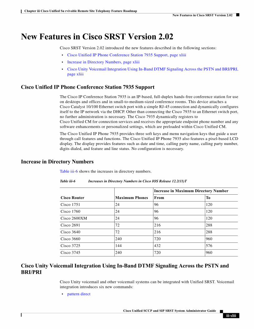
Chapter iii Cisco Unified Su rvivable Remote Site Telephony Feature RoadmapNew Features in Cisco SRST Version 2.02
New Features in Cisco SRST Version 2.02Cisco SRST Version 2.02 introduced the new features described in the following sections:
• Cisco Unified IP Phone Conference Station 7935 Support, page xliii
• Increase in Directory Numbers, page xliii
• Cisco Unity Voicemail Integration Using In-Band DTMF Signaling Across the PSTN and BRI/PRI, page xliii
Cisco Unified IP Phone Conference Station 7935 Support
The Cisco IP Conference Station 7935 is an IP-based, full-duplex hands-free conference station for use on desktops and offices and in small-to-medium-sized conference rooms. This device attaches a Cisco Catalyst 10/100 Ethernet switch port with a simple RJ-45 connection and dynamically configures itself to the IP network via the DHCP. Other than connecting the Cisco 7935 to an Ethernet switch port, no further administration is necessary. The Cisco 7935 dynamically registers to Cisco Unified CM for connection services and receives the appropriate endpoint phone number and any software enhancements or personalized settings, which are preloaded within Cisco Unified CM.
The Cisco Unified IP Phone 7935 provides three soft keys and menu navigation keys that guide a user through call features and functions. The Cisco Unified IP Phone 7935 also features a pixel-based LCD display. The display provides features such as date and time, calling party name, calling party number, digits dialed, and feature and line status. No configuration is necessary.
Increase in Directory Numbers
Table iii-6 shows the increases in directory numbers.
Cisco Unity Voicemail Integration Using In-Band DTMF Signaling Across the PSTN and BRI/PRI
Cisco Unity voicemail and other voicemail systems can be integrated with Unified SRST. Voicemail integration introduces six new commands:
• pattern direct
Table iii-6 Increases in Directory Numbers in Cisco IOS Release 12.2(11)T
Cisco Router Maximum Phones
Increase in Maximum Directory Number
From To
Cisco 1751 24 96 120
Cisco 1760 24 96 120
Cisco 2600XM 24 96 120
Cisco 2691 72 216 288
Cisco 3640 72 216 288
Cisco 3660 240 720 960
Cisco 3725 144 432 576
Cisco 3745 240 720 960
iii-xliiiCisco Unified SCCP and SIP SRST System Administrator Guide
Chapter iii Cisco Unified Su rvivable Remote Site Telephony Feature RoadmapWhere to Go Next
• pattern ext-to-ext busy
• pattern ext-to-ext no-answer
• pattern trunk-to-ext busy
• pattern trunk-to-ext no-answer
• vm-integration
Where to Go NextProceed to the “Setting Up the Network” section on page 39.
iii-xlivCisco Unified SCCP and SIP SRST System Administrator Guide
Cisco Unified SC
C H A P T E R1
Cisco Unified SRST Feature OverviewThis chapter describes Cisco Unified Survivable Remote Site Telephony (Cisco Unified SRST) and what it does. It also includes information about support for Cisco Unified IP Phones and Platforms, specifications, features, prerequisites, restrictions and where to find additional reference documents.
For the most up-to-date information about Cisco Unified IP Phone support, the maximum number of Cisco Unified IP Phones, the maximum number of directory numbers (DNs) or virtual voice ports, and memory requirements for Cisco Unified SRST and Cisco Unified SIP SRST, see Cisco Unified SRST Supported Firmware, Platforms, Memory, and Voice Products.
Contents• Cisco Unified SCCP SRST, page 1
• Cisco Unified SIP SRST, page 9
• Cisco Unified SRST Licenses
• Interface Support for Unified CME and Unified SRST, page 17
• MGCP Gateways and SRST, page 17
• Support for Cisco Unified IP Phones and Platforms, page 24
• IPv6 Support for Unified SRST SIP IP Phones, page 17
• Where to Go Next, page 26
• Additional References, page 27
• Obtaining Documentation, Obtaining Support, and Security Guidelines, page 30
Cisco Unified SCCP SRST• Information About SCCP SRST, page 2
• Prerequisites for Configuring Cisco Unified SCCP SRST, page 4
• Restrictions for Configuring Cisco Unified SCCP SRST, page 7
CP and SIP SRST System Administrator Guide
Chapter 1 Cisco Unified SRST Feature OverviewCisco Unified SCCP SRST
Information About SCCP SRST
Cisco Unified SRST provides Cisco Unified CM with fallback support for Cisco Unified IP phones that are attached to a Cisco router on your local network. Cisco Unified SRST enables routers to provide call-handling support for Cisco Unified IP phones when they lose connection to remote primary, secondary, or tertiary Cisco Unified CM installations or when the WAN connection is down.
Cisco Unified CM supports Cisco Unified IP phones at remote sites attached to Cisco multiservice routers across the WAN. Prior to Cisco Unified SRST, when the WAN connection between a router and the Cisco Unified CM failed or when connectivity with Cisco Unified CM was lost for some reason, Cisco Unified IP phones on the network became unusable for the duration of the failure. Cisco Unified SRST overcomes this problem and ensures that the Cisco Unified IP phones offer continuous (although minimal) service by providing call-handling support for Cisco Unified IP phones directly from the Cisco Unified SRST router. The system automatically detects a failure and uses Simple Network Auto Provisioning (SNAP) technology to autoconfigure the branch office router to provide call processing for Cisco Unified IP phones that are registered with the router. When the WAN link or connection to the primary Cisco Unified CM is restored, call handling reverts back to the primary Cisco Unified CM.
When Cisco Unified IP phones lose contact with primary, secondary, and tertiary Cisco Unified CM, they must establish a connection to a local Cisco Unified SRST router to sustain the call-processing capability necessary to place and receive calls. The Cisco Unified IP phone retains the IP address of the local Cisco Unified SRST router as a default router in the Network Configuration area of the Settings menu. The Settings menu supports a maximum of five default router entries; however, Cisco Unified CM accommodates a maximum of three entries. When a secondary Cisco Unified CM is not available on the network, the local Cisco Unified SRST Router's IP address is retained as the standby connection for Cisco Unified CM during normal operation.
Note Cisco Unified CM fallback mode telephone service is available only to those Cisco Unified IP phones that are supported by a Cisco Unified SRST router. Other Cisco Unified IP phones on the network remain out of service until they re-establish a connection with their primary, secondary, or tertiary Cisco Unified CM.
Typically, it takes three times the keepalive period for a phone to discover that its connection to Cisco Unified CM has failed. The default keepalive period is 30 seconds. If the phone has an active standby connection established with a Cisco Unified SRST router, the fallback process takes 10 to 20 seconds after connection with Cisco Unified CM is lost. An active standby connection to a Cisco Unified SRST router exists only if the phone has the location of a single Cisco Unified CM in its Unified Communications Manager list. Otherwise, the phone activates a standby connection to its secondary Cisco Unified CM.
Note The time it takes for a Cisco Unified IP Phone to fallback to the SRST router can vary depending on the phone type. Phones such as the Cisco 7902, Cisco 7905, and Cisco 7912 can take approximately 2.5 minutes to fallback to SRST mode.
If a Cisco Unified IP phone has multiple Cisco Unified CM in its Cisco Unified CM list, it progresses through its list of secondary and tertiary Cisco Unified CM before attempting to connect with its local Cisco Unified SRST router. Therefore, the time that passes before the Cisco Unified IP phone eventually establishes a connection with the Cisco Unified SRST router increases with each attempt to contact to a Cisco Unified CM. Assuming that each attempt to connect to a Cisco Unified CM takes about 1 minute, the Cisco Unified IP phone in question could remain offline for 3 minutes or more following a WAN link failure.
1Cisco Unified SCCP and SIP SRST System Administrator Guide
Chapter 1 Cisco Unified SRST Feature OverviewCisco Unified SCCP SRST
Note During a WAN connection failure, when Cisco Unified SRST is enabled, Cisco Unified IP phones display a message informing you that they are operating in Cisco Unified CM fallback mode. For example, the Cisco Unified IP Phone 7960G and Cisco Unified IP Phone 7940G display a "CM Fallback Service Operating" message, and the Cisco Unified IP Phone 7910 displays a "CM Fallback Service" message when operating in Cisco Unified CM fallback mode. When the Cisco Unified CM is restored, the message goes away and full Cisco Unified IP phone functionality is restored.
While in Cisco Unified CM fallback mode, Cisco Unified IP phones periodically attempt to re-establish a connection with Cisco Unified CM at the central office. Generally, the default time that Cisco Unified IP phones wait before attempting to re-establish a connection to a remote Cisco Unified CM is 120 seconds. The time can be changed in Cisco Unified CM; see the "Device Pool Configuration Settings" chapter in the appropriate Cisco Unified CM Administration Guide. A manual reboot can immediately reconnect Cisco Unified IP phones to Cisco Unified CM.
When a connection is re-established with Cisco Unified CM, Cisco Unified IP phones automatically cancel their registration with the Cisco Unified SRST Router. However, if a WAN link is unstable, Cisco Unified IP phones can bounce between Cisco Unified CM and Cisco Unified SRST. A Cisco Unified IP phone cannot re-establish a connection with the primary Cisco Unified CM at the central office if it is currently engaged in an active call.
Cisco Unified SRST supports the following call combinations:
• SCCP phone to SCCP phone
• SCCP phone to PSTN/router voice-port
• SCCP phone to WAN VoIP using SIP or H.323
• SIP phone to SIP phone
• SIP phone to PSTN / router voice-port
• SIP phone to Skinny Client Control Protocol (SCCP) phone
• SIP phone to WAN VoIP using SIP
Figure 1-1 shows a branch office with several Cisco Unified IP phones connected to a Cisco Unified SRST router. The router provides connections to both a WAN link and the PSTN. Typically, the Cisco Unified IP phones connect to their primary Cisco Unified Communications Manager at the central office via the WAN link. When the WAN connection is down, the Cisco Unified IP phones use the Cisco Unified SRST router as a fallback for their primary Cisco Unified Communications Manager. The branch office Cisco Unified IP phones are connected to the PSTN through the Cisco Unified SRST router and are able to make and receive off-net calls.
Figure 1-1 Branch Office Cisco Unifed IP Phones Connected to a Remote Central Cisco Unified Communications Manage Operating in SRST Mode
Cisco Unified SCCP and SIP SRST System Administrator Guide
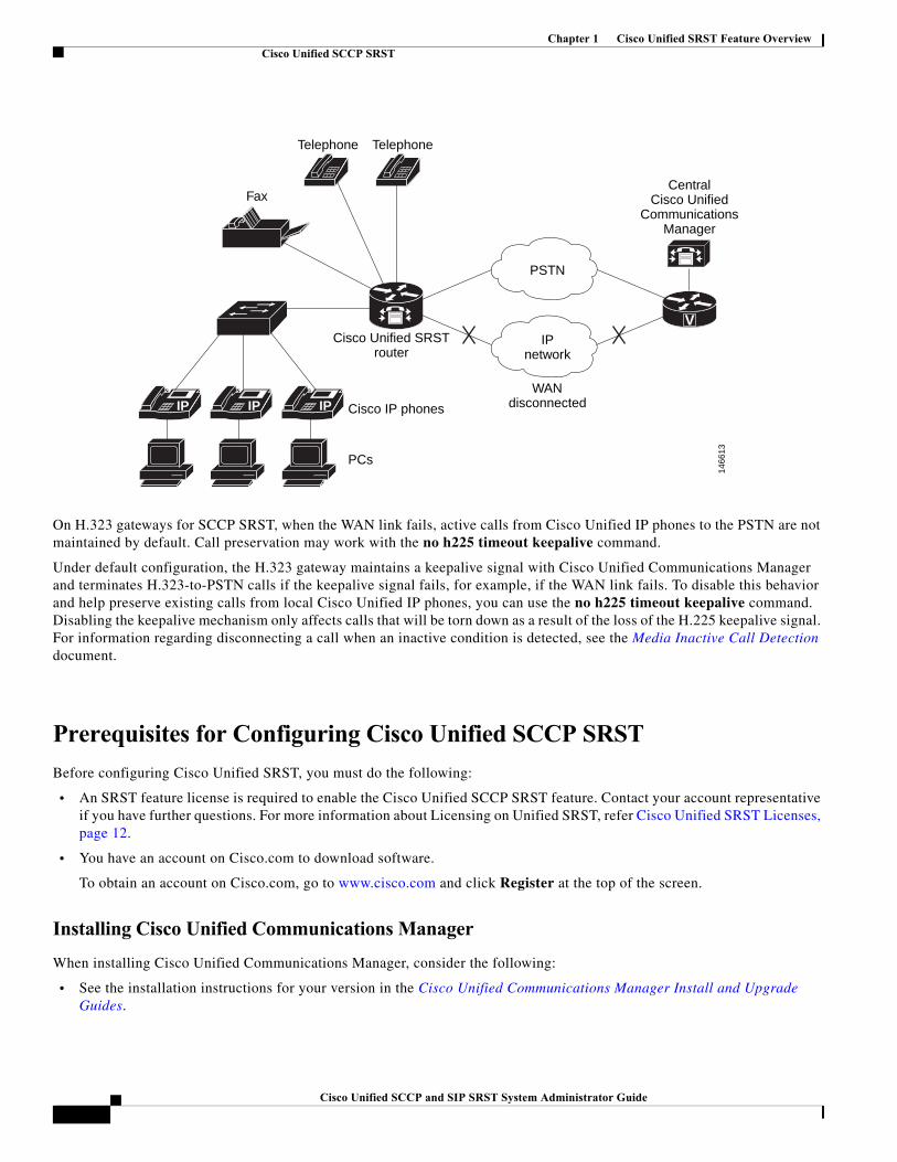
Chapter 1 Cisco Unified SRST Feature OverviewCisco Unified SCCP SRST
On H.323 gateways for SCCP SRST, when the WAN link fails, active calls from Cisco Unified IP phones to the PSTN are not maintained by default. Call preservation may work with the no h225 timeout keepalive command.
Under default configuration, the H.323 gateway maintains a keepalive signal with Cisco Unified Communications Manager and terminates H.323-to-PSTN calls if the keepalive signal fails, for example, if the WAN link fails. To disable this behavior and help preserve existing calls from local Cisco Unified IP phones, you can use the no h225 timeout keepalive command. Disabling the keepalive mechanism only affects calls that will be torn down as a result of the loss of the H.225 keepalive signal. For information regarding disconnecting a call when an inactive condition is detected, see the Media Inactive Call Detection document.
Prerequisites for Configuring Cisco Unified SCCP SRST
Before configuring Cisco Unified SRST, you must do the following:
• An SRST feature license is required to enable the Cisco Unified SCCP SRST feature. Contact your account representative if you have further questions. For more information about Licensing on Unified SRST, refer Cisco Unified SRST Licenses, page 12.
• You have an account on Cisco.com to download software.
To obtain an account on Cisco.com, go to www.cisco.com and click Register at the top of the screen.
Installing Cisco Unified Communications Manager
When installing Cisco Unified Communications Manager, consider the following:
• See the installation instructions for your version in the Cisco Unified Communications Manager Install and Upgrade Guides.
IP IP IP
V
PSTN
IPnetwork
WANdisconnected
CentralCisco Unified
CommunicationsManager
Cisco Unified SRSTrouter
Fax
Telephone Telephone
Cisco IP phones
PCs
1466
13
1Cisco Unified SCCP and SIP SRST System Administrator Guide
Chapter 1 Cisco Unified SRST Feature OverviewCisco Unified SCCP SRST
• Integrate Cisco Unified SRST with Cisco Unified Communications Manager. Integration is performed from Cisco Unified Communications Manager. See the “Integrating Cisco Unified SCCP SRST with Cisco Unified Communications Manager” section on page 5.
Installing Cisco Unified SCCP SRST
Cisco Unified SRST versions have different installation instructions:
• Installing Cisco Unified SRST V3.0 and Later Versions, page 5
• Installing Cisco Unified SRST V2.0 and V2.1, page 5
• Installing Cisco Unified SRST V1.0, page 5
To update Cisco Unified SRST, follow the installation instructions described in this section.
Installing Cisco Unified SRST V3.0 and Later Versions
Install the Cisco IOS software release image containing the Cisco SRST or Cisco Unified SRST version that is compatible with your Cisco Unified Communications Manager version. See the “Cisco Unified Communications Manager Compatibility” section on page 25. Cisco IOS software can be downloaded from the Cisco Software Center at http://www.cisco.com/public/sw-center/.
Cisco SRST and Cisco Unified SRST can be configured to support continuous multicast output of music- on-hold (MOH) from a flash MOH file in flash memory. For more information, see the “Defining XML API Schema” section on page 152. If you plan to use MOH, go to the Technical Support Software Download site at http://www.cisco.com/cgi-bin/tablebuild.pl/ip-iostsp and copy the music-on-hold.au file to the flash memory on your Cisco SRST or Cisco Unified SRST router.
Installing Cisco Unified SRST V2.0 and V2.1
Download and install Cisco SRST V2.0 or Cisco SRST V2.1 from the Cisco Software Center at http://www.cisco.com/public/sw-center/.
Installing Cisco Unified SRST V1.0
Cisco SRST V1.0 runs with Cisco Communications Manager V3.0.5 only. It is recommended that you upgrade to the latest Cisco Unified Communications Manager and Cisco Unified SRST versions.
Integrating Cisco Unified SCCP SRST with Cisco Unified Communications Manager
There are two procedures for integrating Cisco Unified SRST with Cisco Unified Communications Manager. Procedure selection depends on the Cisco Unified Communications Manager version that you have.
If You Have Cisco Communications Manager V3.3 or Later Versions
If you have Cisco Communications Manager V3.3 or later versions, you must create an SRST reference and apply it to a device pool. An SRST reference is the IP address of the Cisco Unified SRST Router.
Step 1 Create an SRST reference.
a. From any page in Cisco Unified Communications Manager, click System and SRST.
b. On the Find and List SRST References page, click Add a New SRST Reference.
c. On the SRST Reference Configuration page, enter a name in the SRST Reference Name field and the IP address of the Cisco SRST router in the IP Address field.
Cisco Unified SCCP and SIP SRST System Administrator Guide
Chapter 1 Cisco Unified SRST Feature OverviewCisco Unified SCCP SRST
d. Click Insert.
Step 2 Apply the SRST reference or the default gateway to one or more device pools.
a. From any page in Cisco Unified Communications Manager, click System and Device Pool.
b. On the Device Pool Configuration page, click on the required device pool icon.
c. On the Device Pool Configuration page, choose an SRST reference or “Use Default Gateway” from the SRST Reference field’s menu.
If You Have Cisco Unified Communications Manager Version Prior to V3.3
If you have firmware versions that enable Cisco Unified SRST by default, no additional configuration is required on Cisco Unified Communications Manager to support Cisco Unified SRST. If your firmware versions disable Cisco Unified SRST by default, you must enable Cisco Unified SRST for each phone configuration.
Step 1 Go to the Cisco Unified Communications Manager Phone Configuration page.
a. From any page in Cisco Unified Communications Manager, click Device and Phone.
b. In the Find and List Phones page, click Find.
c. After a list of phones appears, click on the required device name.
d. The Phone Configuration appears.
Step 2 In the Phone Configuration page, go to the Product Specific Configuration section at the end of the page, choose Enabled from the Cisco Unified SRST field’s menu, and click Update.
Step 3 Go to the Phone Configuration page for the next phone and choose Enabled from the Cisco Unified SRST field’s menu by repeating Step 1 and Step 2.
1Cisco Unified SCCP and SIP SRST System Administrator Guide
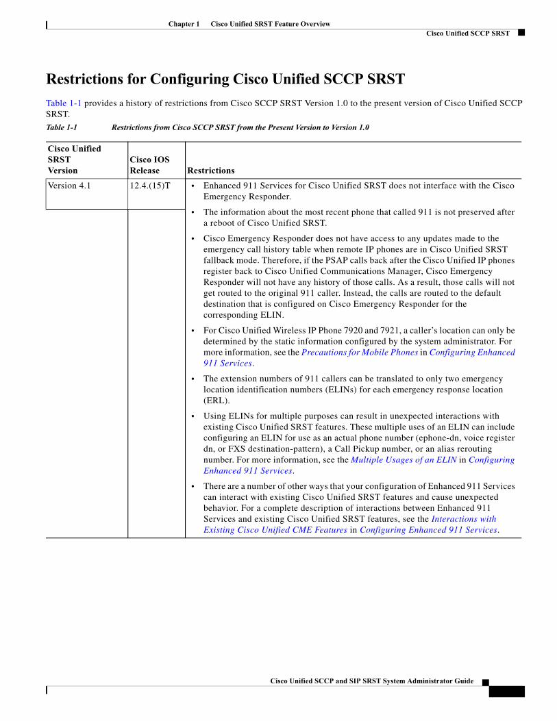
Chapter 1 Cisco Unified SRST Feature OverviewCisco Unified SCCP SRST
Restrictions for Configuring Cisco Unified SCCP SRST
Table 1-1 provides a history of restrictions from Cisco SCCP SRST Version 1.0 to the present version of Cisco Unified SCCP SRST.
Table 1-1 Restrictions from Cisco SCCP SRST from the Present Version to Version 1.0
Cisco Unified SRSTVersion
Cisco IOSRelease Restrictions
Version 4.1 12.4.(15)T • Enhanced 911 Services for Cisco Unified SRST does not interface with the Cisco Emergency Responder.
• The information about the most recent phone that called 911 is not preserved after a reboot of Cisco Unified SRST.
• Cisco Emergency Responder does not have access to any updates made to the emergency call history table when remote IP phones are in Cisco Unified SRST fallback mode. Therefore, if the PSAP calls back after the Cisco Unified IP phones register back to Cisco Unified Communications Manager, Cisco Emergency Responder will not have any history of those calls. As a result, those calls will not get routed to the original 911 caller. Instead, the calls are routed to the default destination that is configured on Cisco Emergency Responder for the corresponding ELIN.
• For Cisco Unified Wireless IP Phone 7920 and 7921, a caller’s location can only be determined by the static information configured by the system administrator. For more information, see the Precautions for Mobile Phones in Configuring Enhanced 911 Services.
• The extension numbers of 911 callers can be translated to only two emergency location identification numbers (ELINs) for each emergency response location (ERL).
• Using ELINs for multiple purposes can result in unexpected interactions with existing Cisco Unified SRST features. These multiple uses of an ELIN can include configuring an ELIN for use as an actual phone number (ephone-dn, voice register dn, or FXS destination-pattern), a Call Pickup number, or an alias rerouting number. For more information, see the Multiple Usages of an ELIN in Configuring Enhanced 911 Services.
• There are a number of other ways that your configuration of Enhanced 911 Services can interact with existing Cisco Unified SRST features and cause unexpected behavior. For a complete description of interactions between Enhanced 911 Services and existing Cisco Unified SRST features, see the Interactions with Existing Cisco Unified CME Features in Configuring Enhanced 911 Services.
Cisco Unified SCCP and SIP SRST System Administrator Guide
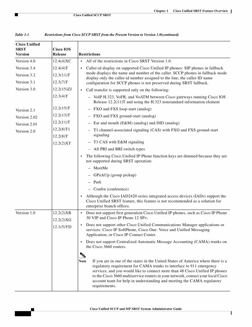
Chapter 1 Cisco Unified SRST Feature OverviewCisco Unified SCCP SRST
Version 4.0
Version 3.4
Version 3.2
Version 3.1
Version 3.0
Version 2.1
Version 2.02
Version 2.01
Version 2.0
12.4(4)XC
12.4(4)T
12.3(11)T
12.3(7)T
12.2(15)ZJ
12.3(4)T
12.2(15)T
12.2(13)T
12.2(11)T
12.2(8)T1
12.2(8)T
12.2(2)XT
• All of the restrictions in Cisco SRST Version 1.0.
• Caller-id display on supported Cisco Unified IP phones: SIP phones in fallback mode displays the name and number of the caller. SCCP phones in fallback mode display only the caller-id number assigned to the line; the caller-ID name configuration for SCCP phones is not preserved during SRST fallback.
• Call transfer is supported only on the following:
– VoIP H.323, VoFR, and VoATM between Cisco gateways running Cisco IOS Release 12.2(11)T and using the H.323 nonstandard information element
– FXO and FXS loop-start (analog)
– FXO and FXS ground-start (analog)
– Ear and mouth (E&M) (analog) and DID (analog)
– T1 channel-associated signaling (CAS) with FXO and FXS ground-start signaling
– T1 CAS with E&M signaling
– All PRI and BRI switch types
• The following Cisco Unified IP Phone function keys are dimmed because they are not supported during SRST operation:
– MeetMe
– GPickUp (group pickup)
– Park
– Confrn (conference)
• Although the Cisco IAD2420 series integrated access devices (IADs) support the Cisco Unified SRST feature, this feature is not recommended as a solution for enterprise branch offices.
Version 1.0 12.2(2)XB
12.2(2)XG
12.1(5)YD
• Does not support first generation Cisco Unified IP phones, such as Cisco IP Phone 30 VIP and Cisco IP Phone 12 SP+.
• Does not support other Cisco Unified Communications Manager applications or services: Cisco IP SoftPhone, Cisco One: Voice and Unified Messaging Application, or Cisco IP Contact Center.
• Does not support Centralized Automatic Message Accounting (CAMA) trunks on the Cisco 3660 routers.
Note If you are in one of the states in the United States of America where there is a regulatory requirement for CAMA trunks to interface to 911 emergency services, and you would like to connect more than 48 Cisco Unified IP phones to the Cisco 3660 multiservice routers in your network, contact your local Cisco account team for help in understanding and meeting the CAMA regulatory requirements.
Table 1-1 Restrictions from Cisco SCCP SRST from the Present Version to Version 1.0(continued)
Cisco Unified SRSTVersion
Cisco IOSRelease Restrictions
1Cisco Unified SCCP and SIP SRST System Administrator Guide
Chapter 1 Cisco Unified SRST Feature OverviewCisco Unified SIP SRST
Cisco Unified SIP SRST• Information About SIP SRST, page 9
• Prerequisites for Configuring Cisco Unified SIP SRST, page 9
• Restrictions for Configuring Cisco Unified SIP SRST, page 9
Information About SIP SRST
This guide describes Cisco Unified SRST functionality for SIP networks. Cisco Unified SIP SRST provides backup to an external SIP proxy server by providing basic registrar and redirect server or back-to-back user agent (B2BUA) services. These services are used by a SIP IP phone in the event of a WAN connection outage when the SIP phone is unable to communicate with its primary SIP proxy.
Cisco Unified SIP SRST can support SIP phones with standard RFC 3261 feature support locally and across SIP WAN networks. With Cisco Unified SIP SRST, SIP phones can place calls across SIP networks in the same way as SCCP phones.
Cisco Unified SIP SRST supports the following call combinations:
• SIP phone to SIP phone
• SIP phone to PSTN / router voice-port
• SIP phone to Skinny Client Control Protocol (SCCP) phone
• SIP phone to WAN VoIP using SIP
SIP proxy, registrar, and B2BUA servers are key components of a SIP VoIP network. These servers are usually located in the core of a VoIP network. If SIP phones located at remote sites at the edge of the VoIP network lose connectivity to the network core (because of a WAN outage), they may be unable to make or receive calls. Cisco Unified SIP SRST functionality on a SIP PSTN gateway provides service reliability for SIP-based IP phones in the event of a WAN outage. Cisco Unified SIP SRST enables the SIP IP phones to continue to make and receive calls to and from the PSTN and also to make and receive calls to and from other SIP IP phones.
To see a branch office Cisco Unifed IP Phones connected to a remote central Cisco Unified CM Operating in SRST mode, see Figure 1-1.
Note Cisco Unity Express (CUE) interworking is not supported with secure SIP SRST.
Prerequisites for Configuring Cisco Unified SIP SRST
Before configuring Cisco Unified SIP SRST, you must do the following:
• An SRST feature license is required to enable the Cisco Unified SIP SRST feature. Contact your account representative if you have further questions. For more information about Licensing on Unified SRST, refer Cisco Unified SRST Licenses, page 12.
Restrictions for Configuring Cisco Unified SIP SRST
Table 1-2 provides a history of restrictions from Cisco SIP SRST Version 3.0 to the present version of Cisco Unified SIP SRST.
Cisco Unified SCCP and SIP SRST System Administrator Guide
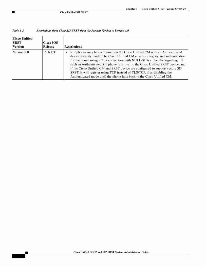
Chapter 1 Cisco Unified SRST Feature OverviewCisco Unified SIP SRST
Table 1-2 Restrictions from Cisco SIP SRST from the Present Version to Version 3.0
Cisco Unified SRSTVersion
Cisco IOSRelease Restrictions
Version 8.0 15.1(1)T • SIP phones may be configured on the Cisco Unified CM with an Authenticated device security mode. The Cisco Unified CM ensures integrity and authentication for the phone using a TLS connection with NULL-SHA cipher for signaling. If such an Authenticated SIP phone fails over to the Cisco Unified SRST device, and if the Cisco Unified CM and SRST device are configured to support secure SIP SRST, it will register using TCP instead of TLS/TCP, thus disabling the Authenticated mode until the phone fails back to the Cisco Unified CM.
1Cisco Unified SCCP and SIP SRST System Administrator Guide
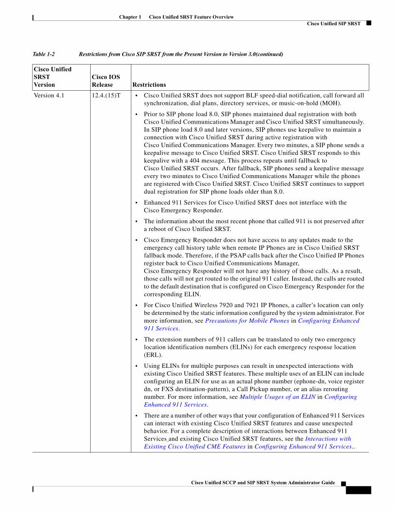
Chapter 1 Cisco Unified SRST Feature OverviewCisco Unified SIP SRST
Version 4.1 12.4.(15)T • Cisco Unified SRST does not support BLF speed-dial notification, call forward all synchronization, dial plans, directory services, or music-on-hold (MOH).
• Prior to SIP phone load 8.0, SIP phones maintained dual registration with both Cisco Unified Communications Manager and Cisco Unified SRST simultaneously. In SIP phone load 8.0 and later versions, SIP phones use keepalive to maintain a connection with Cisco Unified SRST during active registration with Cisco Unified Communications Manager. Every two minutes, a SIP phone sends a keepalive message to Cisco Unified SRST. Cisco Unified SRST responds to this keepalive with a 404 message. This process repeats until fallback to Cisco Unified SRST occurs. After fallback, SIP phones send a keepalive message every two minutes to Cisco Unified Communications Manager while the phones are registered with Cisco Unified SRST. Cisco Unified SRST continues to support dual registration for SIP phone loads older than 8.0.
• Enhanced 911 Services for Cisco Unified SRST does not interface with the Cisco Emergency Responder.
• The information about the most recent phone that called 911 is not preserved after a reboot of Cisco Unified SRST.
• Cisco Emergency Responder does not have access to any updates made to the emergency call history table when remote IP Phones are in Cisco Unified SRST fallback mode. Therefore, if the PSAP calls back after the Cisco Unified IP Phones register back to Cisco Unified Communications Manager, Cisco Emergency Responder will not have any history of those calls. As a result, those calls will not get routed to the original 911 caller. Instead, the calls are routed to the default destination that is configured on Cisco Emergency Responder for the corresponding ELIN.
• For Cisco Unified Wireless 7920 and 7921 IP Phones, a caller’s location can only be determined by the static information configured by the system administrator. For more information, see Precautions for Mobile Phones in Configuring Enhanced 911 Services.
• The extension numbers of 911 callers can be translated to only two emergency location identification numbers (ELINs) for each emergency response location (ERL).
• Using ELINs for multiple purposes can result in unexpected interactions with existing Cisco Unified SRST features. These multiple uses of an ELIN can include configuring an ELIN for use as an actual phone number (ephone-dn, voice register dn, or FXS destination-pattern), a Call Pickup number, or an alias rerouting number. For more information, see Multiple Usages of an ELIN in Configuring Enhanced 911 Services.
• There are a number of other ways that your configuration of Enhanced 911 Services can interact with existing Cisco Unified SRST features and cause unexpected behavior. For a complete description of interactions between Enhanced 911 Services and existing Cisco Unified SRST features, see the Interactions with Existing Cisco Unified CME Features in Configuring Enhanced 911 Services..
Table 1-2 Restrictions from Cisco SIP SRST from the Present Version to Version 3.0(continued)
Cisco Unified SRSTVersion
Cisco IOSRelease Restrictions
Cisco Unified SCCP and SIP SRST System Administrator Guide
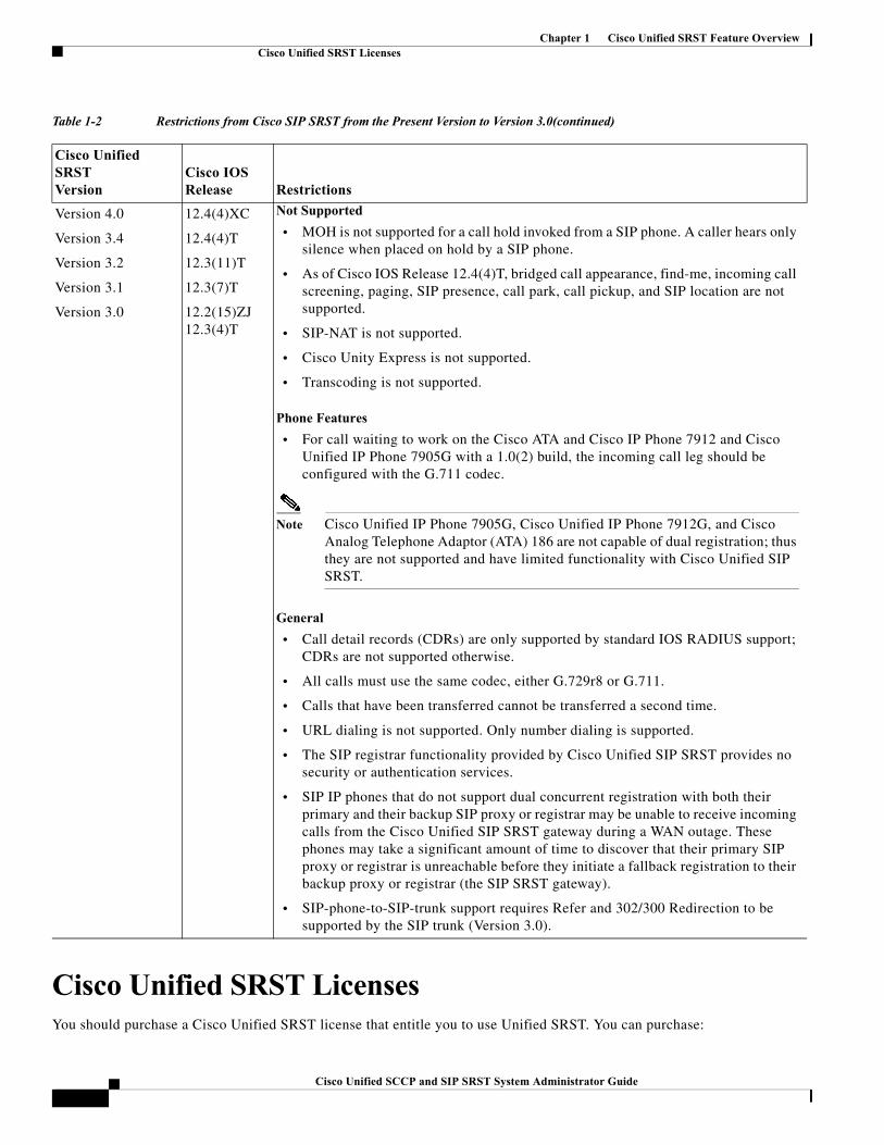
Chapter 1 Cisco Unified SRST Feature OverviewCisco Unified SRST Licenses
Cisco Unified SRST LicensesYou should purchase a Cisco Unified SRST license that entitle you to use Unified SRST. You can purchase:
Version 4.0
Version 3.4
Version 3.2
Version 3.1
Version 3.0
12.4(4)XC
12.4(4)T
12.3(11)T
12.3(7)T
12.2(15)ZJ 12.3(4)T
Not Supported
• MOH is not supported for a call hold invoked from a SIP phone. A caller hears only silence when placed on hold by a SIP phone.
• As of Cisco IOS Release 12.4(4)T, bridged call appearance, find-me, incoming call screening, paging, SIP presence, call park, call pickup, and SIP location are not supported.
• SIP-NAT is not supported.
• Cisco Unity Express is not supported.
• Transcoding is not supported.
Phone Features
• For call waiting to work on the Cisco ATA and Cisco IP Phone 7912 and Cisco Unified IP Phone 7905G with a 1.0(2) build, the incoming call leg should be configured with the G.711 codec.
Note Cisco Unified IP Phone 7905G, Cisco Unified IP Phone 7912G, and Cisco Analog Telephone Adaptor (ATA) 186 are not capable of dual registration; thus they are not supported and have limited functionality with Cisco Unified SIP SRST.
General
• Call detail records (CDRs) are only supported by standard IOS RADIUS support; CDRs are not supported otherwise.
• All calls must use the same codec, either G.729r8 or G.711.
• Calls that have been transferred cannot be transferred a second time.
• URL dialing is not supported. Only number dialing is supported.
• The SIP registrar functionality provided by Cisco Unified SIP SRST provides no security or authentication services.
• SIP IP phones that do not support dual concurrent registration with both their primary and their backup SIP proxy or registrar may be unable to receive incoming calls from the Cisco Unified SIP SRST gateway during a WAN outage. These phones may take a significant amount of time to discover that their primary SIP proxy or registrar is unreachable before they initiate a fallback registration to their backup proxy or registrar (the SIP SRST gateway).
• SIP-phone-to-SIP-trunk support requires Refer and 302/300 Redirection to be supported by the SIP trunk (Version 3.0).
Table 1-2 Restrictions from Cisco SIP SRST from the Present Version to Version 3.0(continued)
Cisco Unified SRSTVersion
Cisco IOSRelease Restrictions
1Cisco Unified SCCP and SIP SRST System Administrator Guide
Chapter 1 Cisco Unified SRST Feature OverviewCisco Unified SRST Licenses
• Cisco Unified SRST Permanent License or
• Collaboration Professional Suite License
• Cisco Smart License
Cisco Unified SRST Permanent License
When you purchase a Cisco Unified SRST permanent license, the permanent license is installed on the device when the product is shipped to you. A permanent license never expires and you will gain access to that particular feature set for the lifetime of the device across all IOS release. If you purchase a permanent license for Cisco Unified SRST, you do not have to go through the Evaluation Right to Use and Right To Use (RTU) licensing processes for using the features. If you want to purchase a CME-SRST license for your existing device, you have to go through the RTU licensing process for using the features. There is no change in the existing process for purchasing the license.
The Cisco Unified SRST permanent license is available in the form of an XML cme-locked3 file. You should get the XML file and load it in the flash memory of the device. To install the permanent license from the command prompt, use the license install flash0:cme-locked3 command. The cme-locked3 is the xml file of the license.
Collaboration Professional Suite License
Collaboration Professional is a new suite of licenses. The Collaboration Professional suite can be purchased either as a permanent license or an RTU license.
Collaboration Professional Suite Permanent License —When you purchase the Collaboration Professional Suite license, by default, the Cisco Unified SRST licenses are delivered as part of the Collaboration Professional Suite. You do not have to separately install and activate the Cisco Unified SRST license. The Collaboration Professional Suite permanent license is available in the form of an XML file. You should get the XML file and load it in the flash memory of the device. To install the permanent license from the command prompt, use the license install flash:lic_name command.
Collaboration Professional Suite RTU License—When you purchase the Collaboration Professional Suite RTU license, you do not have to go through the Evaluation Right to Use process. However, you have to go through the RTU licensing process for using the Cisco Unified SRST features. To install the Collaboration Professional Suite RTU license from the command prompt, use the license install flash0:colla_pro command. To activate the license, use the license boot module c2951 technology-package collabProSuitek9 command.
Also, you have to:
• Choose an appropriate Cisco Unified SRST version. Each SRST version supports a specific set of IP phones, memory requirements, features, and DNs. See the “Platform and Memory Support” section on page 25 and the “Restrictions for Configuring Cisco Unified SCCP SRST” section on page 7.
• Choose an appropriate phoneload. SRST only supports certain phoneloads that have been tested with the various Cisco Unified Communications Manager versions. For the most up-to-date phoneloads, see the Cisco Unified SRST Supported Firmware, Platforms, Memory, and Voice Products.
If you have Cisco Unified Communications Manager already installed, verify that your version of Cisco Unified Communications Manager is compatible with your Cisco Unified SRST release. See the “Cisco Unified Communications Manager Compatibility” section on page 25.
Cisco Unified SCCP and SIP SRST System Administrator Guide
Chapter 1 Cisco Unified SRST Feature OverviewCisco Unified SRST Licenses
Cisco Smart License
From Release 12.1 onwards, Unified SRST supports Smart Licensing, apart from the existing CSL licensing model. Smart Licensing is supported only on Cisco 4000 Series Integrated Services Router. Depending on the technology package available on the router, licenses such as UCK9 and Security are supported using Smart Licensing.
Smart Software Licensing is Cisco's new licensing model that gives you visibility into license ownership and consumption. Smart licenses can be managed by a cloud-based deployment model, namely Cisco Smart Software Manager (CSSM) or an on-prem software, Smart Software Manager satellite. Unified SRST is supported by both CSSM and satellite. Your access to the customer Smart Account residing on CSSM is authenticated using valid Cisco credentials. With the Smart Licensing support for Unified SRST, your device can register with CSSM or Cisco Smart Software Manager satellite. You can access your Licenses at the Cisco Software Central.
Unified SRST needs to register with CSSM or Cisco Smart Software Manager satellite to report license consumption. You can register Unified SRST to a Virtual Account within a Smart Account by generating a token ID from it, and pasting it to the underlying platform, Cisco 4000 Series Integrated Services Router. Once the token is generated, it can be used to register many other product instances in your network.
On the Unified SRST router, you need to ensure that the call home feature is not disabled. Also, Smart Licensing should be enabled at the router using the CLI command license smart enable. Use the no form of the command to disable Smart Licensing.
For more information on configuring Smart Licensing in your router, see Cisco 4000 Series ISRs Software Configuration Guide. For more information on configuring Call Home for your devices, see Configure Call Home, page 15. Once Smart Licensing is enabled, the router enters a 90-day evaluation period that persist until it registers to CSSM or the Cisco Smart Software Manager satellite.
You can register the router to CSSM or Cisco Smart Software Manager satellite with the token ID. To register the device (Unified SRST router) with CSSM or Cisco Smart Software Manager satellite, use the CLI command license smart register idtoken. For information on registering the device with CSSM, see Device Registration, Software Activation Configuration Guide, Cisco IOS Release 15M&T.
Upon successful registration, Unified SRST is in Registered status. As part of the registration process, the router sends an authorization request, indicating the number of phone endpoints defined by the max-pool, for SIP SRST, and max-ephone, for SCCP SRST. Based on the licenses in the Smart Account, CSSM or Cisco Smart Software Manager satellite responds with one of the defined statuses such as Authorized (using less than or equal to the number of licenses provisioned in CSSM or Cisco Smart Software Manager satellite) or Out-of-Compliance (using more than it has licenses for).
The license limit on Unified SRST is restricted by the maximum platform limit defined for the Unified SRST router (a cumulative sum of phones configured under max-pool and max-ephone). Hence, the license usage count cannot exceed the platform limit set for the Unified SRST router even when the cumulative sum of phones configured under max-pool and max-ephone exceeds the defined platform limit. For more details on the platform limits defined for Unified SRST, see Cisco Unified SRST/E-SRST 12.1 Supported Firmware, Platforms, Memory, and Voice Products.
CSSM or Smart Software Manager satellite reports license consumption submitted by the platform in its User Interface (UI), and subtracts it from the available licenses in the Virtual Account within the Smart Account. Unified SRST supports only one license entitlement to validate phones configured on Unified SRST.
SRST_EP —This license type supports all phones configured on Unified SRST.
Note The SRST_EP license count reflects the total phone count of both the ephones and pools that are configured in the Unified SRST irrespective of whether the phones are registered or not.
Unified SRST sends an authorization request when a license consumption changes or every 30 days to let CSSM or Cisco Smart Software Manager satellite know it's still available and communicating. The ID certificate issued to identify Unified SRST at time of registration is valid for one year, and is automatically renewed every six months.
1Cisco Unified SCCP and SIP SRST System Administrator Guide
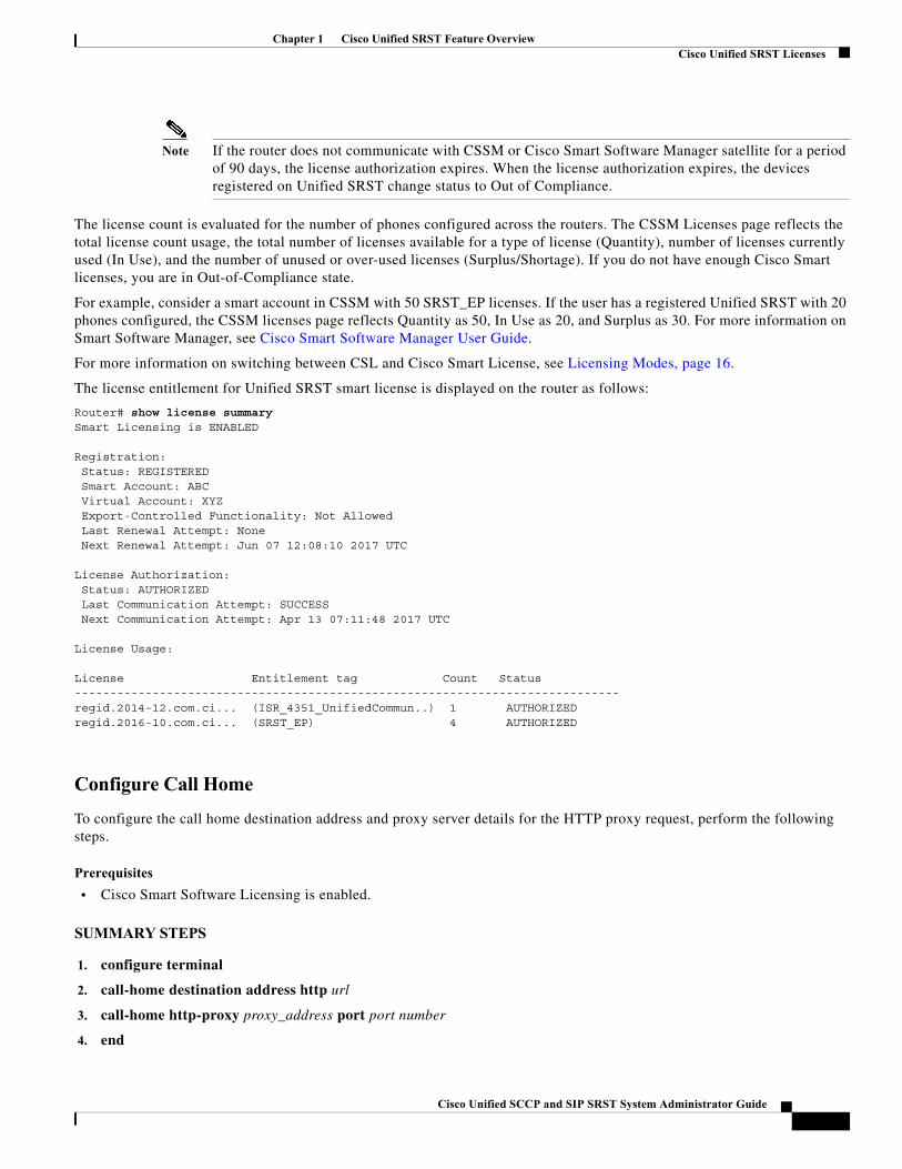
Chapter 1 Cisco Unified SRST Feature OverviewCisco Unified SRST Licenses
Note If the router does not communicate with CSSM or Cisco Smart Software Manager satellite for a period of 90 days, the license authorization expires. When the license authorization expires, the devices registered on Unified SRST change status to Out of Compliance.
The license count is evaluated for the number of phones configured across the routers. The CSSM Licenses page reflects the total license count usage, the total number of licenses available for a type of license (Quantity), number of licenses currently used (In Use), and the number of unused or over-used licenses (Surplus/Shortage). If you do not have enough Cisco Smart licenses, you are in Out-of-Compliance state.
For example, consider a smart account in CSSM with 50 SRST_EP licenses. If the user has a registered Unified SRST with 20 phones configured, the CSSM licenses page reflects Quantity as 50, In Use as 20, and Surplus as 30. For more information on Smart Software Manager, see Cisco Smart Software Manager User Guide.
For more information on switching between CSL and Cisco Smart License, see Licensing Modes, page 16.
The license entitlement for Unified SRST smart license is displayed on the router as follows:
Router# show license summarySmart Licensing is ENABLED
Registration: Status: REGISTERED Smart Account: ABC Virtual Account: XYZ Export-Controlled Functionality: Not Allowed Last Renewal Attempt: None Next Renewal Attempt: Jun 07 12:08:10 2017 UTC
License Authorization: Status: AUTHORIZED Last Communication Attempt: SUCCESS Next Communication Attempt: Apr 13 07:11:48 2017 UTC
License Usage:
License Entitlement tag Count Status-----------------------------------------------------------------------------regid.2014-12.com.ci... (ISR_4351_UnifiedCommun..) 1 AUTHORIZEDregid.2016-10.com.ci... (SRST_EP) 4 AUTHORIZED
Configure Call Home
To configure the call home destination address and proxy server details for the HTTP proxy request, perform the following steps.
Prerequisites
• Cisco Smart Software Licensing is enabled.
SUMMARY STEPS
1. configure terminal
2. call-home destination address http url
3. call-home http-proxy proxy_address port port number
4. end
Cisco Unified SCCP and SIP SRST System Administrator Guide
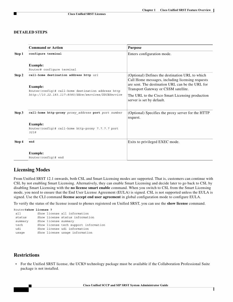
Chapter 1 Cisco Unified SRST Feature OverviewCisco Unified SRST Licenses
DETAILED STEPS
Licensing Modes
From Unified SRST 12.1 onwards, both CSL and Smart Licensing modes are supported. That is, customers can continue with CSL by not enabling Smart Licensing. Alternatively, they can enable Smart Licensing and decide later to go back to CSL by disabling Smart Licensing with the no license smart enable command. When you switch to CSL from the Smart Licensing mode, you need to ensure that the End User License Agreement (EULA) is signed. CSL is not supported unless the EULA is signed. Use the CLI command license accept end user agreement in global configuration mode to configure EULA.
To verify the status of the license issued to phones registered on Unified SRST, you can use the show license command.
Router#show license ? all Show license all information status Show license status information summary Show license summary tech Show license tech support information udi Show license udi information usage Show license usage information
Restrictions
• For the Unified SRST license, the UCK9 technology package must be available if the Collaboration Professional Suite package is not installed.
Command or Action Purpose
Step 1 configure terminal
Example:Router# configure terminal
Enters configuration mode.
Step 2 call-home destination address http url
Example:Router(config)# call-home destination address http http://10.22.183.117:8080/ddce/services/DDCEService
(Optional) Defines the destination URL to which Call Home messages, including licensing requests are sent. The destination URL can be the URL for Transport Gateway or CSSM satellite.
The URL to the Cisco Smart Licensing production server is set by default.
Step 3 call-home http-proxy proxy_address port port number
Example:Router(config)# call-home http-proxy 7.7.7.7 port 3218
(Optional) Specifies the proxy server for the HTTP request.
Step 4 end
Example:Router(config)# end
Exits to privileged EXEC mode.
1Cisco Unified SCCP and SIP SRST System Administrator Guide
Chapter 1 Cisco Unified SRST Feature OverviewInterface Support for Unified CME and Unified SRST
To purchase a license, go to http://www.cisco.com/cgi-bin/tablebuild.pl/ip-key. To activate cme-srst feature license, see the Activating CME-SRST Feature License document.
Interface Support for Unified CME and Unified SRSTUnified CME and Unified SRST routers have multiple interfaces that are used for signaling and data packet transfers. The two types of interfaces available on a Cisco router include the physical interface and the virtual interface. The types of physical interfaces available on a router depends on its interface processors or port adapters. Virtual interfaces are software-based interfaces that you create in the memory of the networking device using Cisco IOS commands. When you need to configure a virtual interface for connectivity, you can use the Loopback Interface for Unified CME and Unified SRST.
The following interfaces are supported on Unified CME and Unified SRST:
• Gigabit Ethernet Interface (IEEE 802.3z) (interface gigabitethernet)
• Loopback Interface (interface loopback)
• Fast Ethernet Interface (interface fastethernet)
MGCP Gateways and SRSTMGCP fallback is a different feature than SRST and, when configured as an individual feature, can be used by a PSTN gateway. To use SRST as your fallback mode on an MGCP gateway, SRST and MGCP fallback must both be configured on the same gateway. MGCP and SRST have had the capability to be configured on the same gateway since Cisco IOS Release 12.2(11)T.
To make outbound calls while in SRST mode on your MGCP gateway, two fallback commands must be configured on the MGCP gateway. These two commands allow SRST to assume control over the voice port and over call processing on the MGCP gateway. With Cisco IOS earlier than 12.3(14)T, the two commands are the ccm-manager fallback-mgcp and call application alternate commands. With Cisco IOS releases after 12.3(14)T, the ccm-manager fallback-mgcp and service commands must be configured. A complete configuration for these commands is shown in the section the “Enabling Cisco Unified SRST on an MGCP Gateway” section on page 40.
Note The commands listed above are ineffective unless both commands are configured. For instance, your configuration will not work if you only configure the ccm-manager fallback-mgcp command.
For more information on the fallback methods for MGCP gateways, see the Configuring MGCP Gateway Support for Cisco Unified Communications Manager document or the MGCP Gateway Fallback Transition to Default H.323 Session Application document.
IPv6 Support for Unified SRST SIP IP PhonesInternet Protocol version 6 (IPv6) is the latest version of the Internet Protocol (IP). IPv6 uses packets to exchange data, voice, and video traffic over digital networks. Also, IPv6 increases the number of network address bits from 32 bits in IPv4 to 128 bits. From Unified SRST Release 12.0 onwards, Unified SRST supports IPv6 protocols for SIP IP phones.
IPv6 support in Unified SRST allows the network to behave transparently in a dual-stack (IPv4 and IPv6) environment and provides additional IP address space to SIP IP phones that are connected to the network. If you do not have a dual-stack configuration, configure the CLI command call service stop under voice service voip configuration mode before changing to dual-stack mode. For an example of switching to dual-stack mode, see Examples for Configuring IPv6 Pools for SIP IP Phones, page 23.
Cisco Unified SCCP and SIP SRST System Administrator Guide
Chapter 1 Cisco Unified SRST Feature OverviewIPv6 Support for Unified SRST SIP IP Phones
The Cisco IP Phone 7800 Series and 8800 Series are supported on IPv6 for Unified SRST.
For more information on configuring SIP IP phones for IPv6 source address, see Configure IPv6 Pools for SIP IP Phones, page 18.
For an example of configuring IPv6 Support on Unified SRST, see Examples for Configuring IPv6 Pools for SIP IP Phones, page 23.
For more details about IPv6 deployment, see IPv6 Deployment Guide for Cisco Collaboration Systems Release 12.0.
Feature Support for IPv6 in Unified SRST SIP IP Phones
The following basic features are supported for a IPv6 WAN down scenario:
• Basic SIP Line (IPv4 or IPv6) to SIP Line calls (IPv4 or IPv6) when Unified SRST is in dual-stack no anat mode.
The following supplementary services are supported as part of IPv6 in Unified SRST IP Phones:
• Hold/Resume
• Call Forward
• Call Transfer
• Three-way Conference (with BIB conferencing only)
• Line to T1/E1 Trunk and Trunk to Line with Supplementary Service Features
• Fax to and from PSTN (IPv4 ATA to ISDN T1/E1) for both T.38 Fax Relay and Fax Passthrough
Restrictions
The following are the known restrictions for IPv6 support on Unified SRST:
• SIP Trunks are not supported on Unified SRST for IPv6 deployment. PSTN calls are supported only through T1/E1 trunks.
• SCCP IP Phones are not supported in a deployment of IPv6 for Unified SRST.
• SIP Phones can be either in IPv4 only or IPv6 only mode (no anat).
• Trancoding and Transrating are not supported.
• H.323 trunks are not supported.
• Secure SIP lines or trunks are not supported.
Configure IPv6 Pools for SIP IP Phones
Before You Begin
• Unified SRST 12.0 or a later version.
• IPv6 option only appears if protocol mode is dual-stack configured under sip-ua configuration mode or IPv6.
• Cisco Unified SRST License must be configured for the gateway to function as a Unified SRST gateway to support IPv6 functionality. For more information on licenses, see Cisco Unified SRST Licenses, page 12.
• Cisco Unified Communications Manager (Unified Communications Manager) is provisioned with the IPv6 address of Unified SRST. For information on configuration of Unified SRST on Unified Communications Manager, see the section Survivable Remote Site Telephony Configuration in Cisco Unified Communications Manager Administration Guide.
1Cisco Unified SCCP and SIP SRST System Administrator Guide
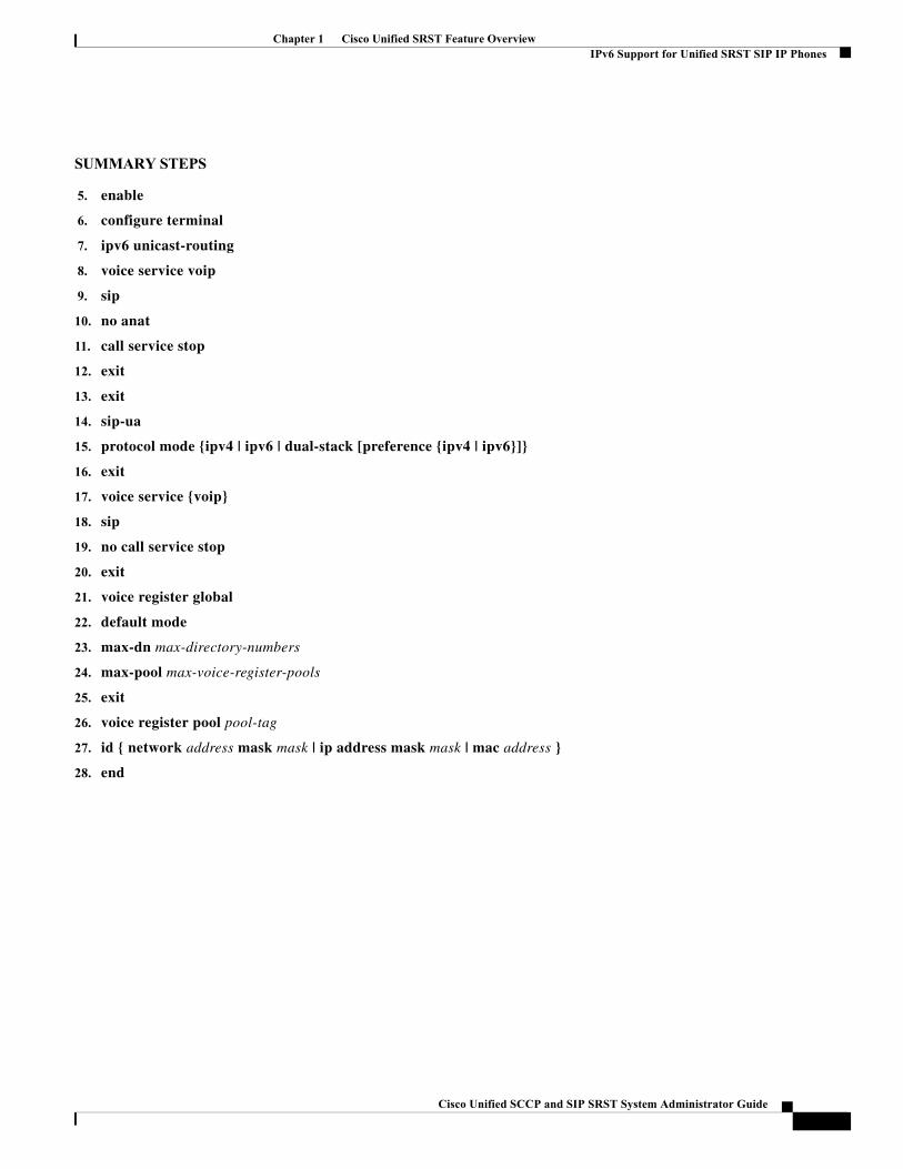
Chapter 1 Cisco Unified SRST Feature OverviewIPv6 Support for Unified SRST SIP IP Phones
SUMMARY STEPS
5. enable
6. configure terminal
7. ipv6 unicast-routing
8. voice service voip
9. sip
10. no anat
11. call service stop
12. exit
13. exit
14. sip-ua
15. protocol mode {ipv4 | ipv6 | dual-stack [preference {ipv4 | ipv6}]}
16. exit
17. voice service {voip}
18. sip
19. no call service stop
20. exit
21. voice register global
22. default mode
23. max-dn max-directory-numbers
24. max-pool max-voice-register-pools
25. exit
26. voice register pool pool-tag
27. id { network address mask mask | ip address mask mask | mac address }
28. end
Cisco Unified SCCP and SIP SRST System Administrator Guide
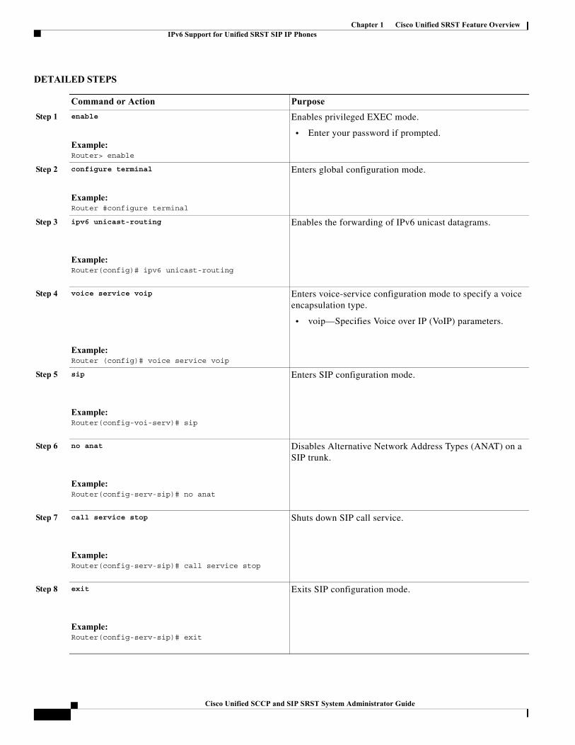
Chapter 1 Cisco Unified SRST Feature OverviewIPv6 Support for Unified SRST SIP IP Phones
DETAILED STEPS
Command or Action Purpose
Step 1 enable
Example:Router> enable
Enables privileged EXEC mode.
• Enter your password if prompted.
Step 2 configure terminal
Example:Router #configure terminal
Enters global configuration mode.
Step 3 ipv6 unicast-routing
Example:Router(config)# ipv6 unicast-routing
Enables the forwarding of IPv6 unicast datagrams.
Step 4 voice service voip
Example:Router (config)# voice service voip
Enters voice-service configuration mode to specify a voice encapsulation type.
• voip—Specifies Voice over IP (VoIP) parameters.
Step 5 sip
Example:Router(config-voi-serv)# sip
Enters SIP configuration mode.
Step 6 no anat
Example:Router(config-serv-sip)# no anat
Disables Alternative Network Address Types (ANAT) on a SIP trunk.
Step 7 call service stop
Example:Router(config-serv-sip)# call service stop
Shuts down SIP call service.
Step 8 exit
Example:Router(config-serv-sip)# exit
Exits SIP configuration mode.
1Cisco Unified SCCP and SIP SRST System Administrator Guide
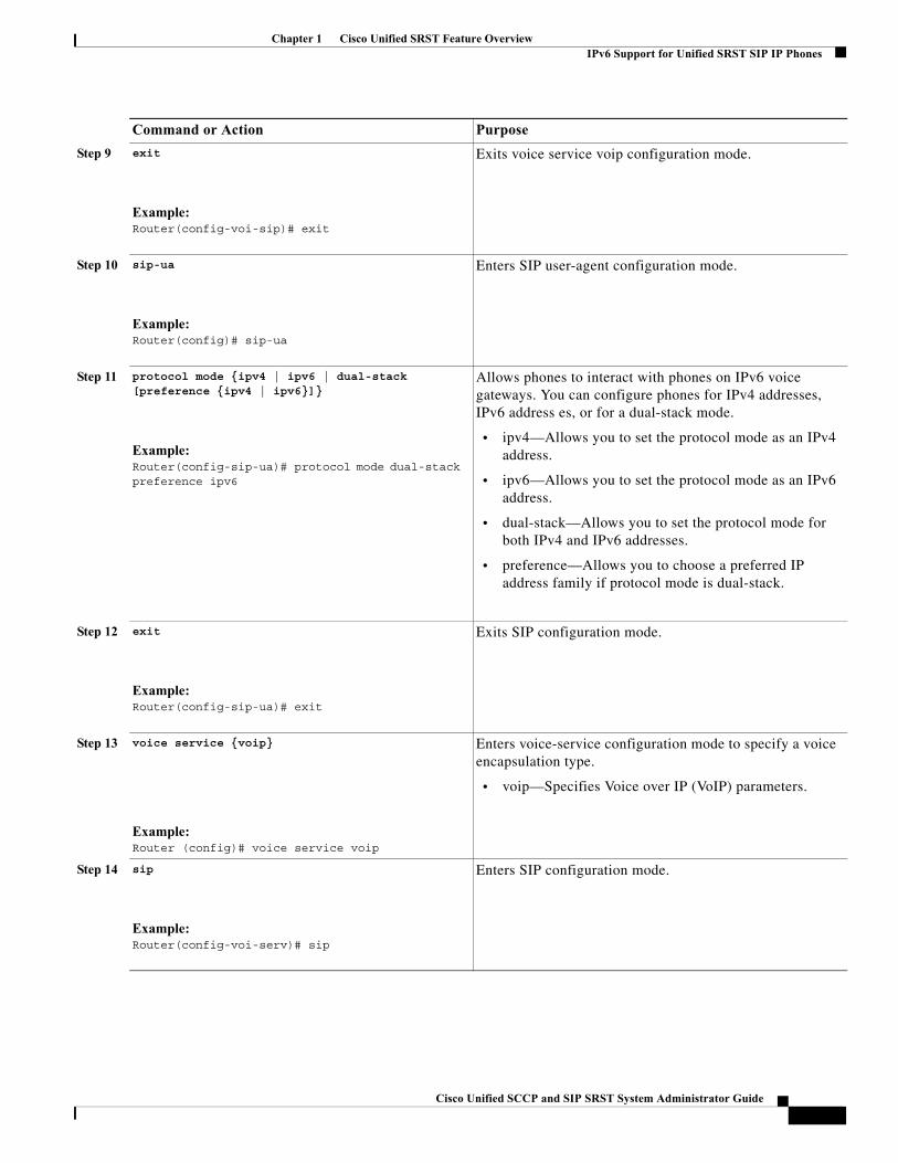
Chapter 1 Cisco Unified SRST Feature OverviewIPv6 Support for Unified SRST SIP IP Phones
Step 9 exit
Example:Router(config-voi-sip)# exit
Exits voice service voip configuration mode.
Step 10 sip-ua
Example:Router(config)# sip-ua
Enters SIP user-agent configuration mode.
Step 11 protocol mode {ipv4 | ipv6 | dual-stack [preference {ipv4 | ipv6}]}
Example:Router(config-sip-ua)# protocol mode dual-stack preference ipv6
Allows phones to interact with phones on IPv6 voice gateways. You can configure phones for IPv4 addresses, IPv6 address es, or for a dual-stack mode.
• ipv4—Allows you to set the protocol mode as an IPv4 address.
• ipv6—Allows you to set the protocol mode as an IPv6 address.
• dual-stack—Allows you to set the protocol mode for both IPv4 and IPv6 addresses.
• preference—Allows you to choose a preferred IP address family if protocol mode is dual-stack.
Step 12 exit
Example:Router(config-sip-ua)# exit
Exits SIP configuration mode.
Step 13 voice service {voip}
Example:Router (config)# voice service voip
Enters voice-service configuration mode to specify a voice encapsulation type.
• voip—Specifies Voice over IP (VoIP) parameters.
Step 14 sip
Example:Router(config-voi-serv)# sip
Enters SIP configuration mode.
Command or Action Purpose
Cisco Unified SCCP and SIP SRST System Administrator Guide
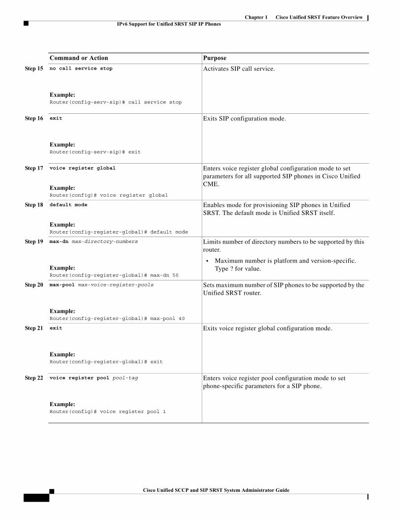
Chapter 1 Cisco Unified SRST Feature OverviewIPv6 Support for Unified SRST SIP IP Phones
Step 15 no call service stop
Example:Router(config-serv-sip)# call service stop
Activates SIP call service.
Step 16 exit
Example:Router(config-serv-sip)# exit
Exits SIP configuration mode.
Step 17 voice register global
Example:Router(config)# voice register global
Enters voice register global configuration mode to set parameters for all supported SIP phones in Cisco Unified CME.
Step 18 default mode
Example:Router(config-register-global)# default mode
Enables mode for provisioning SIP phones in Unified SRST. The default mode is Unified SRST itself.
Step 19 max-dn max-directory-numbers
Example:Router(config-register-global)# max-dn 50
Limits number of directory numbers to be supported by this router.
• Maximum number is platform and version-specific. Type ? for value.
Step 20 max-pool max-voice-register-pools
Example:Router(config-register-global)# max-pool 40
Sets maximum number of SIP phones to be supported by the Unified SRST router.
Step 21 exit
Example:Router(config-register-global)# exit
Exits voice register global configuration mode.
Step 22 voice register pool pool-tag
Example:Router(config)# voice register pool 1
Enters voice register pool configuration mode to set phone-specific parameters for a SIP phone.
Command or Action Purpose
1Cisco Unified SCCP and SIP SRST System Administrator Guide
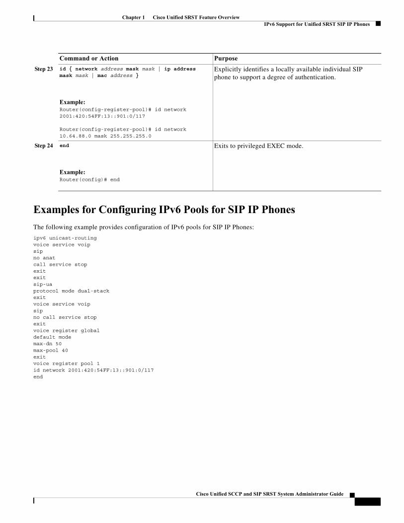
Chapter 1 Cisco Unified SRST Feature OverviewIPv6 Support for Unified SRST SIP IP Phones
Examples for Configuring IPv6 Pools for SIP IP Phones
The following example provides configuration of IPv6 pools for SIP IP Phones:
ipv6 unicast-routingvoice service voipsipno anatcall service stopexitexitsip-uaprotocol mode dual-stackexitvoice service voipsipno call service stopexitvoice register globaldefault modemax-dn 50max-pool 40exitvoice register pool 1id network 2001:420:54FF:13::901:0/117end
Step 23 id { network address mask mask | ip address mask mask | mac address }
Example:Router(config-register-pool)# id network 2001:420:54FF:13::901:0/117
Router(config-register-pool)# id network 10.64.88.0 mask 255.255.255.0
Explicitly identifies a locally available individual SIP phone to support a degree of authentication.
Step 24 end
Example:Router(config)# end
Exits to privileged EXEC mode.
Command or Action Purpose
Cisco Unified SCCP and SIP SRST System Administrator Guide
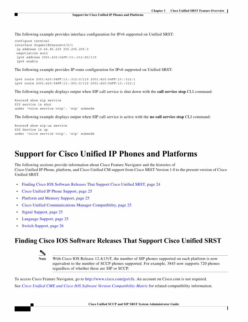
Chapter 1 Cisco Unified SRST Feature OverviewSupport for Cisco Unified IP Phones and Platforms
The following example provides interface configuration for IPv6 supported on Unified SRST:
configure terminalinterface GigabitEthernet0/0/1 ip address 10.64.86.229 255.255.255.0 negotiation auto ipv6 address 2001:420:54FF:13::312:82/119 ipv6 enable
The following example provides IP route configuration for IPv6 supported on Unified SRST:
ipv6 route 2001:420:54FF:13::312:0/119 2001:420:54FF:13::312:1ipv6 route 2001:420:54FF:13::901:0/119 2001:420:54FF:13::312:1
The following example displays output when SIP call service is shut down with the call service stop CLI command:
Router# show sip serviceSIP service is shutunder 'voice service voip', 'sip' submode
The following example displays output when SIP call service is active with the no call service stop CLI command:
Router# show sip-ua serviceSIP Service is upunder 'voice service voip', 'sip' submode
Support for Cisco Unified IP Phones and PlatformsThe following sections provide information about Cisco Feature Navigator and the histories of Cisco Unified IP Phone, platform, and Cisco Unified CM support from Cisco SRST Version 1.0 to the present version of Cisco Unified SRST.
• Finding Cisco IOS Software Releases That Support Cisco Unified SRST, page 24
• Cisco Unified IP Phone Support, page 25
• Platform and Memory Support, page 25
• Cisco Unified Communications Manager Compatibility, page 25
• Signal Support, page 25
• Language Support, page 25
• Switch Support, page 26
Finding Cisco IOS Software Releases That Support Cisco Unified SRST
Note With Cisco IOS Release 12.4(15)T, the number of SIP phones supported on each platform is now equivalent to the number of SCCP phones supported. For example, 3845 now supports 720 phones regardless of whether these are SIP or SCCP.
To access Cisco Feature Navigator, go to http://www.cisco.com/go/cfn. An account on Cisco.com is not required.
See Cisco Unified CME and Cisco IOS Software Version Compatibility Matrix for related compatibility information.
1Cisco Unified SCCP and SIP SRST System Administrator Guide
Chapter 1 Cisco Unified SRST Feature OverviewSupport for Cisco Unified IP Phones and Platforms
Cisco Unified IP Phone Support
For the most up-to-date information about Cisco Unified IP Phone support, see Compatibility Information.
For ATAs that are registered to a Cisco Unified SRST system to participate in FAX calls, they must have their ConnectMode parameter set to use the "standard payload type 0/8" as the RTP payload type in FAX passthrough mode. For ATAs used with Cisco Unified SRST 4.0 and higher versions, this is done by setting bit 2 of the ConnectMode parameter to 1 on the ATA. For more information, see the Parameters and Defaults chapter in Cisco ATA 186 and Cisco ATA 188 Analog Telephone Adaptor Administrator's Guide for SCCP.
During Cisco Unified CM fallback, Cisco Unified SRST considers the Cisco VG248 to be a group of Cisco Unified IP phones. Cisco Unified SRST counts each of the 48 ports on the Cisco VG248 as a separate Cisco Unified IP phone. Support for Cisco VG248 Version 1.2(1) and higher versions is available as of Cisco SRST Version 2.1. For more information, see Cisco VG248 Analog Phone Gateway Data Sheet and Cisco VG248 Analog Phone Gateway Version 1.2(1) Release Notes.
For IPv6 Support on Unified SRST, all the legacy IP Phones and Voice Gateways must be converted or reconfigured to IPv4-Only SIP signaling from SCCP signaling, if applicable.
Platform and Memory Support
For the most up-to-date information about Platform and Memory Support, see Compatibility Information.
Determining Platform Support Through Cisco Feature Navigator
Cisco IOS software is packaged in feature sets that are supported on specific platforms. To get updated information regarding platform support for this feature, access Cisco Feature Navigator. Cisco Feature Navigator dynamically updates the list of supported platforms as new platform support is added for the feature.
Availability of Cisco IOS Software Images
Platform support for particular Cisco IOS software releases is dependent on the availability of the software images for those platforms. Software images for some platforms may be deferred, delayed, or changed without prior notice. For updated information about platform support and availability of software images for each Cisco IOS software release, see the online release notes or, if supported, Cisco Feature Navigator.
For the most up-to-date information about Cisco IOS software images, see Compatibility Information.
Cisco Unified Communications Manager Compatibility
See Cisco Unified Communications Manager Compatibility Matrix.
Signal Support
Cisco Unified SRST supports FXS, FXO, T1, E1, and E1 R2 signals.
Language Support
See Cisco Unified Communications Manager Express Cisco Unified CME Localization Matrix.
Cisco Unified SCCP and SIP SRST System Administrator Guide
Chapter 1 Cisco Unified SRST Feature OverviewWhere to Go Next
Switch Support
Cisco SRST 3.2 and later versions support all PRI and BRI switches including the following:
• basic-1tr6
• basic-5ess
• basic-dms100
• basic-net3
• basic-ni
• basic-ntt NTT switch type for Japan
• basic-ts013
• primary-4ess Lucent 4ESS switch type for the United States
• primary-5ess Lucent 5ESS switch type for the United States
• primary-dms100 Northern Telecom DMS-100 switch type for the United States
• primary-net5 NET5 switch type for the United Kingdom, Europe, Asia, and Australia
• primary-ni National ISDN switch type for the United States
• primary-ntt NTT switch type for Japan
• primary-qsig QSIG switch type
• primary-ts014 TS014 switch type for Australia (obsolete)
Where to Go NextThe next chapters of this book describe how to configure Cisco Unified SIP SRST. As shown in Table 1-3, each chapter takes you through tasks in the order in which they need to be performed. The first task for configuring Cisco Unified SRST is to ensure that the basic software and hardware in your system are configured correctly for Cisco Unified SRST.
Table 1-3 Cisco Unified SRST Configuration Sequence
Task Where Task Is Described
29. Setting up a Cisco Unified SRST system to communicate with your network
Setting Up the Network, page 39
30. Configuring Version 4.1 features Cisco Unified SIP SRST 4.1, page 51
31. Setting up the basic Cisco Unified SRST phone configuration using SCCP
Setting Up Cisco Unified IP Phones using SCCP, page 61
32. Providing a backup to an external SIP proxy server by supplying basic registrar services
Setting Up Cisco Unified IP Phones using SIP, page 81
33. Configuring incoming and outgoing calls Configuring Call Handling, page 99
34. Configuring optional security for SRST Configuring Secure SRST for SCCP and SIP, page 155
35. Setting up voicemail Integrating Voicemail with Cisco Unified SRST, page 239
1Cisco Unified SCCP and SIP SRST System Administrator Guide
Chapter 1 Cisco Unified SRST Feature OverviewAdditional References
Additional ReferencesThe following sections provide additional references related to Cisco Unified SIP SRST:
• Related Documents, page 28
• Standards, page 30
• MIBs, page 30
• RFCs, page 30
• Technical Assistance, page 30
36. Setting up video parameters Setting Video Parameters, page 263
37. Monitoring and maintaining Cisco Unified Survivable Remote Site Telephony (SRST)
Monitoring and Maintaining Cisco Unified SRST, page 277
Table 1-3 Cisco Unified SRST Configuration Sequence(continued)
Task Where Task Is Described
Cisco Unified SCCP and SIP SRST System Administrator Guide
Chapter 1 Cisco Unified SRST Feature OverviewAdditional References
Related Documents
Related Topic Documents
Cisco IOS voice product configuration • Cisco IOS Voice Configuration Library
• Cisco IOS Voice Command Reference
• Cisco IOS Debug Command Reference
• Cisco IOS Tcl IVR and VoiceXML Application Guide
• Cisco IOS Survivable Remote Site Telephony Version 3.2 System Administrator Guide
Configuring SRST and MGCP Fallback • Configuring MGCP Gateway Support for Cisco Unified Communications Manager
• MGCP Gateway Fallback Transition to Default H.323 Session Application
• Configuring SRS Telephony and MGCP Fallback
Cisco Unified Communications Manager user documentation
• Cisco Unified Communications Manager
• Cisco Unified Communications Manager Security Guide
• Cisco Unified Communications Operating System Administration Guide
Cisco Unified IP Phones • Cisco 7900 Series Unified IP Phones End-User Guides
• Cisco IP Phone Authentication and Encryption for Cisco Communications Manager
• Cisco Unified IP Phone 7970 Series Administration Guide for Cisco Unified CallManager, Release 5.0 (for models 7970G and 7971G-GE) (SCCP), “Understanding Security Features for Cisco IP Phones” section.
Cisco Unified SRST commands and specifications • Cisco Unified SRST and Cisco Unified SIP SRST Command Reference (All Versions)
• Cisco Unified SRST 8.0 Supported Firmware, Platforms, Memory, and Voice Products
• Cisco Unified SRST 4.3 Supported Firmware, Platforms, Memory, and Voice Products
Cisco Security Documentation • Media and Signaling Authentication and Encryption Feature for Cisco IOS MGCP Gateways
• Cisco IOS Certificate Server
• Manual Certificate Enrollment (TFTP and Cut-and-Paste)
• Certification Authority Interoperability Commands
• Certificate Enrollment Enhancements
Cisco SIP SRST V3.4: Cisco IOS SIP Survivable Remote Site Telephony Feature Roadmap
• Cisco IOS SIP SRST Feature Roadmap
Cisco SIP functionality • Cisco IOS SIP Configuration Guide
1Cisco Unified SCCP and SIP SRST System Administrator Guide
Chapter 1 Cisco Unified SRST Feature OverviewAdditional References
Cisco SRST command reference • Cisco IOS Survivable Remote Site Telephony Version 3.2 Command Reference
Command reference information for voice and telephony commands
• Cisco IOS Voice Command Reference
• Cisco IOS Debug Command Reference
DHCP • Cisco IOS DHCP Server
Media Inactive Call Detection • Media Inactive Call Detection
Phone documentation for Cisco Unified SRST • Cisco Unified IP Phones 7900 Series
• Survivable Remote Site Telephony
Standard Glossary • Cisco IOS Voice Configuration Library Glossary
Standard Preface • Cisco IOS Voice Configuration Library Preface
Related Topic Documents
Cisco Unified SCCP and SIP SRST System Administrator Guide
Chapter 1 Cisco Unified SRST Feature OverviewObtaining Documentation, Obtaining Support, and Security Guidelines
Standards
MIBs
RFCs
Technical Assistance
Obtaining Documentation, Obtaining Support, and Security GuidelinesFor information on obtaining documentation, obtaining support, providing documentation feedback, security guidelines, and also recommended aliases and general Cisco documents, see the monthly What’s New in Cisco Product Documentation, which also lists all new and revised Cisco technical documentation, at
http://www.cisco.com/en/US/docs/general/whatsnew/whatsnew.html.
Standard Title
ITU X. 509 Version 3 Public-Key and Attribute Certificate Frameworks
MIB MIBs Link
No new or modified MIBs are supported by this feature, and support for existing MIBs has not been modified by this feature.
To locate and download MIBs for selected platforms, Cisco IOS releases, and feature sets, use Cisco MIB Locator found at the following URL:
http://www.cisco.com/go/mibs
RFC Title
RFC 2246 The Transport Layer Security (TLS) Protocol Version 1.0
RFC 2543 SIP: Session Initiation Protocol
RFC 3261 SIP: Session Initiation Protocol
RFC 3711 The Secure Real-Time Transport Protocol (SRTP)
Description Link
The Cisco Technical Support & Documentation website contains thousands of pages of searchable technical content, including links to products, technologies, solutions, technical tips, and tools. Registered Cisco.com users can log in from this page to access even more content.
http://www.cisco.com/techsupport
1Cisco Unified SCCP and SIP SRST System Administrator Guide
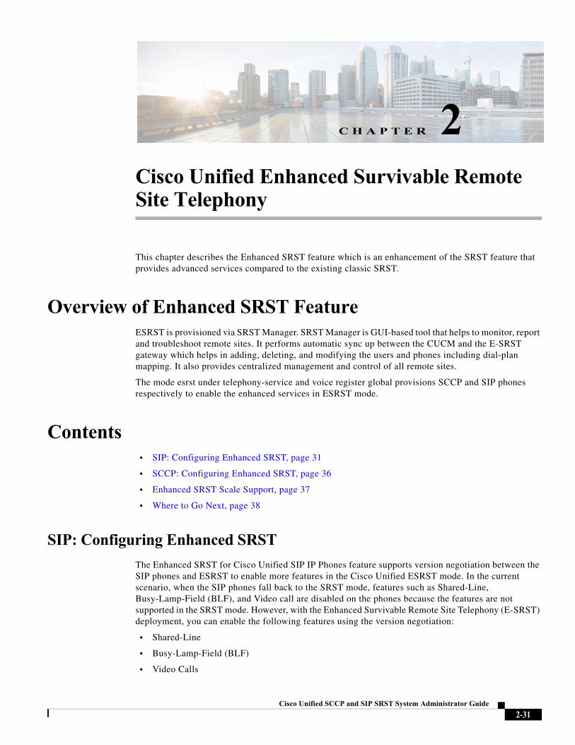
Cisco Unified SC
C H A P T E R 2
Cisco Unified Enhanced Survivable Remote Site TelephonyThis chapter describes the Enhanced SRST feature which is an enhancement of the SRST feature that provides advanced services compared to the existing classic SRST.
Overview of Enhanced SRST FeatureESRST is provisioned via SRST Manager. SRST Manager is GUI-based tool that helps to monitor, report and troubleshoot remote sites. It performs automatic sync up between the CUCM and the E-SRST gateway which helps in adding, deleting, and modifying the users and phones including dial-plan mapping. It also provides centralized management and control of all remote sites.
The mode esrst under telephony-service and voice register global provisions SCCP and SIP phones respectively to enable the enhanced services in ESRST mode.
Contents• SIP: Configuring Enhanced SRST, page 31
• SCCP: Configuring Enhanced SRST, page 36
• Enhanced SRST Scale Support, page 37
• Where to Go Next, page 38
SIP: Configuring Enhanced SRST
The Enhanced SRST for Cisco Unified SIP IP Phones feature supports version negotiation between the SIP phones and ESRST to enable more features in the Cisco Unified ESRST mode. In the current scenario, when the SIP phones fall back to the SRST mode, features such as Shared-Line, Busy-Lamp-Field (BLF), and Video call are disabled on the phones because the features are not supported in the SRST mode. However, with the Enhanced Survivable Remote Site Telephony (E-SRST) deployment, you can enable the following features using the version negotiation:
• Shared-Line
• Busy-Lamp-Field (BLF)
• Video Calls
2-31CP and SIP SRST System Administrator Guide
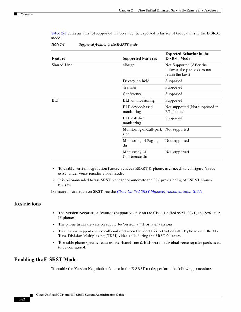
Chapter 2 Cisco Unified Enhanced Survivable Remote Site TelephonyContents
Table 2-1 contains a list of supported features and the expected behavior of the features in the E-SRST mode.
• To enable version negotiation feature between ESRST & phone, user needs to configure "mode esrst" under voice register global mode.
• It is recommended to use SRST manager to automate the CLI provisioning of ESRST branch routers.
For more information on SRST, see the Cisco Unified SRST Manager Administration Guide.
Restrictions
• The Version Negotiation feature is supported only on the Cisco Unified 9951, 9971, and 8961 SIP IP phones.
• The phone firmware version should be Version 9.4.1 or later versions.
• This feature supports video calls only between the local Cisco Unified SIP IP phones and the No Time-Division Multiplexing (TDM) video calls during the SRST failovers.
• To enable phone specific features like shared-line & BLF work, individual voice register pools need to be configured.
Enabling the E-SRST Mode
To enable the Version Negotiation feature in the E-SRST mode, perform the following procedure.
Table 2-1 Supported features in the E-SRST mode
Feature Supported FeaturesExpected Behavior in the E-SRST Mode
Shared-Line cBarge Not Supported (After the failover, the phone does not retain the key.)
Privacy-on-hold Supported
Transfer Supported
Conference Supported
BLF BLF dn monitoring Supported
BLF device-based monitoring
Not supported (Not supported in RT phones)
BLF call-list monitoring
Supported
Monitoring of Call-park slot
Not supported
Monitoring of Paging dn
Not supported
Monitoring of Conference dn
Not supported
2-32Cisco Unified SCCP and SIP SRST System Administrator Guide
Chapter 2 Cisco Unified Enhanced Survivable Remote Site TelephonyContents
SUMMARY STEPS
1. enable
2. configure terminal
3. voice register global
4. mode esrst
5. exit
DETAILED STEPS
Configuring SIP shared-line
To configure SIP shared-line, perform the following procedure:
SUMMARY STEPS
1. enable
2. configure terminal
3. voice register dn dn-tag
4. number number
5. shared-line [max-calls number-of-calls]
6. huntstop channel number-of-channels
7. end
Command or Action Purpose
Step 1 enable
Example:Router> enable
Enables the privileged EXEC mode. Enter your password if prompted.
Step 2 configure terminal
Example:Router# configure terminal
Enters the global configuration mode.
Step 3 voice register global
Example:Router(config)# voice register global
Enters the voice register global configuration mode to set the parameters for all the supported SIP phones in Cisco Unified CME.
Step 4 mode esrst
Example:Router(config-register-global)# mode esrst
Configures the E-SRST mode under the voice register global mode.
Step 5 exit
Example:Router(config-register-global)# exit
Exits the voice register-global configuration mode.
2-33Cisco Unified SCCP and SIP SRST System Administrator Guide
Chapter 2 Cisco Unified Enhanced Survivable Remote Site TelephonyContents
Configuring BLF
To configure BLF, perform the following procedure:
SUMMARY STEPS
1. enable
2. configure terminal
3. sip-ua
4. presence enable
5. exit
6. presence
7. max-subscription number
8. presence call-list
9. end
Enabling a Directory Number to be Watched
To enable a directory number to be watched, perform the following procedure:
1. voice register dn dn-tag
2. number number
3. allow watch
4. end
Enabling BLF on a voice register pool:
To enable BLF on a voice register pool, perform the following steps:
1. enable
2. configure terminal
3. voice register pool pool-tag
4. number tag dn dn-tag
5. blf-speed-dial tag number label string [device]
6. presence call-list (To enable Presence feature for all the missed/received/placed calls)
7. end
For configuration information, see the Cisco Unified Communications Manager Administration Guide.
Example: ESRST mode
The following example shows how to enable the E-SRST mode:
Router# configure terminalRouter(config)# voice register globalRouter(config-register-global)# mode esrst
2-34Cisco Unified SCCP and SIP SRST System Administrator Guide
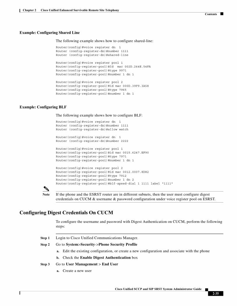
Chapter 2 Cisco Unified Enhanced Survivable Remote Site TelephonyContents
Example: Configuring Shared Line
The following example shows how to configure shared-line:
Router(config)#voice register dn 1Router (config-register-dn)#number 1111Router (config-register-dn)#shared-line
Router(config)#voice register pool 1Router(config-register-pool)#Id mac 002D.264E.54FARouter(config-register-pool)#type 9971Router(config-register-pool)#number 1 dn 1
Router(config)#voice register pool 2Router(config-register-pool)#id mac 000D.39F9.3A58Router(config-register-pool)#type 7965Router(config-register-pool)#number 1 dn 1
Example: Configuring BLF
The following example shows how to configure BLF:
Router(config)#voice register dn 1Router (config-register-dn)#number 1111Router (config-register-dn)#allow watch
Router(config)#voice register dn 1Router (config-register-dn)#number 2222
Router(config)#voice register pool 1Router(config-register-pool)#id mac 0015.6247.EF90Router(config-register-pool)#type 7971Router(config-register-pool)#number 1 dn 1
Router(config)#voice register pool 2Router(config-register-pool)#id mac 0012.0007.8D82Router(config-register-pool)#type 7912Router(config-register-pool)#number 1 dn 2Router(config-register-pool)#blf-speed-dial 1 1111 label "1111"
Note If the phone and the ESRST router are in different subnets, then the user must configure digest credentials on CUCM & username & password configuration under voice register pool on ESRST.
Configuring Digest Credentials On CUCM
To configure the username and password with Digest Authentication on CUCM, perform the following steps:
Step 1 Login to Cisco Unified Communications Manager.
Step 2 Go to System>Security->Phone Security Profile
a. Edit the existing configuration, or create a new configuration and associate with the phone
b. Check the Enable Digest Authentication box
Step 3 Go to User Management > End User
a. Create a new user
2-35Cisco Unified SCCP and SIP SRST System Administrator Guide
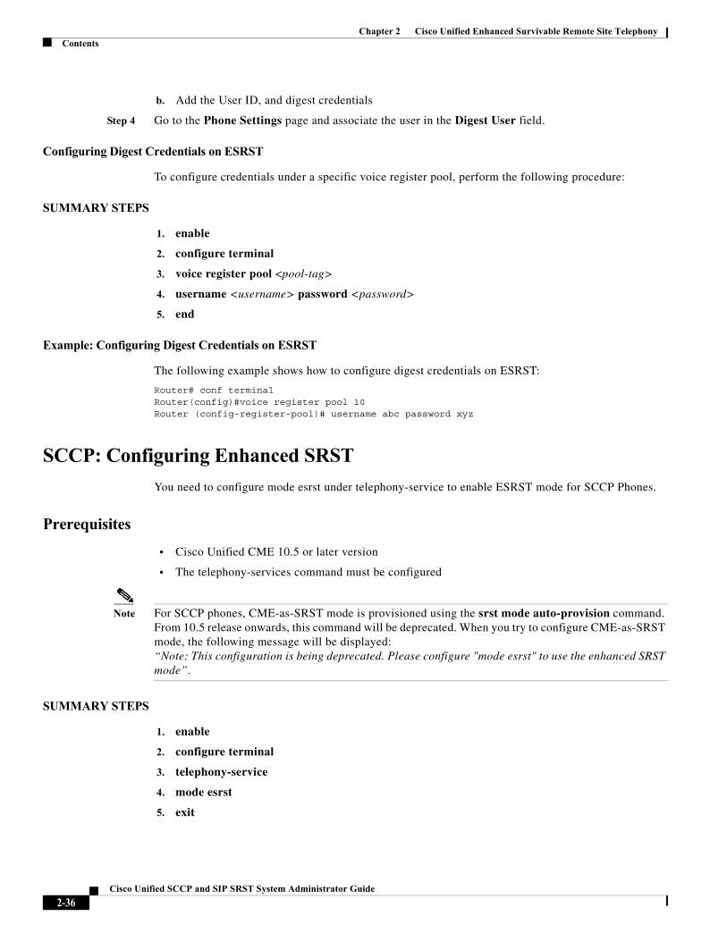
Chapter 2 Cisco Unified Enhanced Survivable Remote Site TelephonyContents
b. Add the User ID, and digest credentials
Step 4 Go to the Phone Settings page and associate the user in the Digest User field.
Configuring Digest Credentials on ESRST
To configure credentials under a specific voice register pool, perform the following procedure:
SUMMARY STEPS
1. enable
2. configure terminal
3. voice register pool <pool-tag>
4. username <username> password <password>
5. end
Example: Configuring Digest Credentials on ESRST
The following example shows how to configure digest credentials on ESRST:
Router# conf terminalRouter(config)#voice register pool 10Router (config-register-pool)# username abc password xyz
SCCP: Configuring Enhanced SRST
You need to configure mode esrst under telephony-service to enable ESRST mode for SCCP Phones.
Prerequisites
• Cisco Unified CME 10.5 or later version
• The telephony-services command must be configured
Note For SCCP phones, CME-as-SRST mode is provisioned using the srst mode auto-provision command. From 10.5 release onwards, this command will be deprecated. When you try to configure CME-as-SRST mode, the following message will be displayed: “Note: This configuration is being deprecated. Please configure "mode esrst" to use the enhanced SRST mode”.
SUMMARY STEPS
1. enable
2. configure terminal
3. telephony-service
4. mode esrst
5. exit
2-36Cisco Unified SCCP and SIP SRST System Administrator Guide
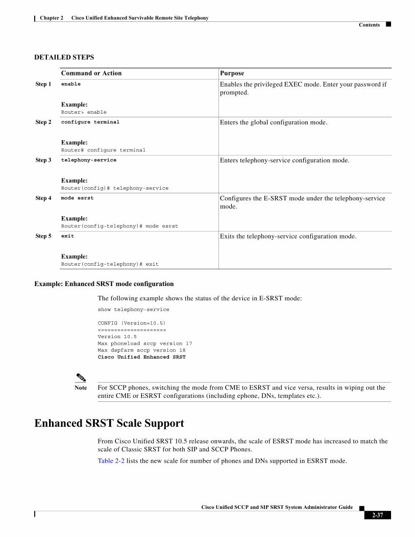
Chapter 2 Cisco Unified Enhanced Survivable Remote Site TelephonyContents
DETAILED STEPS
Example: Enhanced SRST mode configuration
The following example shows the status of the device in E-SRST mode:
show telephony-service
CONFIG (Version=10.5)=====================Version 10.5Max phoneload sccp version 17Max dspfarm sccp version 18Cisco Unified Enhanced SRST
Note For SCCP phones, switching the mode from CME to ESRST and vice versa, results in wiping out the entire CME or ESRST configurations (including ephone, DNs, templates etc.).
Enhanced SRST Scale Support
From Cisco Unified SRST 10.5 release onwards, the scale of ESRST mode has increased to match the scale of Classic SRST for both SIP and SCCP Phones.
Table 2-2 lists the new scale for number of phones and DNs supported in ESRST mode.
Command or Action Purpose
Step 1 enable
Example:Router> enable
Enables the privileged EXEC mode. Enter your password if prompted.
Step 2 configure terminal
Example:Router# configure terminal
Enters the global configuration mode.
Step 3 telephony-service
Example:Router(config)# telephony-service
Enters telephony-service configuration mode.
Step 4 mode esrst
Example:Router(config-telephony)# mode esrst
Configures the E-SRST mode under the telephony-service mode.
Step 5 exit
Example:Router(config-telephony)# exit
Exits the telephony-service configuration mode.
2-37Cisco Unified SCCP and SIP SRST System Administrator Guide
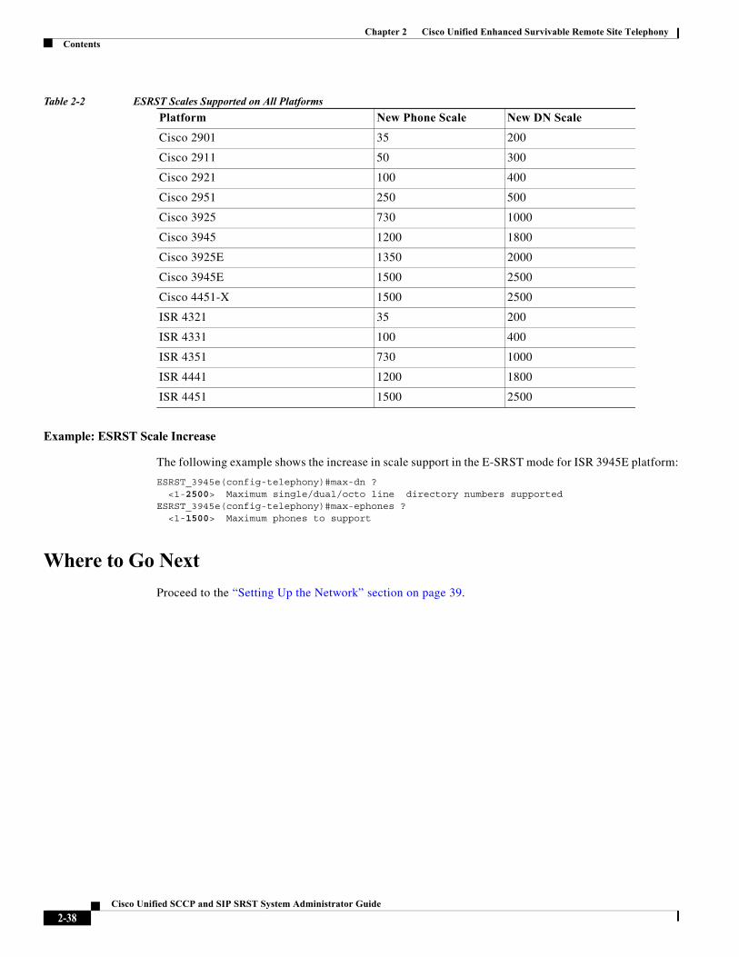
Chapter 2 Cisco Unified Enhanced Survivable Remote Site TelephonyContents
Table 2-2 ESRST Scales Supported on All Platforms
Example: ESRST Scale Increase
The following example shows the increase in scale support in the E-SRST mode for ISR 3945E platform:
ESRST_3945e(config-telephony)#max-dn ? <1-2500> Maximum single/dual/octo line directory numbers supportedESRST_3945e(config-telephony)#max-ephones ? <1-1500> Maximum phones to support
Where to Go Next
Proceed to the “Setting Up the Network” section on page 39.
Platform New Phone Scale New DN Scale
Cisco 2901 35 200
Cisco 2911 50 300
Cisco 2921 100 400
Cisco 2951 250 500
Cisco 3925 730 1000
Cisco 3945 1200 1800
Cisco 3925E 1350 2000
Cisco 3945E 1500 2500
Cisco 4451-X 1500 2500
ISR 4321 35 200
ISR 4331 100 400
ISR 4351 730 1000
ISR 4441 1200 1800
ISR 4451 1500 2500
2-38Cisco Unified SCCP and SIP SRST System Administrator Guide
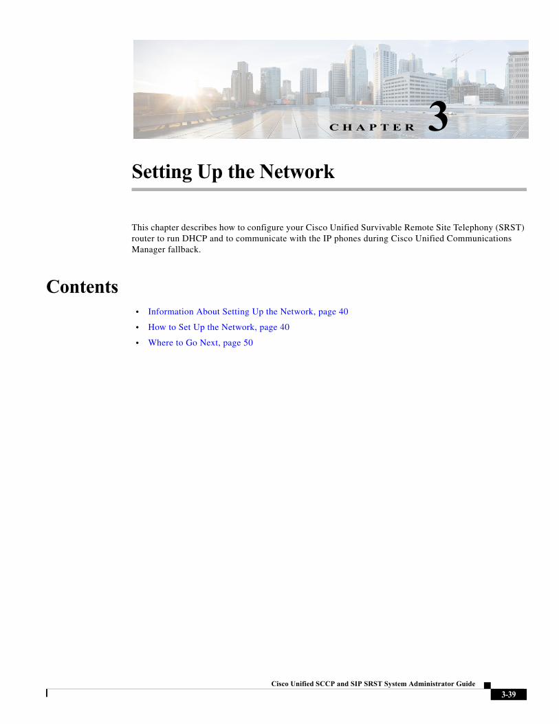
Cisco Unified SC
C H A P T E R 3
Setting Up the NetworkThis chapter describes how to configure your Cisco Unified Survivable Remote Site Telephony (SRST) router to run DHCP and to communicate with the IP phones during Cisco Unified Communications Manager fallback.
Contents• Information About Setting Up the Network, page 40
• How to Set Up the Network, page 40
• Where to Go Next, page 50
3-39CP and SIP SRST System Administrator Guide
Chapter 3 Setting Up the NetworkInformation About Setting Up the Network
Information About Setting Up the NetworkWhen the WAN link fails, the Cisco Unified IP Phones detect that they are no longer receiving keepalive packets from Cisco Unified CM. The Cisco Unified IP Phones then register with the router. The Cisco Unified SRST software is automatically activated and builds a local database of all Cisco Unified IP Phones attached to it (up to its configured maximum). The IP phones are configured to query the router as a backup call-processing source when the central Cisco Unified CM does not acknowledge keepalive packets. The Cisco Unified SRST router now performs call setup and processing, call maintenance, and call termination.
Cisco Unified Communications Manager uses DHCP to provide Cisco Unified IP Phones with the IP address of Cisco Unified Communications Manager. In a remote branch office, DHCP service is typically provided either by the SRST router itself or through the Cisco Unified SRST router using DHCP relay. Configuring DHCP is one of two main tasks in setting up network communication. The other task is configuring the Cisco Unified SRST router to receive messages from the Cisco IP phones through the specified IP addresses. Keepalive intervals are also set at this time.
How to Set Up the NetworkThis section contains the following tasks:
• Enabling IP Routing, page 40 (Required)
• Enabling Cisco Unified SRST on an MGCP Gateway (Required)
• Configuring DHCP for Cisco Unified SRST Phones, page 46 (Required)
• Specifying Keepalive Intervals, page 49 (Optional)
Enabling IP Routing
To initiate SRST service, you need to enable IP routing command and configure an interface that you want to use or bind. For information about enabling IP routing, see Configuring IP Addressing.
Enabling Cisco Unified SRST on an MGCP Gateway
To use SRST as your fallback mode with an MGCP gateway, SRST and MGCP fallback must both be configured on the same gateway. The configuration below allows SRST to assume control over the voice port and over call processing on the MGCP gateway. Due to command changes that were made in Cisco IOS Release 12.3(14)T, use the configuration task that corresponds with the Cisco IOS Release you have installed.
Note The commands described in the configuration below are ineffective unless both commands are configured. For instance, your configuration will not work if you only configure the ccm-manager fallback-mgcp command.
3-40Cisco Unified SCCP and SIP SRST System Administrator Guide
Chapter 3 Setting Up the NetworkHow to Set Up the Network
Note When an MGCP-controlled PRI goes into SRST mode, do not make or save configuration changes to the NVRAM on the router. If configuration changes are made and saved in SRST mode, the MGCP-controlled PRI fails when normal MGCP operation is restored.
Configuring Cisco Unified SRST on an MGCP Gateway Prior to Cisco IOS Release 12.3(14)T
Perform this task to enable SRST on a MGCP Gateway if you are using a software release prior to Cisco IOS Release 12.3(14)T.
SUMMARY STEPS
1. enable
2. configure terminal
3. ccm-manager fallback-mgcp
4. call application alternate [application-name] or service [alternate | default] service-name location
5. exit
DETAILED STEPS
Command or Action Purpose
Step 1 enable
Example:Router> enable
Enables privileged EXEC mode.
• Enter your password when prompted.
Step 2 configure terminal
Example:Router# configure terminal
Enters global configuration mode.
Step 3 ccm-manager fallback-mgcp
Example:Router(config)# ccm-manager fallback-mgcp
Enables the gateway fallback feature and allows an MGCP voice gateway to provide call processing services through SRST or other configured applications when Cisco Unified Communications Manager is unavailable.
3-41Cisco Unified SCCP and SIP SRST System Administrator Guide
Chapter 3 Setting Up the NetworkHow to Set Up the Network
Configuring SRST on an MGCP Gateway Using Cisco IOS Release 12.3(14)T or Later Releases
Perform this task to enable SRST on an MGCP Gateway if you are using Cisco IOS Release 12.3(14)T or later version.
Restrictions
Effective with Cisco IOS Release 12.3(14)T, the call application alternate command is replaced by the service command. The service command can be used in all releases after Cisco IOS Release 12.3(14)T.
Step 4 call application alternate [application-name] orservice [alternate | default] service-name location
Example:Router(config)# call application alternateorRouter(config)# service default
The call application alternate command specifies that the default voice application takes over if the MGCP application is not available. The application-name argument is optional and indicates the name of the specific voice application to use if the application in the dial peer fails. If a specific application name is not entered, the gateway uses the DEFAULT application.
Or
The service command loads and configures a specific, standalone application on a dial peer. The keywords and arguments are as follows:
• alternate (Optional). Alternate service to use if the service that is configured on the dial peer fails.
• default (Optional). Specifies that the default service (“DEFAULT”) on the dial peer is used if the alternate service fails.
• service-name: Name that identifies the voice application.
• location: Directory and filename of the Tcl script or VoiceXML document in URL format. For example, flash memory (flash:filename), a TFTP (tftp://../filename), or an HTTP server (http://../filename) are valid locations.
Step 5 exit
Example:Router(config)# exit
Exits global configuration mode and returns to privileged EXEC mode.
Command or Action Purpose
3-42Cisco Unified SCCP and SIP SRST System Administrator Guide
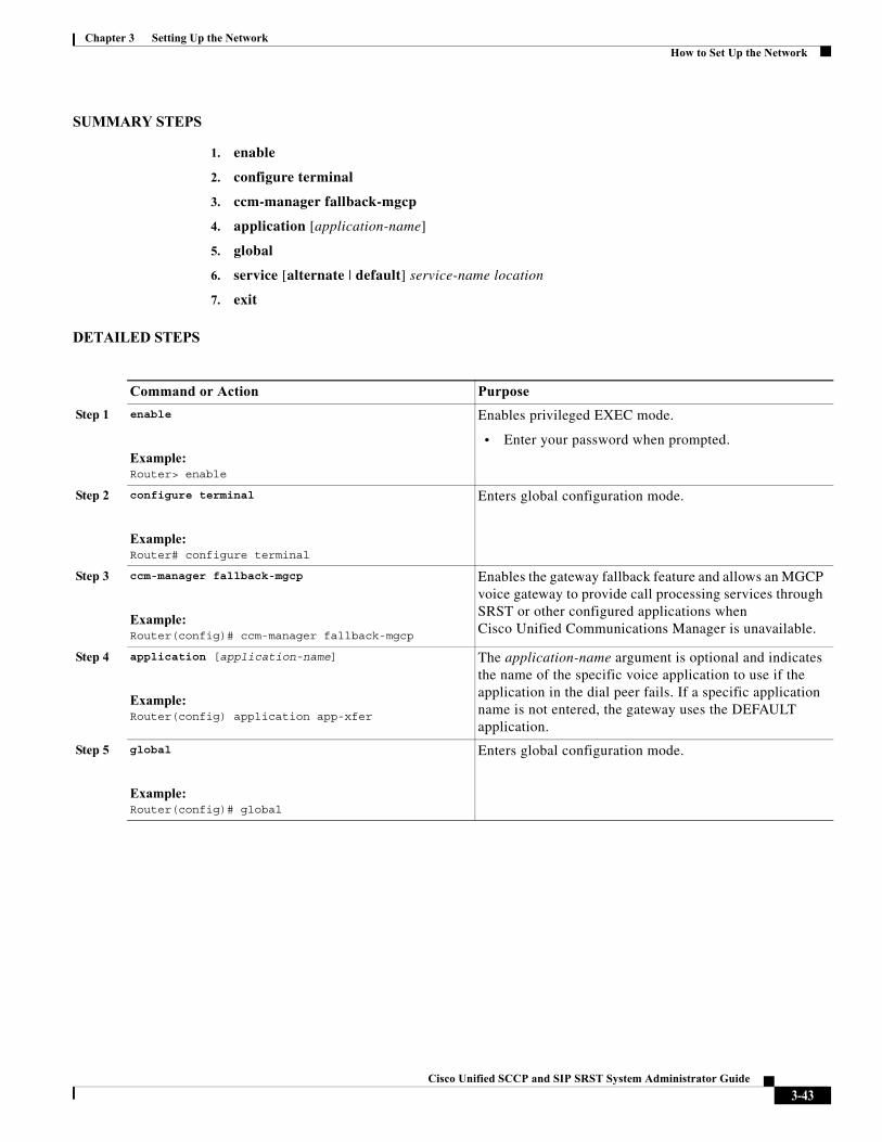
Chapter 3 Setting Up the NetworkHow to Set Up the Network
SUMMARY STEPS
1. enable
2. configure terminal
3. ccm-manager fallback-mgcp
4. application [application-name]
5. global
6. service [alternate | default] service-name location
7. exit
DETAILED STEPS
Command or Action Purpose
Step 1 enable
Example:Router> enable
Enables privileged EXEC mode.
• Enter your password when prompted.
Step 2 configure terminal
Example:Router# configure terminal
Enters global configuration mode.
Step 3 ccm-manager fallback-mgcp
Example:Router(config)# ccm-manager fallback-mgcp
Enables the gateway fallback feature and allows an MGCP voice gateway to provide call processing services through SRST or other configured applications when Cisco Unified Communications Manager is unavailable.
Step 4 application [application-name]
Example:Router(config) application app-xfer
The application-name argument is optional and indicates the name of the specific voice application to use if the application in the dial peer fails. If a specific application name is not entered, the gateway uses the DEFAULT application.
Step 5 global
Example:Router(config)# global
Enters global configuration mode.
3-43Cisco Unified SCCP and SIP SRST System Administrator Guide
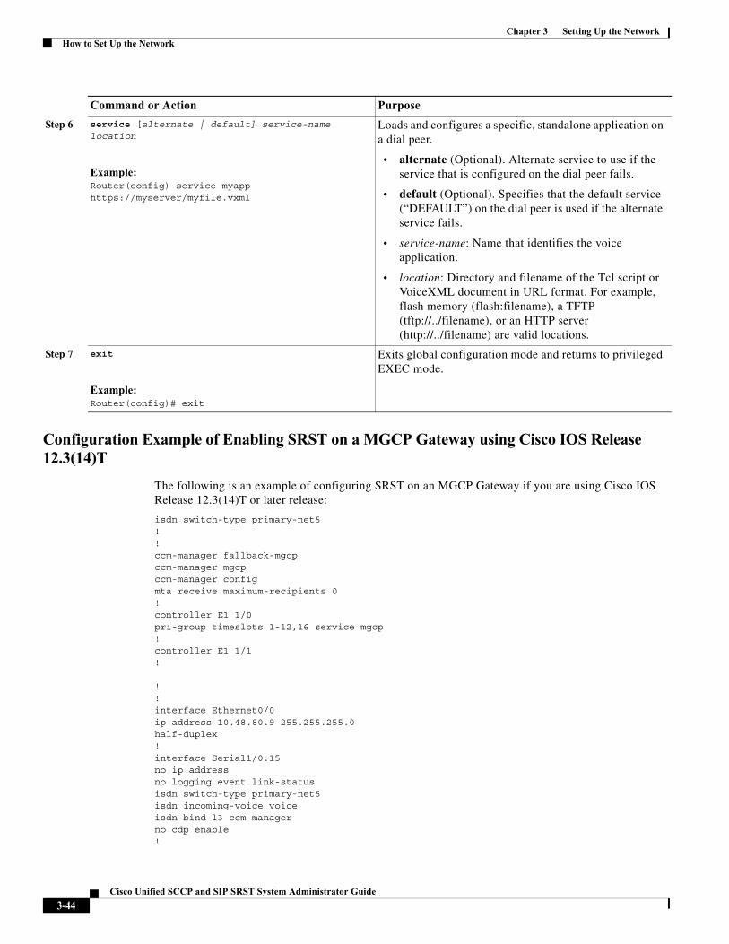
Chapter 3 Setting Up the NetworkHow to Set Up the Network
Configuration Example of Enabling SRST on a MGCP Gateway using Cisco IOS Release 12.3(14)T
The following is an example of configuring SRST on an MGCP Gateway if you are using Cisco IOS Release 12.3(14)T or later release:
isdn switch-type primary-net5!! ccm-manager fallback-mgcpccm-manager mgcpccm-manager configmta receive maximum-recipients 0!controller E1 1/0pri-group timeslots 1-12,16 service mgcp!controller E1 1/1!
! ! interface Ethernet0/0ip address 10.48.80.9 255.255.255.0half-duplex!interface Serial1/0:15no ip addressno logging event link-statusisdn switch-type primary-net5isdn incoming-voice voiceisdn bind-l3 ccm-managerno cdp enable!
Step 6 service [alternate | default] service-name location
Example:Router(config) service myapp https://myserver/myfile.vxml
Loads and configures a specific, standalone application on a dial peer.
• alternate (Optional). Alternate service to use if the service that is configured on the dial peer fails.
• default (Optional). Specifies that the default service (“DEFAULT”) on the dial peer is used if the alternate service fails.
• service-name: Name that identifies the voice application.
• location: Directory and filename of the Tcl script or VoiceXML document in URL format. For example, flash memory (flash:filename), a TFTP (tftp://../filename), or an HTTP server (http://../filename) are valid locations.
Step 7 exit
Example:Router(config)# exit
Exits global configuration mode and returns to privileged EXEC mode.
Command or Action Purpose
3-44Cisco Unified SCCP and SIP SRST System Administrator Guide
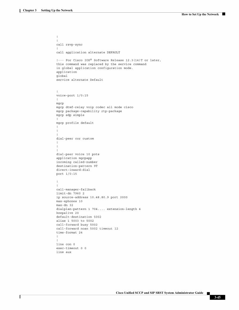
Chapter 3 Setting Up the NetworkHow to Set Up the Network
! !call rsvp-sync!call application alternate DEFAULT
!--- For Cisco IOS® Software Release 12.3(14)T or later,this command was replaced by the service commandin global application configuration mode.applicationglobalservice alternate Default
!voice-port 1/0:15!mgcpmgcp dtmf-relay voip codec all mode ciscomgcp package-capability rtp-packagemgcp sdp simple!mgcp profile default!!!dial-peer cor custom!!!dial-peer voice 10 potsapplication mgcpappincoming called-numberdestination-pattern 9Tdirect-inward-dialport 1/0:15
!!call-manager-fallbacklimit-dn 7960 2ip source-address 10.48.80.9 port 2000max-ephones 10max-dn 32dialplan-pattern 1 704.... extension-length 4keepalive 20default-destination 5002alias 1 5003 to 5002call-forward busy 5002call-forward noan 5002 timeout 12time-format 24!!line con 0exec-timeout 0 0line aux
3-45Cisco Unified SCCP and SIP SRST System Administrator Guide
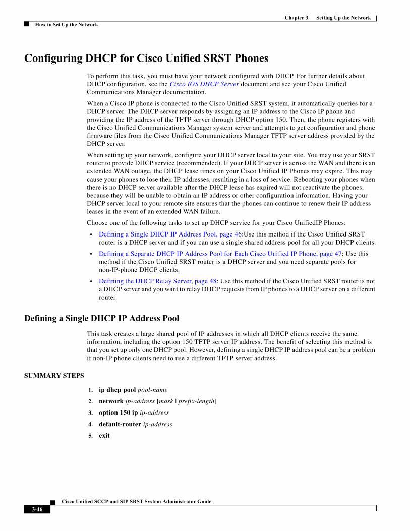
Chapter 3 Setting Up the NetworkHow to Set Up the Network
Configuring DHCP for Cisco Unified SRST Phones
To perform this task, you must have your network configured with DHCP. For further details about DHCP configuration, see the Cisco IOS DHCP Server document and see your Cisco Unified Communications Manager documentation.
When a Cisco IP phone is connected to the Cisco Unified SRST system, it automatically queries for a DHCP server. The DHCP server responds by assigning an IP address to the Cisco IP phone and providing the IP address of the TFTP server through DHCP option 150. Then, the phone registers with the Cisco Unified Communications Manager system server and attempts to get configuration and phone firmware files from the Cisco Unified Communications Manager TFTP server address provided by the DHCP server.
When setting up your network, configure your DHCP server local to your site. You may use your SRST router to provide DHCP service (recommended). If your DHCP server is across the WAN and there is an extended WAN outage, the DHCP lease times on your Cisco Unified IP Phones may expire. This may cause your phones to lose their IP addresses, resulting in a loss of service. Rebooting your phones when there is no DHCP server available after the DHCP lease has expired will not reactivate the phones, because they will be unable to obtain an IP address or other configuration information. Having your DHCP server local to your remote site ensures that the phones can continue to renew their IP address leases in the event of an extended WAN failure.
Choose one of the following tasks to set up DHCP service for your Cisco UnifiedIP Phones:
• Defining a Single DHCP IP Address Pool, page 46:Use this method if the Cisco Unified SRST router is a DHCP server and if you can use a single shared address pool for all your DHCP clients.
• Defining a Separate DHCP IP Address Pool for Each Cisco Unified IP Phone, page 47: Use this method if the Cisco Unified SRST router is a DHCP server and you need separate pools for non-IP-phone DHCP clients.
• Defining the DHCP Relay Server, page 48: Use this method if the Cisco Unified SRST router is not a DHCP server and you want to relay DHCP requests from IP phones to a DHCP server on a different router.
Defining a Single DHCP IP Address Pool
This task creates a large shared pool of IP addresses in which all DHCP clients receive the same information, including the option 150 TFTP server IP address. The benefit of selecting this method is that you set up only one DHCP pool. However, defining a single DHCP IP address pool can be a problem if non-IP phone clients need to use a different TFTP server address.
SUMMARY STEPS
1. ip dhcp pool pool-name
2. network ip-address [mask | prefix-length]
3. option 150 ip ip-address
4. default-router ip-address
5. exit
3-46Cisco Unified SCCP and SIP SRST System Administrator Guide
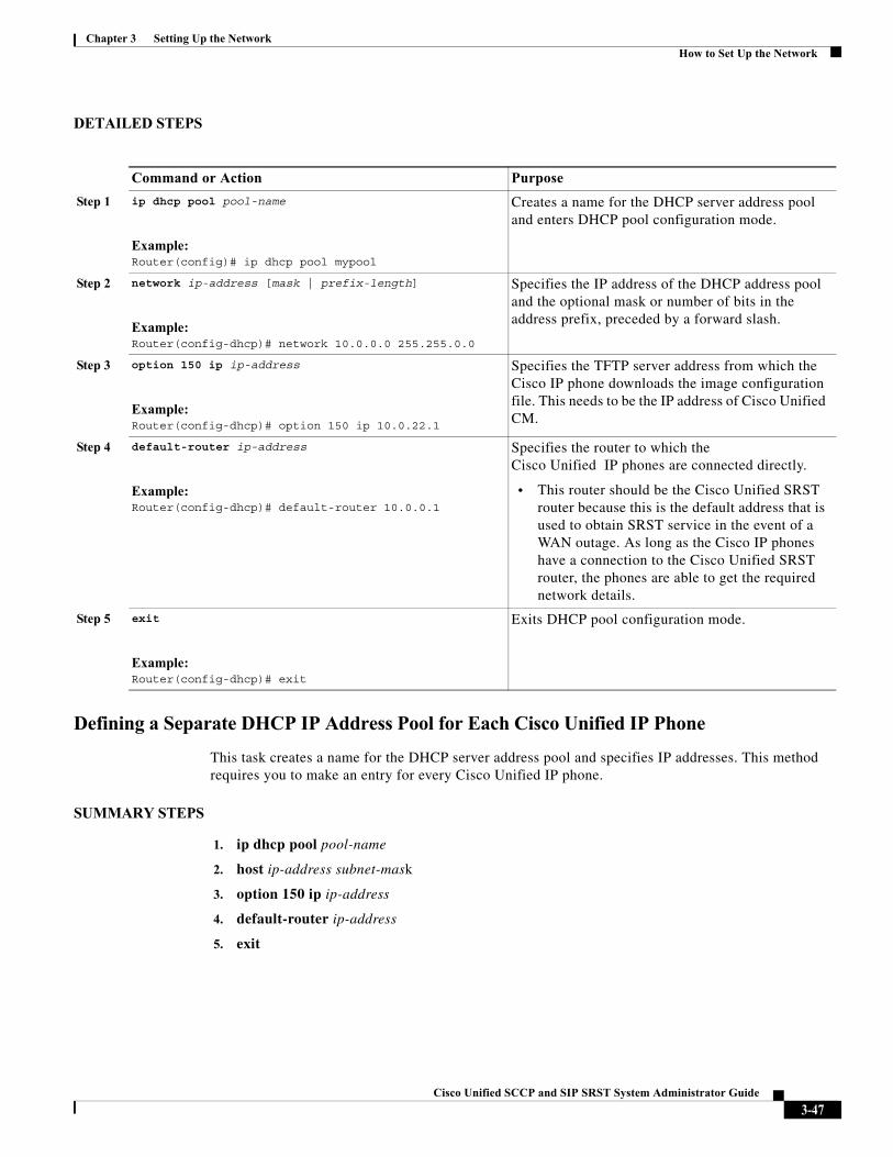
Chapter 3 Setting Up the NetworkHow to Set Up the Network
DETAILED STEPS
Defining a Separate DHCP IP Address Pool for Each Cisco Unified IP Phone
This task creates a name for the DHCP server address pool and specifies IP addresses. This method requires you to make an entry for every Cisco Unified IP phone.
SUMMARY STEPS
1. ip dhcp pool pool-name
2. host ip-address subnet-mask
3. option 150 ip ip-address
4. default-router ip-address
5. exit
Command or Action Purpose
Step 1 ip dhcp pool pool-name
Example:Router(config)# ip dhcp pool mypool
Creates a name for the DHCP server address pool and enters DHCP pool configuration mode.
Step 2 network ip-address [mask | prefix-length]
Example:Router(config-dhcp)# network 10.0.0.0 255.255.0.0
Specifies the IP address of the DHCP address pool and the optional mask or number of bits in the address prefix, preceded by a forward slash.
Step 3 option 150 ip ip-address
Example:Router(config-dhcp)# option 150 ip 10.0.22.1
Specifies the TFTP server address from which the Cisco IP phone downloads the image configuration file. This needs to be the IP address of Cisco Unified CM.
Step 4 default-router ip-address
Example:Router(config-dhcp)# default-router 10.0.0.1
Specifies the router to which the Cisco Unified IP phones are connected directly.
• This router should be the Cisco Unified SRST router because this is the default address that is used to obtain SRST service in the event of a WAN outage. As long as the Cisco IP phones have a connection to the Cisco Unified SRST router, the phones are able to get the required network details.
Step 5 exit
Example:Router(config-dhcp)# exit
Exits DHCP pool configuration mode.
3-47Cisco Unified SCCP and SIP SRST System Administrator Guide
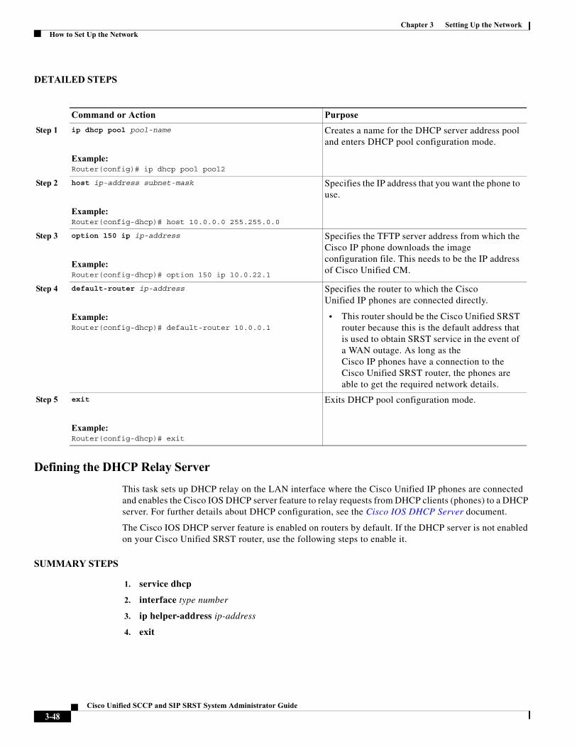
Chapter 3 Setting Up the NetworkHow to Set Up the Network
DETAILED STEPS
Defining the DHCP Relay Server
This task sets up DHCP relay on the LAN interface where the Cisco Unified IP phones are connected and enables the Cisco IOS DHCP server feature to relay requests from DHCP clients (phones) to a DHCP server. For further details about DHCP configuration, see the Cisco IOS DHCP Server document.
The Cisco IOS DHCP server feature is enabled on routers by default. If the DHCP server is not enabled on your Cisco Unified SRST router, use the following steps to enable it.
SUMMARY STEPS
1. service dhcp
2. interface type number
3. ip helper-address ip-address
4. exit
Command or Action Purpose
Step 1 ip dhcp pool pool-name
Example:Router(config)# ip dhcp pool pool2
Creates a name for the DHCP server address pool and enters DHCP pool configuration mode.
Step 2 host ip-address subnet-mask
Example:Router(config-dhcp)# host 10.0.0.0 255.255.0.0
Specifies the IP address that you want the phone to use.
Step 3 option 150 ip ip-address
Example:Router(config-dhcp)# option 150 ip 10.0.22.1
Specifies the TFTP server address from which the Cisco IP phone downloads the image configuration file. This needs to be the IP address of Cisco Unified CM.
Step 4 default-router ip-address
Example:Router(config-dhcp)# default-router 10.0.0.1
Specifies the router to which the Cisco Unified IP phones are connected directly.
• This router should be the Cisco Unified SRST router because this is the default address that is used to obtain SRST service in the event of a WAN outage. As long as the Cisco IP phones have a connection to the Cisco Unified SRST router, the phones are able to get the required network details.
Step 5 exit
Example:Router(config-dhcp)# exit
Exits DHCP pool configuration mode.
3-48Cisco Unified SCCP and SIP SRST System Administrator Guide
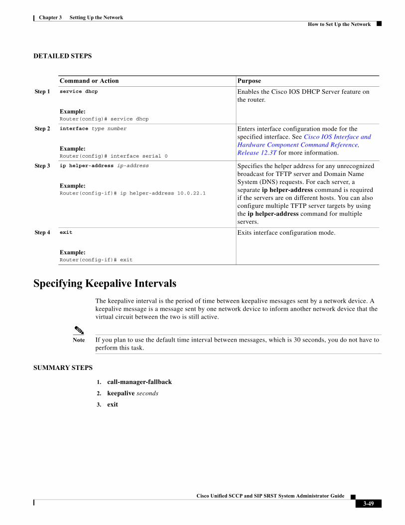
Chapter 3 Setting Up the NetworkHow to Set Up the Network
DETAILED STEPS
Specifying Keepalive Intervals
The keepalive interval is the period of time between keepalive messages sent by a network device. A keepalive message is a message sent by one network device to inform another network device that the virtual circuit between the two is still active.
Note If you plan to use the default time interval between messages, which is 30 seconds, you do not have to perform this task.
SUMMARY STEPS
1. call-manager-fallback
2. keepalive seconds
3. exit
Command or Action Purpose
Step 1 service dhcp
Example:Router(config)# service dhcp
Enables the Cisco IOS DHCP Server feature on the router.
Step 2 interface type number
Example:Router(config)# interface serial 0
Enters interface configuration mode for the specified interface. See Cisco IOS Interface and Hardware Component Command Reference, Release 12.3T for more information.
Step 3 ip helper-address ip-address
Example:Router(config-if)# ip helper-address 10.0.22.1
Specifies the helper address for any unrecognized broadcast for TFTP server and Domain Name System (DNS) requests. For each server, a separate ip helper-address command is required if the servers are on different hosts. You can also configure multiple TFTP server targets by using the ip helper-address command for multiple servers.
Step 4 exit
Example:Router(config-if)# exit
Exits interface configuration mode.
3-49Cisco Unified SCCP and SIP SRST System Administrator Guide
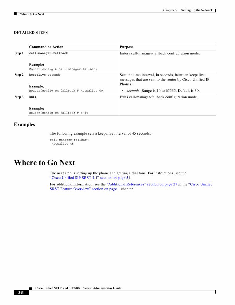
Chapter 3 Setting Up the NetworkWhere to Go Next
DETAILED STEPS
Examples
The following example sets a keepalive interval of 45 seconds:
call-manager-fallbackkeepalive 45
Where to Go NextThe next step is setting up the phone and getting a dial tone. For instructions, see the“Cisco Unified SIP SRST 4.1” section on page 51.
For additional information, see the “Additional References” section on page 27 in the “Cisco Unified SRST Feature Overview” section on page 1 chapter.
Command or Action Purpose
Step 1 call-manager-fallback
Example:Router(config)# call-manager-fallback
Enters call-manager-fallback configuration mode.
Step 2 keepalive seconds
Example:Router(config-cm-fallback)# keepalive 60
Sets the time interval, in seconds, between keepalive messages that are sent to the router by Cisco Unified IP Phones.
• seconds: Range is 10 to 65535. Default is 30.
Step 3 exit
Example:Router(config-cm-fallback)# exit
Exits call-manager-fallback configuration mode.
3-50Cisco Unified SCCP and SIP SRST System Administrator Guide
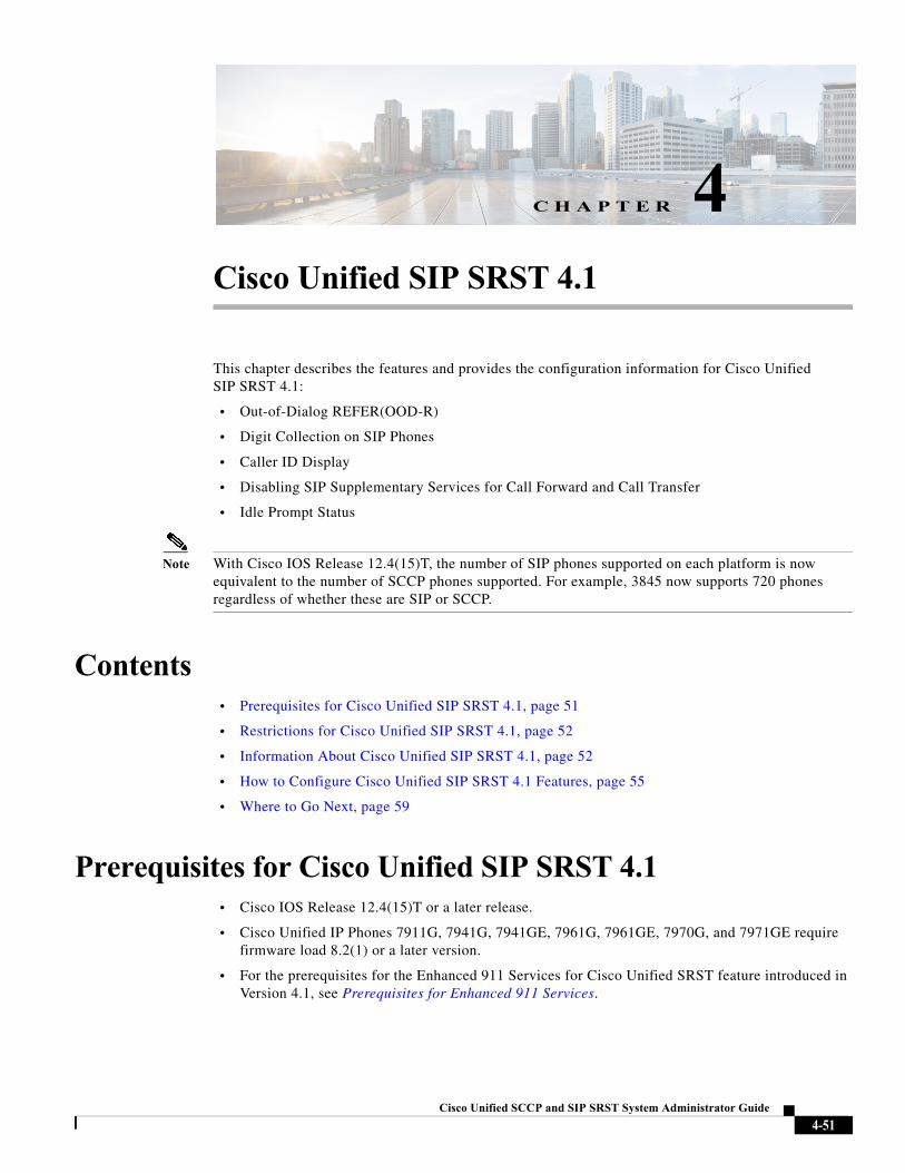
Cisco Unified SC
C H A P T E R 4
Cisco Unified SIP SRST 4.1This chapter describes the features and provides the configuration information for Cisco Unified SIP SRST 4.1:
• Out-of-Dialog REFER(OOD-R)
• Digit Collection on SIP Phones
• Caller ID Display
• Disabling SIP Supplementary Services for Call Forward and Call Transfer
• Idle Prompt Status
Note With Cisco IOS Release 12.4(15)T, the number of SIP phones supported on each platform is now equivalent to the number of SCCP phones supported. For example, 3845 now supports 720 phones regardless of whether these are SIP or SCCP.
Contents• Prerequisites for Cisco Unified SIP SRST 4.1, page 51
• Restrictions for Cisco Unified SIP SRST 4.1, page 52
• Information About Cisco Unified SIP SRST 4.1, page 52
• How to Configure Cisco Unified SIP SRST 4.1 Features, page 55
• Where to Go Next, page 59
Prerequisites for Cisco Unified SIP SRST 4.1• Cisco IOS Release 12.4(15)T or a later release.
• Cisco Unified IP Phones 7911G, 7941G, 7941GE, 7961G, 7961GE, 7970G, and 7971GE require firmware load 8.2(1) or a later version.
• For the prerequisites for the Enhanced 911 Services for Cisco Unified SRST feature introduced in Version 4.1, see Prerequisites for Enhanced 911 Services.
4-51CP and SIP SRST System Administrator Guide
Chapter 4 Cisco Unified SIP SRST 4.1Restrictions for Cisco Unified SIP SRST 4.1
Restrictions for Cisco Unified SIP SRST 4.1• Cisco Unified SRST does not support BLF speed-dial notification, call forward all synchronization,
dial plans, directory services, or music-on-hold (MOH).
• Prior to SIP phone load 8.0, SIP phones maintained dual registration with both Cisco Unified Communications Manager and Cisco Unified SRST simultaneously. In SIP phone load 8.0 and later versions, SIP phones use keepalive to maintain a connection with Cisco Unified SRST during active registration with Cisco Unified Communications Manager. Every 2 minutes, a SIP phone sends a keepalive message to Cisco Unified SRST. Cisco Unified SRST responds to this keepalive with a 404 message. This process repeats until fallback to Cisco Unified SRST occurs. After fallback, SIP phones send a keepalive message every two minutes to Cisco Unified Communications Manager while the phones are registered with Cisco Unified SRST. Cisco Unified SRST continues to support dual registration for SIP phone loads older than 8.0.
Information About Cisco Unified SIP SRST 4.1• Out-of-Dialog REFER, page 52
• Digit Collection on SIP Phones, page 53
• Caller ID Display, page 54
• Disabling SIP Supplementary Services for Call Forward and Call Transfer, page 54
• Idle Prompt Status, page 54
• Enhanced 911 Services, page 54
Out-of-Dialog REFER
Out-of-dialog REFER (OOD-R) enables remote applications to establish calls by sending a REFER message to Cisco Unified SRST without an initial INVITE. After the REFER is sent, the remainder of the call setup is independent of the application and the media stream does not flow through the application. The application using OOD-R triggers a call setup request that specifies the Referee address in the Request-URI and the Refer-Target in the Refer-To header. The SIP messaging used to communicate with Cisco Unified SRST is independent of the end-user device protocol, which can be H.323, plain old telephone service (POTS), SCCP, or SIP. Click-to-dial is an example of an application that can be created using OOD-R.
A click-to-dial application enables users to combine multiple steps into one click for a call setup. For example, a user can click a web-based directory application from his or her PC to look up a telephone number, off-hook the desktop phone, and dial the called number. The application initiates the call setup without the user having to out-dial from his or her own phone. The directory application sends a REFER message to Cisco Unified SRST, which sets up the call between both parties based on this REFER.
For more information about OOD-R, see Out-of-Dialog REFER from the Cisco Unified Communications Manager Express System Administrator Guide.
4-52Cisco Unified SCCP and SIP SRST System Administrator Guide
Chapter 4 Cisco Unified SIP SRST 4.1Information About Cisco Unified SIP SRST 4.1
Digit Collection on SIP Phones
Digit strings dialed by phone users must be collected and matched against predefined patterns to place calls to the destination corresponding to the user's input. Previously, SIP phones in a Cisco Unified SRST system required users to press the DIAL soft key or # key, or wait for the interdigit-timeout to trigger call processing. This could cause delays in processing the call.
Two new methods of collecting and matching digits are supported for SIP phones depending on the model of the phone:
• KPML Digit Collection, page 53
• SIP Dial Plans, page 53
KPML Digit Collection
The Key Press Markup Language (KPML) uses SIP SUBSCRIBE and NOTIFY methods to report user input digit by digit. Each digit dialed by the phone user generates its own signaling message to Cisco Unified SRST, which performs pattern recognition by matching a destination pattern to a dial peer as it collects the dialed digits. This process of relaying each digit immediately is similar to the process used by SCCP phones. It eliminates the need for the user to press the Dial soft key or wait for the interdigit timeout before the digits are sent to the Cisco Unified SRST for processing.
KPML is supported on Cisco Unified IP Phones 7911G, 7941G, 7941GE, 7961G, 7961GE, 7970G, and 7971GE. For configuration information, see the “Enabling KPML for SIP Phones” section on page 55.
SIP Dial Plans
A dial plan is a set of dial patterns that SIP phones use to determine when digit collection is complete after a user goes off-hook and dials a destination number. Dial plans enable SIP phones to perform local digit collection and recognize dial patterns as user input is collected. After a pattern is recognized, the SIP phone sends an INVITE message to Cisco Unified SRST to initiate the call to the number matching the user's input. All of the digits entered by the user are presented as a block to Cisco Unified SRST for processing. Because digit collection is done by the phone, dial plans reduce signaling messages overhead compared to KPML digit collection.
SIP dial plans eliminate the need for a user to press the Dial soft key or # key or to wait for the interdigit timeout to trigger an outgoing INVITE. You configure a SIP dial plan and associate the dial plan with a SIP phone. The dial plan is downloaded to the phone in the configuration file.
You can configure SIP dial plans and associate them with the following SIP phones:
• Cisco Unified IP Phone 7911G, 7941G, 7941GE, 7961G, 7961GE, 7970G, and 7971GE: These phones use dial plans and support KPML. If both a dial plan and KPML are enabled, the dial plan has priority.
If a matching dial plan is not found and KPML is disabled, the user must wait for the interdigit timeout before the SIP NOTIFY message is sent to Cisco Unified SRST. Unlike other SIP phones, these phones do not have a Dial soft key to indicate the end of dialing, except when on-hook dialing is used.
• Cisco Unified IP Phone 7905, 7912, 7940, and 7960: These phones use dial plans and do not support KPML. If you do not configure a SIP dial plan for these phones, or if the dialed digits do not match a dial plan, the user must press the Dial soft key or wait for the interdigit timeout before digits are sent to Cisco Unified SRST for processing.
4-53Cisco Unified SCCP and SIP SRST System Administrator Guide
Chapter 4 Cisco Unified SIP SRST 4.1Information About Cisco Unified SIP SRST 4.1
When you reset a phone, the phone requests its configuration files from the TFTP server, which builds the appropriate configuration files depending on the type of phone.
• Cisco Unified IP Phone 7905 and 7912: The dial plan is a field in their configuration files.
• Cisco Unified IP Phone 7911G, 7940, 7941G, 7941GE, 7960, 7961G, 7961GE, 7970G, and 7971GE: The dial plan is a separate XML file that is pointed to from the normal configuration file.
The Cisco Unified SRST supports SIP dial plans if they are provisioned in Cisco Unified Communications Manager. You cannot configure dial plans in Cisco Unified SRST.
Caller ID Display
The name and number of the caller is included in the Caller ID display on the Cisco Unified IP Phone 7911G, 7941G, 7941GE, 7961G, 7961GE, 7970G, and 7971GE. Other SIP phones display only the number of the caller. Also, the caller ID information is updated on the destination phone when there is a change in the caller ID of the originating party such as with call forwarding or call transfer. No new configuration is required to support these enhancements.
Disabling SIP Supplementary Services for Call Forward and Call Transfer
If a destination gateway does not support supplementary services, you can disable REFER messages for call transfers and redirect responses for call forwarding from being sent by Cisco Unified SRST.
Disabling supplementary services is supported if all endpoints use SCCP or all endpoints use SIP. It is not supported for a mix of SCCP and SIP endpoints.
Idle Prompt Status
A message displays on the status line of a SIP phone after the phone registers to Cisco Unified SRST to indicate that Cisco Unified SRST is providing fallback support for the Cisco Unified Communications Manager. This message informs the user that the phone is operating in fallback mode and that not all features are available. The default message that displays “CM Fallback Service Operating” is taken from the phone dictionary file. You can customize the message by using the system message command on the Cisco Unified SRST router. Cisco Unified SRST updates the idle prompt message when a SIP phone registers or when you modify the message through the configuration. The message displays until a phone switches back to the Cisco Unified Communications Manager.
The idle prompt status message is supported for the Cisco Unified IP Phone 7911G, 7941G, 7941GE, 7961G, 7961GE, 7970G, and 7971GE with Cisco Unified SRST 4.1 and later versions. For versions earlier than Cisco Unified SRST 4.1, the phones display the default message from the dictionary file.
Enhanced 911 Services
Enhanced 911 Services for Cisco Unified SRST enables 911 operators to:
• Immediately pinpoint the location of the 911 caller based on the calling number
• Callback the 911 caller if a disconnect occurs
Before this feature was introduced, Cisco Unified SRST supported only outbound calls to 911. With basic 911 functionality, calls were simply routed to a Public Safety Answering Point (PSAP). The 911 operator at the PSAP would then have to verbally gather the emergency information and location from
4-54Cisco Unified SCCP and SIP SRST System Administrator Guide
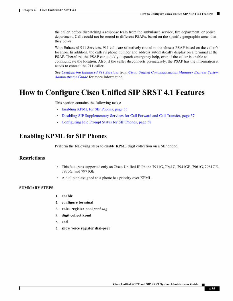
Chapter 4 Cisco Unified SIP SRST 4.1How to Configure Cisco Unified SIP SRST 4.1 Features
the caller, before dispatching a response team from the ambulance service, fire department, or police department. Calls could not be routed to different PSAPs, based on the specific geographic areas that they cover.
With Enhanced 911 Services, 911 calls are selectively routed to the closest PSAP based on the caller’s location. In addition, the caller’s phone number and address automatically display on a terminal at the PSAP. Therefore, the PSAP can quickly dispatch emergency help, even if the caller is unable to communicate the location. Also, if the caller disconnects prematurely, the PSAP has the information it needs to contact the 911 caller.
See Configuring Enhanced 911 Services from Cisco Unified Communications Manager Express System Administrator Guide for more information.
How to Configure Cisco Unified SIP SRST 4.1 FeaturesThis section contains the following tasks:
• Enabling KPML for SIP Phones, page 55
• Disabling SIP Supplementary Services for Call Forward and Call Transfer, page 57
• Configuring Idle Prompt Status for SIP Phones, page 58
Enabling KPML for SIP Phones
Perform the following steps to enable KPML digit collection on a SIP phone.
Restrictions
• This feature is supported only on Cisco Unified IP Phone 7911G, 7941G, 7941GE, 7961G, 7961GE, 7970G, and 7971GE.
• A dial plan assigned to a phone has priority over KPML.
SUMMARY STEPS
1. enable
2. configure terminal
3. voice register pool pool-tag
4. digit collect kpml
5. end
6. show voice register dial-peer
4-55Cisco Unified SCCP and SIP SRST System Administrator Guide
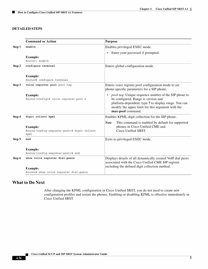
Chapter 4 Cisco Unified SIP SRST 4.1How to Configure Cisco Unified SIP SRST 4.1 Features
DETAILED STEPS
What to Do Next
After changing the KPML configuration in Cisco Unified SRST, you do not need to create new configuration profiles and restart the phones. Enabling or disabling KPML is effective immediately in Cisco Unified SRST.
Command or Action Purpose
Step 1 enable
Example:Router> enable
Enables privileged EXEC mode.
• Enter your password if prompted.
Step 2 configure terminal
Example:Router# configure terminal
Enters global configuration mode.
Step 3 voice register pool pool-tag
Example:Router(config)# voice register pool 4
Enters voice register pool configuration mode to set phone-specific parameters for a SIP phone.
• pool-tag: Unique sequence number of the SIP phone to be configured. Range is version and platform-dependent; type ? to display range. You can modify the upper limit for this argument with the max-pool command.
Step 4 digit collect kpml
Example:Router(config-register-pool)# digit collect kpml
Enables KPML digit collection for the SIP phone.
Note This command is enabled by default for supported phones in Cisco Unified CME and Cisco Unified SRST.
Step 5 end
Example:Router(config-register-pool)# end
Exits to privileged EXEC mode.
Step 6 show voice register dial-peers
Example:Router# show voice register dial-peers
Displays details of all dynamically created VoIP dial peers associated with the Cisco Unified CME SIP register including the defined digit collection method.
4-56Cisco Unified SCCP and SIP SRST System Administrator Guide
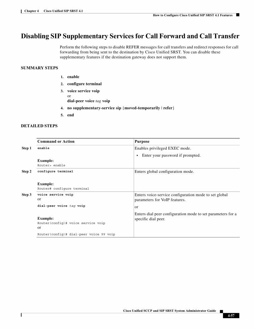
Chapter 4 Cisco Unified SIP SRST 4.1How to Configure Cisco Unified SIP SRST 4.1 Features
Disabling SIP Supplementary Services for Call Forward and Call Transfer
Perform the following steps to disable REFER messages for call transfers and redirect responses for call forwarding from being sent to the destination by Cisco Unified SRST. You can disable these supplementary features if the destination gateway does not support them.
SUMMARY STEPS
1. enable
2. configure terminal
3. voice service voipordial-peer voice tag voip
4. no supplementary-service sip {moved-temporarily | refer}
5. end
DETAILED STEPS
Command or Action Purpose
Step 1 enable
Example:Router> enable
Enables privileged EXEC mode.
• Enter your password if prompted.
Step 2 configure terminal
Example:Router# configure terminal
Enters global configuration mode.
Step 3 voice service voip
or
dial-peer voice tag voip
Example:Router(config)# voice service voip
or
Router(config)# dial-peer voice 99 voip
Enters voice-service configuration mode to set global parameters for VoIP features.
or
Enters dial peer configuration mode to set parameters for a specific dial peer.
4-57Cisco Unified SCCP and SIP SRST System Administrator Guide
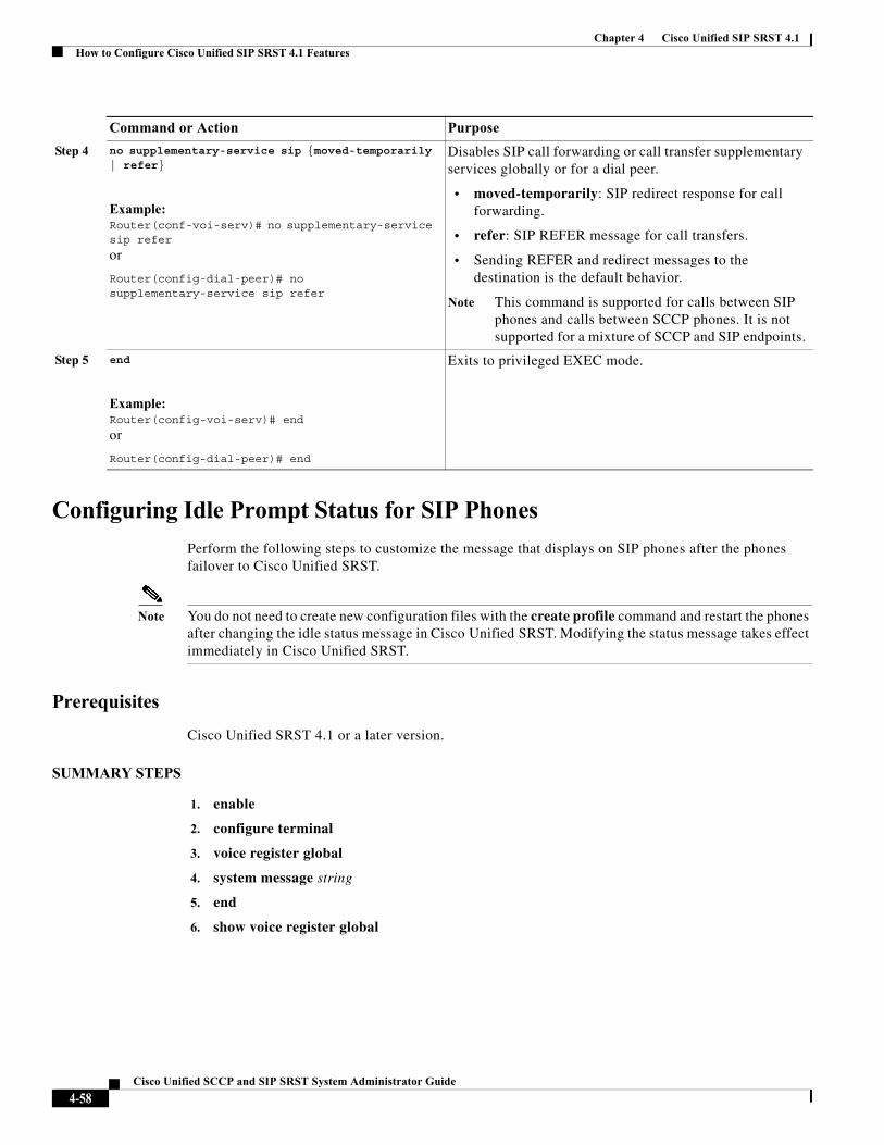
Chapter 4 Cisco Unified SIP SRST 4.1How to Configure Cisco Unified SIP SRST 4.1 Features
Configuring Idle Prompt Status for SIP Phones
Perform the following steps to customize the message that displays on SIP phones after the phones failover to Cisco Unified SRST.
Note You do not need to create new configuration files with the create profile command and restart the phones after changing the idle status message in Cisco Unified SRST. Modifying the status message takes effect immediately in Cisco Unified SRST.
Prerequisites
Cisco Unified SRST 4.1 or a later version.
SUMMARY STEPS
1. enable
2. configure terminal
3. voice register global
4. system message string
5. end
6. show voice register global
Step 4 no supplementary-service sip {moved-temporarily | refer}
Example:Router(conf-voi-serv)# no supplementary-service sip refer
or
Router(config-dial-peer)# no supplementary-service sip refer
Disables SIP call forwarding or call transfer supplementary services globally or for a dial peer.
• moved-temporarily: SIP redirect response for call forwarding.
• refer: SIP REFER message for call transfers.
• Sending REFER and redirect messages to the destination is the default behavior.
Note This command is supported for calls between SIP phones and calls between SCCP phones. It is not supported for a mixture of SCCP and SIP endpoints.
Step 5 end
Example:Router(config-voi-serv)# end
or
Router(config-dial-peer)# end
Exits to privileged EXEC mode.
Command or Action Purpose
4-58Cisco Unified SCCP and SIP SRST System Administrator Guide
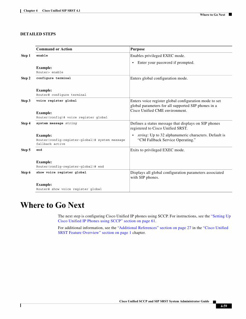
Chapter 4 Cisco Unified SIP SRST 4.1Where to Go Next
DETAILED STEPS
Where to Go NextThe next step is configuring Cisco Unified IP phones using SCCP. For instructions, see the “Setting Up Cisco Unified IP Phones using SCCP” section on page 61.
For additional information, see the “Additional References” section on page 27 in the “Cisco Unified SRST Feature Overview” section on page 1 chapter.
Command or Action Purpose
Step 1 enable
Example:Router> enable
Enables privileged EXEC mode.
• Enter your password if prompted.
Step 2 configure terminal
Example:Router# configure terminal
Enters global configuration mode.
Step 3 voice register global
Example:Router(config)# voice register global
Enters voice register global configuration mode to set global parameters for all supported SIP phones in a Cisco Unified CME environment.
Step 4 system message string
Example:Router(config-register-global)# system message fallback active
Defines a status message that displays on SIP phones registered to Cisco Unified SRST.
• string: Up to 32 alphanumeric characters. Default is “CM Fallback Service Operating.”
Step 5 end
Example:Router(config-register-global)# end
Exits to privileged EXEC mode.
Step 6 show voice register global
Example:Router# show voice register global
Displays all global configuration parameters associated with SIP phones.
4-59Cisco Unified SCCP and SIP SRST System Administrator Guide

Chapter 4 Cisco Unified SIP SRST 4.1Where to Go Next
4-60Cisco Unified SCCP and SIP SRST System Administrator Guide
Cisco Unified SC
C H A P T E R 5
Setting Up Cisco Unified IP Phones using SCCPThis chapter describes how to set up the displays and features that callers will see and use on Cisco Unified IP Phones during Cisco Unified CM fallback.
Note Ciso Unified IP Phones discussed in this chapter are just examples. For a complete list of IP phones, see Compatibility Information.
Contents• Information About Setting Up Cisco Unified IP Phones, page 61
• How to Set Up Cisco Unified IP Phones, page 62
• How to Set Up Cisco IP Communicator for Cisco Unified SRST, page 78
• Where to Go Next, page 79
Information About Setting Up Cisco Unified IP PhonesCisco Unified IP Phone configuration is limited for Cisco Unified SRST because IP phones retain nearly all Cisco Unified CM settings during Cisco Unified CM fallback. You can configure the date format, time format, language, and system messages that appear on Cisco Unified IP Phones during Cisco Unified Communications Manager fallback. All four of these settings have defaults, and the available language options depend on the IP phones and Cisco Unified CM version in use. Also available for configuration is a secondary dial tone, which can be generated when a phone user dials a predefined PSTN access prefix and can be terminated when additional digits are dialed. Dual-line phone configuration is required for dual-line phone operation during Cisco Unified CM fallback.
5-61CP and SIP SRST System Administrator Guide
Chapter 5 Setting Up Cisco Unified IP Phones using SCCPHow to Set Up Cisco Unified IP Phones
How to Set Up Cisco Unified IP Phones This section contains the following tasks:
• Configuring Cisco Unified SRST to Support Phone Functions, page 62 (Required)
• Configuring Cisco Unified 8941 and 8945 SCCP IP Phones, page 64 (Required)
• Verifying That Cisco Unified SRST Is Enabled, page 65 (Optional)
• Configuring IP Phone Clock, Date, and Time Formats, page 66 (Optional)
• Configuring IP Phone Language Display, page 68 (Optional)
• Configuring Customized System Messages for Cisco Unified IP Phones, page 70 (Optional)
• Configuring a Secondary Dial Tone, page 71 (Optional)
• Configuring Dual-Line Phones, page 72 (Required Under Certain Conditions)
• Configuring Eight Calls per Button (Octo-Line), page 74 (Optional)
• Configuring the Maximum Number of Calls, page 76 (Optional)
• Troubleshooting, page 78 (Optional)
Configuring Cisco Unified SRST to Support Phone Functions
Tip When the Cisco Unified SRST is enabled, Cisco Unified IP Phones do not have to be reconfigured while in Cisco Unified Communications Manager fallback mode because phones retain the same configuration that was used with Cisco Unified Communications Manager.
To configure Cisco Unified SRST on the router to support the Cisco Unified IP Phone functions, use the following commands beginning in global configuration mode.
SUMMARY STEPS
1. call-manager-fallback
2. ip source-address ip-address [port port] [any-match | strict-match]
3. max-dn max-directory-numbers [dual-line] [preference preference-order]
4. max-ephones max-phones
5. limit-dn phone-type max-lines
6. exit
5-62Cisco Unified SCCP and SIP SRST System Administrator Guide
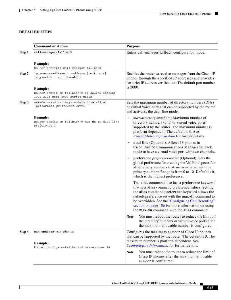
Chapter 5 Setting Up Cisco Unified IP Phones using SCCPHow to Set Up Cisco Unified IP Phones
DETAILED STEPS
Command or Action Purpose
Step 1 call-manager-fallback
Example:Router(config)# call-manager-fallback
Enters call-manager-fallback configuration mode.
Step 2 ip source-address ip-address [port port] [any-match | strict-match]
Example:Router(config-cm-fallback)# ip source-address 10.6.21.4 port 2002 strict-match
Enables the router to receive messages from the Cisco IP phones through the specified IP addresses and provides for strict IP address verification. The default port number is 2000.
Step 3 max-dn max-directory-numbers [dual-line] [preference preference-order]
Example:Router(config-cm-fallback)# max-dn 15 dual-line preference 1
Sets the maximum number of directory numbers (DNs) or virtual voice ports that can be supported by the router and activates the dual-line mode.
• max-directory-numbers: Maximum number of directory numbers (dns) or virtual voice ports supported by the router. The maximum number is platform-dependent. The default is 0. See Compatibility Information for further details.
• dual-line (Optional). Allows IP phones in Cisco Unified Communications Manager fallback mode to have a virtual voice port with two channels.
• preference preference-order (Optional). Sets the global preference for creating the VoIP dial peers for all directory numbers that are associated with the primary number. Range is from 0 to 10. Default is 0, which is the highest preference.
The alias command also has a preference keyword that sets alias command preference values. Setting the alias command preference keyword allows the default preference set with the max-dn command to be overridden. See the “Configuring Call Rerouting” section on page 106 for more information on using the max-dn command with the alias command.
Note You must reboot the router to reduce the limit of the directory numbers or virtual voice ports after the maximum allowable number is configured.
Step 4 max-ephones max-phones
Example:Router(config-cm-fallback)# max-ephones 24
Configures the maximum number of Cisco IP phones that can be supported by the router. The default is 0. The maximum number is platform dependent. See Compatibility Information for further details.
Note You must reboot the router to reduce the limit of Cisco IP phones after the maximum allowable number is configured.
5-63Cisco Unified SCCP and SIP SRST System Administrator Guide
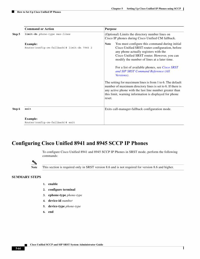
Chapter 5 Setting Up Cisco Unified IP Phones using SCCPHow to Set Up Cisco Unified IP Phones
Configuring Cisco Unified 8941 and 8945 SCCP IP Phones
To configure Cisco Unified 8941 and 8945 SCCP IP Phones in SRST mode, perform the following commands:
Note This section is required only in SRST version 8.6 and is not required for version 8.6 and higher.
SUMMARY STEPS
1. enable
2. configure terminal
3. ephone-type phone-type
4. device-id number
5. device-type phone-type
6. end
Step 5 limit-dn phone-type max-lines
Example:Router(config-cm-fallback)# limit-dn 7945 2
(Optional) Limits the directory number lines on Cisco IP phones during Cisco Unified CM fallback.
Note You must configure this command during initial Cisco Unified SRST router configuration, before any phone actually registers with the Cisco Unified SRST router. However, you can modify the number of lines at a later time.
For a list of available phones, see Cisco SRST and SIP SRST Command Reference (All Versions).
The setting for maximum lines is from 1 to 6. The default number of maximum directory lines is set to 6. If there is any active phone with the last line number greater than this limit, warning information is displayed for phone reset.
Step 6 exit
Example:Router(config-cm-fallback)# exit
Exits call-manager-fallback configuration mode.
Command or Action Purpose
5-64Cisco Unified SCCP and SIP SRST System Administrator Guide
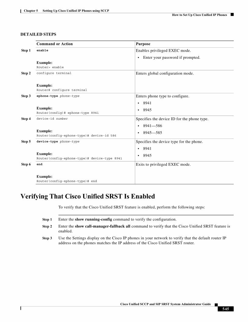
Chapter 5 Setting Up Cisco Unified IP Phones using SCCPHow to Set Up Cisco Unified IP Phones
DETAILED STEPS
Verifying That Cisco Unified SRST Is Enabled
To verify that the Cisco Unified SRST feature is enabled, perform the following steps:
Step 1 Enter the show running-config command to verify the configuration.
Step 2 Enter the show call-manager-fallback all command to verify that the Cisco Unified SRST feature is enabled.
Step 3 Use the Settings display on the Cisco IP phones in your network to verify that the default router IP address on the phones matches the IP address of the Cisco Unified SRST router.
Command or Action Purpose
Step 1 enable
Example:Router> enable
Enables privileged EXEC mode.
• Enter your password if prompted.
Step 2 configure terminal
Example:Router# configure terminal
Enters global configuration mode.
Step 3 ephone-type phone-type
Example:Router(config)# ephone-type 8941
Enters phone type to configure.
• 8941
• 8945
Step 4 device-id number
Example:Router(config-ephone-type)# device-id 586
Specifies the device ID for the phone type.
• 8941—586
• 8945—585
Step 5 device-type phone-type
Example:Router(config-ephone-type)# device-type 8941
Specifies the device type for the phone.
• 8941
• 8945
Step 6 end
Example:Router(config-ephone-type)# end
Exits to privileged EXEC mode.
5-65Cisco Unified SCCP and SIP SRST System Administrator Guide
Chapter 5 Setting Up Cisco Unified IP Phones using SCCPHow to Set Up Cisco Unified IP Phones
Step 4 To temporarily block the TCP port 2000 Skinny Client Control Protocol (SCCP) connection for one of the Cisco IP phones to force the Cisco IP phone to lose its connection to the Cisco Unified Communications Manager and register with the Cisco Unified SRST router, perform the following steps:
a. Use the appropriate IP access-list command to temporarily disconnect a Cisco Unified IP Phone from the Cisco Unified Communications Manager.
During a WAN connection failure, when Cisco Unified SRST is enabled, Cisco Unified IP Phones display a message informing you that they are operating in Cisco Unified Communications Manager fallback mode. The Cisco IP Phone 7960 and Cisco IP Phone 7940 display a “CM Fallback Service Operating” message, and the Cisco IP Phone 7910 displays a “CM Fallback Service” message when operating in Cisco Unified Communications Manager fallback mode. When the Cisco Unified Communications Manager is restored, the message goes away and full Cisco IP phone functionality is restored.
b. Use the debug ephone register command to observe the registration process of the Cisco IP phone on the Cisco Unified SRST router.
c. Use the show ephone command to display the Cisco IP phones that have registered to the Cisco Unified SRST router.
d. Enter the no form of the appropriate access-list command to restore normal service for the phone.
Configuring IP Phone Clock, Date, and Time Formats
The Cisco Unified IP Phone 7970G and Cisco Unified IP Phone 7971G-GE IP phones obtain the correct timezone from Cisco Unified Communications Manager. They also receive the Coordinated Universal Time (UTC) time from the SRST router during SRST registration. When in SRST mode, the phones take the timezone and the UTC time, and apply a timezone offset to produce the correct time display.
Cisco IP Phone 7960 IP phones and other similar SCCP phones such as the Cisco IP Phone 7940, get their display clock information from the local time of the SRST router during SRST registration. If the Cisco Unified SRST router is configured to use the Network Time Protocol (NTP) to automatically sync the Cisco Unified SRST router time from an NTP time server, only UTC time is delivered to the router. This is because the NTP server could be physically located anywhere in the world, in any timezone. As it is important to display the correct local time, use the clock timezone command to adjust or offset the Cisco Unified SRST router time.
The date and time formats that appear on the displays of all Cisco Unified IP Phones in Cisco Unified CM fallback mode are selected using the date-format and time-format commands as configured below:
SUMMARY STEPS
1. clock timezone zone hours-offset [minutes-offset]
2. call-manager-fallback
3. date-format {mm-dd-yy | dd-mm-yy | yy-dd-mm | yy-mm-dd}
4. time-format {12 | 24}
5. exit
5-66Cisco Unified SCCP and SIP SRST System Administrator Guide
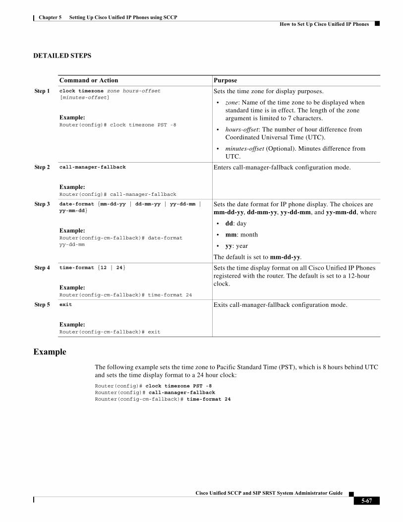
Chapter 5 Setting Up Cisco Unified IP Phones using SCCPHow to Set Up Cisco Unified IP Phones
DETAILED STEPS
Example
The following example sets the time zone to Pacific Standard Time (PST), which is 8 hours behind UTC and sets the time display format to a 24 hour clock:
Router(config)# clock timezone PST -8Rounter(config)# call-manager-fallbackRounter(config-cm-fallback)# time-format 24
Command or Action Purpose
Step 1 clock timezone zone hours-offset [minutes-offset]
Example:Router(config)# clock timezone PST -8
Sets the time zone for display purposes.
• zone: Name of the time zone to be displayed when standard time is in effect. The length of the zone argument is limited to 7 characters.
• hours-offset: The number of hour difference from Coordinated Universal Time (UTC).
• minutes-offset (Optional). Minutes difference from UTC.
Step 2 call-manager-fallback
Example:Router(config)# call-manager-fallback
Enters call-manager-fallback configuration mode.
Step 3 date-format {mm-dd-yy | dd-mm-yy | yy-dd-mm | yy-mm-dd}
Example:Router(config-cm-fallback)# date-format yy-dd-mm
Sets the date format for IP phone display. The choices are mm-dd-yy, dd-mm-yy, yy-dd-mm, and yy-mm-dd, where
• dd: day
• mm: month
• yy: year
The default is set to mm-dd-yy.
Step 4 time-format {12 | 24}
Example:Router(config-cm-fallback)# time-format 24
Sets the time display format on all Cisco Unified IP Phones registered with the router. The default is set to a 12-hour clock.
Step 5 exit
Example:Router(config-cm-fallback)# exit
Exits call-manager-fallback configuration mode.
5-67Cisco Unified SCCP and SIP SRST System Administrator Guide
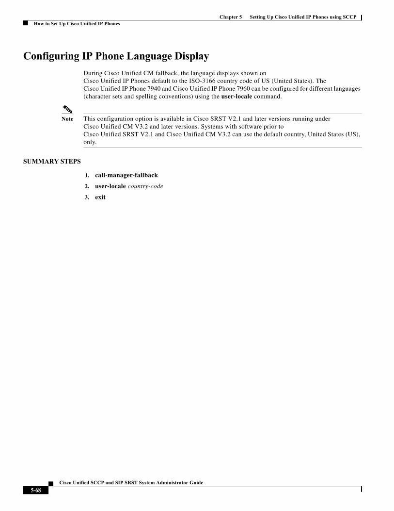
Chapter 5 Setting Up Cisco Unified IP Phones using SCCPHow to Set Up Cisco Unified IP Phones
Configuring IP Phone Language Display
During Cisco Unified CM fallback, the language displays shown on Cisco Unified IP Phones default to the ISO-3166 country code of US (United States). TheCisco Unified IP Phone 7940 and Cisco Unified IP Phone 7960 can be configured for different languages (character sets and spelling conventions) using the user-locale command.
Note This configuration option is available in Cisco SRST V2.1 and later versions running under Cisco Unified CM V3.2 and later versions. Systems with software prior to Cisco Unified SRST V2.1 and Cisco Unified CM V3.2 can use the default country, United States (US), only.
SUMMARY STEPS
1. call-manager-fallback
2. user-locale country-code
3. exit
5-68Cisco Unified SCCP and SIP SRST System Administrator Guide
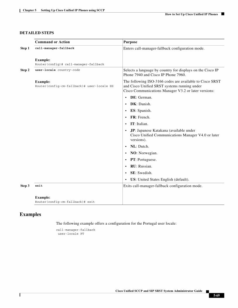
Chapter 5 Setting Up Cisco Unified IP Phones using SCCPHow to Set Up Cisco Unified IP Phones
DETAILED STEPS
Examples
The following example offers a configuration for the Portugal user locale:
call-manager-fallbackuser-locale PT
Command or Action Purpose
Step 1 call-manager-fallback
Example:Router(config)# call-manager-fallback
Enters call-manager-fallback configuration mode.
Step 2 user-locale country-code
Example:Router(config-cm-fallback)# user-locale ES
Selects a language by country for displays on the Cisco IP Phone 7940 and Cisco IP Phone 7960.
The following ISO-3166 codes are available to Cisco SRST and Cisco Unified SRST systems running under Cisco Communications Manager V3.2 or later versions:
• DE: German.
• DK: Danish.
• ES: Spanish.
• FR: French.
• IT: Italian.
• JP: Japanese Katakana (available under Cisco Unified Communications Manager V4.0 or later versions).
• NL: Dutch.
• NO: Norwegian.
• PT: Portuguese.
• RU: Russian.
• SE: Swedish.
• US: United States English (default).
Step 3 exit
Example:Router(config-cm-fallback)# exit
Exits call-manager-fallback configuration mode.
5-69Cisco Unified SCCP and SIP SRST System Administrator Guide
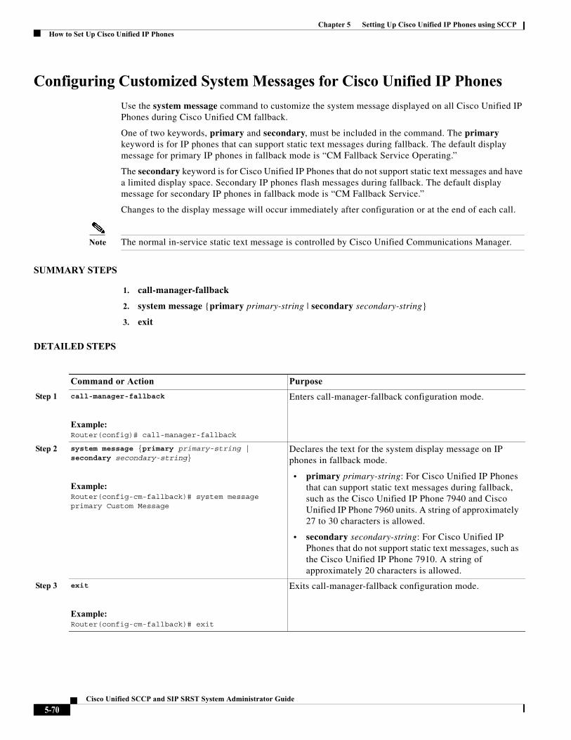
Chapter 5 Setting Up Cisco Unified IP Phones using SCCPHow to Set Up Cisco Unified IP Phones
Configuring Customized System Messages for Cisco Unified IP Phones
Use the system message command to customize the system message displayed on all Cisco Unified IP Phones during Cisco Unified CM fallback.
One of two keywords, primary and secondary, must be included in the command. The primary keyword is for IP phones that can support static text messages during fallback. The default display message for primary IP phones in fallback mode is “CM Fallback Service Operating.”
The secondary keyword is for Cisco Unified IP Phones that do not support static text messages and have a limited display space. Secondary IP phones flash messages during fallback. The default display message for secondary IP phones in fallback mode is “CM Fallback Service.”
Changes to the display message will occur immediately after configuration or at the end of each call.
Note The normal in-service static text message is controlled by Cisco Unified Communications Manager.
SUMMARY STEPS
1. call-manager-fallback
2. system message {primary primary-string | secondary secondary-string}
3. exit
DETAILED STEPS
Command or Action Purpose
Step 1 call-manager-fallback
Example:Router(config)# call-manager-fallback
Enters call-manager-fallback configuration mode.
Step 2 system message {primary primary-string | secondary secondary-string}
Example:Router(config-cm-fallback)# system message primary Custom Message
Declares the text for the system display message on IP phones in fallback mode.
• primary primary-string: For Cisco Unified IP Phones that can support static text messages during fallback, such as the Cisco Unified IP Phone 7940 and Cisco Unified IP Phone 7960 units. A string of approximately 27 to 30 characters is allowed.
• secondary secondary-string: For Cisco Unified IP Phones that do not support static text messages, such as the Cisco Unified IP Phone 7910. A string of approximately 20 characters is allowed.
Step 3 exit
Example:Router(config-cm-fallback)# exit
Exits call-manager-fallback configuration mode.
5-70Cisco Unified SCCP and SIP SRST System Administrator Guide
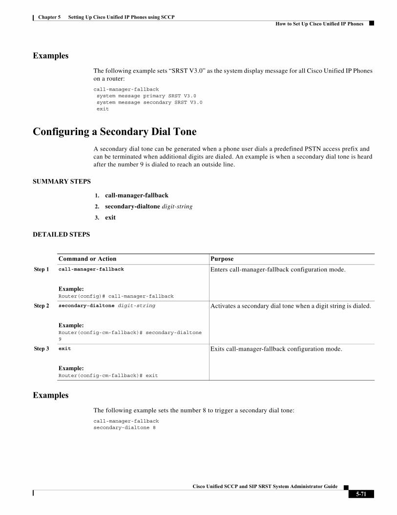
Chapter 5 Setting Up Cisco Unified IP Phones using SCCPHow to Set Up Cisco Unified IP Phones
Examples
The following example sets “SRST V3.0” as the system display message for all Cisco Unified IP Phones on a router:
call-manager-fallbacksystem message primary SRST V3.0system message secondary SRST V3.0exit
Configuring a Secondary Dial Tone
A secondary dial tone can be generated when a phone user dials a predefined PSTN access prefix and can be terminated when additional digits are dialed. An example is when a secondary dial tone is heard after the number 9 is dialed to reach an outside line.
SUMMARY STEPS
1. call-manager-fallback
2. secondary-dialtone digit-string
3. exit
DETAILED STEPS
Examples
The following example sets the number 8 to trigger a secondary dial tone:
call-manager-fallback secondary-dialtone 8
Command or Action Purpose
Step 1 call-manager-fallback
Example:Router(config)# call-manager-fallback
Enters call-manager-fallback configuration mode.
Step 2 secondary-dialtone digit-string
Example:Router(config-cm-fallback)# secondary-dialtone 9
Activates a secondary dial tone when a digit string is dialed.
Step 3 exit
Example:Router(config-cm-fallback)# exit
Exits call-manager-fallback configuration mode.
5-71Cisco Unified SCCP and SIP SRST System Administrator Guide
Chapter 5 Setting Up Cisco Unified IP Phones using SCCPHow to Set Up Cisco Unified IP Phones
Configuring Dual-Line Phones
Dual-line phone configuration is required for dual-line phone operation during Cisco Unified CM fallback, see the “Enabling Consultative Call Transfer and Forward Using H.450.2 and H.450.3 with Cisco SRST 3.0” section on page 124.
Dual-line IP phones are supported during Cisco Unified CM fallback using the max-dn command. Dual-line IP phones have one voice port with two channels to handle two independent calls. This capability enables call waiting, call transfer, and conference functions on a phone-line button.
In dual-line mode, each IP phone and its associated line button can support one or two calls. Selection of one of two calls on the same line is made using the blue Navigation button located below the phone display. When one of the dual-line channels is used on a specific phone, other phones that share the ephone-dn will be unable to use the secondary channel. The secondary channel will be reserved for use with the primary dual-line channel.
It is recommended that hunting be disabled to the second channel. For more information, see the “Configuring Dial-Peer and Channel Hunting” section on page 120.
SUMMARY STEPS
1. call-manager-fallback
2. max-dn max-directory-numbers [dual-line] [preference preference-order]
3. exit
5-72Cisco Unified SCCP and SIP SRST System Administrator Guide
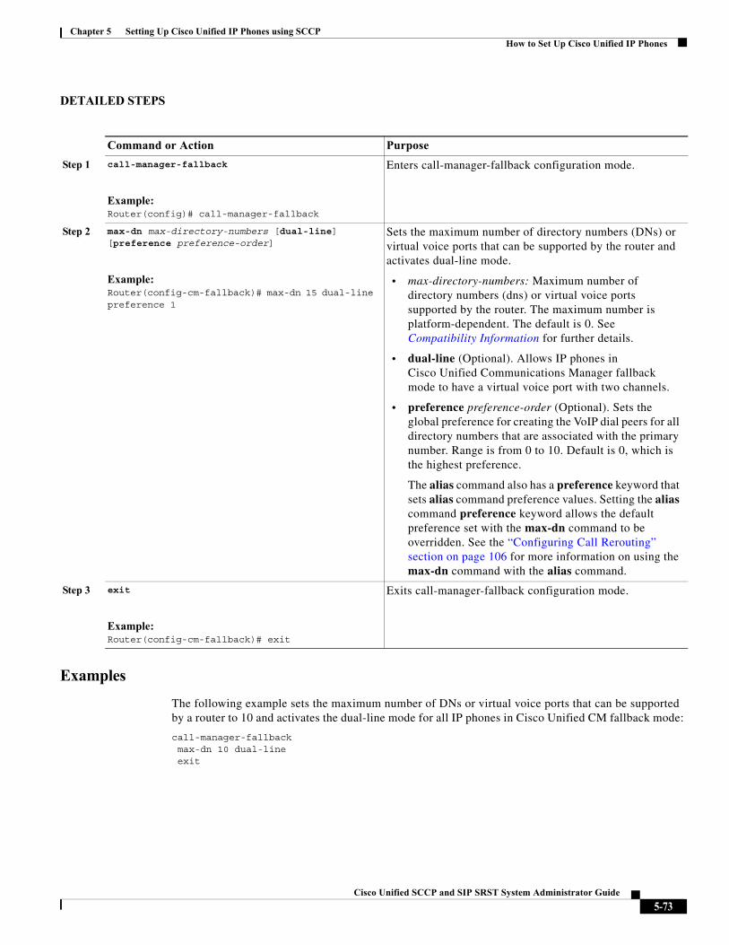
Chapter 5 Setting Up Cisco Unified IP Phones using SCCPHow to Set Up Cisco Unified IP Phones
DETAILED STEPS
Examples
The following example sets the maximum number of DNs or virtual voice ports that can be supported by a router to 10 and activates the dual-line mode for all IP phones in Cisco Unified CM fallback mode:
call-manager-fallbackmax-dn 10 dual-lineexit
Command or Action Purpose
Step 1 call-manager-fallback
Example:Router(config)# call-manager-fallback
Enters call-manager-fallback configuration mode.
Step 2 max-dn max-directory-numbers [dual-line] [preference preference-order]
Example:Router(config-cm-fallback)# max-dn 15 dual-line preference 1
Sets the maximum number of directory numbers (DNs) or virtual voice ports that can be supported by the router and activates dual-line mode.
• max-directory-numbers: Maximum number of directory numbers (dns) or virtual voice ports supported by the router. The maximum number is platform-dependent. The default is 0. See Compatibility Information for further details.
• dual-line (Optional). Allows IP phones in Cisco Unified Communications Manager fallback mode to have a virtual voice port with two channels.
• preference preference-order (Optional). Sets the global preference for creating the VoIP dial peers for all directory numbers that are associated with the primary number. Range is from 0 to 10. Default is 0, which is the highest preference.
The alias command also has a preference keyword that sets alias command preference values. Setting the alias command preference keyword allows the default preference set with the max-dn command to be overridden. See the “Configuring Call Rerouting” section on page 106 for more information on using the max-dn command with the alias command.
Step 3 exit
Example:Router(config-cm-fallback)# exit
Exits call-manager-fallback configuration mode.
5-73Cisco Unified SCCP and SIP SRST System Administrator Guide
Chapter 5 Setting Up Cisco Unified IP Phones using SCCPHow to Set Up Cisco Unified IP Phones
Configuring Eight Calls per Button (Octo-Line)
The octo-line feature supports up to eight active calls, both incoming and outgoing, on a single button. Eight incoming calls to an octo-line directory number ring simultaneously. After an incoming call is answered, the ringing stops and the remaining seven incoming calls hear a call waiting tone.
After an incoming call on an octo-line directory number is answered, the answering phone is in the connected state. Other phones that share the directory number are in the remoteMultiline state. A subsequent incoming call sends the call waiting tone to the phone connected to the call, and sends the ringing tone to the other phones that are in the remoteMultiline state. All phones sharing the directory number can pick up any of the incoming unanswered calls.
When multiple incoming calls ring on an octo-line directory number that is shared among multiple phones, the ringing tone stops on the phone that answers the call, and the call waiting tone is heard for other unanswered calls. The multiple instances of the ringing calls is displayed on other ephones sharing the directory number. After a connected call on an octo-line directory number is put on-hold, any phone that shares this directory number can pick up the held call. If a phone is in the process of transferring a call or creating a conference, other phones that share the octo-line directory number cannot steal the call.
As new calls come in on an octo-line, the system searches for the next available idle line using the huntstop chan tag command, where tag is a number from 1 to 8. An idle channel is selected from the lowest number to the highest. When the highest number of allowed calls is received, the system stops hunting for available channels. Use this command to limit the number of incoming calls on an octo-line directory number and reserve channels for outgoing calls or features such as call transfer or conference calls.
With the new feature, you can:
• Configure only dual-line mode
• Configure only octo-line mode
• Configure dual-line mode and octo-line mode
Prerequisites
• Cisco Unified SRST 7.0/4.3
• Cisco Unified CM 6.0
• Cisco IOS Release 12.4(15)XZ
Restrictions
Octo-line directory numbers are not supported by the Cisco Unified IP Phone 7902, 7920, or 7931, or by analog phones connected to Cisco ATA or Cisco VG224.
SUMMARY STEPS
1. enable
2. configure terminal
3. call-manager-fallback
4. max-dn max-no-of-directories [dual-line | octo-line] [number octo-line]
5. huntstop channel 1-8
6. end
5-74Cisco Unified SCCP and SIP SRST System Administrator Guide
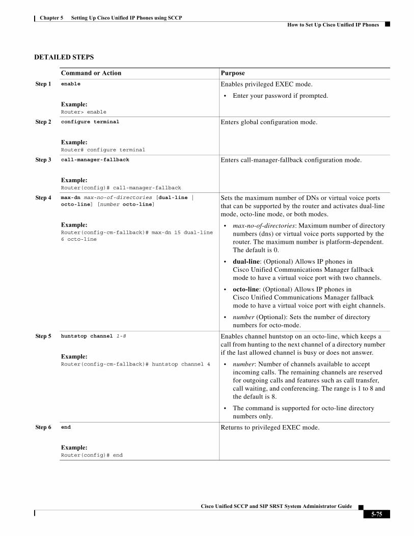
Chapter 5 Setting Up Cisco Unified IP Phones using SCCPHow to Set Up Cisco Unified IP Phones
DETAILED STEPS
Command or Action Purpose
Step 1 enable
Example:Router> enable
Enables privileged EXEC mode.
• Enter your password if prompted.
Step 2 configure terminal
Example:Router# configure terminal
Enters global configuration mode.
Step 3 call-manager-fallback
Example:Router(config)# call-manager-fallback
Enters call-manager-fallback configuration mode.
Step 4 max-dn max-no-of-directories [dual-line | octo-line] [number octo-line]
Example:Router(config-cm-fallback)# max-dn 15 dual-line 6 octo-line
Sets the maximum number of DNs or virtual voice ports that can be supported by the router and activates dual-line mode, octo-line mode, or both modes.
• max-no-of-directories: Maximum number of directory numbers (dns) or virtual voice ports supported by the router. The maximum number is platform-dependent. The default is 0.
• dual-line: (Optional) Allows IP phones in Cisco Unified Communications Manager fallback mode to have a virtual voice port with two channels.
• octo-line: (Optional) Allows IP phones in Cisco Unified Communications Manager fallback mode to have a virtual voice port with eight channels.
• number (Optional): Sets the number of directory numbers for octo-mode.
Step 5 huntstop channel 1-8
Example:Router(config-cm-fallback)# huntstop channel 4
Enables channel huntstop on an octo-line, which keeps a call from hunting to the next channel of a directory number if the last allowed channel is busy or does not answer.
• number: Number of channels available to accept incoming calls. The remaining channels are reserved for outgoing calls and features such as call transfer, call waiting, and conferencing. The range is 1 to 8 and the default is 8.
• The command is supported for octo-line directory numbers only.
Step 6 end
Example:Router(config)# end
Returns to privileged EXEC mode.
5-75Cisco Unified SCCP and SIP SRST System Administrator Guide
Chapter 5 Setting Up Cisco Unified IP Phones using SCCPHow to Set Up Cisco Unified IP Phones
Examples
In the following example, octo-line mode is enabled, there are 8 octo-line directory numbers, there are a maximum of 23 directory numbers, and a maximum of 6 channels are available for incoming calls:
!call-manager-fallbackmax-dn 23 octo-line 8huntstop channel 6
Configuring the Maximum Number of Calls
To configure the maximum number of calls on a Cisco Unified SCCP IP phone in Cisco Unified SRST 9.0, perform the following steps.
Prerequisites
• Cisco Unified SRST 9.0 and later versions.
• Correct firmware, 9.2(1) or a later version, is installed.
SUMMARY STEPS
1. enable
2. configure terminal
3. call-manager-fallback
4. max-dn max-no-of-directories [dual-line | octo-line]
5. timeouts busy seconds
6. end
DETAILED STEPS
Command or Action Purpose
Step 1 enable
Example:Router> enable
Enables privileged EXEC mode.
• Enter your password if prompted.
Step 2 configure terminal
Example:Router# configure terminal
Enters global configuration mode.
Step 3 call-manager-fallback
Example:Router(config)# call-manager-fallback
Enables Cisco Unified SRST support and enters call-manager-fallback configuration mode.
5-76Cisco Unified SCCP and SIP SRST System Administrator Guide
Chapter 5 Setting Up Cisco Unified IP Phones using SCCPHow to Set Up Cisco Unified IP Phones
Step 4 max-dn max-no-of-directories [dual-line | octo-line]
Example:Router(config-cm-fallback)# max-dn 10 octo-line
Sets the maximum possible number of directory numbers or virtual voice ports that can be supported by a router and enables dual-line mode, octo-line mode, or both modes.
• max-no-of-directories—Maximum number of directory numbers or virtual voice ports supported by the router. The maximum possible number is platform-dependent. The default is 0 directory numbers and 1 channel per virtual port.
• dual-line—(Optional) Sets all Cisco Unified IP phones connected to a Cisco Unified SRST router to one virtual voice port with two channels.
• octo-line—(Optional) Sets all Cisco Unified IP phones connected to a Cisco Unified SRST router to one virtual voice port with eight channels.
Step 5 timeouts busy seconds
Example:Router(config-cm-fallback)# timeouts busy 10
Sets the timeout value for call transfers to busy destinations.
• seconds—Number of seconds after connection to a busy destination before a transferred call is disconnected. Range is 0 to 30. Default: 10.
Step 6 end
Example:Router(config-cm-fallback)# end
Exits configuration mode and enters privileged EXEC mode.
Command or Action Purpose
5-77Cisco Unified SCCP and SIP SRST System Administrator Guide
Chapter 5 Setting Up Cisco Unified IP Phones using SCCPHow to Set Up Cisco IP Communicator for Cisco Unified SRST
Troubleshooting
To troubleshoot your Cisco Unified SRST configuration, use the following commands:
• To set keepalive debugging for Cisco IP phones, use the debug ephone keepalive command.
• To set registration debugging for Cisco IP phones, use the debug ephone register command.
• To set state debugging for Cisco IP phones, use the debug ephone state command.
• To set detail debugging for Cisco IP phones, use the debug ephone detail command.
• To set error debugging for Cisco IP phones, use the debug ephone error command.
• To set call statistics debugging for Cisco IP phones, use the debug ephone statistics command.
• To provide voice-packet-level debugging and to display the contents of one voice packet in every 1024 voice packets, use the debug ephone pak command.
• To provide raw low-level protocol debugging display for all SCCP messages, use the debug ephone raw command.
For further debugging, see Cisco IOS Debug Command Reference.
How to Set Up Cisco IP Communicator for Cisco Unified SRST
Cisco IP Communicator is a software-based application that delivers enhanced telephony support on personal computers. Cisco IP Communicator appears on a user’s computer monitor as a graphical, display-based IP phone with a color screen, a keypad, feature buttons, and soft keys.
For information about operation, see the Cisco IP Communicator online help and user documentation.
Prerequisites
You should have the following before you begin this task:
• IP address of the Cisco Unified CM (Call Manager) TFTP server
• IP address of the Cisco Unified SRST TFTP server
• Headset with microphone for your PC (Optional; you can use PC internal speakers and microphone)
Step 1 Download the latest version of the Cisco IP Communicator software and install it on your PC. The software is available for download at http://www.cisco.com/cisco/web/download/index.html.
a. Click Voice and Unified Communication.
b. Click IP Telephony.
c. Click IP Phones.
d. Click Cisco IP Communicator.
Step 2 (Optional) Attach a headset to your PC.
Step 3 Start the Cisco IP Communicator software application.
5-78Cisco Unified SCCP and SIP SRST System Administrator Guide
Chapter 5 Setting Up Cisco Unified IP Phones using SCCPWhere to Go Next
Step 4 Define the IP address of the Cisco Unified CM as primary TFTP server
a. Open the Network > User Preferences window.
b. Enter the IP address of the Cisco Unified CM TFTP server.
Step 5 Define the IP address of the Cisco Unified SRST as secondary TFTP server.
a. Open the Network > User Preferences window.
b. Enter the IP address of the Cisco Unified SRST TFTP server.
Step 6 Ensure that Cisco IP Communicator has at least once registered to Cisco Unified CM. For more details, see Install and Configure IP Communicator with CallManager.
Step 7 Wait for the Cisco IP Communicator to connect to the Cisco Unified SRST system (upon Cisco Unified CM Failure) and register itself.
Step 8 Cisco IP Communicator should have retained the original buttons and numbers for Cisco IP Communicator.
Verifying Cisco IP Communicator
Step 1 Use the show running-config command to display ephone-dn and ephone information associated with this phone.
Step 2 After Cisco IP Communicator registers with Cisco Unified SRST, it displays the phone extensions and soft keys in its configuration. Verify that these are correct.
Step 3 Make a local call from the phone and ask someone to call you. Verify that you have a two-way voice path.
Troubleshooting Cisco IP Communicator
Use the debug ephone detail command to diagnose problems with calls. For more information, see Cisco IOS Debug Command Reference.
Where to Go NextThe next step is configuring Cisco Unified IP Phones using SIP. For more information, see the “” section on page 81.
For additional information, see the “Additional References” section on page 27.
5-79Cisco Unified SCCP and SIP SRST System Administrator Guide

Chapter 5 Setting Up Cisco Unified IP Phones using SCCPWhere to Go Next
5-80Cisco Unified SCCP and SIP SRST System Administrator Guide
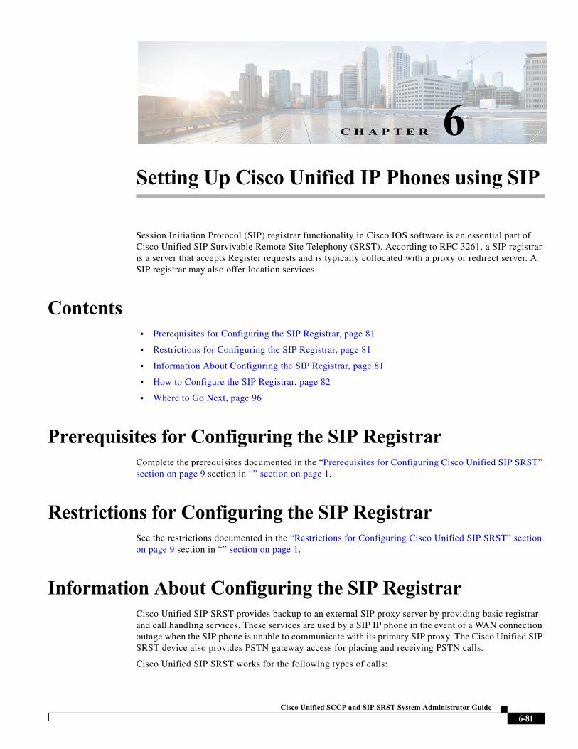
Cisco Unified SC
C H A P T E R 6
Setting Up Cisco Unified IP Phones using SIPSession Initiation Protocol (SIP) registrar functionality in Cisco IOS software is an essential part of Cisco Unified SIP Survivable Remote Site Telephony (SRST). According to RFC 3261, a SIP registrar is a server that accepts Register requests and is typically collocated with a proxy or redirect server. A SIP registrar may also offer location services.
Contents• Prerequisites for Configuring the SIP Registrar, page 81
• Restrictions for Configuring the SIP Registrar, page 81
• Information About Configuring the SIP Registrar, page 81
• How to Configure the SIP Registrar, page 82
• Where to Go Next, page 96
Prerequisites for Configuring the SIP RegistrarComplete the prerequisites documented in the “Prerequisites for Configuring Cisco Unified SIP SRST” section on page 9 section in “” section on page 1.
Restrictions for Configuring the SIP RegistrarSee the restrictions documented in the “Restrictions for Configuring Cisco Unified SIP SRST” section on page 9 section in “” section on page 1.
Information About Configuring the SIP RegistrarCisco Unified SIP SRST provides backup to an external SIP proxy server by providing basic registrar and call handling services. These services are used by a SIP IP phone in the event of a WAN connection outage when the SIP phone is unable to communicate with its primary SIP proxy. The Cisco Unified SIP SRST device also provides PSTN gateway access for placing and receiving PSTN calls.
Cisco Unified SIP SRST works for the following types of calls:
6-81CP and SIP SRST System Administrator Guide
Chapter 6 Setting Up Cisco Unified IP Phones using SIPHow to Configure the SIP Registrar
• Local SIP IP phone to local SIP phone, if the main proxy is unavailable.
• Additional services like class of restriction (COR) for local SIP IP phones to the outgoing PSTN. For example, to block outgoing 1-900 numbers.
How to Configure the SIP RegistrarThis section contains the following procedures:
• Configuring the SIP Registrar, page 82 (required)
• Configuring Backup Registrar Service to SIP Phones, page 84 (required)
• Configuring Backup Registrar Service to SIP Phones (Using Optional Commands), page 88 (optional)
• Verifying SIP Registrar Configuration, page 91 (optional)
• Verifying Proxy Dial-Peer Configuration, page 93 (optional)
Configuring the SIP Registrar
The local SIP gateway that becomes the SIP registrar acts as a backup SIP proxy and accepts SIP Register messages from SIP phones. It becomes a location database of local SIP IP phones.
A registrar accepts SIP Register requests and dynamically builds VoIP dial peers, allowing the Cisco IOS voice gateway software to route calls to SIP phones.
If a SIP Register request has a Contact header that includes a DNS address, the Contact header is resolved before the contact is added to the SIP registrar database. This is done because during a WAN failure (and the resulting Cisco Unified SIP SRST functionality), DNS servers may not be available.
SIP registrar functionality is enabled with the following configuration. By default, Cisco Unified SIP SRST is not enabled and cannot accept SIP Register messages. The following configuration must be set up to accept incoming SIP Register messages.
SUMMARY STEPS
1. enable
2. configure terminal
3. voice service voip
4. allow-connections sip to sip
5. sip
6. registrar server [expires [max sec] [min sec]]
6-82Cisco Unified SCCP and SIP SRST System Administrator Guide
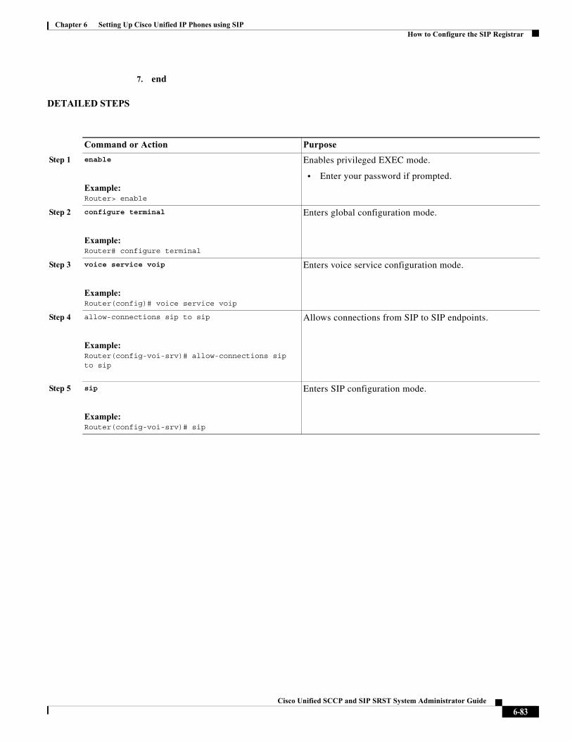
Chapter 6 Setting Up Cisco Unified IP Phones using SIPHow to Configure the SIP Registrar
7. end
DETAILED STEPS
Command or Action Purpose
Step 1 enable
Example:Router> enable
Enables privileged EXEC mode.
• Enter your password if prompted.
Step 2 configure terminal
Example:Router# configure terminal
Enters global configuration mode.
Step 3 voice service voip
Example:Router(config)# voice service voip
Enters voice service configuration mode.
Step 4 allow-connections sip to sip
Example:Router(config-voi-srv)# allow-connections sip to sip
Allows connections from SIP to SIP endpoints.
Step 5 sip
Example:Router(config-voi-srv)# sip
Enters SIP configuration mode.
6-83Cisco Unified SCCP and SIP SRST System Administrator Guide
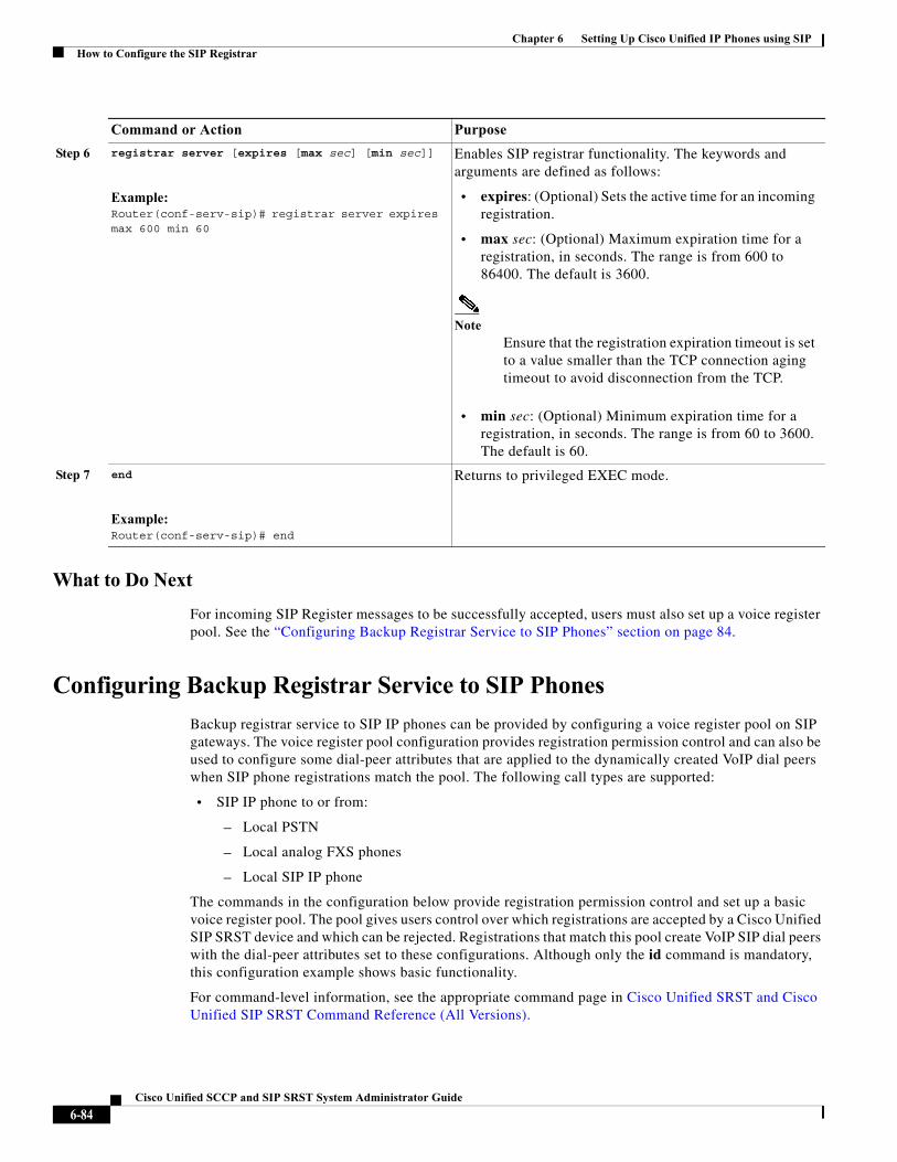
Chapter 6 Setting Up Cisco Unified IP Phones using SIPHow to Configure the SIP Registrar
What to Do Next
For incoming SIP Register messages to be successfully accepted, users must also set up a voice register pool. See the “Configuring Backup Registrar Service to SIP Phones” section on page 84.
Configuring Backup Registrar Service to SIP Phones
Backup registrar service to SIP IP phones can be provided by configuring a voice register pool on SIP gateways. The voice register pool configuration provides registration permission control and can also be used to configure some dial-peer attributes that are applied to the dynamically created VoIP dial peers when SIP phone registrations match the pool. The following call types are supported:
• SIP IP phone to or from:
– Local PSTN
– Local analog FXS phones
– Local SIP IP phone
The commands in the configuration below provide registration permission control and set up a basic voice register pool. The pool gives users control over which registrations are accepted by a Cisco Unified SIP SRST device and which can be rejected. Registrations that match this pool create VoIP SIP dial peers with the dial-peer attributes set to these configurations. Although only the id command is mandatory, this configuration example shows basic functionality.
For command-level information, see the appropriate command page in Cisco Unified SRST and Cisco Unified SIP SRST Command Reference (All Versions).
Step 6 registrar server [expires [max sec] [min sec]]
Example:Router(conf-serv-sip)# registrar server expires max 600 min 60
Enables SIP registrar functionality. The keywords and arguments are defined as follows:
• expires: (Optional) Sets the active time for an incoming registration.
• max sec: (Optional) Maximum expiration time for a registration, in seconds. The range is from 600 to 86400. The default is 3600.
NoteEnsure that the registration expiration timeout is set to a value smaller than the TCP connection aging timeout to avoid disconnection from the TCP.
• min sec: (Optional) Minimum expiration time for a registration, in seconds. The range is from 60 to 3600. The default is 60.
Step 7 end
Example:Router(conf-serv-sip)# end
Returns to privileged EXEC mode.
Command or Action Purpose
6-84Cisco Unified SCCP and SIP SRST System Administrator Guide
Chapter 6 Setting Up Cisco Unified IP Phones using SIPHow to Configure the SIP Registrar
Prerequisites
• The SIP registrar must be configured before a voice register pool is set up. See the “Configuring the SIP Registrar” section on page 82 for complete instructions.
Restrictions
• The id command identifies the individual SIP IP phone or sets of SIP IP phones that are to be configured. Thus, the id command configured in Step 5 is required and must be configured before any other voice register pool commands. When the mac address keyword and argument are used, the IP phone must be in the same subnet as that of the router’s LAN interface, such that the phone’s MAC address is visible in the router’s Address Resolution Protocol (ARP) cache. Once a MAC address is configured for a specific voice register pool, remove the existing MAC address before changing to a new MAC address.
• Proxy dial peers are autogenerated dial peers that route all calls from the PSTN to Cisco Unified SIP SRST. When a SIP phone registers to Cisco Unified SIP SRST and the proxy command is enabled, two dial peers are automatically created. The first dial peer routes to the proxy, and the second (or fallback) dial peer routes to the SIP phone. The same functionality can also be achieved with the appropriate creation of static dial peers (manually creating dial peers that point to the proxy). Proxy dial peers can be monitored to one proxy IP address, only. That is, only one proxy from a voice registration pool can be monitored at a time. If more than one proxy address needs to be monitored, you must manually create and configure additional dial peers.
Note To monitor SIP proxies, the call fallback active command must be configured, as described in Step 3.
SUMMARY STEPS
1. enable
2. configure terminal
3. call fallback active
4. voice register pool tag
5. id {network address mask mask | ip address mask mask | mac address}
6. preference preference-order
7. proxy ip-address [preference value] [monitor probe {icmp-ping | rtr} [alternate-ip-address]]
8. voice-class codec tag
9. application application-name
10. end
6-85Cisco Unified SCCP and SIP SRST System Administrator Guide
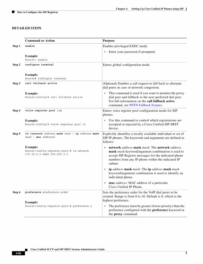
Chapter 6 Setting Up Cisco Unified IP Phones using SIPHow to Configure the SIP Registrar
DETAILED STEPS
Command or Action Purpose
Step 1 enable
Example:Router> enable
Enables privileged EXEC mode.
• Enter your password if prompted.
Step 2 configure terminal
Example:Router# configure terminal
Enters global configuration mode.
Step 3 call fallback active
Example:Router(config)# call fallback active
(Optional) Enables a call request to fall back to alternate dial peers in case of network congestion.
• This command is used if you want to monitor the proxy dial peer and fallback to the next preferred dial peer. For full information on the call fallback active command, see PSTN Fallback Feature.
Step 4 voice register pool tag
Example:Router(config)# voice register pool 12
Enters voice register pool configuration mode for SIP phones.
• Use this command to control which registrations are accepted or rejected by a Cisco Unified SIP SRST device.
Step 5 id {network address mask mask | ip address mask mask | mac address}
Example:Router(config-register-pool)# id network 172.16.0.0 mask 255.255.0.0
Explicitly identifies a locally available individual or set of SIP IP phones. The keywords and arguments are defined as follows:
• network address mask mask: The network address mask mask keyword/argument combination is used to accept SIP Register messages for the indicated phone numbers from any IP phone within the indicated IP subnet.
• ip address mask mask: The ip address mask mask keyword/argument combination is used to identify an individual phone.
• mac address: MAC address of a particular Cisco Unified IP Phone.
Step 6 preference preference-order
Example:Router(config-register-pool)# preference 2
Sets the preference order for the VoIP dial peers to be created. Range is from 0 to 10. Default is 0, which is the highest preference.
• The preference must be greater (lower priority) than the preference configured with the preference keyword in the proxy command.
6-86Cisco Unified SCCP and SIP SRST System Administrator Guide
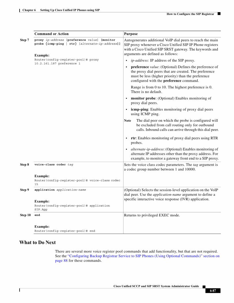
Chapter 6 Setting Up Cisco Unified IP Phones using SIPHow to Configure the SIP Registrar
What to Do Next
There are several more voice register pool commands that add functionality, but that are not required. See the “Configuring Backup Registrar Service to SIP Phones (Using Optional Commands)” section on page 88 for these commands.
Step 7 proxy ip-address [preference value] [monitor probe {icmp-ping | rtr} [alternate-ip-address]]
Example:Router(config-register-pool)# proxy 10.2.161.187 preference 1
Autogenerates additional VoIP dial peers to reach the main SIP proxy whenever a Cisco Unified SIP IP Phone registers with a Cisco Unified SIP SRST gateway. The keywords and arguments are defined as follows:
• ip-address: IP address of the SIP proxy.
• preference value: (Optional) Defines the preference of the proxy dial peers that are created. The preference must be less (higher priority) than the preference configured with the preference command.
Range is from 0 to 10. The highest preference is 0. There is no default.
• monitor probe: (Optional) Enables monitoring of proxy dial peers.
• icmp-ping: Enables monitoring of proxy dial peers using ICMP ping.
Note The dial peer on which the probe is configured will be excluded from call routing only for outbound calls. Inbound calls can arrive through this dial peer.
• rtr: Enables monitoring of proxy dial peers using RTR probes.
• alternate-ip-address: (Optional) Enables monitoring of alternate IP addresses other than the proxy address. For example, to monitor a gateway front end to a SIP proxy.
Step 8 voice-class codec tag
Example:Router(config-register-pool)# voice-class codec 15
Sets the voice class codec parameters. The tag argument is a codec group number between 1 and 10000.
Step 9 application application-name
Example:Router(config-register-pool)# application SIP.App
(Optional) Selects the session-level application on the VoIP dial peer. Use the application-name argument to define a specific interactive voice response (IVR) application.
Step 10 end
Example:Router(config-register-pool)# end
Returns to privileged EXEC mode.
Command or Action Purpose
6-87Cisco Unified SCCP and SIP SRST System Administrator Guide
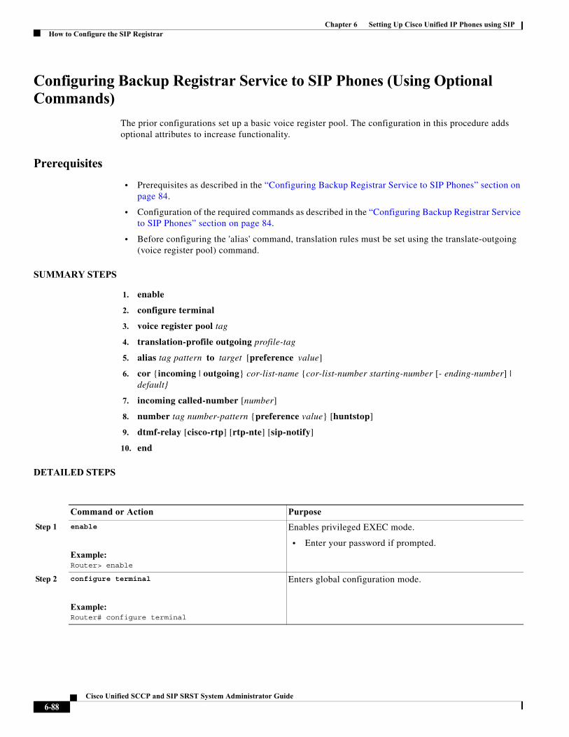
Chapter 6 Setting Up Cisco Unified IP Phones using SIPHow to Configure the SIP Registrar
Configuring Backup Registrar Service to SIP Phones (Using Optional Commands)
The prior configurations set up a basic voice register pool. The configuration in this procedure adds optional attributes to increase functionality.
Prerequisites
• Prerequisites as described in the “Configuring Backup Registrar Service to SIP Phones” section on page 84.
• Configuration of the required commands as described in the “Configuring Backup Registrar Service to SIP Phones” section on page 84.
• Before configuring the 'alias' command, translation rules must be set using the translate-outgoing (voice register pool) command.
SUMMARY STEPS
1. enable
2. configure terminal
3. voice register pool tag
4. translation-profile outgoing profile-tag
5. alias tag pattern to target [preference value]
6. cor {incoming | outgoing} cor-list-name {cor-list-number starting-number [- ending-number] | default}
7. incoming called-number [number]
8. number tag number-pattern {preference value} [huntstop]
9. dtmf-relay [cisco-rtp] [rtp-nte] [sip-notify]
10. end
DETAILED STEPS
Command or Action Purpose
Step 1 enable
Example:Router> enable
Enables privileged EXEC mode.
• Enter your password if prompted.
Step 2 configure terminal
Example:Router# configure terminal
Enters global configuration mode.
6-88Cisco Unified SCCP and SIP SRST System Administrator Guide
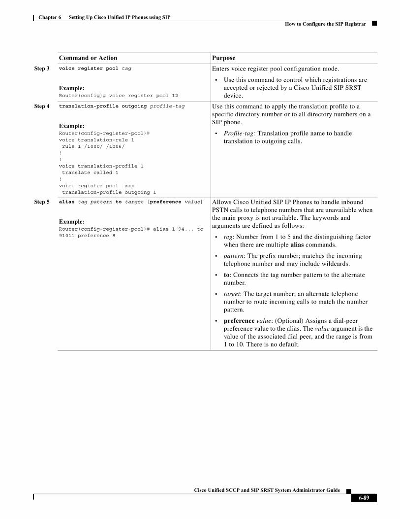
Chapter 6 Setting Up Cisco Unified IP Phones using SIPHow to Configure the SIP Registrar
Step 3 voice register pool tag
Example:Router(config)# voice register pool 12
Enters voice register pool configuration mode.
• Use this command to control which registrations are accepted or rejected by a Cisco Unified SIP SRST device.
Step 4 translation-profile outgoing profile-tag
Example:Router(config-register-pool)#voice translation-rule 1 rule 1 /1000/ /1006/!!voice translation-profile 1 translate called 1!voice register pool xxx translation-profile outgoing 1
Use this command to apply the translation profile to a specific directory number or to all directory numbers on a SIP phone.
• Profile-tag: Translation profile name to handle translation to outgoing calls.
Step 5 alias tag pattern to target [preference value]
Example:Router(config-register-pool)# alias 1 94... to 91011 preference 8
Allows Cisco Unified SIP IP Phones to handle inbound PSTN calls to telephone numbers that are unavailable when the main proxy is not available. The keywords and arguments are defined as follows:
• tag: Number from 1 to 5 and the distinguishing factor when there are multiple alias commands.
• pattern: The prefix number; matches the incoming telephone number and may include wildcards.
• to: Connects the tag number pattern to the alternate number.
• target: The target number; an alternate telephone number to route incoming calls to match the number pattern.
• preference value: (Optional) Assigns a dial-peer preference value to the alias. The value argument is the value of the associated dial peer, and the range is from 1 to 10. There is no default.
Command or Action Purpose
6-89Cisco Unified SCCP and SIP SRST System Administrator Guide
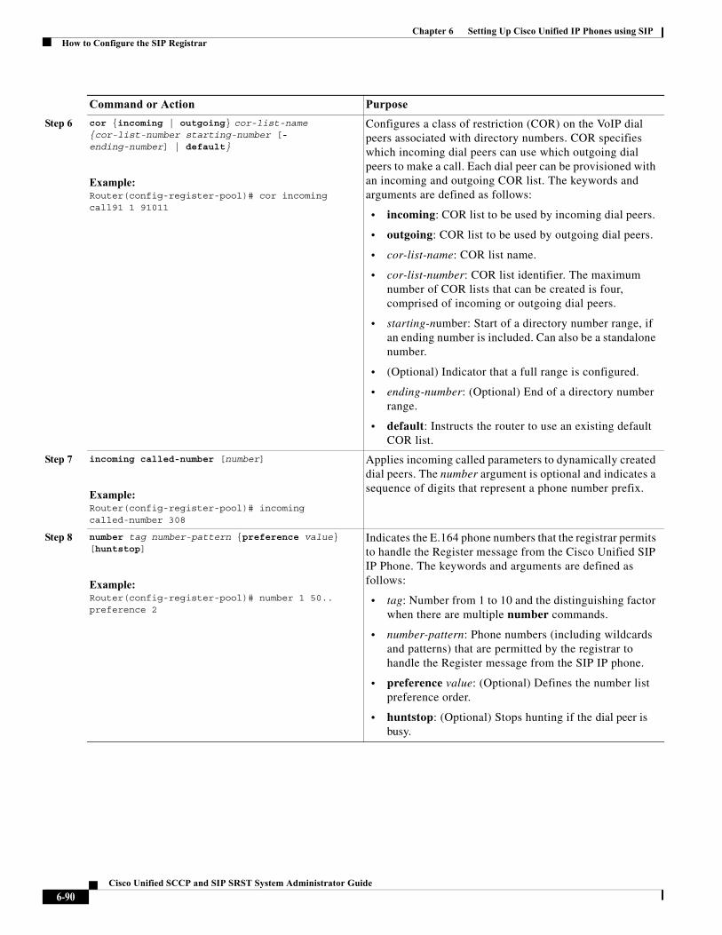
Chapter 6 Setting Up Cisco Unified IP Phones using SIPHow to Configure the SIP Registrar
Step 6 cor {incoming | outgoing} cor-list-name {cor-list-number starting-number [- ending-number] | default}
Example:Router(config-register-pool)# cor incoming call91 1 91011
Configures a class of restriction (COR) on the VoIP dial peers associated with directory numbers. COR specifies which incoming dial peers can use which outgoing dial peers to make a call. Each dial peer can be provisioned with an incoming and outgoing COR list. The keywords and arguments are defined as follows:
• incoming: COR list to be used by incoming dial peers.
• outgoing: COR list to be used by outgoing dial peers.
• cor-list-name: COR list name.
• cor-list-number: COR list identifier. The maximum number of COR lists that can be created is four, comprised of incoming or outgoing dial peers.
• starting-number: Start of a directory number range, if an ending number is included. Can also be a standalone number.
• (Optional) Indicator that a full range is configured.
• ending-number: (Optional) End of a directory number range.
• default: Instructs the router to use an existing default COR list.
Step 7 incoming called-number [number]
Example:Router(config-register-pool)# incoming called-number 308
Applies incoming called parameters to dynamically created dial peers. The number argument is optional and indicates a sequence of digits that represent a phone number prefix.
Step 8 number tag number-pattern {preference value} [huntstop]
Example:Router(config-register-pool)# number 1 50.. preference 2
Indicates the E.164 phone numbers that the registrar permits to handle the Register message from the Cisco Unified SIP IP Phone. The keywords and arguments are defined as follows:
• tag: Number from 1 to 10 and the distinguishing factor when there are multiple number commands.
• number-pattern: Phone numbers (including wildcards and patterns) that are permitted by the registrar to handle the Register message from the SIP IP phone.
• preference value: (Optional) Defines the number list preference order.
• huntstop: (Optional) Stops hunting if the dial peer is busy.
Command or Action Purpose
6-90Cisco Unified SCCP and SIP SRST System Administrator Guide
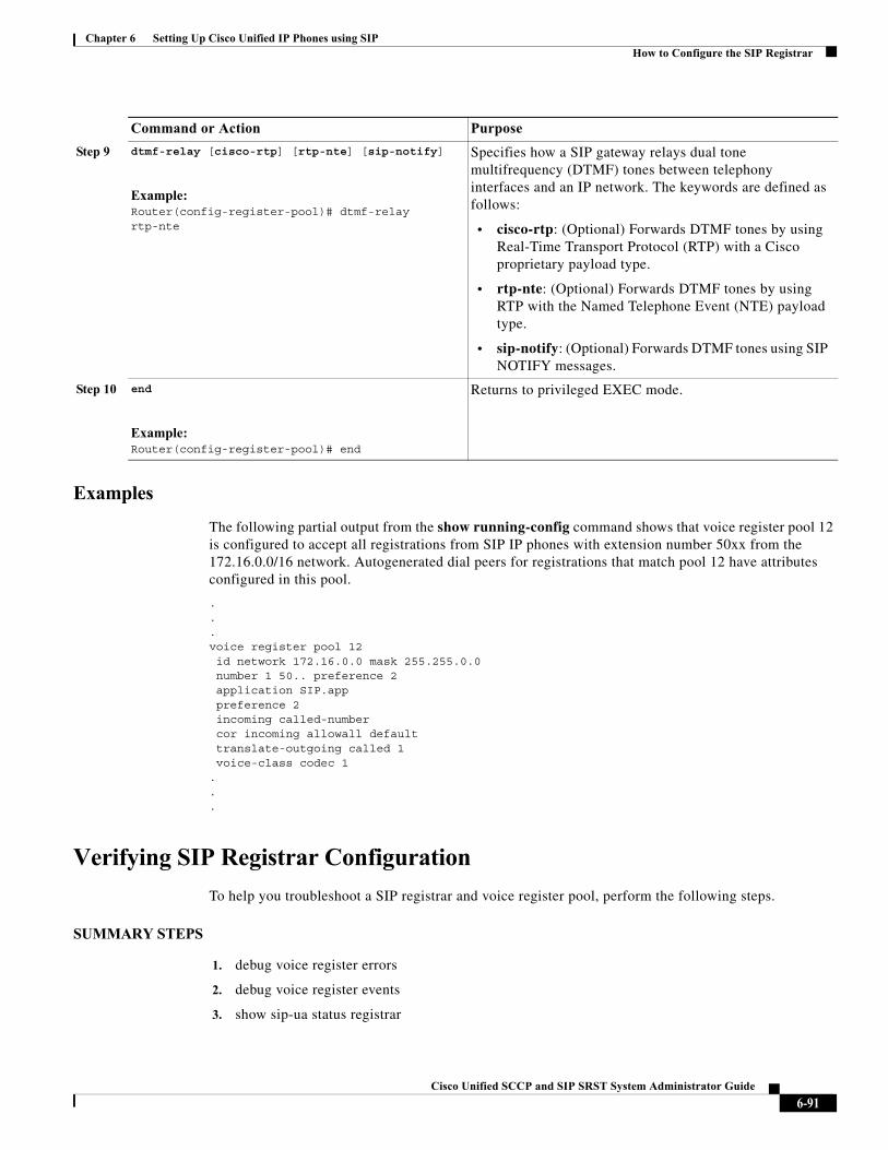
Chapter 6 Setting Up Cisco Unified IP Phones using SIPHow to Configure the SIP Registrar
Examples
The following partial output from the show running-config command shows that voice register pool 12 is configured to accept all registrations from SIP IP phones with extension number 50xx from the 172.16.0.0/16 network. Autogenerated dial peers for registrations that match pool 12 have attributes configured in this pool.
.
.
.voice register pool 12 id network 172.16.0.0 mask 255.255.0.0number 1 50.. preference 2application SIP.apppreference 2incoming called-number cor incoming allowall defaulttranslate-outgoing called 1voice-class codec 1
.
.
.
Verifying SIP Registrar Configuration
To help you troubleshoot a SIP registrar and voice register pool, perform the following steps.
SUMMARY STEPS
1. debug voice register errors
2. debug voice register events
3. show sip-ua status registrar
Step 9 dtmf-relay [cisco-rtp] [rtp-nte] [sip-notify]
Example:Router(config-register-pool)# dtmf-relay rtp-nte
Specifies how a SIP gateway relays dual tone multifrequency (DTMF) tones between telephony interfaces and an IP network. The keywords are defined as follows:
• cisco-rtp: (Optional) Forwards DTMF tones by using Real-Time Transport Protocol (RTP) with a Cisco proprietary payload type.
• rtp-nte: (Optional) Forwards DTMF tones by using RTP with the Named Telephone Event (NTE) payload type.
• sip-notify: (Optional) Forwards DTMF tones using SIP NOTIFY messages.
Step 10 end
Example:Router(config-register-pool)# end
Returns to privileged EXEC mode.
Command or Action Purpose
6-91Cisco Unified SCCP and SIP SRST System Administrator Guide
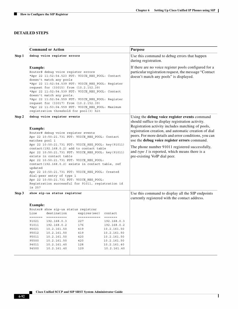
Chapter 6 Setting Up Cisco Unified IP Phones using SIPHow to Configure the SIP Registrar
DETAILED STEPS
Command or Action Purpose
Step 1 debug voice register errors
Example:Router# debug voice register errors*Apr 22 11:52:54.523 PDT: VOICE_REG_POOL: Contact doesn't match any pools *Apr 22 11:52:54.539 PDT: VOICE_REG_POOL: Register request for (33015) from (10.2.152.39) *Apr 22 11:52:54.539 PDT: VOICE_REG_POOL: Contact doesn't match any pools. *Apr 22 11:52:54.559 PDT: VOICE_REG_POOL: Register request for (33017) from (10.2.152.39)*Apr 22 11:53:04.559 PDT: VOICE_REG_POOL: Maximum registration threshold for pool(3) hit
Use this command to debug errors that happen during registration.
If there are no voice register pools configured for a particular registration request, the message “Contact doesn’t match any pools” is displayed.
Step 2 debug voice register events
Example:Router# debug voice register eventsApr 22 10:50:21.731 PDT: VOICE_REG_POOL: Contact matches pool 1Apr 22 10:50:21.731 PDT: VOICE_REG_POOL: key(91011) contact(192.168.0.2) add to contact table Apr 22 10:50:21.731 PDT: VOICE_REG_POOL: key(91011) exists in contact table Apr 22 10:50:21.731 PDT: VOICE_REG_POOL: contact(192.168.0.2) exists in contact table, ref updated Apr 22 10:50:21.731 PDT: VOICE_REG_POOL: Created dial-peer entry of type 1 Apr 22 10:50:21.731 PDT: VOICE_REG_POOL: Registration successful for 91011, registration id is 257
Using the debug voice register events command should suffice to display registration activity. Registration activity includes matching of pools, registration creation, and automatic creation of dial peers. For more details and error conditions, you can use the debug voice register errors command.
The phone number 91011 registered successfully, and type 1 is reported, which means there is a pre-existing VoIP dial peer.
Step 3 show sip-ua status registrar
Example:Router# show sip-ua status registrarLine destination expires(sec) contact======= =========== ============ ======= 91021 192.168.0.3 227 192.168.0.3 91011 192.168.0.2 176 192.168.0.2 95021 10.2.161.50 419 10.2.161.50 95012 10.2.161.50 419 10.2.161.50 95011 10.2.161.50 420 10.2.161.50 95500 10.2.161.50 420 10.2.161.50 94011 10.2.161.40 128 10.2.161.40 94500 10.2.161.40 129 10.2.161.40
Use this command to display all the SIP endpoints currently registered with the contact address.
6-92Cisco Unified SCCP and SIP SRST System Administrator Guide
Chapter 6 Setting Up Cisco Unified IP Phones using SIPHow to Configure the SIP Registrar
Verifying Proxy Dial-Peer Configuration
To use the icmp-ping keyword with the proxy command to assist in troubleshooting proxy dial peers, perform the following steps.
SUMMARY STEPS
1. configure terminal
2. voice register pool tag
3. proxy ip-address [preference value] [monitor probe {icmp-ping | rtr} [alternate-ip-address]]
4. end
5. show voice register dial-peers
6. show dial-peer voice
6-93Cisco Unified SCCP and SIP SRST System Administrator Guide
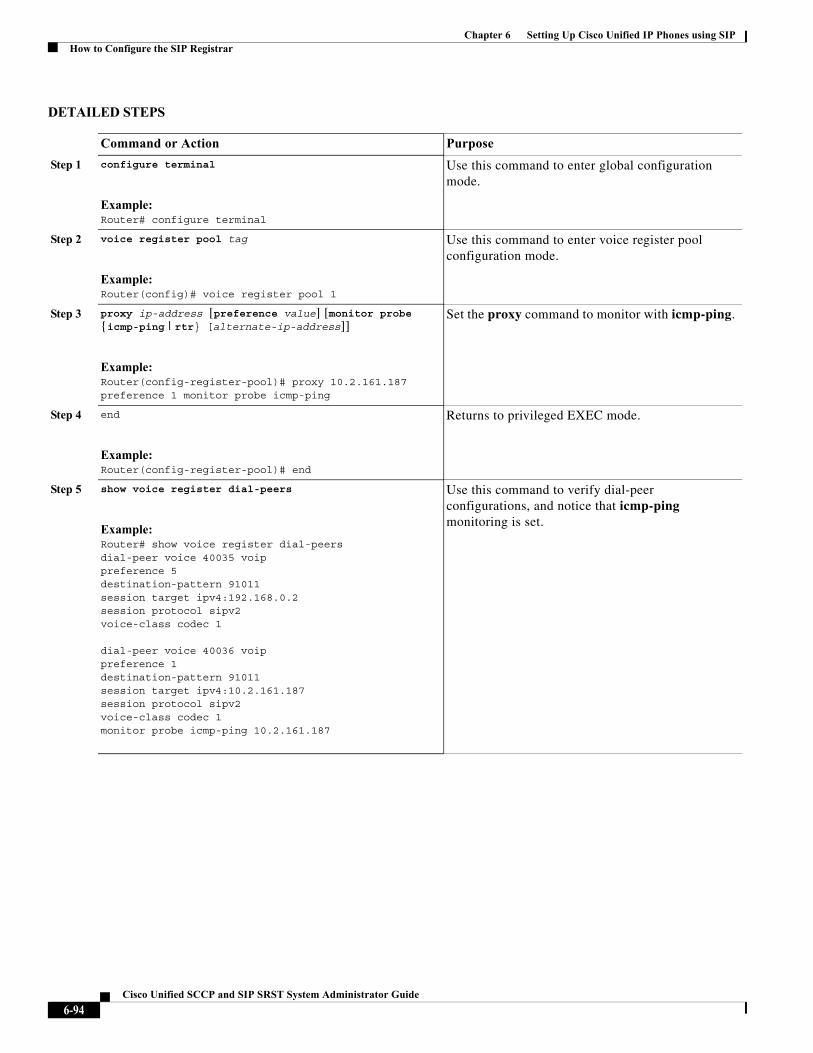
Chapter 6 Setting Up Cisco Unified IP Phones using SIPHow to Configure the SIP Registrar
DETAILED STEPS
Command or Action Purpose
Step 1 configure terminal
Example:Router# configure terminal
Use this command to enter global configuration mode.
Step 2 voice register pool tag
Example:Router(config)# voice register pool 1
Use this command to enter voice register pool configuration mode.
Step 3 proxy ip-address [preference value] [monitor probe {icmp-ping | rtr} [alternate-ip-address]]
Example:Router(config-register-pool)# proxy 10.2.161.187 preference 1 monitor probe icmp-ping
Set the proxy command to monitor with icmp-ping.
Step 4 end
Example:Router(config-register-pool)# end
Returns to privileged EXEC mode.
Step 5 show voice register dial-peers
Example:Router# show voice register dial-peersdial-peer voice 40035 voippreference 5destination-pattern 91011session target ipv4:192.168.0.2session protocol sipv2voice-class codec 1
dial-peer voice 40036 voippreference 1destination-pattern 91011session target ipv4:10.2.161.187session protocol sipv2voice-class codec 1monitor probe icmp-ping 10.2.161.187
Use this command to verify dial-peer configurations, and notice that icmp-ping monitoring is set.
6-94Cisco Unified SCCP and SIP SRST System Administrator Guide
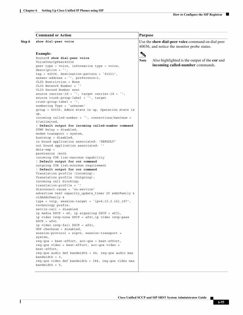
Chapter 6 Setting Up Cisco Unified IP Phones using SIPHow to Configure the SIP Registrar
Step 6 show dial-peer voice
Example:Router# show dial-peer voiceVoiceOverIpPeer40036peer type = voice, information type = voice,description = `',tag = 40036, destination-pattern = `91011',answer-address = `', preference=1,CLID Restriction = NoneCLID Network Number = `'CLID Second Number sent source carrier-id = `', target carrier-id = `',source trunk-group-label = `', target trunk-group-label = `',numbering Type = `unknown'group = 40036, Admin state is up, Operation state is up,incoming called-number = `', connections/maximum = 0/unlimited, ! Default output for incoming called-number commandDTMF Relay = disabled,modem transport = system,huntstop = disabled,in bound application associated: 'DEFAULT'out bound application associated: ''dnis-map = permission :bothincoming COR list:maximum capability ! Default output for cor commandoutgoing COR list:minimum requirement ! Default output for cor commandTranslation profile (Incoming):Translation profile (Outgoing):incoming call blocking:translation-profile = `'disconnect-cause = `no-service'advertise 0x40 capacity_update_timer 25 addrFamily 4 oldAddrFamily 4type = voip, session-target = `ipv4:10.2.161.187',technology prefix: settle-call = disabledip media DSCP = ef, ip signaling DSCP = af31,ip video rsvp-none DSCP = af41,ip video rsvp-pass DSCP = af41ip video rsvp-fail DSCP = af41,UDP checksum = disabled,session-protocol = sipv2, session-transport = system,req-qos = best-effort, acc-qos = best-effort,req-qos video = best-effort, acc-qos video = best-effort,req-qos audio def bandwidth = 64, req-qos audio max bandwidth = 0,req-qos video def bandwidth = 384, req-qos video max bandwidth = 0,
Use the show dial-peer voice command on dial peer 40036, and notice the monitor probe status.
Note Also highlighted is the output of the cor and incoming called-number commands.
Command or Action Purpose
6-95Cisco Unified SCCP and SIP SRST System Administrator Guide
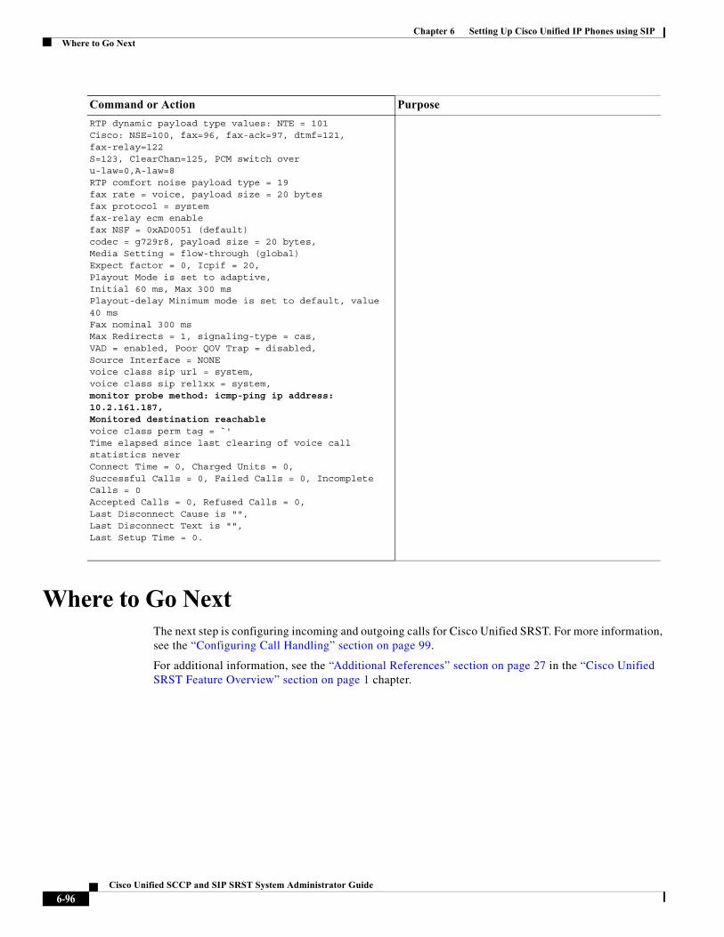
Chapter 6 Setting Up Cisco Unified IP Phones using SIPWhere to Go Next
Where to Go NextThe next step is configuring incoming and outgoing calls for Cisco Unified SRST. For more information, see the “Configuring Call Handling” section on page 99.
For additional information, see the “Additional References” section on page 27 in the “Cisco Unified SRST Feature Overview” section on page 1 chapter.
RTP dynamic payload type values: NTE = 101Cisco: NSE=100, fax=96, fax-ack=97, dtmf=121, fax-relay=122S=123, ClearChan=125, PCM switch over u-law=0,A-law=8RTP comfort noise payload type = 19fax rate = voice, payload size = 20 bytesfax protocol = systemfax-relay ecm enablefax NSF = 0xAD0051 (default)codec = g729r8, payload size = 20 bytes,Media Setting = flow-through (global)Expect factor = 0, Icpif = 20,Playout Mode is set to adaptive,Initial 60 ms, Max 300 msPlayout-delay Minimum mode is set to default, value 40 ms Fax nominal 300 msMax Redirects = 1, signaling-type = cas,VAD = enabled, Poor QOV Trap = disabled, Source Interface = NONEvoice class sip url = system,voice class sip rel1xx = system,monitor probe method: icmp-ping ip address: 10.2.161.187, Monitored destination reachablevoice class perm tag = `'Time elapsed since last clearing of voice call statistics neverConnect Time = 0, Charged Units = 0,Successful Calls = 0, Failed Calls = 0, Incomplete Calls = 0Accepted Calls = 0, Refused Calls = 0,Last Disconnect Cause is "",Last Disconnect Text is "",Last Setup Time = 0.
Command or Action Purpose
6-96Cisco Unified SCCP and SIP SRST System Administrator Guide

Chapter 6 Setting Up Cisco Unified IP Phones using SIPWhere to Go Next
6-97Cisco Unified SCCP and SIP SRST System Administrator Guide

Chapter 6 Setting Up Cisco Unified IP Phones using SIPWhere to Go Next
6-98Cisco Unified SCCP and SIP SRST System Administrator Guide
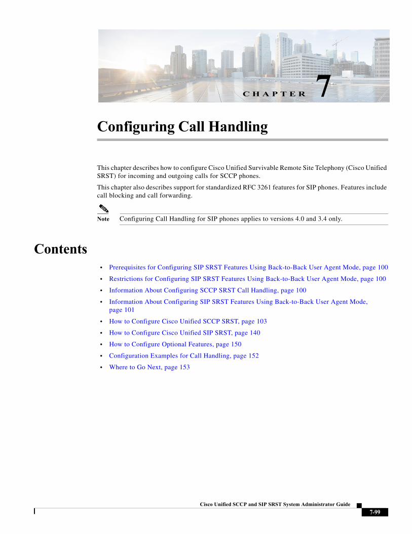
Cisco Unified SC
C H A P T E R 7
Configuring Call HandlingThis chapter describes how to configure Cisco Unified Survivable Remote Site Telephony (Cisco Unified SRST) for incoming and outgoing calls for SCCP phones.
This chapter also describes support for standardized RFC 3261 features for SIP phones. Features include call blocking and call forwarding.
Note Configuring Call Handling for SIP phones applies to versions 4.0 and 3.4 only.
Contents• Prerequisites for Configuring SIP SRST Features Using Back-to-Back User Agent Mode, page 100
• Restrictions for Configuring SIP SRST Features Using Back-to-Back User Agent Mode, page 100
• Information About Configuring SCCP SRST Call Handling, page 100
• Information About Configuring SIP SRST Features Using Back-to-Back User Agent Mode, page 101
• How to Configure Cisco Unified SCCP SRST, page 103
• How to Configure Cisco Unified SIP SRST, page 140
• How to Configure Optional Features, page 150
• Configuration Examples for Call Handling, page 152
• Where to Go Next, page 153
7-99CP and SIP SRST System Administrator Guide
Chapter 7 Configuring Call HandlingPrerequisites for Configuring SIP SRST Features Using Back-to-Back User Agent Mode
Prerequisites for Configuring SIP SRST Features Using Back-to-Back User Agent Mode
• Complete the prerequisites documented in the “Prerequisites for Configuring Cisco Unified SIP SRST” section on page 9 section in the “” section on page 1.
• Configure the SIP registrar. The SIP registrar gives users control of accepting or rejecting registrations. To configure acceptance of incoming SIP Register messages, see the “” section on page 81.
Restrictions for Configuring SIP SRST Features Using Back-to-Back User Agent Mode
• See the restrictions documented in the “Restrictions for Configuring Cisco Unified SIP SRST” section on page 9 section in the “” section on page 1.
Information About Configuring SCCP SRST Call HandlingCisco Unified SRST offers a smaller set of call handling capabilities than Cisco Unified CM, and much of the configuration for these feature involves enabling existing Cisco Unified CM or Cisco Unified IP Phone settings.
• H.323 VoIP Call Preservation Enhancements for WAN Link Failures, page 100
• Toll Fraud Prevention, page 101
H.323 VoIP Call Preservation Enhancements for WAN Link Failures
H.323 VoIP call preservation enhancements for WAN link failures sustains connectivity for H.323 topologies where signaling is handled by an entity, such as Cisco Unified Communications Manager, that is different from the other endpoint and brokers signaling between the two connected parties.
Call preservation is useful when a gateway and the other endpoint (typically a Cisco Unified IP phone) are collocated at the same site and call agent is remote and therefore more likely to experience connectivity failures.
For configuration information see “Configuring H.323 Gateways” chapter in Cisco IOS H.323 Configuration Guide, Release 12.4T.
7-100Cisco Unified SCCP and SIP SRST System Administrator Guide
Chapter 7 Configuring Call HandlingInformation About Configuring SIP SRST Features Using Back-to-Back User Agent Mode
Toll Fraud Prevention
When a Cisco router platform is installed with a voice-capable Cisco IOS software image, appropriate features must be enabled on the platform to prevent potential toll fraud exploitation by unauthorized users. Deploy these features on all Cisco router Unified Communications applications that process voice calls, such as Cisco Unified Communications Manager Express (CME), Cisco Survivable Remote Site Telephony (SRST), Cisco Unified Border Element (UBE), Cisco IOS-based router and standalone analog and digital PBX and public-switched telephone network (PSTN) gateways, and Cisco contact-center VoiceXML gateways. For more information about Toll Fraud Prevention, see Toll Fraud Prevention in Cisco Unified Communications Manager Express System Administration Guide.
Information About Configuring SIP SRST Features Using Back-to-Back User Agent Mode
A Cisco Unified SRST system can now support SIP phones with standard-based RFC 3261 feature support locally and across SIP WAN networks. With Cisco Unified SIP SRST, SIP phones can place calls across SIP networks with similar features, as SCCP phones do. For example, most SCCP phone features such as caller ID, speed dial, and redial are supported now on SIP networks, which gives users the opportunity to choose SCCP or SIP.
Cisco Unified SIP SRST also uses a back-to-back user agent (B2BUA), which is a separate call agent that has more features than Cisco SIP SRST 3.0, which used a redirect server that only accepted and forwarded calls. The main advantage of a B2BUA call agent is in call forwarding, because it forwards calls on behalf of the phone. In addition, it maintains a presence as call middleman in the call path.
Cisco SIP SRST 3.4 supports the following call combinations:
• SIP phone to SIP phone
• SIP phone to PSTN / router voice port
• SIP phone to SCCP phone
Cisco Unified SIP SRST and Cisco SIP Communications Manager Express Feature Crossover
The voice regisiter dn, voice register global and voice register pool configuration mode commands are accessible in both Cisco Unified SIP CME and Cisco Unified SIP SRST modes of operation. However, not all of the commands within these modes are intended for use in SIP SRST mode. Table 7-1 provides a summary guide to which commands are relevant to the CME or SRST modes of operation.
For more detailed information, refer to the command reference pages for each of the individual commands.
Note Table 7-1 is not all-inclusive; additional commands may exist.
7-101Cisco Unified SCCP and SIP SRST System Administrator Guide
http://www.cisco.com/en/US/docs/voice_ip_comm/cucme/admin/configuration/guide/cmeplan.html#wp1106494
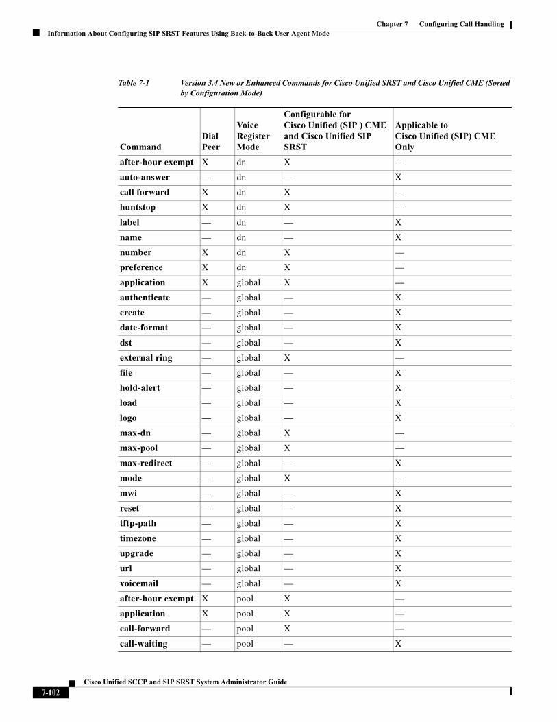
Chapter 7 Configuring Call HandlingInformation About Configuring SIP SRST Features Using Back-to-Back User Agent Mode
Table 7-1 Version 3.4 New or Enhanced Commands for Cisco Unified SRST and Cisco Unified CME (Sorted by Configuration Mode)
CommandDial Peer
Voice Register Mode
Configurable for Cisco Unified (SIP ) CME and Cisco Unified SIP SRST
Applicable to Cisco Unified (SIP) CME Only
after-hour exempt X dn X —
auto-answer — dn — X
call forward X dn X —
huntstop X dn X —
label — dn — X
name — dn — X
number X dn X —
preference X dn X —
application X global X —
authenticate — global — X
create — global — X
date-format — global — X
dst — global — X
external ring — global X —
file — global — X
hold-alert — global — X
load — global — X
logo — global — X
max-dn — global X —
max-pool — global X —
max-redirect — global — X
mode — global X —
mwi — global — X
reset — global — X
tftp-path — global — X
timezone — global — X
upgrade — global — X
url — global — X
voicemail — global — X
after-hour exempt X pool X —
application X pool X —
call-forward — pool X —
call-waiting — pool — X
7-102Cisco Unified SCCP and SIP SRST System Administrator Guide
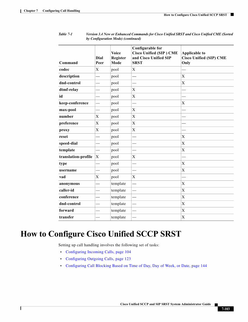
Chapter 7 Configuring Call HandlingHow to Configure Cisco Unified SCCP SRST
How to Configure Cisco Unified SCCP SRSTSetting up call handling involves the following set of tasks:
• Configuring Incoming Calls, page 104
• Configuring Outgoing Calls, page 123
• Configuring Call Blocking Based on Time of Day, Day of Week, or Date, page 144
codec X pool X —
description — pool — X
dnd-control — pool — X
dtmf-relay — pool X —
id — pool X —
keep-conference — pool — X
max-pool — pool X —
number X pool X —
preference X pool X —
proxy X pool X —
reset — pool — X
speed-dial — pool — X
template — pool — X
translation-profile X pool X —
type — pool — X
username — pool — X
vad X pool X —
anonymous — template — X
caller-id — template — X
conference — template — X
dnd-control — template — X
forward — template — X
transfer — template — X
Table 7-1 Version 3.4 New or Enhanced Commands for Cisco Unified SRST and Cisco Unified CME (Sorted by Configuration Mode) (continued)
CommandDial Peer
Voice Register Mode
Configurable for Cisco Unified (SIP ) CME and Cisco Unified SIP SRST
Applicable to Cisco Unified (SIP) CME Only
7-103Cisco Unified SCCP and SIP SRST System Administrator Guide
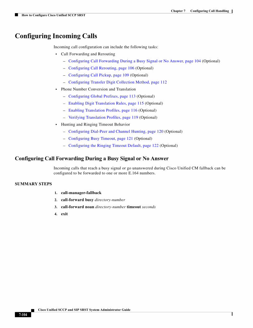
Chapter 7 Configuring Call HandlingHow to Configure Cisco Unified SCCP SRST
Configuring Incoming Calls
Incoming call configuration can include the following tasks:
• Call Forwarding and Rerouting
– Configuring Call Forwarding During a Busy Signal or No Answer, page 104 (Optional)
– Configuring Call Rerouting, page 106 (Optional)
– Configuring Call Pickup, page 109 (Optional)
– Configuring Transfer Digit Collection Method, page 112
• Phone Number Conversion and Translation
– Configuring Global Prefixes, page 113 (Optional)
– Enabling Digit Translation Rules, page 115 (Optional)
– Enabling Translation Profiles, page 116 (Optional)
– Verifying Translation Profiles, page 119 (Optional)
• Hunting and Ringing Timeout Behavior
– Configuring Dial-Peer and Channel Hunting, page 120 (Optional)
– Configuring Busy Timeout, page 121 (Optional)
– Configuring the Ringing Timeout Default, page 122 (Optional)
Configuring Call Forwarding During a Busy Signal or No Answer
Incoming calls that reach a busy signal or go unanswered during Cisco Unified CM fallback can be configured to be forwarded to one or more E.164 numbers.
SUMMARY STEPS
1. call-manager-fallback
2. call-forward busy directory-number
3. call-forward noan directory-number timeout seconds
4. exit
7-104Cisco Unified SCCP and SIP SRST System Administrator Guide
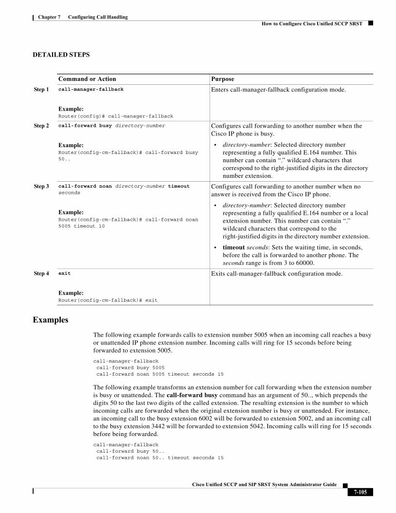
Chapter 7 Configuring Call HandlingHow to Configure Cisco Unified SCCP SRST
DETAILED STEPS
Examples
The following example forwards calls to extension number 5005 when an incoming call reaches a busy or unattended IP phone extension number. Incoming calls will ring for 15 seconds before being forwarded to extension 5005.
call-manager-fallback call-forward busy 5005 call-forward noan 5005 timeout seconds 15
The following example transforms an extension number for call forwarding when the extension number is busy or unattended. The call-forward busy command has an argument of 50.., which prepends the digits 50 to the last two digits of the called extension. The resulting extension is the number to which incoming calls are forwarded when the original extension number is busy or unattended. For instance, an incoming call to the busy extension 6002 will be forwarded to extension 5002, and an incoming call to the busy extension 3442 will be forwarded to extension 5042. Incoming calls will ring for 15 seconds before being forwarded.
call-manager-fallback call-forward busy 50.. call-forward noan 50.. timeout seconds 15
Command or Action Purpose
Step 1 call-manager-fallback
Example:Router(config)# call-manager-fallback
Enters call-manager-fallback configuration mode.
Step 2 call-forward busy directory-number
Example:Router(config-cm-fallback)# call-forward busy 50..
Configures call forwarding to another number when the Cisco IP phone is busy.
• directory-number: Selected directory number representing a fully qualified E.164 number. This number can contain “.” wildcard characters that correspond to the right-justified digits in the directory number extension.
Step 3 call-forward noan directory-number timeout seconds
Example:Router(config-cm-fallback)# call-forward noan 5005 timeout 10
Configures call forwarding to another number when no answer is received from the Cisco IP phone.
• directory-number: Selected directory number representing a fully qualified E.164 number or a local extension number. This number can contain “.” wildcard characters that correspond to the right-justified digits in the directory number extension.
• timeout seconds: Sets the waiting time, in seconds, before the call is forwarded to another phone. The seconds range is from 3 to 60000.
Step 4 exit
Example:Router(config-cm-fallback)# exit
Exits call-manager-fallback configuration mode.
7-105Cisco Unified SCCP and SIP SRST System Administrator Guide
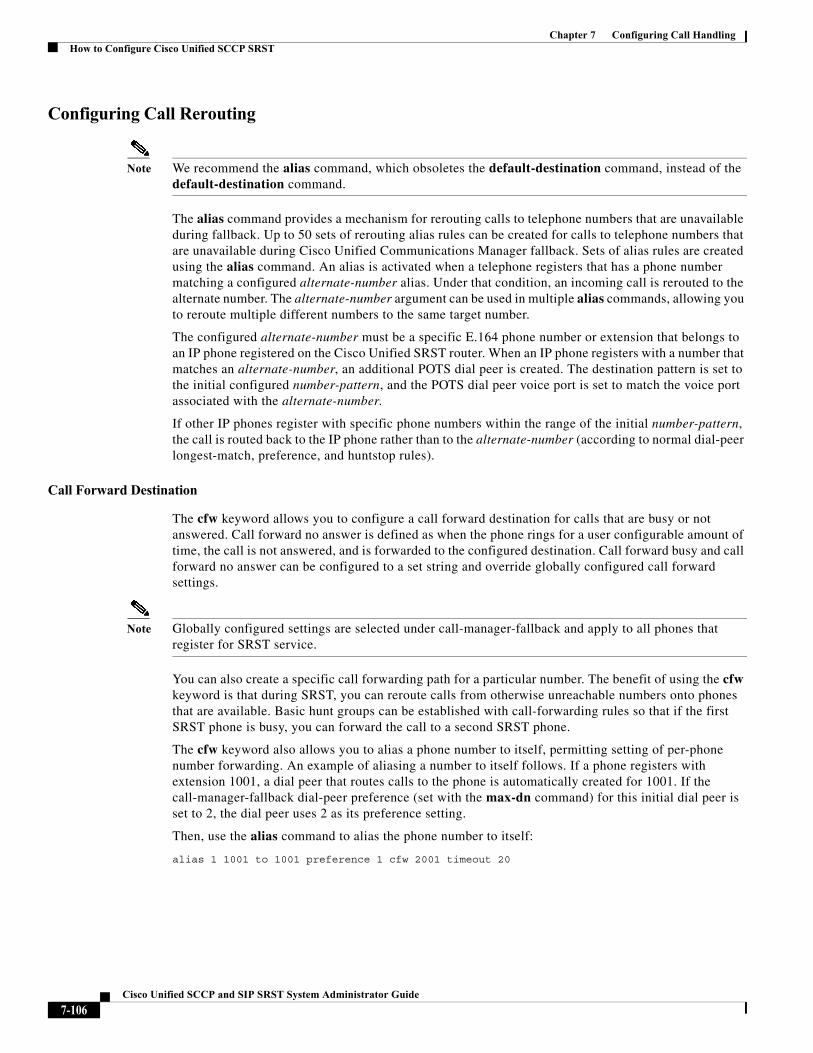
Chapter 7 Configuring Call HandlingHow to Configure Cisco Unified SCCP SRST
Configuring Call Rerouting
Note We recommend the alias command, which obsoletes the default-destination command, instead of the default-destination command.
The alias command provides a mechanism for rerouting calls to telephone numbers that are unavailable during fallback. Up to 50 sets of rerouting alias rules can be created for calls to telephone numbers that are unavailable during Cisco Unified Communications Manager fallback. Sets of alias rules are created using the alias command. An alias is activated when a telephone registers that has a phone number matching a configured alternate-number alias. Under that condition, an incoming call is rerouted to the alternate number. The alternate-number argument can be used in multiple alias commands, allowing you to reroute multiple different numbers to the same target number.
The configured alternate-number must be a specific E.164 phone number or extension that belongs to an IP phone registered on the Cisco Unified SRST router. When an IP phone registers with a number that matches an alternate-number, an additional POTS dial peer is created. The destination pattern is set to the initial configured number-pattern, and the POTS dial peer voice port is set to match the voice port associated with the alternate-number.
If other IP phones register with specific phone numbers within the range of the initial number-pattern, the call is routed back to the IP phone rather than to the alternate-number (according to normal dial-peer longest-match, preference, and huntstop rules).
Call Forward Destination
The cfw keyword allows you to configure a call forward destination for calls that are busy or not answered. Call forward no answer is defined as when the phone rings for a user configurable amount of time, the call is not answered, and is forwarded to the configured destination. Call forward busy and call forward no answer can be configured to a set string and override globally configured call forward settings.
Note Globally configured settings are selected under call-manager-fallback and apply to all phones that register for SRST service.
You can also create a specific call forwarding path for a particular number. The benefit of using the cfw keyword is that during SRST, you can reroute calls from otherwise unreachable numbers onto phones that are available. Basic hunt groups can be established with call-forwarding rules so that if the first SRST phone is busy, you can forward the call to a second SRST phone.
The cfw keyword also allows you to alias a phone number to itself, permitting setting of per-phone number forwarding. An example of aliasing a number to itself follows. If a phone registers with extension 1001, a dial peer that routes calls to the phone is automatically created for 1001. If the call-manager-fallback dial-peer preference (set with the max-dn command) for this initial dial peer is set to 2, the dial peer uses 2 as its preference setting.
Then, use the alias command to alias the phone number to itself:
alias 1 1001 to 1001 preference 1 cfw 2001 timeout 20
7-106Cisco Unified SCCP and SIP SRST System Administrator Guide
Chapter 7 Configuring Call HandlingHow to Configure Cisco Unified SCCP SRST
In this example, you have created a second dial peer for 1001 to route calls to 1001, but that has preference 1 and call forwarding to 2001. Because the preference on the dial peer created by the alias command is now a lower numeric value than the preference that the dial peer first created, all calls come initially to the dial peer created by the alias command. In that way, they are subject to the forward as set by the alias command, instead of any call forwarding that may have been set globally.
Huntstop on an Individual Alias
The alias huntstop keyword is relevant only if you have also set the global no huntstop command under call-manager-fallback. Also, you may need to set the global no huntstop if you have multiple alias commands with the same number-pattern and you want to enable hunting on busy between the aliases. That is, one alias for number-pattern is tried, and then if that phone is busy, the second alias for number-pattern is tried.
The alias huntstop keyword allows you to turn huntstop behavior back on for an individual alias, if huntstop is turned off globally by the no huntstop command. Setting the huntstop keyword on an individual alias stops hunting at the alias, making the alias the final member of the hunt sequence.
SUMMARY STEPS
1. call-manager-fallback
2. alias tag number-pattern to alternate-number [preference preference-value] [cfw number timeout timeout-value] [huntstop]
3. max-dn max-directory-numbers [dual-line] [preference preference-order]
4. end
5. show dial-peer voice summary
7-107Cisco Unified SCCP and SIP SRST System Administrator Guide
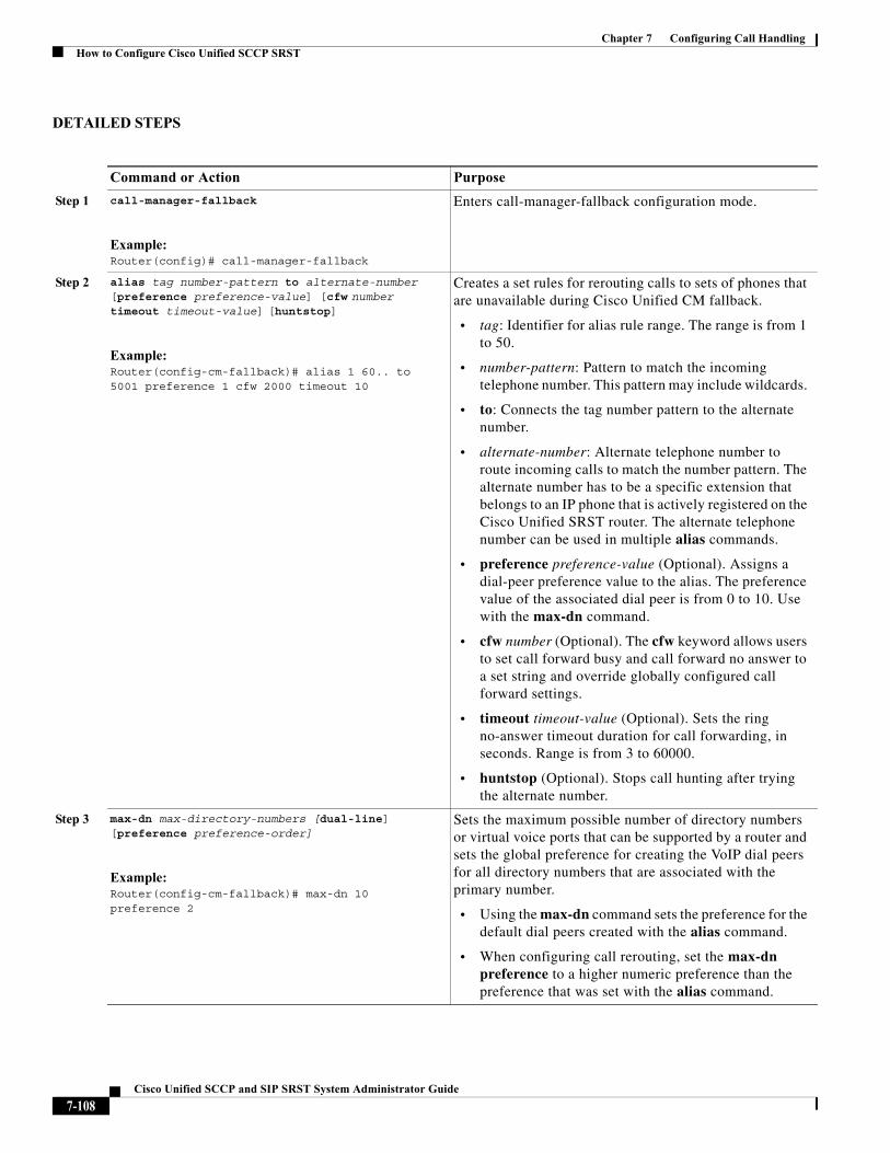
Chapter 7 Configuring Call HandlingHow to Configure Cisco Unified SCCP SRST
DETAILED STEPS
Command or Action Purpose
Step 1 call-manager-fallback
Example:Router(config)# call-manager-fallback
Enters call-manager-fallback configuration mode.
Step 2 alias tag number-pattern to alternate-number [preference preference-value] [cfw number timeout timeout-value] [huntstop]
Example:Router(config-cm-fallback)# alias 1 60.. to 5001 preference 1 cfw 2000 timeout 10
Creates a set rules for rerouting calls to sets of phones that are unavailable during Cisco Unified CM fallback.
• tag: Identifier for alias rule range. The range is from 1 to 50.
• number-pattern: Pattern to match the incoming telephone number. This pattern may include wildcards.
• to: Connects the tag number pattern to the alternate number.
• alternate-number: Alternate telephone number to route incoming calls to match the number pattern. The alternate number has to be a specific extension that belongs to an IP phone that is actively registered on the Cisco Unified SRST router. The alternate telephone number can be used in multiple alias commands.
• preference preference-value (Optional). Assigns a dial-peer preference value to the alias. The preference value of the associated dial peer is from 0 to 10. Use with the max-dn command.
• cfw number (Optional). The cfw keyword allows users to set call forward busy and call forward no answer to a set string and override globally configured call forward settings.
• timeout timeout-value (Optional). Sets the ring no-answer timeout duration for call forwarding, in seconds. Range is from 3 to 60000.
• huntstop (Optional). Stops call hunting after trying the alternate number.
Step 3 max-dn max-directory-numbers [dual-line] [preference preference-order]
Example:Router(config-cm-fallback)# max-dn 10 preference 2
Sets the maximum possible number of directory numbers or virtual voice ports that can be supported by a router and sets the global preference for creating the VoIP dial peers for all directory numbers that are associated with the primary number.
• Using the max-dn command sets the preference for the default dial peers created with the alias command.
• When configuring call rerouting, set the max-dn preference to a higher numeric preference than the preference that was set with the alias command.
7-108Cisco Unified SCCP and SIP SRST System Administrator Guide
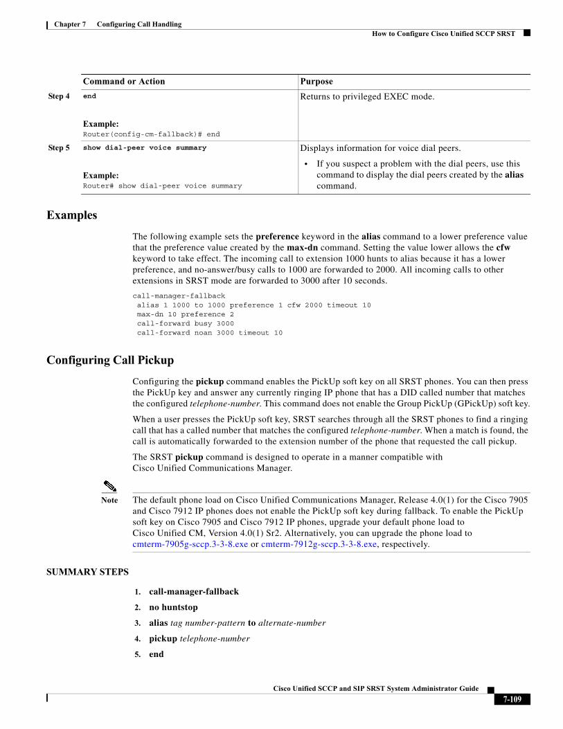
Chapter 7 Configuring Call HandlingHow to Configure Cisco Unified SCCP SRST
Examples
The following example sets the preference keyword in the alias command to a lower preference value that the preference value created by the max-dn command. Setting the value lower allows the cfw keyword to take effect. The incoming call to extension 1000 hunts to alias because it has a lower preference, and no-answer/busy calls to 1000 are forwarded to 2000. All incoming calls to other extensions in SRST mode are forwarded to 3000 after 10 seconds.
call-manager-fallback alias 1 1000 to 1000 preference 1 cfw 2000 timeout 10max-dn 10 preference 2call-forward busy 3000call-forward noan 3000 timeout 10
Configuring Call Pickup
Configuring the pickup command enables the PickUp soft key on all SRST phones. You can then press the PickUp key and answer any currently ringing IP phone that has a DID called number that matches the configured telephone-number. This command does not enable the Group PickUp (GPickUp) soft key.
When a user presses the PickUp soft key, SRST searches through all the SRST phones to find a ringing call that has a called number that matches the configured telephone-number. When a match is found, the call is automatically forwarded to the extension number of the phone that requested the call pickup.
The SRST pickup command is designed to operate in a manner compatible with Cisco Unified Communications Manager.
Note The default phone load on Cisco Unified Communications Manager, Release 4.0(1) for the Cisco 7905 and Cisco 7912 IP phones does not enable the PickUp soft key during fallback. To enable the PickUp soft key on Cisco 7905 and Cisco 7912 IP phones, upgrade your default phone load to Cisco Unified CM, Version 4.0(1) Sr2. Alternatively, you can upgrade the phone load to cmterm-7905g-sccp.3-3-8.exe or cmterm-7912g-sccp.3-3-8.exe, respectively.
SUMMARY STEPS
1. call-manager-fallback
2. no huntstop
3. alias tag number-pattern to alternate-number
4. pickup telephone-number
5. end
Step 4 end
Example:Router(config-cm-fallback)# end
Returns to privileged EXEC mode.
Step 5 show dial-peer voice summary
Example:Router# show dial-peer voice summary
Displays information for voice dial peers.
• If you suspect a problem with the dial peers, use this command to display the dial peers created by the alias command.
Command or Action Purpose
7-109Cisco Unified SCCP and SIP SRST System Administrator Guide
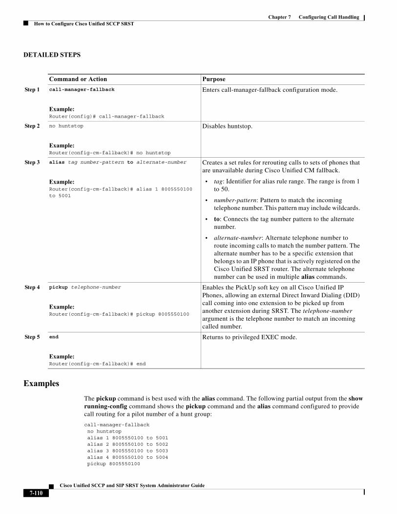
Chapter 7 Configuring Call HandlingHow to Configure Cisco Unified SCCP SRST
DETAILED STEPS
Examples
The pickup command is best used with the alias command. The following partial output from the show running-config command shows the pickup command and the alias command configured to provide call routing for a pilot number of a hunt group:
call-manager-fallbackno huntstopalias 1 8005550100 to 5001alias 2 8005550100 to 5002alias 3 8005550100 to 5003alias 4 8005550100 to 5004pickup 8005550100
Command or Action Purpose
Step 1 call-manager-fallback
Example:Router(config)# call-manager-fallback
Enters call-manager-fallback configuration mode.
Step 2 no huntstop
Example:Router(config-cm-fallback)# no huntstop
Disables huntstop.
Step 3 alias tag number-pattern to alternate-number
Example:Router(config-cm-fallback)# alias 1 8005550100 to 5001
Creates a set rules for rerouting calls to sets of phones that are unavailable during Cisco Unified CM fallback.
• tag: Identifier for alias rule range. The range is from 1 to 50.
• number-pattern: Pattern to match the incoming telephone number. This pattern may include wildcards.
• to: Connects the tag number pattern to the alternate number.
• alternate-number: Alternate telephone number to route incoming calls to match the number pattern. The alternate number has to be a specific extension that belongs to an IP phone that is actively registered on the Cisco Unified SRST router. The alternate telephone number can be used in multiple alias commands.
Step 4 pickup telephone-number
Example:Router(config-cm-fallback)# pickup 8005550100
Enables the PickUp soft key on all Cisco Unified IP Phones, allowing an external Direct Inward Dialing (DID) call coming into one extension to be picked up from another extension during SRST. The telephone-number argument is the telephone number to match an incoming called number.
Step 5 end
Example:Router(config-cm-fallback)# end
Returns to privileged EXEC mode.
7-110Cisco Unified SCCP and SIP SRST System Administrator Guide
Chapter 7 Configuring Call HandlingHow to Configure Cisco Unified SCCP SRST
When a DID incoming call to 800 555-0100 is received, the alias command routes the call at random to one of the four extensions (5001 to 5004). Because the pickup command is configured, if the DID call rings on extension 5002, the call can be answered from any of the other extensions (5001, 5003, 5004) by pressing the PickUp soft key.
The pickup command works by finding a match based on the incoming DID called number. In this example, a call from extension 5004 to extension 5001 (an internal call) does not activate the pickup command because the called number (5001) does not match the configured pickup number (800 555-0100). Thus, the pickup command distinguishes between internal and external calls if multiple calls are ringing simultaneously.
Configuring Consultative Transfer
Before Cisco Unified SRST 4.3, the consultative transfer feature played a dial tone and collected dialed digits until the digits matched the pattern for consultative transfer, blind transfer, or PSTN transfer blocking. The after-hours blocking criteria was applied after the consultative transfer digit collection and pattern matching.
The new feature modifies the transfer digit-collection process to make it consistent with Cisco Unified Communications Manager. This feature is supported only if the transfer-system full-consult command (default) is specified in call-manager-fallback configuration mode and an idle line or channel is available for seizing, digit collection, and dialing.
Two lines are required for a consultative transfer. When the transferor party is an octo-line directory number, Cisco Unified SRST selects the next available idle channel on that directory number. If the maximum number of channels of the directory number are in use, another idle line on the transferor phone is considered. If the auto-line command is configured on the phone, the specified autoline (if idle) takes precedence over other nonauto lines. If no idle line is available on the transferor phone, a blind transfer is initiated instead of the consultative transfer.
During the consultative transfer, the transferor line to the transferee party is locked on the transferor phone to prevent it from being stolen by other phones sharing the same directory number. When the user presses the Transfer soft key for a consultative transfer, the Transfer soft key does not display while digits are being dialed and collected on this seized consultative transfer call leg. The method for consultative transfer pattern matching, blind transfer, PSTN transfer blocking, or after-hour blocking criteria remain the same although the manipulation after the matching is different. When the criteria for the blind transfer is met, Cisco Unified SMST terminates the consultative transfer call leg, informs the Cisco IOS software to transfer the call, and then terminates the original call bubble. The PARK FAC code is handled in the same way as by a new call which requires that a ten-second timer is applied by the Cisco IOS software.
Note The enhancement, by default, collects the transfer digits from the new call leg. If required, you can configure the system to collect the transfer digits from the original call leg. See the “Configuring Transfer Digit Collection Method” section on page 112.
The error handling for transfer failure because of transfer blocking or interdigit timer expiration remains. It includes displaying an error message on the prompt line and logging it if “debug ephone error” is enabled, playing a fast-busy or busy tone, and terminating the consultative transfer call leg.
No new configuration is required to support these enhancements.
7-111Cisco Unified SCCP and SIP SRST System Administrator Guide
Chapter 7 Configuring Call HandlingHow to Configure Cisco Unified SCCP SRST
Conference Calls
No configuration steps are required for these conference call enhancements.
Single-Line Directory Number
If the initiating party for the conference call is a single-line directory number and the phone has multiple directory numbers configured, the system selects another directory number’s idle channel for creating the conference. If there are multiple directory numbers (dual-line or single-line directory numbers) on the phone and each has calls on hold, the system prompts the user to select a line for the conference call.
Dual-Line Directory Number
If the initiating party for the conference call is a dual-line directory number, the system selects another idle channel from the dual-line directory number. If the selected channel has a call on hold, the conference operation will automatically select the hold channel and create the conference.
Octo-Line Directory Number
If the initiating party for the conference call is an octo-line directory number, the system selects an idle channel from the initiating party directory number and the user must establish a new call to complete the conference. If there is no idle channel on the same directory number, other idle directory numbers or channels on the same phone are not selected. If there are existing calls on hold on the other channels of the same directory number or other directory numbers, the user will not have the option to select them to join the conference. If there is no idle channel on the same directory number, the conference will abort with a No Line Available message.
Configuring Transfer Digit Collection Method
By default, transfer digits are collected from the new call leg. To change the transfer digit collection method, perform the following steps.
Prerequisites for Cisco Unified SRST 4.3
• Cisco Unified SRST 4.3
• Cisco Unified CM 6.0
• Cisco IOS Release 12.4(15)XZ
Restrictions for Cisco Unified SRST 4.3
• The Cisco 3200 Series Mobile Access Router does not support SRST.
SUMMARY STEPS
1. enable
2. configure terminal
3. call-manager-fallback
4. transfer-digit-collect {new-call | orig-call}
5. end
7-112Cisco Unified SCCP and SIP SRST System Administrator Guide
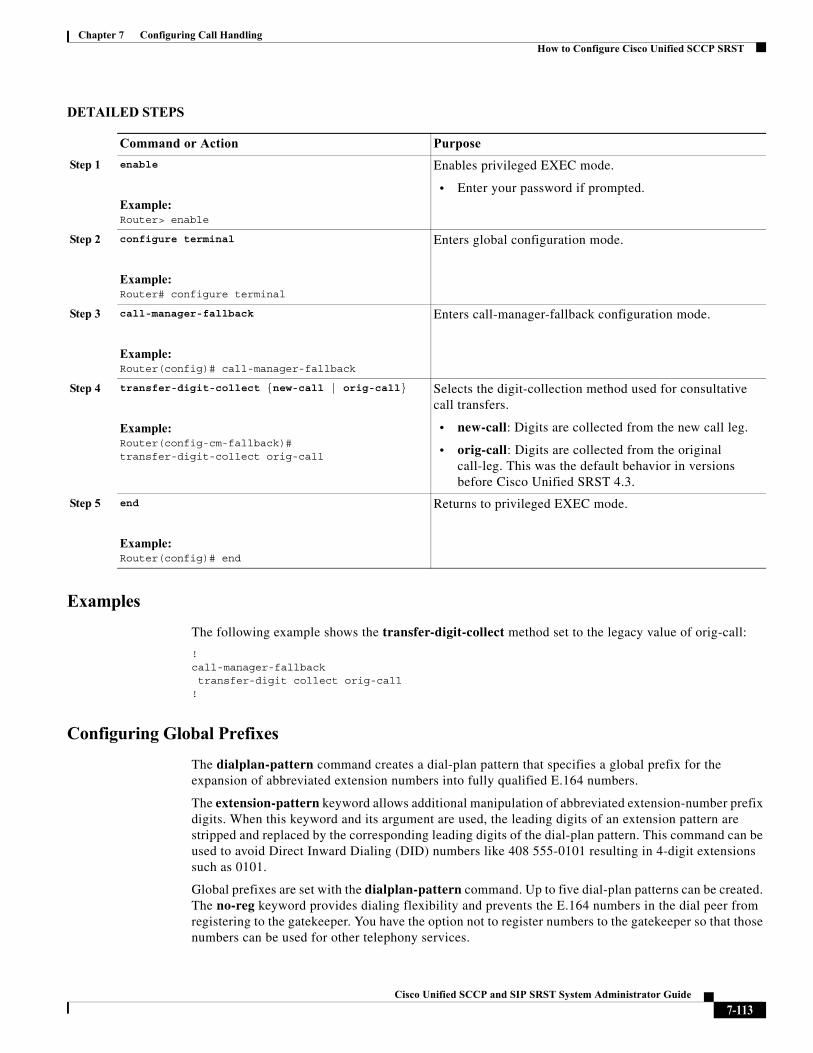
Chapter 7 Configuring Call HandlingHow to Configure Cisco Unified SCCP SRST
DETAILED STEPS
Examples
The following example shows the transfer-digit-collect method set to the legacy value of orig-call:
!call-manager-fallbacktransfer-digit collect orig-call
!
Configuring Global Prefixes
The dialplan-pattern command creates a dial-plan pattern that specifies a global prefix for the expansion of abbreviated extension numbers into fully qualified E.164 numbers.
The extension-pattern keyword allows additional manipulation of abbreviated extension-number prefix digits. When this keyword and its argument are used, the leading digits of an extension pattern are stripped and replaced by the corresponding leading digits of the dial-plan pattern. This command can be used to avoid Direct Inward Dialing (DID) numbers like 408 555-0101 resulting in 4-digit extensions such as 0101.
Global prefixes are set with the dialplan-pattern command. Up to five dial-plan patterns can be created. The no-reg keyword provides dialing flexibility and prevents the E.164 numbers in the dial peer from registering to the gatekeeper. You have the option not to register numbers to the gatekeeper so that those numbers can be used for other telephony services.
Command or Action Purpose
Step 1 enable
Example:Router> enable
Enables privileged EXEC mode.
• Enter your password if prompted.
Step 2 configure terminal
Example:Router# configure terminal
Enters global configuration mode.
Step 3 call-manager-fallback
Example:Router(config)# call-manager-fallback
Enters call-manager-fallback configuration mode.
Step 4 transfer-digit-collect {new-call | orig-call}
Example:Router(config-cm-fallback)# transfer-digit-collect orig-call
Selects the digit-collection method used for consultative call transfers.
• new-call: Digits are collected from the new call leg.
• orig-call: Digits are collected from the original call-leg. This was the default behavior in versions before Cisco Unified SRST 4.3.
Step 5 end
Example:Router(config)# end
Returns to privileged EXEC mode.
7-113Cisco Unified SCCP and SIP SRST System Administrator Guide
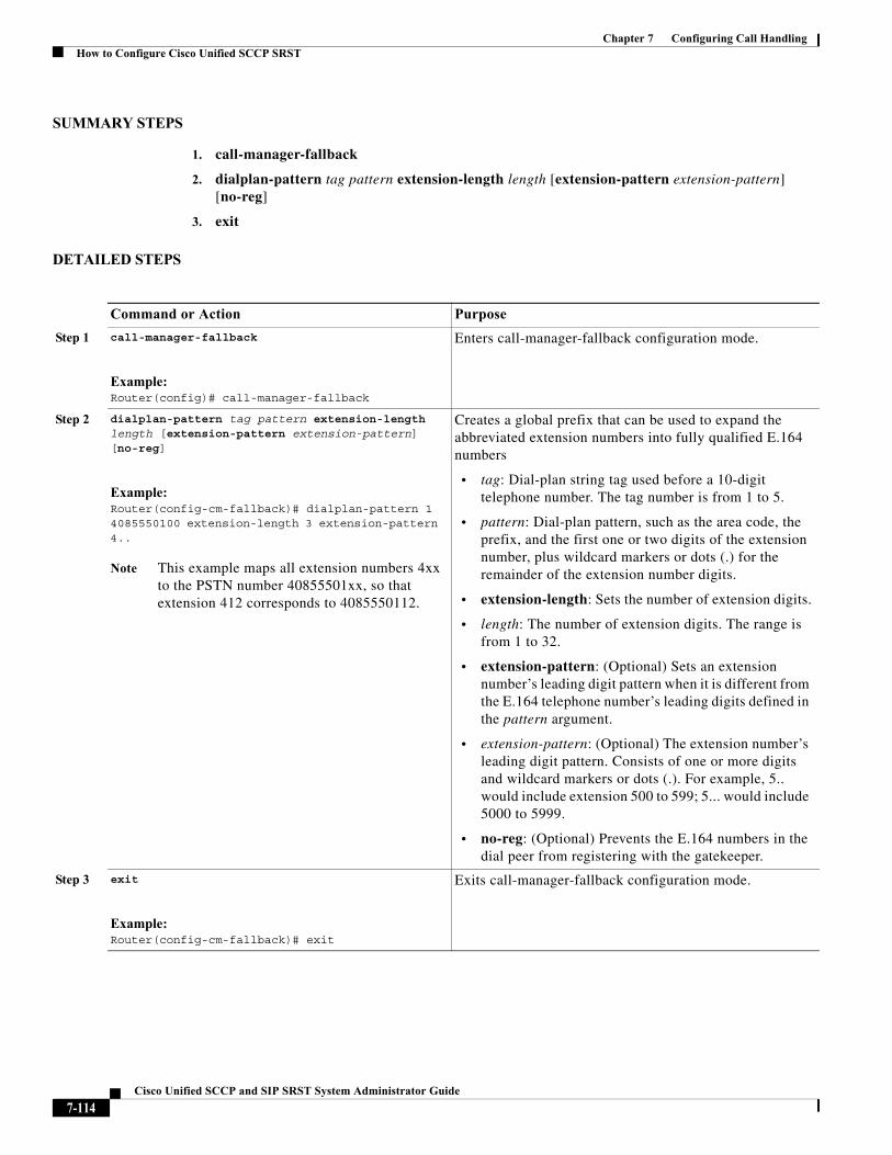
Chapter 7 Configuring Call HandlingHow to Configure Cisco Unified SCCP SRST
SUMMARY STEPS
1. call-manager-fallback
2. dialplan-pattern tag pattern extension-length length [extension-pattern extension-pattern] [no-reg]
3. exit
DETAILED STEPS
Command or Action Purpose
Step 1 call-manager-fallback
Example:Router(config)# call-manager-fallback
Enters call-manager-fallback configuration mode.
Step 2 dialplan-pattern tag pattern extension-length length [extension-pattern extension-pattern] [no-reg]
Example:Router(config-cm-fallback)# dialplan-pattern 1 4085550100 extension-length 3 extension-pattern 4..
Note This example maps all extension numbers 4xx to the PSTN number 40855501xx, so that extension 412 corresponds to 4085550112.
Creates a global prefix that can be used to expand the abbreviated extension numbers into fully qualified E.164 numbers
• tag: Dial-plan string tag used before a 10-digit telephone number. The tag number is from 1 to 5.
• pattern: Dial-plan pattern, such as the area code, the prefix, and the first one or two digits of the extension number, plus wildcard markers or dots (.) for the remainder of the extension number digits.
• extension-length: Sets the number of extension digits.
• length: The number of extension digits. The range is from 1 to 32.
• extension-pattern: (Optional) Sets an extension number’s leading digit pattern when it is different from the E.164 telephone number’s leading digits defined in the pattern argument.
• extension-pattern: (Optional) The extension number’s leading digit pattern. Consists of one or more digits and wildcard markers or dots (.). For example, 5.. would include extension 500 to 599; 5... would include 5000 to 5999.
• no-reg: (Optional) Prevents the E.164 numbers in the dial peer from registering with the gatekeeper.
Step 3 exit
Example:Router(config-cm-fallback)# exit
Exits call-manager-fallback configuration mode.
7-114Cisco Unified SCCP and SIP SRST System Administrator Guide
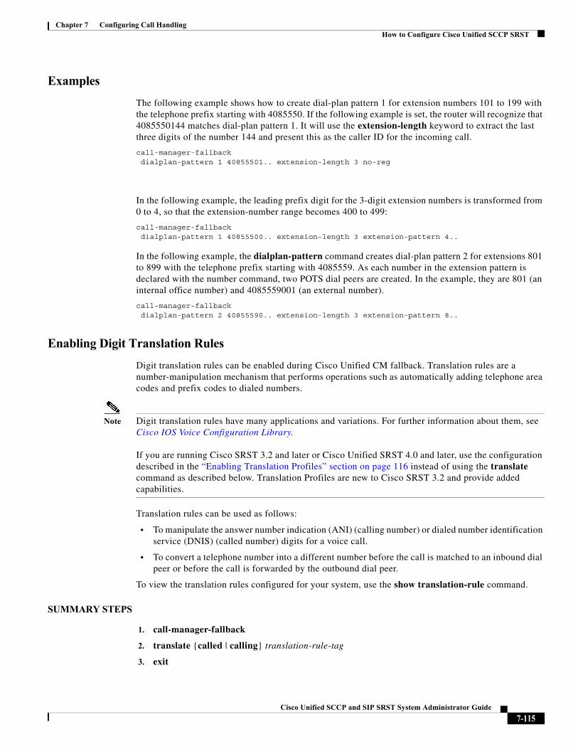
Chapter 7 Configuring Call HandlingHow to Configure Cisco Unified SCCP SRST
Examples
The following example shows how to create dial-plan pattern 1 for extension numbers 101 to 199 with the telephone prefix starting with 4085550. If the following example is set, the router will recognize that 4085550144 matches dial-plan pattern 1. It will use the extension-length keyword to extract the last three digits of the number 144 and present this as the caller ID for the incoming call.
call-manager-fallback dialplan-pattern 1 40855501.. extension-length 3 no-reg
In the following example, the leading prefix digit for the 3-digit extension numbers is transformed from 0 to 4, so that the extension-number range becomes 400 to 499:
call-manager-fallback dialplan-pattern 1 40855500.. extension-length 3 extension-pattern 4..
In the following example, the dialplan-pattern command creates dial-plan pattern 2 for extensions 801 to 899 with the telephone prefix starting with 4085559. As each number in the extension pattern is declared with the number command, two POTS dial peers are created. In the example, they are 801 (an internal office number) and 4085559001 (an external number).
call-manager-fallback dialplan-pattern 2 40855590.. extension-length 3 extension-pattern 8..
Enabling Digit Translation Rules
Digit translation rules can be enabled during Cisco Unified CM fallback. Translation rules are a number-manipulation mechanism that performs operations such as automatically adding telephone area codes and prefix codes to dialed numbers.
Note Digit translation rules have many applications and variations. For further information about them, see Cisco IOS Voice Configuration Library.
If you are running Cisco SRST 3.2 and later or Cisco Unified SRST 4.0 and later, use the configuration described in the “Enabling Translation Profiles” section on page 116 instead of using the translate command as described below. Translation Profiles are new to Cisco SRST 3.2 and provide added capabilities.
Translation rules can be used as follows:
• To manipulate the answer number indication (ANI) (calling number) or dialed number identification service (DNIS) (called number) digits for a voice call.
• To convert a telephone number into a different number before the call is matched to an inbound dial peer or before the call is forwarded by the outbound dial peer.
To view the translation rules configured for your system, use the show translation-rule command.
SUMMARY STEPS
1. call-manager-fallback
2. translate {called | calling} translation-rule-tag
3. exit
7-115Cisco Unified SCCP and SIP SRST System Administrator Guide
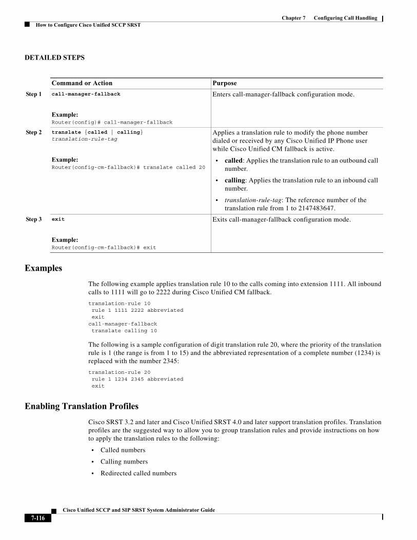
Chapter 7 Configuring Call HandlingHow to Configure Cisco Unified SCCP SRST
DETAILED STEPS
Examples
The following example applies translation rule 10 to the calls coming into extension 1111. All inbound calls to 1111 will go to 2222 during Cisco Unified CM fallback.
translation-rule 10 rule 1 1111 2222 abbreviated exit
call-manager-fallback translate calling 10
The following is a sample configuration of digit translation rule 20, where the priority of the translation rule is 1 (the range is from 1 to 15) and the abbreviated representation of a complete number (1234) is replaced with the number 2345:
translation-rule 20 rule 1 1234 2345 abbreviated exit
Enabling Translation Profiles
Cisco SRST 3.2 and later and Cisco Unified SRST 4.0 and later support translation profiles. Translation profiles are the suggested way to allow you to group translation rules and provide instructions on how to apply the translation rules to the following:
• Called numbers
• Calling numbers
• Redirected called numbers
Command or Action Purpose
Step 1 call-manager-fallback
Example:Router(config)# call-manager-fallback
Enters call-manager-fallback configuration mode.
Step 2 translate {called | calling} translation-rule-tag
Example:Router(config-cm-fallback)# translate called 20
Applies a translation rule to modify the phone number dialed or received by any Cisco Unified IP Phone user while Cisco Unified CM fallback is active.
• called: Applies the translation rule to an outbound call number.
• calling: Applies the translation rule to an inbound call number.
• translation-rule-tag: The reference number of the translation rule from 1 to 2147483647.
Step 3 exit
Example:Router(config-cm-fallback)# exit
Exits call-manager-fallback configuration mode.
7-116Cisco Unified SCCP and SIP SRST System Administrator Guide
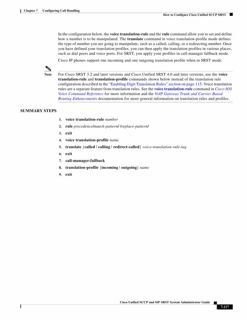
Chapter 7 Configuring Call HandlingHow to Configure Cisco Unified SCCP SRST
In the configuration below, the voice translation-rule and the rule command allow you to set and define how a number is to be manipulated. The translate command in voice translation-profile mode defines the type of number you are going to manipulate, such as a called, calling, or a redirecting number. Once you have defined your translation profiles, you can then apply the translation profiles in various places, such as dial peers and voice ports. For SRST, you apply your profiles in call-manager fallback mode.
Cisco IP phones support one incoming and one outgoing translation profile when in SRST mode.
Note For Cisco SRST 3.2 and later versions and Cisco Unified SRST 4.0 and later versions, use the voice translation-rule and translation-profile commands shown below instead of the translation rule configuration described in the “Enabling Digit Translation Rules” section on page 115. Voice translation rules are a separate feature from translation rules. See the voice translation-rule command in Cisco IOS Voice Command Reference for more information and the VoIP Gateway Trunk and Carrier Based Routing Enhancements documentation for more general information on translation rules and profiles.
SUMMARY STEPS
1. voice translation-rule number
2. rule precedence/match-pattern/ /replace-pattern/
3. exit
4. voice translation-profile name
5. translate {called | calling | redirect-called} voice-translation-rule-tag
6. exit
7. call-manager-fallback
8. translation-profile {incoming | outgoing} name
9. exit
7-117Cisco Unified SCCP and SIP SRST System Administrator Guide
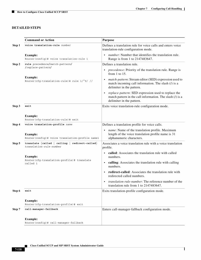
Chapter 7 Configuring Call HandlingHow to Configure Cisco Unified SCCP SRST
DETAILED STEPS
Command or Action Purpose
Step 1 voice translation-rule number
Example:Router(config)# voice translation-rule 1
Defines a translation rule for voice calls and enters voice translation-rule configuration mode.
• number: Number that identifies the translation rule. Range is from 1 to 2147483647.
Step 2 rule precedence/match-pattern/ /replace-pattern/
Example:Router(cfg-translation-rule)# rule 1/^9/ //
Defines a translation rule.
• precedence: Priority of the translation rule. Range is from 1 to 15.
• match-pattern: Stream editor (SED) expression used to match incoming call information. The slash (/) is a delimiter in the pattern.
• replace-pattern: SED expression used to replace the match pattern in the call information. The slash (/) is a delimiter in the pattern.
Step 3 exit
Example:Router(cfg-translation-rule)# exit
Exits voice translation-rule configuration mode.
Step 4 voice translation-profile name
Example:Router(config)# voice translation-profile name1
Defines a translation profile for voice calls.
• name: Name of the translation profile. Maximum length of the voice translation profile name is 31alphanumeric characters.
Step 5 translate {called | calling | redirect-called} translation-rule-number
Example:Router(cfg-translation-profile)# translate called 1
Associates a voice translation rule with a voice translation profile.
• called: Associates the translation rule with called numbers.
• calling: Associates the translation rule with calling numbers.
• redirect-called: Associates the translation rule with redirected called numbers.
• translation-rule-number: The reference number of the translation rule from 1 to 2147483647.
Step 6 exit
Example:Router(cfg-translation-profile)# exit
Exits translation-profile configuration mode.
Step 7 call-manager-fallback
Example:Router(config)# call-manager-fallback
Enters call-manager-fallback configuration mode.
7-118Cisco Unified SCCP and SIP SRST System Administrator Guide
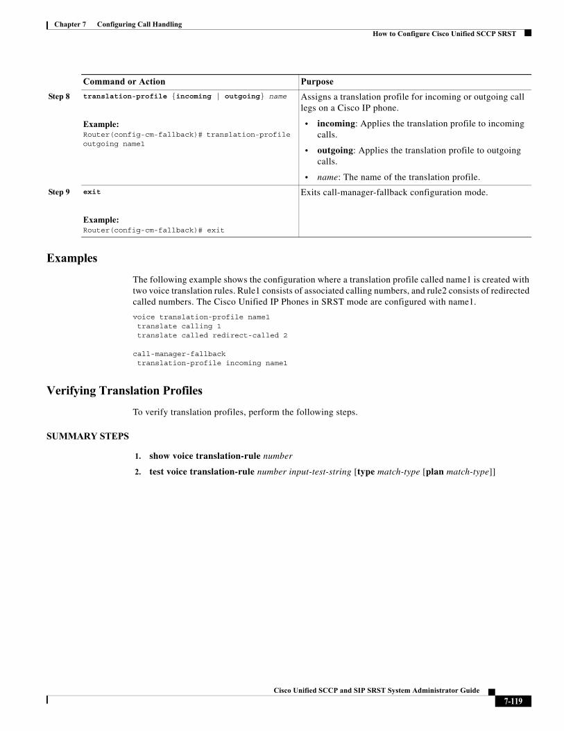
Chapter 7 Configuring Call HandlingHow to Configure Cisco Unified SCCP SRST
Examples
The following example shows the configuration where a translation profile called name1 is created with two voice translation rules. Rule1 consists of associated calling numbers, and rule2 consists of redirected called numbers. The Cisco Unified IP Phones in SRST mode are configured with name1.
voice translation-profile name1translate calling 1translate called redirect-called 2
call-manager-fallbacktranslation-profile incoming name1
Verifying Translation Profiles
To verify translation profiles, perform the following steps.
SUMMARY STEPS
1. show voice translation-rule number
2. test voice translation-rule number input-test-string [type match-type [plan match-type]]
Step 8 translation-profile {incoming | outgoing} name
Example:Router(config-cm-fallback)# translation-profile outgoing name1
Assigns a translation profile for incoming or outgoing call legs on a Cisco IP phone.
• incoming: Applies the translation profile to incoming calls.
• outgoing: Applies the translation profile to outgoing calls.
• name: The name of the translation profile.
Step 9 exit
Example:Router(config-cm-fallback)# exit
Exits call-manager-fallback configuration mode.
Command or Action Purpose
7-119Cisco Unified SCCP and SIP SRST System Administrator Guide
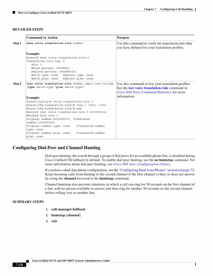
Chapter 7 Configuring Call HandlingHow to Configure Cisco Unified SCCP SRST
DETAILED STEPS
Configuring Dial-Peer and Channel Hunting
Dial-peer hunting, the search through a group of dial peers for an available phone line, is disabled during Cisco Unified CM fallback by default. To enable dial-peer hunting, use the no huntstop command. For more information about dial-peer hunting, see Cisco IOS Voice Configuration Library.
If you have a dual-line phone configuration, see the “Configuring Dual-Line Phones” section on page 72. Keep incoming calls from hunting to the second channel if the first channel is busy or does not answer by using the channel keyword in the huntstop command.
Channel huntstop also prevents situations in which a call can ring for 30 seconds on the first channel of a line with no person available to answer and then ring for another 30 seconds on the second channel before rolling over to another line.
SUMMARY STEPS
1. call-manager-fallback
2. huntstop [channel]
3. exit
Command or Action Purpose
Step 1 show voice translation-rule number
Example:Router# show voice translation-rule 6Translation-rule tag: 6 Rule 1: Match pattern: 65088801.. Replace pattern: 6508880101 Match type: none Replace type: none Match plan: none Replace plan: none
Use this command to verify the translation rules that you have defined for your translation profiles.
Step 2 test voice translation-rule number input-test-string [type match-type [plan match-type]]
Example:Router(config)# voice translation-rule 5Router(cfg-translation-rule)# rule 1 /201/ /102/Router(cfg-translation-rule)# endRouter# test voice translation-rule 5 2015550101Matched with rule 5Original number:2015550101 Translated number:1025550101Original number type: none Translated number type: noneOriginal number plan: none Translated number plan: none
Use this command to test your translation profiles. See the test voice translation-rule command in Cisco IOS Voice Command Reference for more information.
7-120Cisco Unified SCCP and SIP SRST System Administrator Guide
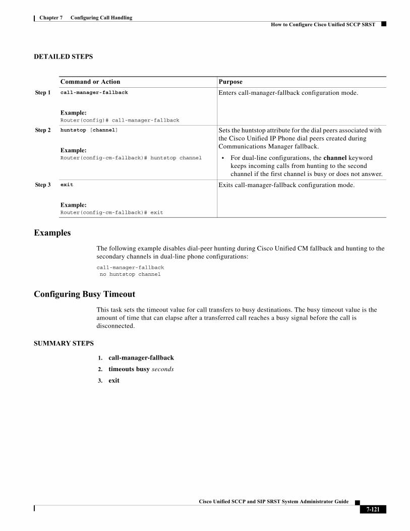
Chapter 7 Configuring Call HandlingHow to Configure Cisco Unified SCCP SRST
DETAILED STEPS
Examples
The following example disables dial-peer hunting during Cisco Unified CM fallback and hunting to the secondary channels in dual-line phone configurations:
call-manager-fallback no huntstop channel
Configuring Busy Timeout
This task sets the timeout value for call transfers to busy destinations. The busy timeout value is the amount of time that can elapse after a transferred call reaches a busy signal before the call is disconnected.
SUMMARY STEPS
1. call-manager-fallback
2. timeouts busy seconds
3. exit
Command or Action Purpose
Step 1 call-manager-fallback
Example:Router(config)# call-manager-fallback
Enters call-manager-fallback configuration mode.
Step 2 huntstop [channel]
Example:Router(config-cm-fallback)# huntstop channel
Sets the huntstop attribute for the dial peers associated with the Cisco Unified IP Phone dial peers created during Communications Manager fallback.
• For dual-line configurations, the channel keyword keeps incoming calls from hunting to the second channel if the first channel is busy or does not answer.
Step 3 exit
Example:Router(config-cm-fallback)# exit
Exits call-manager-fallback configuration mode.
7-121Cisco Unified SCCP and SIP SRST System Administrator Guide
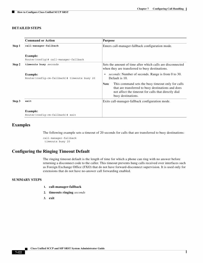
Chapter 7 Configuring Call HandlingHow to Configure Cisco Unified SCCP SRST
DETAILED STEPS
Examples
The following example sets a timeout of 20 seconds for calls that are transferred to busy destinations:
call-manager-fallbacktimeouts busy 20
Configuring the Ringing Timeout Default
The ringing timeout default is the length of time for which a phone can ring with no answer before returning a disconnect code to the caller. This timeout prevents hung calls received over interfaces such as Foreign Exchange Office (FXO) that do not have forward-disconnect supervision. It is used only for extensions that do not have no-answer call forwarding enabled.
SUMMARY STEPS
1. call-manager-fallback
2. timeouts ringing seconds
3. exit
Command or Action Purpose
Step 1 call-manager-fallback
Example:Router(config)# call-manager-fallback
Enters call-manager-fallback configuration mode.
Step 2 timeouts busy seconds
Example:Router(config-cm-fallback)# timeouts busy 20
Sets the amount of time after which calls are disconnected when they are transferred to busy destinations.
• seconds: Number of seconds. Range is from 0 to 30. Default is 10.
Note This command sets the busy timeout only for calls that are transferred to busy destinations and does not affect the timeout for calls that directly dial busy destinations.
Step 3 exit
Example:Router(config-cm-fallback)# exit
Exits call-manager-fallback configuration mode.
7-122Cisco Unified SCCP and SIP SRST System Administrator Guide
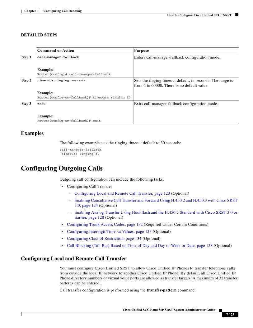
Chapter 7 Configuring Call HandlingHow to Configure Cisco Unified SCCP SRST
DETAILED STEPS
Examples
The following example sets the ringing timeout default to 30 seconds:
call-manager-fallbacktimeouts ringing 30
Configuring Outgoing Calls
Outgoing call configuration can include the following tasks:
• Configuring Call Transfer
– Configuring Local and Remote Call Transfer, page 123 (Optional)
– Enabling Consultative Call Transfer and Forward Using H.450.2 and H.450.3 with Cisco SRST 3.0, page 124 (Optional)
– Enabling Analog Transfer Using Hookflash and the H.450.2 Standard with Cisco SRST 3.0 or Earlier, page 128 (Optional)
• Configuring Trunk Access Codes, page 132 (Required Under Certain Conditions)
• Configuring Interdigit Timeout Values, page 133 (Optional)
• Configuring Class of Restriction, page 134 (Optional)
• Call Blocking (Toll Bar) Based on Time of Day and Day of Week or Date, page 138 (Optional)
Configuring Local and Remote Call Transfer
You must configure Cisco Unified SRST to allow Cisco Unified IP Phones to transfer telephone calls from outside the local IP network to another Cisco Unified IP Phone. By default, all Cisco Unified IP Phone directory numbers or virtual voice ports are allowed as transfer targets. A maximum of 32 transfer patterns can be entered.
Call transfer configuration is performed using the transfer-pattern command.
Command or Action Purpose
Step 1 call-manager-fallback
Example:Router(config)# call-manager-fallback
Enters call-manager-fallback configuration mode.
Step 2 timeouts ringing seconds
Example:Router(config-cm-fallback)# timeouts ringing 30
Sets the ringing timeout default, in seconds. The range is from 5 to 60000. There is no default value.
Step 3 exit
Example:Router(config-cm-fallback)# exit
Exits call-manager-fallback configuration mode.
7-123Cisco Unified SCCP and SIP SRST System Administrator Guide
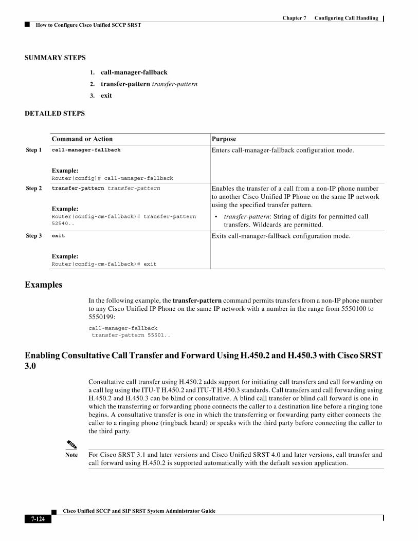
Chapter 7 Configuring Call HandlingHow to Configure Cisco Unified SCCP SRST
SUMMARY STEPS
1. call-manager-fallback
2. transfer-pattern transfer-pattern
3. exit
DETAILED STEPS
Examples
In the following example, the transfer-pattern command permits transfers from a non-IP phone number to any Cisco Unified IP Phone on the same IP network with a number in the range from 5550100 to 5550199:
call-manager-fallback transfer-pattern 55501..
Enabling Consultative Call Transfer and Forward Using H.450.2 and H.450.3 with Cisco SRST 3.0
Consultative call transfer using H.450.2 adds support for initiating call transfers and call forwarding on a call leg using the ITU-T H.450.2 and ITU-T H.450.3 standards. Call transfers and call forwarding using H.450.2 and H.450.3 can be blind or consultative. A blind call transfer or blind call forward is one in which the transferring or forwarding phone connects the caller to a destination line before a ringing tone begins. A consultative transfer is one in which the transferring or forwarding party either connects the caller to a ringing phone (ringback heard) or speaks with the third party before connecting the caller to the third party.
Note For Cisco SRST 3.1 and later versions and Cisco Unified SRST 4.0 and later versions, call transfer and call forward using H.450.2 is supported automatically with the default session application.
Command or Action Purpose
Step 1 call-manager-fallback
Example:Router(config)# call-manager-fallback
Enters call-manager-fallback configuration mode.
Step 2 transfer-pattern transfer-pattern
Example:Router(config-cm-fallback)# transfer-pattern 52540..
Enables the transfer of a call from a non-IP phone number to another Cisco Unified IP Phone on the same IP network using the specified transfer pattern.
• transfer-pattern: String of digits for permitted call transfers. Wildcards are permitted.
Step 3 exit
Example:Router(config-cm-fallback)# exit
Exits call-manager-fallback configuration mode.
7-124Cisco Unified SCCP and SIP SRST System Administrator Guide
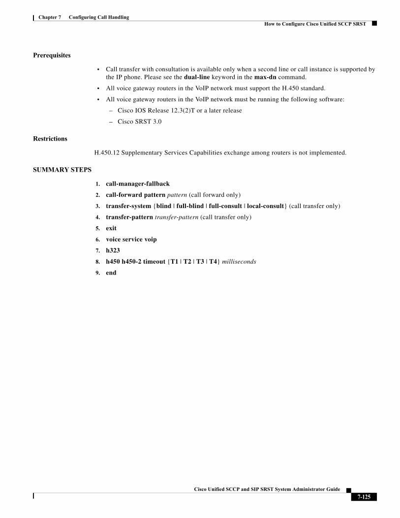
Chapter 7 Configuring Call HandlingHow to Configure Cisco Unified SCCP SRST
Prerequisites
• Call transfer with consultation is available only when a second line or call instance is supported by the IP phone. Please see the dual-line keyword in the max-dn command.
• All voice gateway routers in the VoIP network must support the H.450 standard.
• All voice gateway routers in the VoIP network must be running the following software:
– Cisco IOS Release 12.3(2)T or a later release
– Cisco SRST 3.0
Restrictions
H.450.12 Supplementary Services Capabilities exchange among routers is not implemented.
SUMMARY STEPS
1. call-manager-fallback
2. call-forward pattern pattern (call forward only)
3. transfer-system {blind | full-blind | full-consult | local-consult} (call transfer only)
4. transfer-pattern transfer-pattern (call transfer only)
5. exit
6. voice service voip
7. h323
8. h450 h450-2 timeout {T1 | T2 | T3 | T4} milliseconds
9. end
7-125Cisco Unified SCCP and SIP SRST System Administrator Guide
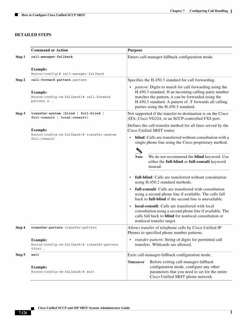
Chapter 7 Configuring Call HandlingHow to Configure Cisco Unified SCCP SRST
DETAILED STEPS
Command or Action Purpose
Step 1 call-manager-fallback
Example:Router(config)# call-manager-fallback
Enters call-manager-fallback configuration mode.
Step 2 call-forward pattern pattern
Example:Router(config-cm-fallback)# call-forward pattern 4...
Specifies the H.450.3 standard for call forwarding.
• pattern: Digits to match for call forwarding using the H.450.3 standard. If an incoming calling-party number matches the pattern, it can be forwarded using the H.450.3 standard. A pattern of .T forwards all calling parties using the H.450.3 standard.
Step 3 transfer-system {blind | full-blind | full-consult | local-consult}
Example:Router(config-cm-fallback)# transfer-system full-consult
Not supported if the transfer-to destination is on the Cisco ATA, Cisco VG224, or an SCCP-controlled FXS port.
Defines the call-transfer method for all lines served by the Cisco Unified SRST router.
• blind: Calls are transferred without consultation with a single phone line using the Cisco proprietary method.
Note We do not recommend the blind keyword. Use either the full-blind or full-consult keyword instead.
• full-blind: Calls are transferred without consultation using H.450.2 standard methods.
• full-consult: Calls are transferred with consultation using a second phone line if available. The calls fall back to full-blind if the second line is unavailable.
• local-consult: Calls are transferred with local consultation using a second phone line if available. The calls fall back to blind for nonlocal consultation or nonlocal transfer target.
Step 4 transfer-pattern transfer-pattern
Example:Router(config-cm-fallback)# transfer-pattern 52540..
Allows transfer of telephone calls by Cisco Unified IP Phones to specified phone number patterns.
• transfer-pattern: String of digits for permitted call transfers. Wildcards are allowed.
Step 5 exit
Example:Router(config-cm-fallback)# exit
Exits call-manager-fallback configuration mode.
Timesaver Before exiting call-manager-fallback configuration mode, configure any other parameters that you need to set for the entire Cisco Unified SRST phone network.
7-126Cisco Unified SCCP and SIP SRST System Administrator Guide
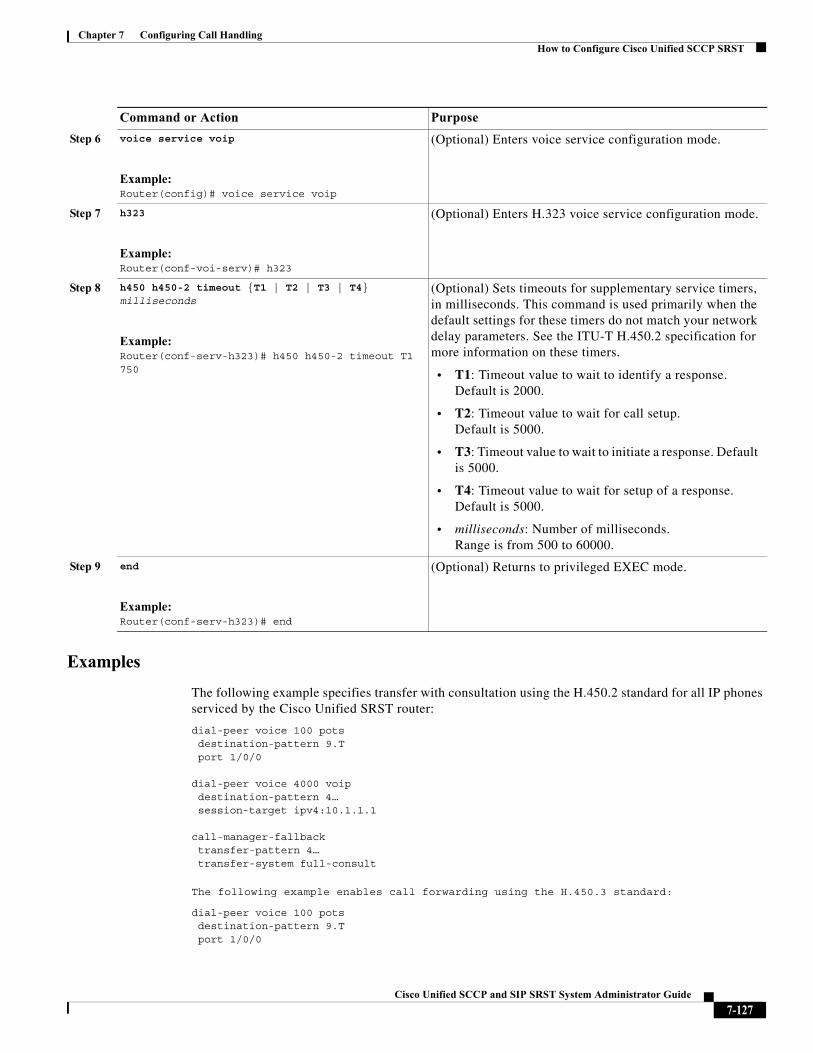
Chapter 7 Configuring Call HandlingHow to Configure Cisco Unified SCCP SRST
Examples
The following example specifies transfer with consultation using the H.450.2 standard for all IP phones serviced by the Cisco Unified SRST router:
dial-peer voice 100 potsdestination-pattern 9.Tport 1/0/0
dial-peer voice 4000 voipdestination-pattern 4…session-target ipv4:10.1.1.1
call-manager-fallbacktransfer-pattern 4…transfer-system full-consult
The following example enables call forwarding using the H.450.3 standard:
dial-peer voice 100 pots destination-pattern 9.T port 1/0/0
Step 6 voice service voip
Example:Router(config)# voice service voip
(Optional) Enters voice service configuration mode.
Step 7 h323
Example:Router(conf-voi-serv)# h323
(Optional) Enters H.323 voice service configuration mode.
Step 8 h450 h450-2 timeout {T1 | T2 | T3 | T4} milliseconds
Example:Router(conf-serv-h323)# h450 h450-2 timeout T1 750
(Optional) Sets timeouts for supplementary service timers, in milliseconds. This command is used primarily when the default settings for these timers do not match your network delay parameters. See the ITU-T H.450.2 specification for more information on these timers.
• T1: Timeout value to wait to identify a response. Default is 2000.
• T2: Timeout value to wait for call setup. Default is 5000.
• T3: Timeout value to wait to initiate a response. Default is 5000.
• T4: Timeout value to wait for setup of a response. Default is 5000.
• milliseconds: Number of milliseconds. Range is from 500 to 60000.
Step 9 end
Example:Router(conf-serv-h323)# end
(Optional) Returns to privileged EXEC mode.
Command or Action Purpose
7-127Cisco Unified SCCP and SIP SRST System Administrator Guide
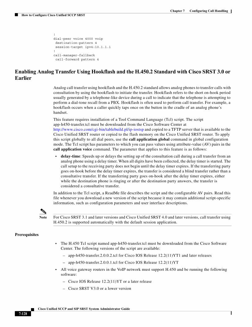
Chapter 7 Configuring Call HandlingHow to Configure Cisco Unified SCCP SRST
! dial-peer voice 4000 voip destination-pattern 4 session-target ipv4:10.1.1.1 ! call-manager-fallback call-forward pattern 4
Enabling Analog Transfer Using Hookflash and the H.450.2 Standard with Cisco SRST 3.0 or Earlier
Analog call transfer using hookflash and the H.450.2 standard allows analog phones to transfer calls with consultation by using the hookflash to initiate the transfer. Hookflash refers to the short on-hook period usually generated by a telephone-like device during a call to indicate that the telephone is attempting to perform a dial-tone recall from a PBX. Hookflash is often used to perform call transfer. For example, a hookflash occurs when a caller quickly taps once on the button in the cradle of an analog phone’s handset.
This feature requires installation of a Tool Command Language (Tcl) script. The script app-h450-transfer.tcl must be downloaded from the Cisco Software Center at http://www.cisco.com/cgi-bin/tablebuild.pl/ip-iostsp and copied to a TFTP server that is available to the Cisco Unified SRST router or copied to the flash memory on the Cisco Unified SRST router. To apply this script globally to all dial peers, use the call application global command in global configuration mode. The Tcl script has parameters to which you can pass values using attribute-value (AV) pairs in the call application voice command. The parameter that applies to this feature is as follows:
• delay-time: Speeds up or delays the setting up of the consultation call during a call transfer from an analog phone using a delay timer. When all digits have been collected, the delay timer is started. The call setup to the receiving party does not begin until the delay timer expires. If the transferring party goes on-hook before the delay timer expires, the transfer is considered a blind transfer rather than a consultative transfer. If the transferring party goes on-hook after the delay timer expires, either while the destination phone is ringing or after the destination party answers, the transfer is considered a consultative transfer.
In addition to the Tcl script, a ReadMe file describes the script and the configurable AV pairs. Read this file whenever you download a new version of the script because it may contain additional script-specific information, such as configuration parameters and user interface descriptions.
Note For Cisco SRST 3.1 and later versions and Cisco Unified SRST 4.0 and later versions, call transfer using H.450.2 is supported automatically with the default session application.
Prerequisites
• The H.450 Tcl script named app-h450-transfer.tcl must be downloaded from the Cisco Software Center. The following versions of the script are available:
– app-h450-transfer.2.0.0.2.tcl for Cisco IOS Release 12.2(11)YT1 and later releases
– app-h450-transfer.2.0.0.1.tcl for Cisco IOS Release 12.2(11)YT
• All voice gateway routers in the VoIP network must support H.450 and be running the following software:
– Cisco IOS Release 12.2(11)YT or a later release
– Cisco SRST V3.0 or a lower version
7-128Cisco Unified SCCP and SIP SRST System Administrator Guide
Chapter 7 Configuring Call HandlingHow to Configure Cisco Unified SCCP SRST
– Tcl IVR 2.0
– H.450 Tcl script (app-h450-transfer.tcl)
Note You can continue to use the app-h450-transfer.2.0.0.1.tcl script if you install Cisco IOS Release 12.2(11)YT1 or later, but you cannot use the app-h450-transfer.2.0.0.2.tcl script with a release of Cisco IOS software that is earlier than Cisco IOS Release 12.2(11)YT1.
Restrictions
• When a consultative transfer is made by an analog FXS phone using hookflash, the consultation call itself cannot be further transferred (that is, it cannot become a recursive or chained transfer) until after the initial transfer operation is completed and the transferee and transfer-to parties are connected. After the initial call transfer operation is completed and the transferee and transfer-to parties are now the only parties in the call, the transfer-to party may further transfer the call.
• Call transfer with consultation is not supported for Cisco ATA-186, Cisco ATA-188, and Cisco IP Conference Station 7935. Transfer attempts from these devices are executed as blind transfers.
SUMMARY STEPS
1. call application voice application-name location
2. call application voice application-name language number language
3. call application voice application-name set-location language category location
4. call application voice application-name delay-time seconds
5. dial-peer voice number pots
6. application application-name
7. exit
8. dial-peer voice number voip
9. application application-name
10. exit
7-129Cisco Unified SCCP and SIP SRST System Administrator Guide
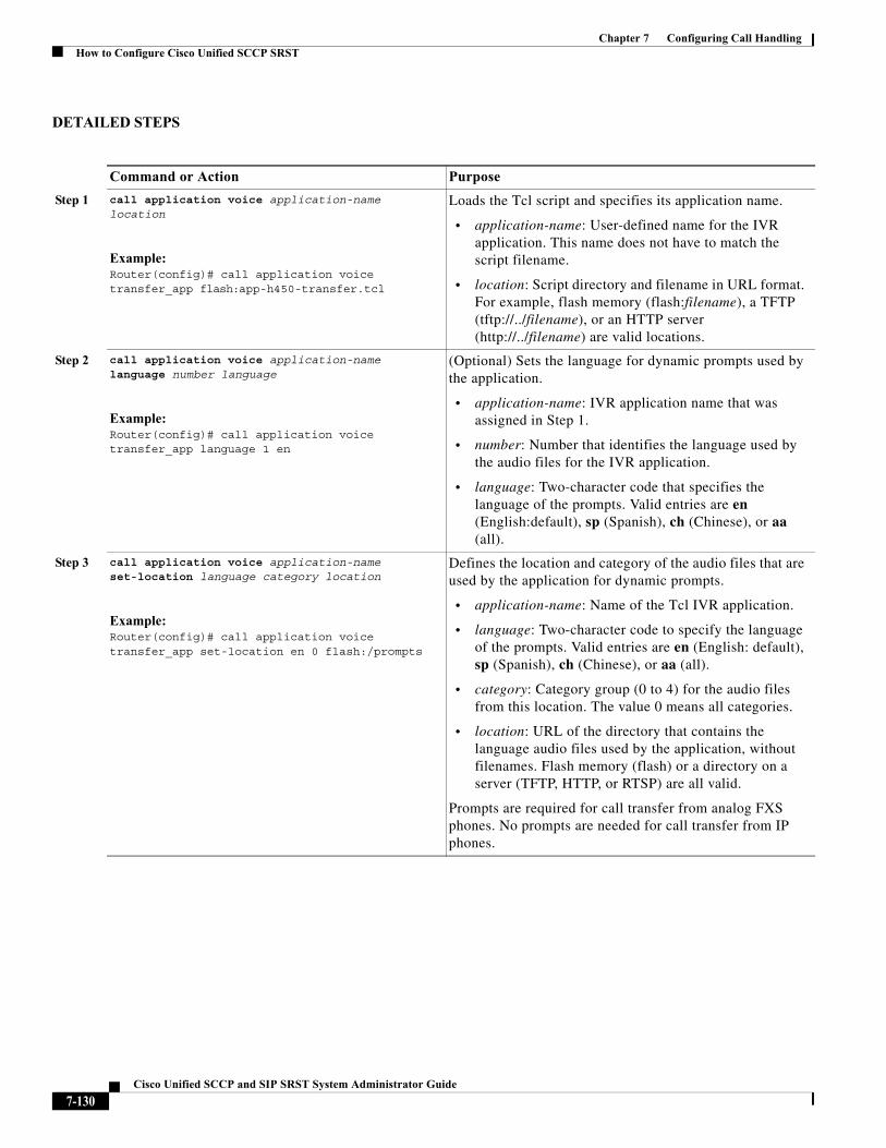
Chapter 7 Configuring Call HandlingHow to Configure Cisco Unified SCCP SRST
DETAILED STEPS
Command or Action Purpose
Step 1 call application voice application-name location
Example:Router(config)# call application voice transfer_app flash:app-h450-transfer.tcl
Loads the Tcl script and specifies its application name.
• application-name: User-defined name for the IVR application. This name does not have to match the script filename.
• location: Script directory and filename in URL format. For example, flash memory (flash:filename), a TFTP (tftp://../filename), or an HTTP server (http://../filename) are valid locations.
Step 2 call application voice application-name language number language
Example:Router(config)# call application voice transfer_app language 1 en
(Optional) Sets the language for dynamic prompts used by the application.
• application-name: IVR application name that was assigned in Step 1.
• number: Number that identifies the language used by the audio files for the IVR application.
• language: Two-character code that specifies the language of the prompts. Valid entries are en (English:default), sp (Spanish), ch (Chinese), or aa (all).
Step 3 call application voice application-name set-location language category location
Example:Router(config)# call application voice transfer_app set-location en 0 flash:/prompts
Defines the location and category of the audio files that are used by the application for dynamic prompts.
• application-name: Name of the Tcl IVR application.
• language: Two-character code to specify the language of the prompts. Valid entries are en (English: default), sp (Spanish), ch (Chinese), or aa (all).
• category: Category group (0 to 4) for the audio files from this location. The value 0 means all categories.
• location: URL of the directory that contains the language audio files used by the application, without filenames. Flash memory (flash) or a directory on a server (TFTP, HTTP, or RTSP) are all valid.
Prompts are required for call transfer from analog FXS phones. No prompts are needed for call transfer from IP phones.
7-130Cisco Unified SCCP and SIP SRST System Administrator Guide
Chapter 7 Configuring Call HandlingHow to Configure Cisco Unified SCCP SRST
Step 4 call application voice application-name delay-time seconds
Example:Router(config)# call application voice transfer_app delay-time 1
(Optional) Sets the delay time for consultation call setup for an analog phone that is making a call transfer using the H.450 application. This command passes a value to the Tcl script by using an attribute-value (AV) pair.
• seconds: Number of seconds to delay call setup. Range is from 1 to 10. Default is 2.
A delay of more than 2 seconds is generally noticeable to users.
For more information about AV pairs and the Tcl script for H.450 call transfer and forwarding, see the ReadMe file that accompanies the script.
Step 5 dial-peer voice number pots
Example:Router(config)# dial-peer voice 25 pots
Enters dial-peer configuration mode to configure a POTS dial peer.
Step 6 application application-name
Example:Router(config-dial-peer)# application transfer_app
Loads the application named in Step 1 onto the dial peer.
Step 7 exit
Example:Router(config-dial-peer)# exit
Exits dial-peer configuration mode.
Timesaver Before exiting dial-peer configuration mode, configure any other dial-peer parameters that you need to set for this dial peer.
Step 8 dial-peer voice number voip
Example:Router(config)# dial-peer voice 29 voip
Enters dial-peer configuration mode to configure a VoIP dial peer.
Step 9 application application-name
Example:Router(config-dial-peer)# application transfer_app
Loads the application named in Step 1 onto the dial peer.
Step 10 exit
Example:Router(config-dial-peer)# exit
Exits dial-peer configuration mode.
Timesaver Before exiting dial-peer configuration mode, configure any other dial-peer parameters that you need to set for this dial peer.
Command or Action Purpose
7-131Cisco Unified SCCP and SIP SRST System Administrator Guide
Chapter 7 Configuring Call HandlingHow to Configure Cisco Unified SCCP SRST
Examples
The following example enables the H.450 Tcl script for analog transfer using hookflash and sets a delay time of 1 second:
call application voice transfer_app flash:app-h450-transfer.tclcall application voice transfer_app language 1 encall application voice transfer_app set-location en 0 flash:/promptscall application voice transfer_app delay-time 1!dial-peer voice 25 potsdestination-pattern 9.Tport 1/0/0application transfer_app
!dial-peer voice 29 voipdestination-pattern 4…session-target ipv4:10.1.10.1application transfer_app
Configuring Trunk Access Codes
Note Configure trunk access codes only if your normal network dial-plan configuration prevents you from configuring permanent POTS voice dial peers to provide trunk access for use during fallback. If you already have local PSTN ports configured with the appropriate access codes provided by dial peers (for example, dial 9 to select an FXO PSTN line), this configuration is not needed.
Trunk access codes provide IP phones with access to the PSTN during Cisco Unified CM fallback by creating POTS voice dial peers that are active during Cisco Unified CM fallback only. These temporary dial peers, which can be matched to voice ports (BRI, E&M, FXO, and PRI), allow Cisco Unified IP Phones access to trunk lines during Cisco Unified CM mode. When Cisco Unified SRST is active, all PSTN interfaces of the same type are treated as equivalent, and any port may be selected to place the outgoing PSTN call.
Trunk access codes are created using the access-code command.
SUMMARY STEPS
1. call-manager-fallback
2. access-code {{fxo | e&m} dial-string | {bri | pri} dial-string [direct-inward-dial]}
3. exit
7-132Cisco Unified SCCP and SIP SRST System Administrator Guide
Chapter 7 Configuring Call HandlingHow to Configure Cisco Unified SCCP SRST
DETAILED STEPS
Examples
The following example creates access code number 8 for BRI and enables DID on the POTS dial peer:
call-manager-fallback access-code bri 8 direct-inward-dial
Configuring Interdigit Timeout Values
Configuring interdigit timeout values involves specifying how long, in seconds, all Cisco Unified IP Phones attached to a Cisco Unified SRST router are to wait after an initial digit or a subsequent digit is dialed. The timeouts interdigit timer is enabled when a caller enters a digit and is restarted each time the caller enters subsequent digits until the destination address is identified. If the configured timeout value is exceeded before the destination address is identified, a tone sounds and the call is terminated.
Command or Action Purpose
Step 1 call-manager-fallback
Example:Router(config)# call-manager-fallback
Enters call-manager-fallback configuration mode.
Step 2 access-code {{fxo | e&m} dial-string | {bri | pri} dial-string [direct-inward-dial]}
Example:Router(config-cm-fallback)# access-code e&m 8
Configures trunk access codes for each type of line so that the Cisco Unified IP Phones can access the trunk lines only in Cisco Unified Communications Manager fallback mode when the Cisco Unified SRST is enabled.
• fxo: Enables a Foreign Exchange Office (FXO) interface.
• e&m: Enables an analog Ear and Mouth (E&M) interface.
• dial-string: String of characters that sets up dial access codes for each specified line type by creating dial peers. The dial-string argument is used to set up temporary dial peers for each specified line type.
• bri: Enables a BRI interface.
• pri: Enables a PRI interface.
• direct-inward-dial: (Optional) Enables Direct Inward Dialing (DID) on the POTS dial peer.
Step 3 exit
Example:Router(config-cm-fallback)# exit
Exits call-manager-fallback configuration mode.
7-133Cisco Unified SCCP and SIP SRST System Administrator Guide
Chapter 7 Configuring Call HandlingHow to Configure Cisco Unified SCCP SRST
SUMMARY STEPS
1. call-manager-fallback
2. timeouts interdigit seconds
3. exit
DETAILED STEPS
Examples
The following example sets the interdigit timeout value to 5 seconds for all Cisco Unified IP Phones. In this example, 5 seconds are the elapsed time after which an incompletely dialed number times out. For example, a caller who dials nine digits (408555010) instead of the required ten digits (4085550100) will hear a busy tone after the second timeout elapses.
call-manager-fallback timeouts interdigit 5
Configuring Class of Restriction
The class of restriction (COR) functionality provides the ability to deny certain call attempts on the basis of the incoming and outgoing class of restrictions provisioned on the dial peers. This functionality provides flexibility in network design, allows users to block calls (for example, calls to 900 numbers), and applies different restrictions to call attempts from different originators. The cor command sets the dial-peer COR parameter for dial peers associated with the directory numbers created during Cisco Unified CM fallback.
You can have up to 20 COR lists for each incoming and outgoing call. A default COR is assigned to directory numbers that do not match any COR list numbers or number ranges. An assigned COR is invoked for the dial peers and created for each directory number automatically during Communications Manager fallback registration.
If a COR is applied on an incoming dial peer (for incoming calls) and it is a superset of or is equal to the COR applied to the outgoing dial peer (for outgoing calls), the call will go through. Voice ports determine whether a call is considered incoming or outgoing. If you hook up a phone to an FXS port on
Command or Action Purpose
Step 1 call-manager-fallback
Example:Router(config)# call-manager-fallback
Enters call-manager-fallback configuration mode.
Step 2 timeouts interdigit seconds
Example:Router(config-cm-fallback)# timeouts interdigit 5
(Optional) Configures the interdigit timeout value for all Cisco IP phones that are attached to the router.
• seconds: Interdigit timeout duration, in seconds, for all Cisco Unified IP Phones. Valid entries are integers from 2 to 120.
Step 3 exit
Example:Router(config-cm-fallback)# exit
Exits call-manager-fallback configuration mode.
7-134Cisco Unified SCCP and SIP SRST System Administrator Guide
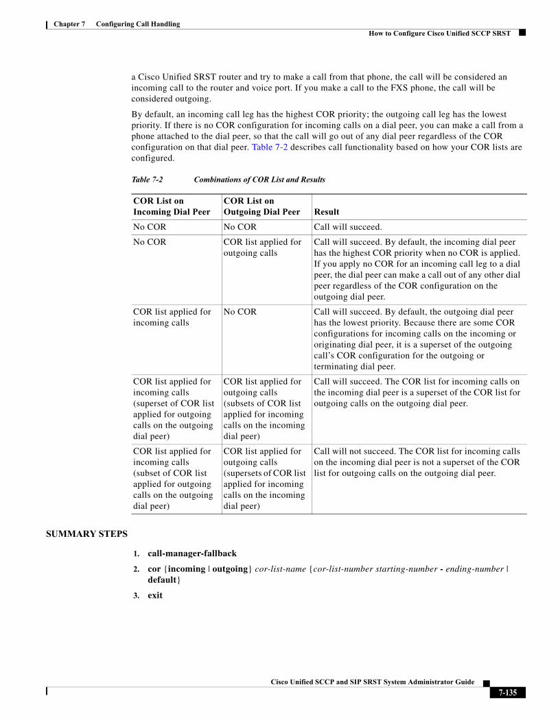
Chapter 7 Configuring Call HandlingHow to Configure Cisco Unified SCCP SRST
a Cisco Unified SRST router and try to make a call from that phone, the call will be considered an incoming call to the router and voice port. If you make a call to the FXS phone, the call will be considered outgoing.
By default, an incoming call leg has the highest COR priority; the outgoing call leg has the lowest priority. If there is no COR configuration for incoming calls on a dial peer, you can make a call from a phone attached to the dial peer, so that the call will go out of any dial peer regardless of the COR configuration on that dial peer. Table 7-2 describes call functionality based on how your COR lists are configured.
SUMMARY STEPS
1. call-manager-fallback
2. cor {incoming | outgoing} cor-list-name {cor-list-number starting-number - ending-number | default}
3. exit
Table 7-2 Combinations of COR List and Results
COR List on Incoming Dial Peer
COR List on Outgoing Dial Peer Result
No COR No COR Call will succeed.
No COR COR list applied for outgoing calls
Call will succeed. By default, the incoming dial peer has the highest COR priority when no COR is applied. If you apply no COR for an incoming call leg to a dial peer, the dial peer can make a call out of any other dial peer regardless of the COR configuration on the outgoing dial peer.
COR list applied for incoming calls
No COR Call will succeed. By default, the outgoing dial peer has the lowest priority. Because there are some COR configurations for incoming calls on the incoming or originating dial peer, it is a superset of the outgoing call’s COR configuration for the outgoing or terminating dial peer.
COR list applied for incoming calls (superset of COR list applied for outgoing calls on the outgoing dial peer)
COR list applied for outgoing calls (subsets of COR list applied for incoming calls on the incoming dial peer)
Call will succeed. The COR list for incoming calls on the incoming dial peer is a superset of the COR list for outgoing calls on the outgoing dial peer.
COR list applied for incoming calls (subset of COR list applied for outgoing calls on the outgoing dial peer)
COR list applied for outgoing calls (supersets of COR list applied for incoming calls on the incoming dial peer)
Call will not succeed. The COR list for incoming calls on the incoming dial peer is not a superset of the COR list for outgoing calls on the outgoing dial peer.
7-135Cisco Unified SCCP and SIP SRST System Administrator Guide
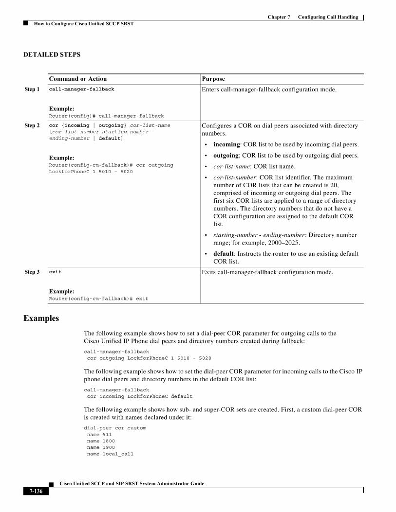
Chapter 7 Configuring Call HandlingHow to Configure Cisco Unified SCCP SRST
DETAILED STEPS
Examples
The following example shows how to set a dial-peer COR parameter for outgoing calls to the Cisco Unified IP Phone dial peers and directory numbers created during fallback:
call-manager-fallback cor outgoing LockforPhoneC 1 5010 - 5020
The following example shows how to set the dial-peer COR parameter for incoming calls to the Cisco IP phone dial peers and directory numbers in the default COR list:
call-manager-fallback cor incoming LockforPhoneC default
The following example shows how sub- and super-COR sets are created. First, a custom dial-peer COR is created with names declared under it:
dial-peer cor customname 911name 1800name 1900name local_call
Command or Action Purpose
Step 1 call-manager-fallback
Example:Router(config)# call-manager-fallback
Enters call-manager-fallback configuration mode.
Step 2 cor {incoming | outgoing} cor-list-name [cor-list-number starting-number - ending-number | default]
Example:Router(config-cm-fallback)# cor outgoing LockforPhoneC 1 5010 – 5020
Configures a COR on dial peers associated with directory numbers.
• incoming: COR list to be used by incoming dial peers.
• outgoing: COR list to be used by outgoing dial peers.
• cor-list-name: COR list name.
• cor-list-number: COR list identifier. The maximum number of COR lists that can be created is 20, comprised of incoming or outgoing dial peers. The first six COR lists are applied to a range of directory numbers. The directory numbers that do not have a COR configuration are assigned to the default COR list.
• starting-number - ending-number: Directory number range; for example, 2000–2025.
• default: Instructs the router to use an existing default COR list.
Step 3 exit
Example:Router(config-cm-fallback)# exit
Exits call-manager-fallback configuration mode.
7-136Cisco Unified SCCP and SIP SRST System Administrator Guide
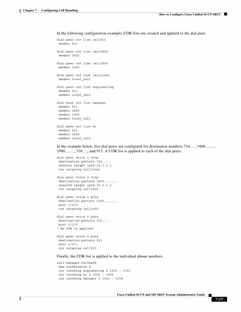
Chapter 7 Configuring Call HandlingHow to Configure Cisco Unified SCCP SRST
In the following configuration example, COR lists are created and applied to the dial peer:
dial-peer cor list call911member 911
dial-peer cor list call1800member 1800
dial-peer cor list call1900member 1900
dial-peer cor list calllocalmember local_call
dial-peer cor list engineeringmember 911member local_call
dial-peer cor list managermember 911member 1800member 1900member local_call
dial-peer cor list hrmember 911member 1800member local_call
In the example below, five dial peers are configured for destination numbers 734…., 1800……., 1900……., 316…., and 911. A COR list is applied to each of the dial peers.
dial-peer voice 1 voipdestination pattern 734....session target ipv4:10.1.1.1cor outgoing calllocal
dial-peer voice 2 voipdestination pattern 1800.......session target ipv4:10.1.1.1cor outgoing call1800
dial-peer voice 3 pots destination pattern 1900.......port 1/0/0cor outgoing call1900
dial-peer voice 5 potsdestination pattern 316....port 1/1/0
! No COR is applied.
dial-peer voice 4 potsdestination pattern 911port 1/0/1cor outgoing call911
Finally, the COR list is applied to the individual phone numbers.
call-manager-fallbackmax-conferences 8cor incoming engineering 1 1001 - 1001cor incoming hr 2 1002 - 1002cor incoming manager 3 1003 - 1008
7-137Cisco Unified SCCP and SIP SRST System Administrator Guide
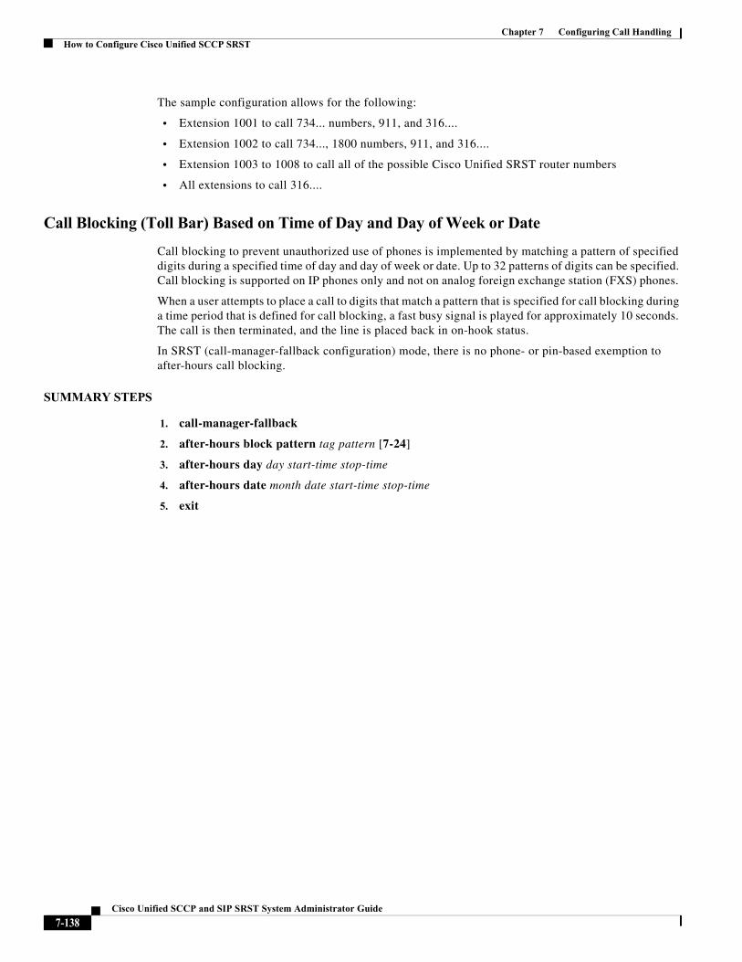
Chapter 7 Configuring Call HandlingHow to Configure Cisco Unified SCCP SRST
The sample configuration allows for the following:
• Extension 1001 to call 734... numbers, 911, and 316....
• Extension 1002 to call 734..., 1800 numbers, 911, and 316....
• Extension 1003 to 1008 to call all of the possible Cisco Unified SRST router numbers
• All extensions to call 316....
Call Blocking (Toll Bar) Based on Time of Day and Day of Week or Date
Call blocking to prevent unauthorized use of phones is implemented by matching a pattern of specified digits during a specified time of day and day of week or date. Up to 32 patterns of digits can be specified. Call blocking is supported on IP phones only and not on analog foreign exchange station (FXS) phones.
When a user attempts to place a call to digits that match a pattern that is specified for call blocking during a time period that is defined for call blocking, a fast busy signal is played for approximately 10 seconds. The call is then terminated, and the line is placed back in on-hook status.
In SRST (call-manager-fallback configuration) mode, there is no phone- or pin-based exemption to after-hours call blocking.
SUMMARY STEPS
1. call-manager-fallback
2. after-hours block pattern tag pattern [7-24]
3. after-hours day day start-time stop-time
4. after-hours date month date start-time stop-time
5. exit
7-138Cisco Unified SCCP and SIP SRST System Administrator Guide
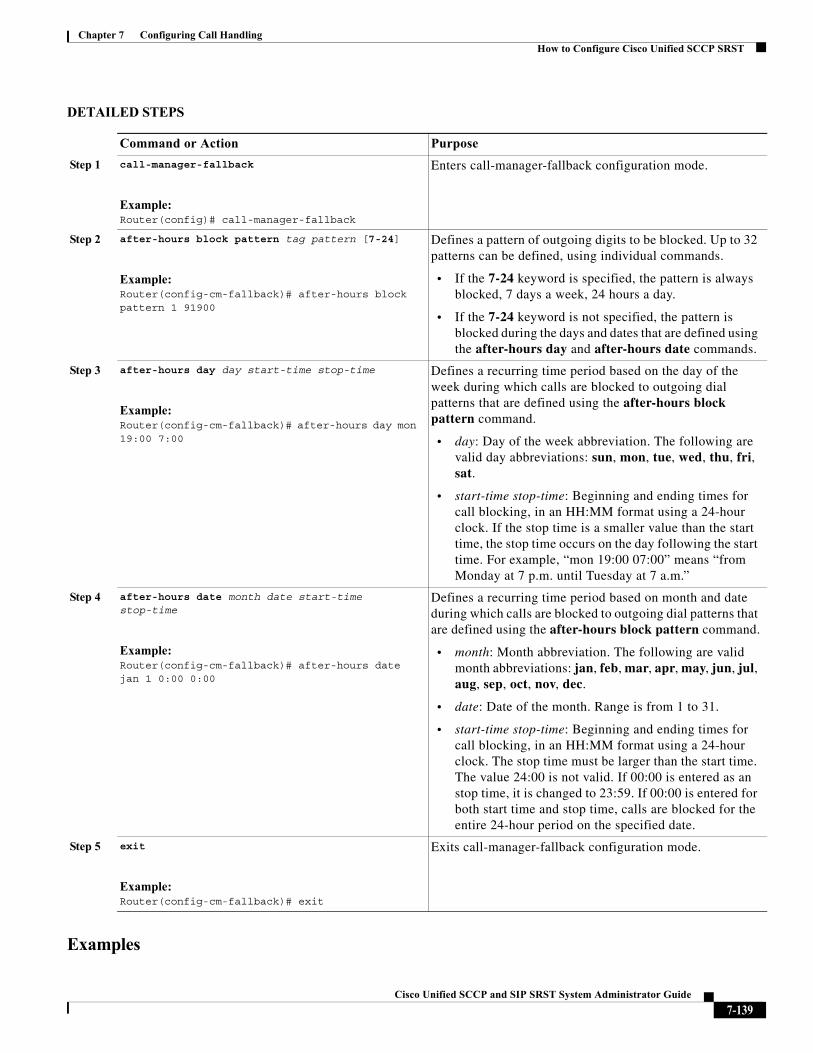
Chapter 7 Configuring Call HandlingHow to Configure Cisco Unified SCCP SRST
DETAILED STEPS
Examples
Command or Action Purpose
Step 1 call-manager-fallback
Example:Router(config)# call-manager-fallback
Enters call-manager-fallback configuration mode.
Step 2 after-hours block pattern tag pattern [7-24]
Example:Router(config-cm-fallback)# after-hours block pattern 1 91900
Defines a pattern of outgoing digits to be blocked. Up to 32 patterns can be defined, using individual commands.
• If the 7-24 keyword is specified, the pattern is always blocked, 7 days a week, 24 hours a day.
• If the 7-24 keyword is not specified, the pattern is blocked during the days and dates that are defined using the after-hours day and after-hours date commands.
Step 3 after-hours day day start-time stop-time
Example:Router(config-cm-fallback)# after-hours day mon 19:00 7:00
Defines a recurring time period based on the day of the week during which calls are blocked to outgoing dial patterns that are defined using the after-hours block pattern command.
• day: Day of the week abbreviation. The following are valid day abbreviations: sun, mon, tue, wed, thu, fri, sat.
• start-time stop-time: Beginning and ending times for call blocking, in an HH:MM format using a 24-hour clock. If the stop time is a smaller value than the start time, the stop time occurs on the day following the start time. For example, “mon 19:00 07:00” means “from Monday at 7 p.m. until Tuesday at 7 a.m.”
Step 4 after-hours date month date start-time stop-time
Example:Router(config-cm-fallback)# after-hours date jan 1 0:00 0:00
Defines a recurring time period based on month and date during which calls are blocked to outgoing dial patterns that are defined using the after-hours block pattern command.
• month: Month abbreviation. The following are valid month abbreviations: jan, feb, mar, apr, may, jun, jul, aug, sep, oct, nov, dec.
• date: Date of the month. Range is from 1 to 31.
• start-time stop-time: Beginning and ending times for call blocking, in an HH:MM format using a 24-hour clock. The stop time must be larger than the start time. The value 24:00 is not valid. If 00:00 is entered as an stop time, it is changed to 23:59. If 00:00 is entered for both start time and stop time, calls are blocked for the entire 24-hour period on the specified date.
Step 5 exit
Example:Router(config-cm-fallback)# exit
Exits call-manager-fallback configuration mode.
7-139Cisco Unified SCCP and SIP SRST System Administrator Guide
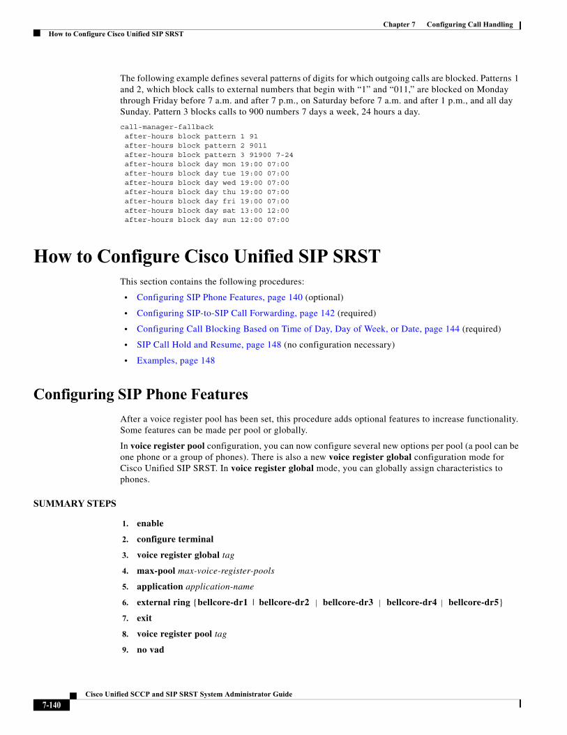
Chapter 7 Configuring Call HandlingHow to Configure Cisco Unified SIP SRST
The following example defines several patterns of digits for which outgoing calls are blocked. Patterns 1 and 2, which block calls to external numbers that begin with “1” and “011,” are blocked on Monday through Friday before 7 a.m. and after 7 p.m., on Saturday before 7 a.m. and after 1 p.m., and all day Sunday. Pattern 3 blocks calls to 900 numbers 7 days a week, 24 hours a day.
call-manager-fallbackafter-hours block pattern 1 91after-hours block pattern 2 9011after-hours block pattern 3 91900 7-24after-hours block day mon 19:00 07:00after-hours block day tue 19:00 07:00after-hours block day wed 19:00 07:00after-hours block day thu 19:00 07:00after-hours block day fri 19:00 07:00after-hours block day sat 13:00 12:00after-hours block day sun 12:00 07:00
How to Configure Cisco Unified SIP SRSTThis section contains the following procedures:
• Configuring SIP Phone Features, page 140 (optional)
• Configuring SIP-to-SIP Call Forwarding, page 142 (required)
• Configuring Call Blocking Based on Time of Day, Day of Week, or Date, page 144 (required)
• SIP Call Hold and Resume, page 148 (no configuration necessary)
• Examples, page 148
Configuring SIP Phone Features
After a voice register pool has been set, this procedure adds optional features to increase functionality. Some features can be made per pool or globally.
In voice register pool configuration, you can now configure several new options per pool (a pool can be one phone or a group of phones). There is also a new voice register global configuration mode for Cisco Unified SIP SRST. In voice register global mode, you can globally assign characteristics to phones.
SUMMARY STEPS
1. enable
2. configure terminal
3. voice register global tag
4. max-pool max-voice-register-pools
5. application application-name
6. external ring {bellcore-dr1 | bellcore-dr2 | bellcore-dr3 | bellcore-dr4 | bellcore-dr5}
7. exit
8. voice register pool tag
9. no vad
7-140Cisco Unified SCCP and SIP SRST System Administrator Guide
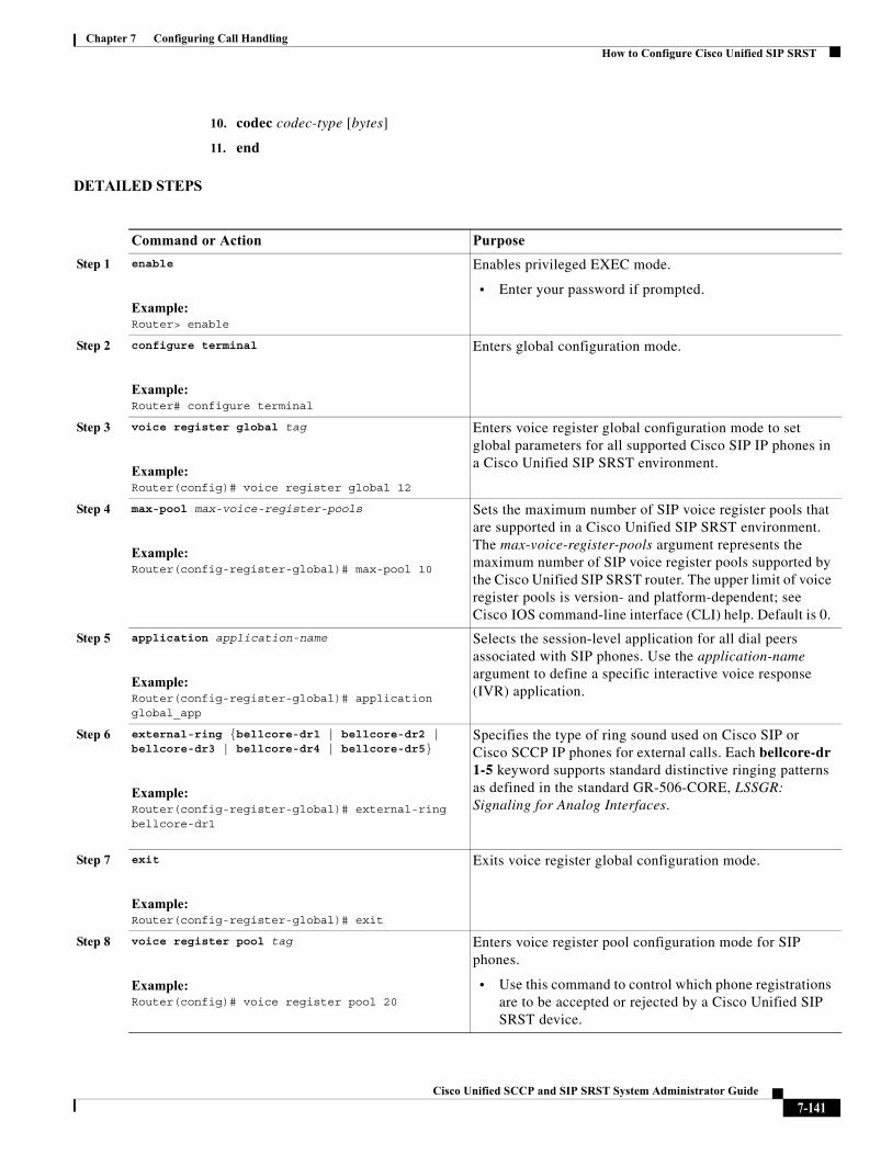
Chapter 7 Configuring Call HandlingHow to Configure Cisco Unified SIP SRST
10. codec codec-type [bytes]
11. end
DETAILED STEPS
Command or Action Purpose
Step 1 enable
Example:Router> enable
Enables privileged EXEC mode.
• Enter your password if prompted.
Step 2 configure terminal
Example:Router# configure terminal
Enters global configuration mode.
Step 3 voice register global tag
Example:Router(config)# voice register global 12
Enters voice register global configuration mode to set global parameters for all supported Cisco SIP IP phones in a Cisco Unified SIP SRST environment.
Step 4 max-pool max-voice-register-pools
Example:Router(config-register-global)# max-pool 10
Sets the maximum number of SIP voice register pools that are supported in a Cisco Unified SIP SRST environment. The max-voice-register-pools argument represents the maximum number of SIP voice register pools supported by the Cisco Unified SIP SRST router. The upper limit of voice register pools is version- and platform-dependent; see Cisco IOS command-line interface (CLI) help. Default is 0.
Step 5 application application-name
Example:Router(config-register-global)# application global_app
Selects the session-level application for all dial peers associated with SIP phones. Use the application-name argument to define a specific interactive voice response (IVR) application.
Step 6 external-ring {bellcore-dr1 | bellcore-dr2 | bellcore-dr3 | bellcore-dr4 | bellcore-dr5}
Example:Router(config-register-global)# external-ring bellcore-dr1
Specifies the type of ring sound used on Cisco SIP or Cisco SCCP IP phones for external calls. Each bellcore-dr 1-5 keyword supports standard distinctive ringing patterns as defined in the standard GR-506-CORE, LSSGR: Signaling for Analog Interfaces.
Step 7 exit
Example:Router(config-register-global)# exit
Exits voice register global configuration mode.
Step 8 voice register pool tag
Example:Router(config)# voice register pool 20
Enters voice register pool configuration mode for SIP phones.
• Use this command to control which phone registrations are to be accepted or rejected by a Cisco Unified SIP SRST device.
7-141Cisco Unified SCCP and SIP SRST System Administrator Guide
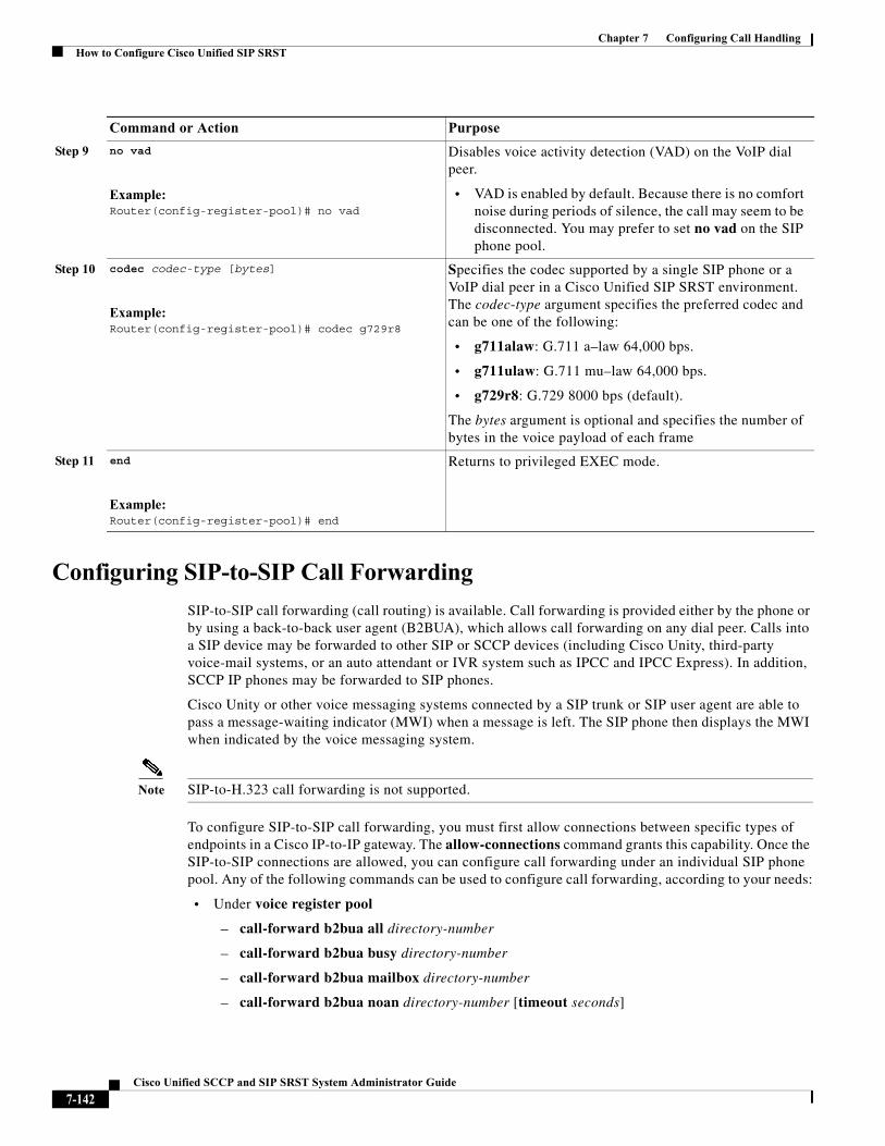
Chapter 7 Configuring Call HandlingHow to Configure Cisco Unified SIP SRST
Configuring SIP-to-SIP Call Forwarding
SIP-to-SIP call forwarding (call routing) is available. Call forwarding is provided either by the phone or by using a back-to-back user agent (B2BUA), which allows call forwarding on any dial peer. Calls into a SIP device may be forwarded to other SIP or SCCP devices (including Cisco Unity, third-party voice-mail systems, or an auto attendant or IVR system such as IPCC and IPCC Express). In addition, SCCP IP phones may be forwarded to SIP phones.
Cisco Unity or other voice messaging systems connected by a SIP trunk or SIP user agent are able to pass a message-waiting indicator (MWI) when a message is left. The SIP phone then displays the MWI when indicated by the voice messaging system.
Note SIP-to-H.323 call forwarding is not supported.
To configure SIP-to-SIP call forwarding, you must first allow connections between specific types of endpoints in a Cisco IP-to-IP gateway. The allow-connections command grants this capability. Once the SIP-to-SIP connections are allowed, you can configure call forwarding under an individual SIP phone pool. Any of the following commands can be used to configure call forwarding, according to your needs:
• Under voice register pool
– call-forward b2bua all directory-number
– call-forward b2bua busy directory-number
– call-forward b2bua mailbox directory-number
– call-forward b2bua noan directory-number [timeout seconds]
Step 9 no vad
Example:Router(config-register-pool)# no vad
Disables voice activity detection (VAD) on the VoIP dial peer.
• VAD is enabled by default. Because there is no comfort noise during periods of silence, the call may seem to be disconnected. You may prefer to set no vad on the SIP phone pool.
Step 10 codec codec-type [bytes]
Example:Router(config-register-pool)# codec g729r8
Specifies the codec supported by a single SIP phone or a VoIP dial peer in a Cisco Unified SIP SRST environment. The codec-type argument specifies the preferred codec and can be one of the following:
• g711alaw: G.711 a–law 64,000 bps.
• g711ulaw: G.711 mu–law 64,000 bps.
• g729r8: G.729 8000 bps (default).
The bytes argument is optional and specifies the number of bytes in the voice payload of each frame
Step 11 end
Example:Router(config-register-pool)# end
Returns to privileged EXEC mode.
Command or Action Purpose
7-142Cisco Unified SCCP and SIP SRST System Administrator Guide
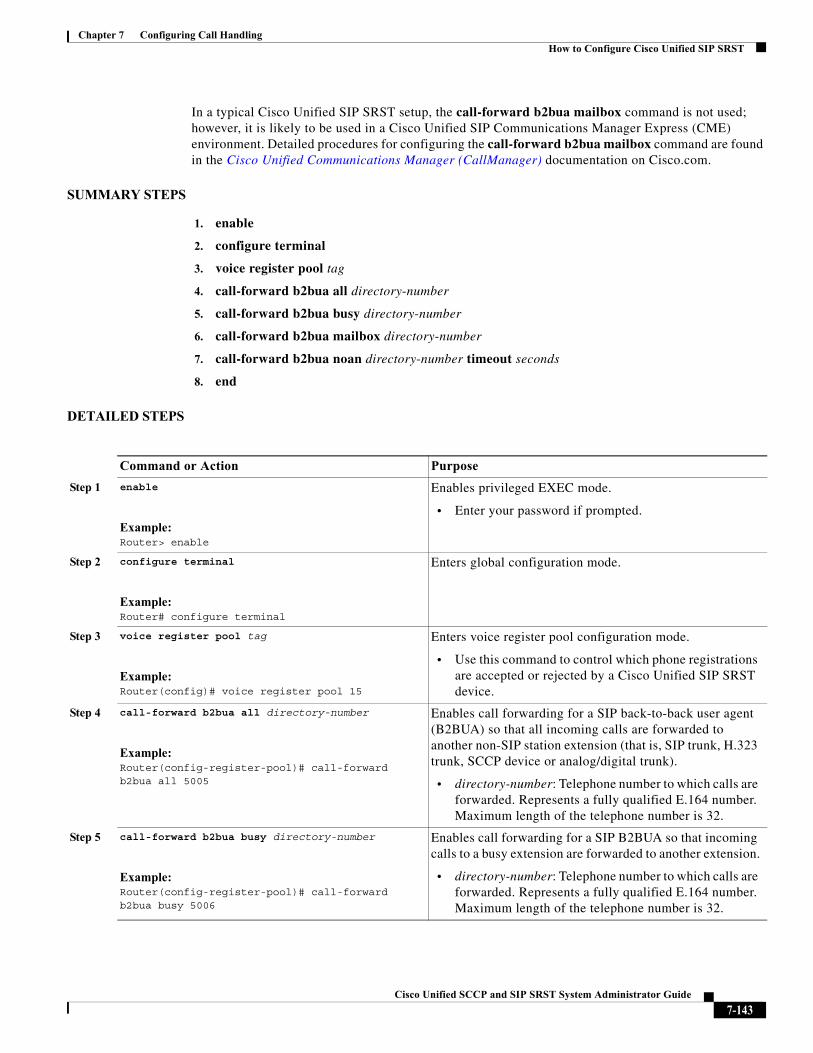
Chapter 7 Configuring Call HandlingHow to Configure Cisco Unified SIP SRST
In a typical Cisco Unified SIP SRST setup, the call-forward b2bua mailbox command is not used; however, it is likely to be used in a Cisco Unified SIP Communications Manager Express (CME) environment. Detailed procedures for configuring the call-forward b2bua mailbox command are found in the Cisco Unified Communications Manager (CallManager) documentation on Cisco.com.
SUMMARY STEPS
1. enable
2. configure terminal
3. voice register pool tag
4. call-forward b2bua all directory-number
5. call-forward b2bua busy directory-number
6. call-forward b2bua mailbox directory-number
7. call-forward b2bua noan directory-number timeout seconds
8. end
DETAILED STEPS
Command or Action Purpose
Step 1 enable
Example:Router> enable
Enables privileged EXEC mode.
• Enter your password if prompted.
Step 2 configure terminal
Example:Router# configure terminal
Enters global configuration mode.
Step 3 voice register pool tag
Example:Router(config)# voice register pool 15
Enters voice register pool configuration mode.
• Use this command to control which phone registrations are accepted or rejected by a Cisco Unified SIP SRST device.
Step 4 call-forward b2bua all directory-number
Example:Router(config-register-pool)# call-forward b2bua all 5005
Enables call forwarding for a SIP back-to-back user agent (B2BUA) so that all incoming calls are forwarded to another non-SIP station extension (that is, SIP trunk, H.323 trunk, SCCP device or analog/digital trunk).
• directory-number: Telephone number to which calls are forwarded. Represents a fully qualified E.164 number. Maximum length of the telephone number is 32.
Step 5 call-forward b2bua busy directory-number
Example:Router(config-register-pool)# call-forward b2bua busy 5006
Enables call forwarding for a SIP B2BUA so that incoming calls to a busy extension are forwarded to another extension.
• directory-number: Telephone number to which calls are forwarded. Represents a fully qualified E.164 number. Maximum length of the telephone number is 32.
7-143Cisco Unified SCCP and SIP SRST System Administrator Guide
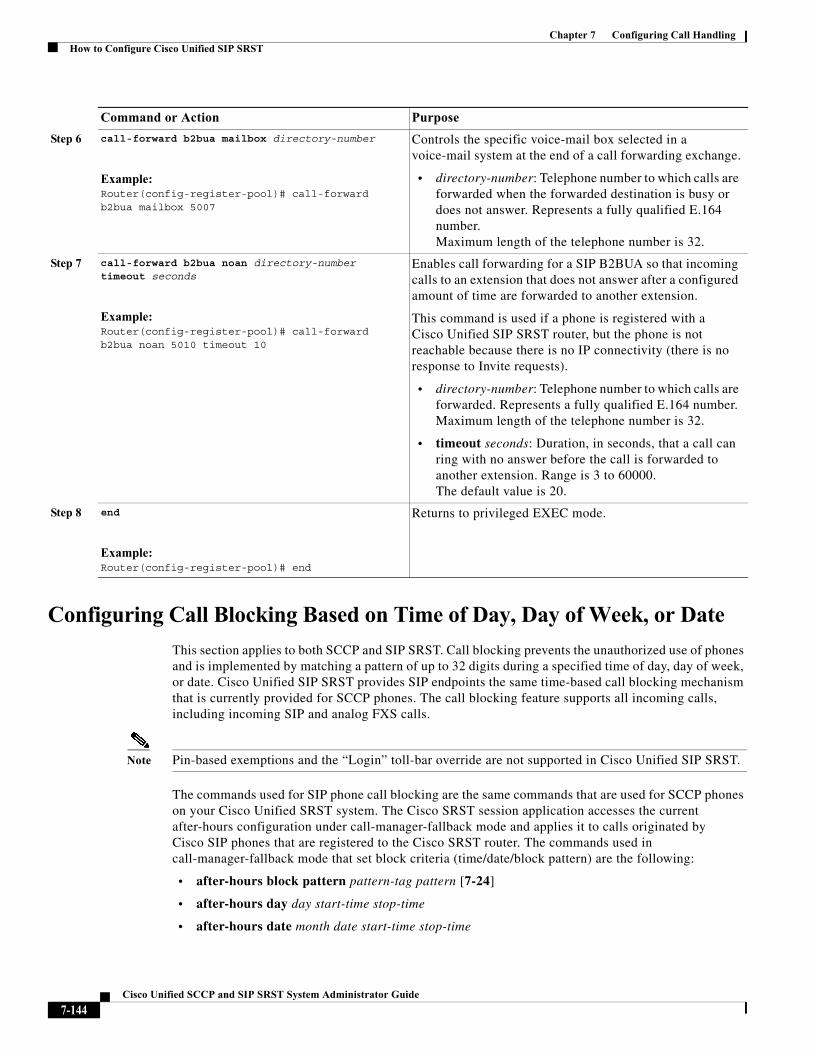
Chapter 7 Configuring Call HandlingHow to Configure Cisco Unified SIP SRST
Configuring Call Blocking Based on Time of Day, Day of Week, or Date
This section applies to both SCCP and SIP SRST. Call blocking prevents the unauthorized use of phones and is implemented by matching a pattern of up to 32 digits during a specified time of day, day of week, or date. Cisco Unified SIP SRST provides SIP endpoints the same time-based call blocking mechanism that is currently provided for SCCP phones. The call blocking feature supports all incoming calls, including incoming SIP and analog FXS calls.
Note Pin-based exemptions and the “Login” toll-bar override are not supported in Cisco Unified SIP SRST.
The commands used for SIP phone call blocking are the same commands that are used for SCCP phones on your Cisco Unified SRST system. The Cisco SRST session application accesses the current after-hours configuration under call-manager-fallback mode and applies it to calls originated by Cisco SIP phones that are registered to the Cisco SRST router. The commands used in call-manager-fallback mode that set block criteria (time/date/block pattern) are the following:
• after-hours block pattern pattern-tag pattern [7-24]
• after-hours day day start-time stop-time
• after-hours date month date start-time stop-time
Step 6 call-forward b2bua mailbox directory-number
Example:Router(config-register-pool)# call-forward b2bua mailbox 5007
Controls the specific voice-mail box selected in a voice-mail system at the end of a call forwarding exchange.
• directory-number: Telephone number to which calls are forwarded when the forwarded destination is busy or does not answer. Represents a fully qualified E.164 number. Maximum length of the telephone number is 32.
Step 7 call-forward b2bua noan directory-number timeout seconds
Example:Router(config-register-pool)# call-forward b2bua noan 5010 timeout 10
Enables call forwarding for a SIP B2BUA so that incoming calls to an extension that does not answer after a configured amount of time are forwarded to another extension.
This command is used if a phone is registered with a Cisco Unified SIP SRST router, but the phone is not reachable because there is no IP connectivity (there is no response to Invite requests).
• directory-number: Telephone number to which calls are forwarded. Represents a fully qualified E.164 number. Maximum length of the telephone number is 32.
• timeout seconds: Duration, in seconds, that a call can ring with no answer before the call is forwarded to another extension. Range is 3 to 60000. The default value is 20.
Step 8 end
Example:Router(config-register-pool)# end
Returns to privileged EXEC mode.
Command or Action Purpose
7-144Cisco Unified SCCP and SIP SRST System Administrator Guide
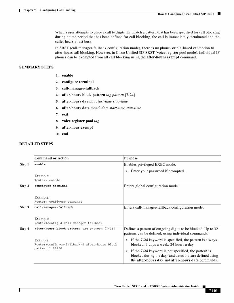
Chapter 7 Configuring Call HandlingHow to Configure Cisco Unified SIP SRST
When a user attempts to place a call to digits that match a pattern that has been specified for call blocking during a time period that has been defined for call blocking, the call is immediately terminated and the caller hears a fast busy.
In SRST (call-manager-fallback configuration mode), there is no phone- or pin-based exemption to after-hours call blocking. However, in Cisco Unified SIP SRST (voice register pool mode), individual IP phones can be exempted from all call blocking using the after-hours exempt command.
SUMMARY STEPS
1. enable
2. configure terminal
3. call-manager-fallback
4. after-hours block pattern tag pattern [7-24]
5. after-hours day day start-time stop-time
6. after-hours date month date start-time stop-time
7. exit
8. voice register pool tag
9. after-hour exempt
10. end
DETAILED STEPS
Command or Action Purpose
Step 1 enable
Example:Router> enable
Enables privileged EXEC mode.
• Enter your password if prompted.
Step 2 configure terminal
Example:Router# configure terminal
Enters global configuration mode.
Step 3 call-manager-fallback
Example:Router(config)# call-manager-fallback
Enters call-manager-fallback configuration mode.
Step 4 after-hours block pattern tag pattern [7-24]
Example:Router(config-cm-fallback)# after-hours block pattern 1 91900
Defines a pattern of outgoing digits to be blocked. Up to 32 patterns can be defined, using individual commands.
• If the 7-24 keyword is specified, the pattern is always blocked, 7 days a week, 24 hours a day.
• If the 7-24 keyword is not specified, the pattern is blocked during the days and dates that are defined using the after-hours day and after-hours date commands.
7-145Cisco Unified SCCP and SIP SRST System Administrator Guide
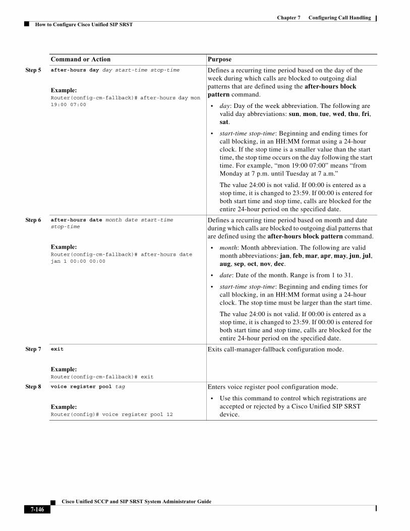
Chapter 7 Configuring Call HandlingHow to Configure Cisco Unified SIP SRST
Step 5 after-hours day day start-time stop-time
Example:Router(config-cm-fallback)# after-hours day mon 19:00 07:00
Defines a recurring time period based on the day of the week during which calls are blocked to outgoing dial patterns that are defined using the after-hours block pattern command.
• day: Day of the week abbreviation. The following are valid day abbreviations: sun, mon, tue, wed, thu, fri, sat.
• start-time stop-time: Beginning and ending times for call blocking, in an HH:MM format using a 24-hour clock. If the stop time is a smaller value than the start time, the stop time occurs on the day following the start time. For example, “mon 19:00 07:00” means “from Monday at 7 p.m. until Tuesday at 7 a.m.”
The value 24:00 is not valid. If 00:00 is entered as a stop time, it is changed to 23:59. If 00:00 is entered for both start time and stop time, calls are blocked for the entire 24-hour period on the specified date.
Step 6 after-hours date month date start-time stop-time
Example:Router(config-cm-fallback)# after-hours date jan 1 00:00 00:00
Defines a recurring time period based on month and date during which calls are blocked to outgoing dial patterns that are defined using the after-hours block pattern command.
• month: Month abbreviation. The following are valid month abbreviations: jan, feb, mar, apr, may, jun, jul, aug, sep, oct, nov, dec.
• date: Date of the month. Range is from 1 to 31.
• start-time stop-time: Beginning and ending times for call blocking, in an HH:MM format using a 24-hour clock. The stop time must be larger than the start time.
The value 24:00 is not valid. If 00:00 is entered as a stop time, it is changed to 23:59. If 00:00 is entered for both start time and stop time, calls are blocked for the entire 24-hour period on the specified date.
Step 7 exit
Example:Router(config-cm-fallback)# exit
Exits call-manager-fallback configuration mode.
Step 8 voice register pool tag
Example:Router(config)# voice register pool 12
Enters voice register pool configuration mode.
• Use this command to control which registrations are accepted or rejected by a Cisco Unified SIP SRST device.
Command or Action Purpose
7-146Cisco Unified SCCP and SIP SRST System Administrator Guide
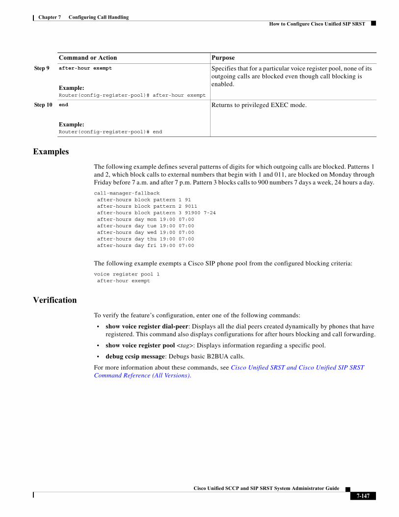
Chapter 7 Configuring Call HandlingHow to Configure Cisco Unified SIP SRST
Examples
The following example defines several patterns of digits for which outgoing calls are blocked. Patterns 1 and 2, which block calls to external numbers that begin with 1 and 011, are blocked on Monday through Friday before 7 a.m. and after 7 p.m. Pattern 3 blocks calls to 900 numbers 7 days a week, 24 hours a day.
call-manager-fallbackafter-hours block pattern 1 91after-hours block pattern 2 9011after-hours block pattern 3 91900 7-24after-hours day mon 19:00 07:00after-hours day tue 19:00 07:00after-hours day wed 19:00 07:00after-hours day thu 19:00 07:00after-hours day fri 19:00 07:00
The following example exempts a Cisco SIP phone pool from the configured blocking criteria:
voice register pool 1after-hour exempt
Verification
To verify the feature’s configuration, enter one of the following commands:
• show voice register dial-peer: Displays all the dial peers created dynamically by phones that have registered. This command also displays configurations for after hours blocking and call forwarding.
• show voice register pool <tag>: Displays information regarding a specific pool.
• debug ccsip message: Debugs basic B2BUA calls.
For more information about these commands, see Cisco Unified SRST and Cisco Unified SIP SRST Command Reference (All Versions).
Step 9 after-hour exempt
Example:Router(config-register-pool)# after-hour exempt
Specifies that for a particular voice register pool, none of its outgoing calls are blocked even though call blocking is enabled.
Step 10 end
Example:Router(config-register-pool)# end
Returns to privileged EXEC mode.
Command or Action Purpose
7-147Cisco Unified SCCP and SIP SRST System Administrator Guide
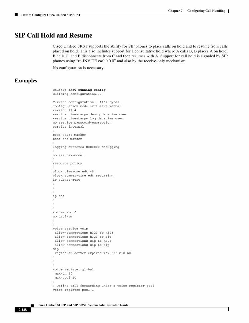
Chapter 7 Configuring Call HandlingHow to Configure Cisco Unified SIP SRST
SIP Call Hold and Resume
Cisco Unified SRST supports the ability for SIP phones to place calls on hold and to resume from calls placed on hold. This also includes support for a consultative hold where A calls B, B places A on hold, B calls C, and B disconnects from C and then resumes with A. Support for call hold is signaled by SIP phones using “re-INVITE c=0.0.0.0” and also by the receive-only mechanism.
No configuration is necessary.
Examples
Router# show running-configBuilding configuration...
Current configuration : 1462 bytesconfiguration mode exclusive manualversion 12.4service timestamps debug datetime msecservice timestamps log datetime msecno service password-encryptionservice internal!boot-start-markerboot-end-marker!logging buffered 8000000 debugging!no aaa new-model!resource policy!clock timezone edt -5clock summer-time edt recurringip subnet-zero!!!ip cef!!!voice-card 0no dspfarm!!voice service voip allow-connections h323 to h323allow-connections h323 to sipallow-connections sip to h323allow-connections sip to sip
sipregistrar server expires max 600 min 60
!!!voice register globalmax-dn 10max-pool 10
!! Define call forwarding under a voice register poolvoice register pool 1
7-148Cisco Unified SCCP and SIP SRST System Administrator Guide
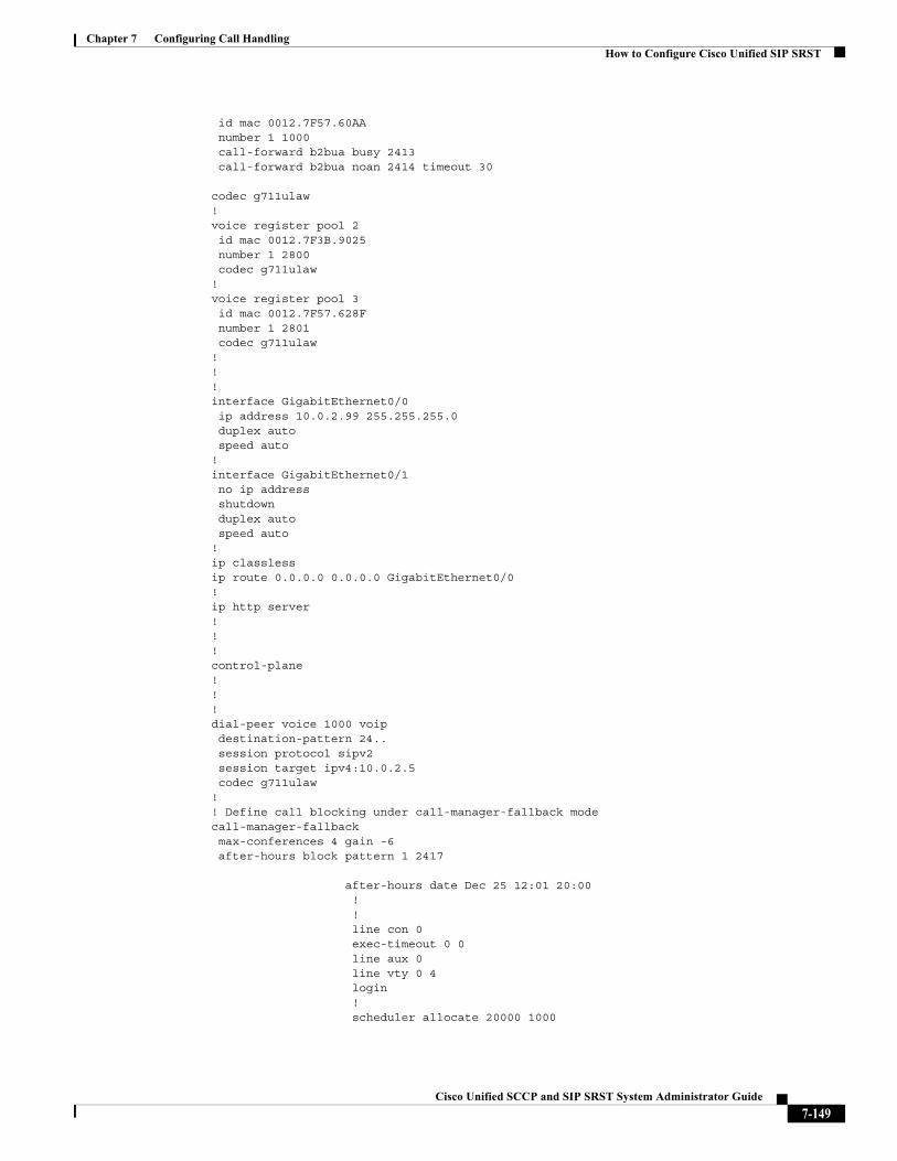
Chapter 7 Configuring Call HandlingHow to Configure Cisco Unified SIP SRST
id mac 0012.7F57.60AAnumber 1 1000call-forward b2bua busy 2413 call-forward b2bua noan 2414 timeout 30
codec g711ulaw!voice register pool 2id mac 0012.7F3B.9025number 1 2800codec g711ulaw
!voice register pool 3id mac 0012.7F57.628Fnumber 1 2801codec g711ulaw
!!!interface GigabitEthernet0/0ip address 10.0.2.99 255.255.255.0duplex autospeed auto
!interface GigabitEthernet0/1no ip addressshutdownduplex autospeed auto
!ip classlessip route 0.0.0.0 0.0.0.0 GigabitEthernet0/0!ip http server!!!control-plane!!!dial-peer voice 1000 voipdestination-pattern 24..session protocol sipv2session target ipv4:10.0.2.5codec g711ulaw
!! Define call blocking under call-manager-fallback modecall-manager-fallback max-conferences 4 gain -6after-hours block pattern 1 2417
after-hours date Dec 25 12:01 20:00 !!line con 0exec-timeout 0 0line aux 0line vty 0 4login !scheduler allocate 20000 1000
7-149Cisco Unified SCCP and SIP SRST System Administrator Guide
Chapter 7 Configuring Call HandlingHow to Configure Optional Features
ntp server 10.0.2.10!end
How to Configure Optional FeaturesThis section describe the following optional additional call features:
• Three-party G.711 ad hoc conferencing—Cisco Unified Survivable Remote Site Telephony (SRST) support for simultaneous three-party conferences.
• eXtensible Markup Language (XML) application program interface (API)— This interface supplies data from Cisco Unified SRST to management software.
The following sections describe how to configure these optional features:
• Enabling Three-Party G.711 Ad Hoc Conferencing, page 150
• Defining XML API Schema, page 152
Enabling Three-Party G.711 Ad Hoc Conferencing
Enabling three-party G.711 ad hoc conferencing involves configuring the maximum number of simultaneous three-party conferences supported by the Cisco Unified SRST router. For conferencing to be available, an IP phone must have a minimum of two lines connected to one or more buttons. See the “Configuring a Secondary Dial Tone” section on page 71.
SUMMARY STEPS
1. call-manager-fallback
2. max-conferences max-conference-numbers
3. exit
7-150Cisco Unified SCCP and SIP SRST System Administrator Guide
Chapter 7 Configuring Call HandlingHow to Configure Optional Features
DETAILED STEPS
Examples
The following example configures up to eight simultaneous three-way conferences on a router:
call-manager-fallbackmax-conferences 8
Command or Action Purpose
Step 1 call-manager-fallback
Example:Router(config)# call-manager-fallback
Enters call-manager-fallback configuration mode.
Step 2 max-conferences max-conference-numbers
Example:Router(config-cm-fallback)# max-conferences 16
Sets the maximum number of simultaneous three-party conferences supported by the router. The maximum number possible is platform dependent:
• Cisco 1751 router:8
• Cisco 1760 router:8
• Cisco 2600 series routers:8
• Cisco 2600-XM series routers:8
• Cisco 2801 router:8
• Cisco 2811, Cisco 2821, and Cisco 2851 routers:16
• Cisco 3640 and Cisco 3640A routers:8
• Cisco 3660 router: 16
• Cisco 3725 router: 16
• Cisco 3745 router: 16
• Cisco 3800 series router: 24
Step 3 exit
Example:Router(config-cm-fallback)# exit
Exits call-manager-fallback configuration mode.
7-151Cisco Unified SCCP and SIP SRST System Administrator Guide
Chapter 7 Configuring Call HandlingConfiguration Examples for Call Handling
Defining XML API Schema
The Cisco IOS commands in this section allow you to specify parameters associated with the XML API. For more information, see XML Provisioning Guide for Cisco CME/SRST. See the “Enabling Consultative Call Transfer and Forward Using H.450.2 and H.450.3 with Cisco SRST 3.0” section on page 124 for configuration instructions.
SUMMARY STEPS
1. call-manager-fallback
2. xmlschema schema-url
3. exit
DETAILED STEPS
Configuration Examples for Call Handling• Example: Monitoring the Status of Key Expansion Modules, page 152
• Example: Configuring Voice Hunt Groups in Cisco Unified SIP SRST, page 153
Example: Monitoring the Status of Key Expansion Modules
Show commands are used to monitor the status and other details of Key Expansion Modules (KEMs).
The following example demonstrates how the show voice register all command displays KEM details with all the Cisco Unified CME configurations and registration information:
show voice register allVOICE REGISTER GLOBAL=====================CONFIG [Version=9.1]
Command or Action Purpose
Step 1 call-manager-fallback
Example:Router(config)# call-manager-fallback
Enters call-manager-fallback configuration mode.
Step 2 xmlschema schema-url
Example:Router(config-cm-fallback)# xmlschema http://server2.example.com/schema/schema1.xsd
Specifies the URL for an XML API schema to be used with this Cisco Unified SRST system.
• schema-url: Local or remote URL as defined in RFC 2396.
Step 3 exit
Example:Router(config-cm-fallback)# exit
Exits call-manager-fallback configuration mode.
7-152Cisco Unified SCCP and SIP SRST System Administrator Guide
Chapter 7 Configuring Call HandlingWhere to Go Next
========================............Pool Tag 5Config: Mac address is B4A4.E328.4698 Type is 9971 addon 1 CKEM Number list 1 : DN 2 Number list 2 : DN 3 Proxy Ip address is 0.0.0.0 DTMF Relay is disabled Call Waiting is enabled DnD is disabled Video is enabled Camera is enabled Busy trigger per button value is 0 keep-conference is enabled registration expires timer max is 200 and min is 60 kpml signal is enabled Lpcor Type is none
The following example demonstrates how the show voice register pool type command displays all the phones configured with add-on KEMs in Cisco Unified CME:
Router# show voice register pool type CKEMPool ID IP Address Ln DN Number State==== =============== =============== == === ==================== ============4 B4A4.E328.4698 9.45.31.111 1 4 5589$ REGISTERED
Example: Configuring Voice Hunt Groups in Cisco Unified SIP SRST
The following example shows how to configure longest-idle hunt group 20 with pilot number 4701, final number 5000, and 6 numbers in the list. After a call is redirected six times (makes 6 hops), it is redirected to the final number 5000.
Router(config)# voice hunt-group 20 longest-idleRouter(config-voice-hunt-group)# pilot 4701Router(config-voice-hunt-group)# list 4001, 4002, 4023, 4028, 4045, 4062 Router(config-voice-hunt-group)# final 5000Router(config-voice-hunt-group)# hops 6Router(config-voice-hunt-group)# timeout 20Router(config-voice-hunt-group)# exit
Where to Go NextIf you need to configure security, see the “Configuring Secure SRST for SCCP and SIP” section on page 155, or if you need to configure voicemail, see the “Integrating Voicemail with Cisco Unified SRST” section on page 239. If you need to configure video parameters, see the “Setting Video Parameters” section on page 263. If you do not need any of those features, go to the “Monitoring and Maintaining Cisco Unified SRST” section on page 277.
For additional information, see the “Additional References” section on page 218 in the “Cisco Unified SRST Feature Overview” section on page 1chapter.
7-153Cisco Unified SCCP and SIP SRST System Administrator Guide

Chapter 7 Configuring Call HandlingWhere to Go Next
7-154Cisco Unified SCCP and SIP SRST System Administrator Guide
Cisco Unified SC
C H A P T E R 8
Configuring Secure SRST for SCCP and SIPThe Secure SRST adds security functionality to the Cisco Unified SRST.
ContentsThis chapter describes new Secure SRST security features such as authentication, integrity, and media encryption.
• Prerequisites for Configuring Secure SRST, page 155
• Restrictions for Configuring Secure SRST, page 156
• Information About Configuring Secure SRST, page 157
• How to Configure Secure Unified SRST, page 164
• Additional References, page 218
• Command Reference, page 220
• Feature Information for Secure SCCP and SIP SRST, page 221
• Where to Go Next, page 221
Prerequisites for Configuring Secure SRSTGeneral
• Secure Cisco Unified IP phones supported in secure SCCP and SIP SRST must have the Certification Authority (CA) or third party certificates installed, and encryption enabled. For more information on CA server authentication, see Autoenrolling and Authenticating the Secure Cisco Unified SRST Router to the CA Server, page 167.
• The SRST router must have a certificate; a certificate can be generated by a third party or by the Cisco IOS certificate authority (CA). The Cisco IOS CA can run on the same gateway as Cisco Unified SRST. Over the TLS channel (port 2445), automated certificate exchange happens between the Unified SRST router and the Cisco Unified Communications Manager. However, the phone certificate exchange to Unified SRST through Unified Communications Manager has to be downloaded manually on the Unified SRST router.
• Certificate trust lists (CTLs) on Cisco Unified Communications Manager must be enabled.
8-155CP and SIP SRST System Administrator Guide
Chapter 8 Configuring Secure SRST for SCCP and SIPRestrictions for Configuring Secure SRST
Public Key Infrastructure on Secure SRST
• Set the clock, either manually or by using Network Time Protocol (NTP). Setting the clock ensures synchronicity with Cisco Unified Communications Manager.
• Enable the IP HTTP server (Cisco IOS processor) with the ip http server command, if not already enabled. For more information on public key infrastructure (PKI) deployment, see the Cisco IOS Certificate Server feature.
• If the certificate server is part of your startup configuration, you may see the following messages during the boot procedure:
% Failed to find Certificate Server's trustpoint at startup % Failed to find Certificate Server's cert.
These messages are informational messages and indicate a temporary inability to configure the certificate server because the startup configuration has not been fully parsed yet. The messages are useful for debugging, in case the startup configuration is corrupted.
You can verify the status of the certificate server after the boot procedure using the show crypto pki server command.
Supported Cisco Unified IP Phones, Platforms, and Memory Requirements
• For a list of supported Cisco Unified IP Phones, routers, network modules, and codecs for secure SRST, see the Cisco Unified Survivable Remote Site Telephony Compatibility Information feature.
• For the most up-to-date information about the maximum number of Cisco Unified IP Phones, the maximum number of directory numbers (DNs) or virtual voice ports, and memory requirements, see the Cisco Unified SRST 12.1 Supported Firmware, Platforms, Memory, and Voice Products feature.
Restrictions for Configuring Secure SRSTGeneral
• Cryptographic software features (“k9”) are under export controls. This product contains cryptographic features and is subject to United States and local country laws governing import, export, transfer, and use. Delivery of Cisco cryptographic products does not imply third-party authority to import, export, distribute or use encryption. Importers, exporters, distributors and, users are responsible for compliance with U.S. and local country laws. By using this product you agree to comply with applicable laws and regulations. If you are unable to comply with U.S. and local laws, return this product immediately.
A summary of U.S. laws governing Cisco cryptographic products may be found at the following URL: http://www.cisco.com/wwl/export/crypto/tool/
If you require further assistance, please contact us by sending e-mail to [email protected].
• When a Secure Real-Time Transport Protocol (SRTP) encrypted call is made between Cisco Unified IP Phone endpoints or from a Cisco Unified IP Phone to a gateway endpoint, a lock icon is displayed on the IP phones. The lock indicates security only for the IP leg of the call. Security of the PSTN leg is not implied.
SCCP SRST
• Secure SCCP SRST is supported only within the scope of a single router.
• Secure SCCP SRST is not supported for Cisco 4000 Series Integrated Services Router.
8-156Cisco Unified SCCP and SIP SRST System Administrator Guide
Chapter 8 Configuring Secure SRST for SCCP and SIPInformation About Configuring Secure SRST
SIP SRST
• Cisco 4000 Series Integrated Services Router only supports Secure SIP SRST. The router series does not support Secure SCCP SRST.
• SRTP passthrough is not supported.
• SDP Passthrough is not supported.
• Video Calling is not supported.
• Transcoding is not supported.
• Hardware Conferencing is not supported (Only BIB Conferencing is supported).
• It is mandatory to configure security-policy secure under voice register global configuration mode.
Information About Configuring Secure SRST• Benefits of Secure SRST, page 157
• Secure SRST Support on Cisco 4000 Series Integrated Services Router, page 158
• Cisco IP Phones Clear-Text Fallback During Non-Secure SRST, page 158
• Signaling Security on Unify SRST - TLS, page 158
• Media Security on Unify SRST - SRTP, page 161
• Establishment of Secure Cisco Unified SRST to the Cisco Unified IP Phone, page 161
• Secure SRST Authentication and Encryption, page 163
Benefits of Secure SRST
Secure Cisco Unified IP phones that are located at remote sites and that are attached to gateway routers can communicate securely with Cisco Unified Communications Manager using the WAN. But if the WAN link or Cisco Unified Communications Manager goes down, all communication through the remote phones becomes nonsecure. To overcome this situation, gateway routers can now function in secure SRST mode, which activates when the WAN link or Cisco Unified Communications Manager goes down. When the WAN link or Cisco Unified Communications Manager is restored, Cisco Unified Communications Manager resumes secure call-handling capabilities.
Secure SRST provides new Cisco Unified SRST security features such as authentication, integrity, and media encryption. Authentication provides assurance to one party that another party is whom it claims to be. Integrity provides assurance that the given data has not been altered between the entities. Encryption implies confidentiality; that is, that no one can read the data except the intended recipient. These security features allow privacy for Cisco Unified SRST voice calls and protect against voice security violations and identity theft.
SRST security is achieved when:
• End devices are authenticated using certificates.
• Signaling is authenticated and encrypted using Transport Layer Security (TLS) for TCP.
• A secure media path is encrypted using Secure Real-Time Transport Protocol (SRTP).
• Certificates are generated and distributed by a CA.
8-157Cisco Unified SCCP and SIP SRST System Administrator Guide
Chapter 8 Configuring Secure SRST for SCCP and SIPInformation About Configuring Secure SRST
Secure SRST Support on Cisco 4000 Series Integrated Services Router
For Unified SRST 12.1 and later releases, Secure SIP SRST support is introduced on the Cisco 4000 Series Integrated Services Router. As a part of the Secure SIP SRST feature on Unified SRST Release 12.1, support is provided for calls with the Transport Layer Security protocols (TLS) versions up to 1.2. Also, TLS 1.2 exclusivity is supported as part of Unified SRST Release 12.1.
The Cisco IP Phone 7800 Series and Cisco IP Phone 8800 Series is supported on the Unified Secure SIP SRST Release 12.1 configured on Cisco 4000 Series Integrated Services Routers.
For Secure SIP SRST to be supported on Cisco 4000 Series Integrated Services Routers, you need to enable the following technology package licenses on the router:
• security
• uck9
Note Only SIP Phones are supported on the Cisco 4000 Series Integrated Services Router for Secure SIP SRST.
Secure Music on Hold
From Unified SRST Release 12.1, support is introduced for Secure Music on Hold (MOH), as part of the Secure SIP SRST solution on Cisco 4000 Series Integrated Services Router. For a Secure SIP call that is put on hold, playback of Flash-based G.729 and G.711 codec format MOH files are supported. Live MOH and transcoded MOH are not supported as part of Secure MOH feature support.
Note If the CLI command srtp pass-thru is configured under the dial peer voice configuration mode, Secure MOH does not work.
Cisco IP Phones Clear-Text Fallback During Non-Secure SRST
• Cisco Unified SRST versions prior to 12.3(14)T are not capable of supporting secure connections or have security enabled. If an SRST router is not capable of SRST as a fallback mode—that is, it is not capable of completing a TLS handshake with Cisco Unified Communications Manager—its certificate is not added to the configuration file of the Cisco IP phone. The absence of a Cisco Unified SRST router certificate causes the Cisco Unified IP phone to use nonsecure (clear-text) communication when in Cisco Unified SRST fallback mode. The capability to detect and fallback in clear-text mode is built into Cisco Unified IP phone firmware. See Media and Signaling Authentication and Encryption Feature for Cisco IOS MGCP Gateways for more information on clear-text mode.
Signaling Security on Unify SRST - TLS
• SRST Routers and the TLS Protocol, page 159
• Certificates Operation on Secure SRST, page 159
• Certificates Transport from CUCM to Secure SRST, page 161
8-158Cisco Unified SCCP and SIP SRST System Administrator Guide
Chapter 8 Configuring Secure SRST for SCCP and SIPInformation About Configuring Secure SRST
SRST Routers and the TLS Protocol
Transport Layer Security (TLS) Version 1.0 provides secure TCP channels between Cisco Unified IP phones, secure Cisco Unified SRST Routers, and Cisco Unified Communications Manager. The TLS process begins with the Cisco Unified IP Phone establishing a TLS connection when registering with Cisco Unified Communications Manager. Assuming that Cisco Unified Communications Manager is configured to fall back to Cisco Unified SRST, the TLS connection between the Cisco Unified IP Phones and the secure Cisco Unified SRST Router is also established. If the WAN link or Cisco Unified Communications Manager fails, call control reverts to the Cisco Unified SRST router.
From Unified Secure SIP SRST Release 12.1, support is introduced for SIP-to-SIP calls with Transport Layer Security up to TLS Version,1.2. For configuring TLS 1.2 exclusivity functionality, you need to configure the command transport tcp tls v1.2 under sip-ua configuration mode. When you configure TLS 1.2 exclusivity on the Secure SIP SRST, any registration attempt by phones using other TLS versions are rejected.
Certificates Operation on Secure SRST
• Cisco Unified SRST Routers and PKI, page 159
• Cisco IOS Credentials Server on Secure SRST Routers, page 160
• Generating a Certificate for the Credentials Server, page 160
Cisco Unified SRST Routers and PKI
The transfer of certificates between a Cisco Unified SRST router and Cisco Unified Communications Manager is mandatory for secure SRST functionality. Public key infrastructure (PKI) commands are used to generate, import, and export the certificates for secure Cisco Unified SRST. Table 8-1 shows the secure SRST-supported Cisco Unified IP Phones and the appropriate certificate for each phone. The “Additional References” section on page 218 contains information and configurations about generating, importing, and exporting certificates that use PKI commands.
Note Certificate text can vary depending on your configuration. You may also need CAP-RTP-00X or CAP-SJC-00X for older phones that support manufacturing installed certificate (MIC).
Note Cisco supports Cisco IP Phones 7900 series phone memory reclamation phones that use MIC or locally significant certificate (LSC) certificates.
Table 8-1 Supported Cisco Unified IP Phones and Certificates
8-159Cisco Unified SCCP and SIP SRST System Administrator Guide
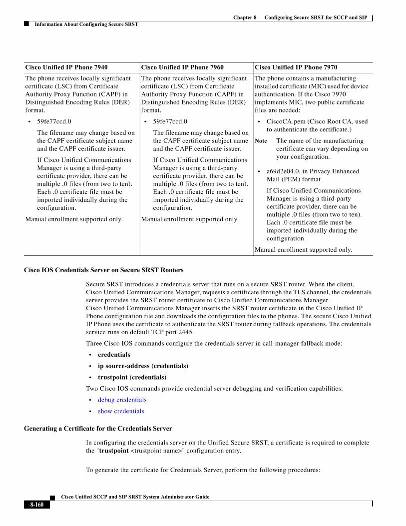
Chapter 8 Configuring Secure SRST for SCCP and SIPInformation About Configuring Secure SRST
Cisco IOS Credentials Server on Secure SRST Routers
Secure SRST introduces a credentials server that runs on a secure SRST router. When the client, Cisco Unified Communications Manager, requests a certificate through the TLS channel, the credentials server provides the SRST router certificate to Cisco Unified Communications Manager. Cisco Unified Communications Manager inserts the SRST router certificate in the Cisco Unified IP Phone configuration file and downloads the configuration files to the phones. The secure Cisco Unified IP Phone uses the certificate to authenticate the SRST router during fallback operations. The credentials service runs on default TCP port 2445.
Three Cisco IOS commands configure the credentials server in call-manager-fallback mode:
• credentials
• ip source-address (credentials)
• trustpoint (credentials)
Two Cisco IOS commands provide credential server debugging and verification capabilities:
• debug credentials
• show credentials
Generating a Certificate for the Credentials Server
In configuring the credentials server on the Unified Secure SRST, a certificate is required to complete the "trustpoint <trustpoint name>" configuration entry.
To generate the certificate for Credentials Server, perform the following procedures:
Cisco Unified IP Phone 7940 Cisco Unified IP Phone 7960 Cisco Unified IP Phone 7970
The phone receives locally significant certificate (LSC) from Certificate Authority Proxy Function (CAPF) in Distinguished Encoding Rules (DER) format.
• 59fe77ccd.0
The filename may change based on the CAPF certificate subject name and the CAPF certificate issuer.
If Cisco Unified Communications Manager is using a third-party certificate provider, there can be multiple .0 files (from two to ten). Each .0 certificate file must be imported individually during the configuration.
Manual enrollment supported only.
The phone contains a manufacturing installed certificate (MIC) used for device authentication. If the Cisco 7970 implements MIC, two public certificate files are needed:
• CiscoCA.pem (Cisco Root CA, used to authenticate the certificate.)
Note The name of the manufacturing certificate can vary depending on your configuration.
• a69d2e04.0, in Privacy Enhanced Mail (PEM) format
If Cisco Unified Communications Manager is using a third-party certificate provider, there can be multiple .0 files (from two to ten). Each .0 certificate file must be imported individually during the configuration.
Manual enrollment supported only.
8-160Cisco Unified SCCP and SIP SRST System Administrator Guide
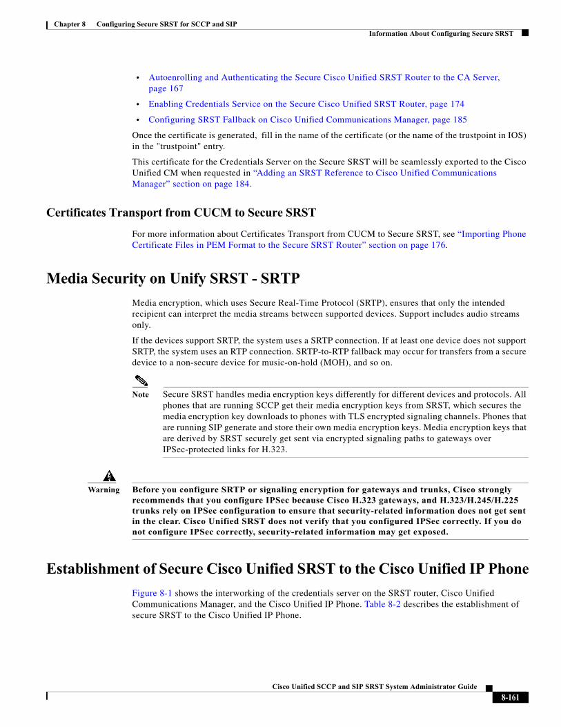
Chapter 8 Configuring Secure SRST for SCCP and SIPInformation About Configuring Secure SRST
• Autoenrolling and Authenticating the Secure Cisco Unified SRST Router to the CA Server, page 167
• Enabling Credentials Service on the Secure Cisco Unified SRST Router, page 174
• Configuring SRST Fallback on Cisco Unified Communications Manager, page 185
Once the certificate is generated, fill in the name of the certificate (or the name of the trustpoint in IOS) in the "trustpoint" entry.
This certificate for the Credentials Server on the Secure SRST will be seamlessly exported to the Cisco Unified CM when requested in “Adding an SRST Reference to Cisco Unified Communications Manager” section on page 184.
Certificates Transport from CUCM to Secure SRST
For more information about Certificates Transport from CUCM to Secure SRST, see “Importing Phone Certificate Files in PEM Format to the Secure SRST Router” section on page 176.
Media Security on Unify SRST - SRTP
Media encryption, which uses Secure Real-Time Protocol (SRTP), ensures that only the intended recipient can interpret the media streams between supported devices. Support includes audio streams only.
If the devices support SRTP, the system uses a SRTP connection. If at least one device does not support SRTP, the system uses an RTP connection. SRTP-to-RTP fallback may occur for transfers from a secure device to a non-secure device for music-on-hold (MOH), and so on.
Note Secure SRST handles media encryption keys differently for different devices and protocols. All phones that are running SCCP get their media encryption keys from SRST, which secures the media encryption key downloads to phones with TLS encrypted signaling channels. Phones that are running SIP generate and store their own media encryption keys. Media encryption keys that are derived by SRST securely get sent via encrypted signaling paths to gateways over IPSec-protected links for H.323.
Warning Before you configure SRTP or signaling encryption for gateways and trunks, Cisco strongly recommends that you configure IPSec because Cisco H.323 gateways, and H.323/H.245/H.225 trunks rely on IPSec configuration to ensure that security-related information does not get sent in the clear. Cisco Unified SRST does not verify that you configured IPSec correctly. If you do not configure IPSec correctly, security-related information may get exposed.
Establishment of Secure Cisco Unified SRST to the Cisco Unified IP Phone
Figure 8-1 shows the interworking of the credentials server on the SRST router, Cisco Unified Communications Manager, and the Cisco Unified IP Phone. Table 8-2 describes the establishment of secure SRST to the Cisco Unified IP Phone.
8-161Cisco Unified SCCP and SIP SRST System Administrator Guide
Chapter 8 Configuring Secure SRST for SCCP and SIPInformation About Configuring Secure SRST
Figure 8-1 Interworking of Credentials Server on SRST Router, Cisco Unified Communications Manager, and Cisco Unified IP Phone
Table 8-2 Establishing Secure SRST
Mode Process Description or Detail
Regular Mode The Cisco Unified IP Phone configures DHCP and gets the TFTP server address.
—
The Cisco Unified IP Phone retrieves a CTL file from the TFTP server.
The CTL file contains the certificates that the phone should trust.
The Cisco IP Phone opens a Transport Layer Security (TLS) protocol channel and registers to Cisco Unified Communications Manager.
Cisco Unified Communications Manager exports secure Cisco Unified SRST router information and the Cisco Unified SRST router certificate to the Cisco Unified IP phone. The phone places the certificate into its configuration. Once the phone has the Cisco Unified SRST certificate, the Cisco Unified SRST router is considered secure. See Figure 8-1.
If the Cisco Unified IP Phone is configured as “authenticated” or “encrypted” and Cisco Unified Communications Manager is configured in mixed mode, the phone looks for an SRST certificate in its configuration file. If it finds an SRST certificate, it opens a standby TLS connection to the default port. The default port is the Cisco Unified IP Phone TCP port plus 443; that is, port 2443 on a Cisco Unified SRST router.
The connection to the SRST router happens automatically, assuming there is not a secondary Cisco Unified Communications Manager and Cisco Unified SRST is configured as the backup device. See Figure 8-1.
Cisco Unified Communications Manager should be configured in mixed mode, which is its secure mode.
In case of WAN failure, the Cisco Unified IP Phone starts Cisco Unified SRST registration.
SRST Mode The Cisco Unified IP Phone registers with the SRST router at the default port for secure communications.
—
1551
00
Cisco UnifiedCommunicationsManager/client
Cisco IP phone
Credentials serverrunning on secure
Cisco UnifiedSRST router
2. The credentials server respondswith the certificate.
3. Cisco Unified Communications Manager insertsthe certificate in the phone configuration file.
IP
WAN
1. Cisco Unified Communications Manager requests the Cisco Unified SRST certificate from the credentials server.
8-162Cisco Unified SCCP and SIP SRST System Administrator Guide
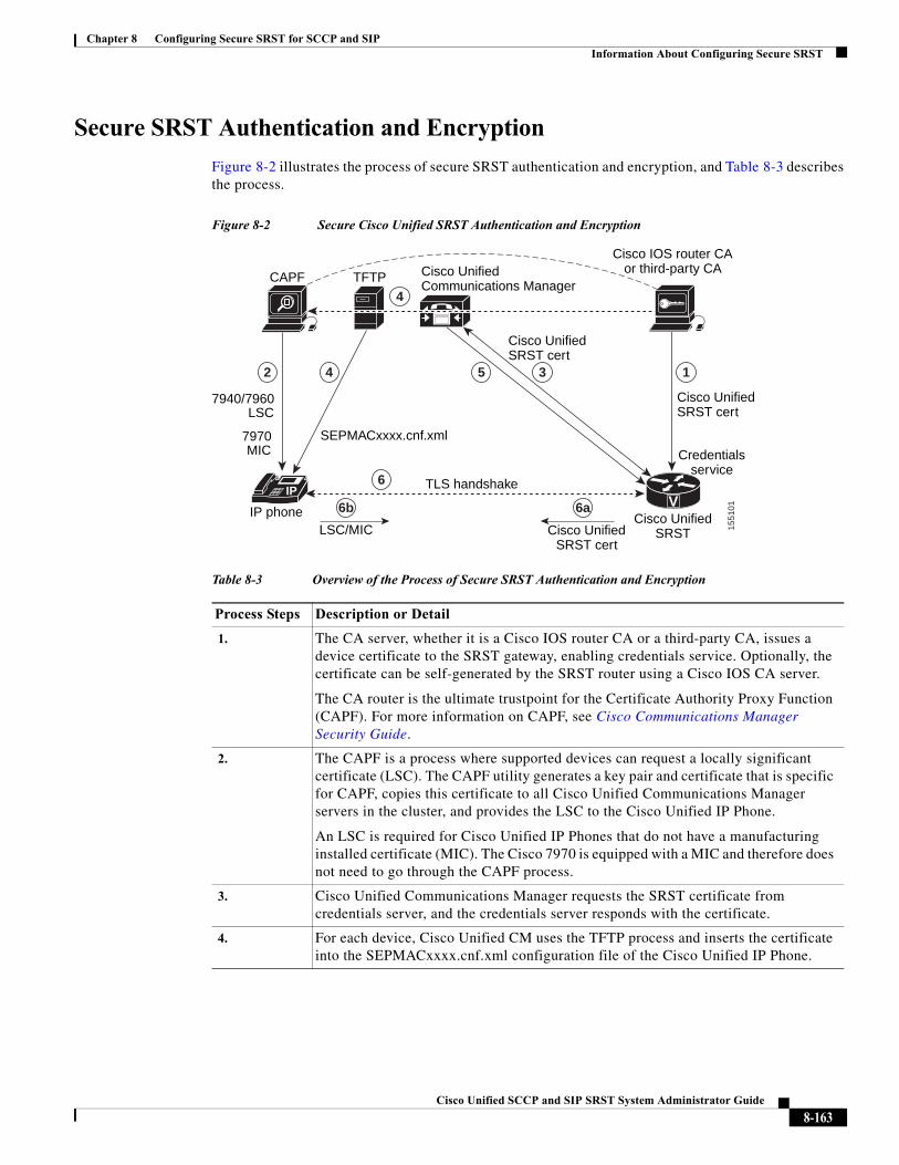
Chapter 8 Configuring Secure SRST for SCCP and SIPInformation About Configuring Secure SRST
Secure SRST Authentication and Encryption
Figure 8-2 illustrates the process of secure SRST authentication and encryption, and Table 8-3 describes the process.
Figure 8-2 Secure Cisco Unified SRST Authentication and Encryption
Table 8-3 Overview of the Process of Secure SRST Authentication and Encryption
Process Steps Description or Detail
1. The CA server, whether it is a Cisco IOS router CA or a third-party CA, issues a device certificate to the SRST gateway, enabling credentials service. Optionally, the certificate can be self-generated by the SRST router using a Cisco IOS CA server.
The CA router is the ultimate trustpoint for the Certificate Authority Proxy Function (CAPF). For more information on CAPF, see Cisco Communications Manager Security Guide.
2. The CAPF is a process where supported devices can request a locally significant certificate (LSC). The CAPF utility generates a key pair and certificate that is specific for CAPF, copies this certificate to all Cisco Unified Communications Manager servers in the cluster, and provides the LSC to the Cisco Unified IP Phone.
An LSC is required for Cisco Unified IP Phones that do not have a manufacturing installed certificate (MIC). The Cisco 7970 is equipped with a MIC and therefore does not need to go through the CAPF process.
3. Cisco Unified Communications Manager requests the SRST certificate from credentials server, and the credentials server responds with the certificate.
4. For each device, Cisco Unified CM uses the TFTP process and inserts the certificate into the SEPMACxxxx.cnf.xml configuration file of the Cisco Unified IP Phone.
1551
01
Cisco UnifiedSRST
LSC7940/7960
MIC7970
IP phone
TLS handshake
CAPF TFTP Cisco UnifiedCommunications Manager
Cisco IOS router CAor third-party CA
SEPMACxxxx.cnf.xml
LSC/MIC Cisco UnifiedSRST cert
Cisco UnifiedSRST cert
Cisco UnifiedSRST cert
Credentialsservice
VIP
2 4
4
6
6b 6a
5 3 1
8-163Cisco Unified SCCP and SIP SRST System Administrator Guide
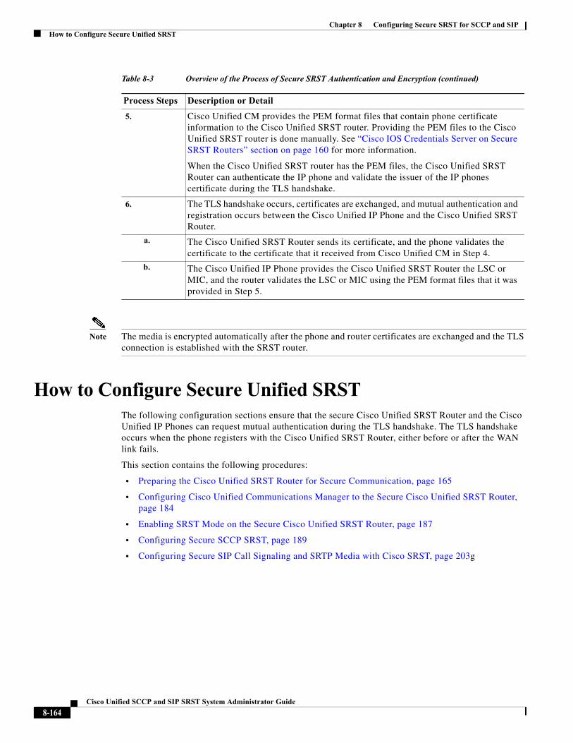
Chapter 8 Configuring Secure SRST for SCCP and SIPHow to Configure Secure Unified SRST
Note The media is encrypted automatically after the phone and router certificates are exchanged and the TLS connection is established with the SRST router.
How to Configure Secure Unified SRSTThe following configuration sections ensure that the secure Cisco Unified SRST Router and the Cisco Unified IP Phones can request mutual authentication during the TLS handshake. The TLS handshake occurs when the phone registers with the Cisco Unified SRST Router, either before or after the WAN link fails.
This section contains the following procedures:
• Preparing the Cisco Unified SRST Router for Secure Communication, page 165
• Configuring Cisco Unified Communications Manager to the Secure Cisco Unified SRST Router, page 184
• Enabling SRST Mode on the Secure Cisco Unified SRST Router, page 187
• Configuring Secure SCCP SRST, page 189
• Configuring Secure SIP Call Signaling and SRTP Media with Cisco SRST, page 203g
5. Cisco Unified CM provides the PEM format files that contain phone certificate information to the Cisco Unified SRST router. Providing the PEM files to the Cisco Unified SRST router is done manually. See “Cisco IOS Credentials Server on Secure SRST Routers” section on page 160 for more information.
When the Cisco Unified SRST router has the PEM files, the Cisco Unified SRST Router can authenticate the IP phone and validate the issuer of the IP phones certificate during the TLS handshake.
6. The TLS handshake occurs, certificates are exchanged, and mutual authentication and registration occurs between the Cisco Unified IP Phone and the Cisco Unified SRST Router.
a. The Cisco Unified SRST Router sends its certificate, and the phone validates the certificate to the certificate that it received from Cisco Unified CM in Step 4.
b. The Cisco Unified IP Phone provides the Cisco Unified SRST Router the LSC or MIC, and the router validates the LSC or MIC using the PEM format files that it was provided in Step 5.
Table 8-3 Overview of the Process of Secure SRST Authentication and Encryption (continued)
Process Steps Description or Detail
8-164Cisco Unified SCCP and SIP SRST System Administrator Guide
Chapter 8 Configuring Secure SRST for SCCP and SIPHow to Configure Secure Unified SRST
Preparing the Cisco Unified SRST Router for Secure Communication
The following tasks prepare the Cisco Unified SRST Router to process secure communications.
• Configuring a Certificate Authority Server on a Cisco IOS Certificate Server, page 165 (optional)
• Autoenrolling and Authenticating the Secure Cisco Unified SRST Router to the CA Server, page 167 (required)
• Disabling Automatic Certificate Enrollment, page 171 (required)
• Verifying Certificate Enrollment, page 172 (optional)
• Enabling Credentials Service on the Secure Cisco Unified SRST Router, page 174 (required)
• Troubleshooting Credential Settings, page 176
• Importing Phone Certificate Files in PEM Format to the Secure SRST Router, page 176
Configuring a Certificate Authority Server on a Cisco IOS Certificate Server
For Cisco Unified SRST Routers to provide secure communications, there must be a CA server that issues the device certificate in the network. The CA server can be a third-party CA or one generated from a Cisco IOS certificate server.
The Cisco IOS certificate server provides a certificate generation option to users who do not have a third-party CA in their network. The Cisco IOS certificate server can run on the SRST router or on a different Cisco IOS router.
If you do not have a third-party CA, full instructions on enabling and configuring a CA server can be found in the Cisco IOS Certificate Server documentation. A sample configuration is provided below.
SUMMARY STEPS
1. crypto pki server cs-label
2. database level {minimal | names | complete}
3. database url root-url
4. issuer-name DN-string
5. grant auto
6. no shutdown
8-165Cisco Unified SCCP and SIP SRST System Administrator Guide
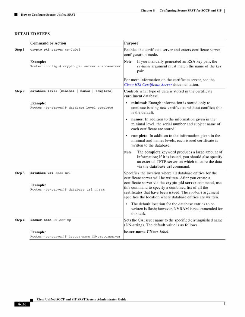
Chapter 8 Configuring Secure SRST for SCCP and SIPHow to Configure Secure Unified SRST
DETAILED STEPS
Command or Action Purpose
Step 1 crypto pki server cs-label
Example:Router (config)# crypto pki server srstcaserver
Enables the certificate server and enters certificate server configuration mode.
Note If you manually generated an RSA key pair, the cs-label argument must match the name of the key pair.
For more information on the certificate server, see the Cisco IOS Certificate Server documentation.
Step 2 database level {minimal | names | complete}
Example:Router (cs-server)# database level complete
Controls what type of data is stored in the certificate enrollment database.
• minimal: Enough information is stored only to continue issuing new certificates without conflict; this is the default.
• names: In addition to the information given in the minimal level, the serial number and subject name of each certificate are stored.
• complete: In addition to the information given in the minimal and names levels, each issued certificate is written to the database.
Note The complete keyword produces a large amount of information; if it is issued, you should also specify an external TFTP server on which to store the data via the database url command.
Step 3 database url root-url
Example:Router (cs-server)# database url nvram
Specifies the location where all database entries for the certificate server will be written. After you create a certificate server via the crypto pki server command, use this command to specify a combined list of all the certificates that have been issued. The root-url argument specifies the location where database entries are written.
• The default location for the database entries to be written is flash; however, NVRAM is recommended for this task.
Step 4 issuer-name DN-string
Example:Router (cs-server)# issuer-name CN=srstcaserver
Sets the CA issuer name to the specified distinguished name (DN-string). The default value is as follows:
issuer-name CN=cs-label.
8-166Cisco Unified SCCP and SIP SRST System Administrator Guide
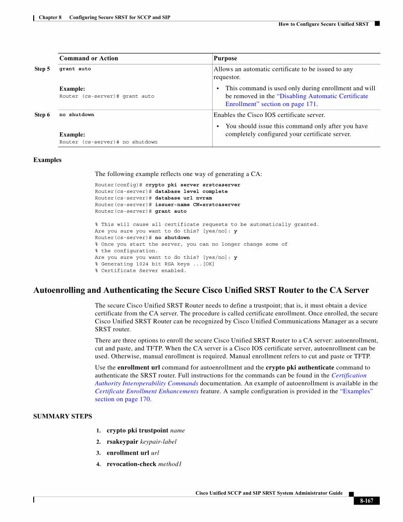
Chapter 8 Configuring Secure SRST for SCCP and SIPHow to Configure Secure Unified SRST
Examples
The following example reflects one way of generating a CA:
Router(config)# crypto pki server srstcaserver Router(cs-server)# database level complete Router(cs-server)# database url nvram Router(cs-server)# issuer-name CN=srstcaserver Router(cs-server)# grant auto
% This will cause all certificate requests to be automatically granted.Are you sure you want to do this? [yes/no]: y Router(cs-server)# no shutdown % Once you start the server, you can no longer change some of % the configuration. Are you sure you want to do this? [yes/no]: y% Generating 1024 bit RSA keys ...[OK]% Certificate Server enabled.
Autoenrolling and Authenticating the Secure Cisco Unified SRST Router to the CA Server
The secure Cisco Unified SRST Router needs to define a trustpoint; that is, it must obtain a device certificate from the CA server. The procedure is called certificate enrollment. Once enrolled, the secure Cisco Unified SRST Router can be recognized by Cisco Unified Communications Manager as a secure SRST router.
There are three options to enroll the secure Cisco Unified SRST Router to a CA server: autoenrollment, cut and paste, and TFTP. When the CA server is a Cisco IOS certificate server, autoenrollment can be used. Otherwise, manual enrollment is required. Manual enrollment refers to cut and paste or TFTP.
Use the enrollment url command for autoenrollment and the crypto pki authenticate command to authenticate the SRST router. Full instructions for the commands can be found in the Certification Authority Interoperability Commands documentation. An example of autoenrollment is available in the Certificate Enrollment Enhancements feature. A sample configuration is provided in the “Examples” section on page 170.
SUMMARY STEPS
1. crypto pki trustpoint name
2. rsakeypair keypair-label
3. enrollment url url
4. revocation-check method1
Step 5 grant auto
Example:Router (cs-server)# grant auto
Allows an automatic certificate to be issued to any requestor.
• This command is used only during enrollment and will be removed in the “Disabling Automatic Certificate Enrollment” section on page 171.
Step 6 no shutdown
Example:Router (cs-server)# no shutdown
Enables the Cisco IOS certificate server.
• You should issue this command only after you have completely configured your certificate server.
Command or Action Purpose
8-167Cisco Unified SCCP and SIP SRST System Administrator Guide

Chapter 8 Configuring Secure SRST for SCCP and SIPHow to Configure Secure Unified SRST
5. exit
6. crypto pki authenticate name
7. crypto pki enroll name
8-168Cisco Unified SCCP and SIP SRST System Administrator Guide
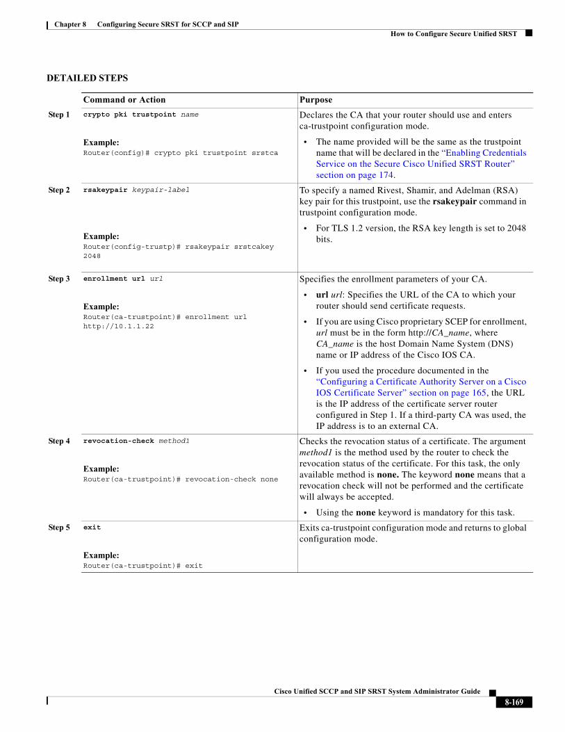
Chapter 8 Configuring Secure SRST for SCCP and SIPHow to Configure Secure Unified SRST
DETAILED STEPS
Command or Action Purpose
Step 1 crypto pki trustpoint name
Example:Router(config)# crypto pki trustpoint srstca
Declares the CA that your router should use and enters ca-trustpoint configuration mode.
• The name provided will be the same as the trustpoint name that will be declared in the “Enabling Credentials Service on the Secure Cisco Unified SRST Router” section on page 174.
Step 2 rsakeypair keypair-label
Example:Router(config-trustp)# rsakeypair srstcakey 2048
To specify a named Rivest, Shamir, and Adelman (RSA) key pair for this trustpoint, use the rsakeypair command in trustpoint configuration mode.
• For TLS 1.2 version, the RSA key length is set to 2048 bits.
Step 3 enrollment url url
Example:Router(ca-trustpoint)# enrollment url http://10.1.1.22
Specifies the enrollment parameters of your CA.
• url url: Specifies the URL of the CA to which your router should send certificate requests.
• If you are using Cisco proprietary SCEP for enrollment, url must be in the form http://CA_name, where CA_name is the host Domain Name System (DNS) name or IP address of the Cisco IOS CA.
• If you used the procedure documented in the “Configuring a Certificate Authority Server on a Cisco IOS Certificate Server” section on page 165, the URL is the IP address of the certificate server router configured in Step 1. If a third-party CA was used, the IP address is to an external CA.
Step 4 revocation-check method1
Example:Router(ca-trustpoint)# revocation-check none
Checks the revocation status of a certificate. The argument method1 is the method used by the router to check the revocation status of the certificate. For this task, the only available method is none. The keyword none means that a revocation check will not be performed and the certificate will always be accepted.
• Using the none keyword is mandatory for this task.
Step 5 exit
Example:Router(ca-trustpoint)# exit
Exits ca-trustpoint configuration mode and returns to global configuration mode.
8-169Cisco Unified SCCP and SIP SRST System Administrator Guide
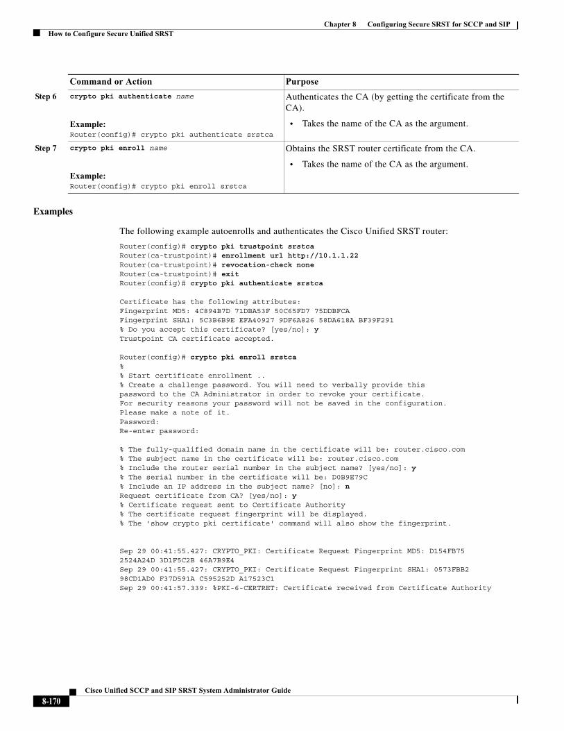
Chapter 8 Configuring Secure SRST for SCCP and SIPHow to Configure Secure Unified SRST
Examples
The following example autoenrolls and authenticates the Cisco Unified SRST router:
Router(config)# crypto pki trustpoint srstca Router(ca-trustpoint)# enrollment url http://10.1.1.22Router(ca-trustpoint)# revocation-check none Router(ca-trustpoint)# exit Router(config)# crypto pki authenticate srstca
Certificate has the following attributes: Fingerprint MD5: 4C894B7D 71DBA53F 50C65FD7 75DDBFCA Fingerprint SHA1: 5C3B6B9E EFA40927 9DF6A826 58DA618A BF39F291 % Do you accept this certificate? [yes/no]: y Trustpoint CA certificate accepted.
Router(config)# crypto pki enroll srstca % % Start certificate enrollment .. % Create a challenge password. You will need to verbally provide this password to the CA Administrator in order to revoke your certificate. For security reasons your password will not be saved in the configuration. Please make a note of it.Password: Re-enter password:
% The fully-qualified domain name in the certificate will be: router.cisco.com % The subject name in the certificate will be: router.cisco.com % Include the router serial number in the subject name? [yes/no]: y % The serial number in the certificate will be: D0B9E79C % Include an IP address in the subject name? [no]: nRequest certificate from CA? [yes/no]: y % Certificate request sent to Certificate Authority % The certificate request fingerprint will be displayed. % The 'show crypto pki certificate' command will also show the fingerprint.
Sep 29 00:41:55.427: CRYPTO_PKI: Certificate Request Fingerprint MD5: D154FB75 2524A24D 3D1F5C2B 46A7B9E4 Sep 29 00:41:55.427: CRYPTO_PKI: Certificate Request Fingerprint SHA1: 0573FBB2 98CD1AD0 F37D591A C595252D A17523C1 Sep 29 00:41:57.339: %PKI-6-CERTRET: Certificate received from Certificate Authority
Step 6 crypto pki authenticate name
Example:Router(config)# crypto pki authenticate srstca
Authenticates the CA (by getting the certificate from the CA).
• Takes the name of the CA as the argument.
Step 7 crypto pki enroll name
Example:Router(config)# crypto pki enroll srstca
Obtains the SRST router certificate from the CA.
• Takes the name of the CA as the argument.
Command or Action Purpose
8-170Cisco Unified SCCP and SIP SRST System Administrator Guide
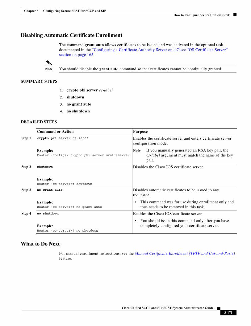
Chapter 8 Configuring Secure SRST for SCCP and SIPHow to Configure Secure Unified SRST
Disabling Automatic Certificate Enrollment
The command grant auto allows certificates to be issued and was activated in the optional task documented in the “Configuring a Certificate Authority Server on a Cisco IOS Certificate Server” section on page 165.
Note You should disable the grant auto command so that certificates cannot be continually granted.
SUMMARY STEPS
1. crypto pki server cs-label
2. shutdown
3. no grant auto
4. no shutdown
DETAILED STEPS
What to Do Next
For manual enrollment instructions, see the Manual Certificate Enrollment (TFTP and Cut-and-Paste) feature.
Command or Action Purpose
Step 1 crypto pki server cs-label
Example:Router (config)# crypto pki server srstcaserver
Enables the certificate server and enters certificate server configuration mode.
Note If you manually generated an RSA key pair, the cs-label argument must match the name of the key pair.
Step 2 shutdown
Example:Router (cs-server)# shutdown
Disables the Cisco IOS certificate server.
Step 3 no grant auto
Example:Router (cs-server)# no grant auto
Disables automatic certificates to be issued to any requestor.
• This command was for use during enrollment only and thus needs to be removed in this task.
Step 4 no shutdown
Example:Router (cs-server)# no shutdown
Enables the Cisco IOS certificate server.
• You should issue this command only after you have completely configured your certificate server.
8-171Cisco Unified SCCP and SIP SRST System Administrator Guide
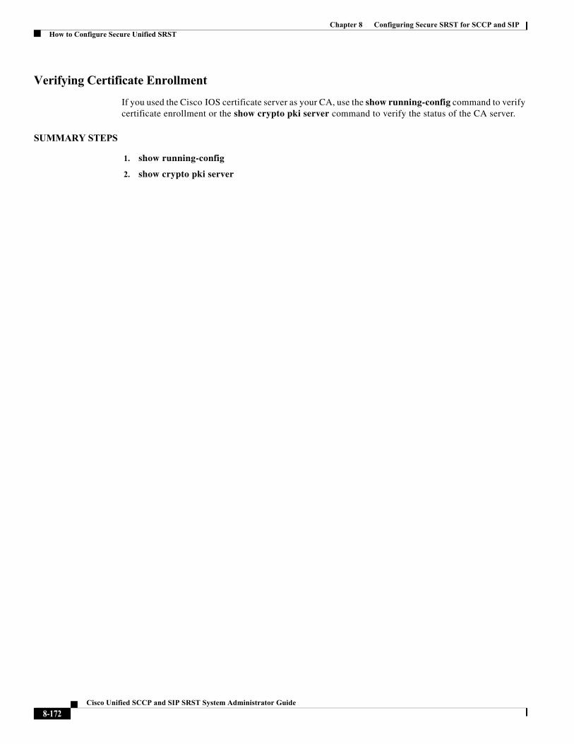
Chapter 8 Configuring Secure SRST for SCCP and SIPHow to Configure Secure Unified SRST
Verifying Certificate Enrollment
If you used the Cisco IOS certificate server as your CA, use the show running-config command to verify certificate enrollment or the show crypto pki server command to verify the status of the CA server.
SUMMARY STEPS
1. show running-config
2. show crypto pki server
8-172Cisco Unified SCCP and SIP SRST System Administrator Guide
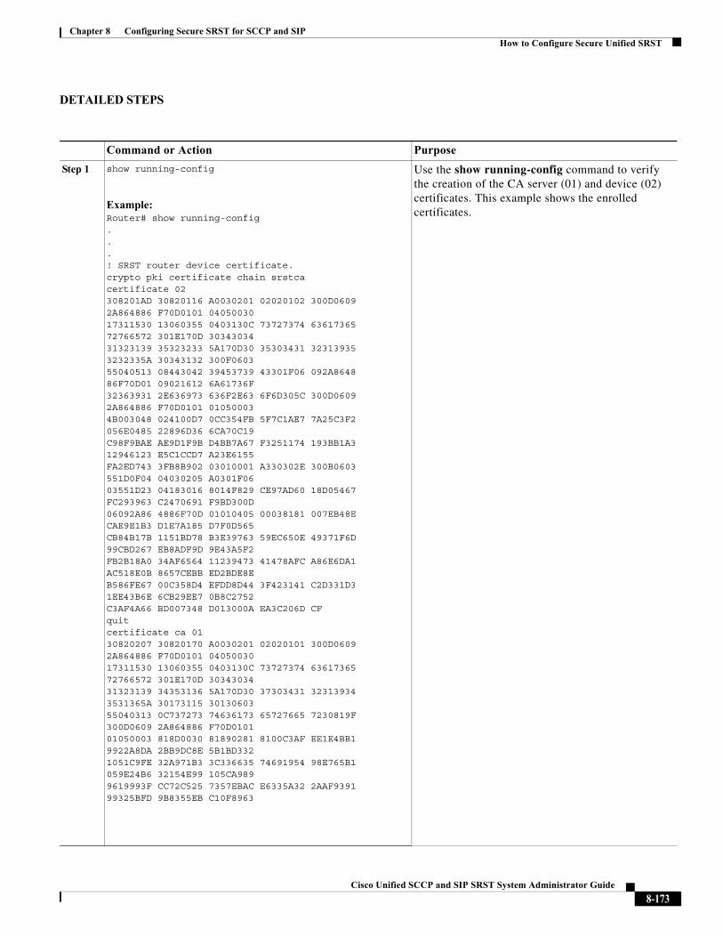
Chapter 8 Configuring Secure SRST for SCCP and SIPHow to Configure Secure Unified SRST
DETAILED STEPS
Command or Action Purpose
Step 1 show running-config
Example:Router# show running-config...! SRST router device certificate.crypto pki certificate chain srstcacertificate 02308201AD 30820116 A0030201 02020102 300D0609 2A864886 F70D0101 0405003017311530 13060355 0403130C 73727374 63617365 72766572 301E170D 3034303431323139 35323233 5A170D30 35303431 32313935 3232335A 30343132 300F060355040513 08443042 39453739 43301F06 092A8648 86F70D01 09021612 6A61736F32363931 2E636973 636F2E63 6F6D305C 300D0609 2A864886 F70D0101 010500034B003048 024100D7 0CC354FB 5F7C1AE7 7A25C3F2 056E0485 22896D36 6CA70C19C98F9BAE AE9D1F9B D4BB7A67 F3251174 193BB1A3 12946123 E5C1CCD7 A23E6155FA2ED743 3FB8B902 03010001 A330302E 300B0603 551D0F04 04030205 A0301F0603551D23 04183016 8014F829 CE97AD60 18D05467 FC293963 C2470691 F9BD300D06092A86 4886F70D 01010405 00038181 007EB48E CAE9E1B3 D1E7A185 D7F0D565CB84B17B 1151BD78 B3E39763 59EC650E 49371F6D 99CBD267 EB8ADF9D 9E43A5F2FB2B18A0 34AF6564 11239473 41478AFC A86E6DA1 AC518E0B 8657CEBB ED2BDE8EB586FE67 00C358D4 EFDD8D44 3F423141 C2D331D3 1EE43B6E 6CB29EE7 0B8C2752C3AF4A66 BD007348 D013000A EA3C206D CFquitcertificate ca 0130820207 30820170 A0030201 02020101 300D0609 2A864886 F70D0101 0405003017311530 13060355 0403130C 73727374 63617365 72766572 301E170D 3034303431323139 34353136 5A170D30 37303431 32313934 3531365A 30173115 3013060355040313 0C737273 74636173 65727665 7230819F 300D0609 2A864886 F70D010101050003 818D0030 81890281 8100C3AF EE1E4BB1 9922A8DA 2BB9DC8E 5B1BD3321051C9FE 32A971B3 3C336635 74691954 98E765B1 059E24B6 32154E99 105CA9899619993F CC72C525 7357EBAC E6335A32 2AAF9391 99325BFD 9B8355EB C10F8963
Use the show running-config command to verify the creation of the CA server (01) and device (02) certificates. This example shows the enrolled certificates.
8-173Cisco Unified SCCP and SIP SRST System Administrator Guide
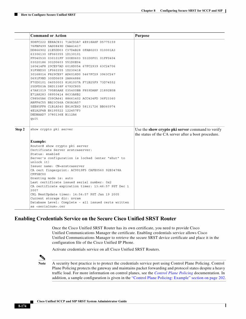
Chapter 8 Configuring Secure SRST for SCCP and SIPHow to Configure Secure Unified SRST
Enabling Credentials Service on the Secure Cisco Unified SRST Router
Once the Cisco Unified SRST Router has its own certificate, you need to provide Cisco Unified Communications Manager the certificate. Enabling credentials service allows Cisco Unified Communications Manager to retrieve the secure SRST device certificate and place it in the configuration file of the Cisco Unified IP Phone.
Activate credentials service on all Cisco Unified SRST Routers.
Note A security best practice is to protect the credentials service port using Control Plane Policing. Control Plane Policing protects the gateway and maintains packet forwarding and protocol states despite a heavy traffic load. For more information on control planes, see the Control Plane Policing documentation. In addition, a sample configuration is given in the “Control Plane Policing: Example” section on page 202.
9D8FC222 EE8AC831 71ACD3A7 4E918A8F D5775159 76FBF499 5AD0849D CAA41417DD866902 21E5DD03 C37D4B28 0FAB0203 010001A3 63306130 0F060355 1D130101FF040530 030101FF 300E0603 551D0F01 01FF0404 03020186 301D0603 551D0E04160414F8 29CE97AD 6018D054 67FC2939 63C24706 91F9BD30 1F060355 1D23041830168014 F829CE97 AD6018D0 5467FC29 3963C247 0691F9BD 300D0609 2A864886F70D0101 04050003 8181007A F71B25F9 73D74552 25DFD03A D8D1338F 6792C80547A81019 795B5AAE 035400BB F859DABF 21892B5B E71A8283 08950414 8633A8B2C98565A6 C09CA641 88661402 ACC424FD 36F23360 ABFF4C55 BB23C66A C80A3A575EE85FF8 C1B1A540 E818CE6D 58131726 BB060974 4E1A2F4B E6195522 122457F3DEDBAAD7 3780136E B112A6quit
Step 2 show crypto pki server
Example:Router# show crypto pki serverCertificate Server srstcaserver:Status: enabledServer's configuration is locked (enter "shut" to unlock it)Issuer name: CN=srstcaserverCA cert fingerprint: AC9919F5 CAFE0560 92B3478A CFF5EC00Granting mode is: autoLast certificate issued serial number: 0x2CA certificate expiration timer: 13:46:57 PST Dec 1 2007CRL NextUpdate timer: 14:54:57 PST Jan 19 2005Current storage dir: nvramDatabase Level: Complete - all issued certs written as <serialnum>.cer
Use the show crypto pki server command to verify the status of the CA server after a boot procedure.
Command or Action Purpose
8-174Cisco Unified SCCP and SIP SRST System Administrator Guide
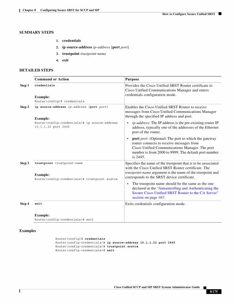
Chapter 8 Configuring Secure SRST for SCCP and SIPHow to Configure Secure Unified SRST
SUMMARY STEPS
1. credentials
2. ip source-address ip-address [port port]
3. trustpoint trustpoint-name
4. exit
DETAILED STEPS
Examples
Router(config)# credentials Router(config-credentials)# ip source-address 10.1.1.22 port 2445Router(config-credentials)# trustpoint srstca Router(config-credentials)# exit
Command or Action Purpose
Step 1 credentials
Example:Router(config)# credentials
Provides the Cisco Unified SRST Router certificate to Cisco Unified Communications Manager and enters credentials configuration mode.
Step 2 ip source-address ip-address [port port]
Example:Router(config-credentials)# ip source-address 10.1.1.22 port 2445
Enables the Cisco Unified SRST Router to receive messages from Cisco Unified Communications Manager through the specified IP address and port.
• ip-address: The IP address is the pre-existing router IP address, typically one of the addresses of the Ethernet port of the router.
• port port: (Optional) The port to which the gateway router connects to receive messages from Cisco Unified Communications Manager. The port number is from 2000 to 9999. The default port number is 2445.
Step 3 trustpoint trustpoint-name
Example:Router(config-credentials)# trustpoint srstca
Specifies the name of the trustpoint that is to be associated with the Cisco Unified SRST Router certificate. The trustpoint-name argument is the name of the trustpoint and corresponds to the SRST device certificate.
• The trustpoint name should be the same as the one declared in the “Autoenrolling and Authenticating the Secure Cisco Unified SRST Router to the CA Server” section on page 167.
Step 4 exit
Example:Router(config-credentials)# exit
Exits credentials configuration mode.
8-175Cisco Unified SCCP and SIP SRST System Administrator Guide
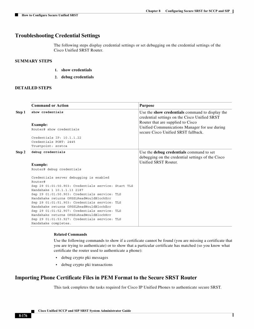
Chapter 8 Configuring Secure SRST for SCCP and SIPHow to Configure Secure Unified SRST
Troubleshooting Credential Settings
The following steps display credential settings or set debugging on the credential settings of the Cisco Unified SRST Router.
SUMMARY STEPS
1. show credentials
2. debug credentials
DETAILED STEPS
Related Commands
Use the following commands to show if a certificate cannot be found (you are missing a certificate that you are trying to authenticate) or to show that a particular certificate has matched (so you know what certificate the router used to authenticate a phone):
• debug crypto pki messages
• debug crypto pki transactions
Importing Phone Certificate Files in PEM Format to the Secure SRST Router
This task completes the tasks required for Cisco IP Unified Phones to authenticate secure SRST.
Command or Action Purpose
Step 1 show credentials
Example:Router# show credentials
Credentials IP: 10.1.1.22Credentials PORT: 2445Trustpoint: srstca
Use the show credentials command to display the credential settings on the Cisco Unified SRST Router that are supplied to Cisco Unified Communications Manager for use during secure Cisco Unified SRST fallback.
Step 2 debug credentials
Example:Router# debug credentials
Credentials server debugging is enabledRouter# Sep 29 01:01:50.903: Credentials service: Start TLS Handshake 1 10.1.1.13 2187 Sep 29 01:01:50.903: Credentials service: TLS Handshake returns OPSSLReadWouldBlockErr Sep 29 01:01:51.903: Credentials service: TLS Handshake returns OPSSLReadWouldBlockErr Sep 29 01:01:52.907: Credentials service: TLS Handshake returns OPSSLReadWouldBlockErr Sep 29 01:01:53.927: Credentials service: TLS Handshake completes.
Use the debug credentials command to set debugging on the credential settings of the Cisco Unified SRST Router.
8-176Cisco Unified SCCP and SIP SRST System Administrator Guide
Chapter 8 Configuring Secure SRST for SCCP and SIPHow to Configure Secure Unified SRST
Cisco Unified Communications Manager 4.X.X and Earlier Versions
For systems running Cisco Unified Communications Manager 4.X.X and earlier versions, the secure Cisco Unified SRST Router must retrieve phone certificates so that it can authenticate Cisco Unified IP phones during the TLS handshake. Different certificates are used for different Cisco Unified IP Phones. Table 8-1 lists the certificates needed for each type of phone.
Certificates must be imported manually from Cisco Unified Communications Manager to the Cisco Unified SRST Router. The number of certificates depends on the Cisco Unified Communications Manager configuration. Manual enrollment refers to cut and paste or TFTP. For manual enrollment instructions, see the Manual Certificate Enrollment (TFTP and Cut-and-Paste) feature. Repeat the enrollment procedure for each phone or PEM file.
For Cisco Unified Communications Manager 4.X.X and earlier versions, certificates are found by going to the menu bar in Cisco Unified Communications Manager, choose Program Files > Cisco > Certificates.
Open the .0 files with Windows Wordpad or Notepad, and copy and paste the contents to the SRST router console. Then, repeat the procedure with the .pem file. Copy all of the contents that appear between “-----BEGIN CERTIFICATE-----” and “-----END CERTIFICATE-----”.
For certification operation on Cisco Unified Communications Operating System Administration Guide, Release 6.1(1), see http://www.cisco.com/en/US/docs/voice_ip_comm/cucm/cucos/6_1_1/cucos/iptpch6.html.
Cisco Unified Communications Manager 5.0 and Later Versions
Systems running Cisco Unified CM 5.0 and later versions require four certificates (CAPF, CiscoCA, CiscoManufactureCA, and CiscoRootCA2048) in addition to the requirements listed in Table 8-1, which must be copied and pasted to Cisco Unified SRST Routers.
Note CiscoRootCA is also called CiscoRoot2048CA.
Prerequisites
You must have certificates available when the last configuration command (crypto pki authenticate) issues the following prompt:
Enter the base 64 encoded CA certificate. End with a blank line or the word "quit" on a line by itself
For Cisco Unified CM 5.0 and later versions, perform the following steps:
Step 1 Login to Cisco Unified Communications Manager.
Step 2 Go to Security > Certificate Management > Download Certificate/CTL.
Step 3 Select Download Trust Cert and click Next.
Step 4 Select CAPF-trust and click Next.
Step 5 Select CiscoCA and click Next.
Step 6 Click Continue.
Step 7 Click the file name.
8-177Cisco Unified SCCP and SIP SRST System Administrator Guide
Chapter 8 Configuring Secure SRST for SCCP and SIPHow to Configure Secure Unified SRST
Step 8 Copy all of the contents that appear between “-----BEGIN CERTIFICATE-----” and “-----END CERTIFICATE-----” to a location where you can retrieve it later.
Step 9 Repeat Steps 5 to 8 for CiscoManufactureCA, CiscoRootCA2048, and CAPF.
Cisco Unified Communications Manager 6.0 and Later Versions
From Cisco Unified Communications Operating System Administration, download all certificates listed under CAPF-trust, including Cisco_Manufacturing_CA, Cisco_Root_CA_2048, CAP-RTP-001, CAP-RTP-002, CAPF, and CAPF-xxx. Also download any CAPF-xxx certificates that are listed under CallManager-trust and not under CAPF-trust.
For instructions on downloading certificates, see the “Security” chapter in the appropriate version of Cisco Unified Communications Operating System Administration Guide.
Authenticating the Imported Certificates on the Cisco Unified SRST Router
To authenticate certificates on the Cisco Unified SRST router, perform these steps.
Restrictions
HTTP automatic enrollment from Cisco Unified Communications Manager through a virtual web server is not supported.
SUMMARY STEPS
1. crypto pki trustpoint name
2. revocation-check none
3. enrollment terminal
4. exit
5. crypto pki authenticate name
8-178Cisco Unified SCCP and SIP SRST System Administrator Guide
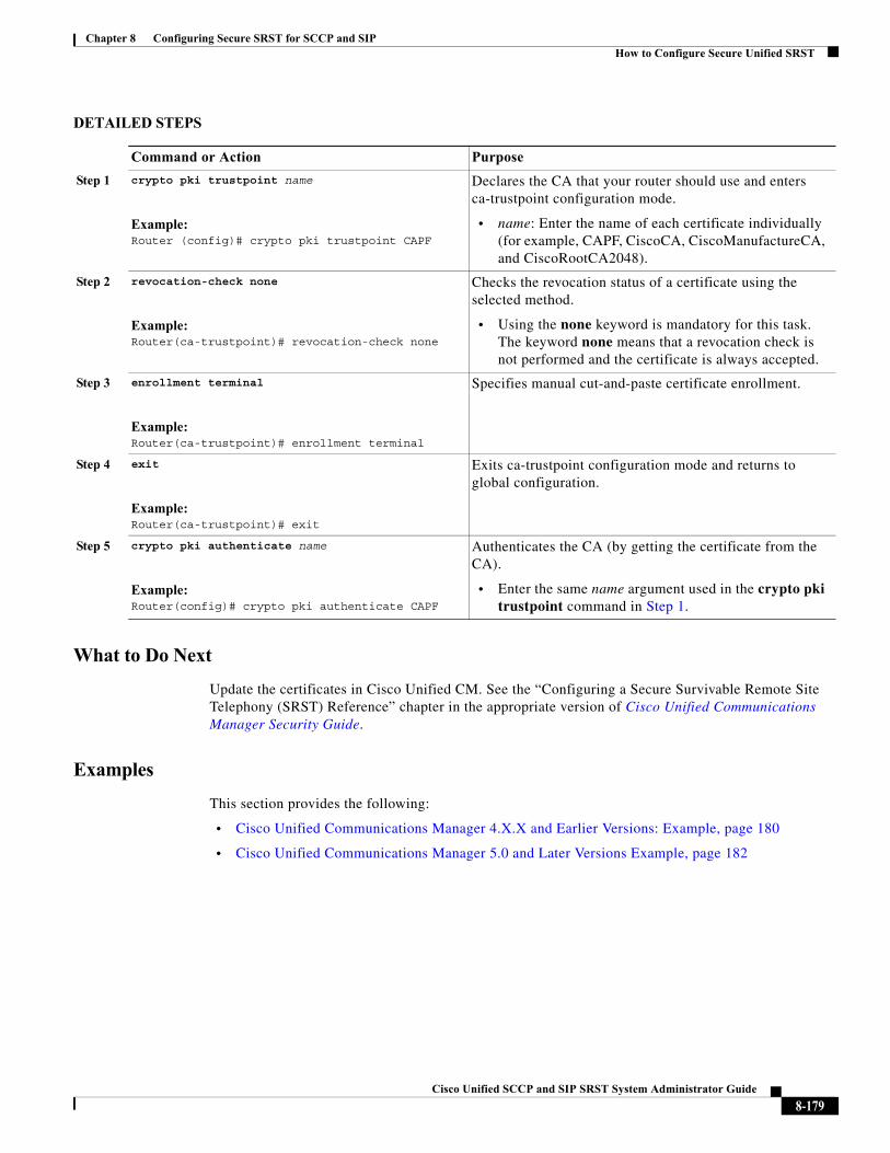
Chapter 8 Configuring Secure SRST for SCCP and SIPHow to Configure Secure Unified SRST
DETAILED STEPS
What to Do Next
Update the certificates in Cisco Unified CM. See the “Configuring a Secure Survivable Remote Site Telephony (SRST) Reference” chapter in the appropriate version of Cisco Unified Communications Manager Security Guide.
Examples
This section provides the following:
• Cisco Unified Communications Manager 4.X.X and Earlier Versions: Example, page 180
• Cisco Unified Communications Manager 5.0 and Later Versions Example, page 182
Command or Action Purpose
Step 1 crypto pki trustpoint name
Example:Router (config)# crypto pki trustpoint CAPF
Declares the CA that your router should use and enters ca-trustpoint configuration mode.
• name: Enter the name of each certificate individually (for example, CAPF, CiscoCA, CiscoManufactureCA, and CiscoRootCA2048).
Step 2 revocation-check none
Example:Router(ca-trustpoint)# revocation-check none
Checks the revocation status of a certificate using the selected method.
• Using the none keyword is mandatory for this task. The keyword none means that a revocation check is not performed and the certificate is always accepted.
Step 3 enrollment terminal
Example:Router(ca-trustpoint)# enrollment terminal
Specifies manual cut-and-paste certificate enrollment.
Step 4 exit
Example:Router(ca-trustpoint)# exit
Exits ca-trustpoint configuration mode and returns to global configuration.
Step 5 crypto pki authenticate name
Example:Router(config)# crypto pki authenticate CAPF
Authenticates the CA (by getting the certificate from the CA).
• Enter the same name argument used in the crypto pki trustpoint command in Step 1.
8-179Cisco Unified SCCP and SIP SRST System Administrator Guide
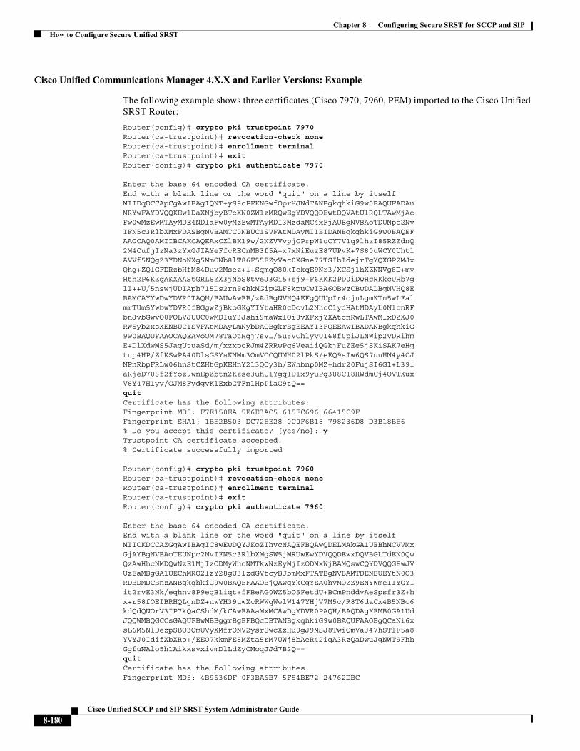
Chapter 8 Configuring Secure SRST for SCCP and SIPHow to Configure Secure Unified SRST
Cisco Unified Communications Manager 4.X.X and Earlier Versions: Example
The following example shows three certificates (Cisco 7970, 7960, PEM) imported to the Cisco Unified SRST Router:
Router(config)# crypto pki trustpoint 7970 Router(ca-trustpoint)# revocation-check none Router(ca-trustpoint)# enrollment terminal Router(ca-trustpoint)# exit Router(config)# crypto pki authenticate 7970
Enter the base 64 encoded CA certificate. End with a blank line or the word "quit" on a line by itselfMIIDqDCCApCgAwIBAgIQNT+yS9cPFKNGwfOprHJWdTANBgkqhkiG9w0BAQUFADAu MRYwFAYDVQQKEw1DaXNjbyBTeXN0ZW1zMRQwEgYDVQQDEwtDQVAtUlRQLTAwMjAe Fw0wMzEwMTAyMDE4NDlaFw0yMzEwMTAyMDI3MzdaMC4xFjAUBgNVBAoTDUNpc2Nv IFN5c3RlbXMxFDASBgNVBAMTC0NBUC1SVFAtMDAyMIIBIDANBgkqhkiG9w0BAQEF AAOCAQ0AMIIBCAKCAQEAxCZlBK19w/2NZVVvpjCPrpW1cCY7V1q9lhzI85RZZdnQ 2M4CufgIzNa3zYxGJIAYeFfcRECnMB3f5A+x7xNiEuzE87UPvK+7S80uWCY0Uhtl AVVf5NQgZ3YDNoNXg5MmONb8lT86F55EZyVac0XGne77TSIbIdejrTgYQXGP2MJx Qhg+ZQlGFDRzbHfM84Duv2Msez+l+SqmqO80kIckqE9Nr3/XCSj1hXZNNVg8D+mv Hth2P6KZqAKXAAStGRLSZX3jNbS8tveJ3Gi5+sj9+F6KKK2PD0iDwHcRKkcUHb7g lI++U/5nswjUDIAph715Ds2rn9ehkMGipGLF8kpuCwIBA6OBwzCBwDALBgNVHQ8E BAMCAYYwDwYDVR0TAQH/BAUwAwEB/zAdBgNVHQ4EFgQUUpIr4ojuLgmKTn5wLFal mrTUm5YwbwYDVR0fBGgwZjBkoGKgYIYtaHR0cDovL2NhcC1ydHAtMDAyL0NlcnRF bnJvbGwvQ0FQLVJUUC0wMDIuY3Jshi9maWxlOi8vXFxjYXAtcnRwLTAwMlxDZXJ0 RW5yb2xsXENBUC1SVFAtMDAyLmNybDAQBgkrBgEEAYI3FQEEAwIBADANBgkqhkiG 9w0BAQUFAAOCAQEAVoOM78TaOtHqj7sVL/5u5VChlyvU168f0piJLNWip2vDRihm E+DlXdwMS5JaqUtuaSd/m/xzxpcRJm4ZRRwPq6VeaiiQGkjFuZEe5jSKiSAK7eHg tup4HP/ZfKSwPA40DlsGSYsKNMm3OmVOCQUMH02lPkS/eEQ9sIw6QS7uuHN4y4CJ NPnRbpFRLw06hnStCZHtGpKEHnY213QOy3h/EWhbnp0MZ+hdr20FujSI6G1+L39l aRjeD708f2fYoz9wnEpZbtn2Kzse3uhU1Ygq1D1x9yuPq388C18HWdmCj4OVTXux V6Y47H1yv/GJM8FvdgvKlExbGTFnlHpPiaG9tQ== quit Certificate has the following attributes: Fingerprint MD5: F7E150EA 5E6E3AC5 615FC696 66415C9F Fingerprint SHA1: 1BE2B503 DC72EE28 0C0F6B18 798236D8 D3B18BE6 % Do you accept this certificate? [yes/no]: y Trustpoint CA certificate accepted. % Certificate successfully imported
Router(config)# crypto pki trustpoint 7960 Router(ca-trustpoint)# revocation-check none Router(ca-trustpoint)# enrollment terminal Router(ca-trustpoint)# exit Router(config)# crypto pki authenticate 7960
Enter the base 64 encoded CA certificate. End with a blank line or the word "quit" on a line by itselfMIICKDCCAZGgAwIBAgIC8wEwDQYJKoZIhvcNAQEFBQAwQDELMAkGA1UEBhMCVVMx GjAYBgNVBAoTEUNpc2NvIFN5c3RlbXMgSW5jMRUwEwYDVQQDEwxDQVBGLTdEN0Qw QzAwHhcNMDQwNzE1MjIzODMyWhcNMTkwNzEyMjIzODMxWjBAMQswCQYDVQQGEwJV UzEaMBgGA1UEChMRQ2lzY28gU3lzdGVtcyBJbmMxFTATBgNVBAMTDENBUEYtN0Q3 RDBDMDCBnzANBgkqhkiG9w0BAQEFAAOBjQAwgYkCgYEA0hvMOZZ9ENYWme11YGY1 it2rvE3Nk/eqhnv8P9eqB1iqt+fFBeAG0WZ5bO5FetdU+BCmPnddvAeSpsfr3Z+h x+r58fOEIBRHQLgnDZ+nwYH39uwXcRWWqWwlW147YHjV7M5c/R8T6daCx4B5NBo6 kdQdQNOrV3IP7kQaCShdM/kCAwEAAaMxMC8wDgYDVR0PAQH/BAQDAgKEMB0GA1Ud JQQWMBQGCCsGAQUFBwMBBggrBgEFBQcDBTANBgkqhkiG9w0BAQUFAAOBgQCaNi6x sL6M5NlDezpSBO3QmUVyXMfrONV2ysrSwcXzHu0gJ9MSJ8TwiQmVaJ47hSTlF5a8 YVYJ0IdifXbXRo+/EEO7kkmFE8MZta5rM7UWj8bAeR42iqA3RzQaDwuJgNWT9Fhh GgfuNAlo5h1AikxsvxivmDlLdZyCMoqJJd7B2Q== quit Certificate has the following attributes: Fingerprint MD5: 4B9636DF 0F3BA6B7 5F54BE72 24762DBC
8-180Cisco Unified SCCP and SIP SRST System Administrator Guide
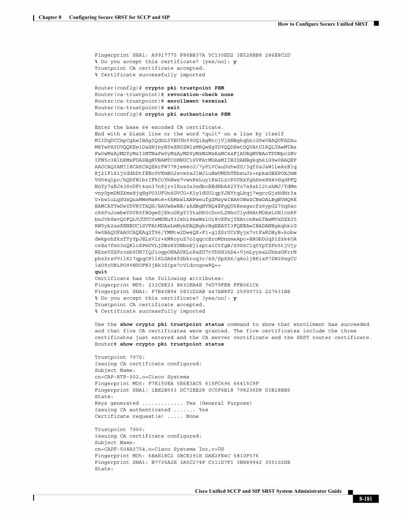
Chapter 8 Configuring Secure SRST for SCCP and SIPHow to Configure Secure Unified SRST
Fingerprint SHA1: A9917775 F86BB37A 5C130ED2 3E528BB8 286E8C2D % Do you accept this certificate? [yes/no]: y Trustpoint CA certificate accepted. % Certificate successfully imported
Router(config)# crypto pki trustpoint PEM Router(ca-trustpoint)# revocation-check none Router(ca-trustpoint)# enrollment terminal Router(ca-trustpoint)# exitRouter(config)# crypto pki authenticate PEM
Enter the base 64 encoded CA certificate. End with a blank line or the word "quit" on a line by itselfMIIDqDCCApCgAwIBAgIQdhL5YBU9b59OQiAgMrcjVjANBgkqhkiG9w0BAQUFADAu MRYwFAYDVQQKEw1DaXNjbyBTeXN0ZW1zMRQwEgYDVQQDEwtDQVAtUlRQLTAwMTAe Fw0wMzAyMDYyMzI3MTNaFw0yMzAyMDYyMzM2MzRaMC4xFjAUBgNVBAoTDUNpc2Nv IFN5c3RlbXMxFDASBgNVBAMTC0NBUC1SVFAtMDAxMIIBIDANBgkqhkiG9w0BAQEF AAOCAQ0AMIIBCAKCAQEArFW77Rjem4cJ/7yPLVCauDohwZZ/3qf0sJaWlLeAzBlq Rj2lFlSij0ddkDtfEEo9VKmBOJsvx6xJlWJiuBwUMDhTRbsuJz+npkaGBXPOXJmN Vd54qlpc/hQDfWlbrIFkCcYhHws7vwnPsLuy1Kw2L2cP0UXxYghSsx8H4vGqdPFQ NnYy7aKJ43SvDFt4zn37n8jrvlRuz0x3mdbcBEdHbA825Yo7a8sk12tshMJ/YdMm vny0pmDNZXmeHjqEgVO3UFUn6GVCO+K1y1dUU1qpYJNYtqLkqj7wgccGjsHdHr3a U+bw1uLgSGsQnxMWeMaWo8+6hMxwlANPweufgZMaywIBA6OBwzCBwDALBgNVHQ8E BAMCAYYwDwYDVR0TAQH/BAUwAwEB/zAdBgNVHQ4EFgQU6Rexgscfz6ypG270qSac cK4FoJowbwYDVR0fBGgwZjBkoGKgYIYtaHR0cDovL2NhcC1ydHAtMDAxL0NlcnRF bnJvbGwvQ0FQLVJUUC0wMDEuY3Jshi9maWxlOi8vXFxjYXAtcnRwLTAwMVxDZXJ0 RW5yb2xsXENBUC1SVFAtMDAxLmNybDAQBgkrBgEEAYI3FQEEAwIBADANBgkqhkiG 9w0BAQUFAAOCAQEAq2T96/YMMtw2Dw4QX+F1+g1XSrUCrNyjx7vtFaRDHyB+kobw dwkpohfkzfTyYpJELzV1r+kMRoyuZ7oIqqccEroMDnnmeApc+BRGbDJqS1Zzk4OA c6Ea7fm53nQRlcSPmUVLjDBzKYDNbnEjizptaIC5fgB/S9S6C1q0YpTZFn5tjUjy WXzeYSXPrcxb0UH7IQJ1ogpONAAUKLoPaZU7tVDSH3hD4+VjmLyysaLUhksGFrrN phzZrsVVilK17qpqCPllKLGAS4fSbkruq3r/6S/SpXS6/gAoljBKixP7ZW2PxgCU 1aU9cURLPO95NDOFN3jBk3Sips7cVidcogowPQ== quit Certificate has the following attributes: Fingerprint MD5: 233C8E33 8632EA4E 76D79FEB FFB061C6 Fingerprint SHA1: F7B40B94 5831D2AB 447AB8F2 25990732 227631BE % Do you accept this certificate? [yes/no]: y Trustpoint CA certificate accepted. % Certificate successfully imported
Use the show crypto pki trustpoint status command to show that enrollment has succeeded and that five CA certificates were granted. The five certificates include the three certificates just entered and the CA server certificate and the SRST router certificate.Router# show crypto pki trustpoint status
Trustpoint 7970: Issuing CA certificate configured: Subject Name: cn=CAP-RTP-002,o=Cisco Systems Fingerprint MD5: F7E150EA 5E6E3AC5 615FC696 66415C9F Fingerprint SHA1: 1BE2B503 DC72EE28 0C0F6B18 798236D8 D3B18BE6 State: Keys generated ............. Yes (General Purpose) Issuing CA authenticated ....... Yes Certificate request(s) ..... None
Trustpoint 7960: Issuing CA certificate configured: Subject Name: cn=CAPF-508A3754,o=Cisco Systems Inc,c=US Fingerprint MD5: 6BAE18C2 0BCE391E DAE2FE4C 5810F576 Fingerprint SHA1: B7735A2E 3A5C274F C311D7F1 3BE89942 355102DE State:
8-181Cisco Unified SCCP and SIP SRST System Administrator Guide
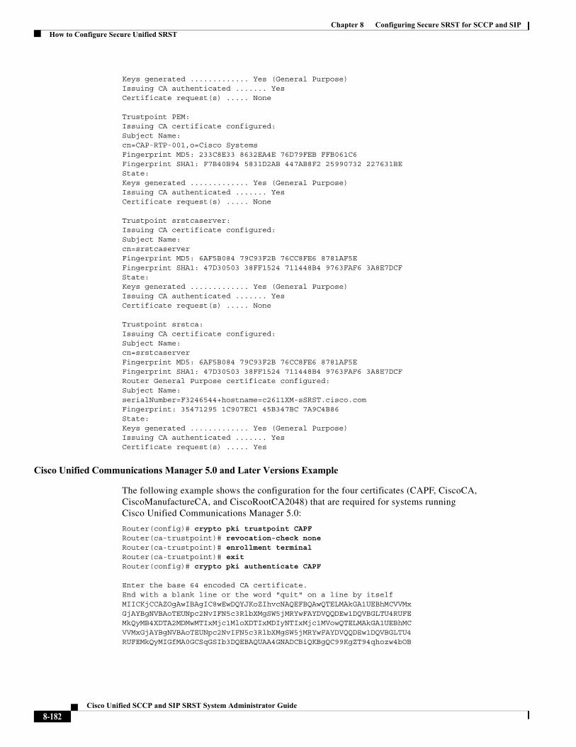
Chapter 8 Configuring Secure SRST for SCCP and SIPHow to Configure Secure Unified SRST
Keys generated ............. Yes (General Purpose) Issuing CA authenticated ....... Yes Certificate request(s) ..... None
Trustpoint PEM: Issuing CA certificate configured: Subject Name: cn=CAP-RTP-001,o=Cisco Systems Fingerprint MD5: 233C8E33 8632EA4E 76D79FEB FFB061C6 Fingerprint SHA1: F7B40B94 5831D2AB 447AB8F2 25990732 227631BE State: Keys generated ............. Yes (General Purpose) Issuing CA authenticated ....... Yes Certificate request(s) ..... None
Trustpoint srstcaserver: Issuing CA certificate configured: Subject Name: cn=srstcaserver Fingerprint MD5: 6AF5B084 79C93F2B 76CC8FE6 8781AF5E Fingerprint SHA1: 47D30503 38FF1524 711448B4 9763FAF6 3A8E7DCF State: Keys generated ............. Yes (General Purpose) Issuing CA authenticated ....... Yes Certificate request(s) ..... None
Trustpoint srstca: Issuing CA certificate configured: Subject Name: cn=srstcaserver Fingerprint MD5: 6AF5B084 79C93F2B 76CC8FE6 8781AF5E Fingerprint SHA1: 47D30503 38FF1524 711448B4 9763FAF6 3A8E7DCF Router General Purpose certificate configured: Subject Name: serialNumber=F3246544+hostname=c2611XM-sSRST.cisco.com Fingerprint: 35471295 1C907EC1 45B347BC 7A9C4B86 State: Keys generated ............. Yes (General Purpose) Issuing CA authenticated ....... Yes Certificate request(s) ..... Yes
Cisco Unified Communications Manager 5.0 and Later Versions Example
The following example shows the configuration for the four certificates (CAPF, CiscoCA, CiscoManufactureCA, and CiscoRootCA2048) that are required for systems running Cisco Unified Communications Manager 5.0:
Router(config)# crypto pki trustpoint CAPF Router(ca-trustpoint)# revocation-check none Router(ca-trustpoint)# enrollment terminal Router(ca-trustpoint)# exit Router(config)# crypto pki authenticate CAPF
Enter the base 64 encoded CA certificate. End with a blank line or the word "quit" on a line by itself MIICKjCCAZOgAwIBAgIC8wEwDQYJKoZIhvcNAQEFBQAwQTELMAkGA1UEBhMCVVMx GjAYBgNVBAoTEUNpc2NvIFN5c3RlbXMgSW5jMRYwFAYDVQQDEw1DQVBGLTU4RUFE MkQyMB4XDTA2MDMwMTIxMjc1MloXDTIxMDIyNTIxMjc1MVowQTELMAkGA1UEBhMC VVMxGjAYBgNVBAoTEUNpc2NvIFN5c3RlbXMgSW5jMRYwFAYDVQQDEw1DQVBGLTU4 RUFEMkQyMIGfMA0GCSqGSIb3DQEBAQUAA4GNADCBiQKBgQC99KgZT94qhozw4bOB
8-182Cisco Unified SCCP and SIP SRST System Administrator Guide
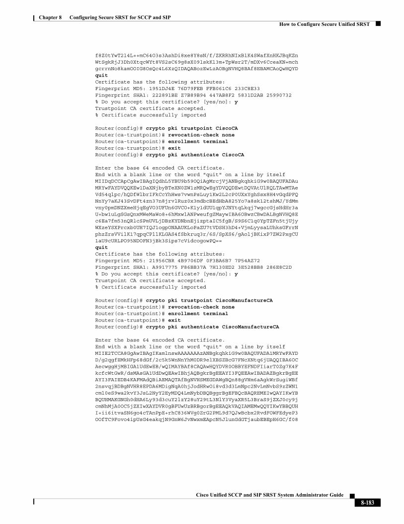
Chapter 8 Configuring Secure SRST for SCCP and SIPHow to Configure Secure Unified SRST
f8Z0tYwT2l4L++mC64O3s3AshDi8xe8Y8sN/f/ZKRRhNIxBlK4SWafXnHKJBqKZn WtSgkRjJ3Dh0XtqcWYt8VS2sC69g8sX09lskKl3m+TpWsr2T/mDXv6CceaKN+mch gcrrnNo8kamOOIG8OsQc4L6XzQIDAQABozEwLzAOBgNVHQ8BAf8EBAMCAoQwHQYDquit Certificate has the following attributes: Fingerprint MD5: 1951DJ4E 76D79FEB FFB061C6 233C8E33Fingerprint SHA1: 222891BE Z7B89B94 447AB8F2 5831D2AB 25990732 % Do you accept this certificate? [yes/no]: y Trustpoint CA certificate accepted. % Certificate successfully imported
Router(config)# crypto pki trustpoint CiscoCA Router(ca-trustpoint)# revocation-check none Router(ca-trustpoint)# enrollment terminal Router(ca-trustpoint)# exit Router(config)# crypto pki authenticate CiscoCA
Enter the base 64 encoded CA certificate. End with a blank line or the word "quit" on a line by itselfMIIDqDCCApCgAwIBAgIQdhL5YBU9b59OQiAgMrcjVjANBgkqhkiG9w0BAQUFADAu MRYwFAYDVQQKEw1DaXNjbyBTeXN0ZW1zMRQwEgYDVQQDEwtDQVAtUlRQLTAwMTAe Vd54qlpc/hQDfWlbrIFkCcYhHws7vwnPsLuy1Kw2L2cP0UXxYghSsx8H4vGqdPFQ NnYy7aKJ43SvDFt4zn37n8jrvlRuz0x3mdbcBEdHbA825Yo7a8sk12tshMJ/YdMm vny0pmDNZXmeHjqEgVO3UFUn6GVCO+K1y1dUU1qpYJNYtqLkqj7wgccGjsHdHr3a U+bw1uLgSGsQnxMWeMaWo8+6hMxwlANPweufgZMaywIBA6OBwzCBwDALBgNVHQ8E c6Ea7fm53nQRlcSPmUVLjDBzKYDNbnEjizptaIC5fgB/S9S6C1q0YpTZFn5tjUjy WXzeYSXPrcxb0UH7IQJ1ogpONAAUKLoPaZU7tVDSH3hD4+VjmLyysaLUhksGFrrN phzZrsVVilK17qpqCPllKLGAS4fSbkruq3r/6S/SpXS6/gAoljBKixP7ZW2PxgCU 1aU9cURLPO95NDOFN3jBk3Sips7cVidcogowPQ== quit Certificate has the following attributes: Fingerprint MD5: 21956CBR 4B9706DF 0F3BA6B7 7P54AZ72 Fingerprint SHA1: A9917775 F86BB37A 7H130ED2 3E528BB8 286E8C2D % Do you accept this certificate? [yes/no]: y Trustpoint CA certificate accepted. % Certificate successfully imported
Router(config)# crypto pki trustpoint CiscoManufactureCA Router(ca-trustpoint)# revocation-check none Router(ca-trustpoint)# enrollment terminal Router(ca-trustpoint)# exit Router(config)# crypto pki authenticate CiscoManufactureCA
Enter the base 64 encoded CA certificate. End with a blank line or the word "quit" on a line by itselfMIIE2TCCA8GgAwIBAgIKamlnswAAAAAAAzANBgkqhkiG9w0BAQUFADA1MRYwFAYD D/g2qgfEMkHFp68dGf/2c5k5WnNnYhM0DR9elXBSZBcG7FNcXNtq6jUAQQIBA6OC AecwggHjMBIGA1UdEwEB/wQIMAYBAf8CAQAwHQYDVR0OBBYEFNDFIiarT0Zg7K4F kcfcWtGwR/dsMAsGA1UdDwQEAwIBhjAQBgkrBgEEAYI3FQEEAwIBADAZBgkrBgEE AYI3FAIEDB4KAFMAdQBiAEMAQTAfBgNVHSMEGDAWgBQn88gVHm6aAgkWrSugiWBf 2nsvqjBDBgNVHR8EPDA6MDigNqA0hjJodHRwOi8vd3d3LmNpc2NvLmNvbS9zZWN1 cml0eS9wa2kvY3JsL2NyY2EyMDQ4LmNybDBQBggrBgEFBQcBAQREMEIwQAYIKwYB BQUHMAKGNGh0dHA6Ly93d3cuY2lzY28uY29tL3NlY3VyaXR5L3BraS9jZXJ0cy9j cmNhMjA0OC5jZXIwXAYDVR0gBFUwUzBRBgorBgEEAQkVAQIAMEMwQQYIKwYBBQUH I+ii6itvaSN6go4cTAnPpE+rhC836WVg0ZrG2PML9d7QJwBcbx2RvdFOWFEdyeP3 OOfTC9Fovo4ipUsG4eakqjN9GnW6JvNwxmEApcN5JlunGdGTjaubEBEpH6GC/f08
8-183Cisco Unified SCCP and SIP SRST System Administrator Guide
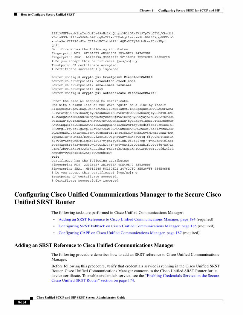
Chapter 8 Configuring Secure SRST for SCCP and SIPHow to Configure Secure Unified SRST
S25l3JNFBemvM2tnIwcGhiLa69yHz1khQhrpz3B1iOAkPV19TpY4gJfVb/Cbcdi6 YBmlsGGGrd1lZva5J6LuL2GbuqEwYf2+rDUU+bgtlwavw+9tzD0865XpgdOKXrbO +nmka9eiV2TEP0zJ2+iC7AFm1BCIolblPFft6QKoSJFjB6thJksaE5/k3Npfquit Certificate has the following attributes: Fingerprint MD5: 0F3BA6B7 4B9636DF 5F54BE72 24762SBR Fingerprint SHA1: L92BB37A S9919925 5C130ED2 3E528UP8 286E8C2D % Do you accept this certificate? [yes/no]: y Trustpoint CA certificate accepted. % Certificate successfully imported
Router(config)# crypto pki trustpoint CiscoRootCA2048Router(ca-trustpoint)# revocation-check none Router(ca-trustpoint)# enrollment terminal Router(ca-trustpoint)# exit Router(config)# crypto pki authenticate CiscoRootCA2048
Enter the base 64 encoded CA certificate. End with a blank line or the word "quit" on a line by itselfMIIDQzCCAiugAwIBAgIQX/h7KCtU3I1CoxW1aMmt/zANBgkqhkiG9w0BAQUFADA1 MRYwFAYDVQQKEw1DaXNjbyBTeXN0ZW1zMRswGQYDVQQDExJDaXNjbyBSb290IENB IDIwNDgwHhcNMDQwNTE0MjAxNzEyWhcNMjkwNTE0MjAyNTQyWjA1MRYwFAYDVQQK Ew1DaXNjbyBTeXN0ZW1zMRswGQYDVQQDExJDaXNjbyBSb290IENBIDIwNDgwggEg MA0GCSqGSIb3DQEBAQUAA4IBDQAwggEIAoIBAQCwmrmrp68Kd6ficba0ZmKUeIhH FR5umgIJFq0roIlgX9p7L6owEAYJKwYBBAGCNxUBBAMCAQAwDQYJKoZIhvcNAQEF BQADggEBAJ2dhISjQal8dwy3U8pORFBi71R803UXHOjgxkhLtv5MOhmBVrBW7hmW Yqpao2TB9k5UM8Z3/sUcuuVdJcr18JOagxEu5sv4dEX+5wW4q+ffy0vhN4TauYuX cB7w4ovXsNgOnbFp1iqRe6lJT37mjpXYgyc81WhJDtSd9i7rp77rMKSsH0T8lasz Bvt9YAretIpjsJyp8qS5UwGH0GikJ3+r/+n6yUA4iGe0OcaEb1fJU9u6ju7AQ7L4 CYNu/2bPPu8Xs1gYJQk0XuPL1hS27PKSb3TkL4Eq1ZKR4OCXPDJoBYVL0fdX4lId kxpUnwVwwEpxYB5DC2Ae/qPOgRnhCzU= quit Certificate has the following attributes: Fingerprint MD5: 2G3LZ6B7 2R1995ER 6KE4WE72 3E528BB8 Fingerprint SHA1: M9912245 5C130ED2 24762JBC 3E528VF8 956E8S5H % Do you accept this certificate? [yes/no]: y Trustpoint CA certificate accepted. % Certificate successfully imported
Configuring Cisco Unified Communications Manager to the Secure Cisco Unified SRST Router
The following tasks are performed in Cisco Unified Communications Manager:
• Adding an SRST Reference to Cisco Unified Communications Manager, page 184 (required)
• Configuring SRST Fallback on Cisco Unified Communications Manager, page 185 (required)
• Configuring CAPF on Cisco Unified Communications Manager, page 187 (required)
Adding an SRST Reference to Cisco Unified Communications Manager
The following procedure describes how to add an SRST reference to Cisco Unified Communications Manager.
Before following this procedure, verify that credentials service is running in the Cisco Unified SRST Router. Cisco Unified Communications Manager connects to the Cisco Unified SRST Router for its device certificate. To enable credentials service, see the “Enabling Credentials Service on the Secure Cisco Unified SRST Router” section on page 174.
8-184Cisco Unified SCCP and SIP SRST System Administrator Guide
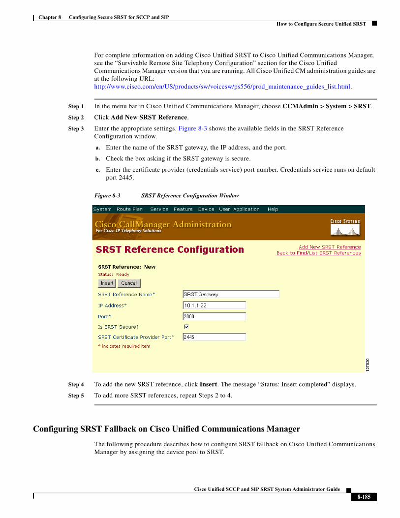
Chapter 8 Configuring Secure SRST for SCCP and SIPHow to Configure Secure Unified SRST
For complete information on adding Cisco Unified SRST to Cisco Unified Communications Manager, see the “Survivable Remote Site Telephony Configuration” section for the Cisco Unified Communications Manager version that you are running. All Cisco Unified CM administration guides are at the following URL: http://www.cisco.com/en/US/products/sw/voicesw/ps556/prod_maintenance_guides_list.html.
Step 1 In the menu bar in Cisco Unified Communications Manager, choose CCMAdmin > System > SRST.
Step 2 Click Add New SRST Reference.
Step 3 Enter the appropriate settings. Figure 8-3 shows the available fields in the SRST Reference Configuration window.
a. Enter the name of the SRST gateway, the IP address, and the port.
b. Check the box asking if the SRST gateway is secure.
c. Enter the certificate provider (credentials service) port number. Credentials service runs on default port 2445.
Figure 8-3 SRST Reference Configuration Window
Step 4 To add the new SRST reference, click Insert. The message “Status: Insert completed” displays.
Step 5 To add more SRST references, repeat Steps 2 to 4.
Configuring SRST Fallback on Cisco Unified Communications Manager
The following procedure describes how to configure SRST fallback on Cisco Unified Communications Manager by assigning the device pool to SRST.
8-185Cisco Unified SCCP and SIP SRST System Administrator Guide
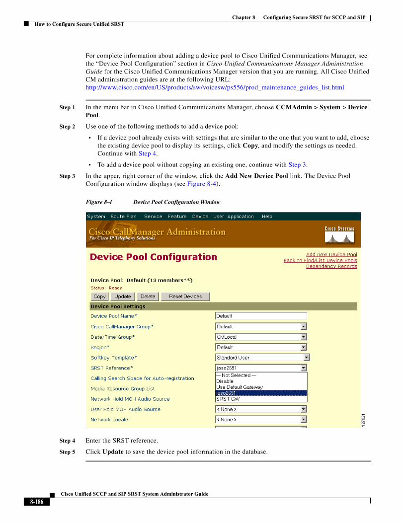
Chapter 8 Configuring Secure SRST for SCCP and SIPHow to Configure Secure Unified SRST
For complete information about adding a device pool to Cisco Unified Communications Manager, see the “Device Pool Configuration” section in Cisco Unified Communications Manager Administration Guide for the Cisco Unified Communications Manager version that you are running. All Cisco Unified CM administration guides are at the following URL: http://www.cisco.com/en/US/products/sw/voicesw/ps556/prod_maintenance_guides_list.html
Step 1 In the menu bar in Cisco Unified Communications Manager, choose CCMAdmin > System > Device Pool.
Step 2 Use one of the following methods to add a device pool:
• If a device pool already exists with settings that are similar to the one that you want to add, choose the existing device pool to display its settings, click Copy, and modify the settings as needed. Continue with Step 4.
• To add a device pool without copying an existing one, continue with Step 3.
Step 3 In the upper, right corner of the window, click the Add New Device Pool link. The Device Pool Configuration window displays (see Figure 8-4).
Figure 8-4 Device Pool Configuration Window
Step 4 Enter the SRST reference.
Step 5 Click Update to save the device pool information in the database.
8-186Cisco Unified SCCP and SIP SRST System Administrator Guide
Chapter 8 Configuring Secure SRST for SCCP and SIPHow to Configure Secure Unified SRST
Configuring CAPF on Cisco Unified Communications Manager
The Certificate Authority Proxy Function (CAPF) process allows supported devices, such as Cisco Unified Communications Manager, to request LSC certificates from Cisco Unified IP Phones. The CAPF utility generates a key pair and certificate that are specific for CAPF, and the utility copies this certificate to all Cisco Unified Communications Manager servers in the cluster.
For complete instructions on configuring CAPF in Cisco Unified Communications Manager, see the Cisco IP Phone Authentication and Encryption for Cisco Communications Manager documentation.
Enabling SRST Mode on the Secure Cisco Unified SRST Router
To configure secure SRST on the router to support the Cisco Unified IP Phone functions, use the following commands beginning in global configuration mode.
SUMMARY STEPS
1. call-manager-fallback
2. secondary-dialtone digit-string
3. transfer-system {blind | full-blind | full-consult | local-consult}
4. ip source-address ip-address [port port]
5. max-ephones max-phones
6. max-dn max-directory-numbers
7. transfer-pattern transfer-pattern
8. exit
8-187Cisco Unified SCCP and SIP SRST System Administrator Guide
Chapter 8 Configuring Secure SRST for SCCP and SIPHow to Configure Secure Unified SRST
DETAILED STEPS
Command or Action Purpose
Step 1 call-manager-fallback
Example:Router(config)# call-manager-fallback
Enters call-manager-fallback configuration mode.
Step 2 secondary-dialtone digit-string
Example:Router(config-cm-fallback)# secondary-dialtone 9
Activates a secondary dial tone when a digit string is dialed.
Step 3 transfer-system {blind | full-blind | full-consult | local-consult}
Example:Router(config-cm-fallback)# transfer-system full-consult
Defines the call-transfer method for all lines served by the Cisco Unified SRST Router.
• blind: Calls are transferred without consultation with a single phone line using the Cisco proprietary method.
• full-blind: Calls are transferred without consultation using H.450.2 standard methods.
• full-consult: Calls are transferred with consultation using a second phone line if available. The calls fallback to full-blind if the second line is unavailable.
• local-consult: Calls are transferred with local consultation using a second phone line if available. The calls fallback to blind for nonlocal consultation or nonlocal transfer target.
Step 4 ip source-address ip-address [port port]
Example:Router(config-cm-fallback)# ip source-address 10.1.1.22 port 2000
Enables the router to receive messages from the Cisco IP Phones through the specified IP addresses and provides for strict IP address verification. The default port number is 2000.
Step 5 max-ephones max-phones
Example:Router(config-cm-fallback)# max-ephones 15
Configures the maximum number of Cisco IP phones that can be supported by the router. The maximum number is platform dependent. The default is 0. See the “Platform and Memory Support” section on page 25 for further details.
Step 6 max-dn max-directory-numbers
Example:Router(config-cm-fallback)# max-dn 30
Sets the maximum number of directory numbers (DNs) or virtual voice ports that can be supported by the router.
• max-directory-numbers: Maximum number of directory numbers or virtual voice ports supported by the router. The maximum number is platform dependent. The default is 0. See the “Platform and Memory Support” section on page 25 for further details.
8-188Cisco Unified SCCP and SIP SRST System Administrator Guide
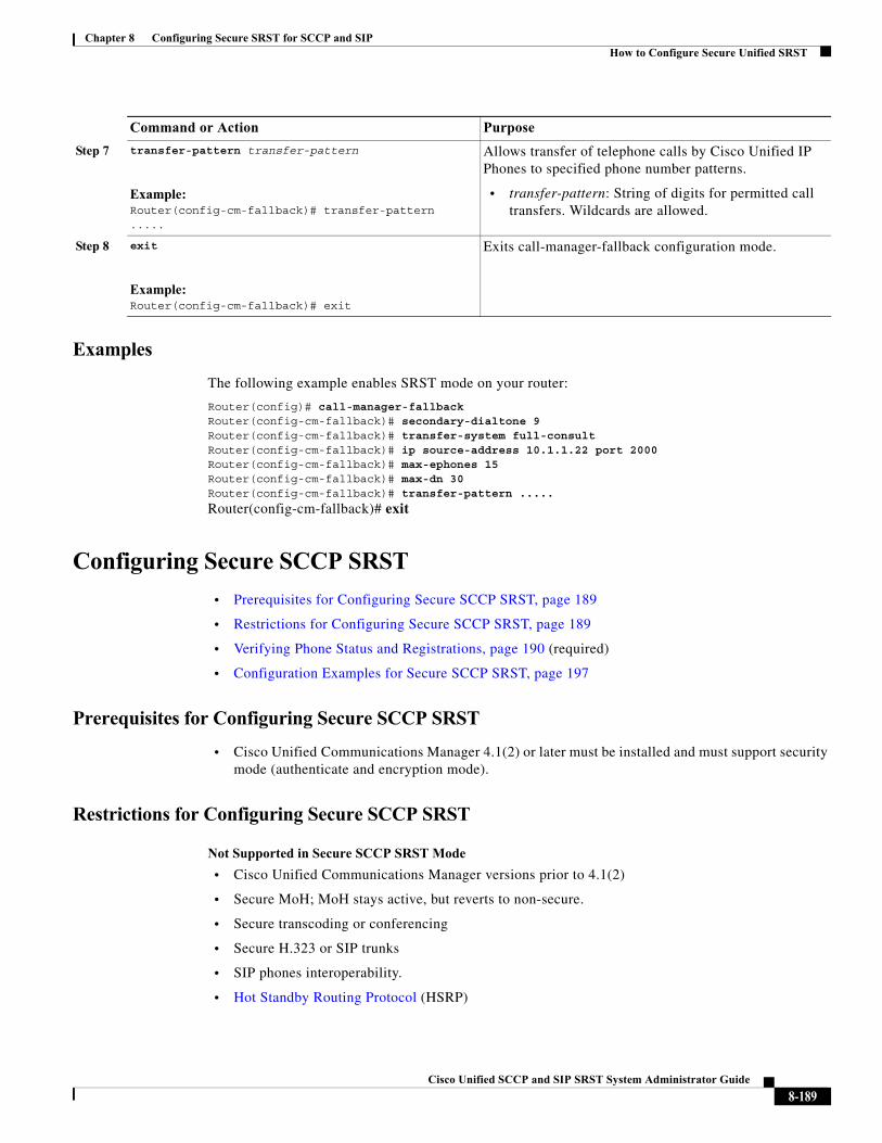
Chapter 8 Configuring Secure SRST for SCCP and SIPHow to Configure Secure Unified SRST
Examples
The following example enables SRST mode on your router:
Router(config)# call-manager-fallback Router(config-cm-fallback)# secondary-dialtone 9 Router(config-cm-fallback)# transfer-system full-consult Router(config-cm-fallback)# ip source-address 10.1.1.22 port 2000 Router(config-cm-fallback)# max-ephones 15 Router(config-cm-fallback)# max-dn 30 Router(config-cm-fallback)# transfer-pattern .....
Router(config-cm-fallback)# exit
Configuring Secure SCCP SRST
• Prerequisites for Configuring Secure SCCP SRST, page 189
• Restrictions for Configuring Secure SCCP SRST, page 189
• Verifying Phone Status and Registrations, page 190 (required)
• Configuration Examples for Secure SCCP SRST, page 197
Prerequisites for Configuring Secure SCCP SRST
• Cisco Unified Communications Manager 4.1(2) or later must be installed and must support security mode (authenticate and encryption mode).
Restrictions for Configuring Secure SCCP SRST
Not Supported in Secure SCCP SRST Mode
• Cisco Unified Communications Manager versions prior to 4.1(2)
• Secure MoH; MoH stays active, but reverts to non-secure.
• Secure transcoding or conferencing
• Secure H.323 or SIP trunks
• SIP phones interoperability.
• Hot Standby Routing Protocol (HSRP)
Step 7 transfer-pattern transfer-pattern
Example:Router(config-cm-fallback)# transfer-pattern .....
Allows transfer of telephone calls by Cisco Unified IP Phones to specified phone number patterns.
• transfer-pattern: String of digits for permitted call transfers. Wildcards are allowed.
Step 8 exit
Example:Router(config-cm-fallback)# exit
Exits call-manager-fallback configuration mode.
Command or Action Purpose
8-189Cisco Unified SCCP and SIP SRST System Administrator Guide
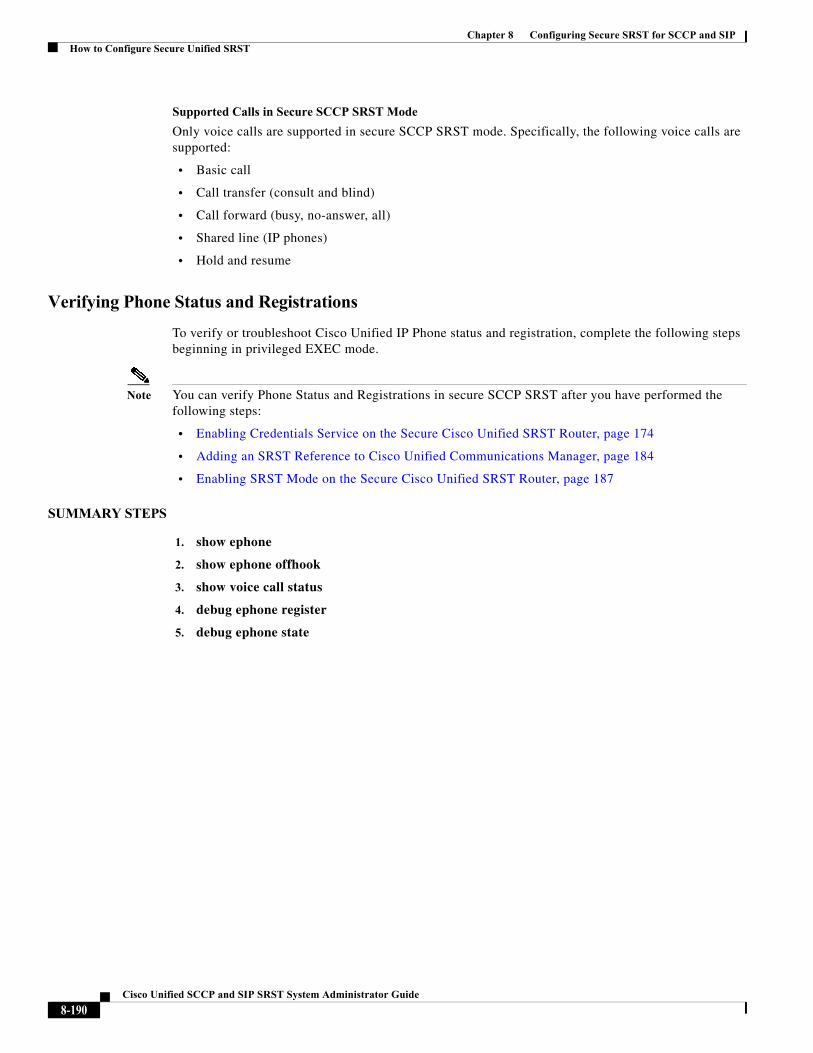
Chapter 8 Configuring Secure SRST for SCCP and SIPHow to Configure Secure Unified SRST
Supported Calls in Secure SCCP SRST Mode
Only voice calls are supported in secure SCCP SRST mode. Specifically, the following voice calls are supported:
• Basic call
• Call transfer (consult and blind)
• Call forward (busy, no-answer, all)
• Shared line (IP phones)
• Hold and resume
Verifying Phone Status and Registrations
To verify or troubleshoot Cisco Unified IP Phone status and registration, complete the following steps beginning in privileged EXEC mode.
Note You can verify Phone Status and Registrations in secure SCCP SRST after you have performed the following steps:
• Enabling Credentials Service on the Secure Cisco Unified SRST Router, page 174
• Adding an SRST Reference to Cisco Unified Communications Manager, page 184
• Enabling SRST Mode on the Secure Cisco Unified SRST Router, page 187
SUMMARY STEPS
1. show ephone
2. show ephone offhook
3. show voice call status
4. debug ephone register
5. debug ephone state
8-190Cisco Unified SCCP and SIP SRST System Administrator Guide
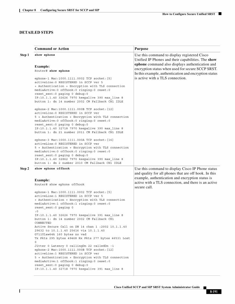
Chapter 8 Configuring Secure SRST for SCCP and SIPHow to Configure Secure Unified SRST
DETAILED STEPS
Command or Action Purpose
Step 1 show ephone
Example:Router# show ephone
ephone-1 Mac:1000.1111.0002 TCP socket:[5] activeLine:0 REGISTERED in SCCP ver 5 + Authentication + Encryption with TLS connection mediaActive:0 offhook:0 ringing:0 reset:0 reset_sent:0 paging 0 debug:0 IP:10.1.1.40 32626 7970 keepalive 390 max_line 8 button 1: dn 14 number 2002 CM Fallback CH1 IDLE
ephone-2 Mac:1000.1111.000B TCP socket:[12] activeLine:0 REGISTERED in SCCP ver 5 + Authentication + Encryption with TLS connection mediaActive:0 offhook:0 ringing:0 reset:0 reset_sent:0 paging 0 debug:0 IP:10.1.1.40 32718 7970 keepalive 390 max_line 8 button 1: dn 21 number 2011 CM Fallback CH1 IDLE
ephone-3 Mac:1000.1111.000A TCP socket:[16] activeLine:0 REGISTERED in SCCP ver 5 + Authentication + Encryption with TLS connection mediaActive:0 offhook:0 ringing:0 reset:0 reset_sent:0 paging 0 debug:0 IP:10.1.1.40 32862 7970 keepalive 390 max_line 8 button 1: dn 2 number 2010 CM Fallback CH1 IDLE
Use this command to display registered Cisco Unified IP Phones and their capabilities. The show ephone command also displays authentication and encryption status when used for secure SCCP SRST. In this example, authentication and encryption status is active with a TLS connection.
Step 2 show ephone offhook
Example:Router# show ephone offhook
ephone-1 Mac:1000.1111.0002 TCP socket:[5] activeLine:1 REGISTERED in SCCP ver 5+ Authentication + Encryption with TLS connectionmediaActive:1 offhook:1 ringing:0 reset:0 reset_sent:0 paging 0:0IP:10.1.1.40 32626 7970 keepalive 391 max_line 8button 1: dn 14 number 2002 CM Fallback CH1 CONNECTEDActive Secure Call on DN 14 chan 1 :2002 10.1.1.40 29632 to 10.1.1.40 25616 via 10.1.1.40G711Ulaw64k 160 bytes no vadTx Pkts 295 bytes 49468 Rx Pkts 277 bytes 46531 Lost 0Jitter 0 Latency 0 callingDn 22 calledDn -1ephone-2 Mac:1000.1111.000B TCP socket:[12] activeLine:1 REGISTERED in SCCP ver5 + Authentication + Encryption with TLS connectionmediaActive:1 offhook:1 ringing:0 reset:0 reset_sent:0 paging 0 debug:0IP:10.1.1.40 32718 7970 keepalive 391 max_line 8
Use this command to display Cisco IP Phone status and quality for all phones that are off hook. In this example, authentication and encryption status is active with a TLS connection, and there is an active secure call.
8-191Cisco Unified SCCP and SIP SRST System Administrator Guide
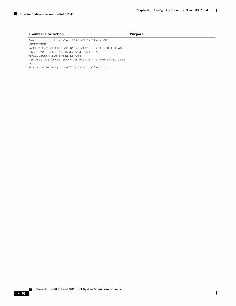
Chapter 8 Configuring Secure SRST for SCCP and SIPHow to Configure Secure Unified SRST
button 1: dn 21 number 2011 CM Fallback CH1 CONNECTEDActive Secure Call on DN 21 chan 1 :2011 10.1.1.40 16382 to 10.1.1.40 16382 via 10.1.1.40G711Ulaw64k 160 bytes no vadTx Pkts 295 bytes 49468 Rx Pkts 277 bytes 46531 Lost 0Jitter 0 Latency 0 callingDn -1 calledDn 11
Command or Action Purpose
8-192Cisco Unified SCCP and SIP SRST System Administrator Guide
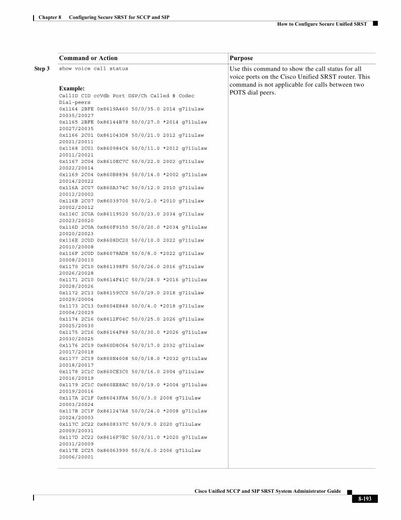
Chapter 8 Configuring Secure SRST for SCCP and SIPHow to Configure Secure Unified SRST
Step 3 show voice call status
Example:CallID CID ccVdb Port DSP/Ch Called # Codec Dial-peers0x1164 2BFE 0x8619A460 50/0/35.0 2014 g711ulaw 20035/200270x1165 2BFE 0x86144B78 50/0/27.0 *2014 g711ulaw 20027/200350x1166 2C01 0x861043D8 50/0/21.0 2012 g711ulaw 20021/200110x1168 2C01 0x860984C4 50/0/11.0 *2012 g711ulaw 20011/200210x1167 2C04 0x8610EC7C 50/0/22.0 2002 g711ulaw 20022/200140x1169 2C04 0x860B8894 50/0/14.0 *2002 g711ulaw 20014/200220x116A 2C07 0x860A374C 50/0/12.0 2010 g711ulaw 20012/200020x116B 2C07 0x86039700 50/0/2.0 *2010 g711ulaw 20002/200120x116C 2C0A 0x86119520 50/0/23.0 2034 g711ulaw 20023/200200x116D 2C0A 0x860F9150 50/0/20.0 *2034 g711ulaw 20020/200230x116E 2C0D 0x8608DC20 50/0/10.0 2022 g711ulaw 20010/200080x116F 2C0D 0x86078AD8 50/0/8.0 *2022 g711ulaw 20008/200100x1170 2C10 0x861398F0 50/0/26.0 2016 g711ulaw 20026/200280x1171 2C10 0x8614F41C 50/0/28.0 *2016 g711ulaw 20028/200260x1172 2C13 0x86159CC0 50/0/29.0 2018 g711ulaw 20029/200040x1173 2C13 0x8604E848 50/0/4.0 *2018 g711ulaw 20004/200290x1174 2C16 0x8612F04C 50/0/25.0 2026 g711ulaw 20025/200300x1175 2C16 0x86164F48 50/0/30.0 *2026 g711ulaw 20030/200250x1176 2C19 0x860D8C64 50/0/17.0 2032 g711ulaw 20017/200180x1177 2C19 0x860E4008 50/0/18.0 *2032 g711ulaw 20018/200170x1178 2C1C 0x860CE3C0 50/0/16.0 2004 g711ulaw 20016/200190x1179 2C1C 0x860EE8AC 50/0/19.0 *2004 g711ulaw 20019/200160x117A 2C1F 0x86043FA4 50/0/3.0 2008 g711ulaw 20003/200240x117B 2C1F 0x861247A8 50/0/24.0 *2008 g711ulaw 20024/200030x117C 2C22 0x8608337C 50/0/9.0 2020 g711ulaw 20009/200310x117D 2C22 0x8616F7EC 50/0/31.0 *2020 g711ulaw 20031/200090x117E 2C25 0x86063990 50/0/6.0 2006 g711ulaw 20006/20001
Use this command to show the call status for all voice ports on the Cisco Unified SRST router. This command is not applicable for calls between two POTS dial peers.
Command or Action Purpose
8-193Cisco Unified SCCP and SIP SRST System Administrator Guide
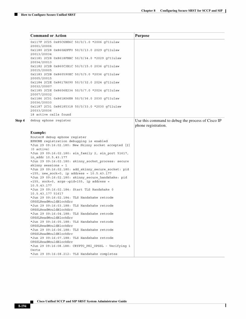
Chapter 8 Configuring Secure SRST for SCCP and SIPHow to Configure Secure Unified SRST
0x117F 2C25 0x85C6BE6C 50/0/1.0 *2006 g711ulaw 20001/200060x1180 2C28 0x860ADFF0 50/0/13.0 2029 g711ulaw 20013/200340x1181 2C28 0x8618FBBC 50/0/34.0 *2029 g711ulaw 20034/200130x1182 2C2B 0x860C3B1C 50/0/15.0 2036 g711ulaw 20015/200050x1183 2C2B 0x860590EC 50/0/5.0 *2036 g711ulaw 20005/200150x1184 2C2E 0x8617A090 50/0/32.0 2024 g711ulaw 20032/200070x1185 2C2E 0x8606E234 50/0/7.0 *2024 g711ulaw 20007/200320x1186 2C31 0x861A56E8 50/0/36.0 2030 g711ulaw 20036/200330x1187 2C31 0x86185318 50/0/33.0 *2030 g711ulaw 20033/2003618 active calls found
Step 4 debug ephone register
Example:Router# debug ephone registerEPHONE registration debugging is enabled*Jun 29 09:16:02.180: New Skinny socket accepted [2] (0 active)*Jun 29 09:16:02.180: sin_family 2, sin_port 51617, in_addr 10.5.43.177*Jun 29 09:16:02.180: skinny_socket_process: secure skinny sessions = 1*Jun 29 09:16:02.180: add_skinny_secure_socket: pid =155, new_sock=0, ip address = 10.5.43.177*Jun 29 09:16:02.180: skinny_secure_handshake: pid =155, sock=0, args->pid=155, ip address = 10.5.43.177*Jun 29 09:16:02.184: Start TLS Handshake 0 10.5.43.177 51617*Jun 29 09:16:02.184: TLS Handshake retcode OPSSLReadWouldBlockErr*Jun 29 09:16:03.188: TLS Handshake retcode OPSSLReadWouldBlockErr*Jun 29 09:16:04.188: TLS Handshake retcode OPSSLReadWouldBlockErr*Jun 29 09:16:05.188: TLS Handshake retcode OPSSLReadWouldBlockErr*Jun 29 09:16:06.188: TLS Handshake retcode OPSSLReadWouldBlockErr*Jun 29 09:16:07.188: TLS Handshake retcode OPSSLReadWouldBlockErr*Jun 29 09:16:08.188: CRYPTO_PKI_OPSSL - Verifying 1 Certs*Jun 29 09:16:08.212: TLS Handshake completes
Use this command to debug the process of Cisco IP phone registration.
Command or Action Purpose
8-194Cisco Unified SCCP and SIP SRST System Administrator Guide
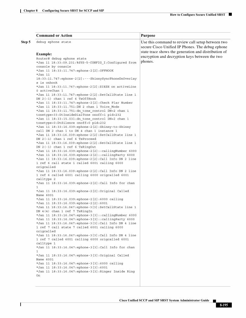
Chapter 8 Configuring Secure SRST for SCCP and SIPHow to Configure Secure Unified SRST
Step 5 debug ephone state
Example:Router# debug ephone state*Jan 11 18:33:09.231:%SYS-5-CONFIG_I:Configured from console by console*Jan 11 18:33:11.747:ephone-2[2]:OFFHOOK*Jan 11 18:33:11.747:ephone-2[2]:---SkinnySyncPhoneDnOverlays is onhook*Jan 11 18:33:11.747:ephone-2[2]:SIEZE on activeLine 0 activeChan 1*Jan 11 18:33:11.747:ephone-2[2]:SetCallState line 1 DN 2(-1) chan 1 ref 6 TsOffHook*Jan 11 18:33:11.747:ephone-2[2]:Check Plar Number*Jan 11 18:33:11.751:DN 2 chan 1 Voice_Mode*Jan 11 18:33:11.751:dn_tone_control DN=2 chan 1 tonetype=33:DtInsideDialTone onoff=1 pid=232*Jan 11 18:33:15.031:dn_tone_control DN=2 chan 1 tonetype=0:DtSilence onoff=0 pid=232*Jan 11 18:33:16.039:ephone-2[2]:Skinny-to-Skinny call DN 2 chan 1 to DN 4 chan 1 instance 1*Jan 11 18:33:16.039:ephone-2[2]:SetCallState line 1 DN 2(-1) chan 1 ref 6 TsProceed*Jan 11 18:33:16.039:ephone-2[2]:SetCallState line 1 DN 2(-1) chan 1 ref 6 TsRingOut*Jan 11 18:33:16.039:ephone-2[2]::callingNumber 6000*Jan 11 18:33:16.039:ephone-2[2]::callingParty 6000*Jan 11 18:33:16.039:ephone-2[2]:Call Info DN 2 line 1 ref 6 call state 1 called 6001 calling 6000 origcalled*Jan 11 18:33:16.039:ephone-2[2]:Call Info DN 2 line 1 ref 6 called 6001 calling 6000 origcalled 6001 calltype 2*Jan 11 18:33:16.039:ephone-2[2]:Call Info for chan 1*Jan 11 18:33:16.039:ephone-2[2]:Original Called Name 6001*Jan 11 18:33:16.039:ephone-2[2]:6000 calling*Jan 11 18:33:16.039:ephone-2[2]:6001*Jan 11 18:33:16.047:ephone-3[3]:SetCallState line 1 DN 4(4) chan 1 ref 7 TsRingIn*Jan 11 18:33:16.047:ephone-3[3]::callingNumber 6000*Jan 11 18:33:16.047:ephone-3[3]::callingParty 6000*Jan 11 18:33:16.047:ephone-3[3]:Call Info DN 4 line 1 ref 7 call state 7 called 6001 calling 6000 origcalled*Jan 11 18:33:16.047:ephone-3[3]:Call Info DN 4 line 1 ref 7 called 6001 calling 6000 origcalled 6001 calltype 1*Jan 11 18:33:16.047:ephone-3[3]:Call Info for chan 1*Jan 11 18:33:16.047:ephone-3[3]:Original Called Name 6001*Jan 11 18:33:16.047:ephone-3[3]:6000 calling*Jan 11 18:33:16.047:ephone-3[3]:6001*Jan 11 18:33:16.047:ephone-3[3]:Ringer Inside Ring On
Use this command to review call setup between two secure Cisco Unified IP Phones. The debug ephone state trace shows the generation and distribution of encryption and decryption keys between the two phones.
Command or Action Purpose
8-195Cisco Unified SCCP and SIP SRST System Administrator Guide
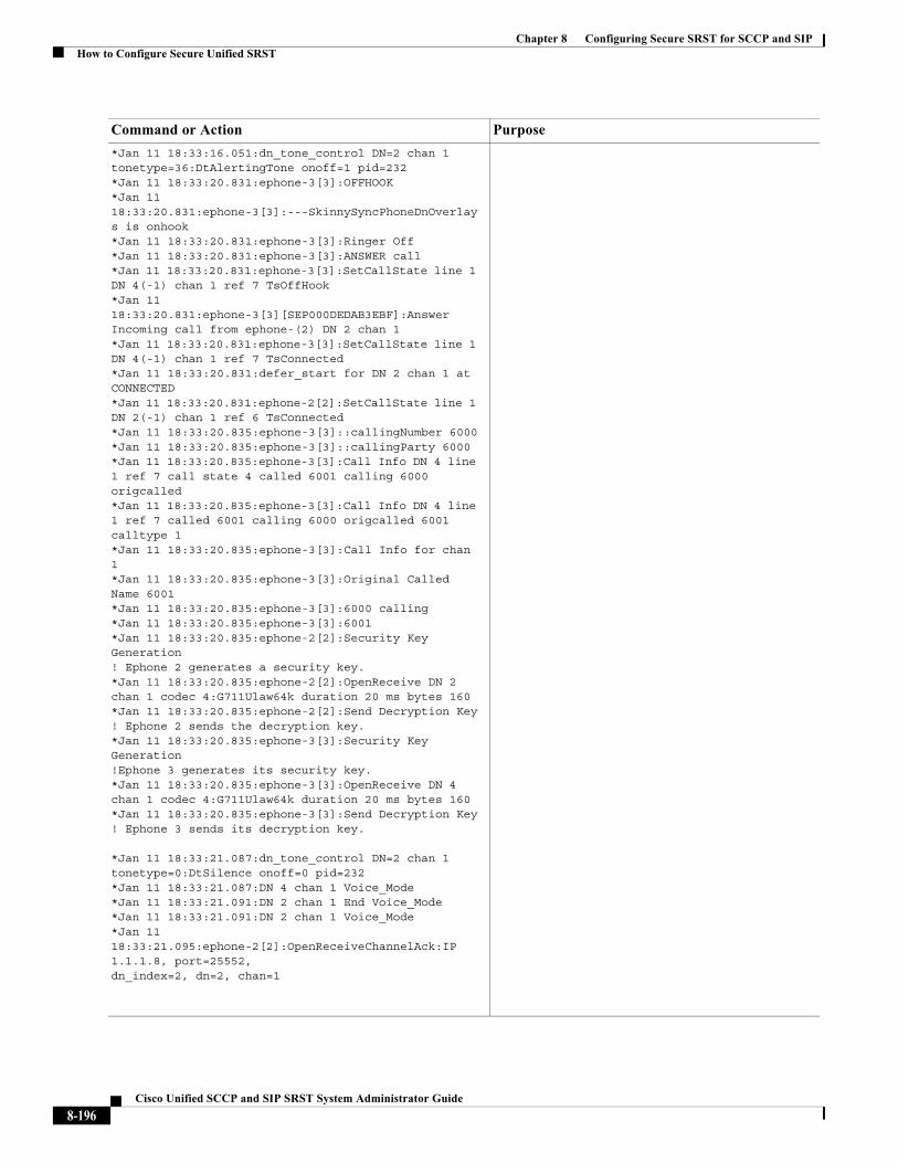
Chapter 8 Configuring Secure SRST for SCCP and SIPHow to Configure Secure Unified SRST
*Jan 11 18:33:16.051:dn_tone_control DN=2 chan 1 tonetype=36:DtAlertingTone onoff=1 pid=232*Jan 11 18:33:20.831:ephone-3[3]:OFFHOOK*Jan 11 18:33:20.831:ephone-3[3]:---SkinnySyncPhoneDnOverlays is onhook*Jan 11 18:33:20.831:ephone-3[3]:Ringer Off*Jan 11 18:33:20.831:ephone-3[3]:ANSWER call*Jan 11 18:33:20.831:ephone-3[3]:SetCallState line 1 DN 4(-1) chan 1 ref 7 TsOffHook*Jan 11 18:33:20.831:ephone-3[3][SEP000DEDAB3EBF]:Answer Incoming call from ephone-(2) DN 2 chan 1*Jan 11 18:33:20.831:ephone-3[3]:SetCallState line 1 DN 4(-1) chan 1 ref 7 TsConnected*Jan 11 18:33:20.831:defer_start for DN 2 chan 1 at CONNECTED*Jan 11 18:33:20.831:ephone-2[2]:SetCallState line 1 DN 2(-1) chan 1 ref 6 TsConnected*Jan 11 18:33:20.835:ephone-3[3]::callingNumber 6000*Jan 11 18:33:20.835:ephone-3[3]::callingParty 6000*Jan 11 18:33:20.835:ephone-3[3]:Call Info DN 4 line 1 ref 7 call state 4 called 6001 calling 6000 origcalled*Jan 11 18:33:20.835:ephone-3[3]:Call Info DN 4 line 1 ref 7 called 6001 calling 6000 origcalled 6001 calltype 1*Jan 11 18:33:20.835:ephone-3[3]:Call Info for chan 1*Jan 11 18:33:20.835:ephone-3[3]:Original Called Name 6001*Jan 11 18:33:20.835:ephone-3[3]:6000 calling*Jan 11 18:33:20.835:ephone-3[3]:6001*Jan 11 18:33:20.835:ephone-2[2]:Security Key Generation! Ephone 2 generates a security key.*Jan 11 18:33:20.835:ephone-2[2]:OpenReceive DN 2 chan 1 codec 4:G711Ulaw64k duration 20 ms bytes 160*Jan 11 18:33:20.835:ephone-2[2]:Send Decryption Key! Ephone 2 sends the decryption key.*Jan 11 18:33:20.835:ephone-3[3]:Security Key Generation!Ephone 3 generates its security key.*Jan 11 18:33:20.835:ephone-3[3]:OpenReceive DN 4 chan 1 codec 4:G711Ulaw64k duration 20 ms bytes 160*Jan 11 18:33:20.835:ephone-3[3]:Send Decryption Key! Ephone 3 sends its decryption key.
*Jan 11 18:33:21.087:dn_tone_control DN=2 chan 1 tonetype=0:DtSilence onoff=0 pid=232*Jan 11 18:33:21.087:DN 4 chan 1 Voice_Mode*Jan 11 18:33:21.091:DN 2 chan 1 End Voice_Mode*Jan 11 18:33:21.091:DN 2 chan 1 Voice_Mode*Jan 11 18:33:21.095:ephone-2[2]:OpenReceiveChannelAck:IP 1.1.1.8, port=25552,dn_index=2, dn=2, chan=1
Command or Action Purpose
8-196Cisco Unified SCCP and SIP SRST System Administrator Guide
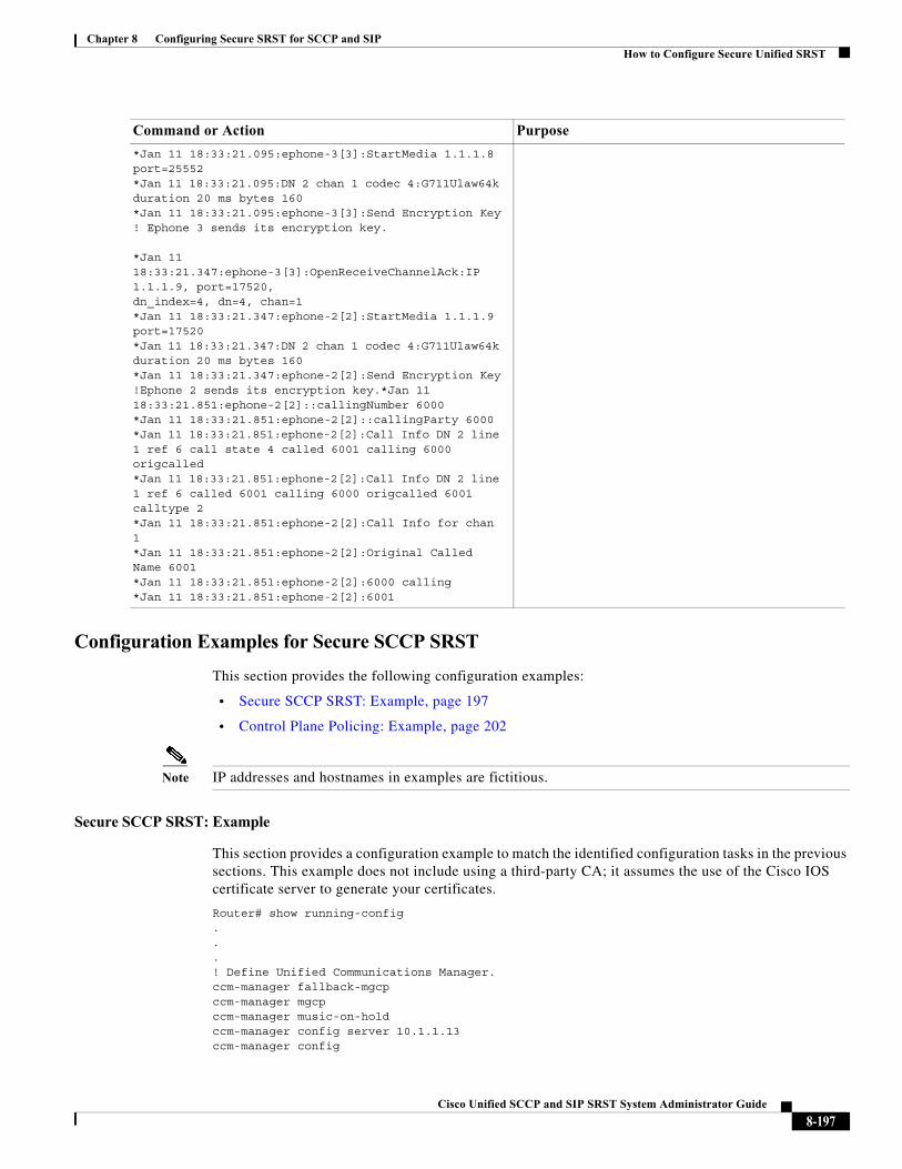
Chapter 8 Configuring Secure SRST for SCCP and SIPHow to Configure Secure Unified SRST
Configuration Examples for Secure SCCP SRST
This section provides the following configuration examples:
• Secure SCCP SRST: Example, page 197
• Control Plane Policing: Example, page 202
Note IP addresses and hostnames in examples are fictitious.
Secure SCCP SRST: Example
This section provides a configuration example to match the identified configuration tasks in the previous sections. This example does not include using a third-party CA; it assumes the use of the Cisco IOS certificate server to generate your certificates.
Router# show running-config...! Define Unified Communications Manager.ccm-manager fallback-mgcpccm-manager mgcpccm-manager music-on-holdccm-manager config server 10.1.1.13ccm-manager config
*Jan 11 18:33:21.095:ephone-3[3]:StartMedia 1.1.1.8 port=25552*Jan 11 18:33:21.095:DN 2 chan 1 codec 4:G711Ulaw64k duration 20 ms bytes 160*Jan 11 18:33:21.095:ephone-3[3]:Send Encryption Key! Ephone 3 sends its encryption key.
*Jan 11 18:33:21.347:ephone-3[3]:OpenReceiveChannelAck:IP 1.1.1.9, port=17520,dn_index=4, dn=4, chan=1*Jan 11 18:33:21.347:ephone-2[2]:StartMedia 1.1.1.9 port=17520*Jan 11 18:33:21.347:DN 2 chan 1 codec 4:G711Ulaw64k duration 20 ms bytes 160*Jan 11 18:33:21.347:ephone-2[2]:Send Encryption Key!Ephone 2 sends its encryption key.*Jan 11 18:33:21.851:ephone-2[2]::callingNumber 6000*Jan 11 18:33:21.851:ephone-2[2]::callingParty 6000*Jan 11 18:33:21.851:ephone-2[2]:Call Info DN 2 line 1 ref 6 call state 4 called 6001 calling 6000 origcalled*Jan 11 18:33:21.851:ephone-2[2]:Call Info DN 2 line 1 ref 6 called 6001 calling 6000 origcalled 6001 calltype 2*Jan 11 18:33:21.851:ephone-2[2]:Call Info for chan 1*Jan 11 18:33:21.851:ephone-2[2]:Original Called Name 6001*Jan 11 18:33:21.851:ephone-2[2]:6000 calling*Jan 11 18:33:21.851:ephone-2[2]:6001
Command or Action Purpose
8-197Cisco Unified SCCP and SIP SRST System Administrator Guide
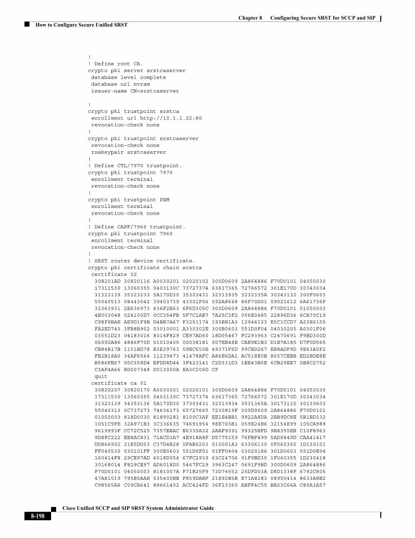
Chapter 8 Configuring Secure SRST for SCCP and SIPHow to Configure Secure Unified SRST
!! Define root CA.crypto pki server srstcaserver database level complete database url nvram issuer-name CN=srstcaserver
!crypto pki trustpoint srstca enrollment url http://10.1.1.22:80revocation-check none
!crypto pki trustpoint srstcaserver revocation-check none rsakeypair srstcaserver!! Define CTL/7970 trustpoint.crypto pki trustpoint 7970 enrollment terminal revocation-check none!crypto pki trustpoint PEM enrollment terminal revocation-check none!! Define CAPF/7960 trustpoint.crypto pki trustpoint 7960 enrollment terminal revocation-check none!! SRST router device certificate.crypto pki certificate chain srstca certificate 02 308201AD 30820116 A0030201 02020102 300D0609 2A864886 F70D0101 04050030 17311530 13060355 0403130C 73727374 63617365 72766572 301E170D 30343034 31323139 35323233 5A170D30 35303431 32313935 3232335A 30343132 300F0603 55040513 08443042 39453739 43301F06 092A8648 86F70D01 09021612 6A61736F 32363931 2E636973 636F2E63 6F6D305C 300D0609 2A864886 F70D0101 01050003 4B003048 024100D7 0CC354FB 5F7C1AE7 7A25C3F2 056E0485 22896D36 6CA70C19 C98F9BAE AE9D1F9B D4BB7A67 F3251174 193BB1A3 12946123 E5C1CCD7 A23E6155 FA2ED743 3FB8B902 03010001 A330302E 300B0603 551D0F04 04030205 A0301F06 03551D23 04183016 8014F829 CE97AD60 18D05467 FC293963 C2470691 F9BD300D 06092A86 4886F70D 01010405 00038181 007EB48E CAE9E1B3 D1E7A185 D7F0D565 CB84B17B 1151BD78 B3E39763 59EC650E 49371F6D 99CBD267 EB8ADF9D 9E43A5F2 FB2B18A0 34AF6564 11239473 41478AFC A86E6DA1 AC518E0B 8657CEBB ED2BDE8E B586FE67 00C358D4 EFDD8D44 3F423141 C2D331D3 1EE43B6E 6CB29EE7 0B8C2752 C3AF4A66 BD007348 D013000A EA3C206D CF quit certificate ca 01 30820207 30820170 A0030201 02020101 300D0609 2A864886 F70D0101 04050030 17311530 13060355 0403130C 73727374 63617365 72766572 301E170D 30343034 31323139 34353136 5A170D30 37303431 32313934 3531365A 30173115 30130603 55040313 0C737273 74636173 65727665 7230819F 300D0609 2A864886 F70D0101 01050003 818D0030 81890281 8100C3AF EE1E4BB1 9922A8DA 2BB9DC8E 5B1BD332 1051C9FE 32A971B3 3C336635 74691954 98E765B1 059E24B6 32154E99 105CA989 9619993F CC72C525 7357EBAC E6335A32 2AAF9391 99325BFD 9B8355EB C10F8963 9D8FC222 EE8AC831 71ACD3A7 4E918A8F D5775159 76FBF499 5AD0849D CAA41417 DD866902 21E5DD03 C37D4B28 0FAB0203 010001A3 63306130 0F060355 1D130101 FF040530 030101FF 300E0603 551D0F01 01FF0404 03020186 301D0603 551D0E04 160414F8 29CE97AD 6018D054 67FC2939 63C24706 91F9BD30 1F060355 1D230418 30168014 F829CE97 AD6018D0 5467FC29 3963C247 0691F9BD 300D0609 2A864886 F70D0101 04050003 8181007A F71B25F9 73D74552 25DFD03A D8D1338F 6792C805 47A81019 795B5AAE 035400BB F859DABF 21892B5B E71A8283 08950414 8633A8B2 C98565A6 C09CA641 88661402 ACC424FD 36F23360 ABFF4C55 BB23C66A C80A3A57
8-198Cisco Unified SCCP and SIP SRST System Administrator Guide
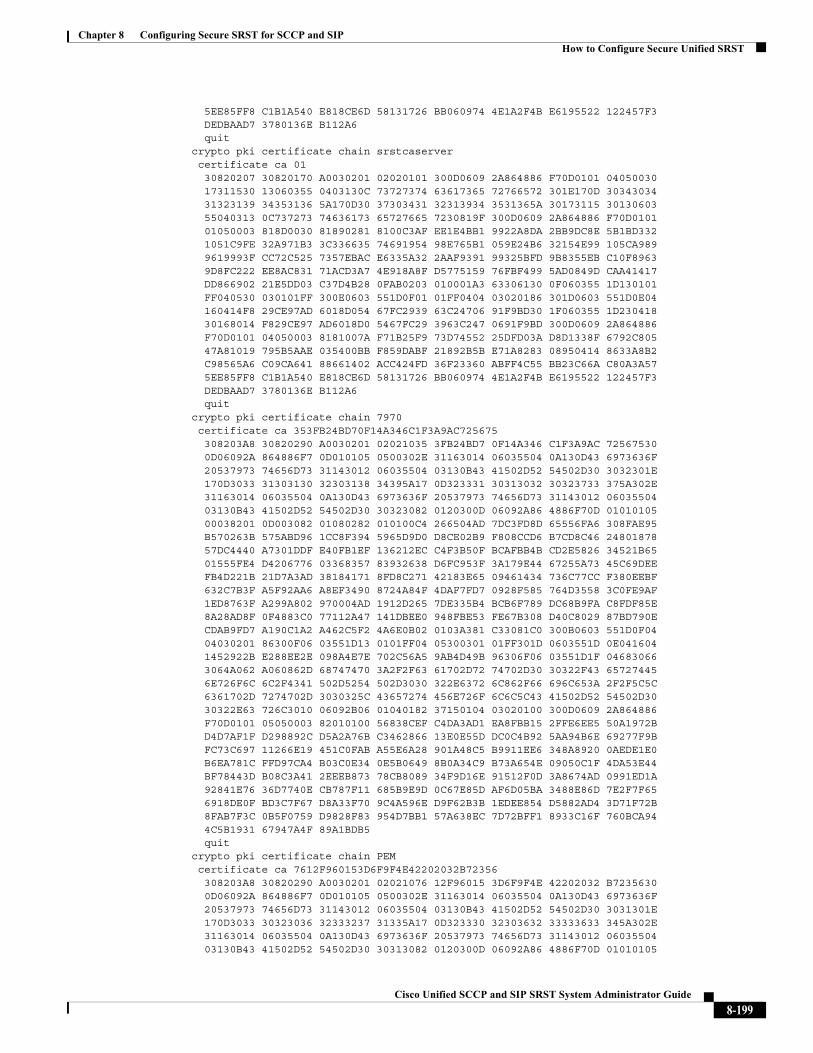
Chapter 8 Configuring Secure SRST for SCCP and SIPHow to Configure Secure Unified SRST
5EE85FF8 C1B1A540 E818CE6D 58131726 BB060974 4E1A2F4B E6195522 122457F3 DEDBAAD7 3780136E B112A6 quitcrypto pki certificate chain srstcaserver certificate ca 01 30820207 30820170 A0030201 02020101 300D0609 2A864886 F70D0101 04050030 17311530 13060355 0403130C 73727374 63617365 72766572 301E170D 30343034 31323139 34353136 5A170D30 37303431 32313934 3531365A 30173115 30130603 55040313 0C737273 74636173 65727665 7230819F 300D0609 2A864886 F70D0101 01050003 818D0030 81890281 8100C3AF EE1E4BB1 9922A8DA 2BB9DC8E 5B1BD332 1051C9FE 32A971B3 3C336635 74691954 98E765B1 059E24B6 32154E99 105CA989 9619993F CC72C525 7357EBAC E6335A32 2AAF9391 99325BFD 9B8355EB C10F8963 9D8FC222 EE8AC831 71ACD3A7 4E918A8F D5775159 76FBF499 5AD0849D CAA41417 DD866902 21E5DD03 C37D4B28 0FAB0203 010001A3 63306130 0F060355 1D130101 FF040530 030101FF 300E0603 551D0F01 01FF0404 03020186 301D0603 551D0E04 160414F8 29CE97AD 6018D054 67FC2939 63C24706 91F9BD30 1F060355 1D230418 30168014 F829CE97 AD6018D0 5467FC29 3963C247 0691F9BD 300D0609 2A864886 F70D0101 04050003 8181007A F71B25F9 73D74552 25DFD03A D8D1338F 6792C805 47A81019 795B5AAE 035400BB F859DABF 21892B5B E71A8283 08950414 8633A8B2 C98565A6 C09CA641 88661402 ACC424FD 36F23360 ABFF4C55 BB23C66A C80A3A57 5EE85FF8 C1B1A540 E818CE6D 58131726 BB060974 4E1A2F4B E6195522 122457F3 DEDBAAD7 3780136E B112A6 quitcrypto pki certificate chain 7970 certificate ca 353FB24BD70F14A346C1F3A9AC725675 308203A8 30820290 A0030201 02021035 3FB24BD7 0F14A346 C1F3A9AC 72567530 0D06092A 864886F7 0D010105 0500302E 31163014 06035504 0A130D43 6973636F 20537973 74656D73 31143012 06035504 03130B43 41502D52 54502D30 3032301E 170D3033 31303130 32303138 34395A17 0D323331 30313032 30323733 375A302E 31163014 06035504 0A130D43 6973636F 20537973 74656D73 31143012 06035504 03130B43 41502D52 54502D30 30323082 0120300D 06092A86 4886F70D 01010105 00038201 0D003082 01080282 010100C4 266504AD 7DC3FD8D 65556FA6 308FAE95 B570263B 575ABD96 1CC8F394 5965D9D0 D8CE02B9 F808CCD6 B7CD8C46 24801878 57DC4440 A7301DDF E40FB1EF 136212EC C4F3B50F BCAFBB4B CD2E5826 34521B65 01555FE4 D4206776 03368357 83932638 D6FC953F 3A179E44 67255A73 45C69DEE FB4D221B 21D7A3AD 38184171 8FD8C271 42183E65 09461434 736C77CC F380EEBF 632C7B3F A5F92AA6 A8EF3490 8724A84F 4DAF7FD7 0928F585 764D3558 3C0FE9AF 1ED8763F A299A802 970004AD 1912D265 7DE335B4 BCB6F789 DC68B9FA C8FDF85E 8A28AD8F 0F4883C0 77112A47 141DBEE0 948FBE53 FE67B308 D40C8029 87BD790E CDAB9FD7 A190C1A2 A462C5F2 4A6E0B02 0103A381 C33081C0 300B0603 551D0F04 04030201 86300F06 03551D13 0101FF04 05300301 01FF301D 0603551D 0E041604 1452922B E288EE2E 098A4E7E 702C56A5 9AB4D49B 96306F06 03551D1F 04683066 3064A062 A060862D 68747470 3A2F2F63 61702D72 74702D30 30322F43 65727445 6E726F6C 6C2F4341 502D5254 502D3030 322E6372 6C862F66 696C653A 2F2F5C5C 6361702D 7274702D 3030325C 43657274 456E726F 6C6C5C43 41502D52 54502D30 30322E63 726C3010 06092B06 01040182 37150104 03020100 300D0609 2A864886 F70D0101 05050003 82010100 56838CEF C4DA3AD1 EA8FBB15 2FFE6EE5 50A1972B D4D7AF1F D298892C D5A2A76B C3462866 13E0E55D DC0C4B92 5AA94B6E 69277F9B FC73C697 11266E19 451C0FAB A55E6A28 901A48C5 B9911EE6 348A8920 0AEDE1E0 B6EA781C FFD97CA4 B03C0E34 0E5B0649 8B0A34C9 B73A654E 09050C1F 4DA53E44 BF78443D B08C3A41 2EEEB873 78CB8089 34F9D16E 91512F0D 3A8674AD 0991ED1A 92841E76 36D7740E CB787F11 685B9E9D 0C67E85D AF6D05BA 3488E86D 7E2F7F65 6918DE0F BD3C7F67 D8A33F70 9C4A596E D9F62B3B 1EDEE854 D5882AD4 3D71F72B 8FAB7F3C 0B5F0759 D9828F83 954D7BB1 57A638EC 7D72BFF1 8933C16F 760BCA94 4C5B1931 67947A4F 89A1BDB5 quitcrypto pki certificate chain PEM certificate ca 7612F960153D6F9F4E42202032B72356 308203A8 30820290 A0030201 02021076 12F96015 3D6F9F4E 42202032 B7235630 0D06092A 864886F7 0D010105 0500302E 31163014 06035504 0A130D43 6973636F 20537973 74656D73 31143012 06035504 03130B43 41502D52 54502D30 3031301E 170D3033 30323036 32333237 31335A17 0D323330 32303632 33333633 345A302E 31163014 06035504 0A130D43 6973636F 20537973 74656D73 31143012 06035504 03130B43 41502D52 54502D30 30313082 0120300D 06092A86 4886F70D 01010105
8-199Cisco Unified SCCP and SIP SRST System Administrator Guide
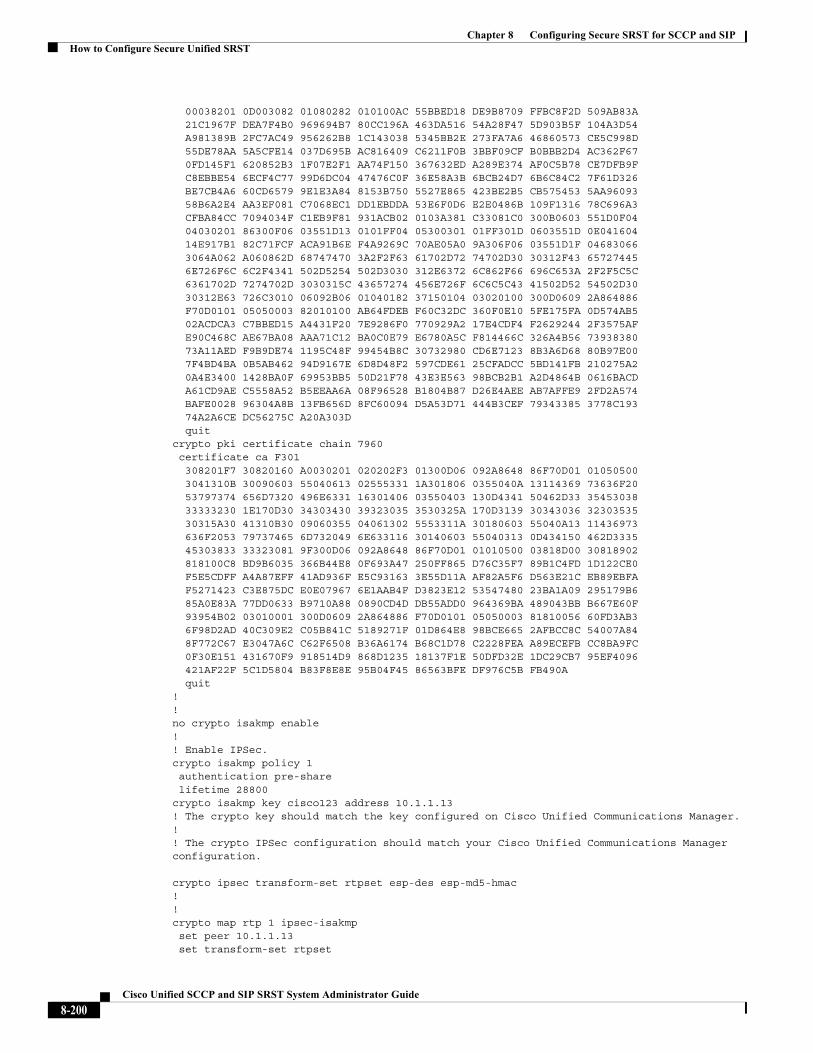
Chapter 8 Configuring Secure SRST for SCCP and SIPHow to Configure Secure Unified SRST
00038201 0D003082 01080282 010100AC 55BBED18 DE9B8709 FFBC8F2D 509AB83A 21C1967F DEA7F4B0 969694B7 80CC196A 463DA516 54A28F47 5D903B5F 104A3D54 A981389B 2FC7AC49 956262B8 1C143038 5345BB2E 273FA7A6 46860573 CE5C998D 55DE78AA 5A5CFE14 037D695B AC816409 C6211F0B 3BBF09CF B0BBB2D4 AC362F67 0FD145F1 620852B3 1F07E2F1 AA74F150 367632ED A289E374 AF0C5B78 CE7DFB9F C8EBBE54 6ECF4C77 99D6DC04 47476C0F 36E58A3B 6BCB24D7 6B6C84C2 7F61D326 BE7CB4A6 60CD6579 9E1E3A84 8153B750 5527E865 423BE2B5 CB575453 5AA96093 58B6A2E4 AA3EF081 C7068EC1 DD1EBDDA 53E6F0D6 E2E0486B 109F1316 78C696A3 CFBA84CC 7094034F C1EB9F81 931ACB02 0103A381 C33081C0 300B0603 551D0F04 04030201 86300F06 03551D13 0101FF04 05300301 01FF301D 0603551D 0E041604 14E917B1 82C71FCF ACA91B6E F4A9269C 70AE05A0 9A306F06 03551D1F 04683066 3064A062 A060862D 68747470 3A2F2F63 61702D72 74702D30 30312F43 65727445 6E726F6C 6C2F4341 502D5254 502D3030 312E6372 6C862F66 696C653A 2F2F5C5C 6361702D 7274702D 3030315C 43657274 456E726F 6C6C5C43 41502D52 54502D30 30312E63 726C3010 06092B06 01040182 37150104 03020100 300D0609 2A864886 F70D0101 05050003 82010100 AB64FDEB F60C32DC 360F0E10 5FE175FA 0D574AB5 02ACDCA3 C7BBED15 A4431F20 7E9286F0 770929A2 17E4CDF4 F2629244 2F3575AF E90C468C AE67BA08 AAA71C12 BA0C0E79 E6780A5C F814466C 326A4B56 73938380 73A11AED F9B9DE74 1195C48F 99454B8C 30732980 CD6E7123 8B3A6D68 80B97E00 7F4BD4BA 0B5AB462 94D9167E 6D8D48F2 597CDE61 25CFADCC 5BD141FB 210275A2 0A4E3400 1428BA0F 69953BB5 50D21F78 43E3E563 98BCB2B1 A2D4864B 0616BACD A61CD9AE C5558A52 B5EEAA6A 08F96528 B1804B87 D26E4AEE AB7AFFE9 2FD2A574 BAFE0028 96304A8B 13FB656D 8FC60094 D5A53D71 444B3CEF 79343385 3778C193 74A2A6CE DC56275C A20A303D quitcrypto pki certificate chain 7960 certificate ca F301 308201F7 30820160 A0030201 020202F3 01300D06 092A8648 86F70D01 01050500 3041310B 30090603 55040613 02555331 1A301806 0355040A 13114369 73636F20 53797374 656D7320 496E6331 16301406 03550403 130D4341 50462D33 35453038 33333230 1E170D30 34303430 39323035 3530325A 170D3139 30343036 32303535 30315A30 41310B30 09060355 04061302 5553311A 30180603 55040A13 11436973 636F2053 79737465 6D732049 6E633116 30140603 55040313 0D434150 462D3335 45303833 33323081 9F300D06 092A8648 86F70D01 01010500 03818D00 30818902 818100C8 BD9B6035 366B44E8 0F693A47 250FF865 D76C35F7 89B1C4FD 1D122CE0 F5E5CDFF A4A87EFF 41AD936F E5C93163 3E55D11A AF82A5F6 D563E21C EB89EBFA F5271423 C3E875DC E0E07967 6E1AAB4F D3823E12 53547480 23BA1A09 295179B6 85A0E83A 77DD0633 B9710A88 0890CD4D DB55ADD0 964369BA 489043BB B667E60F 93954B02 03010001 300D0609 2A864886 F70D0101 05050003 81810056 60FD3AB3 6F98D2AD 40C309E2 C05B841C 5189271F 01D864E8 98BCE665 2AFBCC8C 54007A84 8F772C67 E3047A6C C62F6508 B36A6174 B68C1D78 C2228FEA A89ECEFB CC8BA9FC 0F30E151 431670F9 918514D9 868D1235 18137F1E 50DFD32E 1DC29CB7 95EF4096 421AF22F 5C1D5804 B83F8E8E 95B04F45 86563BFE DF976C5B FB490A quit!!no crypto isakmp enable!! Enable IPSec.crypto isakmp policy 1 authentication pre-share lifetime 28800crypto isakmp key cisco123 address 10.1.1.13! The crypto key should match the key configured on Cisco Unified Communications Manager. !! The crypto IPSec configuration should match your Cisco Unified Communications Manager configuration.
crypto ipsec transform-set rtpset esp-des esp-md5-hmac!!crypto map rtp 1 ipsec-isakmp set peer 10.1.1.13 set transform-set rtpset
8-200Cisco Unified SCCP and SIP SRST System Administrator Guide
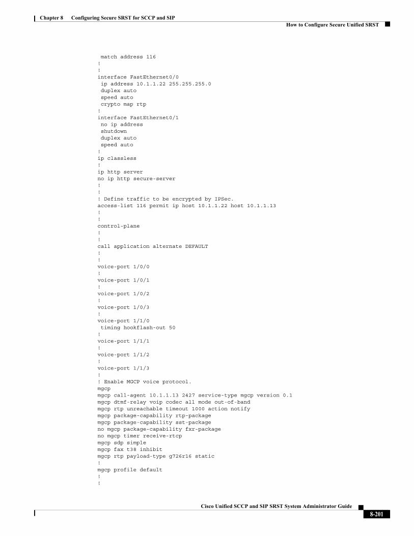
Chapter 8 Configuring Secure SRST for SCCP and SIPHow to Configure Secure Unified SRST
match address 116!!interface FastEthernet0/0 ip address 10.1.1.22 255.255.255.0 duplex auto speed auto crypto map rtp!interface FastEthernet0/1 no ip address shutdown duplex auto speed auto!ip classless!ip http serverno ip http secure-server!!! Define traffic to be encrypted by IPSec.access-list 116 permit ip host 10.1.1.22 host 10.1.1.13!!control-plane!!call application alternate DEFAULT!!voice-port 1/0/0!voice-port 1/0/1!voice-port 1/0/2!voice-port 1/0/3!voice-port 1/1/0 timing hookflash-out 50!voice-port 1/1/1!voice-port 1/1/2!voice-port 1/1/3!! Enable MGCP voice protocol.mgcpmgcp call-agent 10.1.1.13 2427 service-type mgcp version 0.1mgcp dtmf-relay voip codec all mode out-of-bandmgcp rtp unreachable timeout 1000 action notifymgcp package-capability rtp-packagemgcp package-capability sst-packageno mgcp package-capability fxr-packageno mgcp timer receive-rtcpmgcp sdp simplemgcp fax t38 inhibitmgcp rtp payload-type g726r16 static!mgcp profile default!!
8-201Cisco Unified SCCP and SIP SRST System Administrator Guide
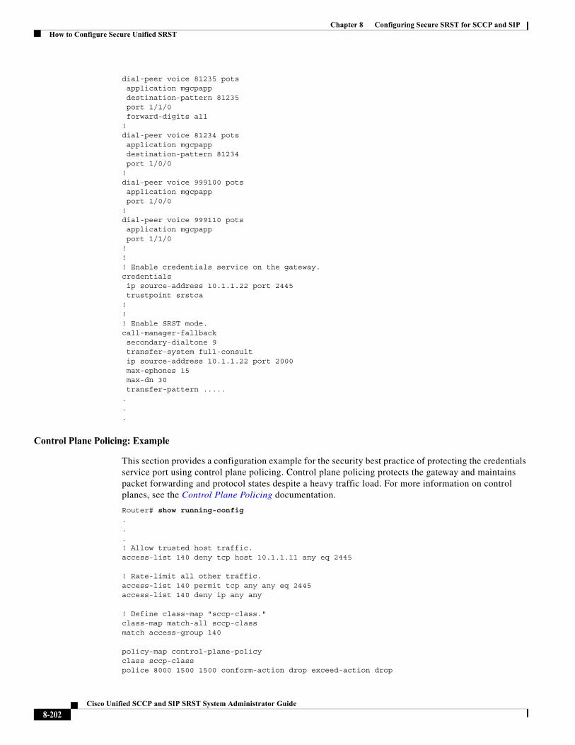
Chapter 8 Configuring Secure SRST for SCCP and SIPHow to Configure Secure Unified SRST
dial-peer voice 81235 pots application mgcpapp destination-pattern 81235 port 1/1/0 forward-digits all!dial-peer voice 81234 pots application mgcpapp destination-pattern 81234 port 1/0/0!dial-peer voice 999100 pots application mgcpapp port 1/0/0!dial-peer voice 999110 pots application mgcpapp port 1/1/0!!! Enable credentials service on the gateway. credentials ip source-address 10.1.1.22 port 2445 trustpoint srstca!!! Enable SRST mode.call-manager-fallbacksecondary-dialtone 9transfer-system full-consult
ip source-address 10.1.1.22 port 2000 max-ephones 15 max-dn 30transfer-pattern .....
.
.
.
Control Plane Policing: Example
This section provides a configuration example for the security best practice of protecting the credentials service port using control plane policing. Control plane policing protects the gateway and maintains packet forwarding and protocol states despite a heavy traffic load. For more information on control planes, see the Control Plane Policing documentation.
Router# show running-config...! Allow trusted host traffic.access-list 140 deny tcp host 10.1.1.11 any eq 2445
! Rate-limit all other traffic.access-list 140 permit tcp any any eq 2445access-list 140 deny ip any any
! Define class-map "sccp-class."class-map match-all sccp-classmatch access-group 140
policy-map control-plane-policyclass sccp-classpolice 8000 1500 1500 conform-action drop exceed-action drop
8-202Cisco Unified SCCP and SIP SRST System Administrator Guide
Chapter 8 Configuring Secure SRST for SCCP and SIPHow to Configure Secure Unified SRST
! Define aggregate control plane service for the active Route Processor.control-planeservice-policy input control-plane-policy
Configuring Secure SIP Call Signaling and SRTP Media with Cisco SRST
Cisco Unified Survivable Remote Site Telephony (Cisco SRST) provides secure call signaling and Secure Real-time Transport Protocol (SRTP) for media encryption to establish a secure, encrypted connection between Cisco Unified IP Phones and gateway devices.
• Prerequisites for Configuring Secure SIP Call Signaling and SRTP Media with Cisco SRST, page 203
• Restrictions for Configuring Secure SIP Call Signaling and SRTP Media with Cisco SRST, page 203
• Information About Cisco Unified SIP SRST Support of Secure SIP Signaling and SRTP Media, page 204
• Configuring Cisco Unified Communications Manager, page 204
• Configuring Phones, page 205
• Configuring SIP options for Secure SIP SRST, page 206
• Configuring SIP SRST Security Policy, page 207 (optional)
• Configuring SIP User Agent for Secure SIP SRST, page 208 (optional)
• Verifying the Configuration, page 210
• Configuration Example for Cisco Unified SIP SRST, page 212
Prerequisites for Configuring Secure SIP Call Signaling and SRTP Media with Cisco SRST
• Cisco IOS Release 15.0(1)XA and later releases.
• Cisco Unified IP Phone firmware release 8.5(3) or later.
• Complete the prerequisites and necessary tasks found in Prerequisites for Configuring SIP SRST Features Using Back-to-Back User Agent Mode.
• Prepare the Cisco Unified SIP SRST device to use certificates as documented in Preparing the Cisco Unified SRST Router for Secure Communication.
Restrictions for Configuring Secure SIP Call Signaling and SRTP Media with Cisco SRST
SIP phones may be configured on the Cisco Unified CM with an authenticated device security mode. The Cisco Unified CM ensures integrity and authentication for the phone using a TLS connection with NULL-SHA cipher for signaling. If an authenticated SIP phone fails over to the Cisco Unified SRST device, it will register using TCP instead of TLS/TCP, thus disabling the authenticated mode until the phone fails back to the Cisco Unified CM.
• By default, non-secure TCP SIP phones are permitted to register to the SRST device on failover from the primary call control. Support for TCP SIP phones requires the secure SRST configuration described in this section even if no encrypted phones are deployed. Without the secure SIP SRST configuration, TCP phones will register to the SRST device using UDP for signaling transport.
8-203Cisco Unified SCCP and SIP SRST System Administrator Guide
Chapter 8 Configuring Secure SRST for SCCP and SIPHow to Configure Secure Unified SRST
Information About Cisco Unified SIP SRST Support of Secure SIP Signaling and SRTP Media
Beginning with Cisco IP Phone firmware 8.5(3) and Cisco IOS Release 15.0(1)XA, Cisco SRST supports SIP signaling over UDP, TCP, and TLS connections, providing both RTP and SRTP media connections based on the security settings of the IP phone.
Cisco SRST SIP-to-SIP and SIP-to-PSTN support includes the following features:
• Basic calling
• Hold/resume
• Conference
• Transfer
• Blind transfer
• Call forward
Cisco SRST SIP-to-other (including SIP-to-SCCP) support includes basic calling, although other features may work.
Configuring Cisco Unified Communications Manager
Like SCCP-controlled devices, SIP-controlled devices will use the SRST Reference profile that is listed in their assigned Device Pool. The SRST Reference profile must have the "Is SRST Secure" checkbox selected if SIP/TLS communication is desired in the event of a WAN failure.
Note All Cisco Unified IP Phones must have their firmware updated to version 8.5(3) or later. Devices with firmware earlier than 8.5(3) will need to have a separate Device Pool and SRST Reference profile created without the "Is SRST Secure" option selected; SIP-controlled devices in this Device Pool will use SIP over UDP to attempt to register to the SRST router.
In Cisco Unified CM Administration, under System > SRST:
• For the secure SRST profile, Is SRST Secure? must be checked. The SIP port must be 5061.
• For the non-secure SRST profile, the Is SRST Secure? checkbox should NOT be checked and the SIP port should be 5060.
Under Device > Phone:
• Secure phones must belong to the pool that uses the secure SRST profile.
• Non-secure phones must belong to the pool that uses the non-secure SRST profile.
Note SIP phones will use the transport method assigned to them by their Phone Security Profile.
8-204Cisco Unified SCCP and SIP SRST System Administrator Guide
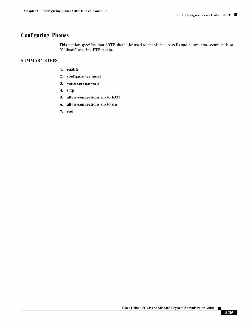
Chapter 8 Configuring Secure SRST for SCCP and SIPHow to Configure Secure Unified SRST
Configuring Phones
This section specifies that SRTP should be used to enable secure calls and allows non-secure calls to "fallback" to using RTP media.
SUMMARY STEPS
1. enable
2. configure terminal
3. voice service voip
4. srtp
5. allow-connections sip to h323
6. allow-connections sip to sip
7. end
8-205Cisco Unified SCCP and SIP SRST System Administrator Guide
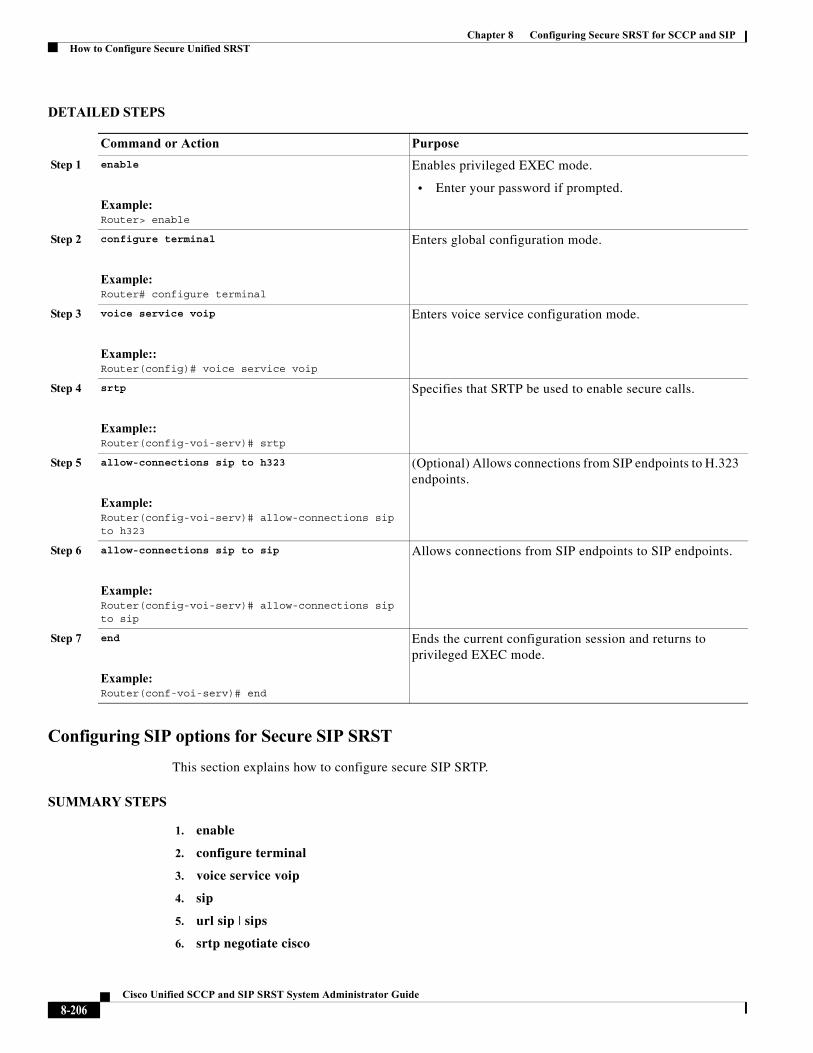
Chapter 8 Configuring Secure SRST for SCCP and SIPHow to Configure Secure Unified SRST
DETAILED STEPS
Configuring SIP options for Secure SIP SRST
This section explains how to configure secure SIP SRTP.
SUMMARY STEPS
1. enable
2. configure terminal
3. voice service voip
4. sip
5. url sip | sips
6. srtp negotiate cisco
Command or Action Purpose
Step 1 enable
Example:Router> enable
Enables privileged EXEC mode.
• Enter your password if prompted.
Step 2 configure terminal
Example:Router# configure terminal
Enters global configuration mode.
Step 3 voice service voip
Example::Router(config)# voice service voip
Enters voice service configuration mode.
Step 4 srtp
Example::Router(config-voi-serv)# srtp
Specifies that SRTP be used to enable secure calls.
Step 5 allow-connections sip to h323
Example:Router(config-voi-serv)# allow-connections sip to h323
(Optional) Allows connections from SIP endpoints to H.323 endpoints.
Step 6 allow-connections sip to sip
Example:Router(config-voi-serv)# allow-connections sip to sip
Allows connections from SIP endpoints to SIP endpoints.
Step 7 end
Example:Router(conf-voi-serv)# end
Ends the current configuration session and returns to privileged EXEC mode.
8-206Cisco Unified SCCP and SIP SRST System Administrator Guide
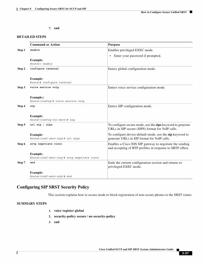
Chapter 8 Configuring Secure SRST for SCCP and SIPHow to Configure Secure Unified SRST
7. end
DETAILED STEPS
Configuring SIP SRST Security Policy
This section explains how to secure mode to block registration of non-secure phones to the SRST router.
SUMMARY STEPS
1. voice register global
2. security-policy secure | no security-policy
3. end
Command or Action Purpose
Step 1 enable
Example:Router> enable
Enables privileged EXEC mode.
• Enter your password if prompted.
Step 2 configure terminal
Example:Router# configure terminal
Enters global configuration mode.
Step 3 voice service voip
Example::Router(config)# voice service voip
Enters voice service configuration mode.
Step 4 sip
Example:Router(config-voi-serv)# sip
Enters SIP configuration mode.
Step 5 url sip | sips
Example:Router(conf-serv-sip)# url sips
To configure secure mode, use the sips keyword to generate URLs in SIP secure (SIPS) format for VoIP calls.
To configure device-default mode, use the sip keyword to generate URLs in SIP format for VoIP calls.
Step 6 srtp negotiate cisco
Example:Router(conf-serv-sip)# srtp negotiate cisco
Enables a Cisco IOS SIP gateway to negotiate the sending and accepting of RTP profiles in response to SRTP offers.
Step 7 end
Example:Router(conf-serv-sip)# end
Ends the current configuration session and returns to privileged EXEC mode.
8-207Cisco Unified SCCP and SIP SRST System Administrator Guide
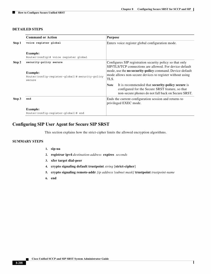
Chapter 8 Configuring Secure SRST for SCCP and SIPHow to Configure Secure Unified SRST
DETAILED STEPS
Configuring SIP User Agent for Secure SIP SRST
This section explains how the strict-cipher limits the allowed encryption algorithms.
SUMMARY STEPS
1. sip-ua
2. registrar ipv4:destination-address expires seconds
3. xfer target dial-peer
4. crypto signaling default trustpoint string [strict-cipher]
5. crypto signaling remote-addr {ip address |subnet mask} trustpoint trustpoint-name
6. end
Command or Action Purpose
Step 1 voice register global
Example:Router(config)# voice register global
Enters voice register global configuration mode.
Step 2 security-policy secure
Example:Router(config-register-global)# security-policy secure
Configures SIP registration security policy so that only SIP/TLS/TCP connections are allowed. For device-default mode, use the no security-policy command. Device-default mode allows non-secure devices to register without using TLS.
Note It is recommended that security-policy secure is configured for the Secure SRST feature, so that non-secure phones do not fall back on Secure SRST.
Step 3 end
Example:Router(config-register-global)# end
Ends the current configuration session and returns to privileged EXEC mode.
8-208Cisco Unified SCCP and SIP SRST System Administrator Guide
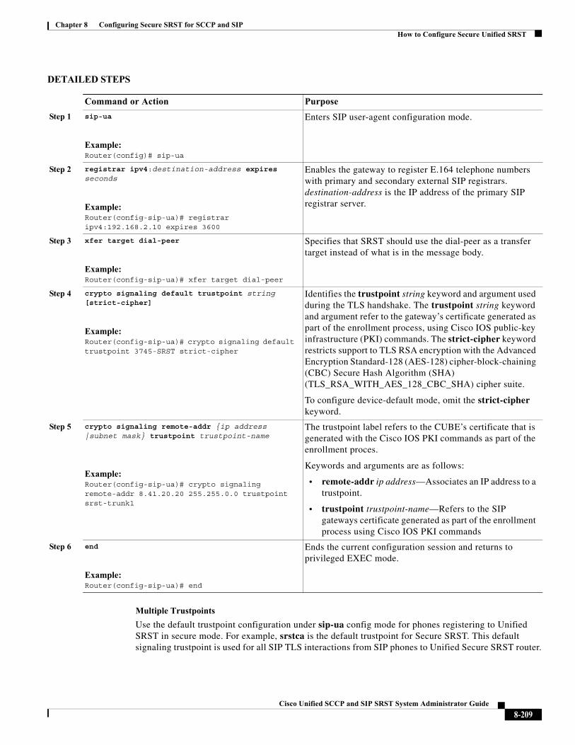
Chapter 8 Configuring Secure SRST for SCCP and SIPHow to Configure Secure Unified SRST
DETAILED STEPS
Multiple Trustpoints
Use the default trustpoint configuration under sip-ua config mode for phones registering to Unified SRST in secure mode. For example, srstca is the default trustpoint for Secure SRST. This default signaling trustpoint is used for all SIP TLS interactions from SIP phones to Unified Secure SRST router.
Command or Action Purpose
Step 1 sip-ua
Example:Router(config)# sip-ua
Enters SIP user-agent configuration mode.
Step 2 registrar ipv4:destination-address expires seconds
Example:Router(config-sip-ua)# registrar ipv4:192.168.2.10 expires 3600
Enables the gateway to register E.164 telephone numbers with primary and secondary external SIP registrars. destination-address is the IP address of the primary SIP registrar server.
Step 3 xfer target dial-peer
Example:Router(config-sip-ua)# xfer target dial-peer
Specifies that SRST should use the dial-peer as a transfer target instead of what is in the message body.
Step 4 crypto signaling default trustpoint string [strict-cipher]
Example:Router(config-sip-ua)# crypto signaling default trustpoint 3745-SRST strict-cipher
Identifies the trustpoint string keyword and argument used during the TLS handshake. The trustpoint string keyword and argument refer to the gateway’s certificate generated as part of the enrollment process, using Cisco IOS public-key infrastructure (PKI) commands. The strict-cipher keyword restricts support to TLS RSA encryption with the Advanced Encryption Standard-128 (AES-128) cipher-block-chaining (CBC) Secure Hash Algorithm (SHA) (TLS_RSA_WITH_AES_128_CBC_SHA) cipher suite.
To configure device-default mode, omit the strict-cipher keyword.
Step 5 crypto signaling remote-addr {ip address |subnet mask} trustpoint trustpoint-name
Example:Router(config-sip-ua)# crypto signaling remote-addr 8.41.20.20 255.255.0.0 trustpoint srst-trunk1
The trustpoint label refers to the CUBE’s certificate that is generated with the Cisco IOS PKI commands as part of the enrollment proces.
Keywords and arguments are as follows:
• remote-addr ip address—Associates an IP address to a trustpoint.
• trustpoint trustpoint-name—Refers to the SIP gateways certificate generated as part of the enrollment process using Cisco IOS PKI commands
Step 6 end
Example:Router(config-sip-ua)# end
Ends the current configuration session and returns to privileged EXEC mode.
8-209Cisco Unified SCCP and SIP SRST System Administrator Guide
Chapter 8 Configuring Secure SRST for SCCP and SIPHow to Configure Secure Unified SRST
In a deployment scenario with multiple trustpoints, communication with a service provider over a secure trunk with certificate issued by CA is achieved using the CLI command crypto signaling remote-addr 8.41.20.20 255.255.0.0 trustpoint srst-trunk1 under sip-ua config mode.
Example
The following example shows a sample configuration of multiple trustpoints for a Unified SRST deployment. In this example, the srst-trunk1 trustpoint points to the network with IP address 8.39.0.0, and srst-trunk2 trustpoint points to the network with IP address 8.41.20.20.
sip-uacrypto signaling remote-addr 8.39.0.0 255.255.0.0 trustpoint srst-trunk1 crypto signaling remote-addr 8.41.20.20 255.255.0.0 trustpoint srst-trunk2 crypto signaling default trustpoint secsrst
Verifying the Configuration
The following examples show a sample configuration displayed by the show sip-ua status registrar command and the show voice register global command.
The show sip-ua status registrar command in privileged EXEC mode displays all SIP endpoints that are currently registered with the contact address.
Router# show sip-ua status registrarLine destination expires(sec) contacttransport call-id
peer ============ =============== ============ =============== 3029991 192.168.2.108 388 192.168.2.108 TLS [email protected]
40004 3029993 192.168.2.103 382 192.168.2.103 TCP [email protected]
40011 3029982 192.168.2.106 406 192.168.2.106 UDP [email protected]
40001 3029983 192.168.2.106 406 192.168.2.106 UDP [email protected]
40003 3029992 192.168.2.107 414 192.168.2.107 TLS [email protected]
40005
The show voice register global command in privileged EXEC mode displays all global configuration parameters associated with SIP phones.
Router# show voice register global CONFIG [Version=8.0] ======================== Version 8.0Mode is srst Max-pool is 50 Max-dn is 100 Outbound-proxy is enabled and will use global configured value Security Policy: DEVICE-DEFAULT timeout interdigit 10 network-locale[0] US (This is the default network locale for this box) network-locale[1] US network-locale[2] US network-locale[3] US network-locale[4] US user-locale[0] US (This is the default user locale for this box)
8-210Cisco Unified SCCP and SIP SRST System Administrator Guide

Chapter 8 Configuring Secure SRST for SCCP and SIPHow to Configure Secure Unified SRST
user-locale[1] US user-locale[2] US user-locale[3] US user-locale[4] US Router#
8-211Cisco Unified SCCP and SIP SRST System Administrator Guide
Chapter 8 Configuring Secure SRST for SCCP and SIPHow to Configure Secure Unified SRST
Configuration Example for Cisco Unified SIP SRST
Current configuration : 15343 bytes!! Last configuration change at 05:34:06 UTC Tue Jun 13 2017! NVRAM config last updated at 11:57:03 UTC Thu Jun 8 2017!version 16.7service timestamps debug datetime msecservice timestamps log datetime msecplatform qfp utilization monitor load 80no platform punt-keepalive disable-kernel-core!hostname router!boot-start-markerboot-end-marker!
vrf definition Mgmt-intf ! address-family ipv4 exit-address-family ! address-family ipv6 exit-address-family!! card type command needed for slot/bay 0/3no logging queue-limitlogging buffered 20000000no logging rate-limitno logging consoleenable password xxxx!no aaa new-model!subscriber templating! multilink bundle-name authenticated!crypto pki server SRST-CA-2 database level complete no database archive grant auto!crypto pki trustpoint TRUSTPT-SRST-CA-2 enrollment url http://10.0.0.1:80 serial-number revocation-check none rsakeypair srstcakey 2048 rsakeypair SRST-CA-2!crypto pki trustpoint SRST-CA-2 revocation-check crl rsakeypair SRST-CA-2!crypto pki trustpoint Cisco_Manufacturing_CA enrollment terminal revocation-check none!crypto pki trustpoint CAPF-3a66269a enrollment terminal revocation-check none
8-212Cisco Unified SCCP and SIP SRST System Administrator Guide
Chapter 8 Configuring Secure SRST for SCCP and SIPHow to Configure Secure Unified SRST
!crypto pki trustpoint Cisco_Root_CA_2048 enrollment terminal revocation-check none!!crypto pki certificate chain TRUSTPT-SRST-CA-2 certificate 02 3082020B 30820174 A0030201 02020102 300D0609 2A864886 F70D0101 05050030 14311230 10060355 04031309 53525354 2D43412D 32301E17 0D313730 36303831 31333131 325A170D 31383036 30383131 33313132 5A303231 30301206 03550405 130B4647 4C313735 31313150 42301A06 092A8648 86F70D01 0902160D 416E7473 41726D79 2D343430 3030819F 300D0609 2A864886 F70D0101 01050003 818D0030 81890281 81009E24 6259A98D A61C1973 45A95DA8 DE83ECAD C2B1B448 741F7E64 3D753BF1 19BD54FB 9A4D4A8E 7A2BA416 B93C40B3 A63A7C4D 7303498F 098EF07F 96F26F5F 49AD4E39 EC113DF4 696CB887 607D545A 52A11469 958F4C04 05868DF9 317456F6 3D23837C D46331FA 69FB29E8 3211E01C A7AB19A3 94DAC09F 97601196 A08D7073 76210203 010001A3 4F304D30 0B060355 1D0F0404 030205A0 301F0603 551D2304 18301680 142110B8 F25BD9BD E1D401EC 9D11DC0E AE52CDB8 2F301D06 03551D0E 04160414 2110B8F2 5BD9BDE1 D401EC9D 11DC0EAE 52CDB82F 300D0609 2A864886 F70D0101 05050003 8181003A DC409694 26D08A31 7B4F495F 002D4E57 B28669A9 10E93C68 A9556659 97D326EC A5508201 C1A86659 B1CDC910 73097FCA F6174794 1057DDDE DBA666D6 0BAFC503 96A10BE5 5FCA3B93 5D377ABE BC9B2774 3732DF01 CE3BF12B 1899AA69 F7EC8726 A1964C5A D6A99A0E E27EE2A0 15A7D364 793C6C8D 961C77E4 397F9CB4 C6A271 quit certificate ca 01 30820201 3082016A A0030201 02020101 300D0609 2A864886 F70D0101 04050030 14311230 10060355 04031309 53525354 2D43412D 32301E17 0D313730 36303831 31323135 305A170D 32303036 30373131 32313530 5A301431 12301006 03550403 13095352 53542D43 412D3230 819F300D 06092A86 4886F70D 01010105 0003818D 00308189 02818100 9E246259 A98DA61C 197345A9 5DA8DE83 ECADC2B1 B448741F 7E643D75 3BF119BD 54FB9A4D 4A8E7A2B A416B93C 40B3A63A 7C4D7303 498F098E F07F96F2 6F5F49AD 4E39EC11 3DF4696C B887607D 545A52A1 1469958F 4C040586 8DF93174 56F63D23 837CD463 31FA69FB 29E83211 E01CA7AB 19A394DA C09F9760 1196A08D 70737621 02030100 01A36330 61300F06 03551D13 0101FF04 05300301 01FF300E 0603551D 0F0101FF 04040302 0186301F 0603551D 23041830 16801421 10B8F25B D9BDE1D4 01EC9D11 DC0EAE52 CDB82F30 1D060355 1D0E0416 04142110 B8F25BD9 BDE1D401 EC9D11DC 0EAE52CD B82F300D 06092A86 4886F70D 01010405 00038181 0018859E D39C6A05 63509442 8746D970 BB716DE2 E82BA822 58AA55AD AC37260F 36BFDFE6 F2D0E489 A8D23690 791AD903 F19AC857 5002E621 A5927ACC DCB759C0 B126ACAB C53BF054 1F62D895 A895C50A E3AE83E3 EC68F346 50B88D39 BB053EE9 5D466AE4 C6B4593D 7EFA7A78 213C0766 7307A051 78FED92E 5A34AAB6 98D2A59C 31 quitcrypto pki certificate chain SRST-CA-2 certificate ca 01 30820201 3082016A A0030201 02020101 300D0609 2A864886 F70D0101 04050030 14311230 10060355 04031309 53525354 2D43412D 32301E17 0D313730 36303831 31323135 305A170D 32303036 30373131 32313530 5A301431 12301006 03550403 13095352 53542D43 412D3230 819F300D 06092A86 4886F70D 01010105 0003818D 00308189 02818100 9E246259 A98DA61C 197345A9 5DA8DE83 ECADC2B1 B448741F 7E643D75 3BF119BD 54FB9A4D 4A8E7A2B A416B93C 40B3A63A 7C4D7303 498F098E F07F96F2 6F5F49AD 4E39EC11 3DF4696C B887607D 545A52A1 1469958F 4C040586 8DF93174 56F63D23 837CD463 31FA69FB 29E83211 E01CA7AB 19A394DA C09F9760 1196A08D 70737621 02030100 01A36330 61300F06 03551D13 0101FF04 05300301 01FF300E 0603551D 0F0101FF 04040302 0186301F 0603551D 23041830 16801421 10B8F25B D9BDE1D4 01EC9D11 DC0EAE52 CDB82F30 1D060355 1D0E0416 04142110 B8F25BD9 BDE1D401 EC9D11DC 0EAE52CD B82F300D 06092A86 4886F70D 01010405 00038181 0018859E D39C6A05 63509442 8746D970 BB716DE2 E82BA822 58AA55AD AC37260F 36BFDFE6 F2D0E489 A8D23690 791AD903 F19AC857 5002E621 A5927ACC DCB759C0 B126ACAB C53BF054 1F62D895 A895C50A E3AE83E3 EC68F346 50B88D39 BB053EE9 5D466AE4 C6B4593D 7EFA7A78 213C0766 7307A051 78FED92E 5A34AAB6 98D2A59C 31
8-213Cisco Unified SCCP and SIP SRST System Administrator Guide
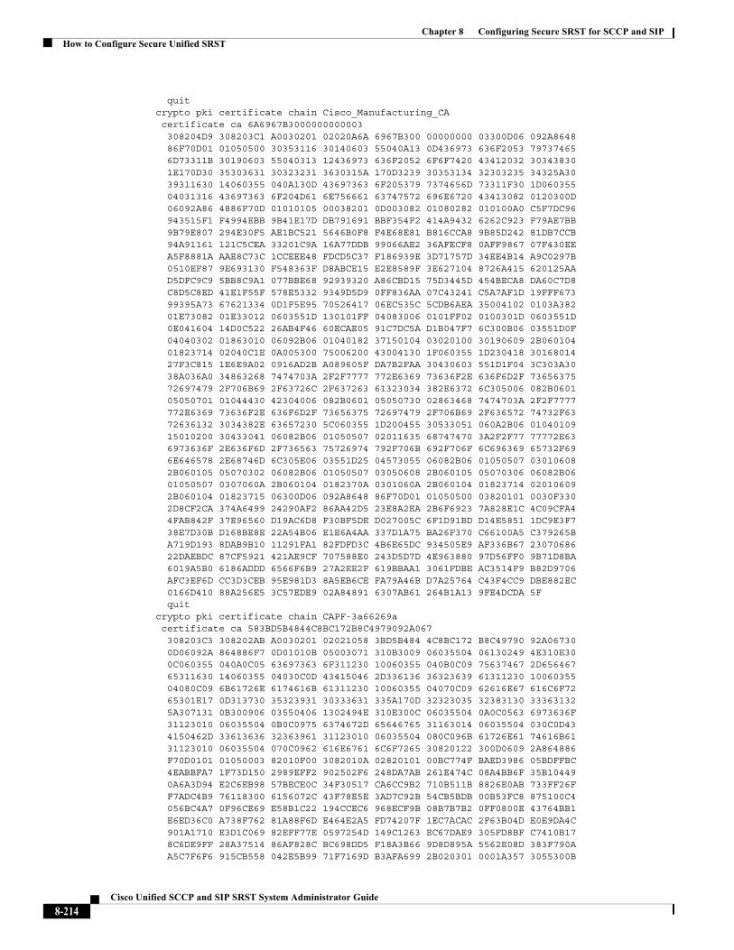
Chapter 8 Configuring Secure SRST for SCCP and SIPHow to Configure Secure Unified SRST
quitcrypto pki certificate chain Cisco_Manufacturing_CA certificate ca 6A6967B3000000000003 308204D9 308203C1 A0030201 02020A6A 6967B300 00000000 03300D06 092A8648 86F70D01 01050500 30353116 30140603 55040A13 0D436973 636F2053 79737465 6D73311B 30190603 55040313 12436973 636F2052 6F6F7420 43412032 30343830 1E170D30 35303631 30323231 3630315A 170D3239 30353134 32303235 34325A30 39311630 14060355 040A130D 43697363 6F205379 7374656D 73311F30 1D060355 04031316 43697363 6F204D61 6E756661 63747572 696E6720 43413082 0120300D 06092A86 4886F70D 01010105 00038201 0D003082 01080282 010100A0 C5F7DC96 943515F1 F4994EBB 9B41E17D DB791691 BBF354F2 414A9432 6262C923 F79AE7BB 9B79E807 294E30F5 AE1BC521 5646B0F8 F4E68E81 B816CCA8 9B85D242 81DB7CCB 94A91161 121C5CEA 33201C9A 16A77DDB 99066AE2 36AFECF8 0AFF9867 07F430EE A5F8881A AAE8C73C 1CCEEE48 FDCD5C37 F186939E 3D71757D 34EE4B14 A9C0297B 0510EF87 9E693130 F548363F D8ABCE15 E2E8589F 3E627104 8726A415 620125AA D5DFC9C9 5BB8C9A1 077BBE68 92939320 A86CBD15 75D3445D 454BECA8 DA60C7D8 C8D5C8ED 41E1F55F 578E5332 9349D5D9 0FF836AA 07C43241 C5A7AF1D 19FFF673 99395A73 67621334 0D1F5E95 70526417 06EC535C 5CDB6AEA 35004102 0103A382 01E73082 01E33012 0603551D 130101FF 04083006 0101FF02 0100301D 0603551D 0E041604 14D0C522 26AB4F46 60ECAE05 91C7DC5A D1B047F7 6C300B06 03551D0F 04040302 01863010 06092B06 01040182 37150104 03020100 30190609 2B060104 01823714 02040C1E 0A005300 75006200 43004130 1F060355 1D230418 30168014 27F3C815 1E6E9A02 0916AD2B A089605F DA7B2FAA 30430603 551D1F04 3C303A30 38A036A0 34863268 7474703A 2F2F7777 772E6369 73636F2E 636F6D2F 73656375 72697479 2F706B69 2F63726C 2F637263 61323034 382E6372 6C305006 082B0601 05050701 01044430 42304006 082B0601 05050730 02863468 7474703A 2F2F7777 772E6369 73636F2E 636F6D2F 73656375 72697479 2F706B69 2F636572 74732F63 72636132 3034382E 63657230 5C060355 1D200455 30533051 060A2B06 01040109 15010200 30433041 06082B06 01050507 02011635 68747470 3A2F2F77 77772E63 6973636F 2E636F6D 2F736563 75726974 792F706B 692F706F 6C696369 65732F69 6E646578 2E68746D 6C305E06 03551D25 04573055 06082B06 01050507 03010608 2B060105 05070302 06082B06 01050507 03050608 2B060105 05070306 06082B06 01050507 0307060A 2B060104 0182370A 0301060A 2B060104 01823714 02010609 2B060104 01823715 06300D06 092A8648 86F70D01 01050500 03820101 0030F330 2D8CF2CA 374A6499 24290AF2 86AA42D5 23E8A2EA 2B6F6923 7A828E1C 4C09CFA4 4FAB842F 37E96560 D19AC6D8 F30BF5DE D027005C 6F1D91BD D14E5851 1DC9E3F7 38E7D30B D168BE8E 22A54B06 E1E6A4AA 337D1A75 BA26F370 C66100A5 C379265B A719D193 8DAB9B10 11291FA1 82FDFD3C 4B6E65DC 934505E9 AF336B67 23070686 22DAEBDC 87CF5921 421AE9CF 707588E0 243D5D7D 4E963880 97D56FF0 9B71D8BA 6019A5B0 6186ADDD 6566F6B9 27A2EE2F 619BBAA1 3061FDBE AC3514F9 B82D9706 AFC3EF6D CC3D3CEB 95E981D3 8A5EB6CE FA79A46B D7A25764 C43F4CC9 DBE882EC 0166D410 88A256E5 3C57EDE9 02A84891 6307AB61 264B1A13 9FE4DCDA 5F quitcrypto pki certificate chain CAPF-3a66269a certificate ca 583BD5B4844C8BC172B8C4979092A067 308203C3 308202AB A0030201 02021058 3BD5B484 4C8BC172 B8C49790 92A06730 0D06092A 864886F7 0D01010B 05003071 310B3009 06035504 06130249 4E310E30 0C060355 040A0C05 63697363 6F311230 10060355 040B0C09 75637467 2D656467 65311630 14060355 04030C0D 43415046 2D336136 36323639 61311230 10060355 04080C09 6B61726E 6174616B 61311230 10060355 04070C09 62616E67 616C6F72 65301E17 0D313730 35323931 30333631 335A170D 32323035 32383130 33363132 5A307131 0B300906 03550406 1302494E 310E300C 06035504 0A0C0563 6973636F 31123010 06035504 0B0C0975 6374672D 65646765 31163014 06035504 030C0D43 4150462D 33613636 32363961 31123010 06035504 080C096B 61726E61 74616B61 31123010 06035504 070C0962 616E6761 6C6F7265 30820122 300D0609 2A864886 F70D0101 01050003 82010F00 3082010A 02820101 00BC774F BAED3986 05BDFFBC 4EABBFA7 1F73D150 2989EFF2 902502F6 248DA7AB 261E474C 08A4BB6F 35B10449 0A6A3D94 E2C6EB98 57BECE0C 34F30517 CA6CC9B2 710B511B 8826E0AB 733FF26F F7ADC4B9 76118300 6156072C 43F78E5E 3AD7C92B 54CB5BDB 00B53FC8 875100C4 056BC4A7 0F96CE69 E58B1C22 194CCEC6 968ECF9B 08B7B7B2 0FF0800E 43764BB1 E6ED36C0 A738F762 81A88F6D E464E2A5 FD74207F 1EC7ACAC 2F63B04D E0E9DA4C 901A1710 E3D1C069 82EFF77E 0597254D 149C1263 EC67DAE9 305FD8BF C7410B17 8C6DE9FF 28A37514 86AF828C BC698DD5 F18A3B66 9D8D895A 5562E08D 383F790A A5C7F6F6 915CB558 042E5B99 71F7169D B3AFA699 2B020301 0001A357 3055300B
8-214Cisco Unified SCCP and SIP SRST System Administrator Guide
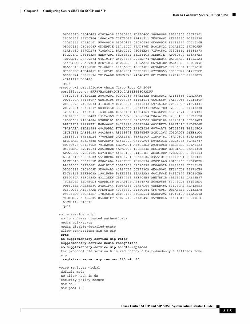
Chapter 8 Configuring Secure SRST for SCCP and SIPHow to Configure Secure Unified SRST
0603551D 0F040403 0202A430 13060355 1D25040C 300A0608 2B060105 05070301 301D0603 551D0E04 16041475 71EC5D35 1A431511 7E8C8462 6E65E570 7C551930 12060355 1D130101 FF040830 060101FF 02010030 0D06092A 864886F7 0D01010B 05000382 0101008F 0D3E9F3E 3574100D 97AD876D B4015C21 300A1BD0 59D5C9BF 41A8448D 597CD278 718A6431 BA94C042 7EC64BA0 71F04501 C33C1664 16484373 F3C226A7 256363A9 8BE97291 6B25B8B4 E3DB84C3 3DDB63E7 A9D8D577 6B8F37B3 7CFCE019 D6F09573 946191F7 C4028465 B072DF74 9D6DED45 CA9E6A3B 1401D1A3 5449EDCE 9FA593E3 2FD71031 C7C7EB9C 045DAAFE C67603BF DAB40EE0 352C009F EAAA6816 A11F6D8B 7C406211 1045A0C6 488B34E1 AF968FAF 3705A364 1EE21A1D B7080EDC 40D4AA15 E110C5F1 D8A57561 DB2B09F1 0779B855 3998CE22 C471B5CB 09605E24 99855176 2D1CA40E BEBC2F23 7434CA2B 8D1C5EFB 822147CC 81F98825 47A1A14F DC5480 quitcrypto pki certificate chain Cisco_Root_CA_2048 certificate ca 5FF87B282B54DC8D42A315B568C9ADFF 30820343 3082022B A0030201 0202105F F87B282B 54DC8D42 A315B568 C9ADFF30 0D06092A 864886F7 0D010105 05003035 31163014 06035504 0A130D43 6973636F 20537973 74656D73 311B3019 06035504 03131243 6973636F 20526F6F 74204341 20323034 38301E17 0D303430 35313432 30313731 325A170D 32393035 31343230 32353432 5A303531 16301406 0355040A 130D4369 73636F20 53797374 656D7331 1B301906 03550403 13124369 73636F20 526F6F74 20434120 32303438 30820120 300D0609 2A864886 F70D0101 01050003 82010D00 30820108 02820101 00B09AB9 ABA7AF0A 77A7E271 B6B46662 94788847 C6625584 4032BFC0 AB2EA51C 71D6BC6E 7BA8AABA 6ED21588 48459DA2 FC83D0CC B98CE026 68704A78 DF21179E F46105C9 15C8CF16 DA356189 9443A884 A8319878 9BB94E6F 2C53126C CD1DAD2B 24BB31C4 2BFF8344 6FB63D24 7709EABF 2AA81F6A 56F6200F 11549781 75A725CE 596A8265 EFB7EAE7 E28D758B 6EF2DD4F A65E629C CF100A64 D04E6DCE 2BCC5BF5 60A52747 8D69F47F CE1B70DE 701B20D6 6ECDA601 A83C12D2 A93FA06B 5EBB8E20 8B7A91E3 B568EEA0 E7C40174 A8530B2B 4A9A0F65 120E824D 8E63FDEF EB9B1ADB 53A61360 AFC27DD7 C76C1725 D473FB47 64508180 944CE1BF AE4B1CDF 92ED2E05 DF020103 A351304F 300B0603 551D0F04 04030201 86300F06 03551D13 0101FF04 05300301 01FF301D 0603551D 0E041604 1427F3C8 151E6E9A 020916AD 2BA08960 5FDA7B2F AA301006 092B0601 04018237 15010403 02010030 0D06092A 864886F7 0D010105 05000382 0101009D 9D8484A3 41A97C77 0CB753CA 4E445062 EF547CD3 75171CE8 E0C6484B B6FE4C3A 198156B0 56EE1996 62AA5AA3 64C1F64E 5433C677 FEC51CBA E55D25CA F5F0939A 83112EE6 CBF87445 FEE705B8 ABE7DFCB 4BE13784 DAB98B97 701EF0E2 8BD7B0D8 0E9DB169 D62A917B A9494F7E E68E95D8 83273CD5 68490ED4 9DF62EEB A7BEEB30 A4AC1F44 FC95AB33 06FB7D60 0ADEB48A 63B09CA9 F2A4B953 0187D068 A4277FAB FFE9FAC9 40388867 B439C684 6F57C953 DBBA8EEE C043B2F8 09836EFF 66CF3EEF 17B35818 2509345E E3CBD614 B6ECF292 6F74E42F 812AD592 91E0E097 3C326805 854BD1F7 57E2521D 931A549F 0570C04A 71601E43 0B601EFE A3CE8119 E10B35 quit!voice service voip no ip address trusted authenticate media bulk-stats media disable-detailed-stats allow-connections sip to sip srtp no supplementary-service sip refer supplementary-service media-renegotiate no supplementary-service sip handle-replaces fax protocol t38 version 0 ls-redundancy 0 hs-redundancy 0 fallback none sip registrar server expires max 120 min 60!voice register global default mode no allow-hash-in-dn security-policy secure max-dn 50 max-pool 40!
8-215Cisco Unified SCCP and SIP SRST System Administrator Guide
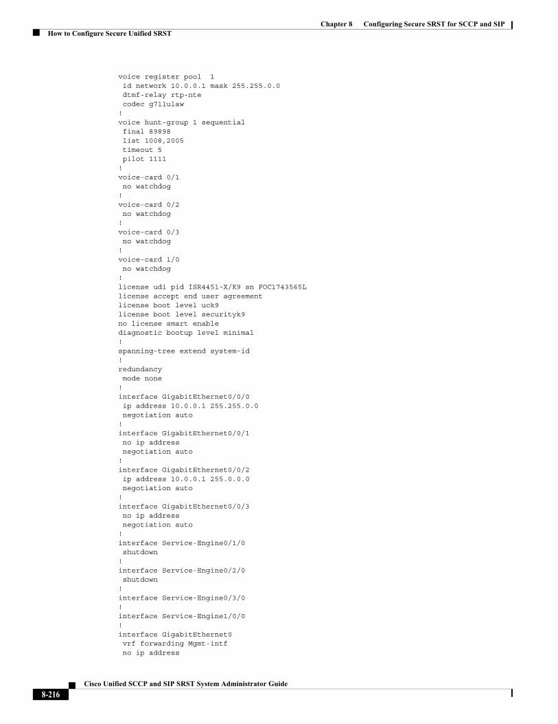
Chapter 8 Configuring Secure SRST for SCCP and SIPHow to Configure Secure Unified SRST
voice register pool 1 id network 10.0.0.1 mask 255.255.0.0 dtmf-relay rtp-nte codec g711ulaw!voice hunt-group 1 sequential final 89898 list 1008,2005 timeout 5 pilot 1111 !voice-card 0/1 no watchdog!voice-card 0/2 no watchdog!voice-card 0/3 no watchdog!voice-card 1/0 no watchdog!license udi pid ISR4451-X/K9 sn FOC1743565Llicense accept end user agreementlicense boot level uck9license boot level securityk9no license smart enablediagnostic bootup level minimal!spanning-tree extend system-id!redundancy mode none!interface GigabitEthernet0/0/0 ip address 10.0.0.1 255.255.0.0 negotiation auto!interface GigabitEthernet0/0/1 no ip address negotiation auto!interface GigabitEthernet0/0/2 ip address 10.0.0.1 255.0.0.0 negotiation auto!interface GigabitEthernet0/0/3 no ip address negotiation auto!interface Service-Engine0/1/0 shutdown!interface Service-Engine0/2/0 shutdown!interface Service-Engine0/3/0!interface Service-Engine1/0/0!interface GigabitEthernet0 vrf forwarding Mgmt-intf no ip address
8-216Cisco Unified SCCP and SIP SRST System Administrator Guide
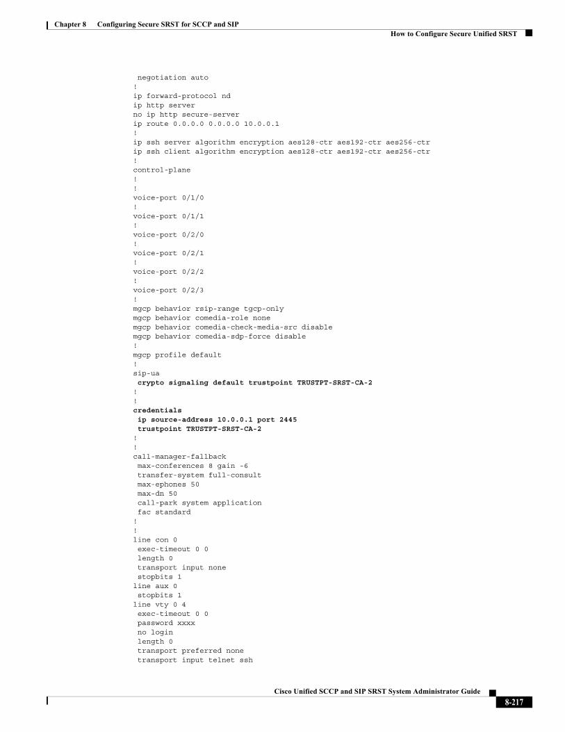
Chapter 8 Configuring Secure SRST for SCCP and SIPHow to Configure Secure Unified SRST
negotiation auto!ip forward-protocol ndip http serverno ip http secure-serverip route 0.0.0.0 0.0.0.0 10.0.0.1!ip ssh server algorithm encryption aes128-ctr aes192-ctr aes256-ctrip ssh client algorithm encryption aes128-ctr aes192-ctr aes256-ctr!control-plane!!voice-port 0/1/0!voice-port 0/1/1!voice-port 0/2/0!voice-port 0/2/1!voice-port 0/2/2!voice-port 0/2/3!mgcp behavior rsip-range tgcp-onlymgcp behavior comedia-role nonemgcp behavior comedia-check-media-src disablemgcp behavior comedia-sdp-force disable!mgcp profile default!sip-ua crypto signaling default trustpoint TRUSTPT-SRST-CA-2 !!credentials ip source-address 10.0.0.1 port 2445 trustpoint TRUSTPT-SRST-CA-2!!call-manager-fallback max-conferences 8 gain -6 transfer-system full-consult max-ephones 50 max-dn 50 call-park system application fac standard!!line con 0 exec-timeout 0 0 length 0 transport input none stopbits 1line aux 0 stopbits 1line vty 0 4 exec-timeout 0 0 password xxxx no login length 0 transport preferred none transport input telnet ssh
8-217Cisco Unified SCCP and SIP SRST System Administrator Guide
Chapter 8 Configuring Secure SRST for SCCP and SIPAdditional References
!end
Additional ReferencesThe following sections provide references related to this feature.
8-218Cisco Unified SCCP and SIP SRST System Administrator Guide
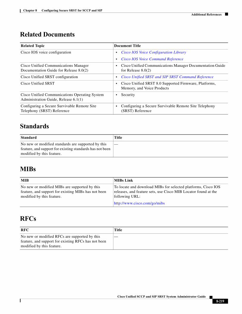
Chapter 8 Configuring Secure SRST for SCCP and SIPAdditional References
Related Documents
Standards
MIBs
RFCs
Related Topic Document Title
Cisco IOS voice configuration • Cisco IOS Voice Configuration Library
• Cisco IOS Voice Command Reference
Cisco Unified Communications Manager Documentation Guide for Release 8.0(2)
• Cisco Unified Communications Manager Documentation Guide for Release 8.0(2)
Cisco Unified SRST configuration • Cisco Unified SRST and SIP SRST Command Reference
Cisco Unified SRST • Cisco Unified SRST 8.0 Supported Firmware, Platforms, Memory, and Voice Products
Cisco Unified Communications Operating System Administration Guide, Release 6.1(1)
• Security
Configuring a Secure Survivable Remote Site Telephony (SRST) Reference
• Configuring a Secure Survivable Remote Site Telephony (SRST) Reference
Standard Title
No new or modified standards are supported by this feature, and support for existing standards has not been modified by this feature.
—
MIB MIBs Link
No new or modified MIBs are supported by this feature, and support for existing MIBs has not been modified by this feature.
To locate and download MIBs for selected platforms, Cisco IOS releases, and feature sets, use Cisco MIB Locator found at the following URL:
http://www.cisco.com/go/mibs
RFC Title
No new or modified RFCs are supported by this feature, and support for existing RFCs has not been modified by this feature.
—
8-219Cisco Unified SCCP and SIP SRST System Administrator Guide
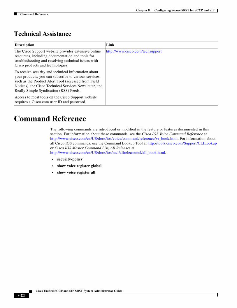
Chapter 8 Configuring Secure SRST for SCCP and SIPCommand Reference
Technical Assistance
Command ReferenceThe following commands are introduced or modified in the feature or features documented in this section. For information about these commands, see the Cisco IOS Voice Command Reference at http://www.cisco.com/en/US/docs/ios/voice/command/reference/vr_book.html. For information about all Cisco IOS commands, use the Command Lookup Tool at http://tools.cisco.com/Support/CLILookup or Cisco IOS Master Command List, All Releases at http://www.cisco.com/en/US/docs/ios/mcl/allreleasemcl/all_book.html.
• security-policy
• show voice register global
• show voice register all
Description Link
The Cisco Support website provides extensive online resources, including documentation and tools for troubleshooting and resolving technical issues with Cisco products and technologies.
To receive security and technical information about your products, you can subscribe to various services, such as the Product Alert Tool (accessed from Field Notices), the Cisco Technical Services Newsletter, and Really Simple Syndication (RSS) Feeds.
Access to most tools on the Cisco Support website requires a Cisco.com user ID and password.
http://www.cisco.com/techsupport
8-220Cisco Unified SCCP and SIP SRST System Administrator Guide
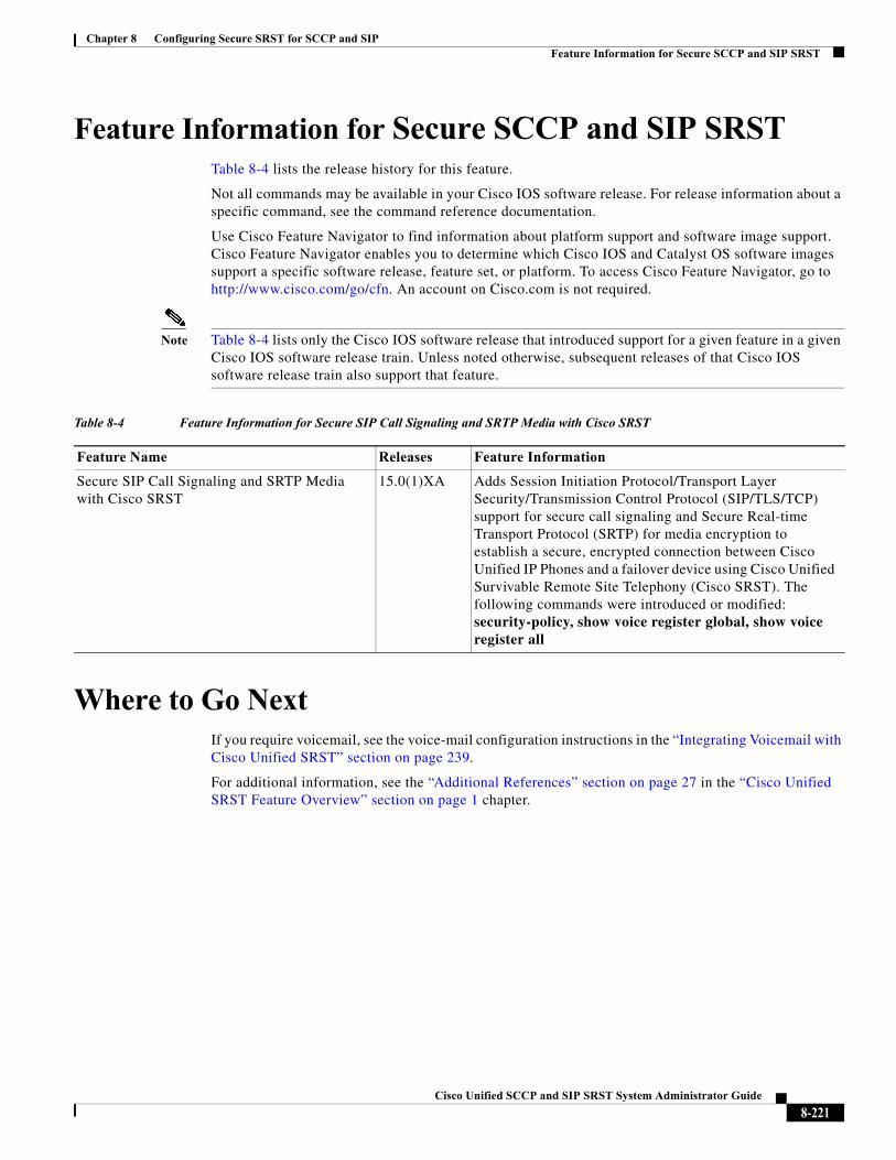
Chapter 8 Configuring Secure SRST for SCCP and SIPFeature Information for Secure SCCP and SIP SRST
Feature Information for Secure SCCP and SIP SRSTTable 8-4 lists the release history for this feature.
Not all commands may be available in your Cisco IOS software release. For release information about a specific command, see the command reference documentation.
Use Cisco Feature Navigator to find information about platform support and software image support. Cisco Feature Navigator enables you to determine which Cisco IOS and Catalyst OS software images support a specific software release, feature set, or platform. To access Cisco Feature Navigator, go to http://www.cisco.com/go/cfn. An account on Cisco.com is not required.
Note Table 8-4 lists only the Cisco IOS software release that introduced support for a given feature in a given Cisco IOS software release train. Unless noted otherwise, subsequent releases of that Cisco IOS software release train also support that feature.
Where to Go NextIf you require voicemail, see the voice-mail configuration instructions in the “Integrating Voicemail with Cisco Unified SRST” section on page 239.
For additional information, see the “Additional References” section on page 27 in the “Cisco Unified SRST Feature Overview” section on page 1 chapter.
Table 8-4 Feature Information for Secure SIP Call Signaling and SRTP Media with Cisco SRST
Feature Name Releases Feature Information
Secure SIP Call Signaling and SRTP Media with Cisco SRST
15.0(1)XA Adds Session Initiation Protocol/Transport Layer Security/Transmission Control Protocol (SIP/TLS/TCP) support for secure call signaling and Secure Real-time Transport Protocol (SRTP) for media encryption to establish a secure, encrypted connection between Cisco Unified IP Phones and a failover device using Cisco Unified Survivable Remote Site Telephony (Cisco SRST). The following commands were introduced or modified: security-policy, show voice register global, show voice register all
8-221Cisco Unified SCCP and SIP SRST System Administrator Guide

Chapter 8 Configuring Secure SRST for SCCP and SIPWhere to Go Next
8-222Cisco Unified SCCP and SIP SRST System Administrator Guide
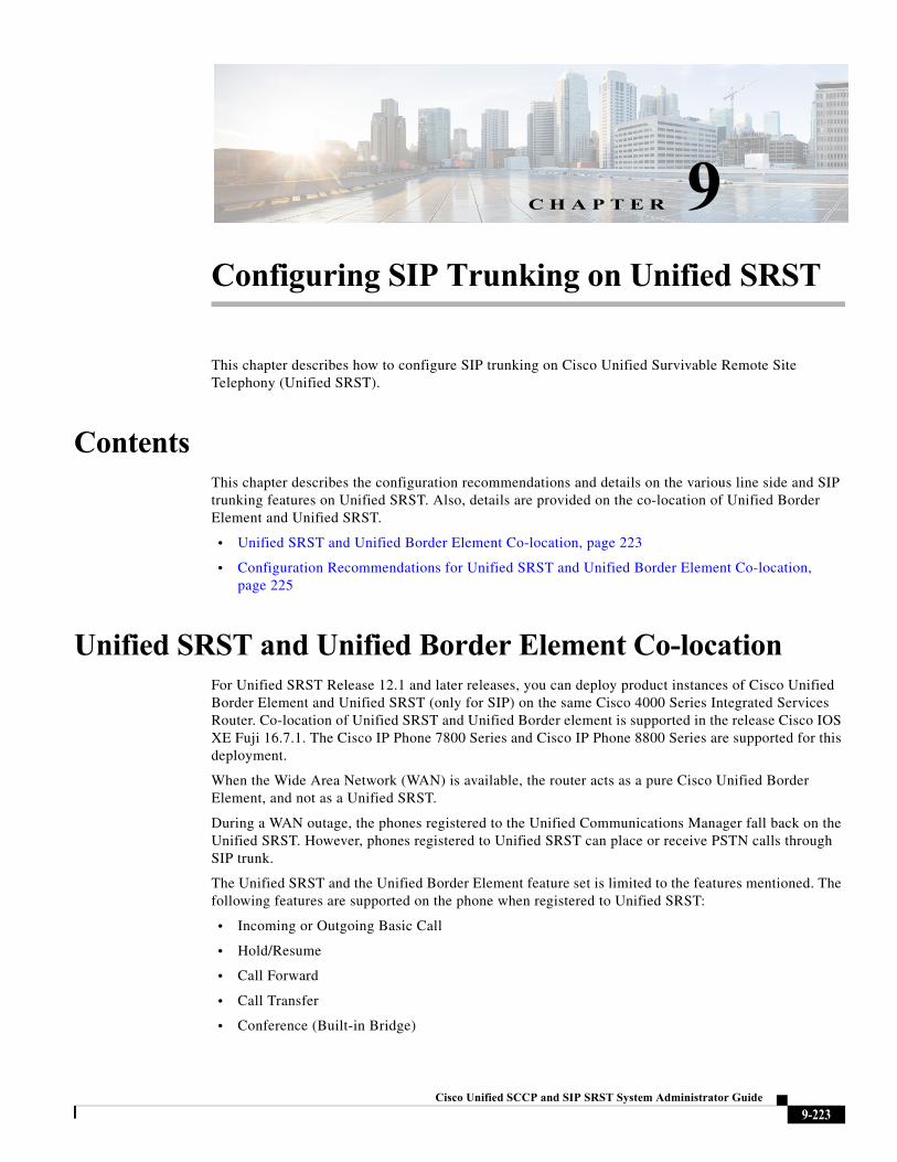
Cisco Unified SC
C H A P T E R 9
Configuring SIP Trunking on Unified SRSTThis chapter describes how to configure SIP trunking on Cisco Unified Survivable Remote Site Telephony (Unified SRST).
ContentsThis chapter describes the configuration recommendations and details on the various line side and SIP trunking features on Unified SRST. Also, details are provided on the co-location of Unified Border Element and Unified SRST.
• Unified SRST and Unified Border Element Co-location, page 223
• Configuration Recommendations for Unified SRST and Unified Border Element Co-location, page 225
Unified SRST and Unified Border Element Co-locationFor Unified SRST Release 12.1 and later releases, you can deploy product instances of Cisco Unified Border Element and Unified SRST (only for SIP) on the same Cisco 4000 Series Integrated Services Router. Co-location of Unified SRST and Unified Border element is supported in the release Cisco IOS XE Fuji 16.7.1. The Cisco IP Phone 7800 Series and Cisco IP Phone 8800 Series are supported for this deployment.
When the Wide Area Network (WAN) is available, the router acts as a pure Cisco Unified Border Element, and not as a Unified SRST.
During a WAN outage, the phones registered to the Unified Communications Manager fall back on the Unified SRST. However, phones registered to Unified SRST can place or receive PSTN calls through SIP trunk.
The Unified SRST and the Unified Border Element feature set is limited to the features mentioned. The following features are supported on the phone when registered to Unified SRST:
• Incoming or Outgoing Basic Call
• Hold/Resume
• Call Forward
• Call Transfer
• Conference (Built-in Bridge)
9-223CP and SIP SRST System Administrator Guide
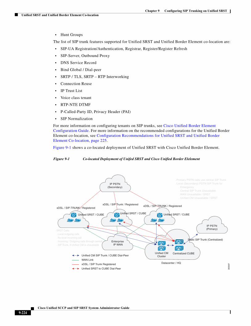
Chapter 9 Configuring SIP Trunking on Unified SRSTUnified SRST and Unified Border Element Co-location
• Hunt Groups
The list of SIP trunk features supported for Unified SRST and Unified Border Element co-location are:
• SIP-UA Registration/Authentication, Registrar, Register/Register Refresh
• SIP-Server, Outbound Proxy
• DNS Service Record
• Bind Global / Dial-peer
• SRTP / TLS, SRTP – RTP Interworking
• Connection Reuse
• IP Trust List
• Voice class tenant
• RTP-NTE DTMF
• P-Called-Party ID, Privacy Header (PAI)
• SIP Normalization
For more information on configuring tenants on SIP trunks, see Cisco Unified Border Element Configuration Guide. For more information on the recommended configurations for the Unified Border Element co-location, see Configuration Recommendations for Unified SRST and Unified Border Element Co-location, page 225.
Figure 9-1 shows a co-located deployment of Unified SRST with Cisco Unified Border Element.
Figure 9-1 Co-located Deployment of Unifed SRST and Cisco Unified Border Elelement
3935
97
IP PSTN(Secondary)
xDSL / SIP-TRUNK / RegisteredxDSL / SIP Trunk / Registered
xDSL / SIP-TRUNK / Registered
Unified SRST / CUBE Unified SRST / CUBE Unified SRST / CUBE
Enterprise IP WAN
Unified CMCluster
Centralized CUBE
Datacenter / HQ
IP PSTN(Primary)
Static SIP Trunk (Centralized)
. Primary PSTN calls use central SIP Trunk
. Local (Secondary) PSTN SIP Trunk for . Emergency . Central SIP Trunk Unavailable . WAN Unavailable / SRST . Unified CM Unavailable / SRST
. SRST Calls: . Local outgoing calls . No local Incoming call . Incoming / Outgoing calls through central . SIP Trunk, if Unified CM is unavailable
Unified CM SIP Trunk / CUBE Dial-Peer
WAN Link
xDSL / SIP Trunk Registered
Unified SRST to CUBE Dial-Peer
9-224Cisco Unified SCCP and SIP SRST System Administrator Guide
Chapter 9 Configuring SIP Trunking on Unified SRSTUnified SRST and Unified Border Element Co-location
Configuration Recommendations for Unified SRST and Unified Border Element Co-location
The dial-peers created after the phones (registered to Unified Communications Manager) fall back on Unified SRST are dynamic dial-peers. Hence, the configurations under voice service voip and sip-ua are inherited by these dynamic dial-peers. Move voice service voip and sip-ua configurations under voice class tenant configuration mode to avoid configuration conflict. The voice class tenant is included in the SIP trunk dial-peer configuration.
Similarly, the relevant global configurations are grouped under a voice class tenant and can be applied on the dial-peer toward Unified Communications Manager as well. These configurations grouped under the voice class tenant are used whenever the Unified Communications Manager is available (WAN is available). For sample configurations of the co-located deployment of Unified SRST and Unified Border Element, see Examples, page 227.
The following are the configuration recommendations for the Unified SRST and Unified Border Element co-location:
• Move SIP trunk specific voice service voip and sip-ua configurations under voice class tenant. This is to avoid configuration conflict between SIP trunk and line side dial-peer configurations. When tenant is configured under dial-peer, the configurations are applied in the following order of preference:
– Dial-peer configuration
– Tenant configuration
– Global configuration
Note Certain CLI commands which need to be moved under tenant, are moved under dial-peer configuration mode. This is because these CLIs are not available under voice class tenant. For example, the CLI command srtp fallback needs to be configured under dial-peer, not voice class tenant configuration mode.
• Use dial-peer groups feature to group multiple outbound dial-peers into a dial-peer group and configure this dial-peer group as the destination of an inbound dial-peer (Unified CM trunk). For more information on dial-peer groups, see Dial Peer Configuration Guide.
• Configure SIP Options Request Keepalives to monitor reachability towards Unified Communications Manager. For example:
voice class sip-options-keepalive 101 up-interval 30 retry 3 transport tcp
Options keepalive under dialpeer
dial-peer voice 101 voip description **CUCM/PBX** voice-class sip options-keepalive profile 101
• The relevant CLI commands for configuring dial-peer groups are:
– voice class dpg dial-peer-group-id (Creates a dial-peer group.)
– destination dpg dial-peer-group-id (Specifies the dial-peer group from which the outbound dial-peer(s) is chosen.)
9-225Cisco Unified SCCP and SIP SRST System Administrator Guide
Chapter 9 Configuring SIP Trunking on Unified SRSTUnified SRST and Unified Border Element Co-location
• Avoid configuring dial-peer groups on the SIP trunk dial-peer pointing to the Service Provider router.
• Configure the destination pattern (.T) on the dial-peer that points to Unified Communications Manager.
• Configure the CLI command destination dpg dial-peer-group-id (destination dpg 101) on the dial-peer pointing to inbound dial-peer for Unified Communications Manager SIP trunk. This configuration has dial-peer information pointing to the Service Provider.
• Do not configure incoming called-number (.T), from the dial-peer towards the Service Provider. Match the incoming call from SIP trunk using the dial-peer address information ‘From URI’, after removing incoming called-number (.T).
voice class uri 201 siphost dns:sip-trunk.sample
Under dial-peer:incoming uri from 201
• Configure the CLI command transport tcp tls v1.2 under sip-ua configuration mode, not voice class tenant.
• Avoid modification of contact header in a Secure SIP to SIP (and vice versa) call flow, as it leads to call establishment issues. If sip-profiles are used to modify header information from sips: to sip: in SIP REQUESTS and RESPONSES, there must be rules to include ‘transport=tls’ in the contact header.
• If dial-peers are using voice class codec, configure the same voice class codec under voice register pool too.
• Ensure that an srtp voice-class is created using the voice class srtp-crypto crypto-tag command. A sample configuration is as follows:
voice class srtp-crypto 1crypto 1 AES_CM_128_HMAC_SHA1_32crypto 2 AES_CM_128_HMAC_SHA1_80
• Configure the SIP Registrar under voice service voip sip configuration mode with maximum and minimum expiry time for an incoming registration using the CLI command registrar server [expires [max sec] [min sec]].
– registrar server expires max 120 min 60
• Move all the CLI commands related to SIP Bind feature under voice class tenant configuration mode. For example, it is recommended to have the CLI commands voice-class sip bind control, and voice-class sip bind media, under voice class tenant configuration mode.
• Exclude SIP ports from NAT services, if NAT is configured on the router. The recommended CLIs for excluding SIP ports from NAT services are:
– no ip nat service sip udp port 5060
– no ip nat service sip tcp port 5060
• Configure the CLI commands no supplementary-service sip refer, no supplementary-service sip moved-temporarily, supplementary-service media-renegotiate under voice service voip configuration mode.
• For the co-located deployment of Unified SRST and Unified Border Element, do not configure the CLI command no transport udp under sip-ua configuration mode. This is because, phones register to the Unified SRST device using UDP for signaling transport with the non-secure SIP SRST configuration.
9-226Cisco Unified SCCP and SIP SRST System Administrator Guide
Chapter 9 Configuring SIP Trunking on Unified SRSTUnified SRST and Unified Border Element Co-location
• Configure Media Inactivity Timer to enable router to monitor and disconnect calls if no Real-Time Protocol (RTP) packets are received within a configurable time period. A sample configuration is as follows:
ip rtcp report interval 9000gateway media-inactivity-criteria all timer receive-rtp 1200 timer receive-rtcp 5
Restrictions
The following restrictions are observed for a co-located deployment of Unified SRST and Unified Border Element:
• You need to disable the NAT firewall support for SIP trunk side, using the CLI commands no ip nat service sip udp port 5060 and no ip nat service sip tcp port 5060.
• All the SIP trunk features are not supported in a Unified SRST and Unified Border Element co-location deployment. For the list of supported features, see Unified SRST and Unified Border Element Co-location.
Examples
The following is a sample configuration for a voice class tenant:
voice class tenant 1 registrar ipv4:10.0.0.1:5061 scheme sips expires 240 tcp tls auth-realm sip-trunk.sample credentials number +492281844672 username xxxx password xxxx realm sip-trunk.sample authentication username xxxx password xxxx realm sip-trunk.sample no remote-party-id timers expires 900000 timers register 100 sip-server dns:sip-trunk.sample:5061 connection-reuse asserted-id pai bind control source-interface GigabitEthernet0/0/1 bind media source-interface GigabitEthernet0/0/1 conn-reuse sip-profiles 3000 outbound-proxy dns:reg.sip-trunk.sample privacy-policy passthru call-route p-called-party-id midcall-signaling preserve-codec
9-227Cisco Unified SCCP and SIP SRST System Administrator Guide
Chapter 9 Configuring SIP Trunking on Unified SRSTUnified SRST and Unified Border Element Co-location
In the following configuration, the voice class tenant configured in the previous example is part of the dial-peer on the SIP trunk.
dial-peer voice 201 voip description **SIP-TRUNK.SAMPLE** session protocol sipv2 session target sip-server session transport tcp tls destination e164-pattern-map 201 incoming uri from 201 voice-class codec 1 voice-class sip url sips voice-class sip asserted-id pai voice-class sip outbound-proxy dns:reg.sip-trunk.sample voice-class sip tenant 1 voice-class sip srtp-crypto 1 voice-class sip bind control source-interface GigabitEthernet0/0/1 voice-class sip bind media source-interface GigabitEthernet0/0/1 dtmf-relay rtp-nte srtp fax-relay ecm disable fax rate 14400 ip qos dscp cs6 signaling clid strip name no vad
9-228Cisco Unified SCCP and SIP SRST System Administrator Guide
Chapter 9 Configuring SIP Trunking on Unified SRSTUnified SRST and Unified Border Element Co-location
The following example provides the show running-config command output for the co-located deployment of Unified SRST and Unified Border Element:
Building configuration...
Current configuration : 15564 bytes!! Last configuration change at 17:52:50 IST Tue Jul 4 2017! NVRAM config last updated at 17:52:54 IST Tue Jul 4 2017!version 16.7service timestamps debug datetime msecservice timestamps log datetime msecservice sequence-numbersplatform qfp utilization monitor load 80no platform punt-keepalive disable-kernel-coreplatform shellplatform trace runtime slot F0 bay 0 process forwarding-manager module aom level debugplatform trace runtime slot F0 bay 0 process forwarding-manager module dsp level verboseplatform trace runtime slot F0 bay 0 process forwarding-manager module sbc level debugplatform trace runtime slot R0 bay 0 process forwarding-manager module dsp level verboseplatform trace runtime slot R0 bay 0 process forwarding-manager module om level debugplatform trace runtime slot R0 bay 0 process forwarding-manager module sbc level debug!hostname be4k-technium!boot-start-markerboot-end-marker!!vrf definition Mgmt-intf ! address-family ipv4 exit-address-family ! address-family ipv6 exit-address-family!! card type command needed for slot/bay 0/1no logging queue-limitlogging buffered 100000000no logging rate-limitno logging console!no aaa new-modelprocess cpu statistics limit entry-percentage 10 size 7200clock timezone IST 5 30!!!ip host gauss-lnx.cisco.com 10.0.0.1ip name-server 10.0.0.1ip dhcp excluded-address 10.0.0.1 10.0.0.2!ip dhcp pool phones network 10.0.0.1 255.255.0.0 default-router 10.0.0.1 domain-name cisco.com dns-server 10.0.0.1 !subscriber templating!multilink bundle-name authenticated!
9-229Cisco Unified SCCP and SIP SRST System Administrator Guide
Chapter 9 Configuring SIP Trunking on Unified SRSTUnified SRST and Unified Border Element Co-location
!trunk group 1 xsvc!!crypto pki trustpoint sipgw1 enrollment url http://10.0.0.1:80 serial-number ip-address 10.0.0.1 subject-name CN=sipgw1 revocation-check crl rsakeypair cisco123!crypto pki certificate chain sipgw1 certificate 02 30820234 3082019D A0030201 02020102 300D0609 2A864886 F70D0101 05050030 13311130 0F060355 04031308 63617365 72766572 301E170D 31373036 32383134 32393330 5A170D31 38303632 38313432 3933305A 305C310F 300D0603 55040313 06736970 67773131 49301206 03550405 130B4644 4F323031 31413132 33301706 092A8648 86F70D01 0908130A 382E3339 2E32332E 3133301A 06092A86 4886F70D 01090216 0D626534 6B2D7465 63686E69 756D3081 9F300D06 092A8648 86F70D01 01010500 03818D00 30818902 818100B5 3CE45902 52517DBE E735F0B5 9D6A412F FBF398A8 F306F28F A4C79A41 198A19D7 06025696 F5EC6237 EFCB1BBD C7430263 1D0D3C7E AF06B4B2 0D30547C F049A3CD CC4FCFA1 335DA8C5 602A2D18 F91ECC32 E0A7E279 60945941 DF5B53F9 102B9067 8782C1E0 874D6CBC DB0CDA82 C64B7423 E56C5C33 2E13C729 9AB7FEEA 068E7102 03010001 A34F304D 300B0603 551D0F04 04030205 A0301F06 03551D23 04183016 8014265B 6595680C E517CC42 F54AE9EC 1F328FBE BF33301D 0603551D 0E041604 14BA096E DE4E2289 12E8F4D8 95E06E4A F93876E7 96300D06 092A8648 86F70D01 01050500 03818100 9B172FF6 291C193A E505ABE9 45AC3202 621BBE2B 6BA45F19 AE0DA7A0 EF5FBC19 5197094E 7A50BCF3 CC49656E A0D991AC FED14749 EAB50892 0239E39C 345ED555 7CD74760 66B0DF49 7E26B654 B8F9E1B1 72FD4039 8A13C9AC EBE75F21 B457D8E3 24BA70E3 F1B3A0C9 5C3153FA B3C744B7 D81F706F B836617F 9E95AD51 813F20AD quit certificate ca 01 308201FF 30820168 A0030201 02020101 300D0609 2A864886 F70D0101 04050030 13311130 0F060355 04031308 63617365 72766572 301E170D 31373036 32383134 32383131 5A170D32 30303632 37313432 3831315A 30133111 300F0603 55040313 08636173 65727665 7230819F 300D0609 2A864886 F70D0101 01050003 818D0030 81890281 8100A3AC A4003239 62667AB4 6E8ACE2B 90672DD8 1E2A2952 AFC8A1F6 D56173C9 269F9176 747E93D1 6F699B6F 0C2E600D 8C864F27 4379ED8A E88187F7 17A77C63 B87B7EF6 1556D949 43C743F6 01D9941D 946FCEC8 880B342C 97CC9CEA 9F015EAC A667F30B 505281AA 29EB10A3 F1C75A99 2A224653 F3B985DD F17BC8DD 40C8C609 62C90203 010001A3 63306130 0F060355 1D130101 FF040530 030101FF 300E0603 551D0F01 01FF0404 03020186 301F0603 551D2304 18301680 14265B65 95680CE5 17CC42F5 4AE9EC1F 328FBEBF 33301D06 03551D0E 04160414 265B6595 680CE517 CC42F54A E9EC1F32 8FBEBF33 300D0609 2A864886 F70D0101 04050003 81810077 C36A6C9A B7C18856 EBDA4504 C38565F0 CF6385EE 29AFC38B 8B90C741 B20C8C36 E979FD72 7B849B34 0BBE3EFA 191E1776 C28FDCF8 5D5F7CFF 170CF615 B4105ABD CD6E0318 4B576FFD 44D115FF 2817E279 78B2794E 577F694F DD129820 B500BB08 E57BFAA9 87835645 4EA53352 B80B51AD 2CC0633A AB9974EB E523A944 0EC230 quit!voice service voip ip address trusted list ipv4 10.0.0.1 255.255.0.0 ipv4 10.0.0.1 255.0.0.0 address-hiding mode border-element license capacity 50 media statistics media bulk-stats media disable-detailed-stats allow-connections sip to sip no supplementary-service sip moved-temporarily
9-230Cisco Unified SCCP and SIP SRST System Administrator Guide
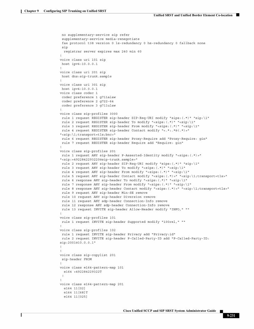
Chapter 9 Configuring SIP Trunking on Unified SRSTUnified SRST and Unified Border Element Co-location
no supplementary-service sip refer supplementary-service media-renegotiate fax protocol t38 version 0 ls-redundancy 0 hs-redundancy 0 fallback none sip registrar server expires max 240 min 60!voice class uri 101 sip host ipv4:10.0.0.1!voice class uri 201 sip host dns:sip-trunk.sample!voice class uri 301 sip host ipv4:10.0.0.1voice class codec 1 codec preference 1 g711alaw codec preference 2 g722-64 codec preference 3 g711ulaw!voice class sip-profiles 3000 rule 1 request REGISTER sip-header SIP-Req-URI modify "sips:(.*)" "sip:\1" rule 2 request REGISTER sip-header To modify "<sips:(.*)" "<sip:\1" rule 3 request REGISTER sip-header From modify "<sips:(.*)" "<sip:\1" rule 4 request REGISTER sip-header Contact modify "<.*:.*@(.*)>" "<sip:\1;transport=tls;bnc>" rule 6 request REGISTER sip-header Proxy-Require add "Proxy-Require: gin" rule 7 request REGISTER sip-header Require add "Require: gin" !voice class sip-profiles 201 rule 1 request ANY sip-header P-Asserted-Identity modify "<sips:(.*)>" "<sip:[email protected]>" rule 2 request ANY sip-header SIP-Req-URI modify "sips:(.*)" "sip:\1" rule 3 request ANY sip-header To modify "<sips:(.*)" "<sip:\1" rule 4 request ANY sip-header From modify "<sips:(.*)" "<sip:\1" rule 5 request ANY sip-header Contact modify "<sips:(.*)>" "<sip:\1;transport=tls>" rule 6 response ANY sip-header To modify "<sips:(.*)" "<sip:\1" rule 7 response ANY sip-header From modify "<sips:(.*)" "<sip:\1" rule 8 response ANY sip-header Contact modify "<sips:(.*)>" "<sip:\1;transport=tls>" rule 9 request ANY sip-header Min-SE remove rule 10 request ANY sip-header Diversion remove rule 11 request ANY sdp-header Connection-Info remove rule 12 response ANY sdp-header Connection-Info remove rule 13 request INVITE sip-header Allow-Header modify "INFO," "" !voice class sip-profiles 101 rule 1 request INVITE sip-header Supported modify "100rel," "" !voice class sip-profiles 102 rule 1 request INVITE sip-header Privacy add "Privacy:id" rule 2 request INVITE sip-header P-Called-Party-ID add "P-Called-Party-ID: sip:[email protected]" !!voice class sip-copylist 201 sip-header FROM!voice class e164-pattern-map 101 e164 +492284229322T !!voice class e164-pattern-map 201 e164 11[02] e164 11[68]T e164 11[025]
9-231Cisco Unified SCCP and SIP SRST System Administrator Guide
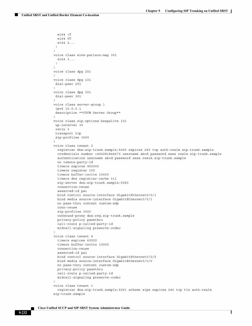
Chapter 9 Configuring SIP Trunking on Unified SRSTUnified SRST and Unified Border Element Co-location
e164 +T e164 0T e164 2... !!voice class e164-pattern-map 301 e164 3... !!voice class dpg 201!voice class dpg 101 dial-peer 201!voice class dpg 301 dial-peer 301!voice class server-group 1 ipv4 10.0.0.1 description **CUCM Server Group**!voice class sip-options-keepalive 101 up-interval 30 retry 3 transport tcp sip-profiles 3000!voice class tenant 2 registrar dns:sip-trunk.sample:5060 expires 240 tcp auth-realm sip-trunk.sample credentials number +492281844673 username abcd password xxxx realm sip-trunk.sample authentication username abcd password xxxx realm sip-trunk.sample no remote-party-id timers expires 900000 timers register 100 timers buffer-invite 10000 timers dns registrar-cache ttl sip-server dns:sip-trunk.sample:5060 connection-reuse asserted-id pai bind control source-interface GigabitEthernet0/0/1 bind media source-interface GigabitEthernet0/0/1 no pass-thru content custom-sdp conn-reuse sip-profiles 3000 outbound-proxy dns:reg.sip-trunk.sample privacy-policy passthru call-route p-called-party-id midcall-signaling preserve-codec!voice class tenant 4 timers expires 60000 timers buffer-invite 10000 connection-reuse asserted-id pai bind control source-interface GigabitEthernet0/0/0 bind media source-interface GigabitEthernet0/0/0 no pass-thru content custom-sdp privacy-policy passthru call-route p-called-party-id midcall-signaling preserve-codec!voice class tenant 1 registrar dns:sip-trunk.sample:5061 scheme sips expires 240 tcp tls auth-realm sip-trunk.sample
9-232Cisco Unified SCCP and SIP SRST System Administrator Guide
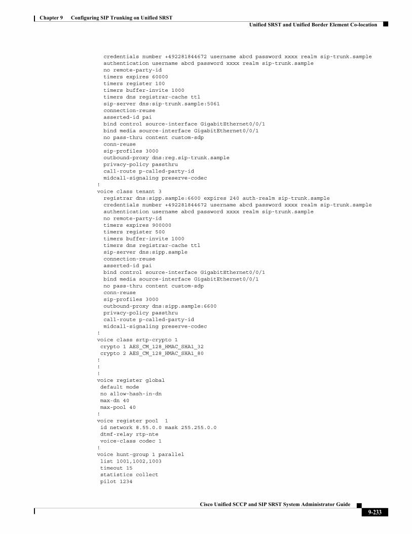
Chapter 9 Configuring SIP Trunking on Unified SRSTUnified SRST and Unified Border Element Co-location
credentials number +492281844672 username abcd password xxxx realm sip-trunk.sample authentication username abcd password xxxx realm sip-trunk.sample no remote-party-id timers expires 60000 timers register 100 timers buffer-invite 1000 timers dns registrar-cache ttl sip-server dns:sip-trunk.sample:5061 connection-reuse asserted-id pai bind control source-interface GigabitEthernet0/0/1 bind media source-interface GigabitEthernet0/0/1 no pass-thru content custom-sdp conn-reuse sip-profiles 3000 outbound-proxy dns:reg.sip-trunk.sample privacy-policy passthru call-route p-called-party-id midcall-signaling preserve-codec!voice class tenant 3 registrar dns:sipp.sample:6600 expires 240 auth-realm sip-trunk.sample credentials number +492281844672 username abcd password xxxx realm sip-trunk.sample authentication username abcd password xxxx realm sip-trunk.sample no remote-party-id timers expires 900000 timers register 500 timers buffer-invite 1000 timers dns registrar-cache ttl sip-server dns:sipp.sample connection-reuse asserted-id pai bind control source-interface GigabitEthernet0/0/1 bind media source-interface GigabitEthernet0/0/1 no pass-thru content custom-sdp conn-reuse sip-profiles 3000 outbound-proxy dns:sipp.sample:6600 privacy-policy passthru call-route p-called-party-id midcall-signaling preserve-codec!voice class srtp-crypto 1 crypto 1 AES_CM_128_HMAC_SHA1_32 crypto 2 AES_CM_128_HMAC_SHA1_80!!!voice register global default mode no allow-hash-in-dn max-dn 40 max-pool 40!voice register pool 1 id network 8.55.0.0 mask 255.255.0.0 dtmf-relay rtp-nte voice-class codec 1!voice hunt-group 1 parallel list 1001,1002,1003 timeout 15 statistics collect pilot 1234
9-233Cisco Unified SCCP and SIP SRST System Administrator Guide
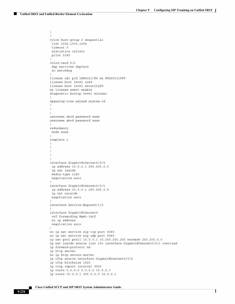
Chapter 9 Configuring SIP Trunking on Unified SRSTUnified SRST and Unified Border Element Co-location
!!voice hunt-group 2 sequential list 1002,1003,1004 timeout 5 statistics collect pilot 2345 !voice-card 0/1 dsp services dspfarm no watchdog!license udi pid ISR4321/K9 sn FDO201115PVlicense boot level uck9license boot level securityk9no license smart enablediagnostic bootup level minimal!spanning-tree extend system-id!!!username abcd password xxxxusername abcd password xxxx!redundancy mode none!template 1!! ! !!interface GigabitEthernet0/0/0 ip address 10.0.0.1 255.255.0.0 ip nat inside media-type rj45 negotiation auto!interface GigabitEthernet0/0/1 ip address 10.0.0.1 255.255.0.0 ip nat outside negotiation auto!interface Service-Engine0/1/0!interface GigabitEthernet0 vrf forwarding Mgmt-intf no ip address negotiation auto!no ip nat service sip tcp port 5060no ip nat service sip udp port 5060ip nat pool pool1 10.0.0.1 10.255.255.255 netmask 255.255.0.0ip nat inside source list 100 interface GigabitEthernet0/0/1 overloadip forward-protocol ndip http serverno ip http secure-serverip tftp source-interface GigabitEthernet0/0/0ip tftp blocksize 1520ip rtcp report interval 9000 ip route 0.0.0.0 0.0.0.0 10.0.0.1ip route 10.0.0.1 255.0.0.0 10.0.0.1
9-234Cisco Unified SCCP and SIP SRST System Administrator Guide
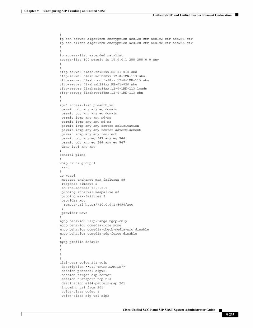
Chapter 9 Configuring SIP Trunking on Unified SRSTUnified SRST and Unified Border Element Co-location
!ip ssh server algorithm encryption aes128-ctr aes192-ctr aes256-ctrip ssh client algorithm encryption aes128-ctr aes192-ctr aes256-ctr!!ip access-list extended nat-listaccess-list 100 permit ip 10.0.0.1 255.255.0.0 any!!tftp-server flash:fbi88xx.BE-01-010.sbntftp-server flash:kern88xx.12-0-1MN-113.sbntftp-server flash:rootfs88xx.12-0-1MN-113.sbntftp-server flash:sb288xx.BE-01-020.sbntftp-server flash:sip88xx.12-0-1MN-113.loadstftp-server flash:vc488xx.12-0-1MN-113.sbn!!ipv6 access-list preauth_v6 permit udp any any eq domain permit tcp any any eq domain permit icmp any any nd-ns permit icmp any any nd-na permit icmp any any router-solicitation permit icmp any any router-advertisement permit icmp any any redirect permit udp any eq 547 any eq 546 permit udp any eq 546 any eq 547 deny ipv6 any any!control-plane!voip trunk group 1 xsvc!uc wsapi message-exchange max-failures 99 response-timeout 2 source-address 10.0.0.1 probing interval keepalive 60 probing max-failures 2 provider xcc remote-url http://10.0.0.1:8090/xcc ! provider xsvc!mgcp behavior rsip-range tgcp-onlymgcp behavior comedia-role nonemgcp behavior comedia-check-media-src disablemgcp behavior comedia-sdp-force disable!mgcp profile default!!!!dial-peer voice 201 voip description **SIP-TRUNK.SAMPLE** session protocol sipv2 session target sip-server session transport tcp tls destination e164-pattern-map 201 incoming uri from 201 voice-class codec 1 voice-class sip url sips
9-235Cisco Unified SCCP and SIP SRST System Administrator Guide
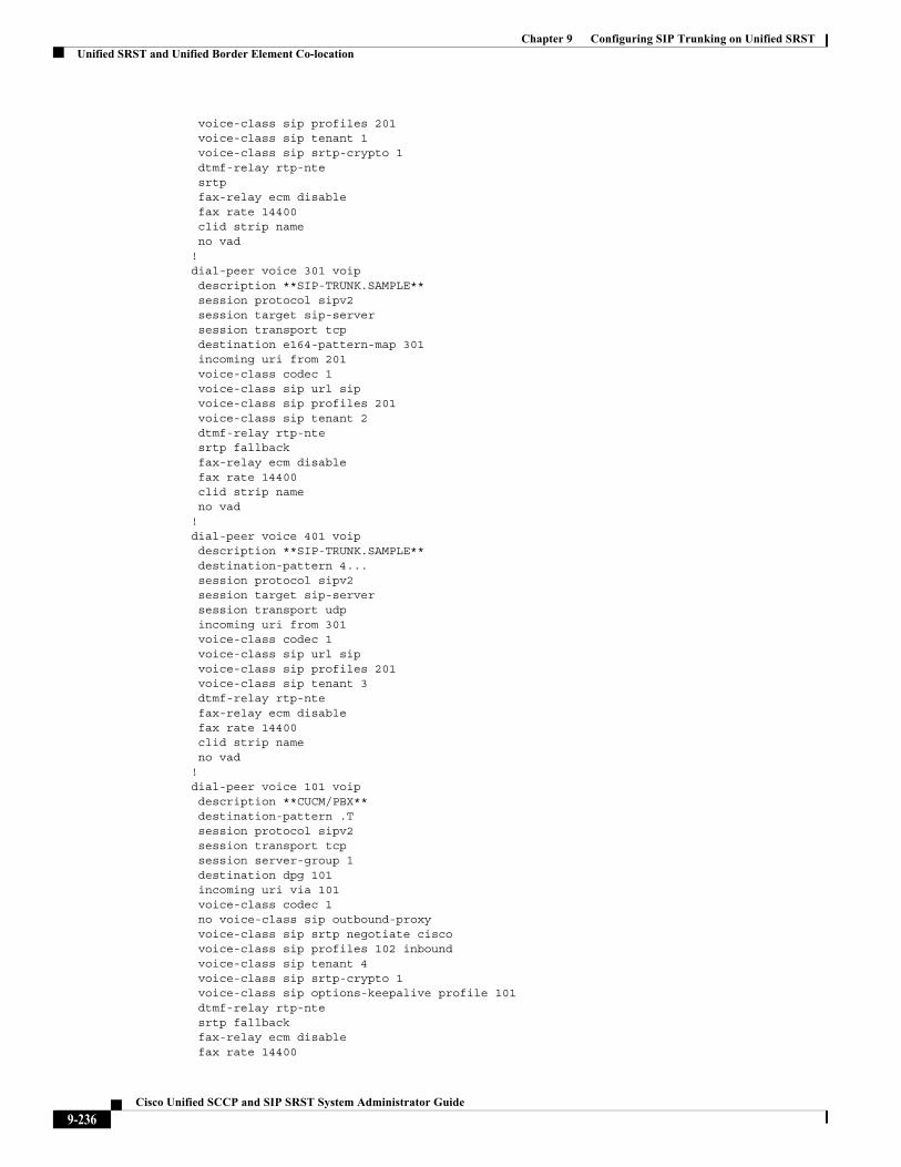
Chapter 9 Configuring SIP Trunking on Unified SRSTUnified SRST and Unified Border Element Co-location
voice-class sip profiles 201 voice-class sip tenant 1 voice-class sip srtp-crypto 1 dtmf-relay rtp-nte srtp fax-relay ecm disable fax rate 14400 clid strip name no vad!dial-peer voice 301 voip description **SIP-TRUNK.SAMPLE** session protocol sipv2 session target sip-server session transport tcp destination e164-pattern-map 301 incoming uri from 201 voice-class codec 1 voice-class sip url sip voice-class sip profiles 201 voice-class sip tenant 2 dtmf-relay rtp-nte srtp fallback fax-relay ecm disable fax rate 14400 clid strip name no vad!dial-peer voice 401 voip description **SIP-TRUNK.SAMPLE** destination-pattern 4... session protocol sipv2 session target sip-server session transport udp incoming uri from 301 voice-class codec 1 voice-class sip url sip voice-class sip profiles 201 voice-class sip tenant 3 dtmf-relay rtp-nte fax-relay ecm disable fax rate 14400 clid strip name no vad!dial-peer voice 101 voip description **CUCM/PBX** destination-pattern .T session protocol sipv2 session transport tcp session server-group 1 destination dpg 101 incoming uri via 101 voice-class codec 1 no voice-class sip outbound-proxy voice-class sip srtp negotiate cisco voice-class sip profiles 102 inbound voice-class sip tenant 4 voice-class sip srtp-crypto 1 voice-class sip options-keepalive profile 101 dtmf-relay rtp-nte srtp fallback fax-relay ecm disable fax rate 14400
9-236Cisco Unified SCCP and SIP SRST System Administrator Guide
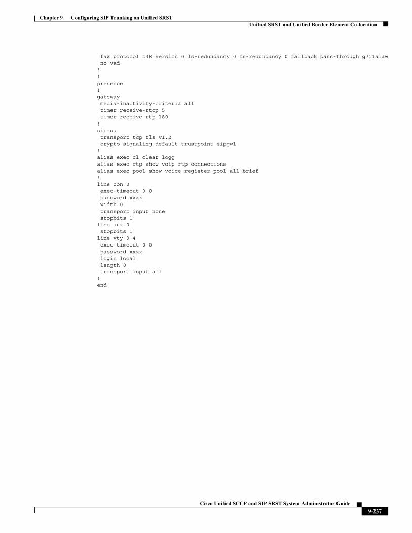
Chapter 9 Configuring SIP Trunking on Unified SRSTUnified SRST and Unified Border Element Co-location
fax protocol t38 version 0 ls-redundancy 0 hs-redundancy 0 fallback pass-through g711alaw no vad!!presence!gateway media-inactivity-criteria all timer receive-rtcp 5 timer receive-rtp 180!sip-ua transport tcp tls v1.2 crypto signaling default trustpoint sipgw1 !alias exec cl clear loggalias exec rtp show voip rtp connectionsalias exec pool show voice register pool all brief!line con 0 exec-timeout 0 0 password xxxx width 0 transport input none stopbits 1line aux 0 stopbits 1line vty 0 4 exec-timeout 0 0 password xxxx login local length 0 transport input all!end
9-237Cisco Unified SCCP and SIP SRST System Administrator Guide
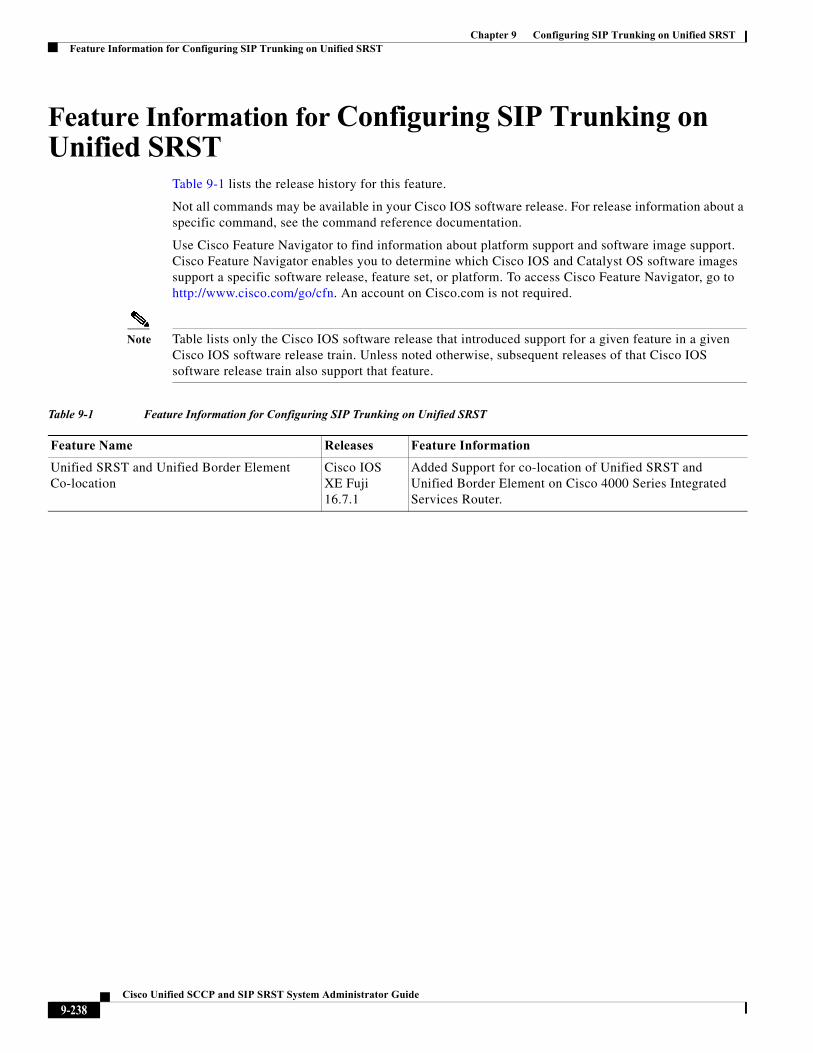
Chapter 9 Configuring SIP Trunking on Unified SRSTFeature Information for Configuring SIP Trunking on Unified SRST
Feature Information for Configuring SIP Trunking on Unified SRST
Table 9-1 lists the release history for this feature.
Not all commands may be available in your Cisco IOS software release. For release information about a specific command, see the command reference documentation.
Use Cisco Feature Navigator to find information about platform support and software image support. Cisco Feature Navigator enables you to determine which Cisco IOS and Catalyst OS software images support a specific software release, feature set, or platform. To access Cisco Feature Navigator, go to http://www.cisco.com/go/cfn. An account on Cisco.com is not required.
Note Table lists only the Cisco IOS software release that introduced support for a given feature in a given Cisco IOS software release train. Unless noted otherwise, subsequent releases of that Cisco IOS software release train also support that feature.
Table 9-1 Feature Information for Configuring SIP Trunking on Unified SRST
Feature Name Releases Feature Information
Unified SRST and Unified Border Element Co-location
Cisco IOS XE Fuji 16.7.1
Added Support for co-location of Unified SRST and Unified Border Element on Cisco 4000 Series Integrated Services Router.
9-238Cisco Unified SCCP and SIP SRST System Administrator Guide
Cisco Unified SC
C H A P T E R 10
Integrating Voicemail with Cisco Unified SRSTThis chapter describes how to make your existing voicemail system run on phones connected to a Cisco Unified SRST router during Cisco Unified Communications Manager fallback.
Cisco Unified SRST also supports incoming and outgoing Session Initiation Protocol (SIP) calls to and from Cisco Unified IP phones and router voice gateway voice ports. SIP may be used in situations where the Cisco Unified SRST Router is separate from the PSTN gateway and the SRST and PSTN gateways are linked together using SIP (instead of H.323).
For more information about SIP, see Cisco IOS SIP Configuration Guide.
Contents• Information About Integrating Voicemail with Cisco Unified SRST, page 239
• How to Integrate Voicemail with Cisco Unified SCCP and SIP SRST, page 241
• Configuring Message Waiting Indication (SIP Phones in SRST Mode), page 253
• How to Configure DTMF Relay for SIP Applications and Voicemail, page 258
• Where to Go Next, page 262
Information About Integrating Voicemail with Cisco Unified SRST
Cisco Unified SRST can send and receive voicemail messages from Cisco Unity and other voicemail systems during Cisco Unified CM fallback. When the WAN is down, a voicemail system with BRI or PRI access to the Cisco Unified SRST system uses ISDN signaling (see Figure 10-1). Systems with Foreign Exchange Office (FXO) or Foreign Exchange Station (FXS) access connect to a PSTN and use in-band dual tone multifrequency (DTMF) signaling (see Figure 10-2).
From Unified SRST Release 12.0 onwards, Unified SRST supports voicemail on IPv6 protocols for SIP IP phones.
10-239CP and SIP SRST System Administrator Guide
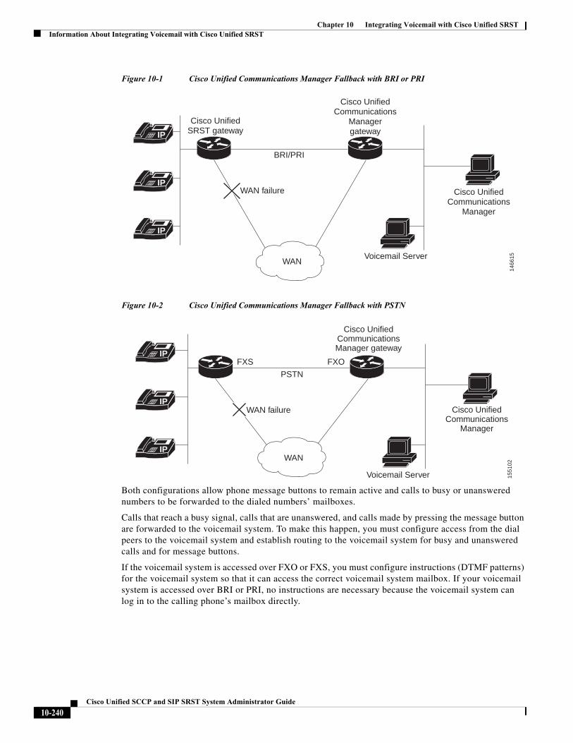
Chapter 10 Integrating Voicemail with Cisco Unified SRSTInformation About Integrating Voicemail with Cisco Unified SRST
Figure 10-1 Cisco Unified Communications Manager Fallback with BRI or PRI
Figure 10-2 Cisco Unified Communications Manager Fallback with PSTN
Both configurations allow phone message buttons to remain active and calls to busy or unanswered numbers to be forwarded to the dialed numbers’ mailboxes.
Calls that reach a busy signal, calls that are unanswered, and calls made by pressing the message button are forwarded to the voicemail system. To make this happen, you must configure access from the dial peers to the voicemail system and establish routing to the voicemail system for busy and unanswered calls and for message buttons.
If the voicemail system is accessed over FXO or FXS, you must configure instructions (DTMF patterns) for the voicemail system so that it can access the correct voicemail system mailbox. If your voicemail system is accessed over BRI or PRI, no instructions are necessary because the voicemail system can log in to the calling phone’s mailbox directly.
IP
IP
IP
1466
15
Cisco UnifiedCommunications
Manager
Voicemail Server
Cisco UnifiedCommunications
Managergateway
BRI/PRI
Cisco UnifiedSRST gateway
WAN
WAN failure
IP
IP
IP
1551
02
Cisco UnifiedCommunications
Manager
Voicemail Server
Cisco UnifiedCommunicationsManager gateway
FXS
PSTN
FXO
WAN
WAN failure
10-240Cisco Unified SCCP and SIP SRST System Administrator Guide
Chapter 10 Integrating Voicemail with Cisco Unified SRSTHow to Integrate Voicemail with Cisco Unified SCCP and SIP SRST
How to Integrate Voicemail with Cisco Unified SCCP and SIP SRST
This section contains the following tasks:
• Configuring Direct Access to Voicemail, page 241 (Required)
• Configuring Message Buttons, page 244 (Required)
• Redirecting to Cisco Unified Communications Manager Gateway, page 247 (Required for BRI or PRI))
• Configuring Call Forwarding to Voicemail, page 247 (Required FXO or FXS)
• Configuring Message Waiting Indication (Cisco Unified SRST Routers), page 251 (Optional)
Note Support for SIP SRST is added from IOS release 15.1(4)M3 and 15.2(1)T2.
Configuring Direct Access to Voicemail
You can configure direct access to voicemail system using BRI/PRI or FXO/FXS. To access voicemail messages with BRI/PRI or FXO/FXS access, you must have POTS dial peers configured with a destination pattern that matches the voicemail system’s number. Also, you must associate the dial peer with the port to which the voicemail system is accessed.
Both sets of configurations are done in dial-peer configuration mode. The summary and detailed steps below include only the basic commands necessary to perform this task. You may require additional commands for your particular dial-peer configuration.
SUMMARY STEPS
1. dial-peer voice tag {pots | voatm | vofr | voip}
2. destination-pattern [+] string [T]
3. port {slot-number/subunit-number/port | slot/port:ds0-group-no}
4. forward-digits {num-digit | all | extra}
5. exit
10-241Cisco Unified SCCP and SIP SRST System Administrator Guide
Chapter 10 Integrating Voicemail with Cisco Unified SRSTHow to Integrate Voicemail with Cisco Unified SCCP and SIP SRST
DETAILED STEPS
Command or Action Purpose
Step 1 dial-peer voice tag {pots | voatm | vofr | voip}
Example:Router(config)# dial-peer voice 1002 pots
(FXO or FXS and BRI or PRI) Defines a particular dial peer, specifies the method of voice encapsulation, and enters dial-peer configuration mode. The dial-peer command provides different syntax for individual routers. This example is syntax for Cisco 3600 series routers.
• tag: Digits that define a particular dial peer. Range is from 1 to 2147483647.
• pots: Indicates that this is a POTS dial peer that uses VoIP encapsulation on the IP backbone.
• voatm: Specifies that this is a VoATM dial peer that uses real-time AAL5 voice encapsulation on the ATM backbone network.
• vofr: Specifies that this is a VoFR dial peer that uses FRF.11 encapsulation on the Frame Relay backbone network.
• voip: Indicates that this is a VoIP dial peer that uses voice encapsulation on the POTS network.
Step 2 destination-pattern [+] string [T]
Example:Router(config-dial-peer)# destination-pattern 1100T
(FXO or FXS and BRI or PRI) Specifies either the prefix or the full E.164 telephone number (depending on your dial plan) to be used for a dial peer.
• +: (Optional) Character that indicates an E.164 standard number.
• string: See Table 10-1.
• T: (Optional) Control character that indicates that the destination-pattern value is a variable-length dial string.
Step 3 port {slot-number/subunit-number/port | slot/port:ds0-group-no}
Example:Router(config-dial-peer)# port 1/1/1
(FXO or FXS and BRI or PRI) Associates a dial peer with a specific voice port on Cisco routers.
• slot-number: Number of the slot in the router in which the voice interface card (VIC) is installed. Valid entries are from 0 to 3, depending on the slot in which it is installed.
• subunit-number: Subunit on the VIC in which the voice port is located. Valid entries are 0 or 1.
• port: Voice port number. Valid entries are 0 and 1.
• ds0-group-no: Specifies the DS0 group number. Each defined DS0 group number is represented on a separate voice port. This allows you to define individual DS0s on the digital T1/E1 card.
10-242Cisco Unified SCCP and SIP SRST System Administrator Guide
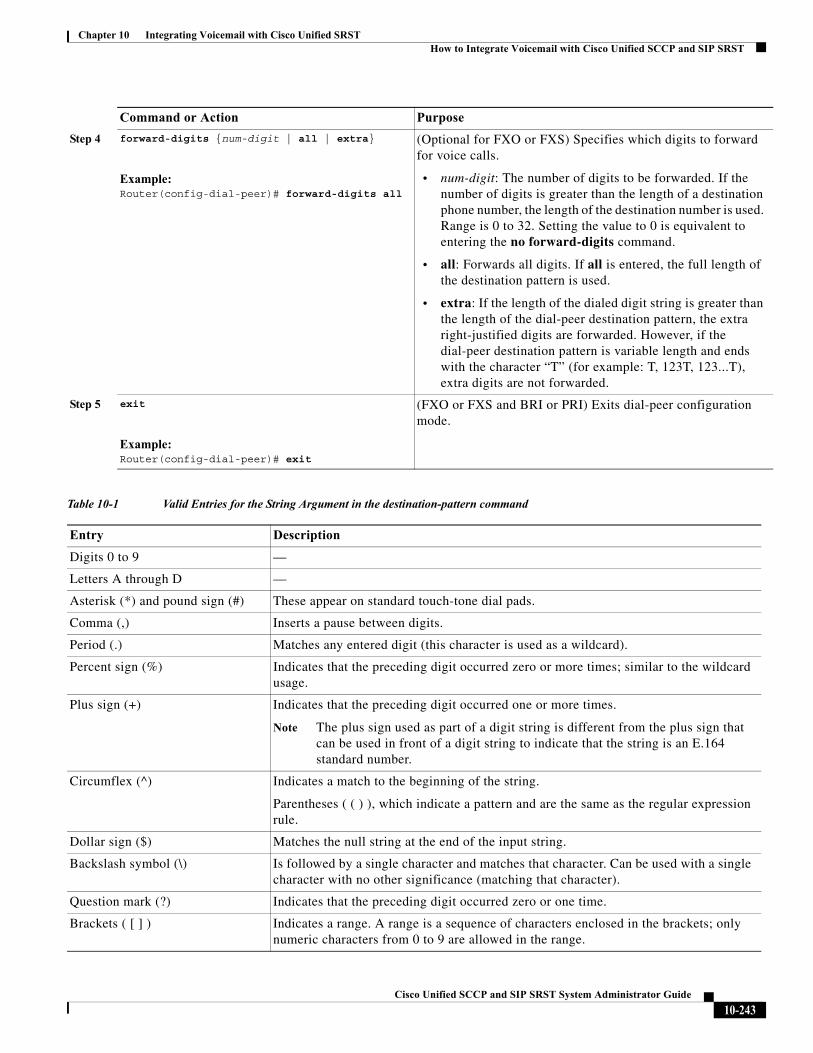
Chapter 10 Integrating Voicemail with Cisco Unified SRSTHow to Integrate Voicemail with Cisco Unified SCCP and SIP SRST
Step 4 forward-digits {num-digit | all | extra}
Example:Router(config-dial-peer)# forward-digits all
(Optional for FXO or FXS) Specifies which digits to forward for voice calls.
• num-digit: The number of digits to be forwarded. If the number of digits is greater than the length of a destination phone number, the length of the destination number is used. Range is 0 to 32. Setting the value to 0 is equivalent to entering the no forward-digits command.
• all: Forwards all digits. If all is entered, the full length of the destination pattern is used.
• extra: If the length of the dialed digit string is greater than the length of the dial-peer destination pattern, the extra right-justified digits are forwarded. However, if the dial-peer destination pattern is variable length and ends with the character “T” (for example: T, 123T, 123...T), extra digits are not forwarded.
Step 5 exit
Example:Router(config-dial-peer)# exit
(FXO or FXS and BRI or PRI) Exits dial-peer configuration mode.
Table 10-1 Valid Entries for the String Argument in the destination-pattern command
Entry Description
Digits 0 to 9 —
Letters A through D —
Asterisk (*) and pound sign (#) These appear on standard touch-tone dial pads.
Comma (,) Inserts a pause between digits.
Period (.) Matches any entered digit (this character is used as a wildcard).
Percent sign (%) Indicates that the preceding digit occurred zero or more times; similar to the wildcard usage.
Plus sign (+) Indicates that the preceding digit occurred one or more times.
Note The plus sign used as part of a digit string is different from the plus sign that can be used in front of a digit string to indicate that the string is an E.164 standard number.
Circumflex (^) Indicates a match to the beginning of the string.
Parentheses ( ( ) ), which indicate a pattern and are the same as the regular expression rule.
Dollar sign ($) Matches the null string at the end of the input string.
Backslash symbol (\) Is followed by a single character and matches that character. Can be used with a single character with no other significance (matching that character).
Question mark (?) Indicates that the preceding digit occurred zero or one time.
Brackets ( [ ] ) Indicates a range. A range is a sequence of characters enclosed in the brackets; only numeric characters from 0 to 9 are allowed in the range.
Command or Action Purpose
10-243Cisco Unified SCCP and SIP SRST System Administrator Guide
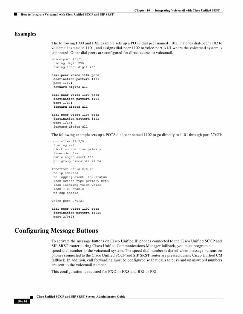
Chapter 10 Integrating Voicemail with Cisco Unified SRSTHow to Integrate Voicemail with Cisco Unified SCCP and SIP SRST
Examples
The following FXO and FXS example sets up a POTS dial peer named 1102, matches dial-peer 1102 to voicemail extension 1101, and assigns dial-peer 1102 to voice-port 1/1/1 where the voicemail system is connected. Other dial peers are configured for direct access to voicemail.
voice-port 1/1/1 timing digit 250 timing inter-digit 250
dial-peer voice 1102 potsdestination-pattern 1101port 1/1/1forward-digits all
dial-peer voice 1103 potsdestination-pattern 1101port 1/1/1forward-digits all
dial-peer voice 1104 potsdestination-pattern 1101port 1/1/1forward-digits all
The following example sets up a POTS dial peer named 1102 to go directly to 1101 through port 2/0:23:
controller T1 2/0 framing esf clock source line primary linecode b8zs cablelength short 133 pri-group timeslots 21-24
interface Serial2/0:23 no ip address no logging event link-status isdn switch-type primary-net5 isdn incoming-voice voice isdn T309-enable no cdp enable
voice-port 2/0:23
dial-peer voice 1102 pots destination-pattern 1101Tport 2/0:23
Configuring Message Buttons
To activate the message buttons on Cisco Unified IP phones connected to the Cisco Unified SCCP and SIP SRST router during Cisco Unified Communications Manager fallback, you must program a speed-dial number to the voicemail system. The speed-dial number is dialed when message buttons on phones connected to the Cisco Unified SCCP and SIP SRST router are pressed during Cisco Unified CM fallback. In addition, call forwarding must be configured so that calls to busy and unanswered numbers are sent to the voicemail number.
This configuration is required for FXO or FXS and BRI or PRI.
10-244Cisco Unified SCCP and SIP SRST System Administrator Guide
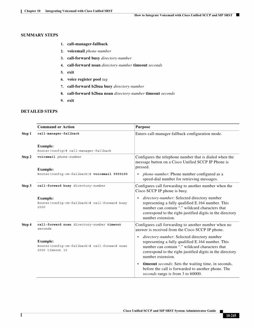
Chapter 10 Integrating Voicemail with Cisco Unified SRSTHow to Integrate Voicemail with Cisco Unified SCCP and SIP SRST
SUMMARY STEPS
1. call-manager-fallback
2. voicemail phone-number
3. call-forward busy directory-number
4. call-forward noan directory-number timeout seconds
5. exit
6. voice register pool tag
7. call-forward b2bua busy directory-number
8. call-forward b2bua noan directory-number timeout seconds
9. exit
DETAILED STEPS
Command or Action Purpose
Step 1 call-manager-fallback
Example:Router(config)# call-manager-fallback
Enters call-manager-fallback configuration mode.
Step 2 voicemail phone-number
Example:Router(config-cm-fallback)# voicemail 5550100
Configures the telephone number that is dialed when the message button on a Cisco Unified SCCP IP Phone is pressed.
• phone-number: Phone number configured as a speed-dial number for retrieving messages.
Step 3 call-forward busy directory-number
Example:Router(config-cm-fallback)# call-forward busy 2000
Configures call forwarding to another number when the Cisco SCCP IP phone is busy.
• directory-number: Selected directory number representing a fully qualified E.164 number. This number can contain “.” wildcard characters that correspond to the right-justified digits in the directory number extension.
Step 4 call-forward noan directory-number timeout seconds
Example:Router(config-cm-fallback)# call-forward noan 2000 timeout 10
Configures call forwarding to another number when no answer is received from the Cisco SCCP IP phone.
• directory-number: Selected directory number representing a fully qualified E.164 number. This number can contain “.” wildcard characters that correspond to the right-justified digits in the directory number extension.
• timeout seconds: Sets the waiting time, in seconds, before the call is forwarded to another phone. The seconds range is from 3 to 60000.
10-245Cisco Unified SCCP and SIP SRST System Administrator Guide
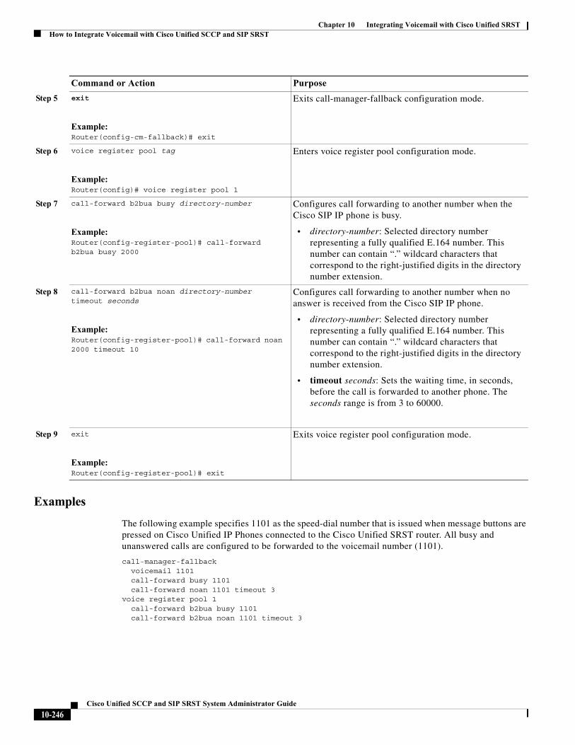
Chapter 10 Integrating Voicemail with Cisco Unified SRSTHow to Integrate Voicemail with Cisco Unified SCCP and SIP SRST
Examples
The following example specifies 1101 as the speed-dial number that is issued when message buttons are pressed on Cisco Unified IP Phones connected to the Cisco Unified SRST router. All busy and unanswered calls are configured to be forwarded to the voicemail number (1101).
call-manager-fallback voicemail 1101 call-forward busy 1101 call-forward noan 1101 timeout 3voice register pool 1 call-forward b2bua busy 1101 call-forward b2bua noan 1101 timeout 3
Step 5 exit
Example:Router(config-cm-fallback)# exit
Exits call-manager-fallback configuration mode.
Step 6 voice register pool tag
Example:Router(config)# voice register pool 1
Enters voice register pool configuration mode.
Step 7 call-forward b2bua busy directory-number
Example:Router(config-register-pool)# call-forward b2bua busy 2000
Configures call forwarding to another number when the Cisco SIP IP phone is busy.
• directory-number: Selected directory number representing a fully qualified E.164 number. This number can contain “.” wildcard characters that correspond to the right-justified digits in the directory number extension.
Step 8 call-forward b2bua noan directory-number timeout seconds
Example:Router(config-register-pool)# call-forward noan 2000 timeout 10
Configures call forwarding to another number when no answer is received from the Cisco SIP IP phone.
• directory-number: Selected directory number representing a fully qualified E.164 number. This number can contain “.” wildcard characters that correspond to the right-justified digits in the directory number extension.
• timeout seconds: Sets the waiting time, in seconds, before the call is forwarded to another phone. The seconds range is from 3 to 60000.
Step 9 exit
Example:Router(config-register-pool)# exit
Exits voice register pool configuration mode.
Command or Action Purpose
10-246Cisco Unified SCCP and SIP SRST System Administrator Guide
Chapter 10 Integrating Voicemail with Cisco Unified SRSTHow to Integrate Voicemail with Cisco Unified SCCP and SIP SRST
Redirecting to Cisco Unified Communications Manager Gateway
Note The following task is required for voicemail systems with BRI or PRI access.
In addition to supporting message buttons for retrieving personal messages, Cisco Unified SRST allows the automatic forwarding of calls to busy and unanswered numbers to voicemail systems. Voicemail systems with BRI or PRI access can log in to the calling phone’s mailbox directly. For this to happen, some Cisco Unified CM configuration is recommended. If your voicemail system supports Redirected Dialed Number Identification Service (RDNIS), RDNIS must be included in the outgoing SETUP message to Cisco Unified CM to declare the last redirected number and the originally dialed number to and from configured devices and applications.
Step 1 From any page in Cisco Unified CM, click Device and Gateway.
Step 2 From the Find and List Gateways page, click Find.
Step 3 From the Find and List Gateways page, choose a device name.
Step 4 From the Gateway Configuration page, check Redirecting Number IE Delivery - Outgoing.
Configuring Call Forwarding to Voicemail
Note The following task is required for voicemail systems with FXO or FXS access.
In addition to supporting message buttons for retrieving personal messages, Cisco Unified SRST allows the automatic forwarding of calls to busy or unanswered numbers to voicemail systems. The forwarded calls can be routed to almost any location in the voicemail system. Typically, calls are forwarded to a location in the called number’s mailbox where the caller can leave messages.
Call Routing Instructions Using DTMF Digit Patterns
Cisco Unified SRST call-routing instructions are required so that forwarded calls can be sent to the correct voicemail boxes. These instructions consist of DTMF digits configured in patterns that match the dial sequences required by the voicemail system to get to a particular voicemail location. For example, a voicemail system may be designed so that callers must do the following to leave a message:
1. Dial the central voicemail number (1101) and press #.
2. Dial an extension number (6000) and press #.
3. Dial 2 to select the menu option for leaving messages in the extension number’s mailbox.
For Cisco Unified SRST to forward a call to a busy or unanswered number to extension 6000’s mailbox, it must be programmed to issue a sequence of 1101#6000#2. As shown in Figure 10-3, this is accomplished through the voicemail and pattern commands.
10-247Cisco Unified SCCP and SIP SRST System Administrator Guide
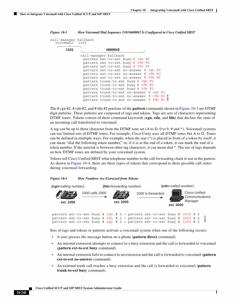
Chapter 10 Integrating Voicemail with Cisco Unified SRSTHow to Integrate Voicemail with Cisco Unified SCCP and SIP SRST
Figure 10-3 How Voicemail Dial Sequence 1101#6000#2 Is Configured in Cisco Unified SRST
The # cgn #2, # cdn #2, and # fdn #2 portions of the pattern commands shown in Figure 10-3 are DTMF digit patterns. These patterns are composed of tags and tokens. Tags are sets of characters representing DTMF tones. Tokens consist of three command keywords (cgn, cdn, and fdn) that declare the state of an incoming call transferred to voicemail.
A tag can be up to three character from the DTMF tone set (A to D, 0 to 9, # and *). Voicemail systems can use limited sets of DTMF tones. For example, Cisco Unity uses all DTMF tones but A to D. Tones can be defined in multiple ways. For example, when the star (*) is placed in front of a token by itself, it can mean “dial the following token number,” or, if it is at the end of a token, it can mark the end of a token number. If the asterisk is between other tag characters, it can mean dial *. The use of tags depends on how DTMF tones are defined by your voicemail system.
Tokens tell Cisco Unified SRST what telephone number in the call forwarding chain to use in the pattern. As shown in Figure 10-4, there are three types of tokens that correspond to three possible call states during voicemail forwarding.
Figure 10-4 How Numbers Are Extracted from Tokens
Sets of tags and tokens or patterns activate a voicemail system when one of the following occurs:
• A user presses the message button on a phone (pattern direct command).
• An internal extension attempts to connect to a busy extension and the call is forwarded to voicemail (pattern ext-to-ext busy command).
• An internal extension fails to connect to an extension and the call is forwarded to voicemail (pattern ext-to-ext no-answer command).
• An external trunk call reaches a busy extension and the call is forwarded to voicemail (pattern trunk-to-ext busy command).
call-manager-fallbackpattern ext-to-ext busy # cgn #2pattern ext-to-ext busy # cdn #2pattern ext-to-ext busy # fdn #2pattern ext-to-ext no-answer # cgn #2pattern ext-to-ext no-answer # cdn #2pattern ext-to-ext no-answer # fdn #2pattern trunk-to-ext busy # cgn #2pattern trunk-to-ext busy # cdn #2pattern trunk-to-ext busy # fdn #2pattern trunk-to-ext no-answer # cgn #2pattern trunk-to-ext no-answer # cdn #2pattern trunk-to-ext no-answer # fdn #2
#6000#21101
call-manager-fallbackvoicemail 1101
8897
8
8897
9ext. 1000
(cgn=calling number)
ext. 2000ext. 3000
(fdn=forwarding number) (cdn=called number)
1000 calls 2000
pattern ext-to-ext busy # cdn # 2 = pattern ext-to-ext busy # 3000 # 2pattern ext-to-ext busy # fdn 2000 # 2pattern ext-to-ext busy # cgn # 2 = pattern ext-to-ext busy # 1000 # 2
1000 is forwarded Cisco UnifiedCommunicationsManager
# 2 = pattern ext-to-ext busy #
IP IP
10-248Cisco Unified SCCP and SIP SRST System Administrator Guide
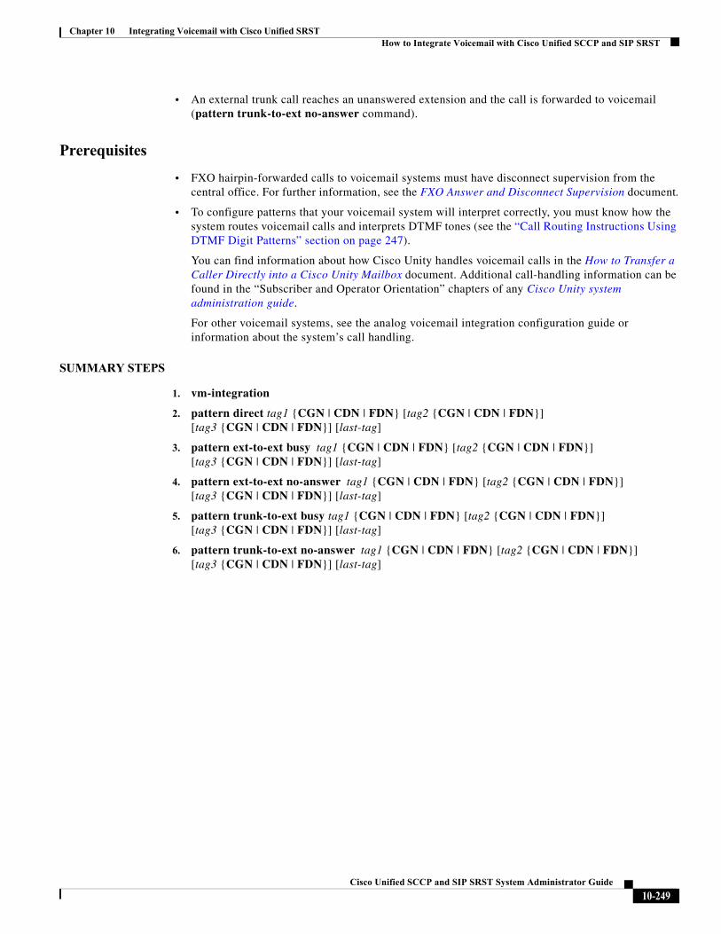
Chapter 10 Integrating Voicemail with Cisco Unified SRSTHow to Integrate Voicemail with Cisco Unified SCCP and SIP SRST
• An external trunk call reaches an unanswered extension and the call is forwarded to voicemail (pattern trunk-to-ext no-answer command).
Prerequisites
• FXO hairpin-forwarded calls to voicemail systems must have disconnect supervision from the central office. For further information, see the FXO Answer and Disconnect Supervision document.
• To configure patterns that your voicemail system will interpret correctly, you must know how the system routes voicemail calls and interprets DTMF tones (see the “Call Routing Instructions Using DTMF Digit Patterns” section on page 247).
You can find information about how Cisco Unity handles voicemail calls in the How to Transfer a Caller Directly into a Cisco Unity Mailbox document. Additional call-handling information can be found in the “Subscriber and Operator Orientation” chapters of any Cisco Unity system administration guide.
For other voicemail systems, see the analog voicemail integration configuration guide or information about the system’s call handling.
SUMMARY STEPS
1. vm-integration
2. pattern direct tag1 {CGN | CDN | FDN} [tag2 {CGN | CDN | FDN}] [tag3 {CGN | CDN | FDN}] [last-tag]
3. pattern ext-to-ext busy tag1 {CGN | CDN | FDN} [tag2 {CGN | CDN | FDN}] [tag3 {CGN | CDN | FDN}] [last-tag]
4. pattern ext-to-ext no-answer tag1 {CGN | CDN | FDN} [tag2 {CGN | CDN | FDN}] [tag3 {CGN | CDN | FDN}] [last-tag]
5. pattern trunk-to-ext busy tag1 {CGN | CDN | FDN} [tag2 {CGN | CDN | FDN}] [tag3 {CGN | CDN | FDN}] [last-tag]
6. pattern trunk-to-ext no-answer tag1 {CGN | CDN | FDN} [tag2 {CGN | CDN | FDN}] [tag3 {CGN | CDN | FDN}] [last-tag]
10-249Cisco Unified SCCP and SIP SRST System Administrator Guide
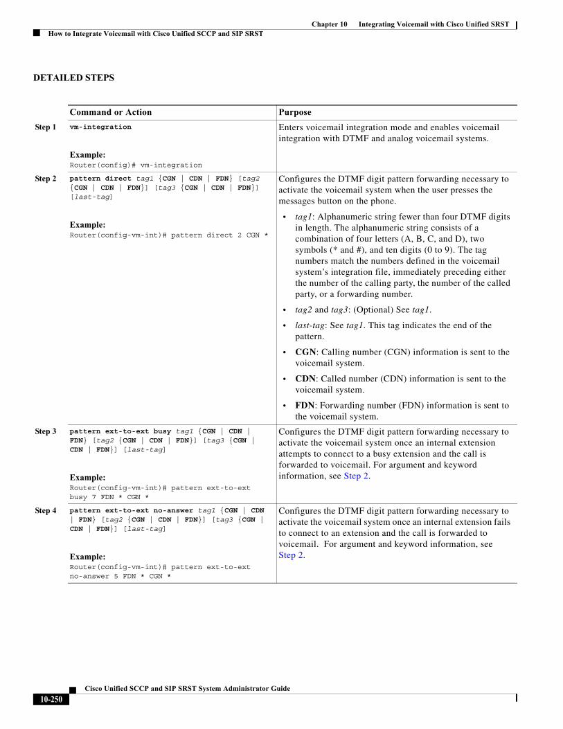
Chapter 10 Integrating Voicemail with Cisco Unified SRSTHow to Integrate Voicemail with Cisco Unified SCCP and SIP SRST
DETAILED STEPS
Command or Action Purpose
Step 1 vm-integration
Example:Router(config)# vm-integration
Enters voicemail integration mode and enables voicemail integration with DTMF and analog voicemail systems.
Step 2 pattern direct tag1 {CGN | CDN | FDN} [tag2 {CGN | CDN | FDN}] [tag3 {CGN | CDN | FDN}] [last-tag]
Example:Router(config-vm-int)# pattern direct 2 CGN *
Configures the DTMF digit pattern forwarding necessary to activate the voicemail system when the user presses the messages button on the phone.
• tag1: Alphanumeric string fewer than four DTMF digits in length. The alphanumeric string consists of a combination of four letters (A, B, C, and D), two symbols (* and #), and ten digits (0 to 9). The tag numbers match the numbers defined in the voicemail system’s integration file, immediately preceding either the number of the calling party, the number of the called party, or a forwarding number.
• tag2 and tag3: (Optional) See tag1.
• last-tag: See tag1. This tag indicates the end of the pattern.
• CGN: Calling number (CGN) information is sent to the voicemail system.
• CDN: Called number (CDN) information is sent to the voicemail system.
• FDN: Forwarding number (FDN) information is sent to the voicemail system.
Step 3 pattern ext-to-ext busy tag1 {CGN | CDN | FDN} [tag2 {CGN | CDN | FDN}] [tag3 {CGN | CDN | FDN}] [last-tag]
Example:Router(config-vm-int)# pattern ext-to-ext busy 7 FDN * CGN *
Configures the DTMF digit pattern forwarding necessary to activate the voicemail system once an internal extension attempts to connect to a busy extension and the call is forwarded to voicemail. For argument and keyword information, see Step 2.
Step 4 pattern ext-to-ext no-answer tag1 {CGN | CDN | FDN} [tag2 {CGN | CDN | FDN}] [tag3 {CGN | CDN | FDN}] [last-tag]
Example:Router(config-vm-int)# pattern ext-to-ext no-answer 5 FDN * CGN *
Configures the DTMF digit pattern forwarding necessary to activate the voicemail system once an internal extension fails to connect to an extension and the call is forwarded to voicemail. For argument and keyword information, see Step 2.
10-250Cisco Unified SCCP and SIP SRST System Administrator Guide
Chapter 10 Integrating Voicemail with Cisco Unified SRSTHow to Integrate Voicemail with Cisco Unified SCCP and SIP SRST
Examples
For the following configuration, if the voicemail number is 1101, and 3001 is a phone with a message button, 1101*3001 would be dialed automatically when the 3001 message button is pressed. Under these circumstances, 3001 is considered to be a calling number or inbound call number.
vm-integrationpattern direct * CGN
For the following configuration, if 3001 calls 3006 and 3006 does not answer, the Unified SRST router will forward 3001 to the voicemail system (1101) and send to the voicemail system the DTMF pattern # 3006 #2. This pattern is intended to select voicemail box number 3006 (3006’s voice mailbox). For this pattern to be sent, 3001 must be a forwarding number.
vm-integrationpattern ext-to-ext no-answer # FDN #2
For the following configuration, if 3006 is busy and 3001 calls 3006, the Unified SRST router will forward 3001 to the voicemail system (1101) and send to the voicemail system the DTMF pattern # 3006 #2. This pattern is intended to select voice mailbox number 3006 (3006’s voice mailbox). For this pattern to be sent, 3001 must be a forwarding number.
vm-integrationpattern ext-to-ext busy # FDN #2
Configuring Message Waiting Indication (Cisco Unified SRST Routers)
The Message Waiting Indication (MWI) relay mechanism is initiated after someone leaves a voicemail message on the remote voicemail message system. MWI relay is required when one Cisco Unity Voicemail system is shared by multiple Cisco Unified SRST routers. Unified SRST routers use the SIP Subscribe and Notify methods for MWI. See Configuring Cisco IOS SIP Configuration Guide for more information on SIP MWI and the Subscribe and Notify methods. The Unified SRST router that is the SIP MWI relay server acts as the SIP notifier. The other remote routers act as the SIP subscribers.
Step 5 pattern trunk-to-ext busy tag1 {CGN | CDN | FDN} [tag2 {CGN | CDN | FDN}] [tag3 {CGN | CDN | FDN}] [last-tag]
Example:Router(config-vm-int)# pattern trunk-to-ext busy 6 FDN * CGN *
Configures the DTMF digit pattern forwarding necessary to activate the voicemail system once an external trunk call reaches a busy extension and the call is forwarded to voicemail. For argument and keyword information, see Step 2.
Step 6 pattern trunk-to-ext no-answer tag1 {CGN | CDN | FDN} [tag2 {CGN | CDN | FDN}] [tag3 {CGN | CDN | FDN}] [last-tag]
Example:Router(config-vm-int)# pattern trunk-to-ext no-answer 4 FDN * CGN *
Configures the DTMF digit pattern forwarding necessary to activate the voicemail system when an external trunk call reaches an unanswered extension and the call is forwarded to voicemail. For argument and keyword information, see Step 2.
Command or Action Purpose
10-251Cisco Unified SCCP and SIP SRST System Administrator Guide
Chapter 10 Integrating Voicemail with Cisco Unified SRSTHow to Integrate Voicemail with Cisco Unified SCCP and SIP SRST
Restriction
• MWI is not supported during a fallback to Unified SRST. The MWI (the phone LED indication) will not correctly reflect when new messages arrive or when all messages have been listened to. We recommend resynchronizing MWIs after the WAN link is available, and connection with Unified Communications Manager is reestablished. The MWI behavior is consistent across voicemail support for IPv4 as well as IPv6 on Unified SRST.
SUMMARY STEPS
1. call-manager-fallback
2. mwi relay
3. mwi reg-e164
4. exit
5. sip-ua
6. mwi-server {ipv4:destination-address | dns:host-name} [expires seconds] [port port][transport {tcp | udp}] [unsolicited]
7. exit
DETAILED STEPS
Command Purpose
Step 1 call-manager-fallback
Example:Router(config)# call-manager-fallback
Enters call-manager-fallback configuration mode.
Step 2 mwi relay
Example:Router(config-cm-fallback)# mwi relay
Enables the Unified SRST router to relay MWI information to remote Cisco IP phones.
Step 3 mwi reg-e164
Example:Router(config-cm-fallback)# mwi reg-e164
Registers E.164 numbers rather than extension numbers with a SIP proxy or registrar.
Step 4 exit
Example:Router(config-cm-fallback)# exit
Exits call-manager-fallback configuration mode.
Step 5 sip-ua
Example:Router(config)# sip-ua
Enters SIP user-agent configuration mode.
10-252Cisco Unified SCCP and SIP SRST System Administrator Guide
Chapter 10 Integrating Voicemail with Cisco Unified SRSTHow to Integrate Voicemail with Cisco Unified SCCP and SIP SRST
Configuring Message Waiting Indication (SIP Phones in SRST Mode)
On SIP phones operating in the SIP SRST mode, you can use the mwi unsolicited command to configure a message-waiting notification when a message is sent by the Cisco Unity Express (CUE). The SIP phone then displays the notification when indicated by the voice messaging system. To configure message-waiting notification, perform the following steps.
SUMMARY STEPS
1. enable
2. configure terminal
3. sip-ua
4. mwi-server {ipv4:destination-address | dns:host-name} [unsolicited]
5. exit
6. voice register global
Step 6 mwi-server {ipv4:destination-address | dns:host-name} [expires seconds] [port port][transport {tcp | udp}] [unsolicited]
Example:Router(config-sip-ua)# mwi-server ipv4:10.0.2.254
Configures voicemail server settings on a voice gateway or user agent. The IP address and port for the SIP-based MWI server should be in the same LAN as the voicemail server. The MWI server is a Cisco Unified SRST router. Keywords and arguments are as follows:
• ipv4:destination-address: IP address of the voicemail server.
• dns:host-name: The argument should contain the complete hostname to be associated with the target address; for example, dns:test.cisco.com.
• expires seconds: Subscription expiration time, in seconds. Range is from 1 to 999999. Default is 3600.
• port port: Port number on the voicemail server. Default is 5060.
• transport: Transport protocol to the voicemail server. Valid values are tcp and udp. Default is UDP.
• unsolicited: Requires the voicemail server to send a SIP notification message to the voice gateway or UA if the mailbox status changes. Removes the requirement that the voice gateway subscribe for MWI service.
Step 7 exit
Example:Router(config-sip-ua)# exit
Exits SIP user-agent configuration mode.
Command Purpose
10-253Cisco Unified SCCP and SIP SRST System Administrator Guide
Chapter 10 Integrating Voicemail with Cisco Unified SRSTHow to Integrate Voicemail with Cisco Unified SCCP and SIP SRST
7. mwi unsolicited
8. end
DETAILED STEPS
Command Purpose
Step 1 enable
Example:Router> enable
Enables privileged EXEC mode.
Enter your password if prompted.
Step 2 configure terminal
Example:Router# configure terminal
Enters global configuration mode.
Step 3 sip-ua
Example:Router(config)# sip-ua
Enters Session Initiation Protocol (SIP) user agent (ua) configuration mode for configuring the user agent.
Step 4 mwi-server {ipv4:destination-address | dns:host-name} [unsolicited]
Example:Router(config-sip-ua)# mwi-server ipv4:10.0.2.254 unsolicited
Or
Router(config-sip-ua)# mwi-server dns:server.yourcompany.com unsolicited
Configures voicemail server settings on a voice gateway or user agent. Keywords and arguments are as follows:
• ipv4:destination-address: IP address of the voicemail server.
• dns:host-name: The argument should contain the complete hostname to be associated with the target address; for example, dns:test.cisco.com.
• unsolicited: Requires the voicemail server to send a SIP notification message to the voice gateway or UA if the mailbox status changes. Removes the requirement that the voice gateway subscribe for MWI service.
Step 5 exit
Example:Router(config-sip-ua)# exit
Exits SIP user-agent configuration mode.
Step 6 voice register global
Example:Router(config)# voice register global
Enters voice register global configuration mode to set parameters for all supported SIP phones in SIP SRST mode.
10-254Cisco Unified SCCP and SIP SRST System Administrator Guide
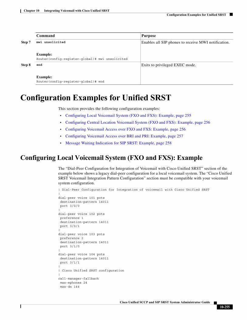
Chapter 10 Integrating Voicemail with Cisco Unified SRSTConfiguration Examples for Unified SRST
Configuration Examples for Unified SRSTThis section provides the following configuration examples:
• Configuring Local Voicemail System (FXO and FXS): Example, page 255
• Configuring Central Location Voicemail System (FXO and FXS): Example, page 256
• Configuring Voicemail Access over FXO and FXS: Example, page 256
• Configuring Voicemail Access over BRI and PRI: Example, page 257
• Message Waiting Indication for SIP SRST: Example, page 258
Configuring Local Voicemail System (FXO and FXS): Example
The “Dial-Peer Configuration for Integration of Voicemail with Cisco Unified SRST” section of the example below shows a legacy dial-peer configuration for a local voicemail system. The “Cisco Unified SRST Voicemail Integration Pattern Configuration” section must be compatible with your voicemail system configuration.
! Dial-Peer Configuration for Integration of voicemail with Cisco Unified SRST!dial-peer voice 101 pots destination-pattern 14011 port 3/0/0!dial-peer voice 102 pots preference 1 destination-pattern 14011 port 3/0/1!dial-peer voice 103 pots preference 2 destination-pattern 14011 port 3/1/0!dial-peer voice 104 potsdestination-pattern 14011port 3/1/1
!! Cisco Unified SRST configuration!call-manager-fallbackmax-ephones 24max-dn 144
Step 7 mwi unsolicited
Example:Router(config-register-global)# mwi unsolicited
Enables all SIP phones to receive MWI notification.
Step 8 end
Example:Router(config-register-global)# end
Exits to privileged EXEC mode.
Command Purpose
10-255Cisco Unified SCCP and SIP SRST System Administrator Guide
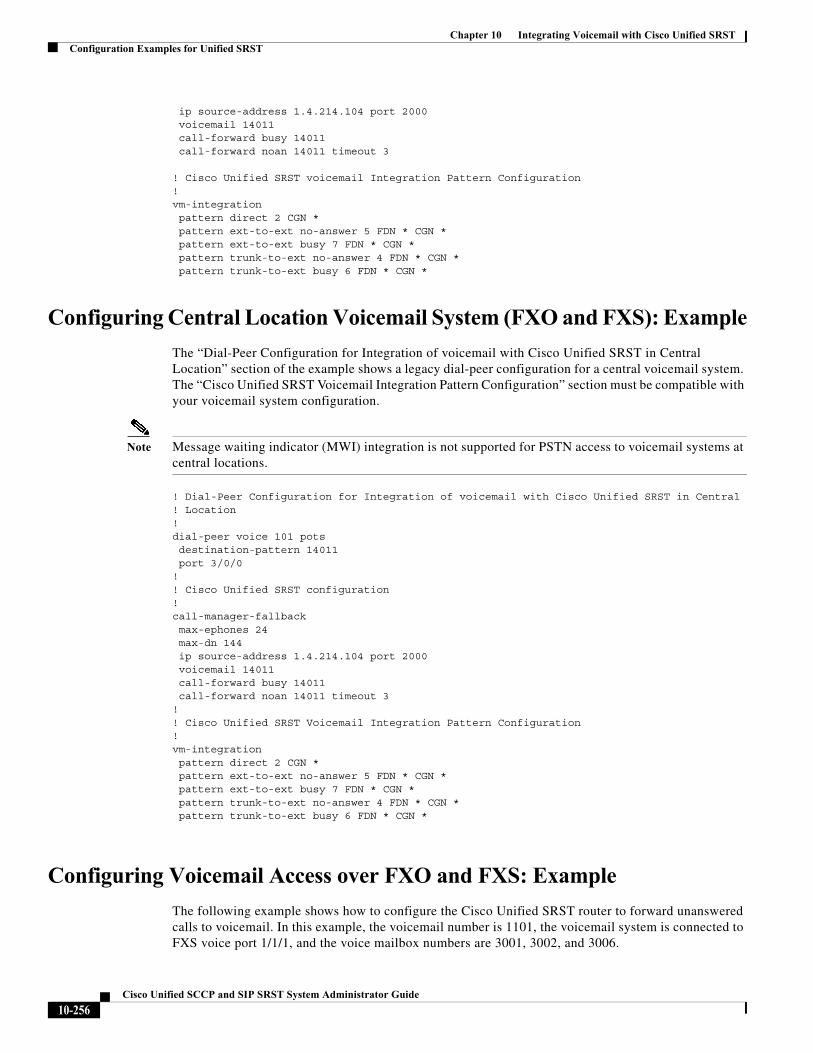
Chapter 10 Integrating Voicemail with Cisco Unified SRSTConfiguration Examples for Unified SRST
ip source-address 1.4.214.104 port 2000voicemail 14011call-forward busy 14011call-forward noan 14011 timeout 3
! Cisco Unified SRST voicemail Integration Pattern Configuration!vm-integration pattern direct 2 CGN * pattern ext-to-ext no-answer 5 FDN * CGN * pattern ext-to-ext busy 7 FDN * CGN * pattern trunk-to-ext no-answer 4 FDN * CGN * pattern trunk-to-ext busy 6 FDN * CGN *
Configuring Central Location Voicemail System (FXO and FXS): Example
The “Dial-Peer Configuration for Integration of voicemail with Cisco Unified SRST in Central Location” section of the example shows a legacy dial-peer configuration for a central voicemail system. The “Cisco Unified SRST Voicemail Integration Pattern Configuration” section must be compatible with your voicemail system configuration.
Note Message waiting indicator (MWI) integration is not supported for PSTN access to voicemail systems at central locations.
! Dial-Peer Configuration for Integration of voicemail with Cisco Unified SRST in Central ! Location!dial-peer voice 101 pots destination-pattern 14011 port 3/0/0!! Cisco Unified SRST configuration!call-manager-fallbackmax-ephones 24max-dn 144ip source-address 1.4.214.104 port 2000voicemail 14011call-forward busy 14011call-forward noan 14011 timeout 3
!! Cisco Unified SRST Voicemail Integration Pattern Configuration!vm-integration pattern direct 2 CGN * pattern ext-to-ext no-answer 5 FDN * CGN * pattern ext-to-ext busy 7 FDN * CGN * pattern trunk-to-ext no-answer 4 FDN * CGN * pattern trunk-to-ext busy 6 FDN * CGN *
Configuring Voicemail Access over FXO and FXS: Example
The following example shows how to configure the Cisco Unified SRST router to forward unanswered calls to voicemail. In this example, the voicemail number is 1101, the voicemail system is connected to FXS voice port 1/1/1, and the voice mailbox numbers are 3001, 3002, and 3006.
10-256Cisco Unified SCCP and SIP SRST System Administrator Guide
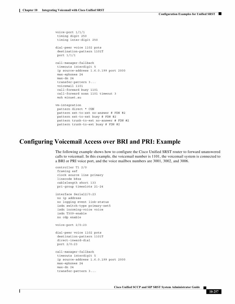
Chapter 10 Integrating Voicemail with Cisco Unified SRSTConfiguration Examples for Unified SRST
voice-port 1/1/1 timing digit 250 timing inter-digit 250
dial-peer voice 1102 pots destination-pattern 1101T port 1/1/1
call-manager-fallback timeouts interdigit 5 ip source-address 1.6.0.199 port 2000 max-ephones 24 max-dn 24 transfer-pattern 3... voicemail 1101 call-forward busy 1101 call-forward noan 1101 timeout 3 moh minuet.au
vm-integration pattern direct * CGN pattern ext-to-ext no-answer # FDN #2 pattern ext-to-ext busy # FDN #2 pattern trunk-to-ext no-answer # FDN #2 pattern trunk-to-ext busy # FDN #2
Configuring Voicemail Access over BRI and PRI: Example
The following example shows how to configure the Cisco Unified SRST router to forward unanswered calls to voicemail. In this example, the voicemail number is 1101, the voicemail system is connected to a BRI or PRI voice port, and the voice mailbox numbers are 3001, 3002, and 3006.
controller T1 2/0 framing esf clock source line primary linecode b8zs cablelength short 133 pri-group timeslots 21-24
interface Serial2/0:23 no ip address no logging event link-status isdn switch-type primary-net5 isdn incoming-voice voice isdn T309-enable no cdp enable
voice-port 2/0:23
dial-peer voice 1102 potsdestination-pattern 1101Tdirect-inward-dialport 2/0:23
call-manager-fallback timeouts interdigit 5 ip source-address 1.6.0.199 port 2000 max-ephones 24 max-dn 24 transfer-pattern 3...
10-257Cisco Unified SCCP and SIP SRST System Administrator Guide
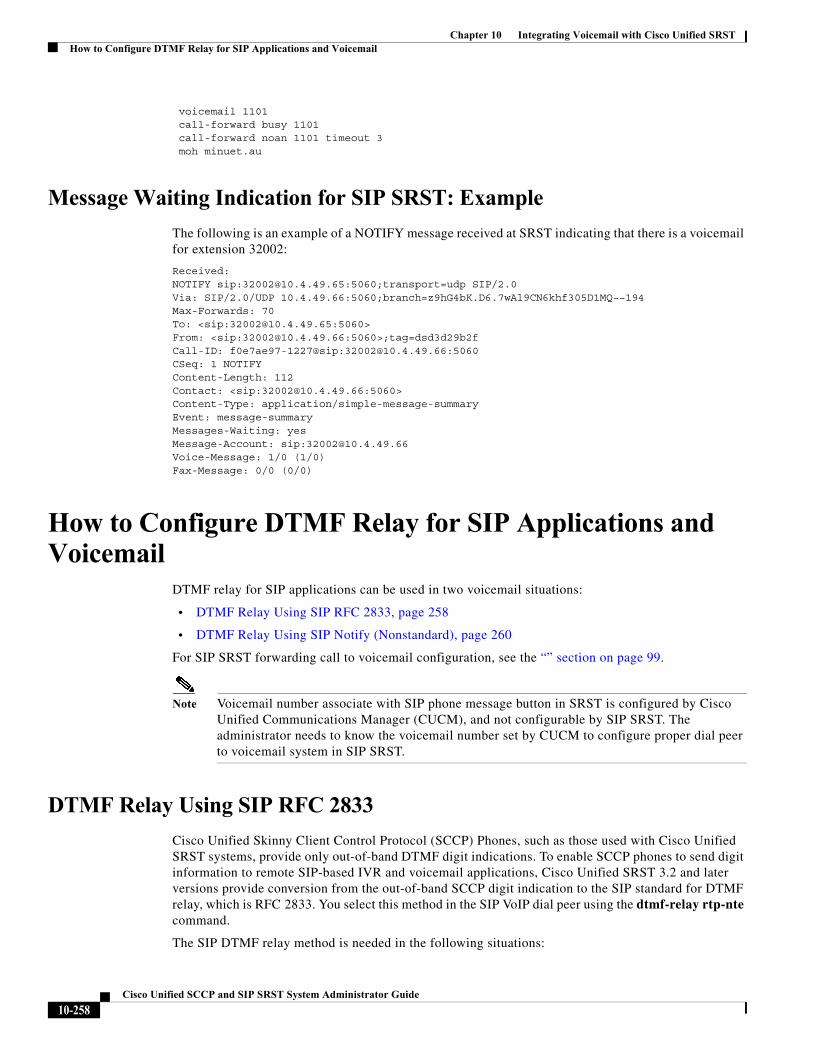
Chapter 10 Integrating Voicemail with Cisco Unified SRSTHow to Configure DTMF Relay for SIP Applications and Voicemail
voicemail 1101 call-forward busy 1101 call-forward noan 1101 timeout 3 moh minuet.au
Message Waiting Indication for SIP SRST: Example
The following is an example of a NOTIFY message received at SRST indicating that there is a voicemail for extension 32002:
Received:NOTIFY sip:[email protected]:5060;transport=udp SIP/2.0Via: SIP/2.0/UDP 10.4.49.66:5060;branch=z9hG4bK.D6.7wAl9CN6khf305D1MQ~~194Max-Forwards: 70To: <sip:[email protected]:5060>From: <sip:[email protected]:5060>;tag=dsd3d29b2fCall-ID: f0e7ae97-1227@sip:[email protected]:5060CSeq: 1 NOTIFYContent-Length: 112Contact: <sip:[email protected]:5060>Content-Type: application/simple-message-summaryEvent: message-summaryMessages-Waiting: yesMessage-Account: sip:[email protected]: 1/0 (1/0)Fax-Message: 0/0 (0/0)
How to Configure DTMF Relay for SIP Applications and Voicemail
DTMF relay for SIP applications can be used in two voicemail situations:
• DTMF Relay Using SIP RFC 2833, page 258
• DTMF Relay Using SIP Notify (Nonstandard), page 260
For SIP SRST forwarding call to voicemail configuration, see the “” section on page 99.
Note Voicemail number associate with SIP phone message button in SRST is configured by Cisco Unified Communications Manager (CUCM), and not configurable by SIP SRST. The administrator needs to know the voicemail number set by CUCM to configure proper dial peer to voicemail system in SIP SRST.
DTMF Relay Using SIP RFC 2833
Cisco Unified Skinny Client Control Protocol (SCCP) Phones, such as those used with Cisco Unified SRST systems, provide only out-of-band DTMF digit indications. To enable SCCP phones to send digit information to remote SIP-based IVR and voicemail applications, Cisco Unified SRST 3.2 and later versions provide conversion from the out-of-band SCCP digit indication to the SIP standard for DTMF relay, which is RFC 2833. You select this method in the SIP VoIP dial peer using the dtmf-relay rtp-nte command.
The SIP DTMF relay method is needed in the following situations:
10-258Cisco Unified SCCP and SIP SRST System Administrator Guide
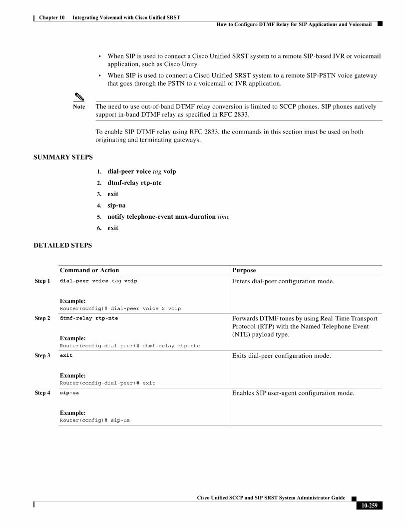
Chapter 10 Integrating Voicemail with Cisco Unified SRSTHow to Configure DTMF Relay for SIP Applications and Voicemail
• When SIP is used to connect a Cisco Unified SRST system to a remote SIP-based IVR or voicemail application, such as Cisco Unity.
• When SIP is used to connect a Cisco Unified SRST system to a remote SIP-PSTN voice gateway that goes through the PSTN to a voicemail or IVR application.
Note The need to use out-of-band DTMF relay conversion is limited to SCCP phones. SIP phones natively support in-band DTMF relay as specified in RFC 2833.
To enable SIP DTMF relay using RFC 2833, the commands in this section must be used on both originating and terminating gateways.
SUMMARY STEPS
1. dial-peer voice tag voip
2. dtmf-relay rtp-nte
3. exit
4. sip-ua
5. notify telephone-event max-duration time
6. exit
DETAILED STEPS
Command or Action Purpose
Step 1 dial-peer voice tag voip
Example:Router(config)# dial-peer voice 2 voip
Enters dial-peer configuration mode.
Step 2 dtmf-relay rtp-nte
Example:Router(config-dial-peer)# dtmf-relay rtp-nte
Forwards DTMF tones by using Real-Time Transport Protocol (RTP) with the Named Telephone Event (NTE) payload type.
Step 3 exit
Example:Router(config-dial-peer)# exit
Exits dial-peer configuration mode.
Step 4 sip-ua
Example:Router(config)# sip-ua
Enables SIP user-agent configuration mode.
10-259Cisco Unified SCCP and SIP SRST System Administrator Guide
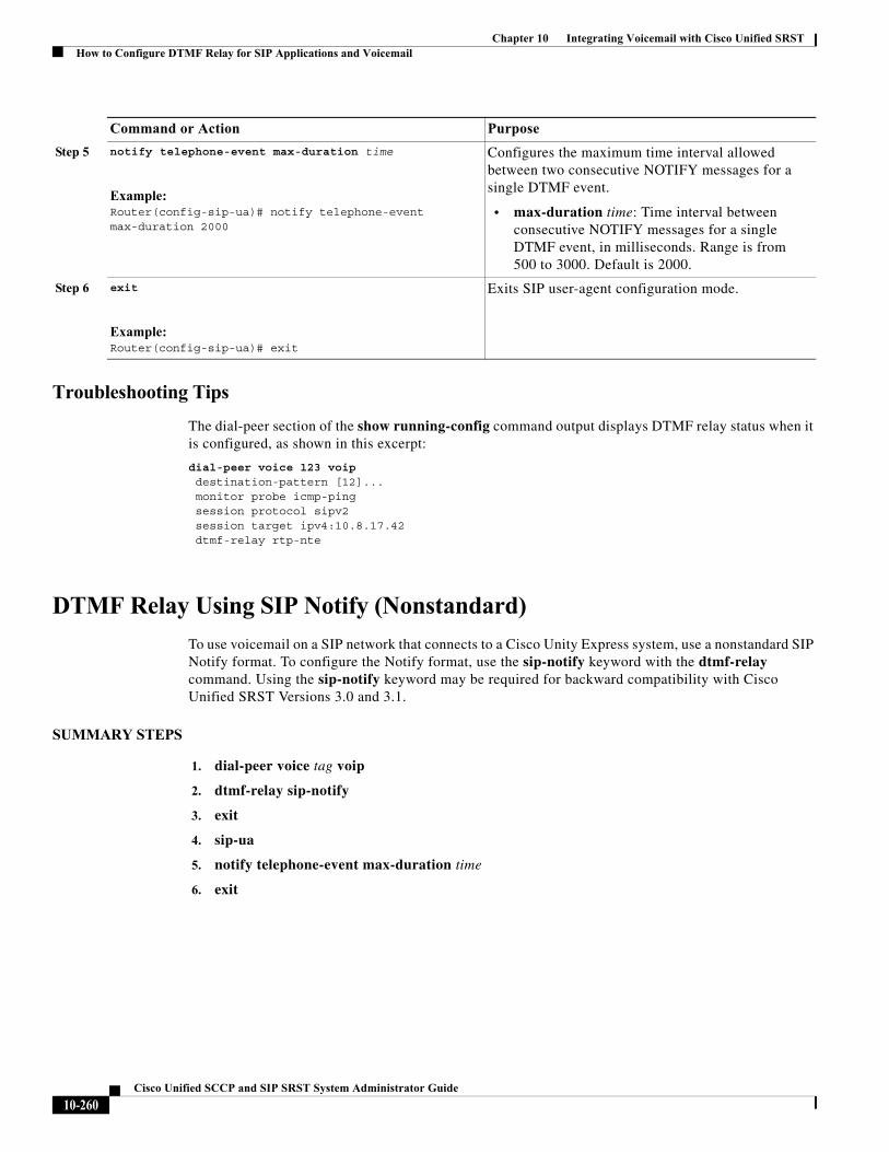
Chapter 10 Integrating Voicemail with Cisco Unified SRSTHow to Configure DTMF Relay for SIP Applications and Voicemail
Troubleshooting Tips
The dial-peer section of the show running-config command output displays DTMF relay status when it is configured, as shown in this excerpt:
dial-peer voice 123 voip destination-pattern [12]... monitor probe icmp-ping session protocol sipv2 session target ipv4:10.8.17.42 dtmf-relay rtp-nte
DTMF Relay Using SIP Notify (Nonstandard)
To use voicemail on a SIP network that connects to a Cisco Unity Express system, use a nonstandard SIP Notify format. To configure the Notify format, use the sip-notify keyword with the dtmf-relay command. Using the sip-notify keyword may be required for backward compatibility with Cisco Unified SRST Versions 3.0 and 3.1.
SUMMARY STEPS
1. dial-peer voice tag voip
2. dtmf-relay sip-notify
3. exit
4. sip-ua
5. notify telephone-event max-duration time
6. exit
Step 5 notify telephone-event max-duration time
Example:Router(config-sip-ua)# notify telephone-event max-duration 2000
Configures the maximum time interval allowed between two consecutive NOTIFY messages for a single DTMF event.
• max-duration time: Time interval between consecutive NOTIFY messages for a single DTMF event, in milliseconds. Range is from 500 to 3000. Default is 2000.
Step 6 exit
Example:Router(config-sip-ua)# exit
Exits SIP user-agent configuration mode.
Command or Action Purpose
10-260Cisco Unified SCCP and SIP SRST System Administrator Guide
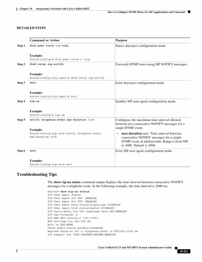
Chapter 10 Integrating Voicemail with Cisco Unified SRSTHow to Configure DTMF Relay for SIP Applications and Voicemail
DETAILED STEPS
Troubleshooting Tips
The show sip-ua status command output displays the time interval between consecutive NOTIFY messages for a telephone event. In the following example, the time interval is 2000 ms:
Router# show sip-ua statusSIP User Agent StatusSIP User Agent for UDP :ENABLEDSIP User Agent for TCP :ENABLEDSIP User Agent bind status(signaling):DISABLED SIP User Agent bind status(media):DISABLED SIP early-media for 180 responses with SDP:ENABLEDSIP max-forwards :6SIP DNS SRV version:2 (rfc 2782)NAT Settings for the SIP-UARole in SDP:NONECheck media source packets:DISABLEDMaximum duration for a telephone-event in NOTIFYs:2000 msSIP support for ISDN SUSPEND/RESUME:ENABLED
Command or Action Purpose
Step 1 dial-peer voice tag voip
Example:Router(config)# dial-peer voice 2 voip
Enters dial-peer configuration mode.
Step 2 dtmf-relay sip-notify
Example:Router(config-dial-peer)# dtmf-relay sip-notify
Forwards DTMF tones using SIP NOTIFY messages.
Step 3 exit
Example:Router(config-dial-peer)# exit
Exits dial-peer configuration mode.
Step 4 sip-ua
Example:Router(config)# sip-ua
Enables SIP user-agent configuration mode.
Step 5 notify telephone-event max-duration time
Example:Router(config-sip-ua)# notify telephone-event max-duration 2000
Configures the maximum time interval allowed between two consecutive NOTIFY messages for a single DTMF event.
• max-duration time: Time interval between consecutive NOTIFY messages for a single DTMF event, in milliseconds. Range is from 500 to 3000. Default is 2000.
Step 6 exit
Example:Router(config-sip-ua)# exit
Exits SIP user-agent configuration mode.
10-261Cisco Unified SCCP and SIP SRST System Administrator Guide
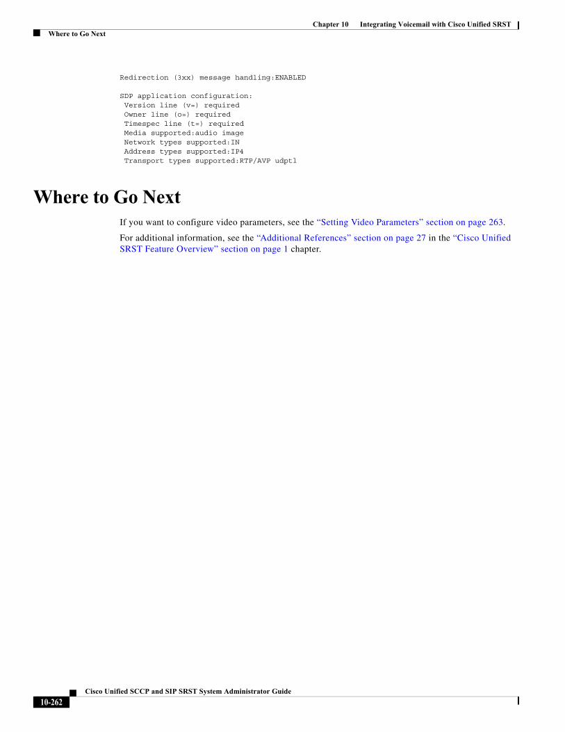
Chapter 10 Integrating Voicemail with Cisco Unified SRSTWhere to Go Next
Redirection (3xx) message handling:ENABLED SDP application configuration: Version line (v=) required Owner line (o=) required Timespec line (t=) required Media supported:audio image Network types supported:IN Address types supported:IP4 Transport types supported:RTP/AVP udptl
Where to Go NextIf you want to configure video parameters, see the “Setting Video Parameters” section on page 263.
For additional information, see the “Additional References” section on page 27 in the “Cisco Unified SRST Feature Overview” section on page 1 chapter.
10-262Cisco Unified SCCP and SIP SRST System Administrator Guide
Cisco Unified SC
C H A P T E R 11
Setting Video ParametersThis chapter describes how to set video parameters for a Cisco Unified Survivable Remote Site Telephony (SRST) Router.
Contents• Prerequisites for Setting Video Parameters, page 263
• Restrictions for Setting Video Parameters, page 264
• Information About Setting Video Parameters, page 264
• How to Set Video Parameters for Cisco Unified SRST, page 267
• Troubleshooting Video for Cisco Unified SRST, page 276
• Where to Go Next, page 276
Prerequisites for Setting Video Parameters• Ensure that you are using Cisco Unified SRST 4.0 or a later version.
• Ensure that you are using Cisco Unified CM 4.0 or a later version.
• Ensure that the Cisco IP phones are registered with the Cisco Unified SRST router. Use the show ephone registered command to verify ephone registration.
• Ensure that the connection between the Cisco Unified Video Advantage application and the Cisco Unified IP phone is up.
From a PC with Cisco Unified Video Advantage 1.02 or a later version installed, ensure that the line between the Cisco Unified Video Advantage and the Cisco Unified IP phone is green. For more information, see Cisco Unified Video Advantage End User Guides.
• Ensure that the correct video firmware is installed on the Cisco Unified IP phone. Use the show ephone phone-load command to view current ephone firmware. The following lists the minimum firmware version for video-enabled Cisco Unified IP phones:
– Cisco Unified IP Phone 7940G version 6.0(4)
– Cisco Unified IP Phone 7960G version 6.0(4)
– Cisco Unified IP Phone 7970G version 6.0(2)
11-263CP and SIP SRST System Administrator Guide
Chapter 11 Setting Video ParametersRestrictions for Setting Video Parameters
• Perform basic Cisco Unified SRST configuration. For more information, see Cisco Unified SRST V4.0: Setting Up the Network.
• Perform basic ephone configuration. For more information, see Cisco Unified SRST V4.0: Setting Up Cisco Unified IP Phones.
Restrictions for Setting Video Parameters• This feature supports only the following video codecs:
– H.261
– H.263
– H.264 (for CUVA from SRST 7.1)
• This feature supports only the following video formats:
– Common Intermediate Format (CIF): Resolution 352x288
– One-Quarter Common Intermediate Format (QCIF): Resolution 176x144
– Sub QIF (SQCIF): Resolution 128x96
– 4CIF: Resolution 704x576
– 16CIF: Resolution 1408x1152
• The call start fast feature is not supported with an H.323 video connection. You must configure call start slow for H.323 video.
• Video capabilities are configured per ephone, not per line.
• All call feature controls (for example, mute and hold) apply to both audio and video calls, if applicable.
• This feature does not support the following:
– Dynamic addition of video capability: The video capability must be present before the call setup starts to allow the video connection.
– T-120 data connection between two SCCP endpoints
– Video security
– Far-end camera control (FECC) for SCCP endpoints
– Video codec renegotiation: The negotiated video codec must match or the call falls back to audio-only. The negotiated codec for the existing call can be used for a new call.
– Video codec transcoding
• When a video-capable endpoint connects to an audio-only endpoint, the call falls back to audio-only. During audio-only calls, video messages are skipped.
Information About Setting Video ParametersThis feature allows you to set video parameters for the Cisco Unified SRST to maintain close feature parity with Cisco Unified CM. When the Cisco Unified SRST is enabled, Cisco Unified IP phones do not have to be reconfigured for video capabilities because all ephones retain the same configuration used
11-264Cisco Unified SCCP and SIP SRST System Administrator Guide
Chapter 11 Setting Video ParametersInformation About Setting Video Parameters
with Cisco Unified CM. However, you must enter call-manager-fallback configuration mode to set video parameters for Cisco Unified SRST. The feature set for video is the same as that for Cisco Unified SRST audio calls.
To set video parameters, you should understand the following concepts:
• Matching Endpoint Capabilities, page 265
• Retrieving Video Codec Information, page 265
• Call Fallback to Audio-Only, page 265
• Call Setup for Video Endpoints, page 265
• Flow of the RTP Video Stream, page 266
Matching Endpoint Capabilities
Endpoint capabilities are stored in the Cisco Unified SRST during phone registration. These capabilities are used to match with other endpoints during call setup. Endpoints can update at any time; however, the router recognizes endpoint-capability changes only during call setup. If a video feature is added to a phone, the information about it is updated in the router’s internal data structure, but that information does not take effect until the next call. If a video feature is removed, the router continues to see the video capability until the call is terminated but no video stream is exchanged between the two endpoints.
Note The endpoint-capability match is executed every time a new call is set up or an existing call is resumed.
Retrieving Video Codec Information
Voice gateways use dial-peer configurations to retrieve codec information for audio codecs. Video codec selection is done by the endpoints and is not controlled by the H.323 service-provider interface (SPI) through dial-peer or other configuration. The video-codec information is retrieved from the SCCP endpoint using a capabilities request during call setup.
Call Fallback to Audio-Only
When a video-capable endpoint connects to an audio-only endpoint, the call falls back to an audio-only connection. Also, for certain features such as conferencing, where video support is not available, the call falls back to audio-only.
Cisco Unified SRST routers use a call-type flag to indicate whether the call is video-capable or audio-only. The call-type flag is set to video when the video capability is matched or set to audio-only when connecting to an audio-only TDM or an audio-only SIP endpoint.
Note During an audio-only connection, all video-related media messages are skipped.
Call Setup for Video Endpoints
The process for handling SCCP video endpoints is the same as that for handling SCCP audio endpoints. The video call must be part of the audio call. If the audio call setup fails, the video call fails.
11-265Cisco Unified SCCP and SIP SRST System Administrator Guide
Chapter 11 Setting Video ParametersInformation About Setting Video Parameters
During call setup for video, media setup handling determines if a video-media path is required or not. If so, the corresponding video-media-path setup actions are taken.
• For an SCCP endpoint, video-media-path setup includes sending messages to the endpoints to open a multimedia path and start the multimedia transmission.
• For an H.323 endpoint, video-media-path setup includes an exchange between the endpoints to open a logical channel for the video stream.
A call-type flag is set during call setup on the basis of the endpoint-capability match. After call setup, the call-type flag is used to determine whether an additional video-media path is required. Call signaling is managed by the Cisco Unified CME router, and the media stream is directly connected between the two video-enabled SCCP endpoints on the same router. Video-related commands and flow-control messages are forwarded to the other endpoint. Routers do not interpret these messages.
Call Setup Between Two Local SCCP Endpoints
For interoperation between two local SCCP endpoints (that exist on the same router), video call setup uses all existing audio-call-setup handling, except during media setup. During media setup, a message is sent to establish the video-media path. If the endpoint responds, the video-media path is established and a start-multimedia-transmission function is called.
Call Setup Between SCCP and H.323 Endpoints
Call setup between SCCP and H.323 endpoints is the same as it is between SCCP endpoints except that, if video capability is selected, the event is posted to the H.323 call leg to send out a video open logical channel (OLC) and the gateway generates an OLC for the video channel. Because the router needs to both terminate and originate the media stream, video must be enabled on the router before call setup begins.
Call Setup Between Two SCCP Endpoints Across an H.323 Network
If call setup between SCCP endpoints occurs across an H.323 network, the setup is a combination of the processes listed in the previous two sections. The router controls the video media setup between the two endpoints, and the event is posted to the H.323 call leg so that the gateway can generate an OLC.
Flow of the RTP Video Stream
For video streams between two local SCCP endpoints, the Real-Time Transport Protocol (RTP) stream is in flow-around mode. For video streams between SCCP and H.323 endpoints or two SCCP endpoints on different Cisco Unified CME routers, the RTP stream is in flow-through mode.
• Media flow-around mode enables RTP packets to stream directly between the endpoints of a VoIP call without the involvement of the gateway. By default, the gateway receives the incoming media, terminates the call, and then reoriginates it on the outbound call leg. In flow-around mode, only signaling data is passed to the gateway, improving scalability and performance.
• Media flow-through mode involves the same video-media path as for an audio call. Media packets flow through the gateway, thus hiding the networks from each other.
11-266Cisco Unified SCCP and SIP SRST System Administrator Guide
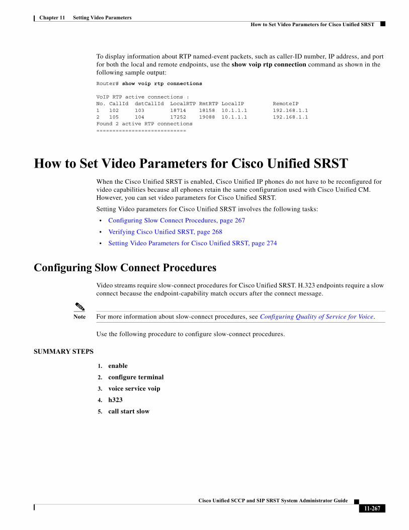
Chapter 11 Setting Video ParametersHow to Set Video Parameters for Cisco Unified SRST
To display information about RTP named-event packets, such as caller-ID number, IP address, and port for both the local and remote endpoints, use the show voip rtp connection command as shown in the following sample output:
Router# show voip rtp connections
VoIP RTP active connections :No. CallId dstCallId LocalRTP RmtRTP LocalIP RemoteIP 1 102 103 18714 18158 10.1.1.1 192.168.1.1 2 105 104 17252 19088 10.1.1.1 192.168.1.1 Found 2 active RTP connections============================
How to Set Video Parameters for Cisco Unified SRSTWhen the Cisco Unified SRST is enabled, Cisco Unified IP phones do not have to be reconfigured for video capabilities because all ephones retain the same configuration used with Cisco Unified CM. However, you can set video parameters for Cisco Unified SRST.
Setting Video parameters for Cisco Unified SRST involves the following tasks:
• Configuring Slow Connect Procedures, page 267
• Verifying Cisco Unified SRST, page 268
• Setting Video Parameters for Cisco Unified SRST, page 274
Configuring Slow Connect Procedures
Video streams require slow-connect procedures for Cisco Unified SRST. H.323 endpoints require a slow connect because the endpoint-capability match occurs after the connect message.
Note For more information about slow-connect procedures, see Configuring Quality of Service for Voice.
Use the following procedure to configure slow-connect procedures.
SUMMARY STEPS
1. enable
2. configure terminal
3. voice service voip
4. h323
5. call start slow
11-267Cisco Unified SCCP and SIP SRST System Administrator Guide
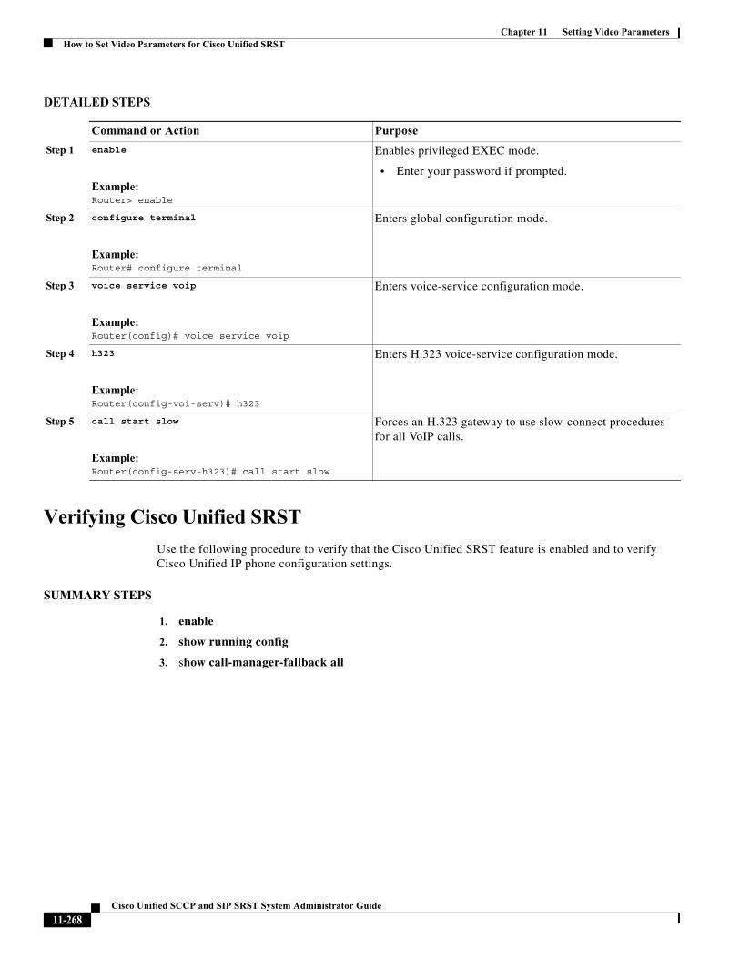
Chapter 11 Setting Video ParametersHow to Set Video Parameters for Cisco Unified SRST
DETAILED STEPS
Verifying Cisco Unified SRST
Use the following procedure to verify that the Cisco Unified SRST feature is enabled and to verify Cisco Unified IP phone configuration settings.
SUMMARY STEPS
1. enable
2. show running config
3. show call-manager-fallback all
Command or Action Purpose
Step 1 enable
Example:Router> enable
Enables privileged EXEC mode.
• Enter your password if prompted.
Step 2 configure terminal
Example:Router# configure terminal
Enters global configuration mode.
Step 3 voice service voip
Example:Router(config)# voice service voip
Enters voice-service configuration mode.
Step 4 h323
Example:Router(config-voi-serv)# h323
Enters H.323 voice-service configuration mode.
Step 5 call start slow
Example:Router(config-serv-h323)# call start slow
Forces an H.323 gateway to use slow-connect procedures for all VoIP calls.
11-268Cisco Unified SCCP and SIP SRST System Administrator Guide
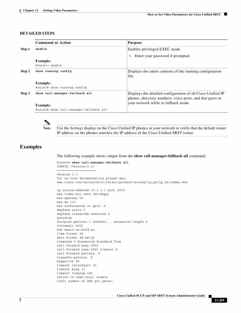
Chapter 11 Setting Video ParametersHow to Set Video Parameters for Cisco Unified SRST
DETAILED STEPS
Note Use the Settings display on the Cisco Unified IP phones in your network to verify that the default router IP address on the phones matches the IP address of the Cisco Unified SRST router.
Examples
The following example shows output from the show call-manager-fallback all command:
Router# show call-manager-fallback allCONFIG (Version=3.3)=====================Version 3.3For on-line documentation please see:www.cisco.com/univercd/cc/td/doc/product/access/ip_ph/ip_ks/index.htm
ip source-address 10.1.1.1 port 2000max-video-bit-rate 384(kbps)max-ephones 52max-dn 110max-conferences 16 gain -6dspfarm units 0dspfarm transcode sessions 0huntstopdialplan-pattern 1 4084442... extension-length 4voicemail 6001moh music-on-hold.autime-format 24date-format dd-mm-yytimezone 0 Greenwich Standard Timecall-forward busy 6001call-forward noan 6001 timeout 8call-forward pattern .Ttransfer-pattern .Tkeepalive 45timeout interdigit 10timeout busy 10timeout ringing 180caller-id name-only: enableLimit number of DNs per phone:
Command or Action Purpose
Step 1 enable
Example:Router> enable
Enables privileged EXEC mode.
• Enter your password if prompted.
Step 2 show running config
Example:Router# show running config
Displays the entire contents of the running configuration file.
Step 3 show call-manager-fallback all
Example:Router# show call-manager-fallback all
Displays the detailed configuration of all Cisco Unified IP phones, directory numbers, voice ports, and dial peers in your network while in fallback mode.
11-269Cisco Unified SCCP and SIP SRST System Administrator Guide
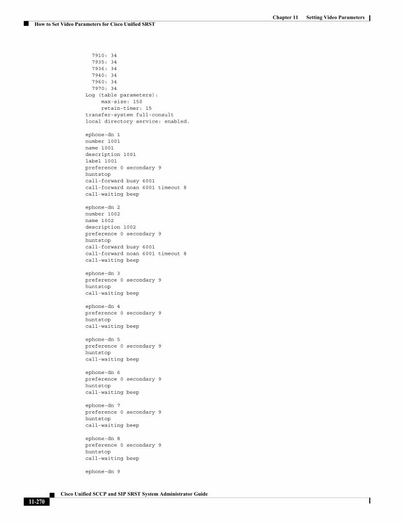
Chapter 11 Setting Video ParametersHow to Set Video Parameters for Cisco Unified SRST
7910: 34 7935: 34 7936: 34 7940: 34 7960: 34 7970: 34Log (table parameters): max-size: 150 retain-timer: 15transfer-system full-consult local directory service: enabled.
ephone-dn 1number 1001name 1001description 1001label 1001preference 0 secondary 9huntstopcall-forward busy 6001call-forward noan 6001 timeout 8call-waiting beep
ephone-dn 2number 1002name 1002description 1002preference 0 secondary 9huntstopcall-forward busy 6001call-forward noan 6001 timeout 8call-waiting beep
ephone-dn 3preference 0 secondary 9huntstopcall-waiting beep
ephone-dn 4preference 0 secondary 9huntstopcall-waiting beep
ephone-dn 5preference 0 secondary 9huntstopcall-waiting beep
ephone-dn 6preference 0 secondary 9huntstopcall-waiting beep
ephone-dn 7preference 0 secondary 9huntstopcall-waiting beep
ephone-dn 8preference 0 secondary 9huntstopcall-waiting beep
ephone-dn 9
11-270Cisco Unified SCCP and SIP SRST System Administrator Guide
Chapter 11 Setting Video ParametersHow to Set Video Parameters for Cisco Unified SRST
preference 0 secondary 9huntstopcall-waiting beep
ephone-dn 10preference 0 secondary 9huntstopcall-waiting beep
ephone-dn 11preference 0 secondary 9huntstopcall-waiting beep
ephone-dn 12preference 0 secondary 9huntstopcall-waiting beep
ephone-dn 13preference 0 secondary 9huntstopcall-waiting beep
ephone-dn 14preference 0 secondary 9huntstopcall-waiting beep
ephone-dn 15preference 0 secondary 9huntstopcall-waiting beep
ephone-dn 16preference 0 secondary 9huntstopcall-waiting beep
ephone-dn 17preference 0 secondary 9huntstopcall-waiting beep
ephone-dn 18preference 0 secondary 9huntstopcall-waiting beep
ephone-dn 19preference 0 secondary 9huntstopcall-waiting beep
ephone-dn 20preference 0 secondary 9huntstopcall-waiting beep
Number of Configured ephones 0 (Registered 2)
voice-port 50/0/1 station-id number 1001 station-id name 1001
11-271Cisco Unified SCCP and SIP SRST System Administrator Guide
Chapter 11 Setting Video ParametersHow to Set Video Parameters for Cisco Unified SRST
timeout ringing 8!voice-port 50/0/2 station-id number 1002 station-id name 1002 timeout ringing 8!voice-port 50/0/3!voice-port 50/0/4!voice-port 50/0/5!voice-port 50/0/6!voice-port 50/0/7!voice-port 50/0/8!voice-port 50/0/9!voice-port 50/0/10!voice-port 50/0/11!voice-port 50/0/12!voice-port 50/0/13!voice-port 50/0/14!voice-port 50/0/15!voice-port 50/0/16!voice-port 50/0/17!voice-port 50/0/18!voice-port 50/0/19!voice-port 50/0/20!
dial-peer voice 20055 pots destination-pattern 1001 huntstop call-forward busy 6001 call-forward noan 6001 progress_ind setup enable 3 port 50/0/1
dial-peer voice 20056 pots destination-pattern 1002 huntstop call-forward busy 6001 call-forward noan 6001 progress_ind setup enable 3 port 50/0/2
dial-peer voice 20057 pots huntstop progress_ind setup enable 3 port 50/0/3
11-272Cisco Unified SCCP and SIP SRST System Administrator Guide
Chapter 11 Setting Video ParametersHow to Set Video Parameters for Cisco Unified SRST
dial-peer voice 20058 pots huntstop progress_ind setup enable 3 port 50/0/4
dial-peer voice 20059 pots huntstop progress_ind setup enable 3 port 50/0/5
dial-peer voice 20060 pots huntstop progress_ind setup enable 3 port 50/0/6
dial-peer voice 20061 pots huntstop progress_ind setup enable 3 port 50/0/7
dial-peer voice 20062 pots huntstop progress_ind setup enable 3 port 50/0/8
dial-peer voice 20063 pots huntstop progress_ind setup enable 3 port 50/0/9
dial-peer voice 20064 pots huntstop progress_ind setup enable 3 port 50/0/10
dial-peer voice 20065 pots huntstop progress_ind setup enable 3 port 50/0/11
dial-peer voice 20066 pots huntstop progress_ind setup enable 3 port 50/0/12
dial-peer voice 20067 pots huntstop progress_ind setup enable 3 port 50/0/13
dial-peer voice 20068 pots huntstop progress_ind setup enable 3 port 50/0/14
dial-peer voice 20069 pots huntstop progress_ind setup enable 3 port 50/0/15
dial-peer voice 20070 pots huntstop progress_ind setup enable 3
11-273Cisco Unified SCCP and SIP SRST System Administrator Guide
Chapter 11 Setting Video ParametersHow to Set Video Parameters for Cisco Unified SRST
port 50/0/16
dial-peer voice 20071 pots huntstop progress_ind setup enable 3 port 50/0/17
dial-peer voice 20072 pots huntstop progress_ind setup enable 3 port 50/0/18
dial-peer voice 20073 pots huntstop progress_ind setup enable 3 port 50/0/19
dial-peer voice 20074 pots huntstop progress_ind setup enable 3 port 50/0/20
tftp-server system:/its/SEPDEFAULT.cnftftp-server system:/its/SEPDEFAULT.cnf alias SEPDefault.cnftftp-server system:/its/XMLDefault.cnf.xml alias XMLDefault.cnf.xmltftp-server system:/its/ATADefault.cnf.xmltftp-server system:/its/united_states/7960-tones.xml alias United_States/7960-tones.xmltftp-server system:/its/united_states/7960-font.xml alias English_United_States/7960-font.xmltftp-server system:/its/united_states/7960-dictionary.xml alias English_United_States/7960-dictionary.xmltftp-server system:/its/united_states/7960-kate.xml alias English_United_States/7960-kate.xmltftp-server system:/its/united_states/SCCP-dictionary.xml alias English_United_States/SCCP-dictionary.xmltftp-server system:/its/XMLDefault7960.cnf.xml alias SEP003094C2772E.cnf.xmltftp-server system:/its/XMLDefault7960.cnf.xml alias SEP001201372DD1.cnf.xmltftp-server system:/its/XMLDefault7960.cnf.xml alias SEPFFDD00000001.cnf.xmltftp-server system:/its/XMLDefault7960.cnf.xml alias SEPFFDD00000002.cnf.xmltftp-server system:/its/XMLDefault7960.cnf.xml alias SEPFFDD00000003.cnf.xmltftp-server system:/its/XMLDefault7960.cnf.xml alias SEPFFDD00000004.cnf.xmltftp-server system:/its/XMLDefault7960.cnf.xml alias SEPFFDD00000005.cnf.xmltftp-server system:/its/XMLDefault7960.cnf.xml alias SEPFFDD00000006.cnf.xmltftp-server system:/its/XMLDefault7960.cnf.xml alias SEPFFDD00000007.cnf.xmltftp-server system:/its/XMLDefault7960.cnf.xml alias SEPFFDD00000008.cnf.xmltftp-server system:/its/XMLDefault7960.cnf.xml alias SEPFFDD00000009.cnf.xmltftp-server system:/its/XMLDefault7960.cnf.xml alias SEPFFDD0000000A.cnf.xmltftp-server system:/its/XMLDefault7960.cnf.xml alias SEPFFDD0000000B.cnf.xmltftp-server system:/its/XMLDefault7960.cnf.xml alias SEPFFDD0000000C.cnf.xmltftp-server system:/its/XMLDefault7960.cnf.xml alias SEPFFDD0000000D.cnf.xmltftp-server system:/its/XMLDefault7960.cnf.xml alias SEPFFDD0000000E.cnf.xmltftp-server system:/its/XMLDefault7960.cnf.xml alias SEPFFDD0000000F.cnf.xmltftp-server system:/its/XMLDefault7960.cnf.xml alias SEPFFDD00000010.cnf.xmltftp-server system:/its/XMLDefault7960.cnf.xml alias SEPFFDD00000011.cnf.xmltftp-server system:/its/XMLDefault7960.cnf.xml alias SEPFFDD00000012.cnf.xml
Setting Video Parameters for Cisco Unified SRST
Using the following procedure to set the maximum bit rate for all video-capable phones in a Cisco Unified SRST system.
11-274Cisco Unified SCCP and SIP SRST System Administrator Guide
Chapter 11 Setting Video ParametersHow to Set Video Parameters for Cisco Unified SRST
SUMMARY STEPS
1. enable
2. configure terminal
3. call-manager-fallback
4. video
5. maximum bit-rate value
DETAILED STEPS
Examples
The following example shows the configuration for video with Cisco Unified SRST:
call-manager-fallbackvideomaximum bit-rate 384
max-conferences 2 gain -6transfer-system full-consultip source-address 10.0.1.1 port 2000max-ephones 52max-dn 110dialplan-pattern 1 4084442... extension-length 4transfer-pattern .Tkeepalive 45voicemail 6001call-forward pattern .T
Command or Action Purpose
Step 1 enable
Example:Router> enable
Enables privileged EXEC mode.
• Enter your password if prompted.
Step 2 configure terminal
Example:Router# configure terminal
Enters global configuration mode.
Step 3 call-manager-fallback
Example:Router(config)# call-manager-fallback
Enters call-manager-fallback configuration mode.
Step 4 video
Example:Router(config-call-manager-fallback)# video
Enters call-manager-fallback video configuration mode.
Step 5 maximum bit-rate value
Example:Router(conf-cm-fallback-video)# maximum bit-rate 256
Sets the maximum IP phone video bandwidth, in kbps. The range is 0 to 10000000. The default is 10000000.
11-275Cisco Unified SCCP and SIP SRST System Administrator Guide
Chapter 11 Setting Video ParametersTroubleshooting Video for Cisco Unified SRST
call-forward busy 6001call-forward noan 6001 timeout 3moh music-on-hold.autime-format 24date-format dd-mm-yy!
Troubleshooting Video for Cisco Unified SRSTUse the following commands to troubleshoot Video for Cisco Unified SRST.
• For SCCP endpoint troubleshooting, use the following debug commands:
– debug cch323 video: Enables video debugging trace on the H.323 SPI.
– debug ephone detail: Debugs all Cisco Unified IP phones that are registered to the router and displays error and state levels.
– debug h225 asn1: Displays Abstract Syntax Notation One (ASN.1) contents of H.225 messages that have been sent or received.
– debug h245 asn1: Displays ASN.1 contents of H.245 messages that have been sent or received.
– debug voip ccapi inout: Displays the execution path through the call-control-application programming interface (CPI).
• For ephone troubleshooting, use the following debug commands:
– debug ephone message: Enables message tracing between Cisco ephones.
– debug ephone register: Sets registration debugging for ephones.
– debug ephone video: Sets ephone video traces, which provide information about different video states for the call, including video capabilities selection, start, and stop.
• For basic video-to-video call checking, use the following show commands:
– show call active video: Displays call information for SCCP video calls in progress.
– show ephone offhook: Displays information and packet counts for ephones that are currently off hook.
– show voip rtp connections: Displays information about RTP named-event packets, such as caller ID number, IP address, and port, for both the local and remote endpoints.
Where to Go NextTo monitor and maintain Cisco Unified SRST, see the “Monitoring and Maintaining Cisco Unified SRST” section on page 277.
For additional information, see the “Additional References” section on page 27 in the “Cisco Unified SRST Feature Overview” section on page 1 chapter.
11-276Cisco Unified SCCP and SIP SRST System Administrator Guide
Cisco Unified SC
C H A P T E R 12
Monitoring and Maintaining Cisco Unified SRSTTo monitor and maintain Cisco Unified Survivable Remote Site Telephony (SRST), use the following commands in privileged EXEC mode.
Command Purpose
Router# show call-manager-fallback all Displays the detailed configuration of all the Cisco Unified IP phones, voice ports, and dial peers of the Cisco Unified SRST Router.
Router# show call-manager-fallback dial-peer Displays the output of the dial peers of the Cisco Unified SRST Router.
Router# show call-manager-fallback ephone-dn Displays Cisco Unified IP Phone destination numbers when in call manager fallback mode.
Router# show call-manager-fallback voice-port Displays output for the voice ports.
Router# show dial-peer voice summary Displays a summary of all voice dial peers.
Router# show ephone phone Displays Cisco Unified IP Phone status.
Router# show ephone offhook Displays Cisco Unified IP Phone status for all phones that are off hook.
Router# show ephone registered Displays Cisco Unified IP Phone status for all phones that are currently registered.
Router# show ephone remote Displays Cisco Unified IP Phone status for all nonlocal phones (phones that have no Address Resolution Protocol [ARP] entry).
Router# show ephone ringing Displays Cisco Unified IP Phone status for all phones that are ringing.
Router# show ephone summary Displays a summary of all Cisco Unified IP Phones.
Router# show ephone telephone-number phone-number Displays Unified IP Phone status for a specific phone number.
Router# show ephone unregistered Displays Unified IP Phone status for all unregistered phones.
Router# show ephone-dn tag Displays Unified IP Phone destination numbers.
Router# show ephone-dn summary Displays a summary of all Cisco Unified IP Phone destination numbers.
Router# show ephone-dn loopback Displays Cisco Unified IP Phone destination numbers in loopback mode.
12-277CP and SIP SRST System Administrator Guide
Chapter 12 Monitoring and Maintaining Cisco Unified SRST
Router# show running-config Displays the configuration.
Router # show sip-ua status registrar Display SIP registrar clients.
Router# show voice port summary Displays a summary of all voice ports.
Router # show voice register all Displays all SIP SRST configurations , SIP phone registrations and dial peer info.
Router # show voice register global Displays voice register global config.
Router # show voice register pool all Displays all config SIP phone voice register pool detail info.
Router # show voice register pool <tag> Displays specific SIP phone voice register pool detail info.
Router # show voice register dial-peers Displays SIP-SRST created dial peer.
Router # show voice register dn all Displays all config voice register dn detail info.
Router # show voice register dn <tag> Displays specific voice register dn detail info.
Command Purpose
12-278Cisco Unified SCCP and SIP SRST System Administrator Guide
Cisco Unified SCCP an
A
P P E N D I X A Configuring Cisco Unified SIP SRST Features Using Redirect ModeNote This chapter applies to version 3.0 only.
This chapter describes Cisco Unified Session Initiation Protocol (SIP) Survivable Remote Site Telephony (SRST) features using redirect mode.
Contents• Prerequisites for Cisco Unified SIP SRST Features Using Redirect Mode, page A-1
• Restrictions for Cisco Unified SIP SRST Features Using Redirect Mode, page A-1
• Information About Cisco Unified SIP SRST Features Using Redirect Mode, page A-2
• How to Configure Cisco Unified SIP SRST Features Using Redirect Mode, page A-2
• Configuration Examples for Cisco Unified SIP SRST Features Using Redirect Mode, page A-6
• Where to Go Next, page A-8
Prerequisites for Cisco Unified SIP SRST Features Using Redirect Mode
Complete the prerequisites documented in the “Prerequisites for Configuring Cisco Unified SIP SRST” section on page 1-9 in the “1” section on page 1-1.
Restrictions for Cisco Unified SIP SRST Features Using Redirect Mode
See the restrictions documented in the “Restrictions for Configuring Cisco Unified SIP SRST” section on page 1-9 section in the “1” section on page 1-1.
A-1d SIP SRST System Administrator Guide
Appendix A Configuring Cisco Unified SIP SRST Features Using Redirect Mode Information About Cisco Unified SIP SRST Features Using Redirect Mode
Information About Cisco Unified SIP SRST Features Using Redirect Mode
Cisco Unified SIP SRST provides backup to an external SIP proxy server by providing basic registrar and redirect services. These services are used by a SIP IP phone in the event of a WAN connection outage when the SIP phone is unable to communicate with its primary SIP proxy. The Cisco Unified SIP SRST device also provides PSTN gateway access for placing and receiving PSTN calls.
To make maximum use of the Cisco Unified SIP SRST service, the local SIP IP phones should support dual (concurrent) registration with both their primary SIP proxy or registrar and the Cisco Unified SIP SRST backup registrar. Cisco Unified SIP SRST works for the following types of calls:
• Local SIP IP phone to local SIP phone, if the main proxy is unavailable.
• Additional services like class of restriction (COR) for local SIP IP phones to the outgoing PSTN. For example, to block outgoing 1-900 numbers.
How to Configure Cisco Unified SIP SRST Features Using Redirect Mode
This section contains the following procedures:
• Configuring Call Redirect Enhancements to Support Calls Between SIP IP Phones for Cisco Unified SIP SRST, page A-2 (required)
• Configuring Sending 300 Multiple Choice Support, page A-5 (required)
Configuring Call Redirect Enhancements to Support Calls Between SIP IP Phones for Cisco Unified SIP SRST
The call redirect enhancement supports calls from a local SIP phone to another local SIP phone through the Cisco IOS voice gateway. Prior to this enhancement, an attempt by a SIP phone to contact another local SIP phone using the Cisco IOS voice gateway as if it were a SIP proxy or redirect server would fail. However, the Cisco IOS voice gateway can now act as a SIP redirect server. The voice gateway responds to the originator with a SIP Redirect message, allowing the SIP phone that originated the call to establish a call to its destination.
The redirect ip2ip (voice service) and redirect ip2ip (dial-peer) commands allow you to enable the SIP functionality, globally or on a specific inbound dial peer. The default application on Cisco Unified SIP SRST supports IP-to-IP redirection.
• Configuring Call Redirect Enhancements to Support Calls Globally, page A-3
• Configuring Call Redirect Enhancements to Support Calls on a Specific VoIP Dial Peer, page A-4
A-2Cisco Unified SCCP and SIP SRST System Administrator Guide
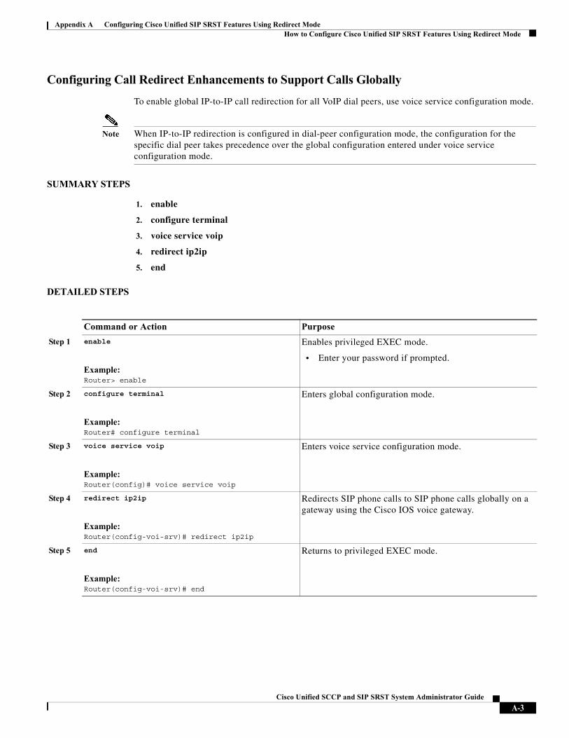
Appendix A Configuring Cisco Unified SIP SRST Features Using Redirect Mode How to Configure Cisco Unified SIP SRST Features Using Redirect Mode
Configuring Call Redirect Enhancements to Support Calls Globally
To enable global IP-to-IP call redirection for all VoIP dial peers, use voice service configuration mode.
Note When IP-to-IP redirection is configured in dial-peer configuration mode, the configuration for the specific dial peer takes precedence over the global configuration entered under voice service configuration mode.
SUMMARY STEPS
1. enable
2. configure terminal
3. voice service voip
4. redirect ip2ip
5. end
DETAILED STEPS
Command or Action Purpose
Step 1 enable
Example:Router> enable
Enables privileged EXEC mode.
• Enter your password if prompted.
Step 2 configure terminal
Example:Router# configure terminal
Enters global configuration mode.
Step 3 voice service voip
Example:Router(config)# voice service voip
Enters voice service configuration mode.
Step 4 redirect ip2ip
Example:Router(config-voi-srv)# redirect ip2ip
Redirects SIP phone calls to SIP phone calls globally on a gateway using the Cisco IOS voice gateway.
Step 5 end
Example:Router(config-voi-srv)# end
Returns to privileged EXEC mode.
A-3Cisco Unified SCCP and SIP SRST System Administrator Guide
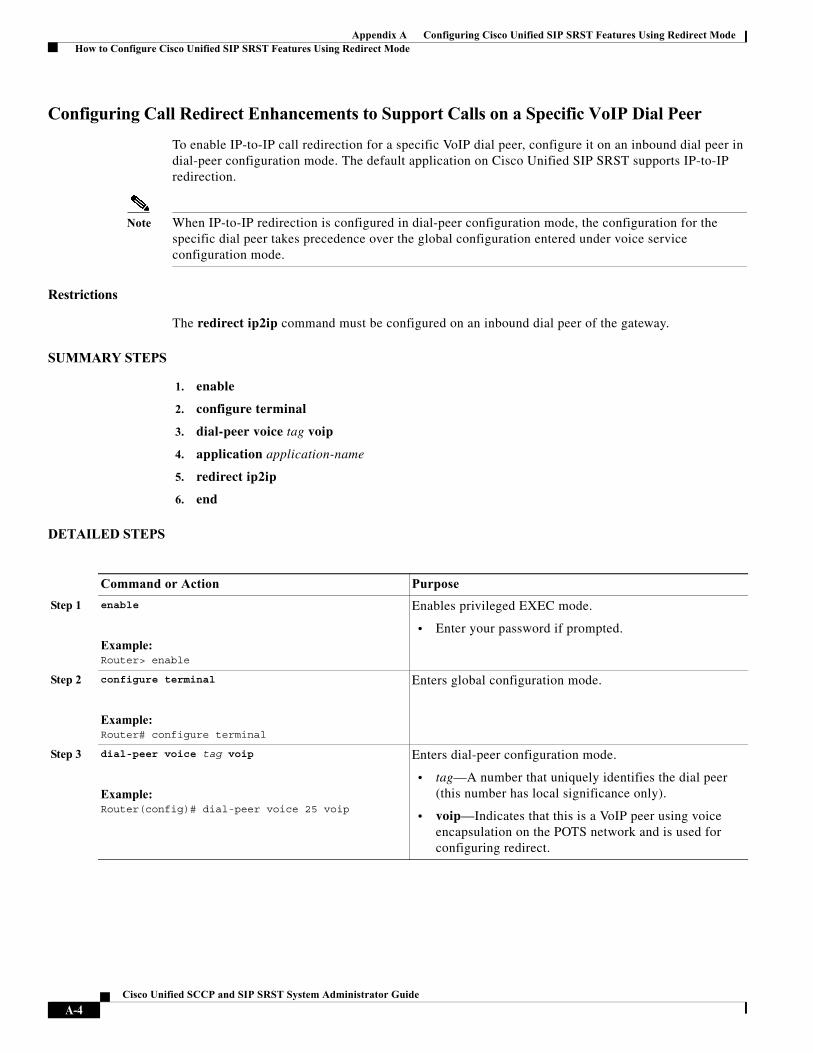
Appendix A Configuring Cisco Unified SIP SRST Features Using Redirect Mode How to Configure Cisco Unified SIP SRST Features Using Redirect Mode
Configuring Call Redirect Enhancements to Support Calls on a Specific VoIP Dial Peer
To enable IP-to-IP call redirection for a specific VoIP dial peer, configure it on an inbound dial peer in dial-peer configuration mode. The default application on Cisco Unified SIP SRST supports IP-to-IP redirection.
Note When IP-to-IP redirection is configured in dial-peer configuration mode, the configuration for the specific dial peer takes precedence over the global configuration entered under voice service configuration mode.
Restrictions
The redirect ip2ip command must be configured on an inbound dial peer of the gateway.
SUMMARY STEPS
1. enable
2. configure terminal
3. dial-peer voice tag voip
4. application application-name
5. redirect ip2ip
6. end
DETAILED STEPS
Command or Action Purpose
Step 1 enable
Example:Router> enable
Enables privileged EXEC mode.
• Enter your password if prompted.
Step 2 configure terminal
Example:Router# configure terminal
Enters global configuration mode.
Step 3 dial-peer voice tag voip
Example:Router(config)# dial-peer voice 25 voip
Enters dial-peer configuration mode.
• tag—A number that uniquely identifies the dial peer (this number has local significance only).
• voip—Indicates that this is a VoIP peer using voice encapsulation on the POTS network and is used for configuring redirect.
A-4Cisco Unified SCCP and SIP SRST System Administrator Guide
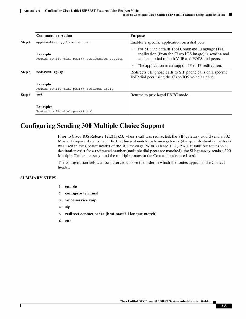
Appendix A Configuring Cisco Unified SIP SRST Features Using Redirect Mode How to Configure Cisco Unified SIP SRST Features Using Redirect Mode
Configuring Sending 300 Multiple Choice Support
Prior to Cisco IOS Release 12.2(15)ZJ, when a call was redirected, the SIP gateway would send a 302 Moved Temporarily message. The first longest match route on a gateway (dial-peer destination pattern) was used in the Contact header of the 302 message. With Release 12.2(15)ZJ, if multiple routes to a destination exist for a redirected number (multiple dial peers are matched), the SIP gateway sends a 300 Multiple Choice message, and the multiple routes in the Contact header are listed.
The configuration below allows users to choose the order in which the routes appear in the Contact header.
SUMMARY STEPS
1. enable
2. configure terminal
3. voice service voip
4. sip
5. redirect contact order [best-match | longest-match]
6. end
Step 4 application application-name
Example:Router(config-dial-peer)# application session
Enables a specific application on a dial peer.
• For SIP, the default Tool Command Language (Tcl) application (from the Cisco IOS image) is session and can be applied to both VoIP and POTS dial peers.
• The application must support IP-to-IP redirection.
Step 5 redirect ip2ip
Example:Router(config-dial-peer)# redirect ip2ip
Redirects SIP phone calls to SIP phone calls on a specific VoIP dial peer using the Cisco IOS voice gateway.
Step 6 end
Example:Router(config-dial-peer)# end
Returns to privileged EXEC mode.
Command or Action Purpose
A-5Cisco Unified SCCP and SIP SRST System Administrator Guide
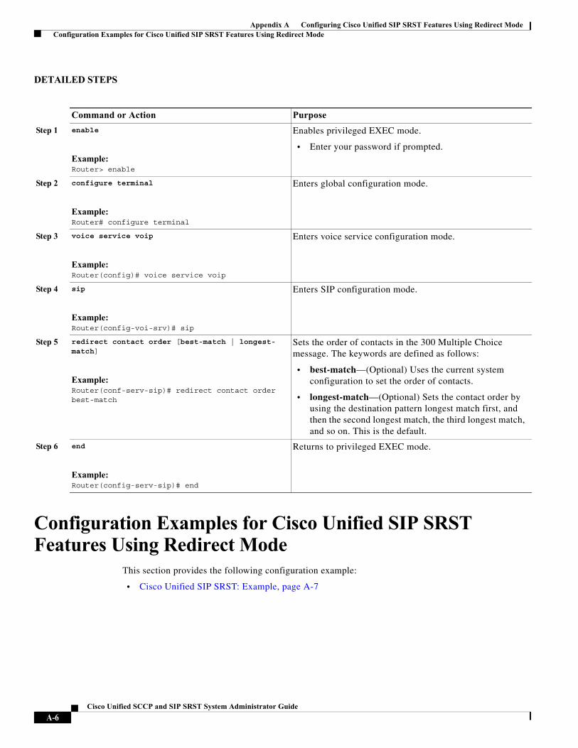
Appendix A Configuring Cisco Unified SIP SRST Features Using Redirect Mode Configuration Examples for Cisco Unified SIP SRST Features Using Redirect Mode
DETAILED STEPS
Configuration Examples for Cisco Unified SIP SRST Features Using Redirect Mode
This section provides the following configuration example:
• Cisco Unified SIP SRST: Example, page A-7
Command or Action Purpose
Step 1 enable
Example:Router> enable
Enables privileged EXEC mode.
• Enter your password if prompted.
Step 2 configure terminal
Example:Router# configure terminal
Enters global configuration mode.
Step 3 voice service voip
Example:Router(config)# voice service voip
Enters voice service configuration mode.
Step 4 sip
Example:Router(config-voi-srv)# sip
Enters SIP configuration mode.
Step 5 redirect contact order [best-match | longest- match]
Example:Router(conf-serv-sip)# redirect contact order best-match
Sets the order of contacts in the 300 Multiple Choice message. The keywords are defined as follows:
• best-match—(Optional) Uses the current system configuration to set the order of contacts.
• longest-match—(Optional) Sets the contact order by using the destination pattern longest match first, and then the second longest match, the third longest match, and so on. This is the default.
Step 6 end
Example:Router(config-serv-sip)# end
Returns to privileged EXEC mode.
A-6Cisco Unified SCCP and SIP SRST System Administrator Guide
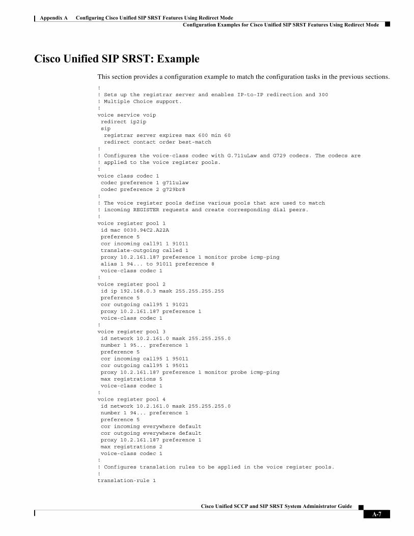
Appendix A Configuring Cisco Unified SIP SRST Features Using Redirect Mode Configuration Examples for Cisco Unified SIP SRST Features Using Redirect Mode
Cisco Unified SIP SRST: Example
This section provides a configuration example to match the configuration tasks in the previous sections.
!! Sets up the registrar server and enables IP-to-IP redirection and 300 ! Multiple Choice support.!voice service voip redirect ip2ip sip registrar server expires max 600 min 60 redirect contact order best-match!! Configures the voice-class codec with G.711uLaw and G729 codecs. The codecs are! applied to the voice register pools.!voice class codec 1 codec preference 1 g711ulaw codec preference 2 g729br8!! The voice register pools define various pools that are used to match! incoming REGISTER requests and create corresponding dial peers.!voice register pool 1 id mac 0030.94C2.A22A preference 5 cor incoming call91 1 91011 translate-outgoing called 1 proxy 10.2.161.187 preference 1 monitor probe icmp-ping alias 1 94... to 91011 preference 8 voice-class codec 1!voice register pool 2 id ip 192.168.0.3 mask 255.255.255.255 preference 5 cor outgoing call95 1 91021 proxy 10.2.161.187 preference 1 voice-class codec 1!voice register pool 3 id network 10.2.161.0 mask 255.255.255.0 number 1 95... preference 1 preference 5 cor incoming call95 1 95011 cor outgoing call95 1 95011 proxy 10.2.161.187 preference 1 monitor probe icmp-ping max registrations 5 voice-class codec 1!voice register pool 4 id network 10.2.161.0 mask 255.255.255.0 number 1 94... preference 1 preference 5 cor incoming everywhere default cor outgoing everywhere default proxy 10.2.161.187 preference 1max registrations 2
voice-class codec 1!! Configures translation rules to be applied in the voice register pools.!translation-rule 1
A-7Cisco Unified SCCP and SIP SRST System Administrator Guide
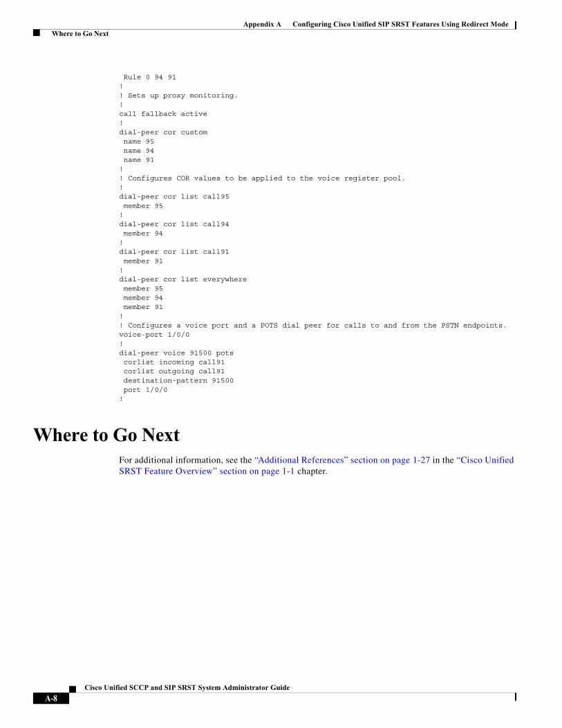
Appendix A Configuring Cisco Unified SIP SRST Features Using Redirect Mode Where to Go Next
Rule 0 94 91!! Sets up proxy monitoring.!call fallback active!dial-peer cor custom name 95 name 94 name 91!! Configures COR values to be applied to the voice register pool.!dial-peer cor list call95 member 95!dial-peer cor list call94 member 94!dial-peer cor list call91 member 91!dial-peer cor list everywhere member 95 member 94 member 91!! Configures a voice port and a POTS dial peer for calls to and from the PSTN endpoints.voice-port 1/0/0!dial-peer voice 91500 pots corlist incoming call91 corlist outgoing call91 destination-pattern 91500 port 1/0/0!
Where to Go NextFor additional information, see the “Additional References” section on page 1-27 in the “Cisco Unified SRST Feature Overview” section on page 1-1 chapter.
A-8Cisco Unified SCCP and SIP SRST System Administrator Guide

Appendix A Configuring Cisco Unified SIP SRST Features Using Redirect Mode Where to Go Next
A-9Cisco Unified SCCP and SIP SRST System Administrator Guide

Appendix A Configuring Cisco Unified SIP SRST Features Using Redirect Mode Where to Go Next
A-10Cisco Unified SCCP and SIP SRST System Administrator Guide
Cisco Unified SCCP an
A
P P E N D I X B Integrating Cisco Unified Communications Manager and Cisco Unified SRST to Use Cisco Unified SRST as a Multicast MOH ResourceThis chapter describes how to configure Cisco Unified CM and Cisco Unified SRST to allow Cisco Unified CM to use Cisco Unified SRST gateways as multicast music-on-hold (MOH) resources during fallback and normal Cisco Unified CM operation. A distributed MOH design with local gateways providing MOH eliminates the need to stream MOH across a WAN and saves bandwidth.
Finding Feature Information in This Module
Your Cisco Unified CME version may not support all of the features documented in this module. For a list of the versions in which each feature is supported, see the “Feature Information for Cisco Unified SRST as a Multicast MOH Resource” section on page B-42.
Contents• Prerequisites for Using Cisco Unified SRST Gateways as a Multicast MOH Resource, page B-12
• Restrictions for Using Cisco Unified SRST Gateways as a Multicast MOH Resource, page B-12
• Information About Using Cisco Unified SRST Gateways as a Multicast MOH Resource, page B-13
• How to Use Cisco Unified SRST Gateways as a Multicast MOH Resource, page B-18
• Configurations Examples for Cisco Unified SRST Gateways, page B-41
• Where to Go Next, page B-43
B-11d SIP SRST System Administrator Guide
Appendix B Integrating Cisco Unified Communications Manager and Cisco Unified SRST to Use Cisco Prerequisites for Using Cisco Unified SRST Gateways as a Multicast MOH Resource
Prerequisites for Using Cisco Unified SRST Gateways as a Multicast MOH Resource
• Multicast MOH for H.323 and MGCP is supported on Cisco Unified CM 3.1.1 and higher versions.
• Cisco Unified CM must be configured as follows:
– With multicast MOH enabled.
– With Media Resource Groups (MRGs) and Media Resource Group Lists (MRGLs) controlling which devices receive multicast MOH and which devices receive unicast MOH.
– With Cisco Unified CM regions assigned so that G.711 is used whenever a Cisco Unified SRST multicast MOH resource is invoked.
• The Cisco Unified SRST gateways must run on Cisco Unified SRST 3.0 on Cisco IOS Release 12.2(15)ZJ2 or a later release.
• Cisco Unified SRST must be registered to Cisco Unified CM using protocol such as H.323, MGCP, or SIP.
• For branches that do not run Cisco Unified SRST, Cisco Unified CM multicast MOH packets must cross the WAN. To accomplish this, you must have multicast routing enabled in your network. For more information about multicast routing, see the “IP Multicast” section of Cisco IOS IP Configuration Guide, Release 12.4T.
• With Cisco IOS earlier than 12.3(14)T, configure Cisco Unified SRST as your MGCP gateway’s fallback mode using the ccm-manager fallback-mgcp and call application alternate commands. With Cisco IOS releases after 12.3(14)T, the ccm-manager fallback-mgcp and service commands must be configured. Configuring these two commands allows Cisco Unified SRST to assume control over the voice port and over call processing on the MGCP gateway. A complete configuration describing setting up Cisco Unified SRST as your fallback mode is shown in Cisco Unified Communications Manager Administration Guide, Release 5.1(3) Survivable Remote Site Telephony Configuration.
Restrictions for Using Cisco Unified SRST Gateways as a Multicast MOH Resource
• Cisco Unified SRST multicast MOH does not support unicast MOH.
• Only a single Cisco Unified CM audio source can be used throughout the network. However, the audio files on each Cisco Unified SRST gateway’s flash memory can be different.
• Cisco Unified SRST multicast MOH supports G.711 only.
• Multicast MOH support for H.323 is unavailable in all versions of Cisco Unified Communications Manager 3.3.2. For more information, see CSCdz00697 using the Bug Toolkit.
• In the Cisco IOS Release 12.2(15)ZJ image for Cisco 1700 series gateways, Cisco Unified SRST multicast MOH does not include support for H.323 mode.
B-12Cisco Unified SCCP and SIP SRST System Administrator Guide
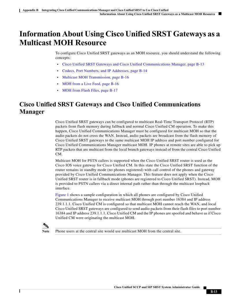
Appendix B Integrating Cisco Unified Communications Manager and Cisco Unified SRST to Use Cisco Unified Information About Using Cisco Unified SRST Gateways as a Multicast MOH Resource
Information About Using Cisco Unified SRST Gateways as a Multicast MOH Resource
To configure Cisco Unified SRST gateways as an MOH resource, you should understand the following concepts:
• Cisco Unified SRST Gateways and Cisco Unified Communications Manager, page B-13
• Codecs, Port Numbers, and IP Addresses, page B-14
• Multicast MOH Transmission, page B-16
• MOH from a Live Feed, page B-16
• MOH from Flash Files, page B-17
Cisco Unified SRST Gateways and Cisco Unified Communications Manager
Cisco Unified SRST gateways can be configured to multicast Real-Time Transport Protocol (RTP) packets from flash memory during fallback and normal Cisco Unified CM operation. To make this happen, Cisco Unified Communications Manager must be configured for multicast MOH so that the audio packets do not cross the WAN. Instead, audio packets are broadcast from the flash memory of Cisco Unified SRST gateways to the same multicast MOH IP address and port number configured for Cisco Unified Communications Manager multicast MOH. IP phones at remote sites are able to pick up RTP packets that are multicast from the local branch gateways instead of from the central Cisco Unified CM.
Multicast MOH for PSTN callers is supported when the Cisco Unified SRST router is used as the Cisco IOS voice gateway for Cisco Unified CM. In this state the Cisco Unified SRST function of the router remains in standby mode (no phones registered) with call control of the phones and gateway provided by Cisco Unified Communications Manager. This feature does not apply when the Cisco Unified SRST router is in fallback mode (phones are registered to Cisco Unified SRST). Instead, MOH is provided to PSTN callers via a direct internal path rather than through the multicast loopback interface.
Figure 1 shows a sample configuration in which all phones are configured by Cisco Unified Communications Manager to receive multicast MOH through port number 16384 and IP address 239.1.1.1. Cisco Unified CM is configured so that multicast MOH cannot reach the WAN, and local Cisco Unified SRST gateways are configured to send audio packets from their flash files to port number 16384 and IP address 239.1.1.1. Cisco Unified CM and the IP phones are spoofed and behave as if Cisco Unified CM were originating the multicast MOH.
Note Phone users at the central site would use multicast MOH from the central site.
B-13Cisco Unified SCCP and SIP SRST System Administrator Guide
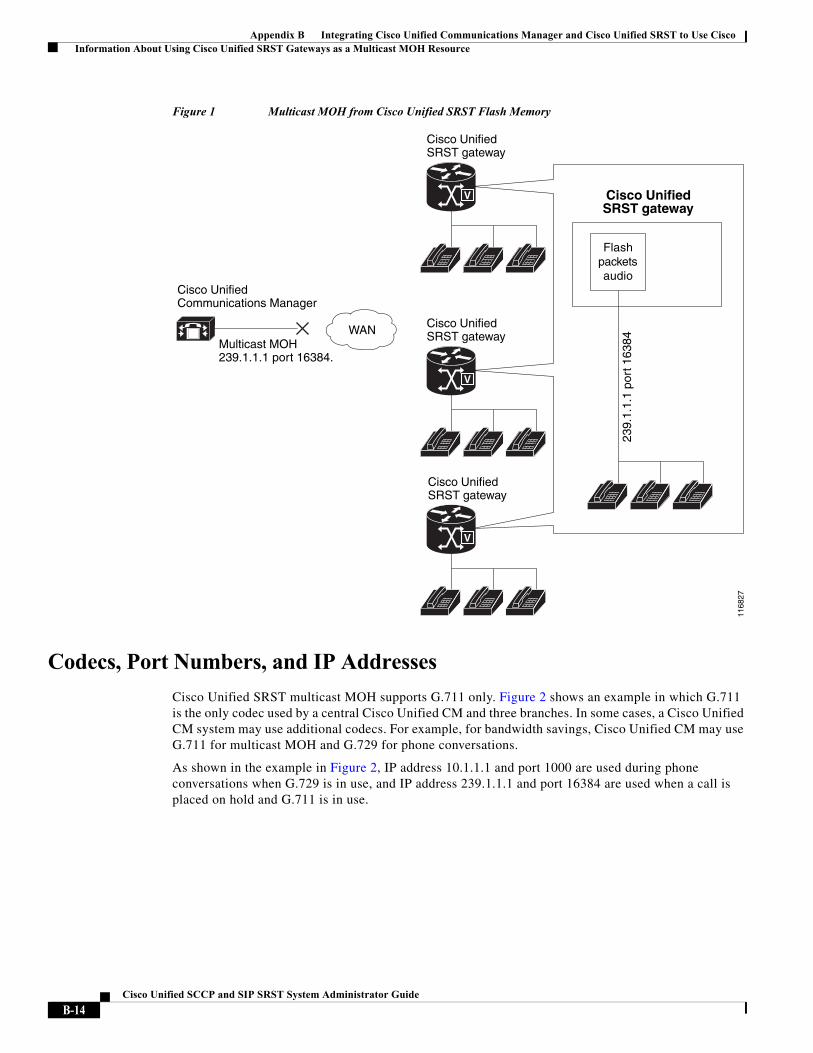
Appendix B Integrating Cisco Unified Communications Manager and Cisco Unified SRST to Use Cisco Information About Using Cisco Unified SRST Gateways as a Multicast MOH Resource
Figure 1 Multicast MOH from Cisco Unified SRST Flash Memory
Codecs, Port Numbers, and IP Addresses
Cisco Unified SRST multicast MOH supports G.711 only. Figure 2 shows an example in which G.711 is the only codec used by a central Cisco Unified CM and three branches. In some cases, a Cisco Unified CM system may use additional codecs. For example, for bandwidth savings, Cisco Unified CM may use G.711 for multicast MOH and G.729 for phone conversations.
As shown in the example in Figure 2, IP address 10.1.1.1 and port 1000 are used during phone conversations when G.729 is in use, and IP address 239.1.1.1 and port 16384 are used when a call is placed on hold and G.711 is in use.
Cisco UnifiedSRST gateway
Cisco UnifiedSRST gateway
Cisco UnifiedSRST gateway
V
V
V
WAN
Cisco UnifiedCommunications Manager
Multicast MOH239.1.1.1 port 16384.
Cisco UnifiedSRST gateway
Flashpacketsaudio
239.
1.1.
1 po
rt 1
6384
1168
27
B-14Cisco Unified SCCP and SIP SRST System Administrator Guide
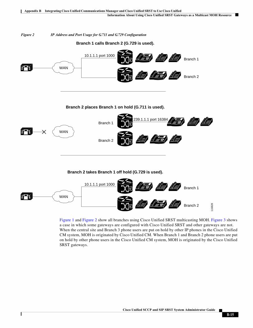
Appendix B Integrating Cisco Unified Communications Manager and Cisco Unified SRST to Use Cisco Unified Information About Using Cisco Unified SRST Gateways as a Multicast MOH Resource
Figure 2 IP Address and Port Usage for G.711 and G.729 Configuration
Figure 1 and Figure 2 show all branches using Cisco Unified SRST multicasting MOH. Figure 3 shows a case in which some gateways are configured with Cisco Unified SRST and other gateways are not. When the central site and Branch 3 phone users are put on hold by other IP phones in the Cisco Unified CM system, MOH is originated by Cisco Unified CM. When Branch 1 and Branch 2 phone users are put on hold by other phone users in the Cisco Unified CM system, MOH is originated by the Cisco Unified SRST gateways.
1168
28
WAN
IPV
Branch 2 places Branch 1 on hold (G.711 is used).
239.1.1.1 port 16384Branch 1
IPVBranch 2
WAN
IPV
Branch 2 takes Branch 1 off hold (G.729 is used).
10.1.1.1 port 1000Branch 1
IPV Branch 2
WAN
IPV
Branch 1 calls Branch 2 (G.729 is used).
10.1.1.1 port 1000Branch 1
IPV Branch 2
B-15Cisco Unified SCCP and SIP SRST System Administrator Guide
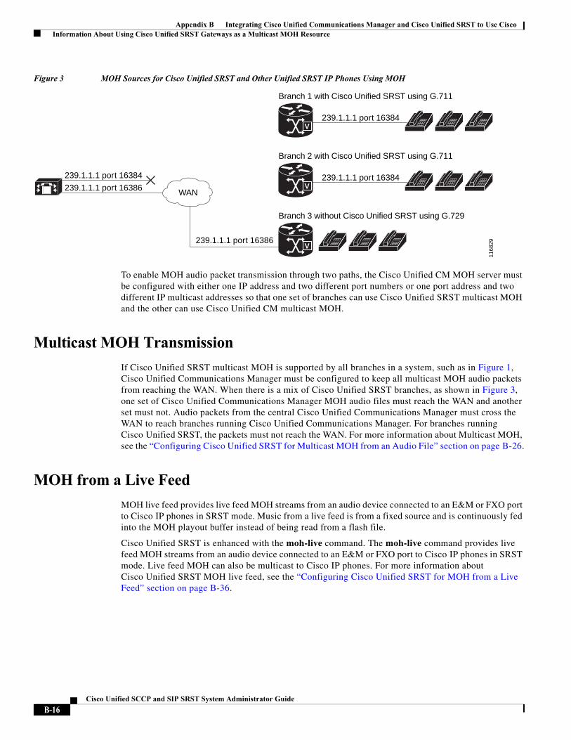
Appendix B Integrating Cisco Unified Communications Manager and Cisco Unified SRST to Use Cisco Information About Using Cisco Unified SRST Gateways as a Multicast MOH Resource
Figure 3 MOH Sources for Cisco Unified SRST and Other Unified SRST IP Phones Using MOH
To enable MOH audio packet transmission through two paths, the Cisco Unified CM MOH server must be configured with either one IP address and two different port numbers or one port address and two different IP multicast addresses so that one set of branches can use Cisco Unified SRST multicast MOH and the other can use Cisco Unified CM multicast MOH.
Multicast MOH Transmission
If Cisco Unified SRST multicast MOH is supported by all branches in a system, such as in Figure 1, Cisco Unified Communications Manager must be configured to keep all multicast MOH audio packets from reaching the WAN. When there is a mix of Cisco Unified SRST branches, as shown in Figure 3, one set of Cisco Unified Communications Manager MOH audio files must reach the WAN and another set must not. Audio packets from the central Cisco Unified Communications Manager must cross the WAN to reach branches running Cisco Unified Communications Manager. For branches running Cisco Unified SRST, the packets must not reach the WAN. For more information about Multicast MOH, see the “Configuring Cisco Unified SRST for Multicast MOH from an Audio File” section on page B-26.
MOH from a Live Feed
MOH live feed provides live feed MOH streams from an audio device connected to an E&M or FXO port to Cisco IP phones in SRST mode. Music from a live feed is from a fixed source and is continuously fed into the MOH playout buffer instead of being read from a flash file.
Cisco Unified SRST is enhanced with the moh-live command. The moh-live command provides live feed MOH streams from an audio device connected to an E&M or FXO port to Cisco IP phones in SRST mode. Live feed MOH can also be multicast to Cisco IP phones. For more information about Cisco Unified SRST MOH live feed, see the “Configuring Cisco Unified SRST for MOH from a Live Feed” section on page B-36.
1168
29
WAN
239.1.1.1 port 16386
Branch 3 without Cisco Unified SRST using G.729
239.1.1.1 port 16386239.1.1.1 port 16384239.1.1.1 port 16384
V
Branch 2 with Cisco Unified SRST using G.711
V
239.1.1.1 port 16384
Branch 1 with Cisco Unified SRST using G.711
V
B-16Cisco Unified SCCP and SIP SRST System Administrator Guide
Appendix B Integrating Cisco Unified Communications Manager and Cisco Unified SRST to Use Cisco Unified Information About Using Cisco Unified SRST Gateways as a Multicast MOH Resource
MOH from Flash Files
The MOH Multicast from Flash Files feature facilitates the continuous multicast of MOH audio feed from files in the flash memories of Cisco Unified SRST branch office routers during Cisco Unified Communications fallback and normal Cisco Unified Communications service. Multicasting MOH from individual branch routers saves WAN bandwidth by eliminating the need to stream MOH audio from central offices to remote branches.
The MOH Multicast from Flash Files feature can act as a backup mechanism to the MOH live feed feature. Using the Flash to backup the live-feed is the recommend method rather than using just the live feed feature alone.
Cisco Unified Communications Manager MOH audio files must reach the WAN and another set must not. Audio packets from the central Cisco Unified CM must cross the WAN to reach branches running Cisco Unified CM. For branches running Cisco Unified SRST, the packets must not reach the WAN.
Table 1 provides a summary of options for MOH.
Table 1 Music-on-Hold (MOH)
Audio Source Description How to Configure
Flash memory No external audio input is required. Configuring Cisco Unified SRST for Multicast MOH from an Audio File, page B-26
Live feed The multicast audio stream has minimal delay for local IP phones. The MOH stream for PSTN callers is delayed by a few seconds. If the live feed audio input fails, callers on hold hear silence.
Configuring Cisco Unified SRST for MOH from a Live Feed, page B-36
Live feed and flash memory
The live feed stream has a few seconds of delay for both PSTN and local IP phone callers. The flash MOH acts as backup for the live-feed MoH.
We recommend this option if you want live-feed because it provides guaranteed MOH if the live-feed input is not found or fails.
Configuring Cisco Unified SRST for Multicast MOH from an Audio File, page B-26
and
Configuring Cisco Unified SRST for MOH from a Live Feed, page B-36
B-17Cisco Unified SCCP and SIP SRST System Administrator Guide
Appendix B Integrating Cisco Unified Communications Manager and Cisco Unified SRST to Use Cisco How to Use Cisco Unified SRST Gateways as a Multicast MOH Resource
How to Use Cisco Unified SRST Gateways as a Multicast MOH Resource
To use Cisco Unified SRST gateways as a multicast MOH resource, perform the following tasks:
• Configuring Cisco Unified Communications Manager for Cisco Unified SRST Multicast MOH, page B-18
• Configuring Cisco Unified SRST for Multicast MOH from an Audio File, page B-26
• Configuring Cisco Unified SRST for MOH from a Live Feed, page B-36
For Cisco Unified CM 8.0 or later, see the Configuring MOH-groups for Cisco Unified SRST (fallback) section in the Cisco Unified Survivable Remote Site Telephony 8.0 Music On Hold Enhancement document.
Configuring Cisco Unified Communications Manager for Cisco Unified SRST Multicast MOH
The following sections describe the Cisco Unified CM configuration tasks for Cisco Unified SRST multicast MOH:
• Configuring the MOH Audio Source to Enable Multicasting, page B-19
• Enabling Multicast on the Cisco Unified Communications Manager MOH Server and Configuring Port Numbers and IP Addresses, page B-20
• Creating an MRG and an MRGL, Enabling MOH Multicast, and Configuring Gateways, page B-23
• Creating a Region for the MOH Server, page B-25
• Verifying Cisco Unified Communications Manager Multicast MOH, page B-26
To use Cisco Unified SRST gateways as multicast MOH resources, you must configure Cisco Unified Communications Manager to multicast MOH to the required branch sites. To accomplish this, you must configure IP addresses, port numbers, the MOH source, and the MOH audio server.
Even though the MOH routing is set up to prevent the Cisco Unified CM-sourced multicast MOH from actually reaching the WAN and the remote phones, the configured Cisco Unified CM MOH IP port and address information are still used by Cisco Unified CM to tell the phones which multicast IP address to listen to for MOH (for the MOH sourced by SRST).
Configuring the MOH server involves designating a maximum number of hops for the audio source. A configuration of one hop keeps Cisco Unified CM multicast MOH packets from reaching the WAN, thus spoofing Cisco Unified CM and allowing Cisco Unified SRST multicast MOH packets to be sent from Cisco Unified SRST gateways to their component phones. For cases in which Cisco Unified CM multicast must reach gateways that do not run Cisco Unified SRST, use the Cisco IOS ip multicast boundary command to control where multicast packets go.
After the MOH server is configured, the MOH server must be added to a Media Resource Group (MRG); the MRG is added to a Media Resource Group List (MRGL); and the designated Cisco Unified CM branch gateways are configured to use the MRGL.
Five Cisco Unified CM windows are used to configure the MOH server, audio source, MRG, MRGL, and individual gateways. Figure 4 provides an overview of this process.
The last Cisco Unified CM configuration task involves creating an MOH region that assigns MOH G.711 codec usage for the central site or sites and branch office or offices.
B-18Cisco Unified SCCP and SIP SRST System Administrator Guide
Appendix B Integrating Cisco Unified Communications Manager and Cisco Unified SRST to Use Cisco Unified How to Use Cisco Unified SRST Gateways as a Multicast MOH Resource
Regions specify the codecs that are used for audio and video calls within a region and between existing regions. For information about regions, see the “Region Configuration” section in the Cisco Unified Communications Manager Administration Guide. From the Cisco Unified Communications Manager documentation directory, click Maintain and Operate Guides and select the required Cisco Unified Communications Manager version to locate the administration guide for your version.
Figure 4 Unified Communications Manager Screens for Configuring Multicast MOH
Configuring the MOH Audio Source to Enable Multicasting
The MOH audio source is a file from which Cisco Unified CM transmits RTP packets. You can create an audio file or use the default audio file. For Cisco Unified SRST multicast MOH, only one audio source can be used, even if, for example, one out of 500 sites uses Cisco Unified SRST multicast MOH. In addition, all Cisco Unified Communications Manager systems must use the same audio source for user and network MOH because Cisco Unified SRST multicast MOH can stream audio only to a single multicast IP address and port. For Cisco Unified SRST multicast MOH, the Cisco Unified Communications Manager audio source file must be configured for G.711 bandwidth.
Music On Hold (MOH) Audio Source Configuration Screen
Music On Hold (MOH) Server Configuration Screen
Media Resource Group Configuration Screen
Media Resource Group Configuration Screen
Phone Configuration Screen
Gateway Configuration Screen
Configure MOH Server
Add Server
Add MRG
1463
19
B-19Cisco Unified SCCP and SIP SRST System Administrator Guide
Appendix B Integrating Cisco Unified Communications Manager and Cisco Unified SRST to Use Cisco How to Use Cisco Unified SRST Gateways as a Multicast MOH Resource
Tip The simplest way to create an audio source is to use the default audio source.
Whether you use a default Cisco Unified CM MOH audio source or you create one, the MOH audio source must be configured for multicasting in the MOH Audio Source Configuration window.
Note that the MOH Audio Source File Status section shows that the MOH audio source file is configured for four codec formats. If you are planning to use several codecs, ensure that the audio source file accommodates them.
For further information about the creation of an MOH audio source, see the Cisco Unified Communications Manager Administration Guide. From the Cisco Unified Communications Manager documentation directory, click Maintain and Operate Guides and select the required Cisco Unified CM version.
Use this procedure to configure the MOH audio source to enable multicasting and continuous play.
Note These instructions assume that an MOH audio source file was already created.
Step 1 To enable multicast MOH for the MOH audio source, choose Service > Media Resources > Music On Hold Audio Source to display the MOH Audio Source Configuration window.
Step 2 Double-click the required audio source listed in the MOH Audio Sources column.
Step 3 In the MOH Audio Source Configuration window, check Allow Multicasting.
Step 4 Click Update.
Enabling Multicast on the Cisco Unified Communications Manager MOH Server and Configuring Port Numbers and IP Addresses
Enter a base multicast IP address and port number in the Multicast Audio Source Information section of the MOH Server Configuration window. If you are using Cisco Unified CM multicast MOH and Cisco Unified SRST multicast MOH (see the “Codecs, Port Numbers, and IP Addresses” section on page B-14 and the “Multicast MOH Transmission” section on page B-16), you must select a port and IP address increment method to configure for two sets of port numbers and IP address.
If the Increment Multicast on radio button is set to IP address, each MOH audio source and codec combination is multicast to different IP addresses but uses the same port number. If it is set to Port Number, each MOH audio source and codec combination is multicast to the same IP address but uses different destination port numbers.
Table 2 shows the difference between incrementing on an IP address and incrementing on a port number, using the base IP address of 239.1.1.1 and the base port number of 16384. The table also matches Cisco Unified Communications Manager audio sources and codecs to IP addresses and port numbers.
B-20Cisco Unified SCCP and SIP SRST System Administrator Guide
Appendix B Integrating Cisco Unified Communications Manager and Cisco Unified SRST to Use Cisco Unified How to Use Cisco Unified SRST Gateways as a Multicast MOH Resource
Note The lower destination port 16384 is assigned to the first multicast-enabled audio source ID, and the subsequent ports will be assigned to the subsequent multicast-enabled audio sources.
Incrementation is triggered by a change in codec usage. When codec usage changes, a new IP address or port number (depending on the incrementation selected) is assigned to the new codec type and is put into use. The original codec keeps its IP address and port number. For example, as seen in Table 2, if your baseline IP address and port number are 239.1.1.1 and 16384 for a G.711 mu-law codec and the codec usage changes to G.729 (triggering an increment on the port number), the IP address and port number in use changes, or increment, to 239.1.1.1 and 16386. If G.711 usage resumes, the IP address and port number returns to 239.1.1.1 and 16384. If G.729 is in use again, the IP address and port goes back to 239.1.1.1 and 16386, and so forth.
It is important to configure a Cisco Unified CM port number and IP address that use a G.711 audio source for Cisco Unified SRST multicast MOH. If Cisco Unified CM multicast MOH is also being used on gateways that do not have Cisco Unified SRST and use a different codec, such as G.729, ensure that the additional or incremental port number or IP address uses the same audio source as the Cisco Unified SRST gateways and the required codec.
The MOH Server Configuration window is also where the multicast audio source for the MOH server is configured. For Cisco Unified SRST multicast MOH, the Cisco Unified CM MOH server can use only one audio source. An audio source is selected by inputting the audio source’s maximum number of hops.
The Max Hops configuration sets the length of the transmission of the audio source packets. Limiting the number of hops is one way to stop audio packets from reaching the WAN and thus spoofing Cisco Unified Communications Manager so Cisco Unified SRST can multicast MOH. If all of your branches run Cisco Unified SRST, use a low number of hops to prevent audio source packets from crossing the WAN. If your system configuration includes routers that do not run Cisco Unified SRST, enter a high number of hops to allow source packets to cross the WAN. Use the ip multicast bounder and access-list commands to keep resource packets from specific IP addresses from reaching the WAN.
Table 2 Example of the Differences Between Incrementing Multicast on IP Address and Incrementing Multicast on Port Number
Audio Source Codec
Increment Multicast on IP Address Increment Multicast on Port Number
Destination IP Address
Destination Port
Destination IP Address
Destination Port
1 G.711 mu-law 239.1.1.1 16384 239.1.1.1 16384
1 G.711 a-law 239.1.1.2 16384 239.1.1.1 16386
1 G.729 239.1.1.3 16384 239.1.1.1 16388
1 Wideband 239.1.1.4 16384 239.1.1.1 16390
2 G.711 mu-law 239.1.1.5 16384 239.1.1.1 16392
2 G.711 a-law 239.1.1.6 16384 239.1.1.1 16394
2 G.729 239.1.1.7 16384 239.1.1.1 16396
2 Wideband 239.1.1.8 16384 239.1.1.1 16398
B-21Cisco Unified SCCP and SIP SRST System Administrator Guide
Appendix B Integrating Cisco Unified Communications Manager and Cisco Unified SRST to Use Cisco How to Use Cisco Unified SRST Gateways as a Multicast MOH Resource
Use this procedure to enable multicast and configure port numbers and IP addresses.
Step 1 Enable multicast MOH for Cisco Unified CM.
a. Choose Service > Media Resource > Music On Hold Server.
b. The MOH Server Configuration window appears.
c. Call up an existing MOH server by clicking Find and double-clicking the required MOH server.
d. Whether you are updating an existing MOH server or creating a new one, click Enable Multicast Audio Sources on this MOH Server.
Step 2 Set the base IP address and port number.
In the MOH Server Configuration window, enter an IP address in the Base Multicast IP Address field and enter a port number in the Base Multicast Port Number field. Ensure that the IP address and port number use the required audio source and codec. See Table 2.
Step 3 Select whether Cisco Unified CM increments port numbers or IP addresses.
In the MOH Server Configuration window, in the Increment Multicast on field, choose Port Number if you want port numbers to be incremented and the IP address to remain unchanged. Choose IP Address if you want IP addresses to be incremented and the port number to remain unchanged.
• If all of your branches run Cisco Unified SRST and thus use G.711 for MOH, use either setting because incrementation does not take place and a selection does not matter.
• If your system configuration includes routers that do not run Cisco Unified SRST and use a different codec, select an incrementation method.
Note If your branches include routers that do not run Cisco Unified SRST and do use G.711, configure separate audio sources: one for the routers that run Cisco Unified SRST and one for the routers that do not.
Step 4 Enter a maximum number of hops.
In the MOH Server Configuration window, next to the Audio Source Name field, enter 1 in the Max Hops field if all of your branches run Cisco Unified SRST. If your system configuration includes routers that do not run Cisco Unified SRST, enter 16 in the Max Hops field.
Step 5 Use Cisco IOS commands to stop Cisco Unified CM signals from crossing the WAN and reaching Cisco Unified SRST gateways.
If all of your branches run Cisco Unified SRST, skip this step. If your system configuration includes routers that do not run Cisco Unified SRST and use a different codec, enter the following Cisco IOS commands starting from global configuration mode on the central site router:
a. interface {serial | fastethernet} slot/port
Enters interface configuration mode, where slot is the slot number and port is the port number.
b. ip multicast boundary access-list-number
Configures an administratively scoped boundary, where access-list-number is a number from 1 to 99 that identifies an access list that controls the range of group addresses affected by the boundary.
c. exit
Exits interface configuration mode.
B-22Cisco Unified SCCP and SIP SRST System Administrator Guide
Appendix B Integrating Cisco Unified Communications Manager and Cisco Unified SRST to Use Cisco Unified How to Use Cisco Unified SRST Gateways as a Multicast MOH Resource
d. access-list access-list-number deny ip-address
Configures the access list mechanism for filtering frames by IP address. For the ip-address argument, enter the MOH IP address that you want to prevent from going over the WAN. Normally this would be the base IP address entered in Step 2.
The following is an example configuration:
Router(config)# interface serial 0/0Router(config-if)# ip multicast boundary 1Router(config-if)# exitRouter(config)# access-list 1 deny 239.1.1.1
Creating an MRG and an MRGL, Enabling MOH Multicast, and Configuring Gateways
The next task involves configuring individual gateways to use an MOH server that can transport the required MOH audio source to their IP phones on hold. This is accomplished by creating a Media Resource Group (MRG). An MRG references media resources, such as MOH servers. The MRG is then added to a Media Resource Group List (MRGL), and the MRGL is added to the phone and gateway configurations.
MRGs are created in the Media Resource Group Configuration window. MRGLs are created in the Media Resource Group List Configuration window. Phones are configured in the Phone Configuration window. Gateways are configured in the Gateway Configuration window.
Note The Gateway Configuration window for an H.323 gateway is similar for MGCP gateways.
Add MRGL to a gateway or IP phone configuration by adding the MRGL to a device pool configuration. For further information about device pools, see Cisco Unified Communications Manager Administration Guide. From the Cisco Unified Communications Manager documentation directory, click Maintain and Operate Guides and select the required Cisco Unified CM version.
B-23Cisco Unified SCCP and SIP SRST System Administrator Guide
Appendix B Integrating Cisco Unified Communications Manager and Cisco Unified SRST to Use Cisco How to Use Cisco Unified SRST Gateways as a Multicast MOH Resource
Use the following procedure to create an MRG and MRGL, to enable MOH multicast, and to configure gateways.
Step 1 Create an MRG with a multicast MOH media resource.
a. Choose Service > Media Resource > Media Resource Group.
b. In the upper-right corner of the window, click the Add a New Media Resource Group link. The Media Resource Group Configuration window appears.
c. Complete the Media Resource Group Name field.
d. Complete the Description field.
e. Select a media resource from the Available Media Resources pane.
This pane lists the media resources that can be chosen for an MRG and can include the following media resource types:
– Conference bridges (CFB)
– Media termination points (MTP)
– Music-on-hold servers (MOH)
– Transcoders (XCODE)
– Annunciator (ANN)
Music-on-hold servers that are configured for multicast are labeled as (MOH) [Multicast].
f. Click the down arrow so that the selected media resource moves to the Selected Media Resources pane.
g. Click Insert.
Step 2 Create an MRGL that contains the newly created MRG.
a. Choose Service > Media Resource > Media Resource Group List.
b. In the upper-right corner of the window, click the Add a New Media Resource Group List link. The Media Resource Group List Configuration window appears.
c. Complete the Media Resource Group List Name field.
d. In the Available Media Resource Groups pane, select the MRG that you just created.
e. Add the MRG to the Selected Media Resource Groups pane by clicking the down arrow. After a media resource group is added, its name moves to the Selected Media Resource Groups pane.
f. Click Insert.
Step 3 Add the MRGL to the required IP phones.
a. Choose Device > Phone to display the Find and List Phones window.
b. Click Find to display a list of phones.
c. Double-click the device name of the phone that you want to update.
d. Complete the Media Resource Group List field by choosing the required MRGL from the drop-down menu.
e. Click Update.
Step 4 Add the MRGL to the required gateway.
a. Choose Device > Gateway to display the Find and List Gateways window.
b. Click Find to display a list of gateways.
B-24Cisco Unified SCCP and SIP SRST System Administrator Guide
Appendix B Integrating Cisco Unified Communications Manager and Cisco Unified SRST to Use Cisco Unified How to Use Cisco Unified SRST Gateways as a Multicast MOH Resource
c. Double-click the device name of the gateway that you want to update.
d. If the gateway is H.323, complete the Media Resource Group List field by choosing the required MRGL from the drop-down menu.
e. Click Update.
Creating a Region for the MOH Server
To ensure that the MOH server uses G.711 for Cisco Unified SRST gateways, you must create a separate region for the MOH server. For more information about codecs, see the “Codecs, Port Numbers, and IP Addresses” section on page B-14. For information about regions, see Cisco Unified Communications Manager Administration Guide. From the Cisco Unified Communications Manager documentation directory, click Maintain and Operate Guides and select the required Cisco Unified Communications Manager version.
Configure the Region Configuration window. If the Cisco Unified CM system uses G.711 only, all of the central sites and their constituent branches for the MOH region must be set to G.711. If a Cisco Unified CM system has a combination of branches that do and do not run Cisco Unified SRST multicast MOH and the branches that do not run Cisco Unified SRST require a different codec for Cisco Unified Communications Manager multicast MOH, they must be configured accordingly.
A Region Configuration window where the “MOH Server” region is configured to use the G.711 and G.729 codecs might look like this:
• G.711 is used for Branch 1 because its gateway is configured to run Cisco Unified SRST multicast MOH, which requires G.711.
• G.729 is used for Branch 2 because its gateway doe not run Cisco Unified SRST and it is configured to use a port and IP address that use G.729.
• G.711 is configured for the central site and the MOH server region.
Use the following procedure to create a region for the MOH server.
Step 1 Create an MOH server region.
a. Choose System > Region.
b. In the upper-right corner of the window, click Add a New Region. The Region Configuration window appears.
c. In the Region Name field, enter the name that you want to assign to the new region and click Insert.
d. If other regions were created, a list of regions appear. Use the drop-down list boxes to choose the audio codec to use for calls between the new region and existing regions. The audio codec determines the type of compression and the maximum amount of bandwidth that is allocated for these calls.
e. In addition to other regions, the newly created region appears in the list. Use its drop-down box to choose the codec for use within the new region.
f. Click Update.
Step 2 Create other regions as needed for different codecs.
B-25Cisco Unified SCCP and SIP SRST System Administrator Guide
Appendix B Integrating Cisco Unified Communications Manager and Cisco Unified SRST to Use Cisco How to Use Cisco Unified SRST Gateways as a Multicast MOH Resource
Verifying Cisco Unified Communications Manager Multicast MOH
The Cisco Unified CM multicast MOH configuration must run correctly for Cisco Unified SRST multicast MOH to work. Verification of Cisco Unified Communications Manager multicast MOH differs for configurations using a WAN with multicast enabled and a WAN with multicast disabled.
You must verify that the Cisco Unified CM multicast MOH is provided through multicasting and not unicasting. Because unicast MOH is enabled by default, it is easy to mistakenly conclude that multicast MOH is working when it is not.
Step 1 Verify that Cisco Unified CM system’s multicast MOH is heard on a remote gateway.
a. If multicast is enabled on the WAN, make sure that the number of hops configured on the Cisco Unified Communications Manager MOH server is sufficient to allow audio packets to reach the remote site (see the “Enabling Multicast on the Cisco Unified Communications Manager MOH Server and Configuring Port Numbers and IP Addresses” section on page B-20). Then call an IP phone on a remote gateway, place the call on hold, and verify that MOH is heard.
b. If multicast is not enabled on the WAN, place an IP phone on the same subnet as the Cisco Unified Communications Manager MOH server and verify that MOH can be heard. Because the IP phone and the MOH server are on the same subnet, no multicast routing capabilities in the network are required.
Step 2 Verify that the Cisco Unified CM system’s MOH is multicast, not unicast.
a. From Microsoft Windows, select Start > Programs > Administrative Tools > Performance.
b. In the Performance window, click the + (plus) icon located at the top of the right pane.
c. In the Add Counters window, select Cisco MOH Device.
d. In the Performance window, you can monitor the MOHMulticastResourceActive and MOHUnicastResourceActive counters to check on multicast activity.
Configuring Cisco Unified SRST for Multicast MOH from an Audio File
Note Use the steps in this section only when you are using Microsoft Windows to run Cisco Unified Communications Manager version 4.3 or below. Use the RTMT (Real-Time Monitoring Tool) in Cisco Unified Communications Manager version 5.0 and later versions on the Linux operating system to monitor MOH activity in Cisco Unified CM version. See Cisco Unified Communications Serviceability System Guide, Release 4.0(1) for more information about RTMT.
Use the following procedures to configure Cisco Unified SRST for multicast MOH from an audio file.
• Enabling Multicast MOH on the Cisco Unified SRST Gateway, page B-27
• Verifying Basic Cisco Unified SRST Multicast MOH Streaming, page B-31
• Verifying Cisco Unified SRST MOH to PSTN, page B-32
• Verifying Cisco Unified SRST Multicast MOH to IP Phones, page B-36
B-26Cisco Unified SCCP and SIP SRST System Administrator Guide
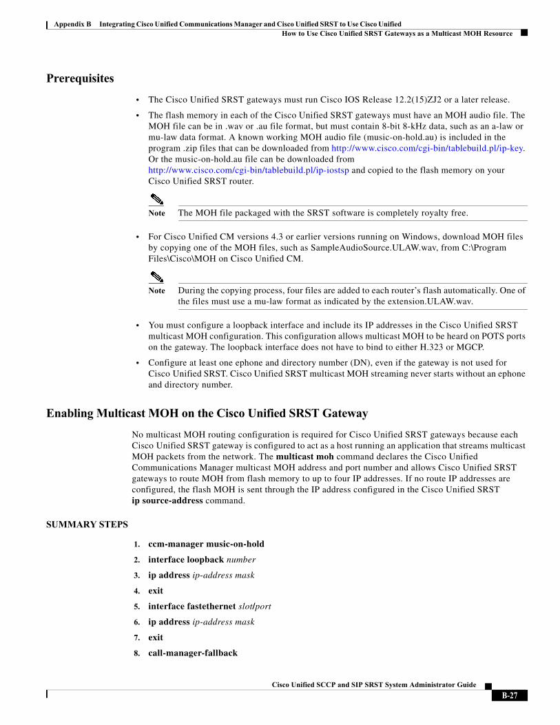
Appendix B Integrating Cisco Unified Communications Manager and Cisco Unified SRST to Use Cisco Unified How to Use Cisco Unified SRST Gateways as a Multicast MOH Resource
Prerequisites
• The Cisco Unified SRST gateways must run Cisco IOS Release 12.2(15)ZJ2 or a later release.
• The flash memory in each of the Cisco Unified SRST gateways must have an MOH audio file. The MOH file can be in .wav or .au file format, but must contain 8-bit 8-kHz data, such as an a-law or mu-law data format. A known working MOH audio file (music-on-hold.au) is included in the program .zip files that can be downloaded from http://www.cisco.com/cgi-bin/tablebuild.pl/ip-key. Or the music-on-hold.au file can be downloaded from http://www.cisco.com/cgi-bin/tablebuild.pl/ip-iostsp and copied to the flash memory on your Cisco Unified SRST router.
Note The MOH file packaged with the SRST software is completely royalty free.
• For Cisco Unified CM versions 4.3 or earlier versions running on Windows, download MOH files by copying one of the MOH files, such as SampleAudioSource.ULAW.wav, from C:\Program Files\Cisco\MOH on Cisco Unified CM.
Note During the copying process, four files are added to each router’s flash automatically. One of the files must use a mu-law format as indicated by the extension.ULAW.wav.
• You must configure a loopback interface and include its IP addresses in the Cisco Unified SRST multicast MOH configuration. This configuration allows multicast MOH to be heard on POTS ports on the gateway. The loopback interface does not have to bind to either H.323 or MGCP.
• Configure at least one ephone and directory number (DN), even if the gateway is not used for Cisco Unified SRST. Cisco Unified SRST multicast MOH streaming never starts without an ephone and directory number.
Enabling Multicast MOH on the Cisco Unified SRST Gateway
No multicast MOH routing configuration is required for Cisco Unified SRST gateways because each Cisco Unified SRST gateway is configured to act as a host running an application that streams multicast MOH packets from the network. The multicast moh command declares the Cisco Unified Communications Manager multicast MOH address and port number and allows Cisco Unified SRST gateways to route MOH from flash memory to up to four IP addresses. If no route IP addresses are configured, the flash MOH is sent through the IP address configured in the Cisco Unified SRST ip source-address command.
SUMMARY STEPS
1. ccm-manager music-on-hold
2. interface loopback number
3. ip address ip-address mask
4. exit
5. interface fastethernet slot/port
6. ip address ip-address mask
7. exit
8. call-manager-fallback
B-27Cisco Unified SCCP and SIP SRST System Administrator Guide
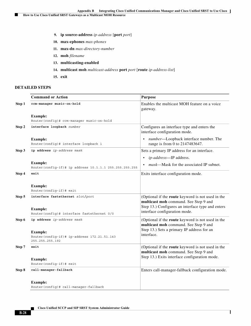
Appendix B Integrating Cisco Unified Communications Manager and Cisco Unified SRST to Use Cisco How to Use Cisco Unified SRST Gateways as a Multicast MOH Resource
9. ip source-address ip-address [port port]
10. max-ephones max-phones
11. max-dn max-directory-number
12. moh filename
13. multicasting-enabled
14. multicast moh multicast-address port port [route ip-address-list]
15. exit
DETAILED STEPS
Command or Action Purpose
Step 1 ccm-manager music-on-hold
Example:Router(config)# ccm-manager music-on-hold
Enables the multicast MOH feature on a voice gateway.
Step 2 interface loopback number
Example:Router(config)# interface loopback 1
Configures an interface type and enters the interface configuration mode.
• number—Loopback interface number. The range is from 0 to 2147483647.
Step 3 ip address ip-address mask
Example:Router(config-if)# ip address 10.1.1.1 255.255.255.255
Sets a primary IP address for an interface.
• ip-address—IP address.
• mask—Mask for the associated IP subnet.
Step 4 exit
Example:Router(config-if)# exit
Exits interface configuration mode.
Step 5 interface fastethernet slot/port
Example:Router(config)# interface fastethernet 0/0
(Optional if the route keyword is not used in the multicast moh command. See Step 9 and Step 13.) Configures an interface type and enters interface configuration mode.
Step 6 ip address ip-address mask
Example:Router(config-if)# ip-address 172.21.51.143 255.255.255.192
(Optional if the route keyword is not used in the multicast moh command. See Step 9 and Step 13.) Sets a primary IP address for an interface.
Step 7 exit
Example:Router(config-if)# exit
(Optional if the route keyword is not used in the multicast moh command. See Step 9 and Step 13.) Exits interface configuration mode.
Step 8 call-manager-fallback
Example:Router(config)# call-manager-fallback
Enters call-manager-fallback configuration mode.
B-28Cisco Unified SCCP and SIP SRST System Administrator Guide
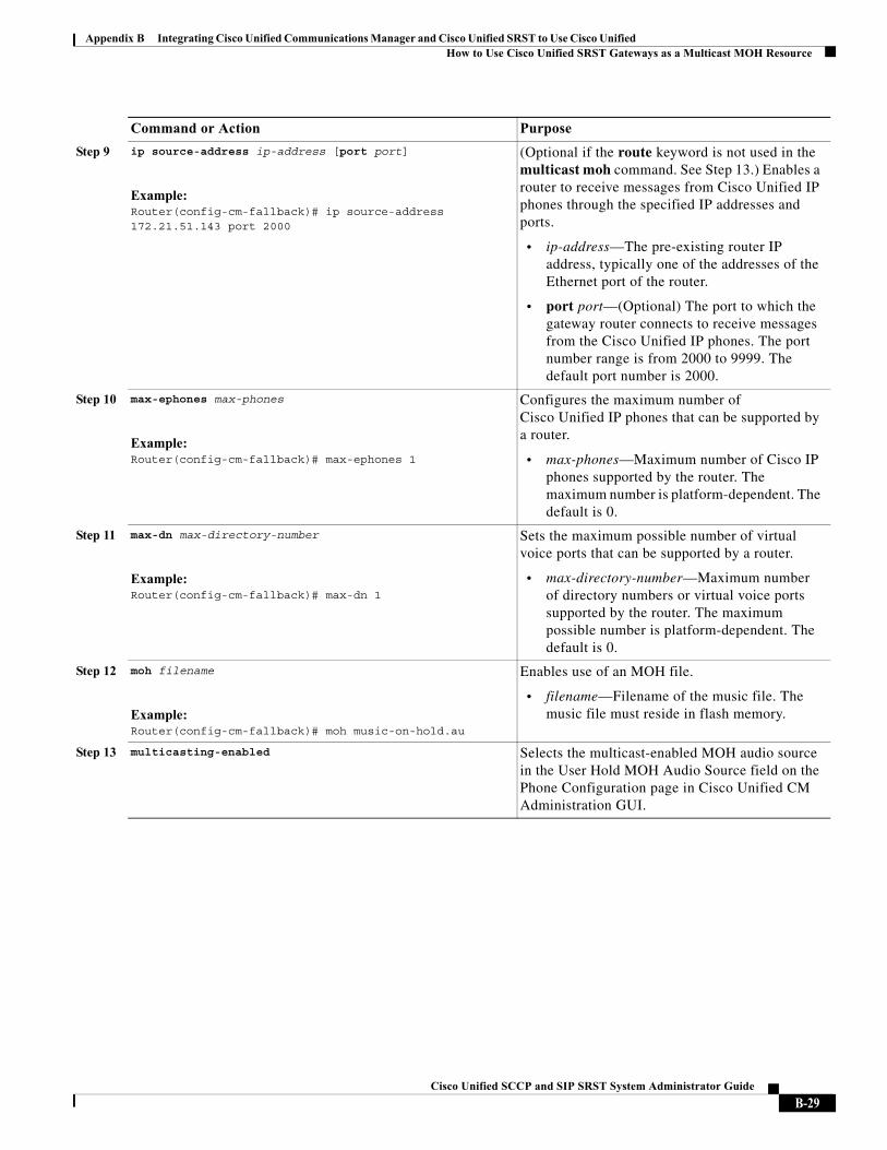
Appendix B Integrating Cisco Unified Communications Manager and Cisco Unified SRST to Use Cisco Unified How to Use Cisco Unified SRST Gateways as a Multicast MOH Resource
Step 9 ip source-address ip-address [port port]
Example:Router(config-cm-fallback)# ip source-address 172.21.51.143 port 2000
(Optional if the route keyword is not used in the multicast moh command. See Step 13.) Enables a router to receive messages from Cisco Unified IP phones through the specified IP addresses and ports.
• ip-address—The pre-existing router IP address, typically one of the addresses of the Ethernet port of the router.
• port port—(Optional) The port to which the gateway router connects to receive messages from the Cisco Unified IP phones. The port number range is from 2000 to 9999. The default port number is 2000.
Step 10 max-ephones max-phones
Example:Router(config-cm-fallback)# max-ephones 1
Configures the maximum number of Cisco Unified IP phones that can be supported by a router.
• max-phones—Maximum number of Cisco IP phones supported by the router. The maximum number is platform-dependent. The default is 0.
Step 11 max-dn max-directory-number
Example:Router(config-cm-fallback)# max-dn 1
Sets the maximum possible number of virtual voice ports that can be supported by a router.
• max-directory-number—Maximum number of directory numbers or virtual voice ports supported by the router. The maximum possible number is platform-dependent. The default is 0.
Step 12 moh filename
Example:Router(config-cm-fallback)# moh music-on-hold.au
Enables use of an MOH file.
• filename—Filename of the music file. The music file must reside in flash memory.
Step 13 multicasting-enabled Selects the multicast-enabled MOH audio source in the User Hold MOH Audio Source field on the Phone Configuration page in Cisco Unified CM Administration GUI.
Command or Action Purpose
B-29Cisco Unified SCCP and SIP SRST System Administrator Guide
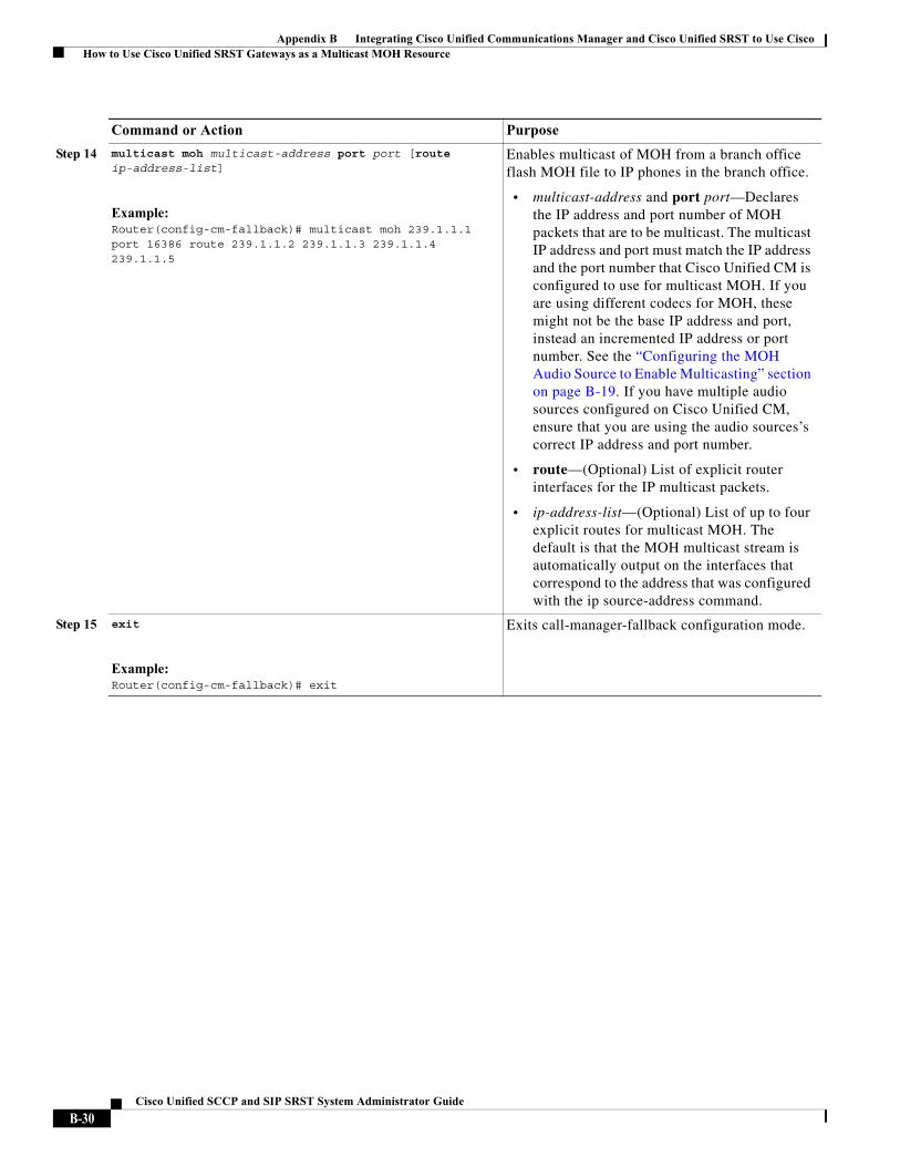
Appendix B Integrating Cisco Unified Communications Manager and Cisco Unified SRST to Use Cisco How to Use Cisco Unified SRST Gateways as a Multicast MOH Resource
Step 14 multicast moh multicast-address port port [route ip-address-list]
Example:Router(config-cm-fallback)# multicast moh 239.1.1.1 port 16386 route 239.1.1.2 239.1.1.3 239.1.1.4 239.1.1.5
Enables multicast of MOH from a branch office flash MOH file to IP phones in the branch office.
• multicast-address and port port—Declares the IP address and port number of MOH packets that are to be multicast. The multicast IP address and port must match the IP address and the port number that Cisco Unified CM is configured to use for multicast MOH. If you are using different codecs for MOH, these might not be the base IP address and port, instead an incremented IP address or port number. See the “Configuring the MOH Audio Source to Enable Multicasting” section on page B-19. If you have multiple audio sources configured on Cisco Unified CM, ensure that you are using the audio sources’s correct IP address and port number.
• route—(Optional) List of explicit router interfaces for the IP multicast packets.
• ip-address-list—(Optional) List of up to four explicit routes for multicast MOH. The default is that the MOH multicast stream is automatically output on the interfaces that correspond to the address that was configured with the ip source-address command.
Step 15 exit
Example:Router(config-cm-fallback)# exit
Exits call-manager-fallback configuration mode.
Command or Action Purpose
B-30Cisco Unified SCCP and SIP SRST System Administrator Guide
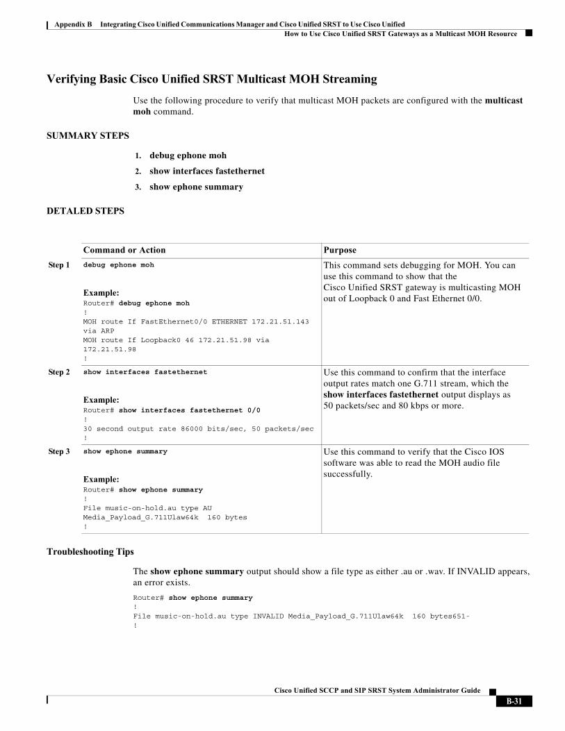
Appendix B Integrating Cisco Unified Communications Manager and Cisco Unified SRST to Use Cisco Unified How to Use Cisco Unified SRST Gateways as a Multicast MOH Resource
Verifying Basic Cisco Unified SRST Multicast MOH Streaming
Use the following procedure to verify that multicast MOH packets are configured with the multicast moh command.
SUMMARY STEPS
1. debug ephone moh
2. show interfaces fastethernet
3. show ephone summary
DETALED STEPS
Troubleshooting Tips
The show ephone summary output should show a file type as either .au or .wav. If INVALID appears, an error exists.
Router# show ephone summary !File music-on-hold.au type INVALID Media_Payload_G.711Ulaw64k 160 bytes651- !
Command or Action Purpose
Step 1 debug ephone moh
Example:Router# debug ephone moh!MOH route If FastEthernet0/0 ETHERNET 172.21.51.143 via ARPMOH route If Loopback0 46 172.21.51.98 via 172.21.51.98!
This command sets debugging for MOH. You can use this command to show that the Cisco Unified SRST gateway is multicasting MOH out of Loopback 0 and Fast Ethernet 0/0.
Step 2 show interfaces fastethernet
Example:Router# show interfaces fastethernet 0/0!30 second output rate 86000 bits/sec, 50 packets/sec!
Use this command to confirm that the interface output rates match one G.711 stream, which the show interfaces fastethernet output displays as 50 packets/sec and 80 kbps or more.
Step 3 show ephone summary
Example:Router# show ephone summary !File music-on-hold.au type AU Media_Payload_G.711Ulaw64k 160 bytes!
Use this command to verify that the Cisco IOS software was able to read the MOH audio file successfully.
B-31Cisco Unified SCCP and SIP SRST System Administrator Guide
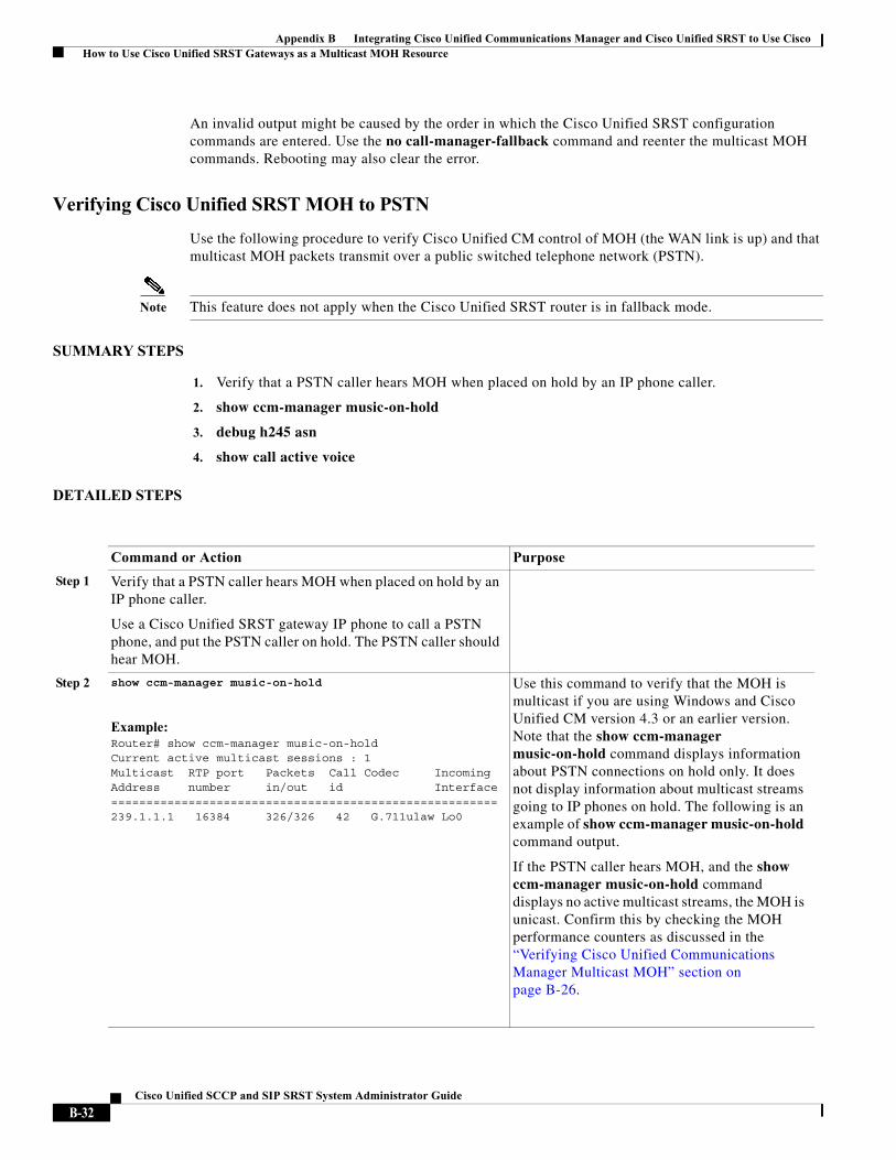
Appendix B Integrating Cisco Unified Communications Manager and Cisco Unified SRST to Use Cisco How to Use Cisco Unified SRST Gateways as a Multicast MOH Resource
An invalid output might be caused by the order in which the Cisco Unified SRST configuration commands are entered. Use the no call-manager-fallback command and reenter the multicast MOH commands. Rebooting may also clear the error.
Verifying Cisco Unified SRST MOH to PSTN
Use the following procedure to verify Cisco Unified CM control of MOH (the WAN link is up) and that multicast MOH packets transmit over a public switched telephone network (PSTN).
Note This feature does not apply when the Cisco Unified SRST router is in fallback mode.
SUMMARY STEPS
1. Verify that a PSTN caller hears MOH when placed on hold by an IP phone caller.
2. show ccm-manager music-on-hold
3. debug h245 asn
4. show call active voice
DETAILED STEPS
Command or Action Purpose
Step 1 Verify that a PSTN caller hears MOH when placed on hold by an IP phone caller.
Use a Cisco Unified SRST gateway IP phone to call a PSTN phone, and put the PSTN caller on hold. The PSTN caller should hear MOH.
Step 2 show ccm-manager music-on-hold
Example:Router# show ccm-manager music-on-hold Current active multicast sessions : 1Multicast RTP port Packets Call Codec IncomingAddress number in/out id Interface=======================================================239.1.1.1 16384 326/326 42 G.711ulaw Lo0
Use this command to verify that the MOH is multicast if you are using Windows and Cisco Unified CM version 4.3 or an earlier version. Note that the show ccm-manager music-on-hold command displays information about PSTN connections on hold only. It does not display information about multicast streams going to IP phones on hold. The following is an example of show ccm-manager music-on-hold command output.
If the PSTN caller hears MOH, and the show ccm-manager music-on-hold command displays no active multicast streams, the MOH is unicast. Confirm this by checking the MOH performance counters as discussed in the “Verifying Cisco Unified Communications Manager Multicast MOH” section on page B-26.
B-32Cisco Unified SCCP and SIP SRST System Administrator Guide
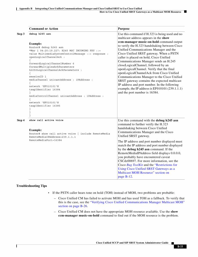
Appendix B Integrating Cisco Unified Communications Manager and Cisco Unified SRST to Use Cisco Unified How to Use Cisco Unified SRST Gateways as a Multicast MOH Resource
Troubleshooting Tips
• If the PSTN caller hears tone on hold (TOH) instead of MOH, two problems are probable:
– Cisco Unified CM has failed to activate MOH and has used TOH as a fallback. To verify that this is the case, see the “Verifying Cisco Unified Communications Manager Multicast MOH” section on page B-26.
– Cisco Unified CM does not have the appropriate MOH resource available. Use the show ccm-manager music-on-hold command to find out if the MOH resource is the problem.
Step 3 debug h245 asn
Example:Router# debug h245 asn*Mar 1 04:20:19.227: H245 MSC INCOMING PDU ::=value MultimediaSystemControlMessage ::= response : openLogicalChannelAck :{forwardLogicalChannelNumber 6forwardMultiplexAckParameters h2250LogicalChannelAckParameters :{sessionID 1mediaChannel unicastAddress : iPAddress :{network 'EF010101'HtsapIdentifier 16384}mediaControlChannel unicastAddress : iPAddress :{network 'EF010101'HtsapIdentifier 16385}}}
Use this command if H.323 is being used and no multicast address appears in the show ccm-manager music-on-hold command output to verify the H.323 handshaking between Cisco Unified Communications Manager and the Cisco Unified SRST gateway. When a PSTN caller is placed on hold, Cisco Unified Communications Manager sends an H.245 closeLogicalChannel, followed by an openLogicalChannel. Verify that the final openLogicalChannelAck from Cisco Unified Communications Manager to the Cisco Unified SRST gateway contains the expected multicast IP address and port number. In the following example, the IP address is EF010101 (239.1.1.1) and the port number is 16384.
Step 4 show call active voice
Example:Router# show call active voice | include RemoteMediaRemoteMediaIPAddress=239.1.1.1RemoteMediaPort=16384
Use this command with the debug h245 asn command to further verify the H.323 handshaking between Cisco Unified Communications Manager and the Cisco Unified SRST gateway.
The IP address and port number displayed must match the IP address and port number displayed by the debug h245 asn command. If the RemoteMediaIPAddress field displays 0.0.0.0, you probably have encountered caveat CSCdz00697. For more information, see the Cisco Bug ToolKit and the “Restrictions for Using Cisco Unified SRST Gateways as a Multicast MOH Resource” section on page B-12.
Command or Action Purpose
B-33Cisco Unified SCCP and SIP SRST System Administrator Guide
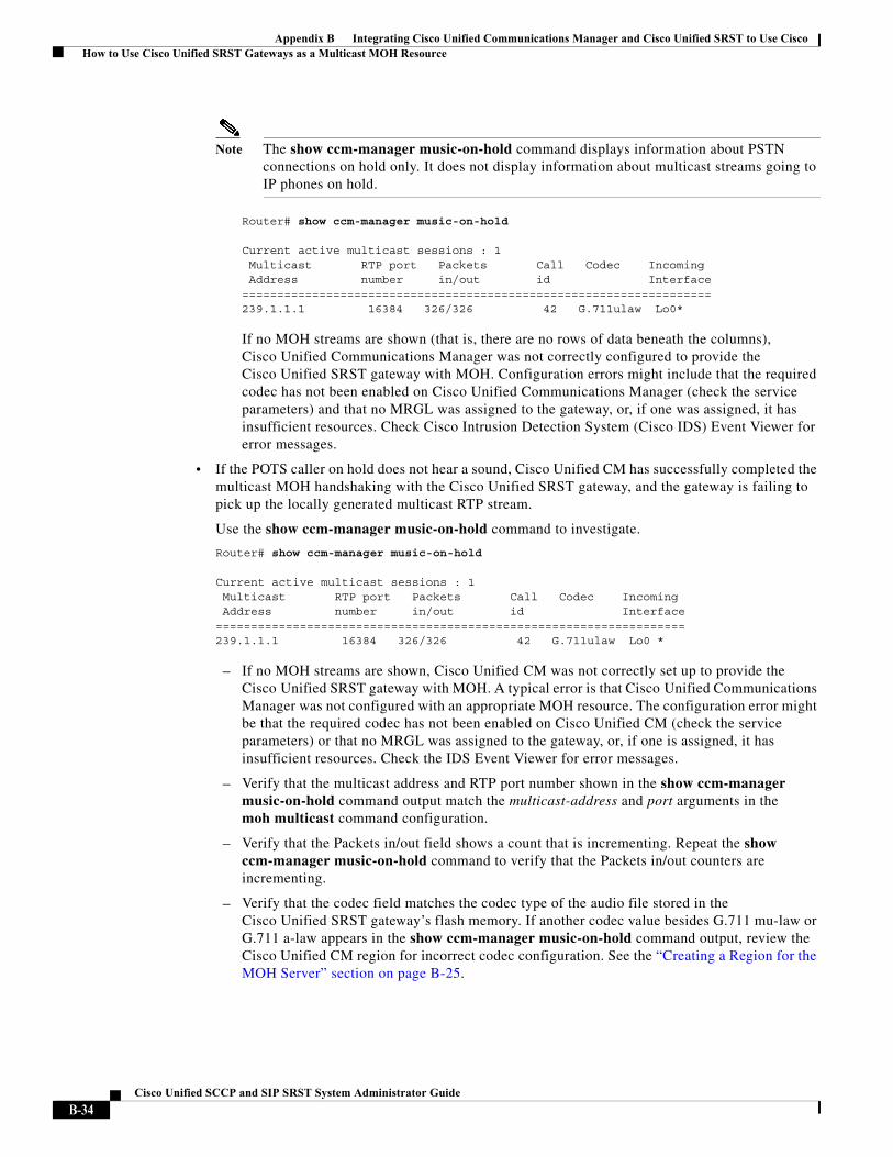
Appendix B Integrating Cisco Unified Communications Manager and Cisco Unified SRST to Use Cisco How to Use Cisco Unified SRST Gateways as a Multicast MOH Resource
Note The show ccm-manager music-on-hold command displays information about PSTN connections on hold only. It does not display information about multicast streams going to IP phones on hold.
Router# show ccm-manager music-on-hold
Current active multicast sessions : 1 Multicast RTP port Packets Call Codec Incoming Address number in/out id Interface===================================================================239.1.1.1 16384 326/326 42 G.711ulaw Lo0*
If no MOH streams are shown (that is, there are no rows of data beneath the columns), Cisco Unified Communications Manager was not correctly configured to provide the Cisco Unified SRST gateway with MOH. Configuration errors might include that the required codec has not been enabled on Cisco Unified Communications Manager (check the service parameters) and that no MRGL was assigned to the gateway, or, if one was assigned, it has insufficient resources. Check Cisco Intrusion Detection System (Cisco IDS) Event Viewer for error messages.
• If the POTS caller on hold does not hear a sound, Cisco Unified CM has successfully completed the multicast MOH handshaking with the Cisco Unified SRST gateway, and the gateway is failing to pick up the locally generated multicast RTP stream.
Use the show ccm-manager music-on-hold command to investigate.
Router# show ccm-manager music-on-hold
Current active multicast sessions : 1 Multicast RTP port Packets Call Codec Incoming Address number in/out id Interface===================================================================239.1.1.1 16384 326/326 42 G.711ulaw Lo0 *
– If no MOH streams are shown, Cisco Unified CM was not correctly set up to provide the Cisco Unified SRST gateway with MOH. A typical error is that Cisco Unified Communications Manager was not configured with an appropriate MOH resource. The configuration error might be that the required codec has not been enabled on Cisco Unified CM (check the service parameters) or that no MRGL was assigned to the gateway, or, if one is assigned, it has insufficient resources. Check the IDS Event Viewer for error messages.
– Verify that the multicast address and RTP port number shown in the show ccm-manager music-on-hold command output match the multicast-address and port arguments in the moh multicast command configuration.
– Verify that the Packets in/out field shows a count that is incrementing. Repeat the show ccm-manager music-on-hold command to verify that the Packets in/out counters are incrementing.
– Verify that the codec field matches the codec type of the audio file stored in the Cisco Unified SRST gateway’s flash memory. If another codec value besides G.711 mu-law or G.711 a-law appears in the show ccm-manager music-on-hold command output, review the Cisco Unified CM region for incorrect codec configuration. See the “Creating a Region for the MOH Server” section on page B-25.
B-34Cisco Unified SCCP and SIP SRST System Administrator Guide

Appendix B Integrating Cisco Unified Communications Manager and Cisco Unified SRST to Use Cisco Unified How to Use Cisco Unified SRST Gateways as a Multicast MOH Resource
– The Incoming Interface field shows where the Cisco Unified SRST gateway is to receive the multicast MOH packets. An interface must be listed and it must be one of the interfaces included in the multicast moh command or the default IP source address, which is configured with the ip source-address command.
For more information, see Step 9 in the “Enabling Multicast MOH on the Cisco Unified SRST Gateway” section on page B-27.
B-35Cisco Unified SCCP and SIP SRST System Administrator Guide
Appendix B Integrating Cisco Unified Communications Manager and Cisco Unified SRST to Use Cisco How to Use Cisco Unified SRST Gateways as a Multicast MOH Resource
Verifying Cisco Unified SRST Multicast MOH to IP Phones
To verify that Cisco Unified CM is signaling the IP phone to receive Cisco Unified SRST multicast MOH correctly, perform the following steps.
Step 1 Verify that an IP phone caller hears MOH when placed on hold by an IP phone caller.
Use an IP phone to call a second IP phone, and put the second caller on hold. The second caller should hear MOH.
Step 2 Check the MOHMulticastResourceActive and MOHUnicastResourceActive counters.
Use the Performance window to check the MOHMulticastResourceActive and MOHUnicastResourceActive counters under the Cisco MOH Device performance object. See Step 2 in the “Verifying Cisco Unified Communications Manager Multicast MOH” section on page B-26. For Cisco Unified SRST multicasting MOH to work, the multicast counter must increment.
Troubleshooting Tips
If no MOH is heard and the Cisco Unified SRST MOH signaling is multicasting, connect a sniffer to the PC port on the back of IP phone. If the IP phone and Cisco Unified SRST gateway are connected to the same subnet, multicast RTP packets must be detected at all times, even when the IP phone was not placed on hold. If the IP phone and the Cisco Unified SRST gateway are not connected to the same subnet, multicast RTP packets are detected only when the IP phone is placed on hold and sends an Internet Group Management Protocol (IGMP) Join to the closest router.
Configuring Cisco Unified SRST for MOH from a Live Feed
The following sections describe the configuration tasks for Cisco Unified SRST MOH live feed:
• Prerequisites, page B-37
• Restrictions, page B-37
• Setting Up the Voice Port on the Cisco Unified SRST Gateway, page B-37
• Setting Up the Directory Numbers on the Cisco Unified SRST Gateway, page B-39
• Establishing the MOH Feed, page B-39
• Verifying Cisco Unified SRST MOH Live Feed, page B-41
To configure MOH from a live feed, establish a voice port and dial peer for the call and then create a “dummy” phone or directory number. The dummy number allows for making and receiving calls, and the number is not assigned to a physical phone. It is that number that the MOH system autodials to establish the MOH feed.
The moh-live command allocates one of the virtual voice ports from the pool of virtual voice ports created by the max-dn command. The virtual voice port places an outgoing call to the dummy number; that is, the directory number specified in the moh-live command. The audio stream obtained from the MOH call provides the music-on-hold audio stream.
We recommend that the interface for live-feed MOH is an analog E&M port because it requires the minimum number of external components. Connect a line-level audio feed (standard audio jack) directly to pins 3 and 6 of an E&M RJ-45 connector. The E&M WAN interface card (WIC) has a built-in audio transformer that provides appropriate electrical isolation for the external audio source. (An audio
B-36Cisco Unified SCCP and SIP SRST System Administrator Guide
Appendix B Integrating Cisco Unified Communications Manager and Cisco Unified SRST to Use Cisco Unified How to Use Cisco Unified SRST Gateways as a Multicast MOH Resource
connection on an E&M port does not require loop current.) The signal immediate and auto-cut-through commands disable E&M signaling on this voice port. A G.711 audio packet stream is generated by a digital signal processor (DSP) on the E&M port.
In Cisco IOS Release 12.4(15)T and later releases, you can directly connect a live-feed source to an FXO port if the signal loop-start live-feed command is configured on the voice port; otherwise, the port must connect through an external third-party adapter to provide a battery feed. An external adapter must supply normal telephone company (telco) battery voltage with the correct polarity to the tip and ring leads of the FXO port and it must provide transformer-based isolation between the external audio source and the tip and ring leads of the FXO port.
Music from a live feed is continuously fed into the MOH playout buffer instead of being read from a flash file, so there is typically a 2-second delay. An outbound call to an MOH live-feed source is attempted (or reattempted) every 30 seconds until the connection is made by the directory number that was configured for MOH. If the live-feed source is shut down for any reason, the flash memory source automatically activates.
A live-feed MOH connection is established as an automatically connected voice call that is made by the Cisco Unified SRST MOH system itself or by an external source directly calling in to the live-feed MOH port. An MOH call can be from or to the PSTN or can proceed via VoIP with voice activity detection (VAD) disabled. The call is assumed to be an incoming call unless the out-call keyword is used with the moh-live command during configuration.
The Cisco Unified SRST router uses the audio stream from the call as the source for the MOH stream, displacing any audio stream that is available from a flash file. An example of an MOH stream received over an incoming call is an external H.323-based server device that calls the directory number to deliver an audio stream to the Cisco Unified SRST router.
Prerequisites
Cisco Unified SRST for multicast MOH, as described in the “Configuring Cisco Unified SRST for Multicast MOH from an Audio File” section on page B-26, is not required for the MOH live-feed configuration. However, MOH live feed is designed to work in conjunction with multicast MOH.
Restrictions
• An FXO port can be used for a live feed if the port is supplied with an external third-party adapter to provide a battery feed.
• An FXS port cannot be used for a live feed.
• For a live feed from VoIP, VAD must be disabled.
• MOH is supplied to PSTN and VoIP G.711 calls. Some versions of Cisco Unified SRST provide MOH to local phones. On Cisco Unified SRST that do not support MOH for local IP phones, callers hear a repeating tone on hold for reassurance that they are still connected.
• Conditions may occur within your network that is caused by brief spikes of a higher CPU usage. Small spikes in CPU usage can temporarily affect the quality of the MOH heard by parties connected via TDM (FXO / PRI / S) interfaces.
Setting Up the Voice Port on the Cisco Unified SRST Gateway
Use the following procedure to activate MOH from a live feed and to set up and connect the physical voice port.
B-37Cisco Unified SCCP and SIP SRST System Administrator Guide
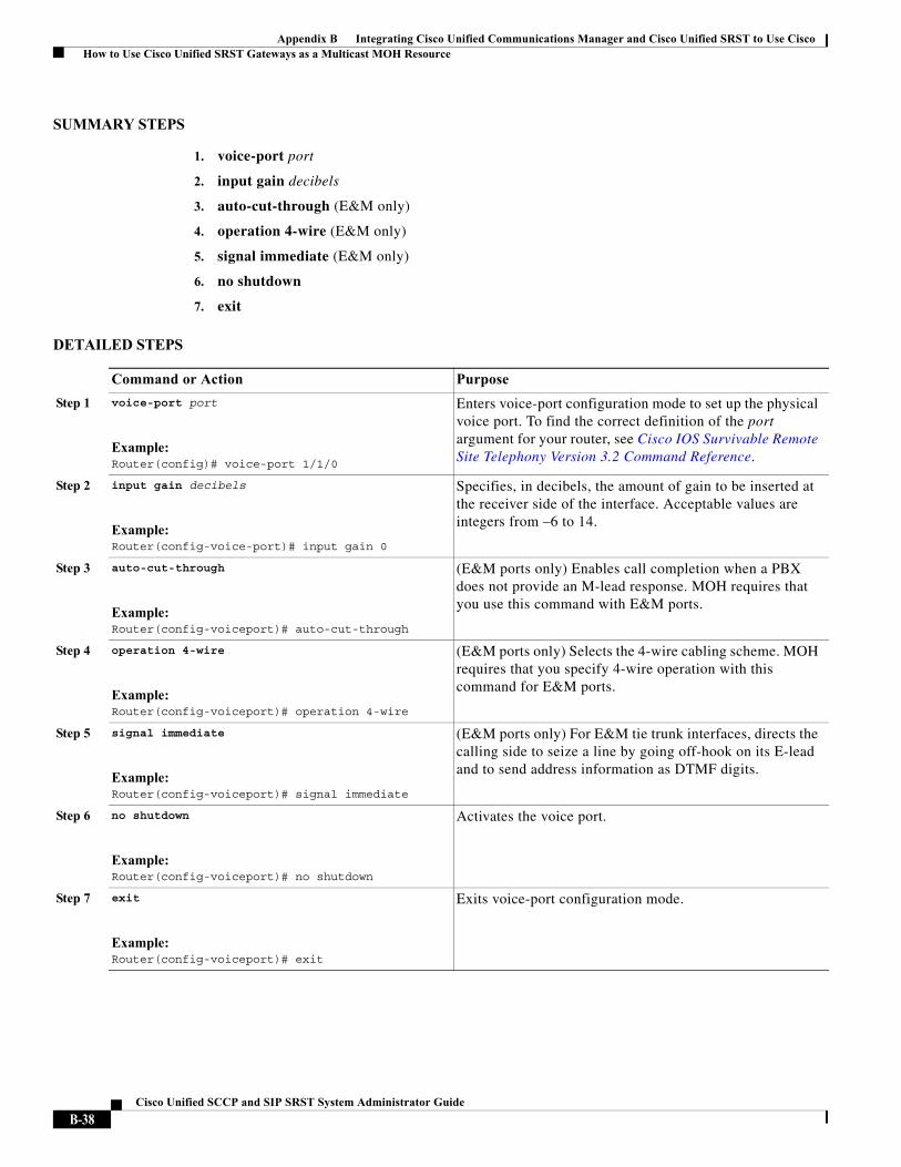
Appendix B Integrating Cisco Unified Communications Manager and Cisco Unified SRST to Use Cisco How to Use Cisco Unified SRST Gateways as a Multicast MOH Resource
SUMMARY STEPS
1. voice-port port
2. input gain decibels
3. auto-cut-through (E&M only)
4. operation 4-wire (E&M only)
5. signal immediate (E&M only)
6. no shutdown
7. exit
DETAILED STEPS
Command or Action Purpose
Step 1 voice-port port
Example:Router(config)# voice-port 1/1/0
Enters voice-port configuration mode to set up the physical voice port. To find the correct definition of the port argument for your router, see Cisco IOS Survivable Remote Site Telephony Version 3.2 Command Reference.
Step 2 input gain decibels
Example:Router(config-voice-port)# input gain 0
Specifies, in decibels, the amount of gain to be inserted at the receiver side of the interface. Acceptable values are integers from –6 to 14.
Step 3 auto-cut-through
Example:Router(config-voiceport)# auto-cut-through
(E&M ports only) Enables call completion when a PBX does not provide an M-lead response. MOH requires that you use this command with E&M ports.
Step 4 operation 4-wire
Example:Router(config-voiceport)# operation 4-wire
(E&M ports only) Selects the 4-wire cabling scheme. MOH requires that you specify 4-wire operation with this command for E&M ports.
Step 5 signal immediate
Example:Router(config-voiceport)# signal immediate
(E&M ports only) For E&M tie trunk interfaces, directs the calling side to seize a line by going off-hook on its E-lead and to send address information as DTMF digits.
Step 6 no shutdown
Example:Router(config-voiceport)# no shutdown
Activates the voice port.
Step 7 exit
Example:Router(config-voiceport)# exit
Exits voice-port configuration mode.
B-38Cisco Unified SCCP and SIP SRST System Administrator Guide
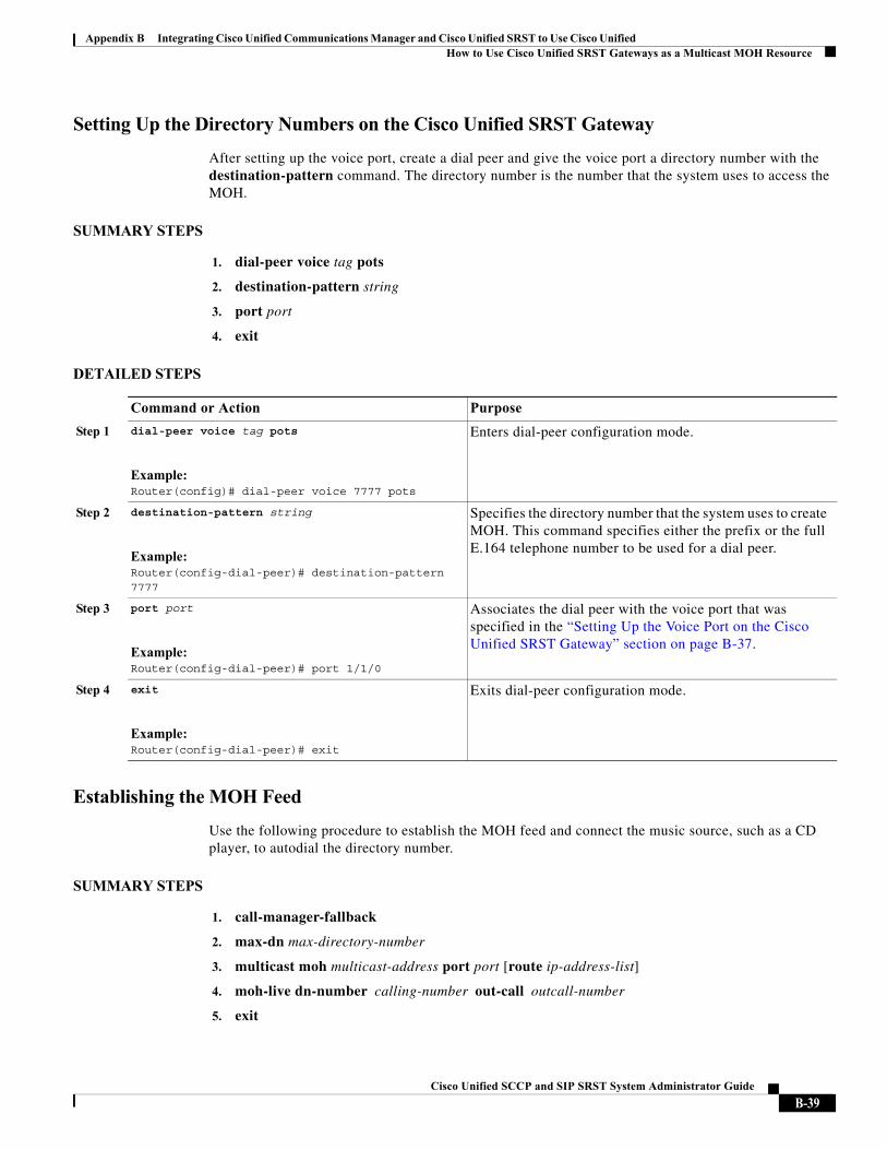
Appendix B Integrating Cisco Unified Communications Manager and Cisco Unified SRST to Use Cisco Unified How to Use Cisco Unified SRST Gateways as a Multicast MOH Resource
Setting Up the Directory Numbers on the Cisco Unified SRST Gateway
After setting up the voice port, create a dial peer and give the voice port a directory number with the destination-pattern command. The directory number is the number that the system uses to access the MOH.
SUMMARY STEPS
1. dial-peer voice tag pots
2. destination-pattern string
3. port port
4. exit
DETAILED STEPS
Establishing the MOH Feed
Use the following procedure to establish the MOH feed and connect the music source, such as a CD player, to autodial the directory number.
SUMMARY STEPS
1. call-manager-fallback
2. max-dn max-directory-number
3. multicast moh multicast-address port port [route ip-address-list]
4. moh-live dn-number calling-number out-call outcall-number
5. exit
Command or Action Purpose
Step 1 dial-peer voice tag pots
Example:Router(config)# dial-peer voice 7777 pots
Enters dial-peer configuration mode.
Step 2 destination-pattern string
Example:Router(config-dial-peer)# destination-pattern 7777
Specifies the directory number that the system uses to create MOH. This command specifies either the prefix or the full E.164 telephone number to be used for a dial peer.
Step 3 port port
Example:Router(config-dial-peer)# port 1/1/0
Associates the dial peer with the voice port that was specified in the “Setting Up the Voice Port on the Cisco Unified SRST Gateway” section on page B-37.
Step 4 exit
Example:Router(config-dial-peer)# exit
Exits dial-peer configuration mode.
B-39Cisco Unified SCCP and SIP SRST System Administrator Guide
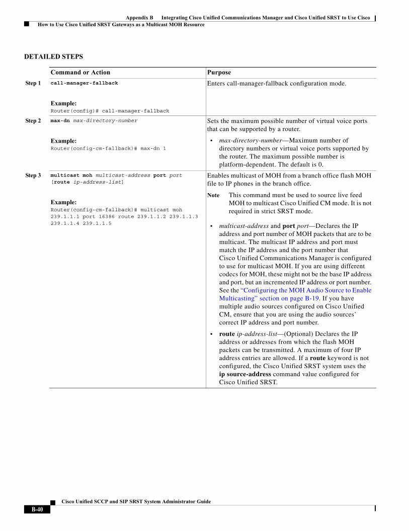
Appendix B Integrating Cisco Unified Communications Manager and Cisco Unified SRST to Use Cisco How to Use Cisco Unified SRST Gateways as a Multicast MOH Resource
DETAILED STEPS
Command or Action Purpose
Step 1 call-manager-fallback
Example:Router(config)# call-manager-fallback
Enters call-manager-fallback configuration mode.
Step 2 max-dn max-directory-number
Example:Router(config-cm-fallback)# max-dn 1
Sets the maximum possible number of virtual voice ports that can be supported by a router.
• max-directory-number—Maximum number of directory numbers or virtual voice ports supported by the router. The maximum possible number is platform-dependent. The default is 0.
Step 3 multicast moh multicast-address port port [route ip-address-list]
Example:Router(config-cm-fallback)# multicast moh 239.1.1.1 port 16386 route 239.1.1.2 239.1.1.3 239.1.1.4 239.1.1.5
Enables multicast of MOH from a branch office flash MOH file to IP phones in the branch office.
Note This command must be used to source live feed MOH to multicast Cisco Unified CM mode. It is not required in strict SRST mode.
• multicast-address and port port—Declares the IP address and port number of MOH packets that are to be multicast. The multicast IP address and port must match the IP address and the port number that Cisco Unified Communications Manager is configured to use for multicast MOH. If you are using different codecs for MOH, these might not be the base IP address and port, but an incremented IP address or port number. See the “Configuring the MOH Audio Source to Enable Multicasting” section on page B-19. If you have multiple audio sources configured on Cisco Unified CM, ensure that you are using the audio sources’ correct IP address and port number.
• route ip-address-list—(Optional) Declares the IP address or addresses from which the flash MOH packets can be transmitted. A maximum of four IP address entries are allowed. If a route keyword is not configured, the Cisco Unified SRST system uses the ip source-address command value configured for Cisco Unified SRST.
B-40Cisco Unified SCCP and SIP SRST System Administrator Guide
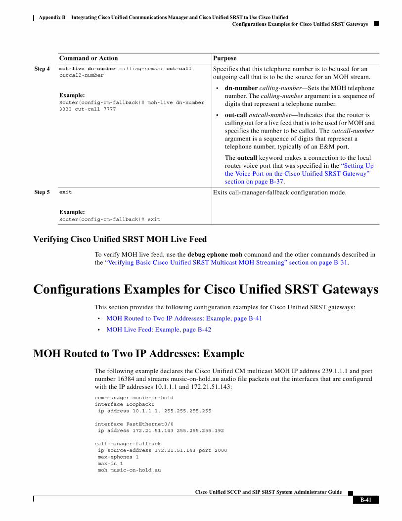
Appendix B Integrating Cisco Unified Communications Manager and Cisco Unified SRST to Use Cisco Unified Configurations Examples for Cisco Unified SRST Gateways
Verifying Cisco Unified SRST MOH Live Feed
To verify MOH live feed, use the debug ephone moh command and the other commands described in the “Verifying Basic Cisco Unified SRST Multicast MOH Streaming” section on page B-31.
Configurations Examples for Cisco Unified SRST GatewaysThis section provides the following configuration examples for Cisco Unified SRST gateways:
• MOH Routed to Two IP Addresses: Example, page B-41
• MOH Live Feed: Example, page B-42
MOH Routed to Two IP Addresses: Example
The following example declares the Cisco Unified CM multicast MOH IP address 239.1.1.1 and port number 16384 and streams music-on-hold.au audio file packets out the interfaces that are configured with the IP addresses 10.1.1.1 and 172.21.51.143:
ccm-manager music-on-holdinterface Loopback0 ip address 10.1.1.1. 255.255.255.255
interface FastEthernet0/0 ip address 172.21.51.143 255.255.255.192
call-manager-fallback ip source-address 172.21.51.143 port 2000 max-ephones 1 max-dn 1 moh music-on-hold.au
Step 4 moh-live dn-number calling-number out-call outcall-number
Example:Router(config-cm-fallback)# moh-live dn-number 3333 out-call 7777
Specifies that this telephone number is to be used for an outgoing call that is to be the source for an MOH stream.
• dn-number calling-number—Sets the MOH telephone number. The calling-number argument is a sequence of digits that represent a telephone number.
• out-call outcall-number—Indicates that the router is calling out for a live feed that is to be used for MOH and specifies the number to be called. The outcall-number argument is a sequence of digits that represent a telephone number, typically of an E&M port.
The outcall keyword makes a connection to the local router voice port that was specified in the “Setting Up the Voice Port on the Cisco Unified SRST Gateway” section on page B-37.
Step 5 exit
Example:Router(config-cm-fallback)# exit
Exits call-manager-fallback configuration mode.
Command or Action Purpose
B-41Cisco Unified SCCP and SIP SRST System Administrator Guide
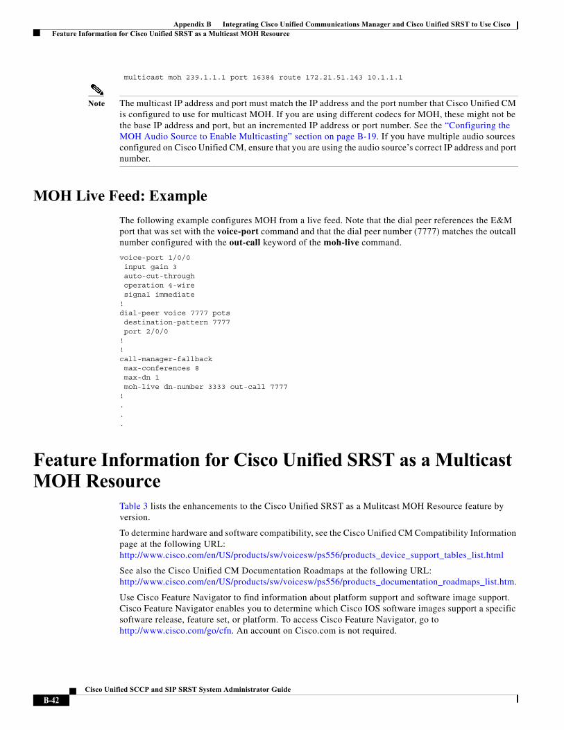
Appendix B Integrating Cisco Unified Communications Manager and Cisco Unified SRST to Use Cisco Feature Information for Cisco Unified SRST as a Multicast MOH Resource
multicast moh 239.1.1.1 port 16384 route 172.21.51.143 10.1.1.1
Note The multicast IP address and port must match the IP address and the port number that Cisco Unified CM is configured to use for multicast MOH. If you are using different codecs for MOH, these might not be the base IP address and port, but an incremented IP address or port number. See the “Configuring the MOH Audio Source to Enable Multicasting” section on page B-19. If you have multiple audio sources configured on Cisco Unified CM, ensure that you are using the audio source’s correct IP address and port number.
MOH Live Feed: Example
The following example configures MOH from a live feed. Note that the dial peer references the E&M port that was set with the voice-port command and that the dial peer number (7777) matches the outcall number configured with the out-call keyword of the moh-live command.
voice-port 1/0/0input gain 3auto-cut-throughoperation 4-wiresignal immediate
!dial-peer voice 7777 potsdestination-pattern 7777port 2/0/0
!!call-manager-fallbackmax-conferences 8max-dn 1moh-live dn-number 3333 out-call 7777
!...
Feature Information for Cisco Unified SRST as a Multicast MOH Resource
Table 3 lists the enhancements to the Cisco Unified SRST as a Mulitcast MOH Resource feature by version.
To determine hardware and software compatibility, see the Cisco Unified CM Compatibility Information page at the following URL: http://www.cisco.com/en/US/products/sw/voicesw/ps556/products_device_support_tables_list.html
See also the Cisco Unified CM Documentation Roadmaps at the following URL:http://www.cisco.com/en/US/products/sw/voicesw/ps556/products_documentation_roadmaps_list.htm.
Use Cisco Feature Navigator to find information about platform support and software image support. Cisco Feature Navigator enables you to determine which Cisco IOS software images support a specific software release, feature set, or platform. To access Cisco Feature Navigator, go to http://www.cisco.com/go/cfn. An account on Cisco.com is not required.
B-42Cisco Unified SCCP and SIP SRST System Administrator Guide
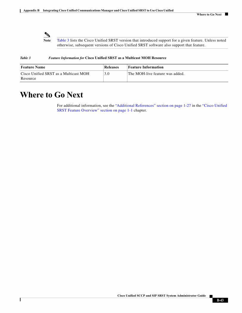
Appendix B Integrating Cisco Unified Communications Manager and Cisco Unified SRST to Use Cisco Unified Where to Go Next
Note Table 3 lists the Cisco Unified SRST version that introduced support for a given feature. Unless noted otherwise, subsequent versions of Cisco Unified SRST software also support that feature.
Where to Go NextFor additional information, see the “Additional References” section on page 1-27 in the “Cisco Unified SRST Feature Overview” section on page 1-1 chapter.
Table 3 Feature Information for Cisco Unified SRST as a Multicast MOH Resource
Feature Name Releases Feature Information
Cisco Unified SRST as a Multicast MOH Resource
3.0 The MOH-live feature was added.
B-43Cisco Unified SCCP and SIP SRST System Administrator Guide

Appendix B Integrating Cisco Unified Communications Manager and Cisco Unified SRST to Use Cisco Where to Go Next
B-44Cisco Unified SCCP and SIP SRST System Administrator Guide