
Cisco Wireless LAN Controller Configuration Guide - Audentia
Upload
khangminh22Category
view
1download
0
Redbooks
Front cover
Implementing IBM FlashSystem 900 Model AE3
Detlef Helmbrecht
Jim Cioffi
Jon Herd
Jeffrey Irving
Christian Karpp
Volker Kiemes
Carsten Larsen
Adrian Orben


International Technical Support Organization
Implementing IBM FlashSystem 900 Model AE3
March 2018
SG24-8414-00

© Copyright International Business Machines Corporation 2018. All rights reserved.Note to U.S. Government Users Restricted Rights -- Use, duplication or disclosure restricted by GSA ADP ScheduleContract with IBM Corp.
First Edition (March 2018)
This edition applies to the IBM FlashSystem 900 Model AE3.
Note: Before using this information and the product it supports, read the information in “Notices” on page ix.

Contents
Notices . . . . . . . . . . . . . . . . . . . . . . . . . . . . . . . . . . . . . . . . . . . . . . . . . . . . . . . . . . . . . . . . . ixTrademarks . . . . . . . . . . . . . . . . . . . . . . . . . . . . . . . . . . . . . . . . . . . . . . . . . . . . . . . . . . . . . . .x
Preface . . . . . . . . . . . . . . . . . . . . . . . . . . . . . . . . . . . . . . . . . . . . . . . . . . . . . . . . . . . . . . . . . xiAuthors. . . . . . . . . . . . . . . . . . . . . . . . . . . . . . . . . . . . . . . . . . . . . . . . . . . . . . . . . . . . . . . . . . xiNow you can become a published author, too! . . . . . . . . . . . . . . . . . . . . . . . . . . . . . . . . . . xivComments welcome. . . . . . . . . . . . . . . . . . . . . . . . . . . . . . . . . . . . . . . . . . . . . . . . . . . . . . . xivStay connected to IBM Redbooks . . . . . . . . . . . . . . . . . . . . . . . . . . . . . . . . . . . . . . . . . . . . xiv
Chapter 1. Introduction to FlashSystem . . . . . . . . . . . . . . . . . . . . . . . . . . . . . . . . . . . . . . 11.1 FlashSystem storage overview . . . . . . . . . . . . . . . . . . . . . . . . . . . . . . . . . . . . . . . . . . . . 31.2 IBM FlashCore technology . . . . . . . . . . . . . . . . . . . . . . . . . . . . . . . . . . . . . . . . . . . . . . . 4
1.2.1 IBM Piece of Mind Initiative. . . . . . . . . . . . . . . . . . . . . . . . . . . . . . . . . . . . . . . . . . . 51.3 Why flash technology matters . . . . . . . . . . . . . . . . . . . . . . . . . . . . . . . . . . . . . . . . . . . . . 61.4 IBM FlashSystem family product differentiation . . . . . . . . . . . . . . . . . . . . . . . . . . . . . . . 71.5 Technology and architectural design overview . . . . . . . . . . . . . . . . . . . . . . . . . . . . . . . . 8
1.5.1 Hardware-only data path. . . . . . . . . . . . . . . . . . . . . . . . . . . . . . . . . . . . . . . . . . . . . 91.5.2 3DTLC flash memory chips. . . . . . . . . . . . . . . . . . . . . . . . . . . . . . . . . . . . . . . . . . 101.5.3 Flash module capacities . . . . . . . . . . . . . . . . . . . . . . . . . . . . . . . . . . . . . . . . . . . . 101.5.4 Gateway interface FPGA . . . . . . . . . . . . . . . . . . . . . . . . . . . . . . . . . . . . . . . . . . . 111.5.5 Flash controller FPGA. . . . . . . . . . . . . . . . . . . . . . . . . . . . . . . . . . . . . . . . . . . . . . 111.5.6 IBM Variable Stripe RAID and 2D Flash RAID overview . . . . . . . . . . . . . . . . . . . 121.5.7 Inline hardware data compression . . . . . . . . . . . . . . . . . . . . . . . . . . . . . . . . . . . . 141.5.8 Encryption . . . . . . . . . . . . . . . . . . . . . . . . . . . . . . . . . . . . . . . . . . . . . . . . . . . . . . . 14
1.6 Usability plus reliability, availability, and serviceability enhancements . . . . . . . . . . . . . 161.6.1 Automatic battery reconditioning. . . . . . . . . . . . . . . . . . . . . . . . . . . . . . . . . . . . . . 161.6.2 Remote Support Assistance . . . . . . . . . . . . . . . . . . . . . . . . . . . . . . . . . . . . . . . . . 161.6.3 Enhanced Thermal Management . . . . . . . . . . . . . . . . . . . . . . . . . . . . . . . . . . . . . 161.6.4 A/C Power Line Monitoring . . . . . . . . . . . . . . . . . . . . . . . . . . . . . . . . . . . . . . . . . . 171.6.5 Enhanced Call Home Data . . . . . . . . . . . . . . . . . . . . . . . . . . . . . . . . . . . . . . . . . . 171.6.6 GUI enhancements . . . . . . . . . . . . . . . . . . . . . . . . . . . . . . . . . . . . . . . . . . . . . . . . 17
Chapter 2. IBM FlashSystem 900 Model AE3 architecture . . . . . . . . . . . . . . . . . . . . . . 192.1 IBM FlashSystem 900 Model AE3 architecture overview . . . . . . . . . . . . . . . . . . . . . . . 20
2.1.1 Capacity . . . . . . . . . . . . . . . . . . . . . . . . . . . . . . . . . . . . . . . . . . . . . . . . . . . . . . . . 202.1.2 Performance and capacity considerations . . . . . . . . . . . . . . . . . . . . . . . . . . . . . . 222.1.3 In-line Hardware Data Compression . . . . . . . . . . . . . . . . . . . . . . . . . . . . . . . . . . . 232.1.4 Physical and effective capacity based on compression rates . . . . . . . . . . . . . . . . 242.1.5 Out Of Physical Space . . . . . . . . . . . . . . . . . . . . . . . . . . . . . . . . . . . . . . . . . . . . . 272.1.6 Performance and latency . . . . . . . . . . . . . . . . . . . . . . . . . . . . . . . . . . . . . . . . . . . 292.1.7 Power requirements . . . . . . . . . . . . . . . . . . . . . . . . . . . . . . . . . . . . . . . . . . . . . . . 302.1.8 Physical specifications . . . . . . . . . . . . . . . . . . . . . . . . . . . . . . . . . . . . . . . . . . . . . 302.1.9 FlashCore technology . . . . . . . . . . . . . . . . . . . . . . . . . . . . . . . . . . . . . . . . . . . . . . 302.1.10 Scalability . . . . . . . . . . . . . . . . . . . . . . . . . . . . . . . . . . . . . . . . . . . . . . . . . . . . . . 322.1.11 Protocol support . . . . . . . . . . . . . . . . . . . . . . . . . . . . . . . . . . . . . . . . . . . . . . . . . 332.1.12 Encryption support . . . . . . . . . . . . . . . . . . . . . . . . . . . . . . . . . . . . . . . . . . . . . . . 332.1.13 IBM FlashSystem Model 900 AE2 and Model 900 AE3 differences . . . . . . . . . . 352.1.14 Management . . . . . . . . . . . . . . . . . . . . . . . . . . . . . . . . . . . . . . . . . . . . . . . . . . . . 35
2.2 Architecture of IBM FlashSystem 900 Model AE3 . . . . . . . . . . . . . . . . . . . . . . . . . . . . 38
© Copyright IBM Corp. 2018. All rights reserved. iii

2.2.1 Overview . . . . . . . . . . . . . . . . . . . . . . . . . . . . . . . . . . . . . . . . . . . . . . . . . . . . . . . . 382.2.2 Hardware components . . . . . . . . . . . . . . . . . . . . . . . . . . . . . . . . . . . . . . . . . . . . . 402.2.3 Canisters . . . . . . . . . . . . . . . . . . . . . . . . . . . . . . . . . . . . . . . . . . . . . . . . . . . . . . . . 412.2.4 Interface cards . . . . . . . . . . . . . . . . . . . . . . . . . . . . . . . . . . . . . . . . . . . . . . . . . . . 422.2.5 MicroLatency modules . . . . . . . . . . . . . . . . . . . . . . . . . . . . . . . . . . . . . . . . . . . . . 442.2.6 Battery modules . . . . . . . . . . . . . . . . . . . . . . . . . . . . . . . . . . . . . . . . . . . . . . . . . . 462.2.7 Power supply units . . . . . . . . . . . . . . . . . . . . . . . . . . . . . . . . . . . . . . . . . . . . . . . . 472.2.8 Fan modules . . . . . . . . . . . . . . . . . . . . . . . . . . . . . . . . . . . . . . . . . . . . . . . . . . . . . 48
2.3 Administration and maintenance. . . . . . . . . . . . . . . . . . . . . . . . . . . . . . . . . . . . . . . . . . 482.3.1 Serviceability and software enhancements. . . . . . . . . . . . . . . . . . . . . . . . . . . . . . 482.3.2 System management . . . . . . . . . . . . . . . . . . . . . . . . . . . . . . . . . . . . . . . . . . . . . . 49
2.4 Support matrix . . . . . . . . . . . . . . . . . . . . . . . . . . . . . . . . . . . . . . . . . . . . . . . . . . . . . . . . 552.5 Product integration overview. . . . . . . . . . . . . . . . . . . . . . . . . . . . . . . . . . . . . . . . . . . . . 55
2.5.1 IBM Spectrum Virtualize - SAN Volume Controller . . . . . . . . . . . . . . . . . . . . . . . . 552.5.2 IBM Storwize V7000 storage array . . . . . . . . . . . . . . . . . . . . . . . . . . . . . . . . . . . . 562.5.3 IBM DB2 database environments . . . . . . . . . . . . . . . . . . . . . . . . . . . . . . . . . . . . . 572.5.4 IBM Spectrum Scale . . . . . . . . . . . . . . . . . . . . . . . . . . . . . . . . . . . . . . . . . . . . . . . 572.5.5 VMware with IBM Spectrum control Base. . . . . . . . . . . . . . . . . . . . . . . . . . . . . . . 58
Chapter 3. Planning . . . . . . . . . . . . . . . . . . . . . . . . . . . . . . . . . . . . . . . . . . . . . . . . . . . . . 593.1 Prerequisites to installation . . . . . . . . . . . . . . . . . . . . . . . . . . . . . . . . . . . . . . . . . . . . . . 60
3.1.1 Contact information and checklist . . . . . . . . . . . . . . . . . . . . . . . . . . . . . . . . . . . . . 603.1.2 Completing the hardware location chart . . . . . . . . . . . . . . . . . . . . . . . . . . . . . . . . 61
3.2 Planning cable connections . . . . . . . . . . . . . . . . . . . . . . . . . . . . . . . . . . . . . . . . . . . . . 633.2.1 Management port connections . . . . . . . . . . . . . . . . . . . . . . . . . . . . . . . . . . . . . . . 633.2.2 Interface card connections . . . . . . . . . . . . . . . . . . . . . . . . . . . . . . . . . . . . . . . . . . 64
3.3 Planning for power . . . . . . . . . . . . . . . . . . . . . . . . . . . . . . . . . . . . . . . . . . . . . . . . . . . . 673.4 Configuration planning . . . . . . . . . . . . . . . . . . . . . . . . . . . . . . . . . . . . . . . . . . . . . . . . . 673.5 Call Home configuration . . . . . . . . . . . . . . . . . . . . . . . . . . . . . . . . . . . . . . . . . . . . . . . . 693.6 Remote Support Assistance . . . . . . . . . . . . . . . . . . . . . . . . . . . . . . . . . . . . . . . . . . . . . 703.7 TCP/IP requirements. . . . . . . . . . . . . . . . . . . . . . . . . . . . . . . . . . . . . . . . . . . . . . . . . . . 723.8 Planning for encryption . . . . . . . . . . . . . . . . . . . . . . . . . . . . . . . . . . . . . . . . . . . . . . . . . 733.9 Planning for compression . . . . . . . . . . . . . . . . . . . . . . . . . . . . . . . . . . . . . . . . . . . . . . . 753.10 Checking web browser settings for the management GUI . . . . . . . . . . . . . . . . . . . . . 763.11 Licensing . . . . . . . . . . . . . . . . . . . . . . . . . . . . . . . . . . . . . . . . . . . . . . . . . . . . . . . . . . . 783.12 Supported hosts and operating system considerations . . . . . . . . . . . . . . . . . . . . . . . 78
Chapter 4. Installation and configuration . . . . . . . . . . . . . . . . . . . . . . . . . . . . . . . . . . . . 814.1 First-time installation . . . . . . . . . . . . . . . . . . . . . . . . . . . . . . . . . . . . . . . . . . . . . . . . . . . 82
4.1.1 Installing the hardware . . . . . . . . . . . . . . . . . . . . . . . . . . . . . . . . . . . . . . . . . . . . . 824.2 Cabling the system . . . . . . . . . . . . . . . . . . . . . . . . . . . . . . . . . . . . . . . . . . . . . . . . . . . . 84
4.2.1 Cabling for Fibre Channel . . . . . . . . . . . . . . . . . . . . . . . . . . . . . . . . . . . . . . . . . . . 844.2.2 Cabling for QDR InfiniBand. . . . . . . . . . . . . . . . . . . . . . . . . . . . . . . . . . . . . . . . . . 864.2.3 FC cable type . . . . . . . . . . . . . . . . . . . . . . . . . . . . . . . . . . . . . . . . . . . . . . . . . . . . 864.2.4 Ethernet management cabling . . . . . . . . . . . . . . . . . . . . . . . . . . . . . . . . . . . . . . . 874.2.5 Power requirements . . . . . . . . . . . . . . . . . . . . . . . . . . . . . . . . . . . . . . . . . . . . . . . 874.2.6 Cooling requirements . . . . . . . . . . . . . . . . . . . . . . . . . . . . . . . . . . . . . . . . . . . . . . 874.2.7 Cable connector locations. . . . . . . . . . . . . . . . . . . . . . . . . . . . . . . . . . . . . . . . . . . 87
4.3 Initializing the system . . . . . . . . . . . . . . . . . . . . . . . . . . . . . . . . . . . . . . . . . . . . . . . . . . 884.3.1 Using the InitTool . . . . . . . . . . . . . . . . . . . . . . . . . . . . . . . . . . . . . . . . . . . . . . . . . 894.3.2 Initializing the system by using the web management interface . . . . . . . . . . . . . 1014.3.3 Service Assistant Tool . . . . . . . . . . . . . . . . . . . . . . . . . . . . . . . . . . . . . . . . . . . . 115
4.4 RAID storage modes. . . . . . . . . . . . . . . . . . . . . . . . . . . . . . . . . . . . . . . . . . . . . . . . . . 115
iv Implementing IBM FlashSystem 900 Model AE3

4.5 Connectivity guidelines for improved performance . . . . . . . . . . . . . . . . . . . . . . . . . . . 1164.5.1 Interface card configuration guidelines . . . . . . . . . . . . . . . . . . . . . . . . . . . . . . . . 1164.5.2 Host adapter guidelines . . . . . . . . . . . . . . . . . . . . . . . . . . . . . . . . . . . . . . . . . . . 1174.5.3 Cabling guidelines. . . . . . . . . . . . . . . . . . . . . . . . . . . . . . . . . . . . . . . . . . . . . . . . 1174.5.4 Zoning guidelines . . . . . . . . . . . . . . . . . . . . . . . . . . . . . . . . . . . . . . . . . . . . . . . . 117
Chapter 5. IBM FlashSystem 900 client host attachment and implementation . . . . . 1195.1 Host implementation and procedures . . . . . . . . . . . . . . . . . . . . . . . . . . . . . . . . . . . . . 1205.2 Host connectivity . . . . . . . . . . . . . . . . . . . . . . . . . . . . . . . . . . . . . . . . . . . . . . . . . . . . . 120
5.2.1 Fibre Channel SAN attachment . . . . . . . . . . . . . . . . . . . . . . . . . . . . . . . . . . . . . 1205.2.2 Fibre Channel direct attachment . . . . . . . . . . . . . . . . . . . . . . . . . . . . . . . . . . . . . 1215.2.3 General FC attachment rules . . . . . . . . . . . . . . . . . . . . . . . . . . . . . . . . . . . . . . . 122
5.3 Operating system connectivity and preferred practices . . . . . . . . . . . . . . . . . . . . . . . 1225.3.1 FlashSystem 900 sector size . . . . . . . . . . . . . . . . . . . . . . . . . . . . . . . . . . . . . . . 1225.3.2 File alignment for the best RAID performance . . . . . . . . . . . . . . . . . . . . . . . . . . 1235.3.3 IBM AIX and FlashSystem 900 . . . . . . . . . . . . . . . . . . . . . . . . . . . . . . . . . . . . . . 1235.3.4 IBM i and FlashSystem 900 AE3 . . . . . . . . . . . . . . . . . . . . . . . . . . . . . . . . . . . . 1285.3.5 FlashSystem 900 AE3 and Linux client hosts . . . . . . . . . . . . . . . . . . . . . . . . . . . 1345.3.6 FlashSystem 900 and Microsoft Windows client hosts . . . . . . . . . . . . . . . . . . . . 1365.3.7 FlashSystem 900 and client VMware ESX hosts . . . . . . . . . . . . . . . . . . . . . . . . 1395.3.8 FlashSystem 900 and IBM SAN Volume Controller or Storwize V7000 . . . . . . . 140
5.4 Miscellaneous host attachment . . . . . . . . . . . . . . . . . . . . . . . . . . . . . . . . . . . . . . . . . . 1405.5 FlashSystem 900 preferred read and configuration examples . . . . . . . . . . . . . . . . . . 140
5.5.1 FlashSystem 900 deployment scenario with preferred read. . . . . . . . . . . . . . . . 1405.5.2 Implementing preferred read. . . . . . . . . . . . . . . . . . . . . . . . . . . . . . . . . . . . . . . . 1435.5.3 Linux configuration file multipath.conf example . . . . . . . . . . . . . . . . . . . . . . . . . 1525.5.4 Example of a VMware configuration . . . . . . . . . . . . . . . . . . . . . . . . . . . . . . . . . . 152
5.6 FlashSystem 900 and Easy Tier . . . . . . . . . . . . . . . . . . . . . . . . . . . . . . . . . . . . . . . . . 1535.7 Troubleshooting . . . . . . . . . . . . . . . . . . . . . . . . . . . . . . . . . . . . . . . . . . . . . . . . . . . . . 153
5.7.1 Troubleshooting Linux InfiniBand configuration issues. . . . . . . . . . . . . . . . . . . . 1535.7.2 Linux fdisk error message. . . . . . . . . . . . . . . . . . . . . . . . . . . . . . . . . . . . . . . . . . 1545.7.3 Changing FC port properties. . . . . . . . . . . . . . . . . . . . . . . . . . . . . . . . . . . . . . . . 155
Chapter 6. Using IBM FlashSystem 900 . . . . . . . . . . . . . . . . . . . . . . . . . . . . . . . . . . . . 1576.1 IBM FlashSystem 900 AE3 management tools overview . . . . . . . . . . . . . . . . . . . . . . 158
6.1.1 GUI access . . . . . . . . . . . . . . . . . . . . . . . . . . . . . . . . . . . . . . . . . . . . . . . . . . . . . 1586.1.2 GUI layout . . . . . . . . . . . . . . . . . . . . . . . . . . . . . . . . . . . . . . . . . . . . . . . . . . . . . . 1596.1.3 Navigation . . . . . . . . . . . . . . . . . . . . . . . . . . . . . . . . . . . . . . . . . . . . . . . . . . . . . . 1616.1.4 Selecting multiple items . . . . . . . . . . . . . . . . . . . . . . . . . . . . . . . . . . . . . . . . . . . 1616.1.5 Performance indicators . . . . . . . . . . . . . . . . . . . . . . . . . . . . . . . . . . . . . . . . . . . . 163
6.2 Dashboard window . . . . . . . . . . . . . . . . . . . . . . . . . . . . . . . . . . . . . . . . . . . . . . . . . . . 1636.3 Monitoring menu . . . . . . . . . . . . . . . . . . . . . . . . . . . . . . . . . . . . . . . . . . . . . . . . . . . . . 166
6.3.1 Monitoring System menu . . . . . . . . . . . . . . . . . . . . . . . . . . . . . . . . . . . . . . . . . . 1666.3.2 Monitoring Network Neighborhood . . . . . . . . . . . . . . . . . . . . . . . . . . . . . . . . . . . 1806.3.3 Monitoring events . . . . . . . . . . . . . . . . . . . . . . . . . . . . . . . . . . . . . . . . . . . . . . . . 1816.3.4 Monitoring performance menu . . . . . . . . . . . . . . . . . . . . . . . . . . . . . . . . . . . . . . 1906.3.5 Monitoring performance with events . . . . . . . . . . . . . . . . . . . . . . . . . . . . . . . . . . 196
6.4 Volumes menu . . . . . . . . . . . . . . . . . . . . . . . . . . . . . . . . . . . . . . . . . . . . . . . . . . . . . . 1996.4.1 Volumes by Host . . . . . . . . . . . . . . . . . . . . . . . . . . . . . . . . . . . . . . . . . . . . . . . . . 204
6.5 Hosts menu . . . . . . . . . . . . . . . . . . . . . . . . . . . . . . . . . . . . . . . . . . . . . . . . . . . . . . . . . 2086.5.1 Navigating to the Hosts menu. . . . . . . . . . . . . . . . . . . . . . . . . . . . . . . . . . . . . . . 2096.5.2 Volumes by Host . . . . . . . . . . . . . . . . . . . . . . . . . . . . . . . . . . . . . . . . . . . . . . . . . 214
6.6 Access menu. . . . . . . . . . . . . . . . . . . . . . . . . . . . . . . . . . . . . . . . . . . . . . . . . . . . . . . . 215
Contents v
6.6.1 Browsing to the Access menu. . . . . . . . . . . . . . . . . . . . . . . . . . . . . . . . . . . . . . . 2156.6.2 User’s window. . . . . . . . . . . . . . . . . . . . . . . . . . . . . . . . . . . . . . . . . . . . . . . . . . . 2166.6.3 Accessing CLI by using PuTTY. . . . . . . . . . . . . . . . . . . . . . . . . . . . . . . . . . . . . . 2196.6.4 User groups . . . . . . . . . . . . . . . . . . . . . . . . . . . . . . . . . . . . . . . . . . . . . . . . . . . . 2226.6.5 Audit log menu . . . . . . . . . . . . . . . . . . . . . . . . . . . . . . . . . . . . . . . . . . . . . . . . . . 225
Chapter 7. Configuring settings. . . . . . . . . . . . . . . . . . . . . . . . . . . . . . . . . . . . . . . . . . . 2297.1 Settings menu . . . . . . . . . . . . . . . . . . . . . . . . . . . . . . . . . . . . . . . . . . . . . . . . . . . . . . . 230
7.1.1 Notifications menu . . . . . . . . . . . . . . . . . . . . . . . . . . . . . . . . . . . . . . . . . . . . . . . 2317.1.2 Network menu. . . . . . . . . . . . . . . . . . . . . . . . . . . . . . . . . . . . . . . . . . . . . . . . . . . 2407.1.3 Security menu . . . . . . . . . . . . . . . . . . . . . . . . . . . . . . . . . . . . . . . . . . . . . . . . . . . 2417.1.4 System menu . . . . . . . . . . . . . . . . . . . . . . . . . . . . . . . . . . . . . . . . . . . . . . . . . . . 2847.1.5 Support menu . . . . . . . . . . . . . . . . . . . . . . . . . . . . . . . . . . . . . . . . . . . . . . . . . . . 2927.1.6 GUI preferences . . . . . . . . . . . . . . . . . . . . . . . . . . . . . . . . . . . . . . . . . . . . . . . . . 303
7.2 Service Assistant Tool. . . . . . . . . . . . . . . . . . . . . . . . . . . . . . . . . . . . . . . . . . . . . . . . . 3037.2.1 Accessing Service Assistant Tool . . . . . . . . . . . . . . . . . . . . . . . . . . . . . . . . . . . . 3037.2.2 Logging in to Service Assistant Tool . . . . . . . . . . . . . . . . . . . . . . . . . . . . . . . . . . 304
Chapter 8. Product integration. . . . . . . . . . . . . . . . . . . . . . . . . . . . . . . . . . . . . . . . . . . . 3078.1 FlashSystem 900 with IBM Spectrum Virtualize - SAN Volume Controller . . . . . . . . . 308
8.1.1 IBM System Storage SAN Volume Controller introduction . . . . . . . . . . . . . . . . . 3088.1.2 SAN Volume Controller architecture and components . . . . . . . . . . . . . . . . . . . . 3118.1.3 SAN Volume Controller hardware options . . . . . . . . . . . . . . . . . . . . . . . . . . . . . 3148.1.4 IBM Spectrum Virtualize - SAN Volume Controller advanced functionality. . . . . 3168.1.5 Reserving space to solve an out of space condition. . . . . . . . . . . . . . . . . . . . . . 319
8.2 SAN Volume Controller connectivity to FlashSystem 900. . . . . . . . . . . . . . . . . . . . . . 3208.2.1 SAN Volume Controller FC cabling to SAN . . . . . . . . . . . . . . . . . . . . . . . . . . . . 3208.2.2 SAN zoning and port designations . . . . . . . . . . . . . . . . . . . . . . . . . . . . . . . . . . . 3218.2.3 Port designations . . . . . . . . . . . . . . . . . . . . . . . . . . . . . . . . . . . . . . . . . . . . . . . . 3228.2.4 Verifying FlashSystem 900 connectivity in SAN Volume Controller . . . . . . . . . . 3248.2.5 Import and export . . . . . . . . . . . . . . . . . . . . . . . . . . . . . . . . . . . . . . . . . . . . . . . . 340
8.3 Integration considerations: FlashSystem 900 and SAN Volume Controller . . . . . . . . 3418.4 Integration considerations: FlashSystem 900 and IBM Storwize V7000. . . . . . . . . . . 341
Chapter 9. Use cases and solutions . . . . . . . . . . . . . . . . . . . . . . . . . . . . . . . . . . . . . . . 3439.1 Use cases introduction . . . . . . . . . . . . . . . . . . . . . . . . . . . . . . . . . . . . . . . . . . . . . . . . 3449.2 Tiering . . . . . . . . . . . . . . . . . . . . . . . . . . . . . . . . . . . . . . . . . . . . . . . . . . . . . . . . . . . . . 345
9.2.1 Easy Tier or block-level tiering . . . . . . . . . . . . . . . . . . . . . . . . . . . . . . . . . . . . . . 3459.2.2 Information Lifecycle Management or file-level tiering . . . . . . . . . . . . . . . . . . . . 347
9.3 Preferred read . . . . . . . . . . . . . . . . . . . . . . . . . . . . . . . . . . . . . . . . . . . . . . . . . . . . . . . 3479.3.1 Implementing preferred read. . . . . . . . . . . . . . . . . . . . . . . . . . . . . . . . . . . . . . . . 350
9.4 Flash only . . . . . . . . . . . . . . . . . . . . . . . . . . . . . . . . . . . . . . . . . . . . . . . . . . . . . . . . . . 3539.5 Solution comparison . . . . . . . . . . . . . . . . . . . . . . . . . . . . . . . . . . . . . . . . . . . . . . . . . . 353
Chapter 10. Hints and tips . . . . . . . . . . . . . . . . . . . . . . . . . . . . . . . . . . . . . . . . . . . . . . . 35510.1 Encryption hints. . . . . . . . . . . . . . . . . . . . . . . . . . . . . . . . . . . . . . . . . . . . . . . . . . . . . 356
10.1.1 Enabling or disabling encryption . . . . . . . . . . . . . . . . . . . . . . . . . . . . . . . . . . . . 35610.1.2 Encryption rekey . . . . . . . . . . . . . . . . . . . . . . . . . . . . . . . . . . . . . . . . . . . . . . . . 356
10.2 Setting up IBM Call Home. . . . . . . . . . . . . . . . . . . . . . . . . . . . . . . . . . . . . . . . . . . . . 35610.3 Setting up remote support . . . . . . . . . . . . . . . . . . . . . . . . . . . . . . . . . . . . . . . . . . . . . 358
10.3.1 Using Remote Support direct . . . . . . . . . . . . . . . . . . . . . . . . . . . . . . . . . . . . . . 35810.3.2 Locating the Remote Support Proxy Server . . . . . . . . . . . . . . . . . . . . . . . . . . . 359
10.4 Encryption . . . . . . . . . . . . . . . . . . . . . . . . . . . . . . . . . . . . . . . . . . . . . . . . . . . . . . . . . 36110.4.1 SKLM servers not available . . . . . . . . . . . . . . . . . . . . . . . . . . . . . . . . . . . . . . . 361
vi Implementing IBM FlashSystem 900 Model AE3

10.5 System check . . . . . . . . . . . . . . . . . . . . . . . . . . . . . . . . . . . . . . . . . . . . . . . . . . . . . . 36410.5.1 Checking the FC connections . . . . . . . . . . . . . . . . . . . . . . . . . . . . . . . . . . . . . . 364
10.6 Host attachment hints . . . . . . . . . . . . . . . . . . . . . . . . . . . . . . . . . . . . . . . . . . . . . . . . 36510.6.1 FC link speed . . . . . . . . . . . . . . . . . . . . . . . . . . . . . . . . . . . . . . . . . . . . . . . . . . 36510.6.2 Host is in a degraded state . . . . . . . . . . . . . . . . . . . . . . . . . . . . . . . . . . . . . . . . 36610.6.3 FlashSystem port status . . . . . . . . . . . . . . . . . . . . . . . . . . . . . . . . . . . . . . . . . . 36610.6.4 AIX multipathing . . . . . . . . . . . . . . . . . . . . . . . . . . . . . . . . . . . . . . . . . . . . . . . . 36610.6.5 Direct attach hints . . . . . . . . . . . . . . . . . . . . . . . . . . . . . . . . . . . . . . . . . . . . . . . 36710.6.6 Save the default configuration . . . . . . . . . . . . . . . . . . . . . . . . . . . . . . . . . . . . . 36810.6.7 Test scenarios. . . . . . . . . . . . . . . . . . . . . . . . . . . . . . . . . . . . . . . . . . . . . . . . . . 36810.6.8 Supported system configurations . . . . . . . . . . . . . . . . . . . . . . . . . . . . . . . . . . . 36910.6.9 Secure erase of data. . . . . . . . . . . . . . . . . . . . . . . . . . . . . . . . . . . . . . . . . . . . . 36910.6.10 Performance data gathering basics . . . . . . . . . . . . . . . . . . . . . . . . . . . . . . . . 371
10.7 Troubleshooting . . . . . . . . . . . . . . . . . . . . . . . . . . . . . . . . . . . . . . . . . . . . . . . . . . . . 37510.7.1 Troubleshooting prerequisites and information to record . . . . . . . . . . . . . . . . . 37510.7.2 User interfaces for servicing your system . . . . . . . . . . . . . . . . . . . . . . . . . . . . . 37710.7.3 Event reporting . . . . . . . . . . . . . . . . . . . . . . . . . . . . . . . . . . . . . . . . . . . . . . . . . 38010.7.4 Resolving a problem . . . . . . . . . . . . . . . . . . . . . . . . . . . . . . . . . . . . . . . . . . . . . 383
10.8 IBM System Storage Interoperation Center . . . . . . . . . . . . . . . . . . . . . . . . . . . . . . . 384
Related publications . . . . . . . . . . . . . . . . . . . . . . . . . . . . . . . . . . . . . . . . . . . . . . . . . . . . 385IBM Redbooks . . . . . . . . . . . . . . . . . . . . . . . . . . . . . . . . . . . . . . . . . . . . . . . . . . . . . . . . . . 385Online resources . . . . . . . . . . . . . . . . . . . . . . . . . . . . . . . . . . . . . . . . . . . . . . . . . . . . . . . . 386Help from IBM . . . . . . . . . . . . . . . . . . . . . . . . . . . . . . . . . . . . . . . . . . . . . . . . . . . . . . . . . . 386
Contents vii

viii Implementing IBM FlashSystem 900 Model AE3

Notices
This information was developed for products and services offered in the US. This material might be available from IBM in other languages. However, you may be required to own a copy of the product or product version in that language in order to access it.
IBM may not offer the products, services, or features discussed in this document in other countries. Consult your local IBM representative for information on the products and services currently available in your area. Any reference to an IBM product, program, or service is not intended to state or imply that only that IBM product, program, or service may be used. Any functionally equivalent product, program, or service that does not infringe any IBM intellectual property right may be used instead. However, it is the user’s responsibility to evaluate and verify the operation of any non-IBM product, program, or service.
IBM may have patents or pending patent applications covering subject matter described in this document. The furnishing of this document does not grant you any license to these patents. You can send license inquiries, in writing, to:IBM Director of Licensing, IBM Corporation, North Castle Drive, MD-NC119, Armonk, NY 10504-1785, US
INTERNATIONAL BUSINESS MACHINES CORPORATION PROVIDES THIS PUBLICATION “AS IS” WITHOUT WARRANTY OF ANY KIND, EITHER EXPRESS OR IMPLIED, INCLUDING, BUT NOT LIMITED TO, THE IMPLIED WARRANTIES OF NON-INFRINGEMENT, MERCHANTABILITY OR FITNESS FOR A PARTICULAR PURPOSE. Some jurisdictions do not allow disclaimer of express or implied warranties in certain transactions, therefore, this statement may not apply to you.
This information could include technical inaccuracies or typographical errors. Changes are periodically made to the information herein; these changes will be incorporated in new editions of the publication. IBM may make improvements and/or changes in the product(s) and/or the program(s) described in this publication at any time without notice.
Any references in this information to non-IBM websites are provided for convenience only and do not in any manner serve as an endorsement of those websites. The materials at those websites are not part of the materials for this IBM product and use of those websites is at your own risk.
IBM may use or distribute any of the information you provide in any way it believes appropriate without incurring any obligation to you.
The performance data and client examples cited are presented for illustrative purposes only. Actual performance results may vary depending on specific configurations and operating conditions.
Information concerning non-IBM products was obtained from the suppliers of those products, their published announcements or other publicly available sources. IBM has not tested those products and cannot confirm the accuracy of performance, compatibility or any other claims related to non-IBM products. Questions on the capabilities of non-IBM products should be addressed to the suppliers of those products.
Statements regarding IBM’s future direction or intent are subject to change or withdrawal without notice, and represent goals and objectives only.
This information contains examples of data and reports used in daily business operations. To illustrate them as completely as possible, the examples include the names of individuals, companies, brands, and products. All of these names are fictitious and any similarity to actual people or business enterprises is entirely coincidental.
COPYRIGHT LICENSE:
This information contains sample application programs in source language, which illustrate programming techniques on various operating platforms. You may copy, modify, and distribute these sample programs in any form without payment to IBM, for the purposes of developing, using, marketing or distributing application programs conforming to the application programming interface for the operating platform for which the sample programs are written. These examples have not been thoroughly tested under all conditions. IBM, therefore, cannot guarantee or imply reliability, serviceability, or function of these programs. The sample programs are provided “AS IS”, without warranty of any kind. IBM shall not be liable for any damages arising out of your use of the sample programs.
© Copyright IBM Corp. 2018. All rights reserved. ix

Trademarks
IBM, the IBM logo, and ibm.com are trademarks or registered trademarks of International Business Machines Corporation, registered in many jurisdictions worldwide. Other product and service names might be trademarks of IBM or other companies. A current list of IBM trademarks is available on the web at “Copyright and trademark information” at http://www.ibm.com/legal/copytrade.shtml
The following terms are trademarks or registered trademarks of International Business Machines Corporation, and might also be trademarks or registered trademarks in other countries.
AIX®BigInsights®DB2®DS8000®Easy Tier®FlashCopy®GPFS™HyperSwap®IBM®IBM FlashCore®IBM FlashSystem®
IBM Flex System®IBM Spectrum™IBM Spectrum Control™IBM Spectrum Protect™IBM Spectrum Scale™IBM Spectrum Storage™IBM Spectrum Virtualize™MicroLatency®NetView®Power Systems™Real-time Compression™
Redbooks®Redpaper™Redbooks (logo) ®Storwize®System Storage®Tivoli®Tivoli Enterprise Console®Variable Stripe RAID™Watson™XIV®
The following terms are trademarks of other companies:
Intel, Intel logo, Intel Inside logo, and Intel Centrino logo are trademarks or registered trademarks of Intel Corporation or its subsidiaries in the United States and other countries.
Linux is a trademark of Linus Torvalds in the United States, other countries, or both.
Microsoft, Windows, and the Windows logo are trademarks of Microsoft Corporation in the United States, other countries, or both.
UNIX is a registered trademark of The Open Group in the United States and other countries.
Other company, product, or service names may be trademarks or service marks of others.
x Implementing IBM FlashSystem 900 Model AE3

Preface
Today’s global organizations depend on being able to unlock business insights from massive volumes of data. Now, with IBM® FlashSystem 900 Model AE3 that is powered by IBM FlashCore® technology, they can make faster decisions that are based on real-time insights. They also can unleash the power of the most demanding applications, including online transaction processing (OLTP) and analytics databases, virtual desktop infrastructures (VDIs), technical computing applications, and cloud environments.
This IBM Redbooks® publication introduces clients to the IBM FlashSystem® 900 Model AE3. It provides in-depth knowledge of the product architecture, software and hardware, implementation, and hints and tips. Also presented are use cases that show real-world solutions for tiering, flash-only, and preferred-read. Examples of the benefits that are gained by integrating the FlashSystem storage into business environments also are described.
This book is intended for pre-sales and post-sales technical support professionals and storage administrators, and anyone who wants to understand how to implement this new and exciting technology.
Authors
This book was produced by a team of specialists from around the world at the IBM European Storage Competence Center (ESCC), in Kelsterbach, Germany.
Detlef Helmbrecht is an Advanced Technical Skills (ATS) IT Specialist working for the IBM Systems. He is in the EMEA Storage Competence Center (ESCC) in Kelsterbach, Germany. Detlef has over 30 years of experience in IT, performing various roles, including software engineer, sales, and solution architect. His areas of expertise include high-performance computing (HPC), disaster recovery, archiving, application tuning, and FlashSystem.
Jim Cioffi is a Senior Product Engineer with IBM FlashSystems. He has 33 years with IBM, mostly in technical support. At various times, he has been a course developer and trainer, project manager, technical support lead, and programmer. His current role is Product Engineering and the focal point for the FlashSystem 900. His current job involves providing level 3 support for FlashSystems, which includes writing and reviewing technical documentation, IBM Redbooks publications, and FlashSystem training.
© Copyright IBM Corp. 2018. All rights reserved. xi

Jon Herd is an IBM Storage Technical Advisor working for the ESCC, Germany. He covers the United Kingdom and Ireland, advising customers on a portfolio of IBM storage products, including IBM FlashSystem products. Jon has been with IBM for more than 40 years, and has held various technical roles, including Europe, Middle East, and Africa (EMEA)-level support on mainframe servers and technical education development. He holds IBM certifications in Supporting IT Solutions at an expert level, and Actualizing IT Solutions at an experienced level. He is also a certified Member of the British Computer Society (MBCS) Chartered IT Professional (CITP), and a certified Member of the Institution of Engineering and Technology (MIET).
Jeffrey Irving is an IBM Storage Technical Advisor who supports multiple storage products. He has more than 30 years of experience in IT. Beginning his career with AT&T Bell Labs testing UNIX operating systems, he moved on to supercomputers, leading several software test teams in the process. Jeff has been with IBM 15 years, specializing in storage virtualization and customer support. He also leads the Technical Advisor team for FlashSystem products. Jeff works in Wisconsin, US.
Christian Karpp is a Senior IT Specialist and Security Consultant at IBM in Mannheim, Germany. He has been with IBM for 22 years, with the last 10 years working as a Client Technical Specialist at the Storage Brand’s technical sales force. Christian has an extensive background in IT, architecture, and concepts, with IBM Spectrum™ Virtualize and IBM Storwize® products being his current focus. He studied Computer Science and graduated from the University of Applied Science in Mannheim, Germany and is the author of “qperf”, which is a tool to collect and analyze performance data of Storwize and Virtualize family members.
Volker Kiemes is an IBM Certified Senior IT Specialist in the Technical Support Organization in Kelsterbach, Germany. Volker has 20 years experience in disk drive storage technology. Since 2001, Volker works for IBM Enterprise Class Storage in support, development, testing, product documentation, and education. Volker shifted his primary work scope as Product Field Engineer in 2013 from IBM DS8000® to IBM FlashSystem, which are Enterprise Class storage products.
Carsten Larsen is an IBM Certified Senior IT Specialist working for the Technical Services Support organization in IBM Denmark and delivering consultancy services to IBM clients within the storage arena. Carsten joined IBM in 2007 when he left HP where he worked with storage arrays and UNIX for 10 years. While working for IBM, Carsten obtained several Brocade and NetApp certifications. Carsten is the author of several IBM Redbooks publications.
xii Implementing IBM FlashSystem 900 Model AE3

The project that produced this publication was managed by Detlef Helmbrecht.
Thanks to the following people for their contributions to this project:
Bertrand DufrasneInternational Technical Support Organization
Erik FranzIBM Systems, EMEA Storage Competence Center
Gordon BloxhamLee SandersMark SistrunkMichael WarburtonIBM Systems, Storage
Robert Wallis, storage softwareIBM Systems, Storage Software
Philip ClarkKelly GroffMatt KeyKim MillerBrent YardleyAl WatsonIBM Systems, Flash System
Thanks to the following authors of the previous edition of this book:
� Karen Orlando� Ingo Dimmer� Matt Levan
Adrian Orban is Product Field Engineer for IBM Flash System. He joined IBM in 2003. Beginning in 2006, he is a member of the Storage Support Team and is responsible for IBM High End Disk products, such as IBM DS8000 and XIV®. During this time, Adrian completed several storage-related certifications. Adrian holds a Bachelor’s degree in Business Informatics at University of Applied Science Mainz, Germany.
Preface xiii

Now you can become a published author, too!
Here’s an opportunity to spotlight your skills, grow your career, and become a published author—all at the same time! Join an ITSO residency project and help write a book in your area of expertise, while honing your experience using leading-edge technologies. Your efforts will help to increase product acceptance and customer satisfaction, as you expand your network of technical contacts and relationships. Residencies run from two to six weeks in length, and you can participate either in person or as a remote resident working from your home base.
Find out more about the residency program, browse the residency index, and apply online at this website:
http://www.ibm.com/redbooks/residencies.html
Comments welcome
Your comments are important to us!
We want our books to be as helpful as possible. Send us your comments about this book or other IBM Redbooks publications in one of the following ways:
� Use the online Contact us review Redbooks form found at this website:
http://www.ibm.com/redbooks
� Send your comments in an email to:
� Mail your comments to:
IBM Corporation, International Technical Support OrganizationDept. HYTD Mail Station P0992455 South RoadPoughkeepsie, NY 12601-5400
Stay connected to IBM Redbooks
� Find us on Facebook:
http://www.facebook.com/IBMRedbooks
� Follow us on Twitter:
http://twitter.com/ibmredbooks
� Look for us on LinkedIn:
http://www.linkedin.com/groups?home=&gid=2130806
� Explore new Redbooks publications, residencies, and workshops with the IBM Redbooks weekly newsletter:
https://www.redbooks.ibm.com/Redbooks.nsf/subscribe?OpenForm
� Stay current on recent Redbooks publications with RSS Feeds:
http://www.redbooks.ibm.com/rss.html
xiv Implementing IBM FlashSystem 900 Model AE3

Chapter 1.Introduction to FlashSystem
Flash technology in the data center is too relevant to be ignored for the following reasons:
� Since its introduction, flash storage improved across all metrics, including higher performance, density, and reliability, all of which translate to improved business efficiency.
� Flash cost per capacity and cost per transaction relative to hard disk storage make it extremely attractive to businesses that are attempting to maintain pace in a 24 x 7 competitive marketplace.
� Flash is easily integrated into data center environments and provides an instant boost to the mission-critical applications.
Although flash in storage is pervasive in the data center, its implementation varies considerably among competitors and technologies. Some use it as a simple cache accelerator; others implement it as yet another permanent data tier. The reality is that flash matters only when the following conditions in the data center are met:
� Flash eliminates I/O bottlenecks while generating higher levels of application efficiency (improved performance).
� Storage economics are improved by its use. That is, it provides lower total cost of ownership (TCO) and faster return on investment (ROI) to the environment (enables new business opportunities).
The IBM FlashSystem storage delivers high performance, efficiency, and reliability for shared enterprise storage environments. It also helps clients address performance issues with their most important applications and infrastructure.
1
© Copyright IBM Corp. 2018. 1

This chapter introduces the IBM FlashSystem Model AE3 storage system and its core value, benefits, and technological advantages and includes the following topics:
� FlashSystem storage overview� IBM FlashCore technology� Why flash technology matters� IBM FlashSystem family product differentiation� Technology and architectural design overview� Variable Stripe RAID (VSR)� Two-dimensional (2D) Flash RAID� In-line Hardware Data Compression� Usability plus Reliability, Availability, and Serviceability (RAS) Enhancements
2 Implementing IBM FlashSystem 900 Model AE3

1.1 FlashSystem storage overview
Flash technology fundamentally changed the paradigm for IT systems, enabling new use cases and unlocking the scale of enterprise applications. Flash technology enhances the performance, efficiency, reliability, and design of essential enterprise applications and solutions by addressing the bottleneck in the IT process (data storage), enabling truly optimized information infrastructure.
The IBM FlashSystem shared flash storage systems offer affordable, high-density, ultra low-latency, highly reliable and scalable performance in a storage device that is both space efficient and power efficient. IBM Flash products, which can augment or replace traditional hard disk drive (HDD) storage systems in enterprise environments, empower applications to work faster and scale further.
In addition to optimizing performance, the IBM FlashSystem family helps bring enterprise reliability and macro efficiency to the most demanding data centers so that businesses can see the following benefits:
� Reduce customer complaints by improving application response time� Service more users with less hardware� Reduce I/O wait and response times of critical applications� Simplify solutions.� Reduce power and floor space requirements� Speed up applications, which enhances the pace of business� Improve the use of the infrastructure� Extend the existing infrastructure� Mitigate risk
From the client business perspective, an IBM FlashSystem provides benefits and value in the following essential areas:
� Extreme performance
Enables businesses to unleash the power of performance, scale, and insight to drive services and products to market faster.
� IBM MicroLatency®
Achieves competitive advantage through applications that enable faster decision making because of microsecond response times.
� Macro efficiency
Decreases costs by getting more from the efficient use of the IT staff, IT applications, and IT equipment because of the efficiencies flash brings to the data center.
� Enterprise reliability
Enhances customer experience through durable and reliable designs that use enterprise class flash and patented data protection technology.
Chapter 1. Introduction to FlashSystem 3
1.2 IBM FlashCore technology
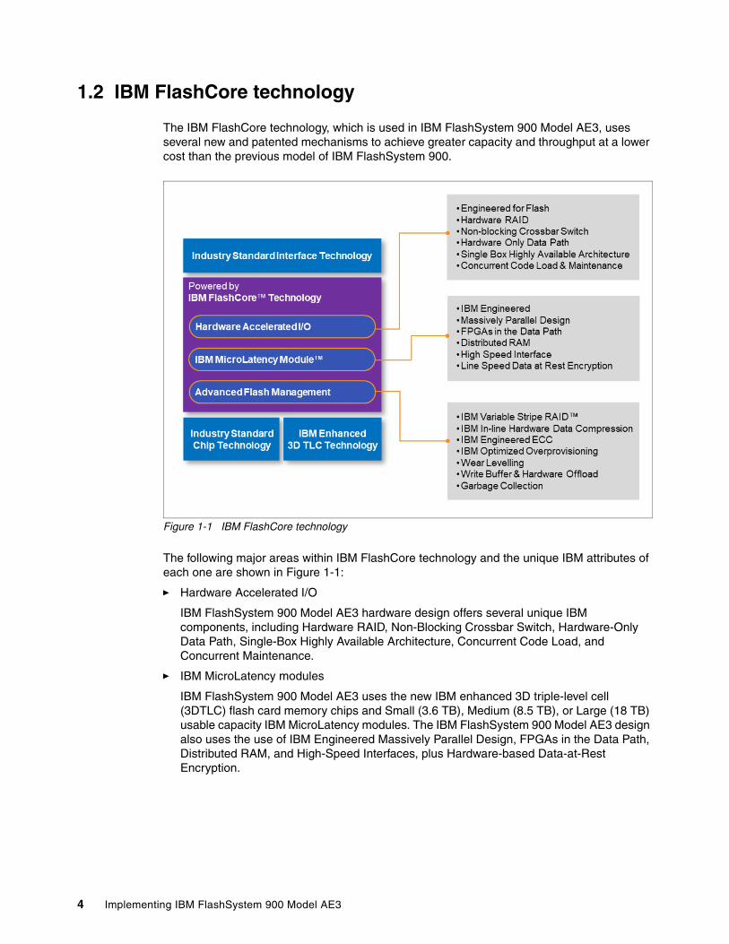
The IBM FlashCore technology, which is used in IBM FlashSystem 900 Model AE3, uses several new and patented mechanisms to achieve greater capacity and throughput at a lower cost than the previous model of IBM FlashSystem 900.
Figure 1-1 IBM FlashCore technology
The following major areas within IBM FlashCore technology and the unique IBM attributes of each one are shown in Figure 1-1:
� Hardware Accelerated I/O
IBM FlashSystem 900 Model AE3 hardware design offers several unique IBM components, including Hardware RAID, Non-Blocking Crossbar Switch, Hardware-Only Data Path, Single-Box Highly Available Architecture, Concurrent Code Load, and Concurrent Maintenance.
� IBM MicroLatency modules
IBM FlashSystem 900 Model AE3 uses the new IBM enhanced 3D triple-level cell (3DTLC) flash card memory chips and Small (3.6 TB), Medium (8.5 TB), or Large (18 TB) usable capacity IBM MicroLatency modules. The IBM FlashSystem 900 Model AE3 design also uses the use of IBM Engineered Massively Parallel Design, FPGAs in the Data Path, Distributed RAM, and High-Speed Interfaces, plus Hardware-based Data-at-Rest Encryption.
4 Implementing IBM FlashSystem 900 Model AE3

� Advanced Flash Management
IBM FlashSystem 900 Model AE3 features unique patented designs to ensure maximum availability, which includes IBM Variable Stripe RAID™, IBM Inline Hardware Data Compression, IBM Engineered ECC (error correction code), IBM Optimized Over-Provisioning, advanced wear leveling on IBM MicroLatency modules, Write Buffer and Hardware Offload, and IBM Garbage Collection. For more information, see “Terminology” on page 31.
These features are possible because of the following IBM patented and world class innovations:
� ECC algorithms that correct high bit-error rates.
� Variable voltage and read level shifting, which maximize flash endurance.
� Health binning and heat segregation, which continually monitor the health of flash blocks and perform asymmetrical wear leveling and subchip tiering.
This usage of IBM FlashCore technology results in up to 3.8x improvement in endurance with a potential 45% reduction in write amplification.
1.2.1 IBM Piece of Mind Initiative
IBM Storage developed the following new programs that are anchored to all-flash IBM storage offerings:
� Data reduction program is designed to reduce planning risks and help lower storage costs by meeting baseline levels of data compression effectiveness in IBM Spectrum Virtualize™ based offerings.
� Controller upgrade program enables customers of designated all-flash IBM storage systems to reduce costs while maintaining leading-edge controller technology for essentially the cost of ongoing system maintenance.
� A new high-availability program helps enterprises avoid the costs and risks that are related to business downtime by ensuring the availability of business-critical data and storage systems.
Separately, the Data Reduction Guarantee, Controller Upgrade Program, and High-Availability Guarantee each offer many benefits. But, when combined as part of an IBM all-flash storage solution, the power of all three to help customers lower costs, reduce business risk, and maintain the most current technologies can be even more significant; for example, Flash endurance coverage while hardware maintenance is current ensuring Flash wear never becomes a problem.
Confidence. Trust. Peace of mind. IBM understands that real solutions include more than simply great engineering.
For more information about the IBM Piece of Mind Initiative, see the technical white paper, The IBM Peace of Mind initiative.
Chapter 1. Introduction to FlashSystem 5

1.3 Why flash technology matters
Flash technology is vibrant and fast growing. Clients want to solve data center problems, optimize applications, reduce costs, and grow their businesses.
Flash is a must in every data center and an IBM FlashSystem changes the storage economics for the following reasons:
� Reduces application and server licensing costs, especially those costs that are related to databases and virtualization solutions.
� Improves application efficiency; that is, an application’s ability to process, analyze, and manipulate more information faster.
� Improves server efficiency. This improvement helps you get more out of your processors, use less RAM per server, and consolidate operations by having server resources spend more time processing data as opposed to waiting for data.
� Improves storage operations. This improvement helps eliminate costly application tuning, wasted developer cycles, storage array hot spots, array tuning, and complex troubleshooting. It also decreases floor space usage and energy consumption by improving overall storage environment performance.
� Enhances performance for critical applications by providing the lowest latency in the market.
Almost all technological components in the data center are getting faster, including central processing units, network, storage area networks (SANs), and memory. All of these components improved their speeds by a minimum of 10 times; some of them by 100 times, such as data networks. However, spinning disk increased only its performance 1.2 times.
IBM FlashSystem 900 Model AE3 provides the following benefits:
� Better user experience� Server and application consolidation� Development cycle reduction� Application scalability� Data center footprint savings� Improved price performance economics
Flash improves the performance of applications that are critical to the user experience, such as market analytics and research applications, trading and data analysis interfaces, simulation, modeling, and rendering. Server and application consolidation is possible because of the increased process utilization that results from the low latency of flash memory, which enables a server to load more users, databases, and applications.
Flash provides or returns time for further processing within the resources of such servers. Clients soon realize that server resources do not need to be acquired or expanded as often or as soon as was expected. Development cycle reduction is possible because developers spend less time designing an application to work around the inefficiencies of HDDs and less time tuning for performance.
Data center footprint savings are result of the high density and high performance per density flash solutions that are replacing racks of spinning HDDs. Reducing the data center footprint also translates into power and cooling savings, which makes flash one of the greenest technologies for the data center.
6 Implementing IBM FlashSystem 900 Model AE3
1.4 IBM FlashSystem family product differentiation
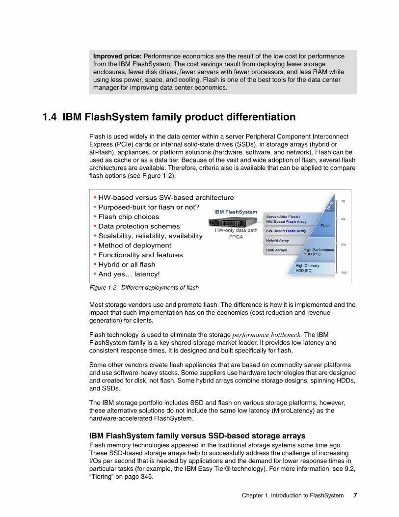
Flash is used widely in the data center within a server Peripheral Component Interconnect Express (PCIe) cards or internal solid-state drives (SSDs), in storage arrays (hybrid or all-flash), appliances, or platform solutions (hardware, software, and network). Flash can be used as cache or as a data tier. Because of the vast and wide adoption of flash, several flash architectures are available. Therefore, criteria also is available that can be applied to compare flash options (see Figure 1-2).
Figure 1-2 Different deployments of flash
Most storage vendors use and promote flash. The difference is how it is implemented and the impact that such implementation has on the economics (cost reduction and revenue generation) for clients.
Flash technology is used to eliminate the storage performance bottleneck. The IBM FlashSystem family is a key shared-storage market leader. It provides low latency and consistent response times. It is designed and built specifically for flash.
Some other vendors create flash appliances that are based on commodity server platforms and use software-heavy stacks. Some suppliers use hardware technologies that are designed and created for disk, not flash. Some hybrid arrays combine storage designs, spinning HDDs, and SSDs.
The IBM storage portfolio includes SSD and flash on various storage platforms; however, these alternative solutions do not include the same low latency (MicroLatency) as the hardware-accelerated FlashSystem.
IBM FlashSystem family versus SSD-based storage arraysFlash memory technologies appeared in the traditional storage systems some time ago. These SSD-based storage arrays help to successfully address the challenge of increasing I/Os per second that is needed by applications and the demand for lower response times in particular tasks (for example, the IBM Easy Tier® technology). For more information, see 9.2, “Tiering” on page 345.
Improved price: Performance economics are the result of the low cost for performance from the IBM FlashSystem. The cost savings result from deploying fewer storage enclosures, fewer disk drives, fewer servers with fewer processors, and less RAM while using less power, space, and cooling. Flash is one of the best tools for the data center manager for improving data center economics.
HW-only data pathFPGA
IBM FlashSystem
HW only dattta path
• HW-based versus SW-based architecture• Purposed-built for flash or not?• Flash chip choices• Data protection schemes• Scalability, reliability, availability• Method of deployment• Functionality and features• Hybrid or all flash• And yes… latency!
Chapter 1. Introduction to FlashSystem 7

However, these technologies typically rely on flash in the format of Fibre Channel (FC), serial-attached SCSI (SAS), or Serial Advanced Technology Attachment (SATA) disks. These formats are placed in the same storage system as traditional spinning disks and use the same resources and data paths. This approach can limit the advantages of flash technology because of the limitations of traditional disk storage systems.
For more information about IBM Easy Tier, see the following sources:
� Implementing the IBM System Storage SAN Volume Controller with IBM Spectrum Virtualize V8.1, SG24-7933 (see the topic about advanced features for storage efficiency).
� IBM System Storage SAN Volume Controller and Storwize V7000 Best Practices and Performance Guidelines, SG24-7521 (see the chapter about IBM System Storage® Easy Tier function).
� IBM System Storage DS8000 Easy Tier, REDP-4667.
IBM FlashSystem storage provides a hardware-only data path that realizes all of the potential of flash memory. These systems differ from traditional storage systems in technology and usage.
An SSD device with an HDD disk form factor includes flash memory that is put into a carrier or tray. This carrier is inserted into an array, such as an HDD. The speed of storage access is limited by the following technology because it adds latency and cannot keep pace with flash technology:
� Array controllers and software layers� SAS controllers and shared bus� Tiering and shared data path� Form factor enclosure
IBM FlashSystem products are fast and efficient. The hardware-only data path features a minimum number of software layers (which are mostly firmware components) and management software that is separated from the data path (out-of-band). The only other family of products with hardware-only access to flash technology is the PCI Express (PCIe) flash product family, where products are installed into a dedicated server. With the appearance of the IBM FlashSystem, the benefits of PCIe flash products to a single server can now be shared by many servers.
1.5 Technology and architectural design overview
The IBM FlashSystem 900 Model AE3, with an all-hardware data path that uses field programmable-gate array (FPGA) modules, is engineered to deliver the lowest possible latency. The modules incorporate proprietary flash controllers and use numerous patented technologies. The FlashSystem controllers feature a proprietary logic design, firmware, and system software.
8 Implementing IBM FlashSystem 900 Model AE3

No commodity 2.5-inch SSDs, PCIe cards, or any other significant non IBM assemblies within the system are available. The flash chips, FPGA chips, processors, and other semiconductors in the system are carefully selected to be consistent with the purpose-built design, which is designed for high performance, reliability, and efficiency.
The following sections describe the technology and architectural design that is available within the IBM FlashSystem 900 Model AE3.
1.5.1 Hardware-only data path
The hardware-only data path design of the IBM FlashSystem eliminates software layer latency. To achieve extremely low latencies, the IBM FlashSystem 900 Model AE3 advanced software functions are carefully assessed and implemented on a limited basis. For environments that require advanced storage services, implementing the IBM FlashSystem 900 Model AE3 with IBM SAN Volume Controller (which delivers IBM Spectrum Virtualize technology) can offer an unmatched combination of performance, low latency, and rich software functionality.
For more information about the IBM FlashSystem 900 storage with the IBM SAN Volume Controller, see Chapter 8, “Product integration” on page 307.
In the IBM FlashSystem 900 Model AE3, data traverses the array controllers through FPGAs and dedicated, low-power CPUs. Cycles are not wasted on interface translation, protocol control, or tiering.
With an all-hardware data path design, IBM FlashSystem 900 Model AE3 features an internal architecture that differs from other hybrid (SSD and HDD) or SSD-only-based disk systems.
Note: Also available is the IBM FlashSystem 900 Model UF3, which is the Storage Utility Offering model of the system. It is functionally equivalent to the IBM FlashSystem 900 Model AE3, but comes fully configured with 12 IBM MicroLatency modules in Small (3.6 TB) or Medium (8.5 TB) capacity. The Storage Utility Offering model allows customers who want to have the convenience of capacity on-demand usage without the need for a hardware upgrade to increase capacity.
IBM Spectrum Control™ Storage Insights is used to monitor the system capacity usage. It also is used to report on capacity that is used beyond the base subscription capacity, which is referred to as variable usage. The variable capacity usage is billed on a quarterly basis, which enables customers to grow or shrink their usage and pay for configured capacity only.
Notes: IBM SAN Volume Controller delivers the functions of IBM Spectrum Virtualize, which is part of the IBM Spectrum Storage™ family. It improved infrastructure flexibility and data economics for more than 10 years. Its innovative data virtualization capabilities provide the foundation for the entire IBM Storwize family. SAN Volume Controller provides the latest storage technologies for unlocking the business value of stored data, including virtualization and IBM Real-time Compression™.
In addition, the latest system includes the new SAN Volume Controller Data Engine to help support the massive volumes of data that is created by today’s demanding enterprise applications. SAN Volume Controller is designed to deliver unprecedented levels of efficiency, ease of use, and dependability for organizations of all sizes.
Chapter 1. Introduction to FlashSystem 9

1.5.2 3DTLC flash memory chips
The flash chip is the basic storage component of the IBM MicroLatency module. A maximum of 56, 3D triple-level cell (3DTLC) flash chips can exist for each flash module. Combining flash chips of different flash technologies is not supported in the same flash module or storage system to maintain consistent wearing and reliability.
The IBM FlashSystem 900 Model AE3 employs the new 3DTLC chips, which are of a higher density than the MLC chips that are used in the IBM FlashSystem 900 Model AE2. This new design of chips, plus inline hardware data compression, allows the IBM FlashSystem 900 Model AE3 to package greater densities of flash memory per card while retaining the same (if not better) performance and wear.
IBM patented ECC correction and checking algorithms ensure the same or greater performance from the 3DTLC based chips, with a greater capacity for the same footprint and at a lower cost per TB.
1.5.3 Flash module capacities
IBM FlashSystem 900 Model AE3 uses 3.6 TB, 8.5 TB, or 18 TB installed IBM MicroLatency modules. This capacity is a 3 x increase in capacity per module over the IBM FlashSystem 900 Model AE2. The modules must be of the same capacity throughout the machine and cannot be intermixed with the older flash modules.
With the addition of the new inline hardware data compression function, the following types of capacity terminology are used:
� Usable capacity: Denoted by a letter “u” after the capacity size; for example, 3.6 TBu� Effective capacity: Denoted by a letter “e” after the capacity size; for example, 21.9 TBe
Only RAID 5 is supported on the IBM FlashSystem 900 Model AE3 with configurations of 6, 8, 10, and 12 modules when the 3.6 TB IBM MicroLatency modules are used, and 8, 10, and 12 modules when the 8.5 TB or 18 TB IBM MicroLatency modules are used.
IBM MicroLatency modules capacity, which is used in the IBM FlashSystem 900 Model AE3, is not shown on the labels. These types of modules use coding for the module type and size; for example, in Figure 1-3 on page 11, the coding on the module is shown as T S03 B.
The following module size coding is used:
� T: 3DTLC flash technology� S: Small, Medium, or Large capacity IBM MicroLatency module � 03: 3Tb NAND chips that are used on the flash module cards � B: Manufacturing use denoting the revision of the IBM MicroLatency module
Therefore, based on this coding, our example module a 3DTLC 3.6 TB flash module.
Note: All sizes of IBM MicroLatency modules feature inline hardware compression that is built in.
Note: The alphanumeric numbering that is underneath the coding value is the part number of the module. IBM support uses this number to order a replacement module if required as part of a service call.
10 Implementing IBM FlashSystem 900 Model AE3

Figure 1-3 Six IBM MicroLatency modules and three flash module filler cards installed in the machine
Figure 1-3 also shows the six IBM MicroLatency modules to the right and three flash module filler cards to the left installed in the system. Each IBM MicroLatency module includes a visible gray coding label that features with black lettering.
1.5.4 Gateway interface FPGA
The gateway interface FPGA provides I/O to the flash module and direct memory access (DMA) path. It is on the flash module and includes two connections to the backplane.
1.5.5 Flash controller FPGA
The flash controller FGPA of the flash module is used to provide access to the flash chips and is responsible for the following functions:
� Provides data path and hardware I/O logic � Uses lookup tables and a write buffer� Controls 12, 14, or 28 3DTLC chips (flash card size dependent) � Operates independently of other controllers� Maintains write ordering and layout� Provides write setup� Maintains garbage collection� Provides error handling� Provides hardware data compression / decompression functionality
Note: IBM MicroLatency modules are placed for the center card slot outwards of the center section and have the same number of free slots on the left and on the right sides.
If fewer than 12 modules are installed, flash module fillers must be installed in the empty bays to maintain cooling airflow in the system enclosure. Figure 1-3 shows the flash module fillers to the left side of the installed flash modules.
Chapter 1. Introduction to FlashSystem 11

An overview of the FPGA design is shown in Figure 1-4.
Figure 1-4 FPGA design
For more information about the FPGA data flow, see Section 2.2, “Architecture of IBM FlashSystem 900 Model AE3” on page 38.
1.5.6 IBM Variable Stripe RAID and 2D Flash RAID overview
Storage systems of any kind are typically designed to perform two main functions: Store and protect data. IBM FlashSystem 900 Model AE3 includes the following options for data protection:
� RAID data protection:
– IBM Variable Stripe RAID– Two-dimensional (2D) Flash RAID
� Flash memory protection methods
� Optimized RAID rebuild times
The various methods of protection are listed in Table 1-1.
Table 1-1 Various types of IBM FlashSystem protection
Layer Managed by Protection
System-level RAID 5 Centralized RAID controllers Module failure
Module-level RAID 5 Each module across the chips Chip failure and page failure
Module-level Variable Stripe RAID
Each module across the chips Subchip, chip, or multi-chip failure
Chip-level error correction code (ECC)
Each module that uses the chips
Bit and block error
12 Implementing IBM FlashSystem 900 Model AE3

Variable Stripe RAIDVariable Stripe RAID (VSR) is a unique IBM technology that provides data protection of the memory page, block, or whole chip, which eliminates the need to replace an entire flash module in a single memory chip failure or plane failures. VSR, in turn, expands the life and endurance of flash modules and reduces considerably maintenance events throughout the life of the system.
Variable Stripe RAID includes the following capabilities:
� Patented Variable Stripe RAID allows RAID stripe sizes to vary.
� If one plane fails in a chip stripe, only the failed plane is bypassed. Then, data is restriped across the remaining chips. No system rebuild is needed.
� Variable Stripe RAID reduces maintenance intervals that are caused by flash failures.
Two-dimensional (2D) Flash RAIDTwo-dimensional (2D) Flash RAID refers to the combination of Variable Stripe RAID (at the flash module level) and system-level RAID 5.
The second dimension of data protection is implemented across flash modules of RAID 5 protection. This system-level RAID 5 is striped across the required number of flash modules in the system based on the selected configuration. System-level RAID 5 can stripe across any of the following flash modules:
� Six (4D+1P+1S: note IBM MicroLatency 3.6 TB module configurations only)� Eight (6D+1P+1S)� Ten (8D+1P+1S) � Twelve (10D+1P+1S).
The architecture allows you to designate a dynamic flash module hot spare. The IBM FlashSystem 2D RAID and the Variable Stripe RAID technology are shown in Figure 1-5.
Figure 1-5 IBM FlashSystem 2D RAID and Variable Stripe RAID technology
Note: The proprietary 2D Flash RAID data protection scheme of the IBM FlashSystem 900 Model AE3 storage system combines system-level RAID 5 and module-level Variable Stripe RAID (not only module-level RAID).
RAID 5 across Flash Modules (10 data + 1 parity + 1 hot spare)
ExternalInterfaces
(FC, IB)
RAIDControllers
VSR within Flash Modules
(n data + 1 parity)2D Flash RAID
Interface A Interface B
RAID Controller A RAID Controller B
Chapter 1. Introduction to FlashSystem 13
The 2D Flash RAID technology within the IBM FlashSystem Model AE3 provides two independent layers of RAID 5 data protection within each system: The module-level Variable Stripe RAID technology and another system-level RAID 5 across flash modules. When operating in system-level RAID 5 mode, redundant centralized RAID controllers create a stripe arrangement across the 4, 6, 8, 10, or 12 flash modules in the system.
1.5.7 Inline hardware data compression
IBM FlashSystem 900 Model AE3 features built-in hardware data compression as standard and this data reduction is “always on”. The user cannot disable this compression.
IBM FlashSystem 900 Model AE3 data compression/decompression algorithm is implemented completely in hardware, no processor is used in the data path.
Data protection (ECC) is implemented on top of compressed data. This configuration allows for garbage collection and other background data transactions to operate on compressed data.
Compression and decompression are transparent above the Flash module, except for space management. Performance is not affected and scales linearly with the number of instances.
For more information about the compression process that is used, see 2.1.3, “In-line Hardware Data Compression”.
IBM Compresstimator toolThe IBM FlashSystem 900 Model AE3 is supported in the IBM Compresstimator tool.
This tool is a host-based application that allows the user to estimate the mount of compression that is available on the IBM FlashSystem 900 Model AE3 for specific workloads and volume types.
The IBM Compresstimator works the same as for previous supported products. For the IBM FlashSystem 900 Model AE3, the following enhancements were made:
� New “Storage system type” -s FLASHSYSTEM
� New options for storage system type - FLASHSYSTEM
� Set the number of flash modules in the simulated system --flash-modules N
� Set the size of the flash modules in the simulated system --flash-module-size [SMALL|MEDIUM|LARGE]
For more information about the tool and how to install and run it on the client’s host systems, see the Comprestimator Utility Version 1.5.3.1 page of the IBM Support website.
1.5.8 Encryption
IBM FlashSystem 900 Model AE3 storage system supports AES-XTS 256-bit data-at-rest encryption when the Encryption Enablement Pack, feature AF14, is ordered.
IBM FlashSystem 900 Model AE3 storage system also provides for SKLM encryption support and up to four SKLM key servers can be defined.
Both versions of encryption on the IBM FlashSystem 900 Model AE3 support the following functions:
� Hot Encryption Activation: Adding an encryption license to a previously initialized system
14 Implementing IBM FlashSystem 900 Model AE3

� Encryption Rekey: Changing the encryption key on a previously initialized system
These operations can be done concurrently and do not cause a loss of data access. These operations also require that you purchase the Feature Code AF14: Encryption Enablement Pack.
For more information, see the IBM FlashSystem 900 Model AE3 page of IBM Knowledge Center.
IBM Security Key Lifecycle Manager encryptionFormerly known as IBM Tivoli® Key Lifecycle Manager), IBM Security Key Lifecycle Manager (SKLM) centralizes, simplifies, and automates the encryption key management process to help minimize risk and reduce operational costs of encryption key management. It offers secure and robust key storage, key serving, and key lifecycle management for IBM and non-IBM storage solutions that use the OASIS Key Management Interoperability Protocol (KMIP).
You can enable encryption by using USB flash drives to copy the encryption key to the system or by configuring an SKLM encryption key server for the system.
You can also have a simultaneous configuration of SKLM key servers and USB flash drives to ensure redundancy of access to encrypted data if either method becomes unavailable or if the keys are permanently lost for one of the methods.
If USB and SKLM are consecutively disabled to a non-encrypted array, data must be reloaded to the non-encrypted array. This operation is disruptive.
Note: To protect against permanent key loss for one of the methods, a simultaneous configuration must be planned. Another key method cannot be enabled when the keys for a method are lost.
Chapter 1. Introduction to FlashSystem 15

1.6 Usability plus reliability, availability, and serviceability enhancements
In this section, we describe the reliability, availability, and serviceability (RAS) enhancements and new usability functions that are available with the IBM FlashSystem 900 Model AE3.
1.6.1 Automatic battery reconditioning
IBM FlashSystem 900 Model AE3 allows the user to select manual or automatic battery reconditioning. This enhancement enables the user to select the battery reconditioning to be run automatically, when needed.
The default is OFF and no change occurs during a code upgrade. All new systems IBM FlashSystem 900 Model AE3 arrays are set to OFF during manufacture. The user must set this option on, if required, after the machine is installed. See 2.2.6, “Battery modules” for more details.
1.6.2 Remote Support Assistance
IBM FlashSystem 900 Model AE3 supports Remote Support Assistance (RSA) allows IBM authorized service personnel remote access to the machine, subject to customer approval. RSA can be used for numerous support scenarios that do not require handling or replacing hardware. It also eliminates the need for dispatching an IBM service engineer (SSR) onsite for manual operations or for guiding customers to conduct special actions on the machine.
Usage scenarios include the following examples:
� IBM Level 1 support center remote collection of SNAP logs
� IBM Level 2 support center personnel logging in and uploading / downloading files to analyze and resolve issues
� IBM FlashSystems developers accessing the machine for data recovery
RSA access is customer-configurable with the following settings:
� At Any Time, the IBM support center can start remote support sessions any time
� On System Error, the support center can start a remote support session when the system experiences a critical failure.
� On Permission Only, the support center can start a remote support session only if the system administrator has granted permission.
Access control is restricted through IBM and customer controls to ensure that no authorized access to the machine occurs. Remote sessions and activity are recorded in IBM Flashsystems Service Center and IBM FlashSystem 900 Model AE3 audit log.
RSA remote operations are performed by using a CLI connection to the machine.
1.6.3 Enhanced Thermal Management
Thermal design was improved to better handle thermal changes in the system. Heat sinks were added to the flash modules to help with cooling and lowering operational fan ranges. A 25 C nominal operating environment is supported in which fans run at a slower base speed.
16 Implementing IBM FlashSystem 900 Model AE3

Fans continue to run when a canister is powered down. A canister can be in a standby state, and the fans in that canister continue to operate. Fans also are forced to 100% during canister repair tasks. The amount of time the canister can be removed during service events was also increased (20 - 30 minutes achievable at 25 C for a full configuration).
1.6.4 A/C Power Line Monitoring
IBM FlashSystem 900 Model AE3 now support the ability to report the AC Line cord power from each of the power supply units (PSUs). This feature is available as part of the lsenclosurepsu CLI command.
The output of the lsenclosurepsu CLI command is shown in Example 1-1.
Example 1-1 Output of the lsenclosurepsu CLI command
# lsenclosurepsuenclosure_id PSU_id status input_power capable_power output_power current_power 1 1 online ac 1300W 1300W 201W 1 2 online ac 1300W 1300W 173W
This data is dynamically updated as the system power changes over time. It is reported directly from the PSUs, not calculated.
1.6.5 Enhanced Call Home Data
The call home “heartbeats” were enhanced to supply more data on the daily heartbeat and the weekly “full” heartbeat. These heartbeats provide vital information about the current health of the IBM FlashSystem 900 Model AE3 system.
The data that is sent to IBM is then analyzed by the IBM Service Center systems and, if any trends or temporary issues that need further analysis are found, the IBM Service Center systems raises a Problem Management Record (PMR) with IBM support.
The following extra items are sent:
� Regular Heartbeat (daily):
– Fibre Channel or InfiniBand port statistics– Flashcard health and status– Canister health and status
� Full Heartbeat (weekly):
– Last 500 lines of the messages that are related to the configuration node
– Configuration data from both canisters.
– Configuration data from the config node.
– Status and configuration data of the SAN fabric, or InfiniBand network, to which the IBM FlashSystem 900 Model AE3 is connected.
1.6.6 GUI enhancements
IBM FlashSystem 900 Model AE3 features a new graphical user interface (GUI). This GUI provides a new Dashboard view of the system and the more traditional Systems View, as seen on the previous models of IBM FlashSystem 900. The following extra features are included:
Chapter 1. Introduction to FlashSystem 17
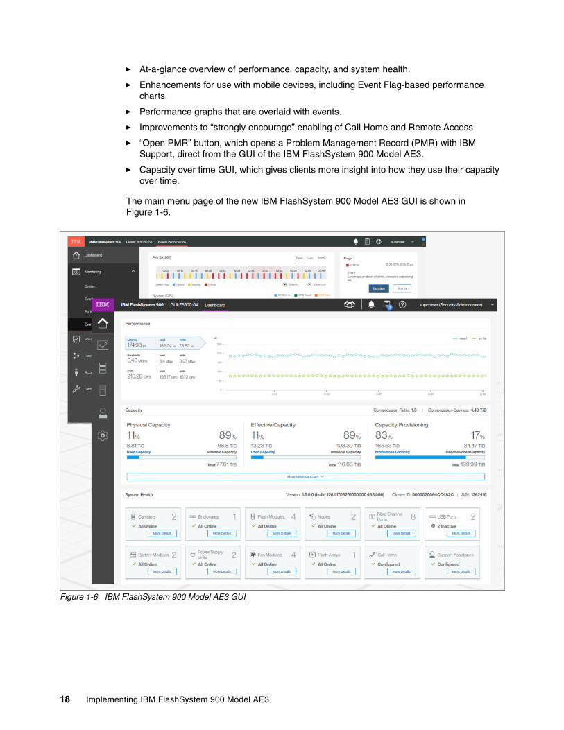
� At-a-glance overview of performance, capacity, and system health.
� Enhancements for use with mobile devices, including Event Flag-based performance charts.
� Performance graphs that are overlaid with events.
� Improvements to “strongly encourage” enabling of Call Home and Remote Access
� “Open PMR” button, which opens a Problem Management Record (PMR) with IBM Support, direct from the GUI of the IBM FlashSystem 900 Model AE3.
� Capacity over time GUI, which gives clients more insight into how they use their capacity over time.
The main menu page of the new IBM FlashSystem 900 Model AE3 GUI is shown in Figure 1-6.
Figure 1-6 IBM FlashSystem 900 Model AE3 GUI
18 Implementing IBM FlashSystem 900 Model AE3

Chapter 2. IBM FlashSystem 900 Model AE3 architecture
In this chapter, we describe the IBM FlashSystem 900 Model AE3 architecture. This chapter also includes an introduction to product features, a comparison to its predecessor (the IBM FlashSystem 900 Model AE2), and an overview of the architecture and hardware. Also included is an overview of the administration and serviceability of the IBM FlashSystem 900 Model AE3, interoperability, and integration with other IBM products.
For more information about IBM FlashSystem architecture, see the IBM FlashSystem 900 Model AE3 page of IBM Knowledge Center.
This chapter includes the following topics:
� 2.1, “IBM FlashSystem 900 Model AE3 architecture overview” on page 20� 2.2, “Architecture of IBM FlashSystem 900 Model AE3” on page 38� 2.3, “Administration and maintenance” on page 48� 2.4, “Support matrix” on page 55� 2.5, “Product integration overview” on page 55
2
© Copyright IBM Corp. 2018. All rights reserved. 19
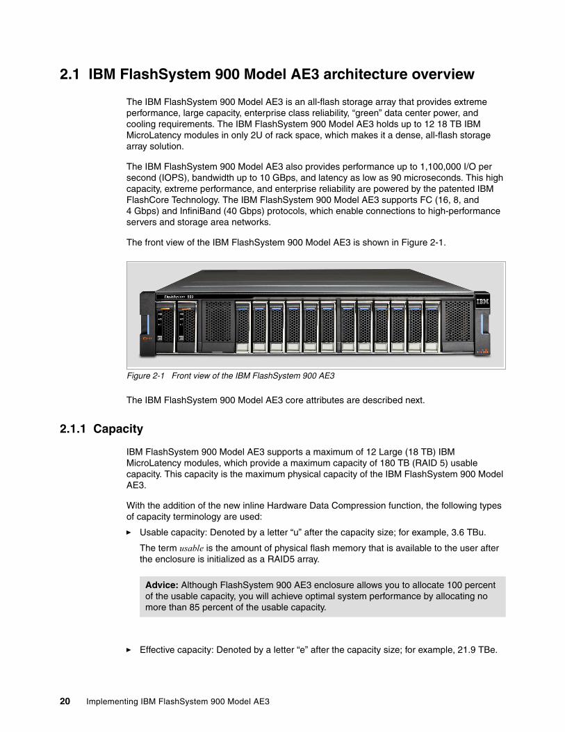
2.1 IBM FlashSystem 900 Model AE3 architecture overview
The IBM FlashSystem 900 Model AE3 is an all-flash storage array that provides extreme performance, large capacity, enterprise class reliability, “green” data center power, and cooling requirements. The IBM FlashSystem 900 Model AE3 holds up to 12 18 TB IBM MicroLatency modules in only 2U of rack space, which makes it a dense, all-flash storage array solution.
The IBM FlashSystem 900 Model AE3 also provides performance up to 1,100,000 I/O per second (IOPS), bandwidth up to 10 GBps, and latency as low as 90 microseconds. This high capacity, extreme performance, and enterprise reliability are powered by the patented IBM FlashCore Technology. The IBM FlashSystem 900 Model AE3 supports FC (16, 8, and 4 Gbps) and InfiniBand (40 Gbps) protocols, which enable connections to high-performance servers and storage area networks.
The front view of the IBM FlashSystem 900 Model AE3 is shown in Figure 2-1.
Figure 2-1 Front view of the IBM FlashSystem 900 AE3
The IBM FlashSystem 900 Model AE3 core attributes are described next.
2.1.1 Capacity
IBM FlashSystem 900 Model AE3 supports a maximum of 12 Large (18 TB) IBM MicroLatency modules, which provide a maximum capacity of 180 TB (RAID 5) usable capacity. This capacity is the maximum physical capacity of the IBM FlashSystem 900 Model AE3.
With the addition of the new inline Hardware Data Compression function, the following types of capacity terminology are used:
� Usable capacity: Denoted by a letter “u” after the capacity size; for example, 3.6 TBu.
The term usable is the amount of physical flash memory that is available to the user after the enclosure is initialized as a RAID5 array.
� Effective capacity: Denoted by a letter “e” after the capacity size; for example, 21.9 TBe.
Advice: Although FlashSystem 900 AE3 enclosure allows you to allocate 100 percent of the usable capacity, you will achieve optimal system performance by allocating no more than 85 percent of the usable capacity.
20 Implementing IBM FlashSystem 900 Model AE3

The term effective is the amount of addressable flash memory that is available that can be provisioned to the hosts. The amount of available effective capacity is depending on the compression rate. This is explained in detail in section 2.1.4, “Physical and effective capacity based on compression rates”.
� Maximum effective capacity: The term maximum effective is the maximum addressable flash memory that can be provisioned to the hosts.
The IBM FlashSystem 900 Model AE3 can be ordered with configurations of 6, 8, 10, and 12 modules when the Small (3.6 TB) IBM MicroLatency modules are used. Configurations of 8, 10, and 12 are available when the Medium (8.5 TB) or Large (18 TB) IBM MicroLatency modules are used.
IBM FlashSystem 900 Model AE3 supports RAID 5 configurations. It also supports the creation of up to 2,048 logical unit numbers (LUNs). The size of the LUNs can be 1 MiB - 163.7 TiB (not to exceed the total system usable capacity).
The IBM FlashSystem 900 Model AE3 supports up to 2,048 host connections and up to 256 host connections for each interface port. IBM FlashSystem 900 Model AE3 allows the mapping of multiple LUNs to each host for Fibre Channel, or InfiniBand protocols.
The IBM FlashSystem 900 Model AE3 usable and maximum effective capacity in TB for RAID 5 are shown in Figure 2-2.
Figure 2-2 IBM FlashSystem 900 Model AE3 capacity in TB for RAID 5
The following capacity models are available:
� Medium 8.5 TB modules:
– Similar to 3.6 TB modules, except the maximum effective is 21.9 TBe per module:
• For 8 modules, you cannot assign volumes greater than 131.94TBe• For 12 modules, you cannot assign volumes greater than 219.9TBe
– Using a fully populated system, up to 85.5 TB of usable storage is available.
– You cannot store more than 85.5 TB of storage (after compression):
Important: The 3.6 TB, 8.5 TB, and 18 TB IBM MicroLatency modules cannot be intermixed in the same IBM FlashSystem 900 Model AE3 chassis.
Note: The maximum effective capacity of the Medium 8.5 TB and Large 18 TB modules is the same value; however, the usable capacities differ greatly. This capacity allows the medium cards to be used where the compression ratio is good and the large modules to be used where the customer is likely to have a high number of non-compressable or low compress ratio volumes. Therefore, it uses more usable capacity versus maximum effective capacity.
Chapter 2. IBM FlashSystem 900 Model AE3 architecture 21
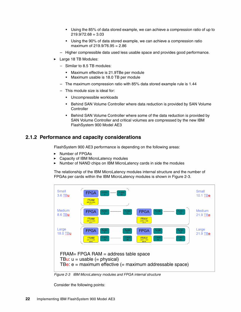
• Using the 85% of data stored example, we can achieve a compression ratio of up to 219.9/72.68 = 3.03
• Using the 90% of data stored example, we can achieve a compression ratio maximum of 219.9/76.95 = 2.86
– Higher compressible data used less usable space and provides good performance.
� Large 18 TB Modules:
– Similar to 8.5 TB modules:
• Maximum effective is 21.9TBe per module• Maximum usable is 18.0 TB per module
– The maximum compression ratio with 85% data stored example rule is 1.44
– This module size is ideal for:
• Uncompressible workloads
• Behind SAN Volume Controller where data reduction is provided by SAN Volume Controller
• Behind SAN Volume Controller where some of the data reduction is provided by SAN Volume Controller and critical volumes are compressed by the new IBM FlashSystem 900 Model AE3
2.1.2 Performance and capacity considerations
FlashSystem 900 AE3 performance is depending on the following areas:
� Number of FPGAs � Capacity of IBM MicroLatency modules � Number of NAND chips on IBM MicroLatency cards in side the modules
The relationship of the IBM MicroLatency modules internal structure and the number of FPGAs per cards within the IBM MicroLatency modules is shown in Figure 2-3.
Figure 2-3 IBM MicroLatency modules and FPGA internal structure
Consider the following points:
FRAM= FPGA RAM = address table space
TBe: e = maximum effective (= maximum addressable space)TBu: u = usable (= physical)
22 Implementing IBM FlashSystem 900 Model AE3

� The Small (3.6 TB) module includes one FPGA chip, which serves 12 NAND flash chips. � The Medium (8.5 TB) module features two FPGAs, which serve 28 NAND flash chips. � The Large (18 TB) module includes two FPGAs and serves 56 NAND flash chips.
Figure 2-3 also shows that the Medium and Large IBM MicroLatency modules features two FPGAs that are connected to the XBARs to service data requests.
An estimation of the performance of FlashSystem 900-AE3 (depending on the MicroLatency module capacity and the number of modules that are installed in a system) is listed in Table 2-1 on page 23.
Table 2-1 Number of FPGA for performance considerations
Because FPGAs service the data throughput and depending on workload patterns, the Medium module minimum configurations might give better performance than the Small modules maximum configurations. This improvement is the result of the number of FPGAs per IBM MicroLatency module to service this data transfer.
2.1.3 In-line Hardware Data Compression
IBM FlashSystem 900 Model AE3 features built-in hardware data compression as standard and this data reduction is “always on”. The user cannot disable this feature. All sizes of IBM MicroLatency modules include built-in compression.
The inline hardware compression includes the following characteristics:
� Implemented completely in hardware; no processor intervention:
– Combines LZ1 with a form of Pseudo Dynamic Huffman
– Modified “gzip” compression algorithm
– Technology originated with IBM zSeries Servers was adopted to fit into a flash controller
� Capable of compressing effectively (up to approximately 128:1)
� Stated maximum effective capacity that is limited by the amount of Logical-to-Physical (LPT) DRAM
� Engine bypasses compression if data is not compressible
� No data expansion, which can occur when attempting to compress uncompressible data
� Compression inline before DDR write-buffer data is stored compressed in write buffer
� Data is compressed “below” the System-Level RAID
� Arrays are created that use the maximum effective capacity
� IBM FlashSystem 900 Model AE3 does not include thin provisioning
� IBM FlashSystem 900 Model AE1 and AE2 do not include compression; therefore, effective capacity equals usable capacity
Configuration Small modules Medium and large modules
6 MicroLatency modules 4 FPGA for performance N/A
8 MicroLatency modules 6 FPGA for performance 12 FPGA for performance
10 MicroLatency modules 8 FPGA for performance 14 FPGA for performance
12 MicroLatency modules 10 FPGA for performance 16 FPGA for performance
Chapter 2. IBM FlashSystem 900 Model AE3 architecture 23

The IBM FlashSystem 900 Model AE3 data compression and decompression algorithm is implemented in hardware; no processor intervention is needed.
Compression and decompression are performed on individual logical pages. It is performed as the first step in the inbound data path before any logical-to-physical mapping occurs. Therefore, less data must be transferred in the back-end, which makes up for small added latency.
The data path for the compression and the compress and decompress during the operation and a double check of the integrity of the data that is stored is shown in Figure 2-4.
Figure 2-4 Data path for the compression function in IBM FlashSystem 900 Model AE3
Decompression is performed as the last step in the outbound data path immediately before returning the requested data (no store and forward operation is needed). Real-time decompressing of compressed data is checked against the original data before committing compressed write. This process allows garbage collection and other background data transactions to operate on compressed data.
Compression and decompression are not apparent above the Flash module, except for optimal management of space. Performance is not affected and it scales linearly with several instances.
2.1.4 Physical and effective capacity based on compression rates
This section describes how the data compression rate affects the physical and effective capacity of FlashSystem 900. The results of different data compression rates is shown by using a FlashSystem 900 with six small modules that feature a physical size of 13.1 TiB and a maximum effective capacity of 40 TiB.
A current compression rate of 9.43 to 1 is shown in Figure 2-5.
Note: The Microlatency modules with small, medium, and large capacity use the same compression algorithm.
24 Implementing IBM FlashSystem 900 Model AE3

Figure 2-5 High compression rate
The following capacity information is shown in Figure 2-5 on page 25:
� Physical Capacity
The physical capacity of the system is 13.1 TiB, which is known as usable capacity. This capacity is shown as Total on the left site of Figure 2-5 on page 25. Currently, 1.44 TiB of the physical capacity is used and shown as Used Capacity. The Available Capacity shows the free physical capacity of 11.66 TiB. This capacity is shown as Used Capacity of the physical capacity.
� Effective Capacity
The current usage of the effective capacity is shown in the middle section of Figure 2-5 on page 25. The hosts wrote 13.55 TiB of data. Based on the current compression ratio of 9.43:1, the total effective capacity is 40 TiB and shown as Total. Hosts can write 26.45 TiB until the effective capacity is fully used, which is shown as Available Capacity.
� Capacity Provisioning
The amount of capacity that can be provisioned to hosts is shown in the right side of Figure 2-5 on page 25. The maximum is 40 TiB and is shown as Total. This capacity is also known as the maximum effective capacity of FlashSystem 900, as described in 2.1.1, “Capacity” on page 20. Currently, 16.25 TiB are provisioned to the hosts and shown as Provisioned Capacity. Another 23.75 TiB can be provisioned to host and is shown as Unprovisioned Capacity.
In this example, the compression ratio can drop to a lower value (for example, 3.6:1) and the system stills features physical capacity to store the data.
An example with a compression rate of 2.48:1 is shown in Figure 2-6.
Figure 2-6 Low Compression rate
Based on the current compression ratio of 2.48:1, the total effective capacity is 32.52 TiB and is shown as Total in the middle section of Figure 2-6. With this compression rate, hosts can at most write 32.52 TiB to the system.
Note: In this example, 40 TiB effective capacity can be used, which uses 4.24 TiB of the physical capacity.
Chapter 2. IBM FlashSystem 900 Model AE3 architecture 25

A current compression rate of 3.6:1 is shown in Figure 2-7.
Figure 2-7 Compression rate with best usage of physical and effective capacity
Based on the current compression ratio of 3.6:1, hosts can use the total effective capacity of 40 TiB, which is shown as Total in the middle part of Figure 2-7. With this compression rate, hosts use 11.1 TiB of the physical capacity, which is 85% of the available physical capacity.
Large capacity cards example An example of the Large (18 TB) Microlatency modules that uses a compression rate of 2.33:1 on a fully populated system is shown in Figure 2-8.
Figure 2-8 Large capacity MicroLatency module compression rate example
The system that is shown in Figure 2-8 features an effective capacity of 200 TiB and a physical capacity of 163.64 TiB. Based on the current compression ratio of 2.33:1, the total effective capacity of 200 TiB can be written by hosts that use 85.8 TiB of the available 163.64 TiB of physical capacity.
In this example, the compression ratio can drop to a lower value (for example, 1.4:1) and the system still has the physical capacity to store the data. The large capacity cards are built for data with a low compression rate.
Note: In this example, the physical capacity of 13.1 is fully used if the hosts write 32.52 TiB of data.
Note: In this optimized example, the physical capacity of 11.1 is used if the hosts write 40 TiB of data.
26 Implementing IBM FlashSystem 900 Model AE3

2.1.5 Out Of Physical Space
The IBM FlashSystem 900 Model AE3 creates arrays by using maximum effective capacity, which is deployed on the management GUI.
However, in cases when the customer’s data does not compress or has a low compression ratio, the usable limit of the storage can be reached quickly. This circumstance is known as Out Of Physical Space (OOPS).
The usable and maximum effective individual capacity of the IBM MicroLatency modules is shown in Figure 2-9.
Figure 2-9 Usable and Maximum Effective Individual Capacity of the IBM Microlatency modules
How the OOPS condition occurs and the safeguards that are in place to alleviate any OOPS condition are described in the following example:
� An array is created that uses 12 Small Capacity data cards (10 data, 1 parity, 1 spare). The array size is 109.9 TB (10 data cards X 10.99 TB).
� The use of the CLI lsarray command shows an array of size 109.9 TB.
� The array can hold only 36 TB of post-compression data.
� Running out of physical capacity - Scenario 1:
– Customer data uncompressible (1:1 compression ratio)– Array will run out of physical capacity after writing 36 TB
� Running out of effective capacity - Scenario 2:
– Customer data averages 4:1 compression ratio– Array will run out of effective capacity after writing 109.9 TB– Only 27.5 TB of physical capacity used
� The customer cannot use the unused physical capacity.
To ensure that the system does not encounter an OOPS scenario, various levels of alert were implemented so that the customer is warned well before the system enters read only mode.
An internal reserved space also is included so that IBM Support can (in some circumstances) help in solving OOOP’s problems; for example, if the attached hosts have few outstanding write IO’s. If a SAN Volume Controller is attached to FlashSystem 900 AE3 its internal space might not be sufficient for all outstanding IO’s. See 8.1.5, “Reserving space to solve an out of space condition” on page 319 for details on SAN Volume Controller and FlashSystem 900 AE3.
Note: The maximum effective capacity of the array cannot be increased. This restriction is a hardware restriction that is part of the design architecture of the systems.
Chapter 2. IBM FlashSystem 900 Model AE3 architecture 27
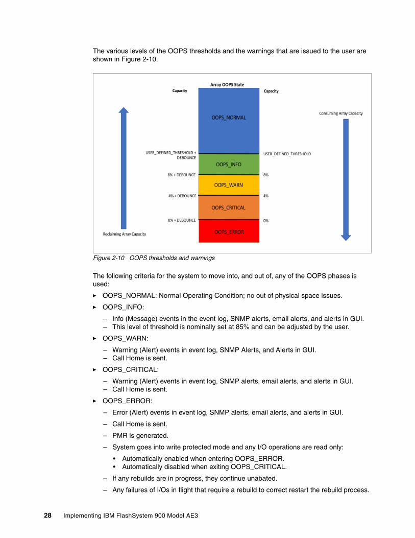
The various levels of the OOPS thresholds and the warnings that are issued to the user are shown in Figure 2-10.
Figure 2-10 OOPS thresholds and warnings
The following criteria for the system to move into, and out of, any of the OOPS phases is used:
� OOPS_NORMAL: Normal Operating Condition; no out of physical space issues.
� OOPS_INFO:
– Info (Message) events in the event log, SNMP alerts, email alerts, and alerts in GUI.– This level of threshold is nominally set at 85% and can be adjusted by the user.
� OOPS_WARN:
– Warning (Alert) events in event log, SNMP Alerts, and Alerts in GUI.– Call Home is sent.
� OOPS_CRITICAL:
– Warning (Alert) events in event log, SNMP alerts, email alerts, and alerts in GUI.– Call Home is sent.
� OOPS_ERROR:
– Error (Alert) events in event log, SNMP alerts, email alerts, and alerts in GUI.
– Call Home is sent.
– PMR is generated.
– System goes into write protected mode and any I/O operations are read only:
• Automatically enabled when entering OOPS_ERROR.• Automatically disabled when exiting OOPS_CRITICAL.
– If any rebuilds are in progress, they continue unabated.
– Any failures of I/Os in flight that require a rebuild to correct restart the rebuild process.
28 Implementing IBM FlashSystem 900 Model AE3

The amount of usable and effective space that can be viewed on the GUI Dashboard page is shown in Figure 2-11.
Figure 2-11 GUI Dashboard showing usable and effective usage and available space
IBM Compresstimator ToolThe IBM FlashSystem 900 Model AE3 is supported in the IBM Compresstimator tool. This tool is a host-based application with which the user can estimate the mount of compression on the IBM FlashSystem 900 Model AE3 for specific workloads.
The IBM Compresstimator works the same as for previously supported products. For the IBM FlashSystem 900 Model AE3, the following additions were made:
� New “Storage system type” -s FLASHSYSTEM
� New options for storage system type - FLASHSYSTEM
� Set the number of flash modules in the simulated system --flash-modules N
� Set the size of the flash modules in the simulated system --flash-module-size [SMALL|MEDIUM|LARGE]
2.1.6 Performance and latency
The IBM FlashSystem 900 Model AE3 uses all hardware field-programmable gateway array (FPGA) components in the data path, which enables fast I/O rates and low latency. The IBM FlashSystem 900 Model AE3 provides extreme performance of up to 1,100,000 IOPS and bandwidth up to 10 GBps. The IBM FlashSystem 900 Model AE3 provides write latency as low as 95 μs and read latency as low as 155 μs.
Chapter 2. IBM FlashSystem 900 Model AE3 architecture 29

2.1.7 Power requirements
The IBM FlashSystem 900 Model AE3 is green data center friendly. The IBM FlashSystem 900 Model AE3 uses only 625 W of power (steady state RAID 5 configuration for a 70/30 read/write workload on an eight-module 3.6 TB flashcard system) and two standard single-phase (100 V - 240 V) electrical outlets.
Consider the following points:
� Plan to attach each of the two power supplies in the enclosure to separate main power supply lines.
� The 1300 W power supply for high-line voltage provides IBM FlashSystem 900 Model AE3 with high power to run at maximum performance for longer durations during power supply servicing, which results in more predictable performance under unexpected failure conditions. Optimal operation is achieved when it is operating 200 V - 240 V (Nominal). The following maximum and minimum voltage ranges (Vrms) and associated high line AC ranges were observed:
– Minimum: 180 V– Nominal: 200 V - 240 V– Maximum: 265 V
The use of two power sources provides power redundancy. Place the two power supplies on separate circuits
2.1.8 Physical specifications
The IBM FlashSystem 900 Model AE3 installs in a standard 19-inch equipment rack and is 2U high and 19 inches wide. A standard data 42U 19-inch data center rack can be fully populated with 21 IBM FlashSystem 900 Model AE3 storage systems.
The IBM FlashSystem 900 Model AE3 features the following physical dimensions:
� Height: 8.62 mm (3.39 inches)� Width: 445 mm (17.5 in; 19-inch Rack Standard)� Depth: 768.12 mm (30.24 inches)� Weight (maximum configuration for 12 flash modules): 34 kg (75 lb)� Airflow path: Cool air flows into the front of the unit (intake) to the rear of the unit (exhaust)� Heat: 2133 BTU per hour (assuming 625 W)
2.1.9 FlashCore technology
The IBM FlashSystem 900 Model AE3 provides enterprise class reliability and serviceability that are unique for the all-flash storage arrays. The IBM FlashSystem 900 Model AE3 uses the FlashCore technology to provide data protection and maximum system uptime. Consider the following points:
� IBM Advanced Flash Management improves flash endurance 9x over standard implementations:
– Proprietary garbage collection, relocation, and block picking algorithms were invented by IBM. For more information, see “Terminology” on page 31.
– Flash wear leveling includes the following functions:
Important: The power cord is the main power disconnect. Ensure that the socket outlets are near the equipment and easily accessible.
30 Implementing IBM FlashSystem 900 Model AE3

• ECC algorithms that correct high bit error rates.
• Variable voltage and read level shifting to maximize flash endurance.
• Health binning and heat segregation continually monitor the health of flash blocks and performs symmetrical wear leveling and subchip tiering.
• Hot Data Placement provides up to 3.8x improvement in endurance. Heat Level Grouping provides up to 45% reduction in write amplification.
� Variable Stripe RAID, which is a patented IBM technology that provides an intramodule RAID stripe on each flash module.
� Two-dimensional (2D) Flash RAID, which is a system-wide RAID 5 along with Variable Stripe RAID that helps reduce downtime and maintains performance. It also allows the provisioning of an entire flash module as a spare to be used in another flash module failure
TerminologyThe following terms are used in this publication:
� Wear leveling: An algorithm that assures an even use of all blocks.
� Garbage collection: Erasing blocks that are no longer used so they can be rewritten.
� Relocation: Moving a block to another location.
� Block picking: The first step of the garbage collection process. By using proprietary algorithms, the best block is picked for garbage collection.
Extra RAS features of IBM FlashSystem 900 Model AE3In addition to the standard features, the IBM FlashSystem 900 Model AE3 includes the following reliability and serviceability features (RAS):
� Hot-swappable IBM MicroLatency modules by way of tool-less front panel access
If a MicroLatency module failure occurs, critical client applications can remain online while the defective module is replaced.
Because client application downtime does not need to be scheduled, you can typically perform this service immediately instead of waiting days for a service window. The directed maintenance procedure, which is accessible from the GUI, can be used to prepare the IBM FlashSystem 900 Model AE3 for a MicroLatency module replacement. You can remove the MicroLatency modules easily from the front of the IBM FlashSystem 900 Model AE3 unit without needing to remove the top access panels or extend cabling.
� Concurrent code loads
The IBM FlashSystem 900 Model AE3 supports concurrent code load, which enables client applications to remain online during firmware upgrades to all components, including the flash modules.
� Redundant hot-swappable components
RAID controllers (known as canisters), management modules, and interface cards (all contained in the canister), batteries, fans, and power supplies are all redundant and hot swappable. Because all components are easily accessible through the front or rear of the unit, the IBM FlashSystem 900 Model AE3 does not need to be moved in the rack. Top access panels or cables do not need to be extended, which makes servicing the unit easy.
Chapter 2. IBM FlashSystem 900 Model AE3 architecture 31

� Automatic Battery Reconditioning
IBM FlashSystem 900 Model AE3 allows the user to select manual or automatic battery reconditioning. If automatic is selected, this enhancement enables the user to select the battery reconditioning to be run automatically, when needed.
� Remote Support Assistance
IBM FlashSystem 900 Model AE3 supports RSA, which allows IBM authorized service personnel remote access to the system (subject to customer approval). RSA can be used for many support scenarios that do not require handling or replacing hardware.
For more information about the RSA feature, see the 3.6, “Remote Support Assistance”.
2.1.10 Scalability
The IBM FlashSystem 900 Model AE3, which supports the growth of the storage capacity after deployment, supports a maximum configuration of 12 Small (3.6 TB), Medium (8.5 TB), or Large (18 TB) IBM MicroLatency modules. The IBM FlashSystem 900 Model AE3 can be purchased with 6, 8, 10, or 12 3.6 TB, and 8, 10, or 12 8.5 TB, or 18 TB modules.
The IBM FlashSystem 900 Model AE3 offers the following upgrade options:
� Systems that are purchased with six MicroLatency modules can be expanded to 8, 10, or 12 of the same capacity MicroLatency modules. This configuration applies to the 3.6 TB MicroLatency modules only.
� Systems that are purchased with eight MicroLatency modules can be expanded to 10 or 12 of the same capacity MicroLatency modules.
� Systems that are purchased with 10 MicroLatency modules can be expanded to 12 of the same capacity MicroLatency modules.
Tip: Concurrent code loads require that all connected hosts include at least two connections (at least one to each canister) to the FlashSystem 900 Model AE3. For more information, see 10.6, “Host attachment hints” on page 365.
Important: Consider the following points:
� Mixing different capacity MicroLatency modules (3.6 TB, 8.5 TB, or 18 TB) in any configuration on the IBM FlashSystem 900 Model AE3 is not supported.
� If an IBM FlashSystem 900 Model AE3 is purchased with 3.6 TB MicroLatency modules, all system expansions must be with 3.6 TB MicroLatency modules.
� If an IBM FlashSystem 900 Model AE3 is purchased with 8.5 TB MicroLatency modules, all system expansions must be with 8.5 TB MicroLatency modules.
� If an IBM FlashSystem 900 Model AE3 is purchased with 18 TB MicroLatency modules, all system expansions must be with 18 TB MicroLatency modules.
� Expanding an IBM FlashSystem 900 Model AE3 unit with 2, 4, or 6, extra MicroLatency modules requires that the system is reconfigured. This task is disruptive and requires all data to be restored from an alternative media.
� A backup of the system configuration and data migration, if needed, must be planned before the expansion.
32 Implementing IBM FlashSystem 900 Model AE3

2.1.11 Protocol support
The IBM FlashSystem 900 Model AE3 supports the following interface protocols and number of connections:
� Fibre Channel (16 ports of 4 Gbps or 8 Gbps)� Fibre Channel (8 ports of 16 Gbps; these ports also support 8 Gbps and 4 Gbps)� InfiniBand (8 ports of quad data rate (QDR) 40 Gbps)
2.1.12 Encryption support
The IBM FlashSystem 900 Model AE3 now supports the following types of encryption:
� By using USB Keys that are physically placed in the back of IBM FlashSystem 900 Model AE3
� By using IBM Security Key Lifecycle Manager (SKLM) Encryption servers
IBM FlashSystem 900 Model AE3 provides optional encryption of data at rest, which protects against the potential exposure of sensitive user data and user metadata that is stored on discarded or stolen flash modules. Because the encryption of system data and metadata is not required, such data is not encrypted.
The following general encryption concepts and terms apply to the IBM FlashSystem 900 Model AE3:
� Encryption-capable refers to the ability of the IBM FlashSystem 900 Model AE3 to optionally encrypt user data and metadata by using a secret key.
� Encryption-disabled describes a system in which no secret key is configured. The secret key is not required or used to encrypt or decrypt user data. Although encryption logic is still implemented by the IBM FlashSystem 900 Model AE3 while it is in the encryption-disabled state, it uses a default (or well-known) key. Therefore, in terms of security, encryption-disabled is effectively the same as not encrypting at all.
� Encryption-enabled describes a system in which a secret key is configured and used. However, that does not necessarily mean that any access control was configured to ensure that the system is operating securely. Encryption-enabled means only that the system is encrypting user data and metadata by using the secret key.
� Access-control-enabled describes an encryption-enabled system that is configured so that an access key must be provided to authenticate with an encrypted entity, such as a secret key or flash module, to unlock and operate that entity.
Important: Consider the following points:
� The IBM FlashSystem 900 Model AE3 supports only one interface type per system. For example, having two FC interface cards and two InfiniBand interface cards in the same IBM FlashSystem 900 Model AE3 storage system is not possible.
� The IBM FlashSystem 900 Model AE3 supports eight active ports across the entire system if 16 Gbps FC is enabled. These eight ports can operate at 16, 8, or 4 Gbps.
SEDs: Some IBM products implement encryption of data at rest, which is stored on a fixed block storage device and implement encryption by using self-encrypting disk drives (SEDs). The IBM FlashSystem 900 Model AE3 flash module chips do not use SEDs. The IBM FlashSystem 900 Model AE3 data encryption and decryption are performed by the IBM MicroLatency modules, which can be thought of as the functional equivalent of Self-Encrypting Flash Controller (SEFC) cards.
Chapter 2. IBM FlashSystem 900 Model AE3 architecture 33
The IBM FlashSystem 900 Model AE3 permits access control enablement only when it is encryption-enabled. A system that is encryption-enabled can also be access-control-enabled to provide functional security.
� Protection-enabled describes a system that is encryption-enabled and access-control-enabled. An access key must be provided to unlock the IBM FlashSystem 900 Model AE3 so that it can transparently perform all required encryption-related functionality, such as encrypt on write and decrypt on read.
� Protection Enablement Process (PEP) transitions the IBM FlashSystem 900 Model AE3 from a state that is not protection-enabled to a state that is protection-enabled. The PEP requires that the client provides a secret key to access the system. The secret key must be resiliently stored and backed up externally to the system; for example, on a USB flash drive or on an external SKLM key server.
PEP is performed during the system initialization process if encryption is activated or it can be activated at a later time using the Hot Key Activation feature.
� Application-transparent encryption is an attribute of the IBM FlashSystem 900 Model AE3 encryption architecture. In this configuration, applications are not aware that encryption and protection are occurring. This configuration contrasts with application-managed encryption (AME), in which an application must serve keys to a storage device.
� Hot Key Activation is the process of changing an encryption-disabled FlashSystem 900 Model AE3 to encryption-enabled while the system is running.
� Non-Disruptive Rekey is the process of creating a new encryption key that supersedes the existing key that is on a running FlashSystem 900 Model AE3.
Configuring encryptionYou can activate encryption by using the easy setup wizard during initialization or the Hot Key Activation process after the FlashSystem 900 Model AE3 is initialized when an encryption feature code is purchased. If encryption is activated, an encryption key is generated by the system to be used for access to the system. The processes start a wizard that guides the user through the process of copying the encryption key to multiple USB keys, multiple SKLM servers, or both.
The IBM FlashSystem 900 Model AE3 supports Encryption Rekey to create encryption keys that supersede the existing encryption keys.
Accessing an encrypted systemAt system start (power on) or to access an encrypted system, the encryption key must be provided by an outside source so that the IBM FlashSystem 900 Model AE3 can be accessed. The encryption key is provided by inserting the USB flash drives into a canister, or by accessing the external SKLM encryption key servers that were created during system initialization.
Encryption technologyKey encryption is protected by an Advanced Encryption Standard (XTS-AES) algorithm key wrap that uses the 256-bit symmetric option in XTS mode, as defined in the IEEE1619-2007 standard. An HMAC-SHA256 algorithm is used to create a hash message authentication
License: The IBM FlashSystem 900 Model AE3 requires a license for encryption. This license is supplied by using the Feature Code (FC) AF14 Encryption Enablement. If encryption is required, validate with IBM marketing or your IBM Business Partner that the license is ordered with the equipment.
34 Implementing IBM FlashSystem 900 Model AE3
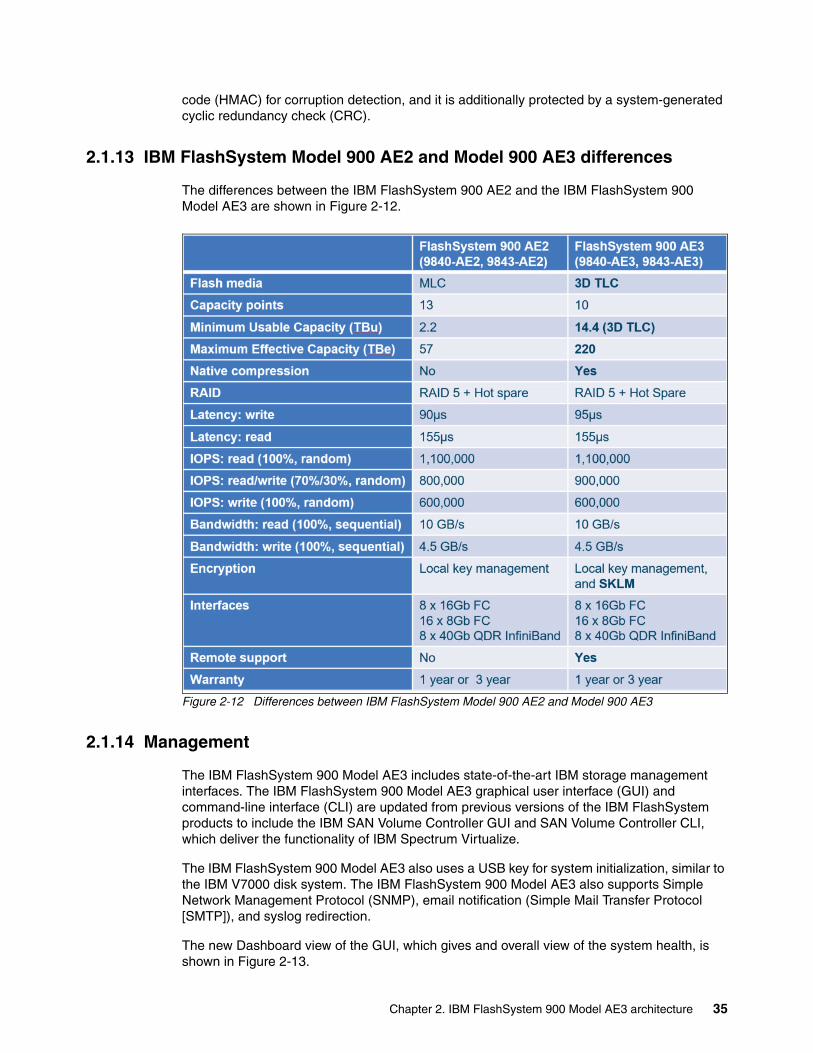
code (HMAC) for corruption detection, and it is additionally protected by a system-generated cyclic redundancy check (CRC).
2.1.13 IBM FlashSystem Model 900 AE2 and Model 900 AE3 differences
The differences between the IBM FlashSystem 900 AE2 and the IBM FlashSystem 900 Model AE3 are shown in Figure 2-12.
Figure 2-12 Differences between IBM FlashSystem Model 900 AE2 and Model 900 AE3
2.1.14 Management
The IBM FlashSystem 900 Model AE3 includes state-of-the-art IBM storage management interfaces. The IBM FlashSystem 900 Model AE3 graphical user interface (GUI) and command-line interface (CLI) are updated from previous versions of the IBM FlashSystem products to include the IBM SAN Volume Controller GUI and SAN Volume Controller CLI, which deliver the functionality of IBM Spectrum Virtualize.
The IBM FlashSystem 900 Model AE3 also uses a USB key for system initialization, similar to the IBM V7000 disk system. The IBM FlashSystem 900 Model AE3 also supports Simple Network Management Protocol (SNMP), email notification (Simple Mail Transfer Protocol [SMTP]), and syslog redirection.
The new Dashboard view of the GUI, which gives and overall view of the system health, is shown in Figure 2-13.
Chapter 2. IBM FlashSystem 900 Model AE3 architecture 35

Figure 2-13 Dashboard view of the GUI
36 Implementing IBM FlashSystem 900 Model AE3

How to browse to the more traditional System view in the GUI by clicking Monitoring → System from the drop-down menu on the left side of the GUI is shown in Figure 2-14.
Figure 2-14 Browsing to the more traditional System view in the GUI
The System view of the IBM FlashSystem 900 Model AE3 GUI is shown in Figure 2-15. For more information about the use of the FlashSystem 900 Model AE3 GUI and CLI, see 2.3.2, “System management” on page 49.
Figure 2-15 IBM FlashSystem 900 Model AE3 System View in GUI
Chapter 2. IBM FlashSystem 900 Model AE3 architecture 37

2.2 Architecture of IBM FlashSystem 900 Model AE3
The IBM FlashSystem architecture is explained. Key product design characteristics, including performance, reliability, and serviceability, are described. Hardware components are also described.
2.2.1 Overview
The design goals for the IBM FlashSystem 900 Model AE3 are to provide the client with the fastest and most reliable all-flash storage array on the market, while making it simple to service and support with as little downtime as possible. The IBM FlashSystem 900 Model AE3 uses many FPGA components and as little software as possible, which keeps I/O latency to a minimum and I/O performance to a maximum.
The IBM FlashSystem 900 Model AE3 design is shown in Figure 2-16 on page 39. At the core of the system are two high-speed non-blocking crossbar buses. The crossbar buses provide two high-speed paths, which carry the data traffic. They can be used by any host entry path into the system. A slower speed bus for management traffic also is featured.
Connected to the crossbar buses are high-speed non-blocking RAID modules and IBM MicroLatency modules. A passive main system board (midplane) also is used to which both the RAID canisters and all the flash modules connect. Connections to battery modules, fan modules, and power supply units also are included.
The two RAID canisters contain crossbar controllers, management modules, interface controllers and interface adapters, and fan modules. The two RAID canisters form a logical cluster. No single point of failure exists in the design (assuming that all host connections include at least one path to each canister).
38 Implementing IBM FlashSystem 900 Model AE3

Figure 2-16 IBM FlashSystem 900 Model AE3 architecture
RAIDX-Bar
Controller
RAIDX-Bar
Controller
RAID Module RAID Module
PMOM Charger
Battery
Battery Module
Quorum
PMOMCharger
Battery
Battery Module
Quorum
InterfaceControl
CPUIfaceCtlr
InterfaceAdapter
InterfaceControl
CPUIfaceCtlr
InterfaceAdapter
InterfaceControl
CPUIfaceCtlr
InterfaceAdapter
InterfaceControl
CPUIfaceCtlr
InterfaceAdapter
SysMgmt
Midplane
Power Interposer
EncVPD
PowerSupplyORing
FlashGateway CPU
Flash Modules
12 of 12
FlashController
Flash ChipArray
FlashController
Flash ChipArray
Daughter
Mother
FlashController
Flash ChipArray
FlashController
Flash ChipArray
FlashGatewayCPU
Flash Modules
1 of 12
FlashController
Flash ChipArray
FlashController
Flash ChipArray
Daughter
Mother
FlashController
Flash ChipArray
FlashController
Flash ChipArray
EncVPD
Power Supply
PSU PSU
Power Supply
ExternalManagementConnectionSys
Mgmt
ExternalManagementConnection
External IOInterface
External IOInterface
FanController
Fan Module
DualFan
DualFan
FanController
Fan Module
DualFan
DualFan
FanController
Fan Module
DualFan
DualFan
FanController
Fan Module
DualFan
DualFan
Chapter 2. IBM FlashSystem 900 Model AE3 architecture 39

A more detailed view of the FPGAs is shown in Figure 2-17 in relation to the rest of the components that make up the IBM MicroLatency modules.
Figure 2-17 Detailed view of the FPGAs in relation to the rest of the components
2.2.2 Hardware components
The IBM FlashSystem 900 Model AE3 includes the following core components:
� Canisters� Interface cards� IBM MicroLatency modules� Battery modules� Power supply units� Fan modules
The front view of the IBM FlashSystem 900 Model AE3 is shown in Figure 2-18. The two battery modules are on the left side and the 12 MicroLatency modules are on the right side.
Figure 2-18 IBM FlashSystem 900 Model AE3 front view
40 Implementing IBM FlashSystem 900 Model AE3
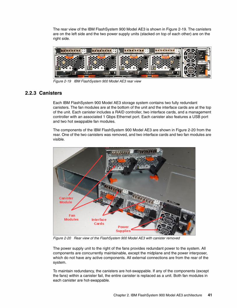
The rear view of the IBM FlashSystem 900 Model AE3 is shown in Figure 2-19. The canisters are on the left side and the two power supply units (stacked on top of each other) are on the right side.
Figure 2-19 IBM FlashSystem 900 Model AE3 rear view
2.2.3 Canisters
Each IBM FlashSystem 900 Model AE3 storage system contains two fully redundant canisters. The fan modules are at the bottom of the unit and the interface cards are at the top of the unit. Each canister includes a RAID controller, two interface cards, and a management controller with an associated 1 Gbps Ethernet port. Each canister also features a USB port and two hot swappable fan modules.
The components of the IBM FlashSystem 900 Model AE3 are shown in Figure 2-20 from the rear. One of the two canisters was removed, and two interface cards and two fan modules are visible.
Figure 2-20 Rear view of the FlashSystem 900 Model AE3 with canister removed
The power supply unit to the right of the fans provides redundant power to the system. All components are concurrently maintainable, except the midplane and the power interposer, which do not have any active components. All external connections are from the rear of the system.
To maintain redundancy, the canisters are hot-swappable. If any of the components (except the fans) within a canister fail, the entire canister is replaced as a unit. Both fan modules in each canister are hot-swappable.
Chapter 2. IBM FlashSystem 900 Model AE3 architecture 41

2.2.4 Interface cards
The IBM FlashSystem 900 Model AE3 supports the following protocol interface cards:
� Fibre Channel (16 Gbps, 8 Gbps, and 4 Gbps)� InfiniBand QDR (40 Gbps)
A four-port FC interface card, which is used for 16 Gbps FC (two ports used only), 8 Gbps, 4 Gbps FC (four ports used), is shown in Figure 2-21.
Figure 2-21 IBM FlashSystem 900 Model AE3 FC Interface card
The two LEDs per port (see Figure 2-21) have the following meanings:
� A: Link state� B: Link speed
Fibre Channel card ports and indicatorsThe FC ports on each interface card are numbered 1 - 4, starting from the left side. Two LED indicators are available for each FC port, or a total of four pairs per interface card.
Fibre Channel port LED descriptionsEach FC interface port in the IBM FlashSystem 900 Model AE3 includes a set of LEDs to indicate its status. The locations of the port LED are shown in Figure 2-21.
The LED states for the FC ports are listed in Table 2-2.
Table 2-2 FC LED port descriptions
LED name Color States
Link state Green � Off: No small form-factor pluggable (SFP) transceiver installed� Slow flash: SFP transceiver installed, no link� Solid: Link connected
Link speed Amber � Off: No link.� Two fast flashes: 4 Gb FC connection� Three fast flashes: 8 Gb FC connection� Four fast flashes: 16 Gb FC connection
42 Implementing IBM FlashSystem 900 Model AE3
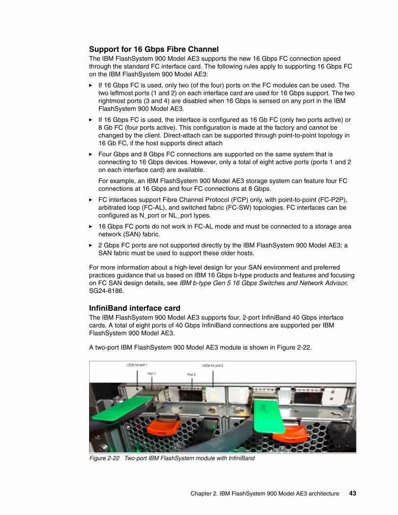
Support for 16 Gbps Fibre ChannelThe IBM FlashSystem 900 Model AE3 supports the new 16 Gbps FC connection speed through the standard FC interface card. The following rules apply to supporting 16 Gbps FC on the IBM FlashSystem 900 Model AE3:
� If 16 Gbps FC is used, only two (of the four) ports on the FC modules can be used. The two leftmost ports (1 and 2) on each interface card are used for 16 Gbps support. The two rightmost ports (3 and 4) are disabled when 16 Gbps is sensed on any port in the IBM FlashSystem 900 Model AE3.
� If 16 Gbps FC is used, the interface is configured as 16 Gb FC (only two ports active) or 8 Gb FC (four ports active). This configuration is made at the factory and cannot be changed by the client. Direct-attach can be supported through point-to-point topology in 16 Gb FC, if the host supports direct attach
� Four Gbps and 8 Gbps FC connections are supported on the same system that is connecting to 16 Gbps devices. However, only a total of eight active ports (ports 1 and 2 on each interface card) are available.
For example, an IBM FlashSystem 900 Model AE3 storage system can feature four FC connections at 16 Gbps and four FC connections at 8 Gbps.
� FC interfaces support Fibre Channel Protocol (FCP) only, with point-to-point (FC-P2P), arbitrated loop (FC-AL), and switched fabric (FC-SW) topologies. FC interfaces can be configured as N_port or NL_port types.
� 16 Gbps FC ports do not work in FC-AL mode and must be connected to a storage area network (SAN) fabric.
� 2 Gbps FC ports are not supported directly by the IBM FlashSystem 900 Model AE3; a SAN fabric must be used to support these older hosts.
For more information about a high-level design for your SAN environment and preferred practices guidance that us based on IBM 16 Gbps b-type products and features and focusing on FC SAN design details, see IBM b-type Gen 5 16 Gbps Switches and Network Advisor, SG24-8186.
InfiniBand interface cardThe IBM FlashSystem 900 Model AE3 supports four, 2-port InfiniBand 40 Gbps interface cards. A total of eight ports of 40 Gbps InfiniBand connections are supported per IBM FlashSystem 900 Model AE3.
A two-port IBM FlashSystem 900 Model AE3 module is shown in Figure 2-22.
Figure 2-22 Two-port IBM FlashSystem module with InfiniBand
Chapter 2. IBM FlashSystem 900 Model AE3 architecture 43

InfiniBand supportThe IBM FlashSystem 900 Model AE3 InfiniBand interface cards include two 4X QDR ports each. The InfiniBand interface card ports can connect to quad data rate (QDR), Double Data Rate (DDR), or Single Data Rate (SDR) InfiniBand host channel adapters (HCAs) by using the SCSI Remote Direct Memory Access (RDMA) Protocol Secure Remote Password (SRP). The IBM FlashSystem 900 Model AE3 InfiniBand interfaces support SCSI RDMA Protocol only.
InfiniBand interface card port LED descriptionsEach InfiniBand interface port in the IBM FlashSystem 900 Model AE3 includes a set of LEDs to indicate the status. The InfiniBand LED port descriptions.
Table 2-3 InfiniBand LED port descriptions
2.2.5 MicroLatency modules
The IBM FlashSystem 900 Model AE3 supports up to 12 IBM MicroLatency modules, which are accessible from the enclosure’s front panel. Each IBM MicroLatency module features a usable capacity of 3.27 TiB (3.6 TB), 7.73 TiB (8.5 TB), or 16.37 TiB (18 TB) of flash storage.
An IBM FlashSystem 900 Model AE3 MicroLatency module is shown in Figure 2-23.
Figure 2-23 IBM FlashSystem 900 Model AE3 MicroLatency module
LED name Color States
Link state Green � Off: No link established� Solid: Link is established
Activity Amber � Off: No physical link� Solid: Link is established, no activity� Flashing: Activity on the link
Note: All MicroLatency modules in the IBM FlashSystem 900 Model AE3 must be ordered as 3.6 TB, 8.5 TB, or 18 TB. IBM MicroLatency modules types cannot be mixed.
44 Implementing IBM FlashSystem 900 Model AE3

The maximum usable storage capacity of the IBM FlashSystem 900 Model AE3 is based on the fact that in a RAID 5 configuration, one IBM MicroLatency module is reserved as an active spare. Also, the capacity equivalent to one module is used to implement a distributed parity algorithm. Therefore, the maximum usable capacity of a RAID 5 configuration is 180 TB (163.7 TiB; 10 MicroLatency modules x 16.37 TiB [18 TB]).
The IBM FlashSystem 900 Model AE3 includes inline hardware data compression. Therefore, the maximum effective storage capacity of the system is 200 TiB (220 TiB).
IBM MicroLatency modules are installed in the IBM FlashSystem 900 Model AE3 that are based on the following configuration guidelines:
� A minimum of six MicroLatency modules must be installed in the system. RAID 5 is the only supported configuration of the IBM FlashSystem 900 Model AE3.
� The system supports configurations of 6, 8, 10, and 12 MicroLatency modules in RAID 5.
� All MicroLatency modules that are installed in the enclosure must be identical in capacity and type.
� For optimal airflow and cooling, if fewer than 12 MicroLatency modules are installed in the enclosure, populate the module bays beginning in the center of the slots and adding on either side until all 12 slots are populated. The empty slots must be populated with filler modules to ensure correct airflow and cooling through the system.
Suggestions for populating MicroLatency module bays are listed in Table 2-4.
Table 2-4 Supported MicroLatency module configurations
Consider the following points:
� If fewer than 12 modules are installed, module blanks must be installed in the empty bays to maintain cooling airflow in the system enclosure.
� During system setup in the storage enclosure management GUI, the system automatically configures RAID settings that are based on the number of flash modules in the system.
� All MicroLatency modules that are installed in the enclosure must be identical in capacity and type.
No. of installed flash modulesa
a. RAID 5 is supported with configurations of 6, 8, 10, and 12 MicroLatency modules.
Flashmod.slot 1
Flashmod.slot 2
Flashmod.slot 3
Flashmod.slot 4
Flashmod.slot 5
Flashmod.slot 6
Flashmod.slot 7
Flashmod.slot 8
Flashmod.slot 9
Flashmod.slot 10
Flashmod.slot 11
Flashmod.slot 12
Six X X X X X X
Eight X X X X X X X X
Ten X X X X X X X X X X
Twelve X X X X X X X X X X X X
Chapter 2. IBM FlashSystem 900 Model AE3 architecture 45

2.2.6 Battery modules
The IBM FlashSystem 900 Model AE3 contains two hot-swappable battery modules. The function of the battery modules is to ensure that the system is gracefully shut down (write cache fully flushed and synchronized) when AC power is lost to the unit. The IBM FlashSystem 900 Model AE3 battery modules are hot-swappable.
Battery module 1, which is in the leftmost front of the IBM FlashSystem 900 Model AE3, is shown in Figure 2-24. An IBM FlashSystem 900 Model AE3 battery module can be hot-swapped without software intervention; however, be sure to follow the directed maintenance procedure from the IBM FlashSystem 900 Model AE3 GUI before any hardware is replaced.
Figure 2-24 IBM FlashSystem 900 Model AE3 Battery Module 1
Battery reconditioningA battery reconditioning feature on the IBM FlashSystem 900 Model AE3 calibrates the gauge to report the amount of charge on the batteries. On systems that were installed for 10 months or more, or systems that experienced several power outages, the recommendation to run “battery reconditioning” appears in the Event Log shortly after upgrading.
Important: MicroLatency modules are hot swappable. However, to replace a module, you must power down the MicroLatency module by using the management GUI before you remove and replace the module. This service action does not affect the active LUNs, and I/O to the connected hosts can continue while the MicroLatency module is replaced. Be sure to follow the directed maintenance procedure from the IBM FlashSystem 900 Model AE3 GUI before any hardware replacement. For more information, see Chapter 6, “Using IBM FlashSystem 900” on page 157.
The suggestion is for the storage enclosure to remain powered on, or be powered on periodically, to retain array consistency. The storage enclosure can be safely powered off for up to 90 days in temperatures up to 40° C. Although the MicroLatency modules retain data if the enclosure is temporarily disconnected from power, data might be lost if the system is powered off for more than 90 days.
When replacing this part, you must follow the recommended procedures for handling devices that are sensitive to electrostatic discharge (ESD).
46 Implementing IBM FlashSystem 900 Model AE3

The IBM FlashSystem 900 Model AE3 also now supports automatic battery reconditioning. This feature allows the user to select manual or automatic battery reconditioning. This enhancement enables the user to select the battery reconditioning to be run automatically, when needed.
The default setting is OFF and no change is made during a code upgrade. All new systems IBM FlashSystem 900 Model AE3 arrays are set to OFF during manufacture. The user must set this option ON, if required, after the machine is installed.
For more information, see the IBM FlashSystem 900 Model AE3 page of IBM Knowledge Center.
2.2.7 Power supply units
The IBM FlashSystem 900 Model AE3 features two hot-swappable power supply units. The system can remain fully online if one of the power supply units fails.
The IBM FlashSystem 900 Model AE3 power supply units are accessible from the rear of the unit and are fully hot-swappable. The two IBM FlashSystem 900 Model AE3 hot-swappable power supply units are shown in Figure 2-25.
Figure 2-25 IBM FlashSystem 900 Model AE3 hot swappable power supply units
The IBM FlashSystem 900 Model AE3 GUI and alerting systems (for example, SNMP) report a power supply fault. The power supply can be hot-swapped without software intervention; however, be sure to follow the directed maintenance procedure from the IBM FlashSystem 900 Model AE3 GUI before any hardware is replaced.
AC Power LED
DC Power LED
Fault LED
Power Supply Module 1
Power SupplyModule 2
Chapter 2. IBM FlashSystem 900 Model AE3 architecture 47

2.2.8 Fan modules
The IBM FlashSystem 900 Model AE3 includes four hot-swappable fan modules. Each FlashSystem 900 Model AE3 canister holds two hot-swappable fan modules. Each fan module features two fans. The system can remain fully online if one of the fan modules fails. The IBM FlashSystem 900 Model AE3 fan modules are accessible from the rear of the unit (in each canister) and are fully hot-swappable.
A n IBM FlashSystem 900 Model AE3 hot-swappable fan module is shown in Figure 2-26. The IBM FlashSystem 900 Model AE3 GUI and alerting systems (for example, SNMP) reports a fan module fault. The fan module can be hot-swapped without software intervention; however, be sure to follow the directed maintenance procedure from the IBM FlashSystem 900 Model AE3 GUI before any hardware is replaced.
Figure 2-26 IBM FlashSystem 900 Model AE3 fan module
2.3 Administration and maintenance
The IBM FlashSystem 900 Model AE3 storage system capabilities for administration, maintenance, and serviceability are described in this section.
2.3.1 Serviceability and software enhancements
IBM FlashSystem 900 Model AE3 includes the following design enhancements for the administration, management, connectivity, and serviceability of the system:
� Concurrent code load
The IBM FlashSystem 900 Model AE3 supports the ability to upgrade the system firmware on the canister (RAID controllers, management modules, and interface cards), and flash modules without affecting the connected hosts or their applications.
� Easily accessible hot-swappable modules with no single point of failure
The IBM FlashSystem 900 Model AE3 design enables the easy replacement of any hardware module through the front or rear of the unit. The IBM FlashSystem 900 Model AE3 does not require the top panel to be removed and does not need to be moved in the rack to replace any component.
48 Implementing IBM FlashSystem 900 Model AE3

� Standard IBM SAN Volume Controller CLI and GUI
The IBM FlashSystem 900 Model AE3 uses the latest SAN Volume Controller CLI and GUI for simple and familiar unit management.
� Encryption support
The IBM FlashSystem 900 Model AE3 supports hardware encryption of the flash modules to meet the audit requirements of enterprise, financial, and government clients.
� Support for 16 Gb Fibre Channel
The IBM FlashSystem 900 Model AE3 supports 16 Gbps FC, which enables clients to use the latest available high-speed networking equipment while increasing performance.
2.3.2 System management
IBM FlashSystem 900 Model AE3 includes the use of the common IBM SAN Volume Controller CLI and the popular IBM SAN Volume Controller GUI, which is based on the IBM XIV GUI. The IBM FlashSystem 900 Model AE3 supports SNMP, email forwarding (SMTP), and syslog redirection for complete enterprise management access.
USB key initialization processIBM FlashSystem 900 Model AE3 uses a USB key initialization process, which is similar to the IBM V7000 disk systems initialization. A USB key includes an initialization file and is placed in a Microsoft Windows workstation to program the initial IP address information into a utility. The USB key is then placed into the IBM FlashSystem 900 Model AE3 on the first start-up and the initialization file is read and applied. The IBM FlashSystem 900 Model AE3 can then be managed through the GUI and CLI. For more information about the USB key initialization process, see 4.3, “Initializing the system” on page 88.
Graphical user interfaceIBM FlashSystem 900 Model AE3 includes the use of the standard IBM SAN Volume Controller GUI. This GUI is simple to use and based on the popular IBM XIV GUI.
The IBM FlashSystem 900 Model AE3 GUI is started from a supported internet browser when you enter the system management IP address. Then, the login window opens (see Figure 2-27) in which you enter a valid user name and password.
Figure 2-27 IBM FlashSystem 900 Model AE3 GUI login window
Chapter 2. IBM FlashSystem 900 Model AE3 architecture 49

The system dashboard window opens (see Figure 2-28). The Dashboard provides an at-a-glance view of the system’s status.
Figure 2-28 System overview window
Using the dashboard, you can see the following information in one window:
� Physical (usable) and effective capacity� Compression ratio and savings� Provisioned capacity� Read and write bandwidth and latency in real time� System health indicators, sorted by importance
More information about the health of system components and capacity history also are available.
At the left of the window, the following menu items are available:
� Monitoring function� Volumes function� Hosts function� Access function� Settings function
These menu items can be displayed as icons only or icons with text, depending on the size of the window. These menu items are briefly described next. For more information about the GUI, see Chapter 6, “Using IBM FlashSystem 900” on page 157. For more information about the Settings element, see Chapter 7, “Configuring settings” on page 229.
50 Implementing IBM FlashSystem 900 Model AE3

Monitoring functionThe Monitoring icon and the associated drop-down menu are shown in Figure 2-29. Click the Monitoring icon if you want to do perform of the following tasks:
� System: Monitor the system health of the IBM FlashSystem 900 Model AE3 hardware.� Neighborhood: Monitor health and status, and manage multiple FlashSystems� Events: View the events log of the IBM FlashSystem 900 Model AE3.� Performance: Start the system I/O performance graphs.� Performance with Events: Correlate events and alerts with performance data.
Figure 2-29 Monitoring icon and drop-down menu
Volumes functionThe Volumes icon and the associated drop-down menu are shown in Figure 2-30. Click the Volumes icon if you want to perform any of the following tasks:
� Volumes: View a list of all system storage volumes (LUNs), create, edit, or delete volumes.
� Volumes by Host: View a list of volumes that are associated with hosts, create associations, or delete associations.
Figure 2-30 Volumes icon and drop-down menu
Hosts functionThe Hosts icon and the associated drop-down menu are shown in Figure 2-31. Click the Hosts icon if you want to perform any of the following tasks:
� Hosts: View a list of all hosts, create, edit, or delete hosts.
� Volumes by Host: View a list of volumes that are associated with hosts, and create or delete associations.
Figure 2-31 Hosts icon and drop-down menu
Chapter 2. IBM FlashSystem 900 Model AE3 architecture 51

Access functionThe Access icon and associated drop-down menu are shown in Figure 2-32. Click the Access icon if you want to perform any of the following tasks:
� Users: View a list of current users, create, edit, or delete users.
� User Groups: Create user groups (based on access rights) and associate users with groups.
� Audit Log: View the system access log and view actions by individual users.
Figure 2-32 Access icon and drop-down menu
Settings functionThe Settings icon and associated drop-down menu are shown in Figure 2-33. Click the Settings icon if you want to configure system parameters, including alerting, remote support access, open access for hosts, GUI settings, and other system-wide configurations. For more information, see Chapter 7, “Configuring settings” on page 229.
Figure 2-33 Settings icon and drop-down menu
Command-line interfaceIBM FlashSystem 900 Model AE3 uses the standard IBM SAN Volume Controller storage CLI (Version 8.1 and higher). This CLI is common among several IBM storage products, including the IBM SAN Volume Controller and the IBM Storwize family of products (the V7000 and IBM V5000 disk systems). IBM SAN Volume Controller CLI is easy to use with built-in help and hint menus.
To access the IBM FlashSystem 900 Model AE3 SAN Volume Controller CLI, an SSH session to the management IP address must be established (Telnet is not enabled on the IBM FlashSystem 900 Model AE3). The client is then prompted for a user name and password.
52 Implementing IBM FlashSystem 900 Model AE3

Call home email SMTP supportIBM FlashSystem 900 Model AE3 supports setting up an SMTP mail server for alerting the IBM Support Center of system incidents that might require a service event. These emails can also be sent within the client’s enterprise to other email accounts that are specified.
After it is set up, system events that might require service are emailed automatically to an IBM Service account that is specified in the IBM FlashSystem 900 Model AE3 code. The email alerting can be set up as part of the system initialization process or added or edited at anytime through the IBM FlashSystem 900 Model AE3 GUI. Also, a test email can be generated at anytime to test the connections.
The IBM FlashSystem 900 Model AE3 email setup window is shown in Figure 2-34.
Figure 2-34 Email alerting setup window
SNMP supportIBM FlashSystem 900 Model AE3 supports SNMP versions 1 and 2. The GUI is used to set up SNMP support on the IBM FlashSystem 900 Model AE3.
To set up SNMP support on the IBM FlashSystem 900 Model AE3, complete the following steps:
1. Click the Settings icon on the left side of the window.
2. Click the Notifications tab.
3. Click the SNMP tab and enter the SNMP trap receiver IP address and community access information.
Chapter 2. IBM FlashSystem 900 Model AE3 architecture 53

The IBM FlashSystem 900 Model AE3 SNMP setup window is shown in Figure 2-35.
Figure 2-35 IBM FlashSystem 900 Model AE3 SNMP setup window
Redirection of syslogYou can redirect syslog messages to another host for system monitoring. Use the GUI to set up syslog redirection on the IBM FlashSystem 900 Model AE3.
To set up syslog redirection, complete the following steps:
1. Click the Settings icon in the lower left of the window.2. Click the Event Notifications tab.3. Click the Syslog tab and enter the remote host trap IP address and directory information.
The Syslog redirection setup window is shown in Figure 2-36.
Figure 2-36 Syslog redirection set up window
Note: Based on technology from SAN Volume Controller, the IBM FlashSystem 900 Model AE3 CLI can also be used to program the SNMP settings.
CLI: The IBM FlashSystem 900 Model AE3 CLI can also be used to set up syslog redirection.
54 Implementing IBM FlashSystem 900 Model AE3

2.4 Support matrix
IBM FlashSystem 900 Model AE3 supports various operating systems (Windows Server 2008 and 2012, Linux, IBM AIX® and VMware vSphere/ESXi), hardware platforms (IBM System x, IBM Power Systems™, and x86 servers not from IBM), host bus adapters (HBAs), and SAN fabrics.
For more information, see the IBM System Storage Interoperation Center (SSIC).
Also, consider the use of the IBM SAN Volume Controller as a front-end, host-facing interface for the IBM FlashSystem 900 Model AE3. If the IBM FlashSystem 900 Model AE3 is used with the IBM SAN Volume Controller, the host interoperability matrix for the IBM SAN Volume Controller is relevant. For more information about IBM SAN Volume Controller interoperability, see the IBM System Storage Interoperation Center (SSIC).
Contact your IBM sales representative or IBM Business Partner for assistance or questions about the IBM FlashSystem 900 Model AE3 or IBM SAN Volume Controller interoperability.
2.5 Product integration overview
IBM FlashSystem 900 Model AE3 is an all-flash storage system that can enhance the performance of almost any application. A high-level overview of how the IBM FlashSystem 900 Model AE3 works with a list of IBM products and applications is described in this section. I
n addition to the products that are described here, the IBM FlashSystem 900 Model AE3 also works with various other IBM software applications and hardware products, and products from third-party vendors. For more information about incorporating the IBM FlashSystem 900 Model AE3 into any of these or other applications, contact with your IBM salesperson or IBM Business Partner.
For more information about deploying the IBM FlashSystem 900 Model AE3 with the IBM products that are described here, see Chapter 8, “Product integration” on page 307.
For more information about the use of the IBM FlashSystem with other IBM and third-party solutions and applications, see the IBM Storage website.
2.5.1 IBM Spectrum Virtualize - SAN Volume Controller
The IBM FlashSystem 900 Model AE3 all-flash storage array provides clients with storage that is fast and features low latency.
IBM SAN Volume Controller delivers the functions of IBM Spectrum Virtualize, which is part of the IBM Spectrum Storage family. It improved infrastructure flexibility and data economics for more than 10 years.
Its innovative data virtualization capabilities provide the foundation for the entire IBM Storwize family. IBM SAN Volume Controller provides the latest storage technologies for unlocking the business value of stored data, including virtualization and Real-time Compression.
Chapter 2. IBM FlashSystem 900 Model AE3 architecture 55

IBM SAN Volume Controller enriches any storage environment by adding storage management functions and the following features:
� IBM FlashCopy® point-in-time copies� Local and remote mirroring� Thin provisioning� Real-time Compression� EasyTier support (automatically directs “hot I/O” to fastest storage)� Support for virtual environment APIs� Support for Hyperswap for high availability� Support for OpenStack Cloud environments� Support for IBM Spectrum Control Base� Storage consolidation
IBM SAN Volume Controller provides these features with minimal delay or latency in the I/O path. The combination of the IBM FlashSystem 900 Model AE3 and IBM SAN Volume Controller enables clients to use the speed of the IBM FlashSystem 900 Model AE3 and the robust storage management capabilities of the IBM SAN Volume Controller.
More informationFor more information, see the following resources:
� FlashSystem 900 Model AE3 and the IBM FlashSystem resources (including IBM Redbooks publications, white papers, and demos, see the IBM Storage website.
� FlashSystem that is running in an IBM Spectrum Virtualize environment and Real-Time Compression, see Implementing FlashSystem 840 with SAN Volume Controller, TIPS1137.
� IBM SAN Volume Controller:
– IBM System Storage SAN Volume Controller and Storwize V7000 Best Practices and Performance Guidelines, SG24-7521
– Implementing the IBM System Storage SAN Volume Controller with IBM Spectrum Virtualize V8.1, SG24-7933
� IBM FlashSystem 900 Model AE3 and IBM Spectrum Virtualize - SAN Volume Controller, see 8.1, “FlashSystem 900 with IBM Spectrum Virtualize - SAN Volume Controller” on page 308.
2.5.2 IBM Storwize V7000 storage array
Similar to the IBM Spectrum Virtualize - SAN Volume Controller product, the IBM Storwize V7000 storage array can provide storage management services (FlashCopy, thin-provisioning, mirroring, replication, Real-time Compression, support for virtual environments, and Easy Tier support) to externally connected storage systems.
The IBM FlashSystem 900 Model AE3 can be connected to the IBM V7000 storage array and provide high performance and low latency to connected hosts, while using the IBM V7000 storage management services.
Note: If you want the advanced software features and low latency of the IBM FlashSystem 900 Model AE3 combined with SAN Volume Controller functions and services, such as mirroring, IBM FlashCopy, thin provisioning, IBM Real-time Compression Copy Services, and broader host support, you can purchase IBM FlashSystem V9000. For more information, see IBM FlashSystem V840, TIPS-1158.
56 Implementing IBM FlashSystem 900 Model AE3

The IBM Storwize V7000 FlashSystem Edition and FlashSystem Enterprise Addition enable you to accelerate your mid-range storage solution by using the extreme performance and low latency of the FlashSystem. For more information, see the IBM Storage website.
More informationFor more information, see the following resources:
� To deploy the IBM V7000 and IBM FlashSystem 900 Model AE3 together, contact your IBM sales representative or IBM Business Partner.
� Information about the IBM V7000 and IBM FlashSystem, see the IBM Storage website.
� Information about the IBM Storwize V7000:
– IBM Storwize V7000 and SANSlide Implementation, REDP-5023
– IBM Flex System V7000 Storage Node Introduction and Implementation Guide, SG24-8068
– Implementing the IBM Storwize V7000 Gen2, SG24-8244
– IBM Flex System V7000 Storage Node, TIPS1039
� IBM FlashSystem 900 Model AE3 and the IBM V7000, see 8.4, “Integration considerations: FlashSystem 900 and IBM Storwize V7000” on page 341.
2.5.3 IBM DB2 database environments
IBM FlashSystem 900 Model AE3 enables clients to speed up their databases dramatically. IBM DB2® is a high-performance, enterprise-scale database that is used by several of the largest IBM clients worldwide. Moving some or all of an IBM DB2 database onto the IBM FlashSystem 900 Model AE3 accelerates performance and increases CPU utilization at the same time. Also, moving a small portion of an IBM DB2 database onto the IBM FlashSystem 900 Model AE3 can have dramatic results.
More informationFor more information about the use of IBM FlashSystem 900 Model AE3 and IBM DB2 products together, the following resources are available:
� Contact your IBM sales representative or IBM Business Partner.� See the IBM Storage website.� Faster DB2 Performance with IBM FlashSystem, TIPS1041.
2.5.4 IBM Spectrum Scale
IBM Spectrum Scale™ is a proven, scalable, high-performance data and file management solution, based on IBM General Parallel File System or GPFS™. IBM Spectrum Scale technology is a high-performance enterprise file management platform that can help you move beyond simply adding storage to optimize data management.
With IBM Spectrum Scale, businesses can achieve higher performance while reducing the footprint by placing elastic storage metadata on the FlashSystem 900 Model AE3. Running IBM Spectrum Scale virtualizes IBM FlashSystem for file-based access in much the same way that SAN Volume Controller and the V7000 virtualize it for block-based access.
IBM Spectrum Scale is also a key component for many big data products. IBM BigInsights®, DB2 PureScale, and SAP HANA all use IBM Spectrum Scale. In addition, IBM Spectrum Scale is used for many high-performance storage applications, such as media, life sciences, and high-performance computing (HPC).
Chapter 2. IBM FlashSystem 900 Model AE3 architecture 57

Some applications need fast I/O for data; some applications need fast I/O for metadata. A mix of random and streaming I/O for data also is available, depending on the type of workload.
IBM Spectrum Scale integrates with the IBM FlashSystem 900 Model AE3 and offers your business environment the following potential benefits:
� IBM Spectrum Scale enables the IBM FlashSystem to be used as a storage tier under user control, scheduled control, or dynamically, where files are moved to and from flash and disk (and even tape) under policy control or when they are used.
� You can use the IBM FlashSystem to support data, metadata, or both. It also can support millions of file creations and deletions per minute.
� A small part of a the IBM FlashSystem can be partitioned for metadata use and the remainder can be used for hot data.
� This integration provides the capability to replicate data sync or async to another site. It also supports full active-active two-site configurations (sync replication only).
� IBM Spectrum Scale can perform mirroring of two FlashSystem 900 Model AE3s, at a single site or across multiple sites.
� IBM Spectrum Scale is used at many sites where InfiniBand is used. IBM Spectrum Scale and InfiniBand are a good match for the IBM FlashSystem 900 Model AE3.
In this scenario, IBM Spectrum Scale and DataDirect Networks (DDN) communicate by using the same SCSI RDMA SRP, which is supported by the IBM FlashSystem 900 Model AE3. SRP is similar to iSCSI protocol. SRP provides access to LUNs across networks, and SRP protocol is used across InfiniBand networks. GPFS was historically implemented by using SRP protocols to access DDN disk subsystems from GPFS Network Shared Disks (NSD) servers.
2.5.5 VMware with IBM Spectrum control Base
IBM FlashSystem 900 Model AE3 supports VMware vSphere Storage APIs - Array Integration (VAAI) and VMware vSphere API for Storage Awareness (VASA) through integration with the IBM Storage Integration Server. IBM FlashSystem 900 Model AE3 support for VAAI includes by using the Block Reclaim/UNMAP primitive to inform the FlashSystem 900 Model AE3 to reclaim storage. IBM FlashSystem 900 Model AE3 integrates with the IBM Storage Integration Server to provide a consolidated method for system monitoring, automation, and provisioning.
For more information about IBM Spectrum control Base that is running with the FlashSystem, see Deploying IBM FlashSystem V840 Storage in a VMware and Cloud Environment, REDP-5148.
58 Implementing IBM FlashSystem 900 Model AE3

Chapter 3. Planning
This chapter provides planning information and general considerations for you to review before you install the IBM FlashSystem 900 AE3 storage enclosure. This information includes connectivity, supported host environments, and IP addresses.
This chapter includes the following topics:
� 3.1, “Prerequisites to installation” on page 60� 3.2, “Planning cable connections” on page 63� 3.3, “Planning for power” on page 67� 3.4, “Configuration planning” on page 67� 3.5, “Call Home configuration” on page 69� 3.6, “Remote Support Assistance” on page 70� 3.7, “TCP/IP requirements” on page 72� 3.8, “Planning for encryption” on page 73� 3.9, “Planning for compression” on page 75� 3.10, “Checking web browser settings for the management GUI” on page 76� 3.11, “Licensing” on page 78� 3.12, “Supported hosts and operating system considerations” on page 78
3
© Copyright IBM Corp. 2018. All rights reserved. 59

3.1 Prerequisites to installation
Understand the contact information and checklists before you start. Plan to provide the required network infrastructure and the storage network infrastructure as described in the following sections. In addition, you might also want to consult the planning section of IBM Knowledge Center for IBM FlashSystem 900.
3.1.1 Contact information and checklist
Before installing the system, collect the necessary information that is described in this section that is used during the installation and setup of the system.
Contact information for the Call Home featureThe FlashSystem 900 can be installed by the customer. Enabling the Call Home feature allows IBM personnel to be notified of any critical hardware problems.
When the IBM Support Center receives a Call Home report, an IBM service representative contacts your company (as specified in the Call Home configuration) to work on resolving the problem. You need basic information, such as an email address and a Simple Mail Transfer Protocol (SMTP) gateway address to set up Call Home. You can complete the necessary information in Table 3-10 on page 72.
For more information about to setting up Call Home before you install the system, see 3.5, “Call Home configuration” on page 69.
Checklist before you startReview the following checklist to be sure that you have the latest information for planning the installation:
� The initialization tool is available on the USB flash drive that is included with the system. The name of the application file is InitTool.exe. If you cannot locate the USB flash drive or you want to use the latest code, you can download the application from the Fix Central support website.
At the support website, select IBM FlashSystem 900 in the product selector, along with your wanted version (or versions) and platform (or platforms), you find the .zip file that contains the tool among your search hits for each respective code version.
The initialization tool is valid for the following operating systems:
– Microsoft Windows 7 (64-bit) and Windows 8.1 (64-bit)– Apple MacOS X 10.7– Red Hat Enterprise Server 5 and 6– Ubuntu desktop 11.04 and 13.10
� The FlashSystem 900 uses 2U of rack space. Check for sufficient free space in the rack and for round or square holes in the rack to attach the enclosure rails.
� If the FlashSystem 900 is used as a storage subsystem in the back-end of IBM Spectrum Virtualize (which is based on technology from SAN Volume Controller), the SAN Volume Controller version must support the FlashSystem 900.
Important: Enable the Call Home feature so that IBM personnel can be notified at any time about any critical hardware problems. Not enabling the Call Home feature can result in long delays for necessary service actions.
60 Implementing IBM FlashSystem 900 Model AE3

Check the IBM System Storage Interoperation Center (SSIC) to determine whether your SAN Volume Controller environment supports the FlashSystem hardware and version that you want to use.
At the SSIC website, complete the following steps:
a. From the Storage Family selector drop-down menu, select IBM System Storage SAN Volume Controller.
b. From the Storage Model drop-down menu, select SVC Storage Controller Support.
c. From the Storage Controller drop-down menu, select IBM FlashSystem 900. By making this selection, the Storage Version selector shows all supported SAN Volume Controller versions.
If your version is not included in this list, contact an IBM sales representative and ask them to raise a Storage Customer Opportunity REquest (SCORE) to have IBM Lab check the validity of your environment. If your version is included, click Submit to see a detailed list of the prerequisites for your environment.
� Check the SSIC website for the latest information about supported operating systems, hosts, switches, and clustering software; for example, Microsoft Cluster Server (MSCS) or Oracle Real Application Clusters (RAC). If an aspect of your environment is not listed as supported, contact an IBM sales representative to open a SCORE.
� Set up a risk mitigation plan that lists all unresolved action items.
� Connect the Ethernet ports to a switch with offline alert notification enabled.
� Collect all necessary information; for example, IP addresses, port information, and user and email names.
3.1.2 Completing the hardware location chart
Planning for the physical location includes documenting the rack locations of the IBM FlashSystem 900 enclosure and other devices that are based on the requirements of each device.
The hardware location chart in Table 3-1 represents the rack into which the enclosure is installed. Each row of the chart represents one Electronic Industries Alliance (EIA) 19-inch wide by 1.75-inch tall rack space or unit, each of which is commonly referred to as 1U of the rack. As you design your rack, use the hardware location chart to record the physical configuration of the 2U enclosure and other devices in your system.
Use Table 3-1 to record the hardware locations of the FlashSystem 900 enclosure and other devices.
Table 3-1 Hardware location of the FlashSystem 900 enclosure and other devices
Note: Install the enclosure where it can be easily serviced. Ensure that the rack is kept stable; for example, by installing enclosures beginning from the bottom.
Rack unit Component
EIA 36
EIA 35
EIA 34
EIA 33
Chapter 3. Planning 61

EIA 32
EIA 31
EIA 30
EIA 29
EIA 28
EIA 27
EIA 26
EIA 25
EIA 24
EIA 23
EIA 22
EIA 21
EIA 20
EIA 19
EIA 18
EIA 17
EIA 16
EIA 15
EIA 14
EIA 13
EIA 12
EIA 11
EIA 10
EIA 9
EIA 8
EIA 7
EIA 6
EIA 5
EIA 4
EIA 3
EIA 2
EIA 1
Rack unit Component
62 Implementing IBM FlashSystem 900 Model AE3

3.2 Planning cable connections
This section describes the steps that are necessary to plan for setting up cable connections for the enclosure. You can use the tables to record the information about the cable connections for your system.
3.2.1 Management port connections
Each of the two canisters that are in the FlashSystem 900 includes an Ethernet port for accessing the management GUI.
Use Table 3-2 to record the management port connection information.
Table 3-2 Enclosure management port Ethernet connections
Canister Management port
Canister 1 Ethernet Management Port
Switch:
Port:
Speed:
Canister 2 Ethernet Management Port
Switch:
Port:
Speed:
Important: Three IP addresses are required for managing the storage enclosure: a cluster IP address and two service IP addresses. Each of the three IP addresses must be a unique value.
The left canister is the first node (when viewed from the back). If the left canister is not available at system start-up, the right canister defaults to be the first node. The first node is the config node, which provides the cluster IP address.
Chapter 3. Planning 63

You use the USB-Key InitTool to set up the cluster IP address. You must set the two service IP addresses after the system is installed. Record the cluster and service IP address settings for the storage enclosure in Table 3-3.
Table 3-3 IP addresses for the storage enclosure
3.2.2 Interface card connections
This section describes the information that is needed for various interface card connections and for the connection switches.
Fibre ChannelEach canister supports the following optional Fibre Channel (FC) interface cards:
� 8 Gb FC cards support four ports � 16 Gb FC cards support the two leftmost ports on the card
Cluster name:
Cluster IP address:
IP:
Subnet mask:
Gateway:
Service IP address 1:
IP:
Subnet mask:
Gateway:
Service IP address 2:
IP:
Subnet mask:
Gateway:
Important: Each host must be connected to both canisters to add redundancy and improve performance. If a host is not connected to both canisters, its state shows as degraded.
Important: Small form-factor pluggable (SFP) transceivers must be obtained and deployed in pairs to support multipathing.
64 Implementing IBM FlashSystem 900 Model AE3

Use Table 3-4 to record the FC port connection information.
Table 3-4 Fibre Channel port connections as shown from rear
Location Item Fibre Channel port 1
Fibre Channel port 2
Fibre Channel port 3 (8 Gb FC only)
Fibre Channel port 4(8 Gb FC only)
Canister 1 (left)Fibre Channel card 1 (left card)
Switch orhost:
Port:
Speed:
Canister 1 (left)Fibre Channel card 2 (right card)
Switch orhost:
Port:
Speed:
Canister 2 (right)Fibre Channel card 1 (left card)
Switch orhost:
Port:
Speed:
Canister 2 (right)Fibre Channel card 2 (right card)
Switch orhost:
Port:
Speed:
Chapter 3. Planning 65

Quad data rate InfiniBandEach canister supports two optional InfiniBand interface cards. Two ports are on each card.
Use Table 3-5 to record the InfiniBand port connection information.
Table 3-5 InfiniBand port connections
Switch informationEach of the two canisters includes an Ethernet port that is attached to an Ethernet switch. These ports are used for system management.
Use Table 3-6 to record the switch information.
Table 3-6 Switch information
Location Item InfiniBand port 1 InfiniBand port 2
Canister 1InfiniBand card 1 (left)
Switch orhosts:
Port:
Speed:
Canister 1InfiniBand card 2 (right)
Switch orhosts:
Port:
Speed:
Canister 2InfiniBand card 1(left)
Switch orhosts:
Port:
Speed:
Canister 2InfiniBand card 2 (right)
Switch orhosts:
Port:
Speed:
IPv4 address IPv6 address Media Access Control (MAC) address
Physical location
Switch 1
Switch 2
Switch 3
Switch 4
66 Implementing IBM FlashSystem 900 Model AE3

3.3 Planning for power
This section describes necessary information for planning to attach both power supplies to the main power supply lines.
Plan to connect the power cords on the right side of the rack (when viewed from the rear) to power sources that provide power in the 100 - 127 V / 200 - 240 V AC range at 10.0/50A 50/60 Hz.
Each power supply can provide a maximum output power of 1300 W if a high line voltage (200-240V AC at 6.9A, 50/60 Hz) power source is used (this configuration is the recommended power configuration). Power supplies also can provide a maximum output power of 900 W if a low line voltage (100-165V AC at 10.0A, 50/60 Hz) power source is used.
Using two power sources provides power redundancy.
Both power connections are shown in Figure 3-1.
Figure 3-1 FlashSystem 900 rear view and power connections
The power cables are specific to the power requirements of your country or region.
3.4 Configuration planning
You must plan for the management address and service addresses before the system is installed. A management address must be assigned to the system. The management address provides access to system configuration and administration functions, such as the management GUI and CLI.
The management IP address is required when the system is initialized. The system initialization tool (InitTool) that is provided on a USB flash drive allows for a convenient configuration of the management IP address through the system setup wizard.
Note: We suggest that you place the two power supplies on different circuits.
Important: The power cord is the main power disconnect. Ensure that the socket outlets are near the equipment and easily accessible.
Important: The management and service addresses for the enclosure must be allocated within the same network.
Chapter 3. Planning 67

Use Table 3-7 to record the management IP address that is assigned to the system.
Table 3-7 Management IP address configuration
Two service addresses must be allocated to the enclosure. The enclosure canisters retain the service IP addresses, which allows convenient access to node configuration and service functions, such as the service assistant GUI and CLI for that node. IPv4 and IPv6 protocols also can be used.
Use Table 3-8 to plan the service IP addresses that are required to perform service actions.
Table 3-8 Service IP address configuration
Use Table 3-9 to configure the system for event notification.
Table 3-9 Event notification settings
Configuration item Value
Management IP address
Subnet mask
Gateway address
Configuration item Value
Service address 1
Management IP address
Subnet mask
Gateway address
Service address 2
Management IP address
Subnet mask
Gateway address
Configuration item Value
Email server address
Simple Network Management Protocol (SNMP) server address
SNMP community strings
Syslog servers
68 Implementing IBM FlashSystem 900 Model AE3

3.5 Call Home configuration
FlashSystem 900 supports setting up an SMTP mail server for alerting the IBM Support Center of system incidents that might require a service event. This option is known as the Call Home option.
To send email, you must configure at least one SMTP server. You can specify as many as five other SMTP servers for backup purposes. The SMTP server must accept relaying email from the management IP address. You can enable Call Home during the set-up. To set it this option, provide the following information:
� System location:
– Company name– Street address – City– State or province – Postal code– Country or region
� Contact information that IBM Support center can use to contact the customer to resolve system errors:
– Contact name– Contact email address– Telephone (primary)– Telephone (alternative, optional)– Machine location
� Email Server, Call Home, and event notifications are routed through the following email servers:
– Email Server IP address– Email Server Port
For more information about setting up the Call Home option, see 7.1.1, “Notifications menu” on page 231.
Tip: Setting up Call Home involves providing a contact that is available 24x7 if a serious Call Home issue occurs. IBM support strives to report any issues to clients in a timely manner; therefore, having a valid contact is important to achieving service level agreements (SLAs).
Note: For the Call Home option, one of the following email addresses are automatically created:
� [email protected] (for systems in North America)� [email protected] (for systems in the rest of the world)
Chapter 3. Planning 69

3.6 Remote Support Assistance
By using the Remote Support Assistance (RSA), the customer can start a secure connection from FlashSystem 900 to IBM when problems arise. An IBM remote support specialist can then connect to the system to collect system logs, analyze a problem, run repair actions remotely (if possible), or assist the client or an IBM SSR who is onsite.
Because the RSA uses a high-speed internet connection, customers can start an outbound Secure Shell (SSH) call to a secure IBM server. Firewall rules might need to be configured at the customer’s firewall to allow the FlashSystem 900 Cluster and Service IPs to establish a connection to the IBM Remote Support Center by using SSH.
The RSA consists of FlashSystem 900 internal functions with a set of globally deployed supporting servers. Together, they provide secure remote access to the FlashSystem 900 when necessary and when authorized by the customer’s personnel.
The remote support mechanism that features the following major components is shown in Figure 3-2:
Figure 3-2 Remote Support Assistance without Proxy
� Remote Support Client (machine internal)
The Remote Support Client is a software component that is inside FlashSystem 900 and manages remote support connectivity. It relies only on a single outgoing Transmission Control Protocol (TCP) connection, and it cannot receive inbound connections of any kind. The Remote Support Client is controlled by using CLI or the GUI.
� Remote Support Center Front Server (internet)
Front Servers are on an IBM Demilitarized Zone (DMZ) of the internet and receive connections from the Remote Support Client and the IBM Remote Support Center Back Server. Front Servers are security-hardened machines that provide a minimal set of services, such as maintaining connectivity to connected Clients and to the Back Server. They are strictly inbound, and never start a process on their own accord.
Important: IBM encourages all customers to use the high-speed remote support solution that is enabled by RSA. Problem analysis and repair actions without a remote connection can get more complicated and time-consuming.
Note: The type of access that is required for a remote support connection is outbound port TCP/22 (SSH) from the FlashSystem 900 Cluster and Service IPs.
70 Implementing IBM FlashSystem 900 Model AE3

No sensitive information is ever stored on the Front Server, and all data that passes through the Front Server from the client to the Back Server is encrypted so that the Front Server cannot access this data.
� Remote Support Center Back Server (IBM intranet)
The Back Server manages most of the logic of the Remote Support Assistance system and is in the IBM intranet. The Back Server maintains connection to all Front Servers and is access-controlled. Only IBM employees that are authorized to perform remote support of FlashSystem 900 can use it.
The Back Server is in charge of authenticating a support person. It provides the support person with a user interface (UI) through which to choose a system to support that is based on the support person’s permissions. It also provides the list of systems that are connected to the Front Servers, and it manages the remote support session as it progresses (logging it, allowing more support persons to join the session, and so on).
Optionally, an application that is named Remote Support Proxy can be used when one or more FlashSystem 900 systems do not have direct access to the internet (for example, because of firewall restrictions). The Remote Support Client within the FlashSystem then connects through this optional proxy server to the Remote Support Center Front Servers.
The Remote Support Proxy runs as a service on a Linux system that has internet connectivity to the Remote Support Center and local network connectivity to the FlashSystem 900. The connection through the Remote Support Proxy is shown in Figure 3-3.
Figure 3-3 Remote Support Assistance with proxy
The communication between the Remote Support Proxy and the Remote Support Center is encrypted with an extra layer of Secure Sockets Layer (SSL).
Note: When activating Remote Support Assistant, the following Front Servers are used and created by default:
� 204.146.30.139� 129.33.206.139� 204.146.30.157� 129.33.207.37
Note: The host that is running the Remote Support Proxy must have TCP/443 (SSL) outbound access to Remote Support Front Servers.
Chapter 3. Planning 71

The Remote Support Proxy is a small program that is supported on some Linux versions. The software is also used for other IBM Storage Systems, such as IBM XIV or FlashSystem A9000. The software is called IBM XIV Remote Support Proxy. It is available at Fix Central https://www.ibm.com/support/fixcentral/ for these products:
� IBM FlashSystem A9000� IBM FlashSystem A9000R� XIV Storage System
You need an IBM FlashSystem A9000/R or XIV Storage System serial number to download the XIV Remote Support Proxy. If you do not have a serial number you can contact IBM support. The IBM support contact for your country can be found at https://www.ibm.com/planetwide/.
For more information about the Remote Support Proxy software, see 10.3, “Setting up remote support” on page 358. For more information about how to configure the FlashSystem 900 to use Remote Support Assistance with and without the use of the Remote Support Proxy, see 7.1.5, “Support menu” on page 292.
3.7 TCP/IP requirements
To plan your installation, consider the TCP/IP address requirements of the system and the requirements to access other services. You must also plan for the Ethernet address allocation and for the configuration of the Ethernet router, gateway, and firewall.
The TCP/IP ports and services that are used are listed in Table 3-10.
Table 3-10 TCP/IP ports and services
Service Traffic direction
Protocol Target port Service type
Email (SMTP) notification and inventory reporting Outbound TCPa 25 Optional
SNMP event notification Outbound UDPb 162 Optional
Syslog event notification Outbound UDP 514 Optional
IPv4 Dynamic Host Configuration Protocol (DHCP) (Node service address)
Outbound UDP 68 Optional
IPv6 DHCP (Node service address) Outbound UDP 547 Optional
Network Time Protocol (NTP) server Outbound UDP 123 Optional
Secure Shell (SSH) for CLI access Inbound TCP 22 Mandatory
HTTPS for GUI access Inbound TCP 443 Mandatory
HTTPS for new firmware check by the GUI Outbound TCP 443 Optional
Remote user authentication service: HTTP Outbound TCP 16310 Optional
Remote user authentication service: HTTPS Outbound TCP 16311 Optional
Remote user authentication service: Lightweight Outbound TCP 389 Optional
Wake On LAN Inbound N/A N/A Mandatory
SKLM Key Server/s Outbound TCP 5696 Optional
72 Implementing IBM FlashSystem 900 Model AE3

For configuration and management, you must allocate an IP address to the Ethernet management port of each canister, which is referred to as the management IP address. If both IPv4 and IPv6 operate concurrently, an address is required for each protocol.
You can configure the enclosure for event notification by using SNMP, syslog, or email. To configure notification, you must ensure that the SNMP agent, syslog IP addresses, or SMTP email server IP addresses can be accessed from all management addresses.
The system does not use name servers to locate other devices. You must supply the numeric IP address of the device. To locate a device, the device must have a fixed IP address.
For example, when you click GUI → Settings → General → Upgrade Software, the software level is checked. This check is done by the GUI by using the specific URL, as shown in the following example:
https://public.dhe.ibm.com/storage/flash/9840.js
To perform this check, the system that runs the GUI must have access to this URL by using target port 443.
3.8 Planning for encryption
Planning for encryption involves purchasing a licensed function and then, activating and enabling the function on the system.
To encrypt data that is stored on drives, they must contain an active license and be configured to use encryption. When encryption is activated and enabled on the system, a valid encryption key must be present on the system when the system unlocks the drives or the user generates a new key.
The encryption key must be stored on USB flash drives that contain a copy of the key that was generated when encryption was enabled or be available at an SKLM server, or both, depending on the method that is configured. Without these keys, user data on the drives cannot be accessed.
The encryption key is read from the USB flash drives that were created during system initialization or fetched from the SKLM server in your environment that must be running. The use of both methods (USB keys and SKLM server) in parallel is also supported.
Remote SupportTarget IPs: 129.33.207.37, 204.146.30.157, 129.33.206.139, and 204.146.30.139
Outbound TCP 22 Optional
a. Transmission Control Protocol (TCP)b. User Datagram Protocol (UDP)
Service Traffic direction
Protocol Target port Service type
Note: IPv4 and IPv6 addresses are supported.
Note: The system supports IBM Security Key Lifecycle Manager version 2.7.0.1 or later for enabling encryption with up to four key servers.
Chapter 3. Planning 73

Before activating and enabling encryption, determine which method to use for accessing key information during times when the system requires the presence of an encryption key. The system requires an encryption key to be present during the following operations:
� System power-on� System restart� User initiated rekey operations� Firmware update
Consider the following factors when planning for encryption:
� Physical security of the system� Need and benefit of manually providing encryption keys when the system requires� Availability of key data� Encryption license is purchased, activated, and enabled on the system
The following options are available for accessing key information that is on USB flash drives:
� USB flash drives are inserted in the system always
If you want the system to unlock the drives automatically when the system requires an encryption key to be present, a USB flash drive must be left inserted in the two canisters. In this way, both canisters can access the encryption key.
This method requires that the system’s physical environment must be secure. A secure location prevents an unauthorized user from making copies of the encryption keys, stealing the system, or accessing data that is stored on the system. If a USB flash drive that contains valid encryption keys is left inserted in the two canisters, the system always can access the encryption keys and the user data on the drives is always accessible.
� USB flash drives are never inserted into the system except as required
A more secure operation that uses USB flash drives is to not keep the USBs inserted in the canisters on the system. However, this method requires that you manually insert the USB flash drives that contain copies of the encryption key in the canisters during operations for which the system requires an encryption key to be present.
USB flash drives that contain the keys must be stored securely to prevent theft or loss. During the operations for which the system requires an encryption key to be present, the USB flash drives must be inserted manually into each canister so data can be accessed. After the system completes unlocking the drives, the USB flash drives must be removed and stored securely.
If you plan to use encryption with key storage on 1 to 4 central key server (or servers) in your environment, complete the following checklist first:
� For Key Server 1:
– Name– IP address – Port
� For Key Server 2 (if any):
– Name– IP address – Port
� For Key Server 3 (if any):
– Name– IP address – Port
74 Implementing IBM FlashSystem 900 Model AE3

� For Key Server 4 (if any):
– Name– IP address – Port
� If you want to use more than one key server, determine which server is the primary or master key server and note of the Name of the server.
You can enable encryption and rekey the encryption key that is stored on the USB device or in a key management server at any time by using the GUI or the CLI (with the GUI being the recommended choice).
3.9 Planning for compression
The FlashSystem 900 Model AE3 offers “always on” inline hardware data compression at the module level. Because this model can be configured with three different types of memory modules, which result in a wide range of 14.4 TB to 180 TB usable (44 TB to 220 TB maximum effective) capacity, we recommend testing your data to see how well it can be compressed.
For more information, see the Comprestimator Utility Version 1.5.3.1 page of the IBM Support website. At this page, download the latest version of the Comprestimator Utility. Run this tool against your data to get an estimation of the capacity savings that can be achieved in your environment.
How to use the stand-alone version of the Comprestimator and the output of the process is shown in Example 3-1.
Example 3-1 Using the Comprestimator Utility tool
$ ./comprestimator_aixComprestimator version : 1.5.3.1 (Build w0117)Usage :comprestimator <-s storage_type> [ -h | -d device] [-c filename] [-v] [-p number_of_threads] [-P] [-I] [--storageVer=version] [--config=task_file]-d device name Path of device to analyze (e.g.: /dev/hdisk0)-p number Number of threads (default 10)-c Export the results to a CSV file-v Verbose output-h Print this help message-P Display results using a paragraph format-s,--storageSys Storage system type. Supported values are: SVC, XIV and FLASHSYSTEM-I Allow larger scale of storage io-error threshold rate (up to 5%)--flash-modules Configuration of flash modules (FLASHSYSTEM) (6, 8, 10, 12)--flash-module-type Type of flash modules (FLASHSYSTEM). Supported values are: SMALL, MEDIUM, LARGE (default is MEDIUM)--config=file Configuration file that contains list of devices to analyze
Note: To protect against permanent key loss for one of the methods, encryption can be set up by using a key server and USB flash drives. Another key method cannot be configured when all keys from the method are lost. Another key method cannot be enabled when the keys for a method already are lost.
Note: Because encryption is a concurrent background process, you can encrypt a FlashSystem 900 at any time. However, you cannot disable it without removing the volumes and destroying the encrypted array first.
For assistance or questions about purchasing this licensed function, contact your IBM sales representative or IBM Business Partner.
Chapter 3. Planning 75

--storageVer=version Target storage system version. Supported Storwize/SVC/Flex options: 6.4, 7.1, 7.2, 7.3; default: 7.3, XIV options: 11.6
$ ./comprestimator_aix -d /dev/hdisk5 -s FLASHSYSTEM --flash-modules 12Analysis started at: 17/11/2017 17:45:59.732159
Sample# | Device | Size(GB) | Compressed | Total | Total | Storage Efficiency| Compression | Compression| Name | | Size(GB) |Savings(GB)|Savings(%)| Savings(%) | Savings(%) | Accuracy Range(%)
--------+--------+----------+------------+-----------+----------+-------------------+-------------+------------------3409 |/dev/hdisk5 |1600.0| 103.5 | 1496.5 | 93.5% | 0.0% | 93.5% | 5.0%
Depending on your overall need for capacity and the estimated savings through compression, choose the FlashSystem 900 configuration that best matches your needs. As a rule, use the small or medium systems if your compression ratio is in the 3:1 range. If your ratio is less, consider the use of the large system because it gives you more physical capacity than the small or medium option.
IBM offered compression in their storage products for many years and gathered much information about the compression ratio of various types of data. The typical compression ratios that we see in the field are listed in Table 3-11.
Table 3-11 Typical compression ratios
The use of the FlashSystem’s compression yields no performance effect on an application. In addition, it also saves CPU cycles on your servers and it might save you from acquiring more licenses; for example, for compression on your databases. Other examples include file system compression features that can be made obsolete with this “always on” compression technology and might save you more licenses.
3.10 Checking web browser settings for the management GUI
To access the management GUI, you must ensure that your web browser is supported and that the correct settings are enabled.
At the time of this writing, the management GUI supports the following web browsers and versions:
� Mozilla Firefox 54� Mozilla Firefox Extended Support Release (ESR) 52� Microsoft Internet Explorer (IE) 11 and Microsoft Edge 40� Google Chrome 59
For more information about supported web browsers, see the Planning topic of the IBM FlashSystem 900 1.2.0 page of IBM Knowledge Center. At the page, click Checking your web browser settings for the management GUI.
IBM supports later versions of the browsers if the vendors do not remove or disable functionality on which the product relies. For browser levels that are later than the versions
Type of data Expected compression ratio
Databases 50-80%
Server Virtualization 45-70%
Seismic Data 40-70%
Engineering Data 50-80%
Email 30-60%
76 Implementing IBM FlashSystem 900 Model AE3
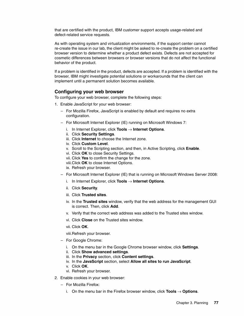
that are certified with the product, IBM customer support accepts usage-related and defect-related service requests.
As with operating system and virtualization environments, if the support center cannot re-create the issue in our lab, the client might be asked to re-create the problem on a certified browser version to determine whether a product defect exists. Defects are not accepted for cosmetic differences between browsers or browser versions that do not affect the functional behavior of the product.
If a problem is identified in the product, defects are accepted. If a problem is identified with the browser, IBM might investigate potential solutions or workarounds that the client can implement until a permanent solution becomes available.
Configuring your web browserTo configure your web browser, complete the following steps:
1. Enable JavaScript for your web browser:
– For Mozilla Firefox, JavaScript is enabled by default and requires no extra configuration.
– For Microsoft Internet Explorer (IE) running on Microsoft Windows 7:
i. In Internet Explorer, click Tools → Internet Options.ii. Click Security Settings.iii. Click Internet to choose the Internet zone.iv. Click Custom Level.v. Scroll to the Scripting section, and then, in Active Scripting, click Enable.vi. Click OK to close Security Settings.vii. Click Yes to confirm the change for the zone.viii.Click OK to close Internet Options.ix. Refresh your browser.
– For Microsoft Internet Explorer (IE) that is running on Microsoft Windows Server 2008:
i. In Internet Explorer, click Tools → Internet Options.
ii. Click Security.
iii. Click Trusted sites.
iv. In the Trusted sites window, verify that the web address for the management GUI is correct. Then, click Add.
v. Verify that the correct web address was added to the Trusted sites window.
vi. Click Close on the Trusted sites window.
vii. Click OK.
viii.Refresh your browser.
– For Google Chrome:
i. On the menu bar in the Google Chrome browser window, click Settings.ii. Click Show advanced settings.iii. In the Privacy section, click Content settings.iv. In the JavaScript section, select Allow all sites to run JavaScript.v. Click OK.vi. Refresh your browser.
2. Enable cookies in your web browser:
– For Mozilla Firefox:
i. On the menu bar in the Firefox browser window, click Tools → Options.
Chapter 3. Planning 77

ii. On the Options window, select Privacy.iii. Set “Firefox will” to Use custom settings for history.iv. Select Accept cookies from sites to enable cookies.v. Click OK.vi. Refresh the browser.
– For Microsoft Internet Explorer:
i. In Internet Explorer, click Tools → Internet Options.ii. Click Privacy. Under Settings, move the slider to the bottom to allow all cookies.iii. Click OK.iv. Refresh your browser.
– For Google Chrome:
i. On the menu bar in the Google Chrome browser window, click Settings.ii. Click Show advanced settings.iii. In the Privacy section, click Content settings.iv. In the Cookies section, select Allow local data to be set.v. Click OK.vi. Refresh your browser.
3. For Mozilla Firefox only, enable scripts to disable or replace context menus:
a. On the menu bar in the Firefox browser window, click Tools → Options.b. On the Options window, select Content.c. Click Advanced by the Enable JavaScript setting.d. Select Disable or replace context menus.e. Click OK to close the Advanced window.f. Click OK to close the Options window.g. Refresh your browser.
4. Enable TLS 1.1/1.2 (Microsoft Internet Explorer 10 only; for Internet Explorer 11 and later TLS 1.1 or 1.2 enabled by default):
a. Open Internet Explorer.b. Select Tools → Internet Options.c. Select the Advanced tab.d. Scroll to the Security section.e. Check Use TLS 1.1 and Use TLS 1.2.
3.11 Licensing
Only one license is used with the FlashSystem 900. The FlashSystem 900 storage system supports AES XTS 256 data-at-rest encryption when the Encryption Enablement Pack, Feature Code AF14 is ordered.
For assistance with or more information about the Encryption Enablement Pack for the FlashSystem 900, contact your IBM sales representative or IBM Business Partner.
3.12 Supported hosts and operating system considerations
For more information about supported operating systems, hosts, switches, and so on, see the IBM System Storage Interoperation Center (SSIC) website.
78 Implementing IBM FlashSystem 900 Model AE3

If a configuration that you want is not available at the SSIC, a Storage Customer Opportunity REquest (SCORE) must be submitted to IBM requesting approval. To submit a SCORE, contact your IBM representative or IBM Business Partner.
Chapter 3. Planning 79

80 Implementing IBM FlashSystem 900 Model AE3

Chapter 4. Installation and configuration
In this chapter, you learn how to install and configure the IBM FlashSystem 900. The chapter describes system cabling and management, and demonstrates how the initial setup procedure prepares the system for use.
This chapter includes the following topics:
� 4.1, “First-time installation” on page 82� 4.2, “Cabling the system” on page 84� 4.3, “Initializing the system” on page 88� 4.4, “RAID storage modes” on page 115� 4.5, “Connectivity guidelines for improved performance” on page 116
4
© Copyright IBM Corp. 2018. All rights reserved. 81

4.1 First-time installation
The initial installation of the IBM FlashSystem 900 includes unpacking the system and installing it in a rack. When the system is physically installed in rack, it must be connected to power and cabled for management. Also, it must be cabled for communication with hosts.
This chapter describes unpacking the system to getting it ready for use.
4.1.1 Installing the hardware
The replaceable components of the IBM FlashSystem 900 are installed from the front or the back of the enclosure.
Installation posterThe installation poster (see Figure 4-1) that is included with the system when it is delivered from the factory is an overview of how to prepare the system for first-time use.
Figure 4-1 Installation poster
Rack installationTo install an enclosure in a rack, complete the following steps:
1. Install the rack mount rails.
2. Align the enclosure with the front of the rack cabinet.
82 Implementing IBM FlashSystem 900 Model AE3

3. Carefully slide the enclosure into the rack along the rails until the enclosure is fully inserted.
4. Secure the enclosure to the rack with a screw in the rack-mounting screw hole on each side of the enclosure.
5. Remove the front bezel to reveal the holes for the screws.
6. Insert the screws.
7. Replace the bezel by snapping it in place.
8. Install the two battery modules.
The rails are not designed to hold an enclosure that is partially inserted. The enclosure must always be in a fully inserted position. To reduce the weight of the enclosure before lifting it, you can temporarily remove the two battery modules and the flash modules from the front of the enclosure.
Installing batteries The IBM FlashSystem 900 storage system features two redundant backup batteries. In a power loss to the enclosure, the batteries supply power so that any volatile data is written to the flash modules and the system shuts down in an orderly manner.
The IBM FlashSystem 900 batteries install in the left front side of the enclosure and plug into the midplane, as shown in Figure 4-2.
Figure 4-2 Installing the batteries
Note: Different screw sizes might be used in the rack kit. Select the longest screws that fit the holes in the enclosure and rack.
Note: Install the enclosure where it can be easily serviced. Ensure that the rack is kept stable by installing the enclosures from the bottom to the top.
Note: Because the IBM FlashSystem 900 does not include power switches, the system is powered on whenever power is applied to one of the power inlets. Batteries and flash cards must be installed before power cables are connected to the power inlets.
Chapter 4. Installation and configuration 83

4.2 Cabling the system
Various issues must be considered when you plan and physically install the IBM FlashSystem 900. In this section, we review these issues and describe preferred practice considerations for Fibre Channel cabling, network cabling, physical installation, and configuration.
4.2.1 Cabling for Fibre Channel
IBM FlashSystem 900 model AE3 supports 16 Gbps Fibre Channel (FC), 8 Gbps FC, or Quadruple Data Rate (QDR) InfiniBand interfaces.
In this example environment, the FlashSystem 900 is configured with four dual port 16 Gbps FC cards, for a total of eight 16 Gbps FC ports. Only two ports for each card are active for 16 Gbps. The optimal cabling scenario with this hardware configuration is to cable Port 1 (P1) on each interface card to storage area network (SAN) Fabric A and Port 2 (P2) on each card to SAN Fabric B, as shown in Figure 4-3.
Figure 4-3 Cabling for 16 Gbps FC connectivity
The FC interface cards feature four ports, but only port P1 and P2 are enabled in the 16 Gbps configuration. The same type of interface card hardware is used for 8 Gbps FC connectivity; however, all four ports on each interface card are enabled in the 8 Gbps FC configuration. This configuration achieves SAN fabric switch-level redundancy and IBM FlashSystem 900 interface card-level redundancy, which provides protection in an issue or failure.
Another consideration is to distribute the IBM FlashSystem 900 FC ports onto different SAN switch port groups to distribute the workload and provide the best available bandwidth. For more information about SAN switch port groups for IBM and Brocade switches, see Implementing an IBM b-type SAN with 8 Gbps Directors and Switches, SG24-6116.
If the environment includes only a single SAN switch, all FC ports from the FlashSystem 900 are cabled to this switch. Although this configuration is technically possible, it does not provide any redundancy in a SAN switch failure.
84 Implementing IBM FlashSystem 900 Model AE3

FC port speed settings When running FC, the IBM FlashSystem 900 can be configured with up to 8 ports at 16 Gbps or 16 ports at 8 Gbps.
Depending on the configuration, the connected SAN switches can run at 16 Gbps or 8 Gbps. However, the IBM FlashSystem 900 FC ports can also run at 4 Gbps, if required. The preferred practice is to manually configure and fix the speed of the SAN switch ports to the highest mutually available speed, rather than using auto negotiate. This process is done for consistency and stability.
Example 4-1 shows a truncated switchshow command, output from an IBM SAN switch, and shows the ports that are connected to the IBM FlashSystem 900 set to 16 Gbps.
Example 4-1 The switchshow output from an IBM SAN switch that shows ports connected at 16 Gbps
IBM_2498_F48:FID128:admin> switchshow
Index Port Address Media Speed State Proto==================================================
0 0 010000 id N8 Online FC F-Port 21:01:00:1b:32:2a:23:b11 1 010100 id N16 Online FC F-Port 50:05:07:60:5e:fe:0a:dd2 2 010200 -- N16 No_Module FC3 3 010300 -- N16 No_Module FC4 4 010400 id N8 Online FC F-Port 21:00:00:24:ff:22:f9:ea5 5 010500 id N16 Online FC F-Port 50:05:07:60:5e:fe:0a:d96 6 010600 -- N16 No_Module FC7 7 010700 -- N16 No_Module FC8 8 010800 id N16 Online FC F-Port 10:00:8c:7c:ff:0b:0f:009 9 010900 id N16 Online FC F-Port 10:00:8c:7c:ff:0b:78:8110 10 010a00 -- N16 No_Module FC11 11 010b00 id N8 Online FC F-Port 10:00:00:00:c9:d4:94:11
The N16 identifier under the Speed column in Example 4-1 indicates that the system negotiates to 16 Gbps. To fix the ports at 16 Gbps, use the command that is shown in Example 4-2.
Example 4-2 Fixing port speed at 16 Gbps on the IBM/Brocade SAN switch
IBM_2498_F48:FID128:admin> portcfgspeed 1 16;IBM_2498_F48:FID128:admin> portcfgspeed 5 16;
IBM_2498_F48:FID128:admin> switchshow
Index Port Address Media Speed State Proto==================================================0 0 010000 id N8 Online FC F-Port 21:01:00:1b:32:2a:23:b11 1 010100 id 16G Online FC F-Port 50:05:07:60:5e:fe:0a:dd2 2 010200 -- N16 No_Module FC3 3 010300 -- N16 No_Module FC4 4 010400 id N8 Online FC F-Port 21:00:00:24:ff:22:f9:ea5 5 010500 id 16G Online FC F-Port 50:05:07:60:5e:fe:0a:d9
Note: The 16 Gbps FC and 8 Gbps FC configurations use the same adapter; however, a configuration change is required to convert 8 Gbps - 16 Gbps. To change the configuration, the correct feature must be ordered from IBM as a Miscellaneous Engineering Specification (MES). The MES includes the SFPs and instructions that are required for IBM to change the configuration to 16 Gbps (eight ports) or 8 Gbps (16 ports).
Chapter 4. Installation and configuration 85

6 6 010600 -- N16 No_Module FC7 7 010700 -- N16 No_Module FC8 8 010800 id 16G Online FC F-Port 10:00:8c:7c:ff:0b:0f:009 9 010900 id 16G Online FC F-Port 10:00:8c:7c:ff:0b:78:8110 10 010a00 -- N16 No_Module FC11 11 010b00 id N8 Online FC F-Port 10:00:00:00:c9:d4:94:11
The ports are no longer negotiating speed; instead, they are fixed to 16 Gbps.
For more information about how to configure the IBM and Brocade SAN switches for the correct and optimal interconnection with the IBM FlashSystem 900, see IBM b-type Gen 5 16 Gbps Switches and Network Advisor, SG24-8186.
4.2.2 Cabling for QDR InfiniBand
The IBM FlashSystem 900 supports Quadruple Data Rate (QDR) InfiniBand when it is ordered with the necessary interface cards for this protocol. Each interface card features two ports that operate at 40 Gbps. The IBM FlashSystem 900 supports four QDR InfiniBand adapters for a total of eight ports, each operating at 40 Gbps.
QDR InfiniBand is used in situations where powerful, high-demand servers need high-bandwidth access to the IBM FlashSystem 900.
The 40 Gbps QDR InfiniBand host bus adapters (HBAs) can be ordered from IBM or from Mellanox Technologies. Mellanox Technologies also offers InfiniBand switches with which you can connect multiple hosts through a redundant switch configuration to a single IBM FlashSystem 900.
Cables that are used for QDR InfiniBand can be ordered from IBM and can be up to 10 meters (32.8 feet) long.
A FlashSystem 900 canister that is mounted with a four-port QDR InfiniBand interface card is shown in Figure 4-4.
Figure 4-4 QDR InfiniBand interface card
4.2.3 FC cable type
OM3 standard cabling must be used (where possible) to provide the clearest connection. All of the connectors must be the LC-LC connector standard.
86 Implementing IBM FlashSystem 900 Model AE3

4.2.4 Ethernet management cabling
The IBM FlashSystem 900 contains dual management control processors, each with its own Ethernet management port. These two Ethernet management ports operate with a single clustered IP address for system management. If one control canister is taken out for service or is inoperable, the other control canister services the clustered IP address. The control canister is also referred to as the config node.
Individual canister service IP addresses are configurable through the Ethernet management ports. These IP addresses provide access to each of the canister modules and are, among other features, can set a canister into a service state or restart a specified canister.
The Ethernet management ports on the system are shown in Figure 4-5 on page 88.
The default speed setting of the IBM FlashSystem 900 Ethernet management network interface is auto, which allows the port to negotiate speed and duplex settings with the switch. The maximum configurable speed of the interface is 1 Gbps full duplex.
4.2.5 Power requirements
The IBM FlashSystem 900 includes dual, redundant AC power modules. Plan to attach each of the two power supplies in the enclosure to separate main power supply lines and to power sources that provide power in the 100 - 240 V AC range, depending on the country.
A single IBM FlashSystem 900 includes a power consumption rating of 1300 watts maximum with 625 watts that is typically seen operating in RAID 5.
Although the system operates when only one power supply is connected, this configuration is not advised. By using the power cords that are provided, connect each IBM FlashSystem 900 power inlet to an uninterruptible power supply (UPS) battery-backed power source. If possible, always connect each of the power cords to separate circuits.
4.2.6 Cooling requirements
The IBM FlashSystem 900 storage system features a British Thermal Unit (BTU) per-hour rating of approximately 2133 BTU. For maximum configurations, it can be as high as 4107 BTU. It is suggested that the cooling vents in the room are at the front of the rack because the air flows from the front of the rack to the back.
4.2.7 Cable connector locations
The IBM FlashSystem 900 includes cable connections for power and management and optional connections for FC or QDR InfiniBand interface cards.
Tips: The IBM FlashSystem 900 device must be connected to a UPS-protected power source and each power supply must be on a different power feed to provide power redundancy.
So that the 1300-watt power supply can supply the full 1300 watts for which it is rated, it must be attached to a high-line voltage (220 - 240 volts).
Chapter 4. Installation and configuration 87

The FC interface cards are typically used for connecting to switches where multiple servers can connect to the IBM FlashSystem 900. The QDR InfiniBand interfaces can be connected directly to a host, or they can be connected through QDR InfiniBand switches.
For more information about various options for host connectivity, see Chapter 2, “IBM FlashSystem 900 Model AE3 architecture” on page 19.
For more information about planning for Ethernet connections and connectivity, see Chapter 3, “Planning” on page 59.
The rear side of the IBM FlashSystem 900 and its connectors is shown in Figure 4-5.
Figure 4-5 Rear view of the IBM FlashSystem 900
The IBM FlashSystem 900 model AE3 is configured with 16 Gbps FC, 8 Gbps FC, or 40 Gbps QDR InfiniBand interface cards. Combinations of interface card types in a single system are not supported. The FlashSystem 900 that is shown in Figure 4-5 is configured with FC interface cards.
4.3 Initializing the system
After installing and powering on the new system, you must initialize it to manage it. You use InitTool, the System Setup wizard in the web management interface, and FlashSystem 900 Storage Management, to initialize your system.
Complete the following steps:
1. Prepare a USB flash drive with the correct IP address by using InitTool by inserting the provided USB flash drive into a personal computer.
2. Run the InitTool and follow the instructions for the use the System Initialization wizard.
3. Initialize the system by inserting the USB flash drive into the left canister USB port.
4. Wait for the initialization to complete. Then, insert the USB flash drive back into the same computer that was used in step 1.
5. Use the InitTool final window to review the results of the initialization (a summary window is shown in Figure 4-15 on page 98).
6. Log on to the system by using your web browser to the FlashSystem 900 Storage Management GUI and continue with the System Setup wizard (see Figure 4-20 on page 103).
Left Canister Interface Cards Right Canister Interface Cards
USB USBManagement Management
Power
Power
88 Implementing IBM FlashSystem 900 Model AE3

4.3.1 Using the InitTool
The supplied USB flash drive contains an initialization tool called InitTool, which is used to initialize the system. After initializing, you can access the web management interface to complete the configuration procedures.
InitTool supports the following operating systems:
� Microsoft Windows XP (32-bit)� Microsoft Windows 7 (64-bit)
Before you begin the initialization process, consider the following points:
� Ensure that the physical installation of the enclosure is complete. � A computer is needed to complete the initialization procedure. � The computer must include a USB 2.0 port.
To initialize the system, complete the following steps:
1. Gather the following information that is needed to configure the system:
a. You must have the IP network address that you use to manage the system:
• IP address• Subnet mask• Gateway
b. Optional: The following information is useful for enabling more capabilities:
• IP address of a Network Time Protocol (NTP) server for automatically setting date and time
• IP address of a Simple Mail Transfer Protocol (SMTP) server for sending alert notifications by using email
c. In the documentation package, find the USB flash drive that is included with your order.
d. Insert the USB flash drive into a USB port on the personal computer. If Windows is configured for autorun, the InitTool starts automatically.
e. If Windows is not configured for autorun, open the USB flash drive and double-click InitTool.bat. The initialization tool wizard starts.
2. In the wizard, click Next. When prompted with the question, “Are you configuring a new system?”, click Yes. Then, click Next.
3. In the wizard, complete the following steps:
Note: If you do not have the original USB flash drive that is provided with your system that that includes the InitTool.bat file, download the latest software archive file initTool_9840.zip from the IBM Fix Central website. The FlashSystem 900 fixes are located at:
https://www.ibm.com/support/fixcentral/swg/selectFixes?parent=Flash%20high%20availability%20systems&product=ibm/StorageSoftware/IBM+FlashSystem+900&release=All&platform=All&function=all
Note: To initialize a FlashSystem 900 AE3 that uses Linux or any other operating system, you must create a special text file and copy it to a USB flash drive manually. For more information, see “Initializing a system by using Linux or other operating system” on page 99.
Chapter 4. Installation and configuration 89

a. Enter the information about the system management address that you want to use.
b. Plug both power cables into the power supply units.
Wait for the canister status LEDs on both canisters to flash, as shown in Figure 4-6. This process can take up to 10 minutes.
Figure 4-6 Canister Status LED
c. Insert the USB flash drive into the IBM FlashSystem 900 and allow it to initialize. Wait until the status LED on both canisters is solid. The process can take up to 20 minutes.
d. Return the flash drive to the workstation to check that the initialization process completed.
4. If the system initialization completed successfully, click Finish.
If you have a network connection to the system, the system management GUI is displayed.
If the workstation does not have a network connection to the system, go to the workstation that you use to manage the system and start a supported browser. Browse to the management address that you specified for the system.
5. Log in with the following user name and password:
– User name: superuser – Password: passw0rd (The “0” character in the password is a zero.)
6. Follow the instructions in the window to begin setting up your system.
90 Implementing IBM FlashSystem 900 Model AE3

Example: Use of Microsoft Windows to initializeThe following example shows the steps to initialize the system by using a Microsoft Windows-based computer to prepare the supplied USB flash drive by using InitTool.
The first window in the System Initialization wizard shows that the tool can be used for the following tasks:
� Installing a new system.� Resetting the superuser password.� Setting the service IP address of a canister.
Starting the InitTool processThe initial step in the use of InitTool is shown in Figure 4-7.
Figure 4-7 System Initialization (InitTool) Welcome
Chapter 4. Installation and configuration 91

TasksIn the second step of the System Initialization wizard, select Yes to configure a new system, as shown in Figure 4-8.
Figure 4-8 InitTool Tasks
If you select No, the InitTool assumes that you cannot access your system and gives you the following options:
� Reset the superuser password � Set the service IP address
92 Implementing IBM FlashSystem 900 Model AE3

Management IP AddressIn the next step of the System Initialization wizard, enter the IP address for managing the IBM FlashSystem 900, as shown in Figure 4-9.
Figure 4-9 InitTool Management IP Address window
Chapter 4. Installation and configuration 93

Power onIn the next step, you are instructed to power on the IBM FlashSystem 900 and wait for the status LEDs of both canisters to flash, as shown in Figure 4-10. Powering on can take up to 10 minutes.
Figure 4-10 InitTool Power on
94 Implementing IBM FlashSystem 900 Model AE3

Insert USB flash drive into canisterIn the next step, you are instructed to remove the USB flash drive from the computer and insert it into the USB port in the left IBM FlashSystem 900 canister (controller), as shown in Figure 4-11. At the end of the process, the Identify LED turns on and then off.
Figure 4-11 InitTool Insert USB flash drive into canister
When the system initialization process finishes, a results file (satask_result.html) is written to the USB flash drive by the IBM FlashSystem 900 canister. The results file indicates the success or failure of the process. InitTool can be used to verify this result.
Note: The USB flash drive must be inserted into the left canister to correctly initialize the IBM FlashSystem 900.
Note: The Identify LED turns on briefly, then off for approximately 1 minute, then on again, as it writes the results of the setup command to the USB. Wait at least 5 minutes after the Identify LED stops flashing before removing the USB from the canister.
Chapter 4. Installation and configuration 95

Reinsert USB flash drive into personal computerIn the next step, you are prompted to reinsert the USB flash drive into the Microsoft Windows computer, as shown in Figure 4-12.
Figure 4-12 Reinsert USB flash drive into personal computer
System initialization failedIf system initialization fails, a message is displayed, as shown in Figure 4-13.
Figure 4-13 System initialization failed
96 Implementing IBM FlashSystem 900 Model AE3

System initialization can fail for several reasons. Follow the steps that are shown in the window to resolve the situation. The initialization process checks the content of the satask_result.html file. The Next option is enabled for the initialization process to continue only if a cluster was successfully created.
Check connectivityInitialization now checks connectivity to the IBM FlashSystem 900, as shown in Figure 4-14.
Figure 4-14 InitTool: Verify connectivity
SummaryIf the Ethernet ports of the newly initialized FlashSystem 900 are attached to the same network as the personal computer where InitTool was run, InitTool checks the connectivity to the system and displays the result of the system initialization process.
When connectivity is successful, the Summary window opens, as shown in as Figure 4-15 on page 98.
Chapter 4. Installation and configuration 97

Figure 4-15 Summary
Click Finish. A message indicates that the initialization process completed successfully. You are then redirected to the Management GUI if the computer is on the same network as the FlashSystem.
The first part of the InitTool process is now completed. You can use the FlashSystem Storage Management GUI (see Figure 4-21 on page 104) to complete the configuration process.
If your browser is not opened automatically to the Management GUI, open a web browser and log on to the system by using the selected IP address. For more information, see 4.3.2, “Initializing the system by using the web management interface” on page 101.
Note: By default, a FlashSystem 900 uses a self-signed SSL certificate. Your web browser might issue a warning regarding this certificate when the browser is redirected to the FlashSystem management GUI for the first time to run the System Setup wizard. The self-signed SSL certificate can be replaced after the initial configuration with an authenticated, third-party certified SSL certificate, if wanted.
98 Implementing IBM FlashSystem 900 Model AE3

Initializing a system by using Linux or other operating systemAn alternative to the use of the InitTool and a computer with a supported version of Windows is to prepare a USB flash drive manually by using a plain text editor. You can use the USB flash drive that is supplied with the FlashSystem or any USB flash drive that is formatted with a FAT32, ext2, or ext3 file system.
Complete the following steps:
1. Gather the following information that you use to configure the system:
a. The IP network address that is used to manage the system:
• IP address (cluster-IP)• Subnet mask (mask)• Gateway (gw)
b. Optional: The following information is useful for enabling more capabilities:
• IP address of a Network Time Protocol (NTP) server for automatically setting date and time
• IP address of a Simple Mail Transfer Protocol (SMTP) server for sending alert notifications by way of email
2. Create a file that is named satask.txt in the root directory of the USB drive.
3. Edit the file by using a plain text editor, such as vi for Linux, and insert the following command as the only line in the file:
satask mkcluster -clusterip <cluster_IP> -gw <gateway_IP> -mask <mask>
4. Save the file as plain text.
5. Power on the IBM FlashSystem 900 and wait for the status LEDs of both canisters to flash, as shown in Figure 4-16. The powering on process can take up to 10 minutes.
Figure 4-16 Canister status LED
Chapter 4. Installation and configuration 99

When both canisters are powered on and both canisters’ status LEDs are flashing, insert the USB drive into the USB port of the left IBM FlashSystem 900 canister (controller), as shown in Figure 4-17. At the end of the process, the Identify LED turns on and then off (see Figure 4-17).
Figure 4-17 Inserting USB drive into canister and canister identify LED
6. When the system initialization process finishes, a results file, satask_result.html, is written to the USB flash drive by the IBM FlashSystem 900 canister. The results file indicates the success or failure of the process. A plain text editor can be used to verify this result. If the initialization is successful, the results file shows Success, and both canisters are in active mode, as shown in Figure 4-18.
Figure 4-18 Successful initialization results in satask_result.html
7. After successful initialization of the system, a cluster is created and you can use the FlashSystem Storage Management GUI to complete the configuration process. Open a web browser and sign in to the system by using the management IP address, as described in 4.3.2, “Initializing the system by using the web management interface” on page 101.
Note: The Identify LED turns on briefly, then off for about 1 minute, then on again, as it writes the results of the setup command to the USB. Wait at least 5 minutes after the Identify LED stops flashing before removing the USB from the canister.
100 Implementing IBM FlashSystem 900 Model AE3

Other purposes of InitToolThe InitTool can be used for other purposes in addition to initializing IBM FlashSystem 900. InitTool can also be used if you are unable to access the system. InitTool provides the following options:
� Reset the superuser password
You can access the login prompt, but you do not know the superuser password. InitTool can be used to modify the superuser password.
� Set the service IP address
You want to access a specific canister, but you do not know the service IP addresses. Specifying /service in the URL (for example: http://10.5.10.8/service) does not open the IBM FlashSystem 900 Service Assistant Tool. InitTool can be used to modify the service IP address for each canister individually.
As with the IBM FlashSystem 900 initialization process, InitTool creates a file (satask.txt) on the USB flash drive. This file contains a Service Assistant (satask) command that is read and run by the IBM FlashSystem 900 canister when the US flash drive is inserted into the USB port of the system. The results of running the command are shown in the results file (satask_result.html).
4.3.2 Initializing the system by using the web management interface
After the IBM FlashSystem 900 is initialized by using the USB flash drive, you use a supported web browser to point it to the selected address.
Supported web browsersThe web-based GUI simplifies storage management and provides a fast and efficient management tool. It is loosely based on the IBM System Storage XIV software and features a similar look and behavior.
The management GUI requires a supported web browser. At the time of this writing, the management GUI supports the following web browsers with equal or later versions:
� Mozilla Firefox 54� Mozilla Firefox Extended Support Release (ESR) 52� Microsoft Internet Explorer (IE) 11 and Microsoft Edge 40� Google Chrome 59
IBM supports later versions of the browsers if the vendors do not remove or disable functionality on which the product relies.
Web browsers include the following requirements:
� JavaScript must be enabled.� Cookies must be allowed.� Scripts must be enabled to disable or replace menus (Mozilla Firefox only).
Note: By default, a FlashSystem 900 uses a self-signed SSL certificate. Your web browser might issue a warning regarding this certificate when the browser is redirected to the FlashSystem management GUI for the first time after initialization. The self-signed SSL certificate can be replaced after initial configuration with an authenticated, third-party certified SSL certificate, if wanted.
Chapter 4. Installation and configuration 101
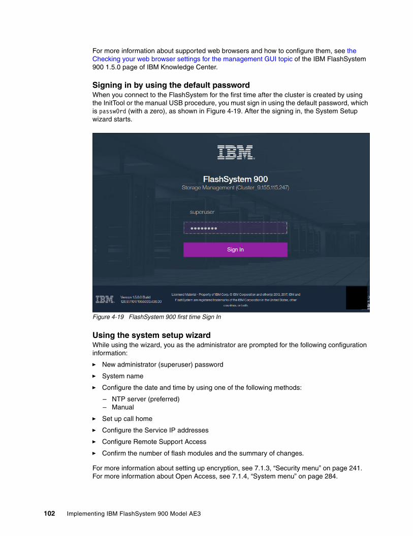
For more information about supported web browsers and how to configure them, see the Checking your web browser settings for the management GUI topic of the IBM FlashSystem 900 1.5.0 page of IBM Knowledge Center.
Signing in by using the default passwordWhen you connect to the FlashSystem for the first time after the cluster is created by using the InitTool or the manual USB procedure, you must sign in using the default password, which is passw0rd (with a zero), as shown in Figure 4-19. After the signing in, the System Setup wizard starts.
Figure 4-19 FlashSystem 900 first time Sign In
Using the system setup wizard While using the wizard, you as the administrator are prompted for the following configuration information:
� New administrator (superuser) password
� System name
� Configure the date and time by using one of the following methods:
– NTP server (preferred)– Manual
� Set up call home
� Configure the Service IP addresses
� Configure Remote Support Access
� Confirm the number of flash modules and the summary of changes.
For more information about setting up encryption, see 7.1.3, “Security menu” on page 241. For more information about Open Access, see 7.1.4, “System menu” on page 284.
102 Implementing IBM FlashSystem 900 Model AE3

These steps can also be configured after the System Setup wizard is completed. These configuration settings can be changed by using the GUI or the CLI.
Welcome windowThe System Setup wizard begins with the Welcome window, as shown in Figure 4-20. The Welcome window of the System Setup wizard prompts you for the following information:
� Any optional licenses� Email (SMTP) server IP address for sending emails with warnings and alerts� Service IP addresses for both canisters� IP addresses for Remote Support Proxy Servers
Figure 4-20 Welcome window
Although not references in the Welcome window, you might also need the following information:
� NTP server IP address for automatic and accurate system time� Email addresses for local users who receive warnings and alerts� Contact information for call home
Click Next to proceed to the Change Password window.
Chapter 4. Installation and configuration 103

Changing the passwordIn this step, you change the password for the superuser ID. Enter a new password and confirm it (see Figure 4-21). Click Apply and Next.
Figure 4-21 Change Password
The IBM FlashSystem 900 administrators are encouraged not to leave the superuser password as the default but instead to create individual users with their own passwords for security reasons. You can also configure authentication and authorization for users of the clustered system, as described in “Configure remote authentication” on page 242.
104 Implementing IBM FlashSystem 900 Model AE3

Configuring a system nameNext, enter a name for the system. Our example uses the system name FlashProd01_Cluster_xx.xx.xx.xx, as shown in Figure 4-22. The host name can be changed later from the main window at the FlashSystem 900 GUI.
Figure 4-22 Initialization procedure to name the system
Chapter 4. Installation and configuration 105

Configuring date and timeNext, configure the system date and time. The preferred practice is to configure the system with an NTP server. By using an NTP server, the date and time settings are always correct, which is useful in log analysis and troubleshooting. If an NTP server is not available at the time of installation, it can be added later. You can then set the date and time manually, as shown in Figure 4-23.
Figure 4-23 Initialization procedure date and time
When a new command runs, the Task window opens. At first, the Task window shows collapsed output. By clicking View more details, the expanded output shows the command that is run on the IBM FlashSystem 900 (see Figure 4-24).
Figure 4-24 Initialization procedure task running
A shortcut to setting the date and time manually is to select the Use Browser Settings option, which causes the date and time to be inherited from the web browser that is used.
106 Implementing IBM FlashSystem 900 Model AE3

Configuring the call home featureNext, configure the call home feature, which sends emails with messages and alerts to IBM Support.
The following information must be provided to set up call home:
� System Location where the system physically.
� Contact Details of who IBM Support can contact for issues that require attention:
– Name– Phone– Email
� Email server or servers (SMTP server):
– IP address– Port (defaults to port 25)
After initial setup, you also can add the email addresses of other people whom you want to be notified of alerts, warnings, or errors. These addresses can be configured by clicking Settings → Notifications, as described in 7.1.1, “Notifications menu” on page 231.
System locationEnter the information about the system’s location in the System Location window, as shown in Figure 4-25. If State or Province is not applicable to your location, use XX for that field.
Figure 4-25 System Location settings for call home
Enter the location information for the system and click Next.
Chapter 4. Installation and configuration 107

Contact informationEnter the support contact information in the Contact window, as shown in Figure 4-26. This contact is the person that IBM support contacts when a problem is reported to IBM by using the call home feature.
Figure 4-26 Contact information for call home
Enter the contact information and click Apply and Next.
Email serversThe next step is to enter the IP address and port of an email (SMTP) server that is used to relay call home and event notification email messages. Enter an IP address, verify the port number (port 25 is the default for email servers), and click Ping to verify that the server’s IP address is active, as shown in Figure 4-27 on page 109.
108 Implementing IBM FlashSystem 900 Model AE3

Figure 4-27 Email Servers configuration
If you click Apply and Next, the call home feature is activated. Optionally, you can choose to set up call home later by selecting the Set up call home later option at the bottom of the window, as shown in Figure 4-28.
Figure 4-28 Set up call home later
If you choose to set up call home later, a warning message is displayed, as shown in Figure 4-29.
Figure 4-29 Initialization procedure: Call home warning
Chapter 4. Installation and configuration 109

Service IP addressesThe service IP addresses provide access to the system if a problem occurs accessing the management GUI or cluster CLI. The addresses must be configured to use the Remote Support Assistance (RSA) feature. The addresses must be different than the IP address for the system (cluster IP address). Enter the IP addresses of the service ports and click Apply and Next (see Figure 4-30).
Figure 4-30 Service IP address configuration
If you select the Set up Service IPs Later option, a pop-up window opens, as shown Figure 4-31.
Figure 4-31 Service IP address warning pop-up window
110 Implementing IBM FlashSystem 900 Model AE3

Remote Support AssistanceIn the next few windows in the setup wizard, you set up the RSA feature. For more information about RSA, see 1.6.2, “Remote Support Assistance” on page 16.
To configure remote support, you must decide how it is set up. Consider the following points:
� If you use a remote support proxy, the IP address and port of the proxy is required. The FlashSystem uses the IBM XIV Remote Support Proxy. The use of a proxy for remote support is optional.
� You must choose the access level that the support center uses. Remote access can be configured to be one of the following settings:
– Always on– On only when an error occurs– On only when given permission by a FlashSystem administrator
� Optionally, an access code can also be specified. If specified, the administrator must supply this code to the support center for the support person to access the system.
If you use a proxy, enter the remote support center proxy information in the window, as shown on Figure 4-32. Then, click Apply and Next.
Figure 4-32 Support center proxy information
If you do not want to set up remote support, select the Set up remote support assistance later option and click Apply and Next.
Configuring access settingsIf you are configuring remote access, you must choose when the support center can access the system, as shown in Figure 4-33 on page 112. Select an option and click Apply and Next.
Chapter 4. Installation and configuration 111

Figure 4-33 Remote support access settings
Specifying access codeThe last step in configuring remote support is to specify an optional access code. Enter a code or leave the field blank and click Apply and Next (see Figure 4-34).
Figure 4-34 Remote support access code
112 Implementing IBM FlashSystem 900 Model AE3

SummaryThe final step in the system set up process is to view the Summary page, as shown in Figure 4-35. Review the information to ensure that it is accurate. If you are satisfied with the summary, click Finish to complete the set up process.
Figure 4-35 System setup summary
When you click Finish, a single RAID 5 array is created and formatted by using the modules that are installed in the system. One flash module is reserved and acts as an active spare while the remaining modules form the RAID 5 array.
With six flash modules, the usable capacity consists of the capacity of four modules because one is used for spare and the other is used for the parity that is used in RAID 5 protection. The FlashSystem uses a distributed parity scheme as described in 2.2.5, “MicroLatency modules” on page 44.
Completing the initializationIt takes approximately 3 minutes to create and format the array and complete the initialization. When the process is completed, a pop-up window displays a task completed message. Click Close and the Setup Completed pop-up window is displayed, as shown in Figure 4-36. When you click Close, you are redirected to the system management GUI.
Figure 4-36 Setup completed
Chapter 4. Installation and configuration 113

Initialization completeThe IBM FlashSystem 900 is now initialized and ready to use. The web browser automatically opens to the Dashboard page of the management GUI, as shown in Figure 4-37.
Figure 4-37 IBM FlashSystem 900 Dashboard
For more information about how to use the FlashSystem 900 GUI, see Chapter 6, “Using IBM FlashSystem 900” on page 157.
Clicking Suggested tasks icon in the upper right of the dashboard page displays the likely next steps in configuration process. As shown in Figure 4-38, it suggests creating host objects or enabling encryption. If you click Not Now, the suggestion is cleared but might reappear later twice.
Figure 4-38 Suggested tasks
If you close a suggested task three times, it does not reappear.
114 Implementing IBM FlashSystem 900 Model AE3

4.3.3 Service Assistant Tool
IBM FlashSystem 900 Service Assistant Tool can be used in various service event cases. Service Assistant Tool is normally used only in cases where the client is instructed to use it by IBM Support because the tool includes destructive and disruptive functions.
IBM FlashSystem 900 Service Assistant Tool includes the following features:
� Review installed hardware and firmware� Review Ethernet ports and IP addresses� Review worldwide names (WWNs)� Change WWNs� Canister enters the Service state� Canister restart� Collect logs� Reinstall software� Configure CLI access� Restart web service� Recover system
Service Assistant Tool can be opened by using one of the following methods:
� Point your web browser directly to the service IP address of each canister.
� Point your web browser to the management IP address of your IBM FlashSystem 900 and to specify service in the URL, as shown in the following example:
https://192.168.10.10/service
4.4 RAID storage modes
The process to implement the various RAID protection technologies that are used in the IBM FlashSystem 900 is described in 2.2, “Architecture of IBM FlashSystem 900 Model AE3” on page 38.
Variable Stripe RAIDIn addition to RAID 5, which protects the IBM FlashSystem 900 against an entire flash module failure, the IBM FlashSystem 900 supports Variable Stripe RAID. Variable Stripe RAID is a built-in data technology that protects data from subcomponent failure on a flash module.
The subcomponent failure Variable Stripe RAID protects against a plane. When a bad plane occurs, Variable Stripe RAID technology allows a plane to be removed from use without affecting the available capacity of other devices within the RAID stripe.
Upon detection of a failure, the failing plane is removed from use (no further writes are allowed) and all used pages within the affected stripe are marked as “critical to move.” Information from the affected stripe is then gradually relocated to stripes that are known to be good, which is a process that is performed as a background task to minimize the required processing power.
Note: Only the superuser account is allowed to log on to the Service Assistant Tool.
Opening the tool: Service Assistant Tool includes destructive and disruptive functions. Open the Service Assistant Tool only when you are instructed to do so by IBM Support.
Chapter 4. Installation and configuration 115

For more information about Variable Stripe RAID, see in 1.5, “Technology and architectural design overview” on page 8.
4.5 Connectivity guidelines for improved performance
You can configure the various network connections to improve the overall performance of the IBM FlashSystem 900. Considerations for planning the installation of the storage system are described next.
4.5.1 Interface card configuration guidelines
You can improve reliability and performance by following specific network connection guidelines for the interface cards in the enclosure.
The rear side of the IBM FlashSystem 900 when it is installed with four FC interface adapter cards is shown in Figure 4-39.
Figure 4-39 Interface adapter cards
The FlashSystem 900 AE3 enclosure includes two canisters, each containing two FC or QDR InfiniBand interface cards. To eliminate any single failure point, use multipathing to span across interface cards in both canisters. Most major operating systems incorporate a multipathing option.
The storage system allows the flexible presentation of volumes, which are also called logical unit numbers (LUNs), through the interface cards. A volume or LUN can be presented and accessed through every port simultaneously. The loss of one interface card does not affect the I/O performance of the other interface cards. This configuration is commonly referred to as active/active or active/active symmetric multipathing.
Note: The IBM FlashSystem 900 AE3 interface cards are equipped with two 16 Gbps FC, four 8 Gbps FC, or four QDR InfiniBand ports.
Each canister mounts with two interface cards. Although having up to 16 ports on a single IBM FlashSystem 900 is possible, it is not a cabling or zoning requirement that host communication be established through all available ports. Therefore, an attached host can connect to fewer than all four ports on the interface cards.
Interface Adapter Cards
116 Implementing IBM FlashSystem 900 Model AE3

4.5.2 Host adapter guidelines
To improve bandwidth, install dual-port HBAs and host channel adapters (HCAs) in the servers that are used with the storage system. Dual-port HBAs and HCAs provide more ports for aggregating bandwidth. In an ideal case, multiple dual-port HBAs and HCAs are installed in each server for redundancy.
QDR InfiniBand HCAs maximize the bandwidth to the storage system. Most QDR InfiniBand HCAs use PCI Express 2.0 (instead of version 1.0) to allow for the higher-rated bandwidth. Servers with PCI Express 2.0, or later, expansion slots provide the highest bandwidth.
The storage system is tested for interoperability against all major HBA and HCA vendors. To verify valid and supported configurations, see the SSIC website.
4.5.3 Cabling guidelines
As described in 4.2, “Cabling the system” on page 84, several considerations exist that are related to the correct cabling.
Design cabling to provide resiliency across storage system management ports and FC or QDR InfiniBand interface card ports. Also, consider the related network switches and server HBA and HCA ports, and create a design that provides redundancy and features enough paths for optimal performance.
All high-availability concepts of a dual-switched fabric setup apply to the storage system. One key element to recognize when cabling the storage system is the use of available paths.
The storage system is designed to deliver I/O throughput through all connected ports. Use all ports if the application can benefit from more bandwidth. To use these ports on the storage system, there an equal number of server ports must be available. Otherwise, underutilized ports are on one side of the fabric.
4.5.4 Zoning guidelines
In a switched fabric environment, implementing zoning when you connect the storage system to the network can improve performance and simplify upgrades.
In a switched fabric deployment, a common approach is to isolate one application’s server storage devices from server storage devices of other applications. This practice prevents cross-traffic and helps ease maintenance. Therefore, employ zoning in all multiple server environments.
Zoning a server’s HBA or HCA is best deployed when only a single HBA or HCA is contained in a zone. This approach is also referred to as Single Initiator Zoning.
Having more than one HBA or HCA in a zone can lead to unexpected errors and can cause unplanned downtime. HBAs or HCAs are called initiators, and these initiators can be zoned to a single or multiple target ports. A target port is a storage controller port, such as the ports in the IBM FlashSystem 900.
The host initiators must be zoned to sufficient storage target ports to carry the expected workload. However, host initiator ports must not be zoned to more than the necessary number of storage target ports. Zoning host initiator ports to more than the necessary number of storage target ports can result in excessive paths to storage, which can decrease performance.
Chapter 4. Installation and configuration 117

For more information about how to zone an IBM FlashSystem to IBM SAN Volume Controller, see 8.2, “SAN Volume Controller connectivity to FlashSystem 900” on page 320.
For more information about how to zone storage devices to IBM Spectrum Virtualize, see IBM System Storage SAN Volume Controller and Storwize V7000 Best Practices and Performance Guidelines, SG24-7521.
Note: When you connect the storage system to a dual-switched fabric architecture, ensure that each zoned server uses interface cards in both canisters in the storage system. Ensure that each zoned server does not depend on a single interface card or a single canister for availability.
118 Implementing IBM FlashSystem 900 Model AE3

Chapter 5. IBM FlashSystem 900 client host attachment and implementation
This chapter describes the installation, implementation, and other general information and guidelines for connecting client host systems to the IBM FlashSystem 900 (FlashSystem 900).
This chapter includes the following topics:
� 5.1, “Host implementation and procedures” on page 120� 5.2, “Host connectivity” on page 120� 5.3, “Operating system connectivity and preferred practices” on page 122� 5.4, “Miscellaneous host attachment” on page 140� 5.5, “FlashSystem 900 preferred read and configuration examples” on page 140� 5.6, “FlashSystem 900 and Easy Tier” on page 153� 5.7, “Troubleshooting” on page 153
5
IBM SAN Volume Controller and IBM Spectrum Virtualize: Some of the sections in this chapter refer to IBM SAN Volume Controller, which delivers the functions of IBM Spectrum Virtualize and is part of the IBM Spectrum Storage family.
IBM Spectrum Virtualize is industry-leading storage virtualization that enhances storage to improve resource use and productivity so that you can achieve a simpler, more scalable, and cost-efficient IT infrastructure. The functionality of IBM Spectrum Virtualize is provided by IBM SAN Volume Controller.
For more information, see the IBM SAN Volume Controller website.
© Copyright IBM Corp. 2018. All rights reserved. 119

5.1 Host implementation and procedures
The procedures that are used to connect the IBM FlashSystem 900 to client hosts that use various operating systems are described in the following sections.
5.2 Host connectivity
The IBM FlashSystem 900 can be attached to a client host by using the following methods:
� Fibre Channel (FC)� InfiniBand
For more information about supported operating systems, hosts, and switches, see the IBM System Storage Interoperation Center (SSIC).
If a configuration that you want is not available on the SSIC, request approval from IBM by submitting a Storage Customer Opportunity REquest (SCORE). To submit a SCORE, contact your IBM FlashSystem marketing/sales representative or IBM Business Partner.
The IBM FlashSystem 900 can be SAN-attached by using a switch or directly attached to a client host. For more information, see the IBM SSIC. Several operating system and FC driver combinations allow point-to-point direct access with 16 Gbps FC. Check your environment and the IBM SSIC to use 16 Gbps direct attachment to the host.
5.2.1 Fibre Channel SAN attachment
If you attach a host by using a SAN switch to the FlashSystem 900, ensure that each host port is connected and zoned to both canisters of the FlashSystem 900. If only one FlashSystem 900 canister is connected to a host port, the host state is shown as degraded. This state is referred to in the remainder of this chapter as the switch rule.
The correct SAN connection of an AIX server with two ports to the FlashSystem 900 is shown in Figure 5-1 on page 121. In this example, the following zones are set up:
� AIX port 8a FlashSystem 900 port 41� AIX port 8a FlashSystem 900 port 61� AIX port 27 FlashSystem 900 port 51� AIX port 27 FlashSystem 900 port 71
Note: When you use a switch, you must zone host ports according to the switch rule.
120 Implementing IBM FlashSystem 900 Model AE3

Figure 5-1 SAN attachment
5.2.2 Fibre Channel direct attachment
If you attach the FlashSystem 900 directly to a host, the host must be attached to both canisters. If the host is not attached to both canisters, the host is shown as degraded.
The correct direct attachment of an AIX server with two ports to the FlashSystem 900 is shown in Figure 5-2. This example shows the following connections:
� AIX port 8a directly attached to FlashSystem 900 port 41� AIX port 27 directly attached to FlashSystem 900 port 71
Figure 5-2 Direct attachment
Chapter 5. IBM FlashSystem 900 client host attachment and implementation 121

If you use SAN attachment and direct attachment simultaneously on a FlashSystem 900, the direct-attached host state is degraded. The use of a switch enforces the switch rule for all attached hosts, which means that a host port must be connected to both FlashSystem canisters. Because a direct-attached host cannot connect one port to both canisters, it does not meet the switch rule and its state is degraded.
5.2.3 General FC attachment rules
The following rules apply to FC connections:
� If directly attached, a host must include ports that are connected to both canisters.
� If connected to a switch, all host ports must include paths to both canisters (which is the switch rule).
� If any port is connected to a switch, the switch rule applies to all hosts except IBM i, regardless of whether that host is connected through a switch.
5.3 Operating system connectivity and preferred practices
The IBM FlashSystem 900 client host connections that use various operating systems are described in the following sections.
5.3.1 FlashSystem 900 sector size
In a traditional spinning disk, a sector refers to a physical part of the disk. The size of the sector is defined by the disk manufacturer and most often set to 512 bytes. The 512-byte sector size is supported by most operating systems and also recommended if a FlashSystem 900 is fronted by an IBM SAN Volume Controller.
The FlashSystem 900 does not include fixed physical sectors as spinning disks do. Data is written in the most effective way on flash. However, to maintain compatibility, the sector size is the same as the sector size of most traditional spinning disk sectors. Therefore, the default sector size that is presented to the host by the FlashSystem 900 is 512 bytes.
Starting with firmware version 1.1.3.0, you can create volumes with a sector size of 4096 bytes by using the CLI mkvdisk command and the new -blocksize parameter. For more information about this command, see the FlashSystem 900 page of IBM Knowledge Center.
The mkvdisk command -blocksize parameter specifies the SCSI logical unit sector size. The only two possible values are 512 (the default) and 4096. Consider the following points:
� Size 512 is the default. It is supported by most operating systems.
� Size 4096 provides better performance, but it might not be supported by your host operating system or application.
Note: Format all client host file systems on the storage system at 4 KB or at a multiple of 4 KB. Use this format for a used sector size of 512 and 4096 bytes. For example, file systems that are formatted at an 8 KB allocation size or a 64 KB allocation size are satisfactory because they are a multiple of 4 KB.
122 Implementing IBM FlashSystem 900 Model AE3
5.3.2 File alignment for the best RAID performance
File system alignment can improve performance for storage systems by using a RAID storage mode. File system alignment is a technique that matches file system I/O requests with important block boundaries in the physical storage system.
Alignment is important in any system that implements a RAID layout. I/O requests that fall within the boundaries of a single stripe perform better than an I/O request that affects multiple stripes. When an I/O request crosses the endpoint of one stripe and into another stripe, the controller must then modify both stripes to maintain their consistency.
Unaligned accesses include those requests that start at an address that is not divisible by 4 KB, or are not a multiple of 4 KB in size. These unaligned accesses are serviced at much higher response times. They can also significantly reduce the performance of aligned accesses that were issued in parallel.
The IBM FlashSystem 900 provides 512-byte sector size support that greatly improves response times for I/O requests that cannot be forcibly aligned. However, alignment to 4 KB must be maintained whenever possible.
Most recent operating systems align their I/Os automatically.
5.3.3 IBM AIX and FlashSystem 900
The IBM FlashSystem 900 can be attached to AIX client hosts by using the Fibre Channel (FC) method in which the IBM FlashSystem 900 connects to AIX through Node Port Identifier Virtualization (NPIV) and Virtual I/O Server (VIOS) modes.
Directly attached Fibre Channel topology for AIXConfigure the FlashSystem 900 FC controllers to arbitrated loop topology when the controllers are directly attached to the AIX hosts. For more information about supported configurations, see the IBM SSIC website. For more information about SSIC, see 5.2, “Host connectivity” on page 120.
Optimal logical unit number configurations for AIXThe number of logical unit numbers (LUNs) that are created on the IBM FlashSystem 900 can affect the overall performance of AIX.
Applications perform optimally if at least 16 LUNs are used in a volume group. If fewer volumes are required by an application, use the Logical Volume Manager (LVM) to map fewer logical volumes to 16 logical units. This configuration does not affect performance in any significant manner (LVM overhead is small).
Note: The FlashSystem 900 16 Gbps FC ports do not support direct connection to AIX client hosts. A SAN switch must be placed between the IBM FlashSystem 900 and any 16 Gbps-attached client host. If arbitrated loop is required by the client host, connect at 8 Gbps FC to the IBM FlashSystem 900.
Note: Use at least 16 LUNs in a volume group because this number is the best balance between good performance (the more queued I/Os the better FlashSystem 900 performs) and minimizing overhead and complexity.
Chapter 5. IBM FlashSystem 900 client host attachment and implementation 123

Sector size restrictions for AIXThe AIX operating system supports the 512-byte sector size, which the IBM FlashSystem 900 supports.
Auto Contingent Allegiance supportCertain host systems require the Auto Contingent Allegiance (ACA) support to run multiple concurrent commands. When the round-robin multipathing algorithm is used, IBM AIX sends out extraneous ACA task management commands. ACA support on logical units is always enabled on the IBM FlashSystem 900.
Volume alignmentThe IBM AIX operating system volumes align to 4 KB boundaries.
Implementing multipathing for IBM AIX hostsMultipathing enables the host to access the FlashSystem 900 LUNs through different paths. This architecture helps to protect against I/O failures, such as port, cable, or other path issues. At the time of this writing, the only supported MPIO attachment method is IBM MPIO with AIX PCM.
Resetting the host bus adapter and disk configurationThe following sections describe how to reconfigure the host bus adapters (HBAs) to implement multipathing. After the latest IBM AIX updates for support of the IBM FlashSystem 900 are installed, AIX must rescan the SCSI bus for the LUNs to recognize them as devices that support multipathing. Begin by reconfiguring the HBA and its attached disks.
To reset the HBA or disk configuration, complete the following steps:
1. Determine the device names of the HBAs to which the storage system is connected by entering this command:
lsdev -t efscsi
2. For each HBA device name, enter the following command to remove the HBA and the disk configuration that is associated with it:
rmdev -l <device name> -R
3. Determine whether any disks are defined that must be removed before rescanning by entering this command:
lsdev -C -c disk
4. If any LUNs are defined as Other FC SCSI Disk Drive, remove the old definitions. For each disk name, enter the following command:
rmdev -l <disk name> -R
Important: For more information about updates for multipathing support on the IBM AIX operating system, see the IBM Support Fix Central website.
Important: If other disks are attached to any HBA devices, the following commands remove the configuration for those disks and the HBA. If you are attempting to save the current configuration, skip these steps.
124 Implementing IBM FlashSystem 900 Model AE3

Setting the fast fail recovery flag for the host bus adapterYou can set the fast fail recovery flag for the HBA to improve the failover response.
For the multipath I/O (MPIO) driver to fail over to an available path in a timely manner after a path failure, set the fast_fail recovery flag for the HBA devices to which the storage system is connected.
At a command prompt, enter the following command:
chdev -a fc_err_recov=fast_fail -l <device name>
In this command, the <device name> is the device name of the HBA that is connected to the system.
Rescanning for the storage system logical unit numbersAfter the host system is configured to recognize that the storage device supports multipathing, you must rescan for the LUNs.
At a command prompt, enter the following command:
cfgmgr -vl <device name>
In this command, the <device name> is the device name of the HBA connected to the system.
Confirming the configurationAfter you change the configuration to support multipathing, confirm that the configuration is working correctly.
To confirm the new configuration, complete the following steps:
1. Ensure that the configuration is successful by entering the following command to list the disks that are available to the system:
lsdev -C -c disk
All LUNs must use MPIO. They must show as MPIO IBM FlashSystem Disk.
The use of the following command provides more information about a LUN:
lscfg -vl <LUN>
The output of these two commands is shown in Example 5-1 on page 126. This AIX system includes the following disks attached:
– FlashSystem 820 LUN that uses MPIO– A LUN without multipathing– Another LUN without multipathing– FlashSystem 900 LUN that uses MPIO
Both IBM FlashSystem units are shown as MPIO IBM FlashSystem Disks. However, you see the different models when you review the Machine Type and Model attribute of the lscfg command output; for example, the fourth LUN is a FlashSystem 900.
Some output lines were removed for clarity (see Example 5-1 on page 126).
Chapter 5. IBM FlashSystem 900 client host attachment and implementation 125
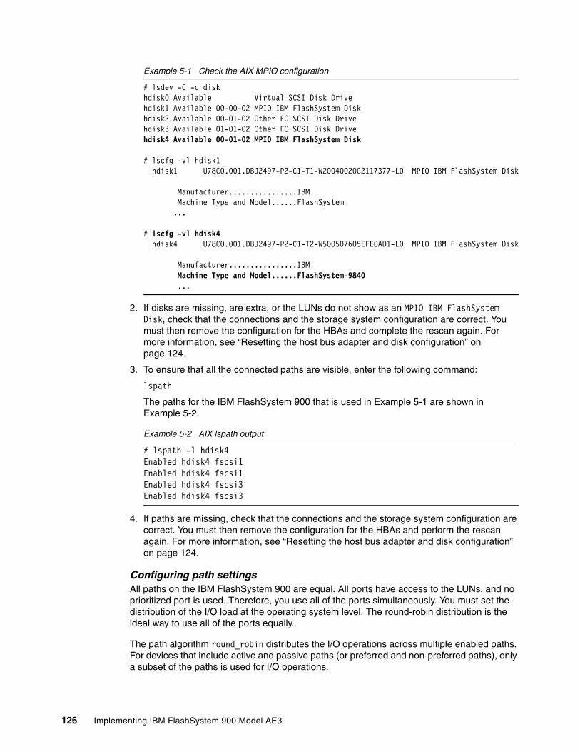
Example 5-1 Check the AIX MPIO configuration
# lsdev -C -c diskhdisk0 Available Virtual SCSI Disk Drivehdisk1 Available 00-00-02 MPIO IBM FlashSystem Diskhdisk2 Available 00-01-02 Other FC SCSI Disk Drivehdisk3 Available 01-01-02 Other FC SCSI Disk Drivehdisk4 Available 00-01-02 MPIO IBM FlashSystem Disk
# lscfg -vl hdisk1 hdisk1 U78C0.001.DBJ2497-P2-C1-T1-W20040020C2117377-L0 MPIO IBM FlashSystem Disk
Manufacturer................IBM Machine Type and Model......FlashSystem ...
# lscfg -vl hdisk4 hdisk4 U78C0.001.DBJ2497-P2-C1-T2-W500507605EFE0AD1-L0 MPIO IBM FlashSystem Disk
Manufacturer................IBM Machine Type and Model......FlashSystem-9840 ...
2. If disks are missing, are extra, or the LUNs do not show as an MPIO IBM FlashSystem Disk, check that the connections and the storage system configuration are correct. You must then remove the configuration for the HBAs and complete the rescan again. For more information, see “Resetting the host bus adapter and disk configuration” on page 124.
3. To ensure that all the connected paths are visible, enter the following command:
lspath
The paths for the IBM FlashSystem 900 that is used in Example 5-1 are shown in Example 5-2.
Example 5-2 AIX lspath output
# lspath -l hdisk4Enabled hdisk4 fscsi1Enabled hdisk4 fscsi1Enabled hdisk4 fscsi3Enabled hdisk4 fscsi3
4. If paths are missing, check that the connections and the storage system configuration are correct. You must then remove the configuration for the HBAs and perform the rescan again. For more information, see “Resetting the host bus adapter and disk configuration” on page 124.
Configuring path settingsAll paths on the IBM FlashSystem 900 are equal. All ports have access to the LUNs, and no prioritized port is used. Therefore, you use all of the ports simultaneously. You must set the distribution of the I/O load at the operating system level. The round-robin distribution is the ideal way to use all of the ports equally.
The path algorithm round_robin distributes the I/O operations across multiple enabled paths. For devices that include active and passive paths (or preferred and non-preferred paths), only a subset of the paths is used for I/O operations.
126 Implementing IBM FlashSystem 900 Model AE3

If a path is marked as failed or disabled, it is no longer used for sending I/O operations. The I/O operation is distributed based on the path priority attribute. Paths that have a higher path priority value receive a greater share of the I/O operations.
Set the algorithm attribute to round_robin before you add the hdisk to any volume group. All outgoing traffic is then spread evenly across all of the ports, as shown in the following example:
chdev -l <LUN> -a algorithm=round_robin
The shortest_queue algorithm is also available in AIX for FlashSystem. The algorithm is similar to the round_robin algorithm. However, the shortest_queue algorithm distributes I/O operations that are based on the number of pending I/O operations on each path.
The path that features the fewest pending I/O operations is selected for the next operation. The path priority attribute is ignored when the algorithm is set to shortest_queue. Therefore, if one path is slow because of congestion in the SAN, the other less congested paths are used for more of the I/O operations. The shortest_queue or round_robin enables the maximum use of the SAN resources.
To list the attributes of the LUN, enter the following command:
lsattr -El <LUN>
The output of the chdev and the lsattr commands of the FlashSystem 900 that is used in Example 5-1 on page 126 is shown in Example 5-3. The number of spaces in the output is changed for clarity.
Example 5-3 AIX chdev and lsattr commands
# chdev -l hdisk4 -a algorithm=round_robinhdisk4 changed
# lsattr -El hdisk4PCM PCM/friend/fcpother Path Control Module FalsePR_key_value none Persistent Reserve Key Value True+algorithm round_robin Algorithm True+clr_q no Device CLEARS its Queue on error Truedist_err_pcnt 0 Distributed Error Percentage Truedist_tw_width 50 Distributed Error Sample Time Truehcheck_cmd test_unit_rdy Health Check Command True+hcheck_interval 60 Health Check Interval True+hcheck_mode nonactive Health Check Mode True+location Location Label True+lun_id 0x0 Logical Unit Number ID Falselun_reset_spt yes LUN Reset Supported Truemax_coalesce 0x40000 Maximum Coalesce Size Truemax_retry_delay 60 Maximum Quiesce Time Truemax_transfer 0x80000 Maximum TRANSFER Size Truenode_name 0x500507605efe0ad0 FC Node Name Falsepvid none Physical volume identifier Falseq_err yes Use QERR bit Trueq_type simple Queuing TYPE Truequeue_depth 64 Queue DEPTH Truereassign_to 120 REASSIGN time out value Truereserve_policy no_reserve Reserve Policy True+rw_timeout 30 READ/WRITE time out value Truescsi_id 0x10100 SCSI ID Falsestart_timeout 60 START unit time out value Truetimeout_policy fail_path Timeout Policy True+unique_id 54361IBM FlashSystem-9840041263a20412-0000-0004-00006410FlashSystem-984003IBMfcp Unique device identifier False
Chapter 5. IBM FlashSystem 900 client host attachment and implementation 127

ww_name 0x500507605e800e41 FC World Wide Name False
5.3.4 IBM i and FlashSystem 900 AE3
This section covers the following topics pertaining to IBM i and FlashSystem 900 AE3:
� Attachment methods� Zoning rules� Hardware and software requirements� Configuration and performance considerations
Attachment methodsThe IBM FlashSystem 900 AE3 can be attached to IBM i hosts by using one of the following Fibre Channel (FC) methods:
� NPIV-attachment through the IBM Virtual I/O Server (VIOS) using Node Port Identifier Virtualization (NPIV) in conjunction with the required NPIV-capable SAN switch.
� Native-attachment, that is, without the IBM VIOS, either with a SAN switch or without one. The latter (without a SAN switch) is also known as direct-attachment.
Zoning rulesThe same rules apply for IBM i direct-attachment to an IBM FlashSystem 900 as for other host operating systems. However, different zoning rules apply for SAN switch-attached IBM i host Fibre Channel initiators. Unlike with other operating systems, these initiators must not be zoned to both FlashSystem canisters.
For IBM FlashSystem 900 native or NPIV SAN switch attachment, a one-to-one zoning should be used such that one IBM i Fibre Channel initiator port is zoned with one FlashSystem target port from a single FlashSystem canister, as shown in Figure 5-3 under Switch Attachemnet. Note that this is different also to IBM FlashSystem V9000, IBM Storwize series, or IBM SAN Volume Controller attachment where a single IBM i initiator should be zoned to both storage controller nodes to support the SCSI Asymmetrical Logical Unit Access (ALUA) LUN affinity concept of these controller nodes with preferred (active) and non-preferred (passive) paths. With IBM FlashSystem 900, all paths are active.
Note: IBM i attachment to the IBM FlashSystem 900 through the IBM VIOS using virtual SCSI is not supported.
128 Implementing IBM FlashSystem 900 Model AE3

Figure 5-3 IBM i FlashSystem 900 attachment and zoning rules
Hardware and software requirementsThe minimum hardware and software requirements for IBM i attachment to IBM FlashSystem 900 AE3 are summarized in Table 5-1. For further interoperability information, see the IBM System Storage Interoperation Center (SSIC):
https://www.ibm.com/systems/support/storage/ssic/interoperability.wss
Table 5-1 IBM i and IBM FlashSystem 900 AE3 Minimum Requirements
Requirement Requirement details and versions
IBM i version and release IBM i 7.2 Technology Refresh 8 or later + latest HIPER PTF groupa
IBM i 7.3 Technology Refresh 4 or later + latest HIPER PTF groupa
IBM Power Systems serverb IBM POWER7® firmware level FW780_40 or laterIBM POWER8® firmware level FW810 or laterIBM POWER9®
Attachment VIOS NPIVNative using switchesNative directc
VIOS level 2.2.3.50 or later
FlashSystem 900 AE3
Canister 1 Canister 2
41 71
IBM iFC_1 FC_2
SAN Switch
FlashSystem 900 AE3
Canister 1 Canister 2
41 71
IBM iFC_1 FC_2
Each IBM i host has to be zoned via different FC initiator ports to both canisters
Above scenario results in two active paths per LUN on IBM i
Each IBM i port has to be zonedto one FlashSystem port
Each canister must have a path to IBM i
Above scenario results in two active paths per LUN on IBM i
Direct Attachment Switch Attachment
Chapter 5. IBM FlashSystem 900 client host attachment and implementation 129

Configuration and performance considerationsAny volume (LUN) configured and attached natively or through a VIOS NPIV connection to an IBM i partition must be created with 4096 byte sectors by using the FlashSystem CLI command mkvdisk with the parameter -blocksize 4096 or by using the GUI version 1.5.1 or later which supports the 4096 byte block size as shown in Figure 5-4. IBM i compresses its tagged pages as a minor subset of its 4160 byte pages to fit into the 4096 byte sector format supported by the IBM FlashSystem 900.
Figure 5-4 FlashSystem 900 AE3 GUI creating 4096 bytes sector LUNs
Fibre Channel adapters Native connection or VIOS NPIV connection: � 8 Gb 2-port FC adapter #5735/#5273� 8 Gb 2-port FC adapter #EN0G/#EN0F (VIOS
NPIV only)� 8 Gb 4-port FC adapter #5729 (VIOS NPIV only)� 8 Gb 4-port FC adapter #EN12/#EN0Y (VIOS
NPIV only)� 16 Gb 2-port FC adapter #EN0A/#EN0B� 16 Gb 4-port FC adapter #EN1C/#EN1D
(POWER9 only; w/ NPIV: VIOS 2.2.6.21+) (no direct attachment, check SSIC)
� 32 Gb 2-port FC adapter #EN1A/#EN1B (POWER9 only; w/ NPIV: VIOS 2.2.6.21+)
SAN switches Brocade or Cisco
FlashSystem firmware 1.5.1.0 or later
a. See the IBM TechNote PTF listing for 4096 disk sector support at 7.2 and 7.3 with D/TD840 or D/T6B4E-050 drives for additional information about recommended PTFs:http://www.ibm.com/support/docview.wss?uid=nas8N1020957
b. Attachment of IBM FlashSystem 900 AE3 to IBM i is supported only in Power Systems models that support the stated firmware levels
c. Direct attachment can be done with: 8 Gb ports in IBM i and FlashSystem – 8 Gb ports in FlashSystem must be configured as Fibre Channel Arbitrated Loop; 16 Gb ports in IBM i (only the 2-port FC adpater are supported) and FlashSystem – 16 Gb ports in FlashSystem must be configured as FC_P2P or Auto Protocol
Requirement Requirement details and versions
130 Implementing IBM FlashSystem 900 Model AE3

Because IBM FlashSystem 900 generally expects a host initiator to log into both of its canisters, which is not applicable to IBM i, the IBM i host is shown with a state of degraded by the FlashSystem as shown in Figure 5-5. This is not a failure indication in this case and should be ignored.
Figure 5-5 FlashSystem 900 AE3 GUI reported IBM i Host State
Similar to other SAN storage systems for the IBM FlashSystem 900, a moderate LUN size should be chosen for IBM i in the approximate range of 40 - 300 GB because IBM i uses a fixed queue depth per disk unit and path. I/O concurrency and performance typically benefit from having a reasonable number of LUNs configured in an IBM i auxiliary storage pool (ASP) especially for applications known to perform a lot of file creates, opens, and closes.
Up to 127 LUNs are supported per IBM i 16 Gb physical, or 8 Gb and higher speed based virtual Fibre Channel adapter port with IBM i 7.2 TR7, IBM i 7.3 TR3, or later.
Prior to these IBM i technology refresh levels this limit used to be 64 LUNs per port.
For further details about IBM PowerVM® Virtual I/O Server planning and implementation including NPIV attachment for IBM i see IBM PowerVM Virtualization Introduction and Configuration, SG24-7940.
With IBM PowerVM Virtual I/O Server NPIV attachment, usually no storage performance tunable parameters are available because VIOS merely acts as a Fibre Channel I/O pass-through from its owned physical Fibre Channel adapter through the IBM Power Systems hypervisor to a VIOS client partition such as IBM i. VIOS does not even “see” the NPIV client LUNs and thus it does not perform I/O multi-pathing for them, which should be done by the IBM i client, preferably across two VIOS partitions as shown in Figure 5-6 on page 132.
Note: The 512 byte sector LUNs on an IBM FlashSystem 900 are not supported by IBM i unless this FlashSystem is virtualized by an IBM SAN Volume Controller.
Chapter 5. IBM FlashSystem 900 client host attachment and implementation 131

Figure 5-6 IBM i NPIV-attachment with two redundant Virtual I/O Servers
For VIOS attachment (NPIV-attachment), the Fibre Channel adapter queue depth is a storage performance-related tunable parameter. It can be considered to be increased if not already using VIOS version 2.2.4.10 or later and having deployed its default rule set for applying IBM recommended device settings.
The Fibre Channel adapter model-dependent current setting for its adapter queue depth, its allowed range, and its increase to its maximum supported value is shown in Example 5-4. With the fcsX FC adapter port resource usually in use, as implied in the example, VIOS would still need to be restarted for the permanent change of the adapter queue depth that is made to its resource database to become effective.
Example 5-4 Displaying and changing the VIOS FC adapter queue depth
$ lsdev -dev fcs0 -attr | grep num_cmd_elemsnum_cmd_elems 500 Maximum number of COMMANDS to queue to the adapter True
$ lsdev -dev fcs0 -range num_cmd_elems20...4096 (+1)
$ chdev -dev fcs0 -perm -attr num_cmd_elems=4096fcs0 changed
For both native and VIOS NPIV-attachment, the IBM FlashSystem 900 LUNs report to IBM i as device type D840 disk units, as shown in Figure 5-7 on page 133.
Figure 5-7 shows the disk configuration of a newly set up IBM i partition with its load source unit, that is, disk unit 1 being the only disk unit configured in the system ASP (ASP 1). All disk units are accessible from IBM i through two active Fibre Channel paths. The IBM i integrated multi-path driver distributes the I/O across all active paths of a disk unit using a round-robin algorithm with some load-balancing applied. Non-configured and non-initialized disk units, that is, those not assigned to an IBM i ASP yet, are still reported with DPHxxx resource names.
POWER Hypervisor
Virtual I/O Server 1 IBM i Client Partition
FC adapter
VFCclient
adapter ID10
VFCclient
adapter ID20
VFCserver
adapter ID10
Virtual I/O Server 2
VFCserver
adapter ID20
FC adapter
**
* IBM i disk multi-pathing or mirroring for Virtual I/O Server redundancy
D840LUNs#1-n
NPIV-capableSAN Switch
IBM FlashSystem 900 AE3
132 Implementing IBM FlashSystem 900 Model AE3
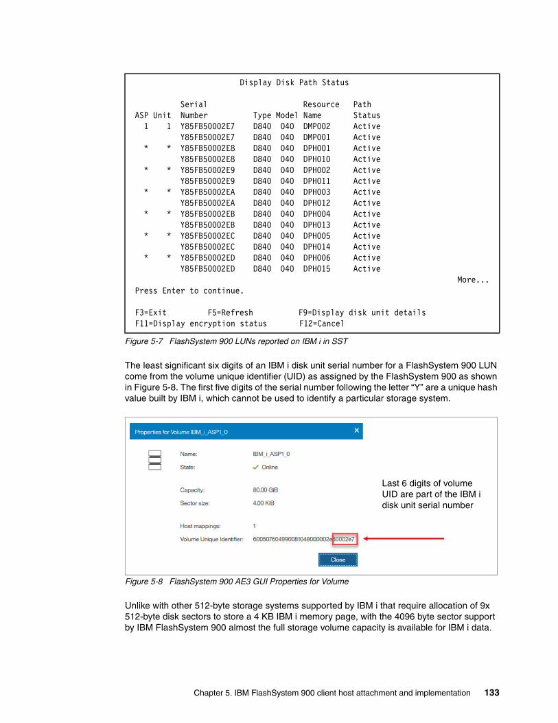
Figure 5-7 FlashSystem 900 LUNs reported on IBM i in SST
The least significant six digits of an IBM i disk unit serial number for a FlashSystem 900 LUN come from the volume unique identifier (UID) as assigned by the FlashSystem 900 as shown in Figure 5-8. The first five digits of the serial number following the letter “Y” are a unique hash value built by IBM i, which cannot be used to identify a particular storage system.
Figure 5-8 FlashSystem 900 AE3 GUI Properties for Volume
Unlike with other 512-byte storage systems supported by IBM i that require allocation of 9x 512-byte disk sectors to store a 4 KB IBM i memory page, with the 4096 byte sector support by IBM FlashSystem 900 almost the full storage volume capacity is available for IBM i data.
Display Disk Path Status Serial Resource Path ASP Unit Number Type Model Name Status 1 1 Y85FB50002E7 D840 040 DMP002 Active Y85FB50002E7 D840 040 DMP001 Active * * Y85FB50002E8 D840 040 DPH001 Active Y85FB50002E8 D840 040 DPH010 Active * * Y85FB50002E9 D840 040 DPH002 Active Y85FB50002E9 D840 040 DPH011 Active * * Y85FB50002EA D840 040 DPH003 Active Y85FB50002EA D840 040 DPH012 Active * * Y85FB50002EB D840 040 DPH004 Active Y85FB50002EB D840 040 DPH013 Active * * Y85FB50002EC D840 040 DPH005 Active Y85FB50002EC D840 040 DPH014 Active * * Y85FB50002ED D840 040 DPH006 Active Y85FB50002ED D840 040 DPH015 Active More... Press Enter to continue. F3=Exit F5=Refresh F9=Display disk unit details F11=Display encryption status F12=Cancel
Last 6 digits of volume UID are part of the IBM i disk unit serial number
Chapter 5. IBM FlashSystem 900 client host attachment and implementation 133

Figure 5-9 shows the example of 16x 80 GiB volumes from an IBM FlashSystem 900 with its 84577 MB usable capacity (80 x 1024 x 1024 x 1024 x 4096/4160 bytes) reported on IBM i.
Figure 5-9 IBM i SST Display Disk Configuration Capacity
IBM FlashSystem 900 LUNs, despite their inherent RAID protection by the FlashSystem, are reported as unprotected disk units to IBM i as shown in Figure 5-9. Thus, additional storage system level protection can be implemented by using IBM i mirroring to a second IBM FlashSystem.
5.3.5 FlashSystem 900 AE3 and Linux client hosts
The FlashSystem 900 can be attached to Linux client hosts by using the following methods:
� FC� InfiniBand
The FlashSystem 900 benefits the most from operating systems in which multipathing and logical volumes are supported. Most Linux distributions feature the same optimum configurations. Specific Linux configuration settings are shown in this section.
Network topology guidelinesYou can use arbitrated loop, point-to-point, or switched fabric topology on FC configurations for Linux hosts.
Display Disk Configuration Capacity ----Protected--- ---Unprotected-- ASP Unit Type Model Threshold Overflow Size %Used Size %Used 1 90% No 0 0.00% 1353245 1.19% 1 D840 040 0 0.00% 84577 8.30% 2 D840 040 0 0.00% 84577 0.71% 3 D840 040 0 0.00% 84577 0.71% 4 D840 040 0 0.00% 84577 0.71% 5 D840 040 0 0.00% 84577 0.71% 6 D840 040 0 0.00% 84577 0.72% 7 D840 040 0 0.00% 84577 0.72% 8 D840 040 0 0.00% 84577 0.72% 9 D840 040 0 0.00% 84577 0.71% 10 D840 040 0 0.00% 84577 0.72% 11 D840 040 0 0.00% 84577 0.71% More... Press Enter to continue. F3=Exit F5=Refresh F10=Display disk unit details F11=Display disk configuration protection F12=Cancel
Note: The FlashSystem 900 16 Gbps FC attachment does not support arbitrated loop topology. The IBM FlashSystem 900 must be connected to a SAN switch when 16 Gbps FC is used if the host operating system does not support point-to-point FC direct connections. If arbitrated loop is required by the client host, connect at 8 Gbps FC to the IBM FlashSystem 900.
134 Implementing IBM FlashSystem 900 Model AE3
Aligning a partition in LinuxUse the procedure that is described in this section to improve performance by aligning a partition in the Linux operating system.
The Linux operating system defaults to a 63-sector offset.
To align a partition in Linux by using the fdisk command, complete the following steps:
1. At the command prompt (#), enter the fdisk /dev/mapper/<device> command.2. To change the listing of the partition size to sectors, enter u.3. To create a partition, enter n.4. To create a primary partition, enter p.5. To specify the partition number, enter 1.6. To set the base sector value, enter 128.7. Press Enter to use the default last sector value.8. To write the changes to the partition table, enter w.
The newly created partition now has an offset of 64 KB and works optimally with an aligned application.
If you are installing the Linux operating system on the storage system, create the partition scheme before the installation process. For most Linux distributions, this process requires starting at the text-based installer and switching consoles (press Alt+F2) to get the command prompt before you continue.
Multipathing information for LinuxYou can use MPIO to improve the performance of the Linux operating system. Linux kernels of 2.6, and later, support multipathing through device-mapper-multipath. This package can coexist with other multipathing solutions if the other storage devices are excluded from device-mapper.
For more information about an example of /etc/multipath.conf for Linux, see IBM Knowledge Center.
Because the storage system controllers provide true active/active I/O, the rr_min_io field in the multipath.conf file is set to 4. This setting results in the best distribution of I/O activity across all available paths. You can set it to 1 for a round-robin distribution or, if the I/O activity is more sequential in nature, you can increase the rr_min_io field by factors of 2 for a performance gain by using buffered I/O (non-direct).
Integrating InfiniBand controllersTo integrate with InfiniBand technology, the storage system provides block storage by using the SCSI Remote Direct Memory Access (RDMA) Protocol (SRP).
The Linux operating system requires several software modules to connect to the storage system through InfiniBand technology and SRP. In particular, ensure that you install the srp and srptools modules, and drivers for the server’s host channel adapter (HCA). Use the OpenFabrics Enterprise Distribution (OFED) package from the OpenFabrics website to install these modules individually or by using the Install All option.
Note: The <device> is the FlashSystem 900 volume by the LINUX multipath command.
Chapter 5. IBM FlashSystem 900 client host attachment and implementation 135

The setting of the InfiniBand /etc/infiniband/openib.conf configuration file for SRP is shown in Figure 5-10.
Figure 5-10 InfiniBand configuration file
These settings cause the SRP and the SRP daemons to load automatically when the InfiniBand driver starts. The SRP daemon automatically discovers and connects to InfiniBand SRP disks.
Use the SRPHA_ENABLE=yes setting. This setting triggers the multipath daemon to create a multipath disk target when a new disk is detected.
InfiniBand technology also requires a Subnet Manager (SM). An InfiniBand network includes an SM. In many cases, an InfiniBand switch acts as the SM. If an SM is needed, install OpenSM, which is included with the OFED package, and start it on a single server in the network by entering the following command:
# /etc/init.d/opensmd start
This script opens an SM on a single port only. If multiple ports directly connect to the storage system, a custom script is needed to start the SM on all ports.
5.3.6 FlashSystem 900 and Microsoft Windows client hosts
The FlashSystem 900 can be attached to Windows client hosts by using the FC method.
The IBM FlashSystem 900 sees the most benefit from operating systems in which multipathing and logical volumes are supported. However, certain applications depend on operating systems that are designed for workstations, and they can still benefit from the storage system performance.
Network topologies for Windows hostsYou can use arbitrated loop, point-to-point, or switched fabric topology on FC configuration for Windows hosts.
Windows Server 2008, 2012, and 2016 multipathingWindows Server operating system versions that begin with Windows Server 2008 no longer require a separate DIstributed Service Manager (DSM). Instead, the MPIO function must be installed on the server. For more information, see the Installing and Configuring MPIO page of the Microsoft TechNet website.
# Load SRP moduleSRP_LOAD=yes #Enable SRP High Availability daemonSRPHA_ENABLE=yesSRP_DAEMON_ENABLE=yes
Note: The FlashSystem 900 16 Gbps FC attachment does not support arbitrated loop topology. The IBM FlashSystem 900 must be connected to a SAN switch when 16 Gbps FC is used if the host operating system does not support point-to-point FC direct connections. If arbitrated loop is required by the client host, connect at 8 Gbps FC to the IBM FlashSystem 900.
136 Implementing IBM FlashSystem 900 Model AE3

You can enable multipathing by clicking Server Manager → Features, as shown in Figure 5-11.
Figure 5-11 Windows 2008 example of activated multipathing
You can set vendor ID (IBM) and product ID (FlashSystem-9840) by clicking Administrative Tools → MPIO. You enter the eight-character vendor ID and the 16-character product ID in using the MPIO Devices pane, as shown in Figure 5-12.
Figure 5-12 Windows MPIO vendor ID and product ID for the FlashSystem 900
Note: The vendor ID must be eight characters in length, including spaces. The product ID must be 16 characters in length, including spaces.
Chapter 5. IBM FlashSystem 900 client host attachment and implementation 137
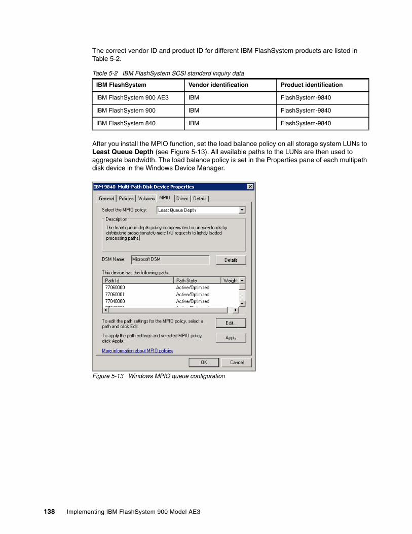
The correct vendor ID and product ID for different IBM FlashSystem products are listed in Table 5-2.
Table 5-2 IBM FlashSystem SCSI standard inquiry data
After you install the MPIO function, set the load balance policy on all storage system LUNs to Least Queue Depth (see Figure 5-13). All available paths to the LUNs are then used to aggregate bandwidth. The load balance policy is set in the Properties pane of each multipath disk device in the Windows Device Manager.
Figure 5-13 Windows MPIO queue configuration
IBM FlashSystem Vendor identification Product identification
IBM FlashSystem 900 AE3 IBM FlashSystem-9840
IBM FlashSystem 900 IBM FlashSystem-9840
IBM FlashSystem 840 IBM FlashSystem-9840
138 Implementing IBM FlashSystem 900 Model AE3

Power option setting for the highest performanceSelect Control Panel → Hardware → Power Options. In the window, select the High performance Windows power plan option, as shown in Figure 5-14.
Figure 5-14 Windows Power Options
Optimum disk command timeout settingsAdjust the disk TimeOutValue parameter on the Windows operating system for more reliable multipath access.
Windows operating systems feature a default disk command TimeOutValue of 60 seconds. If a SCSI command does not complete, the application waits 60 seconds before an I/O request is tried again. Because this behavior can create issues with most applications, you must adjust the disk TimeOutValue in the registry key to a lower value. For more information about setting this value, see the Microsoft TechNet website at https://technet.microsoft.com/en-us/library/aa997069(v=exchg.80).aspx.
Adjust the following key to your needs:
HKLM\System\CurrentControlSet\Services\Disk\TimeOutValue
Consider the following points:
� For a disk in a nonclustered configuration, set TimeOutValue to 10.� For a disk in a clustered configuration, set TimeOutValue to 20.
5.3.7 FlashSystem 900 and client VMware ESX hosts
The FlashSystem 900 can be attached to VMware ESX client hosts by using the FC method.
Arbitrated loop topology is required when you attach the IBM FlashSystem 900 directly to the client VMware ESX hosts.
Note: The FlashSystem 900 16 Gbps FC attachment does not support arbitrated loop topology. The IBM FlashSystem 900 must be connected to a SAN switch when 16 Gbps FC is used if the host operating system does not support point-to-point FC direct connections. If arbitrated loop is required by the client host, connect at 8 Gbps FC to the IBM FlashSystem 900.
Chapter 5. IBM FlashSystem 900 client host attachment and implementation 139

To configure round-robin multipathing in a VMware ESX environment, complete the following steps:
1. In the vSphere client, select the Configuration tab.2. In the Devices view, select each disk on which you want to change the path selection.3. In the Manage Paths pane, change the Path Selection setting to Round Robin (VMware).
You must set the alignment in the guest operating system. Although VMware aligns its data stores to 64 KB, guest virtual machines must still align their own presentation of the storage. Before you continue the installation of a guest Linux operating system or a guest Windows Server 2003 operating system, partition the storage to the aligned accesses.
VAAI unmap supportFlashSystem 900 supports the VMware ESXi VAAI unmap command. The ESXi host informs the storage system that files or VMs were deleted or moved from a VMFS data store by using the VAAI unmap command. The VAAI unmap is then using the SCSI UNMAP command. This VAAI command is often used with Thin Provisioned VMFS datastores; however, this command is not restricted to Thin Provisioned volumes. FlashSystem 900 does not provide thin provisioned volumes.
5.3.8 FlashSystem 900 and IBM SAN Volume Controller or Storwize V7000
For more information about IBM SAN Volume Controller or Storwize V7000 product integration, considerations, and configuration with the IBM FlashSystem 900, see Chapter 8, “Product integration” on page 307.
5.4 Miscellaneous host attachment
This section provides implementation and other general information for connecting client host systems to IBM FlashSystem 900.
If the IBM SSIC does not list the support, submit a SCORE to IBM to request approval. To submit a SCORE, contact your IBM representative or IBM Business Partner.
5.5 FlashSystem 900 preferred read and configuration examples
Examples of implementing preferred read in different environments and of the Linux multipath.conf configuration file are shown in the following sections.
5.5.1 FlashSystem 900 deployment scenario with preferred read
Implementing preferred read with the IBM FlashSystem 900 gives you an easy way to deploy the IBM FlashSystem 900 in an environment. The data is secured by writing it to two separate storage systems.
Note: For more information about supported operating systems, hosts, switches, adapters, see see the IBM SSIC website.
140 Implementing IBM FlashSystem 900 Model AE3

Data is read at the FlashSystem 900 speed because it is always read from the FlashSystem 900. This implementation does not change the infrastructure concepts; for example, data security, replication, backup, and disaster recovery. Preferred read can be implemented with the following techniques:
� IBM SAN Volume Controller Virtualize/V7000: Virtual disk mirroring (also known as volume mirroring)
� At the volume manager or operating system level:
– IBM AIX– Linux LVM (native least queue read)
� At the application level:
– Oracle Automatic Storage Management (ASM).
– Standby or reporting instance.
– SQL Server: AlwaysOn Availability Groups maximizes the availability of a set of user databases for an enterprise. An availability group supports a failover environment for a discrete set of user databases (known as availability databases) that fail over together.
The following examples are schemes that show the logical setup. You must plan the FC or InfiniBand cabling and SAN setup, depending on your environment and needs.
An example of implementing preferred read with the operating system volume manager is shown in Figure 5-15. It represents a schema of IBM AIX LVM mirroring.
Figure 5-15 Preferred read with AIX
An example of implementing preferred read on the application level is shown in Figure 5-16. It represents a schema of Oracle ASM mirroring.
Chapter 5. IBM FlashSystem 900 client host attachment and implementation 141

Figure 5-16 Preferred read with Oracle ASM
An example of implementing preferred read on a virtualization layer is shown in Figure 5-17. It represents a schema of the IBM SAN Volume Controller.
Figure 5-17 Preferred read with the IBM SAN Volume Controller
142 Implementing IBM FlashSystem 900 Model AE3

5.5.2 Implementing preferred read
You can increase the speed of an application by accelerating the read I/Os. Implementing preferred read with the IBM FlashSystem 900 gives you an easy way to deploy the IBM FlashSystem 900 in an environment.
The data is secured by writing it to two separate storage systems. Data is read at the FlashSystem 900 speed because it is always read from the IBM FlashSystem 900. This implementation does not change the existing infrastructure concept;, for example, data security, replication, backup, and disaster recovery. For more information, see 5.5.1, “FlashSystem 900 deployment scenario with preferred read” on page 140.
Preferred read with AIXOn AIX, preferred read is implemented by the AIX LVM.
The following steps are shown in Example 5-5 on page 143 - Example 5-10 on page 149. The examples show the process of creating a preferred read configuration with the FlashSystem 900. The steps assume that the AIX server is cabled and zoned correctly:
1. Create a file system on spinning disk.2. Add the IBM FlashSystem 900 as a mirrored copy to this file system.3. Set the correct read and write policy.4. Set preferred read to the IBM FlashSystem 900.
In the following steps (Example 5-5 on page 143 - Example 5-10 on page 149), two systems that are attached through a SAN to the AIX host are used. The following AIX hdisk information is listed:
� hdisk1 - hdisk4: IBM MPIO FC 2145� hdisk5 - hdisk8: IBM FlashSystem 900 Storage
The following process is based on AIX 7.1.
Creating a file system on spinning diskThe steps that are shown in Example 5-5 create a file system on AIX. In this example, hdisk1 - hdisk4 that is provided by an IBM SAN Volume Controller are used. All commands are preceded by a comment to the next action. Always check the command parameters against your current AIX version.
Example 5-5 Creating AIX file system
## # Create a file system on normal disks
# # list physical disks# lsdev -C -c diskhdisk0 Available Virtual SCSI Disk Drive
# # attach Disksystem to AIX server and check for new disks# cfgmgr
# # list physical disks# lsdev -C -c diskhdisk0 Available Virtual SCSI Disk Drivehdisk1 Available 00-00-02 MPIO FC 2145hdisk2 Available 00-00-02 MPIO FC 2145hdisk3 Available 00-00-02 MPIO FC 2145hdisk4 Available 00-00-02 MPIO FC 2145
Chapter 5. IBM FlashSystem 900 client host attachment and implementation 143

# # set path policy to your needs: round_robin, load_balance, or shortest_queue# # check path for all disks, hdisk1 as an example# lsattr -El hdisk1 | grep algorithmalgorithm load_balance
# # use chdev if needed# chdev -l hdisk1 -a algorithm=round_robin# chdev -l hdisk1 -a algorithm=shortest_queue# chdev -l hdisk1 -a algorithm=load_balance
# # create a volume group with the four IBM 2145 FC Disks# mkvg -B -y test_vg_1 -t 8 hdisk1 hdisk2 hdisk3 hdisk40516-1254 mkvg: Changing the PVID in the ODM.0516-1254 mkvg: Changing the PVID in the ODM.0516-1254 mkvg: Changing the PVID in the ODM.0516-1254 mkvg: Changing the PVID in the ODM.test_vg_1
# # list the information# lsvgrootvgtest_vg_1# lsvg test_vg_1VOLUME GROUP: test_vg_1 VG IDENTIFIER: 00f6600100004c00000001464e967f3dVG STATE: active PP SIZE: 64 megabyte(s)VG PERMISSION: read/write TOTAL PPs: 3196 (204544 megabytes)MAX LVs: 512 FREE PPs: 3196 (204544 megabytes)LVs: 0 USED PPs: 0 (0 megabytes)OPEN LVs: 0 QUORUM: 3 (Enabled)TOTAL PVs: 4 VG DESCRIPTORS: 4STALE PVs: 0 STALE PPs: 0ACTIVE PVs: 4 AUTO ON: yesMAX PPs per VG: 130048MAX PPs per PV: 8128 MAX PVs: 16LTG size (Dynamic): 256 kilobyte(s) AUTO SYNC: noHOT SPARE: no BB POLICY: relocatablePV RESTRICTION: none INFINITE RETRY: noDISK BLOCK SIZE: 512
# # create a logical volume with file system type jfs2# # name will be test_lv_1# mklv -y test_lv_1 -t'jfs2' test_vg_1 3096 hdisk1 hdisk2 hdisk3 hdisk4test_lv_1
# # create a file system on the logical volume# # mount point /test/preferred_read will be created at the same time# crfs -v jfs2 -d test_lv_1 -m /test/preferred_readFile system created successfully.202893060 kilobytes total disk space.New File System size is 405798912
# # mount new created file system# mount /test/preferred_read
# # check# df -g /test/preferred_readFilesystem GB blocks Free %Used Iused %Iused Mounted on/dev/test_lv_1 193.50 193.47 1% 4 1% /test/preferred_read
144 Implementing IBM FlashSystem 900 Model AE3

Adding the FlashSystem 900 as a mirrored copy to this file systemThe steps that are shown in Example 5-6 extend a file system and use this extension to create a mirror. In this example, the second disk, hdisk4, is used.
All commands are preceded by a comment to the next action.
Example 5-6 Create a mirrored file system on AIX
## # Add FlashSystem 900 as a mirrored copy to this file system
# # attach FlashSystem 900 to AIX server and check for new disks# cfgmgr
# # check for new FlashSystem 900 disk, will be hdisk5 hdisk6 hdisk7 hdisk8# lsdev -C -c diskhdisk0 Available Virtual SCSI Disk Drivehdisk1 Available 00-00-02 MPIO FC 2145hdisk2 Available 00-00-02 MPIO FC 2145hdisk3 Available 00-00-02 MPIO FC 2145hdisk4 Available 00-00-02 MPIO FC 2145hdisk5 Available 00-00-02 MPIO IBM FlashSystem Diskhdisk6 Available 00-00-02 MPIO IBM FlashSystem Diskhdisk7 Available 00-00-02 MPIO IBM FlashSystem Diskhdisk8 Available 00-00-02 MPIO IBM FlashSystem Disk
# # set path policy to your needs:round_robin or shortest_queue# # check path for all disks, hdisk5 as an example# lsattr -El hdisk5 | grep algorithmalgorithm shortest_queue
# # use chdev if needed# chdev -l hdisk5 -a algorithm=round_robin# chdev -l hdisk5 -a algorithm=shortest_queue
# # list used Physical volume names# lslv -m test_lv_1 | awk '{print $3, "\t", $5, "\t", $7}' | uniq
PV1 PV2 PV3hdisk1hdisk2hdisk3hdisk4
# # add FlashSystem 900 disk to volume group# extendvg test_vg_1 hdisk5 hdisk6 hdisk7 hdisk80516-1254 extendvg: Changing the PVID in the ODM.0516-1254 extendvg: Changing the PVID in the ODM.0516-1254 extendvg: Changing the PVID in the ODM.0516-1254 extendvg: Changing the PVID in the ODM.
# # create a mirror# mklvcopy test_lv_1 2 hdisk5 hdisk6 hdisk7 hdisk8
# # list used Physical volume names and check mirror# lslv -m test_lv_1 | awk '{print $3, "\t", $5, "\t", $7}' | uniq
PV1 PV2 PV3hdisk1 hdisk5hdisk2 hdisk6
Chapter 5. IBM FlashSystem 900 client host attachment and implementation 145

hdisk3 hdisk7hdisk4 hdisk8
# # check mirror state# lsvg -l test_vg_1test_vg_1:LV NAME TYPE LPs PPs PVs LV STATE MOUNT POINTtest_lv_1 jfs2 3096 6192 8 open/stale /test/preferred_readloglv00 jfs2log 1 1 1 open/syncd N/A
# # the mirror is stale, synchronize it# # this command will take some time depending on volume size# syncvg -P 32 -v test_vg_1
# # check mirror state# lsvg -l test_vg_1test_vg_1:LV NAME TYPE LPs PPs PVs LV STATE MOUNT POINTtest_lv_1 jfs2 3096 6192 8 open/syncd /test/preferred_readloglv00 jfs2log 1 1 1 open/syncd N/A
# # turn VG quorum off# # always check your business needs, if VG quorum should be enabled or disabled# # do this to ensure the VG will not go offline if a quorum of disks goes missing# chvg -Q n test_vg_1
# # check VG state# lsvg test_vg_1VOLUME GROUP: test_vg_1 VG IDENTIFIER: 00f6600100004c00000001464e967f3dVG STATE: active PP SIZE: 64 megabyte(s).OPEN LVs: 2 QUORUM: 1 (Disabled).
Now, the file system data is mirrored onto two separate physical locations. The first copy is on spinning disk; the second copy is on the FlashSystem 900.
Setting the correct read and write policyIBM AIX LVM sets the scheduling policy for reads and writes to the storage systems. If you use mirrored logical volumes, the following scheduling policies for writing to disk can be set for a logical volume with multiple copies:
� Sequential scheduling policy (“s”)
Performs writes to multiple copies or mirrors in order. The multiple physical partitions that represent the mirrored copies of a single logical partition are designated primary, secondary, and tertiary.
In sequential scheduling, the physical partitions are written to in sequence. The system waits for the write operation for one physical partition to complete before starting the write operation for the next partition. When all write operations are complete for all mirrors, the write operation is complete.
� Parallel scheduling policy (“p”)
Simultaneously starts the write operation for all the physical partitions in a logical partition. When the write operation to the physical partition that takes the longest to complete finishes, the write operation is complete. Specifying mirrored logical volumes with a parallel scheduling policy might improve I/O read-operation performance because multiple
146 Implementing IBM FlashSystem 900 Model AE3

copies allow the system to direct the read operation to the least busy disk for this logical volume.
� Parallel write with sequential read scheduling policy (“ps”)
Simultaneously starts the write operation for all the physical partitions in a logical partition. The primary copy of the read is always read first. If that read operation is unsuccessful, the next copy is read. During the read retry operation on the next copy, the failed primary copy is corrected by the LVM with a hardware relocation. This read retry operation patches the bad block for future access.
� Parallel write with round-robin read scheduling policy (“pr”)
Simultaneously starts the write operation for all the physical partitions in a logical partition. Reads are switched back and forth between the mirrored copies.
To get the preferred read performance of the IBM FlashSystem 900, set the policy to parallel write with sequential read. The following functions are available with this option:
� Write operations are done in parallel to all copies of the mirror. � Read operations are always done on the primary copy of the devices in the mirror set.
How to change the LVM scheduler to the parallel write with sequential read scheduling policy is shown in Example 5-7.
Example 5-7 Changing the scheduler to parallel write with the round-robin read scheduling policy
# # check current state of the LVM scheduler# lslv test_lv_1LOGICAL VOLUME: test_lv_1 VOLUME GROUP: test_vg_1LV IDENTIFIER: 00f6600100004c00000001464e967f3d.1 PERMISSION: read/writeVG STATE: active/complete LV STATE: opened/syncdTYPE: jfs2 WRITE VERIFY: offMAX LPs: 3096 PP SIZE: 64 megabyte(s)COPIES: 2 SCHED POLICY: parallelLPs: 3096 PPs: 6192STALE PPs: 0 BB POLICY: relocatableINTER-POLICY: minimum RELOCATABLE: yesINTRA-POLICY: middle UPPER BOUND: 16MOUNT POINT: /test/preferred_read LABEL: /test/preferred_readDEVICE UID: 0 DEVICE GID: 0DEVICE PERMISSIONS: 432MIRROR WRITE CONSISTENCY: on/ACTIVEEACH LP COPY ON A SEPARATE PV ?: yesSerialize IO ?: NOINFINITE RETRY: no PREFERRED READ: 1# lslv test_lv_1 | grep “SCHED POLICY”COPIES: 2 SCHED POLICY: parallel
# # Logical volume must be closed.# # If the logical volume contains a file system,# # the umount command will close the LV device.# umount /test/preferred_read
# # set schedular to parallel write with sequential read-scheduling policy# # (parallel/sequential)# # Note: mklv and chlv: The -d option cannot be used with striped logical volumes.# chlv -d ps test_lv_1
Important: Downtime of the file system is required when you change the LVM scheduler policy.
Chapter 5. IBM FlashSystem 900 client host attachment and implementation 147

# # check changed state of the LVM schedular# lslv test_lv_1LOGICAL VOLUME: test_lv_1 VOLUME GROUP: test_vg_1LV IDENTIFIER: 00f6600100004c00000001464e967f3d.1 PERMISSION: read/writeVG STATE: active/complete LV STATE: closed/syncdTYPE: jfs2 WRITE VERIFY: offMAX LPs: 3096 PP SIZE: 64 megabyte(s)COPIES: 2 SCHED POLICY: parallel/sequentialLPs: 3096 PPs: 6192STALE PPs: 0 BB POLICY: relocatableINTER-POLICY: minimum RELOCATABLE: yesINTRA-POLICY: middle UPPER BOUND: 16MOUNT POINT: /test/preferred_read LABEL: /test/preferred_readDEVICE UID: 0 DEVICE GID: 0DEVICE PERMISSIONS: 432MIRROR WRITE CONSISTENCY: on/ACTIVEEACH LP COPY ON A SEPARATE PV ?: yesSerialize IO ?: NOINFINITE RETRY: no PREFERRED READ: 1# lslv test_lv_1 | grep SCHED POLICYCOPIES: 2 SCHED POLICY: parallel/sequential
# # mount file system# mount /test/preferred_read# # write some data to the filesystem /test/preferred_read# # then read this data and check with iostat
Disks: % tm_act Kbps tps Kb_read Kb_wrtnhdisk1 0.0 147495.2 1036.4 737476 0hdisk2 0.0 134964.8 736.6 674824 0hdisk4 0.0 85035.2 448.6 425176 0hdisk3 0.0 118422.4 684.2 592112 0
The setup of the logical volume is now preferred read from the first copy.
Setting preferred read to the FlashSystem 900Check which logical volumes are primary, which are secondary, and which are tertiary, if any. This list might be a long list. The first 10 lines of the command output and a command for a quick overview are shown in Example 5-8.
Example 5-8 Get first, second, and third logical volume physical disk
# # # Get first, second, and third logical volume's physical disk# # Get reduced list of all involved hdisks# # list used Physical volume names# lslv -m test_lv_1 | awk '{print $3, "\t", $5, "\t", $7}' | uniq PV1 PV2 PV3hdisk1 hdisk5 hdisk2 hdisk6 hdisk3 hdisk7 hdisk4 hdisk8
# # check which copy is selected for primary# lslv test_lv_1 | grep PREFERREDINFINITE RETRY: no PREFERRED READ: 1
148 Implementing IBM FlashSystem 900 Model AE3

Now, the spinning disk devices in the PV1 column are the primary devices. All of the reads are supported by the PV1 devices. During start, the PV1 devices are the primary copy of the mirror, and they are used as the sync point.
To change the primary copy, use the following command:
# chlv -R 2 test_lv_1
It changes the preferred read copy of the logical volume. If the preferred copy is not available, the reads follow the scheduling policy of the logical volume. The PreferredRead variable can be set to a value 0 - 3. Setting the specific PreferredRead variable with the -R option to 0 disables the preferred read copy of the logical volume.
If you check again (which is the preferred copy now), you see:
# lslv test_lv_1 | grep PREFERREDINFINITE RETRY: no PREFERRED READ: 2
You can use the iostat command to see the effects of the parallel/sequential scheduler settings and the performance of the spinning disk or the FlashSystem 900 as the primary disk. Run the following command with the normal disk and again later with the FlashSystem 900 as the primary disk:
iostat -DRlTV 3
Notice that only the first disk is used for reading and that you get a significant performance increase with the FlashSystem 900.
The iostat output before changing the primary disk is shown in Example 5-9. It shows hdisk1, which is a spinning disk. The result after changing the primary disk is shown in Example 5-10. You see that hdisk5, which is the FlashSystem disk, is used only for reading.
The output is shortened for clarity.
Example 5-9 The iostat command checks for preferred read on the spinning disk
## # the volume group has to be in syncd state# # use dd command to read from the mirrored logical volume# dd if=/dev/test_lv_1 of=/dev/zero bs=16k count=100000
# # execute iostat in another windows# iostat -DRlTV 3Disks: --------------hdisk1
Example 5-10 The iostat command checks for preferred read on the IBM FlashSystem 900
## # the volume group has to be in syncd state# # use dd command to read from the mirrored logical volume# dd if=/dev/test_lv_1 of=/dev/zero bs=16k count=100000
# # execute iostat in another windows
Note: The -R flag (available in AIX starting with version 7.1) overwrites the read policy of the -d flag. If the preferred copy is not available, the reads follows the scheduling policy.
Chapter 5. IBM FlashSystem 900 client host attachment and implementation 149

# iostat -DRlTV 3
Disks: --------------hdisk5
Setting the FC topology on the FlashSystem 900 and AIXThe IBM FlashSystem 900 can be directly attached to an AIX host without a switch. In this configuration, the FC ports of the FlashSystem 900 are changed to arbitrated loop (AL) topology. You can use the chportfc command to change port settings on the IBM FlashSystem 900. On the AIX system, the ports also must be changed to AL.
Example 5-11 shows changing two ports, fscsi0 and fscsi2, on the AIX system. This system includes four FC ports: Ports 0 and 2 are directly attached to the FlashSystem 900 by using AL and ports 1 and 3 are attached to a switch. The use of the cfgmgr command detects the correct topology.
Example 5-11 Set the AIX port to arbitrated loop
# # before using these commands # # you must first alter the port topology on the FlashSystem 900# # all traffic has to be stopped before using this command## # remove FC port fscsi0 and then configure it using cfgmgr# rmdev -Rdl fscsi0# cfgmgr -vl fcs0
# # remove FC port fscsi2 and then configure it using cfgmgr# rmdev -Rdl fscsi2# cfgmgr -vl fcs2
# check all 4 ports# lsattr -El fscsi0 | grep attachattach al
# lsattr -El fscsi1 | grep attachattach switch
# lsattr -El fscsi2 | grep attachattach al
# lsattr -El fscsi3 | grep attachattach switch
Preferred read with the IBM SAN Volume ControllerYou can set up preferred read on the IBM FlashSystem 900 with the IBM SAN Volume Controller with a single mouse-click. In the IBM SAN Volume Controller GUI, go to the Volumes menu and right-click the FlashSystem 900 disk of the mirrored volume. Then, select Make Primary. Notice the start asterisk (*) next to your primary disk, which is now the preferred read disk.
Before you run the commands: The topology must be set on an attached system, switch, or storage device before you run these commands.
150 Implementing IBM FlashSystem 900 Model AE3

The mirrored IBM SAN Volume Controller volume with preferred read on a spinning disk is shown in Figure 5-18. In this example, pool enc_71 consists of spinning disks; pool enc72 houses the FlashSystem 900 capacity.
Figure 5-18 SAN Volume Controller mirrored VDisk with preferred read on spinning disk
The option menu to select the primary copy is shown in Figure 5-19. The primary copy is identical to the preferred read disk.
Figure 5-19 SAN Volume Controller option Make Primary
The mirrored IBM SAN Volume Controller volume with preferred read that uses the FlashSystem 900 is shown in Figure 5-20. (You must wait after switching the primary copy until both copies are back in sync.)
Figure 5-20 SAN Volume Controller mirrored VDisk with preferred read on the FlashSystem 900
Preferred read with Oracle ASMOracle ASM in Oracle 11g includes advanced features that can use the performance of the IBM FlashSystem 900. The features of Preferred Mirror Read and Fast Mirror Resync are the two most prominent features that fit in this category.
Chapter 5. IBM FlashSystem 900 client host attachment and implementation 151

You can set up preferred read by using the following features (for more information about these features, see the Oracle documentation):
� Preferred Mirror Read� Fast Mirror Resync
For more information about Oracle ASM, see the Administering ASM Disk Groups topic of the Database Storage Administrator’s Guide, which is available at the Oracle Help Center website.
5.5.3 Linux configuration file multipath.conf example
For an example of /etc/multipath.conf for Linux, see the Settings for Linux hosts page of IBM Knowledge Center.
Using FlashSystem 900 with Linux client hostsThe IBM FlashSystem 840 and FlashSystem 900 share a product string ("FlashSystem-9840") and use the same multipath.conf configuration.
Linux tuningThe Linux kernel buffer file system writes data before it sends the data to the storage system. With the IBM FlashSystem 900, better performance can be achieved when the data is not buffered but is directly sent to the IBM FlashSystem 900.
When the scheduling policy is set to no operation (NOOP), the fewest CPU instructions possible are used for each I/O. Setting the scheduler to NOOP also gives the best write performance on Linux systems. You can use the following setting in most Linux distributions as a boot parameter:
elevator=noop
Current Linux devices are managed by the device manager Udev. You can define how Udev manages devices by adding rules to the /etc/udev/rules.d directory.
The rules for the IBM FlashSystem 900 with Linux are shown in Example 5-12. (This example is also taken from IBM Knowledge Center.)
Example 5-12 Linux device rules
#udev rules filecat /etc/udev/rules.d/99-IBM-FlashSystem.rules
ACTION=="add|change", SUBSYSTEM=="block",ATTRS{device/model}=="FlashSystem-9840",ATTR{queue/scheduler}="noop",ATTR{queue/rq_affinity}="1",ATTR{queue/add_random}="0",ATTR{device/timeout}="5"
ACTION=="add|change", KERNEL=="dm-*",PROGRAM="/bin/bash -c 'cat /sys/block/$name/slaves/*/device/model | grep FlashSystem-9840'",ATTR{queue/scheduler}="noop",ATTR{queue/rq_affinity}="1",ATTR{queue/add_random}="0"
5.5.4 Example of a VMware configuration
You can set the number of I/Os for each path on VMware by using the following command, which sets 10 I/Os for each path:
esxcli nmp roundrobin setconfig --device <device> --iops=10 --type "iops"
152 Implementing IBM FlashSystem 900 Model AE3

5.6 FlashSystem 900 and Easy Tier
You can implement the IBM FlashSystem 900 with IBM SAN Volume Controller Easy Tier. SAN Volume Controller Easy Tier automatically moves hot, frequently used data to the FlashSystem 900 and cold, less frequently or never used data to the traditional disk system. An example of implementing SAN Volume Controller Easy Tier is shown in Figure 5-21.
Figure 5-21 Easy Tier with SAN Volume Controller
For more information about the IBM FlashSystem 900 and SAN Volume Controller solution, see 8.1.4, “IBM Spectrum Virtualize - SAN Volume Controller advanced functionality” on page 316 and 9.2, “Tiering” on page 345.
5.7 Troubleshooting
Troubleshooting information for issues that you might encounter when configuring InfiniBand or creating file systems is described in this section.
5.7.1 Troubleshooting Linux InfiniBand configuration issues
Consider the following potential Linux configuration issues, troubleshooting guidance, and resolutions:
� When you install OFED-X.X.X, an error occurs. This error indicates that you failed to build the ofa_kernel RPM Package Manager (originally Red Hat Package Manager).
The kernel that is used by the server might not be supported by OpenFabrics Enterprise Distribution (OFED). If the Install All option was chosen, use the Customize option in the OFED installation menu and select only the components that are needed. If this process does not work, install a different version of OFED.
Chapter 5. IBM FlashSystem 900 client host attachment and implementation 153

� Loading the driver module fails.
The HCA that is used might not be supported by OFED, or the driver was not installed correctly. Obtain the latest drivers for the HCAs from the HCA vendor’s website.
� When you attempt to install OFED, the following error message is displayed:
"<module 1> is required to build <module 2>"
This error indicates that certain dependencies that are required by OFED are not installed on the server. You must install all of the required dependencies. Consider the following points:
– To search for the necessary RPM (if the yum package-management tool is available), run the following command:
# yum provides <dependency_name>
– To install the RPM, run the following command:
# yum install <dependency_rpm>
� When you attempt to run the srp_daemon command, a message indicates that an operation failed. Perform the following checks:
– Ensure that the storage system is physically connected to the network and that all components are powered on.
– Ensure that the correct cable is used and that OpenSM is running. To confirm whether OpenSM is running, run the following command:
# /etc/init.d/opensmd status
� Loading the ib_srp module fails.
Verify that OFED is installed correctly and that the necessary device drivers are also installed. If a custom OFED installation was performed, ensure that ibutils and all packages that are related to srp were selected.
5.7.2 Linux fdisk error message
You might receive the following messages when you create a partition in Linux:
"Re-reading the partitioning table failed"
Also, the corresponding device is not created in the /dev/mapper directory. Solve this problem by issuing the partprobe command, as shown in Example 5-13.
Example 5-13 Solving the partition table failed with error 22
[root@localhost ~]# fdisk /dev/mapper/FlashSystem_900_3
<partition creation lines left out for clearity>...
Command (m for help): wThe partition table has been altered!
Calling ioctl() to re-read partition table.
Note: If yum is not installed on the server, each dependency must be manually downloaded and installed.
154 Implementing IBM FlashSystem 900 Model AE3

WARNING: Re-reading the partition table failed with error 22: Invalid argument.The kernel still uses the old table. The new table will be used atthe next reboot or after you run partprobe(8) or kpartx(8)Syncing disks.
[root@localhost ~]# ls -l /dev/mapper/ lrwxrwxrwx. 1 root root 7 Oct 8 08:10 FlashSystem_900_2 -> ../dm-0lrwxrwxrwx. 1 root root 7 Oct 8 09:20 FlashSystem_900_3 -> ../dm-2
[root@localhost ~]# partprobe
[root@localhost ~]# ls -l /dev/mapper/ lrwxrwxrwx. 1 root root 7 Oct 8 08:10 FlashSystem_900_2 -> ../dm-0lrwxrwxrwx. 1 root root 7 Oct 8 09:20 FlashSystem_900_3 -> ../dm-2brw-rw----. 1 root disk 253, 7 Oct 8 09:21 FlashSystem_900_3p1
You can search the /dev/mapper directory for newly generated partitions. The new partition is generated after the partprobe command is run.
5.7.3 Changing FC port properties
The FlashSystem 900 automatically detects the SAN topology and speed. If you want to set the speed (for example, 16 Gbps), or the topology, such as arbitrated loop or point-to-point fabric explicitly, use the chportfc command. The lsportfc command lists the current settings.
Note: The FlashSystem 900 16 Gbps FC attachment does not support arbitrated loop topology. The IBM FlashSystem 900 must be connected to a SAN switch when 16 Gbps FC is used if the host operating system does not support point-to-point FC direct connections. If arbitrated loop is required by the client host, connect to the IBM FlashSystem 900 at 8 Gbps FC.
Chapter 5. IBM FlashSystem 900 client host attachment and implementation 155

156 Implementing IBM FlashSystem 900 Model AE3

Chapter 6. Using IBM FlashSystem 900
This chapter describes how to operate IBM FlashSystem 900 AE3 in your business environment. The graphical user interface (GUI) and the command-line interface (CLI) are used to demonstrate how to monitor the system and work with volumes, hosts, and user security.
This chapter includes the following topics:
� 6.1, “IBM FlashSystem 900 AE3 management tools overview” on page 158� 6.2, “Dashboard window” on page 163� 6.3, “Monitoring menu” on page 166� 6.4, “Volumes menu” on page 199� 6.5, “Hosts menu” on page 208� 6.6, “Access menu” on page 215
6
© Copyright IBM Corp. 2018. All rights reserved. 157

6.1 IBM FlashSystem 900 AE3 management tools overview
The FlashSystem 900 can be managed by using the built-in, web-based management tool GUI, or from the CLI.
The web-based GUI is designed to simplify storage management and provide a fast and more efficient management tool. It is based on the IBM System Storage XIV software and features a similar look and behavior.
To use the GUI to manage the FlashSystem 900, ensure that you can access a supported web browser. For more information about web browsers, see “Supported web browsers” on page 101.
6.1.1 GUI access
To log on to the GUI, enter the management IP address your web browser that was set during the initial setup of the FlashSystem 900. The following default credentials are used:
� User name: superuser � Password: passw0rd (with a zero in place of the letter o)
The login window is shown in Figure 6-1.
Figure 6-1 Login window
JavaScript: JavaScript and cookies must be enabled in your browser. For more information, see “Supported web browsers” on page 101.
158 Implementing IBM FlashSystem 900 Model AE3
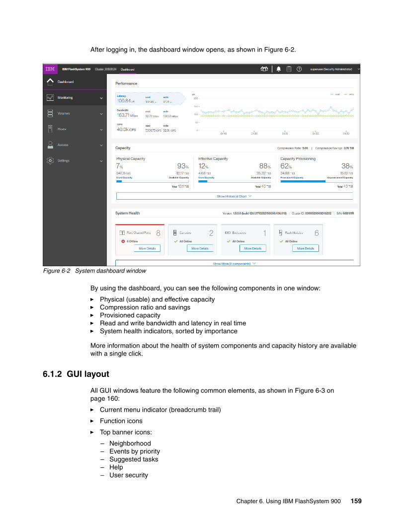
After logging in, the dashboard window opens, as shown in Figure 6-2.
Figure 6-2 System dashboard window
By using the dashboard, you can see the following components in one window:
� Physical (usable) and effective capacity� Compression ratio and savings� Provisioned capacity� Read and write bandwidth and latency in real time� System health indicators, sorted by importance
More information about the health of system components and capacity history are available with a single click.
6.1.2 GUI layout
All GUI windows feature the following common elements, as shown in Figure 6-3 on page 160:
� Current menu indicator (breadcrumb trail)
� Function icons
� Top banner icons:
– Neighborhood– Events by priority– Suggested tasks– Help– User security
Chapter 6. Using IBM FlashSystem 900 159

Most windows also include the following elements:
� Actions menu� Performance indicators in the mini dashboard
Figure 6-3 System monitoring window GUI elements
The top banner icons provide one-click access to the most important or frequently used functions. The current menu indicator shows which menu and function is displayed. At the bottom of the window, summary performance data in real time on most GUI windows is shown.
On the left side of the window are six menu selector icons, which are also referred to as function icons. These function icons can be displayed with text or only as icons, depending upon the size of the window, as shown in Figure 6-4.
Figure 6-4 Expanded function menu showing text
The six function icons represent the following areas:
� Dashboard window� Monitoring menu� Volumes menu� Hosts menu
160 Implementing IBM FlashSystem 900 Model AE3

� Access menu� Settings menu
For more information about these functions, see 6.2, “Dashboard window” on page 163.
6.1.3 Navigation
Navigating the management tool is simple. You can hover the mouse cursor over one of the six function icons on the left side of the window to highlight the function icon. Clicking one of the function icons opens a list of options. Clicking one of the top banner icons opens a menu for them. The various expanded menu options and menus of the FlashSystem 900 are shown in Figure 6-5.
Figure 6-5 FlashSystem 900: Menu options
For more information about these menus, see 6.2, “Dashboard window” on page 163
6.1.4 Selecting multiple items
By using the FlashSystem 900 management tool, you can select multiple items by using a combination of the Shift key or Ctrl key. To select multiple items in a display, click the first item, press and hold the Shift key, and click the last item in the list that you require. All of the items between those two items are selected. For example, multiple selections from the Volumes → Volumes menu are shown in Figure 6-6 on page 162.
Chapter 6. Using IBM FlashSystem 900 161

Figure 6-6 Multiple selections by using the Shift key
This function is useful for expanding multiple volumes at the same time. It is also useful for performing actions on multiple items; for example, to delete multiple volumes at the same time.
If you want to select multiple items that are not in sequential order, click the first item, press and hold the Ctrl key, and click the other items that you require (see Figure 6-7).
Figure 6-7 Multiple selections by using the Ctrl key
162 Implementing IBM FlashSystem 900 Model AE3

6.1.5 Performance indicators
Other useful tools are the performance indicators that appear at the bottom of the window in the mini dashboard (see Figure 6-8). These indicators provide information about latency, throughput, and I/O per second (IOPS). The mini dashboard is displayed in most of the windows in the FlashSystem 900 GUI.
Figure 6-8 Mini dashboard performance indicators
6.2 Dashboard window
The dashboard window is the new default window and home page for the FlashSystem 900 GUI. The dashboard window displays the most important system information in real time in a single pane. An example is shown in Figure 6-2 on page 159. The following sections are available:
� Performance� Capacity� System health
In the performance section, you can choose one of the three options (latency, bandwidth, or IOPS) by clicking the section you want to be displayed. Bandwidth is selected in the example that is shown in Figure 6-9.
Figure 6-9 Dashboard performance section
The capacity section (see Figure 6-10) shows the current physical (usable), effective, and provisioned capacity of the FlashSystem array, and the compression ratio and savings.
Figure 6-10 Dashboard capacity section
Chapter 6. Using IBM FlashSystem 900 163

Figure 6-11 Dashboard capacity section on the FlashSystem AE1/AE2
By clicking Show Historical Chart, the capacity history of the array is shown over several months. This feature allows you to easily identify a trend that might lead to an out-of-space condition, as shown in Figure 6-12.
Figure 6-12 Dashboard capacity history
The bottom section of the dashboard is the system health section. These icons indicate the health of all the major hardware components. The list is prioritized so that if a problem occurs with a component, that component is listed first. An example in which a problem occurred with the Fibre Channel ports is shown in Figure 6-13.
Figure 6-13 Dashboard system health section
Clicking More Details displays a window that shows which ports are affected, as shown in Figure 6-14 on page 165.
Note: When firmware release 1.5.0.0 and higher is running on a FlashSystem AE1 or AE2 (which do not have hardware compression), the capacity section shows only provisioned capacity (see Figure 6-11).
164 Implementing IBM FlashSystem 900 Model AE3

Figure 6-14 Dashboard system health “more details” window
The buttons at the bottom of the window can be used to display the Monitoring System window or the Events window.
The number of system health icons that is displayed on the dashboard depends on the size of the window and the resolution of your display. To see all of the health icons, click Show More at the bottom, as seen in Figure 6-15.
Figure 6-15 Dashboard system health section, expanded
Chapter 6. Using IBM FlashSystem 900 165

6.3 Monitoring menu
The Monitoring menu provides the tools to monitor the real time and historical status and performance of the system. It features the following options, as shown in Figure 6-5 on page 161:
� System� Network Neighborhood� Events� Performance� Performance With Events
6.3.1 Monitoring System menu
Clicking Monitoring → System displays a graphical view of the FlashSystem, in the front and the rear, as shown in Figure 6-16 (front) and in Figure 6-17 on page 167 (rear).
Figure 6-16 Monitoring menu: Front of system
166 Implementing IBM FlashSystem 900 Model AE3

Figure 6-17 Monitoring menu: Rear of system
Rotate the view by clicking the blue or red arrow. A red arrow indicates a problem on the other side of the enclosure, as shown in Figure 6-18.
Figure 6-18 Red arrow indicating a problem
The system menu displays a real-time graphical view of the system. If a problem occurs with a component or a failure, the component is highlighted in red, as shown in Figure 6-19.
Figure 6-19 Fibre Channel ports offline
By hovering the mouse pointer over the component, you can display more information, as shown in Figure 6-20 on page 168.
Chapter 6. Using IBM FlashSystem 900 167

Figure 6-20 Displaying more information about the port
The properties of any hardware component can be displayed by hovering the mouse pointer over the component; for example, a flash module (see Figure 6-21).
Figure 6-21 Flash module properties by using system menu
By clicking Monitoring → System, you can select Actions in the upper-left corner of the window. Actions can also be activated by right-clicking anywhere in the GUI.
The options that are available in the Actions menu are shown in Figure 6-22.
Figure 6-22 Monitoring System menu with actions displayed
168 Implementing IBM FlashSystem 900 Model AE3

Rename systemIf you want to change the system name, click Actions → Rename to open the Rename System window (see Figure 6-23). Enter a new name and click Rename.
Figure 6-23 Rename the system
When the system is renamed, the task window (Modify System Properties) opens (see Figure 6-24). In this window, the CLI command that the system uses to make the change is shown.
Figure 6-24 CLI command displays
The CLI commands that are displayed can also be run by the user from within an open CLI window by using PuTTY or a similar terminal emulation tool. For more information about how to use the CLI, see 6.6.3, “Accessing CLI by using PuTTY” on page 219.
Rename system by using CLIWhen system properties and settings are changed from the GUI, commands are run on the system. In the preceding example, you renamed the system host name by using the GUI, and the Modify System Properties window opened (see Figure 6-24). In that window, the CLI commands that the system uses to change system properties are displayed.
The use of the CLI command to change system properties is shown in Example 6-1. The output is shortened for clarity.
Example 6-1 Change the system name by using the CLI
IBM_FlashSystem:MySystem:superuser>chsystem -name FlashSystem_900_AE3IBM_FlashSystem:MySystem:superuser>lssystemid 000002006E162044name FlashSystem_900_AE3.
Chapter 6. Using IBM FlashSystem 900 169

The CLI prompt shows the new system name at the next CLI login (see Example 6-2).
Example 6-2 New CLI prompt after changing system name
IBM_FlashSystem:FlashSystem_900_AE3:superuser>
Identify LEDAnother function of the Actions menu is the Identify function. When the Identify function is enabled, the blue Identify LED on the front side of the IBM FlashSystem 900 and both controller canisters is activated. The canisters are mounted from the rear side of the FlashSystem 900 and the canister Identify LEDs are shown from the rear side of the unit.
The Identify LED when it on is shown in Figure 6-25.
Figure 6-25 Identify LED is turned on
Also, each canister can be identified by using the IBM FlashSystem 900 Service Assistant Tool. For more information about the Service Assistant Tool, see 7.2, “Service Assistant Tool” on page 303.
Figure 6-26 Enclosure and canister identify LED locations
Note: The enclosure identify LEDs in a FlashSystem enclosure are blue LEDs. An LED is in the front and two (one on each canister) are in the rear of the enclosure.
However, the canister identify LED is a flashing amber LED and is seen on the canister that is identified in the rear of the enclosure only (see Figure 6-26).
Blue enclosure identify LEDAmber canister identify LED
(when flashing)
170 Implementing IBM FlashSystem 900 Model AE3

System restartThe IBM FlashSystem 900 can be restarted by using the Actions menu. This option powers off the FlashSystem completely, then restarts it. The process takes approximately 15 minutes and during this time, host access is stopped. The GUI requires you to confirm the restart request by entering a random confirmation code, as shown in Figure 6-27.
Figure 6-27 Restart system request confirmation
System power offThe IBM FlashSystem 900 can be powered off by using the Actions menu. Powering off the unit can be done for many reasons, including that the system must be reallocated to another site or it must be shut down for scheduled power maintenance. The power off function ensures that the system is turned off securely so that data is preserved.
When you click Actions → Power Off, a warning message displays. Figure 6-28 shows that the Power Off window requires the administrator to enter a confirmation code to prevent an accidental power-off cycle of the device.
Figure 6-28 Power off entire system
Individual controller canisters can be restarted or placed into service state by using the Service Assistant Tool or the CLI under guidance from IBM Support. One reason for placing a controller into service state might be if the system is to be reinitialized or if a controller is to be replaced.
For more information about the Service Assistant Tool, see 7.2, “Service Assistant Tool” on page 303.
Chapter 6. Using IBM FlashSystem 900 171

Modify reserve capacityYou can modify the amount of flash storage capacity that is reserved for system management tasks, which can improve system performance.
Out of the usable flash storage capacity that is available, the system sets aside a specific amount of that capacity for system management tasks, which reduces the overall usable capacity that is available for volumes.
Select Modify Reserve capacity and click Modify to allocate a portion of the usable capacity to enhance system performance, as shown in Figure 6-29.
Figure 6-29 Modify capacity reservation
The amount of usable capacity that is available for volumes is reduced and used to enhance performance.
Fibre Channel portsTo view the Fibre Channel (FC) ports of the IBM FlashSystem 900 interface cards, select Actions → Fibre Channel Ports. The Fibre Channel Ports window opens.
In our example, eight 16 Gbps FC ports are displayed, each showing the following information:
� Depiction of port location� Port state� Port speed: Auto, 16 Gbps, 8 Gbps, 4 Gbps, or 2 Gbps� Protocol: Fibre Channel Arbitrated Loop (FC-AL) or Fibre Channel-Peer to Peer (FC-P2P)� WWPN/GUID: Worldwide port name (WWPN) and globally unique identifier (GUID)
172 Implementing IBM FlashSystem 900 Model AE3
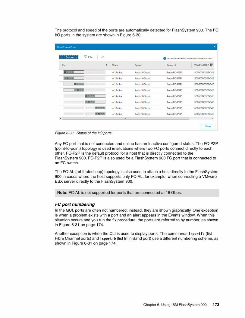
The protocol and speed of the ports are automatically detected for FlashSystem 900. The FC I/O ports in the system are shown in Figure 6-30.
Figure 6-30 Status of the I/O ports
Any FC port that is not connected and online has an Inactive configured status. The FC-P2P (point-to-point) topology is used in situations where two FC ports connect directly to each other. FC-P2P is the default protocol for a host that is directly connected to the FlashSystem 900. FC-P2P is also used for a FlashSystem 900 FC port that is connected to an FC switch.
The FC-AL (arbitrated loop) topology is also used to attach a host directly to the FlashSystem 900 in cases where the host supports only FC-AL; for example, when connecting a VMware ESX server directly to the FlashSystem 900.
FC port numberingIn the GUI, ports are often not numbered; instead, they are shown graphically. One exception is when a problem exists with a port and an alert appears in the Events window. When this situation occurs and you run the fix procedure, the ports are referred to by number, as shown in Figure 6-31 on page 174.
Another exception is when the CLI is used to display ports. The commands lsportfc (list Fibre Channel ports) and lsportib (list InfiniBand port) use a different numbering scheme, as shown in Figure 6-31 on page 174.
Note: FC-AL is not supported for ports that are connected at 16 Gbps.
Chapter 6. Using IBM FlashSystem 900 173

Figure 6-31 Port error window that shows port numbers
In Figure 6-31, Port ID 5 is Inactive. When a fix procedure is run, ports are numbered, as shown in Figure 6-32.
Figure 6-32 FC port numbering in the GUI
Note: To identify the canister with the affected port, use the Panel Name. The node identifier and node name are logical values and might not always match the physical canister ID or Panel Name. For example, sometimes canister 1 (Panel Name 01-1) is node2.
174 Implementing IBM FlashSystem 900 Model AE3

Port numbering that uses the CLI uses a different scheme, depending on the type of ports that are installed, as shown in Figure 6-33 (8 Gb FC), Figure 6-34 on page 176 (16 Gb FC), and Figure 6-35 on page 176 (InfiniBand).
Figure 6-33 8 Gb port numbering in the CLI
Chapter 6. Using IBM FlashSystem 900 175

Figure 6-34 16 Gb port numbering in the CLI
Figure 6-35 InfiniBand port numbering in the CLI
176 Implementing IBM FlashSystem 900 Model AE3

Flash module propertiesClick Actions → Flash Modules to open the Flash Module Properties information window (see Figure 6-36).
Figure 6-36 Flash Module Properties display
Flash modules within an initialized FlashSystem 900 must always be online, except when a flash module is in the failed state.
The Use column (parameter) can include the following values:
� Candidate (ready to be a RAID 5 member or spare)� Member� Spare
RAID 5 provides redundancy for failed flash modules and keeps one flash module as a spare. The only situations in which a flash module can be a candidate are when a module was replaced and becomes the new spare (before it is formatted) or when no RAID configuration is on the flash module.
Including more candidate flash modules into the RAID configuration requires the reinitialization of the array, which is a data-destructive action. For more information about how to reinitialize the RAID configuration, see 4.4, “RAID storage modes” on page 115.
Chapter 6. Using IBM FlashSystem 900 177

To view properties of the individual flash modules, from the Monitoring → System window, hover the mouse pointer over the FlashSystem 900 image, right-click a flash module, and select Properties. The flash module properties are displayed, as shown in Figure 6-37.
Figure 6-37 Flash Module ID 0 properties
Figure 6-38 Flash module slot numbers
Note: Flash module ID numbers are logical number and do not often match the physical slot ID where a flash module is installed. In the example that is shown in Figure 6-37, flash module ID 0 is in physical Slot ID 4.
Slot ID numbers begin with 1, starting on the left, and include empty slots, as shown in Figure 6-38.
178 Implementing IBM FlashSystem 900 Model AE3

Part numbersTo review a list of part numbers for customer-replaceable units (CRUs) and field-replaceable units (FRUs), click Actions → Part Numbers. CRUs can be replaced by IBM clients; FRUs are replaced by IBM Support or an IBM Service Partner.
The part numbers that are available for the IBM FlashSystem 900 are shown in Figure 6-39.
Figure 6-39 List of part numbers
Properties menuThe information that is shown in Figure 6-40 can be displayed in the Properties window by selecting Actions → Properties.
Figure 6-40 Properties for the system cluster
Chapter 6. Using IBM FlashSystem 900 179

6.3.2 Monitoring Network Neighborhood
The Network Neighborhood feature displays a group of FlashSystems with a summary of health, status, and performance. The neighborhood enables you to manage multiple flashsystems and switch between them quickly without requiring browser bookmarks. Five FlashSystems are shown in Figure 6-41.
Figure 6-41 Network Neighborhood
As shown in Figure 6-41, below the system names of the FlashSystems are the status. The following possible statuses are available:
� Online: The system is online and accessible by using the same credentials.� Not authenticated: The system is online; however, you must log in if you try to connect to it.� Unreachable/Offline: The system cannot be reached over the network or might be down.
To manage a different system, you can double-click the icon for that system. However, much summary information is available by hovering the mouse over the system’s icon, as shown in Figure 6-42 on page 181.
Note: The Network neighborhood feature is supported on any FlashSystem 840 or 900 with firmware release 1.2.0.11 and higher. However, systems with firmware levels below 1.4.7.0 cannot access systems that include firmware 1.4.7.0 and higher. Ideally, all systems in the Network Neighborhood run 1.4.7.1 or higher firmware.
180 Implementing IBM FlashSystem 900 Model AE3

Figure 6-42 Neighborhood summary information
You can also change the performance metric that is displayed on the neighborhood icons by using the buttons at the top of the window, as shown in Figure 6-43.
Figure 6-43 Neighborhood performance chart selector
FlashSystem AE3 Storage enclosures that are part of a V9000 system can also be included in a Neighborhood. Storage enclosures that are part of a FlashSystem V840 also can be included; however, the firmware level on the enclosure must be at 1.4.7.0 or higher.
6.3.3 Monitoring events
When an alert is posted to the Events window, the IBM FlashSystem 900 includes an indicator in the top banner of the GUI, as shown in Figure 6-44.
Figure 6-44 Top banner showing one alert
The number included with the icon indicates the number of unfixed alerts that appear in the log. Alerts feature a severity of warning or error. Error usually requires immediate attention. You can browse directly to alert information or to the All Events window on the FlashSystem 900 by clicking the alerts icon in the top banner, as shown in Figure 6-45 on page 182.
If a system name is truncated,hover to see the full name
General informationabout the system
Hover over capacity tosee allocated space
The most severe alerts are highlighted Right click to login usingdifferent credentials
Chapter 6. Using IBM FlashSystem 900 181

Figure 6-45 Shortcuts to all events or details about an event
Navigating to eventsTo browse to the event log, click Monitoring → Events. The window that opens with the Show All mode selected is shown in Figure 6-46. In this mode, all events, including messages, warnings, and errors, are displayed. To get to the Show All mode, first click a recommended action and then, select Show All.
Figure 6-46 Events window
In this example, one error, one warning, and several “fixed” alerts and messages are shown. Unfixed error alerts are displayed shaded in red (Fan fault type 1), and unfixed warning alerts are shared in blue (Reconditioning of batteries required).
Messages and alerts that are marked as “fixed” are not shaded. Marking a message or alert as “fixed” means that it was acknowledged and fixed manually. Unfixed messages are blue and “fixed” messages and alerts are green. Unfixed alerts (warning and error) are always displayed by using red text.
The most common way to resolve a problem that appears in the Events view is to run the Fix Procedure. This procedure is also referred to as a directed maintenance procedure (DMP). For more information, see “Directed maintenance procedures” on page 186.
The Events menu can be manipulated in several ways by using the function tabs that are displayed over the list of events.
182 Implementing IBM FlashSystem 900 Model AE3

Check Log LED offOne function of the FlashSystem 900 is its Check Log LED. This LED illuminates amber for a problem that is not isolated. An error condition results in a call home of the problem.
A service action also is available (a warning condition results in a service action that the user is expected to fix). No correlation exists between the notification type of “error/warning” and the Check Log LED.
The leftmost function key of the Events menu is the Check Log Off. When you click Check Log Off, you turn off the Check Log LED on the front of the IBM FlashSystem 900, and only new events turn it on again.
From the Events window, click Check Log Off. The window that is shown in Figure 6-47 opens. To turn off the Check Log LED, click Yes.
Figure 6-47 Turning off the check log LED
Change the Events viewYou might want more or less information from the Events window. You can change the default columns that are shown in the view by right-clicking the column header or by clicking the columns icon in the upper-right corner of the Events window, as shown in Figure 6-48.
Figure 6-48 Customizing columns
Right click on column header or left click on columns iconto customize the columns.
Chapter 6. Using IBM FlashSystem 900 183

Most GUI windows refresh automatically several times per minute. However, the Events window must be manually refreshed by using the Refresh function, as shown in Figure 6-49. Use Refresh to see whether an error occurred or was cleared after taking an action.
Figure 6-49 Refreshing the Events view
The Actions menu is context-sensitive. If you select an event in the list, you can perform the following actions:
� Run a fix procedure on error and warning events.
� Mark events as fixed.
� Open a Problem Management Record (PMR) with IBM support (for more information, see 7.1.5, “Support menu”, “Open problem management record” on page 299).
� Filter displayed events on date.
� Show only events from the last minutes, hours, or days.
� Reset the date filter.
� Show the properties of an event.
� Clear the event log.
Only events that are newer than 5 hours are selected to view, as shown in Figure 6-50.
Figure 6-50 Show entries within 5 hours
Recommended actionsMessages and alerts are displayed in the Events window. If any unresolved issues exist, the Recommended Actions section opens in the upper left of the window. If more than one alert is available, the system decides which problem is most critical and presents that alert as the recommended problem to fix first.
184 Implementing IBM FlashSystem 900 Model AE3
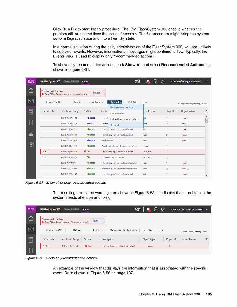
Click Run Fix to start the fix procedure. The IBM FlashSystem 900 checks whether the problem still exists and fixes the issue, if possible. The fix procedure might bring the system out of a Degraded state and into a Healthy state.
In a normal situation during the daily administration of the FlashSystem 900, you are unlikely to see error events. However, informational messages might continue to flow. Typically, the Events view is used to display only “recommended actions”.
To show only recommended actions, click Show All and select Recommended Actions, as shown in Figure 6-51.
Figure 6-51 Show all or only recommended actions
The resulting errors and warnings are shown in Figure 6-52. It indicates that a problem in the system needs attention and fixing.
Figure 6-52 Show only recommended actions
An example of the window that displays the information that is associated with the specific event IDs is shown in Figure 6-56 on page 187.
Chapter 6. Using IBM FlashSystem 900 185

Directed maintenance proceduresWhen a warning or error occurs, the system provides a fix procedure, also referred to as a DMP. Different methods are available to discover that your system needs attention in a warning or error situation. If the call home feature is configured on your system (which is advised), IBM Support is notified directly from the system and the system administrators are contacted by IBM for corrective actions.
The system administrator might also be in the list of email recipients and is notified directly and immediately from the system when an alert is sent.
For more information about how to configure call home, see Chapter 4, “Installation and configuration” on page 81 and 7.1.1, “Notifications menu” on page 231.
Another way of getting alert notifications is through Simple Network Management Protocol (SNMP) alerts. For more information about how to configure SNMP alerts, see “Simple Network Management Protocol” on page 238.
When the system administrator logs on to the GUI of the FlashSystem 900, the Alerts icon in the top banner indicates whether any unfixed alerts are available, as shown in Figure 6-53.
Figure 6-53 Thermal alert in top banner
Many fix procedures require replacing a component, which often is done by IBM Service if the part is an FRU. An example of an event that can be fixed by the user from the Recommended Actions indicator is an error situation in which the ambient temperature is too high, as described next.
Fixing the eventClicking any of the displayed Status Alerts takes you to the Events menu in which information about the events can be reviewed, as shown in Figure 6-54. The Recommended Actions field indicates that unresolved errors are in the log and need attention. This method to fix errors is also referred to as the DMP.
Figure 6-54 Thermal alert in Events window
186 Implementing IBM FlashSystem 900 Model AE3
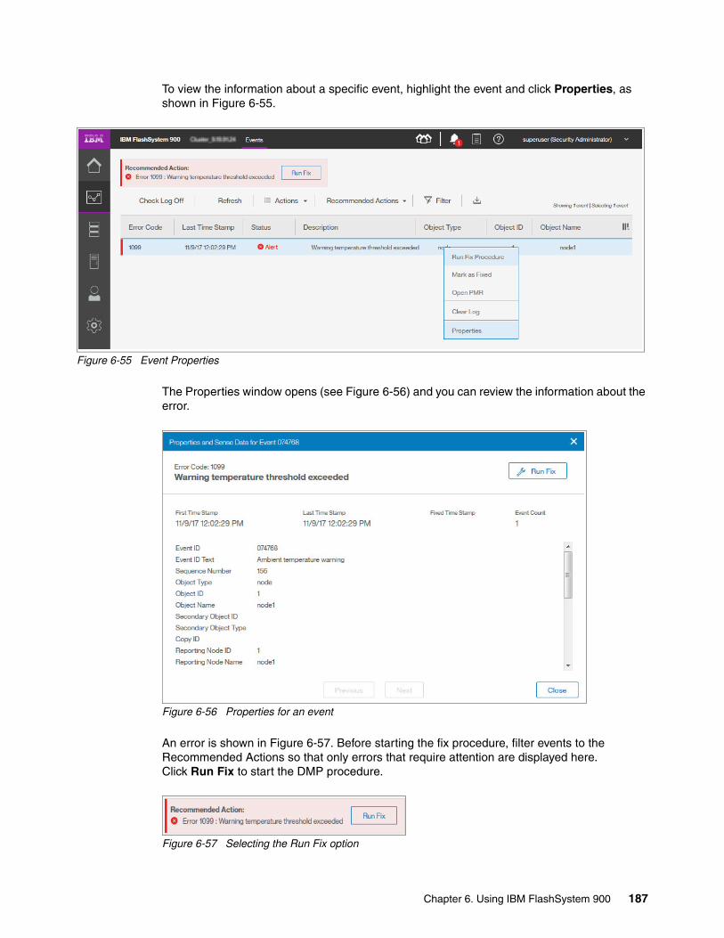
To view the information about a specific event, highlight the event and click Properties, as shown in Figure 6-55.
Figure 6-55 Event Properties
The Properties window opens (see Figure 6-56) and you can review the information about the error.
Figure 6-56 Properties for an event
An error is shown in Figure 6-57. Before starting the fix procedure, filter events to the Recommended Actions so that only errors that require attention are displayed here. Click Run Fix to start the DMP procedure.
Figure 6-57 Selecting the Run Fix option
Chapter 6. Using IBM FlashSystem 900 187

The Run Fix procedure guides you through resolving the error event. The error message in this example is caused by a room temperature that is too high, which might cause the system to overheat and eventually shut down if the error situation is not corrected.
The first step of the DMP procedure is shown in Figure 6-58. The system reports that canister 1 (the left canister as seen from the rear of the system) is measuring a temperature that is too high. The display also indicates that both fans in both canisters are operational and online.
Figure 6-58 DMP procedure step 1
The next step in the DMP procedure is for the administrator to measure the room temperature and to ensure that the ambient temperature is within the specifications that were set for the system. The instructions for this step are shown in Figure 6-59.
Figure 6-59 DMP procedure step 2
188 Implementing IBM FlashSystem 900 Model AE3
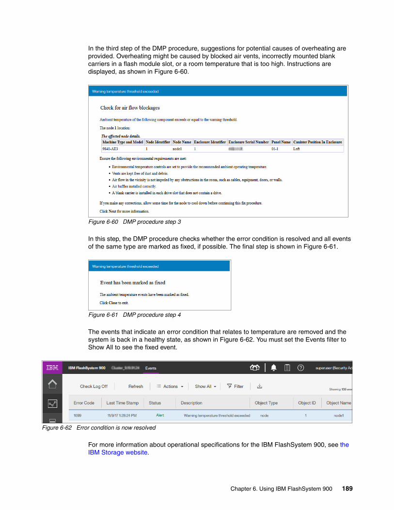
In the third step of the DMP procedure, suggestions for potential causes of overheating are provided. Overheating might be caused by blocked air vents, incorrectly mounted blank carriers in a flash module slot, or a room temperature that is too high. Instructions are displayed, as shown in Figure 6-60.
Figure 6-60 DMP procedure step 3
In this step, the DMP procedure checks whether the error condition is resolved and all events of the same type are marked as fixed, if possible. The final step is shown in Figure 6-61.
Figure 6-61 DMP procedure step 4
The events that indicate an error condition that relates to temperature are removed and the system is back in a healthy state, as shown in Figure 6-62. You must set the Events filter to Show All to see the fixed event.
Figure 6-62 Error condition is now resolved
For more information about operational specifications for the IBM FlashSystem 900, see the IBM Storage website.
Chapter 6. Using IBM FlashSystem 900 189

6.3.4 Monitoring performance menu
The IBM FlashSystem 900 Performance menu provides an overview of a system’s performance. In the latest firmware release, the performance monitor was improved. The default performance monitor shows 5 minutes of captured data and the view can be expanded to show up to 300 days.
Performance menu overviewTo open the FlashSystem 900 performance monitor, select Monitoring → Performance. The first time the browser window opens, system I/O and latency are displayed, as shown in Figure 6-63.
Figure 6-63 Performance monitoring window
The timeline that is at the top of the window displays the time for both graphs. You can select a time range by using the time range selector (recent, hour, day, and so on) or you can scroll forward or backward by using the arrow buttons at either end of the timeline.
You can also zoom in and out in time by using the zoom buttons. Finally, you can use the mouse to change the time and time range by hovering the mouse over one of the graphs and dragging left or right to move backward or forward in time, and you can zoom in or out by using by the mouse wheel.
The maximum resolution of the performance data is 5 seconds. If you zoom in, the 5-second resolution is the smallest interval that is shown. When you zoom out, fewer points are shown on the chart to avoid cluttering it.
190 Implementing IBM FlashSystem 900 Model AE3

Selecting chartsBy default, two charts are shown in the performance window. These charts can be changed by using the chart selector menu that is shown in Figure 6-63. You can also remove one of the graphs so that only one graph is displayed. Clicking the Remove Graph button toggles between one or two graphs.
Five performance charts can be reviewed from the charts menu, as shown in Figure 6-64.
Figure 6-64 Performance chart selector menu
Clicking the Manage Charts Preset option allows you to specify which two graphs are opened by default. The following default choices are available:
� System I/O
The System I/O graph displays the average number of read, write, and total I/O requests per second (IOPS) over the sample period. Each request type (read, write, and total) is represented by a different colored line.
� System Latency
The System Latency graph displays the average amount of time for each read and write I/O request takes over the sampling period. Each request type (read and write) is represented by a different colored line.
� System Bandwidth
The System Bandwidth graph displays the average number of megabytes per second (MBps) of read, write, total, and rebuild bandwidth over the sample period. Each bandwidth type (read, write, total, and rebuild) is represented by a different colored line. One line graph is used for each system that is selected.
� Interface Port Total IOPS
The Total Port IOPS graph displays average number of read, write, and total IOPS over the sample period. One line on the graph is used for each port in each host adapter in each canister. Each adapter features a different color, and all four ports on an adapter include the same color. When displaying Total IOPS for all ports in the system, the chart shows the minimum, average, and maximum values.
� Fibre Channel Port Total Queue Depth
The Total Port Queue Depth graph displays the average number of operations of that type over the sample period. One line on the graph is used for each port in each host adapter in each canister. Each adapter uses a different color, and all four ports on an adapter include the same color. When displaying Total Queue Depth for all ports in the system, the chart shows the minimum, average, and maximum values.
Chapter 6. Using IBM FlashSystem 900 191

Customizing and creating chartsAlthough the five default charts cannot be deleted, they can be used as templates to create charts. Clicking Customize in the performance window allows you to create charts by editing a chart and selecting Save as and View.
Alternatively, you can click Manage Charts Preset in the Charts menu, select a chart, and click Save As to make a copy, as shown in Figure 6-65.
Figure 6-65 Creating a performance chart
When you click Save As, a window is opened for you to customize the new chart, as shown in Figure 6-66 on page 193.
Create a new performance chart by selecting an existing chartthen click “Save As”.
192 Implementing IBM FlashSystem 900 Model AE3

Figure 6-66 Customizing a new performance chart
Chart selector menuThe charts that you create are listed in the chart selector menu, as shown in Figure 6-67.
Figure 6-67 Custom charts displayed in chart selector menu
Name the chart
Select the component to be charted
Select theports to bemonitored(use Shift orCtrl to multi-select)
Choose a metric to be charted
Save the new chart
Chapter 6. Using IBM FlashSystem 900 193

By selecting the chart in the menu, the newly created chart is displayed, including a legend at the bottom of the chart, Figure 6-68.
Figure 6-68 Custom chart showing IOPS for canister 1 ports
If you want to change the default charts in the performance window, click Manage Charts preset in the chart selector menu, and then, select the appropriate choices in the window. Click Save All Changes, as shown in Figure 6-69. In this example, the System I/O option is not selected; instead, the option for the new chart is selected.
Figure 6-69 Changing the default performance charts
194 Implementing IBM FlashSystem 900 Model AE3

If you want the custom chart to be the only chart that is displayed, the bottom chart can be removed from the performance window by clicking Remove Graph, as shown in Figure 6-70.
Figure 6-70 Customized graph as the default
Interface adapter numberingThe numbering and naming of the IBM FlashSystem 900 I/O interface adapters as they correspond to the performance monitor charts for Interface Queue Depth is shown in Figure 6-71.
Figure 6-71 Rear-side numbering of interface adapters
The numbering of the ports in each adapter depends on the adapter type. The ports are on the enclosure are labeled, as shown in Figure 6-33 on page 175 (8 Gb FC), Figure 6-34 on page 176 (16 Gb FC), and Figure 6-35 on page 176 (InfiniBand).
Canister 1 Canister 2
Adapter 1 Adapter 1Adapter 2 Adapter 2
Chapter 6. Using IBM FlashSystem 900 195

IBM data management and storage managementIf you need more performance monitoring, the optimal tool to use is IBM data management and storage management, which is provided by IBM Spectrum Control. You can manage performance and connectivity from the host file system to the physical disk, including in-depth performance monitoring and analysis of the storage area network (SAN) fabric.
IBM data management and storage management solutions deliver the functions of IBM Spectrum Control, which is a member of the IBM Spectrum Storage family.
For more information about IBM Spectrum Control, see the IBM Spectrum Control page of IBM Knowledge Center.
6.3.5 Monitoring performance with events
Events can occur that affect performance. In the FlashSystem 900 AE3 (and other models that are running firmware version 1.5.0.0 and higher), a feature was added with which you can correlate warning and error events with system performance. This feature can be helpful in identifying the cause of performance issues.
In previous releases, you compared the time stamps of events in the Events view with the corresponding time in a performance chart. But with the new Performance With Events view, events are time-aligned with performance data.
Suppose that a user complains of poor application performance at a specific time. By reviewing the performance view for that time, you can instantly correlate the event that caused it.
The performance graphs in Figure 6-72 on page 197 show a sharp drop in I/O and a rise in latency at 4 PM.
Name change: Before version 5.2.8, IBM Spectrum Control was known as IBM Tivoli Storage Productivity Center.
Notes: For initial and current releases of the IBM FlashSystem 900, IBM Spectrum Control does not support the product directly. The exception is if the FlashSystem 900 functions as an MDisk for the IBM SAN Volume Controller, in which case, IBM Spectrum Control supports the product through the SAN Volume Controller.
SAN Volume Controller delivers the functions of IBM Spectrum Virtualize, which part of the IBM Spectrum Storage family.
196 Implementing IBM FlashSystem 900 Model AE3

Figure 6-72 Performance with events overview
On the timeline, a blue line shows a warning event occurred at about the same time. The latency and throughput return to normal between 6:00 and 6:30 PM. On the timeline, a red line indicates that an error was logged then.
By clicking the event in the timeline, the warning or event is displayed. As shown in Figure 6-73, two warnings occurred at 4 PM.
Figure 6-73 Warning events on timeline
Chapter 6. Using IBM FlashSystem 900 197

When the rebuild of the array completed at approximately 6:30 PM, an alert showed that the array is “missing a spare”, as shown in Figure 6-74.
Figure 6-74 Error event on timeline
While viewing the event on this window, you can click More Info to view more information about the error or run the fix procedure. You also can click View Event Page to view all events. Clicking More Info opens a window, as shown in Figure 6-75.
Figure 6-75 Error details
198 Implementing IBM FlashSystem 900 Model AE3

If the error was corrected (in this example, by replacing the failed drive), the error is displayed as “(fixed)” in the window, as shown in Figure 6-76.
Figure 6-76 Error marked as fixed
6.4 Volumes menu
In the Volumes menu, click Volumes; the Volumes window opens (see Figure 6-77). You can perform tasks on the volumes, such as create, expand, rename, and delete, or you can review the properties of the volume.
Figure 6-77 Volumes window that shows all volumes
Creating a volume by using the GUIThe system uses base-2 (binary numeral) as capacity indicators for volumes, drives, and other system objects. The management GUI and the command-line interface (CLI) use different abbreviations to indicate capacity; however, the value for these capacity indicators is the same. The differences in how capacity indicators are displayed in the management GUI and the CLI are shown in Figure 6-78 on page 200.
Note: Not all warnings and errors affect performance. In this example, the rebuild priority was manually changed to “rebuildmax” to speed up the rebuild process and intentionally affect host performance. Other options for rebuild priority feature less effect on host latency. For more information, see the IBM FlashSystem 900 page of IBM Knowledge Center and search for “rebuild priority”.
Chapter 6. Using IBM FlashSystem 900 199

Figure 6-78 Capacity indicates differences between GUI and CLI
To create a volume by using the GUI from the Volumes menu, in the upper left of the window, click Create Volumes (as shown in Figure 6-77 on page 199). The Create Volumes window opens (see Figure 6-79). In this example, use the volume name of SVC, a quantity of 4 volumes, and the requested capacity of 80 GiB. Click Create.
Figure 6-79 Create Volumes window
In the task window (see Figure 6-80), click Close.
Figure 6-80 Create Volumes task window
200 Implementing IBM FlashSystem 900 Model AE3

The Create Volume wizard creates four volumes of 80 GiB each. You can review results in the Volumes window (see Figure 6-81).
Figure 6-81 Four SAN Volume Controller volumes created
The newly created volumes do not include host mappings when they are created. Host mapping can be added by clicking Volumes → Volumes by Host window. For more information about volume host mapping, see “Mapping volumes” on page 205.
Creating a volume by using the CLIThe CLI process for creating a volume is shown in Example 6-3. More or fewer parameters can be applied to the mkvdisk command. The minimum required parameter is specified in Example 6-3.
Example 6-3 Creating a volume by using the CLI
IBM_Flashsystem:FlashSystem_900:superuser>mkvdisk -size 15 -unit gb -name SVC_44Virtual Disk, id [7], successfully created
IBM_Flashsystem:FlashSystem_900:superuser>lsvdiskid name status capacity vdisk_UID udid open_access_scsi_id parent_mdisk_grp_id parent_mdisk_grp_name4 SVC_0 online 80.00GB 6005076111b5d88110000000040001fb 4 0 mdiskgrp05 SVC_1 online 80.00GB 6005076111b5d88110000000050001fc 5 0 mdiskgrp06 SVC_2 online 80.00GB 6005076111b5d88110000000060001fd 6 0 mdiskgrp07 SVC_3 online 80.00GB 6005076111b5d88110000000070001fe 7 0 mdiskgrp08 SVC_44 online 15.00GB 6005076111b5d881100000003a000211 58 0 mdiskgrp0IBM_Flashsystem:FlashSystem_900:superuser>
Chapter 6. Using IBM FlashSystem 900 201

Performing actions on volumesFrom the Volumes window, you can perform various tasks on the volumes. Click Actions to access these operations (see Figure 6-82), or right-click the volume name, which opens a list of tasks that you can perform on the volume.
Figure 6-82 Actions of a single volume
The properties of a volume that indicate the volume name, its capacity, and its sector size are shown in Figure 6-83. Each volume features a unique ID (UID), which can be discovered from the host side as a property of the logical unit. The volume that is shown in Figure 6-83 is not yet mapped to a host.
Figure 6-83 Properties of a volume
A volume can be expanded while it is online, which maintains full functionality to the connected hosts. Because not all operating systems allow concurrent expansion of their disks, precautions must be taken so that the operating system supports dynamic volume expansion. An alternative to expanding the disk is to create a disk and map it to the host.
202 Implementing IBM FlashSystem 900 Model AE3
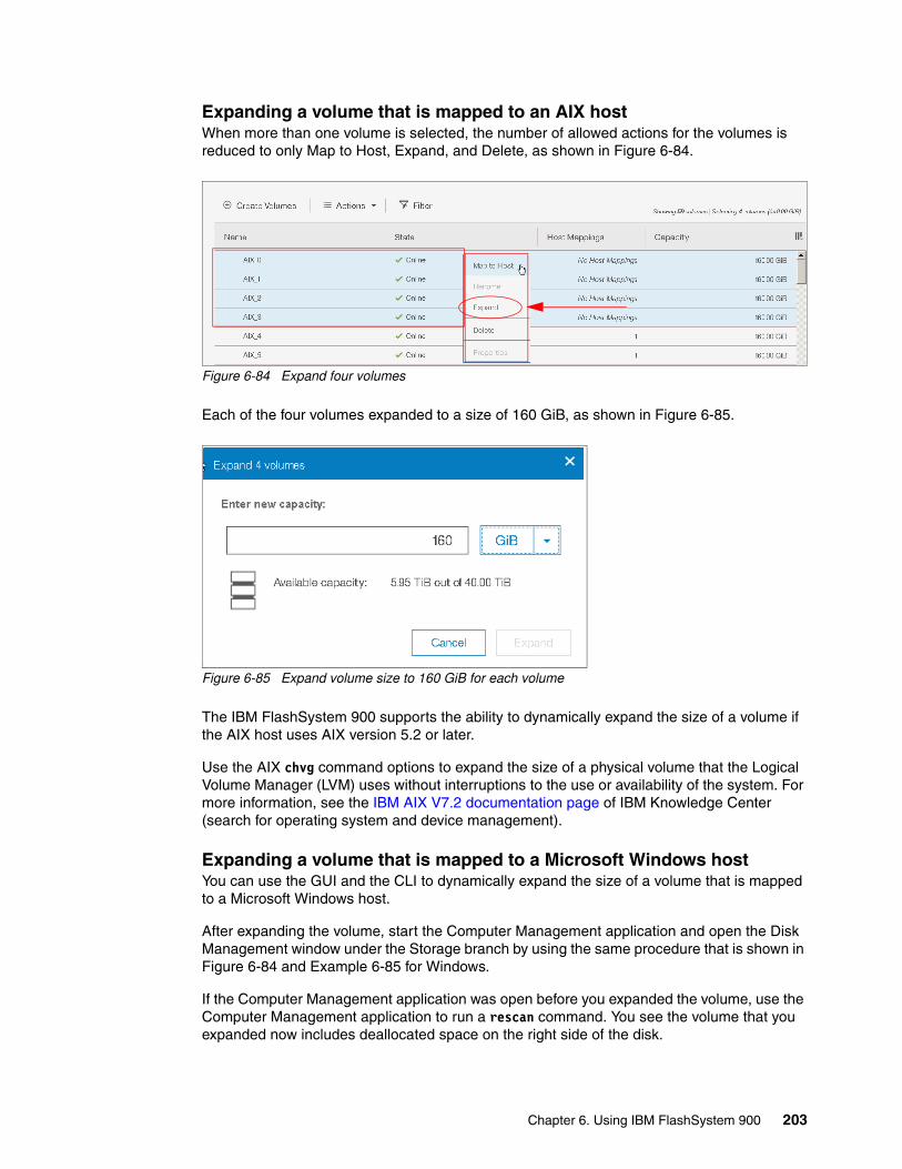
Expanding a volume that is mapped to an AIX hostWhen more than one volume is selected, the number of allowed actions for the volumes is reduced to only Map to Host, Expand, and Delete, as shown in Figure 6-84.
Figure 6-84 Expand four volumes
Each of the four volumes expanded to a size of 160 GiB, as shown in Figure 6-85.
Figure 6-85 Expand volume size to 160 GiB for each volume
The IBM FlashSystem 900 supports the ability to dynamically expand the size of a volume if the AIX host uses AIX version 5.2 or later.
Use the AIX chvg command options to expand the size of a physical volume that the Logical Volume Manager (LVM) uses without interruptions to the use or availability of the system. For more information, see the IBM AIX V7.2 documentation page of IBM Knowledge Center (search for operating system and device management).
Expanding a volume that is mapped to a Microsoft Windows hostYou can use the GUI and the CLI to dynamically expand the size of a volume that is mapped to a Microsoft Windows host.
After expanding the volume, start the Computer Management application and open the Disk Management window under the Storage branch by using the same procedure that is shown in Figure 6-84 and Example 6-85 for Windows.
If the Computer Management application was open before you expanded the volume, use the Computer Management application to run a rescan command. You see the volume that you expanded now includes deallocated space on the right side of the disk.
Chapter 6. Using IBM FlashSystem 900 203

If the disk is a Windows basic disk, you can create a primary or extended partition from the deallocated space.
If the disk is a Windows dynamic disk, you can use the deallocated space to create a volume (simple, striped, or mirrored) or add it to a volume.
Shrinking a volumeThe shrink volume option is provided through the CLI only and cannot be performed by using the GUI. Volumes can be reduced in size, if necessary. However, if the volume contains data, do not shrink the size of the disk because shrinking a volume destroys the data.
When shrinking a volume, consider the following points:
� Shrinking a volume removes capacity from the end of the volume’s address space. If the volume was used by an operating system or file system, predicting what space was used might be difficult. The file system or OS might depend on the space that is removed, even if it is reporting a large amount of free capacity.
� If the volume contains data that is used, do not attempt under any circumstances to shrink a volume without first backing up your data.
You can use the shrinkvdisksize CLI command to shrink the physical capacity that is allocated to the particular volume by the specified amount.
The shrinkvdisksize command uses the following syntax:
shrinkvdisksize -size capacitytoshrinkby -unit unitsforreduction vdiskname/ID
6.4.1 Volumes by Host
Clicking Volumes → Volumes by Host opens the window in which unmapped and mapped volumes are listed. This window shows which hosts are created on the system and which volumes exist. If the volumes are unmapped, they appear as Unmapped Volumes and a twistie ( > ) can be used to expand this section, as shown in Figure 6-86.
Figure 6-86 Volumes by Host window with expandable view
Attention: Shrinking a volume is a data-destructive action. Shrink only volumes that are not in use and that do not contain data. For more information, enter help shrinkvdisksize in the CLI.
204 Implementing IBM FlashSystem 900 Model AE3
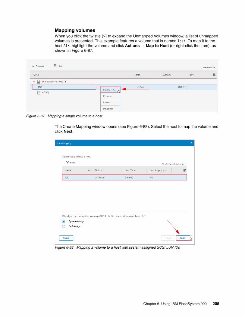
Mapping volumesWhen you click the twistie (>) to expand the Unmapped Volumes window, a list of unmapped volumes is presented. This example features a volume that is named Test. To map it to the host AIX, highlight the volume and click Actions → Map to Host (or right-click the item), as shown in Figure 6-87.
Figure 6-87 Mapping a single volume to a host
The Create Mapping window opens (see Figure 6-88). Select the host to map the volume and click Next.
Figure 6-88 Mapping a volume to a host with system assigned SCSI LUN IDs
Chapter 6. Using IBM FlashSystem 900 205
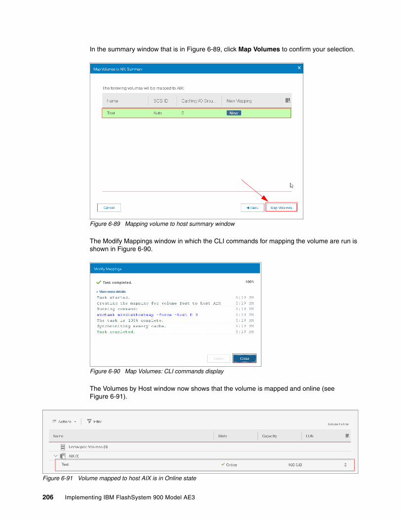
In the summary window that is in Figure 6-89, click Map Volumes to confirm your selection.
Figure 6-89 Mapping volume to host summary window
The Modify Mappings window in which the CLI commands for mapping the volume are run is shown in Figure 6-90.
Figure 6-90 Map Volumes: CLI commands display
The Volumes by Host window now shows that the volume is mapped and online (see Figure 6-91).
Figure 6-91 Volume mapped to host AIX is in Online state
206 Implementing IBM FlashSystem 900 Model AE3

Mapping a volume by using the CLIA useful way for administrators to perform this task might be to use the CLI. Volumes can be mapped by using the svctask mkvdiskhostmap command.
How to map a volume to a host by using the CLI is shown in Example 6-4.
Example 6-4 Map volume by using the CLI
IBM_Flashsystem:FlashSystem_900:superuser>svctask mkvdiskhostmap -force -host 0 4Virtual Disk to Host map, id [4], successfully created
IBM_Flashsystem:FlashSystem_900:superuser>lsvdiskhostmap 4id name SCSI_id host_id host_name vdisk_UID IO_group_id IO_group_name4 SVC_5 4 0 SVC 0020c24004000000 0 io_grp0
IBM_Flashsystem:FlashSystem_900:superuser>
In the CLI process for mapping volumes, this example uses the logical number for the host and the logical number for the volume. These logical numbers can be discovered by using the following commands:
� lshost: Shows defined hosts and their status� lsvdisk: Shows defined volumes and their preferences
Unmapping volumesWhen you remove a volume mapping, you are not deleting the volume. Instead, you are removing the connection from the host to the volume. If you mistakenly map a volume to a host or if you want to reassign the volume to another host, click Volumes → Volumes by Host. Highlight the volume or a group of volumes that you want to unmap, right-click, and click Unmap from Host, as shown in Figure 6-92.
Figure 6-92 Unmap multiple volumes from a single host
The Unmap Volumes from Host window opens, which indicates that the selected volumes are to be unmapped (see Figure 6-93 on page 208). Click Yes to confirm that volume unmaps from the specified host.
Chapter 6. Using IBM FlashSystem 900 207

Figure 6-93 Unmapping volume confirmation dialog
By unmapping the volumes, the volumes are made unavailable to the host.
After a volume is unmapped, it is listed in under Unmapped Volumes (see Figure 6-94) of the FlashSystem 900 GUI. The volumes can now be deleted or mapped to another host.
Figure 6-94 Unmapped volumes view
6.5 Hosts menu
Use the Hosts menu to manage hosts.
You can use the FlashSystem 900 GUI or the CLI mkhost command to create a logical host object. Creating a host object associates one or more worldwide port names (WWPNs) or InfiniBand IDs, of host bus adapters (HBAs), with a logical host object. Fibre Channel and SAS connections use WWPNs to identify the host interfaces to the systems.
A typical configuration features one host object for each host system that is attached to the system. If a cluster of hosts accesses the same storage, you can add HBA ports from several hosts to one host object to make a simpler configuration.
The system does not automatically present volumes to the host system. You must map each volume to a particular host object to enable the volume to be accessed through the WWPNs that are associated with the host object. You can map volumes (also called virtual disks or VDisks) to hosts by using the GUI or CLI mkvdiskhostmap command.
Note: Before unmapping a volume from a host, the host must unmount the connection to the disk for proper destage of data. Otherwise, I/O errors and a loss of data in host cache appear.
208 Implementing IBM FlashSystem 900 Model AE3

The Hosts menu features the following options:
� Hosts� Volumes by Host
6.5.1 Navigating to the Hosts menu
When you hover the cursor over the Hosts function icon, the Hosts menu opens, as shown in Figure 6-95.
Figure 6-95 Browsing to the Hosts menu
Adding a hostThe process of creating a host object includes specifying the host name and selecting ports for the host.
The FlashSystem 900 models are InfiniBand or Fibre Channel (FC) capable. However, interface cards cannot be mixed, and a single system must contain only a single type of interface card.
The FlashSystem 900 detects which type of interface cards are installed, and the Add Host wizard automatically adjusts to request the host port type for the actual model. For example, the host port information can be the FC WWPN.
The Hosts window in which the defined hosts are displayed is shown in Figure 6-96.
Figure 6-96 Hosts window showing already configured hosts
Chapter 6. Using IBM FlashSystem 900 209

In the host window, some host might be shown in Degraded or Offline state when some or all paths are not available to this host. Each connected host initiator port must be zoned and connected to both canisters in the IBM FlashSystem 900. If not, the host reports a Degraded state.
The risk of having a host with degraded paths is that the host might lose access to storage if a canister fails or restarts, which then might cause unplanned downtime. Canister restart also occurs during firmware updates.
Hosts in a FlashSystem 900 configured with FC interface cardsTo create a host object, click Add Host in the upper-left corner of the Hosts window. The Add Host window opens.
Enter the name Exchange01 for the new host and click the arrow at the right side of Host port (WWPN) entry field to select the WWPNs for your Exchange server. Any WWPNs that are zoned to the system but not in use by a configured host are displayed, as shown in Figure 6-97.
Figure 6-97 Adding ports to the new host (the refresh icon is highlighted)
If no WWPNs are listed, the following message is displayed:
No candidate ports found
In that case, the WWPN is used for another host object or the host was not zoned correctly to the FlashSystem 900.
Tip: To refresh the list of WWPN, click the refresh icon, which is highlighted in Figure 6-97.
210 Implementing IBM FlashSystem 900 Model AE3

Up to four WWPNs for each host can be selected. Click Add, as shown in Figure 6-98.
Figure 6-98 Adding a new host
Click Close in the Add Host CLI command detail window (see Figure 6-99).
Figure 6-99 Add host CLI command window
The newly created Exchange01 host is now online and features two ports (see Figure 6-100).
Figure 6-100 Host Exchange01 is now created and online
All WWPNs in a host object are mapped to the virtual disks.
Chapter 6. Using IBM FlashSystem 900 211
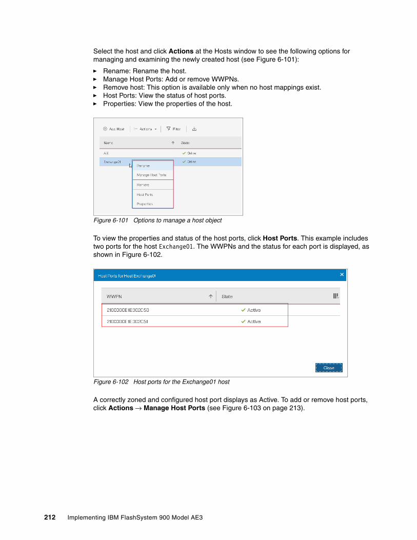
Select the host and click Actions at the Hosts window to see the following options for managing and examining the newly created host (see Figure 6-101):
� Rename: Rename the host.� Manage Host Ports: Add or remove WWPNs.� Remove host: This option is available only when no host mappings exist.� Host Ports: View the status of host ports.� Properties: View the properties of the host.
Figure 6-101 Options to manage a host object
To view the properties and status of the host ports, click Host Ports. This example includes two ports for the host Exchange01. The WWPNs and the status for each port is displayed, as shown in Figure 6-102.
Figure 6-102 Host ports for the Exchange01 host
A correctly zoned and configured host port displays as Active. To add or remove host ports, click Actions → Manage Host Ports (see Figure 6-103 on page 213).
212 Implementing IBM FlashSystem 900 Model AE3

Figure 6-103 Manage Host Ports
In this example, you want to remove host ports. Therefore, select one of the Exchange01 host ports and click Actions → Unassign Host Port (see Figure 6-104).
Figure 6-104 Manage host ports for host Exchange01 to remove ports
After the host port is unassigned, click Close to return to the Hosts view (see Figure 6-105), which shows that the Exchange01 host is Online and only a single port is active.
Figure 6-105 Host now features only a single WWPN port that is configured
Under normal conditions, any configured host features at least two configured host ports for redundancy. However, you might have reasons for unassigning a host port, as demonstrated in this example. One reason might be that if an HBA for a host is replaced, SAN zoning and storage systems must be reconfigured for the new host WWPN.
Chapter 6. Using IBM FlashSystem 900 213

Creating a host by using the CLITo create a host by using the CLI, run the svctask mkhost and svctask addhostport commands, as shown in Example 6-5.
Example 6-5 Creating a host and adding a port
IBM_Flashsystem:Cluster_9.xx.xx.xxx:superuser>svctask mkhost -fcwwpn 5005076801300004 -force -name SVCHost, id [1], successfully created
IBM_Flashsystem:Cluster_9.xx.xx.xxx:superuser>svctask addhostport -fcwwpn 50050768013A0004 -force SVC
IBM_Flashsystem:Cluster_9.xx.xx.xxx:superuser>lshostid name port_count iogrp_count status0 test 1 1 offline1 SVC 2 1 offline
IBM_Flashsystem:Cluster_9.xx.xx.xxx:superuser>lshost SVCid 1name SVCport_count 2type genericmask 1111111111111111111111111111111111111111111111111111111111111111iogrp_count 1status offlineWWPN 50050768013A0004node_logged_in_count 0state offlineWWPN 5005076801300004node_logged_in_count 0state offlineIBM_Flashsystem:Cluster_9.xx.xx.xxx:superuser>
The svctask addhostport command must be run once for every host port that you want to define for your host object.
6.5.2 Volumes by Host
The Volumes by Host option on the Hosts menu is functionally identical to the Volumes by Host option on the Volumes menu. For more information, see 6.4.1, “Volumes by Host” on page 204).
Note: For more information about how to configure host connectivity, see Chapter 5, “IBM FlashSystem 900 client host attachment and implementation” on page 119.
214 Implementing IBM FlashSystem 900 Model AE3

6.6 Access menu
Various levels of user access to the FlashSystem 900 system are managed through the Access menu. The access levels are divided into groups. Each group features a different level of access and authority. Multiple users can be defined and their access assigned to suit the tasks that they perform.
The Access menu features the following options:
� Users� User Groups� Audit Log
6.6.1 Browsing to the Access menu
Hover the mouse cursor over the Access function icon. A menu opens, as shown in Figure 6-106.
Figure 6-106 Browsing to the Access menu
By using the Access menu, you can manage users and review audit logs.
User management includes creating users and maintaining roles and passwords for users. Also, part of user management is the configuration of Secure Shell (SSH) keys to provide secure access to the CLI for users.
The audit log includes actions that are submitted through the management GUI or the CLI. You can use the audit log to monitor user activity on your system. It also contains information about which user ran the command from which IP and any results of this action.
Chapter 6. Using IBM FlashSystem 900 215
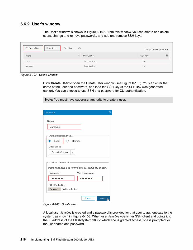
6.6.2 User’s window
The User’s window is shown in Figure 6-107. From this window, you can create and delete users, change and remove passwords, and add and remove SSH keys.
Figure 6-107 User’s window
Click Create User to open the Create User window (see Figure 6-108). You can enter the name of the user and password, and load the SSH key (if the SSH key was generated earlier). You can choose to use SSH or a password for CLI authentication.
Figure 6-108 Create user
A local user JaneDoe is created and a password is provided for that user to authenticate to the system, as shown in Figure 6-108. When user JaneDoe opens her SSH client and points it to the IP address of the FlashSystem 900 to which she is granted access, she is prompted for the user name and password.
Note: You must have superuser authority to create a user.
216 Implementing IBM FlashSystem 900 Model AE3

If the user is required to authenticate by using an SSH key pair, you enter the path for the public key in the SSH Public Key field in the Create User window, as shown in Figure 6-109.
Figure 6-109 Creating a user with SSH key enabled
The Password and Verify password fields are used for GUI access. If a password is not configured, the user cannot log in to the GUI.
When the SSH key is generated by using PuTTYgen, you can choose to configure a pass phrase. If the SSH key pair was generated without a pass phrase, the user JaneDoe is not prompted for a password when she opens her SSH client. She is then authenticated with the private key that matches the uploaded public key.
If a pass phrase was configured when the SSH key pair was created, the user JaneDoe also must enter the pass phrase when opening the CLI to access the system.
For more information about how to create SSH keys by using PuTTYgen, see “Generating an SSH key pair by using PuTTY” on page 220.
Now, the new user is listed (see Figure 6-110) and an SSH key is enabled for that user.
Figure 6-110 User is created and SSH key enabled
Chapter 6. Using IBM FlashSystem 900 217

To verify the SSH public key configuration for user JaneDoe, right-click the user or use the Actions menu. Select Manage SSH public keys, as shown in Figure 6-111.
Figure 6-111 Manage SSH public key configuration
In the Manage SSH Public Key window, you can enable or disable CLI access by using the public SSH key exchange method for an individual user (see Figure 6-112).
Figure 6-112 Configure CLI access by using SSH key exchange
To test whether the new user can log in to the GUI, log out as user superuser and log in as user JaneDoe. The login window is shown in Figure 6-113 on page 219.
Note: For more information about configuring CLI access from a client system, including how to configure SSH keys for secure access only, see 6.6.3, “Accessing CLI by using PuTTY” on page 219
218 Implementing IBM FlashSystem 900 Model AE3
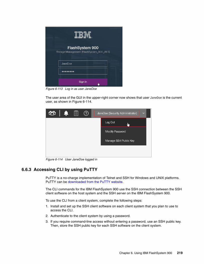
Figure 6-113 Log in as user JaneDoe
The user area of the GUI in the upper-right corner now shows that user JaneDoe is the current user, as shown in Figure 6-114.
Figure 6-114 User JaneDoe logged in
6.6.3 Accessing CLI by using PuTTY
PuTTY is a no-charge implementation of Telnet and SSH for Windows and UNIX platforms. PuTTY can be downloaded from the PuTTY website.
The CLI commands for the IBM FlashSystem 900 use the SSH connection between the SSH client software on the host system and the SSH server on the IBM FlashSystem 900.
To use the CLI from a client system, complete the following steps:
1. Install and set up the SSH client software on each client system that you plan to use to access the CLI.
2. Authenticate to the client system by using a password.
3. If you require command-line access without entering a password, use an SSH public key. Then, store the SSH public key for each SSH software on the client system.
Chapter 6. Using IBM FlashSystem 900 219

Generating an SSH key pair by using PuTTYTo use the CLI with SSH keys enabled, you must generate an SSH key pair. SSH keys can be generated from a Windows host by using the PuTTY key generator, PuTTYgen. Complete the following steps:
1. Run puttygen.exe.
2. Click SSH-2 RSA as the type of key to generate.
Keep the number of bits in a generated key value at 1024.
3. Click Generate and then, move the mouse cursor around the blank area of the key section to generate the random characters that create a unique key. When the key is generated, the information about the new key is displayed in the key section.
4. (Optional) Enter a passphrase in the key passphrase and confirm passphrase fields. The passphrase encrypts the key on the disk; therefore, it is not possible to use the key without first entering the passphrase.
5. Save the public key by completing the following steps:
a. Click Save public key. You are prompted for the name and location of the public key.
b. Enter icat.pub as the name of the public key and specify the location where you want to save the public key. For example, you can create a local directory that is named keys to store the public and private keys.
c. Click Save.
6. Save the private key by completing the following steps:
a. Click Save private key. The PuTTYgen Warning panel is displayed.
b. Click Yes to save the private key without a passphrase.
c. Enter the name of the private key and specify the location where you want to save it. For example, you can create a local directory that is named keys to store the public and private keys. We suggest that you save your public and private keys in the same location.
d. Click Save.
7. Close the PuTTY Key Generator window.
220 Implementing IBM FlashSystem 900 Model AE3
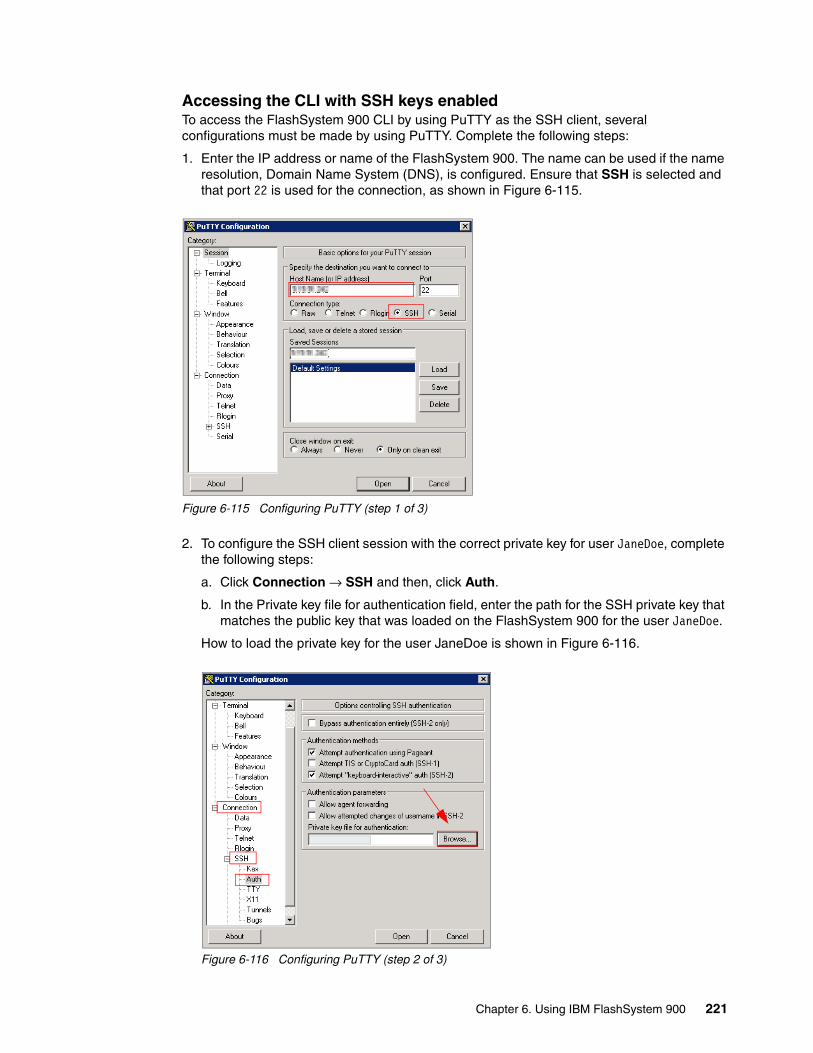
Accessing the CLI with SSH keys enabledTo access the FlashSystem 900 CLI by using PuTTY as the SSH client, several configurations must be made by using PuTTY. Complete the following steps:
1. Enter the IP address or name of the FlashSystem 900. The name can be used if the name resolution, Domain Name System (DNS), is configured. Ensure that SSH is selected and that port 22 is used for the connection, as shown in Figure 6-115.
Figure 6-115 Configuring PuTTY (step 1 of 3)
2. To configure the SSH client session with the correct private key for user JaneDoe, complete the following steps:
a. Click Connection → SSH and then, click Auth.
b. In the Private key file for authentication field, enter the path for the SSH private key that matches the public key that was loaded on the FlashSystem 900 for the user JaneDoe.
How to load the private key for the user JaneDoe is shown in Figure 6-116.
Figure 6-116 Configuring PuTTY (step 2 of 3)
Chapter 6. Using IBM FlashSystem 900 221

3. To save the connection, return to the Session tab, enter a session name and click Save. Now, the connection settings are saved for the next time that you use them. Load the session. Then, click Open to start the CLI session.
The configured session is saved, as shown in Figure 6-117.
Figure 6-117 Configure PuTTY (step 3 of 3)
User JaneDoe logs in to the CLI, as shown in Example 6-6. She is prompted for a pass phrase (password), which was configured when the SSH key pair was generated.
Example 6-6 User JaneDoe logs in to the CLI by using PuTTY
login as: JaneDoeAuthenticating with public key "rsa-key-20131022"Passphrase for key "rsa-key-20131022":********Last login: Tue Oct 22 08:46:27 2013 from 9.xxx.xxx.xx
IBM_Flashsystem:FlashSystem_900:JaneDoe>
For more information about setting up CLI access and generating SSH keys, see the FlashSystem 900 page of IBM Knowledge Center.
6.6.4 User groups
Administrators can create role-based user groups in which any users who are added to the group adopt the role that is assigned to that group. Roles apply to local and remote users on the system and are based on the user group to which the user belongs.
A local user can belong to only a single group; therefore, the role of a local user is defined by the single group to which that user belongs. Users with the Security Administrator role can organize users of the system by role through user groups.
222 Implementing IBM FlashSystem 900 Model AE3

You can assign the user roles to users of the system, as listed in Table 6-1.
Table 6-1 Available user groups on the IBM FlashSystem 900
All users must be a member of a predefined user group.
Creating a user groupThe User Groups window, which lists the default local user groups, is shown in Figure 6-118.
Figure 6-118 User Groups window
To create a user group, click Access → User Groups → Create User Group. The Create User Group window opens. Enter a Group Name and select a Role for the new user. If the group that is created is for remote authentication, select the Enable LDAP for this group option (this option is available for LDAP authentication only; it is not required for the Operations group).
Name Role
SecurityAdmin Users with this role can access all functions on the system, including managing users, user groups, and user authentication.
Administrator Users with this role can access all functions on the system, except those functions that deal with managing users, user groups, and authentication.
Monitor Users with this role can view objects and system configuration; they cannot configure, modify, or manage the system or its resources.
Service Users with this role have monitor-role privileges and can view the system information, begin the disk-discovery process, and include disks that are excluded. This role is used by service personnel.
Note: For more information about how to configure remote authentication, see 7.1.3, “Security menu” on page 241.
Chapter 6. Using IBM FlashSystem 900 223

In this example, you create a group that is named Operations and provide the role Monitor for this group. The new group is a local group, and does not require Lightweight Directory Access Protocol (LDAP) authentication. Click Create in the Create User Group window, as shown in Figure 6-119.
Figure 6-119 Creating a user group
To view the new group, click Access → User Groups. The User Groups window opens (see Figure 6-120).
Figure 6-120 User group named Operations was created
224 Implementing IBM FlashSystem 900 Model AE3

After creating a user group, add users to that group. Click Access → Users → Create User. The Create User window opens. Enter the name of the new user and select the User Group Operations (see Figure 6-121).
Figure 6-121 Creating the user james and adding it to a user group
If authentication is specified with SSH public key file, but without a password, the user can login by using the CLI only. Access to the GUI requires a password that is specified in the Create User window. For more information how to configure user authentication with SSH public key, see “Generating an SSH key pair by using PuTTY” on page 220.
After clicking Create, user JoeDoe is now created and added to the Operations user group. User JoeDoe can now log in to the GUI and CLI by using the provided password. This user features the privileges from the user group Operations, which includes the Monitor role.
6.6.5 Audit log menu
An audit log tracks action commands that are issued through the CLI session or management GUI.
The audit log entries provide the following information:
� Identity of the user who issued the action command� Name of the actionable command� Time stamp of when the actionable command was issued on the configuration node� Parameters that were issued with the actionable command
Note: If remote authentication is not enabled in the Settings’ Security menu, the Create User Group window does not allow you to create the group for remote authentication and LDAP.
Chapter 6. Using IBM FlashSystem 900 225

The following commands are not documented in the audit log:
� cleardumps � finderr � dumperrlog
The following items are also not documented in the audit log:
� Commands that fail� A result code of 0 (success) or 1 (success in progress)� The result object ID of the node type (for the addnode command)� Views
Reviewing the audit logTo review the audit log, click Access → Audit Log. The Audit Log window opens, as shown in Figure 6-122.
Figure 6-122 Audit Log window
The audit log can be filtered by date, as shown in Figure 6-123.
Figure 6-123 Audit log filter by date
226 Implementing IBM FlashSystem 900 Model AE3

The audit logs also offers the possibility to show a group of interaction around a specific date and time. Select an entry in the audit log. Then, in the upper left, click Actions → Show entries within... and specify a time frame around the highlighted event (see Figure 6-124).
Figure 6-124 Showing a group of interaction around a specific time
If you forget to reset the Date Filter, it remains active, even if this filter is not shown in the Audit Log view. To reset the Date Filter, click Actions → Reset Date Filter, as shown in Figure 6-125.
Figure 6-125 Reset the Date Filter in the Audit Log view
The free text filter also works when the search argument is not visible in the current view. In the example that is shown in Figure 6-127, a fraction of an IP address was used to filter the audit log.
Figure 6-126 Audit log free text filter
To show the IP address column in the current view, click in the upper right and select the IP address option. As shown in Figure 6-127, the filter is working, although the associated column is not shown.
Chapter 6. Using IBM FlashSystem 900 227

Figure 6-127 Filter the Audit Log for information that is not shown in the current view
To reset the text filter, click x in the filter window (see Figure 6-128).
Figure 6-128 Audit log text filter reset
To export the audit log in to a comma-separated value (CSV) list, click the Export to CSV button in the upper right, as shown in Figure 6-129.
Figure 6-129 Export the audit log to a CSV file
Note: To export the complete audit log, reset the date and text filter, as shown in Figure 6-125 on page 227 and Figure 6-128 on page 228.
228 Implementing IBM FlashSystem 900 Model AE3

Chapter 7. Configuring settings
In this chapter, we describe the Settings function of the IBM FlashSystem 900 graphical user interface (GUI). The Settings function offers various options for monitoring, configuring network interfaces, security, support configuration, and extracting support logs.
Remote authentication and the firmware update process also are described, including how to access IBM FlashSystem 900 Service Assistant Tool.
This chapter includes the following topics:
� 7.1, “Settings menu” on page 230� 7.2, “Service Assistant Tool” on page 303
7
© Copyright IBM Corp. 2018. All rights reserved. 229

7.1 Settings menu
You can use the Settings function to configure system options for event notifications, security, IP addresses, and preferences that are related to display options in the management GUI.
The Settings menu includes the following options:
� Notifications: Alerting
� Network: Management and service
� Security:
– Remote authentication with Lightweight Directory Access Protocol (LDAP)– Encryption with external key server and USB flash drive – Secure Communication Certificate
� System: Date and Time settings, firmware update, and Host Open Access
� Support:
– Configure and manage remote support assistance– Create and download support package and individual log files– Open a manual Problem Management Record (PMR)
� GUI Preferences:
– Welcome Message, GUI time out and IBM Knowledge Center reference– Navigating to the Settings menu
If you click the Settings function icon, the Settings menu opens, as shown in Figure 7-1.
Figure 7-1 Browsing to the Settings menu
230 Implementing IBM FlashSystem 900 Model AE3

7.1.1 Notifications menu
FlashSystem 900 can use Call Home email, Simple Network Management Protocol (SNMP) traps, and syslog messages to notify you and IBM Support when events are detected. Any combination of these notification methods can be used simultaneously.
Notifications are normally sent immediately after an event is raised. However, a few exceptions exist. For example, event 085031 “Array is missing a spare flash module” (SEC 1690) does not report until the array rebuild is complete. Also, certain events might occur as a result of a service action that is performed. If a recommended service action is active, these events are sent only if they are still not fixed when the service action completes.
EmailThe Call Home feature transmits operational and event-related data to you and IBM through a Simple Mail Transfer Protocol (SMTP) connection in the form of an event notification email. When configured, this function alerts IBM service personnel about hardware failures and potentially serious configuration or environmental issues.
Email alerts were set up during system initialization, but can be modified later. To modify email alerts, click Settings → Notifications. The Notifications window opens (see Figure 7-2).
Figure 7-2 Event Notifications Email window
From this window, you can modify the SMTP email server and email alerts that are included in the Call Home function. During the modification process for Call Home, you configure contact information and email receivers for your own notification (see Figure 7-2).
Chapter 7. Configuring settings 231

If the email notification is not configured during the system setup process, the configuration window opens as shown in Figure 7-3.
Figure 7-3 Event Notifications blank email window
To start the configuration wizard, click Enable Notifications. The setup Call Home window opens. The procedure for configuring Call Home is similar to the initialization of the IBM FlashSystem 900, which also offers configuration of email event notifications. For more information about the initial system setup process, see 4.3, “Initializing the system” on page 88.
The steps to enable Call Home involve configuring the following items:
� System Location: Where is the system located?� Contact Details: Who should IBM contact in a call-home situation?� Email Servers: What is the IP address of the SMTP email server?� Email Notifications: Who else requires notification through email?� Inventory Service: Enable regular inventory heartbeat.
232 Implementing IBM FlashSystem 900 Model AE3

The Welcome window in the Email Events Notification wizard is shown in Figure 7-4. Click Next to continue.
Figure 7-4 Notifications Welcome
How the System Location information is configured is shown in Figure 7-5. This location information is the address and location of the system. It also is where IBM Support assumes the system is when a Call Home is received. Click Next to continue.
Figure 7-5 Notifications System Location
Chapter 7. Configuring settings 233

How the client contact is configured is shown in Figure 7-6. To continue, click Apply and Next.
Figure 7-6 Notifications Contact Details
To send email, the IBM FlashSystem 900 must know which mail server can transport the email. It also must know the TCP port through which the emails are sent.
Note: The State or province field and Country or region field must be configured correctly; otherwise, IBM Support cannot react to Call Home calls from the system. When outside of the US, enter XX in the State or province field.
You can test the validity of this field by submitting an Email Notification test. Wait until the Email Notification wizard finishes to submit your test. IBM Support contacts your organization if the settings are configured correctly.
234 Implementing IBM FlashSystem 900 Model AE3

How to configure an SMTP email server is shown in Figure 7-7. Up to six SMTP email servers can be configured by clicking the plus sign (+) to the right of the Server Port field. Click Apply and Next to continue.
Figure 7-7 Notifications email servers
The Call Home feature from the IBM FlashSystem 900 is enabled by sending an email to IBM at a fixed email destination address that cannot be altered.
Chapter 7. Configuring settings 235

A summary is displayed when all configurations are ready to be applied (see Figure 7-8). Click Finish to apply the Email Notification settings.
Figure 7-8 Notifications summary
Event notifications are now active and the system is reporting to IBM in a failure. The email window of the Settings → Notifications window displays information (see Figure 7-9).
Figure 7-9 Notifications are now enabled and active
236 Implementing IBM FlashSystem 900 Model AE3

Optionally, you can configure event notifications to more email receivers by clicking Edit. Email notification to IBM Support is automatically configured, but typically the client prefers to be notified if any issues occur that need attention.
Client event notification is valuable if email transport to IBM fails. An email transport error can occur in an SMTP server outage, or if the SMTP server IP address is changed without the Call Home function of the IBM FlashSystem 900 being updated correctly. Click Save to continue.
Call Home and email receivers can be tested in Edit mode, as shown in Figure 7-10.
Figure 7-10 Notification Call Home and email receivers test
Click Test for Call Home and each of the mail receivers. Testing the Call Home receiver generates a support call at IBM and you are contacted to confirm successful configuration of Call Home.
Testing the Email Notifications receiver generates a test email with system information to the configured email address.
Click Cancel if you to exit the email configuration menu.
Chapter 7. Configuring settings 237

Simple Network Management ProtocolSNMP is a standard protocol for managing networks and exchanging messages. The system can send SNMP messages that notify personnel about an event. You can use an SNMP manager to view the SNMP messages that the system sends.
You can set up an SNMP agent to provide periodic updates of system information, such as performance metrics and hardware-related information. You can enable the SNMP agent by clicking On in the Agent field. The SNMP agent is disabled by default.
The SNMP configuration menu is shown in Figure 7-11.
Figure 7-11 Event notifications SNMP window
In the SNMP configuration menu, you can configure one or more SNMP servers. For each of these SNMP servers, you configure the following information:
� IP address� SNMP server port: The default is port 162.� SNMP community: The default is public.� Event type: The default is Error but it can be changed to All events.
Various SNMP trap receiver products are available. These products are known as SNMP managers. IBM Tivoli NetView® or IBM Tivoli Enterprise Console® can be used as IBM SNMP managers.
Note: You can download the FlashSystem 900 management information base (MIB) file from the FlashSystem 900 GUI by clicking Settings → Notifications → SNMP.
238 Implementing IBM FlashSystem 900 Model AE3

SyslogThe syslog protocol is a standard protocol for forwarding log messages from a sender to a receiver on an IP network. The IP network can be IPv4 or IPv6. The system can send syslog messages to a syslog server that notify personnel about an event.
The IBM FlashSystem 900 can transmit syslog messages in expanded or concise format. You can use a syslog manager to view the syslog messages that the system sends. A single syslog server can receive log messages from various systems and stores them in a central repository. The IBM FlashSystem 900 uses the User Datagram Protocol (UDP) to transmit the syslog message. You can specify up to a maximum of six syslog servers (see Figure 7-12).
Figure 7-12 Event notifications Syslog window
In the Syslog configuration menu, you can configure one or more syslog servers. For each of these servers, you configure the following information:
� IP address
� Facility
The facility determines the format for the syslog messages and can be used to determine the source of the message.
� Event type (although the default is Error, it can be changed to All events).
Click Apply Changes to continue.
Various syslog server products are available. Many of these products are no-charge products that can be downloaded from the internet.
Chapter 7. Configuring settings 239

7.1.2 Network menu
The Network menu is used for the configuration of the network setup for all the interfaces in the cluster.
Click Settings → Network to open the Network menu. You can update the network configuration, configure Service IP addresses, and view information about the Fibre Channel (FC) connections.
Management IP addressesThe Management IP address is the IP address of the FlashSystem 900 management interface. This interface includes the GUI and the command-line interface (CLI). The GUI is accessed through a web browser and the CLI is accessed through SSH by using PuTTY or a similar tool.
The Management IP address is a clustered IP address, which means that if any of the canisters are offline for maintenance or for any other reason, the Management IP address is still available on the surviving node.
The configured Management IP address can be reviewed or changed by selecting Settings → Network → Management IP Address. The Management IP Address page opens (see Figure 7-13).
Figure 7-13 Network menu: Set management IP address
Service IP addressesThe Service IP addresses are the IP addresses of each of the two FlashSystem 900 controllers, which are called canisters. These canisters feature their own IP addresses in which several support actions can be performed, including the following examples:
� Review installed hardware� Place canister in the Service state� Power cycle canister� Identify canister� Clear all system configuration data� Create new cluster� Recover a failed system (this action is performed only by IBM Support)� Update firmware manually with the controllers offline� Extract system event logs
240 Implementing IBM FlashSystem 900 Model AE3

To configure the FlashSystem 900 Service IP addresses, click Settings → Network → Service IP Address (see Figure 7-14).
Figure 7-14 Configuring Service IP addresses
The default for setting Service IP addresses is to configure an IPv4 address for both FlashSystem 900 nodes. However, IPv6 addresses can also be set by clicking Show IPv6 and then, entering the IPv6 addresses followed by clicking Save (this action is not shown in Figure 7-14).
For more information about how to access and use Service Assistant Tool, see 7.2, “Service Assistant Tool” on page 303.
7.1.3 Security menu
By using the security menu, the following options can be configured:
� Remote authentication
When remote authentication is configured, users authenticate with their domain user and password rather than a locally created user ID and password. Remote authentication gives you central access control. If someone leaves the company, you need to remove access at the domain controller only, which means that no orphan user IDs remain on the storage system.
Note: The Service IP addresses are normally not used by the IBM FlashSystem 900 administrator. They are used only in troubleshooting and scheduled maintenance or when IBM Support performs certain service actions.
Chapter 7. Configuring settings 241

� Encryption
The IBM FlashSystem 900 provides encryption, which protects against the potential exposure of sensitive user data and user metadata that are stored on discarded, lost, or stolen flash modules. Protection of encrypted data is enforced by external key server, such as SKLM or encryption keys stored on external USB flash drives.
An external key server must be available or at least a single USB flash drive with a valid encryption key must be placed in one of the USB connectors of the FlashSystem 900 during start or full system restart.
� Secure Communications
During system setup, an initial certificate is created to use for secure connections between web browsers. Based on the security requirements for your system, you can create a self-signed certificate or install a signed certificate:
– Self-signed certificates are generated automatically by the system and encrypt communications between the browser and the system. Self-signed certificates can generate web browser security warnings and might not comply with organizational security guidelines.
– Signed certificates are created by a third-party certificate authority. These certificate authorities ensure that certificates include the required security level for an organization based on purchase agreements. Signed certificates often feature higher security controls for encryption of data and do not cause browser security warnings.
Configure remote authentication When a FlashSystem 900 clustered system is created, the authentication settings default to local, which means that the IBM FlashSystem 900 contains a local database of users and their privileges. Local users can be created by the superuser account.
You can create the following types of users who can access the system. These types are based on how the users authenticate to the system:
� Local users
These users are authenticated through the authentication methods that are on the IBM FlashSystem 900. If the local user needs access to the management GUI, a password is needed for the user.
If the user requires access to the CLI through Secure Shell (SSH), a password or a valid SSH key file is necessary. Local users must be part of a user group that is defined on the system. User groups define roles that authorize the users within that group to a specific set of privileges on the system.
Remote authentication is disabled by default on the FlashSystem 900 and can be enabled to authenticate users against LDAP servers. You can configure authentication and authorization by using the CLI and the GUI as configured in the Users and User Groups menu. A user who needs access to the CLI must be configured as a local user on the IBM FlashSystem 900.
� Remote user
This user is authenticated on a remote service with LDAP as configured in the Settings → Security section of the FlashSystem 900 GUI (see Figure 7-1 on page 230). Remote users’ roles are defined by the remote authentication service. Remote users do not need to be configured locally; they must be defined on the LDAP server only.
For more information about how to configure remote authentication and authorization for users of the IBM FlashSystem 900, see the User authentication configuration topic of the IBM FlashSystem 900 page of IBM Knowledge Center.
242 Implementing IBM FlashSystem 900 Model AE3

Reasons for using remote authenticationUse remote authentication for the following reasons:
� Remote authentication saves you from having to configure a local user on every IBM storage system in your storage infrastructure.
� If you have multiple LDAP-enabled storage systems, remote authentication makes it more efficient to set up authentication.
� The audit log shows the domain user name of the issuer when commands are run. The domain user name is more informative than a local user name or just superuser.
� Remote authentication gives you central access control. If someone leaves the company, you need to remove access at the domain controller only, which means that no orphan user IDs remain on the storage system.
Prepare the LDAP serverThe first step in configuring LDAP is to prepare the LDAP server. Our example uses a Microsoft Windows 2008 R2 Enterprise server, which is promoted to be a Domain Controller by using the dcpromo command. Next, the computer role Active Directory Lightweight Directory Services is added.
The privileges that the LDAP user receives on the IBM FlashSystem 900 are controlled by user groups on the storage system. Matching user groups must be available on the Active Directory (AD) server and on the IBM FlashSystem 900. The LDAP users must be added to the AD server group.
In this example, you create a group that is called FlashAdmin, which you use to manage your FlashSystem 900 storage device. Complete the following steps:
1. To create this group, log on to the AD Domain Controller and configure Active Directory. An easy way to configure Active Directory from the AD controller is to select Start → Run, enter dsa.msc, and click OK. The Active Directory Users and Computers management console opens (see Figure 7-15).
Figure 7-15 Active Directory Users and Computers window to create a group
Click the Create a new group in the current container icon.
Chapter 7. Configuring settings 243

2. In the Group window that opens (see Figure 7-16), enter FlashAdmin for the new group name, keep the remaining default values, and click OK.
Figure 7-16 Active Directory to create a FlashAdmin group
3. Highlight the users that you want to add to the FlashSystem 900 storage administrator group and click the Adds the selected objects to a group you specify icon (see Figure 7-17).
Figure 7-17 Adding the selected objects to a group you specify
244 Implementing IBM FlashSystem 900 Model AE3

4. In the Select Groups window, enter FlashAdmin and click Check Names (see Figure 7-18).
Figure 7-18 Active Directory Select Groups window to add users to the FlashAdmin group
Any other user that is added to the FlashAdmin group receives the same privileges on the FlashSystem 900.
If other users with different privileges are required, create a group on the IBM FlashSystem 900. A group on the AD server with a matching name is also required.
Your LDAP server is now prepared for remote authentication.
Enabling remote authentication on FlashSystem 900The next step in configuring remote authentication for the IBM FlashSystem 900 is to specify the authentication server, test connectivity, and test whether users can authenticate to the LDAP server. As shown in Figure 7-1 on page 230, the Security page features the following options:
� Remote authentication� Encryptions
If you select Remote Authentication, the Remote Authentication window opens. You can configure user authentication.
Chapter 7. Configuring settings 245

Complete the following steps:
1. As shown in Figure 7-19, the default enabled authentication method is local authentication.
Click Configure Remote Authentication.
Figure 7-19 Enabling remote authentication
2. In the Configure Remote Authentication window (see Figure 7-20), select Microsoft Active Directory, for Security, select Transport Layer Security, and then, click Advanced Settings to expand it.
Figure 7-20 Remote Authentication wizard (step 1of 3)
246 Implementing IBM FlashSystem 900 Model AE3

Any user with authority to query the LDAP directory can be used to authenticate. Because the Active Directory domain in this example is pfe.ibm.com, use the Administrator login name on the pfe.ibm.com domain to authenticate (see Figure 7-22). Enter the user name in the format [email protected]. Then, click Next.
Figure 7-21 Remote Authentication wizard (step 2of 3)
3. Enter the IP address of the LDAP server, which in this case is 9.xx.xx.xxx, and the LDAP Group Base Domain Name (DN) for Microsoft Active Directory.
You can obtain the LDAP User and Group Base DN for Microsoft Active Directory by using the following commands:
dsquery user -name <username>dsquery group -name <group name>
To look up the Base DN, log on to the LDAP server and run the commands that are shown in Example 7-1.
Example 7-1 Checking the LDAP server for the Base DN
C:\Users\Administrator.PFE>dsquery group -name FlashAdmin"CN=FlashAdmin,CN=Users,DC=pfe,DC=ibm"
C:\Users\Administrator>
The Base DN to which you need to enable LDAP authentication requires only the domain part of the output that is shown in Example 7-1. In the Base DN (Optional) field of the Configure Remote Authentication window (see Figure 7-22), enter the following text:
DC=pfe,DC=ibm,DC=com
Figure 7-22 Remote Authentication wizard (step 3of 3)
Chapter 7. Configuring settings 247

4. Click Finish.
A series of CLI commands are shown to complete configuring the LDAP authentication. Click Close to return to the Security window. As shown in Figure 7-23, LDAP is enabled and the preferences of the configured LDAP server also are displayed.
Figure 7-23 Remote Authentication enabled
Creating the FlashSystem 900 LDAP-enabled user group The first part of the LDAP configuration is complete. However, a user group must be created on your FlashSystem 900 with a name that matches the name that you configured on the LDAP server. Configure the name FlashAdmin on the LDAP server by completing the following steps:
1. Click Access → User Groups → Edit, as shown in Figure 7-24.
Figure 7-24 Browsing to User Groups
2. The current configured user groups are shown in Figure 7-25. Click Create User Group.
Figure 7-25 Creating a user group
248 Implementing IBM FlashSystem 900 Model AE3

3. Select Security Administrator and then, select Enable for this group for the LDAP (see Figure 7-26). Enter the group name FlashAdmin for the new user group.
Figure 7-26 Selecting Security Administrator option
The new user group is created and enabled for remote authentication (see Figure 7-27).
Figure 7-27 Group FlashAdmin created
Note: If the field Remote Authentication is not visible in the Create User Groups window, remote authentication is disabled in Settings → Security.
Chapter 7. Configuring settings 249
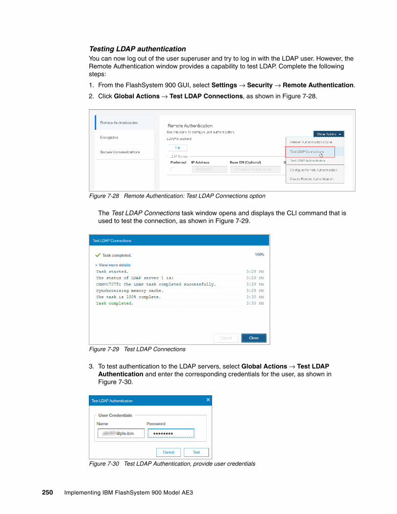
Testing LDAP authenticationYou can now log out of the user superuser and try to log in with the LDAP user. However, the Remote Authentication window provides a capability to test LDAP. Complete the following steps:
1. From the FlashSystem 900 GUI, select Settings → Security → Remote Authentication.
2. Click Global Actions → Test LDAP Connections, as shown in Figure 7-28.
Figure 7-28 Remote Authentication: Test LDAP Connections option
The Test LDAP Connections task window opens and displays the CLI command that is used to test the connection, as shown in Figure 7-29.
Figure 7-29 Test LDAP Connections
3. To test authentication to the LDAP servers, select Global Actions → Test LDAP Authentication and enter the corresponding credentials for the user, as shown in Figure 7-30.
Figure 7-30 Test LDAP Authentication, provide user credentials
250 Implementing IBM FlashSystem 900 Model AE3

4. Click Test to receive the results of the LDAP authentication test, as shown in Figure 7-31.
Figure 7-31 Test LDAP Authentication complete
Logging in as an LDAP userAssuming that remote authentication is successful, the superuser user can now log out, and the LDAP user can log in. When the LDAP user can log in, configuring remote authentication is complete.
About encryptionThe IBM FlashSystem 900 provides optional encryption of data at rest, which protects against the potential exposure of sensitive user data and user metadata that is stored on discarded, lost, or stolen storage devices. Encryption can be activated only on enclosures that support encryption. Because encryption of system data and system metadata is not required, system data and metadata are not encrypted.
Planning for encryption involves purchasing a license and then enabling the function on the system. USB encryption, key server encryption, or both can be enabled on the system. The system supports IBM Security Key Lifecycle Manager version 2.7.0.1 or later for enabling encryption with a key server.
Before encryption is enabled, you must determine the method of accessing key information during times when the system requires an access key to be present. The system requires an access key to be present during the following operations:
� System power-on
� User-started rekey operations
� System recovery
� Hard-reboot of the entire clustered system
� Certain involved service operations, such as Tier 2 (T2), Tier 3 (T3), and Tier 4 (T4) recovery procedures, which attempt to recover from rare events, such as double failures
Note: Data encryption and decryption are performed in hardware by the flash modules, which can be thought of as the functional equivalent of Self-Encrypting Flash Controller (SEFC) cards.
Chapter 7. Configuring settings 251
AES-XTS 256-bit data-at-rest encryptionThe following functions are available with the encryption feature:
� Hot Encryption Activation: Adding an encryption license to a previously initialized system� Encryption Rekey: Changing the encryption key on a previously initialized system
If you want to use encryption, ensure that you purchased feature code (FC) AF14: Encryption Enablement Pack (Plant).
Data Encryption technologyThe IBM FlashSystem 900 data encryption uses the Advanced Encryption Standard (AES) algorithm, with a 256-bit symmetric encryption key in XTS mode. This encryption mode is known as XTS–AES–256, which is described in the IEEE 1619–2007 data encryption standard. The data encryption key is protected by a 256-bit AES key wrap when it is stored in non-volatile form. The following layers of encryption are used with stored data:
� Data that is being protected� Data encryption key
Protection Enablement ProcessThe Protection Enablement Process (PEP) transforms a system from a state that is not protection-enabled to a state that is protection-enabled.
The PEP establishes a secret encryption access key to access the system, which must be stored and made available for use later whenever the system needs to be unlocked. The secret encryption access key must be stored outside the system on a USB drive that the system reads to obtain the key or provided by an external key server. The encryption access key also must be backed up to other forms of storage.
Encryption capability of FlashSystem 900 consists of the following functions:
� Hot Encryption Activation
Allows a decrypted FlashSystem 900 to be encryption-enabled while the system is running, without affecting customer data.
� Non-Disruptive Rekey
Permits creating an encryption access key that supersedes the existing key on a running FlashSystem without affecting customer data.
Handling encryption and encryption keys includes the following tasks:
� Activating encryption by using the GUI.� Activating encryption by using the CLI.� Creating an encryption keys (Rekey).� Keeping encryption keys from more systems on the same USB flash drives (stacking).� Copying the encryption keys.� Storing copies of USB flash drives that hold encryption keys.� Leaving encryption keys in or out of the system during normal operation.
The system also supports USB flash drive and key server-based encryption. You can also simultaneously configure key servers and USB flash drives. Both methods can be configured to ensure access to encrypted data if either method becomes unavailable or if the keys are permanently lost for one of the methods.
252 Implementing IBM FlashSystem 900 Model AE3

Encryption configuration by using USB flash drivesThe FlashSystem 900 predecessor FlashSystem 840 offered the possibility to initialize a new system and enable encryption during the initialization process by using InitTool. With FlashSystem 900 and InitTool, enabling encryption during the initialization process is no longer an option. Encryption is enabled after initialization by using the GUI or CLI.
However, the rules for handling encryption keys on USB flash drives are the same.
When encryption is activated, an encryption key is generated by the system to be used for access to encrypted data that is stored on the system. The GUI starts a wizard that guides you through the process of copying the encryption key to multiple USB flash drives. The following actions are considered preferred practices for copying and storing encryption keys:
� Copy the encryption key on at least two USB flash drives to access the system.
� Copy the encryption keys to other forms of storage to provide resiliency and to mitigate risk, if, for example, the two USB flash drives are from a faulty batch of drives.
� Test each copy of the encryption key before writing any user data to the initialized system.
� Securely store all copies of the encryption key. For example, any USB flash drives that do not remain inserted into the system can be locked in a safe. Use comparable precautions to securely protect any other copies of the encryption key that is in other forms of storage.
Enabling the encryption To enable encryption on a previously initialized system, complete the following steps:
1. In the GUI, click Settings → Security → Encryption see (Figure 7-32).
Figure 7-32 Enable system encryption
2. Click Enable Encryption the Encryption window (see Figure 7-74 on page 280).
Chapter 7. Configuring settings 253

3. A window open to confirm that you purchased an encryption license (see Figure 7-33). Select I have purchased an encryption license and click Certify.
Figure 7-33 Confirm encryption license
The Enable Encryption wizard opens to the Welcome page (see Figure 7-34).
Figure 7-34 Enable Encryption wizard Welcome page
Select Key Servers, USB flash drives, or both as a repository for the encryption keys. Key servers and USB flash drives also can be simultaneously configured. Both methods can be configured to ensure access to encrypted data if either method becomes unavailable or if the keys are permanently lost for one of the methods.
You can migrate between USB flash drive and key server-based encryption non-disruptively or configure key server-based encryption in addition to existing USB encryption by using the management GUI. During migration, the system supports simultaneous configuration of both key management methods. After the migration completes, you can disable the old key management method, if wanted.
4. As shown in Figure 7-34, encryption is set up by using USB flash drives. Click Next to continue with Enable Encryption wizard.
254 Implementing IBM FlashSystem 900 Model AE3

5. Insert two USB flash drives into the FlashSystem 900 controller USB ports (one in each canister) and click Next (see Figure 7-35).
Figure 7-35 Waiting for the USB flash drives
Note: Only USB flash drives that are formatted with FAT32 or EXT3/4 file system are supported in direct connect. If the system does not recognize the USB keys, an error message is issued and the enable encryption process cannot continue until USB drives are inserted into the USB ports.
Chapter 7. Configuring settings 255

6. The encryption keys are now generated and written to both USB drives (see Figure 7-36). When the process finishes, click Next.
Figure 7-36 Encryption keys are written to USB flash drives
A summary page opens, which indicates that encryption is enabled and keys are written to both USB flash drives (see Figure 7-37). Click Finish to complete the encryption enablement process.
Figure 7-37 USB encryption enable summary
256 Implementing IBM FlashSystem 900 Model AE3

A message indicates that encryption enablement is now complete. The message is generic for encryption setup by using key server and USB flash drives. It does not reflect the current setup that uses USB flash drives only to store the encryption key (see Figure 7-38). Click Close to exit this window.
Figure 7-38 Enable Encryption process complete
The Encryption settings are shown in Figure 7-39. The system reports that USB flash drives are inserted into the USB ports of both nodes and that encryption keys are validated on these drives.
Figure 7-39 Encryption enabled and keys validated
Encryption configuration by using key management serverA key server is a centralized system that receives and then distributes encryption keys to its clients. IBM FlashSystem 900 supports use of an IBM Security Key Lifecycle Manager (SKLM) key server as an encryption key provider. SKLM supports Key Management Interoperability Protocol (KMIP), which is a standard for management of cryptographic keys.
After encryption by using key management server is set up, access to the key server that is storing the correct master access key is required to unlock encryption for the FlashSystem 900 after a system restart or power loss.
Chapter 7. Configuring settings 257

Access to the key server is not required during a warm restart, such as a single node that is exiting service mode or a single node restart. The data center power-on procedure must ensure key server availability before FlashSystem 900 by using encryption is powered up.
Key servers and USB flash drives also can be simultaneously configured. By configuring both methods of encryption, you realize the convenience of key servers that can manage keys across multiple systems, and continuous access to encrypted data with backup USB flash drives.
The USB flash drives can be used to access encrypted data if key servers become unavailable for any reason. You can also migrate from USB flash drives to a key server without needing to rekey or unconfigure encryption methods.
Before you can create a key server object in the storage system, the key server must be installed and configured. Complete the following tasks on the SKLM server before you configure encryption by using SKLM server on the IBM FlashSystem 900:
� Configure the SKLM server to use Transport Layer Security version 2 (TLSv2).
� Ensure that the database service is started automatically on startup of the SKLM server.
� Allow network communication from IBM FlashSystem 900 to all SKLM server by using port 5696.
� If encryption is enabled with USB flash drives, at least one of the USB flash drives must be inserted into the system before key servers can be configured for managing keys.
For more information, see the IBM Security Key Lifecycle Manager page of at IBM Knowledge Center.
Setting up SKLM key management server for FlashSystem 900For more information how to set up SKLM key server, see the IBM Redpaper™ publication Data-at-rest Encryption for the IBM Spectrum Accelerate Family, REDP-5402.
The step that is described next guides you through the process of setting up encryption on a FlashSystem 900 that uses a new installed SKLM server. Close interaction is required between FlashSystem 900 and SKLM administrator. To configure the SKLM, we use GUI and CLI login, which often feature a different user ID with an individual password.
Note: Ensure that the key management server function is fully independent from storage that is provided by same systems by using a key server for encryption key management. Failure to observe this requirement can create an encryption deadlock. An encryption deadlock is a situation in which none of key servers in the environment can become operational because some critical part of the data in each server is stored on a storage system that depends on one of the key servers to unlock access to the data.
258 Implementing IBM FlashSystem 900 Model AE3

The sequence of tasks that are used to set up encryption that uses SKLM key management server is listed in Table 7-1. SKLM tasks are done on the primary SKLM server only. When the encryption setup is complete, other SKLM servers are added that use the configuration from the primary SKLM server.
Table 7-1 Overview of encryption setup by using SKLM key management primary key server
SKLM task FlashSystem 900 task
� Create Device Group FLASHSYSTEM.� Export SKLM Server Certificate.� Download Certificate to your local drive.
� Start the encryption setup wizard.� Configure the primary key server IP address.� Import the SKLM certificate to the IBM
FlashSystem 900.� Export public key from FlashSystem 900.� Download public key to your local drive.� Change the name of the public key file.
� Transfer the FlashSystem 900 public key file from your local drive by using SCP to the SKLM default path.
� Import the public key certificate by using SKLM GUI.
� Confirm the certificate import to the SKLM.� Verify communication to the SKLM.� Complete the encryption setup wizard.� Verify that SKLM is in a good state.
� Refresh the SKLM GUI.� Verify that two endpoints and a key UUID are
available for FlashSystem 900.
Chapter 7. Configuring settings 259

Complete the following steps to set up encryption by using SKLM key management server:
1. Log in to the SKLM server by using the default user ID and password, as shown in Figure 7-40.
Figure 7-40 IBM SKLM login window
2. From the SKLM welcome window, click Advanced Configuration → Device Group. Click Create (upper left) to create a Device Group that is named FLASHSYSTEM.
3. Select Many devices to many keys with access via certificate (GPFS) to create a Device Group that is named FLASHSYSTEM.
4. Click Create to create the Device Group (see Figure 7-41).
Figure 7-41 Create SKLM device group FLASHSYSTEM
260 Implementing IBM FlashSystem 900 Model AE3

5. Click Advanced Configuration → Server Certificates. During the initial setup process of SKLM, a self-signed certificate was created by the SKLM administrator (see Figure 7-42).
Figure 7-42 SKLM Server Certificate view
6. Select the certificate that is used. Click Export to export the certificate to the SKLM default directory. (The default directory /sklm/data might not change.)
7. In the Export Certificate window, click Export Certificate, as shown in Figure 7-43.
Figure 7-43 Choosing the Export Certificate option
Chapter 7. Configuring settings 261

8. On your local workstation, open the scp client, such as WinSCP. Transfer the SKLM certificate from /opt/IBM/WebSphere/AppServer/products/sklm/data to your local drive, as shown in Figure 7-44.
Figure 7-44 Self-signed certificate from SKLM to local drive
9. In the IBM FlashSystem 900 GUI, click Settings → Security → Encryption. Expand the Key Servers and USB Flash Drives twistie to show encryption configuration information. As shown in Figure 7-45, encryption is configured by using two USB flash drives. In the Key Servers section, click Configure.
Figure 7-45 Key Servers configuration entry page
262 Implementing IBM FlashSystem 900 Model AE3

10.The Enable Encryption wizard guides you through the encryption setup process for key server. Click Next, as shown in Figure 7-46.
Figure 7-46 Encryption Configuration wizard for key server
11.Specify the primary key server name and IP address. Keep the default port 5696, which is used to communicate between IBM FlashSystem 900 and SKLM key server.
Up to three other key servers can be added later. To ensure that keys are distributed to all other (secondary) key servers, you must configure replication on IBM Security Key Lifecycle Manager or manually transfer configuration by using backup or restore from the primary key server to all secondary key server. Click Next, as shown in Figure 7-47 on page 264).
Note: The supported versions of IBM Security Key Lifecycle Manager (up to V2.7, which was the latest code version available at the time of this writing) differentiate between the primary and secondary key server role.
The Primary SKLM server as defined as the first Key Servers in the Enable Encryption wizard must be the server that is defined as the primary by SKLM administrators.
Chapter 7. Configuring settings 263

Figure 7-47 Configuring primary key server
12.Enter FLASHSYSTEM the Device Group field, even if this field appears to be completed (see Figure 7-48). If you configured a different device group in the SKLM server, adjust the name of the device group to match with SKLM configuration.Click Next.
Figure 7-48 Configuring the key server Device Group
13.In the Key Server Certificate window, you must upload the necessary key server certificate to the IBM FlashSystem 900. Configuration with the self-signed certificate that was exported from the primary SKLM key server in Step 4 of this process is shown in Figure 7-49 on page 265.
264 Implementing IBM FlashSystem 900 Model AE3

Figure 7-49 Uploading the previously exported SKLM certificate to IBM FlashSystem 900
14.In the System Encryption Certificate window, click Export Public Key to download the public key to the local drive. System encryption certificates can also be self-signed or CA-certificate. This certificate is uploaded in later to the primary key server to establish trust for the IBM FlashSystem 900 to communicate with individual key servers.
If IBM Security Key Lifecycle Manager servers are configured for automatic replication, this certificate is copied from the primary key server to all secondary key servers (see Figure 7-50).
Figure 7-50 Exporting FlashSystem 900 public key
Chapter 7. Configuring settings 265

15.Rename the certificate.pem to a meaningful name; for example, certificate_FlashSystem_abcdef.pem.
Renaming the certificate file makes it easier to identify the associated certificates in SKLM.
16.Transfer the FlashSystem 900 certificate that you stored on your local drive to the SKLM by using scp (see Figure 7-51).
Figure 7-51 Transferring the FlashSystem 900 certificate to the SKLM key server
17.Import the FlashSystem 900 public key by adding it to the truststore for the FLASHSYSTEM device group on the primary SKLM key server.
In the IBM SKLM Welcome window under Key and Device Management, right-click the FLASHSYSTEM Device Group. Select Manage key and devices, as shown in Figure 7-52.
Figure 7-52 Preparing for FlashSystem 900 certificate import to SKLM
266 Implementing IBM FlashSystem 900 Model AE3

18.The Advanced Configuration window opens. Click Add → Certificate. Browse for the FlashSystem 900 certificate (see Figure 7-53) that you copied to the SKLM server in Step 16 on page 266. Click Select → Add to import the FlashSystem 900 certificate.
Figure 7-53 Browsing for the FlashSystem 900 certificate in the SKLM
19.After the FlashSystem 900 certificate is added to the SKLM, a warning message is shown that indicates that the SKLM configuration was modified (see Figure 7-54). Click Close.
Figure 7-54 SKLM configuration change warning
Chapter 7. Configuring settings 267

The FlashSystem 900 certificate is presented in the certificate view with an endpoint count of 0, which indicates that it is not yet used. Because the Key UUID is blank, no key is created now (see Figure 7-55).
Figure 7-55 FlashSystem 900 certificate imported to SKLM
20.In the FlashSystem 900 Enable Encryption wizard, select the option to confirm that the FlashSystem 900 certificate is transferred to the SkLM server. Click Next (see Figure 7-56).
Figure 7-56 Confirming that the FlashSystem certificate is transferred to SKLM
268 Implementing IBM FlashSystem 900 Model AE3

21.Select No to keep USB flash drive encryption active. Then, select Next, as shown in Figure 7-57.
Figure 7-57 Keeping the USB encryption enabled during SkLM configuration
22.Review the summary page and confirm that the information is correct. Click Finish, as shown in Figure 7-58.
Figure 7-58 SKLM confirmation summary page
23.A series of CLI commands are presented during the Enable Encryption process. Those commands are stored in the system audit log for later reference. If the Enable Encryption process fails, review the Event Log for open events that require run fix before you can enable encryption.
Chapter 7. Configuring settings 269

If the Enable Encryption process completes, a generic window is shown, regardless whether encryption was enabled by using USB flash drive, SKLM key server, or both. Click Close, as shown in Figure 7-59.
Figure 7-59 Generic encryption enabled success window
24.The FlashSystem 900 encryption window shows the SKLM key server with two green check marks, as shown in Figure 7-60.
Figure 7-60 Encryption overview that confirms the SKLM is in good state
270 Implementing IBM FlashSystem 900 Model AE3
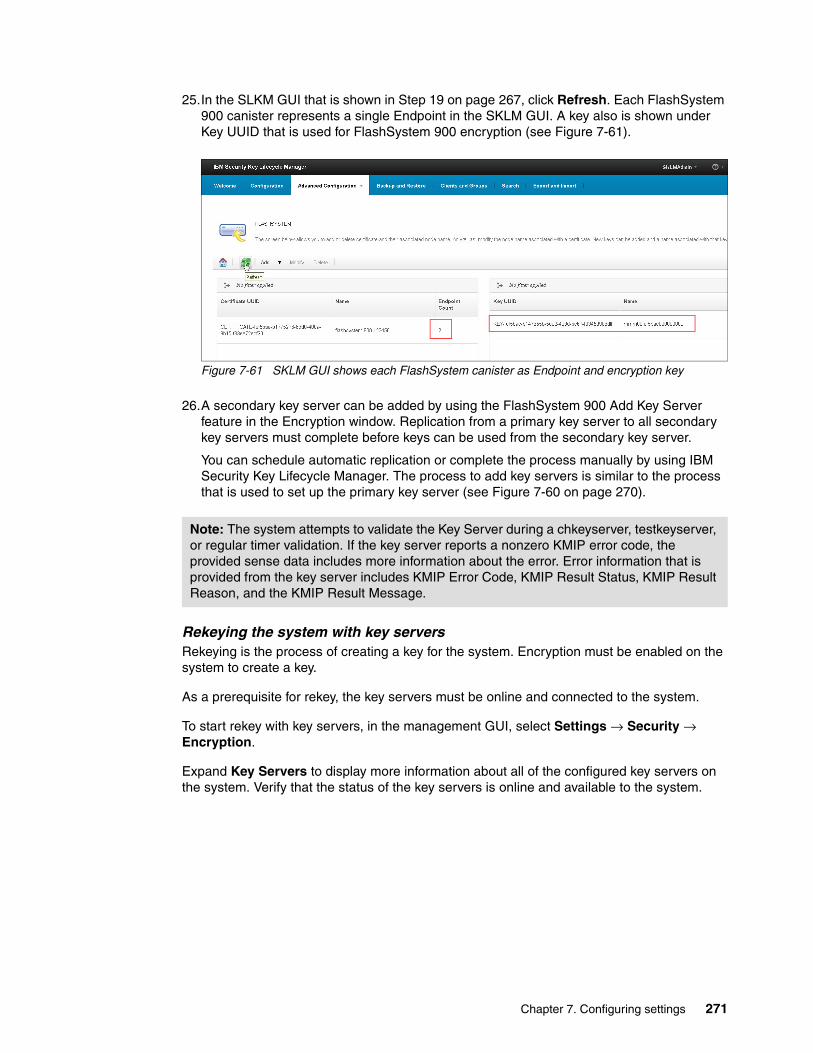
25.In the SLKM GUI that is shown in Step 19 on page 267, click Refresh. Each FlashSystem 900 canister represents a single Endpoint in the SKLM GUI. A key also is shown under Key UUID that is used for FlashSystem 900 encryption (see Figure 7-61).
Figure 7-61 SKLM GUI shows each FlashSystem canister as Endpoint and encryption key
26.A secondary key server can be added by using the FlashSystem 900 Add Key Server feature in the Encryption window. Replication from a primary key server to all secondary key servers must complete before keys can be used from the secondary key server.
You can schedule automatic replication or complete the process manually by using IBM Security Key Lifecycle Manager. The process to add key servers is similar to the process that is used to set up the primary key server (see Figure 7-60 on page 270).
Rekeying the system with key serversRekeying is the process of creating a key for the system. Encryption must be enabled on the system to create a key.
As a prerequisite for rekey, the key servers must be online and connected to the system.
To start rekey with key servers, in the management GUI, select Settings → Security → Encryption.
Expand Key Servers to display more information about all of the configured key servers on the system. Verify that the status of the key servers is online and available to the system.
Note: The system attempts to validate the Key Server during a chkeyserver, testkeyserver, or regular timer validation. If the key server reports a nonzero KMIP error code, the provided sense data includes more information about the error. Error information that is provided from the key server includes KMIP Error Code, KMIP Result Status, KMIP Result Reason, and the KMIP Result Message.
Chapter 7. Configuring settings 271

To rekey the system that uses key server encryption, complete the following steps:
1. In the management GUI, select Settings → Security → Encryption.Expand Key Servers to display all configured key servers on the FlashSystem 900 and select Rekey (see Figure 7-62).
Figure 7-62 Select Rekey for the primary key server
2. Click Yes in the message window. The encryption key is generated by the primary key server and copied to the primary key server only. Ignore the GUI message that the encryption key is stored on all key server (see Figure 7-63).
Figure 7-63 Rekey Key Server confirmation message
272 Implementing IBM FlashSystem 900 Model AE3

3. During the rekey process, a series of CLI commands shows that new key is first prepared and then committed. In the Rekey Key Server window, click Close (Figure 7-64).
Figure 7-64 Rekey Key Server completed
4. (Optional) To verify the new generated key in the SKLM key server, open the SKLM Welcome page, Key and Device Management. Select FLASHSYSTEM. Then, right-click Manage Keys and Devices, as shown in Figure 7-65.
Figure 7-65 SKLM Device Group, Manage Keys and Devices
Chapter 7. Configuring settings 273

In the Key UUID window, the previous and current key is shown. The current key is shown with the higher number in the Key Name, as shown in Figure 7-66.
Figure 7-66 SKLM showing previous and current encryption key
If both methods of encryption (SKLM and USB) are configured on your system, complete rekey for all configured SKLM server by using automatic replication between key server or backup/restore from primary key server to all other configured key server.
Rekey a system by using USB flash drivesRekeying is the process of creating a key for the system. To create a key, encryption must be enabled on the system.
Before creating a key, ensure that all open events are fixed and at least one USB port on the canisters contains a USB flash drive that includes the current key. During the rekey process, a key is generated and copied to the USB flash drives. This key is then used instead of the old key.
The rekey operation fails unless at least one USB flash drive contains the current key. To rekey the system, you need at least three USB flash drives to store the copied key material.
To rekey the system in the management GUI, complete the following steps:
Attention: If you use multiple key servers, the rekey operation occurs on the primary key server only. Any other key servers go offline and the system reports an error against those key servers until the new key is replicated from the primary to the secondary key servers.
You can automatically or manually configure replication with IBM Security Key Lifecycle Manager for the primary and secondary key servers. Replication copies encryption keys between primary and secondary key servers when replication is scheduled on the IBM Security Key Lifecycle Manager.
For example, if replication is scheduled to occur every 5 hours and the system is rekeyed, the secondary key servers remain offline until the scheduled replication occurs. You can also manually replicate the keys from the primary to the secondary with the IBM Security Key Lifecycle Manager.
If errors occur during the rekey process, a status message displays problems with the copy or creation of the key. To determine and fix possible errors, click Monitoring → Events
274 Implementing IBM FlashSystem 900 Model AE3
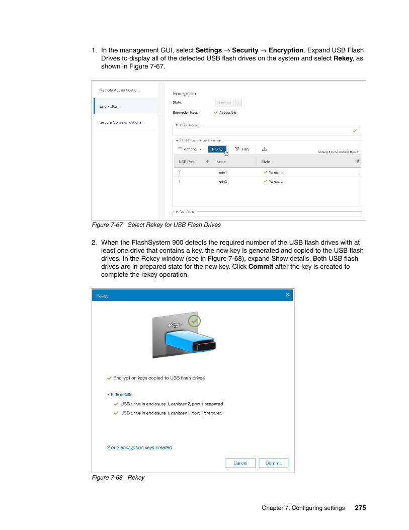
1. In the management GUI, select Settings → Security → Encryption. Expand USB Flash Drives to display all of the detected USB flash drives on the system and select Rekey, as shown in Figure 7-67.
Figure 7-67 Select Rekey for USB Flash Drives
2. When the FlashSystem 900 detects the required number of the USB flash drives with at least one drive that contains a key, the new key is generated and copied to the USB flash drives. In the Rekey window (see in Figure 7-68), expand Show details. Both USB flash drives are in prepared state for the new key. Click Commit after the key is created to complete the rekey operation.
Figure 7-68 Rekey
Chapter 7. Configuring settings 275

3. If errors occur during the rekey process, status messages display problems with the copy or creation of a key. For example, if the minimum number of USB drives are inserted, but none of them include an encryption key, the rekey operation fails. To determine and fix other possible errors, select Monitoring → Events.
When the rekey completed successful, a Rekey complete message is shown. Click Close, as shown in Figure 7-69.
Figure 7-69 USB Rekey complete window
4. The Encryption window shows all connected USB drives as validated, (see Figure 7-70), which indicates that the encryption key on this USB drive is valid to unlock the FlashSystem 900 after a full power cycle.
Figure 7-70 Attached USB drives are validated
5. Create several backup copies of the key on USB flash drives or another external storage media and store this media securely. Two USB flash drives can remain inserted into the storage enclosure canisters if the system is in a secure location.
If the location is not secure, all USB flash drives with the key can be removed from the system and stored securely. Extra copies of the key must be created and stored securely to ensure access to the system if the USB flash drives become damaged or stolen.
Migrating between USB flash drive to key server encryptionYou can migrate between a USB flash drive and key server-based encryption non-disruptively by using the management GUI. To migrate from key servers to USB flash drives, use the CLI only.
During migration, the system supports the simultaneous configuration of both key management methods. After the migration completes, you can disable the old key management method.
276 Implementing IBM FlashSystem 900 Model AE3
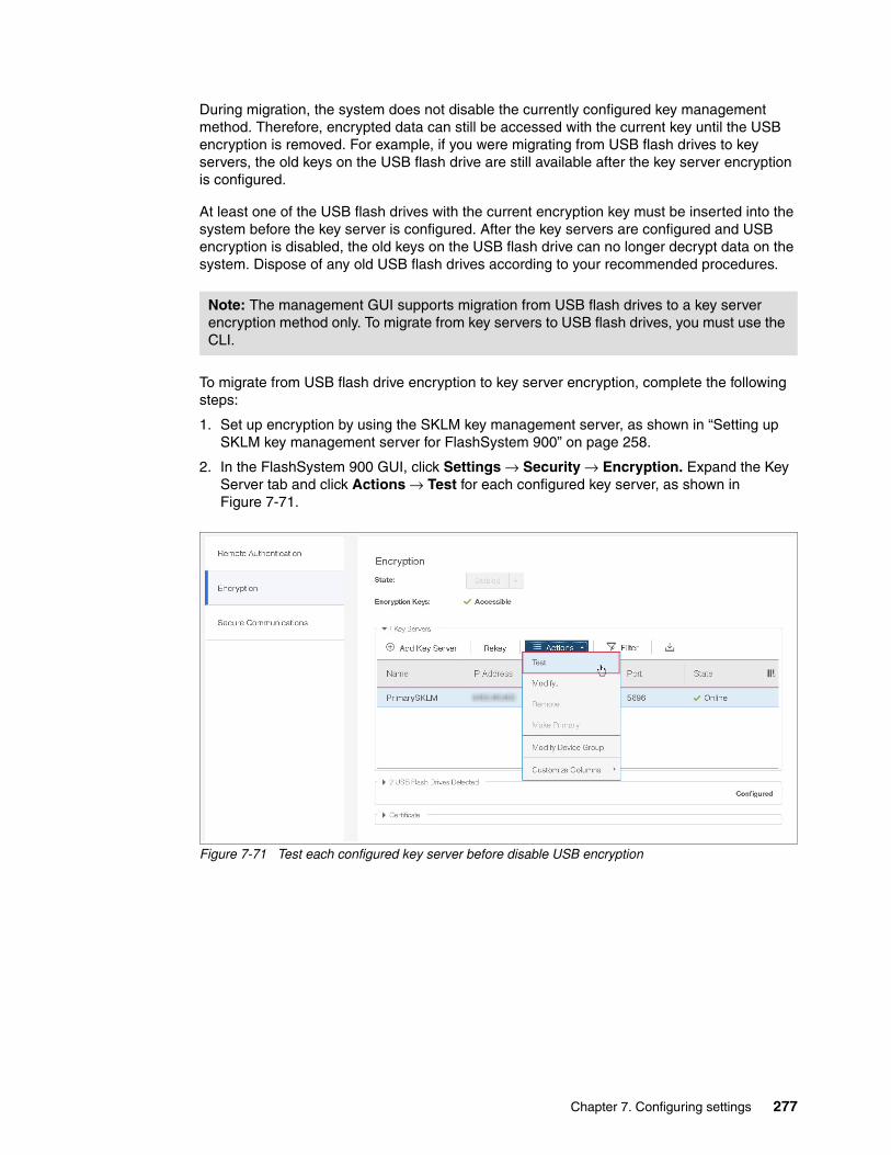
During migration, the system does not disable the currently configured key management method. Therefore, encrypted data can still be accessed with the current key until the USB encryption is removed. For example, if you were migrating from USB flash drives to key servers, the old keys on the USB flash drive are still available after the key server encryption is configured.
At least one of the USB flash drives with the current encryption key must be inserted into the system before the key server is configured. After the key servers are configured and USB encryption is disabled, the old keys on the USB flash drive can no longer decrypt data on the system. Dispose of any old USB flash drives according to your recommended procedures.
To migrate from USB flash drive encryption to key server encryption, complete the following steps:
1. Set up encryption by using the SKLM key management server, as shown in “Setting up SKLM key management server for FlashSystem 900” on page 258.
2. In the FlashSystem 900 GUI, click Settings → Security → Encryption. Expand the Key Server tab and click Actions → Test for each configured key server, as shown in Figure 7-71.
Figure 7-71 Test each configured key server before disable USB encryption
Note: The management GUI supports migration from USB flash drives to a key server encryption method only. To migrate from key servers to USB flash drives, you must use the CLI.
Chapter 7. Configuring settings 277
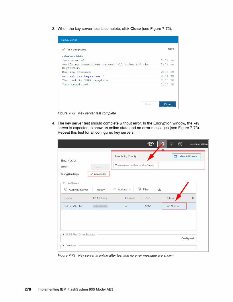
3. When the key server test is complete, click Close (see Figure 7-72).
Figure 7-72 Key server test complete
4. The key server test should complete without error. In the Encryption window, the key server is expected to show an online state and no error messages (see Figure 7-73). Repeat this test for all configured key servers.
Figure 7-73 Key server is online after test and no error message are shown
278 Implementing IBM FlashSystem 900 Model AE3
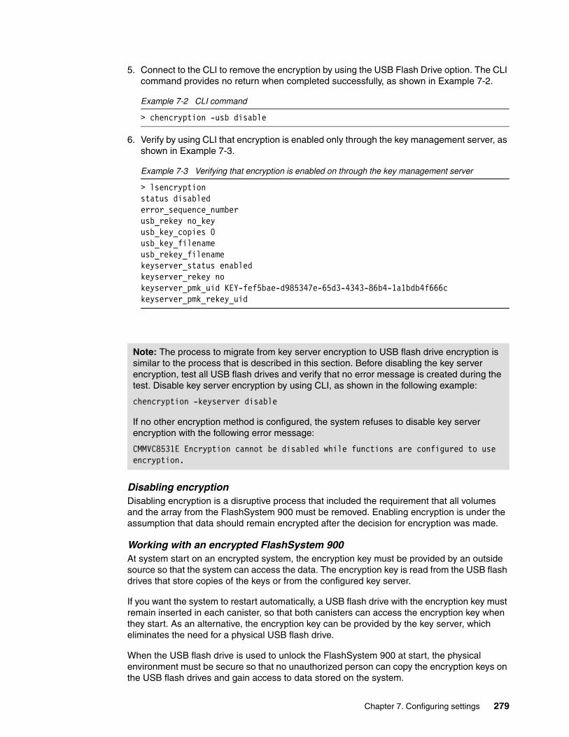
5. Connect to the CLI to remove the encryption by using the USB Flash Drive option. The CLI command provides no return when completed successfully, as shown in Example 7-2.
Example 7-2 CLI command
> chencryption -usb disable
6. Verify by using CLI that encryption is enabled only through the key management server, as shown in Example 7-3.
Example 7-3 Verifying that encryption is enabled on through the key management server
> lsencryptionstatus disablederror_sequence_numberusb_rekey no_keyusb_key_copies 0usb_key_filenameusb_rekey_filenamekeyserver_status enabledkeyserver_rekey nokeyserver_pmk_uid KEY-fef5bae-d985347e-65d3-4343-86b4-1a1bdb4f666ckeyserver_pmk_rekey_uid
Disabling encryptionDisabling encryption is a disruptive process that included the requirement that all volumes and the array from the FlashSystem 900 must be removed. Enabling encryption is under the assumption that data should remain encrypted after the decision for encryption was made.
Working with an encrypted FlashSystem 900At system start on an encrypted system, the encryption key must be provided by an outside source so that the system can access the data. The encryption key is read from the USB flash drives that store copies of the keys or from the configured key server.
If you want the system to restart automatically, a USB flash drive with the encryption key must remain inserted in each canister, so that both canisters can access the encryption key when they start. As an alternative, the encryption key can be provided by the key server, which eliminates the need for a physical USB flash drive.
When the USB flash drive is used to unlock the FlashSystem 900 at start, the physical environment must be secure so that no unauthorized person can copy the encryption keys on the USB flash drives and gain access to data stored on the system.
Note: The process to migrate from key server encryption to USB flash drive encryption is similar to the process that is described in this section. Before disabling the key server encryption, test all USB flash drives and verify that no error message is created during the test. Disable key server encryption by using CLI, as shown in the following example:
chencryption -keyserver disable
If no other encryption method is configured, the system refuses to disable key server encryption with the following error message:
CMMVC8531E Encryption cannot be disabled while functions are configured to use encryption.
Chapter 7. Configuring settings 279

For the most secure operation, do not keep the USB flash drives inserted into the canisters on the system. However, this method requires that you manually insert the USB flash drives that contain copies of the encryption key in both canisters before the system is restarted.
The USB flash drive is required to access encrypted data when only the USB flash drive is configured to hold the encryption key. The key in on the USB flash drive copies and any other copies that are made on other forms of storage. The encryption key cannot be recovered or regenerated by IBM if all user-maintained copies are lost or unrecoverable.
Handling encryption by using CLIIn addition to the use of FlashSystem GUI to enable encryption and handle encryption keys, the FlashSystem CLI can be used to enable encryption while the FlashSystem 900 is running. This procedure is non-destructive when handled correctly.
Updating Secure Communications CertificateBefore you create a request for signed or self-signed certificates, ensure that your current browser does not include restrictions on the type of keys that are used for certificates. Some browsers limit the use of specific key-types for security and compatibility issues. The system also uses certificates to secure communications between key servers that are used to distribute and manage encryption keys to the system.
For more information about your current system certificate, click Settings → Security and then, select Secure Communications, as shown in Figure 7-74.
Figure 7-74 Accessing the Secure Communications window
FlashSystem 900 allows you to generate a new self-signed certificate or to configure a signed certificate.
Attention: Encryption keys or data from FlashSystem 900 cannot be recovered or regenerated by IBM on an encryption-enabled system if encryption keys are lost.
Note: Handling encryption by using CLI includes numerous risks. To protect and preserve data, encryption configuration changes are recommended to be done by using the GUI.
280 Implementing IBM FlashSystem 900 Model AE3

Configuring a signed certificateComplete the following steps to configure a signed certificate:
1. Select Update Certificate in the Secure Communications window.
2. Select Signed certificate and enter the information about the new certificate signing request. All fields are mandatory, except for the email address. Some values are shown in Figure 7-75 as an example. When all of the information is entered, click Generate Request.
Figure 7-75 Generating a signed certificate request
3. Save the generated request file. The Secure Communications window now indicates that an outstanding certificate request is present, as shown in Figure 7-76 on page 282. This issue occurs until the associated signed certificate is installed.
Note: If encryption is used on the system, certificates also secure communications between key servers that are used to distribute and manage encryption keys to the system. If a certificate is changed, the certificate must also be updated on all configured key servers or access to encrypted data can be lost.
Attention: Before generating a request, ensure that your current browser does not include restrictions on the type of keys that are used for certificates. Some browsers limit the use of specific key-types for security and compatibility issues.
Attention: If you must update a field in the certificate request, you can generate a new request. However, do not generate a new request after the original request is sent to the certificate authority. Generating a new request overrides the original request and the signed certificate that is associated with the original request cannot be installed.
Chapter 7. Configuring settings 281

Figure 7-76 Outstanding certificate request
4. Submit the request to the certificate authority to receive a signed certificate.
5. When you receive the signed certificate, select Update Certificate in the Secure Communications window again.
6. Click the folder icon to upload the signed certificate, as shown in Figure 7-77. Click Update.
Figure 7-77 Installing a signed certificate
7. You are prompted to confirm the action, as shown in Figure 7-78 on page 283. Click Yes to proceed. The signed certificate is installed.
282 Implementing IBM FlashSystem 900 Model AE3
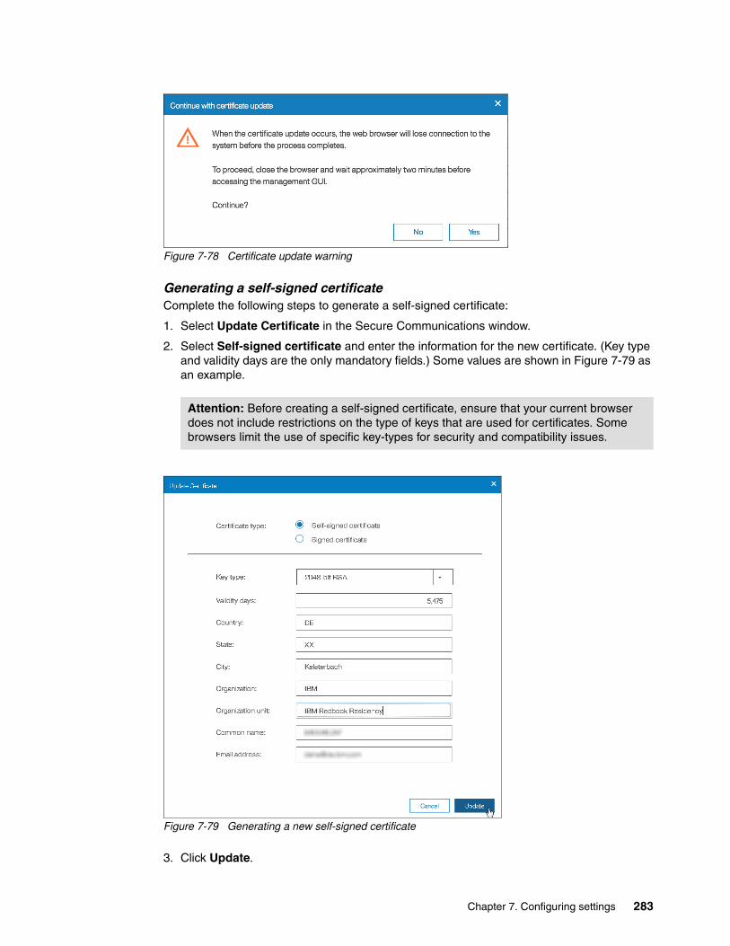
Figure 7-78 Certificate update warning
Generating a self-signed certificateComplete the following steps to generate a self-signed certificate:
1. Select Update Certificate in the Secure Communications window.
2. Select Self-signed certificate and enter the information for the new certificate. (Key type and validity days are the only mandatory fields.) Some values are shown in Figure 7-79 as an example.
Figure 7-79 Generating a new self-signed certificate
3. Click Update.
Attention: Before creating a self-signed certificate, ensure that your current browser does not include restrictions on the type of keys that are used for certificates. Some browsers limit the use of specific key-types for security and compatibility issues.
Chapter 7. Configuring settings 283

4. You are prompted to confirm the action, as shown in Figure 7-80. Click Yes to proceed. The self-signed is generated immediately.
Figure 7-80 Certificate update warning
7.1.4 System menu
In the System menu, you can set the time and date for the cluster, enable Open Access, perform software updates for the cluster, and change the preferences for the GUI.
Date and Time optionClick Settings → System to open the Date and Time window (see Figure 7-81) to set the date and time.
Figure 7-81 Date and time preferences
The preferred method for setting the date and time is to configure a Network Time Protocol (NTP) server. By using an NTP server, all log entries are stamped with an accurate date and time, which is important in troubleshooting issues, such as a temporarily broken Fibre Channel link that caused a path failover at a connected host.
To investigate the root cause of this event, logs from the host, the storage area network (SAN) switches, and the IBM FlashSystem 900 must be compared. If the date and time are inaccurate, events cannot be compared and matched, which makes a root cause analysis much more difficult.
284 Implementing IBM FlashSystem 900 Model AE3
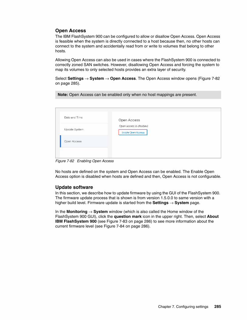
Open AccessThe IBM FlashSystem 900 can be configured to allow or disallow Open Access. Open Access is feasible when the system is directly connected to a host because then, no other hosts can connect to the system and accidentally read from or write to volumes that belong to other hosts.
Allowing Open Access can also be used in cases where the FlashSystem 900 is connected to correctly zoned SAN switches. However, disallowing Open Access and forcing the system to map its volumes to only selected hosts provides an extra layer of security.
Select Settings → System → Open Access. The Open Access window opens (Figure 7-82 on page 285).
Figure 7-82 Enabling Open Access
No hosts are defined on the system and Open Access can be enabled. The Enable Open Access option is disabled when hosts are defined and then, Open Access is not configurable.
Update softwareIn this section, we describe how to update firmware by using the GUI of the FlashSystem 900. The firmware update process that is shown is from version 1.5.0.0 to same version with a higher build level. Firmware update is started from the Settings → System page.
In the Monitoring → System window (which is also called the Home window of the FlashSystem 900 GUI), click the question mark icon in the upper right. Then, select About IBM FlashSystem 900 (see Figure 7-83 on page 286) to see more information about the current firmware level (see Figure 7-84 on page 286).
Note: Open Access can be enabled only when no host mappings are present.
Chapter 7. Configuring settings 285

Figure 7-83 Navigate to ‘About the IBM FlashSystem 900
Figure 7-84 Current release version
Before starting the firmware update, the administrator must download the new firmware image file and latest version of firmware update test utility.
The current firmware for the system can be downloaded from the internet (if the system includes such access), or the administrator can download the firmware from the following web page.
https://www-945.ibm.com/support/fixcentral/swg/selectFixes?parent=Flash%20high%20availability%20systems&product=ibm/StorageSoftware/IBM+FlashSystem+900&release=All&platform=All&function=all
A firmware download requires an appropriate maintenance agreement or indication that the system is covered under warranty. When downloading firmware from IBM, the client must validate coverage by entering the system model number and serial number.
286 Implementing IBM FlashSystem 900 Model AE3

The system model number (MTM) and serial number (S/M) are on the printed serial number label on the system. These numbers also are in the GUI, below the firmware version (see Figure 7-84).
Before you start a system update, ensure that no problems exist on the system that might interfere with a successful update of the system. The software update test utility indicates whether your current system includes issues that must be resolved before you update to the next level. Each software update requires that you run the software update test utility and then, download the correct software package.
The FlashSystem 900 firmware can be updated by using the Settings menu. This update is referred to as Concurrent Code Load (CCL). Each node in the clustered system automatically updates in sequence while maintaining full accessibility for connected hosts.
To start CCL, click Settings → System → Update System → Test & Update (see Figure 7-85).
Figure 7-85 Test and Update System option
The Update System wizard begins by prompting you to select the test utility and update package. The Update System wizard before files are selected is shown in Figure 7-86.
Note: Downloading firmware from IBM is possible only if the system includes an appropriate maintenance agreement or if the machine is under warranty.
Chapter 7. Configuring settings 287

Figure 7-86 Test utility and firmware selection
Click the folder icon to locate the correct test utility and update package. The test utility file is selected (see Figure 7-87).
Figure 7-87 Update test utility file selection
The purpose of running the test utility is to verify that no errors exist and that the system is ready to update. If any issues are discovered by the test utility, the firmware update stops with a message to the administrator that indicates which problems must be fixed before the update system procedure can be repeated.
The procedure for selecting the update package is shown in Figure 7-88.
Figure 7-88 Update package file selection
Selecting the appropriate files for test utility, update package, and target code level is shown in Figure 7-89.
288 Implementing IBM FlashSystem 900 Model AE3

Figure 7-89 Test utility and firmware selection
The system inserts the code level automatically. This example updates to 1.5.0.0.
Click Update to proceed. The update test utility and update package files are uploaded to the FlashSystem 900 config node where firmware update begins.
The initial part of the Update System procedure is shown in Figure 7-90.
Figure 7-90 Test utility and firmware are uploading
If any errors are identified by the test utility, you must resolve the errors before the firmware update can proceed. Any hardware error prevents System Update from proceeding.
Resolve any errors that are identified by the update test utility. You can start troubleshooting by clicking Monitoring → Events. Use this menu to review and resolve any unfixed errors.
The CCL firmware update is now running in the background. While the system updates, the progress indicators are displayed (see Figure 7-91).
Note: The drop-down arrow that is shown in Figure 7-89 on page 289 shows your test utility and update package files that are on the current config node. This function is useful to avoid uploading the same test utility and update package when errors are identified by the software upgrade test utility.
Chapter 7. Configuring settings 289

Figure 7-91 Firmware update running at 2%
The system can be operated normally while it is upgrading; however, no changes can be made until the firmware update process completes. If you attempt to fix any error by using DMP or modifying the system configuration, the message that is shown in Figure 7-92 is displayed.
Figure 7-92 Changes are not allowed while upgrading
During the update, various messages are displayed in the Update System window.
When the node that includes the role of configuration node restarts, a message indicates that node failover is detected (see Figure 7-93). The role of configuration node is now moved to the other controller and the browser window must be refreshed.
290 Implementing IBM FlashSystem 900 Model AE3

Figure 7-93 Node failover happens during update
When both controllers are updated, the FlashSystem 900 firmware update commits the new firmware. After committing the firmware update, the system starts the updating hardware process (see Figure 7-94 on page 291).
Figure 7-94 Firmware updating the enclosure firmware
During the hardware update, all individual components in the system are firmware-updated. For example, the I/O ports are updated, during which time they are being taken offline individually for updating.
Chapter 7. Configuring settings 291

When the Update System wizard completes, the system returns to a redundant status. The system now features the latest firmware, as shown in Figure 7-95. (The firmware update process that is shown in our example completed in approximately 2 hours.)
Figure 7-95 Firmware update completed
You can use the FlashSystem 900 CLI as an alternative to upgrading firmware by using the GUI. For more information, see IBM Knowledge Center.
7.1.5 Support menu
You can configure remote support assistance that allows support personnel to access the system remotely by using a secure connection.
Support assistanceSupport assistance enables support personnel to access the system to complete troubleshooting and maintenance tasks. If you are configuring remote support assistance, ensure that the following prerequisites are met:
� Call Home is configured with a valid email server.
� A valid service IP address is configured on each node on the system.
� If your system is behind a firewall and does not allow access to the remote support server, configure a Remote Support Proxy server. During the set-up for support assistance, specify the IP address and the port number for the proxy server on the Remote Support Centers page.
� If you do not have firewall restrictions and the storage nodes are directly connected to the internet, request your network administrator to allow connections to 129.33.207.37, 204.146.30.157, 129.33.206.139, and 204.146.30.139 on Port 22.
To configure remote support assistance, click Settings → Support → Support Assistance → Reconfigure Settings, as shown in Figure 7-96.
Note: For more information about remote support configuration, see 3.6, “Remote Support Assistance” on page 70.
292 Implementing IBM FlashSystem 900 Model AE3

Figure 7-96 Navigate to Support Assistance, Reconfigure Settings
In the first window of the Remote Support Centers Reconfigure Settings wizard, verify the support centers that are pre-configured for direct access to the remote support center. If the client is using a remote support proxy or network proxy, enter the name, IP address, and port for the proxy server. Specifying a proxy server is required if you use a firewall to protect your internal network (see Figure 7-97).
Figure 7-97 Remote support reconfigure settings wizard
Chapter 7. Configuring settings 293

Click Next. The Access Settings window opens, as shown in Figure 7-98.
Figure 7-98 Access Settings window
Select one of the following options to control when support personnel can access your system to conduct maintenance and fix problems:
� At Any Time
Support personnel can access the system at any time. If an access code is defined, support personnel cannot start a remote support session without the access code. The access code can be distributed to the support center in advance or on an as-needed basis.
� On System Error
Select this option so that support personnel can access the system when a system error occurs. Support personnel can start sessions only when an error occurs on the system. If an access code is defined, support personnel cannot start a remote support session without the access code. The access code can be distributed to the support center in advance or on an as-needed basis.
� On Permission Only
Select this option to start remote support sessions from the Support Assistance page only. For this option, remote support sessions must be started manually. You can specify a maximum time that a session can be idle before the session is automatically closed.
294 Implementing IBM FlashSystem 900 Model AE3
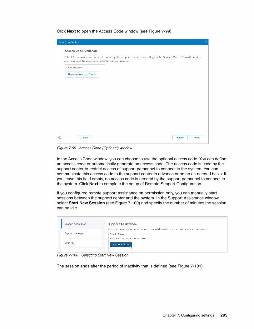
Click Next to open the Access Code window (see Figure 7-99).
Figure 7-99 Access Code (Optional) window
In the Access Code window, you can choose to use the optional access code. You can define an access code or automatically generate an access code. The access code is used by the support center to restrict access of support personnel to connect to the system. You can communicate this access code to the support center in advance or on an as-needed basis. If you leave this field empty, no access code is needed by the support personnel to connect to the system. Click Next to complete the setup of Remote Support Configuration.
If you configured remote support assistance on permission only, you can manually start sessions between the support center and the system. In the Support Assistance window, select Start New Session (see Figure 7-100) and specify the number of minutes the session can be idle.
Figure 7-100 Selecting Start New Session
The session ends after the period of inactivity that is defined (see Figure 7-101).
Chapter 7. Configuring settings 295

Figure 7-101 Begin Remote Support Session with access code
The status of the Remote Support Session is shown in the Support Assistance window (see Figure 7-102). If support starts a service or maintenance operation, the session does not end unless it is stopped on the Support Assistance page. You can also generate a new access code.
Figure 7-102 Remote Support Session status
Support PackageClick Settings → Support → Support Package when log files are requested by IBM Support. IBM Support often requests log files when a support case is opened by the FlashSystem 900 administrators or by the Call Home function.
The system administrator downloads the requested support package from the system and then uploads it to IBM Support. IBM Support analyzes the data.
Downloading a support packageTo download a support package, click Settings → Support → Support Package and then, click Download Support Package (see Figure 7-103).
296 Implementing IBM FlashSystem 900 Model AE3

Figure 7-103 Download Support Package
IBM Support often requests that you select Standard logs plus new statesaves. These logs can be downloaded within minutes to hours from the IBM FlashSystem 900, depending on the situation and the size of the support package that is downloaded.
The destination of the support package file is the system from where the web browser was started. The next step is shown in Figure 7-104 in which you save the support package file on a Windows system.
Figure 7-104 Downloading support package save file
IBM Support often requests log files to be uploaded to a specific problem management record (PMR) number by using Enhanced Customer Data Repository (ECuRep) as the upload media to IBM. For more information, see the Standard Upload page of the Enhanced Customer Data Repository (ECuRep) website.
Downloading individual log filesAfter analyzing the uploaded support package, IBM Support might request more files. To locate these files, click Settings → Support and then, select Show full log listing. By using this option, specific and individual log files can be downloaded, as shown in Figure 7-105.
Chapter 7. Configuring settings 297

Figure 7-105 Download support: Individual files
298 Implementing IBM FlashSystem 900 Model AE3

You can download any of the various log files by selecting a single item and clicking Actions → Download (see Figure 7-106).
Figure 7-106 Download and Delete options of the Actions menu
You can also delete a single item in by selecting a single item and clicking Actions → Delete.
Open problem management recordA PMR is a document that is used to manage a technical product issue that is reported to IBM. You can manually create a PMR by using the Open PMR page. This page displays your contact information and provides a place to enter text to describe the problem.
After the PMR is opened, you can respond through Service Request with information about the reported issue or more questions you have about the reported issue.
Complete the following steps to open a PMR:
1. In the management GUI, select Settings → Support → Open PMR. The Open PMR window opens. Verify that the contact information that is shown in the Open PMR page is correct.
If contact information is not displayed, configure Call Home as shown in 7.1.1, “Notifications menu” on page 231.
If the contact information that is displayed is not correct, edit the contact information.
You can update the contact name, telephone number, and email address.
Enter a description of the technical issue in the Problem Description field. The problem description can be up to 120 characters. The number of available characters displays on the right and decreases as you enter the description.
Delete option: When the Delete option is unavailable, the file cannot be deleted because it is used by the system.
Note: Contact information is obtained through Call Home; therefore, if Call Home is not configured, you cannot open a PMR.
Chapter 7. Configuring settings 299

Click Submit to send the information to IBM (see Figure 7-107).
Figure 7-107 Clicking the Submit option
2. Click Close in the Creating a new PMR window, which confirms a successful completion of CLI commands (see Figure 7-108).
Figure 7-108 Successful completion of CLI commands to create a PMR
300 Implementing IBM FlashSystem 900 Model AE3

3. The Submission Confirmation window opens. You can access the Support Portal site by clicking the hyperlink in the Submission Confirmation window. Click Close to exit the Submission Confirmation window (see Figure 7-109).
Figure 7-109 PMR submission confirmation window
4. A manually submitted PMR creates an event that is titled Unexpected enclosure fault. As shown in Figure 7-110, you can click Details, change to the event view by clicking View All Events and see the event details, or mark the event as fixed.
.
Figure 7-110 Unexpected enclosure fault event created when manually submitting a PMR
Chapter 7. Configuring settings 301

You can manually open a PMR by right-clicking in the GUI Events page, as shown in Figure 7-111.
i
Figure 7-111 Manual open a PMR from the Events view
A PMR also can be manually opened by clicking in the top menu question mark (?) icon and selecting Open PMR, as shown in Figure 7-112.
Figure 7-112 Manual open a PMR from the top menu
302 Implementing IBM FlashSystem 900 Model AE3

7.1.6 GUI preferences
Click Settings → System → GUI Preferences to change the login message, system timeout, and web address of IBM Knowledge Center, which is the help page for the IBM FlashSystem 900. This help page can be reached from any window in the management GUI by clicking the question mark (?) icon in the upper-right corner of the GUI (see Figure 7-113).
Figure 7-113 Default logout time and IBM Knowledge Center web address configuration
The default web address for the IBM FlashSystem 900 web page at IBM Knowledge Center is the internet-accessible version.
Any address can be configured in the Web Address field. If the system cannot access the internet, the web address can be set to access a local version of the IBM FlashSystem 900 web page in IBM Knowledge Center.
For more information, see the IBM FlashSystem 900 page of IBM Knowledge Center.
7.2 Service Assistant Tool
Service Assistant Tool is used for troubleshooting issues or when an IBM Support engineer directs you to use it.
7.2.1 Accessing Service Assistant Tool
Service Assistant Tool is accessed by using a web browser, as shown in the following example in which the cluster management IP address is followed by /service:
https://192.168.10.10/service
Each of the canister’s service IP addresses can also be reached. Different options are available for how to access the Service Assistant Tool.
The following examples list which IP addresses are configured and how they are accessed:
� 192.168.10.10 (Service IP address for Canister 1):
– https://192.168.10.10/service opens Service Assistant Tool for Canister 1.– https://192.168.10.10 opens Service Assistant Tool for Canister 1.
Chapter 7. Configuring settings 303

� 192.168.10.11 (Service IP address for Canister 2 (configuration node)):
– https://192.168.10.11/service/ opens Service Assistant Tool for Canister 2.– https://192.168.10.11 opens the cluster management GUI.
� 192.168.10.12 (Cluster IP address):
– https://192.168.10.12/service opens Service Assistant Tool for configuration node.– https://192.168.10.12 opens the cluster management GUI.
7.2.2 Logging in to Service Assistant Tool
The login window of FlashSystem 900 Service Assistant Tool allows only the superuser to log in; therefore, the user name cannot be changed. The Service Assistant Tool login window is shown in Figure 7-114.
Figure 7-114 Service Assistant Tool login
Note: Canisters are named Canister 1 (view from rear left side) and Canister 2 (view from rear right side). The logical names for canisters in the Service Assistant Tool are node 1 and node 2.
Which is node 1 and which is node 2 depends on the actual configuration and in which order the controllers were added to the cluster. If Canister 2 was added first, it is assigned the logical name node 1. Therefore, no direct relation exists between the canister number and node number.
Attention: Use care when you open Service Assistant Tool. Incorrect usage might cause unintended downtime or even data loss. Use Service Assistant Tool only when IBM Support asks you to use a specific function.
304 Implementing IBM FlashSystem 900 Model AE3

After you enter the password for the superuser, Service Assistant Tool displays the information that is shown in Figure 7-115.
Figure 7-115 Service Assistant Tool main page
The Home window of Service Assistant Tool features various options for examining installed hardware and revision levels and for identifying canisters or placing these canisters into the service state.
Chapter 7. Configuring settings 305

306 Implementing IBM FlashSystem 900 Model AE3

Chapter 8. Product integration
This chapter describes the integration of the IBM FlashSystem 900 storage with the IBM SAN Volume Controller, which delivers the functionality of IBM Spectrum Virtualize with the performance of the FlashSystem 900 storage enclosure.
This chapter also provides an overview of the main concepts of the products that are involved, detailed usage considerations, port assignment, port masking, and host connectivity. Additionally, common usage scenarios are described. Throughout, suggestions and preferred practices are identified, where applicable.
This chapter covers the following topics:
� 8.1, “FlashSystem 900 with IBM Spectrum Virtualize - SAN Volume Controller” on page 308
� 8.2, “SAN Volume Controller connectivity to FlashSystem 900” on page 320
� 8.3, “Integration considerations: FlashSystem 900 and SAN Volume Controller” on page 341
� 8.4, “Integration considerations: FlashSystem 900 and IBM Storwize V7000” on page 341
8
Notes: In this chapter, IBM SAN Volume Controller is referenced, which delivers the functions of IBM Spectrum Virtualize and is part of the IBM Spectrum Storage family.
IBM Spectrum Virtualize is industry-leading storage virtualization that enhances storage to improve resource utilization and productivity so that you can achieve a simpler, more scalable, and cost-efficient IT infrastructure.
The functionality of IBM Spectrum Virtualize is provided by IBM SAN Volume Controller.
For more information, see the IBM SAN Volume Controller website.
© Copyright IBM Corp. 2018. All rights reserved. 307

8.1 FlashSystem 900 with IBM Spectrum Virtualize - SAN Volume Controller
IBM FlashSystem 900 is all about being fast and resilient to minimize latency by using IBM FlashCore hardware-accelerated architecture, IBM MicroLatency modules, inline hardware compression, and many other advanced flash management features and capabilities.
IBM Spectrum Virtualize software, running on IBM SAN Volume Controller and the IBM Storwize family, provides advanced software features with the IBM FlashSystem 900. The IBM SAN Volume Controller is implemented as a clustered appliance in the storage network layer. The IBM Storwize family is deployed as modular storage that provides capabilities to virtualize its own internal storage and external storage.
IBM SAN Volume Controller uses the features of IBM Spectrum Virtualize to provide an enterprise-class solution that integrates functions and services, such as mirroring, FlashCopy, thin provisioning, Real-time Compression, and broader host support. Deploying the FlashSystem 900 behind the IBM SAN Volume Controller achieves all these functions and more.
When clients need efficiency, IBM Easy Tier is available as part of the SAN Volume Controller environment, which automatically promotes hot blocks to the IBM FlashSystem 900. This tiered storage solution efficiently uses the FlashSystem 900 to increase performance in critical applications, and can reduce costs by migrating less critical data to less expensive media.
You can also order IBM FlashSystem V9000, which is a comprehensive all-flash enterprise storage solution. FlashSystem V9000 bundles the full capabilities of IBM FlashCore technology plus a rich set of storage virtualization features by using the SAN Volume Controller technology.
The FlashSystem V9000 improves business application availability and delivers greater resource utilization so that you can get the most from your storage resources, and achieve a simpler, more scalable, and more cost-efficient IT Infrastructure. By using IBM Spectrum Virtualize family functions, management tools, and interoperability, this product combines the performance of the FlashSystem architecture with the advanced functions of software-defined storage to deliver performance, efficiency, and functions that meet the needs of enterprise workloads demanding IBM MicroLatency response time.
For more information, see Implementing IBM FlashSystem V9000 AE3, SG24-8413.
Next, we describe how to configure IBM FlashSystem 900 to provide storage to SAN Volume Controller. Also shown is how they are designed to operate seamlessly together, which reduces management effort. At the time of this writing, SAN Volume Controller software version 8.1 was available.
8.1.1 IBM System Storage SAN Volume Controller introduction
IBM System Storage SAN Volume Controller is a storage virtualization solution that helps to increase the utilization of storage capacity. It also centralizes the management of multiple controllers in an open system storage area network (SAN) environment.
308 Implementing IBM FlashSystem 900 Model AE3

SAN Volume Controller (machine types 2145 / 2147 and accompanying software) supports attachment to IBM and non IBM storage systems. For more information about SAN Volume Controller supported hardware list, see the Support Information for SAN Volume Controller topic of the IBM Support website.
Spectrum Virtualize enables storage administrators to reallocate and scale storage capacity and change underlying storage systems without disrupting applications. Spectrum Virtualize also can simplify storage infrastructure, use storage resources more efficiently, improve personnel productivity, and increase application availability.
Spectrum Virtualize pools storage volumes from IBM and non IBM disk arrays into a single reservoir of capacity, which can be managed from a central point. Spectrum Virtualize also allows data to be migrated between heterogeneous disk arrays without disruption to applications. By moving functionality of copy services into the network, Spectrum Virtualize allows you to use a standardized suite of copy services tools that can be applied across the entire storage infrastructure, irrespective of storage vendor restrictions that often apply for the individual disk controllers in use.
Also, Spectrum Virtualize adds functions to the infrastructure that might not be present in each virtualized subsystem. Examples include thin provisioning, automated tiering, IBM HyperSwap®, volume mirroring, and data compression.
Spectrum Virtualize design overviewThe IBM Spectrum Virtualize is designed to handle the following tasks:
� Combine storage capacity from multiple vendors into a single repository of capacity with a central management point
� Help increase storage utilization by providing host applications with more flexible access to capacity
� Help improve the productivity of storage administrators by enabling the management of combined storage volumes from a single, easy-to-use interface
� Support improved application availability by insulating host applications from changes to the physical storage infrastructure
� Enable a tiered storage environment, in which the cost of storage can be better matched to the value of data
� Support advanced copy services, from higher-cost devices to lower-cost devices and across subsystems from multiple vendors
IBM Spectrum Virtualize implemented on the SAN Volume Controller combines hardware and software into a comprehensive, modular appliance. By using Intel processor-based servers in highly reliable clustered pairs, SAN Volume Controller has no single point of failure. SAN Volume Controller software forms a highly available cluster that is optimized for performance and ease of use.
Note: Some of the SAN Volume Controller functions that are described here are included in the base virtualization license, although you might need to purchase another license for other functions. For more information about extra licenses, contact your IBM representative.
Chapter 8. Product integration 309

Storage utilizationSAN Volume Controller is designed to help increase the amount of storage capacity that is available to host applications. By pooling the capacity from multiple storage arrays within the SAN, it enables host applications to access capacity beyond their island of SAN storage.
The Storage Networking Industry Association (SNIA) estimates that open systems physical space utilization in a non-virtualized environment is only 30 - 50%. With storage virtualization, this utilization can grow up to 80% on average. For more information, see Implementing the IBM System Storage SAN Volume Controller with IBM Spectrum Virtualize V8.1, SG24-7933.
ScalabilityA SAN Volume Controller configuration can start with a pair of high-performance, redundant Intel processor-based servers that form a single I/O group. The servers are referred to as nodes or storage engines. Highly available I/O groups are the basic configuration of a cluster. Adding I/O groups (a nondisruptive process) can help increase cluster performance and bandwidth.
SAN Volume Controller can scale out to support up to four I/O groups and up to 2,048 host servers. For every cluster, SAN Volume Controller supports up to 10,000 volumes, each one up to 256 TB, and a total virtualized capacity of up to 32 petabytes (PB).
Enhanced stretched cluster configurations provide highly available, concurrent access to a single copy of data from data centers up to 300 km (186.4 miles) apart and enable nondisruptive storage and virtual machine mobility between data centers.
Because of this configuration flexibility, SAN Volume Controller configurations can start small with an attractive price to suit smaller environments or pilot projects. They can grow concurrently with customer business operations, which allows you to manage large storage environments.
ManagementSpectrum Virtualize is managed at the cluster level, which provides a single point of control over all the managed storage. Spectrum Virtualize provides a comprehensive, easy-to-use graphical user interface (GUI) for central management. This simple interface incorporates the Storage Management Initiative Specification (SMI-S) application programming interface (API), and further demonstrates the commitment of IBM to open standards.
SAN Volume Controller cluster can also be managed and monitored through a comprehensive command-line interface (CLI) or Secure Shell (SSH), which enables the use of scripts for automated, repeatable operations.
The Spectrum Virtualize GUI is designed for ease of use and includes many built-in IBM functions that simplify storage provisioning and enable new clients to get started quickly with a rapid learning curve.
Clients that use IBM Spectrum Control (formerly IBM Tivoli Storage Productivity Center), IBM Systems Director, and IBM Spectrum Protect™ Snapshot (formerly IBM Tivoli Storage FlashCopy Manager) can take further advantage of integration points with Spectrum Virtualize.
Note: For more information about SAN Volume Controller configuration limits, see the Support Information for SAN Volume Controller page of the IBM Support website. At the page, search for “Configuration Limits and Restrictions”.
310 Implementing IBM FlashSystem 900 Model AE3

Managing SAN Volume Controller under IBM Spectrum Control enables the management of the most common day-to-day activities for SAN Volume Controller without ever needing to leave the IBM Spectrum Control user interface.
For historic performance and capacity management from the perspectives of both the host and the virtualized storage devices, IBM Spectrum Control helps clients with an end-to-end view and control of the virtualized storage infrastructure. Regarding data protection, IBM Spectrum Protect Snapshot helps integrate Spectrum Virtualize FlashCopy function with major applications for consistent backups and restores.
Linking infrastructure performance to business goalsBy pooling storage into a single pool, SAN Volume Controller helps insulate host applications from physical storage pool, which eliminates disruption during layout changes. Spectrum Virtualize simplifies storage infrastructure by including a dynamic data-migration function, which allows for online volume migration from one device to another. By using this function, administrators can reallocate, scale storage capacity, and apply maintenance to storage subsystems without disrupting applications, increasing application availability.
With Spectrum Virtualize, your business can build an infrastructure from assets that is simpler to manage, easier to provision, and can be changed without affecting application availability. Businesses can use their assets more efficiently and measure the improvements. They can allocate and provision storage to applications from a single view and know the effect on their overall capacity instantaneously.
Businesses can also quantify improvements in their application availability to enable better quality of service goals. These benefits help businesses manage their costs and capabilities more closely, linking the performance of their infrastructure to their individual business goals.
Tiered storageIn most IT environments, inactive data makes up most of the stored data. SAN Volume Controller helps administrators control storage growth more effectively by moving low-activity or inactive data into a hierarchy of lower-cost storage. Administrators can free disk space on higher-value storage for more valuable, active data.
Tiered storage is achieved by easily creating various groups of storage, or storage pools, which correspond to underlying storage with various characteristics (for example, speed and reliability). With Spectrum Virtualize software, you can better match the cost of the storage that is used to the value of data that is placed on it.
Technology for an on-demand environmentBusinesses are facing growth in critical application data that is supported by complex heterogeneous storage environments, while their staffs are overburdened. SAN Volume Controller is one of many offerings in the IBM System Storage portfolio that are essential for an on-demand storage environment. These offerings can help you to simplify your IT infrastructure, manage information throughout its lifecycle, and maintain business continuity.
8.1.2 SAN Volume Controller architecture and components
SAN-based storage is managed by SAN Volume Controller in one or more I/O groups (pairs) of SAN Volume Controller nodes, which are referred to as a clustered system. These nodes are attached to the SAN fabric, with storage controllers and host systems. The SAN fabric is zoned to allow SAN Volume Controller to “see” the storage controllers, and for the hosts to “see” SAN Volume Controller.
Chapter 8. Product integration 311

The hosts cannot see or operate on the same physical storage (logical unit number, or LUN) from the storage controllers that are assigned to SAN Volume Controller. All data transfer occurs through SAN Volume Controller nodes. This design is commonly described as symmetric virtualization.
Storage controllers can be shared between SAN Volume Controller and direct host access if the same LUNs are not shared, and both types of access use compatible multipathing drives in the same host or operating system instance. The zoning capabilities of the SAN switch must be used to create distinct zones to ensure that this rule is enforced.
A conceptual diagram of a storage environment that uses SAN Volume Controller is shown in Figure 8-1. Also shown are several hosts that are connected to a SAN fabric or LAN with SAN Volume Controller nodes and the storage subsystems that provide capacity to be virtualized.
Figure 8-1 Conceptual diagram of SAN Volume Controller and the SAN infrastructure
In practical implementations that have high-availability requirements (most of the target clients for SAN Volume Controller), the SAN fabric “cloud” represents a redundant SAN. A redundant SAN consists of a fault-tolerant arrangement of two or more counterpart SANs, which provides alternative paths for each SAN-attached device.
Both scenarios (the use of a single network and the use of two physically separate networks) are supported for Internet Small Computer System Interface (iSCSI)-based and LAN-based access networks to SAN Volume Controller. Redundant paths to volumes can be provided in both scenarios.
For iSCSI-based access, the use of two networks and separating iSCSI traffic within the networks by using a dedicated virtual local area network (VLAN) for storage traffic prevent any IP interface, switch, or target port failure from compromising the host servers’ access to the volumes.
IBM FlashSystem 840
312 Implementing IBM FlashSystem 900 Model AE3
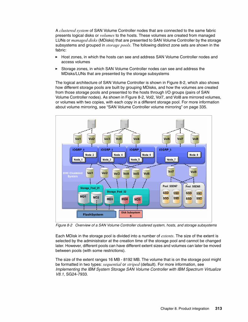
A clustered system of SAN Volume Controller nodes that are connected to the same fabric presents logical disks or volumes to the hosts. These volumes are created from managed LUNs or managed disks (MDisks) that are presented to SAN Volume Controller by the storage subsystems and grouped in storage pools. The following distinct zone sets are shown in the fabric:
� Host zones, in which the hosts can see and address SAN Volume Controller nodes and access volumes
� Storage zones, in which SAN Volume Controller nodes can see and address the MDisks/LUNs that are presented by the storage subsystems
The logical architecture of SAN Volume Controller is shown in Figure 8-2, which also shows how different storage pools are built by grouping MDisks, and how the volumes are created from those storage pools and presented to the hosts through I/O groups (pairs of SAN Volume Controller nodes). As shown in Figure 8-2, Vol2, Vol7, and Vol8 are mirrored volumes, or volumes with two copies, with each copy in a different storage pool. For more information about volume mirroring, see “SAN Volume Controller volume mirroring” on page 335.
Figure 8-2 Overview of a SAN Volume Controller clustered system, hosts, and storage subsystems
Each MDisk in the storage pool is divided into a number of extents. The size of the extent is selected by the administrator at the creation time of the storage pool and cannot be changed later. However, different pools can have different extent sizes and volumes can later be moved between pools (with some restrictions).
The size of the extent ranges 16 MB - 8192 MB. The volume that is on the storage pool might be formatted in two types: sequential or striped (default). For more information, see Implementing the IBM System Storage SAN Volume Controller with IBM Spectrum Virtualize V8.1, SG24-7933.
FlashSystem 840 Disk SubsystemB
Chapter 8. Product integration 313

8.1.3 SAN Volume Controller hardware options
Throughout its lifecycle, SAN Volume Controller used IBM System x server technology to offer a modular, flexible platform for storage virtualization that can be rapidly adapted in response to changing market demands and evolving client requirements. This “flexible hardware” design allows you to quickly incorporate differentiating features. Significant hardware options also are available.
Hardware options for SAN Volume ControllerSAN Volume Controller 2145-SV1 node introduces numerous hardware enhancements. Several of these enhancements relate directly to the Real-time Compression (RtC) feature and offer significant performance and scalability improvements over previous hardware versions.
Other enhanced CPU optionsThe 2145-SV1 node offers two CPUs that contain eight cores as compared to the four-core and six-core CPUs available in previous hardware versions.
Increased memory optionsThe 2145-SV1 node offers the option to increase the node memory from the base 64 GB to 256 GB, for use with Real-time Compression. This extra, compression-dedicated memory allows for improved overall system performance when compression is used over previous hardware models.
Quick Assist compression acceleration cardsThe 2145-SV1 node offers the option to include one or two Intel Quick Assist compression acceleration cards that are based on the Coleto Creek chipset. The introduction of these Intel-based compression acceleration cards in SAN Volume Controller 2145-SV1 node is an industry first. It provides dedicated processing power and greater throughout over previous models.
For more information about the compression accelerator cards, see Implementing the IBM System Storage SAN Volume Controller with IBM Spectrum Virtualize V8.1, SG24-7933.
More HBAsThe 2145-SV1 node can be configured with up to four I/O adapters, which provide up to 16 16-Gb FC ports or up to four 10 Gb Ethernet (iSCSI/FCoE) ports to improve connectivity options on SAN Volume Controller engine.
Note: To use the Real-time Compression feature on 2145-SV1 nodes, at least one compression accelerator card is required.
Note: Regular and Real-time Compression workloads can benefit from adding the 256 GB memory option feature for the 2145-SV1 nodes.
Note: To use the Real-time Compression feature on 2145-SV1 nodes, at least one Quick Assist compression acceleration card is required. With a single card, the maximum number of compressed volumes per I/O group is 200. With adding a second Quick Assist card, the maximum number of compressed volumes per I/O group is 512.
314 Implementing IBM FlashSystem 900 Model AE3

The following example scenarios describe where these extra ports can provide benefits:
� Isolation of node-to-node communication, potentially boosting write performance
� Isolation of node to IBM FlashSystem communication, which allows for maximum performance
� Isolation of remote copy traffic, which avoids performance problems
The HBA support on 2145-SV1 nodes requires SAN Volume Controller Storage Software Version 7.7 or higher.
Port maskingThe addition of Fibre Channel (FC) HBA ports allows you to optimize your SAN Volume Controller configuration by using dedicated ports for certain system functions. However, the addition of these ports necessitates the ability to ensure traffic isolation.
The following examples show traffic types that you might want to isolate by using port masking:
� Local node-to-node communication� Remote copy traffic
Port masking was introduced with SAN Volume Controller Storage Software Version 7.1. This feature enables better control of SAN Volume Controller node ports. Host port masking is supported in earlier SAN Volume Controller software versions. In those versions, host port masking can define which SAN Volume Controller node ports were used to communicate with hosts.
The enhanced port masking in SAN Volume Controller Storage Software Version 7.1 and later can restrict intracluster communication and replication communication to specific ports, which ensures that these traffic types occur only on the ports that you want. This capability eliminates the possibility of host or back-end port congestion because of intracluster communication or replication communication.
The features in SAN zoning and the physical port assignment provide greater control and enable less congestion and better usage of SAN Volume Controller ports.
Note: For more information about SAN Volume Controller V8.1 configuration limits and restrictions for IBM System Storage SAN Volume Controller, see the V8.1.x Configuration Limits and Restrictions for IBM System Storage SAN Volume Controller page of the IBM Support website.
Notes: A SAN Volume Controller node attempts to communicate with other SAN Volume Controller nodes over any available path. When enabled, port masking ensures that only dedicated ports are used for communications.
To use the port masking feature, use the chsystem -localfcportmask or -partnerfcportmask command.
Chapter 8. Product integration 315

SAN Volume Controller Stretched ClusterSAN Volume Controller Stretched Cluster configurations are supported by the IBM FlashSystem storage systems. For more information, see the following IBM Redbooks publications:
� IBM SAN and SVC Stretched Cluster and VMware Solution Implementation, SG24-8072� IBM SAN Volume Controller Stretched Cluster with PowerVM and PowerHA, SG24-8142
8.1.4 IBM Spectrum Virtualize - SAN Volume Controller advanced functionality
The combination of the IBM FlashSystem 900 and IBM Spectrum Virtualize, which delivers the functionality of IBM SAN Volume Controller, helps you to take advantage of the speed of the IBM FlashSystem 900 and the robust storage management capabilities of SAN Volume Controller. IBM SAN Volume Controller offers features that enrich any storage environment by introducing minimal delay or latency in the I/O path. This section describes SAN Volume Controller features and benefits.
Thin provisioningThe thin provisioning function helps automate provisioning and improve productivity by enabling administrators to focus on overall storage deployment and utilization (and longer-term strategic requirements) without being distracted by routine everyday storage provisioning.
When a thin-provisioned volume is created, the user specifies two capacities: the real physical capacity that is allocated to the volume from the storage pool, and its virtual capacity that is available to the host. Therefore, the real capacity determines the quantity of MDisk extents that is initially allocated to the volume. The virtual capacity is the capacity of the volume reported to all other SAN Volume Controller components (for example, FlashCopy, cache, and Remote copy) and to the host servers.
The real capacity is used to store the user data and the metadata for the thin-provisioned volume. The real capacity can be specified as an absolute value or a percentage of the virtual capacity. Thin-provisioned volumes can be used as volumes that are assigned to the host, by FlashCopy, and Remote copy, to implement thin-provisioned targets, and with the mirrored volumes feature.
FlashCopyThe FlashCopy function is designed to create an almost instant copy (or “snapshot”) of active data that can be used for backup purposes or for parallel processing activities. Up to 256 copies of data per source volume can be created.
Order of configuration: When port masking is used with SAN Volume Controller, use the following configuration order:
1. Configure intracluster port masking.2. Configure replication port masking (if replication is used).3. Configure SAN zones for intracluster communication.4. Configure SAN zones for replication communication (if replication is used).5. Configure SAN zones for all back-end storage communication.6. Configure SAN zones for host communication.
For more information about port masking, see the Fibre Channel port masking page of IBM Knowledge Center.
316 Implementing IBM FlashSystem 900 Model AE3

FlashCopy works by creating one or two (for incremental operations) bitmaps to track changes to the data on the source volume. This bitmap is also used to present an image of the source data at the point in time that the copy was taken to target hosts while the actual data is being copied. This capability ensures that copies appear to be instantaneous.
FlashCopy permits the management operations to be coordinated through a grouping of FlashCopy pairs so that a common single point in time is chosen for copying target volumes from their respective source volumes. This capability is called consistency groups and allows a consistent copy of data for an application that spans multiple volumes.
IBM offers IBM Spectrum Protect Snapshot (formerly Tivoli Storage FlashCopy Manager) that is designed to perform near-instant application-aware snapshot backups by using SAN Volume Controller FlashCopy, but with minimal effect to IBM DB2, Oracle, SAP, Microsoft SQL Server, or Microsoft Exchange. IBM Spectrum Protect Snapshot also helps reduce backup and recovery times from hours to a few minutes.
For more information, see the IBM Spectrum Protect Snapshot web page.
Easy TierSAN Volume Controller Easy Tier function helps improve performance at a lower cost through more efficient use of storage. Easy Tier is a performance function that automatically migrates or moves extents off a volume to, or from, one MDisk storage tier to another MDisk storage tier. Easy Tier monitors the host I/O activity and latency on the extents of all volumes with the Easy Tier function turned on in a multitier storage pool over a 24-hour period.
Next, Easy Tier creates an extent migration plan that is based on this activity and then dynamically moves high activity or hot extents to a higher disk tier within the storage pool. It also moves extents whose activity dropped off or cooled from the higher-tier MDisks back to a lower-tiered MDisk.
SAN Volume Controller Easy Tier can deliver up to a three-time performance improvement with only 5% flash storage capacity. Easy Tier can use flash storage, whether deployed in SAN Volume Controller nodes or in virtualized disk systems, to benefit all virtualized storage. This approach delivers greater benefits from flash storage than tiering systems that are limited to only a single disk system.
Because the Easy Tier function is so tightly integrated, functions, such as data movement, replication, and management, all can be used with flash in the same way as for other storage. SAN Volume Controller helps move critical data to and from flash storage as needed without application disruptions. Combining SAN Volume Controller with the FlashSystem storage devices delivers the best of both technologies: extraordinary performance for critical applications with IBM MicroLatency coupled with sophisticated functionality.
Mirroring and copy servicesWith many conventional SAN disk arrays, replication operations are limited to in-box or like-box-to-like-box circumstances. Functions from different vendors can operate in different ways, which make operations in mixed environments more complex and increase the cost of changing storage types. But SAN Volume Controller is designed to enable administrators to apply a single set of advanced network-based replication services that operate in a consistent manner, regardless of the type of storage that is used.
Chapter 8. Product integration 317

SAN Volume Controller supports remote mirroring to enable organizations to create copies of data at remote locations for disaster recovery. Metro Mirror supports synchronous replication at distances up to 300 km (186.4 miles). Global Mirror supports asynchronous replication up to 8,000 km (4970.9 miles). Replication can occur between any Spectrum Virtualize family systems, and can include any supported virtualized storage. Remote mirroring works with Fibre Channel (FC), Fibre Channel over Ethernet (FCoE), and IP (Ethernet) networking between sites.
With IP networking, the IBM Spectrum Virtualize family systems support 1 GbE and 10 GbE connections and use innovative Bridgeworks SANSlide technology to optimize the use of network bandwidth. As a result, the networking infrastructure can require lower speeds (and lower costs), or users might improve the accuracy of remote data through shorter replication cycles. The remote mirroring functions also support VMware vCenter Site Recovery Manager to help speed up disaster recovery.
Volume mirroring is a simple RAID 1 type function that is designed to allow a volume to remain online even when the storage pool backing it becomes inaccessible. Volume mirroring is designed to protect the volume from storage infrastructure failures by seamlessly mirroring between storage pools.
Volume mirroring is provided by a specific volume mirroring function in the I/O stack. It cannot be manipulated like a FlashCopy or other types of copy volumes. However, this feature does provide migration functionality, which can be obtained by splitting the mirrored copy from the source or by using the “migrate to” function. Volume mirroring cannot control back-end storage mirroring or replication.
Real-time CompressionRtC is designed to enable storing up to five times1 as much data in the same physical disk space by compressing data as much as 80%. Unlike other approaches to compression, RtC can be used with active primary data, such as production databases and email systems, which dramatically expands the range of candidate data that can benefit from compression. RtC operates immediately while data is written to disk, which means that no space is wasted storing decompressed data waiting for post-processing.
The benefits of the use of RtC with other efficiency technologies are significant and include reduced acquisition cost (because less hardware is required), reduced rack space, and lower power and cooling costs throughout the lifetime of the system. RtC can significantly enhance the usable capacity of your storage systems, which extends their useful life even more.
By significantly reducing storage requirements with RtC, you can keep more information online, use the improved efficiency to reduce storage costs, or achieve a combination of greater capacity and reduced cost. Because RtC can be applied to a much wider range of data, including primary online data, the benefits of compression with SAN Volume Controller can be much greater than with alternative solutions, which result in much greater savings. Enhancements to SAN Volume Controller nodes support up to three times the performance with RtC, which enables even larger configurations to experience compression benefits.
1 Compression data based on IBM measurements. Compression rates vary by data type and content.
Note: FlashSystem 900 AE3 compression is always on by design because no extra overhead is incurred. If data is compressed by the SAN Volume Controller, the FlashSystem 900 AE3 detects this compression and performs no further compression.
318 Implementing IBM FlashSystem 900 Model AE3

ssion y
ssion y
The command lines that are used to generate comprestimator results for the FlashSystem AE3 inline hardware compression and SAN Volume Controller RtC are shown in Example 8-1. This comparison can be worthwhile to check whether a volume is most effectively compressed on the SAN Volume Controller or FlashSystem AE3.
Example 8-1 Command lines for comprestimator results
comprestimator_aix -d /dev/hdisk5 -s FLASHSYSTEM --flash-modules 12
comprestimator_aix -d /dev/hdisk5 -s SVC
The comprestimator results were reformatted for readability in Table 8-1. Also, note that comprestimator for SAN Volume Controller reports thin provisioning savings, which are not available on the FlashSystem 900 AE3.
Table 8-1 Comprestimator results comparison SAN Volume Controller and FS900 AE3
For more information about compression and the FlashSystem 900 AE3, see 3.9, “Planning for compression” on page 75. For more information about compression for the SAN Volume Controller, see Implementing the IBM System Storage SAN Volume Controller with IBM Spectrum Virtualize V8.1, SG24-7933.
Starting on SAN Volume Controller version 7.1, the concurrent use of Easy Tier and RtC is supported on the same volume, but only read activity is monitored.
8.1.5 Reserving space to solve an out of space condition
If FlashSystem 900 AE3 has an “out of physical space condition” scenario, writes to FlashSystem 900 are blocked and the SAN Volume controller pools that are using volumes from the FlashSystem 900 go offline. When this condition is solved on FlashSystem 900, the SAN Volume Controller writes the data to FlashSystem 900, which is still in the SAN Volume Controller write cache.
To ensure all write cache of the SAN Volume Controller can be written to FlashSystem 900, some capacity must be reserved. For every SAN Volume Controller cluster at least 100 GB of physical space must be reserved on FlashSystem 900. Creating volumes of this size and filling them with uncompressible data reserves this space.
In an “out of physical space condition” scenario, these volumes can be deleted on FlashSystem 900 and the SAN Volume Controller can destage the cache to FlashSystem
Product Device Name Size (GB) Compressed Size (GB)
Total Savings (GB)
Total Savings (%)
Storage Efficiency Savings (%)
Compression Savings (%)
CompreAccuracRange
FS900 AE3 /dev/hdisk5 1600.0 225.4 1374.6 85.9 0% 85.9% 5%
Product Device Name Size (GB) Compressed Size (GB)
Total Savings (GB)
Total Savings (%)
Thin Provisioning Savings (%)
Compression Savings (%)
CompreAccuracRange
SAN Volume Controller
/dev/hdisk5 1600.0 191.5 1408.5 88% 65.3% 65.5% 5.0%
Note: To use the RtC feature on 2145-SV1 nodes, more memory and compression acceleration cards are required, as described in 8.1.3, “SAN Volume Controller hardware options” on page 314.
Chapter 8. Product integration 319
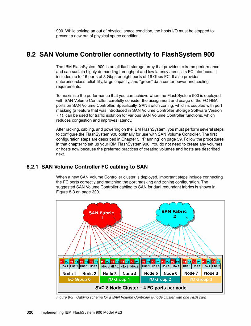
900. While solving an out of physical space condition, the hosts I/O must be stopped to prevent a new out of physical space condition.
8.2 SAN Volume Controller connectivity to FlashSystem 900
The IBM FlashSystem 900 is an all-flash storage array that provides extreme performance and can sustain highly demanding throughput and low latency across its FC interfaces. It includes up to 16 ports of 8 Gbps or eight ports of 16 Gbps FC. It also provides enterprise-class reliability, large capacity, and “green” data center power and cooling requirements.
To maximize the performance that you can achieve when the FlashSystem 900 is deployed with SAN Volume Controller, carefully consider the assignment and usage of the FC HBA ports on SAN Volume Controller. Specifically, SAN switch zoning, which is coupled with port masking (a feature that was introduced in SAN Volume Controller Storage Software Version 7.1), can be used for traffic isolation for various SAN Volume Controller functions, which reduces congestion and improves latency.
After racking, cabling, and powering on the IBM FlashSystem, you must perform several steps to configure the FlashSystem 900 optimally for use with SAN Volume Controller. The first configuration steps are described in Chapter 3, “Planning” on page 59. Follow the procedures in that chapter to set up your IBM FlashSystem 900. You do not need to create any volumes or hosts now because the preferred practices of creating volumes and hosts are described next.
8.2.1 SAN Volume Controller FC cabling to SAN
When a new SAN Volume Controller cluster is deployed, important steps include connecting the FC ports correctly and matching the port masking and zoning configuration. The suggested SAN Volume Controller cabling to SAN for dual redundant fabrics is shown in Figure 8-3 on page 320.
Figure 8-3 Cabling schema for a SAN Volume Controller 8-node cluster with one HBA card
320 Implementing IBM FlashSystem 900 Model AE3

For FlashSystem 900 connectivity, consider the use of more HBAs in SAN Volume Controller. A configuration with one extra SAN Volume Controller HBA in each node and the cabling schema for cabling to SAN fabric switches is shown in Figure 8-4.
Figure 8-4 Cabling schema for SAN Volume Controller 2-node cluster with two HBA cards per node
8.2.2 SAN zoning and port designations
SAN Volume Controller can be configured with two, or up to eight SAN Volume Controller nodes that are arranged in a SAN Volume Controller clustered system. These SAN Volume Controller nodes are attached to the SAN fabric, along with disk subsystems and host systems.
The SAN fabric is zoned to allow the SAN Volume Controllers to “see” each other’s nodes and the disk subsystems, and for the hosts to “see” the SAN Volume Controllers. The hosts cannot directly see or operate LUNs on the disk subsystems that are assigned to the SAN Volume Controller system. The SAN Volume Controller nodes within a SAN Volume Controller system must see each other and all of the storage that is assigned to the SAN Volume Controller system.
In an environment where a fabric with multiple-speed switches is used, the preferred practice is to connect the SAN Volume Controller and the disk subsystem to the switch operating at the highest speed. SAN Volume Controller 8.1with 16 GBps hardware supports 16 GBps, and must be connected to a supported 16 GBps capable switch.
All SAN Volume Controller nodes in the SAN Volume Controller clustered system are connected to the same SANs, and they present volumes to the hosts. These volumes are created from storage pools that are composed of MDisks that are presented by the disk subsystems.
Chapter 8. Product integration 321

The zoning capabilities of the SAN switches are used to create the following distinct zones:
� SAN Volume Controller cluster system
Create up to two zones per fabric, and include a single port per node, which is designated for intracluster traffic. No more than four ports per node should be allocated to intracluster traffic.
� Host
Create a SAN Volume Controller host zone for each server that is accessing storage from the SAN Volume Controller system.
� Storage
Create one SAN Volume Controller storage zone for each storage subsystem that is virtualized by the SAN Volume Controller.
Certain limits and restrictions apply for SAN zoning and switch connectivity in SAN Volume Controller 8.1 environments. For more information, see the V8.1.x Configuration Limits and Restrictions for IBM System Storage SAN Volume Controller page of the IBM Support website.
For more information about supported SAN switches, see the IBM System Storage Interoperation Center (SSIC) website.
8.2.3 Port designations
The port-to-local node communication is used for mirroring write cache and also metadata exchange between nodes and is critical to the stable operation of the cluster. The SV1 nodes, with their 6-, 8-, 12-, and 16-port configurations, provide an opportunity to isolate the port to local node traffic from other cluster traffic on dedicated ports. These configurations provide a level of protection against faulty devices and workloads that can compromise the performance of the shared ports.
Another benefit of isolating remote application traffic on dedicated ports is to ensure that problems that affect the cluster-to-cluster interconnect do not adversely affect ports on the primary cluster. Adversely affected ports can deteriorate the performance of workloads that are running on the primary cluster.
IBM suggests the port designations that are shown in Figure 8-5 for isolating port-to-local and port-to-remote node traffic for the 2145-SV1 nodes. (Other port configurations might apply for iSCSI and FCoE connectivity.)
322 Implementing IBM FlashSystem 900 Model AE3

Figure 8-5 Port designations recommendations for isolating traffic on 2145-SV1 nodes
This suggestion provides the traffic isolation that you want while also simplifying migration from existing configurations with only four ports, or even later migrating from 8-port, 12-port, or 16-port configurations to configurations with more ports.
More complicated port mapping configurations that spread the port traffic across the adapters are supported and can be considered. However, these approaches do not appreciably increase the availability of the solution because the mean time between failures (MTBF) of the adapter is not significantly less than the MTBF of the non-redundant node components.
Although alternative port mappings that spread traffic across HBAs might allow adapters to come back online following a failure, they do not prevent a node from going offline temporarily to restart and attempt to isolate the failed adapter and then, rejoin the cluster. Our suggestion takes all of these considerations into account with a view that the greater complexity might lead to migration challenges in the future and the simpler approach is best.
For more information about the SV1 node as of SAN Volume Controller 8.1, see Implementing the IBM System Storage SAN Volume Controller with IBM Spectrum Virtualize V8.1, SG24-7933.
When you attach your IBM FlashSystem 900 to a SAN Volume Controller node that contains a single HBA quad port, follow the zoning and port guidelines that are suggested for any other storage back-end device. For more information, see IBM System Storage SAN Volume Controller and Storwize V7000 Best Practices and Performance Guidelines, SG24-7521.
Notes: Consider the following points regarding Figure 8-5:
� SAN column assumes an odd/even SAN port configuration. Modifications must be made if other SAN connection schemes are used.
� Use caution when zoning so that inter-node ports are not used for Host/Storage in the 8-, 12-, and 16-port configurations.
� These options represent optimal configurations that are based on port assignment to function. The use of the same port assignment but different physical locations does not result in any significant performance effect in most client environments.
Chapter 8. Product integration 323

8.2.4 Verifying FlashSystem 900 connectivity in SAN Volume Controller
After you activate the zoning, you can identify the IBM FlashSystem 900 as a controller to SAN Volume Controller. You can use the SAN Volume Controller command lscontroller or the SAN Volume Controller GUI to browse to Pools → External Storage to verify.
Change the controller name on the SAN Volume Controller system by one of two methods:
� Issue the SAN Volume Controller command chcontroller and include the -name parameter.
� Use the SAN Volume Controller GUI to browse to Pools → External Storage (indicated by 1 in Figure 8-6) and then, select the controller (2 in Figure 8-6) that you want and click Actions → Rename. Change the name (3 in Figure 8-6) in the window. As shown in Figure 8-6, the controller is renamed to FS900AE3_01.
After you change the name, you can easily identify the IBM FlashSystem 900 as a controller to SAN Volume Controller as shown in Figure 8-6.
Figure 8-6 IBM FlashSystem 900 as external storage to SAN Volume Controller
You also must create zones between SAN Volume Controller and the host. For more information about configuring zoning for host access to SAN Volume Controller, see IBM System Storage SAN Volume Controller and Storwize V7000 Best Practices and Performance Guidelines, SG24-7521.
IBM FlashSystem 900 host and volume creationTo provide usable storage (managed disks) to the SAN Volume Controller, the IBM FlashSystem 900 must include defined volumes. These volumes must be mapped to the SAN Volume Controller host that also must be created. For more information about this process, see Chapter 6, “Using IBM FlashSystem 900” on page 157.
Create one host and name it, for example, SVC. Then, add the SAN Volume Controller worldwide port names (WWPNs) that communicate with the FlashSystem (in this case, SAN
1
2
3
Note: Use the default block size of 512 bytes when volumes are created to be mapped to the SAN Volume Controller.
324 Implementing IBM FlashSystem 900 Model AE3

Volume Controller nodes port 1 and port 5) to this newly created host. Then, create the volumes by following the guidelines that are described next and map them to this newly created host (SVC).
SAN Volume Controller managed disk configurationThe preferred practices and considerations to design and plan the SAN Volume Controller storage pool (MDisk group) setup by using the IBM FlashSystem 900 are described next. Several considerations must be addressed when planning and configuring the MDisks and storage pools for the IBM FlashSystem 900 behind the SAN Volume Controller.
When the IBM FlashSystem 900 is used behind the SAN Volume Controller, the queue assignment and cache assignment are not as relevant as they are with traditional spindle-based disk systems because of the rapid speed with which the IBM FlashSystem 900 can process I/O requests.
Create eight volumes on the FlashSystem 900 to be mapped to the SAN Volume controller. The use of eight volumes provides the best utilization of the processor cores in the control enclosure nodes, and maintains optimal I/O queue balancing among the volumes. Example 8-2 shows how the size of the disks to be created on the FlashSystem is computed.
Example 8-2 Computing the size of the FlashSystem disks
To determine the size of each of the 8 volumes, complete the following steps:Divide the total effective capacity by 8 to determine the size of each volume. For example, for 12 TB of effective capacity, each volume is sized as (12 TB / 8 = 1500 GB).
Storage pool extent sizeWhen you work with an all IBM FlashSystem 900 behind a SAN Volume Controller configuration, the extent size can be kept at the default2 value of 1024 MB (1 GiB). The performance of the IBM FlashSystem 900 with random I/O workload does not require the extent size to be smaller. The maximum extent size is 8,192 MB, which provides for a maximum MDisk of 1,024 TB or 1 petabyte.
If systems and storage pools are available, you must have the same extent size for all pools to use transparent volume migration between pools. If different extent sizes are used, you can use volume mirroring to create a copy of the disk and then promote it to the master volume when the copy is completed. Although this manual process takes slightly longer to complete, its runtime can be controlled in more granular way.
All FlashSystem versus mixed storage poolsIf you use the FlashSystem 900 as the primary data storage, add all of the MDisks from the storage enclosure to a single managed disk group (also know as a storage pool in the SAN Volume Controller GUI). However, if more than one FlashSystem 900 is presented to a SAN Volume Controller cluster, a preferred practice is to create a single storage pool per controller.
If you use the FlashSystem 900 with the SAN Volume Controller Easy Tier function, you likely want to create multiple volumes for each hybrid storage pool. Create four or more volumes for each hybrid pool, with the combined capacity of these volumes matching the capacity that
Note: You can also use the GUI to determine the maximum size for the eight volumes. Enter any size larger than what you expect and the GUI corrects it to maximum available size.
2 Starting on SAN Volume Controller version 7.x.
Chapter 8. Product integration 325

you want for the SSD tier in that pool. For more information about SAN Volume Controller Easy Tier with the FlashSystem is presented.
MDisk mapping, storage pool, and volume creationThis section describes mapping MDisks from an IBM FlashSystem 900 to SAN Volume Controller. Defining a storage pool to accommodate those volumes and the process that is used to provision a volume from the FlashSystem 900 storage pool to the hosts also are described.
After volumes are created on the IBM FlashSystem 900 and presented to the SAN Volume Controller, they must be recognized in the SAN Volume Controller. The first step is to click the Detect MDisks option from the SAN Volume Controller GUI to detect the newly presented MDisks, as shown in Figure 8-7. Complete the following steps:
1. Select the Pools.2. Choose External Storage.3. Click Discover Storage.4. When the task completes, click Close to see the newly available MDisks.
Figure 8-7 Discover Storage that is mapped from the FlashSystem 900
When this detection process completes, a list of MDisks appears, as shown in Figure 8-7 on page 326). For identification, it is important to rename the MDisk when they are added. When naming an MDisk, the following naming convention is suggested:
%controller name_lun id on disk system%
This naming convention defines the name of the controller from which the LUN is presented and the local identifier that is referenced on the source disk system. This information is helpful when troubleshooting.
To rename an MDisk, select the MDisk, right-click, and select Rename. A Rename MDisks window opens. Enter the new names of the MDisk and then, click Rename (see Figure 8-8).
1
32
326 Implementing IBM FlashSystem 900 Model AE3

Figure 8-8 Renaming MDisks to help troubleshooting
The next step is to create a storage pool (if needed), as shown in Figure 8-9. A menu is displayed that you can use to configure the storage pool name and extent size. The default is 1 GiB (1024 MB), which can be left as the default, as described in “SAN Volume Controller managed disk configuration” on page 325. You enter the name of the storage pool and then, click Next.
Figure 8-9 Creating the storage Pool
Chapter 8. Product integration 327

Add Storage to the pool, as shown in Figure 8-10.
Figure 8-10 Selecting Add Storage option
Make the following selections from the add storage to pool window that is shown in Figure 8-11:
1. Select the External disk icon.
The Storage Subsystem that contains the MDisks is discovered (see 2 in Figure 8-11).
2. Select all MDisks in this example (the eight MDisks are from the FlashSystem). The menu appears when you select the field (see 3 in Figure 8-11).
This tier is Tier 0 Flash, which classifies it for Easy Tier (see 2 in Figure 8-11).
3. Select Assign.
328 Implementing IBM FlashSystem 900 Model AE3

Figure 8-11 Adding storage to the pool
After the command completes, the storage pool is created and the MDisks are members of the storage pool. To confirm, review the details of the new storage pool that was created by right-clicking the pool name and selecting Properties, as shown in Figure 8-12.
Figure 8-12 Storage pool properties
All eight MDisks are now added to the pool that is shown in Figure 8-12.
1
2 3
4
5
Suggestion: Use the GUI to add all MDisks to the defined storage pool when the pools are created or before starting volume allocation on that pool. You can select more than one MDisk candidate during the storage pool creation process or you can add it manually by using the addmdisk command.
Chapter 8. Product integration 329

The next step is create the host. Assuming that zoning is configured between the host and SAN Volume Controller, the main menu that is used to create a host on SAN Volume Controller is shown in Figure 8-13. Browse to the host menu by using the left pane that is shown in Figure 8-13.
Figure 8-13 Open up the Hosts pane and Add Host
Complete the following steps (as highlighted in Figure 8-13):
1. Open the Hosts menu.2. Select Hosts. The right pane changes to display any available hosts.3. Select Add Host at the top of the window. The Add Host pane appears.
Add the hosts by completing the following steps as shown in Figure 8-14:
Figure 8-14 Add Host pane
1
2
3
1
2
3
4
330 Implementing IBM FlashSystem 900 Model AE3

1. Enter the Host Name (in our example, we used VMware).2. Select the Host Port to be added to that host. Use the “+” sign to add ports to the list. 3. Select WWPN from the drop-down menu. 4. Check the Port Definitions to ensure that you added the port.5. Select Add to complete the process.
The results of adding the host are shown in Figure 8-15. Select Close to complete the process.
Figure 8-15 Adding a host
Chapter 8. Product integration 331
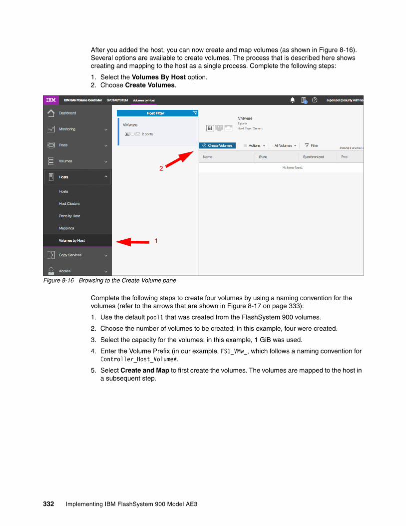
After you added the host, you can now create and map volumes (as shown in Figure 8-16). Several options are available to create volumes. The process that is described here shows creating and mapping to the host as a single process. Complete the following steps:
1. Select the Volumes By Host option.2. Choose Create Volumes.
Figure 8-16 Browsing to the Create Volume pane
Complete the following steps to create four volumes by using a naming convention for the volumes (refer to the arrows that are shown in Figure 8-17 on page 333):
1. Use the default pool1 that was created from the FlashSystem 900 volumes.
2. Choose the number of volumes to be created; in this example, four were created.
3. Select the capacity for the volumes; in this example, 1 GiB was used.
4. Enter the Volume Prefix (in our example, FS1_VMw_, which follows a naming convention for Controller_Host_Volume#.
5. Select Create and Map to first create the volumes. The volumes are mapped to the host in a subsequent step.
1
2
332 Implementing IBM FlashSystem 900 Model AE3

Figure 8-17 Create and Map 4 Volumes to the Host
1
23 4
5
Chapter 8. Product integration 333

The final step is to assign the recently created volume to the host from the window that is shown in Figure 8-17 on page 333. Complete the following steps (refer to the arrows that are shown in Figure 8-18):
1. Select Map Volumes.
Figure 8-18 Mapping the four volumes
Commands are available for your review, as shown in Figure 8-19.
Figure 8-19 Completion shows as the mappings are created
1
334 Implementing IBM FlashSystem 900 Model AE3
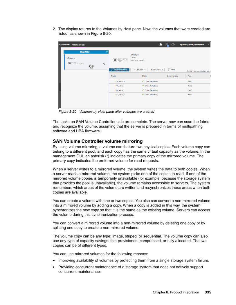
2. The display returns to the Volumes by Host pane. Now, the volumes that were created are listed, as shown in Figure 8-20.
Figure 8-20 Volumes by Host pane after volumes are created
The tasks on SAN Volume Controller side are complete. The server now can scan the fabric and recognize the volume, assuming that the server is prepared in terms of multipathing software and HBA firmware.
SAN Volume Controller volume mirroringBy using volume mirroring, a volume can feature two physical copies. Each volume copy can belong to a different pool, and each copy has the same virtual capacity as the volume. In the management GUI, an asterisk (*) indicates the primary copy of the mirrored volume. The primary copy indicates the preferred volume for read requests.
When a server writes to a mirrored volume, the system writes the data to both copies. When a server reads a mirrored volume, the system picks one of the copies to read. If one of the mirrored volume copies is temporarily unavailable (for example, because the storage system that provides the pool is unavailable), the volume remains accessible to servers. The system remembers which areas of the volume are written and resynchronizes these areas when both copies are available.
You can create a volume with one or two copies. You also can convert a non-mirrored volume into a mirrored volume by adding a copy. When a copy is added in this way, the system synchronizes the new copy so that it is the same as the existing volume. Servers can access the volume during this synchronization process.
You can convert a mirrored volume into a non-mirrored volume by deleting one copy or by splitting one copy to create a non-mirrored volume.
The volume copy can be any type: image, striped, or sequential. The volume copy can also use any type of capacity savings: thin-provisioned, compressed, or fully allocated. The two copies can be of different types.
You can use mirrored volumes for the following reasons:
� Improving availability of volumes by protecting them from a single storage system failure.
� Providing concurrent maintenance of a storage system that does not natively support concurrent maintenance.
Chapter 8. Product integration 335

� Providing an alternative method of data migration with better availability characteristics. When a volume is migrated by using the data migration feature, it is vulnerable to failures on the source and target pool.
Volume mirroring provides an alternative because you can start with a non-mirrored volume in the source pool, and then add a copy to that volume in the destination pool. When the volume is synchronized, you can delete the original copy that is in the source pool. During the synchronization process, the volume remains available, even if a problem exists with the destination pool.
� Converting between fully allocated volumes and thin-provisioned volumes.
When you use volume mirroring, consider how quorum candidate disks are allocated. Volume mirroring maintains some state data on the quorum disks. If a quorum disk is not accessible and volume mirroring cannot update the state information, a mirrored volume might need to be taken offline to maintain data integrity. To ensure the high availability of the system, ensure that multiple quorum candidate disks are allocated and configured on different storage systems.
When a volume mirror is synchronized, a mirrored copy can become unsynchronized if it goes offline and write I/O requests must be progressed, or if a mirror fast failover occurs. The fast failover isolates the host systems from temporarily slow-performing mirrored copies, which affect the system with a short interruption to redundancy.
Write fast failoversWith a write fast failovers, the system submits writes (with a timeout value of 10 seconds) to both copies during processing of host write I/O. If one write succeeds and the other write takes longer than 10 seconds, the slower request times-out and ends.
The duration of the ending sequence for the slow copy I/O depends on the backend from which the mirror copy is configured. For example, if the I/O occurs over the Fibre Channel network, the I/O ending sequence typically completes in 10 - 20 seconds. However, in rare cases, the sequence can take more than 20 seconds to complete.
When the I/O ending sequence completes, the volume mirror configuration is updated to record that the slow copy is now no longer synchronized. When the configuration updates finish, the write I/O can be completed on the host system.
The volume mirror stops using the slow copy for 4 - 6 minutes and subsequent I/O requests are satisfied by the remaining synchronized copy. During this time, synchronization is suspended. Also, the volume's synchronization progress shows less than 100% and decreases if the volume receives more host writes. After the copy suspension completes, volume mirroring synchronization resumes and the slow copy starts synchronizing.
If another I/O request times out on the unsynchronized copy during the synchronization, volume mirroring again stops using that copy for 4 - 6 minutes. If a copy is always slow, volume mirroring attempts to synchronize the copy again every 4 - 6 minutes and another I/O timeout occurs. The copy is not used for another 4 - 6 minutes and becomes progressively unsynchronized. Synchronization progress gradually decreases as more regions of the volume are written.
Note: If the capacity is fully allocated, the primary volume formats before synchronizing to the volume copies. The -syncrate parameter on the mkvdisk command controls the format and synchronization speed.
336 Implementing IBM FlashSystem 900 Model AE3

If write fast failovers occur regularly, an underlying performance problem might exist within the storage system that is processing I/O data for the mirrored copy that became unsynchronized. If one copy is slow because of storage system performance, multiple copies on different volumes are affected. The copies might be configured from the storage pool that is associated with one or more storage systems. This situation indicates possible overloading or other back-end performance problems.
When you run the mkvdisk command to create a volume, the mirror_write_priority parameter is set to latency by default. Fast failover is enabled. However, fast failover can be controlled by changing the value of the mirror_write_priority parameter on the chvdisk command.
If the mirror_write_priority is set to redundancy, fast failover is disabled. The system applies a full SCSI initiator-layer error recovery procedure (ERP) for all mirrored write I/O. If one copy is slow, the ERP can take up to 5 minutes. If the write operation is still unsuccessful, the copy is taken offline. Carefully consider whether maintaining redundancy or fast failover and host response time (at the expense of a temporary loss of redundancy) is more important.
Read fast failoversRead fast failovers affect how the system processes read I/O requests. A read fast failover determines which copy of a volume the system tries first for a read operation. The primary-for-read copy is the copy that the system tries first for read I/O. It is determined by a user-implicated read algorithm.
The system submits host read I/O request to one copy of a volume at a time. If that request succeeds, the system returns the data. If it is not successful, the system retries the request to the other copy volume.
With read fast failovers, when the primary-for-read copy goes slow for read I/O, the system fails over to the other copy. The system tries the other copy first for read I/O during the following 4 - 6 minutes. Then, the system reverts to read the original primary-for-read copy. If read I/O to the other copy also slows during this period, the system reverts immediately.
Also, if the primary-for-read copy changes, the system reverts to try the new primary-for-read copy. This situation can occur when the system topology changes or when the primary or local copy changes. For example, in a standard topology, the system normally tries to read the primary copy first. If you change the volume's primary copy during a read fast failover period, the system reverts to read the newly set primary copy immediately.
The read fast failover function is always enabled on the system. During this process, the system does not suspend the volumes or make the copies out of sync.
Maintaining data integrity of mirrored volumes
Volume mirroring improves data availability by allowing hosts to continue I/O to a volume even if one of the backend storage systems failed. However, this mirroring does not affect data integrity.
Attention: Mirrored volumes can be taken offline if no quorum disk is available. This behavior occurs because synchronization status for mirrored volumes is recorded on the quorum disk. To protect against mirrored volumes being taken offline, follow the guidelines for setting up quorum disks
Chapter 8. Product integration 337

If either of the backend storage systems corrupts the data, the host is at risk of reading that corrupted data in the same way as for any other volume. Therefore, before you perform maintenance on a storage system that might affect the data integrity of one copy, it is important to check that both volume copies are synchronized. Then, remove that volume copy before you begin the maintenance. For example, the scenario applies if you must zero the data on the disks that the storage system is providing.
Use cases: SAN Volume Controller volume mirroring with FlashSystemDepending on the storage system that is chosen for each of the two volume mirror copies, certain details must be considered to meet the high performance and low latency expectations of the solution.
This section describes usage scenarios for the SAN Volume Controller volume mirroring when virtualizing one or more FlashSystem storage systems. Also described is the potential benefits and preferred practices for each scenario.
Use case 1: Volume mirroring between two FlashSystem storage systemsThis case is the basic scenario for SAN Volume Controller volume mirroring because both copies are on the same type of storage systems. In this scenario, performance is not expected to be affected in a failure if the two subsystems are close to the SAN Volume Controller nodes.
This scenario indicates a non-stretched cluster setup. In this case, FC link latency is not likely to present an issue. The default configuration for preferred node, primary copy, and mirroring priority is simplified.
Use case 2: Volume mirroring between a FlashSystem and a non-flash storage system
In this scenario, which is often adopted for cost-reduction reasons, plan to avoid the penalty that is represented by the slowest subsystem to the overall I/O latency. Consider the following suggestions:
� The primary copy of each mirrored volume must be set for the copy that is in the FlashSystem subsystem so that all the reads are directed to it by SAN Volume Controller. This configuration is commonly referred to as a preferred read configuration.
� If both subsystems are close to the SAN Volume Controller nodes, which is a non-Stretched Cluster setup, the -mirrorwritepriority flag for the mirrored volume must be set to latency. Therefore, destaging to the volume copy in the slowest subsystem does not introduce a negative effect in the overall write latency and to cache usage.
Using the FlashSystem with SAN Volume Controller Easy TierIn this scenario, the IBM FlashSystem 900 is used with SAN Volume Controller Easy Tier to improve performance on a storage pool. Because of the complexity of this scenario, important details must be considered when you design and plan to add a FlashSystem to an environment.
Note: Volume mirroring does not contribute to host-side latency on the front end. Volume mirroring destaging is handled by the back end and is transparent to hosts. The time that it takes to cache mirror write I/Os must be considered if the nodes of a stretched cluster are far apart. For more information, see IBM System Storage SAN Volume Controller and Storwize V7000 Best Practices and Performance Guidelines, SG24-7521.
338 Implementing IBM FlashSystem 900 Model AE3

A common question is when to use the FlashSystem storage over internal solid-state drives (SSDs) in SAN Volume Controller. The suggestion is to use the FlashSystem storage when your capacity requirements for Easy Tier exceed five SSDs. At this point, consider the FlashSystem storage systems for cost efficiency and performance. For more information, see Flash or SSD: Why and When to Use IBM FlashSystem, REDP-5020.
When you are planning to use the FlashSystem 900 with SAN Volume Controller Easy Tier, first use the IBM Storage Tier Advisor Tool (STAT) to obtain a comprehensive analysis of hot extents. By using this tool, you can estimate the amount of required FlashSystem capacity. For more information about this tool, see Implementing the IBM System Storage SAN Volume Controller with IBM Spectrum Virtualize V8.1, SG24-7933.
Ensure that you add these MDisks as tier0_flash MDisks. Otherwise, SAN Volume Controller Easy Tier cannot distinguish between the spindle-based generic hard disk drives (HDDs), SSD flash drives that contain Flash tier1_flash, and the FlashSystem 900 MDisks. This task can be done by first creating the new MDisks and then, changing the tier level by using the GUI or chmdisk -tier tier0_flash <mdisk> command after the MDisks are added to a storage pool.
FlashSystem with SAN Volume Controller replicationConsider the following points when you use the IBM FlashSystem 900 with the SAN Volume Controller and replication:
� More latency overhead is incurred with synchronous Metro Mirror� The distance of cross-site links and more latency overhead� Adequate bandwidth for cross-site links� Amount of data to replicate and its I/O rate� Dedicated replication ports
The IBM FlashSystem storage systems provide low latency. The latency of Metro Mirror links might affect the FlashSystem storage systems to a greater degree than other traditional disk systems that are used with SAN Volume Controller.
Metro Mirror replication distances in excess of 10 km (6.2 miles) must be carefully analyzed to ensure that they do not introduce bottlenecks or increase response times when they are used with the FlashSystem storage systems.
FC is the preferred connectivity method that uses a Dense Wavelength Division Multiplexer (DWDM), or equivalent device, between the source and target sites. Also, the use of inter-switch links (ISLs) in a trunk or port channel to increase the aggregate bandwidth between the two sites is advised.
Size the connectivity between sites according to the amount of bandwidth that you are allocating on SAN Volume Controller for replication, with more bandwidth for future growth and peak loads.
Note: SAN Volume Controller Easy Tier can be tuned by using the chmdisk -easytierload command. This tuning is most relevant for external MDisks (internal storage, such as SAS enclosures, are optimized automatically).
Tip: Dedicating ports for replication is advised with this solution. Isolating replication ports can disperse congestion and reduce latency for replication while protecting other ports from the effects of increased amounts of replication traffic.
Chapter 8. Product integration 339

Consider the following factors when you design the replication connectivity:
� Current average and peak write activity to the volumes that you plan to replicate
� Wanted recovery point objective (RPO) and recovery time objective (RTO) values
� Preferred practices for SAN Volume Controller replication (see IBM System Storage SAN Volume Controller and Storwize V7000 Best Practices and Performance Guidelines, SG24-7521)
8.2.5 Import and export
Import and export options are helpful if you use SAN Volume Controller as a migration device in the following ways:
� Import to Image mode
By using this option, you can import a storage MDisk or LUN with its data from an external storage system without putting metadata on it so that the data remains intact. After you import it, all copy services functions can be used to migrate the storage to other locations while the data remains accessible to your hosts.
� Export to Image mode
By using this option, you can move storage from managed mode to image mode, which is useful if the SAN Volume Controller is used as a migration device. For example, vendor A’s product cannot communicate with vendor B’s product, but you must migrate data from vendor A to vendor B. By using Export to image mode, you can migrate data by using Copy Services functions and then return control to the native array while maintaining access to the hosts.
Note: When Fibre Channel over IP (FCIP) is used for replication in this scenario, consider the use of at least 10 Gb links between sites.
340 Implementing IBM FlashSystem 900 Model AE3

8.3 Integration considerations: FlashSystem 900 and SAN Volume Controller
An example of a usage scenario that combines SAN Volume Controller and the IBM FlashSystem with a tiered approach to the storage management of a storage FlashSystem is shown in Figure 8-21.
Figure 8-21 IBM FlashSystem and SAN Volume Controller tiered scenario with mirroring
In this solution, write I/O is performed to the FlashSystem and disk storage for VDisk Mirror copy 1 and copy 2. Read I/O is performed from the FlashSystem to boost performance with microsecond latency.
8.4 Integration considerations: FlashSystem 900 and IBM Storwize V7000
IBM Storwize V7000 is a virtualized software-defined storage system that can consolidate workloads to simplify management, reduce cost, increase highly scalable capacity, and improve performance and high availability. This system offers improved efficiency and flexibility with built-in flash storage optimization, thin provisioning, and nondisruptive migration from storage.
A mid-range storage system, either a racked IBM Storwize V7000 or a chassis model (IBM Flex System® V7000 Storage Node), provides rich functionality and capacity. When you examine either type of storage node (including the usage of Easy Tier), you want to match a certain amount of fast storage with spinning storage. This match typically is a 10:1 ratio. For example, if you wanted to achieve 100 TB of capacity with Easy Tier, you can get 90 TB of spinning capacity and 10 TB of flash capacity.
Chapter 8. Product integration 341

In the Storwize V7000, you can achieve 10 TB of capacity with SSDs in the controller or expansion unit. If you price the solution, you might find that 10 TB of the FlashSystem 900 are more economical. To gain the maximum benefits in this solution, you can use the Storwize V7000 disk slots for the spinning disk capacity, and the FlashSystem 900 as the fast tier.
Similar to SAN Volume Controller, the IBM Storwize V7000 offers the same functionalities, such as mirroring, FlashCopy, thin provisioning, Real-time Compression, and remote copy. All suggestions that are described in SAN Volume Controller section can also be applied to the V7000 integration.
Another similarity with SAN Volume Controller is that you can integrate the FlashSystem 900 with a Storwize V7000 environment and a bundled solution: the FlashSystem 900 plus the Storwize V7000. For more information about ordering these bundled solutions, contact IBM services, your IBM representative, or your IBM Business Partner.
For information about how to deploy the IBM Storwize V7000, see Implementing the IBM Storwize V7000 with IBM Spectrum Virtualize V8.1, SG24-7938.
342 Implementing IBM FlashSystem 900 Model AE3

Chapter 9. Use cases and solutions
The IBM FlashSystem 900 is the perfect solution for various use cases and business needs. The FlashSystem 900 can address I/O issues of applications that require high performance and low latency in relation to storage access.
Knowing how to apply the advantages that this latest technology can offer to I/T market scenarios and solutions is important.
This chapter gives an overview of how to take advantage of the benefits of the IBM MicroLatency, macro efficiency, enterprise reliability, and extreme performance. This chapter also describes where and how to use the FlashSystem as part of your business solution.
The use cases in this chapter provide examples of real-world implementations, design solutions, and scenarios. The use cases highlight the benefits that each scenario can offer to clients.
This chapter includes the following topics:
� 9.1, “Use cases introduction” on page 344� 9.2, “Tiering” on page 345� 9.3, “Preferred read” on page 347� 9.4, “Flash only” on page 353� 9.5, “Solution comparison” on page 353
9
© Copyright IBM Corp. 2018. All rights reserved. 343

9.1 Use cases introduction
Certain applications feature a natural affinity with the FlashSystem 900. These applications include applications that feature a low tolerance to latency, are I/O per second (IOPS) intense (or bound), and must scale in size and performance. These types of applications are key candidates for the FlashSystem because of their sometimes unique requirements for storage needs.
A set of applications are available that especially benefit from the FlashSystem solutions. The following applications are ideal candidates for the FlashSystem storage:
� Online transaction processing (OLTP)� Online analytical processing (OLAP)� Virtual desktop infrastructure (VDI)� Cloud-scale infrastructure� Computational applications
In this chapter, we briefly describe how the IBM FlashSystem 900 can provide value for the special challenges of these applications.
Online transaction processingOLTP applications often rely on a database that must serve the application quickly. In OTLP, parallelism allows the application to run as many transactions as possible at the same time. From a storage perspective, too many parallel I/O requests can be challenging because the parallelism limitation of traditional storage is directly related to its number of disks.
Because the FlashSystem 900 is not limited by mechanical disk, an application’s reach to a new level of parallelism is no longer limited. Applications also can run up to 10x or 20x more transactions in up to one-third of the time, on average.
The FlashSystem 900 allows databases to run more operations, on average up to more than 10x because of the extreme performance. More transactions can occur in less time because of the MicroLatency benefits.
Data can be collected and analyzed to see the FlashSystem benefits. For DB2, performance can be measured by extracting a DB2 MONREPORT. In an Oracle database, you can use an Automatic Workload Repository (AWR) report.
Online analytical processingOLAP applications are important for the business environment because OLAP is a key player in various business intelligence (BI) tools. In many industries, OLAP is increasingly taking a more important role.
Because the business environment is more complex, decisions increasingly rely on results from BI tools. BI provides the decision maker the opportunity to have a broader vision of the market. Response time makes a significant difference. In OLAP, it is even more evident. A decision that is made faster can help position you better in the market. A delayed response might cause a significant negative effect to your business.
OLAP applications use a mathematics model to predict and calculate behavior, which requires accessing a large amount of data (big data) is necessary. It is in this process where FlashSystem is a “game changer” for organizations.
344 Implementing IBM FlashSystem 900 Model AE3

The FlashSystem allows clients to run their analyses and predictions at a new level of speed, which helps companies to go to market faster. It is not only a powerful processor, but the speed of access to big data plays a significant role in OLAP applications.
The FlashSystem 900 with its MicroLatency and extreme performance provides a new competitive advantage to clients.
9.2 Tiering
A tiering approach, as used in the IBM SAN Volume Controller feature Easy Tier, is a solution that combines the business aspect of taking the most out of your investment and functionalities that can add value to other storage with the highly advanced key points that the FlashSystem 900 can offer, such as MicroLatency and maximum performance.
The great advantage of the tiering approach is the capability to automatically move the most frequently accessed data to the highest performing storage system. In this case, the FlashSystem 900 is the highest performing storage. The less frequently accessed data can be moved to slower performing storage, which can be solid-state drive (SSD) based storage or disk-based storage. The data movement that can be done at block or file level is described next.
9.2.1 Easy Tier or block-level tiering
Easy Tier is the IBM implementation of block tiering. Other vendors use other names for the block movement between different tiers of storage. In this section, we do not describe how tiering works. The main objective is to explain how to take the advantage of this implementation by using the FlashSystem 900 and to describe which use case best fits this solution.
Some tiering solutions do not offer the possibility of external tiering. No external tiering means that the block movement can be done only inside the storage device. Because this approach is limited and does not work with the FlashSystem 900, only external tiering is described here.
The IBM solution for external tier, which is known as IBM Easy Tier, is in IBM SAN Volume Controller and the IBM Storwize V5030 and V7000 models, all of which can be put in front of a FlashSystem and integrated into their virtualization. SAN Volume Controller offers excellent synergy and the most I/O power with the FlashSystem 900.
Important: Consider that IBM Easy Tier latency with the FlashSystem is much lower than most of the high-end storage devices on the market.
When Easy Tier is used on volumes with SAN Volume Controller level compression, only read activity is optimized for its latency. Because volumes are always compressed at FlashSystem level, such volumes should not be compressed at SAN Volume Controller level. This configuration ensures the full capabilities of Easy Tier to optimize read and write activities (of block sizes < 64 KB).
Chapter 9. Use cases and solutions 345

SAN Volume Controller and the FlashSystem address the combination of the lowest latency with the highest functionality. The IBM Stowize models V5030 or V7000 and the FlashSystem address the best cost-benefit solution. Both provide the lowest latency for clients that use traditional disk array storage and need to increase the performance of their critical applications.
Use of the IBM Easy Tier solution is indicated when a need exists to accelerate general workloads. SAN Volume Controller includes a map of the hot data (more frequently accessed) and the cold data (less frequently accessed) behind its cache. It moves the hot data to the FlashSystem and the cold data to the conventional storage.
When data that was hot becomes cold, it moves from the FlashSystem to other storage. The inverse process occurs when cold data becomes hot (or more frequently accessed) and is moved from traditional storage to the FlashSystem (see Figure 9-1).
Figure 9-1 Easy Tier moving data between the tiers
This solution focuses on accelerating and consolidating the storage infrastructure. Although it might not reach the same lowest latency that a flash-only solution offers, it can be used to improve the overall performance of the infrastructure, which avoids the acquisition of SSDs.
The main requirement in this solution is to add performance to an application or to multiple applications, especially applications whose performance is costly to improve by using application tuning. The overall latency that SAN Volume Controller adds to the data path does not compromise the expected latency.
SAN Volume Controller adds other important features to the solution, such as replication at the storage layer, snapshots, and Real-time Compression.
How Easy Tier works with the FlashSystem 900 is shown in Figure 9-1. The more frequently accessed hot data is moved to the FlashSystem 900 and the less frequently accessed cold data is moved back to the slower disk array storage.
346 Implementing IBM FlashSystem 900 Model AE3

Easy Tier with the FlashSystem 900 offers the following benefits to the applications:
� Capacity efficiency� Acceleration to all applications in the same pool� Transparent for the application� Smart storage determining which is the hot data
9.2.2 Information Lifecycle Management or file-level tiering
Another tiering approach treats the information at the file level. This type is referred to as Information Lifecycle Management (ILM). When the FlashSystem 900 is used in an environment where the file is the crucial part of the solution, a preferred practice is to keep the most frequently accessed data in the FlashSystem storage. For more information about ILM, see the ILM fact sheet.
Some file systems can move the files between storage pools that contain different kinds of storage; for example, an SSD storage pool and a hard disk drive (HDD) storage pool.
In IBM Spectrum Scale (formerly IBM General Parallel File System (GPFS)), you can create policies and move the files between the pools according to a designed policy. Ideally, keep the core files on a faster disk solution, such as the FlashSystem, which provides a significant performance improvement for the application.
Also, file systems often use the concept of metadata, which is where the file’s descriptive information is stored. Considering that the most accessed information in a file system is the metadata, keeping the metadata in a FlashSystem 900 storage pool can significantly improve the overall performance of a file system. IBM Spectrum Scale is considered highly advantageous for the FlashSystem because it can operate in a parallel fashion. For more information, see the IBM Spectrum Scale website.
9.3 Preferred read
A well-known concept among data administrators is that most applications feature an I/O profile that includes more read events than write events. Traditionally, most databases feature an I/O profile of 70/30, which means that the database spends 70% of the time reading and only 30% of the time writing.
This section describes how a combination of the FlashSystem and another disk storage can add redundancy and allow the use of software functionalities in other storage to provide outstanding performance for the applications with standard I/O behavior.
The examples that are included in this section show the possible combinations in a preferred read implementation and how they can be expanded to other applications.
The preferred read solution approach allows the application to use the lowest latency for reads, or read at the speed of the FlashSystem, because the main goal of this solution is to send all read requests to the FlashSystem 900.
Preferred read presumes a write mirroring relationship in which the I/O is written to two or more storage subsystems. Also, all read I/O requests are served from the FlashSystem 900.
Chapter 9. Use cases and solutions 347

A high-level example of how preferred read works is shown in Figure 9-2.
Figure 9-2 Preferred read overview
The preferred read solution adds another level of protection, as shown in Figure 9-3. For example, if a power failure occurs in a disaster situation on the FlashSystem 900 and it becomes unavailable, the application continues to access the data without interruption and without data loss because, in preferred read, all the data is mirrored (to both storage products).
Figure 9-3 Preferred in a disaster situation on the FlashSystem 900
Important: For the example that is shown in Figure 9-3, the FlashSystem is the failed component. An important consideration in a disaster recovery plan is that the other storage can also fail. Ensure that alerts from hosts and storage are monitored in case one of the components in a preferred read relationship stops responding.
348 Implementing IBM FlashSystem 900 Model AE3

No mirroring exists between the FlashSystem and other storage. The writes are mirrored, or split at host/OS level, which means that every write request goes to both storage systems (the FlashSystem 900 and other storage) that are part of a preferred read relationship.
The latency for write requests is always at the latency of the slower storage. You might think that this solution can seriously compromise the overall performance, but it is important to remember that, typically, the writes are done in cache memory in a traditional storage system. Therefore, write latency is in microseconds most of the time because the cache memory features a low response time.
The reads that are performed at the FlashSystem 900 speed (average 70% of the time) and the writes that are performed with little latency make this solution a good combination of performance and flexibility.
Preferred read can often be implemented on live systems that feature host-based mirroring easily and transparently and with no downtime. For more information about how to configure preferred read, see 5.5, “FlashSystem 900 preferred read and configuration examples” on page 140.
The preferred read solution allows the use of features of other storage systems. For example, if a mirroring relationship exists, such as Metro Mirror or Global Mirror, the preferred read does not affect this functionality because the replication continues sending the write request to the secondary site. This scenario now includes three copies of the data: one in the FlashSystem and two copies in the other storage systems.
How replication can work in a preferred read relationship is shown in Figure 9-4.
Figure 9-4 Preferred read with replication
Important: In the scenario with replication, consider that the write latency is the latency to write the data on the secondary site and receive the acknowledgment.
Chapter 9. Use cases and solutions 349

A solution in which Logical Volume Manager (LVM) is used on site A in a preferred read design is shown in Figure 9-5. A Metro Mirror relationship exists between the two other disk storage systems, going from site A to site B.
Figure 9-5 Preferred read with Metro Mirror in an IBM DS8000
9.3.1 Implementing preferred read
More examples of preferred read implementation in some of the more frequently used scenarios are described in this section.
A preferred read is implemented by using one of the following methods:
� SAN Volume Controller and IBM Storwize V5030/V7000� Application� Operating system
For more information about LVM, see 5.5, “FlashSystem 900 preferred read and configuration examples” on page 140.
350 Implementing IBM FlashSystem 900 Model AE3

Preferred read by using SAN Volume Controller and Storwize V7000IBM SAN Volume Controller and the IBM Storwize V7000 in combination with the FlashSystem 900 add functionality to the solution that is not included with only the FlashSystem 900.
SAN Volume Controller and IBM Storwize V7000 can be used to implement a preferred read solution with the FlashSystem 900. Preferred read is implemented in SAN Volume Controller by using Volume Mirroring or virtual disk (VDisk) mirroring.
This scenario is shown in Figure 9-6. For more information about implementing this feature, see Implementing the IBM System Storage SAN Volume Controller with IBM Spectrum Virtualize V8.1, SG24-7933.
Figure 9-6 Preferred read by using SAN Volume Controller
For more information, see the following resources:
� SAN Volume Controller functionality and the preferred read:
– 5.5, “FlashSystem 900 preferred read and configuration examples” on page 140– Chapter 8, “Product integration” on page 307
� SAN Volume Controller: 8.1, “FlashSystem 900 with IBM Spectrum Virtualize - SAN Volume Controller” on page 308
Note: In this section, concepts that apply to SAN Volume Controller also apply to the IBM Storwize V7000 because the Storwize V7000 features SAN Volume Controller functionality that is included as part of its code.
Chapter 9. Use cases and solutions 351

Preferred read by using applicationsVarious applications can implement mirroring write I/Os and use a preferred read design to read at the FlashSystem speed. Because the applications can be designed and implemented according to the application developer, see the documentation for your application and search by preferred read implementation, split I/O, or I/O mirroring.
For more information about how to implement Automatic Storage Management (ASM) preferred read on Oracle environments, see 5.5, “FlashSystem 900 preferred read and configuration examples” on page 140.
Preferred read by using the operating systemMany operating systems, such as Linux, IBM AIX, and Microsoft Windows, include built-in capability to split the I/O between more than one volume by performing a volume mirror at the operating system (OS) level. This kind of functionality usually allows the administrator to decide where the OS reads the data. Other operating systems perform the decision based on the speed of the volumes (by using the faster path to storage), in this case, the FlashSystem.
LVM from AIX controlling the disk and performing a volume mirror at the OS level is shown in Figure 9-7.
Figure 9-7 Preferred read performed by LVM in an AIX environment
Linux LVM can also be used in this relationship. In Windows environments, you must use Veritas File System to handle the mirroring of the I/O.
Note: Always see the most recent documentation for your application for the latest supported configurations for your environment.
MFlashSystemVolume
StorageVolume
Logical Volume Manager
R/W W
352 Implementing IBM FlashSystem 900 Model AE3

9.4 Flash only
The Flash only solution design is also known as manual placement. Work with the FlashSystem as a dedicated approach by placing the entire application or the most important part of the application inside the FlashSystem 900. This way, the applications benefit the most from the extreme performance and MicroLatency.
Certain databases feature components that accelerate the application without needing to accelerate the data when the speed of the components increases.
Because the FlashSystem 900 can be configured and run with up to 219 TB of effective capacity by using inline hardware compression, a more efficient way often is to place the entire application in the FlashSystem 900. This configuration allows the application to accelerate at maximum speed.
An example of where the entire database is placed inside the FlashSystem 900 is shown in Figure 9-8.
Figure 9-8 Manual data placement example
9.5 Solution comparison
All applications feature unique functionality, which you must consider when you design a solution to use the FlashSystem 900. When you compare solutions, consider the following items:
� Number of I/O per second (IOPS)� Flexibility� Latency
The IBM FlashSystem 900 adds the following benefits to the solution:
� Extreme performance � MicroLatency � Macro efficiency� Enterprise reliability
Chapter 9. Use cases and solutions 353

In some situations, flexibility might be a priority over latency. In other situations, many IOPS and latency are critical and less need exists for flexibility.
The benefits of each type of solution are compared in Table 9-1.
Table 9-1 Solution benefits comparison
The advantages of each solution that are listed in Table 9-1 are shown in Figure 9-9.
Figure 9-9 Highlights of the benefits that each solution can provide
When performance is important, but you need flexibility, use an IBM Easy Tier solution. All SAN Volume Controller features can be used and the administrator does not need to worry about controlling which data is hot.
When every microsecond is important, a flash only solution is the best approach. Systems that need all the capacity of the extreme performance and the MicroLatency typically handles the application flexibility on another level, not on the storage level.
When a balance between maximum performance and some level of flexibility is required, a preferred read solution is the best option. It helps you preserve your investment and offers good flexibility.
Contact your IBM client representative to help you to find the best solution for your application.
Solution scenario Number of IOPS Flexibility Latency
Tiering High Very high Low
Preferred read Very high High Very low
Flash-only or manual placement Extremely high Medium Lowest possible
354 Implementing IBM FlashSystem 900 Model AE3

Chapter 10. Hints and tips
This chapter provides information about enabling or changing encryption, the importance of setting up the IBM Call Home facility, Fibre Channel (FC) attachment, hints, and tips for setting up a test environment for the IBM FlashSystem 900 (FlashSystem 900). The chapter offers guidance to help you understand basic performance and troubleshooting information.
This chapter includes the following topics:
� 10.1, “Encryption hints” on page 356� 10.2, “Setting up IBM Call Home” on page 356� 10.3, “Setting up remote support” on page 358� 10.4, “Encryption” on page 361� 10.5, “System check” on page 364� 10.6, “Host attachment hints” on page 365� 10.7, “Troubleshooting” on page 375� 10.8, “IBM System Storage Interoperation Center” on page 384
10
© Copyright IBM Corp. 2018. All rights reserved. 355

10.1 Encryption hints
You can enable and disable encryption. On a system with enabled encryption, you can change the encryption access keys (rekey).
10.1.1 Enabling or disabling encryption
You can enable or disable encryption after the FlashSystem 900 is initialized. The encryption license is required before you enable encryption. The encryption can be enabled on an encryption-disabled FlashSystem 900 Storage Enclosure while it is running. This procedure is non-destructive and does not affect customer data.
10.1.2 Encryption rekey
The encryption access keys can be changed so that the old encryption access key no longer functions, and a new key is required to unlock the system. Rekeying can be performed on an encryption-enabled FlashSystem 900 while it is running. This procedure is non-destructive and does not affect customer data.
Both operations can be performed by using the FlashSystem 900 GUI display (by clicking Settings → Security → Encryption) or by using the command-line interface (CLI), with the lsencryption command to display the settings and the chencryption command to alter the settings.
10.2 Setting up IBM Call Home
FlashSystem 900 features an IBM Call Home facility that alerts IBM Support if a failure occurs in the machine. The IBM Call Home data is sent to IBM in the form of an email with the error information and failure codes included.
The installation instructions guide you through setting up the IBM Call Home facility. After you set up the facility and your system is connected to the IP network, test the IBM Call Home facility.
Attention: If you use the CLI commands for these changes, contact IBM Support for assistance with this procedure. Mistakes that are made when these commands are used can render the data permanently inaccessible.
356 Implementing IBM FlashSystem 900 Model AE3

Complete the following steps to verify or alter any of the IBM Call Home settings after the installation is finished:
1. From the FlashSystem 900 main GUI window, select Settings → Notifications.
2. In the next window, select Email. The settings for email servers, IBM Call Home notification address, and Simple Mail Transfer Protocol (SMTP) server are listed in the window. These settings can be verified and altered here (see Figure 10-1).
Figure 10-1 Notifications: Email IBM Call Home settings
Having IBM Call Home accurately configured is important for timely service. This fact is emphasized by reminders that are shown during the installation process and normal operations to complete IBM Call Home setup. When IBM Call Home is disabled, more warnings are displayed to stress the importance of IBM Call Home.
IBM Call Home provides the following benefits for your storage systems:
� Faster problem resolution� Always available system monitoring� Automatic notification is sent to you and IBM Support if a system error occurs
Chapter 10. Hints and tips 357

10.3 Setting up remote support
You can configure remote support assistance on the system with the management GUI and or the command-line interface.
Support assistance enables support personnel to access the system to complete troubleshooting and maintenance tasks. You can configure remote support assistance that allows support personnel to access the system remotely through a secure connection. More access controls can be added to individual sessions by the system administrator. With remote support assistance, support personnel can access the system remotely through a secure connection to the support center.
If you are configuring remote support assistance, then ensure that the following prerequisites are met:
� Ensure that IBM Call Home is configured with a valid email server.� Ensure that a valid service IP address is configured on each node on the system.
Two options are available for connecting your systems to IBM Remote Support: Direct or Proxy Server.
10.3.1 Using Remote Support direct
If firewall restrictions are not used and the storage nodes are directly connected to the internet, request your network administrator to allow connections to 129.33.207.37, 204.146.30.157, 129.33.206.139, and 204.146.30.139 on Port 22 for SSH, as shown in Figure 10-2.
Figure 10-2 Direct connect method
358 Implementing IBM FlashSystem 900 Model AE3

10.3.2 Locating the Remote Support Proxy Server
If your system is behind a firewall or if you want to route traffic from multiple storage systems to the same place, you must configure a Remote Support Proxy server so that only one connection is required through the firewall, as shown in Figure 10-3.
Figure 10-3 Connecting by using a proxy system
Before you configure remote support assistance, the proxy server must be installed and configured separately. During the setup for support assistance, specify the IP address and the port number for the proxy server on the Remote Support Centers page.
The remote support proxy is available from IBM Support’s Fix Central website.
Complete the following steps:
1. Select the product XIV Storage System (see 1 in Figure 10-4), Installed Version All (see 2 in Figure 10-4), and platform Linux (see 3 in Figure 10-4). Then, click Continue.
Figure 10-4 Locating the XIV Remote Support Proxy Software
1
2
3
Chapter 10. Hints and tips 359

2. Select the IBM XIV Remote Support Proxy, as shown in Figure 10-5.
Figure 10-5 Select the IBM XIV Remote Support Proxy
Always use the latest Proxy Server because it references the latest secure front end servers at IBM, as shown in Figure 10-6.
Figure 10-6 Select the Latest Proxy Server package
The installation instructions are included in the Users Guide.
Note: A common remote support proxy can be used for IBM FlashSystem 900, XIV, FlashSystem A9000, and FlashSystem V9000.
360 Implementing IBM FlashSystem 900 Model AE3
10.4 Encryption
When encryption is activated on the system, valid access keys must be made available to the system for certain events, such as a rekey operation. For USB encryption, the access key must be stored on two USB flash drives.
Each USB flash drive stores a copy of the key that was generated when encryption was enabled. At least one USB flash drive must be inserted into a canister to use USB flash drive encryption. If key server encryption is enabled on the system, the key is retrieved from the key server. Without this key, user data on the drives cannot be accessed.
Before enabling encryption, you must determine the method that is used to access the key information during the times the system requires an access key to be present. The system requires an access key during the following operations:
� System power-on
� User-started rekey operations
� System recovery
� Hard-restart of the entire clustered system
� Certain involved service operations, such as Tier 2 (T2), Tier 3 (T3), and Tier 4 (T4) recovery procedures, which attempt to recover from rare events (for example, double failures)
In these scenarios, the encryption key is normally available by using the normal methods implemented: the SKLM server or by ensuring the USB key is present when the operation occurs. When implementing encryption, it is also important to consider how to recover when something does not occur as expected. In the following section, we describe how to recover in a scenario when the SKLM servers are not available.
10.4.1 SKLM servers not available
In this scenario, a data center suffers a catastrophic power outage that causes all devices in the environment to perform emergency shutdowns, including the FlashSystem. Currently, power is recovered to our FlashSystem 900 model AE3. Unfortunately, the intra-site network is unavailable and the local SKLM server is not operational.
Our FlashSystem automatically restarted when power was restored; however, when we log in to the GUI, we see multiple errors regarding key servers and USB keys, as shown in Figure 10-7 on page 362.
Chapter 10. Hints and tips 361

Figure 10-7 System Dashboard when Encryption Keys are unavailable
Further investigation by using the CLI shows that the system restarted with error codes, as shown in Example 10-1.
Example 10-1 Command Line sainfo lsservicenodes
IBM_FlashSystem:ITSO:superuser>sainfo lsservicenodespanel_name cluster_id cluster_name node_id node_name relation node_status error_data01-2 0000020063C20412 ITSO 2 node2 local Active 836 KEY-5af0831-4096bc2e-d5c0-4a03-b01-1 0000020063C20412 ITSO 1 node1 partner Active 836 KEY-5af0831-4096bc2e-d5c0-4a03-b
Both nodes are in the Service State and error 836 is present, which indicates that a problem exists in reaching the encryption key server.
362 Implementing IBM FlashSystem 900 Model AE3

The possible error codes and their meanings are listed in Table 10-1.
Table 10-1 Error code meanings
We can now recover our system by inserting USB keys with the encryption key in each canister. This process ensures that an encryption key is available to the configuration node.
The system automatically detects when the USB key is available or the SKLM server comes online.
Error code Message Description
830 Encryption Key Required (USB)
An encryption key must be provided before the system can become fully operational. This node error occurs when a system with encryption enabled is restarted without an encryption key available.
836 Encryption Key Required (SKLM)
An encryption key must be provided before the system can become fully operational. This error occurs when a system with encryption enabled is restarted without an encryption key available.
Note: Contact IBM Support for assistance when required.
Note: The amount of time it takes for the Flash Drives and Array to come online when the USB key is inserted varies. Normally, it takes approximately one a minute for the system to become available.
Chapter 10. Hints and tips 363

10.5 System check
Before investigating performance problems, ensure that the health status of the FlashSystem 900 environment is good. You must review the following connections:
� FC� Switch level� Host level
You can use the FlashSystem 900 GUI to access the event messages by selecting Monitoring → Events and checking for errors. You can also use the lseventlog CLI command. Ensure that no errors exist.
10.5.1 Checking the FC connections
FlashSystem 900 can be attached with up to 16 8-Gbps or 8 16-Gbps adapters. The FlashSystem 900 lsfabric840 command that is shown in Example 10-2 lists the local and remote WWPNs. In this example, the system is attached to an IBM SAN Volume Controller.
Example 10-2 FlashSystem 900 lsfabric840 information
IBM_Flashsystem:FlashSystem-900-03:superuser>lsfabric840remote_uid local_uid canister_id adapter_id port_id node_id node_name type500507680C120951 500507605E800E41 1 1 1 1 node1 fc500507680C120951 500507605E800E51 1 2 1 1 node1 fc500507680C120951 500507605E800E61 2 1 1 2 node2 fc500507680C120951 500507605E800E71 2 2 1 2 node2 fc500507680C110951 500507605E800E41 1 1 1 1 node1 fc500507680C110951 500507605E800E51 1 2 1 1 node1 fc500507680C110951 500507605E800E61 2 1 1 2 node2 fc500507680C110951 500507605E800E71 2 2 1 2 node2 fc500507680140F941 500507605E800E41 1 1 1 1 node1 fc500507680140F941 500507605E800E51 1 2 1 1 node1 fc500507680140F941 500507605E800E61 2 1 1 2 node2 fc500507680140F941 500507605E800E71 2 2 1 2 node2 fc500507680C220951 500507605E800E42 1 1 2 1 node1 fc500507680C220951 500507605E800E52 1 2 2 1 node1 fc500507680C220951 500507605E800E62 2 1 2 2 node2 fc500507680C220951 500507605E800E72 2 2 2 2 node2 fc500507680C210951 500507605E800E42 1 1 2 1 node1 fc500507680C210951 500507605E800E52 1 2 2 1 node1 fc500507680C210951 500507605E800E62 2 1 2 2 node2 fc500507680C210951 500507605E800E72 2 2 2 2 node2 fc500507680110F941 500507605E800E42 1 1 2 1 node1 fc500507680110F941 500507605E800E52 1 2 2 1 node1 fc500507680110F941 500507605E800E62 2 1 2 2 node2 fc500507680110F941 500507605E800E72 2 2 2 2 node2 fc
Also, check all connections at the switch and host levels.
364 Implementing IBM FlashSystem 900 Model AE3

10.6 Host attachment hints
Common host attachment issues and how to resolve them are described in this section.
10.6.1 FC link speed
A preferred practice is to set the FlashSystem 900 port link speed and topology to fixed values.
Example 10-3 shows fixed values for a SAN-attached FlashSystem 900. The first port of every FC interface card is connected to a host, and its speed is set to 8 Gbps. The second port of every FC interface card is connected to a switch, and its speed is set to 16 Gbps.
Example 10-3 SAN-attached FlashSystem 900 with fixed values
#>lsportfcid canister_id adapter_id port_id type port_speed node_id node_name WWPN nportid status attachment topology0 1 1 1 fc 8Gb 1 node1 5005076000000041 000001 active host pp1 1 1 2 fc 16Gb 1 node1 5005076000000042 530500 active switch pp4 1 2 1 fc 8Gb 1 node1 5005076000000051 000001 active host pp5 1 2 2 fc 16Gb 1 node1 5005076000000052 570B00 active switch pp8 2 1 1 fc 8Gb 2 node2 5005076000000061 000001 active host pp9 2 1 2 fc 16Gb 2 node2 5005076000000062 570A00 active switch pp12 2 2 1 fc 8Gb 2 node2 5005076000000071 000001 active host pp13 2 2 2 fc 16Gb 2 node2 5005076000000072 530400 active switch pp
You can set the speed and topology of the ports by using the chportfc command. Example 10-4 shows the setting of a port to point-to-point topology and an 8 Gbps speed.
Example 10-4 Using the chportfc command to set a port topology and speed
>chportfc -topology pp 12>chportfc -speed 8 12>chportfc -reset 12>lsportfc 12id 12canister_id 2adapter_id 2port_id 1type fcport_speed 8Gbnode_id 2node_name node2WWPN 5005076000000071nportid 000001status activeswitch_WWPN 0000000000000000fpmavlanidfcf_MACattachment hosttopology pptopology_auto nospeed_auto no
The use of the CLI is described in 6.6.3, “Accessing CLI by using PuTTY” on page 219.
Chapter 10. Hints and tips 365

10.6.2 Host is in a degraded state
A host is shown in a degraded state if the host or the port is not connected to both FlashSystem 900 canisters. For more information, see 5.2.1, “Fibre Channel SAN attachment” on page 120.
10.6.3 FlashSystem port status
You can use the lsportfc command to check the status of a FlashSystem 900 FC port. The following values are possible for the state:
� active
The port is online and the link to the host or switch is established.
� inactive_configured
This port is online and the link to the host or switch is not working. You can check the following points for more information:
– Cabling– Small form-factor pluggable (SFP)– Host’s ports– Switch for disabled or incorrectly configured ports– Link speed and topology of all involved ports
� inactive_unconfigured
The port is disabled. You can verify that an SFP is installed. Ports might be disabled if an SFP was not present on the controller start-up. Check the logs for error port-related messages.
Use the lsportib command to check the status of InfiniBand. The output is similar to the lsportfc command output. You can also check for a correct InfiniBand host setup.
10.6.4 AIX multipathing
You must update AIX Object Data Manager (ODM) to recognize the FlashSystem 900 device as a multipath I/O (MPIO) device if FlashSystem 900 is recognized as another disk instead of as an MPIO disk. This update applies to AIX version 6.1 or older only. For more information, see the IBM Support technote IV50154: RECOGNIZE NEW IBM FLASHSYSTEM DEVICES APPLIES TO AIX 6100-09.
Then, to get the correct ODM driver for your AIX operating system level, see the references in the line that starts with the following text:
APAR is sysrouted TO
of the technote http://www.ibm.com/support/docview.wss?uid=isg1IV50154.
Tip: Another reason for an inactive_unconfigured port or ports is that an array is not yet created. Always ensure that an array exists before debugging port issues.
366 Implementing IBM FlashSystem 900 Model AE3

10.6.5 Direct attach hints
Always use the latest host driver for direct attachment, especially when connecting with 16 Gb FC. It also is important to check the operating system because some operating systems do not support 16 Gb direct attachment.
As of this writing, direct attachment is supported for Windows, Linux, VMware, and AIX/VIOS. For more information about the available support for your configuration, see the IBM System Storage Interoperability Center (SSIC).
General guidelines for testing a specific configurationYou can evaluate the performance gain when you use FlashSystem 900 by setting up a test environment. This environment can be a dedicated testing environment, or the existing environment.
If you use your environment, you can use preferred read as an unobtrusive way to demonstrate the performance of FlashSystem 900. For more information, see 10.6.7, “Test scenarios” on page 368. Document the test by gathering information before, during, and at the end of the test.
Complete the following steps to document the necessary information:
1. Specify expectations.
Setting reasonable expectations is important to the success of any performance test. Set expectations for the test by analyzing the current environment on the operating system level, or the application. For example, the Oracle Automatic Workload Repository (AWR) includes statistics about the Oracle database I/O. For more information about the commands that are used for gathering statistical data at the operating system level, see 10.6.10, “Performance data gathering basics” on page 371.
2. Create a baseline.
A baseline contains all the information that you compare after the test to check the success of the test, and to verify whether you fulfilled the expectations. You create the baseline with the current storage environment. The baseline contains values for the latency, I/O per second (IOPS), bandwidth, and run time of batch jobs. This baseline is the first baseline that is created in the current environment without a FlashSystem.
3. Diagram the current configuration and the testing configuration.
A diagram helps you to visualize the current configuration and the setup of the FlashSystem 900.
4. Set up a test plan.
The test plan contains milestones for every test.
5. Use the correct data.
Ensure that you are using the correct data and enough data to run the tests.
6. Create a second baseline in the testing configuration.
The first baseline was created in the configuration without FlashSystem. This second baseline is created in the configuration with FlashSystem. You compare these baselines to check the success of the test.
7. Document your results.
Note: If your configuration is not listed at the SSIC website, contact your IBM representative can help when your configuration is not listed.
Chapter 10. Hints and tips 367

The result section of your documentation is the most important part of your documentation.
10.6.6 Save the default configuration
Before testing the FlashSystem 900 performance, save the configuration of the system. By saving the current configuration, you create a backup of the licenses that are installed on the system. This backup assists you in restoring the system to the default settings at the end of the testing. You can save the configuration by using the svcconfig backup command.
Complete the following steps to create a backup of the configuration file and copy the file to another system:
1. Log in to the cluster IP by using a Secure Shell (SSH) client and back up the FlashSystem configuration:
superuser>svcconfig backup
...............................................................
CMMVC6155I SVCCONFIG processing completed successfully
2. Be sure to save your default configuration before you create a logical unit number (LUN) or a host.
3. Copy the configuration backup file from the system. Use secure copy to copy the following file from the system and store it:
/tmp/svc.config.backup.xml
For example, use pscp.exe, which is part of the PuTTY command family:
pscp.exe superuser@<cluster_ip>:/tmp/svc.config.backup.xml .superuser@ycluster_ip> password:svc.config.backup.xml | 163 kB | 163.1 kB/s | ETA: 00:00:00 | 100%
For more information about the use of the CLI, see 6.6.3, “Accessing CLI by using PuTTY” on page 219.
10.6.7 Test scenarios
Test scenarios that are provided show some of the simplest implementations of the FlashSystem 900, an optimal test scenario, and implementation for preferred read.
The simplest implementations of the FlashSystem 900 include the following functions:
� Easy Tier
� Preferred read (FlashSystem 900 is the faster half of mirroring with another type of storage)
� Manual tiering (FlashSystem 900 is used as exclusive storage for critical data)
In test situations, the most important tests are the preferred read and manual tiering variants. An optimal scenario might include the following tests:
� The baseline by using a standard disk array.� by using a preferred read deployment.� by using a manual tiering deployment.
368 Implementing IBM FlashSystem 900 Model AE3

Implementing preferred read with FlashSystem 900 gives you an easy way to deploy FlashSystem 900 in an environment. The data is secured by writing it to two separate storage systems. Data is read at FlashSystem 900 speed because it is always read from FlashSystem 900. This implementation does not change the infrastructure concepts, such as data security, replication, backup, and disaster recovery.
For more information about preferred read configurations, see 5.5.1, “FlashSystem 900 deployment scenario with preferred read” on page 140.
10.6.8 Supported system configurations
For more information about supported operating systems, hosts, switches, and so on, see the IBM System Storage Interoperability Center (SSIC).
For more information about the prerequisites for the host operating system, see Chapter 5, “IBM FlashSystem 900 client host attachment and implementation” on page 119.
10.6.9 Secure erase of data
Some clients, especially in the financial sector, are concerned about data confidentiality. FlashSystem 900 uses encryption to secure data. If you have a license for FlashSystem 900 encryption, you can prevent unauthorized access to FlashSystem data.
The flash cards can be decommissioned by using the chdrive -task erase CLI command. The erasure task has a quick mode (approximately 4 minutes) that uses a crypto-erase algorithm and a normal task that erases and overwrites flashcards with patterned data.
The process that is used to securely erase the entire array is shown in Example 10-5, in which all volumes were removed.
Example 10-5 Secure erase process
Remove the existing arrayIBM_FlashSystem:ITSO:superuser>rmarray
Confirm all drives are in the candidate stateIBM_FlashSystem:ITSO:superuser>lsdriveid status error_sequence_number use tech_type capacity mdisk_id mdisk_name member_id enclosure_id slot_id health_state encrypted rekey auto_manage 2 online candidate sas_ssd 3.7TB 1 4 good no no inactive 3 online candidate sas_ssd 3.7TB 1 5 good no no inactive 4 online candidate sas_ssd 3.7TB 1 6 good no no inactive 5 online candidate sas_ssd 3.7TB 1 7 good no no inactive 6 online candidate sas_ssd 3.7TB 1 8 good no no inactive 7 online candidate sas_ssd 3.7TB 1 9 good no no inactive
Important: Deleting FlashSystem 900 encryption key prevents any access to the data on FlashSystem 900.
Chapter 10. Hints and tips 369

Run a loop to securely erase the drives. The echo command is optional, this is used to show the commands as they are executed.
IBM_FlashSystem:ITSO:superuser>lsdrive -nohdr -delim : | cut -f1 -d : | while read id;do > echo "chdrive -task erase -type quick $id"> chdrive -task erase -type quick $id > donechdrive -task erase -type quick 2chdrive -task erase -type quick 3chdrive -task erase -type quick 4chdrive -task erase -type quick 5chdrive -task erase -type quick 6chdrive -task erase -type quick 7
Confirm the drives are back as candidates and online. First time drives are offline because the erase is in progress.
IBM_FlashSystem:ITSO:superuser>lsdrive -delim : | cut -f1,2,4 -d :id:status:use2:offline:candidate3:offline:candidate4:offline:candidate5:offline:candidate6:offline:candidate7:offline:candidate
Second time drives are online, which indicates that the drive erasure was completed.
IBM_FlashSystem:ITSO:superuser>lsdrive -delim : | cut -f1,2,4 -d :id:status:use2:online:candidate3:online:candidate4:online:candidate5:online:candidate6:online:candidate7:online:candidate
Reconstruct the array
IBM_FlashSystem:ITSO:superuser>mkarrayMDisk, id [0], successfully created
Wait for the array to be formatted, this will take about 4 minutes depending on the drive size. IBM_FlashSystem:ITSO:superuser>lsarray -delim : | cut -f1,2,3,12,13 -d:mdisk_id:mdisk_name:status:encrypt:enclosure_id0:array0:offline:yes:1IBM_FlashSystem:ITSO:superuser>lsarray -delim : | cut -f1,2,3,12,13 -d:mdisk_id:mdisk_name:status:encrypt:enclosure_id0:array0:online:yes:1
370 Implementing IBM FlashSystem 900 Model AE3

10.6.10 Performance data gathering basics
All technical resources (application, database, server, and storage) are described in this section. The type of information that is needed to understand the performance characteristics of the environment also is explained.
The focus of this section is performance data gathering from the following perspectives:
� OS� Server� Database� Storage I/O profile
The following metrics are used to determine the performance of a storage subsystem:
� Average read and write IOPS� Average read and write bandwidth (MBps)� Average latency, which includes wait time and response time� Average read/write ratio� Average I/O queue depth� CPU utilization
The following parameters are optional:
� Service time (response time minus queue time)� Percent (%) busy� Average request size� Block sizes and block size ratios� Average read and write IOPS per block size
You can check for CPU bottlenecks by gathering CPU information with the I/O information.
To evaluate the effects of FlashSystem 900, compare performance data before and after implementing FlashSystem 900. For an initial performance evaluation or to estimate the performance improvement regarding storage only, the following parameters are needed:
� Average read/write latency� Average read/write IOPS� CPU usage
More parameters help you to understand the I/O profile of an application.
Simulating the performance gain with FlashSystem 900You can simulate the workload by using tools, such as IOmeter or VDBench. You need a high-performance server and FlashSystem 900 to simulate the workload. You take the application performance value’s average read and write IOPS per block size and the block size ratio to enter these values as a workload description in IOmeter or vdbench.
When you run this workload pattern in the original environment (the environment in which you gathered the performance data), you see the same IOPS numbers as collected with the application. If you now run this workload pattern on a system with FlashSystem, you see a better IOPS number. The ratio of the new IOPS to the original IOPS is the performance gain.
Chapter 10. Hints and tips 371

Server-side informationThis section lists operating systems and their various methods to gather performance data. Operating systems feature different commands and programs to collect performance data.
To estimate the performance improvement, you gather the IOPS, latency, bock-size, read and write ratio, queue depth and CPU parameters during the peak usage of an application. The time frame is 1 - 2 hours.
AIX iostat command Use the following syntax to create iostat information about AIX:
� iostat -DRlT <INTERVAL> <COUNT> � iostat -T <INTERVAL> <COUNT>
The commands are shown in Example 10-6.
Example 10-6 AIX and iostat
# iostat -DRTl 3 2400 > iostat_disk.txt # iostat -T 3 2400 > iostat_cpu.txt
Set the values INTERVAL and COUNT accordingly (an interval of 3 - 5 seconds is enough). Ensure that you start both commands simultaneously. You can add the -V option to the first command to get only the active disks or only the disks that are used. Example 10-7 shows the use of the iostat command with the -V option.
Example 10-7 AIX and iostat with the -V option
# iostat -DRTlV 3 2400 > iostat_disk.txt # iostat -T 3 2400 -V > iostat_cpu.txt
The main information from the output is the average response time and the CPU usage. Look for the following values:
� CPU: % user + % system
� Await: Average Wait Time per I/O (IOPS/AvgRespTm); Average Response Time
� rps: The number of read transfers per second (read IOPS)
� avgserv (read): The average service time per read transfer
Different suffixes are used to represent the unit of time. The default is in milliseconds (read latency).
� $wps: The number of writes/transfers per second (write IOPS)
� avgserv (write): The average service time per read transfer
Different suffixes are used to represent the unit of time. The default is in milliseconds (write latency).
AIX nmon The use of the nmon command displays local system statistics in interactive mode and records system statistics in recording mode. To collect performance data, use the nmon command in recording mode for 1 - 2 hours. For more information about and to download the nmon tool, see the IBM developerWorks website.
Use the following syntax to create nmon information about AIX:
# nmon -F <FILENAME> -T -d -A -^ -s <INTERVAL> -c <COUNT>
372 Implementing IBM FlashSystem 900 Model AE3

Example 10-8 shows the use of the nmon command.
Example 10-8 AIX and nmon
# nmon -F /tmp/host1_01122012.nmon -T -d -A -^ -s 3 -c 1200
Set the values FILENAME, INTERVAL, and COUNT accordingly (an interval of 3 - 5 seconds is enough).
Windows perfmonThe Windows perfmon program monitors system activities and resources, such as the CPU, memory, network, and disk. You can use it by starting perfmon.msc or perfmon.exe.
The items that you select in the perform program to gather performance values are listed in Table 10-2.
Table 10-2 Windows perfmon program
Citrix iostat How to use the iostat command on Citrix is shown in Example 10-9.
Example 10-9 Citrix iostat
# iostat -xdm 3 1200 > results.txt
Group Item Description
Processor Processor: % Processor Time CPU time spent
Queue depth Physical Disk: Avg. Disk Queue Length Queue length
Physical Disk: Avg. Disk Write Queue Length Queue length for writes
Physical Disk: Avg. Disk Read Queue Length Queue length for reads
Physical Disk: Current Disk Queue Length Current queue length
Block sizes Physical Disk: Avg. Disk Bytes/Read Read block size in bytes
Physical Disk: Avg. Disk Bytes/Write Write block size in bytes
Physical Disk: Avg. Disk Bytes/Transfer R/W block size in bytes
Latency (seconds) Physical Disk: Avg. Disk Sec/Read Read latency
Physical Disk: Avg. Disk Sec/Write Write latency
Physical Disk: Avg. Disk Sec/Transfer Read/write latency
Bandwidth (bytes) Physical Disk: Disk Read Bytes/sec Bandwidth (reads)
Physical Disk: Disk Write Bytes/sec Bandwidth (writes)
Physical Disk: Disk Bytes/sec Bandwidth (total)
IOPS Physical Disk: Disk Reads/sec IOPS (reads)
Physical Disk: Disk Writes/sec IOPS (writes)
Physical Disk: Disk Transfers/sec IOPS (total)
Chapter 10. Hints and tips 373

Solaris iostat How to use the iostat command on Solaris is shown in Example 10-10.
Example 10-10 Solaris iostat
# iostat-xMnz 3 1200 > results.txt
Linux iostat How to use the iostat command for disk and CPU information on Linux is shown in Example 10-11.
Example 10-11 Linux iostat
# iostat -xkNt 3 1200 > results.txt# iostat -c 3 1200 > results-cpu.txt
The iostat return values are listed in Table 10-3.
Table 10-3 Description of iostat return values
Item Description
rrqm/s The number of read requests merged per second queued to the device.
wrqm/s The number of write requests merged per second queued to the device.
r/s The number of read requests issued to the device per second.
w/s The number of write requests issued to the device per second.
wkB/s The number of kilobytes written to the device per second.
rMB/s The number of megabytes read from the device per second.
wMB/s The number of megabytes written to the device per second.
avgrq-sz Average size (in sectors) of the requests issued to the device.
avgqu-sz Average queue length of the requests issued to the device.
await Average time (ms) of I/O requests issued to the device to be served, including the time that is spent in the queue and time that is spent servicing them.
svctm Average service time (ms) for I/O requests issued to the device.
Note: This field is removed in a future sysstat version of FlashSystem advanced software function.
%util Percentage of CPU time during which I/O requests were issued to the device (bandwidth utilization for the device).
Device saturation occurs when this value is close to 100%.
374 Implementing IBM FlashSystem 900 Model AE3

10.7 Troubleshooting
The information in this section can help you determine, report, and resolve problems.
10.7.1 Troubleshooting prerequisites and information to record
Taking advantage of certain configuration options and ensuring that vital system access information is recorded helps ease the process of troubleshooting.
Anyone who is responsible for managing the system must know how to connect to and log on to the system. This knowledge is critical during times when system administrators are unavailable; for example, because of vacation.
Management IP addressThe management IP address connects to the system by using the management GUI or starts a session that runs the CLI commands. Record this address and any limitations regarding where it can be accessed from within your Ethernet network.
Service IP addressThe service IP addresses are used to access the service assistant tool, which you can use to complete service-related actions on the canister. The system features two canisters and each canister includes a different service address. If a canister is in the service state, it does not operate as a member of the system.
Support assistanceConfiguring support assistance allows IBM support personnel remote access to the system in a secure manner. This process can be a critical time saver because IBM can obtain diagnostics with your permission and review the system in real-time.
Follow power management proceduresAccess to your volume data can be lost if you incorrectly power off all or part of a system.
Use the management GUI or the CLI commands to power off a system. The use of either of these methods ensures that any volatile data is written to the flash modules and the system is shut down in an orderly manner.
Set up event notificationsConfigure your system to send notifications when a new event is reported.
Correct any issues that are reported by your system as soon as possible. To avoid monitoring for new events by constantly monitoring the management GUI, configure your system to send notifications when a new event is reported.
Record the information: Record the information that is described next and ensure that authorized people know how to access the information.
Note: Service IP addresses are required to enable support assistance.
Chapter 10. Hints and tips 375

Select the type of event that you want to be notified about. For example, restrict notifications to only events that require immediate action. The following event notification mechanisms are available:
An event notification can be sent to one or more email addresses. This mechanism notifies individuals of problems. Individuals can receive notifications wherever they can access email, including mobile devices.
� Simple Network Management Protocol (SNMP)
An SNMP trap report can be sent to a data center management system that consolidates SNMP reports from multiple systems. By using this mechanism, you can monitor your data center from a single workstation.
You can download the FlashSystem 900 management information base (MIB) file from the Notifications → SNMP GUI page.
� SNMP Agent
An SNMP agent can be enabled on FlashSystem 900. By using this mechanism, SNMP clients can request SNMP data from FlashSystem 900.
� Syslog
A syslog report can be sent to a data center management system that consolidates syslog reports from multiple systems. By using this mechanism, you can monitor your data center from a single workstation.
If your system is under warranty or a hardware maintenance agreement is in place, configure your system to send email events to IBM Support if an issue that requires hardware replacement is detected. This mechanism is referred to as call home. When this event is received, IBM Support automatically opens a problem report, and if needed, contacts you to verify whether replacement parts are required.
If you set up IBM Call Home to IBM Support, ensure that the contact details that you configure are correct and kept up-to-date as personnel changes.
Set up inventory reportingInventory reporting is an extension of the IBM Call Home email.
Rather than reporting a problem, an email is sent to IBM Support that describes your system hardware and critical configuration information. Object names and other information, such as IP addresses, are not sent. The inventory email is sent regularly. Based on the information that is received, IBM Support can inform you whether the hardware or software that you are using requires an upgrade because of a known issue.
Back up your configurationThe storage system needs to back up your control enclosure configuration data to a file daily. This data is replicated on each control node canister in the system. Download this file regularly to your management workstation to protect the data. This file must be used if a serious failure occurs that requires you to restore your system configuration. It is important to back up this file after your system configuration is modified. Downloading the file is shown in Example 10-12.
Example 10-12 Downloading the configuration data to a file
use scp which is part of the OpenSSH command family UNIX systems:
scp superuser@<cluster_ip>:/tmp/svc.config.backup.xml .
376 Implementing IBM FlashSystem 900 Model AE3

superuser@ycluster_ip> password:svc.config.backup.xml | 163 kB | 163.1 kB/s | ETA: 00:00:00 | 100%
This example shows standard UNIX / Linux / AIX commands to back up, previous examples used PuTTY commands to accomplish the same task.
Resolve alerts in a timely mannerYour system reports an alert when an issue or a potential issue that requires user attention occurs. Perform the recommended actions as quickly as possible after the problem is reported.
Your system is resilient to most single hardware failures. However, if you operate for any period with a hardware failure, the possibility increases that a second hardware failure can result in some unavailable volume data.
If several unfixed alerts occur, fixing any one alert might become more difficult because of the effects of the other alerts.
Keep your software up-to-dateCheck for new code releases and update your code regularly. For more information about code recommendations, see the FlashSystem Code Recommendations page of the IBM Support website (the latest code is always shown).
The release notes provide information about new functions in a release, and any issues that are resolved. Update your code regularly if the release notes indicate an issue to which you might be exposed.
Subscribe to support notificationsSubscribe to support notifications so that you are aware of best practices and issues that might affect your system. Subscribe to support notifications by visiting the IBM Support page at https://www.ibm.com/systems/support/myview/subscription/css.wss/?.
By subscribing, you are informed of new and updated support site information, such as publications, hints and tips, technical notes, product flashes (alerts), and downloads.
Know your IBM warranty and maintenance agreement informationIf you have a warranty or maintenance agreement with IBM, know the specific information that must be supplied when you call for support. Support personnel also ask for your customer number, machine location, contact details, and the details of the problem.
10.7.2 User interfaces for servicing your system
Your system provides the following user interfaces to troubleshoot, recover, or maintain your system. The interfaces provide various sets of facilities to help resolve situations that you might encounter:
� Management GUI� Command-line interface
Management GUIThe management GUI is a browser-based GUI that is used to configure and manage all aspects of your system. It provides extensive facilities to help troubleshoot and correct problems.
Chapter 10. Hints and tips 377

You use the management GUI to manage and service your system. Click Monitoring → Events for access to problems that must be fixed and maintenance procedures that guide you through the process of correcting the problem.
The information in the Events window can be filtered by using the following methods:
� Recommended action (default)
This method shows only the alerts that require attention. Alerts are listed in priority order and must be fixed sequentially by using the available fix procedures. For each problem that is selected, you can perform the following tasks:
– Run a fix procedure.– View the properties.
� Unfixed messages and alerts
This method displays only the alerts and messages that are not fixed. For each entry that is selected, you can perform the following tasks:
– Run a fix procedure.– Mark an event as fixed.– Filter the entries to show them by specific minutes, hours, or dates.– Reset the date filter.– View the properties.
� Show all
This method displays all event types as fixed or unfixed. For each entry that is selected, you can perform the following tasks:
– Run a fix procedure.– Mark an event as fixed.– Filter the entries to show them by specific minutes, hours, or dates.– Reset the date filter.– View the properties.
Some events require a specific number of occurrences in the 25 hours before they are displayed as unfixed. If they do not reach this threshold in 25 hours, they are flagged as expired.
You can also sort events by time or error code. When you sort by error code, the most serious events (those with the lowest numbers) are displayed first. You can select any event that is listed and select Actions → Properties to view more information about the event. You can view the following information:
� Recommended actions filter.
For each problem that is selected, you can perform the following tasks:
– Run a fix procedure.– View the properties.
� Event log.
For each entry that is selected, you can perform the following tasks:
– Run a fix procedure.– Mark an event as fixed.– Filter the entries to show them by specific minutes, hours, or dates.– Reset the date filter.– View the properties.
378 Implementing IBM FlashSystem 900 Model AE3

When to use the management GUIThe management GUI is the primary tool that is used to service your system.
Regularly monitor the status of the system by using the management GUI. If you suspect a problem, use this GUI first to diagnose and resolve the problem.
Use the views that are available in the management GUI to verify the status of the system, hardware devices, physical storage, and available volumes. Click Monitoring → Events to access all of the problems on the system. Use the Recommended Actions filter to display the most important events that must be resolved.
If a service error code for the alert exists, you can run a fix procedure that assists you in resolving the problem. These fix procedures analyze the system and provide more information about the problem. They also suggest actions to take and guide you through the process that automatically manage the system, where necessary.
Finally, the fix procedure checks that the problem is resolved. If an error is reported, always use the fix procedures within the management GUI to resolve the problem. Also, always use the fix procedures for system configuration problems and hardware failures.
The fix procedures analyze the system to ensure that the required changes do not cause volumes to be inaccessible to the hosts. The fix procedures automatically perform configuration changes that are required to return the system to its optimum state.
Accessing the management GUIComplete the following steps to access the management GUI:
1. Use a supported web browser to browse to the management IP address of your system.
When the connection is successful, a log in window opens.
2. Log in by using your user name and password.
3. Select Monitoring → Events.
4. Ensure that the events log is filtered by selecting Recommended Actions.
5. Select the recommended action and run the fix procedure.
6. Continue to work through the alerts in the order suggested, if possible.
After all of the alerts are fixed, check the status of your system to ensure that it is operating as expected.
Using fix proceduresYou can use fix procedures to diagnose and resolve problems with the system.
For example, to repair the system, you might perform the following tasks:
� Analyze the event log.� Replace failed components.� Verify the status of a repaired device.� Restore a device to an operational state in the system.� Mark the error as fixed in the event log.
Fix procedures help simplify these tasks by automating as many of the tasks as possible.
Chapter 10. Hints and tips 379

The following example uses the management GUI to repair a system. Complete the following steps to start the fix procedure:
1. Click Monitoring → Events and ensure that you are filtering the event log to display the recommended actions.
The list might contain several errors that must be repaired. If multiple errors are in the list, the error at the top of the list is the highest priority and must always be fixed first. If you do not fix the higher priority errors first, you might not be able to fix the lower priority errors.
2. Select the error at the top of the list or the subsequent errors to repair.
3. Click Run Fix Procedure.
The window displays the error code and provides a description of the condition.
4. Click Next to continue or Cancel to return to the previous window.
5. One or more windows might be displayed with instructions for you to replace parts or perform other repair activity. If you cannot complete the actions now, click Cancel until you return to the previous window. Click Cancel until you are returned to the Next Recommended Actions window.
6. When you return to the fix procedures, the repair can be restarted from step 1. When the actions that you are instructed to perform are complete, click OK. When the last repair action is completed, the procedures might attempt to restore failed devices to the system.
7. After you complete the fix, you see the following statement:
Click OK to mark the error as fixed.
Click OK. This action marks the error as fixed in the event log and prevents this instance of the error from being listed again.
8. When you see the following statement, click Exit:
The repair has been completed.
If other errors must be fixed, those errors are displayed and the fix procedures continue.
9. If no errors remain, the following statement is displayed:
There are no unfixed errors in the event log.
Command-line interfaceUse the CLI to manage a system that uses the task commands and information commands.
10.7.3 Event reporting
Events that are detected are saved in an event log. When an entry is made in this event log, the condition is analyzed. A notification is sent if any service activity is required.
Event reporting processThe following methods are used to notify you and the IBM Support Center of a new event:
� If you enabled SNMP, an SNMP trap is sent to an SNMP manager that is configured by the client.
� If enabled, log messages can be forwarded on an IP network by using the syslog protocol.
� If enabled, event notifications can be forwarded by email by using SMTP.
� The IBM Call Home feature can be enabled so that critical faults generate a problem management record (PMR) that is then sent directly to the correct IBM Support Center by using email.
380 Implementing IBM FlashSystem 900 Model AE3

Understanding eventsWhen a significant change in status is detected, an event is logged in the event log.
Events are classified as alerts or messages:
� An alert is logged when the event requires an action. Certain alerts include an associated error code that defines the service action that is required. The service actions are automated through the fix procedures. If the alert does not include an error code, the alert represents an unexpected change in the state. This situation must be investigated to see whether it is expected or represents a failure. Investigate an alert and resolve it when it is reported.
� A message is logged when a change that is expected is reported; for example, an array build completes.
Viewing the event logYou can view the event log by using the management GUI or the CLI.
You can view the event log by clicking Monitoring → Events in the management GUI. The event log contains many entries. However, you can select only the type of information that you need.
You can also view the event log by using the lseventlog command.
Managing the event logThe event log’s size is limited. After it is full, newer entries replace entries that are no longer required. To avoid having a repeated event that fills the event log, certain records in the event log refer to multiple occurrences of the same event.
When event log entries are coalesced in this way, the time stamp of the first occurrence and the time stamp of the last occurrence of the problem are saved in the log entry. A count of the number of times that the error condition occurred is also saved in the log entry. Other data refers to the last occurrence of the event.
Describing the fields in the event logThe event log includes fields with information that you can use to diagnose problems.
Fields that are available to assist you in diagnosing problems are listed in Table 10-4.
Table 10-4 Data fields for the event log
Data field Description
Event ID A number that precisely identifies why the event was logged.
Error code A number that describes the service action that must be followed to resolve an error condition. Not all events include error codes that are associated with them. Many event IDs can feature the same error code because the service action is the same for all the events.
Sequence number A number that identifies the event.
Event count The number of events coalesced into this event log record.
Object type The object type to which the event log relates.
Object ID The object ID to which the event log relates.
Chapter 10. Hints and tips 381

Event notificationsYour system can use SNMP traps, syslog messages, emails, and IBM Call Home notifications to notify you and IBM Remote Technical Support when significant events are detected. Any combination of these notification methods can be used simultaneously.
Notifications are normally sent immediately after an event is raised. However, certain events might occur because of service actions that are being performed. If a recommended service action is active, these events are notified only if they are still unfixed when the service action completes.
Only events that are recorded in the event log can be notified. Most CLI messages in response to certain CLI commands are not recorded in the event log, so they do not cause an event notification.
The event notifications levels are listed in Table 10-5.
Table 10-5 Notification levels
Fixed When an alert is shown for an error condition, it indicates whether the reason for the event was resolved. In many cases, the system automatically marks the events fixed when appropriate. Certain events must be manually marked as fixed. If the event is a message, this field indicates that you read and performed the action. The message must be marked as read.
First time The time when this error event was reported. If events of a similar type are coalesced so that one event log record represents more than one event, this field is the time that the first error event was logged.
Last time The time when the last instance of this error event was recorded in the log.
Root sequencenumber
If set, this number is the sequence number of an event that represents an error that probably caused this event to be reported. Resolve the root event first.
Sense data More data that gives the details of the condition that caused the event to be logged.
Notification level
Description
Error Error notification is sent to indicate a problem that must be corrected as soon as possible.
This notification indicates a serious problem with the system. For example, the event that is being reported might indicate a loss of redundancy in the system, and it is possible that another failure might result in loss of access to data.
The typical reason for sending this type of notification is a hardware failure, but certain configuration errors or fabric errors also are included in this notification level. Error notifications can be configured to be sent as an IBM Call Home to IBM Remote Technical Support.
Data field Description
382 Implementing IBM FlashSystem 900 Model AE3

Power-on self-testA series of tests is performed to check the operation of the components and several of the options that are installed when the system is first turned on. This series of tests is called the power-on self-test (POST).
When the code is loaded, more testing occurs, which ensures that all of the required hardware and code components are installed and functioning correctly.
Understanding the error codesError codes are generated by the event-log analysis and system configuration code.
Error codes help you to identify the cause of a problem, a failing component, and the service actions that might be needed to solve the problem.
Viewing logs and tracesThe system maintains log files and trace files that can be used to manage your system and diagnose problems.
10.7.4 Resolving a problem
The management GUI provides extensive facilities to help you troubleshoot and correct problems on your system.
To run the management GUI, start a supported web browser and point it to the management IP address of your system.
After the connection is successful, you see a login window. Log on by using your user name and password. After you log on, select Monitoring → Events to view the system event log. Then, select the Recommended Actions filter.
An event in the log can be an informational message, or it can alert you to an error that requires fixing. Errors are prioritized by their error code, and each has a fix procedure that can be run.
Warning A warning notification is sent to indicate a problem or unexpected condition with the system. Always immediately investigate this type of notification to determine the effect that it might have on your operation, and make any necessary corrections.
A warning notification does not require any replacement parts; therefore, it does not require IBM Support Center involvement. The allocation of notification type Warning does not imply that the event is less serious than an event that has notification level Error.
Information An informational notification is sent to indicate that an expected event occurred.
No remedial action is required when these notifications are sent.
These events provide information about the status of an operation. Information events are recorded in the error event log and, depending on the configuration, can be notified through email, SNMP, and syslog.
Notification level
Description
Chapter 10. Hints and tips 383

A fix procedure is a wizard that helps you troubleshoot and correct the cause of an error. Certain fix procedures reconfigure the system based on your responses. Ensure that actions are carried out in the correct sequence, and prevent or mitigate the loss of data. For this reason, you must always run the fix procedure to fix an error, even if the fix might seem obvious.
To run the fix procedure for the error with the highest priority, click Recommended Action at the top of the Event page and click Run This Fix Procedure. When you fix higher priority events first, the system can often automatically mark lower priority events as fixed.
While the Recommended Actions filter is active, the event list shows only alerts (sorted in order of priority) for errors that were not yet fixed. The first event in this list is the same as the event that is displayed in the Recommended Action window at the top of the Event page of the management GUI.
If correcting errors in a different order is necessary, select an error alert in the event log and then, click Action → Run Fix Procedure.
10.8 IBM System Storage Interoperation Center
IBM continuously tests and approves the interoperability of IBM products in different environments. You can search the interoperability results at the IBM System Storage Interoperation Center (SSIC) website.
Check the IBM SSIC website for more information about supported operating systems, hosts, switches, and more.
If a configuration that you want is not available at the SSIC, a Storage Customer OpportunityREquest (SCORE) must be submitted to IBM requesting approval. To submit a SCORE, contact your IBM representative or IBM Business Partner.
384 Implementing IBM FlashSystem 900 Model AE3

Related publications
The publications that are listed in this section are considered particularly suitable for a more detailed discussion of the topics that are covered in this book.
IBM Redbooks
The following IBM Redbooks publications provide more information about the topics in this document. Some publications that are referenced in this list might be available in softcopy only:
� Fabric Resiliency Best Practices, REDP-4722
� Faster DB2 Performance with IBM FlashSystem, TIPS1041
� Flash or SSD: Why and When to Use IBM FlashSystem, REDP-5020
� IBM FlashSystem 900 Model AE3 Product Guide, REDP-5467
� IBM FlashSystem V9000 Model AE3 Product Guide, REDP-5648
� Implementing IBM FlashSystem V9000 AE3, SG24-8413
� IBM FlashSystem in OLAP Database Environments, TIPS0974
� IBM FlashSystem in OLTP Database Environments, TIPS0973
� IBM b-type Gen 5 16 Gbps Switches and Network Advisor, SG24-8186
� IBM FlashSystem V840, TIPS1158
� IBM PowerVM Virtualization Introduction and Configuration, SG24-7940
� IBM SAN Volume Controller 2145-DH8 Introduction and Implementation, SG24-8229
� IBM System Storage SAN Volume Controller and Storwize V7000 Best Practices and Performance Guidelines, SG24-7521
� Implementing FlashSystem 840 with SAN Volume Controller, TIPS1137
� Implementing ProtecTIER 3.3 and IBM FlashSystem, TIPS1140
� Implementing the IBM Storwize V7000 and IBM Spectrum Virtualize V7.6, SG24-7938
� Implementing the IBM System Storage SAN Volume Controller with IBM Spectrum Virtualize V8.1, SG24-7933
You can search for, view, download, or order these documents and other Redbooks, Redpapers, Web Docs, draft, and other materials, at the following website:
ibm.com/redbooks
© Copyright IBM Corp. 2018. All rights reserved. 385

Online resources
The following websites are also relevant as further information sources:
� IBM FlashSystem family products
http://www.ibm.com/storage/flash
� IBM FlashSystem 900 in the IBM Knowledge Center
https://ibm.biz/fs_900_kc
� IBM FlashSystem 900 support portal and product documentation (requires an IBMid)
http://ibm.co/1bPQyZI
� IBM Redbooks Solution and Product Guides for the IBM FlashSystem family
http://www.redbooks.ibm.com/redbooks.nsf/searchsite?SearchView&query=flashss
� IBM System Storage Interoperation Center (SSIC)
https://www.ibm.com/systems/support/storage/ssic/interoperability.wss
Help from IBM
IBM Support and downloads
ibm.com/support
IBM Global Services
ibm.com/services
386 Implementing IBM FlashSystem 900 Model AE3

ISB
N 0738442909
SG
24-8414-00
(0.5” spine)0.475”<
->0.873”
250 <->
459 pages
Implem
enting IBM FlashSystem
900 Model AE3


ibm.com/redbooks
Printed in U.S.A.
Back cover
ISBN 0738442909
SG24-8414-00
®
Copyright © 2022 FDOKUMEN