Introducing and Implementing IBM FlashSystem V9000 - IBM ...
698
Redbooks Front cover Introducing and Implementing IBM FlashSystem V9000 Christophe Fagiano Detlef Helmbrecht Jon Herd Jeffrey Irving Jana Jamsek Carsten Larsen Renato Santos James Thompson
-
Upload
khangminh22 -
Category
Documents
-
view
2 -
download
0
Transcript of Introducing and Implementing IBM FlashSystem V9000 - IBM ...

Redbooks
Front cover
Introducing and Implementing IBM FlashSystem V9000
Christophe Fagiano
Detlef Helmbrecht
Jon Herd
Jeffrey Irving
Jana Jamsek
Carsten Larsen
Renato Santos
James Thompson


International Technical Support Organization
Introducing and Implementing IBM FlashSystem V9000
December 2016
SG24-8273-02

© Copyright International Business Machines Corporation 2015, 2016. All rights reserved.Note to U.S. Government Users Restricted Rights -- Use, duplication or disclosure restricted by GSA ADP ScheduleContract with IBM Corp.
Third Edition (December 2016)
This edition applies to IBM FlashSystem V9000 Version 7.7.1
Note: Before using this information and the product it supports, read the information in “Notices” on page xiii.

Contents
Notices . . . . . . . . . . . . . . . . . . . . . . . . . . . . . . . . . . . . . . . . . . . . . . . . . . . . . . . . . . . . . . . . xiiiTrademarks . . . . . . . . . . . . . . . . . . . . . . . . . . . . . . . . . . . . . . . . . . . . . . . . . . . . . . . . . . . . . xiv
Preface . . . . . . . . . . . . . . . . . . . . . . . . . . . . . . . . . . . . . . . . . . . . . . . . . . . . . . . . . . . . . . . . .xvIBM Spectrum Control family . . . . . . . . . . . . . . . . . . . . . . . . . . . . . . . . . . . . . . . . . . . . . . . . xviAuthors. . . . . . . . . . . . . . . . . . . . . . . . . . . . . . . . . . . . . . . . . . . . . . . . . . . . . . . . . . . . . . . . . xviiNow you can become a published author, too . . . . . . . . . . . . . . . . . . . . . . . . . . . . . . . . . . . xixComments welcome. . . . . . . . . . . . . . . . . . . . . . . . . . . . . . . . . . . . . . . . . . . . . . . . . . . . . . . xixStay connected to IBM Redbooks . . . . . . . . . . . . . . . . . . . . . . . . . . . . . . . . . . . . . . . . . . . . .xx
Summary of changes . . . . . . . . . . . . . . . . . . . . . . . . . . . . . . . . . . . . . . . . . . . . . . . . . . . . . xxiDecember 2016, Third Edition . . . . . . . . . . . . . . . . . . . . . . . . . . . . . . . . . . . . . . . . . . . . . . . xxi
Chapter 1. IBM FlashSystem V9000 introduction. . . . . . . . . . . . . . . . . . . . . . . . . . . . . . . 11.1 IBM FlashSystem V9000 storage overview . . . . . . . . . . . . . . . . . . . . . . . . . . . . . . . . . . 21.2 Why flash matters . . . . . . . . . . . . . . . . . . . . . . . . . . . . . . . . . . . . . . . . . . . . . . . . . . . . . . 51.3 IBM FlashSystem family: Product differentiation. . . . . . . . . . . . . . . . . . . . . . . . . . . . . . . 61.4 IBM FlashSystem V9000: IBM Tier 1 storage . . . . . . . . . . . . . . . . . . . . . . . . . . . . . . . . . 7
Versatile performance. . . . . . . . . . . . . . . . . . . . . . . . . . . . . . . . . . . . . . . . . . . . . . . . . . . . 8Enduring economics . . . . . . . . . . . . . . . . . . . . . . . . . . . . . . . . . . . . . . . . . . . . . . . . . . . . . 8Agile integration . . . . . . . . . . . . . . . . . . . . . . . . . . . . . . . . . . . . . . . . . . . . . . . . . . . . . . . . 9
1.5 IBM FlashCore technology . . . . . . . . . . . . . . . . . . . . . . . . . . . . . . . . . . . . . . . . . . . . . . . 91.5.1 Hardware accelerated I/O . . . . . . . . . . . . . . . . . . . . . . . . . . . . . . . . . . . . . . . . . . . 101.5.2 IBM MicroLatency module. . . . . . . . . . . . . . . . . . . . . . . . . . . . . . . . . . . . . . . . . . . 101.5.3 Advanced flash management . . . . . . . . . . . . . . . . . . . . . . . . . . . . . . . . . . . . . . . . 101.5.4 Flash wear assurance. . . . . . . . . . . . . . . . . . . . . . . . . . . . . . . . . . . . . . . . . . . . . . 11
1.6 Architectural design overview . . . . . . . . . . . . . . . . . . . . . . . . . . . . . . . . . . . . . . . . . . . . 111.6.1 IBM FlashSystem V9000 building blocks . . . . . . . . . . . . . . . . . . . . . . . . . . . . . . . 111.6.2 IBM FlashSystem V9000 expansion enclosures. . . . . . . . . . . . . . . . . . . . . . . . . . 131.6.3 IBM FlashSystem V9000 AE2 flash storage array . . . . . . . . . . . . . . . . . . . . . . . . 151.6.4 IBM Variable Stripe RAID and two-dimensional flash RAID overview . . . . . . . . . 171.6.5 Fixed and scalable configurations. . . . . . . . . . . . . . . . . . . . . . . . . . . . . . . . . . . . . 181.6.6 Scale-up and scale-out solutions . . . . . . . . . . . . . . . . . . . . . . . . . . . . . . . . . . . . . 18
1.7 Advanced software features . . . . . . . . . . . . . . . . . . . . . . . . . . . . . . . . . . . . . . . . . . . . . 211.7.1 Advanced functions for data reduction . . . . . . . . . . . . . . . . . . . . . . . . . . . . . . . . . 211.7.2 Data migration. . . . . . . . . . . . . . . . . . . . . . . . . . . . . . . . . . . . . . . . . . . . . . . . . . . . 221.7.3 Advanced copy services . . . . . . . . . . . . . . . . . . . . . . . . . . . . . . . . . . . . . . . . . . . . 221.7.4 External virtualization . . . . . . . . . . . . . . . . . . . . . . . . . . . . . . . . . . . . . . . . . . . . . . 221.7.5 Easy Tier . . . . . . . . . . . . . . . . . . . . . . . . . . . . . . . . . . . . . . . . . . . . . . . . . . . . . . . . 23
1.8 IBM HyperSwap . . . . . . . . . . . . . . . . . . . . . . . . . . . . . . . . . . . . . . . . . . . . . . . . . . . . . . 231.9 Transparent cloud tiering (V7.8) . . . . . . . . . . . . . . . . . . . . . . . . . . . . . . . . . . . . . . . . . . 231.10 Licensing . . . . . . . . . . . . . . . . . . . . . . . . . . . . . . . . . . . . . . . . . . . . . . . . . . . . . . . . . . . 24
Chapter 2. FlashSystem V9000 architecture. . . . . . . . . . . . . . . . . . . . . . . . . . . . . . . . . . 252.1 Introduction to IBM FlashSystem V9000. . . . . . . . . . . . . . . . . . . . . . . . . . . . . . . . . . . . 26
2.1.1 Capacity . . . . . . . . . . . . . . . . . . . . . . . . . . . . . . . . . . . . . . . . . . . . . . . . . . . . . . . . 272.1.2 Performance and latency . . . . . . . . . . . . . . . . . . . . . . . . . . . . . . . . . . . . . . . . . . . 282.1.3 IBM FlashCore technology . . . . . . . . . . . . . . . . . . . . . . . . . . . . . . . . . . . . . . . . . . 282.1.4 Overview of IBM Variable Stripe RAID and 2D Flash RAID . . . . . . . . . . . . . . . . . 29
© Copyright IBM Corp. 2015, 2016. All rights reserved. iii

2.1.5 Scalability . . . . . . . . . . . . . . . . . . . . . . . . . . . . . . . . . . . . . . . . . . . . . . . . . . . . . . . 342.1.6 Host adapter protocol support. . . . . . . . . . . . . . . . . . . . . . . . . . . . . . . . . . . . . . . . 382.1.7 Encryption support . . . . . . . . . . . . . . . . . . . . . . . . . . . . . . . . . . . . . . . . . . . . . . . . 402.1.8 Management . . . . . . . . . . . . . . . . . . . . . . . . . . . . . . . . . . . . . . . . . . . . . . . . . . . . . 41
2.2 Architecture of IBM FlashSystem V9000 . . . . . . . . . . . . . . . . . . . . . . . . . . . . . . . . . . . 432.2.1 Overview of architecture . . . . . . . . . . . . . . . . . . . . . . . . . . . . . . . . . . . . . . . . . . . . 432.2.2 Hardware components . . . . . . . . . . . . . . . . . . . . . . . . . . . . . . . . . . . . . . . . . . . . . 552.2.3 Power requirements . . . . . . . . . . . . . . . . . . . . . . . . . . . . . . . . . . . . . . . . . . . . . . . 562.2.4 Physical specifications . . . . . . . . . . . . . . . . . . . . . . . . . . . . . . . . . . . . . . . . . . . . . 57
2.3 Control enclosure (AC2) . . . . . . . . . . . . . . . . . . . . . . . . . . . . . . . . . . . . . . . . . . . . . . . . 592.3.1 I/O connectivity . . . . . . . . . . . . . . . . . . . . . . . . . . . . . . . . . . . . . . . . . . . . . . . . . . . 612.3.2 Compression Acceleration Card . . . . . . . . . . . . . . . . . . . . . . . . . . . . . . . . . . . . . . 622.3.3 Technician port . . . . . . . . . . . . . . . . . . . . . . . . . . . . . . . . . . . . . . . . . . . . . . . . . . . 632.3.4 Battery backup . . . . . . . . . . . . . . . . . . . . . . . . . . . . . . . . . . . . . . . . . . . . . . . . . . . 63
2.4 Control enclosure (AC3) . . . . . . . . . . . . . . . . . . . . . . . . . . . . . . . . . . . . . . . . . . . . . . . . 642.5 Storage enclosure (AE2) . . . . . . . . . . . . . . . . . . . . . . . . . . . . . . . . . . . . . . . . . . . . . . . . 71
2.5.1 Interface cards . . . . . . . . . . . . . . . . . . . . . . . . . . . . . . . . . . . . . . . . . . . . . . . . . . . 722.5.2 MicroLatency modules . . . . . . . . . . . . . . . . . . . . . . . . . . . . . . . . . . . . . . . . . . . . . 722.5.3 Battery modules . . . . . . . . . . . . . . . . . . . . . . . . . . . . . . . . . . . . . . . . . . . . . . . . . . 75
2.6 Expansion enclosures (12F, 24F, 92F) . . . . . . . . . . . . . . . . . . . . . . . . . . . . . . . . . . . . . 772.6.1 SAS expansion enclosures intermix . . . . . . . . . . . . . . . . . . . . . . . . . . . . . . . . . . . 82
2.7 Administration and maintenance. . . . . . . . . . . . . . . . . . . . . . . . . . . . . . . . . . . . . . . . . . 842.7.1 System management . . . . . . . . . . . . . . . . . . . . . . . . . . . . . . . . . . . . . . . . . . . . . . 842.7.2 Software and licensing . . . . . . . . . . . . . . . . . . . . . . . . . . . . . . . . . . . . . . . . . . . . . 922.7.3 Serviceability and software enhancements. . . . . . . . . . . . . . . . . . . . . . . . . . . . . . 95
2.8 Support matrix for IBM FlashSystem V9000 . . . . . . . . . . . . . . . . . . . . . . . . . . . . . . . . . 96
Chapter 3. Advanced software functions . . . . . . . . . . . . . . . . . . . . . . . . . . . . . . . . . . . . 973.1 Introduction . . . . . . . . . . . . . . . . . . . . . . . . . . . . . . . . . . . . . . . . . . . . . . . . . . . . . . . . . . 983.2 Advanced features for storage efficiency . . . . . . . . . . . . . . . . . . . . . . . . . . . . . . . . . . . 98
3.2.1 IBM Easy Tier . . . . . . . . . . . . . . . . . . . . . . . . . . . . . . . . . . . . . . . . . . . . . . . . . . . . 993.2.2 Thin provisioning. . . . . . . . . . . . . . . . . . . . . . . . . . . . . . . . . . . . . . . . . . . . . . . . . 1023.2.3 IBM Real-time Compression Software . . . . . . . . . . . . . . . . . . . . . . . . . . . . . . . . 1053.2.4 Data reduction: pattern removal, data deduplication, and compression . . . . . . . 111
3.3 Data migration. . . . . . . . . . . . . . . . . . . . . . . . . . . . . . . . . . . . . . . . . . . . . . . . . . . . . . . 1123.3.1 Migration operations . . . . . . . . . . . . . . . . . . . . . . . . . . . . . . . . . . . . . . . . . . . . . . 1133.3.2 Migrating data from an image mode volume. . . . . . . . . . . . . . . . . . . . . . . . . . . . 113
3.4 Advanced copy services . . . . . . . . . . . . . . . . . . . . . . . . . . . . . . . . . . . . . . . . . . . . . . . 1143.4.1 FlashCopy. . . . . . . . . . . . . . . . . . . . . . . . . . . . . . . . . . . . . . . . . . . . . . . . . . . . . . 1143.4.2 Volume mirroring and migration options . . . . . . . . . . . . . . . . . . . . . . . . . . . . . . . 1223.4.3 Remote Copy . . . . . . . . . . . . . . . . . . . . . . . . . . . . . . . . . . . . . . . . . . . . . . . . . . . 123
3.5 Data encryption . . . . . . . . . . . . . . . . . . . . . . . . . . . . . . . . . . . . . . . . . . . . . . . . . . . . . . 1323.6 IBM HyperSwap . . . . . . . . . . . . . . . . . . . . . . . . . . . . . . . . . . . . . . . . . . . . . . . . . . . . . 132
3.6.1 Overview of HyperSwap . . . . . . . . . . . . . . . . . . . . . . . . . . . . . . . . . . . . . . . . . . . 1333.7 IBM Spectrum Control (formerly IBM Tivoli Storage Productivity Center). . . . . . . . . . 134
Chapter 4. Planning . . . . . . . . . . . . . . . . . . . . . . . . . . . . . . . . . . . . . . . . . . . . . . . . . . . . 1354.1 General planning introduction . . . . . . . . . . . . . . . . . . . . . . . . . . . . . . . . . . . . . . . . . . . 1364.2 Physical planning . . . . . . . . . . . . . . . . . . . . . . . . . . . . . . . . . . . . . . . . . . . . . . . . . . . . 138
4.2.1 Racking considerations. . . . . . . . . . . . . . . . . . . . . . . . . . . . . . . . . . . . . . . . . . . . 1424.2.2 Power requirements . . . . . . . . . . . . . . . . . . . . . . . . . . . . . . . . . . . . . . . . . . . . . . 1444.2.3 Network cable connections . . . . . . . . . . . . . . . . . . . . . . . . . . . . . . . . . . . . . . . . . 1464.2.4 SAS expansion enclosures . . . . . . . . . . . . . . . . . . . . . . . . . . . . . . . . . . . . . . . . . 151
iv Introducing and Implementing IBM FlashSystem V9000

4.3 Logical planning . . . . . . . . . . . . . . . . . . . . . . . . . . . . . . . . . . . . . . . . . . . . . . . . . . . . . 1524.3.1 Management IP addressing plan . . . . . . . . . . . . . . . . . . . . . . . . . . . . . . . . . . . . 1534.3.2 SAN zoning and SAN connections . . . . . . . . . . . . . . . . . . . . . . . . . . . . . . . . . . . 1544.3.3 iSCSI IP addressing plan . . . . . . . . . . . . . . . . . . . . . . . . . . . . . . . . . . . . . . . . . . 1554.3.4 Call home option . . . . . . . . . . . . . . . . . . . . . . . . . . . . . . . . . . . . . . . . . . . . . . . . . 1564.3.5 IBM FlashSystem V9000 system configuration. . . . . . . . . . . . . . . . . . . . . . . . . . 1574.3.6 Easy Tier . . . . . . . . . . . . . . . . . . . . . . . . . . . . . . . . . . . . . . . . . . . . . . . . . . . . . . . 1604.3.7 Volume configuration . . . . . . . . . . . . . . . . . . . . . . . . . . . . . . . . . . . . . . . . . . . . . 1614.3.8 Host mapping (LUN masking) . . . . . . . . . . . . . . . . . . . . . . . . . . . . . . . . . . . . . . . 1634.3.9 SAN boot support . . . . . . . . . . . . . . . . . . . . . . . . . . . . . . . . . . . . . . . . . . . . . . . . 164
4.4 License features . . . . . . . . . . . . . . . . . . . . . . . . . . . . . . . . . . . . . . . . . . . . . . . . . . . . . 1644.4.1 Encryption feature. . . . . . . . . . . . . . . . . . . . . . . . . . . . . . . . . . . . . . . . . . . . . . . . 1654.4.2 External virtualized storage configuration . . . . . . . . . . . . . . . . . . . . . . . . . . . . . . 1664.4.3 Advanced copy services . . . . . . . . . . . . . . . . . . . . . . . . . . . . . . . . . . . . . . . . . . . 1694.4.4 Real-time Compression. . . . . . . . . . . . . . . . . . . . . . . . . . . . . . . . . . . . . . . . . . . . 175
4.5 Data migration. . . . . . . . . . . . . . . . . . . . . . . . . . . . . . . . . . . . . . . . . . . . . . . . . . . . . . . 1764.6 IBM FlashSystem V9000 configuration backup procedure . . . . . . . . . . . . . . . . . . . . . 177
Chapter 5. Scalability . . . . . . . . . . . . . . . . . . . . . . . . . . . . . . . . . . . . . . . . . . . . . . . . . . . 1795.1 Overview . . . . . . . . . . . . . . . . . . . . . . . . . . . . . . . . . . . . . . . . . . . . . . . . . . . . . . . . . . . 1805.2 Building block for scaling. . . . . . . . . . . . . . . . . . . . . . . . . . . . . . . . . . . . . . . . . . . . . . . 1805.3 Scaling concepts . . . . . . . . . . . . . . . . . . . . . . . . . . . . . . . . . . . . . . . . . . . . . . . . . . . . . 181
5.3.1 Scale up for capacity. . . . . . . . . . . . . . . . . . . . . . . . . . . . . . . . . . . . . . . . . . . . . . 1825.3.2 Scale out for performance. . . . . . . . . . . . . . . . . . . . . . . . . . . . . . . . . . . . . . . . . . 1825.3.3 IBM FlashSystem V9000 scaled configurations . . . . . . . . . . . . . . . . . . . . . . . . . 182
5.4 Adding an IBM FlashSystem V9000 storage enclosure (AE2) . . . . . . . . . . . . . . . . . . 1865.5 Adding a second building block. . . . . . . . . . . . . . . . . . . . . . . . . . . . . . . . . . . . . . . . . . 1925.6 Adding an IBM FlashSystem V9000 expansion enclosure . . . . . . . . . . . . . . . . . . . . . 2025.7 Planning . . . . . . . . . . . . . . . . . . . . . . . . . . . . . . . . . . . . . . . . . . . . . . . . . . . . . . . . . . . 2125.8 Installing . . . . . . . . . . . . . . . . . . . . . . . . . . . . . . . . . . . . . . . . . . . . . . . . . . . . . . . . . . . 2125.9 Operations. . . . . . . . . . . . . . . . . . . . . . . . . . . . . . . . . . . . . . . . . . . . . . . . . . . . . . . . . . 2135.10 Concurrent code load in a scaled-out system . . . . . . . . . . . . . . . . . . . . . . . . . . . . . . 223
Chapter 6. Installation and configuration . . . . . . . . . . . . . . . . . . . . . . . . . . . . . . . . . . . 2316.1 Installation overview . . . . . . . . . . . . . . . . . . . . . . . . . . . . . . . . . . . . . . . . . . . . . . . . . . 232
6.1.1 Tasks for the IBM SSR or IBM lab-based services. . . . . . . . . . . . . . . . . . . . . . . 2326.1.2 First customer involvement . . . . . . . . . . . . . . . . . . . . . . . . . . . . . . . . . . . . . . . . . 233
6.2 IBM FlashSystem V9000 physical specifications . . . . . . . . . . . . . . . . . . . . . . . . . . . . 2336.3 Installing the hardware . . . . . . . . . . . . . . . . . . . . . . . . . . . . . . . . . . . . . . . . . . . . . . . . 2336.4 Connecting the components . . . . . . . . . . . . . . . . . . . . . . . . . . . . . . . . . . . . . . . . . . . . 234
6.4.1 Connecting the components in a fixed building block . . . . . . . . . . . . . . . . . . . . . 2346.4.2 Connecting the components in a scalable building block . . . . . . . . . . . . . . . . . . 2356.4.3 Ethernet cabling . . . . . . . . . . . . . . . . . . . . . . . . . . . . . . . . . . . . . . . . . . . . . . . . . 2376.4.4 Scaling from one to two, three, or four building blocks . . . . . . . . . . . . . . . . . . . . 237
6.5 Initial customer setup . . . . . . . . . . . . . . . . . . . . . . . . . . . . . . . . . . . . . . . . . . . . . . . . . 2386.5.1 License agreement and password change . . . . . . . . . . . . . . . . . . . . . . . . . . . . . 2386.5.2 System Setup wizard . . . . . . . . . . . . . . . . . . . . . . . . . . . . . . . . . . . . . . . . . . . . . 2406.5.3 System name change . . . . . . . . . . . . . . . . . . . . . . . . . . . . . . . . . . . . . . . . . . . . . 2416.5.4 Licensed functions . . . . . . . . . . . . . . . . . . . . . . . . . . . . . . . . . . . . . . . . . . . . . . . 2436.5.5 Date and time setup . . . . . . . . . . . . . . . . . . . . . . . . . . . . . . . . . . . . . . . . . . . . . . 2436.5.6 Call Home . . . . . . . . . . . . . . . . . . . . . . . . . . . . . . . . . . . . . . . . . . . . . . . . . . . . . . 2456.5.7 Summary of changes . . . . . . . . . . . . . . . . . . . . . . . . . . . . . . . . . . . . . . . . . . . . . 2486.5.8 Add AE2 storage enclosure . . . . . . . . . . . . . . . . . . . . . . . . . . . . . . . . . . . . . . . . 250
Contents v

Chapter 7. Host configuration . . . . . . . . . . . . . . . . . . . . . . . . . . . . . . . . . . . . . . . . . . . . 2557.1 Host attachment overview. . . . . . . . . . . . . . . . . . . . . . . . . . . . . . . . . . . . . . . . . . . . . . 2567.2 IBM FlashSystem V9000 setup. . . . . . . . . . . . . . . . . . . . . . . . . . . . . . . . . . . . . . . . . . 256
7.2.1 Fibre Channel and SAN setup overview . . . . . . . . . . . . . . . . . . . . . . . . . . . . . . . 2577.2.2 Fibre Channel SAN attachment . . . . . . . . . . . . . . . . . . . . . . . . . . . . . . . . . . . . . 2597.2.3 Fibre Channel direct attachment . . . . . . . . . . . . . . . . . . . . . . . . . . . . . . . . . . . . . 260
7.3 iSCSI . . . . . . . . . . . . . . . . . . . . . . . . . . . . . . . . . . . . . . . . . . . . . . . . . . . . . . . . . . . . . . 2607.3.1 Initiators and targets . . . . . . . . . . . . . . . . . . . . . . . . . . . . . . . . . . . . . . . . . . . . . . 2617.3.2 iSCSI nodes . . . . . . . . . . . . . . . . . . . . . . . . . . . . . . . . . . . . . . . . . . . . . . . . . . . . 2617.3.3 iSCSI qualified name . . . . . . . . . . . . . . . . . . . . . . . . . . . . . . . . . . . . . . . . . . . . . 2617.3.4 iSCSI set up of IBM FlashSystem V9000 and host server . . . . . . . . . . . . . . . . . 2627.3.5 Volume discovery . . . . . . . . . . . . . . . . . . . . . . . . . . . . . . . . . . . . . . . . . . . . . . . . 2637.3.6 Authentication . . . . . . . . . . . . . . . . . . . . . . . . . . . . . . . . . . . . . . . . . . . . . . . . . . . 2637.3.7 Target failover . . . . . . . . . . . . . . . . . . . . . . . . . . . . . . . . . . . . . . . . . . . . . . . . . . . 2637.3.8 Host failover . . . . . . . . . . . . . . . . . . . . . . . . . . . . . . . . . . . . . . . . . . . . . . . . . . . . 264
7.4 File alignment for the best RAID performance . . . . . . . . . . . . . . . . . . . . . . . . . . . . . . 2657.5 AIX: Specific information . . . . . . . . . . . . . . . . . . . . . . . . . . . . . . . . . . . . . . . . . . . . . . . 265
7.5.1 Optimal logical unit number configurations for AIX . . . . . . . . . . . . . . . . . . . . . . . 2667.5.2 Configuring the AIX host . . . . . . . . . . . . . . . . . . . . . . . . . . . . . . . . . . . . . . . . . . . 2667.5.3 Configuring fast fail and dynamic tracking . . . . . . . . . . . . . . . . . . . . . . . . . . . . . 2667.5.4 Subsystem Device Driver Path Control Module (SDDPCM) . . . . . . . . . . . . . . . . 2687.5.5 Configuring the assigned volume by using SDDPCM. . . . . . . . . . . . . . . . . . . . . 2697.5.6 Using SDDPCM . . . . . . . . . . . . . . . . . . . . . . . . . . . . . . . . . . . . . . . . . . . . . . . . . 2717.5.7 Creating and preparing volumes for use with AIX and SDDPCM . . . . . . . . . . . . 2727.5.8 Expanding an AIX volume. . . . . . . . . . . . . . . . . . . . . . . . . . . . . . . . . . . . . . . . . . 2727.5.9 Running IBM FlashSystem V9000 commands from AIX host system . . . . . . . . 273
7.6 IBM i: Specific information. . . . . . . . . . . . . . . . . . . . . . . . . . . . . . . . . . . . . . . . . . . . . . 2737.6.1 Connection of IBM FlashSystem V9000 to IBM i . . . . . . . . . . . . . . . . . . . . . . . . 2737.6.2 Block translation . . . . . . . . . . . . . . . . . . . . . . . . . . . . . . . . . . . . . . . . . . . . . . . . . 2757.6.3 IBM i LUNs and capacity. . . . . . . . . . . . . . . . . . . . . . . . . . . . . . . . . . . . . . . . . . . 2757.6.4 Data layout . . . . . . . . . . . . . . . . . . . . . . . . . . . . . . . . . . . . . . . . . . . . . . . . . . . . . 2767.6.5 Thin provisioning and IBM Real-time Compression . . . . . . . . . . . . . . . . . . . . . . 2767.6.6 Multipath . . . . . . . . . . . . . . . . . . . . . . . . . . . . . . . . . . . . . . . . . . . . . . . . . . . . . . . 2777.6.7 Fibre Channel adapters in IBM i partition . . . . . . . . . . . . . . . . . . . . . . . . . . . . . . 2777.6.8 Zoning SAN switches . . . . . . . . . . . . . . . . . . . . . . . . . . . . . . . . . . . . . . . . . . . . . 2787.6.9 Boot from SAN . . . . . . . . . . . . . . . . . . . . . . . . . . . . . . . . . . . . . . . . . . . . . . . . . . 2797.6.10 IBM i mirroring. . . . . . . . . . . . . . . . . . . . . . . . . . . . . . . . . . . . . . . . . . . . . . . . . . 2797.6.11 Migration . . . . . . . . . . . . . . . . . . . . . . . . . . . . . . . . . . . . . . . . . . . . . . . . . . . . . . 280
7.7 Windows: Specific information . . . . . . . . . . . . . . . . . . . . . . . . . . . . . . . . . . . . . . . . . . 2817.7.1 Configuring Windows Server 2008 and 2012 hosts . . . . . . . . . . . . . . . . . . . . . . 2817.7.2 Configuring Windows . . . . . . . . . . . . . . . . . . . . . . . . . . . . . . . . . . . . . . . . . . . . . 2817.7.3 Hardware lists, device driver, HBAs, and firmware levels. . . . . . . . . . . . . . . . . . 2827.7.4 Installing and configuring the host adapter . . . . . . . . . . . . . . . . . . . . . . . . . . . . . 2827.7.5 Changing the disk timeout on Windows Server . . . . . . . . . . . . . . . . . . . . . . . . . 2827.7.6 Installing the SDDDSM multipath driver on Windows . . . . . . . . . . . . . . . . . . . . . 2837.7.7 Attaching IBM FlashSystem V9000 volumes to Windows Server 2008 R2 and
Windows Server 2012 R2. . . . . . . . . . . . . . . . . . . . . . . . . . . . . . . . . . . . . . . . . . 2867.7.8 Extending a volume . . . . . . . . . . . . . . . . . . . . . . . . . . . . . . . . . . . . . . . . . . . . . . 2917.7.9 Removing a disk from Windows . . . . . . . . . . . . . . . . . . . . . . . . . . . . . . . . . . . . . 2917.7.10 Using IBM FlashSystem V9000 CLI from a Windows host . . . . . . . . . . . . . . . . 2947.7.11 Microsoft 2012 and Offloaded Data Transfer (ODX). . . . . . . . . . . . . . . . . . . . . 2957.7.12 Microsoft Volume Shadow Copy (VSS) . . . . . . . . . . . . . . . . . . . . . . . . . . . . . . 295
7.8 Linux: Specific information . . . . . . . . . . . . . . . . . . . . . . . . . . . . . . . . . . . . . . . . . . . . . 296
vi Introducing and Implementing IBM FlashSystem V9000

7.8.1 Configuring the Linux host . . . . . . . . . . . . . . . . . . . . . . . . . . . . . . . . . . . . . . . . . 2967.8.2 Supported Linux distributions . . . . . . . . . . . . . . . . . . . . . . . . . . . . . . . . . . . . . . . 2977.8.3 Multipathing in Linux . . . . . . . . . . . . . . . . . . . . . . . . . . . . . . . . . . . . . . . . . . . . . . 297
7.9 VMware: Configuration information. . . . . . . . . . . . . . . . . . . . . . . . . . . . . . . . . . . . . . . 3037.9.1 Configuring VMware hosts . . . . . . . . . . . . . . . . . . . . . . . . . . . . . . . . . . . . . . . . . 3037.9.2 Operating system versions and maintenance levels. . . . . . . . . . . . . . . . . . . . . . 3037.9.3 HBAs for hosts that are running VMware . . . . . . . . . . . . . . . . . . . . . . . . . . . . . . 3037.9.4 VMware storage and zoning guidance . . . . . . . . . . . . . . . . . . . . . . . . . . . . . . . . 3047.9.5 Multipathing in ESXi . . . . . . . . . . . . . . . . . . . . . . . . . . . . . . . . . . . . . . . . . . . . . . 3047.9.6 Attaching VMware to volumes. . . . . . . . . . . . . . . . . . . . . . . . . . . . . . . . . . . . . . . 3047.9.7 Volume naming in VMware . . . . . . . . . . . . . . . . . . . . . . . . . . . . . . . . . . . . . . . . . 3077.9.8 Extending a VMFS volume . . . . . . . . . . . . . . . . . . . . . . . . . . . . . . . . . . . . . . . . . 3087.9.9 Removing a data store from an ESXi host . . . . . . . . . . . . . . . . . . . . . . . . . . . . . 309
7.10 Oracle (Sun) Solaris: Configuration information . . . . . . . . . . . . . . . . . . . . . . . . . . . . 3097.10.1 MPxIO dynamic pathing . . . . . . . . . . . . . . . . . . . . . . . . . . . . . . . . . . . . . . . . . . 310
7.11 Hewlett-Packard UNIX: Configuration information . . . . . . . . . . . . . . . . . . . . . . . . . . 3107.11.1 Operating system versions and maintenance levels. . . . . . . . . . . . . . . . . . . . . 3107.11.2 Supported multipath solutions. . . . . . . . . . . . . . . . . . . . . . . . . . . . . . . . . . . . . . 3117.11.3 Clustered-system support . . . . . . . . . . . . . . . . . . . . . . . . . . . . . . . . . . . . . . . . . 3117.11.4 Support for HP-UX with greater than eight LUNs . . . . . . . . . . . . . . . . . . . . . . . 311
7.12 Using NPIV functionality . . . . . . . . . . . . . . . . . . . . . . . . . . . . . . . . . . . . . . . . . . . . . . 3117.12.1 How NPIV works . . . . . . . . . . . . . . . . . . . . . . . . . . . . . . . . . . . . . . . . . . . . . . . . 311
7.13 Using SDDDSM, SDDPCM, and SDD web interface . . . . . . . . . . . . . . . . . . . . . . . . 3197.14 More information . . . . . . . . . . . . . . . . . . . . . . . . . . . . . . . . . . . . . . . . . . . . . . . . . . . . 320
Chapter 8. Using IBM FlashSystem V9000 . . . . . . . . . . . . . . . . . . . . . . . . . . . . . . . . . . 3218.1 Overview of FlashSystem V9000 management tool . . . . . . . . . . . . . . . . . . . . . . . . . . 322
8.1.1 Access to the GUI . . . . . . . . . . . . . . . . . . . . . . . . . . . . . . . . . . . . . . . . . . . . . . . . 3228.1.2 GUI home window: Single building block system . . . . . . . . . . . . . . . . . . . . . . . . 3228.1.3 GUI home window: Multiple building block system . . . . . . . . . . . . . . . . . . . . . . . 3268.1.4 Layout of GUI . . . . . . . . . . . . . . . . . . . . . . . . . . . . . . . . . . . . . . . . . . . . . . . . . . . 3318.1.5 Function icons. . . . . . . . . . . . . . . . . . . . . . . . . . . . . . . . . . . . . . . . . . . . . . . . . . . 3338.1.6 Capacity, performance, and health indicators. . . . . . . . . . . . . . . . . . . . . . . . . . . 3348.1.7 See which user is logged in, get help, and get overview information . . . . . . . . . 3368.1.8 System details. . . . . . . . . . . . . . . . . . . . . . . . . . . . . . . . . . . . . . . . . . . . . . . . . . . 337
8.2 Actions menu . . . . . . . . . . . . . . . . . . . . . . . . . . . . . . . . . . . . . . . . . . . . . . . . . . . . . . . 3388.2.1 Rename System . . . . . . . . . . . . . . . . . . . . . . . . . . . . . . . . . . . . . . . . . . . . . . . . . 3388.2.2 Update System . . . . . . . . . . . . . . . . . . . . . . . . . . . . . . . . . . . . . . . . . . . . . . . . . . 3398.2.3 Power Off . . . . . . . . . . . . . . . . . . . . . . . . . . . . . . . . . . . . . . . . . . . . . . . . . . . . . . 340
8.3 Monitoring menu . . . . . . . . . . . . . . . . . . . . . . . . . . . . . . . . . . . . . . . . . . . . . . . . . . . . . 3408.3.1 System . . . . . . . . . . . . . . . . . . . . . . . . . . . . . . . . . . . . . . . . . . . . . . . . . . . . . . . . 3418.3.2 Events . . . . . . . . . . . . . . . . . . . . . . . . . . . . . . . . . . . . . . . . . . . . . . . . . . . . . . . . . 3428.3.3 Performance . . . . . . . . . . . . . . . . . . . . . . . . . . . . . . . . . . . . . . . . . . . . . . . . . . . . 348
8.4 Pools menu . . . . . . . . . . . . . . . . . . . . . . . . . . . . . . . . . . . . . . . . . . . . . . . . . . . . . . . . . 3548.4.1 Opening the Pools menu . . . . . . . . . . . . . . . . . . . . . . . . . . . . . . . . . . . . . . . . . . 3558.4.2 Storage pools . . . . . . . . . . . . . . . . . . . . . . . . . . . . . . . . . . . . . . . . . . . . . . . . . . . 3558.4.3 Volumes by Pool . . . . . . . . . . . . . . . . . . . . . . . . . . . . . . . . . . . . . . . . . . . . . . . . . 3618.4.4 Creating storage pools . . . . . . . . . . . . . . . . . . . . . . . . . . . . . . . . . . . . . . . . . . . . 3638.4.5 Renaming a storage pool . . . . . . . . . . . . . . . . . . . . . . . . . . . . . . . . . . . . . . . . . . 3668.4.6 Deleting a storage pool . . . . . . . . . . . . . . . . . . . . . . . . . . . . . . . . . . . . . . . . . . . . 3678.4.7 System Migration . . . . . . . . . . . . . . . . . . . . . . . . . . . . . . . . . . . . . . . . . . . . . . . . 368
8.5 Volumes menu . . . . . . . . . . . . . . . . . . . . . . . . . . . . . . . . . . . . . . . . . . . . . . . . . . . . . . 3698.5.1 Opening the Volumes menu . . . . . . . . . . . . . . . . . . . . . . . . . . . . . . . . . . . . . . . . 369
Contents vii

8.5.2 Volumes window . . . . . . . . . . . . . . . . . . . . . . . . . . . . . . . . . . . . . . . . . . . . . . . . . 3708.5.3 Volumes by Pool . . . . . . . . . . . . . . . . . . . . . . . . . . . . . . . . . . . . . . . . . . . . . . . . . 3858.5.4 Volume by Host. . . . . . . . . . . . . . . . . . . . . . . . . . . . . . . . . . . . . . . . . . . . . . . . . . 385
8.6 Hosts menu . . . . . . . . . . . . . . . . . . . . . . . . . . . . . . . . . . . . . . . . . . . . . . . . . . . . . . . . . 3858.6.1 Opening the Hosts menu . . . . . . . . . . . . . . . . . . . . . . . . . . . . . . . . . . . . . . . . . . 3868.6.2 Ports by Hosts. . . . . . . . . . . . . . . . . . . . . . . . . . . . . . . . . . . . . . . . . . . . . . . . . . . 3918.6.3 Host Mappings . . . . . . . . . . . . . . . . . . . . . . . . . . . . . . . . . . . . . . . . . . . . . . . . . . 3918.6.4 Volumes by Host . . . . . . . . . . . . . . . . . . . . . . . . . . . . . . . . . . . . . . . . . . . . . . . . . 392
8.7 Copy Services menu . . . . . . . . . . . . . . . . . . . . . . . . . . . . . . . . . . . . . . . . . . . . . . . . . . 3928.7.1 FlashCopy. . . . . . . . . . . . . . . . . . . . . . . . . . . . . . . . . . . . . . . . . . . . . . . . . . . . . . 3938.7.2 Consistency Groups . . . . . . . . . . . . . . . . . . . . . . . . . . . . . . . . . . . . . . . . . . . . . . 3948.7.3 FlashCopy mappings . . . . . . . . . . . . . . . . . . . . . . . . . . . . . . . . . . . . . . . . . . . . . 3968.7.4 Remote copy. . . . . . . . . . . . . . . . . . . . . . . . . . . . . . . . . . . . . . . . . . . . . . . . . . . . 3978.7.5 Partnerships . . . . . . . . . . . . . . . . . . . . . . . . . . . . . . . . . . . . . . . . . . . . . . . . . . . . 398
8.8 Access menu. . . . . . . . . . . . . . . . . . . . . . . . . . . . . . . . . . . . . . . . . . . . . . . . . . . . . . . . 3998.8.1 Users. . . . . . . . . . . . . . . . . . . . . . . . . . . . . . . . . . . . . . . . . . . . . . . . . . . . . . . . . . 4008.8.2 Audit log . . . . . . . . . . . . . . . . . . . . . . . . . . . . . . . . . . . . . . . . . . . . . . . . . . . . . . . 404
Chapter 9. Configuring settings. . . . . . . . . . . . . . . . . . . . . . . . . . . . . . . . . . . . . . . . . . . 4059.1 Settings menu . . . . . . . . . . . . . . . . . . . . . . . . . . . . . . . . . . . . . . . . . . . . . . . . . . . . . . . 406
9.1.1 Opening the Settings menu . . . . . . . . . . . . . . . . . . . . . . . . . . . . . . . . . . . . . . . . 4069.2 Notifications menu. . . . . . . . . . . . . . . . . . . . . . . . . . . . . . . . . . . . . . . . . . . . . . . . . . . . 406
9.2.1 Email and call home . . . . . . . . . . . . . . . . . . . . . . . . . . . . . . . . . . . . . . . . . . . . . . 4079.2.2 SNMP . . . . . . . . . . . . . . . . . . . . . . . . . . . . . . . . . . . . . . . . . . . . . . . . . . . . . . . . . 4149.2.3 Syslog . . . . . . . . . . . . . . . . . . . . . . . . . . . . . . . . . . . . . . . . . . . . . . . . . . . . . . . . . 415
9.3 Network menu . . . . . . . . . . . . . . . . . . . . . . . . . . . . . . . . . . . . . . . . . . . . . . . . . . . . . . . 4169.3.1 Management IP address. . . . . . . . . . . . . . . . . . . . . . . . . . . . . . . . . . . . . . . . . . . 4169.3.2 Service IP Addresses . . . . . . . . . . . . . . . . . . . . . . . . . . . . . . . . . . . . . . . . . . . . . 4179.3.3 Ethernet ports . . . . . . . . . . . . . . . . . . . . . . . . . . . . . . . . . . . . . . . . . . . . . . . . . . . 4189.3.4 iSCSI . . . . . . . . . . . . . . . . . . . . . . . . . . . . . . . . . . . . . . . . . . . . . . . . . . . . . . . . . . 4239.3.5 Fibre Channel . . . . . . . . . . . . . . . . . . . . . . . . . . . . . . . . . . . . . . . . . . . . . . . . . . . 4259.3.6 Fibre Channel ports . . . . . . . . . . . . . . . . . . . . . . . . . . . . . . . . . . . . . . . . . . . . . . 425
9.4 Security menu . . . . . . . . . . . . . . . . . . . . . . . . . . . . . . . . . . . . . . . . . . . . . . . . . . . . . . . 4269.4.1 Remote authentication . . . . . . . . . . . . . . . . . . . . . . . . . . . . . . . . . . . . . . . . . . . . 4289.4.2 Encryption . . . . . . . . . . . . . . . . . . . . . . . . . . . . . . . . . . . . . . . . . . . . . . . . . . . . . 4389.4.3 Secure Communications. . . . . . . . . . . . . . . . . . . . . . . . . . . . . . . . . . . . . . . . . . . 450
9.5 System menu . . . . . . . . . . . . . . . . . . . . . . . . . . . . . . . . . . . . . . . . . . . . . . . . . . . . . . . 4539.5.1 Date and Time option . . . . . . . . . . . . . . . . . . . . . . . . . . . . . . . . . . . . . . . . . . . . . 4539.5.2 Licensed functions . . . . . . . . . . . . . . . . . . . . . . . . . . . . . . . . . . . . . . . . . . . . . . . 4549.5.3 Update software . . . . . . . . . . . . . . . . . . . . . . . . . . . . . . . . . . . . . . . . . . . . . . . . . 4559.5.4 VVOL . . . . . . . . . . . . . . . . . . . . . . . . . . . . . . . . . . . . . . . . . . . . . . . . . . . . . . . . . 4619.5.5 Resources. . . . . . . . . . . . . . . . . . . . . . . . . . . . . . . . . . . . . . . . . . . . . . . . . . . . . . 4629.5.6 IP Quorum. . . . . . . . . . . . . . . . . . . . . . . . . . . . . . . . . . . . . . . . . . . . . . . . . . . . . . 4639.5.7 I/OGroups: Enable and disable NPIV . . . . . . . . . . . . . . . . . . . . . . . . . . . . . . . . . 464
9.6 Support menu . . . . . . . . . . . . . . . . . . . . . . . . . . . . . . . . . . . . . . . . . . . . . . . . . . . . . . . 4679.6.1 Download support package . . . . . . . . . . . . . . . . . . . . . . . . . . . . . . . . . . . . . . . . 4689.6.2 Download individual log files . . . . . . . . . . . . . . . . . . . . . . . . . . . . . . . . . . . . . . . . 4709.6.3 Deleting log files . . . . . . . . . . . . . . . . . . . . . . . . . . . . . . . . . . . . . . . . . . . . . . . . . 471
9.7 GUI Preferences . . . . . . . . . . . . . . . . . . . . . . . . . . . . . . . . . . . . . . . . . . . . . . . . . . . . . 472
Chapter 10. Service Assistant Tool . . . . . . . . . . . . . . . . . . . . . . . . . . . . . . . . . . . . . . . . 47510.1 Accessing Service Assistant Tool . . . . . . . . . . . . . . . . . . . . . . . . . . . . . . . . . . . . . . . 47610.2 Log in to Service Assistant Tool . . . . . . . . . . . . . . . . . . . . . . . . . . . . . . . . . . . . . . . . 477
viii Introducing and Implementing IBM FlashSystem V9000

10.3 Home page . . . . . . . . . . . . . . . . . . . . . . . . . . . . . . . . . . . . . . . . . . . . . . . . . . . . . . . . 47710.4 Collect Logs page . . . . . . . . . . . . . . . . . . . . . . . . . . . . . . . . . . . . . . . . . . . . . . . . . . . 47910.5 Manage System page . . . . . . . . . . . . . . . . . . . . . . . . . . . . . . . . . . . . . . . . . . . . . . . . 48010.6 Recover System page. . . . . . . . . . . . . . . . . . . . . . . . . . . . . . . . . . . . . . . . . . . . . . . . 48010.7 Re-install Software page . . . . . . . . . . . . . . . . . . . . . . . . . . . . . . . . . . . . . . . . . . . . . . 48110.8 Update Manually page . . . . . . . . . . . . . . . . . . . . . . . . . . . . . . . . . . . . . . . . . . . . . . . 48110.9 Configure Node page . . . . . . . . . . . . . . . . . . . . . . . . . . . . . . . . . . . . . . . . . . . . . . . . 48210.10 Change Service IP page . . . . . . . . . . . . . . . . . . . . . . . . . . . . . . . . . . . . . . . . . . . . . 48210.11 Configure CLI Access page . . . . . . . . . . . . . . . . . . . . . . . . . . . . . . . . . . . . . . . . . . 48310.12 Restart Service page. . . . . . . . . . . . . . . . . . . . . . . . . . . . . . . . . . . . . . . . . . . . . . . . 483
Chapter 11. IBM HyperSwap . . . . . . . . . . . . . . . . . . . . . . . . . . . . . . . . . . . . . . . . . . . . . 48511.1 Overview . . . . . . . . . . . . . . . . . . . . . . . . . . . . . . . . . . . . . . . . . . . . . . . . . . . . . . . . . . 486
11.1.1 HyperSwap Implementations . . . . . . . . . . . . . . . . . . . . . . . . . . . . . . . . . . . . . . 48711.2 HyperSwap design . . . . . . . . . . . . . . . . . . . . . . . . . . . . . . . . . . . . . . . . . . . . . . . . . . 48911.3 Comparison with Enhanced Stretched Cluster . . . . . . . . . . . . . . . . . . . . . . . . . . . . . 493
11.3.1 Disaster recovery . . . . . . . . . . . . . . . . . . . . . . . . . . . . . . . . . . . . . . . . . . . . . . . 49411.3.2 Consistency Groups . . . . . . . . . . . . . . . . . . . . . . . . . . . . . . . . . . . . . . . . . . . . . 49511.3.3 HyperSwap restrictions for software version 7.7.1 . . . . . . . . . . . . . . . . . . . . . . 495
11.4 Planning . . . . . . . . . . . . . . . . . . . . . . . . . . . . . . . . . . . . . . . . . . . . . . . . . . . . . . . . . . 49611.5 Configuration. . . . . . . . . . . . . . . . . . . . . . . . . . . . . . . . . . . . . . . . . . . . . . . . . . . . . . . 496
11.5.1 SAN Configuration . . . . . . . . . . . . . . . . . . . . . . . . . . . . . . . . . . . . . . . . . . . . . . 49711.5.2 Defining the sites . . . . . . . . . . . . . . . . . . . . . . . . . . . . . . . . . . . . . . . . . . . . . . . 50011.5.3 Control enclosures . . . . . . . . . . . . . . . . . . . . . . . . . . . . . . . . . . . . . . . . . . . . . . 50111.5.4 Configuring the IBM FlashSystem V9000 storage enclosures . . . . . . . . . . . . . 50211.5.5 Configuring the external storage controllers . . . . . . . . . . . . . . . . . . . . . . . . . . . 50311.5.6 Define quorum device . . . . . . . . . . . . . . . . . . . . . . . . . . . . . . . . . . . . . . . . . . . . 50311.5.7 Configuring the hosts . . . . . . . . . . . . . . . . . . . . . . . . . . . . . . . . . . . . . . . . . . . . 50411.5.8 Configuring the HyperSwap topology . . . . . . . . . . . . . . . . . . . . . . . . . . . . . . . . 50511.5.9 Configuring synchronization rates. . . . . . . . . . . . . . . . . . . . . . . . . . . . . . . . . . . 50611.5.10 HyperSwap configuration using the GUI wizard . . . . . . . . . . . . . . . . . . . . . . . 50811.5.11 SAN environment for low latency . . . . . . . . . . . . . . . . . . . . . . . . . . . . . . . . . . 51211.5.12 Creating HyperSwap volumes. . . . . . . . . . . . . . . . . . . . . . . . . . . . . . . . . . . . . 51311.5.13 Creating a HyperSwap volume from a basic volume . . . . . . . . . . . . . . . . . . . 51711.5.14 Mapping HyperSwap volumes to a host . . . . . . . . . . . . . . . . . . . . . . . . . . . . . 518
11.6 Operations. . . . . . . . . . . . . . . . . . . . . . . . . . . . . . . . . . . . . . . . . . . . . . . . . . . . . . . . . 51911.6.1 Site failure . . . . . . . . . . . . . . . . . . . . . . . . . . . . . . . . . . . . . . . . . . . . . . . . . . . . . 52211.6.2 Converting a HyperSwap volume to a basic volume. . . . . . . . . . . . . . . . . . . . . 52611.6.3 Deleting HyperSwap volumes. . . . . . . . . . . . . . . . . . . . . . . . . . . . . . . . . . . . . . 52711.6.4 FlashCopy with HyperSwap volumes . . . . . . . . . . . . . . . . . . . . . . . . . . . . . . . . 527
11.7 HyperSwap with SAS attached expansion enclosures . . . . . . . . . . . . . . . . . . . . . . . 52811.8 Disaster recovery with HyperSwap . . . . . . . . . . . . . . . . . . . . . . . . . . . . . . . . . . . . . . 531
11.8.1 Using the VDisk that the hosts are currently accessing . . . . . . . . . . . . . . . . . . 53411.8.2 Going back to the up-to-date copy . . . . . . . . . . . . . . . . . . . . . . . . . . . . . . . . . . 535
11.9 Disaster recovery with consistency groups . . . . . . . . . . . . . . . . . . . . . . . . . . . . . . . . 53711.10 The overridequorum command . . . . . . . . . . . . . . . . . . . . . . . . . . . . . . . . . . . . . . . . 53711.11 HyperSwap Failure scenarios . . . . . . . . . . . . . . . . . . . . . . . . . . . . . . . . . . . . . . . . . 53811.12 Unconfiguring HyperSwap . . . . . . . . . . . . . . . . . . . . . . . . . . . . . . . . . . . . . . . . . . . 539
11.12.1 Removing HyperSwap volumes completely . . . . . . . . . . . . . . . . . . . . . . . . . . 53911.12.2 Converting to basic volumes, while retaining access through the
master VDisk . . . . . . . . . . . . . . . . . . . . . . . . . . . . . . . . . . . . . . . . . . . . . . . . . . . 54011.12.3 Converting to basic volumes, while retaining access through the
auxiliary VDisk . . . . . . . . . . . . . . . . . . . . . . . . . . . . . . . . . . . . . . . . . . . . . . . . . . 540
Contents ix

11.12.4 Converting to system topology standard. . . . . . . . . . . . . . . . . . . . . . . . . . . . . 54111.13 Summary of interesting object states for HyperSwap . . . . . . . . . . . . . . . . . . . . . . . 543
11.13.1 The lsvdisk command . . . . . . . . . . . . . . . . . . . . . . . . . . . . . . . . . . . . . . . . . . . 54311.13.2 The lsvdiskcopy command . . . . . . . . . . . . . . . . . . . . . . . . . . . . . . . . . . . . . . . 54311.13.3 The lsrcrelationship or lsrcconsistgrp commands . . . . . . . . . . . . . . . . . . . . . . 54311.13.4 The lsfcmap command . . . . . . . . . . . . . . . . . . . . . . . . . . . . . . . . . . . . . . . . . . 545
11.14 Naming conventions . . . . . . . . . . . . . . . . . . . . . . . . . . . . . . . . . . . . . . . . . . . . . . . . 54511.15 IBM FlashSystem V9000 HyperSwap CLI commands . . . . . . . . . . . . . . . . . . . . . . 545
11.15.1 Command comparison . . . . . . . . . . . . . . . . . . . . . . . . . . . . . . . . . . . . . . . . . . 54611.15.2 Creating HyperSwap volumes with software V7.5 . . . . . . . . . . . . . . . . . . . . . 54611.15.3 Creating a consistency group . . . . . . . . . . . . . . . . . . . . . . . . . . . . . . . . . . . . . 54711.15.4 Creating the VDisks . . . . . . . . . . . . . . . . . . . . . . . . . . . . . . . . . . . . . . . . . . . . 54811.15.5 HyperSwap V7.5 setup . . . . . . . . . . . . . . . . . . . . . . . . . . . . . . . . . . . . . . . . . . 55211.15.6 Converting to basic volumes, while retaining access through the
auxiliary VDisk . . . . . . . . . . . . . . . . . . . . . . . . . . . . . . . . . . . . . . . . . . . . . . . . . . 558
Chapter 12. Independent software vendors and use cases . . . . . . . . . . . . . . . . . . . . 56112.1 Use cases and ISV overview and considerations . . . . . . . . . . . . . . . . . . . . . . . . . . . 56212.2 VMware . . . . . . . . . . . . . . . . . . . . . . . . . . . . . . . . . . . . . . . . . . . . . . . . . . . . . . . . . . . 56212.3 Cisco VersaStack . . . . . . . . . . . . . . . . . . . . . . . . . . . . . . . . . . . . . . . . . . . . . . . . . . . 56312.4 Database acceleration . . . . . . . . . . . . . . . . . . . . . . . . . . . . . . . . . . . . . . . . . . . . . . . 564
12.4.1 Oracle . . . . . . . . . . . . . . . . . . . . . . . . . . . . . . . . . . . . . . . . . . . . . . . . . . . . . . . . 56412.4.2 Microsoft SQL Server . . . . . . . . . . . . . . . . . . . . . . . . . . . . . . . . . . . . . . . . . . . . 56612.4.3 DB2 . . . . . . . . . . . . . . . . . . . . . . . . . . . . . . . . . . . . . . . . . . . . . . . . . . . . . . . . . . 56712.4.4 Architecture for SAP landscapes featuring IBM FlashSystem . . . . . . . . . . . . . 56812.4.5 Epic . . . . . . . . . . . . . . . . . . . . . . . . . . . . . . . . . . . . . . . . . . . . . . . . . . . . . . . . . . 571
12.5 IBM Spectrum Scale . . . . . . . . . . . . . . . . . . . . . . . . . . . . . . . . . . . . . . . . . . . . . . . . . 57212.5.1 IBM Spectrum Scale benefits . . . . . . . . . . . . . . . . . . . . . . . . . . . . . . . . . . . . . . 57312.5.2 IBM FlashSystem benefits . . . . . . . . . . . . . . . . . . . . . . . . . . . . . . . . . . . . . . . . 57412.5.3 IBM FlashSystem as a cache device with IBM Spectrum Scale . . . . . . . . . . . . 57412.5.4 IBM FlashSystem for metadata acceleration for IBM Spectrum Scale . . . . . . . 57412.5.5 IBM FlashSystem as a storage tier dynamically managed by
IBM Spectrum Scale . . . . . . . . . . . . . . . . . . . . . . . . . . . . . . . . . . . . . . . . . . . . . . 57512.5.6 Use cases: Scientific and medical high-performance computing . . . . . . . . . . . 575
12.6 IBM Spectrum Control Storage Insights . . . . . . . . . . . . . . . . . . . . . . . . . . . . . . . . . . 57612.6.1 Deployment . . . . . . . . . . . . . . . . . . . . . . . . . . . . . . . . . . . . . . . . . . . . . . . . . . . . 577
12.7 Data deduplication . . . . . . . . . . . . . . . . . . . . . . . . . . . . . . . . . . . . . . . . . . . . . . . . . . 57812.7.1 Atlantis USX and Atlantis ILIO . . . . . . . . . . . . . . . . . . . . . . . . . . . . . . . . . . . . . 57912.7.2 Permabit . . . . . . . . . . . . . . . . . . . . . . . . . . . . . . . . . . . . . . . . . . . . . . . . . . . . . . 57912.7.3 IBM ProtecTIER . . . . . . . . . . . . . . . . . . . . . . . . . . . . . . . . . . . . . . . . . . . . . . . . 580
12.8 VMware vCloud integration . . . . . . . . . . . . . . . . . . . . . . . . . . . . . . . . . . . . . . . . . . . . 58112.8.1 IBM FlashSystem V9000 in a VMware vCloud environment. . . . . . . . . . . . . . . 58212.8.2 IBM Spectrum Control. . . . . . . . . . . . . . . . . . . . . . . . . . . . . . . . . . . . . . . . . . . . 58312.8.3 vCloud Suite . . . . . . . . . . . . . . . . . . . . . . . . . . . . . . . . . . . . . . . . . . . . . . . . . . . 58412.8.4 Use case: Provisioning IBM FlashSystem V9000 volumes using VMware. . . . 58512.8.5 Single-site HA: Volume mirroring to another storage system . . . . . . . . . . . . . . 58812.8.6 Cross-site HA: Extended distance . . . . . . . . . . . . . . . . . . . . . . . . . . . . . . . . . . 589
12.9 OpenStack Cinder driver for IBM FlashSystem V9000 . . . . . . . . . . . . . . . . . . . . . . . 59212.10 Running IBM FlashSystem V9000 in a Virtual Storage Center environment . . . . . 593
12.10.1 Licensing. . . . . . . . . . . . . . . . . . . . . . . . . . . . . . . . . . . . . . . . . . . . . . . . . . . . . 596
Chapter 13. Hints and tips . . . . . . . . . . . . . . . . . . . . . . . . . . . . . . . . . . . . . . . . . . . . . . . 59713.1 Performance data and statistics gathering . . . . . . . . . . . . . . . . . . . . . . . . . . . . . . . . 598
x Introducing and Implementing IBM FlashSystem V9000

13.1.1 IBM FlashSystem V9000 controller performance overview . . . . . . . . . . . . . . . 59813.1.2 Performance monitoring . . . . . . . . . . . . . . . . . . . . . . . . . . . . . . . . . . . . . . . . . . 602
13.2 Estimating compression savings. . . . . . . . . . . . . . . . . . . . . . . . . . . . . . . . . . . . . . . . 61113.2.1 IBM Comprestimator: Built-in GUI version . . . . . . . . . . . . . . . . . . . . . . . . . . . . 61113.2.2 IBM Comprestimator utility: Host installed version . . . . . . . . . . . . . . . . . . . . . . 614
13.3 Command-line hints . . . . . . . . . . . . . . . . . . . . . . . . . . . . . . . . . . . . . . . . . . . . . . . . . 61613.3.1 Running commands on the IBM FlashSystem V9000. . . . . . . . . . . . . . . . . . . . 61713.3.2 Creating connections . . . . . . . . . . . . . . . . . . . . . . . . . . . . . . . . . . . . . . . . . . . . 62313.3.3 IBM FlashSystem V9000 command-line scripting. . . . . . . . . . . . . . . . . . . . . . . 62713.3.4 Sample commands of mirrored VDisks. . . . . . . . . . . . . . . . . . . . . . . . . . . . . . . 63013.3.5 Recover lost superuser password. . . . . . . . . . . . . . . . . . . . . . . . . . . . . . . . . . . 63213.3.6 Internal Fibre Channel switch maintenance . . . . . . . . . . . . . . . . . . . . . . . . . . . 63313.3.7 Backup IBM FlashSystem V9000 configuration . . . . . . . . . . . . . . . . . . . . . . . . 63613.3.8 Using the IBM FlashSystem V9000 Software Upgrade Test Utility. . . . . . . . . . 63613.3.9 Secure erase of data. . . . . . . . . . . . . . . . . . . . . . . . . . . . . . . . . . . . . . . . . . . . . 638
13.4 Call home process . . . . . . . . . . . . . . . . . . . . . . . . . . . . . . . . . . . . . . . . . . . . . . . . . . 64313.4.1 Call home details . . . . . . . . . . . . . . . . . . . . . . . . . . . . . . . . . . . . . . . . . . . . . . . 64313.4.2 Email alert . . . . . . . . . . . . . . . . . . . . . . . . . . . . . . . . . . . . . . . . . . . . . . . . . . . . . 64413.4.3 Inventory . . . . . . . . . . . . . . . . . . . . . . . . . . . . . . . . . . . . . . . . . . . . . . . . . . . . . . 644
13.5 Service support . . . . . . . . . . . . . . . . . . . . . . . . . . . . . . . . . . . . . . . . . . . . . . . . . . . . . 64413.5.1 IBM Storage Technical Advisor. . . . . . . . . . . . . . . . . . . . . . . . . . . . . . . . . . . . . 64413.5.2 Enterprise Class Support . . . . . . . . . . . . . . . . . . . . . . . . . . . . . . . . . . . . . . . . . 64513.5.3 How an IBM FlashSystem V9000 is entitled for support . . . . . . . . . . . . . . . . . . 64613.5.4 Providing logs to IBM ECuRep . . . . . . . . . . . . . . . . . . . . . . . . . . . . . . . . . . . . . 64713.5.5 Downloading from IBM Fix Central . . . . . . . . . . . . . . . . . . . . . . . . . . . . . . . . . . 651
Appendix A. Guidelines: Port utilization in an IBM FlashSystem V9000 scalable environment. . . . . . . . . . . . . . . . . . . . . . . . . . . . . . . . . . . . . . . . . . . . . . . . 657
A.1 Overview. . . . . . . . . . . . . . . . . . . . . . . . . . . . . . . . . . . . . . . . . . . . . . . . . . . . . . . . . . . 658A.2 Comparison of port utilization methods . . . . . . . . . . . . . . . . . . . . . . . . . . . . . . . . . . . 658A.3 Guidelines: The performance method . . . . . . . . . . . . . . . . . . . . . . . . . . . . . . . . . . . . 659A.4 Guidelines: The infrastructure savings method . . . . . . . . . . . . . . . . . . . . . . . . . . . . . 662A.5 Guidelines: Zoning and pathing . . . . . . . . . . . . . . . . . . . . . . . . . . . . . . . . . . . . . . . . . 663
A.5.1 NPIV . . . . . . . . . . . . . . . . . . . . . . . . . . . . . . . . . . . . . . . . . . . . . . . . . . . . . . . . . . 663A.5.2 Pathing . . . . . . . . . . . . . . . . . . . . . . . . . . . . . . . . . . . . . . . . . . . . . . . . . . . . . . . . 663A.5.3 Port utilization method for performance . . . . . . . . . . . . . . . . . . . . . . . . . . . . . . . 665A.5.4 Port utilization method for infrastructure savings . . . . . . . . . . . . . . . . . . . . . . . . 666
A.6 Summary . . . . . . . . . . . . . . . . . . . . . . . . . . . . . . . . . . . . . . . . . . . . . . . . . . . . . . . . . . 667A.7 Supported environments. . . . . . . . . . . . . . . . . . . . . . . . . . . . . . . . . . . . . . . . . . . . . . . 668
Related publications . . . . . . . . . . . . . . . . . . . . . . . . . . . . . . . . . . . . . . . . . . . . . . . . . . . . 669IBM Redbooks . . . . . . . . . . . . . . . . . . . . . . . . . . . . . . . . . . . . . . . . . . . . . . . . . . . . . . . . . . 669Other publications . . . . . . . . . . . . . . . . . . . . . . . . . . . . . . . . . . . . . . . . . . . . . . . . . . . . . . . 669Online resources . . . . . . . . . . . . . . . . . . . . . . . . . . . . . . . . . . . . . . . . . . . . . . . . . . . . . . . . 669Help from IBM . . . . . . . . . . . . . . . . . . . . . . . . . . . . . . . . . . . . . . . . . . . . . . . . . . . . . . . . . . 670
Contents xi

xii Introducing and Implementing IBM FlashSystem V9000

Notices
This information was developed for products and services offered in the U.S.A.
IBM may not offer the products, services, or features described in this document in other countries. Consult your local IBM representative for information on the products and services currently available in your area. Any reference to an IBM product, program, or service is not intended to state or imply that only that IBM product, program, or service may be used. Any functionally equivalent product, program, or service that does not infringe any IBM intellectual property right may be used instead. However, it is the user’s responsibility to evaluate and verify the operation of any non-IBM product, program, or service.
IBM may have patents or pending patent applications covering subject matter described in this document. The furnishing of this document does not grant you any license to these patents. You can send license inquiries, in writing, to: IBM Director of Licensing, IBM Corporation, North Castle Drive, Armonk, NY 10504-1785 U.S.A.
The following paragraph does not apply to the United Kingdom or any other country where such provisions are inconsistent with local law: INTERNATIONAL BUSINESS MACHINES CORPORATION PROVIDES THIS PUBLICATION “AS IS” WITHOUT WARRANTY OF ANY KIND, EITHER EXPRESS OR IMPLIED, INCLUDING, BUT NOT LIMITED TO, THE IMPLIED WARRANTIES OF NON-INFRINGEMENT, MERCHANTABILITY OR FITNESS FOR A PARTICULAR PURPOSE. Some states do not allow disclaimer of express or implied warranties in certain transactions, therefore, this statement may not apply to you.
This information could include technical inaccuracies or typographical errors. Changes are periodically made to the information herein; these changes will be incorporated in new editions of the publication. IBM may make improvements and/or changes in the product(s) and/or the program(s) described in this publication at any time without notice.
Any references in this information to non-IBM websites are provided for convenience only and do not in any manner serve as an endorsement of those websites. The materials at those websites are not part of the materials for this IBM product and use of those websites is at your own risk.
IBM may use or distribute any of the information you supply in any way it believes appropriate without incurring any obligation to you.
Any performance data contained herein was determined in a controlled environment. Therefore, the results obtained in other operating environments may vary significantly. Some measurements may have been made on development-level systems and there is no guarantee that these measurements will be the same on generally available systems. Furthermore, some measurements may have been estimated through extrapolation. Actual results may vary. Users of this document should verify the applicable data for their specific environment.
Information concerning non-IBM products was obtained from the suppliers of those products, their published announcements or other publicly available sources. IBM has not tested those products and cannot confirm the accuracy of performance, compatibility or any other claims related to non-IBM products. Questions on the capabilities of non-IBM products should be addressed to the suppliers of those products.
This information contains examples of data and reports used in daily business operations. To illustrate them as completely as possible, the examples include the names of individuals, companies, brands, and products. All of these names are fictitious and any similarity to the names and addresses used by an actual business enterprise is entirely coincidental.
COPYRIGHT LICENSE:
This information contains sample application programs in source language, which illustrate programming techniques on various operating platforms. You may copy, modify, and distribute these sample programs in any form without payment to IBM, for the purposes of developing, using, marketing or distributing application programs conforming to the application programming interface for the operating platform for which the sample programs are written. These examples have not been thoroughly tested under all conditions. IBM, therefore, cannot guarantee or imply reliability, serviceability, or function of these programs.
© Copyright IBM Corp. 2015, 2016. All rights reserved. xiii

Trademarks
IBM, the IBM logo, and ibm.com are trademarks or registered trademarks of International Business Machines Corporation in the United States, other countries, or both. These and other IBM trademarked terms are marked on their first occurrence in this information with the appropriate symbol (® or ™), indicating US registered or common law trademarks owned by IBM at the time this information was published. Such trademarks may also be registered or common law trademarks in other countries. A current list of IBM trademarks is available on the Web at http://www.ibm.com/legal/copytrade.shtml
The following terms are trademarks of the International Business Machines Corporation in the United States, other countries, or both:
AIX®AIX 5L™Cognos®DB2®DB2 Universal Database™DS4000®DS5000™DS8000®Easy Tier®FlashCopy®GDPS®Geographically Dispersed Parallel
Sysplex™HyperFactor®HyperSwap®IBM®IBM FlashCore®IBM FlashSystem®
IBM SmartCloud®IBM Spectrum™IBM Spectrum Accelerate™IBM Spectrum Archive™IBM Spectrum Control™IBM Spectrum Protect™IBM Spectrum Scale™IBM Spectrum Storage™IBM Spectrum Virtualize™IBM z Systems®Informix®MicroLatency®NetView®Parallel Sysplex®Passport Advantage®POWER®Power Systems™POWER7®
POWER8®PowerHA®PowerPC®ProtecTIER®pureScale®Real-time Compression™Redbooks®Redpapers™Redbooks (logo) ®Storwize®System i®System Storage®Tivoli®Variable Stripe RAID™XIV®z/OS®z Systems®
The following terms are trademarks of other companies:
SoftLayer, and SoftLayer device are trademarks or registered trademarks of SoftLayer, Inc., an IBM Company.
Intel, Intel Xeon, Intel logo, Intel Inside logo, and Intel Centrino logo are trademarks or registered trademarks of Intel Corporation or its subsidiaries in the United States and other countries.
Linux is a trademark of Linus Torvalds in the United States, other countries, or both.
Microsoft, Windows, and the Windows logo are trademarks of Microsoft Corporation in the United States, other countries, or both.
Java, and all Java-based trademarks and logos are trademarks or registered trademarks of Oracle and/or its affiliates.
UNIX is a registered trademark of The Open Group in the United States and other countries.
Other company, product, or service names may be trademarks or service marks of others.
xiv Introducing and Implementing IBM FlashSystem V9000

Preface
The success or failure of businesses often depends on how well organizations use their data assets for competitive advantage. Deeper insights from data require better information technology.
As organizations modernize their IT infrastructure to boost innovation rather than limit it, they need a data storage system that can keep pace with highly virtualized environments, cloud computing, mobile and social systems of engagement, and in-depth, real-time analytics.
Making the correct decision on storage investment is critical. Organizations must have enough storage performance and agility to innovate as they need to implement cloud-based IT services, deploy virtual desktop infrastructure, enhance fraud detection, and use new analytics capabilities. At the same time, future storage investments must lower IT infrastructure costs while helping organizations to derive the greatest possible value from their data assets.
The IBM® FlashSystem V9000 is the premier, fully integrated, Tier 1, all-flash offering from IBM. It has changed the economics of today’s data center by eliminating storage bottlenecks. Its software-defined storage features simplify data management, improve data security, and preserve your investments in storage. The IBM FlashSystem® V9000 SAS expansion enclosures provide new tiering options with read-intensive SSDs or nearline SAS HDDs.
IBM FlashSystem V9000 includes IBM FlashCore® technology and advanced software-defined storage available in one solution in a compact 6U form factor. IBM FlashSystem V9000 improves business application availability. It delivers greater resource utilization so you can get the most from your storage resources, and achieve a simpler, more scalable, and cost-efficient IT Infrastructure.
This IBM Redbooks® publication provides information about IBM FlashSystem V9000 Software V7.7 and introduces the recently announced V7.8. It describes the product architecture, software, hardware, and implementation, and provides hints and tips. It illustrates use cases and independent software vendor (ISV) scenarios that demonstrate real-world solutions, and also provides examples of the benefits gained by integrating the IBM FlashSystem storage into business environments.
Using IBM FlashSystem V9000 software functions, management tools, and interoperability combines the performance of IBM FlashSystem architecture with the advanced functions of software-defined storage to deliver performance, efficiency, and functions that meet the needs of enterprise workloads that demand IBM MicroLatency® response time.
This book offers IBM FlashSystem V9000 scalability concepts and guidelines for planning, installing, and configuring, which can help environments scale up and out to add more flash capacity and expand virtualized systems. Port utilization methodologies are provided to help you maximize the full potential of IBM FlashSystem V9000 performance and low latency in your scalable environment.
This book is intended for pre-sales and post-sales technical support professionals, storage administrators, and anyone who wants to understand how to implement this exciting technology.
© Copyright IBM Corp. 2015, 2016. All rights reserved. xv

IBM Spectrum Control family
The following IBM Spectrum™ Storage family of offerings are described and referenced throughout this book. The IBM Spectrum Family consists of the following products:
� IBM Spectrum Accelerate™ offers grid-scale block storage with rapid deployment that helps speed delivery of data across an enterprise, and adds extreme flexibility to cloud deployments.
For more information about IBM Spectrum Accelerate, see the following web page:
http://www.ibm.com/systems/storage/spectrum/accelerate/
� IBM Spectrum Scale™ is flash-accelerated, industrial strength, highly scalable software-defined storage that enables global shared access to data, with extreme scalability and agility for cloud and analytics.
For more information about IBM Spectrum Scale, see the following web page:
http://www.ibm.com/systems/storage/spectrum/scale/
� IBM Spectrum Virtualize™ software is at the heart of IBM SAN Volume Controller and the IBM Storwize® family. It enables these systems to deliver industry-leading virtualization that enhances storage to improve resource utilization and productivity. It also streamlines deployment for a simpler, more responsive, scalable, and cost-efficient IT infrastructure.
For details about IBM Spectrum Virtualize and IBM SAN Volume Controller see the following web page:
http://www.ibm.com/systems/storage/software/virtualization/svc/
� IBM Spectrum Protect™ enables reliable, efficient data protection and resiliency, and advanced data backup and data recovery, for software-defined, virtual, physical, and cloud environments, core applications, and remote facilities.
For more information about IBM Spectrum Protect, see the following web page:
http://www.ibm.com/systems/storage/spectrum/protect/
� IBM Spectrum Control™ provides efficient infrastructure management for virtualized, cloud, and software-defined storage to simplify and automate storage provisioning, capacity management, availability monitoring, and reporting.
For more information about IBM Spectrum Control, see the following web page:
http://www.ibm.com/systems/storage/spectrum/control/
� IBM Spectrum Archive™ enables you to automatically move infrequently accessed data from disk to tape to lower costs while retaining ease of use, and without the need for proprietary tape applications.
For more information about IBM Spectrum Archive, see the following web page:
http://www.ibm.com/systems/storage/tape/ltfs/
� IBM Spectrum Control Storage Insights enables you to optimize storage environments with analytics-driven insights delivered in the cloud within as little as 30 minutes.
For more information about IBM Spectrum Control Storage Insights, see this web page:
http://www.ibm.com/systems/storage/spectrum/insights/
Note: For details about the entire IBM Spectrum Storage™ family, see this web page:
http://www.ibm.com/systems/storage/spectrum/
xvi Introducing and Implementing IBM FlashSystem V9000

Authors
This book was produced by a team of specialists from around the world working at the International Technical Support Organization (ITSO), Poughkeepsie Center.
Christophe Fagiano is a Technical Advisor supporting IBM XIV®, FlashSystem, IBM Scale Out Network Attached Storage (IBM SONAS), and IBM ProtecTIER®. Christophe began his career with IBM in 1991, working in the development of communication controllers, then in Level 3 support. Christophe also worked in developing Power PC chips, with his area of expertise in video and sound interfaces. Other development roles include development of virtualization environments for IBM AIX® and Linux platforms. Christophe works in France.
Detlef Helmbrecht is an Advanced Technical Skills (ATS) IT Specialist working for the IBM Systems and Technology Group (STG). He works at the European Storage Competence Center (ESCC), Germany. Detlef has over 25 years of experience in IT, performing numerous different roles, including software design, sales, and solution architect. His areas of expertise include high performance computing, disaster recovery (DR), archiving, application tuning, and IBM FlashSystem.
Jon Herd is an IBM Storage Technical Advisor working for the ESCC, Germany. He covers the United Kingdom (UK) and Ireland, advising customers on a portfolio of IBM storage products, including IBM FlashSystem products. Jon has been with IBM for more than 40 years, and has held various technical roles, including Europe, Middle East, and Africa (EMEA)-level support on mainframe servers and technical education development. He holds IBM certifications in Supporting IT Solutions at an expert level, and Actualizing IT Solutions at an experienced level. He is also a certified Member of the British Computer Society (MBCS) Chartered IT Professional (CITP), and a certified Member of the Institution of Engineering and Technology (MIET).
Jeffrey Irving is an IBM Storage Technical Advisor supporting multiple storage products. He has more than 30 years of experience in IT. Beginning his career with AT&T Bell Labs testing UNIX operating systems, he moved on to supercomputers, leading several software test teams in the process. Jeff has been with IBM 15 years, specializing in storage virtualization and customer support, and he leads the Technical Advisor team for FlashSystem products. Jeff works in Wisconsin, US.
Preface xvii

Jana Jamsek is an IBM IT specialist in the Storage Advanced Technical Skills (ATS) organization in Europe. Jana is an IBM Storage Systems and IBM i specialist. She has eight years of experience in IBM i, and 16 years of experience in Storage technologies. Jana has a master’s degree in computer science and a bachelor’s degree in mathematics from the University of Ljubljana, Slovenia. Jana works on complex customer solutions that involve IBM i and IBM Storage Systems; she supports IBM customers in Europe, Middle East, and Africa. Jana is a frequent speaker in conferences and workshops where she presents IBM Storage and IBM Power Systems™ topics. Jana is the author and co-author of several IBM publications, including IBM Redbooks and IBM Redpapers™ publications, and white papers.
Carsten Larsen is an IBM Certified Senior IT Specialist working for the Technical Services Support organization in IBM Denmark, delivering consultancy services to IBM clients within the storage arena. Carsten joined IBM in 2007, leaving a job at HP where he worked with storage arrays and UNIX for 10 years, holding, among others, the HP certification: Master Certified Systems Engineer (MASE). While working for IBM, Carsten obtained Brocade Certified Fabric Professional (BCFP), Brocade Certified SAN Designer (BCSD), NetApp Certified Data Administrator (NCDA), and NetApp Certified Implementation Engineer (NCIE) certifications. Carsten is the author of several Redbooks publications related to these product certifications.
Renato Santos is the Storage Technical Advisor for the US Southeast team and he is a Team Leader for Latin America Technical Advisor group, advising customers on the portfolio of IBM storage products, including IBM FlashSystem products. Renato started his IBM career 21 years ago in IBM Brazil where he held several positions such as Senior Service Specialist, IBM Level 1 Storage Support Specialist, XIV certified administrator, IBM ProtecTIER certified Level 3 Support Specialist, Certified Flash System Administrator and Storage Customer Support Manager. Renato is a certified IBM Customer Advocate. He holds an MBA in Executive Management from Fundação Getulio Vargas (FGV), Rio de Janeiro, and a bachelor’s degree in Computer Science from Estacio de Sá University, Rio de Janeiro, Brazil.
James Thompson is a Storage Performance Analyst in the IBM Systems organization. He has 17 years of experience supporting the development teams on IBM storage products. James holds a bachelor’s degree in Computer Science from Utah State University.
xviii Introducing and Implementing IBM FlashSystem V9000

The project that produced this publication was managed by Marcela Adan, IBM Redbooks Project Leader, ITSO.
Thanks to the following people for their contributions to this project:
Philip Clark, Dave Gimpl, Kim Miller, Alan Willard, Al WatsonIBM Systems, FlashSystem
Alex Ainscow , Connor Fawcett, Suri Polisetti, Adam Reid, Rick Welp, John WilkinsonIBM Systems, Hursley GB, Storage Software
Karen Orlando, Christophe Fagiano, Detlef Helmbrecht, Jon Herd, Jeffrey Irving, Brett Kerns, Carsten Larsen, Arne Lehfeldt, Corne Lottering, Alexander WatsonAuthors of previous edition
Now you can become a published author, too
Here’s an opportunity to spotlight your skills, grow your career, and become a published author—all at the same time. Join an ITSO residency project and help write a book in your area of expertise, while honing your experience using leading-edge technologies. Your efforts will help to increase product acceptance and customer satisfaction, as you expand your network of technical contacts and relationships. Residencies run from two to six weeks in length, and you can participate either in person or as a remote resident working from your home base.
Learn more about the residency program, browse the residency index, and apply online:
ibm.com/redbooks/residencies.html
Comments welcome
Your comments are important to us.
We want our books to be as helpful as possible. Send us your comments about this book or other IBM Redbooks publications in one of the following ways:
� Use the online Contact us review Redbooks form:
ibm.com/redbooks
� Send your comments in an email:
� Mail your comments:
IBM Corporation, International Technical Support OrganizationDept. HYTD Mail Station P0992455 South RoadPoughkeepsie, NY 12601-5400
Preface xix

Stay connected to IBM Redbooks
� Find us on Facebook:
http://www.facebook.com/IBMRedbooks
� Follow us on Twitter:
http://twitter.com/ibmredbooks
� Look for us on LinkedIn:
http://www.linkedin.com/groups?home=&gid=2130806
� Explore new Redbooks publications, residencies, and workshops with the IBM Redbooks weekly newsletter:
https://www.redbooks.ibm.com/Redbooks.nsf/subscribe?OpenForm
� Stay current on recent Redbooks publications with RSS Feeds:
http://www.redbooks.ibm.com/rss.html
xx Introducing and Implementing IBM FlashSystem V9000

Summary of changes
This section describes the technical changes made in this edition of the book. This edition might also include minor corrections and editorial changes that are not identified.
Summary of Changesfor SG24-8273-02for Introducing and Implementing IBM FlashSystem V9000as created or updated on December 28, 2016.
December 2016, Third Edition
This revision includes enhancements introduced in IBM FlashSystem V9000 V7.7.1. All chapters were reviewed for currency and new features were added as appropriate.
At the time of writing, IBM FlashSystem V9000 Version 7.8 was not yet available. The authors included information about Version 7.8 whenever possible but the scenarios in this book were developed using IBM FlashSystem V9000 Version 7.1.
© Copyright IBM Corp. 2015, 2016. All rights reserved. xxi

xxii Introducing and Implementing IBM FlashSystem V9000

Chapter 1. IBM FlashSystem V9000 introduction
This chapter introduces the IBM FlashSystem V9000 storage system and its core values, benefits, and technological advantages.
This chapter includes the following topics:
� IBM FlashSystem V9000 storage overview� Why flash matters� IBM FlashSystem family: Product differentiation� IBM FlashSystem V9000: IBM Tier 1 storage� IBM FlashCore technology� Architectural design overview� Advanced software features� IBM HyperSwap� Transparent cloud tiering (V7.8)� Licensing
1
© Copyright IBM Corp. 2015, 2016. All rights reserved. 1

1.1 IBM FlashSystem V9000 storage overview
The IBM FlashSystem V9000, shown in Figure 1-1, delivers high capacity and fully integrated management for the enterprise data center. IBM FlashSystem V9000 uses a fully featured and scalable all-flash architecture that performs at up to 3.0 million input/output operations per second (IOPS) with IBM MicroLatency, is scalable to 68 gigabytes per second (GBps), and delivers an effective flash capacity of up to 2.28 petabytes (PB).
Figure 1-1 IBM FlashSystem V9000
Beyond its base all-flash architecture, the IBM FlashSystem V9000 also addresses tiered capabilities as described below, while not losing its focus on full integration.
With the release of IBM FlashSystem V9000 Software V7.8, extra functions and features are available, including support for new and more powerful IBM FlashSystem V9000 Control Enclosure Model AC3 and new SAS-based small form factor (SFF) and large form factor (LFF) storage enclosures, providing a mixture of nearline SAS hard disk drives (HDDs) and flash managed disks (MDisks) in a pool, which can be used for IBM Easy Tier®.
Up to 20 serial-attached SCSI (SAS) expansion enclosures are supported per IBM FlashSystem V9000 controller pair, providing up to 240 drives with expansion enclosure Model 12F, and up to 480 drives with expansion enclosure Model 24F.
The new IBM FlashSystem V9000 LFF expansion enclosure Model 92F supports up to 92 drives per enclosure, with a mixture of HDD and SSD drives in various capacities.
Using its flash-optimized design, IBM FlashSystem V9000 can provide response times of 180 microseconds. It delivers better acquisition costs than a high-performance spinning disk for the same effective capacity while achieving five times the performance, making it ideal for environments that demand extreme performance.
The new IBM FlashSystem V9000 LFF expansion enclosure Model 12F offers new tiering options with 8 TB or 10 TB nearline SAS hard disk drives (HDDs).
The new IBM FlashSystem V9000 SFF expansion enclosure Model 24F offers new tiering options with low-cost solid-state drives (SSDs).
2 Introducing and Implementing IBM FlashSystem V9000

Figure 1-2 shows IBM FlashSystem V9000 expansion enclosure Model 12F.
Figure 1-2 IBM FlashSystem V9000 expansion enclosure Model 12F
Figure 1-3 shows IBM FlashSystem V9000 expansion enclosure Model 24F.
Figure 1-3 IBM FlashSystem V9000 expansion enclosure Model 24F
Figure 1-4 shows IBM FlashSystem V9000 expansion enclosure Model 92F.
Figure 1-4 IBM FlashSystem V9000 expansion enclosure Model 92F
With IBM Real-time Compression™ technology, IBM FlashSystem V9000 further extends the economic value of all-flash systems. IBM FlashSystem V9000 provides up to two times the improvement in Real-time Compression over the model it is replacing. Using the optional Real-time Compression and other design elements, IBM FlashSystem V9000 provides up to 57 terabtyes (TB) usable flash capacity, and up to 285 TB effective flash capacity in only 6U. This scales to 456 TB usable flash capacity and up to 2.28 PB effective flash capacity in only 34U.
Chapter 1. IBM FlashSystem V9000 introduction 3

The addition of the new IBM FlashSystem V9000 expansion enclosures offers these features:
� SAS LFF and SFF expansion enclosures
Up to 20 expansion enclosures, (up to 80 in total) with twelve 3.5-inch HDDs or twenty-four 2.5-inch flash drives (SSDs) per enclosure:
– Up to 120 TB per enclosure and a total of 9.6 PB raw capacity using nearline HDDs– Up to 367 TB per enclosure and a total of 29.4 PB raw capacity using SSDs
� SAS high-density (HD) expansion enclosures
Up to eight are supported per IBM FlashSystem V9000 controller pair (up to 32 in total), providing up to 92 drives (HDD or SSD mixed) per enclosure:
– Up to 920 TB per enclosure and a total of 29.4 PB raw capacity using nearline HDDs– Up to 1.4 PB per enclosure and a total of 32 PB raw capacity using SSDs
IBM FlashSystem V9000 delivers enterprise-class advanced storage capabilities, including these among others:
� IBM Real-time Compression Accelerators� IBM Easy Tier� Thin provisioning� Copy services� Data virtualization� IBM HyperSwap® Split-Clusters� Highly available configurations� N_Port ID Virtualization (NPIV) support � Distributed redundant array of independent disks (DRAID) Component in Doubt (CID)� iSCSI virtualization support� SKLM Encryption support (at code level 7.8) � Transparent Cloud Tiering (at code level 7.8)
Advanced data services that are provided include copy services, mirroring, replication, external virtualization, IBM HyperSwap capabilities, Microsoft Offloaded Data Transfer (ODX)-capable features, and VMware vSphere Storage application programming interfaces (APIs) Array Integration (VAAI) support.
Host interface support includes 8 gigabit (Gb) and 16 Gb Fibre Channel (FC), and 10 Gb Fibre Channel over Ethernet (FCoE) or Internet Small Computer System Interface (iSCSI). Advanced Encryption Standard (AES) 256 hardware-based encryption adds to the rich feature set.
IBM FlashSystem V9000, including its IBM MicroLatency module (flash modules), is covered by up to seven years of total hardware support through the applicable warranty period.
Note: The AC3 control enclosure supports only the 16 Gb 4-port Fibre Channel adapter, however it can negotiate down to both 8 Gb and 4 Gb, so this book uses the reference “16/8/4” to indicate that the three speeds are supported by this adapter.
4 Introducing and Implementing IBM FlashSystem V9000

1.2 Why flash matters
Flash is a vibrant and fast growing technology. Clients are looking to solve data center problems, optimize applications, reduce costs, and grow their businesses.
Here are several reasons why flash is a must in every data center, and why an IBM FlashSystem changes storage economics:
� Reduces application and server licensing costs, especially those related to databases and virtualization solutions.
� Improves application efficiency, that is, an application’s ability to process, analyze, and manipulate more information, faster.
� Improves server efficiency. Helps you get more out of your existing processors, use less random access memory (RAM) per server, and consolidate operations by having server resources spend more time processing data as opposed to waiting for data.
� Improves storage operations. Helps eliminate costly application tuning, wasted developer cycles, storage array hot spots, array tuning, and complex troubleshooting. Decreases floor space usage and energy consumption by improving overall storage environment performance.
� Enhances performance for critical applications by providing the lowest latency in the market.
Almost all technological components in the data center are getting faster, including central processing units, network, storage area networks (SANs), and memory. All of them have improved their speeds by a minimum of 10x; some of them by 100 times (100x), such as data networks. However, spinning disk has only increased its performance 1.2x.
The IBM FlashSystem V9000 provides benefits that include a better user experience, server and application consolidation, development cycle reduction, application scalability, data center footprint savings, and improved price performance economics.
Flash improves the performance of applications that are critical to the user experience, such as market analytics and research applications, trading and data analysis interfaces, simulation, modeling, rendering, and so on. Server and application consolidation is possible because of the increased process utilization resulting from the low latency of flash memory, which enables a server to load more users, more databases, and more applications. Flash provides or gives back time for further processing within the existing resources of such servers. Clients soon realize that there is no need to acquire or expand server resources as often or as soon as was previously expected.
Development cycle reduction is possible because developers spend less time designing an application to work around the inefficiencies of HDDs and less time tuning for performance.
Data center footprint savings are realized due to the high density and high performance of the IBM flash solutions, these systems are replacing racks and cabinet bays of spinning HDDs. Reducing the data center footprint also translates into power and cooling savings, making flash one of the greenest technologies for the data center.
Improved price: Performance economics are because of the low cost for performance value from the IBM FlashSystem. The cost savings result from deploying fewer storage enclosures, fewer disk drives, fewer servers with fewer processors, and less RAM while using less power, space, cooling and fewer processor licenses. Flash is one of the best tools for the data center manager for improving data center economics.
Chapter 1. IBM FlashSystem V9000 introduction 5

1.3 IBM FlashSystem family: Product differentiation
Flash is used widely in the data center, either within a server (Peripheral Component Interconnect Express (PCIe) cards or internal SSDs), in storage arrays (hybrid or all-flash), appliances, or platform solutions (hardware, software, and network). Flash can be used as cache or as a data tier. Because of the vast and wide adoption of flash, several flash architectures and, therefore, criteria can be applied to compare flash options. See Figure 1-5.
Figure 1-5 The various deployments of flash
Most storage vendors manufacture and market some type of flash memory system. The difference is how it is implemented, and the effect that such implementation has on the economics (cost reduction and revenue generation) for clients.
Flash technology is used to eliminate the storage performance bottleneck. The IBM FlashSystem family is a key shared-storage market leader and provides extremely low latency and consistent response times. It is designed and purpose-built specifically to harness what flash technology has to offer.
Some other vendors create flash appliances based on commodity server platforms and use software-heavy stack. Also, they use hardware technologies designed and created for disk, not flash. Others have designed their products using hybrid arrays combining existing storage designs, spinning HDDs, and SSD. The IBM storage portfolio includes SSD and flash on a variety of storage platforms; however, these alternative solutions do not have the same low latency (MicroLatency) as the hardware-accelerated IBM FlashSystem.
IBM FlashSystem family versus SSD-based storage arraysFlash memory technologies appeared in the traditional storage systems some time ago. These SSD-based storage arrays help to successfully address the challenge of increasing I/Os per second (IOPS) needed by applications, and the demand for lower response times in particular tasks. An implementation example is the IBM Easy Tier technology. For an overview of this technology, see 3.2.1, “IBM Easy Tier” on page 99.
However, these technologies typically rely on flash in the format of Fibre Channel (FC), serial-attached SCSI (SAS), or Serial Advanced Technology Attachment (SATA) disks, placed in the same storage system as traditional spinning disks, and using the same resources and data paths. This approach can limit the advantages of flash technology because of the limitations of traditional disk storage systems.
6 Introducing and Implementing IBM FlashSystem V9000

However, SAS attached storage is still advantageous under the control of the IBM FlashSystem V9000 and can be considered as a good second tier level of storage in this environment.
IBM FlashSystem storage provides a hardware-only data path that realizes all of the potential of flash memory. These systems differ from traditional storage systems, both in the technology and usage.
An SSD device with an HDD disk form factor has flash memory that is put into a carrier or tray. This carrier is inserted into an array, such as an HDD. The speed of storage access is limited by the following technology because it adds latency and cannot keep pace with flash technology:
� Array controllers and software layers� SAS controllers and shared bus� Tiering and shared data path� Form factor enclosure
IBM FlashSystem purpose-built MicroLatency modules are fast and efficient, designed using hardware-only data path technology that has a minimum number of software layers. Using this technology, IBM implements a mostly firmware component data path, and management software that is separated from the data path enabling the lowest latency modules on the market.
The only other family of products with hardware-only access to flash technology is the PCI Express (PCIe) flash product family, where products are installed into a dedicated server. With the appearance of the IBM FlashSystem, the benefits of PCIe flash products to a single server can now be shared by many servers.
1.4 IBM FlashSystem V9000: IBM Tier 1 storage
The market for all-flash arrays is saturated with products aiming to replace enterprise storage arrays but consistently failing to deliver the breadth of data lifecycle, storage services, or the scalability delivered by incumbent solutions. Alternatively, hybrid arrays loaded with storage services consistently lack the low latency and performance scalability delivered by all-flash arrays.
The IBM FlashSystem V9000 merges IBM software-defined storage with the scalable performance of IBM FlashSystem storage to accelerate critical business applications and decrease data center costs simultaneously. As a result, your organization can gain a competitive advantage through a more flexible, responsive, and efficient storage environment.
Chapter 1. IBM FlashSystem V9000 introduction 7

The IBM FlashSystem V9000 provides a true paradigm shift in enterprise storage. Powered by IBM FlashCore Technology, IBM FlashSystem V9000 provides three dimensions of value, as shown in Figure 1-6.
� Versatile performance� Enduring economics� Agile integration
Figure 1-6 IBM FlashSystem V9000 dimensions of value
Versatile performance
IBM FlashSystem V9000 has the following versatile performance attributes:
� Scale-up or scale-out, independently� Scalable to 3 million IOPS� Scalable to 68 GBps bandwidth� Sustained IBM MicroLatency� Quality of service� Faster applications
Enduring economics
IBM FlashSystem V9000 provides the following enduring economics attributes:
� Scalable to 2.2 PB effective capacity using native flash storage� Expandable with up to 480 low-cost SSDs� Expandable with up to 240 high capacity nearline drives� Flash for less than the cost of disk with IBM Real-time Compression� Low power and cooling requirements� Virtualized storage� Flash wear warranty� Infrastructure continuity with space efficient snapshots, cloning, and replication
8 Introducing and Implementing IBM FlashSystem V9000

Agile integration
IBM FlashSystem V9000 has the following agile characteristics:
� Fully integrated system management� Application-aware data services� Advanced Encryption Standard (AES), data at rest encryption� Tier or mirror to existing storage� Mixed workload consolidation� Nondisruptive data migrations� Concurrent code load
By accelerating applications, both physical and virtual, IBM FlashSystem V9000 can help organizations reduce costs, increase revenue, and improve customer satisfaction for all types of applications, including the following categories:
� Transactional� Enterprise resource planning and supply chain management (ERP and SCM)� Big data and analytics� Server and desktop virtualization� Cloud
1.5 IBM FlashCore technology
The IBM FlashCore technology, used in the IBM FlashSystem V9000, employs several new and patented mechanisms to achieve greater capacity and throughput, at a lower cost than the previous IBM FlashSystem V840. Figure 1-7 shows the three major areas within IBM FlashCore technology, and the unique IBM attributes of each one.
Figure 1-7 IBM FlashCore Technology
To learn more about IBM FlashCore technology, visit the following web page:
http://www.ibm.com/systems/storage/flash/900/technology.html
Chapter 1. IBM FlashSystem V9000 introduction 9

1.5.1 Hardware accelerated I/O
IBM FlashSystem V9000 hardware design offers several unique IBM components including Hardware RAID, Non-blocking Crossbar Switch, Hardware Only Data Path, Single Box Highly Available Architecture, Concurrent Code Load and Concurrent Maintenance.
1.5.2 IBM MicroLatency module
IBM FlashSystem V9000 uses the new 20 nanometer (nm) multi-level cell (MLC) flash card memory chips and either 1.2 TB, 2.9 TB, or 5.7 TB capacity IBM MicroLatency modules, as shown in Figure 1-8. The IBM FlashSystem V9000 design also employs the use of IBM Engineered Massively Parallel Design, Field Programmable Gate Arrays (FPGAs) in the Data Path, Distributed RAM, and High-Speed Interfaces plus Hardware-based Data-at-Rest Encryption.
Figure 1-8 IBM MicroLatency module
1.5.3 Advanced flash management
The IBM FlashSystem V9000 has unique patented designs to ensure maximum availability. These include IBM Variable Stripe RAID™, IBM engineered error correction code (ECC), IBM Optimized Over-provisioning, Advanced Wear Leveling on IBM MicroLatency modules, Write Buffer And Hardware Offload, and Garbage Collection. See “Terminology” on page 29.
All this is made possible because of the following IBM patented and world class innovations:
� ECC algorithms that correct very high bit-error rates� Variable voltage and read level shifting that help to maximize flash endurance� Health binning and heat segregation, which continually monitor the health of flash blocks
and perform asymmetrical wear leveling and sub-chip tiering
This all results in providing up to 57% improvement in endurance with a potential 45% reduction in write amplification.
10 Introducing and Implementing IBM FlashSystem V9000
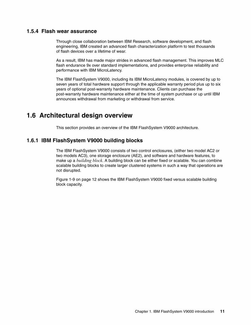
1.5.4 Flash wear assurance
Through close collaboration between IBM Research, software development, and flash engineering, IBM created an advanced flash characterization platform to test thousands of flash devices over a lifetime of wear.
As a result, IBM has made major strides in advanced flash management. This improves MLC flash endurance 9x over standard implementations, and provides enterprise reliability and performance with IBM MicroLatency.
The IBM FlashSystem V9000, including its IBM MicroLatency modules, is covered by up to seven years of total hardware support through the applicable warranty period plus up to six years of optional post-warranty hardware maintenance. Clients can purchase the post-warranty hardware maintenance either at the time of system purchase or up until IBM announces withdrawal from marketing or withdrawal from service.
1.6 Architectural design overview
This section provides an overview of the IBM FlashSystem V9000 architecture.
1.6.1 IBM FlashSystem V9000 building blocks
The IBM FlashSystem V9000 consists of two control enclosures, (either two model AC2 or two models AC3), one storage enclosure (AE2), and software and hardware features, to make up a building block. A building block can be either fixed or scalable. You can combine scalable building blocks to create larger clustered systems in such a way that operations are not disrupted.
Figure 1-9 on page 12 shows the IBM FlashSystem V9000 fixed versus scalable building block capacity.
Chapter 1. IBM FlashSystem V9000 introduction 11

Figure 1-9 IBM FlashSystem V9000 scalability
A scalable building block can be scaled up by adding IBM FlashSystem V9000 AE2 storage enclosures for increased storage capacity. You can add a maximum of four extra storage enclosures.
A scalable building block can be scaled out by combining up to four building blocks to provide higher IOPS and bandwidth needs for increased performance.
Figure 1-9 illustrates the scalable capacity of IBM FlashSystem V9000. It also shows that extra IBM FlashSystem V9000 storage enclosures (SEs) can be added to a single building block, and also to two, three, or four building blocks.
Note: You can mix the AC2 control enclosure-based building blocks with the newer AC3 control enclosure building blocks, but each building block must have either two AC2s or two AC3s. The control enclosure types cannot be inter-mixed within a building block.
12 Introducing and Implementing IBM FlashSystem V9000

1.6.2 IBM FlashSystem V9000 expansion enclosures
With the introduction of IBM FlashSystem V9000 storage expansion enclosures, even greater capacity offerings are now available.
The IBM FlashSystem V9000 large form factor (LFF) expansion enclosure Model 12F offers new tiering options with high capacity nearline SAS hard disk drives (HDDs). Each LFF expansion enclosure supports up to twelve 8 TB or 10 TB drives.
The IBM FlashSystem V9000 small form factor (SFF) expansion enclosure Model 24F offers new tiering options with low-cost SSDs. Each SFF expansion enclosure supports up to 24 2.5-inch low-cost SSD drives.
Up to 20 LFF or SFF expansion enclosures are supported per IBM FlashSystem V9000 controller pair, providing up to 480 drives with expansion enclosure Model 24F (SFF) and up to 240 drives with expansion enclosure Model 12F (LFF).
IBM FlashSystem V9000 HD expansion enclosure Model 92F delivers increased storage density and capacity in a cost-efficient way.
IBM FlashSystem HD expansion enclosure Model 92F offers the following features:
� 5U, 19-inch rack mount enclosure with slide rail and cable management assembly
� Support for up to ninety-two 3.5-inch LFF 12 Gbps SAS top-loading drives
� High-performance disk drives, high-capacity nearline disk drives, and flash drive support:
– High-capacity, archival-class nearline disk drives in 8 TB and 10 TB 7,200 rpm– Flash drives in 1.92 TB, 3.84 TB, 7.68 TB, and 15.36 TB
� Redundant 200 - 240VA power supplies (new PDU power cord required)
Up to eight Model 92F high-density (HD) expansion enclosures are supported per IBM FlashSystem V9000 controller pair, providing up to 736 drives with expansion Model 92F. With four controller pairs, a maximum of 32 HD expansion enclosures with up to 2,944 drives can be attached.
If a mix of SFF, LFF, and HD enclosures is required, see 2.6.1, “SAS expansion enclosures intermix” on page 82.
Figure 1-10 on page 14 shows the maximum possible configuration with a single building block (controller pair) using a combination of native IBM FlashSystem V9000 storage enclosures and LFF or SFF expansion enclosures.
Note: If you require to intermix the storage expansion enclosure types, see the supported configurations in 2.6.1, “SAS expansion enclosures intermix” on page 82.
Note: If you require a mix of storage expansion enclosure types, see the supported configurations in 2.6.1, “SAS expansion enclosures intermix” on page 82.
Chapter 1. IBM FlashSystem V9000 introduction 13

Figure 1-10 Single scalable building block maximum configuration
High-density, low-cost SSDs allow applications to scale and achieve high read performance while maintaining traditional reliability and endurance levels. The 1.92 TB and 3.84 TB SAS 2.5-inch low-cost SSDs options are available for IBM FlashSystem V9000 SFF expansion enclosure.
High-capacity nearline SAS drives enables high value tiered storage with hot data stored in flash and warm data on lower cost nearline SAS HDDs all managed by IBM Easy Tier. The 8 TB and 10 TB SAS 3.5-inch nearline drives are available for IBM FlashSystem V9000 LFF storage expansion enclosure model 12F.
The IBM FlashSystem V9000 Version 7.8 also supports Model 92F 5U-high, 92drive bay, and supports the following drive types:
� High-capacity, nearline HDDs in 8 TB and 10 TB 7,200 rpm� SSD Flash drives in 1.92 TB, 3.84 TB, 7.68 TB, and 15.36 TB
RAID 5 with standby hot spare is the only available RAID option for IBM FlashSystem V9000 native flash storage expansion. However, the SAS attached storage expansion enclosures can be configured with various RAID options. The preference for SAS attached storage is however distributed RAID (DRAID 5 and DRAID 6), which offers improved RAID rebuild times.
Note: To support SAS expansion enclosures, an AH13 - SAS Enclosure Attach adapter card must be installed in slot 3 of each AC2 control enclosure or slot 2 of each AC3 control enclosure in the building block.
14 Introducing and Implementing IBM FlashSystem V9000

1.6.3 IBM FlashSystem V9000 AE2 flash storage array
The IBM FlashSystem V9000 AC2 or AC3 control enclosures combines software and hardware into a comprehensive, modular appliance that uses symmetric virtualization.
Symmetric virtualization is achieved by creating a pool of managed disks (MDisks) from the internal storage and externally attached storage systems. Volumes are created from the MDisk pools and mapped to the attached host systems. System administrators can view and access a common pool of storage on the storage area network (SAN). With this functionality, administrators can use storage resources more efficiently and it provides a common base for advanced functions.
Also with IBM FlashSystem V9000, you can migrate data across MDisks without interfering with any host applications that are simultaneously accessing or writing data.
The IBM FlashSystem V9000 includes a single easy-to-use management graphical user interface (GUI) to help you monitor, manage, and configure your system.
The AE2 flash storage enclosure components include flash modules, battery modules, and canisters. The AE2 storage enclosure, with an all-hardware data path using FPGA modules, is engineered to deliver the lowest possible latency. The modules incorporate proprietary flash controllers and use numerous patented technologies. The flash controllers have a proprietary logic design, firmware, and system software.
No commodity 2.5-inch SSDs, PCIe cards, or any other significant non IBM assemblies are within the AE2 flash storage enclosure. The flash chips, Field Programmable Gate Array (FPGA) chips, processors, and other semiconductors in the system are carefully selected to be consistent with the purpose-built design, which is designed from the “ground up” for high performance, reliability, and efficiency.
The AE2 storage enclosures offer the following notable architectural concepts:
� Hardware-only data path.� Use of FPGAs extensively.� Field-upgradable hardware logic.� Less expensive design cycle.� Extremely high degree of parallelism.� Intelligent flash modules.� Distributed computing model.� Low-power IBM PowerPC® processors.� Interface and flash processors run thin real-time operating systems.� With minimal management communication, the management processor communicates
with the interface and flash processors through an internal network.
Hardware-only data pathThe hardware-only data path design of the AE2 storage enclosures eliminates software-layer latency. To achieve extremely low latencies, the IBM FlashSystem advanced software functions are carefully assessed and implemented.
In the AE2 storage enclosures, data traverses the array controllers through FPGAs and dedicated, low-power processors (CPUs). No cycles are wasted on interface translation, protocol control, or tiering.
The AE2 storage enclosures, with an all-hardware data path design, have an internal architecture that differs from other hybrid (SSD and HDD) or SSD-only based disk systems.
Chapter 1. IBM FlashSystem V9000 introduction 15

The 20 nm flash card memory chipsThe flash chip is the basic storage component of the IBM MicroLatency module. A maximum of 64 multi-level cell (MLC) flash chips can exist on each flash module. To maintain consistent wearing and reliability, combining flash chips of different flash technologies is not supported in the same flash module or storage system.
The IBM FlashSystem V9000 employs the new 20 nm MLC chips, which are of a higher density than the 24 nm enterprise MLC (eMLC) chips used in the IBM FlashSystem V840. This new design of chips enables the IBM FlashSystem V9000 to package greater densities of flash memory per card while retaining the same if not better performance and wear.
IBM patented ECC correction and checking algorithms ensure the same or greater performance from the MCL-based chips, with a greater capacity for the same footprint and at a lower cost per terabyte.
Flash module capacitiesThe IBM FlashSystem V9000 uses either 1.2 TB, 2.9 TB, or 5.7 TB IBM MicroLatency modules. This is a 40% increase in capacity per module over the IBM FlashSystem V840. They must be of the same capacity throughout the AE2 storage enclosure and cannot be intermixed with the older 24 nm flash modules.
Only RAID 5 is supported on the IBM FlashSystem V9000 with configurations of 4, 6, 8, 10, and 12 modules when using the 1.2 TB IBM MicroLatency modules. RAID 5 is supported with configurations of 6, 8, 10, and 12 modules when using the 2.9 TB or 5.7 TB IBM MicroLatency modules.
If fewer than 12 modules are installed, flash module fillers must be installed in the empty bays to maintain cooling airflow in the system enclosure.
Gateway interface FPGAThe gateway interface FPGA is responsible for providing I/O to the flash module and direct memory access (DMA) path. It is on the flash module and has two connections to the backplane.
Flash controller FPGAThe flash controller FPGA of the flash module provides access to the flash chips and is responsible for the following functions:
� Provides data path and hardware I/O logic � Uses lookup tables and a write buffer� Controls 13 or 16 chips (module-size-dependent) � Operates independently of other controllers� Maintains write ordering and layout� Provides write setup� Maintains garbage collection� Provides error handling
16 Introducing and Implementing IBM FlashSystem V9000

Figure 1-11 shows the flash controller design details.
Figure 1-11 Flash controller design
The concurrent operations performed on the flash chips include moving data in and out of the chip through DMA, and by internally moving data and performing erasures. While actively transferring user data in the service of host-initiated I/O, the system can simultaneously run garbage collection activities without affecting the I/O. The ratio of transparent background commands running concurrent to active data transfer commands is 7:1.
A maximum of four flash controllers per IBM MicroLatency module exist: two for each primary board and two for each expansion board.
1.6.4 IBM Variable Stripe RAID and two-dimensional flash RAID overview
Storage systems of any kind are typically designed to perform two main functions: storing and protecting data. IBM FlashSystem V9000 includes the following options for data protection:
� RAID data protection:
– IBM Variable Stripe RAID– Two-dimensional (2D) Flash RAID
� Flash memory protection methods
� Optimized RAID rebuild times
Table 1-1 lists the various methods of protection.
Table 1-1 Various types of IBM FlashSystem protection
Layer Managed by Protection
System-level RAID 5 Centralized RAID controllers Module failure
Module-level RAID 5 Each module across the chips Chip failure and page failure
Module-level Variable Stripe RAID
Each module across the chips Sub-chip, chip, or multi-chip failure
Chip-level error correction code (ECC)
Each module using the chips Bit and block error
Chapter 1. IBM FlashSystem V9000 introduction 17

1.6.5 Fixed and scalable configurations
IBM FlashSystem V9000 can be configured as a fixed building block or a scalable building block.
A fixed building block contains one IBM FlashSystem V9000. The AE2 storage enclosure is cabled directly to each model AC2 control enclosure using 8Gb or 16Gb links or model AC3 control enclosure using 16Gb links. Each control enclosure is connected to switches or directly attached to a host. The control enclosures are directly connected, without the use of switches or a SAN fabric, to form the cluster links. A fixed building block can be upgraded to a scalable building block, but the upgrade process is disruptive to operations.
Scalable building blocks can contain multiple control enclosure pairs and multiple AE2 storage enclosures. In a scalable building block, the control enclosures are not cabled to each other. This infrastructure means that you can add building blocks or storage enclosures non disruptively. Fibre Channel switches are used to create a private storage fabric.
The Fibre Channel switch fabric does not have to be dedicated, and can be shared with hosts or server-side storage area networks (SANs). After connecting the components in a scalable building block, no physical cable connects any host to any switch in the internal Fibre Channel switch fabric. Care must be taken to ensure correct zoning of the back-end storage fabric to prevent interaction with any hosts or server-side storage area network traffic.
For more guidelines of port utilization techniques in a scalable environment, see Appendix A, “Guidelines: Port utilization in an IBM FlashSystem V9000 scalable environment” on page 657.
The back-end storage switch fabric is isolated, through the zoning, from the host or server-side SAN for these reasons:
� So that any host or server does not have access to the AE2 storage enclosures directly
� So that the I/O from the controller to the storage does not interfere with the I/O from the host to the controllers
1.6.6 Scale-up and scale-out solutions
IBM FlashSystem V9000 offers the flexibility of the purchase of an all flash solution and hybrid enclosures that can be upgraded in the future, by the ability to scale-up for increased capacity, scale-out for increased performance, or both.
Clients can start with a fixed building block, or opt for a scale-up scale-out (SUSO) solution, that includes two 16 Gb FC switches, which enables you to add extra storage enclosures and building blocks with minimal effect to the existing systems.
Note: The proprietary 2D Flash RAID data protection scheme of the IBM FlashSystem V9000 storage system combines system-level RAID 5 and module-level Variable Stripe RAID (not only module-level RAID).
18 Introducing and Implementing IBM FlashSystem V9000

Figure 1-12 shows the IBM FlashSystem V9000 scale-up and scale-out capabilities.
Figure 1-12 IBM FlashSystem V9000 scale-up and scale-out capabilities
Figure 1-13 shows a scale-out solution with four IBM FlashSystem V9000 building blocks, using the 16 Gb FC switches for interconnections.
Figure 1-13 Scale out IBM FlashSystem V9000 solution
Fibre Channel Switches
FlashSystem V9000
FlashSystem V9000
FlashSystem V9000
FlashSystem V9000
Chapter 1. IBM FlashSystem V9000 introduction 19

Figure 1-14 shows a scale-up solution with one IBM FlashSystem V9000 scalable building block and four IBM FlashSystem V9000 AE2 storage systems.
Figure 1-14 Scale up IBM FlashSystem V9000 solution
Figure 1-15 shows a scale-up and scale-out solution with four IBM FlashSystem V9000 building blocks and four IBM FlashSystem V9000 AE2 storage systems, indicating a maximum supported configuration.
Figure 1-15 Scale-up and scale-out IBM FlashSystem V9000 solution
Note: The FC internal connection switches are ordered together with the first IBM FlashSystem V9000 scalable building block. IBM also supports the use of customer-supplied FC switches and cables, if they are supported by IBM. See the latest information about supported FC switches at the IBM System Storage® Interoperation Center (SSIC):
http://www.ibm.com/systems/support/storage/ssic/interoperability.wss
FlashSystem AE2 V9000FlashSystem AE2 V9000FlashSystem AE2 V9000
FlashSystem AE2 V9000
Fibre Channel Switches
FlashSystem V9000
FlashSystem AE2 V9000
FlashSystem AE2 V9000
FlashSystem AE2 V9000
FlashSystem AE2 V9000
Fibre Channel Switches
FlashSystem V9000
FlashSystem V9000
FlashSystem V9000
FlashSystem V9000
20 Introducing and Implementing IBM FlashSystem V9000

The IBM FlashSystem V9000 capacity can be expanded further by the inclusion of additional SAS attached expansion enclosures. See more details in 1.6.2, “IBM FlashSystem V9000 expansion enclosures” on page 13.
For more details about IBM FlashSystem V9000 scale-up or scale-out solutions, see Chapter 5, “Scalability” on page 179.
1.7 Advanced software features
The IBM FlashSystem V9000 can function as a feature-rich, software-defined storage layer that virtualizes and extends the functionality of all managed storage. These include Real-time Compression, dynamic tiering, thin provisioning, snapshots, cloning, replication, data copy services and high-availability configurations. In this capacity, it acts as the virtualization layer between the host and other external storage systems, providing flexibility and extending functionality to the virtualized external storage capacity.
Up to 32 PB of storage can be managed by a single IBM FlashSystem V9000 array, and because the storage is virtualized, volumes can be nondisruptively moved between external and internal storage capacity. This functionality enables agile integration into existing storage environments with seamless data migration between IBM FlashSystem V9000 and existing storage systems. When using Real-time Compression for active data sets, IBM FlashSystem V9000 can increase the effective capacity of your flash memory up to five times.
1.7.1 Advanced functions for data reduction
The IBM FlashSystem V9000 employs several features to assist with the reduction of data and the ability to increase its effective capacity.
IBM Real-time CompressionThe IBM Real-time Compression within the IBM FlashSystem V9000 addresses the requirements of primary storage data reduction, without sacrificing performance by the use of dedicated compression acceleration hardware. It does so by implementing a purpose-built technology called Real-time Compression using the Random Access Compression Engine (RACE).
Customers can expect data reduction and effective capacity increases of up to 5x for relevant data sets. When the initial virtual disk (VDisk) volume, also known as the logical unit number (LUN), is created and a thin provisioned volume is allocated, then as data is stored into the VDisk it is compressed in real time.
Thin provisioningIn a shared storage environment, thin provisioning is a method for optimizing the use of available storage. It relies on allocation of blocks of data on demand versus the traditional method of allocating all of the blocks up front. This methodology eliminates almost all white space, which helps avoid the poor usage rates (often as low as 10%) that occur in the traditional storage allocation method where large pools of storage capacity are allocated to individual servers but remain unused (not written to).
Thin-provisioned flash copiesThin-provisioned IBM FlashCopy® (or snapshot function in the GUI) uses disk space only when updates are made to the source or target data and not for the entire capacity of a volume copy.
Chapter 1. IBM FlashSystem V9000 introduction 21

1.7.2 Data migration
The IBM FlashSystem V9000 provides online volume migration while applications are running, which is possibly the greatest single benefit for storage virtualization. This capability enables data to be migrated on and between the underlying storage subsystems without any effect on the servers and applications. In fact, this migration is performed without the knowledge of the servers and applications that it even occurred. The IBM FlashSystem V9000 delivers these functions in a homogeneous way on a scalable and highly available platform over any attached storage and to any attached server.
1.7.3 Advanced copy services
Advanced copy services are a class of functionality within storage arrays and storage devices that enable various forms of block-level data duplication locally or remotely. By using advanced copy services, you can make mirror images of part or all of your data eventually between distant sites. Copy services functions are implemented within an IBM FlashSystem V9000 (FlashCopy and Image Mode Migration), or between one IBM FlashSystem V9000 and another IBM FlashSystem V9000 in three different modes:
� Metro Mirror� Global Mirror� Global Mirror with Change Volumes
Remote replication can be implemented using both Fibre Channel and Internet Protocol (IP) network methodologies.
FlashCopyFlashCopy is the IBM branded name for point-in-time copy, which is sometimes called time-zero (T0) copy. This function makes a copy of the blocks on a source volume and can duplicate them on 1 - 256 target volumes.
Remote mirroringThe three remote mirroring modes are implemented at the volume layer within the IBM FlashSystem V9000. They are collectively referred to as remote copy capabilities. In general, the purpose of these functions is to maintain two copies of data. Often, but not necessarily, the two copies are separated by distance. The remote copy can be maintained in one of two modes: synchronous or asynchronous, with a third asynchronous variant:
� Metro Mirror is the IBM branded term for synchronous remote copy function.� Global Mirror is the IBM branded term for the asynchronous remote copy function.� Global Mirror with Change Volumes is the IBM branded term for the asynchronous
remote copy of a locally and remotely created FlashCopy.
1.7.4 External virtualization
The IBM FlashSystem V9000 includes data virtualization technology to help insulate hosts, hypervisors, and applications from physical storage. This enables them to run without disruption, even when changes are made to the underlying storage infrastructure. The IBM FlashSystem V9000 functions benefit all virtualized storage. For example, Easy Tier and Real-time Compression help improve performance and increase effective capacity, where high-performance thin provisioning helps automate provisioning.
22 Introducing and Implementing IBM FlashSystem V9000

These benefits can help extend the useful life of existing storage assets, reducing costs. And because these functions are integrated into the IBM FlashSystem V9000, they can operate smoothly together, reducing management effort.
1.7.5 Easy Tier
Easy Tier is a performance function that automatically migrates or moves extents of a volume to or from one storage tier to another storage tier. Starting with IBM FlashSystem V9000 Version 7.8, Easy Tier supports four kinds of storage tiers.
Consider the following information about Easy Tier:
� Easy Tier monitors the host volume I/O activity as extents are read and migrates the most active extents to higher performing tiers.
� The monitoring function of Easy Tier is continual but, in general, extents are migrated over a 24-hour period. As extent activity cools, Easy Tier moves extents to slower performing tiers.
� Easy Tier creates a migration plan that organizes its activity to decide how to move extents. This plan can also be used to predict how extents will be migrated.
For more information about Easy Tier see 3.2.1, “IBM Easy Tier” on page 99.
1.8 IBM HyperSwap
IBM HyperSwap is new as of IBM FlashSystem V9000 firmware 7.5. HyperSwap capability enables each volume to be presented by two IBM FlashSystem V9000 I/O groups. The configuration tolerates combinations of node and site failures, using host multipathing driver based on the one that is available for the IBM FlashSystem V9000.
IBM FlashSystem V9000 V7.7.1 and later provides GUI management of the HyperSwap function.
For details about implementation and HyperSwap capability, see Chapter 11, “IBM HyperSwap” on page 485.
1.9 Transparent cloud tiering (V7.8)
IBM FlashSystem V9000 V7.8 includes transparent cloud tiering technology. This capability provides increased flexibility to protect data by leveraging the cloud as snapshot targets and restore snapshots from the cloud. Snapshots are encrypted and compressed before being uploaded to the cloud for more security, lower telecommunication costs, and lower cloud storage costs.
Transparent cloud tiering allows you to configure a cloud account on the system to create and restore cloud snapshots of system volumes.
Configuring transparent cloud tiering on the system, requires you to enable a cloud connection to a supported cloud service provider. The system supports IBM SoftLayer®, OpenStack Swift, and Amazon S3 cloud service providers.
Chapter 1. IBM FlashSystem V9000 introduction 23

1.10 Licensing
The base license that is provided with your system includes the use of its basic functions. However, extra licenses can be purchased to expand the capabilities of your system. Administrators are responsible for purchasing extra licenses and configuring the systems within the license agreement, which includes configuring the settings of each licensed function on the system.
The base 5639-RB7 license entitles IBM FlashSystem V9000 (machine type 9846/9848) to all of the licensed functions, such as Virtualization, FlashCopy, Global Mirror, and Metro Mirror, and Real-time Compression. Any connected storage that is not an IBM FlashSystem V9000 requires the External Virtualization license that is a per-terabyte (TB) capacity unit of metric. You use the Licensed Functions window in the System Setup wizard to enter External Virtualization licenses purchased for your system.
For more details about licensing, see 2.7.2, “Software and licensing” on page 92.
24 Introducing and Implementing IBM FlashSystem V9000

Chapter 2. FlashSystem V9000 architecture
This chapter describes the IBM FlashSystem V9000 architecture, detailing the components, capabilities, and features that make up this product. An introduction to the IBM FlashSystem V9000, product features, a comparison to the IBM FlashSystem V840, and an overview of the architecture and hardware are included.
This chapter includes the following topics:
� Introduction to IBM FlashSystem V9000� Architecture of IBM FlashSystem V9000� Control enclosure (AC2)� Control enclosure (AC3)� Storage enclosure (AE2)� Expansion enclosures (12F, 24F, 92F) � Administration and maintenance� Support matrix for IBM FlashSystem V9000
IBM Knowledge Center has more details about IBM FlashSystem V9000 architecture:
https://ibm.biz/fs_V9000_kc
2
Note: This chapter refers to both AC2 and AC3 control enclosure models. Where fundamental differences exist between the two models, images of both control enclosures are provided. Where no significant differences exist, only the AC2 model is shown, but the action and resulting display are the same on an AC3 control enclosure of an IBM FlashSystemV9000.
© Copyright IBM Corp. 2015, 2016. All rights reserved. 25

2.1 Introduction to IBM FlashSystem V9000
IBM FlashSystem V9000 is an all-flash storage array that provides extreme performance and large capacity while also delivering enterprise-class reliability and “green” data center power and cooling requirements. The IBM FlashSystem V9000 building block holds up to twelve 5.7 terabytes (TB) IBM MicroLatency modules in only 6U of rack space, making it an extremely dense all-flash storage array solution.
IBM FlashSystem V9000 uses a fully featured and scalable all-flash architecture that performs at up to 3 million input/output operations per second (IOPS) with IBM MicroLatency modules, is scalable up to 68 gigabytes per second (GBps), and delivers up to 2.28 petabytes (PB) of internal flash effective capacity. With its flash-optimized design, IBM FlashSystem V9000 can provide response times of 180 microseconds. This high capacity, extreme performance, and enterprise reliability are powered by the patented IBM FlashCore Technology.
IBM FlashSystem V9000 offers the advantages of software-defined storage at the speed of flash. This all-flash storage platform combines the high performance, ultra-low latency, superior efficiency and extreme reliability of IBM FlashCore technology with a rich set of virtualization and storage features such as dynamic tiering, thin provisioning, data copy services and high-availability configurations.
Advanced data services that are provided include copy services, mirroring, replication, external virtualization, IBM HyperSwap, Microsoft Offloaded Data Transfer (ODX) and VMware vSphere Storage APIs - Array Integration (VAAI) support. Host interface support includes 8 gigabit (Gb) and 16 Gb FC, and 10 Gb Fibre Channel over Ethernet (FCoE) and Internet Small Computer System Interface (iSCSI). Advanced Encryption Standard (AES) 256 hardware-based encryption adds to the rich feature set.
The IBM FlashSystem V9000 building block is made up of the two control enclosures, referred to as AC2s or AC3s, and one storage enclosure, referred to as AE2. The IBM FlashSystem V9000 core attributes are described next. Figure 2-1 shows the front view of the IBM FlashSystem V9000.
Figure 2-1 IBM FlashSystem V9000
26 Introducing and Implementing IBM FlashSystem V9000

2.1.1 Capacity
IBM FlashSystem V9000 supports a maximum of four building blocks and four additional storage enclosures. Each building block or storage enclosure can accommodate up to twelve 5.7 TB IBM MicroLatency modules, which provide a capacity of 57 TB (RAID 5). IBM FlashSystem V9000, with 8 storage enclosures, therefore supports a maximum physical capacity of 456 TB of internal MicroLatency flash storage.
By using the optional IBM Real-time Compression and other design elements, the FlashSystem V9000 provides up to 285 TB effective capacity in only 6U. With 8 storage enclosures, the effective capacity goes up to 2.28 PB in only 36U of rack space.
IBM FlashSystem V9000 also supports up to 32 PB of external storage virtualization and also standard and high density expansion enclosures scaling up to 29.4 PB raw capacity by using nearline SAS (NL-SAS) HDDs or 32 PB raw capacity by using SSDs.
Each IBM FlashSystem V9000 building block can be ordered with 4, 6, 8, 10, or 12 MicroLatency modules. The MicroLatency modules available are either 1.2 TB, 2.9 TB, or 5.7 TB storage capacity.
IBM FlashSystem V9000 supports RAID 5 configurations.
IBM FlashSystem V9000 supports the creation of up to 2,048 logical unit numbers (LUNs) per building block. The size of the LUNs can be 1 MiB - 51.8 TiB in size (not to exceed the total system capacity). The IBM FlashSystem V9000 supports up to 2,048 host connections and up to 256 host connections for each interface port. The IBM FlashSystem V9000 supports the mapping of multiple LUNs to each host for Fibre Channel, Fibre Channel over Ethernet (FCoE), and iSCSI protocols.
IBM FlashSystem V9000 supports up to 256 host connections for the iSCSI protocol.
Table 2-1 lists all the combinations of storage capacities for various configurations of the IBM FlashSystem V9000 building block.
Table 2-1 IBM FlashSystem V9000 capacity in TB and TiB for RAID 5
Note: For detailed capacity information about IBM FlashSystem V9000 and expansion enclosures see Table 2-7 on page 58.
Important: 1.2 TB, 2.9 TB, and 5.7 TB IBM MicroLatency modules cannot be intermixed in the same IBM FlashSystem V9000 storage enclosure.
Note: The maximum usable capacity of IBM FlashSystem V9000 in RAID 5 mode is 51.8 tebibytes (TiB) per building block.
IBM FlashSystem 900 AE2 configuration RAID 5 TB RAID 5 TiB
Four 1.2 TB flash modules 2.2 2.0
Six 1.2 TB flash modules 4.5 4.1
Eight 1.2 TB flash modules 6.8 6.2
Ten 1.2 TB flash modules 9.1 8.3
Twelve 1.2 TB flash modules 11.4 10.4
Chapter 2. FlashSystem V9000 architecture 27

2.1.2 Performance and latency
IBM FlashSystem V9000 uses all hardware field-programmable gateway array (FPGA) components in the AE2 storage enclosure data path, which enables fast I/O rates and low latency. IBM FlashSystem V9000 provides extreme performance of up to 3 million IOPS and up to 68 GBps in bandwidth. The IBM FlashSystem V9000 provides response times as low as 180 microseconds (μs).
2.1.3 IBM FlashCore technology
IBM FlashSystem V9000 provides enterprise class reliability and serviceability that are unique for all-flash storage arrays. IBM FlashSystem V9000 uses the patented IBM FlashCore Technology to provide data protection and maximum system uptime:
� IBM Advanced Flash Management improves flash endurance 9x over standard implementations:
– Proprietary garbage collection, relocation, and block-picking algorithms that were invented by IBM.
– Flash wear leveling includes the following functions:
• ECC algorithms that correct very high bit error rates.
• Variable voltage and read-level shifting to maximize flash endurance.
• Health binning and heat segregation continually monitor the health of flash blocks and perform asymmetrical wear leveling and sub-chip tiering.
• Hot-data placement provides up to 57% improvement in endurance. Heat-level grouping provides up to 45% reduction in write amplification.
� IBM Variable Stripe RAID is a patented IBM technology that provides an intra-module RAID stripe on each flash module.
� With two-dimensional (2D) Flash RAID, system-wide RAID 5 along with Variable Stripe RAID helps reduce downtime and maintain performance, and enables the provisioning of an entire flash module as a spare to be used in another flash module failure.
Six 2.9 TB flash modules 11.4 10.3
Eight 2.9 TB flash modules 17.1 15.5
Ten 2.9 TB flash modules 22.8 20.7
Twelve 2.9 TB flash modules 28.5 28.9
Six 5.7 TB flash modules 22.8 20.7
Eight 5.7 TB flash modules 34.2 31.0
Ten 5.7 TB flash modules 45.6 41.4
Twelve 5.7 TB flash modules 57.0 51.8
IBM FlashSystem 900 AE2 configuration RAID 5 TB RAID 5 TiB
28 Introducing and Implementing IBM FlashSystem V9000

TerminologyThe following terms are mentioned in this book:
Wear leveling An algorithm that assures even usage of all blocks.
Garbage collection Erasing blocks, which are not used anymore, so that they can be rewritten.
Relocation Moving a block to another location.
Block picking The first step of the garbage collection process. Using proprietary algorithms, the best block is picked for garbage collection.
More reliability and serviceability features of IBM FlashSystem V9000In addition to the standard features, IBM FlashSystem V9000 includes the following reliability and serviceability features:
� Hot-swappable IBM MicroLatency modules with tool-less front panel access
If a MicroLatency module failure occurs, critical client applications can remain online while the defective module is replaced.
Because client application downtime does not need to be scheduled, you can typically perform this service immediately versus waiting for days for a service window. The Directed Maintenance Procedure (DMP), accessible from the GUI, can be used to prepare the IBM FlashSystem V9000 for a MicroLatency module replacement. You can easily remove the MicroLatency modules from the front of the IBM FlashSystem V9000 unit without needing to remove the top access panels or extend cabling.
� Concurrent code loads
IBM FlashSystem V9000 supports concurrent code load, enabling client applications to remain online during firmware upgrades to all components, including the flash modules.
� Redundant hot-swappable components
RAID controllers (called canisters), management modules, and interface cards (all contained in the canister), and batteries, fans, and power supplies are all redundant and hot-swappable. All components are easily accessible through the front or rear of the unit so the IBM FlashSystem V9000 does not need to be moved in the rack, and top access panels or cables do not need to be extended. This makes servicing the unit easy.
2.1.4 Overview of IBM Variable Stripe RAID and 2D Flash RAID
Storage systems of any kind are typically designed to perform two main functions: to store and protect data. The IBM FlashSystem V9000 includes the following features for data protection:
� RAID data protection:
– IBM Variable Stripe RAID– Two-dimensional (2D) Flash RAID
� Flash memory protection methods
� Optimized RAID rebuild times
Tip: Concurrent code loads require that all connected hosts have at least two connections, at least one to each control enclosure, to the IBM FlashSystem V9000.
Chapter 2. FlashSystem V9000 architecture 29

Variable Stripe RAIDVariable Stripe RAID is a unique IBM technology that provides data protection on the page, block, or chip level. It eliminates the necessity to replace a whole flash module when a single chip or plane fails. This, in turn, expands the life and endurance of flash modules and reduces considerably maintenance events throughout the life of the system.
Variable Stripe RAID provides high redundancy across chips within a flash module. RAID is implemented at multiple addressable segments within chips, in a 15+1 or 12+1 RAID 5 fashion, and it is controlled at the flash controller level (up to four in each flash module). Due to the massive parallelism of direct memory access (DMA) operations controlled by each FPGA and parallel access to chip sets, dies, planes, blocks, and pages, the implementation of Variable Stripe RAID has minimal effect on performance.
The following information describes some of the most important aspects of Variable Stripe RAID implementation:
� Variable Stripe RAID is managed and controlled by each of the up to four flash controllers within a single module.
� A flash controller is in charge of only 13 or 16 flash chips (IBM MicroLatency module capacity size-dependent).
� Data is written on flash pages of 8 kilobytes (KB) and erased in 1 megabyte (MB) flash blocks.
� Variable Stripe RAID is implemented and managed at flash chip plane levels.
� There are 16 planes per chip.
� Before a plane fails, at least 256 flash blocks within a plane must be deemed failed.
� A plane can also fail in its entirety.
� Up to 64 planes can fail before a whole module is considered failed.
� Up to four chips can fail before a whole module is considered failed.
� When a flash module is considered failed, 2D Flash RAID takes control of data protection and recovery.
� When a plane or a chip fails, Variable Stripe RAID activates to protect data while maintaining system-level performance and capacity.
How Variable Stripe RAID worksVariable Stripe RAID is an IBM patented technology. It includes but is more advanced than a simple RAID of flash chips. Variable Stripe RAID introduces two key concepts:
� The RAID stripe is not solely across chips; it actually spans across flash layers.
� The RAID stripe can automatically vary based on observed flash plane failures within a flash module. For example, stripes are not fixed at n+1 RAID 5 stripe members, but they can go down to 15+1, 14+1, or even 13+1 based on plane failures.
This ability to protect the data at variable stripes effectively maximizes flash capacity even after flash component failures. Figure 2-2 on page 31 shows an overview of the IBM FlashSystem Variable Stripe RAID.
30 Introducing and Implementing IBM FlashSystem V9000

Figure 2-2 IBM FlashSystem Variable Stripe RAID (VSR)
Figure 2-3 shows the benefits of IBM Variable Stripe RAID.
Figure 2-3 The value of the IBM FlashSystem Variable Stripe RAID
An important aspect to emphasize is that Variable Stripe RAID has an effect at only the plane level. Therefore, only the affected planes within a plane failure are converted to N-1. Variable Stripe RAID maintains the current stripe member count (N+1) layout through the remainder of the areas of all other planes and chips that are not involved in the plane failure.
To illustrate how Variable Stripe RAID functions, assume that a plane fails within a flash chip and is no longer available to store data. This might occur as a result of a physical failure within the chip, or some damage is inflicted on the address or power lines to the chip. The plane failure is detected and the system changes the format of the page stripes that are used.
The data that was previously stored in physical locations across chips in all 16 or 13 lanes using a page stripe format with 10 pages is now stored across chips in only nine lanes using a page stripe format with nine pages. Therefore, no data stored in the memory system was lost, and the memory system can self-adapt to the failure and continue to perform and operate by processing read and write requests from host devices.
Form Factor SSD� Flash failure = Disk failure� Requires top-level RAID� Relatively frequent hot-swaps
Enterprise Flash Drive or Memory Module� Flash failure = Degraded state
within module� Performance impact on RAID set� Hot-swap to resolve
FlashSystem with Variable Stripe RAID� Preserves flash life� Preserves performance� Re-parity data in microseconds
No Parity
Value of Variable Stripe RAID
Less maintenance touches while still preserving the life, protection, and performance of the Day-1 experience
Parity
Parity
Form Factor SSD• Flash failure = Disk failure• Requires top-level RAID• Relatively frequent hot-swaps
Enterprise Flash Drive or Memory Module• Flash failure = Degraded state
within module• Performance impact on RAID set• Hot-swap to resolve
FlashSystem with Variable Stripe RAID• Preserves flash life• Preserves performance• Re-parity data in microseconds
No Parity
Value of Variable Stripe RAID
Less maintenance touches while still preserving the life,protection, and performance of the Day-1experience
Parity
Parity
Chapter 2. FlashSystem V9000 architecture 31

This ability of the system to automatically self-adapt, when needed, to chip and intra-chip failures makes the FlashSystem flash module extremely rugged and robust, and capable of operating despite the failure of one or more chips or intra-chip regions. It also makes the system easier to use because the failure of one, two, or even more individual memory chips or devices does not require the removal and potential disposal of previously used memory storage components.
The reconfiguration or reformatting of the data to change the page stripe formatting to account for chip or intra-chip failures might reduce the amount of physical memory space that is held in reserve by the system and available for the system for background operation. Note that in all but the most extreme circumstances (in which case the system creates alerts), it does not affect performance. Even in the case of extreme circumstances, the usable capacity is not affected and the system fails the module first.
Reliability, availability, and serviceabilityThe previous explanation points out an increase in reliability, availability, and serviceability (RAS) levels and the IBM FlashSystem RAS levels over other technologies.
In summary, Variable Stripe RAID has these capabilities:
� Patented Variable Stripe RAID allows RAID stripe sizes to vary.
� If one plane fails in a chip stripe, only the failed plane is bypassed, and then data is restriped across the remaining chips. No system rebuild is needed.
� Variable Stripe RAID reduces maintenance intervals caused by flash failures.
Two-dimensional (2D) Flash RAIDTwo-dimensional (2D) Flash RAID refers to the combination of Variable Stripe RAID (at the flash module level) and system-level RAID 5.
The second dimension of data protection is implemented across flash modules of RAID 5 protection. This system-level RAID 5 is striped across the appropriate number of flash modules in the system based on the selected configuration. System-level RAID-5 can stripe across four (2D+1P+1S - IBM MicroLatency 1.2 TB module only), six (4D+1P+1S), eight (6D+1P+1S), ten (8D+1P+1S), or twelve flash modules (10D+1P+1S).
The architecture enables you to designate a dynamic flash module hot spare.
Figure 2-4 on page 33 shows the IBM FlashSystem V9000 2D RAID.
32 Introducing and Implementing IBM FlashSystem V9000

Figure 2-4 IBM FlashSystem 2D RAID
The 2D Flash RAID technology within the IBM FlashSystem V9000 provides two independent layers of RAID 5 data protection within each system:
� The module-level Variable Stripe RAID technology � An additional system-level RAID 5 across flash modules
The system-level RAID 5 complements the Variable Stripe RAID technology implemented within each flash module, and it provides protection against data loss and data unavailability resulting from flash module failures. It also enables data to be rebuilt onto a hot-spare flash module, so that flash modules can be replaced without data disruption.
Other reliability featuresIn addition to 2D Flash RAID and Variable Stripe RAID data protection, the IBM FlashSystem family storage systems incorporate other reliability features:
� Error-correcting codes to provide bit-level reconstruction of data from flash chips.
� Checksums and data integrity fields designed to protect all internal data transfers within the system.
� Overprovisioning to enhance write endurance and decrease write amplification.
� Wear-leveling algorithms balance the number of writes among flash chips throughout the system.
� Sweeper algorithms help ensure that all data within the system is read periodically to avoid data fade issues.
Understanding 2D Flash RAID enables you to visualize the advantage over other flash memory solutions. Both Variable Stripe RAID and 2D Flash RAID are implemented and controlled at FPGA hardware-based levels. Two-dimensional flash RAID eliminates single points of failure and provides enhanced system-level reliability.
Chapter 2. FlashSystem V9000 architecture 33

2.1.5 Scalability
IBM FlashSystem V9000 supports the ability to grow both the storage capacity and performance after deployment, which is referred to as scale up and scale out. IBM FlashSystem V9000 scale up or scale out is achieved by using scalable building blocks and additional storage enclosures. IBM FlashSystem V9000 supports a maximum configuration of twelve 1.2 TB, 2.9 TB, or 5.7 TB IBM MicroLatency modules per AE2 storage enclosure. The IBM FlashSystem V9000 can be purchased with 4, 6, 8, 10, or 12 modules of 1.2 TB, 2.9 TB, or 5.7 TB sizes.
Capacity can be scaled up with external storage virtualization or with standard or high density (HD) expansion enclosures that support NL-SAS HDDs or SDDs. You can attach up to 20 standard expansion enclosures per controller pair (up to 80 total) scaling up to 9.6 PB raw capacity using NL-SAS HDDs or 29.4 PB raw capacity using SSDs. You can attach up to 8 HD expansion enclosures per controller pair (up to 32 total) scaling up to 29.4 PB raw capacity using NL-SAS HDDs or 32PB raw capacity using SSDs. Up to 32PB of external storage can be virtualized.
IBM FlashSystem V9000 offers these upgrade options:
� Systems that are purchased with 4 MicroLatency modules can be expanded to 6, 8, 10, or 12 of the same capacity MicroLatency modules.
� Systems that are purchased with 6 MicroLatency modules can be expanded to 8, 10, or 12 of the same capacity MicroLatency modules.
� Systems that are purchased with 8 MicroLatency modules can be expanded to 10 or 12 of the same capacity MicroLatency modules.
� Systems that are purchased with 10 MicroLatency modules can be expanded to 12 of the same capacity MicroLatency modules.
IBM FlashSystem V9000 delivers up to 57 TB per building block, scales to four building blocks, and offers up to four more 57 TB V9000 storage enclosure expansion units for large-scale enterprise storage system capability. Building blocks can be either fixed or scalable. You can combine scalable building blocks to create larger clustered systems in such a way that operations are not disrupted.
Note: Adding MicroLatency modules to an existing AE2 storage enclosure is a disruptive activity for the IBM FlashSystem V9000 building block. Storage expansions without solution outage are possible with careful planning.
34 Introducing and Implementing IBM FlashSystem V9000

A scalable building block can be scaled up by adding IBM FlashSystem V9000 AE2 storage enclosures for increased storage capacity. You can add a maximum of four extra storage enclosures, one extra storage enclosure per building block, to any scaled solution. A scalable building block can be scaled out by combining up to four building blocks to provide higher IOPS and bandwidth needs for increased performance as shown in Figure 2-5.
Figure 2-5 IBM FlashSystem V9000 scalability options
With IBM Real-time Compression technology, IBM FlashSystem V9000 further extends the economic value of all-flash systems. IBM FlashSystem V9000 provides up to two times the improvement in Real-time Compression over the model it is replacing, by using dedicated Compression Acceleration Cards. Using the optional Real-time Compression and other design elements, IBM FlashSystem V9000 provides up to 57 TB usable capacity and up to 285 TB effective capacity in only 6U. This scales to 456 TB usable capacity and up to 2.28 PB effective capacity in only 36U. These capacity numbers are not considering the use of SAS expansion enclosures.
A fixed building block contains one IBM FlashSystem V9000. The AE2 storage enclosure is cabled directly to each AC2 or AC3 control enclosure using 8 Gb or 16 Gb links, and each AC2 or AC3 control enclosure is connected to switches or to a host. The AC2 or AC3 control enclosures are directly connected without the use of switches or a SAN fabric, to form the cluster links. A fixed building block can be upgraded to a scalable building block, but the upgrade process is disruptive to operations.
Chapter 2. FlashSystem V9000 architecture 35
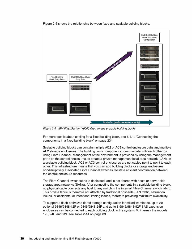
Figure 2-6 shows the relationship between fixed and scalable building blocks.
Figure 2-6 IBM FlashSystem V9000 fixed versus scalable building blocks
For more details about cabling for a fixed building block, see 6.4.1, “Connecting the components in a fixed building block” on page 234.
Scalable building blocks can contain multiple AC2 or AC3 control enclosure pairs and multiple AE2 storage enclosures. The building block components communicate with each other by using Fibre Channel. Management of the environment is provided by using the management ports on the control enclosures, to create a private management local area network (LAN). In a scalable building block, AC2 or AC3 control enclosures are not cabled point to point to each other. This infrastructure means that you can add building blocks or storage enclosures nondisruptively. Dedicated Fibre Channel switches facilitate efficient coordination between the control enclosure resources.
The Fibre Channel switch fabric is dedicated, and is not shared with hosts or server-side storage area networks (SANs). After connecting the components in a scalable building block, no physical cable connects any host to any switch in the internal Fibre Channel switch fabric. This private fabric is therefore not affected by traditional host-side SAN traffic, saturation issues, or accidental or intentional zoning issues, therefore providing maximum availability.
To support a flash-optimized tiered storage configuration for mixed workloads, up to 20 optional 9846/9848-12F or 9846/9848-24F and up to 8 9846/9848-92F SAS expansion enclosures can be connected to each building block in the system. To intermix the models 12F, 24F, and 92F see Table 2-14 on page 83.
36 Introducing and Implementing IBM FlashSystem V9000

Consider the following information:
� A 9846/9848-12F SAS expansion enclosure contains up to 12 3.5-inch nearline SAS drives.
� A 9846/9848-24F SAS expansion enclosure contains up to 24 2.5-inch read-intensive SAS flash drives.
� A 9846-92F or 9848-92F SAS expansion enclosure contains up to 92 3.5-inch SAS drives.
To support SAS expansion enclosures, an AH13 - SAS Enclosure Attach adapter card must be installed in expansion slot 2 of each AC3 control enclosure in the building block.
For more details about cabling for a scalable building block, see 6.4.2, “Connecting the components in a scalable building block” on page 235.
For a comparison and the configuration guidelines of the following two suggested methods for port utilization in an IBM FlashSystem V9000 scalable environment, see Appendix A, “Guidelines: Port utilization in an IBM FlashSystem V9000 scalable environment” on page 657:
� IBM FlashSystem V9000 port utilization for infrastructure savings
This method reduces the number of required customer Fibre Channel ports attached to the customer fabrics. This method provides high performance and low latency but performance might be port-limited for certain configurations. Intra-cluster communication and AE2 storage traffic occur over the internal Fibre Channel switches.
� IBM FlashSystem V9000 port utilization for performance
This method uses more customer switch ports to improve performance for certain configurations. Only ports designated for intra-cluster communication are attached to private internal switches. The private internal switches are optional and all ports can be attached to customer switches.
Remember these important considerations:
� Mixing different capacity MicroLatency modules (1.2 TB, 2.9 TB, or 5.7 TB) in a single AE2 storage enclosure is not supported.
� Expanding an IBM FlashSystem V9000 unit with 2, 4, 6, or 8 extra MicroLatency modules requires that the flash array is deleted and recreated. A backup of the system configuration and data migration, if needed, must be planned before the expansion.
Note: The Fibre Channel internal connection switches are ordered together with the first IBM FlashSystem V9000 scalable building block. IBM also supports the use of customer-supplied Fibre Channel switches and cables, provided it is supported by IBM. See the list of supported Fibre Channel switches:
http://www.ibm.com/systems/support/storage/ssic/interoperability.wss
Chapter 2. FlashSystem V9000 architecture 37

2.1.6 Host adapter protocol support
IBM FlashSystem V9000 supports the following interface protocols:
� 8 Gbps Fibre Channel� 16 Gbps Fibre Channel � 10 Gbps Fibre Channel over Ethernet (FCoE)� 10 Gbps iSCSI
The interface protocols can auto-negotiate down to slower speeds.
AC2 control enclosure interface options For the AC2 control enclosure different interface configuration options are available based on whether the AE2 has 8 Gb or 16 Gb optics and whether the configuration is a fixed or a scalable configuration.
For more details about hardware of the AC2 control enclosure, see 2.3, “Control enclosure (AC2)” on page 59.
Table 2-2 shows the three adapter combinations that are allowed in the AC2 control enclosures when the AE2 storage enclosure is ordered with 8 Gb optics. The adapter combinations are identical for both scalable and fixed building block order types.
Table 2-2 8Gb AE2 fixed or scalable building block allowed AC2 I/O adapter combinations
Table 2-3 shows the four adapter combinations that are allowed in the AC2 control enclosures when the AE2 storage enclosure is ordered with 16 Gb optics and the AC2 control enclosure is ordered as a fixed building block. The AC2 control enclosure has six adapter slots, four of which can be used for interface adapters. The SAS enclosure attach adapter takes up one of these four slots.
Table 2-3 16Gb AE2 fixed building block allowed AC2 I/O adapter combinations
Host connections
16 Gb FC 4-port
8 Gb FC 4-port
16 Gb FC 2-port
10Gb Ethernet 4-port
SAS enclosure attach
8 Gb FC - 3 - - -
16 Gb FC - 2 2 - -
10Gb Ethernet - 2 - 1 -
Host connections
16 Gb FC 4-port
8 Gb FC 4-port
16 Gb FC 2-port
10Gb Ethernet 4-port
SAS enclosure attach
16 Gb FC 4 - - - -
16 Gb FC 3 - - - 0 or 1
16 Gb FC10Gb Ethernet
3 - - 1 -
16 Gb FC10Gb Ethernet
2 - - 1 0 or 1
38 Introducing and Implementing IBM FlashSystem V9000

Table 2-4 shows the nine adapter combinations that are allowed in the AC2 control enclosures when the AE2 storage enclosure is ordered with 16 Gb optics and the AC2 control enclosure is ordered as a scalable building block. A main differentiator is whether you order the 16 Gb adapter with two or four ports.
Table 2-4 16Gb AE2 scaled building block allowed AC2 I/O adapter combinations
AC3 control enclosure interface options For the AC3 control enclosure there are less interface combinations since the AC3 is only ordered when the AE2 has 16Gb optics. The interface combinations are the same for both fixed and scalable order types. The AC3 control enclosure also has more adapter slots than the AC2 control enclosure which allows the AC3 control enclosure to have a dedicated slot for the SAS enclosure attach adapter. The SAS enclosure attach adapter does not take up one of the four allowed adapters that are used for host and AE2 storage communication.
Table 2-5 shows the four adapter combinations that are allowed in the AC3 control enclosures when the AE2 storage enclosure is ordered with 16 Gb optics.
Table 2-5 16Gb AE2 fixed or scalable building block allowed AC3 I/O adapter combinations
For more details about the AC3 control enclosure hardware, see 2.4, “Control enclosure (AC3)” on page 64.
Host connections
16 Gb FC 4-port
8 Gb FC 4-port
16 Gb FC 2-port
10Gb Ethernet 4-port
SAS enclosure attach
16 Gb FC 4 - - - -
16 Gb FC 3 - - - 0 or 1
16 Gb FC10Gb Ethernet
3 - - 1 -
16 Gb FC10Gb Ethernet
2 - - 1 0 or 1
16 GB FC - - 4 - -
16 Gb FC10Gb Ethernet
- - 3 1 -
10 Gb Ethernet - - 2 1 -
8 Gb FC - 2 2 - -
8 Gb FC10Gb Ethernet
- 1 2 1 -
Host connections
16Gb FC 4-port
8Gb FC 4-port
16 Gb FC 2-port
10Gb Ethernet 4-port
SAS enclosure attach
16 Gb FC 4 - - - 0 or 1
16 Gb FC 3 - - - 0 or 1
16 Gb FC10Gb Ethernet
3 - - 1 0 or 1
16 Gb FC10Gb Ethernet
2 - - 1 0 or 1
Chapter 2. FlashSystem V9000 architecture 39

2.1.7 Encryption support
IBM FlashSystem V9000 provides optional encryption of data at rest, which protects against the potential exposure of sensitive user data and user metadata that are stored on discarded or stolen flash modules. Encryption of system data and metadata is not required, so system data and metadata are not encrypted.
Configuring encryptionYou can activate encryption with the easy setup wizard during initialization or the hot key activation process after the IBM FlashSystem V9000 is already initialized, when an encryption feature code is purchased. If encryption is activated, an encryption key is generated by the system to be used for access to the system. The processes start a wizard that guides the user through the process of copying the encryption key to multiple USB keys. For details about setting up encryption, see 9.4, “Security menu” on page 426.
IBM FlashSystem V9000 supports Encryption Rekey to create new encryption keys that supersede the existing encryption keys.
Accessing an encrypted systemAt system start (power on) or to access an encrypted system, the encryption key must be provided by an outside source so that the IBM FlashSystem V9000 can be accessed. The encryption key is provided by inserting the USB flash drives that were created during system initialization into one of the AC2 or AC3 control enclosures in the solution. Starting with FlashSystem V9000 Version 7.8 encryption keys can be managed by an IBM Security Key Lifecycle Manager (SKLM) key server.
Encryption technologyKey encryption is protected by an Advanced Encryption Standard (XTS-AES) algorithm key wrap using the 256-bit symmetric option in XTS mode, as defined in the IEEE1619-2007 standard. An HMAC-SHA256 algorithm is used to create a hash message authentication code (HMAC) for corruption detection, and it is additionally protected by a system-generated cyclic redundancy check (CRC).
IBM Security Key Lifecycle Manager (V7.8 and higher)IBM FlashSystem V9000 Software V7.8 adds improved security with support for encryption key management software that complies with the Key Management Interoperability Protocol (KMIP) standards, such as IBM Security Key Lifecycle Manager (SKLM) to help centralize, simplify, and automate the encryption key management process.
Prior to IBM FlashSystem V9000 Software V7.8, encryption was enabled only by using USB flash drives to copy the encryption key to the system. USB flash drives have the following characteristics:
� Physical access to the system is required to process a rekeying operation.� No moving parts with almost no read operations or write operations to the USB flash drive.� Inexpensive to maintain and use.� Convenient and easy to have multiple identical USB flash drives available as backups.
Starting with IBM FlashSystem V9000 Software V7.8 you have the option to enable encryption by configuring a key server.
Note: If you plan to implement either hot key activation or encryption rekey, be sure to inform IBM Support so that it can monitor the operation. IBM Support personnel will guide you through this process.
40 Introducing and Implementing IBM FlashSystem V9000

Key servers can have the following characteristics:
� Physical access to the system is not required to process a rekeying operation.� Support for businesses that have security requirements not to use USB ports.� Strong key generation.� Key self-replication and automatic backups.� Implementations follow an open standard that aids in interoperability.� Audit detail.� Ability to administer access to data separately from storage devices.
For more information about encryption technologies supported by other IBM storage devices, see IBM DS8880 Data-at-rest Encryption, REDP-4500.
2.1.8 Management
IBM FlashSystem V9000 includes a single state-of-the-art IBM storage management interface. The IBM FlashSystem V9000 single graphical user interface (GUI) and command-line interface (CLI) are updated from previous versions of the IBM FlashSystem products to include the IBM SAN Volume Controller CLI and GUI, which resembles the popular IBM XIV GUI.
IBM FlashSystem V9000 also supports Simple Network Management Protocol (SNMP), email notification (Simple Mail Transfer Protocol (SMTP)), and syslog redirection.
Figure 2-7 on page 42 shows the IBM FlashSystem V9000 GUI for a fixed building block system.
Note: If you are creating a new cluster with V 7.8 you have the option to either use USB-based encryption or key server encryption but not both. The USB flash drive method and key server method cannot be used in parallel on the same system. Existing customers that are currently using USB-based encryption must wait for a future release before they can move to key server encryption. The migration of a local (USB) key to a centrally managed key (SKLM key server) is not yet available at the time of this writing.
Chapter 2. FlashSystem V9000 architecture 41

Figure 2-7 IBM FlashSystem V9000 GUI for a fixed building block system
Figure 2-8 shows the GUI for a fully configured scale up and scale out building block system.
For more details about the use of the IBM FlashSystem V9000 GUI and CLI, see 2.7.1, “System management” on page 84.
Figure 2-8 IBM FlashSystem V9000 GUI for a scale up and scale out scalable building block system
The IBM Mobile Storage Dashboard, version 1.5.4, also supports IBM FlashSystem V9000. IBM Storage Mobile Dashboard is a no-cost application that provides basic monitoring capabilities for IBM storage systems. Storage administrators can securely check the health
42 Introducing and Implementing IBM FlashSystem V9000

and performance status of their IBM Storage systems by viewing events and also real-time performance metrics. You can download this application for your Apple iPhone from this page:
https://itunes.apple.com/us/app/ibm-storage-mobile-dashboard/id677826483?mt=8
Figure 2-9 shows examples of the IBM Storage Mobile Dashboard.
Figure 2-9 IBM Storage Mobile Dashboard
2.2 Architecture of IBM FlashSystem V9000
The IBM FlashSystem V9000 architecture is explained in the following section together with key product design characteristics, performance, and serviceability. Hardware components are also described.
2.2.1 Overview of architecture
The IBM FlashSystem V9000 AC2 or AC3 control enclosure combines software and hardware into a comprehensive, modular appliance that uses symmetric virtualization. Single virtualization engines, which are known as AC2 or AC3 control enclosures, are combined to create clusters. In a scalable solution, each cluster can contain between two and eight control enclosures.
Symmetric virtualization is achieved by creating a pool of managed disks (MDisks) from the attached storage systems. Those storage systems are then mapped to a set of volumes for use by attached host systems. System administrators can view and access a common pool of storage on the storage area network (SAN). This functionality helps administrators to use storage resources more efficiently and provides a common base for advanced functions.
The design goals for the IBM FlashSystem V9000 are to provide the client with the fastest and most reliable all-flash storage array on the market, while making it simple to service and support with no downtime. The IBM FlashSystem V9000 uses hardware acceleration techniques incorporating Field Programmable Gate Array (FPGA) components to reduce the software stack which keeps I/O latency to a minimum and I/O performance to a maximum.
Chapter 2. FlashSystem V9000 architecture 43

IBM Spectrum Virtualize softwareIBM FlashSystem V9000 is built with IBM Spectrum Virtualize software, which is part of the IBM Spectrum Storage family.
Virtualization is a radical departure from traditional storage management. In traditional storage management, storage is attached directly to a host system that controls the storage management. SAN introduced the principle of networks of storage, but storage is still primarily created and maintained at the RAID system level. Multiple RAID controllers of different types require knowledge of, and software that is specific to, the specific hardware. Virtualization provides a central point of control for disk creation and maintenance.
IBM Spectrum Virtualize is a key member of the IBM Spectrum Storage portfolio. It is a highly flexible storage solution that enables rapid deployment of block storage services for new and traditional workloads, on-premises, off-premises, and in a combination of both, and it is designed to help enable cloud environments.
For more information about the IBM Spectrum Storage portfolio, see the following website:
http://www.ibm.com/systems/storage/spectrum
AE2 storage enclosure architectureFigure 2-10 on page 45 illustrates the IBM FlashSystem V9000 AE2 storage enclosure design. At the core of the system are the two high-speed non-blocking crossbar buses. The crossbar buses provide two high-speed paths, which carry the data traffic, and they can be used by any host entry path into the system. There is also a slower speed bus for management traffic.
Connected to the crossbar buses are high-speed non-blocking RAID modules and IBM MicroLatency modules. There is also a passive main system board (midplane) to which both the RAID canisters and all the flash modules connect, and also connections to battery modules, fan modules, and power supply units.
The two RAID canisters contain crossbar controllers, management modules, interface controllers and interface adapters, and fan modules. The two RAID canisters form a logical cluster, and there is no single point of failure in the design (assuming that all host connections have at least one path to each canister).
44 Introducing and Implementing IBM FlashSystem V9000

Figure 2-10 AE2 storage enclosure architecture
IBM FlashSystem V9000 softwareThe IBM FlashSystem V9000 software provides the following functions for the host systems that attach to IBM FlashSystem V9000:
� Creates a pool of storage.
Two choices are available when the system comprises more than one AE2 storage enclosure:
– Create a separate pool for each AE2 storage enclosure.– Create one storage pool that spans all AE2 storage enclosures.
Important: Before deciding whether to create a single or multiple storage pools, carefully evaluate which option best fits your solution needs, considering data availability and recovery management.
RAIDX-Bar
Controller
RAIDX-Bar
Controller
RAID Module RAID Module
PMOM Charger
Battery
Battery Module
Quorum
PMOMCharger
Battery
Battery Module
Quorum
InterfaceControl
CPUIfaceCtlr
InterfaceAdapter
InterfaceControl
CPUIfaceCtlr
InterfaceAdapter
InterfaceControl
CPUIfaceCtlr
InterfaceAdapter
InterfaceControl
CPUIfaceCtlr
InterfaceAdapter
SysMgmt
Midplane
Power Interposer
EncVPD
PowerSupplyORing
FlashGateway CPU
Flash Modules
12 of 12
FlashController
Flash ChipArray
FlashController
Flash ChipArray
Daughter
Mother
FlashController
Flash ChipArray
FlashController
Flash ChipArray
FlashGatewayCPU
Flash Modules
1 of 12
FlashController
Flash ChipArray
FlashController
Flash ChipArray
Daughter
Mother
FlashController
Flash ChipArray
FlashController
Flash ChipArray
EncVPD
Power Supply
PSU PSU
Power Supply
ExternalManagementConnectionSys
Mgmt
ExternalManagementConnection
External IOInterface
External IOInterface
FanController
Fan Module
DualFan
DualFan
FanController
Fan Module
DualFan
DualFan
FanController
Fan Module
DualFan
DualFan
FanController
Fan Module
DualFan
DualFan
Chapter 2. FlashSystem V9000 architecture 45

� Provides logical unit virtualization.
� Manages logical volumes.
IBM FlashSystem V9000 software also provides these advanced functions:
� Large scalable cache
� Copy services:
– IBM FlashCopy (point-in-time copy) function, including thin-provisioned FlashCopy to make multiple targets affordable
– Metro Mirror (synchronous copy)
– Global Mirror (asynchronous copy)
� Data migration
� Space management
� IBM Easy Tier function to automatically migrate the most frequently used data to higher-performance storage
� Thin-provisioned logical volumes
� Compressed volumes to consolidate storage
� HyperSwap, which enables each volume to be presented by two I/O groups
� Microsoft Offloaded Data Transfer (ODX)
� VMware and vSphere 6.0 support
� Enhanced FlashCopy bitmap space increased
For more information about the IBM FlashSystem V9000 advanced software features, see Chapter 3, “Advanced software functions” on page 97.
MDisksA managed disk (MDisk) is a logical unit of physical storage. MDisks are either arrays (RAID) from internal storage or volumes from external storage systems. MDisks are not visible to host systems.
An MDisk might consist of multiple physical disks that are presented as a single logical disk to the storage area network (SAN). An MDisk always provides usable blocks of physical storage to the system even if it does not have a one-to-one correspondence with a physical disk.
Each MDisk is divided into a number of extents, which are sequentially numbered starting at 0 (zero), from the start to the end of the MDisk. The extent size is a property of pools. When an MDisk is added to a pool, the size of the extents that the MDisk is divided into depends on the attribute of the pool to which it was added. The access mode determines how the clustered system uses the MDisk.
Attention: If you observe intermittent breaks in links or if you replaced cables or connections in the SAN fabric or LAN configuration, you might have one or more MDisks in degraded status. If an I/O operation is attempted when a link is broken and the I/O operation fails several times, the system partially excludes the MDisk and changes the status of the MDisk to excluded. You must include the MDisk to resolve the problem.
46 Introducing and Implementing IBM FlashSystem V9000

The MDisks are placed into storage pools where they are divided into several extents, which are 16 - 8192 MB, as defined by the IBM FlashSystem V9000 administrator. For more information about the total storage capacity that is manageable per system regarding the selection of extents, see the following web page:
http://www.ibm.com/support/docview.wss?uid=ssg1S1005250#_Extents
A volume is host-accessible storage that was provisioned from one storage pool. Or, if it is a mirrored volume, it was provisioned from two storage pools. The maximum size of an MDisk is 1 PB. One IBM FlashSystem V9000 supports up to 4096 MDisks.
MDisks consideration for IBM FlashSystem V9000Each MDisk from external storage has an online path count, which is the number of nodes that have access to that MDisk. The path count represents a summary of the I/O path status between the system nodes and the storage device. The maximum path count is the maximum number of paths that were detected by the system at any point in the past. If the current path count is not equal to the maximum path count, the MDisk might be degraded. That is, one or more nodes might not see the MDisk on the fabric.
Previously with the IBM Spectrum Virtualize (2145 SAN Volume Controller Model DH8) and previously with IBM FlashSystem V840, the leading practices stated that the back-end storage (on SAN Volume Controller) or internal storage (in FlashSystem V840) should be divided into 16 MDisks for the best performance.
On the IBM FlashSystem V9000, one MDisk per AE2 array is automatically created, rather than the 16 MDisks previously used on older products.
The reason for this change can be explained in the relationship of the I/O throughput on the machine, versus the number of cores and threading on the control enclosure architecture.
The control enclosures assign workloads to different cores, depending on the object that is associated with the workload. The three categories of objects are as follows:
� Interface channel (I/O) ports � VDisk � MDisks
When an I/O comes in, this input is assigned to the core associated with an interface channel port. It moves to the VDisk thread and then to the MDisk thread and finally back to an interface channel thread, for de-staging back out of the system.
The VDisk has the most amount of work associated with it.
The redesign for IBM FlashSystem V9000 was done to enable the interface ports to use all eight threads, but VDisks are restricted to seven threads and MDisks must all use the thread that VDisks do not use. Tests showed that the VDisk work is approximately seven times more than the MDisk work.
Note: Interface I/O is actually handled on all eight threads. If you do not assign in this way, core 1 runs at only about 70%.
Chapter 2. FlashSystem V9000 architecture 47

Storage poolIn general, a pool or storage pool is an allocated amount of capacity that jointly contains all of the data for a specified set of volumes. The system supports two types of pools:
� Parent pools receive their capacity from MDisks. All MDisks in a pool are split into extents of the same size. Volumes are created from the extents that are available in the pool. You can add MDisks to a pool at any time either to increase the number of extents that are available for new volume copies or to expand existing volume copies. The system automatically balances volume extents between the MDisks to provide the best performance to the volumes.
� Child pools, instead of being created directly from MDisks, are created from existing capacity that is allocated to a parent pool. As with parent pools, volumes can be created that specifically use the capacity that is allocated to the child pool. Child pools are similar to parent pools with similar properties and can be used for volume copy operation.
Child pools are created with fully allocated physical capacity. The capacity of the child pool must be smaller than the free capacity that is available to the parent pool. The allocated capacity of the child pool is no longer reported as the free space of its parent pool.
Consider the following general guidelines when you create or work with a child pool:
� Child pools can be created and changed with the command-line interface or through the IBM Spectrum Control when creating VMware vSphere Virtual Volumes. You can use the management GUI to view child pools and their properties.
� On systems with encryption enabled, child pools can be created to migrate existing volumes in non-encrypted pool to encrypted child pools. When you create a child pool after encryption is enabled, an encryption key is created for the child pool even when the parent pool is not encrypted. You can then use volume mirroring to migrate the volumes from the non-encrypted parent pool to the encrypted child pool.
� As with parent pools, you can specify a warning threshold that alerts you when the capacity of the child pool is reaching its upper limit. Use this threshold to ensure that access is not lost when the capacity of the child pool is close to its allocated capacity.
� Ensure that any child pools that are associated with a parent pool have enough capacity for the volumes that are in the child pool before removing MDisks from a parent pool. The system automatically migrates all extents that are used by volumes to other MDisks in the parent pool to ensure data is not lost.
� You cannot shrink the capacity of a child pool below its real capacity. The system uses reserved extents from the parent pool that use multiple extents. The system also resets the warning level when the child pool is shrunk and issues a warning if the level is reached when the capacity is shrunk.
� The system supports migrating a copy of volumes between child pools within the same parent pool or migrating a copy of a volume between a child pool and its parent pool. Migrations between a source and target child pool with different parent pools are not supported. However, you can migrate a copy of the volume from the source child pool to its parent pool. The volume copy can then be migrated from the parent pool to the parent pool of the target child pool. Finally, the volume copy can be migrated from the target parent pool to the target child pool.
To track the space that is available on an MDisk, the system divides each MDisk into chunks of equal size. These chunks are called extents and are indexed internally. Extent sizes can be 16, 32, 64, 128, 256, 512, 1024, 2048, 4096, or 8192 MB. The choice of extent size affects the total amount of storage that is managed by the system.
48 Introducing and Implementing IBM FlashSystem V9000

At any point in time, an MDisk can be a member in one storage pool only, except for image mode volumes. Image mode provides a direct block-for-block translation from the MDisk to the volume by using virtualization. Image mode enables the virtualization of MDisks that already contain data that was written directly and not through an IBM FlashSystem V9000; rather, it was created by a direct-connected host.
Each MDisk in the storage pool is divided into several extents. The size of the extent is selected by the administrator when the storage pool is created and cannot be changed later. The size of the extent is 16 - 8192 MB.
IBM FlashSystem V9000 limits the number of extents in a system to 222 = ~4 million. Because the number of addressable extents is limited, the total capacity of an IBM FlashSystem V9000 system depends on the extent size that is chosen by the administrator.
The capacity numbers that are specified in Table 2-6 for an IBM FlashSystem V9000 assume that all defined storage pools were created with the same extent size.
Table 2-6 Extent size-to-address ability matrix
For more information, see IBM System Storage SAN Volume Controller and Storwize V7000 Best Practices and Performance Guidelines, SG24-7521.
Tip: A preferred practice is to use the same extent size for all storage pools in a system. This approach is a prerequisite for supporting volume migration between two storage pools. If the storage pool extent sizes are not the same, you must use volume mirroring to copy volumes between pools.
Extent size (MB)
Maximum non thin-provisioned volume capacity in GB
Maximum thin-provisioned volume capacity in GB
Maximum MDisk capacity in GB
Total storage capacity manageable per system
16 2,048 ( 2 TB) 2,000 2,048 ( 2 TB) 64 TB
32 4,096 ( 4 TB) 4,000 4,096 ( 4 TB) 128 TB
64 8,192 ( 8 TB) 8,000 8,192 ( 8 TB) 256 TB
128 16,384 ( 16 TB) 16,000 16,384 ( 16 TB) 512 TB
256 32,768 ( 32 TB) 32,000 32,768 ( 32 TB) 1 PB
512 65,536 ( 64 TB) 65,000 65,536 ( 64 TB) 2 PB
1024 131,072 (128 TB) 130,000 131,072 ( 128 TB) 4 PB
2048 262,144 (256 TB) 260,000 262,144 ( 256 TB) 8 PB
4096 262,144 (256 TB) 262,144 524,288 ( 512 TB) 16 PB
8192 262,144 (256 TB) 262,144 1,048,576 (1,024 TB) 32 PB
Notes:
� The total capacity values amount assumes that all of the storage pools in the system use the same extent size.
� For most systems, a capacity of 1 - 2 PB is sufficient. A preferred practice is to use 256 MB for larger clustered systems. The default extent size is 1024 MB.
Chapter 2. FlashSystem V9000 architecture 49

VolumesA volume is a logical disk that the system presents to attached hosts.
Hosts and application servers access volumes instead of directly connecting to flash storage modules.
You can create different types of volumes, depending on the type of topology that is configured on your system. For example, in standard topology, which is single-site configuration, you can create basic, mirrored, or custom volumes. If you have a HyperSwap topology, which is two-site configuration, you can create basic, HyperSwap, or custom volumes. For each of these volume types you can specify specific details, such as a method of capacity savings for the volumes. The system supports compression and thin provisioning to save space on volumes. With compressed volumes, data is compressed as it is written to the volume, which saves capacity on the volume. Thin provisioning creates a volume with more virtual than real capacity which allows the capacity to grow as it is needed.
Each volume copy can be one of the following types:
� Striped
Striped volumes have the following characteristics:
– A volume copy that has been striped is at the extent level. One extent is allocated, in turn, from each MDisk that is in the storage pool. For example, a storage pool that has 10 MDisks takes one extent from each MDisk. The 11th extent is taken from the first MDisk, and so on. This procedure, known as round-robin, is similar to RAID-0 striping.
– You can also supply a list of MDisks to use as the stripe set. This list can contain two or more MDisks from the storage pool. The round-robin procedure is used across the specified stripe set.
If you are unsure if enough sufficient free space is available to create a striped volume copy, select one of the following options:
– Check the free space on each MDisk in the storage pool by using the lsfreeextents command.
– Let the system automatically create the volume copy by not supplying a specific stripe set.
� Sequential
When extents are selected, they are allocated sequentially on one MDisk to create the volume copy if enough consecutive free extents are available on the chosen MDisk.
� Image
Image volumes have the following characteristics:
– Image-mode volumes are special volumes that have a direct relationship with one MDisk. If you have an MDisk that contains data that you want to merge into the clustered system, you can create an image-mode volume. When you create an image-mode volume, a direct mapping is made between extents that are on the MDisk and extents that are on the volume. The MDisk is not virtualized. The logical block address (LBA) x on the MDisk is the same as LBA x on the volume.
Attention: By default, striped volume copies are striped across all MDisks in the storage pool. If some of the MDisks are smaller than others, the extents on the smaller MDisks are used up before the larger MDisks run out of extents. Manually specifying the stripe set in this case might result in the volume copy not being created.
50 Introducing and Implementing IBM FlashSystem V9000

– When you create an image-mode volume copy, you must assign it to a storage pool. An image-mode volume copy must be at least one extent in size. The minimum size of an image-mode volume copy is the extent size of the storage pool to which it is assigned.
– The extents are managed in the same way as other volume copies. When the extents have been created, you can move the data onto other MDisks that are in the storage pool without losing access to the data. After you move one or more extents, the volume copy becomes a virtualized disk, and the mode of the MDisk changes from image to managed.
Volume statesA volume can be in one of three states:
� Online
At least one synchronized copy of the volume is online and available if both nodes in the I/O group can access the volume. A single node can access a volume only if it can access all the MDisks in the storage pool that are associated with the volume.
� Offline
The volume is offline and unavailable if both nodes in the I/O group are missing, or if none of the nodes in the I/O group that are present can access any synchronized copy of the volume. The volume can also be offline if the volume is the secondary of a Metro Mirror or Global Mirror relationship that is not synchronized. A thin-provisioned volume goes offline if a user attempts to write an amount of data that exceeds the available disk space.
� Degraded
The status of the volume is degraded if one node in the I/O group is online and the other node is either missing or cannot access any synchronized copy of the volume.
Cache modes optionsYou can select to have read and write operations stored in cache by specifying a cache mode. You can specify the cache mode when you create the volume. After the volume is created, you can change the cache mode. The following cache mode options are available:
� Readwrite
All read and write I/O operations that are performed by the volume are stored in cache. This is the default cache mode for all volumes.
� Readonly
All read I/O operations that are performed by the volume are stored in cache.
� None
All read and write I/O operations that are performed by the volume are not stored in cache.
Attention: If you add a managed mode MDisk to a storage pool, any data on the MDisk is lost. Ensure that you create image-mode volumes from the MDisks that contain data before you start adding any MDisks to storage pools.
Note: If you have a degraded volume and all of the associated nodes and MDisks are online, call the IBM Support Center for assistance.
Chapter 2. FlashSystem V9000 architecture 51

Compressed volumesWhen you create volumes, you can specify compression as a method to save capacity for the volume. With compressed volumes, data is compressed as it is written to disk, saving more space. Real-time Compression is licensed through the IBM FlashSystem V9000 base license option 5639-RB7.
Fully allocated volumesA fully allocated volume contains both virtual capacity and real capacity, which are set when you create the volume.
Mirrored volumesBy using volume mirroring, a volume can have two physical copies. Each volume copy can belong to a different pool, and each copy has the same virtual capacity as the volume. In the management GUI, an asterisk (*) indicates the primary copy of the mirrored volume. The primary copy indicates the preferred volume for read requests.
HyperSwap volumesHyperSwap volumes create copies on separate sites for systems that are configured with HyperSwap topology. Data that is written to a HyperSwap volume is automatically sent to both copies so that either site can provide access to the volume if the other site becomes unavailable. HyperSwap volumes are supported on Storwize systems that contain more than one I/O group.
Thin-provisioned volumesWhen you create a volume, you can designate it to be thin-provisioned to save capacity for the volume. A thin-provisioned volume typically has higher virtual capacity than used capacity.
Virtual volumesThe system supports VMware vSphere Virtual Volumes, sometimes referred to as VVols, which allow VMware vCenter to automate the management of system objects like volumes and pools.
IBM Knowledge Center has more detailed information:
https://ibm.biz/BdsinK
Remote Mirror and HyperSwapRemote Mirroring Software allows the use of Metro Mirror and Global Mirror functions. This function enables you to set up a relationship between volumes on two systems, so that updates that are made by an application to one volume are mirrored on the other volume. The volumes can be in the same system or on two different systems. The function provides storage system-based data replication by using either synchronous or asynchronous data transfers over Fibre Channel communication links.
Remote Mirroring Software provides the following advanced functions:
� Metro Mirror
Maintains a fully synchronized copy at metropolitan distances (up to 300 km).
� Global Mirror
Operates asynchronously and maintains a copy at much greater distances (up to 8000 km).
52 Introducing and Implementing IBM FlashSystem V9000

� Global Mirror with change volumes
This is the term for the asynchronous remote copy of a locally and remotely created FlashCopy. All functions support VMware Site Recovery Manager to help speed disaster recovery.
IBM FlashSystem V9000 remote mirroring interoperates with other IBM FlashSystem V9000, V840, SAN Volume Controller and V7000 storage systems.
� HyperSwap
HyperSwap capability enables each volume to be presented by two I/O groups. The configuration tolerates combinations of node and site failures, using a flexible choice of host multipathing driver interoperability. In this usage, both the IBM FlashSystem V9000 control enclosure and the storage enclosure identify and carry a site attribute.
The site attributes are set during the initial cluster formation where the human operator designs the site in which the equipment is. This is then used later when performing provisioning operations to easily automate the creation of a VDisk that has multi-site protection.
The HyperSwap function uses the following capabilities:
– Spreads the nodes of the system across two sites, with storage at a third site acting as a tie-breaking quorum device.
– Locates both nodes of an I/O group in the same site. Therefore, to get a volume resiliently stored on both sites, at least two I/O groups are required.
– Uses additional system resources to support a full independent cache on each site, enabling full performance even if one site is lost. In some environments, a HyperSwap topology provides better performance than a stretched topology.
Hosts, IBM FlashSystem V9000 control enclosures, and IBM FlashSystem V9000 storage enclosures are in one of two failure domains (sites), and volumes are visible as a single object across both sites (I/O groups).
Figure 2-11 shows an overview of the HyperSwap capability.
Figure 2-11 HyperSwap overview
Chapter 2. FlashSystem V9000 architecture 53

Figure 2-11 on page 53 shows the following components:
– Each primary volume (denoted by the “p” in the volume name) has a secondary volume (denoted by the “s” in the volume name) on the opposite I/O group.
– The secondary volumes are not mapped to the hosts.
– The dual write to the secondary volumes is handled by the IBM FlashSystem V9000 HyperSwap function, and is transparent to the hosts.
The following list summarizes the main characteristics of the HyperSwap function:
� The HyperSwap function is available on an IBM FlashSystem V9000 running software version 7.6 and later, and with two or more I/O groups.
� IBM FlashSystem V9000 software version 7.7.1 supports HyperSwap management through GUI and CLI.
� Data is stored on two sites in parallel.
� The maximum distance between sites is 300 kilometers (km).
� Two independent copies of data are maintained (four if you use additional volume mirroring to two pools in each site).
� HyperSwap uses a standard host multipathing driver.
� Cache data is retained if only one site is online.
� Automatically synchronizes and resynchronizes copies.
� Automatic host-to-storage-system path optimization, based on host site (requires Asymmetric Logical Unit Access/Target Port Groups Support (ALUA/TPGS) support from the multipathing driver.
� Stale-consistent data is retained during resynchronization for disaster recovery.
� The maximum number of highly available volumes is 1024.
� Requires a remote mirroring license for volumes. Exact license requirements can vary by product.
For additional information and examples of the HyperSwap function, see Chapter 11, “IBM HyperSwap” on page 485.
System managementThe IBM FlashSystem V9000 AC2 or AC3 control enclosures in a clustered system operate as a single system. A single point of control is provided for both management and service activities. System management and error reporting are provided through an Ethernet interface to one of the AC2 or AC3 control enclosures in the system, called the configuration node. The AC2 or AC3 control enclosures run a web server and provides a CLI.
The configuration node is a role that any AC2 or AC3 control enclosures can take. If the current AC2 or AC3 control enclosures fails, a new configuration node is automatically selected from the remaining nodes. Each node also provides a CLI and web interface for initiating hardware service actions.
54 Introducing and Implementing IBM FlashSystem V9000

2.2.2 Hardware components
Each IBM FlashSystem V9000 AC2 or AC3 control enclosures is an individual server in an IBM FlashSystem V9000 clustered system (I/O group) on which the IBM FlashSystem V9000 software runs. These control enclosures are organized into I/O groups; each I/O group is made up of a pair of either AC2 or AC3 control enclosures.
An I/O group takes the storage that is presented to it by the AE2 storage enclosures as MDisks, adds these to pools, and translates the storage into logical disks (volumes) that are used by applications on the hosts. An AC2 or AC3 control enclosure is in only one I/O group and provides access to the volumes in that I/O group.
These are the core IBM FlashSystem V9000 components:
� Canisters� Interface cards� IBM MicroLatency modules� Battery modules� Power supply units� Fan modules
Figure 2-12 shows the IBM FlashSystem V9000 front view. The 12 IBM MicroLatency modules are in the middle of the unit.
Figure 2-12 IBM FlashSystem V9000 front view
Chapter 2. FlashSystem V9000 architecture 55

Figure 2-13 shows the IBM FlashSystem V9000 rear view. The two AC2 or AC3 control enclosures are at the top and bottom, with the AE2 storage controller in the middle. All power supply units are to the right (small units).
Figure 2-13 IBM FlashSystem V9000 rear view
Figure 2-14 shows the IBM FlashSystem V9000 AC3 control enclosure rear view.
Figure 2-14 IBM FlashSystem AC3 control enclosure rear view
2.2.3 Power requirements
IBM FlashSystem V9000 is green data center friendly. The IBM FlashSystem V9000 building block uses only 3100 W of power under maximum load, and uses six standard single phase (100v - 240v) electrical outlets, two per AC2 orAC3 storage controller and two for the AE2 storage enclosure. Plan to attach each of the two power supplies in each of the enclosures, to separate main power supply lines.
The IBM FlashSystem V9000 maximum configuration, with four scalable building blocks and four additional AE2 storage enclosures, consumes 17900 W of power under maximum load.
Note: Several interface options are available for the AC2 and AC3 control enclosures, which are not shown in Figure 2-13 on page 56 and Figure 2-14 on page 56.
56 Introducing and Implementing IBM FlashSystem V9000

2.2.4 Physical specifications
The IBM FlashSystem V9000 installs in a standard 19-inch equipment rack. The IBM FlashSystem V9000 building block is 6U high and 19 inches wide. A standard data 42U 19-inch data center rack can be used to be populated with the maximum IBM FlashSystem V9000 configuration to use up to 36U.
The IBM FlashSystem V9000 has the following physical dimensions:
� IBM FlashSystem V9000 control enclosure (AC2) each:
– Width: 445 mm (17.5 in); 19-inch Rack Standard– Depth: 746 mm (29.4 in)– Height: 86 mm (3.4 in)– Weight: 22.0 kg (48.4 lb)– Airflow path: Cool air flows into the front of unit (intake) to rear of unit (exhaust)– Heat dissipation: 3480.24 BTU per hour
� IBM FlashSystem V9000 control enclosure (AC3) each:
– Width: 447.6 mm (17.62 in); 19-inch Rack Standard– Depth:801 mm (31.54 in)– Height: 87.5 mm (3.44 in.)– Weight: 23.8 kg (52.47 lb)– Airflow path: Cool air flows into the front of unit (intake) to rear of unit (exhaust)
� Heat dissipation: 3480.24 BTU per hour
� IBM FlashSystem V9000 storage enclosure (AE2):
– Width: 445 mm (17.6 in); 19-inch rack standard– Depth: 761 mm (29.96 in)– Height: 86.2 mm (3.39 in)– Weight (maximum configuration is 12 flash modules): 34 kg (75 lb)– Airflow path: Cool air flows into the front of unit (intake) to rear of unit (exhaust)– Heat dissipation: 1194 BTU (maximum configuration RAID 5)
AE2 storage enclosure: The 1300 W power supply for high-line voltage provides the AE2 storage enclosure with high power to run at maximum performance for longer durations during power supply servicing, resulting in more predictable performance under unexpected failure conditions. Optimal operation is achieved when operating between 200V - 240V (nominal). The maximum and minimum voltage ranges (Vrms) and associated high line AC ranges are as follows:
� Minimum: 180V� Nominal: 200 - 240V� Maximum: 265V
Using two power sources provides power redundancy. The suggestion is to place the two power supplies on different circuits.
Important: The power cord is the main power disconnect. Ensure that the socket outlets are located near the equipment and are easily accessible.
Chapter 2. FlashSystem V9000 architecture 57

Table 2-7 lists the specifications for the configuration of IBM FlashSystem V9000.
Table 2-7 IBM FlashSystem V9000 configuration specifications
IBM FlashSystem V9000
Models 9846/8-AC3 and 9846/8-AE2
Flash type MLC enhance by IBM
Flash module configuration 4 x 1.2 TB, 6 x 1.2 TB, 8 x 1.2 TB, 10 x 1.2 TB, 12 x 1.2 TB, 6 x 2.9 TB, 8 x 2.9 TB, 10 x 2.9 TB, 12 x 2.9 TB, 6 x 5.7 TB, 8 x 5.7 TB, 10 x 5.7 TB, 12 x 5.7 TB
Maximum internal flash capacity
� Scalable from 2.2 TB (usable) up to 456 TB with full scale-out of 8 control and 8 storage enclosures (8x8).
� From 12 TB to 2.2 PB with full scale-out of control enclosures and storage enclosures (at 80% reduction with Real-time Compression).
Maximum expansion enclosure capacity
� Up to 80 standard expansion enclosures (up to 20 per controller pair)� A 9846/9848-12F SAS expansion enclosure contains up to 12 3.5-inch NearLine
SAS HDDs (8 TB or 10 TB)� Up to 9.6PB raw capacity using NL-SAS HDDs ( 9846/8-12F )� A 9846/9848-24F SAS expansion enclosure contains up to 24 2.5-inch SSDs.
(1.9 TB, 3,8 TB, 7.7 TB, 15.4 TB)� Up to 29.4 PB raw capacity using SSDs ( 9846/8-24F )� Up to 32 high density expansion enclosures (up to 8 per controller pair)� 9846/8-92F SAS expansion enclosure contains up to 92 3.5-inch or 2.5-inch
NL-SAS or SSD drives. (8 TB, 10 TB, 1.9 TB, 3,8 TB, 7.7 TB, 15.4 TB)� Up 29.4 PB of raw NL-SAS HDD capacity and 32PB of raw SSD capacity is
supported. (9846/8-92F)
Maximum external storage capacity
� Up to 32 PB usable capacity (requires External Virtualization).
Maximum Performance: Per building block (100% read, cache miss)
Latency (4 K) 180 µs
IOPS (4 K) 750,000
Bandwidth (256 K) 9.5 GBps
Maximum Performance: Scaled out (100% read, fully scaled out with four building blocks)
Minimum Latency (4 K) 180 µs
IOPS (4 K) 3,000,000
Bandwidth (256 K) 68 GBps
Data reduction IOPS (4 K) 1,200,000
Reliability, availability, and serviceability (RAS) features
� Two-dimensional flash RAID� Module-level IBM Variable Stripe RAID� System-level RAID 5 across modules � Hot-swappable flash modules� Tool-less module installation/replacement� Concurrent code load� Redundant and hot-swappable components
Supported platforms Information about servers, operating systems, host adapters, and connectivity products that are supported by FlashSystem products is available at the SSIC web page:http://www.ibm.com/systems/support/storage/config/ssic
Encryption Data-at-rest AES-XTS 256
58 Introducing and Implementing IBM FlashSystem V9000

2.3 Control enclosure (AC2)
The IBM FlashSystem V9000 AC2 control enclosures are based on IBM System x server technology. Each AC2 control enclosure has the following key hardware features:
� Two Intel Xeon E5 v2 Series eight-core processors with 64 GB memory
� 16 Gb FC, 8 Gb FC, 10 Gb Ethernet, and 1 Gb Ethernet I/O ports for FC, iSCSI, and FCoE connectivity
� Hardware-assisted compression acceleration (optional feature)
� Two integrated battery units
� 2U, 19-inch rack mount enclosure with ac power supplies
The AC2 control inclosure includes three 1 Gb Ethernet ports standard for iSCSI connectivity. It can be configured with up to four I/O adapter features providing up to eight 16 Gb FC ports, up to twelve 8 Gb FC ports, or up to four 10 Gb Ethernet (iSCSI or Fibre Channel over Ethernet (FCoE)) ports. See the IBM FlashSystem V9000 documentation:
https://ibm.biz/BdsqVb
Real-time Compression workloads can benefit from the IBM FlashSystem V9000 with two 8-core processors with 64 GB of memory (total system memory). Compression workloads can also benefit from the hardware-assisted acceleration offered by the addition of two Compression Acceleration Cards.
The front panel unit contains a dual-battery pack with its backplane acting as an uninterruptible power supply to the AC2. Batteries are fully redundant and hot-swappable. An AC2 is able to operate with one healthy battery, however it is logged and the control enclosure becomes degraded, but it still continues I/O operations.
IBM FlashSystem V9000 host connectivity options per building block
� 32 x 16/8/4 Gb Fibre Channel� 8 x 10 Gb Fibre Channel over Ethernet (FCoE)� 8 x 10 Gb iSCSI
Virtualization software model
5639-RB7
Tiered Solution Models 9846/8-12F, 9846/8-24F, 9846/8-92F
Shared symmetric multiprocessing (SMP) processor configuration
Two Intel Xeon E5 v4 series 8-core 3.2 GHz processors
Controller memory 64 GB standard, up to 256 GB option (per controller and supported in future releases of code)
Dimensions (height x width x depth)
6U x 445 mm x 761 mm (6U x 17.5 in. x 29.96 in.)
Weight (V9000 single block) 78 kg (171.8 lb.) fully loaded
Weight (Expansion enclosure Model 12F)
Fully configured: 26.7 kg (58.76 lb)
Weight (Expansion enclosure Model 24F)
Fully configured: 27.3 kg (60.19 lb)
Chapter 2. FlashSystem V9000 architecture 59

The AC2 control enclosure hardware layout is presented in Figure 2-15.
Figure 2-15 AC2 control enclosure
Figure 2-16 illustrates the back view of the AC2 control enclosure.
Figure 2-16 Rear view of AC2 control enclosure
60 Introducing and Implementing IBM FlashSystem V9000

2.3.1 I/O connectivity
IBM FlashSystem V9000 offers various options of I/O cards for installation and configuration. The 2U rack-mount form factor of the AC2 enables the control enclosure to accommodate up to six PCIe Gen3 cards for I/O connectivity or compression support. The rear view of the AC2 is shown in Figure 2-17.
Figure 2-17 Rear view of AC2 control enclosure
Slots 4 - 6 are internally attached to processor 2, and are available with both processors and 64 GB of total memory installed in the AC2 control enclosure node.
The I/O card installation options for an IBM FlashSystem V9000 fixed building block are outlined in Table 2-8.
Table 2-8 Layout for IBM FlashSystem V9000 fixed building block
The I/O card installation options for an IBM FlashSystem V9000 16 Gbps scalable building block are outlined in Table 2-9.
Table 2-9 Layout for IBM FlashSystem V9000 16 Gbps scalable building block
Top of node
Processor 1 attachment Processor 2 attachment
Slot 1: I/O card (8 Gbps) Slot 4: Compression Acceleration Card (optional)
Slot 2: I/O card (8 Gbps) Slot 5: I/O card (8 Gbps)
Slot 3: Not used Slot 6: Compression Acceleration Card (optional)
Top of node
Processor 1 attachment Processor 2 attachment
Slot 1: I/O card (16 Gbps) Slot 4: Compression Acceleration Card (optional)
Slot 2: Adapter for host connections only. Options include:� Four port 8 Gbps FC adapter� Two port 16 Gbps FC adapter� Four port 10 Gbps Ethernet adapter
(FCoE or iSCSI)� Four port SAS expansion enclosure adapter
Slot 5: Adapter for host connections only. Options include:� Four port 8 Gbps FC adapter� Two port 16 Gbps FC adapter� Four port 10 Gbps Ethernet adapter
(FCoE or iSCSI)
Slot 3: I/O card (16 Gbps) Slot 6: Compression Acceleration Card (optional)
Slot 6
Slot 1
Slot 5
Slot 4
Slot 2
Slot 3
Processor 1 Processor 2
Chapter 2. FlashSystem V9000 architecture 61

For details, see Chapter 6, “Installation and configuration” on page 231 and 6.3, “Installing the hardware” on page 233.
2.3.2 Compression Acceleration Card
Compressed volumes are a special type of volume where data is compressed as it is written to disk, saving more space. The AC2 control enclosures must have two Compression Acceleration Cards installed to use compression. Enabling compression on the IBM FlashSystem V9000 does not affect non-compressed host to disk I/O performance. Figure 2-18 shows the Compression Acceleration Card and its possible placement in the AC2 control enclosures.
Figure 2-18 Placement of Compression Acceleration Cards
For an IBM FlashSystem V9000 with no Compression Acceleration Cards, an attempt to create a compressed volume fails.
A fully equipped IBM FlashSystem V9000 building block with four compression accelerators supports up to 512 compressed volumes.
Important: For IBM FlashSystem V9000 V7.5 release of code, the AC2 supports direct FC adapter connection to the hosts at 16 Gbps without a switch. At the time of the writing of this book, the only restriction is that AIX hosts are not supported with this direct connect.
Remember: To use compression, two Compression Acceleration Cards are compulsory for each AC2 control enclosure in an IBM FlashSystem V9000.
Slot 4
Slot 6
CompressionAccelerator card
62 Introducing and Implementing IBM FlashSystem V9000
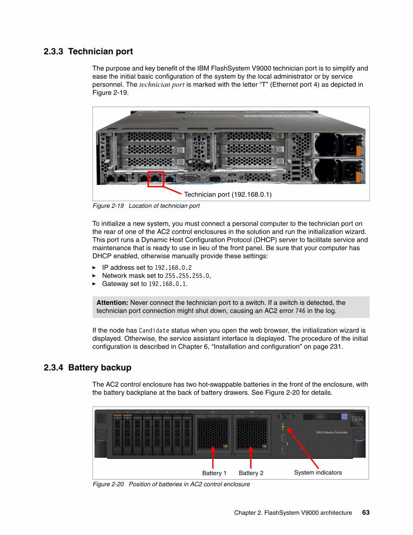
2.3.3 Technician port
The purpose and key benefit of the IBM FlashSystem V9000 technician port is to simplify and ease the initial basic configuration of the system by the local administrator or by service personnel. The technician port is marked with the letter “T” (Ethernet port 4) as depicted in Figure 2-19.
Figure 2-19 Location of technician port
To initialize a new system, you must connect a personal computer to the technician port on the rear of one of the AC2 control enclosures in the solution and run the initialization wizard. This port runs a Dynamic Host Configuration Protocol (DHCP) server to facilitate service and maintenance that is ready to use in lieu of the front panel. Be sure that your computer has DHCP enabled, otherwise manually provide these settings:
� IP address set to 192.168.0.2� Network mask set to 255.255.255.0,� Gateway set to 192.168.0.1.
If the node has Candidate status when you open the web browser, the initialization wizard is displayed. Otherwise, the service assistant interface is displayed. The procedure of the initial configuration is described in Chapter 6, “Installation and configuration” on page 231.
2.3.4 Battery backup
The AC2 control enclosure has two hot-swappable batteries in the front of the enclosure, with the battery backplane at the back of battery drawers. See Figure 2-20 for details.
Figure 2-20 Position of batteries in AC2 control enclosure
Attention: Never connect the technician port to a switch. If a switch is detected, the technician port connection might shut down, causing an AC2 error 746 in the log.
Technician port (192.168.0.1)
Battery 1 Battery 2 System indicators
Chapter 2. FlashSystem V9000 architecture 63

The AC2 battery units provide these items:
� Dual batteries per AC2.� They are hot-swappable.� Designed as redundant within as AC2 control enclosure.� Batteries incorporate a test load capability.� Each battery has its own fault LED indicator.
The AC2 control enclosure is designed for two batteries, but continues to operate on a single battery. To achieve maximum redundancy and to get the full life rating of the cells, the system needs to run with both batteries. Running with a single battery results in almost a full discharge and places a higher discharge current on the cells, which leads to a reduced capacity after several cycles. Running with just one battery is a degraded state and a node error event is logged to ensure the missing or failed battery is replaced.
An AC2 control enclosure is able to continue operation with one failed battery, although after an AC power failure, the node might have to wait for the battery to charge before resuming host I/O operation.
2.4 Control enclosure (AC3)
IBM FlashSystem V9000 control enclosure model AC3 is a component of the IBM FlashSystem V9000 storage system that provides increased performance and additional storage capacity.
The IBM FlashSystem V9000 control enclosure is a purpose-built 2U 19-inch rack-mount enclosure with two AC power supplies, two backup batteries, and dual SSD boot drives. The control enclosure provides up to eight 16 Gb Fibre Channel ports to connect to IBM FlashSystem V9000 storage enclosures, either directly (with the fixed building block) or through SAN switches (with the scalable building block).
Figure 2-21 shows the front view of the IBM FlashSystem V9000 AC3 controller.
Figure 2-21 IBM FlashSystem V9000 AC3 control enclosure front view
IBM FlashSystem V9000 control enclosure model AC3 has the following features:
� Two eight-core processors with 64 GB memory standard, and options to increase memory up to 256 GB.
� 16 Gb Fibre Channel (FC) and 10 Gb iSCSI and Fibre Channel over Ethernet (FCoE) connectivity options.
� Hardware-assisted compression acceleration for Real-time Compression workloads.
� Capability for adding into existing clustered systems with previous generation IBM FlashSystem V9000 control enclosures.
64 Introducing and Implementing IBM FlashSystem V9000

� Up to 20 SAS attached expansion enclosures are supported per IBM FlashSystem V9000 controller pair, providing up to 480 HDD type drives with expansion Model 24F and up to 240 low cost SSD drives with expansion Model 12F.
� Up to eight high-density enclosures are supported per IBM FlashSystem V9000 controller pair, providing up to 736 HDD or SDD drives with expansion Model 92F.
Figure 2-22 shows the IBM FlashSystem V9000 AC3 control enclosure rear view.
Figure 2-22 Rear view of IBM FlashSystem V9000 AC3 control enclosure
IBM FlashSystem V9000 Control Enclosure Model AC3 requires IBM FlashSystem V9000 Software V7.7.1 or later for operation. Use of the software is entitled through the IBM FlashSystem V9000 base license option 5639-RB7.
Battery backup units and front view informationFigure 2-23 shows the IBM FlashSystem AC3 control enclosure front view.
Figure 2-23 AC3 control enclosure front view
The numbers in Figure 2-23 refer to the following items:
1. Battery backup unit 12. Battery backup unit 2 3. SSDs drive slots from 1 to 84. Control enclosure LEDs
Battery backup unit considerations:
� Each AC3 control enclosure in the system contains two batteries that provide backup power to that enclosure. The battery within a control enclosure supplies power only to that control enclosure.
� If power to an AC3 control enclosure node is lost, the system starts to save critical data after a 5-second wait. The saving of critical data runs to completion, even if power is restored during this time. If the power outage is shorter than 5 seconds, the battery continues to support the node and critical data is not saved.
The canister batteries in an AC3 control enclosure periodically discharge and charge again to maintain the battery life.
Chapter 2. FlashSystem V9000 architecture 65

Figure 2-24 shows AC3 control enclosure detailed rear view information.
Figure 2-24 AC3 control enclosure detailed rear view
AC3 control enclosure internal viewThe internal components of the AC3 control enclosure (for example, a fan, CPU, DIMM, or PCIe adapter) only need to be accessed if they must be replaced.
Figure 2-25 shows the location and ID numbers of the fan modules in the AC3 control enclosure, in this case fan IDs from 1 to 6.
Figure 2-25 AC3 control enclosure view from the front of the unit with fan IDs 1 - 6
PSUs Ethernet ports IP Tech port
PCIe Expansion slots
VGA portUSB ports
Serial port
66 Introducing and Implementing IBM FlashSystem V9000

Figure 2-26 shows the location and some of the slot numbers of the DIMM modules, in this case bank slots A0 and C0. The black air baffle was removed to reveal the CPU and DIMM.
Figure 2-26 AC3 control enclosure internal view from the rear of the unit, with 4 DIMM installed using bank0
Figure 2-27 shows the location and ID numbers of the processors, in this case processor 0 and processor 1. The black air baffle was removed to reveal the CPU and the DIMM.
Figure 2-27 AC3 control enclosure internal view from the rear of the unit, with Processor IDs 0 and 1
Chapter 2. FlashSystem V9000 architecture 67

AC3 control enclosure featuresThe AC3 control enclosures have the following features:
� 2U form factor.
� Redundant hardware components and modules.
� Hot-replaceable modules.
� Two (mirrored) boot drives.
� Integrated Ethernet ports.
� PCIe adapter slots.
� Boot drives: 2 SSDs.
� Dual redundant power supplies.
� Dual redundant batteries.
� A dedicated technician port to initialize or service the system.
� A 19-inch rack-mounted enclosure.
� Two eight-core processors.
� 64 GB base memory per processor. Optionally, by adding 64 GB of memory, the processor can support 128 GB, 192 GB, or 256 GB of memory.
� Eight small form factor (SFF) drive bays at the front of the control enclosure.
� Support for various optional host adapter cards, including these:
– 4-port 16 Gbps Fibre Channel adapter cards– 4-port 10 Gbps Fibre Channel over Ethernet (FCoE) adapter cards for host attachment– 4-port 12 Gbps SAS cards to attach to expansion enclosures
� Support for iSCSI host attachment (10 Gbps Ethernet).
� Support for expansion enclosures to attach additional drives:
– 9846/9848-24F to house up to 24 SFF flash drives– 9846/9848-12F to house up to 12 large form factor LFF HDD– 9846/9848-92F to house up to 92 SFF or LFF drives
� Support for optional Compression Accelerator cards for IBM Real-time Compression.
� Support for up to four adapter cards, including:
– 8 Gbps and 16 Gbps Fibre Channel adapter cards
– 10 Gbps iSCSI and 10 Gbps Fibre Channel over Ethernet adapter cards for host attachment
– (Optional) IBM Real-time Compression
I/O connectivityIBM FlashSystem V9000 offers various options of I/O cards for installation and configuration. The 2U rack-mount form factor of the AC3 control enclosure enables it to accommodate up to seven available PCIe Gen3 cards for I/O connectivity or compression support. The AC3 control enclosure has eight physical PCIe adapter slots, but slot 1 is not supported for use. Therefore, up to seven PCIe adapters can be installed in the enclosure.
68 Introducing and Implementing IBM FlashSystem V9000

Figure 2-28 shows the AC3 control enclosure PCIe slot numbers 1 - 8.
Figure 2-28 AC3 control enclosure PCIe slot numbers 1 - 8
Table 2-10 shows the PCIe slot number and adapter type.
Table 2-10 AC3 control enclosure PCIe slot number and adapter type
Integrated Ethernet port Ethernet ports that can be used for management connections are provided on the system board, accessed from the rear of the control enclosure.
Figure 2-29 shows the location and numbers of the integrated Ethernet ports.
Technician portThe purpose and key benefit of the IBM FlashSystem V9000 technician port is to simplify and ease the initial basic configuration of the system by the local administrator or by service personnel. The technician port is marked with the letter “T” (Ethernet port 4) as depicted in Figure 2-29.
Figure 2-29 AC3 control enclosure rear view, technician port
PCIe slot Adapter type
1 Not supported for use
2 SAS
3 Fibre Channel or Ethernet
4 Fibre Channel or Ethernet
5 Compression accelerator
6 Fibre Channel or Ethernet
7 Fibre Channel or Ethernet
8 Compression accelerator
Chapter 2. FlashSystem V9000 architecture 69

AC3 control enclosure Fibre Channel port numbers and WWPNsThe Fibre Channel (FC) port numbers and worldwide port names (WWPNs) depend on the type of adapters that are installed in the control enclosure.
The WWPNs are assigned as follows: 500507680f<P>XXXX
In that assignment, the values have the following meanings:
5 The IEEE Network Address Authority field format number. This value identifies a registered port name.
005076 The Organizationally Unique Identifier (OUI) for IBM.
80f The product unique identifier for an AC3 control enclosure.
<P> The port ID number.
XXXX A unique number for each AC3 control enclosure in the system.
Figure 2-30 shows the FC port numbers for the IBM FlashSystem AC3 control enclosure.
Figure 2-30 AC3 control enclosure FC port numbers
Table 2-11 lists the WWPNs for each FC port in an AC3 control enclosure.
Table 2-11 Standard WWPNs
ID Slot Port Primary Host
1 3 1 500507680f01xxxx 500507680f81xxxx
2 3 2 500507680f02xxxx 500507680f82xxxx
3 3 3 500507680f03xxxx 500507680f83xxxx
4 3 4 500507680f04xxxx 500507680f84xxxx
5 4 1 500507680f05xxxx 500507680f85xxxx
6 4 2 500507680f06xxxx 500507680f86xxxx
7 4 3 500507680f07xxxx 500507680f87xxxx
8 4 4 500507680f08xxxx 500507680f88xxxx
9 6 1 500507680f09xxxx 500507680f89xxxx
10 6 2 500507680f0axxxx 500507680f8axxxx
11 6 3 500507680f0bxxxx 500507680f8bxxxx
12 6 4 500507680f0cxxxx 500507680f8cxxxx
13 7 1 500507680f0dxxxx 500507680f8dxxxx
70 Introducing and Implementing IBM FlashSystem V9000

2.5 Storage enclosure (AE2)
The AE2 storage enclosure components include flash modules, battery modules, and power supplies.
Each IBM FlashSystem AE2 storage enclosure contains two fully redundant canisters. The fan modules are at the bottom and the interface cards are at the top. Each canister contains a RAID controller, two interface cards, and a management controller with an associated 1 Gbps Ethernet port. Each canister also has a USB port and two hot-swappable fan modules.
Figure 2-31 shows the components of the AE2 storage enclosure. One of the two canisters was removed, and now you can see the interface cards and fan modules. The power supply unit to the right of the fans provides redundant power to the system. All components are concurrently maintainable except the midplane and the power interposer, which has no active components. All external connections are from the rear of the system.
Figure 2-31 AE2 storage enclosure components
To maintain redundancy, the canisters are hot-swappable. If any of the components (except the fans) within a canister fail, the entire canister is replaced as a unit. Both fan modules in each canister are hot-swappable.
14 7 2 500507680f0exxxx 500507680f8exxxx
15 7 3 500507680f0fxxxx 500507680f8fxxxx
16 7 4 500507680f10xxxx 500507680f90xxxx
ID Slot Port Primary Host
Chapter 2. FlashSystem V9000 architecture 71

2.5.1 Interface cards
The AE2 storage enclosure supports the following interface cards:
� Fibre Channel 8 Gbps � Fibre Channel 16 Gbps
Figure 2-32 shows a four-port FC interface card, which is used for 16 Gbps FC (only two ports used), and 8 Gbps (four ports used).
Figure 2-32 AE2 storage enclosure FC interface card
Support of 16 Gbps Fibre ChannelThe AE2 storage controller supports the new 16 Gbps FC connection speed through the standard FC interface card. The following rules apply to supporting 16 Gbps FC on the AE2:
� If using 16 Gbps FC, only two (of the four) ports on the FC modules can be used. The two leftmost ports (1 and 2) on each interface card are used for 16 Gbps support. The two right-most ports (3 and 4) are disabled when 16 Gbps is sensed on any port in the AE2.
� If using 16 Gbps FC, the interface is configured as either 16 Gb FC (only two ports active), or 8 Gb FC (4 ports active). This is configured at the factory and is not changeable by the client.
2.5.2 MicroLatency modules
The IBM FlashSystem AE2 storage enclosure supports up to 12 IBM MicroLatency modules, accessible from the enclosure front panel. Each IBM MicroLatency module has a usable capacity of either 1.06 TiB (1.2 TB), 2.62 TiB (2.9 TB), or 5.24 TiB (5.7 TB) of flash memory. IBM MicroLatency modules without the daughterboard are either half-populated with 1.06 TiB
Notes:
� If either interface card in a canister fails, the entire canister (minus the fans) must be replaced as an entire unit. When replacing hardware in the AE2 storage enclosure, follow the DMP that is accessible through the GUI.
� For more details about the IBM FlashSystem canisters, including canister state LEDs, see the IBM FlashSystem V9000 web page at IBM Knowledge Center:
https://ibm.biz/fs_V9000_kc
72 Introducing and Implementing IBM FlashSystem V9000

(1.2 TB) or fully populated with 2.62 TiB (2.9 TB). The optional daughterboard adds another 2.62 TiB (2.9 TB) for a total of 5.24 TiB (5.7 TB).
Figure 2-33 illustrates an AE2 storage enclosure MicroLatency module (base unit and optional daughterboard).
Figure 2-33 AE2 storage enclosure MicroLatency module
The maximum storage capacity of the IBM FlashSystem V9000 is based on the following factor:
� In a RAID 5 configuration, one IBM MicroLatency module is reserved as an active spare, and capacity equivalent to one module is used to implement a distributed parity algorithm. Therefore, the maximum usable capacity of a RAID 5 configuration is 57 TB (51.8 TiB), which is 10 MicroLatency modules x 5.7 TB (5.184 TiB).
IBM MicroLatency modules are installed in the AE2 storage enclosure based on the following configuration guidelines:
� A minimum of four MicroLatency modules must be installed in the system. RAID 5 is the only supported configuration of the IBM FlashSystem V9000. RAID 10 is not supported on the IBM FlashSystem V9000.
� The system supports configurations of 4, 6, 8, 10, and 12 MicroLatency modules in RAID 5.
� All MicroLatency modules that are installed in the enclosure must be identical in capacity and type.
� For optimal airflow and cooling, if fewer than 12 MicroLatency modules are installed in the enclosure, populate the module bays beginning in the center of the slots and adding on either side until all 12 slots are populated.
Note: All MicroLatency modules in the AE2 storage enclosure must be ordered as 1.2 TB, 2.9 TB, or 5.7 TB. IBM MicroLatency modules types cannot be mixed in a single enclosure. The daughterboard cannot be added after deployment.
Chapter 2. FlashSystem V9000 architecture 73

Table 2-12 lists suggestions to populate MicroLatency module bays.
Table 2-12 Supported MicroLatency module configurations
No. of installed flash modulesa
a. RAID 5 is supported with configurations of 4, 6, 8, 10, and 12 MicroLatency modules.
Flashmod.slot 1
Flashmod.slot 2
Flashmod.slot 3
Flashmod.slot 4
Flashmod.slot 5
Flashmod.slot 6
Flashmod.slot 7
Flashmod.slot 8
Flashmod.slot 9
Flashmod.slot 10
Flashmod.slot 11
Flashmod.slot 12
Four X X X X
Six X X X X X X
Eight X X X X X X X X
Ten X X X X X X X X X X
Twelve X X X X X X X X X X X X
Notes:
� If fewer than 12 modules are installed, module blanks must be installed in the empty bays to maintain cooling airflow in the system enclosure.
� During system setup, the system automatically configures RAID settings based on the number of flash modules in the system.
� All MicroLatency modules installed in the enclosure must be identical in capacity and type.
Important:
� MicroLatency modules are hot swappable. However, to replace a module, you must power down the MicroLatency module by using the management GUI before you remove and replace the module. This service action does not affect the active logical unit numbers (LUNs), and I/O to the connected hosts can continue while the MicroLatency module is replaced. Be sure to follow the DMP from the IBM FlashSystem V9000 GUI before any hardware replacement.
� The suggestion is for the AE2 storage enclosure to remain powered on, or be powered on periodically, to retain array consistency. The AE2 storage enclosure can be safely powered down for up to 90 days, in temperatures up to 40 degrees C. Although the MicroLatency modules retain data if the enclosure is temporarily disconnected from power, if the system is powered off for a period of time exceeding 90 days, data might be lost.
� FlashSystem V840 MicroLatency modules are not supported in the IBM FlashSystem V9000 AE2 storage enclosure and installation should not be attempted.
74 Introducing and Implementing IBM FlashSystem V9000

2.5.3 Battery modules
The AE2 storage enclosure contains two hot-swappable battery modules. The function of the battery modules is to ensure that the system is gracefully shut down (write buffer fully flushed and synchronized) when AC power is lost to the unit. The battery modules are hot-swappable. Figure 2-34 shows Battery Module 1, which is in the leftmost front of the AE2 storage enclosure. A battery module can be hot-swapped without software intervention; however, be sure to follow the DMP from the IBM FlashSystem V9000 GUI before any hardware replacement.
Battery reconditioningThe AE2 storage enclosure has a battery reconditioning feature that calibrates the gauge that reports the amount of charge on the batteries. On systems that have been installed for 10 months or more, or systems that have experienced several power outages, the recommendation to run “battery reconditioning” is displayed in the Event Log shortly after upgrading. For more information, see the IBM FlashSystem V9000 web page at IBM Knowledge Center:
https://ibm.biz/fs_V9000_kc
Figure 2-34 AE2 storage enclosure battery module 1
Power supply unitsThe AE2 contains two hot-swappable power supply units. The system can remain fully online if one of the power supply units fails. The power supply units are accessible from the rear of the unit and are fully hot swappable.
Figure 2-35 on page 76 shows the two hot-swappable power supply units. The IBM FlashSystem V9000 GUI and alerting systems (SNMP and so on) will report a power supply fault. The power supply can be hot-swapped without software intervention; however, be sure to follow the DMP from the IBM FlashSystem V9000 GUI before any hardware replacement.
Chapter 2. FlashSystem V9000 architecture 75

Figure 2-35 AE2 storage enclosure hot swappable power supply units
Fan modulesThe AE2 contains four hot-swappable fan modules. Each canister holds two hot swappable fan modules. Each fan module contains two fans. The system can remain fully online if one of the fan modules fails. The fan modules are accessible from the rear of the unit (in each canister) and are fully hot swappable.
Figure 2-36 shows a hot-swappable fan module. The IBM FlashSystem V9000 GUI and alerting systems (SNMP and so on) will report a fan module fault. The fan module can be hot-swapped without software intervention; however, be sure to follow the DMP from the IBM FlashSystem V9000 GUI before any hardware replacement.
Figure 2-36 AE2 storage enclosure fan module
76 Introducing and Implementing IBM FlashSystem V9000

2.6 Expansion enclosures (12F, 24F, 92F)
Three expansion enclosures models are available:
� Model 12F� Model 24F� Model 92F
To support a flash-optimized tiered storage configuration for mixed workloads, up to 20 optional 9846/9848-12F or 9846/9848-24F, or up to eight 9846/9848-92F SAS expansion enclosures can be connected to each control enclosure pair (building block) in the system.
The maximum capacity of the expansion enclosures is as follows:
� A 9846/9848-12F standard expansion enclosure contains up to 12 3.5-inch nearline SAS drives and scales up to 9.6 PB raw capacity with 80 enclosures
– Model 12F supports twelve 8 TB or 10 TB SAS 3.5-inch nearline SAS drives.– 20 standard expansion enclosures supported per control enclosure pair– 9.6 PB = 20 expansion enclosures * 4 control enclosure pairs * 12 drives * 10 TB
� A 9846/9848-24F standard expansion enclosure contains up to 24 2.5-inch read-intensive flash drives and up to 29.4 PB raw capacity with 80 enclosures.
– Model 24F supports twenty-four 1.92 TB, 3.84 TB, 7.68 TB, or 15.36 TB flash drives– 20 standard expansion enclosures supported per control enclosure pair– 29.4PB = 20 expansion enclosures * 4 control enclosure pairs * 24 drives * 15.36 TB
� A 9846/9848-92F high density expansion enclosure contains up to 92 3.5-inch nearline SAS drives or 92 2.5-inch read-intensive flash drives and up to 29.4 PB raw capacity using NL-SAS HDDs or 32 PB raw capacity using SSDs:
– Model 92F supports ninety-two 8 TB or 10 TB NL-SAS. It also supports ninety-two 1.92 TB, 3.84 TB, 7.68 TB, or 15.36 TB flash drives.
– Eight high-density expansion enclosures are supported per control enclosure pair.
– Using NL-SAS HDDs:
29.4 PB of raw capacity = 8 expansion enclosures * 4 control enclosure pairs * 92 drives * 10 TB
– Using SSDs:
32 PB of raw capacity = 8 expansion enclosures * 4 control enclosure pairs * 92 drives * 10 TB
There are enough physical slots to technically house more than 32 PB of capacity, but only up to 32 PB are supported.
Note: To support SAS expansion enclosures, an AH13 - SAS Enclosure Attach adapter card must be installed in expansion slot 2 of each AC3 control enclosure in the building block (only for version 7.7.1 or later). The expansion enclosure Model 9846/9848-92F can be used on only version 7.8 or later.
Chapter 2. FlashSystem V9000 architecture 77

Expansion enclosure model 12FIBM expansion enclosure model 12F offers new tiering options and up to twelve slots for 3.5-inch low cost NL-SAS HDDs.
High capacity nearline drives enables high value tiered storage with hot data stored in flash and warm data on lower cost nearline SAS HDDs all managed by IBM Easy Tier. 8 TB or 10 TB SAS 3.5-inch nearline drives are available for IBM FlashSystem V9000 LFF storage expansion enclosure model 12F for a maximum of 9.6 PB raw capacity with four control enclosure pairs.
Figure 2-37 shows the IBM FlashSystem expansion enclosure model 12F.
Figure 2-37 Front view of expansion enclosure model 12F
Expansion enclosure model 24FIBM expansion enclosure model 24F offers new tiering options and up to 24 slots for 2.5-inch low-cost read-intensive SAS flash drives.
The 1.92 TB, 3.84 TB, 7.68 TB, 15.36 TB SAS 2.5-inch SSD flash drive options are available for IBM FlashSystem V9000 SFF expansion enclosure model 24F for a maximum of 29.4 PB raw capacity with four control enclosure pairs.
Figure 2-38 shows the front view of the IBM FlashSystem expansion enclosure model 24F.
Figure 2-38 Front view of expansion enclosure model 24F
Both models of expansion enclosures have the same common features:
� Two expansion canisters� 12 Gb SAS ports for attachment to the IBM FlashSystem V9000 controllers� 2U, 19-inch rack-mount enclosure with AC power supplies
78 Introducing and Implementing IBM FlashSystem V9000

Figure 2-39 shows the back of IBM FlashSystem expansion enclosure models 12F and 24F.
Figure 2-39 Rear view of the expansion enclosure models 12F and 24F
Figure 2-40 shows the maximum possible configuration with a single building block using a combination of native IBM FlashSystem V9000 flash storage expansion enclosures and SAS attached storage expansion enclosures.
Figure 2-40 Maximum configuration with single building block for 12F and 24F expansion enclosures
Chapter 2. FlashSystem V9000 architecture 79

Expansion enclosure model 92FFigure 2-41 shows the front view of the IBM FlashSystem expansion enclosure model 92F.
Figure 2-41 Front view of the expansion enclosure model 9848-92F
Figure 2-42 shows the rear view of the IBM FlashSystem expansion enclosure model 92F.
Figure 2-42 Rear view of the expansion enclosure model 9848-92F
9848-92F
80 Introducing and Implementing IBM FlashSystem V9000

Figure 2-43 shows the inside of the 9848-92F expansion enclosure.
Figure 2-43 Inside view of the 9848-92F expansion enclosure
IBM FlashSystem V9000 HD expansion enclosure model 92F delivers increased storage density and capacity in a cost-efficient way.
IBM FlashSystem HD expansion enclosure model 92F offers the following features:
� 5U, 19-inch rack mount enclosure with slide rail and cable management assembly
� Support for up to ninety-two 3.5-inch large-form factor (LFF) 12 Gbps SAS top-loading drives or ninety-two 2.5-inch small-form factor (SFF) drives
� High-capacity nearline disk drives, and flash drive support
� High-capacity, archival-class nearline disk drives in 8 TB and 10 TB 7, 7200 rpm
� Flash drives in 1.92 TB, 3.84 TB, 7.68 TB, and 15.36 TB
� Redundant 200 - 240VA power supplies (new PDU power cord required)
Up to eight HD expansion enclosures are supported per IBM FlashSystem V9000 building block, providing up to 736 drives with expansion model 92F for up to 29.4 PB of raw SAS HDD or 32 PB SSD capacity in each building block. With four building blocks a maximum of 32 high-density expansion enclosures can be attached giving a maximum 29.4 PB of raw NL-SAS capacity and 32PB of raw SSD capacity is supported.
Chapter 2. FlashSystem V9000 architecture 81

2.6.1 SAS expansion enclosures intermix
IBM FlashSystem V9000 control enclosures with the SAS enclosure attach adapters support up to two SAS chains of expansion enclosures. The SAS chains have limits depending on the number of standard and dense expansion enclosures. Table 2-13 shows the allowed intermix of expansion enclosures per SAS chain.
Table 2-13 Number of expansion enclosures allowed per SAS chain; two chains per building block
Number of expansion enclosures
Config 1 Config 2 Config 3 Config 4 Config 5
1 Standard Dense Dense Dense Dense
2 Standard Standard Dense Dense Dense
3 Standard Standard Standard Dense Dense
4 Standard Standard Standard Standard Dense
5 Standard Standard Standard Standard
6 Standard Standard Standard
7 Standard Standard Standard
8 Standard Standard
9 Standard
10 Standard
Note: Standard refers to either Model 12F LFF or Model 24F SFF expansion enclosures. Dense refers to the Model 92F HD expansion enclosure.
82 Introducing and Implementing IBM FlashSystem V9000

Table 2-14 shows the allowed intermix of expansion enclosures per building block (control enclosure pair). Any cell in the table is valid but you must balance the enclosures across both chains up to the maximum limits specified per chain.
Table 2-14 Number of expansion enclosure types that can be intermixed on one building block; two SAS chains
Because IBM FlashSystem V9000 supports up to 4 building blocks, the maximum standard expansion enclosures supported in a full scale-out configuration is 80 (20 x 4). The maximum number of dense expansion enclosures in a full scale-out configuration is 32 (8 x 4).
Number of expansion enclosures
Config 1 Config 2 Config 3 Config 4 Config 5
1 Standard Dense Dense Dense Dense
2 Standard Standard Dense Dense Dense
3 Standard Standard Standard Dense Dense
4 Standard Standard Standard Standard Dense
5 Standard Standard Standard Standard Dense
6 Standard Standard Standard Dense Dense
7 Standard Standard Standard Dense Dense
8 Standard Standard Dense Dense Dense
9 Standard Dense Dense Standard
10 Standard Standard Standard Standard
11 Standard Standard Standard
12 Standard Standard Standard
13 Standard Standard Standard
14 Standard Standard Standard
15 Standard Standard
16 Standard Standard
17 Standard Legend:
18 Standard Chain 1
19 Standard Chain 2
20 Standard
Note: Standard refers to either Model 12F LFF or Model 24F SFF expansion enclosures. Dense refers to the Model 92F HD expansion enclosure.
Chapter 2. FlashSystem V9000 architecture 83

2.7 Administration and maintenance
This section describes the IBM FlashSystem V9000 storage system capabilities for administration and maintenance.
2.7.1 System management
The IBM FlashSystem V9000 control enclosures in a system operate as a single system and present a single point of control for system management and service. System management and error reporting are provided through an Ethernet interface to one of the nodes in the system, which is called the configuration node. The configuration node runs a web server and provides a command-line interface (CLI). Any node in the system can be the configuration node. If the current configuration node fails, a new configuration node is selected from the remaining nodes. Each node also provides a command-line interface and web interface for initiating hardware service actions.
IBM FlashSystem V9000 includes the use of the popular IBM SAN Volume Controller CLI and GUI, which deliver the functions of IBM Spectrum Virtualize, part of the IBM Spectrum Storage Family. The IBM FlashSystem V9000 supports SNMP, email forwarding (SMTP), and syslog redirection for complete enterprise management access.
Graphical user interface (GUI)IBM FlashSystem V9000 includes the use of the standard IBM Spectrum Virtualize GUI.
The IBM FlashSystem V9000 GUI is started from a supported Internet browser when you enter the systems management IP address. The login window then opens (Figure 2-44).
Figure 2-44 IBM FlashSystem V9000 GUI login window
Enter a valid user name and password. A system overview window opens:
� Figure 2-45 on page 85 is for fixed building block.� Figure 2-46 on page 85 is for scalable building block configurations.
The middle of the window displays a real-time graphic of the IBM FlashSystem V9000.
84 Introducing and Implementing IBM FlashSystem V9000

Figure 2-45 shows the system overview window for a fixed building block.
Figure 2-45 System overview window (fixed building block)
Figure 2-46 shows the system overview window for a scale-up and scale-out environment.
Figure 2-46 System overview window (scale-up and scale-out environment)
Chapter 2. FlashSystem V9000 architecture 85

The bottom of the window has three dashboard icons:
� Capacity� Performance � System status
The left side of the window displays seven function icons:
� Monitoring function� Pools function� Volumes function� Hosts function� Copy Services function� Access function� Settings function
Those functions are briefly described next. Also, see the following chapters:
� Details about the GUI: Chapter 8, “Using IBM FlashSystem V9000” on page 321� Details about the Settings function: Chapter 9, “Configuring settings” on page 405
Monitoring functionFigure 2-47 shows the Monitoring icon and the associated branch-out menu. Click the Monitoring icon if you want to select any of these actions:
� System: Monitor the system health of the IBM FlashSystem V9000 hardware.� Events: View the events log of the IBM FlashSystem V9000.� Performance: Start the system I/O performance graphs.
Figure 2-47 IBM FlashSystem V9000 GUI: Monitoring icon and branch-out menu
Pools functionFigure 2-48 on page 87 shows the Pools icon and the associated branch-out menu. Click the Pools icon if you want to select any of these actions:
� Pools: View list of pools, create new pools, edit existing pools, and delete pools. � Volumes by Pool: View a list of volumes (LUNs) that are associated with pools, create new
associations, or delete associations.� Internal Storage: View all internal storage associated with the IBM FlashSystem V9000.� External Storage: View and manage all external storage associated with the IBM
FlashSystem V9000.� MDisks by Pools: View a list of MDisk that are associated with pools, create new
associations, or delete associations.� System Migration: Perform storage migration actions for data from externally virtualized
storage.
86 Introducing and Implementing IBM FlashSystem V9000
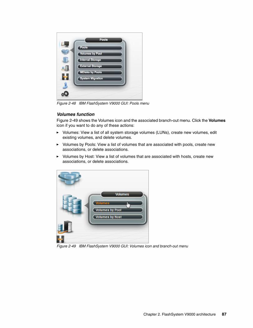
Figure 2-48 IBM FlashSystem V9000 GUI: Pools menu
Volumes functionFigure 2-49 shows the Volumes icon and the associated branch-out menu. Click the Volumes icon if you want to do any of these actions:
� Volumes: View a list of all system storage volumes (LUNs), create new volumes, edit existing volumes, and delete volumes.
� Volumes by Pools: View a list of volumes that are associated with pools, create new associations, or delete associations.
� Volumes by Host: View a list of volumes that are associated with hosts, create new associations, or delete associations.
Figure 2-49 IBM FlashSystem V9000 GUI: Volumes icon and branch-out menu
Chapter 2. FlashSystem V9000 architecture 87

Hosts functionFigure 2-50 shows the Hosts icon and the associated branch-out menu. Click the Hosts icon if you want to select any of these actions:
� Hosts: View a list of all hosts, create new hosts, edit existing hosts, and delete hosts.
� Ports by Host: View a list of ports that are associated with a host, create new hosts, edit existing hosts, and delete hosts.
� Host Mappings: View mappings per host regarding volumes.
� Volumes by Host: View a list of volumes that are associated with hosts, create new associations, or delete associations.
Figure 2-50 IBM FlashSystem V9000 GUI: Hosts icon and branch-out menu
Copy Services functionFigure 2-51 on page 89 shows the Copy Services icon and associated branch-out menu. Click the Copy Services icon if you want to select any of these actions:
� FlashCopy: View a list of all volumes and their associated flash copies, create new FlashCopy relationships, and edit or delete existing relationships.
� Consistency Groups: View the consistency groups created for remote copy partnerships, create new groups, edit existing groups, delete groups.
� FlashCopy Mappings: View a list of current FlashCopy mappings and their status, create new mappings, edit existing mappings, and delete mappings.
� Remote Copy: View the consistency groups created for remote copy partnerships, create new groups, edit existing groups, and delete groups.
� Partnerships: View the system partnerships with secondary system, create a new partnership, edit a partnership, and delete a partnership.
88 Introducing and Implementing IBM FlashSystem V9000

Figure 2-51 IBM FlashSystem V9000 GUI: Copy Services icon and branch-out menu
Access functionFigure 2-52 shows the Access icon and associated branch-out menu. Click the Access icon if you want to select any of these actions:
� Users: View a list of current users, create new users, edit existing users, and delete users.� Audit Log: View the system access log and view actions by individual users.
Figure 2-52 IBM FlashSystem V9000 GUI: Access icon and branch-out menu
Chapter 2. FlashSystem V9000 architecture 89

Settings functionFigure 2-53 shows the Settings icon and associated branch-out menu. Click the Settings icon if you want to configure system parameters, including alerting, open access, GUI settings, and other system-wide configuration.
Figure 2-53 IBM FlashSystem V9000 GUI: Settings icon and branch-out menu
Command-line interface (CLI)IBM FlashSystem V9000 uses the standard IBM Spectrum Virtualize storage CLI. This CLI is common among several IBM storage products, including IBM Spectrum Virtualize and the IBM Storwize family of products: the V7000, IBM V5000, IBM V3700, and IBM V3500 disk systems. IBM Spectrum Virtualize CLI is easy to use with built-in help and hint menus.
To access the IBM FlashSystem V9000 Spectrum Virtualize CLI, a Secure Shell (SSH) session to the management IP address must be established. You are then prompted for a user name and password. For information about using the FlashSystem V9000 CLI, see Chapter 13, “Hints and tips” on page 597.
Call home email SMTP supportIBM FlashSystem V9000 supports setting up a Simple Mail Transfer Protocol (SMTP) mail server for alerting the IBM Support Center of system incidents that might require a service event. These emails can also be sent within the client’s enterprise to other email accounts that are specified. After it is set up, system events that might require service are emailed automatically to an IBM Service account specified in the IBM FlashSystem V9000 code.
The email alerting can be set up as part of the system initialization process or added or edited at anytime through the IBM FlashSystem V9000 GUI. Also, a test email can be generated at anytime to test the connections. Figure 2-54 on page 91 shows the IBM FlashSystem V9000 Email setup window.
Tip: Be sure to set up Call Home. For details, see 9.2.1, “Email and call home” on page 407.
90 Introducing and Implementing IBM FlashSystem V9000

Figure 2-54 IBM FlashSystem V9000 Email alerting setup window
SNMP supportIBM FlashSystem V9000 supports SNMP versions 1 and 2. The GUI is used to set up SNMP support on the IBM FlashSystem V9000.
To set up SNMP support on the IBM FlashSystem V9000, click the Settings icon at the left side of the window, click the Notifications tab and click the SNMP tab to enter the SNMP trap receiver IP address and community access information. Figure 2-55 shows the IBM FlashSystem V9000 SNMP setup window.
Figure 2-55 IBM FlashSystem V9000 SNMP setup window
Note: The IBM FlashSystem V9000 CLI can also be used to program the SNMP settings.
Chapter 2. FlashSystem V9000 architecture 91

Redirection of syslogYou can redirect syslog messages to another host for system monitoring. Use the GUI to set up syslog redirection on the IBM FlashSystem V9000. To set up syslog redirection, click the Settings icon on the lower left of the window, click the Notifications tab, and then click the Syslog tab to enter the remote host trap IP address and directory information. Figure 2-56 shows the Syslog redirection setup window.
Figure 2-56 IBM FlashSystem V9000 Syslog redirection setup window
2.7.2 Software and licensing
IBM FlashSystem V9000 uses the advanced software features of IBM Spectrum Virtualize. IBM FlashSystem V9000 data services are provided through IBM FlashSystem V9000 software. IBM FlashSystem V9000 has both base and optional software licenses.
For more information about IBM FlashSystem V9000 advanced software functionality, see these resources:
� Chapter 3, “Advanced software functions” on page 97 � IBM FlashSystem V9000 Version 7.7 Product Guide, REDP-5409
Base licensed featuresThe following functions are provided with the IBM FlashSystem V9000 base software license 5639-RB7:
� Virtualization of IBM FlashSystem V9000 storage and expansion enclosures
Enables rapid, flexible provisioning, and simple configuration changes.
One IBM FlashSystem V9000 base license option 5639-RB7 is needed for each storage and expansion enclosure.
� Thin provisioning
Helps improve efficiency by allocating disk storage space in a flexible manner among multiple users, based on the minimum space that is required by each user at any time.
� Data migration
Enables easy and nondisruptive moves of volumes from another storage system onto the IBM FlashSystem V9000 system by using Fibre Channel connectivity. Dynamic migration helps speed data migrations from weeks or months to days, eliminating the cost of add-on migration tools and providing continuous availability of applications by eliminating downtime.
� Simple GUI
Simplified management with the intuitive GUI enables storage to be quickly deployed and efficiently managed. The GUI runs on the IBM FlashSystem V9000 system, so there is no need for a separate console. All you need to do is point your web browser to the system.
Note: The IBM FlashSystem V9000 CLI can also be used to set up syslog redirection.
92 Introducing and Implementing IBM FlashSystem V9000

� IBM Easy Tier technology
This feature provides a mechanism to seamlessly migrate data to the most appropriate tier within an IBM FlashSystem V9000 storage pool. This migration can be to and from the internal IBM FlashSystem V9000 storage or expansion enclosure, or to and from external storage systems that are virtualized by IBM FlashSystem V9000. Easy Tier technology adds more blended economy of capacity and is useful for cost effective expansion and usage of your existing storage capacity investment.
Easy Tier supports up to three tiers of storage. For example, you can set up a storage pool intended for Easy Tier volumes where the pool consists of the IBM FlashSystem V9000 storage enclosures, 15,000 RPM Fibre Channel disk drives, and SAS disk drives.
Software version 7.8 introduces a fourth tier so that you can separate the flash storage into two tiers.
� Automatic restriping of data across storage pools
When growing a storage pool by adding more storage to it, IBM FlashSystem V9000 software can restripe your data on pools of storage so you do not need to implement any manual or scripting steps. This feature helps grow storage environments with greater ease while retaining the performance benefits that come from striping the data across the disk systems in a storage pool.
The following functions are provided with the IBM FlashSystem V9000 base software license for internal storage only. Internal storage includes IBM FlashSystem V9000 storage enclosures and expansion enclosures:
� FlashCopy provides a volume level point-in-time copy function for any storage that is virtualized by IBM FlashSystem V9000. FlashCopy and snapshot functions enable you to create copies of data for backup, parallel processing, testing, and development, and have the copies available almost immediately.
� Real-time Compression helps improve efficiency by compressing data by as much as 80%, enabling storage of up to 5x as much data in the same physical space. Unlike other approaches to compression, Real-time Compression is designed to be used with active primary data such as production databases and email systems, dramatically expanding the range of candidate data that can benefit from compression.
� Microsoft Windows Offloaded Data Transfer (ODX) is supported with IBM FlashSystem V9000 Software V7.5 and later. This functionality in Windows improves efficiencies by intelligently managing IBM FlashSystem V9000 systems to directly transfer data within or between systems, bypassing the Windows host system.
� VMware and vSphere 6.0. IBM FlashSystem V9000 Software V7.7 supports vCenter Site Recovery Manager (SRM) and vCenter Web Client (IBM Spectrum Control Base 3.0.2 functionality). Also supported are vStorage application programming interfaces (APIs) for storage awareness.
� Remote Mirroring provides storage system-based data replication by using either synchronous or asynchronous data transfers over Fibre Channel communication links:
– Metro Mirror maintains a fully synchronized copy at metropolitan distances (up to 300 km).
– Global Mirror operates asynchronously and maintains a copy at much greater distances (up to 8000 km).
Both functions support VMware Site Recovery Manager to help speed disaster recovery.
IBM FlashSystem V9000 remote mirroring interoperates with other IBM FlashSystem V9000, FlashSystem V840, SAN Volume Controller, and Storwize V7000 storage systems.
Chapter 2. FlashSystem V9000 architecture 93

Optional licensed featuresThe following optional licensed features are offered with the IBM FlashSystem V9000 software for external storage:
� External Virtualization 5641-VC7 FC 0663
The system does not require a license for its own control and expansion enclosures; however, a capacity-based license is required for any external systems that are being virtualized. The system does not require an external virtualization license for external enclosures that are only being used to provide managed disks for a quorum disk and are not providing any capacity for volumes.
Enables IBM FlashSystem V9000 to manage capacity in other Fibre Channel SAN storage systems. When IBM FlashSystem V9000 virtualizes a storage system, its capacity becomes part of the IBM FlashSystem V9000 system and it is managed in the same way as capacity on internal flash modules within IBM FlashSystem V9000. Capacity in external storage systems inherits all the functional richness of the IBM FlashSystem V9000.
� Real-time Compression for external storage 5641-CP7 FC 0708
With the compression function data is compressed as it is written to the drive, saving additional capacity for the system. This license is capacity-based.
Helps improve efficiency by compressing data by as much as 80%, enabling storage of up to 5x as much data in the same physical space. Unlike other approaches to compression, Real-time Compression is designed to be used with active primary data such as production databases and email systems, dramatically expanding the range of candidate data that can benefit from compression.
For example, suppose that you want to store 500 TB of data where 300 TB of that data cannot be compressed (so it is not configured on compressed volumes), but 200 TB of that data can be compressed and is configured on compressed volumes.
Rather than needing to license 200 TB of Real-time Compression, the compression ratio can be applied to determine how much storage the 200 TB of volumes actually uses. The compression ratio can be obtained in advance using the IBM Comprestimator tool, or it can be shown in the system later as the actual amount of managed disk space used by those compressed volumes.
If, for example, the compression ratio is 3:1 for that 200 TB of data, meaning that only 1 TB of managed storage is consumed for every 3 TB of data, the user would license only 1/3 of the 200 TB, or 67 TB of the 5641-CP7 license. The 5641-CP7 license continues to not be licensed to a specific IBM Spectrum Virtualize hardware device, but is licensed to the customer within a country, in the same way that SAN Volume Controller standard (5639-VC7) software is licensed today.
Note: IBM FlashSystem V9000 V7.5 and later has revised licensing rules for IBM Spectrum Virtualize Real-time Compression for external storage (5641-CP7 FC 0708).
As it pertains to externally virtualized storage, rather than using the volume size as the measure for determining how many terabytes of IBM Spectrum Virtualize Real-time Compression for external storage 5641-CP7 FC 0708 to license, the measured terabyte capacity now applies to the actual managed disk capacity consumed by the compressed volumes.
94 Introducing and Implementing IBM FlashSystem V9000

� FlashCopy for external storage 5641-VC7 FC 0671
The FlashCopy function copies the contents of a source volume to a target volume. This license is capacity-based.
FlashCopy provides a volume level point-in-time copy function for any storage that is virtualized by IBM FlashSystem V9000. FlashCopy and snapshot functions enable you to create copies of data for backup, parallel processing, testing, and development, and have the copies available almost immediately.
� Remote Mirroring Software for external storage 5641-VC7 FC 0679
The remote-copy function allows the use of Metro Mirror and Global Mirror functions. This function enables you to set up a relationship between volumes on two systems, so that updates that are made by an application to one volume are mirrored on the other volume. The volumes can be in the same system or on two different systems. This license is capacity-based. Provides storage system-based data replication by using either synchronous or asynchronous data transfers over Fibre Channel communication links.
Starting with version 7.7 of IBM Spectrum Virtualize, Differential Licensing is used to calculate the license needed for a given configuration. With Differential Licensing, licenses change from per terabyte to per storage capacity unit (SCU). Differential Licensing and how to calculate SCUs is explained in IBM FlashSystem V9000 Version 7.7 Product Guide, REDP-5409.
2.7.3 Serviceability and software enhancements
IBM FlashSystem V9000 includes several design enhancements for the administration, management, connectivity, and serviceability of the system:
� Concurrent code load
IBM FlashSystem V9000 supports upgrading the system firmware on the AC2 or AC3 control enclosures and AE2 storage enclosures (RAID controllers, management modules, and interface cards) and flash modules without affecting the connected hosts or their applications.
� Easily accessible hot swappable modules with no single point of failure
IBM FlashSystem V9000 design enables the easy replacement of any hardware module through the front or rear of the unit. The IBM FlashSystem V9000 does not require the top panel to be removed nor does it need to be moved in the rack to replace any component.
� Standard IBM CLI and GUI
IBM FlashSystem V9000 uses the latest IBM Spectrum Virtualize CLI and GUI for simple and familiar management of the unit.
� Encryption support
IBM FlashSystem V9000 supports hardware encryption of the flash modules to meet the audit requirements of enterprise, financial, and government clients.
� Sixteen Gbps FC support
IBM FlashSystem V9000 supports 16 Gbps FC, enabling clients to take advantage of the latest high-speed networking equipment while increasing performance.
Note: The 5641-VC7 (External Virtualization, FlashCopy, and Remote Mirroring features) and 5641-CP7 FC 0708 (Compression) are licensed per enterprise within one country and are the same licenses as for SAN Volume Controller. Existing SAN Volume Controller licenses can be used for the IBM FlashSystem V9000 for these features.
Chapter 2. FlashSystem V9000 architecture 95

2.8 Support matrix for IBM FlashSystem V9000
The IBM FlashSystem V9000 supports a wide range of operating systems (Windows Server 2008 and 2012, Linux, and IBM AIX), hardware platforms (IBM System x, IBM Power Systems, and x86 servers not from IBM), host bus adapters (HBAs), and SAN fabrics.
For specific information, see the IBM System Storage Interoperation Center (SSIC):
http://ibm.com/systems/support/storage/ssic
Contact your IBM sales representative or IBM Business Partner for assistance or questions about the IBM FlashSystem V9000 interoperability.
96 Introducing and Implementing IBM FlashSystem V9000

Chapter 3. Advanced software functions
This chapter describes the advanced software functions that are available for the IBM FlashSystem V9000. The advanced software functions provide IBM FlashSystem V9000 with rich functionality and create a full Tier 1 storage solution with enterprise class storage mirroring features plus a rich set of storage virtualization and migration features.
The advanced features for storage efficiency increase the efficient capacity of the IBM FlashSystem V9000 beyond the physical capacity. This helps with the economics of flash and can provide flash capacity for less than disk capacity. In addition, IBM FlashSystem can speed up existing storage by automatically placing frequently accessed data on flash memory.
The data migration feature enables easy migration into the virtualized storage environment of the IBM FlashSystem V9000 and supports easy movement of volumes between storage systems and tiers.
With the remote copy features, you can address the need for high availability (HA) and disaster recovery (DR) solutions. IBM FlashCopy enables faster backups and data duplication for testing.
Data encryption protects against stolen data from discarded or stolen flash modules, and prevents accessing the data without the access key.
This chapter includes the following topics:
� Introduction� Advanced features for storage efficiency� Data migration� Advanced copy services� Data encryption� IBM HyperSwap� IBM Spectrum Control (formerly IBM Tivoli Storage Productivity Center)
3
© Copyright IBM Corp. 2015, 2016. All rights reserved. 97

3.1 Introduction
IBM FlashSystem V9000 offers advanced software functions for storage efficiency, data migration, high availability, and disaster recovery. This chapter has an overview of the features, how they work, and how to use them.
3.2 Advanced features for storage efficiency
In modern and complex application environments, the increasing and often unpredictable demands for storage capacity and performance lead to issues of planning and optimization of storage resources.
Consider the following typical storage management issues:
� Typically when a storage system is implemented, only a portion of the configurable physical capacity is deployed. When the storage system runs out of the installed capacity and more capacity is requested, a hardware upgrade is implemented to add physical resources to the storage system.
This new physical capacity can hardly be configured to keep an even spread of the overall storage resources. Typically, the new capacity is allocated to fulfill only new storage requests. The existing storage allocations do not benefit from the new physical resources. In a similar way, the new storage requests do not benefit from the existing resources; only new resources are used.
� In a complex production environment, optimizing storage allocation for performance is not always possible. The unpredictable rate of storage growth and the fluctuations in throughput requirements, which are I/O per second (IOPS), often lead to inadequate performance.
Furthermore, the tendency to use even larger volumes to simplify storage management works against the granularity of storage allocation, and a cost-efficient storage tiering solution becomes difficult to achieve. With the introduction of high performing technologies, such as solid-state drives (SSD) or all flash arrays, this challenge becomes even more important.
� The move to increasingly larger physical disk drive capacities means that previous access densities that were achieved with low-capacity drives can no longer be sustained.
� All businesses have some applications that are more critical than others, and there is a need for specific application optimization. Therefore, a need exists to be able to relocate specific application data to faster storage media.
All of those issues deal with data placement and relocation capabilities or data volume reduction. Most of these challenges can be managed by having spare resources available and by moving data, and by the use of data mobility tools or operating systems features (such as host level mirroring) to optimize storage configurations.
However, all of those corrective actions are expensive in terms of hardware resources, labor, and service availability. Relocating data among the physical storage resources that dynamically or effectively reduce the amount of data (that is, transparently) to the attached host systems is becoming increasingly important.
Note: IBM FlashSystem V9000 is based on IBM Spectrum Virtualize - IBM SAN Volume Controller technology. Details about the advanced features are in Implementing the IBM System Storage SAN Volume Controller with IBM Spectrum Virtualize V7.6, SG24-7933.
98 Introducing and Implementing IBM FlashSystem V9000

3.2.1 IBM Easy Tier
IBM Easy Tier is a solution that combines functionalities that can add value to other storage, in combination with the highly advanced key points that IBM FlashSystem V9000 can offer, such as IBM MicroLatency and maximum performance.
The great advantage of the tiering approach is the capability to automatically move the most frequently accessed data to the highest performing storage system. In this case, IBM FlashSystem V9000 is the highest performing storage, and the less frequently accessed data can be moved to slower external storage, which can be SSD-based storage or disk-based storage.
IBM FlashSystem V9000 addresses the combination of the lowest latency with the highest functionality and can provide the lowest latency for clients that use traditional disk array storage and need to increase the performance of their critical applications.
Usage of the IBM Easy Tier solution is indicated when there is a need to accelerate general workloads. IBM FlashSystem V9000 maintains a map of hot data (more frequently accessed) and cold data (less frequently accessed). This map is used to automatically move the hot data to faster tiers of storage.
When data that was previously hot becomes cold, it moves from the IBM FlashSystem V9000 to slower tiers of storage. The inverse process occurs when cold data becomes hot (or more frequently accessed) and is moved to faster tiers.
Figure 3-1 shows the principles of Easy Tier, where a volume has extents from all the tiers.
Figure 3-1 Principles of Easy Tier
This solution focuses on accelerating and consolidating the storage infrastructure. It might not reach the same lowest latency that an IBM FlashSystem V9000 solution offers, but it is used to improve the overall performance of the infrastructure.
FlashSystem V9000
Nearline TierNearline SAS
extents
Flash Tier 0FS Micro
Latency extents
Enterprise Tier SAS HDD
extents
Easy Tire code
Volume
DB2
Heterogeneous, 4 tier storage pool
Flash Tier 1Flash SSD
extents
Chapter 3. Advanced software functions 99

IBM Easy Tier, a function that responds to the presence of mixed storage devices (MDisks) in a storage pool. The system automatically and nondisruptively moves frequently accessed data between flash, SSD, SAS and HDD managed (MDisks). The goal is to place frequently accessed data in faster tiers of storage.
Easy Tier eliminates manual intervention when you assign highly active data on volumes to faster responding storage. In this dynamically tiered environment, data movement is seamless to the host application regardless of the storage tier in which the data belongs. Manual controls exist so that you can change the default behavior, for example, such as turning off Easy Tier on pools.
The IBM FlashSystem V9000 supports these tiers:
� Tier 0 flash: Specifies a tier0_flash IBM FlashSystem MicroLatency module or an external MDisk for the newly discovered or external volume.
� Tier 1 flash: Specifies a tier1_flash (or flash SSD drive) for the newly discovered or external volume.
� Enterprise tier: Specifies a tier_enterprise hard disk drive or an external MDisk for the newly discovered or external volume. These MDisks can be built from serial-attached SCSI (SAS) drives.
� Nearline tier: The nearline tier exists when nearline-class MDisks are used in the pool, such as those drives built from nearline SAS drives.
If a pool contains a single type of MDisk and Easy Tier is set to Auto (default) or On, balancing mode is active. When the pool contains multiple types of MDisks and Easy Tier is set to Auto or On, then automatic placement mode is added in addition to balancing mode. If Easy Tier is set to Off, balancing mode is not active. All external MDisks are put into the Enterprise tier by default. You must manually identify external MDisks and change their tiers.
Monitoring Easy Tier behaviorThe lssystem command can be used to determine how Easy Tier has distributed data in the storage pool based on capacity. As shown in Figure 3-2 on page 101, the output of the lssystem | grep tier command (1) is filtered using grep to show only items with tier in the name. Easy Tier Acceleration mode (2) can be used to increase the speed of the migration of data between tiers. To change this, use the chsystem -easytieracceleration command.
Note: IBM FlashSystem V9000 Version 7.8 provides an additional tier of flash storage to differentiate Tier 0 flash (high performance) from Tier 1 flash (SSD-based flash).
Notes:
� Easy Tier works with compressed volumes, but it migrates data based only on read activity.
� MDisks shared from an IBM FlashSystem A9000 to IBM FlashSystem V9000 have a tier attribute of Deduplication: Active. This means that these MDisks are not eligible for Easy Tier pools because they must not be mixed with MDisks from other storage enclosures.
100 Introducing and Implementing IBM FlashSystem V9000

Figure 3-2 Use lssystem command to examine Easy Tier behavior
For information about using the IBM FlashSystem V9000 CLI, see Chapter 13, “Hints and tips” on page 597.
For further information about Easy Tier commands, see the “Easy Tier modes of operation” topic in IBM Knowledge Center:
https://ibm.biz/BdsZXE
Balancing modeThis feature assesses the performance disparity between MDisks in a pool and balances extents in the pool to correct that disparity. Balancing works within a single tier pool over all the MDisks in the pool or within each tier of a multitier storage pool. Balancing does not move the data between tiers, but balances performance of the data within each tier. A function of the Easy Tier code is to move the data between tiers.
The process automatically balances existing data when new MDisks are added into an existing pool, even if the pool contains only a single type of storage. This does not mean that it will migrate extents from existing MDisks to achieve even extent distribution among all, old and new MDisks in the storage pool. Easy Tier balancing mode is based on performance and not capacity of underlying MDisks.
Automatic data placement modeWhen IBM Easy Tier on IBM FlashSystem V9000 automatic data placement is active, Easy Tier measures the host access activity to the data on each storage extent. It also provides a mapping that identifies high activity extents, and then moves the high-activity data according to its relocation plan algorithms.
To automatically relocate the data, Easy Tier initiates the following processes:
� Monitors volumes for host access to collect average usage statistics for each extent over a random generated period averaging every 17 - 24 hours.
� Analyzes the amount of input/output (I/O) activity for each extent, relative to all other extents in the pool to determine if the extent is a candidate for promotion or demotion.
� Develops an extent relocation plan for each storage pool to determine exact data relocations within the storage pool. Easy Tier then automatically relocates the data according to the plan.
While relocating volume extents, Easy Tier follows these actions:
� Attempts to migrate the most active volume extents first.� Refreshes the task list as the plan changes. The previous plan and any queued extents
that are not yet relocated are abandoned.
Chapter 3. Advanced software functions 101

Automatic data placement is enabled, by default, for storage pools with more than one tier of storage. When automatic data placement is enabled, by default all striped volumes are candidates for automatic data placement. Image mode and sequential volumes are never candidates for automatic data placement. When automatic data placement is enabled, I/O monitoring is done for all volumes whether the volume is a candidate for automatic data placement.
After automatic data placement is enabled, and if there is sufficient activity to warrant relocation, extents begin to be relocated within a day after enablement. You can control whether Easy Tier automatic data placement and I/O activity monitoring is enabled or disabled by using the settings for each storage pool and each volume.
Evaluation modeWhen IBM Easy Tier evaluation mode is enabled for a storage pool, Easy Tier collects usage statistics for all the volumes in the pool and monitors the storage use at the volume extent level. Easy Tier constantly gathers and analyzes monitoring statistics to derive moving averages for the past 24 hours.
Volumes are not monitored, and balancing is disabled when the Easy Tier attribute of a storage pool is set to off. Volumes are monitored when the Easy Tier attribute of a storage pool is set to measured.
For more details about Easy Tier, see these resources:
� IBM SAN Volume Controller 2145-DH8 Introduction and Implementation, SG24-8229� Implementing the IBM System Storage SAN Volume Controller with IBM Spectrum
Virtualize V7.6, SG24-7933
3.2.2 Thin provisioning
In a shared storage environment, thin provisioning is a method for optimizing the usage of available storage. It relies on allocation of blocks of data on demand versus the traditional method of allocating all of the blocks up front. This methodology eliminates almost all white space, helping to avoid the poor usage rates that occur in the traditional storage allocation method where large pools of storage capacity are allocated to individual servers but remain unused (not written to).
Thin provisioning can present more storage space to the hosts or servers that are connected to the storage system than is available in the storage pool.
An example of thin provisioning is when a storage system contains 5000 gigabytes (GB) of usable storage capacity, but the storage administrator mapped volumes of 500 GB each to 15 hosts. In this example, the storage administrator makes 7500 GB of storage space visible to the hosts, even though the storage system has only 5000 GB of usable space, as shown in Figure 3-3 on page 103. In this case, all 15 hosts cannot immediately use all 500 GB that are provisioned to them. The storage administrator must monitor the system and add storage as needed.
102 Introducing and Implementing IBM FlashSystem V9000

Figure 3-3 Concept of thin provisioning
You can imagine thin provisioning to be the same process as when airlines sell more tickets on a flight than there are available physical seats, assuming that some passengers do not appear at check-in. They do not assign actual seats at the time of sale, which avoids each client having a claim on a specific seat number. The same concept applies to thin provisioning (airline) IBM FlashSystem V9000 (plane) and its volumes (seats). The storage administrator (airline ticketing system) must closely monitor the allocation process and set proper thresholds.
Configuring a thin-provisioned volumeVolumes can be configured as thin-provisioned or fully allocated. Thin-provisioned volumes are created with real and virtual capacities. You can still create volumes by using a striped, sequential, or image mode virtualization policy, as you can with any other volume.
Real capacity defines how much disk space is allocated to a volume. Virtual capacity is the capacity of the volume that is reported to other IBM FlashSystem V9000 components (such as FlashCopy or remote copy) and to the hosts. For example, you can create a volume with real capacity of only 100 GB but virtual capacity of 1 terabyte (TB). The actual space that is used by the volume on IBM FlashSystem V9000 is 100 GB, but hosts see 1 TB volume. The default for the real capacity is 2% of the virtual capacity.
A directory maps the virtual address space to the real address space. The directory and the user data share the real capacity.
Thin-provisioned volumes are available in two operating modes:
� The autoexpand mode� The non-autoexpand mode
You can switch the mode at any time. If you select the autoexpand feature, IBM FlashSystem V9000 automatically adds a fixed amount of more real capacity to the thin volume as required. Therefore, the autoexpand feature attempts to maintain a fixed amount of unused real capacity for the volume. This amount is known as the contingency capacity.
Chapter 3. Advanced software functions 103

The contingency capacity is initially set to the real capacity that is assigned when the volume is created. If the user modifies the real capacity, the contingency capacity is reset to be the difference between the used capacity and real capacity. Contingency capacity is used only when the pool is full. The default is autoexpand mode for volumes created with the graphical user interface (GUI).
A volume that is created without the autoexpand feature, and therefore has a zero contingency capacity, goes offline when the real capacity is used and must expand. Therefore the preference is to use the autoexpand feature.
Autoexpand mode does not cause real capacity to grow much beyond the virtual capacity. The real capacity can be manually expanded to more than the maximum that is required by the current virtual capacity, and the contingency capacity is recalculated.
A thin-provisioned volume can be converted non-disruptively to a fully allocated volume, or vice versa, by using the volume mirroring function. For example, you can add a thin-provisioned copy to a fully allocated primary volume and then remove the fully allocated copy from the volume after they are synchronized.
The fully allocated to thin-provisioned migration procedure uses a zero-detection algorithm so that grains that contain all zeros do not cause any real capacity to be used. If the volume has been in use for some time, it is possible that there is deleted space with data on it. Because IBM FlashSystem V9000 uses a zero detection algorithm to free disk space in the transformation process, you might need to use a utility to zero the deleted space on the volume before starting the fully allocated to thin migration.
Thin-provisioned volumes save capacity only if the host server does not write to whole volumes. Whether the thin-provisioned volume works well partly depends on how the file system allocated the space.
IBM FlashSystem V9000 has a zero write-host-detect feature that detects when servers are writing zeros to thin volumes, and ignores them rather than filling up the space on the thin volume. This keeps the thin volume from growing to full size when, for example, a full format is issued before using the disk.
Space allocation details for thin provisioned volumes can be found in the IBM Redbooks publication Implementing the IBM System Storage SAN Volume Controller with IBM Spectrum Virtualize V7.6, SG24-7933.
Warning threshold: Enable the warning threshold (by using email with Simple Mail Transfer Protocol (SMTP), or by using a Simple Network Management Protocol (SNMP) trap) when you are working with thin-provisioned volumes. You can enable it on the volume and on the storage pool side. When you do not use the autoexpand mode, set a warning threshold on the volume. Otherwise, the thin volume goes offline if it runs out of space. Use a warning threshold on the storage pool when working with thin-provisioned volumes.
Tip: Consider the use of thin-provisioned volumes as targets in the FlashCopy relationships.
Attention: Do not use defragmentation commands on thin-provisioned or flash volumes. Defragmentation process can write data to different areas of a volume, which can cause thin-provisioned volume to grow up to its virtual size.
104 Introducing and Implementing IBM FlashSystem V9000

3.2.3 IBM Real-time Compression Software
The IBM Real-time Compression Software that is embedded in IBM FlashSystem V9000 addresses the requirements of primary storage data reduction, including performance. It does so by using a purpose-built technology that is called Real-time Compression that uses the Random Access Compression Engine (RACE) engine.
It offers the following benefits:
� Compression for active primary data
IBM Real-time Compression can be used with active primary data. Therefore, it supports workloads that are not candidates for compression in other solutions. The solution supports online compression of existing data. Storage administrators can regain free disk space in an existing storage system without requiring administrators and users to clean up or archive data. This configuration significantly enhances the value of existing storage assets, and the benefits to the business are immediate. The capital expense of upgrading or expanding the storage system is delayed.
� Compression for replicated or mirrored data
Remote volume copies can be compressed in addition to the volumes at the primary storage tier. This process reduces storage requirements in Metro Mirror and Global Mirror destination volumes also.
� No changes to the existing environment are required
IBM Real-time Compression is part of IBM FlashSystem V9000. It was designed with transparency in mind so that it can be implemented without changes to applications, hosts, networks, fabrics, or external storage systems. The solution is not apparent to hosts, so users and applications continue to work as-is. Compression occurs within the IBM FlashSystem V9000 system.
� Overall savings in operational expenses
More data is stored in a rack space, so fewer storage expansion enclosures are required to store a data set. This reduced rack space has the following benefits:
– Reduced power and cooling requirements. More data is stored in a system, which requires less power and cooling per gigabyte or used capacity.
– Reduced software licensing for external storage. More data that is stored per external storage reduces the overall spending on licensing.
– Reduced price per capacity because of an increased effective capacity. With this you can realize Flash for less than disk.
� Disk space savings are immediate
The space reduction occurs when the host writes the data. This process is unlike other compression solutions in which some or all of the reduction is realized only after a post-process compression batch job is run.
The license for compression is included in the IBM FlashSystem V9000 base license for internal storage. To use compression on external storage, licensing is required. With IBM FlashSystem V9000, Real-time Compression is licensed by capacity, per terabyte of virtual data.
Tip: Implementing compression in IBM FlashSystem V9000 provides the same benefits to internal storage and externally virtualized storage systems.
Chapter 3. Advanced software functions 105

Common use casesThis section addresses the most common use cases for implementing compression:
� General-purpose volumes� Databases� Virtualized infrastructures� Log server data stores
General-purpose volumesMost general-purpose volumes are used for highly compressible data types, such as home directories, computer aided design/computer aided manufacturing (CAD/CAM), oil and gas geoseismic data, and log data. Storing such types of data in compressed volumes provides immediate capacity reduction to the overall consumed space. More space can be provided to users without any change to the environment.
Many file types can be stored in general-purpose servers. However, for practical information, the estimated compression ratios are based on actual field experience. Expected compression ratios are 50 - 60%.
File systems that contain audio, video files, and compressed files are not good candidates for compression. The overall capacity savings on these file types are minimal.
DatabasesDatabase information is stored in table space files. Observing high compression ratios in database volumes is common. Examples of databases that can greatly benefit from Real-time Compression are IBM DB2®, Oracle, and Microsoft SQL Server. Expected compression ratios are 50 - 80%.
Virtualized infrastructuresThe proliferation of open systems virtualization in the market has increased the use of storage space, with more virtual server images and backups kept online. The use of compression reduces the storage requirements at the source.
Examples of virtualization solutions that can greatly benefit from real-time compression are VMware, Microsoft Hyper-V, and kernel-based virtual machine (KVM). Expected compression ratios are 45 - 75%.
Log server data storesLogs are a critical part for information technology (IT) departments in any organization. Log aggregates or syslog servers are a central point for the administrators, and immediate access is necessary when they are needed. Log server data stores are good candidates for Real-time Compression with expected compression ratios up to 90%.
Important: Some databases offer optional built-in compression. Compressing files that are already compressed yields little benefit and will unnecessarily consume system resources.
Tip: Virtual machines with file systems that contain compressed files are not good candi-dates for compression, as described in “General-purpose volumes”.
106 Introducing and Implementing IBM FlashSystem V9000

Real-time Compression conceptsThe Random Access Compression Engine (RACE) technology is based on over 50 patents that are not primarily about compression. Instead, they define how to make industry-standard Lempel-Ziv (LZ) and Huffman compression of primary storage operate in real-time and allow random access. The primary intellectual property behind this is the RACE engine.
At a high level, the IBM RACE component compresses data that is written into the storage system dynamically. This compression occurs transparently, so connected hosts are not aware of the compression. RACE is an inline compression technology, meaning that each host write is compressed as it passes through the IBM FlashSystem V9000 to the disks. This has a clear benefit over other compression technologies that are based on post-processing. These technologies do not provide immediate capacity savings; therefore, they are not a good fit for primary storage workloads, such as databases and active data set applications.
RACE is based on the LZ and Huffman lossless data compression algorithms and operates in a real-time method. When a host sends a write request, it is acknowledged by the write cache of the system, and then staged to the storage pool. As part of its staging, it passes through the compression engine and is then stored in compressed format onto the storage pool. Therefore, writes are acknowledged immediately after they are received by the write cache, with compression occurring as part of the staging to internal or external physical storage.
Capacity is saved when the data is written by the host, because the host writes are smaller when they are written to the storage pool.
IBM Real-time Compression is a self-tuning solution. It adapts to the workload that runs on the system at any particular moment.
Random Access Compression Engine (RACE)The IBM patented RACE implements an inverted approach when compared to traditional approaches to compression. RACE uses variable-size chunks for the input, and produces fixed-size chunks for the output.
This method enables an efficient and consistent method to index the compressed data, because it is stored in fixed-size containers.
Chapter 3. Advanced software functions 107

Figure 3-4 shows random access compression.
Figure 3-4 Random access compression
Location-based compressionBoth compression utilities and traditional storage systems compress data by finding repetitions of bytes within the chunk that is being compressed. The compression ratio of this chunk depends on how many repetitions can be detected within the chunk. The number of repetitions is affected by how much the bytes that are stored in the chunk are related to each other. The relation between bytes is driven by the format of the object. For example, an office document might contain textual information and an embedded drawing (like this page).
Because the chunking of the file is arbitrary, the file has no notion of how the data is laid out within the document. Therefore, a compressed chunk can be a mixture of the textual information and part of the drawing. This process yields a lower compression ratio, because the different data types mixed together cause a suboptimal dictionary of repetitions. That is, fewer repetitions can be detected because a repetition of bytes in a text object is unlikely to be found in a drawing.
This traditional approach to data compression is also called location-based compression. The data repetition detection is based on the location of data within the same chunk.
This challenge was also addressed with the predecide mechanism.
108 Introducing and Implementing IBM FlashSystem V9000

Predecide mechanismSome data chunks have a higher compression ratio than others. Compressing some of the chunks saves little space, but still requires resources, such as processor (CPU) and memory. To avoid spending resources on uncompressible data, and to provide the ability to use a different, more effective (in this particular case) compression algorithm, IBM invented a predecide mechanism.
The chunks that are below a given compression ratio are skipped by the compression engine therefore saving CPU time and memory processing. Chunks that are decided not to be compressed with the main compression algorithm, but that still can be compressed well with the other, are marked and processed accordingly.
For blocks with a very high compression rate, the Huffmann algorithm is used. The LZ algorithm is used for blocks with a normal compression rate, and the block is not compressed if it has a very low compression rate. This improves the write performance and compression rate of the disk. The result might vary because the predecide mechanism does not check the entire block, only a sample of it.
Temporal compressionRACE offers a technology leap beyond location-based compression: Temporal compression.
When host writes arrive to RACE, they are compressed and fill up fixed size chunks also called compressed blocks. Multiple compressed writes can be aggregated into a single compressed block. A dictionary of the detected repetitions is stored within the compressed block. When applications write new data or update existing data, it is typically sent from the host to the storage system as a series of writes. Because these writes are likely to originate from the same application and be from the same data type, more repetitions are usually detected by the compression algorithm.
This type of data compression is called temporal compression because the data repetition detection is based on the time the data was written into the same compressed block. Temporal compression adds the time dimension that is not available to other compression algorithms. It offers a higher compression ratio because the compressed data in a block represents a more homogeneous set of input data.
Chapter 3. Advanced software functions 109

Figure 3-5 shows (in the upper part) how three writes that are sent one after the other by a host end up in different chunks. They get compressed in different chunks because their location in the volume is not adjacent. This yields a lower compression ratio because the same data must be compressed non-natively by using three separate dictionaries. When the same three writes are sent through RACE (in the lower part of the figure), the writes are compressed together by using a single dictionary. This yields a higher compression ratio than location-based compression.
Figure 3-5 Location-based versus temporal compression
For more details about Easy Tier, see these Redbooks publications:
� IBM SAN Volume Controller 2145-DH8 Introduction and Implementation, SG24-8229
� Implementing the IBM System Storage SAN Volume Controller with IBM Spectrum Virtualize V7.6, SG24-7933
� Accelerate with IBM FlashSystem V840 Compression, REDP-5147
Compression of existing dataIn addition to compressing data in real time, compressing existing data sets is also possible. To do that, you need to add a compressed mirrored copy of an existing volume. After the copies are fully synchronized, you can delete the original, non-compressed copy. This process is nondisruptive, so the data remains online and accessible by applications and users.
With this capability, you can regain space from storage pools, which can then be reused for other applications. With virtualization of external storage systems, the ability to compress already-stored data significantly enhances and accelerates the benefit to users.
110 Introducing and Implementing IBM FlashSystem V9000

Compression hardwareIBM FlashSystem V9000 uses a secondary 8-core CPU and 32 GB memory for use with Real-time Compression. This additional, compression-dedicated hardware enables improved system performance when using compression. IBM FlashSystem V9000 offers the option to include two Intel Quick Assist compression acceleration cards based on the Coletto Creek chipset. These compression acceleration cards are configured by default and are required for Real-time Compression.
3.2.4 Data reduction: pattern removal, data deduplication, and compression
Deduplication can be implemented on the IBM FlashSystem V9000 by attaching an IBM FlashSystem A9000 as external storage. While the IBM FlashSystem V9000 is not currently providing deduplication natively, by creating a storage pool with managed disks from the IBM FlashSystem A9000, the capability is easily provided. This section describes data reduction on the IBM FlashSystem A9000 and how these managed disks are used on the IBM FlashSystem V9000.
IBM FlashSystem A9000 and IBM FlashSystem A9000RIBM FlashSystem A9000 and IBM FlashSystem A9000R use industry-leading data reduction technology that combines inline, real-time pattern matching and removal, data deduplication, and compression. Compression also uses hardware cards inside each grid controller. Compression can easily provide a 2:1 data reduction saving rate on its own, effectively doubling the system storage capacity. Combined with pattern removal and data deduplication services, IBM FlashSystem A9000 and IBM FlashSystem A9000R can easily yield an effective data capacity of five times the original usable physical capacity.
Using IBM FlashSystem A9000 or IBM FlashSystem A9000R with IBM FlashSystem V9000The IBM FlashSystem V9000 uses the IBM FlashSystem A9000 as external storage. This is accomplished by the steps described in the following sections.
IBM FlashSystem A9000 tasks Perform these tasks:
1. Zone the IBM FlashSystem A9000 or IBM FlashSystem A9000R with the IBM FlashSystem V9000.
2. Define the IBM FlashSystem V9000 as a host on the IBM FlashSystem A9000.
3. Map volumes on the IBM FlashSystem A9000 to this IBM FlashSystem V9000 host.
IBM FlashSystem V9000 tasksPerform these tasks:
1. Discover storage on the IBM FlashSystem V9000; the volumes appear as managed disks.
2. Assign these managed disks to a pool containing only storage from this IBM FlashSystem A9000 device.
3. Allocate volumes from this pool to IBM FlashSystem V9000 hosts that are good deduplication targets.
Requirement: To use the Real-time Compression on IBM FlashSystem V9000, two Intel Quick Assist compression acceleration cards are required.
Chapter 3. Advanced software functions 111

With IBM FlashSystem V9000, using IBM FlashSystem A9000 deduplication technology is simple. Figure 3-6 shows that the Deduplication attribute of the managed disk is Active.
Figure 3-6 IBM FlashSystem V9000 managed disks from IBM FlashSystem A9000R
Deduplication status is important because it also allows IBM FlashSystem V9000 to recognize and enforce restrictions:
� Storage pools with deduplication MDisks should only contain MDisks from the same IBM FlashSystem A9000 or IBM FlashSystem A9000R storage controller.
� Deduplication MDisks cannot be mixed in an Easy Tier enabled storage pool.
3.3 Data migration
By using the IBM FlashSystem V9000, you can change the mapping of volume extents to managed disk (MDisk) extents, without interrupting host access to the volume. This functionality is used when volume migrations are performed. It also applies to any volume that is defined on the IBM FlashSystem V9000. This functionality can be used for the following tasks:
� Migrating data from older external storage to IBM FlashSystem V9000 managed storage.
� You can redistribute volumes to accomplish the following tasks:
– Moving workload onto newly installed storage– Moving workload off old or failing storage, ahead of decommissioning it– Moving workload to rebalance a changed workload
Note: Currently the IBM FlashSystem V9000 does allow you to create compressed volumes in a storage pool with deduplication. This capability provides no benefit because the IBM FlashSystem A9000 cannot deduplicate or compress data that is already compressed. A good practice is to allow the IBM FlashSystem A9000 to perform the deduplication and compression.
112 Introducing and Implementing IBM FlashSystem V9000

� Migrating data from one IBM FlashSystem V9000 clustered system to another IBM FlashSystem V9000 system.
� Moving volumes I/O caching between IBM FlashSystem V9000 building blocks to redistribute workload across an IBM FlashSystem V9000 system.
3.3.1 Migration operations
You can perform migration at the volume or the extent level, depending on the purpose of the migration. The following migration tasks are supported:
� Migrating extents within a storage pool and redistributing the extents of a volume on the MDisks within the same storage pool.
� Migrating extents off an MDisk (which is removed from the storage pool) to other MDisks in the same storage pool.
� Migrating a volume from one storage pool to another storage pool.
� Migrating a volume to change the virtualization type of the volume to image.
� Moving a volume between building blocks nondisruptively.
3.3.2 Migrating data from an image mode volume
This section describes migrating data from an image mode volume to a fully managed volume. This type of migration is used to take an existing host logical unit number (LUN) and move it into the virtualization environment as provided by the IBM FlashSystem V9000 system.
To perform any type of migration activity on an image mode volume, the image mode disk first must be converted into a managed mode disk.
The following MDisk modes are available:
� Unmanaged MDisk
An MDisk is reported as unmanaged when it is not a member of any storage pool. An unmanaged MDisk is not associated with any volumes and has no metadata that is stored on it. The IBM FlashSystem V9000 does not write to an MDisk that is in unmanaged mode except when it attempts to change the mode of the MDisk to one of the other modes.
� Image mode MDisk
Image mode provides a direct block-for-block translation from the MDisk to the volume. At this point, the back-end storage is partially virtualized. Image mode volumes have a minimum size of one block (512 bytes) and always occupy at least one extent. An image mode MDisk is associated with exactly one volume.
� Managed mode MDisk
Managed mode MDisks contribute extents to the pool of available extents in the storage pool. One or more volumes might use these extents.
The image mode volume can then be changed into a managed mode volume and is treated in the same way as any other managed mode volume.
Chapter 3. Advanced software functions 113

Example for an image mode migrationA typical image mode migration consists of the following steps:
1. Connecting IBM FlashSystem V9000 to your storage area network (SAN) fabric:
a. Create storage zones.b. Create host zones.
2. Getting your disk serial numbers.
3. Preparing your IBM FlashSystem V9000 to virtualize external disks:
a. Create a storage pool.b. Create the host definition.c. Verify that you can see your storage subsystem.d. Get your disk serial numbers.
4. Moving the LUNs to the IBM FlashSystem V9000:
a. Shut down hosts.b. Unmap and unmask the disks from the server.c. Remap and remask the disks to the IBM FlashSystem V9000.d. From the IBM FlashSystem V9000, discover the new disks by using Detect MDisk.e. Prepare the server with the recommended multipathing driver and firmware.f. Create image mode volume and map to server (an import wizard can automate this).g. Restart server and applications.
5. Migrating the image mode volumes (virtual disks, known as VDisks).
6. Removing the storage system from IBM FlashSystem V9000.
3.4 Advanced copy services
This section describes the advanced copy service features of the IBM FlashSystem V9000.
With these features, you can address the need for high availability and disaster recovery solutions, while FlashCopy enables faster backups and data duplication for testing.
3.4.1 FlashCopy
By using the FlashCopy function of the IBM FlashSystem V9000, you can perform a point-in-time copy of one or more volumes. This section describes the usage scenarios of FlashCopy and provide an overview of its configuration and use.
You can use FlashCopy to help solve critical and challenging business needs that require duplication of data of your source volume. Volumes can remain online and active while you create crash consistent copies of the data sets. Because the copy is performed at the block level, it operates below the host operating system and cache and, therefore, is not apparent to the host.
Important: Because FlashCopy operates at the block level below the host operating system and cache, those levels do need to be flushed for application consistent flash copies. Failing to flush the host operating system and application cache produces what is referred to as a crash-consistent copy.
114 Introducing and Implementing IBM FlashSystem V9000

While the FlashCopy operation is performed, the source volume is frozen briefly to initialize the FlashCopy bitmap and then I/O can resume. Although several FlashCopy options require the data to be copied from the source to the target in the background, which can take some time to complete, the resulting data on the target volume is presented so that the copy appears to complete immediately.
This process is done by using a bitmap (or bit array), which tracks changes to the data after the FlashCopy is started and an indirection layer, which enables data to be read from the source volume transparently.
Use cases for FlashCopyFlashCopy can address a wide range of technical needs. Common use cases for FlashCopy include, but are not limited to the following examples:
� Back up improvements with FlashCopy
FlashCopy can be used to minimize and, under certain conditions, eliminate application downtime that is associated with performing backups or transfer the resource usage of performing intensive backups from production systems.
� Restore with FlashCopy
FlashCopy can perform a restore from any existing FlashCopy mapping. Therefore, you can restore (or copy) from the target to the source of your regular FlashCopy relationships. This approach can be used for various applications, such as recovering your production database application after an errant batch process that caused extensive damage.
� Moving and migrating data with FlashCopy
FlashCopy can be used to facilitate the movement or migration of data between hosts while minimizing downtime for applications. By using FlashCopy, application data can be copied from source volumes to new target volumes while applications remain online. After the volumes are fully copied and synchronized, the application can be brought down and then immediately brought back up on the new server that is accessing the new FlashCopy target volumes.
� Application testing with FlashCopy
Often, an important step is to test a new version of an application or operating system that is using actual production data. FlashCopy makes this type of testing easy to accomplish without putting the production data at risk or requiring downtime to create a constant copy. You create a FlashCopy of your source and use that for your testing. This copy is a duplicate of your production data down to the block level so that even physical disk identifiers are copied. Therefore, distinguishing the difference is impossible for your applications.
FlashCopy attributesThe FlashCopy function in IBM FlashSystem V9000 features the following attributes:
� The target is the time-zero copy of the source, which is known as FlashCopy mapping targets.
� FlashCopy produces an exact copy of the source volume, including any metadata that was written by the host operating system, logical volume manager, and applications.
� The target volume is available for read/write (almost) immediately after the FlashCopy operation.
� The source and target volumes must be the same “virtual” size.
� The source and target volumes must be on the same IBM FlashSystem V9000 system.
Chapter 3. Advanced software functions 115

� The source and target volumes do not need to be in the same building block or storage pool.
� The storage pool extent sizes can differ between the source and target.
� The source volumes can have up to 256 target volumes (Multiple Target FlashCopy).
� The target volumes can be the source volumes for other FlashCopy relationships (cascaded FlashCopy).
� Consistency groups are supported to enable FlashCopy across multiple volumes at the same time.
� Up to 255 FlashCopy consistency groups are supported per system.
� Up to 512 FlashCopy mappings can be placed in one consistency group.
� The target volume can be updated independently of the source volume.
� Bitmaps that are governing I/O redirection (I/O indirection layer) are maintained in both nodes of the IBM FlashSystem V9000 building block to prevent a single point of failure.
� FlashCopy mapping and Consistency Groups can be automatically withdrawn after the completion of the background copy.
� Space Efficient FlashCopy (or Snapshot in GUI) use disk space only when updates are made to the source or target data and not for the entire capacity of a volume copy.
� FlashCopy licensing is included for internal storage and based on the virtual capacity of the source volumes for external storage.
� Incremental FlashCopy copies all of the data when you first start FlashCopy and then only the changes when you stop and start FlashCopy mapping again. Incremental FlashCopy can substantially reduce the time that is required to re-create an independent image.
� Reverse FlashCopy enables FlashCopy targets to become restore points for the source without breaking the FlashCopy relationship and without having to wait for the original copy operation to complete.
� The maximum number of supported FlashCopy mappings is 4096 per IBM FlashSystem V9000 system.
� The size of the source and target volumes cannot be altered (increased or decreased) while a FlashCopy mapping is defined.
Configuring FlashCopyThe IBM FlashSystem V9000 GUI provides three FlashCopy presets (Snapshot, Clone, and Backup) to simplify the more common FlashCopy operations.
These presets meet most FlashCopy requirements, but they do not provide support for all possible FlashCopy options. More specialized options are available by using Advanced FlashCopy. Using the options Create Snapshot, Create Clone, Create Backup automatically creates the target volume to be the same type as the source and puts that FlashCopy in the same pool. If different options are needed, use Advanced FlashCopy.
Figure 3-7 on page 117 shows the FlashCopy GUI. In the FlashCopy panel, you can select the presets by right-clicking a volume. Select multiple volumes to create a FlashCopy for multiple volume as a consistency group.
116 Introducing and Implementing IBM FlashSystem V9000

Figure 3-7 FlashCopy GUI
SnapshotThis preset creates a copy-on-write point-in-time copy. The snapshot is not intended to be an independent copy. Instead, it is used to maintain a view of the production data at the time that the snapshot is created. Therefore, the snapshot holds only the data from regions of the production volume that changed since the snapshot was created. Because the snapshot preset uses thin provisioning, only the capacity that is required for the changes is used.
Snapshot uses the following preset parameters:
� Background copy: None� Incremental: No� Delete after completion: No� Cleaning rate: No� Primary copy source pool: Target pool
Chapter 3. Advanced software functions 117

Use case: SnapshotThe user wants to produce a copy of a volume without affecting the availability of the volume. The user does not anticipate many changes to be made to the source or target volume; a significant proportion of the volumes remains unchanged.
By ensuring that only changes require a copy of data to be made, the total amount of disk space that is required for the copy is reduced. Therefore, many snapshot copies can be used in the environment.
Snapshots are useful for providing protection against some corruptions or similar issues with the validity/content of the data, but they do not provide protection from problems affecting access to or data loss in the source volume. Snapshots can also provide a vehicle for performing repeatable testing (including “what-if” modeling that is based on production data) without requiring a full copy of the data to be provisioned.
CloneThe clone preset creates a replica of the volume, which can be changed without affecting the original volume. After the copy completes, the mapping that was created by the preset is automatically deleted.
Clone uses the following preset parameters:
� Background copy rate: 50 seconds � Incremental: No� Delete after completion: Yes� Cleaning rate: 50� Primary copy source pool: Target pool
The Background copy rate can be changed at any time during the FlashCopy process on a clone or incremental FlashCopy.
Table 3-1 lists possible speeds for the background copy rate.
Table 3-1 Background copy rate
Background copy rate Data copied per second
1-10 128 kilobytes (KB)
11-20 256 KB
21-30 512 KB
31-40 1 megabyte (MB)
41-50 2 MB
51-60 4 MB
61-70 8 MB
71-80 16 MB
81-90 32 MB
91-100 64 MB
118 Introducing and Implementing IBM FlashSystem V9000

Use case: CloneUsers want a copy of the volume that they can modify without affecting the original volume. After the clone is established, there is no expectation that it is refreshed or that there are any further need to reference the original production data again. If the source is thin-provisioned, the target is thin-provisioned for the auto-create target.
BackupThe backup preset creates a point-in-time replica of the production data. After the copy completes, the backup view can be refreshed from the production data, with minimal copying of data from the production volume to the backup volume.
Backup uses the following preset parameters:
� Background copy rate: 50� Incremental: Yes� Delete after completion: No� Cleaning rate: 50� Primary copy source pool: Target pool
Use case: BackupThe user wants to create a copy of the volume that can be used as a backup if the source becomes unavailable, as in the case of the loss of the underlying physical controller. The user plans to periodically update the secondary copy and does not want to suffer the resource cost of creating a new copy each time (and incremental FlashCopy times are faster than full copy, which helps to reduce the window where the new backup is not yet fully effective). If the source is thin-provisioned, the target is thin-provisioned on this option for the auto-create target.
Another use case is to create and maintain (periodically refresh) an independent image that can be subjected to intensive I/O (for example, data mining) without affecting the source volume’s performance.
Chapter 3. Advanced software functions 119

FlashCopy consistency groups can be used to create consistent copies spanning multiple volumes. FlashCopy consistency groups are managed in the Consistency Groups panel. Figure 3-8 shows the Consistency Groups panel. Remote Copy Consistency Groups are managed from the Remote Copy panel. Here you can create, start, stop, delete, and rename FlashCopy consistency groups. In addition, you can move FlashCopy mappings to or remove them from consistency groups, look at related volumes, and start, stop, delete, rename, and edit them.
Figure 3-8 FlashCopy Consistency Groups
120 Introducing and Implementing IBM FlashSystem V9000

FlashCopy Mappings are managed from the FlashCopy Mappings panel (Figure 3-9). Use the Actions menu for tasks to create, start, stop, delete, rename, and edit FlashCopy mappings, look at related volumes, and move them to or remove them from consistency groups.
Figure 3-9 FlashCopy Mappings
IBM Spectrum Protect Snapshot (formerly Tivoli Storage FlashCopy Manager)
IBM Spectrum Protect Snapshot (formerly IBM Tivoli® Storage FlashCopy Manager) provides fast application-aware backups and restores using advanced point-in-time image technologies in the IBM FlashSystem V9000. In addition, it provides an optional integration with IBM Spectrum Protect (formerly IBM Tivoli Storage Manager) for the long-term storage of snapshots. All of these products are part of the IBM Spectrum family of products.
With IBM Spectrum Protect Snapshot, you can coordinate and automate host preparation steps before you issue FlashCopy start commands to ensure that a consistent backup of the application is made. You can put databases into hot backup mode and flush file system cache before starting the FlashCopy.
Chapter 3. Advanced software functions 121

IBM Spectrum Protect Snapshot also enables easier management of on-disk backups that use FlashCopy, and provides a simple interface to perform the “reverse” operation.
IBM Spectrum Protect Snapshot V4.1.6 supports the following applications:
� VMware vSphere 6 environments with Site Recovery Manager (SRM) integration
� Instant restore for Virtual Machine File System (VMFS) data stores
� Microsoft Exchange and Microsoft SQL Server, including SQL Server 2012 Availability Groups
� IBM DB2
� Oracle database
� IBM DB2 pureScale®
� Other applications can be supported through script customizing
IBM Spectrum Protect Snapshot can create FlashCopy backups from remote copy target volumes. This means that backup does not have to be copied from primary site to secondary site because it is already copied through Metro Mirror (MM), Global Mirror and Metro Mirror, or Global Mirror (GM). An application running in the primary site can have its backup taken in the secondary site, where the source of this backup is target remote copy volumes.
For more information about IBM Spectrum Protect Snapshot, see the following website:
http://www.ibm.com/software/products/en/spectrum-protect-snapshot
3.4.2 Volume mirroring and migration options
Volume mirroring is a simple RAID 1-type function that enables a volume to remain online even when one storage pool backing it up becomes inaccessible. Volume mirroring is designed to protect the volume from storage infrastructure failures by seamless mirroring between storage pools.
Volume mirroring is provided by a specific volume mirroring function in the I/O stack; it cannot be manipulated like a FlashCopy or other types of copy volumes. However, this feature provides migration functionality, which can be obtained by splitting the mirrored copy from the source or by using the “migrate to” function.
With volume mirroring you can move data to different MDisks within the same storage pool, or move data between different storage pools. The benefit of using volume mirroring over volume migration is that with volume mirroring storage pools do not need the same extent size as is the case with volume migration.
Note: Volume mirroring does not create a second volume before you split copies. Volume mirroring adds a second copy of the data under the same volume, so you end up having one volume presented to the host with two copies of data connected to this volume. Only splitting copies creates another volume, and then both volumes have only one copy of the data.
122 Introducing and Implementing IBM FlashSystem V9000

You can create a mirrored copy by right-clicking a volume and selecting Volume Copy Actions → Add Mirrored Copy (Figure 3-10).
Figure 3-10 Volume Mirror
By right-clicking a copy of a volume, you can split the copy into a new volume, validate the volume copy, and make a copy the primary copy for read IOs.
3.4.3 Remote Copy
In this section, we describe the Remote Copy services, which are a synchronous remote copy called Metro Mirror (MM), asynchronous remote copy called Global Mirror (GM), and Global Mirror with Changed Volumes.
The general application of remote copy services is to maintain two real-time synchronized copies of a disk. If the master copy fails, you can enable an auxiliary copy for I/O operation.
A typical application of this function is to set up a dual-site solution that uses two IBM FlashSystem V9000 systems, but IBM FlashSystem V9000 supports remote copy
Chapter 3. Advanced software functions 123

relationships to IBM FlashSystem V840, IBM SAN Volume Controller, and Storwize V7000 systems.
The first site is considered the primary or production site, and the second site is considered the backup site or failover site, which is activated when a failure at the first site is detected.
Each IBM FlashSystem V9000 can maintain up to three partner system relationships, which enables as many as four systems to be directly associated with each other. This IBM FlashSystem V9000 partnership capability enables the implementation of disaster recovery (DR) solutions.
IP PartnershipsIBM FlashSystem V9000 already supports remote copy over Fibre Channel (FC). Remote copy over Internet Protocol (IP) communication is supported on IBM FlashSystem V9000 systems by using Ethernet communication links. Remote copy over native IP provides a less expensive alternative to using Fibre Channel configurations.
With native IP partnership, the following Copy Services features are supported:
� Metro Mirror
Referred to as synchronous replication, Metro Mirror provides a consistent copy of a source virtual disk on a target virtual disk. Data is written to the target virtual disk synchronously after it is written to the source virtual disk so that the copy is continuously updated.
� Global Mirror and Global Mirror Change Volumes
Referred to as asynchronous replication, Global Mirror provides a consistent copy of a source virtual disk on a target virtual disk. Data is written to the target virtual disk asynchronously so that the copy is continuously updated. However, the copy might not contain the last few updates if a disaster recovery operation is performed. An added extension to Global Mirror is Global Mirror with Change Volumes. Global Mirror with Change Volumes is the preferred method for use with native IP replication.
Intersite link planningIf you use IP partnership, you must meet the following requirements:
� Transmission Control Protocol (TCP) ports 3260 and 3265 are used by systems for IP partnership communications. Therefore, these ports need to be open.
� The maximum supported round-trip time between systems is 80 milliseconds (ms) for a 1 gigabit per second (Gbps) link.
� The maximum supported round-trip time between systems is 10 ms for a 10 Gbps link.
� For IP partnerships, the suggested method of copying is Global Mirror with Change Volumes.
� This method is suggested because of the performance benefits. Also, Global Mirror and Metro Mirror might be more susceptible to the loss of synchronization.
� The amount of intersite heartbeat traffic is a 1 megabit per second (Mbps) per link.
� The minimum bandwidth requirement for the intersite link is 10 Mbps. This, however, scales up with the amount of host I/O that you choose to do.
Note: For IP partnerships, the suggested method of copying is Global Mirror with Change Volumes.
124 Introducing and Implementing IBM FlashSystem V9000

Consistency GroupsA Remote Copy Consistency Group can contain an arbitrary number of relationships up to the maximum number of Metro Mirror and Global Mirror relationships that is supported by the IBM FlashSystem V9000 system. Metro Mirror and Global Mirror commands can be issued to a Remote Copy Consistency Group. Therefore, these commands can be issued simultaneously for all Metro Mirror and Global Mirror relationships that are defined within that Consistency Group, or to a single Metro Mirror and Global Mirror relationship that is not part of a Remote Copy Consistency Group.
For more details about advanced copy services, see Implementing the IBM System Storage SAN Volume Controller with IBM Spectrum Virtualize V7.6, SG24-7933.
Figure 3-11 shows the concept of Metro Mirror (MM) Consistency Groups. The same applies to Global Mirror (GM) and FlashCopy Consistency Groups.
Figure 3-11 Metro Mirror Consistency Group
Because MM_Relationship 1 and 2 are part of the Consistency Group, they can be handled as one entity. Stand-alone MM_Relationship 3 is handled separately.
Metro MirrorMetro Mirror establishes a synchronous relationship between two volumes of equal size. The volumes in a Metro Mirror relationship are referred to as the master (primary) volume and the auxiliary (secondary) volume. Traditional FC Metro Mirror is primarily used in a metropolitan area or geographical area, up to a maximum distance of 300 km (186.4 miles), to provide synchronous replication of data.
Consistency Group MM1
Chapter 3. Advanced software functions 125

With synchronous copies, host applications write to the master volume, but they do not receive confirmation that the write operation completed until the data is written to the auxiliary volume. This action ensures that both the volumes have identical data when the copy completes. After the initial copy completes, the Metro Mirror function maintains a fully synchronized copy of the source data at the target site always.
Metro Mirror has the following characteristics:
� Zero recovery point objective (RPO)� Synchronous� Production application performance that is affected by round-trip latency
Increased distance directly affects host I/O performance because the writes are synchronous. Use the requirements for application performance when you are selecting your Metro Mirror auxiliary location.
Consistency Groups can be used to maintain data integrity for dependent writes, which is similar to FlashCopy and Global Mirror Consistency Groups.
Events, such as a loss of connectivity between systems, can cause mirrored writes from the master volume and the auxiliary volume to fail. In that case, Metro Mirror suspends writes to the auxiliary volume and allows I/O to the master volume to continue, to avoid affecting the operation of the master volumes.
Figure 3-12 shows how a write to the master volume is mirrored to the cache of the auxiliary volume before an acknowledgment of the write is sent back to the host that issued the write. This process ensures that the auxiliary is synchronized in real time if it is needed in a failover situation.
Figure 3-12 Write on volume in Metro Mirror relationship
However, this process also means that the application is exposed to the latency and bandwidth limitations (if any) of the communication link between the master and auxiliary volumes. This process might lead to unacceptable application performance, particularly when placed under peak load. Therefore, the use of traditional Fibre Channel Metro Mirror has distance limitations that are based on your performance requirements. IBM FlashSystem V9000 does support up to 300 km (186.4 miles), but this greatly increases the latency, especially with flash memory.
126 Introducing and Implementing IBM FlashSystem V9000

Metro Mirror featuresIBM FlashSystem V9000 Metro Mirror supports the following features:
� Synchronous remote copy of volumes that are dispersed over metropolitan distances.
� IBM FlashSystem V9000 implements Metro Mirror relationships between volume pairs, with each volume in a pair that is managed by an IBM FlashSystem V9000 system.
� Intracluster Metro Mirror, where both volumes belong to the same system and building block.
� Intercluster Metro Mirror, where each volume belongs to a separate IBM FlashSystem V9000 system. All intercluster Metro Mirror processing occurs between two IBM FlashSystem V9000 systems that are configured in a partnership.
� Intercluster and intracluster Metro Mirror can be used concurrently.
� For intercluster Metro Mirror, IBM FlashSystem V9000 maintains a control link between two systems. This control link is used to control the state and coordinate updates at either end. The control link is implemented on top of the same Fibre Channel (FC) fabric connection that the IBM FlashSystem V9000 uses for Metro Mirror I/O.
� IBM FlashSystem V9000 implements a configuration model that maintains the Metro Mirror configuration and state through major events, such as failover, recovery, and resynchronization, to minimize user configuration action through these events.
The IBM FlashSystem V9000 allows the resynchronization of changed data so that write failures that occur on the master or auxiliary volumes do not require a complete resynchronization of the relationship.
Metro Mirror attributesThe Metro Mirror function in IBM FlashSystem V9000 possesses the following attributes:
� An IBM FlashSystem V9000 system partnership can be created between an IBM FlashSystem V9000 systems and another IBM FlashSystem V9000, an IBM FlashSystem V840, a SAN Volume Controller System or an IBM Storwize V7000 operating in the replication layer (for intercluster Metro Mirror).
� A Metro Mirror relationship is created between two volumes of the same size.
� To manage multiple Metro Mirror relationships as one entity, relationships can be made part of a Metro Mirror Consistency Group, which ensures data consistency across multiple Metro Mirror relationships and provides ease of management.
� When a Metro Mirror relationship is started and when the background copy completes, the relationship becomes consistent and synchronized.
� After the relationship is synchronized, the auxiliary volume holds a copy of the production data at the primary, which can be used for DR.
� The auxiliary volume is in read-only mode when relationship is active.
� To access the auxiliary volume, the Metro Mirror relationship must be stopped with the access option enabled before write I/O is allowed to the auxiliary. The remote host server is mapped to the auxiliary volume, and the disk is available for I/O.
Global Mirror The Global Mirror copy service is an asynchronous remote copy service. It provides and maintains a consistent mirrored copy of a source volume to a target volume.
Global Mirror establishes a Global Mirror relationship between two volumes of equal size. The volumes in a Global Mirror relationship are referred to as the master (source) volume and the auxiliary (target) volume, which is the same as Metro Mirror.
Chapter 3. Advanced software functions 127

Consistency Groups can be used to maintain data integrity for dependent writes, which is similar to FlashCopy and Metro Mirror Consistency Groups.
Global Mirror writes data to the auxiliary volume asynchronously, which means that host writes to the master volume provide the host with confirmation that the write is complete before the I/O completing on the auxiliary volume.
Global Mirror has the following characteristics:
� Near-zero RPO� Asynchronous
Production application performance is affected by I/O sequencing preparation time.
Asynchronous remote copyGlobal Mirror is an asynchronous remote copy technique. In asynchronous remote copy, the write operations are completed on the primary site and the write acknowledgment is sent to the host before it is received at the secondary site. An update of this write operation is sent to the secondary site at a later stage, which provides the capability to perform remote copy over distances that exceed the limitations of synchronous remote copy.
The Global Mirror function provides the same function as Metro Mirror remote copy, but over long-distance links with higher latency without requiring the hosts to wait for the full round-trip delay of the long-distance link. Figure 3-13 shows that a write operation to the master volume is acknowledged back to the host that is issuing the write before the write operation is mirrored to the cache for the auxiliary volume.
Figure 3-13 Global Mirror write sequence
The Global Mirror algorithms always maintain a consistent image on the auxiliary. They achieve this consistent image by identifying sets of I/Os that are active concurrently at the master, assigning an order to those sets, and applying those sets of I/Os in the assigned order at the secondary. As a result, Global Mirror maintains the features of write ordering and read stability.
128 Introducing and Implementing IBM FlashSystem V9000

The multiple I/Os within a single set are applied concurrently. The process that marshals the sequential sets of I/Os operates at the secondary system. Therefore, it is not subject to the latency of the long-distance link. These two elements of the protocol ensure that the throughput of the total system can be grown by increasing system size while maintaining consistency across a growing data set.
In a failover scenario where the secondary site must become the master source of data, certain updates might be missing at the secondary site. Therefore, any applications that use this data must have an external mechanism for recovering the missing updates and reapplying them, for example, a transaction log replay.
Global Mirror is supported over FC, Fibre Channel over IP (FCIP), Fibre Channel over Ethernet (FCoE), and native IP connections.
IBM FlashSystem V9000 Global Mirror featuresIBM FlashSystem V9000 Global Mirror supports the following features:
� Asynchronous remote copy of volumes that are dispersed over global scale distances (up to 25,000 km or 250 ms latency).
� IBM FlashSystem V9000 implements the Global Mirror relationship between a volume pair, with each volume in the pair being managed by an IBM FlashSystem V9000, IBM FlashSystem V840, SAN Volume Controller, or Storwize V7000 system.
� Intracluster Global Mirror where both volumes belong to the same system and building block.
� Intercluster Global Mirror in which each volume belongs to its separate IBM FlashSystem V9000 system. An IBM FlashSystem V9000 system can be configured for partnership with between one and three other systems.
� Intercluster and intracluster Global Mirror can be used concurrently but not for the same volume.
� IBM FlashSystem V9000 does not require a control network or fabric to be installed to manage Global Mirror. For intercluster Global Mirror, the IBM FlashSystem V9000 maintains a control link between the two systems. This control link is used to control the state and to coordinate the updates at either end. The control link is implemented on top of the same FC fabric connection that the IBM FlashSystem V9000 uses for Global Mirror I/O.
� IBM FlashSystem V9000 implements a configuration model that maintains the Global Mirror configuration and state through major events, such as failover, recovery, and resynchronization, to minimize user configuration action through these events.
� IBM FlashSystem V9000 implements flexible resynchronization support, enabling it to resynchronize volume pairs that experienced write I/Os to both disks and to resynchronize only those regions that changed.
� An optional feature for Global Mirror permits a delay simulation to be applied on writes that are sent to auxiliary volumes. It is useful in intracluster scenarios for testing purposes.
� Global Mirror source and target volumes can be associated with Change Volumes.
Using Global Mirror with Change VolumesGlobal Mirror is designed to achieve a recovery point objective (RPO) as low as possible so that data is as up-to-date as possible. This design places several strict requirements on your infrastructure. In certain situations with low network link quality, congested, or overloaded hosts, you might be affected by multiple 1920 congestion errors.
Chapter 3. Advanced software functions 129

Congestion errors happen in the following primary situations:
� Congestion at the source site through the host or network� Congestion in the network link or network path� Congestion at the target site through the host/storage/network
To address these issues, Change Volumes are an option for Global Mirror relationships. Change Volumes use the FlashCopy functionality, but they cannot be manipulated as FlashCopy volumes because they are special-purpose only. Change Volumes replicate point-in-time images on a cycling period. The default is 300 seconds. Your change rate needs to include only the condition of the data at the point-in-time that the image was taken, rather than all the updates during the period. The use of this function can provide significant reductions in replication volume.
Global Mirror with Change Volumes has the following characteristics:
� Larger RPO� Point-in-time copies� Asynchronous� Possible system performance reduction, because point-in-time copies are created locally
Figure 3-14 shows a simple Global Mirror relationship with Change Volumes.
Figure 3-14 Global Mirror without Change Volumes
With Change Volumes, a FlashCopy mapping exists between the primary volume and the primary Change Volume. The mapping is updated on the cycling period (60 seconds to one day). The primary Change Volume is then replicated to the secondary Global Mirror volume at the target site, which is then captured in another Change Volume on the target site. This approach provides an always consistent image at the target site, and protects your data from being inconsistent during resynchronization.
If a copy does not complete in the cycle period, the next cycle does not start until the prior cycle completes. For this reason, the use of Change Volumes gives you the following possibilities for RPO:
� If your replication completes in the cycling period, your RPO is twice the cycling period.
� If your replication does not complete within the cycling period, your RPO is twice the completion time. The next cycling period starts immediately after the prior cycling period is finished.
Carefully consider your business requirements versus the performance of Global Mirror with Change Volumes. Global Mirror with Change Volumes increases the intercluster traffic for more frequent cycling periods. Therefore, selecting the shortest cycle periods possible is not always the answer. In most cases, the default must meet requirements and perform well.
130 Introducing and Implementing IBM FlashSystem V9000

Configuring Remote CopyRemote Copy relationships and consistency groups can be managed from the Remote Copy pane. There, you create, start, stop, rename, switch, and delete remote copy mappings and consistency groups. In addition, you can add mappings to and remove them from consistency groups. This is shown in Figure 3-15.
Figure 3-15 Remote Copy
Important: When you create your Global Mirror volumes with Change Volumes, make sure that you remember to select the Change Volume on the auxiliary (target) site. Failure to do so leaves you exposed during a resynchronization operation.
Chapter 3. Advanced software functions 131

3.5 Data encryption
The IBM FlashSystem V9000 provides optional encryption of data at rest, which protects against the potential exposure of sensitive user data and user metadata that are stored on discarded or stolen flash modules. Encryption of system data and metadata is not required, so system data and metadata are not encrypted.
Encryption logic is actually still implemented by the IBM FlashSystem V9000 while in the encryption-disabled state, but uses a default, or well-known, key. Therefore, in terms of security, encryption-disabled is effectively the same as not encrypting at all.
In a system that is encryption-enabled, an access key must be provided to unlock the IBM FlashSystem V9000 so that it can transparently perform all required encryption-related functionality, such as encrypt on write and decrypt on read.
At system start (power on), the encryption key must be provided by an outside source so that the IBM FlashSystem V9000 can be accessed. The encryption key is provided by inserting the USB flash drives that were created during system initialization in one of the AC2 or AC3 control enclosures in the solution. Starting with FlashSystem V9000 Version 7.8 encryption keys can be managed by an IBM Security Key Lifecycle Manager (SKLM) key server.IBM FlashSystem V9000 Version 7.8 and later supports enabling encryption on an IBM Security Key Lifecycle Manager (SKLM) key server.
Key encryption is protected by an Advanced Encryption Standard (XTS-AES) algorithm key wrap using the 256-bit symmetric option in XTS mode, as defined in the Institute of Electrical and Electronics Engineers (IEEE)1619-2007 standard. An HMAC-SHA256 algorithm is used to create a hash message authentication code (HMAC) for corruption detection, and it is additionally protected by a system-generated cyclic redundancy check (CRC).
Operational details regarding encryption are described in Chapter 9, “Configuring settings” on page 405.
3.6 IBM HyperSwap
HyperSwap capability enables each volume to be presented by two IBM FlashSystem V9000 I/O groups. The configuration tolerates combinations of node and site failures, using host multipathing driver based on that available for the IBM FlashSystem V9000.
The use of FlashCopy helps maintain a golden image during automatic resynchronization. Because remote mirroring is used to support the HyperSwap capability, Remote Mirroring licensing is a requirement for using HyperSwap on IBM FlashSystem V9000.
132 Introducing and Implementing IBM FlashSystem V9000

3.6.1 Overview of HyperSwap
The HyperSwap high availability function in the IBM FlashSystem V9000 software provides business continuity if hardware failure, power failure, connectivity failure, or disasters, such as fire or flooding, occur. HyperSwap is available on the IBM SAN Volume Controller, IBM Storwize V7000, Storwize V7000 Unified, Storwize V5000, and IBM FlashSystem V9000 products.
The HyperSwap function provides highly available volumes accessible through two sites at up to 300 km apart. A fully independent copy of the data is maintained at each site. When data is written by hosts at either site, both copies are synchronously updated before the write operation is completed. The HyperSwap function automatically optimizes itself to minimize data transmitted between sites and to minimize host read and write latency.
If the nodes or storage at either site go offline, leaving an online and accessible up-to-date copy, the HyperSwap function will automatically fail over access to the online copy. The HyperSwap function also automatically resynchronizes the two copies when possible.
The HyperSwap function in the IBM FlashSystem V9000 software works with the standard multipathing drivers that are available on a wide variety of host types, with no additional host support required to access the highly available volume. Where multipathing drivers support Asymmetric Logical Unit Assignment (ALUA), the storage system tells the multipathing driver which nodes are closest to it, and should be used to minimize I/O latency. You need to tell the storage system which site a host is connected to, and it configures host pathing optimally.
For more information about how to use HyperSwap, see Chapter 11, “IBM HyperSwap” on page 485.
Golden image: The following notes describe how a golden image is created and used to resynchronize a broken HyperSwap relationship:
� An example of an out of sync HyperSwap relationship is when one site goes offline. When the HyperSwap relationship is re-established, then both copies are now out of sync.
� Before the sync process starts, a FlashCopy is taken on the “not in sync” site. The FlashCopy uses the change volume that was assigned to that site during the HyperSwap setup.
� This FlashCopy is now a golden image, so if the other site crashes or the sync process breaks, this FlashCopy contains the data before the sync process was started.
� The golden image only exists during the resync of a broken and reestablished HyperSwap relationship.
Chapter 3. Advanced software functions 133

3.7 IBM Spectrum Control (formerly IBM Tivoli Storage Productivity Center)
IBM Spectrum Control (formerly IBM Tivoli Storage Productivity Center) is data and storage management software for managing heterogeneous storage infrastructures. It helps to improve visibility, control, and automation for data and storage infrastructures. Organizations with multiple storage systems can simplify storage provisioning, performance management, and data replication.
IBM Spectrum Control simplifies the following data and storage management processes:
� A single console for managing all types of data on disk, flash, file, and object storage systems.
� Simplified visual administration tools – including an advanced web-based user interface, VMware vCenter plug-in, and IBM Cognos® Business Intelligence, with pre-designed reports.
� Storage and device management to give you fast deployment with agent-less device management – while intelligent presets improve provisioning consistency and control.
� Integrated performance management features end-to-end views – including devices, SAN fabrics, and storage systems. The server-centric view of storage infrastructure enables fast troubleshooting.
� Data replication management that enables you to have Remote Mirror, snapshot, and copy management, and that supports Windows, Linux, UNIX, and IBM z Systems® data.
IBM Spectrum Protect Snapshot (formally Tivoli Storage FlashCopy Manager), IBM Spectrum Control, and part of Virtual Storage Center (VSC) are all included in the IBM Spectrum Control family.
For more information about IBM Spectrum Control, see the following website:
http://www.ibm.com/software/products/en/spectrum-control-advanced
For more information about IBM Spectrum Suite of software, see the following website:
http://www.ibm.com/systems/storage/spectrum/suite/features.html
134 Introducing and Implementing IBM FlashSystem V9000

Chapter 4. Planning
This chapter describes the steps that are required when you plan the installation of the IBM FlashSystem V9000 in your environment. This chapter considers the implications of your storage network from both the host attachment side and the internal storage expansion side. This chapter also describes all the environmental requirements that you must consider.
This chapter includes the following topics:
� General planning introduction� Physical planning� Logical planning� License features� Data migration� IBM FlashSystem V9000 configuration backup procedure
4
© Copyright IBM Corp. 2015, 2016. All rights reserved. 135

4.1 General planning introduction
To achieve the most benefit from the IBM FlashSystem V9000, preinstallation planning must include several important steps. These steps can ensure that the IBM FlashSystem V9000 provides the best possible performance, reliability, and ease of management to meet the needs of your solution. Proper planning and configuration also helps minimize future downtime by avoiding the need for changes to the IBM FlashSystem V9000 and the storage area network (SAN) environment to meet future growth needs.
Important steps include planning the IBM FlashSystem V9000 configuration and completing the planning tasks and worksheets before system installation.
An IBM FlashSystem V9000 solution is sold in what is referred to as a building block, as shown in Figure 4-1. A single building block consists of two AC2 or AC3 control enclosures and one AE2 expansion. Each building block is an I/O Group in the solution.
Figure 4-1 IBM FlashSystem V9000 base building block
IBM FlashSystem V9000 can be grown in two directions depending on the needs of the environment. This is known as the scale-up, scale-out capability:
� It can have all its capabilities increased by adding up to four total building blocks to the solution. This increases both the capacity and the performance alike.
� If just capacity is needed, it can be increased by adding up to four total AE2 storage enclosures beyond the single AE2 contained within each building block.
A fully configured IBM FlashSystem V9000 consists of eight AC2 or AC3 control enclosures and eight AE2 storage enclosures, sometimes referred to as an eight by eight configuration.
This chapter covers planning for the installation of a single IBM FlashSystem V9000 solution, consisting of a single building block (two AC2 or AC3 control enclosures and one AE2 storage enclosure). When you plan for larger IBM FlashSystem V9000 configurations, consider the required SAN and networking connections for the appropriate number of building blocks and scale-up expansion AE2 storage controllers.
For details about scalability and multiple building blocks, see Chapter 5, “Scalability” on page 179.
136 Introducing and Implementing IBM FlashSystem V9000

Follow these steps when you plan for an IBM FlashSystem V9000 solution:
1. Collect and document the number of hosts (application servers) to attach to the IBM FlashSystem V9000, the traffic profile activity (read or write, sequential, or random), and the performance expectations for each user group (input/output (I/O) operations per second (IOPS) and throughput in megabytes per second (MBps)).
2. Collect and document the storage requirements and capacities:
– Total internal expansion capacity that will exist in the environment.– Total external storage that will be attached to the IBM FlashSystem V9000.– Required storage capacity for local mirror copy (Volume mirroring).– Required storage capacity for point-in-time copy (IBM FlashCopy).– Required storage capacity for remote copy (Metro Mirror and Global Mirror).– Required storage capacity for use of the IBM HyperSwap function.– Required storage capacity for compressed volumes.– Per host for storage capacity, the host logical unit number (LUN) quantity, and sizes.– Required virtual storage capacity that is used as a fully managed volume and used as
a thin-provisioned volume.
3. Define the local and remote IBM FlashSystem V9000 SAN fabrics to be used for both the internal connections and the host and external storage. Also plan for the remote copy or the secondary disaster recovery site as needed.
4. Define the number of building blocks and additional expansion AE2 storage controllers required for the site solution. Each building block that makes up an I/O Group is the container for the volume. The number of necessary I/O Groups depends on the overall performance requirements.
5. Design the host side of the SAN according to the requirements for high availability and best performance. Consider the total number of ports and the bandwidth that is needed between the host and the IBM FlashSystem V9000, and the IBM FlashSystem V9000 and the external storage subsystems.
6. Design the internal side of the SAN according to the requirements as outlined in the cabling specifications for the building blocks being installed. This SAN network is used for IBM FlashSystem V9000 control nodes, and the expansion storage data transfers. Connecting this network across inter-switch links (ISL) is not supported.
7. If your solution uses Internet Small Computer System Interface (iSCSI), design the iSCSI network according to the requirements for high availability (HA) and best performance. Consider the total number of ports and bandwidth that is needed between the host and the IBM FlashSystem V9000.
Requirement: A pre-sale Technical Delivery Assessment (TDA) must be conducted to ensure that the configuration is correct and the solution being planned for is valid. A pre-install TDA must be conducted shortly after the order is placed and before the equipment arrives at the customer’s location to ensure that the site is ready for the delivery and that roles and responsibilities are documented regarding all the parties who will be engaged during the installation and implementation. Before the system is installed and configured, you must complete all the planning worksheets. When the planning worksheets are completed, you submit them to the IBM service support representative (SSR).
Important: Check and carefully count the required ports for the wanted configuration. Equally important, consider future expansion when planning an initial installation to ensure ease of growth.
Chapter 4. Planning 137

8. Determine the IBM FlashSystem V9000 cluster management and AC2 or AC3 service Internet Protocol (IP) addresses needed. The system requires an IP address for the cluster and each of the AC2 or AC3 control enclosures.
9. Determine the IP addresses for the IBM FlashSystem V9000 system and for the hosts that connect through the iSCSI network.
10.Define a naming convention for the IBM FlashSystem V9000 AC2 or AC3 control enclosures, host, and any external storage subsystem planned. For example, ITSO_V9000-1 shows that the IBM FlashSystem V9000 is mainly used by the International Technical Support Organization (ITSO) Redbooks team, and is the first IBM FlashSystem V9000 in the department.
11.Define the managed disks (MDisks) from external storage subsystems.
12.If needed, define storage pools. The use of storage pools depend on the workload, any external storage subsystem connected, more expansions or building blocks being added, and the focus for their use. There might also be a need for defining pools for use by data migration requirements or easy tier.
13.Plan the logical configuration of the volumes within the I/O Groups and the storage pools to optimize the I/O load between the hosts and the IBM FlashSystem V9000.
14.Plan for the physical location of the equipment in the rack. IBM FlashSystem V9000 planning can be categorized into two types:
– Physical planning– Logical planning
The following sections describe these planning types in more detail.
For more details about the HyperSwap function, see Chapter 2, “FlashSystem V9000 architecture” on page 25, and Chapter 11, “IBM HyperSwap” on page 485.
4.2 Physical planning
Use the information in this section as guidance when you are planning the physical layout and connections to use for installing your IBM FlashSystem V9000 in a rack and connecting to your environment.
Industry standard racks are defined by the Electronic Industries Alliance (EIA) as 19-inch wide by 1.75-inch tall rack spaces or units, each of which is commonly referred to as 1U of the rack. Each IBM FlashSystem V9000 building block requires 6U of contiguous space in a standard rack. Additionally, each add-on expansion enclosure requires another 2U of space.
When growing the IBM FlashSystem V9000 solution by adding building blocks and expansions, the best approach is to plan for all of the members to be installed in the same cabinet for ease of cabling the internal dedicated SAN fabric connections. One 42U rack cabinet can house an entire maximum configuration of an IBM FlashSystem V9000 solution, and also its SAN switches and an Ethernet switch for management connections.
Note: IBM FlashSystem V9000 V7.7.1 and later provides GUI management of the HyperSwap function. HyperSwap enables each volume to be presented by two I/O groups. If you plan to use this function, you must consider the I/O Group assignments in the planning for the IBM FlashSystem V9000.
138 Introducing and Implementing IBM FlashSystem V9000

Figure 4-2 shows a fully configured solution of four building blocks in a 42U rack.
Figure 4-2 Maximum future configuration of IBM FlashSystemV9000 fully scaled-out and scaled-up
The AC2 control enclosuresEach AC2 control enclosure can support up to six PCIe expansion I/O cards, as identified in Table 4-1, to provide a range of connectivity and capacity expansion options.
Table 4-1 Layout of expansion card options for AC2 control enclosures
Top of control enclosure cards supported
PCIe Slot 1: I/O Card (8 gigabit (Gb) or 16 Gb Fibre Channel (FC))
PCIe Slot 4: Compression Acceleration Card
PCIe Slot 2: I/O Card (8 Gb,16 Gb FC, or 10 gigabyte Ethernet (GbE))
PCIe Slot 5: I/O Card (8 Gb,16 Gb FC, or 10 GbE)
PCIe Slot 3: I/O (16 Gb FC only) PCIe Slot 6: Compression Acceleration Card
Chapter 4. Planning 139

The AC3 control enclosuresEach AC3 control enclosure can support up to eight PCIe expansion I/O cards, as identified in Table 4-2, to provide a range of connectivity and capacity expansion options.
Table 4-2 Layout of expansion card options for AC3 control enclosures
Five I/O adapter options can be ordered:
� Feature code AH10: Four-port 8 gigabits per second (Gbps) FC Card:
– Includes one four-port 8 Gbps FC Card with four Shortwave Transceivers.– Maximum feature quantity is three.
� Feature code AH11: Two-port 16 Gbps FC Card:
– Includes one two-port 16 Gbps FC Card with two Shortwave Transceivers.– Maximum feature quantity is four.
� Feature code AH12: 4-port 10 Gbps Ethernet (iSCSI/FCoE):
– Includes one four-port 10 GbE Card with four small form-factor pluggable plus (SFP+) transceivers.
– Maximum feature quantity is one.
� Feature code AH13: 4-port 12 Gbps SAS
� Feature code AF44: 4-port 16 Gbps Fibre Channel
There is also an option for ordering the compression accelerator feature, which is included by default with IBM Real-time Compression software:
� Feature code AH1A: Compression Acceleration Card:
– Includes one Compression Acceleration Card.– Maximum feature quantity is two.
Note the following information about the AC3 control enclosure PCIe adapters and slots:
� A maximum of four 4-port 16 Gbps Fibre Channel adapters can be installed in each control enclosure.
� A maximum of one 4-port 10 Gbs Ethernet (iSCSI/FCoE) adapter can be installed in each control enclosure.
PCIe slot Adapter Type
1 Not supported for use
2 SAS
3 Fibre Channel or Ethernet
4 Fibre Channel or Ethernet
5 SAS or Compression accelerator
6 Fibre Channel or Ethernet
7 Fibre Channel or Ethernet
8 Compression Accelerator
140 Introducing and Implementing IBM FlashSystem V9000

� The 4-port SAS adapter can connect to V9000 standard or high-density expansion enclosures only. Only ports 1 and 3 can be used to provide the connections to each of the expansion enclosures.
� The compression accelerator adapter has no external ports. Compression adapters can be installed in PCIe slots 5 and 8 only. Two adapters can be installed offering improved I/O performance when using compressed volumes.
For more IBM FlashSystem product details, see IBM FlashSystem V9000 Version 7.7 Product Guide, REDP-5409.
Figure 4-3 shows the rear view of an AC2 control enclosure with the six available Peripheral Component Interconnect Express (PCIe) adapter slots locations identified.
Figure 4-3 AC2 rear view
Figure 4-4 shows the rear view of an AC3 control enclosure with the eight available PCIe adapter slots locations identified.
Figure 4-4 AC3 control enclosure rear view
The AE2 storage enclosure is a flash memory enclosure that can house up to 12 modules of 1.2 TB, 2.9 TB, and 5.7 TB capacities. The enclosure is equipped with either four FC adapters configured with four 8 Gbps ports, or configured with two 16 Gbps ports. There are two adapters per canister for a total of sixteen or eight ports. The AE2 storage enclosure also has two redundant 1300 W power supplies.
1 Gbps IP Tech Port
PCIe Expansion Slots
USB Ports
Ports
PSUs
PSUs Ethernet ports IP Tech port
PCIe Expansion slots
VGA portUSB ports
Serial port
Chapter 4. Planning 141

Figure 4-5 shows locations of these components. In normal circumstances, the 1 Gbps Ethernet ports and Universal Serial Bus (USB) ports are not used in this enclosure.
Figure 4-5 AE2 view
4.2.1 Racking considerations
IBM FlashSystem V9000 must be installed in a minimum of a one building block configuration. Each building block is designed with the two AC2 or AC3 control enclosures and the AE2 enclosure in the middle. These enclosures must be installed contiguously and in the proper order for the system bezel to be attached to the front of the system. A total of 6U is needed for a single building block. Ensure that the space for the entire system is available.
Location of IBM FlashSystem V9000 in the rackBecause the IBM FlashSystem V9000 AC2 or AC3 control enclosures and AE2 storage enclosure must be racked together behind their front bezel, all the members of the IBM FlashSystem V9000 must be interconnected together; the location where you rack the AC2 or AC3 and the AE2 enclosures is important.
Use Table 4-3 to help plan the rack locations that you use for up to a 42U rack. Complete the table for the hardware locations of the IBM FlashSystem V9000 system and other devices.
Table 4-3 Hardware location planning of the IBM FlashSystem V9000 in the rack
FC Ports PSUs
Rack unit Component
EIA 42
EIA 41
EIA 40
EIA 39
EIA 38
EIA 37
EIA 36
EIA 35
EIA 34
EIA 33
EIA 32
EIA 31
142 Introducing and Implementing IBM FlashSystem V9000

EIA 30
EIA 29
EIA 28
EIA 27
EIA 26
EIA 25
EIA 24
EIA 23
EIA 22
EIA 21
EIA 20
EIA 19
EIA 18
EIA 17
EIA 16
EIA 15
EIA 14
EIA 13
EIA 12
EIA 11
EIA 10
EIA 9
EIA 8
EIA 7
EIA 6
EIA 5
EIA 4
EIA 3
EIA 2
EIA 1
Rack unit Component
Chapter 4. Planning 143

Figure 4-6 shows a single base building block IBM FlashSystem V9000 rack installation with space for future growth.
Figure 4-6 Sample racking of an IBM FlashSystemV9000 single building block with an add-on expansion for capacity
4.2.2 Power requirements
Each AC2 or AC3 and AE2 enclosures requires two IEC-C13 power cable connections to connect to their 750 W and 1300 W power supplies. Country specifics power cables are available for ordering to ensure that proper cabling is provided for the specific region. A total of six power cords are required to connect the IBM FlashSystem V9000 building block to power.
144 Introducing and Implementing IBM FlashSystem V9000

Figure 4-7 shows an example of a base building block with the two AC2s, with two 750-W power supplies in each, and the AE2 with two 1300-W power supplies. There are six connections that require power for the IBM FlashSystem V9000 system.
Figure 4-7 IBM FlashSystemV9000 fixed building block power cable connections
Figure 4-8 shows the rear view of the AC3 control enclosure with two redundant power supplies.
Figure 4-8 AC3 control enclosure rear view.
Upstream redundancy of the power to your cabinet (power circuit panels and on-floor Power Distribution Units (PDUs)) and within cabinet power redundancy (dual power strips or in-cabinet PDUs) and also upstream high availability structures (uninterruptible power supply (UPS), generators, and so on) influences your power cabling decisions.
If you are designing an initial layout that will have future growth plans to follow, you should plan to allow for the additional building blocks to be co-located in the same rack with your initial system for ease of planning for the additional interconnects required. A maximum configuration of the IBM FlashSystem V9000 with dedicated internal switches for SAN and local area network (LAN) can almost fill a 42U 19-inch rack.
Figure 4-6 on page 144 shows a single 42U rack cabinet implementation of a base building block IBM FlashSystem V9000 and also one optional IBM FlashSystem V9000 AE2 expansion add-on, all racked with SAN and LAN switches capable of handling additional future scaled out, scaled up additions with the 16 Gb switches for the SAN.
Chapter 4. Planning 145

You must consider the maximum power rating of the rack: do not exceed it. For more power requirement information, see IBM FlashSystem V9000 at IBM Knowledge Center:
https://ibm.biz/fs_V9000_kc
4.2.3 Network cable connections
As shown in Figure 4-9, the FC ports for this example (an 8 Gbps fixed building block) are identified for all the connections of the internal (back-end) fiber connections.
Figure 4-9 IBM FlashSystemV9000 fixed building block 8 Gbps FC cable connections
Create a cable connection table or similar documentation to track all of the connections that are required for the setup of these items:
� AC2 or AC3 controller enclosures� AE2 storage enclosures� Ethernet� FC ports: Host and internal� iSCSI and Fibre Channel over Ethernet (FCoE) connections
Tip: When cabling the power, connect one power cable from each AC2 or AC3 control enclosures and AE2 storage enclosure to the left side internal PDU and the other power supply power cable to the right side internal PDU. This enables the cabinet to be split between two independent power sources for greater availability. When adding more IBM FlashSystem V9000 building blocks to the solution, continue the same power cabling scheme for each additional enclosure.
146 Introducing and Implementing IBM FlashSystem V9000

Figure 4-10 shows the back of the AC3 control enclosure with PCIe slots information.
Figure 4-10 AC3 control enclosure rear view with PCIe slots information
Slot numbers and adapter types are listed in Table 4-4.
Table 4-4 AC3 control enclosure PCIe slot numbers and adapter type
You can download a sample cable connection table from the IBM FlashSystem V9000 page of IBM Knowledge Center by using the following steps:
1. Go to the following web page:
https://ibm.biz/fs_V9000_kc
2. Click Search and click IBM FlashSystem V9000 and then search for Planning.
3. In the list of results, select Planning for the hardware installation (customer task).
4. Here you can select either option for download:
– Planning worksheets for fixed building blocks – Planning worksheets for scalable building blocks
PCIe slot Adapter types
1 Not supported for use
2 SAS
3 Fibre Channel or Ethernet
4 Fibre Channel or Ethernet
5 SAS or Compression accelerator
6 Fibre Channel or Ethernet
7 Fibre Channel or Ethernet
8 Compression accelerator
Chapter 4. Planning 147

Use Table 4-5 to document the management and service IP address settings for the storage enclosure in your environment.
Table 4-5 Management IP addresses for the IBM FlashSystem V9000 building block cluster
Cluster name:
IBM FlashSystem V9000 Cluster IP address:
IP:
Subnet mask:
Gateway:
AC2 / AC3#1 Service IP address 1:
IP:
Subnet mask:
Gateway:
AC2 / AC3#2 Service IP address 2:
IP:
Subnet mask:
Gateway:
148 Introducing and Implementing IBM FlashSystem V9000

Use Table 4-6 to document FC port connections for a single building block in your environment.
Table 4-6 Fibre Channel (FC) port connections
Location Item Fibre Channel port 1
Fibre Channel port 2
Fibre Channel port 3 (8 Gb FC only)
Fibre Channel port 4(8 Gb FC only)
AC2 / AC3 - Node1Fibre Channel card 1
AE2,Switch
host:
Port:
Speed:
AC2 / AC3 - Node 1Fibre Channel card 2
AE2,Switch
host:
Port:
Speed:
AC2 / AC3 - Node 1Fibre Channel card 3
AE2,Switch
host:
Port:
Speed:
AC2 / AC3 - Node 1Fibre Channel card 4 (16 Gbps only)
AE2,Switch
host:
Port:
Speed:
AE2 - Canister 1Fibre Channel card 1 (left)
AC2 / AC3,Switch
host:
Port:
Speed:
AE2 - Canister 1Fibre Channel card 2 (right)
AC2 / AC3,Switch
host:
Port:
Speed:
Chapter 4. Planning 149

A complete suggested cabling guide is in the installation section of the IBM FlashSystem V9000 in IBM Knowledge Center:
https://ibm.biz/BdsZCM
AE2 - Canister 2Fibre Channel card 1 (left)
AC2 / AC3,Switch
host:
Port:
Speed:
AE2 - Canister 2Fibre Channel card 2 (right)
AC2 / AC3,Switch
host:
Port:
Speed:
AC2 / AC3 - Node 2Fibre Channel card 1
AE2,Switch
host:
Port:
Speed:
AC2 / AC3 - Node 2Fibre Channel card 2
AE2,Switch
host:
Port:
Speed:
AC2 / AC3 - Node 2Fibre Channel card 3
AE2,Switch
host:
Port:
Speed:
AC2 /AC3 - Node 2Fibre Channel card 4 (16 Gbps only)
AE2,Switch
host:
Port:
Speed:
Location Item Fibre Channel port 1
Fibre Channel port 2
Fibre Channel port 3 (8 Gb FC only)
Fibre Channel port 4(8 Gb FC only)
150 Introducing and Implementing IBM FlashSystem V9000

4.2.4 SAS expansion enclosures
Three models of SAS expansion enclosures are offered:
� 9846/9848-12F� 9846/9848-24F � 9846/9848-92F
Expansion enclosure models 12F and 24FTo support a flash-optimized tiered storage configuration for mixed workloads, up to 20 9846/9848-12F or 9846/9848-24F SAS expansion enclosures can be connected to each building block in the system.
Maximum expansion enclosure capacity:
� A 9846/9848-12F SAS expansion enclosure contains up to 12 3.5 inch nearline SAS drives, and up to 9.6 PB raw capacity using 3.5 inch nearline SAS drives.
� A 9846/9848-24F SAS expansion enclosure contains up to 24 2.5 inch high capacity SSDs, and up to 29.4 PB raw capacity.
� Each building block supports up to 480 drives with expansion enclosure Model 24F (SFF) and up to 240 drives with expansion enclosure Model 12F (LFF).
Expansion enclosure model 92FIBM FlashSystem V9000 High-Density (HD) Expansion Enclosure Model 92F delivers increased storage density and capacity for IBM FlashSystem V9000 with cost-efficiency while maintaining its highly flexible and intuitive characteristics:
� A 9846/9848-92F IBM FlashSystem HD expansion
� Expansion enclosure Model 92F offers the following features:
– 5U, 19-inch rack mount enclosure with slide rail and cable management assembly.
– Support for up to ninety-two 3.5-inch large-form factor (LFF) 12 Gbps SAS top-loading drives.
– High-performance disk drives, high-capacity nearline disk drives, and flash drive support.
– High-capacity, archival-class nearline disk drives in 8 TB and 10 TB 7,200 rpm.
– High capacity SSDs in 1.92 TB, 3.84 TB, 7.68 TB, and 15.36 TB.
– Redundant 200 - 240VA power supplies (new PDU power cord required).
– Up to 8 HD expansion enclosures are supported per IBM FlashSystem V9000 building block, providing up to 368 drives with expansion Model 92F for up to 7.36 PB of raw SAS HDD or 11.3 PB SSD capacity in each building block (up to a maximum of 32PB total).
– With four building blocks, a maximum of 32 HD expansion enclosures can be attached giving a maximum 29.4 PB of raw SAS capacity and 32PB of raw SSD capacity is supported.
All drives within an enclosure must be the same model, but, a variety of drive models are supported for use in the IBM FlashSystem expansion enclosures, including SAS flash drives or SAS hard disk drives. These drives are hot swappable and have a modular design for easy replacement.
Chapter 4. Planning 151

Expansion enclosure worksheetIf the system includes optional SAS expansion enclosures, you must record the configuration values that will be used by the IBM SSR during the installation process.
Complete Table 4-7 based on your particular system and provide this worksheet to the IBM SSR prior to system installation.
Table 4-7 Configuration values: SAS enclosure x, building block x, and SAS enclosure n, building block n
If a mix of SFF, LFF, and HD enclosures is required, see 2.6.1, “SAS expansion enclosures intermix” on page 82.
4.3 Logical planning
Each IBM FlashSystem V9000 building block creates an I/O Group for the IBM FlashSystem V9000 system. IBM FlashSystem V9000 can contain up to four I/O Groups, with a total of eight AC2 or AC3 control enclosures in four building blocks.
This section includes the following topics:
� Management IP addressing plan� SAN zoning and SAN connections� iSCSI IP addressing plan� Call home option� IBM FlashSystem V9000 system configuration� Easy Tier� Volume configuration� Host mapping (LUN masking)� SAN boot support
Note: To support SAS expansion enclosures, an AH13 - SAS Enclosure Attach adapter card must be installed in expansion slot 2 of each AC3 control enclosure in the building block only for version 7.7.1 or higher.
Configuration setting Value Usage in CLI
MDisk group name xxxx mkmdiskgrp -name mdisk_group_name -ext extent_size
MDisk extent size in MB xxxx
RAID level (RAID5 or RAID6) xxxx mkdistributedarray -level raid_level -driveclass driveclass_id -drivecount x -stripewidth x -rebuildareas x mdiskgrp_id | mdiskgrp_name
driveclass_id: The class that is being used to create the array, which must be a numeric value.
xxxx
drivecount: The number of drives to use for the array. The minimum drive count for RAID5 is 4; the minimum drive count for RAID6 is 6.
xxxx
stripewidth: The width of a single unit of redundancy within a distributed set of drives. For RAID5, it is 3 - 16; for RAID6, it is 5 - 16.
xxxx
rebuildareas:The reserved capacity that is distributed across all drives available to an array. Valid values for RAID5 and RAID6 are 1, 2, 3, and 4.
xxxx
152 Introducing and Implementing IBM FlashSystem V9000

4.3.1 Management IP addressing plan
To manage the IBM FlashSystem V9000 system, you access the management GUI of the system by directing a web browser to the cluster’s management IP address.
IBM FlashSystem V9000 uses a technician port feature. This is defined on Ethernet port 4 of any AC2 or AC3 control enclosures and is allocated as the technician service port (and marked with the letter “T”). All initial configuration for the IBM FlashSystem V9000 is performed through a technician port. The port broadcasts a Dynamic Host Configuration Protocol (DHCP) service so that any notebook or computer with DHCP enabled can be automatically assigned an IP address on connection to the port.
After the initial cluster configuration has been completed, the technician port automatically routes the connected user directly to the service GUI for the specific AC2 or AC3 control enclosure if attached.
Each IBM FlashSystem V9000 AC2 or AC3 control enclosure requires one Ethernet cable connection to an Ethernet switch or hub. The cable must be connected to port 1. For each cable, a 10/100/1000 Mb Ethernet connection is required. Both Internet Protocol Version 4 (IPv4) and Internet Protocol Version 6 (IPv6) are supported.
To ensure system failover operations, Ethernet port 1 on all AC2 or AC3 control enclosures must be connected to the common set of subnets. If used for increased redundancy, Ethernet port 2 on all AC2 or AC3 enclosures must also be connected to a common set of subnets. However, the subnet for Ethernet port 1 does not have to be the same as the subnet for Ethernet port 2.
Each IBM FlashSystem V9000 cluster must have a cluster management IP address and also a service IP address for each of the AC2 or AC3 control enclosures in the cluster. Example 4-1 shows details.
Example 4-1 Management IP address example
management IP add. 10.11.12.120node 1 service IP add. 10.11.12.121node 2 service IP add. 10.11.12.122node 3 service IP add. 10.11.12.123node 4 service IP add. 10.11.12.124
Support for iSCSI on the IBM FlashSystem V9000 is available from only the optional 10 GbE adapters and would require extra IPv4 or extra IPv6 addresses for each of those 10 GbE ports used on each of the nodes. These IP addresses are independent of the IBM FlashSystem V9000 clustered system configuration IP addresses on the 1 GbE port 1 and port 2 for AC2 control enclosures and 10 GbE for AC3 control enclosures.
Note: The default IP address for the technician port on a 2145-DH8 node is 192.168.0.1. If the technician port is connected to a switch, it is disabled and an error is logged.
Note: For increased redundancy, an optional second Ethernet connection is supported for each AC2 or AC3 control enclosure. This cable can be connected to Ethernet port 2.
Requirement: Each control enclosure in an IBM FlashSystem V9000 clustered system must have at least one Ethernet connection.
Chapter 4. Planning 153

When accessing the IBM FlashSystem V9000 through the GUI or Secure Shell (SSH), choose one of the available management or service IP addresses to connect to. In this case, no automatic failover capability is available. If one network is down, use an IP address on the alternative network.
4.3.2 SAN zoning and SAN connections
IBM FlashSystem V9000 can connect to 8 Gbps or 16 Gbps Fibre Channel (FC) switches for SAN attachments. From a performance perspective, connecting the IBM FlashSystem V9000 to 16 GBps switches is better. For the internal SAN attachments, 16 Gbps switches are both better-performing and more cost-effective, because the 8 Gbps solution requires four switch fabrics, compared to the 16 Gbps needing only two.
Both 8 Gbps and 16 Gbps SAN connections require correct zoning or VSAN configurations on the SAN switch or directors to bring security and performance together. Implement a dual-host bus adapter (HBA) approach at the host to access the IBM FlashSystem V9000. This example shows the 16 Gbps connections; details about the 8 Gbps connections are at IBM Knowledge Center:
https://ibm.biz/fs_V9000_kc
Port configurationWith the IBM FlashSystem V9000 there are up to sixteen 16 Gbps Fibre Channel (FC) ports per building block used for the AE2 (eight ports) and internal AC2 or AC3 communications (four per AC2, back-end) traffic. There are also two adapters, which if FC type, can be divided between the Advanced Mirroring features, host, and external virtualized storage (front-end) traffic.
If you want to achieve the lowest latency storage environment, the “scaled building block” solution provides the most ports per node to intercluster and inter-I/O group traffic with all the back-end ports zoned together. When creating a scaled out solution, the same port usage model is repeated with all building blocks. When creating a scaled up solution, you will add the new AE2 ports to the zone configurations equally so that the traffic load and redundancy are kept equally balanced.
For cabling and port utilization tables and suggestions, see Appendix A, “Guidelines: Port utilization in an IBM FlashSystem V9000 scalable environment” on page 657:
� A.3, “Guidelines: The performance method” on page 659 � A.4, “Guidelines: The infrastructure savings method” on page 662
Note: In the internal (back-end) fabric, ISLs are not allowed in the data path.
Note: The IBM FlashSystem V9000 V7.5 or later supports 16 Gbps direct host connections without a switch.
Note: Connecting the AC2 or AC3 control enclosures FC ports and the AE2 FC ports in an IBM FlashSystem V9000 scalable environment is an IBM lab-based services task. For details, see the IBM FlashSystem V9000 web page at IBM Knowledge Center:
https://ibm.biz/BdsZCM
154 Introducing and Implementing IBM FlashSystem V9000

Customer provided switches and zoningThis topic applies to anyone using customer-provided switches or directors.
External virtualized storage systems are attached along with the host on the front-end FC ports for access by the AC2 or AC3 control enclosures of the IBM FlashSystem V9000. Carefully create zoning plans for each additional storage system so that these systems will be properly configured for use and best performance between storage systems and the IBM FlashSystem V9000. Configure all external storage systems with all IBM FlashSystem V9000 AC2 or AC3 control enclosures; arrange them for a balanced spread across the system.
All IBM FlashSystem V9000 AC2 or AC3 control enclosures in the IBM FlashSystem V9000 system must be connected to the same SANs, so that they all can present volumes to the hosts. These volumes are created from storage pools that are composed of the internal AE2 MDisks and if licensed, the external storage systems MDisks that are managed by the IBM FlashSystem V9000.
For suggested fabric zoning see Appendix A, “Guidelines: Port utilization in an IBM FlashSystem V9000 scalable environment” on page 657 (and specifically A.5, “Guidelines: Zoning and pathing” on page 663).
4.3.3 iSCSI IP addressing plan
IBM FlashSystem V9000 supports host access through iSCSI (as an alternative to FC). The following considerations apply:
� For iSCSI traffic, IBM FlashSystem V9000 supports only the optional 10 Gbps Ethernet adapter feature.
� IBM FlashSystem V9000 supports the Challenge Handshake Authentication Protocol (CHAP) authentication methods for iSCSI.
� iSCSI IP addresses can fail over to the partner node in an I/O Group if a node fails. This design reduces the need for multipathing support in the iSCSI host.
� iSCSI IP addresses can be configured for one or more nodes.
� iSCSI Simple Name Server (iSNS) addresses can be configured in the IBM FlashSystem V9000. The iSCSI qualified name (IQN) for an IBM FlashSystem V9000 node is as follows:
iqn.1986-03.com.ibm:2145.<cluster_name>.<node_name>
Because the IQN contains the clustered system name and the node name, do not change these names after iSCSI is deployed.
� Each node can be given an iSCSI alias, as an alternative to the IQN.
� The IQN of the host to an IBM FlashSystem V9000 host object is added in the same way that you add FC worldwide port names (WWPNs).
� Host objects can have both WWPNs and IQNs.
� Standard iSCSI host connection procedures can be used to discover and configure an IBM FlashSystem V9000 as an iSCSI target.
Consider the following additional points in your planning:
� Networks can set up with either IPv4 or IPv6 addresses.� Networks can use iSCSI addresses in two separate subnets.� IP addresses can be used from redundant networks.� It is valid to use IPv4 addresses on one port and IPv6 addresses on the other port.� It is valid to have separate subnet configurations for IPv4 and IPv6 addresses.
Chapter 4. Planning 155

4.3.4 Call home option
IBM FlashSystem V9000 supports setting up a Simple Mail Transfer Protocol (SMTP) mail server for alerting the IBM Support Center of system incidents that might require a service event. This is the call home option. You can enable this option during the setup.
Table 4-8 lists the necessary items.
Table 4-8 Call home option
Tip: Setting up call home involves providing a contact that is available 24 x 7 if a serious call home issue occurs. IBM support strives to report any issues to clients in a timely manner; having a valid contact is important to achieving service level agreements (SLAs). For more detail about properly configuring call home, see 9.2, “Notifications menu” on page 406.
Configuration item Value
Primary Domain Name System (DNS) server
SMTP gateway address
SMTP gateway name
SMTP “From” address Example: V9000_name@customer_domain.com
Optional: Customer email alert group name Example: group_name@customer_domain.com
Network Time Protocol (NTP) manager
Time zone
156 Introducing and Implementing IBM FlashSystem V9000

4.3.5 IBM FlashSystem V9000 system configuration
To ensure proper performance and high availability in the IBM FlashSystem V9000 installations, consider the following guidelines when you design a SAN to support the IBM FlashSystem V9000:
� All nodes in a clustered system must be on the same LAN segment, because any node in the clustered system must be able to assume the clustered system management IP address. Make sure that the network configuration allows any of the nodes to use these IP addresses. If you plan to use the second Ethernet port on each node, it is possible to have two LAN segments. However, port 1 of every node must be in one LAN segment, and port 2 of every node must be in the other LAN segment.
� To maintain application uptime in the unlikely event of an individual AC2 or AC3 control enclosure failing, IBM FlashSystem V9000 control enclosures are always deployed in pairs (I/O Groups). If a control enclosure fails or is removed from the configuration, the remaining control enclosures operates in a degraded mode, but the configuration is still valid for the I/O Group.
For more details about the HyperSwap function, see Chapter 2, “FlashSystem V9000 architecture” on page 25 and also Chapter 11, “IBM HyperSwap” on page 485.
� The FC SAN connections between the AC2 or AC3 control enclosures and the switches are optical fiber. These connections can run at either 8 or 16 Gbps depending on your switch hardware.
� The AC2 or AC3 control enclosures ports can be configured to connect either by 8 Gbps direct connect, known as the fixed building block configuration, or by 16 Gbps to an FC switch fabric.
� Direct connections between the AC2 or AC3 control enclosures and hosts are supported with some exceptions. Direct connection of AC2 or AC3 control enclosures and external storage subsystems are not supported.
� Two IBM FlashSystem V9000 clustered systems cannot have access to the same external virtualized storage LUNs within a disk subsystem.
� The IBM FlashSystem V9000 enclosures within a building block must be co-located (within the same set of racks) and in a contiguous 6U section.
� The IBM FlashSystem V9000 uses three MDisks as quorum disks for the clustered system. A preferred practice for redundancy is to have each quorum disk in a separate storage subsystem, where possible. The current locations of the quorum disks can be displayed using the lsquorum command and relocated using the chquorum command.
Important: The IBM FlashSystem V9000 V7.5 release or later enables the HyperSwap function, which allows each volume to be presented by two I/O groups. If you plan to use this function, you must consider the I/O Group assignments in the planning for the IBM FlashSystem V9000.
Attention: Configuring zoning so that two IBM FlashSystem V9000 clustered systems have access to the same external LUNs (MDisks) can result in data corruption.
Chapter 4. Planning 157

The storage pool and MDiskThe storage pool is at the center of the relationship between the MDisks and the volumes (VDisk). It acts as a container from which MDisks contribute chunks of physical capacity known as extents, and from which VDisks are created. The internal MDisks in the IBM FlashSystem V9000 are created on a basis of one MDisk per internal expansion enclosure (AE2) attached to the IBM FlashSystem V9000 clustered system. These AE2 storage enclosures can be part of a building block, or an add-on expansion in a scale-up configuration.
Additionally, MDisks are also created for each external storage attached LUN assigned to the IBM FlashSystem V9000 as a managed or as unmanaged MDisk for migrating data. A managed MDisk is an MDisk that is assigned as a member of a storage pool:
� A storage pool is a collection of MDisks. An MDisk can only be contained within a single storage pool.
� IBM FlashSystem V9000 can support up to 128 storage pools.
� The number of volumes that can be allocated from a storage pool is limited by the I/O Group limit of 2048, and the clustered system limit is 8192.
� Volumes are associated with a single storage pool, except in cases where a volume is being migrated or mirrored between storage pools.
Extent sizeEach MDisk is divided into chunks of equal size called extents. Extents are a unit of mapping that provides the logical connection between MDisks and volume copies.
The extent size is a property of the storage pool and is set when the storage pool is created. All MDisks in the storage pool have the same extent size, and all volumes that are allocated from the storage pool have the same extent size. The extent size of a storage pool cannot be changed. If you want another extent size, the storage pool must be deleted and a new storage pool configured.
The IBM FlashSystem V9000 supports extent sizes of 16, 32, 64, 128, 256, 512, 1024, 2048, 4096, and 8192 MB. By default, the MDisk created for the internal expansions of flash memory in the IBM FlashSystem V9000 building block are created with an extent size of 1024 MB. To use a value that differs from the default requires the use of CLI commands to delete and re-create with different value settings. For information about the use of the CLI commands, search for CLI commands in IBM Knowledge Center:
https://ibm.biz/fs_V9000_kc
Information: For more information about the MDisk assignments and explanation of one MDisk per array is used, see “MDisks” on page 46.
158 Introducing and Implementing IBM FlashSystem V9000

Table 4-9 lists all of the extent sizes that are available in an IBM FlashSystem V9000.
Table 4-9 Extent size and maximum clustered system capacities
Consider the following information about storage pools:
� Maximum clustered system capacity is related to the extent size:
– 16 MB extent = 64 TB and doubles for each increment in extent size; for example, 32 MB = 128 TB. For the internal expansion enclosure MDisk, the default extent size is 1024 MB.
– You cannot migrate volumes between storage pools with separate extent sizes. However, you can use volume mirroring to create copies between storage pools with separate extent sizes.
� Storage pools for performance and capacity:
– Before deciding whether to create a single or multiple storage pools, carefully evaluate which option best fits the solution needs, considering data availability and recovery management. Storage pool design affects the extents that make up a volume. The extents are the mapping to the disk storage that affects performance of the volume.
� Reliability, availability, and serviceability (RAS):
– With external storage license, it might make sense to create multiple storage pools in circumstances where a host only gets its volumes built from one of the storage pools. If the storage pool goes offline, it affects only a subset of all the hosts using the IBM FlashSystem V9000.
– If you do not isolate hosts to storage pools, create one large storage pool. Creating one large storage pool assumes that the MDisk members are all of the same type, size, speed, and RAID level.
– The storage pool goes offline if any of its MDisks are not available, even if the MDisk has no data on it. Therefore, do not put MDisks into a storage pool until they are needed.
– If needed, create at least one separate storage pool for all the image mode volumes.
– Make sure that the LUNs that are given to the IBM FlashSystem V9000 have all host-persistent reserves removed.
Extent size Maximum clustered system capacity
16 MB 64 TB
32 MB 128 TB
64 MB 256 TB
128 MB 512 TB
256 MB 1 petabyte (PB)
512 MB 2 PB
1,024 MB 4 PB
2,048 MB 8 PB
4,096 MB 16 PB
8,192 MB 32 PB
Chapter 4. Planning 159

4.3.6 Easy Tier
IBM Easy Tier is a function that automatically and nondisruptively moves frequently accessed data from HDD MDisks to flash drive MDisks, thus placing such data in a faster tier of storage. With version 7.8, Easy Tier supports 4 tiers of storage.
For more information about Easy Tier, see 3.2.1, “IBM Easy Tier” on page 99.
Storage pools have an Easy Tier setting that controls how Easy Tier operates. The setting can be viewed through the management GUI but can only be changed by the CLI.
By default the storage pool setting for Easy Tier is set to Auto (Active). In this state, storage pools with all managed disks of a single tier have easy tier status of Balanced.
If a storage pool has managed disks of multiple tiers, the easy tier status is changed to Active. The chmdiskgrp -easytier off 1 command sets the easy tier status for storage pool 1 to Inactive. The chmdiskgrp -easytier measure 2 command sets the easy tier status for storage pool 2 to Measured.
Figure 4-11 shows four possible Easy Tier states.
Figure 4-11 Easy Tier status for CLI and GUI
Easy Tier evaluation modeEasy Tier evaluation mode is enabled for a storage pool with a single tier of storage when the status is changed with the command line to Measured. In this state, Easy Tier collects usage statistics for all the volumes in the pool. These statistics are collected over a 24-hour operational cycle, so you will have to wait several days to have multiple files to analyze. The statistics are copied from the control enclosures and viewed with the IBM Storage Tier Advisor Tool. Instructions for downloading and using the tool are available in the “Extracting and viewing performance data with the IBM Storage Tier Advisor Tool” topic at IBM Knowledge Center:
https://ibm.biz/BdsjA9
This tool is intended to supplement and support, but not replace, detailed preinstallation sizing and planning analysis.
Easy Tier considerationsWhen a volume is created in a pool that has Easy Tier active, the volume extents are initially be allocated only from the Enterprise tier. If that tier is not present or all the extents have been used, the volume will be assigned extents from other tiers.
To ensure optimal performance, all MDisks in a storage pool tier must have the same technology and performance characteristics.
160 Introducing and Implementing IBM FlashSystem V9000

Easy Tier functions best for workloads that have hot spots or data. Synthetic random workloads across an entire tier are not a good fit for this function. Also, you should not allocate all the space in the storage pool to volumes. You should leave some capacity free on the fastest tier for Easy Tier to use for migration.
4.3.7 Volume configuration
An individual volume is a member of one storage pool and one I/O Group:
� The storage pool defines which MDisks provided by the disk subsystem make up the volume.
� The I/O Group (two nodes make an I/O Group) defines which IBM FlashSystem V9000 nodes provide I/O access to the volume.
Perform volume allocation based on the following considerations:
� Optimize performance between the hosts and the IBM FlashSystem V9000 by attempting to distribute volumes evenly across available I/O Groups and nodes in the clustered system.
� Reach the level of performance, reliability, and capacity that you require by using the storage pool that corresponds to your needs (you can access any storage pool from any node). Choose the storage pool that fulfills the demands for your volumes regarding performance, reliability, and capacity.
� I/O Group considerations:
– With the IBM FlashSystem V9000, each building block that is connected into the cluster is an additional I/O Group for that clustered V9000 system.
– When you create a volume, it is associated with one node of an I/O Group. By default, every time that you create a new volume, it is associated with the next node using a round-robin algorithm. You can specify a preferred access node, which is the node through which you send I/O to the volume rather than using the round-robin algorithm. A volume is defined for an I/O Group.
– Even if you have eight paths for each volume, all I/O traffic flows toward only one node (the preferred node). Therefore, only four paths are used by the IBM Subsystem Device Driver (SDD). The other four paths are used only in the case of a failure of the preferred node or when concurrent code upgrade is running.
� Thin-provisioned volume considerations:
– When creating the thin-provisioned volume, be sure to understand the utilization patterns by the applications or group users accessing this volume. You must consider items such as the actual size of the data, the rate of creation of new data, and modifying or deleting existing data.
– Two operating modes for thin-provisioned volumes are available:
• Autoexpand volumes allocate storage from a storage pool on demand with minimal required user intervention. However, a misbehaving application can cause a volume to expand until it has consumed all of the storage in a storage pool.
• Non-autoexpand volumes have a fixed amount of assigned storage. In this case, the user must monitor the volume and assign additional capacity when required. A misbehaving application can only cause the volume that it uses to fill up.
Important: No fixed relationship exists between I/O Groups and storage pools.
Chapter 4. Planning 161

– Depending on the initial size for the real capacity, the grain size and a warning level can be set. If a volume goes offline, either through a lack of available physical storage for autoexpand, or because a volume that is marked as non-expand had not been expanded in time, a danger exists of data being left in the cache until storage is made available. This situation is not a data integrity or data loss issue, but you must not rely on the IBM FlashSystem V9000 cache as a backup storage mechanism.
– When you create a thin-provisioned volume, you can choose the grain size for allocating space in 32 kilobytes (KB), 64 KB, 128 KB, or 256 KB chunks. The grain size that you select affects the maximum virtual capacity for the thin-provisioned volume. The default grain size is 256 KB, and is the preferred option. If you select 32 KB for the grain size, the volume size cannot exceed 260,000 GB. The grain size cannot be changed after the thin-provisioned volume is created.
Generally, smaller grain sizes save space but require more metadata access, which could adversely affect performance. If you will not be using the thin-provisioned volume as a FlashCopy source or target volume, use 256 KB to maximize performance. If you will be using the thin-provisioned volume as a FlashCopy source or target volume, specify the same grain size for the volume and for the FlashCopy function.
– Thin-provisioned volumes require more I/Os because of directory accesses. For truly random workloads with 70% read and 30% write, a thin-provisioned volume requires approximately one directory I/O for every user I/O.
– The directory is two-way write-back-cached (just like the IBM FlashSystem V9000 fast write cache), so certain applications perform better.
– Thin-provisioned volumes require more processor processing, so the performance per I/O Group can also be reduced.
– A thin-provisioned volume feature called zero detect provides clients with the ability to reclaim unused allocated disk space (zeros) when converting a fully allocated volume to a thin-provisioned volume using volume mirroring.
� Volume mirroring guidelines:
– With the IBM FlashSystem V9000 system in a high performance environment, this capability is only possible with a scale up or scale out solution as the single expansion of the first building block only provides one MDisk in one storage pool. If you are considering volume mirroring for data redundancy, a second expansion with its own storage pool would be needed for the mirror to be on.
– Create or identify two separate storage pools to allocate space for your mirrored volume.
– If performance is of concern, use a storage pool with MDisks that share the same characteristics. Otherwise, the mirrored pair can be on external virtualized storage with lesser-performing MDisks.
Important:
� Keep a warning level on the used capacity so that it provides adequate time to respond and provision more physical capacity.
� Warnings must not be ignored by an administrator.
� Use the autoexpand feature of the thin-provisioned volumes.
162 Introducing and Implementing IBM FlashSystem V9000

4.3.8 Host mapping (LUN masking)
Host mapping is the process of controlling which hosts have access to specific volumes within the system. Host mappings are only available if the system has open access disabled. Open access allows any host to access any volume on the system.
Host mapping is similar in concept to logical unit number (LUN) mapping or masking. LUN mapping is the process of controlling which hosts have access to specific logical units (LUs) within the disk controllers. LUN mapping is typically done at the storage system level. Host mapping is done at the software level.
For the host and application servers, the following guidelines apply:
� Each IBM FlashSystem V9000 control enclosure presents a volume to the SAN through host ports. Because two control enclosures are used in normal operations to provide redundant paths to the same storage, a host with two HBAs can see multiple paths to each LUN that is presented by the IBM FlashSystem V9000. Use zoning to limit the pathing from a minimum of two paths to the maximum that is available of eight paths, depending on the kind of high availability and performance that you want to have in your configuration.
The best approach is to use zoning to limit the pathing to four paths. The hosts must run a multipathing device driver to limit the pathing back to a single device. Native Multipath I/O (MPIO) drivers on selected hosts are supported. Details about which multipath driver to use for a specific host environment are in the IBM System Storage Interoperation Center:
http://www.ibm.com/systems/support/storage/ssic/interoperability.wss
� If a host has multiple HBA ports, each port must be zoned to a separate set of IBM FlashSystem V9000 ports to maximize high availability and performance.
� To configure greater than 256 hosts, you must configure the host to I/O Group mappings on the IBM FlashSystem V9000. Each I/O Group can contain a maximum of 256 hosts, so creating 512 host objects on a four-node IBM FlashSystem V9000 clustered system is possible. Volumes can be mapped only to a host that is associated with the I/O Group to which the volume belongs.
� You can use a port mask to control the node target ports that a host can access, which satisfies two requirements:
– As part of a security policy to limit the set of WWPNs that are able to obtain access to any volumes through a given IBM FlashSystem V9000 port.
– As part of a scheme to limit the number of logins with mapped volumes visible to a host multipathing driver, such as SDD, and therefore limit the number of host objects configured without resorting to switch zoning.
Multipathing: These are examples of how to create multiple paths for highest redundancy:
� With two HBA ports, each HBA port zoned to the IBM FlashSystem V9000 ports 1:2 for a total of four paths.
� With four HBA ports, each HBA port zoned to the IBM FlashSystem V9000 ports 1:1 for a total of four paths.
Optional (n+2 redundancy): With four HBA ports, zone the HBA ports to the IBM FlashSystem V9000 ports 1:2 for a total of eight paths. This chapter uses the term HBA port to describe the SCSI initiator. The term V9000 port is used to describe the SCSI target. The maximum number of host paths per volume must not exceed eight.
Chapter 4. Planning 163

� The port mask is an optional parameter of the mkhost and chhost commands. The port mask is four binary bits. Valid mask values range from 0000 (no ports enabled) to 1111 (all ports enabled). For example, a mask of 0011 enables port 1 and port 2. The default value is 1111 (all ports enabled).
� The IBM FlashSystem V9000 supports connection to the Cisco MDS family and Brocade family. See the SSIC web page for the current support information:
http://www.ibm.com/systems/support/storage/ssic/interoperability.wss
4.3.9 SAN boot support
The IBM FlashSystem V9000 supports SAN boot or startup for IBM AIX, Microsoft Windows Server, and other operating systems. SAN boot support can change, so check the following SSIC web page regularly:
http://www.ibm.com/systems/support/storage/ssic/interoperability.wss
4.4 License features
IBM FlashSystem V9000 is available with many advanced optional features to enable many of the needs for today’s IT solutions. The following options can currently be licensed for the IBM FlashSystem V9000 solution:
� 5641-VC7 FC 0663 External Virtualization
The system does not require a license for its own control and expansion enclosures; however, a capacity-based license is required for any external systems that are being virtualized. The system does not require an external virtualization license for external enclosures that are being used only to provide managed disks for a quorum disk and are not providing any capacity for volumes.
� 5641-VC7 FC 9671 IBM Spectrum Virtualize FlashCopy for external storage
The FlashCopy function copies the contents of a source volume to a target volume. This license is capacity-based.
� 5641-VC7 FC 9679 IBM Spectrum Virtualize Remote Mirroring Software for external storage
The remote-copy function allows the use of Metro Mirror and Global Mirror functions. This function enables you to set up a relationship between volumes on two systems, so that updates that are made by an application to one volume are mirrored on the other volume. The volumes can be in the same system or on two different systems. This license is capacity-based.
� 5639-FC7 FC 0708 IBM Spectrum Virtualize Real-time Compression for external storage
With the compression function data is compressed as it is written to the drive, saving additional capacity for the system. This license is capacity-based.
A strong suggestion is to add FC AH1A - Compression Accelerator Adapter. With the AE2 expansion, there is also a licensed feature for encryption:
– Feature code AF14 - Encryption Enablement Pack.
Note: When you use the External Virtualization Feature, all IBM FlashSystem V9000 features, except for the encryption option, are able to be extended to include the external capacity.
164 Introducing and Implementing IBM FlashSystem V9000

4.4.1 Encryption feature
The IBM FlashSystem V9000 Encryption feature is offered with the IBM FlashSystem V9000 under the following feature:
� Feature code AF14 - Encryption Enablement Pack:
– Includes three USB keys on which to store the encryption key.– Maximum feature quantity is eight (for a full scale up and scale out solution).– Enables data encryption at rest on the internal flash memory MDisks.
This feature requires the use of three USB keys to store the encryption key when the feature is enabled and installed. If necessary, there is a rekey feature that can also be performed.
When the encryption feature is being installed and IBM FlashSystem V9000 cluster GUI is used, the USB keys must be installed in the USB ports that are available on the AC2 enclosure. Figure 4-12 shows the location of USB ports on the AC2 control enclosure. Any AC2 control enclosure can be used for inserting the USB keys.
Figure 4-12 AC2 rear view
When the encryption feature is being installed and IBM FlashSystem V9000 cluster GUI is used, the USB keys must be installed in the USB ports that are available on the AC3 enclosure. Figure 4-13 (rear view) shows the location of USB ports on the AC3 control enclosures. Any AC3 control enclosure can be used for inserting the USB keys.
Figure 4-13 AC3 control enclosure rear view
1 Gbps IP Tech Port
PCIe Expansion Slots
USB Ports
Ports
PSUs
for encryption
PSUs Ethernet ports IP Tech port
PCIe Expansion slots
VGA portUSB ports
Serial port
Chapter 4. Planning 165

IBM Security Key Lifecycle Manager (V7.8 and later)IBM FlashSystem V9000 Software V7.8 adds improved security with support for encryption key management software that complies with the Key Management Interoperability Protocol (KMIP) standards, such as IBM Security Key Lifecycle Manager (SKLM) to help centralize, simplify, and automate the encryption key management process.
Prior to IBM FlashSystem V9000 Software V7.8, you can enable encryption by using USB flash drives to copy the encryption key to the system.
For more information about encryption technologies supported by other IBM storage devices, see the IBM DS8880 Data-at-rest Encryption, REDP-4500.
4.4.2 External virtualized storage configuration
The IBM FlashSystem V9000 system provides symmetric virtualization.
When using the external virtualization feature, all the IBM FlashSystem V9000 features except the encryption option are able to be extended to include the external capacity.
External virtualized storage is a licensed feature for the IBM FlashSystem V9000 and requires configuration planning to be applied for all storage systems that are to be attached to the IBM FlashSystem V9000.
See the IBM System Storage Interoperation Center (SSIC) for a list of currently supported storage subsystems:
http://www.ibm.com/systems/support/storage/ssic/interoperability.wss
Apply the following general guidelines for external storage subsystem configuration planning:
� In the SAN, storage controllers that are used by the IBM FlashSystem V9000 clustered system must be connected through SAN switches. Direct connection between the IBM FlashSystem V9000 and external storage controllers is not supported.
� Multiple connections are allowed from the redundant controllers in the disk subsystem to improve data bandwidth performance. Having a connection from each redundant controller in the disk subsystem to each counterpart SAN is not mandatory but it is a preferred practice.
� All AC2 or AC3 control enclosures in an IBM FlashSystem V9000 clustered system must be able to see the same set of ports from each storage subsystem controller. Violating this guideline causes the paths to become degraded. This degradation can occur as a result of applying inappropriate zoning and LUN masking.
If you do not have an external storage subsystem that supports a round-robin algorithm, make the number of MDisks per storage pool a multiple of the number of storage ports that are available. This approach ensures sufficient bandwidth to the storage controller and an even balance across storage controller ports. In general, configure disk subsystems as though no IBM FlashSystem V9000 is involved.
Note: If you are creating a new cluster with V 7.8, you have the option to either use USB encryption or key server encryption but not both. The USB flash drive method and key server method cannot be used in parallel on the same system. Existing clients that are currently using USB encryption will have to wait for a future release before being able to move to key server encryption. The migration of a local (USB) key to a centrally managed key (SKLM key server) is not yet available at the time of this writing.
166 Introducing and Implementing IBM FlashSystem V9000

The following guidelines are suggested:
� Disk drives:
– Exercise caution with large disk drives so that you do not have too few spindles to handle the load.
– RAID 5 is suggested for most workloads.
� Array sizes:
– An array size of 8+P or 4+P is suggested for the IBM DS4000® and DS5000™ families, if possible.
– Use the DS4000 segment size of 128 KB or larger to help the sequential performance.
– Upgrade to EXP810 drawers, if possible.
– Create LUN sizes that are equal to the RAID array and rank size. If the array size is greater than 2 TB and the disk subsystem does not support MDisks larger than 2 TB, create the minimum number of LUNs of equal size.
– An array size of 7+P is suggested for the V3700, V5000, and V7000 Storwize families.
– When adding more disks to a subsystem, consider adding the new MDisks to existing storage pools versus creating additional small storage pools.
� Maximum of 1024 worldwide node names (WWNNs) per cluster:
– EMC DMX/SYMM, all HDS, and Oracle/HP HDS clones use one WWNN per port. Each WWNN appears as a separate controller to the IBM FlashSystem V9000.
– IBM, EMC CLARiiON, and HP use one WWNN per subsystem. Each WWNN appears as a single controller with multiple ports/WWPNs, for a maximum of 16 ports/WWPNs per WWNN.
� IBM DS8000® using four of, or eight of, the 4-port HA cards:
– Use ports 1 and 3 or ports 2 and 4 on each card (it does not matter for 8 Gb cards).
– This setup provides 8 or 16 ports for IBM FlashSystem V9000 use.
– Use 8 ports minimum, for up to 40 ranks.
– Use 16 ports for 40 or more ranks; 16 is the maximum number of ports.
– Both systems have the preferred controller architecture, and IBM FlashSystem V9000 supports this configuration.
– Use a minimum of 4 ports, and preferably 8 or more ports, up to a maximum of 16 ports, so that more ports equate to more concurrent I/O that is driven by the IBM FlashSystem V9000.
– Support is available for mapping controller A ports to fabric A and controller B ports to fabric B or cross-connecting ports to both fabrics from both controllers. The cross-connecting approach is preferred to avoid auto-volume transfer (AVT) and resulting trespass issues from occurring if a fabric or all paths to a fabric fail.
� IBM System Storage DS3500, DCS3700, and DCS3860, and EMC CLARiiON CX series:
– All of these systems have the preferred controller architecture, and IBM FlashSystem V9000 supports this configuration.
– Use a minimum of four ports, and preferably eight or more ports, up to a maximum of 16 ports, so that more ports equate to more concurrent I/O that is driven by the IBM FlashSystem V9000.
– Support is available for mapping controller A ports to Fabric A and controller B ports to Fabric B or cross-connecting ports to both fabrics from both controllers. The
Chapter 4. Planning 167

cross-connecting approach is preferred to avoid AVT/Trespass occurring if a fabric or all paths to a fabric fail.
� Storwize family:
– Use a minimum of four ports, and preferably eight ports.
� IBM XIV requirements:
– The use of XIV extended functions, including snaps, thin provisioning, synchronous replication (native copy services), and LUN expansion of LUNs presented to the IBM FlashSystem V9000 is not supported.
– A maximum of 511 LUNs from one XIV system can be mapped to an IBM FlashSystem V9000 clustered system.
� Full 15-module XIV recommendations (161 TB usable):
– Use two interface host ports from each of the six interface modules.
– Use ports 1 and 3 from each interface module and zone these 12 ports with all forward facing IBM FlashSystem V9000 node ports.
– Create 48 LUNs of equal size, each of which is a multiple of 17 GB. This creates approximately 1632 GB if you are using the entire full frame XIV with the IBM FlashSystem V9000.
– Map LUNs to the IBM FlashSystem V9000 as 48 MDisks, and add all of them to the single XIV storage pool so that the IBM FlashSystem V9000 drives the I/O to four MDisks and LUNs for each of the 12 XIV FC ports. This design provides a good queue depth on the IBM FlashSystem V9000 to drive XIV adequately.
� Six-module XIV recommendations (55 TB usable):
– Use two interface host ports from each of the two active interface modules.
– Use ports 1 and 3 from interface modules 4 and 5. (Interface module 6 is inactive). Also, zone these four ports with all forward facing IBM FlashSystem V9000 node ports.
– Create 16 LUNs of equal size, each of which is a multiple of 17 GB. This creates approximately 1632 GB if you are using the entire XIV with the IBM FlashSystem V9000.
– Map the LUNs to the IBM FlashSystem V9000 as 16 MDisks, and add all of them to the single XIV storage pool, so that the IBM FlashSystem V9000 drives I/O to four MDisks and LUNs per each of the four XIV FC ports. This design provides a good queue depth on the IBM FlashSystem V9000 to drive the XIV adequately.
� Nine-module XIV recommendations (87 TB usable):
– Use two interface host ports from each of the four active interface modules.
– Use ports 1 and 3 from interface modules 4, 5, 7, and 8 (interface modules 6 and 9 are inactive). Zone the port with all of the forward-facing IBM FlashSystem V9000 node ports.
– Create 26 LUNs of equal size, each of which is a multiple of 17 GB. This creates approximately 1632 GB approximately if you are using the entire XIV with the IBM FlashSystem V9000.
– Map the LUNs to the IBM FlashSystem V9000 as 26 MDisks, and map them all to the single XIV storage pool so that the IBM FlashSystem V9000 drives I/O to three MDisks and LUNs on each of the six ports and four MDisks and LUNs on the other two XIV FC ports. This design provides a useful queue depth on IBM FlashSystem V9000 to drive XIV adequately.
168 Introducing and Implementing IBM FlashSystem V9000

� Configure XIV host connectivity for the IBM FlashSystem V9000 clustered system:
– Create one host definition on XIV, and include all forward-facing IBM FlashSystem V9000 node WWPNs.
– You can create clustered system host definitions (one per I/O Group), but the preceding method is easier.
– Map all LUNs to all forward-facing IBM FlashSystem V9000 node WWPNs.
4.4.3 Advanced copy services
IBM FlashSystem V9000 offers these advanced copy services:
� FlashCopy� Metro Mirror� Global Mirror
FlashCopy guidelines The FlashCopy function copies the contents of a source volume to a target volume. The FlashCopy function is also used to create cloud snapshots of volumes in systems that have transparent cloud tiering enabled. The used capacity for FlashCopy mappings is the sum of all of the volumes that are the source volumes of a FlashCopy mapping and volumes with cloud snapshots. This license is capacity-based.
Consider these FlashCopy guidelines:
� Identify each application that must have a FlashCopy function implemented for its volume.
� FlashCopy is a relationship between volumes. Those volumes can belong to separate storage pools and separate storage subsystems.
� You can use FlashCopy for backup purposes by interacting with the IBM Spectrum Protect Agent or for cloning a particular environment.
� Define which FlashCopy best fits your requirements: no copy, full copy, thin-provisioned, or incremental.
� Define which FlashCopy rate best fits your requirement in terms of the performance and the time to complete the FlashCopy. Table 4-10 on page 170 shows the relationship of the background copy rate value to the attempted number of grains to be split per second.
� Define the grain size that you want to use. A grain is the unit of data that is represented by a single bit in the FlashCopy bitmap table. Larger grain sizes can cause a longer FlashCopy elapsed time and a higher space usage in the FlashCopy target volume. Smaller grain sizes can have the opposite effect. Remember that the data structure and the source data location can modify those effects.
In an actual environment, check the results of your FlashCopy procedure in terms of the data that is copied at every run and in terms of elapsed time, comparing them to the new IBM FlashSystem V9000 FlashCopy results. Eventually, adapt the grain/second and the copy rate parameter to fit your environment’s requirements.
Chapter 4. Planning 169

Table 4-10 shows the relationship of the copy rate value to grains split per second.
Table 4-10 Grain splits per second
Metro Mirror and Global Mirror guidelinesThe remote-copy function allows the use of Metro Mirror and Global Mirror functions. This function enables you to set up a relationship between volumes on two systems, so that updates that are made by an application to one volume are mirrored on the other volume. The volumes can be in the same system or on two different systems. This license is capacity-based.
IBM FlashSystem V9000 supports both intracluster and intercluster Metro Mirror and Global Mirror. From the intracluster point of view, any single clustered system is a reasonable candidate for a Metro Mirror or Global Mirror operation. Intercluster operation, however, needs at least two clustered systems that are separated by several moderately high-bandwidth links.
User percentage Data copied per second
256 KB grain per second
64 KB grain per second
1 - 10 128 KB 0.5 2
11 - 20 256 KB 1 4
21 - 30 512 KB 2 8
31 - 40 1 MB 4 16
41 - 50 2 MB 8 32
51 - 60 4 MB 16 64
61 - 70 8 MB 32 128
71 - 80 16 MB 64 256
81 - 90 32 MB 128 512
91 - 100 64 MB 256 1024
170 Introducing and Implementing IBM FlashSystem V9000

Figure 4-14 shows a schematic of Metro Mirror connections and zones.
Figure 4-14 Replication connections and zones
Figure 4-14 contains two redundant fabrics. Only Fibre Channel switched links can be used to connect to the long-distance wide area networks (WANs) technologies to be used for extending the distance between the two IBM FlashSystem V9000 clustered systems. Two broadband categories are currently available:
� FC extenders� SAN multiprotocol routers
Because of the more complex interactions involved, IBM explicitly tests products of this class for interoperability with the IBM FlashSystem V9000. You can obtain the current list of supported SAN routers on the IBM SSIC web page:
http://www.ibm.com/systems/support/storage/ssic/interoperability.wss
IBM has tested several FC extenders and SAN router technologies with the IBM FlashSystem V9000. You must plan, install, and test FC extenders and SAN router technologies with the IBM FlashSystem V9000 so that the following requirements are met:
� The round-trip latency between sites must not exceed 80 ms (40 ms one way). For Global Mirror, this limit supports a distance between the primary and secondary sites of up to 8000 km (4970.96 miles) using a planning assumption of 100 km (62.13 miles) per 1 ms of round-trip link latency.
� The latency of long-distance links depends on the technology that is used to implement them. A point-to-point dark fibre-based link typically provides a round-trip latency of 1 ms per 100 km (62.13 miles) or better. Other technologies provide longer round-trip latencies, which affect the maximum supported distance.
� The configuration must be tested with the expected peak workloads.
� When Metro Mirror or Global Mirror is used, a certain amount of bandwidth is required for IBM FlashSystem V9000 intercluster heartbeat traffic. The amount of traffic depends on how many nodes are in each of the two clustered systems.
Chapter 4. Planning 171

Table 4-11 shows the amount of heartbeat traffic, in megabits per second (Mbps), that is generated by various sizes of clustered systems that can be involved in a mirroring partnership.
Table 4-11 Inter-cluster heartbeat traffic (megabits per second)
� These numbers represent the total traffic between the two clustered systems when no I/O is taking place to mirrored volumes. Half of the data is sent by one clustered system and half of the data is sent by the other clustered system. The traffic is divided evenly over all available intercluster links. Therefore, if you have two redundant links, half of this traffic is sent over each link during fault-free operation.
� The bandwidth between sites must, at the least, be sized to meet the peak workload requirements, in addition to maintaining the maximum latency that has been specified previously. You must evaluate the peak workload requirement by considering the average write workload over a period of one minute or less, plus the required synchronization copy bandwidth.
With no active synchronization copies and no write I/O disks in Metro Mirror or Global Mirror relationships, the IBM FlashSystem V9000 protocols operate with the bandwidth that is indicated in Figure 4-14 on page 171. However, you can only determine the true bandwidth that is required for the link by considering the peak write bandwidth to volumes participating in Metro Mirror or Global Mirror relationships and adding it to the peak synchronization copy bandwidth.
� If the link between the sites is configured with redundancy so that it can tolerate single failures, you must size the link so that the bandwidth and latency statements continue to be true even during single failure conditions.
� The configuration is tested to simulate failure of the primary site (to test the recovery capabilities and procedures), including eventual fail back to the primary site from the secondary.
� The configuration must be tested to confirm that any failover mechanisms in the intercluster links interoperate satisfactorily with the IBM FlashSystem V9000.
� The FC extender must be treated as a normal link.
� The bandwidth and latency measurements must be made by, or on behalf of, the client. They are not part of the standard installation of the IBM FlashSystem V9000 by IBM. Make these measurements during installation, and record the measurements. Testing must be repeated after any significant changes to the equipment that provides the intercluster link.
Cluster 1 Cluster 2 (in Mbps)
2 control enclosures
4 control enclosures
6 control enclosures
8 control enclosures
2 control enclosures
2.6 4.0 5.4 6.7
4 control enclosures
4.0 5.5 7.1 8.6
6 control enclosures
5.4 7.1 8.8 10.5
8 control enclosures
6.7 8.6 10.5 12.4
172 Introducing and Implementing IBM FlashSystem V9000

Global Mirror guidelinesConsider these guidelines:
� When using IBM FlashSystem V9000 Global Mirror, all components in the SAN must be capable of sustaining the workload that is generated by application hosts and the Global Mirror background copy workload. Otherwise, Global Mirror can automatically stop your relationships to protect your application hosts from increased response times. Therefore, it is important to configure each component correctly.
� Use a SAN performance monitoring tool, such as IBM Spectrum Control (formerly IBM Tivoli Storage Productivity Center), which enables you to continuously monitor the SAN components for error conditions and performance problems. This tool helps you detect potential issues before they affect your disaster recovery solution.
� The long-distance link between the two clustered systems must be provisioned to allow for the peak application write workload to the Global Mirror source volumes, plus the client-defined level of background copy.
� The peak application write workload ideally must be determined by analyzing the IBM FlashSystem V9000 performance statistics.
� Statistics must be gathered over a typical application I/O workload cycle, which might be days, weeks, or months, depending on the environment in which the IBM FlashSystem V9000 is used. These statistics must be used to find the peak write workload that the link must be able to support.
� Characteristics of the link can change with use; for example, latency can increase as the link is used to carry an increased bandwidth. The user must be aware of the link’s behavior in such situations and ensure that the link remains within the specified limits. If the characteristics are not known, testing must be performed to gain confidence of the link’s suitability.
� Users of Global Mirror must consider how to optimize the performance of the long-distance link, which depends on the technology that is used to implement the link. For example, when transmitting FC traffic over an IP link, an approach you might want to take is to enable jumbo frames to improve efficiency.
� Using Global Mirror and Metro Mirror between the same two clustered systems is supported.
� Using Global Mirror and Metro Mirror between the IBM FlashSystem V9000 clustered system and IBM Storwize systems with a minimum code level of 7.3 is supported.
� Support exists for cache-disabled volumes to participate in a Global Mirror relationship; however, doing so is not a preferred practice.
� The gmlinktolerance parameter of the remote copy partnership must be set to an appropriate value. The default value is 300 seconds (5 minutes), which is appropriate for most clients.
� During SAN maintenance, you must choose to reduce the application I/O workload during the maintenance (so that the degraded SAN components are capable of the new workload); disable the gmlinktolerance feature; increase the gmlinktolerance value (meaning that application hosts might see extended response times from Global Mirror volumes); or stop the Global Mirror relationships.
If the gmlinktolerance value is increased for maintenance lasting x minutes, it must only be reset to the normal value x minutes after the end of the maintenance activity.
Note: Metro to Global Mirror to IBM FlashSystem V9000 target system is not supported, because the risk of overwhelming receive buffers is too great.
Chapter 4. Planning 173

If gmlinktolerance is disabled during maintenance, it must be re-enabled after the maintenance is complete.
Global Mirror volumes must have their preferred nodes evenly distributed between the nodes of the clustered systems. Each volume within an I/O Group has a preferred node property that can be used to balance the I/O load between nodes in that group.
Figure 4-15 shows the correct relationship between volumes in a Metro Mirror or Global Mirror solution.
Figure 4-15 Correct volume relationship
� The capabilities of the storage controllers at the secondary clustered system must be provisioned to allow for the peak application workload to the Global Mirror volumes, plus the client-defined level of background copy, plus any other I/O being performed at the secondary site. The performance of applications at the primary clustered system can be limited by the performance of the back-end storage controllers at the secondary clustered system to maximize the amount of I/O that applications can perform to Global Mirror volumes.
� Be sure to perform a complete review before using Serial Advanced Technology Attachment (SATA) for Metro Mirror or Global Mirror secondary volumes. Using a slower disk subsystem for the secondary volumes for high-performance primary volumes can mean that the IBM FlashSystem V9000 cache might not be able to buffer all the writes, and flushing cache writes to SATA might slow I/O at the production site.
� Storage controllers must be configured to support the Global Mirror workload that is required of them. You can dedicate storage controllers to only Global Mirror volumes, configure the controller to ensure sufficient quality of service (QoS) for the disks that are being used by Global Mirror, or ensure that physical disks are not shared between Global Mirror volumes and other I/O (for example, by not splitting an individual RAID array).
� MDisks within a Global Mirror storage pool must be similar in their characteristics, for example, RAID level, physical disk count, and disk speed. This requirement is true of all storage pools, but it is particularly important to maintain performance when using Global Mirror.
� When a consistent relationship is stopped, for example, by a persistent I/O error on the intercluster link, the relationship enters the consistent_stopped state. I/O at the primary site continues, but the updates are not mirrored to the secondary site. Restarting the relationship begins the process of synchronizing new data to the secondary disk. While this synchronization is in progress, the relationship is in the inconsistent_copying state.
Volume 2
Volume 0
Volume 3
Volume 1
Volume 3
Volume 2
Volume 1
Volume 0Primary ControlEnclosure 1
Primary ControlEnclosure 2
Secondary ControlEnclosure 1
Secondary ControlEnclosure 2
174 Introducing and Implementing IBM FlashSystem V9000

Therefore, the Global Mirror secondary volume is not in a usable state until the copy has completed and the relationship has returned to a Consistent state. For this reason, the suggestion is to create a FlashCopy of the secondary volume before restarting the relationship.
When started, the FlashCopy provides a consistent copy of the data, even while the Global Mirror relationship is copying. If the Global Mirror relationship does not reach the Synchronized state (if, for example, the intercluster link experiences further persistent I/O errors), the FlashCopy target can be used at the secondary site for disaster recovery purposes.
� If you plan to use a Fibre Channel over IP (FCIP) intercluster link, an important step is to design and size the pipe correctly.
Example 4-2 shows a best-guess bandwidth sizing formula.
Example 4-2 WAN link calculation example
Amount of write data within 24 hours times 4 to allow for peaksTranslate into MB/s to determine WAN link neededExample:250 GB a day250 GB * 4 = 1 TB24 hours * 3600 secs/hr. = 86400 secs1,000,000,000,000/ 86400 = approximately 12 MB/s,Which means OC3 or higher is needed (155 Mbps or higher)
� If compression is available on routers or WAN communication devices, smaller pipelines might be adequate.
� If the network bandwidth is too small to handle the traffic, the application write I/O response times might be elongated. For the IBM FlashSystem V9000, Global Mirror must support short-term “Peak Write” bandwidth requirements.
� You must also consider the initial sync and resync workload. The Global Mirror partnership’s background copy rate must be set to a value that is appropriate to the link and secondary back-end storage. The more bandwidth that you give to the sync and resync operation, the less workload can be delivered by the IBM FlashSystem V9000 for the regular data traffic.
� Do not propose Global Mirror if the data change rate will exceed the communication bandwidth, or if the round-trip latency exceeds 80 - 120 ms. A round-trip latency that is greater than 80 microseconds, requires submission of either Solution for Compliance in a Regulated Environment (SCORE) or request for price quotation (RPQ).
4.4.4 Real-time Compression
The IBM FlashSystem V9000 Real-time Compression feature uses additional hardware that is dedicated to the improvement of the Real-time Compression functionality. When ordered, the feature includes two Compression Acceleration Cards per control enclosure for the I/O Group to support compressed volumes.
Note: Workload is probably not evenly spread across 24 hours. If extended periods of high-data change rates occur, consider suspending Global Mirror during that time frame.
Chapter 4. Planning 175

The compression accelerator feature is ordered, by default, with Real-time Compression software:
� Feature code AH1A - Compression Acceleration Card:
– Includes one Compression Acceleration Card.– Maximum feature quantity is two.
When you size the number of Compression Acceleration cards per node, be attentive to several considerations. If your active data workload is greater than 8 TB per I/O Group, consider deploying both Compression Acceleration cards per node. With a single Compression Acceleration Card in each node, the existing recommendation on the number of compressed volumes able to be managed per I/O group remains the same at 200 volumes. However, with the addition of the second Compression Acceleration card in each node (a total of four cards per I/O group), the total number of managed compressed volumes increases to 512.
4.5 Data migration
Data migration is an extremely important part of an IBM FlashSystem V9000 implementation. Therefore, you must accurately prepare a data migration plan. You might need to migrate your data for one of these reasons:
� To redistribute workload within a clustered system across the disk subsystem� To move workload onto newly installed storage� To move workload off old or failing storage, ahead of decommissioning it� To move workload to rebalance a changed workload� To migrate data from an older disk subsystem to FlashSystem V9000 managed storage� To migrate data from one disk subsystem to another disk subsystem
Because multiple data migration methods are available, choose the method that best fits your environment, your operating system platform, your kind of data, and your application’s service level agreement (SLA).
Data migration has the following characteristics and applications:
� Changes the MDisks to which the volume is allocated
� Does not disrupt access to the volume data
� Can be used when removing MDisks from a clustered system
� Can move data to an MDisk that has appropriate performance for host requirements
� Can move data from image mode volumes to MDisks when adding a system to an existing SAN infrastructure.
� Can migrate striped and sequential volumes to an image mode volume
Data migration can be based on these items:
� Operating system Logical Volume Manager (LVM) or commands� Special data migration software� The IBM FlashSystem V9000 data migration feature
Note: Active Data Workload is typically 5 - 8% of the total managed capacity. In a single I/O Group, 8 TB of active data equates to approximately 160 TB managed. In a 4 by 4 IBM FlashSystem V9000 configuration, this equates to 32 TB of active data (8 TB per I/O Group).
176 Introducing and Implementing IBM FlashSystem V9000
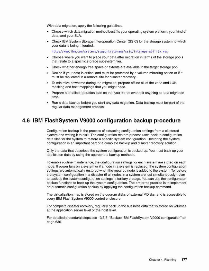
With data migration, apply the following guidelines:
� Choose which data migration method best fits your operating system platform, your kind of data, and your SLA.
� Check IBM System Storage Interoperation Center (SSIC) for the storage system to which your data is being migrated:
http://www.ibm.com/systems/support/storage/ssic/interoperability.wss
� Choose where you want to place your data after migration in terms of the storage pools that relate to a specific storage subsystem tier.
� Check whether enough free space or extents are available in the target storage pool.
� Decide if your data is critical and must be protected by a volume mirroring option or if it must be replicated in a remote site for disaster recovery.
� To minimize downtime during the migration, prepare offline all of the zone and LUN masking and host mappings that you might need.
� Prepare a detailed operation plan so that you do not overlook anything at data migration time.
� Run a data backup before you start any data migration. Data backup must be part of the regular data management process.
4.6 IBM FlashSystem V9000 configuration backup procedure
Configuration backup is the process of extracting configuration settings from a clustered system and writing it to disk. The configuration restore process uses backup configuration data files for the system to restore a specific system configuration. Restoring the system configuration is an important part of a complete backup and disaster recovery solution.
Only the data that describes the system configuration is backed up. You must back up your application data by using the appropriate backup methods.
To enable routine maintenance, the configuration settings for each system are stored on each node. If power fails on a system or if a node in a system is replaced, the system configuration settings are automatically restored when the repaired node is added to the system. To restore the system configuration in a disaster (if all nodes in a system are lost simultaneously), plan to back up the system configuration settings to tertiary storage. You can use the configuration backup functions to back up the system configuration. The preferred practice is to implement an automatic configuration backup by applying the configuration backup command.
The virtualization map is stored on the quorum disks of external MDisks, and is accessible to every IBM FlashSystem V9000 control enclosure.
For complete disaster recovery, regularly back up the business data that is stored on volumes at the application server level or the host level.
For detailed procedural steps see 13.3.7, “Backup IBM FlashSystem V9000 configuration” on page 636.
Chapter 4. Planning 177

178 Introducing and Implementing IBM FlashSystem V9000

Chapter 5. Scalability
This chapter describes the scaling capabilities of IBM FlashSystem V9000:
� Scale out for capacity� Scale up for performance
A single IBM FlashSystem V9000 storage building block consists of two IBM FlashSystem V9000 control enclosures (AC2 or AC3) and one IBM FlashSystem V9000 storage enclosure (AE2). Additionally, the AC3 control enclosures can be configured with SAS-enclosures for capacity expansion.
The examples of scaling in this chapter show how to add control enclosures, a storage enclosure, and an expansion enclosure, and how to configure scaled systems.
This chapter demonstrates scaling out with additional building blocks and adding one additional storage enclosure. This setup consists of two IBM FlashSystem V9000 building blocks configured as one IBM FlashSystem V9000 cluster.
This chapter includes the following topics:
� Overview� Building block for scaling� Scaling concepts� Adding an IBM FlashSystem V9000 storage enclosure (AE2)� Adding a second building block� Adding an IBM FlashSystem V9000 expansion enclosure (12F or 24F)� Planning � Installing � Operations� Concurrent code load in a scaled-out system
5
© Copyright IBM Corp. 2015, 2016. All rights reserved. 179

5.1 Overview
IBM FlashSystem V9000 has a scalable architecture that enables flash capacity to be added (scaled up) to support multiple applications. The virtualized system can also be expanded (scaled out) to support higher IOPS and bandwidth, or the solution can be simultaneously scaled up and out to improve capacity, IOPS, and bandwidth while maintaining MicroLatency. As a result, your organization can gain a competitive advantage through MicroLatency response times and a more efficient storage environment. IBM FlashSystem V9000 has the following scalability features per building block:
� Slots for up to 12 hot-swappable flash memory modules (1.2 TB, 2.9 TB, or 5.7 TB modules)
� Configurable 2.4 - 57 TB of capacity for increased flexibility per storage enclosure
� Up to 20 standard expansion enclosures per controller pair (up to 80 total) with up to 9.6 PB raw capacity using NL-SAS HDDs or 29.4 PB raw capacity using SSDs
� Up to 8 high-density (HD) expansion enclosures per controller pair (up to 32 total) with up to 29.4 PB raw capacity using NL-SAS HDDs or 32 PB raw capacity using SSDs
� IBM FlashSystem V9000 has the following flexible scalability configuration options:
– Scale up: Add more flash capacity– Scale up: Add more SAS capacity– Scale out: Expand virtualized system– Scale up and out: Add more flash and SAS capacity and expand virtualized system
Four types of storage enclosures are discussed in this chapter:
� IBM FlashSystem V9000 storage enclosure (AE2)
– Native IBM FlashSystem V9000 storage– Fibre channel attached– Based on MicroLatency Modules (flash modules)
� IBM FlashSystem V9000 expansion enclosure (12F, 24F, or 92F)
– SAS drive based either SSD or nearline drives– SAS attached– Used for capacity expansion– Model 12F and 24F available from Version 7.7.1– Model 92F available from Version 7.8
5.2 Building block for scaling
A single IBM FlashSystem V9000 storage platform consists of two IBM FlashSystem V9000 control enclosures (AC2 or AC3) directly cabled to one IBM FlashSystem V9000 storage enclosure (AE2), representing a building block.
For balanced increase of performance and scale, up to four IBM FlashSystem V9000 building blocks can be clustered into a single storage system, multiplying performance and capacity with each addition. The scalable building blocks require connectivity through Fibre Channel switches. The scalable building block configurations also support the addition of up to four individual IBM FlashSystem V9000 storage enclosures to be added to the storage system.
If 228 TB from four building blocks is not enough capacity, up to four extra AE2 storage enclosures can then be added. In total, an IBM FlashSystem V9000 storage system can contain a maximum of eight IBM FlashSystem V9000 storage enclosures, offering a potential
180 Introducing and Implementing IBM FlashSystem V9000

storage capacity of 456 TB, and up to 2.2 PB effective capacity is available at 80% compression. Real-time Compression is available as a software feature, assisted by hardware accelerator cards in the IBM FlashSystem V9000 control enclosures. Real-time Compression enables users to deploy Real-time Compression where it is applicable.
From Version. 7.7.1 of IBM FlashSystem V9000, SAS attached expansion enclosures are also supported.
A fixed building block uses direct internal connections without any switches. Contact your IBM representative if you want to scale up or scale out from a fixed building block.
Figure 5-1 illustrates the scalable capacity of IBM FlashSystem V9000. It also shows that extra AE2 storage enclosures can be added to a single building block, and also to two, three, or four building blocks.
Figure 5-1 IBM FlashSystem V9000 scaling
5.3 Scaling concepts
IBM FlashSystem V9000 provides three scaling concepts:
� Scale up: Add more flash capacity.
– Add up to four extra IBM FlashSystem V9000 storage enclosures.
� Scale up: Add more SAS capacity.
– Add up to 80 IBM FlashSystem V9000 model 12F or 24F expansion enclosures.– Add up to 32 IBM FlashSystem V9000 model 92F expansion enclosures.
� Scale out: Expand virtualized system.
– Add up to three IBM FlashSystem V9000 building blocks for extra performance and capacity.
Note: The scalable building blocks require connectivity through Fibre Channel switches.
Scale Out (performance & capacity)
+4 SE+3 SE+2 SE+1 SE Sc
ale
Up
Capa
city
1X 2X 3X 4X
Addtional SE's ( AE2's )
Fibre Channel(FC) Switches
Additional V9000 Building Blocks
Single Entry V9000 Building
Block
Chapter 5. Scalability 181

The first scalable IBM FlashSystem V9000 building block consists of two IBM FlashSystem V9000 control enclosures (AC2 or AC3), one IBM FlashSystem V9000 storage enclosure (AE2), representing a building block and two Fibre Channel switches for the internal 16 Gbps FC cabling. This building block with switches is called scalable building block.
IBM FlashSystem V9000 can have up to four extra storage enclosures and scale out to four building blocks as shown in Figure 5-1 on page 181. The maximum configuration has eight IBM FlashSystem V9000 control enclosures, and eight IBM FlashSystem V9000 storage enclosures.
5.3.1 Scale up for capacity
Scale up for capacity is adding an internal IBM FlashSystem V9000 storage enclosure to an existing building block. This internal storage enclosure will then be managed by the same GUI or CLI as the existing storage enclosures. This IBM FlashSystem V9000 might be a scalable building block or already be a scaled IBM FlashSystem V9000. Adding other storage to an IBM FlashSystem V9000, such as IBM Storwize V7000 or IBM FlashSystem 900, is not considered as IBM FlashSystem V9000 scale up, because it is not managed by the IBM FlashSystem V9000 GUI and it is attached using the external fabric and not the internal switches.
To add an extra IBM FlashSystem V9000 storage enclosure, see 5.4, “Adding an IBM FlashSystem V9000 storage enclosure (AE2)” on page 186.
To add an extra IBM FlashSystem V9000 expansion enclosure, see 5.6, “Adding an IBM FlashSystem V9000 expansion enclosure” on page 202
5.3.2 Scale out for performance
Scaling out for performance is equivalent to adding a second, third, or fourth building block to a scalable building block. This additional building block is managed by the same GUI or CLI as the existing IBM FlashSystem V9000. This existing IBM FlashSystem V9000 might be a single scalable building block, so that the switches are already in place, or already be a scaled IBM FlashSystem V9000 of up to three building blocks.
Scale out always adds two controller nodes and one storage enclosure per building block to an existing IBM FlashSystem V9000.
To add another IBM FlashSystem V9000 building block, see 5.5, “Adding a second building block” on page 192.
5.3.3 IBM FlashSystem V9000 scaled configurations
Table 5-1 on page 183 summarizes the minimum and maximum capacity for scalable building blocks including the addition of AE2 storage enclosures.
Note: Internal FC speed for the AC2 control enclosures can be either 16 Gbps or 8 Gbps. For the AC3 control enclosures only 16 Gbps is supported.
182 Introducing and Implementing IBM FlashSystem V9000

Table 5-1 IBM FlashSystem V9000, scalable building blocks including additional storage enclosures
PCIe expansion portsSeven Peripheral Component Interconnect Express (PCIe) slots are available for port expansions in the IBM FlashSystem V9000 AC3 control enclosures.
Table 5-2 shows the host port count per building block configuration (1, 2, 3, or up to 4 building blocks).
Table 5-2 Host port count per building blocks
Scalable building blocks (BB)
Minimum capacity (TB)
Maximum capacity (TB)
Maximum effective capacity (TB) with Real-time Compression
1 BB 2.2 57 285
1 BB + 1 AE2 4.4 114 570
1 BB + 2 AE2 6.6 171 855
1 BB + 3 AE2 8.8 228 1140
1 BB + 4 AE2 11.0 285 1425
2 BB 4.4 114 570
2 BB + 1 AE2 6.6 171 855
2 BB + 2 AE2 8.8 228 1140
2 BB + 3 AE2 11.0 285 1425
2 BB + 4 AE2 13.2 342 1710
3 BB 6.6 171 855
3 BB + 1 AE2 8.8 228 1140
3 BB + 2 AE2 11.0 285 1425
3 BB + 3 AE2 13.2 342 1710
3 BB + 4 AE2 15.4 399 1995
4 BB 8.8 228 1140
4 BB + 1 AE2 11.0 285 1425
4 BB + 2 AE2 13.2 342 1710
4 BB + 3 AE2 15.4 399 1995
4 BB + 4 AE2 17.6 456 2280
Building blocks
16 Gbps FC(host and storage)
10 Gbps iSCSI (host and storage)
10 Gbps FCoE (host)
1 32 8 8
2 64 16 16
3 96 24 24
4 128 32 32
Chapter 5. Scalability 183

For more detailed information about various interface setups, see Appendix A, “Guidelines: Port utilization in an IBM FlashSystem V9000 scalable environment” on page 657.
Expansion enclosuresIBM FlashSystem V9000 Software V7.7.1 introduces support for the addition of expansion enclosures also called tiered solution Models 9846/8-12F and 9846/8-24F, which are available for the AC3 control enclosures.
The next generation IBM FlashSystem V9000 Software V7.8 offers an additional expansion enclosure, Model 9846/8-92F. The IBM FlashSystem V9000 High-density (HD) Large Form Factor (LFF) Expansion Enclosure Model 92F supports up to 92 drives per enclosure, with a mixture of rotating disks and SSD drives in various capacities.
IBM FlashSystem V9000 Small Form Factor (SFF) expansion enclosure model 24F offers new tiering options with low cost solid-state drives (SSDs). Each SFF expansion enclosure supports up to 24 2.5-inch low cost SSD drives.
Up to 20 expansion enclosures model 12F or 24F are supported per IBM FlashSystem V9000 building block, providing up to 480 drives with expansion enclosure model 24F (SFF) and up to 240 drives with expansion model 12F (LFF) for up to 2.4 PB of raw NL-SAS capacity in each building block. With four building blocks 9.6 PB of raw NL-SAS capacity is supported.
The HD Expansion Enclosure Model 92F provides additional configuration options. Up to eight HD expansion enclosures model 92F are supported per IBM FlashSystem V9000 building block, providing up to 736 drives for up to 7.3 PB of raw NL-SAS capacity or 11.3 PB SSD capacity in each building block. With four building blocks a maximum of 32 HD expansion enclosures model 92F can be attached giving a maximum 29.4 PB of raw NL-SAS capacity and 32 PB of raw SSD capacity. For information about the allowed intermix of expansion enclosures, see 2.6.1, “SAS expansion enclosures intermix” on page 82.
Figure 5-2 on page 185 shows the maximum possible configuration with a single building block using a combination of native IBM FlashSystem V9000 storage enclosures and expansion enclosures.
Note: The focus of this book is on IBM FlashSystem V9000 Software V7.7.1 and therefore does not include examples of connecting expansion enclosures model 92F.
Note: IBM FlashSystem V9000 Version 7.7.1 has maximum manageable capacity of 32 PB. Managing 32 PB of storage requires MDisk extent size of 8192 MB.
184 Introducing and Implementing IBM FlashSystem V9000

Figure 5-2 Maximum configuration with a single scalable building block using model 12F and 24F expansion enclosures
Table 5-3 IBM FlashSystem V9000 maximum capacities
High-density (HD) solid-state drives (SSDs)High-density SSDs allow applications to scale and achieve high performance while maintaining traditional reliability and endurance levels. 1.92 TB, 3.84 TB, 7.68 TB, and 15.36 TB SAS 2.5-inch SSD options are available for IBM FlashSystem V9000 SFF expansion enclosure model 24F for up to 7.3 PB raw SSD capacity in each building block for a maximum 29.4 PB with four building blocks.
With expansion enclosure model 92F 7.68 TB and 15.36 TB SSD drives are available for up to 11.3 PB raw SSD capacity in each building block for a maximum 32 PB with four building blocks.
Model 12F10TB NL-SAS
Model 24F 15.36TB SSD
Model 92F 10TB NL-SAS
Model 92F 15.36TB SSD
1 building block (8 x 92F)
7.3 PB 11.3 PB
4 building blocks (32 x 92F)
29.4 PB 32 PBa
a. IBM FlashSystem V9000 Version 7.7.1 has a maximum manageable capacity of 32 PB.
1 building block(20 x 12F or 24F)
2.4 PB 7.3 PB
4 building blocks (80 x 12F or 24F)
9.6 PB 29.4 PB
Note: IBM FlashSystem V9000 Version 7.7.1 has a maximum manageable capacity of 32 PB.
Chapter 5. Scalability 185

High capacity nearline drivesHigh capacity nearline drives enables high value tiered storage with hot data stored in flash and warm data on lower cost NL-SAS HDDs all managed by IBM Easy Tier. The 10 TB SAS 3.5-inch nearline drives are available for IBM FlashSystem V9000 LFF expansion enclosure Model 12F and for Model 92F. Maximum capacities with four building blocks using expansion enclosure Model 12F is 9.6 PB raw nearline capacity and 29.4 PB using model 92F.
RAID typesRAID5 with standby hot spare is the only available RAID option for IBM FlashSystem V9000 native flash storage expansion. However, the additional SAS attached expansion enclosures can be configured with various RAID options. Distributed RAID (DRAID 5 and DRAID 6), which offers improved RAID rebuild times, is preferred for expansion enclosures.
5.4 Adding an IBM FlashSystem V9000 storage enclosure (AE2)
This section gives an example of adding an extra IBM FlashSystemV9000 storage enclosure (AE2) to a single scalable building block. Before scaling a building block, be sure that the internal cabling is set up and zoning on the switches has been implemented.
Note: To support SAS attached expansion enclosures, an AH13 - SAS Enclosure Attach adapter card must be installed in expansion slot 2 of each AC3 control enclosure in the building block.
Note: The Fibre Channel internal connection switches are ordered together with the first IBM FlashSystem V9000 scalable building block. You can also supply your own Fibre Channel switches and cables, if they are supported by IBM. See the list of supported Fibre Channel switches at the SSIC web page:
http://www.ibm.com/systems/support/storage/ssic/interoperability.wss
186 Introducing and Implementing IBM FlashSystem V9000
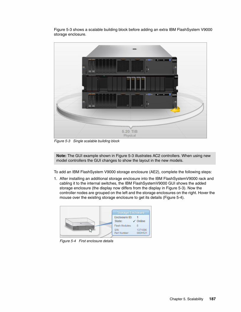
Figure 5-3 shows a scalable building block before adding an extra IBM FlashSystem V9000 storage enclosure.
Figure 5-3 Single scalable building block
To add an IBM FlashSystem V9000 storage enclosure (AE2), complete the following steps:
1. After installing an additional storage enclosure into the IBM FlashSystemV9000 rack and cabling it to the internal switches, the IBM FlashSystemV9000 GUI shows the added storage enclosure (the display now differs from the display in Figure 5-3). Now the controller nodes are grouped on the left and the storage enclosures on the right. Hover the mouse over the existing storage enclosure to get its details (Figure 5-4).
Figure 5-4 First enclosure details
Note: The GUI example shown in Figure 5-3 illustrates AC2 controllers. When using new model controllers the GUI changes to show the layout in the new models.
Chapter 5. Scalability 187

2. Hover over the empty storage enclosure frame; the click to add additional storage message is displayed (Figure 5-5).
Figure 5-5 Single building block with unconfigured additional storage enclosure
3. Click to open the Welcome page of the Add Enclosures wizard (Figure 5-6).
Figure 5-6 Add Enclosure Wizard
188 Introducing and Implementing IBM FlashSystem V9000

4. Click Next to add the storage enclosure.
After some minutes, the enclosure is added to the IBM FlashSystem V9000 and you see the Task completed message (Figure 5-7).
Figure 5-7 Adding storage enclosure completed
5. Click Close at the Task Completed window. A summary is displayed showing capacity and flash modules to be added as shown in Figure 5-8.
Figure 5-8 Add enclosure summary
Chapter 5. Scalability 189

6. Click Finish. After some minutes, the array is initialized and the task finishes (Figure 5-9).
Figure 5-9 Task completed
7. Click Close at the Task Completed screen.
8. The Add Enclosure wizard finishes by advising you that MDisks must be added manually through the MDisks by Pools page (Figure 5-10).
Figure 5-10 Add storage completed
9. Click Close and navigate to the Pools → MDisks by Pools menu or simply click MDisks by Pools at the final window in the Add Enclosure wizard.
The process of adding MDisks is described in step 8 on page 197.
You must decide whether to add the new MDisks in an existing storage pool or in a new storage pool:
� To maximize performance, place all storage in a single pool to improve tiering performance. This way, the VDisks have their extents striped across all storage enclosures, which gives best performance.
� To maximize availability, place each expansion enclosure in a separate pool for fault tolerance purposes.
190 Introducing and Implementing IBM FlashSystem V9000

In this example, the new MDisk is added to the existing MDisk pool. The result is shown in Figure 5-11.
Figure 5-11 New MDisk to the existing MDisk pool
GUI after adding the IBM FlashSystem V9000 storage enclosureFrom the IBM FlashSystem V9000 GUI home window, you now see the added enclosure (highlighted in Figure 5-12).
Figure 5-12 IBM FlashSystem V9000 with added storage enclosure
Hover over the newly added enclosure to get detailed information about it (Figure 5-13).
Figure 5-13 Enclosure 2 details
Important: Before deciding whether to create a single or multiple storage pools, carefully evaluate which option best fits your solution needs, considering data availability and recovery management.
Chapter 5. Scalability 191

Click the added enclosure to review the installed components flash modules and batteries as shown in Figure 5-14.
Figure 5-14 Review the installed components
Click the arrow to spin the enclosure to see the rear-view components (Figure 5-15).
Figure 5-15 Review components from the rear side
5.5 Adding a second building block
This section provides an example on adding an extra IBM FlashSystem V9000 AC3-based building block to a single AC2-based scalable building block.
Figure 5-16 on page 193 shows the home window for an AC2-based scalable building block before an extra IBM FlashSystem V9000 AC3-based building block is added.
192 Introducing and Implementing IBM FlashSystem V9000

Figure 5-16 Single scalable building block with AC2 control enclosures
The process of adding an extra IBM FlashSystem V9000 building block includes rack mount, cabling, power up of the new IBM FlashSystem V9000 and zoning of switches. Use the service assistance tool to check that the new devices are visible and available to the system as shown in Figure 5-17.
Figure 5-17 Service assistant shows that the new devices are available
For more information about how to access the Service Assistant see Chapter 10, “Service Assistant Tool” on page 475.
After preparing the extra IBM FlashSystem V9000, the window now differs from Figure 5-16. Now the controller nodes are grouped on the left side and the storage enclosures on the right.
Note: IBM FlashSystem V9000 AC2 and AC3 control enclosures have different layout of internal disks and batteries. This difference is depicted in the GUI.
Chapter 5. Scalability 193

Complete the following steps:
1. Hover over the non-configured I/O group 1 (Figure 5-18) to get a hint about how to configure it.
Figure 5-18 IBM FlashSystem V9000 with unconfigured second building block
2. Click the empty IO group or the empty storage enclosure to open the Welcome page of the Add Enclosures wizard (Figure 5-19) to configure control and storage enclosure.
Figure 5-19 Add enclosure wizard
3. Click Next to add the storage enclosure.
194 Introducing and Implementing IBM FlashSystem V9000

After a few minutes, the enclosure is added to the IBM FlashSystem V9000 and the Task completed message is displayed (Figure 5-20).
Figure 5-20 Adding storage enclosures
4. Now only the storage enclosure is added. Click Close to select nodes to add to the new I/O group, which by default is numbered with the next higher number. The first I/O group was named io_grp0, and io_grp1 is being added. IBM FlashSystem V9000 supports up to four I/O groups.
5. Figure 5-21 shows the Add Enclosures wizard where the new nodes are automatically selected. Click Next.
Figure 5-21 Verify node names and add enclosures
Chapter 5. Scalability 195

6. A summary is displayed (Figure 5-22). It shows that one new I/O group with two nodes are being added. The capacity field shows zero bytes being added. Capacity will be added later through the MDisks by Pools menu. Click Finish.
Figure 5-22 Summary for adding IO group and storage enclosure
7. After a few minutes the array initialization task finishes. Click Close in the Task Completed window (Figure 5-23).
Figure 5-23 Task completed after adding control and storage enclosures
196 Introducing and Implementing IBM FlashSystem V9000

When the task is completed, the Add Enclosure wizard finishes by indicating that the new MDisk must be added through the MDisks by Pools page (Figure 5-24).
Figure 5-24 Adding enclosure completed
8. Either click MDisks by Pools or click Close and then navigate to Pools → MDisks by Pools, which now shows that the new MDisk is unassigned (Figure 5-25).
Figure 5-25 New MDisk is unassigned
Before deciding whether to create a single or multiple storage pools, carefully evaluate which option best fits your solution needs, considering data availability and recovery management.
In the next example, an additional storage pool for the new MDisk is created. The new MDisk could also have been added to the existing storage pool.
9. Next, the Create Pool wizard opens (Figure 5-26). Select the extent size or accept the default of 1 GiB. Type a name for the new pool, which in this example is mdiskgrp1. Then, click Create.
Figure 5-26 Create Pool
Chapter 5. Scalability 197

The Create Pool wizard creates an empty storage pool. The Task completed message is displayed (Figure 5-27). Click Close.
Figure 5-27 The new pool is created
An empty storage pool is now available for the new MDisk (Figure 5-28).
Figure 5-28 New MDisk is unassigned
10.Either click Add Storage to the right of mdiskgrp1 or right-click the unassigned MDisk and click Assign.
198 Introducing and Implementing IBM FlashSystem V9000
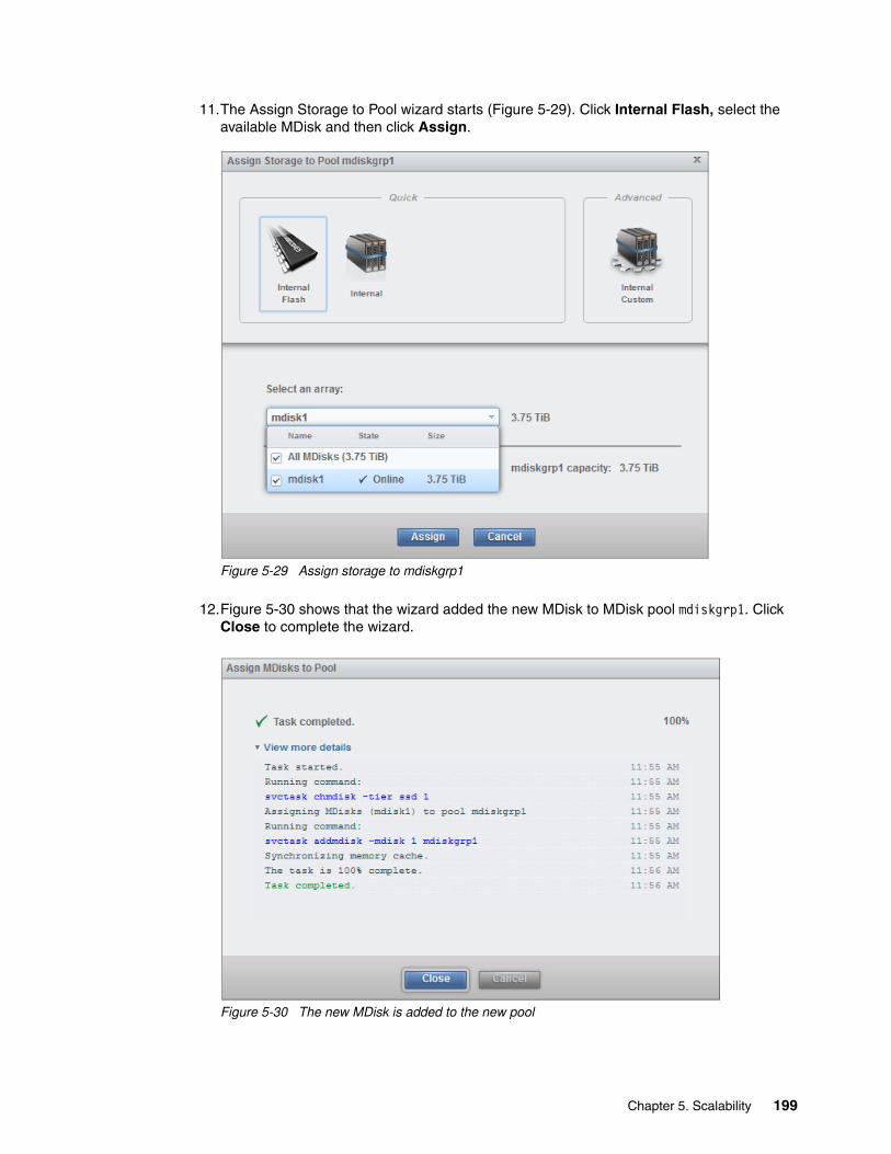
11.The Assign Storage to Pool wizard starts (Figure 5-29). Click Internal Flash, select the available MDisk and then click Assign.
Figure 5-29 Assign storage to mdiskgrp1
12.Figure 5-30 shows that the wizard added the new MDisk to MDisk pool mdiskgrp1. Click Close to complete the wizard.
Figure 5-30 The new MDisk is added to the new pool
Chapter 5. Scalability 199

The new MDisk is now included in MDisk pool mdiskgrp1 (Figure 5-31). Adding new storage is completed.
Figure 5-31 Adding new storage has completed
GUI after adding the extra building blockFrom the GUI home window you now see the added control enclosures and the added storage enclosure (Figure 5-32). The capacity indicated has increased with the value of the added storage capacity.
Figure 5-32 IBM FlashSystem V9000 scale out configuration
Note: You might have to refresh the web-browser to see the new capacity values.
Added control enclosures
Added storage enclosure
200 Introducing and Implementing IBM FlashSystem V9000

Figure 5-33 shows details of the IBM FlashSystem V9000 when you hover over the components.
Figure 5-33 Hovering over the components
Click the added enclosure to review the installed disks (Figure 5-34).
Figure 5-34 AC3 control enclosure frontside
Click the arrow to spin the enclosure in order to view the components at the rear side (Figure 5-35).
Figure 5-35 AC3 control enclosure rear side
Chapter 5. Scalability 201

5.6 Adding an IBM FlashSystem V9000 expansion enclosure
This section gives an example of adding an IBM FlashSystem V9000 expansion enclosure (12F or 24F) to a scalable building block with two building blocks. The expansion enclosure is added to the second building block, which has AC3 controller nodes.
Figure 5-36 shows a scalable building block with two building blocks before adding an extra IBM FlashSystem V9000 expansion enclosure.
Figure 5-36 Two building blocks before adding an IBM FlashSystem V9000 expansion enclosure
To add an IBM FlashSystem V9000 expansion enclosure (12F or 24F), complete these steps.
1. Install the hardware:
– SAS Enclosure Attach adapter for both AC3 control enclosures in the building block.– One or more expansion enclosures: Install the new enclosures in the rack.– SAS cables: Connect the SAS cables to both nodes at the AC3 control enclosures.– Power cables: Connect the expansion enclosures to power.
2. Power on the IBM FlashSystem V9000 expansion enclosure. Wait for the system LEDs to turn green. If any LEDs are yellow, troubleshoot the issue before proceeding.
3. Hover over the empty IBM FlashSystem V9000 expansion enclosure frame; the Click to add additional storage message is displayed (Figure 5-37 on page 203). Click the unassigned expansion enclosure and follow the instructions in the Add Enclosure wizard.
Note: To support the IBM FlashSystem V9000 expansion enclosures, an AH13 - SAS Enclosure Attach adapter card must be installed in expansion slot 2 of each AC3 control enclosure in the building block.
202 Introducing and Implementing IBM FlashSystem V9000

Figure 5-37 Click the unassigned expansion enclosure
Figure 5-38 shows the Add SAS Enclosures wizard and where the unassigned expansion enclosure is displayed with model, type and serial number. The new disk shelf is online and will be assigned an ID of 3. Click Add.
Figure 5-38 Unassigned expansion enclosures to be added
Chapter 5. Scalability 203

Figure 5-39 shows the Task Completed message and the command that was used to assign the new enclosure.
Figure 5-39 Command to assign enclosure is running
When the enclosure is assigned to the system the device is now managed. Disks in the new enclosure appear when you select Pools → Internal Storage (Figure 5-40). The disks are unused and ready to be used in the system.
Figure 5-40 Internal storage: new disks are unused
204 Introducing and Implementing IBM FlashSystem V9000

4. Navigate to Pools → MDisks by Pools.
The system recognizes that the new disks are unused and suggests to include them in the configuration (Figure 5-41). Click Yes.
Figure 5-41 Include new disks
Figure 5-42 shows the CLI commands to include the new disks in the configuration. Disks now have the status of candidate.
Figure 5-42 CLI executes and drives are now candidate drives
Chapter 5. Scalability 205

5. In the MDisks by Pools menu, you must now decide to either expand an existing MDisk pool or create a new pool. The next example takes advantage of the Easy Tier function and therefore expanding the existing pool mdiskgrp0 is chosen.
Figure 5-43 shows that 18 drives are available for storage pools.
Figure 5-43 18 drives are available for storage pools
Because you are about to mix flash and SAS drives in a single storage pool, a good practice is to name the MDisks to reflect in which storage or expansion enclosure they are located. Right-click the MDisk and click Rename (Figure 5-44).
Figure 5-44 Rename the MDisks
Available drives
206 Introducing and Implementing IBM FlashSystem V9000

Rename the existing MDisks to mdisk0-FLASH1 and mdisk1-FLASH2 to indicate that these MDisks come from flash storage. The final result is shown in Figure 5-45.
Figure 5-45 Existing MDisks renamed to reflect their type
6. Assign the new disks to the MDisk pool mdiskgrp0. Right-click the storage pool and click Add Storage (Figure 5-46).
Figure 5-46 Add storage to the MDisk pool
Chapter 5. Scalability 207

The Assign Storage to Pool wizard opens (Figure 5-47). You can choose disks from Internal or Internal Custom. Selecting Internal disks provides only one single default option for configuring RAID and spares. Selecting Internal Custom gives more choices where all available RAID and Distributed RAID (DRAID) can be selected and where stripe width and number of spares can also be configured.
Select Distributed RAID-6 with 2 spares and click Assign.
Figure 5-47 Assign disks with RAID-6 and two spares
208 Introducing and Implementing IBM FlashSystem V9000

The Task completed message is displayed (Figure 5-48).
Figure 5-48 Task completed: The new MDisk is created
Just as you renamed the MDisks coming from flash storage, you also rename the MDisk coming from SAS storage (Figure 5-49).
Figure 5-49 Rename the SAS MDisk
Chapter 5. Scalability 209

The new name should reflect the disk types within the storage pool. Enter the new name mdisk3-SAS10K-3 (Figure 5-50) and then click Rename to continue.
Figure 5-50 Enter new name
7. Check the tiering level. Tiering level is automatically determined by IBM Easy Tier and can be changed only by using CLI commands. Easy Tier operates with three levels, or tiers, with Version 7.7 of IBM FlashSystem V9000 software: flash, enterprise, and nearline.
Easy Tier can manage five types of drives in up to three tiers within a managed pool:
– Tier 0 or flash tier: Flash cards and flash drives (SSD). This tier is the highest performance drive class that is currently available.
– Tier 1 or enterprise tier: 10K RPM or 15K RPM SAS disk drives. This tier is the high-performance drive class.
– Tier 2 or nearline tier: 7.2K RPM nearline disk drives. This tier is the low-cost, large capacity, storage drive class.
To check the tier levels, right-click the blue bar at the top of the MDisks by Pools window and select Tier. The resulting MDisks and tier levels are shown in Figure 5-51.
Figure 5-51 MDisks and tiers
Note: Starting with IBM FlashSystem V9000 Version 7.8, an additional tier of flash storage is provided to differentiate tier 0 flash from tier 1 flash. See 3.2.1 IBM Easy Tier for more information.
210 Introducing and Implementing IBM FlashSystem V9000

GUI after adding the expansion enclosureThe IBM FlashSystem V9000 home window (Figure 5-52) now shows the added enclosure.
Figure 5-52 The added expansion enclosure appears on the GUI
Click the added enclosure to review the installed disks (Figure 5-53).
Figure 5-53 SAS enclosure front
Note: Version 7.8 of IBM FlashSystem V9000 introduces an extra tier level supporting read-intensive solid-state drives (RI SSD). These are the new tiering levels:
� Tier0 - Flash tier (MicroLatency flash modules)� Tier1 - SSD tier (new) (SSD drives) � Tier2 - HDD tier (SAS disk drives)� Tier3 - nearline tier (NL-SAS disk drives)
Added expansion enclosure
Chapter 5. Scalability 211

Click the arrow to spin the enclosure to view components at the rear side (Figure 5-54).
Figure 5-54 SAS enclosure rear side
5.7 Planning
See the following areas of this book:
� Chapter 4, “Planning” on page 135 describes details for planning the set up of a scaled IBM FlashSystem V9000.
� Appendix A, “Guidelines: Port utilization in an IBM FlashSystem V9000 scalable environment” on page 657 provides examples and guidelines for configuring port utilization and zoning to optimize performance and properly isolate the types of Fibre Channel traffic.
Guidelines are provided for two suggested methods of port utilization in an IBM FlashSystem V9000 scalable environment, dependent on customer requirements:
– IBM FlashSystem V9000 port utilization for infrastructure savings
This method reduces the number of required Fibre Channel ports attached to the customer’s fabrics. This method provides high performance and low latency, but performance might be port-limited for certain configurations. Intra-cluster communication and AE2 storage traffic occur over the internal switches.
– IBM FlashSystem V9000 port utilization for performance
This method uses more customer switch ports to improve performance for certain configurations. Only ports that are designated for intra-cluster communication are attached to private internal switches. The private internal switches are optional and all ports can be attached to customer switches.
5.8 Installing
Chapter 6, “Installation and configuration” on page 231 includes details of how to install and configure IBM FlashSystem V9000. It describes the tasks that are done by the IBM Service Support Representative or IBM lab-based services to set up the system and the follow-on task done by the customer.
212 Introducing and Implementing IBM FlashSystem V9000

5.9 Operations
The IBM FlashSystem V9000 GUI is the focal point for operating the system. You need only one GUI to create volumes and hosts, and map the volumes to the host.
This section shows how to add an AIX host to I/O group 0 and I/O group 1. A Red Hat Enterprise Linux host will be added to I/O group 1. This section provides an example of host and volume creation for a scaled IBM FlashSystem V9000.
For information about host and volume creation, see Chapter 8, “Using IBM FlashSystem V9000” on page 321.
Complete the following steps:
1. In the GUI, select Hosts and click Add Hosts.
2. The Add Host wizard opens (Figure 5-55). Click Fibre Channel to add the AIX host.
Figure 5-55 Add host wizard
3. The fields to set the new host are displayed (Figure 5-56). Provide a name for the host and select the host port WWPN. Use the default for the host type unless you have other requirements. Select io_grp0 and io_grp1. Click Add to create the host.
Figure 5-56 Add AIX host to two I/O groups
Chapter 5. Scalability 213

4. To add a Redhat host, restart the wizard and add the Redhat information. Figure 5-57 shows adding a host only for I/O group 1. Click Add to create the Redhat host.
Figure 5-57 Add RedHat host to only I/O group 1
The hosts are now created and available to the number of I/O groups (Figure 5-58).
Figure 5-58 Hosts and number of I/O groups
214 Introducing and Implementing IBM FlashSystem V9000

5. The next step is to create volumes for the hosts. Click Create Volumes in the Volumes menu and click Custom. Provide a name for the volumes, and enter the capacity and number of volumes. Create four volumes for the AIX host (Figure 5-59).
Figure 5-59 Create 4 volumes
6. After you enter the volume detail data, click Volume Location.
7. Volumes are presented to the host by one I/O group. A cluster with two or more I/O groups will, by default, automatically balance the volumes over all I/O groups. The AIX host can access both I/O groups in this example setup. Therefore, the volumes for the AIX host can be auto-balanced over the two I/O groups. This is the default setup, as shown in Figure 5-60. Click Create to create the four volumes.
Figure 5-60 Default volume location settings
Chapter 5. Scalability 215

8. The volume information shows four AIX volumes distributed over both I/O groups. The header in the next figure was altered to show preferred node ID and caching I/O group. The caching I/O group presents the volume to the host, as shown in Figure 5-61.
Figure 5-61 Volumes and caching I/O group
9. The next step creates volumes for the Red Hat host (RedHat). The Redhat host is attached to only I/O group 1 and therefore on the Volume Location tab, the caching I/O group is set to io_grp1 (Figure 5-62). Click Create to create the volumes.
Figure 5-62 Limiting access to I/O group 1
Note: By default, volume format is always on in custom and non custom mode. By selecting custom mode in the Create Volumes wizard, you can deselect Format volume on the General tab. Volume format can take a long time and might not be needed.
Note: The Preferred Node ID in the example in Figure 5-61 shows IDs 1,2,9 and 10. In an actual customer environment where a building block is being added, the node IDs are assigned the next higher number which, in this example, would be 3 and 4. The example shows numbers 9 and 10 due to several additions and removals of I/O groups in our test environment.
216 Introducing and Implementing IBM FlashSystem V9000

10.The volume information shows that the four added Redhat volumes are presented by I/O group 1 to the host (Figure 5-63).
Figure 5-63 Volumes and caching I/O group
Move unmapped volumes to another I/O groupIf there is a need to move a host and its volumes from one I/O group to another, this can be completed with volumes mapped to the host or with unmapped volumes. To move unmapped volumes complete the following steps:
1. From the Hosts menu, right-click a host (Figure 5-64) and click Properties. Then, click Show Details.
Figure 5-64 Show hosts properties with detailed view
The host is enabled only for I/O group 1, and you must enable it for I/O group 0 also.
Chapter 5. Scalability 217

2. Click Edit and then select the I/O group (Figure 5-65) that the host and volumes are to be migrated to. The host is going to be available to I/O group 0 and I/O group 1. Click Save.
Figure 5-65 Edit details: select additional I/O group
3. From the Volumes menu, select the volumes to be moved to the other I/O group. Either right-click or click the Actions menu and select Modify I/O Group (Figure 5-66).
Figure 5-66 Modify I/O group
218 Introducing and Implementing IBM FlashSystem V9000

4. The Move Volumes to a New I/O Group wizard opens (Figure 5-67). Select the new I/O group and click Move.
Figure 5-67 Move I/O group
The volumes are moved to I/O group 0 (Figure 5-68).
Figure 5-68 Volumes now appear in the other I/O group
The host can now be deselected from I/O group 1 or it can be left as is from the Hosts menu.
Move mapped volumes to another I/O groupMoving host-mapped volumes requires more attention from you, because the hosts have to discover new paths and they have to remove the old paths, while at the same time host access to its volumes must remain uninterrupted.
The following example moves the four Red Hat volumes back to I/O group 1 from I/O group 0.
To move host-mapped volumes, complete the following steps:
1. From the Volumes menu select the volumes to be moved to another I/O group, right-click and select Modify I/O Group. The Move Volumes to New I/O Group wizard opens (Figure 5-69 on page 220).
Chapter 5. Scalability 219

Figure 5-69 Move Volumes to a New I/O Group wizard
2. In this example, you allow only the Red Hat host to access I/O group 0 and I/O group 1 so only I/O group 1 is a candidate. Select the new I/O group and click Apply and Next (Figure 5-70).
Figure 5-70 Select new I/O group
220 Introducing and Implementing IBM FlashSystem V9000

CLI commands execute and then the Task completed message is displayed (Figure 5-71).
Figure 5-71 Task completed
3. The system now maps the volumes to the new I/O group while, at the same time, keeping them in the first I/O group. The host now has to discover the new paths, so you must perform path discovery from the host side before continuing to make sure that the host has appropriate access to its volumes on the new paths. After new paths are detected, click Apply and Next (Figure 5-72).
Figure 5-72 Detect new paths
4. When you confirm that hosts discovered all new paths for the volumes, the Move Volumes to a New I/O Group wizard removes access to the first I/O group and thereby also removes all paths to it. Click Next to remove the old paths (Figure 5-73).
Chapter 5. Scalability 221

Figure 5-73 Old paths are removed
5. Review the summary and click Finish (Figure 5-74).
Figure 5-74 Finish Move Volumes to a new I/O Group wizard
222 Introducing and Implementing IBM FlashSystem V9000

The volumes are now moved back to I/O group 1 (Figure 5-75).
Figure 5-75 Volumes were moved to the new I/O group
Creating volumes, adding hosts, and mapping volumes to hosts in an IBM FlashSystem V9000 scaled-out configuration needs careful planning of host connections with regard to the I/O groups. This example of the AIX host and the Red Hat host demonstrates these steps.
5.10 Concurrent code load in a scaled-out system
This section demonstrates the IBM FlashSystem V9000 software update. Before you start a system update, be sure that the system has no problems that might interfere with a successful update. When the system uses HyperSwap volumes, make sure that all HyperSwap relationships have a status of Online by running the lsrcrelationship command or by using the GUI. Hosts must be configured with multipathing between the nodes of the accessing I/O group or groups when using HyperSwap.
The update process is described in 9.5.3, “Update software” on page 455. This section includes a brief description of the update on an IBM FlashSystem V9000 scaled out system.
Figure 5-76 on page 224 shows an IBM FlashSystem V9000 full scaled-out cluster using four building blocks and four additional IBM FlashSystem V9000 storage enclosures (in total, eight controller nodes and eight storage enclosures).
Note: The software release notes contain the current information about the update.
Chapter 5. Scalability 223

Figure 5-76 Full scaled-out and scaled-up IBM FlashSystem V9000
IBM FlashSystem V9000 update consists of three phases, with different steps for each phase:
1. Phase 1: IBM FlashSystem V9000 control enclosures:
a. Update of one controller node per I/O group, one controller at a time.
b. Pause for approximately 30 minutes for host path discovery; hosts have to reconnect to the updated controller nodes.
c. Update of the other controller node of an I/O group, one controller at a time.
2. Phase 2: IBM FlashSystem V9000 storage enclosures software:
a. Update of one canister per storage enclosure, all in parallel.
b. Update of the other canister of a storage enclosure, all in parallel.
3. Phase 3: IBM FlashSystem V9000 storage enclosures hardware:
a. Update batteries, flashcards, and so on.
The update takes about 2.5 hours for a cluster with one building block. You can add 10 - 15 minutes per additional node. Adding IBM FlashSystem V9000 storage enclosures does not increase the amount of time for the update because they are all updated in parallel.
224 Introducing and Implementing IBM FlashSystem V9000

Complete the following steps:
1. To start the concurrent code load (CCL), click Settings → System → Update System → Update.
2. The Update System wizard opens (Figure 5-77). Provide a name for the test utility and the update package. Use the folder buttons to select the correct file names and click Update.
Figure 5-77 Update system file selection
3. You are prompted whether you want the update to be automatic or manual. Select Automatic update (Figure 5-78) and then click Finish.
Figure 5-78 Automatic or manual update
Chapter 5. Scalability 225

After you click Finish, these steps occur:
1. The files are uploaded to IBM FlashSystem V9000. A progress bar shows the status of the upload (Figure 5-79).
Figure 5-79 CCL upload progress bar
2. After uploading the files, the GUI shows the overall progress bar. It takes one to two minutes after uploading the files before the overall progress status is shown. Figure 5-80 shows the information for a cluster of eight nodes and four building blocks.
Figure 5-80 Overall Progress
At the starting point of the update, all eight nodes and the system part, which also includes the IBM FlashSystem V9000 enclosures, are in state Not updated. Then all eight nodes are updated, one by one, starting with the second node of each I/O group. After one node of every I/O group is updated, the update pauses for approximately 30 minutes for host path discovery. Then, the other nodes are updated.
226 Introducing and Implementing IBM FlashSystem V9000

3. Figure 5-81 shows the progress on the first node updating, which is node 2 in this example.
Figure 5-81 Updating first node, the second node of the first I/O group
4. Figure 5-82 shows the progress on the second node that is updating, which is node4 in this example.
Figure 5-82 Second node updating (node 4)
Chapter 5. Scalability 227

5. Figure 5-83 shows the progress on the fourth node that is updating, which is node8 in this example.
Figure 5-83 Fourth node updating, which is node 8
6. After updating half of all nodes, one node of every I/O group, the update pauses for approximately 30 minutes for host path discovery.
After the configuration node update starts, a node failover message is displayed (Figure 5-84).
Figure 5-84 Node failover due to update of the configuration node
228 Introducing and Implementing IBM FlashSystem V9000

7. After all of the IBM FlashSystem V9000 controller nodes are updated, IBM FlashSystem V9000 storage enclosure software is updated. All IBM FlashSystem storage enclosures are updated in parallel, that is, at the same time. First, IBM FlashSystem V9000 storage enclosure software is updated and then all other components, such as flash modules, batteries, and so on are updated (Figure 5-85).
Figure 5-85 IBM FlashSystem storage enclosure canister update
8. When the update is complete, a message indicates that IBM FlashSystem V9000 is running the most current software (Figure 5-86).
Figure 5-86 IBM FlashSystem V9000 running up-to-date software
All IBM FlashSystem V9000 controller nodes and storage enclosures are now updated to the current software level. The updated GUI now has new icons for configuring IP Quorum and NPIV.
Chapter 5. Scalability 229

230 Introducing and Implementing IBM FlashSystem V9000

Chapter 6. Installation and configuration
This chapter shows how to install and configure IBM FlashSystem V9000. The system environmental requirements, cabling, and management are described. Installation from the initial setup procedure through configuring the system for use is demonstrated.
This chapter includes the following topics:
� Installation overview� IBM FlashSystem V9000 physical specifications� Installing the hardware� Connecting the components� Initial customer setup
6
© Copyright IBM Corp. 2015, 2016. All rights reserved. 231

6.1 Installation overview
Installation and initial configuration of IBM FlashSystem V9000 requires the completion of various tasks. An IBM Service Support Representative (SSR) installs a single building block without switches. All other configuration is done by IBM lab services. An SSR is responsible for the physical installation only. After this is done, the customer can then set up the system.
6.1.1 Tasks for the IBM SSR or IBM lab-based services
During installation, the IBM SSR or the IBM lab-based services do the tasks described in this section. To learn about the steps that will be performed, limitations, and requirements, see the “Installing” topic at IBM Knowledge Center:
https://ibm.biz/BdsZrK
Hardware installation To install the IBM FlashSystem V9000 hardware, an IBM SSR or IBM lab-based services must complete the following tasks:
1. Install the AC2 or AC3 control enclosures and AE2 storage enclosure in the rack.
2. Connect the components as planned using Fibre Channel (FC) either in a direct attach configuration or with FC switches for internal, and with switched fabrics for the host, the Ethernet management switch, and to the power distribution units.
3. Connect the components, using FC with or without switches, the Ethernet management switch, and connecting the components to the power distribution units:
– For a fixed building block installation, the SSR completes the cabling.– For a scalable building block installation, IBM lab-based services completes the
cabling.
Initial setup tasks After the hardware is installed in the rack and cabled to meet the configuration you want, an IBM SSR or IBM lab-based services conducts the initial installation and configuration by performing the following tasks:
1. Connect a workstation to an AC2 or AC3 control enclosure technician port.
2. Configure the IBM FlashSystem V9000 clustered system with a name and management IP address.
3. Use the web browser to go to the management IP address of the cluster, and follow the steps of the setup wizard in the management GUI to set up call home by using information from the customer-supplied worksheets, shown in Chapter 4, “Planning” on page 135.
Important: The customer worksheets in 4.2.1, “Racking considerations” on page 142 must be completed before the installation because they determine the location of the components in the rack.
Note: For details about the procedure to power up IBM FlashSystem V9000, see the topic about powering on and powering off an IBM FlashSystem V9000 building block:
https://ibm.biz/BdsZrn
232 Introducing and Implementing IBM FlashSystem V9000

6.1.2 First customer involvement
After the IBM SSR or IBM lab-based services completes the service setup process, you log in to the AC2 or AC3 control enclosure and complete the following tasks by using the customer setup wizard as described in 6.5, “Initial customer setup” on page 238. The following steps are an overview of the process:
1. Change the system password.2. Change the system name.3. Configure licensed functions.4. Set the date and time.5. Confirm the call home settings that the IBM SSR or IBM lab-based services entered.6. Add the AE2 storage enclosure.
6.2 IBM FlashSystem V9000 physical specifications
The IBM FlashSystem V9000 is installed in a standard 19-inch equipment rack. The IBM FlashSystem V9000 building block is 6U high and 19 inches wide. A standard data 42U 19-inch data center rack can be used to populate with the maximum IBM FlashSystem V9000 configuration to use up to 36U. For a description of physical dimensions, see 2.2.4, “Physical specifications” on page 57.
6.3 Installing the hardware
The IBM SSR is responsible for physically installing IBM FlashSystem V9000.
This process involves installing the two control enclosures and the storage enclosure. These three enclosures form a 6U building block. For a scalable building block, additional components, such as Fibre Channel switches and an Ethernet switch are also installed.
When installed, the components of the IBM FlashSystem V9000 appear as shown in Figure 6-1. Only an 8 or 16 Gbps Fibre Channel attachment can be used for direct attach.
Figure 6-1 View of the IBM FlashSystem V9000 front panel
Chapter 6. Installation and configuration 233

6.4 Connecting the components
The AE2 storage enclosure and AC2 or AC3 control enclosures can be connected to create a fixed building block or a scalable building block:
� The IBM SSR is responsible for connecting (cabling) the three enclosures in a fixed building block.
� Lab-based services is responsible for cabling the AC2 or AC3 control enclosures, the AE2 storage enclosure, and the Fibre Channel switches and Ethernet switch in a scalable building block.
For interface protocol and connection tables, see 2.1.6, “Host adapter protocol support” on page 38.
6.4.1 Connecting the components in a fixed building block
The IBM SSR is responsible for connecting the components of a fixed building block.
To create a fixed building block:
1. Create direct links between the AE2 storage enclosure and the two AC2 or AC3 control enclosures.
2. Create a direct link between the control enclosures.
3. Connect the hosts or external storage to the AC2 or AC3 control enclosures.
To improve performance and provide redundancy, both AC2 or AC3 control enclosures are connected to both canisters in the AE2 storage enclosure.
Figure 6-2 illustrates the interface protocols and maximum number of connections supported for an IBM FlashSystem V9000 fixed building block for a five-host, 16 Gbps Fibre Channel configuration. There are also redundant cluster links between the two AC3 control enclosures.
Figure 6-2 Fixed building block protocols and connections for 16 FC Gbps configuration using AC3 control enclosures
234 Introducing and Implementing IBM FlashSystem V9000

Information about supported protocols and connections for IBM FlashSystem V9000 fixed and scalable building blocks is in 2.1.6, “Host adapter protocol support” on page 38.
6.4.2 Connecting the components in a scalable building block
IBM lab-based services is responsible for cabling the building block components.
Cabling involves installing the network and storage data cables that are internal to the IBM FlashSystem V9000 scaled building blocks.
Figure 6-3 shows a conceptual view of a typical cabling example of one building block with an added AE2 storage enclosure.
Figure 6-3 One building block and one additional AE2 storage enclosure connection
The numbers in the figure have the following meanings:
1. Host and external storage connections
2. Redundant cluster links between the AC2 or AC3 control enclosures
3. AC2 or AC3 control enclosures
4. Fibre Channel connections to the AE2 storage enclosures
5. AE2 storage enclosures
Note: For the fixed building block 16 Gbps configuration, you need two FC ports (AC3 to AC3) and six FC ports (AC3 to AE2). The remaining six FC ports can be used for host or external storage attachment.
Internal Switches
Host/external storage switches
Chapter 6. Installation and configuration 235

Remember that one building block contains two AC2 or AC3 control enclosures and one AE2 storage enclosure. Your final configuration can be up to four building blocks and four additional AE2 storage enclosures.
For internal Fibre Channel switches, a minimum of two switches are needed for redundancy purposes on a 16 Gbps configuration and four switches for an 8 Gbps configuration (for AC2 control enclosure only). Switches that IBM suggests can be used, or any other switches can be used with the relevant attention on the open access method that is used by the AC2 or AC3 control enclosure to reach the AE2 storage enclosure.
Host connections to the AC2 or AC3 control enclosures can be these connections types:
� Direct/switched Fibre Channel connections (16 Gbps or 8 Gbps)� Fibre Channel Over Ethernet or ISCSI (10 Gbps Ethernet links)
The rear view of the AC2 control enclosure is shown in Figure 6-4.
Figure 6-4 AC2 controller enclosure rear view
For more information about connecting components, see the following IBM Knowledge Center topics:
� Connecting the components in a fixed building block (IBM SSR task):
https://ibm.biz/BdsPPt
� Connecting the components in a scalable building block (IBM lab based services task)
https://ibm.biz/BdsPPN
Comprehensive examples and configuration guidelines of the following two preferred methods for port utilization in an IBM FlashSystem V9000 scalable environment are in Appendix A, “Guidelines: Port utilization in an IBM FlashSystem V9000 scalable environment” on page 657:
� IBM FlashSystem V9000 port utilization for infrastructure savings
This method reduces the number of required customer Fibre Channel ports attached to the customer fabrics. This method provides high performance and low latency but performance might be port limited for certain configurations. Intra-cluster communication and AE2 storage traffic occur over the internal switches.
� IBM FlashSystem V9000 port utilization for performance
This method uses more customer switch ports to improve performance for certain configurations. Only ports designated for intra-cluster communication are attached to private internal switches. The private internal switches are optional and all ports can be attached to customer switches. By following the cabling guidelines in the appendix you can see performance improvements up to 40% for sequential reads and up to 80% for sequential writes.
Note: When using customer SAN Switches, plan carefully to ensure that optimal performance is available to the V9000 internal communications.
236 Introducing and Implementing IBM FlashSystem V9000

6.4.3 Ethernet cabling
IBM lab-based services is responsible for cabling components to the Ethernet switch.
The internal connectivity Ethernet switch provides management connections for the IBM FlashSystem V9000.
Figure 6-5 shows a typical wiring diagram for cabling the components to the Ethernet switch.
Figure 6-5 Ethernet switch wiring diagram
Switch port usage depends on the speed:
� If two 16 Gbps FC switches are used rather than four 8 Gbps FC switches, only two of the four Ethernet connections for FC switches are needed.
� Redundant Ethernet management links for AC2 or AC3 control enclosures are not necessary to protect them from management link and port failures. The AC2 or AC3 control enclosures function as a pair in an I/O group, and, if a node failure occurs, the partner AC2 or AC3 control enclosure in the I/O group (or another AC2 or AC3 control enclosure in the cluster) takes over management of the I/O group or cluster.
6.4.4 Scaling from one to two, three, or four building blocks
IBM lab-based services is responsible for the configuration tasks that are involved in scaling from one scalable building block to two, three, or four scalable building blocks.
Before you beginBe sure these actions are complete before you scale the environment:
� The building block components must be installed in the rack in the specified locations.� The building block components must be cabled.� The first scalable building block must be operational.
Chapter 6. Installation and configuration 237

ProcedureFollow this procedure to add a new building block:
1. Power on the components for the new building blocks.
2. Log on to the management GUI of the existing system. The system recognizes that there are new candidate enclosures and displays a graphic that shows the new enclosures.
3. Place the cursor over the graphic of a new enclosure, and then click to run the wizard that adds the new enclosure to the system.
4. From the networking section of the GUI, add the management IP addresses for the new building blocks. For details, see 4.3.1, “Management IP addressing plan” on page 153.
More information about various interface setups is in Appendix A, “Guidelines: Port utilization in an IBM FlashSystem V9000 scalable environment” on page 657.
6.5 Initial customer setup
After the service setup of the new system is complete, you can use the management GUI to input the initial setup information.
Before you begin, be sure that you have the following information:
� The cluster management IP address of the system entered by the IBM SSR
� The IP address of a Network Time Protocol (NTP) server, for automated setting of date and time
� Licensed function information
� The Simple Mail Transfer Protocol (SMTP) server IP address
� Any email contacts you want to be added in the notification mails
6.5.1 License agreement and password change
This section explains how to start the customer setup wizard.
Complete the following steps:
1. Open a supported browser and go to the following address:
http://<management_ip_address>
IBM SSRs will provide login information when their portion of the installation is completed, as shown in Figure 6-6 on page 239.
Tips: Next, you need the cluster management IP address (<management_ip_address>) that the IBM SSR entered.
238 Introducing and Implementing IBM FlashSystem V9000

Figure 6-6 SSR customer information screen
2. To continue, read the IBM FlashSystem V9000 product license and click Accept (Figure 6-7).
Figure 6-7 License agreement page
Note: IBM FlashSystem V9000 uses a self-signed certificate, which in some browsers causes a warning message such as The certificate is only valid for xxxx. Adding an exception will avoid this warning in the future.
Chapter 6. Installation and configuration 239

3. You can change the default password (passw0rd with a zero) in the next window (Figure 6-8).
Figure 6-8 Superuser password change panel
6.5.2 System Setup wizard
The Welcome page opens (Figure 6-9 on page 241), which is where system setup starts.
You might need the following information (if the IBM SSR has not yet entered it):
� IP address of an NTP server� IP address of the Single Mail Transfer Protocol server
You will need the following information:
� Licensed function information� The email and contacts you want to be added to the “notification mails”
Note: If the IBM SSR entered this information in the initial GUI, these values are displayed and you can verify them.
240 Introducing and Implementing IBM FlashSystem V9000

Figure 6-9 First wizard panel, click Next
6.5.3 System name change
You can change the system name by completing the following steps:
1. Enter the name, and then click Apply and Next (Figure 6-10).
Figure 6-10 System Name change
Chapter 6. Installation and configuration 241

2. The next window displays the result of the System Name change (Figure 6-11). On error, you can click Cancel, or Close to continue.
Figure 6-11 System name change completion window
242 Introducing and Implementing IBM FlashSystem V9000

6.5.4 Licensed functions
To provide the correct values for the licensed functions (Figure 6-12), refer to the licenses feature code that you purchased.
Figure 6-12 Licensed functions
6.5.5 Date and time setup
In the next step, you set the date and time. Use either of these two options:
� Enter the date and time manually.� Synchronize the logs with all others systems using an external NTP server. This is the
preferred option. NTP is mandatory if you enable VVOL later.
Note: Enter only the purchased values of licensed functions. Inaccurate licensed functions data can compromise the IBM support response.
Note: If during the initial setup, the IBM SSR entered any information, you can validate the information by clicking Apply and Next.
Chapter 6. Installation and configuration 243

Depending on your date and time selection, you see two separate pages (Figure 6-13 and Figure 6-14).
Figure 6-13 Manual date and time setting (not the preferred selection)
Figure 6-14 Date and time using an NTP server (the preferred selection)
244 Introducing and Implementing IBM FlashSystem V9000

The next window shows the results of the date and time change (Figure 6-15). On error, you can click Cancel, or click Close to continue.
Figure 6-15 Date and Time change completion window
6.5.6 Call Home
Call Home is the final step. If the IBM SSR previously entered the system location and the email server, validate the data and alter the values if not correct:
1. Validate or enter the system location (Figure 6-16).
Figure 6-16 Physical system location
Chapter 6. Installation and configuration 245

2. On the Contact page (Figure 6-17), validate or enter contact information for the person that the support center should contact to resolve issues with the system. Other information is used by the the support center to contact your support team, so be sure that the information is accurate.
Figure 6-17 Contact details
Tip: The value in the Email address field will be used by the IBM FlashSystem V9000 to send email messages for heartbeat, call home, or events. This address must be authorized by your SMTP server. Usually a “white list” mechanism is the way to do this. Be sure to involve the SMTP support team when you set up the value in the Email address field.
246 Introducing and Implementing IBM FlashSystem V9000

3. Validate or enter the information about the Email Servers, SMTP server IP address (Figure 6-18). You can add more than one server by clicking the plus sign (+) button.
Figure 6-18 Email Servers (SMTP IP address)
Chapter 6. Installation and configuration 247

6.5.7 Summary of changes
The initial setup is now completed. Review the changes:
1. Figure 6-19 shows a summary of all data. Read the information carefully. You can click Back to correct data, or click Next to validate the data.
Figure 6-19 Summary of all changes
2. The next window summarizes all changes (Figure 6-20). On error, you can click Cancel, or click Close to continue.
Figure 6-20 Summary of all changes completion window
248 Introducing and Implementing IBM FlashSystem V9000

3. You are redirected to the management GUI, click Close to continue (Figure 6-21).
Figure 6-21 Setup wizard completion window
4. A Suggested Tasks window opens (Figure 6-22). For now, click Cancel to move on to adding the AE2 storage enclosure.
Figure 6-22 Setup suggestions
Chapter 6. Installation and configuration 249

6.5.8 Add AE2 storage enclosure
The final step is to add the AE2 storage enclosure to the IBM FlashSystem V9000 configuration:
1. Click the AE2 storage enclosure (Figure 6-23), which automatically starts the wizard.
Figure 6-23 Add AE2 storage enclosure
2. The Welcome panel opens (Figure 6-24). Click Next to start to add the AE2 storage enclosure.
Figure 6-24 Add AE2 storage enclosure wizard Welcome panel
250 Introducing and Implementing IBM FlashSystem V9000

3. The code update or downgrade of the AE2 storage enclosure starts. Wait for the task to complete (Figure 6-25) or click Cancel to stop the process. When the Close button is enabled, click it to continue.
Figure 6-25 Add AE2 storage enclosure results
4. The summary of the available storage is displayed (Figure 6-26 on page 252). Click either Back to stop the process or Finish to continue.
Chapter 6. Installation and configuration 251

Figure 6-26 Add AE2 storage enclosure summary
5. Wait for the task to complete (Figure 6-27). Click either Cancel to stop the task or Close to continue.
Figure 6-27 Add AE2 storage enclosure result
252 Introducing and Implementing IBM FlashSystem V9000

6. You can now close the last window and start to create MDisks on your IBM FlashSystem V9000 (Figure 6-28).
Figure 6-28 Adding AE2 storage enclosure complete
Chapter 6. Installation and configuration 253

254 Introducing and Implementing IBM FlashSystem V9000

Chapter 7. Host configuration
This chapter describes the host configuration procedures to attach supported hosts to IBM FlashSystem V9000.
This chapter includes the following topics:
� Host attachment overview� IBM FlashSystem V9000 setup� iSCSI� File alignment for the best RAID performance� AIX: Specific information� IBM i: Specific information� Windows: Specific information� Linux: Specific information� VMware: Configuration information� Oracle (Sun) Solaris: Configuration information� Hewlett-Packard UNIX: Configuration information� Using NPIV functionality� Using SDDDSM, SDDPCM, and SDD web interface� More information
7
© Copyright IBM Corp. 2015, 2016. All rights reserved. 255

7.1 Host attachment overview
The IBM FlashSystem V9000 can be attached to a client host by using three interface types:
� Fibre Channel (FC)� Fibre Channel over Ethernet (FCoE)� IP-based Small Computer System Interface (iSCSI)
Always check the IBM System Storage Interoperation Center (SSIC) to get the latest information about supported operating systems, hosts, switches, and so on.
If a configuration that you want is not available on the SSIC, a Solution for Compliance in a Regulated Environment (SCORE) or request for price quotation (RPQ) must be submitted to IBM requesting approval. To submit a SCORE/RPQ, contact your IBM FlashSystem marketing representative or IBM Business Partner.
IBM FlashSystem V9000 supports 16 gigabits per second (Gbps) FC attachment direct connection to client hosts. Verify your environment and check its compatibility to use 16 Gbps direct attachment to the host by accessing the IBM System Storage Interoperation Center (SSIC) web page:
http://www.ibm.com/systems/support/storage/ssic/interoperability.wss
For details, see the IBM FlashSystem V9000 web page in IBM Knowledge Center:
https://ibm.biz/fs_V9000_kc
Also see, the “Host attachment” topic in IBM Knowledge Center:
https://ibm.biz/Bdsix6
IBM FlashSystem V9000 supports a wide range of host types (both IBM and non-IBM), which makes it possible to consolidate storage in an open systems environment into a common pool of storage. The storage can then be managed using pooling more efficiently as a single entity from a central point on the storage area network (SAN).
The ability to consolidate storage for attached open systems hosts provides these benefits:
� Unified, single-point storage management� Increased utilization rate of the installed storage capacity� Use data mobility to share storage technologies between applications� Advanced copy services functions offered across storage systems from separate vendors� Only one kind of multipath driver to consider for attached hosts
7.2 IBM FlashSystem V9000 setup
In most IBM FlashSystem V9000 environments where high performance and high availability requirements exist, hosts are attached through a SAN using the Fibre Channel Protocol (FCP). Even though other supported SAN configurations are available, for example, single fabric design, the preferred practice and a commonly used setup is for the SAN to consist of two independent fabrics. This design provides redundant paths and prevents unwanted interference between fabrics if an incident affects one of the fabrics.
256 Introducing and Implementing IBM FlashSystem V9000
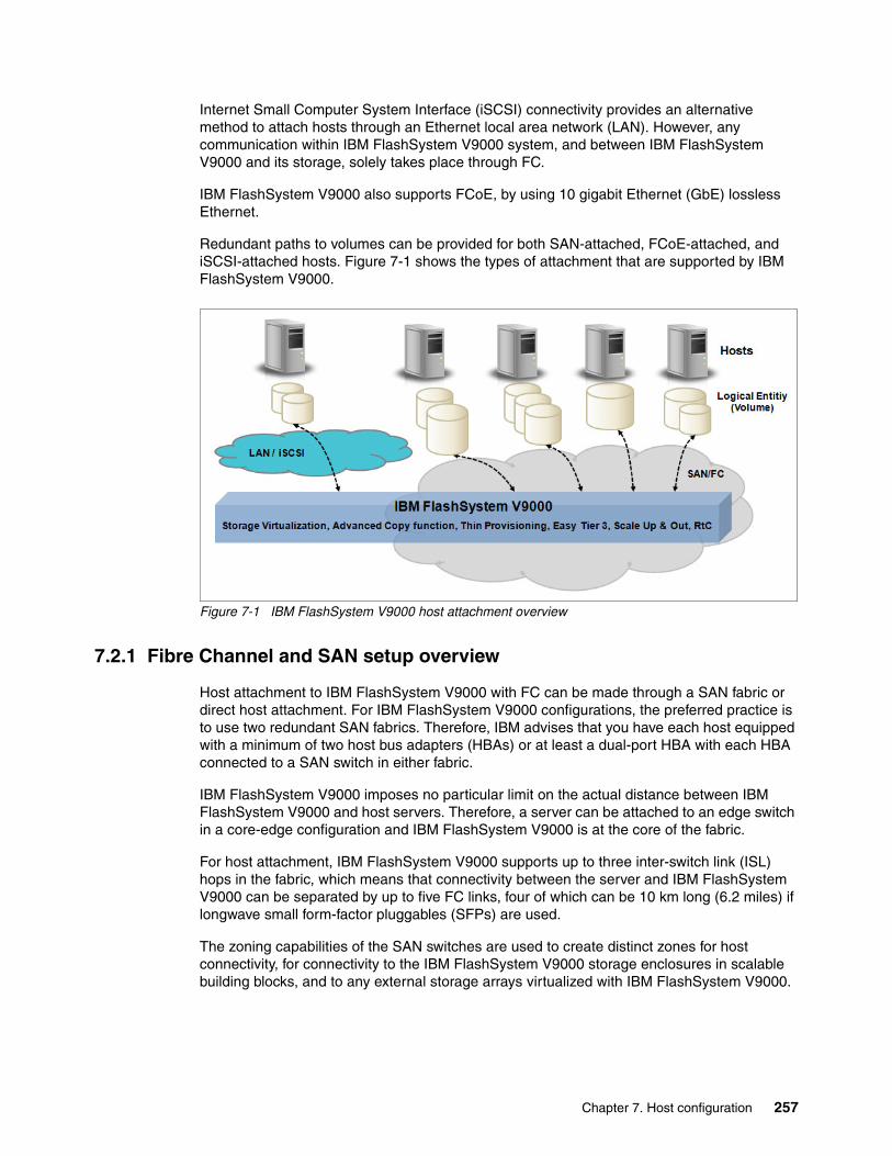
Internet Small Computer System Interface (iSCSI) connectivity provides an alternative method to attach hosts through an Ethernet local area network (LAN). However, any communication within IBM FlashSystem V9000 system, and between IBM FlashSystem V9000 and its storage, solely takes place through FC.
IBM FlashSystem V9000 also supports FCoE, by using 10 gigabit Ethernet (GbE) lossless Ethernet.
Redundant paths to volumes can be provided for both SAN-attached, FCoE-attached, and iSCSI-attached hosts. Figure 7-1 shows the types of attachment that are supported by IBM FlashSystem V9000.
Figure 7-1 IBM FlashSystem V9000 host attachment overview
7.2.1 Fibre Channel and SAN setup overview
Host attachment to IBM FlashSystem V9000 with FC can be made through a SAN fabric or direct host attachment. For IBM FlashSystem V9000 configurations, the preferred practice is to use two redundant SAN fabrics. Therefore, IBM advises that you have each host equipped with a minimum of two host bus adapters (HBAs) or at least a dual-port HBA with each HBA connected to a SAN switch in either fabric.
IBM FlashSystem V9000 imposes no particular limit on the actual distance between IBM FlashSystem V9000 and host servers. Therefore, a server can be attached to an edge switch in a core-edge configuration and IBM FlashSystem V9000 is at the core of the fabric.
For host attachment, IBM FlashSystem V9000 supports up to three inter-switch link (ISL) hops in the fabric, which means that connectivity between the server and IBM FlashSystem V9000 can be separated by up to five FC links, four of which can be 10 km long (6.2 miles) if longwave small form-factor pluggables (SFPs) are used.
The zoning capabilities of the SAN switches are used to create distinct zones for host connectivity, for connectivity to the IBM FlashSystem V9000 storage enclosures in scalable building blocks, and to any external storage arrays virtualized with IBM FlashSystem V9000.
Chapter 7. Host configuration 257

IBM FlashSystem V9000 supports 2 GBps, 4 GBps, 8 GBps, or 16 Gbps FC fabric, depending on the hardware configuration and on the switch where the IBM FlashSystem V9000 is connected. In an environment where you have a fabric with multiple-speed switches, the preferred practice is to connect the IBM FlashSystem V9000 and any external storage systems to the switch that is operating at the highest speed.
For more details about SAN zoning and SAN connections, see the topic about planning and configuration in Implementing the IBM System Storage SAN Volume Controller V7.4, SG24-7933.
IBM FlashSystem V9000 contains shortwave small form-factor pluggables (SFPs). Therefore, they must be within 300 meters (984.25 feet) of the switch to which they attach. The IBM FlashSystem V9000 shortwave SFPs can be replaced with longwave SFPs, which extends the distance for connectivity to the switches with that of the SFPs specification typically 5, 10, or 25 kilometers.
Table 7-1 shows the fabric type that can be used for communicating between hosts, nodes, and RAID storage systems. These fabric types can be used at the same time.
Table 7-1 IBM FlashSystem V9000 communication options
To avoid latencies that lead to degraded performance, avoid ISL hops when possible. That is, in an optimal setup, the servers connect to the same SAN switch as the IBM FlashSystem V9000.
The following guidelines apply when you connect host servers to an IBM FlashSystem V9000:
� Up to 512 hosts per building block are supported, which results in a total of 2,048 hosts for a fully scaled system.
If the same host is connected to multiple building blocks of a cluster, it counts as a host in each building block.
� A total of 2048 distinct, configured, host worldwide port names (WWPNs) are supported per building block for a total of 8192 for a fully scaled system.
This limit is the sum of the FC host ports and the host iSCSI names (an internal WWPN is generated for each iSCSI name) that are associated with all of the hosts that are associated with a building block.
Communication type Host to FlashSystem V9000
FlashSystem V9000 to external Storage
FlashSystem V9000 to FlashSystem V9000
Fibre Channel SAN (FC) Yes Yes Yes
iSCSI (1 Gbps or 10 Gbps Ethernet) Yes Yesa
a. Starting with Version 7.7.1.1 of the IBM FlashSystem V9000 software, IBM FlashSystem A9000 and XIV Gen 3 can also be attached via iSCSI.
No
FCoE (10 Gbps Ethernet) Yes No Yes
258 Introducing and Implementing IBM FlashSystem V9000

7.2.2 Fibre Channel SAN attachment
Switch zoning on the SAN fabric defines the access from a server to IBM FlashSystem V9000.
Consider the following rules for zoning hosts with IBM FlashSystem V9000:
� Homogeneous HBA port zones
Switch zones that contain HBAs must contain HBAs from similar host types and similar HBAs in the same host. For example, AIX and Microsoft Windows hosts must be in separate zones, and QLogic and Emulex adapters must also be in separate zones.
� HBA to IBM FlashSystem V9000 port zones
Place each host’s HBA in a separate zone along with one or two IBM FlashSystem V9000 ports. If there are two ports, use one from each controller in the building block. Do not place more than two IBM FlashSystem V9000 ports in a zone with an HBA, because this design results in more than the advised number of paths, as seen from the host multipath driver.
� Maximum host paths per logical unit (LU)
For any volume, the number of paths through the SAN from IBM FlashSystem V9000 to a host must not exceed eight. For most configurations, four paths to a building block (four paths to each volume that is provided by this building block) are sufficient.
� Balanced host load across HBA ports
To obtain the best performance from a host with multiple ports, ensure that each host port is zoned with a separate group of IBM FlashSystem V9000 ports.
� Balanced host load across IBM FlashSystem V9000 ports
To obtain the best overall performance of the system and to prevent overloading, the workload to each IBM FlashSystem V9000 port must be equal. You can achieve this balance by zoning approximately the same number of host ports to each IBM FlashSystem V9000 port.
When possible, use the minimum number of paths that are necessary to achieve a sufficient level of redundancy. For IBM FlashSystem V9000, no more than four paths per building block are required to accomplish this layout.
Important: A configuration that breaches this rule is unsupported because it can introduce instability to the environment.
Number of paths: For n + 1 redundancy, use the following number of paths:
� With two HBA ports, zone HBA ports to IBM FlashSystem V9000 ports 1:2 for a total of four paths.
� With four HBA ports, zone HBA ports to IBM FlashSystem V9000 ports 1:1 for a total of four paths.
Optional (n+2 redundancy): With 4 HBA ports, zone HBA ports to IBM FlashSystem V9000 ports 1 - 2 for a total of eight paths. The term HBA port is used here to describe the SCSI initiator and IBM FlashSystem V9000 port to describe the SCSI target.
Important: The maximum number of host paths per LUN should not exceed eight.
Chapter 7. Host configuration 259

All paths must be managed by the multipath driver on the host side. If you assume that a server is connected through four ports to IBM FlashSystem V9000, each volume is seen through eight paths. With 125 volumes mapped to this server, the multipath driver must support handling up to 1,000 active paths (8 x 125).
IBM FlashSystem V9000 with 8-port and 12-port configurations provide an opportunity to isolate traffic on dedicated ports, as a result providing a level of protection against misbehaving devices and workloads that can compromise the performance of the shared ports.
There is benefit in isolating remote replication traffic on dedicated ports to ensure that problems affecting the cluster-to-cluster interconnect do not adversely affect ports on the primary cluster and as a result affect the performance of workloads running on the primary cluster. Migration from existing configurations with only four ports, or even later migrating from 8-port or 12-port configurations to configurations with additional ports can reduce the effect of performance issues on the primary cluster by isolating remote replication traffic.
7.2.3 Fibre Channel direct attachment
If you attach the IBM FlashSystem V9000 directly to a host, the host must be attached to both controllers of a building block. If the host is not attached to both controllers, the host is shown as degraded.
If you use SAN attachment and direct attachment simultaneously on an IBM FlashSystem V9000, the direct-attached host state will be degraded. Using a switch enforces the switch rule for all attached hosts, which means that a host port must be connected to both IBM FlashSystem canisters. Because a direct-attached host cannot connect one port to both canisters, it does not meet the switch rule and its state will be degraded.
7.3 iSCSI
The iSCSI protocol is a block-level protocol that encapsulates SCSI commands into TCP/IP packets and, therefore, uses an existing IP network rather than requiring the FC HBAs and SAN fabric infrastructure. The iSCSI standard is defined by RFC 3720. iSCSI connectivity is a software feature that is provided by IBM FlashSystem V9000.
The iSCSI-attached hosts can use a single network connection or multiple network connections.
Each IBM FlashSystem V9000 controller is equipped with four onboard Ethernet ports, which can operate at a link speed of up to1 Gbps for the AC2 controllers and up to 10 Gbps for AC3 controllers. One of these Ethernet ports is the technician port and cannot be used for iSCSI traffic. Each controller’s Ethernet port that is numbered 1 is used as the primary cluster management port.
Note: You can attach a host through a switch and simultaneously attach a host directly to the IBM FlashSystem V9000. But then, the direct-attached host is shown as degraded.
iSCSI for external storage: In earlier versions, only hosts could iSCSI-attach to IBM FlashSystem V9000. However starting with Version 7.7.1.1 of IBM FlashSystem V9000 software, IBM FlashSystem A9000 and XIV Gen 3 can be attached and virtualized through iSCSI.
260 Introducing and Implementing IBM FlashSystem V9000

One additional AH12 four-port 10 Gbps Ethernet PCIe adapter with four preinstalled SFP+ transceivers can be added to each IBM FlashSystem V9000 control enclosure. This adds iSCSI and FCoE connectivity to the system.
For optimal performance achievement, IBM advise that you use 10 Gbps Ethernet connections between IBM FlashSystem V9000 and iSCSI-attached hosts.
7.3.1 Initiators and targets
An iSCSI client, which is known as an (iSCSI) initiator, sends SCSI commands over an IP network to an iSCSI target. A single iSCSI initiator or iSCSI target is referred to as an iSCSI node.
You can use the following types of iSCSI initiators in host systems:
� Software initiator: Available for most operating systems; for example, AIX, Linux, and Windows.
� Hardware initiator: Implemented as a network adapter with an integrated iSCSI processing unit, which is also known as an iSCSI HBA.
For more information about the supported operating systems for iSCSI host attachment and the supported iSCSI HBAs, see the following web pages:
� IBM System Storage Interoperation Center (SSIC) for the IBM FlashSystem V9000 interoperability matrix:
https://www.ibm.com/systems/support/storage/ssic/interoperability.wss
� IBM FlashSystem V9000 web page at IBM Knowledge Center:
https://ibm.biz/fs_V9000_kc
An iSCSI target refers to a storage resource that is on an iSCSI server. It also refers to one of potentially many instances of iSCSI nodes that are running on that server.
7.3.2 iSCSI nodes
One or more iSCSI nodes exist within a network entity. The iSCSI node is accessible through one or more network portals. A network portal is a component of a network entity that has a TCP/IP network address and can be used by an iSCSI node.
An iSCSI node is identified by its unique iSCSI name and is referred to as an iSCSI qualified name (IQN). The purpose of this name is for only the identification of the node, not for the node’s address. In iSCSI, the name is separated from the addresses. This separation enables multiple iSCSI nodes to use the same addresses or, while it is implemented in the IBM FlashSystem V9000, the same iSCSI node to use multiple addresses.
7.3.3 iSCSI qualified name
An IBM FlashSystem V9000 can provide up to eight iSCSI targets, one per controller. Each IBM FlashSystem V9000 controller has its own IQN, which by default is in the following form:
iqn.1986-03.com.ibm:2145.<clustername>.<nodename>
An iSCSI host in IBM FlashSystem V9000 is defined by specifying its iSCSI initiator names. The following example shows an IQN of a Windows server’s iSCSI software initiator:
iqn.1991-05.com.microsoft:itsoserver01
Chapter 7. Host configuration 261

During the configuration of an iSCSI host in IBM FlashSystem V9000, you must specify the host’s initiator IQNs.
An alias string can also be associated with an iSCSI node. The alias enables an organization to associate a string with the iSCSI name. However, the alias string is not a substitute for the iSCSI name.
7.3.4 iSCSI set up of IBM FlashSystem V9000 and host server
You must perform the following procedure when you are setting up a host server for use as an iSCSI initiator with IBM FlashSystem V9000 volumes. The specific steps vary depending on the particular host type and operating system that you use.
To configure a host, first select a software-based iSCSI initiator or a hardware-based iSCSI initiator. For example, the software-based iSCSI initiator can be a Linux or Windows iSCSI software initiator. The hardware-based iSCSI initiator can be an iSCSI HBA inside the host server.
To set up your host server for use as an iSCSI software-based initiator with IBM FlashSystem V9000 volumes, complete the following steps (the CLI is used in this example):
1. Set up your IBM FlashSystem V9000 cluster for iSCSI:
a. Select a set of IPv4 or IPv6 addresses for the Ethernet ports on the nodes that are in the building block that use the iSCSI volumes.
b. Configure the node Ethernet ports on each IBM FlashSystem V9000 controller by running the cfgportip command.
c. Verify that you configured the Ethernet ports of IBM FlashSystem V9000 correctly by reviewing the output of the lsportip command and lssystemip command.
d. Use the mkvdisk command to create volumes on IBM FlashSystem V9000 clustered system.
e. Use the mkhost command to create a host object on IBM FlashSystem V9000. The mkhost command defines the host’s iSCSI initiator to which the volumes are to be mapped.
f. Use the mkvdiskhostmap command to map the volume to the host object in IBM FlashSystem V9000.
2. Set up your host server:
a. Ensure that you configured your IP interfaces on the server.
b. Ensure that your iSCSI HBA is ready to use, or install the software for the iSCSI software-based initiator on the server, if needed.
c. On the host server, run the configuration methods for iSCSI so that the host server iSCSI initiator logs in to IBM FlashSystem V9000 and discovers IBM FlashSystem V9000 volumes. The host then creates host devices for the volumes.
After the host devices are created, you can use them with your host applications.
Note: Ethernet link aggregation (port trunking) or channel bonding for the Ethernet ports of the IBM FlashSystem V9000 controllers is not supported.
262 Introducing and Implementing IBM FlashSystem V9000

7.3.5 Volume discovery
Hosts can discover volumes through one of the following three mechanisms:
� Internet Storage Name Service (iSNS)
IBM FlashSystem V9000 can register with an iSNS name server; the IP address of this server is set by using the chsystem command. A host can then query the iSNS server for available iSCSI targets.
� Service Location Protocol (SLP)
IBM FlashSystem V9000 controller runs an SLP daemon, which responds to host requests. This daemon reports the available services on the node. One service is the CIM object manager (CIMOM), which runs on the configuration controller; iSCSI I/O service now also can be reported.
� SCSI Send Target request
The host can also send a Send Target request by using the iSCSI protocol to the iSCSI TCP/IP port (port 3260). You must define the network portal IP addresses of the iSCSI targets before a discovery can be started.
7.3.6 Authentication
The authentication of hosts is optional; by default, it is disabled. The user can choose to enable Challenge Handshake Authentication Protocol (CHAP) or CHAP authentication, which involves sharing a CHAP secret between the cluster and the host. If the correct key is not provided by the host, IBM FlashSystem V9000 does not allow it to perform I/O to volumes. Also, you can assign a CHAP secret to the IBM FlashSystem V9000.
7.3.7 Target failover
A feature with iSCSI is the option to move iSCSI target IP addresses between IBM FlashSystem V9000 controllers in a building block. IP addresses are moved only from one controller to its partner controller if a controller goes through a planned or unplanned restart. If the Ethernet link to IBM FlashSystem V9000 fails because of a cause outside of IBM FlashSystem V9000 (such as disconnection of the cable or failure of the Ethernet router), IBM FlashSystem V9000 makes no attempt to fail over an IP address to restore IP access to the system. To enable the validation of the Ethernet access to the controllers, it responds to ping with the standard one-per-second rate without frame loss.
For handling the iSCSI IP address failover a clustered Ethernet port is used. A clustered Ethernet port consists of one physical Ethernet port on each controller in the IBM FlashSystem V9000. The clustered Ethernet port contains configuration settings that are shared by all of these ports.
An iSCSI target node failover happens during a planned or unplanned node restart in an IBM FlashSystem V9000 building block. This example refers to IBM FlashSystem V9000 controllers with no optional 10 GbE iSCSI adapter installed:
1. During normal operation, one iSCSI target node instance is running on each IBM FlashSystem V9000 controller. All of the IP addresses (IPv4 and IPv6) that belong to this iSCSI target (including the management addresses if the controller acts as the configuration controller) are presented on the two ports of a controller.
2. During a restart of an IBM FlashSystem V9000 controller, the iSCSI target, including all of its IP addresses defined on Ethernet ports 1, 2, and 3, and the management IP addresses (if it acted as the configuration controller), fail over to Ethernet ports 1, 2, and 3 of the
Chapter 7. Host configuration 263
partner controller within the building block. An iSCSI initiator that is running on a server reconnects to its iSCSI target at the IBM FlashSystem V9000, but now the same IP addresses are presented by the other controller of the IBM FlashSystem V9000 building block.
3. When the controller finishes its restart, the iSCSI target node (including its IP addresses) that is running on the partner controller fails back. Again, the iSCSI initiator that is running on a server runs a reconnect to its iSCSI target. The management addresses do not fail back. The partner controller remains in the role of the configuration controller for this IBM FlashSystem V9000.
7.3.8 Host failover
From a host perspective, a multipathing I/O (MPIO) driver is not required to handle an IBM FlashSystem V9000 controller failover. In the case of an IBM FlashSystem V9000 controller restart, the host reconnects to the IP addresses of the iSCSI target node that reappear after several seconds on the ports of the partner node.
A host multipathing driver for iSCSI is required in the following situations:
� To protect a host from network link failures, including port failures on IBM FlashSystem V9000 controllers
� To protect a host from a HBA failure (if two HBAs are in use)
� To protect a host from network failures, if it is connected through two HBAs to two separate networks
� To provide load balancing on the server’s HBA and the network links
The commands for the configuration of the iSCSI IP addresses are separated from the configuration of the cluster management IP addresses. The following commands are used for managing iSCSI IP addresses:
� The lsportip command lists the iSCSI IP addresses that are assigned for each port on each controller in the IBM FlashSystem V9000.
� The cfgportip command assigns an IP address to each controller’s Ethernet port for iSCSI I/O.
The following commands are used for viewing and configuring IBM FlashSystem V9000 cluster management IP addresses:
� The lssystemip command returns a list of the IBM FlashSystem V9000 management IP addresses that are configured for each port.
� The chsystemip command modifies the IP configuration parameters for the IBM FlashSystem V9000.
The parameters for remote services (SSH and web services) remain associated with the IBM FlashSystem V9000 object. During an IBM FlashSystem V9000 code upgrade, the configuration settings for the IBM FlashSystem V9000 are applied to the controller Ethernet port one.
For iSCSI-based access, the use of redundant network connections and separating iSCSI traffic by using a dedicated network or virtual LAN (VLAN) prevents any NIC, switch, or target port failure from compromising the host server’s access to the volumes.
264 Introducing and Implementing IBM FlashSystem V9000

Three of the four onboard Ethernet ports of an IBM FlashSystem V9000 controller can be configured for iSCSI. For each Ethernet port, a maximum of one IPv4 address and one IPv6 address can be designated. Each port can be simultaneously used for management, remote copy over IP and as an iSCSI target for hosts.
When using the IBM FlashSystem V9000 onboard Ethernet ports for iSCSI traffic the suggestion is for port one to be dedicated to IBM FlashSystem V9000 management, and for ports two and three to be dedicated for iSCSI usage. By using this approach, ports two and three can be connected to a dedicated network segment or VLAN for iSCSI.
Because IBM FlashSystem V9000 does not support the use of VLAN tagging to separate management and iSCSI traffic, you can assign the LAN switch port to a dedicated VLAN to separate IBM FlashSystem V9000 management and iSCSI traffic.
7.4 File alignment for the best RAID performance
File system alignment can improve performance for storage systems by using a RAID storage mode. File system alignment is a technique that matches file system I/O requests with important block boundaries in the physical storage system. Alignment is important in any system that implements a RAID layout. I/O requests that fall within the boundaries of a single stripe have better performance than an I/O request that affects multiple stripes. When an I/O request crosses the endpoint of one stripe and into another stripe, the controller must then modify both stripes to maintain their consistency.
Unaligned accesses include those requests that start at an address that is not divisible by 4 KB, or are not a multiple of 4 KB. These unaligned accesses are serviced at much higher response times, and they can also significantly reduce the performance of aligned accesses that were issued in parallel.
7.5 AIX: Specific information
This section describes specific information that relates to the connection of IBM AIX based hosts in an IBM FlashSystem V9000 environment.
Note: Format all client host file systems on the storage system at 4 KB or at a multiple of 4 KB. This preference is for a used sector size of 512 and 4096 bytes. For example, file systems that are formatted at an 8 KB allocation size or a 64 KB allocation size are satisfactory because they are a multiple of 4 KB.
Note: In this section, the IBM System p information applies to all AIX hosts that are listed on IBM FlashSystem V9000 interoperability support website, including IBM System i partitions and IBM JS blades.
Chapter 7. Host configuration 265

7.5.1 Optimal logical unit number configurations for AIX
The number of logical unit numbers (LUNs) that you create on the IBM FlashSystem V9000 (as well as on IBM FlashSystem 900) can affect the overall performance of AIX. Applications perform optimally if at least 32 LUNs are used in a volume group. If fewer volumes are required by an application, use the Logical Volume Manager (LVM) to map fewer logical volumes to 32 logical units. This does not affect performance in any significant manner (LVM resource requirements are small).
7.5.2 Configuring the AIX host
To attach IBM FlashSystem V9000 volumes to an AIX host, complete these steps:
1. Install the HBAs in the AIX host system.
2. Ensure that you installed the correct operating systems and version levels on your host, including any updates and authorized program analysis reports (APARs) for the operating system.
3. Connect the AIX host system to the FC switches.
4. Configure the FC switch zoning.
5. Install and configure the Subsystem Device Driver Path Control Module (SDDPCM).
6. Perform the logical configuration on IBM FlashSystem V9000 to define the host, volumes, and host mapping.
7. Run the cfgmgr command to discover and configure IBM FlashSystem V9000 volumes.
7.5.3 Configuring fast fail and dynamic tracking
For hosts that are running AIX V5.3 or later operating systems, enable both fast fail and dynamic tracking.
Complete these steps to configure your host system to use the fast fail and dynamic tracking attributes:
1. Run the following command to set the FC SCSI I/O Controller Protocol Device to each adapter:
chdev -l fscsi0 -a fc_err_recov=fast_fail
That command is for adapter fscsi0. Example 7-1 shows the command for both adapters on a system that is running IBM AIX V6.1.
Example 7-1 Enable fast fail
#chdev -l fscsi0 -a fc_err_recov=fast_failfscsi0 changed#chdev -l fscsi1 -a fc_err_recov=fast_failfscsi1 changed
Note: Use at least 32 LUNs in a volume group because this number is the best tradeoff between good performance (the more queued I/Os, the better the performance) and minimizing resource use and complexity.
266 Introducing and Implementing IBM FlashSystem V9000

2. Run the following command to enable dynamic tracking for each FC device:
chdev -l fscsi0 -a dyntrk=yes
This command is for adapter fscsi0.
Example 7-2 shows the command for both adapters in IBM AIX V6.1.
Example 7-2 Enable dynamic tracking
#chdev -l fscsi0 -a dyntrk=yesfscsi0 changed#chdev -l fscsi1 -a dyntrk=yesfscsi1 changed
Host adapter configuration settingsYou can display the availability of installed host adapters by using the command that is shown in Example 7-3.
Example 7-3 FC host adapter availability
#lsdev -Cc adapter |grep fcsfcs0 Available 1Z-08 FC Adapterfcs1 Available 1D-08 FC Adapter
You can display the WWPN, along with other attributes, including the firmware level, by using the command that is shown in Example 7-4. The WWPN is represented as the Network Address.
Example 7-4 FC host adapter settings and WWPN
#lscfg -vpl fcs0 fcs0 U0.1-P2-I4/Q1 FC Adapter
Part Number.................00P4494 EC Level....................A Serial Number...............1E3120A68D Manufacturer................001E Device Specific.(CC)........2765 FRU Number.................. 00P4495 Network Address.............10000000C932A7FB ROS Level and ID............02C03951 Device Specific.(Z0)........2002606D Device Specific.(Z1)........00000000 Device Specific.(Z2)........00000000 Device Specific.(Z3)........03000909 Device Specific.(Z4)........FF401210 Device Specific.(Z5)........02C03951 Device Specific.(Z6)........06433951 Device Specific.(Z7)........07433951 Device Specific.(Z8)........20000000C932A7FB Device Specific.(Z9)........CS3.91A1 Device Specific.(ZA)........C1D3.91A1 Device Specific.(ZB)........C2D3.91A1 Device Specific.(YL)........U0.1-P2-I4/Q1
Note: The fast fail and dynamic tracking attributes do not persist through an adapter delete and reconfigure operation. Therefore, if the adapters are deleted and then configured back into the system, these attributes are lost and must be reapplied.
Chapter 7. Host configuration 267

7.5.4 Subsystem Device Driver Path Control Module (SDDPCM)
The SDDPCM is a loadable path control module for supported storage devices to supply path management functions and error recovery algorithms. When the supported storage devices are configured as Multipath I/O (MPIO) devices, SDDPCM is loaded as part of the AIX MPIO FCP or AIX MPIO serial-attached SCSI (SAS) device driver during the configuration.
The AIX MPIO device driver automatically discovers, configures, and makes available all storage device paths. SDDPCM then manages these paths to provide the following functions:
� High availability and load balancing of storage I/O � Automatic path-failover protection� Concurrent download of supported storage devices’ licensed machine code� Prevention of a single-point failure
The AIX MPIO device driver along with SDDPCM enhances the data availability and I/O load balancing of IBM FlashSystem V9000 volumes.
SDDPCM installationDownload the appropriate version of SDDPCM and install it by using the standard AIX installation procedure. The latest SDDPCM software versions are available at the following web page:
http://www.ibm.com/support/docview.wss?uid=ssg1S4001363
Check the driver readme file and make sure that your AIX system meets all prerequisites.
Example 7-5 shows the appropriate version of SDDPCM that is downloaded into the /tmp/sddpcm directory. From here, you extract it and run the inutoc command, which generates a dot.toc file that is needed by the installp command before SDDPCM is installed. Finally, run the installp command, which installs SDDPCM onto this AIX host.
Example 7-5 Installing SDDPCM on AIX
# ls -ltotal 3232-rw-r----- 1 root system 1648640 Jul 15 13:24 devices.sddpcm.61.rte.tar# tar -tvf devices.sddpcm.61.rte.tar-rw-r----- 271001 449628 1638400 Oct 31 12:16:23 2007 devices.sddpcm.61.rte# tar -xvf devices.sddpcm.61.rte.tarx devices.sddpcm.61.rte, 1638400 bytes, 3200 media blocks.# inutoc .# ls -ltotal 6432-rw-r--r-- 1 root system 531 Jul 15 13:25 .toc-rw-r----- 1 271001 449628 1638400 Oct 31 2007 devices.sddpcm.61.rte-rw-r----- 1 root system 1648640 Jul 15 13:24 devices.sddpcm.61.rte.tar# installp -ac -d . all
Example 7-6 shows the lslpp command that checks the version of SDDPCM that is installed.
Example 7-6 Checking SDDPCM device driver
# lslpp -l | grep sddpcm devices.sddpcm.61.rte 2.2.0.0 COMMITTED IBM SDD PCM for AIX V61 devices.sddpcm.61.rte 2.2.0.0 COMMITTED IBM SDD PCM for AIX V61
For more information about how to enable the SDDPCM web interface, see 7.13, “Using SDDDSM, SDDPCM, and SDD web interface” on page 319.
268 Introducing and Implementing IBM FlashSystem V9000

7.5.5 Configuring the assigned volume by using SDDPCM
This example uses an AIX host with host name Atlantic to demonstrate attaching IBM FlashSystem V9000 volumes to an AIX host. Example 7-7 shows host configuration before IBM FlashSystem V9000 volumes are configured. The lspv output shows the existing hdisks and the lsvg command output shows the existing volume group (VG).
Example 7-7 Status of AIX host system Atlantic
# lspvhdisk0 0009cdcaeb48d3a3 rootvg activehdisk1 0009cdcac26dbb7c rootvg activehdisk2 0009cdcab5657239 rootvg active# lsvgrootvg
Identifying the WWPNs of the host adapter portsExample 7-8 shows how the lscfg commands can be used to list the WWPNs for all installed adapters. The WWPNs are used later for mapping IBM FlashSystem V9000 volumes.
Example 7-8 HBA information for host Atlantic
# lscfg -vl fcs* |egrep “fcs|Network”fcs1 U0.1-P2-I4/Q1 FC Adapter
Network Address.............10000000C932A865Physical Location: U0.1-P2-I4/Q1fcs2 U0.1-P2-I5/Q1 FC Adapter
Network Address.............10000000C94C8C1C
Displaying IBM FlashSystem V9000 configurationYou can use the CLI to display host configuration on the IBM FlashSystem V9000 and to validate the physical access from the host to IBM FlashSystem V9000.
Example 7-9 shows the use of the lshost and lshostvdiskmap commands to obtain the following information:
� That a host definition was properly defined for the host Atlantic.� That the WWPNs (listed in Example 7-8) are logged in, with two logins each. � Atlantic has three volumes that are assigned to each WWPN, and the volume serial
numbers are listed.
Example 7-9 IBM FlashSystem V9000 definitions for host system Atlantic
IBM_2145:ITSO_V9000:admin>svcinfo lshost Atlanticid 8name Atlanticport_count 2type genericmask 1111iogrp_count 4WWPN 10000000C94C8C1Cnode_logged_in_count 2state activeWWPN 10000000C932A865node_logged_in_count 2state active
IBM_2145:ITSO_V9000:admin>svcinfo lshostvdiskmap Atlantic
Chapter 7. Host configuration 269

id name SCSI_id vdisk_id vdisk_name wwpn vdisk_UID8 Atlantic 0 14 Atlantic0001 10000000C94C8C1C 6005076801A180E908000000000000608 Atlantic 1 22 Atlantic0002 10000000C94C8C1C 6005076801A180E908000000000000618 Atlantic 2 23 Atlantic0003 10000000C94C8C1C 6005076801A180E90800000000000062
Discovering and configuring LUNs The cfgmgr command discovers the new LUNs and configures them into AIX. The cfgmgr command probes the devices on the adapters individually:
# cfgmgr -l fcs1# cfgmgr -l fcs2
The following command probes the devices sequentially across all installed adapters:
# cfgmgr -vS
The lsdev command (Example 7-10) lists the three newly configured hdisks that are represented as MPIO FC 2145 devices.
Example 7-10 Volumes from IBM FlashSystem V9000
# lsdev -Cc diskhdisk0 Available 1S-08-00-8,0 16 Bit LVD SCSI Disk Drivehdisk1 Available 1S-08-00-9,0 16 Bit LVD SCSI Disk Drivehdisk2 Available 1S-08-00-10,0 16 Bit LVD SCSI Disk Drivehdisk3 Available 1D-08-02 MPIO FC 2145hdisk4 Available 1D-08-02 MPIO FC 2145hdisk5 Available 1D-08-02 MPIO FC 2145
Now, you can use the mkvg command to create a VG with the three newly configured hdisks, as shown in Example 7-11.
Example 7-11 Running the mkvg command
# mkvg -y itsoaixvg hdisk30516-1254 mkvg: Changing the PVID in the ODM.itsoaixvg# mkvg -y itsoaixvg1 hdisk40516-1254 mkvg: Changing the PVID in the ODM.itsoaixvg1# mkvg -y itsoaixvg2 hdisk50516-1254 mkvg: Changing the PVID in the ODM.itsoaixvg2
The lspv output now shows the new VG label on each of the hdisks that were included in the VGs (Example 7-12).
Example 7-12 Showing the vpath assignment into the Volume Group (VG)
# lspvhdisk0 0009cdcaeb48d3a3 rootvg activehdisk1 0009cdcac26dbb7c rootvg activehdisk2 0009cdcab5657239 rootvg activehdisk3 0009cdca28b589f5 itsoaixvg activehdisk4 0009cdca28b87866 itsoaixvg1 activehdisk5 0009cdca28b8ad5b itsoaixvg2 active
270 Introducing and Implementing IBM FlashSystem V9000

7.5.6 Using SDDPCM
You administer the SDDPM by using the pcmpath command. You use this command to perform all administrative functions, such as displaying and changing the path state. The pcmpath query adapter command displays the current state of the adapters.
Example 7-13 shows the status that both adapters show as optimal with State is NORMAL and Mode is ACTIVE.
Example 7-13 SDDPCM commands that are used to check the availability of the adapters
# pcmpath query adapter
Active Adapters :2Adpt# Name State Mode Select Errors Paths Active 0 fscsi1 NORMAL ACTIVE 407 0 6 6 1 fscsi2 NORMAL ACTIVE 425 0 6 6
The pcmpath query device command displays the current state of adapters. Example 7-14 shows path’s State and Mode for each of the defined hdisks. Both adapters show the optimal status of State is NORMAL and Mode is ACTIVE. Additionally, an asterisk (*) that is displayed next to a path indicates an inactive path that is configured to the non-preferred IBM FlashSystem V9000 controller.
Example 7-14 SDDPCM commands that are used to check the availability of the devices
# pcmpath query deviceTotal Devices : 3DEV#: 3 DEVICE NAME: hdisk3 TYPE: 2145 ALGORITHM: Load BalanceSERIAL: 6005076801A180E90800000000000060==========================================================================Path# Adapter/Path Name State Mode Select Errors 0 fscsi1/path0 OPEN NORMAL 152 0 1* fscsi1/path1 OPEN NORMAL 48 0 2* fscsi2/path2 OPEN NORMAL 48 0 3 fscsi2/path3 OPEN NORMAL 160 0
DEV#: 4 DEVICE NAME: hdisk4 TYPE: 2145 ALGORITHM: Load BalanceSERIAL: 6005076801A180E90800000000000061==========================================================================Path# Adapter/Path Name State Mode Select Errors 0* fscsi1/path0 OPEN NORMAL 37 0 1 fscsi1/path1 OPEN NORMAL 66 0 2 fscsi2/path2 OPEN NORMAL 71 0 3* fscsi2/path3 OPEN NORMAL 38 0
DEV#: 5 DEVICE NAME: hdisk5 TYPE: 2145 ALGORITHM: Load BalanceSERIAL: 6005076801A180E90800000000000062==========================================================================Path# Adapter/Path Name State Mode Select Errors 0 fscsi1/path0 OPEN NORMAL 66 0 1* fscsi1/path1 OPEN NORMAL 38 0 2* fscsi2/path2 OPEN NORMAL 38 0 3 fscsi2/path3 OPEN NORMAL 70 0
Chapter 7. Host configuration 271

7.5.7 Creating and preparing volumes for use with AIX and SDDPCM
This section demonstrates how to create and prepare volumes for use with SDDPCM in AIX V6.1 and later.
The itsoaixvg volume group (VG) is created with hdisk3. A logical volume is created by using the VG. Then, the testlv1 file system is created and mounted, as shown in Example 7-15.
Example 7-15 Host system new VG and file system configuration
# lsvg -oitsoaixvg2itsoaixvg1itsoaixvgrootvg# crfs -v jfs2 -g itsoaixvg -a size=3G -m /itsoaixvg -p rw -a agblksize=4096File system created successfully.3145428 kilobytes total disk space.New File System size is 6291456# lsvg -l itsoaixvgitsoaixvg:LV NAME TYPE LPs PPs PVs LV STATE MOUNT POINTloglv00 jfs2log 1 1 1 closed/syncd N/Afslv00 jfs2 384 384 1 closed/syncd /itsoaixvg
7.5.8 Expanding an AIX volume
AIX supports dynamic volume expansion starting at IBM AIX 5L™ version 5.2. By using this capability, a volume’s capacity can be increased by the storage subsystem while the volumes are actively in use by the host and applications. The following guidelines apply:
� The volume cannot belong to a concurrent-capable VG.� The volume cannot belong to a FlashCopy, Metro Mirror, or Global Mirror relationship.
The following steps expand a volume on an AIX host when the volume is on the IBM FlashSystem V9000:
1. Display the current size of IBM FlashSystem V9000 volume by using IBM FlashSystem V9000 lsvdisk <VDisk_name> CLI command. The capacity of the volume, as seen by the host, is displayed in the capacity field (as GBs) of the lsvdisk output.
2. Identify the corresponding AIX hdisk by matching the vdisk_UID from the lsvdisk output with the SERIAL field of the pcmpath query device output.
3. Display the capacity that is configured in AIX by using the lspv hdisk command. The capacity is shown in the TOTAL PPs field in MBs.
4. To expand the capacity of IBM FlashSystem V9000 volume, use the expandvdisksize command.
5. After the capacity of the volume is expanded, AIX must update its configured capacity. To start the capacity update on AIX, use the chvg -g vg_name command, where vg_name is the VG in which the expanded volume is found.
If AIX does not return any messages, the command was successful and the volume changes in this VG were saved.
If AIX cannot see any changes in the volumes, it returns an explanatory message.
6. Display the new AIX configured capacity by using the lspv hdisk command. The capacity (in MBs) is shown in the TOTAL PPs field.
272 Introducing and Implementing IBM FlashSystem V9000

7.5.9 Running IBM FlashSystem V9000 commands from AIX host system
To run CLI commands, install and prepare the SSH client system on the AIX host system. For AIX 5L V5.1 and later, you can get OpenSSH from the Bonus Packs. You also need its prerequisite, OpenSSL, from the AIX toolbox for Linux applications for IBM Power Systems:
http://ibm.com/systems/power/software/aix/linux/toolbox/download.html
The AIX Open SSH installation images are available at this website:
https://ibm.biz/Bd4Ui7
Complete the following steps:
1. To generate the key files on AIX, run the following command:
ssh-keygen -t rsa -f filename
The -t parameter specifies the type of key to generate: rsa1, rsa2, or dsa. The value for rsa2 is only rsa. For rsa1, the type must be rsa1. When you are creating the key to IBM FlashSystem V9000, use type rsa2.
The -f parameter specifies the file names of the private and public keys on the AIX server (the public key has the .pub extension after the file name).
2. Install the public key on IBM FlashSystem V9000 by using the GUI.
3. On the AIX server, make sure that the private key and the public key are in the .ssh directory and in the home directory of the user.
4. To connect to IBM FlashSystem V9000 and use a CLI session from the AIX host, run the following command:
ssh -l admin -i filename V9000
5. You can also run the commands directly on the AIX host, which is useful when you are making scripts. To run the commands directly on the AIX host, add IBM FlashSystem V9000 commands to the previous command. For example, to list the hosts that are defined on IBM FlashSystem V9000, enter the following command:
ssh -l admin -i filename V9000 lshost
In this command, -l admin is the user name that is used to log in to IBM FlashSystem V9000, -i filename is the file name of the private key that is generated, and V9000 is the host name or IP address of IBM FlashSystem V9000.
7.6 IBM i: Specific information
This section describes specific information that relates to the connection of IBM i hosts in an IBM FlashSystem V9000 environment.
7.6.1 Connection of IBM FlashSystem V9000 to IBM i
IBM FlashSystem V9000 can be attached to IBM i in the following ways:
� Native connection without using Virtual I/O Server (VIOS)
� Connection with VIOS in N_Port ID Virtualization (NPIV) mode
� Connection with VIOS in virtual SCSI (VSCSI) mode
Chapter 7. Host configuration 273

RequirementsTable 7-2 lists the basic requirements.
Table 7-2 Basic requirements
For detailed information about requirements, see the following resources:
� IBM System Storage Interoperation Center (SSIC):
http://www.ibm.com/systems/support/storage/ssic/interoperability.wss
� IBM i POWER® External Storage Support Matrix Summary:
http://w3.ibm.com/support/techdocs/atsmastr.nsf/WebIndex/PRS4563
Native connection: Implementation considerationsNative connection with SAN switches can be done with these adapters:
� 4 Gb Fibre Channel (FC) adapters, feature number 5774 or 5276 � 8 Gb FC adapters, feature number 5735 or 5273� 16 Gb FC adapters, feature number EN0A or EN0B
Direct native connection without SAN switches can be done with these adapters:
� 4 Gb FC adapters in IBM i connected to 8 Gb adapters in IBM FlashSystem V9000� 16 Gb adapters in IBM i connected to 16 Gb adapters in IBM FlashSystem V9000
You can attach a maximum 64 LUNs to a port in an IBM i adapter. The LUNs report in IBM i as disk units with type 2145.
IBM i enables SCSI command tag queuing in the LUNs from natively connected IBM FlashSystem V9000; the queue depth on a LUN with this type of connection is 16.
Connection with VIOS in NPIV: Implementation considerationsThe following rules are for mapping server virtual FC adapters to the ports in VIOS when implementing IBM i in VIOS NPIV connection:
� Map a maximum of one virtual FC adapter from an IBM i LPAR to a port in VIOS.
� You can map up to 64 virtual FC adapters each from another IBM i LPAR to the same port in VIOS.
� You can use the same port in VIOS for both NPIV mapping and connection with VIOS VSCSI.
Attachment type Requirements
Native connection � IBM i logical partition (LPAR) must reside in an IBM POWER7® system or later.
� When implemented in POWER7, requires IBM i V7.1, Technology Release (TR) 7 or later.
� When implemented in an IBM POWER8® system, requires IBM i V7.1 TR 8 or later.
Connection with VIOS NPIV
� IBM i partition must reside in a POWER7 system or later.� When implemented in POWER7, requires IBM i V7.1 TR 6 or later.� When implemented in POWER8, requires IBM i level V7.1 TR 8 or later.
Connection with VIOS VSCSI
� IBM i partition must reside in a POWER7 system or later.� IBM i release V6.1.1 or later is needed when the LPAR resides in
POWER7 � when implemented in POWER8, IBM i V7.1 TR8 or later is needed.
274 Introducing and Implementing IBM FlashSystem V9000

You can attach a maximum of 64 LUNs to a port in virtual FC adapter in IBM i. The LUNs report in IBM i as disk units with type 2145.
IBM i enables SCSI command tag queuing in the LUNs from VIOS NPIV connected IBM FlashSystem V9000; the queue depth on a LUN with this type of connection is 16.
For details about the VIOS NPIV connection, see IBM PowerVM Virtualization Introduction and Configuration, SG24-7940.
Connection with VIOS VSCSI: Implementation considerationsA possibility is to connect up to 4,095 LUNs per target and up to 510 targets per port in a physical adapter in VIOS.
With IBM i release 7.2 and later, you can map a maximum of 32 LUNs to a virtual SCSI adapter in IBM i. With IBM i releases prior to 7.2, a maximum of 16 LUNs can be mapped to an IBM i virtual SCSI adapter. The LUNs report in IBM i as disk units of the type 6B22.
IBM i enables SCSI command tag queuing in the LUNs from a VIOS virtual SCSI-connected IBM FlashSystem V9000. The queue depth on a LUN with this type of connection, is 32.
For more information about VIOS VSCSI connection, see IBM PowerVM Virtualization Introduction and Configuration, SG24-7940.
7.6.2 Block translation
IBM i disk units have a block size of 520 bytes. The IBM FlashSystem V9000 is formatted with a block size of 512 bytes, so a translation or mapping is required to attach these storage units to IBM i.
IBM i performs the following change of the data layout to support 512 byte blocks (sectors) in external storage:
� For every page (8 * 520 byte sectors), it uses an additional ninth sector.
� It stores the 8-byte headers of the 520-byte sectors in the ninth sector, and therefore changes the previous 8 * 520 byte blocks to 9 * 512 byte blocks.
� The data that was previously stored in 8 * sectors is now spread across 9 * sectors, so the required disk capacity on IBM FlashSystem V9000 is 9/8 of the IBM i usable capacity.
� Conversely, the usable capacity in IBM i is 8/9 of the allocated capacity in these storage systems.
Therefore, when attaching an IBM FlashSystem V9000 to IBM i, you should have the capacity overhead on the storage system to be able to use only 8/9th of the effective capacity.
The performance impact of block translation in IBM i is very insignificant or negligible.
7.6.3 IBM i LUNs and capacity
The size of an IBM i LUN can vary from 160 MB up to 2 TB, both these values excluded. When defining LUNs for IBM i, account for the minimal capacity for load source (boot disk) LUN:
� With IBM i release 7.1 the minimal capacity is 20 GB� With IBM i release 7.2 prior to TR1 the minimal capacity is 80 GB in IBM i� With IBM i release 7.2 TR1 and later the minimal capacity is 40 GB in IBM i
Chapter 7. Host configuration 275
For performance reasons, the preferred approach is to define LUNs of capacity 40 GB to 200 GB, and to define a minimum 8 LUNs for an IBM i host. Another preferred practice is to define all LUNs in an IBM i Auxiliary Storage Pool (ASP) of the same capacity.
The capacity of a corresponding disk unit in IBM i, is 8/9th of the LUN capacity. The reason for this is the IBM i block translation described in 7.6.2, “Block translation” on page 275.
7.6.4 Data layout
A storage pool is a collection of managed disks from which volumes are created and presented to the IBM i system as LUNs. The primary property of a storage pool is the extent, which can be of size 16 MB to 8192 MB. The default extent size in IBM FlashSystem V9000 is 1024 MB. This extent size is the smallest unit of allocation from the pool and determines some maximum storage capacity that can be managed by the IBM FlashSystem V9000. For further details, see the V7.6 Configuration Limits and Restrictions for IBM FlashSystem V9000 support document:
http://www.ibm.com/support/docview.wss?uid=ssg1S1005242
When defining IBM FlashSystem V9000 LUNs for IBM i, use the default extent size of 1024 MB. Another good practice is to use the default option of cache mode enabled on the LUNs for IBM i.
Sharing a storage pool among workloads means spreading workloads across all the available resources of the storage system. Consider the following guidelines for sharing a disk pool:
� With traditional disk drives, performance problems can possibly arise when sharing resources because of contention on these resources. For this reason, a good practice is to isolate the important production workloads to separate disk pools.
� With IBM FlashSystem V9000, the data is distributed in a disk pool that can have one or more MDisks, with each MDisk created from one background IBM FlashSystem V9000.
– If multiple IBM FlashSystem V9000 exist, consider separating them for different workloads.
– If one IBM FlashSystem V9000 is in the background, a sensible approach is for IBM i LPARs to share the storage pool among them.
7.6.5 Thin provisioning and IBM Real-time Compression
IBM i can take advantage of thin provisioning and Real-time Compression in IBM FlashSystem V9000 because these functions are transparent to the host server.
With thin provisioning, IBM i 7.1 and later do not pre-format LUNs so that initial allocations of LUNs can be thin provisioned, however there is no space reclamation, thus the effectiveness of the thin provisioning might decline over time.
IBM Real-time Compression allows the use of less physical space on disk than is presented to the IBM i host. The capacity needed on the IBM FlashSystem V9000 is reduced due to both compression and thin provisioning. However, Real-time Compression typically has a latency impact on I/O service times and a throughput impact.
Note: When calculating LUN capacity take into account that IBM i reports capacity in decimal notation (GB) while IBM FlashSystem V9000 reports capacity by default in binary notation (GiB).
276 Introducing and Implementing IBM FlashSystem V9000

Plan carefully before using thin provisioning or Real-time Compression with IBM i. For information about Real-time Compression see Accelerate with IBM FlashSystem V840 Compression, REDP-5147.
7.6.6 Multipath
Multipath provides greater resiliency for SAN attached storage. IBM i supports up to eight active paths to each LUN. In addition to the availability considerations, lab performance testing has shown that two or more paths provide performance improvements when compared to a single path.
With traditional disk drives, two paths to a LUN is typically the ideal balance of price and performance. With IBM FlashSystem V9000 you can expect higher access density (I/O per second per GB) than with traditional disk drives; consider three to four active paths per LUN.
Multipath for a LUN is achieved by connecting the LUN to two or more ports in different physical or virtual adapters in the IBM i partition:
� With native connection to IBM FlashSystem V9000, the ports for multipath must be in different physical adapters in IBM i.
� With VIOS NPIV in dual path, the virtual Fibre Channel adapters for multipath must be assigned to different Virtual I/O Servers. With more that two paths, use at least two Virtual I/O Servers and spread the virtual FC adapters evenly among the Virtual I/O Servers.
� With VIOS VSCSI connection in dual path, the virtual SCSI adapters for multipath must be assigned to different VIOS. With more than two paths, use at least two VIOS and spread the VSCSI adapters evenly among the VIOS.
Every LUN in IBM FlashSystem V9000 uses one control enclosure as the preferred node; the I/O rate to or from the particular LUN normally goes through the preferred node. If the preferred node fails, the I/O operations are transferred to the remaining node.
With IBM i multipath, all the paths to a LUN through the preferred node are active and the paths through the non-preferred node are passive. Multipath employs the load balancing among the paths to a LUN that go through the node that is preferred for that LUN. For more information, see Implementing the IBM System Storage SAN Volume Controller V7.4, SG24-7933.
7.6.7 Fibre Channel adapters in IBM i partition
The following Fibre Channel adapters can be used in IBM i when connecting IBM FlashSystem V9000 in native mode:
� 16 Gb PCIe2 2-port FC adapter, feature number EN0A or feature number EN0B (low-profile)
� 8 Gb PCIe 2-port Port FC adapter, feature number 5735 or feature number 5273 (low-profile)
� 4 Gb PCIe 2-port Port FC adapter, feature number 5774 or feature number 5276 (low-profile)
Chapter 7. Host configuration 277

The following Fibre Channel adapters can be used in IBM i VIOS when connecting IBM FlashSystem V9000 to IBM i client in VIOS NPIV mode:
� 16 Gb PCIe2 2-port FC adapter, feature number EN0A,or feature number EN0B (low-profile)
� 8 Gb PCIe 2-port Port FC adapter, feature number 5735, or feature number 5273 (low-profile)
� 8 Gb PCIe2 4-Port FC adapter, feature number 5729
The following Fibre Channel adapters can be used in IBM i VIOS when connecting IBM FlashSystem V9000 to IBM i client in VIOS Virtual SCSI mode:
� 16 Gb PCIe2 2-port FC adapter feature number EN0A, or feature number EN0B (low-profile)
� 8 Gb PCIe 2-port Port FC adapter feature number 5735, or feature number 5273 (low-profile)
� 8 Gb PCIe2 4-port FC adapter feature number EN0Y (low-profile)
When you size the number of FC adapters for an IBM i workload for native or VIOS NPIV connection, account for the maximum I/O rate (I/O per second) and data rate (MB per second) that a port in a particular adapter can sustain at 70% utilization, and the I/O rate and data rate of the IBM i workload.
If multiple IBM i partitions connect through the same port in VIOS NPIV, account for the maximum rate at the port at 70% utilization and the sum of I/O rates and data rates of all connected LPARs.
7.6.8 Zoning SAN switches
This section provides guidelines for zoning the SAN switches with IBM FlashSystem V9000 connection to IBM i. It describes zoning guidelines for different types of connection, for one IBM FlashSystem V9000 I/O group, and for an IBM FlashSystem V9000 cluster.
Native or VIOS NPIV connection, one IBM FlashSystem V9000 I/O groupWith native connection and the connection with VIOS NPIV, zone the switches so that one World Wide Port Name (WWPN) of one IBM i port is in a zone with two ports of IBM FlashSystem V9000, each port from one control enclosure. This approach improves resiliency for the I/O rate to or from a LUN assigned to that WWPN. If the preferred controller node for that LUN fails, the I/O rate will continue using the non-preferred controller node.
Native or VIOS NPIV connection, two IBM FlashSystemV9000 I/O groups in a clusterWith two I/O groups in the cluster, zone half of the IBM i ports (either in physical or in virtual FC adapter) with one I/O group, each IBM i port zoned with both control enclosures of the I/O group.
Note: For a VIOS NPIV configuration a virtual FC client adapter for IBM i has two WWPNs. For connecting external storage, the first WWPN is used, while the second WWPN is used for Live Partition Mobility. Therefore, a good practice is to zone both WWPNs if you plan to use Live Partition Mobility, otherwise, zone only the first WWPN.
278 Introducing and Implementing IBM FlashSystem V9000

Zone half of IBM i ports with the other I/O group, each port zoned with both control enclosures of the I/O group. Assign a LUN to an IBM i port (either in physical or in virtual FC adapter) that is zoned with the caching I/O group for this LUN. In multipath, assign the LUN to two or more ports, all of them zoned with the caching I/O group of this LUN.
In some cases, such as preparing for LUN migration, preparing for HyperSwap or for additional resiliency, consider zoning each IBM i port with both I/O groups of the IBM FlashSystem V9000 cluster.
For more information, see IBM i and IBM Storwize Family: A Practical Guide to Usage Scenarios, SG24-8197.
VIOS VSCSI connection When connecting with VIOS virtual SCSI (VSCSI), zone one physical port in VIOS with all available ports in IBM FlashSystem V9000, or with as many ports as possible to allow load balancing. Keep in mind that a maximum of 8 paths are available from VIOS to the IBM FlashSystem V9000. IBM FlashSystem V9000 ports zoned with one VIOS port should be evenly spread across the IBM FlashSystem V9000 control enclosures.
7.6.9 Boot from SAN
IBM i boot disk (load source disk) resides on an IBM FlashSystem V9000 LUN. The suggestion is that the load source LUN be of the same size as the other LUNs in the system disk pool (ASP1). No special requirements or guidelines exist for layout or connection of the load source LUN.
When installing the IBM i operating system with disk capacity on IBM FlashSystem V9000, the installation prompts to select one of the available IBM FlashSystem V9000 LUNs for the load source.
7.6.10 IBM i mirroring
Some organizations prefer to have additional resiliency with the IBM i mirroring function. For example, they use mirroring between two IBM FlashSystem V9000, each connected with one VIOS.
When connecting with VIOS, start IBM i mirroring by following these steps:
1. Add the LUNs from two virtual adapters, each adapter connecting one to-be mirrored half of LUNs.
2. After mirroring is started for those LUNs, add the LUNs from two new virtual adapters, each adapter connecting one to-be mirrored half.
3. Continue this way until the mirroring is started for all LUNs.
By following these steps, you ensure that the mirroring is started between the two halves that you want to be mirrored. For example, following this approach, you ensure that the mirroring is started between two IBM FlashSystem V9000 and not among the LUNs in the same IBM FlashSystem V9000.
Chapter 7. Host configuration 279

7.6.11 Migration
This section describes types of migrations of IBM i partition to disk capacity on IBM FlashSystem V9000.
Migration with ASP balancing and copying load sourceThis migration approach can be used to migrate IBM i disk capacity from internal disk, or from any storage system to IBM FlashSystem V9000. It requires relatively short downtime, but it might require to temporarily connect additional FC adapters to IBM i.
Use the following steps to perform the migration:
1. Connect IBM FlashSystem V9000 along with existing internal disk or storage system to the IBM i LPAR.
2. By using the ASP balancing function, migrate data from the currently used disks or LUNs except load source, to the IBM FlashSystem V9000 LUNs. ASP balancing does not require any downtime; it is done while the IBM i partition is running. Depending on the installation needs, you can perform load balancing relatively quickly with some impact on performance, or slowly with minimal performance impact.
3. After the data (except load source) is migrated to IBM FlashSystem V9000, use the IBM i Dedicated Service Tools function to copy the load source to an IBM FlashSystem V9000 LUN, which must be at least as big as the present load source. This action is disruptive, and it requires careful planning and execution.
4. After load source is copied to an IBM FlashSystem V9000 LUN, IBM i starts working with the entire disk capacity on IBM FlashSystem V9000.
5. Disconnect the previous storage system from IBM i, or remove the internal disk.
For information about ASP balancing, see the IBM i web page:
http://www.ibm.com/support/knowledgecenter/ssw_ibm_i
For information about copying load source, see IBM i and IBM System Storage: A Guide to Implementing External Disks on IBM i, SG24-7120.
Migration with save and restoreMigration by saving IBM i system to tape and restoring it from tape to an LPAR with disk capacity on IBM FlashSystem V9000 can be used in any scenario. This migration is straightforward and does not require any additional resources, however, it requires a relatively long downtime.
Migration from one to another type of connectionYou can migrate IBM i from any type of V9000 connection to any type of connection by simply disconnecting the LUNs and reconnecting them the other way. IBM i must be powered-down during these actions. Table 7-3 shows all possible combinations of connections for this type of migration.
Table 7-3 Supported migration with disconnecting and reconnecting LUNs
Migration supported To Native To VIOS NPIV To VIOS VSCSI
From Native Yes Yes Yes
From VIOS NPIV Yes Yes Yes
From VIOS VSCSI Yes Yes Yes
280 Introducing and Implementing IBM FlashSystem V9000

Use the following steps to perform this type of migration:
1. Power-down IBM i.2. Disconnect the V9000 LUNs from the IBM i partition.3. Connect the IBM FlashSystem V9000 LUNs to the IBM i partition in the new way.4. IPL IBM i.
7.7 Windows: Specific information
This section describes specific information about the connection of Windows-based hosts to IBM FlashSystem V9000 environment.
7.7.1 Configuring Windows Server 2008 and 2012 hosts
For attaching IBM FlashSystem V9000 to a host that is running Windows Server 2008, Windows Server 2008 R2, or Windows Server 2012, you must install the IBM SDDDSM multipath driver to make the Windows server capable of handling volumes that are presented by IBM FlashSystem V9000.
Before you attach IBM FlashSystem V9000 to your host, make sure that all of the following requirements are fulfilled:
� Check all prerequisites that are provided in section 2.0 of the SDDSM readme file.
� Check the LUN limitations for your host system. Ensure that there are enough FC adapters installed in the server to handle the total number of LUNs that you want to attach.
7.7.2 Configuring Windows
To configure the Windows hosts, complete the following steps:
1. Make sure that the current OS service pack and fixes are applied to your Windows server system.
2. Use the current supported firmware and driver levels on your host system.
3. Install the HBA or HBAs on the Windows server, as described in 7.7.4, “Installing and configuring the host adapter” on page 282.
4. Connect the Windows Server FC host adapters to the switches.
5. Configure the switches (zoning).
6. Install the FC host adapter driver, as described in 7.7.3, “Hardware lists, device driver, HBAs, and firmware levels” on page 282.
7. Configure the HBA for hosts that are running Windows, as described in 7.7.4, “Installing and configuring the host adapter” on page 282.
8. Check the HBA driver readme file for the required Windows registry settings, as described in 7.7.3, “Hardware lists, device driver, HBAs, and firmware levels” on page 282.
Note: With Windows 2012, you can use native Microsoft device drivers, but a strong suggestion is to install IBM SDDDSM drivers.
Chapter 7. Host configuration 281

9. Check the disk timeout on Windows Server, as described in 7.7.5, “Changing the disk timeout on Windows Server” on page 282.
10.Install and configure SDDDSM.
11.Restart the Windows Server host system.
12.Configure the host, volumes, and host mapping in IBM FlashSystem V9000.
13.Use Rescan disk in Computer Management of the Windows Server to discover the volumes that were created on IBM FlashSystem V9000.
7.7.3 Hardware lists, device driver, HBAs, and firmware levels
For more information about the supported hardware, device driver, and firmware, see the SSIC web page:
https://www.ibm.com/systems/support/storage/ssic/interoperability.wss
There, you can find the hardware list for supported HBAs and the driver levels for Windows. Check the supported firmware and driver level for your HBA and follow the manufacturer’s instructions to upgrade the firmware and driver levels for each type of HBA. The driver readme files from most manufacturers list the instructions for the Windows registry parameters that must be set for the HBA driver.
7.7.4 Installing and configuring the host adapter
Install the host adapters in your system. See the manufacturer’s instructions for the installation and configuration of the HBAs.
Also, check the documentation that is provided for the server system for the installation guidelines of FC HBAs regarding the installation in certain PCI(e) slots, and so on.
The detailed configuration settings that you must make for the various vendor FC HBAs are available at the IBM FlashSystem V9000 web page of IBM Knowledge Center. Search for Configuring and then select Host attachment → Fibre Channel host attachments → Hosts running the Microsoft Windows Server operating system.
7.7.5 Changing the disk timeout on Windows Server
This section describes how to change the disk I/O timeout value on Windows Server 2008, Windows Server 2008 R2, and Windows Server 2012 systems.
On your Windows Server hosts, complete the following steps to change the disk I/O timeout value to 60 in the Windows registry:
1. In Windows, click Start, and then select Run.
2. In the dialog text box, enter regedit and press Enter.
3. In the registry browsing tool, locate the following key:
HKEY_LOCAL_MACHINE\System\CurrentControlSet\Services\Disk\TimeOutValue
4. Confirm that the value for the key is 60 (decimal value) and, if necessary, change the value to 60, as shown in Figure 7-2 on page 283.
282 Introducing and Implementing IBM FlashSystem V9000

Figure 7-2 Regedit
7.7.6 Installing the SDDDSM multipath driver on Windows
This section describes how to install the SDDDSM driver on a Windows Server 2008 R2 host and Windows Server 2012.
Windows Server 2012 (R2), Windows Server 2008 (R2), and MPIOMicrosoft Multipath I/O (MPIO) is a generic multipath driver that is provided by Microsoft, which does not form a complete solution. It works with device-specific modules (DSMs), which usually are provided by the vendor of the storage subsystem. This design supports the parallel operation of multiple vendors’ storage systems on the same host without interfering with each other, because the MPIO instance interacts only with that storage system for which the DSM is provided.
MPIO is not installed with the Windows operating system, by default. Instead, storage vendors must pack the MPIO drivers with their own DSMs. IBM SDDDSM is the IBM Multipath I/O solution that is based on Microsoft MPIO technology. It is a device-specific module that is designed specifically to support IBM storage devices on Windows Server 2008 (R2), and Windows 2012 (R2) servers.
The intention of MPIO is to achieve better integration of multipath storage with the operating system. It also supports the use of multipathing in the SAN infrastructure during the boot process for SAN boot hosts.
SDDDSM for IBM FlashSystem V9000SDDDSM installation is a package for IBM FlashSystem V9000 device for the Windows Server 2008 (R2), and Windows Server 2012 (R2) operating systems. Together with MPIO, SDDDSM is designed to support the multipath configuration environments in IBM FlashSystem V9000. SDDDSM is in a host system along with the native disk device driver and provides the following functions:
� Enhanced data availability � Dynamic I/O load-balancing across multiple paths � Automatic path failover protection � Enabled concurrent firmware upgrade for the storage system� Path-selection policies for the host system
Chapter 7. Host configuration 283

Table 7-4 lists the SDDDSM driver levels that are supported at the time of this writing.
Table 7-4 Currently supported SDDDSM driver levels
For more information about the levels that are available, see this web page:
http://ibm.com/support/docview.wss?uid=ssg1S7001350#WindowsSDDDSM
To download SDDDSM, see this web page:
http://ibm.com/support/docview.wss?uid=ssg1S4000350
After you download the appropriate archive (.zip file), extract it to your local hard disk and start setup.exe to install SDDDSM. A command prompt window opens (Figure 7-3). Confirm the installation by entering Y.
Figure 7-3 SDDDSM installation
Windows operating system SDD level
Windows Server 2012 R2 (x64) 2.4.7.1
Windows Server 2012 (x64) 2.4.7.1
Windows Server 2008 R2 (x64) 2.4.7.1
Windows Server 2008 (32-bit)/Windows Server 2008 (x64) 2.4.7.1
Note: At the time of writing, IBM FlashSystem V9000 is not part of that SDDDSM support matrix. IBM FlashSystem V9000 is supported with SDDDSM and follows the SAN Volume Control levels in this case, and hence it is supported.
284 Introducing and Implementing IBM FlashSystem V9000

After the setup completes, enter Y again to confirm the reboot request (Figure 7-4).
Figure 7-4 Restart system after installation
After the restart, the SDDDSM installation is complete. You can verify the installation completion in Device Manager because the SDDDSM device appears (Figure 7-5) and the SDDDSM tools are installed (Figure 7-6 on page 286).
Figure 7-5 SDDDSM installation
Chapter 7. Host configuration 285

The SDDDSM tools are installed, as shown in Figure 7-6.
Figure 7-6 SDDDSM installation
7.7.7 Attaching IBM FlashSystem V9000 volumes to Windows Server 2008 R2 and Windows Server 2012 R2
Create the volumes on IBM FlashSystem V9000 and map them to the Windows Server 2008 R2 or Windows Server 2012 R2 host.
This example maps three IBM FlashSystem V9000 disks to the Windows Server 2008 R2 host that is named Diomede, as shown in Example 7-16.
Example 7-16 SVC host mapping to host Diomede
IBM_2145:ITSO_V9000:admin>lshostvdiskmap Diomedeid name SCSI_id vdisk_id vdisk_name wwpn vdisk_UID0 Diomede 0 20 Diomede_0001 210000E08B0541BC 6005076801A180E9080000000000002B0 Diomede 1 21 Diomede_0002 210000E08B0541BC 6005076801A180E9080000000000002C0 Diomede 2 22 Diomede_0003 210000E08B0541BC 6005076801A180E9080000000000002D
Complete the following steps to use the devices on your Windows Server 2008 R2 host:
1. Click Start → Run.
2. Run the diskmgmt.msc command, and then click OK. The Disk Management window opens.
3. Select Action → Rescan Disks, as shown in Figure 7-7 on page 287.
286 Introducing and Implementing IBM FlashSystem V9000

Figure 7-7 Windows Server 2008 R2: Rescan disks
IBM FlashSystem V9000 disks now appear in the Disk Management window (Figure 7-8).
Figure 7-8 Windows Server 2008 R2 Disk Management window
Chapter 7. Host configuration 287

After you assign IBM FlashSystem V9000 disks, they are also available in Device Manager. The three assigned drives are represented by SDDDSM/MPIO as IBM-2145 Multipath disk devices in the Device Manager (Figure 7-9).
Figure 7-9 Windows Server 2008 R2 Device Manager
4. To check that the disks are available, select Start → All Programs → Subsystem Device Driver DSM, and then click Subsystem Device Driver DSM (Figure 7-10). The SDDDSM Command Line Utility is displayed.
Figure 7-10 Windows Server 2008 R2 Subsystem Device Driver DSM utility
5. Run the datapath query device command and press Enter. This command displays all disks and available paths, including their states (Example 7-17).
Example 7-17 Windows Server 2008 R2 SDDDSM command-line utility
Microsoft Windows [Version 6.0.6001]Copyright (c) 2006 Microsoft Corporation. All rights reserved.
C:\Program Files\IBM\SDDDSM>datapath query device
Total Devices : 3
DEV#: 0 DEVICE NAME: Disk1 Part0 TYPE: 2145 POLICY: OPTIMIZED
288 Introducing and Implementing IBM FlashSystem V9000

SERIAL: 6005076801A180E9080000000000002B============================================================================Path# Adapter/Hard Disk State Mode Select Errors 0 Scsi Port2 Bus0/Disk1 Part0 OPEN NORMAL 0 0 1 Scsi Port2 Bus0/Disk1 Part0 OPEN NORMAL 1429 0 2 Scsi Port3 Bus0/Disk1 Part0 OPEN NORMAL 1456 0 3 Scsi Port3 Bus0/Disk1 Part0 OPEN NORMAL 0 0
DEV#: 1 DEVICE NAME: Disk2 Part0 TYPE: 2145 POLICY: OPTIMIZEDSERIAL: 6005076801A180E9080000000000002C============================================================================Path# Adapter/Hard Disk State Mode Select Errors 0 Scsi Port2 Bus0/Disk2 Part0 OPEN NORMAL 1520 0 1 Scsi Port2 Bus0/Disk2 Part0 OPEN NORMAL 0 0 2 Scsi Port3 Bus0/Disk2 Part0 OPEN NORMAL 0 0 3 Scsi Port3 Bus0/Disk2 Part0 OPEN NORMAL 1517 0
DEV#: 2 DEVICE NAME: Disk3 Part0 TYPE: 2145 POLICY: OPTIMIZEDSERIAL: 6005076801A180E9080000000000002D============================================================================Path# Adapter/Hard Disk State Mode Select Errors 0 Scsi Port2 Bus0/Disk3 Part0 OPEN NORMAL 27 0 1 Scsi Port2 Bus0/Disk3 Part0 OPEN NORMAL 1396 0 2 Scsi Port3 Bus0/Disk3 Part0 OPEN NORMAL 1459 0 3 Scsi Port3 Bus0/Disk3 Part0 OPEN NORMAL 0 0
C:\Program Files\IBM\SDDDSM>
6. Right-click the disk in Disk Management and then select Online to place the disk online (Figure 7-11).
Figure 7-11 Windows Server 2008 R2: Place disk online
7. Repeat step 6 for all of your attached IBM FlashSystem V9000 disks.
8. Right-click one disk again and select Initialize Disk (Figure 7-12 on page 290).
SAN zoning: When the SAN zoning guidance is followed, you see this result, which uses one volume and a host with two HBAs, (number of volumes) x (number of paths per building block per HBA) x (number of HBAs) = 1 x 2 x 2 = four paths.
Chapter 7. Host configuration 289

Figure 7-12 Windows Server 2008 R2: Initialize Disk
9. Mark all of the disks that you want to initialize and then click OK, (Figure 7-13).
Figure 7-13 Windows Server 2008 R2: Initialize Disk
10.Right-click the deallocated disk space and then select New Simple Volume (Figure 7-14).
Figure 7-14 Windows Server 2008 R2: New Simple Volume
290 Introducing and Implementing IBM FlashSystem V9000

7.7.8 Extending a volume
Using IBM FlashSystem V9000 and Windows Server 2008 and later gives you the ability to extend volumes while they are in use.
You can expand a volume in IBM FlashSystem V9000 cluster, even if it is mapped to a host, because version 2000 Windows Server can handle the volumes that are expanded even if the host has applications running.
A volume, which is defined to be in a FlashCopy, Metro Mirror, or Global Mirror mapping on IBM FlashSystem V9000, cannot be expanded. Therefore, the FlashCopy, Metro Mirror, or Global Mirror on that volume must be deleted before the volume can be expanded.
If the volume is part of a Microsoft Cluster (MSCS), Microsoft advises that you shut down all but one MSCS cluster node. Also, you must stop the applications in the resource that access the volume to be expanded before the volume is expanded. Applications that are running in other resources can continue to run. After the volume is expanded, start the applications and the resource, and then restart the other nodes in the MSCS.
To expand a volume in use on a Windows Server host, you use the Windows DiskPart utility.
To start DiskPart, select Start → Run, and enter DiskPart.
Diskpart was developed by Microsoft to ease the administration of storage on Windows hosts. It is a command-line interface (CLI), which you can use to manage disks, partitions, and volumes by using scripts or direct input on the command line. You can list disks and volumes, select them, and after selecting them, get more detailed information, create partitions, extend volumes, and so on. For more information about DiskPart, see this website:
http://www.microsoft.com
For more information about expanding partitions of a cluster-shared disk, see this web page:
http://support.microsoft.com/kb/304736
Dynamic disks can be expanded by expanding the underlying IBM FlashSystem V9000 volume. The new space appears as deallocated space at the end of the disk.
In this case, you do not need to use the DiskPart tool. Instead, you can use Windows Disk Management functions to allocate the new space. Expansion works irrespective of the volume type (simple, spanned, mirrored, and so on) on the disk. Dynamic disks can be expanded without stopping I/O, in most cases.
7.7.9 Removing a disk from Windows
To remove a disk from Windows, when the disk is an IBM FlashSystem V9000 volume, follow the standard Windows procedure to ensure that no data exists that you want to preserve on the disk, that no applications are using the disk, and that no I/O is going to the disk. After completing this procedure, remove the host mapping on IBM FlashSystem V9000. Ensure that you are removing the correct volume. To confirm, use Subsystem Device Driver (SDD) to locate the serial number of the disk. On IBM FlashSystem V9000, run the lshostvdiskmap command to find the volume’s name and number. Also check that the SDD serial number on the host matches the UID on IBM FlashSystem V9000 for the volume.
Important: Never try to upgrade your basic disk to dynamic disk or vice versa without backing up your data. This operation is disruptive for the data because of a change in the position of the logical block address (LBA) on the disks.
Chapter 7. Host configuration 291

When the host mapping is removed, perform a rescan for the disk, Disk Management on the server removes the disk, and the vpath goes into the status of CLOSE on the server. Verify these actions by running the datapath query device SDD command, but the vpath that is closed is first removed after a restart of the server.
The following examples show how to remove an IBM FlashSystem V9000 volume from a Windows server. Although the examples show it on a Windows Server 2008 operating system, the steps also apply to Windows Server 2008 and Windows Server 2012.
Example 7-18 shows the Disk Manager before removing the disk (Disk1).
To find the volume information for the disk device to be removed, type datapath query device by using SDDDSM CLI, as shown in Example 7-18.
Example 7-18 Removing IBM FlashSystem V9000 disk from the Windows server
C:\Program Files\IBM\SDDDSM>datapath query device
Total Devices : 3
DEV#: 0 DEVICE NAME: Disk1 Part0 TYPE: 2145 POLICY: OPTIMIZEDSERIAL: 6005076801A180E9080000000000000F============================================================================Path# Adapter/Hard Disk State Mode Select Errors 0 Scsi Port2 Bus0/Disk1 Part0 OPEN NORMAL 1471 0 1 Scsi Port2 Bus0/Disk1 Part0 OPEN NORMAL 0 0 2 Scsi Port3 Bus0/Disk1 Part0 OPEN NORMAL 0 0 3 Scsi Port3 Bus0/Disk1 Part0 OPEN NORMAL 1324 0
DEV#: 1 DEVICE NAME: Disk2 Part0 TYPE: 2145 POLICY: OPTIMIZEDSERIAL: 6005076801A180E90800000000000010============================================================================Path# Adapter/Hard Disk State Mode Select Errors 0 Scsi Port2 Bus0/Disk2 Part0 OPEN NORMAL 20 0 1 Scsi Port2 Bus0/Disk2 Part0 OPEN NORMAL 94 0 2 Scsi Port3 Bus0/Disk2 Part0 OPEN NORMAL 55 0 3 Scsi Port3 Bus0/Disk2 Part0 OPEN NORMAL 0 0
DEV#: 2 DEVICE NAME: Disk3 Part0 TYPE: 2145 POLICY: OPTIMIZEDSERIAL: 6005076801A180E90800000000000011============================================================================Path# Adapter/Hard Disk State Mode Select Errors 0 Scsi Port2 Bus0/Disk3 Part0 OPEN NORMAL 100 0 1 Scsi Port2 Bus0/Disk3 Part0 OPEN NORMAL 0 0 2 Scsi Port3 Bus0/Disk3 Part0 OPEN NORMAL 0 0 3 Scsi Port3 Bus0/Disk3 Part0 OPEN NORMAL 69 0
Knowing the Serial/UID of the volume and that the host name is Senegal, identify the host mapping to remove by running the lshostvdiskmap command on IBM FlashSystem V9000.
292 Introducing and Implementing IBM FlashSystem V9000
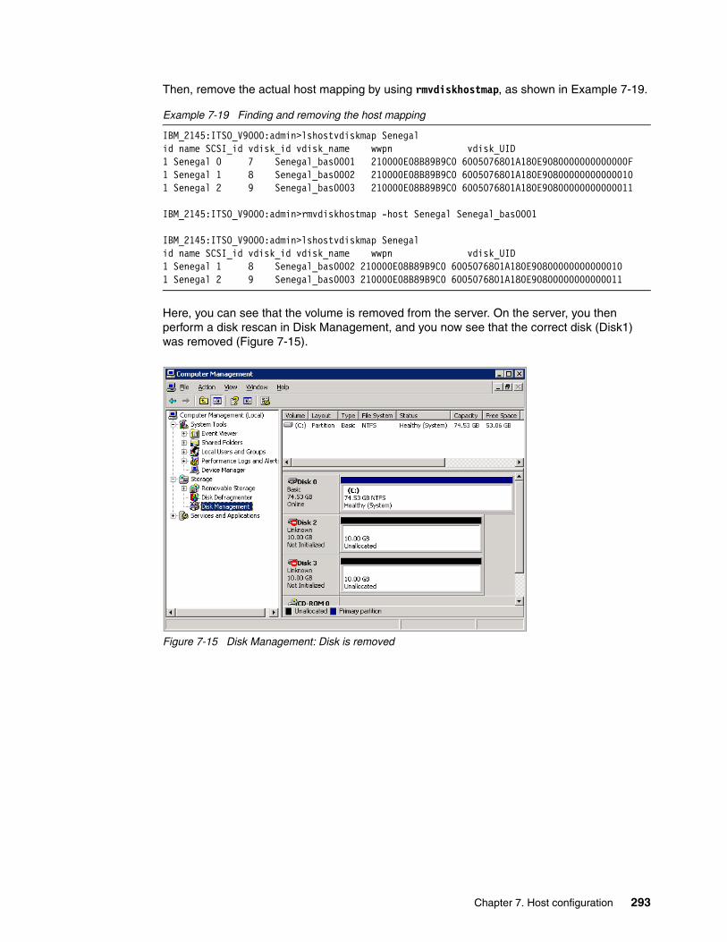
Then, remove the actual host mapping by using rmvdiskhostmap, as shown in Example 7-19.
Example 7-19 Finding and removing the host mapping
IBM_2145:ITSO_V9000:admin>lshostvdiskmap Senegalid name SCSI_id vdisk_id vdisk_name wwpn vdisk_UID1 Senegal 0 7 Senegal_bas0001 210000E08B89B9C0 6005076801A180E9080000000000000F1 Senegal 1 8 Senegal_bas0002 210000E08B89B9C0 6005076801A180E908000000000000101 Senegal 2 9 Senegal_bas0003 210000E08B89B9C0 6005076801A180E90800000000000011
IBM_2145:ITSO_V9000:admin>rmvdiskhostmap -host Senegal Senegal_bas0001
IBM_2145:ITSO_V9000:admin>lshostvdiskmap Senegalid name SCSI_id vdisk_id vdisk_name wwpn vdisk_UID1 Senegal 1 8 Senegal_bas0002 210000E08B89B9C0 6005076801A180E908000000000000101 Senegal 2 9 Senegal_bas0003 210000E08B89B9C0 6005076801A180E90800000000000011
Here, you can see that the volume is removed from the server. On the server, you then perform a disk rescan in Disk Management, and you now see that the correct disk (Disk1) was removed (Figure 7-15).
Figure 7-15 Disk Management: Disk is removed
Chapter 7. Host configuration 293

SDDDSM now shows the status for paths to Disk1 have changed to CLOSE because the disk is not available, as shown in Example 7-20.
Example 7-20 SDD: Closed path
C:\Program Files\IBM\SDDDSM>datapath query device
Total Devices : 3
DEV#: 0 DEVICE NAME: Disk1 Part0 TYPE: 2145 POLICY: OPTIMIZEDSERIAL: 6005076801A180E9080000000000000F============================================================================Path# Adapter/Hard Disk State Mode Select Errors 0 Scsi Port2 Bus0/Disk1 Part0 CLOSE NORMAL 1471 0 1 Scsi Port2 Bus0/Disk1 Part0 CLOSE NORMAL 0 0 2 Scsi Port3 Bus0/Disk1 Part0 CLOSE NORMAL 0 0 3 Scsi Port3 Bus0/Disk1 Part0 CLOSE NORMAL 1324 0
DEV#: 1 DEVICE NAME: Disk2 Part0 TYPE: 2145 POLICY: OPTIMIZEDSERIAL: 6005076801A180E90800000000000010============================================================================Path# Adapter/Hard Disk State Mode Select Errors 0 Scsi Port2 Bus0/Disk2 Part0 OPEN NORMAL 20 0 1 Scsi Port2 Bus0/Disk2 Part0 OPEN NORMAL 124 0 2 Scsi Port3 Bus0/Disk2 Part0 OPEN NORMAL 72 0 3 Scsi Port3 Bus0/Disk2 Part0 OPEN NORMAL 0 0
DEV#: 2 DEVICE NAME: Disk3 Part0 TYPE: 2145 POLICY: OPTIMIZEDSERIAL: 6005076801A180E90800000000000011============================================================================Path# Adapter/Hard Disk State Mode Select Errors 0 Scsi Port2 Bus0/Disk3 Part0 OPEN NORMAL 134 0 1 Scsi Port2 Bus0/Disk3 Part0 OPEN NORMAL 0 0 2 Scsi Port3 Bus0/Disk3 Part0 OPEN NORMAL 0 0 3 Scsi Port3 Bus0/Disk3 Part0 OPEN NORMAL 82 0
The disk (Disk1) is now removed from the server. However, to remove the SDDDSM information about the disk, you must restart the server at a convenient time.
7.7.10 Using IBM FlashSystem V9000 CLI from a Windows host
To run CLI commands, you must install and prepare the SSH client system on the Windows host system.
You can install the PuTTY SSH client software on a Windows host by using the PuTTY installation program. You can download PuTTY from this web page:
http://www.chiark.greenend.org.uk/~sgtatham/putty/
Cygwin software features an option to install an OpenSSH client. You can download Cygwin from this website:
http://www.cygwin.com/
294 Introducing and Implementing IBM FlashSystem V9000

7.7.11 Microsoft 2012 and Offloaded Data Transfer (ODX)
Microsoft ODX is a copy and storage application embedded into the operating system that supports the passing of copy command sets using an API, to reduce CPU utilization during copy operations. Rather than buffering the read and write operations, Microsoft ODX initiates the copy operation with an offload read, and gets a token that represents the data.
Next, the API initiates the offload write command that requests the movement of the data from the source to destination storage volume. The copy manager of the storage device then performs the data movement according to the token.
Client/server data movement is massively reduced, freeing CPU cycles because the actual data movement is on the backend storage device and not traversing the storage area network, further reducing traffic. Use cases include large data migrations and tiered storage support, and can also reduce the overall hardware spending cost and deployment.
ODX and IBM FlashSystem V9000 offer an excellent combination of server and storage integration to reduce CPU usage, and to take advantage of the speed of IBM FlashSystem V9000 all-flash storage arrays and IBM FlashCore technology.
Starting with IBM FlashSystem V9000 software version 7.5, ODX is supported with Microsoft 2012, including the following platforms:
� Clients: Windows� Servers: Windows Server 2012
The following functions are included:
� The ODX feature is embedded in the copy engine of Windows, so there is no additional software to install.
� Both the source and destination storage device LUNs must be ODX-compatible.
� If a copy of an ODX operation fails, traditional Windows copy is used as a fallback.
� Drag-and-drop and Copy-and-Paste actions can be used to initiate the ODX copy.
For more details about offloaded data transfer, see the following website:
https://ibm.biz/Bdsr74
7.7.12 Microsoft Volume Shadow Copy (VSS)
IBM FlashSystem V9000 supports the Microsoft Volume Shadow Copy Service (VSS). The Microsoft Volume Shadow Copy Service can provide a point-in-time (shadow) copy of a Windows host volume while the volume is mounted and the files are in use.
In this section, is described how to install the Microsoft Volume Copy Shadow Service. The following operating system versions are supported:
� Windows Server 2008 with SP2 (x86 and x86_64)� Windows Server 2008 R2 with SP1� Windows Server 2012
Note: By default, the ODX capability of IBM FlashSystem V9000 is disabled. To enable the ODX function from the CLI, issue the chsystem -odx on command on the Config Node.
Chapter 7. Host configuration 295

The following components are used to support the service:
� IBM FlashSystem V9000
� IBM VSS Hardware Provider, which is known as the IBM System Storage Support for Microsoft VSS
� Microsoft Volume Shadow Copy Service
IBM VSS Hardware Provider is installed on the Windows host.
To provide the point-in-time shadow copy, the components follow this process:
1. A backup application on the Windows host starts a snapshot backup.
2. The Volume Shadow Copy Service notifies IBM VSS that a copy is needed.
3. IBM FlashSystem V9000 prepares the volume for a snapshot.
4. The Volume Shadow Copy Service quiesces the software applications that are writing data on the host and flushes file system buffers to prepare for a copy.
5. IBM FlashSystem V9000 creates the shadow copy by using the FlashCopy Service.
6. The VSS notifies the writing applications that I/O operations can resume and notifies the backup application that the backup was successful.
The VSS maintains a free pool of volumes for use as a FlashCopy target and a reserved pool of volumes. These pools are implemented as virtual host systems on IBM FlashSystem V9000.
You can download the installation archive from IBM Support and extract it to a directory on the Windows server where you want to install IBM VSS:
http://ibm.com/support/docview.wss?uid=ssg1S4000833
7.8 Linux: Specific information
This section describes specific information that relates to the connection of Linux on Intel based hosts to IBM FlashSystem V9000 environment.
7.8.1 Configuring the Linux host
Complete the following steps to configure the Linux host:
1. Use the current firmware levels on your host system.
2. Install the HBA or HBAs on the Linux server, as described in 7.7.4, “Installing and configuring the host adapter” on page 282.
3. Install the supported HBA driver or firmware and upgrade the kernel, if required.
4. Connect the Linux server FC host adapters to the switches.
5. Configure the switches (zoning), if needed.
6. Configure DMMP for Linux, as described in 7.9, “VMware: Configuration information” on page 303.
7. Configure the host, volumes, and host mapping in the IBM FlashSystem V9000.
8. Rescan for LUNs on the Linux server to discover the volumes that were created on IBM FlashSystem V9000.
296 Introducing and Implementing IBM FlashSystem V9000

7.8.2 Supported Linux distributions
IBM FlashSystem V9000 supports hosts that run the following Linux distributions:
� Red Hat Enterprise Linux (RHEL)� SUSE Linux Enterprise Server
Ensure that your hosts running the Linux operating system use the correct HBAs and host software.
The IBM SSIC web page has current interoperability information for HBA and platform levels:
https://www.ibm.com/systems/support/storage/ssic/interoperability.wss
Check the supported firmware and driver level for your HBA, and follow the manufacturer’s instructions to upgrade the firmware and driver levels for each type of HBA.
7.8.3 Multipathing in Linux
You must configure and enable multipathing software on all hosts that are attached to IBM FlashSystem V9000. The following software provides multipathing support for hosts that run the Linux operating system:
� SUSE Linux Enterprise Server version 9 and Red Hat Enterprise Linux version 4 support both SDD and native multipathing support that is provided by the operating system.
� SUSE Linux Enterprise Server versions 10 and later and Red Hat Enterprise Linux versions 5 and later support only native multipathing that is provided by the operating system.
Device mapper multipathing for Red Hat Enterprise Linux 7 (RHEL7)Device mapper multipathing (DM Multipath) allows you to configure multiple I/O paths between server nodes and storage arrays into a single device. These I/O paths are physical SAN connections that can include separate cables, switches, and controllers. Multipathing aggregates the I/O paths, creating a new device that consists of the aggregated paths.
Multipath settings for specific Linux distributionsDifferent Linux distributions require different multipath configurations. Figure 7-16 on page 298 and Figure 7-17 on page 299 show the device configurations that are required for /etc/multipath.conf for the Linux versions.
Chapter 7. Host configuration 297

Figure 7-16 Device configurations required for /etc/multipath.conf (Part 1 of 2)
Red Hat Linux versions 5.x, 6.0, and 6.1
vendor "IBM"product "2145"path_grouping_policy "group_by_prio"path_selector "round-robin 0"prio_callout "/sbin/mpath_prio_alua /dev/%n" #Used by Red Hat 5.xprio "alua"path_checker "tur"failback "immediate"no_path_retry 5rr_weight uniformrr_min_io 1000dev_loss_tmo 120
Red Hat Linux versions 6.2 and higher and 7.x
vendor "IBM"product "2145"path_grouping_policy "group_by_prio"path_selector "round-robin 0"# path_selector "service-time 0" # Used by Red Hat 7.x prio "alua"path_checker "tur"failback "immediate"no_path_retry 5rr_weight uniformrr_min_io_rq "1"dev_loss_tmo 120
298 Introducing and Implementing IBM FlashSystem V9000

Figure 7-17 Device configurations required for /etc/multipath.conf (Part 2 of 2)
Setting up DM MultipathBefore setting up DM Multipath on your system, ensure that your system is updated and includes the device mapper multipath package.
You set up multipath with the mpathconf utility, which creates the /etc/multipath.conf multipath configuration file. Consider this information:
� If the /etc/multipath.conf file already exists, the mpathconf utility updates it.
� If the /etc/multipath.conf file does not exist, the mpathconf utility creates it by using a default built-in template file. This does not include multipathing for IBM FlashSystem V9000, which then must be added to the configuration.
SUSE Linux Versions 10.x and 11.0 and 11SP1
vendor "IBM"product "2145"path_grouping_policy "group_by_prio"path_selector "round-robin 0"prio "alua"path_checker "tur"failback "immediate"no_path_retry 5rr_weight uniformrr_min_io 1000dev_loss_tmo 120
SUSE Linux Versions 11SP2 and higher
vendor "IBM"product "2145"path_grouping_policy "group_by_prio"path_selector "round-robin 0" # Used by SLES 11 SP2# path_selector "service-time 0" # Used by SLES 11 SP3+prio "alua"path_checker "tur"failback "immediate"no_path_retry 5rr_weight uniformrr_min_io_rq "1"dev_loss_tmo 120
Note: The examples in this section are based on the Red Hat Enterprise Linux 7 DM Multipath document:
https://ibm.biz/Bdssqz
Chapter 7. Host configuration 299

Configure and enable DM MultipathTo configure and enable DM Multipath on a Red Hat Enterprise Linux 7 (RHEL7):
1. Enable DM Multipath by running the following command:
mpathconf --enable
In this example, no /etc/multipath.conf file exists yet, so the mpathconf command creates it when the DM Multipath daemon is enabled (Example 7-21).
Example 7-21 Configure DM Multipath
[root@rhel7 ~]# mpathconf --enable[root@rhel7 ~]#
2. Open the multipath.conf file and insert the appropriate definitions for the operating system as specified in “Multipath settings for specific Linux distributions” on page 297.The multipath.conf file is in the /etc directory. Example 7-22 shows editing the file by using vi.
Example 7-22 Editing the multipath.conf file
[root@rhel7 etc]# vi multipath.conf
3. Add the following entry to the multipath.conf file:
device {vendor "IBM"product "2145"path_grouping_policy "group_by_prio"path_selector "round-robin 0"# path_selector "service-time 0" # Used by Red Hat 7.x prio "alua"path_checker "tur"failback "immediate"no_path_retry 5rr_weight uniformrr_min_io_rq "1"dev_loss_tmo 120
}
4. Start the DM Multipath daemon by running the following command:
service multipathd start
When the DM Multipath daemon is started, it loads the newly edited /etc/multipath.conf file (Example 7-23).
Example 7-23 Starting the DM Multipath daemon
[root@rhel7 ~]# service multipathd start [root@rhel7 ~]#
5. Check the DM Multipath configuration by running the following commands:
multipathd show config (This command is shown in Example 7-24 on page 301.)multipathd -kmultipathd> show config
300 Introducing and Implementing IBM FlashSystem V9000

Example 7-24 Show the current DM Multipath configuration (output shortened for clarity)
[root@rhel7 ~]# multipathd show configdevice { vendor "IBM" product "2145" path_grouping_policy "group_by_prio" path_selector "round-robin 0" path_checker "tur" features "1 queue_if_no_path" hardware_handler "0" prio "alua" failback immediate rr_weight "uniform" no_path_retry 5 rr_min_io_rq 1 dev_loss_tmo 120 }[root@rhel7 ~]
6. Run the multipath -dl command to see the MPIO configuration. You see two groups with two paths each. All paths must have the state [active][ready], and one group shows [enabled].
7. Run the fdisk command to create a partition on IBM FlashSystem V9000. Use this procedure to improve performance by aligning a partition in the Linux operating system.
The Linux operating system defaults to a 63-sector offset. To align a partition in Linux using fdisk, complete the following steps:
a. At the command prompt, enter # fdisk /dev/mapper/<device>.b. To change the listing of the partition size to sectors, enter u.c. To create a partition, enter n.d. To create a primary partition, enter p.e. To specify the partition number, enter 1.f. To set the base sector value, enter 128.g. Press Enter to use the default last sector value.h. To write the changes to the partition table, enter w.
The newly created partition now has an offset of 64 KB and works optimally with an aligned application.
8. If you are installing the Linux operating system on the storage system, create the partition scheme before the installation process. For most Linux distributions, this process requires starting at the text-based installer and switching consoles (press Alt+F2) to get the command prompt before you continue.
9. Create a file system by running the mkfs command (Example 7-25).
Example 7-25 The mkfs command
[root@rhel7 ~]# mkfs -t ext3 /dev/dm-2mke2fs 1.39 (29-May-2006)Filesystem label=OS type: LinuxBlock size=4096 (log=2)Fragment size=4096 (log=2)
Note: In step a, <device> is the IBM FlashSystem V9000 volume.
Chapter 7. Host configuration 301
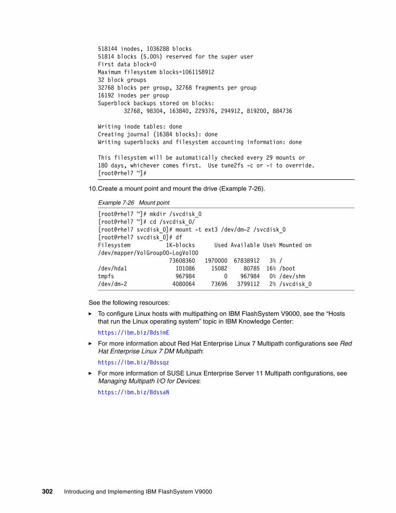
518144 inodes, 1036288 blocks51814 blocks (5.00%) reserved for the super userFirst data block=0Maximum filesystem blocks=106115891232 block groups32768 blocks per group, 32768 fragments per group16192 inodes per groupSuperblock backups stored on blocks: 32768, 98304, 163840, 229376, 294912, 819200, 884736
Writing inode tables: doneCreating journal (16384 blocks): doneWriting superblocks and filesystem accounting information: done
This filesystem will be automatically checked every 29 mounts or180 days, whichever comes first. Use tune2fs -c or -i to override.[root@rhel7 ~]#
10.Create a mount point and mount the drive (Example 7-26).
Example 7-26 Mount point
[root@rhel7 ~]# mkdir /svcdisk_0[root@rhel7 ~]# cd /svcdisk_0/[root@rhel7 svcdisk_0]# mount -t ext3 /dev/dm-2 /svcdisk_0[root@rhel7 svcdisk_0]# dfFilesystem 1K-blocks Used Available Use% Mounted on/dev/mapper/VolGroup00-LogVol00 73608360 1970000 67838912 3% //dev/hda1 101086 15082 80785 16% /boottmpfs 967984 0 967984 0% /dev/shm/dev/dm-2 4080064 73696 3799112 2% /svcdisk_0
See the following resources:
� To configure Linux hosts with multipathing on IBM FlashSystem V9000, see the “Hosts that run the Linux operating system” topic in IBM Knowledge Center:
https://ibm.biz/BdsimE
� For more information about Red Hat Enterprise Linux 7 Multipath configurations see Red Hat Enterprise Linux 7 DM Multipath:
https://ibm.biz/Bdssqz
� For more information of SUSE Linux Enterprise Server 11 Multipath configurations, see Managing Multipath I/O for Devices:
https://ibm.biz/BdssaN
302 Introducing and Implementing IBM FlashSystem V9000

7.9 VMware: Configuration information
This section describes the requirements and other information for attaching VMware hosts and operating systems to IBM FlashSystem V9000.
For more details about the best practices for configuring, attaching, and operating IBM FlashSystem V9000 in a VMware environment, see IBM FlashSystem V9000 and VMware Best Practices Guide, REDP-5247.
7.9.1 Configuring VMware hosts
To configure the VMware hosts, complete the following steps:
1. Install the HBAs in your host system.
2. Connect the server FC host adapters to the switches.
3. Configure the switches (zoning), as described in 7.9.4, “VMware storage and zoning guidance” on page 304.
4. Install the VMware operating system (if not already installed) and check the HBA timeouts.
5. Configure the host, volumes, and host mapping in the IBM FlashSystem V9000, as described in 7.9.6, “Attaching VMware to volumes” on page 304.
7.9.2 Operating system versions and maintenance levels
For more information about VMware support, see the IBM SSIC web page:
https://www.ibm.com/systems/support/storage/ssic/interoperability.wss
At the time of this writing, the following versions are supported:
� ESXi V6.x� ESXi V5.x� ESX / ESxi V4.x (no longer supported by VMware)
7.9.3 HBAs for hosts that are running VMware
Ensure that your hosts that are running on VMware operating systems use the correct HBAs and firmware levels. Install the host adapters in your system. See the manufacturer’s instructions for the installation and configuration of the HBAs.
For more information about supported HBAs for older ESX/ESXi versions, see this web page:
https://www.ibm.com/systems/support/storage/ssic/interoperability.wss
Mostly, the supported HBA device drivers are included in the ESXi server build. However, for various newer storage adapters, you might be required to load more ESXi drivers. if you must load a custom driver for your adapter, see the following VMware web page:
http://www.vmware.com/resources/compatibility/search.php
After the HBAs are installed, load the default configuration of your FC HBAs. You must use the same model of HBA with the same firmware in one server. Configuring Emulex and QLogic HBAs to access the same target in one server is not supported.
Chapter 7. Host configuration 303

If you are unfamiliar with the VMware environment and the advantages of storing virtual machines and application data on a SAN, it is useful to get an overview about VMware products before you continue.
VMware documentation is available at this web page:
http://www.vmware.com/support/pubs/
7.9.4 VMware storage and zoning guidance
The VMware ESXi server can use a Virtual Machine File System (VMFS). VMFS is a file system that is optimized to run multiple virtual machines as one workload to minimize disk I/O. It also can handle concurrent access from multiple physical machines because it enforces the appropriate access controls. Therefore, multiple ESXi hosts can share the set of LUNs.
Theoretically, you can run all of your virtual machines on one LUN. However, for performance reasons in more complex scenarios, it can be better to load balance virtual machines over separate LUNs.
The use of fewer volumes has the following advantages:
� More flexibility to create virtual machines without creating space on IBM FlashSystem V9000
� More possibilities for taking VMware snapshots
� Fewer volumes to manage
The use of more and smaller volumes has the following advantages:
� Separate I/O characteristics of the guest operating systems� More flexibility (the multipathing policy and disk shares are set per volume)� Microsoft Cluster Service requires its own volume for each cluster disk resource
For more information about designing your VMware infrastructure, see these web pages:
� https://www.vmware.com/support/pubs/vsphere-esxi-vcenter-server-6-pubs.html � http://www.vmware.com/vmtn/resources/ � http://www.vmware.com/resources/techresources/1059
7.9.5 Multipathing in ESXi
The VMware ESXi server performs native multipathing. You do not need to install another multipathing driver, such as SDDDSM.
7.9.6 Attaching VMware to volumes
This section describes how to attach VMware to volumes.
First, make sure that the VMware host is logged in to the IBM FlashSystem V9000. These examples use the VMware ESXi server V6 and the host name of Nile.
Enter the following command to check the status of the host:
lshost <hostname>
Guidelines: ESXi server hosts that use shared storage for virtual machine failover or load balancing must be in the same zone. You can have only one VMFS volume per volume.
304 Introducing and Implementing IBM FlashSystem V9000

Example 7-27 shows that host Nile is logged in to IBM FlashSystem V9000 with two HBAs.
Example 7-27 The lshost Nile
IBM_2145:ITSO_V9000:admin>lshost Nileid 1name Nileport_count 2type genericmask 1111iogrp_count 2WWPN 210000E08B892BCDnode_logged_in_count 4state activeWWPN 210000E08B89B8C0node_logged_in_count 4state active
For this configuration, one volume was created and mapped to the ESXi host (Example 7-28).
Example 7-28 Mapped volume to ESXi host Nile
IBM_2145:ITSO_V9000:admin>lshostvdiskmap Nileid name SCSI_id vdisk_id vdisk_name wwpn vdisk_UID1 Nile 0 12 VMW_pool 210000E08B892BCD 60050768018301BF2800000000000010
ESXi does not automatically scan for SAN changes (except when rebooting the entire ESXi server). If you made any changes to your IBM FlashSystem V9000 or SAN configuration, complete the following steps (see Figure 7-18 on page 306 for an illustration):
1. Open your VMware vSphere Client.2. Select the host.3. In the Hardware window, choose Storage.4. Click Rescan.
To configure a storage device to use it in VMware, complete the following steps:
1. Open your VMware vSphere Client.
2. Select the host for which you want to see the assigned volumes and click the Configuration tab.
3. In the Hardware window on the left side, click Storage (Figure 7-18 on page 306).
4. To create a storage datastore, select Add storage.
Tips:
If you want to use features, such as high availability (HA), the volumes that own the VMDK file must be visible to every ESXi host that can host the virtual machine.
In IBM FlashSystem V9000, select Allow the virtual disks to be mapped even if they are already mapped to a host.
The volume should have the same SCSI ID on each ESXi host.
In some configurations, such as MSCS In-guest clustering, the virtual machines must share Raw-device mapping disks for clustering purposes. In this case, it is required to have consistent SCSI ID across all ESXi hosts in the cluster.
Chapter 7. Host configuration 305

5. The Add storage wizard opens. Select Create Disk/Lun, and then click Next.
6. Select IBM FlashSystem V9000 volume that you want to use for the datastore, and then click Next.
7. Review the disk layout, and then click Next.
8. Enter a datastore name, and then click Next.
9. Enter the size of the new partition, and then click Next.
10.Review your selections, and then click Finish.
Now, the created VMFS data store is listed in the Storage window (Figure 7-18). You see the details for the highlighted datastore. Check whether all of the paths are available and that the Path Selection is set to Round Robin.
Figure 7-18 VMware storage configuration
If not all of the paths are available, check your SAN and storage configuration. After the problem is fixed, click Rescan All to perform a path rescan. The view is updated to the new configuration.
The preferred practice is to use the Round Robin Multipath Policy for IBM FlashSystem V9000. If you need to edit this policy, complete the following steps:
1. Highlight the datastore. 2. Click Properties.3. Click Managed Paths.4. Click Change.5. Select Round Robin.6. Click OK.7. Click Close.
306 Introducing and Implementing IBM FlashSystem V9000

Now, your VMFS data store is created and you can start using it for your guest operating systems. Round Robin distributes the I/O load across all available paths. If you want to use a fixed path, the Fixed policy setting also is supported.
7.9.7 Volume naming in VMware
In the Virtual vSphere Client, a device is identified either as volume name if specified during creation in V9000 or as a serial number, as shown in Figure 7-19.
Figure 7-19 V9000 device, volume name
Disk partition: The number of the disk partition (this value never changes). If the last number is not displayed, the name stands for the entire volume.
Chapter 7. Host configuration 307

7.9.8 Extending a VMFS volume
VMFS volumes can be extended while virtual machines are running. First, you must extend the volume on IBM FlashSystem V9000, and then you can extend the VMFS volume.
Complete the following steps to extend a volume:
1. Expand the volume by running the expandvdisksize -size 1 -unit gb <VDiskname> command (Example 7-29).
Example 7-29 Expanding a volume on the IBM FlashSystem V9000
IBM_2145:ITSO_V9000:admin>lsvdisk VMW_poolid 12name VMW_poolIO_group_id 0IO_group_name io_grp0status onlinemdisk_grp_id 0mdisk_grp_name MDG_DS45capacity 60.0GB...IBM_2145:ITSO_V9000:admin>expandvdisksize -size 5 -unit gb VMW_poolIBM_2145:ITSO_V9000:admin>lsvdisk VMW_poolid 12name VMW_poolIO_group_id 0IO_group_name io_grp0status onlinemdisk_grp_id 0mdisk_grp_name MDG_DS45capacity 65.0GB
2. Open the Virtual Infrastructure Client.
3. Select the host.
4. Select Configuration.
5. Select Storage Adapters.
6. Click Rescan.
7. Make sure that the Scan for new Storage Devices option is selected, and then click OK. After the scan completes, the new capacity is displayed in the Details section.
8. Click Storage.
9. Right-click the VMFS volume and click Properties.
10.Click Add Extend.
11.Select the new free space, and then click Next.
12.Click Next.
13.Click Finish.
The VMFS volume is now extended and the new space is ready for use.
Note: Before you perform the steps that are described here, back up your data.
308 Introducing and Implementing IBM FlashSystem V9000

7.9.9 Removing a data store from an ESXi host
Before you remove a data store from an ESXi host, you must migrate or delete all of the virtual machines that are on this data store.
To remove the data store, complete the following steps:
1. Back up the data.
2. Open the Virtual Infrastructure Client.
3. Select the host.
4. Select Configuration.
5. Select Storage.
6. Right-click the datastore that you want to remove.
7. Click Unmount (must be done for all ESXi with mounted datastore).
8. Click Delete to remove.
9. Read the warning, and if you are sure that you want to remove the data store and delete all data on it, click Yes.
10.Select Devices view, right-click the device you want to detach, then click Detach.
11.Remove the host mapping on IBM FlashSystem V9000, or delete the volume, as shown in Example 7-30.
Example 7-30 Host mapping: Delete the volume
IBM_2145:ITSO_V9000:admin>rmvdiskhostmap -host Nile VMW_poolIBM_2145:ITSO_V9000:admin>rmvdisk VMW_pool
12.In the VI Client, select Storage Adapters.
13.Click Rescan.
14.Make sure that the Scan for new Storage Devices option is selected and click OK.
15.After the scan completes, the disk is removed from the view.
Your data store is now removed successfully from the system.
For more information about supported software and driver levels, see the SSIC web page:
https://www.ibm.com/systems/support/storage/ssic/interoperability.wss
7.10 Oracle (Sun) Solaris: Configuration information
At the time of writing, Oracle (Sun) Solaris hosts (SunOS) versions 8, 9, 10, 11, and 12 are supported by IBM FlashSystem V9000. However, SunOS 8 and SunOS 9 (Solaris 8 and Solaris 9) are in the sustaining support phase of their lifecycles.
Chapter 7. Host configuration 309

7.10.1 MPxIO dynamic pathing
Solaris provides its own MPxIO multipath support for the operating system. Therefore, you do not have to install another device driver. Alternatively Veritas DMP can be used.
Veritas Volume Manager with dynamic multipathingVeritas Volume Manager (VM) with dynamic multipathing (DMP) automatically selects the next available I/O path for I/O requests without action from the administrator. VM with DMP is also informed when you repair or restore a connection, and when you add or remove devices after the system is fully booted (if the operating system recognizes the devices correctly). The Java Native Interface (JNI) drivers support the host mapping of new volumes without rebooting the Solaris host.
The support characteristics are as follows:
� Veritas VM with DMP supports load balancing across multiple paths with IBM FlashSystem V9000.
� Veritas VM with DMP does not support preferred pathing with IBM FlashSystem V9000.
OS cluster supportSolaris with Symantec Cluster V4.1, Symantec SFHA, and SFRAC V4.1/5.0, and Solaris with Sun Cluster V3.1/3.2 are supported at the time of this writing.
SAN boot supportBoot from SAN is supported under Solaris 10 and later running Symantec Volume Manager or MPxIO.
Aligning the partition for SolarisFor ZFS no alignment is needed, if a disk is added directly to a ZFS pool using the zpool utility. The utility creates the partition starting at sector 256, which automatically creates a properly aligned partition.
7.11 Hewlett-Packard UNIX: Configuration information
For information about what is supported with Hewlett-Packard UNIX (HP-UX), see the IBM SSIC web page:
https://www.ibm.com/systems/support/storage/ssic/interoperability.wss
7.11.1 Operating system versions and maintenance levels
At the time of this writing, the following HP-UX operating systems (64-bit only) are supported with IBM FlashSystem V9000:
� HP-UX V11iv1 (11.11)� HP-UX V11iv2 (11.23)� HP-UX V11iv3 (11.31)
310 Introducing and Implementing IBM FlashSystem V9000

7.11.2 Supported multipath solutions
For HP-UX version 11.31, HP does not require installing a separate multipath driver. As part of this version, native multipathing solution is supported with the mass storage stack feature.
For releases of HP-UX before 11.31, multipathing support is available using either of the following software:
� IBM System Storage Multipath Subsystem Device Driver (SDD)� HP PVLinks
The IBM FlashSystem V9000 documentation has more information about multipath:
https://ibm.biz/BdsGUw
7.11.3 Clustered-system support
HP-UX version 11.31 supports ServiceGuard 11.18, which provides a locking mechanism called cluster lock LUN. On the IBM FlashSystem V9000, specify the block device name of a volume for CLUSTER_LOCK_LUN variable in the configuration ASCII file. The lock LUN among all system nodes must point to the same volume. This consistency can be ensured by determining the worldwide ID (WWID) of the volume. The system lock LUN cannot be used for multiple system locking and cannot be used as a member of a Logical Volume Manager (LVM) volume group or VxVM disk group.
7.11.4 Support for HP-UX with greater than eight LUNs
HP-UX does not recognize more than eight LUNS per port that use the generic SCSI behavior. If you want to use more than eight LUNs per SCSI target, you must set the type attribute to hpux when you create the host object. You can use the IBM FlashSystem V9000 command-line interface or the management GUI to set this attribute.
7.12 Using NPIV functionality
With IBM FlashSystem V9000 version 7.7.1 and later, N_Port ID Virtualization (NPIV) is available. Configuring IBM FlashSystem V9000 target ports for NPIV provides the advantage of zero connectivity reduction in case of firmware updates and maintenance where a controller is unavailable. When NPIV is enabled, the target ports are virtualized, and all the worldwide names (WWNs) representing the ports remain available during controller outages.
7.12.1 How NPIV works
How NPIV works, how to migrate from traditional physical port WWNs, and how to enable NPIV are all demonstrated in “Check the existing non NPIV environment” on page 312. Also, it demonstrates the failover scenario where one controller is removed from the system, while all WWNs remain available to the attached host.
The scenario for the demonstration is a Microsoft Windows 2008 Server, which connects to IBM FlashSystem V9000 through a dual port HBA connected to two Brocade SAN switches. The SAN switches have zoning enabled for traditional non-NPIV access.
Chapter 7. Host configuration 311

Check the existing non NPIV environmentTo check the existing environment, perform the following tasks:
1. The Microsoft Windows 2008 Server has access to a single 100 GB volume from IBM FlashSystem V9000. View this information in the Disk Management window of the server OS (Figure 7-20).
Figure 7-20 Server has access to a single IBM FlashSystem V9000 volume
2. To check the current target port mode, go to the IBM FlashSystem V9000 GUI and select Settings → System → I/O Groups. Target port mode is disabled (Figure 7-21), which means that the Fibre Channel ports on IBM FlashSystem V9000 are physical ports, each with a WWN connecting to the SAN switches.
Figure 7-21 Target port mode is disabled
3. By logging on to the SAN switches, review the zoning configuration either by using CLI or GUI (as in this example). The physical WWNs can be reviewed while they are connected to the SAN switch ports. IBM FlashSystem V9000 control enclosures connect with two connections to SAN switch ports 10 and 11, as shown in Figure 7-22 on page 313. A similar configuration exists on the second switch fabric, which is not shown here.
312 Introducing and Implementing IBM FlashSystem V9000

Figure 7-22 SAN switch ports 10 and 11 shows which WWNs are connected
For the zoning configuration above two WWNs are configured for the alias V9000. Both WWNs are shown as blue in the right side frame indicating that these are online. The WWNs are greyed out in the left side frame because these are active in the alias V9000 which is selected.
Change to Target Port Mode Transitional Enabling NPIV must be done in two steps so that SAN zoning can be modified with the new WWNs before access to storage is disabled when NIPIV is enabled.
To enable Target Port Mode Transitional perform the following steps:
1. From the IBM FlashSystem V9000 GUI, select Settings → System → I/O Groups. Select the I/O Group to be changed and select Actions → Change Target Port Mode as shown in Figure 7-23.
Figure 7-23 Change Target Port Mode
Chapter 7. Host configuration 313

2. The Change Target Port Mode wizard offers only a change from Disabled to Transitional (Figure 7-24). In Transitional mode, both physical and virtual ports are in use. Click Continue to enable Transitional mode.
Figure 7-24 Change to Transitional
Viewing the SAN switches after changing to Transitional mode now shows additional WWNs (Figure 7-25). These are the virtualized NPIV ports that must be added to the zoning configuration. This ensures hosts keep having access to IBM FlashSystem V9000 storage when the configuration is finalized by change to Target Port Mode Enabled.
Figure 7-25 Additional virtual ports are available
New virtual ports
Original physical ports
314 Introducing and Implementing IBM FlashSystem V9000

3. The next step is to prepare the zoning configuration for NPIV use. Figure 7-26 shows the new virtual NPIV ports have been added to the alias V9000 so that both physical WWNs and Virtual WWNs are in the zone. Save the configuration and enable it.
Figure 7-26 The virtual NPIV ports are added to alias V9000
In the final zoning configuration, the original physical port WWNs must be removed from zoning so that only the new virtual port WWNs exist in the V9000 zone.
4. To ensure nondisruptive storage access, the SAN zoning configuration with both physical WWNs and virtual WWNs must be saved and enabled, then the host must rediscover storage and connectivity to the new NPIV WWNs must be verified. The methods for doing so depends on the operating system. In this example, the Windows 2008 server SDDDSM is used to check the number of paths.
Example 7-31 shows the output, which is shortened here for clarity, from SDDDSM datapath query device before adding the NPIV WWNs to the zoning configuration.
Example 7-31 Paths the IBM FlashSystem V9000 before adding NPIV WWNs
DEV#: 1 DEVICE NAME: Disk3 Part0 TYPE: 2145 POLICY: LEAST I/O AND WEIGHTSERIAL: 60050768028183D58000000000000036Reserved: NoLUN SIZE: 100.0GBHOST INTERFACE: FC===========================================================================================Path# Adapter/Hard Disk State Mode Select Errors 0 Scsi Port2 Bus0/Disk3 Part0 OPEN NORMAL 215 0 1 * Scsi Port2 Bus0/Disk3 Part0 OPEN NORMAL 0 0 2 Scsi Port3 Bus0/Disk3 Part0 OPEN NORMAL 184 0 3 * Scsi Port3 Bus0/Disk3 Part0 OPEN NORMAL 0 0
Chapter 7. Host configuration 315

Example 7-32 shows the output, which is shortens for clarity, from SDDDSM datapath query device after adding the NPIV WWNs to the zoning configuration.
Example 7-32 Paths the IBM FlashSystem V9000 after adding NPIV WWNs
DEV#: 1 DEVICE NAME: Disk3 Part0 TYPE: 2145 POLICY: LEAST I/O AND WEIGHTSERIAL: 60050768028183D58000000000000036Reserved: NoLUN SIZE: 100.0GBHOST INTERFACE: FC===========================================================================================Path# Adapter/Hard Disk State Mode Select Errors 0 * Scsi Port2 Bus0/Disk3 Part0 OPEN NORMAL 215 0 1 * Scsi Port2 Bus0/Disk3 Part0 OPEN NORMAL 0 0 2 * Scsi Port3 Bus0/Disk3 Part0 OPEN NORMAL 184 0 3 * Scsi Port3 Bus0/Disk3 Part0 OPEN NORMAL 0 0 4 * Scsi Port2 Bus0/Disk3 Part0 OPEN NORMAL 0 0 5 Scsi Port2 Bus0/Disk3 Part0 OPEN NORMAL 0 0 6 * Scsi Port3 Bus0/Disk3 Part0 OPEN NORMAL 0 0 7 Scsi Port3 Bus0/Disk3 Part0 OPEN NORMAL 0 0
The number of paths increased from four to eight, indicating that the host connects to IBM FlashSystem V9000 on the NPIV paths.
5. Remove the original physical port WWNs from the zoning configuration (Figure 7-27). Save the zoning configuration and enable it.
Figure 7-27 The new NPIV WWNs are now in the V9000 alias instead of the original physical
6. At this point go to your host and rescan for disks to make sure the host is communicating correctly with IBM FlashSystem V9000 and the NPIV ports.
316 Introducing and Implementing IBM FlashSystem V9000

Change to Target Port Mode EnabledTo enable NPIV, perform the following steps:
1. The next step is to enable target port mode. During this step IBM FlashSystem V9000 stops using the physical ports and starts to use only the virtual NPIV ports. From Settings → System → I/O Groups, select the I/O Group to be changed and select Actions → Change Target Port Mode.
In the Change Target Port Mode dialog, (Figure 7-28), select Enabled and select the Force change check box, and then click Continue.
Figure 7-28 Enable NPIV
A message warns that host operations can be disrupted (Figure 7-29). At this point, if the zoning configuration has not been changed to include the virtualized NPIV WWNs the host will lose access to IBM FlashSystem V9000 storage. Click Yes to continue.
Figure 7-29 Warning - host access may be disrupted
CLI executes and NPIV is enabled. IBM FlashSystem V9000 now no longer uses the original WWNs to propagate its volumes to the Windows 2008 Server host.
Chapter 7. Host configuration 317

2. Click Close to finish the configuration change (Figure 7-30).
Figure 7-30 CLI executes: NPIV is now enabled
3. Review the Target Port Mode, which now indicates Enabled (Figure 7-31).
Figure 7-31 NPIV is now enabled for I/O group 0
4. Check again that the host is functional and connects to its IBM FlashSystem V9000 disks. In this example, the Windows 2008 server continues to have access to IBM FlashSystem V9000 storage during the transition from physical to virtualized NPIV ports.
Warning: Make sure that the new NPIV WWNs are included in the zoning configuration or the host will loose access to IBM FlashSystem V9000 volumes.
318 Introducing and Implementing IBM FlashSystem V9000

Simulating IBM FlashSystem V9000 controller outageIBM FlashSystem V9000 controller reboots during firmware updates. During such a reboot, the physical Fibre Channel connections and their WWNs are unavailable if you use traditional Target Port Mode. When Target Port Mode is enabled, NPIV is active and the WWNs are virtualized, meaning that they can move between controllers when needed.
Figure 7-32 shows an IBM FlashSystem V9000 controller that is placed in Service State and therefore simulates a controller outage. The controller that is being placed in Service State is connected to switch port 10, which before the outage showed two WWNs (one physical and one virtual). Now when the controller is placed in Service State, the two virtualized NPIV ports are both represented on port 11, as shown in the left pane. In the right pane, the two NPIV ports remain blue and online.
Figure 7-32 SAN ports remain online with IBM FlashSystem V9000 controller down
For more information about how to enable and verify NPIV, see 9.5.7, “I/OGroups: Enable and disable NPIV” on page 464.
For more information about NPIV, see the “N_Port ID Virtualization configuration” topic in IBM Knowledge Center:
https://ibm.biz/BdsiGR
7.13 Using SDDDSM, SDDPCM, and SDD web interface
After the SDDDSM or SDD driver is installed, specific commands are available. To open a command window for SDDDSM or SDD, select Start → Programs → Subsystem Device Driver → Subsystem Device Driver Management from the desktop.
For more information about the command documentation for the various operating systems, see Multipath Subsystem Device Driver User’s Guide, S7000303:
http://ibm.com/support/docview.wss?uid=ssg1S7000303
Virtual ports remain online
Chapter 7. Host configuration 319

Also possible is to configure SDDDSM to offer a web interface that provides basic information. Before this configuration can work, you must configure the web interface. SDDSRV does not bind to any TCP/IP port by default, but it does allow port binding to be dynamically enabled or disabled.
The multipath driver package includes an sddsrv.conf template file that is named the sample_sddsrv.conf file. On all UNIX platforms, the sample_sddsrv.conf file is in the /etc directory. On Windows platforms, it is in the directory in which SDDDSM was installed.
You must use the sample_sddsrv.conf file to create the sddsrv.conf file in the same directory as the sample_sddsrv.conf file by copying it and naming the copied file to sddsrv.conf. You can then dynamically change the port binding by modifying the parameters in the sddsrv.conf file and changing the values of Enableport and Loopbackbind to True.
Figure 7-33 shows the start window of the multipath driver web interface.
Figure 7-33 SDD web interface
7.14 More information
For more information about host attachment, storage subsystem attachment, and troubleshooting, see IBM FlashSystem V9000 web page in IBM Knowledge Center:
https://ibm.biz/fs_V9000_kc
320 Introducing and Implementing IBM FlashSystem V9000

Chapter 8. Using IBM FlashSystem V9000
In this chapter, you learn how to operate IBM FlashSystem V9000 in your business environment. The chapter uses the graphical user interface (GUI) and the command-line interface (CLI) to demonstrate how to monitor the system and work with volumes, managed disks, hosts, and user security.
This chapter includes the following topics:
� Overview of FlashSystem V9000 management tool� Actions menu� Monitoring menu� Pools menu� Volumes menu� Hosts menu� Copy Services menu� Access menu
8
Note: This chapter refers to both AC2 and AC3 control enclosure models. Where fundamental differences exist between the two models, images of both control enclosures are included. Where no significant differences exist, only the AC2 model is shown, but the action and resulting display are the same on an AC3 control enclosure based IBM FlashSystemV9000
© Copyright IBM Corp. 2015, 2016. All rights reserved. 321

8.1 Overview of FlashSystem V9000 management tool
The IBM FlashSystem V9000 can be managed from either the built-in GUI, which is a web browser-based management tool, or from the CLI.
You must use a supported web browser to be able to manage the IBM FlashSystem V9000 by using the GUI. For a list of supported web browsers, see the IBM FlashSystem V9000 web page at IBM Knowledge Center:
https://ibm.biz/fs_V9000_kc
Select Configuring → Configuration details → Initializing the system → Checking your web browser settings for the management GUI.
8.1.1 Access to the GUI
To log in to the GUI, point your web browser at the IP address that was set during the initial setup of the IBM FlashSystem V9000. The login window opens (Figure 8-1).
Figure 8-1 Login window: Default is superuser and passw0rd (with a zero)
8.1.2 GUI home window: Single building block system
After you log in, the Monitoring → System window opens, which is the home window. This chapter describes each component of the GUI and provides examples.
There are now two models of the control nodes, the AC2 and the new AC3 model. Figure 8-2 on page 323 shows the AC2 control enclosures above and below the AE2 storage enclosure.
The GUI home window (Figure 8-2 on page 323) represents a system with a single building block. That is a system with two AC2 control enclosures and one AE2 storage enclosure.
JavaScript: You might need to enable JavaScript in your browser. Additionally, if you are using Firefox, under Advanced JavaScript Settings, click Disable or replace context menus and allow cookies.
322 Introducing and Implementing IBM FlashSystem V9000

Figure 8-2 System view: AC2 control enclosure based single building block
The GUI home window shown in Figure 8-3 represents an IBM FlashSystem V9000 system with a single building block, containing two AC3 control enclosures and one AE2 storage enclosure.
Figure 8-3 System view: AC3 control enclosure based single building block
Chapter 8. Using IBM FlashSystem V9000 323

To navigate the home window, complete the following steps:
1. By clicking the yellow arrow in the lower right corner of the IBM FlashSystemV9000 depiction, the image turns around and shows the system from the back. By moving the mouse to each individual port or device, more information is displayed (Figure 8-4).
Figure 8-4 Back view of an AC2 control node based single system
Figure 8-5 shows the rear view of an AC3 control node based single building block.
Figure 8-5 Rear view of an AC3 control node based single building block
324 Introducing and Implementing IBM FlashSystem V9000

2. To view the frontside view properties for the device, point the mouse to the device, right-click, and select Properties (Figure 8-6).
Figure 8-6 Select the storage expansion and right-click for properties
The system property window opens (Figure 8-7).
Figure 8-7 Expansion enclosure properties
Chapter 8. Using IBM FlashSystem V9000 325

8.1.3 GUI home window: Multiple building block system
For systems containing more than a single IBM FlashSystem V9000 building block or more than a single AE2 storage enclosure in the cluster, the GUI home window displays differently. When opening the GUI after logging in, a single IBM FlashSystem V9000 is depicted. This immediately animates into a new depiction of all installed components in the managed entity, as shown in Figure 8-8.
Figure 8-8 System view: with multiple scalable building blocks
The system shown in the GUI in Figure 8-8 has eight IBM FlashSystem V9000 AC2 control enclosures and eight AE2 storage enclosures.
The system shown in the GUI in Figure 8-9 on page 327 has two IBM FlashSystem V9000 AC3 control enclosures, one AE2 storage enclosure and one Model 12F expansion enclosure.
326 Introducing and Implementing IBM FlashSystem V9000

Figure 8-9 System View of AC3 control nodes with AE2 flash storage and 12F expansion enclosure
Hover the mouse over the individual items, and more information is provided. For example, point the mouse at the first controller node in io_grp0 (Figure 8-10).
Figure 8-10 Mouse over node 1 in iogroup io_grp0
Chapter 8. Using IBM FlashSystem V9000 327

By clicking the selected node, the node properties window opens (Figure 8-11).
Figure 8-11 Control enclosure 1 selected in the GUI
Hover the mouse over control enclosure1 and right-click. A menu is displayed (Figure 8-12).
Figure 8-12 Configure control enclosure 1 menu displays
328 Introducing and Implementing IBM FlashSystem V9000

Control enclosure 1 can also be visually rotated by using the twisted-arrow icon, so that the back view is displayed. From the back view, the status of each individual I/O port can be monitored.
Figure 8-13 shows the back of the AC2 control enclosure and the interface connections.
Figure 8-13 Control enclosure 1: AC2 rear view
Figure 8-14 shows the back of the AC3 control enclosure and the interface connections.
Figure 8-14 Control enclosure 1: AC3 rear view
Chapter 8. Using IBM FlashSystem V9000 329

Figure 8-15 shows the back of the Model 12F expansion enclosure and the layout of the SAS interface connections per canister.
Figure 8-15 Model 12F expansion enclosure: Rear view
Information of individual ports can be displayed by pointing the mouse to the port of interest (Figure 8-16).
Figure 8-16 Control enclosure 1: AC2 rear-side view with FC-port information displayed
330 Introducing and Implementing IBM FlashSystem V9000

Figure 8-17 shows the back of the Model AC3 control enclosure and layout of the Fibre Channel interface connections.
Figure 8-17 Control enclosure 1: AC3 rear view and FC port information
For iSCSI-enabled ports, the iSCSI IP address is displayed (Figure 8-18).
Figure 8-18 Control enclosure 1: AC2 rear view with iSCSI information
8.1.4 Layout of GUI
Note: This section refers to both AC2 and AC3 control enclosure models. Where fundamental differences exist between two models, images of both control enclosures are included. Where no significant differences exist, only the AC2 model is shown, but the action and resulting display are the same on an AC3 control enclosure based V9000.
Chapter 8. Using IBM FlashSystem V9000 331

The GUI has multiple functions (Figure 8-19) for navigating through the management tool. Several of those functions are described in this list:
� Actions
This button has a list of menu items and is only visible from the Monitoring System view. You can also reach actions by right-clicking anywhere in the window.
� Function icons
You can directly access various functions.
� Component status indicators
These indicators provide more detailed information about the existing configuration of the IBM FlashSystem V9000 solution.
� User security key and help
The user security key shows which user is currently logged in to the GUI. Click the question mark (?) help icon to get information about licenses, current system code level and serial number, and access to the IBM FlashSystem V9000 page in IBM Knowledge Center.
� Capacity, performance, and health indicators
Get instant status of capacity, overall performance and current health.
� Overview
Shows the number of external MDisks, arrays, pools, volumes, and hosts, and provides a link for managing each of these items.
Figure 8-19 Home window layout for IBM FlashSystem V9000 overview
Actions
Current Menu Indicators User securityHelp
Component status indicators
Capacity HealthPerformance
Function icons
Rotate for rear side view
Save VPD Overview
332 Introducing and Implementing IBM FlashSystem V9000

The overview window shows the number of external MDisks, arrays, pools, volumes, and hosts, and provides a link for management (Figure 8-20). For each item in the overview window, a link is provided. The link opens the appropriate menu to configure the selected item.
.
Figure 8-20 Overview window
8.1.5 Function icons
Each function icon offers various menu options. Click an icon to open its branch-out menu (Figure 8-21 on page 334). The function icons are as follows:
� Monitoring� Pools� Volumes� Hosts� Copy Services� Access� Settings
The Settings menu: Details about the settings menu and its various options are provided in Chapter 9, “Configuring settings” on page 405.
Chapter 8. Using IBM FlashSystem V9000 333

Figure 8-21 Function icons
8.1.6 Capacity, performance, and health indicators
These indicators show real-time values of the current IBM FlashSystem V9000 system (Figure 8-22).
Figure 8-22 Status indicators
Actions menuUpper left corner menu or right-click
Capacity Performance HealthRunning tasks Status Alerts
Capacity toggle between:
Component status
Performance
HealthCapacity
334 Introducing and Implementing IBM FlashSystem V9000

The status indicators show the following information:
� Running tasks:
– Currently ongoing tasks– Recently completed tasks
An example of running tasks is shown in Figure 8-23. If you click one of the running tasks, more information about the task is displayed.
Figure 8-23 Running tasks
� Capacity:
– Used gigabytes– Installed gigabytes
� Performance:
– Bandwidth (in MBps)– I/O per second (IOPS)– Latency, in microseconds (ms)
� Health:
– Healthy (green)– Warning or degraded (yellow) and a link to Monitoring → Events is provided– Error (red) and a link to Monitoring → Events is provided– Upgrade status percentage
� Status alerts:
– Current unread alerts– Current unfixed events
Note: Use the up and down arrows. Click the up arrow to see the Allocated capacity comparison; click the down arrow to see the Virtual capacity comparison.
Note: To view the detailed performance windows, hover the cursor over any of the three areas in the performance pod. For more detail, you can hover your cursor over any of the other components of IBM FlashSystem V9000.
Chapter 8. Using IBM FlashSystem V9000 335

An example of status alerts is shown in Figure 8-24.
Figure 8-24 Status alert
8.1.7 See which user is logged in, get help, and get overview information
This part of the window (Figure 8-25) can be used for these tasks:
� User security
See which user is currently logged in and change password.
� Help
Get context-sensitive help, get current code level and serial number.
� Overview
Access the main functions through the Overview.
Figure 8-25 Systems general parameters
User security
Help and about
Overview with links
336 Introducing and Implementing IBM FlashSystem V9000

8.1.8 System details
The central part of the window enables you to get more deeply into the details for all parts of the IBM FlashSystem V9000. Hover your cursor over an object and click to get details. Some objects also support right-click (Figure 8-26).
Figure 8-26 Front view selection
Click the Rotate arrow (Figure 8-26) to see the back of the system (Figure 8-27).
Figure 8-27 Rear view selection
Mouse-hover
Selection
Right-click
Rotate
Right-click to
Hover mouse
see menu
to see port info
Chapter 8. Using IBM FlashSystem V9000 337

8.2 Actions menu
In the home window, you can click Actions (Figure 8-21 on page 334) to see a list of actions or right-click anywhere in the GUI to get a list of actions.
You can retrieve and update the following information from the Actions menu (Figure 8-28):
� Rename System
Changes the host name and iSCSI IQN name.
� Update System
Provides a link to the firmware update wizard.
� Power Off
Power off entire system.
Figure 8-28 Actions menu
8.2.1 Rename System
You can rename your IBM FlashSystem V9000 by using the GUI and the CLI.
Using the GUI to rename the systemTo change the system name, select Actions → Rename System. In the Rename System window, enter the new name and click Rename (Figure 8-29).
Figure 8-29 System rename
338 Introducing and Implementing IBM FlashSystem V9000

After the system is renamed, the Modify System Properties window opens and displays the Task completed message (Figure 8-30). The window also shows the CLI command that the system used to make the change. Review this for future use and click Close.
Figure 8-30 System Rename CLI command
Using the CLI to rename the systemWhen the system is renamed by using the GUI, commands are run on the system. In the preceding example, the system name was changed by using the GUI, and the Modify System Properties window opened to indicate the CLI commands that the system used to change system properties.
Example 8-1 shows CLI commands to rename the system (for clarity, the output is shortened).
Example 8-1 System name change using CLI
IBM_FlashSystem:ITSO_V9000:superuser>svctask chsystem -name test_change
IBM_FlashSystem:ITSO_V9000:superuser>svcinfo lssystem.... name test_change....
8.2.2 Update System
For updating IBM FlashSystem V9000 code, concurrent upgrade is the default way to upgrade the IBM FlashSystem V9000 system. All components of the system are upgraded including the AC2 and AC3 controllers, the AE2 storage enclosures and the expansion enclosures, if present. Performance is affected during heavy I/O load.
The details of the firmware update process, including concurrent upgrade, are covered in 9.5.3, “Update software” on page 455.
Chapter 8. Using IBM FlashSystem V9000 339

8.2.3 Power Off
The IBM FlashSystem V9000 can be turned off through the Actions menu. The power off function ensures that the system is turned off securely so that data is preserved.
This action powers down the AC2 or AC3 control enclosures, the AE2 storage enclosures, and, if present, the expansion enclosures.
After you select Actions → Power Off → System, a message is displayed in the Power Off System window (Figure 8-31). The message describes what will happen. To confirm the action, enter a confirmation code to prevent an accidental power-off cycle of the device.
Figure 8-31 Power off confirmation window
8.3 Monitoring menu
The Monitoring > System window is the default home for the IBM FlashSystem V9000 GUI. The Monitoring menu has three options:
� System
Default GUI entry point.
� Events
Messages, alerts, and recommended actions/fix procedures.
� Performance
Review overall system performance in a five-minute window.
340 Introducing and Implementing IBM FlashSystem V9000

8.3.1 System
Select Monitoring → System from anywhere in the GUI to return to the main window (Figure 8-32).
Figure 8-32 System home window
Chapter 8. Using IBM FlashSystem V9000 341

8.3.2 Events
The health status indicator can be green (healthy), yellow (degraded or warning), or red (critical), as shown in Figure 8-33. For more details about events that caused the status to change, click Events on the Monitoring menu.
Figure 8-33 Events start menu
At any time, you can click the question mark (?) help icon (Figure 8-34) to get context-sensitive details.
Figure 8-34 Get help on events
Health status indicator
Help for the current menu
342 Introducing and Implementing IBM FlashSystem V9000

Figure 8-35 shows the Monitoring > Events window where the mode is Show All. In this mode, all events, including messages, warnings, and errors, are displayed.
Figure 8-35 Show All events mode
To view the Show All mode, click Recommended Actions → Show All (Figure 8-36).
Figure 8-36 Mode change to Show All
Chapter 8. Using IBM FlashSystem V9000 343
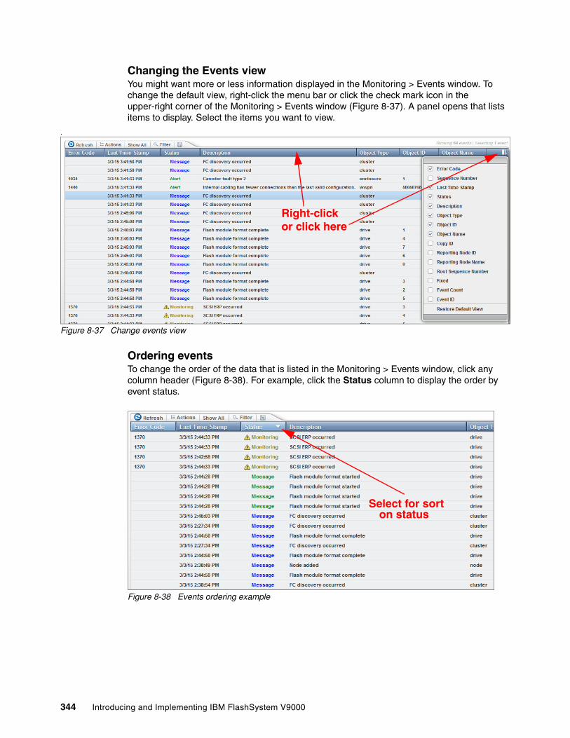
Changing the Events viewYou might want more or less information displayed in the Monitoring > Events window. To change the default view, right-click the menu bar or click the check mark icon in the upper-right corner of the Monitoring > Events window (Figure 8-37). A panel opens that lists items to display. Select the items you want to view.
.
Figure 8-37 Change events view
Ordering eventsTo change the order of the data that is listed in the Monitoring > Events window, click any column header (Figure 8-38). For example, click the Status column to display the order by event status.
Figure 8-38 Events ordering example
Right-clickor click here
Select for sort on status
344 Introducing and Implementing IBM FlashSystem V9000

Events Actions menuUse the Actions menu (Figure 8-39) to select any of these actions, depending on the view choice:
� Run Fix Procedure
This starts the Directed Maintenance Procedure (DMP), which can help you correct the error. See “Directed maintenance procedure” on page 346.
� Mark as Fixed
This marks the event as fixed without running the DMP (force mode). If this mode is used and the fault re-occurs, then a new DMP will be created
� Filter by Date
Filters events by date and time stamp.
� Show entries within
Shows only events from the last minutes, hours, or days.
� Reset Date Filter
Resets filtering by date when set.
� Clear Log
Clears the displayed events, but events are still in the support package if needed.
� Properties
Displays the details for one event, same as clicking the event.
As an example, view only events that are newer than 2 hours (Figure 8-39).
Figure 8-39 Actions menu
Search stringIf you want to see a specific string within the events, click Filter (Figure 8-40).
Figure 8-40 Filter menu
Chapter 8. Using IBM FlashSystem V9000 345

You are then prompted for the search string. Matched data is highlighted (Figure 8-41).
Figure 8-41 Filter result
Save data to CSVTo save any event data as a CSV file (even after filtering), click the Save icon (Figure 8-42).
Figure 8-42 Save event data to local disk
Directed maintenance procedureVarious ways are available to discover that your system needs attention in a warning or error situation. If call home is configured on your system, which is advised, IBM Support is notified directly from the system, and IBM contacts the system administrators for corrective actions.
The system administrator might also be in the list of email recipients and therefore is notified directly and immediately from the system as soon as an alert is sent. Another way of getting alert notifications is through Simple Network Management Protocol (SNMP) alerts.
When the system administrator logs in to the IBM FlashSystem V9000 GUI, a Status Alerts window opens in the lower-right corner. Hover over the Status Alerts icon (X) to see the unresolved alerts (Figure 8-43 on page 347). Information also indicates approximately how long the alert has existed (for example 33 minutes).
Note: A good practice is to review the DMP alerts on a regular basis, and proactively remove those alerts that can be corrected.
346 Introducing and Implementing IBM FlashSystem V9000

Figure 8-43 Status Alerts
By clicking the alert number, you are redirected to the event window, and you can run the fix for the error. To do that, click Run Fix, or you can right-click the alert event and select Run Fix Procedure (Figure 8-44).
Figure 8-44 Two choices to fix the alerts
The fix procedure begins. Follow the procedure (Figure 8-45).
Figure 8-45 Fix procedure example
Pending alerts
Alert since
Alert text
Fix highest
Right-click and
priority alert
alertfix selected
Chapter 8. Using IBM FlashSystem V9000 347

8.3.3 Performance
This section highlights several performance monitoring techniques, using the GUI or the CLI.
Real-time performance monitoring with the GUITo open the Performance window (Monitoring > Performance), select Performance from the Monitoring menu as shown in (Figure 8-46).
Figure 8-46 Performance menu selection
The Performance Monitoring window (Figure 8-47 on page 349) is divided into four sections that provide utilization views for the following resources:
� CPU Utilization. Shows CPU usage for the following items:
– System %– Compression (when enabled) %
� Volumes. Shows the overall volume utilization with the following fields:
– Read– Write– Read latency– Write latency
� Interfaces. Shows the overall statistics for each of the available interfaces:
– Fibre Channel– iSCSI– SAS– IP Replication
� MDisks. Shows the following overall statistics for the MDisks:
– Read– Write– Read latency– Write latency
348 Introducing and Implementing IBM FlashSystem V9000

Figure 8-47 Real time performance graph
You can also view performance statistics for each of the available control enclosures of the system (Figure 8-48).
Figure 8-48 Change statistics from all control enclosures to one specific control enclosure
Chapter 8. Using IBM FlashSystem V9000 349
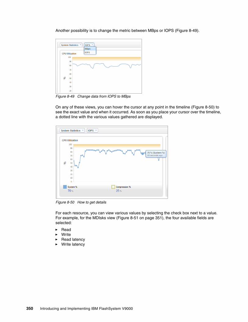
Another possibility is to change the metric between MBps or IOPS (Figure 8-49).
Figure 8-49 Change data from IOPS to MBps
On any of these views, you can hover the cursor at any point in the timeline (Figure 8-50) to see the exact value and when it occurred. As soon as you place your cursor over the timeline, a dotted line with the various values gathered are displayed.
Figure 8-50 How to get details
For each resource, you can view various values by selecting the check box next to a value. For example, for the MDIsks view (Figure 8-51 on page 351), the four available fields are selected:
� Read� Write� Read latency� Write latency
350 Introducing and Implementing IBM FlashSystem V9000

Figure 8-51 All curves selected
Regarding performance, the latency numbers are especially of interest. MDisk latency is latency between the IBM FlashSystem V9000 control enclosure and its storage enclosure. Volume latency is latency between a connected host and the IBM FlashSystem V9000 control enclosures. If a system administrator of a connected host sees slow disk connectivity, that is reflected in the volume latency.
IBM FlashSystem V9000 shows system overall performance in terms of IOPS, MBps, and latency numbers in a time frame of 5 minutes. If there is a need for additional information, for example to monitor if a specific volume has latency, or to investigate why a connected host experienced performance problems at a given time, IBM offers advanced performance and capacity management and monitoring tools using IBM Spectrum Control (formerly IBM Tivoli Storage Productivity Center).
For more information about IBM Spectrum Control, see the following web page:
http://www.ibm.com/systems/storage/spectrum/control/
Real-time performance monitoring with the CLI
The lsnodestats and lssystemstats commands are available for monitoring the statistics through the CLI.
Note: The home window (Figure 8-22 on page 334) provides a high-level view of the performance in the performance pod:
Note: In this section, the term node is sometimes used and can refer to either a control, storage, or expansion enclosure.
Chapter 8. Using IBM FlashSystem V9000 351

The lsnodestats command (Example 8-2) provides performance statistics for the nodes that are part of the system (note that the output is truncated and shows only part of the available statistics). You can also specify a node name in the command to limit the output for a specific node.
Example 8-2 The lsnodestats command output
IBM_FlashSystem:ITSO_V9000:superuser>lsnodestatsnode_id node_name stat_name stat_current stat_peak stat_peak_time1 BB1N1_NODE_01 compression_cpu_pc 8 8 1503051403561 BB1N1_NODE_01 cpu_pc 1 2 1503051402511 BB1N1_NODE_01 fc_mb 0 29 1503051402511 BB1N1_NODE_01 fc_io 225 685 150305140156
This example shows statistics for the node BB1N1_NODE_01 members of system ITSO_V9000. The following columns are displayed:
node_id ID of the current node.node_name Name of the node.stat_name Name of the statistic field.stat_current Current value of the statistic field.stat_peak Peak value of the statistic field in the last 5 minutes.stat_peak_time Time that the peak occurred.
The lssystemstats command (Example 8-3) lists the same set of statistics as the lsnodestats command lists, but represents all nodes in the system.
Example 8-3 The lssystemstats command output
IBM_FlashSystem:ITSO_V9000:superuser>lssystemstatsstat_name stat_current stat_peak stat_peak_timecompression_cpu_pc 0 8 150305141858cpu_pc 1 2 150305141843fc_mb 0 9 150305141718fc_io 437 657 150305141843
The values for these statistics are calculated from the node statistics values as follows:
Bandwidth Sum of bandwidth of all nodes.
Latency Average latency for the cluster, which is calculated by using data from the whole cluster, not an average of the single node values.
IOPS Total IOPS of all nodes.
CPU percentage Average CPU percentage of all nodes.
Table 8-1 describes the statistics presented by the lsnodestats and lssystemstats commands.
Table 8-1 The lssystemstats and lsnodestats statistics field name descriptions
Field name Unit Description
cpu_pc Percentage Utilization of node CPUs
fc_mb MBps Fibre Channel bandwidth
fc_io IOPS Fibre Channel throughput
sas_mb MBps SAS bandwidth
352 Introducing and Implementing IBM FlashSystem V9000

sas_io IOPS SAS throughput
iscsi_mb MBps IP-based Small Computer System Interface (iSCSI) bandwidth
iscsi_io IOPS iSCSI throughput
write_cache_pc Percentage Write cache fullness. Updated every 10 seconds.
total_cache_pc Percentage Total cache fullness. Updated every 10 seconds.
vdisk_mb MBps Total VDisk bandwidth
vdisk_io IOPS Total VDisk throughput
vdisk_ms Milliseconds Average VDisk latency
mdisk_mb MBps MDisk (SAN and RAID) bandwidth
mdisk_io IOPS MDisk (SAN and RAID) throughput
mdisk_ms Milliseconds Average MDisk latency
drive_mb MBps Drive bandwidth
drive_io IOPS Drive throughput
drive_ms Milliseconds Average drive latency
vdisk_w_mb MBps VDisk write bandwidth
vdisk_w_io IOPS VDisk write throughput
vdisk_w_ms Milliseconds Average VDisk write latency
mdisk_w_mb MBps MDisk (SAN and RAID) write bandwidth
mdisk_w_io IOPS MDisk (SAN and RAID) write throughput
mdisk_w_ms Milliseconds Average MDisk write latency
drive_w_mb MBps Drive write bandwidth
drive_w_io IOPS Drive write throughput
drive_w_ms Milliseconds Average drive write latency
vdisk_r_mb MBps VDisk read bandwidth
vdisk_r_io IOPS VDisk read throughput
vdisk_r_ms Milliseconds Average VDisk read latency
mdisk_r_mb MBps MDisk (SAN and RAID) read bandwidth
mdisk_r_io IOPS MDisk (SAN and RAID) read throughput
mdisk_r_ms Milliseconds Average MDisk read latency
drive_r_mb MBps Drive read bandwidth
drive_r_io IOPS Drive read throughput
drive_r_ms Milliseconds Average drive read latency
Field name Unit Description
Chapter 8. Using IBM FlashSystem V9000 353

8.4 Pools menu
Storage pools consist of managed disks (MDisks) that are grouped into storage pools. An MDisk consists of all physical flash modules, within a storage enclosure, which are grouped in RAID 5 sets forming a fault tolerant RAID set.
An MDisk can also be a disk volume, which is presented to IBM FlashSystem V9000 by an external storage device, for example the IBM Storwize V7000.
An MDisk can also be a disk volume, which is included in the IBM FlashSystem V9000 by an internally managed storage device, for example the model 12F, 24F, or 92F expansion enclosures
The tasks that you do with pools are to create new and manage existing storage pools.
The Pools menu has five menu options:
� Pools
Review, create, and manage storage pools.
� Volumes by Pool
Review and manage volumes based on which pool they reside in.
� Internal Storage
Review internal storage flash modules.
� MDisks by Pool
Review managed disks (MDisks) based on which pool they are associated with.
� System Migration
Perform storage migration actions for data from externally virtualized storage.
Note: Although the following storage pool examples show the operations using the AE2 storage enclosures, the operations equally work with the expansion enclosure drives or the externally virtualized storage arrays or storage systems.
354 Introducing and Implementing IBM FlashSystem V9000

8.4.1 Opening the Pools menu
Navigate to the Pools → Pools menu from the home window (Figure 8-52).
Figure 8-52 Pools menu
8.4.2 Storage pools
The default storage pools in IBM FlashSystem V9000 are created by the storage enclosures (and expansion enclosures if present) that are discovered during system initialization and setup. More storage pools can be created from the GUI, and MDisks can be assigned or unassigned from these pools by using the GUI.
Storage pools can also be deleted from the configuration. That however requires that no volumes are dependent of the storage pool to be deleted.
In the Pools > Pools view (Figure 8-53), review the existing storage pools. This example has a single storage pool named mdiskgrp0.
Figure 8-53 Pools view
Note: Although these storage pool examples show the operations using the AE2 storage enclosures, the operations equally work with the expansion enclosure drives or the externally virtualized storage arrays or storage systems.
Chapter 8. Using IBM FlashSystem V9000 355

Right-click any storage pool and select Properties (Figure 8-54).
Figure 8-54 MDisk pool properties
Figure 8-55 shows the properties for the mdiskgrp0 MDisk pool. An important consideration to remember about MDisk pools is that volumes can be migrated between only MDisk pools with the same extent size. In this example, the extent size is 1.00 gibibyte (GiB).
Figure 8-55 MDisk pool properties
If MDisk pools have different extent sizes, and a volume must be migrated from one to the other, an alternative to migrating volumes is that a mirrored volume copy can be created. When the mirror copies are in sync, the original mirror copy can be deleted, and then the volume moved to the other MDisk pool.
Important: Volumes can be migrated only between MDisk pools with the same extent size.
356 Introducing and Implementing IBM FlashSystem V9000

Create an MDisk and add it to a storage poolThis section demonstrates how to create one extra MDisk and how to add it to a storage pool.
Before you start, select Pools → Internal Storage to see if any available flash modules exist, (Figure 8-56). In the output, notice that flash modules 0 - 7 in enclosure ID 1 are available as candidate drives. Other flash modules in enclosure ID 2 are already in use by mdisk0.
Figure 8-56 Internal storage with candidate flash modules
Candidate drives
Chapter 8. Using IBM FlashSystem V9000 357

Figure 8-57 shows the candidate drives for the storage enclosures and also those available in the optional expansion enclosure.
Figure 8-57 Internal storage with candidate drives in both flash modules and expansion enclosure drives
Complete these steps:
1. Open the CLI to configure the new array. Log in as a user with admin rights, for example as superuser (Example 8-4).
Example 8-4 Create MDisk from candidate drives in enclosure ID 1
IBM_FlashSystem:PE_V9K-2_Cluster:superuser>svctask mkarray -enclosure 1mdisk, id [1], successfully created
IBM_FlashSystem:PE_V9K-2_Cluster:
Arrays in IBM FlashSystem V9000 are built from whole storage enclosures and all available drives are used to create one RAID 5 array. One flash module in each storage enclosure is configured as a spare drive.
2. Check the result from the array creation process (Example 8-5).
Example 8-5 Check drives and MDisks (output shortened for clarity)
IBM_FlashSystem:PE_V9K-2_Cluster:superuser>lsdriveid status error_sequence_number use tech_type capacity mdisk_id mdisk_name member_id enclosure_id slot_id node_id node_name0 online member sas_ssd 1.0TB 1 mdisk2 0 1 3 1 online member sas_ssd 1.0TB 1 mdisk2 1 1 4 2 online member sas_ssd 1.0TB 1 mdisk2 2 1 5 3 online member sas_ssd 1.0TB 1 mdisk2 3 1 6 4 online member sas_ssd 1.0TB 1 mdisk2 4 1 7 5 online member sas_ssd 1.0TB 1 mdisk2 5 1 8 6 online member sas_ssd 1.0TB 1 mdisk2 6 1 9 7 online spare sas_ssd 1.0TB 1 10 8 online member sas_ssd 960.0GB 0 mdisk0 0 2 4 9 online member sas_ssd 960.0GB 0 mdisk0 1 2 5 10 online member sas_ssd 960.0GB 0 mdisk0 2 2 6 11 online member sas_ssd 960.0GB 0 mdisk0 3 2 7
358 Introducing and Implementing IBM FlashSystem V9000

12 online member sas_ssd 960.0GB 0 mdisk0 4 2 8 13 online spare sas_ssd 960.0GB 2 9
IBM_FlashSystem:PE_V9K-2_Cluster:superuser>lsmdiskid name status mode mdisk_grp_id mdisk_grp_name capacity ctrl_LUN_# controller_name UID tier encrypt enclosure_id0 mdisk0 online array 0 mdiskgrp0 3.7TB ssd 1 mdisk2 online unmanaged_array 6.2TB ssd
IBM_FlashSystem:PE_V9K-2_Cluster:superuser>
3. Return to the GUI and in the Pools > Internal Storage view (Figure 8-58), you now see that what were previously candidate drives are now member drives of mdisk2.
Figure 8-58 The mdisk2 was created
4. To add the newly created MDisk to an existing storage pool, select Pools → MDisks by Pools. The Pools > MDisks by Pools view is displayed (Figure 8-59).
Figure 8-59 MDisks by Pools shows one unassigned MDisk
Chapter 8. Using IBM FlashSystem V9000 359

5. Select the unassigned MDisk, mdisk2. Either select mdisk2 and select Actions → Assign, or right-click mdisk2 and then select Assign, as shown in Figure 8-60.
Figure 8-60 Select mdisk2 and assign to storage pool
By using the Actions option, you can also see more properties of the MDisk, and additional settings can be applied.
6. Select the pool that you want to expand. This example has only a single MDisk pool. Select it and click Assign (Figure 8-61).
Figure 8-61 Assign mdisk2 to the pool
Tip: A good practice is to rename the MDisk so that the name reflects the source of the MDisk, for example Enclosure1_1TB.
360 Introducing and Implementing IBM FlashSystem V9000

MDisk pool mdiskgrp0 is now expanded and contains two MDisks, including the newly created mdisk2 (Figure 8-62).
Figure 8-62 The MDisk pool has been expanded
8.4.3 Volumes by Pool
To view the volumes by storage pools (Figure 8-63), click Pools → Volumes by Pool.
Figure 8-63 Viewing the volumes by storage pools
To retrieve more information about a specific storage pool, select any storage pool in the Name column. The upper-right corner of the panel (Figure 8-64 on page 362) contains the following information about this pool:
� Status� Number of MDisks� Number of volume copies � Whether Easy Tier is active on this pool � Site assignment� Volume allocation� Capacity
Chapter 8. Using IBM FlashSystem V9000 361

Figure 8-64 Detailed information about a pool
Change the view to show the MDisks by selecting Pools → MDisks by Pools (Figure 8-65).
Figure 8-65 Mdisks by pools
Select the pool that you want to work with and click the plus sign (+) icon, which is the “expand” button. Because you clicked the plus sign to expand the view, Figure 8-66 shows a minus sign, which is the “collapse” button. This panel displays the MDisks that are present in this storage pool.
Figure 8-66 MDisks present in a storage pool
362 Introducing and Implementing IBM FlashSystem V9000

8.4.4 Creating storage pools
Complete the following steps to create a storage pool:
1. Select Pools → MDsks by Pools. The MDisks by Pools view opens. Click Create Pool (Figure 8-67).
Figure 8-67 Selecting the option to create a new storage pool
2. The Create Pool dialog opens. Specify a name for the storage pool. If you do not provide a name, the system automatically generates the name Poolx, where x is the ID sequence number that is assigned by the IBM FlashSystem V9000 internally. We type in the name V7000_SAS_10K, because the available MDisks comes from external storage Storwize V7000.
3. (Optional) You can specify the extent size (the default is 1 GiB), and then click Create (Figure 8-68).
Figure 8-68 Create Pool
As mentioned previously volumes can only be migrated between MDisk pools with the same extent size, so it is good practice to keep the same extent size in all volumes when possible.
Storage pool name: You can use letters A - Z (uppercase) and a - z (lowercase), numbers 0 - 9, and the underscore (_) character. The name can be 1 - 63 characters in length and is case-sensitive. It cannot start with a number or the pattern mdiskgrp because this prefix is reserved for IBM FlashSystem V9000 internal assignment only.
Chapter 8. Using IBM FlashSystem V9000 363

4. Now that the storage pool is created and is still empty, you need to assign disks to it. In the Pools > MDisks by Pool view (Figure 8-69), with no MDisk pool selected, select Actions → Discover Storage.
Figure 8-69 Discover storage
This demonstration maps four external volumes, originating from Storwize V7000 and configured for IBM FlashSystem V9000 (Storwize V7000 to IBM FlashSystem V9000). These are now discovered as unassigned MDisks.
Next, complete the following steps to specify the MDisks that you want to associate with the new storage pool:
1. Select the MDisks that you want to add to this storage pool.
2. Select Actions → Assign to complete the creation process, as shown in Figure 8-70.
Figure 8-70 Assign MDisks to storage pool
Tip: To add multiple MDisks, press and hold the Ctrl key and click selected items.
364 Introducing and Implementing IBM FlashSystem V9000

3. Select the newly created pool (V7000_SAS_10K) and click Assign (Figure 8-71).
Figure 8-71 Select pool and assign disks
4. Close the task completion window.
In the storage pools panel (Figure 8-72), the new storage pool is displayed, it contains four MDisks and has a capacity of 1.95 TiB.
Figure 8-72 Mdisks added successfully to new storage pool
Additional disks can be added to the pool at any time. With regards to adding more disks to a pool containing disks from external storage devices, only include disks from the same storage device in the pool. The exception is when IBM Easy Tier is needed to control automatic tiering, then IBM FlashSystem V9000 disks can be added to the pool and tier level can be selected for the disks.
5. In the Pools > MDisks by Pools view, select Actions → Modify Tier (Figure 8-70 on page 364).
Chapter 8. Using IBM FlashSystem V9000 365

The Modify Tier dialog opens (Figure 8-73) and can be used to control tier level within a storage pool.
Figure 8-73 Modify Tier for Mdisks
When Easy Tier is enabled and a storage pool contains MDisks with different tier levels, then IBM FlashSystem V9000 runs analysis daily and moves data to the appropriate tier depending on load levels for the data. Most accessed data is moved to faster disks, and less used data to slower disks.
8.4.5 Renaming a storage pool
To rename a storage pool, complete the following steps:
1. Select the storage pool that you want to rename and then select Actions → Rename (Figure 8-74).
Figure 8-74 Renaming a storage pool
366 Introducing and Implementing IBM FlashSystem V9000

2. Enter the new name that you want to assign to the storage pool and click Rename (Figure 8-75). A good practice is to name the pools so that the source of the pool is reflected in the name. This example uses V9000_internal_1 because the storage pool exists on the IBM FlashSystem V9000 internal drives in enclosure 1.
Figure 8-75 Changing the name for a storage pool
8.4.6 Deleting a storage pool
A storage pool can only be deleted if no volumes are dependent of the pool, so if a pool is to be deleted, first all volumes must be migrated to other pools.
To delete a storage pool, select the pool that you want to delete and then click Actions → Delete (Figure 8-76). Alternatively, you can right-click directly on the pool that you want to delete and get the same options from the menu.
Figure 8-76 Delete Pool option
Storage pool name: You can use letters A - Z (uppercase), a - z (lowercase), numbers 0 - 9, the hyphen (-), and the underscore (_) character. The name can be 1 - 63 characters in length. However, the name cannot start with a number, hyphen, or underscore.
Chapter 8. Using IBM FlashSystem V9000 367

The storage pool deletes without the need for confirmation, and the MDisks within it become unassigned, as shown in Figure 8-77.
Figure 8-77 Disk pool is deleted, and MDisks within it are now unassigned
8.4.7 System Migration
IBM FlashSystem V9000 offers powerful migration tools. External storage devices in non-virtualized environments can be unmapped from the host that uses them. They can be mapped to IBM FlashSystem V9000 and migrated into IBM FlashSystem V9000 storage.
The only downtime needed for the host using the external storage device is a single restart during which the volume is remapped to IBM FlashSystem V9000, which imports the volume and maps it to the host as an image-mode disk. IBM FlashSystem V9000 then starts migrating the data in the external volume and meanwhile the host can continue operation.
When IBM FlashSystem V9000 completes the migration, the administrator finalizes the process, the connection to the external storage volume is disconnected, and the migration is complete.
To enter the migration wizard, select Pools → System Migration (Figure 8-78).
Figure 8-78 Enter System Migration wizard
Note: IBM FlashSystem V9000 does not allow you to delete pools that contain active volumes.
368 Introducing and Implementing IBM FlashSystem V9000

The procedure for migrating external storage into IBM FlashSystem V9000 is similar to the procedure for IBM SAN Volume Controller, and is described in Implementing the IBM System Storage SAN Volume Controller with IBM Spectrum Virtualize V7.6, SG24-7933.
Before you attach an external storage system to IBM FlashSystem V9000, always check for supported hardware and driver versions in the IBM SSIC:
http://ibm.com/systems/support/storage/ssic/interoperability.wss
8.5 Volumes menu
This topic provides information about managing volumes by using the Volumes menu.
You can use the GUI or use the CLI svctask mkvdisk command to create a volume. After volumes are created, they can be mapped to a host by using the mkvdiskhostmap command.
The volumes are built from extents in the storage enclosure arrays called MDisks in the IBM FlashSystem V9000, and the volumes are presented to hosts as logical units that the host sees as external disks called VDisks in the IBM FlashSystem V9000. This section describes the Volumes menu and its options.
The Volumes menu has three options:
� Volumes� Volumes by Pools� Volumes by Host
8.5.1 Opening the Volumes menu
Move the cursor over the Volumes function icon to open the Volumes menu (Figure 8-79).
Figure 8-79 Navigate to the Volumes menu
Note: The storage pools examples in this section illustrate operations with the AE2 storage enclosures. The operations equally work with expansion enclosure drives, externally virtualized storage arrays, or storage systems.
Chapter 8. Using IBM FlashSystem V9000 369

8.5.2 Volumes window
Click Volumes to open the window shown in Figure 8-80. You can create, expand, rename, and delete volumes, or you can review the properties of the volume.
Figure 8-80 Volumes window that shows all volumes
Multiple selectionsYou can select multiple items by using the Shift or Ctrl key:
� To select a range of items in a list, click the first item in the range, press and hold the Shift key, and then click the last item in the range. All the items in between those two items are selected.
Figure 8-81 shows multiple selections in a range. (This page is displayed after you select Pools → Volumes by Pool.)
Figure 8-81 Multiple selections (in a range) by using the Shift key
370 Introducing and Implementing IBM FlashSystem V9000

� To select multiple items that are not in a range, click an item, press and hold the Ctrl key, and click the other items that you want (Figure 8-82).
Figure 8-82 Multiple selections (not in a range) by using the Ctrl key
Creating a volume by using the GUITo create a volume, select Create Volumes from the Volumes menu. You can select the Basic or Mirrored volume type, or click Custom to get a preset volume type with all available options. Figure 8-83 shows the Create Volumes view.
Figure 8-83 Create volume
Chapter 8. Using IBM FlashSystem V9000 371

Figure 8-84 shows the Custom option to create a volume.
Figure 8-84 Create volume: Custom
Specify the relevant information in each section of customized details. Be sure to include the MDisk group to which the volume will be associated. Make sure that the MDisk group has enough capacity available for the planned new volumes.
For this demonstration (Figure 8-84 through Figure 8-87 on page 373), specify a quantity of 4 volumes, the requested capacity (80 GiB), and the name of each volume, which is ITSOx (where x is an index from 0 to 3).
Figure 8-85 shows the Volume Details section.
Figure 8-85 Volume Details
372 Introducing and Implementing IBM FlashSystem V9000

Figure 8-86 shows the Volume Location section.
Figure 8-86 Volume location
You can format the volume; this operation writes zeros to the volume. Depending on the volume size, this formatting operation can take a long time (Figure 8-87).
Figure 8-87 Formatting option (write zeros)
Click Create (as shown in Figure 8-84 on page 372).
The Create Volumes task window opens (Figure 8-88).
Figure 8-88 Create Volumes task window
Chapter 8. Using IBM FlashSystem V9000 373

The wizard creates four volumes of 80 GiB each. The resulting volumes can be reviewed on the volumes menu (Figure 8-89). Because the formatting option was selected, the volume will be available to the host only after the formatting operation completes.
Figure 8-89 Create volume formatting
The newly created volumes have no host mappings at the time of their creation. Host mapping can be done from the Volumes → Volumes by Host window. For the instructions to map volumes to a host, see “Mapping volumes” on page 380.
Creating a volume by using the CLIThe CLI can be used for creating volumes. CLI commands run faster than GUI commands, and you might prefer using the CLI.
Example 8-6 shows volume creation by using the CLI. More or fewer parameters can be applied to the mkvdisk command. This example specifies the minimum required.
Example 8-6 Create a volume by using the CLI
IBM_Flashsystem:ITSO_V9000:superuser>mkvdisk -mdiskgrp V9KFLASH -size 15 -unit gb -name ITSO_4Virtual Disk, id [8], successfully created
IBM_Flashsystem:ITSO_V9000:superuser>lsvdiskid name IO_group_name status capacity vdisk_UID0 WIN2008_1 io_grp0 online 40.00GB 0020c240000000001 WIN2008_2 io_grp0 online 50.00GB 0020c240010000002 WIN2008_3 io_grp0 online 50.00GB 0020c240020000003 WIN2008_4 io_grp0 online 39.99GB 0020c240030000004 ITSO0 io_grp0 online 15.00GB 0020c24004000000
374 Introducing and Implementing IBM FlashSystem V9000
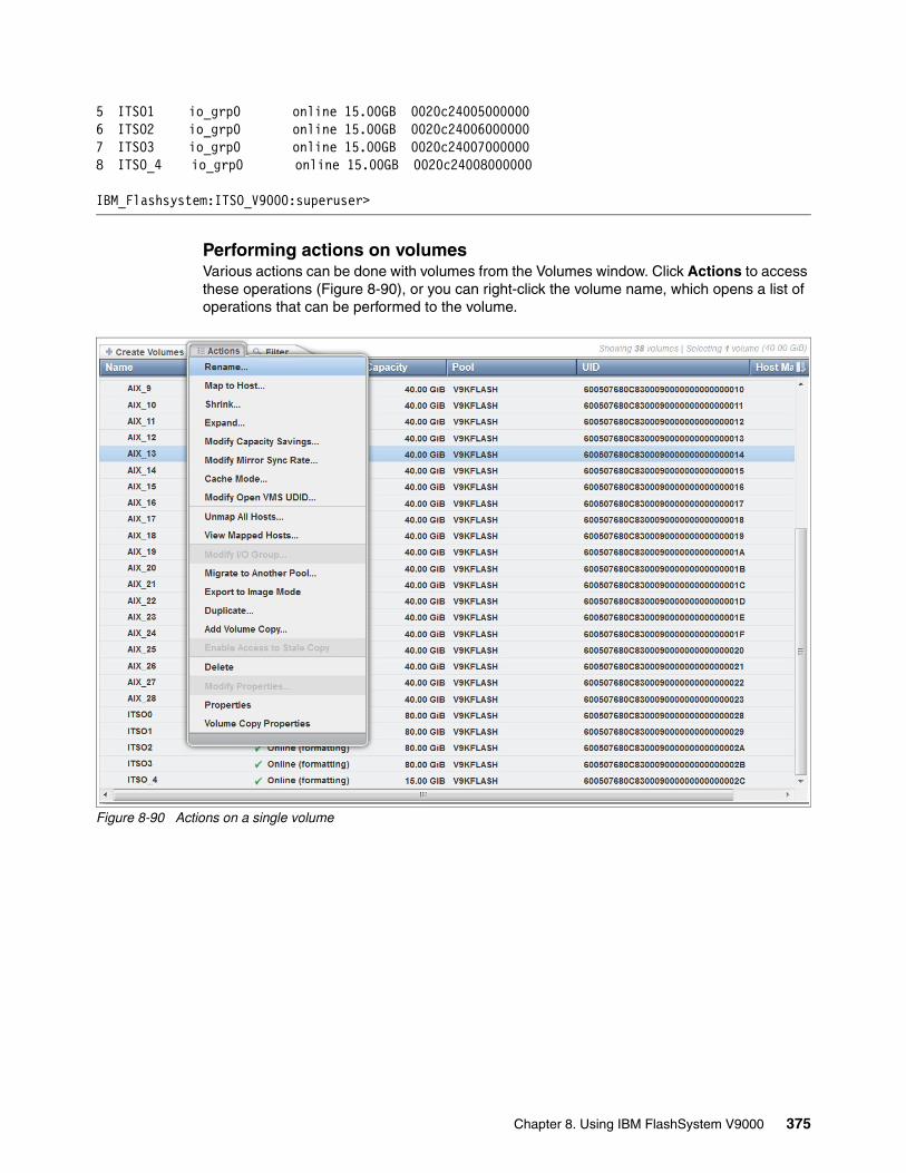
5 ITSO1 io_grp0 online 15.00GB 0020c240050000006 ITSO2 io_grp0 online 15.00GB 0020c240060000007 ITSO3 io_grp0 online 15.00GB 0020c240070000008 ITSO_4 io_grp0 online 15.00GB 0020c24008000000
IBM_Flashsystem:ITSO_V9000:superuser>
Performing actions on volumesVarious actions can be done with volumes from the Volumes window. Click Actions to access these operations (Figure 8-90), or you can right-click the volume name, which opens a list of operations that can be performed to the volume.
Figure 8-90 Actions on a single volume
Chapter 8. Using IBM FlashSystem V9000 375

Figure 8-91 shows the properties of the volume, such as volume name and its capacity. Each volume has a unique ID (UID) that can be discovered from the host side as a property of the logical unit. The volume is currently not mapped to a host.
Figure 8-91 Properties of a volume
A volume can be expanded while it is online, therefore maintaining full functionality to the connected hosts. However, not all operating systems allow concurrent expansion of their disks, so always be sure that the operating system supports it. An alternative to expanding the disk is to create and map a new disk for the host.
376 Introducing and Implementing IBM FlashSystem V9000

Expanding a volume that is mapped to an AIX hostWhen more than one volume is selected, the actions available for the volumes are reduced to only Expand and Delete (Figure 8-92).
Figure 8-92 Expand a volume
Figure 8-93 shows that the volume was expanded to a size of 50 GiB.
Figure 8-93 Expand volume to 50 GB
Chapter 8. Using IBM FlashSystem V9000 377

The resulting Volumes window displays the new capacity (Figure 8-94).
Figure 8-94 Four volumes expanded
The IBM FlashSystem V9000 supports dynamically expanding the size of a virtual disk (VDisk) if the AIX host is using AIX version 5.2 or later.
The AIX chvg command has options to expand the size of a physical volume that the Logical Volume Manager (LVM) uses without interruptions to the use or availability of the system. For more information, see the AIX V7.1 documentation about operating system and device management:
http://bit.ly/1tfL0MV
Expanding a volume that is mapped to a Microsoft Windows hostYou can use the GUI and the CLI to dynamically expand the size of a volume that is mapped to a Microsoft Windows host.
After expanding the volume, using the same procedure as shown in the previous examples (Figure 8-92 on page 377 and Figure 8-93 on page 377) for Windows, start the Computer Management application and open the Disk Management window under the Storage branch.
If the Computer Management application was open before you expanded the volume, use the Computer Management application to issue a rescan command. You see the volume that you expanded now has unallocated space at the right side of the disk:
� If the disk is a Windows basic disk, you can create a new primary or extended partition from the unallocated space.
� If the disk is a Windows dynamic disk, you can use the unallocated space to create a new volume (simple, striped, or mirrored) or add it to an existing volume.
378 Introducing and Implementing IBM FlashSystem V9000

Shrinking a volumeVolumes can be reduced in size, if necessary. The shrink volume option is provided through only the CLI, not the GUI.
When shrinking a volume, consider the following information:
� Shrinking a volume removes capacity from the end of the volume’s address space. If the volume was used by an operating system (OS) or file system, predicting what space was used might be difficult. The file system or OS might depend on the space that is removed, even if it is reporting a high amount of free capacity.
� If the volume contains data that is used, do not attempt under any circumstances to shrink a volume without first backing up your data.
You can use the shrinkvdisksize CLI command to shrink the physical capacity that is allocated to the particular volume by the specified amount.
The shrinkvdisksize command uses this syntax:
shrinkvdisksize -size capacitytoshrinkby -unit unitsforreduction vdiskname/ID
Example 8-7 shows the shrinking of a volume. The volume is called a vdisk in the CLI.
Example 8-7 Shrink a volume (VDisk)
IBM_Flashsystem:ITSO_V9000:superuser>lsvdiskid name IO_group_name status capacity vdisk_UID0 WIN2008_1 io_grp0 online 50.00GB 0020c240000000001 WIN2008_2 io_grp0 online 50.00GB 0020c240010000002 WIN2008_3 io_grp0 online 50.00GB 0020c240020000003 WIN2008_4 io_grp0 online 50.00GB 0020c24003000000
IBM_Flashsystem:ITSO_V9000:superuser>shrinkvdisksize -size 10 -unit gb WIN2008_1
IBM_Flashsystem:ITSO_V9000:superuser>lsvdiskid name IO_group_name status capacity vdisk_UID0 WIN2008_1 io_grp0 online 40.00GB 0020c240000000001 WIN2008_2 io_grp0 online 50.00GB 0020c240010000002 WIN2008_3 io_grp0 online 50.00GB 0020c240020000003 WIN2008_4 io_grp0 online 50.00GB 0020c24003000000
IBM_Flashsystem:ITSO_V9000:superuser>
Attention: If the volume contains data, do not shrink the size of the disk. Shrinking a volume destroys the data.
Chapter 8. Using IBM FlashSystem V9000 379

Mapping volumesClick Volumes to open the Volumes view window.
This example shows four volumes named ITSO_1, ITSO_2, ITSO_3, and ITSO_4 that will be mapped to host ITSO. Highlight all four volumes and click Actions → Map to Host (or right-click and select Map to Host), as shown in Figure 8-95.
Figure 8-95 Map Volumes to Host
The Modify Host Mapping window opens (Figure 8-96). Select the ITSO host and click Map Volumes.
Figure 8-96 Map Volumes: Select the host ITSO
380 Introducing and Implementing IBM FlashSystem V9000

Figure 8-97 shows the Modify Mappings window and that the CLI commands for mapping the volumes are being run.
Figure 8-97 Map Volumes: CLI commands display
The Volumes by Host window now shows that the four ITSO volumes are mapped and online (Figure 8-98).
Figure 8-98 Volumes mapped to host ITSO
Mapping a volume by using the CLIMapping volumes is faster when you use the CLI, which is useful for administrators. Volumes can be mapped by using the svctask mkvdiskhostmap command.
Example 8-8 shows how a volume is mapped to a host by using the CLI.
Example 8-8 Map volume by using the CLI
IBM_Flashsystem:ITSO_V9000:superuser>svctask mkvdiskhostmap -force -host 0 4 Virtual Disk to Host map, id [4], successfully created
IBM_Flashsystem:ITSO_V9000:superuser>lsvdiskhostmap 4id name SCSI_id host_id host_name vdisk_UID IO_group_id IO_group_name4 ITSO_5 4 0 ITSO 0020c24004000000 0 io_grp0
IBM_Flashsystem:ITSO_V9000:superuser>
Chapter 8. Using IBM FlashSystem V9000 381

For mapping volumes by using the CLI, you can use the logical number for the host and use the logical number for the volume. These logical numbers can be discovered by using the following commands:
� lshost: Shows defined hosts and their status.� lsvdisk: Shows defined volumes and their preferences.
Unmapping volumesWhen deleting a volume mapping, you are not deleting the volume itself, only the connection from the host to the volume. For example, if you mapped a volume to a host by mistake or if you want to reassign the volume to another host, click Volumes → Volumes by Host. Select the volume or volumes that you want to unmap, and then right-click and select Unmap from Host (Figure 8-99).
Figure 8-99 Unmap volumes from host
The Unmap from Hosts window opens to indicate that the two selected volumes will be unmapped (Figure 8-100).
Figure 8-100 Unmapping volumes final step
By unmapping the volumes as shown in Figure 8-99 and Figure 8-100, the volumes are made unavailable to the host. If data on the volumes is to be preserved, the host must unmount the disk before the volume is unmapped so that the connection to the disk is closed correctly by the host. No data is left in the host cache when unmap occurs.
Note: Before unmapping a volume from a host, the host must unmount the connection to the disk or I/O errors occur.
382 Introducing and Implementing IBM FlashSystem V9000

Migrating volumesVolumes can be migrated from one storage pool to another if the storage pool has the same extent size. Volume migration is a nondisruptive action and has no effect on connected hosts.
Volume migration is feasible in many situations. For example, if a volume needs higher performance, it can be moved to a storage pool with faster MDisks. Also, when storage is being decommissioned, simply move volumes away from that storage pool, after which the pool can be deleted and the storage device decommissioned.
To migrate a volume to another storage pool, select one or more volumes and click Actions (or right-click and then click Migrate to Another Pool), as shown in Figure 8-101.
Figure 8-101 Migrate to another pool
Chapter 8. Using IBM FlashSystem V9000 383

The IBM FlashSystem V9000 now provides a list of possible target pools. In this example, only a single pool is available. Select the pool and click Migrate (Figure 8-102).
Figure 8-102 Select new target pool
The volume migrates without any interruption to the hosts that are using the volume. Volume migration is a background task that might take time, depending on the size of the volume, the performance of the storage pools, and the load on the volume.
Figure 8-103 shows running tasks, which can be viewed from anywhere in the GUI.
Figure 8-103 Running tasks
At anytime, you can click on a task (1 Migration) to display the task progress (Figure 8-104).
Figure 8-104 Migration in progress
384 Introducing and Implementing IBM FlashSystem V9000

8.5.3 Volumes by Pool
Selecting Volumes → Volumes by Pool is functionally identical to selecting Volumes → Volumes, as explained in 8.5.1, “Opening the Volumes menu” on page 369. Figure 8-105 shows a view of the window.
Figure 8-105 Volumes by Pool view
8.5.4 Volume by Host
Selecting Volumes → Volumes by Host is functionally identical to selecting Volumes → Volumes, as explained in 8.5.1, “Opening the Volumes menu” on page 369. Figure 8-106 shows a view of the window.
Figure 8-106 Volume by Hosts view
8.6 Hosts menu
Host objects associate one or more host bus adapter (HBA) worldwide port names (WWPNs) or InfiniBand IDs with a logical object. You can use the GUI or the mkhost CLI command to create a logical host object.
You can then use the created host to map volumes (also called virtual disks or VDisks) to hosts by using the GUI or the mkvdiskhostmap CLI command.
The Hosts menu has four options:
� Hosts� Ports by Host� Host Mappings� Volumes by Host
Chapter 8. Using IBM FlashSystem V9000 385

8.6.1 Opening the Hosts menu
In the GUI, use the Hosts menu to manage hosts. Navigate to the Hosts window from the GUI by selecting Hosts → Hosts (Figure 8-107).
Figure 8-107 Navigate to Hosts
Adding a hostThe process of creating a host object includes specifying the host name and selecting ports for the host.
The IBM FlashSystem V9000 models support Fibre Channel (FC), Fibre Channel over Ethernet (FCoE), and iSCSI protocols.
The IBM FlashSystem V9000 detects which type of interface card is installed, and Add Host wizard automatically adjusts to request the host port type for the actual model. For example, this can be the FC worldwide port name (WWPN) or the iSCSI initiator name or iSCSI qualified name (IQN).
Figure 8-108 shows the Hosts view where the configured hosts are displayed. This example shows one defined host, ITSO.
Figure 8-108 Hosts panel showing already configured hosts
Each connected host initiator port must be zoned to all AC2 or AC3 control enclosure connections that are on the SAN fabric that see the IO group your LUN belongs to, enabling multipathing on the same fabric. If not, the host reports as Degraded. The risk of having a host with degraded paths is that the host might loose access to storage if a control enclosure fails or a reboot that then can cause unplanned downtime.
386 Introducing and Implementing IBM FlashSystem V9000

The IBM FlashSystem V9000 uses redundant AC2 or AC3 control enclosures. The control enclosures might reboot due to several reasons, such as power outage, system failure, firmware update, and more.
Hosts in a IBM FlashSystem V9000 configured with FC interface cardsTo create a host object, click Add Host in the upper-left of the Hosts panel. The Add Host window opens (Figure 8-109). Type the name of the new host (Exchange1 in this example) and select a WWPN in the Fibre Channel Ports area. Any WWPNs that are zoned to the system, but not already in use by a configured host, are displayed as shown in Figure 8-109.
Figure 8-109 Add ports to the new host
If no WWPNs are displayed, the No candidate HBA ports were found message is displayed. In that case, either the WWPN is already used for another host object or the host has not been zoned correctly to the IBM FlashSystem V9000.
Chapter 8. Using IBM FlashSystem V9000 387
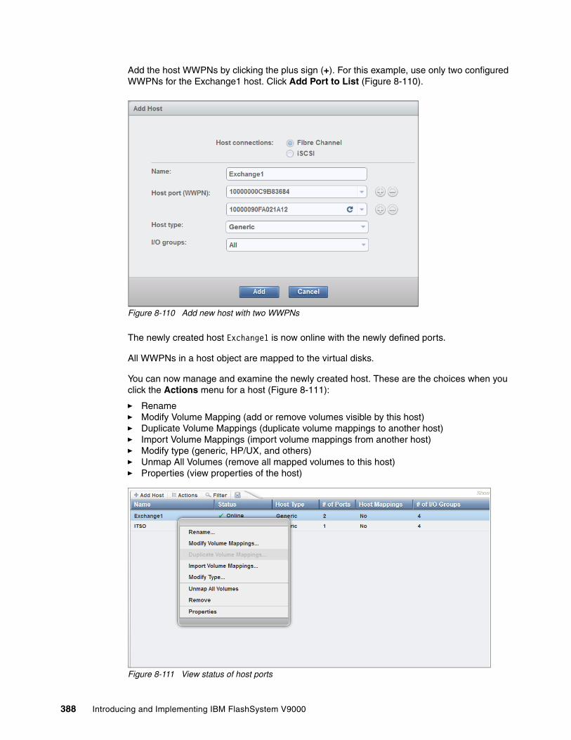
Add the host WWPNs by clicking the plus sign (+). For this example, use only two configured WWPNs for the Exchange1 host. Click Add Port to List (Figure 8-110).
Figure 8-110 Add new host with two WWPNs
The newly created host Exchange1 is now online with the newly defined ports.
All WWPNs in a host object are mapped to the virtual disks.
You can now manage and examine the newly created host. These are the choices when you click the Actions menu for a host (Figure 8-111):
� Rename� Modify Volume Mapping (add or remove volumes visible by this host)� Duplicate Volume Mappings (duplicate volume mappings to another host)� Import Volume Mappings (import volume mappings from another host)� Modify type (generic, HP/UX, and others)� Unmap All Volumes (remove all mapped volumes to this host)� Properties (view properties of the host)
Figure 8-111 View status of host ports
388 Introducing and Implementing IBM FlashSystem V9000

Creating a host by using the CLITo create a host through the CLI, use the svctask mkhost and svctask addhostport commands (Example 8-9).
Example 8-9 Create host and add one more port
IBM_Flashsystem:ITSO_V9000:superuser>svctask mkhost -fcwwpn 5005076801300004 -force -name ITSOHost, id [1], successfully created
IBM_Flashsystem:ITSO_V9000:superuser>svctask addhostport -fcwwpn 50050768013A0004 -force ITSO
IBM_Flashsystem:ITSO_V9000:superuser>lshostid name port_count iogrp_count status0 test 1 1 offline1 ITSO 2 1 offline
IBM_Flashsystem:ITSO_V9000:superuser>lshost ITSOid 1name ITSOport_count 2type genericmask 1111111111111111111111111111111111111111111111111111111111111111iogrp_count 1status offlineWWPN 50050768013A0004node_logged_in_count 0state offlineWWPN 5005076801300004node_logged_in_count 0state offlineIBM_Flashsystem:ITSO_V9000:superuser>
The svctask addhostport command must be run one time for every host port that you want to define for your host object.
Hosts in a IBM FlashSystem V9000 configured with iSCSI interface cardsTo determine which iSCSI hosts already exist, open the Hosts menu and click Hosts (described in 8.6.1, “Opening the Hosts menu” on page 386).
Review the hosts (Figure 8-112). To create a new host, click Add Host.
Figure 8-112 Review iSCSI hosts from the Hosts panel
Chapter 8. Using IBM FlashSystem V9000 389

In the Add Host dialog (Figure 8-113), specify the host name and the iSCSI IQN name obtained from the iSCSI hosts iSCSI initiator software at the host to be connected. Click Add to create the host.
Figure 8-113 Create iSCSI host
Figure 8-114 shows the hosts, including the newly created Win2008_File_SRV host.
Figure 8-114 New iSCSI host created
The new host does not yet have any volume mappings. Volume mappings for iSCSI hosts can be created in the same way as volume mappings for FC and FCoE systems, which is demonstrated in “Mapping volumes” on page 380.
As described in “Creating a host by using the CLI” on page 389, any single host must be able to communicate with both IBM FlashSystem V9000 AC2 or AC3 control enclosures. If not, hosts are not able to perform path failover in case of an AC2 or AC3 control enclosure reboot, which might cause unplanned downtime because the iSCSI host loses access to storage.
That means that an iSCSI-attached host must have its iSCSI initiator software configured so that each of its iSCSI initiators connects to at least one iSCSI target port on each AC2 or AC3 control enclosure.
For more information about how to configure host connectivity, see Chapter 7, “Host configuration” on page 255.
390 Introducing and Implementing IBM FlashSystem V9000

8.6.2 Ports by Hosts
The Hosts → Ports by Hosts selection is functionally identical to Volumes → Volumes by Host as explained in 8.5.1, “Opening the Volumes menu” on page 369. Figure 8-115 shows the Ports by Hosts window.
Figure 8-115 Ports by Hosts
8.6.3 Host Mappings
The Hosts → Host Mappings selection is functionally identical to mapping volumes as explained in “Mapping volumes” on page 380. Figure 8-116 shows the window.
Figure 8-116 Hosts Mapping
Chapter 8. Using IBM FlashSystem V9000 391

8.6.4 Volumes by Host
The Hosts → Volumes by Host selection is functionally identical to the Volumes → Volumes by Host, as explained in 8.5.1, “Opening the Volumes menu” on page 369. See Figure 8-117.
Figure 8-117 Volumes by Host
8.7 Copy Services menu
IBM FlashSystem V9000 provides Copy Services functions so that you can copy data from one system to another system.
Figure 8-118 shows the options in the Copy Services menu.
Figure 8-118 Copy Services menu
These menu options are described in 8.7.1, “FlashCopy” on page 393 through 8.7.5, “Partnerships” on page 398.
Note: The copy services examples in this section illustrate operations with AE2 storage enclosures. The operations equally work with expansion enclosure drives, externally virtualized storage arrays, or storage systems.
392 Introducing and Implementing IBM FlashSystem V9000

The Copy Services functions are as follows:
� IBM FlashCopy
You can either create point-in-time copies on a system, or create a point-in-time data copy on another system.
� Metro Mirror
Provides a consistent copy of a source volume on a target volume. Data is written to the target volume synchronously after it is written to the source volume, so that the copy is continuously updated.
� Global Mirror
Provides a consistent copy of a source volume on a target volume. Data is written to the target volume asynchronously, so that the copy is continuously updated, but the copy might not contain the most recent updates if a disaster recovery operation is performed.
� Consistency groups
A consistency group is a container for FlashCopy mappings, Global Mirror relationships, and Metro Mirror relationships. You can add many mappings or relationships to a consistency group, but FlashCopy mappings, Global Mirror relationships, and Metro Mirror relationships cannot be in the same consistency group. When you use a consistency group, you can complete copy operations on the entire group rather than the individual mappings.
Valid combinations of FlashCopy and Metro Mirror or Global Mirror functionsYou can have both the FlashCopy function and either Metro Mirror or Global Mirror operating concurrently on the same volume. However, constraints exist regarding how these functions can be used together.
The next section provides an overview of the following Copy Services functions:
� FlashCopy� Consistency Groups� FlashCopy Mappings� Remote Copy� Partnerships
For more details about specific Copy Services functions and menus, see these resources:
� 3.4, “Advanced copy services” on page 114 � The “SAN Volume Controller operations using the GUI” topic in Implementing the IBM
System Storage SAN Volume Controller with IBM Spectrum Virtualize V7.6, SG24-7933
8.7.1 FlashCopy
The FlashCopy function creates a point-in-time copy of data, stored on a source volume, to a target volume.
In its basic mode, the IBM FlashCopy function copies the contents of a source volume to a target volume. Any data that existed on the target volume is lost and is replaced by the copied data. After the copy operation completes, the target volumes contain the contents of the source volumes as they existed at a single point in time, unless target writes have been processed.
Chapter 8. Using IBM FlashSystem V9000 393

The FlashCopy function is sometimes described as an instance of a time-zero copy (T 0) or point-in-time copy technology. Although the FlashCopy operation takes some time to complete, the resulting data on the target volume is presented so that the copy appears to have occurred immediately, and all data is available immediately. If needed, data that is still in the process of being copied can be accessed from the source.
Although a difficult task is to make a consistent copy of a data set that is constantly updated, point-in-time copy techniques help solve this problem. If a copy of a data set is created using a technology that does not provide point-in-time techniques and the data set changes during the copy operation, the resulting copy might contain data that is not consistent. For example, if a reference to an object is copied earlier than the object itself and the object is moved before it is copied, the copy contains the referenced object at its new location, but the copied reference still points to the previous location.
More advanced FlashCopy functions allow operations to occur on multiple source and target volumes. FlashCopy management operations are coordinated to provide a common, single point-in-time for copying target volumes from their respective source volumes. This creates a consistent copy of data that spans multiple volumes. The FlashCopy function also enables multiple target volumes to be copied from each source volume. This can be used to create images from different points in time for each source volume.
In its basic mode, the IBM FlashCopy function copies the contents of a source volume to a target volume. Any data that existed on the target volume is lost and is replaced by the copied data
Incremental FlashCopy mappingsIn an incremental FlashCopy, the initial mapping copies all of the data from the source volume to the target volume. Subsequent FlashCopy mappings only copy data that has been modified since the initial FlashCopy mapping. This reduces the amount of time that it takes to re-create an independent FlashCopy image. You can define a FlashCopy mapping as incremental only when you create the FlashCopy mapping.
FlashCopy partner mappingsYou can create a mapping to mirror an existing incremental FlashCopy mapping. The resulting pair of mappings is called partners. A mapping can have only one partner. For example, if you have volume A and volume B with two mappings (mapping 0 from volume A to volume B and mapping 1 from volume B to volume A), mapping 0 and mapping 1 are partners.
Incremental FlashCopy mappings share the metadata for recording changes. Therefore, if one mapping in a mirrored pair (partnership) is incremental, the other mapping becomes incremental automatically and remains incremental until it is deleted.
For more details, see the IBM FlashSystem V9000 pages in IBM Knowledge Center:
https://ibm.biz/Bdsi8N
8.7.2 Consistency Groups
A consistency group is a container for FlashCopy mappings, Global Mirror relationships, and Metro Mirror relationships. You can add many mappings or relationships to a consistency group, but FlashCopy mappings, Global Mirror relationships, and Metro Mirror relationships cannot appear in the same consistency group. When you use a consistency group, you can complete copy operations on the entire group rather than the individual mappings.
394 Introducing and Implementing IBM FlashSystem V9000

FlashCopy consistency groupsThe consistency group is specified when the mapping is created. You can also change the consistency group later. When you use a consistency group, you prepare and start that group rather than the individual mappings. This process ensures that a consistent copy is made of all the source volumes. Mappings to control at an individual level are known as stand-alone mappings. Do not place stand-alone mappings into a consistency group because they become controlled as part of that consistency group.
When you copy data from one volume to another, the data might not include all that you need to use the copy. Many applications have data that spans multiple volumes and requires that data integrity is preserved across volumes. For example, the logs for a particular database are usually on a different volume than the volume that contains the data.
Consistency groups address the problem of applications having related data that spans multiple volumes. In this situation, IBM FlashCopy operations must be initiated in a way that preserves data integrity across the multiple volumes. One requirement for preserving the integrity of data being written is to ensure that dependent writes are run in the intended sequence of the application.
You can set the autodelete attribute for FlashCopy consistency groups. If this attribute is set to on, the consistency group is automatically deleted when the last mapping in the group is deleted or moved out of the consistency group.
Metro Mirror and Global Mirror consistency groupsYou can group Metro Mirror or Global Mirror relationships into a consistency group so that they can be updated at the same time. A command that is issued to the consistency group is simultaneously applied to all of the relationships in the group.
Metro Mirror or Global Mirror relationships can be based on loose or tight associations. A more significant use arises when the relationships contain volumes with a tight association. A simple example of a tight association is the spread of data for an application across more than one volume. A more complex example is when multiple applications run on different host systems. Each application has data on different volumes, and these applications exchange data with each other. In both examples, specific rules exist as to how the relationships can be updated. These rules ensure that the set of secondary volumes contain usable data. The key property is that these relationships are consistent.
Metro Mirror or Global Mirror relationships can belong to only one consistency group; however, they do not have to belong to a consistency group. Relationships that are not part of a consistency group are called stand-alone relationships. A consistency group can contain zero or more relationships. All relationships in a consistency group must have matching primary and secondary systems, which are sometimes referred to as master and auxiliary systems. All relationships in a consistency group must also have the same copy direction and state.
Metro Mirror or Global Mirror relationships cannot belong to the same consistency group. A copy type is automatically assigned to a consistency group when the first relationship is added to the consistency group. After the consistency group is assigned a copy type, only relationships of that copy type can be added to the consistency group. Global Mirror relationships with different cycling modes cannot belong to the same consistency group. The type and direction of the relationships in a consistency group must be the same.
Chapter 8. Using IBM FlashSystem V9000 395

The system supports the following types of relationships and consistency groups:
� Metro Mirror� Global Mirror without change volumes (cycling mode set to None)� Global Mirror with change volumes (cycling mode set to Multiple)
If necessary, you can change the copy type of a remote-copy relationship or consistency group without re-creating the relationship or consistency group with the different type. For example, if the latency of the long-distance link affects host performance, you can change the copy type to Global Mirror to improve host performance over high latency links. Change volumes are available for only Global Mirror relationships and consistency groups and are created when Global Mirror operates with the multiple cycling mode. With the multiple cycling mode, changes are tracked and copied to intermediate change volumes. Changes are transmitted to the secondary site periodically to lower bandwidth requirements.
Possible relationship directions are as follows:
� Intrasystem� From local system to remote system� From remote system to local system
For more details, see the “Consistency groups” topic in the IBM FlashSystem V9000 web pages:
https://ibm.biz/Bdsi87
8.7.3 FlashCopy mappings
A FlashCopy mapping defines the relationship between a source volume and a target volume.
The FlashCopy feature makes an instant copy of a volume at the time that it is started. To create an instant copy of a volume, you must first create a mapping between the source volume (the disk that is copied) and the target volume (the disk that receives the copy). The source and target volumes must be of equal size.
A mapping can be created between any two volumes in a system. The volumes do not have to be in the same I/O group or pool. When a FlashCopy operation starts, a checkpoint is made of the source volume. No data is actually copied at the time a start operation occurs. Instead, the checkpoint creates a bitmap that indicates that no part of the source volume has been copied. Each bit in the bitmap represents one region of the source volume. Each region is called a grain.
After a FlashCopy operation starts, read and write operations to the source volume continue to occur. If new data is written to the source or target volume, the existing data on the source is copied to the target volume before the new data is written to the source or target volume. The bitmap is updated to mark that the grain of the source volume has been copied so that later write operations to the same grain do not recopy the data.
During a read operation to the target volume, the bitmap is used to determine if the grain was copied. If the grain was copied, the data is read from the target volume. If the grain was not copied, the data is read from the source volume.
For more details, see the “FlashCopy mappings” topic in the IBM FlashSystem V9000 web pages:
https://ibm.biz/Bdsi8N
396 Introducing and Implementing IBM FlashSystem V9000

8.7.4 Remote copy
Metro Mirror and Global Mirror are two types of remote-copy operations that you can use to set up a relationship between two volumes, where updates made to one volume are mirrored on the other volume. The volumes can be on either the same system (intrasystem) or on two different systems (intersystem).
Although data is written to only a single volume, the system maintains two copies of the data. If the copies are separated by a significant distance, the Metro Mirror and Global Mirror copies can be used as a backup for disaster recovery. A prerequisite for Metro Mirror and Global Mirror operations between systems over Fibre Channel connections is that the SAN fabric to which they are attached provides adequate bandwidth between the systems. SAN fabrics are not required for IP-only connections.
For both Metro Mirror and Global Mirror copy types, one volume is designated as the primary and the other volume is designated as the secondary. Host applications write data to the primary volume, and updates to the primary volume are copied to the secondary volume. Normally, host applications do not run I/O operations to the secondary volume.
The system supports the following types of relationships and consistency groups:
� Metro Mirror� Global Mirror without change volumes (cycling mode set to None)� Global Mirror with change volumes (cycling mode set to Multiple)
If necessary, you can change the copy type of a remote-copy relationship or consistency group without re-creating the relationship or consistency group with the different type. For example, if the latency of the long-distance link affects host performance, you can change the copy type to Global Mirror to improve host performance over high latency links. Change volumes are only available for Global Mirror relationships and consistency groups and are created when Global Mirror operates with the multiple cycling mode. With the multiple cycling mode, changes are tracked and copied to intermediate change volumes. Changes are transmitted to the secondary site periodically to lower bandwidth requirements.
The Metro Mirror and Global Mirror functions support the following operations:
� Intrasystem copying of a volume, in which both volumes belong to the same system and I/O group within the system.
� Intersystem copying of a volume, in which one volume belongs to a system and the other volume belongs to a different system.
� Intersystem and intrasystem Metro Mirror and Global Mirror relationships can be used concurrently on the same system.
� Bidirectional links are supported for intersystem relationships. This means that data can be copied from system A to system B for one pair of volumes while copying data from system B to system A for a different pair of volumes.
� The copy direction can be reversed for a consistent relationship.
� You can change the copy type for relationships and consistency groups between Metro Mirror and Global Mirror with or without change volumes.
Note: A system can participate in active Metro Mirror and Global Mirror relationships with itself and up to three other systems.
Chapter 8. Using IBM FlashSystem V9000 397

� Consistency groups are supported to manage a group of relationships that must be kept synchronized for the same application. This also simplifies administration, because a single command that is issued to the consistency group is applied to all the relationships in that group.
� The system supports a maximum of 8192 Metro Mirror and Global Mirror relationships per system.
Consider the following terms and their definitions:
� Metro Mirror
Metro Mirror is a type of remote copy that creates a synchronous copy of data from a primary volume to a secondary volume. A secondary volume can either be on the same system or on another system.
� Global Mirror
The Global Mirror function provides an asynchronous-copy process. When a host writes to the primary volume, confirmation of I/O completion is received before the write operation has completed for the copy on the secondary volume.
� Global Mirror change volume
Global Mirror change volumes are copies of data from a primary volume or secondary volume that are used in Global Mirror relationships. Using change volumes lower bandwidth requirements by only addressing the average throughput and not the peak.
� Remote-copy consistency groups
You can group Metro Mirror or Global Mirror relationships into a consistency group so that they can be updated at the same time. A command that is issued to the consistency group is simultaneously applied to all of the relationships in the group.
� Remote-copy relationships
Metro Mirror and Global Mirror relationships define the relationship between two volumes: a master volume and an auxiliary volume.
For more details, see IBM Knowledge Center:
https://ibm.biz/Bdsigc
8.7.5 Partnerships
Partnerships can be used to create a disaster recovery environment or to migrate data between systems that are in different locations. Partnerships define an association between a local system and a partner system.
Before a Metro Mirror or Global Mirror relationship or consistency group can be created with a remote system, a partnership between the two systems must be established. If Global Mirror or Metro Mirror relationships or consistency groups exist between two remote systems, those systems must maintain their partnership. Each system can maintain up to three partnerships, and each partnership can be with a single partner system. As many as four systems can be directly associated with each other.
Systems also become indirectly associated with each other through partnerships. If two systems each have a partnership with a third system, those two systems are indirectly associated. A maximum of four systems can be directly or indirectly associated.
The control enclosures within the system must know not only about the relationship between the two volumes but also about an association among systems.
398 Introducing and Implementing IBM FlashSystem V9000

To establish a partnership between two systems, you must create the partnership using the Create Partnership dialog on both systems. For example, to establish a partnership between system A and system B, run the dialog from system A and specify system B as the partner system. At this point, the partnership is partially configured and is sometimes described as one-way communication. Next, run the dialog on system B and specify system A as the partner system. When this operation completes, the partnership is fully configured for two-way communication between the systems.
For details about system partnership states, creating remote-copy partnership over an IP connection, and also establishing Metro Mirror and Global Mirror partnerships over Fibre Channel, Fibre Channel over Ethernet (FCoE) connections, see the IBM FlashSystem V9000 information in IBM Knowledge Center. See IBM Knowledge Center:
https://ibm.biz/BdsigB
Backing up data: IBM lab-services based taskData must be backed up in the following scenarios:
� If an existing fixed building block is being added to one or more new scaled building blocks to create a scaled system, all customer data must be backed up before the installation process begins, to prevent loss of all data.
� If an existing scaled system is being upgraded to add more scalable building blocks, and a new level of software will be loaded, all customer data must be backed up before the software update.
For more details about backing up data and Copy Services, see the “Copy Services functions” topic in IBM Knowledge Center:
https://ibm.biz/Bdsigd
8.8 Access menu
Several roles of user access to the IBM FlashSystem V9000 are managed through the Access menu (Figure 8-119 on page 400). The access levels are divided by role. You can also assign multiples users to a user group, then a role can be assigned to the user group.
The Access function has two menu options:
� Users: Select this to define users, group users, and user roles.
� Audit log: Tracks action commands that are issued through an SSH session or through the management GUI.
Chapter 8. Using IBM FlashSystem V9000 399

8.8.1 Users
Select Users from the Access menu (Figure 8-119).
Figure 8-119 Navigate to Users menu
Figure 8-120 shows the Users menu. Here, you can create and delete users, change and remove passwords, and add and remove SSH keys. You can also add a user group to the predefined groups. Predefined user groups are named with the user role in the group.
Figure 8-120 Users window
400 Introducing and Implementing IBM FlashSystem V9000

You can get contextual help at any time by clicking the question mark (?) icon (Figure 8-121).
Figure 8-121 Help example
Click Create User to open the window shown in Figure 8-122. You can enter the name of the user and the password, and load the SSH key (if the SSH key was generated). You can choose to use either SSH or a password for CLI authentication. Without a password defined, the user is unable to use the GUI.
Figure 8-122 Create User window
Note: You must have superuser authority to create users.
Local V9000 or external
Input assistance
authentication mechanism
Chapter 8. Using IBM FlashSystem V9000 401

You can assign the following roles to your user groups:
� Security administrator
Users can manage all functions of the system, including managing users, user groups, and user authentication. Users who have the security administrator role can run any system commands from the CLI, but cannot run the sainfo and satask commands from the CLI. Only the superuser ID can run the sainfo and satask commands.
� Administrator
Users can manage all functions of the system except those that manage users, user groups, and authentication. Users who have the administrator role can run the system commands that the security administrator users can run from the CLI, except for commands that deal with users, user groups, and authentication.
� Copy operator
Users can start and stop all existing FlashCopy, Metro Mirror, and Global Mirror relationships. Users who have the copy operator role can run the system commands that administrator role users can run that deal with FlashCopy, Metro Mirror, and Global Mirror relationships.
� Monitor
Users have access to all system viewing actions. Users who have the monitor role cannot change the state of the system or change the resources that the system manages. Monitor role users can access all information-related GUI functions and commands, back up configuration data, and change their own passwords.
� Service
Users can set the time and date on the system, delete dump files, add and delete control and storage enclosures, and shut down the system.
402 Introducing and Implementing IBM FlashSystem V9000

Figure 8-123 shows a local user Christophe is created and is configured with a password to use for authenticating to the system. When user Christophe opens his SSH client and points it to the IP address of the system to which he is granted access, he is prompted for the user name and password. If the user is required to authenticate by using an SSH key pair, you instead enter the path for the public key in the field SSH Public Key.
.
Figure 8-123 User with password and SSH key
Note: The Password and Verify Password fields are used for GUI access. If a password is not configured, the user is not able to log in to the GUI. For a demonstration of how to create a public/private key by using PuTTy, see 13.3.2, “Creating connections” on page 623.
1: GUI and SSH access2: SSH access using private/public key
1
2
Chapter 8. Using IBM FlashSystem V9000 403

8.8.2 Audit log
An audit log documents actions that are submitted through the management GUI or the CLI. You can use the audit log to monitor user activity on your system. The audit log entries provide the following information:
� The sequence of the command� The date and time when the action or command was submitted on the system
� The name of the user who performed the action or command� The IP address of the system where the action or command was submitted� The results of the action or command� Parameters and command submitted� The object identifier that is associated with the action or command
The main window of the audit log supports navigation (Figure 8-124). By clicking any column, you can order the full log.
Figure 8-124 Different navigation options
Note: When logs are displayed in the CLI, the time stamps for the logs are the system time. However, when logs are displayed in the management GUI, the time stamps are translated to the local time where the web browser is running.
404 Introducing and Implementing IBM FlashSystem V9000

Chapter 9. Configuring settings
The Settings function covers various options for monitoring, configuring interfaces, and extracting support logs. It also covers remote authentication and the firmware update process. The Settings section of the IBM FlashSystem V9000 graphical user interface (GUI), shown in Figure 9-1 on page 406, is described in this chapter.
This chapter includes the following topics:
� Settings menu� Notifications menu� Network menu� Security menu� System menu� Support menu� GUI Preferences
9
© Copyright IBM Corp. 2015, 2016. All rights reserved. 405

9.1 Settings menu
You can use the Settings panel to configure system options for event notifications, security, IP addresses, FC connectivity, and preferences related to display options in the management GUI.
The Settings menu includes six options:
� Notifications (alerting)� Network (management and service, Ethernet, iSCSI, Fibre Channel)� Security (remote authentication with Lightweight Directory Access Protocol (LDAP))� System (time settings, firmware update, and so on)� Support (extract support logs)� GUI Preferences (customize the GUI)
9.1.1 Opening the Settings menu
Hover the cursor over the Settings function icon to view the Settings menu (Figure 9-1).
Figure 9-1 Settings menu
9.2 Notifications menu
IBM FlashSystem V9000 can use Simple Network Management Protocol (SNMP) traps, syslog messages, and call home email to notify you and IBM Support when significant events are detected. Any combination of these notification methods can be used simultaneously. Select Notifications from the Settings menu to manage notifications (Figure 9-2).
Figure 9-2 Notifications menu
406 Introducing and Implementing IBM FlashSystem V9000

9.2.1 Email and call home
The call home feature transmits operational and event-related data to you and IBM through a Simple Mail Transfer Protocol (SMTP) server connection in the form of an event notification email. When configured, this function alerts IBM service personnel about hardware failures and potentially serious configuration or environmental issues.
Configuration processSetting up call home involves providing a contact that is available 24 x 7 if a serious call home event is received. IBM uses data analytics to process multiple call home events to proactively open problem management records (PMRs) prior to component failures. IBM support strives to report any issues in a timely manner; having a valid contact is important to achieving service level agreements.
The procedure for configuring call home is similar to the initialization of the IBM FlashSystem V9000, which also offers configuration of email event notifications. The initial system setup is described in 6.5.2, “System Setup wizard” on page 240.
The steps to enable call home are to configure the following information:
� System Location: Where is the system located?� Contact Details: Who is IBM to contact in case of call home?� Email Servers: What is the IP address of the SMTP email server?
This procedure assumes call home was not configured during initial installation. The procedure to update contact information or add extra notifications is basically the same. Simply edit the notifications.
Complete these steps:
1. If call home is not set up, a pop-up area opens (Figure 9-3). Initiate the configuration wizard by clicking Enable Notifications.
.
Figure 9-3 Enable Notifications
Chapter 9. Configuring settings 407

2. The Email Event Notifications wizard starts (Figure 9-4). It briefly describes the benefits of call home. Read through it and then click Next.
Figure 9-4 Configuring Call home enables IBM to provide excellent service
3. System Location panel (Figure 9-5) is important for ensuring that any open support tickets have the correct equipment location. Complete the form and click Next.
Figure 9-5 System Location panel
408 Introducing and Implementing IBM FlashSystem V9000

4. On the Contact panel (Figure 9-6) specify a contact available 24 x 7. IBM must be able to reach a valid contact if an urgent situation exists. Click Apply and Next.
Figure 9-6 IBM support uses this contact 24 x 7
Note: The State or province and Country or region fields must be configured correctly to ensure that IBM support is able to react on call home calls from the system. Hover the cursor to the right of State or province field, and click the window that displays these codes.
Chapter 9. Configuring settings 409

5. The Configuring Email Settings panel (Figure 9-7) shows the results. It also shows the CLI version of the dialog. Click Close.
Figure 9-7 Commands run to register the contact and send inventory every 7 days
6. Enter your SMTP gateway IP address (Figure 9-8 on page 411). You can click Ping to ensure that there is a response to the address, if your SMTP server allows the ping function. Use the plus sign to add extra SMTP servers. Click Apply and Next to move to the next panel.
Note: Only the SMTP server IP address is supported, not the DNS server name. Only an SMTP server without authentication can be selected.
410 Introducing and Implementing IBM FlashSystem V9000

Figure 9-8 Specify and test the SMTP Gateway
7. Results of the command are displayed in the window as shown Figure 9-9. Click Close.
Figure 9-9 SMTP Gateway for all email is defined
Chapter 9. Configuring settings 411

8. Review the summary page information that you entered in the wizard (Figure 9-10) and then click Finish.
Figure 9-10 Completed call home setup
9. Review the command results, which are displayed in the Configuring Email Settings window (Figure 9-11). It indicates that the mail service started. Click Close.
Figure 9-11 Results of starting the email service
10.After the wizard completes, you are returned to the notifications Email page (Figure 9-12 on page 413). Click Edit (1) to modify the values. Click Test (2) in the Call Home section to automatically send a call home mail to IBM and create a problem management record (PMR). IBM support uses the primary contact to confirm receipt of the call home.
412 Introducing and Implementing IBM FlashSystem V9000

Optionally, you can configure to send event notifications to email recipients (see the Email Users section) to be notified when issues that need attention occur. These users might be part of a support team in the customer’s organization or any organization providing services. Email Users are also valuable if email transport to IBM fails. An email transport error can occur due to an SMTP server outage, or if the SMTP server IP address is changed without updating the call home function of the IBM FlashSystem V9000 correctly. Enter any additional users in your organization for Email Users (3).
Select the Notification level, from Error to Info, knowing that Info can generate a large mail volume. Selecting the Inventory option includes information about parts and serial numbers, for inventory purpose, also provides detailed information about the system configuration that is used when PMRs are opened.
Figure 9-12 Email notifications
1
2
3
Tip: Testing call home is important to ensure that the system is correctly registered with IBM. Test call home by submitting an Email Notification test after the Event Notification wizard finishes. If configured correctly, IBM Support will contact the person listed under “Email contact” during regular business hours.
Chapter 9. Configuring settings 413

9.2.2 SNMP
Simple Network Management Protocol (SNMP) is a standard protocol for managing networks and exchanging messages. The system can send SNMP messages that notify personnel about an event. You can use an SNMP manager to view the SNMP messages that the system sends.
In the SNMP configuration menu, you can configure one or more SNMP servers. For each of these SNMP servers, you configure the following information:
� IP address� SNMP server port (The default is port 162.)� SNMP community (The default is public.) � Event type (The default is Alerts but it can be changed to All events.)
Perform the following steps (see Figure 9-13):
1. Select the SNMP tab. 2. Select Actions → Add.3. Complete the details in the Add SNMP Server form that opens.4. Click Download MIB to download the Management Information Base (MIB) file to be use
on your SNMP server.
This MIB file is used for SNMP to configure a network management program to receive SNMP messages that are sent by the system. This file can be used with SNMP messages from all versions of the software.
Figure 9-13 Add the SNMP Servers
Various SNMP trap receiver products are on the market. These are known as SNMP managers. IBM Tivoli NetView® or IBM Tivoli Netcool/OMNibus can be used as IBM SNMP managers.
4
1
2
3
414 Introducing and Implementing IBM FlashSystem V9000

9.2.3 Syslog
The syslog protocol is a standard protocol for forwarding log messages from a sender to a receiver on an IP network. The IP network can be either IPv4 or IPv6. The system can send syslog messages that notify personnel about an event.
The IBM FlashSystem V9000 can transmit syslog messages in either expanded or concise format.
As shown in Figure 9-14, you can perform these tasks:
1. Use a syslog manager to view the syslog messages that the system sends. The system uses the User Datagram Protocol (UDP) to transmit the syslog message.
2. Specify up to a maximum of six syslog servers using the plus sign (+).
Figure 9-14 Complete the Syslog Form
In the Syslog configuration section (Figure 9-14), you can configure one or more syslog servers. For each of these servers, you configure the following information:
� IP address.
� Facility: This determines the format for the syslog messages and can be used to determine the source of the message.
� Notifications: The default is Alerts/Error but it can be customized to show Warning and Informational Notifications also).
There are various syslog server products on the market. Many of these products are no-charge products that can be downloaded from the Internet.
1
2
Chapter 9. Configuring settings 415
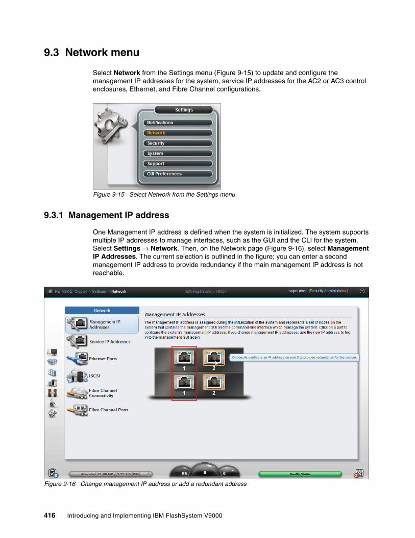
9.3 Network menu
Select Network from the Settings menu (Figure 9-15) to update and configure the management IP addresses for the system, service IP addresses for the AC2 or AC3 control enclosures, Ethernet, and Fibre Channel configurations.
Figure 9-15 Select Network from the Settings menu
9.3.1 Management IP address
One Management IP address is defined when the system is initialized. The system supports multiple IP addresses to manage interfaces, such as the GUI and the CLI for the system. Select Settings → Network. Then, on the Network page (Figure 9-16), select Management IP Addresses. The current selection is outlined in the figure; you can enter a second management IP address to provide redundancy if the main management IP address is not reachable.
Figure 9-16 Change management IP address or add a redundant address
416 Introducing and Implementing IBM FlashSystem V9000

9.3.2 Service IP Addresses
On the Settings → Network page, the Service IP Addresses page (Figure 9-17) is used to access the service assistant tool, which you can use to complete service-related actions on the control enclosure. The system has a minimum of two control enclosures and each must have a different service address. If a control enclosure is in the service state, it does not operate as a member of the system.
Figure 9-17 Set Service IP addresses for each control enclosure
Note: By changing the management IP addresses, you will need to restart the GUI on the new IP address.
Tip: Connecting Ethernet cables to the AE2 storage enclosure and setting the service IP addresses is a good practice since if services are needed on the AE2 storage enclosure, a connection will be required. IBM FlashSystem V9000 AE2 storage enclosures can also be managed through the Service Assistant, described in Chapter 10, “Service Assistant Tool” on page 475.
Chapter 9. Configuring settings 417

9.3.3 Ethernet ports
Ethernet ports for each AC2 or AC3 control enclosure are on the rear of the system and are used to connect the system to iSCSI-attached hosts, and to other systems that are part of remote-copy partnerships. The Ethernet Ports panel indicates whether a specific port is being used for a specific purpose. You can modify how the port is used by selecting Actions → Modify or a right click on the port.
Use the Ethernet Ports panel (Figure 9-18) to display and change how Ethernet ports on the system are being used.
Figure 9-18 Examine Ethernet port connections to the controller
Change settings for Ethernet portsThe following considerations apply to each Ethernet port:
� A maximum of one IPv4 address and one IPv6 address can be designated. � Each port can be simultaneously used for remote copy over IP and as an iSCSI target for
hosts.
You can also configure Ethernet ports exclusively for remote copy. If you are using remote copy between a local and remote system using Ethernet ports, you must specify which ports are used for remote copy operations by creating a remote copy group. The remote copy group indicates the set of local and remote Ethernet ports that can access each other through a long-distance IP connection. For a successful partnership to be established between two systems, the remote copy group must contain at least two ports, one from the local system and the other one from the remote system. You can configure more than two ports from the same system in the remote copy group to enable IP connection failover if either the local or remote system experiences a control enclosure or port failure.
418 Introducing and Implementing IBM FlashSystem V9000

Modify IP addressTo change the IP address of an Ethernet port select the port and select Actions → Modify IP Settings. The resulting dialog is shown in Figure 9-19.
Figure 9-19 Modify IP address for a port
Modify iSCSI hostsiSCSI is enabled for IPv4 as default for each Ethernet port with a configured IP address. iSCSI can also be enabled and disabled for both IPv4 and IPv6. To enable or disable iSCSI for a port from the Settings > Network view, select Actions → Modify iSCSI hosts. The next dialog opens (Figure 9-20). You can also right-click the iSCSI host you want to modify.
Figure 9-20 Enable or disable iSCSI for a port
Modify remote copyThe following leading practices apply to setting up IP partnerships:
� If you have one inter-site link, configure one remote-copy port group.
� If you have two inter-site links, configure two remote-copy port groups.
� If you have one remote-copy group, configure at least one port from each control enclosure in one I/O group in that remote-copy port group. For systems with more than one I/O group, add ports from a second I/O group to the remote-copy group.
� If you have two remote-copy groups and one I/O group, configure one port on each system from one control enclosure in the first remote-copy group, then configure a port from the other control enclosure in the second remote-copy port group. For systems with more than one I/O group, add ports from a second I/O group to each of the two remote-copy groups.
Chapter 9. Configuring settings 419

To enable or disable iSCSI for a port select Actions → Modify Remote Copy. Configure the Ethernet port for remote copy Group 1. The resulting dialog is shown in Figure 9-21.
Figure 9-21 Modify Remote Copy
When remote copy has been configured on both systems and when they can communicate, a partnership can be configured and remote copy can be configured and enabled.
For more information about configuring remote copy and partnerships, see Implementing the IBM System Storage SAN Volume Controller with IBM Spectrum Virtualize V7.6, SG24-7933
Modify VLAN settingsVLAN tagging is a mechanism used by system administrators for network traffic separation at the Layer 2 level for Ethernet transport. Although network traffic separation can be configured at the layer 3 level using IP subnets, VLAN tagging supports traffic separation at the layer 2 level.
IBM FlashSystem V9000 supports VLAN tagging for both iSCSI host attachment and IP replication. Hosts and remote-copy operations can connect to the system through Ethernet ports. Each of these traffic types have different bandwidth requirements, which can interfere with each other if they share the same IP connections. VLAN tagging creates two separate connections on the same IP network for different types of traffic. The system supports VLAN configuration on both IPv4 and IPv6 connections.
When a VLAN ID is configured for the IP addresses used for either iSCSI host attach or IP replication on IBM FlashSystem V9000, appropriate VLAN settings on the Ethernet network and servers must also be properly configured in order to avoid any connectivity issues. After VLANs have been configured, changes to VLAN settings will disrupt iSCSI or IP replication traffic to and from IBM FlashSystem V9000.
During VLAN configuration for each IP address individually, the user must be aware that if VLAN settings for the local and failover ports on two control enclosures of an iogroup are different, switches must be configured so that failover VLANs are configured on the local switch ports. The switches must also be configured so that failover of IP addresses from the failing control enclosure to the surviving control enclosure succeeds. In cases where this is not done, the host experiences loss of paths to the IBM FlashSystem V9000 storage during a control enclosure failure.
Note: No more than two inter-site links or remote-copy port groups are supported.
420 Introducing and Implementing IBM FlashSystem V9000

To change VLAN settings for a pair of ports, select and right-click the port to be changed and select Modify VLAN (Figure 9-22). Select node1 port 2.
Figure 9-22 Modifying VLAN settings
Select Enable and type in the VLAN-tag to be enabled, as shown Figure 9-23.
Figure 9-23 Enter VLAN tag
Two ports are affected when applying this VLAN port modification: A port on one control enclosure corresponds to the same port on the partner control enclosure (see port number in the port column) because control enclosures work in clusters.
Click the 2 ports affected link to view additional details.
Chapter 9. Configuring settings 421

Review the additional details, and then click Modify (Figure 9-24).
Figure 9-24 Enable VLAN tag 3800
The wizard requests confirmation that you are about to change VLAN tags for two ports. Click Yes (Figure 9-25).
Figure 9-25 Confirm changes
The Modify Ethernet Port VLAN tag CLI commands run (Figure 9-26). Click Close to finish the configuration changes.
Figure 9-26 CLI commands run
422 Introducing and Implementing IBM FlashSystem V9000

The two ports now use modified VLAN-tags, which shows on the Ethernet Ports panel (Figure 9-27).
Figure 9-27 VLAN has been changed for two ports
For more information of configuring VLAN tagging, see Implementing the IBM System Storage SAN Volume Controller with IBM Spectrum Virtualize V7.6, SG24-7933
9.3.4 iSCSI
Volumes can be mapped to a host to allow access for a specific server to a set of volumes. A host within the IBM FlashSystem V9000 is a collection of host bus adapter (HBA) worldwide port names (WWPNs) or iSCSI qualified names (IQNs) that are defined on the specific server. The host IQN name can be obtained from the host iSCSI initiator software and in IBM FlashSystem V9000 the host is configured to reflect this IQN name. For more information about how to configure an IBM FlashSystem V9000 iSCSI host, see “Hosts in a IBM FlashSystem V9000 configured with iSCSI interface cards” on page 389.
Chapter 9. Configuring settings 423

To change the iSCSI control enclosure name and alias, select iSCSI from the Settings > Network view. The iSCSI Configuration panel is displayed (Figure 9-28).
Figure 9-28 iSCSI configuration
iSCSI authenticationAuthentication of the host server from the IBM FlashSystem V9000 system is optional and disabled by default. The user can choose to enable the Challenge Handshake Authentication Protocol (CHAP) authentication, which involves sharing a CHAP secret between the IBM FlashSystem V9000 system and the host. The IBM FlashSystem V9000, as authenticator, sends a challenge message to the specific server (peer). The server responds with a value that is checked by the IBM FlashSystem V9000. If there is a match, the IBM FlashSystem V9000 acknowledges the authentication. If not, the IBM FlashSystem V9000 ends the connection and does not allow any I/O to volumes.
A CHAP secret can be assigned to each IBM FlashSystem V9000 host object. The host must then use CHAP authentication to begin a communications session with a control enclosure in the system. A CHAP secret can also be assigned to the system.
Volumes are mapped to hosts and LUN masking is applied by using the same methods that are used for FC LUNs.
Note: Changing a control enclosure name also changes the iSCSI qualified name (IQN) of the control enclosure and might require reconfiguration of all iSCSI-attached hosts for the control enclosure.
424 Introducing and Implementing IBM FlashSystem V9000

Because iSCSI can be used in networks where data security is a concern, the specification supports separate security methods. For more information about securing iSCSI, see Securing Block Storage Protocols over IP, RFC3723, which is available at this web page:
http://tools.ietf.org/html/rfc3723
9.3.5 Fibre Channel
Use the Fibre Channel Connectivity panel (Figure 9-29) to display the Fibre Channel connectivity between AC2 or AC3 control enclosures, AE2 storage enclosure, and hosts. Click Show Results (1) to populate the panel. IBM FlashSystem V9000 individual components are selected (2). You can save the report by clicking the Save icon (3).
Figure 9-29 Fibre Channel Connectivity window
9.3.6 Fibre Channel ports
The preferred configuration is to use an internal SAN switch for control enclosure to control enclosure and control enclosure to AE2 storage enclosure communication, and an external SAN switch for the host and external storage communication to the IBM FlashSystem V9000. In any case, you must zone your host or the external storage on the WWPN address that is flagged Yes in Host IO Permitted column (Figure 9-30 on page 426). You can indicate specific ports to prevent communication between control enclosures in the local system or between control enclosures in a remote-copy partnership. This port specification is called Fibre Channel port mask.
3
2 1
Chapter 9. Configuring settings 425

Figure 9-30 Fibre Channel Port types
Click Actions and then from the menu select a method to copy the host WWPN to your clipboard or change the way the host WWPN is displayed (Figure 9-31).
Figure 9-31 Actions menu
9.4 Security menu
Select Security from the Settings menu (Figure 9-32) to manage the security of the system, including remote authentication and encryption.
Figure 9-32 Select Security from the Settings Menu
426 Introducing and Implementing IBM FlashSystem V9000

Remote Authentication When remote authentication is configured, users authenticate with their domain user and password rather than a locally created user ID and password. Remote authentication gives you central access control. If someone leaves the company, you only need to remove access at the domain controller, which means that no orphan user IDs remain on the storage system. As shown in the Remote Authentication panel (Figure 9-33), click Configure Remote Authentication (1) to see choices and to launch the wizard. Click Global Actions to refresh the LDAP cache (2).
Figure 9-33 Remote Authentication panel
EncryptionIBM FlashSystem V9000 provides encryption, which protects against the potential exposure of sensitive user data and user metadata that are stored on discarded, lost, or stolen storage modules. Protection of encrypted data is enforced by encryption keys stored on external USB sticks inserted in the control enclosure. Starting with Version 7.8, a Security Key Lifecycle Manager (SKLM) key server can be used instead of the USB sticks. Figure 9-34 shows the Encryption panel.
Depending on the storage enclosure, the encryption is done as follows:
� On each flash module if the storage enclosure is an IBM FlashSystem 900� On the SAS adapter card for all SAS storage enclosure
In both cases, the encryption is hardware-based.
Figure 9-34 Enable Encryption
2
1
Note: The Enable Encryption button is disabled if either this system is already encrypted or if the encryption license is not yet activated (see Settings → System → Licensed Functions).
Chapter 9. Configuring settings 427

Secure CommunicationsIBM FlashSystem V9000 uses a certificate to secure connections with web browsers. Based on the security requirements for your system, you can create either a new self-signed certificate or install a signed certificate that is created by a third-party certificate authority. Self-signed certificates are generated automatically by the system and encrypt communications between the browser and the system. Self-signed certificates can generate web browser security warnings and might not comply with organizational security guidelines (see Figure 9-35).
Figure 9-35 Secure Communications
9.4.1 Remote authentication
When an IBM FlashSystem V9000 system is created, the authentication settings default to local, which means that the IBM FlashSystem V9000 contains a local database of users and their privileges. Users can be created on the system and can log in using the user accounts they are given by the local superuser account.
You can create two types of users (local and remote) who can access the system. These types are based on how the users authenticate to the system.
� Local users are authenticated through the authentication methods that are on the IBM FlashSystem V9000.
If the local user needs access to the management GUI, a password is needed for the user. If the user requires access to the command-line interface (CLI) through Secure Shell (SSH), either a password or a valid SSH key file is necessary. Local users must be part of a user group that is defined on the system.
� A remote user is authenticated on a remote service with Lightweight Directory Access Protocol (LDAP) as configured in the Settings → Security section of the IBM FlashSystem V9000 GUI (see “Remote Authentication” on page 427).
Remote users have their roles defined by the remote authentication service.
Remote authentication is disabled by default and can be enabled to authenticate users against LDAP servers.
A user who needs access to the CLI must be configured as a local user on the IBM FlashSystem V9000.
Remote users do not need to be configured locally; they only need to be defined on the LDAP server.
428 Introducing and Implementing IBM FlashSystem V9000

User groups define roles that authorize the users within that group to a specific set of privileges on the system.
For users of the IBM FlashSystem V9000 system, you can configure authentication and authorization by using the CLI or the GUI, Users and User Groups menu.
For more information about configuring remote authentication and authorization for users of the IBM FlashSystem V9000, see the following topics in IBM Knowledge Center:
� Managing security:
https://ibm.biz/Bdsrmt
� Working with local and remote users:
https://ibm.biz/Bdsrm3
Reasons for using remote authenticationUse remote authentication for the following reasons:
� You do not have to configure a local user on every IBM storage system that exists in your storage infrastructure.
� If you have multiple LDAP-enabled storage systems, remote authentication helps to more efficiently set up authentication.
� The audit log shows the domain user name of the issuer when commands are run. The domain user name is more informative than a local user name or just superuser.
� Remote authentication gives you central access control. If someone leaves the company, you need to remove access only at the domain controller level, which means that no orphan user IDs remain on the storage system.
Preparing the LDAP serverThe first step in configuring LDAP is to prepare the LDAP server. The example in this section uses a Microsoft Windows 2008 R2 Enterprise server, which was promoted to be a Domain Controller by using the dcpromo command. Next, the Active Directory Lightweight Directory Services computer role is added.
The privileges that the LDAP user gets on the IBM FlashSystem V9000 are controlled by user groups on the storage system. There must be matching user groups on the Active Directory (AD) server and on the IBM FlashSystem V9000, and the LDAP users must be added to the AD server group.
In this example (Figure 9-37 on page 430), a group named FlashAdmin is created, which is used to manage the IBM FlashSystem V9000 storage device.
Chapter 9. Configuring settings 429

To create this group, log on to the AD Domain Controller and configure Active Directory and then complete the following steps:
1. Launch the Active Directory interface: Go to Start → Run, type dsa.msc, and click OK. The Active Directory Users and Computers management console opens (Figure 9-36).
Figure 9-36 Active Directory Users and Computers window to create a new group
2. Click the Create a new group in the current container icon. The New Object - Group window opens (Figure 9-37).
Figure 9-37 Active Directory to create a FlashAdmin group
3. Specify FlashAdmin for the group name, keep the remaining default values, and click OK.
4. Highlight the users that you want to add to the IBM FlashSystem V9000 storage administrator group and click the Adds the selected objects to a group you specify icon (Figure 9-38).
Figure 9-38 Adds the selected objects to a group you specify
430 Introducing and Implementing IBM FlashSystem V9000

5. In the Select Groups window (Figure 9-39), type FlashAdmin and click Check Names.
Figure 9-39 Active Directory Select Groups window to add users to the FlashAdmin group
Any other users that might be added to the FlashAdmin group get the same privileges on your IBM FlashSystem V9000.
If other users with different privileges are required, another group on the IBM FlashSystem V9000 with different privileges is required. A group on the AD server with a matching name is also required.
The LDAP server is now prepared for remote authentication.
Enabling remote authentication on IBM FlashSystem V9000The next step in configuring remote authentication for the IBM FlashSystem V9000 is to specify the authentication server, test connectivity, and test whether users can authenticate to the LDAP server:
1. Select Settings → Security, and on the Security menu, click Remote Authentication. The default authentication method is Local authentication is enabled (Figure 9-40). Click Configure Remote Authentication.
Figure 9-40 Configure Remote Authentication
2. The Configure Remote Authentication window opens (Figure 9-41). Select LDAP.
Figure 9-41 Remote Authentication wizard (step 1 of 4)
Chapter 9. Configuring settings 431

3. Select Microsoft Active Directory, and for Security, select None (Figure 9-42). Click Advanced Settings to expand it.
Figure 9-42 Remote Authentication wizard (step 2 of 4)
4. Any user with authority to query the LDAP directory can be used to authenticate. In this example, the Active Directory domain is itsolab.ibm.com, so the Administrator login name on the Domain itsolab.ibm.com is used to authenticate. Click Next (Figure 9-43).
Figure 9-43 Remote Authentication wizard (step 3 of 4)
5. Type the IP address of the LDAP server and the LDAP Group Base Domain Name (DN) for Microsoft Active Directory.
To obtain the LDAP User and Group Base DN for Microsoft Active Directory use the following commands:
dsquery user -name <username>dsquery group -name <group name>
432 Introducing and Implementing IBM FlashSystem V9000

To look up the Base DN, log on to the LDAP server and run the commands shown in Example 9-1.
Example 9-1 Checking the LDAP server for the Base DN
C:\Users\Administrator>dsquery group -name FlashAdmin"CN=FlashAdmin,CN=Users,DC=itsolab,DC=ibm,DC=com"
C:\Users\Administrator>
The Base DN to enable LDAP authentication requires only the domain part of the output in Example 9-1.
6. In the Base DN (Optional) field of the Configure Remote Authentication window (Figure 9-44), type the following text:
DC=itsolab,DC=ibm,DC=com
Figure 9-44 Remote Authentication wizard (step 4 of 4)
7. Click Finish to return to the Settings → Security window.
Figure 9-45 shows that LDAP is enabled and the window shows the preferences of the configured LDAP server.
Figure 9-45 Remote Authentication is enabled
Chapter 9. Configuring settings 433

Creating the IBM FlashSystem V9000 LDAP-enabled user group The first part of the LDAP configuration is complete. However, you must create a new user group on the IBM FlashSystem V9000 with a name that matches the name that was configured on the LDAP server. The name FlashAdmin was configured on the LDAP server.
Complete the following steps:
1. Click Access → Users (Figure 9-46).
Figure 9-46 Select Users
2. Figure 9-47 shows the current configured user groups. Click Create User Group.
Figure 9-47 Create a new user group
434 Introducing and Implementing IBM FlashSystem V9000

3. The Create User Group window opens (Figure 9-48). For the Group Name, enter FlashAdmin, select Security Administrator, and select the Enable for this group check box under LDAP.
Figure 9-48 Select Security Administrator
The new user group is created and enabled for remote authentication (Figure 9-49).
Figure 9-49 New user group
Note: If the Remote Authentication field is not visible in the Create User Group window, remote authentication is disabled in Settings → Security.
Chapter 9. Configuring settings 435
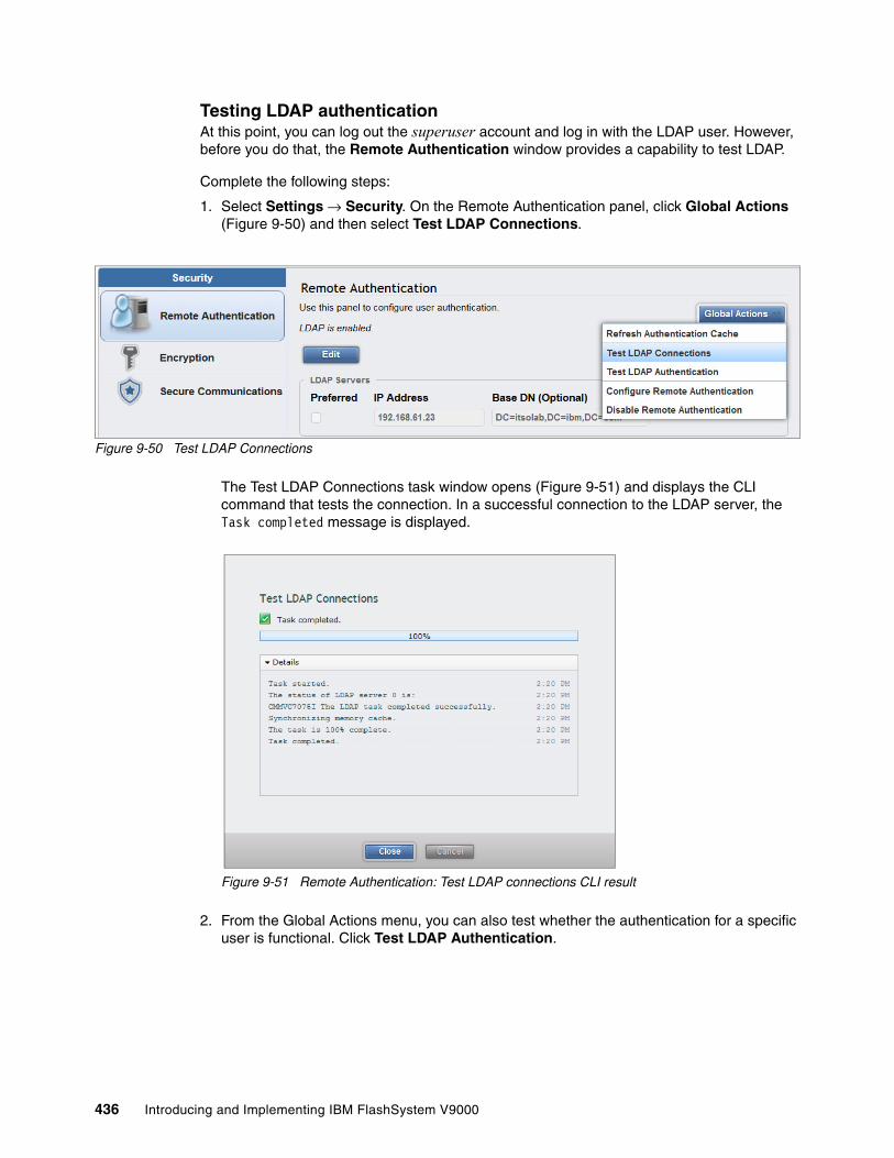
Testing LDAP authenticationAt this point, you can log out the superuser account and log in with the LDAP user. However, before you do that, the Remote Authentication window provides a capability to test LDAP.
Complete the following steps:
1. Select Settings → Security. On the Remote Authentication panel, click Global Actions (Figure 9-50) and then select Test LDAP Connections.
Figure 9-50 Test LDAP Connections
The Test LDAP Connections task window opens (Figure 9-51) and displays the CLI command that tests the connection. In a successful connection to the LDAP server, the Task completed message is displayed.
Figure 9-51 Remote Authentication: Test LDAP connections CLI result
2. From the Global Actions menu, you can also test whether the authentication for a specific user is functional. Click Test LDAP Authentication.
436 Introducing and Implementing IBM FlashSystem V9000

3. The next window opens (Figure 9-52). Type the user credentials of the LDAP user for whom you want to test authentication and click Test.
Figure 9-52 Remote Authentication: Test LDAP Authentication
When you click Test, the CLI command window opens (Figure 9-53):
– If the authentication is successful, you see the same output as in Figure 9-54 on page 438.
– If the test is unsuccessful, you see the message in Figure 9-53.
Figure 9-53 Remote Authentication: Test unsuccessful
Chapter 9. Configuring settings 437

Logging in as an LDAP userAssuming that remote authentication is successful, the superuser user can now log out and the LDAP user can log in (Figure 9-54).
Figure 9-54 Login window for the LDAP user
Configuring remote authentication is complete.
9.4.2 Encryption
IBM FlashSystem V9000 provides optional encryption of data at rest, which protects against the potential exposure of sensitive user data and user metadata that are stored on discarded, lost, or stolen flash modules. Encryption of system data and system metadata is not required, so system data and metadata are not encrypted.
AES-XTS 256-bit data-at-rest encryption with local key managementTwo functions are added to the encryption feature:
� Hot Encryption Activation: Adding an encryption license to a previously initialized system� Encryption Rekey: Changing the encryption key on a previously initialized system
If you want to use encryption, ensure that you purchase Feature Code (FC) AF14: Encryption Enablement Pack (Plant).
Data Encryption MethologyThe IBM FlashSystem V9000 data encryption uses the Advanced Encryption Standard (AES) algorithm, with a 256-bit symmetric encryption key in XTS mode. This encryption mode is known as XTS–AES–256, which is described in the IEEE 1619–2007 data encryption standard. The data encryption key itself is protected by a 256-bit AES key wrap when it is stored in non-volatile form. There are two layers of encryption used with stored data, first on the data being protected, and second on the data encryption key itself.
Attention: Encryption keys or data from IBM FlashSystem V9000 cannot be recovered or regenerated by IBM on an encryption-enabled system if the encryption keys are lost.
438 Introducing and Implementing IBM FlashSystem V9000
Protection Enablement Process (PEP)The Protection Enablement Process (PEP) transforms a system from a state that is not protection-enabled to a state that is protection-enabled.
The PEP establishes a secret encryption access key to access the system, which must be stored and made available for use later, whenever the system needs to be unlocked. The secret encryption access key must be stored outside the system on a USB drive or key servers (version 7.8 is needed), which the system reads to obtain the key. The encryption access key must also be backed up to other forms of storage.
In IBM FlashSystem V9000, two functions comprise the encryption capability:
� Hot Encryption Activation
Allows an unencrypted IBM FlashSystem V9000 to be encryption-enabled while the system is running, without affecting customer data.
� Nondisruptive Rekey
Permits creating a new encryption access key that supersedes the existing key on a running IBM FlashSystem V9000 without affecting customer data.
Encryption can be enabled in three ways:
� Activating encryption using the GUI (preferred)� Activating encryption using the CLI� Creating new encryption keys (Rekey)
Consider these aspects of handling encryption and encryption keys:
� Keeping encryption keys from more systems on the same USB flash drives (stacking)� Making copies of encryption keys� Storing copies of USB flash drives holding encryption keys� Leaving encryption keys in or out of the system during normal operation� Using key servers
In IBM FlashSystem V9000 you can enable encryption either during initialization by using the setup wizard or after the system is initialized. When the encryption Feature Code AF14 is purchased IBM sends a total of three USB flash drives.
When IBM FlashSystem V9000 encryption is activated, an encryption key is generated by the system to be used for access to encrypted data that is stored on the system. The GUI starts a wizard that guides you through the process of copying the encryption key to multiple USB flash drives or setting up key servers.
The following actions are considered preferred practices for copying and storing encryption keys when using USB sticks:
1. Make copies of the encryption key on at least three USB flash drives to access the system.
2. In addition, copy the encryption keys to other forms of storage to provide resiliency and to mitigate risk, if, for example, the three USB flash drives are from a faulty batch of drives.
3. Test each copy of the encryption key to ensure that the key is recognized before writing any user data to the initialized system.
4. Securely store all copies of the encryption key. As an example, any USB flash drives that are not left inserted into the system can be locked in a safe. Take comparable precautions to securely protect any other copies of the encryption key stored to other forms of storage.
Chapter 9. Configuring settings 439

Enable the encryption license Before you can enable encryption, install the encryption license on the system. Complete these steps:
1. Select Settings → System (Figure 9-55).
Figure 9-55 Navigate to Licensed functions
2. In the Licensed Functions panel (Figure 9-56), select the License check box to activate the encryption license, and click Apply Changes.
Figure 9-56 Activate the encryption license
440 Introducing and Implementing IBM FlashSystem V9000

3. Review the commands that run, enabling the licenses, and then click Close (Figure 9-57).
Figure 9-57 License Updated
Starting encryption To start encryption, perform the following steps:
1. Select Settings → Security (Figure 9-58).
Figure 9-58 Open the Security panel
2. Click Encryption, and then click Enable Encryption (Figure 9-59).
Figure 9-59 Enable Encryption
Chapter 9. Configuring settings 441

3. The Enable Encryption wizard starts (Figure 9-60). Select the type of encryption you want to define and then go to one of these sections to continue with the steps:
– “Encryption with USB keys” on page 442 for USB key. – “Encryption with key servers” on page 445 for Key Servers.
Figure 9-60 Encryption setup of FlashSystem V9000
Encryption with USB keysPerform the following steps:
1. Insert the IBM USB keys into the system (Figure 9-61), two keys in one control enclosure and one key in the other. The extra key will be removed later.
Figure 9-61 Set the IBM USB keys in the system
Ports for USB keys
442 Introducing and Implementing IBM FlashSystem V9000

2. As shown in Figure 9-62, the USB key count is incremented (1) as each key is inserted. When the keys are created, click Next (2).
Figure 9-62 Create the encryption keys
Tip: Remove one of the USB keys and store it in a safe place. If security policies allow, leave the two remaining keys in the AC2 or AC3 control enclosure so they are available if the AE2 storage enclosure restarts.
Remember if the encryption keys are not present, a storage enclosure hard reboot is not possible.
1
2
Chapter 9. Configuring settings 443

3. Click Commit (Figure 9-63). Encryption is not enabled until you click commit.
Figure 9-63 Commit to make the encryption effective
4. A confirmation window opens (Figure 9-64). The AE2 storage enclosure is now encrypted. Click Close.
Figure 9-64 System is now encrypted
444 Introducing and Implementing IBM FlashSystem V9000

Encryption with key serversEncryption with key servers requires FlashSystem V9000 Version 7.8 or later. At the time of writing, only one key server can be used, and it must be an IBM Security Key Lifecycle Manager (SKLM). Before you start this task, ensure that you can access the key servers by using the IP address.
For more information about SKLM, see the following resources:
� IBM Security Key Lifecycle Manager V2.6 documentation
http://ibm.biz/SKLMv26KC
� IBM Security Key Lifecycle Manager
https://ibm.biz/Bdsr7k
� IBM DS8880 Data-at-rest Encryption, REDP-4500
To configure SKLM, perform the following steps:
1. In the Enable Encryption window, enter the IP address and port of the key server (Figure 9-65), and then click Next.
Figure 9-65 key server IP and port
2. Enter the Device Group name (Figure 9-66 on page 446).
The default device group name in the GUI is SPECTRUM_VIRT. The device group must be created on the SKLM server prior to this step; you can name the device group SPECTRUM_VIRT or use a name of your choice. Naming the device group SPECTRUM_VIRT is a good practice for compatibility with future versions of SKLM.
Click Next.
Chapter 9. Configuring settings 445

Figure 9-66 Device Group name, default for IBM SKLM server
446 Introducing and Implementing IBM FlashSystem V9000

3. Select the certificate you want to use (Figure 9-67):
– Certificate: Browse to the certificate provided by a Certificate Authority (CA).– <Key server IP address>: Browse to the certificate provided by the SKLM server.
Figure 9-67 Authority or key server certificate.
Note: You can create either a new self-signed certificate or install a signed certificate that is created by a third-party certificate authority. Endpoint certificates should be self-signed certificates.
Chapter 9. Configuring settings 447

4. Transfer the IBM FlashSystem V9000 public key certificate to the key server. Click Export Public Key to get the certificate and add it to the key server.
When the key server is updated, select the check box to confirm the action and click Next (Figure 9-68).
Figure 9-68 IBM FlashSystem V9000 certificate for the Key Server
448 Introducing and Implementing IBM FlashSystem V9000

5. Review the summary of changes and click Finish to encrypt the data with the key server certificate (Figure 9-69).
Figure 9-69 Summary of changes
6. A confirmation window is displayed confirming that encryption is enabled and encryption keys reside on the key server (Figure 9-70).
Figure 9-70 Key server action completed
Chapter 9. Configuring settings 449

7. Review the Encryption panel to verify that the system is encrypted (Figure 9-71).
Figure 9-71 Key server encryption
Migration from USB stick encryption support to key serverContact your IBM representative regarding this process.
9.4.3 Secure Communications
Use the Secure Communications page (Figure 9-72) to enable and manage secure connections.
During system setup, an initial certificate is automatically created to use for secure connections between web browsers. Based on the security requirements for your system, you can create either a new self-signed certificate or install a signed certificate that is created by a third-party certificate authority. Self-signed certificates are generated automatically by the system and encrypt communications between the browser and the system. Self-signed certificates can generate web browser security warnings and might not comply with organizational security guidelines.
Figure 9-72 Update certificate
Click Update Certificate.
450 Introducing and Implementing IBM FlashSystem V9000

You can then create a new self-signed certificate or import your own signed certificate (Figure 9-73). Complete the requested information and click Update to validate your changes or Cancel to ignore them.
Figure 9-73 Self-signed or signed certificate
Chapter 9. Configuring settings 451

Figure 9-74 and Figure 9-75 on page 452 show the update certificate process. The connection with the IBM FlashSystem V9000 GUI is lost as soon as the new certificate is enabled (Figure 9-74).
Click Yes to continue or No to cancel.
Figure 9-74 Lost connection warning
Figure 9-75 shows the certificate update status.
Figure 9-75 Create self-signed certificate in progress
452 Introducing and Implementing IBM FlashSystem V9000

9.5 System menu
Select Settings → System (Figure 9-76). The System page opens where you can set the time and date for the cluster, perform software updates for the cluster, and set GUI preferences to manage licensed functions.
Figure 9-76 System selection
9.5.1 Date and Time option
Select Date and Time to view the Date and Time panel (Figure 9-77). Update the fields are required and click Save to save your changes.
Figure 9-77 Date and Time panel
The preferred method for setting the date and time is to configure a Network Time Protocol (NTP) server. By using an NTP server, all log entries are stamped with an accurate date and time, which is important in troubleshooting. An example might be a temporarily broken FC link that caused a path failover at a connected host. To investigate the root cause of this event, compare logs from the host, logs from the storage area network (SAN) switches, and logs from the IBM FlashSystem V9000. If the date and time are not accurate, events cannot be easily compared and matched, which makes a root cause analysis much more difficult.
Chapter 9. Configuring settings 453

9.5.2 Licensed functions
The base license that is provided with your IBM FlashSystem V9000 includes the use of its basic functions. However, the extra licenses, listed in this section, can be purchased to expand the capabilities of your system. Administrators are responsible for purchasing extra licenses and configuring the systems within the license agreement, which includes configuring the settings of each licensed function on the system.
The base 5639-RB7 license entitles IBM FlashSystem V9000 (machine type 9846/9848) to all the licensed functions, such as Virtualization, FlashCopy, Global and Metro Mirroring, and Real-time Compression. Any connected storage that is not an IBM FlashSystem V9000 requires the External Virtualization license that is a per terabyte (or tebibyte (TiB)) capacity unit of metric. TiB measures volume sizes in binary, so 1 GiB equals 1,073,741,824 bytes, which is 1024 to the power of three; TB measures volume sizes in decimal, so 1 GB equals 1,000,000,000 bytes, which is 1000 to the power of three.
You use the Licensed Functions window in the System Setup wizard to enter External Virtualization licenses purchased for your system.
The system supports the following licensed functions for internal storage:
� Encryption
The system provides optional encryption of data at rest, which protects against the potential exposure of sensitive user data and user metadata that is stored on discarded, lost, or stolen storage devices. Encryption is licensed only for AE2 storage enclosure all others storages (internals or externals) will not be encrypted except if the storage provides its own encryption mechanism that needs to be enable.
� External storage virtualization
The system does not require a license for its own AC2 or AC3 control enclosure and internals storage enclosures; however, a capacity-based license is required for any external systems that are being virtualized.
� FlashCopy
The FlashCopy function copies the contents of a source volume to a target volume. This license is capacity-based.
� Remote Copy (Global and Metro Mirror)
The remote-copy function enables the use of Metro Mirror, Global Mirror or Global Mirror with Change Volume functions. This function enables you to set up a relationship between volumes on two systems, so that updates that are made by an application to one volume are mirrored on the other volume. The volumes can be in the same system or on two different systems. This license is capacity-based.
� Real-time Compression
With the compression function, data is compressed as it is written to the drive, saving additional capacity for the system. This license is capacity-based.
For more details about the base licensed features for IBM FlashSystem V9000 internal storage, and for optional licensed features offered with IBM FlashSystem V9000 for external storage, see 2.7.2, “Software and licensing” on page 92.
For more information about licensing see IBM FlashSystem V9000 Version 7.7 Product Guide, REDP-5409.
454 Introducing and Implementing IBM FlashSystem V9000

Figure 9-78 highlights two areas:
1. Changing the Flash Copy license from 0 TiB to 60 TiB.
2. The Apply Changes button is automatically incremented.
Figure 9-78 Licensed Functions pane
9.5.3 Update software
Concurrent upgrade is the default way to upgrade the IBM FlashSystem V9000 system. All components of the system are upgraded including the AC2 or AC3 control enclosures and AE2 storage enclosures. Performance is affected during heavy I/O load. The suggestion is that you plan a three-hour change window for your upgrades. This time can vary depending on your system configuration.
This section demonstrates how to update firmware through the GUI of the IBM FlashSystem V9000. Before you start a system update, ensure that the system has no errors that might interfere with a successful update. Be sure that any errors are corrected before you start.
A single building block takes approximately 2.5 hours for code upgrade.
A scale-out, scale-up configuration updates one AC2 or AC3 control enclosure of each IO Group, and then the others. All AE2 storage enclosures are updated at the same time. The total time is approximately 2.5 hours.
Host path recovery is an important part of the IBM FlashSystem V9000 upgrade process. There are intentional wait (30 minutes) to ensure that paths have recovered before the upgrade proceeds to the next component. The remaining figures in this section show various stages of the upgrade.
1
2
Tip: Firmware release notes often contain the latest information about specifics of an upgrade. There is also an upgrade test utility that examines the system that can be run non-disruptively before an upgrade. For more details about the upgrade test utility, see 13.3.8, “Using the IBM FlashSystem V9000 Software Upgrade Test Utility” on page 636.
The current firmware for the system can be downloaded from the Internet (if the system has access), or it can be downloaded by the administrator from the following web page:
http://www.ibm.com/support
Chapter 9. Configuring settings 455

Firmware update is initiated from the Update System page (Figure 9-79). On this page, notice the current software level:
� Current version is 7.7.1.2 � Update version 7.7.1.3 is available
Figure 9-79 Firmware update main page
Before starting the firmware update, download the new firmware image file and the update test utility. The current firmware for the system can be downloaded from the Internet (if the system has access), or it can be downloaded by the administrator from the following address:
http://www.ibm.com/support
A firmware download requires an appropriate maintenance agreement or that the system is covered under warranty see 13.5.5, “Downloading from IBM Fix Central” on page 651.
You can update the FlashSystem V9000 firmware through the Settings menu. This update is referred to as Concurrent Code Load (CCL). Each AC2 or AC3 control enclosure and AE2 Storage Enclosure in the system automatically updates in sequence while maintaining interrupted accessibility for connected hosts.
The upgrade is concurrent. The process runs the upgrade utility and immediately starts the update if no problems are found. The test upgrade utility and code upgrade are started simultaneously, but run serially, with the test upgrade utility run first.
To initiate CCL, select Settings → System → Update System. On the Update System panel, click Test & Update (Figure 9-79).
Note: The test utility can also be run by using the CLI.
456 Introducing and Implementing IBM FlashSystem V9000

The Update System wizard begins (Figure 9-80) by requesting you to select the test utility and the update package. When you click Update, both files are uploaded and the test utility begin to run. If the test utility does not find any issues, the upgrade begins.
Figure 9-80 Test utility and firmware selection
The purpose of running the test utility is to verify that no errors exist and that the system is ready to update. If any issue is discovered by the test utility, the firmware update stops and sends a message to the administrator about the problems to fix before the update system procedure can be repeated.
The system inserts the current code level automatically, or the administrator can specify a different firmware level. This example updates to 7.7.1.3. Click Update to proceed.
The Update System panel opens where you can select Automatic update or Service Assistant Manual update. In this example, select Automatic update and click Finish (Figure 9-81).
Figure 9-81 Update System panel
The update test utility and update package files are uploaded to the IBM FlashSystem V9000 control enclosure, and then the firmware update for the entire system proceeds automatically.
Tip: The upgrade test utility can be run multiple times by using the CLI. For details, see “Using the IBM FlashSystem V9000 Software Upgrade Test Utility from the command line” on page 637.
Chapter 9. Configuring settings 457

The initial part of the Update System procedure is shown in Figure 9-82.
Figure 9-82 Code uploading panel
If any errors are identified by the test utility, they are indicated in the Update System panel. Any hardware error prevents the system update from proceeding. If an error is identified, take the correct actions to resolve the error identified by the update test utility.
The Concurrent Code Load (CCL) firmware update is now running in the background. While the system updates, the progress is shown in the progress indicators (Figure 9-83).
Figure 9-83 Updating system controller
The system can be operated normally while it is upgrading; however, no changes can be made until the firmware update completes. If you are trying to fix an error condition, you see the message shown in Figure 9-84 (fixes cannot be applied while the system is being upgraded).
Figure 9-84 Fixes cannot be applied while upgrading
Tip: During the upgrade, the GUI might go offline temporarily as the V9000 controllers are restarted during the upgrade. Refresh your browser to reconnect.
458 Introducing and Implementing IBM FlashSystem V9000

During the update, various messages display in the Update System window (Figure 9-85). The first control enclosure completes its update and the second controller starts to update.
Figure 9-85 Update System panel, one control enclosure completed
Tip: Host path recovery is often quicker than the time the FlashSystem V9000 pauses; the system takes a conservative approach to ensure that paths are stabilized before proceeding (30 minutes).
Chapter 9. Configuring settings 459

After completing the update to the second IBM FlashSystem V9000 control enclosure, the upgrade process moves to the storage enclosure, all are done in parallel. When the Update System wizard completes, the system returns to a healthy status. The system now has the current firmware (Figure 9-86).
Figure 9-86 Firmware update is now complete
During the hardware update, all individual components in the system are being firmware-updated. For example, the I/O ports are updated, during which time they are being taken offline for update one-by-one.
As an alternative to upgrading firmware through the GUI, you can use the FlashSystem V9000 CLI. The process is described in IBM Knowledge Center:
https://ibm.biz/fs_V9000_kc
Search for the “Updating the software automatically using the CLI” topic.
Tip: Customer change windows for update should include the entire upgrade process, approximately 2.5 hours.
460 Introducing and Implementing IBM FlashSystem V9000

9.5.4 VVOL
The system supports VMware vSphere Virtual Volumes, sometimes referred to as VVols, which allow VMware vCenter to automate the management of system objects such as volumes and pools. You can enable VVOL by turning the switch to ON as shown in Figure 9-87. An NTP server must be configured before you can enabled the VVOL feature.
Figure 9-87 VVOL enable screen
Before you configure Virtual Volumes, the following prerequisites must be met:
� Ensure that your system is running version 7.6.0 or later.
� Ensure that IBM Spectrum Control Base Edition (version 2.2.1 or later) is installed.
� Ensure that you are running VMware vSphere (ESXi hosts and vCenter) V 6.0 (or later).
� Ensure that Network Time Protocol (NTP) server is configured on both on the IBM FlashSystem V9000 and on the IBM Spectrum Control Base server. NTP ensures that time settings are consistent between the system and IBM Spectrum Control Base server.
� Confirm that you have the network information for both VMware vCenter and IBM Spectrum Control Base Edition: the IP address, subnet mask, gateway, and fully qualified domain name (FQDN) such as hostname.domain.com.
Select On to enable Virtual Volumes. A utility volume is automatically created to store critical metadata that is required for Virtual Volumes. This utility volume is managed by the IBM Spectrum Control Base Edition server.
Select a storage pool to store the utility volume. If possible, store a mirrored copy of the utility volume in a second storage pool that is in a separate failure domain. For example, use a storage pool that is made from MDisks that are presented from different storage systems or a different I/O group.
Create a user account for the IBM Spectrum Control Base Edition server. Defining the user account for the IBM Spectrum Control Base Edition server automatically configures a new user with the VASA Provider role. IBM Spectrum Control Base Edition server uses these storage credentials and role privileges to access the system and to run the automated tasks that are required for Virtual Volumes. Record these storage credentials. You need them to configure your IBM Spectrum Control Base Edition server.
Note: The VASA Provider role is used only by the IBM Spectrum Control Base Edition server. Users must not directly log in to the management GUI or CLI with an account that has the VASA Provider user role and complete system tasks, unless they are directed to by support.
Chapter 9. Configuring settings 461

Click Enable to enable VVOL or Cancel to stop the process (Figure 9-88).
Figure 9-88 VVOL enable screen
A window showing the enable process is displayed followed by a success window (Figure 9-89).
Figure 9-89 VVOL confirmation window
9.5.5 Resources
Copy Services features and RAID require that small amounts of volume cache be converted from cache memory into bitmap memory to enable the functions to operate. If you do not have enough bitmap space allocated when you try to use one of the functions, you cannot complete the configuration. As an example, if bitmap space is too low, trying to expand a mirrored volume fails until the allocated bitmap space has been expanded.
462 Introducing and Implementing IBM FlashSystem V9000

Table 9-1 describes the amount of bitmap space necessary to configure the various copy services functions and RAID.
Table 9-1 Examples of memory required
The memory limit for Volume Mirroring is changed from the default of 20 MiB to 40 MiB (Figure 9-90). Type in the new amount of bitmap space and click Save.
Figure 9-90 Change bitmap space for Volume Mirroring
9.5.6 IP Quorum
In some HyperSwap configurations, IP quorum applications can be used at the third site as an alternative to third-site quorum disks.
No Fibre Channel connectivity at the third site is required to use an IP quorum application as the quorum device. The IP quorum application is a Java application that runs on a host at the third site.
Feature Grain size 1 MB of memory provides the following volume capacity for the specified I/O group
Metro Mirror or Global Mirror 256 KB 2 TB of total Metro Mirror or Global Mirror volume capacity
FlashCopy 256 KB 2 TB of total FlashCopy source volume capacity
FlashCopy 64 KB 512 GB of total FlashCopy source volume capacity
Incremental FlashCopy 256 KB 1 TB of total incremental FlashCopy source volume capacity
Incremental FlashCopy 64 KB 256 GB of total incremental FlashCopy source volume capacity
Volume mirroring 256 KB 2 TB of mirrored volume capacity
Remember: If you do not have enough bitmap space allocated when you try to use one of the functions, you cannot complete the configuration.
Chapter 9. Configuring settings 463

Figure 9-91 shows the IP Quorum panel. Click the click here link for instructions (1). The IP network is used for communication between the IP quorum application and control enclosures in the system. If you currently have a third-site quorum disk, you must remove the third site before you use an IP quorum application.
Figure 9-91 IP Quorum main screen
9.5.7 I/OGroups: Enable and disable NPIV
N_Port ID Virtualization (NPIV) is a method for virtualizing a physical Fibre Channel port that is used for host I/O. When NPIV is enabled, ports do not become active until they are ready to service I/O. In addition, path failures due to an offline control enclosure are masked from host multipathing. See 7.12, “Using NPIV functionality” on page 311 for more details.
To enable or disable NPIV, you have to perform a transitional step during which the host will connect to the FlashSystem V9000 by using two WWPN addresses. This step ensures that the zoning is correct. Only after you confirm that the host can connect using both addresses, you can then perform the step to enable or disable NPIV.
1
464 Introducing and Implementing IBM FlashSystem V9000

The main I/O Groups page displays the status of NPIV; Figure 9-92 shows Enabled.
Figure 9-92 NPIV enabled
To disable NPIV, right-click the I/O Group and select Change Target Port Mode. The status changes from Enabled to Transitional. Click Continue (Figure 9-93).
Figure 9-93 NPIV transitional step
Target Port Mode is now Transitional. Confirm that your host can access the IBM FlashSystem V9000 using the new WWPN.
Chapter 9. Configuring settings 465

To verify which WWPN your host can use on the FlashSystem V9000, click Setting → Networks → Fibre Channel Ports. See the column Host IO Permitted (Figure 9-94).
Figure 9-94 Confirmation of Transitional mode
After you confirm that the host can connect to the IBM FlashSystem V9000 by using the correct WWPN address, you can change the target port mode to Disabled. Right-click IO_group and select Disabled (Figure 9-95). The Force change check box allows you to perform the action, ignoring whether hosts are still sending I/Os on the port that will be enabled or disabled.
Figure 9-95 Disable WWPN virtualization
Attention: Using force mode may cause a host access loss.
466 Introducing and Implementing IBM FlashSystem V9000

To confirm the results of this step, select Setting → Networks → Fibre Channel Ports as shown in Figure 9-96
Figure 9-96 NPIV disabled confirmation
9.6 Support menu
Access the Support menu to download support packages that contain log files and information that can be sent to support personnel to help troubleshoot problems with the system. You can either download individual log files or download statesaves, which are dumps or live dumps of system data.
To access the Support menu, select Settings → Support (Figure 9-97).
Figure 9-97 Support selection
Attention: To enable or disable host port virtualization, follow the same process. You have to use the transition step to ensure that your host can access the IBM FlashSystem V9000 to avoid a storage access lost.
Chapter 9. Configuring settings 467

9.6.1 Download support package
IBM Support often requests log files when responding to an automatic support issue that is opened by the call home function or a support issue that is opened by the IBM FlashSystem V9000 administrators.
Select Settings → Support when log files are requested by IBM Support.
The system administrator downloads the requested support package from the system and then uploads it to IBM Support. IBM Support then analyzes the data.
To download a support package, follow these steps, as shown in Figure 9-98:
1. Select Settings → Support and click Download Support Package.
2. Select the type of support package to download, and then click Download.
Figure 9-98 Download support package panel
You can download the following types of support packages, as shown in Figure 9-98:
� Standard logs: Contains the most recent logs that were collected on the system. These logs are most commonly used by support to diagnose and solve problems.
� Standard logs plus one existing statesave: Contains the standard logs for the system and an existing statesave from any of the control enclosures in the system. Statesaves are also known as dumps or livedumps. One day to one week traces are also included.
� Standard logs plus the most recent statesave from each control enclosure: Contains the standard logs for the system and the most recent statesave from each of the control enclosures on the system.
� Standard logs plus new statesaves: Generates a new statesave (live dump) for all of the control enclosures in the system and packages them with the most recent logs.
IBM Support usually requests that you click Standard logs to begin an investigation. The length of time to download these logs from the IBM FlashSystem V9000 can be in the range of minutes to an hour, depending on the situation and the size of the support package that is downloaded.
Tip: Log files are needed in most of the support cases processed for the IBM FlashSystem V9000. Clients who upload these logs when the support ticket number is available often have issues resolved quicker than waiting for IBM support to ask for them.
1
2
468 Introducing and Implementing IBM FlashSystem V9000

Figure 9-99 shows that you can monitor the details of the running command. When this completes, it is replaced with the save-file form.
Figure 9-99 Generating the support package
The destination of the support package file is the system where the web browser was launched. Figure 9-100 shows the next step of saving the support package file.
Figure 9-100 Saving the Snap File
IBM Support usually requests log files to be uploaded to a specific PMR number, using Enhanced Customer Data Repository (EcuRep) as the upload method to IBM:
http://www.ecurep.ibm.com/app/upload
Chapter 9. Configuring settings 469

9.6.2 Download individual log files
You can select individual logs to download to review or send them directly to IBM Support. You can also increase CIMOM1 logging levels to add details to the support packages on the CIMOM-related events. However, increasing the logging level can affect system performance and is best used temporarily when you are resolving issues on the system.
After analyzing the uploaded support package, IBM Support might request additional files. To locate these files, select Settings → Support and click Show full log listing. This option supports the download of specific and individual log files.
An example is shown in Figure 9-101:
1. Select a single error log file.2. Click Actions → Download.
Figure 9-101 Download specific file dialog
1 Common Information Model Object Manager (CIMOM)
1
2
Note: Log files are saved from each of the components of the system.
470 Introducing and Implementing IBM FlashSystem V9000

9.6.3 Deleting log files
You can also delete certain types of log files from the system. To preserve the configuration and trace files, any files that match the following wildcard patterns cannot be deleted:
� *svc.config*� .trc� .trc.old
Figure 9-102 shows the deletion process:
1. Select an old snap file.2. Click Actions → Delete.
Figure 9-102 Deleting individual files
The Delete option: When the Delete option is not available, the file cannot be deleted because it is being used by the system.
Tip: Systems running in production for a long time might require that old files be cleaned up before upgrades. Snaps with statesaves are large files, for example.
1
2
Chapter 9. Configuring settings 471
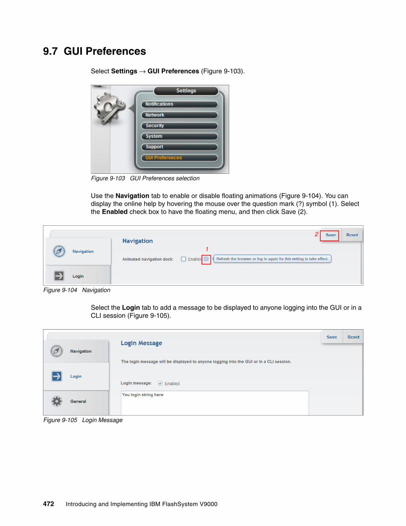
9.7 GUI Preferences
Select Settings → GUI Preferences (Figure 9-103).
Figure 9-103 GUI Preferences selection
Use the Navigation tab to enable or disable floating animations (Figure 9-104). You can display the online help by hovering the mouse over the question mark (?) symbol (1). Select the Enabled check box to have the floating menu, and then click Save (2).
Figure 9-104 Navigation
Select the Login tab to add a message to be displayed to anyone logging into the GUI or in a CLI session (Figure 9-105).
Figure 9-105 Login Message
1
2
472 Introducing and Implementing IBM FlashSystem V9000

Use the General tab to set the following preferences in the GUI (Figure 9-106):
1. Restore default browser preferences2. Automatic logoff3. IBM Knowledge Center URL4. Browser refresh (GUI refresh)5. Low graphics mode6. Enable pool extent size
Figure 9-106 GUI preferences panel
Restore default browser preferences or refresh GUI objects Clicking the Clear button causes any settings that are changed in the browser to revert to their default settings.
Clicking the Refresh button causes all the panels in the GUI to be refreshed. IBM FlashSystem V9000 management interface keeps most windows up-to-date in real time. This operation provides you with a mechanism to initiate a refresh of all the panels.
IBM Knowledge CenterYou can customize the URL to the online documentation that IBM provides in IBM Knowledge Center. IBM offers customers opportunities to participate in beta test programs. This option can be used to change the web address to point to alternate documentation.
Advanced pool settingsConsistent extent sizes are an important factor when migrating VDisks between pools on the IBM FlashSystem V9000. Clearing Allow extent size selection during pool creation means that the user is not offered the option to change the extent size from the default presented by the system.
Default logout timeEnter the elapse time in minutes after which an inactive GUI session is logged off.
Low graphics modeBy selecting Enable low graphics mode, you can customize the GUI to use less bandwidth. This option is available primarily for slow Internet connections; most clients do not need to change this parameter.
1
2
3
4
5
6
Chapter 9. Configuring settings 473

474 Introducing and Implementing IBM FlashSystem V9000

Chapter 10. Service Assistant Tool
The Service Assistant (SA) Tool is used by IBM Support personnel to perform service functions as required on a specific IBM FlashSystem V9000 control enclosure or storage enclosure canister as necessary. This chapter guides you through the various uses of Service Assistant Tool (if IBM Support guides you to use the tool) for IBM FlashSystem V9000.
Service Assistant Tool is used for troubleshooting or when an IBM Support engineer directs you to use it.
This chapter includes the following topics:
� Accessing Service Assistant Tool� Log in to Service Assistant Tool� Home page� Collect Logs page� Manage System page� Recover System page� Re-install Software page� Update Manually page� Configure Node page� Change Service IP page� Configure CLI Access page� Restart Service page
10
© Copyright IBM Corp. 2015, 2016. All rights reserved. 475

10.1 Accessing Service Assistant Tool
Use a web browser to access Service Assistant Tool. An example of getting access is to point your browser to the cluster management IP address and add the text /service to the end of the address, as in this example:
https://192.168.70.121/service
Each of the node’s service IP addresses can also be reached. Various options are available for accessing the Service Assistant (SA) Tool. The following example shows which IP addresses are configured and how they are accessed:
� Default Service IP address for Node 1 (configuration node):
192.168.70.121
Opens SA Tool for Node 1:
– https://192.168.70.121/service – https://192.168.70.121
� Default Service IP address for Node 2:
192.168.70.122
Opens SA Tool for Node 2:
– https://192.168.70.122/service/ – https://192.168.70.122
� Example cluster IP address:
192.168.70.123
– Opens SA Tool for the configuration node:
https://192.168.70.123/service
– Opens the cluster management GUI:
https://192.168.70.123
Node names: Control enclosures are named Node 1 (as determined by the first AC2 or AC3 control enclosure that was used to build the initial cluster) and Node 2 (the second AC2 or AC3 that was added to the cluster). Extra building blocks can add more members to the configuration and more access points are possible.
476 Introducing and Implementing IBM FlashSystem V9000

10.2 Log in to Service Assistant Tool
The login window of FlashSystem V9000 Service Assistant Tool (Figure 10-1) allows only the superuser to log in; therefore, the user name cannot be changed. Enter the system’s superuser password to continue.
Figure 10-1 Service Assistant Tool login
10.3 Home page
After you type the password for the superuser, the Home page of the IBM FlashSystem V9000 Service Assistant Tool Home page opens (Figure 10-2 on page 478).
Figure 10-3 on page 478 and Figure 10-4 on page 479 show the Service Assistant Tool Home page for the fully configured, scalable building block system.
The Home page shows all the members of the IBM FlashSystem V9000 system, including the expansion enclosures. Any one of these members can be selected for running specific tasks to perform service functions. Additionally, various options exist for examining installed hardware, identifying members, checking revision levels, performing maintenance functions, and for placing a selected member into the service state.
Attention: Incorrect use of the Service Assistant Tool (SA) can cause unscheduled downtime or even data loss. Use SA only when IBM Support asks you to use it.
Note: On the fully configured scalable building block system, the control enclosure details of the member selected are shown further down the page, and are accessible by the scroll bars on the right side of the window.
Chapter 10. Service Assistant Tool 477

Figure 10-2 Home page: Single building block system
Figure 10-3 Home page: Fully configured scalable building block system (part 1 of 2)
Note: The reference to Model SV1 is a generic term built into the product operational code. This reference also applies to the IBM FlashSystem V9000 control enclosure model AC3, so the two are interchangeable
478 Introducing and Implementing IBM FlashSystem V9000

Figure 10-4 Home page: Fully configured scalable building block system (part 2 of 2)
10.4 Collect Logs page
The Collect Logs page (Figure 10-5) enables defined logs of the selected member to be collected for transfer to support for detailed analysis of a support request or debug of a fault. The support personnel inform you what level or which of the listed files to collect and how to send them to support for analysis. This page shows the files that can be selected for the selected member (in this example, a control node).
Figure 10-5 Collect Logs page
Chapter 10. Service Assistant Tool 479

10.5 Manage System page
The Manage System page (Figure 10-6) shows the details of the clustered system that the members belong to.
Figure 10-6 Manage System page
10.6 Recover System page
The Recover System page (Figure 10-7) can be used to perform emergency recovery of a clustered system that for technical reasons has its control members all in the Service state at the same time. This procedure is commonly known as the T3 Recovery. In this situation, there is no configuration node to manage the clustered system.
Figure 10-7 Recover System page
Important: Use extreme care with this function; do not attempt to run it without support guidance.
480 Introducing and Implementing IBM FlashSystem V9000

10.7 Re-install Software page
The Re-install Software page (Figure 10-8) enables the firmware release that is currently loaded on the system to be reinstalled on a specific member without reloading to all members of the cluster as might be the case with update software on the Cluster Management GUI.
Figure 10-8 Re-install Software page
10.8 Update Manually page
From the Update Manually page (Figure 10-9), the system can be updated in a step-by-step process to ensure that each member is properly updated as needed when a normal update cannot be performed or fails for some reason.
Figure 10-9 Update Manually page
Note: The use of this feature should be guided by support personnel to ensure that all steps are properly completed.
Chapter 10. Service Assistant Tool 481

10.9 Configure Node page
With the Configure Node page (Figure 10-10), the member control enclosure configuration settings can be changed as necessary to enable it to work in a specific environment.
Figure 10-10 Configure Node page
10.10 Change Service IP page
With the Change Service IP page (Figure 10-11), the selected AC2 or AC3 control enclosure or AE2 storage enclosure canister can have its IP address changed as necessary to meet the IP environment needs so that IBM support can provide the necessary service.
Figure 10-11 Change Service IP page
Attention: These settings should not be modified without direction from support personnel because changes can drastically affect the system’s functions and also risk data access and integrity.
482 Introducing and Implementing IBM FlashSystem V9000

10.11 Configure CLI Access page
The Configure CLI Access page (Figure 10-12) is used to select an SSH key file for an AC2 or AC3 control enclosure that is in the service state or is in candidate mode and does not have a valid SSH key for superuser access to be granted. You can select an SSH key file to enable CLI access.
Figure 10-12 Configure CLI Access page
10.12 Restart Service page
Sometimes, an unexpected interrupt can result in a service function being halted or exiting for no apparent reason. If this happens, use the Restart Service page (Figure 10-13) to restart the more commonly used service daemons and programs. IBM Support might direct you to use this page if necessary.
Figure 10-13 Restart Service page
Chapter 10. Service Assistant Tool 483

484 Introducing and Implementing IBM FlashSystem V9000

Chapter 11. IBM HyperSwap
The IBM HyperSwap function is a high availability feature that provides dual-site, active-active access to a volume. This chapter walks you through the process of setting up, configuring and using HyperSwap.
HyperSwap function was introduced with IBM FlashSystem V9000 software V7.5 and it was only available through command-line interface (CLI) commands. IBM FlashSystem V9000 software V7.6 introduced graphical user interface (GUI) support to configure the HyperSwap function and additional CLI commands to configure HyperSwap volumes.
This chapter describes the GUI and CLI commands for FlashSystem V9000 software V7.7.1. The FlashSystem V9000 software V7.5 commands are still valid and are described in 11.15, “IBM FlashSystem V9000 HyperSwap CLI commands” on page 545.
The HyperSwap function enables each volume to be presented by two I/O groups at two different sites. At the time of publishing, the two I/O groups in a HyperSwap configuration must exist within a single FlashSystem V9000 cluster. The configuration tolerates combinations of control enclosure and site failures, using a flexible choice of host multipathing driver interoperability. This chapter includes the following topics:
� Overview� HyperSwap design� Comparison with Enhanced Stretched Cluster� Planning� Configuration� Operations� HyperSwap with SAS attached expansion enclosures� Disaster recovery with HyperSwap� Disaster recovery with consistency groups� The overridequorum command� HyperSwap Failure scenarios� Unconfiguring HyperSwap� Summary of interesting object states for HyperSwap� Naming conventions� IBM FlashSystem V9000 HyperSwap CLI commands
11
© Copyright IBM Corp. 2015, 2016. All rights reserved. 485

In this chapter, the term VDisk is used for an individual object created with the mkvdisk command. The term HyperSwap volume is used for the volume with copies on two sites in a HyperSwap relation. The term basic volume is used for a volume which is only on one site. For details about these terms, see 11.14, “Naming conventions” on page 545.
For better readability of command-line interface (CLI) examples, the CLI output is shortened in lines, columns, or both in the examples in this chapter.
11.1 Overview
HyperSwap is the high availability (HA) solution for IBM FlashSystem V9000. HyperSwap provides business continuity if hardware failure, power failure, connectivity failure, or disasters occur. HyperSwap is also available on other IBM Spectrum Virtualize products, such as IBM SAN Volume Controller, or IBM Storwize V7000.
The following list includes general HA requirements:
� Two independent main sites� Independent infrastructure for power, fire protection, and so on� Independent servers on each site� Two independent data copies, one in each site� Latency optimized intersite traffic to keep both sites’ data copies in sync� Local high availability in each site� Application site transparency
Figure 11-1 shows a two-site HA environment.
Figure 11-1 High availability environment
The HyperSwap function provides highly available volumes accessible through two sites at a distance up to 300 km apart. A fully-independent copy of the data is maintained at each site. When data is written by hosts at either site, both copies are synchronously updated before the write operation is completed. The HyperSwap function automatically optimizes itself to minimize data transmitted between sites and to minimize host read and write latency.
Note: At the time of publishing, the two I/O groups in a HyperSwap configuration must exist within a single FlashSystem V9000 cluster. The cluster consists of at least two scalable V9000 building blocks.
486 Introducing and Implementing IBM FlashSystem V9000

If the control enclosures, storage enclosures, or any other attached storage at either site go offline, leaving an online and accessible up-to-date copy, the HyperSwap function will automatically fail over access to the online copy. The HyperSwap function also automatically resynchronizes the two copies when possible.
11.1.1 HyperSwap Implementations
The decision for a HyperSwap failover can be managed by the host or by the storage system. IBM currently has two main solutions:
� Host-based HyperSwap. The host handles storage failures.� Storage-based HyperSwap. The storage system handles storage failures.
The next two sections describe these two solutions.
Host-based HyperSwapA HyperSwap function is available when using the IBM DS8000 family of products together with IBM PowerHA® System Mirror for AIX or IBM Geographically Dispersed Parallel Sysplex™ (IBM GDPS®) for IBM z/OS®. The HyperSwap functions on those environments use specific software on that host system. All decisions in split scenarios are made by the host.
Figure 11-2 shows a host-based HyperSwap example of an IBM AIX PowerHA and IBM System Storage DS8000 HyperSwap setup.
Figure 11-2 Host-based HyperSwap example
Chapter 11. IBM HyperSwap 487

Storage-based HyperSwapIBM Spectrum Virtualize provides the HyperSwap feature in the virtualization layer. It uses technologies from:
� Metro Mirror � Global Mirror with Change Volumes� Non-disruptive Volume Move
One volume is presented to the host from two different sites. Two IO groups are presenting the same volume to the host. All decisions in split scenarios are made by IBM Spectrum Virtualize software running on IBM FlashSystem V9000.
The host must detect, accept, and handle HyperSwap changes, and manage the application failover. All FlashSystem V9000 failover decisions are valid for all hosts, or host clusters attached to the FlashSystem V9000 cluster.
Figure 11-3 shows a IBM Spectrum Virtualize-based HyperSwap example. It shows that four VDisks are needed to present one HyperSwap volume to the host.
Figure 11-3 IBM Spectrum Virtualize-based HyperSwap example
The HyperSwap function in the FlashSystem V9000 software works with the standard multipathing drivers that are available on a wide variety of host types, with no additional host support required to access the highly available volume. Where multipathing drivers support Asymmetric Logical Unit Assignment (ALUA), the storage system tells the multipathing driver which control enclosures are closest to it, and should be used to minimize I/O latency. You must assign a site value to the host, to the FlashSystem control enclosures, and storage enclosures. The ALUA supporting multipathing driver configures the host pathing optimally. Details about the configuration are described in 11.5, “Configuration” on page 496.
Tip: When using the HyperSwap function, configure your host multipath driver to use an ALUA-based path policy.
488 Introducing and Implementing IBM FlashSystem V9000

11.2 HyperSwap design
This section provides high-level information about HyperSwap. Details are described throughout the whole chapter.
The IBM FlashSystem HyperSwap function is an active-active mirror based on Metro Mirror technology. It is an unstoppable configuration. The relationship of a HyperSwap volume is never in “stopped mode,” except during disaster recovery scenarios.
The LUN ID of the master VDisk is presented to the host. The auxiliary VDisk is always seen as offline in the GUI and CLI. The auxiliary VDisk is presented to the host with the same LUN ID as the master VDisk. HyperSwap simulates the master LUN ID for the auxiliary VDisk. The LUN ID of the auxiliary VDisk is not visible to the host.
Figure 11-4 shows the host can access the HyperSwap volume using the master and the auxiliary (aux) VDisk. In the CLI and GUI, the aux VDisk is shown offline, but the host can use it with the LUN ID of the master VDisk.
Figure 11-4 HyperSwap LUN ID Simulation
The host can access the HyperSwap volume using the I/O group on site 1, or the I/O group on site 2, or both. The multipath driver of the host is responsible for selecting the optimal paths.
The example in Figure 11-4 shows a host on site 1 accessing the HyperSwap volume using I/O group 1 and the master VDisk on site 1. Data is replicated to the auxiliary VDisk on site 2. When the connection from the host to the master VDisk is broken, for example the Fibre Channel (FC) connection between host and I/O group 1 is broken, then the host accesses the data using I/O group 2.
Chapter 11. IBM HyperSwap 489

The master VDisk is still the primary VDisk, so reads are serviced by the master VDisk and writes are forwarded to the master VDisk and then replicated to the auxiliary or the secondary VDisk. If this scenario is running for more than 20 minutes, the auxiliary VDisk becomes the primary VDisk, servicing reads and writes. The master VDisk becomes the secondary VDisk. I/O arrives in I/O group 2 and is handled by the auxiliary (now primary) VDisk and replicated to the master (now secondary) VDisk.
A HyperSwap volume can be accessed concurrently for read and write I/O from any host in any site. All I/O is forwarded to one I/O group in the site with the primary VDisk. Using the site with the non-primary VDisk increases the long-distance traffic significantly.
HyperSwap Cluster monitors the workload and switches the copy direction if the most workload is arriving on the other site, optimizing performance.
Applications with equal workload pattern to the same HyperSwap volume using both I/O groups, for example Oracle RAC, are currently not optimal for HyperSwap.
A host accessing a HyperSwap volume uses two I/O groups. Therefore, the host multipathing must handle two times more paths compared to a normal volume. When changing from standard to HyperSwap topology, the host zoning has to be reviewed. Some hosts have limits for the optimal number of path to a LUN. If only HyperSwap volumes are configured on FlashSystem V9000, meaning each host accesses a volume using two I/O groups, the maximum number of host objects and the maximum number of volume mappings per host object is cut in half.
HyperSwap volumes use FlashCopy technology to provide consistency protection when synchronizing the master and auxiliary VDisk after a loss of sync, for example when the link between these VDisks was broken. One change volume per HyperSwap volume must be prepared on each site. Therefore, a HyperSwap volume requires the configuration of four internal VDisks. Two FlashCopy mappings to each change volume are required (one in each direction), so four FlashCopy maps are required per HyperSwap volume. all the needed VDisks and remote copy relationships are automatically generated when using the GUI or the CLI when creating a HyperSwap volume.
The auxiliary VDisk is offline because its ID is not shown to the host. The lsvdisk command shows all VDisks of a HyperSwap volume (Example 11-1).
Example 11-1 The lsvdisk command to display all VDisks of a HyperSwap volume
lsvdiskid name IO_group_name status id mdisk_grp_name capacity volume_name function0 HyperSwap_1 io_grp0 online mdiskgrp1 35.00GB HyperSwap_1 master1 vdisk1 io_grp1 offline mdiskgrp2 35.00GB HyperSwap_1 aux2 vdisk2 io_grp0 online mdiskgrp1 35.00GB HyperSwap_1 master_change3 vdisk3 io_grp1 online mdiskgrp2 35.00GB HyperSwap_1 aux_change
Tip: If you are running VMware environment on top of HyperSwap, it is good practice to maintain VMs on the hosts in one site per HyperSwap volume. For example, with VMware Distributed Resource Scheduler (DRS), should run VM-host affinity rules.
490 Introducing and Implementing IBM FlashSystem V9000

Figure 11-5 shows the same HyperSwap volume by using the GUI.
Figure 11-5 HyperSwap volume
The HyperSwap volume master VDisk status attribute of the lsvdisk command shows whether hosts are able to access data, for example whether the HyperSwap volume has access to up-to-date data or not. It does not show whether the master VDisk itself is actually online. The value status for auxiliary VDisk is always offline as shown in Example 11-1 on page 490.
The GUI information shows only the HyperSwap volume but not the four VDisks of a HyperSwap volume. The site attributes and the pool of the master VDisk and the auxiliary VDisk are shown. When creating a HyperSwap volume by using the GUI or the mkvolume command, then the master VDisk disk will be on site1 and the auxiliary VDisk on site 2. Their associated change volumes are created in the same pool as the master or the auxiliary VDisk.
Use the status attribute of the lsrcrelationship command to determine if a VDisk is online or offline. Possible values are online, primary_offline, secondary_offline, io_channel_offline, primary_change_offline, secondary_change_offline, and change_volumes_needed, as described in 11.13.3, “The lsrcrelationship or lsrcconsistgrp commands” on page 543. Use the lsvdisk command to get the name of the remote copy relationship of a HyperSwap volume (Example 11-2).
Example 11-2 HyperSwap volume lsvdisk status information
lsvdisk HyperSwap_1...RC_name rcrel0 ...
The lsrcrelationship command shows the four VDisks of a HyperSwap volume, some lines are omitted for better readability (Example 11-3).
Example 11-3 The lsrcrelationship command
lsrcrelationship rcrel0name rcrel0master_vdisk_name HyperSwap_1aux_vdisk_name vdisk1primary masterstate consistent_synchronizedstatus onlinemaster_change_vdisk_name vdisk2aux_change_vdisk_name vdisk3
Chapter 11. IBM HyperSwap 491

Figure 11-6 shows the active-active relationship using the GUI.
Figure 11-6 HyperSwap volume active-active relationship
The lsfcmap command shows the four FlashCopy mappings of a HyperSwap volume, as shown in Example 11-4.
Example 11-4 The lsfcmap command
lsfcmapid name source_vdisk_id source_vdisk_name target_vdisk_id target_vdisk_name0 fcmap0 0 HyperSwap_1 2 vdisk21 fcmap1 2 vdisk2 0 HyperSwap_12 fcmap2 1 vdisk1 3 vdisk33 fcmap3 3 vdisk3 1 vdisk1
Figure 11-7 shows the FlashCopy mappings using the GUI.
Figure 11-7 HyperSwap volume and its FlashCopy mappings
492 Introducing and Implementing IBM FlashSystem V9000

11.3 Comparison with Enhanced Stretched Cluster
Many of the aspects described so far are the same as those of the existing IBM Spectrum Virtualize Enhanced Stretched Cluster function, introduced in version 7.2 of the software. Table 11-1 provides a list of key differences between the Enhanced Stretched Cluster and HyperSwap functions.
Table 11-1 Enhanced Stretched Cluster and HyperSwap comparison
Note: Enhanced Stretched Cluster is not supported with IBM FlashSystem V9000.
Description IBM Spectrum Virtualize Enhanced Stretched Cluster
IBM FlashSystem V9000 HyperSwap
Product availability SAN Volume Controller only FlashSystem V9000 with 2 or more I/O groups
Configuration CLI or GUI CLI or GUI
Sites Two for data, third for quorum device
Two for data, third for quorum device
Distance between sites Up to 300 km Up to 300 km
Independent copies of data maintained
Two Two (Four if additionally Volume Mirroring to two pools in each site)
Host requirements Standard host multipathing driver
Standard host multipathing driver
Cache retained if only one site online?
No Yes
Synchronization and resynchronization of copies
Automatic Automatic
Stale consistent data retained during resynchronization for disaster recovery?
No Yes
Scope of failure and resynchronization
Single volume One or more volumes, user configurable
Ability to use FlashCopy together with high availability solution
Yes (although no awareness of site locality of data)
Limited
Ability to use Metro Mirror, Global Mirror, or Global Mirror with change volumes together with high availability solution
One remote copy No, can use VDisk mirror for additional copies
Maximum highly available volume count
5000 1250
Licensing Included in the base product Requires Remote Mirroring license.
Chapter 11. IBM HyperSwap 493

The Enhanced Stretched Cluster function and the HyperSwap function spread the control enclosures of the system across two sites, with additional storage at a third site acting as a tie breaking quorum device.
The topologies differ in how the control enclosures are distributed across the sites:
� Enhanced Stretched Cluster
For each I/O group in the system, the Enhanced Stretched Cluster topology has one control enclosure on one site, and one control enclosure on the other site. The topology works with any number (1 - 4) of I/O groups, but because the I/O group is split into two locations, this is only available with SAN Volume Controller, not FlashSystem V9000.
� HyperSwap
The HyperSwap topology locates both control enclosures of an I/O group in the same site, making this possible to use with either FlashSystem V9000 or SAN Volume Controller products. Therefore, to get a volume resiliently stored on both sites, at least two I/O groups are required.
The Enhanced Stretched Cluster topology uses fewer system resources, enabling a greater number of highly available volumes to be configured. However, during a disaster that makes one site unavailable, so the SAN Volume Controller system cache on the control enclosures of the surviving site is disabled.
11.3.1 Disaster recovery
The HyperSwap function automatically controls synchronization and resynchronization of the master VDisk and the auxiliary VDisk. If the master VDisk and the auxiliary VDisk are out of sync, for example the data link to one site had been broken and is fixed again, FlashSystem V9000 will automatically resynchronize the data. Just before resynchronizing data to a VDisk copy, that copy usually contains crash-consistent but stale (out-of-date) data. The storage system automatically retains that consistent data during the resynchronization process using change volume technology.
What this means is that if a problem occurs at the site with the online copy before resynchronization completes, taking that copy offline, you have the opportunity to manually enable read and write access to the consistent, older copy of data, allowing the use of this data for disaster recovery. This option would typically be taken if you know that the offline copy will remain offline for an extended period, and the consistent but older data is useful enough to keep your business running.
As normal with disaster recovery solutions that support business continuity with older data, after the problem is resolved restoring access to the offline copy, you can choose to either revert to that now-online copy, which before the disaster held the latest copy of the data, or continue to work on the stale data used during the disaster. With either choice, the other copy is resynchronized to match the chosen copy.
Requirement: Using HyperSwap requires the Remote Mirroring license.
494 Introducing and Implementing IBM FlashSystem V9000

11.3.2 Consistency Groups
One major advantage of the HyperSwap function, compared to Enhanced Stretched Cluster, is that it is possible to group multiple HyperSwap volumes together for high availability. Using consistency groups to control the synchronization and failover across many HyperSwap volumes in an application ensures that all VDisk copies on a site have data from the same point in time, enabling disaster recovery using that site’s VDisk copies. It also ensures that at least one site has an up-to-date copy of every HyperSwap volume in the consistency group. It further ensures that the other site, if it does not have an up-to-date copy of every VDisk, it has a consistent copy of every VDisk for some out-of-date point-in-time.
The following scenario is an example where the data is not consistent across all those volumes and would affect availability:
1. Site 2 goes offline.2. Application continues to write to its volumes, changes only applied to site 1.3. Site 2 comes online again.4. Volumes are resynchronized back to site 2.5. Site 1 goes offline during the resynchronization, leaving some volumes already
resynchronized and some volumes unresynchronized.
Site 1 is the only site that has usable data. Site 2 might have usable data on some VDisks but not others. If this process is continued, it is possible that neither site will have a complete copy of data, making a failure on either site affect production I/O.
Without consistency groups, site 2’s data would have been made inconsistent on several of the VDisks, by the attempt to resynchronize, which did not complete. The unresynchronized VDisks contain consistent but old data, as described in 11.3.1, “Disaster recovery” on page 494. Site 2 now has some VDisks with old data and VDisks with resynchronized data. If site 1 data cannot be recovered, another solution is needed to recover business operations.
11.3.3 HyperSwap restrictions for software version 7.7.1
The following restrictions apply to the HyperSwap function for software version 7.7.1:
� Cluster internal Metro Mirror is used for replication, so the size of a HyperSwap volume cannot be changed using expandvdisksize and shrinkvdisksize commands.
� A cascaded Remote Copy is currently not available. HyperSwap volumes cannot be replicated to a second, independent storage system using Remote Copy functionality.
� Four FlashCopy mappings are required for each HyperSwap volume, which limits the number of HyperSwap volumes to 1250. Additional FlashCopy requirements will reduce the number of possible HyperSwap volumes.
Check the Configuration Limits and Restrictions:
http://www.ibm.com/support/docview.wss?uid=ssg1S1009268
� FlashCopy usage can be complicated because the Metro Mirror source and target volume can switch during daily operation. For this reason, identification of the copy direction is required for a successful FlashCopy.
� The Remote Copy relationship must be removed first for a reverse FlashCopy operation. After a reverse FlashCopy, all HyperSwap related functions must be manually implemented again (Remote Mirror and FlashCopy relationships).
� IBM FlashCopy Manager is currently not supported with HyperSwap volumes.
Chapter 11. IBM HyperSwap 495

11.4 Planning
Two steps are required to configure IBM FlashSystem V9000 for HyperSwap. The first step is to configure the components of the system correctly for the HyperSwap topology. The second step is to create HyperSwap volumes that use that topology.
The first step includes these high-level tasks:
1. Planning the SAN Configuration2. Define the sites.3. Configure the control enclosures.4. Configure the FlashSystem V9000 internal storage.5. Configure the external storage controllers6. Define the quorum device.7. Configure the hosts.8. Configure the HyperSwap topology.9. Configure synchronization rates.
You should plan to complete all steps to configure sites for control enclosures, storage enclosures, controllers, hosts, and the system topology in one session. Do not leave a system in production if only some of these steps have been performed.
The IBM FlashSystem V9000 storage enclosures and the optional SAS attached expansion enclosures are the IBM FlashSystem V9000 internal storage. The external storage controllers are the additional storage systems, such as an IBM Storwize V7000, which are attached to IBM FlashSystem V9000.
A 3-site setup is required (Figure 11-3 on page 488). Two sites are used as the main data center to provider two independent data copies. A quorum disk or an IP-based quorum can be used as quorum device. However, the quorum device must be placed in a third, independent site.
The quorum disk must be supported as an extended quorum device. More information about HyperSwap configuration details on extended quorum is in IBM Knowledge Center:
https://ibm.biz/Bdsm2F
The IP quorum substitutes the active tie-breaker role of the quorum disk. Redundancy can be implemented by using multiple quorum applications, similar to multiple quorum disks. However, only one application is active at a time, the other applications are available if the active quorum device application fails.
IBM Knowledge Center has more information about quorum disk:
https://ibm.biz/Bdsm2j
11.5 Configuration
Several system objects must be configured before selecting the HyperSwap system topology, including sites, AC2 (or AC3) control enclosures, AE2 storage enclosures, storage controllers, and hosts.
496 Introducing and Implementing IBM FlashSystem V9000

11.5.1 SAN Configuration
Two IBM FlashSystem V9000 scalable building blocks in one cluster are required: each scalable building block is placed in one main site. Appropriate Fibre Channel (FC) or Fibre Channel over Ethernet (FCoE) connections are required between both sites. Check the references on configuration limits and restrictions in 11.3.3, “HyperSwap restrictions for software version 7.7.1” on page 495.
The two main SAN configurations options are:
� Configuration with inter-switch links (ISLs) between both sites.� Configuration without ISLs between both sites.
In a configuration with ISLs between both sites, a division of the SAN infrastructure in a public and a private SAN is required. More details about requirements and use cases for HyperSwap system configuration are available in IBM Knowledge Center:
https://ibm.biz/Bdsm2F
A quorum device in a third, independent site is required. See 11.4, “Planning” on page 496.
Connection between both main sitesMetro Mirror is used for HyperSwap, so the Metro Mirror bandwidth requirements are the minimum requirements extended by HyperSwap specific requirements. The total required bandwidth between both sites depends on the SAN configuration (with or without ISL), the host peak workload, and the expected growth rate.
FlashSystem V9000 uses IBM FlashSystem MicroLatency modules and is built for low latency requirements. Therefore the SAN must provide lowest latency.
Configuration with ISLA bandwidth equal to the peak write bandwidth (as sum from all hosts) is required for intersite communication between I/O groups. This bandwidth must be available in the private SAN. Additionally, you need intersite bandwidth in the public SAN for host-to-control enclosure read and write communication if a host accesses control enclosures in the other sites. For example, after a failure of the local I/O group of the host, or to access volumes that do not use the HyperSwap function. The guideline for a bandwidth equal to the peak write bandwidth for private SANs gives the minimal bandwidth supported for HyperSwap operations. In some non-optimal configurations, additional bandwidth is required to avoid potential performance issues. For example, if hosts at different sites share a volume, then the private SAN needs bandwidth equal to two times the peak write bandwidth plus the peak read bandwidth. Additional bandwidth is required for initial synchronization or resynchronization.
Therefore, the total required bandwidth can be calculated in the following way:
� Public SAN:
– Peak host read and write throughput– Expected growth
� Private SAN:
– Peak host write throughput– Surcharge for volumes used from hosts in both sites– Bandwidth for initial synchronization and resynchronization– Expected growth rate
Important: The SAN must sustain IBM FlashSystem V9000 lowest latency.
Chapter 11. IBM HyperSwap 497

However, in any case at least 4 Gbps are required in the private SAN, if the calculated bandwidth is below 4 Gbps. Consider the following example:
� Assume that the total host peak throughput is 30 GBps, 10 GBps are approximately write throughput.
� Assume that 20% of the peak host workload is created on volumes accessed from hosts at both sites such as in an Oracle Real Application Clusters (RAC) environment.
� Add 20% for initial synchronization and resynchronization.
� The expected growth is 50% in 3 years.
The simplified bandwidth calculation can be done in the according to the following tables.
Table 11-2 shows the calculation for public SAN.
Table 11-2 Public SAN calculation
Table 11-3 shows the calculation for private SAN.
Table 11-3 Private SAN calculation
So at least 45 GBps throughput are required for public SAN, and 19.5 GBps are required for the private SAN.
Public SAN Input Formula Result
Total host peak read and write throughput
30 GBps 30 GBps
Expected growth 50% 50% of 30 GBps 15 GBps
Total Public SAN bandwidth
30 GBps + 15 GBps 45 GBps
Private SAN Input Formula Result
Peak host write throughput
10 GBps 10 GBps
Volumes used from hosts in both sites
20%, half of them use the wrong site, so effective 10%
10% of 10 GBps 1 GBps
Synchronization 20% 20% of 10 GBps 2 GBps
Subtotal 10 GB/s + 1 GB/s + 2 GBps
13 GBps
Expected growth 50% 50% of 13 GB/s 6.5 GB/s
Total Private SAN bandwidth
13 GBps + 6.5 GBps 19.5 GBps
498 Introducing and Implementing IBM FlashSystem V9000

Configuration without ISLThe required bandwidth in a configuration without ISL is significantly lower compared to a configuration with ISL because IBM FlashSystem V9000 does not have to hold bandwidth in different SANs.
The following example uses the example discussed in “Configuration with ISL” on page 497:
� Assume that the total host peak throughput is 30 GBps, of which 10 GBps are write throughput.
� Assume that 20% of the peak host workload is created on volumes accessed from hosts at both sites like in an Oracle RAC environment.
� Add 20% for initial synchronization and resynchronization.
� The expected growth is 50% in 3 years.
The simplified bandwidth calculation can be done as shown in Table 11-4.
Table 11-4 Simplified bandwidth calculation
At least 49.5 GBps throughput is required in a configuration without ISL.
SAN Input Formula Result
Peak host read and write throughput
30 GBps 30 GBps
Peak host write throughput
10 GB/S
Volumes used from hosts in both sites
20%, half of them use the wrong site, so effective 10%
10% of 10 GBps 1 GBps
Synchronization 20% 20% of 10 GBps 2 GBps
Subtotal 30 GBps + 1 GBps + 2GBps
33 GBps
Expected growth 50% 50% of 33 GBps 16.5 GBps
Total Private SAN bandwidth
33 GBps + 16.5 GBps 49.5 GBps
Chapter 11. IBM HyperSwap 499

SAN designA redundant design is suggested with two independent physical links between both sites, each link should be able to handle the calculated workload separately.
Management of the storage enclosure is using the FC connections between the control enclosure having the configuration node role and the storage enclosures. Every control enclosure can have the configuration node role and therefore every control enclosure must be zoned to every control enclosure.
Figure 11-8 shows a schematic zoning design to illustrate the need of FC path from every controller node to every storage enclosure. This is shown as Enclosure Zone in the figure.
The Internal Cluster I/O zone shown in Figure 11-8 is used for the control enclosure to control enclosure traffic. This includes the active-active mirroring traffic and must be sized accordingly.
Figure 11-8 Schematic zoning design
IBM Knowledge Center describes best practices for connecting components in a mirrored scalable system:
https://ibm.biz/BdsmzK
11.5.2 Defining the sites
The site corresponds to a physical location that houses the physical objects of the system. In a client installation, it can correspond to a separate office, an isolated fire zone, for example a separate office with a unique firewall address, a different data center building, or simply different rooms or racked areas of a single data center that has been planned to have internal redundancy.
Parameters that specify that a site exists are used in many of the commands described later. Table 11-5 on page 501 shows the four sites statically defined in the system.
500 Introducing and Implementing IBM FlashSystem V9000

Table 11-5 Site information
Sites 1, 2, and 3 can be renamed from the default name by using the chsite command and can be listed by using the lssite command (Example 11-5).
Example 11-5 The lssite command to rename default sites
chsite -name datacenter_west 1chsite -name datacenter_east 2chsite -name quorum_site 3lssiteID site_name1 datacenter_west2 datacenter_east3 quorum_site
In Example 11-5, the chsite command is issued to rename site 1 as datacenter_west, site2 as datacenter_east, and site 3 as quorum_site. This can help you to understand and describe the location of objects in a more meaningful way. This document uses the default names site1, site2, and site3 for sites.
11.5.3 Control enclosures
With a HyperSwap system topology, all control enclosures in an I/O group must belong to the same site. You should assign the control enclosures of at least one I/O group to each of sites 1 and 2.
To configure HyperSwap volumes on IBM FlashSystem V9000, you need at least four control enclosures, two scalable IBM FlashSystem V9000 building blocks.
Before the HyperSwap system topology can be selected, the site of every control enclosure must be set by using either of the chnode command lines shown in Example 11-6.
Example 11-6 The chnode command to assign a site attribute to a control enclosure
chnode -site 1 node1chnode -site site1 node1
Site ID
Default site name
Objects that can be in site Purpose
None Has no name, cannot be renamed
Hosts, control enclosures, controllers, storage, and expansion enclosures
The default site for objects when they are not assigned to a specific site. The HyperSwap topology requires objects to be in a site.
1 site1 Hosts, control enclosures, controllers, storage, and expansion enclosures
The first of two sites to perform high availability between. Has no implied preferences compared to site 2.
2 site2 Hosts, control enclosures, controllers, storage, and expansion enclosures
The second of two sites to perform high availability between. Has no implied preferences compared to site 1.
3 site3 Controllers,IP Quorum
A third site providing quorum abilities to act as a tie-break between sites 1 and 2 when connectivity is lost.
Chapter 11. IBM HyperSwap 501

This modifies the existing control enclosure node1 from its current site to site 1. This command must be used for all control enclosure.
When the cluster topology is set to HyperSwap and an I/O group contains copies of HyperSwap volumes, the I/O group must stay in the same site even if all control enclosures were deleted from that I/O group. New control enclosures must be added with the same site attribute as the deleted control enclosures. The only way to move an I/O group from one site to the other is to remove all HyperSwap volume copies using that I/O group, delete the control enclosures from that I/O group, then re-add them to the I/O group but with the new site attribute.
Typically, a HyperSwap configuration might contain two or four building blocks, either with one I/O group on site 1 and one I/O group on site 2, or with two I/O groups on each of sites 1 and 2. A possibility is to configure the system with more I/O groups on one site than the other, although the site with fewer control enclosures might become a bottleneck.
Each I/O group should have sufficient bitmap capacity defined using the chiogrp command for the HyperSwap volumes in addition to the bitmap capacity requirements of other FlashCopy and Global Mirror or Metro Mirror objects needed.
11.5.4 Configuring the IBM FlashSystem V9000 storage enclosures
You must assign the site attribute to all IBM FlashSystem V9000 storage enclosures using the chenclosure command:
chenclosure -site <site id> <enclosure id>
For example, a two-building-block setup has two storage enclosures and their site attributes must be set. A site attribute for an expansion enclosure cannot be set because it is attached to control enclosures having a site attribute. Pools of the expansion enclosures will have the site information of the corresponding control enclosure.
Use the chenclosure command (Example 11-7) to assign the site attribute to the control enclosures.
Example 11-7 The chenclosure command to assign the site attribute
chenclosure -site 1 1chenclosure -site 2 2
The lsenclosure command shows the results of the site change (Example 11-8).
Example 11-8 The lsenclosure command to view site attribute details
lsenclosureid status type product_MTM serial_number site_id site_name flashsystem1 online expansion 9846-AE2 6855309 2 site2 yes2 online expansion 9846-AE2 1310478 1 site1 yes3 online expansion 9846-12F 7830019
IBM FlashSystem V9000 storage enclosures must be assigned to site 1 or site 2.
Note: Every control enclosure of an I/O group must be in the same site. A control enclosure can never be assigned to site 3.
502 Introducing and Implementing IBM FlashSystem V9000

You cannot create a HyperSwap volume using a storage enclosure without a site attribute. The site attribute of a storage controller can be set before or after changing to the HyperSwap topology.
11.5.5 Configuring the external storage controllers
For virtualized external storage, you must assign the site attribute to all controllers using the following command:
chcontroller –site <site id> <controller id>
Controllers should be assigned to site 1, site 2, or site 3 when used for quorum, if they have any managed MDisks and the system is set to use the HyperSwap topology. Mdisks can only be assigned to storage pools if they are allocated from a storage controller with a well-defined site that matches that of the storage pool.
You cannot create a HyperSwap volume using a storage controller without a site attribute. The site attribute of a storage controller can be set before or after changing to the HyperSwap topology.
11.5.6 Define quorum device
The quorum device can be implemented by using an external storage system, which must be assigned to the third site. Alternatively, an IP quorum application can be used to provide quorum. IBM Knowledge Center has more information:
https://ibm.biz/Bdsm2j
To assign an external storage system to the third site, use commands in Example 11-9.
Example 11-9 Set site attribute for external storage controller
lscontrollerid controller_name ctrl_s/n vendor_id product_id_low 0 controller0_V7000 2076 IBM 2145 1 controller1_V7000 2076 IBM 2145
chcontroller -site 3 controller0_V7000chcontroller -site 3 controller0_V7000
The HyperSwap environment requires an active quorum disk in site 3 and one quorum disk candidate in the other two main sites. The storage system V7000 is located in the third site and one managed disk is used as the active quorum disk. IBM FlashSystem V9000 storage enclosure spare disks drives are used in site 1 and site 2 as quorum disk candidates. The IBM FlashSystem V9000 cluster should not be able to change the quorum disk settings, so the override yes flag must be used with the chquorum command. Also, use the -active parameter to be sure that the quorum disk on the tie-breaker site is active. Use the chquorum command to set the tie-breaker quorum disk:
quorum -active -mdisk <mdisk of site 3> -override yes <quorom id>
The controller providing the quorum storage has to specify “extended quorum” support on the SAN Volume Controller supported controller list for the installed software release.
Note: Always assign a site attribute to IBM FlashSystem V9000 control, and storage enclosures before changing to HyperSwap topology.
Chapter 11. IBM HyperSwap 503

Using the IP quorum application as a tie-breakerYou can us the IP quorum application if no storage is available at the third site. IBM Knowledge Center has more details:
https://ibm.biz/Bdsmq6
When the IP quorum application is running, it is automatically detected as third quorum device (Example 11-10).
Example 11-10 IP quorum disk
lsquorumquorum_index status id active object_type override site_id site_name0 online 11 no drive no 1 site12 online 23 no drive no 2 site23 online yes device no x3690-x5/<ip-address>
11.5.7 Configuring the hosts
Host objects have a site parameter. This parameter can be configured on existing host objects as follows:
chhost –site 1 Host_AIX
This command defines the ports of host Host_AIX as being on site 1. If the System is in HyperSwap topology you can use the GUI to assign a site to the host.
New hosts can be added with a defined site by using the following command:
mkhost -fcwwpn <WWPN:WWPN> –site <site id>
When HyperSwap volumes are mapped to a host by using the mkvdiskhostmap command, the host must be assigned to either site 1 or site 2.
By default, host objects are associated with all I/O groups. If you use the -iogrp parameter for the mkhost command to override this, be sure that hosts accessing HyperSwap volumes are associated with at least the I/O groups that the master and auxiliary VDisk of the HyperSwap volumes are cached in. Missing an association between the host and such an I/O group prevents the host from being able to access HyperSwap volumes through both sites.
Important: The system dynamically configures host multipathing so that hosts in site 1 preferentially send I/O to control enclosures in site 1, and similarly for site 2. So for optimum performance, all of the WWPNs associated with this host object should be on that site. For clustered host systems attached to both sites, you should define a host object per site to optimize the I/O for each physical server in the clustered host system.
Notes:
� A HyperSwap volume has two accessible I/O groups. A HyperSwap volume can be mapped only to a host having access to all accessible I/O groups of the HyperSwap volume.
� A Fibre Channel attached host will show the degraded status, if not zoned to all control enclosures belonging to the caching and accessible I/O groups of a mapped HyperSwap volume.
504 Introducing and Implementing IBM FlashSystem V9000

11.5.8 Configuring the HyperSwap topology
All control enclosures, storage enclosures, and storage controllers can be set to any of sites 1 or 2 (or 3 for controllers) when the system has been set to the standard system topology. Use the command lssystem to check the current topology, as shown in Example 11-11.
Example 11-11 The lssystem command to check current topology
lssystem ... topology standard ...
Figure 11-9 shows the FlashSystem V9000 GUI in standard topology.
Figure 11-9 FlashSystem V9000 GUI with standard topology
Before the system can be set to the HyperSwap system topology, every control enclosure must have a site configured correctly, and it is advisable to set the site of every storage enclosure, expansion enclosure, storage controller, and host too for existing systems. For a new system, you can choose the HyperSwap topology early in your initial configuration, which helps ensure that objects have their sites set correctly.
When all of the sites have been set, the system can be set to use the HyperSwap topology using the chsystem command:
chsystem –topology hyperswap
Chapter 11. IBM HyperSwap 505

Figure 11-10 shows the IBM FlashSystem V9000 GUI in HyperSwap topology.
Figure 11-10 FlashSystem V9000 GUI with HyperSwap topology
The site attributes of the control enclosures, and storage enclosures had been set before enabling HyperSwap.
11.5.9 Configuring synchronization rates
Two primary factors affect the synchronization rate and are similar to those for the existing Metro Mirror and Global Mirror replication technologies:
� Partnership bandwidth
The total bandwidth between site 1 and 2. This is foreground traffic, such as transferring new host writes to the second site, and background traffic, such as synchronization of new HyperSwap volumes or resynchronization.
You can limit the background traffic of HyperSwap volumes. Limiting the amount of background traffic assures a minimum value for foreground traffic.
� Relationship bandwidth
This is the background traffic limitation per VDisk.
Partnership bandwidthThe primary attribute to configure is the partnership bandwidth. Before the introduction of HyperSwap volumes, this could not be configured for intra-cluster relationships (for example, with both copies in the same system), such as the active-active relationships used for
Note: You will not be able to change the topology back to the standard topology if any HyperSwap volumes are defined.
506 Introducing and Implementing IBM FlashSystem V9000

HyperSwap replication. With HyperSwap-capable systems, the local partnership bandwidth can be configured, and represents the amount of physical bandwidth between sites used for synchronization.
For compatibility with earlier versions, this defaults to 25 MBps (200 Megabits per second) dedicated to synchronization, which can be appropriate for a small environment. For larger systems, or systems with more bandwidth available between sites, you might want to increase this by using the following command:
chpartnership -linkbandwidthmbits 4000 -backgroundcopyrate 20 <localCluster>
In this command, you can specify the bandwidth between sites, and how much can be used for synchronization. <localCluster> should be replaced by the name of the local system.
The -linkbandwidthmbits parameter specifies the aggregate bandwidth of the link between two sites in megabits per second (Mbps). It is a numeric value 15 - 100000. The default is 200, specified in megabits per second (Mbps). This parameter can be specified without stopping the partnership.
The -backgroundcopyrate parameter specifies the maximum percentage of aggregate link bandwidth that can be used for background copy operations. It is a numeric value 0 - 100, and the default value is 100, which means that a maximum of 100% of the aggregate link bandwidth can be used for background copy operations.
As with other types of partnership configuration, the system does not yet use the total amount of bandwidth available in any performance tuning, and only uses the resulting background copy bandwidth to determine HyperSwap synchronization rate. So the previous command could also be expressed as the following command:
chpartnership -linkbandwidthmbits 800 –backgroundcopyrate 100 <localCluster>
This command has the same effect concerning the background traffic, but the earlier command reserves 3200 MBps for foreground VDisk traffic.
The system will attempt to synchronize at the specified rate for background traffic where possible if there are any active-active relationships that require synchronization (including resynchronization after a copy has been offline for some time). This is true no matter how much new host write data is being submitted requiring replication between sites, so be careful not to configure the synchronization rate so high that this synchronization bandwidth consumption affects the amount needed for host writes.
Relationship bandwidthThe other control of how fast a relationship can synchronize is the system setting relationship_bandwidth_limit. This setting configures the maximum rate at which synchronization I/O is generated for a HyperSwap volume. It is shown with the lssystem command (Example 11-12).
Example 11-12 Using lssystem, maximum rate synchronization I/O is generated for a volume
lssystem...relationship_bandwidth_limit 25...
By default this is 25 MBps, this is megabytes, not the megabits of the partnership configuration. This means that no matter how few relationships are synchronizing, the most synchronization I/O that is generated per HyperSwap volume is 25 MBps (this is 25 MBps of reads on the up-to-date copy, and 25 MBps of writes on the other copy).
Chapter 11. IBM HyperSwap 507

If your system has storage that cannot handle the additional 25 MBps of I/O, you can configure this to a lower value using the chsystem command:
chsystem –relationshipbandwidthlimit 10
If you want to accelerate synchronization when there aren’t many HyperSwap volumes synchronizing, you might want to increase it to a higher value:
chsystem –relationshipbandwidthlimit 200
The -relationshipbandwidthlimit parameter specifies the new background copy bandwidth in megabytes per second (MBps), 1 - 1000. The default is 25 MBps. This parameter operates system-wide and defines the maximum background copy bandwidth that any relationship can adopt. The existing background copy bandwidth settings that are defined on a partnership continue to operate, with the lower of the partnership and volume rates attempted.
11.5.10 HyperSwap configuration using the GUI wizard
HyperSwap configuration is possible to do by using the GUI. With V7.7, only a storage controller as quorum on the third site is supported during the GUI wizard configuration.
Complete these steps:
1. Start the HyperSwap GUI wizard, select Actions → Modify System Topology (Figure 11-11).
Figure 11-11 Modify System Topology
The Modify System Topology welcome page opens (Figure 11-12).
Figure 11-12 Modify System Topology wizard welcome page
Note: Do not set this value higher than the default without establishing that the higher bandwidth can be sustained.
508 Introducing and Implementing IBM FlashSystem V9000

2. Assign the site names (Figure 11-13).
Figure 11-13 Assign site names
3. In this example, the default site names are used. Assign the control enclosures to sites (Figure 11-14).
Figure 11-14 Assign control enclosures (nodes) to sites and I/O groups
Chapter 11. IBM HyperSwap 509

4. Assign hosts to a site (Figure 11-15).
Figure 11-15 Optional host site attributes
5. The site assignment for hosts is optional. Assign the site attributes to the storage enclosure (Figure 11-16).
Figure 11-16 Storage enclosure site attributes
510 Introducing and Implementing IBM FlashSystem V9000

6. Assign the site attributes to the external storage controllers (Figure 11-17).
In this example an external IBM Storwize V7000 will be assigned to the third site.
Figure 11-17 Storage controller site attributes
7. The Storwize V7000 will be used as quorum device at the third site. Set the bandwidth limits between sites (Figure 11-18).
Figure 11-18 Bandwidth settings
Note: At least one storage system must be assigned to the quorum site. IP quorum can not be defined using the modify topology wizard.
Chapter 11. IBM HyperSwap 511

Before the changes can be applied, a summary is displayed (Figure 11-19).
Figure 11-19 Summary of the GUI wizard
8. Click Finish. The HyperSwap configuration starts. After the tasks are completed, the system is in HyperSwap topology.
9. Manually set the quorum disk for the third site as described in 11.5.6, “Define quorum device” on page 503.
11.5.11 SAN environment for low latency
IBM FlashSystem V9000 provides lowest latency. A HyperSwap volume resides on two sites. Therefore between both sites, a minimal SAN latency is required. The IBM FlashSystem V9000 latency as seen by the host is depending on the SAN latency between the I/O groups on both sites. The write acknowledgement to the host will be done after both sites receive the data. So, the latency of the SAN between both sites is added to the latency as seen by the host.
Note: The quorum device for the third site must be defined manually.
Note: Lowest SAN latency is needed to preserve IBM FlashSystem V9000 lowest latency.
512 Introducing and Implementing IBM FlashSystem V9000

11.5.12 Creating HyperSwap volumes
HyperSwap capability enables each HyperSwap volume to be presented by two I/O groups. One VDisk on an I/O group of each site stores the data. Each of these two VDisks uses a VDisk on the same site as change volume. When the relationship between these four VDisks is defined, one VDisk is the master VDisk, the other VDisk is the auxiliary VDisk, and these two VDisks have an associated Change Volume. The two VDisks are kept synchronized by the IBM Spectrum Virtualize HyperSwap functions. The host only sees one HyperSwap volume. This HyperSwap volume has the LUN ID from the master VDisk.
Figure 11-20 shows the four VDisks and the HyperSwap volume presented to the host. The host always sees a HyperSwap volume with ID 1. The VDisk with ID 2 is synchronized with the VDisk with ID 1. If the host detects a HyperSwap volume on both I/O groups, both VDisks show ID 1 to the host. If the hosts multipathing driver is Asymmetric Logical Unit Access (ALUA) aware then the hosts multipathing driver detects and uses the preferred control enclosure for I/O.
In case of a failover, for example I/O group 1 is offline, the host accesses site 2 and uses VDisk 2, which presents ID 1 to the host. Even if internally there are different IDs, the host always sees the master ID 1. Therefore, the multipathing driver of the host can switch seamlessly to site 2.
Figure 11-20 shows four VDisk and the HyperSwap volume.
Figure 11-20 The HyperSwap volume build out of four VDisks
Chapter 11. IBM HyperSwap 513

The GUI offers an easy-to-use management interface during the HyperSwap volume creation process. Click Volumes → Volumes → Create Volumes and then select HyperSwap. The HyperSwap wizard guides you through the volume creation process (Figure 11-21). The volume capacity, the volume name, and the pools in each site must be set. Use of additional functions such as thin provisioning and compression are optional settings. Settings related to I/O groups can be modified.
Figure 11-21 HyperSwap select pools
The setup in Figure 11-21 shows select pool mdiskgrp3 on site 1.
514 Introducing and Implementing IBM FlashSystem V9000

For site 2, two possible pools are shown. Make sure to select pools with the same latency for HyperSwap volumes. This example shows the creation of two HyperSwap volumes (Figure 11-22).
Figure 11-22 HyperSwap volume summary
The new HyperSwap volume is visible in the GUI (Figure 11-23) by selecting Volumes → Volumes. Only HyperSwap Master and Auxiliary volumes are shown in the GUI; the required FlashCopy volumes are hidden to reduce the level of complexity.
Figure 11-23 HyperSwap volumes
HyperSwap volumes will always be formatted. Hovering over the state of the HyperSwap volume provides the estimated completion time (Figure 11-24).
Figure 11-24 Formatting time
Chapter 11. IBM HyperSwap 515

The lsvdiskprogress command displays the estimated completion time (Example 11-13).
Example 11-13 Estimating formatting completion time
lsvdiskprogressid progress estimated_completion_time0 2 1610121546401 2 1610121546374 2 1610121546365 2 161012154642
Example 11-14 shows the HyperSwap master, auxiliary VDisks, and the associated change volumes. The change volumes will be automatically created using the same pool as the master or auxiliary VDisks respectively.
Example 11-14 lsvdisk information of HyperSwap volumes
lsvdiskid name IO_group_name status disk_grp_name RC_name volume_name function0 HyperSwap_0 io_grp0 online diskgrp1 rcrel0 HyperSwap_0 master1 vdisk1 io_grp1 offline diskgrp2 rcrel0 HyperSwap_0 aux2 vdisk2 io_grp0 online diskgrp1 rcrel0 HyperSwap_0 master_change3 vdisk3 io_grp1 online diskgrp2 rcrel0 HyperSwap_0 aux_change4 HyperSwap_1 io_grp0 online diskgrp1 rcrel1 HyperSwap_1 master5 vdisk4 io_grp1 offline diskgrp2 rcrel1 HyperSwap_1 aux6 vdisk5 io_grp0 online diskgrp1 rcrel1 HyperSwap_1 master_change7 vdisk6 io_grp1 online diskgrp2 rcrel1 HyperSwap_1 aux_change
516 Introducing and Implementing IBM FlashSystem V9000

11.5.13 Creating a HyperSwap volume from a basic volume
Existing VDisks can be easily converted to a HyperSwap volume by using the addvolumecopy command or the GUI. Use the Add Volume Copy option from the context menu of a basic volume (Figure 11-25).
Figure 11-25 Add volume copy
Chapter 11. IBM HyperSwap 517

Enter the appropriate values for the other site in the Add Volume Copy wizard. Figure 11-26 shows a basic volume on site 2, which will get a volume copy on site 1.
Figure 11-26 Add volume wizard
The running task information displays the progress of the HyperSwap volume synchronization (Figure 11-27).
Figure 11-27 Running tasks information
11.5.14 Mapping HyperSwap volumes to a host
Mapping a HyperSwap volumes to a host is the same process as mapping a basic volume to the host by using the CLI or the GUI.
518 Introducing and Implementing IBM FlashSystem V9000

11.6 Operations
The active-active relationship has a primary attribute like regular Metro Mirror and Global Mirror relationships. This is set to either master or aux. With an active-active relationship, the VDisk in one I/O group acts as the primary, supplying data for reads, and serializing writes. All reads and writes must be initially processed by that I/O group. This is the method where writes are consistently applied to the HyperSwap volumes.
The HyperSwap function optimizes the I/O traffic. HyperSwap monitors which I/O group gets most of the host I/O. The VDisk of the HyperSwap volume used by the host with the same site ID as the I/O group with most of the hosts I/O should act as primary.
From an initially created HyperSwap volume, the master VDisk acts as the primary. If the first I/O to this HyperSwap volume is submitted only to the auxiliary VDisk’s site for approximately more than 10 minutes, then the system switches the direction of the relationship. The hosts have improved read and write performance. The secondary VDisk of this HyperSwap volume is now the primary VDisk and the master VDisk is now the auxiliary VDisk. The active-active relationship is now reversed.
HyperSwap Volumes with most IO going to the secondary VDisk’s site will reverse (or swap) the active-active relationship. The secondary VDisk of this HyperSwap volume will be the primary VDisk and the master VDisk will be the auxiliary VDisk. The time frame of the swap is depending on the IO load and is optimized by IBM FlashSystem V9000.
HyperSwap volumes in consistency groups all switch direction together, so the direction that a set of active-active relationships in a consistency group replicates will depend on which of the two sites has most of the host I/O across all HyperSwap volumes.
To create a consistency group select Copy Services → Remote Copy → Create Consistency Group. The Create Consistency Group wizard opens (Figure 11-28).
Figure 11-28 HyperSwap consistency group creation
The wizard guides you through the steps.
Chapter 11. IBM HyperSwap 519

The auxiliary volumes are located on the same system, so select the appropriate option (Figure 11-29) and create an empty consistency group.
Figure 11-29 Consistency group system selection
Select the remote copy relationships you want to move to the consistency group and add them to the consistency group by using the Actions menu of the remote copy relationships (Figure 11-30).
Figure 11-30 Adding remote copy relationships to a consistency group.
Figure 11-31 shows selection of the consistency group for the selected remote copy relationships.
Figure 11-31 Selection the consistency group
520 Introducing and Implementing IBM FlashSystem V9000

Figure 11-32 shows that the master VDisk is the primary VDisk. The consistency group contains the relationships of the two volumes HyperSwap_0 and HyperSwap_1.
Figure 11-32 HyperSwap normal copy direction
Figure 11-33 shows that the auxiliary VDisk is now the primary VDisk. You see the changed direction of the arrow with the freeze time of the master VDisks. The master VDisk in this consistency group is stopped at the same point in time, because one of the master VDisks went offline to keep a consistent state of all master VDisks in this consistency group.
Next to the state, a sign is added to show that master and auxiliary VDisks are now switched. Hovering over this sign displays this message. When the Primary Volume column is added to the view, you see the name of the current primary VDisk, and notice that the auxiliary VDisk acts as primary.
Figure 11-33 HyperSwap reversed copy direction, indicated by extra reverse sign and reversed arrow
VMware systems can share data stores between multiple virtualized hosts using a single HyperSwap volume. To minimize cross-site I/O traffic, make sure that a data store is only used for virtual machines primarily running on a single site, as this enables HyperSwap to orient the replication optimally.
Note: Most of the I/Os are currently a comparison of number of sectors written to rather than a count of I/Os. A 75% majority is required to switch to prevent frequent alternating of direction.
Chapter 11. IBM HyperSwap 521

11.6.1 Site failure
Normally, the storage and control enclosures on both sites are online, and both copies of every HyperSwap volume, the master and auxiliary VDisk of every active-active relationship, contain up-to-date data. If a site fails so that IBM FlashSystem V9000 control enclosures, storage, Fibre Channel connectivity, or a combination is unavailable through hardware failure, power failure, or site inaccessibility, HyperSwap preserves access to VDisks through the remaining site.
A fully synchronized HyperSwap volume has the active-active relationship with the state consistent_synchronized. If the storage or control enclosures for the VDisk on one site of a fully synchronized HyperSwap volume goes offline, the following changes occur:
� The state of the active-active relationship becomes consistent_copying.
� Host I/O pauses for less than a second in a normal case (this can extend to multiple seconds in some cases, particularly with larger consistency groups).
� If the offline VDisk was the primary copy, the direction of the relationship switches to make the online copy the primary.
� The progress value of the active-active relationship counts down from 100% as the copies become more different (for example, if 10% of the HyperSwap volume was modified while one copy was offline, the progress value shows 90).
� The master VDisk remains online, and the auxiliary VDisk remains offline when viewed through the lsvdisk command, regardless of which copy is no longer accessible.
Figure 11-34 show the remote copy relationship in a configuration when the master VDisk is the primary VDisk.
Figure 11-34 Remote copy relationships
Example 11-15 shows the same information using the CLI.
Example 11-15 Example of relationship changes after a fail over to the remote site
# relationship before fail over to the remote site>lsrcrelationship rcrel0name rcrel0primary master...state consistent_synchronized...progressfreeze_timestatus online
...
522 Introducing and Implementing IBM FlashSystem V9000

Example 11-16 shows the remote copy relationship after a failover to the remote site. Here the auxiliary VDisk is the primary VDisk. The differences between a running relationship shown in Example 11-15 on page 522 and, after a failover, to the remote site are highlighted in Example 11-16.
Example 11-16 Remote copy relationship after fail over to the remote site
# relationship after fail over to the remote site>lsrcrelationship rcrel0name rcrel0primary aux...state consistent_copying...progress 38freeze_time 2016/10/12/21/23/08status secondary_change_offline...
Figure 11-35 shows the reversed remote copy relationship after the site failure.
Figure 11-35 Remote copy reversed relationship
The failover in this example is due to an offline state of the control enclosures on site 1. Therefore the VDisk on site 1 was offline.
Figure 11-36 shows the offline information in the volume view.
Figure 11-36 Site failure offline information
Chapter 11. IBM HyperSwap 523

Table 11-6 shows the differences between the two lsrcrelationship commands. The master VDisk is offline and you can see by it looking at the primary, and status information. The status is secondary_offline and, because the auxiliary VDisk is primary, the secondary offline VDisk is the master VDisk.
Table 11-6 The lsrcrelationship changes
When that offline copy is restored, the progress value counts back up to 100 as the HyperSwap volume is resynchronized. When it has been resynchronized, the state of the active-active relationship becomes consistent_synchronized again. No manual actions are required to make this process occur.
Example 11-17 shows the relationship status after the master VDisk is online again. After the resynchronization completes (depending on the amount of data to be replicated, and new data coming in), the status is identical to the status before the master VDisk went offline. Only the lines different from the offline master are shown.
Example 11-17 Relationship status after volume is online and synchronized again
IBM_FlashSystem:TestCluster:superuser>lsrcrelationship rcrel0primary masterstate consistent_synchronizedprogressfreeze_timestatus online
During resynchronization, you see the FlashCopy mapping progress filled (Figure 11-37).
Figure 11-37 Flash Copy for volume HyperSwap_0 during resynchronisation
For HyperSwap volumes in consistency groups, a single HyperSwap volume with an inaccessible copy will cause this error recovery procedure to take place on every HyperSwap volume in the consistency group. Each active-active relationship becomes consistent_copying. This ensures the consistency of the VDisks on the auxiliary site. If one HyperSwap volume in a group already has one copy offline, and then a different HyperSwap volume VDisks in the same group goes offline, you see two different scenarios.
State Before After
primary master aux
state consistent_synchronized consistent_copying
progress <null> 38
freeze_time <null> 2016/10/12/21/23/08
status online secondary_change_offline
524 Introducing and Implementing IBM FlashSystem V9000

The rcrel0 and rcrel1 are in the same consistency group. Here is the current state of the HS_Vol_1_rel HyperSwap volume: The master VDisk went offline, then the auxiliary VDisk became primary for both HyperSwap volumes (Example 11-18).
Example 11-18 The lsrcrelationship command to see current state of volumes
lsrcrelationship rcrel0primary auxstate consistent_copyingstatus secondary_offlinelsrcrelationship rcrel1primary auxstate consistent_copyingstatus online
Now, one VDisk of the rcrel1 HyperSwap volume goes offline:
1. The offline VDisk is on the auxiliary site, the same site with the already-offline VDisk. In Example 11-19, the master VDisk, which is on the secondary site went offline. The HyperSwap volume is still online and accessible from the host.
Example 11-19 Master VDisk offline
lsrcrelationship rcrel0primary auxstate consistent_copyingstatus secondary_offlinelsrcrelationship rcrel1primary auxstate consistent_copyingstatus primary_offline
2. The offline VDisk is on the primary site, the site currently used for I/O. In Example 11-20, the auxiliary VDisk, which is on the current primary site went offline. The HyperSwap volume is now offline and not accessible from the host.
Example 11-20 Auxiliary VDisk offline
lsrcrelationship rcrel0primary auxstate consistent_copyingstatus secondary_offlinelsrcrelationship rcrel1primary auxstate consistent_copyingstatus primary_offline
HyperSwap was not able to hide the offline VDisk on the primary site of the HS_Vol_2_rel relationship. That HyperSwap volume went offline.
Chapter 11. IBM HyperSwap 525

11.6.2 Converting a HyperSwap volume to a basic volume
To remove a copy from a HyperSwap volume, use the rmvolumecopy command. Example 11-21 shows two HyperSwap volumes and their VDisks and the result of the rmvolumecopy command. The copy on site 2, which is I/O group 1, will be removed from the second HyperSwap volume in this example.
Example 11-21 removing a HyperSwap volume copy
lsvdiskid name IO_group_id IO_group_name volume_name function0 HyperSwap_0 0 io_grp0 HyperSwap_0 master1 vdisk1 1 io_grp1 HyperSwap_0 aux2 vdisk2 0 io_grp0 HyperSwap_0 master_change3 vdisk3 1 io_grp1 HyperSwap_0 aux_change4 HyperSwap_1 0 io_grp0 HyperSwap_1 master5 vdisk4 1 io_grp1 HyperSwap_1 aux6 vdisk5 0 io_grp0 HyperSwap_1 master_change7 vdisk6 1 io_grp1 HyperSwap_1 aux_change
rmvolumecopy -site 2 HyperSwap_1
lsvdiskid name IO_group_id IO_group_name volume_name function0 HyperSwap_0 0 io_grp0 HyperSwap_0 master1 vdisk1 1 io_grp1 HyperSwap_0 aux2 vdisk2 0 io_grp0 HyperSwap_0 master_change3 vdisk3 1 io_grp1 HyperSwap_0 aux_change4 HyperSwap_1 0 io_grp0 HyperSwap_1
The rmvolumecopy command has removed the auxiliary VDisks, the two change volumes, the four flash copy mappings and the HyperSwap remote copy relationship of the volume HyperSwap_1.
526 Introducing and Implementing IBM FlashSystem V9000

11.6.3 Deleting HyperSwap volumes
To delete a HyperSwap volume that contains data that is no longer required, use the rmvolume command or the GUI as though you were deleting a basic volume (Figure 11-38).
Figure 11-38 Deleting a HyperSwap volume
11.6.4 FlashCopy with HyperSwap volumes
FlashCopy can be used to take point-in-time copies of HyperSwap volumes.
A FlashCopy map with a HyperSwap volume as its source cannot cross sites. Therefore, a FlashCopy mapping where the target VDisk is on site 1 must use the VDisk of the HyperSwap volume on site 1 as its source, and likewise for site 2. It is not possible for a FlashCopy map with a HyperSwap volume as its source to copy data between sites.
For example, if a HyperSwap volume has VDisk 10 providing data on site 1, and VDisk 11 on site 2, FlashCopy maps can be created as follows using the mkfcmap command (Example 11-22).
Example 11-22 The mkfcmap command to create FlashCopy maps
mkfcmap -source 10 -target 12 ...mkfcmap -source 11 -target 13 ...
In Example 11-22, VDisk 12 is a basic volume already created on site 1, and VDisk 13 on site 2. These two FlashCopy maps can both be used independently to take point-in-time copies of the HyperSwap volume on the two sites. The system provides no coordination of these maps.
Chapter 11. IBM HyperSwap 527

When triggering the FlashCopy map, the copy of the HyperSwap volume on the same site as the FlashCopy target VDisk must be either of the following options:
� A primary copy of an active-active relationship in any state� A secondary copy of an active-active relationship in a consistent_synchronized state
If access has been enabled to an old but consistent copy of the HyperSwap volume, a FlashCopy map can only be triggered on the site that contains that copy.
A FlashCopy map cannot be created with a HyperSwap volume as its target. If necessary, delete the active-active relationship to convert the HyperSwap volume to a basic volume before creating and triggering the FlashCopy map.
11.7 HyperSwap with SAS attached expansion enclosures
IBM FlashSystem V9000 manages internal storage. The internal storage are the AE2 storage enclosures and the optional SAS attached 12F/24F/92F expansion enclosures. Figure 11-39 shows an IBM FlashSystem V9000 setup with one optional storage enclosure on site 1.
Figure 11-39 FlashSystem V9000 with optional expansion enclosures
This configuration uses one storage enclosure and one expansion enclosure on site 1. Site 2 uses one storage enclosure. Figure 11-40 on page 529 shows the corresponding pools.
Note: A FlashCopy can only be taken from the VDisks of a HyperSwap volume, not from the HyperSwap volume itself. A FlashCopy cannot be restored on a VDisk of a HyperSwap volume. FlashCopy Manager is currently not supported with HyperSwap Volumes.
528 Introducing and Implementing IBM FlashSystem V9000

Figure 11-40 Pools corresponding to the two control enclosures, and one expansion enclosure
You can create a HyperSwap volume by using the HyperSwap volume wizard (Figure 11-41).
Figure 11-41 HyperSwap volume wizard
You can select either the storage enclosure pool (pool name: Pool_0_Flash) or the expansion enclosure pool (pool name: Pool_0_SAS) for the data on site 1. Site 2 does not show the select possibility because there is exactly one pool that is pre-selected.
Chapter 11. IBM HyperSwap 529

To display the volumes dependent on expansion enclosures, from the GUI select Monitor → System, right-click the expansion enclosure, and then select Dependent Volumes (Figure 11-42).
Figure 11-42 Expansion enclosure information
Figure 11-43 shows the expansion enclosures-dependent volumes.
Figure 11-43 Expansion enclosure depending volumes
530 Introducing and Implementing IBM FlashSystem V9000

11.8 Disaster recovery with HyperSwap
The HyperSwap function automatically uses both copies to provide continuous host access to data, providing that both copies are up-to-date. If one copy is up-to-date, and the other is stale, and the up-to-date copy goes offline, the system cannot automatically use the remaining copy to provide high availability to the HyperSwap volume.
However, the user can choose to enable access to that stale copy. This is telling the system to rewind the state of that HyperSwap volume to the point in time of that stale copy.
This rewind to the point in time of that stale copy consists of manual steps, which must be done carefully. Before starting this process, you must make sure that the hosts have not cached data or status of the HyperSwap volumes. Ideally shut down host systems using the HyperSwap volume before taking these steps. Running these commands without these precautions might crash your applications and corrupt the stale copy.
To demonstrate a stale copy with an up-to-date copy going offline, check active-active relationship of a HyperSwap volume using the lsrcrelationship command while the HyperSwap volume is still resynchronizing, after the master had become offline and online again (Example 11-23).
Example 11-23 HyperSwap volume resynchronizing
IBM_FlashSystem:TestCluster:superuser>lsrcrelationship HS_Vol_2_relid 6name HS_Vol_2_relmaster_cluster_id 000002032060460Emaster_cluster_name TestClustermaster_vdisk_id 6master_vdisk_name HS_Vol_2_Masaux_cluster_id 000002032060460Eaux_cluster_name TestClusteraux_vdisk_id 8aux_vdisk_name HS_Vol_2_Auxprimary auxconsistency_group_idconsistency_group_namestate consistent_copyingbg_copy_priority 50progress 85freeze_time 2016/09/29/12/08/31status onlinesynccopy_type activeactivecycling_modecycle_period_seconds 300master_change_vdisk_id 7master_change_vdisk_name HS_Vol_2_Mas_CVaux_change_vdisk_id 9aux_change_vdisk_name HS_Vol_2_Aux_CV
Chapter 11. IBM HyperSwap 531

Here, the site of the master copy had previously been offline, had returned online, and the HyperSwap volume is resynchronizing. The consistent_copying state of the HyperSwap volume shows a resynchronization where the master copy contains a stale image, and the value contained in the freeze_time field shows when that image dates from. The progress value is increasing toward 100 as the resynchronization process continues.
Now, the site of the auxiliary copy goes offline.
Check the active-active relationship using the lsrcrelationship command. Only the changes to the previous output are shown in Example 11-24. The HyperSwap volume is offline because the primary VDisk went offline during resynchronization.
Example 11-24 The lsrcrelationship command after the site of the auxiliary copy has gone offline
IBM_FlashSystem:TestCluster:superuser>lsrcrelationship HS_Vol_2_rel...state consistent_copyingbg_copy_priority 50progress 87freeze_time 2016/09/29/12/08/31status primary_offline...
With the only up-to-date copy of the HyperSwap volume offline, the active-active relationship cannot switch direction to keep the HyperSwap volume online, so the master VDisk is now offline. You see the offline master and auxiliary disk using the lsvdisk command (Example 11-25).
Example 11-25 The lsvdisk command shows the master VDisk offline
IBM_FlashSystem:TestCluster:superuser>lsvdiskID name IO_group_name status mdisk_grp_id mdisk_grp_name capacity6 HS_Vol_2_Mas io_grp0 offline 0 mdiskgrp_west 35.00GB7 HS_Vol_2_Mas_CV io_grp0 online 0 mdiskgrp_west 35.00GB8 HS_Vol_2_Aux io_grp1 offline 1 mdiskgrp_east 35.00GB9 HS_Vol_2_Aux_CV io_grp1 online 1 mdiskgrp_east 35.00GB
At this point, you look at the freeze_time value. If data from that date is not useful, for example it is from too long ago, or before a recent vital update, it might be best to wait until the offline up-to-date copy of the HyperSwap volume can be brought back online.
However, if the stale data is useful, and it is likely that the up-to-date copy of the HyperSwap volume will remain offline for an extended period of time (or will never come online again, for example after a fatal site failure), you can choose to enable access to the stale copy of the HyperSwap volume. Before running this command, make sure that no data or state from this HyperSwap volume is cached on host systems. Stop the active-active relationship using the stoprcrelationship command:
stoprcrelationship -access <relationship>
532 Introducing and Implementing IBM FlashSystem V9000

Check the active-active relationship using the lsrcrelationship command. Only the changes to the previous output are shown in Example 11-26. Stopping the relationship will take the HyperSwap volume online using the stale copy. The state of the relationship is idling.
Example 11-26 The lsrcrelationship command results after stopping the active-active relationship
IBM_FlashSystem:TestCluster:superuser>lsrcrelationship HS_Vol_2_rel...primary masterstate idlingbg_copy_priority 50progressfreeze_timestatus...
At this point, the data presented to hosts from this HyperSwap volume immediately changes to that stored on the stale copy. One way to think of this is that the HyperSwap volume has been consistently rolled back to the point in time denoted by the freeze_time value. The HyperSwap volume continues to be readable and writable at this point. You can start your business applications again, and continue from this stale image.
Replication is paused, even if the up-to-date copy becomes online again. This is because the previously stale image, which is now being accessed by hosts, and the previously up-to-date copy, which contains some changes not present on the previously stale image, are now divergent copies. The two copies were the same at the freeze_time point in time, but then each had different writes applied. Either copy might be the one that the user wants to keep in the long term.
So the system allows the user to choose which copy is more useful to them. This choice is made based on how much data was missing on the stale copy compared to the up-to-date copy, and how much progress has been made on the stale copy since access was enabled to it.
The first step is determining which copy has the stale copy, which is currently accessible to hosts. This is either the master or auxiliary copy, and is visible under the primary attribute of the active-active relationship. You can choose between two scenarios:
� Keep using the copy that hosts are currently accessing, and discard the old up-to-date copy.
The other, previously up-to-date copy is online again. You decide not to use it, but to keep using the previously stale copy the host is currently accessing. This scenario is described in 11.8.1, “Using the VDisk that the hosts are currently accessing” on page 534.
� Go back to the up-to-date copy and discard the stale copy used for disaster recovery.
The other, old up-to-date copy is online again, and you decide to discard the changes on this copy and go back to the up-to-date copy. This scenario is described in 11.8.2, “Going back to the up-to-date copy” on page 535.
Chapter 11. IBM HyperSwap 533

11.8.1 Using the VDisk that the hosts are currently accessing
This section describes using the stale copy and discarding the old up-to-date copy to start the active-active relationship of the HyperSwap volume.
The disaster recovery using the stale copy was successful and the host is now using that copy. You have decides that this copy, the stale copy, should be used and discarding the up-to-date copy. Use the lsrcrelationship command to detect the current primary VDisk (Example 11-27).
Example 11-27 The lsrcrelationship command to detect current primary
IBM_FlashSystem:TestCluster:superuser>lsrcrelationship <relationship>primary masterorprimary aux
Use the startrcrelationship command to start the relationship:
startrcrelationship -primary <current_primary> -force <relationship>
In this example, <current_primary> is the current primary value of the active-active relationship, and is master or aux. The -force flag is there because after you make your decision, that loses the ability to use the copy that is not the primary, so it is telling the system that you are aware that this cannot be reverted. In this example, the command is as follows:
startrcrelationship -primary master -force HS_Vol_2_rel
The host is not affected using this command. There is no need to quiesce host I/O or take any further action. This command resumes HyperSwap replication, and copy across any regions that are different between the two copies to resynchronize as fast as possible. Both copies keep a bitmap of VDisk regions at a 256 KB granularity, used to record writes to that copy that have not yet been replicated to the other copy.
On this resynchronization, both sets of information are used to undo writes applied only to the old up-to-date copy, and also to copy across additional writes made to the stale copy during the disaster recovery. Because the disaster recovery only happened because the copies were resynchronizing before the up-to-date copy went offline, all differences from that interrupted resynchronization process are reverted on the old up-to-date copy now as well.
The active-active relationship goes into an inconsistent_copying state, and as copying continues, the progress increases toward 100. At that point, the relationship goes into a consistent_synchronized state, showing that both copies are up-to-date, and high-availability is restored.
534 Introducing and Implementing IBM FlashSystem V9000

Use the lsrcrelationship command to check the status (Example 11-28).
Example 11-28 HyperSwap volume relationship using stale copy, discarding the up-to-date copy
IBM_FlashSystem:TestCluster:superuser>lsrcrelationship HS_Vol_2_relID 6name HS_Vol_2_relmaster_cluster_id 000002032060460Emaster_cluster_name TestClustermaster_vdisk_id 6master_vdisk_name HS_Vol_2_Masaux_cluster_id 000002032060460Eaux_cluster_name TestClusteraux_vdisk_id 8aux_vdisk_name HS_Vol_2_Auxprimary masterconsistency_group_idconsistency_group_namestate consistent_synchronizedbg_copy_priority 50progressfreeze_timestatus onlinesynccopy_type activeactivecycling_modecycle_period_seconds 300master_change_vdisk_id 7master_change_vdisk_name HS_Vol_2_Mas_CVaux_change_vdisk_id 9aux_change_vdisk_name HS_Vol_2_Aux_CV
11.8.2 Going back to the up-to-date copy
This section describes going back to the up-to-date copy and discarding the stale copy to start the active-active relationship of the HyperSwap volume.
The previous section described the steps keeping the stale copy used for disaster recovery used in the long term. It showed how to synchronize to the other copy.
This section describes the scenario when you decide to discard the writings made to the stale copy and go back to up-to-date copy, the one that held the latest data before the disaster recovery.
This scenario is different from the last one, because the image visible by hosts is going to change again. Just as enabling access to the stale copy required hosts to have no cached data from the HyperSwap volume, and ideally they should be fully shut down, the same is true of reverting to the up-to-date copy.
Before going further, make sure that no running hosts are going to be affected by the data changing, and have no stale data that they might corrupt the up-to-date copy with. When applying the startrcrelationship command the data visible to hosts instantly reverts to the up-to-date copy. Use the startrcrelationship command to start the relationship:
startrcrelationship -primary <current_secondary> -force <relationship>
Chapter 11. IBM HyperSwap 535

In this example, <current_secondary> is the copy other than the current primary value of the active-active relationship, and is master or aux. In other words, if the primary field says master, use aux here, and vice versa. You cannot get back to the other set of data after you have run this command, and the -force flag is there to acknowledge this. In this example, the command is as follows:
startrcrelationship -primary aux -force HS_Vol_2_rel
The image visible to hosts instantly reverts to the up-to-date copy, so it reverts as soon as you have run this command. You can bring the hosts back online and start using this HyperSwap volume again.
As with the other scenario, the active-active relationship is in an inconsistent_copying state while resynchronizing, and again this resynchronization uses the bitmaps of writes to each copy to accelerate this resynchronization process. When the copies are fully synchronized, the relationship goes back to a consistent_synchronized state as high availability is restored for the HyperSwap volume.
Use the lsrcrelationship command to check the status. The primary VDisk in this example is the auxiliary VDisk. While resynchronizing, the state is inconsistent_copying until the HyperSwap volume is synchronized (Example 11-29).
Example 11-29 HyperSwap volume relationship using old up-to-date copy and discarding the used stale copy
IBM_FlashSystem:TestCluster:superuser>lsrcrelationship HS_Vol_2_relid 6name HS_Vol_2_relmaster_cluster_id 000002032060460Emaster_cluster_name TestClustermaster_vdisk_id 6master_vdisk_name HS_Vol_2_Masaux_cluster_id 000002032060460Eaux_cluster_name TestClusteraux_vdisk_id 8aux_vdisk_name HS_Vol_2_Auxprimary auxconsistency_group_idconsistency_group_namestate inconsistent_copyingbg_copy_priority 50progress 56freeze_timestatus onlinesynccopy_type activeactivecycling_modecycle_period_seconds 300master_change_vdisk_id 7master_change_vdisk_name HS_Vol_2_Mas_CVaux_change_vdisk_id 9aux_change_vdisk_name HS_Vol_2_Aux_CV
536 Introducing and Implementing IBM FlashSystem V9000

11.9 Disaster recovery with consistency groups
All the descriptions in 11.7, “HyperSwap with SAS attached expansion enclosures” on page 528 (and after) about enabling access to a stale copy of a HyperSwap volume also apply to HyperSwap consistency groups, for example multiple HyperSwap volumes where the active-active relationships are contained in a single consistency group.
During resynchronization, if any of the up-to-date copies of HyperSwap volumes in a consistency group is offline or unavailable, typically all would be offline in a disaster. You can choose to enable access to the stale copy of every HyperSwap volume in the consistency group. Because the HyperSwap function links replication and failover across HyperSwap volumes in a consistency group, it is assured that during resynchronization, all copies on one site have a stale consistent copy of data, captured at an identical point in time, ideal for disaster recovery.
The startrcconsistgrp and stoprcconsistgrp commands are the consistency group versions of the startrcrelationship and stoprcrelationship commands used in section 11.7, “HyperSwap with SAS attached expansion enclosures” on page 528.
The stoprcconsistgrp command is used to gain access to the stale copies:
stoprcconsistgrp -access <consistency_group>
When restarting the consistency group you can either retain the access to the stale copies or revert to the previous up-to-date copies. Use the lsrcrelationship command to detect the current primary VDisk (Example 11-30).
Example 11-30 The lsrcrelationship command to detect current primary
lsrcrelationship <consistency_group>primary masterorprimary aux
To retain the stale disaster recovery copies currently visible to hosts, and resume HyperSwap replication while discarding the data of the previous up-to-date copies, use the following command:
startrcconsistgrp -primary <current_primary> -force <consistency_group>
To revert to the previous up-to-date copy and discard the changed data on the stale copies, the following command should be used while the host has no access to the HyperSwap volume, as described in 11.8.2, “Going back to the up-to-date copy” on page 535:
startrcconsistgrp -primary <current_secondary> -force <consistency_group>
11.10 The overridequorum command
IBM FlashSystem V9000 provides the overridequorum command that can be used to override the tie-breaking performed by the system quorum if it left the system in an unusable state.
This command is valid on control enclosures that are in a starting state with either of the following control enclosure errors:
� 551� 921
Chapter 11. IBM HyperSwap 537

You can check for these errors by using the sainfo lsservicenodes command. One scenario where using the overridequorum command might be useful is if a rolling disaster first breaks the link between the two sites, resulting in the quorum deciding which site’s control enclosures should be allowed to continue. Next, the rolling disaster affects the chosen site’s control enclosures, taking them offline. The entire system is unusable at this point, because of how the tie-break was resolved.
Use the overridequorum command on a control enclosure displaying an error code of 551 or 921 on the site you want to start manually:
satask overridequorum -force
When the overridequorum command is issued on a control enclosure displaying a 551 or 921 error, that site’s control enclosures use their cluster state to form a new cluster, with a new cluster ID, based on the system state at the point that the tiebreak stopped that site’s control enclosures from taking part in the cluster.
Other than the new cluster ID, this gives the appearance of reverting the system state to the point in time of that tiebreak, and because the restored control enclosures have system cache and local VDisk copies matching that point in time, the VDisk state is reverted to that point in time as well.
There is no specific interaction between HyperSwap volumes and the overridequorum command, if a HyperSwap volume copy local to the site brought online by the overridequorum command was up-to-date at the time of the lost tiebreak, it will immediately come online after the overridequorum command is run. Alternatively, if the copy was stale at the time of the lost tiebreak, access needs to be enabled to it with the stoprcrelationship command.
This command also removes the control enclosures in the other site. This means that HyperSwap volume copies on that site need to be deleted and re-created. For this initial release of the HyperSwap function, this is done by deleting the active-active relationship, and whichever out of the VDisks are in the I/O groups that now have no control enclosures. More details about unconfiguring HyperSwap are in 11.12.1, “Removing HyperSwap volumes completely” on page 539.
When the HyperSwap volumes are converted to basic volumes on the online site, and the control enclosures in the other site have been re-added to the system, you can then convert the basic volumes back to HyperSwap volumes.
11.11 HyperSwap Failure scenarios
Table 11-7 shows failure scenarios and their effect on HyperSwap, hosts, and applications.
Table 11-7 HyperSwap failure scenarios
Failure scenario HyperSwap system behavior Server and application effect
Single switch failure. System continues to operate by using an alternative path in the same failure.
None.
Slow read or write performance to a copy (giving greater than 30 seconds response time)
System temporarily stops replicating to slow copy, and resynchronizes after 5 minutes.
None.
Single data storage failure. System continues to operate by using the other data copy.
None.
538 Introducing and Implementing IBM FlashSystem V9000

11.12 Unconfiguring HyperSwap
This section describes the unconfiguring of HyperSwap, including removing the data or keeping the data from the primary or auxiliary site.
11.12.1 Removing HyperSwap volumes completely
If you do not need any data on a HyperSwap volume, and want to delete all objects related to it, use the rmvolume command (Example 11-31).
Example 11-31 The rmvdisk command to delete all four disks associated with a HyperSwap volume
rmvolume HyperSwap_0rmvolume HyperSwap_1
To use the GUI to delete HyperSwap volumes, right-click the HyperSwap volume, and select Delete.
Single quorum storage failure on site 3.
System continues to operate using alternative storage at site 3.
None.
Failure of either site 1 or 2 System continues to operate on the remaining site.
Servers without high availability (HA) functions in the failed site stop. Servers in the other site continue to operate. Servers with HA software functions are restarted from the HA software. The same disks are seen with the same UIDs in the surviving site, and continue to offer similar read and write performance as before the disaster.
Failure of site 3, containing the active quorum disk
System continues to operate on both sites 1 and 2, selecting a quorum disk from sites 1 and 2 to enable I/O processing to continue.
None.
Access loss between sites 1 and 2
System continues to operate the site that wins the quorum race. The cluster continues with operation, while the control enclosures in the other site stop, waiting for connectivity between sites 1 and 2 to be restored.
Servers without HA functions in the failed site stop. Servers in the other site continue to operate. Servers with HA software functions are restarted from the HA software. The same disks are seen with the same UIDs in the surviving site, and continue to offer similar read and write performance as before the disaster.
Access loss between sites 1 and 2 because of a rolling disaster. One site is down, and the other is still working. Later, the working site also goes down because of the rolling disaster
System continues to operate the site that wins the quorum race. The system continues with operation until the other site goes down. Even if the first site to go down comes back up, the whole system is considered offline until the site that won the quorum race comes back up.
The system can restart using just the site that initially lost the quorum race, by using the overridequorum command. The HyperSwap volumes revert to the state they were at then that site lost the quorum race.Servers must be stopped before issuing this command, and restarted with the reverted state. Full read and write performance is given.
Failure scenario HyperSwap system behavior Server and application effect
Chapter 11. IBM HyperSwap 539

11.12.2 Converting to basic volumes, while retaining access through themaster VDisk
If you want to go back to using basic volumes, decide which copy should be retained. Use the rmvolumecopy command to delete the VDisk of the site not needed anymore, the two change volumes not needed anymore, and the relationship not needed anymore. Assuming the master VDisk is on site 1 and the auxiliary disk is on site 2, you can use the -site parameter of the rmvolumecopy command (Example 11-32).
Example 11-32 The rmvolumecopy command to delete the auxiliary VDisk on site 2, the two change volumes, and the relationship
# check the current HyperSwap vdisks using lsvdisklsvdisk id name IO_group_id IO_group_name status function0 AIX_0 0 io_grp0 online master1 vdisk1 1 io_grp1 offline aux2 vdisk2 0 io_grp0 online master_change3 vdisk3 1 io_grp1 online aux_change# remove the auxiliary copyrmvolumecopy -site site2 -removefcmaps AIX_0# check the changed HyperSwap vdisks using lsvdisklsvdisk id name IO_group_id IO_group_name status function0 AIX_0 1 io_grp0 online
The I/O group io_grp0 is on site 1. Therefore, the remaining volume is on site 1.
11.12.3 Converting to basic volumes, while retaining access through theauxiliary VDisk
Use the rmvolumecopy command to delete the VDisk of the site not needed anymore. The previous section (11.12.2, “Converting to basic volumes, while retaining access through the master VDisk” on page 540) describes deleting the auxiliary VDisk on site 2. This section shows the deletion of the master disk in site 1. Assuming the master VDisk is on site 1 and the auxiliary disk is on site 2, you can use the -site parameter of the rmvolumecopy command (Example 11-33).
Example 11-33 The rmvolumecopy command to delete the master VDisk on site 1, the two change volumes, and the relationship
# check the current HyperSwap vdisks using lsvdisklsvdisk id name IO_group_id IO_group_name status function0 AIX_0 0 io_grp0 online master1 vdisk1 1 io_grp1 offline aux2 vdisk2 0 io_grp0 online master_change3 vdisk3 1 io_grp1 online aux_change# remove the auxiliary copyrmvolumecopy -site site1 -removefcmaps AIX_0# check the changed HyperSwap vdisks using lsvdisklsvdisk id name IO_group_id IO_group_name status function0 AIX_0 1 io_grp1 online
The I/O group io_grp1 is on site 2. Therefore, the remaining volume is on site 2.
540 Introducing and Implementing IBM FlashSystem V9000

11.12.4 Converting to system topology standard
After all active-active relationships are deleted, IBM FlashSystem V9000 topology can be changed to standard. Aspects of the system locked down in the HyperSwap system topology, for example control enclosure and controller sites, can then be changed. The topology of the system can be reverted to the standard topology using the chsystem command:
chsystem –topology standard
You can use the GUI to modify IBM FlashSystem V9000 topology (11.5.10, “HyperSwap configuration using the GUI wizard” on page 508). The wizard now lists two prerequisites (Figure 11-44).
Figure 11-44 Topology wizard when switching to standard topology
Review the Summary page (Figure 11-45 on page 542) and click Finish.
Chapter 11. IBM HyperSwap 541

Figure 11-45 HyperSwap wizard summary when switching to standard topology
The wizard will change all controller control enclosure site attributes to nosite. You can check the status with the lssystem command (Example 11-34).
Example 11-34 The lssystem command to check system topology
lssystem...topology standard...
542 Introducing and Implementing IBM FlashSystem V9000

11.13 Summary of interesting object states for HyperSwap
This section describes the state values of various commands.
11.13.1 The lsvdisk command
The status attribute shown for HyperSwap volume master VDisk in lsvdisk shows whether hosts are able to access data, for example whether the HyperSwap volume has access to up-to-date data or not, not whether the master VDisk itself is actually online. The value status for auxiliary VDisk is always offline.
Running lsvdisk on a specific VDisk to get detailed information also shows the VDisk copy status value. The RC_id and RC_name attributes for both master and auxiliary VDisks show the active-active relationship supporting the HyperSwap volume (Example 11-35).
Example 11-35 The lsvdisk command on a specific disk to see VDisk copy status
lsvdisk HS_Vol_1_Mas...RC_id 0RC_name HS_Vol_1_relRC_change no
...
11.13.2 The lsvdiskcopy command
The status attribute for VDisk copies supporting HyperSwap volumes shows whether the underlying storage is online (Example 11-36).
Example 11-36 The lsvdiskcopy command shows if underlying storage is online
lsvdiskcopy HS_Vol_1_Masvdisk_id vdisk_name copy_id status sync primary mdisk_grp_id mdisk_grp_name 0 HS_Vol_1_Mas 0 online yes yes 0 mdiskgrp_west
11.13.3 The lsrcrelationship or lsrcconsistgrp commands
These values are for stand-alone relationships seen with lsrcrelationship. Relationships in a consistency group must all share the same state, primary, and freeze_time field values, so they change value based on the condition of all the relationships in that consistency group. The consistency group itself shows the same values when queried using lsrcconsistgrp. The status attribute is the key attribute that tells you the HyperSwap volume copying status:
� inconsistent_stopped
This HyperSwap volume only has useful data on the master VDisk, and the relationship’s change volumes are not both configured yet.
� consistent_stopped
This HyperSwap volume only has useful data on the master VDisk, the relationship’s change volumes are not both configured yet, but the relationship was created with -sync, limiting needed copying to only the data written to on the master VDisk since the active-active relationship was created.
Chapter 11. IBM HyperSwap 543

� inconsistent_copying
This HyperSwap volume only has useful data on the master VDisk, but it is correctly configured and is performing initial synchronization.
� consistent_synchronized
This HyperSwap volume is correctly configured, has up-to-date data on both VDisks, and is highly available to hosts, if addvdiskaccess has been run correctly.
� consistent_copying
This HyperSwap volume is correctly configured, has had or is currently having a period of inaccessibility of one VDisk, leaving that VDisk consistent but stale (the freeze_time attribute will show when that stale data dates from). Access to that data can be provided in a disaster with the stoprcrelationship -access command, and resynchronization automatically will take place when possible.
� idling
This HyperSwap volume is correctly configured, and has had access enabled to a stale but consistent copy by running stoprcrelationship -access when the active-active relationship was in a state of consistent_copying. Synchronization is paused, and can be resumed by running startrcrelationship -primary (master | aux) according to the direction that the relationship should resynchronize in.
The primary attribute will be master or auxiliary, and tells you which copy is acting as the primary at the moment, and therefore which I/O group is primarily processing I/Os for this HyperSwap volume.
The status attribute shows online if all needed VDisks are online and are able to synchronize. Otherwise, it shows the reason why synchronization is not possible:
� primary_offline� secondary_offline� primary_change_offline� secondary_change_offline
It shows one of the previous statuses if one of the VDisks of the HyperSwap volume is offline, or change_volumes_needed if the HyperSwap volume does not have both change volumes configured.
The progress attribute shows how similar the two copies are as a percentage, rounded down to the nearest percent. During resynchronization, this counts up to 100 as the HyperSwap volume nears being synchronized.
The freeze_time attribute shows at what point the data is frozen on a stale but consistent copy when the relationship has a state of consistent_copying. This enables the user to decide if there is value in using the data (with the stoprcrelationship -access command) if the up-to-date copy goes offline.
544 Introducing and Implementing IBM FlashSystem V9000

11.13.4 The lsfcmap command
The status attribute for FlashCopy mappings used by a HyperSwap volume shows if a FlashCopy mapping is currently used, for example during a resynchronization of VDisks of a HyperSwap volume after a VDisk failure.
Example 11-37 shows a FlashCopy mapping currently used during resynchronization.
Example 11-37 FlashCopy mapping currently used during resynchronization
lsfcmap fcmap1...name fcmap1source_vdisk_name HS_Vol_1_Mastarget_vdisk_name HS_Vol_1_Mas_CVstatus copyingprogress 42start_time 150804045444...
11.14 Naming conventions
The reference volume can refer to a VDisk or to a HyperSwap volume depending the context.
In standard topology the reference volume is equivalent to the reference VDisk. A VDisk can be created by the mkvdisk command or the mkvolume command in standard topology.
In HyperSwap topology the reference volume is ambiguous. It should be specified as basic volume or HyperSwap volume:
� Basic volume: A volume at one site. This can be a VDisk created by the mkvdisk command or a VDisk with an mirrored copy. A basic volume is always only on one site.
� HyperSwap volume: A volume with two copies on different sites in an active-active relationship. The HyperSwap volume has one basic volume on each site.
11.15 IBM FlashSystem V9000 HyperSwap CLI commands
This section describes the CLI that applies to IBM FlashSystem V9000 Software V7.5. This section assumes that the IBM FlashSystem V9000 topology is set to HyperSwap. The commands in this section are still valid with V7.7, but the mkvolume command introduced in V7.6 is the preferred command to set up HyperSwap volumes.
IBM Knowledge Center has details about the CLI:
https://ibm.biz/BdsmKx
Chapter 11. IBM HyperSwap 545

11.15.1 Command comparison
Table 11-8 lists the commands needed in different IBM FlashSystem V9000 software versions. In software V7.5, eight commands are necessary to create a HyperSwap volume. Starting with software 7.6, only one command is needed to create a HyperSwap volume.
Table 11-8 Creating a HyperSwap volume in different software versions
11.15.2 Creating HyperSwap volumes with software V7.5
HyperSwap capability enables each HyperSwap volume to be presented by two I/O groups. One VDisk on an I/O group of each site stores the data. Each of these two VDisks uses a VDisk on the same site as change volume. When the relationship between these four VDisks is defined, one VDisk is the master VDisk, the other VDisk is the auxiliary VDisk, and these two VDisks have an associated change volume. The two VDisks are kept synchronized by the IBM Spectrum Virtualize HyperSwap functions. The host sees only one HyperSwap volume. This HyperSwap volume has the LUN ID from the master VDisk.
Figure 11-46 on page 547 shows the four VDisks and the HyperSwap volume presented to the host. The host always sees a HyperSwap volume with ID 1. The VDisk with ID 2 is synchronized with the VDisk with ID 1. If the host detects a HyperSwap volume on both I/O groups, both VDisks show ID 1 to the host. The hosts multipathing driver detects and uses the preferred control enclosure for I/O.
In case of a failover, for example I/O group 1 is offline, the host accesses site 2 and uses VDisk 2, which presents ID 1 to the host. Even if internally there are different IDs, the host always sees the master ID 1. Therefore, the multipathing driver of the host can switch seamlessly to site 2.
Creating a HyperSwap volume in V7.5 Creating a HyperSwap volume in V7.6 and later
mkvdisk master_vdisk mkvolume my_volume
mkvdisk aux_vdisk
mkvdisk master_change_volume
mkvdisk aux_change_volume
mkrcrelationship –activeactive
chrcrelationship -masterchange
chrcrelationship -auxchange
addvdiskaccess
546 Introducing and Implementing IBM FlashSystem V9000

Figure 11-46 The HyperSwap volume build out of four VDisks
The four key steps to creating a HyperSwap volume are as follows:
1. Optionally, use mkrcconsistgrp to enable multiple HyperSwap volumes to copy consistently together.
2. Use mkvdisk to create the different VDisk objects required.
3. Use addvdiskaccess to enable the HyperSwap volume to be accessed on either site.
4. Use mkrcrelationship to create an active-active relationship to coordinate replication.
5. Use chrcrelationship to associate change volumes with the HyperSwap volume.
These steps are described in 11.15.3, “Creating a consistency group” on page 547 and 11.6, “Operations” on page 519.
11.15.3 Creating a consistency group
The advantages of a consistency group are described in 11.3.2, “Consistency Groups” on page 495. Creating a consistency group enables all HyperSwap volumes for a specific application to fail over together, ensuring that at least one site has an up-to-date copy of every HyperSwap volume for the application. Use the mkrcconsistgrp command to create a consistency group:
mkrcconsistgrp -name hsConsGrp0
If all HyperSwap volumes are stand-alone, this step can be omitted (if all HyperSwap volumes are fully independent and can operate individually).
Chapter 11. IBM HyperSwap 547

11.15.4 Creating the VDisks
Four VDisks must be created for a HyperSwap volume. The master VDisk, the auxiliary VDisk, the two associated change volumes.
New master VDiskEach HyperSwap volume needs a master VDisk. This VDisk can be created when required to hold new application data. Also possible is to use an existing VDisk, to add HyperSwap function to an existing application without affecting that application. To create a new VDisk, use the mkvdisk command:
mkvdisk -name hsVol0Mas -size 1 -unit gb -iogrp 0 -mdiskgrp mdiskgrp_site1 -accessiogrp 0:1
This will be the VDisk that holds the initial copy of the data, which is then replicated to the other site. For a completely new HyperSwap volume, it doesn’t matter which site this VDisk is created on.
The master VDisk should be mapped to all hosts on both sites that need access to the HyperSwap volume.
In this example mkvdisk command, most parameters are as normal and can be configured according to your needs. If you need the HyperSwap volume to be compressed or have particular Easy Tier characteristics, specify that here. The -accessiogrp parameter is important because it enables the HyperSwap volume to be accessed on both sites. Specify the caching I/O groups that you will use for the auxiliary VDisk, in addition to that which you have specified for the master VDisk.
By default, IBM FlashSystem V9000 VDisk is formatted with version 7.5. The speed of the formatting is controlled by the -sync parameter.
Using an existing master VDiskIf you are using an existing master VDisk, it normally has access through only its own I/O group. To enable access to the HyperSwap volume through both sites, you must add access to the HyperSwap volume through the auxiliary VDisk’s I/O group too. Use the following command:
addvdiskaccess -iogrp 1 hsVol0Mas
This part of the process is not verified, but must be completed in order for the HyperSwap volume to provide high availability through control enclosures on both sites. This step is performed for only the master VDisk.
Auxiliary VDiskThe master and auxiliary VDisks should be on similarly performing storage. If this is not possible, write performance is dictated by the slower of the two, and read performance is that of the VDisk currently acting as the primary of the HyperSwap volume.
Note: The site of the MDisk group defined by the site of the enclosure matches the site of the caching I/O group given by the -iogrp parameter. Both sites must be able to access this HyperSwap volume. Therefore, the -accessiogrp parameter must contain an I/O group of both sites.
548 Introducing and Implementing IBM FlashSystem V9000

A possibility is to use an auxiliary VDisk of a different provisioning type from the master VDisk, for example mixing a fully allocated VDisk with a thin-provisioned VDisk, or compressed and non-compressed thin-provisioned VDisks. This is not a recommended configuration. You get the performance penalty of the smaller VDisk allocation type, yet do not get all of the space benefits you could get by making both the same type. However, mixed types do work correctly, and there are conditions where it is unavoidable, for example, when starting with a compressed master VDisk, and adding an auxiliary VDisk in an I/O group without hardware compression.
A HyperSwap volume needs the master VDisk and an auxiliary VDisk. This must be the same size as the master VDisk, but using storage from the other site, and in an I/O group on the other site. To create a new auxiliary VDisk, use the mkvdisk command:
mkvdisk -name hsVol0Aux -size 1 -unit gb -iogrp 1 -mdiskgrp mdiskgrp_site2
Do not map the auxiliary VDisk to any hosts.
Change volumesTwo thin-provisioned VDisks are required to act as change volumes for this HyperSwap volume. These must be the same logical size as the master VDisk. To create the change volumes use the mkvdisk command (Example 11-38).
Example 11-38 Use the mkvdisk command to create change volumes
mkvdisk -name hsVol0MasCV -size 1 -unit gb -iogrp 0 -mdiskgrp mdiskgrp_site1 -rsize 0% -autoexpandmkvdisk -name hsVol0AuxCV -size 1 -unit gb -iogrp 1 -mdiskgrp mdiskgrp_site2 -rsize 0% -autoexpand
One change volume is created with the same I/O group as the master VDisk, and a storage pool in the same site (not necessarily the same storage pool as the master VDisk, but using the same storage pool assures the same performance, and availability characteristics). Another change volume is created in the auxiliary VDisk’s I/O group, and a storage pool in the same site. The system does not control whether the same pool is used for a change volume as the master/auxiliary VDisk, but future versions might control this.
The change volumes are used to store differences between the copies while resynchronizing the HyperSwap volume copies, and normally only require enough storage performance to satisfy the resynchronization rate. If access is enabled to the stale copy during resynchronization, as outlined in 11.7, “HyperSwap with SAS attached expansion enclosures” on page 528, a portion of host reads and writes is serviced by the change volume storage, but this decreases toward zero within a short period of time.
The change volumes normally consume capacity equal to the initially specified rsize. During resynchronization, the change volume at the stale copy grows as it retains the data needed to revert to the stale image. It grows to use the same amount of storage as the quantity of changes between the two copies.
Therefore, a stale copy that needs 20% of its data changed to be synchronized with the up-to-date copy has its change volume grow to use 20% of its logical size. After resynchronization, the change volume will automatically shrink back to the initially specified rsize.
Note: Do not map the change volumes to any hosts.
Chapter 11. IBM HyperSwap 549

Create the active-active relationshipThis is the main step in creating a HyperSwap volume. This step adds the HyperSwap volume’s master and auxiliary VDisks to a new active-active relationship.
Active-active relationships are a special type of relationship that can only be used in HyperSwap volumes. Currently, they cannot be configured through the GUI, you cannot manually start or stop them (other than in the disaster recovery scenarios outlined in 11.7, “HyperSwap with SAS attached expansion enclosures” on page 528), and you cannot convert them into Metro Mirror or Global Mirror relationships.
If the master disk already contains application data, use the following command to create the relationship. The system name in this example is testCluster.
mkrcrelationship -master hsVol0Mas -aux hsVol0Aux -cluster testCluster -activeactive -name hsVol0Rel
At this point, the auxiliary VDisk goes offline, because from now on it is accessed internally only by the HyperSwap function. The master VDisk remains online.
If the master VDisk has not been written to yet, use the -sync parameter to avoid the initial synchronization process:
mkrcrelationship -master hsVol0Mas -aux hsVol0Aux -cluster testCluster -activeactive -name hsVol0Rel -sync
You should not use the -nofmtdisk parameter of the mkvdisk command to disable the quick initialization of fully allocated VDisk data for HyperSwap volumes. The -nofmtdisk parameter means that the two copies are different, so the -sync parameter to the mkrcrelationship command cannot be used to have HA instantly available. If it is necessary, ensure that the -sync parameter of the mkrcrelationship command is omitted so that the system fully synchronizes the two copies, even if neither has been written to.
The HyperSwap function internally joins the master and auxiliary VDisks together so that they can both be accessed through the master VDisk’s LUN ID, using whichever of the VDisks has an up-to-date copy of the data.
If you are creating many HyperSwap volumes that you want to be part of a new consistency group, you should add the active-active relationships to the group as you create them. A relationship created with a -consistgrp parameter is added into the specified consistency group when that consistency group has a state value of inconsistent_stopped (if the -sync flag was omitted), or consistent_stopped (if the -sync flag was provided).
All other relationships in that group must have been similarly created, and have not had change volumes configured yet. The following command is an example of using the -consistgrp parameter:
mkrcrelationship -master hsVol0Mas -aux hsVol0Aux -cluster testCluster -activeactive -name hsVol0Rel -consistgrp hsConsGrp0
A relationship created with a -sync flag and with a -consistgrp parameter is added into the specified consistency group if that consistency group has a state value of consistent_stopped, essentially meaning that all other relationships in that group have been similarly created, and have not had change volumes configured yet.
The following command is an example of using the -consistgrp parameter with -sync:
mkrcrelationship -master hsVol0Mas -aux hsVol0Aux -cluster testCluster -activeactive -name hsVol0Rel -consistgrp hsConsGrp0 -sync
550 Introducing and Implementing IBM FlashSystem V9000

See “Adding to a consistency group” for details about adding or removing an active-active relationship to or from a consistency group after the relationship has been created.
Adding the change volumesYou must add the two change volumes to the relationship by using the chrcrelationship command (Example 11-39).
Example 11-39 The chrcrelationship command to add two volumes to the relationship
chrcrelationship -masterchange hsVol0MasCV hsVol0Rel chrcrelationship -auxchange hsVol0AuxCV hsVol0Rel
At this point, the active-active relationship starts replicating automatically. If the relationship was created without the -sync flag, the relationship synchronizes the existing data from the master VDisk to the auxiliary VDisk. This initial sync process does not use the change volumes.
The change volume will be used to enable automatic resynchronization after a link outage or other fault causes replication to stop.
Adding to a consistency groupActive-active relationships are added to consistency groups in just the same way as Metro Mirror and Global Mirror relationships. This can either be done when the relationship is created, as mentioned previously, or at a point after the relationship has been created using the chrcrelationship command:
chrcrelationship -consistgrp hsConsGrp0 hsVol0Rel
You cannot mix relationship types in a consistency group. When adding an active-active relationship to a consistency group, the group must either be empty or only contain active-active relationships.
You also cannot mix relationships with different states. For HyperSwap, this means that you can add a relationship to a consistency group only if the relationship has a copy in each site of the same state as the consistency group:
� The active-active relationship’s state attribute must match the active-active consistency group’s state attribute.
� If the state is not consistent_synchronized, the site of the VDisk acting as the primary copy of the active-active relationship must be the same as the site of the VDisks acting as the primary copies of the relationships in the active-active consistency group. Further details about active-active relationship replication direction are in 11.6, “Operations” on page 519.
� If the state is consistent_synchronized, and the site of the primary VDisk of the active-active relationship is not the same as the primary site of the consistency group, the relationship has its direction switched as it is added so that the primary site matches.
� If the site of the master VDisk of the active-active relationship does not match the site of the master VDisks of the relationships in the consistency group, the role of the master and auxiliary VDisks in the active-active relationship are swapped. Host access continues to be provided through the same VDisk ID and host maps, which are now the auxiliary VDisk of the relationship.
The relationship ID is retained even though this now matches the auxiliary VDisk ID. The master and auxiliary roles are restored if the relationship is removed from the consistency group.
Chapter 11. IBM HyperSwap 551

If you need to remove that HyperSwap volume from the consistency group, so that it can fail over independently, use the chrcrelationship command:
chrcrelationship -noconsistgrp hsVol0Rel
11.15.5 HyperSwap V7.5 setup
This section shows examples of configuring FlashSystem V9000 HyperSwap for HyperSwap setup and HyperSwap volume setup, and includes the following tasks:
1. HyperSwap setup:
a. Define the sites.b. Configure the control enclosures.c. Configure the FlashSystem V9000 storage enclosures.d. Configure the storage controllers and quorum disk.e. Configure the hosts.f. Configure the HyperSwap topology.g. Configure synchronization rates.
2. HyperSwap volume setup:
a. Set up the master VDisk.b. Set up the auxiliary VDisk.c. Set up the relationship and change volumes.d. Add to a consistency group.e. Map HyperSwap volumes to the host.
Example 11-40 shows the configuring of IBM FlashSystem V9000 HyperSwap. The command output shown here is shortened for better readability.
Example 11-40 HyperSwap Setup Example
# Define the sitesIBM_FlashSystem:TestCluster:superuser>lssiteID site_name1 site12 site23 site3IBM_FlashSystem:TestCluster:superuser>chsite -?chsiteSyntax>>-chsite-- -- -name--new_ site_name-- ------------------------->>--+-site_id------------+-------------------------------------->< '-existing_site_name-'IBM_FlashSystem:TestCluster:superuser>chsite -name datacenter_west 1IBM_FlashSystem:TestCluster:superuser>chsite -name datacenter_east 2IBM_FlashSystem:TestCluster:superuser>chsite -name quorum_site 3IBM_FlashSystem:TestCluster:superuser>lssiteID site_name1 datacenter_west2 datacenter_east3 quorum_site
# Configure the control enclosuresIBM_FlashSystem:TestCluster:superuser>lsnodeID name site_id site_name1 node12 node_78AV610
552 Introducing and Implementing IBM FlashSystem V9000

3 node_75AD8204 node_75AD830IBM_FlashSystem:TestCluster:superuser>chnode -?chnodeSyntax>>- chnode -- | chnodecanister -- ------------------------------>>--+--------------------------+-- --+- object_id ---+---------->< +- -site --+- site_id ---+-+ '- object_name -' | '- site_name -' | '- -nosite ----------------'IBM_FlashSystem:TestCluster:superuser>chnode -site datacenter_west node1IBM_FlashSystem:TestCluster:superuser>chnode -site datacenter_west node_78AV610IBM_FlashSystem:TestCluster:superuser>chnode -site datacenter_east node_75AD820IBM_FlashSystem:TestCluster:superuser>chnode -site datacenter_east node_75AD830IBM_FlashSystem:TestCluster:superuser>lsnodeid name site_id site_name1 node1 1 datacenter_west2 node_78AV610 1 datacenter_west3 node_75AD820 2 datacenter_east4 node_75AD830 2 datacenter_east
# Configure the FlashSystem V9000 storage enclosuresIBM_FlashSystem:TestCluster:superuser>lsenclosureid status type site_id site_name1 online expansion2 online expansionIBM_FlashSystem:TestCluster:superuser>chenclosure -?chenclosureSyntax>>- chenclosure --+- -identify --yes | no-+-- -- -- ------------> +- -managed --+-yes-+---+ '-no--' >--+--------------------------+-- -id --enclosure_id----------->< +- -site --+- site_name -+-+ | '- site_id ---' | '- -nosite ----------------'IBM_FlashSystem:TestCluster:superuser>chenclosure -site datacenter_west 1IBM_FlashSystem:TestCluster:superuser>chenclosure -site datacenter_east 2IBM_FlashSystem:TestCluster:superuser>lsenclosureID status type site_id site_name1 online expansion 1 datacenter_west2 online expansion 2 datacenter_east
# Configure the storage controllersIBM_FlashSystem:TestCluster:superuser>lscontrollerID controller_name site_id site_name4 controller05 controller1IBM_FlashSystem:TestCluster:superuser>chcontroller -?chcontrollerSyntax>>- chcontroller -- --+---------------------+-- ----------------> '- -name -- new_name -'>--+-------------------------+--+--------------------------+----> '- -allowquorum --+-yes-+-' +- -site --+- site_name -+-+ '-no--' | '- site_id ---' | '- -nosite ----------------'>--+- controller_id ---+---------------------------------------><
Chapter 11. IBM HyperSwap 553

'- controller_name -'IBM_FlashSystem:TestCluster:superuser>chcontroller -site quorum_site 4IBM_FlashSystem:TestCluster:superuser>lscontrollerid controller_name site_id site_name4 controller0 3 quorum_site5 controller1 3 quorum_site
# Configure quorum disk#One quorum disk on each site, active quorum disk on third siteIBM_FlashSystem:TestCluster:superuser>lsquorumquorum_index status id name controller_id active object_type site_id site_name0 online 2 no mdisk 3 datacenter_west1 online 23 no drive 2 datacenter_east2 online 11 yes drive 1 datacenter_westIBM_FlashSystem:TestCluster:superuser>chquorum -?chquorumSyntax>>- chquorum -- --+-----------+-- ------------------------------> '- -active -'>--+--------------------------+-- --+---------------------+-----> +- -mdisk --+-mdisk_id---+-+ '- -override --yes|no-' | '-mdisk_name-' | '- -drive -- drive_id -----'>-- -- quorum_id ----------------------------------------------><IBM_FlashSystem:TestCluster:superuser>chquorum -active -mdisk mdisk4 -override yes 0IBM_FlashSystem:TestCluster:superuser>lsquorumquorum_index status ID name controller_id active object_type site_id site_name0 online 4 mdisk4 4 yes mdisk 3 quorum_site1 online 23 no drive 2 datacenter_east2 online 11 no drive 1 datacenter_west
# Configure the hostsIBM_FlashSystem:TestCluster:superuser>lshostID name port_count iogrp_count status site_id site_name0 Windows_1 4 4 onlineIBM_FlashSystem:TestCluster:superuser>chhost -?chhostSyntax>>- chhost -- --+----------------------------+------------------>>--+--------------------------+--+- host_name -+--------------->< +- -site --+- site_name -+-+ '- host_id ---' | '- site_id ---' | '- -nosite ----------------'IBM_FlashSystem:TestCluster:superuser>chhost -site datacenter_west 0IBM_FlashSystem:TestCluster:superuser>lshostID name port_count iogrp_count status site_id site_name0 Windows_1 4 4 online 1 datacenter_west
# Configure the HyperSwap topologyIBM_FlashSystem:TestCluster:superuser>lssystem. . .topology standardtopology_status. . .IBM_FlashSystem:TestCluster:superuser>chsystem -?chsystemSyntax
554 Introducing and Implementing IBM FlashSystem V9000

>>- chsystem -- -- --+------------------------+-- --------------> '- -name -- system_name -'>--+----------------------------+-- ----------------------------> '- -topology --+-standard--+-' '-hyperswap-'BM_FlashSystem:TestCluster:superuser>chsystem -topology hyperswapIBM_FlashSystem:TestCluster:superuser>lssystem | grep topo. . .topology hyperswaptopology_status dual_site. . .# Configure synchronization rates# 8000 mbits total (writes and synchronization), maximal 50 % synchronizationIBM_FlashSystem:TestCluster:superuser>lspartnershipID name location partnership type cluster_ip event_log_sequence000002032060460E TestCluster localIBM_FlashSystem:TestCluster:superuser>lspartnership 000002032060460E. . .link_bandwidth_mbits 200background_copy_rate 100IBM_FlashSystem:TestCluster:superuser>chpartnership -?chpartnershipSyntax>>- chpartnership -- --+- -start -+-- -------------------------->>-- --+-------------------------------------+-- -- -------------> '- -backgroundcopyrate -- percentage -'>--+-------------------------------------------------+-- -------> '- -linkbandwidthmbits -- link_bandwidth_in_mbps -'>--+- remote_cluster_id ---+----------------------------------->< '- remote_cluster_name -'IBM_FlashSystem:TestCluster:superuser>chpartnership -linkbandwidthmbits 8000 -backgroundcopyrate 50 TestClusterIBM_FlashSystem:TestCluster:superuser>lspartnership 000002032060460Elink_bandwidth_mbits 8000background_copy_rate 50
BM_FlashSystem:TestCluster:superuser>lssystemrelationship_bandwidth_limit 25IBM_FlashSystem:TestCluster:superuser>chsystem -?chsystemSyntax>>- chsystem -- -- --+------------------------+-- --------------> '- -name -- system_name -'>--+----------------------------------------------------+-- ----> '- -relationshipbandwidthlimit -- bandwidth_in_mBps -'
# Maximal 200 MB relationship bandwidth for a vdiskIBM_FlashSystem:TestCluster:superuser>chsystem -relationshipbandwidthlimit 200IBM_FlashSystem:TestCluster:superuser>lssystemrelationship_bandwidth_limit 200IBM_FlashSystem:TestCluster:superuser>
Chapter 11. IBM HyperSwap 555

Example 11-41 shows the configuring of IBM FlashSystem V9000 HyperSwap volumes. Two HyperSwap volumes are created. In total, eight VDisks and two active-active relationships are used. The command output is shortened for better readability.
Example 11-41 HyperSwap Volume example
# Check the sites of the poolsIBM_FlashSystem:TestCluster:superuser>lsmdiskgrpid name status site_id site_name0 mdiskgrp_west online 1 datacenter_west1 mdiskgrp_east online 2 datacenter_east2 mdiskgrp_quorum online 3 quorum_site
# Master Vdisk and associated Change Volumemkvdisk -name HS_Vol_1_Mas -size 34 -unit gb -iogrp 0 -mdiskgrp mdiskgrp_west -accessiogrp 0:1 -syncrate 100mkvdisk -name HS_Vol_1_Mas_CV -size 34 -unit gb -iogrp 0 -mdiskgrp mdiskgrp_west -rsize 0% -autoexpand
# Auxiliary Vdisk and associated Change Volumemkvdisk -name HS_Vol_1_Aux -size 34 -unit gb -iogrp 1 -mdiskgrp mdiskgrp_east -syncrate 100mkvdisk -name HS_Vol_1_Aux_CV -size 34 -unit gb -iogrp 1 -mdiskgrp mdiskgrp_east -rsize 0% -autoexpand
# Relationship master, auxiliary, and change volumesmkrcrelationship -master HS_Vol_1_Mas -aux HS_Vol_1_Aux -cluster TestCluster -activeactive -name HS_Vol_1_relchrcrelationship -masterchange HS_Vol_1_Mas_CV HS_Vol_1_relchrcrelationship -auxchange HS_Vol_1_Aux_CV HS_Vol_1_rel
# Check the HyperSwap volume, all four vdisks and the relationship are createdIBM_FlashSystem:TestCluster:superuser>lsvdiskid name IO_group_name status mdisk_grp_name capacity RC_name0 HS_Vol_1_Mas io_grp0 online mdiskgrp_west 34.00GB HS_Vol_1_rel 1 HS_Vol_1_Mas_CV io_grp0 online mdiskgrp_west 34.00GB HS_Vol_1_rel 2 HS_Vol_1_Aux io_grp1 offline mdiskgrp_east 34.00GB HS_Vol_1_rel 3 HS_Vol_1_Aux_CV io_grp1 online mdiskgrp_east 34.00GB HS_Vol_1_rel
IBM_FlashSystem:TestCluster:superuser>lsrcrelationship HS_Vol_1_relid 0name HS_Vol_1_relmaster_cluster_id 000002032060460Emaster_cluster_name TestClustermaster_vdisk_id 0master_vdisk_name HS_Vol_1_Masaux_cluster_id 000002032060460Eaux_cluster_name TestClusteraux_vdisk_id 2aux_vdisk_name HS_Vol_1_Auxprimary masterconsistency_group_idconsistency_group_namestate consistent_synchronizedbg_copy_priority 50progress
556 Introducing and Implementing IBM FlashSystem V9000

freeze_timestatus onlinesynccopy_type activeactivecycling_modecycle_period_seconds 300master_change_vdisk_id 1master_change_vdisk_name HS_Vol_1_Mas_CVaux_change_vdisk_id 3aux_change_vdisk_name HS_Vol_1_Aux_CV
# second HyperSwap volumemkvdisk -name HS_Vol_2_Mas -size 35 -unit gb -iogrp 0 -mdiskgrp mdiskgrp_west -accessiogrp 0:1 -syncrate 100mkvdisk -name HS_Vol_2_Mas_CV -size 35 -unit gb -iogrp 0 -mdiskgrp mdiskgrp_west -rsize 0% -autoexpandmkvdisk -name HS_Vol_2_Aux -size 35 -unit gb -iogrp 1 -mdiskgrp mdiskgrp_east -syncrate 100mkvdisk -name HS_Vol_2_Aux_CV -size 35 -unit gb -iogrp 1 -mdiskgrp mdiskgrp_east -rsize 0% -autoexpandmkrcrelationship -master HS_Vol_2_Mas -aux HS_Vol_2_Aux -cluster TestCluster -activeactive -name HS_Vol_2_relchrcrelationship -masterchange HS_Vol_2_Mas_CV HS_Vol_2_relchrcrelationship -auxchange HS_Vol_2_Aux_CV HS_Vol_2_rel
IBM_FlashSystem:TestCluster:superuser>lsvdiskid name IO_group_name status mdisk_grp_id mdisk_grp_name capacity type RC_id RC_name0 HS_Vol_1_Mas io_grp0 online 0 mdiskgrp_west 34.00GB striped 0 HS_Vol_1_rel1 HS_Vol_1_Mas_CV io_grp0 online 0 mdiskgrp_west 34.00GB striped 0 HS_Vol_1_rel2 HS_Vol_1_Aux io_grp1 offline 1 mdiskgrp_east 34.00GB striped 0 HS_Vol_1_rel3 HS_Vol_1_Aux_CV io_grp1 online 1 mdiskgrp_east 34.00GB striped 0 HS_Vol_1_rel6 HS_Vol_2_Mas io_grp0 online 0 mdiskgrp_west 35.00GB striped 6 HS_Vol_2_rel7 HS_Vol_2_Mas_CV io_grp0 online 0 mdiskgrp_west 35.00GB striped 6 HS_Vol_2_rel8 HS_Vol_2_Aux io_grp1 offline 1 mdiskgrp_east 35.00GB striped 6 HS_Vol_2_rel9 HS_Vol_2_Aux_CV io_grp1 online 1 mdiskgrp_east 35.00GB striped 6 HS_Vol_2_rel
# Adding to a consistency Group# Create the consistency groupIBM_FlashSystem:TestCluster:superuser>mkrcconsistgrp -name HS_ConsGrp_0RC Consistency Group, id [0], successfully created
# Add HyperSwap volumes, the active-active relationsship to the consistency groupIBM_FlashSystem:TestCluster:superuser>chrcrelationship -consistgrp HS_ConsGrp_0 HS_Vol_1_relIBM_FlashSystem:TestCluster:superuser>chrcrelationship -consistgrp HS_ConsGrp_0 HS_Vol_2_rel
IBM_FlashSystem:TestCluster:superuser>lsrcconsistgrp HS_ConsGrp_0id 0name HS_ConsGrp_0master_cluster_id 000002032060460Emaster_cluster_name TestClusteraux_cluster_id 000002032060460Eaux_cluster_name TestClusterprimary masterstate consistent_synchronizedrelationship_count 2freeze_time
Chapter 11. IBM HyperSwap 557

statussynccopy_type activeactivecycling_modecycle_period_seconds 300RC_rel_id 0RC_rel_name HS_Vol_1_relRC_rel_id 6RC_rel_name HS_Vol_2_rel
# Map HyperSwap volumes to hostIBM_FlashSystem:TestCluster:superuser>mkvdiskhostmap -host Windows_1 HS_Vol_1_MasVirtual Disk to Host map, id [0], successfully createdIBM_FlashSystem:TestCluster:superuser>mkvdiskhostmap -host Windows_1 HS_Vol_2_MasVirtual Disk to Host map, id [1], successfully created
IBM FlashSystem V9000 HyperSwap is created and two HyperSwap volumes are mapped to a host. The next step is to configure the host. Examples of configuring hosts on various supported operating systems are in Chapter 7, “Host configuration” on page 255.
11.15.6 Converting to basic volumes, while retaining access through theauxiliary VDisk
If you need to retain the auxiliary VDisk, two possible procedures are available:
� Deleting the master disk using the rmvdisk command� Deleting the master disk using the rmvdisk -keepaux command and parameter
Deleting the master disk using rmvdiskFirst, you must quiesce any host using this HyperSwap volume. By deleting the master VDisk and the two change volumes, the active-active relationship is automatically deleted, and only the auxiliary VDisk remains. Host maps are deleted as the master VDisk is deleted, and new host maps must be created from the remaining auxiliary VDisk. Use the rmvdisk command. The -force parameter is needed for the master VDisk (Example 11-42).
Example 11-42 rmvdisk command to delete the master VDisk and two change volumes
rmvdisk -force hsVol0Masrmvdisk hsVol0MasCVrmvdisk hsVol0AuxCV
The host accesses the data on the auxiliary VDisk, so it should normally be done only if the auxiliary copy is up-to-date. This can be seen by the active-active relationship either having a primary value of master, or a state value of consistent_synchronized.
You must remap these auxiliary VDisks to the host systems because the existing HyperSwap volume host maps were deleted with the master VDisks, so the VDisks are seen with new unique LUN IDs.
Finally, you can redetect volumes on the host systems, reconfigure them to use the auxiliary VDisks for I/O, and then resume host I/O.
558 Introducing and Implementing IBM FlashSystem V9000

Deleting the master disk using rmvdisk -keepauxAn alternative procedure is to delete the master VDisk with the following command:
rmvdisk -force -keepaux <mastervdisk>
This command can be run with host I/O running. It deletes the master VDisk’s storage and replaces it with the auxiliary VDisk’s storage, preserving the master VDisk ID, the master VDisk host maps, and the auxiliary VDisk storage. It also deletes the active-active relationship. Finally, delete the change volumes (Example 11-43), which are not deleted as part of the previous step.
Example 11-43 The rmvdisk command to delete change volumes
rmvdisk hsVol0MasCVrmvdisk hsVol0AuxCV
This enables a clean-up of failed master storage without affecting host I/O access, potentially as part of replacing the master VDisk’s storage.
Chapter 11. IBM HyperSwap 559

560 Introducing and Implementing IBM FlashSystem V9000

Chapter 12. Independent software vendors and use cases
This chapter describes various independent software vendors (ISVs) and use cases for the IBM FlashSystem V9000 solution. IBM industry sales teams or IBM Business Partners and ISVs often assist customers in developing these solutions to find the best fit for their environments. IBM FlashSystem V9000 offers significant capabilities to enhance any solution, as demonstrated in this chapter.
This chapter includes the following topics:
� Use cases and ISV overview and considerations� VMware� Cisco VersaStack� Database acceleration� IBM Spectrum Scale� IBM Spectrum Control Storage Insights� Data deduplication� VMware vCloud integration� OpenStack Cinder driver for IBM FlashSystem V9000� Running IBM FlashSystem V9000 in a Virtual Storage Center environment
12
© Copyright IBM Corp. 2015, 2016. All rights reserved. 561

12.1 Use cases and ISV overview and considerations
These topics describe real-world usage scenarios running with IBM FlashSystem V9000:
� VMware and vCloud
� IBM Spectrum Scale
� Database acceleration:
– Oracle– MicroSoft SQL Server– IBM DB2– SAP– Epic
� Data deduplication:
– Deduplication can be achieved by virtualizing IBM FlashSystem A9000– Atlantis USX and Atlantis ILIO– Permabit Data Reduction for cloud– IBM ProtecTIER
� IBM Spectrum Control Storage Insights
� IBM Virtual Storage Center, which provides the functions of IBM Spectrum Control
12.2 VMware
VMware workloads including virtual desktop infrastructure (VDI) can benefit from the extreme performance and macro efficiency attributes of IBM FlashSystem family. Tight integration with VMware vSphere (including vCenter, VASA, and VAAI) helps increase efficiencies and performance, and decrease complexity and cost. See the following video:
http://youtu.be/OzdqCMv3zgc
Using IBM FlashSystem V9000 storage to run mission-critical workloads in VMware vSphere environments offers many advantages to help improve performance, reduce storage costs, and scale on-demand to support changing needs. For more information, see the following white paper, which describes the IBM FlashSystem 840 environment:
https://ibm.biz/Bdsm6C
This scenario is also described in Deploying IBM FlashSystem V840 Storage in a VMware and Cloud Environment, REDP-5148.
Notes: See the following web pages for more information:
� IBM Virtual Storage Center:
http://www.ibm.com/software/products/da/ibm-virtual-storage-center
� IBM Spectrum Storage family:
http://www.ibm.com/systems/storage/spectrum/
Note: IBM FlashSystem V840 is the generation before IBM FlashSystem V9000. The same rules for integration with VMware apply for the two products.
562 Introducing and Implementing IBM FlashSystem V9000

IBM FlashSystem V9000 extends this environment with advanced capabilities including VMware vCloud integration described in 12.8, “VMware vCloud integration” on page 581. As the evolution of these technologies continues, IBM and VMware continue to partner to extend these technologies.
12.3 Cisco VersaStack
VersaStack is a converged infrastructure solution of network, compute, and storage for quick deployment and rapid time to value. The solution includes Cisco UCS integrated infrastructure together with IBM storage solutions built with IBM Spectrum Virtualize to deliver extraordinary levels of agility and efficiency. VersaStack is backed by Cisco Validated Designs and IBM Redbooks application guides for faster delivery of infrastructure and workload and application deployment.
The Cisco VersaStack solution combines Cisco UCS Integrated Infrastructure with the efficiency of the IBM Storwize storage system and IBM FlashSystem V9000. Cisco UCS Integrated Infrastructure includes the Cisco Unified Computing System (Cisco UCS), Cisco Nexus and MDS switches, and Cisco UCS Director.
The VersaStack solution is Cisco Application Centric Infrastructure (ACI) ready. IT organizations can build, deploy, secure, and maintain applications through agile frameworks.
The VersaStack solution offers the opportunity to take advantage of integrated infrastructure solutions targeted at cloud, big data and analytics, mobility, and virtualized solutions. With Cisco UCS Management spanning from the data center to the edge, VersaStack addresses the entire spectrum of data center workloads:
� Cisco UCS servers and IBM FlashSystem V9000 storage with the VMware vSphere hypervisor for performance-critical, data center workloads
� Cisco UCS servers and IBM Storwize V7000 storage with the VMware vSphere hypervisor, which addresses virtualized enterprise and midsize businesses.
� Cisco UCS Mini and IBM Storwize V7000 storage with the VMware vSphere hypervisor, which targets edge workloads, Remote Office Back Office (ROBO), factory, oil platform and remote location applications, and use cases.
Important: At the time of this writing, VMware vSphere 5.5 Update 2 and vSphere 6.0 introduced a new method for a datastore heartbeat leveraging Atomic Test and Set for heartbeat I/O.
Due to the low timeout value for heartbeat I/O using ATS, this can lead to host disconnects and application outages if delays of 8 seconds or longer are experienced in completing individual heartbeat I/Os on backend storage systems or the SAN infrastructure.
To roll back to the traditional method of heartbeat, issue the following command on each ESXi connected to IBM FlashSystem V9000 storage or the other Storwize-based arrays:
esxcli system settings advanced set -i 0 -o /VMFS3/useATSForHBOnVMFS5
This reversion of VMFS heartbeat activity is preferred rather than globally disabling VAAI or ATS when using applicable storage systems.
For more details and updates regarding this issue, see these web pages:
� http://www.ibm.com/support/docview.wss?uid=ssg1S1005201 � http://kb.vmware.com/kb/2113956
Chapter 12. Independent software vendors and use cases 563

For more information about the Cisco VersaStack solution, see the following resources:
� VersaStack
http://ibm.com/versastack
� VersaStack Solution
https://ibm.biz/BdXLTv
� VersaStack Solution by Cisco and IBM with Oracle RAC, IBM FlashSystem V9000, and IBM Spectrum Protect, SG24-8364
12.4 Database acceleration
IBM FlashSystem V9000 provides enterprise customers an avenue to quickly and cost-effectively boost database performance for database infrastructures, for example Oracle, SQL Server, Systems, Applications & Products (SAP), and IBM DB2. This section describes ISV scenarios that deployed IBM FlashSystem storage with these database infrastructures that maximized performance with low latency, and elimination of performance bottlenecks, especially in OLTP performance, and implementation of IBM FlashSystem V9000 advanced software functions. These advanced features include Real-time Compression, dynamic tiering, thin provisioning, snapshots, cloning, replication, data copy services and high-availability configurations.
For more details about IBM FlashSystem V9000 advanced software features, see Chapter 3, “Advanced software functions” on page 97.
12.4.1 Oracle
Oracle demonstrates an excellent example of how IBM FlashSystem V9000 technology can be leveraged to implement solutions. By increasing efficiency in CPU utilization, the same workload can be performed on few licensed cores saving costs.
IBM POWER8 and IBM FlashSystem accelerate OracleCTOs, CIOs, and system managers have a wide choice of server and storage technologies. This breadth of servers and types of storage can lead to decision-paralysis, where staying with existing technologies can seem to be the safest course of action.
Combining IBM FlashSystem V9000 technologies with IBM Power Systems server with IBM POWER8 technology, outstanding performance can be demonstrated. In addition, the reliability and flexibility of the IBM FlashSystem V9000 solution can provide significant implementation benefits.
IBM has documented performance characteristics of this solution using a brokerage workload to demonstrate the capabilities of the IBM POWER8 and IBM FlashSystem combination in the following white paper:
http://www.ibm.com/support/docview.wss?uid=tss1wp102440&aid=1
The conclusion is that the Power System S824 server combined with IBM FlashSystem V9000 can offer a quantum leap forward in performance, scalability, and reliability. This combination of processing capability and reduced latency with increased storage capacity provides a new level of performance and capability unequaled by any other commercially available system.
564 Introducing and Implementing IBM FlashSystem V9000

Oracle ASM and IBM FlashSystem leading practicesOracle Automatic Storage Management (ASM) is an all-inclusive approach to storage management, performance, and availability. ASM is an excellent tool for managing mixed storage environments where both flash memory and hard disk drive (HDD) technologies are being used. It is an intrinsic block manager database that balances file access across disks and disk subsystems to eliminate hotspots and increase storage efficiency.
By striping extents across disk group members and mirroring across fail groups, ASM can give RAID performance and protection at the file-level of databases. ASM can also be used in conjunction with high-end disk arrays for mixed storage file management.
ASM overviewASM operates as a lightweight Oracle database and offers the stability and reliability of a standard Oracle database. Therefore, multiple databases can be clients to a single ASM instance. This enables a single pool of disks to be efficiently used for various databases. In addition, ASM can be used in a RAC environment where ASM failover can occur nearly seamlessly between active nodes, permitting non-stop uptime for storage management.
ASM does not replace, but does complement disk subsystems and arrangements for efficient use in specific files. ASM will not automatically separate storage areas in disk groups for log files, archived backups, or database files. ASM templates assist in striping performance of each type of file, but sequential I/O is not differentiated from random I/O. It is still the duty of the architect to specify storage for specific roles. Sequential access log files should traditionally be held separate from the random I/O generated by database files.
This is not a flaw in ASM but a continuing practice of tiered storage that is driven by disk speeds. ASM is most effective when diskgroups are allocated with single homogeneous disks as their components.
Using high-speed IBM FlashSystem highlights the benefits of ASM. When multiple devices are available, the striping performance of ASM can linearly increase the throughput of the storage, reducing the response time to the client. In situations where extremely low-latency is needed, such as log writes, the effect of mirroring with ASM is negligible and the performance promises of a single IBM FlashSystem are met.
ASM features best used with IBM FlashSystemASM in Oracle version 12c includes advances that can take advantage of the performance of IBM FlashSystem. The features of preferred mirror read and fast mirror resync are the two most prominent features that fit in this category.
Preferred mirror read failure groupsThe preferred mirror read is not a new idea, but is implemented in Oracle’s volume management in Oracle version 12c. The concept is to read from the storage that can present the needed data at a lower latency. Initially, this was designed for WAN or site-specific storage to avoid higher-latency site connections. By restricting data reads to the local storage, the application would be able to service requests at nominal read speeds, while writes were the only communication needed to traverse the long haul site link. This is a feature that is available to most SAN/disk managers and to Operating Systems with their included volume manager.
Note: Although that white paper refers to IBM FlashSystem 840 system, IBM FlashSystem V9000 solution offers similar levels of performance, and includes advanced copy services technologies enabling the customer to implement robust solutions.
Chapter 12. Independent software vendors and use cases 565

Fast mirror resyncOracle version 12c includes the fast mirror resync feature, which tracks the changed extents for a given window of repair, a default value of 3.6 hours. If a disk goes offline, ASM will track the extents that are associated with the disk. When the disk is recovered and brought online (knowing that all previous data is still intact) the list of changed extents are applied to the recovered disk. This is extremely useful when working with very large volumes.
Conclusion The high availability, performance gain and ease of management, lead ASM to a win for storage management. Preventing hot spots on disks intuitively leads to lower mechanical costs. Ease of management incurs lower operations costs. With higher performance, the fundamental cost per transaction is also reduced and by using an industry-leading database engine to serve storage, security, and availability are not compromised. IBM FlashSystem V9000 enables Oracle administrators to use ASM to take advantage of extremely low latency when building solutions.
Quick Oracle Statspack and AWR report analysisOracle Automatic Workload Repository (AWR) is used to collect, process, and maintain performance statistics for problem determination and self-tuning purposes. AWR is important to understanding IBM FlashSystem V9000 benefits in the Oracle environment.
12.4.2 Microsoft SQL Server
Fast storage and low latency are vital to maximizing SQL Server performance. Adding servers or processing power often does not improve SQL performance because the system is limited by the speed of data access time. The result is a massive performance gap, often felt most by database servers, which typically process more I/O transactions than other systems. Super-fast processors and massive amounts of bandwidth are often wasted as storage devices take several milliseconds to access requested data.
IBM FlashSystem V9000 provides extremely fast storage performance with a small footprint, and also advanced software defined features in the base software including IBM Real-time Compression, thin provisioning, copy services, and a simple GUI that enables storage to be quickly deployed and easily managed.
IBM FlashSystem products offer extraordinarily high random I/O performance because of its low access times and high bandwidth. You can deliver more and have faster SQL transactions with IBM FlashSystem storage.
Decreasing application performance under heavy user loads is not a new story for most enterprises. In the last three years, dramatic changes in demands have been placed on database servers. While the number of users of database systems has increased, so has the average amount of data stored in databases. Additionally, the demand for more complex business analysis has increased the complexity of the work done by database servers.
Note: See the white paper for Oracle, Oracle ASM, and IBM FlashSystem:
https://ibm.biz/BdsRYm
566 Introducing and Implementing IBM FlashSystem V9000

The combination of more users, greater volume of data, and more complex queries has frequently resulted in slower database response. Administrators often consider the following solutions for database performance problems:
� Server and processor performance: One of the first steps that most IT organizations do when performance decreases is to add processors and memory to servers or add servers to server farms. Adding servers and processors has a minimal effect on database performance that is storage bound, and compounds the resources that are wasted as even more processing power waits on the same slow storage.
� SQL statements: Enterprises invest millions of dollars squeezing every bit of efficiency out of their SQL statements. The software tools that assist programmers with the assessment of their SQL statements can cost tens of thousands of dollars. The personnel required for evaluating and iterating the code costs much more. In the last decade, many consulting firms have appeared that specialize in system tuning, and their number-one billable service is SQL tuning.
Tuning SQL can create performance improvements, but even the best SQL cannot make up for poor storage I/O. In many cases, features that rely heavily on disk I/O cannot be supported by applications. In particular, programs that result in large queries and those that return large data sets are often removed from applications to protect application performance.
In many cases, the money spent in these two pursuits can be significant, but the return is often disappointing. Server performance and SQL tuning alone do not often address the true cause of poor database performance; the gap between processor performance and storage performance. Adding servers and processors has minimal effect on database performance and instead compounds the resources wasted, as more processing power waits on the same slow storage.
Improving database performanceIf you determine that your system has I/O subsystem problems, the next step is to identify which components of your SQL Server database are experiencing the highest I/O and in turn contributing the most to I/O wait time. Consider moving several components, such as transaction logs, temporary databases (tempdb), indexes, and frequently accessed tables to IBM FlashSystem storage, or for simplicity and maximum benefit, you can even move the entire database to IBM FlashSystem. For more information, see the following resources:
� Faster Microsoft SQL Server Performance with IBM FlashSystem Storage, TIPS1038, an IBM Redbooks Solution Guide
� IBM FlashSystem Ecosystem solutions:
http://www.ibm.com/systems/storage/flash/ecosystem/isv.html
12.4.3 DB2
High performance, cost-effective, and easy-to-deploy solutions are available from IBM. IBM Power Systems provide the processing capabilities needed to scale out or scale up while powering the most complex analytics. IBM FlashSystem storage offers performance, efficiency and reliability, and also the virtualization tools that enable enterprises to turn the explosion of data into insight for business advantage. These IT infrastructure components provide the foundation upon which to build a next-generation data platform, using IBM DB2 that keeps transactional workflows and analytics operating at maximum efficiency.
Running with IBM Power Systems, which provide processing capabilities needed to scale out or up while powering the most complex analytics, IBM FlashSystem V9000 offers performance, efficiency, and reliability, and also virtualization and advanced software features that enable enterprises to turn the explosion of data into insight for business advantage.
Chapter 12. Independent software vendors and use cases 567

Typical workloadsThe following list describes some of the typical workload that clients run in DB2 environments:
� Brokerage workload: Examples might Include customer input such as trades, market analysis, and account inquiries.
� Transactional workload: Examples include transactions against a database, transactions that might include entering and fulfilling orders, accepting payments, inquiry of the orders status, and overseeing inventory levels.
� Big data insights analytics workload: Examples include online and catalog sales of merchandise.
Running applications on IBM FlashSystem V9000 accelerates IBM DB2 workloads.
For more information, see the following resources:
� The IBM FlashSystem accelerates IBM DB2 workloads white paper:
https://ibm.biz/BdsRYT
� Discover IBM and ISV partner integrated solutions for your industry and IT challenges:
http://www.ibm.com/systems/storage/flash/ecosystem/crossbrand.html
� Faster DB2 Performance with IBM FlashSystem, TIPS1041, an IBM Redbooks Solution Guide
12.4.4 Architecture for SAP landscapes featuring IBM FlashSystem
SAP provides a common centralized database for all the applications that are running in an organization. The database instance is a mandatory installation component for the installation of an SAP system.
SAP supports the following databases:
� Oracle� MS SQL Server� IBM DB2 Universal Database™ for UNIX and Windows� SAP liveCache technology� MaxDB� IBM DB2 Universal Database for z/OS� IBM DB2 Universal Database for System i®� IBM Informix®
Although almost all storage systems can achieve high performance and high throughput with HDD, they need special technology to achieve low latency, especially for random I/O workloads with a small data block size. This is the typical SAP Business Suite workload.
Typically flash technology has 10 - 50 times less latency than hard disk drives (HDD). By comparing one solid-state drive (SSD) with one HDD, or one SSD RAID with one HDD RAID, an SDD device performs faster than an HDD device, and Flash typically performs faster than an SSD. This is especially true for online transaction processing (OLTP), which is critical for SAP applications.
Integrating IBM FlashSystem V9000 with its IBM FlashCore technology and advanced software technology with SAP and IT infrastructure helps address performance issues with business critical applications, and can either complement or replace traditional HDD and SSD arrays in OLTP or online analytical processing (OLAP).
568 Introducing and Implementing IBM FlashSystem V9000

IBM FlashSystem V9000 is a comprehensive, all-flash enterprise storage solution that delivers the full capabilities of IBM FlashCore technology plus a rich set of software-defined storage features, including the following features:
� IBM Real-time Compression� Dynamic tiering� Thin provisioning� Snapshots� Cloning� Replication� Data copy services� High-availability configurations
IBM FlashSystem V9000 advanced software functions benefit all virtualized storage. For example, Easy Tier optimizes the use of flash memory and hard disk drives. Real-time Compression enhances efficiency even further by enabling the storage of up to five times as much active primary data in the same physical disk space. Finally, high-performance thin provisioning helps automate provisioning. These benefits can help extend the useful life of existing storage assets, reducing costs. Thin provisioning helps improve efficiency by allocating disk storage space in a flexible manner among multiple users, based on the minimum space that is required by each user at any particular time.
The following list summarizes the advanced software functions, provided by IBM FlashSystem V9000, that enhance a SAP environment:
� Improved utilization by pooling all physical storage capacity
� IBM Easy Tier for storage efficiency
� IBM FlashCopy for point-in-time copies in combination with IBM Spectrum Protect Snapshot (formerly IBM Tivoli Storage FlashCopy Manager)
� High availability features through mirroring and copy services for data replication and protection
� IBM Real-time Compression
IBM Easy Tier hot and cold data fully automatedHot data is frequently accessed data, and the amount of data is too large to fit in any cache. Migrating it from HDD to SDD or to IBM FlashSystem storage can provide significant performance improvement.
Cold data is less frequently accessed data or data that is not accessed at all. Migrating it from HDD to SSD might provide little or no benefit.
IBM Easy Tier enables more effective storage consolidation by eliminating the manual placement of data (files or file system) on flash and HDD. Easy Tier automatically and dynamically moves the appropriate data to the appropriate storage tier, based on ongoing performance monitoring. Easy Tier performs data relocation within SSD and flash memory and HDD storage pools (also referred to as a hybrid solution) to achieve the optimum performance, by moving the hottest extents to flash, then the cooler extents to SSD, and the coolest extents to HDD. It is done automatically, dynamically, and transparently to hosts, that is, without disruption to applications. This feature significantly improves the overall storage cost performance and simplifies the performance tuning and management.
Note: SAP HANA uses application provided data compression. To avoid double compression, a good practice is to provision non-compressed VDisks from IBM FlashSystem V9000, which provides the best performance for the SAP HANA solution.
Chapter 12. Independent software vendors and use cases 569

IBM FlashSystem V9000 Version 7.7 supports these tiers:
� Flash tier: The flash tier exists when flash or SSD MDisks are in the pool. The flash and SSD MDisks provide greater performance than enterprise or nearline MDisks.
� Enterprise tier: The enterprise tier exists when enterprise-class MDisks are in the pool, such as those built from Serial Attached SCSI (SAS) drives.
� Nearline tier: The nearline tier exists when nearline-class MDisks are used in the pool, such as those drives built from nearline SAS drives.
IBM Knowledge Center has more information about IBM Easy Tier:
https://ibm.biz/BdsmUT
Standard SAP operations eased with IBM FlashSystem V9000 IBM FlashSystem V9000 virtualization and advanced software functions ease SAP operations and infrastructure administration.
From an operating system (OS) or server perspective only one type of storage device driver is required, delivered by any UNIX, Linux, or Microsoft based operating system.
Adding new or replacing existing storage is transparent to the OS and application, and can be done without any downtime. This is true for storage maintenance also.
Adding IBM FlashSystem or other types of storage to IBM FlashSystem V9000 is transparent to the application, except that the application experiences a lower I/O response time. No manual data, storage, or LUN configuration is necessary. This configuration is fully automated through IBM Easy Tier.
Database backup remains unchanged if database online backup is used, for example with IBM Spectrum Protect for Enterprise Resource Planning (formerly IBM Tivoli Storage Manager for Enterprise Resource Planning), or can be enhanced and accelerated through IBM FlashSystem V9000 FlashCopy in combination with IBM Spectrum Protect Snapshot supporting IBM DB2, Oracle, and Microsoft SQL databases.
IBM Logical Volume Manager (LVM) is fully supported by SAP NetWeaver Landscape Virtualization Manager (SAP LVM), and simplifies operations, such as SAP homogeneous system copy and SAP copy or clone process. Even without SAP LVM, the IBM FlashSystem V9000 virtualization solution eases the process of copying SAP databases through FlashCopy; thin or full provisioned.
For product details, see IBM FlashSystem V9000 Version 7.7 Product Guide, REDP-5409.
For details about IBM FlashSystem and SAP solutions, see SAP documents at the IBM FlashSystem Ecosystem solutions web page:
http://www.ibm.com/systems/storage/flash/ecosystem/isv.html
Note: Version 7.8 of IBM FlashSystem V9000 introduces an extra tier level supporting RI SSD drives. These are the new tiering levels:
� Tier 0: Flash tier (microlatency flash modules)� Tier 1: SSD tier (new; SSD drives) � Tier 2: HDD tier (SAS disk drives)� Tier 3: Nearline tier (NL-SAS disk drives)
570 Introducing and Implementing IBM FlashSystem V9000

SAP full in-memory technology compared to classical implementationSAP HANA is an in-memory, column-oriented, relational database management system developed and marketed by SAP SE. Architecture can handle both high transaction rates and complex query processing on the same platform. This solution can also include SAP HANA Tailored Datacenter Integration (SAP HANA TDI, formerly SAP High-Performance Analytic Appliance) within a SAN environment.
In-memory technology delivers fast query results for Business Analytic workloads, and SAP HANA and also IBM DB0 BLU address increased performance.
As with every major change within an SAP landscape, for example, replacing the database from vendor A with vendor B, changing the server architecture from type X to type Y, there is a risk associated with it, and a price tag.
The following alternatives, which are standard and can be easy to implement, can improve performance with fewer or no risks, not changing the standard, established, operation model, but delivering significant performance improvements:
� Flash technology delivers much faster IO response time, and very low latency, compared to HDD. The integration of FlashCore technology with IBM is not apparent to SAP, so no operational mode is affected. Customers have experienced an SAP batch runtime improvement of factor 10.
� Upgrading and right-sizing the existing server to the latest technology level. Customers have experienced an SAP batch runtime improvement of factor 10, for example upgrading from IBM Power 5 to IBM POWER7 technology.
� Upgrading the database level to benefit from IBM in-memory technology with IBM DB2 10.5 BLU. This is a standard database upgrade. Customers have experienced SAP query time improvements by of factor 4 - 40.
Consider these three alternatives because implementing them is only an upgrade, not a replacement, and can lead to significant performance improvements, while keeping the architecture of the SAP infrastructure unchanged.
For more details, see SAP on the IBM FlashSystem Ecosystem solutions web page:
http://www.ibm.com/systems/storage/flash/ecosystem/isv.html
12.4.5 Epic
Epic is a set of software components that change the way healthcare interacts with patients. Epic covers all aspects of the healthcare organization, which directly affect patients, doctors and operations. This presents challenges to the infrastructure.
The ability of Epic to do what it was designed to do is what directly affects doctors and patients. As a result, solutions must meet minimum requirements when deployed in Epic environments.
Storage ensures that Epic can function efficiently and effectively. The processing ability of IBM POWER8 coupled with the enterprise capabilities and performance of IBM FlashSystem products accelerate performance needs that EPIC requires.
Note: For more information about SAP HANA TDI, see IBM System Storage Architecture and Configuration Guide:
http://www.ibm.com/support/techdocs/atsmastr.nsf/WebIndex/WP102347
Chapter 12. Independent software vendors and use cases 571

Unique storage challengeIn most use cases involving flash memory deployments, the business environment changes, driving a need for higher-performance storage. However, the case of Epic Systems Corporation software is the opposite. The storage requirements have not changed recently, but the options for addressing them have.
Epic is a privately-held company founded in 1979 and based in Wisconsin, US. It makes applications for medical groups, hospitals, and other healthcare organizations. Epic software typically exhibits high frequency, random storage accesses with stringent latency requirements. IBM works with Epic to develop host-side and storage-side solutions to meet these requirements.
Extensive testing has demonstrated that the combination of IBM POWER8 servers and IBM FlashSystem storage more than meets the performance levels that Epic recommends for the back-end storage supporting its software implementations (at a cost-point that is multiple times lower than other storage alternatives).
Award-winning Epic software Epic’s integrated electronic medical record (EMR) software covers all aspects of healthcare operations, including clinical, billing, and revenue, in addition to patient record access. Epic software implementations employ two main database technologies:
� The OLTP database runs cache from InterSystems Corporation as the main OLTP database engine.
� Epic applications use analytical databases that run on Microsoft SQL Server or Oracle database software.
The analytical database component has the highest bandwidth but the cache OLTP database performance is by far the most critical to user satisfaction, and consequently is where most of the attention on storage performance has been focused.
The Epic solution is described in the following white paper:
https://ibm.biz/BdsmWj
The Epic and IBM POWER8 solution is detailed in the following solution brief:
https://ibm.biz/BdsmWz
IBM FlashSystem V9000 and Epic are a good match. Supplementing exceptional high performance with a complete set of enterprise storage services that include FlashCopy, cloning, replication, and compression, built on proven Spectrum Virtualize technology, makes the IBM FlashSystem V9000 an excellent choice for Epic deployments.
12.5 IBM Spectrum Scale
IBM Spectrum Scale is a flash accelerated, industrial strength, highly scalable software-defined storage that enables global shared access to data with extreme scalability and agility for cloud and analytics.
Together, IBM Spectrum Scale and IBM FlashSystem enable enterprises to derive greater value from high-volume and high-velocity big data streams. The IBM FlashSystem V9000 flash memory arrays can help organizations harness the power of big data.
572 Introducing and Implementing IBM FlashSystem V9000

This combination helps ensure that critical applications operate with high availability and peak performance. IBM Spectrum Scale is a proven, scalable, high-performance data and file management solution used extensively across multiple industries worldwide. IBM FlashSystem storage arrays are data center-optimized to deliver extreme performance, reliability, Integrated deployments of IBM FlashSystem and IBM Spectrum Scale are enabling organizations to move away from traditional disk storage solutions cost-effectively. Three key use cases have emerged:
� Using IBM FlashSystem as a cache device with IBM Spectrum Scale� Using IBM FlashSystem to accelerate IBM Spectrum Scale metadata� Using IBM FlashSystem as a storage tier dynamically managed by IBM Spectrum Scale
Figure 12-1 shows an example of the IBM Spectrum Scale architecture and storage environment, including IBM FlashSystem products.
Figure 12-1 IBM Spectrum Scale architecture
12.5.1 IBM Spectrum Scale benefits
Elastic Storage provides simplified data management and integrated information lifecycle tools capable of managing petabytes of data and billions of files.
As a type of clustered file system, Elastic Storage removes data-related bottlenecks by providing parallel access to data, eliminating single-filer choke points or hot spots. Elastic Storage is portable operating system interface (POSIX)-compliant, so organizations can implement enterprise-class, file based storage solutions without modifying their applications. Plus, Elastic Storage supports a wide range of file system block sizes and types to match I/O requirements.
IBM Spectrum Scale also performs important data storage and management functions, including information lifecycle management (ILM), disk caching, snapshots, replication, striping, and clustering. Therefore, organizations can store the correct data in the correct place at the correct time, with the correct performance and at the correct cost; automatically.
For more details, see IBM Spectrum Scale (formerly GPFS), SG24-8254.
Chapter 12. Independent software vendors and use cases 573
12.5.2 IBM FlashSystem benefits
IBM FlashSystem V9000 is a comprehensive all-flash enterprise storage solution that delivers the full capabilities of IBM FlashCore technology plus a rich set of software-defined storage features, including IBM Real-time Compression, dynamic tiering, thin provisioning, snapshots, cloning, replication, data copy services, and high-availability configurations such as HyperSwap. IBM FlashSystem storage arrays are designed to deliver extreme performance, IBM MicroLatency, macro efficiency, and enterprise-grade reliability and serviceability.
At the heart of IBM FlashSystem V9000 is IBM FlashCore Technology, which consists of these key elements:
� Hardware-accelerated architecture that is engineered for flash, with hardware-only data path
� IBM MicroLatency modules that are designed for low latency, density, and reliability
� IBM Advanced Flash Management that improves MLC flash endurance 9x over standard implementations without sacrificing latency
To learn more about IBM FlashCore technology, see the following web page:
http://www.ibm.com/systems/storage/flash/900/technology.html
IBM FlashSystem V9000 and IBM Spectrum Scale running together are a powerful, cost-effective solution for accelerating leading edge scientific, academic, governmental, and commercial computing environments where elastic storage is often deployed.
12.5.3 IBM FlashSystem as a cache device with IBM Spectrum Scale
Extremely fast, low-latency, high-bandwidth IBM FlashSystem storage arrays are now certified for IBM Spectrum Scale. IBM FlashSystem provides the speed of internal flash, but with the flexibility and infrastructure of traditional shared storage solutions. Together, IBM FlashSystem and IBM Spectrum Scale can support millions of transactions without bottlenecks.
Many workload dynamics make it difficult to isolate which data should be on the highest performance storage tier. IBM FlashSystem solves this challenge when deployed as a cache device used to accelerate the most active data. The hottest files are transparently copied to the IBM FlashSystem cache and access to those files served at the speed of flash, rather than waiting on slower disk storage.
Because workloads shift, only the hottest data is kept as a fail-safe copy in the read cache of IBM Spectrum Scale. This enables multiple workloads to use IBM FlashSystem more efficiently and cost effectively.
12.5.4 IBM FlashSystem for metadata acceleration for IBM Spectrum Scale
Using IBM FlashSystem to accelerate metadata (as a separate high-speed metadata broker), organizations can dramatically improve the performance of primary data workloads across IBM Spectrum Scale environments. With the addition of IBM FlashSystem all-flash storage media, metadata small-block I/O operations no longer interfere with the large streaming access operations of the primary workloads. Compute tasks such as batch processing and nightly backups have been significantly shortened by moving metadata stores to IBM FlashSystem storage.
574 Introducing and Implementing IBM FlashSystem V9000

IBM Spectrum Scale employs a distributed metadata architecture that enables exceptional scalability. Optionally, IBM Spectrum Scale can be configured with dedicated metadata servers. IBM FlashSystem improves the performance of this design. Especially for metadata changes that require synchronous updates, IBM FlashSystem ultra-low latency for all I/O enables IBM Spectrum Scale metadata processes to operate with minimal waits, even though metadata uses only a small percentage.
12.5.5 IBM FlashSystem as a storage tier dynamically managed byIBM Spectrum Scale
When using IBM Spectrum Scale to create tiers of storage based on performance or other characteristics, IBM FlashSystem can be deployed as a high-performance, flash-accelerated tier that helps improve the performance of the overall infrastructure. This increases efficiency and eliminates wasted capacity previously needed for performance. When data is moved between storage pools, the management is done automatically by IBM Spectrum Scale.
IBM FlashSystem enables effective storage tiering by offering the most cost-effective high-performance storage solution. To achieve the lowest storage costs, active data can be moved to IBM FlashSystem, while inactive data can stay on the least expensive storage for raw capacity. This approach enables organizations to save money by not overspending on any storage tier for their application needs.
When it comes to performance, parallel file systems such as Elastic Storage are mainly limited by the metadata store, and this is exactly where IBM FlashSystem offers the most value. In Elastic Storage environments, metadata usually comprises less than two percent of the capacity of the file system, but it is, of course, heavily involved in file system operations.
12.5.6 Use cases: Scientific and medical high-performance computing
This section describes a use case in a scientific environment.
Metadata acceleratorThe Research Computing and Cyber infrastructure (RCC) group at Penn State University provides systems and services that are used extensively in computational and data-driven research and teaching by more than 5,000 faculty members and students. By deploying IBM FlashSystem to accelerate Elastic Storage metadata stores, RCC administrators were able to increase overall system performance by 600%.
Workload acceleratorA large research hospital based in New York City is familiar with the rigors, challenges, and rewards of medical research, backed by high-performance computational and data services. For example, the hospital’s medical students are allowed to fully sequence their own genomes, which requires extreme computational resources.
At the hospital, each genome processing project requires its own directory, often with more than a million files and 10 thousand folders, typically comprising 200 GB in total stored data. The sequencing application processing profile involves thousands of processors randomly accessing many small files. In this type of processing environment, HDD performance maxed out when handling the smaller data processing operations, leaving little room for larger operations.
Chapter 12. Independent software vendors and use cases 575

The hospital deployed Elastic Storage to create tiers of production data on IBM FlashSystem storage, including the raw genome data and files, common related scientific data and other reference sources. All of this data was moved by Elastic Storage into storage pools powered by IBM FlashSystem. System IOPS escalated dramatically. As the IT administrators tuned block sizes and processing threads, they saw a significant increase in IOPS performance.
For details, see the technical white paper Deploy smarter, faster infrastructure with IBM storage solutions:
http://public.dhe.ibm.com/common/ssi/ecm/ts/en/tsw03269usen/TSW03269USEN.PDF
12.6 IBM Spectrum Control Storage Insights
IBM Storage Insights is an off-premise, cloud-based software as a service (SaaS) offering from IBM Service Engage. The IBM Storage Insights product is part of the IBM Spectrum Family of products and, as a Service Engage offering, its core runs over IBM SoftLayer.
It combines IBM analytics leadership and a rich history of storage management expertise with a cloud delivery model, enabling you to take control of your storage environment.
When you add IBM FlashSystem V9000 storage, in addition to other IBM supported storage systems, you can monitor the usage of storage space and the performance of the storage systems.
IBM Storage Insights is designed to be easy to configure and to use. For more information about a trial, see the IBM Spectrum Control Storage Insights web page:
http://www.ibm.com/systems/storage/spectrum/insights/
The Storage Insights dashboard (Figure 12-2) provides an overview of the entire storage environment. From this view, you can drill down for efficiency-improving suggestions.
Figure 12-2 Storage Insights Home dashboard
576 Introducing and Implementing IBM FlashSystem V9000

12.6.1 Deployment
Only a single software component, the data collector agent, must be deployed to begin using Storage Insights. The data collector agent acts as a proxy agent that communicates to the storage devices, gathers information that pertains to configuration and performance, and sends it to the Storage Insights instance on the cloud.
IBM Spectrum Control Storage Insights data collectionIBM Storage Insights can be deployed, be set up, and start to collect data in less than 30 minutes.
Gaining insightsTo gain insights into planning capacity, storage tiering, reclaiming storage, and performance, view the charts and information that are provided about the storage systems that are being monitored:
� Viewing insight charts
Go to the pages that show the charts that provide overall views of the capacity, space usage, and performance of the storage systems that you added for monitoring. You can also view charts that show how space can be redistributed across tiers to improve performance, and show how to reclaim space by removing volumes that are not being used for storage.
� Capacity views
Gain insights into the capacity and the usage of space in your data center. You can see the capacity and space usage by storage system, by block storage, by file storage, and by application and by department.
� Performance views
Gain insights into the performance of the resources that are monitored in your storage environment. You can use performance metrics for volumes, disks, or ports to help you measure, identify, and troubleshoot performance issues and bottlenecks in storage systems.
� Reclamation views
Gain insights into the storage that you can reclaim. You can see the amount of storage that can be reclaimed in your data center, and in each of the storage systems that are being monitored.
� Tier planning views
Gain insights into optimizing storage in your data center. You can optimize the placement of volumes by implementing the recommendations to re-tier storage.
Supported Storage SystemsAt the time of writing, IBM FlashSystem 840, IBM FlashSystem V840, IBM FlashSystem 900, and IBM FlashSystem V9000 are supported by IBM Spectrum Control Storage Insights.
Chapter 12. Independent software vendors and use cases 577

Figure 12-3 shows the supported storage systems.
Figure 12-3 Supported storage systems
For the most current list of supported storage systems, see the topic about adding storage systems in IBM Knowledge Center:
https://ibm.biz/BdsKcF
For information about this easy-to-use and cost-effective storage as a service (SaaS) solution, see the IBM Spectrum Control Storage Insights product details:
https://ibm.biz/BdsKcH
12.7 Data deduplication
This section describes the benefits of IBM FlashSystem V9000 running with various data deduplication software and ISVs. Data deduplication can be defined as a specialized data compression technique for eliminating duplicate copies of repeating data. Various applications provide data deduplication techniques to improve storage utilization and can also be applied to network data transfers to reduce the number of bytes that must be sent. In the data deduplication process, unique chunks of data, or byte patterns, are identified and stored during a process of analysis. The following data deduplication software and ISVs running with IBM FlashSystem products are described:
� Atlantis USX and Atlantis ILIO� Permabit � IBM ProtecTIER
578 Introducing and Implementing IBM FlashSystem V9000

12.7.1 Atlantis USX and Atlantis ILIO
Atlantis ILIO is a server-side optimization software that offers data deduplication for virtual desktop environments at the source. This lowers the cost per desktop with better performance, further enhancing the economics of IBM FlashSystem V9000. Atlantis is proven at scale in the largest desktop virtualization deployments in the world and provides enterprise-class reliability with automated deployment and HA/DR.
Atlantis ILIO is a software that is deployed per physical host and integrates seamlessly with existing hypervisors and brokers. As the data deduplication is performed on the physical server, it reduces storage and network traffic, while increasing density and performance with MicroLatency of the IBM FlashSystem V9000. This makes persistent virtual desktops cheaper and faster than a physical PC.
Together, IBM FlashSystem storage and Atlantis ILIO optimization software deliver a unique solution that addresses the challenges of virtual desktop environments. The integrated solution delivers consistently better performance than a PC as projects scale, while reducing storage infrastructure requirements by up to 95%. Built on fully validated reference architectures, the IBM FlashSystem-ILIO virtual desktop infrastructure (VDI) solution supports centralized management with flexible deployment options that can scale to tens of thousands of users.
See the following resources:
� For details about the cost-effective, high performance, and scalable VDI solution running IBM FlashSystem products and Atlantis ILIO, see the IBM Systems Technology White Paper Executive Summary, IBM FlashSystem and Atlantis ILIO:
https://ibm.biz/BdsKci
� Atlantis ILIO and Atlantis USX:
https://ibm.biz/BdsKcZ
� IBM FlashSystem Ecosystem solutions web page:
https://ibm.biz/BdsKcY
12.7.2 Permabit
Permabit provides a high performance inline data deduplication and compression technologies for primary flash, hybrid, and HDD storage.
The Albireo SANblox is a 1U form factor system, which is paired for high availability (HA) and built on proven technology from Permabit, Emulex, and Red Hat Enterprise Linux. It features a simple web-based CLI and GUI for management and offers high performance inline data deduplication and compression. After the inline (4 KB) data deduplication and compression, the data is immediately written to block storage because the SANblox performs no write caching.
SANblox nodes are always deployed in pairs for seamless HA with transparent failover. For data deduplication SANblox analyzes each block to determine if it has been seen and redundant blocks are deduplicated. The remaining unique blocks are compressed, packed together, and stored on the IBM FlashSystem V9000. This typically provides a 6:1 data reduction for most data types.
Note: Atlantis USX is the Next Generation of Atlantis ILIO
Chapter 12. Independent software vendors and use cases 579

SANblox can be deployed with IBM FlashSystem V9000 for a lower effective cost of flash memory.
Typical use cases are as follows:
� General-purpose storage� Test and development (DevOps) environments� databases (Oracle, SAP, SQL, MongoDB)
For more details about the benefits of running Permabit SANBlox appliances and IBM FlashSystem products, see the IBM FlashSystem and Permabit FAQ:
https://ibm.biz/BdsKcz
12.7.3 IBM ProtecTIER
Data protection, in the form of backup, restore, and replication plays a key role in ensuring applications are always available. Products like IBM ProtecTIER have changed the landscape for data protection by implementing Enterprise class, scalable, and high-performance data deduplication backup solutions. ProtecTIER uses the patented IBM HyperFactor® data deduplication technology to deliver storage savings by a factor of 25 or more.
Backup, restore, and replication using ProtecTIER and IBM FlashSystem technology delivers an optimized solution that offers the performance and throughput of flash, and advanced software features such as advanced software features. For a price that is half that of traditional hard disk solutions. Customers can also reduce their storage footprint by racks full of disk enclosures to a compact IBM FlashSystem enclosure.
Making the solution even more cost-effective, IBM FlashSystem can be implemented with ProtecTIER in several specific configurations, which enables flash performance to be targeted at the exact parts of the infrastructure requiring it.
Delivering high performance backup is all about achieving high throughput. In a ProtecTIER system, the data deduplication process operates inline (or in real time) to achieve best performance, generating both read and write activity. When data is restored from ProtecTIER to the primary system, the contents of the backup are read from storage and, because of the nature of data deduplication, results in highly random I/O.
IBM FlashSystem arrays, which include MicroLatency, provide extreme performance with extremely low latency, making them particularly suitable for economical deployment with ProtecTIER.
IBM FlashSystem storage can be used with ProtecTIER in several configurations to suit the requirements of the customer. These provide a balance between price and performance, depending on the capability required:
� Flash for metadata
IBM FlashSystem can be deployed to host the metadata for one or more ProtecTIER systems. Metadata information is constantly accessed to store new content and retrieve backup data for delivery to the host. The user data can remain on spinning disk if that provides sufficient throughput. In some scenarios, it might be more cost-effective to share IBM FlashSystem between two or more ProtecTIER clusters, enabling each to take advantage of metadata performance improvements.
580 Introducing and Implementing IBM FlashSystem V9000

� Flash for metadata and user data
IBM FlashSystem can be used to host the entire ProtecTIER environment, covering both system metadata and user data. This scenario would be beneficial where a high volume of single stream backup and restore is required.
ProtecTIER with IBM FlashSystem reduces the wasted space and expense seen with deploying large numbers of hard disks just to meet the throughput requirements of high performance ProtecTIER environments.
One other benefit of using IBM FlashSystem for the data repository is the ability to encrypt data-at-rest on the array. If data is encrypted before being sent to ProtecTIER, any data deduplication benefits might not be realized. Encryption after the data is deduplicated is therefore much more desirable.
For details about the benefits of IBM FlashSystem and IBM ProtecTIER, see the following PDF file:
http://theedison.com/pdf/samples_IBM_FlashSystem_ProtecTIER_WP.pdf
12.8 VMware vCloud integration
VMware vCloud Suite is an integrated offering for building and managing a VMware vSphere-based private cloud. IBM FlashSystem V9000 supports the vCloud environment with automation in several key areas.
IBM FlashSystem V9000 storage addresses business performance and capacity requirements, but a viable ISV integration that is needed by a software-defined environment (SDE) remains a challenge. The IBM Storage Integration Server addresses this requirement by bringing automation, elasticity, capabilities of storage as a service, and operations management for storage management.
The VMware vCloud Suite delivers virtualization across the data center enabling rapid provisioning applications with the correct levels of compliance and availability for improved efficiency, agility, and control. For more information, see the following web page:
http://www.vmware.com/products/vcloud-suite/features.html#sthash.Ph5vmdK9.dpuf
Notes:
� Consult with your IBM sales representative or IBM Business Partner for more information about deploying the IBM FlashSystem V9000 with IBM ProtecTIER.
� See the IBM System Storage Interoperation Center (SSIC) web page:
http://www.ibm.com/systems/support/storage/ssic/interoperability.wss
If the configuration that you want is not available for selection on the IBM System Storage Interoperation Center (SSIC) web page, submit a Solution for Compliance in a Regulated Environment (SCORE) to IBM, requesting approval. Another name for this procedure is request for price quotation (RPQ).
Note: The IBM FlashSystem product vCloud integrated solution in this section describes IBM Spectrum Control Base Edition 3.0.2 and IBM FlashSystem V9000.
Chapter 12. Independent software vendors and use cases 581

12.8.1 IBM FlashSystem V9000 in a VMware vCloud environment
This section provides an introduction for IBM FlashSystem V9000 storage with VMware and the IBM Storage Integration Server software, which delivers functions of IBM Spectrum Control. Figure 12-4 shows the current solution.
Figure 12-4 vCloud with IBM FlashSystem V9000 integrated with IBM Spectrum Control Base Edition
Many integration points exist in VMware, including vCenter, vRealize Orchestrator, management capabilities in both traditional vSphere client and the vSphere Web Client or VASA. These VMware entities generate thousands of requests against the storage system to gather the information that they need.
Moreover, these entities are requesting the same information from the storage system. This approach, with many redundant requests against the storage system, does not scale well in very large environments that have multiple virtual centers.
In large environments, those numerous requests cannot be handled regularly in a timely manner. For example, when using the IBM System Storage plug-in for vCenter in such large environments, the time that is spent to refresh that agent (plug-in) can easily be 30 minutes or as much as one hour for very large sites. Using the traditional approach of having an agent (in this case, the vCenter plug-in) polling the storage system for each vCenter or ESX host is the cause of the long refresh time.
582 Introducing and Implementing IBM FlashSystem V9000

12.8.2 IBM Spectrum Control
IBM Spectrum Control Base Edition 3.0.2 is a centralized server system that consolidates a range of IBM storage provisioning, automation, and monitoring solutions through a unified server platform. Version 3.0.2 replaces version 3.0.1 and fixes issues with IBM Storage Provider for VMware VASA. The following solution components are included in the IBM Spectrum Control Base package:
� IBM Storage Enhancements for VMware vSphere Web Client � IBM Storage Provider for VMware VASA � IBM Storage Plug-in for VMware vRealize Orchestrator
For information, see the IBM Spectrum Control Base Edition user guide. Also see the release notes:
https://ibm.biz/BdsKcf
This application facilitates the integration of Storage System resources by using options (user credential, storage system, and storage pool management) with supported independent software vendor (ISV) platforms and frameworks. It provides a foundation for integration with IBM systems and ISV solutions.
IBM Spectrum Control version 3.0.2 provides a single-server backend location, and enables centralized management of IBM storage resources for different virtualization and cloud platforms, including the following platforms:
� VMware vCenter Server� VMware vSphere Web Client� VMware vSphere APIs for Storage Awareness (VASA)� VMware vCenter Operations Manager (vCops)� VMware vRealize Orchestrator� VMware virtual volumes (VVOLs)
Through unique credentials, storage array, and storage pool management options, the Spectrum Control server facilitates the integration of IBM storage system resources with the supported virtualization and cloud platforms, such as VMWare. The Spectrum Control server also provides a foundation for integration with future IBM systems and ISV cloud solutions.
It can be managed through a standard web browser and a graphical user interface (GUI), or through a terminal and a command-line interface (CLI).
Value to customersUse of the IBM Spectrum Control creates an abstraction layer between the storage system and the operating systems. This abstraction reduces the complexity of storage services in a cloud environment by focusing on the business and workload goals of IT storage infrastructure and delivering the customer values.
Note: IBM Spectrum Control provides efficient infrastructure management for virtualized, cloud, and software-defined storage to simplify and automate storage provisioning, capacity management, availability monitoring, and reporting.
The functionality of IBM Spectrum Control is provided by IBM Data and Storage Management Solutions, and includes functionality that is delivered by IBM Virtual Storage Center, IBM Spectrum Control (formerly IBM Tivoli Storage Productivity Center), and others.
Chapter 12. Independent software vendors and use cases 583

These are the values to the customer:
� Discover data store relationships down to IBM storage volumes and file shares � View native IBM storage array, pool, and volumes and file share properties� Self-provision volumes and file shares from delegated pools� View IBM storage capabilities� Optimize VM storage placement automatically (VMware Storage DRS)
FeaturesThe following solution components, known as cloud interfaces, are included and supported by IBM FlashSystem V9000 in the IBM Spectrum Control Base Edition V3.0.2 software package:
� IBM Storage Provider for VMware VASA
The IBM Storage Provider for VMware VASA improves the ability to monitor and automate storage-related operations on VMware platforms.
� IBM Storage Enhancements for VMware vSphere Web Client
The IBM Storage Enhancements for VMware vSphere Web Client integrate into the VMware vSphere Web Client platform and enable VMware administrators to independently and centrally manage their storage resources on IBM storage systems.
Downloading IBM Spectrum Control Base Edition V3.0.2You can download the current version at no charge from IBM Fix Central. Find the download link at the IBM Spectrum Control Base Edition web page in IBM Knowledge Center:
https://ibm.biz/BdrDCU
12.8.3 vCloud Suite
VMware vCloud Suite is a vSphere private cloud. VMware vCloud Suite enables IT to build and manage a vSphere–based private cloud, resulting in strategic IT outcomes. It does this by assembling an integrated set of products, engineered to work better together, which provide these benefits:
� Infrastructure virtualization� Disaster recovery and testing automation� Cloud management for on-premises vSphere environments
VMware vCloud Suite contains these integrated products:
� Infrastructure Platform
– VMware vSphere: Industry-leading server virtualization platform
– Disaster Recovery Automation with VMware vCenter Site Recovery Manager: Policy-based disaster recovery and testing for all virtualized applications
� Cloud Management Platform
– VMware vRealize Operations: Intelligent performance, capacity, and configuration management for vSphere environments
– VMware vRealize Automation: Self-service and policy-based infrastructure and application provisioning for vSphere environments
– VMware vRealize Business: Automated costing, usage metering, and service pricing of virtualized infrastructure for vSphere environments
584 Introducing and Implementing IBM FlashSystem V9000

12.8.4 Use case: Provisioning IBM FlashSystem V9000 volumes using VMware
This section has an example of a vCloud solution that is focused on VMware Site Recovery manager.
The IBM Storage Enhancements for the VMware vSphere Web Client plug-in is used to create and manage IBM FlashSystem V9000 volumes in storage pools that are attached to the IBM Spectrum Control Base Edition server 3.0.2
Figure 12-5 shows how to create new IBM FlashSystem V9000 volumes directly from vCenter.
Figure 12-5 Volume creation
Pool1(ITSO_V9000A)
ITSO_V9000A
Chapter 12. Independent software vendors and use cases 585

Follow these steps to use the plug-in to create new IBM FlashSystem V9000 volumes:
1. Use the plug-in to select WIN-70507KRD4O (Figure 12-6). Then, select Actions → All IBM Storage Enhancements for VMware vSphere Web Client Actions → Create New Volume.
Figure 12-6 The IBM Storage Enhancements for VMware vSphere Web Client plug-in
2. The Create New Volume window opens (Figure 12-7). The Host Mapping selection field shows that ITSO-Cluster is the selected host to be mapped to the newly created volumes. In this example, two 500 GB volumes are created and mapped to ITSO-Cluster.
Figure 12-7 Create mirrored volume
586 Introducing and Implementing IBM FlashSystem V9000

The initial volume is named ITSO-Cluster_Vol_1 and is created in the Pool1 on the perfV9000a storage array. The number in the brackets sequentially increases by one.
The second volume is called ITSO-CLuster_Vol_2. The Storage Array/Pool drop-down menu lists the storage pools that were configured on the IBM Spectrum Control Server.
Figure 12-8 shows the additional volume properties that can be selected when you create a volume from the Storage Enhancements for VMware vSphere Web Client plug-in. The following volume properties are available to select:
– Enable Thin Provisioning– Enable Data Compression– Enable Virtual Disk Mirroring
Figure 12-8 Select additional volume properties
3. During volume creation, a mirrored copy of the volume can also be defined. When Enable Disk Mirroring is selected, a secondary pool and I/O Group must be provided. The Secondary Pool drop-down menu lists pools that are available on the storage array. In this example, select the secondary pool, Pool2.
4. The I/O Group drop-down menu lists the I/O groups that are available on the storage array. Select the io_grp0 I/O group.
Your selections here determine where the mirrored volume is placed on the storage array. Having a second pool on a second storage controller is a preferred practice for redundancy. These pools should have similar performance characteristics.
Figure 12-9 shows the new IBM FlashSystem V9000 volumes, created and mapped directly from the vSphere Web Client, without the need for the VMware administrator to access the IBM FlashSystem V9000 GUI or CLI directly. This view lists the storage array where the volumes are located. The names and size of the volumes can also be seen in this view.
Figure 12-9 IBM FlashSystem V9000 volumes created and mapped from the vSphere Web Client
Note: Data compression requires the volume to be thinly provisioned. If you select data compression, thin provisioning is automatically selected for the volume. The thin provisioning selection is disabled, and a check mark is placed in the selection box.
Chapter 12. Independent software vendors and use cases 587

The results of the volume that was created by the VMware vSphere Web Client plug-in can also be seen in the IBM FlashSystem V9000 GUI (Figure 12-10). This particular view of the GUI lists the volumes that were defined on the IBM FlashSystem V9000. The figure also shows the two volumes that were created from the plug-in. These volumes are named ITSO-Cluster_Vol_1 and ITSO-Cluster_Vol_Cluster_2.
Figure 12-10 IBM FlashSystem V9000 view, Volumes by Pool window Use cases: Availability solutions
Two availability solutions of IBM FlashSystem V9000 are highlighted in this section:
� A single-site high availability (HA) solution using volume mirroring� Cross-site (extended distance) solutions: metro and global mirroring, and global mirroring
with changed volumes
12.8.5 Single-site HA: Volume mirroring to another storage system
Replication of data within a single site is typically used to protect against failure of a single subsystem by mirroring the data to another subsystem, usually within the same site. IBM FlashSystem V9000 supports volume mirroring, which maintains a synchronous copy of the volume within the same storage pool or in different storage pools. Typically, the two copies are allocated in different storage pools. By using volume mirroring, having two copies of a volume provides a basic RAID-1 function at the storage level.
The first storage pool (in this example, Pool1) contains the primary copy. The second pool, Pool2, contains the secondary copy. If one of the storage pools fails, a volume copy is not affected if it was placed in a different storage pool. Volume mirroring is apparent to the host. If one of the subsystems fails, the host continues without any effect. After the failed subsystem is repaired, the mirrors must be re synchronized.
588 Introducing and Implementing IBM FlashSystem V9000

Figure 12-11 shows volumes by pools that are defined on the IBM FlashSystem V9000. The ITSO-Cluster_Vol_1 has two copies: Copy 0 and Copy 1. The asterisk (*) indicates that Copy 0 is the primary copy of the volume.
Figure 12-11 Mirrored volumes
When a server writes to a mirrored volume, IBM FlashSystem V9000 completes the writes to both volumes. Similarly, when a server reads a mirrored volume, IBM FlashSystem V9000 reads the copy from the primary volume. In the case where one of the copies is in flash memory and the other copy is on a spinning disk, a preferred read configuration can be implemented.
In a preferred read configuration, the copy in flash is typically defined as the copy used to satisfy all read requests from a host or application to the mirrored volume. The write performance in a preferred read is determined by the I/O performance of the slowest device. This provides the highest read performance back to the application. This configuration is typically used in database environments, but it can be implemented for any workload where you want to enhance the read performance.
12.8.6 Cross-site HA: Extended distance
If a greater level of protection is required, such as protection against fire or flooding at the primary site, moving the auxiliary storage to another location is necessary. IBM FlashSystem V9000 provides additional copy services to protect data by creating a copy of the data at the secondary site. IBM FlashSystem V9000 can replicate data to another IBM FlashSystem V9000 at another location. It can also replicate to an IBM Storwize SAN Volume Controller or Storwize V7000 at a separate location.
IBM FlashSystem V9000 offers the following copy services:
� FlashCopy creates a point-in-time copy and gives the application continuous operation during backups.
� Metro Mirror is a synchronous remote copy function. In a synchronous mirror relationship, updates are committed to both the primary and secondary copy before the host I/O completes. This slightly increases latency, depending on the distance and type of technology used as the link between the two sites. It is suitable for disaster recovery solutions for limited distances. Metro Mirror is supported up to 300 km. It keeps consistent and current images of primary volumes.
Chapter 12. Independent software vendors and use cases 589

Figure 12-12 shows a simplified view of a Metro Mirror relationship.
Figure 12-12 Metro Mirror
� Global Mirror offers an asynchronous copy function for distances greater than 300 km. Global Mirror is an asynchronous process, so the host I/O completes after the primary copy is updated. The update is then queued to the remote subsystem to update the secondary copy. This prevents the host from seeing any additional latency from delays on the remote link, but it means that the remote copy is always slightly outdated.
Global Mirror keeps consistent images of data at all times, even when the sites are separated by long distances. To maintain integrity, IBM FlashSystem V9000 ensures that all remote updates are sent in the order that they are received from the host. Global Mirror supports up to 80 ms of round-trip latency.
590 Introducing and Implementing IBM FlashSystem V9000

Figure 12-13 shows the relationships between IBM FlashSystem V9000 and Global Mirror.
Figure 12-13 Global Mirror relationship
� Global Mirror with Change Volumes is an asynchronous function that is based on adjustable point-in-time copies of data. Global Mirror with Change Volumes was designed for replication over lower-bandwidth networks. Figure 12-14 shows a simplified Global Mirror with Change Volumes relationship.
Figure 12-14 Global Mirroring with Change Volumes relationship
Chapter 12. Independent software vendors and use cases 591

VMware offers Site Recovery Manager (SRM) as an optional element of VMware Infrastructure to enable automated disaster recovery. A Storage Replication Adapter (SRA) for the SRM is the link between VMware SRM and IBM FlashSystem V9000. It makes VMware software fully aware of IBM FlashSystem V9000 features, such as FlashCopy and Remote Copy. It gives the SRM the possibility to automate a recovery process by using IBM FlashSystem V9000 storage replication services.
The benefit of adding SRM is that it enables VMware to manage the remote copy function of the IBM FlashSystem V9000 and also the VMware hosts and guest virtual machines. It aids in the following tasks:
� Setting up the recovery infrastructure� Creation of recovery plans� Testing recovery plans
Automating failoverThe combination of VMware Site Recovery Manager, Storage Replication Adapter, and IBM FlashSystem V9000 enables the automated failover of virtual machines from one location to another location that is connected by IBM Metro Mirroring or Global Mirroring technology. This ensures that, if there is a disaster at the primary location, VMware vCenter is able to restart all of the required virtual machines at the secondary location with minimal delay and manual intervention and the shortest recovery time.
For information, see the VMware vCenter Site Recovery Manager Documentation web page:
https://www.vmware.com/support/pubs/srm_pubs.html
12.9 OpenStack Cinder driver for IBM FlashSystem V9000
The term cloud is used as a metaphor for the Internet and a virtualized set of hardware resources. The term cloud is an abstraction for the complex infrastructure it conceals. The National Institute of Standards and Technology (NIST) defines cloud computing as follows:
Cloud Computing is a model for enabling convenient, on-demand network access (usually the Internet) to a shared pool of configurable computing resources that can be rapidly provisioned and released with minimal management effort or service provider interaction.
https://www.nist.gov/programs-projects/cloud-computing
OpenStack is an open source software platform that consists of interrelated components that control diverse, multi-vendor hardware pools of processing, storage, and networking resources providing an Infrastructure as a service (IaaS) cloud computing model.
The IBM Storage Driver for OpenStack is a software component that integrates with the OpenStack cloud environment and enables utilization of storage resources provided by supported IBM storage systems.
With the availability of the IBM Storage Driver for OpenStack, IBM Spectrum Virtualize and IBM FlashSystem V9000 offer a range of capabilities that enable more effective storage automation deployments into private or public clouds. Enabling OpenStack with IBM Spectrum Virtualize and IBM FlashSystem V9000 allows for storage to be made available whenever needed without the traditional associated cost of highly skilled administrators and infrastructure.
592 Introducing and Implementing IBM FlashSystem V9000

After the IBM Storage Driver for OpenStack is installed on the OpenStack Cinder (OpenStack Block Storage) nodes, IBM Spectrum Virtualize and IBM FlashSystem V9000 storage volumes can be allocated by the Cinder nodes to the Nova-compute nodes. Virtual machines on the Nova-compute nodes can then utilize these storage resources.
See the following resources:
� Information about OpenStack Cinder integration with IBM Spectrum Virtualize and IBM FlashSystem V9000 is in IBM Private, Public, and Hybrid Cloud Storage Solutions, REDP-4873.
� Information about deployment of OpenStack Cinder drivers is in IBM Knowledge Center:
https://ibm.biz/BdsqT8
12.10 Running IBM FlashSystem V9000 in a Virtual Storage Center environment
IBM Virtual Storage Center (VSC), a component of IBM Spectrum Control, provides an end-to-end view of storage, which helps you manage your data with more confidence. VSC can automate a wide variety of storage management tasks (including virtualization and provisioning) that enable storage to easily be integrated into a cloud computing environment.
IBM FlashSystem V9000 and IBM VSC provide efficient virtualization, management, and data protection for heterogeneous storage environments. This solution helps IT storage managers migrate to an agile cloud-based storage environment and manage it effectively without having to replace existing storage systems.
This powerful offering removes the physicality of storage, and also the complexity that is associated with managing multivendor infrastructures. It delivers to customers, under one licensed software product, the complete set of functions that are available in IBM Spectrum Control (formerly IBM Tivoli Storage Productivity Center), the functions, and capabilities that are associated with the IBM FlashSystem V9000 (including copy services), and the capabilities of the IBM Spectrum Protect Snapshot (formerly IBM Tivoli Storage FlashCopy Manager). This powerful solution enables organizations to optimize provisioning, capacity, availability, reporting, and management for virtual storage.
IBM Spectrum Control:
� Provides efficient infrastructure management of virtualized, cloud, and software-defined storage to simplify and automate storage provisioning, capacity management, availability monitoring, and reporting.
� The functionality of IBM Spectrum Control is provided by IBM Data and Storage Management, solutions, and delivered by IBM Virtual Storage Center.
For more information, see these resources:
� IBM Spectrum Control:
http://www.ibm.com/systems/storage/spectrum/control/
� IBM Virtual Storage Center:
http://www.ibm.com/software/products/da/ibm-virtual-storage-center
Chapter 12. Independent software vendors and use cases 593

IBM Virtual Storage Center, a component of IBM Spectrum Control, offers these features:
� A single console for managing all types of data on disk, flash, file, and object storage systems.
� Analytics-driven tiered storage optimization that automatically moves data to the most cost-effective tier.
� Software-defined storage that is dynamic, service-oriented, and cost-effective. In this demonstration, you provision, monitor storage activity, analyze and optimize, and transform your storage resources according to their utilization.
As shown in Figure 12-15, IBM Virtual Storage Center includes core functionality from three IBM offerings:
� Storage management through IBM Spectrum Control (formerly IBM Tivoli Storage Productivity Center)
� Storage virtualization with IBM FlashSystem V9000
� Application-aware data protection with IBM Spectrum Protect Snapshot, formerly IBM Tivoli Storage FlashCopy Manager.
Figure 12-15 Overview of IBM Virtual Storage Center
594 Introducing and Implementing IBM FlashSystem V9000

IBM FlashSystem V9000 with IBM VSC offers the following features in forming a storage cloud solution:
� Virtualization. VSC virtualizes heterogeneous storage at a block I/O level regardless of the vendors.
� Optimization. VSC optimizes the use of the block storage, creating a unique physical pool from which the customers can create their own tiers of storage.
� Analytics. VSC provides advanced storage analytics capabilities to discover, monitor, and report about the disk capacity usage and performances, and implement the chargeback; it simplifies the root cause analysis of performance issues.
� Policy automation. With VSC, customers can implement standardized storage provisioning by automation, with policies.
� Copy Management. Clients can use VSC to produce and manage multiple point-in-time copies of the data for backup, which can be sent to IBM Spectrum Protect (formerly Tivoli Storage Manger) for backup to media.
� Improved storage utilization. Make better use of existing storage and controlling storage growth expenditures.
� Improved application availability and simplified data migrations. Clients can make changes to storage and move data without taking applications down.
� Simplified storage management. VSC offers greater efficiency and productivity for storage management staff.
� Network-based replication and software architectural advantages. Helps enable greater choice (lower cost) when buying storage and lowers software costs.
� Reduction in storage management and administration cost. A core group of administrators can control multiple assets across a distributed storage environment (efficiency is improved by 50%).
� Improved storage utilization. Improves capacity utilization of existing storage assets.
� Controls future spending. Controls the growth of future spending (improves use by 30%).
� Reduced cost of storage. Capitalize on being able to purchase the lowest cost storage resources (growth is controlled, on average, by 20%).
� Improved customer and user availability to data-driven applications. Minimizes downtime associated with migrating data between storage assets.
For implementation of VSC with IBM FlashSystem V9000, see IBM SmartCloud Virtual Storage Center, SG24-8239.
Chapter 12. Independent software vendors and use cases 595

12.10.1 Licensing
VSC for the Storwize Family (5608-ACL) can also be used for the IBM FlashSystem V9000 internal storage enclosures. You must use VSC Standard (5608-AE1) for IBM FlashSystem V9000 externally virtualized storage. If VSC is not required, you can continue to license IBM FlashSystem V9000 external virtualization (5639-FV7) per enclosure for externally virtualized storage.
For the storage that is internal to the IBM FlashSystem V9000 (meaning not storage from another vendor, which the IBM FlashSystem V9000 might be virtualizing), you can license with the VSC for Storwize Family license (5608-ACL), licensed on a per storage device (per enclosure) basis. You also have the option to license that storage internal to the IBM FlashSystem V9000 by terabyte capacity using the standard VSC (per terabyte) license (5608-AE1).
The following criteria must be completed according to your business environment:
� IBM FlashSystem V9000 software (5639-FS7) for all of the IBM FlashSystem V9000 storage enclosures that are internal to the system have been purchased
� IBM SmartCloud® Virtual Storage Center (5608-AE1) or IBM SmartCloud Virtual Storage Center for Storwize Family (5608-ACL) licenses that have been purchased for all internal (5608-AE1 and 5608-ACL) and external enclosures (5608-AE1 only), managed by IBM FlashSystem V9000 system
Organizations receive the following entitlements:
� The complete set of advanced functions available in IBM Tivoli Storage Productivity Center Storage Analytics Engine
� All the capabilities of IBM Spectrum Control (formerly IBM Tivoli Storage Productivity Center).
� All the capabilities of IBM Spectrum Protect Snapshot (formerly IBM Tivoli Storage FlashCopy Manager).
� All of the functions available for virtualization and remote mirroring.
Note: The VSC for Storwize offering can be used on only storage that is internal to the IBM FlashSystem V9000. For external virtualization, you must use VSC (the standard, per terabyte offering, 5608-AE1). If VSC is not required, you can continue to license IBM FlashSystem V9000 external virtualization (5639-FV7) per enclosure for externally virtualized storage.
596 Introducing and Implementing IBM FlashSystem V9000

Chapter 13. Hints and tips
FlashSystem V9000 has exceptional capabilities for customers to address data security, redundancy, and application integration. It uses industry-leading IBM support infrastructure, including the IBM Comprestimator utility. This chapter provides helpful hints and tips to use these capabilities in productive ways.
This chapter includes the following topics:
� Performance data and statistics gathering� Estimating compression savings� Command-line hints� Call home process� Service support
13
© Copyright IBM Corp. 2015, 2016. All rights reserved. 597

13.1 Performance data and statistics gathering
This section provides an overview of the performance analysis capabilities of the IBM FlashSystem V9000, and a method for collecting and processing performance statistics. For a more in-depth understanding of performance statistics and interpretation, see IBM System Storage SAN Volume Controller and Storwize V7000 Best Practices and Performance Guidelines, SG24-7521.
IBM FlashSystem V9000 differs from IBM SAN Volume Controller with IBM FlashSystem 900: the IBM FlashSystem V9000 is tightly integrated with its flash memory. IBM FlashSystem V9000 is optimized to work with its AE2 storage enclosure as a single managed disk. IBM FlashSystem V9000 high IOPS and low latency often require host tuning to realize its performance capabilities. For host attachment and configuration guidance, see Chapter 7, “Host configuration” on page 255.
IBM SAN Volume Controller and IBM FlashSystem 900 requires extra steps to configure and tune for optimal performance. For more details regarding IBM FlashSystem 900 running with IBM SAN Volume Controller, see the chapter about product integration in Implementing IBM FlashSystem 900, SG24-8271.
13.1.1 IBM FlashSystem V9000 controller performance overview
The caching capability of the IBM FlashSystem V9000 controller and its ability to effectively manage multiple FlashSystem enclosures along with standard disk arrays can provide a significant performance improvement over what can otherwise be achieved when disk subsystems alone are used. To ensure that the wanted performance levels of your system are maintained, monitor performance periodically to provide visibility to potential problems that exist or are developing so that they can be addressed in a timely manner.
Performance considerationsWhen you are designing an IBM FlashSystem V9000 storage infrastructure or maintaining an existing infrastructure, you must consider many factors in terms of their potential effect on performance. These factors include, but are not limited to, mixed workloads competing for the same resources, overloaded resources, insufficient resources available, poorly performing resources, and similar performance constraints, especially when using external storage.
Remember these rules as you design your SAN and IBM FlashSystem V9000 layout:
� Host to IBM FlashSystem V9000 controller interlink (ISL) oversubscription
This area is the most significant I/O load across ISLs. The suggestion is to maintain a maximum ratio of 7:1 oversubscription. A higher ratio is possible, but it tends to lead to I/O bottlenecks. This suggestion also assumes a core-edge design, where the hosts are on the edge and the IBM FlashSystem V9000 controller is on the core.
� Storage to IBM FlashSystem V9000 controller ISL oversubscription
IBM FlashSystem V9000 scale-up scale-out configurations suggest dedicated SAN48B-5 FC switches to support the IBM FlashSystem V9000 controllers and enclosures. Although any supported switch can be used, be careful to avoid bottlenecks.
� Node-to-node ISL oversubscription
IBM FlashSystem V9000 guidelines do not allow for node-to-node ISL oversubscription.
This area is the least significant load of the three possible oversubscription bottlenecks. In standard setups, this load can be ignored. Although it is not entirely negligible, it does not
598 Introducing and Implementing IBM FlashSystem V9000

contribute significantly to ISL load. However, it is mentioned here regarding the split-cluster capability that was made available with SAN Volume Controller technology.
� ISL trunking or port channeling
For the best performance and availability, it is suggested that you use ISL trunking or port channeling. Independent ISL links can easily become overloaded and turn into performance bottlenecks. Bonded or trunked ISLs automatically share load and provide better redundancy in the case of a failure.
� Number of paths per host multipath device
The maximum supported number of paths per multipath device that is visible on the host is eight. Although the Subsystem Device Driver Path Control Module (SDDPCM), related products, and most vendor multipathing software can support more paths, the V9000 controller expects a maximum of eight paths. In general, you see only a negative effect on performance from more paths than eight. Although the SAN Volume Controller can work with more than eight paths, this design is technically unsupported.
� Do not intermix dissimilar array types or sizes
Although the IBM FlashSystem V9000 controller supports an intermix of differing storage within storage pools, the best approach is to always use the same array model, RAID mode, RAID size (RAID 5 6+P+S does not mix well with RAID 6 14+2), and drive speeds. Mixing standard storage with FlashSystem volumes is not advised unless the intent is to use Easy Tier.
Rules and guidelines are no substitution for monitoring performance. Monitoring performance can provide a validation that design expectations are met and identify opportunities for improvement.
IBM FlashSystem V9000 performance perspectivesIBM FlashSystem V9000 controller consists of software and hardware. The software was developed by the IBM Research Group for IBM Spectrum Virtualize, which delivers the function of SAN Volume Controller and was designed to run on commodity hardware (mass-produced Intel-based CPUs with mass-produced expansion cards), while providing distributed cache and a scalable cluster architecture.
One of the main advantages of this design is the capability to easily refresh hardware. Currently, the IBM FlashSystem V9000 controller is scalable up to four building blocks (eight controllers) and these controllers can be swapped for newer hardware while online. This capability provides a great investment value because the controllers are relatively inexpensive. This capability provides an instant performance boost with no license changes. Newer controllers can dramatically increase cache per controller, providing an extra benefit on top of the typical refresh cycle.
For more information about the controller replacement and swap, and instructions about adding nodes, see the IBM Techdocs Library:
http://www.ibm.com/support/techdocs/atsmastr.nsf/WebIndex/TD104437
The performance is near linear when controllers are added into the cluster until performance eventually becomes limited by the attached components. This scalability is significantly enhanced using FlashCore technology included with the storage enclosures in each building block.
Note: IBM FlashSystem V9000 does not currently support split-cluster capability.
Chapter 13. Hints and tips 599

FlashCore technology is built on three core principles: hardware accelerated I/O, IBM MicroLatency module, and advanced flash management. Partnership with Micron and FlashSystem development teams help to ensure system reliability and optimization for flash. The design goals for IBM FlashSystem V9000 are to provide the customer with the fastest and most reliable all flash memory arrays on the market, while making it simple to service and support.
Virtualization with the IBM FlashSystem V9000 controller building block design provides specific guidance in terms of the components that are used, so that it can deliver optimal performance. The key item for planning is your SAN layout. Switch vendors have slightly different planning requirements, but the goal is that you always want to maximize the bandwidth that is available to the IBM FlashSystem V9000 controller ports. The IBM FlashSystem V9000 controller is one of the few devices that can drive ports to their limits on average, so be sure that you put significant thought into planning the SAN layout.
Figure 13-1 shows the overall environment with two SAN fabrics:
� Dedicated SAN Switch Fabric for building block communications� SAN Switch fabric with host zone and an optional storage zone for external storage.
Figure 13-1 IBM FlashSystem V9000 scale up and scale out
Tip: In a real environment, a preferred practice is to use redundant SAN fabrics, which is not shown here.
600 Introducing and Implementing IBM FlashSystem V9000

A dedicated SAN is suggested but not required; the objective is to not introduce external latency between IBM FlashSystem V9000 controllers and their IBM FlashSystem storage enclosures. This can be accomplished through other SAN administration techniques.
Essentially, IBM FlashSystem V9000 controller performance improvements are gained by optimizing delivery of FlashCore technology storage enclosure resources and with advanced functionality that is provided by the IBM FlashSystem V9000 controller cluster. However, the performance of individual resources to hosts on the SAN eventually becomes the limiting factor.
IBM FlashSystem V9000 deployment optionsIBM FlashSystem V9000 brings high capacity and fully integrated management to the enterprise data center. IBM FlashSystem V9000 delivers up to 57 TB per building block, scales to four building blocks, and offers up to four additional 57 TB IBM FlashSystem V9000 storage enclosure expansion units for large-scale enterprise storage system capability. External storage and internal SAS expansion enclosures can also be added to increase overall capacity.
IBM FlashSystem V9000 has the following flexible scalability configuration options:
� Base configuration� Scale up: Add capacity� Scale out: Add controllers and capacity
For more details, see Chapter 5, “Scalability” on page 179.
The following topics illustrate the performance benefits of two-dimensional scaling in various environments. By offering two-dimensional scaling, the IBM FlashSystem V9000 provides scalable performance that is difficult to surpass. Figure 13-2 on page 601 shows examples of the maximum performance that can be achieved.
Figure 13-2 Two-dimensional scaling
For more details, see IBM FlashSystem V9000 Version 7.7 Product Guide, REDP-5409.
Chapter 13. Hints and tips 601

13.1.2 Performance monitoring
This section highlights several performance monitoring techniques.
Collecting performance statisticsThe IBM FlashSystem V9000 components are constantly collecting performance statistics. The default frequency by which files are created is at 5-minute intervals with a supported range of 15 - 60 minutes.
The statistics files (VDisk, MDisk, and Node) are saved at the end of the sampling interval and a maximum of 16 files (each) are stored before they are overlaid in a rotating log fashion. This design provides statistics for the most recent 80-minute period if the default 5-minute sampling interval is used. The IBM FlashSystem V9000 supports user-defined sampling intervals of 1- 60 minutes.
The maximum space that is required for a performance statistics file is 1,153,482 bytes. There can be up to 128 files (16 for each of the three types across eight nodes) across eight IBM FlashSystem V9000 AC2 controller enclosures. This design makes the total space requirement a maximum of 147,645,694 bytes for all performance statistics from all nodes in an IBM FlashSystem V9000 controller cluster.
Make note of this maximum when you are in time-critical situations. The required size is not otherwise important because IBM FlashSystem V9000 controller enclosure hardware can map the space. You can define the sampling interval by using the startstats -interval 2 command to collect statistics at 2-minute intervals.
For more information, see the startstats command in IBM Knowledge Center:
https://ibm.biz/BdsKgt
The IBM FlashSystem V9000 does not collect cluster-level statistics. Instead, you use the per node statistics that are collected. The sampling of the internal performance counters is coordinated across e both nodes of the IBM FlashSystem V9000 controller cluster so that when a sample is taken, all nodes sample their internal counters at the same time. An important step is to collect all files from all nodes for a complete analysis. Tools such as Tivoli Storage Productivity Center, a component of IBM Spectrum Control, can perform this intensive data collection for you.
Note: IBM FlashSystem V9000 enclosure performance is not included in this section. For details about enclosure performance for IBM SAN Volume Controller, see Implementing the IBM System Storage SAN Volume Controller with IBM Spectrum Virtualize V7.6, SG24-7933.
Tip: The collection interval can be changed by using the svctask startstats command.
Collection intervals: Although more frequent collection intervals provide a more detailed view of what happens within the IBM FlashSystem V9000, they shorten the amount of time that the historical data is available on the IBM FlashSystem V9000 Controller. For example, rather than an 80-minute period of data with the default 5-minute interval, if you adjust to 2-minute intervals, you have a 32-minute period instead.
602 Introducing and Implementing IBM FlashSystem V9000

Statistics file namingThe files that are generated are written to the /dumps/iostats/ directory. The file name is in the following formats:
� For MDisk statistics:
Nm_stats_<node_serial_number>_<date>_<time>
� For VDisk statistics:
Nv_stats_<node_serial_number>_<date>_<time>
� For node statistics:
Nn_stats_<node_serial_number>_<date>_<time>
� For disk drive statistics (not used for IBM FlashSystem V9000 controller):
Nd_stats_<node_serial_number>_<date>_<time>
The node_node_serial_number is of the node on which the statistics were collected. The date is in the form <yymmdd> and the time is in the form <hhmmss>. The following example shows an MDisk statistics file name:
Nm_stats_75AM710_150323_075241
Example 13-1 shows the typical MDisk, volume, node, and disk drive statistics file names.
Example 13-1 File names of per node statistics
IBM_FlashSystem:ITSO_V9000:superuser>svcinfo lsiostatsdumpsid iostat_filename0 Nv_stats_75AM710_150323_1643161 Nm_stats_75AM710_150323_1643162 Nd_stats_75AM710_150323_1643163 Nn_stats_75AM710_150323_1643164 Nm_stats_75AM730_150323_1643165 Nv_stats_75AM730_150323_1643166 Nd_stats_75AM730_150323_1643167 Nn_stats_75AM730_150323_164316
The qperf utilityqperf is an unofficial (no initial cost and unsupported) collection of awk scripts that was made available for download from IBM Techdocs. It provides a quick performance overview using the CLI and a UNIX Korn shell (it can also be used with Cygwin on Windows platforms).
Note: Starting with Tivoli Storage Productivity Center version 5.2.6, IBM FlashSystem V9000 is supported. See the current support matrix for more detail:
http://www.ibm.com/support/docview.wss?uid=swg21386446
Tip: The performance statistics files can be copied from the IBM FlashSystem V9000 Controllers to a local drive on your workstation by using the pscp.exe (included with PuTTY) from an MS-DOS command prompt, as shown in this example:
C:\>pscp -unsafe -load ITSOadmin ITSOadmin@ITSO_V9000:/dumps/iostats/* c:\statsfiles
� Specify the -unsafe parameter when you use wildcards.� Use the -load parameter to specify the session that is defined in PuTTY.
Chapter 13. Hints and tips 603

You can download qperf from the following address:
http://www.ibm.com/support/techdocs/atsmastr.nsf/WebIndex/TD105947
The performance statistics files are in .xml format. They can be manipulated by using various tools and techniques. Figure 13-3 shows the type of chart that you can produce by using the IBM FlashSystem V9000 controller performance statistics.
Figure 13-3 Spreadsheet example
Real-time performance monitoringIBM FlashSystem V9000 controller supports real-time performance monitoring. Real-time performance statistics provide short-term status information for the IBM FlashSystem V9000 controller. The statistics are shown as graphs in the management GUI or can be viewed from the CLI. With system-level statistics, you can quickly view the CPU usage and the bandwidth of volumes, interfaces, and MDisks. Each graph displays the current bandwidth in megabytes per second (MBps) or I/O per second (IOPS), and a view of bandwidth over time.
Each control enclosure collects various performance statistics, mostly at 5-second intervals, and the statistics that are available from the config node in a clustered environment. This information can help you determine the performance effect of a specific node. As with system statistics, node statistics help you to evaluate whether the node is operating within normal performance metrics.
Real-time performance monitoring gathers the following system-level performance statistics:
� CPU utilization� Port utilization and I/O rates� Volume and MDisk I/O rates� Bandwidth� Latency
Note: Real-time statistics are not a configurable option and cannot be disabled.
604 Introducing and Implementing IBM FlashSystem V9000

Real-time performance monitoring with the CLIThe lsnodestats and lssystemstats commands are available for monitoring the statistics through the CLI. Next, examples of how to use them are described next.
The lsnodestats command provides performance statistics for the nodes that are part of a clustered system, as shown in Example 13-2 (the output is truncated and shows only part of the available statistics). You can also specify a node name in the command to limit the output for a specific node. Statistics field name descriptions are in Table 13-1 on page 606.
Example 13-2 The lsnodestats command output
$ ssh superuser@ITSO_V9000 lsnodestatsnode_id node_name stat_name stat_current stat_peak stat_peak_time1 BB1ACN1sn75AM710 compression_cpu_pc 10 10 1503261708351 BB1ACN1sn75AM710 cpu_pc 28 28 1503261708351 BB1ACN1sn75AM710 fc_mb 351 351 1503261708351 BB1ACN1sn75AM710 fc_io 109447 111531 1503261708051 BB1ACN1sn75AM710 drive_io 0 5 1503261708201 BB1ACN1sn75AM710 drive_ms 0 0 1503261708352 BB1ACN2sn75AM730 write_cache_pc 34 35 1503261707382 BB1ACN2sn75AM730 total_cache_pc 80 80 1503261708382 BB1ACN2sn75AM730 vdisk_mb 212 213 1503261708332 BB1ACN2sn75AM730 vdisk_io 16272 16389 1503261703582 BB1ACN2sn75AM730 vdisk_ms 0 0 1503261708382 BB1ACN2sn75AM730 mdisk_mb 25 27 1503261707332 BB1ACN2sn75AM730 mdisk_io 1717 2101 150326170423
The example shows statistics for the two node members of cluster ITSO_V9000. For each node, the following columns are displayed:
� stat_name. The name of the statistic field.� stat_current. The current value of the statistic field.� stat_peak. The peak value of the statistic field in the last 5 minutes.� stat_peak_time. The time that the peak occurred.
However, the lssystemstats command lists the same set of statistics that is listed with the lsnodestats command, but representing all nodes in the cluster. The values for these statistics are calculated from the node statistics values in the following way:
� Bandwidth. Sum of bandwidth of all nodes.
� Latency. Average latency for the cluster, which is calculated by using data from the whole cluster, not an average of the single node values.
� IOPS. Total IOPS of all nodes.
� CPU percentage. Average CPU percentage of all nodes.
Chapter 13. Hints and tips 605

Example 13-3 shows the resulting output of the lssystemstats command.
Example 13-3 The lssystemstats command output
$ ssh superuser@ITSO_V9000 lssystemstatsstat_name stat_current stat_peak stat_peak_timecompression_cpu_pc 9 10 150326172634cpu_pc 28 28 150326172649fc_mb 757 780 150326172629fc_io 217243 219767 150326172454sas_mb 0 0 150326172649sas_io 0 0 150326172649iscsi_mb 0 0 150326172649iscsi_io 0 0 150326172649write_cache_pc 34 35 150326172639total_cache_pc 80 80 150326172649vdisk_mb 392 414 150326172154vdisk_io 31891 32894 150326172154vdisk_ms 0 0 150326172649mdisk_mb 99 116 150326172439...
Table 13-1 briefly describes each of the statistics that are presented by the lssystemstats and lsnodestats commands.
Table 13-1 The lssystemstats and lsnodestats statistics field name descriptions
Field name Unit Description
cpu_pc Percentage Utilization of node CPUs
fc_mb MBps Fibre Channel bandwidth
fc_io IOPS Fibre Channel throughput
sas_mb MBps SAS bandwidth
sas_io IOPS SAS throughput
iscsi_mb MBps IP-based Small Computer System Interface (iSCSI) bandwidth
iscsi_io IOPS iSCSI throughput
write_cache_pc Percentage Write cache fullness. Updated every 10 seconds.
total_cache_pc Percentage Total cache fullness. Updated every 10 seconds.
vdisk_mb MBps Total VDisk bandwidth
vdisk_io IOPS Total VDisk throughput
vdisk_ms Milliseconds Average VDisk latency
mdisk_mb MBps MDisk (SAN and RAID) bandwidth
mdisk_io IOPS MDisk (SAN and RAID) throughput
mdisk_ms Milliseconds Average MDisk latency
drive_mb MBps Drive bandwidth
drive_io IOPS Drive throughput
drive_ms Milliseconds Average drive latency
606 Introducing and Implementing IBM FlashSystem V9000

vdisk_w_mb MBps VDisk write bandwidth
vdisk_w_io IOPS VDisk write throughput
vdisk_w_ms Milliseconds Average VDisk write latency
mdisk_w_mb MBps MDisk (SAN and RAID) write bandwidth
mdisk_w_io IOPS MDisk (SAN and RAID) write throughput
mdisk_w_ms Milliseconds Average MDisk write latency
drive_w_mb MBps Drive write bandwidth
drive_w_io IOPS Drive write throughput
drive_w_ms Milliseconds Average drive write latency
vdisk_r_mb MBps VDisk read bandwidth
vdisk_r_io IOPS VDisk read throughput
vdisk_r_ms Milliseconds Average VDisk read latency
mdisk_r_mb MBps MDisk (SAN and RAID) read bandwidth
mdisk_r_io IOPS MDisk (SAN and RAID) read throughput
mdisk_r_ms Milliseconds Average MDisk read latency
drive_r_mb MBps Drive read bandwidth
drive_r_io IOPS Drive read throughput
drive_r_ms Milliseconds Average drive read latency
Field name Unit Description
Chapter 13. Hints and tips 607

Real-time performance monitoring with the GUIReal-time statistics are also available from the IBM FlashSystem V9000 controller GUI. Select Monitoring → Performance (Figure 13-4) to open the performance monitoring window.
Figure 13-4 IBM FlashSystem V9000 Monitoring menu
As shown in Figure 13-5 on page 609, the Performance monitoring window is divided into the following sections that provide utilization views for the following resources:
� CPU Utilization. Shows the overall CPU usage percentage.
� Volumes. Shows the overall volume utilization with the following fields:
– Read– Write– Read latency– Write latency
� Interfaces. Shows the overall statistics for each of the available interfaces:
– Fibre Channel– iSCSI– SAS– IP Remote Copy
� MDisks. Shows the following overall statistics for the MDisks:
– Read– Write– Read latency– Write latency
608 Introducing and Implementing IBM FlashSystem V9000

Figure 13-5 Performance monitoring window
You can also select to view performance statistics for each of the available nodes of the system (Figure 13-6).
Figure 13-6 Select controller node
Also possible is to change the metric between MBps or IOPS (Figure 13-7).
Figure 13-7 Changing to MBps or IOPS
Chapter 13. Hints and tips 609

On any of these views, you can select any point with your cursor to know the exact value and when it occurred. When you place your cursor over the time line, it becomes a dotted line with the various values gathered, as shown in Figure 13-8.
Figure 13-8 Detailed resource use
For each of the resources, you can view various values by selecting the value. For example, as shown in Figure 13-9, the four available fields are selected for the MDisks view: Read, Write, Read latency, and Write latency. In this example, latencies are not selected.
Figure 13-9 Detailed resource use
Performance data collection and IBM Spectrum ControlIBM Spectrum Control (previously known as IBM Tivoli Storage Productivity Center) provides efficient infrastructure management for virtualized, cloud, and software-defined storage to simplify and automate storage provisioning, capacity management, availability monitoring, and reporting.
The functionality of IBM Spectrum Control is provided by IBM Data and Storage Management Solutions and includes functionality delivered by IBM Virtual Storage Center, IBM Storage Integration Server, and others.
610 Introducing and Implementing IBM FlashSystem V9000

Although you can obtain performance statistics in standard .xml files, the use of .xml files is a less efficient method to analyze the IBM FlashSystem V9000 controller performance statistics. IBM Spectrum Control is the supported IBM tool to collect and analyze IBM FlashSystem V9000 controller performance statistics.
See the following resources:
� IBM Spectrum Control:
http://www.ibm.com/developerworks/servicemanagement/sm/spectrum_control
� Current support matrix
http://www.ibm.com/support/docview.wss?uid=swg21386446
� Using IBM Spectrum Control to manage your storage subsystem:
IBM Spectrum Family: IBM Spectrum Control Standard Edition, SG24-8321.
� Performance data information in IBM Knowledge Center:
https://ibm.biz/Bdss5B
13.2 Estimating compression savings
Some common data types are good candidates for compression, and others are not. The best candidates for data compression are data types that are not compressed by nature. Viable candidates include data types that are involved in many workloads and applications, such as databases, character/ASCII based data, email systems, server virtualization, CAD/CAM, software development systems, and vector data.
The IBM Comprestimator utility can help determine whether your data is a candidate for compression, and to which degree data can be compressed. A host installed version can be used on any type of attached block devices, and a built-in tool is available for analyzing existing IBM FlashSystem V9000 volumes.
IBM Comprestimator can quickly scan existing volumes and provide an accurate estimation of expected compression ratio.
13.2.1 IBM Comprestimator: Built-in GUI version
The management GUI has a built-in Comprestimator function that uses mathematical and statistical algorithms to estimate the potential savings for the system. If you are wondering whether to purchase the compression license for the system, this tool helps determine the capacity that you might save by using compression.
Estimating each volume does not take long to complete; however, analysis is completed on one volume at a time per node. In large configurations, estimation results can take some time.
Chapter 13. Hints and tips 611

Figure 13-10 shows how to start the analysis of the system. In the Volumes > Volumes view, select Actions → Space Savings → Estimate Compression Savings. The system should have volumes with data that has already been written for the analysis to be accurate.
Figure 13-10 Starting the Compression Savings Estimate analysis of existing volumes
The same selection to start the analysis is used to determine whether it completed. In the Volumes > Volumes view, select Actions → Space Savings → Estimate Compression Savings. Figure 13-11 shows what occurs when the system is still analyzing the compression savings.
Figure 13-11 Compression Savings Estimate analysis is in progress
612 Introducing and Implementing IBM FlashSystem V9000

Figure 13-12 shows the results of the analysis. This is viewed using the same selection for starting the analysis.
Figure 13-12 Compression Savings Estimate analysis complete
After the Estimate Compression Savings process shows a value for the savings, you can also download a more detailed report that lists the savings per volume.
Figure 13-13 shows how to download the Space Savings Report. In the Volumes > Volumes view, select Actions → Space Savings → Download Savings Report.
Figure 13-13 Downloading the Space Savings Report
Compression affects the entire system performance as system resources become dedicated to compression when the first compressed volume is created. These resources are released when the last compression volume is removed. Care should be taken before creating any compressed volumes if the system is already heavily loaded.
Chapter 13. Hints and tips 613

13.2.2 IBM Comprestimator utility: Host installed version
IBM Comprestimator is a command-line host-based utility that can be used to estimate the compression rate for block-devices. The IBM Comprestimator utility uses advanced mathematical and statistical formulas to perform the sampling and analysis process in a short and efficient way. The utility also displays its accuracy level by showing the maximum error range of the results achieved based on the formulas it uses. The utility runs on a host that has access to the devices to be analyzed, and only runs read operations, so it has no effect on the data stored on the device.
The following section provides useful information about installing IBM Comprestimator on a host and using it to analyze devices on that host. Depending on the environment configuration, in many cases, IBM Comprestimator is used on more than one host to analyze additional data types.
IBM Comprestimator is supported and as of the time this publication was written, can be used on the following client operating system versions:
� Windows 2008 R2 Server, Windows 2012, Windows 7, Windows 8� Red Hat Enterprise Linux Version 5.x, 6.x (x86 64 bit)� ESXi 4.1, 5.0� Oracle Solaris 10, 11� AIX 6.1, 7� HPUX 11.31� SUSE Linux Enterprise Server 11 (x86 64 bit)� Ubuntu 12 (x86 64 bit)
Installing IBM ComprestimatorThe Comprestimator utility and installation instructions are available from IBM:
http://www14.software.ibm.com/webapp/set2/sas/f/comprestimator/home.html
IBM Comprestimator must initially be installed on a supported operating system (see the previous list). After installation completes, the binary files for other supported operating systems are available in the Windows installation folder.
By default, the files are copied to the following locations:
� In Windows 64-bit: C:\Program Files (x86)\IBM\Comprestimator� In Windows 32-bit: C:\Program Files\IBM\Comprestimator
After transferring the operating system-dependent IBM Comprestimator tools to your system, follow the installation instructions that are provided on the Comprestimator download page. The program invocation is different on different operating systems, but the output is the same.
Using IBM ComprestimatorThis topic describes the syntax, the output, and an explanation of the output of the IBM Comprestimator utility.
IBM Comprestimator syntaxExample 13-4 on page 615 shows a sample syntax for the IBM Comprestimator tool.
614 Introducing and Implementing IBM FlashSystem V9000
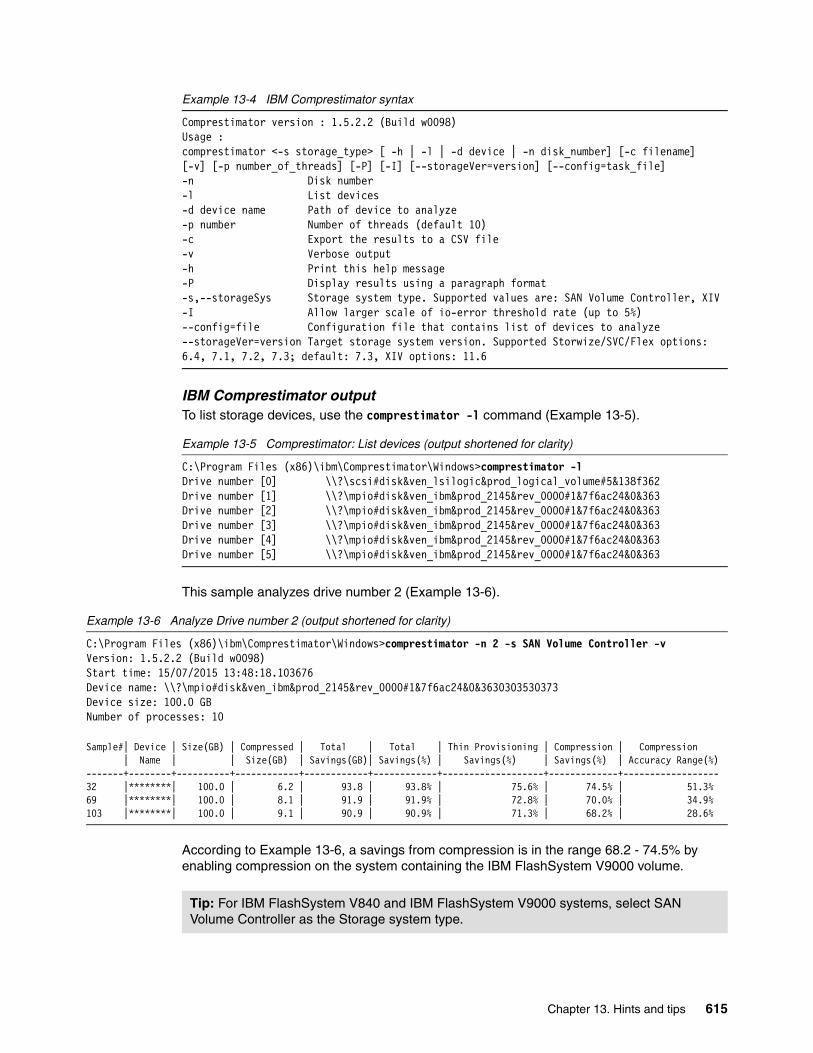
Example 13-4 IBM Comprestimator syntax
Comprestimator version : 1.5.2.2 (Build w0098)Usage :comprestimator <-s storage_type> [ -h | -l | -d device | -n disk_number] [-c filename] [-v] [-p number_of_threads] [-P] [-I] [--storageVer=version] [--config=task_file]-n Disk number-l List devices-d device name Path of device to analyze-p number Number of threads (default 10)-c Export the results to a CSV file-v Verbose output-h Print this help message-P Display results using a paragraph format-s,--storageSys Storage system type. Supported values are: SAN Volume Controller, XIV-I Allow larger scale of io-error threshold rate (up to 5%)--config=file Configuration file that contains list of devices to analyze--storageVer=version Target storage system version. Supported Storwize/SVC/Flex options: 6.4, 7.1, 7.2, 7.3; default: 7.3, XIV options: 11.6
IBM Comprestimator outputTo list storage devices, use the comprestimator -l command (Example 13-5).
Example 13-5 Comprestimator: List devices (output shortened for clarity)
C:\Program Files (x86)\ibm\Comprestimator\Windows>comprestimator -lDrive number [0] \\?\scsi#disk&ven_lsilogic&prod_logical_volume#5&138f362Drive number [1] \\?\mpio#disk&ven_ibm&prod_2145&rev_0000#1&7f6ac24&0&363Drive number [2] \\?\mpio#disk&ven_ibm&prod_2145&rev_0000#1&7f6ac24&0&363Drive number [3] \\?\mpio#disk&ven_ibm&prod_2145&rev_0000#1&7f6ac24&0&363Drive number [4] \\?\mpio#disk&ven_ibm&prod_2145&rev_0000#1&7f6ac24&0&363Drive number [5] \\?\mpio#disk&ven_ibm&prod_2145&rev_0000#1&7f6ac24&0&363
This sample analyzes drive number 2 (Example 13-6).
Example 13-6 Analyze Drive number 2 (output shortened for clarity)
C:\Program Files (x86)\ibm\Comprestimator\Windows>comprestimator -n 2 -s SAN Volume Controller -vVersion: 1.5.2.2 (Build w0098)Start time: 15/07/2015 13:48:18.103676Device name: \\?\mpio#disk&ven_ibm&prod_2145&rev_0000#1&7f6ac24&0&3630303530373Device size: 100.0 GBNumber of processes: 10
Sample#| Device | Size(GB) | Compressed | Total | Total | Thin Provisioning | Compression | Compression | Name | | Size(GB) | Savings(GB)| Savings(%) | Savings(%) | Savings(%) | Accuracy Range(%)-------+--------+----------+------------+------------+------------+-------------------+-------------+------------------32 |********| 100.0 | 6.2 | 93.8 | 93.8% | 75.6% | 74.5% | 51.3%69 |********| 100.0 | 8.1 | 91.9 | 91.9% | 72.8% | 70.0% | 34.9%103 |********| 100.0 | 9.1 | 90.9 | 90.9% | 71.3% | 68.2% | 28.6%
According to Example 13-6, a savings from compression is in the range 68.2 - 74.5% by enabling compression on the system containing the IBM FlashSystem V9000 volume.
Tip: For IBM FlashSystem V840 and IBM FlashSystem V9000 systems, select SAN Volume Controller as the Storage system type.
Chapter 13. Hints and tips 615

Explanation of compression outputTable 13-2 explains the output from the IBM Comprestimator.
Table 13-2 IBM Comprestimator output explanations
13.3 Command-line hints
IBM FlashSystem V9000 contains a robust command-line interface based on the IBM SAN Volume Controller and Storwize family of products. These command-line scripting techniques can be used to automate the following tasks:
� Running commands on the cluster� Creating connections� IBM command-line scripting� Example commands� Backing up the Configuration� Running the Software Upgrade Test Utility� Secure Erase of Data
Header Explanation
Sample# The number of the current sample reported.
Device The device name used in the scan.
Size (GB) The total size of the device as reported by the operating system, in gigabytes.
Compressed Size (GB) The estimated size of the device if it is compressed using IBM FlashSystem V9000 Real-time Compression, in gigabytes.
Total Savings (GB) The total estimated savings from thin-provisioning and compression, in gigabytes.
Total Savings (%) The estimated savings from thin-provisioning and compression, in percentage of the size of the device. This value is calculated in the following method: Total Savings (%) = 1 - ( Compressed Size (GB) / Size (GB) ).
Thin Provision Savings (%) The estimated savings from thin provisioning (areas with zeros are stored using minimal capacity).
Compression Savings (%) The estimated savings from compression.
Compression Accuracy Range (%) The accuracy of the estimate provided by Comprestimator. The results provided are estimated based on samples from the device, and therefore might be lower or higher than the actual compression that would be achieved. The approximate accuracy of the results is represented as a percentage of the total size of the device. For example, if the estimated Compression Savings (%) is 67%, and the Compression Accuracy Range is 5%, the actual compression savings (in percentage) if this device is compressed on IBM FlashSystem V9000 is 62% - 72%.
616 Introducing and Implementing IBM FlashSystem V9000

13.3.1 Running commands on the IBM FlashSystem V9000
To automate copy services processes, you must connect to the cluster. In normal operations, you connect to the cluster by using the GUI or command line. The GUI is not an appropriate interface for automating processes, so that alternative is not described here. All automation techniques are achieved through the IBM FlashSystem V9000 command line or the Common Information Model Object Manager (CIMOM), which currently acts as a proxy to the command line.
This section uses the term user agent. The user agent can be the CIMOM, which connects to the cluster by using Secure Shell (SSH). Or the user agent can be a user connecting directly with an SSH client, either in an interactive mode or by using a script.
Running commands to the cluster follows this sequence of steps:
1. Connection2. Authentication3. Submission4. Authorization5. Running a command (Execution)
ConnectionCommands are submitted to the cluster during a connection session to the cluster. User agents make connections through the SSH protocol. FlashSystem has several security features that affect how often you can attempt connections. These security features are in place to prevent attacks (malicious or accidental) that can bring down an IBM FlashSystem V9000 controller node. These features might initially seem restrictive, but they are relatively simple to work with to maintain a valid connection.
When creating automation by using the CLI, an important consideration is to be sure that scripts behave responsibly and do not attempt to breach the connection rules. At a minimum, an automation system must ensure that it can gracefully handle rejected connection attempts.
Chapter 13. Hints and tips 617

Figure 13-14 shows how IBM FlashSystem V9000 connection restrictions work.
Figure 13-14 IBM FlashSystem V9000 SSH restrictions
Figure 13-14 shows that two queues are in action: Pending Connections and Active Connections. The connection process follows this sequence:
1. A connection request comes into the IBM FlashSystem V9000. If the Pending Connections queue has a free position, the request is added to it otherwise, the connection is explicitly rejected.
2. Pending Connections are handled in one of two ways:
a. If any of the following conditions are true, the connection request is rejected:
• No key is provided, or the provided key is incorrect.• The provided user name is not admin or service.• The Active Connections queue is full. In this case, a warning is returned to the SSH
client as shown in Example 13-7 on page 619.
b. If none of the conditions listed in the previous step are true, the connection request is accepted and moved from the Pending Connections queue to the Active Connections queue.
3. Active Connections end after any of the following events:
– The user logs off manually.
– The SAN Volume Controller SSH daemon recognizes that the connection has grown idle.
– The network connectivity fails.
– The configuration node fails over.
In this case, both queues are cleared because the SHH daemon stops and restarts on a different node.
618 Introducing and Implementing IBM FlashSystem V9000

Example 13-7 shows an IBM FlashSystem V9000 command-line warning about too many logins. Only 10 concurrent active SSH sessions are allowed.
Example 13-7 IBM FlashSystem V9000 command-line warning about too many logins
$ ssh ITSOadmin@ITSO_V9000CMMVC7017E Login has failed because the maximum number of concurrent CLI sessions has been reached.
Connection to ITSO_V9000 closed.
If the limit of 10 concurrent active SSH sessions is reached, an entry is generated on the error log as shown in Figure 13-15.
Figure 13-15 GUI console warning the limit was reached
Double-click the status alert to see the event panel (Figure 13-16).
Figure 13-16 Error 2500: SSH Session limit reached
Chapter 13. Hints and tips 619

To view the details, right-click the error event and select Properties. The event details are displayed (Figure 13-17).
Figure 13-17 Event details
620 Introducing and Implementing IBM FlashSystem V9000

To fix this error, choose the Run Fix Procedure (described in “Directed maintenance procedure” on page 346, and shown in Figure 8-44 on page 347). A list with active SSH sessions is displayed (Figure 13-18). The quickest way to resolve the error is as follows:
1. Close all connections.
Selecting Close all SSH sessions through this fix procedure closes the listed sessions, and the error is fixed. If you close the active sessions manually on the host side without choosing to close all of the sessions through the Run Maintenance Procedures, you must select The number of SSH sessions has been reduced, mark this event as fixed.
2. Click Next to continue.
Figure 13-18 SSH Session limit reached
3. A warning that all CLI connections will be closed is displayed (Figure 13-19). Click Next to determine whether the process is completed.
Figure 13-19 Warning about closing all SSH connections
Chapter 13. Hints and tips 621

AuthenticationIBM FlashSystem V9000 enables you to log in with basically a user name and password. The two types of users who can access the system are local users and remote users. These types are based on how the users are authenticated to the system:
� Local users must provide a password, an SSH key, or both. Local users are authenticated through the authentication methods that are in the SAN Volume Controller system. If the local user needs access to the management GUI, a password is needed for the user. If the user requires access to the CLI through SSH, either a password or a valid SSH key file is necessary.
Local users must be part of a user group that is defined on the system. User groups define roles that authorize the users within that group to a specific set of operations on the system.
� Remote users are authenticated on a remote service with either Tivoli Integrated Portal or Lightweight Directory Access Protocol (LDAP v3) support, such as IBM Tivoli Storage Productivity Center, which delivers the functionality of IBM Spectrum Control, or IBM Security Directory Server. A remote user does not need local authentication methods.
With Tivoli Integrated Portal, both a password and SSH key are required to use the CLI. With LDAP, having a password and SSH key is not necessary, although SSH keys optionally can be configured. Remote users who need to access the system when the remote service is down also need to configure local credentials. Remote users have their groups defined by the remote authentication service.
See the following sections:
� For details about using the management GUI to manage users and user groups on the system, see 8.8.1, “Users” on page 400.
� To configure remote authentication with Tivoli Integrated Portal or Lightweight Directory Access Protocol, see 9.4.2, “Encryption” on page 438.
� For information about the auditing of commands on the IBM FlashSystem V9000 cluster, see 8.8.2, “Audit log” on page 404.
SubmissionWhen connected to a cluster, the user agent can start submitting commands. First, the syntax is checked. If the syntax checking fails, an appropriate error message is returned. Any automation implementation must ensure that all submitted commands have the correct syntax. If they do not, they must be designed to handle syntax errors. Designing a solution that does not generate invalid syntax is easier than designing a solution to handle all potential syntax errors.
AuthorizationNext, commands with valid syntax are checked to determine whether the user agent has the authority to submit the command. A role is associated with the key that was used to authenticate the connection. IBM FlashSystem V9000 checks the submitted command against the authorization role. If the user agent is authorized, the command is sent to be run.
If the user agent is not authorized to run this command, the following error is returned:
CMMVC6253E The task has failed because the user's role is not authorized to submit the command.
622 Introducing and Implementing IBM FlashSystem V9000

See the following resources:
� For information about authorization and roles, see 8.8.1, “Users” on page 400.
� For more details, see Implementing the IBM System Storage SAN Volume Controller with IBM Spectrum Virtualize V7.6, SG24-7933.
Running a commandWhen a command is run, it can fail (one possible scenario) or succeed (four possible scenarios):
� The command fails. An error message is written to STDERR.� The command succeeds. A warning is written to STDERR.� The command succeeds. A warning is written to STDERR; information is sent to STDOUT.� The command succeeds. Information is written to STDOUT.� The command succeeds. Nothing is written to STDOUT.
13.3.2 Creating connections
Connecting to the IBM FlashSystem V9000 cluster is the first step in running commands. Any automation solution requires a connection component. This component must be as robust as possible, because it forms the foundation of your solution.
There are two forms of connection solutions:
� Transient: One command is submitted per connection, and the connection is closed after the command is completed.
� Persistent: The connection is made and stays open. Multiple commands are submitted through this single connection, including interactive sessions and the CIMOM.
Transient connectionsTransient connections are simple to create. The most common SSH clients enable the user to submit a command as part of the user’s invocation. Example 13-8 shows a user submitting two commands as part of the user’s invocation using ssh on an AIX server. Using the operating system command, the IBM FlashSystem V9000 output can be processed.
Example 13-8 Transient connection to IBM FlashSystem V9000 from AIX Server
# ssh -i publickey -l ITSOadmin ITSO_V9000 lsenclosure -delim :id:status:type:managed:IO_group_id:IO_group_name:product_MTM:serial_number:total_canisters:online_canisters:total_PSUs:online_PSUs:drive_slots:total_fan_modules:online_fan_modules1:online:expansion:yes:0::9846-AE2:1371006:2:2:2:2:12:0:0
# ssh -i publickey -l ITSOadmin ITSO_V9000 lsenclosure -delim : | cut -f1,2,7,8 -d :id:status:product_MTM:serial_number1:online:9846-AE2:1371006#
Note: Data that is written to STDOUT and STDERR by the IBM FlashSystem V9000 is written to STDOUT and STDERR by your SSH client. However, you must manually verify that the data was written to STDOUT and STDERR by your SSH client.
Chapter 13. Hints and tips 623

Example 13-9 shows a user submitting a command as part of the user’s invocation using the plink command on a Windows server.
Example 13-9 Transient connection to IBM FlashSystem V9000 from Windows server
C:\Program Files\Putty>plink -i private.ppk -l superuser ITSO_V9000 lsenclosure -delim :id:status:type:managed:IO_group_id:IO_group_name:product_MTM:serial_number:total_canisters:online_canisters:total_PSUs:online_PSUs:drive_slots:total_fan_modules:online_fan_modules1:online:expansion:yes:0::9846-AE2:1371006:2:2:2:2:12:0:0
C:\Program Files\Putty>
These transient connections go through all five stages of running a command and return to the command line. You can redirect the two output streams (STDOUT and STDERR) using the operating system’s standard redirection operators to capture the responses.
These lengthy invocations can be shortened in client-specific ways. User configuration files can be used with the AIX SSH client. The configuration file in Example 13-10 enables you to create a transient connection.
Example 13-10 Sample SSH configuration file saved as sampleCfg
# cat sampleCfgHost ITSOHostName ITSO_V9000IdentityFile ./privateKeyUser ITSOadmin
Host ITSOsuHostName ITSO_V9000IdentityFile .ssh/id_rsaUser superuser
The Transient connection is shown in Example 13-11.
Example 13-11 Transient connection to IBM FlashSystem V9000 using SSH and configuration file
# ssh -F sampleCFG ITSOsu sainfo lsservicenodespanel_name cluster_id cluster_name node_id node_name relation node_status error_data75AM710 00000203202035F4 ITSO_V9000 1 BB1ACN1sn75AM710 local Active75AM730 00000203202035F4 ITSO_V9000 2 BB1ACN2sn75AM730 cluster Active01-2 00000203202035F4 ITSO_V9000 expansion Service 69001-1 00000203202035F4 ITSO_V9000 expansion Managed
624 Introducing and Implementing IBM FlashSystem V9000

Shortening the plink invocation requires the creation of a PuTTY session. First, open the PuTTY application and enter the following line in the Host Name (or IP address) field, as shown in Figure 13-20:
superuser@<Host Name or cluster IP address>
Figure 13-20 Add user name and system name to PuTTY session
Chapter 13. Hints and tips 625

Configure the private key for this session by making the selections, as shown in steps 1, 2, and 3 of Figure 13-21. click Browse (step 4) to locate the private key file.
Figure 13-21 Set private key for PuTTY SSH session
Complete saving the session (Figure 13-22) by returning to the Session Panel (1), providing a session name (2), and clicking Save (3).
Figure 13-22 Save PuTTY session for use with plink
4
1
2
3
3
2
1
626 Introducing and Implementing IBM FlashSystem V9000

After a session is saved, you can use it to make transient connections from the command line (Example 13-12).
Example 13-12 Transient connection to IBM FlashSystem V9000 using plink with PuTTY session
C:\Users\IBM_ADMIN>plink -load ITSOsu lsenclosurebatteryenclosure_id battery_id status charging_status recondition_needed percent_charged end_of_life_warning1 1 online idle no 97 no1 2 online idle no 91 no
C:\Users\IBM_ADMIN>
Persistent connectionsA persistent connection is a connection that exists beyond the submission and execution of a single command. As outlined previously, the CIMOM provides a persistent connection, but it does not provide direct access to the command line. To provide a persistent connection to the command line, you must use multiple processes.
There are as many ways to provide a persistent connection to the command line as there are programming languages. Most methods involve creating a process that connects to the cluster, writing to its STDIN stream, and reading from its STDOUT and STDERR streams.
You can use persistent connections in several ways:
� On a per-script basis
A script opens a connection that exists for the life of the script, enabling multiple commands to be submitted. The connection ends when the script ends.
� As a stand-alone script
A connection is opened and other scripts communicate with this script to submit commands to the cluster. This approach enables the connection to be shared by multiple scripts. This in turn enables a greater number of independent scripts to access the cluster without using up all of the connection slots.
For more information about transient and persistent connections, see IBM System Storage SAN Volume Controller and Storwize V7000 Replication Family Services, SG24-7574.
13.3.3 IBM FlashSystem V9000 command-line scripting
When connected to the cluster command line, you can use small amounts of automation for various purposes, including for the following tasks:
� Repeatedly submitting a single command to a set of IBM FlashSystem V9000 objects� Searching the configuration for objects conforming to certain criteria
The IBM FlashSystem V9000 command line is a highly restricted Bash shell. You cannot access UNIX commands, such as cd or ls. The only commands that are available are built-in commands, such as echo or read. In addition, redirecting inputs and outputs is not supported, but you can pipe commands together.
Note: IBM FlashSystem V9000 uses IBM Spectrum Virtualize technology, built on the foundation of the SAN Volume Controller. The command lines function in the same secure way, which enables you to use existing scripting for automation and especially replication.
Chapter 13. Hints and tips 627

Example 13-13 shows a script that lists all volumes that are not online. This script complements the filtervalue parameter of the lsvdisk command. The filtervalue parameter provides matches only when a property matches a value. The command-line script in Example 13-13 provides matches according to other criteria.
Example 13-13 IBM FlashSystem V9000 command-line script listing volumes that are not online
001. lsvdisk -nohdr | while read id name IOGid IOGname status rest002. do003. if [ "$status" != "online" ]004. then005. echo "Volume '$name' \($id\) is $status"006. fi007. done
Line 001 submits the lsvdisk command and pipes the output to the read command, which is combined with a while command. This combination creates a loop that runs once per line of output from the lsvdisk command.
The read command is followed by a list of variables. A line is read from the lsvdisk command. The first word in that line is assigned to the first variable. The second word is assigned to the second variable, and so on, with any remaining words assigned to the final variable (with intervening spaces included).
In this case, the -nohdr parameter is used to suppress display of the headings.
Lines 003 - 006 check the status variable. If it is not equal to online, the information is printed to STDOUT.
Submitting command-line scriptsYou can submit command-line scripts from an interactive prompt, if required. However, you can also submit the scripts as batch files. Example 13-14 shows how to submit scripts as batch files with ssh.
Example 13-14 Submission of batch file to IBM FlashSystem V9000 using SSH
ssh superuser@ITSO_V9000 -T < batchfile.shHost and WWPN info:
Host 0 (TA_Win2012) : WWPN is =10000000C9B83684Host 0 (TA_Win2012) : WWPN is =10000000C9B83685
Note: The message vdisks offline is an error condition. In normal operations, you do not find any that are not online.
628 Introducing and Implementing IBM FlashSystem V9000

Example 13-15 shows how to submit scripts as batch files with plink.
Example 13-15 Submission of batch file to IBM FlashSystem V9000 using plink
C:\>plink -load ITSOadmin -m batchfile.sh
Host and WWPN info:
Host 0 (RedHat) : WWPN is =2100000E1E302C73Host 0 (RedHat) : WWPN is =2100000E1E302C72Host 0 (RedHat) : WWPN is =2100000E1E302C51Host 0 (RedHat) : WWPN is =2100000E1E302C50Host 1 (AIX) : WWPN is =10000090FA13B915Host 1 (AIX) : WWPN is =10000090FA13B914Host 1 (AIX) : WWPN is =10000090FA0E5B95Host 1 (AIX) : WWPN is =10000090FA0E5B94Host 1 (AIX) : WWPN is =10000090FA02F630Host 1 (AIX) : WWPN is =10000090FA02F62FHost 1 (AIX) : WWPN is =10000090FA02F621Host 1 (AIX) : WWPN is =10000090FA02F620Host 2(TA_Win2012) : WWPN is =10000000C9B83684Host 2(TA_Win2012) : WWPN is =10000000C9B83685
Both commands submit a simple batch file, as shown in Example 13-16. This command lists the WWPN for each host defined in the IBM FlashSystem V9000 ()Example 13-15.
Example 13-16 Command-line batch file (batchfile.sh) used in the previous examples
echo "Host and WWPN info:"echo " "lshost -nohdr | while read name product_name WWPNdo lshost $name| while read key value do
if [ "$key" == "WWPN" ] then
echo "Host $name ($product_name) : WWPN is =$value" fi
donedone
Server-side scriptingServer-side scripting involves scripting where the majority of the programming logic is run on a server.
Part of server-side scripting is the generation and management of connections to the IBM FlashSystem V9000 system. For an introduction of how to create and manage a persistent connection to a system and how to manage requests coming from multiple scripts, see “Persistent connections” on page 627.
The Perl module handles the connection aspect of any script. Because connection management is often the most complex part of any script, an advisable task is to investigate this module. Currently, this module uses transient connections to submit commands to a cluster, and it might not be the best approach if you plan to use multiple scripts submitting commands independently.
Chapter 13. Hints and tips 629

13.3.4 Sample commands of mirrored VDisks
This section contains sample commands that use the techniques demonstrated in 13.3.3, “IBM FlashSystem V9000 command-line scripting” on page 627. These examples are based on a single building block configuration with sample data designed to support this publication.
VDisk mirroring to a second enclosureThis example shows how to mirror all VDisks for redundancy or how to vacate a storage enclosure.
The sync rateExample 13-17 shows mirroring the VDisks to a new managed disk group. In this example, sync rate is low so that it does not adversely affect the load on the system. You can check the progress of synchronization with lsvdisksyncprogress command.
Example 13-17 Mirror all VDisks
lsvdisk -filtervalue copy_count=1 -nohdr |while read id vdiskname restdo
addvdiskcopy -mdiskgrp newgroupname -syncrate 30 $iddoneVdisk [0] copy [1] successfully createdVdisk [1] copy [1] successfully createdVdisk [2] copy [1] successfully createdVdisk [3] copy [1] successfully createdVdisk [4] copy [1] successfully createdVdisk [5] copy [1] successfully created
Raise the sync rateRaise the sync rate to 80 for all the VDisks currently not synchronized (Example 13-18).
Example 13-18 Raise syncrate to 80
lsvdiskcopy -filtervalue sync=no -nohdr | while read id vdisk copyid restdo
echo “Processing $vdisk”chvdisk -syncrate 80 $vdisk
done
Tip: Start with small examples to understand the behavior of the commands.
Tip: Remember, raising the sync rate causes more I/O to be transferred, which can be an issue for a standard disk array.
630 Introducing and Implementing IBM FlashSystem V9000

Change primary in use to the new MDisk groupIn Example 13-19, the primary is changed to the copy that was created in Example 13-17 on page 630.
Example 13-19 Change VDisk mirror primary to copy in newgroupname
lsvdiskcopy -filtervalue mdisk_grp_name=newgroupname -nohdr | while read id vdisk copyid restdo
echo Processing $vdiskchvdisk -primary $copyid $vdisk
done
Remove all the copies not primaryExample 13-20 removes all VDisk copies in the previous MDisk group.
Example 13-20 Remove VDisk copies
lsvdiskcopy -filtervalue mdisk_grp_name=prevmdiskgroup -nohdr |while read id vdisk copyid restdo
echo “Processing rmvdiskcopy -copy $copyid $vdisk”rmvdiskcopy -copy $copyid $vdisk
done
Create compressed mirrored copies of VDisks not currently mirroredExample 13-21 looks for all VDisks that have a single copy and creates a mirrored compressed copy.
Example 13-21 Create compressed VDisk mirrors
lsvdisk -filtervalue copy_count=1 -nohdr |while read id vdiskname restdo
addvdiskcopy -mdiskgrp BB1mdiskgrp0 -autoexpand -rsize 50% -syncrate 30 -compressed $id
doneVdisk [0] copy [1] successfully createdVdisk [1] copy [1] successfully createdVdisk [2] copy [1] successfully createdVdisk [3] copy [1] successfully createdVdisk [4] copy [1] successfully createdVdisk [5] copy [1] successfully created
Tip: Remember, all of these volumes must be in a sync state, as shown by the lsvdisk command output.
Tip: Use extreme care when removing a storage enclosure from service. For example, in the case of IBM FlashSystem V9000, the AE2 enclosure should be unmanaged. The V840 equivalent state is to remove all the mdisk instances from prevmdiskgroup; these MDisks become unmanaged.
Chapter 13. Hints and tips 631

Turn on autoexpand for all offline volumesDuring testing, an out-of-space condition was encountered with multiple mirrored copies. The condition is the result of the autoexpand option not being used when the volumes were mirrored. See Example 13-22.
Example 13-22 Activate autoexpand for all offline VDisk copies
lsvdiskcopy -filtervalue status=offline -nohdr | while read vid name copyid restdo
chvdisk -autoexpand on -copy $copyid $viddone
SummaryThis section presented simple scripts that can be used to automate tasks using the IBM FlashSystem V9000 command-line interface. These concepts can be applied to other commands including backup process, such as creating flash copies of volumes.
13.3.5 Recover lost superuser password
Use the following steps to reset the IBM FlashSystem V9000 superuser password to the factory default value:
1. Locate a blank USB stick and write a file named satask.txt into the root directory of the first partition of the USB stick. The file should contain the single satask resetpassword command.
2. Plug the USB stick into a free USB port on an active AC2 or AC3 control enclosure.
3. Wait for the identification blue led to turn on then off.
4. Unplug the USB stick. The command output is written to the USB key in a file named satask_result.html. This is successful if no errors are returned (Figure 13-23).
Figure 13-23 Command output in satask_result.html on USB key
Tip: From the CLI, issue the help addvdiskcopy command or look in IBM Knowledge Center for details of parameters for this command. All options that are available in the GUI can be issued from the CLI, which helps you more easily work with large numbers of volumes.
632 Introducing and Implementing IBM FlashSystem V9000

5. Log in to the GUI by using superuser and passw0rd, the default password. A prompt guides you to change the default password.
13.3.6 Internal Fibre Channel switch maintenance
Most scalable building block configurations are purchased with IBM System Storage SAN48B-5 (2498-F48) switches that are used for storage controller cluster and AE2 expansion storage connections. These switches are private or internal to the product and are not attached to the customer SAN. These switches use open zoning and are initialized during installation as an IBM lab based services task.
After installation, maintenance of the internal switches is a customer responsibility.
Microcode updatesFix central for the 2498-F48 switch directs you to the following website:
https://ibm.brocadeassist.com/public/FabricOSv7xRelease
From there you can download a current level of microcode and the documentation to help you perform the update.
Example 13-23 shows how to check the firmware level from the switch CLI.
Example 13-23 Checking the firmware level with firmwareshow
IBM_2498_F48:FID128:admin> firmwareshowAppl Primary/Secondary Versions------------------------------------------FOS v7.4.1c v7.4.1cIBM_2498_F48:FID128:admin>
Troubleshooting and monitoringThe CLI and GUI have troubleshooting and monitoring capabilities.
Health monitorThe Monitoring and Alerting Policy Suite (MAPS) is a health monitor supported with Fabric OS 7.2.0 or later. The mapsdb --show command shows you the health of the switch.
Example 13-24 CLI command to view the health of the switch
IBM_2498_F48:FID128:admin> mapsdb --show
1 Dashboard Information:=======================
DB start time: Thu Jun 23 22:34:59 2016Active policy: dflt_conservative_policyConfigured Notifications: NoneFenced Ports : None
Tip: The satask_result.html file also contains a report of the system status with several lines of output. The same system status can be obtained at any time by inserting a blank USB key into a AC2 or AC3 control enclosure.
Chapter 13. Hints and tips 633

Decommissioned Ports : NoneQuarantined Ports : None
2 Switch Health Report:=======================
Current Switch Policy Status: HEALTHY
3.1 Summary Report:===================
Category |Today |Last 7 days |--------------------------------------------------------------------------------Port Health |No Errors |Out of operating range |BE Port Health |No Errors |No Errors |Fru Health |In operating range |In operating range |Security Violations |No Errors |No Errors |Fabric State Changes |No Errors |No Errors |Switch Resource |In operating range |In operating range |Traffic Performance |In operating range |In operating range |FCIP Health |Not applicable |Not applicable |Fabric Performance Impact|In operating range |In operating range |
Troubleshooting port errorsIf you suspect or want to check for port errors, you can use the porterrshow command. It can be helpful to clear the counters during a workload and to check the command after a few minutes to determine if any ports are seeing increasing errors. To clear the counters for all ports on the switch use the portstatsclear -i 0-47 command.
Example 13-25 shows the porterrshow 8-16 command to view error counters for ports 8-16.
Example 13-25 CLI command to view port error counters
IBM_2498_F48:FID128:admin> porterrshow 8-16 frames enc crc crc too too bad enc disc link loss loss frjt fbsy c3timeout pcs tx rx in err g_eof shrt long eof out c3 fail sync sig tx rx err 8: 39.4m 39.1m 0 0 0 0 0 0 0 0 0 0 0 0 0 0 0 0 9: 13.0k 12.4k 0 0 0 0 0 0 0 0 0 0 0 0 0 0 0 0 10: 39.5m 39.2m 0 0 0 0 0 0 0 0 0 0 0 0 0 0 0 0 11: 13.0k 12.4k 0 0 0 0 0 0 0 0 0 0 0 0 0 0 0 0 12: 39.3m 40.1m 0 0 0 0 0 0 0 0 0 0 0 0 0 0 0 0 13: 1.3k 781 0 0 0 0 0 0 0 0 0 0 0 0 0 0 0 0 14: 39.6m 39.8m 0 0 0 0 0 0 0 0 0 0 0 0 0 0 0 0 15: 13.0k 12.4k 0 0 0 0 0 0 0 0 0 0 0 0 0 0 0 0 16: 39.4m 39.6m 0 0 0 0 0 0 0 0 0 0 0 0 0 0 0 0
634 Introducing and Implementing IBM FlashSystem V9000

Viewing port performanceUse the portperfshow command to view the throughput per port on the switch. This can be useful to ensure that the load is balanced across the ports.
Example 13-26 shows restricting of the ports monitor to 8 - 16 and setting the refresh duration to 5 seconds with the portperfshow 8-16 -t 5 command.
Example 13-26 CLI command to view port performance
IBM_2498_F48:FID128:admin> portperfshow 8-16 -t 5 8 9 10 11 12 13 14 15 16 Total========================================================================= 217.6k 0 281.5k 0 259.5k 0 248.0k 0 344.9k 1.3m 8 9 10 11 12 13 14 15 16 Total========================================================================= 180.0k 0 229.0k 0 211.4k 0 244.0k 0 209.4k 1.0m 8 9 10 11 12 13 14 15 16 Total
Figure 13-24 shows how to view the port performance using the GUI capabilities of the internal switch.
Figure 13-24 Internal switch Performance Monitor
Chapter 13. Hints and tips 635

13.3.7 Backup IBM FlashSystem V9000 configuration
Before making major changes to the IBM FlashSystem V9000 configuration be sure to save the configuration of the system. By saving the current configuration, you create a backup of the licenses that are installed on the system. This can assist you in restoring the system configuration. You can save the configuration by using the svcconfig backup command.
The next two steps show how to create a backup of the configuration file and to copy the file to another system:
1. Log in to the cluster IP using an SSH client and back up the FlashSystem configuration:
superuser> svcconfig backup...............................................................CMMVC6155I SVCCONFIG processing completed successfully
2. Copy the configuration backup file from the system. Using secure copy, copy the following file from the system and store it:
/tmp/svc.config.backup.xml
For example, use pscp.exe, which is part of the PuTTY commands family:
pscp.exe superuser@<cluster_ip>:/tmp/svc.config.backup.xml .superuser@ycluster_ip> password:svc.config.backup.xml | 163 kB | 163.1 kB/s | ETA: 00:00:00 | 100%
The use of the CLI is described in 13.3, “Command-line hints” on page 616.
13.3.8 Using the IBM FlashSystem V9000 Software Upgrade Test Utility
In preparation for upgrading firmware on an IBM FlashSystem V9000, be sure to run the Software Upgrade Test Utility before any upgrade. This step ensures that your system configuration is supported and identifies any potential issue during your upgrade change window.
Overview of Software Upgrade Test UtilityYou can download this small utility from IBM Fix Central (see 13.5.5, “Downloading from IBM Fix Central” on page 651).
The utility is run on the IBM FlashSystem V9000 before a firmware upgrade. The purpose of the utility is to check for known issues and system configurations that might present a problem for the upgrade and warn you of conditions that might need to be corrected before running the upgrade. It can be run as many times as needed. The utility is run automatically as part of the GUI upgrade process, or stand-alone, to assess the readiness of a system for upgrade as part of the upgrade planning process.
In releases before 7.6, the Software Upgrade Test Utility is run automatically before upgrading. Later releases provide the capability to run the utility from the GUI stand-alone, as referenced in 9.5.3, “Update software” on page 455. This section is provided to document past releases where this capability was not possible. In earlier IBM Spectrum Virtualize firmware releases, it was optional, but strongly suggested.
Tip: This process saves only the configuration of the system. User data must be backed up by using normal system backup processes.
636 Introducing and Implementing IBM FlashSystem V9000

When an upgrade is initiated using the IBM FlashSystem web management GUI, you are prompted to download the utility and firmware from Fix Central. Most users prefer to do this in advance of the upgrade and select the files as shown in Figure 13-25 during the upgrade process. If you click Update, the utility runs. If successful, the firmware upgrade process runs.
Figure 13-25 Update System
A preferred practice is for firmware upgrades to be initiated using the GUI so that the Software Upgrade Test Utility is uploaded and run during the upgrade process. The upgrade process is stopped if any issue is identified. If that happens, examine the output of the utility before proceeding. If the utility provides any warnings, correct them before continuing the upgrade.
Upgrades can also be run by using the applysoftware command using the CLI.
Using the IBM FlashSystem V9000 Software Upgrade Test Utility from the command lineThe installation and use of this utility is nondisruptive and does not require any node to be restarted, so there is no interruption to host I/O. The utility will be installed only on the current configuration node. To install and run the utility, complete the following steps:
1. Copy the utility to the /upgrade directory on the IBM FlashSystem V9000 using a secure copy utility such as Secure Copy Protocol (SCP) or pscp.exe:
pcsp <test_utility_filename> superuser@<cluster_ip_address>:/upgrade
2. Install the utility:
applysoftware -file <test_utility_filename>
3. Run the test utility:
svcupgradetest -v 7.7.1.3
The output is displayed (Example 13-27 on page 638).
Tip: During the IBM FlashSystem V9000 GUI upgrade process, the upgrade proceeds immediately after the Software Upgrade Test Utility completes successfully.
Tip: Always ensure that the upgrade package for the IBM FlashSystem V9000 is the correct package as indicated by the IBM9846 prefix on the file name.
Chapter 13. Hints and tips 637

Example 13-27 Output from test utility
svcupgradetest version 20.10
Please wait, the test may take several minutes to complete.
******************* Warning found *******************
The audit log of the system was cleared to prepare for the upgrade.The old audit log can be found in /dumps/audit/ on this node.
Results of running svcupgradetest:==================================
The tool has found 0 errors and 1 warnings.
4. You can rerun the utility (step 3 on page 637) after it is installed. Installing it again is unnecessary. Installing a new version overwrites the old version.
13.3.9 Secure erase of data
Some clients, especially in the healthcare sector, are concerned about data confidentiality. IBM FlashSystem V9000 uses encryption to secure data. If you have a license for IBM FlashSystem V9000 encryption, you can prevent unauthorized access to IBM FlashSystem data.
Secure erase of IBM FlashSystem V9000 MicroLatency modules
Flash modules can be securely decommissioned by using the chdrive -task erase command. IBM has certified this erasure process; contact your IBM representative or IBM Business Partner for documentation regarding this process.
Tip: There will be a massage ******************* Warning found ******************* in the output for each warning detected.
Important: Deleting IBM FlashSystem V9000 encryption key prevents any access to the data on IBM FlashSystem V9000 when the encryption feature is enabled.
638 Introducing and Implementing IBM FlashSystem V9000

Example erasure procedureThese steps can be used to decommission and entire IBM FlashSystem V9000 enclosure.
Complete these steps:
1. Start with confirming the enclosure ID to be erased using the IBM FlashSystem V9000 GUI. Select Pools → MDisks by Pool (Figure 13-26).
Figure 13-26 Select MDisks by Pools
2. Right-click an MDisk and select Drives (Figure 13-27).
Figure 13-27 Select Drives
Attention: This procedure is designed to securely destroy data. There is no recovery, so be careful to identify the correct enclosure.
Chapter 13. Hints and tips 639

3. In the Member Drives panel, note that the Enclosure ID to be erased is enclosure 1 (Figure 13-28).
Figure 13-28 Identify the enclosure
4. Right-click the managed disk (mdisk1) and select Delete (Figure 13-29).
Figure 13-29 Delete the mdisk from the pool
)
5. The drives that made up the MDisk are now in candidate state (1) for Enclosure ID 1 (2) shown in Figure 13-30.
Figure 13-30 Drives in Candidate state for Enclosure ID 1
Tip: The pool in this example does not have any VDisks allocated. If VDisks are present, there would have to be other managed disks in the pool with enough free space to hold the VDisks. The operation is not allowed without adequate space.
640 Introducing and Implementing IBM FlashSystem V9000

6. This series of commands (Figure 13-31) securely erases the drives for Enclosure ID 1. The loop (highlighted by number 1) filters just enclosure iD 1. The lsdrive command (2) shows the drive status as offline while the erase process occurs.
Figure 13-31 Secure erase of the drives in Enclosure ID 1
7. Confirm that the erase operation is complete by verifying that the drives are online (Figure 13-32).
Figure 13-32 Drives have returned to online status
Chapter 13. Hints and tips 641

8. Return to the GUI and use the system panel to complete removing the storage enclosure. Confirm that you are working with the correct enclosure by hovering over the device as shown in Figure 13-33.
Figure 13-33 Confirm the correct enclosure
9. Complete the removal of the storage enclosure as shown in Figure 13-34:
a. Select the enclosure (1).b. Right-click over the exploded view (2).c. Select Remove Expansion Enclosure (3).
Figure 13-34 Complete removal of storage enclosure
TIP: If the GUI does not show the menu to remove the expansion enclosure, refresh your browser by re-logging into the system.
642 Introducing and Implementing IBM FlashSystem V9000

10.The storage enclosure is now removed from the system. The wizard (Figure 13-35) will lead you through deinstalling the storage enclosure.
Figure 13-35 Remove storage enclosure
Erasing flash drives is not a normal operation. By using the encryption features of the IBM FlashSystem V9000, the erasure can be avoided because the data cannot be read, even on a failed flash module. This hint was provided for customers that require an extra layer of security and certification.
13.4 Call home process
IBM encourages all clients to take advantage of the following settings to enable you and IBM to partner for your success. With the call home feature enabled, your system is effectively monitored 24 x 7 x 365. As an IBM client you can enjoy faster response times, faster problem determination and effectively reduced risk over an unmonitored system. In the future, IBM plans to use inventory report data to directly notify clients who are affected by known configuration or code issues.
While enabling call home reporting, IBM encourages clients to also enable inventory reporting in order to take advantage of this future offering. For a more detailed explanation, followed by steps to configure, see 9.2.1, “Email and call home” on page 407. The configuration setup is a simple process and takes several minutes to complete.
13.4.1 Call home details
The call home function opens a service alert if a serious error occurs on the system, automatically sending details of the error and contact information to IBM Service personnel. If the system is entitled for support, a problem management record (PMR) is automatically created and assigned to the appropriate IBM Service personnel.
The information provided to IBM in this case might be an excerpt from the Event Log containing the details of the error and client contact information from the system. This enables IBM Service personnel to contact you and arrange service on the system, which can greatly improve the speed of resolution by removing the need for you to detect the error and raise a support call.
Tip: The Secure Erase process is currently available for only the IBM FlashSystem V9000 AE2 storage enclosure. In version 7.7.x.x, adding and removing the storage enclosure is automated in the GUI.
Chapter 13. Hints and tips 643

13.4.2 Email alert
Automatic email alerts can be generated and sent to an appropriate client system administrator or distribution list. This is effectively the same as call home but you can be additionally notified about error, warning, information messages when they occur, and also you can receive inventory emails (see 13.4.3, “Inventory” on page 644).
You can view IBM Knowledge Center documentation for your specific IBM FlashSystem V9000 product to determine whether a particular event is classified as error, warning, or informational. Look for the Notification type for each error to determine which you want to be notified for. Because you can customize this, based on the individual, maximum flexibility exists.
13.4.3 Inventory
Rather than reporting a problem, an email is sent to IBM that describes your system hardware and critical configuration information. Object names and other potentially sensitive information, such as IP addresses, are not sent.
IBM suggests that the system inventory be sent on a one-day or seven-day interval for maximum benefit.
13.5 Service support
Understanding how support issues are logged is important information. This section describes support for the IBM FlashSystem V9000, including the IBM Technical Advisor role, Enterprise Class Support, support entitlement, registering components in the Service Request Tool, and calling IBM for support.
13.5.1 IBM Storage Technical Advisor
The IBM Storage Technical Advisor (TA) enhances end-to-end support for complex IT solutions. Each IBM FlashSystem V9000 includes an IBM TA for the initial hardware warranty period. This section describes the IBM TA program in general with specifics on how customers can work with their TA.
The TA service is built around three value propositions:
� Proactive approach to ensure high availability for vital IT services � Client Advocate that manages problem resolution through the entire support process� A trusted consultant for both storage hardware and software
Technical Advisors benefit customers by providing a consultant for questions on the IBM FlashSystem V9000. Most customers meet their TA during a Technical Delivery Assessment (Solution Assurance Meeting) before the initial installation. After this initial meeting, the TA is the focal point for support related activities as follows:
� Maintains a support plan that is specific to each client. This support plan contains an inventory of equipment including customer numbers and serial numbers.
� Coordinates service activities, working with your support team in the background. Monitors progress of open service requests, escalation, expert consultation on problem avoidance.
644 Introducing and Implementing IBM FlashSystem V9000

� Communicates issues with customers, IBM Business Partners, and IBM Sales teams.
� Periodically reviews and provides reports of hardware inventories and service requests. This includes using call home information to provide customer reports on the state of the customer systems.
� Oversight of IBM support activities helps companies anticipate and respond to new problems and challenges faster.
� Proactive planning, advice, and guidance to improve availability and reliability.
The IBM Storage Technical Advisor is an effective way to improve total cost of ownership and free up customer resources. Customers have options to extend the Technical Advisor service beyond the initial hardware warranty using IBM Technical Support Services (TSS) offerings.
Contact your IBM Sales Team or IBM Business Partner for details.
13.5.2 Enterprise Class Support
IBM Enterprise Class Support (ECS) delivers improved response times, hardware and software installation assistance, onsite code upgrades and service coordination across IBM. This enhanced support is available to IBM FlashSystem V9000 customers with the 3-year warranty machine type 9848. This service extends the Technical Advisor service described in 13.5.1, “IBM Storage Technical Advisor” on page 644.
During the Enterprise Class Support warranty period you receive these items:
� Priority Access
IBM Direct Access Code (DAC) allows you to call IBM and access a specialized team that serves as the initial point of contact for any issues that arise.
� Priority Response
IBM helps you get to the root of issues faster. A support team, available 24 x 7, returns your call within 30 minutes of receiving the issue notification.
� Software updates
IBM will coordinate and complete up to six software updates over the warranty period (requires applicable Software Maintenance Agreement, SWMA). This provides you the option of having an IBM System Support Representative (SSR) perform upgrades. Customers were responsible for this task in the past.
� Services coordination
Each customer is assigned an Account Advocate in addition to the Technical Advisor. These technical experts coordinate service activities working closely with the customer and IBM SSR throughout the 3 year warranty period.
IBM Enterprise Support is an evolving service designed to assist you with the support of your storage products. IBM FlashSystem V9000 with release 7.8 includes the optional capability for remote support. As with call home, by choosing to enable this capability, you can benefit from Enterprise Class Support as features are developed to enhance the support received.
Chapter 13. Hints and tips 645

13.5.3 How an IBM FlashSystem V9000 is entitled for support
IBM FlashSystem V9000 systems consist of various hardware and software components, each carrying their own unique requirements for proper entitlement. IBM FlashSystem V9000 systems consist of at least three unique hardware machine types (models) for each building block. Each building block carries its own serial number. Warranty and maintenance entitled software, requires customer ID, product description, and storage enclosure serial number to properly entitle it.
Calling IBM Support Consider this information when you call for support:
� For problems known to be hardware-related, place calls against the affected 9846 or 9848-AC2 or AE2 machine type and serial number. Using the correct machine type, model, and serial number avoids service delays.
� For software problems, navigate through the Automated Voice Response for Software and provide customer ID, product description, and 9846 or 9848-AE2 storage enclosure, plus serial number.
� If you are unsure whether the issue is hardware or software, call in for Storage Support (option 3 is US only). Provide customer ID, product description and 9846 or 9848-AE2 storage enclosure.
Scenario 1: Host connectivity issueThe customer is experiencing difficulty with attaching a host to the IBM FlashSystem V9000 AC2 control enclosures. The customer opens a Software issue (bullet item 2 in “Calling IBM Support” on page 646) against the IBM FlashSystem V9000 AE2 storage enclosure. The customer describes that the issue is the host attachment to the controller enclosure.
Scenario 2: PerformanceThe customer reports that performance of the IBM FlashSystem V9000 solution is not meeting expectations. The customer opens a Storage Support issue (bullet item 3 in “Calling IBM Support” on page 646) against the IBM FlashSystem V9000 AE2 storage enclosure. The customer can save time by uploading snaps from both controller AC2 and storage enclosure AE2 after the PMR number is obtained.
Scenario 3: Hardware issueThe customer reports that email alerts indicate a failed hard disk in the AC2 control enclosure. The customer opens a hardware issue (bullet item 1 in “Calling IBM Support” on page 646) against the IBM FlashSystem V9000 AC2 controller serial number reporting the error. This is processed as a standard hardware failure.
Tip: Customer ID and customer number are the same. The customer number is included in the customer support plan you receive from your Technical Advisor.
Note: Most hardware support tickets are opened by call home events. However, if there are effects because of component failure, you can open an appropriate severity support ticket independently.
646 Introducing and Implementing IBM FlashSystem V9000

13.5.4 Providing logs to IBM ECuRep
IBM Enhanced Customer Data Repository (ECuRep) is a secure and fully supported data repository with problem determination tools and functions. It updates problem management records (PMR) and maintains full data lifecycle management.
This server-based solution is used to exchange data between IBM customers and IBM Technical Support. Do not place files on or download files from this server without prior authorization from an IBM representative. The representative is able to provide further instructions as needed.
To use ECuRep, you need a documented problem management record (PMR) number either provided by the IBM support team with a call home, or issued by using the IBM Service Request tool on the IBM support portal:
http://www.ibm.com/support
IBM provides the service request (SR) problem submission tool (the link is highlighted in Figure 13-36) to electronically submit and manage service requests on the web. This tool replaces the Electronic Service Request (ESR) tool.
Figure 13-36 Service request link on Support Portal
Chapter 13. Hints and tips 647

To provide logs to IBM ECuRep, complete the following steps:
1. Go to the Enhanced Customer Data Repository (ECuRep) web page (Figure 13-37):
https://www.secure.ecurep.ibm.com/app/upload
This web page provides information about the repository, instructions for preparing files for upload, and multiple alternatives for sending data. For details, you can click Help.
Figure 13-37 Select Help for detailed upload options
Tip: This system is connected to the IBM Problem Management Record. Support tickets are automatically updated, with the files uploaded and queued for an IBM support representative response.
648 Introducing and Implementing IBM FlashSystem V9000

2. IBM provides multiple options for uploading data. Review the options for sending data before you complete the PMR number. The following options are shown in Figure 13-38:
– Notice in this description that the Send Data tab is selected.
– As a way to upload a file you can select either FTP (1) or the Java utility (2). The Java utility is the most efficient method to upload file.
– Select Prepare data tab (3) to see the details about file name conventions.
– The HTTPS (4) option eliminates the file naming requirement.
Figure 13-38 Options for sending data
3
1 2
4
Chapter 13. Hints and tips 649

3. Standard upload (Figure 13-39) is the default upload selection. Complete these fields and then click Continue:
– PMR: Using the PMR number on this form accurately logs the files uploaded to the correct PMR.
– Upload is for: Select Hardware for the IBM FlashSystem V9000.
– Email address: (Optional) Provide your email address for a confirmation.
Figure 13-39 Using the HTTP option
650 Introducing and Implementing IBM FlashSystem V9000

4. The file selection panel opens (Figure 13-40). Select files and click Upload.
Figure 13-40 File Selection dialog
13.5.5 Downloading from IBM Fix Central
Fix Central provides fixes and updates for your system’s software, hardware, and operating system. Go to the IBM Fix Central web page:
http://www.ibm.com/support/fixcentral
If you are not looking for fixes or updates, go to IBM Passport Advantage® to download most purchased software products, or My Entitled Systems Support to download system software.
Tip: Most clients find this way the most effective method to upload logs. IBM suggests understanding the best method for your organization in advance and documenting the process to save precious time during a crisis.
Chapter 13. Hints and tips 651

The following sections describe downloading code from IBM.
Using an IBMidTo use the IBM Fix Central website, you must have an IBMid. Your IBMid provides access to IBM applications, services, communities, support, online purchasing, and more. Additionally, your information is centralized so you can maintain it in a convenient and secure location. The benefits of having an IBMid will increase over time as more applications migrate to IBMid.
The login window is shown in Figure 13-41.
Figure 13-41 IBM id login window
Fix CentralThe following steps document the current process for obtaining updates for your IBM FlashSystem V9000. This site is frequently updated based on customer feedback and as IBM documents field experience. It is a good practice to review the support information on this site on a regular basis.
1. After signing in with your IBMid, a page opens to the Support Portal (Figure 13-42). In the Product finder field, start typing FlashSystem (1). Select IBM FlashSystem V9000 from the list (2). The IBM FlashSystem V9000 specific information is displayed.
Figure 13-42 Support Portal
1
2
652 Introducing and Implementing IBM FlashSystem V9000

2. The product page provides capabilities to download product updates and review other product documentation. In Figure 13-43 new product firmware is displayed by selecting Downloads (drivers, firmware, PTFs).
Figure 13-43 Download updates for IBM FlashSystem V9000
3. The Select fixes panel (Figure 13-44) provides a selection of release families. IBM FlashSystem V9000 Release 7.7 and later is required for IBM FlashSystem V9000 System using 9846/9848 model AC3 control enclosure and 12F, 24F expansion enclosures. IBM model 92F requires version 7.8.
Figure 13-44 Select the Firmware Release family
4. The license agreement is presented. At this time entitlement is confirmed through the acceptance of this agreement shown in Figure 13-45 on page 654.
Chapter 13. Hints and tips 653

Figure 13-45 Support Portal agreement example
5. Read the release notes in Figure 13-46 to determine the best fix pack for your environment, Select the fix pack (1) and click Download now (2) to initiate the file transfer. Download director is the preferred method for download because it is multi-threaded.
Figure 13-46 Download the best fix pack for your environment
TIP: Previously the support portal prompted for the country, machine type and serial number to entitle the download. It is important to enter accurate information so that the entitlement lookup is successful.
654 Introducing and Implementing IBM FlashSystem V9000
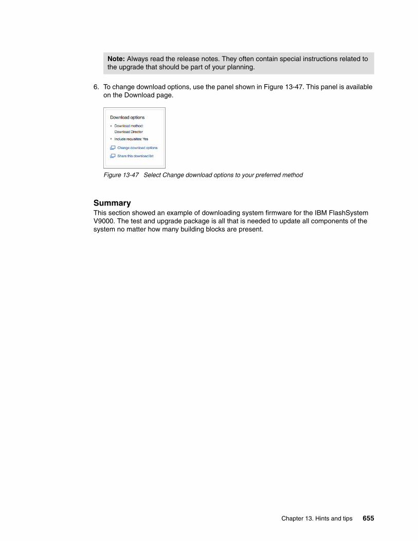
6. To change download options, use the panel shown in Figure 13-47. This panel is available on the Download page.
Figure 13-47 Select Change download options to your preferred method
SummaryThis section showed an example of downloading system firmware for the IBM FlashSystem V9000. The test and upgrade package is all that is needed to update all components of the system no matter how many building blocks are present.
Note: Always read the release notes. They often contain special instructions related to the upgrade that should be part of your planning.
Chapter 13. Hints and tips 655

656 Introducing and Implementing IBM FlashSystem V9000

Appendix A. Guidelines: Port utilization in an IBM FlashSystem V9000 scalable environment
To maximize the full potential of performance and low latency of IBM FlashSystem V9000 with IBM FlashCore technology in a scalable environment, several important items must be considered in configuring your environment. For example, host, internal and external storage, intra-cluster, and optional remote copy ports must be properly designated and zoned in order to optimize performance and properly isolate the types of Fibre Channel traffic.
This appendix covers the following topics:
� Overview� Comparison of port utilization methods� Guidelines: The performance method� Guidelines: The infrastructure savings method� Guidelines: Zoning and pathing� Summary� Supported environments
A
© Copyright IBM Corp. 2015, 2016. All rights reserved. 657

A.1 Overview
IBM FlashSystem V9000 provides a flexible architecture for assigning port resources. Two primary methods of port utilization that can be implement in a Fibre Channel environment are suggested depending on your needs. This appendix compares and provides guidelines for these two methods:
� IBM FlashSystem V9000 port utilization for infrastructure savings
This method reduces the number of required customer Fibre Channel ports that are attached to the customer fabrics. This method provides high performance and low latency but performance might be port-limited for certain configurations. Intra-cluster communication and AE2 storage enclosure traffic occur over the internal switches.
� IBM FlashSystem V9000 port utilization for performance
This method uses more customer switch ports to improve performance for certain configurations. Only ports that are designated for intra-cluster communication are attached to private internal switches. The private internal switches are optional and all ports can be attached to customer switches.
Random workloads can also experience performance benefits with the performance method because more host ports are available when compared with the infrastructure savings method. This benefit is more pronounced for a IBM FlashSystem V9000 solution that includes dedicated ports for remote copy.
A.2 Comparison of port utilization methods
The infrastructure savings method has dedicated internal switches for the IBM FlashSystem V9000 AE2 storage enclosure connections and also intra-cluster communication with a reduced number of customer host facing ports. Eight ports per I/O group are available for storage traffic to the AE2s.
The performance method uses the customer fabric for all connections (with the option to use dedicated internal switches for intra-cluster communication). The ports have designated purposes based on fabric attachment, zone assignments, and port masking. This method provides shared-use ports that use the full bidirectional capabilities of Fibre Channel. Sixteen ports per I/O group are available for storage traffic to the AE2s.
Both methods can designate host ports for remote copy and mirroring. The performance method is more efficient when ports are designated to remote copy.
Both methods support attachment to external storage. In both cases, zones in the customer fabric are required for attaching external storage.
The infrastructure savings method requires up to four types of zones: open zoning, host zones, with optional remote copy zones, or external storage zones.
The performance method requires up to four types of zones; host zones, storage zones (internal and external), intra-cluster zones, with optional remote copy zones.
Note: AC3 controller can have up to four 4-port 16 Gb cards. This appendix will focus on the three card configuration.
658 Introducing and Implementing IBM FlashSystem V9000

The infrastructure savings method has specific port cabling suggestions for the AE2 storage enclosures and AC3 controller enclosure that are calculated to support connections and non disruptive scalability for up to eight AC3 controller enclosure and eight AE2 storage enclosures (four building blocks plus four AE2 storage enclosures). For details, see A.4, “Guidelines: The infrastructure savings method” on page 662.
The performance method requires planning to ensure non disruptive scalability. For details, see A.3, “Guidelines: The performance method” on page 659.
A.3 Guidelines: The performance method
The performance method for port utilization provides shared use of ports that use the full bidirectional capabilities of Fibre Channel.
Table A-1 on page 660 lists the connections to the two AC3 control enclosures, and host and storage connections to switches that are external to the building block. The building blocks connect to two customer fabrics external to the building block.
If you are doing remote copy (Metro Mirror or Global Mirror), then some ports designated for host and storage can be used for remote copy traffic. Another possibility is to get a fourth 16 Gb card and use some of those ports for remote copy. Depending on the remote copy bandwidth, you might use only one port per node. Table A-1 on page 660 provides an example of port utilization that designates ports for intra-cluster traffic, ports for host and storage traffic, and optional ports for remote copy.
Note: The performance method requires customer planning to ensure nondisruptive scalability.
Appendix A. Guidelines: Port utilization in an IBM FlashSystem V9000 scalable environment 659

Table A-1 Port connections in scalable environment with port utilization for performance
12 x 16 Gb per AC3
Source port on AC3 (slot:port)
# Type SAN Usage
3:1 1 16 Gb C (S1) Intra-cluster
3:2 2 16 Gb D (S2) Intra-cluster
3:3 3 16 Gb C Host/Storage (or remote copy)
3:4 4 16 Gb D Host/Storage
4:1 5 16 Gb C (S1) Intra-cluster
4:2 6 16 Gb D (S2) Intra-cluster
4:3 7 16 Gb C Host/Storage
4:4 8 16 Gb D Host/Storage (or remote copy)
7:1 9 16 Gb C Host/Storage
7:2 10 16 Gb D Host/Storage
7:3 11 16 Gb C Host/Storage
7:4 12 16 Gb D Host/Storage
localfcportmask 000000110011
partnerfcportmask 000000100001
SAN - C / D customer fabricSAN - Optional S1 / S2 internal switches
32 ports per building block connect to customer fabric: 12 ports per AC3 and 8 ports per AE2
Note: When comparing the port utilization for infrastructure savings in Table A-2 on page 662 with the port utilization for performance listing in Table A-1 on page 660, you see that the customer fabric port connection mapping and usage is much higher in the port utilization for performance method. This method provides shared-use ports that take advantage of the full bidirectional capabilities in Fibre Channel, resulting in higher performance.
660 Introducing and Implementing IBM FlashSystem V9000

Port maskTable A-1 on page 660 also lists the port masks (localfcportmask and partnetfcportmask) to use with these port designations.
Figure A-1 shows an example from the IBM FlashSystem V9000 GUI that displays Fibre Channel port masks (localfcportmask and partnetfcportmask). This information is displayed when you select Settings → Network → Fibre Channel Ports → Actions → Modify Connection → View details.
Deviations from the port assignments shown in Table A-1 on page 660 require corresponding changes to the port masks. The port masks are used to limit intra-cluster and remote copy traffic to designated ports. Proper zoning is still required.
Figure A-1 Modify Fibre Channel port connection displays port mask
Appendix A. Guidelines: Port utilization in an IBM FlashSystem V9000 scalable environment 661

A.4 Guidelines: The infrastructure savings method
The infrastructure savings method for port utilization provides a dedicated port setup. The ports are used either for host, storage, or intra-cluster communication. This method has dedicated internal switches for the IBM FlashSystem V9000 AE2 storage enclosure connections and also intra-cluster communication with a reduced number of customer host facing ports.
Table A-2 shows the connections to the two AC3 control enclosures, including the cluster connections to the switch that is internal to the building block. Host, remote copy, and external storage connections to switches that are external to the building block are shown.
The building blocks connect to two SAN fabrics within the building block, and two customer fabrics external to the building block.
Table A-2 Port connections in scalable environment for minimum infrastructure effect
The infrastructure savings method has specific port cabling guidelines for the AE2 storage enclosures and AC3 controller enclosures. The guidelines are calculated to support connections and non disruptive scalability for up to eight AC3 controller enclosures and eight AE2 storage enclosures (four building blocks plus four AE2 storage enclosures).
12 x 16 Gb per AC3
Source port on AC3 (slot:port)
# Type SAN Usage
3:1 1 16 Gb S1 Intra-cluster/Internal Storage
3:2 2 16 Gb S2 Intra-cluster/Internal Storage
3:3 3 16 Gb C Remote copy (variable)
3:4 4 16 Gb D Host/External storage (Variable)
4:1 5 16 Gb S1 Intra-cluster/Internal storage
4:2 6 16 Gb S2 Intra-cluster/internal storage
4:3 7 16 Gb C Host/External storage (variable)
4:4 8 16 Gb D Remote copy (variable)
7:1 9 16 Gb C Host
7:2 10 16 Gb D Host
7:3 11 16 Gb C Host
7:4 12 16 Gb D Host
localfcportmask 000000110011
partnerfcportmask 000010000100
SAN - C / D Customer FabricSAN - S1 / S2 Internal Switches
16 ports per building block connect to customer fabric: 8 per AC3
662 Introducing and Implementing IBM FlashSystem V9000
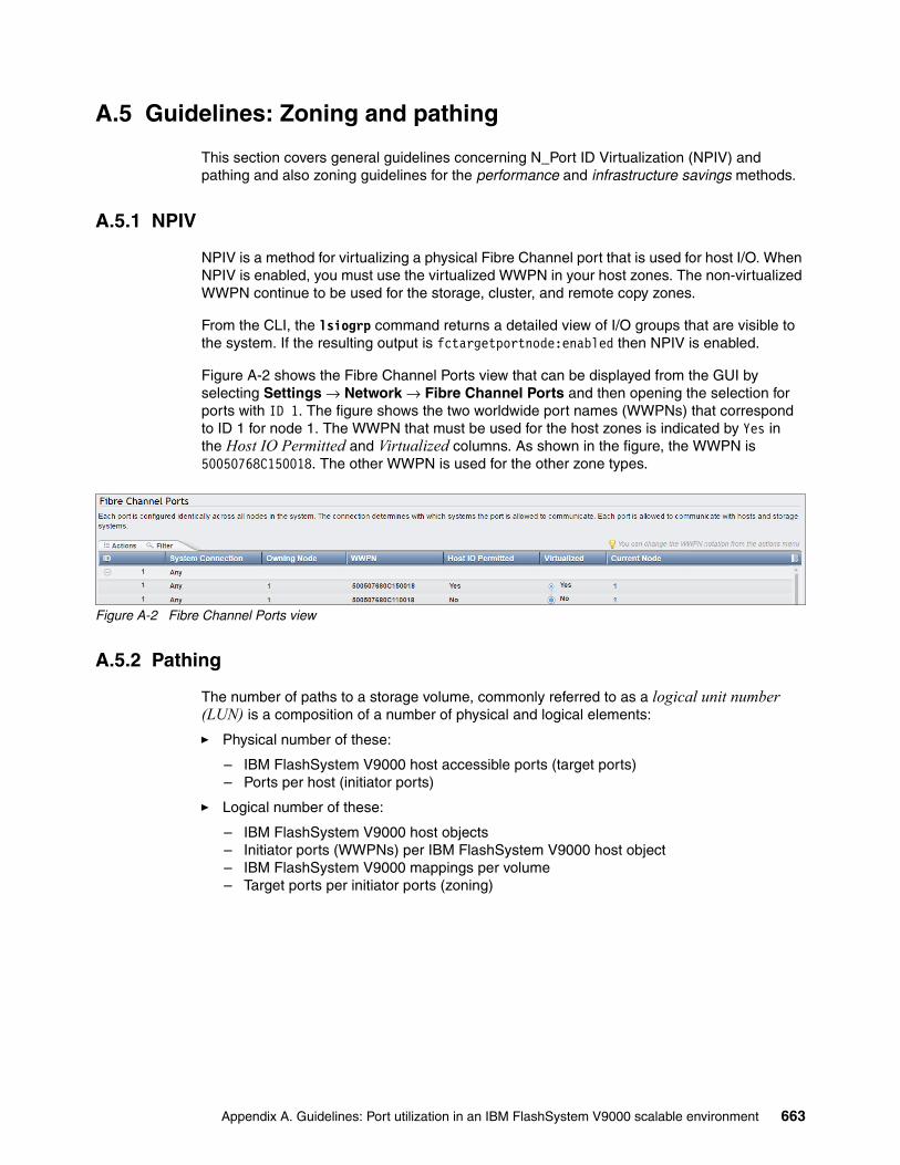
A.5 Guidelines: Zoning and pathing
This section covers general guidelines concerning N_Port ID Virtualization (NPIV) and pathing and also zoning guidelines for the performance and infrastructure savings methods.
A.5.1 NPIV
NPIV is a method for virtualizing a physical Fibre Channel port that is used for host I/O. When NPIV is enabled, you must use the virtualized WWPN in your host zones. The non-virtualized WWPN continue to be used for the storage, cluster, and remote copy zones.
From the CLI, the lsiogrp command returns a detailed view of I/O groups that are visible to the system. If the resulting output is fctargetportnode:enabled then NPIV is enabled.
Figure A-2 shows the Fibre Channel Ports view that can be displayed from the GUI by selecting Settings → Network → Fibre Channel Ports and then opening the selection for ports with ID 1. The figure shows the two worldwide port names (WWPNs) that correspond to ID 1 for node 1. The WWPN that must be used for the host zones is indicated by Yes in the Host IO Permitted and Virtualized columns. As shown in the figure, the WWPN is 50050768C150018. The other WWPN is used for the other zone types.
Figure A-2 Fibre Channel Ports view
A.5.2 Pathing
The number of paths to a storage volume, commonly referred to as a logical unit number (LUN) is a composition of a number of physical and logical elements:
� Physical number of these:
– IBM FlashSystem V9000 host accessible ports (target ports)– Ports per host (initiator ports)
� Logical number of these:
– IBM FlashSystem V9000 host objects – Initiator ports (WWPNs) per IBM FlashSystem V9000 host object– IBM FlashSystem V9000 mappings per volume– Target ports per initiator ports (zoning)
Appendix A. Guidelines: Port utilization in an IBM FlashSystem V9000 scalable environment 663

Calculating the number of paths to a storage volumeThe goal is to have no more than eight redundant paths between the hosts and the volumes. This provides good performance and protection from single point of failures. Increasing the number of zones or increasing the number of host objects per host decreases the number of paths to a volume.
The first row in Table A-3 represents a typical way to keep the number of paths to eight. This scales with hosts with more than two ports. In this case, there would be a host object for every pair of ports. These port pairs would each be connected to a separate fabric. An equal portion of volumes would be mapped to each host object.
The last row is not a recommended configuration and shows a high number of paths that can result from lumping all the host ports and all the target ports into one zone per fabric.
Table A-3 Calculating the number of paths to a volume
The calculation is simple arithmetic as follows:
# of initiator ports per host object * number of host object mappings per volume * number of target ports per initiator port = number of paths
Host with 16 initiator portsAC3s with 16 target ports2 redundant fabrics
Number of initiator ports (WWPNs) per host object
Number of host object mappings per volume
Number of target ports per initiator port
Number of paths
4 host zones, 8 host objects 2 1 4 8
2 host zones, 1 host object 16 1 8 128
664 Introducing and Implementing IBM FlashSystem V9000

A.5.3 Port utilization method for performance
The method for performance requires up to four types of zones: host zones, storage zones (internal and external), intra-cluster zones, with optional remote copy zones. They can be defined as follows:
� One intra-cluster zone per fabric� Two host zones per fabric� One storage zone per fabric� One remote copy zone per fabric (if needed)
Figure A-3 shows an overview of the zoning that is configured for the performance method.
Figure A-3 High level zone requirements
Local HostsLocal Storage
FlashSystem V9000 - Zoning for Performance
V9000 AE2 Storage
Redundant fabric(s)
Remote Copy Zones
Storage Zones Host Zones
Intra-clusterZones
External Storage
Node 1 Node 2
Node 1 Node 2
V9000 AC3
Remote V9000 AC3
Appendix A. Guidelines: Port utilization in an IBM FlashSystem V9000 scalable environment 665

Figure A-4 shows an example for zoning storage and host, based on Table A-1 on page 660 for 12 x 16 Gbps building blocks.
Figure A-4 Zoning for performance detailed example
The same physical AC3 ports are used for both storage and host connections but the WWPNs are different due to NPIV.
A.5.4 Port utilization method for infrastructure savings
The infrastructure savings method requires up to four types of zones:
� Open zoning� Host zones� Remote copy zones (optional)� External storage zones
These zones are described as follows:
� Open zoning on internal switches
AC3 and AE2 components are connected as documented in the “Installing” topic of IBM Knowledge Center:
https://ibm.biz/BdsZCM
� Two host zones per fabric
� One external storage zone per fabric
� One remote copy zone per fabric (if needed)
Tip: You must use the virtualized WWPN for the host zones with NPIV enabled.
FlashSystem V9000 - Zones for Performance (No Remote Copy or Hyperswap) 12 x 16 Gb Single Building Block Example
Local Hosts
V9000 AE2 Storage
External Storage
Node 1 Node 2
V9000 AC3
Fabric C
Storage Zone
AC3 Node 1 – Ports 3,7,9,11AC3 Node 2 – Ports 3,7,9,11
AE2 Ports – 1,3,5,7External Storage
Cluster Zone
AC3 Node 1 – Ports 1,5AC3 Node 2 – Ports 1,5
Host Zone 1
AC3 Node 1 – VPorts 3,9AC3 Node 2 – VPorts 3,9
Local Host Ports
Host Zone 2
AC3 Node 1 – VPorts 7,11AC3 Node 2 – VPorts 7,11
Local Host Ports
Fabric D
Storage Zone
AC3 Node 1 – Ports 4,8,10,12AC3 Node 2 – Ports 4,8,10,12
AE2 Ports – 2,4,6,8External Storage
Cluster Zone
AC3 Node 1 – Ports 2,6AC3 Node 2 – Ports 2,6
Host Zone 1
AC3 Node 1 – VPorts 4,10AC3 Node 2 – VPorts 4,10
Local Host Ports
Host Zone 2
AC3 Node 1 – VPorts 8,12AC3 Node 2 – VPorts 8,12
Local Host Ports
666 Introducing and Implementing IBM FlashSystem V9000

Figure A-5 shows an overview of the zoning configured for the infrastructure savings method.
Figure A-5 IBM FlashSystem V9000 scalable solution: Zoning for infrastructure savings
A.6 Summary
This appendix provides guidelines for two methods or port utilization in a scalable IBM FlashSystem V9000 environment. Depending on customer requirements, the following methods of port utilization can be put into practice:
� IBM FlashSystem V9000 port utilization for performance
This method uses more customer switch ports to improve performance for certain configurations. Only ports designated for intra-cluster communication are attached to private internal switches. The private internal switches are optional and all ports can be attached to customer switches.
� IBM FlashSystem V9000 port utilization for infrastructure savings
This method reduces the number of required customer Fibre Channel ports that are attached to the customer fabrics. This method provides high performance and low latency but performance might be port-limited for certain configurations. Intra-cluster communication and AE2 storage traffic occur over the internal switches.
By following the port utilization cabling and zoning guidelines in this appendix, you can maximize the full potential of performance and low latency of IBM FlashSystem V9000 in enterprise-scalable environments.
Local Hosts
FlashSystem V9000 - Zoning for Infrastructure Savings
V9000 AE2 Storage
Redundant fabric(s)
Remote Copy Zones
ExternalStorage Zones Host Zones
Intra-cluster + AE2 StorageOpen Zoning
V9000 AE2 Storage
External Storage
Node 1 Node 2
Node 1 Node 2
V9000 AC3
Remote V9000 AC3
Internal Switches
Appendix A. Guidelines: Port utilization in an IBM FlashSystem V9000 scalable environment 667

A.7 Supported environments
IBM FlashSystem V9000 can be used in different port utilizations. To check for supported switches, see the IBM System Storage Interoperation Center (SSIC):
https://www.ibm.com/systems/support/storage/ssic/interoperability.wss
For your search, use the values listed in Table A-4.
Table A-4 Values for the search fields
Validate that the intended FC switches are listed in the SAN or Networking field.
If there are additional host-side details, such as platform, OS, or multipathing, that restricts your switch selection, then choose the selections in the appropriate lists.
Field Value to select
Storage Family IBM System Storage Enterprise Flash
Storage Version FlashSystem V9000 7.7.x
Connection Protocol Fibre Channel
668 Introducing and Implementing IBM FlashSystem V9000

Related publications
The publications listed in this section are considered particularly suitable for a more detailed description of the topics covered in this book.
IBM Redbooks
The following IBM Redbooks publications provide additional information about the topic in this document. Some publications referenced in this list might be available in softcopy only:
� Accelerate with IBM FlashSystem V840 Compression, REDP-5147
� Deploying IBM FlashSystem V840 Storage in a VMware and Cloud Environment, REDP-5148
� IBM FlashSystem V9000 and VMware Best Practices Guide, REDP-5247
� IBM FlashSystem V9000 in a VersaStack Environment, REDP-5264
� IBM FlashSystem V9000 Version 7.7 Product Guide, REDP-5409
� IBM SAN Volume Controller 2145-DH8 Introduction and Implementation, SG24-8229
� IBM System Storage SAN Volume Controller and Storwize V7000 Best Practices and Performance Guidelines, SG24-7521
� Implementing IBM FlashSystem 900, SG24-8271
� Implementing the IBM System Storage SAN Volume Controller with IBM Spectrum Virtualize V7.6, SG24-7933
You can search for, view, download or order these documents and other Redbooks, Redpapers, Web Docs, draft and additional materials, at the following website:
ibm.com/redbooks
Other publications
The IBM FlashSystem V9000 Quick Start Guide, GI13-2894 publication is also relevant as a further information source.
Online resources
These websites are also relevant as further information sources:
� IBM FlashSystem V9000 in IBM Knowledge Center:
https://ibm.biz/fs_V9000_kc
� IBM FlashSystem family:
– https://ibm.biz/BdsaFF – https://ibm.biz/BdsaFH
© Copyright IBM Corp. 2015, 2016. All rights reserved. 669

� IBM FlashSystem Ecosystem solutions:
http://www.ibm.com/systems/storage/flash/ecosystem/isv.html
� IBM System Storage Interoperation Center (SSIC):
https://www.ibm.com/systems/support/storage/ssic/interoperability.wss
Help from IBM
IBM Support and downloads
ibm.com/support
IBM Global Services
ibm.com/services
670 Introducing and Implementing IBM FlashSystem V9000

ISB
N 0738442356
SG
24-8273-02
(1.0” spine)0.875”<
->1.498”
460 <->
788 pages
Introducing and Implem
enting IBM
FlashSystem V9000


ibm.com/redbooks
SG24-8273-02
ISBN 0738442356
Printed in U.S.A.
Back cover